
SSERC Science and Technology Bulletin 176
36
-
Upload
khangminh22 -
Category
Documents
-
view
0 -
download
0
Transcript of SSERC Science and Technology Bulletin 176


SSERC Science and Technology Bulletin 176 March 1993
Contents
Opinion A question of standards 1
Introduction2
Readers’ Letters Health and safety topics 3
Technical queries 4
Safety Notes Guidance on new regulations 6
Electrical safety problems
- Radford labpack 6
- ambiguous connectors 7
- shaper saws 8
Laser safety and laser diodes 8
Technical Articles Making necessary links
- ideas for teaching on linkages 11
Equipment Notes Oscilloscopes 17
Laser diode modules 25
Trade news etc.28
Surplus equipment offers30
© SSERC 1993
Copyright is held to be waived only for bona-fide educational uses within Scottish schools and
colleges in current membership of SSERC.
Typeset by SSERC in Trinity and Homerton on an Acorn Archimedes 440 running Computer Concepts Impression ii DTP
software, Acorn !Draw and 4Mation’s Vector. The line drawings were compiled from elements of the SSERC Graphics
Libraries for Science and Technology. Camera ready copy was produced at 600 x 600 d.p.i. on a Computer Concepts
LaserDirect printer.

Opinion
A question of standards
Whilst in some educational circles quality assuranceremains flavour of the month in others the mere mentionof the phrase means reaching for that wooden stake andthe cloves of garlic. The latter are in any case de rigeuralso in the other camp since much of the push for qualityassurance is Euro-driven. Because of the single marketthe search is still on for that latter day Holy Grail - thelevel playing field. It’s a shame for us that in much ofScotland you don’t get many of those to the Ecu.
Particularly fashionable with the gourmets of quality isBS 5750 and its international equivalent ISO 9000. NowSSERC has for some time been a member of the BritishStandards Institution. Given the number of Ecus that thiscosts us each year you may assume that we stronglysupport the aims of that organisation. We are also for thebusiness of testing products according to technicalstandards and against the raising of technical barriers totrade. What we are not in favour of is that our clients -
education authorities and teachers as customers for goodsand services - should be misled as to what are reliableand relevant indicators of quality.
Relevance is the key.
BS 5750 is a good standard for which to aim andapproval isn’t easily obtained. The process involves anyorganisation in a significant expenditure of time, effortand money. Firms like Philip Harris who recentlyreceived approval for their quality control systems arethus to be quite properly and heartily congratulated. Notethough that it is a quality system and its associateddocumentation for which approval is given and not theindividual goods or services which are sold. That is whywe very carefully add the word “relevant’ to the“reliable”.
BS 5750 is much concerned with the standard ofquality assurance documentation, less so with actualproducts. The cynical say that it is entirely feasible for afirm which produces shoddy goods or a college whichdelivers tatty training merely to polish up its paperworkto 5750 standard. Sadly there is nothing then to preventsuch firms or institutions from delivering welldocumented shoddiness and tat.
We speak from a number of recent, annoyingexperiences. Over the last year or so we have testedseveral products of registered firms where some aspectsof design and construction never came within sniffingdistance of meeting the relevant technical and safetystandards. Our complaints no doubt were meticulouslyfed into immaculate quality assurance systems. We stillawait the emergence of acceptable products at the otherend. We must also mention the printing firm with whichwe dealt, once, whose 5750 system did not include anycomplaints or disputes procedure. Now there’s anassumption!
A parallel can be drawn here between this confusionover the real status of BS 5750 and that of some of thenewspapers who got hold of our work on the risk of burnsfrom the wearing of shell-suits in practical rooms. Parentswere advised by these august journals to “make sure youbuy a more expensive type from a well known maker andif possible one carrying a British Standards numberThere is no relevant BS for flammability in suchgarments. Any BS referred to on a clothing label will beone dealing with issues such as resistance of the fabric toabrasion, colour fastness etc.
We are not saying that BS 5750 is worthless - far fromit. It is a useful indicator that an organisation has put inplace a systematic approach to quality control.Nonetheless that finn’s goods or services still must bejudged against separate technical standards directlyrelevant to that class of product. As the good book says
“By their works shall ye know them”
SSERC Bulletin 176 March 1993 1

Notice : Further Education Colleges
Introduction
Readers in Scottish colleges which will beincorporated on 1st April of this year shouldnote that this will be the last bulletin issue theywill receive through the distribution system ofthe education authority. In future FE collegeswill only be able to receive our publications andaccess our advisory and training services bybecoming subscribing members in their ownright. Details of subscription rates andapplication forms can be obtained by writing tothe Executive Director of SSERC.
Diary dates
Technology Conference
The World Council of Associations for TechnologyEducation (WOCATE) is this year to hold its international conference in Scotland. WOCATE ‘93, is to be a“Festival of Technology Education for Elementary Stages(5 - 14)”. It will take place at the Aberdeen campus ofNorthern College.
For the submission both of papers and workshopproposals the deadline is April 30th. These should be sentto the Conference Director for consideration (see AddressList on the inside rear cover of this issue).
TTA Annual Meeting
The Technology Teachers’ Association has once moregiven generous notice of the date and venue for its majormeeting. The AGM will again be held in Coatbridge HighSchool and the date this year is Saturday 6th November(note studious avoidance of jokes about there possiblybeing lots of fireworks [Ed.]).
Science and Technology Festival
The Edinburgh International Festival of Science andTechnology will be held from 10th - 24th April with theschools’ programme running from 1st March until themain festival closes. The schools’ programme includes anOlympiad at Heriot Watt University on the 23rd to 24th
of March. SSERC will be hosting some workshops on theSchools Chip which will be held here in the Centre andwill be open to the general public on a ticket holder basis.Further details on the festival itself are available from theaddress given in our address list on the inside rear coverof this bulletin.
SSERC Courses
All this stuff about dates reminds us that our own diaryis rapidly filling up. Already we have bookings forcourses in Health and Safety as far ahead as the Spring of1994. There is some slack in other areas such as courseson the Schools Chip and other practical workshops. Givenall the other things we have to do however - such aspublishing bulletins and developing new courses - oncewe have taken a manageable number of additionalbookings we intend closing the diary for the whole ofnext session. So, if you want a SSERC course in thesession 1993-94, don’t hang about!
From your own correspondence
In order to demonstrate to our own Lords and Masters(Ladies and Mistresses?) that this place is no ivory tower,(sceptred lotus eaters’ isle what you will) we keep enquirylogs. Of late we have been a little disturbed to see that forsome regions the balance of our contacts has begun toswing away from the established pattern.
In the past this has shown that most of our work hasbeen done directly for teachers, technicians and seniorpupils in schools. We believe that this demand led natureof the service keeps it in tune with the needs of schools.In our latest reporting period however, for some areas theenquiries from directorate and advisory staff haveoutnumbered those from schools, sometimes by as muchas two to one. At the same time we are getting moreideas for articles from direct teacher and technicianenquiries than we have for some years - curious isn’t it?
It has been decided to open up the bulletin to moredirect access and also to trial a readers’ letters section.Rather than begin with a literally empty gesture, we haveincluded some readers’ letters in this issue. The conditionsunder which we will accept and publish your letters arealso outlined in an introduction to that section.
2 SSERC Bulletin 176 March 1993

Readers’ letters
Introductory
We would be pleased to receive your letters on anysubject relevant to our remit. Such matters includeproblems with the supply or maintenance of equipment,usage including safety, and general technical difficultieswith practical work.
We would also appreciate your (reasonably polite,please) comments on material appearing in thispublication or on more general matters which in youropinion are germane to our broader concerns in promotingthe more practical aspects of science and technologyeducation in Scotland.
It would be helpful if letters were kept short and to thepoint. SSERC reserves the right to edit them if necessary -
but in sympathetic manner. Names and addresses must besupplied but we will not publish these unless yourpermission is specifically given. Where a published letterreceives an open reply we undertake to treat the subjectappropriately. In other words we undertake not topatronise correspondents, not to treat enquiries orquestions flippantly or facetiously and there will be noattributions of the type:
“Yours, Worried of Auchtermuchty”.
In order to illustrate the type of direct enquiry we havein mind we are publishing, with permission, one or two
typical examples recently received from advisers, teachersor technicians.
Health and SafetyHazard warning labels
general provisions of the Health and Safety at Work Actand of the COSHH Regulations, it is prudent to put someof the relevant information on reagent bottles.
Some dilute solutions are not required by the CPLRegulations to carry any warnings or the same hazardwarnings as would be needed for more concentratedforms. Similarly for other solutions of identical molaritybut of different substances. For example, both nitric andsulphuric acids have to be labelled “irritant”, but not sohydrochloric acid unless “the molarity exceeds four”.
Personally I would ignore such anomalies and wouldattach the risk phrase “irritant even to 1 molar HCI oreven to 0.1 M if it were in a bulk supply. This is justcommon sense. Handling a larger volume increases therisks of splashing and a splash of HCI, even if only 0.1molar would certainly irritate.
On the other hand it is certainly not necessary toattempt to put all the relevant risk phrases on the label ofa secondary container. In cases where reagent bottles aresmall there will be insufficient room!
You will see from the chemical catalogues thatsuppliers sometimes use two hazard pictograms butusually only where both types of hazard are sufficientlyserious. That may serve as a useful model for our ownpractice. When you get down to the last stage however -
where the chemical is collected in a beaker or flask by apupil - then a single self adhesive label with the name ofthe substance and any one principal hazard will besufficient1.
Sticky question
Dear Sirs, Dear Sir/Madam,
In connection with the requirements of COSHH:
Are hazard warning labels or pictograms required onbottles or worksheets when solutions are very dilute eg<0.1 M?
If a chemical has three hazard warning signs associatedwith it, is it necessary to put all three on the bottle egcopper sulphate solution?
Yours etc.
The Carriage, Packaging and Labelling (CPL)Regulations require suppliers to put specified labels onthe bottles which they supply to you and I but they do notrequire us to repeat that exercise when we breakchemicals down from bulk. In order however to meet
1 wonder ifyou would comment on whether it is stillpermissible for teachers to provide pupils withfirst-aidtreatment or are they just making themselves liable tolitigation? For example what jf a pupil were allergic toordinary sticking plaster?
Yours etc.
We first contacted the St.Andrew’s AmbulanceAssociation for their advice and they were of the opinionthat there could be a slight risk of litigation in thecircumstance described. They themselves would only usepads rather than plasters. We thought it best then to seek a
‘Note that the CPL Regulations are to be replaced by theChemical Hazard Information and Packaging [CHIP] Regulationssometime during 1993 but that the changes should not affect theabove advice.
SSERC Bulletin 176 March 1993 3

second opinion and did so from the Employment MedicalAdvisory Service (EMAS) of the Health and SafetyExecutive.
The EMAS spokesperson took the line that teacherswould be acting in loco parentis. Any first aid treatmentwhich did not go beyond that which might be expected ofa reasonable parent - say in treating a small cut - wouldbe difficult to challenge at all effectively. (The EMASspokesperson also said however that all teachers wouldbenefit from basic first aid training and that they hadnoted significant criticism from parents who generally hada perception of poor provision of first aid care in schools).
It is also worth remembering that most EAs will havearranged cover for their legal liability in such situations. Itwould be wise to have a general policy as to who sticks onplasters or supervises, say the washing of eyes, and towhat extent the employer will back up such actions by itsteachers.
A sense of proportion is needed also however. Whichwould be the greater negligence causing some minoradditional irritation to the skin or eye or standing back anddoing nothing whilst the designated person is sent for andmeantime the pupil carries on bleeding or alkali continuesto burn their eyes?
Similar cards recommended to be carried by personsperceived to be in “higher risk” groups, for exampleanglers and canoeists, are available from some of thewatersports organisations such as the British CanoeUnion or the Flydressers’ Guild. The cards containinformation about the need to take seriously certainsymptoms which otherwise could be mistaken forinfluenza.
Weil’s disease has had a higher profile over the lastthree years or so. This is because of an increase inrecorded cases although the total in any one year remainsvery small. The increased incidence is thought to belinked to an increase in rat populations because of arecent succession of mild winters. That in turn hasslightly increased the probability of Leptospirosis contamination of water courses and reservoirs etc and thusthe likelihood of infection in those who regularly comeinto contact with untreated waters - such as anglers,sailors, canoeists who habitually partake in water sportson reservoirs, gravel pits etc.
I don’t have any separate statistics for Scotland butwould be surprised if on rivers and lochs away frompopulated areas the risk was significantly greater now inrural Scotland. It is also important to remember that thereported increase for the UK as a whole was from analready small base.
Weil’s Disease References
Dear SSERC,
Some of our Principal Teachers have recently raised aspecific issue of health and safety in fieldwork. This is inconnection with possible contamination of water by themicrobe Leptospirosis (from rat urine). Do you havecomments or background information to offer?
Yours etc
Weil’s disease (Leptospirosis icterohaemorrhagica) is azoonosis or zoonotic infection - a disease transmissiblebetween animals and man. It is a relatively rare yetserious infection which begins with symptoms rather likethose of a common cold or ‘flu but if not recognised andtreated in time its effects, acting chiefly on the liver, canprove fatal.
It is important however to put leptospirosis or Weil’sdisease in a proper context. I enclose information onzoonotic infections in general and on a range of specificdiseases of this type. This information comes from arecent IPMS publication which is in a handy folding cardformat [1]. You will see from the references on this cardthat further information, specific to Weil’s disease isavailable in the HSE pocket card;
“Leptospirosis - are you at risk?” [2]
1. “A Working Guide to Zoonotic Infections”, IPMS,1992.
2. “Leptospirosis - are you at Risk?” HSE, IND(a)84L 2/9 70 M.
Technical queries
Dodgy question?
Dear SSERC,
The enclosed is a photocopyfrom part of a specimenquestion paperfor the new Higher Grade Human Biologycourse. This states that Clinistix changesfrom pink toblue with glucose but not with any other reducing sugars.We realise that the question works okay as a question butthere is a mis-match here with our own experience ofwhat actually happens at the bench. We get a positiveresult with Clinistix and maltose.
Try out the practical yourselves and tell the world aboutit before it becomes gospel. Our maltose could becontaminated and we could be wrong. Don’t tell the worldabout that!
Awra best, awra time!Yours etc cont.I.
4 SSERC Bulletin 176 March 1993

You are both right and wrong at the same time. Wereckon we should perhaps tell others about that - but youflatter us if you think the Bulletin covers the entire knownworld!
We checked our own stocks of maltose and like youwe obtained a positive result with Clinistix but notusually within the 10 s period recommended as thereading time after immersion of the active tip. We also reread our detailed technical literature on Clinistix andconfirmed that the test is indeed claimed to be specific forglucose. This is because it is an enzyme based system andthus markedly substrate specific (see Biology Notes inBulletin 161, October 1988 for a detailed account of theworkings of Clinistix).
We then even more carefully read the small print onour bottle of maltose and discovered that it contained “notmore than 1% dextrin”. Us old fogies recognise “dextrin”as a synonym for d-glucose. Eureka! A search through thecatalogues showed that even relatively pure grades ofmaltose are never completely glucose free. Even gradesrecommended for tissue culture or chromatography forexample typically contain 0.05% w:w. So in theory thequestion setter was correct. In practice so are you. In thereal world many samples of maltose will test positive forglucose with Clinistix.
Many thanks for alerting us to this problem.Best wishes,Yours etc....
Demonstrable gain
Dear SSERC,
Standard Grade : Electronics - Gain ofan amp!jfier
Further to our earlier correspondence I believe thatthere is a much simpler way to show gain. Using thecircuit shown, the input and output voltages and currentcan be measured.
Fig. 1 - amplifier circuit
In addition the LED and series resistor can be used asthe loadfor the amplifier.
For voltage gain the input and output voltages can bemeasured.
For power gain the LED and resistor can be connecteddirectly to the potentiometer to show that power to theamplifier is not enough to light the LED. When the LED isconnected to the amplifier as the load, it lights showingsufficient powerfrom the amplifier.
Once the idea of power gain is established using inputvoltage and current compared with output voltage andcurrent then the idea of input/output “resistance” can beintroduced.
it follows then that P = V 2 R can also be derived.
Please excuse the scribble but I am writing this andtrying to tidy up all those loose ends before the schoolbreaks up tomorrowfor the holidays!
1 hope that this may be of use.
Yours etc
P.S. The meters we used were Cirkit 7040/6040multimeters on the current range 20 mA and voltagerange 20 V.
The method you present is technically correct and hasthe merit of being simple and neat. It is not howeverwholly satisfactory because it misses some subtleties.
1. Drive capability of amplifier
The maximum current which can be drawn from a 741op-am p is 20 mA. It can be argued from a relativityviewpoint that the absolute size of this maximum currentdoes not matter. As well as driving LEDs, you can findsmall lamps and motors that run off currents of less than20 mA. However stuff relativity! I am 6 feet tall. I would
not like to be six inches tall. Norwould I like to be 60 feet tall! It is toocontrived to work within a 20 mAlimit. In my judgement the limitshould be at least ten times higher,preferably one hundred times or so.
2. Two stage amplifier
ft’s normal practice for amplifierswith power outputs to be constructedin separate stages. The first stage
amplifies the voltage; the second, the power. Although few pupilsat Standard Grade could be expected to appreciate all the reasonsfor this two stage system, they can at least be introduced to theconcept of separate stages for voltage and power amplification.
1.5 V
SSERC Bulletin 176 March 1993 5

3. Drive capacity of signal source
The reason that the LED cannot be lit if directlyconnected to the potentiometer is because the supplyvoltage is too small, not because the supply’s drivecapacity is too little. For instance, if your single 1.5 V cellwere to be replaced by a battery of cells, the LED wouldlight provided there was a suitable value of series resistor.
To demonstrate the need for power gain, you shouldreally start off with an e.m.f. source whose internalresistance prevents the load being operated. For exampleyou could show that a low voltage motor cannot be drivendirectly from a small solar cell. Or, instead of the motoryou could use a 3.5 V, 300 mA, MES lamp, which alsowould not operate.
All of these subtleties were incorporated into theSuggested Activity written up in the Standard GradeTechnical Guide (pages 76-77). Unfortunately I musthave been getting weary when I wrote that part for I didnot explicitly state them, for which I apologize.
There is a lot of meat here and interesting issues areraised. They are really not about right or wrong but moreabout shades of correctness. What, from a pedagogicalviewpoint, is the best way of demonstrating poweramplification?
Many thanks for writing again. You have undoubtedlyraised some very interesting points.
Safety notes
New regulations - ACoPs published
The new legislation of which we gave advance noticein Bulletins 173 and 174 came into force on 1st Januarythis year (or more accurately at midnight on Hogmanay -
you probably never a felt a thing!). All of the new sets ofregulations are now available together with either theirrelevant approved code of practice (ACoP) or guidance.They all follow a useful format wherein each regulationor clause is straight way followed by relevant informationwhich explains usually in plain simple English what isrequired in practice.
The collection of all the combined regulation andACoP or Guidance booklets has already and inevitablybecome known as “The Six Pack”. They are entitledslightly differently from the Regulations themselves andall are dated 1992.
Each title, with Regulations and ACoP or Guidancecombined, costs £5.00 per copy from the HMSOPublications Centre, HMSO bookshops, or from HMSOaccredited agents (see Yellow Pages) or through goodbooksellers.
References
1. “Management of health and safety at work”, ISBN 0-11-886330-4.
2. “Workplace health, safety and welfare”, ISBN 0-11-886333-9.
3. “Work equipment”, ISBN 0-11-886332-0.4. “Manual handling”, ISBN 0-11-886335-55. “Display screen equipment work” ISBN 0-11-886331-26. “Personal protective equipment at work” ISBN 0-11-
886334-7.
Electrical safety problemsRadford Labpack accident report
A technician early this year got a nasty shock from aType 59R Labpack he had been renovating. The accidentoccurred when he was trying to remove the cap securingthe mains fuse. Because the fuseholder of circular cross-section was insecure, the entire fuseholder rotated,causing a side terminal at live potential to touch the frameof the isolating transformer (Fig. 1). This caused theenclosure to become hazardous live. Had the rest of theelectrical system been in good order, a fuse should haveblown almost instantly to render the apparatus dead.Unfortunately there were several other fault conditions:
- The protective earth conductor in the extension socketthat supplied the Labpack had significant resistance. Thisfault would have caused the shock voltage to be higherthan 120 V, and perhaps nearly as high as 240 V. It wouldalso have prolonged the shock current by delaying theeventual blowing of a fuse.
- The supply live had been wrongly taken to a sideconnector rather than to the base connector on thefuseholder (Fig. 1). This isolated the 2 A instrumentationfuse. Had that fuse been in the fault circuit, it would haveprovided better protection than the fuse in the 13 A plug.
- The 13 A plug had been fitted with a 13 A fuse, whichwas far too high a value. Had this fuse rating been 3 A, theshock current period would have been shorter.
In conclusion, the accident was caused by thecompound effects of four fault conditions, added to whichwas the dangerous procedure of removing a fuse while the
6 SSERC Bulletin 176 March 1993

apparatus was live. Electrical systems in general arefailsafe - that is to say they are designed to be completelysafe in single fault condition. It is nearly always whenthere are multiple faults that electrical accidents occur.
There are lessons to be learned for all of us from thisincident. (In health and safety management jargon this iscalled reactive safety monitoring). We would stress thatwe are not merely exercising the wisdom of hindsight.Nor do we intend attaching blame to or scoring points offany of those involved - whether they be manager or themanaged. Our recommendations are listed below:
1. The importance of routine safety checks on portableapparatus and fixed installations needs to be restated.None of the faults found here are unusual. All arespecifically referred to by the Health and SafetyExecutive [1] in their checklist for testing schoolapparatus.
2. The renovation of sub-standard apparatus to complywith acceptable standards of electrical safety requirescareful consideration including technical expertise andcompetence, and proper supervision. The capabilitiesof employees needs to be taken into consideration.Responsibility rests entirely with the employer inorganising such work and ensuring that it is carried outcompetently. It was noted that some fault conditions inthis accident were copied from the original Radforddesign.
3. If there are multiple problems with sub-standardapparatus such as Radford Labpacks, it would bepreferable to institute a programme of replacementwith new apparatus of satisfactory design andconstruction. This would prevent new fault conditionsbeing introduced when attempting renovations.
4. The installation of residual current circuit breakers(RCCBs) at least in test and repair areas desrvesserious consideration. This supplements the protectionprovided by protective earthing and insulation andshould prevent injury from this type ofincident.
when fuseholder rotated .._—
during accident, lug Btouched transformer framecausing a live to earthshort
Fig. 1 Fuseholder
live conductor from supplyshould be taken to connector Aat end of fuseholder
Some technical matters
1. The supply live must be wired to the connector on thebase of a fuseholder (Fig. 1) and not to a sideconnector. This ensures that the outer fuseholder collaris dead when the fuse is removed. It helps to prevent aperson inserting or removing a fuse from getting anelectric shock when the apparatus is connected to thesupply.
Fig. 2 Die profiles for fuseholders
2. Fuseholders and other round sectioned parts have anti-rotation mechanisms. These must be utilized. Forinstance some fuseholders are fitted with an anti-rotation spigot which fits into a key profile mountinghole (Fig. 2). Others have a D profile. A suitable punchand die should be used when preparing the mountinghole. These are stocked by RS Components and are,we admit, expensive! Reliance should not be placed onlock nuts solely.
Reference
1. Electrical safety in schools (Electricity at WorkRegulations 1989), Guidance Note GS 23, Health andSafety Executive, HMSO, 1990.
Ambiguous connectors: 3-pin Bulgins
Going from reactive to proactive safety management,your attention is drawn to a hazard which might present ahigh risk in your school. It concerns some low voltageequipment such as soldering irons which use the sametype of connector as a relatively small group of 240 V
B’ mains apparatus. The solder stations include ones madeby Antex and Weller, sold by distributors such as RapidElectronics, RS Components and Farnell Electronics.
The 24 V output from these stations is through a 3 pinBulgin connector which the Rapid catalogue refers to astype PX0429 and which RS Components call a 3-wayminiature connector. The RS reference number for oneexample of the cable socket is 489-504, to be found onpage 205 of their current catalogue.
00outline of hole cut bykey profile die
outline of hole cut byD’ profile die
B
A
/
SSERC Bulletin 176 March 1993 7

Laser safety and laser diodesThe apparatus we know of which uses this same
connector on a detachable lead at the 240 V supply inletare a version of Radford Labpacks and products made byEDU-ELEQUIP, a company possibly now defunct thatalso used to trade under the name of EducationalElectronic Equipment. Their products included powersupplies, function generators, digital counters, and so on.
The hazard is a grave one. Were 240 V to be applied tothe outlet of a l.v. solder station, a very dangerous systemwould be in place. In order that there can be noopportunity for such a mix-up, we recommend that anydetachable 3-pin Bulgin connector supplying 240 Vshould be taken out of service and replaced with one withan IEC connector. This recommendation is meant to applyto all schools whether or not they already use solderstations because of the likelihood that at some stage in thefuture such a solder station might be purchased.
The list of types of apparatus at risk is not meant to bedefinitive. Other types may be found using this connector.
Spiralux shaper saws
Back again to reactive management. We have comeacross an earthing problem with Spiralux shaper saws.The fault develops in the protective earth conductorconnecting the vibrator plate to the earth bond point onthe enclosure base. This is a 64 stranded 0.2 mm diameterconductor that is wound into a series of spirals so as toabsorb the stress generated by the vibrations.Unfortunately it is liable to sever. Fractures in 4 out of 7relatively new Spiralux saws have been found. They canoccur at either end of the earth conductor, either at thevibrator plate, or at the enclosure. The fault can only befound by opening the enclosure because there is noexternal access to the vibrator plate.
Some three months ago we requested that Neill Tools,the company who own Spiralux, investigate the problem.Whilst this Bulletin was being prepared we enquired as towhat stage these investigations had reached. To be blunt,it seems that they had not got very far. To be fair, we havealso to report that in the interim the relevant specialistpersonnel had changed. Nonetheless we weregobsmacked by their response which was that “theproduct instructions state that the top should not beremoved”.
In other words the advice seems to be that what youdon’t see shouldn’t worry you! Presumably you have towait either until someone actually gets a shock because ofa break in the earth continuity or burned because theaccumulated dust inside the saw body goes on fire.
We get the feeling that this might just be one that couldrun and run!
Several schools have enquired about laser diodes. Weaddress the safety issues here in this part of the Bulletinand give some technical information and buying advice inthe Equipment Notes section.
Firstly, what is it that we are writing about? A laserdiode is a p-n junction structure made from galliumarsenide. If the diode conducts, there is stimulatedemission from the junction resulting in the emission oflaser radiation. These devices therefore are hazardous.
The use of lasers in schools is still legally controlledby SOED through Circular 766 [1], but as we pointed outin Bulletin 174 this is now hopelessly out of step withcurrent safety standards, the one now applying in the UKbeing BS EN 60825: 1992 [2]. This classifies and setsdown requirements for laser products and equipment, andprovides a user’s guide. Although it doesn’t have thestatus of government regulations, it provides a frameworkof advice and restrictions which in effect must becomplied with. However it may be prudent for schools,because of the risks of irresponsible or bad behaviour, toimpose further restrictions to those in the BritishStandard.
Classification
Laser products are classified according to the hazardsthey present. They are grouped into classes known asClass 1, 2, 3A, 3B and 4, the hazard rating going fromlow to high. Each product is classified according to thelaser light that is emitted from the product’s enclosure.For instance a typical laser printer may contain a laserthat would be Class 3B were the laser out on the openworkbench, but because the laser is embedded within anenclosure that prevents any laser light from beingemitted, the product is classified as Class 1. A simplifieddescription of Classes 1, 2 and 3A is given:
Class 1 lasers are those that are inherently safe.
Class 2 lasers are low power devices emitting visibleradiation only (the wavelength range is 400 nm to700 nm). The maximum output power limit is 1 mW.Class 2 lasers are not in general inherently safe. Wereit possible to look continuously at them, the eye wouldsuffer retinal damage. They are, in practice, reasonablysafe. Because of the two natural aversion responses -
blinking, and turning the head away - you would bevery unlikely to suffer harm. However exposure to aClass 2 laser is distressing and the eye can take about aweek to recover. On no account let pupils look at theemission from a Class 2 laser.
Class 3A lasers are those that have an output power ofup to 5 mW if emitting visible light, or up to oierlimits if emitting invisible radiation. The aversion
8 SSERC Bulletin 176 March 1993

responses to visible light still normally give protection,but direct viewing with optical aids may be hazardous.There is no aversion response to infrared.
Safety precautions to comply with BS EN 60825
A summary of the precautions to take when workingwith lasers of Classes 1, 2 and 3A is shown in Table 1. As
pointed out above, some further classroom restrictionsmay be advisable. The table shows the minimumrequirements. Class I and 2 lasers can readily be used infull compliance with the standard in schools because ofthe lack of restrictions. However the standard effectivelyprecludes the usage of Class 3A lasers because of the
need for training and because of the need to assess themaximum permissible exposure (MPE). It also effectivelyprecludes the use in schools of infrared lasers becausethey could not be in Class 2 since they emit radiationbeyond the visible spectrum. In addition they are unlikelyto be of low enough power to fall into Class 1.
Laser diodes
Laser diodes can be purchased as discrete components,but are more usually available as laser diode modules.This comprises a laser diode, a drive board and acollimator housed in a metal case.
The optical output power of laser diodes tends to lie inthe range between 3 mW and 100 mW depending on type.In fact we do not at the time of preparing this article haveany catalogue reference to a laser diode with an opticaloutput power of 1 mW or less. There are therefore atpresent possibly no discrete laser diodes of sufficientlylow enough power for use in bench work in schools.
There are however several laser modules whose outputpower does not exceed 1 mW. These would be, in somecircumstances, suitable for school use. The radiation theyemit must of course be visible - not infrared, which manyof them are. Our main concern is portability (Fig. 1).
mm ,:‘
75mm
Weight: 55 g
Fig.1- Laser diode module - typical size and weight
Classification Class I Class 2 Class 3A
Remote interlock Not required Not required Not required
Key control Not required Not required Not required
Beam attenuator Not required Not required Not required
Emissionindicator device Not required Not required Not required
Warning signs Not required Not required Not required
Beam path Not required Terminate beam Terminate beamat end of useful at end of usefullength length
Specularreflection No requirements No requirements No requirements
Eye protection No requirements No requirements Required if eng. &admin. proceduresnot practicable andMPE exceeded
Protective clothing No requirements No requirements No requirements
Training No requirements No requirements Required for alloperator andmaintenancepersonnel
Table 1 - Summary of use precautions (from BS EN 60825)
SSERC Bulletin 176 March 1993 9

They are very easy to move about. There is then of coursethe attraction of using them as pointers - or as Star Warguns to zap out the opposition at the far end of theclassroom! It therefore seems reasonable to insist thatthey must be clamped in a jig. Normal laboratory clampstands might do, but probably are too big and clumsy.Therefore a suitable laboratory jig should be bought, ormade.
Recommended code of practice
This is a suggested code of practice for applying tolaser diode systems in schools. It may soon need to bemodified in the light of experience and because oftechnological change.
1. Laser diodes should not be used as discretecomponents, but may be used in laser diode modules.
2. The laser should be rated Class 1 or Class 2.
3. The radiation from a laser diode module must bevisible.
4. The optical power output of the laser diode moduleshould not exceed 1 mW.
5. The drive circuit of a laser diode module should neverbe modified so as to increase the output power of thelaser diode.
6. The lens should never be removed from a laser diodemodule because such removal would raise the poweroutput.
7. Under no circumstances view the laser directly unlessthe radiation has been greatly reduced in intensity.
8. Do not direct the laser radiation at another person.
9. The laser diode module should not be powered upunless the module has been clamped in a laboratoryjig.
10. Optical beams should be prevented from leaving theworkbench working area by bench stops unless thereis an experimental requirement for the beam to travelbeyond the confines of the workbench.
11. Optical beams should remain if possible in a horizontalplane within 20 cm of benchtop height.
12. If it is not practicable to restrict the laser radiation to ahorizontal plane or to the confines of a worktop, theuse of barriers to prevent persons accidentally viewingthe radiation should be considered.
13. A laser hazard warning sign should be positioned atthe work area.
14. When the system is being set up, the operator shoulduse a slip of white paper as a translucent screen totrack the whereabouts of the radiation to arrangebench stops and optical apparatus.
15. If using optical fibres, you should not look into thefibre and you should not direct the fibre at anotherperson. When setting up the system, a slip of papershould be placed at the end of the fibre to detect theemergence of laser light.
16. Normal classroom lighting should be used wheneverpossible, but blackout conditions may be used if theexperiment warrants this.
17. Relevant parts of this code of practice should beexplained orally and given in writing to pupils beforeallowing them to work with laser diode modules.
References
1. The Use ofLasers in Schools, Colleges of Educationand Further Education Establishments, Circular No.766, SED (now SOED), 1970.
2. BS EN 60825: 1992 Radiation safety of laserproducts, equipment classification, requirements anduser’s guide, British Standards Institution.
Acknowledgement
Extracts from EN 60825 : 1992 are reproduced withthe permission of BSI. Complete copies of the standardcan be obtained by post from BSI Publications,Linford Wood, Milton Keynes, MK14 6LE.
10 SSERC Bulletin 176 March 1993

Making necessary links
Technical Articles
An account is provided of some basic linkagemechanisms and suggestions made as to theirusefulness for project work and the improvement of technological competence at upperprimary and lower secondary levels.
Background
The answer from politicians to the recent markedincreases in youth and adult unemployment appearsalways to be yet more training and ‘better education’.Many only too willingly will offer opinions as to whatconstitutes “better education”. Even the normallygarrulous become silent when asked “Training for what”?It is generally training for the sunrise industries,electronics and computing that is highlighted as leading tothe dawn of a new age of fuller employment.
Ironically it is these same industries which are oftenindirectly responsible for so many job losses throughoutcommerce and industry. A non apochryphal tale I canrelate is that of my neighbour sent on a word-processingcourse at the age of sixty, being advised that in order tohave any job prospects he needed to keep abreast of newtechnologies. He had been made redundant by the closureof the last ink manufacturer in Edinburgh!
Electronics base bias?
In technology education many of us must, and do,keep up to date with what is happening in electronics andcomputing. We should not lose sight however of theneed to understand other basic concepts and acquire theother skills required to undertake a modem technologicaleducation.
Attempting to exchange a book token, given as aChristmas present, on some worthwhile literature, I madea visit to James Thin Ltd, booksellers, to browse throughtheir selection on technology. It was dispiriting to findthe majority of the publications were aimed at the EnglishNational Curriculum, with few specific to Standard Gradeor Higher Grade Technological Studies. Of equal concernwere the number of publications concerned solely withelectronics.
This interest in electronics is understandable and basedon what we ourselves have in the past pointed to as itsadvantages as an educational vehicle. It is reasonablyinexpensive to resource, clean and perceived both as ‘hightech’ and as giving most pupils the opportunity of somesuccess. But, of itself it is not technology. There is an
added concern that electronics projects may becomeeducationally sterile. You know the sort of thing : lightson at dusk; how hot is the bath water, can you automatically control a greenhouse ventilator? etc. etc.
Rarely can electronics alone carry out useful work.
This is by no means to denigrate the work of pupils inelectronics. Much of what we have seen in recent yearshas been excellent and at the time of writing a member ofthe Centre staff had just adjudicated at one school wherethe standard of the electronics based projects was mindbogglingly high. This was not just in the circuit designsbut also in their wiresmanship and sheer complexity.
Beyond electronics
But where are all the linkages, levers, pulley systems orinteresting gearing systems? A few of us remember beingenlightened, confused and/or bored with the endlessrepetition of 1st, 2nd, or 3rd class levers. Why arescissors 1st class and tweezers 3rd class? Where do nailclippers fit in the classification? Who cares?
We do not intend to backtrack to that kind of teachingnor herein to trigger off renewed trench warfare, or evenre-enter discussion, on the demise of mechanics andengineering science. Instead we attempt to have a not tooserious look at some ideas that may strike that vital sparkin pubescent technologists.
The word pubescent is chosen deliberately. Much ofwhat follows could be attempted at S1/S2 with 12 to 14year olds. It may be that some readers will be remindedof both grannies and eggs as they read on - no apologies.This is not mere nostalgia but a gentle nudge to encouragerecall that there was technological life before electronics.
Linkages
Much of the important work on kinematics1andlinkages was carried out by the mathematical andengineering giants of the 18th and 19th centuries Watt,Brunel, Newcomen, Sylvester, Kempe and probably themost pragmatic, the Swede Christopher Polhem.
1Kinematics is a branch of mechanics that looks at the spatialqualities of a linkage, the more formal definition is that branch ofmechanics concerned with the phenomena of motion withoutreference to mass or force. [11.
SSERC Bulletin 176 March 1993 11

Technological literacy
Over a number of years some SSERC staff have beenfortunate to be invited to assist with so-called Egg Races.Sometimes this has been in adjudicating. On other When the Adams apple is pushedoccasions we have helped with resources, by giving a the tongue will stick out, a simple
scene-setting talk, or have provided the brief. We have if vulgar use of the bell crank.
always come away from such events on a high, impressedwith what so many young people have managed toachieve in the limited time. On the minus side we havealso been surprised that in some key areas significantnumbers of pupils or students seem to lack a basictechnological literacy.
This loss of an engineering vocabulary and culture issometimes most keenly observed when, for example,structures are required in Egg Races, the tallest tower for 0
example where some groups may not realise thattriangulation is the key to a stable structure.
.Other parts of a technological vocabulary which may
be at times conspicuous by their absence include planning and designing using rough sketches; and an implicit Fixed pointunderstanding of basic mechanisms such as linkages. 0
Ideas for projects
Mechanisms which now we take for granted, eg an Bell crank
ironing board, a deck chair, an up-and-over garage door,almost all are dependent on some form of linkage with along history. Such simple linkages can provide useful Fig. 2 - the clown’s tonguestarting points for projects at the upper end of 5 - 14.
Simple devices such as see-saws or bell crank leverscan be used to make simple card toys, the see-saw can bedeveloped to introduce a simple balance, this can thenlead to a letter balance and Roberval linkage. Adapting the Butchart or lever balance
into a goal kicking toy, making use of
_______
linkage.
Fixed point
01)( I I
Reverse crank 4’.’.” Fig. 3 - the kicking toy
Fig.1 - reverse crank lever as the bee and flower toy
12 SSERC Bulletin 176 March 1993
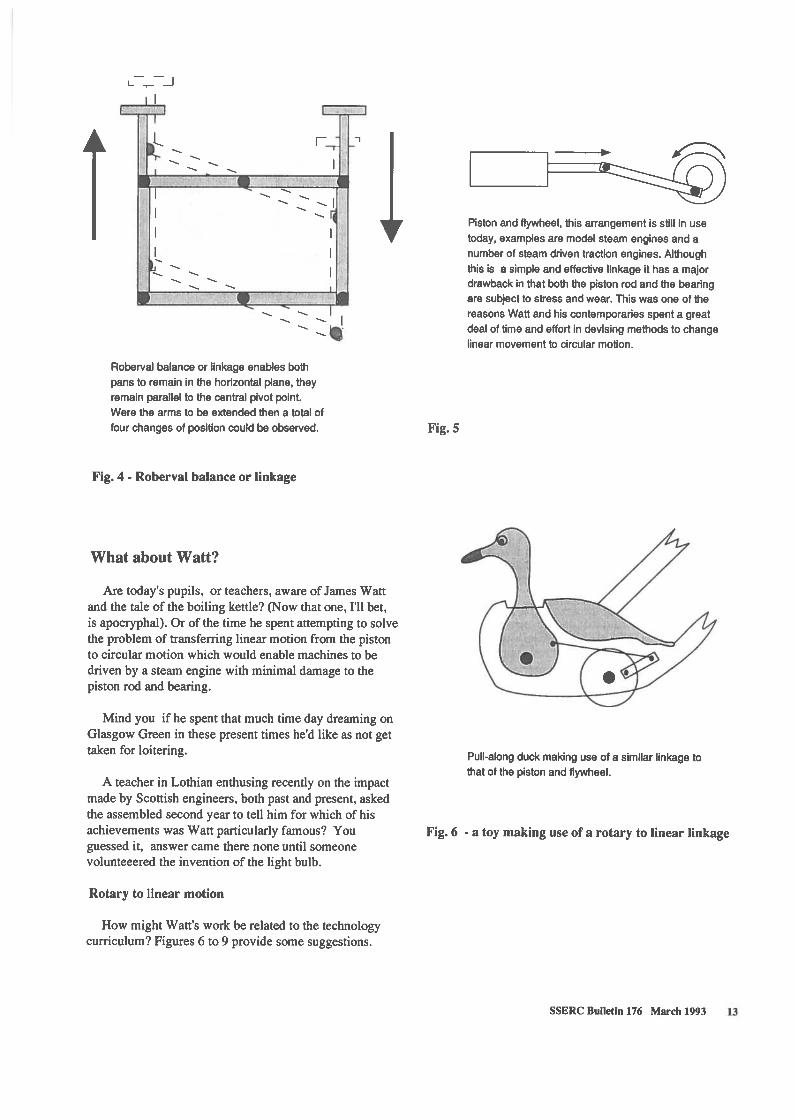
Piston and flywheel, this arrangement is still in usetoday, examples are model steam engines and anumber of steam driven traction engines. Althoughthis is a simple and effective linkage it has a majordrawback in that both the piston rod and the bearingare subject to stress and wear. This was one of thereasons Watt and his contemporaries spent a greatdeal of time and effort in devising methods to changelinear movement to circular motion.
Roberval balance or linkage enables bothpans to remain in the horizontal plane, theyremain parallel to the central pivot point.Were the arms to be extended then a total offour changes of position could be observed.
Fig. 4 - Roberval balance or linkage
What about Watt?
Are today’s pupils, or teachers, aware of James Wattand the tale of the boiling kettle? (Now that one, I’ll bet,is apocryphal). Or of the time he spent attempting to solvethe problem of transferring linear motion from the pistonto circular motion which would enable machines to bedriven by a steam engine with minimal damage to thepiston rod and bearing.
Mind you if he spent that much time day dreaming onGlasgow Green in these present times he’d like as not gettaken for loitering. Pull-along duck making use of a similar linkage to
that of the piston and flywheel.A teacher in Lothian enthusing recently on the impact
made by Scottish engineers, both past and present, askedthe assembled second year to tell him for which of hisachievements was Watt particularly famous? Youguessed it, answer came there none until someonevolunteeered the invention of the light bulb.
Rotary to linear motion
How might Watt’s work be related to the technologycurriculum? Figures 6 to 9 provide some suggestions.
L.J
r
Fig. 5
Fig. 6 - a toy making use of a rotary to linear linkage
SSERC Bulletin 176 March 1993 13

x
Fixed point Fixed point
Watt linkage, in this design Watt attempts to control
the lateral movement of the piston rod and thus
reduce wear on the bearing. Watt considered this one
of his finest achievements. It is interesting to try this
linkage with a pencil placed at point X, what type ofpath is described by the pencil point?
Fig. 7
This ratchet arrangement was originallydesigned by Pohiem as a winch, here Itcould be used as a form of indexing toolactivated by a pneumatic cylinder.
Fig. 8 - linear to rotary linkage with ratchet as anindexer
An elegant method of transforming linear movement
to circular motion developed by Pohlem. It would bedifficult to transmit much power with this system.
Fig. 9 - Polhem’s linear to circular motion device
Standard Grade Projects?
There are further examples of similar applications foruse with somewhat older pupils. For example would thedevices shown in Figures 10 and 11 opposite proveacceptable to the Exam Board, in satisfying two of theelements of Standard Grade in regard to integratingpneumatics with mechanisms?
14 SSERC Bulletin 176 March 1993

This deceptively simple linkage, a toggle linkage, amplifies the power available from a hydraulic
or pneumatic cylinder. It was widely used in stone crushing and in some forms of metal forming.
g
When a force is applied to the piston rod
at right angle to the centre line X-X, along
which sliding member e moves, this force isamplified at e because large movement atg causes slight movement at e. As the angle
a gets smaller movement at e decreases asthe force increases until the links b and c are in line
Fig. 10 - a toggle linkage which effectively amplifies the force applied by a single hydraulic or pneumatic cylinder
Fig. 11 - rotary motion from a pneumatic system
bFixed point
x
nut
x
/cylinder
sliding block
I A method of obtaining circular motion from a
pneumatic piston. As it stands this would on;y
give reciprocating motion of the leadscrew, some
form of ‘freewheel’ mechanism would be needed if
rotation in only one direction was desirable.
SSERC Bulletin 176 March 1993 15

ConclusionJust for fun!Our last two suggestions (Figs. 12 and 13) are intended
to be just that - fun. But, could we make an OR gate insimilar fashion to that shown for the mechanical ANDgate in figure 13?
Chinese windlass, this system can be designed togive very high or low transmission factors. It is alsothe basis of the conjuror’s magic box, pulling fromone end of a closed box appears to enable one topull more string from the box than enters it. Designdetails are left to the maker.
We have tried to offer a few ideas on teaching aboutlinkages. The aims include having a bit of fun as well asothers which are deliberately educational. The two arehowever not necessarily mutually incompatible! The funlies in trying out new ideas, in making toys, and inbuilding useful working linkages as well as mechanicalframeworks.
The contemporary tendency to imply denigration bydubbing a model Heath Robinson is to miss the pointentirely. Early in this century Heath Robinson pokedgentle fun at what he saw as the trivialisation of manytechnological advances. He was in fact a first classdraughtsman and, apart from the knots in his ropes, mostof his pulley and gear systems would actually work.
The educational value in building some of the devicesshown should be fairly obvious in the context of teachingabout mechanisms and structures. But how about applying a similar approach to graphical communications ormathematics?
We believe that enhancing understanding of thepossible applications of levers, of the interaction ofshapes and an improved awareness of spatial movements,is important for all our pupils. It may well be crucial forthose with ambitions to become effective engineers andtechnologists.
Fig.12 Any more?
Simple AND gate using two pulleys.
As with all articles of this type we can only offer but afew ideas. There are many, many more. If you have anyfavourite systems you think may be of interest to othersplease send us the details. If it works when we build it wewill try to publish it in these pages, with your name if notin lights at least in emboldened type.
References
1. A Dictionary ofScience, Penguin Books, 1976,ISBN 0 14051 OO1X (source of definition ofkinematics).
Other useful sources:
2. Mathematics meets Technology, Bolt, B.Cambridge University Press, 1992,ISBN 0 521 376920
3. Machines - an illustrated history, Strandh, S.,Mitchell Beazley, 1968, ISBN 0 86134 0 124(Out of print).
Fig.13
16 SSERC Bulletin 176 March 1993

Oscilloscopes
Equipment Notes
This article describes the general features which are available on oscilloscopesand gives advice on their relevance for schools. We also describe and comparethe performances of five single trace and twelve dual trace oscilloscopes, andgive buying advice thereon. The need for the pupil oscilloscope, or instrumentswith minimalist controls is recognised.
Introduction
The oscilloscope is perhaps the most complexscientific instrument to be found in quantity in schools.Costing typically between £200 and £300 apiece, thepurchase of even just one oscilloscope is a sizeable part ofa department’s budget. Since they are more suited forindividual pupil work rather than for teacherdemonstration, they are therefore normally required inmultiples of five or more per class. The purchase ofsufficient number of ‘scopes is therefore of some import.
There are now few single trace oscilloscopes on themarket. Our report looks at five of these, including threethat have been specially designed for schools, the socalled pupil oscilloscope. On dual trace instruments, wehave in general tested the instrument with the lowestspecification out of a manufacturer’s range. We havechosen to look at some of the big names - Hameg, Hitachiand Philips - at instruments from some of the principaldistributors - Farnell, Rapid and RS - at some importsfrom Asia distributed by smaller companies - Crotech,Kenwood and Sarnpo - and at a new model fromBeckman, assembled here in Scotland. Sadly, it does notcome out too well in some tests!
That does of course leave many models unteste&Unlooked at, for the present, are the Griffin Novoscopeand models from Blackstar, GW, ITT, Leader, Topward,and so on. We are sorry that some models, from lack oftime, have had to be omitted, but intend to testinstruments from some of these companies in the future.
The models tested are listed in Table 1. Most weretested in the last 12 months, but a few were examinedsome years back. Specifically, we looked at two GoldstarOS-7020 scopes in 1988, having obtained samples fromAlpha Electronics and Rapid Electronics. Neither Alphanor Rapid continue now to sell this model, although,confusingly, Rapid have transferred the Goldstarcatalogue number onto its replacement, also called the7020. In case the Goldstar is still available from otherstockists, it is included in the test report summary.
Description of features and tests
We give here a description of the features and, wherenecessary, an explanation of technical terms to be metwith in manufacturers’ specifications. The relevance toschool use is indicated.
Bandwidth
Bandwidth is the operating frequency range of the Yamplifier. It normally extends from d.c., or zerofrequency, to the bandwidth value. This is usually20 MHz on bottom-of-the-range machines, signifying apower loss of -3 dB in signal strength at 20 MHz. Therise-time is the response time of the Y amplifier to aninfinitely steep step input. It can be worked out innanoseconds from the bandthwidth f in megahertz usingthe relationship:
rise-time = 350/f
Thus a 20 MHz oscilloscope has a rise time of 17.5 ns.Since most of the dual trace machines in our survey have20 MHz bandwidths, there is little purpose in their havinga sweep sensitivity any higher than 20 ns/division.Excepting the model from Rapid, this is the fastest sweeprate provided on the machines with the highestspecifications. The 10 ns/division sweep rate on the Rapidscope is just a nonsense (Table 2).
The bandwidth of each oscilloscope was measured byus. Compliance with specification is shown in Table 5.Most models were found to comply.
An example of a fast timing requirement is theexperiment to measure the velocity of light whereinpulsed light is transmitted through 10 m of optical fibre.Since the transmission time is 50 ns, a dual traceinstrument with a 20 ns/division calibrated sensitivity and20 MHz bandwidth is able to provide a measurement ofthe time delay with an accuracy of about ±20%.
SSERC Bulletin 176 March 1993 17

Oscilloscope model Supplier Stock Price Screen Screen Graticule Extranumber () shape size Facilities
(mm)
Single trace
Crotech 3036 RMR Measurements 3036 265.00 1 rectangular 130 10 x 8Hameg 1 03-2 S J Electronics HM 103-2 255.00 1 rectangular 95 10 x 8Harris Super 5 Harris P63860/8 265.65 rectangular 130 10 x 8
Irwin EA1270 Irwin EA 1270 238.30 circular 75 lOx 10Unilab Student Oscilloscope Unilab 032.603 194.20 circular 70 10 x 10
Dual trace
Beckman 9012 Tait Components 9012 285.00 rectangular 130 10x8Crotech 3324 RMR Measurements 3324 325.00 1 rectangular 130 10 x 8 power supplyFarnell DTV2O Farnell instruments 19 DTV 20 320.00 rectangular 130 10 x 8
Goldstar OS-7020 unknown - - rectangular 130 10x8Hameg 203-7 S J Electronics HM 203-7 362.00 1 rectangular 130 lOx 8Harris MuPEC Harris P63921/2 491.93 rectangular 130 lOx 8 pwr.sply./fn.gen.
Hitachi V-212 Tait Components V-212 360.001 rectangular 130 lOx 8ISO - TECH ISR 620 RS Components 204 - 476 295.00 I rectangular 130 10 x 8Kenwood CS 4025 S J Electronics CS - 4025 295.00 1 rectangular 130 10 x 8
Philips PM 3208 Cuthbertson & Laird PM 3208 375.001 rectangular 130 lOx 8Rapid 7020 Rapid Electronics 85 - 2000 270.00 rectangular 130 10 x 8Sampo SSI 2120 RMR Measurements SS1 - 2120 275.00 1 rectangular 130 lOx 8
NOTE:
1. BNC test lead(s) supplied inclusive with quoted price.
Table 1 Oscilloscope suppliers, prices and screen detail
Sensitivity
All of the instruments with 1-2-5 switch sequences(Table 2) can be used for quantitative measurements, intheory to the accuracy specified, which is usually ±3% or±5%. This group comprises all of the dual trace models,together with the Crotech 3036 and Hameg 103-2 singletrace models. The former has the edge over the latterbecause of its larger screen size (Table 1). Of theremaining three, comprising the pupil oscilloscopes, theIrwin model can indicate order of magnitude voltages andtimes, and the Unilab and Harris Super 5 models canmeasure to precisions of at best ±5% on Y and on time.
Testing for accuracy
The accuracy of the Y amplifiers and sweep rates wereassessed by measuring the error on each setting at 80% ofscreen width. For most instruments, the errors wererandom rather than systematic. If the errors were random,the standard deviation 0 of the percentage errors in eachsetting was calculated. From this a value of 30 wasobtained, which was compared with the specifiedaccuracy or tolerance. If both values were similar, thespecification was judged to be about right.
Our test method therefore looks for the commonindustrial practice of specifying a random error which isthree times the standard deviation of actual randomerrors. Our test findings are summarized in Table 5. Itshows that most Y amplifiers, but only half the sweeps,perform within specification.
Display modes
There are several ways of controlling the displays ondual trace oscilloscopes (Table 3). Most allow you to lookat one channel at a time, with the other channel beingswitched off. All provide for both alternate and choppeddual displays. In alternate mode, each trace is sweptthrough in its entirety, without interruption, from one endof the screen to the other. After one trace is sweptthrough, then so is the other. The process alternatesbetween one whole trace and the other whole trace. If theinput frequencies are low, then there can be a disturbingflicker between channels 1 and 2. The alternate modedisplay should not therefore be used at low frequencies.In chopped mode, the sweep flips at high frequencybetween tracing out a little bit of channel 1 and a little bitof channel 2. If the input signal frequencies are low, the
18 SSERC Bulletin 176 March 1993

Oscilloscope model Band- Calibrated No. of Switch V Calibrated No. of Switch Sweep Max.width Y settings Y set- sequence accur- sweep sweep sequence accur- caiibr.
tinge acy speed set- acy sweeptinge rate
(Hz) (V/division) (%) (s/division) (%) (s/div.)
Single trace
Crotech 3036 20 M 2 mV to 10 V 12 1,2,5 3 0.5 ps to 200 ms 18 1,2,5 5 100 ns
Hameg 103-2 10 M 5 mV to 5 V 10 1,2,5 3 0.2 ps to 100 ms 18 1,2,5 5 200 ns
Harris Super 5 5 M 50 mV to 200 mV 9 I 1,2,5 5 1 ps to 100 ms 5 1,10,100 10 1 p5
Irwin EA1270 50k 5OmVto5V 0 continuous NS 100 ps to lOms 3 1,10,100 NS lOOps
UnilabStudentO’scope 100k 5OmVto 10V 8 1,2,5 NS 100 ps to lOOms 4 1,10,100 NS lops
Dual trace
Beckman 9012 20 M 5 mV to 5 V 10 1,2,5 3 0.5 ps to 200 ms 18 1,2,5 3 50 ns
Crotech 3324 25 M 5 mV to 20 V 12 1,2,5 3 0.5 ps to 200 ms 18 1,2,5 5 100 ns
Farnell DTV2O 20 M 5 mV to 5 V 10 1,2,5 3 0.2 ps to 500 ms 20 1,2,5 3 20 ns
Goldstar OS-7020 20 M 5 mV to 5 V 10 1,2,5 3 0.2 ps to 200 ms 19 1,2,5 3 100 ns
Hameg 203-7 20 M 5 mV to 5 V 10 1,2,5 3 0.2 ps to 100 ms 18 1,2,5 3 20 ns
Harris MuPEC 25 M 2 mV to 10 V 12 1,2,5 3 0.5 ps to 200 ms 18 1,2,5 5 100 ns
Hitachi V-21 2 20 M 5 mV to 5 V 10 1,2,5 3 0.2 ps to 200 ms 19 1,2,5 3 20 ns
ISO - TECH ISR 620 20 M 5 mV to 5 V 10 1,2,5 3 0.2 p5 to 500 ms 20 1,2,5 3 20 nsKenwood CS 4025 20 M 1 mV to 5 V 12 1,2,5 3 0.5 ps to 500 ms 19 1,2,5 3 50 ns
Philips PM 3208 20 M 5 mV to 5 V 10 1,2,5 32 0.2 ps to 500 ms 20 1,2,5 3 20 nsRapid 7020 20M 5mVto5V 10 1,2,5 3 0.1 psto200ms 20 1,2,5 3 iOns
Sampo SSI 2120 20 M 5 mV to 5 V 10 1,2,5 3 0.5 ms to 200 ms 18 1,2,5 3 50 ns
NOTES:
1. The Harris Super 5 uses pushbutton switches rather than rotary switches to select amplifier and sweep sensitivities.
2. The accuracy of the V sensitivity is stated to be ±5% in the Technical Specification for the PM3208 scope. This iscompletely honest and fair of Philips because they are quoting the worst case accuracy of the combined effects of thestepped amplifier and x5 magnifier. However no other manufacturer is as honest as Philips in this respect. By commonpractice, the best case accuracy is quoted in specifications. To keep things on a level playing field, we therefore quote thebest case accuracy for the Philips amplifier, viz. 3%.
Table 2 : Oscilloscope specifications
chopping is of too high a frequency to be noticed.However, at high input frequencies, chopping will beevident and break up the traces. Therefore, choppingshould not be used at high frequencies.
Other commonplace display modes are add, whichdisplays the algebraic sum of channels 1 and 2, and invert,which usually operates on only one channel. In combination, one signal subtracted from the other is displayed.
Triggering
Most models provide several trigger modes (Table 4).All provide automatic triggering (formerly sometimesknown as bright line triggering), which causes the timebase to free run, giving a base line trace on the screen in
the absence of a Y signal. If a signal is then applied, thetrace locks onto the signal and displays it. This would bethe preferable trigger mode for looking at signals ofsimple shape, or for operation by inexperienced students.The sole form of triggering provided on pupiloscilloscopes is automatic.
Normal triggering in the absence of a signal leaves thescreen blank. The oscilloscope only sweeps if a triggerpulse is provided. For this, it needs a Y input signal.Normal triggering is preferable for displaying complex,or peculiar, waveforms, such as a square wave with markto space ratio of 1 to 100. Were automatic triggering usedwith this type of signal, the trace might form a series ofoverlapping images, it being impossible to triggerproperly. Level and slope controls affect both automaticand normal tiggering modes.
SSERC Bulletin 176 March 1993 19

The trigger level control allows for manual adjustmentof the trigger voltage. This is used together with thetrigger slope control. On positive (+) slopes, a rising edgeor slope, or an increasing voltage, causes the trigger tooperate. On negative (-) slopes, a falling edge or slope, ora decreasing voltage, causes the trigger to operate. Thesecontrols are particularly useful in triggering complexwaveforms. They are not provided on pupil oscilloscopes.
The external trigger facility causes the trace to betriggered on a signal applied to the external triggerterminal rather than from a Y input. One place where thisis used is when displaying signals from data loggers suchas VELA, or the Thurlby-Thandar Digital StorageOscilloscope Unit. Signals from data loggers are often oftransient events and, as such, can be highly irregular, andtherefore generally impossible to trigger through the Yamplifier. Another place is displaying a complex digitalwaveform from a binary counter. Such a signal istriggered by applying a low frequency signal from thecounter to the external trigger input. A third example isthe display of amplitude or frequency modulation, wherethe low frequency signal is applied to the external triggerterminal.
Alternate mode (sometimes called vertical mode)triggering is distinct from, and should not be confused
with, alternate mode display. On alternate modetriggering, two traces are separately triggered at the leveland slope selected. It is especially useful in simultaneous
ly displaying two asynchronous waveforms, i.e. twosignals at different and unrelated frequencies. Withoutthis feature, only one of a pair of asynchronous waveforms can be triggered, the other being impossible to keepsteady. However there is a penalty. The phase differencebetween the signals can be falsified by the triggeringprocess so that what appears on the screen may notcorrespond to the phase difference that physically exists.Thus alternate mode triggering should not be used whenmeasuring the phase difference between signals, or whenmeasuring the time difference between correspondingparts of two digital waveforms.
Note that alternate triggering is not required whendisplaying two synchronous, i.e. frequency related,waveforms, when triggering on one waveform willreliably stabilize the trace of the other. Usually of course,in dual mode, the two signals are synchronous. Thereforealternate triggering is really not that often needed.
Line triggering gives you a sure fire way of lockingonto a 50 Hz signal. This is useful when examiningsignals derived from mains supplies, such as in analysingthe operation of power supplies, or indeed any elementary
Key to features:
A Alternate and choppedoperation
B Algebraic addition oftraces
C Inversion of one or bothtraces
D Y amplifier switchedmagnifier or attenuator
E Y amplifier variable gainor attenuator control
F Sweep rate switchedmagnifier
G Sweep rate variablemagnifier or attenuatorcontrol
H Component testing facilityJ Calibrator output providedK Trace rotation adjustableL Illuminated graticuleM Trace locate function0 Amplifier outputX X-YfacilityZ Z modulation facility
Oscilloscope features A B C D E F G H J K L M 0 X Z
Single trace
Crotech 3036 F G J K XHameg 1 03-2 0 E G H J K XHarrisSuper5 0 G K X
Irwin EA1270 E G XUnilab Student Oscilloscope G x
Dual trace
Beckman90l2 A B CD E F G HJ K OXCrotech 3324 A B C D F G H J K X ZFarnell DTV2O A B C D E F G H J K L X Z
Goldstar OS-7020 A B C D E F G J K L XHameg2O3-7 A B CD E F GHJ K X ZHarris MuPEC A B C F G H J K X Z
Hitachi V-212 A B C D E F G J K 0 X ZISO - TECH ISR 620 A B C D E F G J K L 0 X ZKenwood CS 4025 A B C E F G J K 0 X 2
Philips PM 3208 A B C D E F G J K L 0 X ZRapid7O2O A B CD E F GHJ K L M XSampo SSI 2120 A B C E F G J K 0 X Z
Table 3: Oscilloscope features
20 SSERC Bulletin 176 March 1993

Key to trigger features:
A Automatic triggeringB Normal triggeringC Manual level controlD Selection of trigger slope
polarity (+ I -)E External triggeringG Alternate (ALT) or vertical
mode triggeringH Sweep hold-off facilityJ LF triggering, or HF rejectionK HF triggeringL Supply line triggering (50 Hz)S Single shot triggeringT TV sync pulse separator facility
Table 4: Oscilloscope trigger features
instruction in a.c. electricity, which is normally done at50 Hz. It is also useful for examining mains noise superposed on another signal.
The hold off facility delays the onset of sweeping, thedelay period being under variable control. It is sometimesuseful in triggering complex waveforms, but for schoolpurposes is more of an added complexity, and therefore anuisance, than a benefit.
Single shot or single sweep triggering generates onesweep only and is a means of glimpsing a transient event.Since this would be far better seen with a fast data logger,or computer and interface, the facility is of little benefitand again may be a nuisance.
Trigger modes related to TV sync. pulse separationwould be superfluous because they are not normallyrequired in schools. They may be a nuisance feature, butall of our dual trace samples have TV signal triggering.
Layout of controls
This is not an easy matter to decide upon because it ishard to be objective in comparing one oscilloscope layoutwith another. At least we think so! What seems to workwell are logical groupings of controls, with clearlydemarked boundaries between one set and another set.
These boundaries seem to be easiest to work with whenthey extend right across the front panel, either verticallyor horizontally. However a mosaic of little groups is notso easy to work with. Nor are boundaries with dog-legs,or inserts. Another feature we dislike is an array ofunrelated controls all equally spaced out in line. Althoughsuperficially this looks neat, you have troubledistinguishing which does what.
The marking of controls has got to be absolutely clear.Rotary switches are generally easier to comprehend thanare pushbutton switches. It is unclear sometimes whetherthe active state is in or out. On top of this, somepushbuttons are used for switching functions on and off,whereas others switch between different functions. Thisdual purpose of on/off and alternate mode function cancause confusion.
Since educational equipment should generally be assimple as possible to operate, a front panel layout that iseasy to use may be of greater importance than aninstrument with every gizzmo going. The presence ofblanks on Tables 3 and 4 may be a recommendation!
The Pupil Oscilloscope
There is still a requirement for instruments withminimalist features. The paucity of facilities is a sellingpoint because minimalist controls are as simple as can beto operate. The three models reviewed here (Harris, Irwin
Oscilloscope triggering A B C D E G H J K L S T
Single trace
Crotech 3036 A B C D EHameg 103-2 A B C 0 E THarris Super 5 A B E
Irwin EA1270 AUnilab Student Oscilloscope A
Dual trace
Beckman9ol2 A B C 0 E G J K L TCrotech 3324 A B C D E H J L TFarnell DTV2O A B C 0 E H J L T
Goldstar OS-7020 A B C D E H J K L THameg 203-7 A B C D E G H J K L THarris MuPEC A B C 0 E J L T
Hitachi V-212 A B C D E G L TISO-TECH ISR 620 A B C 0 E G H J L S TKenwood CS 4025 A B C D E G L T
Philips PM 3208 A B C 0 E H J L S TRapid7O2O A B C D E G H L TSampo SSI 2120 A B C D E G L T
SSERC Bulletin 176 March 1993 21

and Unilab) are each so different in mode of operation asto offer an interesting choice - unlike the dual tracemodels, which are all basically alike.
Relative to a pupil oscilloscope, the additional featureson the other single trace models, which we will call theindustrial single-trace models (Crotech 3036 and Hameg103-2), are
- 1, 2, 5, 10 switch positions on theY amplifier andsweep rather than 1, 10, 100 settings;- extra variable or switched gain controls on theamplifier and sweep;- extra trigger features;- calibrator output and (Hameg 103 only) componenttester.
The question we now address is - how much morecomplex than pupil oscilloscopes are industrial singletrace models?
If the oscilloscope is being used for measurement, it isbeneficial having 1, 2, 5, 10 subdivisions rather than only1, 10, 100 divisions because readings of greater precisionand accuracy are obtainable. The variable and fixedmagnitude gain controls can be confusing to beginners -
but as every model of pupil oscilloscope has itself at leastone variable gain control, there is little benefit from thisfactor. That really leaves the additional trigger facilities,which certainly make the industrial models morecomplicated to use. In mitigation, most traces areexceedingly easy to trigger. In competent usage, a greaterrange of signals can be successfully triggered.
If we look at the other side of the comparison, thewider bandwidth of the industrial models allows them tobe used with higher frequencies. It should be noted in thisrespect that the upper working frequency of the Irwin andUnilab models is about 10 kHz.
In conclusion, whilst the minimalist features of thepupil oscilloscopes offer the simplest of possiblearrangements, the additional features to be found onindustrial single trace models are not significantlycomplex, yet may offer very desirable enhancements inperformance.
Single or dual trace?
for inspection, for measurement, or for testing. Itscurricular usage has widened from Physics to includenow Technological Studies and Electronics. With respectto Physics, an analysis of possible usage in StandardGrade Physics using the SSERC Technical Guidesindicates that a single trace model will suffice in mostinstances. A dual trace model is seldom needed in thatcourse. Excepting Standard Grade Physics, it is probablyonly in courses with a heavy electronics content that dualtrace models are particularly useful. These include HGrade and CSYS Physics, H Grade Technological Studiesand certain Electronics Short Courses. Elsewhere, theremay continue to be places in S 1/S2 Science and StandardGrade Science where an oscilloscope, almost certainly asingle trace model, is needed.
In conclusion, we advise mixed purchasing - single forsimplicity, dual for necessity. Our suggested buying ratiois 3:1 in Physics, and 1:1 in Technological Studies. Theseratios should be modified for particular needs. Forinstance if a department is heavily into electronics, orCSYS, with above average intake numbers, then a greaterweighting of dual trace models may be advisable.
Best buys?
Single trace
Amongst the single trace models, the Crotech 3036,having no significant adverse points, and fully living upto its specification, is the best buy. It is, as we haveindicated above, reasonably simple to operate. Its 130 cm(5”) screen gives it the edge over the Hameg 103-2. Itslist price of £265 is subject to an educational discount.
The Hameg 103-2 is also a fine instrument which fullylives up to its specification. Because of its small screen(95 cm or 33/4”), the overall enclosure size is small, whichwould be advantageous in laboratories with narrowworkbenches. However the size of the ventilationapertures is a cause of concern. The price withoutdiscount is £255.
Amongst the pupil oscilloscopes, the Unilab modelstands out best. Not only does it out perform the othermodels in most respects, it is, at £194.20, far cheaper.
Dual trace
Since there is little financial benefit in buying singletrace models, effectively the sole reason is the benefitderived from simplicity. The relative complexities areclearly shown in Tables 3 and 4. There are thereforesound educational reasons for buying single trace models.
Considering the curricular needs, the oscilloscope usedto be studied in its own right in the days of 0 GradePhysics. This is now no longer a curricular requirement.The oscilloscope is needed as a functional instrument -
It is pleasing to record that five models out of thetwelve inspected have ended up with A assessments.These are the Hameg 203-7, Hitachi V-212, iSO-TECHISR 620, Kenwood CS 4025 and Philips PM 3208. TheRapid 7020 just misses an A rating by a hair’s breadth. Allsix are pretty sound buys. However the one which standsout with the best performance for its price is the ISO-TECH JSR 620, sold by RS Components, at £295.
22 SSERC Bulletin 176 March 1993

Oscilloscope model Electrical Standard of Y amplifier Bandwidth Sweep X-Y mode Layout of Assessmentsafety construction performance performance performance performance controls
Single trace
Crotech 3036 A A A A A B1 A AHameg 103-2 B1 A A A A B B AHarris Super 5 A A C1 A C1 B B / C2 C
Irwin EA1270 A A C1 C2 C3 B B C4Unilab Student Oscilloscope A A A1 C 2 B3 B A B 4
Dual trace
Beckman 9012 B12 B23 A B C A B BCrotech 3324 C12 B A A3 C4 B5 B CFarnell DTV2O C1 A B A A A B C
Goldstar OS-7020 C12 - C 3- C 3 C B C
Hameg 203-7 A1 A A A A A 2 AHarris MuPEC A A C A C/A1 A B B
Hitachi V-212 A A A1 A1 A1 B A AISO - TECH ISR 620 A A A1 A1 A1 A A AKenwood CS 4025 A1 A A2 A2 A2 A B A
Philips PM 3208 A1 A A A A2 A A3 ARapid 7020 A A A A B1 A B 81
Sampo SSI 2120 A123 B4 A B B A B B
Table 5: Oscilloscope performance
KEY TO PERFORMANCE RATINGS:
In general,
NOTES:
Crotech 3036
A Good B Fair
Specifically,
C Poor
Electrical safetyA Complies fully with IEC 1010-1 as far as our testsare able to indicate, except for some very minorinfringements; has no appreciable points of weaknessfor use in schools.B Complies in general with IEC 1010-1, but has one ormore features where there is a very small risk of harm.C One or more features present an unacceptable riskof harm.
Y amplifier performance:Bandwidth performance:Sweep performance:
A Performs to specification.B Performs slightly poorer than specification.C Performs considerably worse than specification.
Assessment:A Most suitable for use in Scottish schools and non-advanced FE.B Satisfactory for use in above.C Unsatisfactory.
1. X - V operation: Rather unusually the sensitivity of thehorizontal amplifier is 400 mV/div., whereas the verticalamplifier is 500 mV/div. Because of this quirk, a 1: 1 x- y signal ratio gives a corner to corner trace on the 10 x8 screen.
HameglO3-2
1. The enclosure has a series of ventilation aperturesconsisting of circular holes whose diameters are justunder 4.0 mm and slots whose widths are just under4.0 mm, but whose lengths are 26 mm. This complieswith lEG 1010. However concern is expressed thatpupils could insert through these slots knifeblades,coins, steel rules, or other conductors, into theenclosure and touch parts at hazardous live. The risk ofaccidental harm is negligible. The risk comes fromfoolishness or malfeasance.
Harris Super 5
1. Unusually, neither the Y amplifier nor sweep has presetcontrols for facilitating recalibration. The Y amplifier wasfound to have a systematic error of 9%, about which
SSERC Bulletin 176 March 1993 23

nothing can be done. The sweep rate has a randomerror which is larger than specified, whether using the±5% value in the handbook, or even the ±1 0% value inthe catalogue.
2. The Super 5 uses pushbutton switches rather thanrotary switches to select amplifier and sweepsensitivities. This is a deliberate attempt by Harris tosimplify the controls. If you accept this, then the featuregets a B rating. If you don’t accept it, then it gets a Crating. Unfortunately, whereas the V amplifier multipliercontrol attenuates the trace, the sweep magnifierexpands the trace. This contrariness is confusing.
3. This is the only oscilloscope tested whose trace couldnot be satisfactorily focused.
Irwin EA1270
1. The V amplifier accuracy is not specified. We found thatit reads 10% high at the 0.05 V potentiometer setting, isspot on at the 0.5 V position, and is 37% high on the5 V position.
2. The bandwidth is about 17 kHz, whereas it is specifiedto be 50 kHz.
3. The sweep rate accuracy is not specified. We found thatthe fastest setting is 20% high. The other settings are8% high.
4. Other poorish features were the triggering, whichstruggles to hold a trace for a signal with a high mark tospace ratio, and the focusing, which does not produce asharp image at high intensity.
Unilab Student Oscilloscope
1. The V amplifier accuracy is not specified. We reckon onthe sample we tested that it is about ±6%, which is asgood as could be expected for a screen of this size.
2. The bandwidth was only 35 kHz, much lower than the100 kHz specified.
3. It proved impossible to recalibrate the timebase suchthat all four calibrated settings were spot on. The bestwe could achieve were errors on the three fastestranges of less than 3%, but an error on the slow rangeof 1 0%. This is reasonably fair.
4. Signals above 10 kHz are almost impossible to trigger.The trace is very sharp for a screen of this size.However the trace is skew at the top and bottom of thescreen, but horizontal through the centre.
Beckman 9012
1. When we carried out our tests, the supply was fused onthe neutral rather than on the live conductor. Weunderstand that Beckman have now corrected this fault.
2. The metal panel on the front of the enclosure has somelarge unused cutouts (up to 73 mm long). These areprotected only by the label membrane covering the frontpanel. The integrity of this part of the enclosure issuspect.
3. The robustness of switches with levers and with longmechanical linkages is suspect. In response, Beckmansay that they have had no switch faults on anyinstrument referred to them so far.
Crotech 3324
1. There is a 115 V a.c. socket outlet on the rear panel,whose terminals sit at 240 V a.c. and 120 V a.c. withrespect to earth. Although these terminals are recessedby 8 mm, they can be touched by a 4 mm plug. Thisoutlet is therefore hazardous.
2. The supply voltage selector on the rear of the enclosurecan be changed from 240 V to 115 V by hand, evenwhile the apparatus is powered up.
3. An input with a fast edge causes ringing.
4. The calibrated sweep rate is badly off spec at slowsweep speeds.
5. After the sweep is switched off, the spot drifts for 10 sbefore settling.
Farnell DTV 20
1. The earth terminal on the front of the enclosure is anon-captive type of 4 mm socket. Farnell have so farfailed to assure us that there is no risk, or that thesocket is being replaced by a safe type.
Goldstar 7020
1. The earth terminal on the front of the enclosure is anon-captive type of 4 mm socket.
2. The carrying handle is not earthed.
3. The calibrated settings were found to be wildly out ofspec.
Hameg 203-7
1. The enclosure has a series of ventilation holes ofdiameter slightly less than 4.0 mm. This complies withlEG 1010.
2. The layout of the controls is, in our opinion, a dog’sbreakfast. Whilst a skilled technician would find thecontrols easy to work with, they are bound to beconfusing to beginners. We especially dislike thepushbuttons whose markings fail to indicate whether afunction is on or not.
24 SSERC Bulletin 176 March 1993

Harris MuPEC
1. Two instruments have been tested. The time base ofone of them was out of spec.
Hitachi V-212
1. These features perform better than specified.
ISO-TECH ISR 620
1. These features perform better than specified.
Kenwood CS 4025
1. The earth terminal on the front panel is a non-captivetype of 4 mm socket. Because a 10 cm probe insertedthrough this socket is unable to touch any part that ishazardous live, the risk is judged to be negligible.
2. These features perform better than specified.
Philips PM 3208
1. The earth terminal on the front panel is a non-captivetype of 4 mm socket. Philips have investigated the riskand assert that no live components could be accessedby pushing wire through the earth socket to a depth of 9inches. The risk is therefore judged to be negligible.
2. The sweep calibrated settings perform better thanspecified.
Equipment Notes
Laser diode modules
This note provides a buyers’ guide to laser diodemodules (LDMs) and discusses whether they are ofinterest to schools. The reader is directed to the safetynotes section of this issue where matters of laser safety,classification and operating procedures are written about.
As discussed in Safey Notes, laser diodes should notbe used in schools as discrete components, but only in theform of a laser diode module. This product comprises alaser diode, drive circuit and lens, all fitted within acylindrical brass enclosure. The overall dimensions rangefrom about 30 mm to 75 mm in length by between 10 mmand 25 mm in diameter. Even in module form, it reallycan be quite small. A low voltage external power supplyis needed. Typically this could be a 4.5 V or 9 V battery,or a 5 V regulated voltage supply.
3. The controls were judged to be lain out more clearlyand simply than on any other model of dual trace scopethat we have so far tested.
Rapid 7020
1. The sweep rate has a systematic error of 2% slow,which presumably can be removed by recalibration.There is also a random error, whose magnitude is wellbelow the ±3% value in the specification. Systematicerrors in new instruments are unusual. It points toincorrect adjustment in manufacture. We switheredabout giving the machine an A assessment.
Sampo 5512120
1. A metallic label covers two 16 mm diameter and two8 mm diameter holes on the back panel of theenclosure. This label could be punctured by vandalismor accident. However, in the event of puncturing, therewould be no ready access within the enclosure tohazardous live conductors.
2. There are seven 8 mm diameter holes for accessingpreset controls in the base of the enclosure. A metaltest pin inserted through each opening was unable toaccess any hazardous live conductors. This featuretherefore presents negligible risk.
3. The temperature rise of the instrument was markedlyhigher than on other models tested, but remained wellwithin compliance of lEO 1010 requirements.
4. The openings for preset controls were out of registerwith the presets themselves.
Only the least expensive types of LDMs have beenlisted (Table 1). They are all in Class 2. The colour ofradiation emitted by all is a dull cherry red, thewavelength being about 670 nm. Shorter wavelengthemitters are available, but cost very much more, perhapsover £300 a unit. If compared with the optical outputfrom a HeNe laser of similar power, emitting at 633 nm, alaser diodes output appears to be far less bright. This isbecause the eye is less sensitive at 670 nm.
Can an LDM be used as a substitute for a HeNe laser?In some respects it performs less well. In others, it issuperior. Although a collimated beam from an LDM doesnot give the startlingly intense spot on a diffuse whitescreen that you get from a HeNe laser, the beam from a1 mW LDM is quite bright enough to use with lenses insubdued daylight, say at 400 lux. If looking at diffractionor interference patterns with an LDM, blackout or partialblackout conditions would be required - unlike similar
SSERC Bulletin 176 March 1993 25

Outputpower(mW)
LDM1 45/670/1.0 1.0LDM1 45M/670/1 .0 1.0
670 CW670 analogue or digital
660-690 CW660-690 analogue or digital
Price
()
99140
Table 1 - Laser diode modules
work with a HeNe laser. In a comparison of interferencepatterns from multiple slits, 19 fringes were seen from theLDM system against 42 from the HeNe system inblackout. Although the LDM’s fringes were dimmer andfewer in number, the central group of fringes were easierto distinguish than those from the HeNe, which were toostartlingly bright.
The drive circuit contained within the moduleenclosure typically contains one or several potentiometersto set the forward diode current. This controls the opticaloutput power. These settings must not be tampered with.Almost certainly the laser diode is being under-run tocomply with the Class 2 power limit of 1 mW. The diodeitself may well be capable of producing 5 mW or more.Laser diodes operate in forward conduction mode. Whythen do they always contain a second diode in reversebias (Fig. 1)? This is part of the feedback mechanism tocontrol the optical power. The second diode is aphotodiode that senses the laser power for referring to thedrive circuit.
1. Photodiode anode2. Common terminal3. Laserdiode cathode
Light emerges from the LDM through a spherical lenswhich is mounted on a fme screw thread. You cantherefore adjust the lens to get either a diverging,collimated, or converging beam. The position of the focuson the module we looked at could be brought to as near as55 mm from the lens. This setting would make a suitablesource for an optical bench light. For instance if the LDMis mounted at one end of an optical bench (Fig.2) andadjusted to produce a focused beam near to the module,the focus can be used as a point source of light. Itsposition can be found by a paper screen. If a sphericallens is placed in the diverging cone of light beyond thefocus, the standard relationships between u, v andf can beexplored.
A sheet of white paper placed in the beam makes asuitable viewing screen. Because light from the image onthe paper is scattered in all directions, viewing can befrom any direction except directly into the main beam.When viewed under blackout conditions, a faint aureoleof light surrounds the main beam. Typical sizes at 1.6 mfrom the LDM are shown (Fig.3). The aureole would notbe noticed in daylight.
The fitment of a collimating lens would seem to makethe laser diode module a more useful laboratory tool thanthe standard form of educational HeNe laser. Because thecollimating lens attenuates the laser power by about 20%,it should never be removed from an LDM that is emittinglaser light as this could push the output beyond 1 mW.
Fig.1 - Example of a laser diode structureReferring to the Operating mode column in Table 1,
the cryptic comment CW stands for continuous wave. Theoutput from this type of LDM cannot be pulsed or
Manufacturer Stock no.Supplier
Farnell Melles Griot
Lambda Imatronic
Laser Lines Uniphase
Rs
Wavelength Operatingmode
(nm)
212-866 <1 675 cw 195
3505-0080504-008
194-010564-504
670670
0.70.7
1.01.0
cwanalogue
150165
119155
26 SSERC Bulletin 176 March 1993

Adjust collimator lens to focuslaser light near to LDM.Use this as the point sourcefor the spherical lens.
55mm
4-.U
Use a slip of paper as a translucentscreen to investigate the laser beamas it converges and diverges.
V
Fig.2 - Using an LDM with an optical bench
modulated by electronic means. The other types of LDMhave drive circuitry for either analogue modulation, ordigital pulsing, or both of these features. The preferredoperating frequencies of the modulating signal may beabove 100 kHz, which is rather high for schoolinstruments to handle.
Because of the risk of destroying an LDM by applyingpower of the wrong polarity, it is recommended that theLDM is hardwired to a school-built power supply (12 Va.c. in, d.c. out), or to protection diodes.
Fig.3 - Aureole and main beam
Problems with discretes
We advised against using discrete laser diodes inSafety Notes. Apart from the difficulty of limiting theoptical output to 1 mW, there is a risk of static damageand there is at present no apparent fmancial benefitfavouring discretes against LDMs. For instance HeroElectronics sell the 3 mW Philips laser diode CQL 80 at£42.80, a Philips drive board at £39.50, a collimator at£35.50 and lens key at £3.50. This totals £121.30. Thelaser diode in isolation is extremely susceptible toelectrostatic damage. The person handling it must wearearthing straps, use an earthed iron and work on anearthed mat. Only when connected to its drive board is thesystem fully protected. Then it may be handled withouttaking static protection.
Laser pointers or laser pens
Laser pointers or laser pens are really just laser diodemodules with batteries. They can be used as screenmarkers with overhead projector transparencies. Inphysical size, they might typically be about 135 mm longby 15 mm in diameter. They are easily pocketable.Because of the risk of theft, it would seem prudent forschools to refrain from buying them - even those inClass 2. Those with an optical output power of 5 mW,making them fall into Class 3A, should not be purchased.
collimated beamand aureole at 1.6 m
(actual size)focused beam and aureoleat 1.6 m (actual size)
SSERC Bulletin 176 March 1993 27

Trade News and Announcements
Balance burn out
A number of EAs and individual independent schoolshave appointed outside contractors to carry out electricalsafety testing to HSE Guidance Note GS23. Sometimesthese finns are, to put it mildly, inexperienced in handlingspecialised educational equipment. One consequence ofthis can be that although some pieces of your kit might beworking when the tester arrives - they’re certainly not bythe time he or she leaves! This is known in some circlesas the pest control or timber infestation operativesyndrome.
One category of equipment which has tended to suffersuch damage has been the older type of electronic balanceworking on the torsion principle. The relatively heavycurrents applied during the earth test may damage thetorsion strips on such balances. Specialist repairers ofsuch balances are now somewhat scarce. One firm whichstill does this this kind of work is SMK Balances ofNewcastle-upon-Tyne. A typical charge for replacing oneburnt out strip would be about £60 whilst replacing allfour will cost you ca. £100.
You may well be entitled to reimbursement from thetester but you will have to convince them that it was theirintitial ignorance and negligence which broke yourbalance. From experiences reported to us it would seemthat may not be easy. At least one firm swore blind that itwas technically impossible for the earth test to damagethe balance and that someone in the school “must havedropped it” after the testers had left. Good luck!
CD-ROMs for science courses
When CD-ROM readers first became more or lessaffordable on a one per school basis most of the discswere general encyclopaedias or archived newspapers.Resources for science courses are now starting to comeon to the market.
Living body
This CD-ROM from Philip Harris is an atlas of thesystems of the human body. It contains a wide range ofvisual material including colour micrographs of tissues,photographs of organs, X-rays, animation sequences, textboxes and diagrams. An A to Z index allows searches onkey words.
At present the hardware requirement is for an IBM PC(or compatible) microcomputer and CD drive although itcan be read using an Acorn Archimedes running PCEmulator version 1.81. A single user version is £199 andthe full network version £295.
SSERC Graphics CD
Talk of CD-ROM reminds us also to announce thefairly imminent availability of our own in-house effort.We hope to publish our own CD in early Summer whichwill contain, among many other things, all of ourGraphics Library, Draw Guides, apparatus set ups, circuitdiagrams and molecules designed using the ChemicalModeller etc. All told the SSERC CD will contain over7,000 files. These will be made up of science andtechnology graphics in various formats plus datafiles fromexperimental procedures, and other sources.
This collection, running to some 300 Mb will be forArchimedes in the first instance, have a RISCOS frontend and run in the desktop environment. It will have athesaurus and be capable of being searched withkeywords. The likely price will be around the £200 markand distribution will be on a site licence only basis.
Apple Mac software
We have received details of some interesting softwareand associated resources from Israel. These are in theExplorer series which to date supports biology andphysics courses at upper secondary levels. The approachis experiment based with built in spreadsheets andgraphical display utilities.
Topics covered in biology include; genetics, populationecology, cardiovascular physiology and photosynthesis.In physics the topics to date are: gravity, harmonicmotion, one body and two bodies, waves, diffraction,ripple tanks, a.c./d.c., electrodynamics and electrostatics.
Hardware requirements are Apple Mac familymachines with 1 Mb minimum memory and hard disc ortwo 800 K floppies.
The UK distributor for the Explorer series is AngliaUniversity - see Address List inside rear cover.
Video encyclopaedia of physics
This is a collection of 25 interactive videodiscs (12”laserdiscs) which deals with some 600 physicsdemonstrations suitable for use with secondary school andcollege students. The video material on the laser discs isaugmented by slow motion sequences and animation.
Obviously this huge amount of material does’t comecheap. The entire collection costs 2,995 US$ plus ashipping charge of 69.95 $ US. This means that theinclusive price in sterling is about £2,000.
2S SSERC Bulletin 176 March 1993

Chemistry project prizeA sample preview videotape is available on request
from the suppliers in the USA who are known as ‘TheEducation Group’.
We understand that SCET holds an evaluation set ofthese materials. At the time of writing they did not yethave any Education Group software (probably IBM PC)to allow true random access to the demonstrations on anyparticular disc.
Strange moves
Mention of SCET reminds us to announce the appointment of Philip Strange of TVEI and IT support fame as anofficer of SCET. As from 1st March this year he becameAdviser in IT in SCETs Research and DevelopmentDivision.
Phil wrote “Interfacing with Datadisc” which waspublished and distributed by SSERC as well as beingwidely used in training courses in Scotland. We havesince enjoyed working with him from time to time on aninformal basis. This was in a number of other projects andparticularly when we were a Joint Support Activity forTVEI.
We are confident that his appointment will significantly increase the support directly available from SCETfor individual teachers trying to implement informationtechnology applications in classrooms, laboratories andtechnology departments.
Higher physics
Adrian Watt of VELA guide fame has produced a setof resources for a practical approach to the revised Higherphysics course.
His course materials have been grouped into threemain topics : Mechanics and Matter; Electricity andElectronics and Radiation and Matter. A set of pupilmaterials is provided for each of these and there is one setof Teachers Notes. The teacher’s materials are set out as asingle side per experiment each giving notes on the aimsof the activity, previous knowledge required, list ofapparatus and where appropriate a sample set of typicalexperimental results with notes on errors.
These materials are published by and available fromEdinburgh Peripherals. Individual private purchasers andschool purchasers are granted certain waivers oncopyright and allowed to make multiple copies for usewith classes. Further information is available from thepublisher.
The Fine Chemicals and Medicinals Group of theIndustrial Division of The Royal Society of Chemistry areagain holding their competition for the best schoolsproject report. The prize is worth £2,000 to the winningschool.
The project report should describe a project carried outin the school sessions 1991-92 or 1992-93. Preference isgiven to projects carried in collaboration with the localchemical industry. The subject should fall broadly withinthe areas of interest of the Fine Chemicals and MedicinalsGroup, that is medicinal, agricultural, veterinary, flavouror fragrance chemistry, or fine chemicals.
The aim of the competition is to promote interest inpractical applications of chemistry through instructiveprojects and preferably in association with local chemicalindustry. The next submission date for entries is on orbefore 1st September 1993.
Projects will be judged on their novelty, applicability,quality etc. and on the quality of reporting. Summariesnot exceeding 10 pages in length should be submitted tothe Honorary Secretary (see Address List) before 1stSeptember 1993. Note that the Group also can makegrants of up to £500 per school for the purchase ofequipment or chemicals. Again applications should bemade to the Honorary Secretary at the same address.
Chemistry Club Festivals
The Chemistry Club, supported by Salters’ Institute,RSC and hundreds of commercial firms, is again invitingschools to register for its Festivals of Chemistry.
In June of this year schools will receive advancedetails of a series of Regional Chemistry Festivals to beheld in university chemistry departments for teams of 11to 14 year olds. These festivals will be held on datesbetween March and July 1994 and school teams will beasked to demonstrate chemistry experiments around atheme and to compete in chemical egg races.
There will also be other events such as chemistry trails,lecture demonstrations, and opportunities to meet youngchemists and chemical engineers. Industrial sponsorshipwill be offered to all schools entering teams and there willbe substantial cash prizes to be won.
To register your interest and receive more informationabout these festivals of chemistry write to or send a fax toThe Chemistry Club (see inside rear cover).
SSERC Bulletin 176 March 1993 29

Surplus Equipment Offers
Items are arranged by similarity of application, or forother reasons, and not by stock number sequence. Oftenthe item number serves only for stock identification by usin making up orders.
The prices quoted do not include VAT. However VATis added to every customer’s order. Local authority establishments will be able to reclaim this from the InlandRevenue.
Postage and, where necessary, packing, will becharged for. It is therefore best not to send cash with anorder, but wait for us to bill you. Official orders may beused. Please try and ask for at least £10 worth of goodsbecause the administrative costs of handling orders aresignificant.
Changes in stock
Since most of our stock is bought on the surplusmarket it is subject to an uncertainty of supply. Someitems regrettably become unobtainable. Items recentlydropped include several models of motor.
Amongst new stock items there is a neodymiummagnet, an astonishingly powerful pemianent magnetmade from an alloy of neodymium, iron and boron.Anything that you might try with an ordinary magnet isenhanced many times more! We also have a low pressuresodium lamp, a Shandon chromatography kit and astainless steel encoder disk for 4-bit Gray code (Fig. 1).
000
\/
252.1 _ 987.6
202.6 167.5
Fig.1 - 4-bit Gray code disk
Motors
591 Stepper motor, 4 phase, 12-14 V d.c., 400 mA, 27.5 Q,step angle 750, powerful motor with 15 mm x 6 mm dia.output shaft. Dimensions 40 mm x 70 mm dia. on 70 mmsquare mounting plate with fixing holes at 56 mm centres.Circuit diagram supplied. £4.50
755 Pulley wheel kit comprising:- plastic pulley wheel, 30 mm dia., with deep V-notch tofit 4 mm dia. shaft,- two M4 grub screws to secure pulley wheel,- Allen key for grub screws, and- 3 mm to 4 mm axle adaptor.The whole making up a kit devised for SSERC tachogenerators with 3 mm shafts. Specially supplied toSSERC by Unilab. £1.25
766 Precision motor, 0.12 V to 12 V d.c.,no load current and speed 7.5 mA and 7800 r.p.m.,stall torque 14.9 mN m, 9 segments, dimensions34.1 mm x 23 mm dia., output shaft 8 mm x 3.5 mm dia.steel spline, back EMF constant 1.55 V/i 000 r.p.m.Suggested application: tachogenerator
767 Precision motor, 0.33 V to 24 V,no load current and speed 3.5 mA and 6400 r.p.m.,stall torque 11 mN m, 9 segments, dimensions34.1 mm x 23mm dia., output shaft 14 toothedsteel pinion, back EMF constant 3.6 V/i 000 r.p.m.Suggested application: tachogenerator
593 Miniature motor, 1.5 V to 3 V d.c., no load current350 mA at 14800 r.p.m. and 3 V, stall torque 50 mN m,dims. 25 mm x 21 mm dia., shaft 8 mm x 2 mm dia. 30p
614 Miniature motor, 3 V to 6 V d.c., no load current220 mA at 9600 r.p.m. and 3 V, stall torque 110 mN m,dims. 30mm x 24mm dia., shaft 10mm x 2mm dia. 45p
621 Miniature motor, 1.5 V to 3 V d.c., open construction,ideal for demonstration, dimensions 19 x 9 x 18 mm,double ended output shaft 5 mm x 1.5 mm dia. 20p
739 Miniature motor, 1.5 V d.c., dimensions 23 mmxi5mmdia., shaft 8mm x 1.7 mm dia. 25p
732 Motor with gear box, high torque, 1.5 V to 12 V d.c.,125 r.p.m. at 12 V, dimensions 40 x 40 x 28 mm,shaft 10 mm x 3mm dia. with key. Suitable for drivingbuggies, conveyor belt, or any other mechanismrequiring a slow drive
773 Tachometer (ex equipment) £2.25
625 Worm and gear for use with miniature motors,nylon worm and plastic gear wheel. 35p
378 Encoder disk, 15 slots, stainless steel, 30mm dia.with 4 mm dia. fixing hole. 75p
642 Encoder disk, 30 slots, stainless steel, 30 mm dia.with 4 mm fixing hole. £1.30
772 Encoder disk, 4-bit Gray code (Fig.1), stainless steel,81.28 mm dia., 3 mm fixing hole, slots sized toregister with components mounted on 0.1” stripboard.Applications: shaft position sensing, wind directionindicator.For related electronic circuitry see Bulletin 146
Miscellaneous items
629 Dual tone buzzer with flashing light, mounted on smallp.c.b. The unit has a PP3 battery clip and two flyingleads for switch applications.
710 Sonic switch and motor assembly. First sound startsthe motor, a second reverses the direction of rotation,a third sound stops the motor. Driven by 4 AA cells(not supplied). 45p
£10
£10
— 40Mm3810,00
3848,00
20Mm
17.70 110011.2411,,,
10.11 11.,,
£6.00
lb
.oob, ,A 101. -3.On.n
£3.00
30 SSERC Bulletin 176 March 1993

715 Pressure gauge, ca. 40mm o.d. case, 25 mm deep 724 Dual in line (DIL) sockets, 8 way 5p
and 33mm dia. dial reading 0 to 4 bar (i.e. above 760 14 way 7p
atmospheric). With rear fitting for 1/8 BSP. Suitablefor use as indicator for pneumatic circuits in 716 3-core cable with heat resisting silicone rubber insulation,
Technological Studies. 75p 0.75 mm2 conductors, can be used to re-wire solderingirons as per Safety Notes, Bulletin 166. Per metre. £1.35
746 4 mm push-in fitting, with adaptor for pressure gauge(stock item 715). £1.60 756 Silicone coated, braided glass sleeving, yellow, 2.5mm
dia., gives both heat and electrical insulation to con-
313 Thermostat, open construction, adjustable, temperature ductors (e.g. for autoclave rewiring). Price per metre. 55p
range +100 to +65°C. Rated at 10 A, 250 V, but lowvoltage switching also possible. 60p 714 Sign “Radioactive substance” to BS spec., 145 x 105 mm,
semi-rigid plastic material. Suitable for labelling a radio-
165 Bimetallic strip, length 10cm; active materials store. With pictogram and legend. £2.30
high expansivity metal: Ni/Cr/Fe - 22/3/75low expansivity metal: Ni/Fe - 36/64 (invar) 15p 763 Sign “DANGER, Electric shock risk” to BS spec.,
166 Ditto, but 30cm length. 40p rigid plastic, 200 x 150 mm. £2.70
385 Pressure switch, operable by water or air pressure. 764 Sign “DANGER, Laser hazard” to BS spec.,
Rated 15 A, 250 V (low voltage operation therefore rigid plastic, 200 x 150 mm. £2.70
possible). Dimensions 2” x 3” dia. 65p757 Twin bladed propellor, plastic, 130 mm dia.,
419 Humidity switch, operates by contraction or expansion fits 2mm shaft. lOp
of membrane. Suitable for greenhouse or similarcontrol project. Rated 3.75 A, 240 V. 75p 727 Hose clamp, clamping diameter from 8 mm to 90 mm,
101 uses - securing hose to metal pipe, tree to stake,
753 Submersible pump, 6 V to 12 V d.c., 8 litres/mm., joining wooden battens for glueing, etc. 30p
0.6 bar, dry operation protected. £4.55731 Re-usable cable ties, length 90 mm, width 2 mm,
371 Ferrite rod aerial, two coils MW and LW, 50 per pack. 12p
dimesions 140mm x 10mm dia. 85p612 Beaker tongs, metal, not crucible type, but kind which
758 Loudspeaker, 8 U, 5 W, 66 mm dia. 50p grasps the beaker edge with formed jaws. £1.20
771 Neodymium magnet, 14mm dia. x 4mm thick. £1.30 752 Shandon chromatography solvent trough. £1.00
745 Sub-miniature microphone insert (ex James Bond?), 754 Stereo microscope, Vickers long arm type with knuckle
dia. 9 mm, overall depth 5 mm, solder pad connections. 40p joint, mechanically coupled eyepiece tube, xl 0 eyepiece,xl and x2 objectives on tumble change, built-in illuminator
723 Microswitch, miniature, SPDT, lever operated. 40p with either top or basal illumination, weight 12 kg, verystable even with arm swung away from base. Suitable
740 Microswitch, miniature, SPDT, button operated. 25p for biology, primary, electronics, geology, etc. Equivalentpresent day model would cost in excess of £250. Delivery
353 Reed switch, SPST, 80 mm long overall, can be arranged for multiple purchases, otherwise has
fits RS reed operating coil Type 1. 30p to be uplifted. £100.00
354 Reed switch, SPST, 46 mm long overall, Components - resistorsfits RS reed operating coil Type 3. 1 Op
328 Potentiometer, wire wound, 15 U, lin., 36mm dia. 30p738 Relay, 6 V coil, DPDT, contacts rated 3 A, 24 V d.c.
or 110 V a.c. 75p 737 Ditto, 22 U, lin., 36 mm dia. 30p
774 Solenoid, 12 V, stroke length 30mm, 329 Ditto, 33 U, lin., 36 mm dia. 3Opspring not provided £2.25
330 Ditto, 50 U, lin., 40 mm dia. 30p742 Key switch, 8 pole changeover. 4Op
331 Ditto, 100 U, lin., 36 mm dia. 30p382 Wafer switch, rotary, 6 pole, 8 way. 70p
421 DIL resistor networks, following values available:688 Croc clip, miniature, insulated, red. 5p 62R. 100R, 11<0, 1K2, 6K8, 10K, 20K, 150K,759 Ditto, black. 5p 1 25R11 39R and 1 M0/6K0. Price per 10. 30p
741 LES lamp, 6 V. 15p 420 resistors, 5% tolerance, 1/4W:1R5, 4R7, 5R6, 6R8, 8R2, bR, 15R, 22R, 33R,
770 LES lamp, 12 V. 15P 47R, 56R, 68R, 82R, 10CR, 120R, 15CR, 18CR,220R, 27CR, 330R, 39CR, 47CR, 560R, 68CR, 820R,
690 MES lamp, 6 V, 150 mA. 9P 1 KC, 1 K2, 1 K5, 1KB, 2K2, 21<7, 3K3, 31<9, 4K7, 5K6,6K8, 8K2, 10K, 12K, 15K, 18K, 22K, 27K, 33K, 39K,
691 MES battenholder. 2Cp 47K, 56K, 68K, 82K, lOOK, 150K, 220K, 330K, 470K,680K, 1MO, 1M5, 2M2, 4M7, 1OM. Per 10. 6p
692 Battery hoTder, C-type cell, holds 4 cells, PP3 outlet 20p
SP1OC Precision Helipots, Beckman, mainly 10 turn, lOp-SOp730 Battery holder, AA-type cell, holds 4 cells, PP3 outlet. 20p
729 Battery connector, PP3 type, snap-on press-stud,also suitable for items 692 and 730. 5p
SSERC Bulletin 176 March 1993 31

Thermocouple wire, Type K, 0.5 mm dia., I m of eachtype supplied: Chromel (Ni Cr) and Alumel (Ni Al);for making thermocouples, see Bulletins 158 and 165. £2.20
640 Disk thermistor, resistance of 15 kfi at 25°C, f3 = 4200 K.Means of accurate usage described in Bulletin 162. 30p
641 Precision R-T curve matched thermistor,resistance of 3000 0 at 25°C, tolerance ±0.2°C,R-T characteristics supplied. Means of accurateusage described in Bulletin 162. £2.90
718 Pyroelectric infrared sensor, single element, PhilipsRPY1O1, spectral response 6.5 pm to >14 pm,recommended blanking frequency range of 0.1 Hz to20 Hz. The sensor is sealed in a low profile T039 canwith a window optically coated to filter out wavelengthsbelow 6.5 pm. Data sheet supplied. For application seeSG Physics Technical Guide, Vol.2, pp 34-5. 50p
751 Hacksaw blade with pair of strain gauges, terminal padsand leads attached. Suitable for impulse measurementas described in Bulletin 171. Delivery time 3 months. £12.50
501 Kynar film, screened, 28 pm thick, surface area18 x 100 mm, coaxial lead and 4 mm connectors.Applications: Impulse (Bulletins 155 and 174),long wave infrared (Bulletin 155, SG PhysicsTechnical Guide, Vol.2, pp 33-4) £20.00
502 Ditto, with BNC connector. £20.00
503 Kynar film, unscreened, 28 pm thick, surface area12 x 30 mm, no connecting leads. 55p
504 Copper foil with conductive adhesive backing, makespads for unscreened Kynar film to which connectingleads may be soldered. Priced per inch. lop
506 Resistor, 1 gigohm, 1,4 W. £1.25
Opto-electronic devices
507 Optical fibre, plastic, single strand, 1 mm dia.ip Applications described in Bulletin 140 and SG
Physics Technical Guide Vol.1. Priced per metre.
2p 508 LEDs, 3mm, red. Price per 10.761 Ditto, yellow. Per 10.
ip 762 Ditto, green. Per 10.
Other components
We also hold in stock a quantity of other electronic components.If you require items not listed above please let us know and wewill do our best to meet your needs, or to direct you to othersources of supply.
8p Items not for posting
4p The following items are only available to callers because of ourdifficulties in packing and posting glassware and chemicals. We
4p will of course hold items for a reasonable period of time to enableyou to arrange an uplift.
5p
Glassware5p
657 Screw cap storage jar, plastic cap, 4 oz., wide neck. lOp
5p663 Flat bottom round flask, 250 ml. 50p
lop664 Flat bottom round flask, 500 ml. 50p
665 Flat bottom round flask, 800 ml. 50p
747 Quickfit vented receiver, 10 ml. 20p
775 Glass volumetric bulb pipette, 25 cm3 50p
768 Sodium lamp, low pressure, 35 W. Notes on methodof control available on application. 85p
Chemicals
NB: chemicals are named here as described on supplier’s labels.
667 250 ml N.H carbamide (Urea). 25p
668 500 ml dodecan-l-ol. 50p
670 500 g Keiselguhr acid, washed.
672 500 g Magnesite native lump. 25p
673 250 g manganese metal flake, 99.9%. 50p
674 250 g manganese(ll) sulphate AR. 25p
676 500 g quartz, native lump. 25p
677 100 g sodium n-butyrate. 25p
678 500 g strontium chloride AR. 25p
681 Zinc acetate AR. 25p
682 2.25 litre ammonia solution. 5Op
685 500 ml n-decanoic Acid (Lauric acid).
769 500 ml 1-1-1 trichloroethene. 50p
712 Smoke pellets. For testing local exhaust ventilation(LEV) - fume cupboards and extractor fans, etc. 50p
lp
£1.00
40p
5Op50p50p
Components - capacitors
695 Capacitors, tantalum,4.7pF35V, 15pF1OV, 47pF6.3V.
696 Capacitors, polycarbonate,lOnF, 47nF, 68OnF, 1 pF, 2.2pF.
697 Capacitor, polyester, 15 nF 63 V.
698 Capacitors, electrolytic,1 pF25V, 2.2pF63V, 10 pF35 V, 33pF 10 V.
358 Capacitor, electrolytic, 28 pF, 400 V.
Components - semiconductors
322 Germanium diodes
701 Transistor, BC1 84, NPN Si, low power.
702 Transistor, BC214, PNP Si, low power.
717 Triac, ZO1O5DT, 0.8 A, low power.
726 MC74HCO2N quad 2-input NOR gates.
725 MC74HC1 39N dual 2 to 4 line decoders/rn ultiplexers
699 MCI4O15BCP dual 4-stage shift register.
711 Voltage regulator, 6.2 V, 100 mA, pre-cut leads.
Sensors
615
32 SSERC Bulletin 176 March 1993

SSERC, 24 Bernard Terrace, Edinburgh, EH8 9NX;Tel. 031 668 4421, Fax. 031 667 9344.
Beckman Industrial Ltd., Astec Building, High Street,Wollaston, Stourbridge, West Midlands, DY8 4PG;Tel. 0384 442394; Fax. 0384 440252.
British Standards Institution, BSI Publications, LinfordWood, Milton Keynes, MK14 6LE;Tel. 0908 221166, Fax. 0908 322484.
The Chemistry Club, Homerton College, Cambridge,CB2 2PH; Tel. 0223 414860, Fax. 0223 413543.
Cuthbertson & Laird Instruments Limited, Parkburn
Court, Glasgow Road, Burnbank, Hamilton,ML3 OQQ; Tel. 0698 829711.
Edinburgh Peripherals, 14 Hallcroft Crescent,Edinburgh, EH28 8SB.
Edinburgh Science Festival Limited, Freepost,P.O. Box 92, Edinburgh, EH3 OEN;Tel. 031 557 4296.
The Education Group, 1235 Sunset Plaza Drive,Los Angeles, CA 90069, USA.
Explorer Series Software, do Sue Clacher, AngliaUniversity; Tel. 0727 869791.
Farnell Electronic Components Ltd., Canal Road, Leeds,LE11 ORG; Tel. 0532 636311, Fax. 0532 633411.
Farnell Instruments Limited, Sandbeck Way, Wetherby,West Yorkshire, LS22 4DN; Tel. 0937 581961,Fax. 0937 586907.
Festival of Technology Education for Elementary Stages(5 - 14), do Carole Thomson, Northern College ofEducation, Aberdeen Campus, Hilton Place,Aberdeen, AB9 1FA; Tel. 0224 283642,Fax. 0224 487046.
Fine Chemicals & Medicinals Group, Dr NormanRogers, Hon.Sec., Smith Kline BeechamPharmaceuticals, Great Burgh, Yew Tree BottomRoad, Epsom, Surrey, KT18 5XQ.
Griffin and George Limited, Bishop Meadow Road,Loughborough, Leicestershire, LE1 1 ORG;Tel. 041 248 5680, or 0509 233344,Fax. 0509 231893.
Philip Harris Education:
2 North Avenue, Clydebank Business Park,Clydebank, Glasgow, G81 2DR; Tel. 041 952 9538;
Lynn Lane, Shenstone, Lichfield, Staffordshire,WS14 OEE; Tel. 0543 480077, Fax. 0543 480068.
Health and Safety Executive, Public Enquiry Service,Information Centre, Broad Lane, Sheffield, S3 7HQ;Tel. 0742 892345, Fax. 0742 892333.
Hero Electronics Limited, Dunstable Street, Ampthill,Bedfordshire, MK45 2JS; Tel. 0525 405015,Fax. 0525 402383.
IPMS (Institution of Professionals, Managers andSpecialists), 75 - 79 York Road, London, SE1 7AQ;Tel. 071 928 9951, Fax. 071 928 5996.
Irwin-Desman Limited, 294 Purley Way, Croydon,CR9 4QL; Tel. 081 686 6441, Fax. 081 681 8429.
Lambda Photometrics Limited, Lambda House, BatfordMill, Harpenden, Hertfordshire, AL5 5BZ;Tel. 0582 764334, Fax. 0582 712084.
Laser Lines Limited, Beaumont Close, Banbury,Oxfordshire, 0X16 7TQ; Tel. 0295 267755,Fax. 0295 269651.
Neill Tools, Handsworth Road, Sheffield, S13 9BR;Tel. 0742449911, Fax. 0742 431360.
Rapid Electronics Limited, Heckworth Close, SeverallsIndustrial Estate, Colchester, Essex, C04 4Th;Tel. 0206751166, Fax. 0206 751188.
RMR Measurements, 2 MacTaggart Road, Seafar,Cumbernauld, G67 1JL; Tel. 02367 28170.
Professor J.M. Robertson, Lothian Professor ofMicroelectronics, Department of ElectricalEngineering, The University of Edinburgh,The King’s Buildings, Mayfield Road, Edinburgh,EH9 3JL; Tel. 031 650 5574, Fax. 031 650 6554.
RS Components Limited, P0 Box 99, Corby,Northamptonshire, NN17 9RS; Tel. 0536 201201,Fax. 0536 201501.
SCET, 74 Victoria Crescent Road, Dowanhill, Glasgow,012 9JN; Tel. 041 3349314.
SJ Electronics, St Mary’s House, Kelvedon, Colchester,Essex, C05 9AN; Tel. 0376 570618,Fax. 0376 572023.
S .M.K. Balances, Newcastle Technopole, CentralBusiness and Technical Park, Tragalgar Street,Newcastle-upon-Tyne, NE1 2LA; Tel. 091 201 2106,Fax. 091 201 2105,Mobile 0860 731623 (Contact Steve Dews).
Tait Components Limited, 20 Couper Street, Glasgow,G4 OBR; Tel. 041 552 5043, Fax. 041 552 8826.
Unilab Limited, The Science Park, Hutton Street,Blackburn, Lancashire, BB1 3BT; Tel. 0254 681222,Fax. 0254 681777.

Ii