SPECIFICATIONS – JOB SPECIFIC - Aetna Bridge Company
412
SPECIFICATIONS – JOB SPECIFIC
-
Upload
khangminh22 -
Category
Documents
-
view
5 -
download
0
Transcript of SPECIFICATIONS – JOB SPECIFIC - Aetna Bridge Company

SPECIFICATIONS – JOB SPECIFIC
Item SPECIAL PROVISION INDEX
Description
Page
JS-i
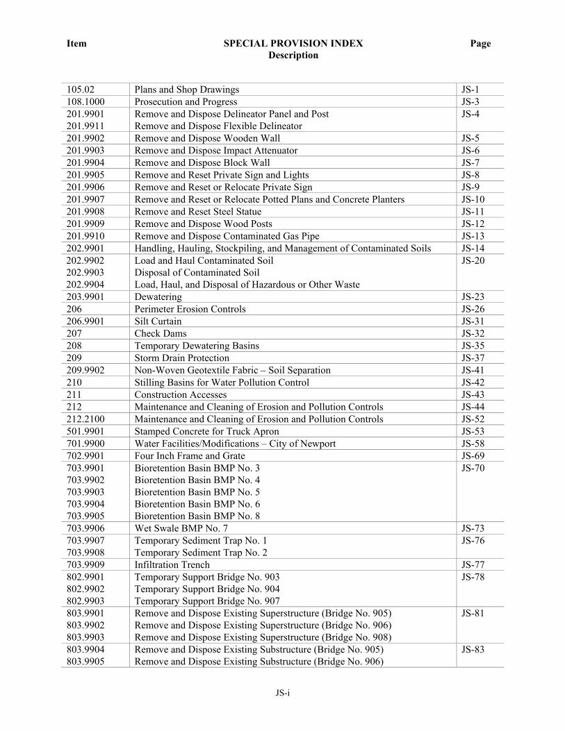
105.02 Plans and Shop Drawings JS-1
108.1000 Prosecution and Progress JS-3
201.9901
201.9911
Remove and Dispose Delineator Panel and Post
Remove and Dispose Flexible Delineator
JS-4
201.9902 Remove and Dispose Wooden Wall JS-5
201.9903 Remove and Dispose Impact Attenuator JS-6
201.9904 Remove and Dispose Block Wall JS-7
201.9905 Remove and Reset Private Sign and Lights JS-8
201.9906 Remove and Reset or Relocate Private Sign JS-9
201.9907 Remove and Reset or Relocate Potted Plans and Concrete Planters JS-10
201.9908 Remove and Reset Steel Statue JS-11
201.9909 Remove and Dispose Wood Posts JS-12
201.9910 Remove and Dispose Contaminated Gas Pipe JS-13
202.9901 Handling, Hauling, Stockpiling, and Management of Contaminated Soils JS-14
202.9902
202.9903
202.9904
Load and Haul Contaminated Soil
Disposal of Contaminated Soil
Load, Haul, and Disposal of Hazardous or Other Waste
JS-20
203.9901 Dewatering JS-23
206 Perimeter Erosion Controls JS-26
206.9901 Silt Curtain JS-31
207 Check Dams JS-32
208 Temporary Dewatering Basins JS-35
209 Storm Drain Protection JS-37
209.9902 Non-Woven Geotextile Fabric – Soil Separation JS-41
210 Stilling Basins for Water Pollution Control JS-42
211 Construction Accesses JS-43
212 Maintenance and Cleaning of Erosion and Pollution Controls JS-44
212.2100 Maintenance and Cleaning of Erosion and Pollution Controls JS-52
501.9901 Stamped Concrete for Truck Apron JS-53
701.9900 Water Facilities/Modifications – City of Newport JS-58
702.9901 Four Inch Frame and Grate JS-69
703.9901
703.9902
703.9903
703.9904
703.9905
Bioretention Basin BMP No. 3
Bioretention Basin BMP No. 4
Bioretention Basin BMP No. 5
Bioretention Basin BMP No. 6
Bioretention Basin BMP No. 8
JS-70
703.9906 Wet Swale BMP No. 7 JS-73
703.9907
703.9908
Temporary Sediment Trap No. 1
Temporary Sediment Trap No. 2
JS-76
703.9909 Infiltration Trench JS-77
802.9901
802.9902
802.9903
Temporary Support Bridge No. 903
Temporary Support Bridge No. 904
Temporary Support Bridge No. 907
JS-78
803.9901
803.9902
803.9903
Remove and Dispose Existing Superstructure (Bridge No. 905)
Remove and Dispose Existing Superstructure (Bridge No. 906)
Remove and Dispose Existing Superstructure (Bridge No. 908)
JS-81
803.9904
803.9905
Remove and Dispose Existing Substructure (Bridge No. 905)
Remove and Dispose Existing Substructure (Bridge No. 906)
JS-83
Item SPECIAL PROVISION INDEX
Description
Page
JS-ii
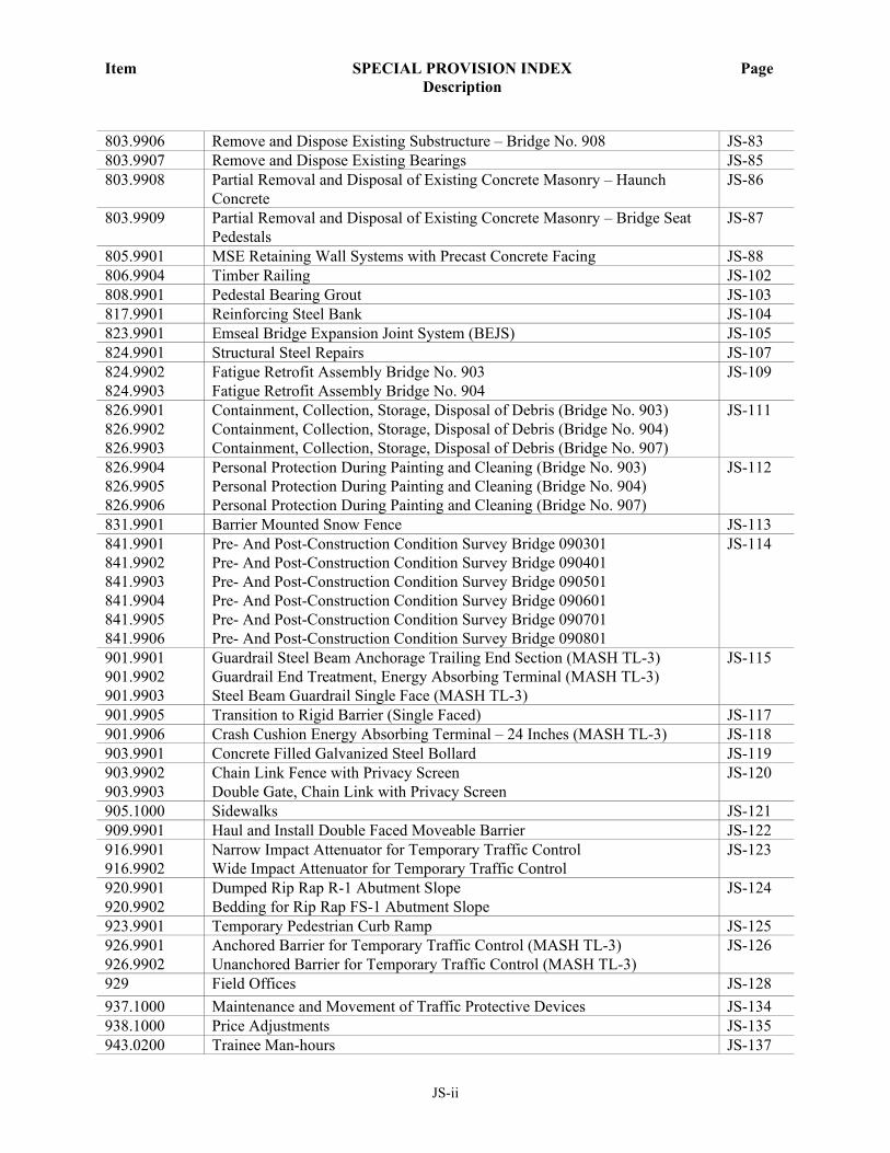
803.9906 Remove and Dispose Existing Substructure – Bridge No. 908 JS-83
803.9907 Remove and Dispose Existing Bearings JS-85
803.9908 Partial Removal and Disposal of Existing Concrete Masonry – Haunch
Concrete
JS-86
803.9909 Partial Removal and Disposal of Existing Concrete Masonry – Bridge Seat
Pedestals
JS-87
805.9901 MSE Retaining Wall Systems with Precast Concrete Facing JS-88
806.9904 Timber Railing JS-102
808.9901 Pedestal Bearing Grout JS-103
817.9901 Reinforcing Steel Bank JS-104
823.9901 Emseal Bridge Expansion Joint System (BEJS) JS-105
824.9901 Structural Steel Repairs JS-107
824.9902
824.9903
Fatigue Retrofit Assembly Bridge No. 903
Fatigue Retrofit Assembly Bridge No. 904
JS-109
826.9901
826.9902
826.9903
Containment, Collection, Storage, Disposal of Debris (Bridge No. 903)
Containment, Collection, Storage, Disposal of Debris (Bridge No. 904)
Containment, Collection, Storage, Disposal of Debris (Bridge No. 907)
JS-111
826.9904
826.9905
826.9906
Personal Protection During Painting and Cleaning (Bridge No. 903)
Personal Protection During Painting and Cleaning (Bridge No. 904)
Personal Protection During Painting and Cleaning (Bridge No. 907)
JS-112
831.9901 Barrier Mounted Snow Fence JS-113
841.9901
841.9902
841.9903
841.9904
841.9905
841.9906
Pre- And Post-Construction Condition Survey Bridge 090301
Pre- And Post-Construction Condition Survey Bridge 090401
Pre- And Post-Construction Condition Survey Bridge 090501
Pre- And Post-Construction Condition Survey Bridge 090601
Pre- And Post-Construction Condition Survey Bridge 090701
Pre- And Post-Construction Condition Survey Bridge 090801
JS-114
901.9901
901.9902
901.9903
Guardrail Steel Beam Anchorage Trailing End Section (MASH TL-3)
Guardrail End Treatment, Energy Absorbing Terminal (MASH TL-3)
Steel Beam Guardrail Single Face (MASH TL-3)
JS-115
901.9905 Transition to Rigid Barrier (Single Faced) JS-117
901.9906 Crash Cushion Energy Absorbing Terminal – 24 Inches (MASH TL-3) JS-118
903.9901 Concrete Filled Galvanized Steel Bollard JS-119
903.9902
903.9903
Chain Link Fence with Privacy Screen
Double Gate, Chain Link with Privacy Screen
JS-120
905.1000 Sidewalks JS-121
909.9901 Haul and Install Double Faced Moveable Barrier JS-122
916.9901
916.9902
Narrow Impact Attenuator for Temporary Traffic Control
Wide Impact Attenuator for Temporary Traffic Control
JS-123
920.9901
920.9902
Dumped Rip Rap R-1 Abutment Slope
Bedding for Rip Rap FS-1 Abutment Slope
JS-124
923.9901 Temporary Pedestrian Curb Ramp JS-125
926.9901
926.9902
Anchored Barrier for Temporary Traffic Control (MASH TL-3)
Unanchored Barrier for Temporary Traffic Control (MASH TL-3)
JS-126
929 Field Offices JS-128
937.1000 Maintenance and Movement of Traffic Protective Devices JS-134
938.1000 Price Adjustments JS-135
943.0200 Trainee Man-hours JS-137

Item SPECIAL PROVISION INDEX
Description
Page
JS-iii
945.9901 Remove and Dispose/Salvage Steel Camera Pole, Cabinet and Lowering
Device
JS-140
945.9902 Remove and Dispose HAR Signs, Poles, Transmitters, and Flashing Beacons JS-141
L01.9901 Wetland Mitigation JS-142
L01.9902 MS4 Restoration JS-146
L02.1000 Seeding JS-149
L06.1000 Planting JS-150
L12.9901 Bike Rack JS-151
L12.9902 Trash Receptacle JS-152
T04.9901
T13.9901
T13.9902
T13.9903
Optical Detector Cable
Optical Detector – Single Channel, One-Way
Multimode Phase Selector and Chassis
Optical Detector Confirmation Beacon
JS-153
T04.9902
T04.9903
12 Strand Single Mode Fiber Optic Cable
72 Strand Single Mode Fiber Optic Cable
JS-156
T04.9904
T12.9906
T13.9904
Thermal IP Video Detector Cable
Thermal IP Video Detector Interface Card
Thermal IP Video Detector
JS-163
T06.9921 Multi-Cell Fabric Innerduct JS-167
T11.9901
T11.9902
T11.9903
T11.9904
T11.9905
T11.9906
T11.9907
T11.9908
T11.9909
T11.9910
T11.9911
T11.9912
T11.9913
T11.9914
T11.9915
15 Foot, Round Tapered Steel Mast Arm with 16 Flute Steel Post, Base and
Foundation
20 Foot, Round Tapered Steel Mast Arm with 16 Flute Steel Post, Base and
Foundation
25 Foot, Round Tapered Steel Mast Arm with 16 Flute Steel Post, Base and
Foundation
30 Foot, Round Tapered Steel Mast Arm with 16 Flute Steel Post, Base and
Foundation
40 Foot, Round Tapered Steel Mast Arm with 16 Flute Steel Post, Base and
Foundation
45 Foot, Round Tapered Steel Mast Arm with 16 Flute Steel Post, Base and
Foundation
50 Foot, Round Tapered Steel Mast Arm with 16 Flute Steel Post, Base and
Foundation
8 Foot, 16 Flute Steel Traffic Signal Post, Base, and Foundation
10 Foot, 16 Flute Steel Traffic Signal Post, Base, and Foundation
Dual Mast Arm (15X35) Round Tapered Steel Mast Arm with 16 Flute Steel
Post, Base and Foundation
Dual Mast Arm (30X30) Round Tapered Steel Mast Arm with 16 Flute Steel
Post, Base and Foundation
Dual Mast Arm (30X35) Round Tapered Steel Mast Arm with 16 Flute Steel
Post, Base and Foundation
Dual Mast Arm (30X40) Round Tapered Steel Mast Arm with 16 Flute Steel
Post, Base and Foundation
30 Foot, Round Tapered Steel Mast Arm with 16 Flute Steel Post, Base and
Foundation (Modified I)
40 Foot, Round Tapered Steel Mast Arm with 16 Flute Steel Post, Base and
Foundation (Modified I)
JS-168
Item SPECIAL PROVISION INDEX
Description
Page
JS-iv
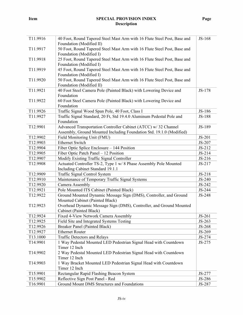
T11.9916
T11.9917
T11.9918
T11.9919
T11.9920
40 Foot, Round Tapered Steel Mast Arm with 16 Flute Steel Post, Base and
Foundation (Modified II)
50 Foot, Round Tapered Steel Mast Arm with 16 Flute Steel Post, Base and
Foundation (Modified I)
25 Foot, Round Tapered Steel Mast Arm with 16 Flute Steel Post, Base and
Foundation (Modified I)
45 Foot, Round Tapered Steel Mast Arm with 16 Flute Steel Post, Base and
Foundation (Modified I)
50 Foot, Round Tapered Steel Mast Arm with 16 Flute Steel Post, Base and
Foundation (Modified II)
JS-168
T11.9921
T11.9922
40 Foot Steel Camera Pole (Painted Black) with Lowering Device and
Foundation
60 Foot Steel Camera Pole (Painted Black) with Lowering Device and
Foundation
JS-178
T11.9926 Traffic Signal Wood Span Pole, 40 Foot, Class I JS-186
T11.9927 Traffic Signal Standard, 20 Ft, Std 19.4.0 Aluminum Pedestal Pole and
Foundation
JS-188
T12.9901 Advanced Transportation Controller Cabinet (ATCC) w/ 32 Channel
Assembly, Ground Mounted Including Foundation Std. 19.1.0 (Modified)
JS-189
T12.9902 Field Monitoring Unit (FMU) JS-201
T12.9903 Ethernet Switch JS-207
T12.9904 Fiber Optic Splice Enclosure – 144 Position JS-212
T12.9905 Fiber Optic Patch Panel – 12 Position JS-214
T12.9907 Modify Existing Traffic Signal Controller JS-216
T12.9908 Actuated Controller TS-2, Type 1 w/ 8 Phase Assembly Pole Mounted
Including Cabinet Standard 19.1.1
JS-217
T12.9909 Traffic Signal Control System JS-218
T12.9910 Maintenance of Temporary Traffic Signal Systems JS-240
T12.9920 Camera Assembly JS-242
T12.9921 Pole Mounted ITS Cabinet (Painted Black) JS-244
T12.9922
T12.9923
Ground Mounted Dynamic Message Sign (DMS), Controller, and Ground
Mounted Cabinet (Painted Black)
Overhead Dynamic Message Sign (DMS), Controller, and Ground Mounted
Cabinet (Painted Black)
JS-248
T12.9924 Fixed 4-View Network Camera Assembly JS-261
T12.9925 Field Site and Integrated Systems Testing JS-263
T12.9926 Breaker Panel (Painted Black) JS-268
T12.9927 Ethernet Router JS-269
T13.1000 Traffic Detectors and Relays JS-274
T14.9901
T14.9902
T14.9903
1 Way Pedestal Mounted LED Pedestrian Signal Head with Countdown
Timer 12 Inch
2 Way Pedestal Mounted LED Pedestrian Signal Head with Countdown
Timer 12 Inch
1 Way Bracket Mounted LED Pedestrian Signal Head with Countdown
Timer 12 Inch
JS-275
T15.9901 Rectangular Rapid Flashing Beacon System JS-277
T15.9902 Reflective Sign Post Panel - Red JS-286
T16.9901 Ground Mount DMS Structures and Foundations JS-287

Item SPECIAL PROVISION INDEX
Description
Page
JS-v
T17.9901
T17.9902
Overhead Sign Structure 81-85 Foot Span – Steel
Overhead Sign Structure 116-120 Foot Span – Steel
JS-289
T17.9903 Overhead DMS Structure and Foundation 35-39 Foot – Cantilever JS-295
T17.9904 Overhead DMS Structure and Foundation 15-19 Foot – Cantilever JS-301
T18.9901
T18.9902
Guardrail End Delineator – Red
Delineator – White
JS-307
T20.9901 Final Epoxy Resin Pavement Marking Symbol – Handicap Parking JS-308
Track and Crossing Specifications JS-309

Job Specific
RIC No. 2020-CH-065
Page 1 of 2
105.02
PLANS AND SHOP DRAWINGS
Remove Subsection 105.02, Plans and Shop Drawings, pages 1-32 and 1-33 of the RI Standard Specifications
for Road and Bridge Construction in its entirety and replace it with the following:
105.02 Plans and Shop Drawings. Plans shall be supplemented by Contractor-prepared Shop Drawings as
necessary to control the Work and its prosecution. Shop Drawings consisting of details that are not included in the
Plans but required for the Work shall be furnished to the Department. Copies of any calculations required or used
to prepare the Shop Drawings shall be furnished with the submission. Manufacturer’s engineering data for
prefabricated material, including that for falsework and forms shall be furnished with each set of Shop Drawings.
1) The Contractor shall submit to the Department for approval or documentation, the necessary Shop
Drawings in a timely manner so as not to adversely affect the Contractor’s accepted schedule. The
Contractor shall not perform work for items requiring shop drawings before receiving approval of the
corresponding Shop Drawings. This approval shall neither confer upon the State nor relieve the
Contractor of any responsibility for the accuracy and completeness of the drawings, conformity with
Contract requirements and successful completion of the Contract. Prior to approval of the Contractor’s
shop drawing, the Contractor bears all risk and all costs of delays for items related to the respective shop
drawing.
2) Shop Drawings illustrate the Contractor’s way it intends to carry out the design concepts contained in
the Contract and are not part of the Contract. The Contractor’s submission of a Shop Drawing represents
to the Engineer that the Contractor (i) coordinated the Shop Drawing with the Contract; (ii) verified and
measured the field dimensions and other information; (iii) calculated all details, construction and
performance criteria; and(iv) reviewed and accepted the Shop Drawings as its means and methods.
3) Submission of Shop Drawings. All shop drawings shall be submitted in a timely fashion such that the
Contractor’s accepted schedule will not be adversely impacted by the submittal process. Shop drawing
submittals shall be via PDF files submitted electronically by the Contractor into the Department’s web-
based Project Management Portal (PMP), per RIDOT procedure posted in the Documents Tab. Each
shop drawing submittal shall be accompanied by design computations, cuts from manufacturers'
catalogs, and/or all other supporting technical bulletins and data. Upon the Department’s request, once
shop drawings have been approved or approved as noted, the Contractor shall submit for the record four
(4) hard copy sets of shop drawings to the Department.
a) All Shop Drawings shall be stamped by a Rhode Island Registered Professional Engineer. The stamping
of Shop Drawings shall be in accordance with the applicable requirements of the Rhode Island Board of
Registration for Professional Engineers, or other Boards of Professional Registration, as applicable.
4) Approval of Shop Drawings All shop drawings will be reviewed and returned to the Contractor for
appropriate action within 45 calendar days from receipt of the submission or resubmission, or as detailed
in the Contract.
a) Shop drawings that are found to be erroneous, lacking required Professional Engineer stamps, lacking
information necessary to control construction, or not in conformance with accepted design criteria will
be rejected and returned to the Contractor. The Contractor shall address the Engineer's comments and
resubmit revised shop drawings.
b) Shop drawings designated “Approved-As-Noted” may be used by the Contractor to commence
corresponding work subject to satisfying the written conditions of the approval; such shop drawings
JS-1

Job Specific
RIC No. 2020-CH-065
Page 2 of 2
shall be revised according to the notes (as applicable) and transmitted to the Engineer within fourteen
calendar days of such approval.
5) There shall be no claims for additional payment by the Contractor, nor will there be an extension of time
under Section 108.03 for delays resulting from resubmissions due to incomplete Shop Drawings; for the
time taken by the Contractor to submit revised Shop Drawings caused by an erroneous submission; or by
a previous submission either lacking the information necessary to control construction; or for not
conforming to accepted design criteria. In addition, the Engineer’s review time of the revised Shop
Drawings will not constitute justification for an extension of time.
6) The Contract price includes the cost of furnishing all Shop Drawings, including resubmissions
JS-2

Job Specific RIC No. 2020-CH-065
Page 1 of 1
108.1000
PROSECUTION AND PROGRESS
In accordance with Subsection 108.08, Failure to Complete on Time, Para. a., Phased and Interim
Completion the following defines the Phase and Interim Completion Dates and Associated Liquidated Damages: Substantial Completion: See Table Below All Contract work shall be completed, as defined by Section 101.71. Liquidated Damages: $1,500.00 per calendar day.
Substantial Completion
July 31, 2024
JS-3

Job Specific
RIC No. 2020-CH-065
Page 1 of 1
CODE 201.9901
REMOVE AND DISPOSE DELINEATOR PANEL AND POST
CODE 201.9911
REMOVE AND DISPOSE FLEXIBLE DELINEATOR
DESCRIPTION: This item of work shall consist of removing and legally disposing of the delineator panel,
delineator post, and flexible delineators as shown on the plans or as directed by the Engineer.
CONSTRUCTION METHODS: The Contractor shall remove and dispose the delineator panel, delineator post,
and flexible delineators at the locations indicated on the plans or as directed by the Engineer. The area where the
existing anchoring/mounting system has been removed is to be restored as required, and any excavation
backfilled.
All debris shall be removed from the site and legally disposed. No disposal shall be made on State property.
METHOD OF MEASUREMENT: “REMOVE AND DISPOSE DELINEATOR PANEL AND POST” and
“REMOVE AND DISPOSE FLEXIBLE DELINEATOR” will be measured for payment by the unit “EACH” of
such units actually removed and legally disposed in accordance with the Plans and/or as directed by the Engineer.
BASIS OF PAYMENT: “REMOVE AND DISPOSE DELINEATOR PANEL AND POST” and “REMOVE
AND DISPOSE FLEXIBLE DELINATOR” will be paid for at the contract unit bid price per “EACH” as listed in
the proposal. The prices so-stated constitute full and complete compensation for all labor, tools, materials and
equipment, disposal, and all other incidentals required to finish the work, complete in place and accepted by the
Engineer.
JS-4

Job Specific
RIC No. 2020-CH-065
Page 1 of 1
CODE 201.9902
REMOVE AND DISPOSE WOODEN WALL
DESCRIPTION: This item of work shall consist of removing and legally disposing of the wooden wall as shown
on the plans or as directed by the Engineer.
CONSTRUCTION METHODS: The Contractor shall remove and dispose the wooden wall at the locations
indicated on the plans or as directed by the Engineer.
All debris shall be removed from the site and legally disposed. No disposal shall be made on State property.
METHOD OF MEASUREMENT: “REMOVE AND DISPOSE WOODEN WALL” shall be measured for
payment by the unit “LINEAR FEET” of such units actually removed and legally disposed in accordance with the
Plans and/or as directed by the Engineer.
BASIS OF PAYMENT: “REMOVE AND DISPOSE WOODEN WALL” shall be paid for at the contract unit
bid price per “LINEAR FOOT” as listed in the proposal. The prices so-stated constitute full and complete
compensation for all labor, tools, materials and equipment, disposal, and all other incidentals required to finish the
work, complete in place and accepted by the Engineer.
JS-5

Job Specific
RIC No. 2020-CH-065
Page 1 of 1
CODE 201.9903
REMOVE AND DISPOSE IMPACT ATTENUATOR
DESCRIPTION: This item of work shall consist of removing and legally disposing of the impact attenuator as
shown on the plans or as directed by the Engineer.
CONSTRUCTION METHODS: The Contractor shall remove and dispose the impact attenuator, connections,
and concrete foundation at the locations indicated on the plans or as directed by the Engineer.
All debris shall be removed from the site and legally disposed. No disposal shall be made on State property.
METHOD OF MEASUREMENT: “REMOVE AND DISPOSE IMPACT ATTENUATOR” shall be measured
for payment by the unit “EACH” of such units actually removed and legally disposed in accordance with the
Plans and/or as directed by the Engineer.
BASIS OF PAYMENT: “REMOVE AND DISPOSE IMPACT ATTENUATOR” shall be paid for at the
contract unit bid price per “EACH” as listed in the proposal. The prices so-stated constitute full and complete
compensation for all labor, tools, materials and equipment, disposal, and all other incidentals required to finish the
work, complete in place and accepted by the Engineer.
JS-6

Job Specific
RIC No. 2020-CH-065
Page 1 of 1
CODE 201.9904
REMOVE AND DISPOSE BLOCK WALL
DESCRIPTION: This item of work shall consist of removing and legally disposing of the block wall as shown
on the plans or as directed by the Engineer.
CONSTRUCTION METHODS: The Contractor shall remove and dispose the block wall, gravel subbase, and
underdrains at the locations indicated on the plans or as directed by the Engineer.
All debris shall be removed from the site and legally disposed. No disposal shall be made on State property.
METHOD OF MEASUREMENT: “REMOVE AND DISPOSE BLOCK WALL” shall be measured for
payment by the unit “LINEAR FOOT” of such units actually removed and legally disposed in accordance with
the Plans and/or as directed by the Engineer.
BASIS OF PAYMENT: “REMOVE AND DISPOSE BLOCK WALL” shall be paid for at the contract unit bid
price per “LINEAR FOOT” as listed in the proposal. The prices so-stated constitute full and complete
compensation for all labor, tools, materials and equipment, disposal, and all other incidentals required to finish the
work, complete in place and accepted by the Engineer.
JS-7

Job Specific
RIC No. 2020-CH-065
Page 1 of 1
CODE 201.9905
REMOVE AND RESET PRIVATE SIGN AND LIGHTS
The work under this item shall conform to the relevant sections of the RIDOT Standard Specifications Section 201
and the following:
DESCRIPTION: This work consists of removing, stockpiling, and relocating designated private signs and lights
as necessary to complete the work to the limits shown on the Plans and as directed by the Engineer. All work shall
be in accordance with the Standard Specifications.
CONSTRUCTION METHODS: All construction shall be in accordance with Section 201 of the Standard
Specifications and the following:
All work performed under this item shall be done in a professional manner so as to not damage the sign or lights.
The removal and resetting of the signs and lights shall be completed where indicated on the Contract Plans or as
indicated by the Engineer.
The Contractor shall submit to the Engineer for approval prior to the start of work, a complete plan and
description of the methods he intends to use to perform all work under this item. Contractor’s proposed means and
methods must not increase impacts beyond the limits shown on the Contract Plans. No work shall commence on
this item until such submission is approved by the Engineer.
METHOD OF MEASUREMENT: “REMOVE AND RESET PRIVATE SIGN AND LIGHTS” shall be
measured for payment by the unit “EACH” of such units actually removed and reset in accordance with the Plans
and/or as directed by the Engineer.
BASIS OF PAYMENT: “REMOVE AND RESET PRIVATE SIGN AND LIGHTS” shall be paid for at the
contract unit bid price per “EACH” as listed in the proposal. The prices so-stated constitute full and complete
compensation for all labor, tools, materials and equipment, electric work and connections, resetting, and all other
incidentals required to finish the work, complete in place and accepted by the Engineer.
JS-8

Job Specific
RIC No. 2020-CH-065
Page 1 of 1
CODE 201.9906
REMOVE AND RESET OR RELOCATE PRIVATE SIGN
The work under this item shall conform to the relevant sections of the RIDOT Standard Specifications Section 201
and the following:
DESCRIPTION: This work consists of removing, stockpiling, and relocating designated private signs as necessary
to complete the work to the limits shown on the Plans and as directed by the Engineer. All work shall be in
accordance with the Standard Specifications.
CONSTRUCTION METHODS: All construction shall be in accordance with Section 201 of the Standard
Specifications and the following:
All work performed under this item shall be done in a professional manner so as to not damage the sign. The
removal and resetting of the sign shall be completed where indicated on the Contract Plans or as indicated by the
Engineer.
The Contractor shall submit to the Engineer for approval prior to the start of work, a complete plan and
description of the methods he intends to use to perform all work under this item. Contractor’s proposed means and
methods must not increase impacts beyond the limits shown on the Contract Plans. No work shall commence on
this item until such submission is approved by the Engineer.
METHOD OF MEASUREMENT: “REMOVE AND RESET OR RELOCATE PRIVATE SIGN” shall be
measured for payment by the unit “EACH” of such units actually removed and reset or relocated in accordance
with the Plans and/or as directed by the Engineer.
BASIS OF PAYMENT: “REMOVE AND RESET OR RELOCATE PRIVATE SIGN” shall be paid for at the
contract unit bid price per “EACH” as listed in the proposal. The prices so-stated constitute full and complete
compensation for all labor, tools, materials and equipment, resetting, relocating, and all other incidentals required
to finish the work, complete in place and accepted by the Engineer.
JS-9

Job Specific
RIC No. 2020-CH-065
Page 1 of 1
CODE 201.9907
REMOVE AND RESET OR RELOCATE POTTED PLANTS AND CONCRETE PLANTERS
The work under this item shall conform to the relevant sections of the RIDOT Standard Specifications Section 201
and the following:
DESCRIPTION: This work consists of removing, stockpiling, and relocating designated potted plants and planters
as necessary to complete the work to the limits shown on the Plans and as directed by the Engineer. All work shall
be in accordance with the Standard Specifications.
CONSTRUCTION METHODS: All construction shall be in accordance with Section 201 of the Standard
Specifications and the following:
All work performed under this item shall be done in a professional manner so as to not damage the planters. The
removal and resetting of the sign planters be completed where indicated on the Contract Plans or as indicated by
the Engineer.
The Contractor shall submit to the Engineer for approval prior to the start of work, a complete plan and
description of the methods he intends to use to perform all work under this item. Contractor’s proposed means and
methods must not increase impacts beyond the limits shown on the Contract Plans. No work shall commence on
this item until such submission is approved by the Engineer.
METHOD OF MEASUREMENT: “REMOVE AND RESET OR RELOCATE POTTED PLANTS AND
CONCRETE PLANTERS” shall be measured for payment by the unit “EACH” of such units actually removed
and reset or relocated in accordance with the Plans and/or as directed by the Engineer.
BASIS OF PAYMENT: “REMOVE AND RESET OR RELOCATE POTTED PLANTS AND CONCRETE
PLANTERS” shall be measured for payment by the unit “EACH” of such units actually removed and reset or
relocated in accordance with the Plans and/or as directed by the Engineer.
.
JS-10

Job Specific
RIC No. 2020-CH-065
Page 1 of 1
CODE 201.9908
REMOVE AND RESET STEEL STATUE
The work under this item shall conform to the relevant sections of the RIDOT Standard Specifications Section 201
and the following:
DESCRIPTION: This work consists of removing and resetting designated statue as necessary to complete the
work to the limits shown on the Plans and as directed by the Engineer. All work shall be in accordance with the
Standard Specifications.
CONSTRUCTION METHODS: All construction shall be in accordance with Section 201 of the Standard
Specifications and the following:
All work performed under this item shall be done in a professional manner so as to not damage the statue. The
removal and resetting of the statue shall be completed where indicated on the Contract Plans or as indicated by the
Engineer.
The Contractor shall submit to the Engineer for approval prior to the start of work, a complete plan and
description of the methods he intends to use to perform all work under this item. Contractor’s proposed means and
methods must not increase impacts beyond the limits shown on the Contract Plans. No work shall commence on
this item until such submission is approved by the Engineer.
METHOD OF MEASUREMENT: “REMOVE AND RESET STEEL STATUE shall be measured for payment
by the unit “EACH” of such units actually removed and reset in accordance with the Plans and/or as directed by
the Engineer.
BASIS OF PAYMENT: “REMOVE AND RESET STEEL STATUE” shall be paid for at the contract unit bid
price per “EACH” as listed in the proposal. The prices so-stated constitute full and complete compensation for all
labor, tools, materials and equipment, resetting, and all other incidentals required to finish the work, complete in
place and accepted by the Engineer.
JS-11

Job Specific
RIC No. 2020-CH-065
Page 1 of 1
CODE 201.9909
REMOVE AND DISPOSE WOOD POSTS
DESCRIPTION: This item of work shall consist of removing and legally disposing of the wood posts as shown
on the plans or as directed by the Engineer.
CONSTRUCTION METHODS: The Contractor shall remove and dispose the wood posts at the locations
indicated on the plans or as directed by the Engineer.
All debris shall be removed from the site and legally disposed. No disposal shall be made on State property.
METHOD OF MEASUREMENT: “REMOVE AND DISPOSE WOOD POSTS” shall be measured for
payment by the unit “EACH” of such units actually removed and legally disposed in accordance with the Plans
and/or as directed by the Engineer.
BASIS OF PAYMENT: “REMOVE AND DISPOSE WOOD POSTS” shall be paid for at the contract unit bid
price per “EACH” as listed in the proposal. The prices so-stated constitute full and complete compensation for all
labor, tools, materials and equipment, disposal, and all other incidentals required to finish the work, complete in
place and accepted by the Engineer.
JS-12

Job Specific
RIC No. 2020-CH-065
Page 1 of 1
CODE 201.9910
REMOVE AND DISPOSE CONTAMINATED GAS PIPE
DESCRIPTION: This item of work shall consist of removing and disposing contaminated abandoned gas pipe as
noted on the plans, in accordance with these Specifications or as directed by the Engineer.
MATERIALS: Materials shall conform to the applicable subsections of Subsection 201.02 Materials of the
Standard Specifications.
CONSTRUCTION METHODS: Construction Methods shall conform to the applicable subsections of Subsection
201.03 Construction Methods of the Standard Specifications.
The Contractor shall coordinate with National Grid. National Grid will purge old gas main, wipe test the inside of
the pipe, cap the ends of the pipe, and abandon in place. If the wipe test results show PCB contamination than a
section of pipe will need to be removed. The contractor shall remove the contaminated pipe, place in an open top
container, transport the pipe, arrange to have the pipe cleaned, and dispose of the pipe sections as scrap metal.
Transport, cleaning, and disposal of pipe shall meet environmental requirements.
The Contractor shall seal or cap the open pipe ends of the abandoned pipe remaining in the ground. Plugs and caps
for abandoned pipe remaining in the ground shall be of the type approved by the utility company for a particular
application.
METHOD OF MEASURMENT. “Remove and Dispose Contaminated Abandoned Gas Pipe” will be measured
by the number of linear feet of such pipe actually removed, placed in an open container, transported, cleaned, and
disposed of as scrap metal in accordance with the Plans and/or as directed by the Engineer
BASIS OF PAYMENT. The accepted quantity of “Remove and Dispose Contaminated Abandoned Gas Pipe”
will be paid for at the contract unit price per “linear foot” as listed in the Proposal. The price so-stated constitutes
full and complete compensation for all labor, materials and equipment and all other incidentals required to finish
the work, including coordination, removal, placing, transporting, cleaning, and disposing according to the plans,
complete and to the satisfaction of the Engineer.
JS-13
Job Specific
RIC No. 2020-CH-065
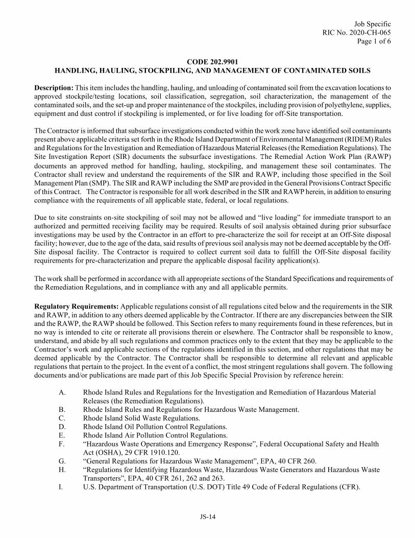
Page 1 of 6
CODE 202.9901
HANDLING, HAULING, STOCKPILING, AND MANAGEMENT OF CONTAMINATED SOILS
Description: This item includes the handling, hauling, and unloading of contaminated soil from the excavation locations to
approved stockpile/testing locations, soil classification, segregation, soil characterization, the management of the
contaminated soils, and the set-up and proper maintenance of the stockpiles, including provision of polyethylene, supplies,
equipment and dust control if stockpiling is implemented, or for live loading for off-Site transportation.
The Contractor is informed that subsurface investigations conducted within the work zone have identified soil contaminants
present above applicable criteria set forth in the Rhode Island Department of Environmental Management (RIDEM) Rules
and Regulations for the Investigation and Remediation of Hazardous Material Releases (the Remediation Regulations). The
Site Investigation Report (SIR) documents the subsurface investigations. The Remedial Action Work Plan (RAWP)
documents an approved method for handling, hauling, stockpiling, and management these soil contaminates. The
Contractor shall review and understand the requirements of the SIR and RAWP, including those specified in the Soil
Management Plan (SMP). The SIR and RAWP including the SMP are provided in the General Provisions Contract Specific
of this Contract. The Contractor is responsible for all work described in the SIR and RAWP herein, in addition to ensuring
compliance with the requirements of all applicable state, federal, or local regulations.
Due to site constraints on-site stockpiling of soil may not be allowed and “live loading” for immediate transport to an
authorized and permitted receiving facility may be required. Results of soil analysis obtained during prior subsurface
investigations may be used by the Contractor in an effort to pre-characterize the soil for receipt at an Off-Site disposal
facility; however, due to the age of the data, said results of previous soil analysis may not be deemed acceptable by the Off-
Site disposal facility. The Contractor is required to collect current soil data to fulfill the Off-Site disposal facility
requirements for pre-characterization and prepare the applicable disposal facility application(s).
The work shall be performed in accordance with all appropriate sections of the Standard Specifications and requirements of
the Remediation Regulations, and in compliance with any and all applicable permits.
Regulatory Requirements: Applicable regulations consist of all regulations cited below and the requirements in the SIR
and RAWP, in addition to any others deemed applicable by the Contractor. If there are any discrepancies between the SIR
and the RAWP, the RAWP should be followed. This Section refers to many requirements found in these references, but in
no way is intended to cite or reiterate all provisions therein or elsewhere. The Contractor shall be responsible to know,
understand, and abide by all such regulations and common practices only to the extent that they may be applicable to the
Contractor’s work and applicable sections of the regulations identified in this section, and other regulations that may be
deemed applicable by the Contractor. The Contractor shall be responsible to determine all relevant and applicable
regulations that pertain to the project. In the event of a conflict, the most stringent regulations shall govern. The following
documents and/or publications are made part of this Job Specific Special Provision by reference herein:
A. Rhode Island Rules and Regulations for the Investigation and Remediation of Hazardous Material
Releases (the Remediation Regulations).
B. Rhode Island Rules and Regulations for Hazardous Waste Management.
C. Rhode Island Solid Waste Regulations.
D. Rhode Island Oil Pollution Control Regulations.
E. Rhode Island Air Pollution Control Regulations.
F. “Hazardous Waste Operations and Emergency Response”, Federal Occupational Safety and Health
Act (OSHA), 29 CFR 1910.120.
G. “General Regulations for Hazardous Waste Management”, EPA, 40 CFR 260.
H. “Regulations for Identifying Hazardous Waste, Hazardous Waste Generators and Hazardous Waste
Transporters”, EPA, 40 CFR 261, 262 and 263.
I. U.S. Department of Transportation (U.S. DOT) Title 49 Code of Federal Regulations (CFR).
JS-14

Job Specific
RIC No. 2020-CH-065
Page 2 of 6
J. Safety and Health Regulations Promulgated by the U.S. Department of Labor OSHA, 29 CFR 1910 –
Occupational Safety and Health Standards, and 29 CFR 1920 – Safety and Health Regulations for
Construction.
K. U.S. EPA Standard Operating Safety Guidelines – Office of Emergency and Remedial Response –
Hazardous Response Support Division.
L. U.S. EPA Medical Monitoring Program Guidelines.
Materials: All materials to be used shall be in accordance with all appropriate sections of the Standard Specifications.
Personal protective equipment shall be as specified in the Contractor’s project specific Health and Safety Plan (HASP).
Construction Methods:
Health and Safety: The Contractor shall comply with all applicable state, federal and local health and safety requirements
established by regulation including but not limited to, OSHA Standard 1910.120 Hazardous Waste Operations (HazWoper),
consistent with the type of contaminants identified in the SIR for the Project. The Contractor shall prepare and maintain a
Site-specific HASP which must be certified by a Certified Industrial Hygienist and implemented as part of this work. The
Contractor’s employees and any Subcontractor employees who will be potentially exposed to contaminated soils are
required to have OSHA 40-hour health and safety training, and 8-hour refresher training as required. The Contractor must
provide a copy of their site-specific HASP (including documentation of training, any required medical monitoring or fit
testing documentation and copies of employee training certificates) to the Engineer for the persons who shall be performing
the work at least 2 weeks prior to project implementation.
If visible dust is generated, then the level of dermal and respiratory protection shall be determined by the Contractor for his
employees based upon periodic air monitoring to be performed by the Contractor in addition to any additional requirements
of the Contractor’s HASP. The Engineer may conduct duplicate air monitoring for quality assurance purposes. Level D
protection, in addition to the following, shall be the minimum personal protective level for all on-Site personnel:
• Safety Leather Steel Toe Boots;
• Reflective Safety Vest;
• Rubber or Leather Gloves;
• Eye and Hearing Protection; and
• Hard Hat.
The Contractor shall provide a safety officer having experience in activities involving similar hazardous waste and
contamination levels who will be responsible for ensuring safety and compliance during the Project. The Contractor shall
have the necessary personal protective equipment available as specified in the Contractor’s site-specific HASP and access to
an inventory of personal protection equipment in the event that the level of personal protection equipment needs to be
upgraded.
The Contractor shall provide stations allowing workers to wash and put on and remove protective clothing, stations for
vehicles to be cleaned if necessary, before leaving the Site, and air monitoring and evaluation of areas where unsafe levels
of gas have or may have accumulated.
Smoking shall not be permitted in any area where gases can accumulate, or in areas where contaminated soil is present.
Welding or open flames shall not be permitted in enclosed areas where combustible gases are present. The Contractor shall
be responsible to assess air quality in enclosed areas prior to welding or the use of open flames for the presence of
combustible gases.
JS-15
Job Specific
RIC No. 2020-CH-065
Page 3 of 6
The Contractor shall provide toxic gas indicators, an organic vapor analyzer, a combustible gas indicator, an oxygen
indicator, and fire extinguishers at all times during operations. The Contractor shall perform periodic monitoring with
portable monitoring devices in areas susceptible to gas accumulation. The Contractor shall maintain daily monitoring
records that shall be submitted to RIDOT upon request.
If at any time, the RIDOT is apprised of a safety hazard which demands immediate attention because of its high potential for
harm to the public, persons on or about the work, or public or private property, the RIDOT shall have the right to order such
safeguards to be erected and such precautions to be taken as necessary and the Contractor shall comply with such orders. If
under such circumstances, the Contractor does not or cannot immediately put the work into proper and approved condition,
or if the Contractor or his representative is not upon the site so that he or she can be notified immediately of the
insufficiency of safety precautions, then the RIDOT may put the work into such a condition that shall be, in its opinion, in
all respects safe, and the Contractor shall pay all expenses of such labor and materials as may have been used for this
purpose by him or by the RIDOT. The fact that RIDOT does not observe a safety hazard or does not order the Contractor to
take remedial measures shall in no way relieve the Contractor of the entire responsibility for any costs, loss or damage by
any party sustained on account of the insufficiency of the safety precautions taken by him or by the Owner acting under the
authority of this Section.
The Contractor is alerted to the fact that conditions of high hazard are present or can be present at the Site during
performance of the work. It is the responsibility of the Contractor to take the appropriate safety precautions to meet
whatever conditions of hazard may be present during the performance of the work, whether reasonably foreseeable or not.
The safety conditions enumerated within the Specifications are the minimum permissible and RIDOT does not make any
representation that the safety standards provided herein will be adequate to meet all eventualities. The Contractor is
therefore alerted to the fact that it shall be his responsibility to anticipate and provide such additional safety precautions,
facilities, personnel, and equipment as shall be necessary to protect life and property from whatsoever conditions of hazard
are present or may be present.
Soil Characterization: All soil which is proposed for excavation and which is not interred within the project limits beneath
the proposed cap (refer to SIR and RAWP) needs to be characterized for Off-Site disposal purposes. The Contractor shall be
responsible for testing/characterization or obtaining pre-characterization. If such pre-characterization is performed and proof
of disposal facility acceptance obtained and approved by the Engineer, the Contractor may live load soils for disposal off-
site. Copies of all analytical results and proof of acceptance by the disposal facility must be submitted to RIDOT at least 2
weeks prior to the commencement of excavation for soils being live-loaded, and at least 2 weeks prior to transportation to
the disposal facility for those soils being stockpiled.
All excavated soil which is not interred below one of the approved capping methods (refer to SIR and RAWP) at the Site
will either be stockpiled for off-Site disposal characterization or will be pre-characterized and classified for off-Site
disposal via live loading.
Based upon the results of previous soil investigations (refer to SIR), all excavated soils not being interred beneath one of
the approved capping methods at the Site are assumed to be acceptable at the Rhode Island Resource Recovery Corporation
(RIRRC) for disposal as Solid Waste Soils pending the Contractor’s pre-classification or soil stockpile sampling results
below the characteristic of toxicity per 40 CFR 261.24, TVOCs less than 40 ppm via field screening, and soil samples
above RIDEM Method 1 Industrial/Commercial DEC and GA Leachability Criteria but are otherwise non-hazardous.
Should any excavated soils that are not being interred beneath one of the approved capping methods at the Site exhibit
characteristics of toxicity per 40 CFR 261.24 or TVOCs greater than 40 ppm via field screening, they shall be stockpiled
separated from other stockpiled soils and further tested for hazardous waste characteristics and RIRRC disposal parameters.
Soils which exhibit the characteristic of toxicity per 40 CFR 261.24 or which otherwise exceed EPA hazardous waste
characteristics and are not acceptable at the RIRRC facility are to be disposed of as a hazardous waste.
JS-16

Job Specific
RIC No. 2020-CH-065
Page 4 of 6
Off-Site Identification: The Contractor shall identify authorized and licensed receiving facilities for disposal of excess soil.
The Contractor shall contact the proposed receiving facility and identify the appropriate waste characterization analysis
required for the facility to accept the soil for disposal. The Contractor shall provide the appropriate soil characterization and
obtain acceptance from the Off-Site disposal facility.
Before an excavation of soil, the Contractor shall provide the Engineer with the name, address, permit numbers, and pre-
approvals to receive the soil generated from the project, in addition to copies of any new analytical results.
Where soils are approved for disposal, the Contractor will identify the proposed receiving facility within a minimum of
forty-eight (48) hours of excavation at the Site, such that all excavated soils can be disposed within ninety (90) days of
excavation. The Contractor shall forward the receiving facility information to the Engineer. The Contractor shall
provide a copy of the information, along with the cover letter, to RIDOT’s Natural Resources Unit, 2 Capitol Hill,
Providence, Rhode Island. RIDOT reserves the right to reject the proposed receiving facility. The Contractor must
receive concurrence from the RIDOT for the proposed disposal facility. Upon approval by RIDOT, the Contractor will
submit a letter to the RIDEM Project Manager informing them of the selected receiving facility.
Unexpected Conditions: Site excavation associated with the placement of footings, construction, and/or other activities
throughout the Project area may unearth solid debris and/or refuse materials such as concrete, brick, rubble, pipe, lumber
and other building materials. This material should be segregated to the extent feasible and stockpiled separately from Site
soils. Disposal of this material will be handled by the Contractor in a manner consistent with demolition and refuse clearing
projects and in accordance with RIDEM Solid Waste Regulations.
If unusual observations (i.e. drums, free product, or unusual odors) are made during excavation within the Project work
areas, then the Contractor will immediately cease all further excavation work and contact the Engineer. Workers should not
handle the identified material of interest and shall notify the Engineer for further direction. The Engineer will in turn notify
RIDEM if appropriate and the need for an addendum or amendment will be evaluated. If required, the Contractor is
responsible for contacting an emergency response contractor to collect the material/item for immediate containerization and
off-Site disposal. If required, Contractor will provide approved, lined and covered roll-off containers (or other competent
and suitable container) for the containment of any semi-solid, liquid, or other hazardous waste. These emergency response
actions will be conducted in accordance with all state, federal and local laws and the Contractor will provide the Engineer
with copies of all analytical, approvals, shipping papers, and confirmation of proper disposal.
Any soils characterized as hazardous waste shall be properly and competently contained. Any semi-solid or liquid
hazardous waste will be placed in an approved, lined and covered roll-off or other appropriate container. If the containment
of any hazardous waste is determined to be not competent, it will be immediately competently contained, transferred to an
appropriate and effective container, or disposed of at a licensed disposal facility following the protocols established in this
Job Specific Special Provision. Photographic evidence of containment quality will be provided via email or hard copy to the
Engineer on a monthly basis and immediately following any significant weather event. This information will also be
provided to the Engineer. The Engineer shall provide documentation to the RIDEM if required.
Stockpiling: The Contractor shall supply and utilize all required equipment to adequately place and maintain the soil
stockpiles in a neat and orderly fashion in 500 cubic yard intervals within the approved stockpile areas should there be
adequate space for stockpiling. All stockpiled soil shall be placed entirely on two layers of 6-mil polyethylene and be
completely covered with a 6 mil layer of polyethylene at the completion of each day. The polyethylene sheets shall overlap
adjacent sheets by a minimum of four (4) feet. The stockpiles shall be surrounded with staked hay bales or straw waddles. It
is the responsibility of the Contractor to ensure that each stockpile location has been placed on and covered by the required
polyethylene, and that erosion controls are in place. However, due to site constraints on-site stockpiling of soil may be
limited or not allowed. Results of soil analysis obtained during prior subsurface investigations may be used by the
Contractor in an effort to pre-characterize the soil for “live loading” and transport to an off-Site disposal facility.
JS-17

Job Specific
RIC No. 2020-CH-065
Page 5 of 6
Live Loading : The Contractor is allowed to excavate, directly load, and immediately transport pre-characterized soils
that have been approved by the receiving Off-Site disposal facility and RIDOT.
Dust/Odor Control: It is the Contractor’s responsibility to control dust and odors as required by the applicable Regulations
at any stockpile locations and at all locations traveled for this stockpiling operation leading to and from the stockpile areas.
The Contractor must provide all reasonable precautions to prevent excessive dust generation during soil handling activities,
and the Contractor’s work must comply with all applicable federal, state and local regulations include the RIDEM Air
Pollution Control Regulations, specifically Regulation No. 5 regarding fugitive dust. The Contractor must conduct dust
control measures during and after normal work hours and on weekends, as necessary, to control dust. Any stockpiles shall
be inspected on a daily basis. Any conditions warranting corrective actions shall be addressed immediately upon being
brought to the attention of the Contractor.
Runoff Protection: The Contractor is required to protect all catch basins/storm drains on the Site by placing Engineer-
approved best management practices (BMP) around them. The Contractor shall inspect the catch basins/storm drains
weekly, or after any major storm event, to ensure the BMPs are adequately protecting the structures. If they are deemed
inadequate, the Contractor must contact the Engineer and propose an alternative protection method.
Security: The Contractor shall secure the site to keep the Public away from contaminated material stockpiled on site. The
Contractor shall provide a temporary fence securing contaminated stockpiles.
Decontamination: The Contractor is responsible for decontaminating all tools, heavy equipment, and other items that leave
the work area in accordance with the all requirements set forth in the applicable regulations and/or in the RAWP and SMP,
and properly characterizing and disposing of waste/wastewater resulting from decontamination procedures. This includes,
but is not necessarily limited to, the following:
• Brush soil from equipment and containerize prior to washing equipment surfaces;
• Sample and analyze the containerized waste for proper off-Site transportation and disposal at the frequencies and
for the parameters established in the applicable regulations;
• Proper disposal of the containerized material (refer to Code 202.9902); and
• Construction entrances/stone stabilized pads will be placed at the construction boundary zone to facilitate the
removal of excess soil from vehicle tires for those vehicles which need to leave the work zone on a daily basis.
Operations Log: The Contractor is responsible for maintaining an Operations Log as included in the RAWP. The
Operations Log will be maintained daily and will document the observations made during excavation throughout the Project
Area. The log must include, but not necessarily be limited to, the following:
• Dates of earthwork activities;
• Dates and times of sampling;
• Soil Management Observations;
• Description of soil movements;
• Approximate volumes of excavated materials;
• Waste/Soil tracking;
• Final off-Site disposal locations; and
• Disposal documentation.
The Contractor will provide a summary report to the Engineer on a daily basis and shall provide copies of their Operating
Log to the Engineer on a weekly basis. If required by RIDEM, the engineer will be responsible for compiling and
submitting the logs to RIDEM in a manner and timeframe acceptable to RIDEM.
JS-18

Job Specific
RIC No. 2020-CH-065
Page 6 of 6
Conformance: While engaged in contamination/hazardous material removal and contaminated soil management, the
Contractor shall be subject to on-Site inspection by the RIDOT Inspector, Engineer, or other regulatory officials. If the work
is in violation of the requirements of this, or any other specification, or is in violation of a state, local or federal regulation,
the inspector may issue a stop work order to be in effect immediately and until the violation is resolved. Standby time and
expenses required to resolve the violation shall be at the Contractor’s expense.
Submittals: The Contractor shall submit the following to the Engineer:
A. The names, addresses, and responsibilities of subcontractors retained for work described in this section.
B. A proposed schedule for work.
C. Proposed dust monitoring and control measures.
D. Health and Safety Plan and OSHA documentation.
E. Proposed decontamination procedures.
F. Soil/waste profile forms including analytical characterization data.
G. Minimum three (3) day notice before off-Site transportation for disposal of excavated material or waste.
H. Copies of shipping papers, manifests, bills of lading, weight slips etc with regulatory time frames.
I. Written confirmation from reuse, recycling or disposal facilities that they will accept material from the
Project Site.
J. Proposed stockpile location plan, if applicable.
K. The name, address, telephone number, name of contact, EPA number, proof of license, and permit to
transport hazardous waste from the Project Site, as applicable.
L. The name, address, telephone number, name of contact, EPA/state license number, proof of license, and
permit for proposed Transfer, Storage and Disposal Facilities and recyclers.
M. Daily work summary detailing excavation activities including the location and volume of excavated
material, the disposal facility to which the material was transported via live loading, and weekly submittals
of the operations log.
N. Certified scale weight tickets cross-referenced to shipping papers.
Method of Measurement: This item will not be measured for payment.
Basis of Payment: “Handling, Hauling, Stockpiling and Management of Contaminated Soils” will be paid for at its
respective contract unit price per “Lump Sum” as listed in the Proposal. The price so stated shall constitute full and
complete compensation for all labor, materials, tools and equipment, loading, handling, hauling, stockpiling, management of
contaminated soils, off-site identification, polyethylene, erosion control, dust/odor control, soil classification, segregation,
soil characterization, erosion controls, health and safety plan, security, runoff protection, decontamination, operation logs,
submittals, installation and removal of construction entrances/stone stabilized pads, vehicle washing, street sweeping, and
all other incidentals required to complete the work as described in this Job Specific Special Provision and elsewhere as
referenced in the Contract Documents, complete in place and accepted by the Engineer.
The Contractor shall not be paid separately for loading, handling, and hauling soils suitable for reuse on the project from the
stockpiles to the areas of reuse. The cost for this effort shall be included in this item.
Excavation of contaminated soil and/or sediment shall be paid for under the appropriate excavation item.
Best management practices shall be paid for under Item Code 209.9902 “Inlet Protection.”
JS-19

Job SpecificRIC No. 2020-CH-065
Page 1 of 3CODE 202.9902
LOAD AND HAUL CONTAMINATED SOIL
CODE 202.9903DISPOSAL OF CONTAMINATED SOIL
CODE 202.9904LOAD, HAUL, AND DISPOSAL OF HAZARDOUS OR OTHER WASTE
Description: This item includes handling, loading, hauling, transporting, and disposing of contaminated or hazardous soil or other waste, to proper and fully licensed Off-Site disposal or recycling facilities. The work shall be performed in accordance with all appropriate sections of the Standard Specifications and requirements of the Remediation Regulations, and in compliance with any and all applicable permits.
Regulatory Requirements: See Code 202.9901; Handling, Hauling, Stockpiling, and Management of Contaminated Soils for details
Other Waste: Solid debris and/or refuse materials such as concrete, brick, rubble, pipe, lumber and other building materials.
Materials: All materials to be used shall be in accordance with all appropriate sections of the Standard Specifications. Personal protective equipment shall be as specified in the Contractor’s project specific Health and Safety Plan (HASP).
Construction Methods:
Health and Safety: See Code 202.9901; Handling, Hauling, Stockpiling, and Management of Contaminated Soils for details.
Decontamination: See Code 202.9901; Handling, Hauling, Stockpiling, and Management of Contaminated Soils for details.
Operations Log: See Code 202.9901; Handling, Hauling, Stockpiling, and Management of Contaminated Soils for details.
Conformance: While engaged in contamination/hazardous material removal and contaminated soil management, the Contractor shall be subject to On-Site inspection by the Engineer, RIDOT inspector, or other regulatory officials. If the work is in violation of the requirements of this, or any other specification, or is in violation of a state, local or federal regulation, the inspector may issue a stop work order to be in effect immediately and until the violation is resolved. Standby time and expenses required to resolve the violation shall be at the Contractor’s expense.
Disposal of soil or other material that becomes contaminated as a result of careless handling or use of unauthorized procedures by the Contractor or their employees/subcontractors shall be at the Contractor’s expense.
Submittals: See Code 202.9901; Handling, Hauling, Stockpiling, and Management of Contaminated Soils for details.
Contaminated Soil Transportation and Disposal: The Contractor shall be responsible for obtaining all necessary permits, manifests, shipping papers, bills of lading, and acceptance approvals in conjunction with contaminated soil, hazardous material/waste, and/or solid waste removal, hauling, transportation and disposal. The Contractor shall provide timely notification of such actions as may be required by applicable federal, state, and/or local authorities.
JS-20
Job SpecificRIC No. 2020-CH-065
Page 2 of 3The Contractor must obtain RIDOT signatures on all manifests, shipping papers, profiles, etc as required by law.
All contaminated soil stockpiled for disposal, or live loaded for disposal, shall be sent to an off-Site recycling or disposal facility in accordance with applicable local, state and federal regulations governing their transportation, recycling and disposal. Waste characterization and profiling, including requirements for characterization sampling and analysis, are the responsibility of the Contractor, however, the Contractor must notify, and obtain approval from the Engineer for the following before any off-Site shipment for transportation, disposal or recycling:
Provide the name, address and licenses of the proposed disposal or recycling facility for the soil/waste to be removed (the Engineer reserve the right to reject the proposed receiving facility in which case the Contractor must provide an alternative recommendation);
Soil/waste profile forms and characterization data including, but not limited to, results of characterization analysis;
Shipping papers including, but not limited to, hazardous waste manifests, bills of lading, and other shipping documents;
The schedule for off-Site disposal of excavated material or solid waste at least three (3) working days in advance.
All excavated contaminated soil and waste transported upon public roadways shall be covered to minimize fugitive dust, and where necessary truck tire and undercarriage decontamination shall be employed to minimize tracking of soils onto public roadways (refer to Code 202.9901).
The Contractor shall be responsible for loading all contaminated soil, waste, and other material to be transported off-Site into properly licensed and permitted vehicles, and transport all excavated material for off-Site recycling, reuse, or disposal directly to the receiving facility which has been approved by the Engineer in accordance with applicable state and federal regulations including but not limited to Department of Transportation, Environmental Protection Agency and applicable state and local regulations.
Method of Measurement: CODES 202.9902 AND 202.9903 LOAD, HAUL, AND DISPOSAL OF CONTAMINATED SOIL: Loading, hauling and disposal of Contaminated Soil will be measured for payment by the “ton” actually loaded and hauled for disposal in accordance with the Contract Documents and/or as directed by the Engineer. The number of tons will be determined from weight slips generated by the receiving facility, or other scale approved by the Engineer.
CODE 202.9904 LOAD, HAUL, AND DISPOSAL OF HAZARDOUS OR OTHER WASTE: This item will not be measured for payment.
Basis of Payment: The accepted quantity of item Code 202.9902 LOAD AND HAUL CONTAMINATED SOIL will be paid for at its respective contract unit price per “Ton” as listed in the Proposal. The price so stated shall constitute full and complete compensation for all labor, materials, tools and equipment, loading, hauling, decontamination, and all other incidentals required to complete the work as described in this Code, and elsewhere as referenced in the Contract Documents, complete in place and accepted by the Engineer.
The accepted quantity of item Code 202.9903 DISPOSAL OF CONTAMINATED SOIL will be paid for at its respective contract unit price per “Ton” as listed in the Proposal. The price so stated shall constitute full and complete compensation for all labor, materials, tools and equipment, disposal, and all other incidentals required to complete the work as described in the Contract Documents complete in place and accepted by the Engineer. The only acceptable bid price for Item 202.9903 shall be $45.00 (forty five dollars) per ton. If the cost of disposing this material that is charged by the receiving facility is different (higher or lower) than $45.00/Ton, then the price paid per ton for this item will be adjusted (higher or lower) by that difference in dollars/ton.
JS-21

Job SpecificRIC No. 2020-CH-065
Page 3 of 3
The accepted quantity of item Code 202.9904 LOAD, HAUL AND DISPOSAL OF HAZARDOUS WASTE SOIL OR OTHER WASTE will be paid for at the actual amount expended to handle, load, transport, and dispose of the type of soil. The price so stated shall constitute full and complete compensation for all labor, materials, tools, and equipment and all other incidentals required to complete the work as described in the Contract Documents complete in place and accepted by the Engineer. The estimated dollar figure for this item of work is established by the Department at $100,000.00 and is inserted in the proposal as an authorized Lump Sum amount from which payments will be drawn.
Operations Log, Health and Safety, and Submittals shall be paid for under Code 202.9901; Handling, Hauling, Stockpiling, and Management of Contaminated Soils.
JS-22

Job SpecificRIC No. 2020-CH-065
Page 1 of 3CODE 203.9901DEWATERING
GENERAL: The work under this item shall be in accordance with Section 203 of the Rhode Island Department of Transportation Standard Specifications for Road and Bridge Construction except as modified herein. Soil and groundwater contamination is present in the construction work areas. The Site Investigation Report (SIR) and Remedial Action Work Plan (RAWP), if available, to be provided on the CD of contract documents. A RIDEM-approved Remedial Action Work Plan (RAWP) is anticipated no later than mid-November 2020. In the event that the RAWP is not included in the advertising CD, it will be provided as an Addendum.
DESCRIPTION:A. Dewatering as necessary, in excavations for all foundations, within all temporary earth retaining
structures, utility construction, and for all and any other work requiring Dewatering project wide. The Contractor is informed that groundwater in the project area is impacted by nearby present or historic land uses and that water resulting from dewatering can not be pumped as a point discharge to an existing storm water system. All water shall flow through a dewatering basin or approved equal treatment.
B. Dewatering systems that shall perform the following functions:
1. Lower groundwater levels or hydrostatic pressure heads in the soils within the excavation limits to Maintain a dry and stable subgrade and/or work area.
2. Divert surface water away from excavations and all other work areas on the project.3. Control and remove seepage, surface water, and precipitation in excavations and/or work areas.4. Prevent disturbance of adjacent structures due to the Dewatering.5. Remove sediment and control the rates and volumes of disposal of surface and subsurface water
removed from the work area.6. Retain all sediments on-site with the work area.
C. Operating all construction Dewatering in a manner that prevents disturbance of adjacent structures due to the lowering of groundwater levels outside of the project limits.
D. The Contractor shall comply with all requirements of federal, state, and local permits.
SUBMITTALS:The following submittals shall apply to Dewatering and shall be made by the Contractor for review and approval by the Engineer prior to start of Dewatering. The Contractor shall conform to all submittal requirements of the Contract, including submitting the information specified herein to the Engineer. The Contractor shall submit the following information:
A. The proposed methods for removing water from all excavations when deemed necessary, the proposed type and size of the dewatering basin.
EXECUTION, DESIGN, AND PERFORMANCE CRITERIA:A. The methods of controlling water, inside and outside the work area being dewatered, are the option of the
Contractor who shall be solely responsible for the design, operation, performance, location, arrangement, and depth of any system or systems selected to accomplish the work. Equipment shall be of suitable size, capacity and type to perform Dewatering and to maintain dry and stable working surfaces, and to pump, store, and otherwise manage the groundwater removed from the work areas.
B. The Contractor shall adapt and modify the dewatering system(s) as required throughout the course of the work to meet the requirements of the work.
JS-23
Job SpecificRIC No. 2020-CH-065
Page 2 of 3
C. The Contractor shall maintain site, construction dewatering equipment and subsurface drainage in an acceptable manner during the course of the work. The Contractor shall maintain site grades to direct surface runoff to collection points and shall prevent surface water from running or collecting over prepared subgrades, fill surfaces, or the work area being dewatered. The Contractor shall collect and temporarily store surface water, seepage, precipitation, groundwater and other water that enters work areas being dewatered. No standing water shall be allowed to accumulate in excavations or work areas being dewatered.
D. The Contractor shall dewater without loss of ground or unacceptable ground movements.
E. The Contractor shall minimize impacts to groundwater levels outside the limits at all times during construction. These levels may be monitored by piezometers and observation wells prior to and during construction by the Engineer.
F. The Contractor shall dewater such that all construction is conducted “in-the-dry”, unless otherwise stated. “In-the dry” shall be construed to mean without standing water or saturated conditions that may interfere with construction operations and the successful completion of the work.
G. The Contractor shall take measures to prevent damage to properties, buildings or structures, utilities, and all other existing and newly constructed work on and immediately adjacent to the project site.
H. The Contractor shall modify the system(s) at no additional cost to the State if, after installation and while in operation, it causes or threatens to cause damage to properties, buildings or structures, utilities, and all other existing or newly constructed work, or otherwise does not perform as required.
I. The Contractor shall immediately repair damage to any utility, structure, and/or facility resulting directly or indirectly from dewatering activities, including inadequate performance of such systems, to the satisfaction of the Engineer at no additional cost to the State.
J. The Contractor shall comply with all federal, state, and local codes, ordinances and regulations for disposal of all water.
K. The Contractor shall maintain continuous and complete effectiveness of dewatering systems and surface water control 24 hours per day, 7 days per week at all times until no longer required.
L. The Contractor shall maintain and employ adequate back-up equipment, Dewatering system components, and power (if needed) in the case of equipment breakdown. The Contractor shall devise emergency procedures for maintaining continuous, uninterrupted Dewatering operations (if needed). The Contractor shall regularly check the back-up equipment for proper operation at the start of the work and every week thereafter.
Dewatering System:A. The Contractor shall provide, install, maintain, and operate pumps, and related equipment of sufficient
capacity to adequately dewater excavations or work areas until the required construction, installation, and backfilling of underground structures are completed to a level at which the construction is no longer impacted, as approved by the Engineer.
Dewatering systems may include gravity wells, vacuum wellpoints or open pumping from sumps and/or drainage trenches, depending upon location on-site, and/or soil conditions. All sumps shall include suitable filter fabric, crushed stone, or other acceptable materials to prevent the migration or pumping of fine-grained materials and subgrade disturbance.
JS-24

Job SpecificRIC No. 2020-CH-065
Page 3 of 3B. The Contractor shall maintain water levels or hydrostatic pressure heads to maintain an “in-the-dry” stable
work area.
Dewatering operations shall prevent loss of fine materials into bedding, boiling up of trench and excavation bottoms, or other disturbances that may cause subsidence or loss of strength of the underlying natural soils.
If requested by the Engineer, the Contractor shall excavate all soils made unsuitable due to inadequate Dewatering or disturbance by construction operation and replace the unsuitable soils with compacted fill, to the satisfaction of the Engineer at no additional cost to the State.
If the Dewatering procedures result in boiling, loss of fines, ground instability, uncontrolled flow, or other detrimental effects, the Contractor shall immediately notify the Engineer of these unsuitable conditions. The Contractor shall be required to modify its operations or take other supplementary measures to correct the situation as approved by the Engineer at no additional cost to the State.
C. When installing tank vaults, sewer manholes, or other structures that are subject to buoyant forces, the Contractor shall maintain Dewatering operations until sufficient structure dead weight or backfill is placed to resist uplift forces.
D. Permanent utilities and piping shall not be used as part of Dewatering system(s).The Contractor shall remove and backfill Dewatering elements when they are no longer required, using methods acceptable to the Engineer. The Contractor shall backfill any voids resulting from Dewatering system removal with cement grout, concrete, or other material as directed by the Engineer to prevent potential loss of ground.
E. The Contractor shall inform the Engineer in writing of any changes in the Dewatering System that the Contractor wishes to make to accommodate field conditions prior to making the changes.
F. The Contractor shall dispose of all Dewatering effluent off-site in accordance with all state and federal regulations.
G. The Contractor shall pay for all fines, penalties and other costs associated with noncompliance at no additional cost to the State.
METHOD OF MEASUREMENT: This item will not be measured for payment.
BASIS OF PAYMENT: The accepted quantity of DEWATERING will be paid for at the actual amount expended for dewatering as described. The price so stated shall constitute full and complete compensation for all labor, materials, tools, and equipment and all other incidentals required to complete the work as described in the Contract Documents complete in place and accepted by the Engineer. The estimated dollar figure for this item of work is established by the Department at $50,000.00 and is inserted in the proposal as an authorized Lump Sum amount from which payments will be drawn.
JS-25
Job Specific
RIC No. 2020-CH-065
Page 1 of 5
Remove Section 206, Perimeter Erosion Controls, pages AC-17 through AC-23 of the September 2018
Compilation of Approved Specifications in its entirety and replace it with the following.
SECTION 206
PERIMETER EROSION CONTROLS
206.01 DESCRIPTION. This work consists of the provision of perimeter erosion controls in reasonably close
conformity with the dimensions and details indicated on the plans or as directed by the Engineer, all in accordance
with these Specifications. Perimeter erosion controls consist of the following four types.
206.01.1 Baled Straw Erosion Checks. Baled straw erosion checks shall consist of baled straw, each bale of
which is embedded and attached to the ground with wood stakes, and are constructed as indicated on the Plans.
206.01.2 Silt Fence. Silt fencing shall consist of oak fence posts to which are attached industrial support netting
and sediment control filter fabric, constructed as indicated on the Plans.
206.01.3 Baled Hay Erosion Check and Silt Fence Combined. Baled straw erosion checks and silt fence
combined shall consist of baled hay straw erosion check installed abutting the filter fabric side of a silt fence, with
a minimum of six (6) inches along the bottom edge of the silt fence toed in under the baled straw erosion check as
indicated on the Plans.
206.01.4 Compost Filter Sock. Compost filter socks shall consist of a flexible mesh tube filled with composted
material and staked to the ground with wooden stakes, constructed as indicated on the plans.
206.02 MATERIALS.
206.02.1 Baled Straw Erosion Checks. Baled r straw shall be baled within twelve months of use. Bindings shall
be sufficiently strong to act as handles when placing bales in position by hand. The minimum dimension of any
bale shall be 18 inches. Wood stakes shall be oak, 1-inch by 1-inch in section, and at least 3 feet in length.
206.02.2 Silt Fence. The filter fabric shall be a material suitable for erosion control applications and shall be one
of those included on the Department’s Approved Materials List. Wood posts shall be oak, 2-inch by 2-inch in
section, and at least 4.5 feet in length. Support netting shall be heavy-duty plastic mesh. For prefabricated silt
fences, 1-inch by 1-inch wood posts will be permitted.
206.02.3 Baled Straw Erosion Check and Silt Fence Combined. Baled straw shall conform to the requirements
of Subsection 206.02.1 above. Silt fencing shall conform to the requirements of Subsection 206.02.2 above.
206.02.4 Compost Filter Sock. Compost filter sock material shall contain composted organic matter in
accordance with AASHTO Designation: MP 9-06. Compost filter material shall be in accordance with AASHTO
Designation: MP 9-06 (latest revision). Compost material shall also meet all applicable Federal and State
Regulations. For compost filter socks 18 inches or less in diameter, wooden stakes shall be 1 inch by 1 inch, at
10-foot intervals on center, and of a length that shall project into the soil 1 foot leaving 3 inches to 4 inches
protruding above the filter sock. For compost filter socks greater than 18 inches in diameter, wooden stakes shall
be 2 inches by 2 inches at 10-foot intervals on center, and of a length that shall project into the soil 1 foot, leaving
3 inches to 4 inches protruding above the filter sock.
206.03 CONSTRUCTION METHODS. Those erosion and pollution controls indicated on the Plans shall be
installed and approved by the Engineer before the commencement of any drainage, roadway, or bridge
construction.
JS-26

Job Specific
RIC No. 2020-CH-065
Page 2 of 5
206.03.1 Baled Straw Erosion Checks.
a. Installation. Baled straw erosion checks shall be constructed at the locations, and in accordance with the
details indicated on the Plans, or as directed by the Engineer. The following stipulations also apply:
1. Bales shall be placed in a single row, lengthwise on the contour, with ends of adjacent bales
tightly abutting one another.
2. The erosion check shall be entrenched and backfilled. The trench shall be excavated the width of
the bale and the length of the check to a minimum depth of 3 inches. After the bales are staked
and chinked, the excavated soil shall be backfilled against the check. Backfill shall conform to the
ground level on the downhill side and shall be built up to 4 inches against the uphill side.
3. The bales are to be installed so that the bindings are oriented around the sides of the bales rather
than along their tops and bottoms.
4. Each bale shall be securely anchored by at least two stakes driven through the bale. The first stake
in each bale should be driven toward the previously laid bale to force the bales together.
5. The gaps between bales shall be chinked (filled by wedging) with straw to prevent water from
escaping between bales. Loose straw shall be scattered over the area immediately uphill from the
bale erosion check to increase efficiency.
6. At approximate intervals of 100 feet, one bale is to be placed against those bales positioned along
the limit of clearing. This bale is to be placed at a right angle to the line of the toe of slope.
b. Removal. Before removal, all accumulated sediment and debris on the upstream side shall be removed
and legally disposed. Erosion controls shall not be removed until the adjacent exposed areas are free from
future uncontrolled discharges. All stakes must be removed from the bales at a time designated by the
Engineer. Unless otherwise specified, the bales may be left to rot in place. If the Contract requires the
haybales to be removed, they shall be removed only when the adjacent exposed area has been stabilized,
i.e., the area has an established grass or stone cover or has been paved, and is free from future
uncontrolled discharges. Immediately upon removal of the bales, the remaining exposed areas (under the
bales) shall be backfilled with plantable soil, raked, and graded as necessary to match the surrounding
grade and then seeded.
206.03.2 Silt Fence.
a. Installation. Silt fences shall be constructed at the locations and in accordance with the details indicated
on the Plans, or as directed by the Engineer. The following stipulations shall apply:
1. A 6-inch deep by 1-foot wide minimum trench shall be dug where the fence is to be installed.
2. The fence shall be positioned in the trench with the fence posts set at 8 feet on center (maximum)
in wetland areas and 4 feet on center (maximum) in wetland ravine, gully or drop-off areas, as
indicated on the plans.
3. The sedimentation control fabric and the industrial netting shall be stapled to each post. When
joints are necessary, filter fabric shall be spliced together only at support posts. Splices shall
consist of a 6-inch overlap, and shall be securely sealed.
JS-27
Job Specific
RIC No. 2020-CH-065
Page 3 of 5
4. Each wood post with industrial support netting and filter fabric attached shall be driven into the
undisturbed soil in the trench as indicated on the Plans.
5. The trench shall be backfilled and the soil compacted over the filter fabric.
6. The installed height of the fence shall be 2½ feet (minimum). However, height shall not exceed
36 inches since higher barriers impound volumes of water sufficient to cause failure of the fence
structure.
b. Removal. This work includes the removal of the silt fence erosion checks and posts. Silt fences shall not
be left in place. Before removal, all accumulated sediment and debris on the upstream side shall be
removed and legally disposed. Erosion controls shall not be removed until the adjacent exposed areas are
free from future uncontrolled discharges. A silt fence shall be removed only when the adjacent exposed
area is stabilized, i.e., the area has an established grass or stone cover or has been paved, and is free from
future uncontrolled discharges. Immediately upon removal of the silt fence, the remaining exposed areas
shall be finished as specified above in Para. b of Subsection 206.03.1.
206.03.3 Baled Straw Erosion Check and Silt Fence Combined.
a. Installation. Baled Straw Erosion Check and Silt Fence Combined shall be installed in accordance with
the requirements of Para. a of Subsections 206.03.1 and 206.03.2, with the following additional
provisions:
1. Silt fencing shall be installed prior to the installation of the baled straw.
2. The trench shall be a minimum of 6-inches deep and a width wide enough to accommodate the
baled straw as it abuts the filter fabric side of the silt fence.
3. Prior to backfilling the trench, the baled straw shall be installed tight against the filter fabric side
of the silt fence, with a minimum of six (6) inches of the bottom edge of the silt fence toed in
under the baled straw within the trench.
b. Removal. This work includes the removal of the combined baled straw erosion check and silt fence in
accordance with Para. b of Subsections 206.03.1 and 206.03.2, with the exception that the baled straw
erosion checks shall not be left to rot in place. Before removal, all accumulated sediment and debris on
the upstream side shall be removed and legally disposed. Erosion controls shall not be removed until the
adjacent exposed areas are free from future uncontrolled discharges.
206.03.4 Compost Filter Sock.
a. Installation. Compost Filter socks shall be constructed at the locations and in accordance with the details
indicated on the plans, or as directed by the Engineer. The following stipulations also apply:
1. Compost filter socks may be either fabricated on-site or delivered to the site.
2. Trenching is not required. Compost filter socks shall be placed over the top of ground, wooden
stakes shall be driven in pairs on each side of the filter socks to secure them to the ground. To
ensure optimum performance, heavy vegetation shall be cut down or removed, and extremely
uneven surfaces shall be graded to ensure that the compost filter sock uniformly contacts the
ground surface.
JS-28

Job Specific
RIC No. 2020-CH-065
Page 4 of 5
3. Filter socks shall be placed in a continuous line. Where ends intersect they shall be sleeved to
create an interlock with a two (2) foot overlap. After one section is filled and the ends tied off, the
next section shall be pulled over the tied-off end of the previous section, to create a 2-foot
overlap. The overlap shall be staked. The intersecting overlaps shall be constructed to ensure that
stormwater does not break through at these intersection points.
b. Removal. This work, if required, shall include the removal of the compost filter sock and stakes. Before
removal, all accumulated sediment and debris on the upstream side shall be removed and legally
disposed. Erosion controls shall not be removed until the adjacent exposed areas are free from future
uncontrolled discharges. Unless biodegradable, the mesh filter sock material shall be cut open and the
mesh removed. In general, the compost filter material may be left in place; however, the material shall be
raked out level to surrounding grades, then seeded. Immediately upon removal of the compost filter socks,
the remaining exposed areas shall be finished as specified in Para. b of Subsection 206.03.1.
206.04 METHOD OF MEASUREMENT.
206.04.1 Baled Straw Erosion Checks. "Baled Straw Erosion Checks" will be measured by the number of linear
feet actually installed in accordance with the Plans and/or as directed by the Engineer.
a. Removal. If required by the Contract, "Removal of Baled Straw Erosion Checks" will be measured by the
number of linear feet actually removed in accordance with the Plans and/or as directed by the Engineer.
206.04.2 Silt Fence. "Silt Fence" erosion checks will be measured by the number of linear feet actually installed
in accordance with the Plans and/or as directed by the Engineer.
a. 206.04.3 Baled Straw Erosion Check and Silt Fence Combined. “Baled Straw Erosion Check and Silt
Fence Combined” will be measured by the number of linear feet of combined baled straw erosion check
and silt fence actually installed in accordance with the Plans and/or as directed by the Engineer.
b. 206.04.4 Compost Filter Sock. “Compost Filter Sock” of the various sizes as indicated on the plans will
be measured by the number of linear feet of continuous runs of such compost filter sock actually installed
in accordance with the Plans and/or as directed by the Engineer.
206.05 BASIS OF PAYMENT.
206.05.1 Baled Straw Erosion Checks. The accepted quantity of "Baled Straw Erosion Checks" will be paid for
at the contract unit price per linear foot as listed in the Proposal. The price so-stated constitutes full and complete
compensation for all labor, materials, cleaning, maintenance, and equipment, including excavation, bales, stakes,
removal of stakes, and all incidentals required to finish the work, complete and accepted by the Engineer.
a. Removal. If required by the Contract, the accepted quantity of "Removal of Baled Straw Erosion Checks"
will be paid for at the contract unit price per linear foot as listed in the Proposal. The price so-stated
constitutes full and complete compensation for all labor, materials, and equipment including, removal of
straw, grading, raking, and seeding necessary to match the surrounding area, and all incidentals required
to finish the work complete and accepted by the Engineer.
206.05.2 Silt Fence. The accepted quantity of "Silt Fence" erosion checks will be paid for at the contract unit
price per linear foot as listed in the Proposal. The price so-stated constitutes full and complete compensation for
all labor, materials, cleaning, maintenance, and equipment including excavation, filter fabric, industrial netting,
posts, removal of fence, grading, raking and seeding necessary to match the surrounding area, and all incidentals
required to finish the work complete and accepted by the Engineer.
JS-29

Job Specific
RIC No. 2020-CH-065
Page 5 of 5
206.05.3 Baled Straw Erosion Check and Silt Fence Combined. The accepted quantity of “Baled Straw
Erosion Check and Silt Fence Combined” will be paid for at the contract unit price per linear foot as listed in the
Proposal. The price so-stated constitutes full and complete compensation for all labor, materials, cleaning,
maintenance, and equipment, including excavation; filter fabric, baled straw, stakes, industrial netting, posts,
removal of baled straw, removal of fence, removal and disposal of entrapped material, backfill material, grading,
raking and seeding as necessary to match the surrounding area, and all incidentals required to finish the work
complete and accepted by the Engineer.
206.05.4 Compost Filter Sock. The accepted quantity of “Compost Filter Sock” will be paid for at the contract
unit prices per linear foot as listed in the Proposal. The price so-stated constitutes full and complete compensation
for all labor, materials , cleaning, maintenance, and equipment, including mesh filter socks, removal of mesh filter
socks, compost filter material, stakes, removal of stakes, removal and disposal of entrapped material, grading,
raking and seeding as necessary to match the surrounding area, and all incidentals required to finish the work
complete and accepted by the Engineer.
206.05.5 Cleaning and Maintenance. There will be no separate payment for cleaning and maintenance of Baled
Straw Erosion Checks, Silt Fence, Baled Straw Erosion Check and Silt Fence Combined, and Compost Filter
Socks. Cleaning and Maintenance will be considered incidental to the installation and removal of these items.
JS-30
Job Specific
RIC No. 2020-CH-065
Page 1 of 1
CODE 206.9901
SILT CURTAIN
DESCRIPTION: Silt Curtain shall consist of a permeable material with a turbidity curtain suspended vertically in the
water with an enclosed floatation material at the top hem and a ballast chain at the lower hem and constructed as indicated
on the Plans.
MATERIALS: Silt Curtain material shall consist of a pervious woven monofilament fabric.
The top tension cable shall be 5/16” galvanized wire rope and the ballast chain shall be a 5/16” galvanized chain.
CONSTRUCTION METHODS:
a. Installation: Silt Curtain shall be constructed at the locations, and in accordance with the details indicated on
the plans, or as directed by the Engineer. The following stipulations also apply:
1. Silt curtain shall be installed in accordance with the manufacturer’s recommendation
2. The silt curtain shall be towed into position as indicated on the plans.
METHOD OF MEASUREMENT: “SILT CURTAIN” will be measured by the number of “LINEAR FOOT” of
continuous runs of such silt curtain actually installed in accordance with the Plans and/or as directed by the Engineer.
BASIS OF PAYMENT: The accepted quantities of “SILT CURTAIN” will be paid for at the contract unit price per
“LINEAR FOOT” as listed in the Proposal. The price so-stated constitutes full and complete compensation for all labor,
materials and equipment, and all other incidentals required to finish the work complete and accepted by the Engineer.
JS-31

Job Specific
RIC No. 2020-CH-065
Page 1 of 3
Remove Section 207, Check Dams, pages 2-43 to 2-48 of the RI Standard Specifications for Road and Bridge
Construction in its entirety and replace it with the following.
SECTION 207
CHECK DAMS
207.01 DESCRIPTION. This work consists of the provision of check dams and dikes in reasonably close
conformity with the dimensions and details indicated on the Plans or as directed by the Engineer, all in
accordance with these Specifications. Check dams consist of the following three types:
207.01.1 Sand Bag Erosion Dikes. This work consists of the placement of sand bags across either riprap or earth
ditches, thereby forming a dike, to create temporary stilling basins for pollution control, constructed as indicated
on the Plans.
207.01.2 Stone Check Dams. This work consists of the placement of stone in ditches or drainage swales,
constructed as indicated on the Plans.
207.01.3 Compost Filter Sock Check Dams. Compost filter sock check dams shall consist of a flexible mesh
tube filled with composted material and staked to the ground with wooden stakes, constructed as indicated on the
plans.
207.02 MATERIALS.
207.02.1 Sand Bag Erosion Dikes. The sand bags and the sand material shall be of a quality acceptable to the
Engineer. Dumped stone, when required, shall meet the requirements of Subsection M.10.03.2 for Modified NSA
Class R-4 riprap. The filled sand bags will weigh a minimum of 60 pounds.
207.02.2 Stone Check Dams. The stone shall meet the requirements of Subsection M.01.09, Table I, Column V
for Filter Stone.
207.02.3 Compost Filter Sock Check Dams. Compost filter sock material shall be in accordance with AASHTO
Designation: MP 9-06. Compost material shall also meet all applicable Federal and State Regulations. For
compost filter socks 18 inches or less in diameter, wooden stakes shall be 1 inch by 1 inch, and of a length that
shall project into the soil 1 foot leaving 3 inches to 4 inches protruding above the filter sock. For compost filter
socks greater than 18 inches in diameter wooden stakes shall be 2-inch by 2-inch and of a length that shall project
into the soil 1 foot leaving 3 inches to 4 inches protruding above the filter sock. Stakes shall be placed at the ends
and at 5- foot intervals, on center.
207.03 CONSTRUCTION METHODS. Those erosion and pollution controls indicated on the Plans shall be
installed and approved by the Engineer before the commencement of any drainage, roadway or bridge
construction.
207.03.1 Sand Bag Erosion Dikes.
a. Installation. Sand bag erosion dikes shall be constructed as indicated on the Plans. The sand bags will be
placed a minimum of four layers high. Over the center of the ditch the top layer of sand bags will have a
weir opening equal to one half the bottom ditch width. The sand bags shall be extended such a length that
the bottom of the end sand bags are higher in elevation than the top of the lowest middle sand bag.
When the sand bag dike is constructed across an earth ditch, the down-stream side of the dike at the weir
opening is to be protected with Modified NSA Class R-4 dumped riprap.
JS-32

Job Specific
RIC No. 2020-CH-065
Page 2 of 3
b. Removal. Sand bag erosion dikes shall be removed prior to the completion of the project at a time
designated by the Engineer. Before removal, all accumulated sediment and debris on the upstream side
shall be removed and legally disposed. Check dams shall not be removed until the adjacent exposed areas
are free from future uncontrolled discharges. Immediately upon removal of the sand bag erosion dikes the
remaining exposed areas shall be backfilled, raked, and graded as necessary to match the surrounding
grade and then seeded.
207.03.2 Stone Check Dams.
a. Installation. Stone check dams shall be constructed as indicated in on the Plans. The stone shall be
placed across the ditch or swale to achieve complete coverage and shaped to the required configuration by
the use of hand tools. The stone shall be sloped from the sides of the ditch/swale towards the center such
that the center is 6 inches lower than the stone at the sides of the ditch/swale. The check dam shall have 2
horizontal to 1 vertical side slopes and shall not exceed 2 feet in height.
b. Removal. Stone check dams shall be removed prior to the completion of the project at a time designated
by the Engineer. Removal shall not occur until the adjacent exposed areas are free from future
uncontrolled discharges. Before removal, all accumulated sediment on the upstream side shall be removed
and legally disposed. Immediately upon removal of the Stone Check Dams, the remaining exposed areas
shall be backfilled, raked, and graded as necessary to match the surrounding grade, and then seeded.
207.03.3 Compost Filter Sock Check Dams.
a. Installation. Compost filter sock check dams shall be constructed at the locations, and in accordance with
the details indicated on the plans, or as directed by the Engineer. The following stipulations also apply:
1. Compost filter sock check dams may be either fabricated on site or delivered to the site.
2. Trenching is not required. Compost filter sock check dams shall be placed over the top of ground,
wooden stakes shall be driven in pairs on each side of the filter socks to anchor them to the
ground. To ensure optimum performance, heavy vegetation shall be cut down or removed, and
extremely uneven surfaces should be graded to ensure that the compost filter sock uniformly
contacts the ground surface. These may be placed over the top of rolled erosion controls mats or
turf re-enforcement mats. These may also be stacked if additional height is needed.
3. Compost filter sock check dams shall be installed perpendicular to flow. The check dams shall
extend to such a length that the bottoms of each end are higher in elevation than the lowest
middle part or the top of the banks (maximum flow line) are reached.
b. Removal. This work, if required, shall include the removal of the compost filter sock and stakes. Before
removal, all accumulated sediment and debris on the upstream side shall be removed and legally
disposed. Erosion checks shall not be removed until the adjacent exposed areas are relatively free from
future uncontrolled discharges. Unless biodegradable, the mesh filter sock material shall be cut open and
the mesh removed. In general, the compost filter material may be left in place, however the material shall
be raked out leveled to surrounding grades, then seeded.
207.04 METHOD OF MEASUREMENT.
207.04.1 Sand Bag Erosion Checks. "Sand Bag Erosion Checks" will be measured by the number of sand bags
actually installed in accordance with the Plans and/or as directed by the Engineer.
JS-33

Job Specific
RIC No. 2020-CH-065
Page 3 of 3
207.04.2 Stone Check Dams. "Stone Check Dams" will be measured by the number of cubic feet of stone
actually placed in accordance with the Plans and/or as directed by the Engineer.
207.04.3 Compost Filter Sock Check Dams. “Compost Filter Sock Check Dams” of the various sizes as
indicated on the plans will be measured by the number of linear feet of continuous runs of such compost filter
sock actually installed in accordance with the Plans and/or as directed by the Engineer.
207.05 BASIS OF PAYMENT.
207.05.1 Sand Bag Erosion Checks. The accepted quantity of "Sand Bag Erosion Checks" will be paid for at the
contract unit price per each bag as listed in the Proposal. The price so-stated constitutes full and complete
compensation for all labor, cleaning, maintenance, equipment and materials, including bags, sand, the subsequent
removal of sand bags, and all other incidentals required to finish the work, complete and accepted by the
Engineer.
207.05.2 Stone Check Dams. The accepted quantity of "Stone Check Dams" will be paid for at the contract unit
price per cubic foot as listed in the Proposal. The price so-stated constitutes full and complete compensation for
all labor, materials, cleaning, maintenance, and equipment, the subsequent removal of the stone, and all
incidentals required to finish the work, complete and accepted by the Engineer.
207.05.3 Compost Filter Sock Check Dams. The accepted quantity of “Compost Filter Sock Check Dams” will
be paid for at the contract unit prices per linear foot as listed in the Proposal. The price so-stated constitutes full
and complete compensation for all labor, materials, cleaning, maintenance and equipment, including mesh filter
socks, removal of mesh filter socks, compost filter material, stakes, removal of stakes, removal and disposal of
entrapped material, backfill material, grading, raking and seeding as necessary to match the surrounding area, and
all incidentals required to finish the work, complete and accepted by the Engineer.
207.05.4 Cleaning and Maintenance. There will be no separate payment for cleaning and maintenance of Sand
Bag Erosion Checks, Stone Check Dams, and Compost Filter Sock Check Dams.
JS-34

Job Specific
RIC No. 2020-CH-065
Page 1 of 2
Remove Section 208, Temporary Dewatering Basins, pages 2-48 to 2-50 of the RI Standard Specifications for
Road and Bridge Construction in its entirety and replace it with the following.
SECTION 208
TEMPORARY DEWATERING BASINS
208.01 DESCRIPTION. This work consists of the provision of temporary dewatering basins for the purpose of
controlling water pollution caused by sediment-laden discharge from excavation sites. The basins shall be
constructed in reasonably close conformity with the dimensions and details indicated on the Plans or as directed
by the Engineer, all in accordance with these Specifications. Temporary dewatering basins consist of the
following two types:
208.01.1 Dewatering Basin. The basin consists of a rectangular concrete barrier enclosure, the bottom and sides
of which are lined with filter fabric. The bottom fabric is stabilized with filter stone. The basin is divided into the
required number of 12-foot sections by stone berms approximately 18 inches high. The entire unit is constructed
as indicated on the Plans.
208.01.2 Filter Fabric Retention Basin. The basin consists of a rectangular enclosure formed by a 2-foot high
chain link fence. Both the fence and the bottom of the enclosure are lined with filter fabric which is stabilized by a
layer of rock riprap. The entire unit is constructed as indicated on the Plans.
208.02 MATERIALS.
208.02.1 Dewatering Basins. Precast concrete barrier units shall conform to details indicated on the Plans and to
the applicable requirements of SECTION 909 of these Specifications. Filter fabric shall conform to the
applicable requirements of Subsection 206.02.2; Silt Fence, of these Specifications. Filter stone shall conform to
the requirements of Subsection M.01.09, Table I, Column V of these Specifications. Sand bags shall be of a
quality acceptable to the Engineer. Straw bales and wood stakes shall conform to the requirements of Subsection
206.02.1 of these Specifications.
208.02.2 Filter Fabric Retention Basins. The fence shall conform to the requirements for Type I Chain Link
Fence as set forth in SECTION 903 of these Specifications. Wood posts shall be 2-inch by 2-inch oak and at least
3 feet in length. Filter fabric shall conform to the requirements for same as set forth in Subsection 206.02.2 of
these Specifications. The layer of stone over the bottom of the basin shall meet the requirements of Subsection
M.10.03.2 for Modified NSA Class R-4 riprap.
208.03 CONSTRUCTION METHODS. Those erosion and pollution controls indicated on the Plans shall be
installed and approved by the Engineer before the commencement of any drainage, roadway, or bridge
construction.
208.03.1 Dewatering Basin.
a. Installation. Dewatering basins shall be constructed at the locations, and in accordance with the details
indicated on the Plans, or as directed by the Engineer. The following stipulations shall also apply:
1. The precast concrete barrier units shall be placed on level, or nearly level, ground.
2. Filter fabric shall be placed on the bottom of the entire area enclosed by the concrete barrier
units. If more than one sheet of fabric is required, the adjacent section shall be overlapped a
minimum of 12 inches to insure full coverage. Filter fabric shall be turned up along the inside
face of the concrete barriers to the top of same, there to be folded across the top of the
JS-35
Job Specific
RIC No. 2020-CH-065
Page 2 of 2
barriers. The fabric will be maintained in position by the placement of sand bags, end-to-end,
along the top of the concrete barrier enclosure.
3. A minimum layer of 6 inches of filter stone shall be spread over the bottom of the basin.
Stone berms shall be constructed at 12-foot intervals along the length of the basin.
b. Removal. The dewatering basin will not be removed until all dewatering operations are complete. Prior to
such removal, however, all accumulated sediment within the basin shall be removed and legally disposed
of in accordance with the applicable requirements of SECTION 212 of these Specifications. The area
covered by the basin shall be seeded and mulched immediately after the basin is removed.
208.03.2 Filter Fabric Retention Basin.
a. Installation. Retention basins shall be constructed at the locations, and in accordance with the details
indicated on the Plans, or as directed by the Engineer. The following stipulations shall also apply:
1. The filter fabric retention basin shall be placed on stabilized and level, or nearly level, ground
to prevent erosion by water exiting the basin.
2. A 6-inch by 6-inch minimum trench shall be dug where the basin is to be constructed.
3. The filter fabric and wire backing shall be 3 feet wide (minimum) positioned in the trench
and secured to metal posts positioned 4 feet on center (maximum).
4. The metal posts shall be driven into undisturbed soil next to the trench to a minimum depth of
12 inches.
5. Place fill material in the trench and compact.
6. The installed height of the fence shall be 2 feet (minimum).
7. A minimum layer of 6 inches of filter stone (Modified NSA Class R-4 riprap) shall be spread
evenly over the bottom of the basin.
b. Removal requirements for the filter fabric retention basin are the same as set forth for the dewatering
basin in Para. b of Subsection 208.03.1.
208.04 METHOD OF MEASUREMENT. "Dewatering Basins" and "Filter Fabric Retention Basins" will be
measured by the number of square feet of each such basin actually provided in accordance with the Plans and/or
as directed by the Engineer. Area will be computed based on the outside dimensions of the basin enclosures.
208.05 BASIS OF PAYMENT. The accepted quantities of "Dewatering Basins" and "Filter Fabric Retention
Basins" will be paid for at their respective contract unit prices per square foot as listed in the Proposal. The prices
so-stated constitute full and complete compensation for all labor, materials, cleaning, maintenance, and
equipment, including installation, subsequent removal, and restoration of basin areas, and all other incidentals
required to finish the work, complete and accepted by the Engineer.
208.05.1 Cleaning and Maintenance. There will be no separate payment for the cleaning and maintenance of
Dewatering Basins and Filter Fabric Retention Basins. Cleaning and Maintenance will be considered incidental to
the installation and removal of these items.
JS-36
Job Specific
RIC No. 2020-CH-065
Page 1 of 4
Remove Section 209, Storm Drain Protection, pages 2-50 to 2-53 of the RI Standard Specifications for Road
and Bridge Construction in its entirety and replace it with the following.
SECTION 209
STORM DRAIN PROTECTION
209.01 DESCRIPTION. This work consists of the provision of temporary storm drain protection facilities
constructed in reasonably close conformity with the dimensions and details indicated on the Plans or as directed
by the Engineer, all in accordance with these Specifications. Storm drain protection facilities consist of the
following three types.
209.01.1 Silt Fence Catch Basin Inlet Protection. This work consists of placing a temporary filter fabric fence
around inlet grates. Silt fence inlet protection shall be constructed as indicated on the Plans.
209.01.2 Baled Straw Catch Basin Inlet Protection. This work consists of placing baled straw around catch
basin inlets. Baled straw inlet protection shall be constructed as indicated on the Plans.
209.01.3 Sack Insert Catch Basin Inlet Protection and High Flow Sack Insert Catch Basin Inlet Protection.
This work consists of placing a reusable geotextile sack to be installed in drainage structures for the protection of
wetlands and other resource areas and the prevention of silt and sediment from the construction site from entering
the storm water collection system. Catch Basin Insert Sediment Sack shall be constructed as indicated on the
Plans.
209.02 MATERIALS.
209.02.1 Silt Fence Catch Basin Inlet Protection. The filter fabric shall be a material suitable for erosion control
applications and shall be one of those included on the Department’s Approved Materials List. Wood posts shall be
oak, 2-inch by 2-inch in section, and at least 4½ feet in length. Support netting shall be heavy-duty plastic mesh.
For prefabricated silt fence, 1-inch by 1-inch wood posts will be permitted.
209.02.2 Baled Straw Catch Basin Inlet Protection. Baled straw and wood stakes shall conform to the
requirements of Subsection 206.02.1 of these Specifications.
209.02.3 Catch Basin Insert Sediment Sack.and High Flow Sack Insert Catch Basin Inlet Protection Shall
be made of a permeable geotextile that allows water to pass but prevents silt, sediment and trash from passing.
Sacks shall be rated as regular flow or high flow. High flow sacks shall be woven polypropylene geotextile and
sewn by a double needle machine using high strength nylon. Both regular and high flow may include overflow
holes to make the silt sack effective even in the most extreme weather events.
1. Regular flow sacks must meet the following:
a. Minimum Puncture Strength, ASTM D4533 of 140 lbs.
b. Minimum sieve size of 40
c. Minimum flow rate, ASTM D4491 of 50 gpm/ft2
2. High flow sacks must meet the following:
a. Minimum Puncture Strength, ASTM D4533 of 130 lbs.
b. Minimum sieve size of 20
c. Minimum flow rate, ASTM D4491 of 100 gpm/ ft2
JS-37
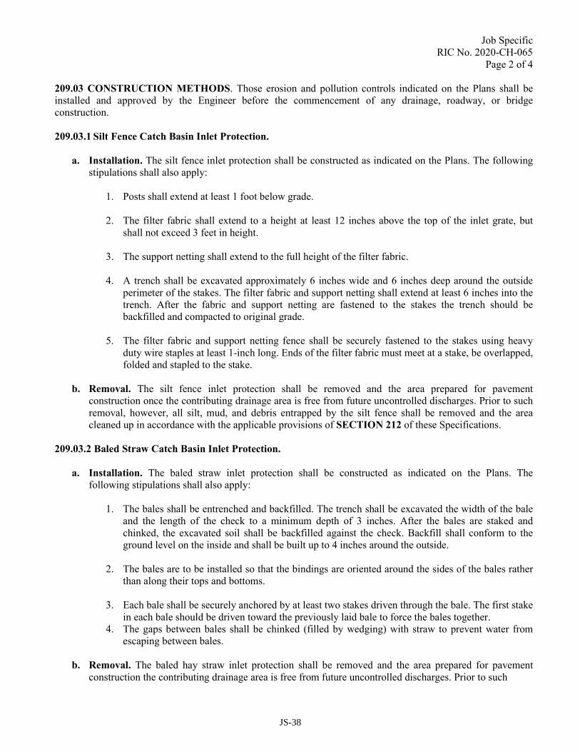
Job Specific
RIC No. 2020-CH-065
Page 2 of 4
209.03 CONSTRUCTION METHODS. Those erosion and pollution controls indicated on the Plans shall be
installed and approved by the Engineer before the commencement of any drainage, roadway, or bridge
construction.
209.03.1 Silt Fence Catch Basin Inlet Protection.
a. Installation. The silt fence inlet protection shall be constructed as indicated on the Plans. The following
stipulations shall also apply:
1. Posts shall extend at least 1 foot below grade.
2. The filter fabric shall extend to a height at least 12 inches above the top of the inlet grate, but
shall not exceed 3 feet in height.
3. The support netting shall extend to the full height of the filter fabric.
4. A trench shall be excavated approximately 6 inches wide and 6 inches deep around the outside
perimeter of the stakes. The filter fabric and support netting shall extend at least 6 inches into the
trench. After the fabric and support netting are fastened to the stakes the trench should be
backfilled and compacted to original grade.
5. The filter fabric and support netting fence shall be securely fastened to the stakes using heavy
duty wire staples at least 1-inch long. Ends of the filter fabric must meet at a stake, be overlapped,
folded and stapled to the stake.
b. Removal. The silt fence inlet protection shall be removed and the area prepared for pavement
construction once the contributing drainage area is free from future uncontrolled discharges. Prior to such
removal, however, all silt, mud, and debris entrapped by the silt fence shall be removed and the area
cleaned up in accordance with the applicable provisions of SECTION 212 of these Specifications.
209.03.2 Baled Straw Catch Basin Inlet Protection.
a. Installation. The baled straw inlet protection shall be constructed as indicated on the Plans. The
following stipulations shall also apply:
1. The bales shall be entrenched and backfilled. The trench shall be excavated the width of the bale
and the length of the check to a minimum depth of 3 inches. After the bales are staked and
chinked, the excavated soil shall be backfilled against the check. Backfill shall conform to the
ground level on the inside and shall be built up to 4 inches around the outside.
2. The bales are to be installed so that the bindings are oriented around the sides of the bales rather
than along their tops and bottoms.
3. Each bale shall be securely anchored by at least two stakes driven through the bale. The first stake
in each bale should be driven toward the previously laid bale to force the bales together.
4. The gaps between bales shall be chinked (filled by wedging) with straw to prevent water from
escaping between bales.
b. Removal. The baled hay straw inlet protection shall be removed and the area prepared for pavement
construction the contributing drainage area is free from future uncontrolled discharges. Prior to such
JS-38
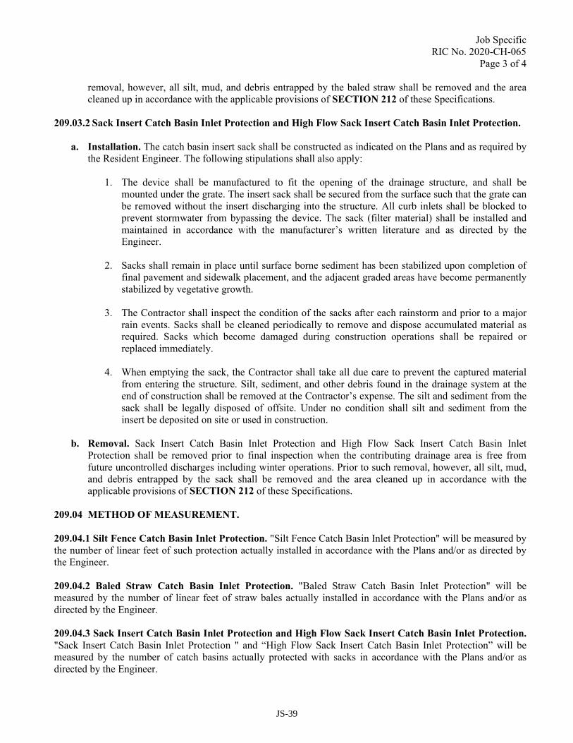
Job Specific
RIC No. 2020-CH-065
Page 3 of 4
removal, however, all silt, mud, and debris entrapped by the baled straw shall be removed and the area
cleaned up in accordance with the applicable provisions of SECTION 212 of these Specifications.
209.03.2 Sack Insert Catch Basin Inlet Protection and High Flow Sack Insert Catch Basin Inlet Protection.
a. Installation. The catch basin insert sack shall be constructed as indicated on the Plans and as required by
the Resident Engineer. The following stipulations shall also apply:
1. The device shall be manufactured to fit the opening of the drainage structure, and shall be
mounted under the grate. The insert sack shall be secured from the surface such that the grate can
be removed without the insert discharging into the structure. All curb inlets shall be blocked to
prevent stormwater from bypassing the device. The sack (filter material) shall be installed and
maintained in accordance with the manufacturer’s written literature and as directed by the
Engineer.
2. Sacks shall remain in place until surface borne sediment has been stabilized upon completion of
final pavement and sidewalk placement, and the adjacent graded areas have become permanently
stabilized by vegetative growth.
3. The Contractor shall inspect the condition of the sacks after each rainstorm and prior to a major
rain events. Sacks shall be cleaned periodically to remove and dispose accumulated material as
required. Sacks which become damaged during construction operations shall be repaired or
replaced immediately.
4. When emptying the sack, the Contractor shall take all due care to prevent the captured material
from entering the structure. Silt, sediment, and other debris found in the drainage system at the
end of construction shall be removed at the Contractor’s expense. The silt and sediment from the
sack shall be legally disposed of offsite. Under no condition shall silt and sediment from the
insert be deposited on site or used in construction.
b. Removal. Sack Insert Catch Basin Inlet Protection and High Flow Sack Insert Catch Basin Inlet
Protection shall be removed prior to final inspection when the contributing drainage area is free from
future uncontrolled discharges including winter operations. Prior to such removal, however, all silt, mud,
and debris entrapped by the sack shall be removed and the area cleaned up in accordance with the
applicable provisions of SECTION 212 of these Specifications.
209.04 METHOD OF MEASUREMENT.
209.04.1 Silt Fence Catch Basin Inlet Protection. "Silt Fence Catch Basin Inlet Protection" will be measured by
the number of linear feet of such protection actually installed in accordance with the Plans and/or as directed by
the Engineer.
209.04.2 Baled Straw Catch Basin Inlet Protection. "Baled Straw Catch Basin Inlet Protection" will be
measured by the number of linear feet of straw bales actually installed in accordance with the Plans and/or as
directed by the Engineer.
209.04.3 Sack Insert Catch Basin Inlet Protection and High Flow Sack Insert Catch Basin Inlet Protection.
"Sack Insert Catch Basin Inlet Protection " and “High Flow Sack Insert Catch Basin Inlet Protection” will be
measured by the number of catch basins actually protected with sacks in accordance with the Plans and/or as
directed by the Engineer.
JS-39
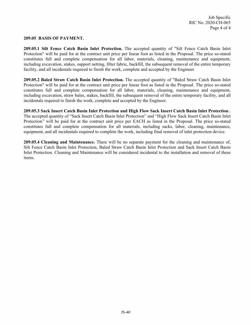
Job Specific
RIC No. 2020-CH-065
Page 4 of 4
209.05 BASIS OF PAYMENT.
209.05.1 Silt Fence Catch Basin Inlet Protection. The accepted quantity of "Silt Fence Catch Basin Inlet
Protection" will be paid for at the contract unit price per linear foot as listed in the Proposal. The price so-stated
constitutes full and complete compensation for all labor, materials, cleaning, maintenance and equipment,
including excavation, stakes, support netting, filter fabric, backfill, the subsequent removal of the entire temporary
facility, and all incidentals required to finish the work, complete and accepted by the Engineer.
209.05.2 Baled Straw Catch Basin Inlet Protection. The accepted quantity of "Baled Straw Catch Basin Inlet
Protection" will be paid for at the contract unit price per linear foot as listed in the Proposal. The price so-stated
constitutes full and complete compensation for all labor, materials, cleaning, maintenance and equipment,
including excavation, straw bales, stakes, backfill, the subsequent removal of the entire temporary facility, and all
incidentals required to finish the work, complete and accepted by the Engineer.
209.05.3 Sack Insert Catch Basin Inlet Protection and High Flow Sack Insert Catch Basin Inlet Protection .
The accepted quantity of “Sack Insert Catch Basin Inlet Protection” and “High Flow Sack Insert Catch Basin Inlet
Protection” will be paid for at the contract unit price per EACH as listed in the Proposal. The price so-stated
constitutes full and complete compensation for all materials, including sacks, labor, cleaning, maintenance,
equipment, and all incidentals required to complete the work, including final removal of inlet protection device.
209.05.4 Cleaning and Maintenance. There will be no separate payment for the cleaning and maintenance of,
Silt Fence Catch Basin Inlet Protection, Baled Straw Catch Basin Inlet Protection and Sack Insert Catch Basin
Inlet Protection. Cleaning and Maintenance will be considered incidental to the installation and removal of these
items.
JS-40

Job Specific
RIC No. 2020-CH-065
Page 1 of 1
CODE 209.9902
NON-WOVEN GEOTEXTILE FABRIC – SOIL SEPARATION
Description: This work consists of furnishing and installing a filter fabric as indicated on the Plans and as directed by
the Engineer, all in accordance with the Standard Specifications.
Materials: Filter fabric shall conform to AASHTO M288, be a material suitable for soil separation applications, one
of those included on the Department's Approved Materials List, and the following:
• Puncture resistance minimum of 120 pounds; and
• Mullen burst strength minimum of 400 pounds per square inch.
Construction Methods: Construction methods shall be in accordance with manufacturer’s recommendations.
Method of Measurement: “Non-Woven Geotextile Fabric – Soil Separation” shall be measured by the “Square
Yard”, in place, in accordance with the Plans and/or as directed by the Engineer.
Basis of Payment: The accepted quantities of the “Non-Woven Geotextile Fabric – Soil Separation” will be paid for
at the contract unit price per “Square Yard” as listed in the Proposal. The price so stated constitutes full and complete
compensation for all labor, equipment, materials, including fabric, stockpiling, hauling, placing, and all other
incidentals complete and accepted by the Engineer.
JS-41

Job Specific
RIC No. 2020-CH-065
Page 1 of 1
Remove Section 210, Stilling Basins for Water Pollution Control, pages 2-53 to 2-54 of the RI Standard
Specifications for Road and Bridge Construction in its entirety and replace it with the following.
SECTION 210
STILLING BASINS FOR WATER POLLUTION CONTROL
210.01 DESCRIPTION. This work consists of the provision of temporary and/or permanent stilling basins in
reasonably close conformity with the dimensions and details indicated on the Plans or as directed by the Engineer,
all in accordance with these Specifications.
210.02 MATERIALS. The various materials required for the construction of stilling basins will be indicated on
the Plans.
210.03 CONSTRUCTION METHODS. The stilling basins will be constructed in such a manner to allow any
material which may cause a natural water course or the surrounding environment to be damaged to be retained in
the basin. During the life of the Contract, the Contractor will be required to periodically clean the pool and to
maintain the basin, both as directed by the Engineer. If the basin is temporary, the Contractor will be required to
fill the basin with suitable material and to restore the area in which the basin was located to either its original
condition or to the requirements of the Contract.
In all cases the stilling basins are to be constructed immediately after the clearing and grubbing operation and
before commencement of any excavation and/or embankment. The single exception to this requirement is the
construction of a leveling course to create a work platform. Excavation for stilling basins is to take place from the
downstream end of the basin and to proceed upstream. Prior to the start of excavation, temporary baled hay ditch
erosion checks and/or hay log check dams are to be constructed immediately beyond the downstream end of the
basin. When the basin is complete the above temporary erosion control measures are to be removed.
210.04 METHOD OF MEASUREMENT. "Stilling Basins for Water Pollution Control" will not be measured by
a single unit of measurement usually associated with a specific Proposal item. Rather, each individual item of
work required to provide such basins will be measured by their respective units of measurement for the quantity
actually provided in accordance with the Plans and/or as directed by the Engineer.
210.05 BASIS OF PAYMENT. "Stilling Basins for Water Pollution Control" will not be paid for as completed
facilities. Rather, such basins will be paid for at the contract unit prices listed in the Proposal for those various
items of work required to construct, clean, and maintain the facility, and in the cases of temporary basins, those
items of work necessary to remove the basin and restore the area to its original or proposed condition, and all
incidentals required to finish the work, complete and accepted by the Engineer.
210.05.1 Cleaning and Maintenance. There will be no separate payment for the cleaning and maintenance of
“Stilling Basins for Water Pollution Control.” Cleaning and Maintenance will be considered incidental to the
installation and removal of this item
JS-42

Job Specific
RIC No. 2020-CH-065
Page 1 of 1
Remove Section 211, Construction Accesses, pages 2-54 to 2-55 of the RI Standard Specifications for Road and
Bridge Construction in its entirety and replace it with the following.
SECTION 211
CONSTRUCTION ACCESSES
211.01 DESCRIPTION. This work consists of the provision of stabilized stone pads located at points of
vehicular ingress and egress on construction sites.
211.01.1 Planning Considerations. Public roads adjacent to a construction site shall be clean at the end of each
day. This SECTION 211 provides for an area where mud can be removed from the tires of construction vehicles
before such vehicles enter a public road. The action of vehicles traveling over a stabilized stone pad will remove
most of the mud from tires. Construction accesses shall be used in conjunction with the stabilization of
construction roads to reduce the amount of mud picked up by construction vehicles.
211.02 MATERIALS. Crushed stone shall conform to the requirements of Subsection M.01.09, Table I,
Column II of these Specifications. Filter fabric shall conform to the requirements for same as set forth in
Subsection 206.02.2 of these Specifications.
211.03 CONSTRUCTION METHODS. Stabilized stone pads employed as construction entrances shall be
constructed as indicated on the Plans.
211.03.1 Entrance Dimensions.
a. Thickness. The thickness of the stabilized stone pad shall be a minimum of 5 inches.
b. Width. The width shall not be less than the full width of the respective points of ingress or egress.
c. Length. The length of construction entrances shall be at least 50 feet where the soils are sands or gravels,
except where the traveled length is less than 50 feet. Where soils are clays or silts, the length of
construction entrances shall be at least 100 feet except where the traveled length is less than 100 feet.
211.03.2 Installation Requirements. The area of the construction entrance shall be cleared of all vegetation,
roots, stumps, or other objectionable material. The area shall then be excavated to subgrade and graded. Filter
fabric shall be placed on the prepared subgrade prior to the placement of the stone pad. The stone shall be placed
according to the specified dimensions.
211.04 METHOD OF MEASUREMENT. "Construction Accesses" will be measured by the number of square
yards of stabilized stone pads actually installed for this purpose in accordance with the Plans and/or as directed by
the Engineer.
211.05 BASIS OF PAYMENT. The accepted quantity of "Construction Accesses" will be paid for at the contract
unit price per square yard as listed in the Proposal. The price so-stated constitutes full and complete compensation
for all labor, material, cleaning, maintenance and equipment, including excavating, filter fabric, stabilized stone
pad, and subsequent removal of same, and all incidentals required to finish the work complete and accepted by the
Engineer.
211.05.1 Cleaning and Maintenance. There will be no separate payment for the cleaning and maintenance of
Construction Accesses. Cleaning and Maintenance will be considered incidental to the installation and removal of
this item.
JS-43
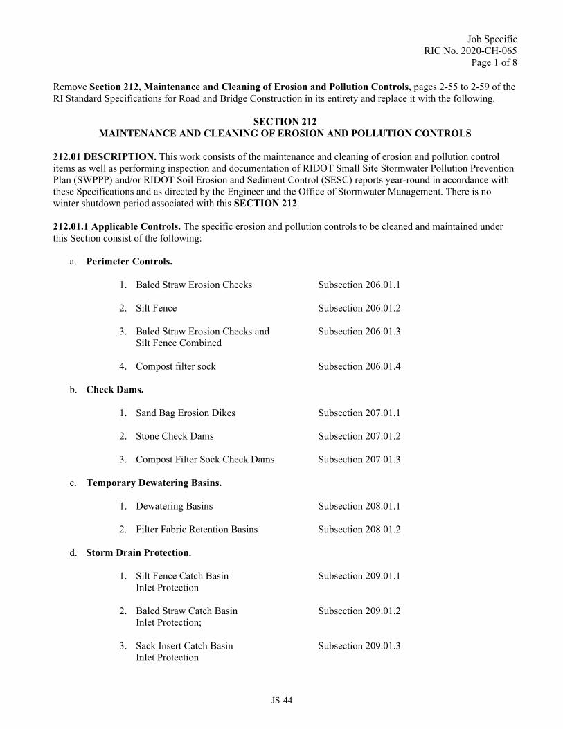
Job Specific RIC No. 2020-CH-065
Page 1 of 8
Remove Section 212, Maintenance and Cleaning of Erosion and Pollution Controls, pages 2-55 to 2-59 of the RI Standard Specifications for Road and Bridge Construction in its entirety and replace it with the following.
SECTION 212
MAINTENANCE AND CLEANING OF EROSION AND POLLUTION CONTROLS
212.01 DESCRIPTION. This work consists of the maintenance and cleaning of erosion and pollution control items as well as performing inspection and documentation of RIDOT Small Site Stormwater Pollution Prevention Plan (SWPPP) and/or RIDOT Soil Erosion and Sediment Control (SESC) reports year-round in accordance with these Specifications and as directed by the Engineer and the Office of Stormwater Management. There is no winter shutdown period associated with this SECTION 212. 212.01.1 Applicable Controls. The specific erosion and pollution controls to be cleaned and maintained under this Section consist of the following:
a. Perimeter Controls.
1. Baled Straw Erosion Checks Subsection 206.01.1
2. Silt Fence Subsection 206.01.2
3. Baled Straw Erosion Checks and Subsection 206.01.3 Silt Fence Combined
4. Compost filter sock Subsection 206.01.4
b. Check Dams.
1. Sand Bag Erosion Dikes Subsection 207.01.1
2. Stone Check Dams Subsection 207.01.2
3. Compost Filter Sock Check Dams Subsection 207.01.3
c. Temporary Dewatering Basins.
1. Dewatering Basins Subsection 208.01.1
2. Filter Fabric Retention Basins Subsection 208.01.2
d. Storm Drain Protection.
1. Silt Fence Catch Basin Subsection 209.01.1 Inlet Protection
2. Baled Straw Catch Basin Subsection 209.01.2
Inlet Protection;
3. Sack Insert Catch Basin Subsection 209.01.3 Inlet Protection
JS-44
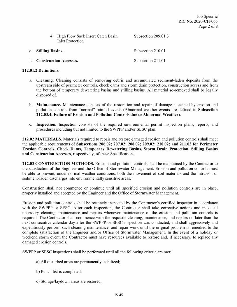
Job Specific RIC No. 2020-CH-065
Page 2 of 8
4. High Flow Sack Insert Catch Basin Subsection 209.01.3 Inlet Protection
e. Stilling Basins. Subsection 210.01
f. Construction Accesses. Subsection 211.01
212.01.2 Definitions.
a. Cleaning. Cleaning consists of removing debris and accumulated sediment-laden deposits from the
upstream side of perimeter controls, check dams and storm drain protection, construction access and from the bottom of temporary dewatering basins and stilling basins. All material so-removed shall be legally disposed of.
b. Maintenance. Maintenance consists of the restoration and repair of damage sustained by erosion and pollution controls from “normal” rainfall events (Abnormal weather events are defined in Subsection
212.03.4; Failure of Erosion and Pollution Controls due to Abnormal Weather).
c. Inspection. Inspection consists of the required environmental permit inspection plans, reports, and procedures including but not limited to the SWPPP and/or SESC plan.
212.02 MATERIALS. Materials required to repair and restore damaged erosion and pollution controls shall meet the applicable requirements of Subsections 206.02; 207.02; 208.02; 209.02; 210.02; and 211.02 for Perimeter
Erosion Controls, Check Dams, Temporary Dewatering Basins, Storm Drain Protection, Stilling Basins
and Construction Accesses, respectively, of these Specifications. 212.03 CONSTRUCTION METHODS. Erosion and pollution controls shall be maintained by the Contractor to the satisfaction of the Engineer and the Office of Stormwater Management. Erosion and pollution controls must be able to prevent, under normal weather conditions, both the movement of soil materials and the intrusion of sediment-laden discharges into environmentally sensitive areas. Construction shall not commence or continue until all specified erosion and pollution controls are in place, properly installed and accepted by the Engineer and the Office of Stormwater Management. Erosion and pollution controls shall be routinely inspected by the Contractor’s certified inspector in accordance with the SWPPP or SESC. After each inspection, the Contractor shall take corrective actions and make all necessary cleaning, maintenance and repairs whenever maintenance of the erosion and pollution controls is required. The Contractor shall commence with the requisite cleaning, maintenance, and repairs no later than the next consecutive calendar day after the SWPPP or SESC inspection was conducted, and shall aggressively and expeditiously perform such cleaning maintenance, and repair work until the original problem is remedied to the complete satisfaction of the Engineer and/or Office of Stormwater Management. In the event of a holiday or weekend storm event, the Contractor must have resources available to restore and, if necessary, to replace any damaged erosion controls. SWPPP or SESC inspections shall be performed until all the following criteria are met:
a) All disturbed areas are permanently stabilized;
b) Punch list is completed;
c) Storage/laydown areas are restored.
JS-45

Job Specific RIC No. 2020-CH-065
Page 3 of 8 212.03.1 Threshold for Cleaning Erosion Controls. Erosion and pollution controls shall be cleaned when directed by the Engineer and/or Office of Stormwater Management; after a rainstorm; or when sediment deposits reach the heights indicated in the following table:
a. Perimeter Controls Height
1. Baled Straw Erosion Checks ½ Bale Height
2. Silt Fence 6 inches
3. Baled Straw Erosion Checks and ½ Bale Height Silt Fence Combined
4. Compost Filter Sock ½ Sock Height
b. Check Dams
1. Sand Bag Erosion Dike ½ Dike Height
2. Stone Check Dam ½ Dam Height
3. Compost Filter Sock Check Dam ½ Sock Height
c. Temporary Dewatering Basins
1. Dewatering Basins ½ Original Basin Height
2. Filter Fabric Retention Basin ½ Original Basin Height
d. Storm Drain Protection
1. Silt Fence Catch Basin 6 inches
Inlet Protection
2. Baled Hay Catch Basin ½ Bale Height Inlet Protection
3. Sack Insert Catch Basin 1/3 Sack Height
Inlet Protection
4. High Flow Sack Insert Catch Basin 1/3 Sack Height Inlet Protection
e. Stilling Basins ½ Depth Below Outlet Elevation
212.03.2 Other Requirements.
a. Certified SWPPP/SESC Inspector. The Contractor shall provide a certified SWPPP/SESC inspector at the contractor’s own expense to perform and report on SWPPP/SESC inspections. A certified
JS-46

Job Specific RIC No. 2020-CH-065
Page 4 of 8 SWPPP/SESC inspector shall be an individual that is a Certified Professional in Erosion and Sediment Control (CPESC) or a Certified Professional in Stormwater Quality (CPSWQ).
1. A Certified Professional in Erosion and Sediment Control (CPESC) and/or Certified
Professional in Stormwater Quality (CPSWQ), is intended to ensure certificants meet the Federal requirements including the US Environmental Protection Agency’s National Pollutant Discharge Elimination System definition of “Qualified Personnel” and also ensure that the projects they oversee; meet the requirements of all contract permits and State/Local regulations.
2. Certified Inspectors must attach a valid Certificate to each SWPPP/SESC report. Certificates must include the certifying agency/organization name and seal, the inspectors name, expiration date, and unique certification identification number.
3. Certifications may be rejected by the Engineer or the Office of Stormwater Management if:
(a) SWPPP/SESC reports from the inspector are incomplete/inaccurate as determined by the Engineer or the Office of Stormwater Management more than twice in a calendar year. (b) It is determined by the Office of Stormwater Management that the certifying agency/organization does not meet the requirements in Subsection 212.03.2.a.1. (c) A SWPPP/SESC report is intentionally incorrect, inaccurate or missing important information of any kind as determined by the Engineer or the Office of Stormwater Management.
4. If the Office of Stormwater Management rejects a Certification, the Office of Stormwater Management, at its’ discretion may contact the certifying agency/organization to inform them of the reason for the Departments rejection of the certificate.
5. If a Certification is rejected, due to sections (a) or (b) above, the inspector will be required to submit a new certification. There is no time restriction.
6. If a Certification is rejected, due to sections (c) above, the inspector will be required to
submit a new certification after a period no sooner than 3 months after rejection of certification. In extreme cases the Office of Stormwater Management will forward the falsified documentation to RIDEM and/or EPA under RIDOT Consent Decree reporting requirements.
b. Perimeter Controls, Check Dams, Temporary Dewatering Basins, and Storm Drain Protection,
Stilling Basins and Construction Accesses.
The following requirements apply:
1. Non-compliant, damaged, and/or controls requiring maintenance as identified in a SWPPP or SESC plan report shall be cleaned, repaired or replaced within 24 hours of identification. The Contractor shall designate a qualified person, experienced in stormwater management and erosion to be available on site throughout the duration of the project. This person shall have the authority to direct contractor’s personnel and/or subcontractor’s personnel in carrying out corrective actions as needed. The Contractor’s designated SWPPP or SESC contact person will be responsible to perform inspection of erosion and pollution controls in accordance with
JS-47

Job Specific RIC No. 2020-CH-065
Page 5 of 8 RIDOT special provisions and environmental permits of the Contract. Documentation of the inspections shall be submitted by the Contractor in the form of signed SWPPP or SESC plan report, in accordance with RIDOT’s templates, or as provided in the Contract to RIDOT’s Project Manager, Resident Engineer, and Office of Stormwater Management. Templates can be found on RIDOT website.
2. The Engineer and/or the Office of Stormwater Management has the authority to verify, enforce, and to specify maintenance activities and to ensure that erosion and pollution controls have been properly maintained.
3. The Contractor shall be responsible for maintaining an onsite stockpile of perimeter control,
check dams, and storm drain protection for the duration of the Contract. The stockpile shall contain 5% of each contract item quantity for perimeter controls, 5% of each contract item quantity for check dams, and 10% for each contract item quantity for storm drain protection.
c. Temporary Dewatering Basins and Stilling Basins. The following requirements apply:
1. The basins will be periodically inspected for signs of erosion around the basin and downslope
area.
2. Repairs will be promptly carried out as directed by the Engineer.
3. The Engineer and/or the Office of Stormwater Management has the authority to verify, enforce, and to specify maintenance activities and to ensure that controls have been properly maintained.
212.03.3 Failure to Maintain Erosion and Pollution Controls. If the Engineer and/or the Office of Stormwater Management decides on any given day that those erosion and pollution controls specified in the Contract, SWPPP, or SESC Plan are not in place or have not been adequately maintained as specified in this Section or per permit requirements, the daily charge will be deducted from monies due the Contractor as a charge for failure to comply set forth below and/or as revised in Special Provision Code 212.1000. The stated daily charge per incident will continue each consecutive calendar day thereafter until the deficiencies noted have been corrected to the complete satisfaction of the Engineer and/or the Office of Stormwater Management. Failure to comply charges are independent of other charges assessed by other agencies and/or entities.
JS-48
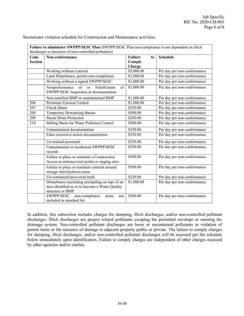
Job Specific RIC No. 2020-CH-065
Page 6 of 8 Stormwater violation schedule for Construction and Maintenance activities.
Failure to administer SWPPP/SESC Plan (SWPPP/SESC Plan non-compliance is not dependent on illicit discharges or presence of non-controlled pollutants)
Code
Section
Non-conformance Failure to
Comply
Charge
Schedule
Working without a permit $5,000.00 Per day per non-conformance
Land Disturbance, permit non-compliance $1,000.00 Per day per non-conformance
Working without a signed SWPPP/SESC $1,000.00 Per day per non-conformance
Nonperformance of or Falsification of SWPPP/SESC Inspection or documentation
$1,000.00 Per day per non-conformance
Non-installed BMP or unmaintained BMP $1,000.00 Per day per non-conformance
206 Perimeter Erosion Control $1,000.00 Per day per non-conformance
207 Check Dams $250.00 Per day per non-conformance
208 Temporary Dewatering Basins $500.00 Per day per non-conformance
209 Storm Drain Protection $250.00 Per day per non-conformance
210 Stilling Basin for Water Pollution Control $500.00 Per day per non-conformance
Unmaintained documentation $250.00 Per day per non-conformance
False corrective action documentation $250.00 Per day per non-conformance
Un-trained personnel $250.00 Per day per non-conformance
Unmaintained or incoherent SWPPP/SESC records
$250.00 Per day per non-conformance
Failure to place or maintain a Construction Access at entrance/exit points or staging sites
$500.00 Per day per non-conformance
Failure to place or maintain controls around storage sites/laydown areas
$500.00 Per day per non-conformance
Un-contained/uncovered trash $250.00 Per day per non-conformance
Disturbance (including stockpiling on top) of an area identified as or to become a Water Quality structure or BMP.
$1,000.00 Per day per non-conformance
SWPPP/SESC non-compliance items not included in standard list
$500.00 Per day per non-conformance
In addition, this subsection includes charges for dumping, illicit discharges, and/or non-controlled pollutant discharges. Illicit discharges are project related pollutants escaping the permitted envelope or entering the drainage system. Non-controlled pollutant discharges are loose or uncontained pollutants in violation of permit items or the nuisance of damage to adjacent property public or private. The failure to comply charges for dumping, illicit discharges, and/or non-controlled pollutant discharges will be assessed per the schedule below immediately upon identification. Failure to comply charges are independent of other charges assessed by other agencies and/or entities.
JS-49
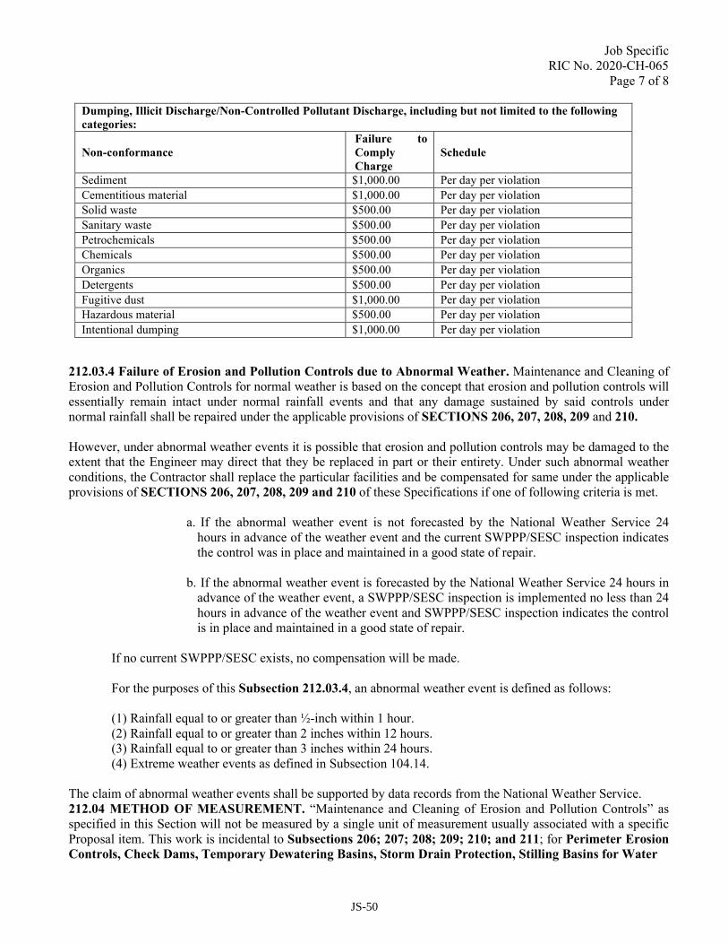
Job Specific RIC No. 2020-CH-065
Page 7 of 8 Dumping, Illicit Discharge/Non-Controlled Pollutant Discharge, including but not limited to the following
categories:
Non-conformance
Failure to
Comply
Charge
Schedule
Sediment $1,000.00 Per day per violation
Cementitious material $1,000.00 Per day per violation
Solid waste $500.00 Per day per violation
Sanitary waste $500.00 Per day per violation
Petrochemicals $500.00 Per day per violation
Chemicals $500.00 Per day per violation
Organics $500.00 Per day per violation
Detergents $500.00 Per day per violation
Fugitive dust $1,000.00 Per day per violation
Hazardous material $500.00 Per day per violation
Intentional dumping $1,000.00 Per day per violation
212.03.4 Failure of Erosion and Pollution Controls due to Abnormal Weather. Maintenance and Cleaning of Erosion and Pollution Controls for normal weather is based on the concept that erosion and pollution controls will essentially remain intact under normal rainfall events and that any damage sustained by said controls under normal rainfall shall be repaired under the applicable provisions of SECTIONS 206, 207, 208, 209 and 210.
However, under abnormal weather events it is possible that erosion and pollution controls may be damaged to the extent that the Engineer may direct that they be replaced in part or their entirety. Under such abnormal weather conditions, the Contractor shall replace the particular facilities and be compensated for same under the applicable provisions of SECTIONS 206, 207, 208, 209 and 210 of these Specifications if one of following criteria is met.
a. If the abnormal weather event is not forecasted by the National Weather Service 24 hours in advance of the weather event and the current SWPPP/SESC inspection indicates the control was in place and maintained in a good state of repair.
b. If the abnormal weather event is forecasted by the National Weather Service 24 hours in advance of the weather event, a SWPPP/SESC inspection is implemented no less than 24 hours in advance of the weather event and SWPPP/SESC inspection indicates the control is in place and maintained in a good state of repair.
If no current SWPPP/SESC exists, no compensation will be made.
For the purposes of this Subsection 212.03.4, an abnormal weather event is defined as follows:
(1) Rainfall equal to or greater than ½-inch within 1 hour. (2) Rainfall equal to or greater than 2 inches within 12 hours. (3) Rainfall equal to or greater than 3 inches within 24 hours. (4) Extreme weather events as defined in Subsection 104.14.
The claim of abnormal weather events shall be supported by data records from the National Weather Service. 212.04 METHOD OF MEASUREMENT. “Maintenance and Cleaning of Erosion and Pollution Controls” as specified in this Section will not be measured by a single unit of measurement usually associated with a specific Proposal item. This work is incidental to Subsections 206; 207; 208; 209; 210; and 211; for Perimeter Erosion
Controls, Check Dams, Temporary Dewatering Basins, Storm Drain Protection, Stilling Basins for Water
JS-50

Job Specific RIC No. 2020-CH-065
Page 8 of 8
Pollution Control, and Construction Accesses, respectively, of these Specifications, including the inspection and development of SWPPP and SESC reports. 212.05 BASIS OF PAYMENT. There will be no separate payment for the Maintenance and Cleaning of Erosion and Pollution Controls. This work is incidental to Subsections 206; 207; 208; 209; 210; and 211; for Perimeter Erosion Controls, Check Dams, Temporary Dewatering Basins, Storm Drain Protection, Stilling Basins for Water Pollution Control, and Construction Accesses, respectively, of these Specifications, including the inspection and development of SWPPP and SESC reports.
JS-51

Job Specific RIC No. 2020-CH-065
Page 1 of 1
CODE 212.2100 MAINTENANCE AND CLEANING OF EROSION AND POLLUTION CONTROLS
Description. Subsection 212.03.3; Failure to Maintain Erosion and Pollution Controls, of the Standard Specifications requires that a daily charge be deducted from monies due the Contractor in the event the Engineer decides that erosion and pollution controls are not in place or have not been adequately maintained. This shall include, but not limited to, failure to comply with any of the contract provisions and of the following environmental contract requirements, permits, and approvals: Stormwater Pollution Prevention Plan (SWPPP). The contractor shall sign the SWPPP as the Operator prior to initiating contract work acknowledging the he understands the terms and conditions of the SWPPP and agrees to follow the Best Management Practices described in it. The contractor shall be held responsible for any and all cost associated with fines and clean-up activities over and above the penalty assessed herein resulting from contractor failure in this regard. For the first violation, the charge for this Contract will be $ 1,000.00 per day. For the second violation, the charge for this Contract will be $ 5,000.00 per day. For the third violation, the charge for this Contract will be $ 10,000.00 per day.
JS-52

Job Specific
RIC No. 2020-CH-065
Page 1 of 5
CODE 501.9901
STAMPED CONCRETE FOR TRUCK APRON
DESCRIPTION: This item of work shall consist of furnishing and installing stamped Portland Cement Concrete Truck
Apron at the locations shown on the plans as specified herein.
MATERIALS:
Joint Sealant: Joint sealant shall be a high quality polyurethane based, having a 97 percent nonvolatile content and a
combined weight of 12.1 pounds per gallon.
Reinforcement: Shall be galvanized W6 x W6 welded wire fabric, and shall be in accordance with the Standard
Specifications, Section 501, and Section M.05 .02.
Forms: Set forms to required grades and lines, as shown on the plans, rigidly braced and secured. Install sufficient
quantity of forms to allow continuous progress of work' and so that forms can remain in place at least twenty-four (24)
hours after concrete placement.
Imprinting Texturing Tools: Shall be mat-type tools of a high-quality to produce Running Bond Used Brick Pattern as
produced by Bomanite Co. or approved equal. The manufacturer of such tools shall have provided adequate training to
the Contractor. The Contractor shall submit documentation that he has been trained by the tool manufacturer.
Color: Gray – Federal Color # FS36320
Color Agent: The coloring agent for integrally colored concrete shall meet the requirements of ASTM C 979, be
approved by the Engineer and it shall be used in accordance with manufacturer’s recommendations. The amount of
coloring agent to be used in the Concrete mix shall be in accordance with the manufacturer’s recommendations to attain
a final hydrated concrete color that matches granite-like (i.e. shale gray) by Bomanite Co. or approved equal. It shall not
contain calcium chloride.
Color Hardener: Color hardener shall be ready-to-use, dry-shake type color hardener and shall be streak-free intergrind
of pigments, surface conditioning and dispersing agents, and Portland cement, blended with an approved graded
aggregate as specified by the manufacturer. It shall not contain calcium chloride.
Color hardener shall meet ASTM C 979 for color stability.
Color hardener shall be granite-like (i.e. shale gray) by Bomanite Co. or approved equal.
Application rate shall be a minimum of sixty (60) pounds per one hundred (100) square feet or as recommended by the
manufacturer.
Release Agent: Release agent shall be a powdered, colored, bond-breaker formulated to break the bond between mat-
type concrete texturing tools and the surface of the color-hardened concrete.
Release agent shall meet ASTM C 979 for color stability.
Release agent shall be granite-like (i.e. shale gray) by Bomanite Co. or approved equal.
Application rate shall be 4 pounds per 100 square feet.
The release agent shall be applied in accordance with the manufacturer’s recommendations.
JS-53

Job Specific
RIC No. 2020-CH-065
Page 2 of 5
Concrete: The Portland cement concrete shall be in accordance with Section 601 of the Standard Specifications and as
modified herein.
The proportioning of ingredients for the stamped concrete shall be approved by the Engineer as specified herein. The
concrete may be modified by either chemical admixtures, mineral admixtures or both as required in conjunction with
insulated curing methods to obtain the concrete characteristics listed in Table 1. All admixtures must be compatible in
their use.
TABLE 1
Concrete Mix Design and Approval Process: Proportioning and testing of the concrete components and mixture shall be
accomplished by using the methods outlined in Section 601. The Contractor shall proportion the concrete mix to obtain
the desired texture, aggregate exposure, and meet the appropriate mixture classification requirements of Section 601.
The following information shall be added in addition to the requirements listed in Section 601 to be included in the
laboratory test data report:
1. Curing Compound
2. Surface Penetrating Sealer
Prior to performing the concrete field trial runs, the Contractor shall submit to the Engineer the proposed mix design(s)
and one concrete prototype (1' x l' x 3" min.) for each concrete classification, texture, and aggregate exposure as specified
in the project plans.
The prototype shall be submitted to the Engineer sufficiently in advance to allow for review and approval of texture and
aggregate exposure of the concrete.
Trial Run: After the concrete mix design provided by the Contractor has received conditional approval by the Engineer,
the Contractor shall conduct a trial run in accordance with the requirements listed in Section 601 prior to production,
using the submitted mix design's component materials and proportions including the amount of admixtures, finishing
and curing techniques which will be necessary to produce concrete of the specified plasticity, workability, air content,
compressive strength, texture, surface pattern and any other specified concrete property.
During the field trial runs, the Contractor shall also manufacture and submit the required number of prototypes in
accordance with the above listed requirements.
Field Sample: During the trial run the Contractor shall make a field sample, no less than 12 square feet (4' x 3') in size,
using the submitted mix. This sample shall not be part of the permanent pavement area. The field sample shall include
ninety (90%) percent patterned area, as specified on the plans, impressed from full patterns and ten (10%) percent
patterned area using hand tools methods to match the full formed area.
The sample shall be approved by the Engineer for texture and pattern. Additional samples shall be required in the event
that the first or subsequent samples are rejected.
When all specified concrete parameters have been attained the Engineer shall approve the proposed mix design, texture,
and aggregate exposure for production.
JS-54

Job Specific
RIC No. 2020-CH-065
Page 3 of 5
CONSTRUCTION METHODS:
Handling and Placement: The Contractor shall be advised that the specified concrete may result in an accelerated initial
concrete set. The Contractor shall take proper precautions to conduct all of the handling, testing, and placement prior to
concrete initial set and perform the required stamping and curing and sealing of concrete thereafter in accordance with
manufacturer's recommendations. During concrete operations in hot weather, the Contractor shall take measures with
the approval of the Engineer to reduce hazards such as, flash set, rapid loss of water due to evaporation, high concrete
temperatures, and the increased difficulty of concrete placement, and finishing. Any concrete admixture modifications
proposed by the Contractor must be submitted in writing to the Engineer for approval.
Construction shall be in accordance with the Standard Specifications, Section 501, with the following additions:
Experienced Personnel: The installation finishing, patterning, and related activities are operations requiring a thorough
knowledge of the properties of concrete, the characteristics of the patterning process, and experience with these methods
and only skilled and experienced artisans shall be employed in this work item. Specifically, the placement crew's chief
shall remain the same person from installation and approval of the sample(s) through the entire project.
The contractor shall provide conclusive proof that he is qualified to, and has previously produced such textured paving
as specified and can comply with the provisions specified herein and shown on the plans. Proof shall consist of at least
three high quality installations similar to that specified herein. Evidence that the contractor is qualified shall be submitted
within thirty (30) days after the Contract Award is received and it shall be the responsibility of the prime bidder to ensure
that the subcontractor he intends to use for this work be pre-qualified in accordance with this paragraph.
Concrete Placement: No concrete under this item shall be placed unless it can achieve final set prior to the start of
precipitation. Place only the amount of concrete that can be completely finished and patterned in accordance with these
specifications. Concrete which becomes too stiff for the proposed pattering shall be removed and disposed of by the
Contractor and replaced in accordance with the plans, these specifications and or as directed by the Engineer. Concrete
removed, disposed of and replaced shall be at the Contractor's expense. Do not place concrete until subbase and forms
have been checked for line and grade. Moisten subbase to provide a uniform saturated surface damp condition at the
time the concrete is placed. Do not place concrete around manholes or other structures until they are at required finish
elevation and alignment.
Deposit and spread concrete in continuous operation between transverse joints, as far as possible. If interrupted for more
than 1 hour, place a construction joint.
Joints:
General – Construct expansion, weakened-plane (contraction), and construction joints true-to- line with face
perpendicular to surface of concrete. Construct transverse joints at right angles to the center line, unless otherwise
indicated.
When jointing existing structures, place transverse joints to align with previously placed joints, unless otherwise
indicated.
Weakened-Plane (Contraction) Joints – Provide weakened-plane joints, sectioning concrete into areas as shown on
drawings. Construct weakened-plane joints for a depth equal to at least one-quarter (1/4) concrete thickness, as follows:
1. Tooled Joints -Form weakened-plane joints in fresh concrete by grooving top portion with a recommended
cutting tool and finishing edges with a jointer. Sawed contraction joints shall be created in accordance with
Subsection 501.03.9(c) of these Specifications.
2. Inserts -Use embedded strips of flexible PVC to form weakened-plane joints. Set strips into plastic concrete
and carefully remove strips after concrete has hardened.
JS-55

Job Specific
RIC No. 2020-CH-065
Page 4 of 5
Construction Joints – Place construction joints at end of placements and at locations where placement operations are
stopped for a period of more than one (1) hour except where such placements terminate at expansion joints. Construct
joints as shown or, if not shown, use standard metal keyway section forms.
Expansion Joints – Provide premolded joint filler for expansion joints abutting concrete curbs, granite curbs, catch
basins, manholes, inlets, structures, walks, and other fixed objects, unless otherwise indicated. Locate expansion joints
as indicated on drawings.
1. Extend joint filler full-width and depth of joint and not less than one-quarter (Y4) inches or more than one
(1) foot below finished surface where joint sealer is indicated. If not joint sealer, place top of joint filler flush
with finished concrete surface.
2. Furnish joint fillers in one-piece lengths for full width being placed, wherever possible. Where more than
one length is required, lace or clip filler sections together.
3. Protect top edge of joint filler during concrete placement with a metal cap or other temporary material.
Remove protection after concrete has been placed on both sides of joint.’
Filler and Sealants – Install in accordance with manufacturer's recommendation.
Primary Concrete Finishing: After strike-off and consolidating concrete, smooth surface by screeding and floating. Use
hand methods only where mechanical floating is not possible. Adjust floating to compact surface and produce uniform
texture.
After floating, test surface for trueness with a 10' straightedge. Distribute concrete as required to remove surface
irregularities, and refloat repaired areas to provide a continuous smooth finish. Finished surfaces should conform to
tolerances required in Section 501 of the Standard Specifications.
Special Concrete Finishing: After completion of floating the entire surface finish as follows:
1. Application rate shall be a minimum of one hundred (100) pounds per 100 square feet or as recommended
by the manufacturer.
2. Fresh concrete shall be carefully and continuously monitored and tested during partial setting up so that
proper consistency for patterning is achieved. Air temperature, humidity, wind conditions, and other factors
affecting setting rate shall be considered in determining the start of patterning operations.
3. Release agent shall be applied evenly to surface.
4. Application rate shall be 1-1 ½ pounds per 100-square feet.
5. The release agent shall be applied in accordance with the manufacturer's recommendations.
6. While the concrete is still in the plastic stage of set, the imprinting tools shall be applied to create the surface
pattern.
a. Full patterns shall be used to the maximum extent possible. Care shall be taken to ensure continuity of the
pattern and to maintain proper relationships to direction of travel, edges, cut route, curbs, and other
opportunities.
b. Where full patterns cannot be used, such as at corners, narrow areas, angles, ramps, or obstructions, hand
detailing tools and methods shall be used to continue the intended pattern to the limit of the area. The hand
methods shall match as closely as possible the pattern and texture of the full pattern area.
c. Carefully lift and remove the polyethylene sheet.
d. At all edges of globes, hooks of curbing, and principal obstructions, smooth and finish the patterned art
concrete with a metal edging tool, having a three (3) inch plate width and a one-half (112) inch radius. A
principal obstruction shall be, for example, a light or signal standard, catch basin, manhole, or planting
area, but shall not be a water gate, fire hydrant, parking meter, sign post, or similar incidental opportunity.
JS-56

Job Specific
RIC No. 2020-CH-065
Page 5 of 5
Curing compound shall be applied in accordance with the manufacturer's instructions and also Subsection 601.03.8 of
the Standard Specifications.
Once the concrete has attained a compressive strength of 3000 psi and a minimum of twenty-four (24) hours curing time,
the surface of the concrete shall be carefully power washed to remove any debris without removing the release agent and
thereafter sealed.
Repairs and Protection: Repair or replace broken or defective concrete as required. Protect concrete from damage until
acceptance of work. Exclude traffic from pavement until the concrete has attained a compressive strength of 3000 psi
and for at least 1 day after placement. Maintain pavement free of stain and other damage until accepted by the Engineer.
Sweep concrete pavement and wash free of stains, discolorations, dirt, and other foreign material just prior to final
inspection.
The Engineer shall determine when the concrete shall be opened to traffic.
METHOD OF MEASUREMENT: "CEMENT CONCRETE TRUCK APRON" shall be measured for payment by the
number of “Square Yards” installed in accordance with the plans and accepted by the Engineer.
BASIS OF PAYMENT: "CEMENT CONCRETE TRUCK APRON" shall be paid for at the contract unit price per
square yard as listed in the proposal. The price so stated constitutes full and complete compensation for all labor, material,
equipment, tools, form work, reinforcing, applied finishes and colors and for all incidentals necessary required to finish
the work, complete in place and accepted by the Engineer.
JS-57

Job Specific
RIC No. 2020-CH-065
Page 1 of 11
CODE 701.9900
WATER FACILITIES/MODIFICATIONS – CITY OF NEWPORT
DESCRIPTION. This section includes modifying the existing water system, furnishing and installing ductile iron pipe,
fittings, gate valves, tapping sleeves and valves, flexible couplings, service connections, hydrants and appurtenances in
reasonably close conformity with the details as indicated on the Plans or as directed by the Engineer, all in accordance
with these Specifications.
Submittals. The Contractor shall submit to the Engineer and the City, within ten (10) days after signing of the Contract,
a list of materials to be furnished, the names of the suppliers and the date of delivery of material to the site.
Certificate of Compliance: The Contractor shall, upon accepting delivery of the pipe, fittings, gate valves, tapping sleeves
and valves, flexible couplings, service connections, hydrants and appurtenances, provide two (2) copies of pipe
manufacturer certification that inspection and all specified tests have been made and results comply with requirements
of AWWA C151-76.
The Contractor shall furnish manufacturers' operating and maintenance instructions to the Engineer for equipment
furnished under these Specifications.
The Contractor shall furnish special tools, if required, for normal operation and maintenance of the equipment.
MATERIALS.
General.
Cement mortar lining for pipe, fittings, as specified above, shall conform in all respects to AWWA Designation C104.
The lining thickness shall be twice that specified in Section 4.7.1 of AWWA Designation C104. The seal coat shall be
twice that specified in Section 4.11 of AWWA Designation C104
Rubber gasket joints for the water main pipe and fittings, as specified above, shall be in accordance with AWWA
Designation C111.
All pipe, pipe fittings, accessories and appurtenances shall be new and unused.
All bolts, nuts and miscellaneous connecting pieces not provided with an approved factory coating shall be given two
(2) coats of bitumastic coal-tar after installation.
Joint restraint shall be provided for all mechanical joint valves, fittings, fire hydrants and pipe. Joint restraint shall be
MEGALUG or approved equal.
Pipe. Water main piping shall be ductile iron pipe in accordance with AWWA/ANSI Designation C151/A21.51 and to
the additional requirements specified herein.
Laying length: 18 or 20 feet,
Thickness class: 52
Joint type: push on (unless otherwise noted on the plans),
Interior surface: cement lined (double thickness) and seal coat (double coat)
Exterior surface: asphaltic coating.
Underground – Type Line Markers. Underground – Type Line Markers shall be standard permanent detection tape,
bright colored, continuous-printed polyethylene tap with a metallic core for easy detection of underground installations,
intended for direct burial service. Underground – Type Line Markers for Piping are required on installation of all piping.
JS-58

Job Specific
RIC No. 2020-CH-065
Page 2 of 11
Fittings. Fittings for water mains shall be ductile iron in accordance with AWWA/ANSI Designation C153/A21.53 and
to the additional requirements specified herein.
Joint type: mechanical with restraint joint glands and shall be the “Mega-Lug” gland as manufactured by EBAA Sales
Iron, Inc., or equal as manufactured by:
Clow Division
McWane, Inc.
U.S. Pipe and Foundry Co., Inc.
Pressure rating: 350 psi, Type of iron: ductile,
Interior surface: cement lined (double thickness) and seal coat (double coat)
Exterior surface: asphaltic coating.
Pipe Couplings. Pipe couplings shall be ductile iron, solid sleeves giving a watertight seal suitable for water pressure
classification at least equal to that of the pipe with which they are used, as approved by the Engineer.
Gate Valves. All gate and tapping valves shall be New York Metropolitan pattern gate valves or resilient seated wedge
gate valves unless otherwise specified in the Contract.
Metropolitan Pattern Valves:
• Shall meet or exceed the minimum standards and performance requirements of AWWA Standard C-500 (latest
revision). The letters "MET" shall appear on the bonnet of iron bodied Metropolitan pattern valves. Both ends
shall be mechanical joint in accordance with AWWA Standard C-III except tapping valves where only the outlet
end shall be mechanical joint. Valves shall open to the right (clockwise) as indicated by a directional arrow cast
on a 2" operating nut.
• Valves shall be tested by the manufacturer for a bubble tight 200 psi differential sealing ability and a 400 psi
valve open shell test.
• Valves shall be iron body, bronze mounted, double disc, parallel seat, wrench operated non-rising stem with
yoke nut an O-ring seal.
• Each valve shall have makers initials, pressure rating and year of manufacture cast on the body. For purposed of
standardization, valves shall be as manufactured by A. P. Smith Manufacturing Company or M & H Valve and
Fitting Company or an approved equal,
Resilient Seated Wedge Valves (Including Tapping Valves):
• Shall meet or exceed the minimum materials and performance requirements of AWWA Standard C-509 (latest
revision). Both ends shall be mechanical joint in accordance with C-III except tapping valves where only the
outlet end shall be mechanical joint.
• Valves shall have a minimum design working pressure of 200 psi and a minimum test pressure of 400 psi. The
pressure rating shall be cast on the outside of the valve.
• Valve body and bonnet shall be of ductile iron coated on all exterior and interior surfaces with a fusion bonded
or thermo set epoxy conforming to AWWA Standard 550 (latest revision). The coating shall be applied with a
minimum thickness of 8 MILS. The manufacturer shall certify that the coating is suitable for use in a potable
water system and that the interior coating is holiday free. Reduced wall ductile iron valves are not acceptable.
• The resilient seated disc wedge shall be fully encapsulated in rubber. The rubber shall be securely bonded to
the wedge including the part which houses the stem nut. The stem hole through the wedge shall be full opening
top to bottom and shall also be covered in rubber. Disc wedges not 100 percent fully encapsulated in rubber
shall not be acceptable.
• The stem shall be non-rising design, Grade "E" bronze with a yield of not less than 3200 psi and an elongation
of not less than 10 percent in two inches or stainless steel AISI Type 420, 304 or 316. The 300 Series stainless
steel shall be strain-hardened to meet the physical requirements referenced above.
• The "O" Ring stem seal shall be replaceable with the valve under pressure in the full open position. Valves
JS-59

Job Specific
RIC No. 2020-CH-065
Page 3 of 11
shall open to the right (clockwise) as indicated by a directional arrow cast on a 2" square operating nut.
• All bonnet bolts, seal or gland plate bolts, stuffing box bolts and other bolts with threads exposed to the
environment and all exposed nuts shall be manufactured of Type 304 stainless steel.
• Tapping valves shall be furnished with the tapping flange having a raised face or lip designed to engage the
corresponding recess in the tapping sleeve flange in accordance with MSS-SP60. Tapping valves without the
raised face shall not be allowed because they do not insure the proper alignment required to prevent damage
caused by a misaligned shell cutter. The interior of the waterway in the valve body shall be a full opening
capable of passing a full sized shell cutter equal to the nominal diameter of the valve.
Tapping Sleeves and Valves:
• Cast iron mechanical joint tapping sleeves shall have confined end gaskets to resist cold flow and creep, and be
designed for a maximum working pressure of 200 psi. The tapping sleeve shall be shipped with small and large
O.D. range gaskets clearly marked and tagged.
• Tapping sleeves shall be cast iron with mechanical joints.
• Tapping valves shall be the Metropolitan New York or Resilient Seated Wedge type with mechanical joint for
branch main, and capable of operating at 200 psi.
• Valve opening direction shall be "open-right" (clockwise)
Valve Boxes:
• Each gate valve shall be accompanied by a valve box. Valve boxes shall be heavy pattern ductile iron, and cast
in two telescoping sections of sliding construction. Valve boxes shall be coated with coal-tar pitch enamel or
other approved coating.
• The upper section of each box shall have a flange at the bottom having sufficient bearing area to prevent
settling. The lower section shall be at least 5-1/4 inches inside diameter, belied or domed at bottom to fit over
the work. Covers shall be at least 6 inches in diameter, fit flush with the top and shall have the word
“WATER" cast thereon in raised letters.
• Valve boxes shall be "Buffalo" type suitable for the size valve on which they are used and shall be as
manufactured by Buffalo Pipe and Foundry or approved equal.
Service Box. Service boxes to be provided for new service connections. Service boxes shall be cast iron “Buffalo" type
or approved equal. The upper section shall be sliding type with 2-1/2 inch shaft and 24 inches long. The lower section
shall have 2-1/2 inch shaft, sliding 40-inches long.
Service Connections. Service connection lines shall be 3/4 or 1 inch Type K Copper as shown on the plans,
corporation stop, and service box.
• New service shall include pack joint ball valve curb stop such as Ford of approved equal with 5/8-inch rolled
steel rod, 42-inches long.
• Relocated services shall require a pack joint three part coupling such as Ford or approved equal at connection
to existing house service.
Air Release Assembly. Air release assembly shall be a corporation stop, copper tubing, and a valve box
Corporation Stop. Corporation stops shall be pack joint fitting such as Ford or Macdonald or approved equal.
Copper Tubing. Copper tubing shall be 1 inch, Type "K", soft temper.
Hydrants. Hydrants shall be "Mueller Super Centurion 250, Model A423" as manufactured by the Mueller Company
or the "M&H Style 129" as manufactured by the M & H Valve Company and shall meet or exceed the requirements of
AWWA Standard C502 (latest revision)
Hydrants shall have a typical bury of 4 .5 feet, but at all times be installed to meet the manufacturer's specification for
JS-60

Job Specific
RIC No. 2020-CH-065
Page 4 of 11
proper operation of the traffic breakaway feature.
Hydrants shall have two (2), two and one-half inch (2.5") hose nozzles and one (1) four and one-half inch (4.5")
pumper nozzle outlet. All outlet nozzle threads are to be National standard.
Hydrant valve openings shall be five and one-quarter inch (5 1/4")
Hydrants shall have a six inch (6") mechanical joint inlet.
Hydrants shall open left (counterclockwise). The operating nut shall be National standard pentagon (1.5" point to flat).
All exterior above ground ferrous surfaces of the hydrants are to be painted yellow by the manufacturer.
The standpipe section shall be connected at the ground line by a designed breakaway coupling device, and the main
valve rod sections shall be connected at the ground line by a designed breakaway coupling device of ample strength for
normal operating service.
Hydrants must be mechanically and hydrostatically tested as required by AWWA Standard C-502 (latest revision). An
affidavit of compliance is to be submitted upon request.
Hose and pumper nozzle caps shall be provided with rubber gaskets and shall be chained to the hydrant barrel.
Pipe Bedding. Material for pipe bedding shall be as specified in Section 701 of the Standard Specifications for Class
B Bedding.
Concrete Thrust Blocks and Collars. Concrete for thrust blocks and collars uses shall meet the requirements of Class
B as specified in Section 601 of the Standard Specifications.
CONSTRUCTION METHODS.
General Requirements: Water shut-downs shall be coordinated with the owner of the specific system being worked on
and shall be performed only as authorized by the Newport Water Department at no additional expense to the state. The
contractor should assume that all tie-ins requiring a shutdown of the existing water distribution system will be
performed during off peak hours. No additional compensation shall be granted to the contractor to perform these tie-
ins during premium time. All additional costs shall be covered in the unit cost of the items being installed.
Cleaning and Prime Coating Valves and Appurtenances. All surfaces of the valves and appurtenances shall be
thoroughly clean, dry and free from all mill-scale, rust, grease, dirt, paint and other foreign substances to the satisfaction
of the Engineer.
Notification. Newport Water Department shall be notified at least forty-eight (48) hours prior to any item being installed
within the system. Pressure testing and/or chlorination shall require a two (2) business day notification. It is a requirement
that a representative of the Newport Water Department witness all testing.
Inspection. Newport Water Department personnel shall be given full access to the project at all times for inspection or
observation of construction of the water main in progress as deemed necessary by Newport Water Department. Failure
to construct the new extension of the system as per the approval will cause immediate cessation of all construction work.
RIDOT is solely responsible to control their contractor in the progression of work to ensure the water infrastructure
installation is accomplished in accordance with the approval. Any part of the installation found to be noncompliant shall
be immediately corrected at the contractor’s cost to the satisfaction of Newport Water Department.
JS-61

Job Specific
RIC No. 2020-CH-065
Page 5 of 11
The Contractor shall maintain design drawings and record drawings of the progress of the work at the job site and shall
be available for Newport Water Department inspectors to view at any time. Failure to have these documents available
for review or failure to have the documents prepared, may cause cessation of all construction work and disconnection
from the Newport Water Department system until such time that remedial measures to those requirements have been
made.
Handling Pipe and Fittings. The Contractor shall take care during loading, transporting and unloading to prevent injury
to the pipe or coating. Under no circum-stances shall pipe or fittings be dropped. The Engineer and the City of Newport
Water Department shall examine all pipe and fittings before laying, and no piece shall be installed which is found to be
defective. The Contractor shall repair any damage to pipe coatings as directed by the Engineer.
If any defective pipe is discovered after it has been laid, the Contractor shall be remove and replace with sound pipe in
a satisfactory manner at his own expense. The Contractor shall thoroughly clean all pipe and fittings before laying, shall
be kept clean until used in the completed work, and when laid shall conform to the lines and grades shown.
Care shall be taken to prevent damage to valves and appurtenances during handling and installation. All materials shall
be carefully inspected for defects in workmanship and materials; all debris and foreign material cleaned out of valve
openings, etc.; all operating mechanisms operated to check their proper functioning, and all nuts and bolts checked for
tightness. Valves and other equipment which do not operate easily, or are otherwise defective, shall be repaired or
replaced at the Contractor's expense
Laying Pipe and Fittings. The Contractor shall use workmen thoroughly experienced in the installation of pipe, fittings,
gate valves, tapping sleeves and valves, flexible couplings, service connections, hydrants and appurtenances and provide
supervision by qualified personnel furnished by the manufacturer to accomplish the work under these Specifications.
Laying pipe and fittings shall be in accordance with the requirements of AWWA Standard Specifications for Installation
of Ductile Iron Water Mains, C600, except as otherwise provided herein. Pipe shall be laid with bell ends facing in the
direction of laying, unless directed otherwise by the Engineer.
A firm even bearing throughout the length of the pipe shall be constructed by tamping suitable gravel borrow on all sides
of the pipe, including above the pipe. Where ledge is encountered in the bottom of the trench, pipe shall be bedded in a
6-inch minimum layer of suitable backfill or sand. Blocking will not be permitted.
All pipe shall be sound and clean before laying. Good alignment shall be preserved in laying. The deflection at joints
shall not exceed manufacturer’s recommended deflection. Fittings in addition to those shown on the plans shall be
provided, if required, in crossing utilities which may be encountered upon opening the trench. Solid sleeves shall be used
only where approved by the Engineer.
When cutting of pipe is required, the cutting shall be done by saw in a neat and workmanlike manner without damage to
the pipe or cement lining. Cut ends shall be smooth and at right angles to the axis of the pipe. Pipe ends to be used with
a rubber joint shall be beveled and filed or ground smoothly to conform to the manufactured spigot end. Cement lining
shall be undamaged.
At all times when pipe laying is not in progress, including lunchtime or when the trench is unattended, the open ends of
pipe shall be closed by watertight plugs or other approved means.
The Contractor shall have on hand at the start of the job, at least two 11-1/4° bends, two 22-1/2° bends and two 45° bends
for each size of pipe. These shall be used as job conditions require.
All fittings shall be anchored to prevent any movement of the fittings or the adjacent pipe. This anchorage shall be
provided by the installation of Portland cement concrete thrust blocks and retainer glands as shown on the Contract Plans
and as directed by the Engineer. The Contractor shall verify the extent of anchorages required by the Engineer prior to
JS-62

Job Specific
RIC No. 2020-CH-065
Page 6 of 11
piping assembly. Hand excavation may be required to excavate for the concrete thrust blocks, the shape and size of which
shall be in accordance with the Contract Plans. The Engineer may require concrete to be placed at points on the pipeline
other than at fittings. All concrete used for thrust restraint shall be exposed for at least 16 hours before being
covered.
Jointing Ductile Iron Pipe (Push-On-Type). Push-on joints shall be made in strict accordance with the manufacturer’s
instructions. Pipe shall be laid with bell ends looking ahead. A rubber gasket shall be inserted in the groove of the bell
end of the pipe, and the joint surfaces cleaned and lubricated. The plain end of the pipe to be entered shall then be inserted
in alignment with the bell of the pipe to which it is to be jointed, and pushed home with a jack or by other means. After
jointing the pipe, a metal feeler shall be used to make certain that the rubber gasket is correctly located.
Jointing by pushing the pipe home with a backhoe bucket or other heavy equipment will not be permitted. Utilizing the
backhoe and a sling to suspend pipe while pushed home by bar or jack is permitted.
Protect the end of the pipe from damage at all times by using a timber header between the end of pipe and the bar or jack.
Jointing Mechanical Joint Valves. Mechanical joints at valves and where designated shall be installed in accordance
with the “Notes on Method of Installation” under AWWA C111, AWWA C-600 and the instruction of manufacturer. To
assemble the joints in the field, the CONTRACTOR shall thoroughly clean the joint surfaces and rubber gasket with
soapy water before tightening the bolts. Bolts shall be tightened to the specified torque. Under no conditions shall
extension wrenches or pipe over handle of ordinary ratchet torque wrench be used to secure greater leverage.
Pipe couplings shall be installed, where required, for connection to the existing work and as shown on the Contract Plans.
Valves and Boxes. Buried valves and valve boxes shall be set with the stem vertically aligned in the center of the gate
box. Valves shall be set on a firm foundation and supported by tamping selected excavated material under and at the
sides of the valve. The valve box shall be vertically centered over the operating nut and maintain vertical alignment
during backfilling operation. Set top flush with finish grade.
After completing the installation, the valve shall be flushed to ensure that the valve seat is clean. Boxes shall be set
vertically and adequately supported squarely over the operating nut.
The entire operation shall be conducted by workmen thoroughly experienced in the installation of restrained and
flanged joints and valves.
All old valve boxes to be filled with asphalt, lid removed.
Couplings. After assembly, all exterior surfaces, including bolts and nuts, shall be thoroughly coated with two (2) coats
of heavy-duty protective asphaltic coating.
Tapping Sleeves and Valves. Where indicated on the Plans or directed by the Engineer, make installations under
pressure using tapping sleeves and valves and maintain the flow of water through the existing mains at all times.
The Contractor shall determine the location of the existing main to be tapped to confirm the fact that the proposed
position for the tapping sleeve will be satisfactory and no interference will be encountered. No tap will be made closer
than 3 feet from a pipe joint.
Set tapping sleeves, valves and boxes vertically and squarely centered on the main to be tapped. Provide adequate
support under the sleeve and valve during the tapping operation. Sleeves shall be no closer than three (3) feet from
water main joints. Proper tamping of supporting earth around and under the valve and sleeve is mandatory. After
completing the tap, flush the valve to ensure that the valve seat is clean.
JS-63

Job Specific
RIC No. 2020-CH-065
Page 7 of 11
The entire operation of installing the tapping sleeve and valve shall be done under line pressure, and conducted by
workmen thoroughly experienced in the installation of tapping sleeves and valves and shall be made under the
supervision of qualified personnel furnished by the manufacturer.
Service Connections. New service connections shall be installed for all locations where existing service is not Type K
copper or red brass as shown on Plans or directed by Engineer.
Existing service connection of Type K copper or red brass shall be relocated as shown on Plans or directed by the
Engineer.
New service connections shall include new tap, corporation, copper tubing and new ball valve curb stop.
Relocated service connections shall include new tap, corporation, copper tubing and new adapter-fitting at a location on
the existing house service connection designated by the Engineer.
Air Release Assembly. Air release assemblies shall be installed as Directed by the Engineer.
Hydrants. Hydrants shall be set at the location shown or designated by the Engineer and bedded on a firm foundation.
Hydrant shall be set in true vertical alignment and properly braced.
All interior valves, couplings and appurtenances shall be installed true to alignment and rigidly supported. Any damage
to the above items shall be repaired to the satisfaction of the Engineer before they are installed.
No hydrant shall be backfilled until directed by the Engineer.
Testing. The Contractor shall furnish all necessary equipment and labor for carrying out pressure and leakage tests on
the pipeline in accordance with AWWA C-600 Specifications.
The pipe shall be subjected to a hydrostatic pressure of 200 psi and this pressure maintained for at least 2 hours. The
following pressure restrictions shall apply:
• Not to be less than 1.25 times the working pressure at the highest point along the test section.
• Not to exceed pipe or thrust restraint design pressures.
• Be of at least 2-hour duration.
• Not vary by more than + 5 psi.
• Not to exceed twice the rated pressure of the valves or hydrants when the pressure boundary of the test section
includes closed gate valves or hydrants.
• Not to exceed the rated pressure of the valves if resilient seated butterfly valves are used.
Leakage Test - A leakage test shall be conducted concurrently with the pressure test.
The Contractor shall at his own expense make any taps and furnish all necessary caps, plugs, etc., as required in
conjunction with testing a portion of the main between gate valves. He shall also furnish a test pump, gauges, and any
other equipment required in conjunction with carrying out the hydrostatic tests. He shall at all times protect the new
water mains and the existing water mains against the entrance of pollution material.
Chlorination. Before being placed in service, all new water pipelines shall be chlorinated in accordance with AWWA
C-601, “Standard Procedure for Disinfecting Water Mains”. The procedure shall be discussed with the City of Newport
Distribution and Collection Superintendent before doing the work for his approval.
JS-64

Job Specific
RIC No. 2020-CH-065
Page 8 of 11
The location of the chlorination and sampling points will be determined by the Engineer in the field. The Contractor shall
uncover and backfill taps for chlorination and sampling as required.
The general procedure for chlorination shall be first to flush all dirty or discolored water from the lines and then introduce
chlorine in approved dosages through a tap at one end, while water is being withdrawn at the other end of the line.
Following the chlorination period, all treated water shall be flushed from the lines at their extremities, and replaced with
water from the distribution system. Bacteriological sampling and analysis of the replacement water shall then be made
by the Engineer in full accordance with the AWWA Manual C-601. The Contractor shall be required to re-chlorinate, if
necessary, and the line shall not be placed in service until the requirements of the State Public Health Department are
met.
Special disinfection procedures, such as soaking or swabbing, approved by the Engineer and the City, shall be used in
connections to existing mains, and where the method outlined above is not practical.
The Contractor must dispose of chlorinated water in accordance with State of R. I. Stormwater Regulations.
Disposal of Removed Materials. The Contractor shall be responsible to properly dispose of water pipe and/or
appurtenances that are removed.
The Contractor shall cap at all openings water mains, water services, and hydrant runouts that are disconnected from the
system and abandoned in place. When pipes are severed at tees, the Contractor shall remove and replace the remaining
tee with a section of straight pipe, if possible.
Trench Excavation and Backfill. The Contractor shall install water mains and services with a minimum cover of 4'-6"
to the crown of the pipe in an AWWA “Type 5 Trench”. Where unsuitable material is found at or below the grade of the
placement of the pipe or fitting, the Contractor shall remove said material shall be removed to the required width and
depth and replace with thoroughly compacted bank run or processed gravel. The Contractor shall deposit material across
the full width and length of the trench in layers of not more than twelve (12) inches in depth, before compaction. Each
layer shall be compacted to 95% Standard Proctor to a minimum depth of the street subgrade.
The Contractor shall install temporary and permanent pavement over the freshly backfilled trench in an existing street or
sidewalk using hot bituminous concrete. Pavement installation shall be installed in accordance with applicable State and
Local Municipal standards and requirements.
Thrust Restraint. The preferred method of counteracting thrust is through the use of a mechanical joint restraint device.
Concrete thrust blocks are required in conjunction with a mechanical joint restraint device.
Thrust blocks shall be designed using a soil bearing strength of 1,500 pounds per square foot (psf). They shall be
constructed in place using Portland cement concrete (R.I. Dept. of Transportation Class "B") having a 28-day
compressive strength of at least 3,000 psi, and be located in such a way so as to bear against undisturbed earth. They
shall be utilized on all water mains for the following conditions:
• Pipeline direction changes (tees, bends, etc.)
• Dead end lines (caps, plugs or hydrants)
• Transition pieces (reducers, offsets, etc.)
PIPE
SIZE
(in)
TEES &
DEAD
ENDS
90
BEND
45
BEND
22 ¼
BEND
11 ½
BEND
4 2,356 3,332 1,803 919 462
6 5,301 7,497 4,058 2,069 1,039
JS-65

Job Specific
RIC No. 2020-CH-065
Page 9 of 11
8 9,425 13,329 7,2 13 3,677 1,848
10 14,726 20,826 11 ,271 5,746 2,887
12 21,206 29,989 16,230 8,274 4,157
14 28,863 40,819 22,091 11 ,262 5,658
16 37,699 53,3 15 28,854 14,709 7,390
18 47,713 67,476 36,5 18 18,617 9,353
20 58,905 83,304 45,084 22,984 11 ,547
24 84,823 11 9,958 64,921 33,096 16,628
30 132,536 187,434 10 1,439 5 1,7 13 25,982
36 190,852 269,905 146,072 74,467 37,413
42 259,770 367,371 198,820 10 1,357 50,924
48 339,292 479,831 259,683 132,385 66,5 13
54 429,416 607,287 328,661 167,550 84,180
60 530,144 749,736 405,754 206,852 103,926
66 64 1,474 907,181 490,963 250,291 125,75 1
*Calculated by the Formula T = (2PA SIN(Θ*2)) x 1.25 (except for Tees & Dead Ends where T = PA x 1.25) where ....
T = Thrust, in pounds
P = Water Pressure, in pounds per square inch
A = Area of Pipe, in square inches
Θ = Bend Deflection Angle, in degrees
1.25 Factor of Safety
The sides of thrust blocks shall be formed. Forms shall be removed before backfilling commences. Curing time should
be at least forty-eight (48) hours. Minimum bearing shall be that which is depicted on the plans or as directed by Newport
Water Department. Felt roofing paper shall be used to protect pipe joints. Concrete shall not be placed over bolts or nuts,
or placed in such a way that will prevent the removal of joints (NOTE: concrete reaction blocks may be used when
bearing against undisturbed soil cannot be achieved).
Vertical fittings shall be anchored to thrust blocks using at least two (2) #5 (5/8-inch minimum), Grade 60, deformed
steel rebars. Blocks shall be designed by a professional engineer for pipe sizes greater than 12-inches. Anchors shall be
bent to match to outs ide radius of the fitting to be restrained.
Thrust restraint, where concrete blocks cannot be poured against undisturbed earth, shall be via restrained joint as
approved by Newport Water Department. This may be accomplished by using a mechanical joint restraining device.
Refer to the Ductile Iron Pipe Restraint Guide.
Restrained joint pipe lengths (restrained length), where required, shall be sufficient to counter the thrust imparted by 1
1/2 times the anticipated working pressure, but not less than 150 psi. Calculations for determining the length of pipe
restraint shall be based on, the following assumptions: Trench Configuration - A WW A Type 4; Soil Type - Silt 1; Depth
of Bury - 4.0' (min); Working Pressure - 150 psi (min); and Factor of Safety - 1.5 (NOTE: computer software such as
that produced and distributed by the Ductile Iron Pipe Research Association [DIPRA] may be used [website
www.dipra.org]). A printed copy of detailed calculations shall be submitted to Newport Water Department for review
and approval prior to implementation. Design data shall be displayed on the appropriate plan sheets.
Steel tie rods will be allowed with permission from Newport Water Department. If allowed, they shall be of sufficient
strength to withstand forces imparted to them. A factor of safety of 2.0 shall be used for all rod thickness calculations.
Rods shall be protected from corrosion with at least two (2) coats of asphaltic paint or fusion-bonded epoxy coating.
METHOD OF MEASUREMENT. “Water Pipe and Service Tubing” of various types of materials and sizes shall be
measured by the number of “Linear Foot” actually installed in accordance with the Plans and/or as directed by the
Engineer.
JS-66

Job Specific
RIC No. 2020-CH-065
Page 10 of 11
“Fittings and Couplings” of various types of materials and sizes shall be measured by the number of “Pounds” actually
installed in accordance with the Plans and/or as directed by the Engineer.
“Gate Valves, Valves and Service Boxes, Service Brass, Blow-off Assemblies, Hydrants and Leakage Tests” of various
types of materials and sizes shall be measured by the number of “Each” unit actually installed in accordance with the
Plans and/or as directed by the Engineer.
“Disinfection of New Water Mains” will not be measured.
BASIS OF PAYMENT. The accepted quantities of the various types and sizes of “Water Pipe and Service Tubing”
indicated on the Plans will be paid for at the respective contract unit prices per “Linear Foot” as listed in the Proposal.
These separate payments so stated constitutes full and complete compensation for all labor, materials, tools and
equipment, including ductile iron pipe, sawcutting, excavation (except trench rock excavation and excavation of
unsuitable material below grade), sheeting, shoring, and bracing for excavation and backfill, pipe bedding class B, laying,
setting and joining pipe, removal of temporary caps or plugs with or without restraints, provisions of joint restraint,
installing pipe on pipe hangers, slides and guides, backfill, temporary pavement patching, and other incidentals necessary
to finish the work required, complete and accepted by the Engineer.
The accepted quantities of the various types and sizes of “Fittings and Couplings” indicated on the Plans will be paid for
at the respective contract unit prices per “Pound” as listed in the Proposal. These separate payments so stated constitutes
full and complete compensation for all labor, materials, tools and equipment, including fittings, couplings, excavation
(except trench rock excavation and excavation of unsuitable material below grade), sheeting, shoring, and bracing for
excavation and backfill, pipe bedding class B, laying, setting and joining pipe, concrete thrust and anchor blocks, anchor
rods, removal of temporary caps or plugs with or without restraints, provisions of joint restraint, backfill, and other
incidentals necessary to finish the work required, complete and accepted by the Engineer.
The accepted quantities of the various types and sizes of “Gate Valves, Valves and Service Boxes, Service Brass, Blow-
off Assemblies, Hydrants and Leakage Tests” indicated on the Plans will be paid for at the respective contract unit prices
per “Each” as listed in the Proposal. These separate payments so stated constitutes full and complete compensation for
all labor, materials, tools and equipment, including gate valves, valves and service boxes, service brass, blow-off
assemblies, hydrants, excavation (except trench rock excavation and excavation of unsuitable material below grade),
sheeting, shoring, and bracing for excavation and backfill, pipe bedding class B, removal of temporary caps or plugs
with or without restraints, provision of joint restraint, pressure and leakage tests, sterilization of water main, backfill, and
other incidentals necessary to finish the work required, complete and accepted by the Engineer.
“Disinfection of Water Mains” will be paid for at the contract unit price per “Lump Sum” as listed in the Proposal as
follows:
a. First Payment. The first payment of 50-percent of the contract unit price per lump sum will be made when
samples are taken from the water main after all chlorine has been flushed from the system.
b. Second Payment. The second payment of the contract unit price per lump sum less the first payment will be
made when the samples meet the laboratory standards as determined by the Rhode Island Department of Health,
Division of Water Supply.
This price so stated constitutes full and complete compensation for all labor, materials, tools and equipment, including
disinfecting solution, flushing, sampling, repeated treatments, double check valves and installation, sterilization of water
main, and other incidentals necessary to finish the work required, complete and accepted by the Engineer.
Payment for bedding material shall conform to Subsection 701.05.4, Bedding Material, of the Standard Specifications.
This specification covers the following item codes:
Item Code 201.0418 Remove and Dispose Hydrant
JS-67

Job Specific
RIC No. 2020-CH-065
Page 11 of 11
Item Code 701.5306 6 Inch Ductile Iron Water Pipe Class 52, Push-On Joint
Item Code 701.5316 16 Inch Ductile Iron Water Pipe Class 52, Push-On Joint
Item Code 701.8100 Furnish and Install Ductile Iron Fittings
Item Code 701.8106 6 Inch Gate Valve and Box
Item Code 701.8160 Blow Off Assembly
Item Code 701.9001 Conduct Leakage Test
Item Code 701.9002 Sterilization of Water Mains
Item Code 709.8103 Furnish & Install Cement Concrete Class B Thrust & Anchor Cast In Place
Item Code 713.8268 Adjust Curb Stop Boxes to Grade
Item Code 713.8269 Adjust Water Gate Boxes to Grade
Item Code 714.8163 Post Type Hydrant
JS-68

Job Specific
RIC No. 2020-CH-065
Page 1 of 1
CODE 702.9901
FOUR INCH FRAME AND GRATE
DESCRIPTION: This work consists of furnishing and installing four-inch frame and grate on inlets and catch
basins in reasonably close conformity with the details indicated on the Plans or as directed by the Engineer, all in
accordance with these Specifications.
MATERIALS:
General. Clay Brick, Concrete Masonry Units, Lime, Mortar, Frames, Grates, Covers, and Ladder Rungs shall
conform to the applicable requirements of Subsection M.04.03 of these Specifications.
CONSTRUCTION METHODS: Construction Methods shall conform to the applicable requirements of Section
702.03; Construction Methods of the Standard Specifications.
METHOD OF MEASUREMENT: “FOUR INCH FRAME AND GRATE” will be measured for payment by
the unit “EACH” of such assemblies actually installed in accordance with the Plans and/or as directed by the
Engineer.
BASIS OF PAYMENT: The accepted quantities of “FOUR INCH FRAME AND GRATE” will be paid for at
the contract bid price per “EACH” such assembly as listed in the proposal. The prices so-stated constitute full
and complete compensation for all labor, tools, materials and equipment, for providing said assemblies and for all
other incidentals required to finish the work, complete in place and accepted by the Engineer.
JS-69

Job Specific
RIC No. 2020-CH-065
Page 1 of 3
CODES 703.9901-703.9905
BIORETENTION BASIN BMP NO. 3
BIORETENTION BASIN BMP NO. 4
BIORETENTION BASIN BMP NO. 5
BIORETENTION BASIN BMP NO. 6
BIORETENTION BASIN BMP NO. 8
DESCRIPTION: This item of work shall consist of constructing the water quality bioretention basin BMPs in
reasonably close conformity with the details as indicated on the Plans or as directed by the Engineer, all in accordance
with these Specifications and Section 703.01 in the Standard Specifications.
MATERIALS: The materials for this work shall conform to the relevant provisions of the Standard Specifications and
“RIDEM Stormwater Design and Installation Standards Manual 03-2015” including all revisions, and the following:
Perforated Polyvinyl Chloride Pipe M278 Underdrain and Connections with Filter Material: Materials shall
conform to the applicable requirements of Section 703.02 of the Standard Specifications.
Filter Fabric/Geotextiles: Filter fabric shall conform to ASTM D-751, ASTM D-1117, and ASTM D-1682 and be a
material suitable for soil separation applications, one of those included on the Department's Approved Materials List and
the following:
• Puncture resistance minimum of 125 pounds; and
• Mullen burst strength minimum of 400 pounds per square inch.
• Tensile Strength of 300 pounds.
Impermeable Liner: Impermeable liner shall be 30 MIL PVC with the following minimums:
• Thickness (ASTM D 751)
• Tensile Strength (ASTM D 412): 1,100 lb., elongation 200%
• Tear Resistance (ASTM D 624): 150lb/in
• Water Absorption (ASTM D 471): +8 to -2% mass
Bioretention Soil. Soil shall be Mixture 3 from the Rhode Island Department of Transportation Linear Stormwater
Manual February 2019. Compost shall not be used as organic matter. See Section 2.3.5; Bioretention Swale of the
Rhode Island Department of Transportation Linear Stormwater Manual February 2019 for acceptable organic soil
amendments.
Pea Gravel: Pea Gravel shall be a choking stone layer conforming to AASHTO M43 (ASTM D 448) No. 8 or 89 gravel
with a size 0.375” to 0.75”.
Gravel. Gravel shall be a crushed stone layer conforming to AASHTO M43 No. 56 with a size 0.375” to 1”.
Grouted Stone. Stone shall conform to the requirements of Section M.14; Stone for Masonry of the Standard
Specifications.
Mortar. Mortar shall conform to the requirements of Subsection M.04.03.5; Mortar of the Standard Specifications.
Filter Stone. Stone shall meet the requirements of Subsection M.01.09; Table I, Column V for Filter Stone.
Crushed Stone. Stone shall meet the requirements of Subsection M.01.09; Table I, Column II for Crushed Stone.
JS-70

Job Specific
RIC No. 2020-CH-065
Page 2 of 3
Polyvinyl Chloride (PVC) Pipe and Fittings. Pipe and fittings shall comply with the requirements of ASTM D-1785,
or AASHTO M278 for Schedule 40 pipe and fittings. Pipe shall be continually marked with manufacturer's name, pipe
size, cell classification, SDR rating, and ASTM D1785 or AASHTO M278 classification. Pipe shall be 3/8 inch
perforated at 6 inches on center; 4 holes per row.
Erosion Control Blanket. Erosion Control Blanket shall conform to the requirements of Section M.18; Landscaping
Materials of the Standard Specifications. Erosion Control Blanket shall be an extended term product, double netted, and
degradable.
Curbing. Erosion Control Blanket shall conform to the Subsections 906.02 Materials of the Standard Specifications.
Seeding. Seeding shall be a 50/50 mixture of tall fescue (festuca arundinacea) and red fescue (festuca rubra). Seeding
shall conform to the requirements of Subsection M.18.10; Seed Mixtures of the Standard Specifications.
Erosion Control Blanket. Erosion Control Blanket shall conform to the requirements of Section M.18; Landscaping
Materials of the Standard Specifications. Erosion Control Blanket shall be an extended term product and double netted.
The Erosion Control Blanket shall be manufactured from 100% biodegradable non-plastic materials such as just, sisal
or coir plant fiber. Degradable, photodegradable, UV-degradable, oxo-degradable, or oxo-biodegradable plastic netting
(including polypropylene, nylon, polyethylene, and polyester) are not acceptable alternatives
Inspection of Materials: All materials will be subject to periodic inspection for compliance with approved methods of
manufacture. Material samples will be obtained by the Engineer for laboratory testing to determine compliance with
Specifications. In addition, material test certificates shall be required. Such inspection of manufacturing plants, materials
testing, and certificates shall provide the basis for acceptance of materials.
CONSTRUCTION METHODS: Construction methods shall conform to these Specifications and Section 703.01 in
the Standard Specification.
Replace Subsection 703.03.2. parts c. and d. with the following: The Impermeable Liner shall be placed continuously
along the bottom of the excavation with thermal welded seams. Underdrains of the type and size specified shall be
embedded in the pea gravel as indicated on the Plans or as directed by the Engineer.
Perforated pipe shall be placed with the perforations down, and the pipe shall be joined securely with the appropriate
coupling fittings or bands. The upgrade ends of all underdrain pipe shall be attached to Tee-Wye’s to grade for cleaning
under drain.
After the pipe installation has been inspected and approved, filter fabric complying with Section 703.02.2 of the Standard
Specifications and shall be listed on the RIDOT Approved Materials List as a fabric suitable for underdrain applications
shall be placed on stone, then concreter sand conforming to Section M.02.02 of the Standard Specifications shall be
placed to the required height above the pea gravel section, all as shown on the Plans. A layer of filter fabric placed on
top of the sand layer to separate the filter sand from the loam and seed.
METHOD OF MEASUREMENT: “BIORENTION AREA BMP No. 3”, “BIORENTION AREA BMP No. 4” ,
“BIORENTION AREA BMP No. 5” , “BIORENTION AREA BMP No. 6” , and “BIORENTION AREA BMP No. 8”
, shall be measured for payment by the number of “EACH” installed in accordance with the plans and accepted by the
Engineer.
BASIS OF PAYMENT: “BIORENTION AREA BMP No. 3”, “BIORENTION AREA BMP No. 4” , “BIORENTION
AREA BMP No. 5” , “BIORENTION AREA BMP No. 6” , and “BIORENTION AREA BMP No. 8” shall be paid for
at the contract unit price bid per “EACH”, which price shall include full compensation for all labor, materials, tools, and
equipment, including trench excavation (except Trench Excavation - Rock and Trench Rock Excavation/Mechanical),
JS-71

Job Specific
RIC No. 2020-CH-065
Page 3 of 3
sediment forebay, stone protection, gravel, grouted stone, mortar, filter fabric/geotextiles, filter stone, curbing,
impermeable liner, pea gravel, PVC piping and fittings, bioretention soil, plantings, seeding, erosion control blanket,
inspection, underdrain, bioretention soil, , loam & seed, all dewatering, including pumping, draining, or bailing, the legal
disposal of all excess or unsuitable excavated materials, filter fabric/geotextile, sand, PVC connections and cleanouts,
and all other incidentals required to perform the work, complete and accepted by the Engineer.
Additional payment for modifications to the curbing, drain holes, shall be considered incidental to the curb installation
included in this item.
JS-72

Job Specific
RIC No. 2020-CH-065
Page 1 of 3
CODE 703.9906
WET SWALE BMP NO. 7
DESCRIPTION: This item of work shall consist of constructing the water quality Wet Swale BMP and sediment
forebay in reasonably close conformity with the details as indicated on the Plans or as directed by the Engineer, all in
accordance with these Specifications and Section 703.01 in the Standard Specifications.
MATERIALS: The materials for this work shall conform to the relevant provisions of the Standard Specifications and
“RIDEM Stormwater Design and Installation Standards Manual 03-2015” including all revisions, and the following:
Filter Fabric/Geotextiles: Filter fabric shall conform to ASTM D-751, ASTM D-1117, and ASTM D-1682 and be a
material suitable for soil separation applications, one of those included on the Department's Approved Materials List and
the following:
• Puncture resistance minimum of 125 pounds; and
• Mullen burst strength minimum of 400 pounds per square inch.
• Tensile Strength of 300 pounds.
Gravel. Gravel shall be a crushed stone layer conforming to AASHTO M43 No. 56 with a size 0.375” to 1”.
Grouted Stone. Stone shall conform to the requirements of Section M.14; Stone for Masonry of the Standard
Specifications.
Mortar. Mortar shall conform to the requirements of Subsection M.04.03.5; Mortar of the Standard Specifications.
Filter Stone. Stone shall meet the requirements of Subsection M.01.09; Table I, Column V for Filter Stone.
Erosion Control Blanket. Erosion Control Blanket shall conform to the requirements of Section M.18; Landscaping
Materials of the Standard Specifications. Erosion Control Blanket shall be an extended term product, double netted, and
degradable.
Curbing. Erosion Control Blanket shall conform to the Subsections 906.02 Materials of the Standard Specifications.
Seeding. Seeding shall be a 50/50 mixture of tall fescue (festuca arundinacea) and red fescue (festuca rubra) as indicated
on the plans. Seeding shall conform to the requirements of Subsection M.18.10; Seed Mixtures of the Standard
Specifications.
Wetland Seed Mix: shall comprise the seeds of at least 15 nonwoody, wetland plant species native to Rhode Island.
Non-native species will not be accepted. Seed shall originate from a reputable nursery located in the Northeastern United
States and may be nursery grown and/or legally wild harvested. By nature of the product, hydric seed mix is variable
by nursery, but the selected mix must conform with the following criteria:
1. 60-80% of the seed mix by weight comprises seeds representing at least 8 species of the genera Carex, Juncus,
and Scirpus. Each of these three genera must be represented. Not more than 10 percent of this total may also comprise
Cyperus, Dulichium, and Eleocharis. No single species shall comprise more than 10% of the mix. Recommended
species include the following:
Genus Species
Carex C. comosa, C. crinita, C. intumescens, C. lurida,
C. stricta, C. tribuloides, and C. vulpinoidea
Juncus J. effusus and J. canadensis
JS-73

Job Specific
RIC No. 2020-CH-065
Page 2 of 3
Scirpus S. cyperinus and S. atrovirens
Cyperus C. esculentus
Dulichium D. arundinaceum
Eleocharis E. obtusa and E. palustris
2. 20-40% of the mix by weight comprises seeds of at least 7 of the following wetland broadleaf and grass species.
Common Name Scientific Name
Arrowhead Sagittaria latifolia
Beggarticks Bidens spp.
Blue flag Iris versicolor
Bluejoint grass Calamagrostis Canadensis
Blue vervain Verbena hastata
Boneset Eupatorium perfoliatum
Burreed Sparganium spp.
Cardinal flower Lobelia cardinalis
Common Name Scientific Name
Clearweed Pilea pumila
Curly dock Rumex crispus
Flat-topped aster Aster umbellatus
Grass-leaved goldenrod Euthamia graminifolia
Ironweed Vernonia noveboracensis
Narrow-leaved goldenrod Euthamia tenuifolia (E. galetorum)
New England aster Aster novae-angliae
Mannagrass Glyceria spp.
Marsh St. Johnswort Hypericum virginicum
Pickerelweed Pontederia cordata
Rice cutgrass Leersia oryzoides
Spotted joe-pye-weed Eupatoriadelphus maculatus
Swamp loosestrife Lysimachia terrestris
Swamp milkweed Asclepia incarnata
Turtlehead Chelone glabra
Water-horehound Lycopus virginicus
Waterparsnip Sium suave
Waterplantain Alisma plantago-aquatica
Mixes that compromise less than 5% of wetland ferns will be acceptable. Acceptable fern species include:
Common Name Scientific Name
Cinnamon fern Osmunda cinnamomea
Interrupted fern Osmunda claytoniana
Marsh fern Thelypteris thelypteris
New York fern Thelypteris noveboracensis
Royal fern Osmunda regalis
Sensitive fern Onoclea sensibilis
Virginia chain-fern Woodwardia virginica
Erosion Control Blanket. Erosion Control Blanket shall conform to the requirements of Section M.18; Landscaping
Materials of the Standard Specifications. Erosion Control Blanket shall be an extended term product and double netted.
JS-74

Job Specific
RIC No. 2020-CH-065
Page 3 of 3
The Erosion Control Blanket shall be manufactured from 100% biodegradable non-plastic materials such as just, sisal
or coir plant fiber. Degradable, photodegradable, UV-degradable, oxo-degradable, or oxo-biodegradable plastic netting
(including polypropylene, nylon, polyethylene, and polyester) are not acceptable alternatives
Inspection of Materials: All materials will be subject to periodic inspection for compliance with approved methods of
manufacture. Material samples will be obtained by the Engineer for laboratory testing to determine compliance with
Specifications. In addition, material test certificates shall be required. Such inspection of manufacturing plants, materials
testing, and certificates shall provide the basis for acceptance of materials.
CONSTRUCTION METHODS: Construction methods shall conform to these Specifications and Section 703.01 in
the Standard Specification.
METHOD OF MEASUREMENT: “WET SWALE BMP No. 7” shall be measured for payment by the number of
“EACH” installed in accordance with the plans and accepted by the Engineer.
BASIS OF PAYMENT: “WET SWALE BMP No. 7” shall be paid for at the contract unit price bid per “EACH”,
which price shall include full compensation for all labor, materials, tools, and equipment, including trench excavation
(except Trench Excavation - Rock and Trench Rock Excavation/Mechanical), sediment forebay, stone protection, gravel,
grouted stone, mortar, filter fabric/geotextiles, filter stone, curbing, plantings, seeding, erosion control blanket,
inspection, underdrain, loam & seed, all dewatering, including pumping, draining, or bailing, the legal disposal of all
excess or unsuitable excavated materials, filter fabric/geotextile, sand, PVC connections and cleanouts, and all other
incidentals required to perform the work, complete and accepted by the Engineer.
Additional payment for modifications to the curbing, drain holes, shall be considered incidental to the curb installation
included in this item.
JS-75

Job Specific
RIC No. 2020-CH-065
Page 1 of 1
CODES 703.9907 - 703.9908
TEMPORARY SEDIMENT TRAP NO. 1
TEMPORARY SEDIMENT TRAP NO. 2
DESCRIPTION: This item of work shall consist of constructing the temporary sediment trap in reasonably close
conformity with the details as indicated on the Plans or as directed by the Engineer, all in accordance with these
Specifications and Section 703.01 in the Standard Specifications.
MATERIALS: The materials for this work shall conform to the relevant provisions of the Standard Specifications and
“RIDEM Stormwater Design and Installation Standards Manual 03-2015” including all revisions, and the following:
Pervious Stone. Stone shall meet the requirements of Subsection M.01.09; Table I, Column IV for pervious fill.
Grouted Stone. Stone shall conform to the requirements of Section M.14; Stone for Masonry of the Standard
CONSTRUCTION METHODS: Construction methods shall conform to these Specifications and Section 703.01 in
the Standard Specification.
METHOD OF MEASUREMENT: “TEMPORARY SEDIMENT TRAP NO. 1” and shall be measured for payment
by the number of “EACH” installed in accordance with the plans and accepted by the Engineer.
BASIS OF PAYMENT: “TEMPORARY SEDIMENT TRAP NO.1” and “TEMPORARY SEDIMENT TRAP NO.2”
shall be paid for at the contract unit price bid per “EACH”, which price shall include full compensation for all labor,
materials, tools, and equipment, including trench excavation (except Trench Excavation - Rock and Trench Rock
Excavation/Mechanical), top soil stripping, pervious stone, loam & seed, all dewatering, including pumping, draining,
or bailing, the removal of temporary sediment trap and the legal disposal of all excess or unsuitable excavated materials,
and all other incidentals required to perform the work, complete and accepted by the Engineer.
JS-76

Job Specific
RIC No. 2020-CH-065
Page 1 of 1
CODE 703.9909
INFILTRATION TRENCH
DESCRIPTION: This item of work shall consist of constructing the infiltration trench in reasonably close conformity
with the details as indicated on the Plans or as directed by the Engineer, all in accordance with these Specifications and
Section 703.01 in the Standard Specifications.
MATERIALS: The materials for this work shall conform to the relevant provisions of the Standard Specifications and
“RIDEM Stormwater Design and Installation Standards Manual 03-2015” including all revisions, and the following:
Pervious Stone. Stone shall meet the requirements of Subsection M.01.09; Table I, Column II for clean washed stone.
Perforated Polyvinyl Chloride Pipe M278 Underdrain and Connections with Filter Material: Materials shall
conform to the applicable requirements of Section 703.02 of the Standard Specifications.
Filter Fabric/Geotextiles: Filter fabric shall conform to ASTM D-751, ASTM D-1117, and ASTM D-1682 and be a
material suitable for soil separation applications, one of those included on the Department's Approved Materials List and
the following:
• Puncture resistance minimum of 125 pounds; and
• Mullen burst strength minimum of 400 pounds per square inch.
• Tensile Strength of 300 pounds.
CONSTRUCTION METHODS: Construction methods shall conform to these Specifications and Section 703.01 in
the Standard Specification.
METHOD OF MEASUREMENT: “INFILTRATION TRENCH” and shall be measured for payment by the number
of “EACH” installed in accordance with the plans and accepted by the Engineer.
BASIS OF PAYMENT: “INFILTRATION TRENCH” shall be paid for at the contract unit price bid per “EACH”,
which price shall include full compensation for all labor, materials, tools, and equipment, including trench excavation
(except Trench Excavation - Rock and Trench Rock Excavation/Mechanical), washed stone, pvc pipe and fittings, all
dewatering, including pumping, draining, or bailing, the removal of temporary sediment trap and the legal disposal of
all excess or unsuitable excavated materials, and all other incidentals required to perform the work, complete and
accepted by the Engineer.
JS-77

Job Specific
RIC No. 2020-CH-065
Page 1 of 3
CODE 802.9901
TEMPORARY SUPPORT BRIDGE NO. 903
CODE 802.9902
TEMPORARY SUPPORT BRIDGE NO. 904
CODE 802.9903
TEMPORARY SUPPORT BRIDGE NO. 907
DESCRIPTION: The work under this item code shall consist of designing, erecting, jacking, shoring, monitoring,
maintaining and removing temporary shoring towers to support bridge beams to allow for bearing replacement and
concrete repairs. The work shall include test pits to verify existing foundation locations for temporary foundation
design, excavation, removal and disposal of slope blocks, compacted fill, leveling, shoring connections that include
any girder stiffeners or blocking required, anchorages, bracing, attachment and temporary foundations, as well as back
filling where indicated to restoring the original ground surface after removal of the shoring (unless noted otherwise).
All work shall be performed in accordance with the contract drawings, the Rhode Island Standard Specifications for
Road and Bridge Construction, as modified by this special provision, and as directed by the Engineer.
MATERIALS: Jacks shall be single-acting hydraulic cylinder. Jacks shall be equipped with tilt saddles to minimize
cylinder offset loading. The jacking system shall be equipped with appropriate pumps, manifolds, control valves,
gauges, etc. to ensure simultaneous and accurately controlled jacking at all supports.
The Contractor shall provide all necessary materials for shoring the superstructure (such as columns, towers,
foundations, etc.) in accordance with their design. Proposed materials shall meet applicable sections of Division III,
Part M of Rhode Island Standard Specifications for Road and Bridge Construction.
CONSTRUCTION METHODS: The Contractor shall design a temporary shoring system including, shoring
columns, bracing, and other components to jack and shore the beams. The contractor shall conduct test pit excavations
to confirm footing location when designing the foundations. The Contractor shall submit temporary shoring and
jacking schemes for review and approval by the Engineer.
All work shall be performed in accordance with the traffic management plans and traffic control plans prepared for
this project.
Design and shop drawings shall be submitted to the Engineer in accordance with the special provisions titled “Plans
and Shop Drawings” and shall be stamped by an engineer registered in the State of Rhode Island. The submission
shall contain a description and plan of the proposed methods and materials in sufficient detail to permit evaluation of
the system for structural adequacy. Specific jack related items to be submitted with the shop drawings include:
1. A hydraulic schematic.
2. General jacking procedure, including lowering of the structure.
3. A Proof Test Certificate for the jacks, gauges, and fittings and all accessories.
4. A certificate verifying 2% accuracy of all gages.
5. Catalog cut sheets and assembly drawings of each size of jack.
6. A conversion chart for converting pressures to loads.
The Contractor shall consider the possibility of the lead time to obtain the required jacks. Any resulting delays in
operations will not result in claims for additional payment to the State of Rhode Island, nor an extension of the project
completion date.
JS-78

Job Specific
RIC No. 2020-CH-065
Page 2 of 3 The Contractor shall assure that no debris or any other foreign materials falls onto the roadways beneath the structure.
Should any debris fall to the ground despite this assurance, all work shall stop until the debris has been recovered to
the satisfaction of the Engineer, and a revised procedure of operation has been submitted by the Contractor to the
Engineer for review and approval. Any delay caused because of cessation of work and approval of the revised
procedure of operation shall not relieve the contractor of any of his responsibilities under this Contract, including the
timely completion of work.
A qualified representative of the manufacturer of the jacks shall be present in the field to give the Contractor such
technical site assistance as may be necessary to assure that the jacking is performed properly and safely. At a
minimum, this representative shall be present during the jacking of the initial set of beams at a pier.
Prior to any jacking, the Contractor shall ensure that all personnel involved with the jacking operations shall be
completely familiar with all jacking equipment and jacking operating procedures. The Contractor and all personnel
involved in the jacking operations shall obtain, read, and understand the (ASME/ANSI B30.1) safety standards for
jacking equipment. The Contractor and personnel shall review the safety standards and submit documentation to the
Engineer. The Contractor shall operate the jacking system several times while unloaded before attempting to jack the
bridge beams. This will allow the Contractor to verify the system is operating as intended and to obtain a “feel” for
the system and controls. The hydraulic equipment manufacturer’s recommendations and operating and maintenance
instructions shall be strictly adhered to.
At no time shall any beam jacking be performed unless the Engineer is present. The Contractor shall provide a
minimum of two working days notice to the Engineer prior to any beam jacking.
To ensure that the beam is supported on the jacks for the least possible amount of time, the Contractor shall have all
materials, equipment, tools, spare parts, and labor on hand (including all concrete repair material, etc.) prior to
commencing with the jacking operation and concrete demolition at the piers.
The Contractor shall submit to the Engineer, a record of the jacking loads encountered for each jack just prior to the
final lock-off or final shimming, clearly indicating the corresponding jack number, abutment location, and beam
numbers. The beams shall be jacked simultaneously. Differential displacement of beams shall not be permitted.
Lateral stability of the system must be maintained throughout the jacking process. The Contractor shall be responsible
for submitting shop drawings showing the proposed method, design, details, and backup computations for review and
approval by the Engineer. The proposed method, details and backup computations shall contain provisions for the
shoring and cribbing, including installation of stiffeners and beam jacking seats where required, sizing of masonry
plate. Lateral stability shall include maintaining fixity of the superstructure at the locations indicated on the plans. If
lateral stability requires bracing to the existing bridge substructure, methods for repairing the substructure upon
removal of the shoring system shall be included as part of the shop drawing.
In addition to the above requirements, the following specifics shall apply:
• The Contractor shall carefully lower the structure by using the hydraulic system of the jacks. Such lowering shall
be performed simultaneously for all jacks, or in the reverse order of differential jacking, if such a method was
used to raise the structure.
• Materials and equipment used to perform these operations shall be capable of supporting the beams under full
dead load and full live load.
• The jacks shall be mechanically locked, or the structure shimmed after dead load is removed from the bearings at
the completion of the lift. The hydraulic system of the jack shall not be relied upon to sustain the jacking loads
once the lifting has been completed.
JS-79

Job Specific
RIC No. 2020-CH-065
Page 3 of 3
The beam elevations shall be the same before and after the completion of work.
In the case of a failure of the hydraulic system of a jack, traffic shall be stopped until the span is safe to carry loads, all
jacks shall be carefully and immediately lowered to the relative shim or lock-off height corresponding to the failed
jack, and the beam adjacent to the failed jack shall be supported such that the jack can be replaced. All repairs as
required by the Engineer (including associated design) shall be performed by the Contractor prior to further jacking, at
no additional cost to the State. The Contractor shall provide emergency back-up jacks, of the rated capacity, on site in
case of a failure of a jack.
• The Contractor shall thoroughly familiarize themself with the site conditions prior to commencing work.
• The survey work as directed shall be performed prior to the commencement of jacking.
• The certified jack capacity and stroke shall be clearly indicated on each jack.
METHOD OF MEASUREMENT: This item will not be measured for payment.
BASIS OF PAYMENT: “TEMPORARY SUPPORT BRIDGE NO. 903” “TEMPORARY SUPPORT BRIDGE NO.
904” and “TEMPORARY SUPPORT BRIDGE NO. 907” will be paid for at the contract “LUMP SUM” prices as
listed in the Proposal. The prices so stated shall constitute full and complete compensation for all labor, materials,
tools, equipment, and all other incidentals required to design, construct, jack, shore, monitor, maintain, remove and
restore the site as described above under “DESCRIPTION” and elsewhere in the Contract Documents, complete in
place and accepted by the Engineer.
Partial payments for these lump sum items will be made in accordance with Section 109.07 of the RI Standard
Specifications.
Any item not covered in these Special Provisions, but shown on the plans, shall be included in the contract lump sum
prices for these items.
JS-80

Job Specific
RIC No. 2020-CH-065
Page 1 of 2
CODE 803.9901
REMOVE AND DISPOSE EXISTING SUPERSTRUCTURE (BRIDGE NO. 905)
CODE 803.9902
REMOVE AND DISPOSE EXISTING SUPERSTRUCTURE (BRIDGE NO. 906)
CODE 803.9903
REMOVE AND DISPOSE EXISTING SUPERSTRUCTURE (BRIDGE NO. 908)
DESCRIPTION: These items shall consist of the removal and disposal (including saw cuts), of the existing steel
girders, bearings, bracings, and diaphragms, bituminous pavement, concrete safety walks, concrete parapets with
mounted 1 bar steel rail, concrete deck, granite curbs, reinforcing steel, conduits, under bridge lights (if applicable),
junction boxes, steel hardware embedded in concrete, all deck joint systems and joint modifications, as shown on plans
and described in this Special Provision. All work shall be performed in accordance with applicable provisions of the
Standard Specifications, except as modified herein and as required by the Engineer.
CONSTRUCTION METHODS: Limits and sequence of demolition shall be in accordance with the contractor’s
approved phasing and sequencing of construction of the project. All work to be performed in the removal of the
existing safety curbs, parapets and rail, deck concrete, girders and diaphragms shall be done in such a manner that no
debris falls beyond the temporary protective shield. If any materials do fall beyond the protective shield, the contractor
shall remove said materials immediately to the satisfaction of the Engineer.
The temporary protective shield, Item 803.0500, shall be in place and accepted prior to the commencement of any
work under this item. Contractor shall prepare and submit to the Engineer for review, plans for falsework required for
protection of traffic, utilities, adjacent property and areas below the structure.
The use of explosives in any manner whatsoever will not be permitted.
Removal of concrete shall be done in a workmanlike manner to prevent damage to the new, temporary or existing
structure to remain. If any damage to any portion of the new, temporary or existing structure to remain does ensue due
to the Contractor’s operations, it shall be repaired or replaced by the Contractor at his sole expense and to the
satisfaction of the Engineer.
The Contractor shall submit to the Engineer, in writing, his proposed method of demolition. Demolition operations
shall not begin until his method has been approved by the Engineer. This submission shall include the following:
1. The demolition plans, equipment, sequence and method the Contractor proposes to use, in detail.
2. Computations for bridge capacity for any equipment the contractor intends to place on the bridge.
3. The location where the Contractor intends to dispose of the demolition debris.
The demolition submittal must be stamped by a professional engineer registered in the State of Rhode Island. The
furnishing of demolition submittal and plans shall not serve to relieve the Contractor of any part of his/her
responsibility for the safety of the work or for the successful completion of the work.
Pavement or Concrete breakers which involve the use of a ball, or punch, dropped or swung mechanically or by
gravity or any other method, or use of any equipment which, in the opinion of the Engineer would endanger the
stability of the structure to remain or cause a hazard to vehicular or pedestrian traffic, will not be allowed. Concrete
removal along the phase lines shall be performed in a manner such that portions of the structure to remain are in no
way damaged and a neat sawcut line meeting the dimensions on the plans is produced.
JS-81

Job Specific
RIC No. 2020-CH-065
Page 2 of 2
All removed materials shall be taken from the site to an approved destination as the work progresses. Storing or
burying of material/debris on site shall not be permitted.
Note: The Contractor should be aware of the existence of electrical wiring within conduits in portions of the concrete
parapets to be removed. Prior to commencement of any removal work, the Contractor shall verify that all such
electrical services are inactive.
Note: The Contractor is hereby notified that the existing paint system may contain toxic substances such as lead or
chromium which may be considered hazardous waste when removed. Protection of persons and environment during
removal and disposal of the existing steel shall be in accordance with Section 826 of the Standard Specifications.
METHOD OF MEASUREMENT: This item will not be measured for payment.
BASIS OF PAYMENT: The accepted quantity of “Remove and Dispose Existing Superstructure (Bridge No. 905)”,
“Remove and Dispose Existing Superstructure (Bridge No. 906)" and “Remove and Dispose Existing Superstructure
(Bridge No. 908)” will be paid for at their respective contract “Lump Sum” prices as listed in the Proposal. The prices
so stated shall constitute full compensation for all labor, materials, equipment, access, protection of persons and
environment and all other incidentals required to finish the work, as described above and elsewhere in the Contract
Documents, complete in place and accepted by the Engineer.
Partial payments for this Lump Sum item will be made in accordance with Section 109.07 of the RI Standard
Specifications.
Any item not covered in these Special Provisions, but shown on the plans, shall be included in the Contract Lump Sum
Price for this item.
JS-82

Job Specific
RIC No. 2020-CH-065
Page 1 of 2
CODE 803.9904
REMOVE AND DISPOSE EXISTING SUBSTRUCTURE (BRIDGE NO. 905)
CODE 803.9905
REMOVE AND DISPOSE EXISTING SUBSTRUCTURE (BRIDGE NO. 906)
CODE 803.9906
REMOVE AND DISPOSE EXISTING SUBSTRUCTURE (BRIDGE NO. 908)
DESCRIPTION. These items shall consist of the removal and disposal (including sawcuts), in phases if applicable,
of the pavements, approach slabs, abutments, footings, parapets, walls, end post, conduits, drains, fencing and railing,
as shown on plans and described in this Special Provision. This item of work shall also include removal and disposal
of slope paving in front of abutments. All work shall be performed in accordance with applicable provisions of the
Standard Specifications, except as modified herein and as required by the Engineer.
CONSTRUCTION METHODS. Limits and sequence of demolition shall be in accordance with the suggested phase
construction scheme provided on the contract plans. All work to be performed in the complete or partial removal of
the existing substructures shall be done in such a manner that no debris falls beyond the temporary protective shield. If
any materials do fall beyond the protective shield, the contractor shall remove said materials immediately to the
satisfaction of the Engineer.
Contractor shall prepare and submit to the Engineer for review, plans for falsework required for protection of traffic,
utilities and adjacent property.
The use of explosives in any manner whatsoever will not be permitted.
Removal of concrete shall be done in a workmanlike manner to prevent damage to the new, temporary or existing
structure to remain. If any damage to any portion of the new, temporary or existing structure to remain does ensue due
to the Contractor’s operations, it shall be repaired or replaced by the Contractor at his sole expense and to the
satisfaction of the Engineer.
The Contractor shall submit to the Engineer, in writing, his proposed method of demolition. Demolition operations
shall not begin until his method has been approved by the Engineer. This submission shall include the following:
1. The demolition plans, equipment, sequence and methods the Contractor proposes to use, in detail.
2. The location where the Contractor intends to dispose of the demolition debris.
The demolition and falsework submittals must be stamped by a professional engineer registered in the State of Rhode
Island. The furnishing of demolition and falsework submittals and plans shall not serve to relieve the Contractor of any
part of his/her responsibility for the safety of the work or for the successful completion of the work.
Pavement or Concrete breakers which involve the use of a ball, or punch, dropped or swung mechanically or by
gravity or any other method, or use of any equipment which, in the opinion of the Engineer would endanger the
stability of the structure to remain or cause a hazard to vehicular or pedestrian traffic, will not be allowed. Concrete
removal along the phase lines shall be performed in a manner such that portions of the structure to remain are in no
way damaged and a neat sawcut line meeting the dimensions on the plans is produced.
All removed materials shall be taken from the site to an approved destination as the work progresses. Storing or
burying of material/debris on site shall not be permitted.
JS-83

Job Specific
RIC No. 2020-CH-065
Page 2 of 2
Note: The Contractor is hereby notified that the existing paint system may contain toxic substances such as lead or
chromium which may be considered hazardous waste when removed. Protection of persons and environment during
removal and disposal of the existing steel shall be in accordance with Section 826 of the Standard Specifications.
METHOD OF MEASUREMENT. These items will not be measured for payment.
BASIS OF PAYMENT. The accepted quantity of “Remove and Dispose Existing Substructure-Bridge No. 905”,
“Remove and Dispose Existing Substructure-Bridge No. 906”, and “Remove and Dispose Existing Substructure-
Bridge No. 908” will be paid for at their respective contract “Lump Sum” prices as listed in the Proposal. The prices
so stated shall constitute full compensation for all labor, materials, equipment, access and all other incidentals required
to finish the work, as described above and elsewhere in the Contract Documents, complete in place and accepted by
the Engineer.
Partial payments for these Lump Sum item will be made in accordance with Item Code 109.07 of the RI
Standard Specifications.
Any item not covered in these Special Provisions, but shown on the plans, shall be included in the Contract Lump Sum
Price for these items.
JS-84
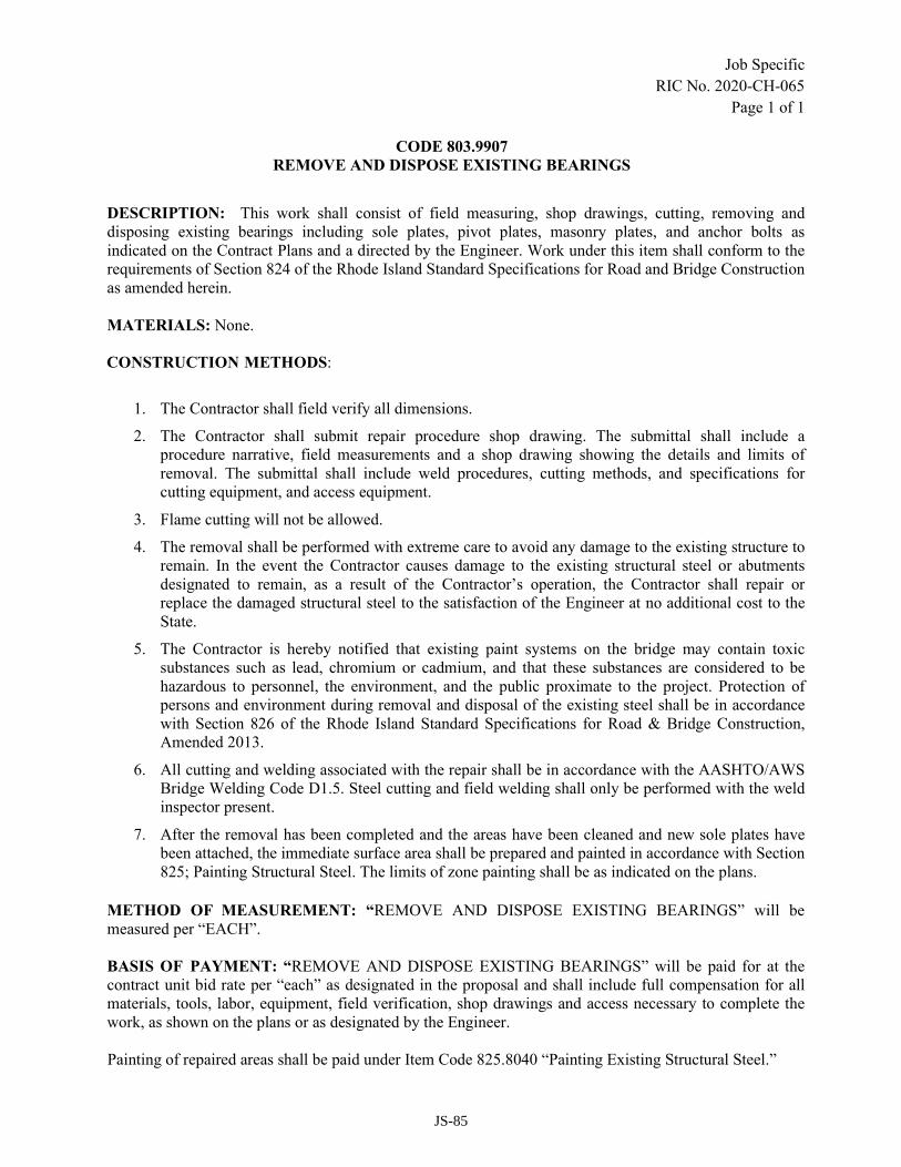
Job Specific
RIC No. 2020-CH-065
Page 1 of 1
CODE 803.9907
REMOVE AND DISPOSE EXISTING BEARINGS
DESCRIPTION: This work shall consist of field measuring, shop drawings, cutting, removing and
disposing existing bearings including sole plates, pivot plates, masonry plates, and anchor bolts as
indicated on the Contract Plans and a directed by the Engineer. Work under this item shall conform to the
requirements of Section 824 of the Rhode Island Standard Specifications for Road and Bridge Construction
as amended herein.
MATERIALS: None.
CONSTRUCTION METHODS:
1. The Contractor shall field verify all dimensions.
2. The Contractor shall submit repair procedure shop drawing. The submittal shall include a
procedure narrative, field measurements and a shop drawing showing the details and limits of
removal. The submittal shall include weld procedures, cutting methods, and specifications for
cutting equipment, and access equipment.
3. Flame cutting will not be allowed.
4. The removal shall be performed with extreme care to avoid any damage to the existing structure to
remain. In the event the Contractor causes damage to the existing structural steel or abutments
designated to remain, as a result of the Contractor’s operation, the Contractor shall repair or
replace the damaged structural steel to the satisfaction of the Engineer at no additional cost to the
State.
5. The Contractor is hereby notified that existing paint systems on the bridge may contain toxic
substances such as lead, chromium or cadmium, and that these substances are considered to be
hazardous to personnel, the environment, and the public proximate to the project. Protection of
persons and environment during removal and disposal of the existing steel shall be in accordance
with Section 826 of the Rhode Island Standard Specifications for Road & Bridge Construction,
Amended 2013.
6. All cutting and welding associated with the repair shall be in accordance with the AASHTO/AWS
Bridge Welding Code D1.5. Steel cutting and field welding shall only be performed with the weld
inspector present.
7. After the removal has been completed and the areas have been cleaned and new sole plates have
been attached, the immediate surface area shall be prepared and painted in accordance with Section
825; Painting Structural Steel. The limits of zone painting shall be as indicated on the plans.
METHOD OF MEASUREMENT: “REMOVE AND DISPOSE EXISTING BEARINGS” will be
measured per “EACH”.
BASIS OF PAYMENT: “REMOVE AND DISPOSE EXISTING BEARINGS” will be paid for at the
contract unit bid rate per “each” as designated in the proposal and shall include full compensation for all
materials, tools, labor, equipment, field verification, shop drawings and access necessary to complete the
work, as shown on the plans or as designated by the Engineer.
Painting of repaired areas shall be paid under Item Code 825.8040 “Painting Existing Structural Steel.”
JS-85

Job Specific
RIC No. 2020-CH-065
Page 1 of 1
CODE 803.9908
PARTIAL REMOVAL AND DISPOSAL OF EXISTING CONCRETE MASONRY – HAUNCH CONCRETE
DESCRIPTION: These items shall consist of the removal and disposal (including sawcuts), in phases, of the haunch
concrete, as shown on plans and described in this Special Provision. All work shall be performed in accordance with
applicable provisions of the Standard Specifications, except as modified herein and as required by the Engineer.
CONSTRUCTION METHODS: Limits and sequence of demolition shall be in accordance with the suggested phase
construction scheme provided on the contract plans. All work to be performed in the complete or partial removal of
the existing haunch concrete shall be done in such a manner that no debris falls beyond the temporary protective
shield. If any materials do fall beyond the protective shield, the contractor shall remove said materials immediately to
the satisfaction of the Engineer.
Removal of concrete shall be done in a workmanlike manner to prevent damage to the new, temporary or existing
structure to remain. If any damage to any portion of the new, temporary or existing structure to remain does ensue due
to the Contractor’s operations, it shall be repaired or replaced by the Contractor at his sole expense and to the
satisfaction of the Engineer.
The work shall be completed using chipping hammers of the 15-lb class to remove the haunch concrete. All work shall
be performed in accordance with Section 803 of the RIDOT Standards for Road and Bridge Construction.
All removed materials shall be taken from the site to an approved destination as the work progresses. Storing or
burying of material/debris on site shall not be permitted.
Note: The Contractor is hereby notified that the existing paint system may contain toxic substances such as lead or
chromium which may be considered hazardous waste when removed. Protection of persons and environment during
removal and disposal of the existing steel shall be in accordance with Section 826 of the Standard Specifications.
METHOD OF MEASUREMENT: “PARTIAL REMOVAL AND DISPOSAL OF EXISTING CONCRETE
MASONRY – HAUNCH CONCRETE” shall be measured by the “LINEAR FOOT” of haunch sections actually
removed in accordance with the plans and/or as directed by the Engineer. Prior to removal of the haunches, the
contractor shall delineate the areas for haunch removal and coordinate this with the engineer.
BASIS OF PAYMENT: The accepted quantity of “PARTIAL REMOVAL AND DISPOSAL OF EXISTING
CONCRETE MASONRY – HAUNCH CONCRETE,” will be paid for at their respective contract “LINEAR FOOT”
prices as listed in the Proposal. The prices so stated shall constitute full compensation for all labor, materials,
equipment, access and all other incidentals required to finish the work, as described above and elsewhere in the
Contract Documents, complete in place and accepted by the Engineer.
JS-86
Job Specific
RIC No. 2020-CH-065
Page 1 of 1
CODE 803.9909
PARTIAL REMOVAL AND DISPOSAL OF EXISTING CONCRETE MASONRY – BRIDGE SEAT
PEDESTALS
DESCRIPTION: These items shall consist of the removal and disposal (including sawcuts), in phases, of the existing
bridge seat pedestal concrete, as shown on plans and described in this Special Provision. All work shall be performed
in accordance with applicable provisions of the Standard Specifications, except as modified herein and as required by
the Engineer.
CONSTRUCTION METHODS: Limits and sequence of demolition shall be in accordance with the suggested phase
construction scheme provided on the contract plans. All work to be performed in the complete or partial removal of
the existing bridge seat pedestal concrete shall be done in such a manner that no debris falls beyond the temporary
protective shield. If any materials do fall beyond the protective shield, the contractor shall remove said materials
immediately to the satisfaction of the Engineer.
Removal of concrete shall be done in a workmanlike manner to prevent damage to the new, temporary or existing
structure to remain. If any damage to any portion of the new, temporary or existing structure to remain does ensue due
to the Contractor’s operations, it shall be repaired or replaced by the Contractor at his sole expense and to the
satisfaction of the Engineer.
The work shall be completed using chipping hammers of the 15-lb class to remove the existing bridge seat pedestal
concrete. All work shall be performed in accordance with Section 803 of the RIDOT Standards for Road and Bridge
Construction.
All removed materials shall be taken from the site to an approved destination as the work progresses. Storing or
burying of material/debris on site shall not be permitted.
Note: The Contractor is hereby notified that the existing paint system may contain toxic substances such as lead or
chromium which may be considered hazardous waste when removed. Protection of persons and environment during
removal and disposal of the existing steel shall be in accordance with Section 826 of the Standard Specifications.
METHOD OF MEASUREMENT: “PARTIAL REMOVAL AND DISPOSAL OF EXISTING CONCRETE
MASONRY – BRIDGE SEAT PEDESTALS” shall be measured by the “CUBIC FOOT” of existing bridge seat
concrete actually removed in accordance with the plans and/or as directed by the Engineer.
BASIS OF PAYMENT: The accepted quantity of “PARTIAL REMOVAL AND DISPOSAL OF EXISTING
CONCRETE MASONRY – BRIDGE SEAT PEDESTALS,” will be paid for at their respective contract “CUBIC
FOOT” prices as listed in the Proposal. The prices so stated shall constitute full compensation for all labor, materials,
equipment, access and all other incidentals required to finish the work, as described above and elsewhere in the
Contract Documents, complete in place and accepted by the Engineer.
JS-87
Job Specific
RIC No. 2020-CH-065
Page 1 of 14
CODE 805.9901
MSE RETAINING WALL SYSTEMS WITH PRECAST CONCRETE FACING
GENERAL
A. This specification applies to Mechanically Stabilized Earth (MSE) Retaining Wall Systems with
Concrete Facings to be used for the Bike Shared Use Path Retaining Wall and Garfield Street
Retaining Wall.
B. The MSE Walls shall be designed and the submittals sealed by a Professional Engineer registered in
the State of Rhode Island, who shall provide complete design, detailed shop drawings, and
computations to the Engineer for review and approval. The design shall be in accordance with the
applicable provisions of the latest edition of the AASHTO LRFD Bridge Design Specifications, the
Contract Plans, and these Special Provisions. All information necessary for complete erection of the
MSE Retaining Wall Systems with Precast Concrete Facing shall be designed and detailed on the shop
drawings, including RIDOT excavation and fill requirements. The MSE Retaining Wall Systems with
Precast Concrete Facing shall be designed to withstand AASHTO live loads and surcharge loads.
C. It shall be the Contractor’s responsibility to coordinate with the MSE wall designer to provide
loadings from construction equipment proposed to be used by the Contractor and placed upon the
completed wall system. This construction loading, if greater than the AASHTO loads, shall be used in
the design. Evidence of this coordination must be included in the shop drawing submittal.
D. It shall be the responsibility of the Contractor and his MSE wall designer to review both the soil data
in the Geotechnical Data Report (GDR) in order to account for appropriate drainage needs and
incorporate into the design.
E. It is not the intent of these Special Provisions to provide detailed step-by-step instructions for the
design and execution of the work, nor to identify each material or component to be supplied or each
item of work or coordination to be performed. However, the Plans, the Special Provisions, and the
MSE Wall Standard Specifications do delineate the general design intent with regard to lines and
grades, appearance, materials, type of construction, physical requirements, relationships of elements,
and the type and quality of construction required. Where specific details, sequences, relationships,
requirements and materials are shown or specified, they shall be strictly adhered to and provided.
Where such information is not provided, is only partially provided, or is addressed only in a general
nature, it shall be the Contractor’s responsibility to provide or fully develop such information and
submit the same for the Engineer’s approval. This shall include comprehensive, coordinated, detailed
design and Shop Drawings, drawings of existing and adjacent conditions, design calculations, product
data, test results, installation instructions and sequencing, and all other information required for a
complete evaluation by the Engineer of proposed materials, details, systems, quality and thoroughness
of work.
F. The Contractor shall submit a detailed resume of the MSE wall designer, listing similar projects and
demonstrating the necessary experience to perform the MSE wall design, including a brief description
of each project listed. As a minimum, the reference shall include the designer’s name, address and
current phone number
JS-88
Job Specific
RIC No. 2020-CH-065
Page 2 of 14
DESCRIPTION
A. Except for the excluded items of work indicated below, the work under these items shall consist of
designing, furnishing materials, and the construction of Mechanically Stabilized Earth (MSE) Retaining
Wall Systems with Concrete Facings. The supply of precast concrete facing, precast wall caps, precast
leveling pads, reinforced fill, geogrid, metallic reinforcing strips, metallic reinforcing mesh, connection
devices, drainage systems, and the engineering, are all to be furnished by the Contractor and his MSE
system supplier.
B. This work shall include the following:
a. Furnishing design computations and construction drawings stamped by a Professional
Engineer Registered in the State of Rhode Island and providing supplier representatives for
preconstruction meetings with Contractor and the Engineer.
b. Furnishing precast concrete facing, structural reinforcement (geogrid, metallic reinforcing
strips, or metallic reinforcing mesh), and drainage system as required by design and as shown
on the construction drawings.
c. Storing, cutting and placing precast concrete facing, structural reinforcement, and the drainage
system as specified herein and as shown on the construction drawings.
d. Placement and compaction of reinforced fill and backfill material as specified herein and as
shown on the construction drawings.
e. It shall be the responsibility of the Contractor and his MSE wall system designer to review
both the soil data and the proposed application of MSE wall system in order to account for
appropriate drainage needs and incorporate into the design. A positive drainage system shall
be included in the design and construction.
SUBMITTALS
A. Prior to construction the Contractor shall submit to the Engineer the manufacturer's certification that all
reinforcement been evaluated in full compliance with these Special Provisions. The Contractor's
submittal package shall include; but not be limited to, actual tests results for tension/creep,
durability/aging, construction damage, joint strength, pullout and quality control.
B. As applicable, the manufacturer shall also provide written certification that all resin used to produce the
primary geogrid is virgin and classified as high density polyethylene or high molecular weight polyester
and is capable of withstanding direct exposure to sunlight for 120 days with no measurable deterioration
as measured per ASTM D4355.The manufacturer of the structural geogrid shall supply written
certification that the resins and additives used in manufacture of the primary geogrid (including coating
materials, if applicable) are specifically formulated to provide long-term tensile strength and long-term
interlock with soil; and that the manufactured geogrid product is durable in a soil environment for
applications up to 100 years and is fit-for-use in long-term, critical soil reinforcement applications.
Certification shall be notarized and signed by an officer of the manufacturing company.
C. The Contractor shall submit details of the precast yard and the concrete mix design in accordance with
Section 809 and 601 of the Rhode Island Standard Specifications for Road and Bridge Construction.
JS-89

Job Specific
RIC No. 2020-CH-065
Page 3 of 14
D. The shop drawings shall show the configuration and all details, dimensions, quantities and cross-sections
necessary to construct the wall facing, including but not limited to, the following:
a. A plan view which shall include dimensions, stations, and offsets at the face of wall line as
shown on the Plans.
b. An elevation view of the wall which shall include the elevations at the top of the wall at all
horizontal and vertical break points, all steps in the leveling pads, the designation as to the
type of retaining wall system(s), and an indication of the final ground line.
c. A typical cross section or cross sections showing the elevation relationship between existing
ground conditions and proposed grades, and the proposed wall configuration.
d. General notes pertaining to the design criteria and wall construction.
e. A listing of the summary of material quantities for each wall.
f. Details of sleeves and pipes and other embedded items to be installed through the walls, if
any.
g. Clear details for the construction of reinforcing elements around drainage or other utilities, or
any other potential obstructions.
h. Details of the architectural treatment. Sufficient information must be provided to properly
evaluate the textured finish provided by the form liners. The form liners must be approved by
the Engineer.
i. Drainage design detail and design scheme.
j. Location of utilities, if any.
k. Sequence and schedule of construction, including overall construction schedule.
l. Methods of excavation and backfill.
m. Method of maintaining stability of excavations.
n. Methods of monitoring plumbness and deviation of wall.
o. Excavation support system, if any.
p. Any acceptance testing and frequency.
q. Details and location of all necessary construction and expansion joints along the wall.
E. The Contractor shall also submit design computations, demonstrating compliance with the criteria
specified herein and shown on the Plans. They shall be prepared, signed, and stamped by a registered
professional engineer licensed in the State of Rhode Island and specializing in geotechnical engineering.
a. The design computations shall include:
JS-90

Job Specific
RIC No. 2020-CH-065
Page 4 of 14
i. A statement of all assumptions made and copies of all references used in the
calculations.
ii. Analyses demonstrating compliance with all applicable earth, water, surcharges,
seismic, or other loads, as specified herein, shown on the Plans, and required by
applicable Codes.
iii. Analysis demonstrating the durability and corrosion resistance of retaining wall
systems for the proposed location and environment.
F. The Contractor shall submit six (6) sets of detailed design calculations, construction drawings, and shop
drawings for approval at least thirty (30) days prior to the beginning of MSE retaining wall construction.
The calculations and drawings shall be prepared and sealed by a professional engineer, licensed in the
State of Rhode Island. The supplier shall have past experience in the design and construction of at least
ten (10) projects of a similar magnitude of the proposed system.
G. The Contractor shall submit six (6) sets of manufacturer's certifications that the reinforcement meets the
requirements set forth in the respective material specifications, for approval at least thirty (30) days prior
to start of MSE retaining wall construction.
H. To certify the reinforced backfill complies with this special provision, the Contractor shall submit to the
Engineer six (6) sets of the following: gradation report; pH test report; corrosivity test report; and a
Certificate of Compliance certifying that the reinforced backfill material complies with these Special
Provisions. Copies of other test results performed by the Contractor to assure compliance with these
special provisions, if any, shall be furnished to the Engineer.
MATERIALS
A. STRUCTURAL GEOGRID
The geogrid shall be a regular network of integrally connected polymer tensile elements with aperture
geometry sufficient to permit significant mechanical interlock with the surrounding soil or rock. The geogrid
structure shall be dimensionally stable and able to retain its geometry under manufacture, transport, and
installation. The structural geogrid is placed within the reinforced backfill in alternating primary and
secondary geogrid layers as required by design.
a. Primary Geogrid Reinforcement: identified as Types P1, P2, P3 and P4 shall provide the
following allowable tensile properties:
Property Method P1 P2 P3 P4
1. Tensile Strength
(a) 2% Strain, lbs/ft* ASTM D4595 1000 1800 2330 2740
(b) 5% Strain, lbs/ft* ASTM D4595 2000 3700 4450 5400
(c) Ultimate, lbs/ft ASTM D4595 4400 6900 9000 10,000
(d) Long-Term (Ta), lbs/ft FHWA/SA-93-025 1402 2333 3008 3811
Where : Ta = TULT
FSCR x FSID x FSDU x FSJNT as described in FHWA/SA-93-025
i. The tensile strength at 2% and 5% strain shall be determined from a zero offset stress-
strain curve without use of a preload.
JS-91

Job Specific
RIC No. 2020-CH-065
Page 5 of 14
ii. TULT, Ultimate Tensile Strength: shall be the minimum average roll value ultimate
tensile strength as tested per ASTM D4595.
iii. FSCR, Partial Factor for Creep Deformation: is the ratio of TULT, to the creep limited
strength determined in accordance with ASTM D5262. The test results shall be
extrapolated for a 100 year design life per GRI GG4. Creep performance data of a
polymer product at a designed temperature is limited to one order of magnitude in
extrapolation. Creep performance data at an elevated temperature permits an additional
order of magnitude in extrapolation with time temperature superposition principals.
iv. Elevated temperature testing of the specific geogrid for 10,000 hours or creep testing at
room temperature for 100,000 hours is required. Creep limited strength testing is
required on representative samples of the finished product for each product proposed
for use and not a single component of the geogrid (i.e. polymer strand). Default values
for FSCR are not allowed.
v. FSID, Partial Factor for Installation Damage: shall be determined from construction
damage tests for each product proposed for use with project specific representative or
more severe backfill and construction techniques. The backfill soil used if other than
project specific, shall have a D50 at 0.6mm (No. 30 sieve). Testing shall be consistent
with GRI GG4. A default FSID value of 3.0 shall be used if such testing has not been
conducted. The minimum FSID shall be 1.05.
vi. FSDU, Partial Factor for Durability/Aging: is the combined partial factor for potential
chemical and biological degradation. FSDU shall be determined from polymer specific
(HDPE and PP as identified by specific gravity and melt flow index and PETP as
identified by CEG number and intrinsic viscosity) durability testing covering the range
of expected soil environments. Prior to approval by the Engineer, the manufacturer
shall submit test results from a minimum of at least four (4) tests conducted in
accordance with EPA 9090 at temperatures of 23 degrees and 50 degrees C. EPA 9090
test results shall include the following minimum number of leachate types:
pH Minimum Number of Test Results
3 < pH < 7
7 < pH < 9 1
9 < pH < 11 1
11 <pH < 14 1
vii. As a minimum, the following tests should be performed for Geogrids after immersion
in the above described leachates:
TEST TEST PROCEDURE MAX % CHANGE ALLOWED
Mass Per Unit Area EPA 9090 ± 1.0
Dimensions EPA 9090 ± 1.0
Thickness ASTM D374C ± 5.0
Wide Width Strip Tensile ASTM D4595 - 2.0
viii. FSDU shall not be less than the recommended minimum values discussed in
FHWA/RD-89-186 and listed below:
JS-92

Job Specific
RIC No. 2020-CH-065
Page 6 of 14
1. High Density Polyethylene (HDPE) 1.10
2. High Tenacity Polyester (PETP) 2.00
3. Polypropylene (PP) 1.25
ix. Composite (flexible) Geogrids shall be evaluated based on the durability characteristics
of the interior reinforcement polymer. Therefore, any protective coating shall be
removed prior to durability testing, unless a minimum 40 micron coating thickness is
used on flexible Geogrids and the minimum 40 micron coating thickness is certified by
the manufacturer
x. For soils of potential concern, as presented below (modified soils shall include lime
stabilized soil, cement stabilized soil or concrete), only polymers listed as "no effect"
shall be used within or adjacent to (3 feet shortest measurable distance) these soil
environments (Ref: Table 28, FHWA/RD-89-186). The criteria by which soils may be
classified can be found in FHWA/RD-89-186 and FHWA-NHI-00-044.
Soil Environment PETP PE PP
Acid Sulfate Soils ? NE ?
Organic Soils NE NE NE
Salt Affected Soils ? NE NE
Ferroginous NE NE X
Calcareous X NE NE
Modified Soils X NE NE
NE= No Effect
?= Questionable Use
X= Not Recommended
xi. FSJNT, Partial Factor for Joint Strength: shall be determined from joined specimen
strength tests performed in accordance with ASTM D4595 for mechanical joints and
GRI GG5 for overlap joints. FSJNT shall be the ratio of the unjoined tensile strength
to the joined tensile strength. Sustained tension tests of 1000 hour minimum duration
should also be conducted on mechanically connected joints, according to GRI-GG4
xii. Soil Interaction Coefficient: Ci value shall be determined from long-term effective
stress pullout tests per GRI GG5, unless the junction creep testing of the geogrid is
used to determine Ta. The Ci value is determined as follows:
Ci = F .
2 L δN tan φ
where F = Pullout force (lb/ft), per GRI GG5
L = Geogrid Embedment Length in Test (ft)
δN = Effective Normal Stress (psf)
φ = Effective Soil Friction Angle, Degrees
b. Secondary Geogrid Reinforcement: identified as Types S1 and S2, shall meet the following
minimum average physical property requirements:
Property Method S1 S2
1. Tensile Strength (1) ASTM D4595
(a) 2% Strain, lbs/ft 280 555
(b) 5% Strain, lbs/ft 920 1340
JS-93

Job Specific
RIC No. 2020-CH-065
Page 7 of 14
(c) Ultimate, lbs/ft 1300 1975
2. Open Area, % COE CW02215 >50,<80 >50,<80
NOTE: (1) In direction perpendicular to slope/wall face.
c. Manufacturing Quality Control
i. The purpose of the QC testing program is to verify that the geogrid being supplied to
the project is representative of the geogrid used for the performance testing described
earlier in these Special Provisions. In most cases, however, sampling can be carried
out on sacrificial portions of the supplied material.
ii. Conformance testing shall be performed as part of the manufacturing process. The
manufacturer of the selected geogrid shall have an established quality control program;
the documentation describing the program shall be submitted to the Engineer for
review. As a minimum, the manufacturer shall conduct quality control testing as
outlined below:
Test Test Procedure Testing Frequency (SF)
Flexural Rigidity ASTM D1388 100,000
Tensile Modulus GRI GG1 100,000
Junction Strength GRI GG2 100,000
Specific Gravity ASTM D1505 200,000
Melt Flow Index (HDPE,PP) ASTM D1238 200,000
Wide Width Tensile ASTM D4595 200,000
Coating Thickness ASTM 374C 100,000
Intrinsic Viscosity (PET) ASTM D4603 200,000
Carboxyl End Group (PET) ASTM D2455 200,000
iii. These tests shall be performed by the manufacturer. Samples not satisfying the
specifications shall result in the rejection of the applicable rolls at no cost to the State.
At the manufacturer's discretion and expense, additional testing of individual rolls may
be performed to more closely identify the noncomplying rolls and/or to qualify
individual rolls.
iv. The manufacturer shall certify the quality of the rolls of Geosynthetic reinforcement.
As a minimum, the manufacturer shall provide quality control certificates for each
batch of resin and each shift's production. These quality control certificates shall be
signed by an officer of the manufacturer (such as the production manager), and
supplied to the Engineer at least two (2) weeks prior to installation of the structural
geogrid.
v. The quality control certificate shall include:
1. Roll numbers and identification
2. Sampling procedures
3. Result of quality control tests, including a description of test methods used
B. STEEL COMPONENTS
a. Steel components shall conform to the following requirements.
JS-94

Job Specific
RIC No. 2020-CH-065
Page 8 of 14
i. Galvanization: Soil reinforcement steel shall be hot-dip galvanized in accordance with
AASHTO M 111 (ASTM A123). Connection hardware steel can be galvanized by hot-
dipping or other means, provided the method satisfies the requirements of AASHTO M
111 (ASTM A123). A minimum galvanization coating of 2.0 oz/ft2 (605 g/m2) or 3.4
mils (85 μm) thickness is required. Soil reinforcement steel shall be adequately
supported while lifting and placing such that the galvanization remains intact. Steel
members with damaged (peeled) galvanization shall be repaired according to ASTM
A780 and as specified in approved working drawings, at no additional cost to the
Agency.
ii. Metallic Reinforcing Strips and Tie Strips: Reinforcing strips shall be hot-rolled from
bars to the required shape and dimensions. The strips’ physical and mechanical
properties shall conform to the requirements of ASTM A572, Grade 65 minimum. Tie
strips shall be shop fabricated of hot-rolled steel conforming to the requirements of
ASTM A1101, Grade 50 minimum. The minimum bending radius of the tie strips shall
be 3/8 inch. Galvanization shall be applied after the strips are fabricated, inclusive of
punch holes for bolts as shown on approved drawings.
iii. Metallic Reinforcing Mesh: Reinforcing mesh shall be shop fabricated of cold-drawn
steel wire conforming to the requirements of AASHTO M 32, and shall be welded into
the finished mesh fabric in accordance with AASHTO M 55. Galvanization shall be
applied after the mesh is fabricated. A minimum galvanization coating of 2.0 oz/ft2
(605 g/m2) or 3.4 mils (85 μm) thickness is required.
iv. Connection Plates and Shapes: Connector pins and mat bars shall be fabricated from
AASHTO M 183 (ASTM A 36) steel and shall be fastened to the soil reinforcement
mats as shown on the Plans. Galvanizing shall conform to AASHTO M 111 (ASTM A
123).
v. Fasteners: Connection hardware shall conform to the requirements shown in the
approved working drawings. Connection hardware shall be cast in the precast concrete
panels such that all connectors are in alignment and able to transfer full and even load
to the soil reinforcement. Once the reinforcement is connected to the panel, the amount
of slack shall not exceed 1/8 inch between the connector and the reinforcement during
field installation. Fasteners shall be galvanized and conform to the requirements of
ASTM F3125or equivalent.
C. REINFORCED SOIL BACKFILL
a. All backfill material used in the structural volume shall be “Gravel Borrow” as shown on the
plans. Gravel Borrow shall consist of crushed, hard, durable particles or fragments of stone or
gravel and shall be free from organic matter or deleterious material such as shale or other soft
particles that have poor durability.
b. The gradation of Gravel Borrow shall conform to the gradation requirements per section
M.01.09 of the RIDOT Standard Specifications for Road and Bridge Construction.
c. Gravel Borrow Backfill shall be placed in lifts not exceeding 10-inches in thickness and
compacted with at least 4 passes of a steel drum roller. The backfill material shall show no
visible movement when compaction is complete. In those locations not accessible for normal
JS-95

Job Specific
RIC No. 2020-CH-065
Page 9 of 14
placing and rolling, fill shall be placed in lifts not to exceed 5 inches before compaction and
compacted by means of mechanical tampers, or suitable vibratory equipment. For minor
operations, hand tamping with heavy iron tampers may be used.
d. A non-woven geotextile filter fabric shall be placed as a separation layer wherever open-
graded backfill or drainage aggregate will interface with other soil types. The wall designer
shall depict the filter fabric, where needed, on the details within the design drawings.
e. The backfill shall conform to the following additional requirements:
i. The compaction shall be in accordance with AASHTO T-180 as described in
subsection 203.03.5 paragraph c.
ii. The plasticity index (PI), as determined by AASHTO T90, shall not exceed 6.
iii. The material shall exhibit an angle of internal friction of not less than that specified by
the wall designer. The internal friction angle will be determined by the standard Direct
Shear Test, AASHTO T-236, on the portion of the material finer than the No. 10 sieve,
compacted to 95% of AASHTO T-180 at optimum moisture content. There is no need
for oversize correction while preparing the sample.
iv. Permeability – The material shall be free-draining and shall have a permeability
coefficient greater than 1x10(E-4) centimeters per second at maximum density when
measured according to AASHTO T215.
v. Soundness - The materials shall be substantially free of shale or other soft, poor
durability particles.
vi. Electrochemical Requirements – The backfill material shall meet the following criteria
when placed in areas where metallic reinforcing is utilized:
Requirements Test Methods
Organic Content <1% AASHTO T 267
Resistivity 3,000 ohm centimeters, min. AASHTO T 288 (ASTM G 57)
pH between 5 and 10, inclusive AASHTO T 289 (ASTM G 51)
Chlorides 100 parts per million, max. AASHTO T 291 (ASTM D 512)
Sulfates <200 parts per million, max. AASHTO T 290 (ASTM D 516)
vii. Reinforced backfill not conforming to these Special Provisions shall not be used
without the written consent of both the Designer and the geogrid supplier.
D. PRECAST CONCRETE FACING
a. The precast concrete facing panels shall be manufactured in accordance with Sections 601,
809 and M.02 of the RI Standard Specifications for Road and Bridge Construction with the
following exceptions and additions:
i. Panels shall be manufactured of air-entrained 5,000 psi, ¾ inch, cement concrete with
calcium nitrite based corrosion inhibitor in accordance with Code 605 of the Rhode
Island Standard.
ii. Specifications for Road and Bridge Construction and as follows:
JS-96

Job Specific
RIC No. 2020-CH-065
Page 10 of 14
1. Reinforced concrete facing panels shall be of the sizes and shapes that will
generally conform to the dimensions of the wall envelopes shown on the Plans.
Panel dimensions and layout shall be shown on the shop drawings and shall
include a minimum design joint width of three-quarters (¾) of an inch in order
to accommodate differential settlement without impairing the appearance of
the facing or compromising the structural integrity of individual panels.
2. Facing panels shall have tongue and groove, ship lap or similar approved
connections along all joints, both horizontal and vertical. The ¾ inch joint
width shall be held throughout the depth of the joint.
3. Walls or wall sections which intersect at an angle of one hundred thirty (130)
degrees or less shall include a special corner element to cover the joint formed
by the abutting walls or wall sections and to permit relative movement. Corner
elements shall not consist of connected standard facing panels.
4. Individual units may be rejected because of any of the following:
a. Variations in the exposed face that substantially deviate from panel
uniformity as to texture, relief and reveals: in accordance with precast
concrete industry standards.
b. Dimensions not conforming to the following:
i. Face of panel dimensions: plus or minus three sixteenth (3/16)
of an inch from intended dimensions for uniformity.
ii. Element squareness: one half (½) inch difference between
diagonals.
iii. Position of tie strips: within one (1) inch.
iv. Surface defects on smooth-formed surfaces, measured on a
length of five (5) feet, shall not exceed one eighth (⅛) of an
inch.
v. Surface defects on textured-finish surfaces, measured on a
length of five (5) feet shall not exceed five sixteenth (5/16) of
an inch.
c. Defects indicating honeycombed or open texture.
d. Defects which would affect the structural integrity of the unit including
cracked or severely chipped panels.
e. Color variations on the front faces of the panels due to excess form oil
or other reasons. Face panels shall match the color of the proposed
concrete abutment and wingwalls.
iii. Form Liners for Concrete Texturing – Reinforced Panels.
JS-97

Job Specific
RIC No. 2020-CH-065
Page 11 of 14
1. All facing panels shall receive an architectural finish treatment which shall be
shown on the shop drawings for approval. The architectural treatment shall be
part of the pre-casting process. Forms for the units shall be constructed of
rigid and durable material with dimensional tolerances that will assure the
production of uniform units. The exposed faces of the walls shall be consistent
in color and texture from the top of leveling pads to the top of the precast
concrete caps or copings. All surfaces of the precast panels to receive
architectural finish treatment shall have an ashlar masonry pattern or similar as
shown in the RIDOT Bridge Design Standard Details).
iv. The units shall be fully supported until the concrete reaches a minimum compressive
strength of 2,000 psi. The units may be shipped after reaching a minimum compressive
strength of 5,000 psi and a minimum cure period of seven (7) days.
v. Unless otherwise indicated on the Plans, the concrete surfaces shall be finished in
accordance with Sections 809.03.6, and 809.03.8 of the RI Standard Specifications as
modified herein. The panels shall be cast on a flat area. The coil embeds, tie strip
guides, or other galvanized devices shall not be in contact with, or be attached to, the
face panel reinforcement steel.
vi. The date of manufacture, the production lot number, and the piece mark shall be clearly
scribed on an unexposed face of each panel.
vii. All units shall be handled, stored, and shipped in such a manner as to eliminate the
dangers of chipping, discoloration, cracks, fractures, and excessive bending stresses.
Panels in storage shall be supported on firm blocking to protect the panel connection
devices and the exposed exterior finish.
viii. All units shall be manufactured within the following tolerances:
1. Panel Dimensions – Position of panel connection devices: within one inch,
except for coil and loop imbeds which shall be 3/16 inch. All other dimensions
within 3/16 inch.
2. Panel Squareness – Squareness as determined by the difference between the
two diagonals shall not exceed ½ inch.
3. Panel Surface Finish – Surface defects on smooth-formed surfaces measured
over a length of five feet shall not exceed ⅛ inch. Surface defects on textured-
finished surfaces measured over a length of five feet shall not exceed 5/16
inch.
4. Reinforcing steel for precast panels (bars or wire fabric) shall be galvanized
and in accordance with Section 810.
E. DRAINAGE SYSTEM
a. The subsurface drainage system shall consist of weep holes in the precast concrete facing with
2” PVC pipes which will connect a 4-inch minimum diameter perforated drain pipe
JS-98

Job Specific
RIC No. 2020-CH-065
Page 12 of 14
surrounded by 12 inches of Filter Stone wrapped in non-woven geotextile fabric located at the
back edge of the reinforced soil backfill zone.
EXECUTION
A. The Contractor is responsible for determining any construction equipment height restrictions and should
coordinate work with the Engineer in order to determine project requirements. The Contractor is advised
to visit the site to assess equipment access limitations due to headroom clearance and sloping grades.
The Contractor shall submit a plan to the Engineer detailing his strategy to deal with clearance and
grading issues associated with the installation of MSE wall (i.e. type and specifications of rig, method of
installation, if grading or benching will be required, etc.).
B. Excavation for MSE Retaining Walls With Precast Concrete Facing shall be in accordance with the
requirements of Section 203 of the Standard Specifications. The foundations shall be graded level for a
minimum distance of two (2) feet beyond the outside dimensions of the structures and shall be
compacted with a smooth wheel vibratory roller. Any foundation soils found to be unsuitable shall be
removed and replaced with gravel borrow as per Section 203 and Section 204. It should be noted that
boring data at the Garfield Street Wall indicates unsuitable existing fill material is present to
approximately 2.0 feet. If the foundation is placed on fill material, the material shall be a gravel borrow
conforming to the relevant provisions of Section 302.
C. The Contractor shall check all materials upon delivery to ensure that the proper material has been
received. During all periods of shipment and storage, the reinforcement shall be protected from
temperatures greater than 140°F and from all deleterious materials that might otherwise become affixed
to the geogrid and adversely affect its performance. The Contractor shall follow manufacturer's
recommendations in regards to protection from direct sunlight.
D. All tears, cracks, punctures or flaws to the structural reinforcement coating, if applicable, shall be
repaired in accordance with the manufacturer’s specification and as approved by the Engineer. If the
substrate of a coated geogrid is exposed at the roll ends or as a result of cuts, cracks, punctures or flaws,
the exposed area shall be sealed with a coating solution identical to the original coating. The coating
solution shall be applied by dip coating or spread coating with an applicator. The area shall be
thoroughly clean and dry, and working temperatures shall not be below 32°F. All exposed substrate or
repair patches shall be treated in the same manner.
E. The Contractor’s Quality Control program shall verify that the products supplied to the jobsite meet the
design requirements to include testing of field samples at the frequency given below.
F. The installation of the MSE Retaining Walls with Concrete Facing shall be installed in accordance with
the procedures and tolerances outlined below.
G. MSE Retaining Walls With Precast Concrete Facing suppliers shall provide a qualified and experienced
representative on site to assist the Contractor and the Engineer at the start of construction for a
maximum of three (3) days. If there is more than one wall on a project, then this requirement will apply
Tensile Strength Property Method Frequency (SY)
2% Strain, lbs/ft
5% Strain, lbs/ft
Ultimate, lbs/ft
Junction Strength, lbs/ft
ASTM D4595
ASTM D4595
ASTM D4595
GRI GG2
150,000
150,000
150,000
150,000
JS-99

Job Specific
RIC No. 2020-CH-065
Page 13 of 14
to construction of the initial wall only. The representative shall be available as needed by the Contractor
or as directed by the Engineer during construction of the remaining wall(s).
H. The foundation for the MSE Retaining Walls With Precast Concrete Facing shall be properly prepared in
accordance with the applicable provisions of Section 203 of the Standard Specifications, as detailed on
the Plans, as specified elsewhere within these Special Provisions, and as directed by the Engineer.
Foundation surfaces shall be level, free from deleterious materials, loose, or otherwise unsuitable soils.
Construction of the MSE Retaining Walls With Precast Concrete Facing shall not proceed until the
foundation surfaces have been approved by the Engineer.
I. The reinforcement shall be installed in accordance with the manufacturer's recommendations except as
indicated on the approved construction drawings. The reinforcement shall be placed within the layers of
the compacted soil as shown on the approved construction drawings. The geogrid shall be placed in
continuous longitudinal strips in the direction of the main reinforcement. Adjacent strips, in the case of
100% coverage in plan view, need not be overlapped. However, if the Contractor is unable to complete
a required length with a single continuous length of reinforcement, a joint may be made with the
Engineer's approval. Only one joint per length of reinforcement shall be allowed. Geogrid soil
reinforcement shall be connected in the direction of loading where required through the use of either a
mechanical polymer bar (i.e. Bodkin bar) or sewing with Kevlar sewing thread perpendicular to the
direction of loading at the ends of the materials. Mechanical bar connections shall be placed, as a
minimum, on the second row of apertures from the end of the roll.
J. Overlap connections may be used if the Contractor provides the Engineer independent test
documentation which demonstrates that the load/deformation characteristics of the overlap connection
are consistent with the design tolerances of both the finished project and appurtenant materials.
Minimum overlap of geogrid materials shall be 5'0" in the direction of loading, unless the geogrid
materials have a junction strength in excess of 90%, as defined by GRI GG2, in which case a 2'0"
minimum overlap may be used.
K. In order to prevent undue damage, the Contractor shall place only that amount of reinforcement required
for immediately pending work. After a layer of reinforcement has been placed, the next succeeding
layer of soil shall be placed and compacted as appropriate. Under no circumstances shall a track-type
vehicle be allowed on the geogrid before at least six inches of soil has been placed. All geogrid shall be
placed to lay flat, and it shall be pulled tight prior to backfilling.
L. During construction, the surface of the fill shall be kept approximately horizontal. Geogrids shall be
placed directly on the compacted horizontal fill surface. Geogrids are to be placed within three inches of
the design elevations and shall extend the length as shown on the elevation view unless otherwise
directed by the Engineer. The correct orientation of the geogrid shall be verified by the Contractor.
M. Fill shall be placed in ten (10) inch maximum uncompacted lift thickness where heavy compaction
equipment is to be used, and five (5) inch maximum uncompacted lift thickness where hand operated
equipment is used.
N. Backfill shall be graded away from the slope crest and rolled at the end of each work day to prevent
ponding of water on surface of the reinforced soil mass. The site shall be maintained to prevent the flow
of water from overtopping the slope crest during both the construction and after the completion of the
slope.
O. Turning of tracked vehicles shall be kept to a minimum to prevent tracks from displacing the fill and the
geogrid. Rubber-tired equipment may pass over geogrid reinforcement at speeds less than 10 mph.
JS-100

Job Specific
RIC No. 2020-CH-065
Page 14 of 14
Sudden braking and sharp turning will not be permitted.
P. All construction of the MSE wall facing shall be in accordance with the manufacturer’s recommendation
and instructions, as indicated in the approved shop drawings and the contract documents. Where
conflicts exist, the manufacturer shall be consulted, subject to final approval by the Engineer.
Q. Precast concrete panels shall be placed so that their final position is vertical as shown on the Plans. For
erection, panels shall be handled by means of lifting devices connected to the upper edge of the panel.
Panels shall be placed in successive horizontal lifts in the sequence shown on the approved Shop
Drawings. Concrete facing vertical tolerances and horizontal alignment tolerances shall not exceed ¾
inch when measured with a ten-foot straight edge. During construction, the maximum allowable offset in
any panel joint shall be ¾ inch. The overall vertical tolerance of the wall (top to bottom) shall not
exceed ½ inch per ten feet of wall height. Connection elements shall be placed normal to the face of the
wall, unless otherwise shown on the approved Shop Drawings. Wall panels damaged during erection
procedures shall be repaired or replaced, at the Engineer’s discretion, and at the expense of the
Contractor.
R. The drainage system shall be installed in accordance with the MSE system supplier requirements and the
approved construction drawings.
METHOD OF MEASUREMENT
A. “MSE Walls” shall be measured by the “Square Foot” of wall units actually placed in accordance with
the plans and/or as directed by the Engineer.
BASIS OF PAYMENT
A. The accepted quantity of “MSE Walls” will be paid for at the contract unit bid price per “Square
Foot” as listed in the Proposal. The payment constitutes full compensation for all labor, materials,
and equipment, including placing the units to the satisfaction of the Engineer.
JS-101

Job Specific
RIC No. 2020-CH-065
Page 1 of 1 CODE 806.9904
TIMBER RAILING
DESCRIPTION: The work under this item shall consist of furnishing and installing timber rail mounted adjacent to
the shared use path retaining wall. The work to construct the timber pedestrian rail shall include all timber posts,
railings, caps, hardware, HDPE pipe and sand. All work shall be performed in accordance with the Standard
Specifications, all applicable compilations of approved specifications, as modified by this special provision, and as
directed by the Engineer.
MATERIALS: Materials shall be in accordance with Section 830 of Standard Specifications.
CONSTRUCTION METHODS: Construction Methods shall be accordance with Section 830 of Standard
Specifications.
METHOD OF MEASUREMENT: “TIMBER RAILING” at the locations indicated on the Plans shall be measured per
“LINEAR FOOT” of continuous runs of said units installed in accordance with the Plans and/or as directed by the
Engineer.
BASIS OF PAYMENT: The accepted quantities of “TIMBER RAILING” shall be paid for at their respective contract
unit prices per “LINEAR FOOT” as listed in the Proposal. The prices so-stated constitute full and complete
compensation for all labor, materials, and equipment for furnishing and placing units and for all incidentals required to
finish the work, complete, in place and accepted by the Engineer.
JS-102

Job Specific
RIC No. 2020-CH-065
Page 1 of 1
CODE 808.9901
BEARING PEDESTAL GROUT
DESCRIPTION: The work under this item shall consist of furnishing high strength non-shrink grout at the bearing
pedestals as shown on the plans or as directed by the Engineer. All work shall be performed in accordance with the
Standard Specifications, all applicable compilations of approved specifications, and as directed by the Engineer.
MATERIALS: High strength non-shrink grout shall have a minimum 28-day concrete compressive strength of 5,000
psi and shall be an approved grout from the Rhode Island Department of Transportation Approved Materials List for
Transportation Construction Projects.
CONSTRUCTION METHODS: Construction Methods shall be in accordance with the high strength non-shrink
grout manufacturer’s recommendations.
METHOD OF MEASUREMENT: “BEARING PEDESTAL GROUT” at the locations indicated on the Plans shall be
measured per “CUBIC INCH” of said units installed in accordance with the Plans and/or as directed by the Engineer.
BASIS OF PAYMENT: The accepted quantities of “BEARING PEDESTAL GROUT” shall be paid for at their
respective contract unit prices per “CUBIC INCH” as listed in the Proposal. The prices so-stated constitute full and
complete compensation for all labor, materials, and equipment for furnishing and placing units and for all incidentals
required to finish the work, complete, in place and accepted by the Engineer.
JS-103

Job Specific
RIC No. 2020-CH-065
Page 1 of 1
CODE 817.9901
REINFORCING STEEL BANK
DESCRIPTION: This item of work shall consist of establishing a bank for unanticipated but necessary reinforcing
steel, wire mesh and anchors, when applicable, as separate payment of concrete patch repairs. The concrete repairs
and supplemental steel reinforcing and anchors shall be in accordance with Section 817.03.2 "Placement of
Reinforcement" of the Standard Specifications and as directed by the Engineer or as shown on the contract drawings.
METHOD OF MEASUREMENT: “REINFORCING STEEL BANK” will be measured per the unit “EACH” of
in accordance with the plans and/or as directed by the engineer.
BASIS OF PAYMENT: Payment for the “REINFORING STEEL BANK” will be paid at the contract unit price
per “EACH” as listed in the proposal. The price so-stated shall constitute the full compensation for furnishing,
installing, all labor, materials and all incidentals required to complete the work to the satisfaction of the Engineer.
Once Section 817 force account billing for concrete repairs reinforcing has been approved, the Contractor will be
paid from this item.
JS-104

Job Specific
RIC No. 2020-CH-065
Page 1 of 2
CODE 823.9901
EMSEAL BRIDGE EXPANSION JOINT SYSTEM (BEJS)
DESCRIPTION: The work included under this item code shall consist of furnishing and installing the
BEJS by EMSEAL and elastomeric concrete nosing. The work shall be in accordance with the plans, the
manufacturer's recommendations and shall conform to all the applicable sections of the Rhode Island
Standard Specifications for Road and Bridge Construction, amended August 2018, including all revisions
unless otherwise specified herein, and these Special Provisions.
MATERIALS: BEJS-XXXX, where “xxxx” indicates the joint size, by EMSEAL correlating to the
nominal joint size indicated on the plans or recommended by the manufacturer in their construction
submittal. The joint shall be sized to accommodate bridge skew and bridge expansion range indicated in the
plans. The manufacturer shall use the temperature range of at least -10 degrees to 105 degrees Fahrenheit.
Sealant system including the BEJS seal, epoxy adhesive and silicone sealants shall conform to
manufacturer's specifications.
Expansion joint header/nosing material shall be impact resistant elastomeric concrete “Emcrete” by
EMSEAL.
CONSTRUCTION METHODS:
Manufacturer’s Representative -The BEJS shall be installed in strict accordance to the manufacturer’s
instructions. An experienced technical representative employed by the manufacturer shall be present during
all phases of preparation and installation. Manufacturer's Representative shall be there to advise the
Engineer and the Contractor in the proper techniques to be followed. The Engineer may release the technical
representative at his discretion with the allowance to recall if needed to the project.
Preparation and Installation - Prepare the joint headers of impact resistant elastomeric concrete by saw
cutting bituminous concrete, removing any materials present and cleaning the opening with sandblasting or
grinding to the satisfaction of the Engineer and the Manufacturers’ Representative.
Additional steps shall be according to the Manufacturer’s installation materials details.
The Contractor shall field verify the deck and barrier geometry to ensure that the joint will fit between the
phase lines as detailed on the plans. It shall be the Contractor's responsibility to adjust the joint material
length to achieve a proper fit.
Joints shall be temporarily filled with preformed foam filler between construction phases. Emseal shall be
placed for the full width of the roadway in a single operation so that the Manufacturer's warranty is not
voided.
JS-105

Job Specific
RIC No. 2020-CH-065
Page 2 of 2
Shop Drawings - The Contractor shall submit detailed shop drawings for the BEJS in sufficient time to
allow for review and approval by the Engineer prior to fabrication. It is expressly understood and agreed that
approval by the Engineer, or his designated representative, will not relieve the Contractor of any or all
responsibility resulting from improper fabrication and installation of the deck joint system. The shop
drawing submission shall include, but not be limited to, the following:
1. Details showing joint size, joint dimensions, material strengths, connection details, etc. as required
for fabrication and installation.
2. Details showing the proposed deck joint system installation.
3. Obtain acceptance of shop drawings before beginning manufacture.
The BEJS seal, epoxy adhesive and silicone sealants shall be installed and spliced to provide a watertight
seal from end to end per the manufacturer’s written instructions and as directed by the manufacturer’s
representative.
METHOD OF MEASUREMENT. “Emseal Bridge Expansion Joint System (BJS)” shall be measured by
the “Linear Foot” of bridge joint actually placed in accordance with the plans and/or as directed by the
Engineer.
BASIS OF PAYMENT. The accepted quantity of “Emseal Bridge Expansion Joint System (BJS),” will be
paid for at their respective contract “Linear Foot” prices as listed in the Proposal. The prices so stated shall
constitute full compensation for all labor, materials, equipment, access and all other incidentals required to
finish the work, as described above and elsewhere in the Contract Documents, complete in place and
accepted by the Engineer.
JS-106

Job Specific
RIC No. 2020-CH-065
Page 1 of 2
CODE 824.9901
STRUCTURAL STEEL REPAIRS
DESCRIPTION: The work under these items shall consists of field measuring existing conditions, shop
drawing preparation, surface preparation, field drilling, furnishing and installing bolted and or welded steel
repairs at girder webs, flanges, stiffeners, as detailed at the locations indicated on the plans and as specified here
in this Special Provision. All work shall be performed in accordance with applicable provisions of the Rhode
Island Standard Specifications for Road & Bridge Construction, Amended 2018, except as modified herein and
as required by the Engineer.
CONSTRUCTION METHODS: The Contractor shall obtain all field measurements as necessary for the
proper fabrication and fit of the steel components. The Contractor shall be solely responsible for the fabrication
and fit of his or her work.
The Contractor shall submit shop drawings of the steel repairs in accordance with RI DOT Standard
Specifications for Road and Bridge Construction Subsection 105.02. Field measurement (height and width) of
the repair areas shall be verified by the Engineer and submitted with the shop drawings of the repair plates. The
cost of field verification of dimensions and shop drawings shall be included under this item of work. Bolted
repair plates and structural sections shall be shop drilled.
The Contractor shall take necessary precaution to prevent debris from falling to the ground/water beneath the
structure. A protective shielding shall be erected at the locations and to the limits indicated on the contract
drawings and/or as directed by the Engineer. All work shall be performed in accordance with the Maintenance
and Protection of Traffic Plans.
If the Contractor’s operations damage any existing portions of the bridge that are not within the scope of the
contract, such damage shall be repaired at the Contractor’s expense, and to the satisfaction of the Engineer.
Where steel removal is indicated, all removed materials shall be taken from the site to an approved destination
as the work progresses. Storing or burying of material/debris on site shall not be permitted.
Cleaning, and surface preparation shall be in accordance with Section 825; PAINTING STRUCTURAL
STEEL. Paint, corrosion debris and spent material shall be legally disposed. Prior to the installation of steel
repair, the Contractor shall remove the existing paint, rust, delaminations, corrosion products and other foreign
matter within existing steel repainting limit, using hand tools, power tool and blast cleaning as needed to to
achieve SSPC-SP10 surface as shown on drawings.
Note: The Contractor is hereby notified that the existing paint system may contain toxic substances such as lead
or chromium which may be considered hazardous waste when removed. Protection of persons and environment
during removal and disposal of the existing steel shall be in accordance with Section 826 of the Rhode Island
Standard Specifications for Road & Bridge Construction, inclusive of the latest supplemental compilation
specifications.
Edges of the existing corrosion holes through web of girders shall be ground to rectangular shapes so that fill
plates can be accurately sized to fit in the prepared holes. The fill plate shall be tack welded in place to fill the
hole in the existing web and touch-up painted prior to installing the web repair plates.
Bolt holes in existing girders shall be drilled. Punching holes in existing girders shall not be allowed.
Bolts shall be tightened in accordance with the RIDOT Standard Specifications, except heavily corroded
protions, where the bolts shall be snug tightened.
JS-107

Job Specific
RIC No. 2020-CH-065
Page 2 of 2
After the removal of the areas of the concrete deck at the girder ends indicated in the plans the contractor shall
inspect the top flange for the existence of heavy rusting or section losses. If the contractor observes heavy rust
or section losses to the top flange, he/she shall provide a 3 day notice to the engineer for inspection. The
contractor shall provide access for the engineer to inspect girder and determine if a repair is required. The
engineer will provide details if a repair is necessary. The contractor shall carry an additional quantity of 500
LBS for bidding purposes.
Drilled holes shall be filled with bolts prior to the end of the work shift.
METHOD OF MEASUREMENT.
“STRUCTURAL STEEL REPAIRS” shall be measured by “LBS” repair actually placed in accordance with the
plans and/or as directed by the Engineer.
BASIS OF PAYMENT. The accepted quantity of “STRUCTURAL STEEL REPAIRS” will be paid for at their
respective contract “EACH” prices as listed in the Proposal. The prices so stated shall constitute full
compensation for all labor, materials, equipment, access and all other incidentals required to finish the work, as
described above and elsewhere in the Contract Documents, complete in place and accepted by the Engineer.
Any item not covered in these Special Provisions, but shown on the plans, shall be included in the Contract
"LBS" Price for these items.
JS-108

Job Specific
RIC No. 2020-CH-065
Page 1 of 2
CODE 824.9902
FATIGUE RETROFIT ASSEMBLY BRIDGE NO. 903
CODE 824.9903
FATIGUE RETROFIT ASSEMBLY BRIDGE NO. 904
DESCRIPTION: This work shall consist of installing bolted cover plate end splices on bottom flange
cover plates at locations indicated on the Contract Plans and at other locations directed by the Engineer.
Work under this item shall conform to the requirements of SECTION 824 of the Rhode Island Standard
Specifications for Road and Bridge Construction as amended herein.
MATERIALS: Materials for this work shall conform to the following:
1. Steel plates shall conform to AASHTO Designation M270 Grade 36.
2. High strength bolts, nuts and washers shall be in accordance with the plans.
CONSTRUCTION METHODS:
1. The locations and limits shall include cover plate location shown on the Contract Plans.
2. Field conditions may exist that deviate from the details shown on the plans. The Contractor shall
take all field measurements necessary, including cover plate thickness and beam bottom flange
width and thickness, to assure proper fit of the finish work and shall assume all responsibility for
accuracy.
3. Shop drawings shall be prepared and submitted to the engineer for approval. Field measurements
shall be submitted with the shop drawing. Shop drawings submitted without field measurements
included is cause for rejection.
4. The Contractor is hereby notified that existing paint systems on the bridges may contain toxic
substances such as lead, chromium or cadmium, and that these substances are considered to be
hazardous to personnel, the environment, and the public proximate to the project. Protection of
persons and environment during removal and disposal of the existing steel shall be in accordance
with Section 826 of the Rhode Island Standard Specifications for Road & Bridge Construction,
Amended 2018.
5. Prior to installing the cover plates the Contractor shall provide access to the cover plate end areas
for the Engineer to perform magnetic particle testing at the end of the longitudinal cover plate
welds.
6. All holes in new and existing steel shall be drilled.
7. Provide Slip Critical Class A contact surface for all plates in contact with the existing beam or
cover plates.
8. The preparation work for both sealing the cover plate end seam and installing bolted splicing
shall be coordinated to the achieve specified surface preparation requirements of splicing. The
JS-109

Job Specific
RIC No. 2020-CH-065
Page 2 of 2
splicing operation shall not damage the sealant.
9. After the bolted splice has been installed and if the entire bridge superstructure steel is not being
fully painted, the immediate surface area shall be prepared and painted in accordance with
Section 825; Painting Structural Steel. The limits of zone painting shall be as indicated on the
plans.
METHOD OF MEASUREMENT: “FATIGUE RETROFIT ASSEMBLY BRIDGE NO. 903” and
“FATIGUE RETROFIT ASSEMBLY BRIDGE NO. 904” will be measured per “EACH” cover plate end
or field splice cleaned, sealed and accepted.
BASIS OF PAYMENT: “FATIGUE RETROFIT ASSEMBLY BRIDGE NO. 903” AND “FATIGUE
RETROFIT ASSEMBLY BRIDGE NO. 904” will be paid for at the contract unit bid rate per “EACH”
cover plate end or field splice sealed, as designated in the proposal and shall include full compensation for
all access necessary to complete the work, materials, tools, labor, supervision, equipment, field
measurements, and all other incidentals necessary to complete the work in accordance with the Rhode
Island Standard Specifications for Road and Bridge construction and as shown on the plans or as
designated by the Engineer.
Painting of repaired areas shall be paid under Item Code 825.8040 “Painting Existing Structural Steel”.
JS-110

Job SpecificRIC No. 2020-CH-065
Page 1 of 1CODE 826.9901
CONTAINMENT, COLLECTION, STORAGE, DISPOSAL OF DEBRIS (BRIDGE NO. 903)
CODE 826.9902CONTAINMENT, COLLECTION, STORAGE, DISPOSAL OF DEBRIS (BRIDGE NO. 904)
CODE 826.9903CONTAINMENT, COLLECTION, STORAGE, DISPOSAL OF DEBRIS (BRIDGE NO. 907)
DESCRIPTION: This provision covers the requirements for removal and containment of paint and/or corrosion products from the above items during blast cleaning operations.
CONSTRUCTION METHODS: Containment, collection, storage, disposal of debris for the above items shall conform to all the applicable sections of the Rhode Island Standard Specifications for Road and Bridge Construction, Amended March 2018, all applicable compilations of approved specifications.
METHOD OF MEASUREMENT: These items will not be measured for payment.
BASIS OF PAYMENT: "CONTAINMENT, COLLECTION, STORAGE, DISPOSAL OF DEBRIS (BRIDGE NO. 903)", "CONTAINMENT, COLLECTION, STORAGE, DISPOSAL OF DEBRIS (BRIDGE NO. 904)", and "CONTAINMENT, COLLECTION, STORAGE, DISPOSAL OF DEBRIS (BRIDGE NO. 907)" will be paid for at the contract lump sum price as listed in the proposal. The price so stated shall constitute full and complete compensation for all materials, labor, equipment, collection and containment equipment, storage requirements, engineering, sampling, testing, disposal fees and all incidentals required to finish the work, complete and accepted by the Engineer.
JS-111

Job SpecificRIC No. 2020-CH-065
Page 1 of 1
CODE 826.9904 PERSONAL PROTECTION DURING PAINTING AND CLEANING (BRIDGE NO. 903)
CODE 826.9905 PERSONAL PROTECTION DURING PAINTING AND CLEANING (BRIDGE NO. 904)
CODE 826.9906 PERSONAL PROTECTION DURING PAINTING AND CLEANING (BRIDGE NO. 907)
DESCRIPTION: This provision covers the requirements to assure that both Contractor and Department employees are adequately equipped and protected from the harmful effects of lead, blast media dust and fumes from the blasting operations.
CONSTRUCTION METHODS: Personal protection during painting and cleaning for the above items shall conform to all the applicable sections of the Rhode Island Standard Specifications for Road and Bridge Construction, Amended March 2018, all applicable compilations of approved specifications.
METHOD OF MEASUREMENT. These items will not be measured for payment.
BASIS OF PAYMENT. "PERSONAL PROTECTION DURING PAINTING AND CLEANING (BRIDGE NO. 903)", "PERSONAL PROTECTION DURING PAINTING AND CLEANING (BRIDGE NO. 904)", and "PERSONAL PROTECTION DURING PAINTING AND CLEANING (BRIDGE NO. 907)" will be paid for at the contract lump sum price listed in the proposal. The price so stated shall constitute full and complete compensation for all materials, labor, equipment, monitoring devices, changing and shower facilities, professional hygienist, medical facilities and all incidentals required to finish the work and complete and accepted by the Engineer.
JS-112

Job SpecificRIC No. 2020-CH-065
Page 1 of 1CODE 831.9901
BARRIER MOUNTED SNOW FENCE
DESCRIPTION: The work under this item shall consist of furnishing and installing a galvanized steel chain link snow fence mounted on top of the concrete barrier at the locations shown on plans or as directed by the Engineer. All work shall be performed in accordance with the Standard Specifications, all applicable compilations of approved specifications, and as directed by the Engineer.
MATERIALS: Materials shall be as indicated on the plans.
CONSTRUCTION METHODS: Construction Methods shall be accordance with Section 831 of Standard Specifications.
Posts shall be located 1’-0” minimum from expansion and contraction joints in the concrete barrier.
METHOD OF MEASUREMENT: “BARRIER MOUNTED SNOW FENCE” at the locations indicated on the Plans shall be measured per “LINEAR FOOT” of continuous runs of said units installed in accordance with the Plans and/or as directed by the Engineer.
BASIS OF PAYMENT: The accepted quantities of “BARRIER MOUNTED SNOW FENCE” shall be paid for at their respective contract unit prices per “LINEAR FOOT” as listed in the Proposal. The prices so-stated constitute full and complete compensation for all labor, materials, and equipment for furnishing and placing units and for all incidentals required to finish the work, complete, in place and accepted by the Engineer.
JS-113

Job Specific
RIC No. 2020-CH-065
Page 1 of 1
CODE 841.9901
PRE- AND POST- CONSTRUCTION CONDITION SURVEY BRIDGE 090301
CODE 841.9902
PRE- AND POST- CONSTRUCTION CONDITION SURVEY BRIDGE 090401
CODE 841.9903
PRE- AND POST- CONSTRUCTION CONDITION SURVEY BRIDGE 090501
CODE 841.9904
PRE- AND POST- CONSTRUCTION CONDITION SURVEY BRIDGE 090601
CODE 841.9905
PRE- AND POST- CONSTRUCTION CONDITION SURVEY BRIDGE 090701
CODE 841.9906
PRE- AND POST- CONSTRUCTION CONDITION SURVEY BRIDGE 090801
DESCRIPTION: Refer to Section 841 of the Rhode Island Standard Specifications for Road and Bridge
Construction (2004 Edition, Amended March 2018) with all approved compilation specifications to date.
METHOD OF MEASUREMENT: This item will be not be measured for payment and will be paid on a lump
sum basis.
BASIS OF PAYMENT: Cost for this item shall be paid at the "LUMP SUM" price as listed in the Proposal. The
price so stated shall constitute full and complete compensation for all labor, materials, tools and equipment, and
all other incidentals required to complete the work as described in these Special Provisions and elsewhere in the
Contract Documents, complete in place and accepted by the Engineer.
JS-114

Job Specific
RIC No. 2020-CH-065
Page 1 of 2
CODE 901.9901
GUARDRAIL STEEL BEAM ANCHORAGE TRAILING END SECTION (MASH TL-3)
CODE 901.9902
GUARDRAIL END TREATMENT, ENERGY ABSORBING TERMINAL (MASH TL-3)
CODE 901.9903
STEEL BEAM GUARDRAIL SINGLE FACE (MASH TL-3)
DESCRIPTION: Work under this item shall consist of furnishing and installing galvanized steel beam guardrail,
anchored trailing end sections, and guardrail end treatments in the form of energy absorbing terminal sections at the
locations indicated on the Plans or as directed by the Engineer. All galvanized steel beam guardrail, anchored trailing
end sections, and guardrail end treatments in the form of energy absorbing terminal sections shall be in accordance
with the latest AASHTO Manual for Assessing Safety Hardware (MASH).
The approved guardrail end treatment in the form of energy absorbing terminal section shall pass, at a minimum, Test
Level 3 (TL-3) crash test criteria at locations indicated on the Plans or as directed by the Engineer. As part of this
work, an object marker shall be furnished and affixed to the approach end of the guardrail terminal in accordance with
the latest MUTCD.
MATERIALS: The galvanized steel beam guardrail, guardrail posts and guardrail hardware shall conform to the latest
MASH.
The steel beam guardrail shall have been tested and verified to meet all the criteria for MASH, Test Level 3 (TL-3),
and the Contractor shall provide supporting documentation such as an FHWA acceptance letter. The energy absorbing
guardrail end terminals shall be products listed on the Department’s Approved Materials List, or approved equivalents.
Any products not included on the Approved Materials List shall have been tested and verified to meet all the criteria
for latest MASH, Test Level 3 (TL-3), and the Contractor shall provide supporting documentation such as an FHWA
acceptance letter.
The object marker affixed to the approach end of the guardrail terminal shall meet the requirements of the latest
MUTCD. Every terminal shall have an object marker. The object marker shall conform to the size and shape of the
approach end of the guardrail terminal with alternating black and retroreflective yellow stripes sloping downward at an
angle of 45 degrees toward the side of the guardrail on which traffic is to pass. High intensity retroreflective sheeting
shall be used for the object marker, and it shall conform to the requirements of AASHTO M 268, Type A, Standard
Specification for Retroreflective Sheeting for Flat and Vertical Traffic Control Applications. The object marker shall
have a smooth weather-resistant outer surface, a pre-coated pressure sensitive adhesive backing, and adhere to steel.
The adhesive shall have no staining effect on the retroreflective sheeting and shall be mildew resistant.
CONSTRUCTION METHODS: The steel beam guardrail, anchored trailing end sections, and guardrail end
treatments in the form of energy absorbing terminals shall be installed per the manufacturer’s recommendations.
The Contractor shall affix the object marker in accordance with the manufacturer’s recommendations and their
provided application instructions, all in accordance with this specification. Placement and orientation of the object
marker shall be in accordance with the latest MUTCD. The finished object marker shall show careful workmanship,
be free of burrs, scratches, or damage and shall have a smooth surface.
Where boulders or other unsuitable materials are encountered during installation of the steel beam guardrail, such
material shall be removed and replaced with suitable material to permit the setting of the post. Where ledge is
encountered, the Contractor shall excavate the ledge where the guardrail post is to be set to meet the requirements as
indicated in the AASHTO Roadside Design Guide, latest edition. This work shall be paid for under Item Code
202.0201 Rock Excavation Mechanical and Item Code 202.0700 Common Borrow.
JS-115

Job Specific
RIC No. 2020-CH-065
Page 2 of 2
The Contractor shall use suitable equipment for the installation of the guardrail posts to prevent battering or injury to
the posts and to prevent the galvanizing on the posts above the ground line from being scratched, defaced or damaged.
The Contractor is cautioned that within the limits of any project, buried electrical cable for illumination or utilities may
be present.
The steel beam guardrail shall be erected to produce a smooth, continuous installation. The terminal end sections shall
be lapped in the direction of traffic. All bolts shall be tightened and be of sufficient length per manufacturer’s
recommendations.
The wire rope for all anchorages shall be drawn taut and fastened securely. Before the installation of longitudinal
guardrail (parallel to traffic) begins, the required end sections shall be in place. An unprotected blunt end facing traffic
will not be permitted. By the end of each working day, blunt trailing ends must be protected by an approved method as
directed by the Engineer. All costs associated with the protection of blunt trailing ends shall be incurred by the
Contractor at no additional costs to the State.
The Contractor shall conform to the manufacturer’s recommendations for the installation of the reflectorized triangular
delineators onto each sixth guardrail post. Silver reflectors shall be installed on the right side of the road and amber on
the left side, all in accordance with the latest MUTCD Guidelines for Pavement Edgeline Markings.
The Contractor shall conform to the manufacturer’s recommendations if galvanized elements require cutting during
installation of the steel beam guardrail system for the repair of the galvanized finish.
Prior to installation of the steel beam guardrail, steel beam anchored trailing end sections, and energy absorbing end
terminals, the Contractor shall furnish three (3) copies of the manufacturer’s installation manual to the Engineer. The
Contractor shall submit for approval Shop Drawings for the steel beam guardrail and guardrail terminals in accordance
with the provisions of Subsection 105.02 of the Standard Specifications.
METHOD OF MEASUREMENT: “STEEL BEAM GUARDRAIL SINGLE FACE (MASH TL-3)” will be
measured by the number of “LINEAR FEET”, end-to-end of continuous sections, actually installed in accordance with
the Plans and/or as directed by the Engineer.
“GUARDRAIL STEEL BEAM ANCHORAGE TRAILING END SECTION (MASH TL-3)” and “GUARDRAIL
END TREATMENT – ENERGY ABSORBING TERMINAL (MASH TL-3)” will be measured by the number of
“EACH” such sections actually installed in accordance with the Plans and/or as directed by the Engineer.
BASIS OF PAYMENT: The accepted quantities of “STEEL BEAM GUARDRAIL SINGLE FACE (MASH TL-3)”
will be paid for at the respective contract unit price per “LINEAR FOOT” as listed in the Proposal. The price stated
constitutes full and complete compensation for all labor, tools, materials and equipment, including hardware, nuts,
bolts, washers, splice plates, reflectorized triangular delineators, steel beam guardrail sections, guardrail posts, and all
incidentals required to finish the work, complete in place and accepted by the Engineer.
The accepted quantities of “GUARDRAIL STEEL BEAM ANCHORAGE TRAILING END SECTION (MASH TL-
3)” and “GUARDRAIL END TREATMENT – ENERGY ABSORBING TERMINAL (MASH TL-3)” will be paid for
at the respective contract unit price per “EACH” as listed in the Proposal. The price stated constitutes full and
complete compensation for all labor, tools, materials and equipment, accessories, including hardware, nuts, bolts,
washers, splice plates, anchor plate, anchor cable, reflectorized triangular delineators, steel beam guardrail section,
terminal end section, guardrail posts, and all incidentals required to finish the work, complete in place and accepted by
the Engineer.
JS-116

Job Specific
RIC No. 2020-CH-065
Page 1 of 1
CODE 901.9905
TRANSITION TO RIGID BARRIER (SINGLE FACED)
DESCRIPTION: Work under this item shall consist of furnishing and installing galvanized steel thrie beam
guardrail connection to barrier at the locations indicated on the Plans or as directed by the Engineer.
MATERIALS: The materials for this item shall conform to Section 901 of the Standard Specifications, including
all revisions unless otherwise specified herein with the following modifications.
CONSTRUCTION METHODS: The construction methods for this item shall conform to Section 901 of the
Standard Specifications, including all revisions unless otherwise specified herein with the following additions:
Where boulders or other unsuitable materials are encountered during installation of the steel beam guardrail, such
material shall be removed and replaced with suitable material to permit the setting of the post. Where ledge is
encountered, the Contractor shall excavate the ledge where the guardrail post is to be set to meet the requirements
as indicated in the AASHTO Roadside Design Guide, latest edition. This work shall be incidental to the cost of
the item.
The Contractor shall use suitable equipment for the installation of the guardrail posts to prevent battering or injury
to the posts and to prevent the galvanizing on the posts above the ground line from being scratched, defaced or
damaged.
The Contractor is cautioned that within the limits of any project, buried electrical cable for illumination or utilities
may be present.
The steel thrie beam guardrail shall be erected to produce a smooth, continuous installation. The terminal end
sections shall be lapped in the direction of traffic. All bolts shall be tightened and be of sufficient length per
manufacturer’s recommendations.
The Contractor shall conform to the manufacturer’s recommendations for the installation of the reflectorized
triangular delineators onto each sixth guardrail post. Silver reflectors shall be installed on the right side of the road
and amber on the left side, all in accordance with the latest MUTCD Guidelines for Pavement Edgeline Markings.
The Contractor shall conform to the manufacturer’s recommendations if galvanized elements require cutting
during installation of the steel beam guardrail system for the repair of the galvanized finish.
METHOD OF MEASUREMENT: “TRANSITION TO RIGID BARRIER (SINGLE FACED)” will be
measured by the number of “EACH” actually installed in accordance with the Plans and/or as directed by the
Engineer.
BASIS OF PAYMENT: The accepted quantities of “TRANSITION TO RIGID BARRIER (SINGLE FACED)”
will be paid for at the respective contract unit price per “EACH” as listed in the Proposal. The price stated
constitutes full and complete compensation for all labor, tools, materials and equipment, including hardware, nuts,
bolts, washers, splice plates, reflectorized triangular delineators, steel thrie beam guardrail sections, guardrail
posts, rock excavation, common borrow and all incidentals required to finish the work, complete in place and
accepted by the Engineer.
JS-117

Job Specific
RIC No. 2020-CH-065
Page 1 of 1
CODE 901.9906
CRASH CUSHION ENERGY ABSORBING TERMINAL – 24 INCHES (MASH TL-3)
DESCRIPTION: Work under this item shall consist of furnishing and installing AASHTO Manual for Assessing
Safety Hardware (MASH) Test Level 3 (TL-3) approved crash cushion energy absorbing terminals at the locations
designated on the plans or as directed by the Engineer. In addition to the installation of the crash cushion terminals, the
Contractor shall supply and affix a reflective Type 3 object marker to the terminal.
MATERIALS: The crash cushion energy absorbing end terminal shall be a product listed on the Department’s
approved materials list, or approved equals. Any product not included on the approved materials list shall be tested and
verified as meeting all the criteria for MASH, Test Level 3.
The reflective Type 3 object marker shall meet the requirements of M.16 of the Standard Specifications and Section
2C.63 of the MUTCD 2009 Edition.
CONSTRUCTION METHODS: The impact attenuator shall be installed in accordance with the specifications and
recommendations of the manufacturer. Each installation shall be supervised and certified as correct upon completion
by a representative of the device manufacturer or by an employee of the Contractor who is a certified installer.
The impact attenuator shall be designed to fit within reasonably location given in the plans. The Contractor is
responsible to field measure and to quantify the required material to complete this task. Prior to installation, the
Contractor shall furnish three (3) copies of the manufacturer’s installation manual to the Engineer. Shop Drawings for
the crash cushion terminal sections shall be submitted by the Contractor in accordance with the provisions of
Subsection 105.02 of the Standard Specifications.
METHOD OF MEASUREMENT: “CRASH CUSHION ENERGY ABSORBING TERMINAL – 24 INCHES
(MASH TL-3)” will be measured for payment per “EACH” unit actually furnished, fabricated, and installed in
accordance with the Plans and/or as directed by the Engineer.
BASIS OF PAYMENT: The accepted quantities of “CRASH CUSHION ENERGY ABSORBING TERMINAL – 24
INCHES (MASH TL-3)” will be paid for at the contract unit price per “EACH” as listed in the Proposal. The price so-
stated constitutes full and complete compensation for all labor, tools, materials, excavation, gravel, foundation if
required, anchorage, equipment, accessories, hardware, reflective Type 3 object marker crash cushion transitions to
steel thrie beam and or concrete barrier, and all other incidentals required to finish the work, complete and accepted by
the Engineer.
JS-118

Job Specific
RIC No. 2020-CH-065
Page 1 of 1
CODE 903.9901
CONCRETE FILLED GALVANIZED STEEL BOLLARD
DESCRIPTION: This item of work shall consist of furnishing and installing concrete filled steel bollards at the
locations shown on the plans or as directed by the Engineer.
MATERIALS: The materials shall conform to the standard specifications, the steel bollard shall be galvanized.
CONSTRUCTION METHODS: The construction shall conform to the Standard Specifications for Road
and Bridge Construction. The steel bollards shall be set in a concrete foundation and shall be plumb. The
steel pipes shall be filled with concrete and finished in a workman like manner.
METHOD OF MEASUREMENT: “CONCRETE FILLED GALVANIZED STEEL BOLLARD” will be
measured by the unit "EACH" for the number of units actually installed and accepted by the Engineer.
BASIS OF PAYMENT: “CONCRETE FILLED GALVANIZED STEEL BOLLARD” will be paid for at the
contract bid price per "EACH", which price and payment shall constitute full compensation for furnishing all
labor, materials (including compacted gravel), saw cutting, excavation, backfill, concrete, steel pipe, complete
in place and accepted by the Engineer.
JS-119

Job Specific
RIC No. 2020-CH-065
Page 1 of 1
CODE 903.9902
CHAIN LINK FENCE WITH PRIVACY SCREEN
CODE 903.9903
DOUBLE GATE, CHAIN LINK WITH PRIVACY SCREEN
DESCRIPTION: This work consists providing woven wire fence of the chain link design, including gates, post and
post foundation, hardware and appurtenances, and privacy screen all in accordance with these Specifications.
MATERIALS: Fencing shall conform to the applicable requirement of Section M.08; Fence and Guardrail of the
Standard Specifications. Privacy screen shall be green in color in reasonably match the existing fence with privacy
screen
CONSTRUCTION METHODS: Construction Methods shall conform to the applicable requirements of Section
903.03; Construction Methods of the Standard Specifications.
METHOD OF MEASUREMENT: “CHAIN LINK FENCE WITH PRIVACY SCREEN” at the locations indicated
on the Plans shall be measured per “LINEAR FOOT” end-to-end along the top of fence, of continuous sections
actually installed in accordance wit eh the Plans and/or as directed by the engineer. “DOUBLE GATE, CHAIN LINK
FENCE WITH PRIVACY SCREEN” at the locations indicated on the Plans shall be measured per “EACH” of such
units actually installed in accordance with the Plans and/or as directed by the engineer.
BASIS OF PAYMENT: The accepted quantities of “CHAIN LINK FENCE WITH PRIVACY SCREEN” shall be
paid for at their respective contract unit prices per “LINEAR FOOT” as listed in the Proposal. The price so-stated
constitute full and complete compensation for all labor, materials, and equipment, including clearing and all incidentals
required to finish the work, complete and accepted by the engineer. The accepted quantities of “DOUBLE GATE,
CHAIN LINK WITH PRIVACT SCREEN” shall be paid for at their respective contract unit prices per “EACH” as
listed in the Proposal. The price so-stated constitute full and complete compensation for all labor, materials, and
equipment, and all incidentals required to finish the work, complete and accepted by the engineer.
JS-120

Job Specific RIC No. 2020-CH-065
Page 1 of 1
905.1000
SIDEWALKS
Description. Subsection 905.03.1(a): Failure to Comply, In the event the Engineer determines that new sidewalks wave not been constructed within the seven consecutive calendar days required by Subsection 905.03.1(a) of the Standard Specifications, a daily charge will be deducted from monies due the contractor.
The charge for this Contract will be $1000.00 per day, for each day that the contractor is not in compliance with Subsection 905.03.1(a) of the Specifications.
JS-121

Job Specific
RIC No. 2020-CH-065
Page 1 of 1
CODE 909.9901
HAUL AND INSTALL DOUBLE FACED MOVEABLE BARRIER
DESCRIPTION: This work consists of hauling and installing Moveable Barrier at the locations indicated on the Plans
or as directed by the Engineer in conformance with the applicable sections of the Standard Specifications. RITBA
currently owns and stores the barrier to be placed.
MATERIALS: Materials shall conform to Section 909.02 of the Standard Specifications and manufacturer
recommendations.
CONSTRUCTION METHODS: Construction Methods shall conform to Section 909.03 of the Standard
Specifications and manufacturer recommendations. Contractor shall coordinate with RITBA for locations of materials,
pick-up/drop-off times, and installation dates.
METHOD OF MEASUREMENT: “HAUL AND INSTALL DOUBLE FACED MOVEABLE BARRIER” at the
locations indicated on the Plans shall be measured per “LINEAR FOOT” of continuous runs of said units actually
installed in accordance with the Plans and/or as directed by the Engineer.
BASIS OF PAYMENT: The accepted quantities of “HAUL AND INSTALL DOUBLE FACED MOVEABLE
BARRIER” shall be paid for at their respective contract unit prices per “LINEAR FOOT” as listed in the Proposal.
The prices so-stated constitute full and complete compensation for all labor, materials, and equipment for furnishing
and placing units on previously prepared compacted subbase courses, including spacer timbers and concrete grout
where applicable, and for all incidentals required to finish the work, complete, in place and accepted by the Engineer.
JS-122

Job Specific
RIC No. 2020-CH-065
Page 1 of 1
CODE 916.9901
NARROW IMPACT ATTENUATOR FOR TEMPORARY TRAFFIC CONTROL
CODE 916.9902
WIDE IMPACT ATTENUATOR FOR TEMPORARY TRAFFIC CONTROL
DESCRIPTION: This item shall consist of furnishing, installing and maintaining temporary impact attenuators in
conformance with the manufacturer’s specifications as well as removing, relocating (if necessary), and resetting
temporary impact attenuators and all accompanying hardware from their initial locations and subsequently installing
said attenuators at new locations in conformance with the location, lines and grades shown on the Plans.
MATERIALS: All materials used in the foundation and anchorage of temporary impact attenuators shall meet the
requirements of the manufacturer’s recommendations. The temporary impact attenuator may be any impact
attenuator which meets the requirements of the 2016 Manual for Assessing Safety Hardware (MASH) and has been
accepted by the Federal Highway Administration for use in the location intended. The temporary impact attenuator
shall be designed for Test Level 3 (TL-3) at a design speed of 62 miles per hour. The temporary impact attenuator
shall be compatible with the barrier or other device it is attached to or protecting. The type of temporary impact
attenuator selected shall have as small a footprint as possible while providing its intended function. Narrow Impact
Attenuators (NIA) shall be a non-redirective and gating type attenuator designed to protect hazards equal to or less
than two (2) feet in width. Wide Impact Attenuators (WIA) shall be a redirective non-gating type attenuator designed
to protect hazards greater than two (2) feet in width.
CONSTRUCTION METHODS: All temporary impact attenuators shall be installed in accordance with the
Manufacturer’s recommendations. The Contractor shall furnish a manufacturer’s installation manual to the Engineer
prior to installing the unit.
The Contractor shall assign experienced tradesmen to provide the required technical assistance to personnel for
removing and relocating the various components of the Attenuators at the site of the work.
If a water filled temporary impact attenuator is used, the Contractor shall follow the manufacturer’s
recommendations to prevent water freezing.
METHOD OF MEASUREMENT: “NARROW IMPACT ATTENUATOR FOR TEMPORARY TRAFFIC
CONTROL” and “WIDE IMPACT ATTENUATOR FOR TEMPORARY TRAFFIC CONTROL” will be
measured by “EACH” unit installed and completed in accordance with the plans and/or as directed by the Engineer.
BASIS OF PAYMENT: “NARROW IMPACT ATTENUATOR FOR TEMPORARY TRAFFIC CONTROL” and
“WIDE IMPACT ATTENUATOR FOR TEMPORARY TRAFFIC CONTROL” will be paid for at the Contract
unit price per “EACH”, which price shall include all labor, materials, equipment, relocation and incidental costs
required to complete the work.
JS-123

Job Specific
RIC No. 2020-CH-065
Page 1 of 1
CODE 920.9901
DUMPED RIP RAP R-1 ABUTMENT SLOPE
CODE 920.9902
BEDDING FOR RIP RAP FS-1 ABUTMENT SLOPE
DESCRIPTION: The work under this item shall consist of furnishing dumped rip rap R-1 and bedding for rip rap FS-
1 at the front slopes of the abutments indicated in the plans.
MATERIALS: Materials shall be in accordance with Section 920 of the Rhode Island Standard Specifications for
Road and Bridge Construction.
CONSTRUCTION METHODS: Construction Methods shall be in accordance with Section 920 of the Rhode Island
Standard Specifications for Road and Bridge Construction.
METHOD OF MEASUREMENT: “DUMPED RIP RAP R-1 ABUTMENT SLOPE” AND “BEDDING FOR RIP RAP
FS-1 ABUTMENT SLOPE” shall be measured per “SQUARE YARD” installed in accordance with the Plans and/or as
directed by the Engineer.
BASIS OF PAYMENT: The accepted quantities of “DUMPED RIP RAP R-1 ABUTMENT SLOPE” AND
“BEDDING FOR RIP RAP FS-1” shall be paid for at their respective contract unit prices per “SQUARE YARD” as
listed in the Proposal. The prices so-stated constitute full and complete compensation for all labor, materials, and
equipment for furnishing and placing units and for all incidentals required to finish the work, complete, in place and
accepted by the Engineer.
JS-124

Job Specific
RIC No. 2020-CH-065
Page 1 of 1
CODE 923.9901
TEMPORARY PEDESTRIAN CURB RAMP
DESCRIPTION: This work consists of furnishing, installing, maintaining in proper operating conditions,
relocating, resetting, and removing temporary pedestrian curb ramps for temporary traffic control in order to
guide pedestrians around a fully- or partially-closed sidewalk at the locations shown on the Plans or as directed by
the Engineer in conformance with the applicable sections of the Standard Specifications.
MATERIALS: The Temporary Pedestrian Curb Ramp shall provide a 48-inch minimum width, with a firm,
stable, and non-slip surface. Protective edging with a two (2) inch minimum height shall be installed when the
curb ramp or landing platform has a vertical drop of six (6) inches or greater and shall be in conformance with the
Americans with Disabilities Act Accessibility Guidelines (ADAAG) for Buildings and Facilities.
The Temporary Pedestrian Curb Ramp walkway and landing area surface shall be of a solid, continuous,
contrasting color abutting up to the existing sidewalk.
If a Temporary Pedestrian Curb Ramp leads to a crosswalk, a detectable warning pad must be used at the base of
the ramp; if it leads to a protected path that does not conflict with vehicular traffic then a detectable pad shall not
be used.
CONSTRUCTION METHODS: The Temporary Pedestrian Curb Ramp shall be installed in accordance with
the Manufacturer’s recommendations. Care shall be exercised during transportation, storing, handling and
relocating the units to prevent damage. No damaged units shall be installed. Units showing defects or damage as a
result of the Contractor’s operations or negligence shall be removed and replaced by the Contractor, and at no
additional cost to the State if due to the Contractor’s operations or negligence.
METHOD OF MEASUREMENT: “TEMPORARY PEDESTRIAN CURB RAMP” will be measured by the
number of “EACH” unit actually installed in accordance with the Plans and/or as directed by the Engineer.
BASIS OF PAYMENT: “TEMPORARY PEDESTRIAN CURB RAMP” will be paid for at the respective
contract unit price per “EACH” as listed in the Proposal. The price so-stated constitutes full and complete
compensation for all labor, tools, materials, equipment, placement of the units in accordance with the Plans,
furnishing, hauling, handling, maintaining, relocation, resetting, hardware, subsequent removal of said units and
for all incidentals required to finish the work, complete and accepted by the Engineer.
JS-125

Job Specific
RIC No. 2020-CH-065
Page 1 of 2
CODE 926.9901
ANCHORED BARRIER FOR TEMPORARY TRAFFIC CONTROL (MASH TL-3)
CODE 926.9902
UNANCHORED BARRIER FOR TEMPORARY TRAFFIC CONTROL (MASH TL-3)
DESCRIPTION: This work consists of furnishing, installing, maintaining, relocating, and removing anchored
precast barrier and unanchored precast barrier for temporary traffic control at the locations shown on the Plans or
as directed by the Engineer in conformance with the applicable sections of the Standard Specifications. Anchored
or unanchored barriers on bridge decks and/or roadway approaches shall meet or exceed the test level as indicated
on the Plans.
MATERIALS: The anchored precast barrier or unanchored precast barrier for temporary traffic control shall
meet the requirements of the Manual for Assessing Safety Hardware (MASH) 2016 and has been accepted by the
Federal Highway Administration for use in the location intended. The anchored barrier or unanchored barrier for
temporary traffic control shall be designed for Test Level 3 (TL-3).
Delineators shall have a minimum of 9 square inches of reflective surface area. The unit shall be capable of being
mounted on the side of barrier by use of an adhesive or other method approved by the manufacturer. Such
delineators may be one of those products which appear on the Department’s Approved Materials List.
For new or existing bridge decks, the anchorage system shall meet or exceed the specific test level as specified on
the Plans. Anchors shall be installed per manufacturer’s recommendations.
For new bridge decks and existing bridge decks to remain, only adhesive, embedded or expansion anchors shall
be used. For existing bridge decks not to remain, through-bolts may be used in lieu of adhesive or expansion
anchors.
All barrier anchors, nuts and washers shall conform to the manufacturer’s recommendations.
Drainage slots shall be provided on all temporary precast barrier units.
High Strength Non-Shrink Grout shall conform to the requirements of Subsection 819.02.2 of the Standard
Specifications.
Submittals: The Contractor shall submit detailed shop drawings to the Engineer. The shop drawings shall include
dimensions, and anchor type and spacing for the barrier, and the test results that show the temporary barrier meets
or exceeds MASH TL-3.
CONSTRUCTION METHODS: All barrier for temporary traffic control shall be installed in accordance with
the Manufacturer’s recommendations. The barrier used for temporary traffic control shall be placed on the
pavement at the locations indicated on the Plans or as directed by the Engineer. Care shall be exercised during
transporting, storing, hoisting and handling of the units to prevent damage. No damaged units or units that have
markings painted on them from previous work sites shall be installed. Units showing defects or damage as a result
of the Contractor’s operations or negligence shall be removed and replaced or repaired by the Contractor, and at
no additional cost to the State if due to the Contractor’s operations or negligence.
Anchored barrier shall be carefully removed from their initial locations and transported to alternate locations
where they shall be placed on the pavement as directed by the Engineer.
JS-126

Job Specific
RIC No. 2020-CH-065
Page 2 of 2 Anchored barrier units shall be firmly secured to the bridge deck surface. Traffic shall not be allowed near the
barrier until units are firmly anchored and highway approach transitions are in place. The Contractor shall be
responsible for developing details for transitioning its chosen temporary barrier system to any existing highway or
bridge barrier systems.
Anchors shall be placed on the traffic side of the barrier and located such that interference with the longitudinal
deck reinforcement is minimized. Prior to barrier placement, deck reinforcement shall be located and marked
using a pachometer. The position of the barrier shall then be adjusted to minimize interference between the
anchors and deck reinforcement.
The barrier units shall be placed in such a manner as not to leave exposed blunt ends of said units.
White delineators shall be installed on the right side of the travel way and amber delineators on the left side of the
travel way. The delineators shall be installed at 50-foot intervals and they shall be located 3 inches from the top of
the barriers.
Upon completion of the work the Contractor shall completely remove and legally dispose of said barrier units
from the project site. For anchored barrier, the remaining holes in the new deck shall be patched with high
strength non-shrink grout and on roadway approaches shall be repaired as directed by the Engineer.
METHOD OF MEASUREMENT: “ANCHORED BARRIER FOR TEMPORARY TRAFFIC CONTROL
(MASH TL-3)” and “UNANCHORED BARRIER FOR TEMPORARY TRAFFIC CONTROL (MASH TL-
3)”will be measured in “LINEAR FOOT” of continuous runs of those units actually placed in accordance with the
Plans and/or as directed by the Engineer. The measured length includes all joints between the units.
BASIS OF PAYMENT: The accepted quantities of “ANCHORED BARRIER FOR TEMPORARY TRAFFIC
CONTROL (MASH TL-3)” and “UNANCHORED BARRIER FOR TEMPORARY TRAFFIC CONTROL
(MASH TL-3)” will be paid for at their respective contract unit prices per “LINEAR FOOT” as listed in the
Proposal. The price so-stated constitutes full and complete compensation for all labor, tools, materials, equipment,
placement of the units in accordance with the Plans, furnishing, hauling, handling, any new parts required to
secure the units to the pavement or to adjacent units, maintaining, relocating, reflective delineators, bolts, anchors,
nuts, washers, hardware, high strength non-shrink grout, pavement repair, subsequent removal of said units and
for all incidentals required to finish the work, complete and accepted by the Engineer.
The Contractor will be compensated for barrier brought onto the jobsite. The Contractor is expected to relocate
barrier for construction phasing and work zone modifications during construction. The cost of these relocations
and modifications are included in the cost of the barrier items. The Contractor will not be compensated for
moving (relocating or modifying) the barrier once the barrier in on the jobsite. The Contractor will not be
compensated for any work necessary to realign the barrier units if they are disturbed or damaged as a result of the
Contractor’s operations.
The Contractor will be paid 90 percent of the contract unit price when the barrier units are in place. The remaining
10 percent of the contract unit price will be paid when the barrier units have been removed from the project.
JS-127

Job Specific RIC No. 2020-CH-065
Page 1 of 6
Remove Section 929 Field Offices, pages 9-55 to 9-62 of the 2004 (Amended 2018) RI Standard Specifications for Road and Bridge Construction and Job-Specific Code 929.1000, Field Office Requirements, pages AC-130 to AC-131 of the September 2018 Compilation of Approved Specifications in their entirety and replace it with the following.
SECTION 929
FIELD OFFICES
929.01 DESCRIPTION. This work consists of providing and maintaining an adequate weatherproof and ADA compliant field office for the exclusive use of the Engineer and his staff during both the contract period and approximately 180 days thereafter, all in accordance with these Specifications. 929.02 GENERAL REQUIREMENTS.
929.02.1 Location. The field office shall be located on a site that is both satisfactory to the Engineer and convenient to the project site with dedicated parking facilities. 929.02.2 Minimum Spatial Requirements. Unless specified otherwise in the Special Provisions of the Contract, the Engineer's field office shall contain a minimum of 550 square feet of floor area, at least 3 rooms, and 7 feet minimum of headroom for Small Sized Projects (contract value < $10,000,000). For projects with a contract value ≥ $10,000,000, the Engineer's field office shall contain a minimum of 1000 square feet of floor area, at least 5 rooms, and 7 feet minimum of headroom. It shall contain a sufficient number of windows to provide at least 27 square feet of natural light. Existing building structures meeting the above minimum requirements are considered acceptable. 929.02.3 Other Requirements.
a. The Contractor shall be responsible for arranging and complying with all necessary local and State regulatory permits and inspections, including all costs associated therewith.
b. The Engineer’s field office shall be fully equipped, operational and ready for occupancy at least two (2)
weeks prior to the start of actual construction operations.
c. The Contractor shall protect the field office against fire, flooding, and theft throughout the 24 hours of every day the unit is in service. The Contractor shall be responsible for the loss of any property belonging to the State that is housed therein due to theft, fire, or natural causes.
d. At the time either the field office is made available to the State, the Contractor shall furnish evidence to
the Engineer that adequate insurance has been obtained which protects the State against loss of property from theft, fire, or natural causes.
In the event of fire, theft, or equipment breakdown, all equipment involved shall be repaired or replaced by the Contractor as soon as possible. In the event the field office is destroyed or rendered untenable for any reason, it shall be replaced by the Contractor within two weeks, or as directed.
929.02.4 ADA Considerations. The Department is committed to providing equal access and opportunity for all persons in conjunction with Federal Law under Title I of the American’s with Disabilities Act (ADA). The United States Access Board defines a reasonable accommodation as; “a modification or adjustment to a job, an employment practice, or the work environment that makes it possible for a qualified individual with a disability to enjoy an equal employment opportunity.”
JS-128

Job Specific RIC No. 2020-CH-065
Page 2 of 6 In keeping with these directives, the Department will ensure that construction field offices will be accessible to anyone with a disability, and will also ensure that reasonable accommodation in a manner consistent with the ADA will be made to allow Department employees to be productive and efficient members of the Department’s workforce. Personnel may contact the Department’s Human Resources Office with any reasonable accommodation requests. 929.03 SPECIFIC REQUIREMENTS. The field office shall be provided for as follows: 929.03.1 Outside Utilities.
a. Electrical Power. The Contractor shall arrange for electrical service for the field office and provide the necessary meter connections, fuse box and switches as required by the power company, all in accordance with State and local building codes. The power supply shall be 115-volt, 60-cycle current of sufficient amperage to provide for heat, interior and exterior lighting, operating office equipment and air conditioning.
b. Sanitary Sewer Outfall. The Contractor shall provide an adequate temporary outfall into either the
municipal sanitary sewer system or an individual sewage disposal system that has been approved by the R.I. Department of Environmental Management. Disposal of sanitary wastes must conform to the applicable requirements of both the R.I. Department of Environmental Management and municipal regulations.
c. Security. All office trailer units shall be enclosed within a 6-foot chain link fence with adequate gates and
locks. Outside area floodlighting, together with appropriate timers, shall be provided on all four sides of trailers.
929.03.2 Interior Utility Services.
a. Lighting. Lighting fixtures required to provide a minimum illumination of 70 foot-candles in all areas.
b. Electrical receptacles. Duplex electrical receptacles shall be provided as required in the State Building
Code and as directed by the Engineer. At least ⅓ of these receptacles shall be 20- amp capacity.
c. Heating and Air Conditioning. Heating and cooling equipment capable of maintaining a year round temperature between 68°F and 78°F shall be provided.
d. Sanitary Facilities. A water closet, lavatory, slop sink, vent fan, and a hot water heater of a minimum 5-
gallon capacity shall be provided.
e. Network Internet Service. The Contractor shall provide and install a secure high-speed internet service capable of interconnecting and networking a combination of 8 computers, printers, copiers, and scanners, compatible with the equipment specified in 929.03.5c. The Contractor provided high speed internet service shall have a minimum upload and download speed of 50 Mbps.
929.03.3 Doors and Windows. Doors shall be stock sizes and shall have a key-in-knob lock of an approved manufacturer. All doors shall be keyed alike. All windows shall be operative except for picture windows. Operative windows shall be either double hung or casement type equipped with adequate locks. All windows shall be provided with either shades or venetian blinds. All window openings shall be adequately screened. Windows in sanitary areas shall have frosted glass.
JS-129

Job Specific RIC No. 2020-CH-065
Page 3 of 6
929.03.4 Furnishings and Equipment. The field office shall be provided with the following and shall be new or approved by the Engineer when received by the Rhode Island Department of Transportation:
a. Furnishings.
1. One work table, 30 inches high, with a minimum of 24 square feet of work area.
2. One drafting stool.
3. Two folding-type chairs.
4. One fire resistant drawer-type safe, legal size, with combination or key lock.
5. One four-drawer legal size metal filing cabinet equipped with lock.
6. Two two-drawer (14½” x 16") metal filing cabinets.
7. Two round wastebaskets.
8. One plan rack of an approved design to be equipped with 10 rods.
b. Equipment.
1. A 5-pound CO2 fire extinguisher of approved manufacture shall be furnished for each 200 square feet of floor area.
2. A 115-volt, 60-cycle rotating fan.
3. One First-Aid Kit.
4. One electric sanitary water cooler with refrigerated storage compartment; supply with paper cups.
5. Toilet paper holders, paper towel dispensers and soap dispensers in the toilet rooms.
929.03.5 Special Requirements for Field Office. The field office shall also be provided with the following which shall be new or approved by the Engineer when received by the Rhode Island Department of Transportation:
a. Furnishings.
1. Three office type desks, minimum top dimensions 32" x 60", with two or more drawers on each side.
2. Three swivel desk chairs.
3. Ten (10) folding-type chairs with cushioned seating area.
4. One (1) conference/meetings table, minimum top dimensions 42" x 96".
b. Equipment.
JS-130

Job Specific RIC No. 2020-CH-065
Page 4 of 6
1. Two fully automatic electronic calculators with tape.
2. One (1) business grade, multi-function (Copy, Print, Scan, Fax) high volume stand-alone color/black printer. The print quality shall be 1200 by 1200 dpi minimum resolution for black and white printing and 1200 X 1200 optimized dpi for color printing. It shall be capable of printing 35 ppm (black and white) and 35 ppm (color). It shall be capable of scanning 20 ppm in PDF format @ 600 dpi, stapling and three hole punching. The printer will have wireless capability and will be able to generate a maximum size printed document of 11" x 17". The printer shall be Apple AirPrint compatible.
3. One pencil sharpener.
c. Computer Equipment. The items of computer equipment and software to be furnished, installed, tested,
made operational and maintained as follows: Tier I: Small Sized Projects (contract value < $10,000,000)
1. Two (2) new Microsoft Surface Pro (newest version) tablet computers with an i7 processor
(minimum); 256GB Solid State Drive (SSD) (minimum); 12.3" touch screen display 2736 x 1824 (267 PPI) (minimum); 16GB of RAM (minimum); Intel® Iris™ graphics; IEEE 802.11a/b/g/n compatible; one (1) AC/DC power adaptors; and carrying bag. Installed software shall include the minimum of: Microsoft Windows 10 Pro with the latest service packs and security updates, Microsoft Office Professional (2019 or newer version) with latest service packs, Bluebeam Revu Extreme (newest version) with maintenance for the duration of the contract, and Symantec Endpoint Protection 12.1.6 (or RIDOT Approved equivalent) with subscription support for the life of the project. All software shall be purchased in the name of RIDOT, installation CDs, perpetual licenses, registration codes and user manuals/documentation shall be provided to the Engineer.
Each tablet shall include a compatible Microsoft Surface Pro type cover, North American Layout (color to be determined by the engineer), a surface pen, compatible Ethernet adapters and compatible DVI, VGA, HDMI adapters. Each tablet shall be equipped with a screen protector to resist scratches made of tempered glass that does not adversely affect touch sensitivity of the tablet. Each tablet shall also be equipped with a protective case that meets military drop-test standards (MIL STD 810G 516.6) when used with Microsoft Type Cover keyboard, is Compatible with Microsoft Type Cover Keyboard, with built in Surface Pen storage, 360 degree rotating hand strap, kickstand and shoulder strap.
2. Three (3) Microsoft Surface Docks (compatible with the provided Surface Pros) with a minimum
of the following: 1 Gigabit Ethernet port, 4 USB 3.0 ports, 2 Mini Display Ports, and External power supply. Each dock shall include a wireless 101 key enhanced keyboards, a wireless optical mouse with scroll wheel, 8x External USB DVD±RW/CD-RW Drive, two (2) 24" (minimum) wide screen flat panel LED Monitor with 1920 x 1080 (minimum) resolution (including any required adapters) and a dual monitor stand. All necessary power cords, internet cables, electrical wires, and surge protectors shall be provided by the contractor at the direction of the Engineer.
3. The computer equipment, software, and licenses will become the property of the State at contract completion. The contractor is responsible for proper maintenance of computers and all office equipment for the life of the project which includes but is not limited to network support, computer support and peripheral support. Supplies for the project shall be provided by the
JS-131

Job Specific RIC No. 2020-CH-065
Page 5 of 6 contractor for both new and existing equipment which includes but is not limited to flash drives, DVDs, toner, binders, folders, paper, dry erase boards, etc. All supplies shall be provided with the delivery and set-up of the office equipment and as required by the Engineer.
Tier II: Large Sized Projects ($10,000,000 ≤ Contract value) In addition to Tier I
1. Three (3) new Microsoft Surface Pro (newest version) tablet computers with an i7 processor (minimum); 256GB Solid State Drive (SSD) (minimum); 12.3" touch screen display 2736 x 1824 (267 PPI) (minimum); 16GB of RAM (minimum); Intel® Iris™ graphics; IEEE 802.11a/b/g/n compatible; one (1) AC/DC power adaptors; and carrying bag. Installed software shall include the minimum of: Microsoft Windows 10 Pro with the latest service packs and security updates, Microsoft Office Professional (2019 or newer version) with latest service packs, Bluebeam Revu Extreme (newest version) with maintenance for the duration of the contract, and Symantec Endpoint Protection 12.1.6 (or RIDOT Approved equivalent) with subscription support for the life of the project. All software shall be purchased in the name of RIDOT, installation CDs, perpetual licenses, registration codes and user manuals/documentation shall be provided to the Engineer.
Each tablet shall include a compatible Microsoft Surface Pro type cover, North American Layout (color to be determined by the engineer), a surface pen, compatible Ethernet adapters and compatible DVI, VGA, HDMI adapters. Each tablet shall be equipped with a screen protector to resist scratches made of tempered glass that does not adversely affect touch sensitivity of the tablet. Each tablet shall also be equipped with a protective case that meets military drop-test standards (MIL STD 810G 516.6) when used with Microsoft Type Cover keyboard, is Compatible with Microsoft Type Cover Keyboard, with built in Surface Pen storage, 360 degree rotating hand strap, kickstand and shoulder strap.
2. Four (4) Microsoft Surface Docks (compatible with the provided Surface Pros) with a minimum
of the following: 1 Gigabit Ethernet port, 4 USB 3.0 ports, 2 Mini Display Ports, and External power supply. Each dock shall include a wireless 101 key enhanced keyboards, a wireless optical mouse with scroll wheel, 8x External USB DVD±RW/CD-RW Drive, two (2) 24" (minimum) wide screen flat panel LED Monitor with 1920 x 1080 (minimum) resolution (including any required adapters) and a dual monitor stand. All necessary power cords, internet cables, electrical wires, and surge protectors shall be provided by the contractor at the direction of the Engineer.
3. The computer equipment, software, and licenses will become the property of the State at contract
completion. The contractor is responsible for proper maintenance of computers and all office equipment for the life of the project which includes but is not limited to network support, computer support and peripheral support. Supplies for the project shall be provided by the contractor for both new and existing equipment which includes but is not limited to flash drives, DVDs, toner, binders, folders, paper, dry erase boards, etc. All supplies shall be provided with the delivery and set-up of the office equipment and as required by the Engineer.
4. One (1) 50” (minimum) conference room monitor with 3840x2160 (minimum) resolution with
video conferencing camera (minimum 1080P resolution).
Failure to furnish, install, make operational and maintain the field office equipment and peripheral equipment/accessories specified under Subsection 929.03.5, will result in delay to the processing of progress payments.
JS-132

Job Specific RIC No. 2020-CH-065
Page 6 of 6
929.03.6 Maintenance and Custodial Service. The Contractor shall provide the following maintenance and custodial services.
a. Maintenance. All necessary repairs of damaged, defective, or vandalized parts of the field office and their associated furnishings and equipment. Maintenance operations shall continue as long as the field office is occupied by the Engineer.
b. Custodial.
1. Weekly trash removal.
2. Bi-weekly floor cleaning.
3. Bi-monthly window cleaning.
4. Snow plowing, sanding and removal of snow at parking areas and walks.
5. Replacement of supplies as required to maintain office equipment and sanitary facilities.
929.03.7 Project Sign. The field office shall be equipped with a sign for the purpose of identifying the use of the structure and providing notice against trespassing. The Field Office Identification Sign is detailed in the RI Standard Details. 929.04 METHOD OF MEASUREMENT. "Field Office" will be measured by the number of calendar months said facilities are used under the Contract.
a. Computer Equipment. The “Computer Equipment” as noted in 929.03.5c will not be measured separately for payment.
929.05 BASIS OF PAYMENT. "Field Office" will be paid for at the respective contract unit prices per month as listed in the Proposal. The prices so-stated constitute full and complete compensation for furnishing, maintaining, and subsequently removing the field office, together with all associated costs of equipment and peripherals and supplies, including all costs associated with electrical utility, heating, lighting, air conditioning, water, sewer and telecommunication connections, permits, identification sign, maintenance, custodial services and supplies, and all incidentals required to provide this service, complete and accepted by the Engineer.
a. Computer Equipment. The “Computer Equipment” as noted in 929.03.5c will not be paid for separately, but shall be considered a subsidiary obligation of the Contractor. The timely provision of field offices and/or computer equipment for use by the State is required prior to initial payment to the Contractor for any and all work performed.
JS-133

Job Specific RIC No. 2020-CH-065
Page 1 of 1
937.1000 MAINTENANCE AND MOVEMENT OF TRAFFIC PROTECTIVE DEVICES
Description. Subsection 937.05.2; Failure to Comply, of the Standard Specifications, requires that daily charges be deducted from monies due the Contractor for failure to satisfactorily maintain traffic control devices or to remove and relocate traffic control devices in accordance with the provisions of the contract.
a) Maintenance. If, in the judgment of the Engineer, the Contractor fails to adequately and safely maintain traffic control devices along any portion of the project, a charge will be assessed for each day the Contractor is determined to be in noncompliance.
The charge for this Contract will be $ 1,000.00 per day.
b) Movement. If the Contractor fails to remove and/or relocate traffic control devices for compliance with the traffic-related work restrictions included in the Transportation Management Plan or to otherwise meet changes in traffic conditions, construction operations, or other conditions affecting the safety and/or mobility of the traveling public, a charge will be assessed for each day the Contractor is determined to be in noncompliance.
The charge for this Contract will be $ 1,000.00 per day.
JS-134

Job Specific
RIC No. 2020-CH-065
Page 1 of 1
938.1000
PRICE ADJUSTMENTS
Description.
a) Liquid Asphalt Cement. The Base Price of Liquid Asphalt Cement as required to implement
Subsection 938.03.1 of the Standard Specifications is $ 500.00 per ton.
b) Diesel Fuel. The Base Price of Diesel Fuel as required to implement Subsection 938.03.2 of the
Standard Specifications is $ 1.1618 per gallon.
c) Steel. The Base Price of Steel as required to implement Subsection 938.03.3 of the Standard
Specifications. The following page provides the base prices for structural steel and rebar for this
Contract.
JS-135

09-05-2020
JULY 2020 Structural Steel & Rebar Base Prices for Contracts Note 1: This list goes into effect July 1, 2020 and will remain in effect until revised.Note 2: This list supersedes and replaces any earlier list.Note 3: This list is based on the July 2020 Worksheet.
July 2020 July 2020PRICE PRICE
ITEM PER PERNO. DESCRIPTION POUND KILOGRAM
1 ASTM A615/A615M Grade 60 (AASHTO M31 Grade 420) Reinforcing Steel $ 0.34 $ 0.742 ASTM A27 (AASHTO M103) Steel Castings, H-Pile Points & Pipe Pile Shoes (See Note (1) below.) $ 0.46 $ 1.013 ASTM A668 / A668M (AASHTO M102) Steel Forgings $ 0.46 $ 1.014 ASTM A108 (AASHTO M169) Steel Forgings for Shear Studs $ 0.51 $ 1.135 ASTM A709/A709M Grade 36 / AASHTO M270M/M270 Grade 250 Structural Steel Plate $ 0.55 $ 1.226 ASTM A709/A709M Grade 36 / AASHTO M270M/M270 Grade 250 Structural Steel Shapes $ 0.39 $ 0.877 ASTM A709/A709M Grade 50 / AASHTO M270M/M270 Grade 345 Structural Steel Plate $ 0.49 $ 1.078 ASTM A709/A709M Grade 50 / AASHTO M270M/M270 Grade 345 Structural Steel Shapes $ 0.39 $ 0.879 ASTM A709/A709M Grade 50WT / AASHTO M270M/M270 Grade 345WT Structural Steel Plate $ 0.57 $ 1.27
10 ASTM A709/A709M Grade 50WT / AASHTO M270M/M270 Grade 345WT Structural Steel Shapes $ 0.44 $ 0.9611 ASTM A709/A709M Grade 50W / AASHTO M270M/M270 Grade 345W Structural Steel Plate $ 0.52 $ 1.1512 ASTM A709/A709M Grade 50W / AASHTO M270M/M270 Grade 345W Structural Steel Shapes $ 0.40 $ 0.8913 ASTM A709/A709M Grade HPS 50W / AASHTO M270M/M270 Grade HPS 345W Structural Steel Plate $ 0.59 $ 1.2914 ASTM A709/A709M Grade HPS 70W / AASHTO M270M/M270 Grade HPS 485W Structural Steel Plate $ 0.62 $ 1.3715 ASTM A514/A514M-05 Grade HPS 100W / AASHTO M270M/M270 Grade HPS 690W Structural Steel Plate $ 0.95 $ 2.0816 ASTM A276 Type 316 Stainless Steel $ 2.81 $ 6.1917 ASTM A240 Type 316 Stainless Steel $ 2.81 $ 6.1918 ASTM A148 Grade 80/50 Steel Castings (See Note (1) below.) $ 0.97 $ 2.1519 AASHTO M270M/M270 Grade 345W Structural Steel Plate - same as Item #11. Same as Item #11. 20 AASHTO M270M/M270 Grade HPS 345W Structural Steel Plate - same as Item #13. Same as Item #13. 21 AASHTO M270M/M270 Grade 250 Structural Steel Plate - same as Item #5. Same as Item #5. 22 ASTM A53 Grade B Structural Steel Pipe $ 0.62 $ 1.3823 ASTM A500 Grades A, B, 36 & 50 Structural Steel Pipe $ 0.62 $ 1.3824 ASTM A252, Grades 240 (36 KSI) & 414 (60 KSI) Pipe Pile $ 0.48 $ 1.0625 ASTM 252, Grade 2 Permanent Steel Casing $ 0.48 $ 1.0626 ASTM A36 (AASHTO M183) H-piles, steel supports and sign supports $ 0.42 $ 0.9327 ASTM A328 / A328M, Grade 50 (AASHTO M202) Steel Sheetpiling $ 0.92 $ 2.0428 ASTM A572 / A572M, Grade 50 Sheetpiling $ 0.92 $ 2.0329 ASTM A36/36M, Grade 50 $ 0.54 $ 1.1930 ASTM A570, Grade 50 $ 0.54 $ 1.1931 ASTM A572 (AASHTO M223), Grade 50 H-Piles $ 0.40 $ 0.8732 ASTM A1085 Grade A (50 KSI) Steel Hollow Structural Sections (HSS), heat-treated per ASTM A1085 Supplement S1 $ 0.63 $ 1.39
NOTES:(1) Steel Castings are generally used only on moveable bridges. Cast iron frames, grates and pipe are not “steel” castingsand will not be considered for price adjustments.
JS-136

Job Specific RIC No. 2020-CH-065
Page 1 of 3
943.0200
TRAINEE MAN-HOURS
This On-the-Job Training Specification conforms to the requirements of 23 U.S.C. 140(a).
As part of the contractor's equal employment opportunity and affirmative action programs, training shall be provided as follows:
A. The contractor shall provide on-the-job training aimed at developing full journey worker status in the type oftrade or job classification involved.
B. The number of training hours assigned to this contract per this specification will be 2350 hours. The specificnumber of trainees shall be determined by the Contractor during the post qualification process.
C. In the event that a contractor subcontracts a portion of the contract work, he shall determine how many, if any,of the trainees are to be trained by the subcontractor, provided, however, that the contractor shall retain theprimary responsibility for meeting the training requirements of this specification. The contractor shall alsoinsure that this specification is made applicable to such subcontract. Where feasible, 25 percent of apprenticesor trainees in each occupation shall be in their first year of apprenticeship or training.
D. The number of trainees shall be distributed among the work classifications on the basis of the contractor'sneeds and the availability of journey workers in the various classifications within a reasonable area ofrecruitment. Prior to commencing construction, the contractor shall submit to RIDOT for approval the numberof trainees to be trained in each selected classification and training program to be used. Furthermore, thecontractor shall specify the starting time for training in each of the classifications. The contractor will becredited for each trainee employed by him on the contract work that is currently enrolled or becomes enrolledin an approved program, and will be reimbursed for such trainees as provided hereinafter.
GOOD FAITH EFFORTS
Training and upgrading of minorities and women toward journey worker status is a primary objective of this Specification. Accordingly, the contractor shall make every effort to enroll minority trainees and women (e.g., by conducting systematic and direct recruitment through public and private sources likely to yield minority and women trainees) to the extent that such persons are available within a reasonable area of recruitment. The contractor will be responsible for demonstrating the steps that he has taken in pursuance thereof, prior to a determination as to whether the contractor is in compliance with this Specification. This training commitment is not intended, and shall not be used, to discriminate against any applicant for training, whether a member of a minority group or not. No employee shall be employed as a trainee in any classification in which he has successfully completed a training course leading to journey worker status, or in which he/she has been employed as a journey worker. The contractor may satisfy this requirement by including appropriate questions in the employee application, or by other suitable means. Regardless of the method used, the contractor's records shall document the findings in each case.
ACCEPTABLE TRAINING
The minimum length and type of training for each classification shall be as established in the training program selected by the contractor and approved by RIDOT and the Federal Highway Administration. RIDOT and the Federal Highway Administration will approve a program if it is reasonably calculated to meet the equal employment opportunity obligations of the contractor and to qualify the trainee(s) for journey worker status in the classification concerned by the end of the training period. Furthermore, apprenticeship programs registered with the U.S. Department of Labor, Bureau of Apprenticeship and Training, or with the Rhode Island apprenticeship agency recognized by the Bureau, and training programs approved but not necessarily sponsored by the U.S. Department of Labor, Manpower Administration, and Bureau of Apprenticeship are acceptable for the purposes of this specification.
JS-137

Job Specific RIC No. 2020-CH-065
Page 2 of 3
Training will be considered acceptable provided it is being administered in a manner consistent with the equal employment obligations of Federal-aid highway construction contracts. Approval or acceptance of a training program shall be obtained from RIDOT prior to commencing work on the classification covered by the program. It is the intention of this specification that training is to be provided in the construction crafts rather than clerk-typists or secretarial-type positions. Training is permissible in lower level management positions such as office engineers, estimators, timekeepers, etc., where the training is oriented toward construction applications. Training in the laborer classification will be permitted provided that significant and meaningful training is provided and is approved by the division office of the FHWA. Some offsite training is permissible as long as the training is an integral part of an approved training program and does not comprise a significant part of the overall training.
REIMBURSEMENT
Except as otherwise noted below, the contractor will be reimbursed at a rate of $6.00 per hour of training provided to each trainee in accordance with an approved training program. This reimbursement will be made even if the contractor receives additional training program funds from other sources, provided such other does not specifically prohibit the contractor from receiving other reimbursement.
Reimbursement for offsite training will not be made to the contractor. However credit for offsite training will be granted if the contractor; contributes to the cost of the training, provides the instruction to the trainee or pays the trainee's wages during the offsite training period, or the trainees are concurrently employed on another Federal-aid project. No payment will be made to the contractor if either the failure to provide the required training, or the failure to hire the trainee as a journey worker, is caused by the contractor and evidences a lack of good faith on the part of the contractor in meeting the requirements of this Specification. It is normally expected that a trainee will begin training on the project as soon as feasible after start of work, utilizing the skill(s) involved, and remain on the project as long as training opportunities exist in the work classification or until the trainee has completed the training program. It is not required that all trainees be employed as such for the entire length of the contract. A contractor will have fulfilled his responsibilities under this Specification if he has provided acceptable training to the number of trainees specified. The number trained shall be determined on the basis of the total number enrolled on the contract for a significant period.
Trainees will be paid the appropriate rates approved by the Departments of Labor or Transportation.
Trainees will be paid at least 60 percent of the appropriate minimum journeyman's rate specified in the contract for the first half of the training period, 75 percent for the third quarter of the training period, and 90 percent for the last quarter of the training period, unless apprentices or trainees in an approved existing program are enrolled as trainees on this project. In that case, the appropriate rates approved by the Departments of Labor or Transportation in connection with the existing program shall apply to all trainees being trained for the same classification covered by this Specification.
The contractor shall furnish the trainee a copy of the program he will follow in providing the training. The contractor shall provide each trainee with a certification showing the type and length of training satisfactorily completed.
The contractor will provide for the maintenance of records and furnish periodic reports documenting his performance under this Specification.
CONTRACTORS’ PROCEDURES
Pre-award:
A. Before beginning any federal aid project, the Contractor must have his or her Affirmative Action Plan in placeand on file with the Department of Administration/EEO Office.
JS-138

Job Specific RIC No. 2020-CH-065
Page 3 of 3
B. Prior to any award, the Contractor must submit to the Office of Business and Community Resources’ (OBCR)OJT Compliance Officer for review and approval, a specific plan that includes the following: the RIDOT OJTANNUAL Training PLAN, which includes a listing of all current projects (FAP and Non-FAP), TraineeRegistration Form and the OJT Acknowledgment and Statement of Intent.
C. The Contractor must either use a US or RI DOL approved program or an approved training program of arecognized labor organization or trades council.
Post-award:
A. Proposed On-the-Job trainees are to be listed on the Trainee Registration enrollment form for each trainee to be employed and submitted to OBCR’s OJT Compliance Officer for approval. Trainees may not begin training until the Trainee Plan is approved by RIDOT.
B. The Contractor orients the training foreman, superintendent and the On-the-Job Training trainee(s) to theirrespective responsibilities in the program and provides copies of the training guidelines for the training jobclassification being used.
C. The Contractor shall provide a certified payroll weekly to the Resident Engineer. This payroll shoulddistinguish clearly the trainee’s training hours from regular hours worked for each On-the-Job trainee.
D. The Contractor will monitor and submit monthly reports (called Monthly Report) for all trainees in theprogram, for progress, any problems or training issues to the OJT Compliance Officer.
E. The Contractor must notify the Resident Engineer and the OJT Compliance Officer verbally within 5 workingdays of any trainee termination or trainee resignations. The Contractor must also submit terminationforms/documentation to the Resident Engineer and the OJT Compliance Officer within 10 working days afterthe termination. Subsequent to any trainee’s termination or resignation, the OJT Compliance Officer will makea good faith effort determination (regarding the contractor’s best efforts to replace the trainee as to whetherthis training position needs to be filled.
F. Contractors who assign training position(s) to subcontractors must be sure the subcontractor has an approvedOn-The-Job Training Plan on file with the OBCR. The Prime Contractor shall retain the responsibility for fullcompliance with OJT training requirements of the project.
G. The contractor shall furnish the trainee a copy of the program he will follow in providing the training. Thecontractor shall provide each trainee with a certification showing the type and length of training satisfactorilycompleted.
H. The contractor will provide for the maintenance of record and furnish periodic reports documenting hisperformance under this Specification.
JS-139

Job Specific RIC No. 2020-CH-065
Page 1 of 1
CODE 945.9901 REMOVE AND DISPOSE/SALVAGE STEEL CAMERA POLE, CABINET AND LOWERING DEVICE
DESCRIPTION: This work shall consist of removing and disposing the existing camera pole, foundation and ground mounted cabinet. The Contractor shall remove and salvage the camera lowering device at the top of the pole. The RIDOT TMC shall remove the existing camera assembly and cabinet equipment prior to the contractor removing the cabinet and pole.
CONSTRUCTION METHODS: Prior to removal of the CCTV field equipment, the Contractor shall disconnect the existing power cabling and communication cabling. The Contractor shall coordinate with the local power and communication companies to disconnect the existing power and communication cabling to the cabinet.
The Contractor shall contact the RIDOT TMC a minimum of 30 calendar days prior to the planned removal of the site and notify them to remove the salvageable electronic equipment and camera assembly. The Contractor shall remove and salvage the camera lowering device at the top of the pole. The Contractor shall lower and unhook the camera disconnect device from the lowering unit prior to taking down the pole to prevent the connection pins from bending. The entire lowering device, disconnect unit and cabling shall be delivered to the RIDOT TMC. The Contractor shall obtain a written receipt from the RIDOT TMC that the equipment has been received.
All other equipment including but not limited to the pole and cabinet foundations, conduits, wiring, and cabinet equipment shall be removed and legally disposed of in its entirety.
METHOD OF MEASUREMENT: “REMOVE AND DISPOSE/SALVAGE STEEL CAMERA POLE, CABINET AND LOWERING DEVICE” shall be measured for payment by the unit “LUMP SUM” for each unit installed and accepted.
BASIS OF PAYMENT: “REMOVE AND DISPOSE/SALVAGE STEEL CAMERA POLE, CABINET AND LOWERING DEVICE” shall be paid for at the contract unit price bid per "LUMP SUM", which price shall include full compensation for all materials, equipment, tools, labor, and work incidental thereto complete in place and accepted by the Engineer.
JS-140

Job Specific RIC No. 2020-CH-065
Page 1 of 1
CODE 945.9902 REMOVE AND DISPOSE HAR SIGNS, POLES, TRANSMITTERS, AND FLASHING BEACONS
DESCRIPTION: This work shall consist of removing and disposing highway advisory poles, transmitters, signs, cabinets and equipment at the locations as shown on the plans.
CONSTRUCTION METHODS: Prior to removal of the HAR Transmitter Site, the Contractor shall disconnect the existing power cabling and communication cabling. The Contractor shall coordinate with the local power and communication companies to disconnect the existing power and communication cabling to the cabinet.
All other equipment including but not limited to the wood pole, cabinets, signs, beacons, conduits, wiring, and HAR/Transmitter equipment shall be removed and legally disposed of in its entirety. The poles shall be cut off 12 inches below grade or pulled out in their entirety. The remaining holes shall be backfilled and compacted with gravel borrow and have 4 inches of topsoil and seed as directed by the Engineer.
METHOD OF MEASUREMENT: “REMOVE AND DISPOSE HAR SIGNS, POLES, TRANSMITTERS, AND FLASHING BEACONS” shall be measured for payment by the unit “EACH” for each unit installed and accepted.
BASIS OF PAYMENT: “REMOVE AND DISPOSE HAR SIGNS, POLES, TRANSMITTERS, AND FLASHING BEACONS” shall be paid for at the contract unit price bid per "EACH", which price shall include full compensation for all materials, backfill, topsoil and seed, equipment, tools, labor, and work incidental thereto complete in place and accepted by the Engineer.
JS-141

Job Specific
RIC No. 2020-CH-065
Page 1 of 4
CODE L01.9901
WETLAND MITIGATION
DESCRIPTION: This work consists of the construction of wetland mitigation area including the embankment
modifications, restoration of the former channel, and wetland construction in reasonably close conformity with
the dimensions and details indicated on the Plans or as directed by the Engineer, all in accordance with these
Specifications.
MATERIALS: Common Borrow shall consist of approved material required for the construction of
embankments or for other portions of the work. Common Borrow shall meet the requirements of Subsection
M.01.01 of these Specifications prior to its final placement on the Project. The practice of culling deleterious or
out of specification material after placement and/or grading in-place will not be allowed.
Wetland soil is detailed on the Plans, shall be clean and free of any undesirable material, and conform to the
applicable requirements of Section M.18; Landscaping Materials.
Trees and shrubs are detailed on the Plans and shall conform to the applicable requirements of Section M.18;
Landscaping Materials.
Seed mixtures are detailed on the Plans and shall conform to the applicable requirements of Section L.02; Seeding
of the Standard Specifications.
Seed stabilizers shall consist of jute mesh and shall conform to the applicable requirements of Section M.18;
Landscaping Materials.
Lime, fertilizer, mulch, and water shall conform to the applicable requirements of Section M.18; Landscaping
Materials
Leaf Compost without Biosolids shall conform to the applicable requirements of Subsection M.18.03; Compost.
Riprap, crushed stone, gravel borrow shall conform to the applicable requirements of Subsection M.01.04 and
M.10.03 of the Standard Specifications.
Erosion Control Coir Mesh shall be an erosion control mat that is 100% biodegradable and consist of a minimum
30% coconut fibers. The erosion control mat shall be acceptable for slope up to 3:1.
Compost Filter Sock shall conform to the applicable requirement of Section 206.02 of the Standard
Specifications.
Cofferdams shall conform to the applicable requirement of Section 203 of the Standard Specifications.
CONSTRUCITON METHODS:
Construction Methods shall conform to the applicable requirements of Section 202.03; Construction Methods,
Section L.01.03; Construction Methods, Section L.02.03; Construction Methods, Section L.05.03; Construction
Methods and Section L.06.03; Construction Methods of the Standard Specifications.
The Contractor shall excavate two feet below finish ground, replace the bottom eighteen inches with clean
common borrow, and place wetland topsoil and plantable soil as shown in the plans or as directed by the
Engineer.
Dewatering as necessary, to perform the proposed work of wetland mitigation. Cofferdams shall be used as
needed to complete the dewatering. All water shall flow through a dewatering basin or approved equal treatment.
JS-142

Job Specific
RIC No. 2020-CH-065
Page 2 of 4
SUBMITTALS:
The following submittals shall apply to Dewatering and shall be made by the Contractor for review and approval
by the Engineer prior to start of Dewatering. The Contractor shall conform to all submittal requirements of the
Contract, including submitting the information specified herein to the Engineer. The Contractor shall submit the
following information:
A. The proposed methods for removing water from all excavations when deemed necessary, the proposed type
and size of the dewatering basin, cofferdam details, sizing and flow calculations of pump and hoses.
EXECUTION, DESIGN, AND PERFORMANCE CRITERIA:
A. The methods of controlling water, inside and outside the work area being dewatered, are the option of the
Contractor who shall be solely responsible for the design, operation, performance, location, arrangement, and
depth of any system or systems selected to accomplish the work. Equipment shall be of suitable size, capacity
and type to perform Dewatering and to maintain dry and stable working surfaces, and to pump, store, and
otherwise manage the groundwater removed from the work areas.
B. The Contractor shall adapt and modify the dewatering system(s) as required throughout the course of the
work to meet the requirements of the work.
C. The Contractor shall maintain site, construction dewatering equipment and subsurface drainage in an
acceptable manner during the course of the work. The Contractor shall maintain site grades to direct surface
runoff to collection points and shall prevent surface water from running or collecting over prepared
subgrades, fill surfaces, or the work area being dewatered. The Contractor shall collect and temporarily store
surface water, seepage, precipitation, groundwater and other water that enters work areas being dewatered.
No standing water shall be allowed to accumulate in excavations or work areas being dewatered.
D. The Contractor shall dewater without loss of ground or unacceptable ground movements.
E. The Contractor shall minimize impacts to groundwater levels outside the limits at all times during
construction. These levels may be monitored by piezometers and observation wells prior to and during
construction by the Engineer.
F. The Contractor shall dewater such that all construction is conducted “in-the-dry”, unless otherwise stated. “In-
the dry” shall be construed to mean without standing water or saturated conditions that may interfere with
construction operations and the successful completion of the work.
G. The Contractor shall take measures to prevent damage to properties, buildings or structures, utilities, and all
other existing and newly constructed work on and immediately adjacent to the project site.
H. The Contractor shall modify the system(s) at no additional cost to the State if, after installation and while in
operation, it causes or threatens to cause damage to properties, buildings or structures, utilities, and all other
existing or newly constructed work, or otherwise does not perform as required.
I. The Contractor shall immediately repair damage to any utility, structure, and/or facility resulting directly or
indirectly from dewatering activities, including inadequate performance of such systems, to the satisfaction of
the Engineer at no additional cost to the State.
J. The Contractor shall comply with all federal, state, and local codes, ordinances and regulations for disposal of
all water.
K. The Contractor shall maintain continuous and complete effectiveness of dewatering systems and surface water
JS-143

Job Specific
RIC No. 2020-CH-065
Page 3 of 4
control 24 hours per day, 7 days per week at all times until no longer required.
L. The Contractor shall maintain and employ adequate back-up equipment, Dewatering system components, and
power (if needed) in the case of equipment breakdown. The Contractor shall devise emergency procedures for
maintaining continuous, uninterrupted Dewatering operations (if needed). The Contractor shall regularly
check the back-up equipment for proper operation at the start of the work and every week thereafter.
Dewatering System:
A. The Contractor shall provide, install, maintain, and operate pumps, and related equipment of sufficient
capacity to adequately dewater excavations or work areas until the required construction, installation, and
backfilling of underground structures are completed to a level at which the construction is no longer impacted,
as approved by the Engineer.
Dewatering systems may include gravity wells, vacuum wellpoints or open pumping from sumps and/or
drainage trenches, depending upon location on-site, and/or soil conditions. All sumps shall include suitable
filter fabric, crushed stone, or other acceptable materials to prevent the migration or pumping of fine-grained
materials and subgrade disturbance.
B. The Contractor shall maintain water levels or hydrostatic pressure heads to maintain an “in-the-dry” stable
work area.
Dewatering operations shall prevent loss of fine materials into bedding, boiling up of trench and excavation
bottoms, or other disturbances that may cause subsidence or loss of strength of the underlying natural soils.
If requested by the Engineer, the Contractor shall excavate all soils made unsuitable due to inadequate
Dewatering or disturbance by construction operation and replace the unsuitable soils with compacted fill, to
the satisfaction of the Engineer at no additional cost to the State.
If the Dewatering procedures result in boiling, loss of fines, ground instability, uncontrolled flow, or other
detrimental effects, the Contractor shall immediately notify the Engineer of these unsuitable conditions. The
Contractor shall be required to modify its operations or take other supplementary measures to correct the
situation as approved by the Engineer at no additional cost to the State.
C. Permanent utilities and piping shall not be used as part of Dewatering system(s).The Contractor shall remove
and backfill Dewatering elements when they are no longer required, using methods acceptable to the
Engineer. The Contractor shall backfill any voids resulting from Dewatering system removal with cement
grout, concrete, or other material as directed by the Engineer to prevent potential loss of ground.
D. The Contractor shall inform the Engineer in writing of any changes in the Dewatering System that the
Contractor wishes to make to accommodate field conditions prior to making the changes.
E. The Contractor shall dispose of all Dewatering effluent off-site in accordance with all state and federal
regulations.
F. The Contractor shall pay for all fines, penalties and other costs associated with noncompliance at no
additional cost to the State.
METHOD OF MEASUREMENT: “WETLAND MITIGATION” does not require a measurement for a
lump sum payment.
JS-144

Job Specific
RIC No. 2020-CH-065
Page 4 of 4
BASIS OF PAYMENT: The accepted quantity of “WETLAND MITIGATION” will be paid for at the contract
lump sum price as listed in the Proposal. The prices so-stated constitute full and complete compensation for all
labor, materials, tools, equipment, earthwork, embankment, common borrow, trees, shrubs, plantings, wetland
soil, plantable soil, soil mixtures, seed, jute mesh, lime, fertilizer, mulch, water and leaf compost without
biosolids, erosion control gravel, crushed stone, riprap, dewatering, dredging, pumping, pump intake, cofferdams,
settling basins, stockpiling and dewatering dredge materials, including excavation (except rock excavation),
placing and compacting backfill, the legal disposal of all surplus excavated and/or unsuitable material, and all
incidentals required to finish the work, complete and accepted by the Engineer.
Management of the excavated soil will be paid for under Item Code 202.9901.
JS-145

Job Specific
RIC No. 2020-CH-065
Page 1 of 3
CODE L01.9902
MS4 RESTORATION
DESCRIPTION: This work consists of the construction of the municipal separate storm sewer system (MS4)
area including the restoration of the former channel and embankment modifications in reasonably close
conformity with the dimensions and details indicated on the Plans or as directed by the Engineer, all in
accordance with these Specifications.
MATERIALS: Common Borrow shall consist of approved material required for the construction of
embankments or for other portions of the work. Common Borrow shall meet the requirements of Subsection
M.01.01 of these Specifications prior to its final placement on the Project. The practice of culling deleterious or
out of specification material after placement and/or grading in-place will not be allowed.
Seed mixtures are detailed on the Plans and shall conform to the applicable requirements of Section L.02; Seeding
of the Standard Specifications.
Seed stabilizers shall consist of jute mesh and shall conform to the applicable requirements of Section M.18;
Landscaping Materials.
Riprap, crushed stone, gravel borrow shall conform to the applicable requirements of Subsection M.01.04 and
M.10.03 of the Standard Specifications.
Compost Filter Sock shall conform to the applicable requirement of Section 206.02 of the Standard
Specifications.
Cofferdams shall conform to the applicable requirement of Section 203 of the Standard Specifications.
CONSTRUCTION METHODS:
Contractor shall create and submit a plan for approval for the swale restoration work and stockpile locations for
dewatering dredged materials. Plan shall consist of dewatering methods including pumping configuration, settling
basins, cofferdams, and work associated with the swale restoration. All work shall be in accordance with RIDEM
regulations and the stipulations as described in the RIDEM permit.
Construction Methods shall conform to the applicable requirements of Section 202.03; Construction Methods,
Section L.01.03; Construction Methods, Section L.02.03; Construction Methods, Section L.05.03; Construction
Methods and Section L.06.03; Construction Methods of the Standard Specifications.
The Contractor shall excavate two feet below finish ground, replace the bottom eighteen inches with clean
common borrow, and place wetland topsoil and plantable soil as shown in the plans or as directed by the
Engineer.
Dewatering as necessary, to perform the proposed work of wetland mitigation. Cofferdams shall be used as
needed to complete the dewatering. All water shall flow through a dewatering basin or approved equal treatment.
SUBMITTALS:
The following submittals shall apply to Dewatering and shall be made by the Contractor for review and approval
by the Engineer prior to start of Dewatering. The Contractor shall conform to all submittal requirements of the
Contract, including submitting the information specified herein to the Engineer. The Contractor shall submit the
following information:
A. The proposed methods for removing water from all excavations when deemed necessary, the proposed type
and size of the dewatering basin, cofferdam details, sizing and flow calculations of pump and hoses.
JS-146

Job Specific
RIC No. 2020-CH-065
Page 2 of 3
EXECUTION, DESIGN, AND PERFORMANCE CRITERIA:
A. The methods of controlling water, inside and outside the work area being dewatered, are the option of the
Contractor who shall be solely responsible for the design, operation, performance, location, arrangement, and
depth of any system or systems selected to accomplish the work. Equipment shall be of suitable size, capacity
and type to perform Dewatering and to maintain dry and stable working surfaces, and to pump, store, and
otherwise manage the groundwater removed from the work areas.
B. The Contractor shall adapt and modify the dewatering system(s) as required throughout the course of the
work to meet the requirements of the work.
C. The Contractor shall maintain site, construction dewatering equipment and subsurface drainage in an
acceptable manner during the course of the work. The Contractor shall maintain site grades to direct surface
runoff to collection points and shall prevent surface water from running or collecting over prepared
subgrades, fill surfaces, or the work area being dewatered. The Contractor shall collect and temporarily store
surface water, seepage, precipitation, groundwater and other water that enters work areas being dewatered.
No standing water shall be allowed to accumulate in excavations or work areas being dewatered.
D. The Contractor shall dewater without loss of ground or unacceptable ground movements.
E. The Contractor shall minimize impacts to groundwater levels outside the limits at all times during
construction. These levels may be monitored by piezometers and observation wells prior to and during
construction by the Engineer.
F. The Contractor shall dewater such that all construction is conducted “in-the-dry”, unless otherwise stated. “In-
the dry” shall be construed to mean without standing water or saturated conditions that may interfere with
construction operations and the successful completion of the work.
G. The Contractor shall take measures to prevent damage to properties, buildings or structures, utilities, and all
other existing and newly constructed work on and immediately adjacent to the project site.
H. The Contractor shall modify the system(s) at no additional cost to the State if, after installation and while in
operation, it causes or threatens to cause damage to properties, buildings or structures, utilities, and all other
existing or newly constructed work, or otherwise does not perform as required.
I. The Contractor shall immediately repair damage to any utility, structure, and/or facility resulting directly or
indirectly from dewatering activities, including inadequate performance of such systems, to the satisfaction of
the Engineer at no additional cost to the State.
J. The Contractor shall comply with all federal, state, and local codes, ordinances and regulations for disposal of
all water.
K. The Contractor shall maintain continuous and complete effectiveness of dewatering systems and surface water
control 24 hours per day, 7 days per week at all times until no longer required.
L. The Contractor shall maintain and employ adequate back-up equipment, Dewatering system components, and
power (if needed) in the case of equipment breakdown. The Contractor shall devise emergency procedures for
maintaining continuous, uninterrupted Dewatering operations (if needed). The Contractor shall regularly
check the back-up equipment for proper operation at the start of the work and every week thereafter.
JS-147

Job Specific
RIC No. 2020-CH-065
Page 3 of 3
Dewatering System:
A. The Contractor shall provide, install, maintain, and operate pumps, and related equipment of sufficient
capacity to adequately dewater excavations or work areas until the required construction, installation, and
backfilling of underground structures are completed to a level at which the construction is no longer impacted,
as approved by the Engineer.
Dewatering systems may include gravity wells, vacuum wellpoints or open pumping from sumps and/or
drainage trenches, depending upon location on-site, and/or soil conditions. All sumps shall include suitable
filter fabric, crushed stone, or other acceptable materials to prevent the migration or pumping of fine-grained
materials and subgrade disturbance.
B. The Contractor shall maintain water levels or hydrostatic pressure heads to maintain an “in-the-dry” stable
work area.
Dewatering operations shall prevent loss of fine materials into bedding, boiling up of trench and excavation
bottoms, or other disturbances that may cause subsidence or loss of strength of the underlying natural soils.
If requested by the Engineer, the Contractor shall excavate all soils made unsuitable due to inadequate
Dewatering or disturbance by construction operation and replace the unsuitable soils with compacted fill, to
the satisfaction of the Engineer at no additional cost to the State.
If the Dewatering procedures result in boiling, loss of fines, ground instability, uncontrolled flow, or other
detrimental effects, the Contractor shall immediately notify the Engineer of these unsuitable conditions. The
Contractor shall be required to modify its operations or take other supplementary measures to correct the
situation as approved by the Engineer at no additional cost to the State.
C. Permanent utilities and piping shall not be used as part of Dewatering system(s).The Contractor shall remove
and backfill Dewatering elements when they are no longer required, using methods acceptable to the
Engineer. The Contractor shall backfill any voids resulting from Dewatering system removal with cement
grout, concrete, or other material as directed by the Engineer to prevent potential loss of ground.
D. The Contractor shall inform the Engineer in writing of any changes in the Dewatering System that the
Contractor wishes to make to accommodate field conditions prior to making the changes.
E. The Contractor shall dispose of all Dewatering effluent off-site in accordance with all state and federal
regulations.
F. The Contractor shall pay for all fines, penalties and other costs associated with noncompliance at no
additional cost to the State.
METHOD OF MEASUREMENT: “MS4 RESTORATION” does not require a measurement for a lump
sum payment.
BASIS OF PAYMENT: The accepted quantity of “MS4 RESTORATION” will be paid for at the contract lump
sum price as listed in the Proposal. The prices so-stated constitute full and complete compensation for all labor,
materials, tools, equipment, earthwork, embankment, common borrow, plantings, wetland soil, plantable soil,
seed, erosion control gravel, crushed stone, riprap, dewatering, dredging, pumping, pump intake, cofferdams,
settling basins, stockpiling and dewatering dredge materials, including excavation (except rock excavation),
placing and compacting backfill, the legal disposal of all surplus excavated and/or unsuitable material, and all
incidentals required to finish the work, complete and accepted by the Engineer.
Management of the excavated soil will be paid for under Item Code 202.9901.
JS-148

Job Specific RIC No. 2020-CH-065
Page 1 of 1
L.02.1000
SEEDING
Description. Subsection L.02.03.7; Paragraph c, Failure to Perform Care During Construction, of the Standard Specifications requires that a daily charge be deducted from monies due to the Contractor in the event the Engineer decides that the “Care During Construction” has not been adequately performed.
The charge for this Contract will be $ 500.00 per day.
JS-149

Job Specific RIC No. 2020-CH-065
Page 1 of 1
L06.1000
PLANTING
DESCRIPTION: Subsection L.06.03.13; Para. A, Failure to Perform One-Year Establishment Period, of the Standard Specifications requires that a daily charge be deducted from monies due the Contractor in the event the Engineer decides that the One-Year Establishment Period has not been adequately performed.
The charge for this Contract will be $500.00 per day.
JS-150

Job SpecificRIC No. 2020-CH-065
Page 1 of 1
CODE L12.9901BIKE RACK
DESCRIPTION: This work shall consist of supplying and installing bike racks at the locations shown on the plans.
MATERIALS: Hoop rack shall be 2” schedule 40 pipe, hot-dipped galvanized finish performed after fabrication. Hop racks shall be surface mounted bolted to concrete with masonry anchors. Total bicycle parking must be a minimum of 8 spaces.
CONSTRUCTION METHODS: Install per the manufacturer’s instructions for surface mounting.
METHOD OF MEASUREMENT: “Bike Rack” will be measured for payment by “Each” furnished and installed, in accordance with this specification, the Plans and/or as directed by the Engineer.
BASIS OF PAYMENT: The accepted quantity of “Bike Rack” will be paid for at the contract unit price per “Each”, which price will include all labor, materials, submittals, tools, and equipment necessary to complete the work as specified.
JS-151
Job SpecificRIC No. 2020-CH-065
Page 1 of 1
CODE L12.9902TRASH RECEPTACLE
DESCRIPTION: This work shall consist of supplying and installing trash receptacles at the locations shown on the plans.
MATERIALS: Receptacle body 32 gallon. Manufactured from ASTM A36 carbon steel utilizing flat bars, round bars, and plates. Cover shall be 14-gauge ASTM A 1011 steel plate. Liner shall be HDPE. Finish shall be powder coating, TGIC-polyester powder to an average of 4-5 mils. Color black.
CONSTRUCTION METHODS: Install per the manufacturer’s instructions for surface mounting.
METHOD OF MEASUREMENT: “Trash Receptacle” will be measured for payment by “Each” furnished and installed, in accordance with this specification, the Plans and/or as directed by the Engineer.
BASIS OF PAYMENT: The accepted quantity of “Trash Receptacle” will be paid for at the contract unit price per “Each”, which price will include all labor, materials, submittals, tools, and equipment necessary to complete the work as specified.
JS-152

Job Specific
RIC No. 2020-CH-065
Page 1 of 3
CODE T04.9901
OPTICAL DETECTOR CABLE
CODE T13.9901
OPTICAL DETECTOR – SINGLE CHANNEL, ONE-WAY
CODE T13.9902
MULTIMODE PHASE SELECTOR AND CHASSIS
CODE T13.9903
OPTICAL DETECTOR CONFIRMATION BEACON
DESCRIPTION: This item of work shall consist of furnishing and installing the components of an optically
activated priority control system consisting of a matched system of optical emitters, optical detectors, optical
detector cable and phase selectors. The phase selector firmware shall be able to support Transit Signal Priority
(TSP).
The emergency vehicle preemption/bus priority system shall be 3M OPTICOM Priority Control System, for
compatibility with the existing Opticom systems already deployed by the City of Newport and RIPTA, installed in
the same cabinet as the controller.
MATERIALS: The emergency vehicle preemption/bus priority control system shall consist of a data-encoded
phase selector to be installed within the traffic control cabinet. This unit will serve to validate, identify, classify,
and record the signal from the optical receivers located on support structures at the intersection. Upon receiving a
valid signal from the detector, the phase selector shall generate a preempt call to the controller initiating a
preemption operation as shown on the plans.
The phase selector shall be a rack-mounted plug-in two channel, dual priority device. Programming the phase
selector shall be via a PC-based computer utilizing unit specific software. One copy of software on a USB flash
drive shall be supplied and licensed to the RIDOT as part of this contract. A hard copy of final programming
data shall be left in the drawer of the control cabinet. The CONTRACTOR shall supply a complete set of
interface cables for phase selector to laptop connection.
The Contractor shall install a confirmation beacon at the traffic signal locations as shown on the plans, and the
beacon shall be mounted on brackets to achieve visibility in all directions. The confirmation beacon shall be
active only when emergency pre-emption is active in the controller and the pre-emption phase(s) is green. The
confirmation beacon shall be a white lens Whelen model 1500 or equivalent.
The individual components of the priority control system shall be as follows:
• Optical Detector – Opticom Model 711
• Phase Selector– Opticom Model 764
• Chassis– Opticom Model 760
• Lead-in Cable – Opticom M138 Detector Cable, or approved equal
• Confirmation Beacon – Whelen Model IS3220HC (clear lens), or approved equal
Where required, an extension bracket shall be provided for the optical receiver to ensure adequate sight lines are
provided.
JS-153
Job Specific
RIC No. 2020-CH-065
Page 2 of 3
The Optical Phases Selectors provided shall be capable of supporting Transit Signal Priority (TSP), without the
need for additional software or hardware. The TSP system shall initially be disabled by the Contractor, as the
system will be activated on a future date mutually agreed upon by RIDOT and RIPTA.
CONSTRUCTION METHODS: All components of the priority control system shall be installed in accordance
with the manufacturer’s recommendations.
The CONTRACTOR shall be responsible for the proper programming of the phase selector, orientation of the
optical detectors and all other work necessary to provide a complete and operating emergency vehicle preemption
system. The CONTRACTOR may be required to field adjust the location of the optical detectors in the presence
of the Engineer to properly detect preemption calls from approaching vehicles.
Upon activation of the newly installed traffic signal or the completed installation of the preemption system on an
existing traffic signal (whichever applies), the CONTRACTOR shall test and validate all components of the
preemption system to ensure proper operation, and shall ensure that optimal range of the receivers is achieved by
testing the system with a vehicle mounted Opticom emitter. The use of a flashlight styled test emitter is not
allowed for the testing procedure. All testing/validation shall be done in the presence of the Engineer or his
designated representative. Upon completion, the CONTRACTOR shall submit the findings of the
testing/validation procedure in writing to the Engineer. The findings shall include, but not be limited to, the
approximate range (in feet) achieved by each receiver along with confirmation that each receiver calls its intended
direction as shown on the plans.
METHOD OF MEASUREMENT: The individual components of the priority control system will be measured
for payment as follows:
Lead-in Cable: “OPTICAL DETECTOR CABLE” will be measured for payment by the unit “LINEAR FOOT” of
cable actually installed in accordance with the Plans and/or as directed by the Engineer.
Optical Detector: “OPTICAL DETECTOR – SINGLE CHANNEL, ONE-WAY” will be measured for payment
by the units “EACH” installed, tested, and accepted by the Engineer.
Phase Selector and Chassis: “MULTIMODE PHASE SELECTOR AND CHASSIS” will be measured for payment by
the units “EACH” which includes one or two phase selectors (as required for pre-emption as indicated on the plans)
and chassis installed, tested, and accepted by the Engineer.
Confirmation Strobe: “OPTICAL DETECTOR CONFIRMATION BEACON” will be measured for payment by
the units “EACH” installed, tested, and accepted by the Engineer.
BASIS OF PAYMENT: The accepted quantity of the individual system components will be paid for as follows:
Lead-in Cable: “OPTICAL DETECTOR CABLE” will be paid for at the contract unit price per “LINEAR
FOOT", which price shall constitute full and complete compensation for all materials, labor, tools, equipment and
all other incidentals required to finish the work, complete in place and accepted.
Optical Detectors: “OPTICAL DETECTOR – SINGLE CHANNEL, ONE-WAY” will be paid for at the contract
unit price per “EACH”, which price shall constitute full and complete compensation for all materials, labor, tools,
equipment, including mounting hardware, and all other incidentals required to finish the work, complete in place
and accepted by the Engineer.
Phase Selector and Chassis: “MULTIMODE PHASE SELECTOR AND CHASSIS” will be paid for at the
contract unit price per “EACH”, which price shall constitute full and complete compensation for all materials,
JS-154

Job Specific
RIC No. 2020-CH-065
Page 3 of 3
labor, tools, equipment and all other incidentals required to finish the work, complete in place and accepted by the
Engineer.
Confirmation Strobe: “OPTICAL DETECTOR CONFIRMATION BEACON” will be paid for at the contract unit
price per “EACH”, which price shall constitute full and complete compensation for all materials, labor, tools,
equipment, including mounting brackets and hardware, adjustments, and all other incidentals required to finish the
work, complete in place and accepted by the Engineer.
The cost of the confirmation strobe cabling will be paid for under Item T04.5303, 14 AWG 3 Conductor Cable.
The cost of the optical emitters for the host municipality will be borne by the local fire/police department and is
not included in this contract.
The testing/validation of the pre-emption system shall be considered incidental to each item of work contained in
this specification.
JS-155
Job Specific RIC No. 2020-CH-065
Page 1 of 7
CODE T04.9902 12 STRAND SINGLE MODE FIBER OPTIC CABLE
CODE T04.9903 72 STRAND SINGLE MODE FIBER OPTIC CABLE
DESCRIPTION. This item of work shall conform to the applicable sections of the Standard Specifications, and with IMSA General Specification 70 for Single and Multi-Mode Fiber Optic Cable. This item shall consist of furnishing and installing Fiber Optic cable and appurtenances. The fiber optic cable shall consist of either 12 or 72 strands as shown on the Plans.
MATERIALS. The materials for this work shall conform to the following requirements:
1. General Requirements. All of the fiber optic cable for this project shall be from the same manufacturerand shall be either 12 or 72 -strand single-mode.
The Fiber Optic Cable shall meet the following requirements:
1.1. The fiber optic cable shall operate over a temperature range of -40 to 74 degrees C at a relativehumidity of 10% to 90% condensing.
1.2. All fiber optic cable materials shall be non-conductive to electricity.
1.3. The fiber optic cable shall meet or exceed the following performance characteristics when tested in accordance with the following fiber optic test procedures (FOTP) from EIA/TIA-455-B Series standards:
1.3.1. When tested in accordance with FOTP-3, "Procedure to Measure Temperature Cycling Effects on Optical Fibers, Optical Cable, and Other Passive Fiber Optic Components," the change in attenuation at extreme operational temperatures (-400C and +700C) shall not exceed 0.2 dB/km at 1550 nm.
1.3.2. When tested in accordance with FOTP-25, "Repeated Impact Testing of Fiber Optic Cables and Cable Assemblies," the cable shall withstand 25 impact cycles. The change in attenuation shall not exceed 0.2 dB at 1550 nm.
1.3.3. When tested in accordance with FOTP-33, "Fiber Optic Cable Tensile Loading and Bending Test," using a maximum mandrel and sheave diameter of 560 mm, the cable shall withstand a tensile load of 2700 N (608 lbs.). The change in attenuation shall not exceed 0.2 dB during loading and 0.1 dB after loading at 1550 nm.
1.3.4. When tested in accordance with FOTP-37, "Low or High Temperature Bend Test for Fiber Optic Cable", the cable shall withstand four full turns around a mandrel of < 10 times the cable diameter for non-armored cables and < 20 times the cable diameter for armored cables after conditioning for four hours at test temperatures of -300C and +600C. Neither the inner or outer surfaces of the jacket shall exhibit visible cracks, splits, tears or other openings. Optical continuity shall be maintained throughout the test.
JS-156
Job Specific RIC No. 2020-CH-065
Page 2 of 7
1.3.5. When tested in accordance with FOTP-41, "Compressive Loading Resistance of Fiber Optic Cables," the cable shall withstand a minimum compressive load of 440 N/cm (250 lbf/in) for armored cables and 220 N/cm (125 lbf/in) for non-armored cables applied uniformly over the length of the sample. The load shall be applied at the rate of 3 mm to 20 mm per minute and maintained for ten minutes. The change in attenuation shall not exceed 0.4 dB during loading and 0.2 dB after loading at 1550 nm.
1.3.6. When tested in accordance with FOTP-81, "Compound Flow (Drip) Test for Filled Fiber Optic Cable", the cable shall exhibit no flow (drip or leak) of filling and/or flooding material at 80ºC.
1.3.7. When tested in accordance with FOTP-85, "Fiber Optic Cable Twist Test," a length of cable no greater than 4 meters shall withstand 10 cycles of mechanical twisting. The change in attenuation shall not exceed 0.1 dB at 1550 nm.
1.3.8. When tested in accordance with FOTP-104, "Fiber Optic Cable Cyclic Flexing Test," the cable shall withstand 25 mechanical flexing cycles around a sheave diameter not greater than 20 times the cable diameter. The change in attenuation shall not exceed 0.1 dB at 1550 nm.
2. Cable Construction. The cable shall be composed of the following elements:
2.1. Anti-buckling central member which shall prevent the cable from buckling and stretching. Thecentral member shall consist of a dielectric glass reinforced plastic rod. The central member expansion and contraction characteristics shall be similar to the optical fibers and the fiber tubes.
2.2. Loose Buffered Tubes in which multiple fibers strands are placed inside. Each Buffer Tube shall meet the following requirements:
2.2.1. Allowed buffered tube diameters shall be in the range of 1.9 mm to 3.0 mm.
2.2.2. The number of fibers inside a Buffer Tube shall be 12 strands.
2.2.3. Buffer Tube material shall prevent the fiber from adhering to the inside of the tube.
2.2.4. Buffer Tubes shall be colored in accordance with TIA/EIA-598-A, “Color Coding of Optical Fiber Cables”.
2.2.5. Fiber Optic strands shall be placed loosely inside the Buffer Tube to allow for fiber expansion and contraction due to temperature changes.
2.2.6. Buffer Tubes shall be filled with a dry water blocking material meeting the following requirements:
2.2.6.1. The filling shall prevent water intrusion, be nontoxic, and non-irritant to skin contact.
2.2.6.2. The filling shall be non-nutritive to fungus.
JS-157

Job Specific RIC No. 2020-CH-065
Page 3 of 7
2.2.6.3. The filling shall be electrically non-conductive and readily removable with conventional non-toxic solvents.
2.3. Fiber Optic Strands, which shall consist of a doped-glass cylindrical core, surrounded by a concentric cladding. An acrylate coating shall cover the fiber to add protection and color. Each fiber optic strand shall meet the following requirements:
2.3.1. Core diameter shall be 8.3 µm ± 0.5µm.
2.3.2. Cladding diameter shall be 125 µm ± 1.0 µm.
2.3.3. Core to Cladding offset shall be less than 0.8 µm.
2.3.4. Cladding Non-Circularity shall be less than 1.0 %.
2.3.5. Total coating diameter shall be 245 ± 10 µm and shall be mechanically strippable.
2.3.6. Coating color shall be in accordance with TIA/EIA-598-A, “Optical Cable Color Coding”.
2.3.7. No point discontinuity along the fiber shall have attenuation greater than 0.10 dB at either 1310 or 1550 nm.
2.3.8. Attenuation at the Water Peak shall not exceed 2.1 dB/km at 1383 ± 3 nm.
2.3.9. Mode-Field Diameter shall be 9.30 ± 0.50 µm at 1310 nm, and 10.5 ± 1.0 µm at 1550 nm.
2.3.10. Zero Dispersion Wavelength shall be between 1301.5 nm and 1321.5 nm.
2.3.11. Zero Dispersion Slope shall be less than 0.092 ps/ (nm2 * km).
2.3.12. Cable loss shall not exceed 0.4dB/Km when measured at a light wavelength of 1310nm.
2.3.13. Cable loss shall not exceed 0.3dB/Km when measured at a light wavelength of 1550nm.
2.4. The cable casing shall be composed of a minimum of two protective layers. Each layer requirements are as follows:
2.4.1. The first casing layer shall be composed of high tensile strength dielectric yarns helically stranded evenly around the cable core.
2.4.2. The second and outer most layer shall be a polyethylene jacket. The jacket shall meet the following requirements:
2.4.2.1. The jacket shall be black medium or high density polyethylene in accordance with ASTM D1248, Type II or Type III, Class C, Category 3, 4, or 5 and contain a suitable antioxidant.
2.4.2.2. The jacket shall contain carbon black to provide ultraviolet light protection.
2.4.2.3. The jacket shall have a minimum thickness of 1.4 mm.
JS-158
Job Specific RIC No. 2020-CH-065
Page 4 of 7
2.4.2.4. The jacket shall have permanent affixed markings every two feet or every one meter along the cable. These markings shall contain at a minimum the cable length (in feet if markings appear every two feet or in meters if markings appear every one meter) manufacturer’s name, date of manufacturer, and fiber count.
2.4.3. A ripcord shall be provided between the first and second layer.
2.4.4. All casing layers shall be non-nutritive to fungus.
CONSTRUCTION METHODS. The Contractor shall meet the following construction and installation procedures when installing the fiber optic cable:
1. Shipping Reels: The fiber optic cable shall be shipped in reels that meet the following requirements:
1.1. The reels shall be designed to prevent damage to the cable during shipment and installation.
1.2. Each reel shall contain an identification tag with the following minimum information:
1.2.1. Date of Manufacture
1.2.2. Manufacturer’s Cable Code
1.2.3. Fiber Count
1.2.4. Length of Cable
1.2.5. Beginning and End length markings
1.2.6. Both ends of the cable shall be accessible to provide access for testing.
1.2.7. The cable ends shall be securely fastened and shall not protrude beyond any portion of the reel in an unprotected manner to prevent the cable from becoming loose in transport.
1.2.8. Cables ends shall be sealed to prevent the entry of moisture during shipping, handling, storage, and installation.
2. Installation. The Contractor shall adhere to the following installation procedures during the placement ofthe fiber optic cable:
2.1. All fiber optic cables to be installed in a conduit or duct facility shall be pulled as a unit. TheContractor shall ensure the cable is not damaged during storage, delivery and installation.
2.2. All fiber cables shall be pulled into fabric innerducts. The innerducts shall also be installed in the conduits by the Contractor. Each fiber optic cable shall be installed in the same color of fabric innerduct for the entire length of that cable.
2.3. The cable shall not be pulled along the ground or over or around obstructions. The cable shall not be stepped on by workmen, or run over by vehicles or equipment, or damaged in any way. All cable shall be inspected and approved by the Engineer prior to installation.
JS-159

Job Specific RIC No. 2020-CH-065
Page 5 of 7
2.4. All cables shall be pulled in conduit with a cable grip designed to provide a firm hold on the exterior covering of the cable, with heat shrinkable end caps placed on the cable ends.
2.5. The Contractor shall establish adequate voice communications between the cable feeding location and the cable pulling equipment prior to commencing any pulling operation. The cable reels shall be placed on the same side of the pull box with the conduit where the cable is being installed. The reel shall be made level and brought into proper alignment with the conduit section, such that the cable will pass from the top of the reel. The cable shall be fed by manually rotating the reel.
2.6. The fiber optic cable shall not be pulled through an intermediate junction box, pull box, or any other opening in the conduit, unless approved by the Engineer. The necessary length of cable to be installed shall be pulled from pull box, or cabinet to the immediate next downstream pull box, or cabinet. The remaining length of cable to be installed in the next conduit or along aerial messenger shall be carefully stacked or stored in a manner that allows that length of cable to be safely pulled into the next conduit.
2.7. An approved cable feeder guide shall be used between the cable reel or the storage stack and the face of the conduit to protect the cable, and to guide the cable installation. The dimensions and set-up of the feeder guide shall be such that the cable does not bend at any location to a radius less than the cable’s minimum allowable bending radius. The cable shall not be pulled over edges or corners, over or around obstructions, or through unnecessary curves or bends. The cable shall be looped in and out to cabinets and pull boxes to provide adequate slack (as specified in Section 4. Cable Spare of this specification) and the least amount of stress on the fibers. The Contractor shall ensure that the cable is not damaged during storage or installation.
2.8. Fiber optic cable ends shall be kept sealed at all times during installation, using an approved cable end cap. Tape shall not be permitted to seal the cable end. The cable end shall remain sealed until the Contractor terminates the fiber cables. Cables that are not immediately terminated shall have a minimum of six feet of slack.
2.9. The maximum pulling tensions and minimum bending radius shall not be violated at any time during installation, and shall be monitored at all times during installation. Prior to any installation of cable, the Contractor shall clean existing conduit and aerial messengers (if applicable), per industry standards.
2.10. The Contractor shall monitor the tension on the fiber optic cable with the use of an approved tension gauge. The gauge shall be placed sufficient distance from the take up reel, such that the tension can be read throughout the entire pulling operation.
2.11. The allowable pulling tension shall be the lesser of either of the two values below:
2.11.1. The cable manufacturer’s recommended pulling tension from the outer jacket for the cable.
2.11.2. Eighty percent of the cable manufacturer’s maximum pulling tension from the outer jacket.
2.12. When using lubricants, the Contractor shall adhere to the cable manufacturer’s requirements for the proper amount, application tools and method, and removal of the lubricant from the exposed cable.
2.13. All cable shall run continuously from termination point to termination point as indicated on the plans or the Engineer. The Contractor shall carefully determine the length of cable to reach from
JS-160

Job Specific RIC No. 2020-CH-065
Page 6 of 7
termination point to termination point. Splicing of fiber optic cables at any location other than those shown on the plans shall not be permitted.
2.14. The Contractor shall document the locations of all splices and connections for each strand of fiber optic cable. This documentation shall show the distance in feet of fiber optic cable from the end of the cable for every splice and connection, and shall also show the cable length marking as marked on the cable for every splice and connection. Four copies of the documentation shall be furnished to the Engineer prior to testing.
2.15. The Contractor shall tag each fiber optic cable leaving all splice enclosures, splice manholes, etc. Each tag shall be 2 inches by 3.5 inches in size, minimum, and shall be affixed to the fiber optic cable with two nylon cable ties or other method as approved by the Engineer. The tag shall include holes for securing the cable ties, and shall be placed such that the cable ties do not obscure the information shown on the tag. The tag shall be constructed of ten (10) mil thick vinyl, minimum, and shall include a two mil thick, minimum, adhesive backed clear polyester laminating cover. The tag background color shall be yellow. The Contractor shall clearly show on the tag all information shown below, using permanent ink, before affixing the laminating cover. The tag shall permanently show the following:
2.15.1. "FO Cable"
2.15.2. Strand count, e.g., "72F"
2.15.3. Direction of travel of the cable, e.g., "N", "S", " E", "W"
2.15.4. Roadway(s) along which cable is placed
2.15.5. Destination of cable, e.g., "Cabinet 3", "Hub 2", "SV 6"
2.15.6. An example of an acceptable tag is: FO Cable - 72F E. along E. Main Rd.To Wyatt Rd.
3. Cable Termination. The Contractor shall terminate fiber optic cables in the following manner:
3.1. All splice installations shall be performed using a fusion splicing technique. Bidirectional splice insertion loss shall not exceed 0.1 dB.
3.2. The Contractor shall provide all equipment and consumable supplies necessary for performing the splices.
3.3. Each spliced fiber shall be packaged in a protective, waterproof sleeve.
4. Cable Spare. The Contractor shall install spare cable as follows and as indicated by the engineer:
4.1. A total of two hundred feet of 72 strand fiber optic cable and one hundred feet of 12 strand fiber optic cable shall be stored in all fiber optic splice manholes unless otherwise noted on the Plans. A total of one hundred feet of 72 strand fiber optic cable and 50 feet of 12 strand fiber optic cable shall be stored or handholes unless otherwise noted on the Plans. If a splice enclosure is present, a minimum of 100 feet of slack cable shall be located on each side of the splice enclosure.
JS-161

Job Specific RIC No. 2020-CH-065
Page 7 of 7
4.2. A total of 25 feet minimum, 50 feet maximum shall be stored in all equipment cabinets, unless there is a slack storage facility (e.g., splice vault or man hole) within 75 feet of the cabinet, in which case all spare cable shall be stored in that facility in an amount equal 200 feet, minimum, as described above.
4.3. Cable storage shall be performed in an industry standard manner that does not violate the minimum bending radius specification of the cable.
4.4. All spare cable shall be hung on cable racks.
METHOD OF MEASUREMENT. “12 STRAND SINGLE MODE FIBER OPTIC CABLE” AND “72 STRAND SINGLE MODE FIBER OPTIC CABLE” will be measured for payment by the unit “LINEAR FOOT” for the amount of linear feet actually installed complete in place and accepted.
BASIS OF PAYMENT. The accepted quantities of “12 STRAND SINGLE MODE FIBER OPTIC CABLE” AND “72 STRAND SINGLE MODE FIBER OPTIC CABLE” will be paid for at their respective contract unit prices per “LINEAR FOOT”, which price shall include furnishing, installing, connecting, and splicing the fiber optic cable of the type specified. The price shall also include furnishing all labor, tools, materials, equipment, storage, transportation and other incidentals necessary to complete the work.
JS-162

Job Specific
RIC No. 2020-CH-065
Page 1 of 4
CODE T04.9904
THERMAL IP VIDEO DETECTOR CABLE
CODE T12.9906
THERMAL IP VIDEO DETECTOR INTERFACE CARD
CODE T13.9904
THERMAL IP VIDEO DETECTOR
DESCRIPTION: This item of work shall conform to the applicable sections of the Standard Specifications with
the following additions.
The video detection system shall be FLIR TrafiSense Thermal Detector or approved equivalent.
MATERIALS: The Contractor shall provide a Thermal IP Video Detection System, as indicated by the plans
and these Technical Special Provisions. The Thermal IP Video Detection System shall detect vehicles, bicycles
and pedestrians in an aerial mounted all-in-one sensor assembly that consists of a mounting bracket, a thermal
imaging detector, broadband over power line (BPL) cabling and an in-cabinet IP Interface Card. The system shall
monitor vehicles, bicycles and pedestrians on the approach roadways via the processing of video images and
provide corresponding detector outputs to the traffic controller. No additional hardware, software items and/or
subscription fees/costs shall be needed/allowed to satisfy the requirements as defined in these specifications. At
each of the locations shown on the plans, the Contractor shall supply and install a Thermal IP Video Detection
System. The Thermal IP Video Detection System shall be the FLIR TrafiSense Thermal Traffic Detector or
approved equivalent.
Prior to installation of the Thermal IP Video Detection System and prior to ordering any traffic signal structure
where the detector is to be mounted, a detailed site survey shall be conducted by a factory trained and certified
representative. The site survey shall ensure that the design of the Thermal IP Video Detector, detector location,
and BPL cable is appropriate for the application. The supplier of the Thermal IP Video Detection System shall
supervise the installation and testing of the Thermal IP Video Detection System and computer software. A
factory certified representative from the supplier shall be on site during installation. The installer shall follow all
manufacturer written instructions/recommendations and requirements related to the install. Installer shall also
submit a list of personnel that will be involved in the installation and provide certification that the technician has
received factory approved/authorized training.
The major components of the Thermal IP Video Detection System are further described as follows:
A. The Thermal IP Video Detection System shall operate correctly when powered with 12-42VAC, 12-60VDC
power service.
B. The Thermal IP Video Detection System shall provide flexible, user configurable detection zone placement at
any orientation within the field of view of the Thermal IP Video Detector. It shall be possible to overlap
detection zones. Zones shall be configured as 1 detection zone per lane for stop line detection.
C. The Thermal IP Video Detection System shall provide indicators on the front of the Thermal IP Video
Detector which will illuminate when each detection zone is occupied by a vehicle.
D. The Thermal IP Video Detection System shall provide failsafe operation whereby it places continuous vehicle
calls to the traffic signal controller on all detection zones in the event it senses unacceptable Thermal video
from the Thermal IP Video Detector.
E. The Thermal IP Video Detection System shall be comprised of a mounting bracket, Thermal IP Video
JS-163

Job Specific
RIC No. 2020-CH-065
Page 2 of 4
Detector, Broadband over Power Line (BPL) cable, and a Thermal IP Video Detector Interface card.
F. Analog cameras with separate video encoders shall not be allowed. All Thermal IP Video Detectors shall
allow for the programming of a unique IP address to each of the Thermal IP Video Detectors. An analog
camera that uses a separate device to assign an IP address shall not be allowed.
G. The Thermal IP Video Detection Systems shall support the following:
1. 24 Vehicle Presence Zones
2. 8 Bicycle Presence Zones
3. 8 Pedestrians Zones
4. 8 Traffic Data Zones
5. 8 Inverse Direction Zones
6. 6 Queue Zones.
H. Thermal IP Video Detector
1. The Thermal IP Video Detector shall operate without degradation over a temperature range of -34 to 165
degrees Celsius.
2. The Thermal IP Video Detector shall be mast arm mounted as shown on the plans.
3. The Thermal IP Video Detector shall be housed in a water resistant, dust proof housing rated at IP 68.
4. The Thermal IP Video Detector shall have a sunshield to protect the lens.
5. The Thermal IP Video Detector shall meet or exceed the following:
a. Resolution VGA (640x480)
b. Frame rate 30 FPS
c. Type Long wave Infrared (7 – 14 µm)
d. Compression H.264, MPEG-4, MJPEG
I. Thermal IP Video Detector Cable
1. The Thermal IP Video Detector Cable shall interconnect the Thermal IP Video Detector with the Thermal
IP Video Detector Interface Card in the traffic signal control cabinet.
2. The Thermal IP Video Detector Cable shall meet the design requirements of the manufacturer and shall
be designed and manufactured specifically for the Thermal IP Video Detector supplied.
3. The Thermal IP Video Detector Cable shall transport all required signals between the Thermal IP Video
Detector and the Thermal IP Video Detector Interface Card.
JS-164

Job Specific
RIC No. 2020-CH-065
Page 3 of 4
4. The Thermal IP Video Detector Cable shall be installed with a suitable drip loop (using UV rated cable
ties) to prevent the entrance of water into the housing.
5. The Thermal IP Video Detector Cable shall use Broadband over Powerline (BPL).
6. The BPL cable shall be of a type recommend by the Thermal IP Video Detector manufacturer.
7. The use of twisted pair Ethernet cable tied/connected/bonded together shall not be allowed.
8. The use of coax cable with separate power cables shall not be allowed.
J. Thermal IP Video Detector Interface Card
1. The Thermal IP Video Detector Interface Card shall include all necessary electronics for processing the
video signal from multiple Thermal IP Video Detectors and provide detection inputs to the traffic signal
controller. The system shall be able to support up to 64 channels of detection.
2. The Thermal IP Video Detector Interface Card shall include all necessary cables for interconnection to
the traffic signal controller and AC/DC power services.
3. The Thermal IP Video Detector Interface Card shall have an Ethernet Interface.
4. The Thermal IP Video Detector Interface Card shall operate without degradation over a temperature range
of -34 to 74 degrees Celsius at a relative humidity of 10% to 90% condensing.
5. The Thermal IP Video Detector Interface Card shall include an interface device which shall be installed in
the traffic control cabinet.
• The interface device shall be used to terminate the traffic controller cabinet end of the Thermal IP
Video Detector Cable (BPL).
• The interface device shall contain transient suppression devices for all signals transported on the
Thermal IP Video Detector Cable, including Ethernet, and power.
• The interface device shall contain a switch that shall allow the user to turn off power service to all
components of the Thermal IP Video Detection System.
CONSTRUCTION METHODS: The Thermal IP Video Detector shall be installed in accordance with the plans
and based on a detailed site survey to be conducted by a factory trained and certified representative. All
components of the Thermal IP Video Detection System shall be installed in accordance with the manufacturer’s
recommendations. The locations of the video detection zones shown on the plans are approximate. Final size and
locations of the video detection zones shall be positioned in the field and tested in cooperation with the Engineer
to ensure that detection zones are established to cover the approach lanes and that the detection system is
functioning to the satisfaction of the Engineer.
METHOD OF MEASUREMENT: The individual components of the Video Detection System will be measured
for payment as follows:
“THERMAL IP VIDEO DETECTOR CABLE” will be measured for payment by the unit “LINEAR FOOT” for
each unit installed and accepted.
“THERMAL IP VIDEO DETECTOR INTERFACE CARD” will be measured for payment by the unit “EACH”
for each unit installed and accepted.
JS-165

Job Specific
RIC No. 2020-CH-065
Page 4 of 4
“THERMAL IP VIDEO DETECTOR” will be measured for payment by the unit “EACH” for each unit installed
and accepted.
BASIS OF PAYMENT: The accepted quantity of the individual system components will be paid for as follows:
“THERMAL IP VIDEO DETECTOR CABLE” will be paid for at the contract unit price bid per "LINEAR FOOT"
which price shall include full compensation for all materials, equipment, tools, testing, labor, and work incidental
thereto complete in place and accepted by the Engineer.
“THERMAL IP VIDEO DETECTOR INTERFACE CARD” will be paid for at the contract unit price bid per
"EACH" which price shall include full compensation for all materials, equipment, firmware, tools, testing, labor,
and work incidental thereto complete in place and accepted by the Engineer.
“THERMAL IP VIDEO DETECTOR” will be paid for at the contract unit price bid per "EACH" which price shall
include full compensation for all materials, equipment, tools, testing, field adjustments, labor, and work incidental
thereto complete in place and accepted by the Engineer.
JS-166

Job Specific RIC No. 2020-CH-065
Page 1 of 1
CODE T06. 9921 MULTI-CELL FABRIC INNERDUCT
DESCRIPTION: The work under this item specifies the requirements for the fabric innerducts to be installed within the 4” conduits used for fiber optic cabling throughout the project as specific in the plans.
MATERIALS: The multi-cell fabric innerduct shall be MaxCell Edge Detectable 4 Inch with three cells and a sewn in 18 AWG solid copper suitable for toning equipment or approved equal. The multi-cell innerduct shall be MaxCell product number MXED86383 for 4 inch conduit or approved equal. The fabric innerducts shall be supplied with factory installed color coded pull tapes (no rope will be allowed) with a minimum tensile strength of 1250 pounds. The number of bends shall adhere to the cable manufacturer’s maximum pulling tension specifications. The fabric innerduct shall be UL certified.
CONSTRUCTION METHODS: The Contractor shall be trained by the fabric innerduct manufacturer on the correct installation procedures of the product. The Contractor shall use a swivel during installation of the multi-cell innerduct to prevent twisting. The pull tapes must be free floating during installation. All proposed fiber optic cabling shall be installed in the same colored sleeve of the multi-cell innerduct throughout the project. The Contractor shall leave a 15’ length of each pull tape in the manhole/handholes for innerduct in each direction for ease of toning the wire.
METHOD OF MEASUREMENT: “MULTI-CELL FABRIC INNERDUCT” shall be measured for payment by the unit “LINEAR FOOT” for each unit installed and accepted.
BASIS OF PAYMENT: “MULTI-CELL FABRIC INNERDUCT” shall be paid for at the contract unit price bid per "LINEAR FOOR", which price shall include full compensation for all materials, equipment, tools, testing, labor, and work incidental thereto complete in place and accepted by the Engineer.
JS-167

Job Specific
RIC No. 2020-CH-065
Page 1 of 10
CODE T11.9901
15 FOOT, ROUND TAPERED STEEL MAST ARM WITH 16 FLUTE STEEL POST, BASE AND
FOUNDATION
CODE T11.9902
20 FOOT, ROUND TAPERED STEEL MAST ARM WITH 16 FLUTE STEEL POST, BASE AND
FOUNDATION
CODE T11.9903
25 FOOT, ROUND TAPERED STEEL MAST ARM WITH 16 FLUTE STEEL POST, BASE AND
FOUNDATION
CODE T11.9904
30 FOOT, ROUND TAPERED STEEL MAST ARM WITH 16 FLUTE STEEL POST, BASE AND
FOUNDATION
CODE T11.9905
40 FOOT, ROUND TAPERED STEEL MAST ARM WITH 16 FLUTE STEEL POST, BASE AND
FOUNDATION
CODE T11.9906
45 FOOT, ROUND TAPERED STEEL MAST ARM WITH 16 FLUTE STEEL POST, BASE AND
FOUNDATION
CODE T11.9907
50 FOOT, ROUND TAPERED STEEL MAST ARM WITH 16 FLUTE STEEL POST, BASE AND
FOUNDATION
CODE T11.9908
8 FOOT, 16 FLUTE STEEL TRAFFIC SIGNAL POST, BASE, AND FOUNDATION
CODE T11.9909
10 FOOT, 16 FLUTE STEEL TRAFFIC SIGNAL POST, BASE, AND FOUNDATION
CODE T11.9910
DUAL MAST ARM (15X35) ROUND TAPERED STEEL MAST ARM WITH 16 FLUTE STEEL POST,
BASE AND FOUNDATION
CODE T11.9911
DUAL MAST ARM (30X30) ROUND TAPERED STEEL MAST ARM WITH 16 FLUTE STEEL POST,
BASE AND FOUNDATION
CODE T11.9912
DUAL MAST ARM (30X35) ROUND TAPERED STEEL MAST ARM WITH 16 FLUTE STEEL POST,
BASE AND FOUNDATION
CODE T11.9913
DUAL MAST ARM (30X40) ROUND TAPERED STEEL MAST ARM WITH 16 FLUTE STEEL POST,
BASE AND FOUNDATION
JS-168

Job Specific
RIC No. 2020-CH-065
Page 2 of 10
CODE T11.9914
30 FOOT, ROUND TAPERED STEEL MAST ARM WITH 16 FLUTE STEEL POST, BASE AND
FOUNDATION (MODIFIED I)
CODE T11.9915
40 FOOT, ROUND TAPERED STEEL MAST ARM WITH 16 FLUTE STEEL POST, BASE AND
FOUNDATION (MODIFIED I)
CODE T11.9916
40 FOOT, ROUND TAPERED STEEL MAST ARM WITH 16 FLUTE STEEL POST, BASE AND
FOUNDATION (MODIFIED II)
CODE T11.9917
50 FOOT, ROUND TAPERED STEEL MAST ARM WITH 16 FLUTE STEEL POST, BASE AND
FOUNDATION (MODIFIED I)
CODE T11.9918
25 FOOT, ROUND TAPERED STEEL MAST ARM WITH 16 FLUTE STEEL POST, BASE AND
FOUNDATION (MODIFIED I)
CODE T11.9919
45 FOOT, ROUND TAPERED STEEL MAST ARM WITH 16 FLUTE STEEL POST, BASE AND
FOUNDATION (MODIFIED I)
CODE T11.9920
50 FOOT, ROUND TAPERED STEEL MAST ARM WITH 16 FLUTE STEEL POST, BASE AND
FOUNDATION (MODIFIED II)
DESCRIPTION: These items of work shall consist of designing, fabricating, furnishing, transporting, and
erecting ornamental mast arm traffic signal structures and/or traffic posts, all associated hardware and attachments
required, complete with foundations, temporary retaining systems and dewatering as required, crushed stone and
filter fabric, at the locations indicated on the Plans and/or as directed by the Engineer, all in accordance with this
specification and the approved shop drawings.
All traffic signal mast arm, span pole and foundations shall conform to Section T.11; Traffic Signal Standards
and Posts, of the Standard Specifications, except for any references made to Rhode Island Standard Details
19.5.0 and 19.5.1. These two Rhode Island Standard Details do not apply for use in the design of the traffic signal
mast arm foundations for this contract.
MATERIALS: Traffic posts for items 25 Foot, Round Tapered Steel Mast Arm with 16 Flute Steel Post, Base
and Foundation (Modified I), 45 Foot, Round Tapered Steel Mast Arm with 16 Flute Steel Post, Base and
Foundation (Modified I), and 50 Foot, Round Tapered Steel Mast Arm with 16 Flute Steel Post, Base and
Foundation (Modified II) shall be 30’ in height to accommodate CCTV camera installation.
Overhead Signal Structures and Hardware: Shall be steel and shall conform to Section M.16 of the Standard
Specification. Structural steel plates and shapes shall conform to AASHTO M270 (ASTM A709) Grade 50.
Structural Tubing shall conform to ASTM A500, Grade B and structural pipe ASTM A53, Grade B.
The mast arm assembly, where required, shall be in accordance with the details shown on the Plans. The mast arm
shall be round tapered steel, and the traffic signal post shall be a 16 flute steel monotube, tapered approximately
JS-169

Job Specific
RIC No. 2020-CH-065
Page 3 of 10
0.14 inch per foot, welded to a base plate for double nut mounting with the circle pattern, number and size of
anchor bolts as recommended by the manufacturer. A 3 inch by 5 inch reinforced handhole with cover shall be
provided near the base of the pole. This handhole shall be located as to be concealed when the decorative base is
in place.
It shall have a cover plate to protect access of the wiring if the outer cast iron base door is removed or tampered
with. A grounding lug shall be provided near the handhole. The decorative base, where called for on the plans,
shall be of the same design as the mast arm and pedestal poles installed under the “Downtown Providence Traffic
Circulation Improvements Phase 3 reconstruction project” (“Ornamental Traffic Standards for Providence, Rhode
Island”, as manufactured by Union Metal Corporation – “REQ#/ S.O.# NRI-54674-1, Drawing No. 50603-
B311”), no substitutions allowed, and must be fabricated urethane. The decorative bases must be modified in
height to 3’-0” +/- max as shown on the details to allow for a pedestrian pushbutton to be mounted at 42”
maximum height. The 16 flute shaft and round tapered steel mast arm shall also match the Washington Street
design.
The base shall be fabricated in split halves. Shop drawings must be submitted to the Engineer and approval
obtained prior to fabrication as specified in Section 105.02 of these Special Provisions. These drawings must
contain dimensions, material used (urethane for bases), method of securing base halves to each other as well as
the base to the pole and foundation. When the base halves are machined and matched during fabrication, and
doors fitted, they must be marked as a set and shipped, handled and installed as a set. Access doors shall also be
made from urethane and be secured by means of tamper resistant screws.
The Contractor shall field verify the existing bolt circle diameter and pattern prior to ordering any poles to be
installed on existing foundations.
Anchor rods shall conform to ASTM F1554, Grade 55 minimum. The leveling nuts shall conform to ASTM
A563, Heavy Hex Grade DH. The internal threads of nuts shall be re-tapped after galvanizing to accommodate
the increased diameter of the rods. The washers shall conform to ASTM F436, Type 1. The rods, nuts and
washers shall be galvanized in accordance with ASTM A153. Welding to anchor rods is not permitted.
Mast arms, traffic signal posts, and decorative bases shall be painted gloss black. The painting of the traffic signal
equipment shall be done in the factory in accordance with the paint manufacturer’s specifications. Painting of any
of the traffic signal equipment in the field will not be allowed.
Concrete: Mast Arm Foundation concrete shall be Class XX (3/4”), 4,000 psi a at 28 days, in accordance with the
latest revision of tables (1) and (2) under Section 601 “Portland Cement Concrete” of the Standard Specifications.
Reinforcing Steel: Foundation reinforcing steel shall be galvanized per Section 810 “Reinforcing Steel” and
conform to ASTM Designation A615, Grade 60.
The crushed stone under structures must meet the gradation requirements of Column II, Table I in Subsection
M.01.09 of the Standard Specifications. The filter fabric must meet the requirements of the Standard
Specifications.
All complete shop drawings and design computations shall bear the stamp of a Registered Professional Engineer
in the State of Rhode Island. Shop drawings shall be approved prior to fabrication, and it shall be expressly
understood and agreed upon that said approval does not relieve the Contractor of its responsibility for the design,
fabrication and erection of the structure that meets the design/performance criteria indicated on the plans and
within these Specifications.
Design. Standards, posts, and foundations shall be designed in accordance with the applicable provisions of
JS-170

Job Specific
RIC No. 2020-CH-065
Page 4 of 10
Subsection T.11.02.1 of the Standard Specifications.
A. The design and fabrication of the mast arm and span pole assembly, including its anchorage (into the
foundation), shall conform to the requirements of the latest edition (and interim specifications) of the
AASHTO “LRFD Specifications for Structural Supports for Highway Signs, Luminaires and Traffic
Signals,” (SLTS) amended in accordance with applicable provisions of Subsection T.11.02.3.
B. The Contractor shall be required to provide, at his own expense, a mast arm foundation design by a Rhode
Island Registered Professional Engineer in accordance with the latest edition of the AASHTO Standard
Specifications and detailed similarly to the Plans. The foundation will be limited to a maximum of 3’ in
diameter. The Contractor shall submit all calculations, designs, and details to the Engineer in the form of a
shop drawing in accordance with Subsection 105.02. No work shall be performed until approved shop
drawings have been returned to the Contractor.
Mast arm foundation design shall be based on assumed well graded granular soil with design soil pressure of
1,250 PSF. Contractor shall adjust the design required if field conditions vary from this assumption. Utility
probe findings are included in the contract documents. Foundations shall be designed to resist the loads
given in the pole shop drawing in accordance with specifications.
C. The Contractor shall be responsible for the design of temporary earth retaining and dewatering systems
where required and shop drawings shall be submitted to the Engineer for review and sealed by an Engineer
registered in the State of Rhode Island.
Submittals.
A. Shop Drawing Submission shall be in accordance with Special Provision 105.02 and Section T.16.03.5 of the
R.I. Standard Specification except as modified herein.
B. Shop Drawings shall include plans and calculations for each of the overhead signal structures.
C. The following notes shall be included on all plans and/or shop drawings in reference to the anchor bolts:
“Pretensioning of the anchor nuts is required, and shall be accomplished by tightening the nut beyond the
snug-tight position in accordance with the Specifications.”
“The maximum clearance between the bottom of the leveling nuts and the top of the concrete is critical and
shall not exceed the amount specified on this drawing.”
D. Plans shall include complete details of each Overhead Signal Structure including but not limited to elevation
views, cross sections and details necessary for the complete fabrication and erection of each structure.
E. Plans shall include a materials list specifying size, material type, finish, location and quantity for each
element of each structure.
F. Calculations shall be provided for each of the different overhead signal structures, including foundation design,
and shall clearly specify all loads, load combinations, design stresses, allowable stresses, assumptions, and
design references.
G. Drilled Shaft Working Drawings
JS-171

Job Specific
RIC No. 2020-CH-065
Page 5 of 10
1. The Contractor shall obtain survey elevations of the ground surface at the foundation. He shall submit to
the Engineer for approval an elevation view of the foundation showing:
• The proposed foundation with elevations at the top and bottom of the proposed foundation
• The proposed elevation at the mandatory construction joint
• The existing ground elevations at the high and low side of the proposed foundation
The Contractor shall furnish the approved foundation elevations to the reinforcing bar detailer. These
elevations shall be included with the foundation reinforcing shop drawings when submitted to the Designer
for review.
2. The Contractor shall submit a foundation constructability plan which includes the following:
• Access to the area including the following, when applicable:
▪ Temporary road.
▪ Removal of guard rails or concrete barriers.
▪ Utility locations and drainage installations that could obstruct construction.
▪ Clearing and grubbing.
• Traffic and Maintenance and Protection plans.
• Drilling operation including all calculations and specifications associated with the Contractor’s proposed
drilling procedure and tools and machinery used.
H. Drilled Shaft Shop Drawings
1. The Contractor shall submit shop drawings for the reinforcement including the following:
• A note indicating that no welding of reinforcement will be allowed.
• Supplemental cages or ties that will be used to lift the reinforcing cage and prevent distortion. Reinforcing
cages shall be tied adequately for handling, but may need internal ties or cages, which shall be detailed for
approval. The support bars or cage, if intended to remain in the finished foundation, shall be arranged so
as not to interfere with concrete placement.
2. The Contractor shall submit shop drawings for the anchor rods and plates including the following:
• Material designations.
• Length and diameter of anchor rods.
• Number of anchor rods.
• Thickness and dimensions of anchor plate.
• Anchor rod hole diameters and locations, including bolt circle diameter and edge distance.
• Angular orientation of the anchor rods around the bolt circle.
• Galvanizing requirements.
CONSTRUCTION METHODS: DELIVERY, STORAGE, AND HANDLING: All materials for the work of this
section shall be delivered, stored, and handled to prevent damage. Manufactured materials shall be delivered and
stored in their original containers, plainly marked with product and manufacturer’s name. Coordinate delivery of
all items to the project site to prevent delays. The mast arms and traffic signal posts shall be installed as indicated
on the Plans and shall conform to the following requirements:
JS-172
Job Specific
RIC No. 2020-CH-065
Page 6 of 10
Standards, posts, and foundations shall be installed in accordance with the applicable provisions of Subsection
T.11.03 of the Standard Specifications. Mast arms and traffic signal posts shall be installed in accordance with the
National Electric Safety Code.
The Contractor shall perform soil borings for all mast arm structures to aide in the Contractor’s determination of
soil types and classifications for use in the design of the mast arm foundations. The boring logs, soil types, and
classifications shall be submitted with the mast arm foundation shop drawing submittal package.
A. Contractor shall coordinate the installation of the anchor bolts on the foundation to insure that the bolt
pattern can accommodate the proposed signal structures. The traffic signal mast arms shall be bolted with
a minimum of six anchor bolts at the foundation in accordance with the latest edition of the AASHTO
Standards and Specifications.
B. Prior to the start and fabrication of the overhead signal structure, the Contractor shall, in the field, verify
location of the foundations and establish and verify all elevations, dimensions and longitudinal grades.
The signal structure must be assembled after galvanizing and prior to shipment to assure fit up. It may be
disassembled for shipping.
C. Maintenance and Protection of Traffic during construction shall be in accordance with the details shown
on the plans and the latest edition of the Manual on Uniform Traffic Control Devices (MUTCD) including
the latest corrections and addenda.
D. All connections using high strength bolts shall conform to the applicable requirements of Section 824
“Structural Steel Construction” of the Standard Specifications.
E. Prior to assembly, the top and bottom surfaces of the base plates shall be planed, or else the plate shall be
hot straightened. The posts shall be faced at the bottom end.
F. The top leveling nuts and the leveling template shall be removed prior to placing the base plate and post
assembly upon the foundation. The slots in the base at the anchor bolts shall be completely filled with
polyurethane sealant.
G. Any damaged galvanized areas shall be given two coats of zinc paint conforming to the requirements of
the ASTM A780. All damaged areas of the galvanizing shall be properly repaired and touched up.
H. The Contractor shall remove and legally dispose of all material excavated for the foundations.
I. The concrete foundations and substructures shall cure a minimum of 28 days before any load is applied to
the foundation.
J. The Contractor shall provide topsoil and seeding at all disturbed grassed areas in accordance with Section
T.01.03.6 of the Standard Specifications.
K. To prevent warping of the tubular members, base plates, connection plates and splice plates during
welding of the plates, precautions such as the use of steel strongbacks bolted to the plates shall be utilized.
Fabricated members which are warped and do not fit properly during the trial fit up shall be rejected.
L. After the tubular members have been completely fabricated, including cambering, after galvanizing, all
connections and splices shall be trial fitted and bolted in the fabricator’s shop. The fabricated members
may be rejected by the Engineer if the mating surfaces of the plates have a gap greater than ¼” at any
location prior to the bolting. If after the shop bolting, the interface of the plates is not in contact at each
JS-173

Job Specific
RIC No. 2020-CH-065
Page 7 of 10
bolt location, the fabricated members may be rejected by the Engineer. Bolts used for the trial shop fit-up
shall not be reused in the final field assembly.
M. The horizontal member on the Tubular Signal Support Structure shall be checked for proper residual
camber prior to it being galvanized. Horizontal members with splices shall be bolted together with
temporary bolts for checking camber. With the horizontal member supported at its ends, the residual
camber shall be measured at mid-span and the member shall be rejected if the camber does not fall within
the following limits:
Minimum Residual Camber Span/1000
Maximum Residual Camber Span/500
N. Crushed stone under structures with filter fabric shall meet the applicable requirements of Section 203
“Structure Excavation and Backfill” and must be placed and compacted on a prepared surface to a 12”
minimum thickness. A filter fabric must be used between the crushed stone and the surrounding soils.
The surface of the crushed stone layer must be placed in such a manner that a reasonably uniform texture
is produced. The surface will have a tolerance of ½ inch plus-or-minus to the proposed level grades
and/or as directed by the Engineer.
O. All structural excavation and temporary earth retaining systems shall be in accordance with Sections 203
and 805, respectively, of the Standard Specifications.
P. Contractor shall ensure that foundation type used is capable of being constructed in locations shown on
the Plans without modifying the existing paved roadways and sidewalks. Any existing items not
identified on the Plans to be modified that are disturbed during construction shall be repaired or replaced
to the satisfaction of the Engineer at no additional cost.
Q. The signal structure supports shall have a ground lug internal to the signpost. Each signal post shall be
grounded with a 3/4" x10' (minimum) ground rod and #6 AWG solid bare ground wire. The ground wire
shall be cadweld to the ground rod and travel through the support foundation via a flexible conduit (size as
required) to the internal ground lug. A ground wire connected externally to the signal structure support will
not be allowed. The overhead signal structure shall be electrically bonded to all metallic conduits between
the support structure and the ground mounted control box.
R. Dielectric material shall be placed between dissimilar metals to prevent corrosion by electrolysis.
S. Cable Supports: J-Hooks & Eyelets: Top and bottom J-hooks shall be located within the mast arm
poles directly aligned with each other. The bottom J-Hook shall be positioned upside down 2 inches
below the bottom hand hole. The eyelet(s) shall be directly below the slot(s) in the tenon and located 2”
below the top of the hand hole.
Constructing the Drilled Shaft Portion of the Foundation.
A. The Contractor is responsible for properly locating the foundation and shall notify the Engineer two
weeks before beginning to drill the foundation. Should ledge, high ground water, or unsuitable materials
be encountered, the Contractor shall notify the Engineer immediately so the Engineer may determine if
relocation or alteration of the foundation is necessary.
B. This work may require rock excavation, drilling rock or using slurry filled shafts through whatever
materials are encountered to reach the depths indicated on the plans and specifications. The Contractor
JS-174

Job Specific
RIC No. 2020-CH-065
Page 8 of 10
shall submit a sequence plan outlining drilling, casing, slurry, reinforcement and concrete placement
procedures for the Engineer to review.
C. Construction of drilled shaft shall be in accordance with AASHTO Standard Specifications for Highway
Bridges, latest edition, Section 5 and with U.S.D.O.T. Publication FHWA-NHI-10-016, “Drilled Shafts:
Construction Procedures and Design Methods” and latest revisions to these specifications.
D. The maximum allowable horizontal variation of the center of the top of the drilled shaft from the required
location shall be 0.5% of the shaft diameter. If adjacent earth is disturbed or removed beyond the neat
lines of the foundation, it shall be replaced with controlled low strength material (CLSM).
E. The concrete shaft shall not be out of plumb by more than 1% of the total length.
F. Should the depth of drilled shaft extend below the depth shown on the shop drawings, a minimum of one
half of the longitudinal bars required in the upper portion of the shaft shall be extended the additional
length by adding longitudinal reinforcing bars at the bottom of the cage. Tie or spiral bars shall be
continued for the extra depth and the stiffener bars shall be extended to the final depth. All longitudinal
and transverse bars shall be lap spliced or spliced with mechanical splices. Welding to the reinforcing
steel will not be permitted.
G. Approved cylindrical concrete feet (bottom supports) shall be provided to insure that the bottom of the
reinforcing cage is maintained the proper distance above the base.
H. The drilled shaft concrete shall be placed as soon as possible after the placement of reinforcing steel.
Concrete shall be placed to the level of the construction joint shown on the shop drawings. Longitudinal
reinforcing shall extend above the construction joint to within 3” of the top of foundation.
I. Casings, if used in drilling operations, shall be removed from the hole. The casing may be removed as
concrete is placed provided a 5 foot head of concrete is maintained, or the casing may be removed after
the concrete has been poured, provided that the concrete has not been set. Separation of the concrete by
hammering or otherwise vibrating the casing during withdrawal operations shall be prohibited.
J. Concrete and placement methods shall conform to the latest Standard Specifications Sections 601, 808
and the contract Special Provisions.
K. Concrete for the drilled shaft shall be Class XX.
Constructing the Top of the Foundation.
A. The top 12” portion of the concrete foundation shall be formed and reinforced as shown on the shop
drawings. The top surface shall be level within ± 1/8". The top of foundation shall be set to finished grade
and finished level. After curing, the forms shall be removed and backfilled with suitable material and
compacted in 12-inch layers.
B. The number of conduits in the foundation shall be as shown on the plans. Electrical conduits of the size
specified on the plans shall extend 2 feet out from the side of the formed portion of the foundation. All
conduit ends terminating below grade shall be capped with a malleable iron cap. All above grade conduit
ends shall be terminated with an insulated bonding bushing with tinned insert. Conduit caps shall be
installed before the concrete is placed and shall remain in place until the cable is installed.
C. Rigid metal conduit, drain pipe, anchor rods and the anchor plate shall be placed and secured in proper
position in the formed portion of the top of foundation. A template shall be used to hold the required
anchor rod assembly, ground rod sleeve and conduits in their correct positions. The orientation of the
JS-175
Job Specific
RIC No. 2020-CH-065
Page 9 of 10
anchor rods on the bolt circle are important to the positioning of the handhole on the pole. The anchor rod
locations shall be in accordance with approved shop drawings. Each anchor rod shall be fitted with two
leveling nuts and double nuts above the base plate. Conduits shall extend up from the top of foundation
to the height shown on the plans.
D. Concrete shall be placed in the forms in accordance with the applicable provisions of Section 808.
E. Curing of the concrete shall be performed in accordance with Section 601.
F. Forms shall not be removed until after the concrete has hardened properly and not less than 24 hours after
the concrete has been placed.
G. The portions of the foundations that will remain exposed to view shall be finished to the satisfaction of
the Engineer and in conformance with the pertinent requirements of sub-article 6.01.03-21.
H. The Contractor may install the signal pole after a minimum of 7 days of proper curing of the concrete if
he can show that the concrete has reached 3000 psi as confirmed by test cylinders. Concrete cylinders
shall be cast, cured and tested in accordance with Section 601.
I. Where a foundation is placed within or adjacent to a concrete sidewalk, the entire section of sidewalk
between joints shall be replaced, unless otherwise directed by the Engineer.
METHOD OF MEASUREMENT: “15 FOOT, ROUND TAPERED STEEL MAST ARM WITH 16 FLUTE
STEEL POST, BASE AND FOUNDATION”, “20 FOOT, ROUND TAPERED STEEL MAST ARM WITH 16
FLUTE STEEL POST, BASE AND FOUNDATION”, “25 FOOT, ROUND TAPERED STEEL MAST ARM
WITH 16 FLUTE STEEL POST, BASE AND FOUNDATION”, “30 FOOT, ROUND TAPERED STEEL MAST
ARM WITH 16 FLUTE STEEL POST, BASE AND FOUNDATION”, “40 FOOT, ROUND TAPERED STEEL
MAST ARM WITH 16 FLUTE STEEL POST, BASE AND FOUNDATION”, “45 FOOT, ROUND TAPERED
STEEL MAST ARM WITH 16 FLUTE STEEL POST, BASE AND FOUNDATION”, “50 FOOT, ROUND
TAPERED STEEL MAST ARM WITH 16 FLUTE STEEL POST, BASE AND FOUNDATION”, “8 FOOT, 16
FLUTE STEEL TRAFFIC SIGNAL POST, BASE, AND FOUNDATION”, “10 FOOT, 16 FLUTE STEEL
TRAFFIC SIGNAL POST, BASE, AND FOUNDATION”, “DUAL MAST ARM (15X35) ROUND TAPERED
STEEL MAST ARM WITH 16 FLUTE STEEL POST, BASE AND FOUNDATION”, “DUAL MAST ARM
(30X30) ROUND TAPERED STEEL MAST ARM WITH 16 FLUTE STEEL POST, BASE AND
FOUNDATION”, “DUAL MAST ARM (30X35) ROUND TAPERED STEEL MAST ARM WITH 16 FLUTE
STEEL POST, BASE AND FOUNDATION”, “DUAL MAST ARM (30X40) ROUND TAPERED STEEL
MAST ARM WITH 16 FLUTE STEEL POST, BASE AND FOUNDATION”, “30 FOOT, ROUND TAPERED
STEEL MAST ARM WITH 16 FLUTE STEEL POST, BASE AND FOUNDATION (MODIFIED I)”, “40
FOOT, ROUND TAPERED STEEL MAST ARM WITH 16 FLUTE STEEL POST, BASE AND
FOUNDATION (MODIFIED I)”, “40 FOOT, ROUND TAPERED STEEL MAST ARM WITH 16 FLUTE
STEEL POST, BASE AND FOUNDATION (MODIFIED II)”, “50 FOOT, ROUND TAPERED STEEL MAST
ARM WITH 16 FLUTE STEEL POST, BASE AND FOUNDATION (MODIFIED I)”, “25 FOOT, ROUND
TAPERED STEEL MAST ARM WITH 16 FLUTE STEEL POST, BASE AND FOUNDATION (MODIFIED
I)”, “45 FOOT, ROUND TAPERED STEEL MAST ARM WITH 16 FLUTE STEEL POST, BASE AND
FOUNDATION (MODIFIED I)”, and “50 FOOT, ROUND TAPERED STEEL MAST ARM WITH 16 FLUTE
STEEL POST, BASE AND FOUNDATION (MODIFIED II)” will be measured for payment by the unit
“EACH” for each unit actually furnished and installed in accordance with the plans, this specification and/or as
directed by the Engineer.
BASIS OF PAYMENT: “15 FOOT, ROUND TAPERED STEEL MAST ARM WITH 16 FLUTE STEEL
POST, BASE AND FOUNDATION”, “20 FOOT, ROUND TAPERED STEEL MAST ARM WITH 16 FLUTE
JS-176

Job Specific
RIC No. 2020-CH-065
Page 10 of 10
STEEL POST, BASE AND FOUNDATION”, “25 FOOT, ROUND TAPERED STEEL MAST ARM WITH 16
FLUTE STEEL POST, BASE AND FOUNDATION”, “30 FOOT, ROUND TAPERED STEEL MAST ARM
WITH 16 FLUTE STEEL POST, BASE AND FOUNDATION”, “40 FOOT, ROUND TAPERED STEEL MAST
ARM WITH 16 FLUTE STEEL POST, BASE AND FOUNDATION”, “45 FOOT, ROUND TAPERED STEEL
MAST ARM WITH 16 FLUTE STEEL POST, BASE AND FOUNDATION”, “50 FOOT, ROUND TAPERED
STEEL MAST ARM WITH 16 FLUTE STEEL POST, BASE AND FOUNDATION”, “8 FOOT, 16 FLUTE
STEEL TRAFFIC SIGNAL POST, BASE, AND FOUNDATION”, “10 FOOT, 16 FLUTE STEEL TRAFFIC
SIGNAL POST, BASE, AND FOUNDATION”, “DUAL MAST ARM (15X35) ROUND TAPERED STEEL
MAST ARM WITH 16 FLUTE STEEL POST, BASE AND FOUNDATION”, “DUAL MAST ARM (30X30)
ROUND TAPERED STEEL MAST ARM WITH 16 FLUTE STEEL POST, BASE AND FOUNDATION”,
“DUAL MAST ARM (30X35) ROUND TAPERED STEEL MAST ARM WITH 16 FLUTE STEEL POST,
BASE AND FOUNDATION”, “DUAL MAST ARM (30X40) ROUND TAPERED STEEL MAST ARM WITH
16 FLUTE STEEL POST, BASE AND FOUNDATION”, “30 FOOT, ROUND TAPERED STEEL MAST ARM
WITH 16 FLUTE STEEL POST, BASE AND FOUNDATION (MODIFIED I)”, “40 FOOT, ROUND
TAPERED STEEL MAST ARM WITH 16 FLUTE STEEL POST, BASE AND FOUNDATION (MODIFIED
I)”, “40 FOOT, ROUND TAPERED STEEL MAST ARM WITH 16 FLUTE STEEL POST, BASE AND
FOUNDATION (MODIFIED II)”, “50 FOOT, ROUND TAPERED STEEL MAST ARM WITH 16 FLUTE
STEEL POST, BASE AND FOUNDATION (MODIFIED I)”, “25 FOOT, ROUND TAPERED STEEL MAST
ARM WITH 16 FLUTE STEEL POST, BASE AND FOUNDATION (MODIFIED I)”, “45 FOOT, ROUND
TAPERED STEEL MAST ARM WITH 16 FLUTE STEEL POST, BASE AND FOUNDATION (MODIFIED
I)”, and “50 FOOT, ROUND TAPERED STEEL MAST ARM WITH 16 FLUTE STEEL POST, BASE AND
FOUNDATION (MODIFIED II)” will be paid for at their respective contract unit prices per “EACH” as listed in
the Proposal. The price so-stated shall constitute full compensation for all labor, tools, materials and equipment,
including soil borings, design, foundations, signal structure, sign connection hardware, miscellaneous hardware,
topsoil and seeding, anchor bolt assembly, all excavation and backfill, removing excavated materials, crushed
stone and filter fabric, temporary earth retaining systems, dewatering, survey, and all other incidentals required to
finish the work in accordance with the plans, this specification, the approved shop drawings, complete and
accepted by the Engineer.
NOTE: The Contractor is responsible for any damage to the signal poles and luminaires prior to the poles being
installed and accepted by the Engineer. The Contractor shall repair (as recommended by the manufacturer) or
replace any damage to the signal poles and luminaires to the satisfaction of the Engineer until receiving
acceptance of the poles by the Engineer.
JS-177
Job Specific RIC No. 2020-CH-065
Page 1 of 8
CODE T11.9921 40 FOOT STEEL CAMERA POLE (PAINTED BLACK) WITH LOWERING DEVICE AND
FOUNDATION CODE T11.9922
60 FOOT STEEL CAMERA POLE (PAINTED BLACK) WITH LOWERING DEVICE AND FOUNDATION
DESCRIPTION: This work shall consist of furnishing, installing, and testing a galvanized steel camera pole with foundation, lowering device, portable lowering tool, ground rod array, lightning dissipaters and surge suppressors at the locations indicated on the Plans or as directed by the Engineer, all in accordance with the Standard Specifications. The camera lowering system device and the pole are interdependent; and thus, must be considered a single unit or system. The lowering system shall consist of a pole, suspension contact unit, divided support arm, and a pole adapter for attachment to a pole top tenon, pole top junction box, and camera connection box. All equipment and appurtenances shall be painted gloss black. MATERIALS: CAMERA POLE: Material Certification: All materials and products shall be manufactured in the United States of America, and comply with ASTM or AASHTO specifications. Military Standard (MIL-STD) certifications shall be supplied as proof of compliance with the Specifications. Identification Tag: An aluminum identification tag shall be secured to the inside of the pole with stainless steel screws. The tag shall be visible from inside the lower handhole. The tag shall include the Rhode Island contract number, manufacturer’s name, date of fabrication, pole height, pole base (Fy of Steel) and pole base wall thickness. Fabricator: The Fabricator shall be certified under Category I, “Conventional Steel Structures” as set forth by the American Institute of Steel Construction Quality Certification Program. Proof of this certification will be required. Welding: All welding shall be in accordance with Sections 1 through 8 of the American Welding Society (AWS) D1.1 Structural Welding Code. Tackers and welders shall be qualified in accordance with the code. Tube longitudinal seam welds shall be free of cracks and excessive undercut, performed with automatic processes, and be visually inspected. Longitudinal welds suspected to contain defects shall be magnetic particle inspected. All circumferential butt-welded pole and arm splices shall be ultrasonically and radiographically inspected. Pole Shaft: The pole shaft shall be no more than two-piece construction and shall conform to ASTM A595 Grade A with a minimum yield strength of 55 ksi or ASTM A572 with a minimum yield strength of 65 ksi. The pole shaft shall be galvanized in accordance with ASTM A123. The shaft shall be round or 16 sided with a four inch corner radius, have a constant linear taper of 0.14 in/ft, and contain only one longitudinal seam weld. Circumferential welded tube butt splices and laminated tubes are not permitted. Longitudinal seam welds within 6 inches of complete penetration pole to base plate welds shall be complete penetration welds. The shaft shall be hot dip galvanized per the requirements of the contract documents.
JS-178

Job Specific RIC No. 2020-CH-065
Page 2 of 8 Foundations: The Contractor shall provide a foundation design in accordance with the plans and with details to support the camera pole(s). The design and details shall be stamped by a Registered Professional Engineer from the State of Rhode Island. The design criteria shall be in accordance with the AASHTO LRFD Specifications for Structural Supports for Highway Signs, Luminaires, and Traffic Signals, First Edition inclusive of the latest interim revisions and also the RI Standard Specifications for Road and Bridge Construction (2004 Edition, Amended 2019). Hand Hole at Camera Pole Base: The hand hole opening shall be reinforced with a minimum 2-inch wide hot rolled steel rim. The nominal outside dimension is 6 inches x 27 inches. The hand hole shall have a galvanized steel cover secured with a clip on lock and tamper proof bolts. The handhole shall have a tapped hole for mounting the portable lowering tool supplied by MG2. The hand holes shall be fully compatible with the portable lowering tool. Hand Holes at Weatherheads and Camera Pole Top: Provide Hand Holes with removable galvanized steel covers at the location of the weatherheads and at the Camera Pole top, as shown on the Plans, to provide access to internal cabling. Weatherhead: 2 Inch galvanized steel weatherheads shall be installed in the camera pole as shown in the plans for cable access to pole mounted equipment. Pole Top Tenon: The pole shall have a custom plate mounted tenon that allows the field modification of the arm/camera orientation up to 360 degrees. With this design, the Engineer can make slight orientation modifications to the camera mount to allow optimum viewing in case of future road development, change in terrain or a change in the viewing needs priority. The tenon shall have mounting holes and slot as required for the mounting of the camera-lowering system. The tenon shall be of dimensions necessary to facilitate camera lowering device component installation. Each slot shall be parallel to the pole centerline for mounting the lowering device. For details, see applicable drawings. Cable Supports / Wire Eyes and Park Stands: Two wire eyes and three park stands shall be located within the pole. One wire eye shall be positioned 2 inches below the handhole and the other shall be positioned 1 inch directly below the top of tenon. Two park stands shall be positioned a maximum of 2.0 inches below the top of the handhole and located at 90 and 270 degrees from the handhole. A third park stand shall be located in the center of the upper inside edge of the handhole as shown on the drawings. These park stands shall be a minimum of ¼ inch O.D. and a max 3/8 inch O.D. Base Plate: Base plates shall conform to ASTM A36 or A572 Grade 50. Plates shall be integrally welded to the tubes with a telescopic welded joint or a full penetration butt weld with backup bar. After the plates are welded to the pole, the assembly shall be hot dip galvanized as a single unit per the requirements of the contract documents. Anchor Bolts: Anchor bolts shall conform to the requirements of ASTM F1554 Grade 55. At a minimum, the upper 12 inches of the bolts shall be hot dip galvanized per ASTM A153. Each anchor bolt shall be supplied with two hex nuts and two flat washers. The strength of the nuts shall equal or exceed the proof load of the bolts. A minimum of (6) anchor bolts are required. Ground Rod Array: The Contractor shall supply and install a ground array system to be installed at the base of the camera pole as shown on the Plans. The ground array system shall be connected to the pole through an appropriate ground clamp. A #4 AWG copper wire shall be installed between the camera pole and the control cabinet providing a common ground system for each terminus. A flexible conduit through
JS-179

Job Specific RIC No. 2020-CH-065
Page 3 of 8 the foundation to the inside of the pole shall provide the means to connect the ground wire from the inside of the pole to the ground rods. No ground wires mounted externally to the camera pole will be permitted. Lightning Dissipater: The Contractor shall supply and install a Lightning Master Corporation Model #CA-72-CAM system or approved equivalent as shown on the plans. The system shall include a surge suppressor device (s) to be supplied and installed by the Contractor and to be located in the base of the camera pole and connected to the ground rod array system and/or installed in the Ground Mounted Control Cabinet as recommended by the lightning dissipater manufacturer. The surge suppressor(s) shall be of the type recommended by the lightning dissipater manufacturer and shall properly interface with the pole mounted dissipater. Painting: The camera pole, lowering device, handhole covers, conduit, weatherheads and all appurtenances shall be painted gloss black. The painting of the camera pole and equipment shall be done in the factory in accordance with the paint manufacturer’s specifications. Painting of any of the equipment in the field will not be allowed. CAMERA LOWERING SYSTEM: The camera lowering system shall be designed to support and lower an IP type closed circuit television camera, lens, housing, PTZ mechanism, cabling, connectors and other supporting field components without damage or causing degradation of camera operations. The camera lowering system device and the pole are interdependent; and thus, must be considered a single unit or system. The lowering system shall consist of a pole, suspension contact unit, divided support arm, and a pole adapter for attachment to a pole top tenon, pole top junction box, and camera connection box. The divided support arm and receiver brackets shall be designed to self-align the contact unit with the pole center line during installation and insure the contact unit cannot twist under high wind conditions. Round support arms are not acceptable. The camera-lowering device shall withstand wind forces of 100 mph with a 30 percent gust factor using a 1.65 safety factor. The lowering device manufacturer, upon request, shall furnish independent laboratory testing documents certifying adherence to the stated wind force criteria utilizing, as a minimum effective projected area (EPA), the actual EPA or an EPA greater than that of the camera system to be attached. The camera lowering device shall be [MG] ² Model CLDMG2-HYPIP6-040 (DOM) and CLDMG2-HYPIP6-060 (DOM) for the 40 and 60 foot poles respectively. The Contractor shall verify the part numbers as they may change.
The lowering device manufacturer shall furnish a factory representative to assist the electrical contractor with the assembly and testing of the first lowering system onto the pole assembly. The manufacturer shall furnish the Engineer documentation certifying that the electrical contractor has been instructed on the installation, operation and safety features of the lowering device. The Contractor shall be responsible for providing applicable maintenance personnel “on site" for operational instructions. SUSPENSION CONTACT UNIT: The suspension contact unit shall have a load capacity 600 lbs. with a 4 to 1 safety factor. There shall be a locking mechanism between the fixed and moveable components of the lowering device. The movable assembly shall have a minimum of 2 latches. This latching mechanism shall securely hold the device and its mounted equipment. The latching mechanism shall operate by alternately raising and lowering the assembly using the winch and lowering cable. When latched, all weight shall be removed from the lowering cable. The fixed unit shall have a heavy duty cast tracking guide and means to allow latching in the same position each time. The contact unit housing shall be weatherproof with a gasket provided to seal the interior from dust and moisture.
JS-180

Job Specific RIC No. 2020-CH-065
Page 4 of 8 The prefabricated components of the lift unit support system shall be designed to preclude the lifting cable from contacting the power or video cabling. The lowering device manufacturer shall provide a conduit mount adapter for housing the lowering cable. This adapter shall have an interface to allow the connection of a contractor provided conduit and be located just below the cable stop block at the back of the lowering device. The Contractor shall supply a 1-1/4” PVC internal conduit in the pole to separate the lowering cable from other equipment cables. The conduit shall be installed to a point approximately even with the top of the lowering device handhole. The only cable permitted to move within the pole or lowering device during lowering or raising shall be the stainless steel lowering cable. All other cables must remain stable and secure during lowering and raising operations. ETHERNET CONTACT BLOCK: The Lowering Device must be properly equipped with a multiple contact connector designed and tested specifically for Ethernet Fed IP Cameras and/or IP Equipment utilizing Gigabit communications with or without POE. The Contact Connectors shall be designed for extreme environmental outdoor use and per the technical requirements in the specifications and plans. Each contact block shall consist of a female and male half. For environmental durability, the female and male socket contact halves shall be made of an outdoor rated thermosetting synthetic rubber. The female barrel contacts and the male pin contacts shall be permanently and integrally encased in this rubber material to ensure optimum protection of moisture and the environment. For optimum weatherproofing, each male shall be self-wiping with a shoulder or “O” ring at the base of each male contact so that it will recess into the female block, thereby giving a rain-tight seal to each individual contact when mated. Further, the wire leads from both the male and female rubber contact blocks shall be permanently and integrally molded in the synthetic rubber body. For optimum electrical conductivity and durability, all signal carrying male pin and female socket/barrel contacts shall be copper alloy and Gold plated per ASTM B-488. To ensure pins are not easily bent, the Male contact sizing shall be a minimum of 0.09 inches O.D., while the female contacts shall be at least 0.09 inches I.D. at the contact area. All contacts shall be a minimum of 0.09 inches in diameter at the contact area. Each individual female barrel contact shall have a sleeve which prevents foreign particles from entering the contact area as well as preclude the possibility of the tines of the female contact from opening beyond allowable limits and ensure a snug fit around the respective male pins. The contact block shall have a spring loaded design that provides constant pressure on the contact block enabling consistent electrical and data performance during moderate shaking conditions. For proper and complete performance, each Ethernet/IP Male-Female connector shall be equipped with a total of (14) specifically designed contacts. Nine (9) contacts silver soldered to Cat6a High Flex Shielded Industrial Grade Outdoor Rated Network Cable. Shielding shall include both an overall shield of 38 AWG tinned copper braid over the cable core and a second shield of aluminized foil applied over the braid. The Ethernet cable shall be end terminated with a RJ45 (shielded) male connector. There shall be Five (5) additional gold plated contacts silver soldered to #18/1 UL lead wire utilizing a chlorosulfanated polyethylene (CSPE) jacket – bare and numbered 1-5, which may be used for additional camera/equipment requirements including but not limited to power, alarms or grounds. All cable jackets shall be outdoor rated. All silver soldering shall be per IPC J STD-001E. Each individual contact shall be rated for up to 600v and 7A but de-rated according to the wire used in the application.
JS-181

Job Specific RIC No. 2020-CH-065
Page 5 of 8 Each Ethernet connector block must be tested & verified for Ethernet Data Transmission speeds of up to 1000Base-T (1 GigaBit per Second). If requested, a copy of the verified connector test report showing 1000Base-T compliance shall be provided. CAMERA JUNCTION BOX: The camera junction box shall be of two piece clamshell design with one hinge side and one latch side to facilitate easy opening. The general shape of the box shall be cylindrical to minimize the effective projected area (EPA). The Camera Junction Box shall be cast aluminum with stabilizing weights on the outside of the box to increase room on the interior. The box shall be capable of having up to 40 pounds of stabilizing weights. The bottom of the Camera Junction Box shall be drilled and tapped with a 1-1/2” NPT to accept industry standard dome housings and be able to be modified to accept a wide variety of other camera mountings. The junction box shall be gasketed to prevent water intrusion. The bottom of the box shall incorporate a screened and vented hole to allow airflow and reduce internal condensation per the manufacturer’s specifications. All pulleys for the camera lowering device and portable lowering tool shall have sealed, self lubricated bearings, oil tight bronze bearings, or sintered bronze bushings. The lowering cable shall be a minimum 1/8-inch diameter stainless steel aircraft cable with a minimum breaking strength of 1740 pounds with (7) strands of 19 wires each. All electrical and Ethernet connections between the fixed and lowerable portion of the contact block shall be protected from exposure to the weather by a waterproof seal to prevent degradation of the electrical contacts. The electrical connections between the fixed and movable lowering device components shall be designed to conduct high data rate signals and one (1) volt peak-to-peak video signals as well as the power requirements for operation of dome environmental controls. The interface and locking components shall be made of stainless steel and/or aluminum. All external components of the lowering device shall be made of corrosion resistant materials, powder coated, galvanized, or otherwise protected from the environment by industry accepted coatings to withstand exposure to a corrosive environment. The corrosion resistance materials shall be as per manufacturer’s specifications and procedures. The lowering unit will have sufficient weight to disengage the camera and its control components in order that it can be lowered properly. The Contractor shall install outdoor rated Category 6a shielded Ethernet cable and any additional power/signal cables in one continuous run from the respective equipment cabinet to the pole top junction box of each lowering device pole. The wiring shall be continuous with no splicing allowed. The cable shielding shall be bonded to ground at the cabinet. The Contractor shall install any special connectors required by the camera assembly manufacturer. The Camera Assembly manufacturer shall provide a mounting flange sufficient for mounting their respective camera assembly to the bottom of the Camera connection box.
JS-182
Job Specific RIC No. 2020-CH-065
Page 6 of 8 PORTABLE LOWERING TOOL W/POWER WINCH: The contractor shall supply a portable lowering tool used to raise and lower the camera assembly utilizing the camera lowering device. The portable lowering tool shall be manufactured and supplied by [MG] 2. The camera-lowering device shall be operated by use of a portable lowering tool. The tool shall consist of a lightweight aluminum frame and winch assembly with factory spooled 5/32" 7x19 construction stainless steel aircraft cable, a quick release cable connector, an adjustable safety clutch and a variable speed industrial duty electric drill motor. This tool shall be compatible with accessing the support cable through the hand hole of the pole. The lowering tool shall attach/secure to the pole with one single bolt. The tool will support itself and the load during lowering/raising operations. The lowering tool shall be delivered to the Transportation Management Center Manager upon project completion. The lowering tool shall have a reduction gear to reduce the manual effort required to operate the lifting handle to raise and lower a capacity load. The lowering tool shall be provided with an adapter for operating the lowering device by a portable drill using a clutch mechanism. The lowering tool shall be equipped with a positive automatic breaking mechanism to secure the cable reel during raising and lowering operations and prevent freewheeling. The manufacturer shall provide a variable speed, heavy-duty reversible drill motor, clutch and a lowering tool. The lowering tool shall be made of durable and corrosion resistant materials, powder coated heavy duty aluminum or otherwise protected from the environment by industry-accepted coatings to withstand exposure to a corrosive environment. DESIGN Camera poles, foundations, connections, clamps, anchor bolts, shoe bases and all other members shall be designed and fabricated in accordance with the requirements of the latest edition (and interim specifications) of the 2015 AASHTO “LRFD Specifications for Structural Supports for Highway Signs, Luminaries and Traffic Signals, First Edition” and Section T.11 Traffic Signals and Standards of the Rhode Island Standard Specifications for Road and Bridge Construction (2004 Edition, Amended 2019). Calculations: The pole shall be designed to support a domed camera and lowering device. Close consideration must be given to the effective projected area of the complete lowering system and camera equipment to be mounted on the pole along with the weight when designing the pole to meet the specified deflection performance criteria including consideration for all possible loading combinations including wind and ice loads; and the design stresses and allowable stresses for all components which comprise the proposed structure. The top of the pole deflection shall not exceed the following: A. 1 % of pole height due to 90 mph (non-gust) winds. B. 1 inch due to 40 mph (3 Second gust) winds. All complete shop drawings shall include design computations and shall bear the stamp of a Registered Professional Engineer in the State of Rhode Island. Shop drawings shall be submitted, and must be approved by the Department, prior to fabrication. Further, it shall be expressly required that said approval does not relieve the Contractor of its responsibility for the design, fabrication and erection of the structure in accordance with all contract requirements. The Engineer reserves the right to reject a pole design if the calculated deflection exceeds that specified herein.
The design computations shall include a pole, base plate, and anchor bolt analysis. The pole calculations shall be analyzed at the pole base and at 5-foot pole intervals. At each of these locations, the following information shall be given:
JS-183

Job Specific RIC No. 2020-CH-065
Page 7 of 8 A. The pole’s diameter, thickness, section modulus, moment of inertia, and cross sectional area. B. The centroid, weight, projected area, drag coefficient, velocity, pressure, and wind force of each
trapezoidal pole segment. C. The axial force, shear force, primary moment, total moment, axial stress, bending stress, allowable
axial stress, allowable bending stress, and combined stress ratio (CSR) at each elevation. D. The pole’s angular and linear deflection at each elevation. The Contractor shall submit manufacturer’s shop drawings, layout drawings and specifications for equipment and appurtenances for the approval of the Engineer. CONSTRUCTION METHODS: Standards and posts for the camera poles shall be installed as indicated on the Plans and shall conform to the following requirements: Camera Poles shall be capable of withstanding the applied load shown on the Plans with the maximum deflection as indicated above without the necessity of a back guy. Camera poles shall be installed in accordance with the National Electric Safety Code. The Contractor shall perform soil borings for all camera pole locations to aide in the Contractor’s determination of soil types and classifications for use in the design of the mast arm foundations. The borings shall be completed to a depth of 20 feet below surface elevation. The boring logs, soil types, and classifications shall be submitted with the camera pole foundation shop drawing submittal package. Cast-in-place Concrete Pole Foundation shall be Class XX (AE) Concrete = 4000 psi at 28 days, in accordance with the latest revision of tables (1) and (2) under Section 601 “Portland Cement Concrete” of the Rhode Island Standard Specifications for Road and Bridge Construction (2004 Edition, Amended 2018). Reinforcing Steel shall be Galvanized per ASTM A767 Class I (Galvanized Steel) and conform to ASTM Designation A615, Grade 60. The concrete shall cure a minimum of 28 days before any load is applied to the foundation. Crushed stone under structures with filter fabric shall meet the applicable requirements of Section 203 “Structure Excavation and Backfill” and must be placed and compacted on a prepared surface to a 12” minimum thickness. A filter fabric must be used between the crushed stone and the surrounding soils. The surface of the crushed stone layer must be placed in such a manner that a reasonably uniform texture is produced. The surface will have a tolerance of ½ inch plus-or-minus to the proposed level grades and/or as directed by the Engineer. The lowering system shall be provided and installed with all components as per manufacturer’s specifications and procedure. TESTING: The Contractor shall demonstrate in front of the Engineer that the lowering device operates as intended with the portable lowering tool. The Contractor shall raise and lower the device a minimum of three times by fully engaging and disengaging the lowering device locking mechanism each time. METHOD OF MEASUREMENT: “40 FOOT STEEL CAMERA POLE (PAINTED BLACK) WITH LOWERING DEVICE AND FOUNDATION” and “60 FOOT STEEL CAMERA POLE (PAINTED BLACK) WITH LOWERING DEVICE AND FOUNDATION” shall be measured for payment by “EACH” unit actually installed in accordance with the Plans and/or as directed by the Engineer.
JS-184

Job Specific RIC No. 2020-CH-065
Page 8 of 8 BASIS OF PAYMENT: The accepted quantity of "40 FOOT STEEL CAMERA POLE (PAINTED BLACK) WITH LOWERING DEVICE AND FOUNDATION” and “60 FOOT STEEL CAMERA POLE (PAINTED BLACK) WITH LOWERING DEVICE AND FOUNDATION” will be paid for at its respective contract unit price per "EACH" as listed in the Proposal. The price so stated shall constitute full and complete compensation for all labor, materials, tools, borings, and equipment; and all other incidentals required to complete the work as described in these Special Provisions and elsewhere in the Contract Documents, complete in place, tested and accepted by the Engineer.
JS-185
Job Specific
RIC No. 2020-CH-065
Page 1 of 2
CODE T11.9926
TRAFFIC SIGNAL WOOD SPAN POLE, 40 FOOT, CLASS I
DESCRIPTION: This item of work shall conform to the applicable sections of the Standard Specifications with
the following additions.
The Contractor shall install wood span poles for use with the temporary traffic signal at the intersection of
Admiral Kalbfus Road and Halsey Street.
MATERIALS: The lengths of wood poles shall be 40 feet as indicated in the Plans. Class 1 poles or better shall
be used for traffic signal support poles.
The Contractor shall develop and submit shop drawings in accordance with Subsection 105.02; Plans and Shop
Drawings of these contract documents.
Poles shall not have more than 180 degrees twist in grain over the full length. Tops of poles shall be beveled.
Poles shall be smoothly trimmed either by hand or by machine. The depth of cut shall be kept to a practical
minimum on the surface and in no case be more than ¼ inch except at knot holes. The circumference at any point
between knot holes shall not be reduced by more than 1 inch.
Excessive splitting shall not be acceptable and shall be defined as:
A. A check or split which will permit a number 10 B & S wire to be extended 3 inches into the body of the pole.
B. Checking and splitting of such size that at any point along the pole, two checks or splits occur into which a
number 10 wire may be inserted for a depth of more than 7/8 inches.
Tops and butts of poles shall be free of pith holes.
The depth of a trimmed scar shall not be greater than 1 inch or 1/10th of the pole diameter at that location.
Any deviation from straightness shall not exceed 2 inches in a 5 foot section. A pole may sweep in one plane and
in one direction provided a straight line joining the midpoint of the pole at the butt and the midpoint of the pole at
the top does not at any intermediate point pass through the external surface of the pole. No poles with sweeps in
two planes will be accepted.
Before treatment, poles shall be sufficiently air-seasoned or kiln dried to reduce checking after treatment to a
minimum and to permit maximum penetration and retention of the preservative. Prior to treatment, the moisture
content of the sapwood, based on the oven dried weight, shall not exceed 25%. The moisture content shall be
determined by an electrical resistance type moisture meter having insulated needles. The needles shall be driven
2¼ inches deep into the wood.
The preservative shall be pentachlorophenal (penta) meeting the requirements of the American Wood Preservers
Association (AWPA) Standard P8. The carrier shall be a volatile petroleum solvent meeting the requirements of
AWPA Standard P9. Retention shall not be less than 0.5 pounds of penta per cubic foot in the 1/2 to 2 inch zone.
CONSTRUCTION METHODS: The wood strain poles shall be fabricated and constructed in conformance with
the details shown on the Plans.
JS-186

Job Specific
RIC No. 2020-CH-065
Page 2 of 2
Wood poles shall be placed in the ground to the depth shown on the applicable detail. After each pole is set in the
ground, the pole shall be backfilled with gravel borrow. Backfill shall be free of rocks and debris and placed in
layers of no more than 6 inches before layer compaction. Each layer shall be moistened and thoroughly
compacted.
The shop drawing submittal shall conform to the requirements of Subsection 105.02; Plans and Shop Drawings.
METHOD OF MEASUREMENT: “TRAFFIC SIGNAL WOOD SPAN POLE, 40 FOOT, CLASS I” will be
measured for payment by the unit “EACH” of units actually installed in accordance with the Plans and/or as
directed by the Engineer.
BASIS OF PAYMENT: “TRAFFIC SIGNAL WOOD SPAN POLE, 40 FOOT, CLASS I” will be paid for at the
contract unit price per “EACH", which price shall constitute full and complete compensation for all materials,
labor, tools, equipment and all other incidentals required to finish the work, complete in place and accepted.
JS-187
Job Specific
RIC No. 2020-CH-065
Page 1 of 1
CODE T11.9927
TRAFFIC SIGNAL STANDARD, 20 FT, STD 19.4.0 ALUMINUM PEDESTAL POLE AND
FOUNDATION
DESCRIPTION: This work consists of furnishing and installing galvanized steel poles with foundations at the
locations indicated on the Plans and/or as directed by the Engineer, all in accordance with the Standard
Specifications.
All traffic signal poles and foundations shall conform to SECTION T.11; TRAFFIC SIGNAL STANDARDS
AND POSTS, of the Standard Specifications.
MATERIALS: All materials shall be in accordance with the applicable provisions of Subsection T.11.02 of the
Standard Specifications.
CONSTRUCTION METHODS: Traffic signal poles, and foundations shall be installed in accordance with the
applicable provisions of Subsection T.11.03 of the Standard Specifications.
METHOD OF MEASUREMENT: “TRAFFIC SIGNAL STANDARD, 20 FT, STD 19.4.0 ALUMINUM
PEDESTAL POLE AND FOUNDATION” will be measured for payment by the unit “EACH” for each unit
actually furnished and installed in accordance with the plans, this specification and/or as directed by the Engineer.
BASIS OF PAYMENT: “TRAFFIC SIGNAL STANDARD, 20 FT, STD 19.4.0 ALUMINUM PEDESTAL
POLE AND FOUNDATION” will be paid for at their respective contract unit price per “EACH” as listed in the
Proposal. The price so-stated shall constitute full compensation for all labor, tools, materials and equipment,
including design, foundations, miscellaneous hardware, all excavation and backfill, removing excavated materials,
and all other incidentals required to finish the work in accordance with the plans, this specification, the approved
shop drawings, complete and accepted by the Engineer.
JS-188

Job Specific
RIC No. 2020-CH-065
Page 1 of 12
CODE T12.9901
ADVANCED TRANSPORTATION CONTROLLER CABINET (ATCC) W/ 32 CHANNEL ASSEMBLY,
GROUND MOUNTED INCLUDING FOUNDATION STANDARD 19.1.0 (MODIFIED)
DESCRIPTION: The work under this item shall conform to the applicable requirements of Section T.12
“Traffic Signal Controllers and Cabinets” of the Standard Specifications. All controllers and in cabinet devices
supplied under these items shall be of identical models of current production with the most current manufacturers
firmware. Untried or prototype units shall not be acceptable. All software supplied shall be of the most recent
revision at the time of final acceptance.
MATERIALS: The materials for this item shall conform to the Standard Specifications, with the following
additions:
Advanced Transportation Controller Cabinet (ATCC)
The traffic signal control equipment shall be enclosed within a dust and moisture-proof aluminum housing with an
auxiliary door in door feature. The door hinge pins shall be made of stainless steel.
All cabinets shall be factory painted gloss black on all exterior and interior surfaces. All meter sockets, disconnect
switches, and extension bases shall be painted gloss black by the manufacturer.
All new controller cabinets, traffic signal or lighting, shall be designed and manufactured to eliminate arc flash. All
electrical equipment shall be dead front, no open terminals, busbars, breakers, or exposed terminal strips. The
cabinet shall be designed, constructed and installed with all necessary provisions to comply with the latest NFPA
70E requirements. All electrically live parts over 50 volts shall be covered with Lexan or a suitable physical barrier
to eliminate the possibility of arc flash.
The cabinets shall be a NEMA “P” size cabinet (44” W x 26” D x 67” H). The cabinet shall be supplied with two
side by side, 19” rack cages which shall extend from the bottom to the top of the cabinet. The cabinet shall be
supplied with four doors; two on the front face and two on the back face. Each door shall open independently with
an independent center post latching for each of the four doors. The cabinet front shall provide for user interface to
the in-cabinet equipment including the front panel of the controller, the cabinet status displays and detection system
control interfaces. The cabinet rear shall provide access for field cable termination and shall only be accessed for
installation and for cabinet troubleshooting. The left-side rack of the cabinet relative to facing the cabinet from the
front, to be referred to as the ‘Control’ side, shall house the control devices such as the Controller, Cabinet Monitor
Unit (CMU) and Auxiliary Display Unit (ADU), switch packs and the power distribution panel. As such, this rack
shall be referred to as the “Control” side of the cabinet. The right-side rack of the cabinet relative to facing the
cabinet from the front, to be referred to as the ‘Power and Auxiliary’ side, shall house the spare card cage assembly,
battery back-up devices, communications elements and future ancillary devices. The cabinets shall be supplied with
32 output channels and 48 input channels.
The controller cabinets shall be installed and oriented as shown on the plans, with the cabinet front (where air intake
louvers are installed) facing back of sidewalk.
All equipment installed within the controller cabinets shall be compliant with all existing and approved ATC,
NTCIP and all related national standards, as well as all applicable state and local requirements.
All cabinets shall be electrically bonded and grounded to comply with Section 643, the National Electrical Code
(NEC) and the National Electrical Safety Code (NESC), latest versions of each document.
JS-189

Job Specific
RIC No. 2020-CH-065
Page 2 of 12
The Contractor shall supply and install four (4) ground rod electrodes in accordance with the ATCC detail on the
plans. All electrical connections between the ground rods and the grounding conductor shall be Cadweld. The
ground conductor shall be routed into the cabinets and connected to the cabinet electric ground. The maximum
earth to ground impedance shall be 5 ohms.
All ground rods shall be installed subsurface at a depth of twelve (12) inches.
The cabinets shall be supplied with a spare equipment card cage assembly. This card cage assembly shall not be
wired to any cabinet device, but rather used to store spare rack mounted cabinet devices such as switch packs, serial
interface units (SIUs), CMUs and phase selectors. This spare rack assembly shall be located at the top of the Power
and Auxiliary rack.
The Contractor shall supply a full set of as-built cabinet wiring diagrams (3 copies), and shall email a PDF copy of
the box prints to RIDOT Electrical Maintenance (Traffic). The wiring diagrams shall depict all of the as-built
cabinet wiring routing and terminations for each in cabinet device (switches, relays, connectors, surge protection
devices, etc.). All terminations and connections shall be labeled on the wiring diagram as to function.
The cabinets shall be supplied with a police door panel located in the middle area of the front door on the Power
and Auxiliary’ side. The switches shall be mounted in the police panel and labelled as to function. Four switches
shall be supplied as follows:
1. Power On/Off
2. Signal On/Off
3. Signal/Flash
4. Manual/Auto with cord
The manual control cord shall be a coiled type, sealed weatherproof covered hand switch extending to six feet when
fully stretched. The cord shall be fastened to the cabinet via a compression type connector to provide strain relief
for the cord’s electrical connections. The police door panel shall be of sufficient size so as to store the manual
control cord when panel door is closed.
The cabinets shall be supplied with a technician’s panel mounted on the back of the police panel. This panel shall
be supplied with the following switches:
1. Controller On/Off
2. Flash/Auto (Allows the controller to cycle while flashing)
3. Signals On/Off (Allows the controller to cycle with signal displays
being dark)
4. Stop Time Normal/On (Provides the ability to manually activate a
controller stop time input)
The cabinets shall be supplied with white LED light panels which shall automatically illuminate via a door open
switch whenever any one of the four main cabinet doors are opened. The LED panels shall produce a minimum of
1,000 lumens on the Control side of the cabinet and 1,000 lumens on the Power/Auxiliary side of the cabinet and
be protected by a clear shatterproof shield. The cabinet shall contain four light panels; two at the top of each rack
assembly and two at the bottom portion of each rack assembly. A second door open status switch per door shall
activate a controller input to log a report event that one of the doors was opened. All door open status switches shall
be connected to the same controller input. There shall be two switches on each of the four main doors. LED light
panel mounting brackets shall be installed such that they do not interfere with the unused rack mounting holes which
could potentially conflict with the installation of future rack mounted devices.
JS-190

Job Specific
RIC No. 2020-CH-065
Page 3 of 12
All cabinets shall be provided with a thermostatically controlled ventilating fans and throwaway glass fiber air
filters. The electric fan shall have ball or roller bearings and shall have a capacity of 100 ft³ per minute. The fans
shall be rated for continuous duty with a minimum service life of 3 years. The fan blades shall be supplied with a
safety screen to prevent accident contact with the blades. The ventilating system shall be designed to prevent the
entrance of rain, snow, dust, and insects. The fan and vents shall be arranged in such a manner that the air intake is
at the cabinet bottom and the exhaust is at the cabinet top. The air intake shall be rain tight and covered with a
removable glass fiber air filter. There shall be vents at the bottom of both front and back doors for the cabinet. The
removable air filter shall be firmly held in place with aluminum louvered backing plate such that cracks, and
openings are eliminated to ensure that all air is filtered. The cabinets shall contain two fans. The thermostat shall
be mounted on the top interior of the cabinet and user adjustable to allow for temperature settings from a minimum
of 70°F to 140°F and capable of activating the fans within plus or minus five degrees of the set temperature; the
thermostat shall be initially set to 100°F. Any exposed terminals shall be covered to protect a technician’s hand.
There shall be four intake vents provided with the cabinets, one per door.
The Contractor shall supply sixteen (16) spare glass fiber air filters per cabinet, to be delivered to RIDOT
Electrical Maintenance (Traffic).
The cabinets shall contain a pull-out drawer, 19” wide with sufficient strength to hold a laptop computer. The top
of the drawer shall be covered with a non-conductive, non-skid material and hinged such that a storage space is
available to store cabinet documentation or small parts. The pull-out shelf shall be located in the rack space directly
under the controller unit. The back of the “Control” side front door shall contain a resealable, heavy-duty opaque
plastic envelope with two grommets that provide mounting to two integrated hooks installed on the back side of the
front cabinet door. The heavy-duty plastic envelope will be used to store cabinet wiring diagrams and operations
manuals that cannot be accommodated in the pull-out draw storage tray.
The cabinets shall be supplied with a 6” minimum high riser aluminum base that elevates the cabinet above the
cabinet foundation.
All conduits entering the cabinet foundation shall be located on the right or “Power and Auxiliary” side of the
cabinet for ease of access.
The cabinets shall be supplied with a detector test switch panel. This panel shall be rack mounted and located above
the controller. There shall be a total of 24 switches to allow for the manual placement of detector calls into the
controller. Each switch shall be clearly labelled as to input channel. Each switch position shall correspond to the
same controller input; switch one is for controller input channel one, switch two is for controller input channel 2,
etc. Each switch shall have a corresponding red LED light to indicate when the switch places a call to the controller
in the “UP” (constant call) or “Down” (momentary call) position. The switch labels shall define the channels and
switch position functions. The labels shall be factory installed by the cabinet manufacturer. The use of aftermarket
printed, or handwritten labels shall not be allowed. Detector switches shall be three position and function as follows:
- Up Position = Provides a constant call
- Center Position = Normal operation
- Down Position = Provides a momentary call
The cabinets shall be supplied with a laminated door sticker. This sticker shall be permanently affixed to the inside
front control side of the cabinet door. At a minimum, the sticker shall contain the following information:
• Vehicle detection information including detector channel assignment, phase assigned, approach and cabinet
termination points.
• Per approach preemption information including channel, approach/direction and termination points.
• Field termination chart showing per approach/per phase numbering of all signal circuits.
JS-191

Job Specific
RIC No. 2020-CH-065
Page 4 of 12
• Signal phasing and signal plan with intersection geometry and signal head designations.
The lock for the police door panel of the cabinet shall unlock with a skeleton style (#1) key. The locks for the main
doors of the cabinet shall unlock with a Corbin #2 key. Two sets of two keys (main door/police door panel) shall
be furnished with each cabinet.
The cabinets shall be supplied with a permanent label mounted on the upper portion of the inside front main door
which contains the name of the cabinet manufacturer, controller manufacturer, model/part number and year/month
of assembly.
All traffic signal controller cabinets shall be supplied with a GFCI duplex outlet, as well as a 10 position multi-
outlet surge strip.
All electrically conductive incoming and outgoing circuits connected to the ATCC assembly, shall contain transient
protection conforming to Section 5 of the NEMA TS2-2016 standard.
The cabinets shall be supplied with a generator panel. The generator panel shall consist of a manual transfer switch
and a twist-lock connector for generator hookup. The manual generator transfer switch shall be Reliance Controls
model CSR302 or approved equal. The transfer switch and twist-lock connector shall be located inside a generator
access panel with a separate lockable door mounted on the lower left, exterior of the control side wall of the cabinet.
The door shall be equipped with a tamper resistant hinge. The generator panel assembly shall be housed in a heavy-
duty, vandal resistant, weatherproof, dustproof enclosure designed for exterior applications. The connection to an
external generator shall be a waterproof, secure connection. The connection shall allow authorized personnel; to
access, connect and secure an external electrical source to the cabinet for power restoration. The generator panel
door shall be constructed with a weatherproof seal and supplied with a lock accessed with a Corbin (#2) key.
The cabinets shall be supplied and installed with an electric service meter socket trim and electrical service
disconnect switch mounted on the exterior, Power and Auxiliary side of the cabinet. The meter and disconnect
switch shall be installed centered on the side of the cabinet without doors such that it is not less than 48 inches nor
more than 60 inches above final grade. The Contractor shall coordinate with the local electric utility company to
determine the appropriate type of electric service meter socket trim and electrical conductors to be used. The line
side cable shall be routed external to the cabinet from the ground to a 50 amp disconnect switch, then continuing to
the bottom of the electric service meter socket trim, all through rigid steel conduit furnished and installed by the
Contractor. The load side cable shall be routed through the cabinet and terminated on the line side of the main
cabinet circuit breaker. The cable shall be routed through the interior of the cabinet such that it does not block or
enter into available rack space preventing that space from being used either by equipment supplied as part of the
project, or future equipment that would be installed in the rack system. The cable shall be routed between the edge
of the rack system and the cabinet side wall, along the bottom of the cabinet and below the bottom opening of the
doors. Care shall be taken by the Contractor when installing the electric service meter socket trim and electrical
service disconnect switch so that there is no damage inflicted on installed devices or the rack system during the
installation. All metal shavings produced during the drilling of the access hole for the electric service shall be
removed from the cabinet interior by the Contractor. The Contractor shall install appropriate bushings to all cabinet
penetrations. All wiring shall comply with all applicable local electrical codes as well as the National Electric Code.
The cabinet main doors shall be provided with a stop to limit door opening to both 90° and 180° ±10°. The door
stop bar shall be a captive type mechanism that serves to keep the bar in contact with the cabinet at both stop bar
ends and provided with a catch that can be operated when the door reaches these 2 positions and will hold the door
open securely until released. The cabinet shall be supplied with a three-point draw roller latching system consisting
of the following latching points:
- Center of the cabinet (lock)
- Top of the cabinet – controlled by door handle
JS-192
Job Specific
RIC No. 2020-CH-065
Page 5 of 12
- Bottom of the cabinet – controlled by door handle
The latching points on the top and bottom of the cabinet door shall remain in the locked position until the door lock
is disengaged. The locking mechanism shall be equipped with nylon rollers to secure the top and bottom of the
door.
The cabinet shall be supplied with a ¾” diameter shank, stainless steel latching handle for each door. The latching
handle shall have a provision for padlocking the door in a closed position.
Cabinets shall have a pliable seal composed of caulking compound or mastic installed between the cabinet base and
the concrete foundation and in between the riser base and the cabinet to prevent dust and dirt from entering the
cabinet.
The Contractor shall supply and install identification tags on all cables routed into the cabinet. This includes, but
not limited to, communication cables, signal cables, vehicle detection cables, preemption receiver cables, Ethernet
cables, and power cables. The tags shall be designed for outdoor applications and be an engraved type tag consisting
of a two layer permanently bonded plastic. The tags shall be black with white lettering. The size/letter font of the
tag shall be large enough to display a legible message without being too large that it would unnecessarily clutter the
cable space at the bottom of the cabinet. A sample tag for each of the cable types shall be included in the shop
drawing submittal to the Engineer prior to installation. The tag message per cable shall be as follows:
• Signal Cable – One tag per vehicle or pedestrian phase. For a three-circuit vehicle phase, one tag shall be
installed for the three signal conductors. For a two-circuit pedestrian phase, one tag shall be installed for
the two signal conductors. The tag shall contain phase/overlap designation as well as the intersection
crossing.
• Vehicle Detection – One tag per vehicle detector cable. Tag shall contain phase assignment, detector
number and approach.
• Communications Cable– One tag per cable. Tag shall contain the number of strands for the fiber optic cable.
The tag shall also identify the location of the traffic signal control cabinet the cable is being routed from.
• Preemption Receiver Cable – One tag per receiver. Tag shall contain the approach name and the preemption
input channel number.
A Cabinet Monitor Unit (CMU) and Auxiliary Display Unit (ADU) shall be supplied and installed in each cabinet.
The CMU and ADU shall conform to requirements defined in the Advanced Transportation Controller Cabinet
(ATCC) 5301 v02 standard. The CMU/ADU units supplied and installed as part of this project shall support 32
channels. All configuration programming shall be resident in a non-volatile Datakey device. Each CMU shall be
supplied with a Datakey programmer and associated software. The Datakey programming software shall include a
set-up wizard which shall assist the user with the initial set up of the device. The Contractor shall program the
Datakey with data entries appropriate for each intersection. All programing resident on the Datakey shall be
included in the hardcopy.
The CMU/cabinet assembly shall be configured such that when the “Datakey” is removed the signal shall revert
into “Flash” operation. This requirement shall not be conditional based on the Opening/Closing of any cabinet
door.
The operation of the police door panel switches shall not result in a CMU fault condition that would require a reset
operation of the CMU. This requirement shall not be conditional based on any of the cabinet door positions
(open/closed).
The Contractor shall reconfigure the default username and passwords on all communications / control equipment
within the ATC Controller and Cabinet. This includes but is not limited to the ATC traffic controller, ATC ancillary
JS-193

Job Specific
RIC No. 2020-CH-065
Page 6 of 12
equipment, video detection equipment, Ethernet switches, and routers. The new username and passwords shall be
created in coordination with the RIDOT DoIT staff and or as directed by the engineer; no manufacture default level
passwords shall be allowed. The Contractor shall utilize network communications encryption settings on all forms
of wired Ethernet data paths. No “in the clear” communications shall be allowed. At a minimum all wired Ethernet
connections shall meet 802.1AE standards. The Contractor shall supply and configure a Cyber Intrusion and
Prevention Device (CIPD) in each ATC cabinet. The CIPD shall prevent any unauthorized access/connections to
the traffic control system. Upon detection of unauthorized attempts, the CIPD shall notify the agency via SMS
message and or email and log the event. The CIPD shall be installed prior to any remote access device. The
Contractor shall coordinate with RIDOT DoIT staff and or the engineer for finale configuration of the CIPD. No
direct access to the traffic system shall be allowed without the installation of a CIPD and or Router/Firewall.
A cabinet power supply shall be supplied with each cabinet. The cabinet power supply shall comply with ATCC
5301 v02.
A full complement of switch packs shall be supplied with each cabinet. Switch packs shall comply with ATCC
5301 v02.
A full complement of flashers shall be supplied with each cabinet. Flashers shall comply with ATCC 5301 v02.
A full complement of SIUs shall be supplied with each cabinet. The Serial Interface Units (SIU) shall comply with
ATCC 5301 v02.
A full complement of flash transfer relays shall be supplied with each cabinet. Flash transfer relays shall comply
with ATCC 5301 v02.
In addition to the full complement of switch packs, flashers, SIU’s and flash transfers relays; two (2) additional
SIU’s, thirty-two (32) additional Phoenix connectors, one (1) additional CMU USB datakey programmer tool with
software shall be supplied. All spare equipment required to be supplied with the cabinet shall be stored in the spare
equipment rack and any additional spare equipment shall be placed on the Power and Auxiliary side shelves. No
spare equipment shall be placed on the interior cabinet foundation.
The field electrical loading for flash operation shall be wired through the transfer relays such that the load on the 2-
circuit flasher is as balanced as possible within the limitations of the signal phasing. All signal indications on an
approach shall flash with the same on/off state.
Electrical filtering/surge protection shall be supplied and installed in each cabinet in accordance with ATCC 5301
v02 requirements and the manufacturer’s recommendations. At a minimum, surge suppression shall be provided
for incoming electric utility power conductors, all signal control circuits, vehicle detection, pedestrian detection,
communications and preemption system terminations. The use of a single fuse for surge suppression shall not be
allowed.
Each ATC unit, flasher and all other current interrupting devices shall be equipped with a suitable radio interference
suppressor installed at the input power point. Interference suppressors shall be designed to minimize interference
in both broadcast and aircraft frequencies. Suppressors shall be designed for 125 percent of the total connected load
and shall meet standards of the UL and the EIA.
Three copies of the database programming for all in cabinet devices shall be provided with each cabinet. The
database programming sheets shall reflect as-built programming resident in each unit at the time of acceptance.
If noted on the plans, hardwire preempt circuits shall be provided for emergency vehicles and/or railroad crossings.
The clearance and preempt indications shall be as noted on the plans. Preempt circuits shall function during stop
JS-194
Job Specific
RIC No. 2020-CH-065
Page 7 of 12
and go and flashing operation unless otherwise noted. The duration of clearance and preempt intervals shall be
adjustable over the range noted on the plans and shall be labeled according to function. The railroad preempt circuit
shall be designed to operate as a fail-safe loop through a normally made contact on the railroad's control relay in
the railroad's control cabinet. Railroad preemption shall have precedence over all preemption intervals for other
purposes.
Automatic transfer to or from flashing operation shall conform to the MUTCD. Manual advance of the intervals by
use of hand cord control shall cause the controller to advance to the next programmed interval only upon pulse
signal from the hand cord circuit, interval timing shall hold the interval for the minimum programmed amber and
red clearance intervals.
When on manual operation, all phases shall be called regardless of vehicle detection and the controller shall be
advanced upon pulse from the hand cord circuit, except yellow and red clearance intervals shall be timed for the
duration programmed.
The cabinet monitor unit shall be connected to the field terminals of the signal light circuit to provide protection
against conflicting green, yellow or walk indications being simultaneously energized as a result of controller failure,
relay or solid-state switch failure, short circuited field wiring or other failures.
When a conflict is detected, the cabinet monitor unit shall cause the signal system to commence flashing operation;
energize the stop-timing circuit of the controller while controller power shall remain on; lock-in flashing operation
until manual actuation of the momentary contact reset push button resident on the cabinet monitor unit.
The main cabinet circuit breaker shall be rated at 30 amps. Circuit breakers shall be approved and listed by the UL.
All circuit breakers shall be quick-make, quick-break on either automatic or manual operation. Contacts shall be
silver alloy enclosed in an arc quenching chamber. Overload tripping of breakers shall not be influenced by an
ambient temperature range of from 0 to +158°F.
Advanced Transportation Controller (ATC)
All controllers shall be shelf-mounted, solid state, menu driven, keyboard units conforming to the ATC 5201 v06.25
Advanced Transportation Controller (ATC) Standard. The controller shall be supplied with all necessary interfaces
needed to support Advanced Transportation Controller Cabinet (ATCC) / Serial Interface Unit (SIU)
communications. Controllers shall be supplied with an internal real-time clock/calendar capable of daily, weekly,
and yearly events time programming. The controller shall be designed and supplied to provide the number of phases
and sequencing as shown on the plans without any auxiliary equipment.
Traffic signal controllers shall be supplied as follows:
• Contain ATC API operational software conforming to ATC 5401 Standard v02.
• Be configured to operate in an ATCC 5301 v02 cabinet platform.
• Be supplied with the appropriate version of the Linux operating system, Board Support Package (BSP) and
internal processing levels necessary to support connected vehicle (CV) as well as local and system
operations.
• Shall be fully compliant with NTCIP 1201 and 1202 standards.
• Include a minimum of 3 High Speed USB 2.0 ports.
• Include a minimum of 3 10/100BaseT, RJ45 Ethernet connector ports.
• Shall be supplied with 2 SDLC ports, at a minimum.
JS-195
Job Specific
RIC No. 2020-CH-065
Page 8 of 12
o The SDLC ports shall be fully functional and operate simultaneously with all other ports.
o The SDLC ports shall support the following baud rates:
▪ SDLC Port 1
• Asynchronous Rates (bps) 1200 / 2400 / 4800 / 9600 / 19.2k / 38.4k / 57.6k / 115.2k
/ 230.4k
▪ SDLC Port 2 (SIU)
• Synchronous Rates (bps) 153.6k / 614.4k
• All data communication connectors shall be supplied and installed with an outer boot molded cover
designed specifically for the connector to ensure physical protection for the connector wire terminations.
There shall be no exposed wires visible between the connector and the cable insulated jacket.
• Shall contain real-time context sensitive HELP screens.
• Shall include a time-of-day, day-of-week, week-of-year scheduler.
• Shall include dedicated phase detection inputs, pedestrian detection inputs, and system detection inputs.
• Shall be supplied with the ability to provide 12 unique preemption/priority inputs.
• Shall contain the ability to alter the controller unit’s internal database using a built-in front panel keyboard,
using a computer connected to the controller unit with a USB cable or an Ethernet cable, and remotely using
a central management system application. In addition, a remote access system shall be provided using
Telnet and/or HTTPS.
• Shall include an internal database which stores all configurable parameters, including but not limited to
phase timings, phase sequencing, overlaps, coordination parameters, preemption and priority parameters,
time base parameters, communications parameters, detection parameters, flashing operation parameters,
and security parameters.
• Shall include detector failure algorithms that initiates user defined actions when user defined criteria are
met.
• Shall be supplied with the ability to generate user defined alarms and alerts.
• As a minimum, all ATC controllers shall be supplied and installed to comply with the following
requirements. No additional hardware, software items and/or subscription fees/costs shall be
needed/allowed to satisfy the requirements as defined in these specifications:
o Shall be supplied with programming documentation fully defining the coding (compiler and C
libraries) used to create the ATC controller applications residing in the unit.
o Shall be supplied with the source code used to produce and support the Linux kernel environment
(Board Support Package).
o Shall be supplied with a manufactures Software Development tool Kit (SDK) for supplied firmware
version to allow for future system modifications/expansions.
o Shall be designed to operate in the following environmental conditions:
▪ -40ºC to 74ºC operating temperature range
▪ -40ºC to 85ºC storage temperature range
▪ 10% to 95% relative humidity (non-condensing)
▪ 89 VAC to 135 VAC, 60 Hz
JS-196

Job Specific
RIC No. 2020-CH-065
Page 9 of 12
• Meet the functional requirements of the NEMA TS-2, 2016 Standard, including all amendments.
• Shall have connectors for all external input/output functions that are rigidly defined by the ATC, NTCIP
and applicable national standards.
• Based on application, connectors for external input/output functions shall be identical in quantity, size, type,
configuration, and pinout for all manufacturer’s units used in the project.
• Shall be supplied with all necessary hardware and software elements needed to fully support Connected
Autonomous Vehicle (CAV) operations utilizing dual mode DSRC/5G communications.
• Shall be supplied with all necessary ATC hardware, software elements and instruction procedures needed
to facilitate the extraction and processing of the SPM data.
• Support Flashing Yellow Arrow (FYA) and Flashing Red Arrow (FRA) operation with the ability to provide
a minimum of 6 flashing pairs.
• Contain the ability to alter the controller unit’s internal database using a built-in front panel keyboard, using
a computer connected to the controller unit with a USB cable or an Ethernet cable, and remotely using the
central management system application.
• Be supplied and installed with the ability to collect, store, and report various measures of effectiveness
(MOE’s).
• Shall collect and process all 255 high resolution enumerations as defined in the report entitled “Indiana
Traffic Signal Hi Resolution Data Enumerations”, dated 2019. This data will be processed in the controller
and available via download from the controller USB Ethernet port or, if available, via system
communications. At a minimum, the controller shall be set up to provide the following performance reports:
- Approach delay
- Preemption events
- Transit Priority Events
- Split Monitor
- Approach Volumes
- Purdue Coordination Diagrams
- Arrivals on Red
- Arrivals on Green
- Phase Termination
- Pedestrian Delay
• Be able to backup and restore ATC programing data to a USB memory device connected to the front of the
controller. No additional software shall be required to perform this function.
• Be able to upgrade the ATC firmware via USB memory device connected to the front of the controller. No
additional software shall be required to perform this function.
• All ATC units supplied and installed as part of this project shall be provided with Transit Signal Priority
(TSP) operation without the need for additional software, hardware, data key device or any recurring
licensing fees. The TSP algorithm shall be fully programmable to extend a phase or reduce a vehicle
phase depending on user defined settings. This function shall be available for operation during both
coordinated and free operation.
o TSP shall support a minimum of six priority routines.
o The TSP program shall be capable of extending the priority phase green time and truncating the
non-priority phase(s) green when a priority call is received by the ATC unit.
JS-197

Job Specific
RIC No. 2020-CH-065
Page 10 of 12
o TSP operation shall not cause the ATC unit to skip any phases that have active vehicle/pedestrian
demand.
o Emergency vehicle preemption (EVP) shall override TSP operation.
o The TSP program shall have the ability to delay and/or extend priority calls.
o The TSP program shall have the ability to support user defined time periods between servicing
valid priority calls.
o All TSP events shall be logged (time/date stamped) in the ATC unit.
o The TSP algorithm shall allow for non-TSP phases to be conditionally truncated based on the
absence of a concurrent pedestrian service of the non-TSP phase.
o It shall be possible to user define in the traffic controller a minimum time between responses to
priority calls.
• TSP Coordinated Operation – Under coordinated operation, the controller shall modify existing signal
operation to accommodate a priority call. This may include modification to per phase termination points
established under normal coordinated control. During a priority event, per phase coordination modes shall
remain in effect. Priority and non-priority phase duration shall be user programmable per coordination
pattern.
• TSP Non-Coordinated (Free operation) – Upon receipt of a valid priority call, the controller shall either
extend the priority phase or reduce the non-priority(s). These settings for the adjusted green times shall be
user defined, on a per phase basis, and adjustable on a time-of-day basis.
Bench Testing Requirements
The bench testing process is required to ensure that the controller and cabinet assembly perform properly and meet
all requirements described and required as part of this project have been met. This includes testing of all hardware
and all software supplied and installed as part of this project. All tests shall be conducted in accordance with the
approved test procedures developed by the Contractor. The Contractor shall submit test procedures and
forms/checklists for review and approval to the Engineer.
Prior to installation in the street, the Contractor shall perform bench testing of the proposed completed
controller/cabinet assembly and the proposed controller unit in the presence of the Engineer at the Contractors
facility prior to installation in the field. The Contractor shall develop and submit detailed test plans to the Engineer
for review prior to testing. The test plans shall list all project requirements along with expected results for each
individual test. Any issues identified during the testing shall be successfully mitigated by the Contractor prior to
installation. In addition to the detailed testing of all project requirements, the following items shall be included in
the test plans developed by the Contractor:
• Conflict Test Chart – A matrix identifying all green/yellow/walk conflicting movements and a space for
acknowledging that each conflicting movement simultaneously activated as part of the testing has been
performed. Conflict testing shall be performed on all signal field circuits.
• Emergency Vehicle Preemption Operation
• Controller Signal Phasing
• Controller Signal Timing
• Vehicle Detection
• Pedestrian Detection
• Cabinet Manual Control Switches
JS-198

Job Specific
RIC No. 2020-CH-065
Page 11 of 12
The actual testing of the assembly shall be performed by the Contractor in the presence of the Engineer. The
Contractor shall provide this testing facility at the traffic signal distributor’s facility or the Contractors facility. In
order for the facility to be acceptable for testing, it must be clean, air conditioned/heated, have signal displays, cell
service of 4G LTE at a minimum and other equipment needed to properly test the controller assembly supplied as
part of this project.
The Contractor shall set up the cabinet assembly/controller to operate test displays on all field signal circuits used
for the signal sequence shown on the plans. The Contractor shall furnish a hard copy along with a digital copy
supplied on a USB thumb drive of all programming data resident in each of the devices at the time of inspection.
The services of a test engineer shall be made available by the Contractor during the entire test process at no
additional cost.
Tests shall be conducted to ensure that the all items supplied meet all requirements described and required as part
of this project. All tests shall be conducted in accordance with the approved test procedures developed by the
Contractor. The Contractor shall submit test procedures and forms for review and approval to the Engineer.
The Contractor shall propose the testing plans and submit the test plan(s) and procedures as detailed herein to the
Engineer for approval prior to testing. Each of the test plans shall contain the following elements:
• Proposed date, time, and location of the testing
• Names of the Contractor personnel who will be conducting the testing
• Descriptive overview of the proposed test procedure
• List of test equipment required to perform the testing
• Test cases and test logging forms which detail every step of the test procedure:
Test logging forms shall be presented in tabular format, with separate columns for each of the following:
• Test case description detailing the test step to be performed.
• Expected result
• Actual result
• Pass/fail
• Comments
The Contractor shall supply separate test logging forms at the time of testing for each test plan, and for each device
location. The test logging forms shall show the device location, date, and the start and end times of the test.
At the end of each test logging form, there shall be signature and date locations for each of the following:
• Contractor personnel conducting the test
• RIDOT’s representative witness
• Design Engineer witness
Signatures on the test logging form will signify only that the test was performed and witnessed, not that it passed
or failed.
The detailed Test Plans shall be submitted to the Engineer no later than thirty (30) days prior to the beginning of
each test phase.
JS-199

Job Specific
RIC No. 2020-CH-065
Page 12 of 12
The Contractor shall have approved test plans prior to submitting a request to schedule the start of any test activities.
The Contractor shall notify the Engineer no less than fourteen (14) days prior to the beginning of any equipment or
systems testing.
Testing shall include providing all documentation necessary to verify that all requirements included in the Contract
Documents are met. The Test Plans shall be developed by the Contractor to provide a mechanism that ensures that
all contract requirements have been tested successfully and verified by the Engineer.
If any deviations or changes to the approved Test Plans arise, it shall be resubmitted for review and approval by the
Engineer at least fourteen (14) calendar days prior to any planned test activity stage. No tests shall be conducted
until the Engineer has approved the test plan.
A summary of all tests shall be produced at the completion of each testing phase of the project to ensure that all
requirements defined by the system are satisfied.
The Engineer reserves the right at any time to examine and test or retest any or all materials furnished by the
Contractor for the project to determine if they meet the requirements specified within the Contract Documents.
If RIDOT decides that any material used in the construction of this project is defective or otherwise unsuitable, and
the workmanship does not conform to the requirements of this Contract, the Contractor shall replace such defective
parts and material at no cost to the Project.
The times and dates of the tests shall be approved by RIDOT and the Engineer. The Contractor shall conduct all
tests in the presence of the Engineer. Testing shall take place only on weekdays, which are official working days,
unless the Engineer allows the test to be conducted and/or continued on weekends and non-working days. The
Contractor shall make a request in writing at least fourteen (14) days prior to the proposed testing, and schedule
tests only if permission is granted by RIDOT in writing.
The Contractor shall be responsible for the conduct and documentation of the results of these tests that will be
countersigned by the Engineer at the end of each test. The signature of the Engineer implies only proof of presence.
Test results shall be packaged and submitted to the Engineer within one week of test completion. No field test
phase shall begin until all prior bench test phases have been completed, and test results have been approved by
RIDOT, or the Engineer.
The Contractor shall utilize vendor supplied or any test specific software for testing, as needed, at no additional
cost.
METHOD OF MEASUREMENT: “ADVANCED TRANSPORTATION CONTROLLER CABINET (ATCC)
W/ 32 CHANNEL ASSEMBLY, GROUND MOUNTED INCLUDING FOUNDATION STANDARD 19.1.0
(MODIFIED)” will be measured for payment by the unit “EACH” for each unit installed and accepted.
BASIS OF PAYMENT: “ADVANCED TRANSPORTATION CONTROLLER CABINET (ATCC) W/ 32
CHANNEL ASSEMBLY, GROUND MOUNTED INCLUDING FOUNDATION STANDARD 19.1.0
(MODIFIED)” will be paid for at the contract unit price per "EACH", which price shall include full compensation
for all materials (including foundation and work pads), equipment including spares, tools, testing, labor, and work
incidental thereto complete in place and accepted by the Engineer.
JS-200
Job Specific
RIC No. 2020-CH-065
Page 1 of 6
CODE T12.9902
FIELD MONITORING UNIT (FMU)
DESCRIPTION: The work under this item shall conform to the applicable requirements of Section T.12
“Traffic Signal Controllers and Cabinets” of the Standard Specifications and the following additions. This item
shall consist of furnishing and installing a Field Monitoring Unit (FMU) and software, as well as all needed
accessories required for a full and complete installation, including but not limited to power adapters, Ethernet
cables, and interface cables, as described herein.
MATERIALS: This work shall consist of furnishing, installing, configuring, and testing an FMU that meets
the following requirements:
A. The work under this item specifies the requirements for the FMU. The FMU shall operate independent of
the brand/type of intersection controller, thermal detection system and battery backup system (if
applicable) deployed in the traffic cabinet.
B. The FMU shall function correctly between -34 degrees C and +74 degrees C.
C. The FMU shall be provided with appropriately rated connectors that allows the FMU to be exchanged by
unplugging connectors, without tools.
D. The Contractor shall develop a test plan that fully demonstrates that all requirements as defined in these
specifications have been met. The test plan shall define in detail each test, and the expected result of each
test. The test plan shall be submitted as part of the shop drawings and shall be subject to revisions based on
review and comment by RIDOT and the design consultant. Where applicable, the Contractor shall provide
manufacturer certificates of compliances to verify that the unit supplied meets a specific requirement.
E. The FMU shall monitor and log all Controller and cabinet faults and or alarms.
F. The FMU shall be wired directly to the cabinet.
G. The FMU shall have an internal cellular modem running at 4G LTE.
o The Cellular modem shall be designed to be replaced / upgraded to 5G service when available.
H. The FMU shall incorporate an integrated GPS and cell modem.
I. The configuration of the FMU shall be accomplished by accessing the internal web server with a browser.
It shall be possible to configure the FMU without any special software.
J. The FMU shall be powered via a standard 120 VAC input power.
K. The FMU shall allow for the routing of the controller configuration packets to and from the controller by
Ethernet for any type of controller utilized by RIDOT. In this way it shall be possible to configure the
controller and utilize the controller specific software to interrogate the controller, and the FMU shall
provide the redundant communications pipeline which allows this to be accomplished.
JS-201
Job Specific
RIC No. 2020-CH-065
Page 2 of 6
L. The FMU shall be connected via a RJ-45 Ethernet cable to the Ethernet Switch (if applicable).
M. The FMU shall be configured to allow for the remote display and control of the connected traffic signal
controller via the FMU web-based software. This feature shall not require the end user to create a separate
VPN connection to the FMU.
N. The FMU shall be configured to provide access to view the thermal based detection system, including the
video image of each approach, via the FMU web-based software. This feature shall not require the end
user to create a separate VPN connection to the FMU.
O. The FMU shall perform a load test of the connected Battery Backup System (BBS) batteries on a
scheduled or on demand basis (if applicable).
P. The FMU shall, within the size limitations above, include a battery and battery charging/monitoring circuit
to allow the FMU to function correctly even when all power to the intersection has failed. The battery shall
continue to power the FMU for a minimum of 5 hours after all power has failed to the intersection.
Q. The FMU shall incorporate an integrated GPS which will allow the FMU to geo-locate itself on the FMU
management software map, without configuration.
R. The FMU shall be connected to the traffic signal controller to provide for GPS time sync pulse for the
traffic signal internal clock.
S. The FMU shall operate without requiring a static IP address. The only configuration required at the FMU
is to enter the URL of where the FMU management software is hosted.
T. In the event that the cell service is interrupted or is not available, the FMU shall store any events that occur
in its internal memory and forward these events automatically to the FMU management software when the
cell service is restored. In this way, a complete record of events at the device can be maintained even if
cell service is interrupted for a period of time. The system shall store 5000 events.
U. The FMU shall utilize HTTP and HTTPS protocols, and XML data structures, for communication with the
FMU management software. In this way the data shall be scalable for future expansion and competition.
The use of custom proprietary protocols is not permitted.
V. The FMU shall include Ethernet communications via an Ethernet Port with RJ45 connector.
W. The FMU shall include an integrated four port Ethernet switch.
X. The FMU shall be supplied and installed to include weatherproof antennas to support operations.
Y. The FMU shall be supplied, installed and configured by the Contractor with map display management
software that has the following features:
JS-202
Job Specific
RIC No. 2020-CH-065
Page 3 of 6
o The FMU shall include a scrollable, zoomable map display, with the intersections and other
monitored devices shown as representative icons on the map. The map shall include the ability to
see the intersections using Google Streetview or similar.
o The alarm status of the intersection shall be clearly indicated on the icon on the map so that the
user can see at a glance which intersections are in an alarm condition.
o The map display shall also include a list of intersections, with the number and priority of alarms
indicated on the list. Intersections in high priority alarm shall be moved to the top of the list,
followed by medium priority, low priority and then finally by intersections not in an alarm state.
o The icons shall dynamically change to be able to clearly indicate if an intersection is offline.
o Clicking on the icon on the map shall expose a display window with the current parameters of the
intersection shown.
o The default map display position and zoom shall be configurable by user so that the user’s view
will default to show the intersections that the user is responsible for managing.
o The map view shall have the ability to show Google traffic overlays on the map.
Z. The FMU shall be supplied, installed and configured by the Contractor with intersection detail display
management software that has the following features:
o It shall be possible to drill down, either from the map icon or from the list, to a device level detail
for the intersection. The following constitutes the minimum level of parameters that shall be
displayed:
▪ The alarm status, with priority indicated, and a text description of the alarm (if an alarm is
present for this device).
▪ The time since the last communication with the device.
▪ The following parameters (real time values, minimum for the day values, maximum for
the day values, and average for the day values).
• The AC mains voltage (value)
• The battery back-up voltage (value)
• The cabinet temperature (value)
• The cabinet humidity (value)
• The presence of AC power (OK or Fail)
• The flashing status of the intersection (OK or Flashing)
• Stop Time status (OK or Stop Time Active)
• The cabinet door status (Open or Closed)
• The intersection fan status (Fan on or Fan off)
JS-203

Job Specific
RIC No. 2020-CH-065
Page 4 of 6
▪ It shall be possible to view graphs of each of the value parameters in graphical form over
the most recent two-week period. This includes real time graphs of:
• The AC mains voltage
• The battery back-up voltage
• The cabinet temperature
• The cabinet humidity
AA. The FMU shall be supplied, installed and configured by the Contractor with a diagnostics and log display
management software that meets or exceeds the following:
o From the device level detail within the FMU management software, it shall be possible to drill
down to get the raw data; the error logs; and the communications logs to allow a technician to
fault-find problems.
o It shall be able to filter the logs by Device; by Device Type and/or by Group as well as between
dates.
o It shall be able to print these selected logs to a local printer or a PDF file.
o It shall be able to export these logs to Excel on the local computer for further analysis.
BB. The FMU shall be supplied, installed and configured by the Contractor with an alarm management
software that meets or exceeds the following:
o The FMU management software shall have a comprehensive alarm generation capability.
o It shall be able to configure alarms to be generated on any parameter that indicates a value that is
out of tolerance, including analog values, digital values and enumerated values.
o Alarms shall be configurable to be of Low, High or Critical Priority.
o The alarm priority shall be displayed throughout the FMU management software, on all displays
using color codes such as red-critical; yellow–high; and amber-low to indicate the priority of the
alarm.
o The current active alarms shall be accessible for viewing via an expandable window, to observe
which alarms are active and when the alarm occurred. The highest priority alarms shall rise to the
top of the list.
CC. The FMU shall be supplied, installed and configured by the Contractor with alerts management software
that meets or exceeds the following:
o The FMU management software shall have a comprehensive alerting function to enable the
response personnel to be notified when an abnormal situation has occurred.
o It shall be able to configure alerts to one or more personnel for each alarm. This will cause, as
selected, an SMS and/or an email to be sent to the person when an alarm occurs.
JS-204

Job Specific
RIC No. 2020-CH-065
Page 5 of 6
o The alert notification system shall be configurable by the system user to optionally send via email
and/or via SMS message when an alarm clears.
o The SMS and email alerts shall be issued within 30 seconds of the occurrence of an event which
results in an alert being issued.
DD. The FMU shall be supplied, installed and configured by the Contractor with connectivity and server
management software that meets or exceeds the following:
o The contractor shall supply the FMU with the FMU manufacturers 10-year options for
Connectivity and Service, as part of the purchase price. The Contractor shall provide terms,
conditions and costs for optional service agreements that, at RIDOT’s discretion, could be
executed at the conclusion of the original included 10-year service package. If price reductions
are available on optional service agreements at the conclusion of the initial 10-year agreement, the
Contractor shall submit revised pricing to RIDOT for consideration. The optional service
agreements shall be provided in 1, 2, 3, 4, 5 and 10-year increments to the agency. The
Connectivity and Service agreement shall include at a minimum:
▪ Cellular Connectivity
▪ No cellular overage charges
▪ Video Streaming
▪ Extended warranty on the hardware for the period of the Connectivity and Service
Agreement
▪ Over-the-air software updates
▪ Over-the-air security updates
▪ Future Connected Vehicles Service
The Contractor shall develop and submit shop drawings in accordance with Subsection 12.105.02; Plans and
Shop Drawings of the Rhode Island Standard Department of Administration Procurement Regulations.
Miscellaneous. The Uninterruptible Power Supply is an integral component of the complete communications
system. All ITS communication equipment power supplies shall be connected to the Uninterruptible Power
Supply by way of the battery backup system.
CONSTRUCTION METHODS: The Contractor shall configure and integrate the FMU to all ethernet
capable devices in the ATCC, including but not limited to the ATC unit, MMU, thermal detection system and
the battery backup system (if applicable). The Contractor shall configure the FMU internal cellular modem to
provide redundant communications in the event of a fiber optic network loss. This redundant communications
switchover shall be configured to automatically select the lowest latency connection to the RIDOT CMS and
ATCS. All connections shall be encrypted VPN tunnels. The Contractor shall coordinate all configuration
settings with The RIDOT DoIT and the Engineer.
METHOD OF MEASUREMENT: “FIELD MONITORING UNIT (FMU)” will be measured by “EACH”
unit installed and accepted by the Engineer.
JS-205

Job Specific
RIC No. 2020-CH-065
Page 6 of 6
BASIS OF PAYMENT: The accepted quantity of “FIELD MONITORING UNIT (FMU)” will be paid for at
the contract unit price bid per “EACH”, which price shall include full compensation for all materials, cables,
equipment, tools, configuration (including but not limited to connections to monitored in-cabinet devices and
alarm configuration as requested by RIDOT), software, connectivity and service, testing, system maintenance,
final inspection and acceptance, guaranties/warranties, labor and work incidental thereto complete in place and
accepted by Engineer.
JS-206
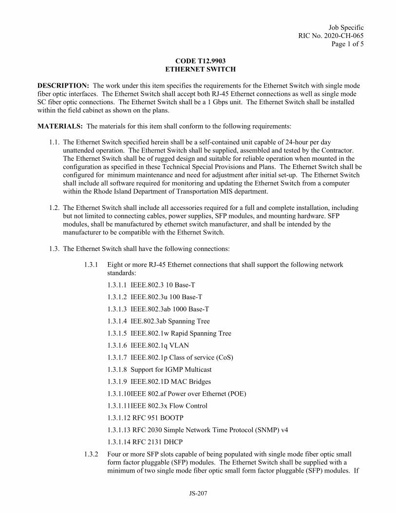
Job Specific RIC No. 2020-CH-065
Page 1 of 5
CODE T12.9903 ETHERNET SWITCH
DESCRIPTION: The work under this item specifies the requirements for the Ethernet Switch with single mode fiber optic interfaces. The Ethernet Switch shall accept both RJ-45 Ethernet connections as well as single mode SC fiber optic connections. The Ethernet Switch shall be a 1 Gbps unit. The Ethernet Switch shall be installed within the field cabinet as shown on the plans.
MATERIALS: The materials for this item shall conform to the following requirements:
1.1. The Ethernet Switch specified herein shall be a self-contained unit capable of 24-hour per day unattended operation. The Ethernet Switch shall be supplied, assembled and tested by the Contractor. The Ethernet Switch shall be of rugged design and suitable for reliable operation when mounted in the configuration as specified in these Technical Special Provisions and Plans. The Ethernet Switch shall be configured for minimum maintenance and need for adjustment after initial set-up. The Ethernet Switch shall include all software required for monitoring and updating the Ethernet Switch from a computer within the Rhode Island Department of Transportation MIS department.
1.2. The Ethernet Switch shall include all accessories required for a full and complete installation, including but not limited to connecting cables, power supplies, SFP modules, and mounting hardware. SFP modules, shall be manufactured by ethernet switch manufacturer, and shall be intended by the manufacturer to be compatible with the Ethernet Switch.
1.3. The Ethernet Switch shall have the following connections:
1.3.1 Eight or more RJ-45 Ethernet connections that shall support the following network standards:
1.3.1.1 IEEE.802.3 10 Base-T
1.3.1.2 IEEE.802.3u 100 Base-T
1.3.1.3 IEEE.802.3ab 1000 Base-T
1.3.1.4 IEE.802.3ab Spanning Tree
1.3.1.5 IEEE.802.1w Rapid Spanning Tree
1.3.1.6 IEEE.802.1q VLAN
1.3.1.7 IEEE.802.1p Class of service (CoS)
1.3.1.8 Support for IGMP Multicast
1.3.1.9 IEEE.802.1D MAC Bridges
1.3.1.10 IEEE 802.af Power over Ethernet (POE)
1.3.1.11 IEEE 802.3x Flow Control
1.3.1.12 RFC 951 BOOTP
1.3.1.13 RFC 2030 Simple Network Time Protocol (SNMP) v4
1.3.1.14 RFC 2131 DHCP
1.3.2 Four or more SFP slots capable of being populated with single mode fiber optic small form factor pluggable (SFP) modules. The Ethernet Switch shall be supplied with a minimum of two single mode fiber optic small form factor pluggable (SFP) modules. If
JS-207

Job Specific RIC No. 2020-CH-065
Page 2 of 5
the Plans indicate that more than two SFP modules are required to interface with the project fiber optic cable strands, then the required number of SFP modules shown in the Plans shall be provided. The SFP modules shall meet the following requirements:
1.3.2.1. The SFP modules shall be manufactured by the same firm that manufactures the Ethernet Switch.
1.3.2.2. The optical emitters shall be laser diode type.
1.3.2.3. The SFP modules shall have an operating wavelength of 1310 nm, single mode and/or 1550 nm, single mode. The optical wavelength chosen shall be consistent with and compatible with the optical wavelength chosen for all Ethernet switches with which the Ethernet Switch must communicate optically.
1.3.2.4. The SFP modules shall each have an optical power budget that is equal or greater than the actual worst case link optical loss based on an analysis of all 1000 Mbps optical links on the project, plus a safety margin of 4 dB.
1.3.2.5. Each SFP module shall accommodate two fiber optic strands.
1.3.2.6. Each SFP module shall have a distance capability as needed to provide stable, reliable communications to the locations shown in the Plans, however the SFP shall have a minimum distance capability of 20 kilometers.
1.3.2.7. The single mode fiber optic ports shall each have an optical power budget of 13dB, minimum.
1.3.2.8. The optical emitters shall have a transmit power of -15dbM, minimum.
1.3.2.9. The optical detectors shall have receive sensitivity of -28dbM, worst case.
1.3.2.10. Each SFP module shall have SC type fiber optic connectors, or as directed by the Engineer. In the event that SC type connectors are not supplied, suitable fiber optic patch cords shall be supplied to allow proper connection of the SFP modules to other cabinet equipment
1.3.3. The single mode fiber optic ports shall support the following network standards:
1.3.3.1. IEEE.802.3u 100 Base-FX
1.3.3.2. IEEE.802.3z 1000 Base-FX
1.3.3.3. IEEE.802.1d Spanning Tree
1.3.3.4. IEEE.802.1w Rapid Spanning Tree
1.3.3.5. IEEE.802.1q VLAN
1.3.3.6. IEEE.802.1p Class of Service (CoS)
1.3.3.7. Support for IGMP Multicast
1.3.4. All single mode fiber optic ports of Ethernet switches supplied on the project shall be fully compatible with each other, as well as with existing Ethernet switches on adjacent projects with which they must connect and interoperate. This compatibility shall include, but not be limited to, such characteristics as optical operating wavelength(s), transmit power, receive sensitivity, and operating protocols.
JS-208

Job Specific RIC No. 2020-CH-065
Page 3 of 5
1.3.5. The Contractor shall supply, install, and test all Ethernet cables required to make all connections as shown in the Plans. The Ethernet cables shall be the length required to establish connections to any device placed in the cabinet, or three feet long minimum, whichever is greater.
1.4 The Ethernet Switch shall be a managed Ethernet layer 2 device.
1.5 The Ethernet Switch shall have a switching method of store and forward.
1.6 The Ethernet Switch shall support the following protocols:
1.6.1 RTP/ID
1.6.2 TCP/IP with full multicast support
1.6.3 DNS
1.6.4 DHCP
1.6.5 RFC 3376 IGMPv3 IP Multicast
1.6.6 HTML and Telnet management
1.6.7 IEEE 802.1X Port Based Network Access Control
1.6.8 RFC 1492 TACACS+
1.6.9 Secure Sockets Layer (SSL)
1.6.10 SSHv1SSHv2 Secure Shell
1.7 The Ethernet Switch shall support the following network management protocols:
1.7.1 SNMP V2c
1.7.2 RMON for Ethernet agent
1.7.3 Telnet/TFTP
1.7.4 HTTP graphical web-based
1.7.5 Command Line Interface
1.8 The Ethernet Switch shall be field hardened and rated by its manufacturer in accordance with the operating temperature, storage temperature, and relative humidity requirements of the NEMA TS2 Standard. The design shall be inherently temperature compensated to prevent abnormal operation. The circuit design shall include such compensation as is necessary to overcome effects due to temperature in the specified environmental range.
1.9 The Ethernet Switch shall be both rack and shelf mountable.
1.10 The Ethernet Switch shall be UL listed.
JS-209
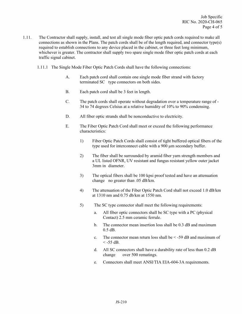
Job Specific RIC No. 2020-CH-065
Page 4 of 5
1.11. The Contractor shall supply, install, and test all single mode fiber optic patch cords required to make all connections as shown in the Plans. The patch cords shall be of the length required, and connector type(s) required to establish connections to any device placed in the cabinet, or three feet long minimum, whichever is greater. The contractor shall supply two spare single mode fiber optic patch cords at each traffic signal cabinet.
1.11.1 The Single Mode Fiber Optic Patch Cords shall have the following connections:
A. Each patch cord shall contain one single mode fiber strand with factoryterminated SC type connectors on both sides.
B. Each patch cord shall be 3 feet in length.
C. The patch cords shall operate without degradation over a temperature range of -34 to 74 degrees Celsius at a relative humidity of 10% to 90% condensing.
D. All fiber optic strands shall be nonconductive to electricity.
E. The Fiber Optic Patch Cord shall meet or exceed the following performancecharacteristics:
1) Fiber Optic Patch Cords shall consist of tight buffered optical fibers of thetype used for interconnect cable with a 900 µm secondary buffer.
2) The fiber shall be surrounded by aramid fiber yarn strength members anda UL listed OFNR, UV resistant and fungus resistant yellow outer jacket3mm in diameter.
3) The optical fibers shall be 100 kpsi proof tested and have an attenuationchange no greater than .05 dB/km.
4) The attenuation of the Fiber Optic Patch Cord shall not exceed 1.0 dB/kmat 1310 nm and 0.75 db/km at 1550 nm.
5) The SC type connector shall meet the following requirements:
a. All fiber optic connectors shall be SC type with a PC (physicalContact) 2.5 mm ceramic ferrule.
b. The connector mean insertion loss shall be 0.3 dB and maximum0.5 dB.
c. The connector mean return loss shall be < -59 dB and maximum of< -55 dB.
d. All SC connectors shall have a durability rate of less than 0.2 dBchange over 500 rematings.
e. Connectors shall meet ANSI/TIA EIA-604-3A requirements.
JS-210

Job Specific RIC No. 2020-CH-065
Page 5 of 5
METHOD OF MEASUREMENT: “ETHERNET SWITCH” shall be measured for payment by the unit “EACH” for each unit installed and accepted.
BASIS OF PAYMENT: “ETHERNET SWITCH” shall be paid for at the contract unit price bid per "EACH", which price shall include full compensation for all materials, equipment, tools, labor, and work incidental thereto complete in place and accepted by the Engineer.
JS-211

Job Specific RIC No. 2020-CH-065
Page 1 of 2
CODE T12.9904 FIBER OPTIC SPLICE ENCLOSURE – 144 POSITION
DESCRIPTION. This item of work shall conform to the applicable sections of the Standard Specifications. This item shall consist of furnishing and installing Fiber Optic Splice Enclosure, splices, and appurtenances of the type specified at the locations shown on the plans or as indicated by the Engineer, in accordance with these specifications.
MATERIALS. The Fiber Optic Splice Enclosure shall be a stand-alone unit manufactured for installation in an underground storage box and shall meet the following requirements:
1. Mounting brackets as recommended by the manufacturer shall be provided.
2. The Splice Enclosures shall be waterproof and airtight.
3. The Splice Enclosure shall be manufactured of non-corroding materials and shall be resistant to causticsolutions.
4. All splice enclosures shall employ re-usable sealing materials allowing multiple re-entrance withoutreplacing any component.
5. If special tools or kits are required to enter and close splice cases, then these tools or kits shall be providedby the Contractor.
6. The splice enclosures shall be large enough to retain the number and size of splice trays capable of holdinga minimum of 144 splices.
7. Each splice case shall contain a splice tray organizer capable of holding the required number of splicetrays.
8. The splice trays shall meet the following requirements:
a. The splice trays shall incorporate a system to retain and provide strain relief to the fiber optic bufferstubes.
b. The splice trays shall incorporate grooves where the fiber optic splice can be held in place.c. Each splice tray shall incorporate a clear snap on lid.
9. The Fiber Optic Splice Enclosure shall incorporate cable guides that maintain fiber strands and fiber buffertubes bending radius greater than the minimum allowed.
10. The Fiber Optic Splice Enclosure shall incorporate a restraining mechanism to hold each fiber optic cablecentral member and outside jacket.
11. The Fiber Optic Splice Enclosure shall have a sufficient number of cable ports to accommodate thenumber of fiber optic cables shown in the Plans at each location.
CONSTRUCTION METHODS. The Contractor shall perform splices in each Fiber Optic Splice Enclosure as shown in the plans. The maximum splice loss shall be 0.1 dB.
JS-212

Job Specific RIC No. 2020-CH-065
Page 2 of 2
METHOD OF MEASUREMENT. “FIBER OPTIC SPLICE ENCLOSURE – 144 POSITION” will be measured for payment by the unit “EACH” for each unit installed and accepted.
BASIS OF PAYMENT. The accepted quantity of “FIBER OPTIC SPLICE ENCLOSURE - 144 POSITION” will be paid at the contract unit price per “EACH”, which price shall include full compensation for all splices, materials, equipment, tools, labor, and work incidental thereto complete in place and accepted by Engineer.
JS-213

Job Specific RIC No. 2020-CH-065
Page 1 of 2
CODE T12.9905 FIBER OPTIC PATCH PANEL - 12 POSITION
DESCRIPTION. This item of work shall conform to the applicable sections of the Standard Specifications. This item shall consist of furnishing and installing Fiber Optic Patch Panels of the type specified at the locations shown on the plans or as indicated by the Engineer, in accordance with these specifications.
MATERIALS. The Fiber Optic Patch Panels shall meet the following requirements:
A. The Fiber Optic Patch Panel - 12 position shall be a stand-alone unit manufactured for outdoor fieldcabinets.
B. The Fiber Optic Patch Panel - 12 position shall be capable of accommodating a minimum of 12 SC typeconnector sleeves.
C. The Fiber Optic Patch Panel - 12 position shall be capable of terminating up to 12 connectorized pigtails.
D. The Fiber Optic Patch Panel shall incorporate a hinged access door.
E. The patch panel shall be rack, wall, or shelf mountable as required by the specific location. The patchpanel shall be securely fastened in place as recommended by the manufacturer.
F. The Fiber Optic Patch Panel shall include splice trays meeting the following requirements:
1) The splice trays in the Fiber Optic Patch Panel - 12 position shall be capable of holding a minimum of12 splices.
2) The splice trays shall incorporate a system to retain and provide strain relief to the fiber optic bufferstubes and connector pigtails.
3) The splice trays shall incorporate grooves where the fiber optic splice can be held in place
4) Each splice tray shall incorporate a clear snap on lid.
G. The Fiber Optic Patch Panel shall include a restraining system to hold the splice trays securely in place.
H. The Fiber Optic Patch Panel shall incorporate cable guides that maintain fiber strands and fiber buffertubes bending radius greater than the minimum allowed.
I. The Fiber Optic Patch Panel - 12 Position shall use 12 connectorized pigtails to connect the fiber opticcable to the Fiber Optic Patch Panel front panel.
J. The number of pigtails to be furnished and spliced to the fiber optic cable are included in the plans. Theconnectorized pigtails shall meet the following requirements:
1) All fiber optic connectors shall be SC type with a PC (physical Contact) 2.5 mm ceramic ferrule.
2) The connector mean insertion loss shall be 0.3 dB and maximum 0.5 dB.
3) The connector mean return loss shall be ≤ -59 dB and maximum of ≤ -55 dB.
4) All SC connectors shall have a durability rate of less than 0.2 dB change over 500 rematings.
5) Connectors shall meet ANSI/TIA EIA-604-3A requirements.
6) The fiber optic strand of the connectorized pigtail shall have matching optical properties as the fiberoptic strand used on the fiber optic cable.
7) The Contractor shall provide factory assembled fiber optic pigtails. Modified fiber optic patch cordswill not be accepted.
K. The Fiber Optic Patch Panel shall incorporate a restraining mechanism to hold the fiber optic cable centralmember and outside jacket.
JS-214

Job Specific RIC No. 2020-CH-065
Page 2 of 2
METHOD OF MEASUREMENT. “FIBER OPTIC PATCH PANEL - 12 POSITION” will be measured for payment by the unit “EACH” for each unit installed and accepted.
BASIS OF PAYMENT. The accepted quantity of “FIBER OPTIC PATCH PANEL - 12 POSITION” will be paid at the contract unit price per “EACH”, which price shall include full compensation for all materials including pigtails and required splices, equipment, tools, labor, and work incidental thereto complete in place and accepted by Engineer.
JS-215

Job Specific
RIC No. 2020-CH-065
Page 1 of 1
CODE T12.9907
MODIFY EXISTING TRAFFIC SIGNAL CONTROLLER
DESCRIPTION: This item of work shall conform to the applicable sections of the Standard Specifications with
the following additions:
The work consists of the necessary rewiring/wiring terminations and reprogramming in the existing controller as
indicated on the plans to accommodate any phasing or timing modifications that are called for on the plans. Also
included in this item is the programming of detector relays (delays and phase assignments) as called for on the
plans.
Three hardcopies of all programmable controller data shall be supplied by the Contractor. The recorded data shall
reflect settings resident in the controller upon acceptance of the project by the Engineer and the Owner.
CONSTRUCTION METHODS: The Contractor shall make the required modifications to existing controllers to
accommodate the traffic signal phasing, timings and detection as shown on the plans.
Where any modifications are made at existing traffic signal controller cabinets, Contractor shall supply two (2)
copies of box prints showing all of the modifications that are made. If existing box prints are not available, the
Contractor shall produce and supply function-based connection diagrams showing various in-cabinet
interconnections and wiring changes made as part of the project. Where new loop detectors are installed, the
Contractor shall install a revised cabinet door sticker table showing the detector assignment information including
the approach names, detector numbers, terminal numbers, detector relay slot number, relay number, relay channel
number, and phase associated with each detector. A supplemental cabinet door sticker which depicts the
intersection layout, including detection, shall also be installed by the Contractor where needed.
METHOD OF MEASUREMENT: “MODIFY EXISTING TRAFFIC SIGNAL CONTROLLER” will be
measured for payment by the unit “EACH” which shall consist of all labor, tools, equipment, materials, rewiring,
splicing, reprogramming and incidentals necessary to complete this item of work to the satisfaction of the
Engineer.
BASIS OF PAYMENT. The accepted quantity of “MODIFY EXISTING TRAFFIC SIGNAL CONTROLLER”
will be paid for at the contract unit price per “EACH”, which price and payment shall constitute full compensation
for furnishing all labor, tools, equipment, materials, relays, load switches, rewiring, splicing, disabling of existing
detection, cabinet door stickers, reprogramming and incidentals necessary to complete this item of work to the
satisfaction of the Engineer.
JS-216
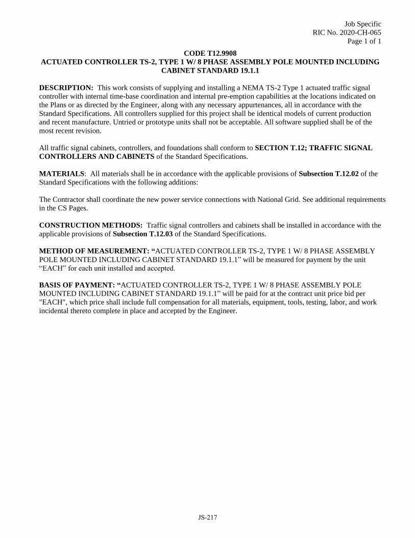
Job Specific
RIC No. 2020-CH-065
Page 1 of 1
CODE T12.9908
ACTUATED CONTROLLER TS-2, TYPE 1 W/ 8 PHASE ASSEMBLY POLE MOUNTED INCLUDING
CABINET STANDARD 19.1.1
DESCRIPTION: This work consists of supplying and installing a NEMA TS-2 Type 1 actuated traffic signal
controller with internal time-base coordination and internal pre-emption capabilities at the locations indicated on
the Plans or as directed by the Engineer, along with any necessary appurtenances, all in accordance with the
Standard Specifications. All controllers supplied for this project shall be identical models of current production
and recent manufacture. Untried or prototype units shall not be acceptable. All software supplied shall be of the
most recent revision.
All traffic signal cabinets, controllers, and foundations shall conform to SECTION T.12; TRAFFIC SIGNAL
CONTROLLERS AND CABINETS of the Standard Specifications.
MATERIALS: All materials shall be in accordance with the applicable provisions of Subsection T.12.02 of the
Standard Specifications with the following additions:
The Contractor shall coordinate the new power service connections with National Grid. See additional requirements
in the CS Pages.
CONSTRUCTION METHODS: Traffic signal controllers and cabinets shall be installed in accordance with the
applicable provisions of Subsection T.12.03 of the Standard Specifications.
METHOD OF MEASUREMENT: “ACTUATED CONTROLLER TS-2, TYPE 1 W/ 8 PHASE ASSEMBLY
POLE MOUNTED INCLUDING CABINET STANDARD 19.1.1” will be measured for payment by the unit
“EACH” for each unit installed and accepted.
BASIS OF PAYMENT: “ACTUATED CONTROLLER TS-2, TYPE 1 W/ 8 PHASE ASSEMBLY POLE
MOUNTED INCLUDING CABINET STANDARD 19.1.1” will be paid for at the contract unit price bid per
"EACH", which price shall include full compensation for all materials, equipment, tools, testing, labor, and work
incidental thereto complete in place and accepted by the Engineer.
JS-217

Job Specific
RIC No. 2020-CH-065
Page 1 of 22
CODE T12.9909
TRAFFIC SIGNAL CONTROL SYSTEM
DESCRIPTION: The work under this item shall conform to the applicable requirements of Section T12 “Traffic
Signal Controllers and Cabinets” of the Standard Specifications. Untried or prototype units shall not be
acceptable. All software supplied shall be of the most recent revision at the time of final acceptance.
MATERIALS:
Traffic Signal Control System
The traffic signal control system shall meet the following minimum performance standards:
General The Central Management System (CMS) and the Adaptive Signal Control Technology (ASCT) system
shall satisfy the following basic requirements:
1. The CMS system shall be able to provide multiple signal group operations. Individual intersections within
a group must be able to be reassigned to a different operational group by manual, time-of day, or traffic
responsive command. For those locations identified to be operating as part of the ASCT system, individual
intersections within a group shall be able to be reassigned to a different operational group via adaptive
system command.
2. No additional hardware, software items and/or subscription fees/costs shall be needed/allowed to satisfy
the requirements as defined in these specifications.
3. All communications between CMS and ASCT system and the local controllers shall comply with NTCIP
protocol consistent with other similar RIDOT projects. Compatibility is required for all currently
approved mandatory NTCIP standards with similar RIDOT projects. To help assure this compatibility,
the system manufacturer shall certify and list what level of NTCIP compliance is supported for all current
mandatory and optional NTCIP objects and standards via shop drawing submittal. In addition, the list
shall describe all manufacturer specific NTCIP objects and functions available. The system supplier shall
also list the non-approved NTCIP objects and standards in the system and furnish a description of the
company’s involvement in and input to the various NTICP standards committees, their degree of
involvement, and present efforts including timetables for meeting proposed NTCIP standards under
review. All communications between the local field controllers to the CMS and the ASCT shall be
Ethernet based protocols, serial of FSK communications shall not be allowed.
4. The CMS and the ASCT shall be installed on a Contractor furnished, supplied and configured cloud-based
system. This cloud-based system shall be sized for the Pell Bridge Approach Roads and Ramp
Improvements Newport Side project (herein referred to as the “Pell Bridge” project) needs as well as 1000
intersections for future growth. The Contractor shall supply all additional software and hardware
accessories to provide a complete and functional cloud-based CMS and ASCT system.
5. The cloud-based CMS and ASCT system shall be configured to provide remote access to the “Pell
Bridge” intersections as well as system users as designated by RIDOT and or the Engineer.
6. The cloud-based CMS and ASCT shall be configured to require a multi-factor authentication to gain
access to the system. The Contractor shall coordinate and submit for approval all proposed network
security settings with RIDOT DoIT and the Engineer.
JS-218
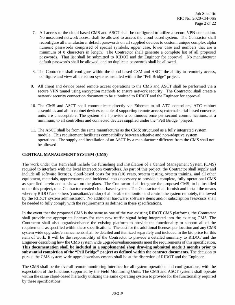
Job Specific
RIC No. 2020-CH-065
Page 2 of 22
7. All access to the cloud-based CMS and ASCT shall be configured to utilize a secure VPN connection.
No unsecured network access shall be allowed to access the cloud-based system. The Contractor shall
reconfigure all manufacturer default passwords on all supplied devices to custom, unique complex alpha
numeric passwords comprised of special symbols, upper case, lower case and numbers that are a
minimum of 8 characters in length. The Contractor shall generate a complete list of all proposed
passwords. That list shall be submitted to RIDOT and the Engineer for approval. No manufacturer
default passwords shall be allowed, and no duplicate passwords shall be allowed.
8. The Contractor shall configure within the cloud based CSM and ASCT the ability to remotely access,
configure and view all detection systems installed within the “Pell Bridge” project.
9. All client and device based remote access operations to the CMS and ASCT shall be performed via a
secure VPN tunnel using encryption methods to ensure network security. The Contractor shall create a
network security connection document to be submitted to RIDOT and the Engineer for approval.
10. The CMS and ASCT shall communicate directly via Ethernet to all ATC controllers, ATC cabinet
assemblies and all in cabinet devices capable of supporting remote access; external serial-based converter
units are unacceptable. The system shall provide a continuous once per second communications, at a
minimum, to all controllers and connected devices supplied under the “Pell Bridge” project.
11. The ASCT shall be from the same manufacturer as the CMS; structured as a fully integrated system
module. This requirement facilitates compatibility between adaptive and non-adaptive system
operations. The supply and installation of an ASCT by a manufacturer different from the CMS shall not
be allowed.
CENTRAL MANAGEMENT SYSTEM (CMS)
The work under this Item shall include the furnishing and installation of a Central Management System (CMS)
required to interface with the local intersection controllers. As part of this project, the Contractor shall supply and
include all software licenses, cloud-based costs for ten (10) years, system testing, system training, and all other
equipment, materials, appurtenances and incidental costs necessary to provide a complete, fully operational CMS
as specified herein and as shown on the plans. The Contractor shall integrate the proposed CMS, to be installed
under this project, on a Contractor created cloud-based system. The Contractor shall furnish and install the means
whereby RIDOT and others (consultant/vendor) shall be able to monitor and control the system remotely, if allowed
by the RIDOT system administrator. No additional hardware, software items and/or subscription fees/costs shall
be needed to fully comply with the requirements as defined in these specifications.
In the event that the proposed CMS is the same as one of the two existing RIDOT CMS platforms, the Contractor
shall provide the appropriate licenses for each new traffic signal being integrated into the existing CMS. The
Contractor shall also upgrade/enhance the existing platform to provide the functionality to support all of the
requirements as specified within these specifications. The cost for the additional licenses per location and any CMS
system wide upgrades/enhancements shall be detailed and itemized separately and included in the bid price for this
item of work. It will be the responsibility of the Contractor to provide a detailed summary to RIDOT and the
Engineer describing how the CMS system wide upgrades/enhancements meet the requirements of this specification.
This documentation shall be included in a supplemental shop drawing submittal made 3 months prior to
substantial completion of the “Pell Bridge” project as defined within the contract documents. The decision to
pursue the CMS system wide upgrades/enhancements shall be at the discretion of RIDOT and the Engineer.
The CMS shall be the overall remote monitoring interface for all system operations and configurations, with the
expectation of the functions supported by the Field Monitoring Units. The CMS and ASCT systems shall operate
within the same cloud-based hierarchy utilizing the same operating system to provide for the functionality required
by these specifications.
JS-219
Job Specific
RIC No. 2020-CH-065
Page 3 of 22
The CMS and ASCT systems shall include a Data Base (DB) management tool that shall allow RIDOT to perform
queries on all collected device data. This DB management tool shall be integrated within the CMS and ASCT
systems and shall provide user definable scenarios to allow for detailed database analysis based on RIDOT
requirements in relation to stored CMS and ASCT system data.
The CMS shall be supplied and configured with a high-level dashboard allowing RIDOT to monitor the current
status and conditions of all intersections included in the “Pell Bridge” project.
The CMS and ASCT systems shall support communications to all ATC intersection controllers. ATC intersection
controllers shall be supplied with the ability of communicating with the system, at a minimum rate of once-per-
second.
The CMS system clock shall utilize the per intersection internet network connection to provide for “Time
Synchronization” to all ATCC devices. The CMS central clock shall be set to the “National Institute of Standards
and Technology” (NIST) and/or WorldTimeServer.com. The time sync to all ATC controllers shall occur once per
day at 2:00 AM. In the event of a loss of communications between the CMS and the ATC, the FMU GPS time sync
reference shall be used to provide for time synchronization.
In addition to the requirements contained elsewhere within these specifications, the CMS shall be supplied and
installed with the following functionality. No additional hardware or software items shall be needed to enable the
operations listed:
• Shall be supplied and installed with the ability to remotely monitor and control all traffic signal
intersections installed under this project.
• Shall be supplied and installed to support the latest nationally adopted versions of NTCIP 1201 and
NTCIP 1202 to allow for the CMS to communicate and transmit data elements from different
manufacturers ATC controllers in real-time.
• Shall be resident on a cloud-based system and configured to allow for secure, remote monitoring and
control of the system for operators and staff as designated by RIDOT.
• Shall allow for full monitoring and control capabilities of the system, limited only by virtue of the user
privileges assigned to specific users by the System Administrator, not by location such as TMC vs.
remote access.
• Shall be programmed with varying levels of access privileges for up to 20 initial users. RIDOT will
provide the user list and privileges that will be assigned to each user.
• Shall be supplied and installed with the ability of supporting new technologies as they become
available.
• Shall be supplied and installed with the ability of supporting a minimum of 1000 signalized intersection.
• The CMS shall log all user accesses to system controller units, including but not limited to username,
date, and time.
• Shall be supplied and installed with the ability of being accessed from any web enabled device,
including computers, tablets, and smart phones as limited based on security requirements.
• Shall be supplied and installed with the ability of uploading the entire controller database and download
user selectable parameters such as controller timing data.
• Shall be supplied and installed with the ability for labeling traffic controller alarms and displaying the
user defined name when the alarm is active.
JS-220
Job Specific
RIC No. 2020-CH-065
Page 4 of 22
• Shall be supplied and installed with a system-wide, real time status display map. This map shall support
common GIS map navigation, Google based maps and have the ability to incorporate standard ESRI
vector/image files and support user selectable levels.
• Shall be supplied and installed with the ability of displaying the operational and alarm status of each
system controller, system link and/or detector status as well as displaying intersection name, and
operational status. It shall also be possible for the system-wide status map to be displayed on user
workstations. This system wide status map shall display alarms, reports, failures and other user defined
operational parameters in real time. Contractor shall coordinate all work with RIDOT and the Engineer.
• Shall be supplied and installed with the ability of displaying real time status of all CMS system ATC
units. This includes real time status of adaptive and non-adaptive operation. In addition to the
requirements contained elsewhere within these specifications, the status display shall include the
current state of phase output status and vehicle/pedestrian detection.
• Shall be supplied and installed with the ability of displaying time space diagrams, in real time, including
green band progression and speed.
• Shall be supplied and installed with the ability of supporting system reports and event logging functions.
Reports shall be recorded to disk, viewable on workstations, remote access clients or printed as selected
by the user.
• Shall be supplied and installed with the ability of supporting central scheduler functions including
traffic controller/group time operations, device log collection, collection of traffic data, email
notifications and reports, date/time broadcast to all controllers and timing parameter audit reports.
• Shall be supplied and installed with the ability of providing system security functions including
username and password for each user and access level restrictions settable by the system administrator.
Contractor shall coordinate all work with RIDOT and the Engineer in regard to network/system
security.
• Shall be a full production, fully tested and certified product (certified to be compliant with all standards
with which it is required to be compliant), with a minimum of 10 identical production systems in
continuous operation, running intersections within the United States.
• Shall be supplied and installed with an integrated adaptive control software as part of the CMS
contained in user programmable configuration database format. Adaptive control software supplied
with a script only level software shall not be accepted.
• Shall allow the system operator to manually configure groups of intersections that operate in a
coordinated manner.
• Shall provide database upload and download capability to all intersection ATC units under its control.
The ATC units shall remain on stop and go during upload/download operations.
• Shall have a graphical user interface that is consistent with the Windows™ operating system. The
system software shall be designed so that additional signalized locations may be added to the map
display by agency personnel
• Shall provide multiple intersection maps showing current real time status for each intersection in the
system.
• Shall include a user programmable scheduler that shall allow scheduled operations to take place,
including but not limited to, controller unit operations and device log retrieval.
• Shall be configured to require multi-level user authentication that prevents unauthorized users from
logging on to the cloud-based system (CMS/ASCT).
JS-221

Job Specific
RIC No. 2020-CH-065
Page 5 of 22
• Shall be supplied and installed with the ability to implement control strategies based on traffic
conditions, including but not limited to controller time-of-day operations and patterns.
• Shall manage/restrict remote access to the system. All access to the system shall be by encrypted VPN
tunnels, no open connections shall be allowed.
• Shall have the ability to immediately notify designated staff of alarms and alerts. Alarms at RIDOT’s
TMC and Maintenance Facility shall include an audible option for selected alarms. The volume and
tone type shall be user selectable. A single audible alarm shall be provided for an alarm which re-
occurs within a user defined period.
• Shall be supplied with the ability to collect high resolution data from each ATC unit.
• Shall be supplied with the ability to store all operational data for the CMS/ASCT signal timing
parameters calculated by the adaptive system and export selected data in an agency usable format.
• Shall be supplied with the ability to report and display all signal performance data for the CMS/ASCT
in user defined sampling periods.
• Shall be programmed to generate historic and real-time reports that effectively support operations,
maintenance and reporting of system performance and traffic conditions. These historic reports shall
be available in 15 minute or hourly increments for user selected sensors and be available by the day,
week or month.
• Shall be supplied with the ability for system wide, controller-based detector failure monitoring that will
trigger user defined actions when user defined conditions are met.
• Shall be supplied with the ability to include user defined alarms and alerts. The following conditions
shall trigger an immediate alarm report via on-screen, SMS and email notification:
o Power On/Off
o Cabinet Flash
o Manual Control
o Door Open
o Detector Failure
o Communications Failure
Split Monitor
The CMS shall include the capability to display, from stored data, a split monitor report for intersections
operating non-adaptive, coordinated. This split monitor report shall consist of an online report, updated
every cycle(s) or sample time defined by the user, that gives the operator a comparison of actual
programmed split times, in seconds, versus the actual split times utilized by each phase, in seconds, during
the defined sample time. Split monitor reports shall have the ability to store and retrieve the required
information necessary to produce the Split Monitor report at a later date from the system’s stored data. In
addition to the requirements contained elsewhere within these specifications, the split monitor report shall
show the following:
• Location name/number
• Time and date the report was initiated
• Programmed split times for each phase (seconds)
• Coordination pattern in effect
• Actual split time used per phase, per cycle (seconds)
Active Time-Space Diagram
JS-222

Job Specific
RIC No. 2020-CH-065
Page 6 of 22
The CMS shall provide a real-time dynamic display showing all intersections within a user selected signal
group. The Active Time Space Diagram display shall also graphically show:
• The relative position of each intersection in the signal group as compared to the adjacent
intersections.
• The signal status of each signal (red or green).
• The system green band moving along the display updating at a minimum of once per second from
real time field data.
• The impact of early main street green returns on the system.
Schedules
The CMS shall have the ability of creating/modifying a time schedule to control system commands. The
time schedule shall be supplied with the ability to control various functions and operations for individual
intersections and groups of intersections. scheduling capability shall include time-of-day/day-of-
week/week-of-year schedules with a one-minute resolution. The CMS shall automatically assign the
schedule for each day to its corresponding day of week. In addition, a calendar scheduler shall be used to
define which day of the week or generic holiday schedule will be used in lieu of the normal day of the week
schedule for a particular day of the year.
The CMS scheduling ability shall include two types of schedules:
• Permanent (repeating) schedules
• Temporary (one-time event) schedules
All CMS functions executed by the system shall be recorded in the system log. The system log shall identify
the source of the executed function as initiated by the scheduler or an interactive user, including
identification of whether it represents a permanent or temporarily scheduled function. Permanent schedules
shall contain the schedule of events for each day of the week and several generic holidays. Functions shall
be stored in the permanent schedule and remain unchanged after they have been executed. Temporary
schedules shall provide the capability of scheduling one-time events in addition to the events scheduled for
the current day. Commands stored in the temporary schedule shall be deleted following their execution. A
one-time event shall be scheduled to execute any time in the future.
User Interface
All CMS traffic system reports, graphic displays, and dialogues shall be functions of the user interface
software running on individual clients. Each client shall access data as needed from the CMS traffic
control database system. Programming Standards
All client user interface functions shall be implemented using window-based graphical user interface
(GUI) concepts conforming to Microsoft Windows Standards. The GUI shall use a Microsoft Windows
platform to manage the CMS client environment.
Object Library
The CMS user interface shall include an object library that contains dynamic icon objects for system control
and monitoring devices. These objects shall include as a minimum traffic signals, pedestrian signals, video
detection locations and detection zones. The library shall also include an interactive editor for placing these
objects within dynamic graphic screens. The system shall allow the user to hyper link dynamic graphics
objects directly to system database elements without programming or recompilation. The library shall also
JS-223
Job Specific
RIC No. 2020-CH-065
Page 7 of 22
include dynamic objects allowing the user to define directional roadway links using a simple vector drawing
facility. Proper representation of directional status attributes shall be available at all zoom levels. The use
of stock intersection layout drawings shall not be allowed.
Graphical User Interface (GUI)
All operators accessing the CMS and ASTC system shall have security access based on their login password
as assigned by the system administrator. The GUI shall use icons and vectors, in conjunction with a pointing
device to interact with and allow an operator to enter decisions, draw graphics, issue commands, and receive
information from the system. The GUI shall include an intersection/link base map with windowed table
reports and management input windows. The base map shall be GIS, Google and or CAD drawings. The
GUI shall provide access to all monitoring and control options from a single user interface. As a result, all
operator actions shall be immediately visible as graphical status changes and onscreen display windows.
The GUI shall provide interactive mechanisms to assist in creating, editing, and modifying dynamic graphic
screens that are linked to system dynamic elements. These dynamic condition maps shall provide a simple
mechanism for system navigation, presentation of status, and selections within the user interface.
The user interface available at each client shall simultaneously support the following operations by the operator:
• Generate and display in real-time intersection status screens, section level maps, and system
level maps.
• Issue manual commands to the intersection controllers.
• Provide intersection controller database management as follows:
o Upload database from controllers.
o Edit database and save on disk.
o Download database to controllers.
o Compare field and central databases.
o Retrieve detector logs and event logs from local controllers.
o Print event reports from system SQL database.
o Print or plot system detector data from system SQL database.
Graphical Displays
The CMS shall allow the user to access functions using map-based graphical displays. The CMS shall use
graphical icons on the graphical displays to represent system devices. The graphical icons shall provide
access to traffic control data (signal timing, geometrics, etc.), real-time data (intersection, link status, etc.),
the database, and graphical image files. Graphical symbols (icons) shall be employed to activate common
functions. Graphics shall be used to provide added capabilities for portraying system status and soliciting
input from operators.
The graphic map shall act as a system selection palate enabling the operator to make a selection by pointing
to a particular system object installed within the ATCC that allows for remote monitoring and control.
When that system object is selected, a more detailed status window shall be displayed. The CMS GUI shall
provide an interactive mechanism to assist in creating, editing, and modifying dynamic graphic screens that
are linked to system dynamic elements. These dynamic condition maps shall provide a simple mechanism
for system navigation, presentation of status, and selections within the user interface. Multiple traffic
condition views shall be supported simultaneously on the desktop including multiple detailed interactive
views. The user shall be able to create a new window by clicking the appropriate button in the toolbar.
Traffic condition graphics displays shall contain multiple levels of background images.
JS-224

Job Specific
RIC No. 2020-CH-065
Page 8 of 22
Background map images shall be capable of containing commercial vector images such as Google Maps,
NavTech, Etak, Tiger and TIFF geographically accurate map scanned images. The use of scanned project
plans containing equipment callouts shall not be allowed. These images shall be compatible with standard
graphical raster or vector image file types, common paint/drawing programs, and other packages that allow
export of drawings in vector and/or bitmap form. These images shall be used as the display layers of real-
time graphics displays. Zooming and scrolling and automatic control layers of graphic presentation shall
be included with the system.
Intersection Maps:
o Graphical representation of the intersection geometry including curb lines and
approach/departure lane configurations (scaled maps are not required)
o Intersection ID
o Municipality
o Street Names
o System Name
o North Arrow
o Real Time Signal Display Status; Vehicle and Pedestrian
o Vehicle and System Detector Per Phase Call Status
o System Parameters Status (Cycle, Split, Offset)
o Intersection Operational Status (Flash, Coordinated, Free, On-line, Preemption)
o Controller Cabinet Location (static)
o Time/Date
System Map:
o Graphical representation of the system showing all intersections within the Subsystem (scaled
maps are not required)
o Municipality
o Street Names
o Subsystem Number, if applicable
o North Arrow
o Coordinated Phase Green at Each Location
o System Parameters Status (Cycle, Split, Offset)
o System Detector Status
o Intersection Operational Status (Flash, Coordinated, Free, On-line, Preemption).
• Intersection status screens shall provide an exploded dynamic display of local intersection
geometries showing, via color code and icon symbols, the status of each item of field hardware
(controllers, detectors, on-line controller status, etc.). The Intersection Status display shall also
display text fields providing current status data.
• All text data shall be displayed in common traffic engineering terms. All information shall be
shown simultaneously and continuously displayed until canceled by the operator. Displays shall
not affect system operation. All displays shall have a maximum three-second resolution.
• Toolbar
o The workspace session window shall display a toolbar.
o The toolbar shall contain buttons for opening windows, setting session parameters, or
invoking any other action or activity that affects the entire session.
JS-225
Job Specific
RIC No. 2020-CH-065
Page 9 of 22
o The main workspace shall contain an action bar comprising menu selections for operator
commands and actions.
o Windows may also contain action bars and controls. Actions supported by and pertaining to a
single window shall be invoked through that window’s action bar menu or controls internal to
the window itself.
o All action bar menus shall support a set of keyboard equivalent accelerators and arrow key
navigation of the menu bar and individual pull-down menus.
o Menu and dialogue box options that are not appropriate in a particular context or not
available to a given user shall be “grayed-out” and unavailable for selection.
o It shall be possible to select an object by entering its identification number on a data entry
line on the GUI.
Data Base Management
The CMS shall use a database management system to allow for the programming of the intersection
controller databases. Each intersection controller shall have separate database programming pages. These
pages shall contain all the programming options/settings unique to each intersection. All programming
entries shall primarily consist of numerical values, YES/NO or ON/OFF entries. During program entry,
the new data shall overwrite the old data. In the event that the data is out of range based on predefined data
formats (NEMA, NTCIP, etc.), changes shall not be permitted and an error message on the display or a
warning tone shall alert the user. Common traffic engineering terminology shall be used throughout the
programming displays. Display organization and data entry approach shall allow system operators to
operate the central office software without using reference cards or manuals.
All data stored within the CMS and ASCT system Data Base (DB) shall be archived utilizing individual
timestamps.
The CMS and ASCT systems shall include a Data Base (DB) management tool that shall allow RIDOT to
perform queries on all collected device data. This DB management tool shall be integrated within the CMS
and ASCT systems and shall provide user definable scenarios to allow for detailed database analysis based
on RIDOT requirements in relation to stored CMS and ASCT system data.
Data Upload/Download
All devices shall use Ethernet based upload/download systems for database programming. The CMS shall
provide for ability to upload/download the entire database, or user definable portions of the database, from/to
the selected ATCC Ethernet enabled device. All upload/download data shall use block transfer techniques
and be verified by block checksum method or equivalent means. Non-verified data shall cause termination
of the upload/download with no data transfer taking place. Errors associated with improper transmission of
data between the CMS and the ATCC devices shall not result in the intersection reverting to “Flash
Operation”. In addition, upload techniques shall not cause the ATCC devices to go offline; traffic control
operation shall remain intact in all respects. It shall not be possible to load erroneous interval and
configuration information to the ATCC devices.
Following an upload, it shall be possible to compare the database of an intersection controller to the database
on file. The compare function shall identify any differences between uploaded and file data.
Monitoring and Alarms
The CMS shall transmit alarms to any assigned users/devices based on user defined parameters. All alarms
shall be recorded in the event log. Significant alarms, as defined by the system administrator, shall be brought
to the immediate attention of users via a “heads-up” alarm feature, SMS message and/or email alert. Heads-
up alarms shall be provided as pop-up alerts on client systems. Each alert shall contain a message that notifies
JS-226
Job Specific
RIC No. 2020-CH-065
Page 10 of 22
a user of the alarm condition. For example, if a status message from a controller is returned that indicates a
critical controller event, such as cabinet flash, a pop-up window will be displayed on the user’s workstation
notifying them of the condition.
ADAPTIVE SIGNAL CONTROL TECHNOLOGY (ASCT) SYSTEM
The work under this Item shall include the furnishing and installation of an Adaptive Signal Control Technology
(ASCT) system required to interface with the local intersection controllers. As part of this project, the Contractor
shall supply and include all software licenses, cloud-based costs, system testing, system training, and all other
equipment, materials, appurtenances and incidental costs necessary to provide a complete, fully operational adaptive
traffic signal system as specific herein and as shown on the plans. The Contractor shall integrate the proposed
adaptive system to be installed under this project on a Contractor created cloud-based adaptive system. The
Contractor shall furnish and install the means whereby RIDOT and others shall be able to monitor and control the
system remotely, if allowed by the system administrator. No additional hardware, software items and/or
subscription fees/costs shall be needed/allowed to fully comply with the requirements as defined in these
specifications.
The ASCT system and the Central Management System (CMS) shall operate as an integrated system, in which the
operation and functions of each system is supported by both systems. For example, if the ASCT system for whatever
reason fails to function or generates a local error, the CMS system will be the notifying agent.
The Contractor shall furnish, install, test and make fully operational a cloud-based ASCT system supplied as part
of this project.
In addition to the requirements contained elsewhere within these specifications, the ASCT system shall be supplied
and installed with the following functionality:
• Alter the timing of signal controllers when current measured traffic conditions meet user-defined
criteria providing adequate capacity to meet demand.
• Alter the timing of signal controllers when current measured traffic conditions meet user-defined
criteria preventing queues from exceeding the storage capacity between intersections at specified
locations.
• Alter the timing of signal controllers when current measured traffic conditions meet user-defined
criteria providing equitable distribution of green times.
• Alter the timing of signal controllers when current measured traffic conditions meet user-defined
criteria providing two-way progression on coordinated routes.
• Alter the timing of signal controllers when current measured traffic conditions meet user-defined
criteria providing for non-coordinated operation (free) at one or more system locations.
• Shall respond in real time when user defined levels of traffic demand are detected by the system.
• Shall be provided with the ability for the system operator to adjust the level of system responsiveness.
• Shall limit the change in consecutive cycle lengths to be less than a user defined value.
• Shall limit the change in phase times between consecutive cycles to be less than a user defined value.
• Shall limit the frequency of change in coordinated phase(s) based on a user defined value.
• In the event of the adaptive system not being operational, the system shall operate non-adaptively in
accordance with a user-defined time of day schedule to accommodate scheduled special events.
• Shall operate non-adaptively when the system operator manually commands the system to cease
adaptive operation.
• Shall provide user-settable maximum and minimum phase times. Multiple maximum times shall be
available by Time of Day scheduling and/or via manual selection.
• Shall not prevent the traffic signal controller from servicing the next sequential phase when there is
vehicle or pedestrian demand for that phase.
• Shall provide a user-defined maximum value for each phase at each system controller.
JS-227

Job Specific
RIC No. 2020-CH-065
Page 11 of 22
• Shall not provide a phase length longer than a user-defined maximum value.
• Shall not allow a phase length shorter than the minimum allowed from the summation
• Shall determine the coordinated route(s) based on traffic conditions.
• Shall determine the coordinated routes based on a user defined schedule.
• Shall select a stored coordinated route(s) based on a user defined schedule.
• Shall be able to manually implement a stored coordinated route(s) by system operator command.
• Shall support FYA and FRA signal operations.
• Shall not omit phases containing a valid vehicle or pedestrian call.
• Shall assign unused time from preceding phases that terminate early to a user-specified phase as
follows:
o Next phase
o Next coordinated phase
o User specified non-coordinated phase
• Shall be supplied and installed with the ability of selecting a cycle length range based on a time of day
schedule.
• Shall be supplied and installed with the ability of dynamically calculating a phase length (split) for all
phases at each location based on the current coordination strategy and system detector data.
• Shall calculate offsets to suit the current coordination strategy along a coordinated route(s) within the
system.
• Shall calculate a cycle length for each cycle based on user-defined optimization objectives and system
detector data.
• Shall detect the presence of queues at pre-defined locations.
• Shall respond in real time when user-defined levels of change in traffic conditions are detected.
• Shall not alter the order of phases at any location. Phases without active calls may be skipped.
• When queues are detected at pre-defined locations, the ASCT system shall automatically adjust signal
timings at signalized locations in proximity to the queueing condition, execute a user-defined timing
plan or user-defined operational mode.
• Shall allow flexible timing of non-coordinated phases while maintaining coordination.
• Shall provide coordination provisions to fully support existing signal sequencing and operations. This
includes supporting the number of phases, overlaps and rings currently in place at all existing project
locations.
• Shall allow any phase(s) to be designated as the coordinated phase(s), changeable by time of day or
coordination pattern.
• Shall automatically operate under CMS control when adaptive equipment required to support system
operation have failed. If remote control from the CMS is unavailable due to hardware, software or
communications failures, the local controller will revert to time-based coordination. The Contractor
shall program each local intersection controller with time-based coordination plans and event time
scheduling consistent with coordination and TOD/DOW/WOY scheduling.
• Shall be provided with the ability to allow the system operator to manually override adaptive operation
control system-wide or on an individual intersection basis, or by user defined intersection groupings.
• Shall operate non-adaptively when a user specified system detector(s) fails.
• Shall operate non-adaptively when a user specified number of system detectors fail.
• Shall operate non-adaptively when a user specified communications link fails.
• Shall be supplied and installed with the ability to provide a fall back state that allows for signal
coordination to continue in the event of a system level failure such as loss of communications or a
malfunction at the RIDOT TMC (if applicable).
• Shall be supplied and installed with the ability to provide a fall back state that allows for signal
coordination to continue in the event of a cabinet level failure such as a defective vehicle/pedestrian
detector.
JS-228

Job Specific
RIC No. 2020-CH-065
Page 12 of 22
• Shall be supplied and installed with the ability to provide fall back operation which will support
system wide, as well as user defined sub-grouping of coordination based on a common cycle length as
well as supporting multiple cycles, splits and offsets suitable for use during peak and off-peak
periods.
• Shall maintain adaptive coordinated operation, operating in the controller background, during an
active preemption event. This capability shall minimize the length of time required for the controller
to revert back to a non-resynching, adaptive operation after a preemption event has occurred.
• Shall be supplied and installed with the ability to limit the frequency of cycle changes and provide
limits for minimum and maximum cycle lengths based on time of day/day of week and seasonal
programming.
• Shall be programmable to provide user selectable strategies to support one or two-way progression,
cross arterial coordination, queue management and critical intersection accommodation based on
manual override or automatically based on real time traffic conditions.
• Shall accommodate the following custom pedestrian features:
o Exclusive pedestrian operation
o Concurrent pedestrian operation
o Overlapping phase pedestrian operation
o Leading Pedestrian Interval (LPI) operation
o Pedestrian APD systems.
• Shall be provided with the ability to facilitate bicycle travel through the signalized intersections.
• Shall provide coordination for movements between intersections based on traffic conditions.
• Shall detect and automatically accommodate queues from traffic generators internal and at the
boundaries of the ASCT system.
• Shall store and report data used to calculate signal timings and have the data available for subsequent
analysis.
• Shall store all operational data and signal timing parameters calculated by the adaptive system and
export selected data in an agency usable format.
SIGNAL PERFORMANCE MEASURES (SPM)
The CMS/ASCT system shall be supplied with a dashboard to allow RIDOT to be able to monitor traffic
signal operations and traffic conditions, in real time, on arterial roadways and/or individual intersections. This
dashboard shall have the ability to be accessed remotely via secure web page interface. This SPM dashboard
shall be furnished, installed and configured by the Contractor with no additional recurring costs to RIDOT.
All SPM operational requirements as described in these specifications shall be in place for 10 years; costs
associated with these requirements shall be included in the bid price.
a. Dashboard
The default display setting of the dashboard shall be a split screen display, showing the project
area via Google type street map that is populated with icons depicting all intersections included
within the “Pell Bridge” project. These per location icons shall be dynamically colored based on
their current real-time status. In addition, a list of all intersections shall be shown on the screen
JS-229

Job Specific
RIC No. 2020-CH-065
Page 13 of 22
simultaneously with the state-wide map. The intersection list shall be capable of being sorted by
predefined methods (alphabetically, alarm status, fault status, etc.).
In addition to the default display setting, the dashboard shall be user adjustable to alter the layout
and information that can be displayed. The information that shall be made available to the end
user via hover over icon and/or drill down displays in the dashboard shall be as follows:
i. Intersection Status
1. Flash
2. Door Status
3. Temperature
4. ATC Time
ii. Current Phase in operation
iii. Cycle Length
iv. Adaptive or non-adaptive operation
v. ATC alarms
vi. Connected Vehicle (CV) system alarms
vii. Detector faults
viii. SPM reports
b. SPM Reports
SPM reports shall be provided which can be used by RIDOT for planning, operations and
maintenance purposes. The reports shall be user definable as to format (hardcopy and/or
electronic). The generation of reports shall be user definable and include manual and/or a time
scheduled basis. These reports shall include the following:
i. Planning
1. Turning Movement Counts (TMC)
2. Approach Volumes
3. Pedestrian Delay
4. Purdue Coordination Diagrams
ii. Operations
1. Arrival on Green (AOG)
2. Arrival on Red (AOR)
3. Split Monitoring
4. Preempt Service Requests
5. Approach Delay
6. Split Failure
iii. Maintenance
1. Vehicle Detector Faults (Constant Call/No Call)
2. Pedestrian Detector Fault (Stuck Button)
3. Signal on Flash
4. Power Failure
5. Communications Failure
6. Manual Control Active
JS-230

Job Specific
RIC No. 2020-CH-065
Page 14 of 22
Technical Support
Telephone technical support shall be provided to RIDOT for ten (10) years by the ATC, ATCC, SPM,
vehicle detection system manufacturers. The cost for this telephone technical support shall be included in
the bid price for the project. Telephone technical support shall be available to RIDOT Monday through
Friday, during normal business hours.
Local field technical support must be available for a period of 60 months after the “System Start-up”
project phase is completed.
Remote technical support for the CMS/ASCT/SPM shall be provided to RIDOT for ten (10) years by the
manufacturer with 24/7 access with a response time of 2 hours. The cost for this remote technical support
shall be included in the bid price for the project.
Start-up and System Loading
The system supplier shall initiate complete system operation including ATC, ATCC, CMS, ASCT, SPM,
vehicle detection system, Hosted cloud-based systems, FMU, the communications system, and remote
monitoring and control of CMS/ASCT/SPM operations as shown on the plans and/or directed by RIDOT
and the Engineer. After the supplier has initiated system operation, the system shall be run for a
continuous 7-day initial operational testing period. If any major functions of the system fail to operate
during this testing period, as determined by RIDOT and/or the Engineer, the supplier shall correct or
repair the system and the continuous 7-day testing period shall be restarted. Any major system
malfunctions encountered during this testing period shall be corrected by the supplier, and the test
restarted. At the completion of a successful 7-day testing period, the supplier shall advise RIDOT and/or
the Engineer that the system is ready for the Start-up Phase. During this period, RIDOT and/or the
Engineer may make modifications to the system timing parameters, but this will not result in a restart of
the testing period. At the completion of the testing period, the system will be deemed ready for final
acceptance testing as described in Acceptance Testing.
System Training
Under this Item, the Contractor shall provide a minimum of 12 days of personnel training in the use of all
hardware and software elements supplied as part of this project. The Contractor is to coordinate with
RIDOT as to the exact location and time of the training. It is the responsibility of the Contractor to
provide training manuals, class notes, and other instructional materials for all attendees at the training
session. Training shall be provided for twenty (20) participants, which includes four (4) attendees from
VHB (project consultant/designer).
No training shall begin unless and until the final inspection process indicates, in the opinion of the Resident
and Design Engineers, that the adaptive system is sufficiently complete and operational such that training
would be useful at the time.
The Contractor shall provide hardware and software training in the configuration, operation,
troubleshooting, administration, calibration, and maintenance of the ATC, ATCC, CMS, ASCT, SPM and
vehicle detection system, Hosted cloud-based systems, FMU, the communications system, and remote
monitoring and control of CMS/ASCT/SPM operations.
The Contractor shall develop and supply all necessary manuals, displays, class notes, and visual aids, and
other instructional materials furnished by equipment manufacturers. Instructional materials shall include all
data sheets and manuals from manufacturers for all contract items supplied. The required manuals shall be
provided in loose-leaf binder form to all participants. Where appropriate, training shall include hands-on
JS-231

Job Specific
RIC No. 2020-CH-065
Page 15 of 22
training of supplied system elements. The Contractor shall also supply electronic copies of all handout
materials.
The Contractor shall indicate on the Project schedule the calendar week in which they propose to begin this
training program. The training shall be conducted in eight-hour segments spread over a maximum of six
(6) months. A detailed training plan and resumes of the trainers shall be submitted for review and approval
at least 30 days prior to the start of the proposed training. The training plan shall include copies of all
presentations, handouts, manuals, and all other training materials that will be used during the actual training.
The plan shall consist of training on every proposed hardware and software element of the system. Written
approval of this training plan shall be required prior to the actual presentation of the training sessions and/or
the production in quantity of any training materials. The Contractor shall be responsible for providing the
training venue at the agreed location and time, with RIDOT to make the final determination.
For the training program, a staff of engineers, technicians, maintenance, and IT personnel will be the
training participants. Attendance will be determined by RIDOT.
At a minimum, training shall be provided on the following topics. Each of the following topics shall include
training on configuration, operation, troubleshooting, administration, calibration, and maintenance of the
applicable systems.
Traffic Signal Control System – 5 days
• ATC unit hardware
• ATC unit firmware
• ATCC unit hardware
• ASCT system software
• ASCT system hardware
• FMU
• System troubleshooting
• Preventative maintenance
Communication System – 1 day
• Fiber optic technology
• Fiber optic communications system architecture
• Ethernet Switch
• FMU/VPN
• Remote VPN
• VLANS
Detection System – 1 day
• Detection System Cloud-Based software
• Vehicle Detection System
Cloud-Based System– 1 day
• Hosting system
• CMS
• ASCT
• SPM
JS-232

Job Specific
RIC No. 2020-CH-065
Page 16 of 22
• System Administration
• System Calibration
Manuals and Documentation
Operating manuals shall be supplied for all equipment and components of the system. Hard copies of all training
handouts and operational manuals shall also be supplied. Each set of operating manuals shall provide all
necessary instructions for day-to-day use of the system by the end user. The manuals shall contain but not limited
to the following information:
• Table of Contents
• System Overview (to include operation of all system features).
• Complete step-by-step instructions for performing each available function with sample screens,
sample reports, and examples.
• Quick Start Guide with instructions for performing the basic and common functions.
• Updated manuals and system documentation must be provided as part of any system upgrade
received by RIDOT.
The ATCC shall contain a door sticker with laminated chart showing intersection layout and detection
information; a laminated copy of the intersection print from the as-built intersection plan would be acceptable.
The cabinet shall also be provided with the following documentation:
• Operating and Maintenance manuals.
• ATC and all in cabinet devices - database printout.
• Box prints.
The Contractor shall produce as-built documentation that shall be accurate based on the day of acceptance
conditions.
System Maintenance
Under this Item the Contactor, through his Vendor, shall provide operations and maintenance services of the
ATC, ATCC, CMS, ASCT, SPM and all system related field elements including communications and all control
devices for a 5-year period. This maintenance period shall begin once the project is accepted by RIDOT. In
addition to the requirements contained elsewhere within these specifications, the Contractor shall provide the
following tasks:
• Provide software upgrades for the CMS/ASCT/SPM systems;
o At any time that operating software updates are released by the manufacturer, whether routine
enhancement updates, releases to fix software issues, or a combination of both, it shall be possible
for personnel from RIDOT to update the software in all its devices supplied as part of this project
without any assistance or supervision from any other agency, firm, or persons. The device shall
log which user installed the updates and provide a rollback feature to go back to the previous
version in the event the update is not compatible with other system elements.
o At any time that operating software updates are released by the manufacturer, they shall be made
available to RIDOT immediately upon release to the distributor by the manufacturer, including the
release notes of the new firmware.
o Software updates by the manufacturer shall be made available to the RIDOT for the operating life
of the devices at no additional cost to RIDOT, except as expressly identified in the Contract
documents.
JS-233

Job Specific
RIC No. 2020-CH-065
Page 17 of 22
o At any time that operating software updates are released by the manufacturer, whether routine
enhancement updates, releases to fix software issues, or a combination of both, it shall be possible
for personnel from RIDOT to update the software on all of its cloud-based systems without any
assistance or supervision from any other agency, firm, or persons. The system supplier shall
provide phone based technical support to RIDOT personnel installing software updates.
o The cloud-based system software shall operate under the Windows™ operating system, current
version available at the time of installation. In addition, during the support period, the system
supplier shall provide updates to the CMS/ASCT software to allow continued operation with a
new Windows™ version when the current Windows™ version no longer receives support from
Microsoft.
• After system acceptance the manufacturer and supplier shall be responsible for all system operations and
maintenance for a period of five (5) years.
• Preserve the CMS/ASCT/SPM system to operate as designed or mitigate issues when anomalies occur.
• Signal performance measures shall be collected and retained based on a daily time schedule by RIDOT.
• Respond to alarms, faults and communication issues.
• Prior to system acceptance, the Contractor shall be responsible for all maintenance on the systems.
• The manufacturer and supplier shall warrant the system to be free of defects for a period of one (1) year,
except that some system elements shall have a warranty of greater than one year, as shown in these
specifications.
• If a unit is found to be defective during this warranty period, it will be the responsibility of the manufacturer
and/or representative to assume the cost of shipping the unit to and from the factory, supplying parts and
making repairs at no cost to RIDOT.
• During the warranty period, while repairs are underway on original affected equipment, the vendor shall
provide a temporary unit of the same type to make the intersection operational per the design plans.
• Each piece of equipment shall carry its own individual warranty from the equipment manufacturer and the
supplier.
• Standard maintenance practices and standards compliance shall be adhered to as set forth in the contract
documents.
• In the absence of a defining standard or code, all work shall be conducted using the highest standards of
care and methodology normally associated with the specific activity.
The Contractor/ Vendor shall conduct monitoring of the CMS/ASCT/SPM system operations throughout the length
of the maintenance period. In addition to monitoring the Contractor/ Vendor shall implement changes to parameters
associated with the CMS/ASCT/SPM system as approved by RIDOT.
Note: The Contractor shall staff and provide resources to ensure a maximum two (2) hour response time to address
signal operational issues identified and communicated by RIDOT throughout the life on the maintenance period.
The Contractor shall be required to keep records of dates when parameter changes are implemented, including a
detailed explanation on why the change was implemented. These records shall be submitted by the Contractor/
Vendor to RIDOT and the Engineer. A written copy shall be transmitted to RIDOT by the first of each month. After
the field installation of equipment, the Contractor shall request written approval from RIDOT and the Engineer
prior to making any changes to the ATC database programming, ATCC wiring or CMS/ASCT programming.
The system must come with a minimum five (5) year software maintenance agreement to become effective when
the proposed system has been accepted, in writing, by RIDOT.
JS-234

Job Specific
RIC No. 2020-CH-065
Page 18 of 22
Software updates shall be provided free of charge for five (5) years from date of system acceptance. Software
corrections or required modifications for proper system operation per these specifications shall be furnished to
RIDOT at no additional cost during the warranty period.
Hardware equipment shall be warranted for three (3) years, effective when the proposed system has been accepted
in writing by RIDOT.
Third party hardware and software licenses and warranties shall be passed to RIDOT.
License Agreement
The suppliers of the CMS/ASCT/SPM shall provide an unlimited software seat license to RIDOT. If additional
systems are installed and connected, any additional software licenses required shall be at the same cost or less as
the remote licenses furnished for the initial project. Suppliers shall attach a copy of its standard Software License
Agreement (SLA). The SLA, as negotiated, shall be made a part of the final equipment ordering contract. The
licensing arrangement must address access to the system by agencies other than RIDOT. The supplier shall carry
out no work that will infringe on the licensing of third-party hardware and software.
Bench Testing Requirements
Prior to installation in the street, the Contractor shall perform bench testing of the proposed completed
controller/cabinet assembly and the proposed controller unit in the presence of the Engineer at the Contractors
facility. The Contractor shall develop and submit detailed test plans to the Engineer for review prior to testing. The
test plans shall list all project requirements along with expected results for each individual test. Any issues identified
during the testing shall be successfully mitigated by the Contractor prior to installation. In addition to the detailed
testing of all project requirements, the following items shall be included in the test plans developed by the
Contractor:
• Conflict Test Chart – A matrix identifying all green/yellow/walk conflicting movements and a space for
acknowledging that each conflicting movement simultaneously activated as part of the testing has been
performed. Conflict testing shall be performed on all signal field circuits.
• Emergency Vehicle Preemption Operation
• Controller Signal Phasing
• Controller Signal Timing
• Vehicle Detection
• Pedestrian Detection
• Field Monitoring Unit
• Cabinet Manual Control Switches
The actual testing of the assembly shall be performed by the Contractor in the presence of the Engineer. The
Contractor shall provide this testing facility at the traffic signal distributor’s facility or the Contractors facility, final
determination to be made by RIDOT. In order for the facility to be acceptable for testing, it must be clean, air
conditioned/heated, have signal displays, cell service of 4G LTE at a minimum and other equipment needed to
properly test the controller assembly supplied as part of this project.
The Contractor shall set up the cabinet assembly/controller to operate test displays on all field signal circuits used
for the signal sequence shown on the plans. The Contractor shall furnish a hard copy along with a digital copy
supplied on a USB thumb drive (one per ATCC) of all programming data resident in each of the devices at the time
of inspection. The services of a test engineer shall be made available by the Contractor during the entire test process
at no additional cost.
JS-235

Job Specific
RIC No. 2020-CH-065
Page 19 of 22
Tests shall be conducted to ensure that the all items supplied meet all requirements described and required as part
of this project. All tests shall be conducted in accordance with the approved test procedures developed by the
Contractor. The Contractor shall submit test procedures and forms for review and approval to the Engineer.
The Contractor shall propose the testing plans and submit the test plan(s) and procedures as detailed herein to the
Engineer for approval prior to testing. Each of the test plans shall contain the following elements:
• Proposed date, time, and location of the testing
• Names of the Contractor personnel who will be conducting the testing
• Descriptive overview of the proposed test procedure
• List of test equipment required to perform the testing
• Test cases and test logging forms which detail every step of the test procedure:
Test logging forms shall be presented in tabular format, with separate columns for each of the following:
• Test case description detailing the test step to be performed.
• Expected result
• Actual result
• Pass/fail
• Comments
The Contractor shall supply separate test logging forms at the time of testing for each test plan, and for each device
location. The test logging forms shall show the device location, date, and the start and end times of the test.
At the end of each test logging form, there shall be signature and date locations for each of the following:
• Contractor personnel conducting the test
• RIDOT’s representative witness
• Design Engineer witness
Signatures on the test logging form will signify only that the test was performed and witnessed, not that it passed
or failed.
The detailed Test Plans shall be submitted to the Engineer no later than thirty (30) days prior to the beginning of
each test phase.
The Contractor shall have approved test plans prior to submitting a request to schedule the start of any test activities.
The Contractor shall notify the Engineer no less than fourteen (14) days prior to the beginning of any equipment or
systems testing.
Testing shall include providing all documentation necessary to verify that all requirements included in the Contract
Documents are met. The Test Plans shall be developed by the Contractor to provide a mechanism that ensures that
all contract requirements have been tested successfully and verified by the Engineer.
If any deviations or changes to the approved Test Plans arise, it shall be resubmitted for review and approval by the
Engineer at least fourteen (14) calendar days prior to any planned test activity stage. No tests shall be conducted
until the Engineer has approved the test plan.
A summary of all tests shall be produced at the completion of each testing phase of the project to ensure that all
requirements defined by the system are satisfied.
JS-236

Job Specific
RIC No. 2020-CH-065
Page 20 of 22
The Engineer reserves the right at any time to examine and test or retest any or all materials furnished by the
Contractor for the project to determine if they meet the requirements specified within the Contract Documents.
If RIDOT decides that any material used in the construction of this project is defective or otherwise unsuitable, and
the workmanship does not conform to the requirements of this Contract, the Contractor shall replace such defective
parts and material at no cost to the Project.
The times and dates of the tests shall be approved by RIDOT and the Engineer. The Contractor shall conduct all
tests in the presence of the Engineer. Testing shall take place only on weekdays, which are official working days,
unless the Engineer allows the test to be conducted and/or continued on weekends and non-working days. The
Contractor shall make a request in writing at least fourteen (14) days prior to the proposed testing, and schedule
tests only if permission is granted by RIDOT in writing.
The Contractor shall be responsible for the content and documentation of the results of these tests that will be
countersigned by the Engineer at the end of each test. The signature of the Engineer implies only proof of presence.
Test results shall be packaged and submitted to the Engineer within one (1) week of test completion. No field test
phase shall begin until all prior bench test phases have been completed, and test results have been approved by
RIDOT, or the Engineer.
The Contractor shall utilize vendor supplied or any test specific software for testing, as needed, at no additional
cost.
System Integration Testing Requirements
Upon completion of work, tests shall be conducted to ensure that the system integration has been performed properly
and all requirements described and required as part of this project have been met. This includes all hardware and all
software installed as part of this project. All tests shall be conducted in accordance with the approved test procedures
developed by the Contractor. The Contractor shall submit test procedures and forms/checklists for review and approval
to the Resident and Design Engineers. As part of the system integration testing, the Contractor will be required to
verify all system and intersection dynamic graphic displays against observed field conditions. This will require that a
person be in the field while another person is at central during this central to field verification of graphic displays and
logging data to ensure that what the operator observes at central matches what is actually occurring in the field at each
local intersection.
Verification confirms that a system meets all its specified requirements. Validation confirms that a system has achieved
all of the operational needs identified in the Concept of Operations. The Contractor will be required to develop and
submit a detailed system test plan. This test plan, when approved and executed, must demonstrate that the system
achieves all the operational needs identified in the project Plans and Specifications. The successful execution of this
test plan will therefore meet the requirements for system verification and validation.
The Contractor shall propose testing plans and submit the test plan(s) and procedures as detailed herein to the Resident
and Design Engineers for approval prior to testing. Each of the test plans shall contain the following elements:
• Proposed date, time, and location of the testing
• Names of the Contractor personnel who will be conducting the testing
• Descriptive overview of the proposed test procedure
• List of test equipment required to perform the testing
• Test cases and test logging forms which detail every step of the test procedure:
Test logging forms shall be presented in tabular format, with separate columns for each of the following:
• Test case description detailing the test step to be performed
JS-237

Job Specific
RIC No. 2020-CH-065
Page 21 of 22
• Expected result
• Actual result
• Pass/fail
• Comments
The Contractor shall supply separate test logging forms at the time of testing for each test plan, and for each device
location. The test logging forms shall show the device location, date, and the start and end times of the test.
At the end of each test logging form, there shall be signature and date locations for each of the following:
• Contractor personnel conducting the test
• RIDOT representative witness
• Design Engineer witness
Signatures on the test logging form will signify only that the test was performed and witnessed, not that it passed or
failed.
The detailed Test Plans shall be submitted to the Resident Engineer and Design Engineer no later than thirty (30) days
prior to the beginning of each test phase.
The Contractor shall have approved test plans prior to submitting a request to schedule the start of any test activities.
The Contractor shall notify the Resident and Design Engineers no less than fourteen (14) days prior to the beginning
of any equipment or systems testing.
Testing shall provide verification and documentation that all requirements included in the Contract Documents are
met. The Test Plans shall be developed by the Contractor to provide a mechanism that ensures that all contract
requirements have been tested fully and verified.
If any deviations or changes to the approved Test Plans arise, it shall be resubmitted by the Contractor for review and
approval by the Engineer at least fourteen (14) calendar days prior to any planned test activity stage. No tests shall be
conducted until the Resident Engineer, Design Engineers have approved the test plan.
A summary of all tests shall be produced at the completion of each testing phase of the project to ensure that all
requirements defined by the system are satisfied.
RIDOT reserves the right to examine and test or retest any or all materials furnished by the Contractor for the project
to determine if they meet the requirements specified within the Contract Documents.
If the RIDOT decides that any material used in the construction of this project is defective or otherwise unsuitable,
and the workmanship does not conform to the requirements of this Contract, the Contractor shall replace such defective
parts and material at no cost to the Project. The times and dates of the tests shall be approved by the Resident and
Design Engineers. The Contractor shall conduct all tests in the presence of the Resident and Design Engineers. Testing
shall take place only on weekdays, which are official working days, unless the Resident and Design Engineers allows
the test to be conducted and/or continued on weekends and non-working days. The Contractor shall make a request in
writing at least fourteen (14) days prior to the proposed testing, and schedule tests only if permission is granted by
RIDOT in writing.
The Contractor shall be responsible for the conduct and documentation of the results of these tests that will be
countersigned by the Resident and Design Engineers at the end of each test. The signature of the Engineers implies
only proof of presence. Test results shall be packaged and submitted to the Engineers within one week of test
completion. No test phase shall begin until all prior test phases have been completed, and test results have been
approved by the Engineers.
JS-238

Job Specific
RIC No. 2020-CH-065
Page 22 of 22
The Contractor shall utilize vendor supplied or any test specific software for testing, as needed, at no additional cost.
Acceptance Testing
Upon completion of the 7-day testing period, RIDOT and/or the Engineer shall evaluate system operations. It is
expected that the complete system shall operate fully functional for a period of 30 consecutive days without
malfunction. Minor malfunctions of inoperability not the fault of the Contractor, as judged by RIDOT and/or the
Engineer, are not included in the 30-day period. If the system fails to operate as intended by this specification the
malfunction shall be corrected by the Contractor at its cost and a new 30- day testing period shall begin. This
process shall continue until a completely operable system is demonstrated for a consecutive 30-day period.
Acceptance testing must demonstrate to RIDOT and/or the Engineer’s reasonable satisfaction that the hardware
and licensed software function in accordance with the specifications, requirements, functionalities, performance
criteria or other benefits stated in documentation, proposals, and/or demonstrations given to RIDOT.
METHOD OF MEASUREMENT: “TRAFFIC SIGNAL CONTROL SYSTEM” will be measured by “LUMP
SUM” unit installed and accepted by the Engineer.
BASIS OF PAYMENT: The accepted quantity of “TRAFFIC SIGNAL CONTROL SYSTEM” will be paid for
at the contract unit price bid per “LUMP SUM”, which price shall include full compensation for all materials,
cables, equipment, tools, configuration (including but not limited to connections to monitored in-cabinet devices
and alarm configuration as requested by RIDOT), software, connectivity and service, testing, system
maintenance, final inspection and acceptance, guaranties/warranties, labor and work incidental thereto complete
in place and accepted by Engineer.
JS-239

Job Specific
RIC No. 2020-CH-065
Page 1 of 2
CODE T12.9910
MAINTENANCE OF TEMPORARY TRAFFIC SIGNAL SYSTEMS
DESCRIPTION: This item of work shall conform to the applicable sections of the Standard Specifications with
the following additions.
This item of work shall consist of performing response maintenance and revising setups at the temporary traffic
signals to be installed under this project.
MATERIALS: Materials to be provided under this item shall be in accordance with the applicable sections of the
Standard Specifications.
CONSTRUCTION METHODS: The work under this item shall be performed by a traffic signal contractor
having demonstrated experience in the construction, operation and maintenance of signal systems similar to those
installed in this project.
Prior to the award of the contract, the qualifications of the traffic signal contractor shall be submitted in writing, to
the Electrical Inspection Unit of the Rhode Island Department of Transportation for approval by the Chief
Electrical Inspector. Upon approval, the traffic signal Contractor will be required to provide the Department with
response maintenance and repair services for the duration of the construction project.
The signal contractor shall make provisions for on-call response maintenance service 24 hours a day, 7 days a
week, including holidays, at the direction of the Department’s Chief Electrical Inspector. Upon notification by the
Chief Electrical Inspector the signal contractor shall dispatch qualified personnel to the location to identify and
correct any operational problems. The response time is defined as follows:
When notification is received between 7:00 AM and 4:00 PM Monday to Friday the response time shall be no
more than 1 hour.
When notification is received at any other time or day the response time shall be no more than 4 hours.
When the Department declares an emergency or dangerous situation exists, the Contractor shall immediately
dispatch qualified personnel to eliminate such conditions.
Work shall include, but is not limited to, re-lamping or replacement of broken or cracked lenses, relocation and
adjustments to the alignment or spacing of signal heads, repairs to detection systems, relocation of detectors,
adjustments to the video detection zones due to construction operations, programming timings, replacement of
controllers or any other cabinet equipment and/or procedures necessary to return the system to normal operation.
Prior to performing any work, the estimated scope and cost of the work is to be submitted to the Chief Electrical
Inspector for approval. When approved the Contractor shall perform all required work and submit a bill to the
Department.
This work will not supersede any Manufacturers or Contractors Warranties as specified in Subsection T.10.02.1
of the Standard Specifications.
METHOD OF MEASUREMENT: This item does not require measurement for payment. The estimated Lump
Sum figure established by the Department and as extended in the bid proposal is an authorized amount from
which payments will be drawn. When 90% of the Lump Sum Bid amount has been disbursed, the Engineer will
determine if it is necessary to increase the Lump Sum dollar amount to cover the estimated cost to complete the
project.
JS-240

Job Specific
RIC No. 2020-CH-065
Page 2 of 2
BASIS OF PAYMENT: Upon completion of a work task or response call, the Contractor shall submit a bill to
the Engineer documenting the actual cost of labor and materials, complete, in place and accepted by the Chief
Electrical Inspector.
Payment for work under this item “MAINTENANCE OF TEMPORARY TRAFFIC SIGNAL SYSTEMS” shall
be made by drawing against the Lump Sum amount provided in the contract for this item. The only acceptable bid
price for Item T12.9910 shall be $8,000.
JS-241

Job Specific RIC No. 2020-CH-065
Page 1 of 2
CODE T12.9920 CAMERA ASSEMBLY
DESCRIPTION. This item of work shall conform to the applicable sections of the Standard Specifications. This item shall consist of furnishing and installing all hardware, software, and cabling required to make a complete, fully functional system. The camera shall meet the requirements as outlined herein, and be fully compatible with the RIDOT TMC’s Video Management System. Cameras shall be installed in locations as shown in the Plans, and the Contractor shall utilize the manufacturer’s recommended installation procedures. The Contractor shall supply all mounting hardware required for a complete installation. The camera shall be an Axis model Q-6155-LE, or approved equivalent.
MATERIALS. The materials for this work shall conform to the following requirements:
1. General Requirements.
The Camera Assembly shall meet the following requirements:
1.1. The camera shall be an outdoor ready device in a NEMA 4x and IP66-rated metal casing and shalloperate between -550C to +500C.
1.2. The camera shall be powered using Power over Ethernet. The manufacturer recommended powerover Ethernet injector shall be included in this item.
1.3. The camera shall be equipped with an RJ 45 10BASE-T/100BASE-TX Ethernet interface.
1.4. The camera shall be equipped with a built-in laser that provides instant focus.
1.5. The camera shall support multiple individually configurable streams in H.264, and Motion JPEG,with a native resolution of 1920x1080 at 25 or 30 frames per second.
1.6. The camera shall be able to Pan: 360° endless, Tilt: +20 to -90°, Zoom: 30x optical, 12x digital, total360x zoom.
1.7. The camera shall support power over Ethernet according to IEEE 802.3af.
1.8. The camera shall accept static IP addresses as well as addresses provided by a DHCP server.
1.9. The camera shall support both IPv4 and IPv6 based addresses.
1.10. The camera shall provide text overlay that includes date/time support synchronized with an NTP server, and the ability to apply a graphical image as an overlay or privacy mask into the video image.
1.11. The camera shall provide multiple user password levels, support for HTTPS and SSL/TLS and incorporate IEEE 802.1X authentication.
1.12. The camera shall be equipped with a built-in web server.
1.13. The camera shall be supported by an open and published API.
1.14. The camera shall conform to ONVIF® Profile G and ONVIF® Profile S.
1.15. The camera shall be connected using the Axis IP66 rated RJ 45 connector. The connector shall be manufactured and recommended by Axis.
1.16. The camera shall include Wide Dynamic Range (WDR) image processing to balance the light and dark areas of a scene to provide greater detail.
JS-242

Job Specific RIC No. 2020-CH-065
Page 2 of 2
1.17. All products shall be new and approved by the Engineer. All equipment shall be of the latest revision or product version under production by the equipment supplier. Obsolete, no-longer-supported, or no-longer-produced equipment will not be acceptable.
CONSTRUCTION METHODS.
The Contractor shall meet the following construction and installation procedures when installing the camera assembly:
1. General requirements.
1.1. The Contractor shall determine the optimal camera orientation and position at each location in orderto maximize useful camera fields of view.
1.2. The Contractor shall provide and activate all camera licenses required to add the project cameras to the existing RIDOT video management software platform.
1.3. The Contractor shall be responsible for fully configuring the camera settings as directed by the Engineer, including but not limited to camera resolution, camera address, default settings, and pre-set and home positions. The cameras shall be configured in such a manner that they are fully compatible with the RIDOT TMC video management system.
1.4. In coordination with the Engineer, the Contractor shall set the camera address number to provide a unique identification that is compatible with the camera addressing scheme utilized by RIDOT.
1.5. The Contractor shall provide and install Ethernet network cabling and low voltage power cabling surge protection equipment for all incoming data and power lines.
1.6. The Contractor shall provide for camera video to be viewed locally at the camera cabinet.
1.7. The Contractor shall supply and install all required data and power cabling between the cabinet and the camera. The data/power connection to the physical camera assembly shall be connected using the manufacturer recommend cables and connectors only. All cabling and connectors shall be of the weatherproof type.
1.8. The Contractor shall provide and install all required camera assembly mounting brackets, bands, straps, posts, plates, pole mount adapters and all required hardware to mount the camera to the camera lowering device.
1.9. The Contractor shall provide three (3) sets of operating manuals, service manuals, and maintenance instructions for all components of the system.
METHOD OF MEASUREMENT: Item “CAMERA ASSEMBLY” will be measured by “EACH” unit actually installed in accordance with the Contract Documents and/or as directed by the Engineer.
BASIS OF PAYMENT: The accepted quantity of Item “CAMERA ASSEMBLY” will be paid for at its respective contract unit price per “EACH” as listed in the Proposal. The price so stated shall constitute full and complete compensation for all hardware, components, software, and installation, as well as all labor, additional materials, tools and equipment, and all other incidentals (including cabling) required to complete the work as described in these Special Provisions and elsewhere in the Contract Documents, complete in place and accepted by the Engineer.
JS-243

Job Specific RIC No. 2020-CH-065
Page 1 of 4
CODE T12.9921 POLE MOUNTED ITS CABINET (PAINTED BLACK)
DESCRIPTION. This item of work shall conform to the applicable sections of the Standard Specifications. This item shall consist of furnishing and installing a pole mounted cabinet, including all hardware, software, cabling, and grounding system required to make a complete, fully functional system.
MATERIALS. The materials for this work shall conform to the following requirements:
1. General Requirements.
The Pole Mounted Cabinet shall meet the following requirements:
1.1. Cabinet TypeThis item shall be a NEMA 3R, pole-mounted cabinet with standard 19” EIA rack rails and DIN rails, with both upper and lower cabinet mounting straps and shall be UL listed. The cabinet shall be a minimum 336S Type double door cabinet (46” H x 24.25” W x 20.25” D minimum) sized to house all proposed equipment. The pole-mounting device shall have a heavy-duty pole mounting kit, suitable for supporting the cabinet and all specified equipment. The cabinet shall have two full size locking doors located on opposite sides of the cabinet. The doors shall be hinged on the same side and open towards the pole. The doorframe openings shall be flanged on all four sides. These flanges should increase the strength and prevent dust and liquids from entering the enclosure when the doors are opened. The cabinet shall have a sun shield that covers the top. The door seals shall have a rubber gasket to provide a weather tight seal. The doors shall be equipped with three-point latching mechanisms with nylon rollers at the top and bottom. The cabinet enclosure shall be 0.125” thick and made of aluminum alloy Type 5052. The door handles shall be 0.75” stainless steel round bars and have provision for a padlock. All exterior seams shall be sealed tight with a silicone sealant. The cabinet shall be supplied with captive door restraint bars. The bars shall allow the doors to be kept open at a minimum of two different angles one at 90 degrees and the other in a fully open position. Panels and shelves shall be supplied as required to support the equipment. Ventilation in the cabinet shall consist of a thermostatically controlled 100 CFM fan with louvered air intake in the doors, with metal air filters. Thermostats shall have the capability of being field adjusted from 50° F to 90 ° F. The Cabinet shall be painted gloss black. The painting of the cabinet shall be done in the factory in accordance with the paint manufacturer’s specifications. Painting of any equipment in the field will not be allowed.
1.2. Cabinet Mounting Height The cabinet shall be mounted to the pole at a height that allows the technician access while standing at ground level or on a maintenance pad. The bottom of the cabinet shall be at least 2 feet above finished grade, and the top shall be no more than 7 feet above finished grade. The cabinet and mounting kit shall be mounted to the pole using stainless steel straps.
1.3. Cabinet Mounting Angle and Guidance To the maximum extent possible, the cabinet shall be mounted in relation to the pole as shown in the plans. All weatherheads, handholes, conduit access points shall be factory drilled and no field drilling shall be allowed. The cabinet shall be mounted in such a way that it will not interfere with the winch operation nor the camera in a lowered position.
JS-244

Job Specific RIC No. 2020-CH-065
Page 2 of 4
1.4. Cabinet Equipment The cabinet shall house the power supplies and power overcurrent and disconnect means, surge protection and communications interface, as shown on the Contract Documents for each location. Multi-stage, hybrid technology surge protection shall be provided on all circuits entering the cabinet, including AC power mains, power lines to all devices external to the cabinet, and all data and video lines entering the cabinet. All equipment installed in the cabinet shall be constructed of a non-corrosive material. Ancillary equipment (fans, lights, outlets, etc.) installed within the cabinet shall have manufacturer supplied catalog cutsheets provided at time of submission.
1.5. Shelf/Drawer The cabinet shall be equipped with a full size rack mounted aluminum shelf and a separate rack mounted shelf with sliding drawer to store documents and other materials.
1.6. Power Panel Board/Circuit Breakers The main power panel board shall contain the primary circuit breaker which will accept the incoming, 120 VAC, single phase, 2-wire plus ground power. This primary circuit breaker shall serve as the electrical disconnect for the cabinet and shall shut off all cabinet power when in the “off’ position. The primary circuit breaker shall be single pole, with a current rating sufficient to accommodate all installed branch circuits, but a minimum of 30 amps. Three (3) branch circuit breakers shall be supplied and installed in the main power panel and shall be fed from the primary circuit breaker. These circuit breakers shall be single pole circuit breakers. One circuit breaker shall be a minimum 15-amp circuit breaker and shall feed the utility receptacles in the cabinet.
1.7. Power Receptacle The cabinet shall be provided with two utility duplex electric power receptacles, with a minimum of one ground-fault circuit interrupter to support maintenance equipment operation. The utility power receptacle shall be installed within the cabinet and not on the cabinet door. The current rating of the duplex receptacles shall be 15 amperes.
1.8. Terminal Busses The cabinet shall be supplied with electrical and ground terminal busses. The electrical neutral buss, the ground buss, the cabinet shell and the ground rod shall all be wired in conformance with the local electrical code. The ground terminal buss shall be bonded to the pole internal ground lug, in conformance with the local electrical code.
1.9. Air Vents All air venting arrangements shall contain air filters. The air filters shall be rated at MERV 7. All fans shall be located above the air filters at the top of the cabinet. All intake and exhaust vents shall meet NEMA 3R requirements with and without powering the air venting arrangements. All exhaust vents shall be furnished with a screen to prevent insects from entering the field cabinet.
1.10. Cabinet Lighting The cabinet shall be supplied and installed with two LED lamps located in the top of the cabinet at each door. This light shall automatically turn on when the cabinet door is open and shut off when the door is closed. The light shall be hardwire connected to the cabinet’s electrical power distribution buss.
JS-245

Job Specific RIC No. 2020-CH-065
Page 3 of 4
1.11. Equipment Protection The cabinet shall protect the electronics and interfaces against sustained winds of 90 miles per hour (MPH), with 120 MPH wind gusts, blowing sand and dust, roadside pollutants from vehicle exhausts, blowing rain and snow and heavy ice accumulations experienced in the project area.
1.12. Cabinet Wiring All exposed, high voltage electrical terminals shall be insulated with non-conducting material such as rubber boots or silicon/rubber caulking.
1.13. Cabinet Documents The Contractor shall furnish in a watertight resealable pouch a control cabinet wiring diagram. Three wiring diagrams shall be furnished for each cabinet. Aluminum hooks shall be welded to each door to hang the watertight envelope.
1.14. Maintenance Pads In unpaved areas a 3’0” x 2’6” x 4” concrete work pad shall be installed in front of each cabinet door. The pad shall be placed on 8-inches of gravel borrow sub-base course. The pad shall be with a slight grade such that any water on the pad shall flow away from the cabinet.
1.15. AC Surge Protector (120 VAC), In-Cabinet The Contractor shall install an SPD at the closest termination/disconnection point where the supply circuit enters the cabinet. The Contractor shall locate the SPD on the load side of the main cabinet disconnect and ahead of any and all electronic devices. Leads shall be as short and straight as possible. Wire nuts shall not be permitted. The AC Surge Protector shall be sized for the incoming current and loads to be protected. The AC Surge Protector shall filter and absorb power line noise and switching transients. The AC Surge Protector shall provide a degree of lightning and lightning induced voltage surge protection. The AC Surge Protector shall be DIN rail mounted.
1.16. Technical and Environmental Requirements for AC Surge Protectors, in-cabinet: The SPD shall be UL 1449 Fourth Edition (or latest revision) Listed or Recognized. The SPD shall be posted at UL.com, under Certifications, under UL Category Code Number (CCN) VZCA or VZCA2 and shall have a 20kA I-nominal rating. The following ratings shall not be exceeded:
L-N L-G N-GVoltage Protection Rating (VPR): 700V 700V 700VMaximum Continuous Operating Voltage (MCOV): 150V 150V 150V
The SPD shall be listed as Type 2. The SPD surge current rating shall equal or exceed 40kA per mode and shall equal or exceed 80kA per phase (sum of L-N plus L-G.). The SPD Short Circuit Current Rating (SCCR) shall equal or exceed 50kA or the available short circuit current, whichever is higher. Gas tube and spark gap SPDs shall not be permitted. The SPD protective devices shall be metal oxide varistors (MOVs). Each MOV’s operational status shall be monitored via visual indicator, including N-G. The SPD shall include one set of Normally Open (NO), Normally Closed (NC) Form C contacts for remote monitoring. The SPD shall be complimentary listed as a UL 1283 EMI/RFI filter. The SPD operating temperature range shall be: -40-degrees C to + 85-degrees C. The SPD relative humidity range shall be: 95% Non-Condensing.
JS-246

Job Specific RIC No. 2020-CH-065
Page 4 of 4
1.17. AC Surge Protector (120 VAC), Cabinet Disconnect The Contractor shall install an SPD at the main/utility disconnect to the cabinet. The Contractor shall install an SPD on the power distribution to the equipment. The Contractor shall install an SPD at the equipment’s power connection terminals, closet to the equipment; top-of-pole included. Leads shall be as short and straight as possible. Wire nuts shall not be permitted. The AC Surge Protector shall be sized for the incoming current and loads to be protected. The AC Surge Protector shall filter and absorb power line noise and switching transients. The AC Surge Protector shall provide a degree of lightning and lightning induced voltage surge protection.
1.18. Technical and Environmental Requirements for AC Surge Protectors, Cabinet disconnect The SPD shall be UL 1449 Fourth Edition (or latest revision) Listed or Recognized. The SPD shall be posted at UL.com, under Certifications, under UL Category Code Number (CCN) VZCA or VZCA2 and shall have a 20kA I-nominal rating. The following ratings shall not be exceeded:
L-N L-GVoltage Protection Rating (VPR): 700V 700VMaximum Continuous Operating Voltage (MCOV): 150V 150V
The SPD surge current rating shall equal or exceed 50kA per phase (sum of L-N plus L-G). The SPD shall include directly connected Metal Oxide Varistors (MOV) exceeding 32mm in diameter from L-N, L-G and N-G. Each MOV shall include thermal safety disconnectors. The SPD Short Circuit Current Rating (SCCR) shall equal or exceed 50kA or the available short circuit current, whichever is higher. The SPD shall be listed as Type 1. Gas tube and spark gap SPDs shall not be permitted. Each MOV’s operational status monitored via visual indicator. The SPD shall be outdoor rated as NEMA 4X.
METHOD OF MEASUREMENT: “POLE MOUNTED CABINET (PAINTED BLACK)” shall be measured for payment by the unit “EACH” for each unit installed and accepted by the Engineer.
BASIS OF PAYMENT: “POLE MOUNTED CABINET (PAINTED BLACK)” shall be paid at the contractor unit bid price per “EACH”, which price shall include full compensation for all materials, equipment including cabinets, concrete work pad, mounting kit and hardware, ground rod and wire, conduits, appurtenances, tools, labor, excavation, backfill, top soil and seeding, system maintenance, final inspection and acceptance, training, guaranties/warranties, labor and work incidental thereto complete in place and accepted by Engineer.
JS-247

Job Specific RIC No. 2020-CH-065
Page 1 of 13
CODE T12.9922 GROUND MOUNTED DYNAMIC MESSAGE SIGN (DMS), CONTROLLER, AND GROUND
MOUNTED CABINET (PAINTED BLACK)
CODE T12.9923 OVERHEAD DYNAMIC MESSAGE SIGN (DMS), CONTROLLER, AND GROUND MOUNTED
CABINET (PAINTED BLACK)
DESCRIPTION. This item of work shall conform to the applicable sections of the Standard Specifications. This item shall consist of furnishing and installing all hardware, software, cabling, and grounding system required to make a complete, fully functional system. These items shall meet the requirements as outlined herein. Dynamic message signs shall be installed in locations as shown in the Plans, and the Contractor shall utilize the manufacturer’s recommended installation procedures. The Contractor shall supply all mounting hardware required for a complete installation. Installation shall include the DMS board(s), sign controller, mounting brackets/hardware, ground mounted cabinet, and any necessary cabling required to connect the DMS Sign Controller to the DMS board(s). The DMS and Sign Controller shall be compliant and compatible with the DMS Sign Control System Software (Daktronics Vanguard Version 4) employed by the Rhode Island Department of Transportation (RIDOT) Transportation Management Center (TMC).
Item T12.9922 shall be a full color front access dynamic message sign capable of displaying three (3) rows of twelve (12) characters at a character height of twelve (12) inches. Item T12.9922 shall be a Daktronics model VF-2420-64x160-20-RGB, or approved equal. A ground mounted cabinet as specified herein shall also be included in this item.
Item T12.9923 shall be a full color walk-in access dynamic message sign capable of displaying three (3) rows of twenty (20) characters at a character height of eighteen (18) inches. Item T12.9923 shall be a Daktronics model VF-2020-96x384-20-RGB, or approved equal. A ground mounted cabinet as specified herein shall also be included in this item.
MANUFACTURER QUALIFICATIONS:
1. The contractor shall provide proof that the DMS manufacturer selected has installed at a minimum five(5) full color LED sign systems in the United States of America and have remained operational andaccepted by the owning agency for a period of at least one (1) year.
MATERIALS. The materials for this work shall conform to the following requirements:
1. General Requirements.
1.1. The DMS shall be a walk-in, full color full matrix type display (Item T12.9923 only).
1.2. The DMS shall be a front access, full color full matrix type display (T12.9922 only).
1.3. The DMS shall support a high-intensity LED pixel, with a minimum of ninety-six (96) full colorpixels vertically and three hundred eighty-four (384) full color pixels horizontally (Item T12.9923 only).
JS-248

Job Specific RIC No. 2020-CH-065
Page 2 of 13
1.4. The DMS shall support a high-intensity LED pixel, with a minimum of sixty-four (64) full color pixels vertically and one hundred sixty (160) full color pixels horizontally (Item T12.9922 only).
1.5. The DMS shall provide three (3) rows of eighteen (18) inch characters, with a minimum of twenty (20) characters per row (Item T12.9923 only).
1.6. The DMS shall provide three (3) rows of twelve (12) inch characters, with a minimum of twelve (12) characters per row (T12.9922 only).
1.7. For walk-in DMS located over travel lanes (Item T12.9923 only), the Contractor shall provide and install a 3-foot (1 meter) walkways (catwalk), with OSHA approved railing for access to variable or dynamic message signs on overhead structures. The catwalks and maintenance platforms provided shall be compliant with all applicable OSHA requirements. The catwalk shall fit flush with the DMS walk-in sign housing entry doorway. The catwalks shall extend to the edge of pavement. The walk-in DMS doorway shall open over the external access catwalk. Doors shall not open to free space over traffic or present a potential fall hazard for technicians. DMS signs mounted over a travel way shall be accessible without having to use a bucket truck over the travel lane, or having to shut down the travel lanes for access.
1.8. The DMS display panel shall incorporate full color pixels with a high-intensity LED pixel pitch of twenty (20) mm or less.
1.9. The DMS display panel shall have a viewing angle of 30° x 30° (H x V), or Engineer approved equivalent.
1.10. The full color DMS sign display intensity shall meet or exceed 12,400 candelas/m², when the LED’s are displaying the color white.
1.11. The DMS display system shall be able to display ASCII characters 32 through 126 (including all upper and lower-case letters and digits from 0 to 9) at any location or position on the sign.
1.12. In three-line operation, the sign shall display single stroke characters with double-column spacing between characters.
1.13. The DMS shall also be able to display narrower, wider or double stroke character fonts and permit the adjustment of spacing between characters.
1.14. The spacing options shall be selectable between one, two or three-pixel columns.
1.15. The Horizontal alignment of text on the display shall include left, center, and right justification.
1.16. The Vertical alignment of text on the display shall include top, middle, and bottom justification.
JS-249

Job Specific RIC No. 2020-CH-065
Page 3 of 13
1.17. The DMS shall be able to display messages utilizing the following methods and effects, at a minimum:
1.17.1. Static Message – The DMS message is displayed continuously until the sign is blanked or another message commanded to be displayed.
1.17.2. Flashing Message – All or part of a DMS message is displayed and blanked alternately at rates between 0.1 second and 9.9 seconds; user selectable in increments of 0.1 second.
1.17.3. Scrolling Message – The DMS message moves across the display from side to side; selectable from left-to-right or right-to-left, inclusive.
1.17.4. Multi-Page Message – The DMS message shall include up to six (6) different pages of information, with the entire DMS display area available for each page. Each page’s display time shall be selectable from 0.5 second to 25.5 seconds, in increments of 0.5 second.
1.18. The DMS shall be able to activate messages utilizing the following methods, at a minimum:
1.18.1. Manual Activation – An operator selects and displays a DMS message either locally using the DMS controller’s local control panel; or remotely at the TMC using the RIDOT TMC DMS Control System.
1.18.2. Scheduled Activation – The DMS Controller shall be programmable from the central RIDOT TMC DMS Control System to display selected messages at user defined dates and times. The format and operation of the message scheduler shall be compliant with the provisions of NTCIP 1201 and NTCIP 1203 standards.
1.18.3. Event Based Activation – Certain events such as loss of communications or intermittent power shall be utilized as a trigger for particular message displays or to blank the sign.
1.18.4. Priority Activation – Certain messages shall be able to be designated as “priority” messages and shall override other non-priority message displays.
1.19. The DMS display system and controller shall be compliant with NTCIP 1203 v2. Graphic type messages shall be able to be displayed in any location or position on the sign.
1.20. The DMS shall include internal temperature monitoring and shall provide a high and low temperature alarm at the RIDOT TMC DMS Control System.
1.21. The DMS shall include a door monitoring system to detect and report door openings on the DMS and DMS Controller Cabinet to the RIDOT TMC DMS Control System.
1.22. The DMS shall include two (2) twelve (12) inch flashing yellow beacons that are controllable, per message, from the RIDOT TMC DMS Control System. The flashing beacon heads shall be of an
JS-250

Job Specific RIC No. 2020-CH-065
Page 4 of 13
LED type.
1.23. All metal components shall be protected against rust, corrosion and degradation due to their use in a roadside environment and must be protected by a lead-free powder coat guaranteed to withstand 5 years of UV Florida exposures as set forth in AAMA 2604-98.
1.24. All high voltage electrical components (exceeding 24 VDC) shall be UL listed.
1.25. The DMS display enclosure shall be rated NEMA Type 3R. The DMS display enclosure and assembly construction shall protect the internal components from falling rain, snow and sleet; and shall be undamaged by the external formation of ice on the display board.
1.26. DMS structural assembly hardware shall be fabricated from hot dipped or mechanically galvanized steel, stainless steel, or aluminum per the recommendation of the DMS manufacturer.
1.27. The mounting procedure shall be submitted to the Engineer for review and approval, including any field drilling procedures.
1.28. The DMS structural design shall be in accordance with AASHTO Standard Specifications for Structural Supports for Highway Signs, Luminaires, and Traffic Signals (AASHTO LTS), 6th Edition, including the latest interims.
1.28.1. Mounting brackets shall be 6061-T6 aluminum alloy.
1.28.2. Structural housing framing shall consist of 6061-T6 and/or 6063-T6 aluminum alloy.
1.28.3. Housing shall consist of minimum 0.090-inch thick sheets of 5052-H32 aluminum alloy.
1.28.4. The Contractor shall submit all calculations, designs, and details to the Rhode Island Department of Transportation in the form of a shop drawing in accordance with Section 105.02 of Standard Specifications. The shop drawing shall be prepared and stamped by a Professional Engineer registered in the State of Rhode Island.
1.28.4.1. The analysis of the DMS structural design shall include the housing, mounting brackets, lifting eyebolts, and bracket-to-housing mounting hardware, and bracket-to- existing sign support structure mounting hardware. The mounting brackets shall be designed to connect to the existing support structure.
1.29. The Contractor shall supply and install all required data and power cabling between the cabinet and the DMS sign housing. The data/power connections shall be connected using the manufacturer recommend cables and connectors only. All cabling and connectors shall be of the weatherproof type.
JS-251

Job Specific RIC No. 2020-CH-065
Page 5 of 13
1.30. DMS CONTROLLER:
1.30.1. The Dynamic Message Sign shall include a DMS Controller to be installed in a separate ground mounted DMS Controller Cabinet.
1.30.2. The DMS Controller shall control all features and functions of the Dynamic Message Sign to include, Message Display, Diagnostic Testing, Environmental Monitoring and Fault Detection.
1.30.3. The DMS Controller shall include an integrated Control Panel to allow field personnel to fully control the DMS locally.
1.30.4. The integrated Control Panel shall allow field personnel to select and display DMS messages and perform maintenance and diagnostic tasks.
1.30.5. The DMS Controller shall be password protected.
1.30.6. The DMS Controller shall include a 10/100 Base-T Ethernet port with a RJ45 Jack for communication to the RIDOT TMC Network.
1.30.7. The DMS Controller shall communicate with the DMS via either Fiber Optic Cable or Shielded Twisted Pair rated a minimum of CAT-5E.
1.31. The DMS walk-in and front access enclosures shall provide safe and convenient access to all internal assemblies, components, wiring and subassemblies. All replaceable internal components of the DMS shall be removable by a single technician with the use of simple hand tools.
1.32. Control and distribution boxes shall provide access to all components without having to remove other devices or cabling in order to perform service operations. All equipment and devices that require routine maintenance shall have clear access for the maintenance technicians.
1.33. Locking provisions shall be provided for all DMS Enclosures.
1.34. DMS STANDARDS AND NTCIP COMPLIANCE:
1.34.1. The Dynamic Message Sign shall be fully compliant with the relevant provisions of the following Standards and Publications, Manufacturing Standards, Electrical Codes and Regulatory Documentation:
1.34.1.1. NEMA Standards Publication TS 4-2016, “Hardware Standards for Dynamic Message Signs (DMS) with NTCIP Requirements.
JS-252

Job Specific RIC No. 2020-CH-065
Page 6 of 13
1.34.1.2. FHWA-HOP-07-088, “Testing Programs for Transportation Management Systems: A Technical Handbook”
1.34.1.3. National Transportation Communications for ITS Protocol (NTCIP)
1.34.1.4. AASHTO
1.34.1.5. Federal Highway Administration (FHWA) Manual on Uniform Traffic Control Devices (MUTCD) – 2009 Edition
1.34.1.6. National Electric Code (NEC)
1.34.1.7. Rhode Island Electric Code
1.34.1.8. National Electrical Manufacturers Association (NEMA)
1.34.1.9. American Architectural Manufacturers Association, AAMA 2604-98
1.34.1.10. Underwriter’s Laboratory (UL)
1.34.1.11. NEMA Standards Publication TS 4-2016, “Hardware Standards for Dynamic Message Signs (DMS) with NTCIP Requirements”.
1.34.1.11.1. The Dynamic Message Sign shall be fully compliant with all Mandatory Requirements of NEMA Standards Publication TS 4-2016 as defined in Section 11; Item 11.5, Conformance Table.
1.34.1.11.2. The Dynamic Message Sign shall be fully compliant with all Optional Requirements of NEMA Standards Publication TS 4-2016 as defined in Section 11; Item 11.5, Conformance Table; for all cases noted below.
1.34.1.11.3. As per the requirements of NEMA Standards Publication TS 4-2016, Paragraph 11.4, Conformance Documentation Requirements; the DMS vender shall include with the submission an authenticated statement of conformance with this Standard from the DMS manufacturer. This conformance statement shall include a copy of the Conformance Table (Section 11.5 of NEMA TS 4-2016) that shall document which requirements are met with the DMS product proposed, and which requirements are not met by the DMS product proposed. This conformance statement shall be signed by an authorized representative of the DMS manufacturing company.
1.34.1.11.4. If any NEMA TS 4-2016 mandatory requirement cannot be met by the submitted DMS, the vender shall clearly document this in the completed Conformance Table and shall provide an explanation, if applicable.
JS-253

Job Specific RIC No. 2020-CH-065
Page 7 of 13
1.34.1.11.5. At the request of RIDOT, backup documentation to verify compliance with the Standard shall be provided by the DMS manufacturer.
1.34.1.11.6. Mandatory requirements, optional requirements changed to mandatory requirements; and non- applicable sections of NEMA Standards Publication TS 4-2016, Conformance Table:
1.34.1.11.6.1. Environmental – All Requirements Mandatory
1.34.1.11.6.2. Sign Mechanical Construction
1.34.1.11.6.2.1. NEMA TS 4 Item 3.1.1.2, Access Panel and Doorway Gaskets – Mandatory
1.34.1.11.6.2.2. NEMA TS 4 Item 3.1.1.3, Vents and Filters – Mandatory
1.34.1.11.6.2.3. NEMA TS 4 Item 3.1.2.1, Ventilation Considerations for Housings that may be Entered – Mandatory
1.34.1.11.6.2.4. NEMA TS 4 Item 3.1.2.2, Temperature Considerations for Continued Sign Operation – Mandatory
1.34.1.11.6.2.5. NEMA TS 4 Item 3.1.3.1, Sign Face Material – Mandatory
1.34.1.11.6.2.6. NEMA TS 4 Item 3.1.4, Galvanic Protection – Mandatory
1.34.1.11.6.3. Fixed-Location DMS
1.34.1.11.6.3.1. NEMA TS 4 Item 3.2.1, Design Life of Fixed DMS – Mandatory
1.34.1.11.6.3.2. NEMA TS 4 Item 3.2.3.2, Exterior Housing Finish – Mandatory
1.34.1.11.6.3.3. NEMA TS 4 Item 3.2.8, Walk-in Access DMS – Mandatory
1.34.1.11.6.3.4. NEMA TS 4 Item 3.2.8.1, Access Door(s) – Mandatory
1.34.1.11.6.3.5. NEMA TS 4 Item 3.2.8.2, Work Area – Mandatory
1.34.1.11.6.3.6. NEMA TS 4 Item 3.2.8.3, Nighttime Service Lighting – Mandatory
JS-254

Job Specific RIC No. 2020-CH-065
Page 8 of 13
1.34.1.11.6.3.7. NEMA TS 4 Item 3.2.9, Convenience Outlets, Walk-In Access DMS – Mandatory
1.34.1.11.6.4. Controller to DMS Interface
1.34.1.11.6.4.1. NEMA TS 4 Item 4.4.1, Power Supply Locations – Mandatory
1.34.1.11.6.4.2. NEMA TS 4 Item 4.4.1.2, AC Power Supplies in DMS Cabinet – Mandatory
1.34.1.11.6.4.3. NEMA TS 4 Item 4.4.2, DMS Controller and Driver Module Locations – Mandatory
1.34.1.11.6.5. Display Properties
1.34.1.11.6.5.1. NEMA TS 4 Item 5.5.2, Chromaticity Uniformity – Mandatory, as applicable to full color RGB pixel types
1.34.1.11.6.5.2. NEMA TS 4 Item 5.6.1, Fonts and Font Alphabet – Mandatory
1.34.1.11.6.5.3. NEMA TS 4 Item 5.8, Moving Arrows – Mandatory 8.4.6.Controller Cabinet – All Requirements Mandatory 8.4.7.Electronic and Electrical – All Requirements Mandatory 8.4.8.Performance Monitoring – All Requirements Mandatory
1.34.1.11.6.6. Controller Cabinet – All Requirements Mandatory
1.34.1.11.6.7. Electronic and Electrical – All Requirements Mandatory
1.34.1.11.6.8. Performance Monitoring – All Requirements Mandatory
1.34.1.11.6.9. Power Requirements – All Requirements Mandatory
1.35. GROUND MOUNTED CABINET
1.35.1. Cabinet Type
This item shall be a NEMA 3R, ground mounted cabinet with standard 19” EIA rack rails and DIN rails, and shall be UL listed. The cabinet shall be a minimum 332 Type double door cabinet (67” H x 24” W x 30” D minimum) sized to house all proposed equipment. The cabinet shall have two full size locking doors located on opposite sides of the cabinet. The doors shall be hinged on the same side. The doorframe openings shall be flanged on all four sides. These flanges shall increase the strength and prevent dust and liquids from entering the enclosure when
JS-255

Job Specific RIC No. 2020-CH-065
Page 9 of 13
the doors are opened. The cabinet shall have a sun shield that covers the top. The door seals shall have a rubber gasket to provide a weather tight seal. The doors shall be equipped with three-point latching mechanisms with nylon rollers at the top and bottom. The cabinet enclosure shall be 0.125” thick and made of aluminum alloy Type 5052. The door handles shall be 0.75” stainless steel round bars and have provision for a padlock. All exterior seams shall be sealed tight with a silicone sealant. The cabinet shall be supplied with captive door restraint bars. The bars shall allow the doors to be kept open at a minimum of two different angles one at 90 degrees and the other in a fully open position. Panels and shelves shall be supplied as required to support the equipment. Ventilation in the cabinet shall consist of a thermostatically controlled 100 CFM fan with louvered air intake in the doors, with metal air filters. Thermostats shall have the capability of being field adjusted from 50° F to 90 ° F. The Cabinet shall be painted gloss black. The painting of the cabinet shall be done in the factory in accordance with the paint manufacturer’s specifications. Painting of any equipment in the field will not be allowed.
1.35.2. Cabinet Mounting Angle and Guidance
To the maximum extent possible, the cabinet shall be mounted in relation to the DMS such that a person standing at one of the open cabinet doors can also view the DMS sign face. All weatherheads, handholes, conduit access points shall be factory drilled and no field drilling shall be allowed.
1.35.3. Cabinet Equipment
The cabinet shall house the power supplies and power overcurrent and disconnect means, surge protection and communications interface, as shown on the Contract Documents for each location. Multi-stage, hybrid technology surge protection shall be provided on all circuits entering the cabinet, including AC power mains, power lines to all devices external to the cabinet, and all data lines entering the cabinet. All equipment installed in the cabinet shall be constructed of a non-corrosive material. Ancillary equipment (fans, lights, outlets, etc.) installed within the cabinet shall have manufacturer supplied catalog cutsheets provided at time of submission.
1.35.4. Shelf/Drawer
The cabinet shall be equipped with a full size rack mounted aluminum shelf and a separate rack mounted shelf with sliding drawer to store documents and other materials.
1.35.5. Power Panel Board/Circuit Breakers
The main power panel board shall contain the primary circuit breaker which will accept the incoming, 120/240 VAC, single phase, 3-wire plus ground power. This primary circuit breaker shall serve as the electrical disconnect for the cabinet and shall shut off all cabinet power when in the “off’ position. The primary circuit breaker shall be two pole, with a current rating sufficient to accommodate all installed branch circuits, but a minimum of 50 amps for item T12.9923, and 30 amps for item T12.9922. Three (3) branch circuit breakers shall be supplied and installed in the main power panel and shall be fed from the primary circuit breaker. Two of these circuit breakers shall be single pole circuit breakers, one of which shall be a minimum 15-amp circuit breaker and shall feed the utility receptacles in the cabinet. One circuit breaker shall
JS-256

Job Specific RIC No. 2020-CH-065
Page 10 of 13
be a two pole device and shall feed the power to the DMS.
1.35.6. Power Receptacle
The cabinet shall be provided with two utility duplex electric power receptacles, with a minimum of one ground-fault circuit interrupter to support maintenance equipment operation. The utility power receptacle shall be installed within the cabinet and not on the cabinet door. The current rating of the duplex receptacles shall be 15 amperes.
1.35.7. Terminal Busses
The cabinet shall be supplied with electrical and ground terminal busses. The electrical neutral buss, the ground buss, the cabinet shell and the ground rod shall all be wired in conformance with the local electrical code.
1.35.8. Air Vents
All air venting arrangements shall contain air filters. The air filters shall be rated at MERV 7. All fans shall be located above the air filters at the top of the cabinet. All intake and exhaust vents shall meet NEMA 3R requirements with and without powering the air venting arrangements. All exhaust vents shall be furnished with a screen to prevent insects from entering the field cabinet.
1.35.9. Cabinet Lighting
The cabinet shall be supplied and installed with two LED lamps located in the top of the cabinet at each door. This light shall automatically turn on when the cabinet door is open and shut off when the door is closed. The light shall be hardwire connected to the cabinet’s electrical power distribution buss.
1.35.10. Equipment Protection
The cabinet shall protect the electronics and interfaces against sustained winds of 90 miles per hour (MPH), with 120 MPH wind gusts, blowing sand and dust, roadside pollutants from vehicle exhausts, blowing rain and snow and heavy ice accumulations experienced in the project area.
1.35.11. Cabinet Wiring
All exposed, high voltage electrical terminals shall be insulated with non-conducting material such as rubber boots or silicon/rubber caulking.
1.35.12. Cabinet Documents
The Contractor shall furnish in a watertight resealable pouch a control cabinet wiring diagram. Three wiring diagrams shall be furnished for each cabinet. Aluminum hooks shall be welded to each door to hang the watertight envelope.
JS-257

Job Specific RIC No. 2020-CH-065
Page 11 of 13
1.35.13. Cabinet Pads
A concrete pad shall be installed to which the cabinet shall be securely attached. The pad shall be placed on 6-inches of gravel borrow sub-base course. The pad shall be with a slight grade such that any water on the pad shall flow away from the cabinet. In unpaved areas a 4’0” x 2’6” x 4” concrete work pad shall be installed in front of each cabinet door.
1.35.14. AC Surge Protector (120 VAC), In-Cabinet
The Contractor shall install an SPD at the closest termination/disconnection point where the supply circuit enters the cabinet. The Contractor shall locate the SPD on the load side of the main cabinet disconnect and ahead of any and all electronic devices. Leads shall be as short and straight as possible. Wire nuts shall not be permitted. The AC Surge Protector shall be sized for the incoming current and loads to be protected. The AC Surge Protector shall filter and absorb power line noise and switching transients. The AC Surge Protector shall provide a degree of lightning and lightning induced voltage surge protection. The AC Surge Protector shall be DIN rail mounted.
1.35.15. Technical and Environmental Requirements for AC Surge Protectors, in-cabinet:
The SPD shall be UL 1449 Fourth Edition (or latest revision) Listed or Recognized. The SPD shall be posted at UL.com, under Certifications, under UL Category Code Number (CCN) VZCA or VZCA2 and shall have a 20kA I-nominal rating. The following ratings shall not be exceeded:
L-N L-G N-GVoltage Protection Rating (VPR): 700V 700V 700VMaximum Continuous Operating Voltage (MCOV): 150V 150V 150V
The SPD shall be listed as Type 2. The SPD surge current rating shall equal or exceed 40kA per mode and shall equal or exceed 80kA per phase (sum of L-N plus L-G.). The SPD Short Circuit Current Rating (SCCR) shall equal or exceed 50kA or the available short circuit current, whichever is higher. Gas tube and spark gap SPDs shall not be permitted. The SPD protective devices shall be metal oxide varistors (MOVs). Each MOV’s operational status shall be monitored via visual indicator, including N-G. The SPD shall include one set of Normally Open (NO), Normally Closed (NC) Form C contacts for remote monitoring. The SPD shall be complimentary listed as a UL 1283 EMI/RFI filter. The SPD operating temperature range shall be: -40-degrees C to + 85-degrees C. The SPD relative humidity range shall be: 95% Non-Condensing.
1.35.16. AC Surge Protector (120 VAC), Cabinet Disconnect
The Contractor shall install an SPD at the main/utility disconnect to the cabinet. The Contractor shall install an SPD on the power distribution to the equipment. The Contractor shall install an SPD at the equipment’s power connection terminals, closet to the equipment; top-of-pole included. Leads shall be as short and straight as possible. Wire nuts shall not be permitted. The AC Surge Protector shall be sized for the incoming current and loads to be protected. The AC
JS-258

Job Specific RIC No. 2020-CH-065
Page 12 of 13
Surge Protector shall filter and absorb power line noise and switching transients. The AC Surge Protector shall provide a degree of lightning and lightning induced voltage surge protection.
1.35.17. Technical and Environmental Requirements for AC Surge Protectors, Cabinet disconnect
The SPD shall be UL 1449 Fourth Edition (or latest revision) Listed or Recognized. The SPD shall be posted at UL.com, under Certifications, under UL Category Code Number (CCN) VZCA or VZCA2 and shall have a 20kA I-nominal rating. The following ratings shall not be exceeded:
L-N L-GVoltage Protection Rating (VPR): 700V 700VMaximum Continuous Operating Voltage (MCOV): 150V 150V
1.35.18. The SPD surge current rating shall equal or exceed 50kA per phase (sum of L-N plus L-G). The SPD shall include directly connected Metal Oxide Varistors (MOV) exceeding 32mm in diameter from L-N, L-G and N-G. Each MOV shall include thermal safety disconnectors. The SPD Short Circuit Current Rating (SCCR) shall equal or exceed 50kA or the available short circuit current, whichever is higher. The SPD shall be listed as Type 1. Gas tube and spark gap SPDs shall not be permitted. Each MOV’s operational status monitored via visual indicator. The SPD shall be outdoor rated as NEMA 4X.
1.36. The Contractor shall furnish and install an earth ground system providing a maximum of twenty-five (25) ohms to earth ground. In the event that any ITS equipment manufacturer requires a resistance to ground of less than 25 ohms, then this more stringent requirement shall govern.
1.36.1. The DMS and the DMS controller cabinet shall be connected to the earth ground system as shown in the Plans and as required by the manufacturer.
1.36.2. The Contractor shall provide and install ITS equipment grounding systems using one or more ground rods to achieve the required resistance. Ground rods shall comply with the requirements of UL 467, Grounding and Bonding Equipment. Use ground rods that are solid copper or copper clad. Make all ground wire to ground rod connections using exothermic welds. Install additional ground rods and utilize soil preparation and grounding augmentation fill such as coke oven coke breeze if required to achieve the required resistance to ground.
1.36.3. A shared grounding system to an existing source will not be permitted.
CONSTRUCTION METHODS.
1. General requirements.
1.1. The Dynamic Message Sign shall be installed as shown on the plans, detail layouts, andmanufacturer’s recommendations. The installation of the DMS shall be approved by the Engineer, the RIDOT Bridge Section, and the RIDOT TMC.
JS-259

Job Specific RIC No. 2020-CH-065
Page 13 of 13
METHOD OF MEASUREMENT: “GROUND MOUNTED DYNAMIC MESSAGE SIGN (DMS), CONTROLLER, AND GROUND MOUNTED CABINET (PAINTED BLACK)” will be measured for payment at the unit price “EACH” by the number of such units installed in accordance with the plans and/or as directed by the Engineer. “OVERHEAD DYNAMIC MESSAGE SIGN (DMS), CONTROLLER, AND GROUND MOUNTED CABINET (PAINTED BLACK)” will be measured for payment at the unit price “EACH” by the number of such units installed in accordance with the plans and/or as directed by the Engineer.
BASIS OF PAYMENT: The accepted quantities of “GROUND MOUNTED DYNAMIC MESSAGE SIGN (DMS), CONTROLLER, AND GROUND MOUNTED CABINET (PAINTED BLACK)” will be paid for at their respective contract unit price per “EACH” such unit as listed in the Proposal. The price so-stated constitutes full and complete compensation for all labor, materials, and equipment, including all mounting hardware and brackets, for providing and installing said units and all other incidentals required to finish the work, complete and accepted by the Engineer. The accepted quantities of “OVERHEAD DYNAMIC MESSAGE SIGN (DMS), CONTROLLER, AND GROUND MOUNTED CABINET (PAINTED BLACK)” will be paid for at their respective contract unit price per “EACH” such unit as listed in the Proposal. The price so-stated constitutes full and complete compensation for all labor, materials, and equipment, including all mounting hardware and brackets, for providing and installing said units and all other incidentals required to finish the work, complete and accepted by the Engineer.
JS-260

Job Specific RIC No. 2020-CH-065
Page 1 of 2
CODE T12.9924 FIXED 4-VIEW NETWORK CAMERA ASSEMBLY
DESCRIPTION. This item of work shall conform to the applicable sections of the Standard Specifications. This item shall consist of furnishing and installing all hardware, software, and cabling required to make a complete, fully functional system. The camera shall meet the minimum recommended requirements as outlined herein, and be fully compatible with the RIDOT TMC’s Video Management System. Cameras shall be installed in locations as shown in the Plans, and the Contractor shall utilize the manufacturer’s recommended installation procedures. The Contractor shall supply all mounting hardware required for a complete installation. The camera shall be an Axis model Q-6010-E, or approved equivalent. At all locations at which this camera is installed, as shown in the Plans, the Contractor shall also install a Camera Assembly, Item Code T12.9920. The Fixed 4-View Network Camera Assembly and the Camera Assembly shall be attached together as recommended by the manufacturer.
MATERIALS. The materials for this work shall conform to the following requirements:
1. General Requirements.
The Camera Assembly shall meet the following requirements:
1.1. The camera shall be an outdoor ready device in a NEMA 4x and IP66-rated metal casing and shalloperate between -400C to +500C.
1.2. The camera shall be powered using Power over Ethernet.
1.3. The camera shall be equipped with an RJ 45 10BASE-T/100BASE-TX Ethernet interface.
1.4. The camera shall be compatible with the Camera Assembly mounted below it.
1.5. The camera shall support multiple individually configurable streams in H.264, and Motion JPEG,with a native resolution of 1920x1080 at 25 or 30 frames per second.
1.6. The camera shall be equipped with four (4) each 5 megapixel Progressive scan RGB CMOS 4 x1/2.5” sensors, spaced 90 degrees apart from each other.
1.7. The camera shall support power over Ethernet according to IEEE 802.3af.
1.8. The camera shall accept static IP addresses as well as addresses provided by a DHCP server.
1.9. The camera shall support both IPv4 and IPv6 based addresses.
1.10. The camera shall provide text overlay that includes date/time support synchronized with an NTP server, and the ability to apply a graphical image as an overlay or privacy mask into the video image.
1.11. The camera shall provide multiple user password levels, support for HTTPS and SSL/TLS and incorporate IEEE 802.1X authentication.
1.12. The camera shall be equipped with a built-in web server.
1.13. The camera shall be supported by an open and published API.
1.14. The camera shall conform to ONVIF® Profile G and ONVIF® Profile S.
1.15. The camera shall be connected using the Axis IP66 rated RJ 45 connector. The connector shall be manufactured and recommended by Axis.
JS-261

Job Specific RIC No. 2020-CH-065
Page 2 of 2
1.16. All products shall be new and approved by the Engineer. All equipment shall be of the latest revision or product version under production by the equipment supplier. Obsolete, no-longer-supported, or no-longer-produced equipment will not be acceptable.
CONSTRUCTION METHODS.
The Contractor shall meet the following construction and installation procedures when installing the camera assembly:
1. General requirements.
1.1. The Contractor shall determine the optimal camera orientation and position at each location in orderto maximize useful camera fields of view.
1.2. The Contractor shall provide and activate all camera licenses required to add the project cameras to the existing RIDOT video management software platform.
1.3. The Contractor shall be responsible for fully configuring the camera settings as directed by the Engineer, including but not limited to: camera resolution, camera address, default settings, and pre-set and home positions. The cameras shall be configured in such a manner that they are fully compatible with the RIDOT TMC video management system.
1.4. In coordination with the Engineer, the Contractor shall set the camera address number to provide a unique identification that is compatible with the camera addressing scheme utilized by RIDOT.
1.5. The Contractor shall provide and install Ethernet network cabling and low voltage power cabling surge protection equipment for all incoming data and power lines.
1.6. The Contractor shall provide for camera video to be viewed locally at the camera cabinet.
1.7. The data/power connection to the physical camera assembly shall be connected using the manufacturer recommend connectors only.
1.8. The Contractor shall provide and install all required camera assembly mounting brackets, bands, straps, posts, plates, pole mount adapters and all required hardware to mount the camera to the camera lowering device.
1.9. The Contractor shall provide three (3) sets of operating manuals, service manuals, and maintenance instructions for all components of the system.
METHOD OF MEASUREMENT: Item “FIXED 4-VIEW NETWORK CAMERA ASSEMBLY” will be measured by “EACH” unit actually installed in accordance with the Contract Documents and/or as directed by the Engineer.
BASIS OF PAYMENT: The accepted quantity of Item “FIXED 4-VIEW NETWORK CAMERA ASSEMBLY” will be paid for at its respective contract unit price per “EACH” as listed in the Proposal. The price so stated shall constitute full and complete compensation for all hardware, components, software, and installation, as well as all labor, additional materials, tools and equipment, and all other incidentals (including cabling) required to complete the work as described in these Special Provisions and elsewhere in the Contract Documents, complete in place and accepted by the Engineer.
JS-262

Job Specific RIC No. 2020-CH-065
Page 1 of 5
CODE T12.9925 FIELD SITE AND INTEGRATED SYSTEMS TESTING
DESCRIPTION. This item of work shall conform to the applicable sections of the Standard Specifications. This item shall consist of furnishing and installing all hardware, software, cabling, and labor required to perform testing of Project components, required to make a complete, fully functional system. Project components requiring testing per the requirements stated herein include, but are not limited to:
T12.9903 ETHERNET SWITCH T12.9904 FIBER OPTIC SPLICE ENCLOSURE - 144 POSITION T12.9905 FIBER OPTIC PATCH PANEL - 12 POSITION T12.9920 CAMERA ASSEMBLY T12.9921 POLE MOUNTED ITS CABINET (PAINTED BLACK) T12.9922 GROUND MOUNTED DYNAMIC MESSAGE SIGN (DMS), CONTROLLER, AND
GROUND MOUNTED CABINET (PAINTED BLACK) T12.9923 OVERHEAD DYNAMIC MESSAGE SIGN (DMS), CONTROLLER, AND GROUND
MOUNTED CABINET (PAINTED BLACK) T12.9924 FIXED 4-VIEW NETWORK CAMERA ASSEMBLY T12.9927 ETHERNET ROUTER T04.9902 12 STRAND SINGLE MODE FIBER OPTIC CABLE T04.9903 72 STRAND SINGLE MODE FIBER OPTIC CABLE
1. Testing.
1.1. The personnel involved and responsible for the installation and testing shall meet the followingminimum requirements:
1.1.1. Documented proof of three (3) years’ experience with the installation and testing of these devices.
1.1.2. The installation experience must be applicable to the work required for this project and shall include projects of similar or larger scope.
1.1.3. The Contractor shall provide the names and phone numbers of references to the Engineer.
1.1.4. At least thirty (30) days prior to the installation of these devices, the Contractor shall submit to the Engineer, documentation outlining the information above. Permission for the Engineer to contact the owner must be authorized prior to submitting the information.
1.2. The Contractor shall propose a test plan and submit the test plan and procedures as detailed herein. At a minimum, the test plan shall contain the following elements:
1.2.1. Proposed date, time, and location of the testing
1.2.2. Names of the Contractor personnel who will be conducting the testing, and proof of qualifications of the test personnel, as detailed in 1.1.1, and 1.1.2, above.
1.2.3. Descriptive overview of the proposed test procedure
1.2.4. List of test equipment required to perform the testing, and calibration and certification document proving that it is in proper working order.
JS-263

Job Specific RIC No. 2020-CH-065
Page 2 of 5
1.2.5. Test cases and test logging forms which detail every step of the test procedure. Test logging forms shall be presented in tabular format, with separate columns for each of the following:
1.2.5.1. Test case description detailing the test step to be performed. 1.2.5.2. Expected result 1.2.5.3. Actual result 1.2.5.4. Pass/fail 1.2.5.5. Comments
1.2.6. The Contractor shall supply separate test logging forms at the time of testing for each location. The test logging forms shall show the location, date, and the start and end times of the test.
1.2.7. At the end of each test logging form, there shall be signature and date locations for each of the following:
1.2.7.1. Contractor personnel conducting the test 1.2.7.2. Authorized RIDOT representative witness
1.2.8. Signatures on the test logging form will signify only that the test was performed and witnessed, not that it passed or failed.
1.2.9. The detailed Test Plan shall be submitted to the Engineer no later than thirty (30) days prior to the beginning of each test.
1.2.10. The Contractor shall have an approved test plan prior to submitting a request to schedule the start of any test activities. The Contractor shall notify the Engineer no less than three days prior to the beginning of any equipment or systems testing.
1.2.11. Testing shall provide verification and documentation that all requirements for the communications equipment as indicated in the Contract Documents are met. The Test Plans shall be developed by the Contractor to provide a mechanism that ensures that all contract requirements have been tested successfully and verified. Vendor supplied factory certification that the equipment has been constructed according to the Contract Documents shall be supplied to the Engineer.
1.2.12. If any deviations or changes to the approved Test Plan arises, it shall be resubmitted for review and approval by the Engineer at least fourteen (14) calendar days prior to any planned test activity. No tests shall be conducted until the Engineer has approved the test plan.
1.2.13. A summary of all tests shall be produced at the completion of each test to ensure that all requirements are satisfied.
1.2.14. RIDOT reserves the right to examine and test or retest any or all materials furnished by the Contractor for the project to determine if they meet the requirements specified within the Contract Documents.
JS-264

Job Specific RIC No. 2020-CH-065
Page 3 of 5
1.2.15. If RIDOT determines that any material used in the construction of this project is defective or otherwise unsuitable, and the workmanship does not conform to the requirements of this contract, the Contractor shall replace such defective parts and material at no cost to RIDOT.
1.2.16. The times and dates of the tests shall be approved by the Engineer. The Contractor shall conduct all tests in the presence of the Engineer (or his representative). Testing shall take place only on weekdays, which are official working days of the State, unless the Engineer allows the test to be conducted and/or continued on weekends and non-working days. The Contractor shall make a request in writing at least fourteen (14) days prior to the proposed testing, and schedule tests only if permission is granted by RIDOT in writing. The Contractor shall be responsible for the conduct and documentation of the results of these tests that will be countersigned by the Engineer or his representative at the end of each test. The signature of the Engineer or his representative implies only proof of presence. Test results shall be packaged and submitted to RIDOT within one week of test completion. No test phase shall begin until all prior test phases have been completed, and test results have been approved by the RIDOT.
1.2.17. Contractor shall provide any vendor supplied or test specific software for testing, as needed.
1.2.18. Testing of the equipment and system shall include:
1.2.18.1. Verification by means of inspection that all equipment has been installed in accordance with the Contract Documents.
1.2.18.2. Verification by means of testing that all project requirements shown herein and, in the Plans, have been satisfied, including but not limited to field site and integrated systems testing.
1.3. Additional test requirements for fiber optic components of the project, items T04.9902 12 STRAND SINGLE MODE FIBER OPTIC CABLE, T04.9903 72 STRAND SINGLE MODE FIBER OPTIC CABLE, T12.9904 FIBER OPTIC SPLICE ENCLOSURE - 144 POSITION, and T12.9905 FIBER OPTIC PATCH PANEL - 12 POSITION.
1.3.1. Prior to shipping, the manufacturer of the cable shall conduct fiber loss tests on the entire length of cable to be delivered for this project, including all strands of the cable. These tests shall be conducted at both 1310 nm and 1550 nm light wavelengths. Four (4) manufacturer certified copies of the fiber loss tests shall be delivered with the cable for review by the Engineer. If an Optical Time Domain Reflectometer (OTDR) is used for this test, then the OTDR settings shall conform to the requirements described below for the final fiber optic tests, except that bidirectional OTDR testing is not required (only unidirectional is required).
1.3.2. Upon delivery of the cable to the project site, the Contractor shall conduct fiber loss tests on the entire length of cable in the presence of the Engineer, including all strands of the cable. These tests shall be conducted at both 1310 nm and 1550 nm light wavelengths. The Contractor shall provide the Engineer with four (4) certified copies of the loss test results for comparison with the tests made on the cable prior to delivery. If an OTDR is used for this test, then the OTDR settings shall conform to the requirements described below for the final fiber optic tests, except that bidirectional OTDR testing is not required (only unidirectional is required).
JS-265

Job Specific RIC No. 2020-CH-065
Page 4 of 5
1.3.3. After installation of the cable is complete, the Contractor shall conduct final fiber optic tests on all strands of the entire length of each installed cable demonstrating that all requirements of this specification are met. These tests shall be conducted at both 1310 nm and 1550 nm light wavelengths. All testing shall be performed with an OTDR, as follows:
1.3.3.1. Testing shall be conducted on all components of the fiber optic cable plant, including all strands of all fiber cables, all splices, all connectors, and all terminated patch panel positions, as shown in the Plans.
1.3.3.2. The OTDR testing shall be performed bidirectionally, i.e., testing shall be conducted from both ends of each fiber segment. The optical loss for all components of the fiber optic cable plant (i.e., spans, splices, and connectors) used by the Engineer for comparison against the specification requirements shall be the average of the two readings from the two ends of each fiber segment.
1.3.3.3. The OTDR used shall internally store all fiber optic cable signatures, and the signatures shall be downloadable to a computer. Signatures of all cables tested shall be supplied by the Contractor in electronic format. The Contractor shall supply OTDR emulation software manufactured by the OTDR manufacturer which is capable of reading the stored signatures and performing all measurement and analysis on the stored signatures as if the OTDR were connected live to the fiber optic cable. The analysis shall include, but not be limited to, readout of fiber loss per unit length, splice loss measurement (amount of loss and distance from OTDR), connector loss measurement (amount of loss and distance from OTDR), total fiber optic cable length, and generation of event tables, as well as identification and measurement of any other reflective events or faults.
1.3.3.4. The pulse width setting of the OTDR shall be set to the lowest possible setting while allowing the full length of fiber optic cable to be measured for faults or reflective events, however in no event shall the pulse width be set to a value greater than 100 ns. Further, the pulse width shall be set to a value sufficiently small so that the optical dead zone shall not extend into the cable under test by any distance.
1.3.3.5. All OTDR testing shall be performed using a launch cable of 1500 feet in length, or greater.
1.3.3.6. The OTDR A and B markers shall be placed as follows:
1.3.3.6.1. If the cable end to which the launch cable is being connected is a terminated end which includes a project specified connector, such as a patch panel, then the A marker shall be placed upstream of the connection between the launch cable and the cable under test. If the cable end to which the launch cable is being connected is an unterminated end (bare fiber), then the A marker shall be placed downstream of the launch cable connection, but it shall not be placed downstream of this point by a distance exceeding two percent of the length of the cable under test.
1.3.3.6.2. The B marker shall be placed upstream of the end of the cable, but it shall not be placed upstream of this point by a distance exceeding two percent of the length of the cable under test.
JS-266

Job Specific RIC No. 2020-CH-065
Page 5 of 5
1.3.3.7. All OTDR traces shall show the total optical loss between the A and B markers, in units of decibels per kilometer (dB/km).
1.3.3.8. In addition to supplying OTDR signatures electronically, as described above, the Contractor shall document the OTDR readings by supplying hard copies of the OTDR signatures for all fiber optic cables. The Contractor shall also supply hard copies of the reflective event table for all optical fibers which shall be directly printed out from the OTDR.
1.3.4. The Contractor shall supply fiber optic cable plant loss calculations for all installed components of the cable plant demonstrating that the total plant losses for each fiber are less than the minimum optical fiber optic modem power budget by a safety margin of at least 4dB.
1.3.5. The test plan shall include network testing at the Ethernet level, which shall be performed after successful completion of all optical testing. Network testing shall demonstrate that all fiber optic interconnected locations, including ITS equipment locations, communicate correctly with the RIDOT TMC.
1.3.6. Splicing
1.3.6.1. All splice installations shall be performed using a fusion splicing technique. Bidirectional splice insertion loss shall not exceed 0.1 dB.
1.3.6.2. The Contractor shall provide all equipment and consumable supplies necessary for performing the splices.
1.3.6.3. Each spliced fiber shall be packaged in a protective, waterproof sleeve.
1.4. Additional test requirements for grounding systems
1.4.1. The Contractor shall measure ground resistance using test equipment specifically intended for the purpose of measuring earth/ground resistance, soil resistance and current flow. Utilize the Fall-of-Potential method to verify the ground as defined in IEEE Standard 142-1991. Record all test results for each grounding system at each project site.
METHOD OF MEASUREMENT: Item “FIELD SITE AND INTEGRATED SYSTEMS TESTING” will be measured for payment at the unit price “LUMP SUM” by the number of such units installed in accordance with the plans and/or as directed by the Engineer.
BASIS OF PAYMENT: The accepted quantity of Item “FIELD SITE AND INTEGRATED SYSTEMS TESTING” will be paid for at its respective contract unit price per “LUMP SUM” such unit as listed in the Proposal. The price so-stated constitutes full and complete compensation for all labor, materials, and equipment, for providing and installing said units and all other incidentals required to finish the work, complete and accepted by the Engineer.
JS-267

Job Specific RIC No. 2020-CH-065
Page 1 of 1 CODE T12.9926
BREAKER PANEL (PAINTED BLACK)
DESCRIPTION: This item of work shall conform to the applicable sections of the Standard Specifications with the following additions: The work under this item consists of furnishing and installing the components of a breaker panel consisting of NEMA enclosure, circuit breakers and mounting hardware at the locations shown on the plans. MATERIALS: All materials for this item shall be in accordance with the Standard Specifications as amended and as shown on the plans. The breaker panels shall be enclosed in a NEMA 3R enclosure. The enclosure shall be suitable for pole mounting as shown on the plans. The circuit breakers shall be designed for single-phase, 3-wire, 120/240 volts alternating current. The circuit breakers shall be sized as shown in the plans. The breaker panel shall contain one (1) single pole and one (1) double pole circuit breaker and these circuit breakers shall serve as the electrical disconnect to the sites they are supplying power. The circuit breaker shall provide a means to manually operate a circuit and automatically open a circuit under overload or short circuit conditions. The circuit breakers shall be UL listed and CSA certified. All Conductors and installation shall be in accordance with the Nation Electrical Code (NEC) and the Standard Specifications. All mounting hardware shall be in accordance to the manufacturer’s recommendation and RIDOT standards. The panel shall be painted gloss black. The painting of the cabinet shall be done in the factory in accordance with the paint manufacturer’s specifications. Painting of any equipment in the field will not be allowed. CONSTRUCTION METHODS: The breaker panel shall be mounted on the pedestal posts at the locations indicated on the plans. The contractor shall provide a mounting kit, suitable for supporting the enclosure and all specified equipment. All mounting hardware shall be in accordance to the manufacturer’s recommendation and RIDOT standards. The Contractor shall develop and submit shop drawings in accordance with Subsection 105.02 – Plans and Shop Drawings. METHOD OF MEASUREMENT: “BREAKER PANEL (PAINTED BLACK)” shall be measured for payment by the unit “EACH” for each unit installed and accepted. BASIS OF PAYMENT: “BREAKER PANEL (PAINTED BLACK)” shall be paid for at the contract unit price bid per "EACH", which price shall include full compensation for all materials, equipment, tools, labor, and work incidental thereto complete in place and accepted by the Engineer
JS-268

Job Specific RIC No. 2020-CH-065
Page 1 of 5
CODE T12.9927 ETHERNET ROUTER
DESCRIPTION: The work under this item specifies the requirements for the Ethernet Router. The Ethernet Router shall accept both RJ-45 Ethernet connections as well as Small Form Pluggable (SFP) transceiver connections. The Ethernet Router shall be a 1 Gbps unit. The Ethernet Router shall be installed at the locations shown on the plans, and listed below. The Ethernet Router shall be configured by the Contractor to provide for network connection redundancy between the following intersections to the Rhode Island Department Transportation Management Center:
• DMS Cabinet 4 on Admiral Kalbfus Road • CCTV Cabinet at West Main Road at Home Depot Drive • The RITBA facility in Jamestown, RI
The Ethernet Router shall be a full unrestricted Layer 3 device furnished, configured and installed by the Contractor. However, the Ethernet Router at the RITBA Facility shall be furnish only. The Contractor shall obtain a written receipt upon delivery of the Ethernet Router to RITBA. Prior to installation of the Ethernet Router the Contractor shall develop and submit to the Engineer for approval a detailed “Microsoft Word” document explaining how the Ethernet Router shall be configured by the Contractor for automatic route change in the event of a network connection loss. This “Microsoft Word” document shall list which network protocols are to be used and how they will be used. The Contractor shall secure the Ethernet Router to a Contractor supplied DIN rail bracket installed within the traffic/ITS cabinet.
MATERIALS: The materials for this item shall conform to the following requirements:
1.1. The Ethernet Router specified herein shall be a self-contained unit capable of 24-hour per day unattended operation. The Ethernet Router shall be supplied, assembled and tested by the Contractor. The Ethernet Router shall be of rugged design and suitable for reliable operation when mounted in the configuration as specified in these Technical Special Provisions and Plans. The Ethernet Router shall be configured for minimum maintenance and need for adjustment after initial set-up. The Ethernet Router shall include all software required for monitoring and updating the Ethernet Router from a computer within the Rhode Island Department of Transportation MIS department.
1.2. The Ethernet Router shall include all accessories required for a full and complete installation, including
but not limited to connecting cables, power supplies, SFP modules, and mounting hardware. SFP modules shall be manufactured by the ethernet router manufacturer, and shall be intended by the manufacturer to be compatible with the Ethernet Router.
1.3. The Ethernet Router shall meet the following hardware requirements:
1.3.1. 1 GB of DRAM 1.3.2. 128 MB onboard flash memory 1.3.3. DIN rail mountable 1.3.4. Four or more GB RJ-45 Ethernet ports 1.3.5. Eight or more GB SFP ports 1.3.6. Mini-USB connector
JS-269

Job Specific RIC No. 2020-CH-065
Page 2 of 5
1.3.7. Dual Power Supplies
1.4. The Ethernet Router shall be supplied and configured by the Contractor for the following network protocols:
1.4.1. PIM sparse mode (PIM-SM) 1.4.2. PIM dense mode (PIM-DM) 1.4.3. PIM sparse-dense mode 1.4.4. OSPF 1.4.5. EIGRP 1.4.6. BGPv4 1.4.7. IS-IS 1.4.8. RIPv2 1.4.9. Policy-Based Routing (PBR) 1.4.10. HSRP 1.4.11. VRRP 1.4.12. IP-SLA 1.4.13. VTPv2 1.4.14. NTP 1.4.15. UDLD 1.4.16. CDP 1.4.17. LLDP 1.4.18. Unicast Mac filter 1.4.19. Flexlink 1.4.20. Resilient Ethernet Protocol (REP) 1.4.21. VTPv3 1.4.22. EtherChannel 1.4.23. Voice VLAN 1.4.24. QinQ tunneling 1.4.25. IEEE 802.1AE MACsec (including PSK based MKA support) 1.4.26. Cisco TrustSec 1.4.27. SGT inline tagging 1.4.28. SGACL 1.4.29. SCP 1.4.30. SSH 1.4.31. SNMPv3 1.4.32. TACACS+ 1.4.33. RADIUS Server/Client 1.4.34. MAC Address Notification 1.4.35. BPDU Guard, Port-Security 1.4.36. Private VLAN 1.4.37. DHCP Snooping 1.4.38. Dynamic ARP Inspection 1.4.39. IP Source Guard 1.4.40. 802.1x 1.4.41. Guest VLAN 1.4.42. MAC Authentication Bypass 1.4.43. 802.1x Multi-Domain Authentication 1.4.44. Storm Control 1.4.45. Trust Boundary 1.4.46. FIPS 140-2
JS-270

Job Specific RIC No. 2020-CH-065
Page 3 of 5
1.4.47. ACT2, Secure boot
1.5. Any and all licenses needed to support the protocols shall be supplied and installed in the Ethernet Router by the Contractor.
1.5.1. The Ethernet Router shall be supplied with a minimum of four single mode fiber optic small form factor pluggable (SFP) modules. If the Plans indicate that more than four SFP modules are required to interface with the project fiber optic cable strands, then the required number of SFP modules shown in the Plans shall be provided. The SFP modules shall meet the following requirements:
1.5.1.1. The SFP modules shall be manufactured by the same firm that manufactures the Ethernet Router.
1.5.1.2. The optical emitters shall be laser diode type.
1.5.1.3. The SFP modules shall have an operating wavelength of 1310 nm, single mode and/or 1550 nm, single mode. The optical wavelength chosen shall be consistent with and compatible with the optical wavelength chosen for all Ethernet switches and routers with which the Ethernet Router must communicate optically.
1.5.1.4. The SFP modules shall each have an optical power budget that is equal or greater to the actual worst case link optical loss based on an analysis of all 1000 Mbps optical links on the project, plus a safety margin of 4 dB.
1.5.1.5. Each SFP module shall accommodate two fiber optic strands.
1.5.1.6. Each SFP module shall have a distance capability as needed to provide stable, reliable communications to the locations shown in the Plans, however the SFP shall have a minimum distance capability of 20 kilometers.
1.5.1.7. The single mode fiber optic ports shall each have an optical power budget of 13dB, minimum.
1.5.1.8. The optical emitters shall have a transmit power of -15dbM, minimum.
1.5.1.9. The optical detectors shall have receive sensitivity of -28dbM, worst case.
1.5.1.10. Each SFP module shall have LC type fiber optic connectors, or as directed by the Engineer.
1.5.1.10.1. The SFP modules shall support the following network standards:
1.5.1.10.2. IEEE.802.3u 100 Base-FX
1.5.1.10.3. IEEE.802.3z 1000 Base-FX
1.5.1.10.4. IEEE.802.1d Spanning Tree
1.5.1.10.5. IEEE.802.1w Rapid Spanning Tree
1.5.1.10.6. IEEE.802.1q VLAN
1.5.1.10.7. IEEE.802.1p Class of Service (CoS)
1.5.1.10.8. Support for IGMP Multicast
1.5.1.11. All single mode fiber optic modules for Ethernet equipment supplied on the project shall be fully compatible with each other, as well as with existing Ethernet switches on adjacent projects with which they must connect and interoperate. This compatibility shall
JS-271

Job Specific RIC No. 2020-CH-065
Page 4 of 5
include, but not be limited to, such characteristics as optical operating wavelength(s), transmit power, receive sensitivity, and operating protocols.
1.5.1.12. The Contractor shall supply, install, and test all Ethernet cables required to make all connections as shown in the Plans. The Ethernet cables shall be the length required to establish connections to any device placed in the cabinet, or three feet long minimum, whichever is greater.
1.6. The Contractor shall supply, install, and test all single mode fiber optic patch cords required to make all connections as shown in the Plans. The patch cords shall be of the length required, and connector type(s) required to establish connections to any device placed in the cabinet, or three feet long minimum, whichever is greater. The contractor shall supply two spare single mode fiber optic patch cords at each traffic signal cabinet.
1.6.1. The Single Mode Fiber Optic Patch Cords shall have the following connections:
1.6.1.1. Each patch cord shall contain one single mode fiber strand with factory terminated LC type connector on one end and one SC connector on the other end.
1.6.1.2. Each patch cord shall be 3 feet in length.
1.6.1.3. The patch cords shall operate without degradation over a temperature range of -34 to 74 degrees Celsius at a relative humidity of 10% to 90% condensing.
1.6.1.4. All fiber optic strands shall be nonconductive to electricity.
1.6.1.5. The Fiber Optic Patch Cord shall meet or exceed the following performance characteristics:
1.6.1.5.1. Fiber Optic Patch Cords shall consist of tight buffered optical fibers of the type used for interconnect cable with a 900 µm secondary buffer.
1.6.1.5.2. The fiber shall be surrounded by aramid fiber yarn strength members and a UL listed OFNR, UV resistant and fungus resistant yellow outer jacket 3mm in diameter.
1.6.1.5.3. The optical fibers shall be 100 kpsi proof tested and have an attenuation change no greater than .05 dB/km.
1.6.1.5.4. The attenuation of the Fiber Optic Patch Cord shall not exceed 1.0 dB/km at 1310 nm and 0.75 db/km at 1550 nm.
1.6.1.5.5. The connector shall meet the following requirements:
1.6.1.5.5.1. All fiber optic connectors shall have a PC (physical Contact) 2.5 mm ceramic ferrule.
1.6.1.5.5.2. The connector mean insertion loss shall be 0.3 dB and maximum 0.5 dB.
1.6.1.5.5.3. The connector mean return loss shall be < -59 dB and maximum of < -55 dB.
1.6.1.5.5.4. All connectors shall have a durability rate of less than 0.2 dB change over 500 rematings.
1.6.1.5.5.5. Connectors shall meet ANSI/TIA EIA-604-3A requirements.
JS-272

Job Specific RIC No. 2020-CH-065
Page 5 of 5
METHOD OF MEASUREMENT: “ETHERNET ROUTER” shall be measured for payment by the unit “EACH” for each unit installed and accepted. BASIS OF PAYMENT: “ETHERNET ROUTER” shall be paid for at the contract unit price bid per "EACH", which price shall include full compensation for all materials, equipment, tools, labor, and work incidental thereto complete in place and accepted by the Engineer.
JS-273

Job Specific
RIC No. 2020-CH-065
Page 1 of 1
T13.1000
TRAFFIC DETECTORS AND RELAYS
DESCRIPTION. Subsection T.13.05.4; Failure to Comply, of the Standard Specifications requires that a
daily charge be deducted from monies due the Contractor for failure to satisfactorily provide roadway
approaches with loop detection and/or video detection within the required period of thirty (30) calendar days
from the date of the final pavement installation (applicable for loop detection) or cabinet activation (applicable
for video detection).
The charge for this Contract will be $ 1,000.00 per day.
JS-274

Job Specific
RIC No. 2020-CH-065
Page 1 of 2
CODE T14.9901
1 WAY PEDESTAL MOUNTED LED PEDESTRIAN SIGNAL HEAD WITH
COUNTDOWN TIMER 12 INCH
CODE T14.9902
2 WAY PEDESTAL MOUNTED LED PEDESTRIAN SIGNAL HEAD WITH
COUNTDOWN TIMER 12 INCH
CODE T14.9903
1 WAY BRACKET MOUNTED LED PEDESTRIAN SIGNAL HEAD WITH
COUNTDOWN TIMER 12 INCH
DESCRIPTION: This item of work shall conform to the applicable sections of the Standard Specifications, with
the following additions. All LED Pedestrian Signal Heads with countdown timers supplied for this project shall be
identical models of current production. Untried or prototype units shall not be acceptable.
MATERIALS: The materials for this work shall conform to the relevant provisions of the Standard
Specifications with the following additions:
Pedestrian Signal Housings
The Pedestrian signal housings shall be one or two section, as called for on the plans, 12” aluminum.
The single section housings or the upper section of the two-section housings shall be 12” and consist of a double
message overlay combining the international symbols of a hand and walking man. The lower section of the two
section housings shall be a 12” countdown timer.
General
The LED Pedestrian Signal Module and the Countdown Timer shall operate from -40 to +165F and shall be
completely sealed against dust and moisture intrusion per the requirements of NEMA Standard 250-1991 Sections
4.7.2.1 and 4.7.3.2 for type 4 enclosures.
The measured chromaticity coordinates for the “lunar white” walking man and the “Portland orange” hand shall
conform to the chromaticity requirements of Section 8.04 and figure 1 of the VTCSH standard.
The driver board shall drive the LED’s at a DC current not exceeding 20 ma.
The LED’s shall not show any changes in color over the input line voltage range of 80 VAC to 135 VAC.
The circuitry shall ensure compatibility and proper triggering and operation of load switches and conflict monitors
in use by the traffic signals.
The LED modules shall be designed to reduce the intensity of light output by 30% in response to diminished
ambient light level. The dimming circuit shall have a 30-second relay to prevent interference from headlights or
shadows. The LED drive current shall be regulated just as effectively when in the “dimmed” state.
LED Countdown Signal Module
The L.E.D. Countdown Signal Module shall be Model TP12N-CD manufactured by Leotek Electronics
Corporation or approved equal.
The LED Countdown Signal Module shall be made of two, dual row, 7 segment digits, 8” high, made up of 160
JS-275

Job Specific
RIC No. 2020-CH-065
Page 2 of 2
red LED’s, and shall be compatible with all makes and models of traffic signal controllers. The module shall be
equipped with a test switch to turn on all 7 segments of both digits for verification.
The LED Countdown Signal Module shall have a microprocessor capable of setting its own time when connected
to the traffic signal controller. The microprocessor shall be monitored by a watchdog circuit with a flashing LED
for confirmation of proper operation. The LED Countdown Signal Module shall continuously monitor the traffic
signal controller for any changes to the pedestrian phase time and re-program itself automatically if needed.
The LED Countdown Signal Module shall have two “user selectable” operating modes:
1. “Fixed Time”: The timer shall count down the entire duration of the pedestrian walk and clearance times.
2. “Coordinated”: The timer shall count down the duration of the clearance time only.
The LED Countdown Signal Module shall be initially set up under the “coordinated” mode.
The LED Countdown Signal Module shall have an internal conflict monitor to prevent any possible conflicts
between the hand/man symbols and the countdown signals.
The LED Countdown Signal Module shall automatically clear to “0” if a flashing hand becomes solid for more
than .750 seconds.
In the case of a power failure, the LED Countdown Signal Module shall be dark during the initial cycle for
automatic reprogramming.
METHOD OF MEASUREMENT: “1 WAY PEDESTAL MOUNTED LED PEDESTRIAN SIGNAL HEAD
WITH COUNTDOWN TIMER 12 INCH”, “2 WAY PEDESTAL MOUNTED LED PEDESTRIAN SIGNAL
HEAD WITH COUNTDOWN TIMER 12 INCH”, and “1 WAY BRACKET MOUNTED LED PEDESTRIAN
SIGNAL HEAD WITH COUNTDOWN TIMER 12 INCH” will be measured for payment by the unit "EACH"
for each unit installed and accepted by the Engineer.
BASIS OF PAYMENT: “1 WAY PEDESTAL MOUNTED LED PEDESTRIAN SIGNAL HEAD WITH
COUNTDOWN TIMER 12 INCH”, “2 WAY PEDESTAL MOUNTED LED PEDESTRIAN SIGNAL HEAD
WITH COUNTDOWN TIMER 12 INCH”, and “1 WAY BRACKET MOUNTED LED PEDESTRIAN SIGNAL
HEAD WITH COUNTDOWN TIMER 12 INCH” will be paid for at the contract bid price "EACH" which price
and payment shall constitute full compensation for all labor, materials, mounting brackets, cabling, attachment
hardware, field adjustments and settings and other incidentals complete in place and accepted by the Engineer.
JS-276

Job Specific
RIC No. 2020-CH-065
Page 1 of 9
CODE T15.9901
RECTANGULAR RAPID FLASHING BEACON SYSTEM
DESCRIPTION: This item of work shall conform to the applicable sections of the latest edition Rhode Island
Department of Transportation Standard Specifications for Road and Bridge Construction, the 2009 Manual on
Uniform Traffic Control Devices (MUTCD) and include the following additions:
The work shall include the furnishing and installation of part or all of the following items: side-of-post mounted
control cabinet; ornamental signal posts and foundations; solar powered rectangular rapid flashing beacon
(RRFB); pedestrian pushbuttons; batteries; wireless radio; signs; all cable and wiring; ground rods, equipment
grounding and bonding; service connections; and all other equipment, materials and incidental costs necessary to
provide complete, fully operational RRFB systems as specific herein and as shown on the plans.
MATERIALS:
An RRFB system shall, at a minimum, consist of the following items, which shall be included in the item bid:
• (2) concrete foundations;
• (2) 16’ traffic signal posts and pedestals;
• (2) pushbutton systems;
• (4) dual rectangular yellow LED beacons in NEMA enclosures;
• (2) 36”x36” W11-2L (PEDESTRIAN) signs;
• (2) 36”x36” W11-2R (PEDESTRIAN) signs;
• (2) 9”x12” R10-25 (PUSH BUTTON TO TURN ON WARNING LIGHTS) signs;
• (2) 9”x12” SP-1 (WAIT FOR VEHICLES TO STOP BEFORE CROSSING) signs;
• (2) solar panels;
• (2) NEMA Type 3R or higher enclosures to house:
o Electrical components, including wiring and solid-state circuit boards;
o On-board user interface;
o Battery; and
o Frequency hopping spread spectrum (or other alternate FCC approved) wireless activation unit with
a minimum 150’ range; and
• All mounting and supporting hardware and wiring necessary to complete a working system
The RRFBs shall consist of three-sided units with rapidly and alternately flashing rectangular yellow indications
having LED-array based pulsing light sources, and shall be designed, located, and operated with the detailed
requirements specified herein and on the Plans. The RRFB units shall be color gloss black and have two LED-
array indications visible to approaching vehicles and shall have one LED-array indication visible to pedestrians in
crosswalks to give confirmation that the RRFB is in operation.
Each LED-array for vehicles shall be a minimum of approximately 7 inches wide by approximately 3 inches high,
and for pedestrians shall be a minimum of approximately 1.5 inches wide by approximately 3.5 inches high.
Each RRFB unit shall be approximately 22 inches wide by approximately 4 inches high.
Each RRFB shall be located between the bottom of the W11-2 or S1-1 sign and the top of the supplemental
downward diagonal arrow sign (W16-7p) unless otherwise noted on the Plans.
RRFBs shall be located as shown on the plans.
JS-277

Job Specific
RIC No. 2020-CH-065
Page 2 of 9 Beacon Flashing Requirements:
The RRFB system shall remain dark until pedestrian actuation.
Upon actuation, all LED beacons shall activate and flash in a rapidly flashing sequence. Each sequence shall last
800 milliseconds and there shall be 75 sequences per minute. The sequence shall be the same for each pair of
LED beacons in an enclosure and shall be as follows:
1. The RRFB indication on the left-hand side shall be illuminated for approximately 50 milliseconds.
2. Both RRFB indications shall be dark for approximately 50 milliseconds.
3. The RRFB indication on the right-hand side shall be illuminated for approximately 50 milliseconds.
4. Both RRFB indications shall be dark for approximately 50 milliseconds.
5. The RRFB indication on the left-hand side shall be illuminated for approximately 50 milliseconds.
6. Both RRFB indications shall be dark for approximately 50 milliseconds.
7. The RRFB indication on the right-hand side shall be illuminated for approximately 50 milliseconds.
8. Both RRFB indications shall be dark for approximately 50 milliseconds.
9. Both RRFB indications shall be illuminated for approximately 50 milliseconds.
10. Both RRFB indications shall be dark for approximately 50 milliseconds.
11. Both RRFB indications shall be illuminated for approximately 50 milliseconds.
12. Both RRFB indications shall be dark for approximately 250 milliseconds.
The flash rate of each individual RRFB indication, as applied over the full flashing sequence, shall not be between
5 and 30 flashes per second.
All RRFBs within the system shall commence and cease operation simultaneously.
The length of the flashing cycle upon actuation and the minimum allowable time between actuations shall be per
the plans. These settings shall be user-programmable through the on-board user interface. No-fee wireless (Wi-Fi,
Bluetooth®, etc.) may be used as an alternative programming method.
When activated, the RRFB indications shall flash in a rapidly alternating “wig-wag” flashing sequence (left light
on, then right light on).
As a specific exception to the 2009 MUTCD Section 4L.01 requirements for the flash rate of beacons, RRFBs
shall have a much faster flash rate. Each of the yellow indications of an RRFB shall have 70 to 80 periods of
flashing per minute and shall have alternating but approximately equal periods of rapid pulsing light emissions
and dark operation. During each of its 70 to 80 flashing periods per minute, the yellow indication on the left side
of the RRFB shall emit two slow pulses of light after which the yellow indications on the right shall emit four
rapid pulses of light followed by a long pulse.
The flash rate of each individual yellow indication, as applied over the full on-off sequence of a flashing period of
the indication, shall not be between 5 and 30 flashes per second, to avoid frequencies that might cause seizures.
The light intensity of the yellow indications shall meet the minimum specifications of Society of Automotive
Engineers (SAE) standard J595 (Directional Flashing Optical Warning Devices for Authorized Emergency,
Maintenance, and Service Vehicles) dated January 2005.
The light intensity of the LED beacons during daytime conditions shall meet the minimum specifications for
Class 1 yellow peak luminous intensity in the Society of Automotive Engineers (SAE) Standard J595 (Directional
Flashing Optical Warning Devices for Authorized Emergency, Maintenance, and Service Vehicles) dated January
2005. An automatic signal dimming device shall be included to reduce the brilliance of the LED beacons during
nighttime conditions.
JS-278

Job Specific
RIC No. 2020-CH-065
Page 3 of 9 Beacon Operation:
The RRFBs, normally dark, shall initiate operation via pedestrian push button actuation, and shall cease operation
at a predetermined time limit. This time limit shall be initially set as noted on the plans. The following example is
provided to clarify this operation:
If the predetermined flash period is set for 20 seconds and a new actuation is received when the RRFBs have
already been flashing for 12 seconds, a new 20-second period will immediately commence, thus resulting in a
continuous flashing duration of 32 seconds. If the predetermined flash period is set for 20 seconds and a new
actuation is received 1 second after the RRFBs have ceased flashing, a new 20-second period will immediately
commence, thus resulting in a flashing duration of 41 seconds with a 1-second interruption.
All RRFBs associated with a given crosswalk shall, when activated, simultaneously commence operation of their
alternating rapid flashing indications and shall cease operation simultaneously via a wireless communication
system.
Beacon Power Source:
• Power for the RRFB shall be solar, no AC power required.
• Side-of-pole mounted aluminum cabinet with a minimum NEMA 3R rating and lockable clasps.
• Autonomy up to 30 days without sun.
• Top-of-pole mounted solar panel. Solar package shall be sized by manufacturer using location and
load based calculation software.
• Batteries per manufacturer’s recommendations, with a life span up to 3 years.
Any proprietary software required for the programming and/or operation of the system shall be included at no
additional cost.
The solar panels shall be affixed to an aluminum plate and bracket, adjustable at an angle of 45° to 60° and each
assembly shall be mounted on a 360° rotatable pole cap mount to facilitate adjustment for maximum solar
collection and optimal battery strength. The solar panel assemblies shall be rated for 90 mph wind conditions.
The batteries shall conform to Battery Council International specifications and have a capacity allowing up to 30
days of autonomy without sunlight and varying with ambient temperature and number of activations. The
batteries shall be rated for a minimum lifespan of 3 years. Batteries shall be replaceable independently of other
components.
The solar panels and battery shall have a minimum operating temperature range of -40° to 122°F (-40° to 50°C).
The Contractor shall provide shop drawings and calculations to confirm solar panel sizing and battery/solar
energy storage will meet the functional requirements of the system.
Pedestrian Push Buttons:
Pedestrian push button controls shall be raised from or flush with their housings and shall be a minimum of 2
inches in the smallest dimension. The force required to activate the controls shall be no greater than 5 pounds.
Pedestrian push button housings shall be color gloss black.
Pedestrian push buttons shall be located as close as practicable to the sidewalk curb ramp serving the controlled
crossing and shall permit operation from a clear ground space. If two crosswalks, oriented in different directions,
end at or near the same location, the positioning of pedestrian pushbuttons and/or legends on the pedestrian push
button signs should clearly indicate which crosswalk signal is actuated by each pedestrian push button. If a
JS-279

Job Specific
RIC No. 2020-CH-065
Page 4 of 9 maximum 10” lateral reach from face of curb to pushbutton cannot be achieved, pushbutton extension brackets
shall be used. The pushbutton shall not extend into the pedestrian access route.
A maximum mounting height of 42 inches above the finish sidewalk grade shall be used for pedestrian push
buttons.
A pedestrian instruction sign with the legend PUSH BUTTON TO TURN ON WARNING LIGHTS (R10-25) and
a pedestrian instruction sign with the legend WAIT FOR VEHICLES TO STOP BEFORE CROSSING (SP-1)
shall be mounted above the pedestrian push button.
Sign panels shall conform to the applicable requirements of Section T.15; Directional, Regulatory, and Warning
Signs and also the applicable requirements of Section M.16; Signs and Sign Supports, of the latest edition of the
Rhode Island Standard Specifications.
Posts and Bases:
The traffic signal post shall be a 16 flute steel monotube, tapered approximately 0.14 inch per foot, welded to a
base plate for mounting with a circular pattern, number and size of anchor bolts as recommended by the
manufacturer. Structural steel plates and shapes shall conform to AASHTO M270 (ASTM A572) Grade 50.
Structural Tubing shall conform to ASTM A595, Grade A and structural pipe A500, Grade B.
A 3 inch by 5 inch reinforced handhole with cover shall be provided near the base of the pole. This handhole
shall be located as to be concealed when the decorative base is in place.
It shall have a cover plate to protect access of the wiring if the outer cast iron base door is removed or tampered
with. A grounding lug shall be provided near the handhole. The decorative base, where called for on the plans,
must be fabricated urethane. The decorative bases must be modified in height to 3’-0” +/- max as shown on the
details to allow for a pedestrian pushbutton to be mounted at 42” maximum height.
The base shall be fabricated in split halves. Shop drawings must be submitted to the Engineer and approval
obtained prior to fabrication as specified in Section 105.02 of these Special Provisions. These drawings must
contain dimensions, material used (urethane for bases), method of securing base halves to each other as well as
the base to the pole and foundation. When the base halves are machined and matched during fabrication, and
doors fitted, they must be marked as a set and shipped, handled and installed as a set. Access doors shall also be
made from urethane and be secured by means of tamper resistant screws.
Anchor rods shall conform to ASTM F1554, Grade 55 minimum. The leveling nuts shall conform to ASTM
A563, Heavy Hex Grade DH. The internal threads of nuts shall be re-tapped after galvanizing to accommodate
the increased diameter of the rods. The washers shall conform to ASTM F436, Type 1. The rods, nuts and
washers shall be galvanized in accordance with ASTM A153, Class C Welding to anchor rods is not permitted.
Traffic signal posts and decorative bases shall be painted gloss black. The painting of the traffic signal equipment
shall be done in the factory in accordance with the paint manufacturer’s specifications. Painting of any of the
traffic signal equipment in the field will not be allowed.
Post shall be of sufficient length to provide a distance of six (6) feet between the finish grade and the bottom of
the supplemental downward diagonal arrow sign (W16-7p).
Base foundations shall not obstruct a sidewalk or crosswalk so that passage by physically-challenged persons is
impaired.
JS-280

Job Specific
RIC No. 2020-CH-065
Page 5 of 9 Concrete: Traffic signal post foundation concrete shall be Class XX (3/4”), 4,000 psi a at 28 days, in accordance
with the latest revision of tables (1) and (2) under Section 601 “Portland Cement Concrete” of the Rhode Island
Standard Specifications for Road and Bridge Construction, Amended 2013 and/or its latest revisions.
Reinforcing Steel: Foundation reinforcing steel shall be galvanized per ASTM A767 Class I (Galvanized Steel)
and conform to ASTM Designation A615, Grade 60.
The crushed stone under structures must meet the gradation requirements of Column II, Table I in Subsection
M.01.09 of the latest edition of the Rhode Island Standard Specifications for Road and Bridge Construction. The
filter fabric must meet the requirements of the latest edition of the Rhode Island Standard Specifications for Road
and Bridge Construction.
All complete shop drawings and design computations shall bear the stamp of a Registered Professional Engineer
in the State of Rhode Island. Shop drawings shall be approved prior to fabrication, and it shall be expressly
understood and agreed upon that said approval does not relieve the Contractor of its responsibility for the design,
fabrication and erection of the structure that meets the design/performance criteria indicated on the plans and
within these Specifications.
The Contractor shall adequately protect all painted equipment (including but not limited to poles & bases) during
delivery from the fabricator to the jobsite, as well as during handling of all equipment during installation to avoid
damage to the finish. The Engineer, or its representative, shall inspect all equipment upon delivery and after
installation for any damages. Any damage to the finish during delivery to the jobsite or installation may result in
rejection of the equipment at the Engineer’s discretion. If minor damage is encountered, it shall be repaired at no
additional cost to the State using methods recommended by the fabricator. Any repairs shall be performed to the
satisfaction of the Engineer.
Signal base foundations shall not obstruct a sidewalk or crosswalk so that passage by physically-challenged
persons is impaired.
System Documentation
The Contractor shall submit to the Engineer two (2) copies of the operating and maintenance instructions for all
equipment complete in wiring diagram of the internal, external and field connections of all equipment the
Contractor has installed on the project.
Fine Tuning, Adjustment, and Testing Period
After the Contractor has finished installing the Rectangular Rapid Flashing Beacon and all other associated
beacon equipment and after the Contractor has set the beacon system to operate as specified in the Contract
documents, the fine tuning, adjusting and testing period shall begin. The Contractor shall advise the Engineer, in
writing, of the date of the beginning of the fine-tuning and testing period. This period shall not start until the
work at the intersection is complete. During this period, the Contractor, under the direction of the Engineer, shall
make necessary adjustments and tests to insure safe and efficient operation of the equipment. This period shall
not last for more than 30 days and the Contract completion date has taken this testing period into consideration.
No request for final acceptance will be considered until successful completion of the testing period.
The Contractor shall notify the Engineer in writing of the starting date of the fine-tuning period prior to the
starting date.
JS-281

Job Specific
RIC No. 2020-CH-065
Page 6 of 9 Wiring Diagram
Two sets of wiring diagrams with both internal and external wiring for the control cabinet and all accessories as
actually used in the field shall be furnished to the Owner. All actual and potential terminal strip connections shall
be shown. All identification on the diagrams shall be as installed, and all field labeling shall be consistent with the
diagram.
Manuals and Keys
The Contractor shall supply two (2) copies of operating and maintenance manuals and two (2) sets of cabinet keys
to the Owner.
CONSTRUCTION METHODS:
DELIVERY, STORAGE, AND HANDLING: All materials for the work of this section shall be delivered,
stored, and handled to prevent damage. Manufactured materials shall be delivered and stored in their original
containers, plainly marked with product and manufacturer’s name. Coordinate delivery of all items to the project
site to prevent delays. The traffic signal posts shall be installed as indicated on the Plans and shall conform to the
following requirements:
Traffic signal posts, and foundations shall be installed in accordance with the applicable provisions of Subsection
T.11.03 of the Standard Specifications. Traffic signal posts shall be installed in accordance with the National
Electric Safety Code.
A. Contractor shall coordinate the installation of the anchor bolts on the foundation to insure that the bolt
pattern can accommodate the proposed signal structures.
B. Maintenance and Protection of Traffic during construction shall be in accordance with the details shown
on the plans and the latest edition of the Manual on Uniform Traffic Control Devices (MUTCD) including
the latest corrections and addenda.
C. All connections using high strength bolts shall conform to the applicable requirements of Section 824
“Structural Steel Construction” of the Rhode Island Standard Specifications, Amended 2013 and/or its
latest revisions.
D. Prior to assembly, the top and bottom surfaces of the base plates shall be planed, or else the plate shall be
hot straightened. The posts shall be faced at the bottom end.
E. The top leveling nuts and the leveling template shall be removed prior to placing the base plate and post
assembly upon the foundation. The slots in the base at the anchor bolts shall be completely filled with
polyurethane sealant.
F. Any damaged galvanized areas shall be given two coats of zinc paint conforming to the requirements of
the Federal Specification TT-P-641-b(2). All damaged areas of the galvanizing shall be properly repaired
and touched up.
G. The Contractor shall remove and legally dispose of all material excavated for the foundations.
H. The concrete foundations and substructures shall cure a minimum of 28 days before any load is applied to
the foundation.
JS-282
Job Specific
RIC No. 2020-CH-065
Page 7 of 9 I. The Contractor shall provide topsoil and seeding at all disturbed grassed areas in accordance with Section
T.01.03.6 of the Rhode Island Standard Specifications for Road and Bridge Construction, Amended 2013
and/or its latest revisions.
J. To prevent warping of the tubular members, base plates, connection plates and splice plates during
welding of the plates, precautions such as the use of steel strongbacks bolted to the plates shall be utilized.
Fabricated members which are warped and do not fit properly during the trial fit up shall be rejected.
K. After the tubular members have been completely fabricated, including cambering, after galvanizing, all
connections and splices shall be trial fitted and bolted in the fabricator’s shop. The fabricated members
may be rejected by the Engineer if the mating surfaces of the plates have a gap greater than ¼” at any
location prior to the bolting. If after the shop bolting, the interface of the plates is not in contact at each
bolt location, the fabricated members may be rejected by the Engineer. Bolts used for the trial shop fit-up
shall not be reused in the final field assembly.
L. Crushed stone under structures with filter fabric shall meet the applicable requirements of Section 203
“Structure Excavation and Backfill” and must be placed and compacted on a prepared surface to a 12”
minimum thickness. A filter fabric must be used between the crushed stone and the surrounding soils.
The surface of the crushed stone layer must be placed in such a manner that a reasonably uniform texture
is produced. The surface will have a tolerance of ½ inch plus-or-minus to the proposed level grades
and/or as directed by the Engineer.
M. All structural excavation and temporary earth retaining systems shall be in accordance with Sections 203
and 805, respectively, of the latest edition of the Rhode Island Standard Specifications for Road and
Bridge Construction.
N. Contractor shall ensure that foundation type used is capable of being constructed in locations shown on
the Plans without modifying the existing paved roadways and sidewalks. Any existing items not
identified on the Plans to be modified that are disturbed during construction shall be repaired or replaced
to the satisfaction of the Engineer at no additional cost.
O. The signal structure supports shall have a ground lug internal to the signpost. Each signal post shall be
grounded with a 3/4" x10' (minimum) ground rod and #6 AWG solid bare ground wire. The ground wire
shall be cadweld to the ground rod and travel through the support foundation via a flexible conduit (size
as required) to the internal ground lug. A ground wire connected externally to the signal structure support
will not be allowed. The overhead signal structure shall be electrically bonded to all metallic conduits
between the support structure and the ground mounted control box.
P. Dielectric material shall be placed between dissimilar metals to prevent corrosion by electrolysis.
Constructing the Drilled Shaft Portion of the Foundation
A. The Contractor is responsible for properly locating the foundation and shall notify the Engineer two
weeks before beginning to drill the foundation. Should ledge, high ground water, or unsuitable materials
be encountered, the Contractor shall notify the Engineer immediately so the Engineer may determine if
relocation or alteration of the foundation is necessary.
B. This work may require rock excavation, drilling rock or using slurry filled shafts through whatever
materials are encountered to reach the depths indicated on the plans and specifications. The Contractor
shall submit a sequence plan outlining drilling, casing, slurry, reinforcement and concrete placement
procedures for the Engineer to review.
JS-283

Job Specific
RIC No. 2020-CH-065
Page 8 of 9 C. Construction of drilled shaft shall be in accordance with AASHTO Standard Specifications for Highway
Bridges 2002 Division II, Section 5 and with U.S.D.O.T. Publication FHWA-IF-99-025, “Drilled Shafts:
Construction Procedures and Design Methods.”
D. The maximum allowable horizontal variation of the center of the top of the drilled shaft from the required
location shall be 0.5% of the shaft diameter. If adjacent earth is disturbed or removed beyond the neat
lines of the foundation, it shall be replaced with controlled low strength material (CLSM).
E. The concrete shaft shall not be out of plumb by more than 1% of the total length.
F. Should the depth of drilled shaft extend below the depth shown on the shop drawings, a minimum of one
half of the longitudinal bars required in the upper portion of the shaft shall be extended the additional
length by adding longitudinal reinforcing bars at the bottom of the cage. Tie or spiral bars shall be
continued for the extra depth and the stiffener bars shall be extended to the final depth. All longitudinal
and transverse bars shall be lap spliced or spliced with mechanical splices. Welding to the reinforcing
steel will not be permitted.
G. Approved cylindrical concrete feet (bottom supports) shall be provided to insure that the bottom of the
reinforcing cage is maintained the proper distance above the base.
H. The drilled shaft concrete shall be placed as soon as possible after the placement of reinforcing steel.
Concrete shall be placed to the level of the construction joint shown on the shop drawings. Longitudinal
reinforcing shall extend above the construction joint to within 3” of the top of foundation.
I. Casings, if used in drilling operations, shall be removed from the hole. The casing may be removed as
concrete is placed provided a 5 foot head of concrete is maintained, or the casing may be removed after
the concrete has been poured, provided that the concrete has not been set. Separation of the concrete by
hammering or otherwise vibrating the casing during withdrawal operations shall be avoided.
J. Concrete and placement methods shall conform to the latest RI standard Specifications Sections 601, 808
and the contract Special Provisions.
K. Concrete for the drilled shaft shall be Class XX.
Constructing the Top of the Foundation
A. The top 12” portion of the concrete foundation shall be formed and reinforced as shown on the
shop drawings. The top surface shall be level within ± 1/8". The top of foundation shall be set to
be flush with the finished grade and finished level of the adjacent sidewalk. After curing, the
forms shall be removed and backfilled with suitable material and compacted in 12-inch layers.
B. The number of conduits in the foundation shall be as shown on the plans (if applicable).
Electrical conduits of the size specified on the plans shall extend 2 feet out from the side of the
formed portion of the foundation. All conduit ends terminating below grade shall be capped with
a malleable iron cap. All above grade conduit ends shall be terminated with an insulated bonding
bushing with tinned insert. Conduit caps shall be installed before the concrete is placed and shall
remain in place until the cable is installed.
C. Rigid metal conduit, drain pipe, anchor rods and the anchor plate shall be placed and secured in
proper position in the formed portion of the top of foundation. A template shall be used to hold
the required anchor rod assembly, ground rod sleeve and conduits in their correct positions. The
orientation of the anchor rods on the bolt circle are important to the positioning of the handhole
JS-284

Job Specific
RIC No. 2020-CH-065
Page 9 of 9 on the pole. The anchor rod locations shall be in accordance with approved shop drawings. Each
anchor rod shall be fitted with two leveling nuts and double nuts above the base plate. Conduits
shall extend up from the top of foundation to the height shown on the plans.
D. Concrete shall be placed in the forms in accordance with the applicable provisions of Section 808.
E. Curing of the concrete shall be performed in accordance with Section 601.
F. Forms shall not be removed until after the concrete has hardened properly and not less than 24
hours after the concrete has been placed.
G. The portions of the foundations that will remain exposed to view shall be finished to the
satisfaction of the Engineer and in conformance with the pertinent requirements of sub-article
6.01.03-21.
H. The Contractor may install the signal pole after a minimum of 7 days of proper curing of the
concrete if he can show that the concrete has reached 3000 psi as confirmed by test cylinders.
Concrete cylinders shall be cast, cured and tested in accordance with Section 601.
I. Where a foundation is placed within or adjacent to a concrete sidewalk, the entire section of
sidewalk between joints shall be replaced, unless otherwise directed by the Engineer.
J. Any brick, paver, exposed aggregate or stamped concrete/asphalt sidewalk or roadway disturbed
by the construction activities shall be repaired by the Contractor at no additional cost to the State.
The cost shall be considered incidental to the installation of the system. Any brick, paver,
exposed aggregate or stamped concrete/asphalt sidewalks or roadways damaged, or to be restored
shall match the same materials that exist, or an approved equal, unless otherwise noted on the
Plans. Where foundations are to be installed within areas of exposed aggregate sidewalk that will
not require conduit connections (i.e. solar powered units), the Contractor shall core drill for the
installation of the foundation to minimize the areas of disturbance.
METHOD OF MEASUREMENT: “RECTANGULAR RAPID FLASHING BEACON SYSTEM” will be
measured for payment by the unit “EACH” for each unit actually furnished and installed in accordance with the
Plans, this specification and/or as directed by the Engineer.
BASIS OF PAYMENT: “RECTANGULAR RAPID FLASHING BEACON SYSTEM” will be paid for at the
contract unit bid price per “EACH” as listed in the Proposal. The price so-stated constitutes full and complete
compensation for furnishing all labor, tools, equipment, materials, foundations, ornamental signal post, solar
panel, batteries, pole mounted cabinet, extension brackets, signs and connection hardware, miscellaneous
hardware, topsoil and seeding, sidewalk panel in-kind replacement, anchor bolt assembly, all excavation and
backfill, removing excavated materials, crushed stone and filter fabric, temporary earth retaining systems,
dewatering, and all other incidentals required to finish the work in accordance with the Plans, this specification,
the approved shop drawings, complete in place and accepted by the Engineer.
NOTE: The Contractor is responsible for any damage to the signal poles prior to the poles being installed and
accepted by the Engineer. The Contractor shall repair (as recommended by the manufacturer) or replace any
damage to the signal poles to the satisfaction of the Engineer until receiving acceptance of the poles by the
Engineer.
JS-285

Job Specific
RIC No. 2020-CH-065
Page 1 of 1
CODE T15.9902
REFLECTIVE SIGN POST PANEL - RED
DESCRIPTION: This item of work shall conform to the applicable sections of the Standard Specifications with
the following additions:
This item shall consist of furnishing and installing red reflective sign post panels on all proposed signs as
indicated on the plans or as directed by the Engineer.
MATERIALS: Reflective Diamond Grade Sign Posts shall be BriteSide Model BSX372DGY/ BSX372DGR,
Brimar Industries Model Y3475 /Y3473, Pexco Sign Post Reflector Model, or approved equivalent. Reflective
Sign Post Panels shall measure 3”x48”.
CONSTRUCTION: The work shall include furnishing and installing reflective sign post panels on proposed
directional, regulatory, and warning sign posts as shown on the plans and by the manufacturer’s specifications.
Installation onto Steel Posts with Bolts: Align the top of the reflector with the bottom of the sign or slightly under
the sign edge. Every 9" on center there will be a 1/4" hole for mounting. Use a 1/4” Bolt and Nyloc nut for simple
fastening. Snug the fasteners but do not over-tighten, to allow the materials to move with temperature changes.
METHOD OF MEASURMENT: “REFLECTIVE SIGN POST PANEL – RED” will be measured by the unit
“EACH” for each sign panel actually furnished and installed in accordance with the plans and this specification
and/or as directed by the Engineer.
BASIS OF PAYMENT: “REFLECTIVE SIGN POST PANEL – RED” will be paid for at the contract unit price
per “EACH” as listed in the Proposal. The price so-stated constitutes full and complete compensation for all labor,
materials and equipment and all other incidentals required to finish the work and accepted by the Engineer.
JS-286

Job Specific RIC No. 2020-CH-065
Page 1 of 2
CODE T16.9901 GROUND MOUNT DMS STRUCTURES AND FOUNDATIONS
DESCRIPTION: This item of work shall consist of designing, fabricating, furnishing, transporting, and erecting ground mount DMS structures and foundations, all associated hardware and attachments required, complete with drilled shaft foundations, borings, temporary retaining systems and dewatering as required, crushed stone and filter fabric, at the locations indicated on the Plans and/or as directed by the Engineer, all in accordance with Section T.16 of the Rhode Island Standard Specifications for Road and Bridge Construction, all applicable compilations of approved specifications and the approved shop drawings. The number of posts and foundations to support a single ground mount DMS shall be considered one unit measured as a total of EACH. For example, two posts and two foundations are required to support a single DMS constitutes a total of 1 EACH. MATERIALS: A. The crushed stone under structures must meet the gradation requirements of Column II, Table I in Subsection
M.01.09. The filter fabric must meet the requirements of the Rhode Island Standard Specifications.
B. Painting: All metal components of the ground mount DMS structures, conduit, and all appurtenances shall be painted gloss black. The painting of the components shall be done in the factory in accordance with the paint manufacturer’s specifications. Painting of any of the equipment in the field will not be allowed.
DESIGN: A. All support designs and associated shop drawing reviews shall be in conformance with AASHTO LRFD
Specifications for Structural Supports for Highway Signs, Luminaires and Traffic Signals," (SLTS), latest edition, except as modified herein.
B. All work shall also conform to the requirements of Section T.16 of the State of Rhode Island Standard
Specifications.
C. The Contractor shall perform soil borings for all structures to aide in the Contractor’s determination of soil types and classifications for use in the design of the structure foundations. The boring logs, soil types, and classifications shall be submitted with the mast arm foundation shop drawing submittal package.
D. The Contractor shall be responsible for the design of temporary earth retaining, drill shaft casing, and dewatering systems where required, and shop drawings shall be submitted to the Engineer for review and sealed by an Engineer registered in the State of Rhode Island.
E. The sign structure supports shall have a ground lug welded to the signpost. Each sign post shall be grounded
with a 3/4" x10' (minimum) ground rod and #6 AWG solid bare ground wire. The ground wire shall be cadweld to the ground rod and travel through a galvanized rigid steel conduit (size as required) from underground to a minimum of two feet above ground to the ground lug. The sign structure shall be electrically bonded to all metallic conduits between the support structure and the ground mounted control box.
F. Dielectric material shall be placed between dissimilar metals to prevent corrosion by electrolysis.
JS-287

Job Specific RIC No. 2020-CH-065
Page 2 of 2
SUBMITTALS: A. Shop Drawing Submission shall be in accordance with Special Provision 105.02 and Section T.16.03.5 of the
R.I. Standard Specifications except as modified herein. B. Shop Drawings shall include plans and calculations for the ground mount DMS structures.
CONSTRUCTION METHODS: A. Prior to the start and fabrication of the ground mount DMS structures and foundations, the Contractor shall, in
the field, verify location of the foundation and establish and verify all elevations, dimensions and longitudinal grades. The sign structure must be assembled after galvanizing and prior to shipment to assure fit up. It may be disassembled for shipping.
B. The Contractor shall remove and legally dispose of all material excavated for the foundations. C. The concrete foundations and substructures shall cure a minimum of 28 days before any load is applied to the
foundation. D. Areas around existing drainage swales shall be restored to the grades that existed prior to the excavation of
foundations. E. The Contractor shall provide topsoil and seeding at all disturbed grassed areas in accordance with Section
T.01.03.6 of the Rhode Island Standard Specifications. F. Crushed stone under structures with filter fabric shall meet the applicable requirements of Section 203
“Structure Excavation and Backfill” and must be placed and compacted on a prepared surface to a 12” minimum thickness. A filter fabric must be used between the crushed stone and the surrounding soils. The surface of the crushed stone layer must be placed in such a manner that a generally level surface is produced.
METHOD OF MEASUREMENT: “GROUND MOUNT DMS STRUCTURES AND FOUNDATIONS” will be measured for payment by the unit “EACH” of such units actually furnished and installed in accordance with the plans, this specification and/or as directed by the Engineer. BASIS OF PAYMENT: “GROUND MOUNT DMS STRUCUTRES AND FOUNDATIONS” will be paid for at the contract unit price bid per “EACH” as listed in the Proposal. The price so-stated shall constitute full compensation for all labor, tools, materials and equipment, including borings, design, foundations, sign structures, sign connection hardware, miscellaneous hardware, painting, topsoil and seeding, anchor bolt assemblies, all excavation and backfill, removing excavated materials, crushed stone and filter fabric, temporary earth retaining systems, dewatering, survey, and all other incidentals required to finish the work in accordance with the plans, this specification, the approved shop drawings, complete and accepted by the Engineer.
JS-288

Job Specific
RIC No. 2020-CH-065
Page 1 of 6
CODE T17.9901
OVERHEAD SIGN STRUCTURE 81-85 FOOT SPAN – STEEL
CODE T17.9902
OVERHEAD SIGN STRUCTURE 116-120 FOOT SPAN - STEEL
DESCRIPTION: This item of work shall consist of designing, fabricating, furnishing, transporting, and erecting
overhead signs with a span sign support, all associated hardware and attachments required, and where indicated,
complete with a drilled shaft foundation, temporary retaining systems and dewatering as required, crushed stone
and filter fabric, at the locations indicated on the Plans and/or as directed by the Engineer, all in accordance with
the Rhode Island Standard Specifications for Road and Bridge Construction, all applicable compilations of
approved specifications and the approved shop drawings.
MATERIALS:
A. Overhead Sign Structures and Hardware: Shall be steel and shall conform to Section M.16 of the R.I.
Standard Specification. Structural steel plates and shapes shall conform to AASHTO M270 (ASTM A709)
Grade 50. Structural Tubing shall conform to ASTM A500, Grade B and structural pipe ASTM A53, Grade
B.
B. Sign Panels: Shall be aluminum and shall conform to Sections T.16.03.3 and M.16.
C. Concrete: Foundation concrete shall be Class HP (AE) Concrete = 5,000 psi at 28 days, shall conform to
applicable requirements of Section 601; Portland Cement Concrete.
D. Reinforcing Steel: Foundation reinforcing steel shall be galvanized per Section 810 and conform to ASTM
Designation A615, Grade 60.
E. The crushed stone under structures must meet the gradation requirements of Column II, Table I in Subsection
M.01.09. The filter fabric must meet the requirements of the Rhode Island Standard Specifications.
DESIGN:
A. All support designs and associated shop drawing reviews shall be in conformance with AASHTO LRFD
Specifications for Structural Supports for Highway Signs, Luminaires and Traffic Signals," (SLTS), latest
edition, except as modified herein.
B. All work shall also conform to the requirements of Section T.17 of the State of Rhode Island Standard
Specifications.
C. All overhead bridge support structures shall consist of a single horizontal steel member supported by single
columns at either side. The overhead bridge support shall be capable of supporting the design loads and signs
as indicated in the plans and approved by the Engineer.
D. Vibration mitigation devices will not be allowed.
E. All sign structures must comply with fatigue Category I requirements, including galloping, vortex shedding
(if applicable), natural wind gusts, and truck induced gusts. The truck induced loading will be based on 65
mph velocity.
F. The Basic Wind Speed, V, used in the determination of the design wind pressure shall be 130 mph.
JS-289

Job Specific
RIC No. 2020-CH-065
Page 2 of 6
G. Structure components and their connections shall be designed to resist the worst-case fatigue loading, upon
evaluation of all applicable cases acting separately.
H. The design of the anchor bolts shall result in a ductile steel failure prior to any sudden brittle failure of the
concrete. Anchor bolts shall conform to the requirements of ASTM F1554 Grade 55. The bolts shall be hot
dip galvanized per ASTM F153. Each anchor bolt shall be supplied with two hex nuts and two flat washers.
The strength of the nuts shall equal or exceed the proof load of the bolts. A minimum of six anchor bolts are
required for all structures.
I. When the clearance between the bottom of the leveling nut and the top of the concrete is equal to or greater
than one bolt diameter, bending stress in the anchor bolt shall be considered in the design.
J. Contractor shall be responsible for the design of all components of Overhead Sign Structures, including
member sizes, connections, and foundations as applicable.
K. The sign structures shall have foundations under each support column. Contractor shall coordinate the
installation of the anchor bolts on the bridge to ensure that the bolt pattern can accommodate the proposed
overhead sign structure.
L. Design of Overhead Sign Structures shall be based on weights and dimensions of overhead signs as shown on
the plans.
M. Foundation design shall be based on soil parameters obtained from soil boring logs included in the contract
documents.
N. The Contractor shall be responsible for the design of temporary earth retaining, drill shaft casing, and
dewatering systems where required, and shop drawings shall be submitted to the Engineer for review and
sealed by an Engineer registered in the State of Rhode Island.
O. All structural excavation and temporary earth retaining systems shall be in accordance with Sections 203 and
805, respectively, of the Rhode Island Standard.
P. Contractor shall ensure that foundation type used is capable of being constructed in locations shown on the
Plans without modifying the existing paved roadways. Any existing items not identified on the Plans to be
modified that are disturbed during construction shall be repaired or replaced to the satisfaction of the Engineer
at no additional cost to the State.
Q. Design of Overhead Sign Structure, including all loads, member sizes, connections and foundations shall be
in accordance with the SLTS.
R. The sign structure supports shall have a ground lug internal to the signpost. Each sign post shall be grounded
with a 3/4" x10' (minimum) ground rod and #6 AWG solid bare ground wire. The ground wire shall be
cadweld to the ground rod and travel through the support foundation via a flexible conduit (size as required)
to the internal ground lug. A ground wire connected externally to the sign structure support will not be
allowed. The overhead sign structure shall be electrically bonded to all metallic conduits between the support
structure and the ground mounted control box.
S. Dielectric material shall be placed between dissimilar metals to prevent corrosion by electrolysis.
JS-290

Job Specific
RIC No. 2020-CH-065
Page 3 of 6
SUBMITTALS:
A. Shop Drawing Submission shall be in accordance with Special Provision 105.02 and Section T.16.03.5 of the
R.I. Standard Specifications except as modified herein.
B. Shop Drawings shall include plans and calculations for each of the overhead sign structures.
C. The following notes shall be included on all plans and/or shop drawings in reference to the anchor bolts:
1. “Pretensioning of the anchor nuts is required, and shall be accomplished by tightening the nut beyond the
snug-tight position in accordance with the specifications.”
2. “The maximum clearance between the bottom of the leveling nuts and the top of the concrete is critical
and shall not exceed the amount specified on this drawing.”
D. The use of grout under base plates shall not be permitted.
E. Headed cast-in-place anchor bolts shall be used in lieu of hooked anchor bolts.
F. Plans shall include complete details of each Overhead Sign Structure including but not limited to elevation
views, cross sections and details necessary for the complete fabrication and erection of each structure.
G. Plans shall include a materials list specifying size, material type, finish, location and quantity for each element
of each structure.
H. Calculations shall be provided for the overhead sign structures, including foundation design, and shall clearly
specify all loads, load combinations, design stresses, allowable stresses, assumptions, and design references.
I. Drilled Shaft Working Drawings
1. The Contractor shall obtain survey elevations of the ground surface at the foundation. He shall submit to
the Engineer for approval an elevation view of the foundation showing:
o The proposed foundation with elevations at the top and bottom of the proposed foundation
o The existing ground elevations at the high and low side of the proposed foundation
The Contractor shall furnish the approved foundation elevations to the reinforcing bar detailer. These
elevations shall be included with the foundation reinforcing shop drawings when submitted to the
Designer for review.
2. The Contractor shall submit a foundation constructability plan which includes the following:
• Access to the area including the following, when applicable:
▪ Temporary road.
▪ Removal of guide rails or concrete barriers.
▪ Utility locations and drainage installations that could obstruct construction.
▪ Clearing and grubbing.
• Traffic and Maintenance and Protection plans.
JS-291

Job Specific
RIC No. 2020-CH-065
Page 4 of 6
• Drilling operation including all calculations and specifications associated with the Contractor’s
proposed drilling procedure and tools and machinery used.
J. Drilled Shaft Shop Drawings
1. The Contractor shall submit shop drawings for the reinforcement including the following:
• A note indicating that no welding of reinforcement will be allowed.
• Supplemental cages or ties that will be used to lift the reinforcing cage and prevent distortion.
Reinforcing cages shall be tied adequately for handling, but may need internal ties or cages, which shall
be detailed for approval. The support bars or cage, if intended to remain in the finished foundation,
shall be arranged so as not to interfere with concrete placement.
2. The Contractor shall submit shop drawings for the anchor rods and plates including the following:
• Material designations.
• Length and diameter of anchor rods.
• Number of anchor rods.
• Thickness and dimensions of anchor plate.
• Anchor rod hole diameters and locations, including bolt circle diameter and edge distance.
• Angular orientation of the anchor rods around the bolt circle.
• Galvanizing requirements.
CONSTRUCTION METHODS:
A. Prior to the start and fabrication of the overhead sign supports, the Contractor shall, in the field, verify
location of the foundation and establish and verify all elevations, dimensions and longitudinal grades. The
sign structure must be assembled after galvanizing and prior to shipment to assure fit up. It may be
disassembled for shipping.
B. Maintenance and Protection of Traffic during construction shall be in accordance with the details shown on
the plans and the latest edition of the Manual on Uniform Traffic Control Devices (MUTCD) including the
latest corrections and addenda.
C. All connections using high strength bolts shall conform to the applicable requirements of Section 824
“Structural Steel Construction” of the Rhode Island Standard Specifications.
D. Prior to assembly, the top and bottom surfaces of the base plates shall be planed, or else the plate shall be hot
straightened. The posts shall be faced at the bottom end.
E. The top leveling nuts and the grout leveling template shall be removed prior to placing the base plate and post
assembly upon the foundation. The slots in the base at the anchor bolts shall be completely filled with
polyurethane sealant.
F. The Overhead Sign Structure shall not be painted except that any damaged galvanized areas shall be given
two coats of zinc paint conforming to the requirements of the Federal Specification TT-P-641-b(2). All
damaged areas of the galvanizing shall be properly repaired and touched up.
G. The Contractor shall remove and legally dispose of all material excavated for the foundations.
JS-292

Job Specific
RIC No. 2020-CH-065
Page 5 of 6
H. The concrete foundations and substructures shall cure a minimum of 28 days before any load is applied to the
foundation.
I. Areas around existing drainage swales shall be restored to the grades that existed prior to the excavation of
foundations.
J. The Contractor shall provide topsoil and seeding at all disturbed grassed areas in accordance with Section
T.01.03.6 of the Rhode Island Standard Specifications.
K. To prevent warping of the tubular members, base plates, connection plates and splice plates during welding of
the plates, precautions such as the use of steel strongbacks bolted to the plates shall be utilized. Fabricated
members which are warped and do not fit properly during the trial fit up shall be rejected.
L. After the tubular members have been completely fabricated, including cambering, after galvanizing, all
connections and splices shall be trial fitted and bolted in the fabricator’s shop. The fabricated members may
be rejected by the Engineer if the mating surfaces of the plates have a gap greater than ¼” at any location
prior to the bolting. If after the shop bolting, the interface of the plates are not in contact at each bolt location,
the fabricated members may be rejected by the Engineer. Bolts used for the trial shop fit-up shall not be
reused in the final field assembly.
M. The horizontal members shall be checked for proper residual camber prior to it being galvanized. With the
horizontal member supported at its ends, the residual camber shall be measured at mid-span and the member
shall be rejected if the camber does not fall within the following limits:
Minimum Residual Camber Span/1000
Maximum Residual Camber Span/500
N. Crushed stone under structures with filter fabric shall meet the applicable requirements of Section 203
“Structure Excavation and Backfill” and must be placed and compacted on a prepared surface to a 12”
minimum thickness. A filter fabric must be used between the crushed stone and the surrounding soils. The
surface of the crushed stone layer must be placed in such a manner that a generally level surface is produced.
O. Constructing the Drilled Shaft Portion of the Foundation
The Contractor is responsible for properly locating the foundation. He shall notify the Engineer two weeks
before beginning to drill the foundation. Should ledge, boulder, high ground water, or unsuitable materials be
encountered, the Contractor shall notify the Engineer immediately so the Engineer may determine if
relocation or alteration of the foundation is necessary.
This work may require rock excavation, drilling rock or using slurry filled shafts through whatever materials
are encountered to reach the depths indicated on the plans and specifications. The Contractor shall submit a
sequence plan outlining drilling, casing, slurry, reinforcement and concrete placement procedures for the
Engineer to review.
Construction of drilled shafts shall be in accordance with AASHTO LRFD Bridge Construction
Specifications, latest edition, Section 5 and with U.S.D.O.T. Publication FHWA-NHI-10-016, “Drilled
Shafts: Construction Procedures and Design Methods” and latest revisions to these publications. The
maximum allowable horizontal variation of the center of the top of the drilled shaft from the required location
shall be 2 inches.
The concrete shaft shall not be out of plumb by more than 1% of the total length. Perform all corrections
required to construct the supported elements at no additional cost to the State.
JS-293

Job Specific
RIC No. 2020-CH-065
Page 6 of 6
Should the depth of drilled shaft extend below the depth shown on the shop plans, a minimum of one half of
the longitudinal bars required in the upper portion of the shaft shall be extended the additional length by
adding longitudinal reinforcing bars at the bottom of the cage. Tie or spiral bars shall be continued for the
extra depth and the stiffener bars shall be extended to the final depth. All longitudinal and transverse bars
shall be lap spliced or spliced with mechanical splices. Welding to the reinforcing steel will not be permitted.
Approved cylindrical concrete feet (bottom supports) shall be provided to ensure that the bottom of the
reinforcing cage is maintained the proper distance above the base.
The drilled shaft concrete shall be placed as soon as possible after the placement of reinforcing steel. The
bottom of the shaft shall be monitored for accumulation sediments; Greater than 1 inch of sediment shall be
removed prior to placement of concrete.
Casings, if used in drilling operations, shall be removed from the hole. The casing may be removed as
concrete is placed provided a 5-foot head of concrete is maintained, or the casing may be removed after the
concrete has been poured, provided that the concrete has not been set. Separation of the concrete by
hammering or otherwise vibrating the casing during withdrawal operations shall be avoided.
Concrete shall be placed in accordance with Subsection 808.03.5 and concrete shall not hit the reinforcing,
supporting cage or the side walls of the shaft before it reaches the base. Concrete placement down the center
of the shaft shall be directed by use of a hopper and drop chute
Concrete placement shall be continuous from the bottom of drilled shaft to the construction joint at the top.
The elapsed time from the beginning of concrete placement in the shaft to the completion of the placement
shall not exceed 2 hours. Admixtures such as water reducers, plasticizers, when approved for use, shall be
adjusted for the conditions encountered on the job so the concrete remains in a workable plastic state
throughout the 2-hour placement limit. Prior to concrete placement, the Contractor shall provide test results
of both a trial mix and a slump loss test conducted by an approved testing laboratory using approved methods
to demonstrate that the concrete will maintain a minimum slump of 4” for 4 hours. Tests shall be conducted
at temperatures comparable to those at which the concrete will be placed.
METHOD OF MEASUREMENT: “OVERHEAD SIGN STRUCTURE 81-85 FOOT SPAN - STEEL” and
“OVERHEAD SIGN STRUCTURE 116-120 FOOT SPAN - STEEL” will be measured for payment by the unit
“EACH” of such units actually furnished and installed in accordance with the plans, this specification and/or as
directed by the Engineer.
BASIS OF PAYMENT: “OVERHEAD SIGN STRUCTURE 81-85 FOOT SPAN - STEEL” and “OVERHEAD
SIGN STRUCTURE 116-120 FOOT SPAN - STEEL” will be paid for at the contract unit price bid per “EACH”
as listed in the Proposal. The price so-stated shall constitute full compensation for all labor, tools, materials and
equipment, including design, foundations, sign structure, sign connection hardware, miscellaneous hardware,
topsoil and seeding, anchor bolt assembly, all excavation and backfill, removing excavated materials, crushed
stone and filter fabric, temporary earth retaining systems, dewatering, survey, and all other incidentals required to
finish the work in accordance with the plans, this specification, the approved shop drawings, complete and
accepted by the Engineer.
JS-294

Job Specific RIC No. 2020-CH-065
Page 1 of 6
CODE T17.9903 OVERHEAD DMS STRUCTURE AND FOUNDATION 35-39 FOOT – CANTILEVER
DESCRIPTION: This item of work shall consist of designing, fabricating, furnishing, transporting, and erecting an overhead cantilever sign structure and foundation with a catwalk and railing system, all associated hardware and attachments required, complete with a drilled shaft foundation, borings, temporary retaining systems and dewatering as required, crushed stone and filter fabric, at the locations indicated on the Plans and/or as directed by the Engineer, all in accordance with the Rhode Island Standard Specifications for Road and Bridge Construction, all applicable compilations of approved specifications and the approved shop drawings. MATERIALS: A. Overhead Sign Structures and Hardware: Shall be steel and shall conform to Section M.16 of the R.I.
Standard Specification. Structural steel plates and shapes shall conform to AASHTO M270 (ASTM A709) Grade 50. Structural Tubing shall conform to ASTM A500, Grade B and structural pipe ASTM A53, Grade B.
B. Concrete: Foundation concrete shall be Class HP (AE) Concrete = 5,000 psi at 28 days, shall conform to applicable requirements of Section 601; Portland Cement Concrete.
C. Reinforcing Steel: Foundation reinforcing steel shall be galvanized per Section 810 and conform to ASTM
Designation A615, Grade 60. D. The crushed stone under structures must meet the gradation requirements of Column II, Table I in Subsection
M.01.09. The filter fabric must meet the requirements of the Rhode Island Standard Specifications. DESIGN: A. All support designs and associated shop drawing reviews shall be in conformance with AASHTO LRFD
Specifications for Structural Supports for Highway Signs, Luminaires and Traffic Signals," (SLTS), latest edition, except as modified herein.
B. All work shall also conform to the requirements of Section T.17 of the State of Rhode Island Standard
Specifications.
C. Sign Structure shall be the rigid frame sign bridge type including four-chord members with carry beams, rectangular in cross section supported by tapered or straight tubular frames or any frame capable of supporting the design loads, catwalks and DMS as indicated in the plans and approved by the Engineer. The columns and horizontal members may be either tapered or non-tapered members.
D. Overhead Sign Structures shall include catwalk for access to the Dynamic Message Signs (DMS) for
maintenance purposes. Location of catwalk shall be coordinated with DMS manufacturer and shall extend horizontally from the DMS doorway to the location shown in the Plans.
E. Catwalk dimensions shall meet the requirements of OSHA “Standards for Walking-Working Surfaces” Part
1910. The catwalk shall be designed for access from a bucket truck parked in the shoulder of the roadway. F. Vibration mitigation devices will not be allowed. G. All sign structures must comply with fatigue Category I requirements, including galloping, vortex shedding
(if applicable), natural wind gusts, and truck induced gusts. The truck induced loading will be based on 65 mph velocity.
JS-295

Job Specific RIC No. 2020-CH-065
Page 2 of 6
H. The Basic Wind Speed, V, used in the determination of the design wind pressure shall be 130 mph. I. Structure components and their connections shall be designed to resist the worst-case fatigue loading, upon
evaluation of all applicable cases acting separately. J. The design of the anchor bolts shall result in a ductile steel failure prior to any sudden brittle failure of the
concrete. Anchor bolts shall conform to the requirements of ASTM F1554 Grade 55. The bolts shall be hot dip galvanized per ASTM F153. Each anchor bolt shall be supplied with two hex nuts and two flat washers. The strength of the nuts shall equal or exceed the proof load of the bolts. A minimum of six anchor bolts are required for all structures.
K. When the clearance between the bottom of the leveling nut and the top of the concrete is equal to or greater
than one bolt diameter, bending stress in the anchor bolt shall be considered in the design. L. Contractor shall be responsible for the design of all components of Overhead Sign Structures, including
member sizes, connections, and foundations as applicable. M. The sign structures shall have foundations under each support column. Contractor shall coordinate the
installation of the anchor bolts to ensure that the bolt pattern can accommodate the proposed overhead sign structure.
N. Design of Overhead Sign Structures shall be based on weights and dimensions of overhead DMS approved in
the shop drawing process. The sizes shown in the plans are approximate.
O. The Contractor shall perform soil borings for all structures to aide in the Contractor’s determination of soil types and classifications for use in the design of the structure foundations. The boring logs, soil types, and classifications shall be submitted with the mast arm foundation shop drawing submittal package.
P. The Contractor shall be responsible for the design of temporary earth retaining, drill shaft casing, and dewatering systems where required, and shop drawings shall be submitted to the Engineer for review and sealed by an Engineer registered in the State of Rhode Island.
Q. All structural excavation and temporary earth retaining systems shall be in accordance with Sections 203 and
805, respectively, of the Rhode Island Standard. R. Contractor shall ensure that foundation type used is capable of being constructed in locations shown on the
Plans without modifying the existing paved roadways. Any existing items not identified on the Plans to be modified that are disturbed during construction shall be repaired or replaced to the satisfaction of the Engineer at no additional cost to the State.
S. Design of Overhead Sign Structure, including all loads, member sizes, connections and foundations shall be
in accordance with the SLTS. T. The sign structure supports shall have a ground lug internal to the signpost. Each sign post shall be grounded
with a 3/4" x10' (minimum) ground rod and #6 AWG solid bare ground wire. The ground wire shall be cadweld to the ground rod and travel through the support foundation via a flexible conduit (size as required) to the internal ground lug. A ground wire connected externally to the sign structure support will not be allowed. The overhead sign structure shall be electrically bonded to all metallic conduits between the support structure and the ground mounted control box.
JS-296
Job Specific RIC No. 2020-CH-065
Page 3 of 6
U. Dielectric material shall be placed between dissimilar metals to prevent corrosion by electrolysis. SUBMITTALS: A. Shop Drawing Submission shall be in accordance with Special Provision 105.02 and Section T.16.03.5 of the
R.I. Standard Specifications except as modified herein. B. Shop Drawings shall include plans and calculations for the overhead DMS structures. C. The following notes shall be included on all plans and/or shop drawings in reference to the anchor bolts:
1. “Pretensioning of the anchor nuts is required, and shall be accomplished by tightening the nut beyond the snug-tight position in accordance with the specifications.”
2. “The maximum clearance between the bottom of the leveling nuts and the top of the concrete is critical and shall not exceed the amount specified on this drawing.”
D. The use of grout under base plates shall not be permitted. E. Headed cast-in-place anchor bolts shall be used in lieu of hooked anchor bolts. F. Plans shall include complete details of each Overhead Sign Structure including but not limited to elevation
views, cross sections and details necessary for the complete fabrication and erection of each structure. G. Plans shall include a materials list specifying size, material type, finish, location and quantity for each element
of each structure.
H. Calculations shall be provided for the overhead sign structures, including foundation design, and shall clearly specify all loads, load combinations, design stresses, allowable stresses, assumptions, and design references.
I. Drilled Shaft Working Drawings
1. The Contractor shall obtain survey elevations of the ground surface at the foundation. He shall submit to the Engineer for approval an elevation view of the foundation showing:
o The proposed foundation with elevations at the top and bottom of the proposed foundation o The existing ground elevations at the high and low side of the proposed foundation
The Contractor shall furnish the approved foundation elevations to the reinforcing bar detailer. These elevations shall be included with the foundation reinforcing shop drawings when submitted to the Designer for review.
2. The Contractor shall submit a foundation constructability plan which includes the following as applicable:
• Access to the area including the following, when applicable:
Temporary road. Removal of guide rails or concrete barriers. Utility locations and drainage installations that could obstruct construction. Clearing and grubbing.
• Traffic and Maintenance and Protection plans.
JS-297

Job Specific RIC No. 2020-CH-065
Page 4 of 6
• Drilling operation including all calculations and specifications associated with the Contractor’s proposed drilling procedure and tools and machinery used.
J. Drilled Shaft Shop Drawings
1. The Contractor shall submit shop drawings for the reinforcement including the following:
• A note indicating that no welding of reinforcement will be allowed. • Supplemental cages or ties that will be used to lift the reinforcing cage and prevent distortion.
Reinforcing cages shall be tied adequately for handling, but may need internal ties or cages, which shall be detailed for approval. The support bars or cage, if intended to remain in the finished foundation, shall be arranged so as not to interfere with concrete placement.
2. The Contractor shall submit shop drawings for the anchor rods and plates including the following:
• Material designations. • Length and diameter of anchor rods. • Number of anchor rods. • Thickness and dimensions of anchor plate. • Anchor rod hole diameters and locations, including bolt circle diameter and edge distance. • Angular orientation of the anchor rods around the bolt circle. • Galvanizing requirements.
CONSTRUCTION METHODS: A. Prior to the start and fabrication of the overhead sign supports, the Contractor shall, in the field, verify
location of the foundation and establish and verify all elevations, dimensions and longitudinal grades. The sign structure must be assembled after galvanizing and prior to shipment to assure fit up. It may be disassembled for shipping.
B. Maintenance and Protection of Traffic during construction shall be in accordance with the details shown on
the plans and the latest edition of the Manual on Uniform Traffic Control Devices (MUTCD) including the latest corrections and addenda.
C. All connections using high strength bolts shall conform to the applicable requirements of Section 824
“Structural Steel Construction” of the Rhode Island Standard Specifications. D. Prior to assembly, the top and bottom surfaces of the base plates shall be planed, or else the plate shall be hot
straightened. The posts shall be faced at the bottom end. E. The top leveling nuts and the grout leveling template shall be removed prior to placing the base plate and post
assembly upon the foundation. The slots in the base at the anchor bolts shall be completely filled with polyurethane sealant.
F. The Overhead Sign Structure shall not be painted except that any damaged galvanized areas shall be given
two coats of zinc paint conforming to the requirements of the Federal Specification TT-P-641-b(2). All damaged areas of the galvanizing shall be properly repaired and touched up.
G. The Contractor shall remove and legally dispose of all material excavated for the foundations.
JS-298

Job Specific RIC No. 2020-CH-065
Page 5 of 6
H. The concrete foundations and substructures shall cure a minimum of 28 days before any load is applied to the foundation.
I. Areas around existing drainage swales shall be restored to the grades that existed prior to the excavation of
foundations. J. The Contractor shall provide topsoil and seeding at all disturbed grassed areas in accordance with Section
T.01.03.6 of the Rhode Island Standard Specifications. K. To prevent warping of the tubular members, base plates, connection plates and splice plates during welding of
the plates, precautions such as the use of steel strongbacks bolted to the plates shall be utilized. Fabricated members which are warped and do not fit properly during the trial fit up shall be rejected.
L. After the tubular members have been completely fabricated, including cambering, after galvanizing, all
connections and splices shall be trial fitted and bolted in the fabricator’s shop. The fabricated members may be rejected by the Engineer if the mating surfaces of the plates have a gap greater than ¼” at any location prior to the bolting. If after the shop bolting, the interface of the plates are not in contact at each bolt location, the fabricated members may be rejected by the Engineer. Bolts used for the trial shop fit-up shall not be reused in the final field assembly.
M. The horizontal members shall be checked for proper residual camber prior to it being galvanized. With the
horizontal member supported at its ends, the residual camber shall be measured at mid-span and the member shall be rejected if the camber does not fall within the following limits:
Minimum Residual Camber Span/1000 Maximum Residual Camber Span/500
N. Crushed stone under structures with filter fabric shall meet the applicable requirements of Section 203
“Structure Excavation and Backfill” and must be placed and compacted on a prepared surface to a 12” minimum thickness. A filter fabric must be used between the crushed stone and the surrounding soils. The surface of the crushed stone layer must be placed in such a manner that a generally level surface is produced.
O. Constructing the Drilled Shaft Portion of the Foundation
The Contractor is responsible for properly locating the foundation. He shall notify the Engineer two weeks before beginning to drill the foundation. Should ledge, boulder, high ground water, or unsuitable materials be encountered, the Contractor shall notify the Engineer immediately so the Engineer may determine if relocation or alteration of the foundation is necessary.
This work may require rock excavation, drilling rock or using slurry filled shafts through whatever materials are encountered to reach the depths indicated on the plans and specifications. The Contractor shall submit a sequence plan outlining drilling, casing, slurry, reinforcement and concrete placement procedures for the Engineer to review.
Construction of drilled shafts shall be in accordance with AASHTO LRFD Bridge Construction Specifications, latest edition, Section 5 and with U.S.D.O.T. Publication FHWA-NHI-10-016, “Drilled Shafts: Construction Procedures and Design Methods” and latest revisions to these publications. The maximum allowable horizontal variation of the center of the top of the drilled shaft from the required location shall be 2 inches.
The concrete shaft shall not be out of plumb by more than 1% of the total length. Perform all corrections required to construct the supported elements at no additional cost to the State.
JS-299
Job Specific RIC No. 2020-CH-065
Page 6 of 6
Should the depth of drilled shaft extend below the depth shown on the shop plans, a minimum of one half of the longitudinal bars required in the upper portion of the shaft shall be extended the additional length by adding longitudinal reinforcing bars at the bottom of the cage. Tie or spiral bars shall be continued for the extra depth and the stiffener bars shall be extended to the final depth. All longitudinal and transverse bars shall be lap spliced or spliced with mechanical splices. Welding to the reinforcing steel will not be permitted.
Approved cylindrical concrete feet (bottom supports) shall be provided to ensure that the bottom of the reinforcing cage is maintained the proper distance above the base.
The drilled shaft concrete shall be placed as soon as possible after the placement of reinforcing steel. The bottom of the shaft shall be monitored for accumulation sediments; Greater than 1 inch of sediment shall be removed prior to placement of concrete.
Casings, if used in drilling operations, shall be removed from the hole. The casing may be removed as concrete is placed provided a 5-foot head of concrete is maintained, or the casing may be removed after the concrete has been poured, provided that the concrete has not been set. Separation of the concrete by hammering or otherwise vibrating the casing during withdrawal operations shall be avoided.
Concrete shall be placed in accordance with Subsection 808.03.5 and concrete shall not hit the reinforcing, supporting cage or the side walls of the shaft before it reaches the base. Concrete placement down the center of the shaft shall be directed by use of a hopper and drop chute
Concrete placement shall be continuous from the bottom of drilled shaft to the construction joint at the top. The elapsed time from the beginning of concrete placement in the shaft to the completion of the placement shall not exceed 2 hours. Admixtures such as water reducers, plasticizers, when approved for use, shall be adjusted for the conditions encountered on the job so the concrete remains in a workable plastic state throughout the 2-hour placement limit. Prior to concrete placement, the Contractor shall provide test results of both a trial mix and a slump loss test conducted by an approved testing laboratory using approved methods to demonstrate that the concrete will maintain a minimum slump of 4” for 4 hours. Tests shall be conducted at temperatures comparable to those at which the concrete will be placed.
METHOD OF MEASUREMENT: “OVERHEAD DMS STRUCTURE AND FOUNDATION 35-39 FOOT – CANTILEVER” will be measured for payment by the unit “EACH” of such units actually furnished and installed in accordance with the plans, this specification and/or as directed by the Engineer. BASIS OF PAYMENT: “OVERHEAD DMS STRUCTURE AND FOUNDATION 35-39 FOOT – CANTILEVER” will be paid for at the contract unit price bid per “EACH” as listed in the Proposal. The price so-stated shall constitute full compensation for all labor, tools, materials and equipment, including borings, design, foundations, sign structure, catwalks and railings, sign connection hardware, miscellaneous hardware, topsoil and seeding, anchor bolt assembly, all excavation and backfill, removing excavated materials, crushed stone and filter fabric, temporary earth retaining systems, dewatering, survey, and all other incidentals required to finish the work in accordance with the plans, this specification, the approved shop drawings, complete and accepted by the Engineer.
JS-300
Job Specific RIC No. 2020-CH-065
Page 1 of 6
CODE T17.9904 OVERHEAD DMS STRUCTURE AND FOUNDATION 15-19 FOOT– CANTILEVER
DESCRIPTION: This item of work shall consist of designing, fabricating, furnishing, transporting, and erecting an overhead cantilever sign structure and foundation, all associated hardware and attachments required, complete with a drilled shaft foundation, borings, temporary retaining systems and dewatering as required, crushed stone and filter fabric, at the locations indicated on the Plans and/or as directed by the Engineer, all in accordance with the Rhode Island Standard Specifications for Road and Bridge Construction, all applicable compilations of approved specifications and the approved shop drawings. All equipment and appurtenances shall be painted gloss black. MATERIALS: A. Overhead Sign Structures and Hardware: Shall be steel and shall conform to Section M.16 of the R.I.
Standard Specification. Structural steel plates and shapes shall conform to AASHTO M270 (ASTM A709) Grade 50. Structural Tubing shall conform to ASTM A500, Grade B and structural pipe ASTM A53, Grade B.
B. Concrete: Foundation concrete shall be Class HP (AE) Concrete = 5,000 psi at 28 days, shall conform to applicable requirements of Section 601; Portland Cement Concrete.
C. Reinforcing Steel: Foundation reinforcing steel shall be galvanized per Section 810 and conform to ASTM
Designation A615, Grade 60. D. The crushed stone under structures must meet the gradation requirements of Column II, Table I in Subsection
M.01.09. The filter fabric must meet the requirements of the Rhode Island Standard Specifications.
E. Painting: The overhead sign structure, handhole covers, conduit, weatherheads and all appurtenances shall be painted gloss black. The painting of the structure and equipment shall be done in the factory in accordance with the paint manufacturer’s specifications. Painting of any of the equipment in the field will not be allowed.
DESIGN: A. All support designs and associated shop drawing reviews shall be in conformance with AASHTO LRFD
Specifications for Structural Supports for Highway Signs, Luminaires and Traffic Signals," (SLTS), latest edition, except as modified herein.
B. All work shall also conform to the requirements of Section T.17 of the State of Rhode Island Standard
Specifications.
C. All overhead support structures shall consist of a single or double horizontal steel member supported by a single column. The overhead support shall be capable of supporting the design loads and signs as indicated in the plans and approved by the Engineer.
D. Vibration mitigation devices will not be allowed. E. All sign structures must comply with fatigue Category I requirements, including galloping, vortex shedding
(if applicable), natural wind gusts, and truck induced gusts. The truck induced loading will be based on 65 mph velocity.
F. The Basic Wind Speed, V, used in the determination of the design wind pressure shall be 130 mph.
JS-301

Job Specific RIC No. 2020-CH-065
Page 2 of 6
G. Structure components and their connections shall be designed to resist the worst-case fatigue loading, upon evaluation of all applicable cases acting separately.
H. The design of the anchor bolts shall result in a ductile steel failure prior to any sudden brittle failure of the
concrete. Anchor bolts shall conform to the requirements of ASTM F1554 Grade 55. The bolts shall be hot dip galvanized per ASTM F153. Each anchor bolt shall be supplied with two hex nuts and two flat washers. The strength of the nuts shall equal or exceed the proof load of the bolts. A minimum of six anchor bolts are required for all structures.
I. When the clearance between the bottom of the leveling nut and the top of the concrete is equal to or greater
than one bolt diameter, bending stress in the anchor bolt shall be considered in the design. J. Contractor shall be responsible for the design of all components of Overhead Sign Structures, including
member sizes, connections, and foundations as applicable. K. The sign structures shall have foundations under each support column. Contractor shall coordinate the
installation of the anchor bolts to ensure that the bolt pattern can accommodate the proposed overhead sign structure.
L. Design of Overhead Sign Structures shall be based on weights and dimensions of overhead DMS approved in
the shop drawing process. The sizes shown in the plans are approximate.
M. The Contractor shall perform soil borings for all structures to aide in the Contractor’s determination of soil types and classifications for use in the design of the structure foundations. The boring logs, soil types, and classifications shall be submitted with the mast arm foundation shop drawing submittal package.
N. The Contractor shall be responsible for the design of temporary earth retaining, drill shaft casing, and dewatering systems where required, and shop drawings shall be submitted to the Engineer for review and sealed by an Engineer registered in the State of Rhode Island.
O. All structural excavation and temporary earth retaining systems shall be in accordance with Sections 203 and
805, respectively, of the Rhode Island Standard. P. Contractor shall ensure that foundation type used is capable of being constructed in locations shown on the
Plans without modifying the existing paved roadways. Any existing items not identified on the Plans to be modified that are disturbed during construction shall be repaired or replaced to the satisfaction of the Engineer at no additional cost to the State.
Q. Design of Overhead Sign Structure, including all loads, member sizes, connections and foundations shall be
in accordance with the SLTS. R. The sign structure supports shall have a ground lug internal to the signpost. Each sign post shall be grounded
with a 3/4" x10' (minimum) ground rod and #6 AWG solid bare ground wire. The ground wire shall be cadweld to the ground rod and travel through the support foundation via a flexible conduit (size as required) to the internal ground lug. A ground wire connected externally to the sign structure support will not be allowed. The overhead sign structure shall be electrically bonded to all metallic conduits between the support structure and the ground mounted control box.
S. Dielectric material shall be placed between dissimilar metals to prevent corrosion by electrolysis.
JS-302
Job Specific RIC No. 2020-CH-065
Page 3 of 6
SUBMITTALS: A. Shop Drawing Submission shall be in accordance with Special Provision 105.02 and Section T.16.03.5 of the
R.I. Standard Specifications except as modified herein. B. Shop Drawings shall include plans and calculations for the overhead DMS structures. C. The following notes shall be included on all plans and/or shop drawings in reference to the anchor bolts:
1. “Pretensioning of the anchor nuts is required, and shall be accomplished by tightening the nut beyond the snug-tight position in accordance with the specifications.”
2. “The maximum clearance between the bottom of the leveling nuts and the top of the concrete is critical and shall not exceed the amount specified on this drawing.”
D. The use of grout under base plates shall not be permitted. E. Headed cast-in-place anchor bolts shall be used in lieu of hooked anchor bolts. F. Plans shall include complete details of each Overhead Sign Structure including but not limited to elevation
views, cross sections and details necessary for the complete fabrication and erection of each structure. G. Plans shall include a materials list specifying size, material type, finish, location and quantity for each element
of each structure.
H. Calculations shall be provided for the overhead sign structures, including foundation design, and shall clearly specify all loads, load combinations, design stresses, allowable stresses, assumptions, and design references.
I. Drilled Shaft Working Drawings
1. The Contractor shall obtain survey elevations of the ground surface at the foundation. He shall submit to the Engineer for approval an elevation view of the foundation showing:
o The proposed foundation with elevations at the top and bottom of the proposed foundation o The existing ground elevations at the high and low side of the proposed foundation
The Contractor shall furnish the approved foundation elevations to the reinforcing bar detailer. These elevations shall be included with the foundation reinforcing shop drawings when submitted to the Designer for review.
2. The Contractor shall submit a foundation constructability plan which includes the following as applicable:
• Access to the area including the following, when applicable:
Temporary road. Removal of guide rails or concrete barriers. Utility locations and drainage installations that could obstruct construction. Clearing and grubbing.
• Traffic and Maintenance and Protection plans.
JS-303

Job Specific RIC No. 2020-CH-065
Page 4 of 6
• Drilling operation including all calculations and specifications associated with the Contractor’s proposed drilling procedure and tools and machinery used.
J. Drilled Shaft Shop Drawings
1. The Contractor shall submit shop drawings for the reinforcement including the following:
• A note indicating that no welding of reinforcement will be allowed. • Supplemental cages or ties that will be used to lift the reinforcing cage and prevent distortion.
Reinforcing cages shall be tied adequately for handling, but may need internal ties or cages, which shall be detailed for approval. The support bars or cage, if intended to remain in the finished foundation, shall be arranged so as not to interfere with concrete placement.
2. The Contractor shall submit shop drawings for the anchor rods and plates including the following:
• Material designations. • Length and diameter of anchor rods. • Number of anchor rods. • Thickness and dimensions of anchor plate. • Anchor rod hole diameters and locations, including bolt circle diameter and edge distance. • Angular orientation of the anchor rods around the bolt circle. • Galvanizing requirements.
CONSTRUCTION METHODS: A. Prior to the start and fabrication of the overhead sign supports, the Contractor shall, in the field, verify
location of the foundation and establish and verify all elevations, dimensions and longitudinal grades. The sign structure must be assembled after galvanizing and prior to shipment to assure fit up. It may be disassembled for shipping.
B. Maintenance and Protection of Traffic during construction shall be in accordance with the details shown on
the plans and the latest edition of the Manual on Uniform Traffic Control Devices (MUTCD) including the latest corrections and addenda.
C. All connections using high strength bolts shall conform to the applicable requirements of Section 824
“Structural Steel Construction” of the Rhode Island Standard Specifications. D. Prior to assembly, the top and bottom surfaces of the base plates shall be planed, or else the plate shall be hot
straightened. The posts shall be faced at the bottom end. E. The top leveling nuts and the grout leveling template shall be removed prior to placing the base plate and post
assembly upon the foundation. The slots in the base at the anchor bolts shall be completely filled with polyurethane sealant.
F. The Overhead Sign Structure shall not be painted except that any damaged galvanized areas shall be given
two coats of zinc paint conforming to the requirements of the Federal Specification TT-P-641-b(2). All damaged areas of the galvanizing shall be properly repaired and touched up.
G. The Contractor shall remove and legally dispose of all material excavated for the foundations.
JS-304

Job Specific RIC No. 2020-CH-065
Page 5 of 6
H. The concrete foundations and substructures shall cure a minimum of 28 days before any load is applied to the foundation.
I. Areas around existing drainage swales shall be restored to the grades that existed prior to the excavation of
foundations. J. The Contractor shall provide topsoil and seeding at all disturbed grassed areas in accordance with Section
T.01.03.6 of the Rhode Island Standard Specifications. K. To prevent warping of the tubular members, base plates, connection plates and splice plates during welding of
the plates, precautions such as the use of steel strongbacks bolted to the plates shall be utilized. Fabricated members which are warped and do not fit properly during the trial fit up shall be rejected.
L. After the tubular members have been completely fabricated, including cambering, after galvanizing, all
connections and splices shall be trial fitted and bolted in the fabricator’s shop. The fabricated members may be rejected by the Engineer if the mating surfaces of the plates have a gap greater than ¼” at any location prior to the bolting. If after the shop bolting, the interface of the plates are not in contact at each bolt location, the fabricated members may be rejected by the Engineer. Bolts used for the trial shop fit-up shall not be reused in the final field assembly.
M. The horizontal members shall be checked for proper residual camber prior to it being galvanized. With the
horizontal member supported at its ends, the residual camber shall be measured at mid-span and the member shall be rejected if the camber does not fall within the following limits:
Minimum Residual Camber Span/1000 Maximum Residual Camber Span/500
N. Crushed stone under structures with filter fabric shall meet the applicable requirements of Section 203
“Structure Excavation and Backfill” and must be placed and compacted on a prepared surface to a 12” minimum thickness. A filter fabric must be used between the crushed stone and the surrounding soils. The surface of the crushed stone layer must be placed in such a manner that a generally level surface is produced.
O. Constructing the Drilled Shaft Portion of the Foundation
The Contractor is responsible for properly locating the foundation. He shall notify the Engineer two weeks before beginning to drill the foundation. Should ledge, boulder, high ground water, or unsuitable materials be encountered, the Contractor shall notify the Engineer immediately so the Engineer may determine if relocation or alteration of the foundation is necessary.
This work may require rock excavation, drilling rock or using slurry filled shafts through whatever materials are encountered to reach the depths indicated on the plans and specifications. The Contractor shall submit a sequence plan outlining drilling, casing, slurry, reinforcement and concrete placement procedures for the Engineer to review.
Construction of drilled shafts shall be in accordance with AASHTO LRFD Bridge Construction Specifications, latest edition, Section 5 and with U.S.D.O.T. Publication FHWA-NHI-10-016, “Drilled Shafts: Construction Procedures and Design Methods” and latest revisions to these publications. The maximum allowable horizontal variation of the center of the top of the drilled shaft from the required location shall be 2 inches.
The concrete shaft shall not be out of plumb by more than 1% of the total length. Perform all corrections required to construct the supported elements at no additional cost to the State.
JS-305
Job Specific RIC No. 2020-CH-065
Page 6 of 6
Should the depth of drilled shaft extend below the depth shown on the shop plans, a minimum of one half of the longitudinal bars required in the upper portion of the shaft shall be extended the additional length by adding longitudinal reinforcing bars at the bottom of the cage. Tie or spiral bars shall be continued for the extra depth and the stiffener bars shall be extended to the final depth. All longitudinal and transverse bars shall be lap spliced or spliced with mechanical splices. Welding to the reinforcing steel will not be permitted.
Approved cylindrical concrete feet (bottom supports) shall be provided to ensure that the bottom of the reinforcing cage is maintained the proper distance above the base.
The drilled shaft concrete shall be placed as soon as possible after the placement of reinforcing steel. The bottom of the shaft shall be monitored for accumulation sediments; Greater than 1 inch of sediment shall be removed prior to placement of concrete.
Casings, if used in drilling operations, shall be removed from the hole. The casing may be removed as concrete is placed provided a 5-foot head of concrete is maintained, or the casing may be removed after the concrete has been poured, provided that the concrete has not been set. Separation of the concrete by hammering or otherwise vibrating the casing during withdrawal operations shall be avoided.
Concrete shall be placed in accordance with Subsection 808.03.5 and concrete shall not hit the reinforcing, supporting cage or the side walls of the shaft before it reaches the base. Concrete placement down the center of the shaft shall be directed by use of a hopper and drop chute
Concrete placement shall be continuous from the bottom of drilled shaft to the construction joint at the top. The elapsed time from the beginning of concrete placement in the shaft to the completion of the placement shall not exceed 2 hours. Admixtures such as water reducers, plasticizers, when approved for use, shall be adjusted for the conditions encountered on the job so the concrete remains in a workable plastic state throughout the 2-hour placement limit. Prior to concrete placement, the Contractor shall provide test results of both a trial mix and a slump loss test conducted by an approved testing laboratory using approved methods to demonstrate that the concrete will maintain a minimum slump of 4” for 4 hours. Tests shall be conducted at temperatures comparable to those at which the concrete will be placed.
METHOD OF MEASUREMENT: “OVERHEAD DMS STRUCTURE AND FOUNDATION 15-19 FOOT – CANTILEVER” will be measured for payment by the unit “EACH” of such units actually furnished and installed in accordance with the plans, this specification and/or as directed by the Engineer. BASIS OF PAYMENT: “OVERHEAD DMS STRUCTURE AND FOUNDATION 15-19 FOOT – CANTILEVER” will be paid for at the contract unit price bid per “EACH” as listed in the Proposal. The price so-stated shall constitute full compensation for all labor, tools, materials and equipment, including borings, design, foundations, sign structure, sign connection hardware, miscellaneous hardware, painting, topsoil and seeding, anchor bolt assembly, all excavation and backfill, removing excavated materials, crushed stone and filter fabric, temporary earth retaining systems, dewatering, survey, and all other incidentals required to finish the work in accordance with the plans, this specification, the approved shop drawings, complete and accepted by the Engineer.
JS-306

Job Specific
RIC No. 2020-CH-065
Page 1 of 1
CODE T18.9901
GUARDRAIL END DELINEATOR – RED
CODE T18.9902
DELINEATOR – WHITE
DESCRIPTION: This work consists of furnishing and erecting delineator panels and post supports of the type
and design as indicated on the Plans and/or as directed by the Engineer, all in accordance with the Standard
Specifications or as shown or noted on the Contract Drawings. Delineators shall conform to Section 2C and 3F of
the 2009 MUTCD with revisions and as shown or noted on the Contract Drawings.
MATERIALS: The retro-reflective panel sheeting shall be 6”x12” and ASTM Type XI sheeting (unmetalized
cube corner micro-prismatic) per ASTM D4956-11a Standard Specification for Retroreflective Sheeting for
Traffic Control. The post shall be steel U-channel galvanized finish, 7 feet long, and 1.12 lb. per foot minimum
weight. All mounting hardware shall be galvanized. The steel posts shall conform to the applicable requirements
of the Standard Specifications, Sections M.16; SIGNS AND SIGN SUPPORTS.
CONSTRUCTION METHODS: Delineator posts shall be driven or the hole augered thoroughly tamped and
backfilled. The posts shall be plumb above ground, and any post bent or otherwise damaged by the Contractor to
the extent that it is, in the opinion of the Engineer, unfit for use, shall be removed from the site and replaced by
the Contractor at his own expense, at no cost to the State.
For flared end guardrail sections the delineator shall be mounted within 6 inches perpendicular to the web of the
first, the post at the break point of the guardrail, and last full height guardrail post. For non-flared end guardrail
sections the delineator shall be mounted within 6 inches perpendicular to the web of the first and last full height
guardrail post.
METHOD OF MEASUREMENT: “GUARDRAIL END DELINEATOR – RED" and “DELINEATOR –
WHITE" will be measured for payment by the unit “EACH” of such units actually furnished and installed in
accordance with the plans, this specification and/or as directed by the Engineer.
BASIS OF PAYMENT: The “GUARDRAIL END DELINEATOR – RED" and “DELINEATOR – WHITE"
will be paid for at the contract unit bid price per “EACH” as listed in the Proposal. The prices so-stated constitute
full and complete compensation for all labor, tools, materials and equipment, cleaning of site installation area, the
post support, reflector units, assembly bolts and nuts, and all other incidentals required to finish the work,
complete in place and accepted by the Engineer.
JS-307
Job Specific
RIC No. 2020-CH-065
Page 1 of 1
CODE T20.9901
FINAL EPOXY RESIN PAVEMENT MARKING SYMBOL – HANDICAP PARKING
DESCRIPTION: This item of work shall include furnishing and installing epoxy resin pavement marking
handicap parking symbols at the locations indicated on the Plans and/or as directed by the Engineer, all in
accordance with the Standard Specifications.
MATERIALS: All materials shall be in accordance with the applicable provisions of Subsection T.20.02 of the
Standard Specifications.
CONSTRUCTION METHODS: Construction methods shall be in accordance with Subsection T.20.03 of the
Standard Specifications.
METHOD OF MEASUREMENT: “FINAL EPOXY RESIN PAVEMENT MARKING SYMBOL –
HANDICAP PARKING” will be measured for payment per “EACH” unit installed in accordance with the
Contract Documents and/or as directed by the Engineer.
BASIS OF PAYMENT: “FINAL EPOXY RESIN PAVEMENT MARKING SYMBOL – HANDICAP
PARKING” will be paid for at the contract bid price per “EACH” as listed in the Proposal. The price so-stated
constitutes full compensation for all labor, equipment, tools, including protection of newly applied markings from
traffic, layout cleaning and sweeping, furnishing and applying the pavement markings, and all other incidentals
required to finish the work, complete in place and accepted by the Engineer.
JS-308
TRACK AND CROSSING SPECIFICATIONS
JS-309

T000 GENERAL
DESCRIPTION:
This section specifies the work necessary to remove and reconstruct track and crossing related work from the northern compromise joints to the existing southern compromise joints. This segment of existing rail is welded 115 LB RE rail and it is not anticipated that this rail will need to be cut and rewelded. Should welding be required of the 115 LB RE rail it shall conform to AREMA welding specifications. Work will include but not be limited to the removal of all components of the existing asphalt crossing and replacement with a precast concrete panel crossing. Work will also include drainage improvements to provide surface and subsurface drainage and removal of the existing drainage system.
DESIGN STANDARDS:
All trackwork shall be constructed to the current AREMA standards as well as these specifications. All RIDOT related work shall be constructed to RIDOT standards as well as these track specifications. The latest edition of the MUTCD including any RIDOT modifications
JS-310

T001 CONSTRUCTION OF BALLASTED TRACK
DESCRIPTION:
A. This Section specifies the Work necessary to remove and reconstruct portions of ballasted track as shown in the Contract Documents.
B. The Contractor shall provide all necessary labor, equipment and materials to be incorporated into the work on tracks as indicated on the Contract Drawings and in these specifications.
C. Construction of Ballasted Track shall match temporary and final profiles in the contract drawings. All work affecting operations shall be completed and restored within the service outage times coordinated with the Operating Railroads.
D. Final condition of ballasted track shall be as shown in the Contract Drawings.
E. Ballasted track construction and rehabilitation as shown and defined in the contract documents includes the removal and installation of track to complete work including:
1. Smoothing and compacting subballast surface, as required.
2. Placing and aligning wood ties.
3. Placing and compacting ballast.
4. Spiking and/or clipping ties,
5. Installing rail joints.
6. Thermal adjustment of existing jointed rail.
7. Installing bonded and welded rail joints.
8. Tamping, gauging, lining, and surfacing track.
9. Removal, reinstallation and/or disposals of all materials and items which interfere with the rehabilitation and construction, include timber ties, rail, and OTM.
F. The above construction includes all pertinent trackwork labor, equipment and materials associated with track construction such as the welds, and bonded insulated joints; rail cutting and stress adjustment; tamping, surfacing, lining and gaging and all other work necessary to construct Ballasted Track.
G. Related work specified elsewhere includes:
1. Section T002 - TIMBER TIES
2. Section T003 - STONE BALLASTSTONE BALLAST
3. Section T004 - SURFACE AND ALIGNING OF BALLASTED TRACK
JS-311
4. Section T005 - GRADE CROSSING
MATERIALS:
Materials to be furnished by the Contractor are detailed in the related Sections noted above. Materials to be furnished by the Contractor shall include all materials required to complete the sections of track indicated on the Contract Drawings and as specified in these Specifications.
CONSTRUCTION METHODS:
GENERAL
A. Track construction shall be performed as shown on the contract plans. Construction within existing right of way shall be coordinated with the Operating Railroad and shall be performed in a manner that will minimize impact to railroad service. Flagging and inspection services, as required by the Operating Railroad shall be arranged for by the Contractor and at the expense of the Operator.
B. Alignment information shown on the Contract Drawings refers to geometric control points used for the design and construction of track.
C. Engineering stationing is used to reference all geometric control points. Independent stationing is used for the track.
D. Northing and Easting for the track is included in the Contract Drawings. TRACK GEOMETRY
A. Construct track to conform with the alignment and profile data as indicated on the Contract Drawings.
B. For tangent track, the alignment is based on the centerline of track, equidistant between the gage faces of the running rails.
C. Track gage as specified herein:
1. Track gage shall be 4 feet 8-1/2 inches as measured 5/8” below top of rail.
D. Rail Cant (Inclination)
1. Ballasted track shall be constructed with rail cant at 40 to 1 inward inclination of the rails.
E. Track Surface:
1. Track surface is the relationship of both rails opposite each other in profile and cross level.
2. Track profile is the running surface along the top of the rails or grade rail.
JS-312

3. Cross level is the difference in elevation between the top of heads of opposite rails measured at right angles to the track alignment.
TRACK CONSTRUCTION TOLERANCES
A. Track construction tolerances shall be as follows: 1. Track Centers: Maximum permissible variation in location from design shall not exceed + ½” and –
0”.
Gage variation ± 1/8-inch
Cross Level:
Variation from design at any point
± 1/8-inch
Maximum variation in cross level and superelevation shall not exceed
± 1/8-inch in 31 feet
Horizontal Track Alignment:
Maximum permissible variation from design shall not exceed
± 1/4-inch
Maximum elevation in middle ordinate of chord
± 1/8-inch middle ordinate in 31-foot chord on curves, and ± 1/16-inch in a 31- foot chord on tangent
Vertical Track Profile: Maximum permissible variation from design shall not exceed
± 1/4-inch
Maximum elevation in middle ordinate of chord
± 1/8-inch middle ordinate of a 62-foot chord
2. No tolerances from design shall be allowed at locations where vertical and horizontal clearances are
restricted by the Operator. REMOVAL OF EXISTING TRACK AND STOCKPILING OF MATERIALS
A. Contractor shall provide necessary labor and equipment to remove and install track.
B. Contractor shall take care not to damage track materials during removal and installation of track panels. Damaged track and track materials shall be replaced at no additional cost to RIDOT.
C. Contractor shall provide necessary labor and equipment to stack and band salvage materials by material and type at a location on or near the job site as directed by RIDOT.
D. Contractor shall segregate scrap wood and ferrous materials and handle materials as follows: 1. Ties: scrap ties, as identified by RIDOT, shall be removed from the project by the contractor and
disposed of at a registered landfill.
JS-313

2. Ties: relay ties, as identified by the RIDOT, remain the property of the RIDOT and shall be bundled (3 bands per bundle) in stacks of 20 (5 wide and 4 high) and set on dunnage for pickup.
3. Bolts and spikes: remain the property of the Operator and shall be placed in metal cans or buckets and placed on wooden pallets for pickup.
4. Joint bars and tie plates: remain the property of the Operator and shall be piled in stacks of no more than six (6) high and placed on wooden pallets for pickup.
5. Anchors: remain the property of the Operator and shall be placed in metal cans or buckets and placed on wooden pallets for pickup.
6. All other scrap ferrous and wood materials: shall be removed from the project site by the Contractor and disposed of at a registered landfill.
PLACEMENT OF STONE BALLAST
A. Ballasted material shall be in accordance with Section T003 – STONE BALLAST.
B. Ballast shall be placed at a minimum ambient temperature of 35 degrees Fahrenheit.
C. Prior to placement of base layer of ballast, all trash and debris shall be removed from subballast. Subballast shall be clear of voids and tire ruts, fully compacted.
D. Deliver ballast at a rate no faster than can be satisfactorily incorporated into the Work, maintaining a proper interval of operations, and at such times as to permit proper inspection by the Operator.
E. To the extent practical, unload ballast in a position of use with a minimum of redistribution and dressing.
F. Uniformly distribute and compact base layer of ballast over the finished subgrade or subballast and compact before tie distribution.
1. Shape and compact initial base layer of ballast over the entire track section as shown on the Contract Drawings. Thoroughly compact ballast until stones are firmly interlocked and surface is true and unyielding.
2. Limit the base layer of ballast to a total compacted depth between 1 inches and 2 inches below final bottom of tie elevation. The top surface of the base layer of ballast shall be smooth, flat, and uniformly compacted prior to distributing ties.
3. Each lift of ballast within the base layer shall not be greater than a 6 inches compacted depth and shall be uniformly spread and compacted with not less than four passes by either a self-propelled, pneumatic-tired roller or vibratory compactor. Dynamic force for either type shall not be less than 20,000 pounds and the frequency range shall be 1,100 to 1,500 vpm. Use machines equipped with a governor which can be set and locked to control rate of impulse. Provide a tachometer or other suitable device for accurately checking the frequency of vibration during compacting operation.
4. The minimum depth of bottom ballast (bottom of tie to the top of Subballast) shall be as shown on the typical sections on the Contract Drawings.
G. Placing Top Ballast: Install ballast for track surfacing/tamping in compacted (tamped) thickness as indicated in accordance with the requirements of the relevant specification sections for track construction.
JS-314

H. Tamping: Tamp each lift of ballast with tamping (automatic with 16-tool minimum) and ballast consolidating equipment as approved by the Operator.
I. Trimming: Trim and dress ballast as indicated in cross sections on the plans with a ballast regulator and by hand as required. Leave that portion of the subballast or subgrade outside of the ballast with an even surface which has been sloped to drain.
PLACEMENT OF CROSS TIES
A. Wood crossties shall be in accordance with Section T002 - TIMBER TIES and as specified on the Contract Drawings.
B. Except as modified herein, handle, transport and store in accordance with the current AREMA Recommended Practice.
C. Use only approved lifting devices, that will not damage the tie. Transport cross ties and switch ties in a horizontal position and brace to prevent any movement that could cause damage. Do not throw ties from cars or trucks onto rails or rocks.
D. Transport the cross ties from the storage area to the job site, where the ties shall be distributed and properly spaced on the compacted base layer of ballast and/or subballast.
E. Carefully distribute and properly space cross ties at 18” center-to-center within the limits of the grade crossing and at 19½” on center in other areas, unless otherwise indicated on the plans. Spacing shall be measured at centerline of track.
F. Respacing of ties to avoid conflict with power ducts, manholes, and drainage facilities will be as determined in the field by the Contractor and approved by the Operator.
G. Do not cut timber cross ties or switch ties without permission of the Operator. Treat all surfaces so cut or adzed with a hot solution of 60/40 creosote petroleum preservative.
H. Place timber ties so that the heartwood is down. Do not adze ties unless approved.
I. Place ties normal to centerline of track unless shown otherwise on the Contract Drawings.
J. Properly space and align ties prior to rail and OTM installation. Wood crossties shall be installed perpendicular to the rails.
K. In placing or spacing treated ties, handle only with tongs or suitable devices. Do not use chisels, forks, mauls, picks, punches, shovels, or sledges for moving ties or placing them into position beneath rails.
L. In areas of track rehabilitation, new ties shall be uniformly distributed in track as directed by the Operator. Areas designated as full depth construction shall have 100% new ties.
M. Avoid unnecessary handling, redistribution, and reloading of ties. To extent practical, distribute ties in proper position for use without further handling.
N. Remove ties damaged as a result of improper handling by the Contractor and rejected by the Operator and replace with undamaged ties at no additional cost to the Operator.
JS-315

INSTALLATION OF OTHER TRACK MATERIALS (OTM) The Contractor shall furnish new OTM to the project as needed.
A. Joint Bars 1. For running rails and special trackwork: new, six-hole toeless joints in accordance with AREMA
Specifications for High-Carbon Steel Joint Bars, Chapter 4, Part 2.
B. Bolts, Nuts, and Spring Washers
1. Provide all new, properly sized for drillings of the rail section to be installed and conforming to AREMA Specifications for Heat-Treated Carbon Steel Bolts, Nuts and Spring Washers.
C. Tie Plates
1. Provide new 115-pound double shoulder canted, 7-3/4 inch by 14 inch, low carbon steel. 2. Conform to AREMA Specifications for Tie Plates with Plan No. 5, Punching B of the AREMA
Manual.
D. Track Spikes
1. Provide new screw and drive, 5/8 inch by 6 inch, reinforced throat, 5-1/2 inches under the head, in accordance with AREMA Manual.
E. Rail Anchors for Timber Ties
1. Provide new as needed, one-piece, heavy-duty type designed to be fastened to the rail base and to exert rail creepage force against the edge of the tie plate or into the side of the tie.
2. High-carbon or alloy heat-treated steel, shaped to have required anchorage to restrain rail creepage on new and old rail, and capable of removal and reapplication without appreciable loss of anchoring capability.
F. Insulated Joints
1. New, polyinsulated joints for 115-pound section rail, with high-pressure laminated end posts, two insulated poly-plate tie plates, steel core bushings, fastened with lock bolts.
G. Screw Spikes
1. Start and drive screw spikes vertically and square with rail. Drive spikes straight.
2. Straightening screw spikes will not be permitted. Screw spikes bent during driving shall be withdrawn and replacement spike driven.
3. Number of screw spikes used per tie shall conform to the Contract Drawings.
4. Under no circumstances shall gauge be adjusted by striking lags, spikes, or plate edge after it is fixed to tie.
5. Seat rail properly between tie plate shoulders with outside base of rail tight against outside plate shoulder.
JS-316

JOINTS - WELDED, BONDED, INSULATED, STANDARD & COMPROMISE
A. Joints shall be offset a minimum of 5’ longitudinally from each other unless otherwise noted on the plans.
B. Ambient temperature during installation shall not be less than 35 degrees Fahrenheit. SURFACING AND ALIGNING
A. Surfacing and aligning of ballasted track shall be performed in accordance with Section T004- SURFACE AND ALIGNING OF BALLASTED TRACK.
FINAL TRACK INSPECTION
A. Final horizontal and vertical alignment, gauge, superelevation, and cross level shall be within the tolerances specified in this Section throughout the areas worked on as shown on the Contract Drawings. In addition, tests shall be made for rail and weld defects in the completed track and to ascertain if rail is within the specified thermal stress range. In order to determine the acceptability of finished track, the Contractor, together with the Operator, shall conduct the following tests and procedures to establish that track construction is within tolerances specified herein and free of defects.
B. Track deviations and defects disclosed by inspection and which exceed tolerances specified herein shall be corrected by the Contractor at no additional cost to the Operator. Re-inspections shall be made by the Contractor and the Operator to ensure that corrections have been made.
C. Final inspection of geometric parameters will include testing by an approved track geometry test car capable of testing gauge, cross level, lift, left and right rail profiles, track alignment, twist, warp, and superelevation. Test car shall be capable of measuring the parameters specified above with sufficient accuracy to establish that the track construction is within the specified tolerances.
D. The Contractor shall correct track deviations, as disclosed by final inspection, at no additional cost to the Operator.
E. The Contractor shall retest areas re-worked as a result of corrections at no additional cost to the Operator.
METHOD OF MEASUREMENT:
“CONSTRUCTION OF BALLASTED TRACK” will be measured by the number of linear feet constructed in accordance with the Plans and/or as directed by the Operator.
BASIS OF PAYMENT:
The accepted quantities of “CONSTRUCTION OF BALLASTED TRACK” will be paid for at the contract unit price per linear foot as listed in the Proposal. The price so-stated shall constitute full and complete compensation for all labor, materials, equipment and incidentals required to finish the work, complete and accepted by the Operator.
JS-317

T002 TIMBER TIES
DESCRIPTION:
The work specified in this Section includes specifications for the removal and disposal of existing timber ties and the manufacture, treatment, inspection and shipment of new timber cross ties and switch timbers. REMOVAL AND DISPOSAL OF EXISTING TIES:
A. Remove, bundle and haul existing ties. B. Dispose existing ties at an approved landfill.
MATERIALS:
WOOD SPECIES
A. Crossties shall be new, creosote treated with a minimum of 90% oak and the balance shall be hardwoods of the following species: Beech Birches Hard Maples Cherries
ANTI SPLITTING END PLATES
A. Anti-Splitting End Plates shall be manufactured from a minimum of 18 gage galvanized steel plate, hot dipped. End plate shall have nail teeth not less than 3/8 inch in length and of sufficient sharpness to fully penetrate oak ties. Plate shall be located so that teeth twist vertically to provide better grip in tie. Plates shall be 6 inches by 7 inches and shall be machine applied so that nail teeth side of plate is flush with end surface of tie.
DIMENSIONS AND TOLERANCES
A. Crossing ties shall be 10’X 7”X 9” B. Standard ties shall be 8’6” X 7 X 9”
INSPECTION AND TREATMENT
A. INSPECTION 1. Green ties will be inspected at the time of delivery to seasoning area. Dry ties will be subject to
inspection after seasoning and before treatment. 2. Inspector will make a close examination of the top, bottom, sides and ends of each tie. Each tie will
be graded independently without regard for the grading of the others in the same lot. Ties covered with ice, or too muddied for ready examination, will be rejected. The responsibility and expense for the inspection described above will be borne by the manufacturer.
3. Ties are subject to inspection at delivery. 4. Anti-splitting plates that are found to be loose or not firmly against the end of the tie will be cause for
rejection of the tie.
JS-318

B. SEASONING 1. Crossties shall be air seasoned prior to treatment. Ties shall be stacked for seasoning in accordance
with AREMA Manual, Chapter 3. Seasoning shall continue for at least 12 months and no more than 18 months.
2. In the absence of air seasoned crossties, the Boulton drying process may be used. If the Boulton process is used, conditioning should continue until moisture removal rate indicates a percent moisture retained equal to a 12 month air dried crosstie, but not less than 45 percent by weight.
3. A minimum of 20 borer cores per treatment charge shall be taken of seasoned ties to determine that adequate drying has taken place.
4. The borer cores shall be taken mid-way between the ends and mid-way between the top and bottom surfaces of the tie. Three 3-inch borer cores shall be taken to determined moisture content.
C. TREATMENT
1. Prior to treatment, anti-splitting plates must be checked by the treating facility to ensure that plates are firmly imbedded in the tie. If plates are found to be loose or not flush against the end of the tie, plate shall be firmly pressed against the tie before treatment begins.
2. Cross tie treatment shall be to retention of seven pounds or to refusal of 60/40 creosote coal tar solution per cubic foot of timber in accordance with the AREMA Manual, Specifications for Treatment, Section 3.7.2.1.2, Empty Cell Process.
3. A minimum of 20 borings shall be taken per charge after treatment to determined proper penetration.
METHOD OF MEASUREMENT:
“TIMBER TIES” will be measured for payment by the unit “Each” for each individual timber tie installed in accordance with the Plans and/or as directed by the Operator.
A. Railroad Ties – Timber 8’-6” B. Railroad Ties – Timber 10’-0” C. Disposal of Wood Ties
BASIS OF PAYMENT:
The accepted quantities of “TIMBER TIES” will be paid for at the contract unit price per each tie as listed in the Proposal. The price so stated shall constitute full and complete compensation for all labor, materials, equipment and incidentals required to finish the work, complete and accepted by the Operator.
A. Railroad Ties – Timber 8’-6” B. Railroad Ties – Timber 10’-0” C. Disposal of Wood Ties
JS-319

T003 STONE BALLAST
DESCRIPTION: The work specified in this Section shall include specifications for furnishing, testing and handling of aggregate for Stone Ballast as indicated on the Contract Drawings.
DESIGN STANDARDS:
The Rhode Island Department of Transportation Standard Specifications and these specifications.
SIZE: AREMA No. 4 Ballast
MATERIALS:
A. Processed (prepared) ballast shall be crushed, quarried and washed stone or a material of comparable characteristic composed of hard, strong, angular and durable particles, free from injurious amounts of substances and conforming to all of the requirements of these specifications. Provide new stone ballast in conformance with this Material Specification T003 - STONE BALLAST. 1. Deleterious Substances. The amount of deleterious substances present in prepared ballast shall not
exceed the following limits, when using test methods specified herein. Percent by
Weight Method of Test
Soft and Friable Pieces 3.0 ASTM C235
Material Finer than No. 200 Sieve
0.5 ASTM C117
Clay Lumps 0.5 ASTM C142
2. Flat or elongated particles having a length equal to or greater than five times the average thickness of the particle shall not exceed five percent by weight of the total when visually inspected.
3. Water absorption shall not exceed 0.4 pounds per cubic foot when tested in accordance with ASTM C127.
4. Percentage of wear, when tested in the Los Angeles abrasion machine in accordance with ASTM C535, grading No. 2, shall not exceed 18 percent.
5. Soundness of the prepared ballast shall be such that when tested in the sodium sulphate soundness test in accordance with ASTM C88, weighted average loss shall not exceed 1.5 percent after 10 cycles of test.
6. Cementing value of the ballast shall not exceed an average value of 320 pounds per square inch for five specimens when tested in accordance with the Logan Walter Page Method (U.S. Department of Agriculture, Bulletin No. 347, 1916, Pg. 15) except as modified as follows: a. A sufficient amount of pea size pieces of the rock, amounting to about 500 grams (1.1 pounds)
is revolved in Los Angeles Abrasion Cylinder with three cast iron balls 4.76 cm. (1.875 inch) diameter and weighting approximately 0.43 kilograms (0.95 pounds) at the rate of 30 and 33 revolutions per minute, and the stiff dough at room temperature resulting from about 500 grams (17.64 oz.) of dust screened through a 100 mesh sieve, mixed with sufficient water, thoroughly kneaded for five minutes, allowed to stand in an air tight container for two hours, is molded into cylindrical briquettes 2.54 cm. (1 inch) diameter by 2.54 cm. (1 inch) in height under a pressure of 132 kgs. Per sq. cm. (1877.5 pounds per square inch), after which they are dried for 20 hours in air at room temperature, 4 hours in a hot air bath at a temperature of 100 degrees C (212 degrees F), then cooled for 20 minutes in a desiccator and immediately tested in a compression testing machine for static crushing strength, the bearing heads being suspended
JS-320

by pivots to secure uniform distribution of load, which is applied at 600 pounds per minute, approximately.
7. Determine ballast weight per cubic foot in accordance with ASTM C29. 8. Ballast samples shall be obtained in accordance with ASTM D75.
METHOD OF MEASUREMENT:
STONE BALLAST will be measured by the number of cubic yards actually in place in accordance with the Plans and/or as directed by the Operator.
BASIS OF PAYMENT:
The accepted quantities of STONE BALLAST will be paid for at the respective contract unit prices per cubic yard compacted in place as listed in the Proposal. The prices so-stated shall constitute full and complete compensation for all labor, materials, and equipment, and all incidentals required to finish the work, complete and accepted by the Operator.
JS-321

T004 SURFACE AND ALIGNING OF BALLASTED TRACK
DESCRIPTION:
This Section specifies the requirements for placing track STONE BALLAST and for surfacing and aligning the track. Work includes general procedures for modifications in existing track, as well as final surfacing and alignment.
1. Initial and final surfacing and aligning of tracks
2. STONE BALLAST compaction
3. Resurfacing and aligning of track.
MATERIALS:
Provide new stone ballast in conformance with the Specification T003 - STONE BALLAST
CONSTRUCTION METHODS:
CONSTRUCTION TOLERANCES
A. Final surface, aligning and gauge of track shall be within the following tolerances.
B. Runoff – Vertical Alignment 1. The runoff at the end of a raise into a hold point in track, such as at the project’s limits location, shall
not exceed ¼ inch in 62 feet of track unless otherwise approved by the RIDOT SURFACE AND ALIGNING TRACK
A. Ballasting
1. Following assembly of track, unload ballast in tie cribs and shoulders of track structure.
2. Unload ballast in quantities which will fill tie cribs and provide an adequate amount of ballast for the initial track raise with sufficient surplus to continue to hold track after initial raise.
3. Prior to dumping ballast in track, ties shall be properly spaced as specified and shall be square with rails.
4. Contractor shall re-space and straighten ties as required before stone is distributed.
5. The Contractor shall use a ballast regulator machine to distribute the STONE BALLAST in sufficient quantity for tamping the track and for restoring the ballast section.
6. The Contractor shall avoid pulling sod, vegetation, and other foreign material onto the track structure or shoulders for purpose of tamping or dressing the ballast section. Any sod, vegetation or foreign matter inadvertently pulled in shall be removed by the Contractor prior to tamping.
JS-322

7. Clean the track way area of all debris and standing water prior to placing of ballast. Do not place ballast on frozen subgrade or subballast.
8. Deliver ballast at a rate no faster than can be satisfactorily incorporated into the work.
9. To the extent practicable, unload ballast in position for use with a minimum of redistribution and dressing.
B. Tamping
1. Tamp ballast with 16 tool, squeeze-vibratory type, power tamping equipment. Control of power tamper shall ensure maximum compaction of ballast uniformly along track. The Operator will determine tamping variables, including rate of advance, number of passes, number of insertions per tie (if more than two are required), length and number of blades, and frequency of vibration. Tamping tools shall be replaced when the working surface is worn more than 30 percent of its original surface area. Procedures and equipment shall be as approved. To allow for proper insertion depth below bottom of crossties, the tamping tools shall be adjusted to compensate for concrete/timber crosstie size difference.
2. Tamp ballast thoroughly under both sides of tie from a point 15 inches inside rails to ends of tie.
3. For each tie, tamp simultaneously inside and outside both running rails on both sides of tie. Minimum tamping insertions will be two.
4. Immediately following each tamping lift, cribs and shoulders shall be compacted by a machine specifically designed for this purpose. Crib and shoulder compaction machine shall be as approved.
5. The Contractor shall remove 5 ties per mile, at locations selected by the Operator, in order that the Operator may inspect ballast compaction beneath ties. If compaction does not meet requirements of these Specifications, additional ties shall be pulled at the Operator direction to discover limits of inadequate tamping. Areas of inadequate tamping shall be tamped at no additional cost to the Operator.
6. Tamping on snow covered or frozen ballast will not be permitted.
C. Initial Surfacing and Aligning
1. Surface and align track to achieve horizontal and vertical alignment as specified.
2. Initial surfacing and aligning shall be performed to bring track geometry to within one inch of final profile and to within one inch of final alignment, prior to thermal adjustment of rail.
3. Surface and align track by methods which will prevent undue bending of rail, straining of joints, or damaging of rail fastening assemblies.
4. Surface and align track only after cribs are filled with ballast.
5. The amount of any track lift shall neither exceed three inches nor endanger horizontal and vertical stability of tracks.
6. Perform as many raising and surfacing passes of three inches or less as needed to bring track surface to within one inch of final design elevation as shown on Contract Drawings.
JS-323

7. Initially line track to within one inch of final alignment.
8. Restore ties pulled loose during surfacing to full bearing against rail and properly secure them.
9. Remove and replace with new ties and fasteners any ties or fasteners damaged during surfacing operations at no additional expense to the Operator.
D. Final Surfacing and Aligning
1. Concurrent with both initial and final surfacing and aligning of all track, consolidate cribs and shoulders and dress ballast to conform to ballast section shown on Contract Drawings.
2. Compact ballast shoulders and cribs, after each surfacing raise, using a track machine specifically designed for that purpose. Machine shall compact cribs and shoulders continuously by applying a combination of pressure and vibration. Ballast compaction shall be completed prior to any train operation.
3. After final surfacing and alignment of track is completed, consolidate cribs and shoulders and dress ballast to conform to ballast section shown on Standard Plans and Contract Drawings. Top of ballast shall be one inch below base of rail.
4. Subbase outside toe of slope of ballast that has been fouled or disturbed by Contractor's operations shall be properly sloped as shown on Contract Drawings.
5. Upon completion of final surfacing and aligning produce as-built chart form tamper or liner and submit to the Operator.
6. After final surfacing and alignment of track is completed, consolidate cribs and shoulders and dress ballast to conform to ballast section shown on Standard Plans and Contract Drawings. Top of ballast shall be one inch below base of rail.
7. Subbase outside toe of slope of ballast that has been fouled or disturbed by Contractor's operations shall be properly sloped as shown on Contract Drawings.
JS-324

FINAL TRACK INSPECTIONS
A. Final horizontal and vertical alignment, gauge, and cross level shall be within the tolerances specified. In order to determine the acceptability of finished track, the Contractor together with the Operator shall conduct a final inspection to establish that track construction is within tolerances specified herein.
B. Track deviations disclosed by inspection, which exceed tolerances specified herein, shall be corrected by the Contractor at no additional cost to the Operator. Reinsertions shall be made by the Contractor and Operator to ensure that corrections have been made.
C. Final inspection will include testing by an Operator furnished track geometry test car capable of testing gauge, cross level, left and right rail profiles, track alignment, twist, warp and superelevation. Test car is capable of measuring the parameters specified above with sufficient accuracy to establish that the track construction is within the specified tolerances.
D. Notify the Operator one month in advance regarding the request for the scheduling of final track inspections. E. The Contractor shall correct track deviations, as disclosed by final inspection, at no additional cost to the
Operator. F. The Contractor shall participate in any retesting, required as a result of corrections to work, at no additional
cost to the Operator. Cost of Operator supplied geometry car and crew, required for retesting, shall be borne by the Contractor and will not exceed $1,000.00 per retest.
RESURFACING AND ALIGNMENT
A. Approximately 3 to 6 months after the completion of all trackwork within a specified milestone segment of the work and prior to contract closeout, at a time agreed to by the Operator, the Contractor shall resurface and realign all trackwork performed by the Contractor, as required to restore the track surface, superelevation and line to the originally intended design condition per the Contract Drawings.
B. This work shall be performed only on weekends, unless otherwise directed by the Operator. Track outages for this work shall be requested at least one month in advance of the work. Such request will be subject to Operator approval.
C. Resurfacing and alignment shall be defined as a smoothing operation to correct deviations from tolerances specified herein whereby all crossties and switch timber are tamped and rack raises are held to less than one inch unless track settlement dictates otherwise.
D. Existing ballast shall be used. Additional ballast, if required, shall be furnished and installed by the Contractor.
E. During this resurfacing and alignment operation, ballast shoulders and cribs shall be consolidated, and the ballast dressed to conform to the ballast section shown on the Contract Drawings.
F. Following completion of track resurfacing and aligning an Operator furnished geometry car will measure track parameters. Deviations disclosed by this test, which exceed tolerances specified herein, shall be corrected by the Contractor at no additional cost to the Operator. Re-inspections shall be made by the Contractor and Operator to ensure that corrections have been made.
METHOD OF MEASUREMENT:
SURFACE AND ALIGNING OF BALLASTED TRACK will be measured by the number of linear feet surfaced and aligned in accordance with the Plans and/or as directed by the Operator.
BASIS OF PAYMENT:
The accepted quantities of “SURFACE AND ALIGNING OF BALLASTED TRACK” will be paid for at the contract unit price per linear foot as listed in the Proposal. The price so-stated shall constitute full and complete compensation for all labor, materials, equipment and incidentals required to finish the work, complete and accepted by the Operator.
JS-325

T005 GRADE CROSSING
DESCRIPTION:
A. Work Included: This Section specifies the requirements for grade crossings or tracks which will be located within asphalt or concrete pavements.
MATERIALS:
A. Crossing Material or Surface:
1. Roadway width shall be as indicated in the Contract Drawings. Crossing material or surface shall comply with the Contract Drawings.
2. Contractor shall provide asphalt crossing materials and, precast concrete panel materials indicated in the Contract Drawings.
B. Rail: 1. Rail within the asphalt or concrete road crossing and for at least 20 feet on either side of the
crossing shall be continuous welded rail (CWR) C. Ties:
1. Ties within the road crossing and for at least 10 feet on either side of the crossing shall be hardwood and shall not be less than 10’ wide and 7 inches thick and 9 inches wide.
2. Standard Tie length shall be 8’6” wide for all other ties.
D. Threaded Fasteners and Screw Spikes:
1. Threaded fasteners for use in grade crossings shall be of the sizes and lengths specified by the grade crossing manufacturer or as indicated for built-in-place crossings.
2. Screw spikes shall have a minimum ultimate tensile strength of 60,000 psi and shall be galvanized for corrosion protection.
E. Anchors:
1. Anchors shall be applied to the CWR used in asphalt and concrete grade crossings. Every other tie will be box anchored in the CWR panel. Grade crossing designs shall be used and materials shall be obtained by the Contractor that can accommodate rail anchors boxed on every other tie.
CONSTRUCTION METHODS:
A. Grade crossings within the Project shall be located and constructed as indicated on the Drawings. B. Ballast Placement and Surfacing:
1. Ballast shall be placed and tamped as specified in Section T001 - CONSTRUCTION OF BALLASTED TRACK except that in crossings, the ballast between the ties shall be thoroughly compacted with a vibratory compactor, or other approved means, after each track raise.
2. In the area of the crossing surfaces, the ballast in the cribs and on the shoulders shall be compacted using a track stabilizer, ballast compactor or a smooth drum steel roller (field side) as approved by the Construction Manager.
C. Tie Plates, Spikes, and Anchors:
1. All ties within the crossing and for 20 FT beyond each end of the crossing shall be fully tie plated and spiked with 4 rail-holding spikes per tie plate.
JS-326

2. Every other tie within the CWR crossing panel shall be fully box anchored. D. Rail:
1. CWR within the crossing area shall be reused from the project Section 115 RE.
2. Rail shall be protected from corrosion by application of an approved rust inhibitor.
3. Bolted joints will not be permitted in the crossing or within 20 feet of the edge of the crossing surface.
E. Crossing Surface: 1. Concrete Crossings:
a. Precast full depth concrete crossing panels shall be used. They shall be secured to the timber ties according to the manufacturer’s specifications.
b. The ends of the crossing panels shall be a minimum of two feet from the edge of the traveled surface.
c. The Contractor shall obtain precast concrete panel materials that have been specially designed to fit and be installed with the available or rented equipment.
F. Crossing Flangeways: 1. Upon completion of the grade crossing installation, the flangeways through the crossing shall be a
maximum of 2 inches deep and a maximum of 2-1/2 inches wide. 2. The Contractor shall ensure that adequate flangeways are provided prior to installation of the final
crossing surface. 3. Tight fitting rubber rail seal materials (both on flange and field sides) are required for precast
concrete crossing surfaces.
METHOD OF MEASUREMENT:
GRADE CROSSING will be measured by the number of linear feet of crossing material provided and installed in accordance with the Plans and/or as directed by the Operator.
BASIS OF PAYMENT:
The accepted quantities of “AT GRADE CROSSING” shall be paid for at the contract unit price per linear foot as listed in the Proposal. The price so stated shall constitute full and complete compensation for all labor, materials, equipment and incidentals required to finish the work, complete and accepted by the Operator.
JS-327

TRACK SIGNAL AND COMMUNICATION SYSTEM
JS-328

T011
BASIC TECHNICAL REQUIREMENTS
DESCRIPTION: These grade crossing improvements are being conducted in conjunction with Pell Bridge Approach Roads and Ramp Improvements Project. Admiral Kalfbaus Road in the Town of Newport intersects with the Newport and Narragansett Bay Railroad. For clarity purposes when the Contract Documents refer to the “Railroad” the Contractor shall assume this to mean RIDOT. These Contract Documents specify the basic requirements and set out “typical” designs and criteria for the work to be performed by the Contractor. The work includes:
• Final detail railroad signal and track design, • Furnishing all of the equipment specified within the Contract Documents, • Installation of all of the equipment, material, and hardware, • Field and In-Service pre-testing necessary to prove conformance with the Contract Documents, • Certification that the work and material provided by the Contractor forms a complete, safe, and operating
Automatic Highway Crossing Warning (AHCW) System in conformance with these Contract Documents. The Contractor is instructed not to enter upon the Railroad Right-Of-Way (ROW) without the specific training required by, or under the permission and guidance of, a qualified Railroad employee.
The Admiral Kalfbaus grade crossing is identified by the FRA as 537193M. The work specified within this section consists of the removal and replacement of the existing AHCW crossing material with new AHCW equipment and systems as shown on the Contract Documents, in accordance with the AREMA and MUTCD recommendations, and FHWA and FRA requirements. Should the Contractor detect or believe that there may be a conflict between industry standards stated within these Contract Documents and this specification, they shall bring it to the attention of the Engineer prior to proceeding with any work.
The Contractor shall mobilize immediately upon receipt of the Notice to Proceed (NTP). The Contractor’s staging area shall be included in their bid and shall meet all of the terms of the Contract Documents. The Contractor shall submit, for approval, a detailed Project Schedule in accordance with the terms and conditions of this contract within 10 calendar days after the NTP.
The Contractor shall submit, for approval, a fully detailed signal circuit design in accordance with the terms and conditions of this contract within 60 calendar days after the NTP.
The work shall include a complete and fully functional wired Signal Instrument House (SIH) and all of the apparatuses required to form a complete system. During the progress of the work, it may be necessary for other Contractors or Railroad personnel to perform work on or within the work limits of this Contract. The Contractor is instructed to cooperate and coordinate their work to the greatest extent possible. Should it become necessary for the Contractor to vacate the project site and leave the railroad ROW for an extended period, the Contractor shall have a fallback work plan. No additional schedule time or funding shall be granted to the Contractor should the fall back plan not be implemented.
JS-329

The Contractor shall perform their work continuously and diligently and shall conduct the work to minimize interference with other work. QUALITY ASSURANCE All apparatus or materials furnished by the Contractor shall be new, of the highest quality, and be the latest design of manufacturers who regularly produce such apparatus or materials. All items of the same type and rating shall be interchangeable. The design and workmanship of the apparatus shall comply in every respect with the Code of Federal Requirements (CFR) 49 Parts 234 and 236 and the American Railway Engineering and Maintenance Association (AREMA) Signal Manual, and the standards of the organizations listed herein. Should any conflicts arise as to which of the standards should be followed, the Contractor shall refer to the Engineer for clarification. Layout plans are provided that represent the following:
1. Major components and the amount/type of equipment that make up the AHCW System.
2. Illustrate the approximate placement of the AHCW components and their relationship to both roadway and
track. It shall be the Contractor’s sole responsibility to perform the final design and to detail the AHCW system utilizing the typical design plans provided in the bid documents. Additionally, the Contractor shall note that a portion of the work will involve making changes and modifications to the existing signal system. As part of the Contract Documents, the Contractor is being given the existing vital signal plans. It shall be the Contractor’s responsibility to field verify that the plans provided are a true and accurate representation of the existing system. Once the Contractor is satisfied that the plans do reflect the existing conditions, the Contractor shall perform detail design to integrate the existing signal system vital railroad circuits with the Contractor’s new AHCW system. The Contractor shall provide all necessary equipment and labor needed to fully install with the Contract Documents.
All components of the AHCW system shall be new and of the most modern type/model from the manufacturer, including the latest improved designs which shall provide the highest degree of safety and reliability for train service. The Contractor is to employ a program for the systematic monitoring and evaluation of the materials being furnished under this contract and ensure that standards of quality specified herein are being met. Contractor shall submit their Quality Assurance program for any and all products to the Engineer. Whenever the Contract Documents identify materials and/or equipment by product or manufacturer, the intention is to establish a minimum degree of quality and indicate requirements of performance, design, and finish. The Contractor, at their option, may request, in writing, approval of an “approved equal” substitution. The Contractor’s request for substitution shall be reviewed by the Engineer. If approved by the Engineer the material/component may be used on the project, however, approval of the component will in no way relieve the Contractor from any requirements set forth in these Contract Documents. Additionally, should the approved substitution result in damage to any portion of the existing or new railroad signal system the cost to repair and replace such equipment shall be the responsibility of the Contractor. If any part of the work is found to be defective by the Engineer or representative, the Contractor shall, without cost to the Railroad, promptly remedy such defect in a manner to comply with the Contract. If any materials are damaged during shipping or handling, or if damage is discovered upon delivery to the work site, the Contractor shall replace all damaged equipment or materials at no additional charge to the Railroad.
JS-330

SUBMITTALS
In addition to the submittals identified within these Contract Documents the Contractor shall submit the following to the Engineer for approval:
1. A Project Schedule identifying the interrelationships and the duration of the significant tasks and associated major Milestones to be met.
2. Factory Test and Inspection Procedure(s) for products shall be submitted a minimum of two weeks prior to final assembly.
3. Signal circuit design drawings fully detailed prior to ordering any material. 4. Installation plans, detailing all of the projects major work items, methods and means of installation, labor, and
durations. 5. Materials, equipment, and methods of work to be performed under this Contract as required within these
Contract Documents. All submittals shall be site specific and shall indicate the proposed location, application, and purpose of material and equipment. Submittals depicting multiple products on the same sheet shall be clearly identified by the Contractor as to which item is being supplied.
6. Additional and/or alternate material or equipment may be necessary to complete the Railroad’s design and/or installation requirements. Drawings or lists depicting the requested changes shall be submitted to the Engineer for approval prior to the purchase, fabrication, and installation.
7. All written certificates of compliance and manufacturer warranties for all material and equipment provided under this contract as required.
The Contractor shall maintain a submittal schedule and checklist (matrix) that indicates when the submittal shall be received as well as its status over the duration of this project. The Contractor shall note that no more than four submittals may be made within a calendar week without advance permission by the Engineer or their representative.
GENERAL
The Contractor shall be responsible for all work at the crossing, except as specified herein. The Contractor shall furnish and install all new equipment and appurtenances required for the complete and safe operation of the AHCW system, as specified herein and as identified in the Contract Documents. The Contractor shall be responsible for providing and performing all miscellaneous work necessary to complete the work in accordance with all manufacturers’ printed recommendations on installation and testing of the materials.
The Contractor shall perform work on the Railroad’s ROW only when advance permission has been granted based upon their proposed work plan. The Engineer is responsible for providing railroad supervision and a flagman or a designated representative shall be granted when the Contractor has given advance notice (minimum of 10 calendar days) to designated railroad personnel.
Railroad personnel only will connect or disconnect any working wires, cables, or equipment. The Contractor shall not perform any work on live signal circuits or working equipment. The Contractor shall not have access to any location where vital equipment is in active service unless under the direct supervision of a designated railroad employee.
At all times during the Contract, the Engineer shall have the right to inspect the work, including materials and their manufacture or preparation, and to draw the attention of the Contractor to all defects in workmanship or materials or other errors or variations from the Contract requirements. The Engineer or designated representative shall be allowed to inspect any part of the work site and will be permitted to inspect materials at any place or stage of their manufacture, preparation, shipment, delivery, or installation. The Engineer’s right to make inspections shall include the right to order the Contractor to stop work in progress, or, to uncover or take down portions of finished work to determine if work has been installed in accordance with the
JS-331

Contract Documents. OVERVIEW:
Following is a description of Contractor responsibilities and requirements, but shall not be considered the total extent of what the Contractor is responsible for under this contract:
1. Provide detailed AHCW vital circuit design for both AHCW system(s), including signal system interface, as required. The Contractor shall utilize the existing signal circuit drawings included in the Contract documents.
2. The Contractor shall promptly remove and properly dispose of all retired equipment in accordance with the Engineer’s instructions. Contractor is to bring any equipment deemed salvageable, by the Engineer and/or their representative, to the Railroad’s designated salvage site. Any equipment the Railroad determines is not salvageable will be the Contractor’s sole responsibility to dispose of properly. Retired equipment shall include, but not be limited to, gates, flashers, cantilevers, pole line, line wire, cable and associated hardware, wayside cases, junction boxes, etc. The Contractor will not leave these locations in a hazardous condition. The Contractor will fill in holes, disconnect and remove power lines, remove tripping hazards, and perform any other actions required to alleviate any safety concerns at the site as determined by the Engineer.
3. Install (trench, plow, and hand-dig, as defined in the Engineer approved Contractor’s Installation plan) all cables,
as depicted on the Contract Documents. Conduit systems shall be used to the greatest extent possible and the use of GRS conduit shall be required for all cables run under or within the sphere of influence of the railroad right-of-way, under the roadway or where required depth of 30” for direct buried cable is not obtainable, etc.
4. Install the conduit layouts and supporting pull boxes, handholds or terminal boxes based on the Cable Layouts
and the Typical Conduit Layout drawings included in the Contract Documents. 5. As site work progresses, field conditions may necessitate adjustments in the location or the routing of the conduit
and cable runs. The Contractor shall propose the new conduit and cable locations to the Engineer for acceptance prior to construction.
6. Every effort shall be made to run continuous lengths of cable between points. Do not splice railroad signal cable
without specific permission from the Engineer or representative. Should permission be granted, junction boxes for terminations shall be used as specified in the Junction Boxes section of these specifications.
7. The Contractor shall procure and install pre-wired signal houses as shown on the Contract Documents. The SIH’s
for the crossing shall include, but not be limited to, batteries, battery trays, electronics, and electrical appurtenances required for a complete and functional AHCW system in accordance with these specifications and all standards identified within the Contract Documents.
8. The Contractor shall furnish and install highway grade crossing gates, cables, flashers and their associated
foundations, as well as, highway cantilever flashers, gates and foundations, as depicted on the Contract Documents.
9. The Contractor is required to pothead cables, terminate and test cables and coordinate with Railroad signal,
communications, and electrical personnel as delineated in these Contract documents and as directed by the Engineer.
10. The Contractor shall be responsible for the insulated joints, crossing termination shunts and track work
requirements necessary to install new crossing and maintain the existing signal system, as delineated in these Contract documents.
JS-332

11. The Contractor is required to run cables as shown; Contractor shall not perform final connections and terminations of the cable. Contractor shall coordinate with Railroad signal, communications, and electrical personnel as delineated in these Contract documents and as directed by the Engineer, and shall assist the Railroad, as required, in all testing as required.
12. Provide excavation as delineated in Excavation section of these specifications. 13. After installation of ground materials, Contractor shall level and grade entire work site to allow safe vehicle and
foot traffic. Contractor shall revisit finished sites up to final Railroad acceptance, on a weekly basis, to ensure there is no settling of earthwork and ensure the elimination of hazardous situations. Refill settled areas as necessary to comply with this section up to final Railroad acceptance, until settlement stops.
14. The Contractor shall be responsible for design and installation of required cribbing work required on this project.
Cribbing work locations shall be reviewed with and approved by the Engineer. 15. Contractor shall be responsible for all equipment and tools used on the project. All equipment and tools are to be
calibrated as necessary in accordance with the manufacturers’ recommendations; equipment and tools shall be kept in safe and proper working order. All equipment and tools shall meet or exceed OSHA standards.
16. The Contractor is required to receive the Railroad’s approval for open ditches, trenches, and holes left unattended.
Contractor shall use appropriate safeguards to prevent accidents, such as stakes, danger tape, snow fence, etc. 17. The Contractor shall provide resumes of proposed Contract personnel. Only approved personnel shall be eligible
to perform work within Contract limits. At a minimum, Contractor personnel should be capable of assembling, wiring, tagging and installing signal appliances required by this Contract.
18. Qualified personnel, with a safe working record, shall perform all hoisting and rigging work. Hoisting and rigging
personnel will be appropriately licensed to perform hoisting and rigging work. 19. The Contractor is to assure that every employee or sub-contractor working on this project and on railroad property
has successfully completed the Railroad Right of Way Protection (RWP) Safety Training Program and understand the requirements thereof.
20. Contractor shall adhere to the direction of the Railroad flag-person, as well as, signal, track and electrical personnel
at all times. 21. The Contractor shall discuss performing the work with the crew and Railroad personnel prior to working at a
particular location. This is to be in accordance with CFR 49 and the Railroad safety rules. The discussion shall include the means and methods of performing the work and any potential hazards possibly found in or near the worksite.
22. Provide as-built location plans of all structures, equipment, materials, and cables installed. Plans shall be marked
to reflect actual location of trenching and cabling as demonstrated by distance from centerline of track and other quantifiable methods.
23. Installation of Highway-Rail Grade Crossing
a. Contractor to install signal housings, grounding layout and cable entrances as shown on the Contract Documents, and as prescribed by the Railroad.
b. Contractor to install conduits and cables, as shown on the Contract Documents, and as prescribed by the
Railroad.
JS-333

c. Contractor to install crossing gate, flasher, and cantilever foundations, as shown on the Contract Documents.
d. The Contractor shall wire, tag, terminate, and mount gates and flashers on new foundations, as shown on
the Contract Documents.
e. The Contractor shall assemble the cantilever/gate combinations and mount them on the new foundations, as shown on the Contract Documents.
f. The Contractor is required to obtain dig-safe tickets prior to all excavations in or around the crossing, as
necessary.
g. The Contractor shall support the Railroad with the phased activation of the new crossing signals. This work may include installation of temporary interface cables between the existing and the new signal housings and the crossing signals, as required.
25. Railroad electrical work
a. Contractor shall furnish and install electrical service, grounding layout and cable entrances for the crossing. Electrical interface is to be as shown on the Contract Documents.
b. Contractor shall furnish and install conduit, junction boxes, pull boxes, and handholds as shown on the Contract Documents.
c. Contractor shall furnish and install cables as shown on Contract Documents and documents as prescribed
by the Railroad.
d. Contractor shall furnish and install all junction boxes, conduits, cables, and hardware required to install a functional electrical service as shown on the Contract Documents.
26. Power Company Interface, electrical work
a. Contractor shall design, furnish, and install electrical service power drops, including meter service and
interface, method of grounding and cable entrances, up to the demarcation point, as shown on the Contract Documents.
b. Contractor shall install interface to electrical services consistent with the Railroad Electrical Department Standards and Requirements.
c. Contractor to provide a minimum of 200-amp meter service unless calculations from the signal
manufacturer require greater capacity for crossing locations.
d. Contractor shall be responsible for coordinating all work with the affected Railroad Department(s) to ensure compliance.
e. The Contractor is responsible for providing a complete and functional electrical system.
27. Conduit Installation, Galvanized Rigid Steel (GRS)
a. Conduit length shall be 10’.
JS-334

b. Where conduit runs parallel the tracks, conduits shall be buried a minimum of 30” cover depth below finished grade or ballast. Where conduits pass under tracks, electrical conduits shall be buried a minimum of 30" below bottom of tie.
c. Manufactured sweeps shall have a minimum radius of 36”, or 48“, as required by the conduit size or the
minimum bending radius of the cable to be installed.
d. Threads shall be full cut and hot galvanized after cutting in accordance with ANSI B1.20.1.
e. Each conduit length shall be provided complete with a galvanized steel coupling.
f. Galvanize Touch-Up. Where galvanizing is removed by welding or other assembly procedures, touch-up abraded areas with 2 coats of zinc-rich chromate paint designed for repair of galvanizing.
g. Changes in direction of conduit runs exceeding a total of 10 degrees, either vertical or horizontal, shall be
accomplished by long radius bends which have a minimum radius of curvature of 25 feet, except that manufactured bends may be used at the ends of the run. The long sweep bends may be made up on 1 or more curved or straight sections or combinations thereof.
28. Conduit Installation, Galvanized Rigid Steel (GRS)
a. Where conduits run parallel to the tracks, conduit shall be buried a minimum of 30” cover below finished grade. b. GRS conduit only is to be used under the tracks; conduits shall be 8’ sections centered perpendicularly under the
tracks. Electrical conduits in GRS shall be buried a minimum of 48” cover depth below top of tie, signal conduits shall be buried a minimum of 30" below bottom of tie.
29. Excavation
a. This work consists of performing the excavation for direct buried cable, cable support hardware,
foundations, enclosures and the excavation of unsuitable material (if required).
b. The width of the trenches shall allow proper installation of the cable. The side walls of the trenches are to be as vertical as practical. The excavated depth of the trenches shall be as shown in the Contract Documents.
c. The Contractor shall restore the ROW to its original condition daily unless approved otherwise by the
Engineer.
d. Backfilling of trenches shall take place on the same day that cables are installed in the trench and no cable shall be left exposed. The Engineer shall approve all trenches that are required to be left open.
e. The Contractor shall use bracing, sheeting, and shoring as necessary to protect all excavations. When
bracing, sheeting or shoring is used, it shall be removed upon completion of backfilling.
f. The Contractor shall furnish and install protective devices to ensure the safety of all personnel around the open trenches. The Contractor shall submit the method and details of the protective devices to the Engineer for review and approval, prior to beginning the work.
g. The Contractor shall use a protective covering, approved by the Engineer, over track ballast to prevent
contamination during excavation and backfilling operations. Where it is not possible to provide a protective covering, the Contractor shall remove the contaminated ballast and replace with new ballast that shall be compacted as described herein. Piles of excavated material shall not be left in such a way
JS-335

as to present a hazard to personnel.
h. All backfill used by the Contractor shall contain no larger than 2” stone. The Engineer may request new backfill, should the existing backfill show signs of contamination.
i. Wherever the Contractor has to excavate under or adjacent to tracks that are in-service, the Contractor
shall provide sheeting and shoring approved by the Engineer and as necessary to prevent damage to the track structure. The Contractor shall make every effort possible to complete excavation and backfilling operations within the same workday.
31. Existing line circuits
a. The Contractor shall furnish and install the all material including relays required by their detailed
interface design. . On the west side of the crossing, the existing remote start point is being used for the pre-emption.
b. The Contractor shall test and verify that the spare wires within the line cable is available and free from
grounds and that there are sufficient spare contacts on the existing relays to support their design.
c. The Contractor shall be solely responsible for the safe application of the preemption application within the new AHCW system.
32. Qualifications
a. The Contractor’s qualifications shall provide a list of past completed projects that relate to the work to be
performed under this contract with client references and resumes of key personnel. b. The Contractor shall demonstrate having successfully completed similar projects. Key personnel shall
have a minimum of five years of acceptable experience in rail/transit signaling, communications and electrical work.
c. The Contractor shall employ a qualified, on-site, railroad Signal Engineer for the duration of the Contract,
to supervise the installation of the signal work as described herein until final acceptance by the Railroad. The Contractor’s Signal Engineer shall be responsible for all railroad signal work performed during this Contract and shall provide the Railroad with a written verification of all inspections and tests performed as being personally witnessed and correct.
DELIVERY, STORAGE AND HANDLING
The Contractor shall apply measures for maintaining the integrity, security, and acceptability of items during receiving, handling, storage, movement, or placement of material. The Contractor shall store the material according to the manufacturer’s recommendations, so as not to void product warranties. The Contractor shall maintain packing and preservation of items as necessary to ensure conformance with this Contract until these items are installed. The packaging of items inspected at the receiving point will be resealed upon completion of the inspection. The Contractor, at no additional cost to the Railroad, shall replace any equipment damaged, lost, or stolen prior to full acceptance by the Engineer. SITE CONDITIONS
JS-336

The existing information on the Contract Documents describing the existing signal and communication facilities pertinent to this Contract is correct insofar as it is shown; however, the Engineer cannot guarantee that the existing signal and communication facilities completely conform to the Contract Documents.
The Bidders shall visit the site with the Engineer, or an authorized representative of the Railroad, and satisfy themselves by visual inspection as to existing conditions. No claim for extra cost or time extension shall be allowed by the Railroad because of the Contractor's unfamiliarity with observable site conditions.
Dust, dirt, varying climatic conditions, and most importantly, overhead power electrical interference shall be considered in implementing the installation of all systems, subsystems, equipment, and components.
PHASING REQUIREMENTS The project shall be completed in phases as determined by the Contractor with agreement and approval of the Engineer. The phasing plan shall be in accordance with the approved Contractor provided Installation Plan and overall Project Schedule.
REGULATORY ELECTRICAL REQUIREMENTS The Contractor shall comply with the electrical requirements of all national, state and local codes, laws and ordinances, and all rules and regulations of public administrative authorities having jurisdiction over the project where the requirements do not conflict with these Contract Documents. The Contractor shall comply with the current standards, codes, recommendations, or requirements of the organizations called out in these Contract Documents in effect at the date of the NTP, where the requirements do not conflict with these Contract Documents. In case of a conflict, the Contractor shall bring it to the immediate attention of Engineer for resolution. MATERIALS Provide new material and apparatus as specified in these Contract Documents, as shown on the Contract Documents and in accordance with the organizations and federal and state agencies specified within.
Provide products and components that are free of manufacturing defects. Provide electrical components rated to operate at power, voltage, current and temperature levels 20 percent greater than those to which components shall be subjected to when in service, unless otherwise specified herein. GENERAL REQUIREMENTS The Contract Documents depicting equipment installation layouts are provided for bidding purposes and to assist the Contractor’s in completing the final detailed design specific to the equipment and the installation sites. Contract Documents shall not be construed to indicate every instance or condition that may be encountered during the construction. It is the Contractor’s sole responsibility to provide fully detailed AHCW circuit design and AHCW installation plans for initial approval to the Engineer and to maintain them throughout the duration of this Project. No work within the ROW shall occur until approval of the Engineer is obtained by the Contractor. The Contractor shall progress and update the Installation drawings into a final “As-Built” package that is consistent with the system and equipment provided. The Contractor shall thoroughly review the Contract Documents and resolve any questions or discrepancies with the
JS-337
Engineer prior to initiating the installation of materials and equipment. If a conflict occurs, the Contractor shall submit a proposed solution for approval by the Engineer. Revisions and modifications made on site shall be recorded with a copy of modified drawings submitted to the Engineer for approval.
REGULATORY ELECTRICAL REQUIREMENTS The latest published issues of the standards, codes, recommendations, or requirements of the following listed organizations in effect at the date of the NTP where the requirements do not conflict with these Contract Documents. In case of a conflict, the Engineer shall be consulted as to which one should apply.
Performance of the work, as well as provision of all associated equipment and materials, shall comply with the latest versions of the following:
AASHTO AREMA
American Association of State Highway and Transportation Officials American Railway Engineering Maintenance-of-Way Association
ANSI American National Standards Institute AWS American Welding Society ASTM CFR FHWA FRA
American Society for Testing and Materials Code of Federal Regulations CFR 49 Parts 234/236 Federal Highway Administration Insulated Cable Engineers Association
ICEA Insulated Cable Engineers Association IEEE Institute of Electrical and Electronic Engineers IES Illuminating Engineering Society MUTCD Manual on Uniform Traffic Control Devices NEC National Electrical Code NEMA National Electrical Manufacturer’s Association NESC National Electrical Safety Code NFPA National Fire Protection Association OSHA Occupational Safety and Health Administration UL Underwriter’s Laboratories, Inc.
In the event of conflict between referenced standards, the most stringent shall apply. METHOD OF MEASUREMENT:
There is no Method of Measurement for T011 - BASIC TECHNICAL REQUIREMENTS.
BASIS OF PAYMENT: There is no Basis of Payment for T011 - BASIC TECHNICAL REQUIREMENTS.
JS-338

T012
BASIC MATERIALS AND METHODS FOR ELECTRICAL WORK
DESCRIPTION: This Section specifies basic materials and methods of installation applicable to electrical work. All services shall be coordinated with the Railroad. The electrical work required for the electrical system as depicted within the Contract Documents will include, but not be limited to the following:
1. Furnish and install 240/120 VAC, single-phase services to both locations; 2. Coordinate, after NTP, with the Railroad and the local utility companies to identify service locations for
the signal equipment installation; 3. The Contractor shall coordinate and schedule in accordance with the Contractor’s approved work plan
with the railroad and utility companies to complete the work required. 4. The Contractor shall install all equipment and provide cabling to the signal equipment, as depicted in the
Contract Documents. SUBMITTALS
The submittals required for the materials and methods for electrical work to be performed are specified throughout the Contract Documents.
REGULATORY REQUIREMENTS
Comply with all national, state and local codes, laws and ordinances, and all rules and regulations of public administrative authorities having jurisdiction over the work where the requirements do not conflict with those specified within the Contract Documents, (NEC, NEMA, NESC, AREMA).
SYSTEM CIRCUIT DESIGN REQUIREMENTS
The Contract Documents depict the typical type, amount and layout of the vital signal system components required under this Contract. The Contractor shall carefully review and check the Contract documents to verify the design documents are in compliance with the latest version of all the regulatory agencies called out in the Contract Documents. Any deviation from the Contract documents and the regulatory requirements shall be brought to the attention of the Engineer by the Contractor. Upon review, the Engineer will provide the Contractor with direction on how to proceed. The Contractor shall apply necessary engineering to complete or modify the design to the final installation. The Contractor shall provide or contract with a specialty contractor who has, in the past, successfully demonstrated the ability to manufacturer and assemble a complete and functional AHCW system in compliance with the Contract Documents, National Organizations and federal and state agencies specified within. The signal manufacturer shall carefully review the Contract Documents and provide, for Engineer approval, final vital circuits, wiring plans and detailed design plans required to provide a fully functional and operating AHCW system. Upon Engineer approval the Signal Manufacturer may construct the AHCW system in accordance with the Engineer approved plans.
JS-339

QUALITY ASSURANCE
Electrical components and products used on this Contract shall be:
1. New and free any defects; 2. Clearly and permanently labeled with identification and value.
Electrical components shall be rated to operate at power, voltage, current, and temperature levels that exceed the rating of the device, by a minimum of 20 percent.
SITE CONDITIONS
The Contract Documents describe the existing electrical facilities pertinent to this Contract, the Contractor shall field verify the Contract documents prior to start of any work or design activity. The Railroad does not guarantee or represent that the existing facilities are in complete agreement with all of the Contract Documents. Understand that conditions may exist that may be different from the existing plans. The Contractor will take into account the amount of the work required to form a complete system in accordance with the Contract Documents. Attend the site visit and familiarize themselves, by visual inspection, as to the existing conditions. No claim for extra cost shall be considered by the Railroad for the failure of the Contractor to familiarize themselves with the existing site conditions.
MATERIALS: GENERAL REQUIREMENTS
All equipment, devices, material, etc. shall be free from defects, new and of the most modern type, including latest improved designs to provide the highest degree of safety and reliability capable of being integrated into the system and subsystems specified within these Contract Documents. The material and apparatus required for the work shall be performed is specified within the respective sections of these Contract Documents.
CONSTRUCTION Perform the work shown on the Contract Documents; it shall include all work, complete from the final detailed design to furnishing, installing and testing of all electrical equipment.
INSTALLATION
The installation of various equipment and materials specified herein shall be in accordance with the respective sections of these Contract Documents. METHOD OF MEASUREMENT: There is no Method of Measurement for T012 - BASIC MATERIALS AND METHODS FOR ELECTRICAL WORK.
BASIS OF PAYMENT: There is no Basis of Payment for T012 - BASIC MATERIALS AND METHODS FOR ELECTRICAL WORK.
JS-340

T013
AUTOMATIC HIGHWAY CROSSING WARNING SYSTEM LAYOUTS
DESCRIPTION: The work to be done in this Section consists of installing Automatic Highway Crossing Warning System (AHCW) layouts in conformance with the manufacturer’s recommendations and as specified in these Contract Documents. AHCW layouts shall meet the recommendations shown in the applicable sections of the AREMA Signal Manual, the FHWA’s MUTCD Part 8 and in compliance with the latest version of the Code of Federal Requirements (CFR) 49 Part 234.
MATERIALS: All equipment shall be procured under a separate contract and furnished by the Railroad; gate, cantilever and flasher assemblies are to be furnished fully assembled.
CONSTRUCTION METHODS: GENERAL
A. All AHCW equipment shall be installed per the requirements of AREMA Signal Manual section 3 and as approved by the Engineer. Gate and flasher assemblies shall be fully assembled prior to shipping to the final field location. The Contractor will raise and mount the assemblies on the respective foundations, as shown on the Contract Documents.
FLASHER POLE INSTALLATION
A. Ground-mount flasher masts shall be securely fastened within the junction box base in manner such that the distance between the split halves of the base shall be equal when tightened.
B. The base shall be securely fastened to the galvanized steel foundation with the hardware provided for that purpose.
C. The mast shall be plumb when the base assembly is fastened to the foundation. Shims, spacers, or other fillers shall not be used to level and plumb highway crossing warning flashers.
FLASHING LIGHT SIGNAL UNITS INSTALLATION
A. A hole shall be factory drilled in the mast for the bottom crossarm. The centerline of the hole shall be located so that, when the crossarm with light units is attached thereto, the center of the lens of the light unit shall be seven feet, ten inches above the top of the foundation. Holes for additional crossarms, when required, shall be located in the field after the bottom crossarm has been secured to the mast. The location and drilling of the hole shall result in the centerline of the additional light units to be 23 inches above the centerline of the lower light unit.
B. Underground cables shall be installed within the mast and terminate in the split base junction box.
C. Wiring for the flashing light units and the bell shall be, No. 10 AWG in accordance with the requirements of AREMA Signal Manual, Part 10.3.1.
D. Where additional light units are used, wiring for these units shall multiple off the wiring in the next lowest
JS-341

crossarm junction box.
E. Wiring for bells shall go directly from the bottom junction box to the bell.
F. Terminations for flasher unit and bell wiring shall be solder-less compression type terminals.
G. With ac power off and standby battery in a fully charged condition, the lamp voltage shall be adjusted to nine and one-half volts (measured at the lamp) by varying the resistor for the flasher unit; then, with ac power on the lamp voltage (measured at the lamp) shall be adjusted to the same voltage. Lamp voltage adjustment shall be in accordance with CANTILEVER LAYOUT INSTALLATION
A. The base of the cantilever shall be securely fastened to the concrete foundation with the hardware provided
for that purpose. The mast shall be plumb when the base assembly is fastened to the foundation. Shims, spacers, or other filler devices shall not be used to level and plumb cantilever layouts; the installation of leveling nuts prior to installation of signal is required.
B. The railroad crossing sign for the cantilever arm shall be securely fastened with the hardware provided for that purpose as per manufacturer’s recommendation.
C. Installation of cantilever shall provide a minimum clearance of 17 feet-six inches above the roadway.
AUTOMATIC HIGHWAY CROSSING WARNING GATES
A. The gate arm tip light shall be steadily illuminated, and the other gate arm lights shall flash in unison with the mast or cantilever mounted lights.
B. Sidewalk gate lights shall be steadily illuminated.
C. Sidewalk gate lights shall be adjustable for installations not perpendicular to the tracks.
D. Gate arm counterweights shall be adjusted in accordance with the manufacturer's standards for the length of
gate arm specified.
E. Masts shall be securely fastened within the junction box base in manner such that the distance between the split halves of the base shall be equal when tightened. (Ground mount gates)
F. The base shall be securely fastened to the concrete foundation with the hardware provided for that purpose.
G. The mast shall be plumb when the base assembly is fastened to the foundation. Shims, spacers, or other
fillers shall not be used to level and plumb highway crossing warning gates.
H. Gate operating mechanism, including counter-weight arms, shall be securely fastened to the mast with the hardware provided for that purpose.
I. The mechanism shall be located on the pole in a position that shall allow for the gate arms, when in the
down position, to be not more than four feet - six inches, nor less than three feet - six inches, above the crown of the roadway.
J. Underground cables shall be installed in the split base junction box. The cables shall be pot headed, tagged
and terminated.
JS-342

TESTS The Contractor shall coordinate and assist the operating railroad in testing the Automatic Highways Crossing Warning layouts. Testing shall be in accordance with the approved Installation Test Procedure and in accordance with Section T023 - SIGNAL SYSTEM TESTS. METHOD OF MEASUREMENT: Separate measurement and payment will not be made for work under this section, but all costs in connection therewith shall be included in the total Contract Lump Sum price for Track Signal and Communication System.
BASIS OF PAYMENT: There is no Basis of Payment for T013 - AUTOMATIC HIGHWAY CROSSING WARNING SYSTEM LAYOUTS.
JS-343

T014
GROUNDING
DESCRIPTION:
A. Furnish and install a complete system neutral and equipment grounding system for electrical systems as shown on the Contract Drawings and in accordance with this section, except as modified herein.
B. Provide a grounding system and materials to support the outside utility and railroad signal power
applications to form a completely operable grounding system to support the work depicted in the Contract Documents
C. Equipment grounding includes:
1. Snowmelter control cases
2. Power service equipment manholes and handholds
3. Other electrical apparatus as specified within these Contract Documents
SUBMITTALS Submit, for Engineer’s approval, manufacturer’s catalog cuts and descriptive literature for all materials as specified herein for approval. QUALITY CONTROL Electrical equipment such as snowmelter control cases, power service equipment, electrical manholes, handholes, and other electrical apparatus whose manufacturer requires grounding will meet the resistance test value specified below.
A. Resistance Test Value. The maximum allowable value for electrical apparatus specified above will be 15 ohms or less. If it is found that the resistance value exceeds 15 ohms, the Contractor will install additional ground rods in series until the resistance value reaches 15 ohms or less. Additional ground rods are to be spaced no less than 10 feet apart. The Contractor will notify the Engineer if, after additional ground rods are installed, excessive readings persist.
B. Resistance tests will be as outlined in section T023 - SIGNAL SYSTEM TESTS.
DELIVERY, STORAGE, AND HANDLING
A. Protect materials from damage throughout delivery, storage, and handling. Contractor will comply fully with the requirements of Section T011 - BASIC TECHNICAL REQUIREMENTS.
MATERIALS:
A. Ground rods - Copperweld Corp, or approved equal.
Ground rods will be copper-clad steel; the size of the rod will be 5/8“x 8’.
B. Ground wire JS-344

Actual sizing of ground wire will be in accordance with the regulatory requirements of the applicable organization. Grounding Wire will be continuous without joints or splices and at a minimum consist of a bare, soft drawn # 6 conductor.
C. Ground rod connections
Use acorn type mechanical clamps Erico number HDC58R, Burndy GRC58, or approved equal, for all ground wire connections to ground rods, as shown on the Contract drawings.
CONSTRUCTION METHODS:
A. Ground Electrodes (Rods) 1. Ground rods will not protrude above finished grade to prevent a tripping hazard. 2. Provide grounding conductors for all circuits as required by these Specifications.
B. Signal Instrument Houses, signal cases and snowmelter control cases
1. Ground all signal houses and snowmelter control cases as shown on the Contract Documents.
C. Fencing 1. Ground fencing with a discrete ground rod/grid not included in the signal ground grid.
D. Metering Cabinet
1. Ground metering cabinet for the primary power service in accordance with the local Power Company’s
requirements.
METHOD OF MEASUREMENT: Separate measurement and payment will not be made for work under this section, but all costs in connection therewith shall be included in the total Contract Lump Sum price for Track Signal and Communication System.
BASIS OF PAYMENT: There is no Basis of Payment for T014 - GROUNDING.
JS-345

T015
POWER WIRE AND CABLE
DESCRIPTION: A. This Section specifies requirements for furnishing, installing and testing of all power wire and cable for the
AC power distribution system. Size and make-up of cable is to be printed on the outside jacket.
B. Wire and cable to be furnished under this Contract will meet the requirements AREMA.
QUALITY ASSURANCE:
A. Material and workmanship will be of the highest quality assuring durability for minimum life expectancy of 40 years. These cables will be suitable for use in the environment to be encountered on a railroad signal system, and will be certified for continuous operation at -40 to +75 degrees C, in wet or dry locations, with no conductor failing in continuity or with loss of insulation to cross wire or ground less than one meg-ohm.
B. Qualifications will be based on the following criteria:
1. The cable manufacturer(s) will demonstrate previous successful experience in supplying the types and quantity of cable for use in the Railroad industry. A list of installations and contacts to verify compliance with this section will be provided for each type of cable to be used on this project.
2. The cable manufacturer(s) will have a Quality Assurance Program in place that meets the intent of the ASQC Standard CI-1968, General Requirements for a Quality Program as well as the AREMA Signal Manual, Part 10.3.16 and the ICEA S-95-658. Such compliance will promote a thoroughly tested cable, which will render long service life to the user. Prime concern must be focused on the necessary formal assurance requirements to ensure that cable failure cannot be attributed to actions or lack of actions by the manufacturer.
3. The Contractor will provide technical data to demonstrate conformity with the requirements of these
Specifications. The Engineer may request further information and data to determine compliance at no additional charge. The Contractor will submit technical data in compliance with the Contract Documents for each cable type required by the project.
4. The Contractor will arrange with the prospective cable manufacturer(s) to perform demonstration tests as required by the Engineer.
5. The Contractor will, if requested by the Railroad, furnish to the Engineer, within 30 days prior to the start of the installation, sample specimens in 16” lengths similar to that which the manufacturer(s) proposes to furnish for each type cable specified herein. The sample specimens will be remained and become the property of the Railroad.
6. The cable manufacturer(s) will certify, in writing, compliance with the following warranties:
a. The manufacturer(s) warrants that the design, material, and workmanship incorporated in each item of cable will be of the highest grade and consistent with the established, and generally accepted, standards as stated above in the Quality Assurance section, for aerial and underground cable for ac power circuits. Additionally, each item and every part and component thereof will comply with these Specifications.
b. The manufacturer(s) agrees that this warranty will commence with the acceptance of each item of the cable, whether the defect is patent or latent, and will continue for a period of
JS-346

two (2) years after initial satisfactory operation of the item or four (4) years after acceptance of the item, whichever is shorter.
c. The warranty covering any length of cable that will be replaced by the manufacturer(s) under the above conditions will be reinstated for a period of two (2) years effective as of the day when said replacement is affected. If the failure is found to be of major importance and affects any other item of cable, the reinstatement of the warranty will then be extended to cover the item so affected as well and will start as of the date of such replacement. The warranty reinstatement provided for in this subparagraph 3. Will apply only to the first replacement or repair of any such item and, in the case of failure of major importance, to the first extension of the said warranty to said affected items.
d. The preceding warranties are exclusive and in lieu of all other warranties written, oral, implied, or statutory (except as to title and freedom from lien). In no event will the manufacturer be liable due to breach or warranty for special or consequential damages.
e. All wire and cable furnished will be clearly identified and easily traceable to the test data on file for each step in its manufacturing process.
C. After Selection
1. Each finished wire and cable will be traceable to the test date on file for each step in its manufacturing process.
D. Cable Inspections
1. Inspection
a. The Railroad, or its authorized representative, will have the right to make inspection and tests necessary to determine if the cable meets the requirements of these Specifications. The inspector for the Railroad will have the right to reject cable that is defective in any respect.
b. The Railroad will be given ten (10) days advance notice of the date the cable will be ready for final testing so that the Railroad may witness the tests, if it so elects.
c. Physical tests will be made on samples selected at random at the place of production. Each test sample will be taken from the accessible end of different reels. Each reel selected and the corresponding sample will be identified. The number and lengths of samples will be as specified under the individual tests. All applicable tests for the cable materials and cable construction specified will be performed.
d. The manufacturer(s) will provide, at the point of production, apparatus and labor for making any or all of the following tests, to include:
1) Insulation HV and IR tests;
2) Physical Dimension Tests;
3) Special tests on materials in coverings;
4) Final HV, IR, and conductor resistance tests on shipping reels.
JS-347

5) Certified electrical and physical test reports for the finished cables no later than the time of shipment. Each test document will indicate the test results, the date the tests were performed, and the signature of the manufacturers authorized representative.
e. The Railroad reserves the right to conduct itself, or by its duly authorized representative, those tests it so elects to further satisfy itself that the cable is manufactured in accordance with the requirements of these Specifications.
SUBMITTALS
A. The Contractor will submit the following to the Engineer for approval:
1. The name and place of manufacturing for all of the wire and cable supplied under this project. 2. All of the data requested and supplemental information as requested by the Railroad for the Engineer's
evaluation and will arrange for wire and cable samples, demonstrations and tests, if requested. 3. List of each cable manufacturer’s railway installations;
4. Each cable manufacturer’s Quality Assurance Program;
5. Full technical data for each type of cable which each cable manufacturer intends to supply;
6. Cable installation procedure;
7. The test equipment each cable manufacturer intends to utilize;
8. The skilled personnel each cable manufacturer intends to utilize;
9. The warranty agreement the manufacturer intends to furnish.
B. The Contractor will submit 2 certified copies of the Cable test reports for all tests required by the Contract Documents to the Engineer for approval.
C. The Contract will submit, for approval, a copy of the Manufacturers cable test report(s). The report will, at a
minimum, include the following:
1. Report number;
2. Date and location of test;
3. Description of test and test conditions;
4. Complete cable or wire description;
5. The amount and type of test equipment used including date of last calibration;
6. Manufacture Date, Lot, batch, or reel (QA/QC) identification number;
7. Quantitative test results;
8. Pass/Fail Result;
JS-348

9. Certified Signature of test personnel, date and location performed, and notary certifying.
D. The Contractor will furnish to the Railroad 5 copies of the cable manufacturer’s suggested procedures for potheading, as defined in section T018 - EXTERNAL SIGNAL CABLE, of each type of underground cable to be furnished.
E. The Contractor will submit manhole cable racking details prior to the construction of manholes and cable
installation.
DELIVERY, STORAGE, AND HANDLING A. Packing
Wire that is smaller than No. 4 AWG will be shipped in cartons or in coils. When shipped in coils, the wire will be securely bound with a layer of waterproof paper with each turn overlapping the other one-half its width if flat-edge paper is used, or one-third its width if folded-edge paper is used. Wires larger than No. 4 A.W.G. will be shipped on nonreturnable reels protected by fiberboard covering, bound with a steel strap or wire to prevent damage in transportation.
B. Marking
1. Purchaser’s order, requisition, and package number, name of Consignor, and name and address of Consignee, will be plainly stenciled with weatherproof paint or marker on outside of cartons, coils or reels.
2. The Contractor will be notified 14 days prior to the shipment of any cable.
C. Handling
1. Each shipment will be inspected by the Contractor for evidence of damage upon delivery. Any damage
such as reels loose from their blockings, damaged protective wrapping or lagging, or broken flanges will be reported to the manufacturer, the carrier, and the Railroad.
2. Cable reels will be lifted with a lifting sling and spreader attached to a shaft through the wheel hubs, or
with a forklift with tines supporting both reel heads. Lift pressure will not be placed on the cable. 3. Reels will be rolled only on flat surfaces cleared from any debris. Direction of rolling will tighten the
cable wind marked on the reel. 4. The factory-applied protective heat shrunk cap will be left in place until cable installation. After partial
installation of any cable from a reel, the remaining cable will be resealed, and the end tied off to prevent damage to the cable from un-coiling.
D. Storage
1. Cable reels will be stored on a firm paved surface or on cribbing with good drainage. Outdoor storage time will not exceed the manufacturer’s recommendations
JS-349

MATERIALS: AC POWER DISTRIBUTION CABLES - Low Voltage Power Cables (less than 1000 volts)
A. Provide the wire and cable under this Contract for signal, communication, and electrical applications to meet the requirements of the Railroad wire and cable specifications contained within TA-1, C & S No. 101, in the appendix of these Specifications, and hereby made part of these Specifications.
B. Low voltage power cables for snowmelter power supply, snowmelter power circuits, power services, SIH
utilities and other ac requirements will be Type, XHHW-2, intended for use as direct burial, in raceways or aerial applications. Conductors will be stranded copper per ASTM B-3 or B-8. Insulation will be cross-linked polyethylene in accordance with NEMA WC 7/ICEA S-66-524.
CABLE MAKE-UP
A. If any cables are required beyond those stated in the Contract Documents the Contractor will determine size of conductors and cable make-up to meet design requirements and submit to the Engineer for Approval. Increases in conductor sizes, as necessary, are to be in accordance with the National Electrical Code (NEC) requirements.
B. The Contractor will be required to supply all cables, wires and ancillary materials and equipment for this
project in sufficient quantities and qualities as prescribed by the recommendations of AREMA Section 10 Wire and Cable, inclusive.
CABLE TERMINATIONS
A. AC power cable terminations will be in accordance with Specifications Section T012 - BASIC MATERIALS AND METHODS FOR ELECTRICAL WORK.
IDENTIFICATION TAGS
A. Identification tags for power and control wires will be in accordance with Specifications Section T012 - BASIC MATERIALS AND METHODS FOR ELECTRICAL WORK.
CABLE IDENTIFICATION
A. Conductors will be marked indicating the manufacturer’s name, conductor size, conductor material, insulation type, voltage rating and year of manufacture repeated every two feet on the outside of the cable jacket.
CONSTRUCTION METHODS
GENERAL
A. The installation of power wire and cable will conform to applicable sections of the NEC and the requirements and regulations as specified herein.
B. Power and signal cables will be installed in separate conduits.
C. Power and signal cables buried in the same trench will be separated from each other by a minimum of 12”.
D. The Contractor will give the Engineer a minimum 24 hours’ notice prior to installing cables.
JS-350

E. In certain types of installation where the cable cannot be constrained, ample cable slack will be provided for additional flexibility due to vibration of such equipment.
F. Cables will not be bent to a radius less than eight (8) times the diameter of the cable during installation or as finally installed.
G. All cables will be tagged at their termination points. In addition, all cables will be tagged within handholes, manholes, enclosures, etc. and on each side of any barrier the cable passes through. Cables will also be tagged at aerial exits from conduit risers.
H. All cable entrance openings will be sealed as defined in Section T018 - EXTERNAL SIGNAL CABLE.
I. Where cables leave conduits, the ends of the conduit will be fitted with approved fittings for the conduit system.
J. Cables will be potheaded at termination points as defined in Section T018 - EXTERNAL SIGNAL CABLE. K. Contractor will arrange the cables to allow free access to all existing cables for maintenance.
L. Cable terminations will be made in strict accordance with the Railroad’s standards.
M. All cable splices are to be made in accordance with the manufacturer’s recommendations.
INSTALLATION IN CONDUIT
A. Reels will be stripped of all nails in outside edges of reel heads before pulling of cable and will be conveniently located for feeding cable into the conduit without excessive bending or possible injury to cable by abrasion on the sides of handholes. Reels will be jacked to clear ground level by at least six (6) inches before pulling of cable.
B. Cable reels will be carefully handled to avoid injury to persons or cables. Movement of reels on loading skids or sloping grades will be controlled by use of a snub line or wedge. Reels will always be blocked after positioning.
C. Cable will be pulled into conduits with the use of a pulling eye approved by the Engineer. Pulling ropes will be attached to the pulling eye with ball-bearing swivels to prevent twisting of cable during pulling.
D. Cable will be pulled into conduits under moderate tension. Manufacturers recommended maximum pulling tension will not be exceeded at any time. Before pulling any cable into conduits, the Contractor will first consult with the Engineer as to methods and locations of cable pulling.
E. Personnel will be stationed between the reel and the conduit entrance during pulling operations to inspect control and direct the passage of cable. The conduit mouth will be equipped with conduit shields to prevent chafing of the cable.
F. Cables will be lubricated with an approved material in accordance with the manufacturer’s recommendation, which will be placed onto the cable during the pulling operation.
G. Cables will not be allowed to chafe on the ground, handhole or manhole edges, or any sharp surfaces during pulling. Flexible cable pulling tubes will be provided to guide and protect the cable, where necessary.
H. All cut ends of the cable will have a watertight seal installed immediately after installation, until the cable is
JS-351

spliced or terminated.
I. Cables will be installed with freedom of horizontal movement to accommodate expansion and contraction of the cables in the conduits. Cables passing through manholes will have at least one (1) bend to accommodate such changes in length. Cables will be racked at both sides of manholes in such a manner that adequate room is allowed for splicing.
J. Any voids remaining, where cables enter housings, cases, junction boxes, signals, switch machines, or any other apparatus, will be made water-tight with cold sealing compound in accordance with AREMA C&S Manual, Part 15.2.15.
K. After cable installation, all cable entrance openings will be sealed as delineated in section T018.
L. All conduits, spare and filled, will be sealed or plugged as approved by the Railroad or their designated
representative.
M. All conduits partially filled or spare conduits are to have a pull line installed for the installation of future cables.
SPECIAL PROTECTION
A. The Contractor will provide appropriate special protection for cables in areas where the cables are unavoidably exposed to hazardous conditions such as vibration or sharp corners on equipment. The Contractor will be responsible for replacing, at no additional cost to the Railroad, any cable he has installed which is subsequently damaged prior to acceptance because of the Contractor’s failure to provide such special protection.
TESTING
A. General
1. The Contractor will provide all instruments, materials and labor required for tests specified herein.
2. Tests conducted at the factory will include, but not be limited to, the following:
• NEMA 6.4 Test samples and Specimens for Physical and Aging Tests
• NEMA 6.6 Accelerated Water Absorption Tests
• NEMA 6.11 Tests for Discharge Resistance
• NEMA 6.12 Volume Resistivity
• NEMA 6.14 Voltage Tests
• NEMA 6.15 Insulation Resistance
3. Test and checkouts in the field will include, but not be limited to, the following:
• Dielectric Test
• Continuity Test
JS-352

• Insulation Resistance Test
• Phasing Test
B. Conditions for Tests
Prior to performing any cable testing, the following conditions will be fulfilled by the Contractor.
1. Contractor will have submitted cable testing procedures for the Engineer’s approval at least 45 days in advance of the testing. No testing will be performed unless the Contractor has the approved test procedures in hand.
2. For factory tests, a minimum of four weeks advance notification will be given to the Engineer on the schedule date of tests to enable him to witness the tests. Field tests will be scheduled in consultation with the Engineer.
C. Witness Tests
The Engineer, at his option, will witness complete field testing on all cable installation.
D. Field Tests
1. General. All ac power cables will be subjected to Acceptance Tests as specified below to ascertain that the dielectric strength of the cable insulation has not been impaired during installation, that the splices and termination are properly made and to confirm the integrity of the cable system prior to energization. Tests will include continuity tests and insulation resistance tests.
2. Acceptance Tests. After installation of the entire length of a cable, the Contractor will perform the tests listed below on each cable. To preclude damage to equipment and devices, the tests will be conducted before the cable is terminated at the electrical equipment. If termination has already been made, cables will be disconnected from the equipment for testing and will be reconnected after completion of tests.
a. Dielectric Test
1. This test will be performed to ensure that the cable insulation has not been impaired during installation.
b. Continuity Test
1. This test will be performed to prove the continuity of the conductor.
c. Insulation Resistance Test
1. This test will be performed to determine the cable insulation resistance to ground.
2. Tests will be conducted with a properly calibrated megger. Test voltage will be applied between the conductor and ground and will be held until the reading reaches a constant value for five minutes. Insulation resistance values obtained by the megger tests will not be less than twenty megohms. Contractor will bring to the attention of the Engineer the results of similar tests having unequal readings with the variations of 25 percent or more.
JS-353

3. Contractor will record all information on the Railroad provided megger test sheet.
d. Phasing Test
1. Phasing test will be performed to establish the phase identification of the conductors of a cable for phasing.
3. Defective Cables
a. Any cable installed under this Contract found defective during the testing will be replaced with new cables at the expense of the Contractor.
E. A record of all approved tests will be forwarded to the Engineer.
METHOD OF MEASUREMENT: Separate measurement and payment will not be made for work under this section, but all costs in connection therewith shall be included in the total Contract Lump Sum price for Track Signal and Communication System.
BASIS OF PAYMENT: There is no Basis of Payment for T015-POWER WIRE AND CABLE.
JS-354

T016
EQUIPMENT REMOVAL
DESCRIPTION: A. Remove all materials and equipment retired under this Contract. Protect-in-place signal equipment affected by
both temporary and permanent modifications to the signal system.
B. The Engineer will determine the final disposition of retired material and equipment prior to scheduled removal, whether or not it is shown on the Contract Documents. All retired equipment to be salvaged to be delivered to a site as determined by the Railroad.
C. Provide the approved documentation to the Engineer recording the delivery of the materials and acceptance by the Railroad.
D. Material and equipment that cannot be identified as either salvage, or scrap, is to be stored by the Contractor, in a secured area, until the final disposition is determined.
E. Removal, extraction or demolition of materials and equipment will result in the complete elimination of all scrapped equipment from the site.
F. In a manner approved by the Engineer, dispose of unwanted material and associated debris. The Contractor is responsible for all required permits.
QUALITY ASSURANCE
A. Comply fully with the requirements of Section T011 - BASIC TECHNICAL REQUIREMENTS.
B. All work specified herein to be performed in close coordination with, and under the supervision of, the Railroad’s personnel before and during the actual removal, salvage and disposal of any existing signal, communications and electrical system equipment.
SUBMITTALS
Comply fully with the requirements of Section T011 - BASIC TECHNICAL REQUIREMENTS.
DELIVERY, STORAGE, AND HANDLING
Comply fully with the requirements of Section T011 - BASIC TECHNICAL REQUIREMENTS.
CONSTRUCTION METHODS: A. All demolition and disposal are to be performed in accordance with applicable codes, and all federal, State,
and Local requirements.
B. Provide labor, material, equipment, and services necessary to perform any temporary or interim work required to facilitate the removal and/or demolition of materials and equipment required under this Contract.
C. Prior to the beginning of demolition, all existing signal facilities within construction area to be surveyed by the
Contractor and the Railroad. JS-355

1. Prior to removal of any facilities, the Contractor is to inspect the existing equipment for any damage and
report any existing damage to the Railroad in writing. 2. Any facilities damaged at the time of the Railroad’s acceptance and not previously reported to be replaced
in-kind by the Contractor at no additional cost to the Railroad.
D. Signal equipment that is to be reused by the Railroad, as identified by the Engineer, is to be labeled and disconnected in a careful manner to avoid any damage. 1. Remove and place in a crate, box, or pallet and deliver to the Railroad at a location designated by the
Engineer. 2. Unload and stack the salvaged material at the designated location. The Engineer is to be notified at least
three days in advance when equipment to be salvaged is ready to be identified.
E. Prepare material salvage reports, in duplicate on the approved forms, listing item description, location, condition, and date delivered. Upon delivery to the Railroad, an appropriate Railroad representative will verify receipt by signature. The Contractor will tender one copy to the Railroad.
F. No equipment under this Contract, described as existing signal system facilities, will be abandoned in-place
unless specifically stated herein or by the Railroad’s direction.
1. Retired aerial cables, including the messenger, and all associated cable straps, are to be removed and scrapped by the Contractor.
2. Poles to be removed are to be cut 12 inches below finished grade, if unable to be pulled out and removed to an appropriate site.
3. Existing direct buried cables that are to be retired are to be abandoned in place; the ends cut back to 20
inches below finished grade.
4. Use suitable fill, as delineated in Section -16806, Excavation, to backfill the cut-back sections of pole and cable; the fill is to be brought up to finished grade.
G. Existing foundations that are to be retired will be demolished and excavated to a point 6 inches below finished
grade, or be excavated and removed, at the Engineer’s discretion. H. Any voids left from the removal of retired equipment to be back-filled as delineated in RIDOT Standard
Specification 202- Excavation and Embankment. I. Wayside signal cases, relays, and miscellaneous equipment mounted inside and outside the wayside signal
cases or Signal Instrument Houses (SIHs) designated for removal will be removed, protected and delivered to the Railroad. Every relay to be individually packed; other internal equipment may be identified by the Engineer as needed to be packaged and protected for transport to a Railroad facility.
J. Rail bonds, potheads, cable leads, and rail connections to be removed and disposed of, in an approved manner,
off-site by the Contractor and remnants buried to a depth of 30 inches. K. Wayside signal assemblies including ladders, brackets, signs, and integral junction box cases designated to be
retired to be removed and delivered to the Railroad.
JS-356

EQUIPMENT REMOVAL
A. All non-salvaged signal material removed from the project to be delivered to the approved disposal site as submitted in the Contractor's "Certificate of Dumping Facilities" in the Contract Proposal.
B. The Contractor to remove and dispose of all equipment, including cable disconnected by this Contract and located
in the duct system or conduit up to and including removing wires and cable following the Railroad’s disconnect from termination points.
PROTECTION OF FACILITIES
A. Protect in place all equipment identified as temporary or permanent to avoid any damage during the execution of the work.
B. Protect the existing track structure from damage and protect the existing ballast from contamination.
C. Any equipment damaged by Contractor is to be replaced, in-kind, with new equipment, without time extension
and at no additional cost to the Railroad. CLEAN UP
A. Remove all protective materials from the signal equipment and dispose of that material off-site, as approved.
B. Any excavation returned to final grade. DEMOLITION/SALVAGE OF EXISTING SIGNAL EQUIPMENT AND SYSTEMS
A. Existing Signal Houses and Wayside Cases
1. All existing equipment contained in each enclosure to be inventoried and identified by manufacturer and product description prior to removal.
2. All vital and non-vital relays relay bases, transformers, battery chargers, and other electric and electronic
equipment will be salvaged, and removed from the shelter.
3. Relays and similarly delicate equipment will be packed in protective cartons and delivered to RIDOT.
4. Racks and terminal boards are to be retired and scrapped or salvaged as directed by the Engineer.
5. Batteries pose an environmental risk; all battery components will be disposed of properly at facilities approved by the EPA and in accordance with RIDOT Environmental Laws, as directed by the Engineer.
B. Cut back all local cables to be retired to 20 inches below finished grade. Suitable fill is to be used to backfill
the cut-back sections of pole and cable; the fill is to be brought up to finished grade.
JS-357

METHOD OF MEASUREMENT: Separate measurement and payment will not be made for work under this section, but all costs in connection therewith shall be included in the total Contract Lump Sum price for Track Signal and Communication System.
BASIS OF PAYMENT: There is no Basis of Payment for T016 - EQUIPMENT REMOVAL.
JS-358

T017
CONCRETE AND OTHER FOUNDATIONS
DESCRIPTION: A. This Section specifies furnishing and installing precast concrete foundations and galvanized steel piers.
B. All foundations are to include all galvanized hardware and associated material in compliance with the AREMA Signal Manual.
C. Signal Instrument Houses, (SIHs), supplied will have integral steel footings.
D. Precast concrete foundations will be furnished and installed for bracket mast signals, and ground mount signals, as specified herein and as shown on the Contract Documents. Pre-cast concrete foundations will be sized per AREMA standards for each signal structure and will be as manufactured by Dixie Precast or approved equal.
E. Precast concrete foundations will be furnished and installed for cantilevers as specified herein and as shown on the Contract Documents. Pre-cast concrete foundations will be designed to include the bottom two sections split into two pieces similar to Dixie Precast DPS-16-B, or approved equal.
F. Galvanized steel foundations will be furnished and installed for pole-mounted cases will be as manufactured
by Lindsay, L&W Industries or approved equal. Bolt spacing to be 9-1/2 inches for pole mounted case foundations.
G. Crossing foundations required for the AHCW systems equipment are to be furnished under a separate contract.
H. All general construction effort, which includes items such as excavation for foundations, site grubbing and
clearing, and restoration, is the responsibility of the Contractor.
QUALITY ASSURANCE
A. Comply fully with the requirements of Section T011 - BASIC TECHNICAL REQUIREMENTS. B. Foundations will meet the requirements of AREMA C&S Manual Parts 14.4.1 thru 14.4.11, where the
requirements of the AREMA Specifications do not conflict with any requirement of these Specifications.
C. A permanent record will be kept by the precast fabricator of the date and conditions of casting of each unit and a copy of the data submitted to the Engineer.
D. Test Specimens
1. The fabrication will certify in writing that the precast concrete units supplied meet the compressive strength required for the application and are in accordance with the AREMA signal manual.
SUBMITTALS
A. Comply fully with the requirements of Section T011 - BASIC TECHNICAL REQUIREMENTS.
B. Submit certified copies of the fabricator's records showing the date and conditions relating to the manufacture
JS-359

of each precast unit, which shall include type of fabricator's building or enclosure, form material used, curing procedures, (steam or water), temperature ranges, air entrainment content, water-cement ratio, method of finishing the units, and all other pertinent information.
C. Submit 4 certified copies of the tests conducted by the "Accredited Authoritative Testing Laboratory" for approval and acceptance of the precast units.
DELIVERY, STORAGE AND HANDLING
A. Comply fully with the requirements of Section T011 - BASIC TECHNICAL REQUIREMENTS.
MATERIALS: PRE-CAST CONCRETE FOUNDATIONS
A. Comply fully with the requirements of Section T011 - BASIC TECHNICAL REQUIREMENTS.
B. Precast concrete foundations and piers shall be made of concrete with a compressive strength of not less than 5000 p.s.i. and be accordance with recommendation of AREMA C&S Manual, Part 14.4. The pre-cast concrete foundations to be furnished and installed under this Contract shall be foundations specifically designed for the support of signal instrument cases, signal masts, and signal apparatus.
C. Precast concrete foundations shall be steel reinforced. Reinforcing steel shall be placed not less than one inch
from outside surface. Reinforcing steel shall be grade 60, AASHTO M31. BOLTS, NUTS AND HARDWARE
A. Bolts, nuts and washers shall be galvanized. Nuts and threads shall be in accordance with AREMA Specifications for Bolts, Nuts and Threads.
B. Plain washers shall be in accordance with AREMA Specifications for Plain and Spring Lock Washers. Steel shall be in accordance with AREMA Specifications for Various Types of Steel.
GALVANIZED STEEL PIERS
A. Steel piers shall be constructed of steel angle and plate welded together. Piers shall be constructed of 2-1/2 inch by 2-1/2 inch by 1/4 inch steel angle and 1/4 inch steel plate.
B. Bolt spacing shall be per the Contract Documents and per the manufacturer’s recommendations.
C. Steel piers shall be galvanized in accordance with Section 16897, Miscellaneous Components.
CONSTRUCTION METHODS: INSTALLATION
A. Prior to placing precast concrete foundations, or steel piers, the excavation(s) and installation of crushed stone base will be placed and compacted as specified in RIDOT Standard Specification 202- Excavation and Embankment.
JS-360

B. Foundations and piers will be buried to a minimum depth of 40 inches below top of finished grade, unless otherwise approved by the Engineer. Top of final grade to top of foundation will be as shown on the Contract Documents.
C. When placing foundations, exercise care to ensure that anchor bolts are not bent or threads damaged. All anchor bolt threads, washers and nuts will be protected by applying friction tape, or other approved method satisfactory to the Engineer, until the unit to be supported is installed. Anchor bolts requiring leveling nuts will be of sufficient length.
D. Foundation(s) will be installed level and plumb.
E. If the surfaces of all foundations exposed to view do not present a uniformly clean surface of even texture and appearance, the surface will be treated and rubbed to obtain a satisfactory finish, subject to approval by the Engineer.
METHOD OF MEASUREMENT: Separate measurement and payment will not be made for work under this section, but all costs in connection therewith shall be included in the total Contract Lump Sum price for Track Signals
BASIS OF PAYMENT: There is no Basis of Payment for T017- CONCRETE AND OTHER FOUNDATIONS.
JS-361

T018
EXTERNAL SIGNAL CABLE
DESCRIPTION:
A. This Section specifies requirements for furnishing, installing and testing of a new external signal cable system.
B. Local distribution cables are defined as those cables that run from Signal Instrument Houses (SIH’s) and cases to equipment, such as SIH to signal, track circuit, switch machine, or main SIH to east SIH etc.
QUALITY ASSURANCE
A. Material and workmanship will be warranted and of the highest quality to ensure durability for a minimum life expectancy of forty (40) years. The cables will be suitable for use in the environment to be encountered and will be certified for continuous operation at 90 degrees C in wet or dry locations with no conductor failing in continuity or with loss of insulation to cross or ground less than fifty meg-ohms.
SUBMITTALS
A. Signal Wire and Cable submittals will include, but not be limited to, the following:
1. List of each cable manufacturer's railway signal installations;
2. Manufacturer’s technical information describing the cable and its electrical and mechanical characteristics including a cross-section drawing to include cable shape, construction, number of conductors, size, insulation thickness and type, jacket thickness and type, approximate weight per foot and outside diameter for each type of cable the Contractor proposes to use. The intended use of each cable (external cable to switch machines, external power cable to SIH, track circuit cable, etc.) will also be noted on each submittal;
3. Furnish sample specimen of a four-foot length, if requested, for each proposed cable type. The samples
will remain the property of the Railroad.
4. Certified factory cable test reports will include:
a. Report Number;
b. Date and location of test;
c. Description of test, including the testing equipment and conditions;
d. Complete cable or wire description;
e. Lot, batch, and reel identification number;
f. Certified, quantitative test results including a completed, signed and notarized standard wire and cable test report sheet;
g. Summary of the test results;
h. Information on the components of the cable tested to include batch numbers and physical and
JS-362

electrical properties;
i. Intended use of the cable.
5. Submit two certified copies of the following to the RIDOT for approval:
a. Cable test reports for all demonstration tests required by AREMA; b. Cable test and inspection reports for tests and inspections required and described by these
Specifications; c. Test reports of cable tests conducted in the field in accordance with approved testing procedures; d. Certification that each cable supplied complies with the requirements of these Specifications.
6. Submit 2 copies of complete, signed, and notarized standard Wire and Cable Test Report Sheet as part
of each cable test report;
7. Furnish to the Railroad 10 copies of the cable manufacturer's instructions and procedures, as well as, a sample end-seal specimen for the pot heading of each type of cable to be furnished and installed under this Contract;
8. Cable jacket removal and termination procedures;
9. Sample sheet showing format for Cable Termination Report Forms;
10. Cable Termination Report Forms when work is completed;
11. Cable pot heading method and product manufacturer.
12. Submit 10 copies of detailed installation plans, showing all hardware to be used, methods of attachment,
cable routing through conduits and pull boxes, etc. and including fill percentages, for approval prior to construction/installation, including but not limited to:
a. Detailed cable routing plans.
b. Pulling plans, including pulling tension calculations and Contractor's proposal for monitoring
pulling tension during wire and cable installation.
c. Cable bending radius plans demonstrating minimum bending radius compliance during installation and after installation is complete.
13. Provide a final as built copy in the case adjacent to the cable run. Submit to Engineer Final as built in
electronic format. 14. Splicing of signal wire and cable will not be allowed.
B. Indication and Control Cable (I & C)
1. The Contractor will provide 7 copies of complete technical data, including catalog cuts for all cables to
be supplied.
JS-363

2. Results of tests on 100% completed cable including:
a. Shield continuity,
b. Dielectric strength between conductors and shield,
c. Conductor continuity, electrical strength between conductors,
d. Average mutual capacitance,
e. Demonstration test results, as required,
f. Certificates of compliance that the cable meets the requirements of these Specifications and REA references.
3. Catalog cuts for indication and control (I & C) cables,
4. Splicing of I & C cables will not be allowed.
C. Communications Cable
1. Submittal requirements same as above for I & C cable.
2. Splicing of communications cabling will not be allowed.
D. Power Distribution Cable
1. Submittal requirements same as above for signal cable & wire.
2. Splicing of power cabling will only be allowed by written authorization from the Railroad or their
authorized representative. DELIVERY, STORAGE, AND HANDLING
A. Ship all wire and cable on reels, adequately protected by heavy wrapping or wood lagging from damage during shipment. The Contractor will be responsible for any defect in wire or cable occurring in transit. External protective wrapping will be secured to reels to protect cable during shipment.
B. Provide reels designed and constructed to withstand handling and so both ends of wire or cable are secured and accessible but protected from injury. If the inner end of the wire or cable projects through the flange of the reel, protect the inner end with a suitable cover of metal with rounded ends and sides and securely fastened in place to protect the wire or cable end. Secure both ends of wire or cable on the reel in place, to prevent their becoming loose in transit or during handling of the reel.
C. Provide reel drums with a radius larger than the minimum bending radius of the cable to prevent damage to wire or cable during reeling. The arbor hole will admit a spindle 2-1/2 (two and one-half) inches in diameter without binding. Ship wire and cable in non-returnable reels.
D. After acceptance of factory tests, seal wire or cable against the entrance of moisture. Protect both ends of each length of wire or cable with wrappings of rubber tape and plastic tape, or an effective boot taped or sealed into place, or by other suitable means approved by the Railroad. The use of friction tape, other than
JS-364

as an external mechanical protection over an adequate rubber and/or plastic tape, will not be accepted. The wire or cable end protection to be adequate to protect wire or cable in shipment and for prolonged external storage.
E. Wind each layer of wire or cable closely and tightly on the reel in a uniform manner.
F. Paint an arrow on one head of each reel pointing to the opposite direction from the outer end of the wire or cable, with the words "Roll This Way", using letters not less than 3/4-inch in height and arrow not less than six inches in length and 1/2-inch in width.
G. Requirements for shipping, storage, and handling will also be in accordance with AREMA C&S Manual, Parts 10.4.1 and 10.3.16 as well as other provisions established throughout these Contract Documents.
MATERIALS: SIGNAL WIRE AND CABLE
A. Provide the wire and cable under this Contract for signal, communication and electrical applications to meet the requirements of AREMA
B. Furnish 600 volt class wire and cable, XHHW-2 INSULATION, for all 120/240 and 120/208 volt circuits supplying power to signal facilities.
C. Size and make-up of cable is to be identified on the outside jacket. CABLE MAKE-UP
A. General
1. If any cables are required beyond those shown on the Contract Documents the Contractor will determine size of conductors and cable make-up to meet design requirements and submit to the Engineer for Approval. Increases in conductor sizes, as necessary, are to be in accordance with the National Electrical Code (NEC) requirements.
2. The Contractor will be required to supply all cables, wires and ancillary materials and equipment for this
project in sufficient quantities and qualities as prescribed by the C & S No. 101 found in the appendices of this document and the recommendations of AREMA Section 10, Wire and Cable, inclusive.
B. Spare Requirements
1. Provide spare conductors in all multi-conductor cables. Multi-conductor cables originating at SIH and
continuing to wayside junction boxes/cases will contain a minimum of 20 percent spare conductors. Local distribution cables will contain a minimum of ten percent spare conductors or minimum of one spare conductor, except that a two conductor local cable will not require a spare conductor.
2. Where more than one cable is used between the same locations, the quantity of spare wires or pairs will
not be less than 20 percent of the total number of working wires or pairs. In no case will the total quantity of spare wires or pairs be less than the quantity of spare wires or pairs required in the largest cable in the group.
SEALING OF CABLE ENTRANCES
A. Any voids remaining, where cables enter housings, cases, junction boxes, signals, switch machines, or any other apparatus, will be made watertight with cold sealing compound in accordance with AREMA C&S Manual, Part 15.2.15.
JS-365

B. After cable installation, all cable entrance openings will be sealed with paintable, non-toxic sealant that is pliable, a “Duct Seal” type-sealing compound, after the cable is in place. Dry cloth strips will be used to fill the initial conduit void and then a “Duct Seal” type-sealing compound will be used to seal the area around cable where the cable emerges from the end of a conduit, pipe, or duct bank.
C. All conduits, spare and filled, will be sealed or plugged as approved by the Engineer or their designated
representative. TAGS
A. Tags for identification of individual wires and cable conductors and field-installed wire will be the sleeve type as manufactured by RAYCHEM RPS-1K-8-4/2.0-9 or approved equal.
B. Tags for cables will be the flag type or approved equal.
C. Back-wired terminal boards in SIHs, and cases will be provided with factory-printed strip tags with wire
nomenclature adjacent to the wire entrance hole on the terminal board. Front-wired terminal boards in junction boxes will have sleeve tags affixed to each individual conductor. Brass cable tags 2” in diameter will be supplied to identify individual cables entering each house, case or junction box in accordance with the Contractor’s installation drawings, as approved by the Engineer. All wires and cables will be equipped at both ends with an approved tag.
D. All strip and sleeve tags will be machine printed. E. Three-line, sleeve type tags will state the cable identification with “TO”, “NOMENCLATURE”, and
“FROM” destinations.
F. Spare conductors will also be identified as “Spare” in the “NOMENCLATURE” line of the tag.
G. Submit catalog cuts or samples of each type of cable, wire, and equipment identification tags to be installed.
H. Additional information regarding tagging is presented in Section T024 - MISCELLANEOUS COMPONENTS AND PRODUCTS.
CONSTRUCTION METHODS: WIRE AND CABLE INSTALLATION
A. General
1. The installation of wire and cable will conform to Part 10.4.1 of the AREMA C&S Manual, except as modified herein.
2. The Engineer will have a minimum of 24 hours’ notice prior to the Contractor installing cables.
3. Cables will not be bent to a radius less than 10 times the diameter of the cable during installation or as finally
installed. Express cables will be installed with a minimum radius of curvature of 25 feet.
4. All signal cable runs to be continuous without splices between cable terminating locations. Every effort will be made for continuous runs without breaks. Junction boxes are required where a continuous length exceeds the reel length obtainable and all terminated cable wires within junction boxes will be identified by tags as previously explained within the section and requires the Engineers approval.
JS-366

5. Inspect wire and cable carefully prior to installation to be certain that the wire and cable is free from defects.
It is suggested that the Contractor megger test the cable on the reels prior to installation for continuity and cross-meggering. This does not relieve the Contractor from final cable testing and results when both cable ends are dressed within their final terminating points.
6. Any instance of damage to existing, operating wire and cable facilities that occurs during construction, or is
discovered subsequent to construction activities, to be immediately reported to the Railroad. The Railroad forces will promptly make necessary repairs with all necessary assistance by the Contractor, with all related costs, Railroad and other, to be paid by the Contractor within 60 days. In the case of damage to any new wire and cable facilities installed under this Contract, the Contractor to be solely responsible to provide repair or replacement of such wire and cable, depending on the nature of repair and correction of any damage to be as prescribed by written instruction from the Railroad and the Project Engineer.
7. When pulling cable, an approved wire cable grip, extending not less than 18 inches back from the end of
the cable, to be used. Clutch on the pulling device to be set to slip at 50 percent of the cable manufacturer’s allowable maximum. The equipment used for pulling cable to be equipped with a dynamometer, which will continuously indicate the pulling force in pounds. The maximum pulling tensions to be recorded for each cable pull and submitted to the Engineer.
8. A suitable lubricating medium, non-injurious to the cable insulation, to be used when pulling cables into
conduit, pipe, or duct bank.
9. Cables will not cross one another when they are placed in a trench or pulled into a conduit or pipe and care will be taken not to have the conductors pulled tight or kinked. All cables to be installed in the same conduit will be pulled and installed simultaneously.
10. The track bed and ballast will be protected from contamination during cable installation and will be
restored to the existing condition after cable installation. Plastic tarps and plywood to be used to prevent ballast contamination.
11. Where buried cables enter a concrete foundation, junction box, signal house, or case, five feet of slack for
each cable will be left in the trench below the foundation or pedestal. Do not coil the cable slack used with electronic equipment. The PVC conduit end will be sealed to prevent water penetration and the cable will be encased in a minimum of 3 inches of sand. Cable marker tape will be installed over top of the cable coil at a depth of 1 foot below the finished grade, in accordance with Specification section RIDOT Standard Specification 202- Excavation and Embankment.
12. Where signal, communications or track cables are installed in the same trench as or are required to
intersect low voltage power cables, these cables will be installed such that the distance between such cable and the low voltage power cable will not be less than 12 inches. The cover depth of not less than 30 inches for the cable will be maintained. The 12 inches between any intersecting direct burial cables of different voltages as specified herein will be filled with sand to a distance of two feet from each cable from the point of intersection.
13. Cable carrying 480V or more will not be installed in the same trench, conduit, or other raceway as signal
cable without desired spacing or Engineers approval.
14. The Contractor will provide appropriate special protection for wire and cable in areas where the cables are unavoidably exposed to hazardous conditions such as vibration or sharp corners on equipment. The Contractor will be responsible for the replacement, at no additional cost to the Railroad, or any cable that
JS-367

is subsequently damaged because of a failure to provide such special protection.
15. Cables will be protected by conduit across bridges, culverts, thru rock cuts, under tracks, where minimum cover depths cannot be maintained, where minimum side clearances cannot be maintained and as shown on the Contract Documents.
16. Where cable leaves the ground at other than buildings or in foundations, it must be protected by a bootleg
or other covering extending above the ground line. Top of such protective coverings be filled with a sealing compound as approved by the Engineer.
17. Restoration of backfill and ballast will be in accordance with the construction methods outlined RIDOT
Standard Specification 202- Excavation and Embankment.
18. Where any cable transfers from trays into a conduit, the ends of the conduit will be fitted with bell ends to prevent damage to the cable.
19. Cables will enter equipment and foundations thru cable entry openings, chase ways, etc. that have been
specifically designed and approved for cable entrance or through cable entrance pipes, as specified in T024.
20. All wires to be terminated in conductor order. Individual cable conductors will be identified at each cable
termination with plastic tags as specified above. All spare conductors in each cable to be terminated and identified.
21. All cable entrance openings in equipment enclosures and junction boxes to be sealed after the cable is in
place, as stated in the TAGS section of this specification. All spare conduits to be sealed in the same manner.
22. Dry sand to be used to fill openings, chutes, risers; digging below the riser will release the sand. Sealing compound to be used to seal the area around the cable where the cable emerges from the end of a conduit, pipe, or duct bank.
23. All cables to be potheaded, tagged, and terminated. Tags to identify cables to be of plastic material. Tags
to be lettered to correspond with the cable destination and number of conductors in the cable. The tag to be applied at the cable entrance in a manner to be easily read. In addition, all cables to be tagged within each manhole, each enclosure, and on each side of any barrier the cable passes through. Cables will also be tagged at aerial exits from conduit risers. The type of tag to be used to be as described in Section T024.
24. Wherever multiple conductor cables are terminated, the outer jacket of the cable will be carefully removed
to the point of cable entrance. Only approved cable jacket cutting tools, specifically designed for the purpose, with a positive means of setting and controlling the depth of cut into the jacket will be permitted. Razor instruments are not be used. All conductors to be inspected for damaged insulation immediately after removal of outer jacket and before tape is applied.
25. Cables to be potheaded at termination points. The outer sheath to be carefully removed to within 3”-12”
of the cable entrance. Any bronze or metal type shielding not used for grounding to be nipped off and the edges bent outward away from the conductors. This will be followed with several wrappings of 30-mil rubber tape (Scotch 130C) and two layers of 8.5-mil vinyl tape (Super 88) as manufactured by the 3M Company or an approved equal.
26. Excess cable slack will not be left at terminal boards. Cable will be cut so any wire within the cable can
reach the furthest terminal designated for that cable then neatly trained back into its allotted terminal.
JS-368

Provide sufficient slack in wire or cable conductors at all terminating posts to enable three reterminations of the conductor due to broken eyelets without reservicing or repotheading the cable.
27. Train cables to farthest end of terminal board from entry point and then fan out wires, providing sufficient
slack in cable conductors at all terminating points, to allow three re-terminations of each conductor due to broken eyelets without re-servicing or re-pot heading the cable.
28. In certain types of installation, the cable cannot be constrained; therefore, ample cable slack will be provided
for additional flexibility due to vibration of such equipment.
29. Wires and cables will be installed (dressed) in a neat, workman-like manner. Wires and cables in trays or in toughs will be laid therein and not pulled into it. The cables will be arranged to allow free access to all cables for maintenance. Wires and cables will be installed with a minimum amount of crossover in the trays and will not be pulled tightly around bends. All wires and cables to be protected from abrasion and sharp edges.
30. Cables will be run into SIH or wayside case cable entrance racks geographically; the cables from the north
will be run into the north side of the terminal board and the cables from the south enter on the opposite side. Cables will not cross each other, not entering the SIH or case, nor are they to cross on the terminal board itself.
31. The entrance board wiring is to be as shown on the Contract Documents unless otherwise approved by
the Engineer.
32. All conductors will be eyed (solid only), or terminated as specified in Section T024, insulation will be removed carefully to ensure the conductor is not nicked or damaged.
33. All conductors including spares will be identified (tagged) and terminated. The type of tag used for
identification will be as described in Section T024.
34. Seal all openings in equipment housings during construction and upon completion to prevent weather and rodents from entering.
B. Underground Buried Installation
1. PVC conduit will be used for all underground cable installations as shown on the Contract Documents and stated in these specifications.
2. Underground cable installation will be in PVC conduit, buried a minimum of 36” below top of tie or 30”
minimum cover depth outside of the tie area. Should the cable burial depth be unachievable, the cable is to be installed in GRS conduit.
3. Cables are not cross one another when they are pulled into a conduit or pipe and care will be taken not to
have the conductors pulled tight or kinked in conduit fittings or boxes. All cables to be installed in the same conduit are to be pulled and installed simultaneously.
4. The track bed and ballast will be protected from contamination during cable installation, and will be restored
to the existing condition after cable installation. Plastic tarps and plywood will be used to prevent ballast contamination.
5. Where buried cables enter a concrete foundation, junction box, or case, the Contractor will coil five feet of
JS-369

slack for each cable below the foundation or pedestal. The conduit end will be sealed to prevent water penetration and the cable coil will be encased in a minimum of three (3) inches of sand. Cable marker tape will also be installed over top of the cable coil at a depth of one (1) foot below the finished grade.
6. Where signal, communications or track cables are installed in the same trench as, or are required to intersect
low voltage power cables, these cables will be installed such that the distance between such cable and the low voltage power cable will not be less than twelve (12) inches. A minimum cover depth of not less than 30 inches for the cable will be maintained. The twelve (12) inches between any intersecting direct burial cables of different voltages as specified herein will be filled with sand to a distance of two feet from each cable from the point of intersection.
C. Non-Buried Installation
1. Installation in Cable Trays - Cable installed in cable trays will be laid and not pulled in place. Cables installed in trays will have a minimum amount of crossover and will not be pulled tightly around bends.
2. Installation in Conduit
a. All above ground conduit to be galvanized rigid steel (GRS). When GRS conduit risers transition into the ground, GRS to PVC conduit adapters are to be installed 3” (minimum) to 5” (maximum) above grade.
b. Cables will not cross one another when they are pulled into a conduit or pipe and care to be taken not to
have the conductors pulled tight or kinked in conduit fittings or boxes. All cables to be installed in the same conduit will be pulled and installed simultaneously.
TESTS
All installed external cable shall be tested in accordance with requirements of Section T023 - SIGNAL SYSTEM TESTS of these Specifications.
METHOD OF MEASUREMENT: Separate measurement and payment will not be made for work under this section, but all costs in connection therewith shall be included in the total Contract Lump Sum price for Track Signal and Communication System.
BASIS OF PAYMENT: There is no Basis of Payment for T018-EXTERNAL SIGNAL CABLE.
JS-370

T019
CONDUIT SYSTEM
DESCRIPTION: This section covers the installation and material specifications for underground conduit systems
MATERIALS: Conduit and Fittings
A. Galvanized Rigid Steel conduit will be used at locations as specified in the Contract Documents. Supply Rigid Steel conduit, couplings, sweeps and nipples as follows: 1. UL approved, Manufactured of highest quality prime steel. Hot dip galvanized in compliance with
ANSI Specification C80.1.
2. 10’ long furnished with one standard coupling.
Trade Size Conduit (inches)
Dimensions (inches) Threads (per inch) ID OD Thickness
2 2.083 2.375 .146 11 1/2 3 3.090 3.500 .205 8 4 4.050 4.500 .225 8
Table 1. Rigid Steel Conduit
B. Polyvinyl Chloride (PVC) Conduit to be used for the various applications will be as follows:
1. Thick wall polyvinyl chloride conduit, high impact schedule 80 herein referred to as PVC conduit, will
be furnished per Contract Documents. Where elbows are used, they will be the long radius type.
2. All PVC Schedule 80 pipe will be manufactured from a Type I, Grade I Polyvinyl Chloride (PVC) compound with a Cell Classification of 12454 per ASTM D1784. The pipe will be manufactured in strict compliance to ASTM D1785. The pipe will be manufactured in the USA, using domestic materials, by an ISO 9001 certified manufacturer.
PULL LINE A. Pull line to be 3/16" (minimum) in diameter with a tensile strength of 720 pounds (minimum). Pull line will
be of a polypro material, highly visible bright yellow and weather resistant.
BACKFILL A. Comply fully with the requirements of RIDOT Standard Specification 202- Excavation and Embankment.
CONDUIT MARKER TAPE A. Comply fully with the requirements of RIDOT Standard Specification 202- Excavation and Embankment.
JS-371

CONSTRUCTION METHODS: EXCAVATION AND BACKFILLING
A. Comply fully with the requirements of RIDOT Standard Specification 202- Excavation and Embankment. DIRECT BURIED CONDUITS
A. Comply fully with the requirements of Section T011 - BASIC TECHNICAL REQUIREMENTS. B. During construction the ends of the conduits will be plugged to prevent water from washing mud or other
obstructing material into the conduits. Particular care will be taken to keep the ducts clear of concrete, dirt and any other substance during the course of construction.
C. Where it is necessary to cut a tapered end on a piece of conduit at the site, the cut will be made with a tool or
lathe that is designed to cut a taper to match the taper of the particular conduit that is being used. D. After the duct has been installed, a standard flexible mandrel, not less than 12” long and approximately ¼”
less in diameter than the inside diameter of the conduit, will be pulled through the conduit. After this, a brush with stiff bristles will be pulled through the conduit to make certain that no particles of earth, sand or gravel have been left in the line. An approved pull wire will be installed in each conduit after brushing and the ends will be plugged in a manner that will positively prevent entry of foreign objects. Pneumatic rodding may be used to draw in the pull line.
E. All track circuits feeds run through conduit shall be furnished with 1 spare conduit for each track circuit
location. CONDUIT MARKER TAPE
A. Conduit marker tape to be installed over each duct bank or direct buried conduit run as specified RIDOT Standard Specification 202- Excavation and Embankment.
CABLES
A. Comply fully with the requirements of Sections T015 - POWER WIRE AND CABLE and T018 - EXTERNAL SIGNAL CABLE.
CLEANUP AND DISPOSAL
A. Comply fully with the requirements of Section T011 - BASIC TECHNICAL REQUIREMENTS.
METHOD OF MEASUREMENT: Separate measurement and payment will not be made for work under this section, but all costs in connection therewith shall be included in the total Contract Lump Sum price for Track Signal and Communication System.
BASIS OF PAYMENT: There is no Basis of Payment for T019- CONDUIT SYSTEM.
JS-372

T020
SIGNAL INSTRUMENT HOUSES
DESCRIPTION:
A. Signal Instrument Houses (SIH)s for the crossing.
B. Work to be done under this Section includes the procurement and installation of factory-wired Signal Instrument Houses for Admiral Kalfbaus Road.
C. The house is to be an 8’x 8’, as manufactured by PTMW, Inc., part #90000286, or approved equal.
Contractor is to include batteries, battery trays, and connection to the provided electrical service, as described herein and as shown on the Contract Drawings.
D. The Contractor will equip the SIH with all vital and non-vital circuitry, equipment and components required
to comprise a safe and reliable signal system. The SIH will be laid out according to the Contract Documents. The Contractor will need to connect to the provided electrical service, as described herein and as shown on the Contract Documents.
E. Other work to be done under this Section consists of the installation of factory-wired Signal Instrument
Houses, as furnished by the Railroad, as shown on the Contract Drawings and as directed by the Engineer. The Contractor will need to install the Railroad furnished batteries and battery trays, and will need to connect to the provided electrical service, as described herein and as shown on the Contract Drawings.
F. SIHs procured by the Railroad, all but CPR-36, will be provided with all vital and non-vital circuitry,
equipment and components required, and will be laid out according the Contract Drawings.
G. The Contractor will be responsible for arranging transport of the SIHs from the Railroad storage site to the proposed site along the right-of-way. Prior to transport, the Contractor will prepare each site for SIH installation providing cable routing systems and electrical power service, etc.
SUBMITTALS
1. The Contractor will submit for review, and approval by the Engineer, the design proposed for the following:
1. Main terminal board structural design, mounting methods and layout.
2. Apparatus boards and shelves structural design, spacing, mounting methods and layout.
3. Power Panels and breaker boxes.
4. Details concerning the workspace behind apparatus boards, wire chases, wire management and tagging mounting hardware, overhead cable trays and all other related material.
2. The Contractor will submit detailed methods and procedures for lifting and placement for each housing. The procedure and plans will be approved by the Engineer. The plan will include but not be limited to the weight, requirements for lifting, lifting points, lifting equipment, and drawings showing method of installation as well as any overhead wires or other obstructions.
JS-373

3. The Contractor’s design for housing lifting will take into consideration the low clearances due to overhead wires and cables adjacent to and/or over the Railroad right-of-way. The Contractor will furnish special lifting rigs and beams designed to permit the installation of the housings under the overhead obstructions.
4. The Engineers approval of all submittals is required prior to the final fabrication and installation of the Signal Instrument Houses.
DELIVERY, STORAGE AND HANDLING
A. Relays and printed circuit boards will be removed from their receptacles following acceptance of factory testing and prior to SIH shipping. Relays and other equipment, as designated by the Engineer, will be re-packaged in an approved manner for separate shipment to the designated storage site at a designated time.
B. The Contractor will be responsible for coordination of delivery routes and delivery to the project storage site to
accept delivery. The Contractor will obtain all necessary permits required for transport and delivery.
MATERIALS: GENERAL
A. All equipment and materials provided will conform to the requirements of Section T011 - BASIC TECHNICAL REQUIREMENTS and other applicable references as stated within this Specification.
B. All equipment described in this Section will be painted in accordance with the requirements of Section T024 - MISCELLANEOUS COMPONENTS AND PRODUCTS and other applicable sections of these Specifications.
1. Terminal, apparatus boards and shelves will be painted with fire retardant gray, ANSI 61 or approved
equal. 2. The Manufacturer will apply approved corrosion resistant undercoating’s to all metal parts of the SIHs.
3. The battery trays will be painted with two coats of an approved acid resistant black paint.
C. All equipment, materials and components will be new and free of manufacturing defects.
D. The SIHs will be dust-tight and insulated to provide maximum heating and cooling system efficiency.
E. The testing plan for all systems and equipment contained within the SIH will be in accordance with the
requirements of Section T023 - SIGNAL SYSTEM TESTS. MATERIALS
A. Signal Instrument House
1. Signal instrument houses will be constructed of 12 gauge sheet steel with access to underground and aerial cable knock-out entrances behind the cable entrance racks.
2. The top and sides will be lined with fire resistant insulating material complying with a flame spread of 0-20 and a fire rating of 7 in accordance with ASTM-E-84. Roof and side ventilation openings will be provided as required for the size of the signal instrument house the Contractor proposes.
3. Hoist bars will be provided to facilitate the movement of the Signal Instrument house.
JS-374

B. Special Security Brackets
1. Special security brackets, fabricated from steel angle, one-quarter inch by two inches by two inches, three inches long will be furnished to provide extra security to the signal instrument house. These brackets will be welded to the exterior of the signal instrument house and the doors in a manner of mate. A one-half inch hole will be drilled in the free ends of the brackets for the application of a padlock.
2. Padlocks will be furnished for each signal instrument house door as specified in Section T024. This security arrangement will be for all signal instrument house doors, and in addition to the normal locking mechanism and door latch.
3. Each housing will have sufficient structural strength to permit lifting by overhead crane or lifting from below, with all equipment installed, without additional bracing. Eye bolts, or suitable arrangement will be provided for lifting including, but not limited to, structural skid pads under the housing to permit lifting and sliding into place.
C. Cable Entrance Pipes
1. Cable entrance pipes will be as specified in Section T024 - MISCELLANEOUS COMPONENTS AND
PRODUCTS.
D. Grounding Material
1. Grounding Material for connection to the grounding system will be as specified in Section T014 - GROUNDING.
E. Painting
1. The exterior of the signal instrument house will be painted in accordance with requirements of AREMA
1.5.10. The finish color will be as directed by the Engineer. The bottom of the signal instrument house will be treated with a corrosion resistant undercoating.
2. All paint will be fire retardant.
F. Batteries
Batteries will be as specified in Section 16860, Batteries and Rectifiers.
CONSTRUCTION METHODS: INSTALLATION
A. The signal instrument houses will be mounted level and plumb on either self-contained drop down foundations or approved equal. Installation will follow the contract installation drawing and any deviation will be addressed by the Project Engineer.
B. Cable entrance pipes will be installed through the cable knockout holes provided in the floor of the house
behind the terminal board(s). All cable entrance openings will be sealed with paintable, non toxic sealant that is pliable, a “Duct Seal” type sealing compound, after the cable is in place. Dry cloth strips will be used to fill the initial conduit void and then a “Duct Seal” type sealing compound will be used to seal the area around cable where the cable emerges from the end of a conduit, pipe, or duct bank. All conduits, spare and filled, will be sealed or plugged as approved by Pan Am Railways or their designated representative.
JS-375

C. The signal instrument house will be grounded as specified in Section T014.
D. Cables will enter signal instrument houses by entrance knockouts and fittings and entrance pipes provided.
Cables will be dressed, pot headed, tagged and terminated as specified in Section T018.
E. Seal all openings in equipment housings during construction and upon completion to prevent weather and rodents from entering.
F. The wood battery trays will be painted with two coats of acid resistant paint. Install all batteries as shown on
the Contract Drawings.
G. Battery Charging
1. Within 3 days prior to cutover, adjust the rectifier per manufacturer’s requirements.
2. Record all voltage and current measurements beginning with the initial 24 hour period and daily until final acceptance by the Railroad.
3. Non-maintenance free batteries will be filled properly and in fully charged condition. TESTS
A. The Railroad, in conjunction with the Contractor, will test the functioning of the equipment contained within the instrument house in accordance with the requirements of Section T023 - SIGNAL SYSTEM TESTS.
B. All of the systems and equipment contained within the SIH will be tested in accordance with the approved Installation & Test Procedures and other applicable references of these Contract Documents.
C. All of the systems and equipment contained within the SIHs will be factory tested and field tested in accordance
with the approved applicable references of this Specification.
PAINTING
A. All equipment described in this Section will be painted in accordance with the Materials of this Section, in accordance with the recommendations of AREMA C&S Manual, part 1.5.10 and the applicable references of these Specifications.
B. Terminal, apparatus boards and shelves will be painted with fire retardant gray, ANSI 61 or approved equal.
C. Apply approved corrosion resistant undercoating to metal parts of the SIHs.
D. Battery trays will be painted with two coats of an approved acid resistant black paint.
E. In addition, one coat of paint will be applied prior to placing in-service.
METHOD OF MEASUREMENT: Separate measurement and payment will not be made for work under this section, but all costs in connection therewith shall be included in the total Contract Lump Sum price for Track Signal and Communication System.
BASIS OF PAYMENT: There is no Basis of Payment for T020 - SIGNAL INSTRUMENT HOUSES.
JS-376

T021
INTERNAL WIRE AND CABLE
DESCRIPTION: A. This Section specifies furnishing and installing of wire and cable in the wayside cases, equipment, devices
and in enclosures where it will not be exposed to the elements. All intra-rack and rack-to-rack wire and cable will conform to the requirements of this Section. All required wiring materials will be approved by the Engineer, (type of wire, stranded or solid, number of conductors, etc.). Internal wiring for vital circuits will be in accordance with the applicable AREMA Signal Manual unless otherwise specified herein.
QUALITY ASSURANCE
A. The Contractor is responsible for monitoring the manufacturer's conformance to the quality assurance requirements and the Engineer reserves the right to audit conformance in accordance with AREMA
B. All other work covered by this Section will be accomplished in compliance with a Quality Assurance Program that meets the intent of the ASQC Standard Cl-1985, General Requirements for a Quality Program.
SUBMITTALS
A. Contractor’s submittals to include, but not be limited to the following:
1. Complete technical data verifying that the internal wire and cable which the Contractor proposes to furnish is in compliance with the requirements of this Section;
2. Qualification samples;
a. Reports of all qualification tests witnessed by the Contractor;
b. Certified test reports of all breakdown tests conducted on finished cable;
c. Certified tests reports of all flame tests conducted on finished cable;
3. A Certificate of Compliance to the requirements of the Specification. The certificate will list all
requirements and will show a confirmation for each item. The certificate is to be signed by the Contractor’s quality control officer.
MATERIALS: A. Stranded Wire for General Use
1. General Requirements
a. The requirements for TEFZEL®, Okonite, Rockbestos, or approved equal railroad cable supplier wire
described herein will consist of this Specification and Military Specification MIL-W-22759, the latest issue. Where there is a discrepancy between this Specification and the requirements of the applicable Military Specification, the requirements of this Specification will govern.
b. All internal stranded wire furnished and installed under this Contract will be subject to the following requirements:
(1) Conductor: Concentric-Lay-Stranded, Annealed Copper per ASTM B-8
JS-377
(2) Coating: Tin or Lead per ASTM B-33 or B-189 (3) Insulation: ETFE – Ethylene-Tetrafluoroethylene or E-CTFE - Ethylene- Chlorotrifluorethylene per MIL-W-22759 (4) Construction: per Table A. (5) Performance: per Tables B. and C.
JS-378

TABLE A. Construction Details
Wire Size
(AWG)
Conductor Stranding
(Strands x Size)
Maximum Diameter Stranded Conductor
(Inches)
Conductor Resistance
Maximum @ 20 C (Ohms/1000 Ft.)
22 19 x 34 .033 16.2
20 19 x 32 .041 9.88
18 19 x 30 .051 6.23
16 19 x 29 .058 4.81
14 19 x 27 .073 3.06
12 37 x 28 .090 2.02
10 37 x 26 .114 1.26
8 133 x 29 .173 .701
TABLE B. Performance Details
Wire Size
(AWG)
Minimum Resistance
(Inches of Tape)
Weight Support Bracket
Weight
(Pounds)
Tension Load
(Pounds)
22 26 A 1.0 1.0
20 26 A 1.0 1.0
18 27 A 1.0 1.0
16 28 A 1.0 2.0
14 19 B 3.0 2.0
12 29 B 3.0 2.0
10 36 B 3.0 3.0
8 35 B 3.0 3.0
JS-379
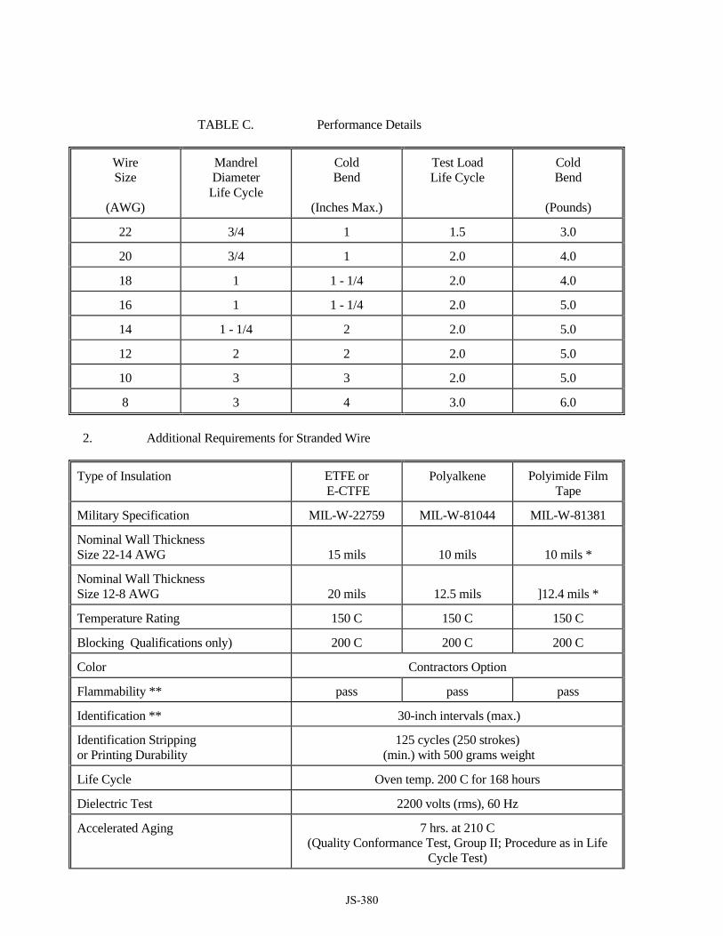
TABLE C. Performance Details
Wire Size
(AWG)
Mandrel Diameter
Life Cycle
Cold Bend
(Inches Max.)
Test Load Life Cycle
Cold Bend
(Pounds)
22 3/4 1 1.5 3.0
20 3/4 1 2.0 4.0
18 1 1 - 1/4 2.0 4.0
16 1 1 - 1/4 2.0 5.0
14 1 - 1/4 2 2.0 5.0
12 2 2 2.0 5.0
10 3 3 2.0 5.0
8 3 4 3.0 6.0
2. Additional Requirements for Stranded Wire
Type of Insulation ETFE or E-CTFE
Polyalkene Polyimide Film Tape
Military Specification MIL-W-22759 MIL-W-81044 MIL-W-81381
Nominal Wall Thickness Size 22-14 AWG
15 mils
10 mils
10 mils *
Nominal Wall Thickness Size 12-8 AWG
20 mils
12.5 mils
]12.4 mils *
Temperature Rating 150 C 150 C 150 C
Blocking Qualifications only) 200 C 200 C 200 C
Color Contractors Option
Flammability ** pass pass pass
Identification ** 30-inch intervals (max.)
Identification Stripping or Printing Durability
125 cycles (250 strokes) (min.) with 500 grams weight
Life Cycle Oven temp. 200 C for 168 hours
Dielectric Test 2200 volts (rms), 60 Hz
Accelerated Aging 7 hrs. at 210 C (Quality Conformance Test, Group II; Procedure as in Life
Cycle Test)
JS-380
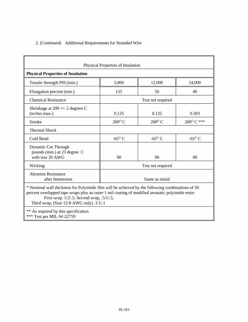
2. (Continued) Additional Requirements for Stranded Wire
Physical Properties of Insulation
Physical Properties of Insulation
Tensile Strength PSI (min.) 5,000 12,000 24,000
Elongation percent (min.) 125 50 40
Chemical Resistance Test not required
Shrinkage at 200 +/- 2 degrees C (inches max.)
0.125
0.125
0.303
Smoke 200O C 200O C 200O C ***
Thermal Shock
Cold Bend -65O C -65O C -65O C
Dynamic Cut Through pounds (min.) at 23 degree C with size 20 AWG
90
90
90
Wicking Test not required
Abrasion Resistance after Immersion
Same as initial
* Nominal wall thickness for Polyimide film will be achieved by the following combinations of 50 percent overlapped tape wraps plus an outer 1 mil coating of modified aromatic polyimide resin: First wrap. 1/2/.5; Second wrap, .5/1/.5; Third wrap, (Size 12-8 AWG only) .1/1/.1
** As required by this specification *** Test per MIL-W-22759
JS-381

Type of Insulation ETFE or E-CTFE
Polyalkene Polyimide Film Tape
Military Specification MIL-W-22759 MIL-W-81044 MIL-W-81381
Lamination Sealing NA NA 230OC 48 hrs
Polyimide Cure Test NA NA required
Resin Coating Durability NA NA ****
Humidity Resistance IR after exposure will meet initial requirements
Voltage Rating 600 V RMS 600 V RMS 600 V RMS
Impulse Dielectric Test (100%) 8 KV Peak 8 KV Peak 8 KV Peak
Insulation Resistance 5000 megohms per 1000 ft. (min.)
Spark Test Test not required
Surface Resistance Megohms per inch (min.) Initial and Final
500
500
500
Wet Dielectric Test Volts (rms) 2500 2500 2500
**** 250 cycles (500 strokes) (minimum) with one pound load.
3. Identification
a. Each stranded wire to be marked with the following information: (1) Manufacturer's name (2) Year in which wire is manufactured (3) Size of conductor (4) Type of insulation.
b. The identifying markings will be permanent and will be easily readable and understandable.
c. Stranded wires used in multi-conductor cable will be numbered or color-coded in addition to the basic four-part identification.
B. Internal Multi-conductor Cable
1. The outer jacket will be fabricated of TPR - thermoplastic rubber and will comply with the requirements of
IEEE Standard No. 383 latest revision. The jacket will be stabilized for outdoor exposure. The outer sheath will have a nominal thickness in accordance with IPCEA S-68-516, Table 4-16. The barrier tape will be .005 inches thick, with a minimum 25 percent overlap. The individual conductors will be sized to meet 150 percent of the load requirements, but will be no smaller than size 19 AWG, stranded.
2. Cables will be made by assembling the individual or twisted pairs of insulated wires into a tight, cylindrical
JS-382
form. Individual or twisted pairs will be assembled helically and with adjacent layers wound in opposite directions.
3. The makeup of multi-conductor cables specified by this Section will not exceed thirty or fifty conductors
for use with vital or non-vital plug connectors respectively.
4. Multi-conductor cables will have 10% spare conductors or, as shown on Contract Drawings, whichever is greater. Reduction in the number of spares is not allowed unless otherwise directed by the Engineer in writing. All spare conductors are to be terminated unless otherwise directed by the Engineer in writing or otherwise specified herein.
5. The cable outer sheath will be marked with the following information repeated at intervals no greater than
36 inches:
a. Manufacturer's name;
b. Year of cable manufacture;
c. Number and size of conductors;
d. Type of insulation on wires;
e. Type of outer sheath insulation;
f. Voltage rating.
6. The identifying markings will be permanent and will be easily readable and understandable.
CONSTRUCTION METHODS: INSTALLATION
A. General Internal wire and cable will be installed in accordance with the applicable requirements of AREMA C&S
Manual, Part 10.4.1 and as specified herein.
1. Wires and cables will be installed in a neat, workmanlike manner. Cables in trays are to be laid therein and not pulled in. Cables will be installed with a minimum amount of crossover in the trays and will not be pulled tightly around bends. All exposed wires and cables entering or leaving equipment racks or housings will be protected from abrasion caused by sharp metallic edges.
2. Nylon straps will be provided and installed for bundling and cabling of conductors where two or more single
conductors are exposed in internal rack bundles, cable trays, or whenever wires are to be bundled. Tape will not be used for this purpose. Straps will be installed at intervals no greater than five feet along the cable run. The wires of multi-conductor cables exposed by the stripping of the cable jacket for terminations will be trained in a neat, workmanlike manner and tied approximately every three inches with nylon straps.
3. There will be no point-to-point redundancy of wires for increased current capacity.
4. Single conductor No. 14 stranded wire will be used for interconnecting signal junction boxes and lamp
JS-383

compartments, as well as other miscellaneous equipment, as shown on the Contract Drawings.
5. Internal Ground wires are to be run separately and will be colored green.
6. Low voltage wiring, less than 50 volts, will be separated from wiring carrying more than 50 volts by a minimum of six inches. Where wiring of less than 50 volts crosses wiring of more than 50 volts it will do so at right angles. Individual ground wires will be separated from all wiring by a minimum of 6 inches.
B. Module Wiring
Unless otherwise approved by the Engineer in writing, all module wiring will be accomplished with solder-less connections using stranded wire as specified herein. Minimum wire size will be No. 22 AWG for stranded wire.
C. High Voltage Wiring
Internal wire used in circuits directly connected to the rails and internal wire used in circuits which operate at voltages in excess of 1000 volts will meet the requirements of Section T018 - EXTERNAL SIGNAL CABLE, as specified herein.
D. Energy Distribution
1. Vital Racks Unless otherwise approved by the Engineer in writing, all wiring for energy distribution will be
accomplished using single conductor stranded wire as specified herein. Rack wiring will be accomplished with solder less connections using stranded wire, minimum size No. 14 AWG. Rack-to-rack wiring will be accomplished with solder less connections using stranded wire, minimum size No. 14 AWG.
2. Non-Vital Wiring Unless otherwise approved by the Engineer in writing, all wiring for energy distribution will be
accomplished using single conductor stranded wire as specified herein. Rack wiring will be accomplished with solder less connections using stranded wire, minimum size No. 16 AWG. Rack-to-rack wiring will be accomplished using solder less connections using stranded wire, minimum size No. 14 AWG.
E. Conductor Sizing
All conductors must be sized per the National Electrical Code (NEC), to satisfy the load requirements of the
equipment and systems provided but will not be smaller than the minimum conductor sizes specified herein. TESTS
A. Special Requirements for Stranded Wire, Vertical Flame Test
1. Single Wire. The test specimen will be 18 inches in length, and will be placed vertically within a chamber approximately 2 feet by 1 foot by 1 foot, open at the top and one vertical side (front), which allows a sufficient flow of air for complete combustion, but which is free from drafts. The upper end of the specimen will be fastened in the chamber by means of a clamp and a weight will be attached to the lower end of the specimen to hold the specimen taut during the flammability test. The weights will be
JS-384
the same as those used for the life cycle tests. The specimen will be marked at approximately 7 inches above the floor of the chamber to indicate where the flame is to be applied.
2. A flame from a Bunsen burner will be applied for 15 seconds to the specimen. The Bunsen burner will
be positioned below the test mark on the specimen and at an angle of 20 degrees to the vertical plane of the specimen. The Bunsen burner will have a 1/4 inch inlet, a nominal bore of 3/8 inch, and a length of approximately 4 inches from the top to primary inlets. The burner will be adjusted to produce a 3-inch high flame with an inner cone approximately one-third of the flame height. The temperature of the hottest portion of the flame, as measured by a thermocouple pyrometer, will be not less than 955 degrees C ±30 degrees C. The burner will be positioned so that the hottest portion of the flame is applied to the approximate position of the test mark on the wire. The time of burning and the flame travel after removal of the flame will be recorded. Breaking of the wire specimens in sizes 24 and smaller will not be considered as a failure.
3. Bundles. The test specimens will be prepared by assembling seven single wire specimens, each 14
inches long, into a bundle tied in two places with glass cord or equivalent non-metallic, noncombustible material, 3 inches from each end. The bundles will be suspended vertically in the test chamber described above. A flame from a Bunsen burner will be applied vertically to the base of the bundle for 15 seconds. The burner flame will be adjusted as described for the single wire flame test. The time of burning and flame travel after removal of the flame will be recorded.
4. Dynamic Cut -Through
a. The dynamic cut-through test will be performed at room temperature using a tensile testing machine equipped with a recorder, which will be suitable for recording the force in pounds necessary to force a tungsten carbide cutting tool through the insulation of a finished wire specimen. This cutting tool will have a cutting edge of .005-inch radius of curvature on a 90-degree wedge. The testing machine will also be equipped with a 12-volt detection circuit designed to stop the testing machine when the cutting edge cuts through the wire insulation and contacts the conductor.
5. One inch of insulation will be removed from one end of an 18-inch finished wire specimen. The
specimen will be placed on a hard, flat surface and the cutting edge oriented perpendicularly to the axis of the wire specimen. The cutting edge will be forced through the insulation at a constant rate of 0.2 inch per minute until contact with the conductor occurs. The force measured at the time of contact with the conductor will be recorded. Four tests will be performed on each specimen with the specimen being moved forward one-inch (minimum), and rotated clockwise 90 degrees between each test. The cut-through resistance will be the average of the four test result values.
METHOD OF MEASUREMENT: Separate measurement and payment will not be made for work under this section, but all costs in connection therewith shall be included in the total Contract Lump Sum price for Track Signal and Communication System.
BASIS OF PAYMENT: There is no Basis of Payment for T021 - INTERNAL WIRE AND CABLE.
JS-385

T022
RELAYS
DESCRIPTION:
A. The work to be done under this Section consists of furnishing and installing all required relays. Relays to be as shown on the Contract Documents unless otherwise approved by the Engineer. Unless otherwise indicated on the Contract Drawings, relays are to be plug-in type. Relays of each type to be uniform in design and contact assembly.
B. A sufficient number of contacts for the number of circuits to be controlled plus a minimum of one additional
spare circuit contact to be provided per relay.
C. All relays and equipment specified to be rated to operate consistently and reliably at a temperature range of minus 40 degrees F to plus 160 degrees F.
D. All relays are to be sealed in clear dust-proof enclosures, except a provision will be made for ventilation,
where required, for heat dissipation.
E. Vital relays are to be equipped with a registration plate to prevent relays of the wrong style, contact arrangement, or operating characteristics, from being inserted into the plug board.
QUALITY ASSURANCE
A. Vital relays are to meet the requirements of AREMA Signal Manual Part 6.2.1, except as specified herein.
B. Non-vital relays are to meet the requirements of AREMA Signal Manual Part 6.3.1, where the recommendations of the AREMA Specification do not conflict with any requirements specified in this Section.
SUBMITTALS Submit the following to the Engineer for approval:
Within 30 days of delivery of a Notice-to-Proceed (NTP), all relay documentation including specifications, any special mounting or supporting arrangements, circuit contact arrangements, for every type of relay proposed by the Contractor. The submittal Is to include any arc suppression data when arc suppression is required.
A. Seven (7) hard copies and three (3) Compact Disc (CD) electronic (pdf) versions of the relay manuals prior
to the procurement and use on this project. The relay manual(s) is to provide comprehensive descriptions and illustrations of each type of relay provided under this Contract, including such items as operation, overhaul, adjustments, part numbers, and other pertinent information.
B. Upon approval, ten (10) additional hard copy and five (5) additional electronic versions be provided on CD’s. C. A sample of relay identification tag, including the Contractor proposed method of mounting, to be submitted
to the Engineer for approval. D. Mean Time Between Failures (MTBF) data for all types of relay he proposes on the project E. Failure Mode and Effects Analysis (FMEA) data for all types of relay he proposes on the project.
JS-386

F. Perform calculations to determine time-release settings for all time element relays furnished and installed
under this Contract. Perform calculations in accordance with AREMA Signal Manual Part 2.4.20, and submit to the Engineer for approval.
DELIVERY, STORAGE AND HANDLING
A. Ship vital relays separately from the wired racks and instrument housings where they will be used. Package relays individually, each in a sturdy weatherproof carton with the location where the relay is to be installed, rack number and position, and the manufacturer’s drawing number clearly printed on the outside of the carton. Store relays in a climate-controlled area until tested and installed by the Contractor.
MATERIALS: A. General
1. Vital DC relays, unless otherwise approved by the Engineer, to be of the plug-in type and rack-
mounted. They will have a transparent dust cover made of a non-flammable composition that will not support combustion.
2. Vital relays, will have a nominal operating voltage of 10-16 volts, and capable of operating con-
tinuously without resultant damage within a voltage range of 7 to 21 volts.
3. Design biased neutral vital relays so that gravity alone will prevent the armature from picking up if the permanent magnet is de-energized or if no current is applied to the coil due to interruption of the normal magnetic circuit. Design biased neutral vital relays so that up to at least 50 times working energization, applied for two seconds at both normal and reverse polarity, will not affect their operating characteristics by more than two percent, and will not pick up their armature on reverse polarity.
4. Each vital relay unless, approved by the Engineer, will have a minimum of four (4) dependent
front-back contacts, two independent front contacts and one independent back contact. All front contacts to be silver-to-metalized carbon.
5. When three (3) DC vital relays, suppressed as specified, herein are connected in parallel and operated
as a test load from normal working voltage, a vital relay front or back contact that breaks this load is to be capable of at least five (5) million operations. The contact resistance, measured with a 10-ma current, for the vital relay front or back contact breaking this load, to not exceed five (5) ohms.
6. Arc suppression for vital relays to be built into the relay or into its plug board.
7. Contact arrangements to be identical for similar types of relays except special function relays.
8. All vital plug-in relays, except vital time-element relays and special application relays to be equipped
with front current testing facilities. Where required by the Engineer, and as shown on the Contract Drawings, facilities to be provided to enable the testing of voltage from the front of the relay.
B. Slow Acting Relays
1. Slow Acting Relays, i.e. slow pickup or slow release, to have their slow acting characteristics provided
by the use of copper or aluminum washers or slugs applied to the relay core.
JS-387

C. Flasher Relays
1. Flasher rates for Automatic Highway Crossing Warning Systems to be provided by either vital relay or by solid-state flashers. The flashing rate to be no less than 35 times per minute or more than 55 times per minute and to be in accordance with AREMA Signal Manual, Part 3.2.55.
2. Flasher rates for wayside signals to be adjustable and be provided by a vital neutral relay designed to
provide successive energizations of the electric lamp at a rate not less than 45 or more than 75 times per minute. The electric lamp to be energized between 40 and 60 percent of the cycle time. The flashing rate to be determined and controlled by a solid-state device.
D. Time Element Relays
1. Time element relays used for loss of shunt protection or special applications approved by the Engineer
will be of the vital solid-state type. Any interruption of power or loss of an input will reset the timer to the beginning of the time cycle. The timing cycle to be a minimum of 5 seconds and be accurate to +0.1% over the entire temperature range of -40ºF to 185ºF.
IDENTIFICATION
Facilities to be included for mounting an approved typed or printed relay nametag for each relay, either on the relay cover or on the relay cabinet front plate, as applicable. Nametag to be easily replaceable, but will not come off during normal service. Proposed excessive long relay identification tag nomenclature are to be submitted by the Contractor for approval.
NON-VITAL RELAYS
A. Each non-vital relay to be equipped with a minimum of two front-back contacts. Stationary contacts
to be bifurcated silver, palladium, or approved equal. Movable contacts to be bifurcated silver, palladium with gold overlay, or approved equal.
B. Non-vital relays to be OMRON G2R5, Potter Bromfield KRPA, as shown on the Contract Documents, or approved equal.
C. Non-vital relays to be mounted in dust-proof cabinets having transparent front plates, which will not support combustion. These cabinets to be mounted in racks as specified. As an alternate, these relays may be furnished with individual transparent covers that will not support combustion and be rack mounted.
D. The design of the individual relay covers and of the cabinet in which several relays are mounted to permit viewing the relays without disassembly or other mechanical manipulation to determine whether each relay is in the picked up or dropped out position.
E. Non-vital relays to be plug-in dc neutral, biased, or diode-suppressed relays with a typical, nominal operating voltage of 12 volts. The voltage for power off indication non-vital relay to be 110 volts.
F. Where other voltages are required, the relay and application to be submitted and approval will be at the discretion of the Engineer.
G. Contact resistance of non-vital relay front and back contacts will not exceed five ohms after 10 million operations when breaking a test load equivalent to three non-vital relays connected in parallel and
JS-388

suppressed as required in these Specifications. Operating voltage for this test to be 24 volts. Contact resistance to be measured with a 10 ma current. All non-vital relays to be identical by type and class, or function.
H. Relay coils that are wired to solid-state equipment will have their coils suppressed such that transient voltage spikes are minimized to protect electronic equipment.
CONSTRUCTION METHODS: INSTALLATION
A. Test that the relay’s operating characteristics have not altered during shipping procedures.
B. Verify that all AC and DC energy is de-energized while installing relays and not reconnect these buses
until all relays have been installed.
C. Relays and components are to be mounted as shown on the Contract Drawings, TESTS
A. Test all relays in accordance with the recommended practices as established in Parts 6.4.1. and 6.4.5 of the AREMA C&S Manual and all requirements of Section T023 – SIGNAL SYSTEM TESTS and record all results on an Engineer approved Relay Test Form.
METHOD OF MEASUREMENT: Separate measurement and payment will not be made for work under this section, but all costs in connection therewith shall be included in the total Contract Lump Sum price for Track Signal and Communication System.
BASIS OF PAYMENT:
There is no Basis of Payment for T022 - RELAYS.
JS-389

T023
SIGNAL SYSTEM TESTS
DESCRIPTION:
A. This work to be done under this Section consists of the tests and inspections that the Contractor will perform to demonstrate that installation of systems, subsystems, assemblies, subassemblies, and components supplied and/or installed under this Contract form a complete and operating signal system fully compliant with the Contract Documents.
B. The signal system operational testing is to be performed by a RIDOT representative.
C. In addition to the signal systems, these tests also include, but are not limited to, testing of the electric services and
communications systems. The Contractor will be responsible for Factory Acceptance Tests (FAT), Field Installation Testing (FIT) and assistance with the field-commissioning test for In Service Testing (IST).
D. The work also includes the costs of the Contractor's personnel as well as any special equipment or third-party
assistance required to conduct all tests and complete the required documentation.
E. Should any portion of the new signal system not meet the intent of the Contract Documents, the Contractor will provide whatever resources (personnel or equipment) necessary to properly make the corrections required for revenue service. All tests or re-tests to prove compliance to be included in the work, without any additional cost to this Contract, including additional Railroad costs.
F. Test work specified elsewhere in these Specifications to be construed as related to and inclusive with the testing
described herein.
G. Develop a testing schedule with input from RIDOT The schedule will plan testing work two weeks prior to field tests that require the presence of the Railroad, their designated representatives, and/or any other regulatory agency.
H. The Contractor's test procedures package will include pre-approved, pre-printed data sheets and/or inspection
sheets for each test. The test sheets to include the procedures, as approved, for all testing required for acceptance and to be in a Microsoft (MS) Project Schedule format to outline when, where and by who the tests are going to be completed and the order of the testing.
I. Tests and inspections to be made during the FIT and the IST phases with the Railroad. These tests should be
detailed in the Contractor’s test plan, which is to be reviewed and approved by the Engineer. These tests to consist of, but not be limited to, circuit breakdown tests, wiring verification tests, continuity tests, resistance tests, voltage and current tests, time tests, operating tests, simulation tests, and other electrical and mechanical tests and inspections.
1. The Engineer reserves the right to witness any or all tests and inspections in the Contractor's plants or other
manufacturing facilities. RIDOT to be advised a minimum of sixty (60) days in advance of each FAT. 2. All system and subsystem tests to be tested to demonstrate that the assemblies and installations meet the
requirements and intention of the Contract Documents. These lower level testing to be completed prior to the performance of operational testing of systems or subsystems.
J. The work to include all necessary test-purpose disconnecting and reconnecting as well as for temporary phasing of work.
JS-390

K. The Contractor will provide only personnel that are highly qualified with the products and the systems that are
formed by these products during all phases of the system testing, cut-overs and other designated milestones identified in the schedule during the field installation phase of the Contract.
L. Testing plans and procedures to be submitted to and approved by the Engineer. These plans to incorporate
interface signaling arrangements required by the Engineer approved phasing of the IST. QUALITY ASSURANCE
A. Test procedures and inspection procedures to be subject to the approval of the Engineer and to comply with all FRA rules and regulations, as well as, AREMA, MUTCD and The Railroad’s recommendations.
B. The Contractor will provide a listing (matrix) of all testing required for each component. Design the matrix in
a manner that to allow an immediate reference to the status of the testing and the remaining time to complete. One matrix to be provided for each of the major tests defined as FAT, FIT, and IST. Tests to be included in the matrices to include, but not be limited to, the following:
1. Pre-installation Inspection, 2. Ground Resistance Tests, 3. Crossing signal tests, 4. Energy Distribution & Ground Detection Tests, 5. Vital Circuit Breakdown Tests, 6. Non-Vital Circuit Breakdown Tests, 7. Signal Adjustment & Check-out Test, 8. Track Circuit Adjustment & Test, Pre/Post Shunt Tests 9. Event Recorder Check-out Tests – Vital & Non-Vital.
C. Satisfactory performance of the installation testing will not waive the requirement for performance of the same
or similar tests as part of the final field In Service Testing (IST).
D. Test equipment of the proper type, capacity, range and accuracy will be supplied by the Contractor is to perform the required tests and inspections. This equipment is to be in good working order and properly calibrated within sixty (60) days of the time the tests or inspections are conducted. The calibration of each instrument to be certified by an Engineer approved facility. Instruments not calibrated within the last sixty (60) days will be considered as non-certified. Tests conducted with non-certified instruments will be rejected.
E. Each component of the signal system to be inspected at the point of manufacture and documented evidence to
accompany the wayside signal system material.
F. The work to include all tests required to prove that proper and safe operation of all systems and subsystems meet the requirements of these specifications and result in a safe and complete signal system. The tests performed to cause each system and subsystem to be sequenced through its required operations, including the imposition of simulated conditions to prove that the assemblies and installations comply with all specified fail-safe requirements.
G. The Contractor will maintain and re-issue the MS Project Schedule of tests every two (2) weeks for the life of the
Contract. RIDOT to be given a minimum of 10 days notice to have the ability to witness any or all tests conducted by the Contractor. No part of the signal system to be placed in service by the Contractor.
JS-391
STANDARDS, REGULATIONS, and PROCEDURES
A. Standards – AREMA C&S Manual, Part 2.4.1.
B. Regulations - Code of Federal Regulations (CFR) 49, Part 234 and Part 236 inclusive.
C. MUTCD Part 8, where applicable. SUBMITTALS
A. Within 60 days after receipt of NTP, submit:
1. A schedule of test procedures in MS Project format to the Engineer for approval. The schedule to show the interdependences, resources required, and length of time to perform each test.
2. An outline and draft procedures for the tests to be performed on each type of component or unit and a
matrix showing each test and the equipment to be checked, together with samples of test record forms and matrices as hereinafter specified.
3. The numbers of each type of component or unit to be tested to demonstrate the adequacy of design and quality control.
B. At least 60 days prior to the scheduled performance of each test a detailed test schedule(s), as described herein, to
be submitted for approval of the Engineer.
1. The detailed test schedule(s) for significant cut-over and testing activities to outline the Contractor’s activities by task, expected duration and associated manpower requirements.
2. Within the projected schedule, a description of expected transportation impact should be addressed. Requests
for track & power outages, flagging, etc. should be identified in sufficient detail.
C. At least 30 days prior to the scheduled FAT on the first location, and in accordance with the approved schedule discussed above, submit detailed test procedures for approval of the Engineer. The detailed test procedures submittal to also include all pertinent information regarding the simulating devices and the methods of simulation to be employed in effecting a complete functional/operational series of tests.
1. Provide a complete set of “test data sheets” as part of the detailed test procedures submitted. These data
sheets to contain all information required to successfully perform the tests, including identifying acceptable ranges of test results and pass/fail criteria.
D. The results of each test, as herein specified, both factory and field to be recorded. The completed FAT data
package, including all forms and marked plans, to be furnished to the Engineer prior to shipping. The completed FIT data package, including all forms and marked plans needs to be submitted at a minimum of 10 days before the equipment is to be placed in service. IST forms and testing will be handled by the Railroad.
E. Certified test results to also be furnished for tests performed by any subcontractors when such tests are required
within this Specification.
F. All test reports to be checked and approved by the Contractor prior to submittal to the Engineer.
JS-392

G. Test reports to be logically grouped by location and in the order the tests were performed, FAT, FIT, and IST. These reports to be provided in a three ring, tabbed binder for easy access and discovery.
H. Upon completion of all tests specified herein, the Contractor will certify in writing by submitting a letter signed
by the Contractor’s Project Manager and a second authorized Contractor representative, certifying that all tests have been performed and meet the intent of the Contract Documents.
MATERIALS: SITE TEST EQUIPMENT AND MATERIALS
A. Prior to the start of any of the testing, the Contractor will have all test instruments and equipment necessary to conduct the required tests, including two spare sets of all equipment, available and ready for use. “Ready for use” to mean properly matched for test parameters, properly calibrated, properly programmed, with sufficient leads, probes, adapters, stands etc., necessary to conduct the particular test in a completely professional manner.
B. Temporary or interim test related materials, special tools, connections, jumpers, etc. to be furnished and available not less than one week in advance of the test need. This to also include all materials required to accommodate temporary or interim signaling arrangements.
CONSTRUCTION METHODS: FACTORY TEST PROCEDURES
A. Confirmation to be provided by the Contractor that all required factory tests of systems, subsystems, assemblies, subassemblies, and components supplied under this Contract have been performed. These tests to verify design and name-plate ratings and adequate and proper performance.
B. All systems, subsystems, and equipment to be 100 percent inspected and tested.
C. All components, other than those related to fail-safe circuits, may be tested on a sampling basis. An approved
number of randomly selected components or units from the manufacturing process to be tested to ensure the adequacy and acceptability of all components and units produced.
D. When test results are not recorded on a test-data plate affixed to the equipment or unit, certified test reports to
be furnished for each item at the time of delivery in a form and format suitable for regular office file record keeping.
E. Each component and unit to be inspected at its point of manufacture and evidence of this inspection and
acceptability to be indicated on the item where practicable. FIELD TEST PROCEDURES
A. The quality of the installation to be demonstrated by field tests for continuity, insulation resistance, and resistance to ground, circuit breakdown, visual inspection, megger tests and any other tests required by these Specifications. These tests to be performed as planned in the Contractor’s approved MS Project schedule.
B. The Contractor's test procedures package to include pre-approved, pre-printed data sheets and/or inspection sheets
for each test. When completed by the field test personnel and checked for accuracy and completeness, the sheet to be submitted as the test report. Contractors test results sheets to conform to all state and federal requirements for preprinted information contained therein.
JS-393

C. When tests require specific meter or test instrument readings, the pre-printed data sheet to show the allowable range of values for each part of the test. The test report to also contain a check-off system for each action and a blank space adjacent to the expected value in which to record the test readings.
D. The test report to also contain a final description sheet on which the Contractor will record discrepancies found
and action taken.
E. All test reports to be dated and signed by the responsible employee of the Contractor or subcontractor on the day the test is performed. Space to also be provided for the signature of the witnessing inspector, engineer, or Railroad’s designated representative.
F. The report to show the specific test instruments used on each test, with the instruments identified by name, type,
serial number, and calibration due date.
G. Should an error be discovered during field-testing, due to field wiring and connections that do not agree with the approved circuit plans, the Contractor may correct such errors without prior approval of the Engineer. The Contractor will not, however, make any changes that affect safety of operation of the approved circuit(s), as designed, without prior written approval of the Engineer.
H. The Engineer will make all final determinations as to whether or not the entire test to be re-run when any specific
field test does not meet the requirements specified for the test.
I. Any changes made after completion of test procedure to be sufficient cause for the system or sub-system to be re-tested in accordance with the applicable test procedure.
FIELD TESTS AND INSPECTION
A. General Field Tests General Field tests to include, but not be limited to, those required by the approved matrix and the following:
1. Ground verification test;
2. Energy distribution system and power tests;
3. Line circuit verification between wayside instrument houses;
4. Breakdown test of all vital circuitry;
5. Wiring verification of all non-vital circuitry;
6. Vital function tests;
7. Operating tests;
8. All applicable tests prescribed by FRA, AREMA C&S Manual Part 2.4.1, where these inspections and tests do not conflict with the requirements of these Specifications.
B. Specific Field Tests
1. Preliminary Verification Tests
JS-394

The Contractor will use the Contract Drawings and the existing Railroad documentation or other approved drawings to verify all existing cables and their terminations. The existing Railroad drawings and documentation will be given to the Contractor upon NTP. Within 14 days from the receipt of the existing Railroad drawings and documentation, the Contractor will submit to the Engineer the results of these inspections. This documented examination to utilize pre-approved forms and be conducted by the Contractor's approved signal engineer. The process to include the inspection of existing signal houses, wayside signals, junction boxes, and cases required to be interfaced with or requiring modified wiring and confirm that:
a. That the number of cables entering and leaving is in conformance with the approved documentation package;
b. All individual wiring is terminated as indicated by the approved documentation package;
c. The terminated wires contain the number of conductors on each terminal as indicated by the approved
documentation package;
d. That all cables include the number of wires and are the wire gauge indicated by the approved documentation package;
e. That the existing nomenclature tags are in conformance with the approved documentation package.
2. Cable Routing Inspections
Within no longer than 60 days from the receipt of NTP, the Contractor will submit documentation showing the results of his inspection of cable routings and raceway areas intended for use under this Contract. The Contractor will confirm the adequacy of proposed routing & methods and report any perceived problems or areas of concern.
3. Resistance of Ground Connection Test
All grounding connections to be tested to determine that the ground resistance is not greater than 5 ohms using the approved Ground Resistance test method. All ground connections to be tested.
4. Insulation Resistance Tests
The test procedure for testing of insulation resistance to include tests to verify the following:
a. All wire and cable installed along the right-of-way and the wire and cable entering or leaving wayside instrument cases and houses to be tested after installation, including termination, to ensure that insulation of wires and cable and connected equipment meet the specified resistance value. A direct reading instrument, having a 0-megohm to 200-megohm scale range and a self-contained DC power supply rated 500 volts (minimum) to 1000 volts (maximum), to be used to measure the insulation resistance. Resistance between conductors and ground to not be less than that specified in CFR 49 Part 236.108.
b. If any of the existing wire connections are affected by installation, maintenance or repair work
involving vital conductors that leave the house, case, junction box or device, or if such existing conductors are replaced or installed or spliced, then the insulation resistance of those conductors must be tested to each other and to earth ground prior to any other safety certification tests. Simply opening and closing slider straps are not considered to be work affecting the conductors. Insulation resistance of new conductors must be no less than 1 Meg Ohm for 600V-class cable and no less than l00Meg
JS-395

Ohm, for 1000V-class cable. Conductors with insulation resistance measured less than 500k Ohm must be repaired without undue delay.
c. The Engineer is to be immediately notified of any conductors with insulation resistance measured less
than 200k Ohm so that the Railroad can take appropriate action. These conductors must be taken out of service for repair immediately; power sources, made grounds and connections to the rails to be disconnected from the circuits during testing.
d. Insulation resistance test values to be recorded on approved Insulation Resistance Record Forms and kept
in the Test Reports binder.
5. Energy Distribution These tests to be conducted on all energy busses:
a. Energy-Off Tests With all power to wayside instrument house or case off, the following checks and tests to be performed.
These to include but not be limited to:
(1) All fuses to be removed. (2) Verify that circuit breaker size compares to that of approved circuit plans.
(3) All energy distribution to be checked using resistance test instrument acceptable to the Engineer,
to verify agreement with the approved plans.
(4) Compare wire gauges with those called for on the approved circuit drawings. All discrepancies in wire sizes to be replaced with the proper size wire.
(5) During energy distribution breakdown, a wire count on each terminal, relay contact, etc. to be taken
to ensure that only the number of wires called for on the approved circuit plans is present at each terminal, relay contact, etc. Any discrepancies found to be corrected and additional wires, if found, to be removed.
(6) Tags to be verified for proper nomenclature and terminal location.
(7) Each energy bus to be tested to all other energy buses to ensure that no crosses exist.
b. Energy-On Tests
Upon completion of the energy-off tests, the following checks and tests which to be performed. These
tests to include but not be limited to:
(1) Insert fuses for power supply feeds and verify proper size according to the approved circuit drawings.
(2) Turn on energy feeds and test operation of power transfer for proper operation.
(3) Each AC voltage input to be measured and recorded.
JS-396
(4) Each power supply or charger output voltage to be measured and recorded.
(5) Verify that the proper voltage is present at all distribution points.
(6) Check battery fluid level and specific gravity of all cells as applicable per manufacturer’s recommended installation/maintenance procedures.
6. Circuit Continuity Tests
All wire and cable installed by the Contractor will be tested to verify the continuity of each conductor and
that each conductor is connected to the proper terminal as shown on the approved drawings. Where parallel circuits exist, each parallel path to be tested independently to verify the continuity of each path.
7. Vital Circuit Breakdown
The vital circuit breakdown test consists of three major steps; wire counts, continuity and finally, contact verification. A copy of applicable drawings to be used as data sheets for this test. Green and brown colored pencils are required for documenting this test on the data sheet. Green circled numbers indicate wire counts at connection points. Green tracing on circuit conductors indicate continuity verifications. Brown check marks indicate contact verifications.
a. Wire Counts: The first step is to make a physical count of number of wires connected at each point in the circuit, for all circuit points worked on by personnel for the maintenance or modification being tested. The number of wires connected at each point must agree with the drawing. For each verified connection point, write and circle the number of wires found connected to that point next to it on the data sheet. Resolve any discrepancies before proceeding to the next step.
b. Continuity: The second step is to verify continuity of the circuit conductors as drawn, one conductor at a time. If, according to the drawing, a conductor is electrically connected to more than two points and it is impractical to separate those multiple terminations, verify the continuity to each of those points. Perform this test on each conductor that is connected to any of the circuit points worked on by personnel for the maintenance or modification being tested. To perform this portion of the test, all relay contacts, slider straps and termination points to which the conductor(s) is connected must be verified open. (Removing vital relays from their plug boards may simplify the opening of relay contacts; however, this method may become complicated when processor I/O circuits are involved.) Also, confirm that no energy is present on the conductor. Verify the continuity of the conductor from one end to the other. For each conductor so verified, trace the conductor on the data sheet for its entire length using green pencil. Resolve any discrepancies before proceeding to the next step.
c. Contact Verification: The third step of the vital circuit breakdown test consists of applying the vital circuit’s normal energy under the conditions required to energize the vital component. Some of the conditions may have to be simulated. If conditions are simulated, as much as possible they should be simulated outside the circuit being tested by forcing relays or other devices to the desired state. Specific details of each method used to simulate conditions must be approved and documented in the logbook, immediately, during the tests. One at a time; each relay contact, circuit controller contact, slider strap and test link in the circuit, must be opened to interrupt the circuit current and verified to de-energize the vital relay or device.
In cases where a contact under test is intended to provide a circuit shunt, such as that of a circuit controller shunt contact, an ohmmeter must be used at the relay coil or other vital device to verify the circuit makes and breaks the shunt as intended. In cases where the circuit load is a motor or other high current device, a voltmeter may be used to simulate the motor. When a meter is used in place of the normal load, it should be placed as close as practical to the load device, and never in the portion of
JS-397

the circuit that was modified or repaired.
This contact verification test must be performed for all circuit points worked on by personnel for the maintenance or modification being tested and one circuit point further into each circuit branch. As each contact is verified, write a brown pencil checkmark next to the contact on the drawing. Resolve any discrepancies before proceeding to the next step. Immediately following the test, review the logbook and verify that all simulations used during the test have been restored to normal configurations. After the vital circuit breakdown test verifies that the circuit is wired as it is drawn, perform all applicable functional tests to verify the circuit functions in a safe manner.
8. Non-Vital Circuit Breakdown All circuits not checked during factory test or modified after factory test to be checked for accuracy against the
approved circuit drawings. Tests may be done with energy on or off and to verify, but not be limited to, the following:
a. Point to point wiring. b. A wire count of all field installed wires to be made for each terminal, relay contact, etc. to ensure that
only the number of wires called for on the approved circuit plans is present at each terminal, relay contact, etc. Any discrepancies found to be corrected.
c. Verify tags and nomenclature where applicable.
d. Verify that all components, relays, resistors, etc. are the same as called for on the approved circuit
drawings and located in proper positions.
9. Track Circuits
Tests to be made to assure that all track circuits are properly installed, phasing is checked, and the complete circuit is adjusted in accordance with the Engineer approved detail test procedure. The Contractor will assist in the testing for the proper rotation of the phasing for track circuits. Each track circuit to be tested in accordance with the manufacturer’s approved test procedure and to include tests to verify the following:
a. Each track circuit to be walked by the Contractor making a visual test of the bonding and rail and
ballast conditions so as to assure themselves that they are not adjusting to a known failure. b. Each track circuit to be tested for shunting sensitivity. A 0.15 ohm shunt strap to be placed across the
rails at the track feed, track receiver, and all fouling points. The track circuit to meet the requirement of FRA Rule 236.56, except with the track relay to be in the de-energized position with the 0.06 ohm shunt. This test to be performed after the final track circuit adjustment has been made. Value of current required to pick up the track relay to be recorded.
c. Each track relay to be tested to assure that the proper phase relationship exists between the track
energy being received and the local source used for comparison using the methods approved by the Engineer.
10. Signal layouts
Tests to be performed on all signal layouts. These tests to include, but not be limited to the following:
a. Check continuity of field wires and verify all nomenclature.
JS-398

b. Apply energy to signal lighting circuits and adjust all LED unit voltages to 10 percent less than the
nominal rating.
c. A functional test of signal lighting circuits must be performed after appropriate megger and circuit breakdown test(s) are complete, and whenever any signal lighting circuit conductors in the train control room, yard case, junction box or signal head are disconnected/connected during maintenance or modification.
d. Sight signals for maximum visibility, adjust as required.
e. Light-out testing for signal heads, verify appropriate signal aspects displayed in light-out condition.
METHOD OF MEASUREMENT: Separate measurement and payment will not be made for work under this section, but all costs in connection therewith shall be included in the total Contract Lump Sum price for Track Signal and Communication System.
BASIS OF PAYMENT: There is no Basis of Payment for T023 - SIGNAL SYSTEM TESTS.
JS-399
T024
MISCELLANEOUS COMPONENTS AND PRODUCTS
DESCRIPTION:
The work shall be done under this Section consists of the furnishing and installing miscellaneous components as referenced in this Section and throughout this Specification required to affect an operational signaling system.
MATERIALS: PRINTED CIRCUIT CARDS
Printed circuit (PC) cards will be of glass epoxy construction. Card material shall meet the requirements of NEMA Type FR-4. Cards will have sufficient thickness to permit easy insertion and removal, and shall be physically keyed to protect against incorrect interchange. Circuits shall be formed by etching. Conductor material shall be copper and shall be protected from exposure to air. PC cards containing components that may be damaged in the event a plug connector or plug-in unit is removed while the equipment is energized will be clearly marked or labeled with a warning note and means provided to remove power to the PC cards. Components mounted on the PC card, weighing more than one-half ounce or with a displacement of more than 1/2 cubic inch, will have a mechanical supporting attachment to the card, which is separate from all electrical connections. Stacking or piggy-backing of printed circuit card sections in order to accomplish changes or modifications to wiring or components on printed circuit cards shall not be allowed.
PRINTED CIRCUIT CARD CONNECTORS
Connectors shall have gold plating a minimum thickness of 0.000050 inch.
CIRCUIT BREAKERS, FUSES AND FUSE CLIPS
Fuses and circuit breakers will be of suitable capacities to protect the various pieces of signal apparatus from the effects of short circuits or overloads. All circuit breakers and fuses required for the equipment and systems shall be in accordance with these Specifications. Circuit fuses shall be as determined by the signal apparatus manufacturers. In branch circuits, where fusing is impractical, a protective resistance unit will be furnished. All fuses will be centrally located on the power distribution panel and power racks. Fuse clips will be so constructed that they will retain their resilience under all installation and service conditions to assure a positive contact between the clips and the fuse. DIODES All diodes shall be furnished under this Contract shall carry a JEDEC number or shall be available from more than one manufacturer and shall be used within the published specifications for such number. All diodes shall be silicon type, unless otherwise approved by the Engineer.
JS-400
RESISTORS All resistors, other than those required for electronic circuits, shall be in accordance with all the applicable sections of the AREMA Signal Manual. REACTORS
All reactors, other than those required for electronic circuits, shall be in accordance with all the applicable sections of the AREMA Signal Manual CAPACITORS All capacitors shall be in accordance with all the applicable sections of the AREMA Signal Manual SIGNAL MOLDED TERMINAL BLOCKS
Signal System terminal blocks shall be in accordance with all the applicable sections of the AREMA Signal Manual SIGNAL TERMINAL BINDING POSTS Signal System Terminal binding posts, other than those required for supervisory control circuits, shall be in accordance with all the applicable sections of the AREMA Signal Manual TERMINAL POST INSULATORS All terminal posts, located on terminal boards in the wayside cases and central instrument house used to terminate 120V or greater shall be provided with a protective insulator. The type of insulator shall be individual for each terminal post, and shall be fire-resistant. INSULATED TEST LINK Insulated test links shall be Invensys Gold NVT, 024620-1x, Type 0255-l0l as manufactured by Western-Cullen-Hayes, Inc. or Engineer approved equal. LIGHTNING ARRESTERS AND EQUALIZERS Air Gap Lightning arresters and equalizers will be mounted on 3-post porcelain or approved type base and shall be in accordance with all the applicable sections of the AREMA Signal Manual TERMINALS FOR WIRES AND CABLES All solderless terminals shall be in accordance with all the applicable sections of the AREMA Signal Manual, or as specified herein. Terminals shall be of the solderless crimp-on type. Samples of all solderless terminals shall be submitted for approval. All stranded copper wire shall be fitted with an approved type of terminal at all points where the wires shall be terminated on terminal binding posts.
JS-401
The terminating means will be of 5 types:
1. A lug for terminating heavy wires or signal power wires; 2. A solderless insulated terminal as manufactured by AMP, Inc. or approved equal, for terminating No. 16 and No.
14 AWG stranded wires; 3. A solderless insulated terminal similar to AMP Catalog No. 35627 or approved equal, for terminating insulated
wires Nos. 12-10; 4. A solderless insulated terminal similar to AMP Catalog No. 324108or approved equal. 5. A solderless insulated terminal, AMP Catalog No. 320554, will be furnished for No. 8 studs and AMP Catalog
No. 32057l or approved equal. Where flag type terminals are required, they will be similar to AMP Catalog No. 322313, or approved equal, for terminating No. 16 and No. 14 AWG stranded wires. The terminals will be for attaching to the ends of the conductor in such a manner that the flexibility of the conductor will not be destroyed and the possibility of breakage at the terminal will be reduced to a minimum. Terminals shall be for attaching to the wire with a tool made approved and recommended by the manufacturer of the terminals being furnished. The tool shall be equipped with a ratchet device to insure proper indentation of the terminal and which shall not release until proper indentation is complete. The Contractor shall supply 3 (three) of every type needed to correctly terminate wires to the devices. TAGGING FOR CABLES, WIRES AND EQUIPMENT All wire tagging shall be in accordance with all the applicable sections of the AREMA Signal Manual, or as approved by the Engineer. Except as otherwise specified in this Section, both ends of each cable and each cable wire and all single wires that terminate in the wayside cases, junction boxes, signal instrument housings on entrance racks, and any equipment of the signal system outside of such locations will be permanently identified with a tag. Tags will not obscure connecting links used between terminal binding posts. Tags will be installed so that they may be read with a minimum of disturbance of the tags and wiring. Each conductor of the cable will be rung out and identified before applying the tag. Tags for wire and cable identification and for identification of transformers, resistors, reactors and other components shall meet the following requirements and shall be subject to the approval of the Engineer:
1. Sleeve Type Tags: Tags for identification of individual cable conductors and field-installed wires within the wayside cases and Signal Instrument Housings, base of crossing gates will be the sleeve type as manufactured by Raychem Corporation, or an Engineer approved equal. The application of the conductor nomenclature shall be in accordance with the approved Signal Manufacturers plans and in accordance with all the applicable sections of the AREMA Signal Manual and shall result in a permanently bonded and legible identification.
2. Tags for cables will be the PANDUIT flag type, or Engineer approved equal. 3. Flat Plastic Tags:
a. Tags for identification of vital relay plug boards, individual transformers, resistors, reactors, terminals, and other miscellaneous components within the wayside cases, Signal Instrument Housings and outside terminal cases will be the flat plastic laminated type.
JS-402

b. These tags will be 1-1/2” long by ¾” wide with one, 5-3/5” hole located in the center of the width. The distance from the edge of tag to the hole will be approximately 9/32 of an inch. The untreated tag will be milk white "vinylite", or Engineer approved equal.
c. The identifying nomenclature space will allow for 3 (three) rows of lettering, and the tag material will be capable of receiving typed-on characters by conventional means. The height of the lettering will be not less than 1/8”.
d. After lettering, both the face and back side of the tag will be covered with a clear plastic coating, "vinylite", or approved equal, of at least 1/100 of an inch thick.
e. The nomenclature applied to tags to go on entrance racks and boards will show the terminal post identification on the top line. The functional nomenclature will appear on the bottom line, or, if required, on the middle and bottom lines. The terminal posts will be identified by geometry coordinates, such as rack, row and post number.
4. Wrap Around Tags Tags for identification of the individual wires of plug-in relays, within the SIH and the wayside cases will be the wrap around, self-adhesive type.
5. Flag Marker Tags Tags for identification of individual wires of shelf-mounted relays and wires and conductors in junction boxes will be flag marker tags of the miniature locking type.
PRESSURE SENSITIVE LABELS The rows and columns on entrance racks will be identified by pressure-sensitive labels bearing the geometric coordinates. Wires on plug-in vital relays will be identified by the contact to which they are applied. These tags will be wrap-around self-adhesive type. HARDWARE All mounting hardware exposed to the elements and used for signal equipment, cases, conduit, hangers, brackets, clamps, etc., shall be hot-dip galvanized to meet the requirements of the latest version of ASTM A123/A123M-97a, Specification for Zinc, (Hot Galvanized), Coatings on Iron and Steel Products. All threads shall be chased after galvanized
1. Galvanizing:
a. The hot dip process of galvanizing shall be used. All parts shall be pickled so that all scale and adhering impurities shall be removed. The zinc coating shall be of commercially pure zinc, and shall be continuous and thorough. It shall not scale or blister or be removable by any of the processes of handling or installation. The finished surface shall be free from fine line cracks, holes, or other indications of faulty galvanizing. It will be smooth and free from adhering flux and other impurities. The edges and ends of parts will be free from lumps and globules. Parts shall be coated with at least 2 ounces of zinc per square foot of galvanized surface, after all bending, cutting, drilling, and final fabrication.
b. In order to avoid destruction of resilience encountered in the hot dip process of galvanizing, all lock-washers shall be cadmium plated.
2. Cadmium Plating a. All nuts, bolts, and washers used for the mounting of equipment within finished enclosures shall be
cadmium plated or stainless steel. As an alternate, the Contractor may submit another type of plating or non-corroding metal for the Engineer's approval.
b. Cadmium plating shall be an impervious, dense, hard, continuous, closely adhering coating of commercially pure cadmium, free from capillaries and shall completely cover the surface of the part in a smooth, bright layer. Plating on raised or prominent portions shall show no evidence of blackness or loose crystalline
JS-403
structure. It shall have a minimum thickness of 0.0006 of an inch and shall withstand the salt spray test for at least 1000 hours or an equivalent test approved by RIDOT.
FLEXIBLE CONDUIT AND HOSE Hose for track circuit leads will be braided cordura rayon, vari-purpose hose, internal tube neoprene cover or approved equal. The hose will be clamped at both ends with stainless steel clamps. Clamps are not required for track risers. Flexible conduit: Where the engineer permits the use of flexible conduit it will be type UA or approved equal. STAINLESS STEEL CLAMPS
Clamps for clamping hose at each end shall be stainless steel. SECURITY Enclosure doors for SIH’s, cases, etc. shall be provided with a padlocking handle and a 3-point latch mechanism to ensure that the doors cannot be locked until completely closed. Doors shall be provided with a two-position retaining device to secure door(s) when open. Security plates, fabricated from steel angle iron, shall be furnished to provide extra security to the enclosure with dimensions as shown on the contract drawings. These plates shall be bolted vertically to the exterior of the enclosure and door in a manner to mate. A 1” hole will be drilled in each end for the application of a padlock. This security arrangement shall be for each door in addition to the normal locking mechanism and handle. Each plate shall be fastened with 2 3/8”x1-1/2” carriage bolts. This material shall be cadmium plated or hot dip galvanized. CABINET LOCKS, CAM LOCKS AND KEYS Cabinet locks, cam locks, and keys will be with key change in accordance with the Railroad’s standard for signal equipment requiring cabinet locks and cam locks. A minimum of 12 keys will be included for cabinet and cam locks and 150 keys for each type of signal and switch padlock. Padlocks for signal apparatus requiring padlocks will be provided by “others”. SEALING COMPOUND Sealing compound for use in sealing cable entrances shall be in accordance with all the applicable sections of the AREMA Signal Manual. PAINT AND FINISH All paint and painting procedures shall be in accordance with all the applicable sections of the AREMA Signal Manual, where the AREMA requirements do not conflict with any requirement of these Specifications. The Project Engineer shall resolve any conflict.
JS-404
CABLE ENTRANCE PIPES Cable entrance pipes for ground-mounted wayside signal cases shall be 4” galvanized steel, 3'-6" long, threaded on one end, reamed and chamfered and shall be furnished complete with one (1) locknut and one (1) bushing for each such pipe. One spare entrance pipe assembly shall be furnished for each ground mounted wayside case. Cable entrance pipes for ground-mount SIH’s shall be 4” galvanized steel, 3' 6" long, threaded on one end, reamed and chamfered and shall be furnished complete with one locknut and one bushing for each such pipe. One spare pipe shall be furnished and installed within each SIH. GROUND RODS AND WIRE Ground rods shall be copper-clad steel, of the non-rusting type as manufactured by Copperweld Corporation, or Engineer approved equal. The rod will be at least 8’ feet in length and at least 5/8” diameter for signal equipment. Internal ground wire, from the equipment to the ground bus shall be insulated No. 6 AWG stranded copper wire, as specified within the detail sections of the Specification. Insulated ground wire shall be colored green. A grounding bus of nickel plated hard drawn pure copper shall be provided in each SIH and wayside instrument case. The minimum dimensions of this bus shall be 8”x8”x1/2” thick. A minimum of 12, 3/8” holes shall be drilled and tapped in the bus and 12, 3/8”x1-1/2” long hex head nickel plated bronze studs with one washer each shall be installed. RUBBER MATS
Rubber mats shall be furnished for installation in the SIH. Rubber mats shall meet the applicable sections of ANSA-STANDARD C-37-14 and NEMA-Standard 1CS-1970. EVENT RECORDER Event recorder shall be capable of monitoring and recording the functions of the crossing, the event recorder shall be stand alone, have a minimum of 32 inputs, and be able to be monitored remotely. The event recorder shall be of the Micro-Aide CWR series, the CTC-Igor series or an Engineer approved equal. ENVIRONMENTAL PROTECTION Projection as hereinafter specified, for machined- finished surfaces, threaded rods and nuts and other parts that are susceptible to rusting, shall be a corroding preventive compound, NO-OX-IDE No. 90918, Sanchem, Ideal, or Railroad’s approved equal. The product must have sufficient body to resist weather and rusting for at least six (6) months. 2 gallons or equivalent weight will be furnished by the Contractor. COMMUNICATIONS Communications modems for the Event Recorders shall be determined by the signal manufacturer and approved by the Engineer prior to procurement.
JS-405

CONSTRUCTION METHODS: INSTALLATION All material and apparatus specified herein shall be installed in accordance with the manufacturers approved installation methods and in accordance with the Contract Documents. METHOD OF MEASUREMENT: Separate measurement and payment will not be made for work under this section, but all costs in connection therewith shall be included in the total Contract Lump Sum price for Track Signal and Communication System.
BASIS OF PAYMENT: There is no Basis of Payment for T024 - MISCELLANEOUS COMPONENTS AND PRODUCTS.
JS-406