Infantry mobility hybrid electric vehicle performance analysis and design
Upload
khangminh22Category
view
0download
0
RESTRICTED
31 DECEMBER 1943
a
. *
W;
PREPARED BY
J*
SPECIAL SERIES. NO. 19
■*
INFANTRY WEAPONS» • : . H?
■ 'J- ,J?
MILITARY INTELLIGENCE DIVISION
y
WAR DEPARTMENT
RESTRICTED

RESTRICTED
military intelligence division War Department
Washington 25, D. C., 31 December 1943
SPECIAL SERIES No. 19MID 461
NOTICE1. Publication of Special Series is for the purpose of providing oftivc^rs with reasonably confirmed information from oflicial and other reliable sources. This issue has been prepared with the assistance of the Ordnance Intelligence Unit, Technical Division,' Office of the Chief of Ordnance, and the Foreign Materiel Branch and Mobile Artillery Branch, The Proving Center, Aberdeen Proving Ground.2. In order to meet the special requirements of certain headquarters, or in order to conserve shipping space, the distribution of any particular issue may be modified from the standard of 150 copies to a division, 30 to a non- divisional group or regiment, 6 to an independent squadron or battalion, and 2 to an independent troop or company. In an infantry division organized according to T/O & E 7 (15 July 1943), redistribution should be effected as follows:
Div H<|_______ ______ — 7Div Ilq Co_____________ 2MP Plat_______________ 1Ren Tp________________ 2Ord Co---------------------— 2QM Co--------------------------- \2Sig Co---------------------------- 2Hngr Bn------------------------ 6Med Bn_______ 6Div Arty_______________ 30Inf Regts (3)________ 00
Total, Inf Div 150
Hq_______________________ 4Ilq Btiv________________ 2Bns (4)___________________ 24
Total, Div Aktv_________30
Regtl Ilq_______________ 4"Regtl Ilq Co____________ 2Serv Co__________________ 2Cn Co___________________ 2AT Co___________________ 2Bns (3)----------------- .--------- IS
_Total, Inf Reot ______ 30_
3, In addition to Special Series, publications of the Military Intelligence Division include Tactical and Technical Trends (biweekly), Intelligence Bulletin (monthly), and Military Reports on the United Nations (monthly). Distribution to AAF units and installations is made by the Assistant Chief of Air Staff, Intelligence, Army Air Forces, and quantities sent to AGF addresses are recommended by the Commanding General, Army Ground Forces. Requests for additional copies of any MID publication should be made through channels.4, Every command should circulate available copies among its officers. Reproduction within the military service is permitted provided that (1) the source is stated, (2) the classification is maintained, and (3) one copy of the publication in which the material is reproduced is forwarded to the Dissemination Unit, Military Intelligence Division, War Department, Washington 25, D. C. Comments on this publication and suggestions for _ future issues may be sent directly to the same address.
555825°—43--------1
RESTRICTED

CONTENTSPage
Section I. INTRODUCTION.......... .............. 1II. NOMENCLATURE.............. _............................. 4
1. General_____________________________________ 42. Model Numbers_______________ ,_______________ 43. Calibers_____________________________________ 64. Common Names______ 6
III. PISTOLS AND RIFLES...........-____ ___________ ________ 75. Nambu 8-mm Pistol________________ 1_________ 7
a. General_________________________________ 7b. How to Identify________________ 8c. Characteristics.—_____ __________________ 8d. How to Operate____________________ 10e. Ammunition_____________________________ 12f. Maintenance____________________________ 12g. Accessories______________________________ 14
6. Model 14 (1925) 8-mm Pistol___ ____ _________ 14a. General_____.L'_—S.................. 14b. How to Identify___ ... ..______ 15C. Characteristics__ _______________________ 16d. How to Operate_________________________ 18e. Ammunition------------ 18f. Maintenance____________________________ 19g. Accessories_______________________ 20
7. Model 94 (1934) 8-mm Pistol..------- ---------------- 21a. General_______________ —........... 21b. How to Identify------ ----------- ------- ------------ 22C. Characteristics ......... — 22d. How to Operate_________ ____ __________ 23e. Ammunition______________ ____ ____ — 24f. Maintenance____________________ .. — 24g. Accessories------------- ------------------------------- 25
8. Model 38 (1905) 6.5-mm Rifle______________ — 25a. General________________________________ 25b. How to Identify-...................... 27c. Characteristics.................. 27d. How to Operate----- -------- 31e. Ammunition____________________________ 32f. Maintenance____________________________ 32g. Accessories________ _____ - -_____ _______ 33

CONTENTS HI
Section III. PISTOLS AND RIFLES—Continued. Page9. Model 99 (1939) 7.7-mm Rifle__________________ 39
a. General_________________________________ 39b. How to Identify_________________________ 39c. Characteristics___________ 41d. How to Operate_________________________ 42e. Ammunition_____________________________ 44f. • Maintenance____________________________ 44
IV. GRENADES AND LAND MINES—............... 4510. Model 91 (1931) Hand Grenade........... .............. 45
a. General__________________________________ 45b. How to Identify___ ________________________ 45c. Characteristics___________________,________ 45d. How to Operate_________________________ 46
11. Model 97 (1937) Hand Grenade________________ 49a. General__________________________________ 49b. How to Identify___ ________.____ _________ 49c. Characteristics___________________________ 49d. How to Operate___________________ 50
12. Model “Kiska” Hand Grenade________________ 51a. General___ ____________ 51b. How to Identify. 51c. Characteristics_______ __ 51d. How to Operate__________________________ 53
13. High-Explosive Stick Hand Grenade___________ 53a. General__________________________________ 53b. How to Identify. _____________________ 53c. Characteristics______ 53d. How to Operate__________________________ 55
14. Incendiary Stick Hand Grenade______________ 56a. General__________________ 56b. How to Identify__________________________ 56c. Characteristics___________________________ 56d. How to Operate________ 56
15. Bangalore Torpedo.................. 58a. General__________________ _______ .._____ 58b. How to Identify______ ____ ______________ 58c. Characteristics............... 58d. How to Operate......... .... .................... .......... 59
16. Model 93 (1933) Mine____ _______ _____________ 61a. General___ ________ 61b. How to Identify__________________________ 61c. Characteristics______ 61d. How to Operate__________ 62

IV CONTENTS
Section IV. GRENADES AND LAND MINES —Continued. Page
17. Model 99 (1939) Armor-Piercing Mine_________ 63a. General--- ---------------- ---- .------------------------- 63b. How to Identify__________________________ 64C. Characteristics____________________________ 64d. How to Operate__________________________ 66
V. GRENADE DISCHARGERS_______ _______________ _ 6818. Introduction_________________________________ 6819. Model 10 (1921) 50-mm Grenade Discharger____ 68
a. General___________ 68b. How to Identify__________________________ 69c. Characteristics____________________________ 69d. How to Operate__________________________ 70e. Ammunition______________________________ 71f. Maintenance--------- -------- 71
20. Model 89 (1929) 50-mm Grenade Discharger____ 73a. General____________ 73b. How to Identify---------------- 74e. Characteristics____________________________ 74d. How to Operate___ ________________ 76e. Ammunition....------------ 80f. Maintenance_____ i._______________________ 85
VI. MACHINE GUNS.......................................... 8821. Model 11 (1922) 6.5-mm Light Machine Gun____ 88
a. General__________________________________ 88b. How to Identify_________________ 89c. Characteristics____________________ 89d. How to Operate__________________________ 91e. Ammunition------ --------- 94f. Maintenance________________________ 94g. Accessories_____________________ _____ —~ 96
22. Model 96 (1936) 6.5-mm Light Machine Gun------- 96a. General________________ 96b. How to Identify__________________________ 97c. Characteristics___________________________ 97d. How to Operate__________________________ 98e. Ammunition...... .......... — 103f. Maintenance....__________________________ 103g. Accessories_____________ 104
23. Model 99 (1939) 7.7-mm Light Machine Gun........ 106a. General__________________________________ 106b. How to Identify--------------------------------------- 107c. Characteristics__________________ -..............- 108d. How to Operate__________________________ 111e. Ammunition______________________________ 112

CONTENTS V
Section VI. MACHINE GUNS—Continued.23. Model 99 (1939) 7.7-mm Light Machine Gun—Con. Page
f. Maintenance______________________________ 113g. Accessories_____________________________ ... 115
24. Model 92 (1932) 7.7-mm Heavy Machine Gun___ 115a. General__________________________________ 115b. How to Identify__________________________ 116c. Characteristics______________________ 117d. How to Operate__________________________ 119e. Ammunition______________ 121f. Maintenance_____________________________ 124g. Accessories_______________________________ 127
25. Model 93 (1933) 13-mm Twin Heavy Machine Gun. 127a. General__________________________________ 127b. How to Identify___ 1______________________ 128c. Characteristics____________________________ 128d. How to Operate______________ 128e. Ammunition ______ 133f. Maintenance_____________________________ 131
VII. MORTARS...... ................................ 13526. Model 98 (1938) 50-mm Mortar......... ..................... 135
a. General_________________________________ 135b. How to Identify______ ______ 136c. Characteristics___________________________ 138d. How to Operate _______ 138e. Ammunition_____________________________ 140f. Maintenance_____________________________ 140
27. Model 11 (1922) 70-mm Mortar________________ 142a. General__________________________________ 142b. How to Identify__________________________ 142c. Characteristics_____________ 142d. How to Operate_____________________ 143e. Ammunition_____________________________ 145f. Maintenance_______ 146
28. 70-mm Barrage Mortar_______________________ 146a. General____________________________ _____ 146b. How to Identify___ _____ _______ ^..____ 147c. Characteristics________________ . . ______ 147d. How to Operate....... .................... 148e. Ammunition__________ 148f. Maintenance_____________________________ 150
29. Model 97 (1937) 81-mm Mortar________________ 150a. General__________________________________ 150b. How to Identify___________________ 150

VI CONTENTS
Section VII. MORTARS—Continued.29. Model 97 (1937) 81-mm Mortar-—Continued. Page
C. Characteristics_____________ 151d. How to Operate______________ 152e. Ammunition______________________ 152f. Maintenance__________ 152
30. Model 99 (1939) 81-mm Mortar________________ 152a. General__________________________________ 152b. How to Identify......................... . 153c. Characteristics______________________ 153d. How to Operate__________________________ 155e. Ammunition............ ................ 157f. Maintenance_________________ ___ ______.. 159
31. Model 94 (1934) 90-mm Mortar___ _____ _______ 160a. General___ _______________ _____ _____ ... 160b. How to Identify_____________________ 160c. Characteristics_________ 160d. How to Operate______________ 162e. Ammunition______________________________ 164f. Maintenance_____________________________ 168
VIII. ANTITANK AND INFANTRY GUNS........................... 17032. Model 97 (1937) 20-mm Antitank Rifle_______ 170
a. General__________________________________ 170b. How to Identify_______________ 170c. Characteristics______________ 171d. How to Operate__________________________ 172e. Ammunition_____________________________ 175f. Maintenance-------- --------- 175
33. Model 98 (1938) 20-mm Antiaircraft-AntitankMachine Cannon_____________ 177
a. General______________ 177b. How to Identify_____ _________ 178c. Characteristics_______________________ 179d. How to Operate________________ 181e. Ammunition__________ 182f. Maintenance____________ ..______________ 185g. Accessories__________________ 187
34. Model 11 (1922) 37-mm Gun.......... ........... 188a. General_______________ 188b. How to Identify............................... 190C. Characteristics............................. 190d. How to Operate____________ ____________ - 190e. Ammunition_____________________________ 193f. Maintenance_____________________________ 194

CONTENTS VII
Section VIII. ANTITANK AND INFANTRY GUNS—Continued. Page35. Model 94 (1934) 37-mm Gun___ _____ ___________ 194
a. General__________________________________ 194b. How to Identify__________________________ 195c. Characteristics________ 195d. How to Operate.. ____________________ 198e. Ammunition----- 200f. Maintenance___________________ 203g. Accessories----------------------------------------------- 206
36. Model 1 (1941) 47-mm Gun___________________ 206a. General__________________ 206b. How to Identify.____ _____________________ 206c. Characteristics....... .............................. 208d. How to Operate____ ____________ 209e. Ammunition______________________ 209
37. Model 92 (1932) 70-mm Howitzer (BattalionGun)..................... 210
a. General________________ 210b. How to Identify__________________________ 211c. Characteristics_________ 211d. How to Operate__________ 213e. Ammunition--------------- 216f. Maintenance__ —_______ 218g. Accessories__________ 219
38. Model 41 (1908) 75-mm Mountain (Infantry) Gun. 222a. General__________________________________ 222b. How to Identify__________________________ 223e. Characteristics__________________ 223d. How to Operate__ ______ 225e. Ammunition__ ______ 226f. Maintenance____ _____ 232
IX. SMALL-ARMS AMMUNITION................... 23439. Introduction________________ 23440. Color of Bands_____________________ 23441. Model 38 (1905) 6.5-mm Ammunition___________ 234
a. How to Identify____ __________ . . ------ 234b. Where to Use_________ ________ _________ 235
42. Model 38 (1905) 6.5-mm Reduced-ChargeAmmunition__________ 235
a. How to Identify______ __________ _________ 235b. Where to Use__ ______ 236
43. 7.7-mm Ammunition________ 236a. How to Identify________________ 236b. Where to Use-______ ____________________ 237
44. 8-mm Pistol Ammunition----------------------------------- 238

VIII CONTENTS
PageAPPENDIX................... 239
45. General______________ 23946. Sniper’s 6.5-mm Rifle__________ 23947. Long 7.7-mm Rifle____________________________ 24048. Model 97 (1937) 7.7-mm Tank Machine Gun
(Ground Mount)_________________________ 240
ILLUSTRATIONSFigure Page
1. Organization and armament of a Japanese infantry regiment____ XIV2. Nambu 8-mm pistol (left side).................... 73. Nambu 8-mm pistol (three-quarter view), showing marking on
right side----------- _------- - ------- ---------- ------- --------------------- 94. Nambu 8-mm pistol (top view)________________________ ____ 105. Cross section of Nambu 8-mm pistol in firing position_________ 116. Cross section of Nambu 8-mm pistol, showing recoil__________ 127. Nambu 8-mm pistol with wooden combination shoulder-stock-
holster attached_______________________________________ 148. Model 14 (1925) 8-mm pistol (leftside)_____________________ 159. Mwnfeu 8-mm pistol (left) and Model 14 (1925) 8-mm pistol (right). 16
10. Cross section of Model 14 (1925) 8-mm pistol------- ---------------- 1711. Model 14 (1925) 8-mm pistol (right side), showing lanyard. ... 2012. Model 94 (1934) 8-mm pistol (left side), showing also holster and
spare magazine................... 2113. Model 38 (1905) 6.5-mm rifle, showing bolt closed------------------ 2514. Model 38 (1905) 6.5-mm rifle, showing also bayonet in scabbard. _ 2515. Two views of Model 38 (1905) 6.5-mm carbine, showing also
bayonet scabbard_______________________________ ____ _ 2616. Three views of Model 44 (1911) 6.5-mm cavalry carbine----------- 2817. Model 38 (1905) 6.5-mm rifle, showing its unusual length_____ 2918. Close-up of bolt and leaf sight of Model 38 (1905) 6.5-mm rifle.. 3019. Model 38 (1905) 6.5-mm rifle with bayonet attached, showing
bolt open with cartridge clip about to be inserted_______ ... 3120. Model 30 (1897) bayonet and accessories------------------------------ 3321. Ammunition belt and pouches, and bayonet frog................... 3422. Armor-piercing rifle grenade and cup-type grenade launcher----- 3523. Cross section of armor-piercing rifle grenade, showing hollow
charge________________________________________________ 3624. High-explosive rifle grenade and spigot-type grenade launcher.. 3725. Rifle grenades and accessories------ -------- - ---------- ------------------ 3826. Model 99 (1939) 7.7-mm rifle: ® top view; ® right side, with
monopod down; ® bottom view, showing hinged floor plate open, and sling; ® left side, showing sight raised-------------- 40
27. Model 38 (1905) 6.5-mm rifle (top), Model 38 (1905) 6.5-mmcarbine (center), and Model 99 (1939) 7.7-mm rifle (bottom)41

CONTENTS IX
Figure Page
28. Model 99 (1939) 7.7-mm rifles being cleaned_________________ 4329. Model 91 (1931) hand grenade_________________________ 4730. Two views of packing box for Model 91 (1931) hand grenades
(20 grenades)_____ _____ ______—........... —.............. 4831. Model 89 (1929) shell (left), Model 91 (1931) hand grenade
(left center), Model 97 (1937) hand grenade (right center), and Model “Kiska” hand grenade (right)._______ ____ ________ 50
32. Cross section of Model “Kiska” hand grenade_______________ 5233. High-explosive stick hand grenade__________________________ 5434. Incendiary stick hand grenade_____________________________ 5735. Bangalore torpedo: ® ready for use and ® with fuze detached
for shipment___________________________________________ 5936. Fuze used in bangalore torpedo____________________________ 6037. Model 93 (1933) mine---------------------------------------------- --------- 6138. Cross section of Model 93 (1933) mine-------- . ____ _______ 6239. Model 99 (1939) armor-piercing mine and accessories___ __ 6440. Diagrammatic drawings of Model 99 (1939) armor-piercing mine
(top, right) with its carrying pouch (top, left) and cross section of fuze assembly (bottom)________________ ______________ 65
41. Model 99 (1939) armor-piercing mine disassembled___________ 6642. Model 10 (1921) 50-mm grenade discharger__________________ 6943. Three views of Model 10 (1921) 50-mm grenade discharger:
® assembled, ® assembled for carrying, and ® disassembled- 7244. Model 89 (1929) 50-mm grenade discharger__________ __ 7545. Model 89 (1929) 50-mm grenade discharger, showing also canvas
carrying case___________________ T_____________________ 7646. Firing Model 89 (1929) 50-mm grenade discharger from kneeling
position......................... 7747. Firing Model 89 (1929) 50-mm grenade discharger from prone
position--------------------------- -------------------------------------------- 7848. Modified version of Model 89 (1929) 50-mm grenade discharger.. 7849. Diagrammatic drawings of Model 89 (1929) 50-mm grenade
discharger, showing range scales (left) and cross section of firing mechanism (right)________________________________ 79
50. Two types of ammunition fired in Model 89 (1929) 50-mmgrenade discharger................... ........... ......... . . _______ 80
51. 50-mm incendiary grenade for use in Model 89 (1929) 50-mmgrenade discharger________________________________ _____ 81
52. Packing box for fuzes used in Model 89 (1929) 50-mm shells (100fuzes)________________________________________________ 82
53. Two views of packing box for Model 89 (1929) 50-mm shells,showing method of packing individual shells (40 rounds without fuzes)_____________________________________________ 82

X CONTENTS
Figure Page
54. Crate of five Mode] 89 (1929) 50-mm shells used in Model 89(1929) 50-mm grenade discharger________________________ 83
55. Disassembled parts of Model 89 (1929) 50-mm grenade discharger______________________________________________ 87
56. Model II (1922) 6.5-mm light machine gun (left side)________ 8857. Close-up of feed hopper (empty) of Model 11 (1922) 6.5-mm light
machine gun__________________________________________ 9058. Loaded feed hopper of Model 11 (1922) 6.5-mm light machine
gun___________________ ____ ______ —......... —.......... 9159. Diagrammatic cross section of Model 11 (1922) 6.5-mm light
machine gun, showing also various parts_________________ 9260. Model 11 (1922) 6.5-mm light machine gun, showing also
accessories---- --------- 9561. Model 96 (1936) 6.5-mm light machine gun partially dis
assembled__________________ 9962. Diagrammatic cross section of Model 96 (1936) 6.5-mm light
machine gun, showing also various parts__________________ 9963. Firing Model 96 (1936) 6.5-mm light machine gun from standing
position______________________________________________ 10064. Model 96 (1936) 6.5-mm light machine guns with bipods attached- 10565. Model 99 (1939) 7.7-mm light machine gun, showing adjustable
reaT monopod_________________________________________ 10766. Close-up of Model 99 (1939) 7.7-mm light machine gun, showing
method of withdrawing barrel___________________________ 10867. Model 96 (1936) 6.5-mm light machine gun (left) and Model 99
(1939) 7.7-mm light machine gun (right)--------------------------- 11068. Model 92 (1932) 7.7-mm heavy machine gun (right side)---------- 11669. Model 92 (1932) 7.7-mm heavy machine gun (rear view)______ 11870. Model 92 (1932) 7.7-mm heavy machine gun (left side)---- ----- 11971. Model 93 (1933) telescopic sight (left) and Model 94 (1934) tele
scopic sight (right)------------ ------------------------------------------- 12072. Base for telescopic sight (top view)------------- ------------------------ 12273. Base for telescopic sight (right side)--------------------------------- - . 12274. Model 96 (1936) telescopic sight......... -------- ------------------------- 12375. Model 92 (1932) 7.7-mm heavy machine gun equipped with
Model 96 (1936) telescopic sight----------- ------------------------- 12476. Model 92 (1932) 7.7-mm heavy machine gun disassembled------- 12577. Model 92 (1932) 7.7-mm heavy machine gun, showing tool and
spare-parts box_____ ____ _________________ ______ ____ 12678. Model 93 (1933) 13-mm twin heavy machine gun (left side)----- 12979. Model 93 (1933) 13-mm twin heavy machine gun, showing maxi
mum elevation___________________ ____ ______________ - 13080. Antiaircraft sight on Model 93 (1933) 13-mm twin heavy machine
gun_............................ . ................................................................... 131

CONTENTS XI
Figure Page
81. Receiver of Model 93 (1933) 13-mm twin heavy machine gun asseen from above_______________________________________ 132
82. Model 98 (1938) 50-mm mortar assembled, with cleaning tool. . 13683. Stick bombs which are inserted in muzzle of Model 98 (1938)
50-mm mortar_________________________________________ 13784. Adjusting graduated range slide on Model 98 (1938) 50-mm
mortar________________________________________________ 13985. Base of Model 98 (1938) 50-mm mortar, showing primer seat.. 14086. Model 98 (1938) 50-mm mortar in carrying box______________ 14187. Model 11 (1922) 70-mni mortar___ _____ 14388. Gunner’s quadrant with carrying case_______________________ 14489. 70-mm barrage mortars, captured in the Aleutians_____________ 14790. 70-mm barrage mortar, showing spike and block used as balance.. 14891. Shell used in 70-mm barrage mortar and its method of operating. 14992. Front view of Japanese Model 97 (1937) 81-mm mortar (left) and
U. S. 81-mm mortar, Ml (right)-------------------------------------- 15193. Model 99 (1939) 81-mm mortar and shell___________ ___ 15494. Mortar sight........................... 15495. Unloading Model 99 (1939) 81-mm mortar---------------------------- 15696. Two views of packing box for Model 100 (1940) shells used in
Model 99 (1939) 81-mm mortar (four complete rounds)______ 15897. Model 99 (1939) 81-mm mortar disassembled________________ 15998. Model 94 (1934) 90-mm mortar____________________________ 16199. Laying-in Model 94 (1934) 90-mm mortar___________________ 163
100. Loading Model 94 (1934) 90-mm mortar____________________ 164101. Model 94 (1934) 90-mm mortar shell_______________________ 165102. Incendiary shell for Model 94 (1934) 90-mm mortar__________ 166103. Model 94 (1934) 90-mm mortar shell with two views of its pack
ing box (two complete rounds)__________________________ 167104. Model 94 (1934) 90-mm mortar disassembled________________ 168105. Model 97 (1937) 20-mm antitank rifle (right side)____________ 171106. Model 97 (1937) 20-mm antitank rifle (left rear view)_________ 173107. Model 97 (1937) 20-mm antitank rifle with shield and rear
carrying handles in place_______________________________ 173108. Model 97 (1937) 20-mm antitank rifle with shield and front
carrying handles in place_______________________________ 174109. Model 97 (1937) 20-mm antitank rifle disassembled___________ 176110. Model 98 (1938) 20-mm antiaircraft-antitank machine cannon
in traveling position___ ______ ___________ _____ _____... 177111. Model 38 (1938) 20-mm antiaircraft-antitank machine cannon
inaction.____ _____ ________ __________________________ 178112. Model 98 (1938) 20-mm antiaircraft-antitank machine cannon
(leftside)_____________________________________________ 179

XII CONTENTS
Figure Page
113. 20-mm high-explosive round for Model 98 (1938) antiaircraft-antitank machine cannon_______________________________ 182
114. 20-mm high-explosive tracer shell---------------------------------------- 183115. Cross section of point-detonating fuze used in 20-mm high-
explosive tracer shell------------------------ 184116. 20-mm armor-piercing round with cardboard container................ 185117. Packing box for Model 100 (1940) 20-mm armor-piercing am
munition (70 complete rounds)----------------------------------------- 186118. Magazine of Model 98 (1938) 20-mm antiaircraft-antitank
machine cannon_______________________________________ 187119. Two views of Model 11 (1922) 37-mm gun, showing accessories. 188120. Model 11 (1922) 37-mm gun in action______________________ 189121. Method of carrying Model 11 (1922) 37-mm gun by hand_____ 189122. Close-up of breech of Model 11 (1922) 37-mm gun___________ 191123. Telescopic sight mounted on Model 11 (1922) 37-mm gun ___ 192124. Breechblock operating cam of Model 11 (1922) 37-mm gun in
lower, or nonautomatic, position_________________________ 193125. Model 94 (1934) 37-mm gun (right side)._____ ______ ______ 195126. Model 94 (1934) 37-mm gun, showing parts----------------------- -- 196127. Armor-piercing (left) and high-explosive (right) shells for
Model 94 (1934) 37-mm gun................ 201128. Cross section of Model 94 (1934) high-explosive shell.................. 202129. Cross section of small instantaneous nose fuze used in Model
94 (1934) high-explosive shell____________________________ 202130. Cross section of Model 94 (1934) armor-piercing shell................. 202131. Cross section of base fuze used in Model 94 (1934) armor-
piercing shell__________ _______________________________ 203132. Two views of metal carrying case for 37-mm shells used in Model
94 (1934) 37-mm gun (12 complete rounds)------- ------- - ------- 205133. Model 1 (1941) 47-mm gun (right side)______________________ 207134. Model 1 (1941) 47-mm gun (front view)............................. 207135. Close-up of breech of Model 1 (1941) 47-mm gun....................... 208136. Model 92 (1932) 70-mm howitzer with trails closed___________ 210137. Model 92 (1932) 70-mm howitzer with breech and trails open___ 211138. Model 92 (1932) 70-mm howitzer with trails open.............. 212139. Panoramic artillery sight................ 214140. Model 92 (1932) 70-mm howitzer (battalion gun) in action____ 215141. 70-mm high-explosive shell for Model 92 (1932) 70-mm howitzer. 217142. Gun-carriage type of packing box for 70-mm high-explosive shells
(eight complete rounds)_________________________ ______ 219143. Model 92 (1932) 70-mm howitzer captured on Guadalcanal. . . 220144. Metal carrying case for 70-mm high-explosive shells (five com
plete rounds)__________________________________________ 221

CONTENTS XIII
Figure Page
145. Manner of packing 70-mm high-explosive shells (three completerounds)............................................................... 222
146. Model 41 (1908) 75-mm mountain (infantry) .gun____________ 223147. Gun crew of Model 41 (1908) 75-mm mountain (infantry) gun
inaction______________ 224148. 75-mm armor-piercing round_______________ 227149. Fuzes for 70- and 75-mm shells: instantaneous type (left) and
delayed-action type (right)____________________________ 228150. Packing box for Model 97 (1937) 75-mm high-explosive shells
(two complete rounds)__________________________________ 229151. Packing box for 75-mm armor-piercing shells (four complete
rounds)__________ ______________ ____ _________________ 229152. Metal carrying case for 75-mm high-explosive shells (three
complete rounds)_______________________________________ 230153. Meta) carrying case for 75-mm high-explosive shells (six com
plete rounds)__________________ 231154. Label and markings used on box of Model 38 (1905) 6.5-mm
semirimmed, reduced-charge ball ammunition___ __________ 236155. Label and markings used on box of Model 92 (1932) 7.7-mm
ammunition___________________________________________ 237156. Infantry small-arms ammunition chart______________________ 238157. Sniper’s 6.5-mm rifle______________ 239158. Long 7.7-mm rifle with muzzle cover attached___________ 241159. Model 97 (1937) 7.7-mm tank machine gun on ground mount. 241160. Schematic drawing, indicating ranges of principal Japanese
infantry weapons_________________________________ follows 241---- Graphic comparison of millimeters and inches_______ inside back cover

6 37-m
m or
-47-
mm
AT
guns
(6 81-
mm
mor
tars
)
Figu
re 1.—
Org
aniz
atio
n and
arm
amen
t of a
Japa
nese
infan
try re
gim
ent. (Thi
s cha
rt sh
ows th
e pr
inci
pal u
nit w
hich
empl
oys t
he w
eapo
ns de
scrib
ed he
rein
.)
XIV

Section I. INTRODUCTION
The purpose of this study is to provide a concise description of Japanese infantry weapons. The successful operations of United Nations forces on Guadalcanal, New Guinea, New Georgia, and the Aleutians have resulted in the capture of large amounts of Japanese materiel. Many types of this materiel are available, and wherever possible, the descriptions are based upon an examination of actual weapons. Furthermore, reports from the various theaters of war have been compared and evaluated in order to present in the simplest and most compact form all the pertinent information concerning the main Japanese infantry weapons. No attempt has been made to provide all the details that would be required for permanently servicing them, but enough are given to enable U. S. troops to identify, to deal with, and, if necessary, to operate them.
As is well known, the industrialization of Japan took place in relatively recent times, and Japan’s experience in the manufacture of modern weapons is comparatively brief. As a consequence, since the Japanese purchased European and American weapons and imitated them in their factories, the design of their weapons inevitably reflects their studies of foreign materiel. In some cases the imitation is meticulous and slavish, but it would be a mistake to conclude that the Japanese are incapable of manufacturing first-class weap-
1

2 JAPANESE INFANTRY WEAPONS
ons or of creating original designs of their own. All reports agree that the Japanese infantry encountered in recent combats has been well armed. While antitank weapons have so far been found only in small numbers, it is probable that they will be more numerous when engagements are fought on terrain that favors the employment of tanks. Much of the fighting thus far has been in jungle country, and the Japanese weapons have been well suited to the tactical requirements of such terrain. In this connection, the efficiency of the Model 89 (1929) 50-mm grenade discharger should be especially noted. In many respects it is a unique weapon and provides the Japanese with something between the hand grenade and the standard type of mortar; for jungle fighting, it has proved to be a most effective weapon.
In only one respect does Japanese equipment appear not to have been entirely suited to the situation. At the beginning of the war, the Japanese Army was (‘quipped generally with the Model 38 (1905) 6.5-mm rifle and the Models 11 (1922) and 96 (1936) 6.5-mm light machine guns. While the advantages of light weight and mobility were considerable, and while the calibers of these weapons have been particularly useful in the jungle, nevertheless the size and weight of the bullets proved to be not so effective as was required. Consequently the Japanese Army has been replacing its 6.5-mm infantry weapons with 7.7-mm weapons capable of delivering a fire comparable with that of calibers .30 and .303 weapons used by the United Nations. The Model 99 (1939) 7.7-mm rifle was first captured on Guadal

INTRODUCTION 3
canal, where it was apparently present in small numbers, but on Attn whole units were armed exclusively with the new rifle and with its companion piece, the Model 99 (1939) 7.7-mm light machine gun. Both of these weapons are thoroughly dependable, modern pieces.
In addition to the weapons mentioned above, there are known to exist several modifications of Japanese standard small arms which have not yet been encountered in combat areas. Details concerning some of these will be found in the appendix, page 239.1
’Also, as a result of early Japanese successes in the present war, various U. S., Dutch, and British weapons are in use among Japanese units. From time to time, a few German weapons likewise will be encountered. Descriptions of these weapons, however, are not included in this study.
For the organization and armament of a Japanese infantry regiment, the principal unit which employs the weapons described herein, see figure 1, page xiv. *

Section 11. NOMENCLATURE
1. GENERAL
The weapons described in this volume have been named in accordance with a standardized system. This system of nomenclature is based on (a) the Japanese model number, (b) the caliber, and (c) the common ordnance name of the weapon. The model number is written first, followed by the year of the Christian Era in parentheses, the bore of the piece in millimeters, and the common ordnance name: for example, Model 38 (1905) 6.5-mm rifle.
2. MODEL NUMBERS
The Japanese model number may often be found among the markings inscribed on the weapons.
Before the death of Emperor Meiji in 1912, Japanese ordnance was marked in accordance with the year of his reign: for example, Model 44 (1911) 6.5-mm carbine, which was adopted in the 44tli year of the Meiji Era. (The Japanese characters for Meiji are id >&.)
Similarly, during the reign of Emperor Taisho (1912-25), Japanese weapons were marked with the year of their adoption, the Japanese calendar year then being the year of the Taisho Era: for example, model
4

NOMENCLATURE 5
11 (1922) 6.5-mm light machine gun, which was adopted during the lltli year of the Taisho Era. (The Japanese characters for Taisho are A.jl.)
Subsequent to the death of Emperor Taisho, most Japanese ordnance has been marked with the last two digits of the year since the foundation of the Japanese Empire; for example, Model 89 (1929) 50-mm grenade discharger, the Japanese year referred to in this instance being 2589. Beginning with the Japanese year 2601 (1941), only the last digit has been used: for example, Model 1 (1941) 47-mm antitank gun, which was adopted during the Japanese year 2601. The Japanese year 2600 (1940) is usually represented by the last digit, 0, as in the Type (or Model) Zero airplane, but in at least some instances, in connection with ammunition, 100 is used (see fig. 96, p. 158, and fig. 117, p. 186). Presumably the system of referring to the Japanese year by the last digit will be used through the year 2609 (1949).
However, while most of the recent Japanese weapons are marked in accordance with the year of the Empire, ordnance may occasionally be marked with the year of the present Emperor, Hirohito, who began to rule on 26 December 1925. The era of his reign has been given the name Showa, the Japanese characters for which are ■?$ . Thus Showa 17 is 1942, Showa 18 is1943, and so on.
In addition to the model number, there also appears on each Japanese piece or munition its date of manufacture. In the case of an assembled weapon, each part may bear its respective date of manufacture. The manufacturer’s serial number is also commonly found.

G JAPANESE INFANTRY WEAPONS
3. CALIBERS
Like the Germans, the Japanese use the metric system for designating the calibers of weapons. Artillery calibers are often only approximate: for example, the Model 88 (1928) 7-cm high-angle gun is really a 75-mm antiaircraft gun. Weapons up to 70-mm are usually referred to in millimeters, and higher calibers either in millimeters or in centimeters. Small arms (up to 20-mm) present no difficulties except for the Model 93 (1933) 13-mm heavy machine gun, which actually lias a caliber of 13.2 mm (par. 25, p. 127).
4. COMMON NAMES
With the exception of the grenade dischargers, no novel Japanese weapons have appeared which cannot be given one of the common ordnance terms. Some difficulty arises, however, when the Japanese themselves do not use a common ordnance name. For example, they refer to one of their weapons, the Model 11 (1922) 70-mm mortar (par. 27, p. 142), as a high-angle infantry gun despite the fact that the common ordnance name would be “mortar.” In such cases the common name is used.

Section III. PISTOLS AND RIFLES
5. NAMBU 8-MM PISTOL1
a. GeneralThe Nambu 8-mm pistol (fig. 2), which is popularly
called the Nambu pistol from the name of its designer,Hear sight leaf
Figure 2.—Nambu 8-mm pistol (left side).
'This weapon is listed by the Japanese as ’ which is read(from left to right) Nambu Kenju, meaning “Nambu pistol.” The Japanese often use the word pistol in place of Kenju. Note that the order of characters prevailing in Japanese printed matter is from top to bottom in columns from the right of the page to the left. When characters are written horizontally, as on weapons, the order is often from right to left. However, the newer practice, now in common use, follows the English order from left to right.
7

8 JAPANESE INFANTRY WEAPONS
Colonel Kijiro Nambu, somewhat resembles the German Luger pistol2 in outward appearance, but the Luger and the Nambu have entirely different mechanisms. In fact, the Nambu is one of the weapons created and developed by the Japanese themselves.
’For a description of the German Luger pistol, see “German Infantry Weapons,” Special Series, No. 14 (25 May 1943), par. 1, pp. 3-10,
3 See p. 7, note 1.
Although the Nambu pistol is no longer manufactured and is being replaced by the Model 14 (1925) 8-mm pistol (par. 6, p. 14), many are still in service.
b. How to IdentifyThe Nambu 8-mm pistol may be identified by—(1) The rear sight leaf.(2) The horizontal bulge (recoil-spring housing) on
the left side of the receiver (see figs. 2 and 4).(3) The slot cut for the wooden combination
shoulder-stock-holster at the heel of the butt.(4) The grip safety just below the trigger guard on
the butt.(5) The marking A $ which is on the right side
of the receiver at the rear (fig. 3). (This marking, which is read Nambu Shiki from right to left,3 means “Nambu model.”)
c. Characteristics(1) General.—The Nambu 8-mm pistol is a semiauto
matic, recoil-operated, magazine-fed hand weapon. Its 8-round magazine fits into the butt and is held secure by a magazine catch similar to that on the U. S. service automatic pistol (M1911 or M1911A1 Colt .45).

PISTOLS AND RIFLES 9
Figure 3.—Nambu 8-mm pistol (three-quarter view), showing marking on right side.
(2) Table of characteristics.—Caliber___________________ 8mm (.315 inch).Principle of operation---------- Recoil-operated, semiautomatic.Ammunition_______________Semirimmed, bottle-necked case,
roundnosed bullet.Capacity of magazine_______ 8 rounds.

10 JAPANESE INFANTRY WEAPONS
Sights:Front________________ Inverted V blade on T base.Rear__________________Leaf with open V notch slid
ing on ramp, graduated from 100 to 500 meters (109.4 to 546.8 yards) (fig. 4); no windage adjustment.
Length of barrel___________ 4$j inches.Weight (empty)___________ 31 ounces.Range:
Effective____________ _ 50 feet.Maximum_____________ 547 yards.
Muzzle velocity____________ 950 feet per second.
housingFigure 4.—Nambu 8-mm pistol (top view).
d. How to Operate(1) Safety.—A grip safety is provided just below
the trigger guard. This is a simple mechanism that catches the trigger in its forward position and prevents any rearward movement unless the grip safety is depressed.
Unlike the U. S. service automatic pistol, the Nambu has no disconnector.1 The firing pin, being of the
1 In the U. S. service automatic pistol the disconnector prevents the release of the hammer unless the slide and barrel are in the forward position safely interlocked. It also prevents more than one shot following each squeeze of the trigger. See FM 23-35, “Automatic Pistol Caliber .45 M1911 and M1911 Al’’ (30 Apr 1940), par. 26, p. 26.

PISTOLS AND RIFLES 11
plunger type, does not have sufficient momentum' to fire a second round.
(2) To load and fire.—Insert a loaded magazine into the butt and shove it home until the magazine catch locks. This is similar to the operation used in loading the U. S. service automatic pistol.
To move one of the cartridges forward into the chamber for firing, pull the cocking piece to the rear and then let it snap forward. This operation will carry forward a cartridge from the lips of the magazine into the chamber. The pistol is then ready to be fired (fig. 5). The pistol is fired by squeezing the grip safety and trigger at the same time.
Figure 5.—Cross section of Nambu 8-mm pistol in firing position.
(3) To unload.—First, press the magazine catch, allowing the magazine to drop out of the butt. Then, to extract any cartridge that may be in the chamber, grasp the cocking piece and pull it to the rear as far

12 JAPANESE INFANTRY WEAPONS
as it will go (fig. 6). This operation will usually extract and eject any cartridge in the chamber. Repeat this operation several times as a safety precaution.
Figure 6.—Cross section of Nambu 8-mm pistol, showing recoil.
e. AmmunitionThe 8-mm cartridge used in this pistol is bottle
necked and semirimmed, and at first glance resembles the caliber .30 Luger ammunition. At the present time no definite information is available as to the name and packing of the cartridge. The same type of cartridge -is also used in the Model 14 (1925) pistol (par. 6, p. 14) and the Model 94 (1934) pistol (par. 7, p. 21). (See also par. 44, p. 238.)f. Maintenance
(1) Oiling and cleaning.—This pistol requires the same type of care as the U. S. service automatic pistol. It should be cleaned and oiled frequently. However, in sandy or dusty regions, oil should be used sparingly or not at all.
%

PISTOLS ANO RIFLES 13
(2) Stripping.—No particular tools are required to strip this pistol. Press in on the magazine catch and remove the magazine. With the thumb pressingin on the firing-pin spring guide,5 turn it counterclockwise a quarter turn and remove it. Pull the cocking piece to the rear until it clears the rear end of the bolt and unscrew it from the recoil-spring guide. Remove the recoil spring and the recoil-spring guide to the front; this can be done easily, as the recoil spring will not be under compression. Squeeze simultaneously both the trigger and the grip safety, and allow the firing-pin assembly and its spring to drop out to the rear. Turn the magazine-catch lock a quarter turn counterclockwise and remove it and the magazinecatch spring. Remove the magazine catch itself by turning it clockwise.
5 The firing-pin spring guide is located on the center of the rear face of the cocking piece (see figs. 5 and 6).
Remove the left grip after removing the grip screw. Push the barrel to the rear approximately one-eighth of an inch and allow the trigger and grip-safety group to drop to the bottom of the slot milled in the lower front portion of the receiver. Remove to the front the barrel, the bolt, and the bolt lock. Then remove the bolt-lock spring. Pull the grip safety outward and slide the trigger downward until it is free of the grooves. Turn the bolt stop until the arrow points down, and then pull the bolt stop out. Taking care that the sear spring, located at the forward end of the sear, is not lost, remove the sear.
(3) Assembly.—To assemble the weapon, proceed in the reverse order to that followed in stripping. Be

14 JAPANESE INFANTRY WEAPONS
fore attempting to insert the barrel, the bolt, and the bolt-lock assemblies, care must be taken that the arrow on the bolt stop is pointed forward.g. Accessories
A wooden holster, which has a telescopic section, is used both as a holster and as a stock to attach to the butt of the pistol to form a carbine (fig. 7). However, a leather holster is used more extensively than the wooden combination shoulder-stock-holster, which is obsolete.
Figure 7.—Nambu 8-mm pistol with wooden combination shoulder-stock-holster attached.
6. MODEL 14 (1925) 8-MM PISTOL0a. General
The Model 14 (1925) 8-mm pistol (fig. 8) is a development of the Nambu (par. 5, p. 7). Both pistols use the same ammunition. The design, like that of the Nambu, is original, but the workmanship is usually poor. Un-
'This weapon is listed by the Japanese as-}- ® . which is read(from left to right) Juyonen Shiki Kenju, meaning “14th year model pistol.” (See p. 7, note 1.) The Japanese often use the word pistol in place of Kenju.

PISTOLS AMI RIFLES 15
like the Nambu, this pistol is not fitted for a shoulder stock.b. How to Identify
The Model 14 (1925) 8-mm pistol, which resembles the Nambu pistol but does not have the leaf sight which
Cocking piece
Figure 8.—Model 14 (1925) 8-mm pistol (left side).
distinguishes the latter (see fig. 9), may also be identified by—
(1) The horizontally grooved wooden grips.(2) The distinctive shape of the cocking piece at
the rear end of the bolt.(3) The absence of the recoil-spring housing on the
left side of the receiver, noticeable on the Nambu.(4) The marking -r m 4 which is on the left
side of the receiver at the rear (fig. 8). (This marking,

16 JAPANESE INFANTRY WEAPONS
which is read Juyonen Shiki from left to right/ means ‘ ‘ 14th year model. ’ ’)c. Characteristics
(1) General.—The Model 14 (1925) 8-mm pistol is a semiautomatic, recoil-operated, magazine-fed hand weapon (fig. 10). There is no slide. The barrel is
Figure 9.—Nambu 8-mm pistol (left) and Model 14 (1925) 8-mm pistol (right).
extended to the rear and carries the ejection opening and seat foi’ the bolt lock. The bolt moves inside the barrel extension, and energy for the forward movement is supplied by two coil springs situated one on either side of the bolt, inside the barrel extension.
T See p. 7, note 1.

PISTOLS AND RIFLES 17
(2) Table of characteristics.—Caliber____________Principle of operation.
Ammunition
Capacity of magazine.Sights:
Front________ _Rear__________
Length of barrel------------Weight:
With loaded magazine.With empty magazine.
Range:Effective___________Maximum_____ L____
Muzzle velocity________
8 mm (.315 inch).Recoil-operated, semiauto
matic.Semirimmed, bottle-necked
case, roundnosed bullet.8 rounds.
Inverted V blade on T base.Open V notch, nonadjust-
able.4y2 inches.
2.2 pounds.2 pounds.
50 feet.547 yards.950 feet per second.
Figure 10.—Cross section of Model 14 (1925) 8-mm pistol.
Trigger guard

18 JAPANESE INFANTRY WEAPONS
d. How to Operate(1) Safety.—A safety lever is located on the left
side of the receiver directly above the trigger. When this lever is in the forward position (marked —Ka, “fire”), the action is free, and the pistol can be fired. When the lever is in the rear position (marked # —An, “safe”), the action is locked. Even if there is a round in the chamber, the pistol will not fire unless a magazine is inserted.
(2) To load and. fire.—Make sure that the safety lever is in the forward position. Insert a loaded magazine into the magazine well, which is situated in the butt, and push it in until it clicks. Pull the cocking piece rearward as far as it will go, and then let it snap forward. The pistol is now loaded and ready to be fired.
(3) To unload.—Make sure that the safety lever is in the forward position. Press downward on the magazine, release the button on the right side of the stock, and pull out the magazine. Pull the cocking piece all the way back to eject any cartridge in the chamber. Repeat this operation several times as a safety precaution.
e. AmmunitionThe 8-mm cartridge used in this pistol is bottle
necked and semirimmed. The same type of cartridge is also used in the Nambu pistol (par. 5e, p. 12) and the Model 94 (1934) pistol (par. 7, p. 21). See also par. 44, p. 238.)

PISTOLS AND RIFLES 19
f. Maintenance(1) Oiling and cleaning.—The type of care given
the U. S. service automatic pistol will keep this pistol in good working order. It should be cleaned and oiled frequently. However, in sandy or dusty regions, oil should be used sparingly or not at all.
(2) Stripping.—A drift and a hammer are necessary to strip this pistol. Insert an empty magazine. Pull back the bolt by drawing the cocking piece fully to the rear. Then remove the cocking piece by depressing the small plunger (firing-pin spring guide) in the center of the cocking piece and unscrewing it counterclockwise. Remove the firing-pin spring guide, the firing-pin spring, and the firing pin.
Remove the magazine. Push the magazine catch to the right, and pull down on the trigger guard. The barrel, bolt, bolt lock, and two recoil springs may be removed to the front. Complete the removal of the trigger guard, remove the left grip, and remove the magazine catch to the left. Care should be taken that the magazine-catch spring does not fly out and become lost.
Move the safety lever to a downward position and pull it out. Drift out the trigger-release pin and remove the trigger release. Drift out the sear pin and remove the sear. Since the trigger-release spring and plunger and the sear spring are small and under considerable compression, care should be taken that these parts are not lost.
(3) Assembly.—To assemble the weapon, proceed in the reverse order to that followed in stripping. In re-
555825°—43--------3

20 JAPANESE INFANTRY WEAPONS
placing the safety, the front end of the sear should be depressed with the firing pin, and after the safety is in position, it should be moved to the “fire,” or forward, position before replacing the barrel and bolt assemblies.
Figure 11.—Model 14 (1925) 8-mm pistol (right side), showing lanyard.
g. AccessoriesA holster of heavy leather or rubberized canvas is
provided, having a flap with a safety catch and containing a pocket for reserve ammunition. Provision is made for attaching a lanyard to the rear of the receiver (fig. 11).

PISTOLS AND RIFLES 217. MODEL 94 (1934) 8-MM PISTOL8
’This weapon is listed by the Japanese as jL- V0 which isread (from left to right) Kyuyon Shlki Renju, meaning “94 model pistol.” (See p. 7, note 1.) The Japanese often use the word pistol in place of Kenju.
a. GeneralThe Model 94 (1934) 8-mm pistol (fig. 12) is the
latest design of semiautomatic pistol found in use among the Japanese. It is believed to be inferior to the (Vamfru
Breech lock
Magazine catch
Plastic grip'
Holster with shoulder strap
Lanyard hook
Disassembly bolt
Magazine (fully loaded)Safety catch in “fire” position
Figure 12.—Model 94 (1934) 8-mm pistol (left side), showing also holster and spare magazine.
and the Model 14 (1925) pistols because of poor manufacture and the design of the grip. Detailed information on the weapon is not yet available. While the

22 JAPANESE INFANTRY WEAPONS
action is designed to lock at the moment of firing, it is reported that one specimen fired with the action unlocked—an evidence of poor workmanship.b. How to Identify
The Model 94 (1934) 8-mm pistol may be identified by—
(1) The unique appearance, sharply distinguishing it from other Japanese pistols.
(2) The slide covering the barrel. (No other Japanese service pistol has its barrel covered by a slide.)
(3) The odd-shaped butt and plastic grips.(4) The marking A tL which is on the left side
of the frame above the trigger. (This marking, which is read Kyuyon Shiki from right to left,0 means “94 model.”)c. Characteristics
(1) General.—The Model 94 (1934) 8-mm pistol is a comparatively new weapon and to date has not often been reported, although it is apparently being manufactured in quantity. It is issued to aircraft crews as well as to ground forces. It is a semiautomatic, recoil- operated, magazine-fed hand weapon. Feed is by a box magazine fitting into the butt in the usual manner.
(2) Table of characteristics.—Caliber___________________ 8 mm (.315 inch).Principle of operation______ Recoil-operated, semiautomatic.Ammunition_______________ Same 8-mm semirimmed, bottle
necked cartridge as used in the Nambu and the Model 14 pistols.
Capacity of magazine_______ 6 rounds.
” See p. 7, note 1.

PISTOLS AND RIFLES 23Sights:
Front_________________Rear_________________
Length of barrel___________Over-all length_____________Weight with empty magazine— Effective range--------------------Muzzle velocity____________
Inverted V blade.Open V notch, nonadjustable.3.8 inches.7.5 inches.1 pound 11 ounces.50 feet.900 feet per second.
d. How to Operate(1) Safety.—The safety is on the left side of the
receiver, in approximately the same position as the safety on the U. S. service automatic pistol (M1911 of M1911A1 Colt .45). It is a lever, pivoted at the rear end. When the safety catch is pivoted forward so that it is in the horizontal position, it is in the “fire” position. When it is pivoted backward into the vertical position, it is in the “safe” position.
A mechanical safety mechanism is included in the trigger assembly, which contains a disconnecter to insure that the action is locked before the hammer is released and to prevent more than one shot from being fired for one squeeze of the trigger.
(2) To load and fire.—Insert a loaded magazine into the butt until the magazine catch clicks. Set the safety catch to the “fire” position and pull the cocking piece to the rear as far as it will go; then let it snap forward. This operation will chamber a round. The pistol is then ready to be fired. If immediate firing is not desired, the safety catch should be moved to the vertical, or “safe,” position.
(3) To unload.—Press in the magazine catch, which is located on the left side of the receiver, in the same

24 JAPANESE INFANTRY WEAPONS
position as on the U. S. service automatic pistol (Ml911 or M1911A1 Colt .45). The magazine can then be removed. By working the slide back and forth several times, check to be certain that the chamber is clear of the round.e. Ammunition
The same ammunition used in the Nambu pistol (par. 5e, p. 12) and the Model 14 pistol (par. 7, p. 21) is used in this pistol. (See also par. 44, p. 238.)f. Maintenance
(1) Oiling and cleaning.—This pistol requires the same type of care as the U. S. service automatic pistol. It should be cleaned and oiled frequently. However, in sandy or dusty regions, oil should be used sparingly or not at all.
(2) Stripping.—Check the pistol to be sure that the chamber is clear. Insert an empty magazine. Turn the safety catch to the “fire” position and pull the slide to the rear until it remains in the rear, or open, position. Turn the pistol over with the slide down, the butt end forward. With the left forefinger push the rear end of the firing pin as far forward as it will go. Push the disassembly lock out to the left, being careful not. to allow the slide and bolt to spring apart. Pull the slide, the barrel, and the recoil spring forward off the receiver and remove the bolt from the rear end of the receiver.
(3) Assembly.—To assemble the weapon, proceed in the reverse order to that followed in stripping. When assembling the breech lock, the vertical face should be kept forward so that it fits into the recess

PISTOLS AND RIFLES 25
in the slide. The firing pin should be assembled with the cutaway section uppermost.
g. AccessoriesA heavy leather holster, with a pocket for a spare
magazine, is provided. Provision is made for attaching a lanyard to the rear of the receiver.
Figure 13.—Model 38 (1905) 6.5-mm rifle, showing bolt closed.
Figure 14.—Model 38 (1905) 6.5-mm rifle, showing also bayonet in scabbard.
8. MODEL 38 (1905) 6.5-MM RIFLE 10
10 This weapon is listed by the Japanese as -fc whichis read (from left to right) Sampaclii Shiki Ilolieiju, meaning “88 model infantry rifle.” (See p. 7, note 1.) It is commonly called the ArisaAn Sampachi, from the name of its designer, Arisaka. Various Arisaka rifles have been developed over a long period of years.
a. GeneralThe Model 38 (1905) 6.5-mm rifle (figs. 13 and 14),
a modified Mauser type, has an action somewhat similar to that of the U. S. caliber .30 M1903 (Springfield) rifle. It is a medium-velocity, small-bore weapon of rather clumsy design. The mechanism is sturdy and the

26 JAPANESE INFANTRY WEAPONS
piece is comparatively light for its length. Because of the ]ight bullet and the small cal iber, there is only a slight recoil. Th e 1 ong barrel, the smal 1 cal i ber, the 1 ight bul I et, and the medium muzzle velocity practically eliminate muzzle flash. This characteristic, however, is evidently considered of little importance by the Japanese, since their latest rifle, the Model 99 (1939) 7.7-mm (par. 9, p. 39), has a shorter barrel (see fig. 27, p. 41), larger caliber, and heavier bullet, thereby increasing the recoil and the muzzle flash.
Figure 15.—Two views of Model 38 (1905) 6.5-mm carbine, showing also bayonet scabbard.
A carbine version of this rifle, the Model 38 (1905) 6.5-mm carbine11 (fig. 15), is used by transport and engineer troops. The carbine may be distinguished from the rifle by the short barrel and the smaller rear sight leaf, as well as by the sling’s being attached to the side of the carbine. Otherwise the carbine and long rifle are
"This weapon, commonly called Sampachi Kiju, is listed by the Japanese as JT zN. which is read (from left to right) Sampachi SJwki Kiju,meaning “38 model cavalry carbine.” (See p. 7, note 1.)

PISTOLS AND RIFLES 27
similar (see fig. 27, p. 41). This carbine, like the rifle, is fitted to take the Model 30 (1897) bayonet (see g (1), below, and fig. 20, p. 33).
A later carbine, the Model 44 (1911) 6.5-mm cavalry carbine,12 differs from the Model 38 carbine in having a permanently attached bayonet, which folds under the barrel when not in use (fig. 16). This carbine is used only by mounted troops.
'“This weapon, commonly called is listed by the Japanese asIS 133' th, which is read (from left to right) Yonyon Shiki Kijtl, meaning “11 model cavalry carbine.” (See p. 7, note 1.)
15 See p. 7, note 1.
(For a special sniper’s 6.5-mm rifle, see par. 46,р. 239.)b. How to Identify
The Model 38 (1905) 6.5-mm rifle may be identified by—
(1) Its unusual length (fig. 17).(2) The sling swivels underneath the barrel and
stock as in the U. S. caliber .30 Ml (Garand) and M1903 (Springfield) rifles.
(3) The marking =. which is on top of the receiver immediately below the imperial seal. (This marking, which is read Sampachi Shiki from left to right,13 means “38 model.”)с. Characteristics
(1) General.—The Model 38 (1905) 6.5-mm rifle is a manually operated, bolt-action, air-cooled shoulder weapon. It is loaded by means of a clip containing five rounds of ammunition in a similar manner to the U. S. M1903 (Springfield) rifle. To keep dirt from fouling the mechanism, a detachable semicircular cover of sheet metal slides with the bolt in loading and extracting. * 15

28 JAPANESE INFANTRY WEAPONS
Figure 16.—Three views of Model 44 (1911) 6.5-mm cavalry carbine. (The photograph on the left shows the bayonet folded under the barrel.)

PISTOLS AND RIFLES 29
Figure 17.—Model 38 (1905) 6.5-mm rifle, showing its unusual length.

30 JAPANESE INFANTRY WEAPONS
(2) Table of characteristics.—Caliber________________ 6.5 mm (.256 inch).Principle of operation_____Manually bolt-operated.Ammunition____________ Model 38 (1905) ball and tracer;
Model 38 (1905) reduced-chargeball.
Capacity of magazine_____5 rounds.
Figure 18.—Close-up of bolt and leaf sight of Model 38 (1905) 6.5-mm rifle.
Sights:Front_______________Rear_______________
Length of barrel_________Over-all length---------------Weight without sling and
bayonet.Range:
Effective______________Maximum_____________
Muzzle velocity__________
Inverted V blade on T base.Leaf and slide, graduated from 400
to 2,400 meters (437.4 to 2,625 yards) (fig. 18) ; no windage adjustment ; peep battle sight set for 300 meters (328.1 yards) on rifles of late manufacture; open V sight on rifles of early manufacture.
31.4 inches.50.2 inches.9 pounds 4 ounces.
400 yards.2,600 yards.2,400 feet per second.

PISTOLS AND RIFLES 31
d. How to Operate(1) Safety.—The safety is in the form of a' cylin
drical cap on the rear end of the bolt. It can be placed in the safety position only when the action is cocked. To lock the action, push the safety forward with the palm of the hand and turn it clockwise as far as it will go.
(2) To load and, fire.—The rifle is loaded in the same manner as the U. S. M1903 (Springfield) rifle. To load, pull the bolt fully to the rear, place one end of
Figure 19.—Model 38 (1905) 6.5-mm rifle with bayonet attached, showing bolt open with cartridge clip about to be inserted.
the loaded clip into its guide seat in the receiver (fig. .19), and, with the fingers of the right hand against the floor plate and the thumb on the top cartridge in the clip, press downward until the top cartridge is caught by the lips of the magazine. The empty clip is forced

32 JAPANESE INFANTRY WEAPONS
out when the bolt is closed. When the bolt is pushed forward, a cartridge is chambered, and the rifle is ready to be fired.
(3) To unload.—-Open the bolt and work it back and forth until all the cartridges have been removed from the magazine and chamber.e. Ammunition
The ammunition fired in the Model 38 (1905) 6.5- mm rifle is the standard 6.5-mm ammunition (see par. 41, p. 234). It is semirimmed and has a pointed nose. It is packed in a container containing 15 rounds to a box. This rifle also fires the reduced-charge ball ammunition made for the Models 11 (1922) and 96 (1936) 6.5-mm light machine guns (see par. 42, p. 235, and fig. .154, p. 236). Ball ammunition is distinguished by a pink band around the bullet where it meets the cartridge case, and also by a similarly colored circle on the upper left-hand corner of box labels. Tracer ammunition is similarly marked in green.f. Maintenance
(1) Oiling and cleaning.—The care of this rifle is the same as that required for the U. S. M1903 (Springfield) rifle.
(2) Stripping.—(a) To remove and disassemble bolt.—Pull out on the bolt stop with one hand and at the same time pull the bolt out from the rear of the receiver with the other hand. Press the safety knob forward and turn it in a clockwise motion until the locking lug on the side of the safety-knob shaft frees itself from the firing pin. Remove the firing pin and main spring. Turn the extractor to the right, forcing

PISTOLS AND RIFLES 33
its tongue out of its groove in the front of the bolt, and force the extractor forward and oft' the bolt.
(b) To remove and disassemble floor plate and follower.—-Depress the floor-plate catch inside the trigger guard. This releases the floor plate, which may then be removed together with the follower spring and follower. liaise the rear end of the follower spring- high enough to (dear the shoulder on the floor plate and draw it out of its mortise; in the same manner separate the follower spring from the follower.
(3) Assembly.-—To assemble the weapon, proceed in the reverse order to that followed in stripping.g. Accessories
(1) General.—A bolt cover is provided. However, most Japanese rifles are without bolt covers, probably because bolt covers retard speedy operation of the bolt and increase the amount of noise made when the bolt is operated. U. S. soldiers using this rifle will also do
Figure 20.—Model 30 (1897) bayonet and accessories.

34 JAPANESE INFANTRY WEAPONS
well to discard the bolt cover. A straight, one-edged bayonet, the Model 30 (1897) (fig. 20), is provided; it locks firmly to the muzzle and upper band in the same manner as the bayonet for the U. S. M1903 (Springfield) rifle. (See also figs. 14,15, and 19, pp. 25, 26, and 31, respectively.)
The rifle is fitted with a cleaning rod which is carried in the stock below the barrel and released by pressing on a catch located below the upper band. This rod is only the main section. Brush, eye, and other accessories are carried in a squad kit. A carrying sling (leather, canvas, or rubberized canvas) is normally provided with the rifle. A muzzle cover for sheddingrain and keeping out dirt is sometimes used. Older muzzle covers were made of brass; they are now made of plastic.
The standard belt and ammunition pouches (fig. 21), which may be leather or rubberized canvas, are used with this rifle.
Figure 21.—Ammunition belt and pouches, and bayonet frog. (The two smaller pouches hold 30 rounds each. The larger pouch, containing 60 rounds, is worn at the rear, increasing the total for each man to 120 rounds.)

PISTOLS AXI) RIFLES 35
(2) Grenade launchers.—(a) General.—There are two types of rifle-grenade launchers—a cup type and a spigot type. The cup-type launcher (fig. 22) is fitted over the muzzle and locked over the front sight of the rifle. It has a short, rifled barrel, and is a faithful copy of the German cup-type launcher (Schiessl)echer) used to fire the German rifle grenades G.PzgrP and gr.G.PzgrP
(b) Cup-type^—The armor-piercing grenade (fig. 22) for this cup-type launcher works on the liollow- cliarge principle (fig. 23) * 10 and is a copy of the Ger-
11 Getvehr-Panecrgranale. See “German Infantry Weapons,” SpecialSeries, No. 14 (25 May 1943), par. 4g(3) (b), p. 29.
'“Grosse Gewehr-Pansergranate (see figs. 22 and 23).10 A hollow charge concentrates explosive forces of a projectile in order to
intensify greatly the penetrating effect against armorplate. The bursting 555825“—4.3---- 4
Figure 22.—Armor-piercing rifle grenade and cup-type grenade launcher. (The grenade in this illustration corresponds to the German gr.G.Pzgr. type.)

36 JAPANESE INFANTRY WEAPONS
ma/i rifle grenade gr.G.Pzgr. The grenade is 7.08 inches long and 1.58 inches at the greatest diameter, and contains a bursting charge of 3.81 ounces of TNT. It is safe to handle, since the fuze is not armed until after being fired from the rifle. However, the grenade should not be jolted. A special cartridge with a wooden projectile is used to propel the grenade.
Figure 23.—Cross section of armor-piercing rifle grenade, showing hollow charge. (This grenade corresponds to the German gr.G.Pzgr. type.)
(c) Spigot-type.—The spigot-type launcher (fig. 24) also fits over the muzzle and is locked behind the front sight of the rifle. Two types of grenades used in the spigot-type launcher are the high-explosive grenade and the smoke grenade.
The high-explosive rifle grenade (figs. 24 and 25) resembles the Model 91 (1931) hand grenade (par. 10, p. 45) except that it has a fin assembly instead of the propelling charge. The exact maimer of operating this rifle grenade is not known. It is thought that the rifle grenade is placed over the spigot, the safety pin pulled, and a special cartridge with a wooden projectile fired in the rifle. Setback probably causes the firing pin tocharge is formed to leave a cone-shaped hollow space in the nose end of the projectile.

PISTOLS AND RIFLES 37strike the percussion cap, thereby starting the delay fuze, the duration of which is not known. The special cartridge with a wooden projectile comes packed inside the base of the rifle grenade.
Figure 24.—High-explosive rifle grenade and spigot-type grenade launcher.
The smoke rifle grenade (fig. 25), consisting of a body unit and a tail unit, has the following specifications:Total weight_______________________________ 1.29 pounds.Length of body unit_________________________ 4 inches.Length of tail unit___________________________2.37 inches.
The body unit has rounded ends, with four smoke ports, which are covered with metal disks at the bottom end. Heat causes the metal disks to drop off, allowing smoke to be emitted. The body contains 0.6 pound of a smoke mixture of the following composition:
PercentHexachlorethane___________________________________ 27.6Zinc, metallic______________________________________ 27.6Zinc chloride______________________________________ 2.9Zinc oxide_________________________________________ 13.4

38 JAPANESE INFANTRY WEAPONS
There is nothing unusual about this smoke mixture. The tail unit is provided with four vanes to assist in maintaining direction. A 6.5-mm cartridge, fitted with
Figure 25.—Rifle grenades and accessories. (From left to right are a launcher, a smoke grenade, and a high-explosive grenade. The carrying case is in the background.)
a wooden projectile, is the propellant. One such cartridge is packed inside the tube of the tail unit of each smoke rifle grenade. The range is estimated at 150 yards.

PISTOLS AND RIFLES 39
9. MODEL 99 (1939) 7.7-MM RIFLE 17
’’This weapon, commonly called Kyukyu Tanshoju, is listed by the Japanese as A^5. 'J' > "’hiell is read (from left to right ) Kyukyu ShikiTanshoju, meaning “ 99 model short rifle.” (See p. 7, note 1.)
” See p. 7, note 1.
a. GeneralIn some areas the Model 99 (1939) 7.7-mm rifle
(fig. 26) is replacing the Model 38 (1905) 6.5-mm rifle (Arisaka Sampachi') (par. 8, p. 25) as the basic Japanese infantry weapon. It is 5 inches shorter and of larger caliber than the Model 38, but otherwise it is identical in construction (see fig. 27). Like the older model, it is fitted to take the Japanese service bayonet (fig. 20, p. 33). (For a long model 7.7-mm rifle, see par. 47, p. 240.)b. How to Identify
The Japanese Model 99 (1939) 7.7-mm rifle may be identified by—
(1) A monopod which is attached to the lower band and can be rotated forward to catch on the stock when not in use.
(2) The sling, which is attached to swivels on the left side, instead of the bottom, of the rifle.
(3) The slide on the rear sight, which is equipped with two arms (right and left) that can be swung out 2% inches from the center of the rifle. (These arms are used when firing at aircraft.)
(4) The marking A. tL which is on top of the receiver immediately below the imperial seal. (This marking, which is read Kyukyu Shiki from right to left,18 means “99 model.”)

40 JAPANESE INFANTRY WEAPONS
©
Figure 26.—Model 99 (1939) 7.7-mm rifle: (T) top view; @ right side, with monopod down; ® bottom view, showing hinged floor plate open, and sling; © left side, showing sight raised.

PISTOLS AND RIFLES 41
c. Characteristics(1) General.—The Model 99 (1939) 7.7-mm rifle is
a manually operated, bolt-action, air-cooled shoulder weapon. The rifle is equipped with a full length cleaning rod that fits in the stock and is held in place by a catch. A sling, which is made of rubberized canvas, is attached to swivels on the lower band and stock on the left side of the rifle. A monopod is also attached to the lower band and can be folded forward to catch on the stock when not being used. This monopod is about 12 inches long from the center line of the bore and appears to be too long for use in a prone position. The operating mechanism is protected by a detachable semicircular cover of sheet metal that
Figure 27.—Model 38 (1905) 6.5-mm rifle (top), Model 38 (1905) 6.5- mm carbine (center), and Model 99 (1939) 7.7-mm rifle (bottom).

42 JAPANESE INFANTRY WE APONS
slides with the bolt in loading and extracting. The action is exactly the same as that in the Model 38 (1905) 6.5-mm rifle and carbine.
(2) Table of characteristics^—Caliber_________________________Principle of operation_____________Ammunition--------------------------------
7.7 min (.303 inch). Manually bolt-operated. Model 99 (1939) rimless
ball.5 rounds.Capacity of magazine---------------------
Sights:Front_______________________ Inverted V blade on T
base.Rear________________________ Leaf and slide, gradu
ated from 300 to 1,500 meters (328.1 to 1,640 yards) ; no windage adjustment : folding arms for taking leads in antiaircraft fire; peep battle sight set for 300 meters (328.1 yards).
Length of barrel-------------------------- 25% inches.Over-all length----------------------------- 45 inches.Weight (unloaded with sling)-------- 8.8 pounds.Range:
Effective_____________________Maximum____________________
Muzzle velocity_______________ .___
600 yards.3,000 yards.2,300 feet per second.
d. How to Operate(1) Safety.—The safety is in the form of a cylin
drical cap on the rear end of the bolt. It can be placed in the safety position only when the action is cocked. To lock the action, push the safety forward with the

PISTOLS AND RIFLES 43
Figure 28.—Model 99 (1939) 7.7-mm rifles being cleaned.
palm of the hand and turn it clockwise as far as it will go.
(2) To load and fire.—The rifle is loaded in the same manner as the U. S. M1903 (Springfield) rifle.

44 JAPANESE INFANTRY WEAPONS
To load, pull the bolt fully to the rear, place one end of the loaded clip into its guide seat in the receiver, and, with the fingers of the right hand against the floor plate and the thumb on the top cartridge in the clip, press downward until the top cartridge is caught by the lips of the magazine. The empty clip is forced out when the bolt is closed. When the bolt is pushed forward, a cartridge is chambered, and the rifle is ready to be fired.
(3) To unload.—Open the bolt and work it back and forth until all the cartridges have been removed from the magazine and chamber.e. Ammunition
The ammunition fired in the Model 99 (1939) 7.7-mm rifle is true rimless and has a pointed nose. It is also used in the Model 99 (1939) 7.7-mm light machine gun (par. 23e, p. 112), and will function in the Model 92 (1932) 7.7-mm heavy machine gun (par. 24e, p. 121). The color of the band painted around the circumference of the bullet where the bullet joins the cartridge case is pink, indicating ball ammunition. Tracer ammunition is marked by a green band, and armor-piercing by a black band. (See par. 43b, p. 237.)
f. MaintenanceThe description of the maintenance of the Model 38
(1905) 6.5-mm rifle (par. 8f, p. 32) applies also to this model (see fig. 28).

Section IV. GRENADES AND LAND MINES
10. MODEL 91 (1931) HAND GRENADE1
a. General
The Model 91 (1931) hand grenade (figs. 29 and 30) can be either fired from the Models 10 (1921) (par. 19, p. 68) and89 (1929) (par. 20e (2),p.81) 50-mm grenade dischargers or thrown by hand. It can also be modified for use as a rifle grenade by substituting a tubular tail fin assembly for the propellant container (see par. 8g (2) (c), p. 36, and fig. 24, p. 37).b. How to Identify
The Model 91 (1931) hand grenade may be recognized by the serrated black body, the brass safety cover, and the perforated propellant container screwed into the base.
c. Characteristics(1) General.—The body of the Model 91 (1931)
hand grenade is of cast iron, painted black, with a serrated surface.
The firing pin is screwed into the firing-pin holder. In shipment the firing-pin head is flush with the top of
’This weapon is listed by the Japanese as J- which is read(from left to right) Kyuichi Shilci Sliiiri/udail, meaning “91 model hand grenade." (See p. 7, note 1.)
45

46 JAPANESE INFANTRY WEAPONS
the holder so that the point of the firing pin does not protrude below the holder. Before the grenade can be used, the firing pin must be screwed with a screw driver, or a knife blade, into the firing-pin holder as far as it will go.
The explosive train is initiated by setback action. The fuze has a burning time of approximately 8 to 9 seconds.
(2) Table of characteristics.—Over-all length_____________________________________ 4.95 inches.Length without the propellant container-----------------3.75 inches.Diameter_______1------------------------------------------1.97 inches.Weight______________________________________18.8 ounces.
d. How to Operate(1) Safety.—-The safety pin passes through the wall
of the protective cover of the fuze and the firing-pin holder and thereby prevents the firing pin from coming into contact with the percussion cap.
(2) To arm.—Make sure that the safety pin is in position and that tTie firing pin is screwed down into the firing-pin holder as fat as it will go.
(3) To use as mortar grenade.—Remove the safety pin and drop the grenade base-downward into the Model 10 (1921) (par. 19, p. 68) or the Model 89 (1929) (par. 20, p. 73) 50-mm grenade discharger as far as it will go. A firing pin hits the percussion cap in the base of the grenade when the trigger mechanism of the grenade discharger is operated. During the acceleration of the grenade in the barrel of the discharger, the firing pin sets back, overcoming the resistance of the creep spring, and fires the percussion cap.

GRENADES AND LAND MINES 47
(4) To use as hand grenade.—Grasp the grenade so that the fuze points downward, and withdraw the safety pin. Making sure that the safety cover does not fall off, strike the head of the fuze against some hard object, such as the heel of your shoe or the
cover W M2!'rholder
pin
Detonator
Felt packing Grenade body
Fuze bodyGas ventPlug screwed into grenade body
washerdelay train
to 9 seconds)Delay assembly tubeBursting chargePerforated steel disk
for insertion of safety pinspring
Percussion capflash holes
Figure 29.—Model 91 (19311 hand grenade.
=1
( o 1top of your helmet. Throw the grenade immediately, as the fuzes are sometimes erratic. A propelling charge is not required when this grenade is used as a hand grenade, and can be removed by unscrewing the propellant container from the grenade body.

48 JAPANESE INFANTRY WEAPONS
Figure 30.—Two views of packing box for Model 91 (1931) hand grenades (20 grenades).
GRENADES AND LAND MINES 49
(5) To disarm.—Replace the safety pin. If none is available, use a piece of heavy wire. Unscrew the firing pin until its head is flush with the top of the firing-pin holder.
11. MODEL 97 (1937) HAND GRENADE
a. GeneralThe Model 97 (1937) hand grenade (fig. 31) is
believed to be carried by all Japanese front-line troops. It cannot be fired from a grenade discharger.b. How to Identify
The Model 97 (1937) hand grenade is similar to the Model 91 (1931) hand grenade (par. 10, p. 45) except that it has no provision for a propelling charge. It may be recognized as well by the serrated body and the brass fuze, which is identical with the fuze on the Model 91.
c. Characteristics(1) General.—The body of the Model 97 (1937)
hand grenade is of cast iron, painted black, and is serrated to insure maximum fragmentation. It is loaded with TNT. The time delay is 4 or 5 seconds. This is accomplished by a delay train of black powder which is ignited by the flash from the percussion cap set off by the firing pin.
The Model 97 hand grenade can be used as a booby trap by pulling out the safety pin and placing the

50 JAPANESE INFANTRY WEAPONS
grenade under planks, chair seats, or the like. The weight of a man on the fuze is sufficient to set it oft.
(2) Table of characteristics.—Over-all length--------------------- - -- 3.75 inches.Diameter--------------------------------- 1.97 inches.Weight------------------------------------1 pound (approximately).
d. How to Operate(1) Safety.—The safety pin passes through the
wall of the safety cover of the fuze and the firing-
Figure 31.—Model 89 (1929) shell (left), Model 91 (1931) hand grenade (left center), Model 97 (1937) hand grenade (right center), and model “Kiska” hand grenade (right).
pin holder and thereby prevents the firing pin from coming into contact with the percussion cap. Upon withdrawal of the safety pin, there is a further slight safety feature in that a creep spring holds the firing pin away until the head of the cover is struck.

grenades and land mines 51
(2) To arm.—Make sure that the safety pin is in position and that the firing pin is screwed down into the firing-pin holder as far as it will go.
(3) To throw.—Grasp the grenade so that the fuze points downward, and withdraw the safety pin. Making sure that the safety cover does not fall off, strike the head of the fuze cover against some hard object, such as the heel of your shoe or the top of your helmet. There should be no delay in throwing the grenade, for the fuzes are sometimes erratic in behavior.
(4) To disarm.—Replace the safety pin. If none is available, use a piece of heavy wire. Unscrew the firing pin until its head is flush with the top of the firingpin holder.
12. MODEL “KiSKA” HAND GRENADE
a. GeneralThe Model “Kiska” offensive hand grenade (fig. 32),
hitherto unidentified, was discovered on Kiska. The model number has not been ascertained, but the majority of the captured grenades were manufactured in August 1942.b. How to Identify
The Model “Kiska” hand grenade is smaller than the Model 97 (1937) hand grenade (par. 11, p. 49), and, unlike both the Model 91 (1931) (par. 10, p. 45) and the Model 97, it is not serrated (see fig. 31).c. Characteristics
(1) General.—The body of the Model “Kiska” hand grenade is smooth and cylindrical both outside and in-
555825’—43------- 5

52 JAPANESE INFANTRY WEAPONS
side, with a rim at either end. It is closed by a right-hand threaded plug which contains a hole in the center to receive a right-hand threaded fuze.
The sleeve that holds in place the firing pin and the creep spring is held to the fuze by means of a small screw. The detonator is crimped to the lower part of
the fuze body. A small collar, which surrounds the base of the sleeve, serves to protect the thrower’s hand from the sparks generated when the powder delay train is ignited.
The time delay is 4 to 5 seconds. A gas vent is located between the percussion cap, which is fixed

GRENADES AND LAND MINES 53
within the fuze body, and the black-powder train, which initiates the detonator.
(2) Table of characteristics.—Over-all length________________ 3^ inches.Diameter______________________ 1% inches.Weight________________________ 10 ounces (approximately).
d. How to OperateThe safety pin, which is held in place by a cord,
prevents the firing pin from striking the percussion cap. The grenade is armed and thrown in the same manner as the Model 91 (par. lOd, p. 46) and the Model 97 (par. 1 Id, p. 50).
To disarm, replace the safety pin. If none is available, use a piece of heavy wire. Unlike the Models 91 and 97, the firing pin is integral with the firing-pin holder. It therefore cannot be withdrawn.
13. HIGH-EXPLOSIVE STICK HAND GRENADE
a. GeneralThe high-explosive stick hand grenade (fig. 33) is
a useful close-range weapon. It is sometimes called the “offensive hand grenade,” because it depends in part on blast effect. Fragmentation is probably poor.b. How to Identify
The high-explosive stick hand grenade may be recognized by its potato-masher shape and the pressed metal cap screwed to the end of the wooden handle.c. Characteristics.
(1) General.—The body of the high-explosive stick hand grenade is cylindrical in shape, is nonserrated,

54 JAPANESE lNH'AATKY WEAPONS
and lias attached to it, by means of wood screws, a wooden handle. Two and three-fourths ounces of
Wooden handle
Friction primer
Delay fuze
Fuze body
Detonator
Be sting charge
— Waxed-paper cover
Vents, sealed with tinfoil
Screw cap----------
Pull cord
Screw securing handle to body^_
Waxed-paper washers
Grenade body
Waxed-paper cylinder
Figure 33.—High-explosive stick hand grenade.
lyddite2 make up the bursting charge. The time delay is 4 to 5 seconds.
A picric-acid explosive.
GRENADES AND LAND MINES 55
A trip-wire boobv trap can easily be contrived from the high-explosive stick hand grenade; all that is necessary is to attach a wire to the ring of the pull cord (see d (2), below) and to something that may possibly be moved, such as a house door, a truck door, a vine, or a trip wire across a path. An attractive souvenir, such as a helmet or the 1 ike, supplies an ideal means for setting off such a trap. To render the trap safe, merely cut the wires and replace the ring and screw cap.
(2) Table of characteristics.—Over-all length________________________7.87 inches.Diameter of grenade body______________ 1.97 inches.Weight______________________________ 1 pound 3^ ounces.
d. How to Operate(1) Safety.—The metal cap screwed to the end of
the wooden handle is the safety for the high-explosive stick hand grenade.
(2) To throw.—In order to arm and throw the grenade, it is necessary to remove the metal cap screwed to the end of the wooden handle. Inside the hollow handle is a ring attached to a pull cord.
The wooden handle is grasped and the ring placed over a finger, and the grenade is thrown. As the grenade leaves the hand, the ring and cord are retained, thereby pulling out the cord and igniting the friction primer which activates the delaying element.
(3) To disarm.—In order to disarm the grenade, merely replace the pull cord and the finger ring in the wooden handle, and screw on the metal cap. Disassembly should be attempted only by trained personnel.

56 JAPANESE INFANTRY WEAPONS
14. INCENDIARY STICK HAND GRENADE
a. GeneralThe incendiary stick hand grenade (fig. 34) is not
very well known. That it exists is certain, for there is written information from several sources concerning it, but so far it has not been well identified in the field.b. How to Identify
The incendiary stick hand grenade cannot be mistaken for the high-explosive stick hand grenade (par. 13, p. 53), for it has curved instead of flat ends.c. Characteristics
(1) General.—The incendiary stick hand grenade has a solid wooden handle with a hole drilled through near the end.
The body of the grenade is filled with phosphorus- impregnated rubber pellets in carbon disulphide. There are some 40 pellets in each grenade, and they are scattered by means of a small central bursting charge, or burster.3
3 It is possible that the grenade is sometimes filled with phosphorous smoke filling.
(2) Table of characteristics.—Over-all length_____________________________ 13.2 inches.Diameter of grenade body------------------------------ 2.1 inches.
d. How to Operate(1) Safety.—A safety pin passes through the safety
cover of the fuze and prevents the firing pin from

GRENADES AND LAND MINES 57
coming into contact with the percussion cap. On the withdrawal of the safety pin, a creep spring holds the firing pin away until the head of the safety cover is struck.
Rubber pellets.
White phosphorus and carbon disulphide
filling
Percussion cap spring
Firing pin Light brass cover
(2) To arm.—Make sure that the safety pin is in position and that the firing pin is threaded down into the'firing-pin holder.
(3) To throw.—With the fuze pointing downward, withdraw the safety pin. Making sure that the safety cover does not fall off, strike the head of the fuze against some hard object, such as the heel of your shoe or the top of your helmet. There should be no delay in throwing the grenade, for the fuzes are sometimes erratic in behavior.
(4) To disarm.—Replace the safety pin. If there is none available, use a piece of heavy wire. Then unscrew the firing pin until its head is flush with the top of the firing-pin holder.
58 JAPANESE INFANTRY WEAPONS
15. BANGALORE TORPEDO
a. GeneralThe Bangalore torpedo (fig. 35) is used by the
Japanese to demolish barbed-wire entanglements. The fragments sever the wire. The torpedo can also be used as a booby trap, actuated by pull.1
‘There have been casualties when U. S. soldiers tried to use the pipes ascrowbars or fire grates.
5 A Bangalore torpedo made of split bamboo was found at Milne Bay. It had five to seven charges placed in the hollow spaces of the pole, connected by a length of primer cord. At one end of the primer cord was a short length of safety fuse and a detonator; the torpedo was functioned by igniting the short length of safety fuse.
b. How to IdentifyThe Bangalore torpedo consists of an explosive
charge placed in a piece of common iron pipe, capped on both ends.* * 5 Around the body of the pipe, which is about 2 inches in diameter, then1 is painted a red band. Hanging from one end of the pipe is a braided cord.c. Characteristics
(1) General.—The fuze of the Bangalore torpedo (fig. 36) is shipped separately, ft comprises a cylinder flanged at one end, with two delay tubes projecting beyond the flange, and a braided cord, projecting from the other end (fig. 36 ®). For shipment, the delay tubes are covered by a cylinder closed to a point at one end. An open-ended cylinder having spiraled grooves on its surface (fig. 36 ®) is screwed into the pointed cylinder, the end of the fuze with the braided cord projecting through the open-ended cylinder as

GRENADES AND LAND MINES 59shown in figure 36 ©. The pipe containing the explosive is capped at both ends, the caps being removed when the torpedo is made readv for use.
(2) Table of characteristics.—Over-all length________________________________ 40 inches.Diameter_____________________________________ 2 inches.
d. How to OperateRemove the caps from the pipe. Insert the fuze
in one end with the delay tubes first, and thread the open-ended cylinder over the fuze. Then thread the pointed cylinder onto the other end of the pipe.
Figure 35.—Bangalore torpedo: (T) ready for use and © with fuze detached for shipment. (The markings shown were found on one torpedo.)
Attach a lanyard to the braided cord that hangs from one end of the pipe. Pull the lanyard sharply to fire a friction primer at the end of the cord within

60 JAPANESE INFANTRY WEAPONS
Figure 36.—Fuze used in bangalore torpedo. (The fuze is shown (T) assembled for shipment, @ assembled for insertion in pipe, and ® disassembled.)
GRENADES AND LAND MINES 61
the body of the torpedo. Personnel can then take cover, since there is a 6- or 7-second delay before the torpedo will detonate.16. MODEL 93 (1933) MINE
a. GeneralThe Japanese Model 93 (1933) mine (fig. 37) is
commonly called the “tape-measure mine” because of its resemblance to an encased rolled-up tape measure.
b. How to IdentifyThe Model 93 (1933) mine is painted yellow or
olive-drab. There is a brass dome ld/j inches in diameter in the center of the top, with a red ring painted on it. On the side of the mine there are four
metal rings: one pair 2 inches apart on one side, and another pair directly opposite with the same dimension between them.
c. Characteristics(1) General.—The four rings on the side of the
Model 93 (1933) mine are carrying rings, but they may also be used to tie the mine in place. The fuze
62 JAPANESE INFANTRY WEAPONS
is under the brass dome (fig. 38). The strength of the shear pin determines the weight which will cause the mine to detonate. This may vary from 7 to 200 pounds. At no time should the brass dome be subjected to any pressure whatsoever.
The mine can be lifted by its rings. But before attempting to do so, examine the vicinity carefully for wires or other contrivances, as this mine is often connected with other explosives to form a booby trap. Usually the mines are laid in a diagonal pattern about
Figure 38.—Cross section of Model 93 (1933) mine.
(2) Table of characteristics.—Diameter____________________________________ 6% inches.Thickness____________________________________ 1% inches.Weight______________________________________ 3 pounds.
d. How to Operate(1) Safety.—There are two safety features on the
Model 93 (1933) mine. One is a small safety cap that screws on the end of the firing pin, and when this

GRENADES AND LAND MINES 63
is in position, it prevents depression of the firing pin and the explosion of the mine. An additional safety device is a brass cap which fits around the firing pin and safety cap and is surrounded by a washer held in place by the brass dome.
(2) To arm.-—Unscrew and remove the brass dome. Then remove the brass cap and washer, and unscrew the safety cap from the firing pin. Now replace the dome, and the mine is armed. Pressure on the firing pin will break the shear pin and cause the firing pin to strike the percussion cap, which will fire in succession the detonator, the booster, and the main filling.
(3) To disarm.—Unscrew the brass dome and replace the safety cap, brass cap, and washer.17. MODEL 99 (1939) ARMOR-PIERCING MINE0a. General
The Model 99 (1939) armor-piercing mine (fig. 39) is issued to infantry units and is carried by the individual soldier. The mine is also called a magnetic antitank bomb or a magnetic armor-piercing hand grenade.
Although it is claimed that the Model 99 mine can be thrown by hand, its awkward shape and the position of its magnets make this impracticable. The mine has four permanent magnets attached to its side to hold it against a metal target until it detonates. It should be placed by hand in direct contact with an armored vehicle or with iron doors of pillboxes.
“This mine is listed by the Japanese as f M'S' isread (from left Io right) Ki/iikim Shiki Ilako Bakurai, meaning ”!)!) model armor-piercing mine.” (See p. 7, note 1.)
64 JAPANESE INFANTRY WEAPONS
b. How to IdentifyThe Model 99 (1939) armor-piercing mine is easily
recognized by the four equally-spaced permanent magnets attached by khaki webbing to the outer edge of the mine body (figs. 39, 40, and 41).’
Magnets/
Figure 39.—Model 99 (1939) armor-piercing mine and accessories.
c. Characteristics(1) General.—The Model 99 (1939) armor-piercing
mine consists of eight separate sections of cast TNT wrapped in waxed paper, all held together in a khakicolor canvas cover (figs. 40 and 41). The general shape of the mine is that of a flat disk, resembling a water bottle.
'There is a variation of this mine called Kyuchaku Bakurai, meaning “magnetic mine.” It has the same use as the Model 99, but is shaped like a bun with a flat base. The magnetized surface is the base. This mine, it is believed, can be thrown from a 10-yard range.

GRENADES AND LAND MINES 65The mine is carried in a stiff canvas pouch (figs.
39 and 40) which is attached to the soldier’s belt. The fuze is carried separately in a metal cylindrical container which also fits inside the pouch. The fuze
Grooves enabling balls to release firing pin
Safety pin I
Steel balls (4)
Cylindrical body
Canvas cover
Permanent magnet
Blocksexplosive (3)
Detonator
Detonator tube /
' Powder delay train
(5 to 6 seconds)
Compression Firing-pin \spring spring Firing pin Percussion cap
Figure 40.—Diagrammatic drawings of Model 99 (1939) armor- piercing mine (top, right) with its carrying pouch (top, left) and cross section of fuze assembly (bottom).
must be inserted in the mine prior to using. When the mine is carried in the pouch, a wooden plug is inserted in the fuze cavity.

66 JAPANESE INFANTRY WEAPONS
(2) Table of characteristics.—4% inches.iy2 inches.2 pounds 11 ounces.5*4 inches.7% by 6*4 by 1% inches
Blocks of explosive
Diameter---------------------------------Thickness_____________________Total weight__________________Length of fuze________________Size of carrying pouch---------------
Figure 41.—Model 99 (1939) armor-piercing mine disassembled.
d. How to Operate(1) General.—The Model 99 (1939) mine may be em
ployed singly against three-quarter-ineli armorplate or coupled with a second mine for penetration of 1^-incli plate. Coupled mines are considered the usual method of use. To couple the mines, place one on top of the other so that opposite magnetic poles are together.
(2) To arm.—With the fuze inserted in the cavity (fig. 41), the Model 99 armor-piercing mine should be placed by hand in direct contact with any steel or iron part of the objective after the safety pin

GRENADES AND LAND MINES 67
lias been withdrawn by means of the cord attached, the fuze is armed by giving the fuze cap (fig. 40) a sharp rap after the mine is placed on the objective. A 5- or 6-second delay gives a man time to retire to safety.
(2) To disarm—To disarm the Model 99 armor- piercing mine and render it safe, the following steps should be followed:
(a) Do not put any weight on the fuze, cap;(b) If the safety pin is absent, insert a piece of
heavy wire in the safety-pin hole;(c) Unscrew the fuze.
If the fuze cap has been depressed (this can be easily determined when an attempt, is made to replace the safety pin, and the safety-pin holes are not found clear), do not attempt to disarm the mine. Mark the mine as a dud and leave it for trained disposal personnel.

Section V. GRENADE DISCHARGERS
18. INTRODUCTION1
'Grenade dischargers are sometimes referred to as grenade launchers or grenade throwers. See MID Intelligence Bulletin, Vol. I, No. 9 (May 1943), p. 15, and TM 30-480, “Handbook on Japanese Military Forces” (21 Sep 1942), par. 33, p. 101.
■ When a Marine on Guadalcanal fired one of the dischargers from his thigh, his upper leg bone was broken by the force of the recoil.
3 This weapon is listed by the Japanese as •}- ’ which isread (front left to right) Junen Shiki Tekidanto, meaning “10th year model
Designed for use by the individual soldier, grenade dischargers bridge the gap in range between hand grenades and mortars. Sometimes they have been mistakenly called “knee mortars,” perhaps because of the curved shape of the small attached base plate. This base plate is made to rest on the ground—not on a soldier’s knee or thigh * 2—while the discharger is being fired.
Two types of grenade discharger, both 50-mm, have been used by the Japanese: tin* Model 89 (1929) and the Model 10 (1921), which is the smaller of the two.
In the hands of experienced personnel, the grenade discharger is an effective short-range weapon, especially in areas where visibility is poor.19. MODEL 10 (1921) 50-MM GRENADE DISCHARGER 2
a. GeneralThe Model 10 (1921) 50-mm grenade discharger
(fig. 42), constructed entirely of steel, was perfected
C8

GRENADE DISCHARGERS 69
in 1921. Commonly known as the “10-year type,” it is still being used by the Japanese, mainly for firing signal pyrotechnics. It also fires the Model 91 (1931) grenade (see par. 10, p. 45).
b. How to IdentifyThe Model 10 (1921) 50-mm grenade discharger may
be distinguished from the Model 89 (1929) (par. 20, p. 73) by observing that its range is regulated by a gas port and that its barrel is not rifled.
Figure 42.—Model 10 (1921) 50-mm grenade discharger.
c. Characteristics(1) General.—The Model 10 (1921) 50-mm grenade
discharger is muzzle-loaded, and is fired by a firing pin which is operated by a lever on the outside of the discharger body. Like the newer type, the 1921 model is fired while attached to a small base plate, which is used as a spade. No bipod attachments are used.
grenade discharger.” (See p. 7, note 1.) The Japanese tactical symbol and abbreviation for a grenade discharger are J MW- -MW, an abbreviation of ihe German Minenwerfcr (‘“mine thrower”), is rarely found with the symbol.

70 JAPANESE INFANTRY WEAPONS
(2) Table of characteristics.—Ammunition_______________ Model 91 grenade, Model 11
smoke shell, Model 10 flare shell. Model 10 signal shell. Model 91 practice grenade, Model 10 blank shell, etc.
Length of barrel____________91^ inches.Over-all length_____________ 20 inches.Weight___________________ 5% pounds.Range for Model 91 grenade__ 65 to 175 yards.Barrel____________________ Smooth bore.Transport_________________ Carried on the man.
d. How to Operate(1) Safety.—There is no safety on this weapon.(2) To load and fire.—The grenade or signal pro
jectile, with safety pin removed, is placed in the barrel, and then the weapon is fired by a trigger attached to the pedestal. When the trigger is pulled, the following action takes place: the trigger pin rotates in a notch, and the trigger lips compress the firing-pin spring by engaging and forcing the cocking-piece sleeve forward on the firing-pin spring guide.
When the sear has rotated approximately one-half the way back, it slips off the notch and releases the firing-pin spring guide, which jumps forward because the firing-pin spring is compressed. Thus the firing pin contacts the primer. When the trigger is released, the firing-pin spring—which still has a slight tension— forces the trigger back into position to be fired again.
Upon being released, the sear moves back over the notch, which has a small leaf spring that depresses and also allows the notch to move downward. This latter

GRENADE DISCHARGERS 71
movement allows the sear to go back to its original position so that the piece can be fired again.
This complete operation takes place each time the trigger is pulled, since the firing mechanism is of the continuous-pull type.
The range-control gauge governs the range of the projectile by the opening or closing of a gas port in the base of the barrel which in turn regulates the gas expansion within the barrel. By opening the gas port to its fullest extent, the range is decreased to its minimum; by closing the port, the range is increased to its maximum. The discharger is fired at a constant elevation of 45 degrees.e. Ammunition
This weapon fires principally the Model 91 (1931) hand grenade (par. 10, p. 45) and signal and smoke projectiles.f. Maintenance
(1) Oiling and cleaning.—Care must be taken to keep the bore clean.
(2) Stripping.—The following procedure will permit a complete disassembly of the weapon (see fig. 43) :
(a) Release the latch on the pedestal adapter and unscrew the barrel.
(b) Unscrew the gas regulator from the tube.(c) Unscrew the pedestal-adapter coupling and re
move the pedestal adapter and the split bushing.(d) Remove the axis-pin retaining lock and the axis
pin, and lift out the trigger.(e) Turin the firing pin one-half turn and slip it
forward until it engages the shoulders in the pedestal; then turn the pin one-half turn and remove it.

72 JAPANESE INFANTRY WEAPONS
CD
Figure 43.—Three views of Model 10 (1921) 50-mm grenade discharger: (T) assembled, @ assembled for carrying, and @ disassembled.
1. Barrel.2. Gas port.3. Threaded portion of tube for gas
regulator.4. Firing-pin spring guide.5. Firing pin.6. Firing-pin spring.7. Striker.8. Firing-pin spring follower.9. Sear spring.
10. Split-pin bushing.
11. Trigger.12. Axis pin.13. Axis-pin retaining lock.14. Sear.15. Pedestal-adapter coupling.16. Pedestal-adapter latch.17. Pedestal adapter.18. Muzzle cap.19. Base-plate spring latch.20. Base plate.21. Pedestal.
GRENADE DISCHARGERS 73
(f) Compress the firing-pin spring, unscrew the striker from the firing pin, and remove the spring, guide, and spring follower.
(g) Depress the base-plate spring latch, and remove the base plate and muzzle cap from the pedestal.
(3) Assembly.—To assemble the weapon, proceed in the reverse order to that followed in stripping. The weapon may, however, be assembled to the carrying position as shown in figure 43®, by unscrewing the pedestal adapter from the barrel and inserting the pedestal into the barrel. The threaded section of the adapter screws into the base of the barrel from the inside of the barrel, and the muzzle cap screws into the barrel, completely enclosing the interior of the barrel and protecting it from foreign material. The weapon is then in a compact assembly for carrying.
20. MODEL 89 (1929) 50-MM GRENADE DISCHARGER 1
a. GeneralThe Model 89 (1929) 50-mm grenade discharger
(fig. 44), perfected in 1929, is an improvement over the earlier Model 10 (1921) (par. 19, p. 68). The fourth squad of the Japanese infantry platoon is equipped with three (or four) grenade dischargers (see fig. 1, p. XIV, which, in an attack, are fired to pin the enemy to the ground while the other squads attack.
‘This weapon, commonly called Juteki, is listed by the Japanese as A t ■ which is read (from left to right) Ilachiki/u Shiki
Jutekidanto, meaning “89 model heavy grenade discharger.” (See p. 7, note 1.) The Japanese tactical symbol and abbreviation for a grenade discharger are T MW- (See p. 68, note 3.)
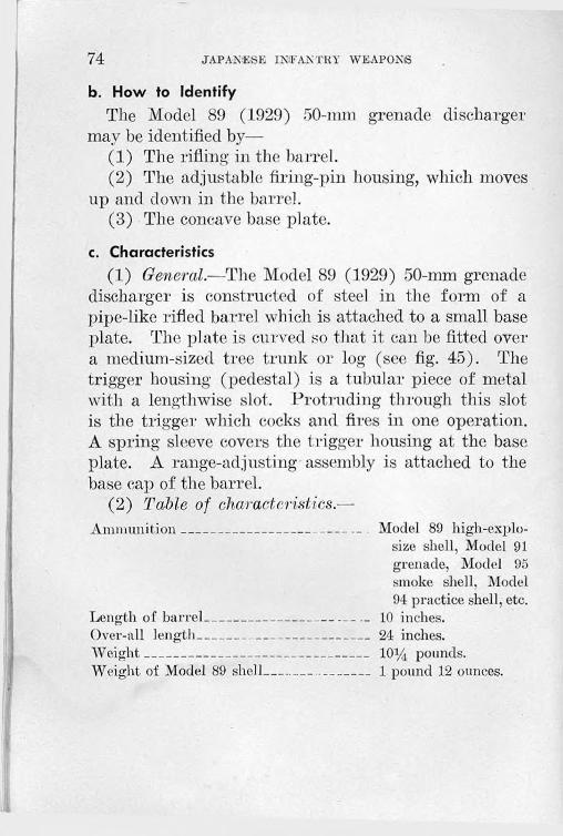
74 JAPANESE lNl'ANTKY WEAPONS
b. How to IdentifyThe Model 89 (1929) 50-mm grenade discharger
may be identified by—(1) The rifling in the barrel.(2) The adjustable firing-pin housing, which moves
up and down in the barrel.(3) The concave base plate.
c. Characteristics(1) General.—The Model 89 (1929) 50-mm grenade
discharger is constructed of steel in the form of a pipe-like rifled barrel which is attached to a small base plate. The plate is curved so that it can be fitted over a medium-sized tree trunk or log (see fig. 45). The trigger housing (pedestal) is a tubular piece of metal with a lengthwise slot. Protruding through this slot is the trigger which cocks and fires in one operation. A spring sleeve covers the trigger housing at the base plate. A range-adjusting assembly is attached to the base cap of the barrel.
(2) Table of characteristics.—Ammunition______________________ _ Model 89 high-explo-
size shell, Model 91 grenade, Model 95 smoke shell, Model 94 practice shell, etc.
Length of barrel----------------------------- 10 inches.Over-all length--------- ---------------------24 inches.Weight______________________ _____ IO14 pounds.Weight of Model 89 shell------------------- 1 pound 12 ounces.

GRENADE DISCHARGERS 75
Figure 44.— Model 89
(1929) 50-mm
grenade discharger.
Range scale:On left of tube, for Model 89 shell_ 120 (o 650 meters
(131.2 to 710.8 yards).
On right of tube, for Model 91 40 to 190 meters (43.7grenade. to 207.8 yards).
Maximum range:For Model 89 shell_______________ 770 yards.For Model 91 grenade____________ 175 yards.
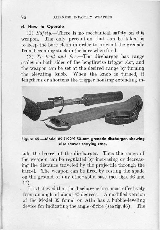
76 JAPANESE INFANTRY WEAPONS
d. How to Operate(1) Safety.—There is no mechanical safety on this
weapon. The only precaution that can be taken is to keep the bore clean in order to prevent the grenade from becoming stuck in the bore when fired.
(2) To load and fire.—The discharger has range scales on both sides of the lengthwise trigger slot, and the weapon can be set at the desired range by turning the elevating knob. When the knob is turned, it lengthens or shortens the trigger housing extending in
Figure 45.—Model 89 (1929) 50-mm grenade discharger, showing also canvas carrying case.
side the barrel of the discharger. Thus the range of the weapon can be regulated by increasing or decreasing the distance traveled by the projectile through the barrel. The weapon can be fired by resting the spade on the ground or any other solid base (see figs. 46 and 47).
It is believed that the discharger fires most effectively from an angle of about 45 degrees. A modified version of the Model 89 found on Attu has a bubble-leveling device for indicating the angle of fire (see fig. 48). The
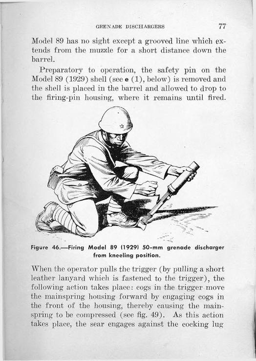
GRENADE DISCHARGERS 77
Model 89 has no sight except a grooved line which extends from the muzzle for a short distance down the barrel.
Preparatory to operation, the safety pin on the Model 89 (1929) shell (see e (1), below) is removed and the shell is placed in the barrel and allowed to drop to the firing-pin housing, where it remains until fired.
Figure 46.—Firing Model 89 (1929) 50-mm grenade discharger from kneeling position.
When (lie operator pulls the trigger (by pulling a short leather lanyard which is fastened to the trigger), the following action takes place: cogs in the trigger move the mainspring housing forward by engaging cogs in the front of the housing, thereby causing the mainspring to be compressed (see fig. 49). As this action takes place, the sear engages against the cocking lug
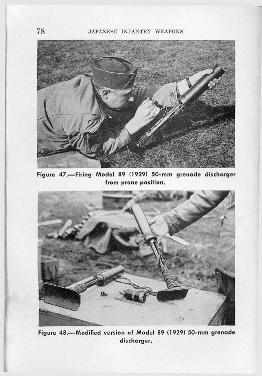
78 JAPANESE INFANTRY WEAPONS
Figure 47.—Firing Model 89 (1929) 50-mm grenade discharger from prone position.
Figure 48.—Modified version of Model 89 (1929) 50-mm grenade discharger.

GUEN ADE DISCHARGEES 79
Permissible movement
of firing pin
Trigger
Mainspring housing
Elevating knob
Figure 49.—Diagrammatic drawings of Model 89 (1929) 50-mm grenade discharger, showing range scales (left) and cross section of firing mechanism (right).
Elevating worm
Firing pin
Firing pin
Base cap'
Range scale_ for mortar shell
Base plate
Range scale for grenade
Cocking lug
Spring and dust protector sleeve
Mainspring
Trigger
of the firing-pin shaft. A continued pull on the trigger allows the sear to become disengaged from the cocking lug, and the compression of the mainspring,

80 JAPANESE INFANTRY WEAPONS
upon being released, sends the firing pin forward and sets off the propellant.
e. Ammunition(1) Model 89 (1929) 50-mm liigli-explosive shell.—
The discharger fires high-explosive (fig. 50; see also fig. 31, p. 50), incendiary (fig. 51), smoke, and signal projectiles. The Model 89 (1929) high-explosive shells which have been examined weigh 1 pound J 2
Figure 50.—Two types of ammunition fired in Model 89 (1929) 50- mm grenade discharger. (From left to right are shown the Model 89 (1929) shell Q disassembled, (2) assembled; the Model 91 (1931) hand grenade @ with propellant container, @ without propellant container.)
ounces, and are painted with black enamel, with a quarter-inch red band at the head and a slightly larger yellow band around the center of the shell body. The shell consists of three major parts: the fuze (Model 88), . the body, and the propellant assembly. The fuze is of a simple point-detonating type with a safety pin. The fuze is safe

GRENADE DISCHARGERS 81
until the pin is pulled out. It is armed by setback when the shell is fired.
The body of the projectile is made of mild steel. It serves as a receptacle for 0.31 pound of TNT-type explosive filler.
Figure 51.—50-mm incendiary grenade for use in Model 89 (1929) 50-mm grenade discharger.
The propellant assembly consists of the percussion cap, the propellant, and an expanding copper rotating band. This unit is assembled to the body by a righthand screw thread, and is ignited when the firing pin hits the percussion cap. When the firing action occurs, the propelling gases expand the copper band against the rifling. This action causes the projectile to rotate. The fuzes for the Model 89 shells are packed separately (figs. 52, 53, and 54).
(2) Model 91 (1931') liigh-explosive grenade.—The Model 91 (1931) high-explosive grenade (fig. 50) consists of two parts: the body and a base attachment that contains a propellant and primer. The grenade can be

82 JAPANESE INFANTRY WEAPONS
Figure 52.—Packing box for fuzes used in Model 89 (1929) 50-mm shells (100 fuzes).
Figure 53.—Two views of packing box for Model 89 (1929) 50-mm shells, showing method of packing individual shells (40 rounds without fuzes).
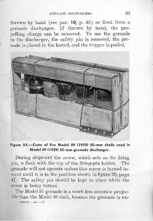
GRENADE DISCHARGERS 83
thrown by hand (see par. 10, p. 45) or fired from a grenade discharger. If thrown by hand, the propelling charge can be removed. To use the grenade in the discharger, the safety pin is removed, the grenade is placed in the barrel, and the trigger is pulled.
Figure 54.—Crate of five Model 89 (1929) 50-mm shells used in Model 89 (1929) 50-mm grenade discharger.
During shipment the screw, which acts as the firing pin, is flush with the top of the firing-pin holder. The grenade will not operate unless this screw is turned inward until it is in the position shown in figure 29, page 47. The safety pin should be kept in place while the screw is being turned.
The Model 91 grenade is a much less accurate projectile than the Model 89 shell, because the grenade is un-
555825°—43 7

84 JAPANESE INFANTRY WEAPONS
stable in flight, there being no provision on it to take the rifling in the barrel. The fuze is initiated by setback.
When this grenade is used as a hand grenade, the fuze cover is hit on some hard object to initiate the powder delay train, and then the grenade is thrown. Although the powder delay train is apparently intended to give a delay of 8 to 9 seconds, reports indicate that the delay action is erratic.
(3) 50-mm incendiary grenade.—The 50-mm incendiary grenade (fig. 51) is a cylindrical sheet-metal tube with a semi spherical nose, and is covered with a clear lacquer. Around the side of the grenade are four silver foil disks, each disk covering seven holes through the grenade casing. The base is of light metal, threaded to receive the propelling charge.
The propelling charge is the same type as that used with the Model 91 (1931) grenade.
The grenade weighs 1.25 pounds and contains a charge weighing 0.67 pound of the following specifications :
PercentPotassium nitrate______ -__________________________ 47.7Aluminum_________________________________________ 21.7Sulphur------------------------------------------------------------------19.9Antimony trisulphide---------------------------------------------- 6.1Wax_____________________________________________ 2.8
98.2The charge is ignited by two black-powder pyro
technic trains that run through the base of the grenade. These are actuated by the flash of the propellant.

GRENADE DISCHARGERS 85
(4) Other ammunition.—In addition to the Model 89 high-explosive shell and the Model 91 high-explosive grenade, the following types of ammunition may also be used:
(a) Model 94 practice shell.(b) Model 94 dummy shell.(c) Model 95 smoke shell.(d) Model 11 smoke shell.(e) Model 10 flare shell.(f) Model 10 signal shell.(g) Model 91 practice grenade.(h) Model 10 blank shell.
f. Maintenance(1) Oiling and cleaning.—To operate efficiently, the
bore and the moving parts of the weapon such as the elevating worm gear and the trigger assembly must be kept free from dirt.
(2) Stripping.—The following procedure will permit a complete disassembly of the weapon (see fig. 55):
(a) Unscrew the barrel from the base cap.(b) Remove the elevating-nut lock ring, the elevat
ing-knob retaining nut, and the elevating knob.(c) Remove the elevating-knob shaft retaining sleeve
and the elevating-knob shaft.(d) Remove the elevating-knob gear.(e) Unlock the finger lock on the side of the base
cap, and unscrew the base cap (right-hand thread).(f) Remove the elevating worm gear.(g) Remove the trigger-pin lock ring, the trigger
pin, and the trigger.
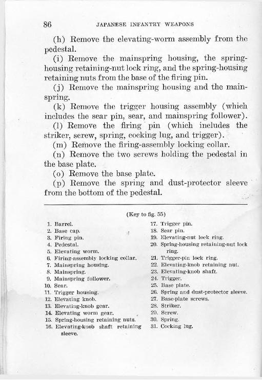
86 JAPANESE INFAN TEA' WEAPONS
(h) Remove the elevating-worm assembly from the pedestal.
(i) Remove the mainspring housing, the springhousing retaining-nut lock ring, and the spring-housing retaining nuts from the base of the firing pin.
(j) Remove the mainspring housing and the mainspring.
(k) Remove the trigger housing assembly (which includes the sear pin, sear, and mainspring follower).
(l) Remove the firing pin (which includes the striker, screw, spring, cocking lug, and trigger).
(m) Remove the firing-assembly locking collar.(n) Remove the two screws holding the pedestal in
the base plate.(o) Remove the base plate.(p) Remove the spring and dust-protector sleeve
from the bottom of the pedestal.
(Key to fig. 55)1. Barrel.2. Base cap. •3. Firing pin.4. Pedestal.5. Elevating worm.6. Firing-assembly locking collar.7. Mainspring housing.8. Mainspring.9. Mainspring follower.
10. Sear.11. Trigger housing.12. Elevating knob.13. Elevating-knob gear.14. Elevating worm gear.15. Spring-housing retaining nuts.16. Elevating-knob shaft retaining
17. Trigger pin.18. Sear pin.19. Elevating-nut lock ring.20. Spring-housing retaining-nut lock
ring.21. Trigger-pin lock ring.22. Elevating-knob retaining nut.23. Elevating-knob shaft.24. Trigger.25. Base plate.26. Spring and dust-protector sleeve.27. Base-plate screws.28. Striker.29. Screw.30. Spring.31. Cocking lug.
T
sleeve.
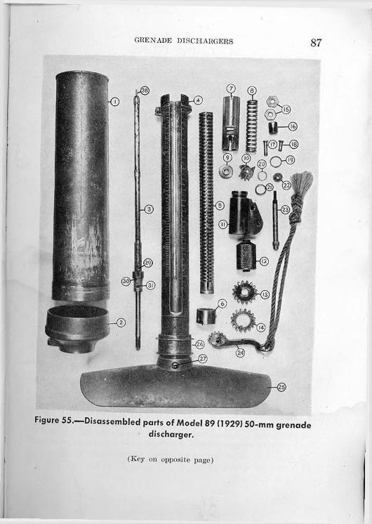
GRENADE DISCHARGERS 87
Figure 55.—Disassembled parts of Model 89 (1929) 50-mm grenade discharger.
(Key on opposite page)

Section VI. MACHINE GUNS
21. MODEL 11 (1922) 6.5-MM LIGHT MACHINE GUN 1
a. GeneralThe Model 11 (1922) 6.5-mm light machine gun (fig.
56) lias been standard equipment in the Japanese infantry squad. As compared with other machine guns,
Front sight
Oil reservoir* illjl 11H - \ Feed hopper
f Rear sightGas regulator
^Backplate pin
Operating handle
Figure 56.—Model 11 (1922) 6.5-mm light machine gun (left side).
it. is unusual in that it is fed by 5-round clips of ammunition. It fires reduced-charge rifle cartridges and will not function properly with the standard-charge rifle ammunition. Although a newer light machine gun of this caliber, the Model 96 (par. 22, p. 96), is
’This weapon, commonly called Nambu Keiki, is listed by the Japanese as -f — Jf. ft, > which is read (from left to right) JuichincnShiki Keikikanju, meaning “lltli year model light machine gun.” (See p. 7, note 1.) The Japanese symbol and abbreviation for a light machine gun are ^LG- an abbreviation of the German Icichtes Oewehr (“light gun”), is rarely found with the symbol.
88

MACHINE GUNS 89
now in use, the Model 11 is still used and is not obsolete. It is employed as a light machine gun on the bipod mount and as a combination heavy and antiaircraft gun on the tripod mount; the tripod mount is seldom encountered.b. How to Identify
The Model 11 (1922) 6.5-mm light machine gun may be identified by—
(1) The feed hopper (figs. 57 and 58) by which 30 rounds are loaded, consisting of six 5-round clips of rifle cartridges placed one on top of the other.
(2) The cutout section of the shoulder stock.(3) The front and rear sights offset to the right.(4) The marking + - 4 A which is on top of the
receiver. (This marking, which is read Juichinen Shiki from left to right,2 means “11th year model.”)c. Characteristics
(1) General.—The Model 11 (1922) 6.5-mm light machine gun is gas-operated, air-cooled, and hopper- fed. Like many Japanese automatic weapons, its design stems from the Hotchkiss (French) gun, but the method of feed, consisting of a hopper attached to the left side of the receiver opposite the feedway and charged with clips of cartridges, is unique.
(2) Table of characteristics.—Caliber----------------------------- 6.5 mm (.256 inch).Principle of operation______ Gas-o p e r a t e d, full-automatic
only.Ammunition------------- .------_ Model 38 (1905) semirimmed, re
duced-charge cartridges in 5- ________ round clips.
* See p. 7, note 1.

90 JAPANESE INFANTRY WEAPONS
Type of feedSights:
Front__
Rear___
Length of barrel
Hopper.
Inverted V blade with guards, offset to right.
Leaf with open V notch sliding on ramp, graduated from 300 to 1,500 meters (328.1 to 1,640 yards), offset to right; no windage adjustment.
19 inches.
Feed hopper
Figure 57.—Close-up of feed hopper (empty) of Model 11 (1922)6.5-mm light machine gun.
Operating handle

MACHINE GUNS 91Over-all length_____________Weight__________________Range:
Effective_______________Maximum_____________
Muzzle velocity_____________Rate of fire:
Effective______________
Cyclic (maximum)______
43i/> inches.2214 pounds.
1,640 yards.4,374 yards.2,440 feet per second.
150 rounds per minute in 5-round bursts.
500 rounds per minute.
d. How to Operate(1) Safety.—A safety lever on the left of the trig
ger guard is shifted downward until approximately
Figure 58.—Loaded feed hopper of Model 11 (1922) 6.5-mm light machine gun.

92 JAPANESE INFANTRY WEAPONS
vertical for “safe.” In this position its lower end engages two small notches in the side of the trigger guard and cannot easily be displaced. For “fire,” the safety lever is rotated backward and upward until it points horizontally to the rear.
The safety level* is attached to the end of a pin, part of which is cut away. When the safety lever is set at “safe,” the solid portion of the pin obstructs the
Figure 59.—Diagrammatic cross section of Model 11 (1922) 6.5-mm light machine gun, showing also various parts.
trigger, whereas when it is set on “fire,” the cutaway allows the trigger to operate freely and to depress the sear.
(2) To load and fire.—(a) General.—Be sure that the oil in the oil reservoir is adequate. Raise the follower of the feed hopper and insert horizontally six clips of cartridges. Allow the follower to snap down so as to hold the cartridges and clips in place in the hopper. Cock the gun by pulling back the operating handle on the left until the projection on the piston engages

MACHINE GUNS 93
the sear notch. Push the operating handle forward until its catch clips into the receiver. The gun is now cocked and ready to be fired.
(b) Regulating rate of fire.—Similar to the U. S. Browning automatic rifle (BAR) M1918 and modifications, the rate of fire is regulated by means of a gas regulator with several openings of different sizes for the passage of gas through the regulator until it strikes the gas piston. These holes regulate the force with which the bolt recoils. Adjustments are made to “smooth out” the action of the gun so that only enough gas is utilized to force the recoiling parts to the rear smoothly and without their striking the buffer with excessive force. After initial regulation, changes are necessary only when the gun becomes excessively fouled and dirty, so that more force is required to drive the parts rearward.
(3) Sights.—The front and rear sights are of necessity offset to the right to prevent obstruction of sighting by the oil reservoir. To set the rear sight, press the knurled catch on the left side of the rear-sight slide, move the slide to the desired range, and release the catch.
(4) To unloads—Pull back on the knurled feed-housing lock on the feed-house assembly, where it projects out of the lower center of the right side of the feedway, and remove the feed-housing assembly to the left. Remove the live ammunition from the feed well of the feed-housing assembly and replace the feed-housing assembly in place on the gun. Do not attempt to unload the gun by working live rounds through the
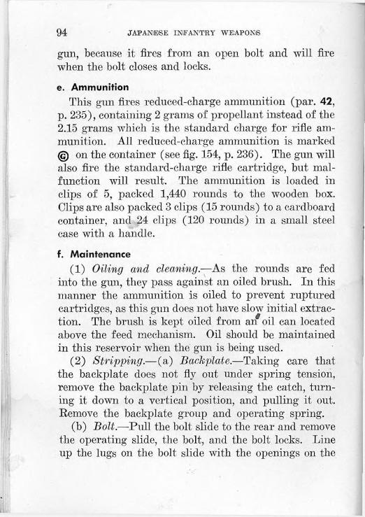
94 JAPANESE INFANTRY WEAPONS
gun, because it fires from an open bolt and will fire when the bolt closes and locks.e. Ammunition
This gun fires reduced-charge ammunition (par. 42, p. 235), containing 2 grams of propellant instead of the 2.15 grams which is the standard charge for rifle ammunition. All reduced-charge ammunition is marked © on the container (see fig. 154, p. 236). The gun will also fire the standard-charge rifle cartridge, but malfunction will result. The ammunition is loaded in clips of 5, packed 1,440 rounds to the wooden box. Clips are also packed 3 clips (15 rounds) to a cardboard container, and 24 clips (120 rounds) in a small steel case with a handle.f. Maintenance
(1) Oiling and cleaning—As the rounds are fed into the gun, they pass against an oiled brush. In this manner the ammunition is oiled to prevent ruptured cartridges, as this gun does not have slow initial extraction. The brush is kept oiled from an oil can located above the feed mechanism. Oil should be maintained in this reservoir when the gun is being used.
(2) Stripping.—(a) Backplate.—Taking care that the backplate does not fly out under spring tension, remove the backplate pin by releasing the catch, turning it down to a vertical position, and pulling it out. Remove the backplate group and operating spring.
(b) Bolt.—Pull the bolt slide to the rear and remove the operating slide, the bolt, and the bolt locks. Line up the lugs on the bolt slide with the openings on the
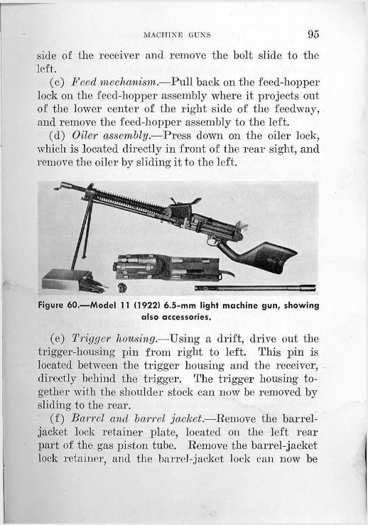
MACHINE GUNS 95
side of the receiver and remove the bolt slide to the left.
(c) Feed mechanism.—Pull back on the feed-hopper lock on the feed-hopper assembly where it projects out of the lower center of the right side of the feedway, and remove the feed-hopper assembly to the left.
(d) Oiler assembly.—Press down on the oiler lock, which is located directly in front of the rear sight, and remove the oiler by sliding it to the left.
Figure 60.—Model 11 (1922) 6.5-mm light machine gun, showing also accessories.
(e) Trigger housing.—Using a drift, drive out the trigger-housing pin from right to left. This pin is located between the trigger housing and the receiver, directly behind the trigger. The trigger housing together with the shoulder stock can now be removed by sliding to the rear.
(f) Barrel and barrel jacket.—Remove the barreljacket lock retainer plate, located on the left rear part of the gas piston tube. Remove the barrel-jacket lock retainer, and the barrel-jacket lock can now be

96 JAPANESE INFANTRY WEAPONS
driven out to the front. Unscrew the barrel jacket from the receiver (right-hand threads).
(3) Assembly.—To assemble the weapon, proceed in the reverse order to that followed in stripping.g. Accessories
Among the accessories of this weapon are an extra barrel, a box of cleaning equipment, and a kit containing tools, a spare operating spring, and other spare parts. (See fig. 60.)
22. MODEL 96 (1936) 6.5-MM LIGHT MACHINE GUN 3
a. GeneralThe Model 96 (1936) 6.5-mm light machine gun
(fig. 61) is very similar in appearance to the British Bren light machine gun, caliber .303. Jn construction, however, it embodies certain features of modern European light machine guns, particularly the Hotchkiss (French) and the Z. B.' (Czech). The mechanism is largely an improvement on the Model 11 (1922) 6.5-mm light machine gun (par. 21, p. 88). It handles well and can be fired easily from the hip. It is fitted to take the Japanese service bayonet Model 30 (1897) (fig. 20, p. 33).
’This weapon, commonly called Kyuroku Shiki Keiki, is listed by the Japanese as^ M ’ wh*ch *s reati (fr°m left to right) KyurokuShiki Keikikanju, meaning “96 model light machine gun.” (See p. 7, note 1.) The Japanese tactical symbol and abbreviation for light machine gun are ^L.G- (See p. 88, note 1.)
' Zbrojovka, Brno, a Czechoslovak armament factory in the city of Brno (Briinn). Now under Herman control, it is known as Waffenfnbrik, Briinn.

MACHIN GMJNS 97
b. How to IdentifyThe Model 96 (1936) 6.5-mm light machine gun may
be identified by—(1) The carrying handle directly in front of the
receiver.(2) The operating handle on the left of the receiver.(3) The drum-controlled peep rear sight.(4) The quick-change barrel with the swinging-arm
type of release catch.(5) The similarity in appearance to the British Bren
light machine gun.(6) The marking a. a A which is on the right side
of the receiver. (This marking, which is read Kyuroku Shiki from left to right,’1 means “96 model.”)c. Characteristics
(1) General.—The Model 96 (1936) is a later type of Japanese light machine gun. It is gas-operated and air-cooled, a spare barrel being carried for changing should it be necessaiy. The method of feeding is by a curved-box magazine, containing 30 rounds, which is placed on top of the receiver.
(2) Table of characteristics.—Caliber__________________________ 6.5 mm (.256 inch).Principle of operation_____________ Gas-operated, full-auto
matic only.Ammunition_____________________ Model 38 (1905)
semirimmed reduced-charge.
Type of feed_____________________ 30-round box magazine.
5 See p. 7, note 1.

98 JAPANESE INFANTRY WEAPONS
Sights:Front_______________________
Rear________________________
Telescopic:Weight----------------------------Magnifying power—_______Field of view_____________
Windage____________________
Length of barrel_________________Over-all length___________________Weight of barrel__________________Weight with sling________________Range:
Effective____________________Maximum___________________
Muzzle velocity-__________________Rate of fire (cyclic)-----------------------
Inverted V blade with guards, offset to left.
Drum-controlled peep sight, with windage adjustment, graduated from 200 to 1,500 meters (218.7 to 1,640 yards) in jumps of 100 meters (109.4 yards), offset to left.
/1.4 pounds.2.5 times. e10 degrees.10 mils (0.5G2 degree)
right and left.21.65 inches.42 inches.5.24 pounds.20 pounds.
1,640 yards.4,374 yards.2,410 feet per second. 550 rounds per minute.
d. How to Operate(1) Safety.—The safety (fig. 62) is located on the
left side of the trigger housing in front of and above the trigger. In the horizontal position it is set to “fire”; in the vertical position, to “safe.” At “safe” the trigger mechanism is locked by the surface of the pin preventing movement of the trigger. At “fire” the cutaway portion of the pin allows the sear to move.

MACHINE GUNS 99
'MlillllllUiUlUlUUUlltUIUllIUllIllUltUlttZZlS!!
Figure 61.—Model 96 (1936) 6.5-mm light machine gun partially disassembled.
(2) To load and fire.—^-Open the magazine-opening cover on the top of the receiver. Insert a loaded 30- round magazine into the opening, catching the front
Bolt in firing position
Figure 62.—Diagrammatic cross section of Model 96 (1936) 6.5-mm light machine gun, showing also various parts.
655825°—43---- 8

100 JAPANESE INFANTRY WEAPONS
side of the magazine first and pulling it back until the catch on the back of' the magazine opening engages the magazine. Pull the operating handle to the rear until the sear engages the operating slide. Return the operating handle to its forward position and set the
Figure 63.—Firing Model 96 (1936} 6.5-mm light machine gun from standing position.
range on the sight drum. The gun is now ready to be fired (fig. 63).
(3) To unload.—(a) Press the magazine catch forward with the base of the palm of the hand, at the same time grasping the magazine and tilting it forward until it is clear of the magazine catch; then lift

MACHINE GUNS 101
off the magazine. Now examine the chamber to be sure that it is empty.
(b) If the safety is at the “on” position, move it to the “off” position.
(c) Press the trigger, cock the gun, and press the trigger again.
(d) Close the magazine and the ejection-opening covers and muzzle cover if attached.
(4) Adjustments.—The gas piston plug has five positions. They are numbered one to five, respectively. As the gas piston plug is turned from one toward five, the size of the gas port increases. If the gun is recoiling too hard, a smaller number should be used. If the recoil is too light or is insufficient for operation, a larger number should be used.
(5) Stoppages.—The following chart is designed to assist in locating and remedying various causes of trouble which may arise during the use of this weapon:
Stoppage Cause Remedy
MagazineFails to feed................................. Bent magazine lip.................... Replace the magazine.
Replace the magazine.Worn-out lug in magazineWeak or damaged follower Replace the follower spring.
Fails to feed: double loadingspring.
Bent magazine.............................. Replace the magazine.
BarrelChamber scores cartridge case; Corrosion or rust in chamber Clean the chamber or replace the
damages parts. barrel.Damaged bolt breaks extractor Damaged breech face or bolt Replace the barrel and bolt lock.
spring. lock in receiver.Heavy impact scars on bolt and Replace the barrel and bolt lock.
Barrel is loose..............................extractor.
Burred barrel-locking lever slot. File off the burrs in barrel-locking
Worn-out barrel-locking lever .lever slot.
Replace the lever.Seating barrel into receiver is Busted threads on barrel or Replace the barrel or clean the
difficult. receiver. locking lever and slot.

102 JAPANESE INFANTRY WEAPONS
Stoppage Cause Remedy
Gas Port, Cylinder, and Piston
Gas pressure is low. ... .......... Enlarged, worn-out, or fouled Clean the gas port. If in aerton,gas port. replace the barrel.
Worn-out or rusted gas-cylinder Replace the piston.piston.
Gas-cylinder lock rotates Worn-out or broken gas-cylinder Replace the spring. If in action.freely. lock spring. replace the barrel.
Gas-cylinder piston scrapes.—. Bent piston........................... ......... Replace the piston.
ReceiverEjection is faulty. ..................... Loose ejector pivot bearing_____ Replace the bolt.
Buffer and Driving Grout Assembly
Driving spring is twisted. . Worn-out or bent driving-spring Straighten or replace the driving-guide. spring guide.
BoltFiring pin strikes light blow on Firing pin bent or firing-pin slot Replace the firing pin or elean
primer. clogged with carbon. and oil the firing-pin slot.Fails to fire................................. Cracked bolt _____ Replace the bolt.Breech will not lock; pre- Bent bolt-locking cam seat........ . Replace the bolt-locking cam
battery explosion will result. seal.Primers are punctured. Enlarged or fouled firing-pin Replace the bolt.
ExtractorFails to extract................... . ..
hole.
Worn-out or broken extractor Replace the extractor spring.spring.
Worn-out or broken spring re- Replacre the spring retainer.taincr.
Worn-out or rusted extractor— Replace the extractor.Rusted or damaged bolt............. Replace the bolt lock.
Bolt LockAction does not lock Rusted, cracked, or bent boh Replace the bolt lock.
Magazine Catch Magazine is not secure . .
lock.
Worn-out or damaged magazine Replace the magazine-catch levelcatch or spring. or spring.
SearBolt will not stay back Broken or worn sear Replace the scar.
Operating Handle Bolt will not go forward (loose Worn-out operating handle cam. Replace the cam.
operating handle).
EjectorFails to eject Rusted or bent ejector................ Replace the ejector. If in action,
replace the bolt.Bolt Lock
Bolt-lock catch doos not funo Rusted or bent bolt lock.. ____ Replace the bolt lock.tion.
Assembly of bolt lock to re- Worn-out or bent bolt-lock Replace the bolt-lock retainingceiver is difficult. spring. spring.

MACHINE GUNS 103e. Ammunition
The Model 96 (1936) 6.5-mm light machine gun will not handle the Japanese 6.5-mm service ammunition without malfunction. Ammunition in containers marked with a Gamma circle, ©, is a special reduced charge for both the Model 11 (1922) and the Model 96 (1936) 6.5-mm light machine guns. (See par. 42, p. 235, and fig. 154, p. 236.)
f. Maintenance(1) Oiling and cleaning.—The Model 96 (1936)
6.5-mm light machine gun is sensitive to dirt, dust, and sand. To function well, it must be kept cleaned and oiled at all times. The magazine- and ejectionopening covers should be kept closed whenever the gun is not being fired. The same type of care and cleaning as- is given to similar gas-operated U. S. weapons will suffice.
(2) Stripping—(a) Barrel.—With the bolt forward, pull out on the barrel-lock knob, which is located on the front left side of the receiver, and turn it about one-third turn upwards. The barrel will now slide forward, disengaging from the receiver. If it sticks, tap lightly on the rear face of the barrel-carrying handle.
(b) Backplate.—Rotate about one-eighth of a turn upward the backplate pin knob, located on the rear left side of the receiver. Holding in on the backplate, against the recoil spring action, pull the backplate pin to the left as far as it will go. The backplate group and recoil spring may then be removed.

104 •JAPANESE INIFANTRY WEAPONS
(c) Gas piston and bolt.—Pull the operating handle to the rear and remove the gas-piston assembly bolt. Slide them off from the rear of the receiver.
(d) Bolt lock.—Pull down on the bolt-lock cover on the bottom of the receiver in front of the trigger. The bolt lock will then slide out the bottom of the receiver, or it can be pushed out.
(e) Trigger-guard group.—-Drift out the triggerguard housing key, located on the bottom rear of the receiver. By pulling the trigger, the stock and trigger housing can be drawn from the rear of the receiver.
(f) Bipod.—After the barrel has been removed, the bipod (fig. 64) can be rotated either to the left or right and then be removed from the gas cylinder tube.
(3) Assembly.—To assemble the weapon, proceed in the reverse order to that followed in stripping. Make sure that all burrs are removed, that parts are clean and well oiled, that the firing pin is assembled in front of the piston hammer stud, and that the operating or recoil spring is not buckled and is free on its guide.
g. Accessories
The following items are accessories to this weapon:(1) Telescope sight and case.(2) Muzzle cover and flash hider. (Only one can be
used at a time.)(3) Leather hand guard used in holding the barrel
when firing from the hip.(4) Magazine loader. (It accommodates the Model
38 (1905) semirimmed, reduced-charge ammunition in the standard 5-round clips.)

MACHINE GUNS 105
Figure 64.—Model 96 (1936) 6.5-mm light machine guns with bipods attached.
106 JAPANESE INFANTRY WEAPONS
(5) Spare barrel.(6) Spare-parts kit in a metal box. (The contents
include a spare bolt assembly, operating and other springs, a bolt lock, a combination tool, and other parts.)
(7) Bayonet.(8) Carrying sling.(9) Canvas-and-leather gun cover.
23. MODEL 99 (1939) 7.7-MM LIGHT MACHINE GUN'
a. GeneralThe Model 99 (1939) 7.7-mm light machine gun
(fig. 65), one of the newest types to appear in action, is an evidence of the Japanese change from 6.5-mm (.256-inch) to 7.7-mm (.303-inch) weapons.
The Model 99 (1939) 7.7-mm light machine gun and the Model 99 (1939) 7.7-mm rifle use the Model 99 (1939) 7.7-mm rimless ammunition. Basically this new Model 99 (1939) 7.7-mm light machine gun is the same as the Model 96 (1936) 6.5-mm light machine gun (par. 22, p. 96). There are, however, two important differences: (1) a new method of changing the barrel (see fig. 66_), a device which includes headspace adjustment, and (2) an adjustable rear monopod. Like the Model 96 (1936) 6.5-mm light machine gun, this weapon is fitted to take the Japanese service bayonet (fig. 20, p. 33).
“This weapon, commonly called Ryukyu Shiki Reiki, is listed by the Japanese which is read (from left to right) RyukyuShiki Reikikunju, meaning “9!) model light machine gun.” (See p. 7, note 1.) The Japanese tactical symbol and abbreviation for a light machine gun are i(_G. (See p. 88, note 1.)

MACHINE GUNS 107b. How to Identify
Though differing in caliber, the Model 99 (1939) 7.7-mm light machine gun is quite similar (see fig. 67) to the Model 96 (1936) 6.5-mm light machine gun (par. 22, p. 96) except for—
(1) The adjustable rear monopod.
Figure 65.—Model 99 (1939) 7.7-mm light machine gun, showing adjustable rear monopod.
(2) The nut and wedge type of barrel release. (This is used instead of the pivoting barrel-lockingknob of the Model 96 light machine gun.)
(3) The safety on the right side of the receiver. (The safety is on the left side of the Model 96 light machine gun.)
(4) The method used to attach the flash hider. (The Model 96 light machine gun has a bayonet-type locking device, whereas the flash hider is screwed on the Model 99.)

108 JAPANESE INFANTRY WEAPONS
(5) The marking A which is on the receiver. (This marking, which is read Kyukyu Shiki from left to right,7 means “99 model.”)
’ See p. 7. note 1.
c. Characteristics(1) General.—The Model 99 (1939) 7.7-mm light
machine gun is gas-operated, air-cooled, and maga-
Figure 66.—Close-up of Model 99 (1939) 7.7-mm light machine gun, showing method of withdrawing barrel.
zine-fed. It is fired from a bipod and rear monopod, which is adjustable for elevation. The weapon is fed by a 30-round, curved-box magazine, which is placed on top of the receiver. The mechanism of this

MACHINE GUNS 109model is virtually the same as that of the Model 96 (1936) 6.5-mm light machine gun. Many parts are common to both guns.
(2) Table of characteristics.—Calibei'---------------------- 7.7 min (.303 inch).Principle of operation---- Gas-operated, full-automatic only.Ammunition--------------- Model 99 (1939) 7.7-mm rimless car
tridges only. (The use of ball cartridges is known, but no reports of armor-piercing or tracer cartridges have been received.)
Type of feed__________ 30-round box magazine.Sights:
Front_____________Inverted V blade with guards, offsetto left.
Rear---------------------Drum-controlled peep sight, withwindage adjustment, graduated from 200 to 1,500 meters (218.7 to 1,640 yards) in jumps of 100 meters (109.4 yards), offset to left.
Windage--------------- 10 mils (0.562 degree) right and left.Length of barrel----------- 21.65 inches.Over-all length------------ 42 inches.Weight:
Without magazine... 20 pounds.Magazine (empty)... 1.36 pounds.Magazine (loaded)... 3.03 pounds.
Range:Effective___________ 1,500 yards.Maximum__________ 3,800 yards.
Muzzle velocity________ 2,300 feet per second.Rate of fire:
Effective__________ 250 rounds per minute.Cyclic____________ 800 rounds per minute.

110 JAPANESE INFANTRY WEAPONS
Figure 67.—Model 96 (1936) 6.5-mm light machine gun (left) and model 99 (1939) 7.7-mm light machine gun (right).
MACHINE GUNS 111d. How to Operate
(1) Safety.—A safety lever is located on the right side of the receiver. To put the lever in the “safe” position, rotate it upward until it is in the vertical position. To put the lever in the “fire” position, rotate it downward until it is in the horizontal position. In the “safe” position the sear is prevented from moving. In the “fire” position the cutaway section of the pin attached to the safety lever allows the sear to move.
(2) To load and fire.—(a) General.—If present, remove the muzzle, or mud, cover. Move the safety lever to the “fire” position. Open the magazine and ejection port covers. Insert a loaded magazine with its inside curve facing forward and engage the front end first in the front end of the magazine opening. Press it down until the magazine catch engages its rear flange. Pull the operating handle to the rear as far as it will go, and then push it forward again, as this will prevent injury to the firer’s hand. Set the sights by turning the elevating drum until the desired range shows in the cut at the rear of the drum. As long as the trigger is pulled, the gun will fire; there is no provision for semiautomatic fire.
(b) Regulating rate of fire.—The gas regulator, which regulates the rate of fire, has five positions, numbered one to five, respectively. As the gas regulator is turned from one toward five, the size of the port increases. If the gun is recoiling too hard (that is, pounding), a sma ller-numbered port should be used. If the recoiling parts do not come far enough to the rear to operate, a larger hole should be used. Compressing a spring lock allows the gas regulator to be moved for the necessary adjustments.

112 JAPANESE INFANTRY WEAPONS
(3) Sights.—(a) Metallis sights.—The front and rear sights, of necessity, are offset to the left because of the position of the vertical box magazine placed on top of the receiver. The standard metallic rear sight is set for elevation by turning the elevation drum until the desired range (in meters) is shown in the window on the rear of the rear-sight housing. Adjustment for windage is made by turning the knob located to the left of the peep on the rear sight.
(b) Telescopic sight.—The dove-tail base situated on the right of the rear top plate of the receiver takes a 2%-power telescopic sight. A spring-loaded catch locks the sight in place.
(4) To unload.—Press forward on the magazine catch and remove the magazine. Press the trigger. Cock the gun. Press the trigger again. Set the safety lever to “safe.” Set the sights to zero. Do not attempt to unload the gun by working live rounds through the action, because the gun fires from an open bolt and will fire when the bolt closes and locks. Close the magazine and ejection port covers, and put the muzzle cover in place.
(5) Stoppages.—The stoppages chart for the Model 96 (1936) 6.5-mm light machine gun (see par. 22d (5), p. 101) applies also to the Model 99 (1939) 7.7-mm light machine gun, as the actions of these guns are identical.e. Ammunition
This machine gun uses the Model 99 (1939) 7.7-mm (.303-inch) rimless ammunition, which—unlike the Model 92 (1932) 7.7-mm ammunition used in the Model 92 (1932) 7.7-mm heavy machine gun—is true rimless

MACHINE GUNS 113
ammunition, not semirimmed. The Model 99 (1939)7.7-mm rimless ammunition will function in the Model 92 (1932) 7.7-mm heavy machine gun if it is loaded in the 30-round feed strips for the heavy machine gun, and it has been found loaded in this manner.
The semirimmed ammunition usually found in 30- round feed strips is designed for the Model 92 (1932)7.7-mm heavy machine gun and will not function in the Model 99 (1939) 7.7-mm light machine gun. (See also par. 43b (3), p. 237.)
Before loading the magazine, check to see that the oil reservoir on the loader is filled. Attach the empty magazine to the loader. Pull back the loading handle until the 5-round clip can be inserted. Press the rounds into the magazine by pushing down on the loading handle. Remove the empty clip, and repeat until the 30 rounds are loaded into the magazine.f. Maintenance
(1) Oiling and cleaning—The Model 99 (1939)7.7-mm light machine gun is less sensitive to dirt, dust, and sand than the Model 11 (1922) 6.5-mm light machine gun. Nevertheless the weapon still requires tire care given to similar LT. S. weapons. The gas piston and cylinder should be scraped clean just as in the similar assemblies on the Browning automatic rifle (BAR), M1.918.
(2) Stripping.—(a) Barrel.—Unscrew the headspace adjusting bolt, and pull it out as far as it will come. Then withdraw the barrel to the front. If the barrel should stick, tap lightly on the rear face of the barrel-carrying handle while at the same time holding

114 JAPANESE INFANTRY WEAPONS
onto the carrying handle in order to prevent the barrel from falling to the ground.
(b) Backplate.—Rotate the backplate pin knob, located on the left rear side of the receiver, about one- eighth of a turn upward. Maintaining pressure on the backplate to prevent the recoil spring from flying out, pull the backplate pin to the left as far as it will go. Ease up on the backplate; both the backplate and the recoil spring can be withdrawn to the rear.
(c) Gas piston and bolt.—Pull back the operating handle smartly. The bolt can now be grasped through the open rear end of the receiver and withdrawn. Bring with it the gas-piston assembly, to which it is connected by the hammer stud on the gas piston. Lift the bolt vertically away from the gas piston, and they will readily come apart.
(d) Bolt lock.—Pull down the bolt-lock cover located on the bottom plate of the receiver in front of the trigger guard. Inserting a finger through the magazine opening in the top of the receiver, push the bolt lock down until it falls into the hand held underneath to catch it.
(e) Trigger-guard group.—Drive out the triggerhousing split pin, located on the bottom rear of the receiver. Pull the trigger and withdraw the triggerguard group and shoulder-stock group to the rear.
(f) Bipod.—With the barrel group removed, the bipod can be removed from the gas cylinder merely by rotating it in either direction until it is free.
(3) Assembly.—To assemble the weapon, proceed in the reverse order to that followed in stripping. Make sure that all parts are free from burrs and well oiled.
MACHINE GUNS 115
Check to be certain that the bolt is assembled to the gas-piston assembly so that the gas-piston hammer stud is behind the firing pin in the bolt. Also, make sure that the operating, or recoil, spring is not buckled in assembly and is free on its guide.g. Accessories
The following items are accessories to this weapon:(1) Telescopic sight and case.(2) Muzzle cover and flash hider. (Only one can be
used at a time.)(3) Leather hand guard used in holding the barrel
when firing from the hip.(4) Magazine loader. (It accommodates the Model
99 (1939) 7.7-mm rimless light machine-gun and rifle ammunition in the standard 5-round clips.)
(5) Spare barrel.(6) Spare-parts kit in a metal box. (The contents
include a spare bolt assembly, operating and other springs, a bolt lock, a combination tool, and other parts.)
(7) Bayonet.(8) Carrying sling.(9) Canvas-and-leather gun cover.
24. MODEL 92 (1932) 7.7-MM HEAVY MACHINE GUN s a. General
The Model 92 (1932) 7.7-mm heavy machine gun (fig. 68) is the standard Japanese heavy machine
“This weapon, commonly called Juki, is listed by the Japanese as 7L- which is read (from left to right) Kyuni ShikiJukikanju. meaning “92 model heavy machine gun.” (See p. 7, note 1.) The Japanese tactical symbol for a (heavy) machine gun is t.
555825°—43----- 9

116 JAPANESE INFANTRY WEAPONS
gun. It is normally mounted on a tripod for use against ground targets. When mounted on its standard tripod with an adapter, it can be used as an antiaircraft machine gun.b. How to Identify
The Model 92 (1932) 7.7-mm heavy machine gun may be identified by—
(1) The large radiating rings (air-cooling flanges).(2) The adjustable traversing handles (figs. 69 and
70).
Figure 68.—Model 92 (1932) 7.7-mm heavy machine gun (right side).
(3) The cocking handle on the right side.(4) The trigger thumbpiece (figs. 69 and 70).(5) The oiler (fig. 70), which is situated above and
to the left of the receiver directly above the feedway.
(6) The marking > which is on top of the receiver.A

MACHINE GUNS 117
(This marking, which is read Kyuni Shiki from top to bottom,9 means “92 model.”)
’ See p. 7, note 1.
c. Characteristics(1) General.—The Model 92 (1932) 7.7-mm heavy
machine gun is a modified Hotchkiss-type weapon. Because of its slow cyclic rate, the gun seldom overheats, and the life of a barrel is unusually long. .A base on the receiver accommodates a telescopic sight.
(2) Table of characteristics.—Caliber___________________Principle of operation______
Ammunition_______________
Type of feed_ ____________Sights:
Front________________
Rear_________________
Telescopic_____________
Length of barrel___________Over-all length____________Weight:
Without tripod________With tripod___________
7.7 mm (.303 inch).Gas-opera te d, full-auto
matic only.Ball, tracer, and armor-piercing.
(Both semirimmed and rimless ammunition can be fired.)
Strips (30 rounds each).
Either V blade with guards, offset to right, or an antiaircraft sight of the cartwheel type.
Either post type, with windage adjustment, graduated from 300 to 2,700 meters (328.1 to 2,953 yards), offset to right, or special antiaircraft sight mounted on ground-sight base.
Model 96 (4-power), Model 93 (6-power), and Model 94 (5-power).
29.5 inches.45.5 inches.
61 pounds.122 pounds.

118 JAPANESE INFANTRY WEAPONS
Traverse (with tripod mount).
Elevation (with tripod mount) :Maximum_____________Minimum--------------------
Range:Effective______________Maximum--------------------
360 degrees (33.5 degrees on an arc).
11 degrees.— 15 degrees.
1,500 yards.4,587 yards.
Figure 69.—Model 92 (1932) 7.7-mm heavy machine gun (rear view).
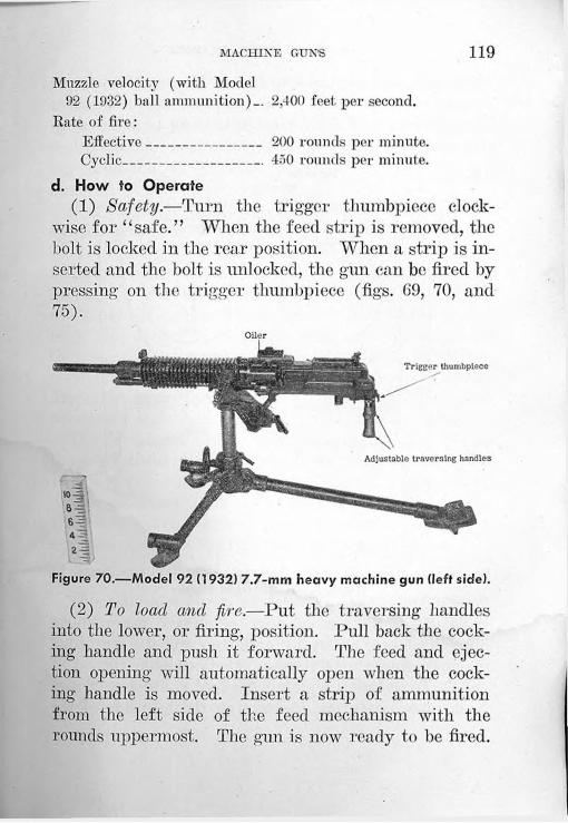
MACHINE GUNS 119Muzzle velocity (with Model
92 (1932) ball ammunition)— 2,400 feet per second.Rate of fire:
Effective______________ 200 rounds per minute.Cyclic_________________ 450 rounds per minute.
d. How to Operate(1) Safety.—Turn the trigger thumbpiece clock
wise for “safe.” When the feed strip is removed, the bolt is locked in the rear position. When a strip is inserted and the bolt is unlocked, the gun can be fired by pressing on the trigger thumbpiece (figs. 69, 70, and 75).
Trigger thumbpiece
Adjustable traversing handles
Figure 70.—Model 92 (1932) 7.7-mm heavy machine gun (left side).
(2) To load and fire.—Put the traversing handles into the lower, or firing, position. Pull back the cocking handle and push it forward. The feed and ejection opening will automatically open when the cocking handle is moved. Insert a strip of ammunition from the left side of the feed mechanism with the rounds uppermost. The gun is now ready to be fired.
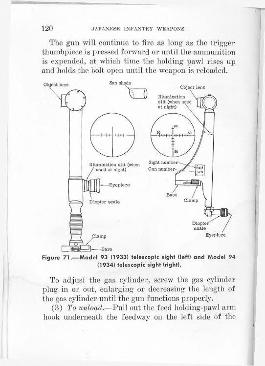
120 JAPANESE INFANTRY WEAPONS
The gun will continue to fire as long as the trigger thumbpiece is pressed forward or until the ammunition is expended, at which time the holding pawl rises up and holds the bolt open until the weapon is reloaded.
Figure 71.—Model 93 (1933) telescopic sight (left) and Model 94 (1934) telescopic sight (right).
To adjust the gas cylinder, screw the gas cylinder plug in or out, enlarging or decreasing the length of the gas cylinder until the gun functions properly.
(3) To unload.—Pull out the feed holding-pawl arm hook underneath the feedway on the left side of the
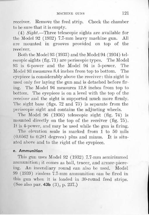
MACHINE GUNS 121
receiver. Remove the feed strip. Check the chamber to be sure that it is empty.
(4) Sight.—Three telescopic sights are available for the Model 92 (1932) 7.7-mm heavy machine gun. All are mounted in grooves provided on top of the receiver.
Both the Model 93 (1933) and the Model 94 (1934) telescopic sights (fig. 71) are periscopic types. The Model 93 is 6-power and the Model 94 is 5-power. The Model 93 measures 8.4 inches from top to bottom. The eyepiece is considerably above the receiver: this sight is used only for laying the gun and is detached before firing. The Model 94 measures 12.8 inches from top to bottom. The eyepiece is on a level with the top of the receiver and the sight is supported much more firmly. The sight base (figs. 72 and 73) is separate from the periscopic sight and contains the adjusting wheels.
The Model 96 (1936) telescopic sight (fig. 74) is mounted directly on the top of the receiver (fig. 75). It is 4-power, and may be used while the gun is firing.
The elevation scale is marked from 1 to 50 mils (0.0562 to 0.281 degrees) plus and minus. It is situated above and to the right of the eyepiece.e. Ammunition
This gun uses Model 92 (1932) 7.7-mm semirimmed ammunition; it conies as ball, tracer, and armor-piercing. An incendiary round can also be used. Model 99 (1939) rimless 7.7-mm ammunition can be fired in this gun when it is loaded in 30-round feed strips. (See also par. 43b (3), p. 237.)
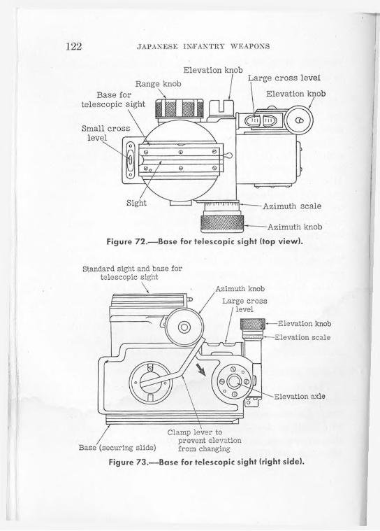
122 JAPANESE INFANTRY WEAPON'S
Azimuth knobLarge cross
Standard sight and base for telescopic sight
•Elevation knob
Elevation axle
-—Elevation scale
/Clamp lever to prevent elevation
Base (securing slide) from changing
Figure 73.—Base for telescopic sight (right side).
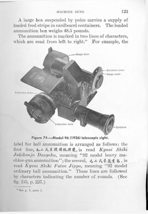
MACHINE GUNS 123
A large box suspended by poles carries a supply of loaded feed strips in cardboard containers. The loaded ammunition box weighs 48.5 pounds.
The ammunition is marked in two lines of characters, which are read from left to right.10 For example, the
Range knob
Deflection scale.
‘Deflection knobEyepiece
Elevation scale■Range scale
Figure 74.—Model 96 (1936) telescopic sight.
label for ball ammunition is arranged as follows: the first line, A i $ I®., is read Kyuni ShikiJukikanju Danyaku, meaning- “92 model heavy machine-gun ammunition”; the second, i - M M , is read Kyuni Shiki Futsu Jippo, meaning “92 model ordinary ball ammunition.” These lines are followed by characters indicating the number of rounds. (See fig. 155, p. 237.)
'"Sec p. 7, note 1.

124 JAPANESE INFANTRY WEAPONS
f. Maintenance(1) Oiling and cleaning.—The same type of care
and cleaning as is given to U. S. gas-operated weapons will suffice to keep this weapon in good working order.
(2) Stripping (fig. 76).—(a) Backplate.—Remove the backplate pin by turning it down to a vertical position and then pulling it out, holding it in place against the pressure of the operating, or recoil, spring. Then remove the backplate group and operating spring.
OilingTelescope sight
handle
with peep and windage removed
Trigger thumbpiece
Figure 75.—Model 92 (1932) 7.7-mm heavy machine gun equipped with Model 96 (1936) telescopic sight. (The feedway is opened to show the oiling brush.)
(b) Bolt.—Pull the bolt slide to the rear, and remove the operating slide, bolt lock, and bolt. Align the lugs on the bolt slide with the openings on the side of the receiver and remove the bolt slide.

MACHINE GUNS 125
Figu
re 76.
Mod
el 92
(193
2) 7.7-
mm
heavy
machi
ne gun
disas
sem
bled
.

126 JAPANESE INFANTRY WEAPONS
(c) Oiler.—Push forward on the oil-reservoir lock, raising up on the rear of the oil reservoir. Remove the oil-reservoir retaining screw, and lift off the oil reservoir.
(d) Barrel.—Remove the gas-jet cover from the bottom of the gas cylinder, and unscrew the gas jet
Figure 77.—Model 92 (1932) 7.7-mm heavy machine gun, showing tool and spare-parts box.
from the barrel. Remove the barrel nut. Turn the barrel one-half turn to the right and pull it out. Then pull out the barrel sleeve. A special wrench to remove the barrel will be found in the tool and spare-parts kit.
(e) Feed mechanism.—Locate the holding pin, which is at the front and bottom of the feed box. Rotate this pin one-half turn in a downward direction; then pull it out. Remove the holding pawl and holding

MACHINE GUNS 127
paw] spring. Align the marks on the feed slide with the marks on the feed box, and drift the feed-slide pin out to the front of the feed box. Slide the feed slide to the left, removing the feed pawl and feed-pawl spring at the same time.
(3) Assembly.—To assemble the weapon, proceed in the reverse order to that followed in stripping.g. Accessories
The following accessories are furnished with the weapon (see fig. 77) :
(1) Antiaircraft adapter.(2) Antiaircraft ring and blade sights and container.(3) One or more telescopic sights and cases.(4) Tool and spare-parts kit.(5) Handles for carrying the weapon.(6) Gun cover.
25. MODEL 93 (1933) 13-MM TWIN HEAVY MACHINE GUN 11
11 This weapon is listed by the Japanese as X A + X th-A $1 which is read (from left to right ) Kyiisan Shiki Shuxiii Ju Kan Miri Kikanju, meaning “93 model wheeled 13-mm machine gun.” (See p. 7, note 1.) The Japanese tactical symbol for a (heavy) machine gun is t.
a. General *The Model 93 (1933) 13-mm twin heavy machine gun
(fig. 78 and 79) is an automatic twin-mounted antitank-antiaircraft gun. It is .gas-operated, air-cooled, full-automatic only, and magazine-fed. Its actual caliber is 13.2 mm. A single-barreled version of this weapon, likewise known as the Model 93 (1933) 13-mm machine gun, also exists. The mount for the single- barreled version differs from the three known mounts for tlie double-barreled version.

128 JAPANESE INFANTRY WEAPONS
b. How to IdentifyThe Model 93 (1933) 13-mm twin heavy machine gun
may be identified by—(1) The two barrels.(2) The tripod mount.(3) The iron gunner’s chair.
c. Characteristics(1) General.—The two guns on the Model 93 (1933)
13-mm twin heavy machine gun are mounted separately and can be individually stripped from the mount. There is an iron chair for the gunner, who operates each of the guns with separate pedals.12
(2) Table of characteristics.—
“ It is believed that the axle stubs may be used for a wheeled mount, which would greatly facilitate the movement of the weapon. However, no wheels have been recovered to date.
Caliber__________________________ 13.2 mm (.519 inch).Principle of operation_____________ Gas-operated, full-auto
matic only.Ammunition_____________________ Ball, tracer, and armor-
piercing.Length of barrel:
With flash hider_______________ 65 inches.Without flash hider___________ 56% inches.
Total weight of each gun__________ 87 pounds.Muzzle velocity:
Ball ammunition______________2,210 feet per second.Armor-piercing ammunition____ 2,280 feet per second.
d. How to Operate(1) Safety.—No safety is provided on this weapon.(2) Sight.—The Model 93 (1933) 13-mm twin heavy
machine gun has two sets of sights: ground and antiaircraft.
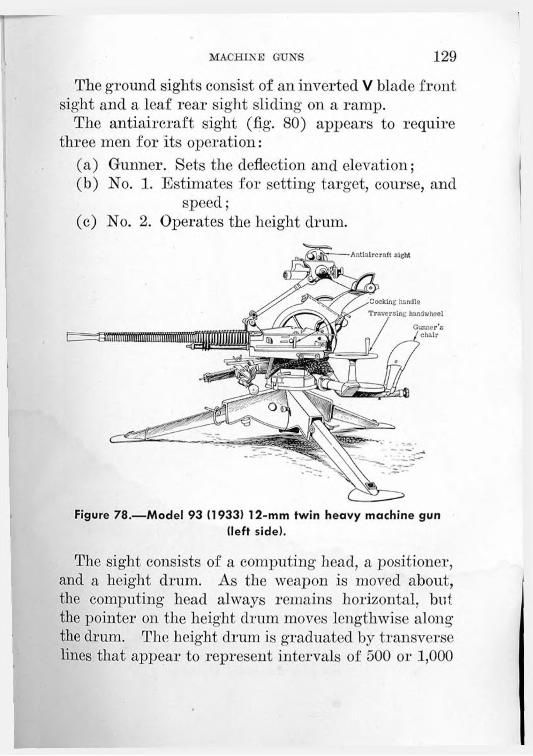
MACHINE GUNS 129The ground sights consist of an inverted V blade front
sight and a leaf rear sight sliding on a ramp.The antiaircraft sight (fig. 80) appears to require
three men for its operation:(a) Gunner. Sets the deflection and elevation;(b) No. 1. Estimates for setting target, course, and
speed;(c) No. 2. Operates the height drum.
chair
handlehandwheel
Figure 78.—Model 93 (1933) 12-mm twin heavy machine gun (left side).
The sight consists of a computing head, a positioner, and a height drum. As the weapon is moved about, the computing head always remains horizontal, but the pointer on the height drum moves lengthwise along the drum. The height drum is graduated by transverse lines that appear to represent intervals of 500 or 1,000
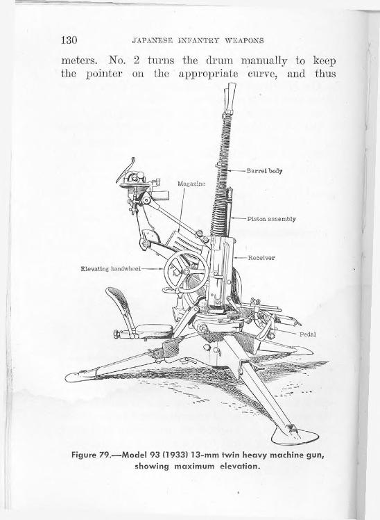
130 JAPANESE INFANTRY WEAPONS
meters. No. 2 turns the drum manually to keep the pointer on the appropriate curve, and thus
Piston assembly
Elevating handwheel
Barrel body
Figure 79.—Model 93 (1933) 13-mm twin heavy machine gun, showing maximum elevation.
Pedal

MACHINE GUNS 131
changes the reading on the computing head for deflection by an amount proportional to the time of flight.
About the horizontal axis of the computing head is a positioner, crudely shaped like an airplane. When this positioner is put in an upright position pointing
Figure 80.—Antiaircraft sight on Model 93 (1933) 13-mm twin heavy machine gun.
at the target, placed in a position so that it is parallel to the flight of the target, and kept parallel by its operator, the final deflection is referred to the guns.
The target speed is set into the head by a setting knob.
(3) To elevate.—The elevating handwheel is on the right of the weapon and will raise the guns from the horizontal to an angle of approximately 85 degrees.
555825'’—13-------10
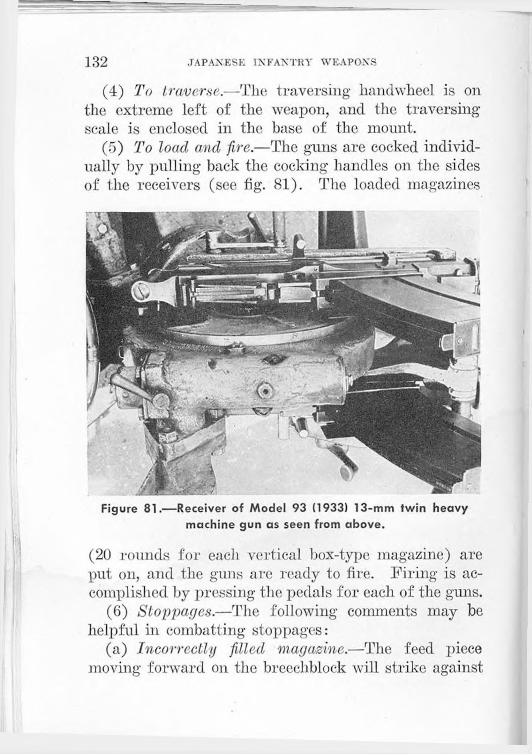
132 JAPANESE INFANTRY WEAPONS
(4) To traverse.—The. traversing handwheel is on the extreme left of the weapon, and the traversing scale is enclosed in the base of the mount.
(5) To load and fire.—The guns are cocked individually by pulling back the cocking handles on the sides of the receivers (see fig. 81). The loaded magazines
Figure 81.—Receiver of Model 93 (1933) 13-mm twin heavy machine gun as seen from above.
(20 rounds for each vertical box-type magazine) are put on, and the guns are ready to fire. Firing is accomplished by pressing the pedals for each of the guns.
(6) Stoppages.—The following comments may be helpful in combatting stoppages:
(a) Incorrectly filled magazine.—The feed piece moving forward on the breechblock will strike against

MACHINE GUNS 133
the base of two rounds and try to force them into the breech, causing the gun to jam.
(b) Misfire.—When the piston moves forward but the gun fails to fire, remove the magazine, pull back the cocking handle, and inspect the ejected round. If the round shows signs of having been struck, this may indicate a faulty round. Place the magazine on again, and if a misfire recurs, inspect the firing pin.
(c) Insufficient gas.—If the gun fires only one round and then stops, there is probably insufficient gas to drive recoiling portions to the rear. Unload, adjust the gas regulator, reload, and continue firing.
(d) Ruptured case.—When the piston moves forward but the gun fails to fire, and the ejected shell has a portion missing, the missing portion is stuck in the barrel, thereby preventing a new round from being correctly fitted into the breech.
(e) Faulty ejection.—When an empty case does not clear the weapon, the recoiling portions will jam on the forward movement.
(f) Difficult extraction.—A swelled case in the breech will impede the piston group in rear movement. Pull the cocking handle by hand or with a rope lanyard.
(7) To unload.—Remove the magazines by pressing forward on the magazine release lever and lifting the magazines forward and off.e. Ammunition
The Model 93 (.1933) 13-mm twin heavy machine gun uses ball, armor-piercing, and tracer ammunition. The ammunition is marked by a colored band on the

134 JAPANESE INFANTRY WEAPONS
outer edge of the primer. The ball ammunition has a black band, the armor-piercing a white band, and the tracer a red band. (Four and three-fourths seconds is the time of burning of the tracer element.)f. Maintenance
(1) Oiling and cleaning.—The Model 93 (1933) 13- mm twin heavy machine gun may be given the same care as U. S. gas-operated weapons. The bolt parts may be oiled lightly except in dry, dusty, or sandy country, then not at all.
(2) Stripping.—The stripping of the Model 93 (1933) 13-mm twin heavy machine gun is comparatively easy, since it involves only three main groups: piston assembly, barrel body, and rear buffer group in the receiver.
To strip these groups from the gun, see that the gun is not cocked, push out the receiver locking pin which is located at the rear end of the receiver, at the same time taking the weight of the return spring on the rear handle, and withdraw the buffer group.
Give the cocking handle a sharp pull to the rear; this will bring with it the bolt and piston assembly. Raise the tail of the interlocking catch, which is immediately behind the magazine release lever, and remove the piston assembly.
(3) Assembly.—To assemble the weapon, proceed in the reverse order to that followed in stripping.

Section VII. MORTARS
26. MODEL 98 (1938) 50-MM MORTAR1
a. GeneralThe Model 98 (1938) 50-mm mortar (fig. 82) is easy
to set up. It consists of three main parts—the base plate, the bipod, and the barrel. It has a fixed elevation of about 40 degrees. Provision is made for a limited traverse. At the base of the tube is an offset primer seat. Two links, one on each side, extend from the barrel collar. A range slide, graduated from 0 to 60, may be clamped to the muzzle of the mortar.
The Model 98 (1938) 50-mm mortar fires a formidable stick bomb (fig. 83), weighing nearly 10 pounds and containing an explosive charge of approximately 7 pounds of picric acid in rectangular blocks. The body of the bomb, made of sheet metal (three-sixteenths of an inch thick), is rectangular in shape (4^ by 4)Z> by 6J/> inches) and is painted black. A hardwood stick 21 inches long and 1.91 inches in diameter fits into a socket in the base of the body, and is held in place by nails or screws. The bottom end of the stick is covered with a metal cap.
Two friction-type pull igniters, with black-powder delay trains giving a delay interval of approximately 7 seconds, fit into holes in the base of the charge.
'The Japanese tactical symbol for mortar is 135

136 JAPANESE INFANTRY AVE APONS
The propelling charge consists of black-powder increments packed in small silk bags. Each increment is approximately 3.75 inches long and 1.25 inches in diameter. A pull-type friction primer, 0.88 inch in length, equipped with a loop lanyard, is designed to fit into the primer seat, or touch hole.
Figure 82.—Model 98 (1938) 50-mm mortar assembled, with cleaning tool.
b. How to IdentifyThe Model 98 (1938) 50-mm mortar may be identified
by—(1) The rectangular, sectionalized base plate.(2) The fixed position of the bipod.(3) The V slots painted white and located at 12
o’clock on both the barrel collar and the projection of the muzzle hoop.

MORTARS 137
Figure 83,—Stick bombs which are inserted in muzzle of Model 98 (1938) 50-mm mortar.

138 JAPANESE IMFANTRY WEAPONS
(4) The marking KA a.a, which is on the outside of the container in which the weapon is packed. (This marking, which is read Kyuhachi Shiki Totekiki from right to left,2 means “98 model discharger.”)
c. Characteristics(1) General.—The Model 98 (1938) 50-mm mortar is
a smooth-bore, muzzle-loading weapon.(2) Table of characteristics.—
Ammunition________________________10-pound stick bomb.Total weight._______________________ 48 pounds.Length of barrel____________________ 25 inches.Traverse___________________________ 124 mils (7 degrees).Elevation (fixed)___________________ 708 mils (40 degrees).
d. How to Operate(1) To load.—Insert one or more powder increments
in the muzzle. Place the stick of the stick bomb in the tube.
(2) To aim.—Adjust the graduated range slide to the desired distance (fig. 84). This regulates the length of the stick extending into the barrel of the mortar. The greater the distance the stick extends into the barrel, the greater the range. The principle involved is similar to that employed in adjusting the range of the Model 89 (1929) 50-mm grenade discharger (par. 2Od(2), p. 76).
To traverse, loosen the two wing nuts that secure the bipod, and swing the bipod feet around the arc in front of the base plate.
2 See p. 7, note 1.

MORTARS 139
(3) To arm explosive charge.—Insert the two friction-type pull igniters in the holes provided in the base
Figure 84.—Adjusting graduated range slide on Model 98 (1938) 50-mm mortar.
of the charge. Connect each igniter by cord to one of the two links extending from the barrel collar of the mortar on each side. Insert a pul l-type friction primer

140 JAPANESE INFANTRY WEAPONS
in the primer seat, which is on the side of the barrel near the base (fig. 85).
(4) To fire.—Pull the loop lanyard attached to the friction primer.
Figure 85.—Base of Model 98 (1938) 50-mm mortar, showing primer seat.
e. AmmunitionThe stick bomb described in a, above, is the only
ammunition for this weapon that has been recovered to date. A recent report states, however, that a finned Bangalore torpedo may also be used (par. 15, p. 58).
f. Maintenance(1) Oiling and cleaning.—The Model 98 (1938)
50-mm mortar may be given the same care as would be given to U. S. mortars. There is a cleaning brush

MORTARS 141
which comes attached to the underside of the carryingbox cover (fig. 86).
(2) Stripping.—The Model 98 (1938) 50-mm mortar is easy to disassemble. Unscrew the thumb screws and
Figure 86.—Model 98 (1938) 50-mm mortar in carrying box.
remove the bipod feet from the traversing arc in the base plate; then remove the barrel-assembly ball out of the socket in the base plate. Remove the collar which attaches the bipod to the barrel.

142 JAPANESE INFANTRY WEAPONS
' (3) Assembly.—To assemble the weapon, proceed in the reverse order to that followed in stripping.
27. MODEL 11 (1922) 70-MM MORTAR3 4
3 This weapon is listed by the Japanese as jj-. ,which is read (from left to right ) Jitichiiun Shiki Kyoku«ha lloheiho, meaning "11th year mode] high-angle infantry gun.” (See p. 7, note 1.)The Japanese tactical symbol for a mortar is .
4 See p. 7, note 1.
a. GeneralThe Model 11 (1922) 70-mm mortar (fig. 87) is
muzzle-loaded, yet has a rifled bore.
b. How to IdentifyThe Model 11 (1922) 70-mm mortar may be identi
fied by—(1) The wooden base plate.(2) The barrel supported by an elevating screw
without a bipod.(3) The side carrying rings.(4) The two parallel spades on the base plate.(5) The marking/a A A 4 •" t which is on the
breech end of the barrel. (This marking, which is read Juichinen Shiki Kyokusha lloheiho from right to left,'1 means “11th year model high-angle infantry gun.”)c. Characteristics
(1) General.—Tin* support of the barrel of the Model 11 (.1922) 70-mm mortar by the elevating screw is similar to the support of the U. S. 4.2-inch chemical mortar.

MORTARS 143(2) Table of characteristics.—
Total weight_____________________Weight of base plate_______________Traverse_________________________Elevation:
Maximum___________________Minimum____________________
Barrel__________________________
133.75 pounds.99.5 pounds.410 mils (23 degrees).
1,370 mils (77 degrees). 061 mils (37 degrees).Rifled bore.
d. How to Operate(1) Safety.—The Model 11 (1922) 70-mm mortar
has a safety, in that the latch pin on the breech end of

144 JAPANESE INFANTRY WEAPONS
the barrel must be set in its recess in order to fire the weapon.
(2) Gunner’s quadrant.—The gunner’s quadrant (fig. 88) used for laying-in the Model 11 (1922) 70-mm mortar is simple in construction. There is a level vial,
Figure 88.—Gunner’s quadrant with carrying case.
which is actuated by a knob, a movable arm, and a fixed elevation scale, 'rhe elevation scale is graduated in half-degree intervals from 0 to 55 degrees. The movable arm has a vernier scale which allows readings of one-sixteenth of a degree.
(3) To load and fire.—The mortar is fired by means of a lanyard attached to a striker arm.
Set the base-plate level with the spades dug in firmly. Rotate the elevating nut in order to bring the piece to the desired elevation. Traverse by means of the traversing handwheel. Allow the shell to travel down the barrel. At the signal to fire, all members of

MORTARS 145
the crew, for purposes of safety, should be crouched below the level of the muzzle.
(4) To unload.—Release the barrel from the elevating screw. Rotate the barrel to swing it to the rear and disengage the barrel from the trunnions. Lift the barrel from the base plate and tilt it forward a little, being careful that the round slides out very slowly into your hand.e. Ammunition
(1) General.—A three-piece high-explosive shell, similar in appearance and construction to the Model 89 (1929) 50-mm high-explosive shell (par. 2Oe(l), p. 80), is fired from this mortar. The shell consists of three major parts: the fu?e, the body, and the propellingcharge assembly. The fuze is a simple point-detonating type, consisting of a two-piece fuze body, a booster cup, a detonator holder, and a spacing washer. Unlike the Model 89 (1929) 50-mm shell, there is no safety pin. The fuze is of brass.
The shell body is of steel, threaded at the top to receive the fuze assembly, and at the bottom to receive the propelling-charge assembly. It is marked with a white band near its base and with a red band at the nose.
The propelling-charge assembly consists of the percussion cap, the propellant, and an expanding copper rotating band. The propelling charge is ignited when the firing pin hits the percussion cap. The propellent gases expand the copper rotating band against the rifling in the barrel of the mortar. This action causes

146 JAPANESE INFANT'RY WEAPONS
the projectile to rotate in flight. Because of this construction, it is believed that this mortar is capable of accurate aimed fire over considerable distances.
(2) Table of characteristics.—Over-all length_____________________Diameter__________________________Width of copper rotating band_______Weight of complete round____________
8.62 inches.2.8 inches.1.05 inches.4 pounds 10.8 ounces.
f. Maintenance(1) Oiling and cleaning.—The Model 11 (1922) 70-
mm mortar may be given the same care as is given to U. S. mortars. Cleaning materials may be found with the equipment.
(2) Stripping.—(a) To remove barrel.—The barrel may be removed by releasing it from the elevating screw, rotating the top of the barrel to the rear to disengage it from the trunnions, and lifting it upward.
(b) To remove breechblock, and firing mechanism.— The breechblock may be removed from the barrel by releasing the latch-pin and unscrewing the breech. There is a spring retainer which can be unscrewed from the breech; when the spring retainer is unscrewed, the firing pin and the firing-pin holder are released.
(3) Assembly.—Each of the assemblies may be accomplished by reversing the stripping procedure.28. 70-MM BARRAGE MORTAR
a. GeneralThe 70-mm barrage mortar (fig. 89) was first en
countered on the island of Attu. Consisting only of a barrel, wooden base plate, and spike extension rod,

MORTARS 147
this weapon is simply designed. The barrel has a smooth bore and fires a shell which contains seven small parachute bombs charged with nitrostarch. The mortar is apparently intended as a defense against low-flying aircraft.b. How to Identify
The 70-mm barrage mortar may be identified by—(1) The wooden block base (fig. 90).(2) The spike extension rod.
c. Characteristics(1) General.—The base of the 70-mm barrage mor
tar is a wooden block approximately 10 by 12 by 8 inches. Two bolts fasten a small base plate to the block. The wooden block absorbs the shock of firing and prevents the mortar from embedding itself in the ground.
Figure 89.—70-mm barrage mortars, captured in the Aleutians.555825’—43------- 11

148 JAPANESE INFANTRY WEAPONS
(2) Table of characteristics.—Ammunition--------------------Shell containing parachute bombs.Length of barrel________ 48 inches.Over-all length--------------- 75 inches (approximately).
d. How to Operate(1) Safety.—There is no safety on the 70-mm bar
rage mortar.(2) To elevate and depress.—Changes in elevation
and depression are accomplished by altering the position in which the rod is pegged into the ground.
Figure 90.—70-mm barrage mortar, showing spike and block used as balance.
(3) To load and fire.—The mortar is muzzle-loading. When ready to fire, the shell is allowed to slide down the barrel, propelling charge first.
(4) To unload.—Lift the mortar from the ground and allow the round to slide slowly out of the barrel.
e. AmmunitionAmmunition for the 70-mm barrage mortar is packed
10 rounds to a box. The shell contains 7 parachute bombs 3 inches long by eleven-sixteenths of an inch in diameter. A steel cylinder encases the whole assembly.
The shell (fig. 91) is painted black and is 11% e inches long and 2% inches in diameter. The nose is

MORTARS 149
capped with a wooden disk. After the shell is projected from the mortar by a propelling charge in the base, a time train and fixed powder charge cause the
Figure 91.—Shell used in 70-mm barrage mortar and its method of operating. (The marking on the shell is read, from fop to bottom, Nana Sanchi Uchiage Sosaidan, meaning “7-cm ‘shooting- up’ barrage shell.”)
projection of the seven smaller bombs borne by ricepaper parachutes. At the same time a larger parachute is opened-—-tilting the main container and thus insuring the scattering of the seven bombs. These small bombs are loaded with three pellets of nitrostarch and are detonated in the air by a sensitive pull-igniter fuze with phosphorus-coated string and delay element. They may also be used as an effective booby trap for the curious or unwary soldier.
150 JAPANESE INFANTRY WEAPONS
f. Maintenance(1) Oiling and cleaning.—The care given to this
mortar can be the same as that required for U. S. mortars.
(2) .Stripping.—The simple construction of the 70-mm barrage mortar makes it easy to strip. The barrel is unscrewed from the metal base plates, the firing pin-is unscrewed from the male fitting which holds it to the base plate, and the base plate is unfastened from the wooden block by removing the two bolts. The steel spike can be removed from the base of the wooden block.
(3) Assembly.—To assemble the weapon, proceed in the reverse order to that followed in stripping.29. MODEL 97 (1937) 81-MM MORTAR 5
’ Tlie Japanese tactical symbol for a mortar
a. GeneralThe Model 97 (1937) 81-mm mortar is almost identi
cal with the U. S. 81-mm mortar, Ml (see fig. 92). Japanese 81-mm mortar shells can be fired from the U. S. 81-mm mortar, Ml, and U. S. 81-mm mortar shells can probably be used in the Japanese Model 97 (1937) 81-mm mortar. Full and adequate information is not yet available on the Model 97 (1937) 81-mm mortar.b. How to Identify
The Model 97 (1937) 81-mm mortar may be identified by—
(1) The general resemblance that it bears to the U. S. 81-mm mortar, Ml.
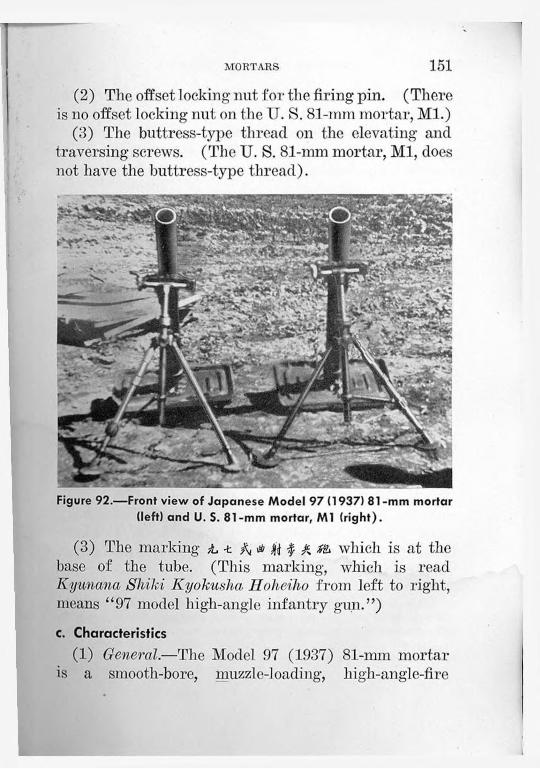
MORTARS 151(2) The offset locking nut. for the firing pin. (There
is no offset locking nut on the U. S. 81-mm mortar, Ml.)(3) The buttress-type thread on the elevating and
traversing screws. (The U. S. 81-mm mortar, Ml, does not have the buttress-type thread).
Figure 92.—Front view of Japanese Model 97 (1937) 81 -mm mortar (left) and U. S. 81-mm mortar, Ml (right).
(3) The marking Ju -t A I A which is at the base of the tube. (This marking, which is read Kyunana Shiki Kyokusha Hoheiho from left to right, means “97 model high-angle infantry gun.”)c. Characteristics
(1) General.—The Model 97 (1937) 81-mm mortar is a smooth-bore, muzzle-loading, high-angle-fire

152 JAPANESE INFANTRY WEAPONS
weapon. It is composed of three units: the barrel, the bipod, and the base plate.
(2) Table of characteristics.—Length of barrel (over-all)____________ 49.5 inches.Rate of fire (estimated)_______________ 18 to 30 rounds per
minute.d. How to Operate
The operation of this weapon appears to be the same as for the U. S. 81-mm mortar, ML.e. Ammunition
The weapon fires the same types of ammunition as are fired in the Model 99 (1939) 81-mm mortar (par. 30e, p. 157).f. Maintenance
The same maintenance given the LT. S. 81-mm mortar, Ml, will keep this weapon in good operating order.
30. MODEL 99 (1939) 81-MM MORTAR6
'This weapon is listed by the Japanese as whichis read (from left to right) Kyukiiu Shiki Shohakuffekiho, meaning "99 model small trench mortar.” The Japanese tactical symbol for a mortar is ?.
a. GeneralThe Model 99 (1939) 81-mm mortar is similar to
the Model 97 (1937) 81-mm mortar (par. 29, p. 150) and the U. S. 81-mm mortar, Ml, except that it has a shorter barrel, is equipped for trigger firing, and has a close fit between the bore and the projectile to compensate for the shorter barrel.

MORTARS 153
All are patterned after the Stokes-Brandt type of mortar.7
'The Stokes-Brandt mortar is muzzle-loaded and has a smooth bore. It fires a rocket-shaped projectile with tail fins, which is very stable in flight, with the nose of the shell kept forward throughout the trajectory. The fuze used is the point-detonating type.
’ A sight that collimates, or adjusts its line of sight relative to the position of other parts of the mortar.
Two men can carry the mortar. It can also be transported by horse-cart or motor truck.b. How to Identify
The Model 99 (1939) 81-mm mortar may be identified by—
(1) The short barrel.(2) The offset manually operated firing mechanism
at the base of the barrel.(3) The square base plate.(4) The marking 3L J- A which is on the base
of the tube. (This marking, which is read Kyukyu Slviki Sholiakuyekilio from right to left, means “99 model small trench mortar.”)
c. Characteristics(1) General.—The Model 99 (1939) 81-mm mortar
incorporates in the barrel collar a buffer system to absorb part of the recoil. There are two cylinders filled with light grease or heavy oil.
The weapon employs a collimator sight8 (fig. 94). There is, however, a seat provided on the bipod for a gunner’s quadrant (see par. 27d(2), p. 144). Likewise, there is a white line painted along the top of the barrel to aid in sighting.
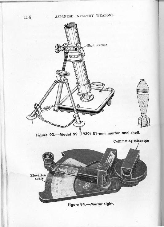
154 JAPANESE INFANTRY WEAPONS
Collimating telescope
Figure 94.—Mortar sight.

MORTARS 155
(2) Table of characteristics.—Ammunition___________________Over all length_________________Total weight___________________
Barrel_____________________Base plate_________________Bipod_____________________
Traverse______________________Maximum elevation_____________
7.2 and 14.3-pound shells.25% inches.52 pounds.17% pounds.18 pounds.16% pounds.118 mils (6.7 degrees).1,240 mils (70 degrees).
Minimum range:7.2-pound shell_____________14.3-pound shell____________
545 yards.207 yards.
Maximum range:7.2-pound shell-14.3-pound shell
Rate of fire______
. 3,280 yards.
. 1,312 yards... 15 rounds per minute.
d. How to Operate(1) Safety.—There is a safety lever at the side of
the base cap at the base of the mortar barrel. When this lever is turned to the right, the firing pin is in the “safe” position. By turning the lever to the left, the firing pin is placed in the firing position.
(2) Sight.—The mount is a dovetail bracket. The sight is equipped with a collimating telescope, two level vials, and an elevation scale graduated in 10-mil (0.562-degree) intervals from 800 to 1,600 mils (45 to 90 degrees). The simplicity of construction and method of mounting indicate that this mortar sight may be used with other mortars.
(3) To load and fire.—Level and lay-in the mortar as would be done with the U. S. 81-mni mortar, Ml.

156 JAPANESE INFANTRY WEAPONS
When 1’eady to fire, load the piece according to the following instructions. With the smaller 7.2-pound shell, hold the shell in one hand and place the shell, fins first, in the muzzle, guiding it with the other hand. However, with the heavier 14.3-pound shell, the shell must be held in both hands in order to place it in the muzzle. At the signal to fire, with either shell, allow the projectile to slide down the barrel, and at the same time clear both your hands from the muzzle. To fire, strike the firing-pin cam shaft (see fig. 97)
With barrel collar locked, lift barrel to allow shell
Figure 95.—Unloading Model 99 (1939) 81-mm mortar.
with a wooden mallet. This blow will drive the firingpin cam shaft into the base cap, and as the cam shaft is driven inward, the cam surface on its upper side cams the firing pin upward into contact with the primer of the cartridge. At this point, as a safety precaution, all members of the crew should crouch down oi’ be lying on the ground.
(4) To unload.—In case of a misfire, wait at least 1 minute before attempting to remove the shell.9
“Sometimes there is a primer hangfire which will seem dead at first, then suddenly flare up an instant later.

MORTARS 157Before proceeding further, first determine if the shell
has become lodged in the barrel, somewhere short of the firing pin. By striking the side of the barrel in several places with a timber, the shell may be dislodged. If, however, this fails, then proceed to unload (fig. 95).e. Ammunition
Two types of ammunition, smoke or chemical, and high-explosive, are known. Likewise, there are two weights of shells—7.2 pounds and 14.3 pounds. The complete 7.2-pound round consists of a percussion fuze, the shell body, the fin assembly, the primer cartridge, and the propelling charge. The propellingcharge is made up of increments, each increment consisting of a lacquered silk envelope containing a ballistite-type propellant. The primer cartridge, enclosed at one end by a lacquered brass head, resembles a 12-gauge shotgun shell.
The body of the high-explosive shell is painted black, inside and out, and contains an explosive charge of about 1 pound of TNT. A white band is painted around the base of the body of the shell, a yellow band at the junction of the shell and the fin assembly, and a red band around the nose, on the fuze adapter. The 7.2-pound shell is 11.6 inches long unfuzed.
The fuze of the 81-mm shell functions on impact with instantaneous or delayed action. A hollow brass plug, that can be inserted in the fuze, provides delayed action of probably 0.1 second. For transport, the fuze is carried separately from the rest of the shell in a soldered tinplate cannister with a screw-lid (fig. 96).

158 JAPANESE INFANTRY WEAPONS
Figure 96.—Two views of packing box for Model 100 (1940) shells used in Model 99 (1939) 81 -mm mortar (four complete rounds).
The fuze is held within the cannister by two wooden blocks shaped to take the base and the nose of the fuze. Two holes are drilled in the upper surface of the top block, and in one of these the delay plug rests.
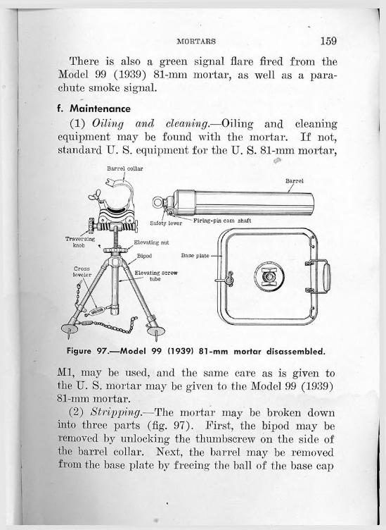
MORTARS 159There is also a green signal flare fired from the
Model 99 (1939) 81-mm mortar, as well as a parachute smoke signal.
f. Maintenance(1) Oiling and cleaning.—Oiling and cleaning
equipment may be found with the mortar. If not, standard U. S. equipment for the U. S. 81-mm mortar,
Barrel collar
Ml, may be used, and the same care as is given to the U. S. mortar may be given to the Model 99 (1939) 81-mm mortar.
(2) Stripping.-—The mortar may be broken down into three parts (fig. 97). First, the bipod may be removed by unlocking the thumbscrew on the side of the barrel collar. Next, the barrel may be removed from the base plate by freeing the ball of the base cap

160 JAPANESE INFANTRY WEAPONS
from the socket in the base plate. ‘This is accomplished by rotating the barrel 90 degrees.
(3) Assembly.—To assemble the weapon, proceed in the reverse order to that followed in stripping.
31. MODEL 94 (1934) 90-MM MORTAR10
10 The Japanese tactical symbol tor a moi-
a. GeneralThe Model 94 (1934) 90-mm mortar (fig. 98) is a
smooth-bore, muzzle-loading weapon, with a fixed firing pin. Unlike most mortars, it has a special recoil mechanism. Both chemical and high-explosive shells are used.
b. How to IdentifyThe Model 94 (1934) 90-mm mortar may be identi
fied by—(1) The special recoil mechanism.(2) The large caliber and long barrel.(3) The markingAjL> which is on the
base of the tube. (This marking, which is read Kyuyon Shiki Keiliakuyekiho from right to left, means “94 model light trench mortar.”)
c. Characteristics
(1) General.—The feature of the Model 94 (1934) 90-mm mortar is its recoil mechanism, which consists of two equal cylinders mounted on a one-piece U- shaped frame. The frame fits into the base plate by

MORTARS 161
a ball-and-socket arrangement. The barrel is connected by a bar to the recoil cylinders, while the recoil cylinders are also attached to bipod shock absorbers.
Figure 98.—Model 94 (1934) 90-mm mortar.
(2) Table of characteristics.—Ammunition___________________ HE and incendiary shells.Length of barrel with breech cap_ ol'tio inches.Weight in action_______________ 340 pounds.Total traverse_________________ 177 mils (10 degrees).Maximum range_______________ 4,150 yards.Length of recoil_______________ 5.67 inches.

162 JAPANESE INFANTRY WEAPONS
d. How to Operate(1) 2’o elevate.—Elevating is accomplished by turn
ing the crank at the junction of the bipod legs and the elevating screw.
(2) To traverse.—Traversing is accomplished by turning the knob situated at the end of the traversing screw where the barrel is collared to the bipod (fig. 99).
(3) To load and fire.—Level and lay-in the mortar in the same manner as would be done with the U. S. 81-mm mortar, Ml. The sight is also operated in the same way. The cross-leveling device is the knurled nut and collar on the bipod leg.
At the signal to fire, all members of the crew, for purposes of safety, should crouch below the level of the muzzle. Then the projectile can be allowed to slide down the barrel, fins first (fig. 100).
If the mortar fails to fire when the projectile is allowed to slide down the barrel, in all probability the firing pin is not long enough to fire the igniting charge. To remedy this, turn the round nut at the lower rear of the breech ring a quarter turn and remove it. Then tighten the split nut at the top rear of the breech ring until the shoulders match the milled recess.
(4) To unload.—If there is a misfire, wait at least t minute before attempting to unload the weapon. Then try to find whether the shell has become lodged in the barrel somewhere short of the firing pin. Use a piece of timber, and strike the barrel at several places. If that fails, proceed to unload. (Sec fig. 95, p. 156, for the method of unloading.)
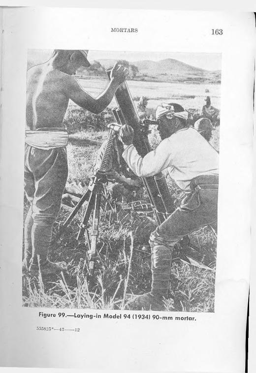
MORTARS 163
555825 °—-4 3_____1 o

164 JAPANESE INFANTRY WEAPONS
e. AmmunitionThe Model 94 (1934) 90-mm mortar fires high-ex-
plosive and chemical shells (see figs. 101, 102, and
Figure 100.—Loading Model 94 (1934) 90-mm mortar.
103). The incendiary shell is 16 inches long and weighs 11.6 pounds. The incendiary mixture is white phosphorus, carbon disulphide,11 and some 40 impreg- *
” A highly inflammable liquid.

MOBTABS 165
nated cylindrical rubber pellets. A bursting charge of 2.8 ounces scatters the mixture upon impact of the shell at the target. The propelling charge consists of 1 cartridge and 6 increments.
In appearance, the incendiary shell is very similar to the U. S. 81-mm mortal- projectile. The body is
Figure 101.—Model 94 (1934) 90-mm mortar shell. (Note the propelling increments between the fins.)
painted with four colored bands painted around its circumference, as follows:
(1) Red band just below the f uze;(2) Blue band halfway between the fuze and the
bourrelet;(3) Yellow band halfway between the bourrelet and
the fin assembly;(4) White band at the junction of the shell body
and the fin.

166 JAPANESE INFANTRY WEAPONS
Red band
Blue band
Incendiary rubber pellets (40)
Yellow band
Tail
Fins
White band
Primary propelling charge
Transit plug
Fuze holder
Burster
Gas rings -
Cardboard packing
Wooden spacing block
Yellow phosphorus and carbon - disulphide filling
FigurePercussion cap
102.—Incendiary shell for Model 94 (1934) 90-mm mortar.

MORTARS 167
Figure 103.—Model 94 (1934) 90-mm mortar shell with two views of its packing box (two complete rounds).
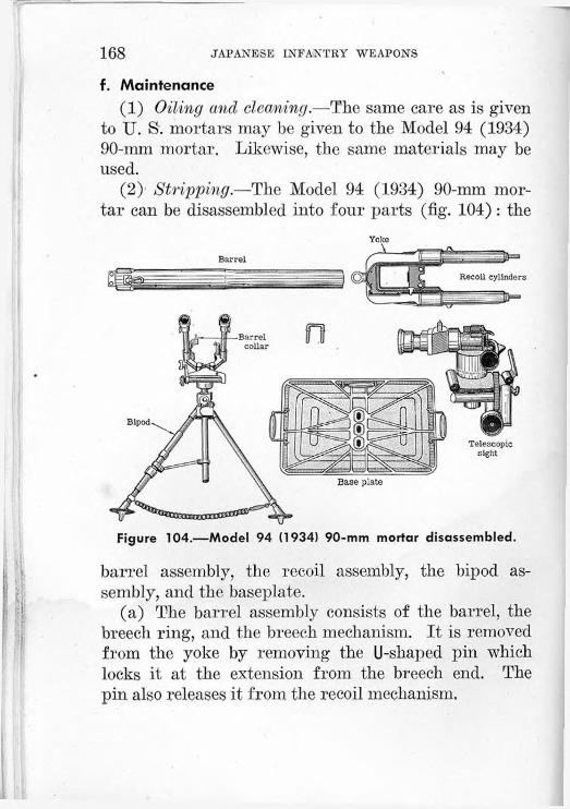
168 JAPANESE INFANTRY WEAPONS
f. Maintenance(1) Oiling and cleaning.—The same care as is given
to U. S'. mortal's may be given to the Model 94 (1934) 90-mm mortar. Likewise, the same materials may be used.
(2) Stripping.—The Model 94 (1934) 90-mm mortar can be disassembled into four parts (fig. 104): the
Yoke
Figure 104.—Model 94 (1934) 90-mm mortar disassembled.
barrel assembly, the recoil assembly, the bipod assembly, and the baseplate.
(a) The barrel assembly consists of the barrel, the breech ring, and the breech mechanism. It is removed from the yoke by removing the U-shaped pin which locks it at the extension from the breech end. The pin also releases it from the recoil mechanism,

MORTARS 169
(b) The frame, or yoke, can be removed from the baseplate by rotating the whole frame 90 degrees around its longitudinal axis in order to disengage the ball from the socket in the base plate.
(c) Next, the bipod is removed by unlocking the barrel collar.
(d) This procedure leaves the baseplate clear.(3) Assembly,—To assemble the weapon, proceed in
the reverse order to that followed in stripping.

Section VIII. ANTITANK AND INFANTRY GUNS
32. MODEL 97 (1937) 20-MM ANTITANK RIFLE
a. GeneralThe Model 97 (1937) 20-mm antitank rifle (figs. 105
and 106), sometimes referred to as an antitank machine cannon, is a single-purpose, full-automatic antitank weapon. Infantry troops can maneuver it in any sort of terrain. Two men can carry it, since it weighs oifly 150 pounds complete. However, the usual method of transportation, with carrying handles in the brackets provided in the front and rear of the cradle, requires three or four men.b. How to Identify
The Model 97 (1937) 20-mm antitank rifle may be identified by—
(1) The rear monopod and front bipod.(2) The nonadjustable inverted V front sight, and
the peep sight to the rear.(3) The low silhouette.
(4) The marking -t which is on top of the receiver.A
(This marking, which is read Kyunana Sliiki from top to bottom,1 means “97 Model.”)
1 See p. 7, note 1.170 •

ANTITANK AND INFANTRY GUNS 171c. Characteristics
(1) General.—The Model 97 (1937) 20-mm antitank rifle is easy to conceal because of its low silhouette— 16% inches high, excluding the shield. It can be quickly moved from place to place by employing the two sets of removable carrying handles which fit into the brackets in the front and rear part of the weapon (figs. 107 and 108). Straps, which fit in between the handles and can be looped over a man’s shoulder when the gun is carried, are also provided.
Figure 105.—Model 97 (1937) 20-mm antitank rifle (right side).
The weapon is gas-operated, air-cooled, and magazine- fed.' Its operation is divided into si.x phases, occurring in the following order:
(a) Loading. (d) Unlocking.(b) Locking (bolt forward), (e) Extracting.(c) Firing. (f) Ejecting.The first three phases occur in counterrecoil, and
th(> last three in recoil. Tin1 spent cartridge case is ejected through an opening in the bottom of the receiver.

172 JAPANESE INFANTRY WEAPONS
(2) Table, of characteristics.—Principle of operation_______ Gas-operated, full-automa tic
only.High-explosive and armor-Ammunition________________
Type of feed-----------------------Length of barrel:
With compensator_______Without compensator_____
Over-all length:With carrying handles____Without carrying handles—
Weight:In action_______________Complete with carrying
handles_______________Thickness of shield armor-------Traverse___________________Elevation:
Maximum______________Minimum_______________
Effective range—____________Rate of fire________________
piercing.7-round box magazine.
48% inches.47% inches.
89% inches.82% inches.
140 pounds.
150 pounds.fk inch.1,600 mils (90 degrees).
89 mils (5 degrees).— 89 mils ( — 5 degrees). 1,100 yards.Unknown.
d. How to Operate(1) Safety.—There are two safety features. One
is a trigger block, located on the left side of the trigger housing above the pistol grip; this, when rotated, prevents the trigger from being pulled. The other is a bolt stop on the right rear side near the top of the receiver; when it is turned, the bolt is held to the rear.
(2) To elevate.—The two front legs of the tripod are telescopic. Each of these two legs is provided with

ANTITANK AND INFANTRY GUNS 173
.Front sight
Retracting handle
Figure 106.—Model 97 (1937) 20-mm antitank rifle (left rear view).
Figure 107.—Model 97 (1937) 20-mm antitank rifle with shield and rear carrying handles in place.

174 JAPANESE INFANTRY WEAPONS
a knurled collar. Elevating is accomplished by turning the collars.
(3) To traverse.—Traversing to 45 degrees is done by shoulder control against the shoulder stock at the rear of the gun; the front bipod can swivel up that amount without being moved, but the rear leg must be pulled from the ground and reset each time.
(4) To sight.—The sighting equipment consists of a nonadjustable inverted V front sight, and a peep
Figure 108.—Model 97 (1937) 20-mm antitank rifle with shield and front carrying handles in place.
rear sight which can be adjusted up to 1,000 meters (1,094 yards) range, and 10 mils (0.562 degree) windage right and left.
(5) To load and fire.—To cock the gun, the retracting handle on the left side of the receiver is pulled to the rear. Make sure that the rear monopod is well sunk, for this weapon has considerable recoil.

ANTITANK AND 1NIFANTRY GUNS 175With the bolt stop used to engage and hold the
bolt to the rear, the vertical box-type magazine is inserted and locked in the top of the receiver.
Release the bolt stop and the trigger block. Push the retracting handle forward. Pull the trigger. The gun will fire full-automatic only; if the trigger is released, the sear is forced up into the receiver and holds the operating parts to the rear.
When the last round has been fired, hold the bolt to the rear before inserting a new magazine.
(6) To unload.—If there is a misfired round in the chamber, place the trigger block in the safe position, and pull the retracting handle to the rear in order to extract and eject the round.e. Ammunition
Two types of ammunition, similar in shape and size, are fired in the Model 97 (1937) 20-mm antitank rifle : high-explosive with point-detonating fuze, and armor- piercing shot. The complete round is 7% inches long; it must not be confused with the 20-mm ammunition made for the Model 98 (1938) AA/AT machine gun, which is in a larger shell case (see part. 33e, p. 183).
f. Maintenance(1) Oiling and cleaning.—The bore requires careful
swabbing and cleaning for firing. The bolt parts should be oiled lightly, except in dry, dusty, or sandy country, then not at all. Where lubrication oils and greases are required, use the same lubricants as would be used for similar moving parts on U. S. weapons.

176 JAPANESE INFANTRY WEAPONS
(2) Stripping.—(a) Barrel.—Pull the retracting handle to the rear. Put the gun on “safe.” Release the barrel-bushing lock. Turn the barrel bushing approximately one-sixth of a turn to the right. Then pull the barrel straight out to the front. (For disassembly, see fig. 109.)
:elver
Front sight
Trigger housing
Magazine
Gas piston
Compensator
Shoulder rest
Backplate
Barrel bushing
Trigger block
Return springBarrel
Figure 109.—Model 97 (1937) 20-mm antitank rifle disassembled.
(b) Bolt group.—Release the safeties and allow the bolt to travel forward by pulling the trigger. Push forward on the backplate to release the tension imparted to it by the return springs, and remove the backplate pin from the right side of the receiver. Be cautious in removing the backplate so that the com

ANTITANK AND INFANTRY GUNS 177
pressed springs will not cause the plate to fly from the gun.
Pull the retracting handle to the rear and remove the gas piston, bolt lock, and bolt.
(3) Assembly.—To assemble the weapon, proceed in the reverse order to that followed in stripping.33. MODEL 98 (1938) 20-MM ANTIAIRCRAFT-ANTITANK
MACHINE CANNON ’
a. GeneralThe Model 98 (1938) 20-mm AA/AT machine can
non (fig. 110) is an all-purpose weapon. It is a fine weapon for defense against low-flying aircraft (fig. Ill), because it is light in weight and very maneuver-
Figure 110.—Model 98 (1938) 20-mm antiaircraft-antitank machine cannon in traveling position.
' Die Japanese tactical symbol for the antitank-antiaircraft machine cannon is t .

178 JAPANESE 1NFANTBY WEAPONS
Figure 111 .—Mode! 98 (1938) 20-mm antiaircraft-antitank machine cannon in action.
able. It is estimated that an experienced gun crew can place tlie piece in battery, ready for antiaircraft fire, in less than 3 minutes. In an emergency, the weapon could be fired as a straight artillery piece, for it has a split trail and wheels.b. How to Identify
The Model 98 (1938) 20-mm AA/AT machine cannon may be identified by—

ANTITANK AND IN'FANTKY GUNS 179
(1) Its general appearance, which is different from any other Japanese field piece (see fig. 112).
(2) The front outrigger.(3) The barrel traveling lock.
(4) The marking a which is on the top of theA
receiver. (This marking, which is read Kyuhachi Slii/.i from top to bottom, means “98 model.”)c. Characteristics
(1) General.—The mechanism of the Model 98 (1938) 20-mm AA/AT machine cannon is patterned after the Model 97 (1937) 20-mm antitank rifle (par. 32, p. 170). It is semi- or full-automatic, gas-operated,
Figure 112.—Model 98 (1938) 20-mm antiaircraft-antitank machinecannon (left side).

180 JAPANESE INFANTRY WEAPONS
and magazine-fed. The cycle of operation is carried out in the following order:
(a) Loading. (d) Unlocking.(b) Locking (bolt forward), (e) Extracting.(c) Firing. (f) Ejecting.
Unlocking, extracting, and ejecting are done duringrecoil; loading, locking, and firing, during counterrecoil.
The recoil mechanism consists of two spring-loaded cylinders that lie one on each side of the barrel. Air valves, located in the forward ends of the cylinders, allow air to be drawn into the cylinders during recoil; as the air cannot readily escape, it acts as a cushion during counterrecoil.
The vertical box-type magazine—with a capacity of 20 rounds—fits into a slot in the top of the receiver and is held in place by a spring catch.
For traveling, towing shafts are inserted in slots at the end of the trails, and a traveling lock, which connects the forward part of the barrel to the bottom carriage, holds the gun steady in transit.
(2) Table of characteristics.—Principle of operation_____________ Gas-operated, semi- or
full-automatic.Ammunition_____________________ High-explosive, tracer,
and armor-piercing.Type of feed_____________________20-round box magazine.Length of barrel:
With muzzle brake____________ 57% inches.Without muzzle brake---------------55% inches.
Over-all length with trails folded____ 108 inches.
ANTITANK AND INFANTRY GUNS 181Total weight without wheels________ 836 pounds.Traverse without wheels___________ 6,400 mils (360 degrees).Elevation:
Maximum____________________ 1,511 mils (85.7 degrees).Minimum____________________ —178 mils (—10 degrees).
Maximum range:Horizontal___________________ 5,450 yards.Vertical______________________ 12,000 feet.
Muzzle velocity___________________ 2,720 feet per second.Rate of fire______________________ 120 rounds per minute.Length of recoil__________________ Adjustable from 2 inches
to 2.5 inches.d. How to Operate
(1) Safety.—There are two safety features on the Model 98 (1938) AA/AT 20-mm machine cannon: (a) the lock on the firing handle, to the left and rear of the gun, which must be depressed before the handle can be moved forward; and (b) the manual safety mechanism, to the rear and upper right side of the receiver, which must be turned counterclockwise before the weapon jan be fired.
(2) To place in firing position.—The trails and outrigger are set in the ground. The eccentric—crankshaped—axle is swung so that the weapon is resting on the trails and outrigger, and the wheels are clear of the ground. Then the wheels can be removed by releasing the spring catches, which lock them to the axle.
(3) To elevate.—The elevating handwheel is to the left rear.
(4) To traverse.—Swing the gun by pressing on the shoulder rest at the left rear of the weapon.

182 JAPANESE INFANTRY WEAPONS
(5) To load.—Place a loaded magazine into the slot on top of the receiver. The first round can be pushed into the chamber by pulling the operating handle to the rear and then pushing it forward. (The operating handle is at the right of the receiver.)
Figure 113.—20-mm high-explosive round for the Model 98 (1938) antiaircraft-antitank machine cannon.
(6) To fire.—Press the lock on the firing handle and move the firing handle forward. Automatic or semiautomatic fire may be chosen by moving the change lever at the right rear of the sleigh.
(7) To unload.—If there is a misfired round in the chamber, pull back the operating handle in order to extract and eject the round.

ANTITANK AND INFANTRY GUNS 183e, Ammunition
There are two types of ammunition fired from the Model 98 (1938) 20-mm AA/AT machine cannon: high-explosive and armor-piercing.
(1) The high-explosive ammunition has an abnormally large brass shell case, and a black projectile body (figs. 113 and 114). On the shell body are painted a green and yellow band together around its middle, and a red band just below the bourrelet.
Fuze body
Red band
Projectile
Booster cup
Shell case
Flash hole
Primer cup
—►<0.755 inch’re-• ___ —i .
r-<—1.316 inch-»-i
Figure 114.—20-mm high-explosive tracer shell
'Green and yellow bands
Bursting charge
Tracer composition
Tracer retaining ring
Propelling charge
Black powder
Primer composition
Rotating band

184 JAPANESE INFANTRY WEAPONS
The complete round weighs 14.5 ounces, and is 8.187 inches long. The brass nose fuze is point-detonating, bore-safe, and supersensitive (fig. 115). There is a tracer compound in the base of the shell.
Copper sealing disk
Firing-pin head
Spring
Firing pin
Primer detonator
Bursting charge
Washer
Figure 115.—Cross section of point-detonating fuze used in 20-mm high-explosive tracer shell.
Wooden plug
Fuze body
Plug
Safety fork
Booster charge
Booster cup
(2) The difference between the high-explosive ammunition and the armor-piercing ammunition is in the projectile, for both use the same shell case. The complete armor-piercing round is 8.183 inches long.
Both the high-explosive and the armor-piercing rounds are wrapped individually in cardboard containers (fig. 116). The armor-piercing ammunition is packed 70 rounds to a wooden box (fig. 117).

ANTITANK AND INFANTRY GUNS 185
The fuzes for the high-explosive rounds are waxdipped, covered with a metal cap, and paper-wrapped. The wrapped fuzes are packed between holes in boards mounted in an unlined crate, and shipped separately from the rest of the round.
Figure 116.—20-mm armor-piercing round with cardboard container.
f. Maintenance(1) Oiling and cleaning.—The Model 98 (1938)
20-mm AA/AT machine cannon may be given the same care as is given to U. S. machine guns and automatic cannons. The bolt parts may be oiled lightly, except in dusty or sandy countries, then not at all.
(2) Stripping.—(a) Barrel.—The barrel on the Model 98 (1938) 20-mm AA/AT machine cannon is

186 JAPANESE INFANTRY WEAPONS
keyed to the receiver by a set screw. When this set screw is loosened, the barrel may be freed by releasing a latch on the rim of the barrel bushing, and turning the barrel about one-sixth of a turn. With the barrel will come the gas-cylinder yokes as one assembly. *
Figure 117.—Packing box For Modei 100 (1940) 20-mm armor- piercing ammunition (70 complete rounds).
(b) Bolt.—Place the bolt in the forward position with the operating handle. Remove the receiver rearplate assembly and slide the bolt out to the rear.
(c) Magazine.—The principal parts of the magazine may be stripped as shown in figure 118.
(3) Assembly.—To assemble the weapon, proceed in the reverse order to that followed in stripping.

ANTITANK AND INFANTRY GUNS 187
Figure 118.—Magazine of Model 98 (1938) 20-mm antiaircraft- antitank machine cannon.
g. AccessoriesA carrying case for the sight comes with the Model
98 (1938) 20-mm AA/AT machine cannon. There is also a small box containing a quantity of headspace washers. The ammunition is carried in a caisson which may be horse-drawn.
The sight-mount carrying case-lias in it the following items:
Amount Article1_____________Complete sight.1------------------- Pair of glasses.1------------------- Pair of colored glasses.1------------------- Lighting apparatus.1-------------------- Rain cover.1-------------------- Small camel’s-hair cleaning brush1------------------- Towel.1------------------- Oil can.3------------------- Brushes.

188 JAPANESE INFANTRY WEAPONS
34. MODEL 11 (1922) 37-MM GUN 3
a. GeneralThe Model 11 (1922) 37-mm gun (figs. 119 and 120)
is now obsolete, but is still used in some areas. It is
Figure 119.—Two views of Model 11 (1922) 37-mm gun, showing accessories.
similar to the U. S. 37-mm gun, M1916. It can be carried by its normal crew of four men (fig. 121).
’This weapon is listed by the Japanese as -j- — -fwhich is read (from left to right) Juichinen Shiki Heisha Iloheiho, meaning “11th year model low-trajectory infantry gun.” (See p. 7, note 1.) The
Japanese tactical symbol for the 37-mm gun is H< .

ANTITANK AND INFANTRY GUNS 189
Figure 120.—Model 11 (1922) 37-mm gun in action.
Figure 121.—Method of carrying Model 11 (1922) 37-mm gun by hand.

190 JAPANESE INFANTRY WEAPONS
b. How to IdentifyThe Model 1.1 (1922) 37-mm gun is easily identified
by its very short barrel, tubular steel trails, and a front leg and a front-leg float.c. Characteristics
(1) General.—The barrel and breech of the Model 11 (1922) 37-mm gun form one integral part (fig. 122). The breech has a vertical sliding-wedge breechblock which can be operated either manually or automatically. The standard sighting device on this weapon is a simple telescopic sight (fig. 123).
(2) Table of characteristics.—Length (with trails folded)________ 90 inches.Over-all width (firing position)_____ 49.25 inches.Weight in action_________________ 205.75 pounds.Traverse_________________________ 584 mils (33 degrees).Elevation:
Maximum____________________ 248 mils (14 degrees).Minimum____________________ — 85 mils (—4.8 degrees).
d. How to Operate(1) Safety.—The safety feature of the Model 11
(1922) 37-mm gun is the locking mechanism, which fits into a cavity in the rear face of the breechblock and holds it closed regardless of the motion of the barrel. When this lock is pushed in, the breechblock is locked.
(2) To set-in.—By inserting two handspikes in recesses found in front of the front leg, two men can move the gun about in its firing position. One man lifts the front end of the weapon while the other lifts the trails by means of the handgrips on the trails. This procedure is very useful in combat, be-

ANTITANK AND INFANTRY GUNS 191
Figure 122.—Close-up of breech of Model 11 (1922) 37-mm gun.
cause the position of the gun can thus be changed without loss of time.

192 JAPANESE INFANTRY WEAPONS
(3) To elevate.—The elevating handwheel is directly beneath the cradle of the gun. It may be locked with a locking nut over the frame which the elevating screw rides.
(4) To traverse.—The traversing handwheel is to the left of the left trail.
Figure 123.—Telescopic sight mounted on Model 11 (1922) 37-mm gun.
(5) To load and fire.—Insert a round in the chamber ; the base of the cartridge case trips the extractors and the breech is automatically closed. Attach and pull a lanyard on the firing mechanism.
In order to have automatic operation of the breechblock, pull the locking mechanism out and pivot the breechblock operating cam to its upper position. (The breechblock operating cam is to the left of the lower

ANTITANK AND INFANTRY GUNS 193
face of the breechblock.) Then as the shell case is ejected, the breech opens and stays open, locked by the extractors.
To operate the breechblock by hand, push in the locking mechanism and pivot the operating cam to its lower position (fig. 124). The breech stays closed and cannot be opened again until the locking mechanism is pulled out and the breechblock opened manually with the operating handle.
Figure 124.—Breechblock operating cam of Model 11 (1922) 37-mm gun in lower, or nonautomatic, position.
(6) To unload.—If a misfire occurs, wait a few minutes before attempting to unload. Then slowly open the breech and catch the round as it is forced out of the chamber.e. Ammunition
Adequate information is not available on the ammunition used in this weapon.

194 JAPANESE INFANTRY WEAPONS
f. Maintenance(1) Oiling and cleaning.—The Model 11 (1922)
37-mm gun may be given the same general care as is given to U. S. guns.
(2) Stripping.—(a) Barrel.—Uncouple the barrel from the recoil mechanism, and slide the barrel to the rear.
(b) Breech.—Push the barrel to the rear so that the breech recess is behind the shoulder guard. Remove the operating handle, and withdraw the closingspring rod from the closing-spring cylinder, which is to the right of the breech. Move the extractors forward in order to be able to lift the breechblock up and out of the breech recess.
(3) Recoil mechanism.—The recoil piston rod is attached to the barrel. When the gun recoils, the recoil cylinder remains stationary and the piston moves with the barrel. The recoil piston rod is hollow. For filling the system with recoil fluid, a hole is provided on the piston head.
(4) Assembly.—To assemble the weapon, proceed in the reverse order to that followed in stripping.
35. MODEL 94 (1934) 37-MM GUN '
a. GeneralThe Model 94 (1934) 37-mm gun (fig. 125) is an
infantry close-support gun and can be used both as
’ This weapon, commonly called Sanjunana Miri Ho. is listed by the Japanese as -j- -t which is read (from left to right)Kyuyim Shiki SoiijniKiiKi Miri Ho. meaning “94 model 37-mm gun.” (See p. 7, note 1.) The Japanese tactical symbol for the 37-mm gun is^,.

1ANTITANK AND INFANTRY GUNS 195
an antitank and as an antipersonnel weapon. The ammunition used in the gun is armor-piercing, high- explosive, and shrapnel.b. How to Identify
The Model 94 (1934) 37-mm gun may be identified bv—
(1) The long, slender barrel.(2) The low mount.(3) The spade brackets on the trails (fig. 126).(4) The marking which is on the
barrel. (This marking, which is read Kyuyon Shiki Sanjunana Miri llo from right to left, means “94 model 37-mm gun.”)
c. Characteristics(1) General.—The barrel and breech of the Model
94 (1934) 37-mm gun form one integral part, like that of the Model 11 (1922) 37-mm gun (par. 34, p. 188).
655S25’— I."--------14
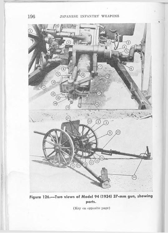
196 JAPANESE INFANTRY WEAPONS
Figure 126.—Two views of Model 94 (1934) 37-mm gun, showing parts.
(Key on opposite page)

ANTITANK AND INFANTRY GUNS 197
The breechblock is a horizontal sliding wedge. When a round is fired, the breech is cammed open and the cartridge case extracted automatically. The breech, however, remains open when the gun returns to battery, that is, moves forward again. When another round is inserted in the chamber, the breech closes automatically. It slams shut when the rim of the cartridge case trips the lips of two extractors which lie in a recess next to the chamber.
The gun may be transported with its trails closed, locked with a yoke. Extensions are attached to the trail connecting it to the pack saddle of the animal drawing the gun.
The ends of the trails are provided with handgrips for manhandling. Steel disk wheels with steel rims are usually provided. In difficult terrain, larger wooden- spoke wheels with steel rims are used to give additional ground clearance.
(Key to tig. 126)
1. Left-wheel positioning latch.2. Angle-of-slte handwheel and trig
ger actuator.3. Elevating handwheel.4. Range drum.5. Equalizer bar.6. Trail detaching handle.7. Markings on lube.8. Tube.9. Breech-closing m ec hauls in
housing.10. Breechblock.11. Traversing handwheel.12. Trigger arm.13. Trigger-arm safety.
14. Hammer safety.15. Breechblock-opening cam.16. Hammer.17. Breech ring.18. Breech-opening-mechanism spring
lock.19. Operating handle.20. Sight base and rack.21. Firing knob.22. Breech block-opening cam guide.23. Trail traveling locking bar.24. Spades.25. Firing-knob lock.26. Shield-brace-attachment latches.

198 JAPANESE INFANTRY WEAPONS
The left wheel may be pivoted outward vertically to allow more operating space for the gunner.
(2) Table of characteristics^—Lengt h:
Barrel_________________________ 66.5 inches.Over-all in traveling position______ 114 inches.Over-all with trail extension______ 174 inches.
Width:Over-all_________________Over-all with trails open___
Total weight in action_______ -Thickness of shield armor____ _Traverse____________________
47 inches.96 inches.714 pounds.0.2 mm (.787 inch).1,062 mils (60 de
grees).Elevat ion:
MaximumMinimum
480 mils (27 degrees).— 124 mils (—7 de
grees).Range:
Effective-.Maximum
2.500 ya rds. 5,000 yards.
Muzzle velocity (armor-piercing round)2,300 feet per secondRate of fire________________________ 10 to 20 rounds per
minute.Length of recoil____________________ 6 to 8 inches.
d. How to Operate(1) .Safety.—There are three safety features on the
Model 94 (1934) 37-mm gun. They are—(a) The safety lock located on the lower left por
tion of the breech face. When this lock is turned to a horizontal position, the firing mechanism will lock and the breechblock cannot be opened. When the lock is in the vertical position, the weapon can be fired.

ANTITANK AND INiFANTHY GUNS 199(b) The breechblock operating-handle latch, which
engages in a recess on the top of the breech and locks the operating handle to keep it from obstructing the semiautomatic operation of the breech during firing. The operating handle must be forced down in order to disengage the latch.
(c) The safety lock, which is located to the right of the firing knob, obstructing the front-to-rear movement of the tiring knob. The weapon cannot be fired by pulling the knob to the rear.
(2) To sight.—The gun is laid-in by two distinct and independent elevating mechanisms. One is the handwheel, which contains the firing knob—this is to the left above and forward of the breech. It moves the telescope and the barrel. The other is the elevating handwheel, which moves the barrel only—this is to the right and forward of the breech.
The movement of the elevating handwheel operates the range drum. The range drum has three scales. The left scale is graduated from 0 to 30, and is marked for armor-piercing shells. The center scale is graduated from 0 to 40, and is marked for high-explosive shells. The right scale is graduated from 0 to 50, and is marked for shrapnel ammunition.
(3) To traverse.—Traversing is accomplished by the traversing handwheel at the left of the breech. Traverse to the right is accomplished by rotating the handwheel clockwise; to the left, counterclockwise.
(4) To load and fire.—Insert a round in the chamber. The breech is automatically closed when the shell case forces in against the extractors. In order

200 JAPANESE INFANTRY WEAPONS
to fire the weapon, pull the firing knob outward to the rear.
(5) To set-in the trails.—At the end of the trails are spade brackets which enable the spades to be locked in three positions; two for firing (hard or soft ground), and one for traveling.
(6) Gun crew.—The Model 94 (1934) 37-mm gun can be handled by a five-man crew. This is set up as follows:
(a) Chief of section.(b) Gunner.(c) No. 1 (gunner’s assistant).(d) No. 2 (ammunition carrier).(e) No. 3 (ammunition carrier).
For direct firing, only one man is required to control the aiming, elevating, and traversing mechanisms, assisted by a loader. But for indirect firing, a second man is needed to operate the range drum.
(7) To unload.—If a misfire occurs, wait a few minutes before attempting to unload. The gun may be unloaded by slowly opening the breech and catching the round as it is forced out by the extractors.e. Ammunition
The Model 94 (1934) 37-mm gun has three types of ammunition—armor-piercing, high-explosive, and shrapnel (fig. 127).
Specifications for the high-explosive round (fig. 128)are as follows:Length of complete round___________________ 11.28 inches.Weight of complete round___________________ 2.70 pounds.

ANTITANK AND INFANTRY GUNS 201Diameter of round at base of cartridge case____ 21.36 inches.Length of projectile------------------------------------ 4.98 inches.Weight of projectile________________________ 25.05 ounces.Weight of propellant________________________ 4.32 ounces.
Armor-piercing shell case High-explosive
Figure 127.—Armor-piercing (left) and high-explosive (right) shells for Model 94 (1934) 37-mm gun.
The HE round is provided with a small, short-delav nose fuze (fig. 129). The radius of burst of the high- explosive shell is not large and, consequently, not con-

202 JAPANESE INFANTRY WEAPONS
sidered dangerous except at the point of impact or in a small enclosure directly penetrated.
Body of shell Rotating bandCase
bursting chargebursting charge-
Figure 128.—Cross section of Model 94 (1934) high-explosive shell.
Centrifugal pin
Figure 129.—Cross section of small instantaneous nose fuze used in Model 94 (1934) high-explosive shell.
ProjectileFuse
Upper Lowerbursting charge bursting charge
Propellant
Figure 130.—Cross section of Model 94 (1934) armor-piercing shell.
Case
1
The armor-piercing projectile (fig. 130) can penetrate 1.32 inches of armor plate in a direct hit at 1,000

ANTITANK AND INFANTRY GUNS 203
yards, or 0.96 inch if the shot hits at a 30-degree angle. A base fuze (fig. 131) is used with the armor- piercing projectile.
f. Maintenance(1) Oiling and cleaning.—The Model 94 (1934)
37-mm gun may be given the same general care as U. S. guns. Where lubricating oils and greases are required, use the same lubricants as would be used for similar moving parts on U. S. weapons.
Figure 131.—Cross section of base fuze used in Model 94 (1934) armor-piercing shell.
(2) Stripping.—(a) Barrel.—In order to remove the barrel from the gun, uncouple it from the recoil mechanism by releasing a coupler pin located on the lower right of the breech ring; this pin can be unlocked with a quarter turn to the right. Then slide the barrel to the rear.
(b) Breech.—Close the breech to release, the tension on the breechblock operating plunger (a small cylinder

204 JAPANESE INFANTRY WEAPONS
on top of flic breech). Then the spring and plunger can be removed.
When the breech ring and the breechblock operating shaft are lined up, the operating shaft can be disengaged. from the slots of the breech ring and lifted out.
The removal of the extractor shaft (on the left side of the breech ring) permits the removal of the breechblock to the left.
(c) Firing mechanism.—Compress and rotate the firing-pin housing, located in the center of the breech, and remove it from the breech. Then unscrew the firing-pin housing and its integral parts.
(d) Recoil mechanism.—The recoil system of the gun is hydrospring. The fluid content of the cylinders is about lYs pints. When the gun goes into recoil, the braking at the end of that phase is accomplished by a compression of two coil springs, which then restore the energy to bring the gun back to battery again. Buffing action, which eases the gun into battery at the end of the recoil cycle, is effected by throttling the recoil fluid past a valve on the buffer rod. In firing, the recoil cylinder and buffer rod remain stationary, while the piston rod, which is coupled to the barrel, moves to the rear.
After a period of firing, the recoil fluid, a glycerine- water solution, may heat and expand, causing the gun to hang out of battery. In such a case, enough liquid should be drained from the cylinders to allow the gun to return to battery. Insufficient liquid in the recoil mechanism will cause the gun to slam into battery.

ANTITANK AND INFANTRY GUNS 205In order to get access to the filling hole of the re
coil mechanism, first remove the barrel of the gun, and then the recoil mechanism from the cradle. Remove the buffer-cap nut on the forward end of the
Figure 132.—Two views of metal carrying case for 37-mm shells used in Model 94 (1934) 37-mm gun (12 complete rounds).

JAPANESE INFANTRY WEAPONS206
recoil mechanism, and the front cap on the recoilcylinder head. The filling ping of the piston will protrude past the forward end of the cylinder, if the couplei’ is unscrewed.
If the cylinder is to be replenished with fluid, the front end of the recoil mechanism should be elevated before the filling plug is removed.
(3) Assembly.—To assemble the weapon, proceed in the reverse order to that followed in stripping.g. Accessories
The ammunition for the Model 94 (1934) 37-mm gun is carried in a horse-drawn caisson containing 6 to 8 cases of ammunition, 12 rounds to a case (fig. 132).
The gun is also equipped with trail extensions for transportation by horse.36. MODEL 1 (1941) 47-MM GUN 6
’This weapon is listed by the Japanese as — \® -j- -twhich is read (from left to right) Ichi Shiki Yonjunana Miri Kidoho, meaning “1 mode! 47-mm mobile gun.” (See p. 7, note 1.)
'In general, this piece resembles the later models of the ZIK 45-min Russian antitank gun; both are developments of the original German Rheinmetall designs.
a. GeneralThe Model 1 (1941) 47-mm gun (figs. 133 and 134)
is a new gun of modern design. It is»an antitank and antipersonnel weapon.0b. How to Identify
The Model 1 (1941) 47-mm gun may be identified by—
(1) The long barrel, reinforced at the muzzle.

1ANTITANK AND INFANTRY GUNS 207
Figure 133.—Model 1 (1941) 47-mm gun (right side).
Figure 134.—Model 1 (1941) 47-mm gun (front view).
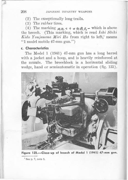
208 JAPANESE INFANTRY WEAPONS
(2) The exceptionally long trails.(3) The rubber tires.(4) The marking -t + 1S? - which is above
the breech. (This marking, which is read Ichi Shiki Kido Yonjunana Miri llo from right to left,1 means “1 model mobile 47-mm gun.”)c. Characteristics
The Model 1 (1941) 47-mm gun has a long barrel with a jacket and a hoop, and is heavily reinforced at the muzzle. The breechlock is a horizontal sliding wedge, hand or semiautomatic in operation (fig. 135).
Figure 135.—Close-up of breech of Model 1 (1941) 47-mm gun.
’ See p. 7, note 1.

ANTITANK AND INFANTRY GUNS 209The gun is transported with the trails closed, locked with a yoke. This gun is adapted for motor transport only. Its great length and low clearance make it difficult to manhandle except on exceptionally favorable terrain. A wide shield, cut away at the bottom, is provided. Perforated steel disk wheels are fitted with rubber tires. The tread is wide, lint ground clearance is low.
The low silhouette, wide tread, and long trails should give this gun excellent stability. Preliminary tests indicate a muzzle velocity of 2,700 feet per second.d. How to Operate
All of the details on the operation of this gun are not known. It is believed, however, that it may be operated in the same manner as the Model 94 (1934) 37-inm gun (par. 35, p. 194).e. Ammunition
The rimmed armor-piercing-high-explosive round has a brass case. It is of comparatively large diameter, necked down to take the 47-mm projectile. The projectile has a red tip, a black body, and a white band just in front of the copper rotating band. Specifications for the round are as follows:Length of complete round_____________Weight of complete round_____________Maximum diameter of case____________Length of case_______________________Length of projectile__________________Weight of projectile__________________Weight of propellant_________________
15.54 inches.6 pounds 6.4 ounces.2.55 inches.11.09 inches4.45 inches.3 pounds 6.4 ounces.13.94 ounces.

210 JAPANESE INFANTRY WEAPONS
A simple high-explosive round is also reported to be available for use in this weapon.
37. MODEL 92 (1932) 70-MM HOWITZER (BATTALION GUN)8
‘This weapon is listed by the Japanese as jg - fa, whichis read (from left to right) Kt/uni Shiki lloheiho, meaning “92 model infantry gun.” The Japanese tactical symbol for the 70-mm howitzer
a. GeneralThe Model 92 (1932) 70-mm howitzer (battalion
gun) (fig. 136) is an infantry-support howitzer. It is
Figure 136.—Model 92 (1932) 70-mm howitzer with trails closed.
a horse-drawn piece, but can be handled by a 10-man section according to Japanese requirements. Despite its clumsy appearance, it has proved to be an effective weapon.

ANTITANK AND IN'FANTKY GUN'S 211
b. How to IdentifyThe Model 92 (1932) 70-mm howitzer may be iden
tified by—(1) The low mount.(2) The extremely short barrel.(3) A sliding plate on the shield.(4) The marking MA f A. - tL which is on the rear
end of the barrel. (This marking, which is read Kyuni Shiki lloheiho (from right to left), means “92 model infantry gun.”)c. Characteristics
(1) General.—The Model 92 (1932) 70-mm howitzer has a rifled barrel approximately 9 calibers long. The
Figure 137.—Model 92 (1932) 70-mm howitzer with breech andtrails open.
5558250—43------ 15

212 JAPANESE INFANTRY WEAPONS
barrel, breech ring, and top sleigh are all of one forging. The breechblock is the interrupted-thread, swingdown type (fig. 137). Extraction is accomplished when the breech is opened after firing.
The carriage has a split trail (fig. 138) and is of welded construction, except where the spades are riveted on. The trails lock together for traveling and
Figure 138.—Model 92 (1932) 70-mm howitzer with trails open.
have two extension attachments for horse transportation. The wheels are steel disks with steel rims. There is a shield plate which rests on top of the barrel and slides up and down with the movement of the barrel.
(2) Table of characteristics.—Over-all length with trails folded_ 87 inches.Over-all width_________________ 36 inches.

ANTITANK AND INFANTRY GUNS 213Total weight in action__________Thickness of shield armor______Traverse______________________Elevation:
Maximum_________________Minimum__________________
Range:Effective__________________Maximum_________________
Rate of fire___________________Length of recoil________________
468 pounds.0.156 inch.1,600 mils (90 degrees).
889 mils (50 degrees).— 178 mils ( — 10 degrees).
1,500 yards.3,000 yards.10 rounds per minute.4 to 6 inches.
d. How to Operate(1) Safety.—There are two important safety fea
tures on the Model 92 (1932) 70-mm howitzer:(a) The safety lock, which is found to the right of
the firing mechanism on the breech carrier, when in the “up” position prevents the weapon from being fired and the breechblock from being opened.
(b) The breechblock operating-handle latch, which prevents the breechblock from coming open during firing, and must be depressed when operating the breech by hand. (A third safety feature should also be noted: the piece cannot be fired unless the breech is fully closed.)
(2) Sight.—The Model 92 (1932) 70-mm howitzer uses the same panoramic sight (fig. 139) as the field- artillery weapons. The mount of the sight is on the left side of the piece. The sight bracket includes a range drum, an elevating bubble, and a cross-leveling bubble for correcting for differences in level of the wheels. There are four strips on the range drum, numbered I, IT, III, and IV, corresponding to powder charges 1, 2, 3, and 4. When the strip which is selected ac-

214 JAPANESE INFANTRY WEAPONS
cording to the number of the charge is pulled back, it will reveal the proper range scale for that charge.
(3) Gun crew.—It is possible that a smaller crew than the 10 men called for by the Japanese table of
Figure 139.—Panoramic artillery sight.
organization could handle the Model 92 (1932) 70-inm howitzer (fig. 140). Five men could be assigned as follows:
(a) Chief of section.(b) Gunner.

ANTITANK AND INFANTRY GUNS 215
Figure 140.—Model 92 (1932) 70-mm howitzer (battalion gun) in action.
(c) No. 1 (gunner’s assistant).(d) No. 2 (ammunition carrier).(e) No. 3 (ammunition carrier).(4) To elevate.—Elevation of the Model 92 (1932)
70-mm howitzer is accomplished by turning the elevating handwheel on the right of the carriage clockwise; depression, by turning it counterclockwise.
(5) To traverse.—The traversing handwheel is located on the left side of the upper carriage. Turn the handwheel clockwise to traverse to the right, and counterclockwise to traverse to the left.
(6) To load and fire.—To fire the Model 92 (1932) 70-mm howitzer, open the breechblock with force and

21(5 JAPANESE INFANTRY WEAPONS
insert a round of ammunition in the chamber. Then close the breech, adjust the safety lock to the “up,” or “safe,” position, and attach a lanyard. When ready to fire, release the safety lock and pull the lanyard.
(7) To unload.—If a misfire occurs, wait a few minutes before attempting to unload. Then slowly open the breech and catch the round as it is forced out of the chamber.e. Ammunition
The ammunition used in the Model 92 (1932) 70-mm howitzer is semifixed with a brass, or brass-plated steel, case (fig. 141). High-explosive, shrapnel, and smoke shells are used. The weight of the high-ex- plosive shell is 8.36 pounds, and the danger area of its burst is 40 yards radially.
The propelling charge is made up of an igniter pad, a base charge, and three increments. The maximum and minimum ranges for each of these charges are as follows:
1 This leaves the igniter pad and base charge in place.
Charge Maximum range Minimum range (0elevation)
Complete 3.075 yards____ 1.100 vards.Remove No. 1 onlv (19 grains) 1.975 vards. 660 vards.Remove Nos. 1 and 2 (9 grams) 1.300 vards 225 vards.Remove Nos. 1,2, and 3 (5 grams)1 _ 985 yards ____ 110 yards.
Instantaneous or delay fuzes are used. Both are designated Model 88 and are used also in the ammunition for the Model 41 (1908) 75-min mountain gun. (See par. 38e (4), p. 227, and fig. 149, p. 228.)

ANTITANK ANI) INFANTRY GUNS
Figure 141. 70-mm high-explosive shell for Model 92 (1932)70-mm howitzer.

218 JAPANESE INFANTRY WEAPONS
The high-explosive shell is approximately 9(4 inches long and is filled with an ammonium-nitrate explosive. The body of the shell is painted black, with a yellow band above the rotating band and a red band around the fuze adaptor.f. Maintenance
(1) Oiling and cleaning.—-The Model 92 (1932) 70-mm howitzer may be given the same general care as is given to U. S. weapons.
(2) Stripping.—(a) Barrel.—Uncouple the barrel from the recoil mechanism, set the elevation at zero, and slide the barrel to the rear.
(b) Breech.—Line up the assembly marks of the breechblock operating arm and remove the operating arm by pulling it outward. In order to remove the extractor from the breech recess, pull out the extractor shaft and spring. Rotate the breechblock out of its carrier.
(3) Recoil mechanism.—The recoil mechanism is housed in a cylinder in the cradle. Il contains about three-fourths of a pint of a glyeerine-water- solution recoil fluid. In firing, the recoil cylinder remains stationary while the piston rod moves with the barrel, for the barrel is attached to the piston rod by a coupler pin.
Too much fluid in the recoil mechanism will cause the piece to hang out of battery, while an insufficient amount of fluid will cause it to slam into battery. In order to remedy these two conditions, fluid must be added or drained according to the circumstance.
To get access to the filling hole, the shield must be removed, along with the barrel, and the sleigh and

ANTITANK AND INFANTRY GUNS 219recoil mechanism elevated about 40 degrees. After the cap nut on the end of the cylinder is removed along with the cylinder head, turn the piston-rod coupler in a counterclockwise direction until the recoil piston head protrudes slightly from the recoil cylinder. (The filling hole and plug are at the side of the recoil piston head.)
(4) Assembly.-—To assemble the weapon, proceed in the reverse order to that followed in stripping.g. Accessories
There is an ammunition caisson which accompanies the Model (1932) 70-mm howitzer. It carries three boxes of ammunition (fig. 142), as well as sights, tools
Figure 142.—Gun-carriage type of packing box for 70-mm high- explosive shells (eight complete rounds).

220 JAPANESE INFANTRY WEAPONS
and other accessories (fig. 143); it is transported behind a horse in tandem with the howitzer.
There is also a 1-man steel ammunition case for carrying 5 complete rounds and 10 fuzes—5 instan-
Figure 143.—Model 92 (1932) 70-mm howitzer captured on Guadalcanal. (The weapon is shown complete with accessories.)
taneous and 5 delayed-action (fig. 144)—and boxes holding 3 complete rounds (fig. 145).
A sight-mount carrying case and a box of tools, which contains brushes and cleaning equipment, accompany the weapon.

IANTITANK AND INFANTRY GUNS 221
Figure 144.—Metal carrying case for 70-mm high-explosive shells (five complete rounds).

222 JAPANESE INFANTRY WEAPONS
Figure 145.—Manner of packing 70-mm high-explosive shells (three complete rounds),
38. MODEL 41 (1908) 75-MM MOUNTAIN (INFANTRY) GUN 0
a. GeneralThe Model 41 (1908) 75-mm mountain (infantry)
gun (fig. 146) was originally used as a field-artillery pack gun, but when it was largely superseded by the Model 94 (1934) 75-nnn mountain (pack) gun, it was issued for use as an infantry regimental gun. This gun is widely distributed throughout the Japanese Army.
"This weapon is listed by the Japanese as J' UtL < which isread (from left to right) Towiefti Shiki Sampo, meaning “41 model mountain gun.” The Japanese tactical symbol for the 75-mm mountain (infantry) gun is

ANTITANK AND INFANTRY GUNS 223b. How to Identify
The Model 41 (1908) 75-mm mountain (infantry) gun may be identified by—
(1) The modified box trail of tubular steel.(2) The short barrel (fig. 147).(3) The large, single-piece shield with sighting door.
c. Characteristics(1) General.—The Model 41 (1908) 75-mm moun
tain (infantry) gun has an interrupted-thread, swingtype breechblock. The recoil mechanism is hydrospring. There are no equalizers or equilibrators. The gun is mounted on a field carriage with steel-rimmed wooden wheels. The trail is of modified box type, of tubular steel—two parallel trails connected to a large,
Figure 146.—Model 41 (1908) 75-mm mountain (infantry) gun.

224 JAPANESE INFANTRY WEAPONS
Figure 147.—Gun crew of Model 41 (1908) 75-mm mountain (infantry) gun in action. (Note the method of moving the trail.)
single detachable spade. For transporting, the spade is removed and two shafts are attached so that the gun can be horse-drawn.
(2) Table of characteristics.—Length of barrel_______________ 54i/> inches.Over-all length (with spade)------- 170 inches.Over-all width_________________ 48 inches.Total weight__________________Thickness of shield armor-----------Traverse______________________
1,200 pounds.0.167 inch.106 mils (6 degrees).
Elevation:Maximum_________________ 354 mils (20 degrees).Minimum_________________ —319 mils (-18 degrees).
ANTITANK AND INFANTRY GUNS 225Range:
Effective__________________Maximum:
With long-pointed shell__With ordinary shell______
Rate of fire____________________Length of recoil_______________
2,100 yards.
7,675 yards.6,575 yards.10 rounds per minute,17 to 20 inches.
d. How to Operate(1) Safety.—There are three safety features on the
Model 41 (1908) 75-min mountain (infantry) gun:(a) .Safety lock.—The safety lock is found on the
left of the rear plate of the breechblock. Push the safety-lock handle upward to lock the firing mechanism. An accidental pull on the lanyard will not fire the piece, nor will the breech be opened.
(b) Breechblock operating-handle latch.—When the breech is fully closed, the latch of the breechblock operating handle engages with a catch on the breechblock and locks the breech in the closed position for firing.
(c) Hack lock.—There is a rack lock which automatically prevents the breechblock from rotating during the hinged movement of opening and closing the breech.
(2) To elevate.—Elevation and depression are accomplished by operating the handwheel on the left side of the carriage. A clockwise turn will depress the gun, and a counterclockwise turn will elevate it.
(3) To traverse.—The traversing handwheel is to the right rear of the carriage. Turning it clockwise moves the gun to the right; counterclockwise, to the left.

226 JAPANESE INFANTRY AVE A PONS
(4) To load and fire.-—Open the breechblock, insert a round in the chamber, and swing the breech closed. Then turn the handle of the safety lock upward. When ready to fire, release the safety lock and pull the lanyard.
When the breech is opened again by hand, the extractors will force out the empty shell case.
(5) To unload.—If a misfire occurs, wait a few minutes before attempting to unload. Then slowly open the breech and catch the round as it is forced out of the chamber by the extractors.e. Ammunition
(1) General.—This gun fires two types of ammunition—high-explosive and armor-piercing.
(2) High-explosive.—The high-explosive ammunition is of the fixed type. The cartridge case is of brass, or brass-plated steel, 6.5 inches long. The propellant powder is nitrocellulose contained in a silk bag. The projectile is of standard construction except that picric acid is used in the booster. Cast TNT is used as the explosive. The projectile is painted black and may have either a single yellow band in the center of the projectile or a yellow band below the bourrelet and a white band above the rotating band. The difference in marking is not understood, but it is believed that the white band may indicate a spotting charge incorporated with the explosive.
(3) Armor-piercing.—The armor-piercing round (fig. 148) is shorter than the high-explosive round and is painted black with a white band below the bourrelet.

ANTITANK AND INFANTRY GUNS 227The round lias a small explosive filling which is detonated (presumably after penetration of the target) by a base-detonating fuze.
Figure 148.—75-mm armor-piercing round.
(4) Fuzes.—The fuzes used are the Model 88 instantaneous and Model 88 delayed-action (estimated delay, 0.05 second) (fig. 149). These same fuzes arc used in the ammunition for the Model 92 (1932) 70-mm infantry howitzer (battalion gun) (par. 37e,
555825®—13--------l<i

228 JAPANESE INFANTRY WEAPONS
p. 216). The fuzes are packed separately from the rounds in sealed, rectangular tin boxes, 10 to a box. The tin boxes are packed in wooden boxes (26 by 12 by 5 inches), 10 to a box.
Figure 149.—Fuzes for 70- and 75-mm shells: instantaneous type (left) and delayed-action type (right).
The fuzes carry safety wires which must be removed before firing. So long as the wires are in place, the fuzes arc safe for handling. When fired, they become armed

ANTITANK AND INFANTRY GUNS 229
Figure 150.—Packing box for Model 97 (1937) 75-mm high- explosive shells (two complete rounds).
Figure 151.—Packing box for 75-mm armor-piercing shells (four complete rounds)

230 JAPANESE INFANTRY WEAPONS
by setback and centrifugal force, and are actuated by impact. They have no bore-safe features.
Figure 152.—-Metal carrying case for 75-mm high-explosive shells (three complete rounds).
(5) Packing.-—Ammunition is packed in 2- and 4- l'ound wooden boxes (figs. 150 and 151) and in 3-
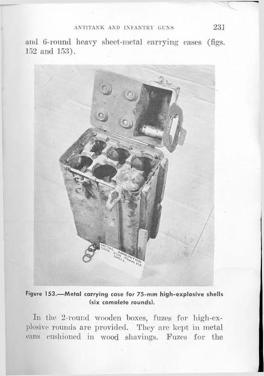
ANTITANK AND 1N1ANTKY GINS 231
and 6-round heavy sheet-metal carrying cases (figs.152 and 153).
Figure 153.—Metal carrying case for 75-mm high-explosive shells (six comolete rounds).
In the 2-round wooden boxes, fuzes for high-ex- plosive rounds are provided. They are kept in metal cans cushioned in wood shavings. Fuzes for the

232 JAPANESE INFANTRY WEAPONS
rounds in the 3-round metal carrying cases are in metal tubes fitted into the cases. The 6-round metal carrying case has a rectangular recess formed in the cover. Fuzes in individual metal tubes fit into this recess.f. Maintenance
(1) Oiling and cleaning.—The gun may be given the same care as U. S. guns. Where lubricating oils and greases are needed, U. S. requirements for similar moving parts may be used.
(2) Stripping.—(a) Barrel.—-Unlock the barrel locking band, and swing it open to the left. Then grasp the handle of the barrel locking band, and rotate the barrel one-eighth of a turn. Two men can then easily lift the barrel off the sleigh.
(b) Breech.—The operating-handle shaft may be removed by tapping it and pulling it out. Rotate the breechblock until the firing-mechanism safety lock is in line with the left-hand slot of the breechblock carrier (the part in which the breechblock is screwed). The safety lock can be slid out. Rotate the breechblock until it is in the closed position, and force the sear against its spring to release the trigger. Then remove the firing mechanism.
(3) Recoil mechanism.—The recoil mechanism is housed in the cradle. In recoil, the recoil cylinder remains stationary, while the piston rod moves to the rear with the barrel.
After the gun has been fired, the recoil fluid, a glycerine-water solution, may heat and expand, causing the gun to hang out of battery. In such a case, the liquid may be drained to allow the gun to return

ANTITANK AND INFANTRY GUNS 233to battery. Insufficient fluid causes tlic gun to slam back into battery too fast.
In order to get access to the filling holes—of which there are two, one in the front of the recoil mechanism, and one in the rear—-first depress the weapon to —10 degrees. Then remove the front cover of the cradle. Remove the buffer-rod nut on one cylinder to get to the front filling hole, and remove the nut on the other to get to the rear filling hole.
Both the front and the rear filling holes should be used in refilling the recoil cylinders. Force the liquid into the front hole until it runs out the rear hole free of bubbles, indicating that there is no air present.
(4) Assem&Z#.—To assemble the weapon, proceed in the reverse order to that followed in stripping.

Section IX. SMALL-ARMS AMMUNITION
39. INTRODUCTION
The primary purpose of this section is to describe the ammunition used in Japanese small arms (see the chart, fig. 156, p. 238. Since the employment of unidentified ammunition may be a danger to the user, all available information is included concerning the system by which the Japanese label and mark their ammunition. The Japanese do not mark individual rounds. The band color on the bullet, the shape of the round, and the composition of the bullet jacket are the only visual means of identifying the various types of rounds.40. COLOR OF BANDS
It appears that the following significance may be attached to the colors of the bands used on Japanese small-arms ammunition:Pink___________________________________ Ball.Green__________________________________ Tracer.Black___________________________________ Armor-piercing.
41. MODEL 38 (1905) 6.5-MM AMMUNITION
a. How to IdentifyModel 38 (1905) 6.5-mm (.256 inch) ammunition
may be identified by its size, by its semirimmed case, and by the label on the container in which it is found. These rounds are packed in wooden boxes; three 5-round clips are packed in separate pasteboard
234

SMALL-ARMS AMMUNITION . 235
containers. A colored band around the circumference of the bullet where it enters the neck of the cartridge case and a similarly colored circle on the upper left corner of box labels serve to indicate the character of the round (see par. 40).
b. Where to UseThis ammunition functions in the following
weapons:Model 38 (1905) 6.5-mm rifle.Model 38 (1905) 6.5-mm carbine.Model 44 (1911) 6.5-mm cavalry carbine.
It also functions in the following obsolescent weapons which are not described in this study:
Model 38 (1905) 6.5-mm heavy machine gun.Model 3 (1914) 6.5-mm heavy machine gun.
42. MODEL 38 (1905) 6.5-MM REDUCED-CHARGE AMMUNITION
a. How to IdentifyModel 38 (1905) 6.5-mm reduced-charge ammunition
may be identified by its size, by its semirimmed case, and by the label on its container. This ammunition is difficult to distinguish from the standard Model 38 (1905) 6.5-mm ammunition. The Japanese appear to distinguish the reduced-charge round solely by means of the marking on the containers. The labels for the reduced-charge ammunition have a capital G in a circle in the lower left corner. A colored band around the circumference of the bullet where it enters the neck of the cartridge (see par. 40) and a similarly colored circle on the upper left corner of box labels
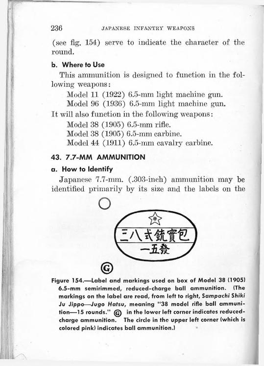
236 JAPANESE INFANTRY WEAPONS
(see fig. 154) serve to indicate the character of' the round.b. Where to Use
This ammunition is designed to function in the following weapons:
Model 11 (1922) 6.5-mm light machine gun.Model 96 (1936) 6.5-mm light machine gun.
It will also function in the following weapons:Model 38 (1905) 6.5-mm rifle.Model 38 (1905) 6.5-mm carbine.Model 44 (1911) 6.5-mm cavalry carbine.
43. 7.7-MM AMMUNITION
a. How to IdentifyJapanese 7.7-mm. (.303-inch) ammunition may be
identified primarily by its size and the labels on the
Figure 154.—Label and markings used on box of Model 38 (1905) 6.5-mm semirimmed, reduced-charge ball ammunition. (The markings on the label are read, from left to right, Sampachi Shiki Ju Jippo—Jugo Hatsu, meaning “38 model rifle ball ammunition—15 rounds.” (g) in the lower left corner indicates reduced- charge ammunition. The circle in the upper left corner (which is colored pink) indicates ball ammunition.)

SMALL ARMS AMMUNITION 237
boxes (fig. 155). There are three types of 7.7-mm ammunition: rimmed, semirimmed, and rimless.b. Where to Use
(1) Rimmed.—Japanese 7.7-mm rimmed ammunition is interchangeable with British caliber .303 ammunition, but may be used only in the Vickers-type (fixed) and Lewis-type (flexible) aircraft machine guns and in the Lewis-type ground machine guns.
(2) Semirimmed.—Model 92 (1932) 7.7-mm semirimmed ammunition (fig. 155) is used only in the Model
Figure 155.—Label and markings used on box of Model 92 (1932) 7.7-mm ammunition. (The markings on the label are read, from left to right, Kyuni Shiki Jukikanju Danyaku—Kyuni Shiki Futsu Jippo—Sanju Hatsu, meaning “92 model heavy-machine-gun ammunition—92 model ordinary ball ammunition—30 rounds.”)
92 (1932) 7.7-mm heavy machine gun and in certain types of aircraft machine guns other than the Vickers and Lewis types mentioned above. (See (3), below.)
(3) Rimless.—Model 99 (1939) 7.7-mm rimless ammunition is used in the Model 99 (1939) 7.7-mm rifle and the Model 99 (1939) 7.7-mm light machine gun. It will function also in the Model 92 (1932) 7.7-mm heavy machine gun,.although the Model 92 (1932) semirimmed

238 JAPANESE INFANTRY WEAPONS
ammunition will not, in turn, function in the Model 99 rifle or light machine gun.44. 8-MM PISTOL AMMUNITION
Japanese 8-mm (.315-inch) pistol ball ammunition may be identified by its semirimmed, bottlenecked case and roundnosed bullet. At present no information is available as to the nomenclature or packing of this cartridge, which is used in all three of the Japanese automatic pistols: the Nambu, the Model 14 (1925), and the Model 94 (1934). There are no color markings on the rounds that have been examined.
Caliber Model Type of round Color of band
Color of bullet Shape of bullet
6.5-mm Model38 (1905),semirimmed.
Bal) Bink.. Silver or Pointed nose.
'I'racercopper.
Silver. ..6.5-mm Model 38 (1905), Green Pointed nose.semirimmed.
6.5-mm Model 38(1905), Special reduced charge for Pink Silver... Pointed nose.semirimmed light machine guns (Can be iden-special. Models 11 (1922) and 96 tified only by
(1936). ©on ammunition containers.)
7.7-mm Model 92 (1932), Ball for Model 92 (1932) Pink Silver Pointed nose.semirimmed. heavy machine gun (Packed 300
only. rounds in 30- round clips in unlined wooden case.)
7.7-mm Model 92 (1932), Armor-piercing for Model Black. Brass. Pointed n se.semi rim med. 92 (1932) heavy machine
gun only.7.7-mm Model 92 (1932), Tracer for Model 92 (1932) Green Silver Pointed nose.
semirimmed. heavy machine gun only.7.7-mm Model 99(1939), Ball for Model 99 (1939) Pink Copper__ Pointed nose.
rimless. rifle and Model 99 (1939) light machine gun; also functions in Model 92 (1932) heavy machine gun.
8-mm Ball for Nambu. Model I I None. Silver Round nose.(1925), and Model 94 (1934) automatic pistols.
Figure 156.—Infantry small-arms ammunition chart
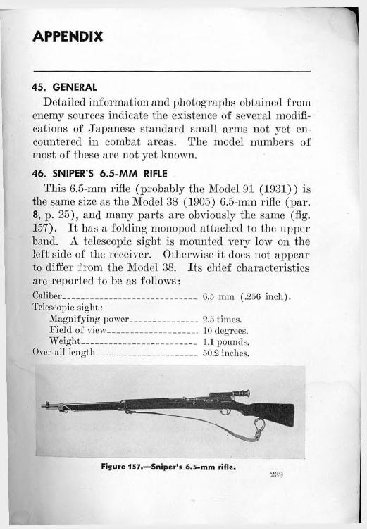
APPENDIX
45. GENERALDetailed information and photographs obtained from
enemy sources indicate the existence of several modifications of Japanese standard small arms not yet encountered in combat areas. The model numbers of most of these are not yet known.46. SNIPER’S 6.5-MM RIFLE
This 6.5-mm rifle (probably the Model 91 (1931)) is the same size as the Model 38 (1905) 6.5-mm rifle (par. 8, p. 25), and many parts are obviously the same (fig. 157). It has a folding monopod attached to the upper band. A telescopic sight is mounted very low on the left side of the receiver. Otherwise it does not appear to differ from the Model 38. Its chief characteristics are reported to be as follows:Caliber--------------------------------------- 6.5 mm (.256 inch).Telescopic sight:
Magnifying power------------------- 2.5 times.Field of view_________________ 10 degrees.Weight--------------------------------- 1.1 pounds.
Over-all length___________________ 50.2 inches.
Figure 157.—Sniper’s 6.5-mm rifle.239

240 JAPANESE INFANTRY WEAPONS
Weight_____________________ ‘____ 9.8 pounds.Maximum range__________________ 2,600 yards.
47. LONG 7.7-MM RIFLEThis 7.7-mm rifle (fig. 158) is 5.5 inches longer than
the Model 99 (1939) 7.7-mm rifle (par. 9, p. 39), the extra length being entirely in the barrel. It is a fraction of an inch shorter than the Model 38 (1905) 6.5-mm rifle. Like the Model 99 rifle, it has a folding monopod attached to the upper band, but the sling swivels are on the bottom of the rifle, not on the side as in the Model 99. The rear sight is the same as that used on the Model 99, including the folding arms to be used when firing at aircraft. This rifle does not appear to differ essentially from the usual Arisaka pattern. Its chief characteristics are reported to be as follows: Caliber___________________ 7.7 mm (.303 inch).Capacity of magazine_______ 5 rounds.lieai- sight________________ Graduated from 100 to 1,500
meters (109.4 to 1,640 yards). Length of barrel____________31.4 inches.Length:
Without bayonet------------ 50.1 inches.With bayonet__________ 65.2 inches.
Height of monopod_________ 12.4 inches.Weight:
Without bayonet------------ 9.02 pounds.With bayonet___________10 pounds.
Maximum range___________ 3,829 yards.Muzzle velocity------------------- 2,560 feet per second.
48. MODEL 97 (1937) 7.7-MM TANK MACHINE GUN(GROUND MOUNT)
By the addition of a bipod and the removal of the armor cover over the forepart of the weapon, the Model
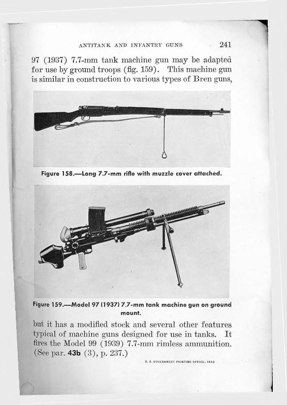
antitank and infantry guns 241
97 (1937) 7.7-mm tank machine gun may be adapted for use by ground troops (fig. 159). This machine gun is similar in construction to various types of Bren guns,
Figure 158.—Long 7.7-mm rifle with muzzle cover attached.
Figure 159.—Model 97 (1937) 7.7-mm tank machine gun on ground mount.
but it has a modified stock and several other features typical of machine guns designed for use in tanks. It fires the Model 99 (1939) 7.7-mm rimless ammunition. (See par. 43b (3), p. 237.)
U. S. GOVERNMENT PRINTING OFFICE. 1943

Weight (pounds) Action
Maximum range (yards)
Effective range (yards)
Hate of fire (rounds per
minute)
o Model 14 (1925)8-mrn pistol
2 Semiautomatic 547 17
Model 99 (1939) 7.7-cun light machine gun
21.36 Automatic 3,800 1,500 800(cyclic)
© Model 99 (1939) 7.7-mm rifle
8.8 Manual 3,000 600
© Model 38 (1905)6.5-mm rifle
9.4 Manual 2,600 400
© Model 89 (1929)50-mn grenade aiecharger
10.25 Manual\
175 to770
© Model 92 (1932) 7.7-am heavy machine gun
122 Automatic 4,587 1,500 450(cyclic)
e Model 97 (1937)20-ram antitank rifle
140 Automatic 1,100
© Model 94 (1934)37-nn gun
714 Manual 5,000 2,500 10 to 20
© Model 1 (1941)47-mm gun
1,660 Manual
© Model 99 (1939) 81-mro mortar
52 Manual 1,312 to3.280
15
© Model 94 (1934)90-mm mortar
340 Manual 4,150
Model 92 (1932) 70-mm howitzer (battalion gun)
468 Manual 3,000 1,500 10
© Model 41 (1908)75-mm mountain (infantry) gun
1,200 Manual 7,675 2,100
© Model 93 (1933) 13-rua twin heavy machine gun
Automatic
© Model 98 (1938)20-mm AA/AT gun
836 Automatic or
semiautomatic
12,000 feet (vertical)
Figure 160.—Schematic drawing, indicating ranges of principal Japanese infantry weapons. u. s. government printing office-.i9« o-ssssss
Copyright © 2022 FDOKUMEN