spc benchmark 1™ full disclosure report datacore software corporation
107
SPC BENCHMARK 1™ FULL DISCLOSURE REPORT DATACORE SOFTWARE CORPORATION DATACORE PARALLEL SERVER (DUAL NODE, FIBRE CHANNEL SAN) SPC-1 V1.14 Submitted for Review: June 15, 2016 Submission Identifier: A00179 Revised: June 17, 2016
-
Upload
khangminh22 -
Category
Documents
-
view
2 -
download
0
Transcript of spc benchmark 1™ full disclosure report datacore software corporation

SPC BENCHMARK 1™ FULL DISCLOSURE REPORT
DATACORE SOFTWARE CORPORATION DATACORE PARALLEL SERVER (DUAL NODE, FIBRE CHANNEL SAN)
SPC-1 V1.14
Submitted for Review: June 15, 2016 Submission Identifier: A00179
Revised: June 17, 2016

ii
SPC BENCHMARK 1™ V1.14 FULL DISCLOSURE REPORT Submission Identifier: A00179 DataCore Software Corporation Submitted for Review: JUNE 15, 2016 DataCore Parallel Server(Dual Node, Fibre Channel SAN) Revised: June 17, 2016
First Edition – June 2016 THE INFORMATION CONTAINED IN THIS DOCUMENT IS DISTRIBUTED ON AN AS IS BASIS WITHOUT ANY WARRANTY EITHER EXPRESS OR IMPLIED. The use of this information or the implementation of any of these techniques is the customer’s responsibility and depends on the customer’s ability to evaluate and integrate them into the customer’s operational environment. While each item has been reviewed by DataCore Software Corporation for accuracy in a specific situation, there is no guarantee that the same or similar results will be obtained elsewhere. Customers attempting to adapt these techniques to their own environment do so at their own risk. This publication was produced in the United States. DataCore Software Corporation may not offer the products, services, or features discussed in this document in other countries, and the information is subject to change with notice. Consult your local DataCore Software Corporation representative for information on products and services available in your area. © Copyright DataCore Software Corporation 2016. All rights reserved. Permission is hereby granted to reproduce this document in whole or in part, provided the copyright notice as printed above is set forth in full text on the title page of each item reproduced. Trademarks SPC Benchmark-1, SPC-1, SPC-1 IOPS, SPC-1 LRT and SPC-1 Price-Performance are trademarks of the Storage Performance Council. DataCore, SANsymphony and the DataCore logo are trademarks or registered trademarks of DataCore Software Corporation in the United States and other countries. Other DataCore product or service names or logos referenced herein are trademarks of DataCore Software Corporation in the United States and other countries. All other brands, trademarks, and product names are the property of their respective owners.
iii
SPC BENCHMARK 1™ V1.14 FULL DISCLOSURE REPORT Submission Identifier: A00179 DataCore Software Corporation Submitted for Review: JUNE 15, 2016 DataCore Parallel Server(Dual Node, Fibre Channel SAN) Revised: June 17, 2016
Table of Contents Note: Each line in the Table of Contents is a hyperlink to the listed item/page.
Audit Certification .................................................................................................. vii
Audit Certification (cont.) .................................................................................... viii
Letter of Good Faith ................................................................................................. ix
Executive Summary ................................................................................................. 10
Test Sponsor and Contact Information ......................................................................... 10 Revision Information and Key Dates ............................................................................ 10 Tested Storage Product (TSP) Description .................................................................. 11 Summary of Results ........................................................................................................... 12 Storage Capacities, Relationships, and Utilization ................................................... 13 Response Time – Throughput Curve ............................................................................. 16 Response Time – Throughput Data ................................................................................ 16 Priced Storage Configuration Pricing .......................................................................... 17 Differences between the Tested Storage Configuration (TSC) and Priced Storage Configuration ....................................................................................................... 17 Priced Storage Configuration Diagram ........................................................................ 18 Priced Storage Configuration Components ................................................................. 19
Configuration Information .................................................................................... 20
Benchmark Configuration (BC)/Tested Storage Configuration (TSC) Diagram . 20 Storage Network Configuration ..................................................................................... 20 Host System(s) and Tested Storage Configuration (TSC) Table of Components 20 Benchmark Configuration/Tested Storage Configuration Diagram ...................... 21 Host System and Tested Storage Configuration Components ................................ 22 Customer Tunable Parameters and Options ............................................................... 23 Tested Storage Configuration (TSC) Description ...................................................... 23 SPC-1 Workload Generator Storage Configuration ................................................... 23 ASU Pre-Fill ......................................................................................................................... 24
SPC-1 Data Repository ............................................................................................ 25
Storage Capacities and Relationships .......................................................................... 25 SPC-1 Storage Capacities .................................................................................................. 25 SPC-1 Storage Hierarchy Ratios ....................................................................................... 26 SPC-1 Storage Capacity Charts ........................................................................................ 26
Storage Capacity Utilization ........................................................................................... 28 Logical Volume Capacity and ASU Mapping ............................................................... 29
SPC-1 Benchmark Execution Results .................................................................. 30
iv
SPC BENCHMARK 1™ V1.14 FULL DISCLOSURE REPORT Submission Identifier: A00179 DataCore Software Corporation Submitted for Review: JUNE 15, 2016 DataCore Parallel Server(Dual Node, Fibre Channel SAN) Revised: June 17, 2016
SPC-1 Tests, Test Phases, and Test Runs ...................................................................... 30 “Ramp-Up” Test Runs ........................................................................................................ 31 Primary Metrics Test – Sustainability Test Phase ..................................................... 31
SPC-1 Workload Generator Input Parameters ................................................................ 32 Sustainability Test Results File ........................................................................................ 32 Sustainability – Data Rate Distribution Data (MB/second) ............................................ 32 Sustainability – Data Rate Distribution Graph ............................................................... 32 Sustainability – I/O Request Throughput Distribution Data .......................................... 33 Sustainability – I/O Request Throughput Distribution Graph ....................................... 33 Sustainability – Average Response Time (ms) Distribution Data .................................. 34 Sustainability – Average Response Time (ms) Distribution Graph ................................ 34 Sustainability – Response Time Frequency Distribution Data ....................................... 35 Sustainability – Response Time Frequency Distribution Graph .................................... 35 Sustainability – Measured Intensity Multiplier and Coefficient of Variation................ 36
Primary Metrics Test – IOPS Test Phase ...................................................................... 37 SPC-1 Workload Generator Input Parameters ................................................................ 37 IOPS Test Results File ....................................................................................................... 37 IOPS Test Run – I/O Request Throughput Distribution Data ........................................ 38 IOPS Test Run – I/O Request Throughput Distribution Graph ...................................... 38 IOPS Test Run – Average Response Time (ms) Distribution Data ................................. 39 IOPS Test Run – Average Response Time (ms) Distribution Graph .............................. 39 IOPS Test Run –Response Time Frequency Distribution Data ...................................... 40 IOPS Test Run –Response Time Frequency Distribution Graph .................................... 40 IOPS Test Run – I/O Request Information ....................................................................... 41 IOPS Test Run – Measured Intensity Multiplier and Coefficient of Variation .............. 41
Primary Metrics Test – Response Time Ramp Test Phase ....................................... 42 SPC-1 Workload Generator Input Parameters ................................................................ 42 Response Time Ramp Test Results File ............................................................................ 42 Response Time Ramp Distribution (IOPS) Data .............................................................. 43 Response Time Ramp Distribution (IOPS) Data (continued) .......................................... 44 Response Time Ramp Distribution (IOPS) Graph ........................................................... 44 SPC-1 LRT™ Average Response Time (ms) Distribution Data ....................................... 45 SPC-1 LRT™ Average Response Time (ms) Distribution Graph .................................... 45 SPC-1 LRT™ (10%) – Measured Intensity Multiplier and Coefficient of Variation ...... 46
Repeatability Test .............................................................................................................. 47 SPC-1 Workload Generator Input Parameters ................................................................ 47 Repeatability Test Results File ......................................................................................... 48 Repeatability 1 LRT – I/O Request Throughput Distribution Data ................................ 49 Repeatability 1 LRT – I/O Request Throughput Distribution Graph ............................. 49

v
SPC BENCHMARK 1™ V1.14 FULL DISCLOSURE REPORT Submission Identifier: A00179 DataCore Software Corporation Submitted for Review: JUNE 15, 2016 DataCore Parallel Server(Dual Node, Fibre Channel SAN) Revised: June 17, 2016
Repeatability 1 LRT –Average Response Time (ms) Distribution Data ......................... 50 Repeatability 1 LRT –Average Response Time (ms) Distribution Graph ....................... 50 Repeatability 1 IOPS – I/O Request Throughput Distribution Data .............................. 51 Repeatability 1 IOPS – I/O Request Throughput Distribution Graph ............................ 51 Repeatability 1 IOPS –Average Response Time (ms) Distribution Data ........................ 52 Repeatability 1 IOPS –Average Response Time (ms) Distribution Graph ..................... 52 Repeatability 2 LRT – I/O Request Throughput Distribution Data ................................ 53 Repeatability 2 LRT – I/O Request Throughput Distribution Graph ............................. 53 Repeatability 2 LRT –Average Response Time (ms) Distribution Data ......................... 54 Repeatability 2 LRT –Average Response Time (ms) Distribution Graph ....................... 54 Repeatability 2 IOPS – I/O Request Throughput Distribution Data .............................. 55 Repeatability 2 IOPS – I/O Request Throughput Distribution Graph ............................ 55 Repeatability 2 IOPS –Average Response Time (ms) Distribution Data ........................ 56 Repeatability 2 IOPS –Average Response Time (ms) Distribution Graph ..................... 56 Repeatability 1 (LRT) Measured Intensity Multiplier and Coefficient of Variation ..... 57 Repeatability 1 (IOPS) Measured Intensity Multiplier and Coefficient of Variation .... 57 Repeatability 2 (LRT) Measured Intensity Multiplier and Coefficient of Variation ...... 57 Repeatability 2 (IOPS) Measured Intensity Multiplier and Coefficient of Variation .... 58
Data Persistence Test ........................................................................................................ 59 SPC-1 Workload Generator Input Parameters ................................................................ 59 Data Persistence Test Results File ................................................................................... 59 Data Persistence Test Results ........................................................................................... 60
Priced Storage Configuration Availability Date ............................................... 61
Pricing Information ................................................................................................. 61
Tested Storage Configuration (TSC) and Priced Storage Configuration Differences ................................................................................................................. 61
Anomalies or Irregularities ................................................................................... 61
Appendix A: SPC-1 Glossary ................................................................................. 62
“Decimal” (powers of ten) Measurement Units ............................................................ 62 “Binary” (powers of two) Measurement Units .............................................................. 62 SPC-1 Data Repository Definitions ................................................................................ 62 SPC-1 Data Protection Levels ......................................................................................... 63 SPC-1 Test Execution Definitions .................................................................................. 63 I/O Completion Types ........................................................................................................ 65 SPC-1 Test Run Components ........................................................................................... 65
Appendix B: Customer Tunable Parameters and Options ............................. 66
Windows 2012 Server Registry Settings ....................................................................... 66
vi
SPC BENCHMARK 1™ V1.14 FULL DISCLOSURE REPORT Submission Identifier: A00179 DataCore Software Corporation Submitted for Review: JUNE 15, 2016 DataCore Parallel Server(Dual Node, Fibre Channel SAN) Revised: June 17, 2016
SANsymphony-V Cache Settings for defined Virtual Disks ............................................ 66 SANsymphony-V Poller settings ....................................................................................... 67 SANsymphony-V settings for Pools ................................................................................... 67 SANsymphony-V settings for specific Pools ..................................................................... 67
Appendix C: Tested Storage Configuration (TSC) Creation ......................... 69
MapToAll-12x48-1to1-2switches-2.ps1 ............................................................................... 82
Appendix D: SPC-1 Workload Generator Storage Commands and Parameters ................................................................................................................ 85
ASU Pre-Fill ......................................................................................................................... 85 Primary Metrics, and Repeatability Tests ................................................................... 85 SPC-1 Persistence Test ...................................................................................................... 86 SPC-2 Persistence Test ...................................................................................................... 87
SPC-2 Persistence Test Run 1 (write phase) ..................................................................... 87 SPC-2 Persistence Test Run 2 (read phase) ...................................................................... 87
Appendix E: SPC-1 Workload Generator Input Parameters ......................... 88
RunSPC1.bat .......................................................................................................................... 89 config.bat ............................................................................................................................. 106 Persist2.bat .......................................................................................................................... 106
Appendix F: Third-Party Quotation .................................................................. 107
Priced Storage Configuration ....................................................................................... 107
vii
SPC BENCHMARK 1™ V1.14 FULL DISCLOSURE REPORT Submission Identifier: A00179 DataCore Software Corporation Submitted for Review: JUNE 15, 2016 DataCore Parallel Server(Dual Node, Fibre Channel SAN) Revised: June 17, 2016
AUDIT CERTIFICATION

viii
SPC BENCHMARK 1™ V1.14 FULL DISCLOSURE REPORT Submission Identifier: A00179 DataCore Software Corporation Submitted for Review: JUNE 15, 2016 DataCore Parallel Server(Dual Node, Fibre Channel SAN) Revised: June 17, 2016
AUDIT CERTIFICATION (CONT.)

ix
SPC BENCHMARK 1™ V1.14 FULL DISCLOSURE REPORT Submission Identifier: A00179 DataCore Software Corporation Submitted for Review: JUNE 15, 2016 DataCore Parallel Server(Dual Node, Fibre Channel SAN) Revised: June 17, 2016
LETTER OF GOOD FAITH
EXECUTIVE SUMMARY Page 10 of 107
SPC BENCHMARK 1™ V1.14 FULL DISCLOSURE REPORT Submission Identifier: A00179 DataCore Software Corporation Submitted for Review: JUNE 15, 2016 DataCore Parallel Server(Dual Node, Fibre Channel SAN) Revised: June 17, 2016
EXECUTIVE SUMMARY
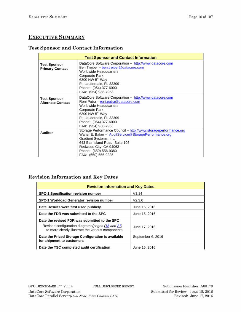
Test Sponsor and Contact Information
Test Sponsor and Contact Information Test Sponsor Primary Contact
DataCore Software Corporation – http://www.datacore.com Ben Treiber – [email protected] Worldwide Headquarters Corporate Park 6300 NW 5th Way Ft. Lauderdale, FL 33309 Phone: (954) 377-6000 FAX: (954) 938-7953
Test Sponsor Alternate Contact
DataCore Software Corporation – http://www.datacore.com Roni Putra – [email protected] Worldwide Headquarters Corporate Park 6300 NW 5th Way Ft. Lauderdale, FL 33309 Phone: (954) 377-6000 FAX: (954) 938-7953
Auditor Storage Performance Council – http://www.storageperformance.org Walter E. Baker – [email protected] Gradient Systems, Inc. 643 Bair Island Road, Suite 103 Redwood City, CA 94063 Phone: (650) 556-9380 FAX: (650) 556-9385
Revision Information and Key Dates
Revision Information and Key Dates SPC-1 Specification revision number V1.14
SPC-1 Workload Generator revision number V2.3.0
Date Results were first used publicly June 15, 2016
Date the FDR was submitted to the SPC June 15, 2016
Date the revised FDR was submitted to the SPC Revised configuration diagrams(pages (18 and 21)
to more clearly illustrate the various components
June 17, 2016
Date the Priced Storage Configuration is available for shipment to customers
September 6, 2016
Date the TSC completed audit certification June 15, 2016

EXECUTIVE SUMMARY Page 11 of 107
SPC BENCHMARK 1™ V1.14 FULL DISCLOSURE REPORT Submission Identifier: A00179 DataCore Software Corporation Submitted for Review: JUNE 15, 2016 DataCore Parallel Server(Dual Node, Fibre Channel SAN) Revised: June 17, 2016
Tested Storage Product (TSP) Description DataCore Parallel Server provides a flexible platform for enterprise environments. Because it is designed from the outset as parallel storage software, it is uniquely able to scale to its underlying hardware environment and to do so in both conventional storage topologies and in more recent converged environments. This SPC-1 Result, which used the Lenovo x3650-M5 as storage servers, demonstrates, by employing parallel processing, the software balances load and better utilizes memory, compute and storage resources to accelerate the I/O between the external workload and the storage subsystem. This parallel I/O architecture further enhances the system’s ability to process intensive and mixed workloads typical of database and other transactional oriented applications.
EXECUTIVE SUMMARY Page 12 of 107
SPC BENCHMARK 1™ V1.14 FULL DISCLOSURE REPORT Submission Identifier: A00179 DataCore Software Corporation Submitted for Review: JUNE 15, 2016 DataCore Parallel Server(Dual Node, Fibre Channel SAN) Revised: June 17, 2016
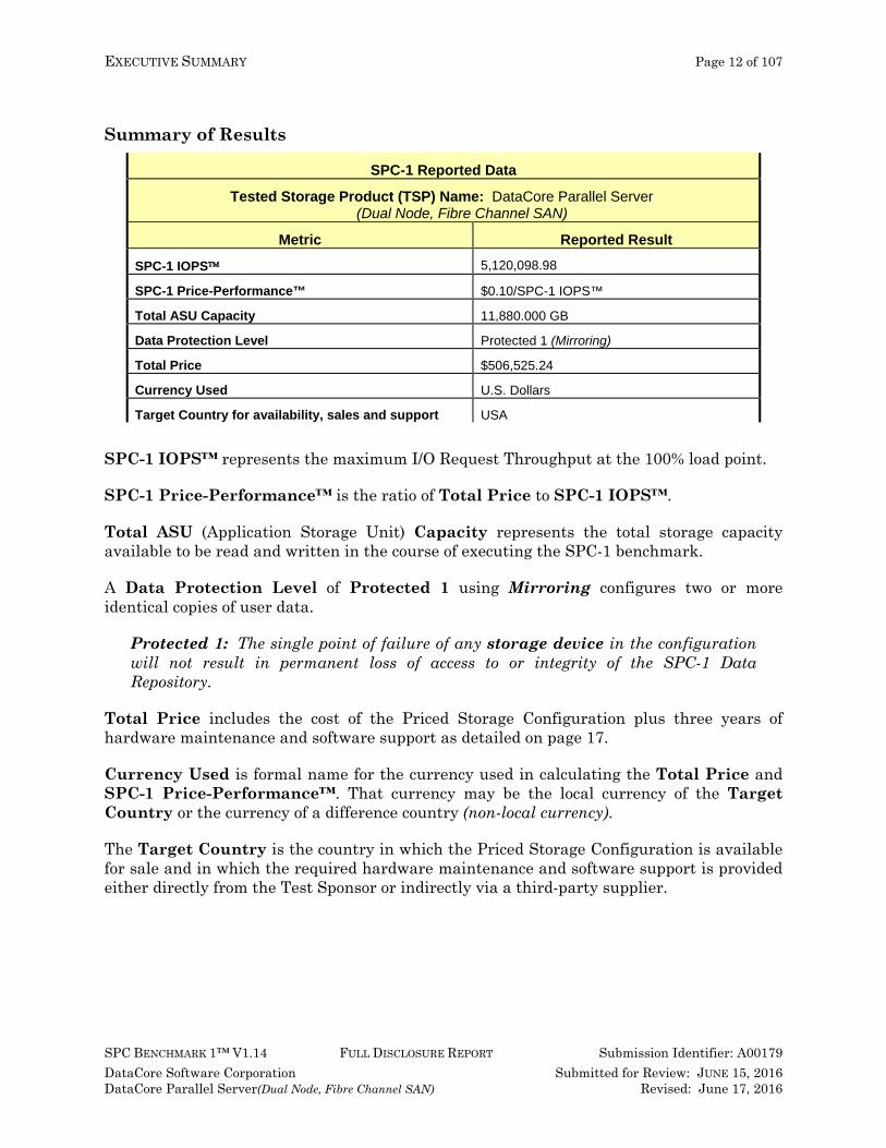
Summary of Results
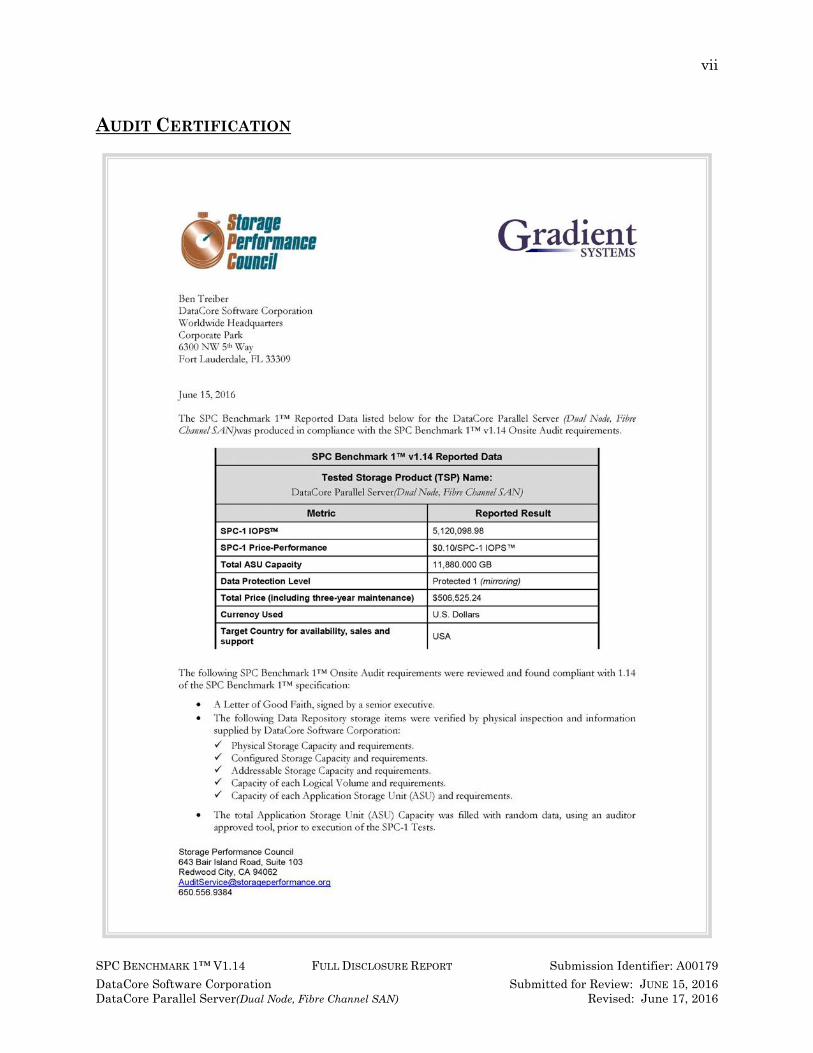
SPC-1 Reported Data
Tested Storage Product (TSP) Name: DataCore Parallel Server (Dual Node, Fibre Channel SAN)
Metric Reported Result
SPC-1 IOPS 5,120,098.98
SPC-1 Price-Performance™ $0.10/SPC-1 IOPS™
Total ASU Capacity 11,880.000 GB
Data Protection Level Protected 1 (Mirroring)
Total Price $506,525.24
Currency Used U.S. Dollars
Target Country for availability, sales and support USA
SPC-1 IOPS™ represents the maximum I/O Request Throughput at the 100% load point.
SPC-1 Price-Performance™ is the ratio of Total Price to SPC-1 IOPS™.
Total ASU (Application Storage Unit) Capacity represents the total storage capacity available to be read and written in the course of executing the SPC-1 benchmark.
A Data Protection Level of Protected 1 using Mirroring configures two or more identical copies of user data.
Protected 1: The single point of failure of any storage device in the configuration will not result in permanent loss of access to or integrity of the SPC-1 Data Repository.
Total Price includes the cost of the Priced Storage Configuration plus three years of hardware maintenance and software support as detailed on page 17.
Currency Used is formal name for the currency used in calculating the Total Price and SPC-1 Price-Performance™. That currency may be the local currency of the Target Country or the currency of a difference country (non-local currency).
The Target Country is the country in which the Priced Storage Configuration is available for sale and in which the required hardware maintenance and software support is provided either directly from the Test Sponsor or indirectly via a third-party supplier.

EXECUTIVE SUMMARY Page 13 of 107
SPC BENCHMARK 1™ V1.14 FULL DISCLOSURE REPORT Submission Identifier: A00179 DataCore Software Corporation Submitted for Review: JUNE 15, 2016 DataCore Parallel Server(Dual Node, Fibre Channel SAN) Revised: June 17, 2016
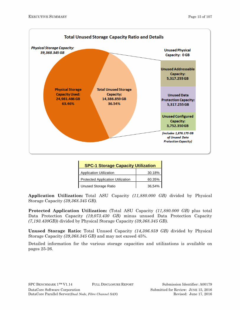
Storage Capacities, Relationships, and Utilization The following four charts and table document the various storage capacities, used in this benchmark, and their relationships, as well as the storage utilization values required to be reported.

EXECUTIVE SUMMARY Page 14 of 107
SPC BENCHMARK 1™ V1.14 FULL DISCLOSURE REPORT Submission Identifier: A00179 DataCore Software Corporation Submitted for Review: JUNE 15, 2016 DataCore Parallel Server(Dual Node, Fibre Channel SAN) Revised: June 17, 2016
EXECUTIVE SUMMARY Page 15 of 107
SPC BENCHMARK 1™ V1.14 FULL DISCLOSURE REPORT Submission Identifier: A00179 DataCore Software Corporation Submitted for Review: JUNE 15, 2016 DataCore Parallel Server(Dual Node, Fibre Channel SAN) Revised: June 17, 2016
SPC-1 Storage Capacity Utilization
Application Utilization 30.18%
Protected Application Utilization 60.35%
Unused Storage Ratio 36,54%
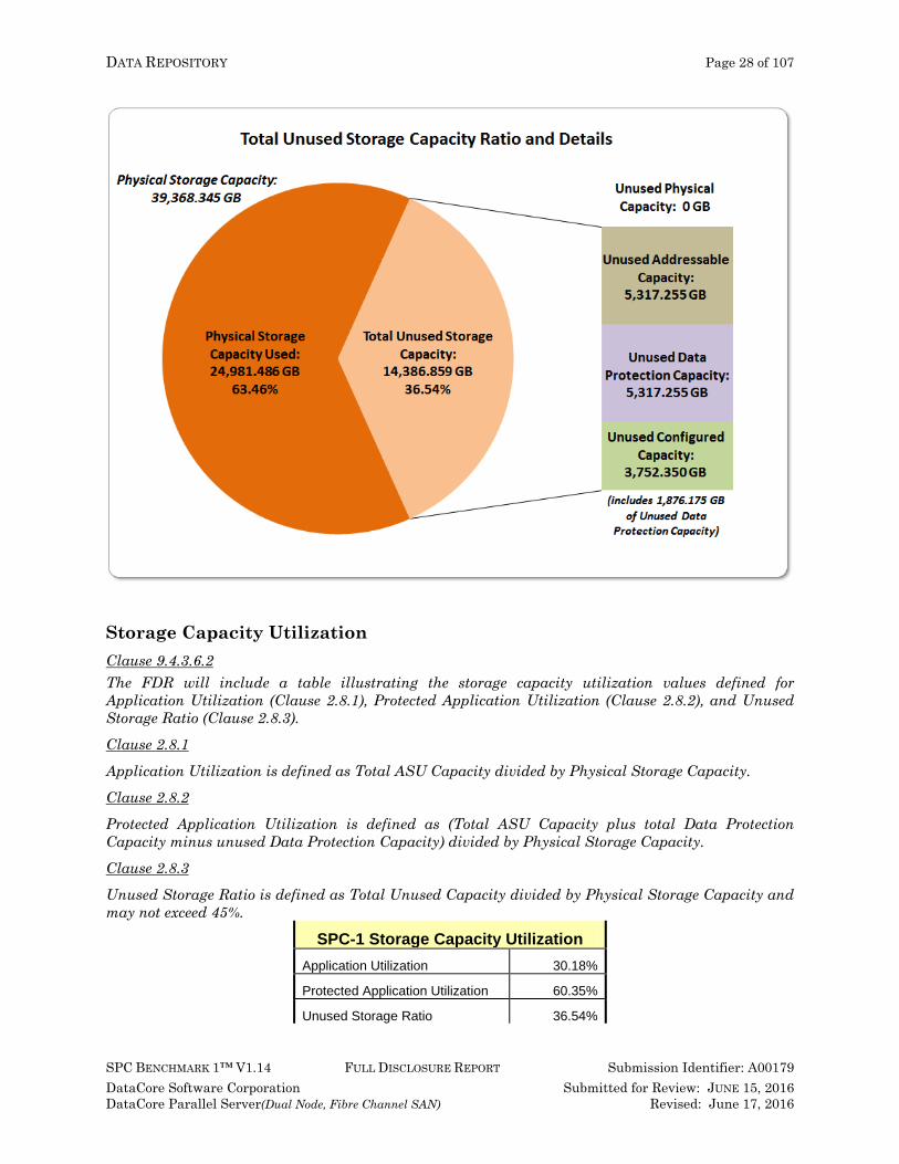
Application Utilization: Total ASU Capacity (11,880.000 GB) divided by Physical Storage Capacity (39,368.345 GB).
Protected Application Utilization: (Total ASU Capacity (11,880.000 GB) plus total Data Protection Capacity (19,073.430 GB) minus unused Data Protection Capacity (7,193.430GB)) divided by Physical Storage Capacity (39,368.345 GB).
Unused Storage Ratio: Total Unused Capacity (14,386.859 GB) divided by Physical Storage Capacity (39,368.345 GB) and may not exceed 45%. Detailed information for the various storage capacities and utilizations is available on pages 25-26.

EXECUTIVE SUMMARY Page 16 of 107
SPC BENCHMARK 1™ V1.14 FULL DISCLOSURE REPORT Submission Identifier: A00179 DataCore Software Corporation Submitted for Review: JUNE 15, 2016 DataCore Parallel Server(Dual Node, Fibre Channel SAN) Revised: June 17, 2016
Response Time – Throughput Curve The Response Time-Throughput Curve illustrates the Average Response Time (milliseconds) and I/O Request Throughput at 100%, 95%, 90%, 80%, 50%, and 10% of the workload level used to generate the SPC-1 IOPS™ metric. The Average Response Time measured at any of the above load points cannot exceed 30 milliseconds or the benchmark measurement is invalid.
Response Time – Throughput Data
10% Load 50% Load 80% Load 90% Load 95% Load 100% LoadI/O Request Throughput 512,050.42 2,560,046.41 4,095,932.88 4,608,044.73 4,863,951.58 5,120,098.98 Average Response Time (ms): All ASUs 0.12 0.27 0.28 0.27 0.27 0.28 ASU-1 0.11 0.26 0.27 0.26 0.26 0.27 ASU-2 0.15 0.32 0.33 0.32 0.32 0.33 ASU-3 0.12 0.26 0.27 0.27 0.27 0.28 Reads 0.13 0.30 0.30 0.29 0.29 0.30 Writes 0.11 0.25 0.26 0.26 0.26 0.27

EXECUTIVE SUMMARY Page 17 of 107
SPC BENCHMARK 1™ V1.14 FULL DISCLOSURE REPORT Submission Identifier: A00179 DataCore Software Corporation Submitted for Review: JUNE 15, 2016 DataCore Parallel Server(Dual Node, Fibre Channel SAN) Revised: June 17, 2016
Priced Storage Configuration Pricing The Priced Storage Configuration pricing information is not embedded in this document due it size and format. The pricing information is available via the following hyperlink: Priced Storage Configuration Pricing
The above pricing includes hardware maintenance and software support for three years, 7 days per week, 24 hours per day. The hardware maintenance and software support provides the following:
• Acknowledgement of new and existing problems within four (4) hours. • Onsite presence of a qualified maintenance engineer or provision of a customer
replaceable part within four (4) hours of the above acknowledgement for any hardware failure that results in an inoperative Price Storage Configuration that can be remedied by the repair or replacement of a Priced Storage Configuration component.
Differences between the Tested Storage Configuration (TSC) and Priced Storage Configuration There were no differences between the Tested Storage Configuration and the Priced Storage Configuration.

EXECUTIVE SUMMARY Page 18 of 107
SPC BENCHMARK 1™ V1.14 FULL DISCLOSURE REPORT Submission Identifier: A00179 DataCore Software Corporation Submitted for Review: JUNE 15, 2016 DataCore Parallel Server(Dual Node, Fibre Channel SAN) Revised: June 17, 2016
Priced Storage Configuration Diagram
EXECUTIVE SUMMARY Page 19 of 107
SPC BENCHMARK 1™ V1.14 FULL DISCLOSURE REPORT Submission Identifier: A00179 DataCore Software Corporation Submitted for Review: JUNE 15, 2016 DataCore Parallel Server(Dual Node, Fibre Channel SAN) Revised: June 17, 2016
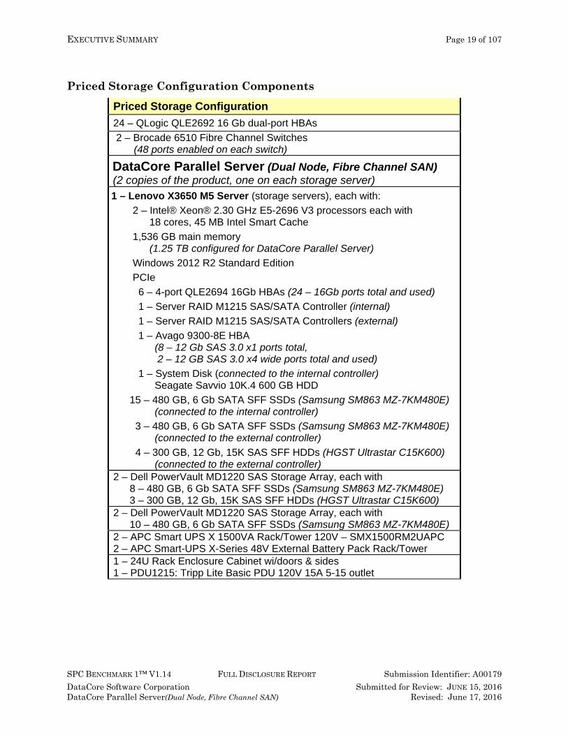
Priced Storage Configuration Components
Priced Storage Configuration 24 – QLogic QLE2692 16 Gb dual-port HBAs 2 – Brocade 6510 Fibre Channel Switches
(48 ports enabled on each switch)
DataCore Parallel Server (Dual Node, Fibre Channel SAN) (2 copies of the product, one on each storage server) 1 – Lenovo X3650 M5 Server (storage servers), each with:
2 – Intel® Xeon® 2.30 GHz E5-2696 V3 processors each with 18 cores, 45 MB Intel Smart Cache
1,536 GB main memory (1.25 TB configured for DataCore Parallel Server)
Windows 2012 R2 Standard Edition PCIe 6 – 4-port QLE2694 16Gb HBAs (24 – 16Gb ports total and used) 1 – Server RAID M1215 SAS/SATA Controller (internal) 1 – Server RAID M1215 SAS/SATA Controllers (external) 1 – Avago 9300-8E HBA
(8 – 12 Gb SAS 3.0 x1 ports total, 2 – 12 GB SAS 3.0 x4 wide ports total and used)
1 – System Disk (connected to the internal controller) Seagate Savvio 10K.4 600 GB HDD
15 – 480 GB, 6 Gb SATA SFF SSDs (Samsung SM863 MZ-7KM480E) (connected to the internal controller)
3 – 480 GB, 6 Gb SATA SFF SSDs (Samsung SM863 MZ-7KM480E) (connected to the external controller)
4 – 300 GB, 12 Gb, 15K SAS SFF HDDs (HGST Ultrastar C15K600) (connected to the external controller)
2 – Dell PowerVault MD1220 SAS Storage Array, each with 8 – 480 GB, 6 Gb SATA SFF SSDs (Samsung SM863 MZ-7KM480E) 3 – 300 GB, 12 Gb, 15K SAS SFF HDDs (HGST Ultrastar C15K600)
2 – Dell PowerVault MD1220 SAS Storage Array, each with 10 – 480 GB, 6 Gb SATA SFF SSDs (Samsung SM863 MZ-7KM480E)
2 – APC Smart UPS X 1500VA Rack/Tower 120V – SMX1500RM2UAPC 2 – APC Smart-UPS X-Series 48V External Battery Pack Rack/Tower 1 – 24U Rack Enclosure Cabinet wi/doors & sides 1 – PDU1215: Tripp Lite Basic PDU 120V 15A 5-15 outlet

CONFIGURATION INFORMATION Page 20 of 107
SPC BENCHMARK 1™ V1.14 FULL DISCLOSURE REPORT Submission Identifier: A00179 DataCore Software Corporation Submitted for Review: JUNE 15, 2016 DataCore Parallel Server(Dual Node, Fibre Channel SAN) Revised: June 17, 2016
In each of the following sections of this document, the appropriate Full Disclosure Report requirement, from the SPC-1 benchmark specification, is stated in italics followed by the information to fulfill the stated requirement. CONFIGURATION INFORMATION
Benchmark Configuration (BC)/Tested Storage Configuration (TSC) Diagram Clause 9.4.3.4.1 A one page Benchmark Configuration (BC)/Tested Storage Configuration (TSC) diagram shall be included in the FDR…
The Benchmark Configuration (BC)/Tested Storage Configuration (TSC) is illustrated on page 21 (Benchmark Configuration/Tested Storage Configuration Diagram).
Storage Network Configuration Clause 9.4.3.4.1 …
5. If the TSC contains network storage, the diagram will include the network configuration. If a single diagram is not sufficient to illustrate both the Benchmark Configuration and network configuration in sufficient detail, the Benchmark Configuration diagram will include a high-level network illustration as shown in Figure 9-8. In that case, a separate, detailed network configuration diagram will also be included as described in Clause 9.4.3.4.2.
Clause 9.4.3.4.2 If a storage network was configured as a part of the Tested Storage Configuration and the Benchmark Configuration diagram described in Clause 9.4.3.4.1 contains a high-level illustration of the network configuration, the Executive Summary will contain a one page topology diagram of the storage network as illustrated in Figure 9-9.
The storage network is illustrated on page 21 (Benchmark Configuration/Tested Storage Configuration Diagram).
Host System(s) and Tested Storage Configuration (TSC) Table of Components Clause 9.4.3.4.3 The FDR will contain a table that lists the major components of each Host System and the Tested Storage Configuration (TSC).
The Host System(s) and TSC table of components may be found on page 22 (Host System and Tested Storage Configuration Components).
CONFIGURATION INFORMATION Page 21 of 107
SPC BENCHMARK 1™ V1.14 FULL DISCLOSURE REPORT Submission Identifier: A00179 DataCore Software Corporation Submitted for Review: JUNE 15, 2016 DataCore Parallel Server(Dual Node, Fibre Channel SAN) Revised: June 17, 2016
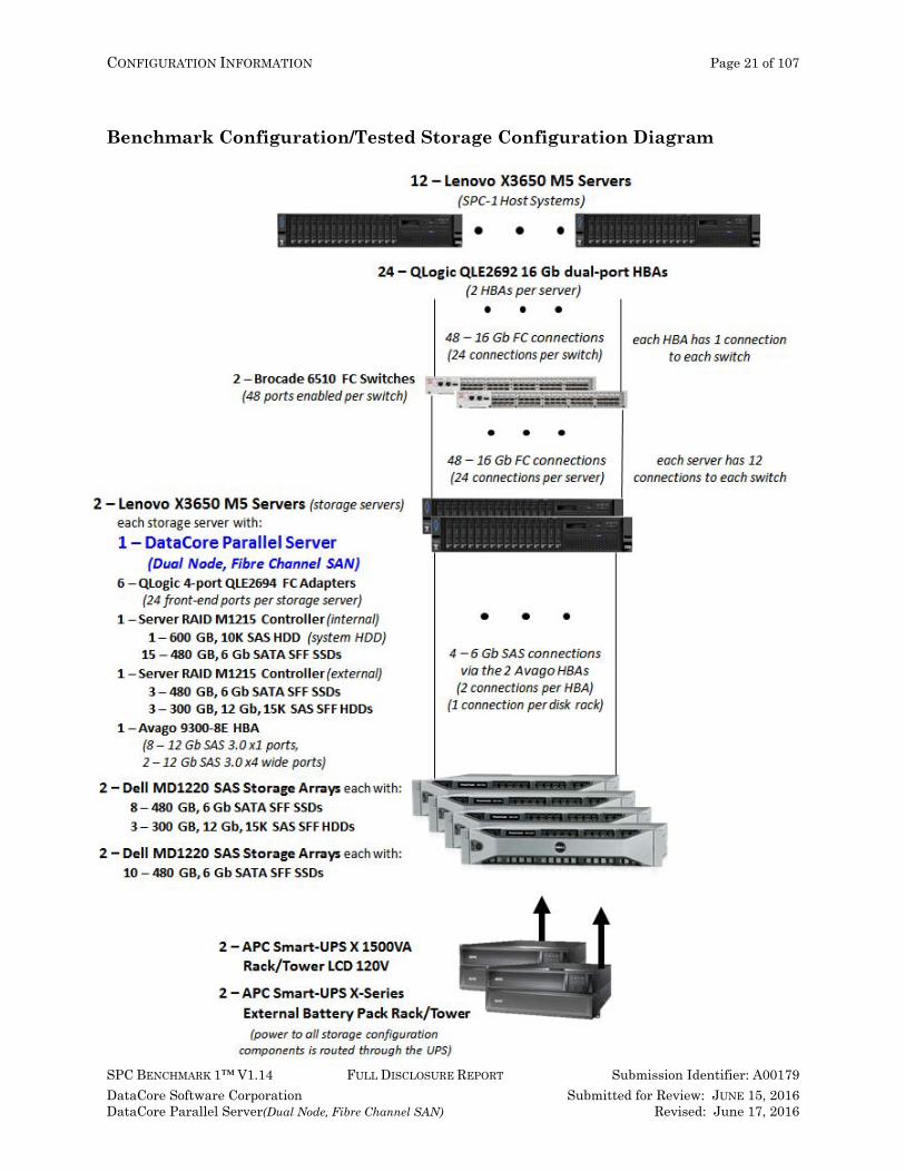
Benchmark Configuration/Tested Storage Configuration Diagram

CONFIGURATION INFORMATION Page 22 of 107
SPC BENCHMARK 1™ V1.14 FULL DISCLOSURE REPORT Submission Identifier: A00179 DataCore Software Corporation Submitted for Review: JUNE 15, 2016 DataCore Parallel Server(Dual Node, Fibre Channel SAN) Revised: June 17, 2016
Host System and Tested Storage Configuration Components
Host Systems 12 – Lenovo X3650 Servers (SPC-1 Host Systems), each with
2 – Intel® Xeon® 2.30 GHz E5-2620 V3 processors each with 6 cores, 15 MB Intel Smart Cache
96 GB main memory Windows Server 2008 R2 PCIe
Tested Storage Configuration 24 – QLogic QLE2692 16 Gb dual-port HBAs 2 – Brocade 6510 Fibre Channel Switches
(48 ports enabled on each switch)
DataCore Parallel Server (Dual Node, Fibre Channel SAN) (2 copies of the product, one on each storage server) 1 – Lenovo X3650 M5 Server (storage servers), each with:
2 – Intel® Xeon® 2.30 GHz E5-2696 V3 processors each with 18 cores, 45 MB Intel Smart Cache
1,536 GB main memory (1.25 TB configured for DataCore Parallel Server) Windows 2012 R2 Standard Edition PCIe 6 – 4-port QLE2694 16Gb HBAs (24 – 16Gb ports total and used) 1 – Server RAID M1215 SAS/SATA Controller (internal) 1 – Server RAID M1215 SAS/SATA Controllers (external) 1 – Avago 9300-8E HBA
(8 – 12 Gb SAS 3.0 x1 ports total, 2 – 12 GB SAS 3.0 x4 wide ports total and used)
1 – System Disk (connected to the internal controller) Seagate Savvio 10K.4 600 GB HDD
15 – 480 GB, 6 Gb SATA SFF SSDs (Samsung SM863 MZ-7KM480E) (connected to the internal controller)
3 – 480 GB, 6 Gb SATA SFF SSDs (Samsung SM863 MZ-7KM480E) (connected to the external controller)
4 – 300 GB, 12 Gb, 15K SAS SFF HDDs (HGST Ultrastar C15K600) (connected to the external controller)
2 – Dell PowerVault MD1220 SAS Storage Array, each with 8 – 480 GB, 6 Gb SATA SFF SSDs (Samsung SM863 MZ-7KM480E) 3 – 300 GB, 12 Gb, 15K SAS SFF HDDs (HGST Ultrastar C15K600)
2 – Dell PowerVault MD1220 SAS Storage Array, each with 10 – 480 GB, 6 Gb SATA SFF SSDs (Samsung SM863 MZ-7KM480E)
2 – APC Smart UPS X 1500VA Rack/Tower 120V – SMX1500RM2UAPC 2 – APC Smart-UPS X-Series 48V External Battery Pack Rack/Tower 1 – 24U Rack Enclosure Cabinet wi/doors & sides 1 – PDU1215: Tripp Lite Basic PDU 120V 15A 5-15 outlet
CONFIGURATION INFORMATION Page 23 of 107
SPC BENCHMARK 1™ V1.14 FULL DISCLOSURE REPORT Submission Identifier: A00179 DataCore Software Corporation Submitted for Review: JUNE 15, 2016 DataCore Parallel Server(Dual Node, Fibre Channel SAN) Revised: June 17, 2016
Customer Tunable Parameters and Options Clause 9.4.3.5.1 All Benchmark Configuration (BC) components with customer tunable parameter and options that have been altered from their default values must be listed in the FDR. The FDR entry for each of those components must include both the name of the component and the altered value of the parameter or option. If the parameter name is not self-explanatory to a knowledgeable practitioner, a brief description of the parameter’s use must also be included in the FDR entry.
Appendix B: Customer Tunable Parameters and Options on page 66 contains the customer tunable parameters and options that have been altered from their default values for this benchmark.
Tested Storage Configuration (TSC) Description Clause 9.4.3.5.2 The FDR must include sufficient information to recreate the logical representation of the TSC. In addition to customer tunable parameters and options (Clause 4.2.4.5.3), that information must include, at a minimum:
• A diagram and/or description of the following: All physical components that comprise the TSC. Those components are also illustrated in
the BC Configuration Diagram in Clause 9.2.4.4.1 and/or the Storage Network Configuration Diagram in Clause 9.2.4.4.2.
The logical representation of the TSC, configured from the above components that will be presented to the Workload Generator.
• Listings of scripts used to create the logical representation of the TSC. • If scripts were not used, a description of the process used with sufficient detail to recreate the
logical representation of the TSC.
Appendix C: Tested Storage Configuration (TSC) Creation on page 69 contains the detailed information that describes how to create and configure the logical TSC.
SPC-1 Workload Generator Storage Configuration Clause 9.4.3.5.3
The FDR must include all SPC-1 Workload Generator storage configuration commands and parameters.
The SPC-1 Workload Generator storage configuration commands and parameters for this measurement appear in Appendix D: SPC-1 Workload Generator Storage Commands and Parameters on page 85.
CONFIGURATION INFORMATION Page 24 of 107
SPC BENCHMARK 1™ V1.14 FULL DISCLOSURE REPORT Submission Identifier: A00179 DataCore Software Corporation Submitted for Review: JUNE 15, 2016 DataCore Parallel Server(Dual Node, Fibre Channel SAN) Revised: June 17, 2016
ASU Pre-Fill Clause 5.3.3
Each of the three SPC-1 ASUs (ASU-1, ASU-2 and ASU-3) is required to be completely filled with specified content prior to the execution of audited SPC-1 Tests. The content is required to consist of random data pattern such as that produced by an SPC recommended tool.
The configuration file used to complete the required ASU pre-fill appears in Appendix D: SPC-1 Workload Generator Storage Commands and Parameters on page 85.
DATA REPOSITORY Page 25 of 107
SPC BENCHMARK 1™ V1.14 FULL DISCLOSURE REPORT Submission Identifier: A00179 DataCore Software Corporation Submitted for Review: JUNE 15, 2016 DataCore Parallel Server(Dual Node, Fibre Channel SAN) Revised: June 17, 2016
SPC-1 DATA REPOSITORY This portion of the Full Disclosure Report presents the detailed information that fully documents the various SPC-1 storage capacities and mappings used in the Tested Storage Configuration. SPC-1 Data Repository Definitions on page 62 contains definitions of terms specific to the SPC-1 Data Repository.
Storage Capacities and Relationships Clause 9.4.3.6.1
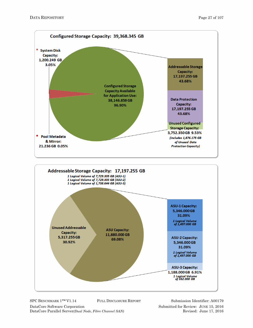
Two tables and four charts documenting the storage capacities and relationships of the SPC-1 Storage Hierarchy (Clause 2.1) shall be included in the FDR. … The capacity value in each chart may be listed as an integer value, for readability, rather than the decimal value listed in the table below.
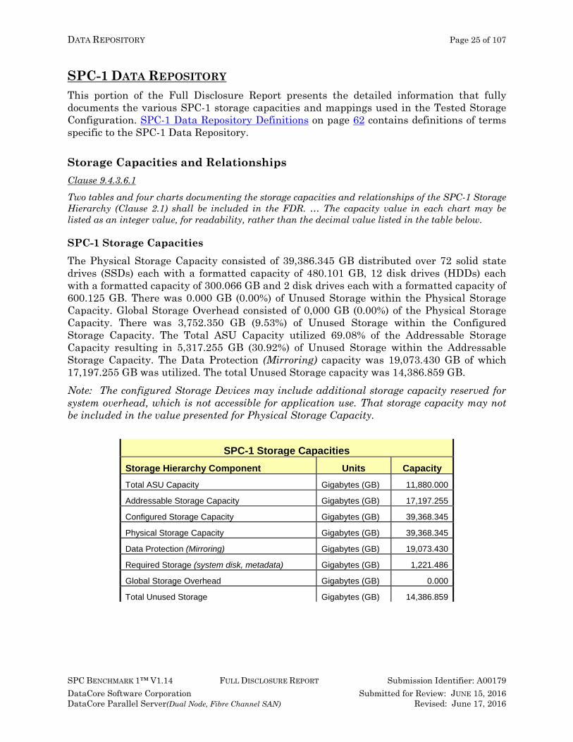
SPC-1 Storage Capacities The Physical Storage Capacity consisted of 39,386.345 GB distributed over 72 solid state drives (SSDs) each with a formatted capacity of 480.101 GB, 12 disk drives (HDDs) each with a formatted capacity of 300.066 GB and 2 disk drives each with a formatted capacity of 600.125 GB. There was 0.000 GB (0.00%) of Unused Storage within the Physical Storage Capacity. Global Storage Overhead consisted of 0,000 GB (0.00%) of the Physical Storage Capacity. There was 3,752.350 GB (9.53%) of Unused Storage within the Configured Storage Capacity. The Total ASU Capacity utilized 69.08% of the Addressable Storage Capacity resulting in 5,317.255 GB (30.92%) of Unused Storage within the Addressable Storage Capacity. The Data Protection (Mirroring) capacity was 19,073.430 GB of which 17,197.255 GB was utilized. The total Unused Storage capacity was 14,386.859 GB. Note: The configured Storage Devices may include additional storage capacity reserved for system overhead, which is not accessible for application use. That storage capacity may not be included in the value presented for Physical Storage Capacity.
SPC-1 Storage Capacities Storage Hierarchy Component Units Capacity Total ASU Capacity Gigabytes (GB) 11,880.000
Addressable Storage Capacity Gigabytes (GB) 17,197.255
Configured Storage Capacity Gigabytes (GB) 39,368.345
Physical Storage Capacity Gigabytes (GB) 39,368.345
Data Protection (Mirroring) Gigabytes (GB) 19,073.430
Required Storage (system disk, metadata) Gigabytes (GB) 1,221.486
Global Storage Overhead Gigabytes (GB) 0.000
Total Unused Storage Gigabytes (GB) 14,386.859

DATA REPOSITORY Page 26 of 107
SPC BENCHMARK 1™ V1.14 FULL DISCLOSURE REPORT Submission Identifier: A00179 DataCore Software Corporation Submitted for Review: JUNE 15, 2016 DataCore Parallel Server(Dual Node, Fibre Channel SAN) Revised: June 17, 2016
SPC-1 Storage Hierarchy Ratios
Addressable Storage Capacity
Configured Storage Capacity
Physical Storage Capacity
Total ASU Capacity 69.08% 30.18% 30.18%
Required for Data Protection (Mirroring) 48.45% 48.45%
Addressable Storage Capacity 43.68% 43.68%
Required Storage (system disk, metadata) 3.10% 3.10%
Configured Storage Capacity 100.00%
Global Storage Overhead 0.00%
Unused Storage:
Addressable 30.92%
Configured 9.53%
Physical 0.00%
SPC-1 Storage Capacity Charts
DATA REPOSITORY Page 27 of 107
SPC BENCHMARK 1™ V1.14 FULL DISCLOSURE REPORT Submission Identifier: A00179 DataCore Software Corporation Submitted for Review: JUNE 15, 2016 DataCore Parallel Server(Dual Node, Fibre Channel SAN) Revised: June 17, 2016
DATA REPOSITORY Page 28 of 107
SPC BENCHMARK 1™ V1.14 FULL DISCLOSURE REPORT Submission Identifier: A00179 DataCore Software Corporation Submitted for Review: JUNE 15, 2016 DataCore Parallel Server(Dual Node, Fibre Channel SAN) Revised: June 17, 2016
Storage Capacity Utilization Clause 9.4.3.6.2 The FDR will include a table illustrating the storage capacity utilization values defined for Application Utilization (Clause 2.8.1), Protected Application Utilization (Clause 2.8.2), and Unused Storage Ratio (Clause 2.8.3).
Clause 2.8.1
Application Utilization is defined as Total ASU Capacity divided by Physical Storage Capacity.
Clause 2.8.2
Protected Application Utilization is defined as (Total ASU Capacity plus total Data Protection Capacity minus unused Data Protection Capacity) divided by Physical Storage Capacity.
Clause 2.8.3
Unused Storage Ratio is defined as Total Unused Capacity divided by Physical Storage Capacity and may not exceed 45%.
SPC-1 Storage Capacity Utilization Application Utilization 30.18%
Protected Application Utilization 60.35%
Unused Storage Ratio 36.54%

DATA REPOSITORY Page 29 of 107
SPC BENCHMARK 1™ V1.14 FULL DISCLOSURE REPORT Submission Identifier: A00179 DataCore Software Corporation Submitted for Review: JUNE 15, 2016 DataCore Parallel Server(Dual Node, Fibre Channel SAN) Revised: June 17, 2016
Logical Volume Capacity and ASU Mapping Clause 9.4.3.6.3 A table illustrating the capacity of each ASU and the mapping of Logical Volumes to ASUs shall be provided in the FDR. … Logical Volumes shall be sequenced in the table from top to bottom per its position in the contiguous address space of each ASU. The capacity of each Logical Volume shall be stated. … In conjunction with this table, the Test Sponsor shall provide a complete description of the type of data protection (see Clause 2.4.5) used on each Logical Volume.
Logical Volume Capacity and Mapping ASU-1 (5,346.000 GB)
1 Logical Volume 7,729.305 GB per Logical Volume
(5,346.000 GB used per Logical Volume)
ASU-2 (5,346.000 GB)
1 Logical Volume 7,729.305 GB per Logical Volume
(5,346.000 GB used per Logical Volume)
ASU-3 (1,188.000 GB)
1 Logical Volume 1, 738.644 GB per Logical Volume
(1,888.000 GB used per Logical Volume)
The Data Protection Level used for all Logical Volumes was Protected 1 using Mirroring as described on page 12. See “ASU Configuration” in the IOPS Test Results File for more detailed configuration information.
SPC-1 BENCHMARK EXECUTION RESULTS Page 30 of 107
SPC BENCHMARK 1™ V1.14 FULL DISCLOSURE REPORT Submission Identifier: A00179 DataCore Software Corporation Submitted for Review: JUNE 15, 2016 DataCore Parallel Server(Dual Node, Fibre Channel SAN) Revised: June 17, 2016
SPC-1 BENCHMARK EXECUTION RESULTS
This portion of the Full Disclosure Report documents the results of the various SPC-1 Tests, Test Phases, and Test Runs. An SPC-1 glossary on page 62 contains definitions of terms specific to the SPC-1 Tests, Test Phases, and Test Runs. Clause 5.4.3
The Tests must be executed in the following sequence: Primary Metrics, Repeatability, and Data Persistence. That required sequence must be uninterrupted from the start of Primary Metrics to the completion of Persistence Test Run 1. Uninterrupted means the Benchmark Configuration shall not be power cycled, restarted, disturbed, altered, or adjusted during the above measurement sequence. If the required sequence is interrupted other than for the Host System/TSC power cycle between the two Persistence Test Runs, the measurement is invalid.
SPC-1 Tests, Test Phases, and Test Runs The SPC-1 benchmark consists of the following Tests, Test Phases, and Test Runs:
• Primary Metrics Test Sustainability Test Phase and Test Run IOPS Test Phase and Test Run Response Time Ramp Test Phase
o 95% of IOPS Test Run o 90% of IOPS Test Run o 80% of IOPS Test Run o 50% of IOPS Test Run o 10% of IOPS Test Run (LRT)
• Repeatability Test Repeatability Test Phase 1
o 10% of IOPS Test Run (LRT) o IOPS Test Run
Repeatability Test Phase 2 o 10% of IOPS Test Run (LRT) o IOPS Test Run
• Data Persistence Test Data Persistence Test Run 1 Data Persistence Test Run 2
Each Test is an atomic unit that must be executed from start to finish before any other Test, Test Phase, or Test Run may be executed. The results from each Test, Test Phase, and Test Run are listed below along with a more detailed explanation of each component.
SPC-1 BENCHMARK EXECUTION RESULTS Page 31 of 107 PRIMARY METRICS TEST – SUSTAINABILITY TEST PHASE
SPC BENCHMARK 1™ V1.14 FULL DISCLOSURE REPORT Submission Identifier: A00179 DataCore Software Corporation Submitted for Review: JUNE 15, 2016 DataCore Parallel Server(Dual Node, Fibre Channel SAN) Revised: June 17, 2016
“Ramp-Up” Test Runs Clause 5.3.13
In order to warm-up caches or perform the initial ASU data migration in a multi-tier configuration, a Test Sponsor may perform a series of “Ramp-Up” Test Runs as a substitute for an initial, gradual Ramp-Up.
Clause 5.3.13.3
The “Ramp-Up” Test Runs will immediately precede the Primary Metrics Test as part of the uninterrupted SPC-1 measurement sequence.
Clause 9.4.3.7.1
If a series of “Ramp-Up” Test Runs were included in the SPC-1 measurement sequence, the FDR shall report the duration (ramp-up and measurement interval), BSU level, SPC-1 IOPS and average response time for each “Ramp-Up” Test Run in an appropriate table.
There were no “Ramp-Up” Test Runs executed.
Primary Metrics Test – Sustainability Test Phase Clause 5.4.4.1.1
The Sustainability Test Phase has exactly one Test Run and shall demonstrate the maximum sustainable I/O Request Throughput within at least a continuous eight (8) hour Measurement Interval. This Test Phase also serves to insure that the TSC has reached Steady State prior to reporting the final maximum I/O Request Throughput result (SPC-1 IOPS™).
Clause 5.4.4.1.2
The computed I/O Request Throughput of the Sustainability Test must be within 5% of the reported SPC-1 IOPS™ result.
Clause 5.4.4.1.4
The Average Response Time, as defined in Clause 5.1.1, will be computed and reported for the Sustainability Test Run and cannot exceed 30 milliseconds. If the Average Response time exceeds that 30-milliseconds constraint, the measurement is invalid.
Clause 9.4.3.7.2 For the Sustainability Test Phase the FDR shall contain:
1. A Data Rate Distribution graph and data table. 2. I/O Request Throughput Distribution graph and data table. 3. A Response Time Frequency Distribution graph and table. 4. An Average Response Time Distribution graph and table. 5. The human readable Test Run Results File produced by the Workload Generator (may be
included in an appendix). 6. A listing or screen image of all input parameters supplied to the Workload Generator (may be
included in an appendix). 7. The Measured Intensity Multiplier for each I/O stream. 8. The variability of the Measured Intensity Multiplier, as defined in Clause 5.3.13.3.
SPC-1 BENCHMARK EXECUTION RESULTS Page 32 of 107 PRIMARY METRICS TEST – SUSTAINABILITY TEST PHASE
SPC BENCHMARK 1™ V1.14 FULL DISCLOSURE REPORT Submission Identifier: A00179 DataCore Software Corporation Submitted for Review: JUNE 15, 2016 DataCore Parallel Server(Dual Node, Fibre Channel SAN) Revised: June 17, 2016
SPC-1 Workload Generator Input Parameters The SPC-1 Workload Generator input parameters for the Sustainability, IOPS, Response Time Ramp, Repeatability, and Persistence Test Runs are documented in Appendix E: SPC-1 Workload Generator Input Parameters on Page 88.
Sustainability Test Results File A link to the test results file generated from the Sustainability Test Run is listed below. Sustainability Test Results File
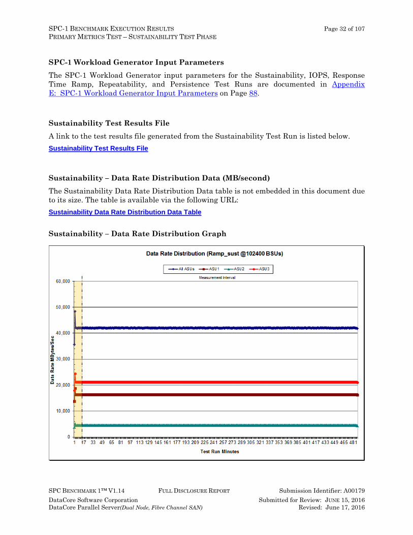
Sustainability – Data Rate Distribution Data (MB/second) The Sustainability Data Rate Distribution Data table is not embedded in this document due to its size. The table is available via the following URL: Sustainability Data Rate Distribution Data Table
Sustainability – Data Rate Distribution Graph
SPC-1 BENCHMARK EXECUTION RESULTS Page 33 of 107 PRIMARY METRICS TEST – SUSTAINABILITY TEST PHASE
SPC BENCHMARK 1™ V1.14 FULL DISCLOSURE REPORT Submission Identifier: A00179 DataCore Software Corporation Submitted for Review: JUNE 15, 2016 DataCore Parallel Server(Dual Node, Fibre Channel SAN) Revised: June 17, 2016
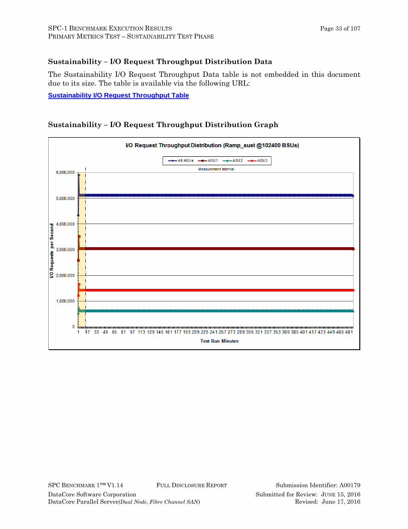
Sustainability – I/O Request Throughput Distribution Data The Sustainability I/O Request Throughput Data table is not embedded in this document due to its size. The table is available via the following URL: Sustainability I/O Request Throughput Table
Sustainability – I/O Request Throughput Distribution Graph
SPC-1 BENCHMARK EXECUTION RESULTS Page 34 of 107 PRIMARY METRICS TEST – SUSTAINABILITY TEST PHASE
SPC BENCHMARK 1™ V1.14 FULL DISCLOSURE REPORT Submission Identifier: A00179 DataCore Software Corporation Submitted for Review: JUNE 15, 2016 DataCore Parallel Server(Dual Node, Fibre Channel SAN) Revised: June 17, 2016
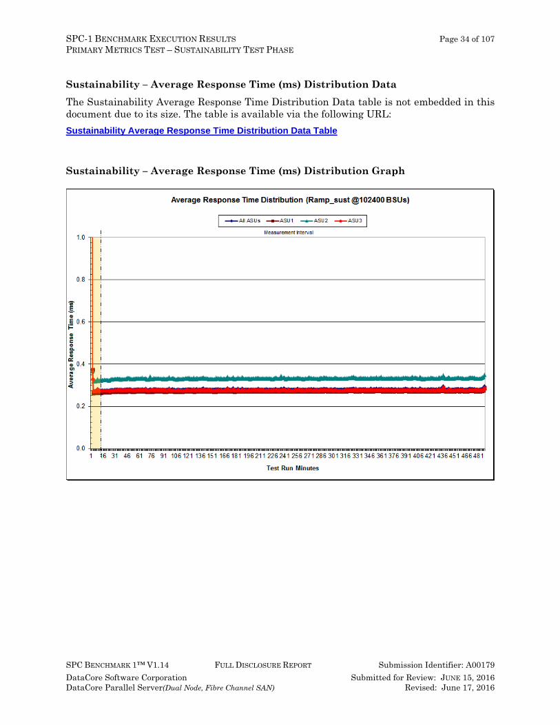
Sustainability – Average Response Time (ms) Distribution Data The Sustainability Average Response Time Distribution Data table is not embedded in this document due to its size. The table is available via the following URL: Sustainability Average Response Time Distribution Data Table
Sustainability – Average Response Time (ms) Distribution Graph

SPC-1 BENCHMARK EXECUTION RESULTS Page 35 of 107 PRIMARY METRICS TEST – SUSTAINABILITY TEST PHASE
SPC BENCHMARK 1™ V1.14 FULL DISCLOSURE REPORT Submission Identifier: A00179 DataCore Software Corporation Submitted for Review: JUNE 15, 2016 DataCore Parallel Server(Dual Node, Fibre Channel SAN) Revised: June 17, 2016
Sustainability – Response Time Frequency Distribution Data The Sustainability Response Time Frequency Distribution Data table is not embedded in this document due to its size. The table is available via the following URL: Sustainability Response Time Frequency Distribution Data Table
Sustainability – Response Time Frequency Distribution Graph
SPC-1 BENCHMARK EXECUTION RESULTS Page 36 of 107 PRIMARY METRICS TEST – SUSTAINABILITY TEST PHASE
SPC BENCHMARK 1™ V1.14 FULL DISCLOSURE REPORT Submission Identifier: A00179 DataCore Software Corporation Submitted for Review: JUNE 15, 2016 DataCore Parallel Server(Dual Node, Fibre Channel SAN) Revised: June 17, 2016
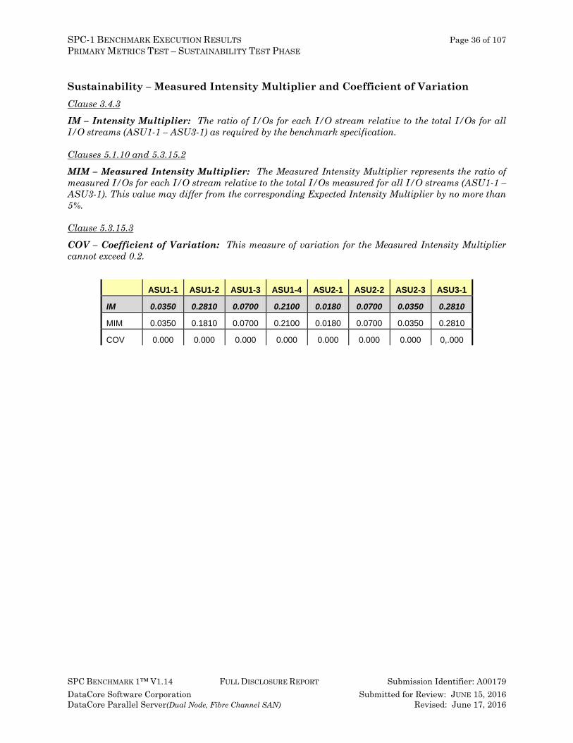
Sustainability – Measured Intensity Multiplier and Coefficient of Variation Clause 3.4.3
IM – Intensity Multiplier: The ratio of I/Os for each I/O stream relative to the total I/Os for all I/O streams (ASU1-1 – ASU3-1) as required by the benchmark specification.
Clauses 5.1.10 and 5.3.15.2
MIM – Measured Intensity Multiplier: The Measured Intensity Multiplier represents the ratio of measured I/Os for each I/O stream relative to the total I/Os measured for all I/O streams (ASU1-1 – ASU3-1). This value may differ from the corresponding Expected Intensity Multiplier by no more than 5%.
Clause 5.3.15.3
COV – Coefficient of Variation: This measure of variation for the Measured Intensity Multiplier cannot exceed 0.2.
ASU1-1 ASU1-2 ASU1-3 ASU1-4 ASU2-1 ASU2-2 ASU2-3 ASU3-1
IM 0.0350 0.2810 0.0700 0.2100 0.0180 0.0700 0.0350 0.2810
MIM 0.0350 0.1810 0.0700 0.2100 0.0180 0.0700 0.0350 0.2810
COV 0.000 0.000 0.000 0.000 0.000 0.000 0.000 0,.000

SPC-1 BENCHMARK EXECUTION RESULTS Page 37 of 107 PRIMARY METRICS TEST – IOPS TEST PHASE
SPC BENCHMARK 1™ V1.14 FULL DISCLOSURE REPORT Submission Identifier: A00179 DataCore Software Corporation Submitted for Review: JUNE 15, 2016 DataCore Parallel Server(Dual Node, Fibre Channel SAN) Revised: June 17, 2016
Primary Metrics Test – IOPS Test Phase Clause 5.4.4.2 The IOPS Test Phase consists of one Test Run at the 100% load point with a Measurement Interval of ten (10) minutes. The IOPS Test Phase immediately follows the Sustainability Test Phase without any interruption or manual intervention.
The IOPS Test Run generates the SPC-1 IOPS™ primary metric, which is computed as the I/O Request Throughput for the Measurement Interval of the IOPS Test Run.
The Average Response Time is computed for the IOPS Test Run and cannot exceed 30 milliseconds. If the Average Response Time exceeds the 30 millisecond constraint, the measurement is invalid.
Clause 9.4.3.7.3 For the IOPS Test Phase the FDR shall contain:
1. I/O Request Throughput Distribution (data and graph). 2. A Response Time Frequency Distribution. 3. An Average Response Time Distribution. 4. The human readable Test Run Results File produced by the Workload Generator. 5. A listing or screen image of all input parameters supplied to the Workload Generator. 6. The total number of I/O Requests completed in the Measurement Interval as well as the
number of I/O Requests with a Response Time less than or equal to 30 milliseconds and the number of I/O Requests with a Response Time greater than 30 milliseconds.
SPC-1 Workload Generator Input Parameters The SPC-1 Workload Generator input parameters for the Sustainability, IOPS, Response Time Ramp, Repeatability, and Persistence Test Runs are documented in Appendix E: SPC-1 Workload Generator Input Parameters on Page 88.
IOPS Test Results File A link to the test results file generated from the IOPS Test Run is listed below. IOPS Test Results File
SPC-1 BENCHMARK EXECUTION RESULTS Page 38 of 107 PRIMARY METRICS TEST – IOPS TEST PHASE
SPC BENCHMARK 1™ V1.14 FULL DISCLOSURE REPORT Submission Identifier: A00179 DataCore Software Corporation Submitted for Review: JUNE 15, 2016 DataCore Parallel Server(Dual Node, Fibre Channel SAN) Revised: June 17, 2016
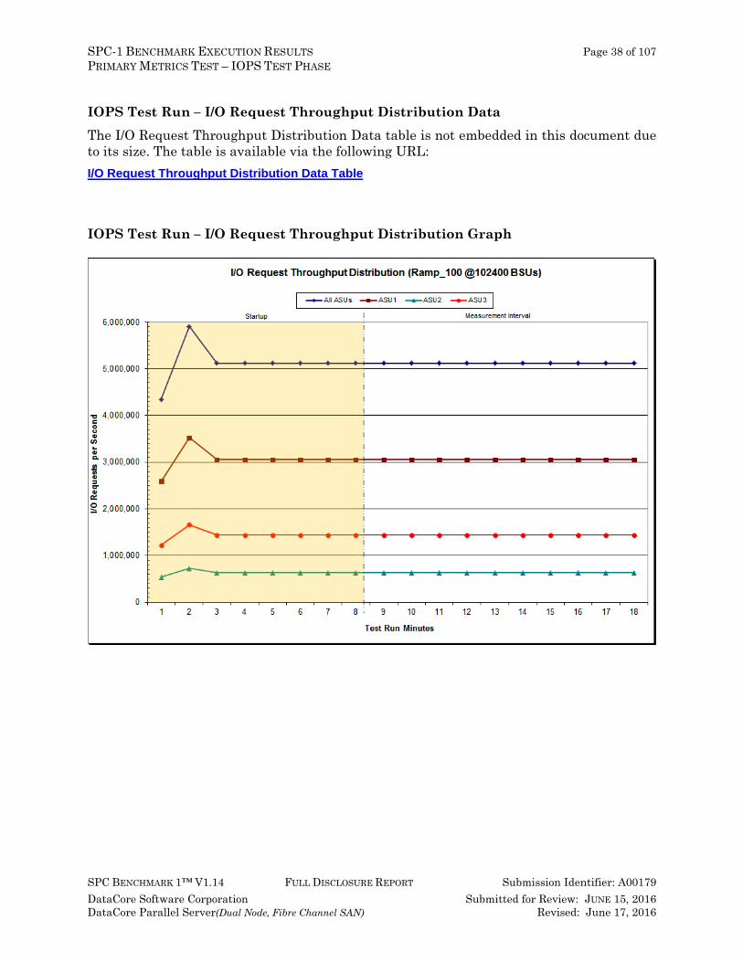
IOPS Test Run – I/O Request Throughput Distribution Data The I/O Request Throughput Distribution Data table is not embedded in this document due to its size. The table is available via the following URL: I/O Request Throughput Distribution Data Table
IOPS Test Run – I/O Request Throughput Distribution Graph
SPC-1 BENCHMARK EXECUTION RESULTS Page 39 of 107 PRIMARY METRICS TEST – IOPS TEST PHASE
SPC BENCHMARK 1™ V1.14 FULL DISCLOSURE REPORT Submission Identifier: A00179 DataCore Software Corporation Submitted for Review: JUNE 15, 2016 DataCore Parallel Server(Dual Node, Fibre Channel SAN) Revised: June 17, 2016
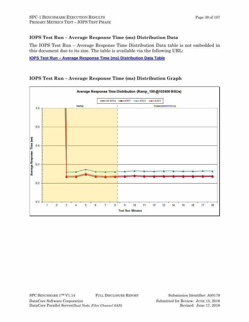
IOPS Test Run – Average Response Time (ms) Distribution Data The IOPS Test Run – Average Response Time Distribution Data table is not embedded in this document due to its size. The table is available via the following URL: IOPS Test Run – Average Response Time (ms) Distribution Data Table
IOPS Test Run – Average Response Time (ms) Distribution Graph
SPC-1 BENCHMARK EXECUTION RESULTS Page 40 of 107 PRIMARY METRICS TEST – IOPS TEST PHASE
SPC BENCHMARK 1™ V1.14 FULL DISCLOSURE REPORT Submission Identifier: A00179 DataCore Software Corporation Submitted for Review: JUNE 15, 2016 DataCore Parallel Server(Dual Node, Fibre Channel SAN) Revised: June 17, 2016
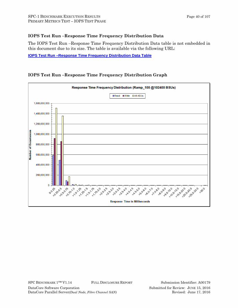
IOPS Test Run –Response Time Frequency Distribution Data The IOPS Test Run –Response Time Frequency Distribution Data table is not embedded in this document due to its size. The table is available via the following URL: IOPS Test Run –Response Time Frequency Distribution Data Table
IOPS Test Run –Response Time Frequency Distribution Graph
SPC-1 BENCHMARK EXECUTION RESULTS Page 41 of 107 PRIMARY METRICS TEST – IOPS TEST PHASE
SPC BENCHMARK 1™ V1.14 FULL DISCLOSURE REPORT Submission Identifier: A00179 DataCore Software Corporation Submitted for Review: JUNE 15, 2016 DataCore Parallel Server(Dual Node, Fibre Channel SAN) Revised: June 17, 2016
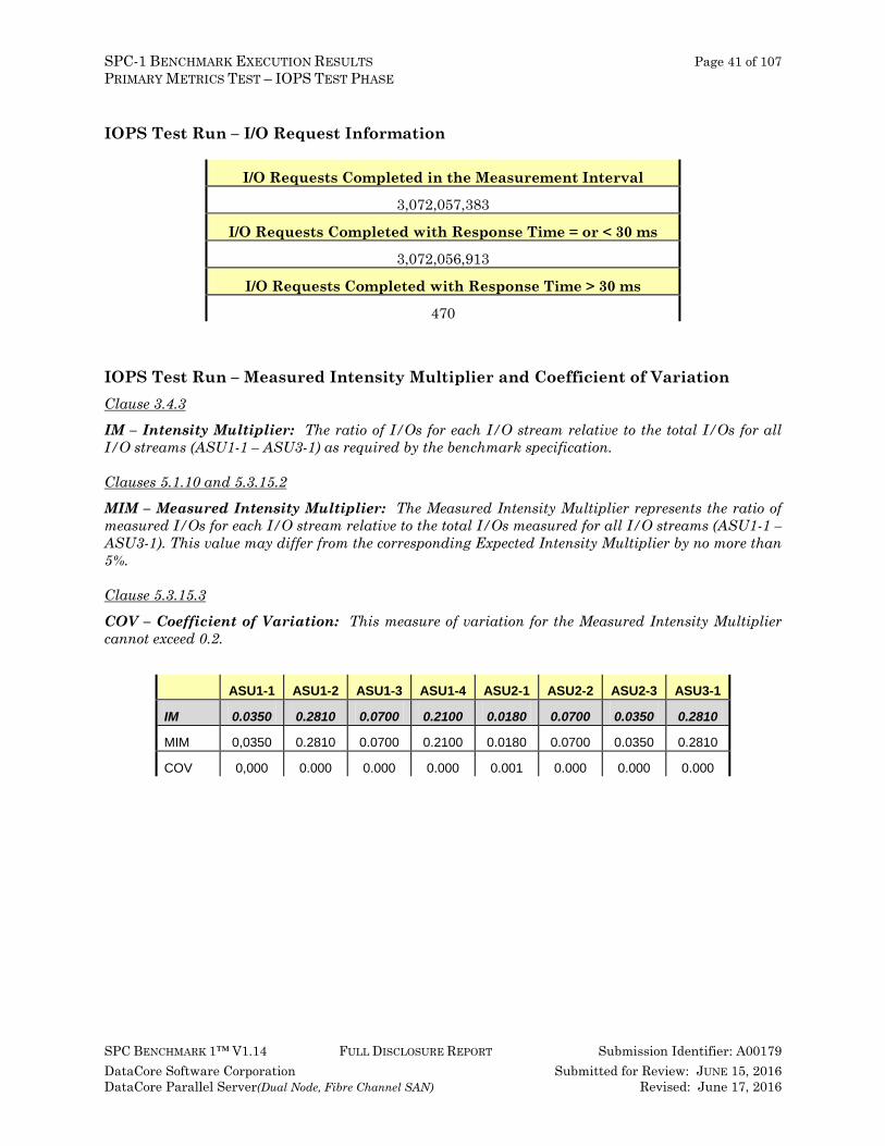
IOPS Test Run – I/O Request Information
I/O Requests Completed in the Measurement Interval
3,072,057,383
I/O Requests Completed with Response Time = or < 30 ms
3,072,056,913
I/O Requests Completed with Response Time > 30 ms
470
IOPS Test Run – Measured Intensity Multiplier and Coefficient of Variation Clause 3.4.3
IM – Intensity Multiplier: The ratio of I/Os for each I/O stream relative to the total I/Os for all I/O streams (ASU1-1 – ASU3-1) as required by the benchmark specification.
Clauses 5.1.10 and 5.3.15.2
MIM – Measured Intensity Multiplier: The Measured Intensity Multiplier represents the ratio of measured I/Os for each I/O stream relative to the total I/Os measured for all I/O streams (ASU1-1 – ASU3-1). This value may differ from the corresponding Expected Intensity Multiplier by no more than 5%.
Clause 5.3.15.3
COV – Coefficient of Variation: This measure of variation for the Measured Intensity Multiplier cannot exceed 0.2.
ASU1-1 ASU1-2 ASU1-3 ASU1-4 ASU2-1 ASU2-2 ASU2-3 ASU3-1
IM 0.0350 0.2810 0.0700 0.2100 0.0180 0.0700 0.0350 0.2810
MIM 0,0350 0.2810 0.0700 0.2100 0.0180 0.0700 0.0350 0.2810
COV 0,000 0.000 0.000 0.000 0.001 0.000 0.000 0.000

SPC-1 BENCHMARK EXECUTION RESULTS Page 42 of 107 PRIMARY METRICS TEST – RESPONSE TIME RAMP TEST PHASE
SPC BENCHMARK 1™ V1.14 FULL DISCLOSURE REPORT Submission Identifier: A00179 DataCore Software Corporation Submitted for Review: JUNE 15, 2016 DataCore Parallel Server(Dual Node, Fibre Channel SAN) Revised: June 17, 2016
Primary Metrics Test – Response Time Ramp Test Phase Clause 5.4.4.3 The Response Time Ramp Test Phase consists of five Test Runs, one each at 95%, 90%, 80%, 50%, and 10% of the load point (100%) used to generate the SPC-1 IOPS™ primary metric. Each of the five Test Runs has a Measurement Interval of ten (10) minutes. The Response Time Ramp Test Phase immediately follows the IOPS Test Phase without any interruption or manual intervention.
The five Response Time Ramp Test Runs, in conjunction with the IOPS Test Run (100%), demonstrate the relationship between Average Response Time and I/O Request Throughput for the Tested Storage Configuration (TSC) as illustrated in the response time/throughput curve on page 16.
In addition, the Average Response Time measured during the 10% Test Run is the value for the SPC-1 LRT™ metric. That value represents the Average Response Time of a lightly loaded TSC.
Clause 9.4.3.7.4 The following content shall appear in the FDR for the Response Time Ramp Phase:
1. A Response Time Ramp Distribution. 2. The human readable Test Run Results File produced by the Workload Generator for each Test
Run within the Response Time Ramp Test Phase. 3. For the 10% Load Level Test Run (SPC-1 LRT™ metric) an Average Response Time
Distribution. 4. A listing or screen image of all input parameters supplied to the Workload Generator.
SPC-1 Workload Generator Input Parameters The SPC-1 Workload Generator input parameters for the Sustainability, IOPS, Response Time Ramp, Repeatability, and Persistence Test Runs are documented in Appendix E: SPC-1 Workload Generator Input Parameters on Page 88.
Response Time Ramp Test Results File A link to each test result file generated from each Response Time Ramp Test Run list listed below. 95% Load Level
90% Load Level
80% Load Level 50% Load Level
10% Load Level
SPC-1 BENCHMARK EXECUTION RESULTS Page 43 of 107 PRIMARY METRICS TEST – RESPONSE TIME RAMP TEST PHASE TEST PHASE
SPC BENCHMARK 1™ V1.14 FULL DISCLOSURE REPORT Submission Identifier: A00179 DataCore Software Corporation Submitted for Review: JUNE 15, 2016 DataCore Parallel Server(Dual Node, Fibre Channel SAN) Revised: June 17, 2016
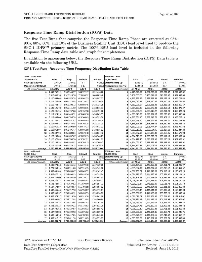
Response Time Ramp Distribution (IOPS) Data The five Test Runs that comprise the Response Time Ramp Phase are executed at 95%, 90%, 80%, 50%, and 10% of the Business Scaling Unit (BSU) load level used to produce the SPC-1 IOPS™ primary metric. The 100% BSU load level is included in the following Response Time Ramp data table and graph for completeness. In addition to appearing below, the Response Time Ramp Distribution (IOPS) Data table is available via the following URL. IOPS Test Run –Response Time Frequency Distribution Data Table 100% Load Level: 95% Load Level:102,400 BSUs Start Stop Interval Duration 97,280 BSUs Start Stop Interval DurationStart-Up/Ramp-Up 16:58:16 17:06:17 0-7 0:08:01 Start-Up/Ramp-Up 17:36:51 17:44:52 0-7 0:08:01Measurement Interval 17:06:17 17:16:18 8-17 0:10:01 Measurement Interval 17:44:52 17:54:53 8-17 0:10:01
(60 second intervals) All ASUs ASU-1 ASU-2 ASU-3 (60 second intervals) All ASUs ASU-1 ASU-2 ASU-30 4,349,732.22 2,592,343.77 534,972.17 1,222,416.28 0 4,475,041.52 2,667,225.83 550,222.87 1,257,592.82 1 5,910,046.98 3,522,318.58 726,838.92 1,660,889.48 1 5,258,063.65 3,133,671.68 646,739.97 1,477,652.00 2 5,120,664.05 3,051,974.78 629,802.25 1,438,887.02 2 4,863,833.25 2,898,858.58 598,253.18 1,366,721.48 3 5,119,745.40 3,051,275.95 629,739.37 1,438,730.08 3 4,864,087.73 2,898,920.95 598,410.15 1,366,756.63 4 5,119,733.45 3,051,308.72 629,693.45 1,438,731.28 4 4,863,998.57 2,898,831.22 598,316.68 1,366,850.67 5 5,120,195.78 3,051,441.50 629,938.15 1,438,816.13 5 4,864,203.28 2,899,070.33 598,253.58 1,366,879.37 6 5,120,291.95 3,051,737.88 629,762.98 1,438,791.08 6 4,864,031.70 2,898,915.27 598,294.20 1,366,822.23 7 5,119,924.25 3,051,449.52 629,609.18 1,438,865.55 7 4,863,873.73 2,898,994.67 598,223.02 1,366,656.05 8 5,119,885.00 3,051,746.78 629,544.63 1,438,593.58 8 4,863,651.10 2,898,543.72 598,402.20 1,366,705.18 9 5,120,336.77 3,051,851.82 629,698.85 1,438,786.10 9 4,863,628.50 2,898,667.42 598,192.10 1,366,768.98
10 5,119,906.83 3,051,470.45 629,702.15 1,438,734.23 10 4,863,695.28 2,898,688.05 598,350.92 1,366,656.32 11 5,119,910.28 3,051,590.90 629,647.17 1,438,672.22 11 4,863,921.08 2,898,744.47 598,267.30 1,366,909.32 12 5,119,914.07 3,051,496.47 629,601.58 1,438,816.02 12 4,863,919.25 2,898,694.95 598,387.10 1,366,837.20 13 5,120,307.93 3,051,800.03 629,673.48 1,438,834.42 13 4,863,767.92 2,898,930.48 598,166.45 1,366,670.98 14 5,120,280.03 3,051,657.67 629,876.13 1,438,746.23 14 4,864,315.68 2,899,229.23 598,117.10 1,366,969.35 15 5,120,370.83 3,051,786.70 629,702.22 1,438,881.92 15 4,864,172.48 2,898,937.32 598,225.25 1,367,009.92 16 5,120,256.53 3,051,844.92 629,705.15 1,438,706.47 16 4,864,051.70 2,898,872.97 598,488.82 1,366,689.92 17 5,119,821.50 3,051,379.13 629,823.18 1,438,619.18 17 4,864,392.77 2,899,003.07 598,307.75 1,367,081.95
Average 5,120,098.98 3,051,662.49 629,697.46 1,438,739.04 Average 4,863,951.58 2,898,831.17 598,290.50 1,366,829.91 90% Load Level: 80% Load Level:92,160 BSUs Start Stop Interval Duration 81,920 BSUs Start Stop Interval DurationStart-Up/Ramp-Up 18:14:24 23:13:21 0-7 4:58:57 Start-Up/Ramp-Up 18:50:06 18:58:07 0-7 0:08:01Measurement Interval 23:13:21 23:13:21 8-17 0:00:00 Measurement Interval 18:58:07 19:08:08 8-17 0:10:01
(60 second intervals) All ASUs ASU-1 ASU-2 ASU-3 (60 second intervals) All ASUs ASU-1 ASU-2 ASU-30 4,439,974.38 2,646,166.12 546,079.18 1,247,729.08 0 4,099,464.03 2,443,356.33 504,201.73 1,151,905.97 1 4,779,969.15 2,848,911.00 587,915.35 1,343,142.80 1 4,095,897.32 2,441,237.68 503,798.12 1,150,861.52 2 4,608,061.83 2,746,053.67 566,845.72 1,295,162.45 2 4,096,256.07 2,441,319.63 504,013.15 1,150,923.28 3 4,607,477.13 2,745,868.93 566,814.30 1,294,793.90 3 4,096,477.55 2,441,395.38 503,881.07 1,151,201.10 4 4,607,749.00 2,746,364.30 566,736.27 1,294,648.43 4 4,095,848.13 2,441,128.05 503,886.68 1,150,833.40 5 4,608,253.37 2,746,610.67 566,693.43 1,294,949.27 5 4,096,914.38 2,441,766.90 503,977.28 1,151,170.20 6 4,608,424.85 2,746,639.52 566,830.60 1,294,954.73 6 4,096,075.17 2,441,283.80 503,681.78 1,151,109.58 7 4,607,673.97 2,745,972.07 566,794.88 1,294,907.02 7 4,095,882.62 2,441,204.93 503,821.38 1,150,856.30 8 4,608,445.43 2,746,717.90 566,953.87 1,294,773.67 8 4,095,930.43 2,441,141.93 503,897.60 1,150,890.90 9 4,607,946.37 2,746,249.92 566,659.73 1,295,036.72 9 4,095,831.98 2,441,108.80 503,785.20 1,150,937.98
10 4,607,974.27 2,746,215.90 566,915.38 1,294,842.98 10 4,096,078.67 2,441,354.35 503,711.30 1,151,013.02 11 4,607,992.67 2,746,717.98 566,713.88 1,294,560.80 11 4,096,131.13 2,441,137.12 504,017.95 1,150,976.07 12 4,607,737.38 2,746,313.05 566,661.43 1,294,762.90 12 4,095,989.55 2,441,179.07 503,867.27 1,150,943.22 13 4,608,230.23 2,746,659.32 566,738.63 1,294,832.28 13 4,095,994.78 2,441,250.55 503,909.82 1,150,834.42 14 4,607,701.62 2,746,127.07 566,919.13 1,294,655.42 14 4,096,027.40 2,441,169.22 503,791.88 1,151,066.30 15 4,607,939.08 2,746,392.98 566,876.62 1,294,669.48 15 4,095,986.93 2,441,184.45 503,865.73 1,150,936.75 16 4,608,163.10 2,746,417.85 566,702.03 1,295,043.22 16 4,095,971.78 2,441,362.15 503,742.42 1,150,867.22 17 4,608,317.17 2,746,621.58 566,715.65 1,294,979.93 17 4,095,386.08 2,440,757.53 503,769.75 1,150,858.80
Average 4,608,044.73 2,746,443.36 566,785.64 1,294,815.74 Average 4,095,932.88 2,441,164.52 503,835.89 1,150,932.47
SPC-1 BENCHMARK EXECUTION RESULTS Page 44 of 107 PRIMARY METRICS TEST – RESPONSE TIME RAMP TEST PHASE TEST PHASE
SPC BENCHMARK 1™ V1.14 FULL DISCLOSURE REPORT Submission Identifier: A00179 DataCore Software Corporation Submitted for Review: JUNE 15, 2016 DataCore Parallel Server(Dual Node, Fibre Channel SAN) Revised: June 17, 2016
Response Time Ramp Distribution (IOPS) Data (continued)
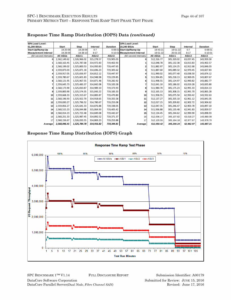
Response Time Ramp Distribution (IOPS) Graph
50% Load Level: 10% Load Level:51,200 BSUs Start Stop Interval Duration 10,240 BSUs Start Stop Interval DurationStart-Up/Ramp-Up 19:20:08 19:28:09 0-7 0:08:01 Start-Up/Ramp-Up 19:43:21 19:51:22 0-7 0:08:01Measurement Interval 19:28:09 19:38:10 8-17 0:10:01 Measurement Interval 19:51:22 20:01:23 8-17 0:10:01
(60 second intervals) All ASUs ASU-1 ASU-2 ASU-3 (60 second intervals) All ASUs ASU-1 ASU-2 ASU-30 2,562,149.62 1,526,966.02 315,278.57 719,905.03 0 512,316.77 305,320.02 63,037.45 143,959.30 1 2,560,163.45 1,525,787.68 314,972.83 719,402.93 1 512,048.78 305,132.38 63,013.83 143,902.57 2 2,560,199.02 1,525,800.53 314,950.83 719,447.65 2 511,882.97 305,124.25 62,912.68 143,846.03 3 2,559,873.03 1,525,871.18 314,696.23 719,305.62 3 511,887.60 305,089.32 62,970.45 143,827.83 4 2,559,917.05 1,525,656.97 314,812.12 719,447.97 4 511,990.02 305,077.40 63,038.50 143,874.12 5 2,559,780.67 1,525,601.83 314,948.98 719,229.85 5 511,994.85 305,218.13 62,969.05 143,807.67 6 2,560,121.95 1,525,967.55 314,871.48 719,282.92 6 511,998.55 305,124.97 62,990.82 143,882.77 7 2,559,645.73 1,525,483.37 314,842.08 719,320.28 7 512,041.10 305,186.02 63,019.28 143,835.80 8 2,560,173.90 1,525,810.87 314,989.10 719,373.93 8 511,980.70 305,175.23 62,991.33 143,814.13 9 2,559,800.90 1,525,574.35 315,043.22 719,183.33 9 512,165.13 305,308.15 62,991.70 143,865.28
10 2,559,668.33 1,525,313.67 314,883.87 719,470.80 10 511,958.55 305,075.50 62,950.42 143,932.63 11 2,560,196.93 1,525,922.70 314,918.65 719,355.58 11 512,137.27 305,335.10 62,961.12 143,841.05 12 2,559,830.27 1,525,796.52 314,780.67 719,253.08 12 512,017.15 305,209.82 62,902.72 143,904.62 13 2,559,856.27 1,525,641.33 314,876.88 719,338.05 13 512,047.35 305,246.47 62,903.78 143,897.10 14 2,560,515.23 1,526,044.88 315,064.93 719,405.42 14 511,936.88 305,135.48 62,941.83 143,859.57 15 2,560,014.23 1,525,722.48 314,849.08 719,442.67 15 512,134.45 305,244.62 62,990.90 143,898.93 16 2,560,251.33 1,525,987.45 314,892.52 719,371.37 16 512,006.17 305,107.82 63,018.27 143,880.08 17 2,560,156.67 1,526,033.55 314,869.23 719,253.88 17 512,120.55 305,164.18 62,977.67 143,978.70
Average 2,560,046.41 1,525,784.78 314,916.82 719,344.81 Average 512,050.42 305,200.24 62,962.97 143,887.21

SPC-1 BENCHMARK EXECUTION RESULTS Page 45 of 107 PRIMARY METRICS TEST – RESPONSE TIME RAMP TEST PHASE TEST PHASE
SPC BENCHMARK 1™ V1.14 FULL DISCLOSURE REPORT Submission Identifier: A00179 DataCore Software Corporation Submitted for Review: JUNE 15, 2016 DataCore Parallel Server(Dual Node, Fibre Channel SAN) Revised: June 17, 2016
SPC-1 LRT™ Average Response Time (ms) Distribution Data The SPC-1 LRT™ Average Response Time Distribution Data table is not embedded in this document due to its size. The table is available via the following URL: SPC-1 LRT™ Average Response Time Distribution Data Table
SPC-1 LRT™ Average Response Time (ms) Distribution Graph
SPC-1 BENCHMARK EXECUTION RESULTS Page 46 of 107 PRIMARY METRICS TEST – RESPONSE TIME RAMP TEST PHASE TEST PHASE
SPC BENCHMARK 1™ V1.14 FULL DISCLOSURE REPORT Submission Identifier: A00179 DataCore Software Corporation Submitted for Review: JUNE 15, 2016 DataCore Parallel Server(Dual Node, Fibre Channel SAN) Revised: June 17, 2016
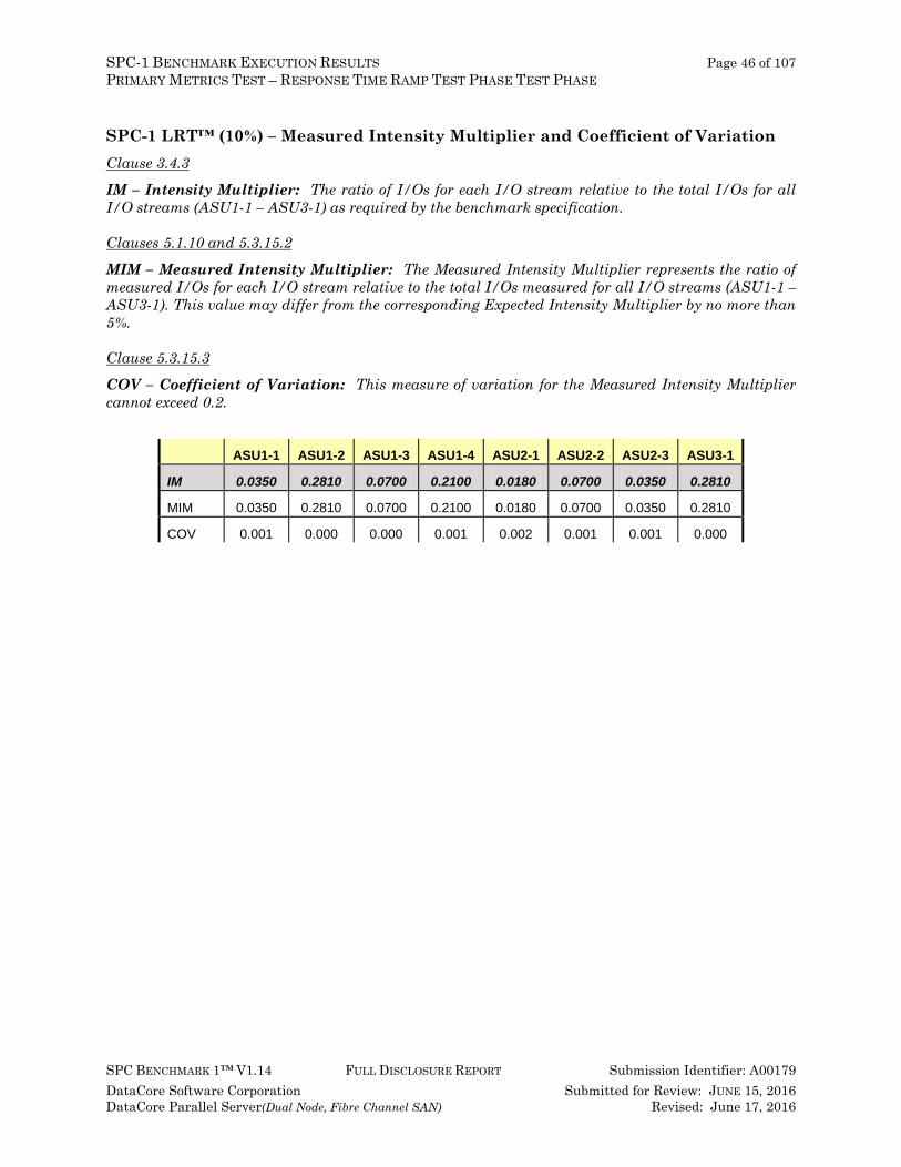
SPC-1 LRT™ (10%) – Measured Intensity Multiplier and Coefficient of Variation Clause 3.4.3
IM – Intensity Multiplier: The ratio of I/Os for each I/O stream relative to the total I/Os for all I/O streams (ASU1-1 – ASU3-1) as required by the benchmark specification.
Clauses 5.1.10 and 5.3.15.2
MIM – Measured Intensity Multiplier: The Measured Intensity Multiplier represents the ratio of measured I/Os for each I/O stream relative to the total I/Os measured for all I/O streams (ASU1-1 – ASU3-1). This value may differ from the corresponding Expected Intensity Multiplier by no more than 5%.
Clause 5.3.15.3
COV – Coefficient of Variation: This measure of variation for the Measured Intensity Multiplier cannot exceed 0.2.
ASU1-1 ASU1-2 ASU1-3 ASU1-4 ASU2-1 ASU2-2 ASU2-3 ASU3-1
IM 0.0350 0.2810 0.0700 0.2100 0.0180 0.0700 0.0350 0.2810
MIM 0.0350 0.2810 0.0700 0.2100 0.0180 0.0700 0.0350 0.2810
COV 0.001 0.000 0.000 0.001 0.002 0.001 0.001 0.000
SPC-1 BENCHMARK EXECUTION RESULTS Page 47 of 107 REPEATABILITY TEST
SPC BENCHMARK 1™ V1.14 FULL DISCLOSURE REPORT Submission Identifier: A00179 DataCore Software Corporation Submitted for Review: JUNE 15, 2016 DataCore Parallel Server(Dual Node, Fibre Channel SAN) Revised: June 17, 2016
Repeatability Test Clause 5.4.5 The Repeatability Test demonstrates the repeatability and reproducibility of the SPC-1 IOPS™ primary metric and the SPC-1 LRT™ metric generated in earlier Test Runs.
There are two identical Repeatability Test Phases. Each Test Phase contains two Test Runs. Each of the Test Runs will have a Measurement Interval of no less than ten (10) minutes. The two Test Runs in each Test Phase will be executed without interruption or any type of manual intervention.
The first Test Run in each Test Phase is executed at the 10% load point. The Average Response Time from each of the Test Runs is compared to the SPC-1 LRT™ metric. Each Average Response Time value must be less than the SPC-1 LRT™ metric plus 5% or less than the SPC-1 LRT™ metric plus one (1) millisecond (ms).
The second Test Run in each Test Phase is executed at the 100% load point. The I/O Request Throughput from the Test Runs is compared to the SPC-1 IOPS™ primary metric. Each I/O Request Throughput value must be greater than the SPC-1 IOPS™ primary metric minus 5%. In addition, the Average Response Time for each Test Run cannot exceed 30 milliseconds.
If any of the above constraints are not met, the benchmark measurement is invalid.
Clause 9.4.3.7.5 The following content shall appear in the FDR for each Test Run in the two Repeatability Test Phases:
1. A table containing the results of the Repeatability Test. 2. An I/O Request Throughput Distribution graph and table. 3. An Average Response Time Distribution graph and table. 4. The human readable Test Run Results File produced by the Workload Generator. 5. A listing or screen image of all input parameters supplied to the Workload Generator.
SPC-1 Workload Generator Input Parameters The SPC-1 Workload Generator input parameters for the Sustainability, IOPS, Response Time Ramp, Repeatability, and Persistence Test Runs are documented in Appendix E: SPC-1 Workload Generator Input Parameters on Page 88.
SPC-1 BENCHMARK EXECUTION RESULTS Page 48 of 107 REPEATABILITY TEST
SPC BENCHMARK 1™ V1.14 FULL DISCLOSURE REPORT Submission Identifier: A00179 DataCore Software Corporation Submitted for Review: JUNE 15, 2016 DataCore Parallel Server(Dual Node, Fibre Channel SAN) Revised: June 17, 2016
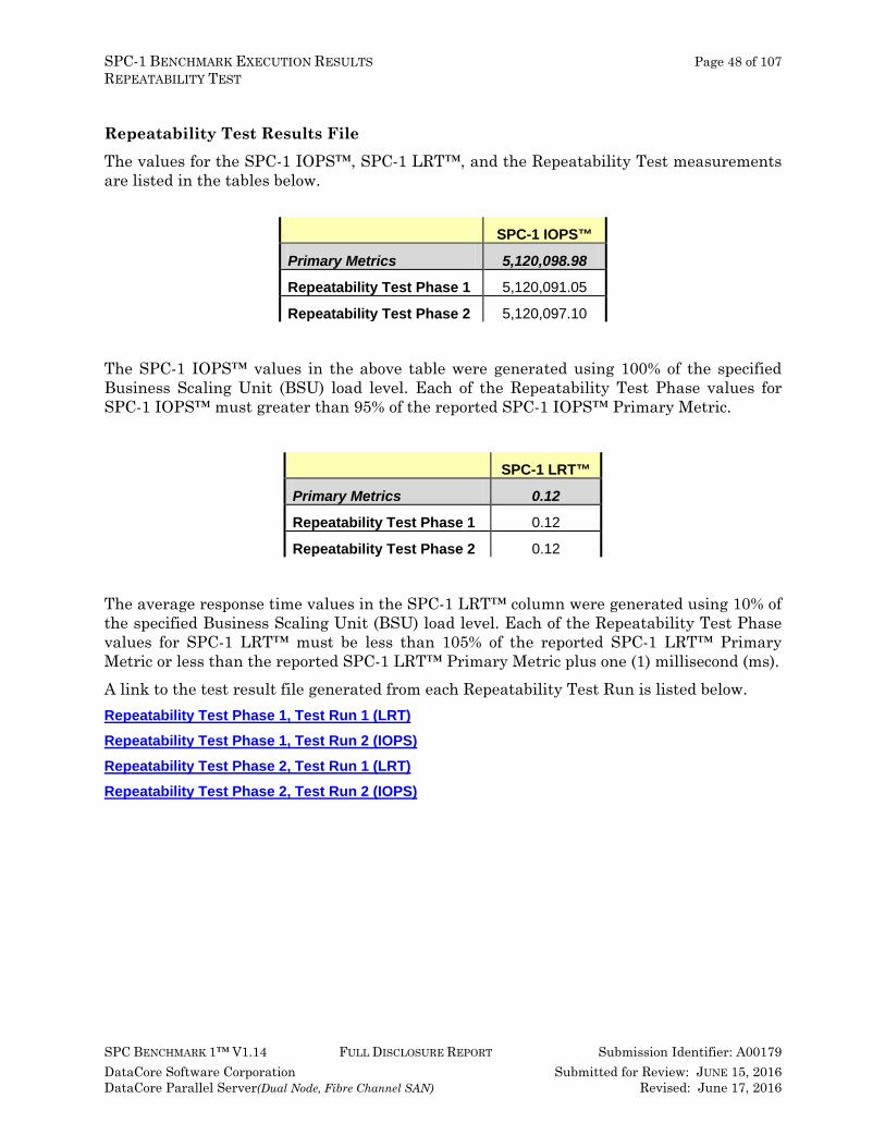
Repeatability Test Results File The values for the SPC-1 IOPS™, SPC-1 LRT™, and the Repeatability Test measurements are listed in the tables below.
SPC-1 IOPS™
Primary Metrics 5,120,098.98
Repeatability Test Phase 1 5,120,091.05
Repeatability Test Phase 2 5,120,097.10
The SPC-1 IOPS™ values in the above table were generated using 100% of the specified Business Scaling Unit (BSU) load level. Each of the Repeatability Test Phase values for SPC-1 IOPS™ must greater than 95% of the reported SPC-1 IOPS™ Primary Metric.
SPC-1 LRT™
Primary Metrics 0.12
Repeatability Test Phase 1 0.12
Repeatability Test Phase 2 0.12
The average response time values in the SPC-1 LRT™ column were generated using 10% of the specified Business Scaling Unit (BSU) load level. Each of the Repeatability Test Phase values for SPC-1 LRT™ must be less than 105% of the reported SPC-1 LRT™ Primary Metric or less than the reported SPC-1 LRT™ Primary Metric plus one (1) millisecond (ms). A link to the test result file generated from each Repeatability Test Run is listed below. Repeatability Test Phase 1, Test Run 1 (LRT) Repeatability Test Phase 1, Test Run 2 (IOPS)
Repeatability Test Phase 2, Test Run 1 (LRT)
Repeatability Test Phase 2, Test Run 2 (IOPS)
SPC-1 BENCHMARK EXECUTION RESULTS Page 49 of 107 REPEATABILITY TEST
SPC BENCHMARK 1™ V1.14 FULL DISCLOSURE REPORT Submission Identifier: A00179 DataCore Software Corporation Submitted for Review: JUNE 15, 2016 DataCore Parallel Server(Dual Node, Fibre Channel SAN) Revised: June 17, 2016
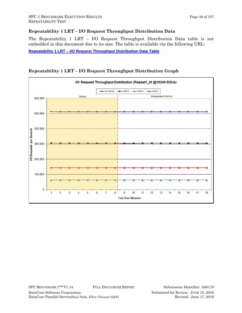
Repeatability 1 LRT – I/O Request Throughput Distribution Data The Repeatability 1 LRT – I/O Request Throughput Distribution Data table is not embedded in this document due to its size. The table is available via the following URL: Repeatability 1 LRT – I/O Request Throughput Distribution Data Table
Repeatability 1 LRT – I/O Request Throughput Distribution Graph
SPC-1 BENCHMARK EXECUTION RESULTS Page 50 of 107 REPEATABILITY TEST
SPC BENCHMARK 1™ V1.14 FULL DISCLOSURE REPORT Submission Identifier: A00179 DataCore Software Corporation Submitted for Review: JUNE 15, 2016 DataCore Parallel Server(Dual Node, Fibre Channel SAN) Revised: June 17, 2016
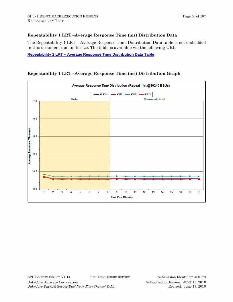
Repeatability 1 LRT –Average Response Time (ms) Distribution Data The Repeatability 1 LRT – Average Response Time Distribution Data table is not embedded in this document due to its size. The table is available via the following URL: Repeatability 1 LRT – Average Response Time Distribution Data Table
Repeatability 1 LRT –Average Response Time (ms) Distribution Graph
SPC-1 BENCHMARK EXECUTION RESULTS Page 51 of 107 REPEATABILITY TEST
SPC BENCHMARK 1™ V1.14 FULL DISCLOSURE REPORT Submission Identifier: A00179 DataCore Software Corporation Submitted for Review: JUNE 15, 2016 DataCore Parallel Server(Dual Node, Fibre Channel SAN) Revised: June 17, 2016
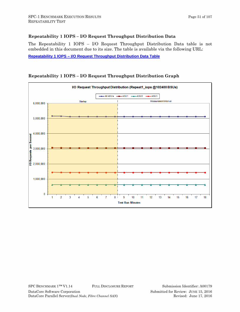
Repeatability 1 IOPS – I/O Request Throughput Distribution Data The Repeatability 1 IOPS – I/O Request Throughput Distribution Data table is not embedded in this document due to its size. The table is available via the following URL: Repeatability 1 IOPS – I/O Request Throughput Distribution Data Table
Repeatability 1 IOPS – I/O Request Throughput Distribution Graph

SPC-1 BENCHMARK EXECUTION RESULTS Page 52 of 107 REPEATABILITY TEST
SPC BENCHMARK 1™ V1.14 FULL DISCLOSURE REPORT Submission Identifier: A00179 DataCore Software Corporation Submitted for Review: JUNE 15, 2016 DataCore Parallel Server(Dual Node, Fibre Channel SAN) Revised: June 17, 2016
Repeatability 1 IOPS –Average Response Time (ms) Distribution Data The Repeatability 1 IOPS – Average Response Time Distribution Data table is not embedded in this document due to its size. The table is available via the following URL: Repeatability 1 IOPS – Average Response Time Distribution Data Table
Repeatability 1 IOPS –Average Response Time (ms) Distribution Graph

SPC-1 BENCHMARK EXECUTION RESULTS Page 53 of 107 REPEATABILITY TEST
SPC BENCHMARK 1™ V1.14 FULL DISCLOSURE REPORT Submission Identifier: A00179 DataCore Software Corporation Submitted for Review: JUNE 15, 2016 DataCore Parallel Server(Dual Node, Fibre Channel SAN) Revised: June 17, 2016
Repeatability 2 LRT – I/O Request Throughput Distribution Data The Repeatability 2 LRT – I/O Request Throughput Distribution Data table is not embedded in this document due to its size. The table is available via the following URL: Repeatability 2 LRT – I/O Request Throughput Distribution Data Table
Repeatability 2 LRT – I/O Request Throughput Distribution Graph

SPC-1 BENCHMARK EXECUTION RESULTS Page 54 of 107 REPEATABILITY TEST
SPC BENCHMARK 1™ V1.14 FULL DISCLOSURE REPORT Submission Identifier: A00179 DataCore Software Corporation Submitted for Review: JUNE 15, 2016 DataCore Parallel Server(Dual Node, Fibre Channel SAN) Revised: June 17, 2016
Repeatability 2 LRT –Average Response Time (ms) Distribution Data The Repeatability 2 LRT – Average Response Time Distribution Data table is not embedded in this document due to its size. The table is available via the following URL: Repeatability 2 LRT – Average Response Time Distribution Data Table
Repeatability 2 LRT –Average Response Time (ms) Distribution Graph

SPC-1 BENCHMARK EXECUTION RESULTS Page 55 of 107 REPEATABILITY TEST
SPC BENCHMARK 1™ V1.14 FULL DISCLOSURE REPORT Submission Identifier: A00179 DataCore Software Corporation Submitted for Review: JUNE 15, 2016 DataCore Parallel Server(Dual Node, Fibre Channel SAN) Revised: June 17, 2016
Repeatability 2 IOPS – I/O Request Throughput Distribution Data The Repeatability 2 IOPS – I/O Request Throughput Distribution Data table is not embedded in this document due to its size. The table is available via the following URL: Repeatability 2 IOPS – I/O Request Throughput Distribution Data Table
Repeatability 2 IOPS – I/O Request Throughput Distribution Graph
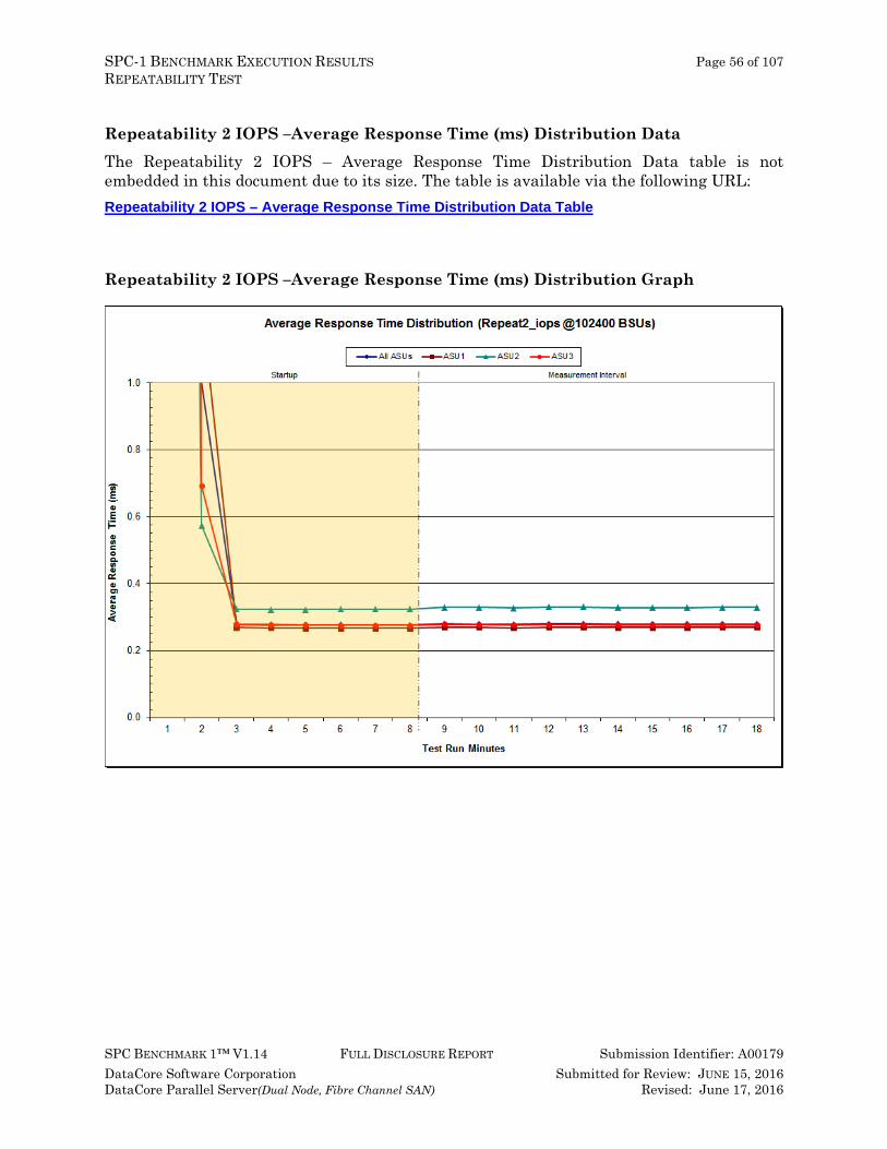
SPC-1 BENCHMARK EXECUTION RESULTS Page 56 of 107 REPEATABILITY TEST
SPC BENCHMARK 1™ V1.14 FULL DISCLOSURE REPORT Submission Identifier: A00179 DataCore Software Corporation Submitted for Review: JUNE 15, 2016 DataCore Parallel Server(Dual Node, Fibre Channel SAN) Revised: June 17, 2016
Repeatability 2 IOPS –Average Response Time (ms) Distribution Data The Repeatability 2 IOPS – Average Response Time Distribution Data table is not embedded in this document due to its size. The table is available via the following URL: Repeatability 2 IOPS – Average Response Time Distribution Data Table
Repeatability 2 IOPS –Average Response Time (ms) Distribution Graph
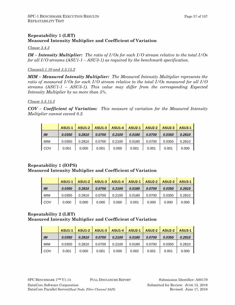
SPC-1 BENCHMARK EXECUTION RESULTS Page 57 of 107 REPEATABILITY TEST
SPC BENCHMARK 1™ V1.14 FULL DISCLOSURE REPORT Submission Identifier: A00179 DataCore Software Corporation Submitted for Review: JUNE 15, 2016 DataCore Parallel Server(Dual Node, Fibre Channel SAN) Revised: June 17, 2016
Repeatability 1 (LRT) Measured Intensity Multiplier and Coefficient of Variation Clause 3.4.3
IM – Intensity Multiplier: The ratio of I/Os for each I/O stream relative to the total I/Os for all I/O streams (ASU1-1 – ASU3-1) as required by the benchmark specification.
Clauses5.1.10 and 5.3.15.2
MIM – Measured Intensity Multiplier: The Measured Intensity Multiplier represents the ratio of measured I/Os for each I/O stream relative to the total I/Os measured for all I/O streams (ASU1-1 – ASU3-1). This value may differ from the corresponding Expected Intensity Multiplier by no more than 5%.
Clause 5.3.15.3
COV – Coefficient of Variation: This measure of variation for the Measured Intensity Multiplier cannot exceed 0.2.
ASU1-1 ASU1-2 ASU1-3 ASU1-4 ASU2-1 ASU2-2 ASU2-3 ASU3-1
IM 0.0350 0.2810 0.0700 0.2100 0.0180 0.0700 0.0350 0.2810
MIM 0.0350 0.2810 0.0700 0.2100 0.0180 0.0700 0.0350 0.2810
COV 0.001 0.000 0.001 0.000 0.001 0.001 0.001 0.000
Repeatability 1 (IOPS) Measured Intensity Multiplier and Coefficient of Variation
ASU1-1 ASU1-2 ASU1-3 ASU1-4 ASU2-1 ASU2-2 ASU2-3 ASU3-1
IM 0.0350 0.2810 0.0700 0.2100 0.0180 0.0700 0.0350 0.2810
MIM 0.0350 0.2810 0.0700 0.2100 0.0180 0.0700 0.0350 0.2810
COV 0.000 0.000 0.000 0.000 0.001 0.000 0.000 0.000
Repeatability 2 (LRT) Measured Intensity Multiplier and Coefficient of Variation
ASU1-1 ASU1-2 ASU1-3 ASU1-4 ASU2-1 ASU2-2 ASU2-3 ASU3-1
IM 0.0350 0.2810 0.0700 0.2100 0.0180 0.0700 0.0350 0.2810
MIM 0.0350 0.2810 0.0700 0.2100 0.0180 0.0700 0.0350 0.2810
COV 0.001 0.000 0.001 0.000 0.002 0.001 0.001 0.000
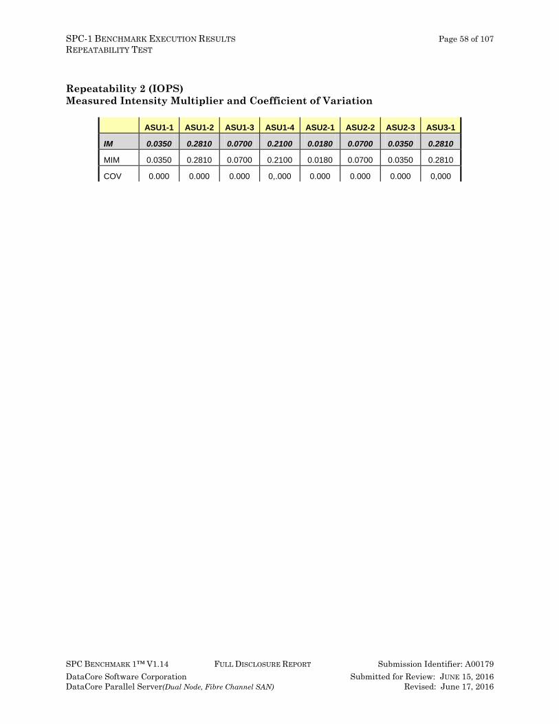
SPC-1 BENCHMARK EXECUTION RESULTS Page 58 of 107 REPEATABILITY TEST
SPC BENCHMARK 1™ V1.14 FULL DISCLOSURE REPORT Submission Identifier: A00179 DataCore Software Corporation Submitted for Review: JUNE 15, 2016 DataCore Parallel Server(Dual Node, Fibre Channel SAN) Revised: June 17, 2016
Repeatability 2 (IOPS) Measured Intensity Multiplier and Coefficient of Variation
ASU1-1 ASU1-2 ASU1-3 ASU1-4 ASU2-1 ASU2-2 ASU2-3 ASU3-1
IM 0.0350 0.2810 0.0700 0.2100 0.0180 0.0700 0.0350 0.2810
MIM 0.0350 0.2810 0.0700 0.2100 0.0180 0.0700 0.0350 0.2810
COV 0.000 0.000 0.000 0,.000 0.000 0.000 0.000 0,000

SPC-1 BENCHMARK EXECUTION RESULTS Page 59 of 107 DATA PERSISTENCE TEST
SPC BENCHMARK 1™ V1.14 FULL DISCLOSURE REPORT Submission Identifier: A00179 DataCore Software Corporation Submitted for Review: JUNE 15, 2016 DataCore Parallel Server(Dual Node, Fibre Channel SAN) Revised: June 17, 2016
Data Persistence Test Clause 6 The Data Persistence Test demonstrates the Tested Storage Configuration (TSC):
• Is capable of maintain data integrity across a power cycle.
• Ensures the transfer of data between Logical Volumes and host systems occurs without corruption or loss.
The SPC-1 Workload Generator will write 16 block I/O requests at random over the total Addressable Storage Capacity of the TSC for ten (10) minutes at a minimum of 25% of the load used to generate the SPC-1 IOPS™ primary metric. The bit pattern selected to be written to each block as well as the address of the block will be retained in a log file.
The Tested Storage Configuration (TSC) will be shutdown and restarted using a power off/power on cycle at the end of the above sequence of write operations. In addition, any caches employing battery backup must be flushed/emptied.
The SPC-1 Workload Generator will then use the above log file to verify each block written contains the correct bit pattern.
Clause 9.4.3.8 The following content shall appear in this section of the FDR:
1. A listing or screen image of all input parameters supplied to the Workload Generator. 2. For the successful Data Persistence Test Run, a table illustrating key results. The content,
appearance, and format of this table are specified in Table 9-12. Information displayed in this table shall be obtained from the Test Run Results File referenced below in #3.
3. For the successful Data Persistence Test Run, the human readable Test Run Results file produced by the Workload Generator (may be contained in an appendix).
SPC-1 Workload Generator Input Parameters The SPC-1 Workload Generator input parameters for the Sustainability, IOPS, Response Time Ramp, Repeatability, and Persistence Test Runs are documented in Appendix E: SPC-1 Workload Generator Input Parameters on Page 88.
Data Persistence Test Results File A link to each test result file generated from each Data Persistence Test is listed below. Persistence 1 Test Results File
Persistence 2 Test Results File
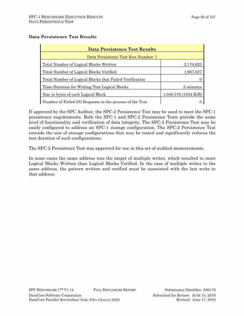
SPC-1 BENCHMARK EXECUTION RESULTS Page 60 of 107 DATA PERSISTENCE TEST
SPC BENCHMARK 1™ V1.14 FULL DISCLOSURE REPORT Submission Identifier: A00179 DataCore Software Corporation Submitted for Review: JUNE 15, 2016 DataCore Parallel Server(Dual Node, Fibre Channel SAN) Revised: June 17, 2016
Data Persistence Test Results
Data Persistence Test Results Data Persistence Test Run Number: 1
Total Number of Logical Blocks Written 2,170,625
Total Number of Logical Blocks Verified 1,967,037
Total Number of Logical Blocks that Failed Verification 0
Time Duration for Writing Test Logical Blocks 5 minutes
Size in bytes of each Logical Block 1,048,576 (1024 KiB)
Number of Failed I/O Requests in the process of the Test 0
If approved by the SPC Auditor, the SPC-2 Persistence Test may be used to meet the SPC-1 persistence requirements. Both the SPC-1 and SPC-2 Persistence Tests provide the same level of functionality and verification of data integrity. The SPC-2 Persistence Test may be easily configured to address an SPC-1 storage configuration. The SPC-2 Persistence Test extends the size of storage configurations that may be tested and significantly reduces the test duration of such configurations.
The SPC-2 Persistence Test was approved for use in this set of audited measurements.
In some cases the same address was the target of multiple writes, which resulted in more Logical Blocks Written than Logical Blocks Verified. In the case of multiple writes to the same address, the pattern written and verified must be associated with the last write to that address.
SPC-1 AVAILABILITY DATE, PRICING INFORMATION, AND Page 61 of 107 ANOMALIES OR IRREGULARITIES
SPC BENCHMARK 1™ V1.14 FULL DISCLOSURE REPORT Submission Identifier: A00179 DataCore Software Corporation Submitted for Review: JUNE 15, 2016 DataCore Parallel Server(Dual Node, Fibre Channel SAN) Revised: June 17, 2016
PRICED STORAGE CONFIGURATION AVAILABILITY DATE Clause 9.4.3.9 The committed delivery data for general availability (Availability Date) of all products that comprise the Priced Storage Configuration must be reported. When the Priced Storage Configuration includes products or components with different availability dates, the reported Availability Date for the Priced Storage Configuration must be the date at which all components are committed to be available.
The entire Priced Storage Configuration, as documented in this Full Disclosure Report, will become available on September 6, 2016 for customer purchase and shipment.
PRICING INFORMATION Clause 9.4.3.3.6 The Executive Summary shall contain a pricing spreadsheet as documented in Clause 8.3.1.
Pricing information may be found in the Priced Storage Configuration Pricing section on page 17.
TESTED STORAGE CONFIGURATION (TSC) AND PRICED STORAGE CONFIGURATION DIFFERENCES Clause 9.4.3.3.8 The Executive Summary shall contain a list of all differences between the Tested Storage Configuration (TSC) and the Priced Storage Configuration.
A list of all differences between the Tested Storage Configuration (TSC) and Priced Storage Configuration may be found in the Executive Summary portion of this document on page 17.
ANOMALIES OR IRREGULARITIES Clause 9.4.3.10 The FDR shall include a clear and complete description of any anomalies or irregularities encountered in the course of executing the SPC-1 benchmark that may in any way call into question the accuracy, verifiability, or authenticity of information published in this FDR.
There were no anomalies or irregularities encountered during the SPC-1 Onsite Audit of the DataCore Parallel Server.
APPENDIX A: Page 62 of 107 SPC-1 GLOSSARY
SPC BENCHMARK 1™ V1.14 FULL DISCLOSURE REPORT Submission Identifier: A00179 DataCore Software Corporation Submitted for Review: JUNE 15, 2016 DataCore Parallel Server(Dual Node, Fibre Channel SAN) Revised: June 17, 2016
APPENDIX A: SPC-1 GLOSSARY
“Decimal” (powers of ten) Measurement Units In the storage industry, the terms “kilo”, “mega”, “giga“, “tera”, “peta”, and “exa” are commonly used prefixes for computing performance and capacity. For the purposes of the SPC workload definitions, all of the following terms are defined in “powers of ten” measurement units.
A kilobyte (KB) is equal to 1,000 (103) bytes. A megabyte (MB) is equal to 1,000,000 (106) bytes. A gigabyte (GB) is equal to 1,000,000,000 (109) bytes. A terabyte (TB) is equal to 1,000,000,000,000 (1012) bytes. A petabyte (PB) is equal to 1,000,000,000,000,000 (1015) bytes An exabyte (EB) is equal to 1,000,000,000,000,000,000 (1018) bytes
“Binary” (powers of two) Measurement Units The sizes reported by many operating system components use “powers of two” measurement units rather than “power of ten” units. The following standardized definitions and terms are also valid and may be used in this document.
A kibibyte (KiB) is equal to 1,024 (210) bytes. A mebibyte (MiB) is equal to 1,048,576 (220) bytes. A gigibyte (GiB) is equal to 1,073,741,824 (230) bytes. A tebibyte (TiB) is equal to 1,099,511,627,776 (240) bytes. A pebibyte (PiB) is equal to 1,125,899,906,842,624 (250) bytes. An exbibyte (EiB) is equal to 1,152,921,504,606,846,967 (260) bytes.
SPC-1 Data Repository Definitions
Total ASU Capacity: The total storage capacity read and written in the course of executing the SPC-1 benchmark.
Application Storage Unit (ASU): The logical interface between the storage and SPC-1 Workload Generator. The three ASUs (Data, User, and Log) are typically implemented on one or more Logical Volume.
Logical Volume: The division of Addressable Storage Capacity into individually addressable logical units of storage used in the SPC-1 benchmark. Each Logical Volume is implemented as a single, contiguous address space.
Addressable Storage Capacity: The total storage (sum of Logical Volumes) that can be read and written by application programs such as the SPC-1 Workload Generator.
APPENDIX A: Page 63 of 107 SPC-1 GLOSSARY
SPC BENCHMARK 1™ V1.14 FULL DISCLOSURE REPORT Submission Identifier: A00179 DataCore Software Corporation Submitted for Review: JUNE 15, 2016 DataCore Parallel Server(Dual Node, Fibre Channel SAN) Revised: June 17, 2016
Configured Storage Capacity: This capacity includes the Addressable Storage Capacity and any other storage (parity disks, hot spares, etc.) necessary to implement the Addressable Storage Capacity.
Physical Storage Capacity: The formatted capacity of all storage devices physically present in the Tested Storage Configuration (TSC).
Data Protection Overhead: The storage capacity required to implement the selected level of data protection.
Required Storage: The amount of Configured Storage Capacity required to implement the Addressable Storage Configuration, excluding the storage required for the three ASUs.
Global Storage Overhead: The amount of Physical Storage Capacity that is required for storage subsystem use and unavailable for use by application programs.
Total Unused Storage: The amount of storage capacity available for use by application programs but not included in the Total ASU Capacity.
SPC-1 Data Protection Levels
Protected 1: The single point of failure of any storage device in the configuration will not result in permanent loss of access to or integrity of the SPC-1 Data Repository. Protected 2: The single point of failure of any component in the configuration will not result in permanent loss of access to or integrity of the SPC-1 Data Repository.
SPC-1 Test Execution Definitions Average Response Time: The sum of the Response Times for all Measured I/O Requests divided by the total number of Measured I/O Requests.
Completed I/O Request: An I/O Request with a Start Time and a Completion Time (see “I/O Completion Types” below).
Completion Time: The time recorded by the Workload Generator when an I/O Request is satisfied by the TSC as signaled by System Software.
Data Rate: The data transferred in all Measured I/O Requests in an SPC-1 Test Run divided by the length of the Test Run in seconds.
Expected I/O Count: For any given I/O Stream and Test Phase, the product of 50 times the BSU level, the duration of the Test Phase in seconds, and the Intensity Multiplier for that I/O Stream.
Failed I/O Request: Any I/O Request issued by the Workload Generator that could not be completed or was signaled as failed by System Software. A Failed I/O Request has no Completion Time (see “I/O Completion Types” below).
APPENDIX A: Page 64 of 107 SPC-1 GLOSSARY
SPC BENCHMARK 1™ V1.14 FULL DISCLOSURE REPORT Submission Identifier: A00179 DataCore Software Corporation Submitted for Review: JUNE 15, 2016 DataCore Parallel Server(Dual Node, Fibre Channel SAN) Revised: June 17, 2016
I/O Request Throughput: The total number of Measured I/O requests in an SPC-1 Test Run divided by the duration of the Measurement Interval in seconds.
In-Flight I/O Request: An I/O Request issued by the I/O Command Generator to the TSC that has a recorded Start Time, but does not complete within the Measurement Interval (see “I/O Completion Types” below).
Measured I/O Request: A Completed I/O Request with a Completion Time occurring within the Measurement Interval (see “I/O Completion Types” below).
Measured Intensity Multiplier: The percentage of all Measured I/O Requests that were issued by a given I/O Stream.
Measurement Interval: The finite and contiguous time period, after the TSC has reached Steady State, when data is collected by a Test Sponsor to generate an SPC-1 test result or support an SPC-1 test result.
Ramp-Up: The time required for the Benchmark Configuration (BC) to produce Steady State throughput after the Workload Generator begins submitting I/O Requests to the TSC for execution.
Ramp-Down: The time required for the BC to complete all I/O Requests issued by the Workload Generator. The Ramp-Down period begins when the Workload Generator ceases to issue new I/O Requests to the TSC.
Response Time: The Response Time of a Measured I/O Request is its Completion Time minus its Start Time.
Start Time: The time recorded by the Workload Generator when an I/O Request is submitted, by the Workload Generator, to the System Software for execution on the Tested Storage Configuration (TSC).
Start-Up: The period that begins after the Workload Generator starts to submit I/O requests to the TSC and ends at the beginning of the Measurement Interval.
Shut-Down: The period between the end of the Measurement Interval and the time when all I/O Requests issued by the Workload Generator have completed or failed.
Steady State: The consistent and sustainable throughput of the TSC. During this period the load presented to the TSC by the Workload Generator is constant.
Test: A collection of Test Phases and or Test Runs sharing a common objective.
Test Run: The execution of SPC-1 for the purpose of producing or supporting an SPC-1 test result. SPC-1 Test Runs may have a finite and measured Ramp-Up period, Start-Up period, Shut-Down period, and Ramp-Down period as illustrated in the “SPC-1 Test Run Components” below. All SPC-1 Test Runs shall have a Steady State period and a Measurement Interval.
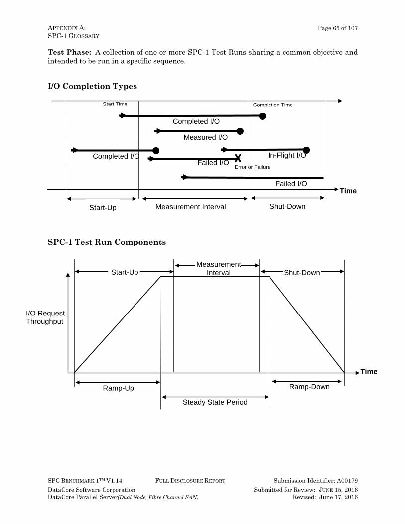
APPENDIX A: Page 65 of 107 SPC-1 GLOSSARY
SPC BENCHMARK 1™ V1.14 FULL DISCLOSURE REPORT Submission Identifier: A00179 DataCore Software Corporation Submitted for Review: JUNE 15, 2016 DataCore Parallel Server(Dual Node, Fibre Channel SAN) Revised: June 17, 2016
Test Phase: A collection of one or more SPC-1 Test Runs sharing a common objective and intended to be run in a specific sequence.
I/O Completion Types
SPC-1 Test Run Components
Shut-Down
Time
Measurement Interval Start-Up
Start Time Completion Time
Completed I/O
Measured I/O
Completed I/O
In-Flight I/O
Failed I/O
Failed I/O
X Error or Failure
I/O Request Throughput
Time
Measurement Interval
Ramp-Up Ramp-Down
Steady State Period
Shut-Down Start-Up
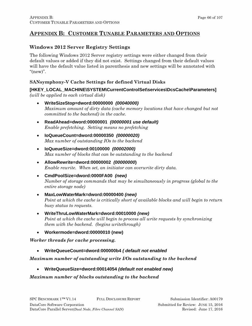
APPENDIX B: Page 66 of 107 CUSTOMER TUNABLE PARAMETERS AND OPTIONS
SPC BENCHMARK 1™ V1.14 FULL DISCLOSURE REPORT Submission Identifier: A00179 DataCore Software Corporation Submitted for Review: JUNE 15, 2016 DataCore Parallel Server(Dual Node, Fibre Channel SAN) Revised: June 17, 2016
APPENDIX B: CUSTOMER TUNABLE PARAMETERS AND OPTIONS
Windows 2012 Server Registry Settings The following Windows 2012 Server registry settings were either changed from their default values or added if they did not exist. Settings changed from their default values will have the default value listed in parenthesis and new settings will be annotated with “(new)”.
SANsymphony-V Cache Settings for defined Virtual Disks [HKEY_LOCAL_MACHINE\SYSTEM\CurrentControlSet\services\DcsCache\Parameters] (will be applied to each virtual disk)
• WriteSizeStop=dword:00000000 (00040000) Maximum amount of dirty data (cache memory locations that have changed but not committed to the backend) in the cache.
• ReadAhead=dword:00000001 (00000001 use default) Enable prefetching. Setting means no prefetching
• IoQueueCount=dword:00000350 (00000020) Max number of outstanding IOs to the backend
• IoQueueSize=dword:00100000 (00002000) Max number of blocks that can be outstanding to the backend
• AllowRewrite=dword:00000002 (00000000) Enable rewrite. When set, an initiator can overwrite dirty data.
• CmdPoolSize=dword:0000FA00 (new) Number of storage commands that may be simultaneously in progress (global to the entire storage node)
• MaxLowWaterMark=dword:00000400 (new) Point at which the cache is critically short of available blocks and will begin to return busy status to requests.
• WriteThruLowWaterMark=dword:00010000 (new) Point at which the cache will begin to process all write requests by synchronizing them with the backend. (begins writethrough)
• Workermode=dword:00000010 (new) Worker threads for cache processing.
• WriteQueueCount=dword:000000b4 ( default not enabled
Maximum number of outstanding write I/Os outstanding to the backend
• WriteQueueSize=dword:00014054 (default not enabled new)
Maximum number of blocks outstanding to the backend
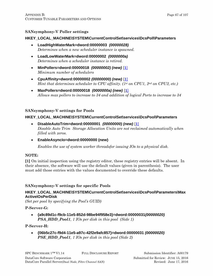
APPENDIX B: Page 67 of 107 CUSTOMER TUNABLE PARAMETERS AND OPTIONS
SPC BENCHMARK 1™ V1.14 FULL DISCLOSURE REPORT Submission Identifier: A00179 DataCore Software Corporation Submitted for Review: JUNE 15, 2016 DataCore Parallel Server(Dual Node, Fibre Channel SAN) Revised: June 17, 2016
SANsymphony-V Poller settings HKEY_LOCAL_MACHINE\SYSTEM\CurrentControlSet\services\DcsPoll\Parameters
• LoadHighWaterMark=dword:00000003 (00000028) Determines when a new scheduler instance is spawned.
• LoadLowWaterMark=dword:00000002 (0000000a) Determines when a scheduler instance is retired.
• MinPollers=dword:00000018 (00000002) (new) [1] Minimum number of schedulers
• CpuAffinity=dword:00000002 (00000000) (new) [1] Hint that determines scheduler to CPU affinity. (1st on CPU1, 2nd on CPU2, etc.)
• MaxPollers=dword:00000018 (0000000a) (new) [1] Allows max pollers to increase to 34 and addition of logical Ports to increase to 34
SANsymphony-V settings for Pools HKEY_LOCAL_MACHINE\SYSTEM\CurrentControlSet\services\DcsPool\Parameters
• DisableAutoTrim=dword:00000001 (00000000) (new) [1] Disable Auto Trim Storage Allocation Units are not reclaimed automatically when filled with zeros.
• EnableAsyncIo=dword:00000000 (new) Enables the use of system worker threadsfor issuing IOs to a physical disk.
NOTE: [1] On initial inspection using the registry editor, these registry entries will be absent. In their absence, the software will use the default values (given in parenthesis). The user must add those entries with the values documented to override these defaults.
SANsymphony-V settings for specific Pools HKEY_LOCAL_MACHINE\SYSTEM\CurrentControlSet\services\DcsPool\Parameters\MaxActiveIOsPerDisk (Set per pool by specifying the Pool’s GUID) P-Server-G:
• {a9c89d1c-f9cb-11e5-852d-98be94f958e3}=dword:00000031(00000020) PSA_HDD_Pool1, 1 IOs per disk in this pool (Side 1)
P-Server-H: • {06b5c27c-f9d4-11e5-a97c-42f2e9afc857}=dword:00000031 (00000020)
PSE_HDD_Pool1, 1 IOs per disk in this pool (Side 2)
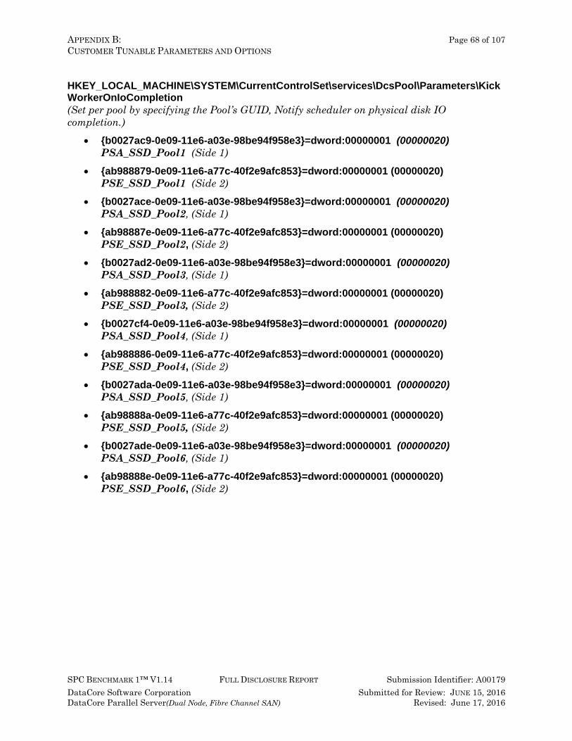
APPENDIX B: Page 68 of 107 CUSTOMER TUNABLE PARAMETERS AND OPTIONS
SPC BENCHMARK 1™ V1.14 FULL DISCLOSURE REPORT Submission Identifier: A00179 DataCore Software Corporation Submitted for Review: JUNE 15, 2016 DataCore Parallel Server(Dual Node, Fibre Channel SAN) Revised: June 17, 2016
HKEY_LOCAL_MACHINE\SYSTEM\CurrentControlSet\services\DcsPool\Parameters\KickWorkerOnIoCompletion (Set per pool by specifying the Pool’s GUID, Notify scheduler on physical disk IO completion.)
• {b0027ac9-0e09-11e6-a03e-98be94f958e3}=dword:00000001 (00000020) PSA_SSD_Pool1 (Side 1)
• {ab988879-0e09-11e6-a77c-40f2e9afc853}=dword:00000001 (00000020) PSE_SSD_Pool1 (Side 2)
• {b0027ace-0e09-11e6-a03e-98be94f958e3}=dword:00000001 (00000020) PSA_SSD_Pool2, (Side 1)
• {ab98887e-0e09-11e6-a77c-40f2e9afc853}=dword:00000001 (00000020) PSE_SSD_Pool2, (Side 2)
• {b0027ad2-0e09-11e6-a03e-98be94f958e3}=dword:00000001 (00000020) PSA_SSD_Pool3, (Side 1)
• {ab988882-0e09-11e6-a77c-40f2e9afc853}=dword:00000001 (00000020) PSE_SSD_Pool3, (Side 2)
• {b0027cf4-0e09-11e6-a03e-98be94f958e3}=dword:00000001 (00000020) PSA_SSD_Pool4, (Side 1)
• {ab988886-0e09-11e6-a77c-40f2e9afc853}=dword:00000001 (00000020) PSE_SSD_Pool4, (Side 2)
• {b0027ada-0e09-11e6-a03e-98be94f958e3}=dword:00000001 (00000020) PSA_SSD_Pool5, (Side 1)
• {ab98888a-0e09-11e6-a77c-40f2e9afc853}=dword:00000001 (00000020) PSE_SSD_Pool5, (Side 2)
• {b0027ade-0e09-11e6-a03e-98be94f958e3}=dword:00000001 (00000020) PSA_SSD_Pool6, (Side 1)
• {ab98888e-0e09-11e6-a77c-40f2e9afc853}=dword:00000001 (00000020) PSE_SSD_Pool6, (Side 2)

APPENDIX C: Page 69 of 107 TESTED STORAGE CONFIGURATION (TSC) CREATION
SPC BENCHMARK 1™ V1.14 FULL DISCLOSURE REPORT Submission Identifier: A00179 DataCore Software Corporation Submitted for Review: JUNE 15, 2016 DataCore Parallel Server(Dual Node, Fibre Channel SAN) Revised: June 17, 2016
APPENDIX C: TESTED STORAGE CONFIGURATION (TSC) CREATION 1. Install DataCore Parallel Server Software on servers Pserver-G and
Pserver-H: The software installation is performed by running a self-extracting executable file. After installation, the DataCore Management Console can be accessed from the Windows “start” menu or by using the desktop shortcut with the DataCore logo. Online help for using the DataCore Management Console is located at http://www.datacore.com/ParallelServer-Webhelp/ (refer the help topic, DataCore Management Console for more information).
2. On Pserver-G, open and log in to the DataCore Management Console using the following steps. At the end of this step, you will be logged into the management and configuration console: a. On the system desktop, double-click on the “DataCore Management Console”
icon to start the management console. b. Select the “Use default credentials checkbox and click Connect to proceed to the
management console.
3. Group servers Pserver-G and Pserver-H with the following steps:
a. In the management console, right click Server Group in the left panel, then left click Add DataCore Server
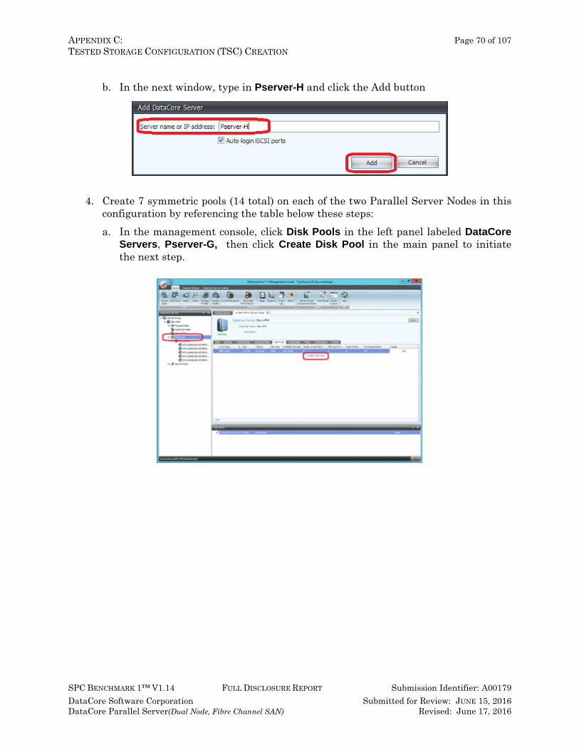
APPENDIX C: Page 70 of 107 TESTED STORAGE CONFIGURATION (TSC) CREATION
SPC BENCHMARK 1™ V1.14 FULL DISCLOSURE REPORT Submission Identifier: A00179 DataCore Software Corporation Submitted for Review: JUNE 15, 2016 DataCore Parallel Server(Dual Node, Fibre Channel SAN) Revised: June 17, 2016
b. In the next window, type in Pserver-H and click the Add button
4. Create 7 symmetric pools (14 total) on each of the two Parallel Server Nodes in this
configuration by referencing the table below these steps: a. In the management console, click Disk Pools in the left panel labeled DataCore
Servers, Pserver-G, then click Create Disk Pool in the main panel to initiate the next step.
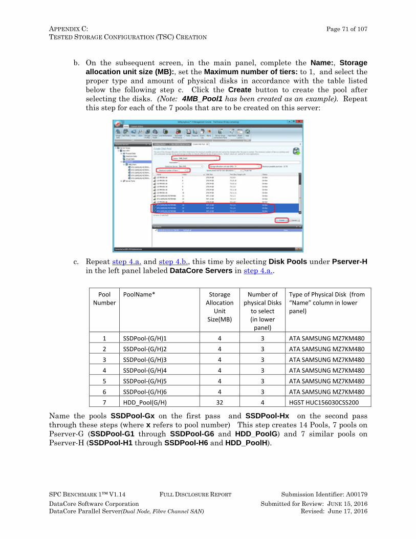
APPENDIX C: Page 71 of 107 TESTED STORAGE CONFIGURATION (TSC) CREATION
SPC BENCHMARK 1™ V1.14 FULL DISCLOSURE REPORT Submission Identifier: A00179 DataCore Software Corporation Submitted for Review: JUNE 15, 2016 DataCore Parallel Server(Dual Node, Fibre Channel SAN) Revised: June 17, 2016
b. On the subsequent screen, in the main panel, complete the Name:, Storage
allocation unit size (MB):, set the Maximum number of tiers: to 1, and select the proper type and amount of physical disks in accordance with the table listed below the following step c. Click the Create button to create the pool after selecting the disks. (Note: 4MB_Pool1 has been created as an example). Repeat this step for each of the 7 pools that are to be created on this server:
c. Repeat step 4.a. and step 4.b., this time by selecting Disk Pools under Pserver-H in the left panel labeled DataCore Servers in step 4.a..
Pool
Number PoolName* Storage
Allocation Unit
Size(MB)
Number of physical Disks
to select (in lower
panel)
Type of Physical Disk (from “Name” column in lower panel)
1 SSDPool-(G/H)1 4 3 ATA SAMSUNG MZ7KM480 2 SSDPool-(G/H)2 4 3 ATA SAMSUNG MZ7KM480 3 SSDPool-(G/H)3 4 3 ATA SAMSUNG MZ7KM480 4 SSDPool-(G/H)4 4 3 ATA SAMSUNG MZ7KM480 5 SSDPool-(G/H)5 4 3 ATA SAMSUNG MZ7KM480 6 SSDPool-(G/H)6 4 3 ATA SAMSUNG MZ7KM480 7 HDD_Pool(G/H) 32 4 HGST HUC156030CSS200
Name the pools SSDPool-Gx on the first pass and SSDPool-Hx on the second pass through these steps (where x refers to pool number) This step creates 14 Pools, 7 pools on Pserver-G (SSDPool-G1 through SSDPool-G6 and HDD_PoolG) and 7 similar pools on Pserver-H (SSDPool-H1 through SSDPool-H6 and HDD_PoolH).

APPENDIX C: Page 72 of 107 TESTED STORAGE CONFIGURATION (TSC) CREATION
SPC BENCHMARK 1™ V1.14 FULL DISCLOSURE REPORT Submission Identifier: A00179 DataCore Software Corporation Submitted for Review: JUNE 15, 2016 DataCore Parallel Server(Dual Node, Fibre Channel SAN) Revised: June 17, 2016
5. Mirror each pooled physical disk in each pool created in step 4.b. by performing step
5a for each pool, then step 5b for each disk in the pool. a. Select the pool. In the management console, click on a disk pool in the left panel,
then click the tab labeled Physical Disks in the main panel and then select a disk in the panel below that tab.
b. Right-click on the disk (Name column) and select Add Mirror Disk and select a
disk of the same type to mirror to.
APPENDIX C: Page 73 of 107 TESTED STORAGE CONFIGURATION (TSC) CREATION
SPC BENCHMARK 1™ V1.14 FULL DISCLOSURE REPORT Submission Identifier: A00179 DataCore Software Corporation Submitted for Review: JUNE 15, 2016 DataCore Parallel Server(Dual Node, Fibre Channel SAN) Revised: June 17, 2016
6. Create 30 Virtual Disks repeating step 6a through step 6d 30 times, once for each of
the virtual disks to be created, using the details in the following table. The virtual disks created in this step will be mapped and are used to create the SPC-1 Logical Volumes that comprise the SPC-1 ASUs.
Virtual Disk
Number Name: Size: (GB) Source Pool / Pool Name:
1 GASU1_1 600 SSDPool-G5 2 GASU1_2 600 SSDPool-G1 3 GASU1_3 600 SSDPool-G6 4 GASU1_4 600 SSDPool-G4 5 GASU1_5 600 SSDPool-G3 6 GASU1_6 600 SSDPool-G2 7 GASU2_1 600 SSDPool-G5 8 GASU2_2 600 SSDPool-G1 9 GASU2_3 600 SSDPool-G6
10 GASU2_4 600 SSDPool-G4 11 GASU2_5 600 SSDPool-G3 12 GASU2_6 600 SSDPool-G2 13 GASU3_1 270 HDDPool-G 14 GASU3_2 270 HDDPool-G 15 GASU3_3 270 HDDPool-G 16 HASU1_1 600 SSDPool-H5 17 HASU1_2 600 SSDPool-H1 18 HASU1_3 600 SSDPool-H6 19 HASU1_4 600 SSDPool-H4 20 HASU1_5 600 SSDPool-H3 21 HASU1_6 600 SSDPool-H2 22 HASU2_1 600 SSDPool-H5 23 HASU2_2 600 SSDPool-H1 24 HASU2_3 600 SSDPool-H6 25 HASU2_4 600 SSDPool-H4 26 HASU2_5 600 SSDPool-H3 27 HASU2_6 600 SSDPool-H2 28 HASU3_1 270 HDDPool-H 29 HASU3_2 270 HDDPool-H 30 HASU3_3 270 HDDPool-H
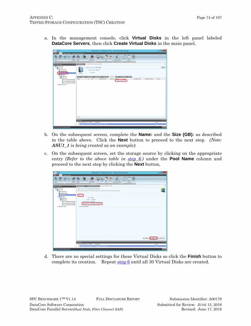
APPENDIX C: Page 74 of 107 TESTED STORAGE CONFIGURATION (TSC) CREATION
SPC BENCHMARK 1™ V1.14 FULL DISCLOSURE REPORT Submission Identifier: A00179 DataCore Software Corporation Submitted for Review: JUNE 15, 2016 DataCore Parallel Server(Dual Node, Fibre Channel SAN) Revised: June 17, 2016
a. In the management console, click Virtual Disks in the left panel labeled
DataCore Servers, then click Create Virtual Disks in the main panel.
b. On the subsequent screen, complete the Name: and the Size (GB): as described in the table above. Click the Next button to proceed to the next step. (Note: ASU1_1 is being created as an example):
c. On the subsequent screen, set the storage source by clicking on the appropriate entry (Refer to the above table in step 6.) under the Pool Name column and proceed to the next step by clicking the Next button,
d. There are no special settings for these Virtual Disks so click the Finish button to complete its creation. Repeat step 6 until all 30 Virtual Disks are created.
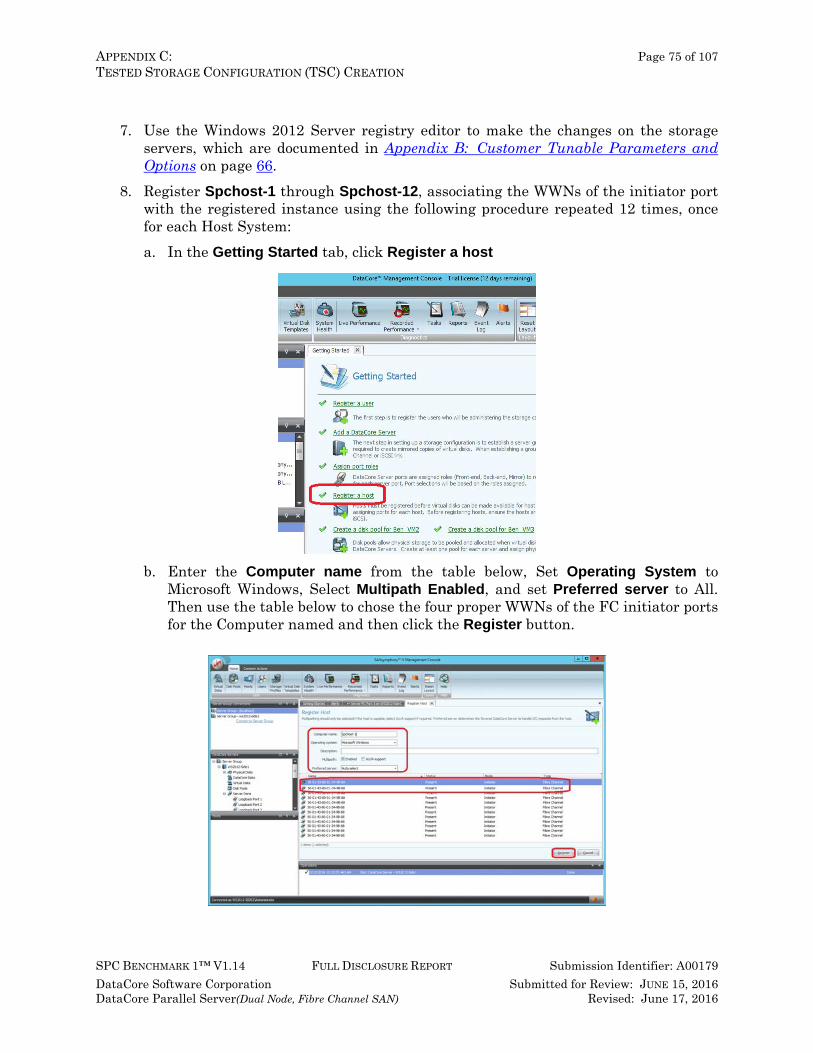
APPENDIX C: Page 75 of 107 TESTED STORAGE CONFIGURATION (TSC) CREATION
SPC BENCHMARK 1™ V1.14 FULL DISCLOSURE REPORT Submission Identifier: A00179 DataCore Software Corporation Submitted for Review: JUNE 15, 2016 DataCore Parallel Server(Dual Node, Fibre Channel SAN) Revised: June 17, 2016
7. Use the Windows 2012 Server registry editor to make the changes on the storage
servers, which are documented in Appendix B: Customer Tunable Parameters and Options on page 66.
8. Register Spchost-1 through Spchost-12, associating the WWNs of the initiator port with the registered instance using the following procedure repeated 12 times, once for each Host System: a. In the Getting Started tab, click Register a host
b. Enter the Computer name from the table below, Set Operating System to Microsoft Windows, Select Multipath Enabled, and set Preferred server to All. Then use the table below to chose the four proper WWNs of the FC initiator ports for the Computer named and then click the Register button.
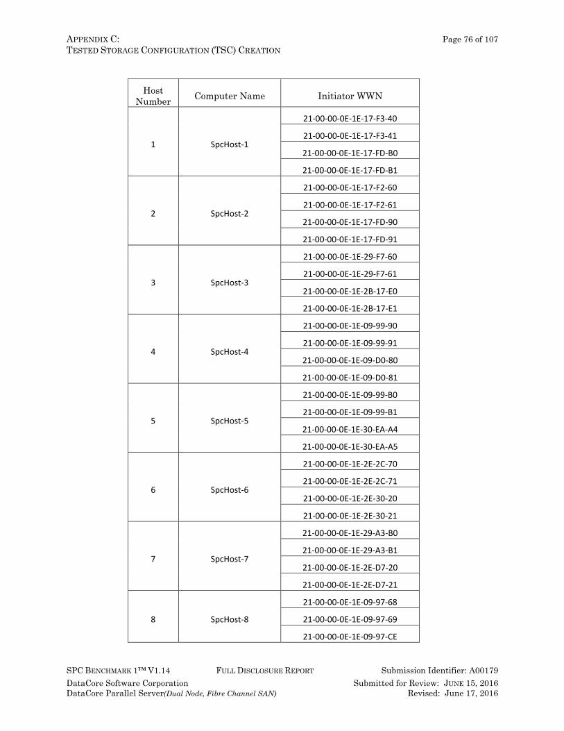
APPENDIX C: Page 76 of 107 TESTED STORAGE CONFIGURATION (TSC) CREATION
SPC BENCHMARK 1™ V1.14 FULL DISCLOSURE REPORT Submission Identifier: A00179 DataCore Software Corporation Submitted for Review: JUNE 15, 2016 DataCore Parallel Server(Dual Node, Fibre Channel SAN) Revised: June 17, 2016
Host
Number Computer Name Initiator WWN
1 SpcHost-1
21-00-00-0E-1E-17-F3-40
21-00-00-0E-1E-17-F3-41
21-00-00-0E-1E-17-FD-B0
21-00-00-0E-1E-17-FD-B1
2 SpcHost-2
21-00-00-0E-1E-17-F2-60
21-00-00-0E-1E-17-F2-61
21-00-00-0E-1E-17-FD-90
21-00-00-0E-1E-17-FD-91
3 SpcHost-3
21-00-00-0E-1E-29-F7-60
21-00-00-0E-1E-29-F7-61
21-00-00-0E-1E-2B-17-E0
21-00-00-0E-1E-2B-17-E1
4 SpcHost-4
21-00-00-0E-1E-09-99-90
21-00-00-0E-1E-09-99-91
21-00-00-0E-1E-09-D0-80
21-00-00-0E-1E-09-D0-81
5 SpcHost-5
21-00-00-0E-1E-09-99-B0
21-00-00-0E-1E-09-99-B1
21-00-00-0E-1E-30-EA-A4
21-00-00-0E-1E-30-EA-A5
6 SpcHost-6
21-00-00-0E-1E-2E-2C-70
21-00-00-0E-1E-2E-2C-71
21-00-00-0E-1E-2E-30-20
21-00-00-0E-1E-2E-30-21
7 SpcHost-7
21-00-00-0E-1E-29-A3-B0
21-00-00-0E-1E-29-A3-B1
21-00-00-0E-1E-2E-D7-20
21-00-00-0E-1E-2E-D7-21
8 SpcHost-8
21-00-00-0E-1E-09-97-68
21-00-00-0E-1E-09-97-69
21-00-00-0E-1E-09-97-CE
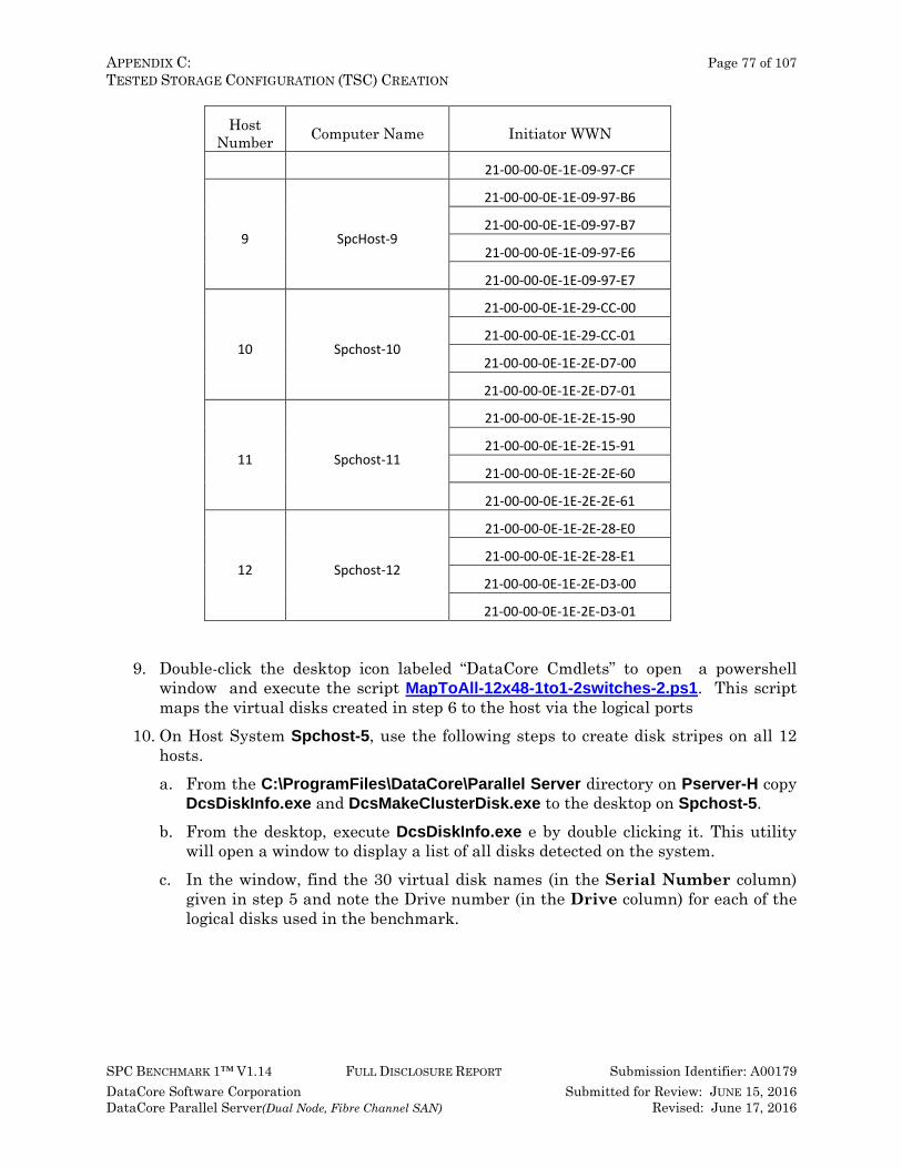
APPENDIX C: Page 77 of 107 TESTED STORAGE CONFIGURATION (TSC) CREATION
SPC BENCHMARK 1™ V1.14 FULL DISCLOSURE REPORT Submission Identifier: A00179 DataCore Software Corporation Submitted for Review: JUNE 15, 2016 DataCore Parallel Server(Dual Node, Fibre Channel SAN) Revised: June 17, 2016
Host Number Computer Name Initiator WWN
21-00-00-0E-1E-09-97-CF
9 SpcHost-9
21-00-00-0E-1E-09-97-B6
21-00-00-0E-1E-09-97-B7
21-00-00-0E-1E-09-97-E6
21-00-00-0E-1E-09-97-E7
10 Spchost-10
21-00-00-0E-1E-29-CC-00
21-00-00-0E-1E-29-CC-01
21-00-00-0E-1E-2E-D7-00
21-00-00-0E-1E-2E-D7-01
11 Spchost-11
21-00-00-0E-1E-2E-15-90
21-00-00-0E-1E-2E-15-91
21-00-00-0E-1E-2E-2E-60
21-00-00-0E-1E-2E-2E-61
12 Spchost-12
21-00-00-0E-1E-2E-28-E0
21-00-00-0E-1E-2E-28-E1
21-00-00-0E-1E-2E-D3-00
21-00-00-0E-1E-2E-D3-01
9. Double-click the desktop icon labeled “DataCore Cmdlets” to open a powershell
window and execute the script MapToAll-12x48-1to1-2switches-2.ps1. This script maps the virtual disks created in step 6 to the host via the logical ports
10. On Host System Spchost-5, use the following steps to create disk stripes on all 12 hosts. a. From the C:\ProgramFiles\DataCore\Parallel Server directory on Pserver-H copy
DcsDiskInfo.exe and DcsMakeClusterDisk.exe to the desktop on Spchost-5. b. From the desktop, execute DcsDiskInfo.exe e by double clicking it. This utility
will open a window to display a list of all disks detected on the system. c. In the window, find the 30 virtual disk names (in the Serial Number column)
given in step 5 and note the Drive number (in the Drive column) for each of the logical disks used in the benchmark.
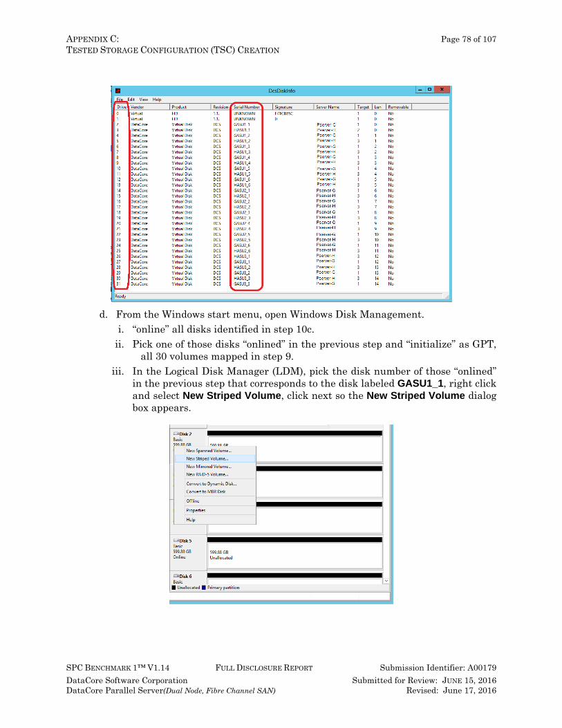
APPENDIX C: Page 78 of 107 TESTED STORAGE CONFIGURATION (TSC) CREATION
SPC BENCHMARK 1™ V1.14 FULL DISCLOSURE REPORT Submission Identifier: A00179 DataCore Software Corporation Submitted for Review: JUNE 15, 2016 DataCore Parallel Server(Dual Node, Fibre Channel SAN) Revised: June 17, 2016
d. From the Windows start menu, open Windows Disk Management. i. “online” all disks identified in step 10c.
ii. Pick one of those disks “onlined” in the previous step and “initialize” as GPT, all 30 volumes mapped in step 9.
iii. In the Logical Disk Manager (LDM), pick the disk number of those “onlined” in the previous step that corresponds to the disk labeled GASU1_1, right click and select New Striped Volume, click next so the New Striped Volume dialog box appears.
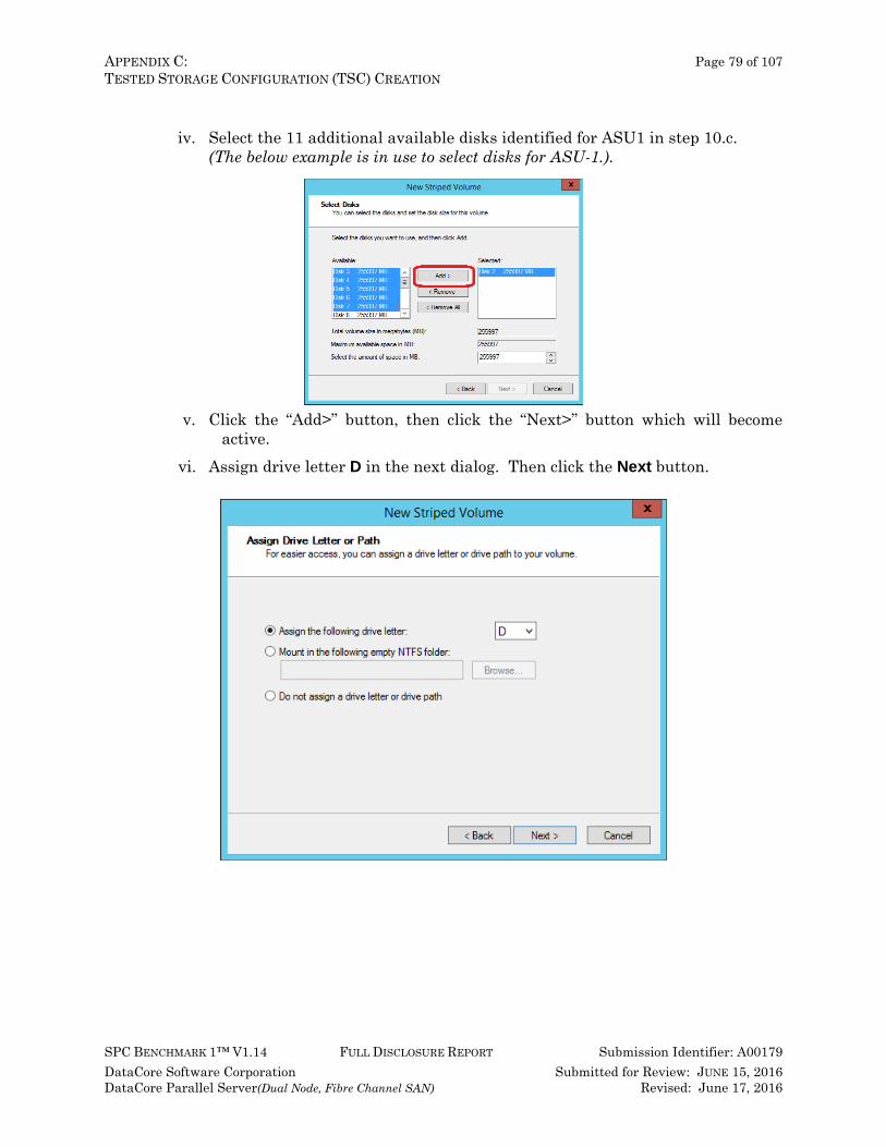
APPENDIX C: Page 79 of 107 TESTED STORAGE CONFIGURATION (TSC) CREATION
SPC BENCHMARK 1™ V1.14 FULL DISCLOSURE REPORT Submission Identifier: A00179 DataCore Software Corporation Submitted for Review: JUNE 15, 2016 DataCore Parallel Server(Dual Node, Fibre Channel SAN) Revised: June 17, 2016
iv. Select the 11 additional available disks identified for ASU1 in step 10.c.
(The below example is in use to select disks for ASU-1.).
v. Click the “Add>” button, then click the “Next>” button which will become active.
vi. Assign drive letter D in the next dialog. Then click the Next button.
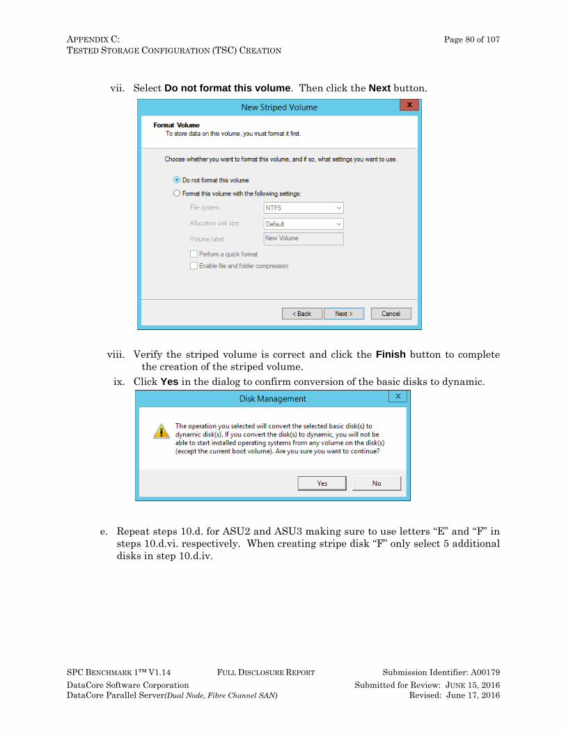
APPENDIX C: Page 80 of 107 TESTED STORAGE CONFIGURATION (TSC) CREATION
SPC BENCHMARK 1™ V1.14 FULL DISCLOSURE REPORT Submission Identifier: A00179 DataCore Software Corporation Submitted for Review: JUNE 15, 2016 DataCore Parallel Server(Dual Node, Fibre Channel SAN) Revised: June 17, 2016
vii. Select Do not format this volume. Then click the Next button.
viii. Verify the striped volume is correct and click the Finish button to complete
the creation of the striped volume. ix. Click Yes in the dialog to confirm conversion of the basic disks to dynamic.
e. Repeat steps 10.d. for ASU2 and ASU3 making sure to use letters “E” and “F” in
steps 10.d.vi. respectively. When creating stripe disk “F” only select 5 additional disks in step 10.d.iv.
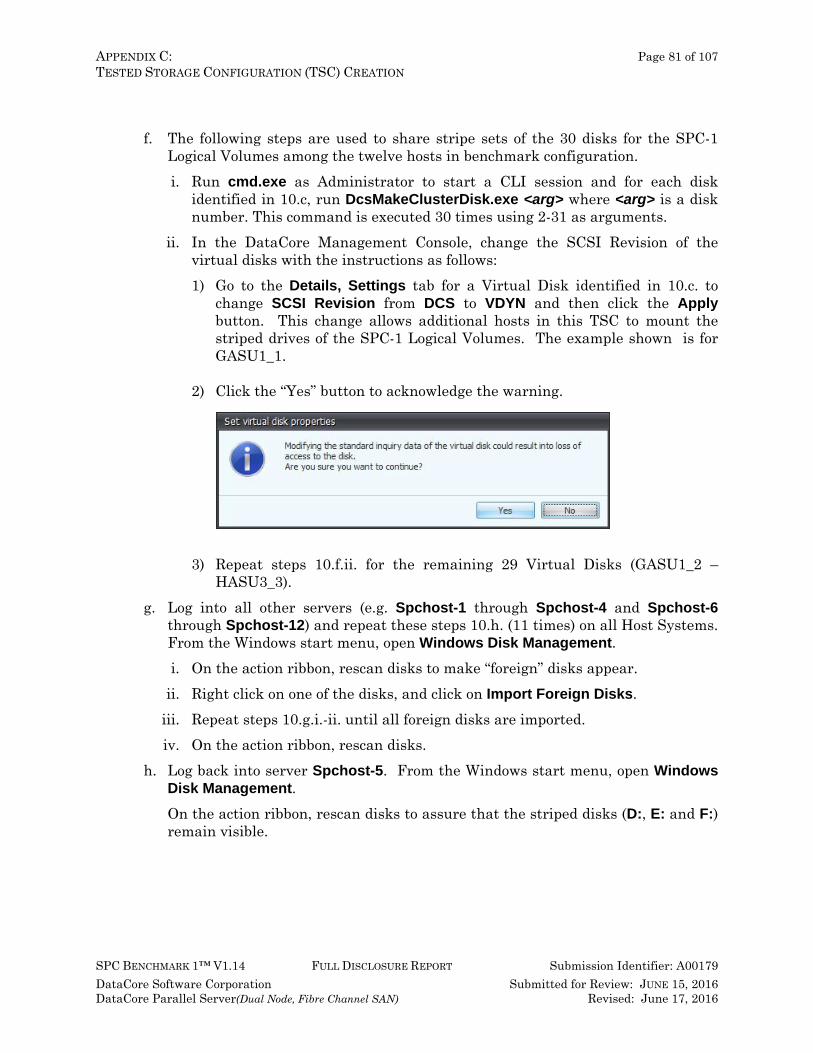
APPENDIX C: Page 81 of 107 TESTED STORAGE CONFIGURATION (TSC) CREATION
SPC BENCHMARK 1™ V1.14 FULL DISCLOSURE REPORT Submission Identifier: A00179 DataCore Software Corporation Submitted for Review: JUNE 15, 2016 DataCore Parallel Server(Dual Node, Fibre Channel SAN) Revised: June 17, 2016
f. The following steps are used to share stripe sets of the 30 disks for the SPC-1
Logical Volumes among the twelve hosts in benchmark configuration. i. Run cmd.exe as Administrator to start a CLI session and for each disk
identified in 10.c, run DcsMakeClusterDisk.exe <arg> where <arg> is a disk number. This command is executed 30 times using 2-31 as arguments.
ii. In the DataCore Management Console, change the SCSI Revision of the virtual disks with the instructions as follows: 1) Go to the Details, Settings tab for a Virtual Disk identified in 10.c. to
change SCSI Revision from DCS to VDYN and then click the Apply button. This change allows additional hosts in this TSC to mount the striped drives of the SPC-1 Logical Volumes. The example shown is for GASU1_1.
2) Click the “Yes” button to acknowledge the warning.
3) Repeat steps 10.f.ii. for the remaining 29 Virtual Disks (GASU1_2 –
HASU3_3). g. Log into all other servers (e.g. Spchost-1 through Spchost-4 and Spchost-6
through Spchost-12) and repeat these steps 10.h. (11 times) on all Host Systems. From the Windows start menu, open Windows Disk Management. i. On the action ribbon, rescan disks to make “foreign” disks appear.
ii. Right click on one of the disks, and click on Import Foreign Disks. iii. Repeat steps 10.g.i.-ii. until all foreign disks are imported. iv. On the action ribbon, rescan disks.
h. Log back into server Spchost-5. From the Windows start menu, open Windows Disk Management. On the action ribbon, rescan disks to assure that the striped disks (D:, E: and F:) remain visible.
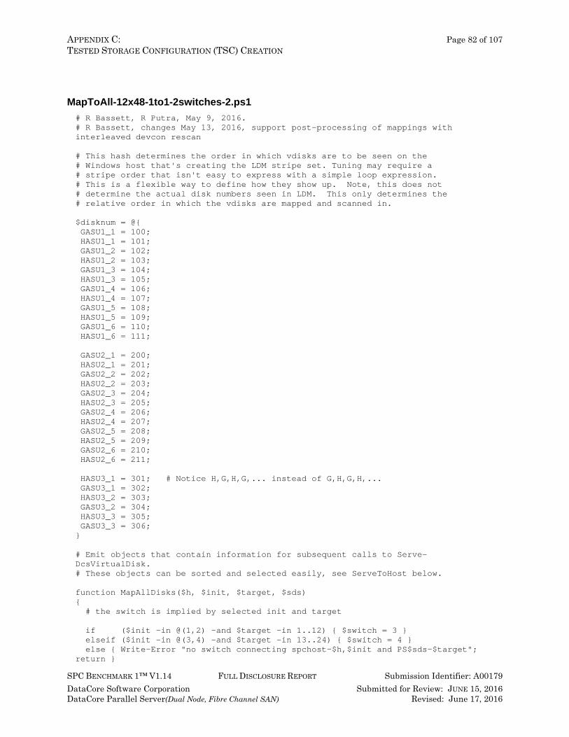
APPENDIX C: Page 82 of 107 TESTED STORAGE CONFIGURATION (TSC) CREATION
SPC BENCHMARK 1™ V1.14 FULL DISCLOSURE REPORT Submission Identifier: A00179 DataCore Software Corporation Submitted for Review: JUNE 15, 2016 DataCore Parallel Server(Dual Node, Fibre Channel SAN) Revised: June 17, 2016
MapToAll-12x48-1to1-2switches-2.ps1 # R Bassett, R Putra, May 9, 2016. # R Bassett, changes May 13, 2016, support post-processing of mappings with interleaved devcon rescan # This hash determines the order in which vdisks are to be seen on the # Windows host that's creating the LDM stripe set. Tuning may require a # stripe order that isn't easy to express with a simple loop expression. # This is a flexible way to define how they show up. Note, this does not # determine the actual disk numbers seen in LDM. This only determines the # relative order in which the vdisks are mapped and scanned in. $disknum = @{ GASU1_1 = 100; HASU1_1 = 101; GASU1_2 = 102; HASU1_2 = 103; GASU1_3 = 104; HASU1_3 = 105; GASU1_4 = 106; HASU1_4 = 107; GASU1_5 = 108; HASU1_5 = 109; GASU1_6 = 110; HASU1_6 = 111; GASU2_1 = 200; HASU2_1 = 201; GASU2_2 = 202; HASU2_2 = 203; GASU2_3 = 204; HASU2_3 = 205; GASU2_4 = 206; HASU2_4 = 207; GASU2_5 = 208; HASU2_5 = 209; GASU2_6 = 210; HASU2_6 = 211; HASU3_1 = 301; # Notice H,G,H,G,... instead of G,H,G,H,... GASU3_1 = 302; HASU3_2 = 303; GASU3_2 = 304; HASU3_3 = 305; GASU3_3 = 306; } # Emit objects that contain information for subsequent calls to Serve-DcsVirtualDisk. # These objects can be sorted and selected easily, see ServeToHost below. function MapAllDisks($h, $init, $target, $sds) { # the switch is implied by selected init and target if ($init -in @(1,2) -and $target -in 1..12) { $switch = 3 } elseif ($init -in @(3,4) -and $target -in 13..24) { $switch = 4 } else { Write-Error "no switch connecting spchost-$h,$init and PS$sds-$target"; return }
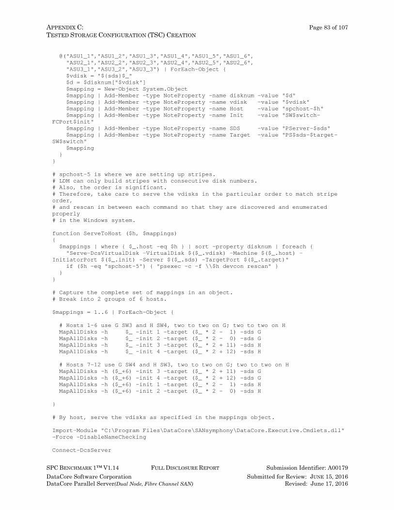
APPENDIX C: Page 83 of 107 TESTED STORAGE CONFIGURATION (TSC) CREATION
SPC BENCHMARK 1™ V1.14 FULL DISCLOSURE REPORT Submission Identifier: A00179 DataCore Software Corporation Submitted for Review: JUNE 15, 2016 DataCore Parallel Server(Dual Node, Fibre Channel SAN) Revised: June 17, 2016
@("ASU1_1","ASU1_2","ASU1_3","ASU1_4","ASU1_5","ASU1_6", "ASU2_1","ASU2_2","ASU2_3","ASU2_4","ASU2_5","ASU2_6", "ASU3_1","ASU3_2","ASU3_3") | ForEach-Object { $vdisk = "${sds}$_" $d = $disknum["$vdisk"] $mapping = New-Object System.Object $mapping | Add-Member -type NoteProperty -name disknum -value "$d" $mapping | Add-Member -type NoteProperty -name vdisk -value "$vdisk" $mapping | Add-Member -type NoteProperty -name Host -value "spchost-$h" $mapping | Add-Member -type NoteProperty -name Init -value "SW$switch-FCPort$init" $mapping | Add-Member -type NoteProperty -name SDS -value "PServer-$sds" $mapping | Add-Member -type NoteProperty -name Target -value "PS$sds-$target-SW$switch" $mapping } } # spchost-5 is where we are setting up stripes. # LDM can only build stripes with consecutive disk numbers. # Also, the order is significant. # Therefore, take care to serve the vdisks in the particular order to match stripe order, # and rescan in between each command so that they are discovered and enumerated properly # in the Windows system. function ServeToHost ($h, $mappings) { $mappings | where { $_.host -eq $h } | sort -property disknum | foreach { "Serve-DcsVirtualDisk -VirtualDisk $($_.vdisk) -Machine $($_.host) -InitiatorPort $($_.init) -Server $($_.sds) -TargetPort $($_.target)" if ($h -eq "spchost-5") { "psexec -c -f \\$h devcon rescan" } } } # Capture the complete set of mappings in an object. # Break into 2 groups of 6 hosts. $mappings = 1..6 | ForEach-Object { # Hosts 1-6 use G SW3 and H SW4, two to two on G; two to two on H MapAllDisks -h $_ -init 1 -target ($_ * 2 - 1) -sds G MapAllDisks -h $_ -init 2 -target ($_ * 2 - 0) -sds G MapAllDisks -h $_ -init 3 -target ($_ * 2 + 11) -sds H MapAllDisks -h $_ -init 4 -target ($_ * 2 + 12) -sds H # Hosts 7-12 use G SW4 and H SW3, two to two on G; two to two on H MapAllDisks -h ($_+6) -init 3 -target ($_ * 2 + 11) -sds G MapAllDisks -h ($_+6) -init 4 -target ($_ * 2 + 12) -sds G MapAllDisks -h ($_+6) -init 1 -target ($_ * 2 - 1) -sds H MapAllDisks -h ($_+6) -init 2 -target ($_ * 2 - 0) -sds H } # By host, serve the vdisks as specified in the mappings object. Import-Module "C:\Program Files\DataCore\SANsymphony\DataCore.Executive.Cmdlets.dll" -Force -DisableNameChecking Connect-DcsServer
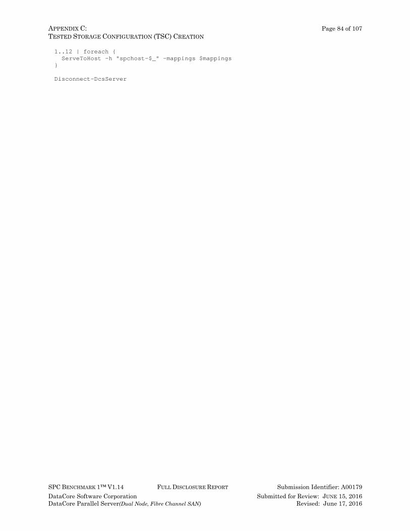
APPENDIX C: Page 84 of 107 TESTED STORAGE CONFIGURATION (TSC) CREATION
SPC BENCHMARK 1™ V1.14 FULL DISCLOSURE REPORT Submission Identifier: A00179 DataCore Software Corporation Submitted for Review: JUNE 15, 2016 DataCore Parallel Server(Dual Node, Fibre Channel SAN) Revised: June 17, 2016
1..12 | foreach { ServeToHost -h "spchost-$_" -mappings $mappings } Disconnect-DcsServer

APPENDIX D: Page 85 of 107 SPC-1 WORKLOAD GENERATOR STORAGE COMMANDS AND PARAMETERS
SPC BENCHMARK 1™ V1.14 FULL DISCLOSURE REPORT Submission Identifier: A00179 DataCore Software Corporation Submitted for Review: JUNE 15, 2016 DataCore Parallel Server(Dual Node, Fibre Channel SAN) Revised: June 17, 2016
APPENDIX D: SPC-1 WORKLOAD GENERATOR STORAGE COMMANDS AND PARAMETERS
ASU Pre-Fill The content of the command and parameter file used in the benchmark to execute the required ASU pre-fill operation is listed below. compratio=1 sd=default,threads=8 sd=asu1_1,lun=\\.\E:,size=5346000000000,threads=4 sd=asu2_1,lun=\\.\F:,size=5346000000000,threads=4 sd=asu3_1,lun=\\.\G:,size=1188000000000,threads=4 wd=default,rdpct=0,seek=-1,xfersize=512k wd=wd1,sd=asu1_1 wd=wd2,sd=asu2_1 wd=wd3,sd=asu3_1 rd=asuprefill,wd=wd*,iorate=max,elapsed=24h,interval=60
Primary Metrics, and Repeatability Tests The content of SPC-1 Workload Generator command and parameter file used in this benchmark to execute the Primary Metrics (Sustainability Test Phase, IOPS Test Phase, and Response Time Ramp Test Phase) and Repeatability (Repeatability Test Phase 1 and Repeatability Test Phase 2) Tests is listed below. host=master slaves=(h1,h87,h173,h259,h345,h431,h517,h603,h689,h775,h861,h947,h2,h88,h174,h260,h346,h432,h518,h604,h690,h776,h862,h948,h3,h89,h175,h261,h347,h433,h519,h605,h691,h777,h863,h949,h4,h90,h176,h262,h348,h434,h520,h606,h692,h778,h864,h950,h5,h91,h177,h263,h349,h435,h521,h607,h693,h779,h865,h951,h6,h92,h178,h264,h350,h436,h522,h608,h694,h780,h866,h952,h7,h93,h179,h265,h351,h437,h523,h609,h695,h781,h867,h953,h8,h94,h180,h266,h352,h438,h524,h610,h696,h782,h868,h954,h9,h95,h181,h267,h353,h439,h525,h611,h697,h783,h869,h955,h10,h96,h182,h268,h354,h440,h526,h612,h698,h784,h870,h956,h11,h97,h183,h269,h355,h441,h527,h613,h699,h785,h871,h957,h12,h98,h184,h270,h356,h442,h528,h614,h700,h786,h872,h958,h13,h99,h185,h271,h357,h443,h529,h615,h701,h787,h873,h959,h14,h100,h186,h272,h358,h444,h530,h616,h702,h788,h874,h960,h15,h101,h187,h273,h359,h445,h531,h617,h703,h789,h875,h961,h16,h102,h188,h274,h360,h446,h532,h618,h704,h790,h876,h962,h17,h103,h189,h275,h361,h447,h533,h619,h705,h791,h877,h963,h18,h104,h190,h276,h362,h448,h534,h620,h706,h792,h878,h964,h19,h105,h191,h277,h363,h449,h535,h621,h707,h793,h879,h965,h20,h106,h192,h278,h364,h450,h536,h622,h708,h794,h880,h966,h21,h107,h193,h279,h365,h451,h537,h623,h709,h795,h881,h967,h22,h108,h194,h280,h366,h452,h538,h624,h710,h796,h882,h968,h23,h109,h195,h281,h367,h453,h539,h625,h711,h797,h883,h969,h24,h110,h196,h282,h368,h454,h540,h626,h712,h798,h884,h970,h25,h111,h197,h283,h369,h455,h541,h627,h713,h799,h885,h971,h26,h112,h198,h284,h370,h456,h542,h628,h714,h800,h886,h972,h27,h113,h199,h285,h371,h457,h543,h629,h715,h801,h887,h973,h28,h114,h200,h286,h372,h458,h544,h630,h716,h802,h888,h974,h29,h115,h201,h287,h373,h459,h545,h631,h717,h803,h889,h975,h30,h116,h202,h288,h374,h460,h546,h632,h718,h804,h890,h976,h31,h117,h203,h289,h375,h461,h547,h633,h719,h805,h891,h977,h32,h118,h204,h290,h376,h462,h548,h634,h720,h806,h892,h978,h33,h119,h205,h291,h377,h463,h549,h635,h721,h807,h893,h979,h34,h120,h206,h292,h378,h464,h550,h636,h722,h808,h894,h980,h35,h121,h207,h293,h379,h465,h551,h637,h723,h809,h895,h981,h36,h122,h208,h294,h380,h466,h552,h638,h724,h810,h896,h982,h37,h123,h209,h295,h381,h467,h553,h639,h725,h811,h897,h983,h38,h124,h210,h296,h382,h468,h554,h640,h726,h812,h898,h984,h39,h125,h211,h297,h383,h469,h555,h641,h727,h813,h899,h985,h40,h126,h212,h298,h384,h470,h556,h642,h728,h814,h900,h986,h41,h127,h213,h299,h385,h471,h557,h643,h729,h815,h901,h987,h42,h128,h214,h300,h386,h472,h558,h644,h730,h816,h902,h988,h43,h129,h215,h301,h387,h473,h559,h645,h731,h817,h903,h989,h44,h130,h216,h302,h388,h474,h560,h646,h732,h818,h904,h990,h45,h131,h217,h303,h38
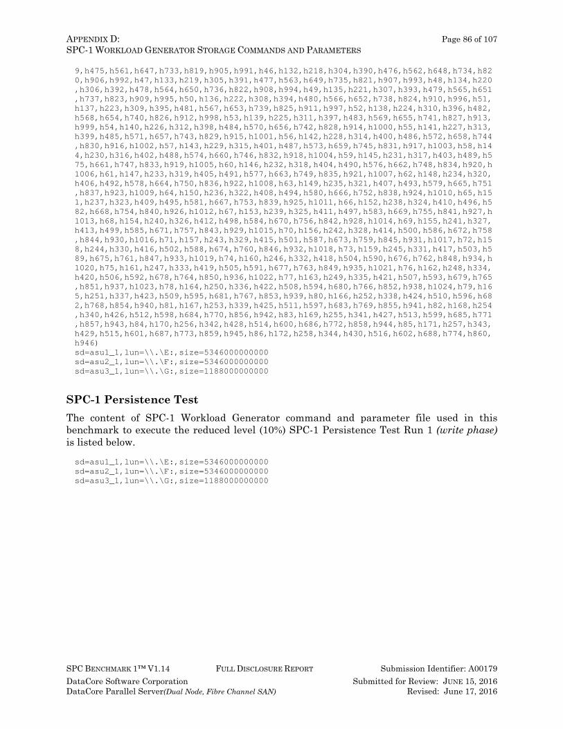
APPENDIX D: Page 86 of 107 SPC-1 WORKLOAD GENERATOR STORAGE COMMANDS AND PARAMETERS
SPC BENCHMARK 1™ V1.14 FULL DISCLOSURE REPORT Submission Identifier: A00179 DataCore Software Corporation Submitted for Review: JUNE 15, 2016 DataCore Parallel Server(Dual Node, Fibre Channel SAN) Revised: June 17, 2016
9,h475,h561,h647,h733,h819,h905,h991,h46,h132,h218,h304,h390,h476,h562,h648,h734,h820,h906,h992,h47,h133,h219,h305,h391,h477,h563,h649,h735,h821,h907,h993,h48,h134,h220,h306,h392,h478,h564,h650,h736,h822,h908,h994,h49,h135,h221,h307,h393,h479,h565,h651,h737,h823,h909,h995,h50,h136,h222,h308,h394,h480,h566,h652,h738,h824,h910,h996,h51,h137,h223,h309,h395,h481,h567,h653,h739,h825,h911,h997,h52,h138,h224,h310,h396,h482,h568,h654,h740,h826,h912,h998,h53,h139,h225,h311,h397,h483,h569,h655,h741,h827,h913,h999,h54,h140,h226,h312,h398,h484,h570,h656,h742,h828,h914,h1000,h55,h141,h227,h313,h399,h485,h571,h657,h743,h829,h915,h1001,h56,h142,h228,h314,h400,h486,h572,h658,h744,h830,h916,h1002,h57,h143,h229,h315,h401,h487,h573,h659,h745,h831,h917,h1003,h58,h144,h230,h316,h402,h488,h574,h660,h746,h832,h918,h1004,h59,h145,h231,h317,h403,h489,h575,h661,h747,h833,h919,h1005,h60,h146,h232,h318,h404,h490,h576,h662,h748,h834,h920,h1006,h61,h147,h233,h319,h405,h491,h577,h663,h749,h835,h921,h1007,h62,h148,h234,h320,h406,h492,h578,h664,h750,h836,h922,h1008,h63,h149,h235,h321,h407,h493,h579,h665,h751,h837,h923,h1009,h64,h150,h236,h322,h408,h494,h580,h666,h752,h838,h924,h1010,h65,h151,h237,h323,h409,h495,h581,h667,h753,h839,h925,h1011,h66,h152,h238,h324,h410,h496,h582,h668,h754,h840,h926,h1012,h67,h153,h239,h325,h411,h497,h583,h669,h755,h841,h927,h1013,h68,h154,h240,h326,h412,h498,h584,h670,h756,h842,h928,h1014,h69,h155,h241,h327,h413,h499,h585,h671,h757,h843,h929,h1015,h70,h156,h242,h328,h414,h500,h586,h672,h758,h844,h930,h1016,h71,h157,h243,h329,h415,h501,h587,h673,h759,h845,h931,h1017,h72,h158,h244,h330,h416,h502,h588,h674,h760,h846,h932,h1018,h73,h159,h245,h331,h417,h503,h589,h675,h761,h847,h933,h1019,h74,h160,h246,h332,h418,h504,h590,h676,h762,h848,h934,h1020,h75,h161,h247,h333,h419,h505,h591,h677,h763,h849,h935,h1021,h76,h162,h248,h334,h420,h506,h592,h678,h764,h850,h936,h1022,h77,h163,h249,h335,h421,h507,h593,h679,h765,h851,h937,h1023,h78,h164,h250,h336,h422,h508,h594,h680,h766,h852,h938,h1024,h79,h165,h251,h337,h423,h509,h595,h681,h767,h853,h939,h80,h166,h252,h338,h424,h510,h596,h682,h768,h854,h940,h81,h167,h253,h339,h425,h511,h597,h683,h769,h855,h941,h82,h168,h254,h340,h426,h512,h598,h684,h770,h856,h942,h83,h169,h255,h341,h427,h513,h599,h685,h771,h857,h943,h84,h170,h256,h342,h428,h514,h600,h686,h772,h858,h944,h85,h171,h257,h343,h429,h515,h601,h687,h773,h859,h945,h86,h172,h258,h344,h430,h516,h602,h688,h774,h860,h946) sd=asu1_1,lun=\\.\E:,size=5346000000000 sd=asu2_1,lun=\\.\F:,size=5346000000000 sd=asu3_1,lun=\\.\G:,size=1188000000000
SPC-1 Persistence Test The content of SPC-1 Workload Generator command and parameter file used in this benchmark to execute the reduced level (10%) SPC-1 Persistence Test Run 1 (write phase) is listed below. sd=asu1_1,lun=\\.\E:,size=5346000000000 sd=asu2_1,lun=\\.\F:,size=5346000000000 sd=asu3_1,lun=\\.\G:,size=1188000000000
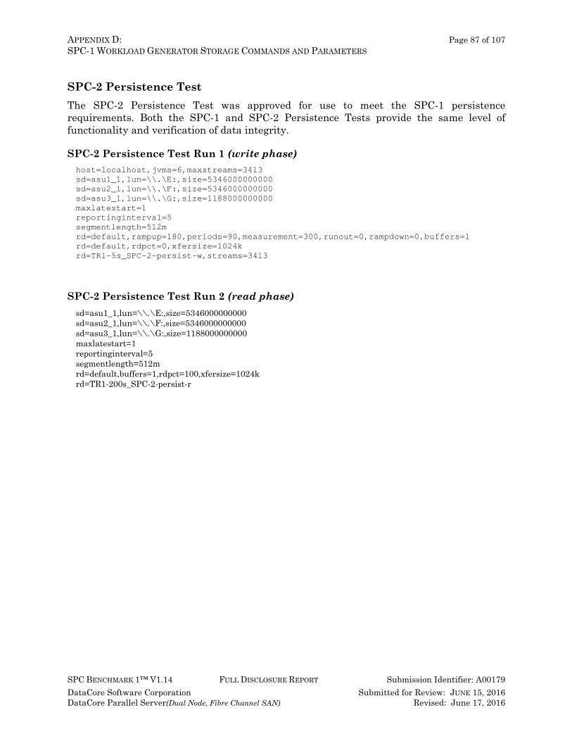
APPENDIX D: Page 87 of 107 SPC-1 WORKLOAD GENERATOR STORAGE COMMANDS AND PARAMETERS
SPC BENCHMARK 1™ V1.14 FULL DISCLOSURE REPORT Submission Identifier: A00179 DataCore Software Corporation Submitted for Review: JUNE 15, 2016 DataCore Parallel Server(Dual Node, Fibre Channel SAN) Revised: June 17, 2016
SPC-2 Persistence Test The SPC-2 Persistence Test was approved for use to meet the SPC-1 persistence requirements. Both the SPC-1 and SPC-2 Persistence Tests provide the same level of functionality and verification of data integrity.
SPC-2 Persistence Test Run 1 (write phase) host=localhost,jvms=6,maxstreams=3413 sd=asu1_1,lun=\\.\E:,size=5346000000000 sd=asu2_1,lun=\\.\F:,size=5346000000000 sd=asu3_1,lun=\\.\G:,size=1188000000000 maxlatestart=1 reportinginterval=5 segmentlength=512m rd=default,rampup=180,periods=90,measurement=300,runout=0,rampdown=0,buffers=1 rd=default,rdpct=0,xfersize=1024k rd=TR1-5s_SPC-2-persist-w,streams=3413
SPC-2 Persistence Test Run 2 (read phase) sd=asu1_1,lun=\\.\E:,size=5346000000000 sd=asu2_1,lun=\\.\F:,size=5346000000000 sd=asu3_1,lun=\\.\G:,size=1188000000000 maxlatestart=1 reportinginterval=5 segmentlength=512m rd=default,buffers=1,rdpct=100,xfersize=1024k rd=TR1-200s_SPC-2-persist-r

APPENDIX E: Page 88 of 107 SPC-1 WORKLOAD GENERATOR INPUT PARAMETERS
SPC BENCHMARK 1™ V1.14 FULL DISCLOSURE REPORT Submission Identifier: A00179 DataCore Software Corporation Submitted for Review: JUNE 15, 2016 DataCore Parallel Server(Dual Node, Fibre Channel SAN) Revised: June 17, 2016
APPENDIX E: SPC-1 WORKLOAD GENERATOR INPUT PARAMETERS The first ‘master’ script, RunSPC1.bat, was executed on Host System, Spchost-5, to:
• Dynamically determine the number of CPUs in each NUMA node and specific affinity mask based on the benchmark configuration (:setcpus). A value of 6 CPUs was used for this benchmark execution.
• Set various benchmark-related environment variables (config.bat). • Generate the required SPC-1 Workload Generator configuration files required for
the Test Run (:config, :configure, :discover, :slavecfg, :updatecfg). The appropriate ‘master’ spc1.cfg files for the benchmark execution.
(The same file is used for the Primary Metrics and Repeatability Tests (multiple Slave JVMs) and a separate file for the SPC-1 Persistence Test (one Slave JVM)
A configuration file, spc1.cfg, for each Slave JVM, which is derived from the appropriate ‘master’ configuration file.
• Using the appropriate arguments, execute the following the following in an uninterrupted sequence: Terminate any pre-existing Slave JVMs prior to executing the ASU pre-fill or
SPC-1 Test Run (:killjvms). Start the required number of Slave JVMs and bind each Slave JVM to a set of
CPUs located on the same NUMA node (:startjvms, :startlocal, :setmask). Activate the appropriate ‘master’ configuration file, spc1.cfg (:mastercfg). Execute the following, based invocation arguments (:benchmark):
o Generate the first set of storage configuration information required for audit (:sysinfo).
o The required ASU pre-fill (:prefill). o The Primary Metrics Test
(Sustainability Test Phase, IOPS Test Phase, and Response Time Ramp Test Phase).
o Terminate and restart the Slave JVMs prior to each Repeatability Test Phase (:restartjvms).
o The Repeatability Test (Repeatability Test Phase 1 and Repeatability Test Phase 2).
o Terminate the Slave JVM used in the prior Tests (:killjvms) o Reduced level (10%) SPC-1 Persistence Test Run 1 (write phase) (:persist1).
(The spc2persist variable in RunSPC1.bat was set to true, so the SPC-2 Persistence Test was used as a substitute for the maximum BSU level SPC-1 Persistence Test. As a result, the SPC-1 Persistence Test Run 1 (write phase) was executed with the reduced BSU level of 10% of which the SPC-1 Workload Generator used 25% of that value.)
o The SPC-2 Persistence Test Run 1 (write phase) (:persist1) which was executed as part of the SPC-2 Persistence Test substitution approved by the auditor.
o Create the second ‘master’ script, Persist2.bat.
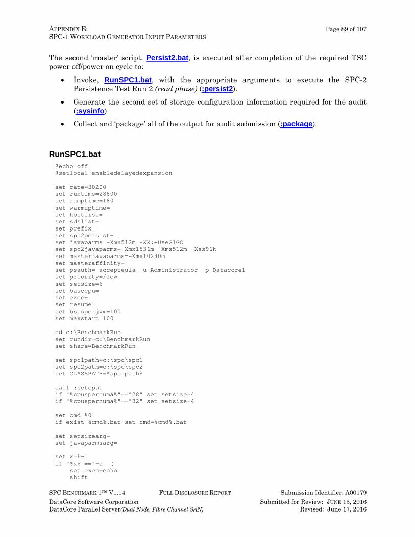
APPENDIX E: Page 89 of 107 SPC-1 WORKLOAD GENERATOR INPUT PARAMETERS
SPC BENCHMARK 1™ V1.14 FULL DISCLOSURE REPORT Submission Identifier: A00179 DataCore Software Corporation Submitted for Review: JUNE 15, 2016 DataCore Parallel Server(Dual Node, Fibre Channel SAN) Revised: June 17, 2016
The second ‘master’ script, Persist2.bat, is executed after completion of the required TSC power off/power on cycle to:
• Invoke, RunSPC1.bat, with the appropriate arguments to execute the SPC-2 Persistence Test Run 2 (read phase) (:persist2).
• Generate the second set of storage configuration information required for the audit (:sysinfo).
• Collect and ‘package’ all of the output for audit submission (:package).
RunSPC1.bat @echo off @setlocal enabledelayedexpansion set rate=30200 set runtime=28800 set ramptime=180 set warmuptime= set hostlist= set sdslist= set prefix= set spc2persist= set javaparms=-Xmx512m -XX:+UseG1GC set spc2javaparms=-Xmx1536m -Xms512m -Xss96k set masterjavaparms=-Xmx10240m set masteraffinity= set psauth=-accepteula -u Administrator -p Datacore1 set priority=/low set setsize=6 set basecpu= set exec= set resume= set bsusperjvm=100 set maxstart=100 cd c:\BenchmarkRun set rundir=c:\BenchmarkRun set share=BenchmarkRun set spc1path=c:\spc\spc1 set spc2path=c:\spc\spc2 set CLASSPATH=%spc1path% call :setcpus if "%cpuspernuma%"=="28" set setsize=4 if "%cpuspernuma%"=="32" set setsize=4 set cmd=%0 if exist %cmd%.bat set cmd=%cmd%.bat set setsizearg= set javaparmsarg= set x=%~1 if "%x%"=="-d" ( set exec=echo shift
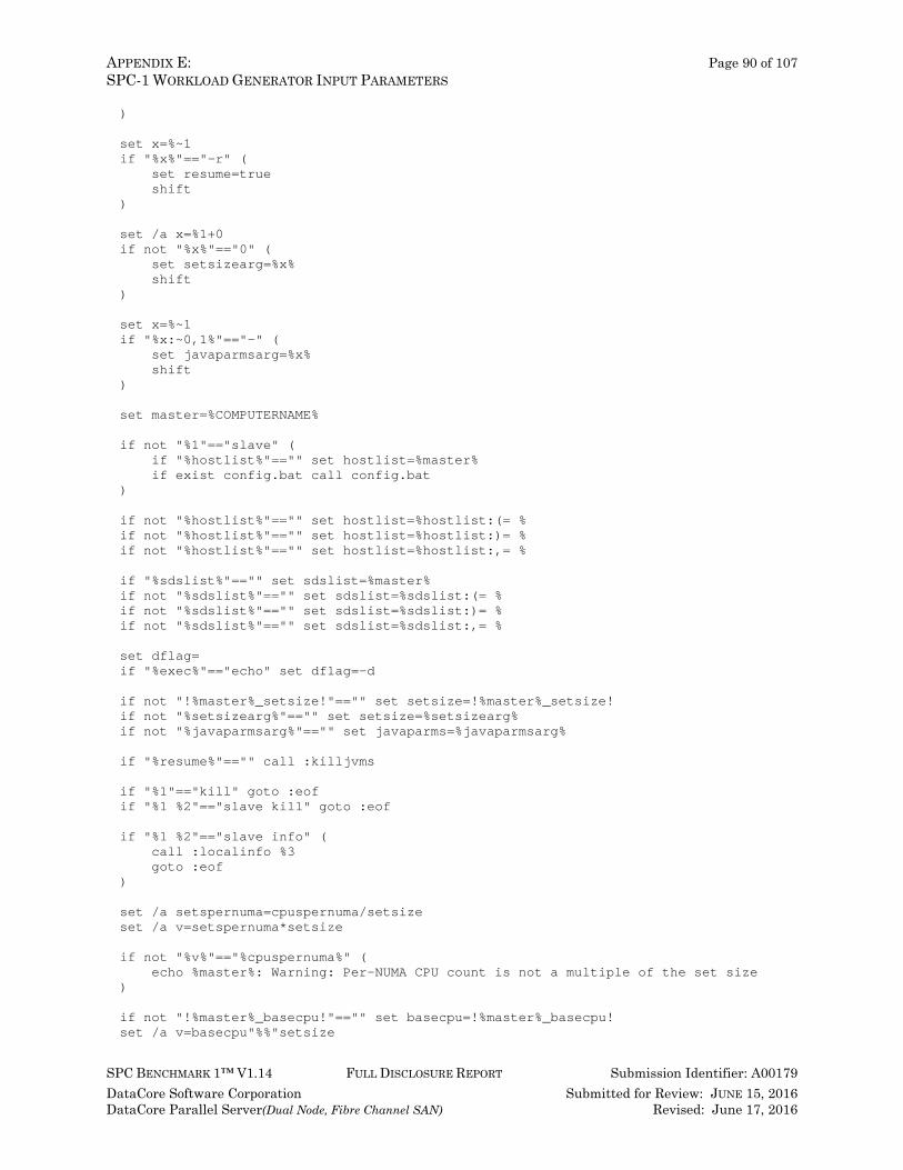
APPENDIX E: Page 90 of 107 SPC-1 WORKLOAD GENERATOR INPUT PARAMETERS
SPC BENCHMARK 1™ V1.14 FULL DISCLOSURE REPORT Submission Identifier: A00179 DataCore Software Corporation Submitted for Review: JUNE 15, 2016 DataCore Parallel Server(Dual Node, Fibre Channel SAN) Revised: June 17, 2016
) set x=%~1 if "%x%"=="-r" ( set resume=true shift ) set /a x=%1+0 if not "%x%"=="0" ( set setsizearg=%x% shift ) set x=%~1 if "%x:~0,1%"=="-" ( set javaparmsarg=%x% shift ) set master=%COMPUTERNAME% if not "%1"=="slave" ( if "%hostlist%"=="" set hostlist=%master% if exist config.bat call config.bat ) if not "%hostlist%"=="" set hostlist=%hostlist:(= % if not "%hostlist%"=="" set hostlist=%hostlist:)= % if not "%hostlist%"=="" set hostlist=%hostlist:,= % if "%sdslist%"=="" set sdslist=%master% if not "%sdslist%"=="" set sdslist=%sdslist:(= % if not "%sdslist%"=="" set sdslist=%sdslist:)= % if not "%sdslist%"=="" set sdslist=%sdslist:,= % set dflag= if "%exec%"=="echo" set dflag=-d if not "!%master%_setsize!"=="" set setsize=!%master%_setsize! if not "%setsizearg%"=="" set setsize=%setsizearg% if not "%javaparmsarg%"=="" set javaparms=%javaparmsarg% if "%resume%"=="" call :killjvms if "%1"=="kill" goto :eof if "%1 %2"=="slave kill" goto :eof if "%1 %2"=="slave info" ( call :localinfo %3 goto :eof ) set /a setspernuma=cpuspernuma/setsize set /a v=setspernuma*setsize if not "%v%"=="%cpuspernuma%" ( echo %master%: Warning: Per-NUMA CPU count is not a multiple of the set size ) if not "!%master%_basecpu!"=="" set basecpu=!%master%_basecpu! set /a v=basecpu"%%"setsize
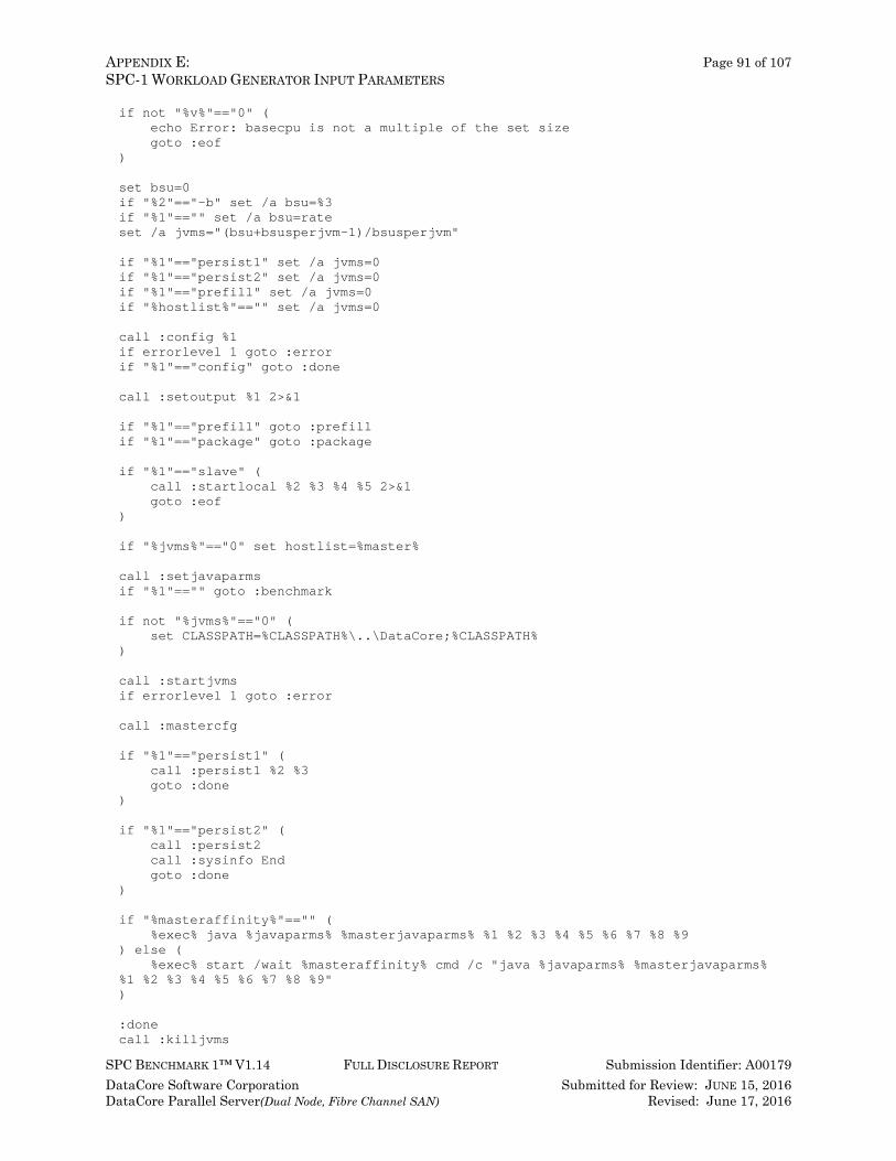
APPENDIX E: Page 91 of 107 SPC-1 WORKLOAD GENERATOR INPUT PARAMETERS
SPC BENCHMARK 1™ V1.14 FULL DISCLOSURE REPORT Submission Identifier: A00179 DataCore Software Corporation Submitted for Review: JUNE 15, 2016 DataCore Parallel Server(Dual Node, Fibre Channel SAN) Revised: June 17, 2016
if not "%v%"=="0" ( echo Error: basecpu is not a multiple of the set size goto :eof ) set bsu=0 if "%2"=="-b" set /a bsu=%3 if "%1"=="" set /a bsu=rate set /a jvms="(bsu+bsusperjvm-1)/bsusperjvm" if "%1"=="persist1" set /a jvms=0 if "%1"=="persist2" set /a jvms=0 if "%1"=="prefill" set /a jvms=0 if "%hostlist%"=="" set /a jvms=0 call :config %1 if errorlevel 1 goto :error if "%1"=="config" goto :done call :setoutput %1 2>&1 if "%1"=="prefill" goto :prefill if "%1"=="package" goto :package if "%1"=="slave" ( call :startlocal %2 %3 %4 %5 2>&1 goto :eof ) if "%jvms%"=="0" set hostlist=%master% call :setjavaparms if "%1"=="" goto :benchmark if not "%jvms%"=="0" ( set CLASSPATH=%CLASSPATH%\..\DataCore;%CLASSPATH% ) call :startjvms if errorlevel 1 goto :error call :mastercfg if "%1"=="persist1" ( call :persist1 %2 %3 goto :done ) if "%1"=="persist2" ( call :persist2 call :sysinfo End goto :done ) if "%masteraffinity%"=="" ( %exec% java %javaparms% %masterjavaparms% %1 %2 %3 %4 %5 %6 %7 %8 %9 ) else ( %exec% start /wait %masteraffinity% cmd /c "java %javaparms% %masterjavaparms% %1 %2 %3 %4 %5 %6 %7 %8 %9" ) :done call :killjvms
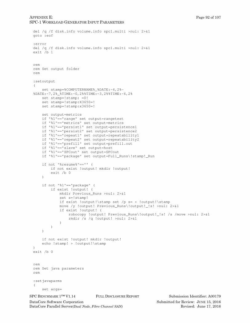
APPENDIX E: Page 92 of 107 SPC-1 WORKLOAD GENERATOR INPUT PARAMETERS
SPC BENCHMARK 1™ V1.14 FULL DISCLOSURE REPORT Submission Identifier: A00179 DataCore Software Corporation Submitted for Review: JUNE 15, 2016 DataCore Parallel Server(Dual Node, Fibre Channel SAN) Revised: June 17, 2016
del /q /f disk.info volume.info spc1.multi >nul: 2>&1 goto :eof :error del /q /f disk.info volume.info spc1.multi >nul: 2>&1 exit /b 1 rem rem Set output folder rem :setoutput ( set stamp=%COMPUTERNAME%_%DATE:~4,2%-%DATE:~7,2%_%TIME:~0,2%%TIME:~3,2%%TIME:~6,2% set stamp=!stamp: =0! set stamp=!stamp:X3650=! set stamp=!stamp:x3650=! set output=metrics if "%1"=="range" set output=rangetest if "%1"=="metrics" set output=metrics if "%1"=="persist1" set output=persistence1 if "%1"=="persist2" set output=persistence2 if "%1"=="repeat1" set output=repeatability1 if "%1"=="repeat2" set output=repeatability2 if "%1"=="prefill" set output=prefill.out if "%1"=="slave" set output=host if "%1"=="SPCout" set output=SPCout if "%1"=="package" set output=Full_Runs\!stamp!_Run if not "%resume%"=="" ( if not exist !output! mkdir !output! exit /b 0 ) if not "%1"=="package" ( if exist !output! ( mkdir Previous_Runs >nul: 2>&1 set s=!stamp! if exist !output!\stamp set /p s= < !output!\stamp move /y !output! Previous_Runs\!output!_!s! >nul: 2>&1 if exist !output! ( robocopy !output! Previous_Runs\!output!_!s! /s /move >nul: 2>&1 rmdir /s /q !output! >nul: 2>&1 ) ) ) if not exist !output! mkdir !output! echo !stamp! > !output!\stamp ) exit /b 0 rem rem Set java parameters rem :setjavaparms ( set args=
APPENDIX E: Page 93 of 107 SPC-1 WORKLOAD GENERATOR INPUT PARAMETERS
SPC BENCHMARK 1™ V1.14 FULL DISCLOSURE REPORT Submission Identifier: A00179 DataCore Software Corporation Submitted for Review: JUNE 15, 2016 DataCore Parallel Server(Dual Node, Fibre Channel SAN) Revised: June 17, 2016
for /f delims^=^"^ tokens^=2 %%i in ('findstr javaparms= spc1.cfg') do ( for %%x in (%%i) do ( set v=%%x echo " !args! !javaparms! " > java.parms for /f %%y in ('findstr /c:" %%x " java.parms') do set v= if not "!v!"=="" set args=!args! !v! del /q /f java.parms >nul: 2>&1 ) ) set javaparms=!args! !javaparms! set javaparms=!javaparms:~1! ) exit /b 0 rem rem Run benchmark rem :benchmark ( for %%o in (SPCout range metrics repeat1 repeat2 persist1 prefill) do ( call :setoutput %%o ) call :sysinfo Start call :prefill set output=metrics if not "%warmuptime%"=="" set output=rangetest call :startjvms if errorlevel 1 goto :error call :mastercfg if not "%warmuptime%"=="" ( set /a warmuprate=rate/2 %exec% java %javaparms% %masterjavaparms% range -b !warmuprate! -s %ramptime% -t %warmuptime% call :restartjvms metrics if errorlevel 1 goto :error ) %exec% java %javaparms% %masterjavaparms% metrics -b %rate% -s %ramptime% -t %runtime% call :restartjvms repeatability1 if errorlevel 1 goto :error %exec% java %javaparms% %masterjavaparms% repeat1 -b %rate% -s %ramptime% call :restartjvms repeatability2 if errorlevel 1 goto :error %exec% java %javaparms% %masterjavaparms% repeat2 -b %rate% -s %ramptime% call :killjvms for %%h in (%hostlist%) do ( if /I "%%h" NEQ "%master%" ( xcopy /s /q /r /y /z /i \\%%h\%share%\host !output! >nul: )
APPENDIX E: Page 94 of 107 SPC-1 WORKLOAD GENERATOR INPUT PARAMETERS
SPC BENCHMARK 1™ V1.14 FULL DISCLOSURE REPORT Submission Identifier: A00179 DataCore Software Corporation Submitted for Review: JUNE 15, 2016 DataCore Parallel Server(Dual Node, Fibre Channel SAN) Revised: June 17, 2016
) set /a jvms=0 set output=persistence1 call :mastercfg call :persist1 -b %rate% echo call RunSPC1 %dflag% persist2 > Persist2.bat echo call RunSPC1 %dflag% package >> Persist2.bat echo pause >> Persist2.bat pause ) exit /b 0 rem rem Restart JVMs rem :restartjvms ( call :killjvms for %%h in (%hostlist%) do ( if /I "%%h" NEQ "%master%" ( xcopy /s /q /r /y /z /i \\%%h\%share%\host %output% >nul: copy /Y /Z %output%\spc1-%%h.cfg \\%%h\%share%\spc1-%master%.cfg >nul: ) ) set output=%1 copy /y spc1.cfg %1 > nul: call :startjvms if errorlevel 1 goto :error ) exit /b 0 rem rem Package benchmark output rem :package ( move /y rangetest %output% move /y metrics %output% move /y persistence1 %output% move /y persistence2 %output% move /y prefill.out %output% move /y repeatability1 %output% move /y repeatability2 %output% move /y SPCOut %output% move /y HW_INFO %output% move /y asu*.map %output% move /y asu*.jnl %output% copy /y spc1.cfg %output% copy /y spc1.parm %output% copy /y *.config %output% copy /y *.ps1 %output% copy /y *.bat %output%
APPENDIX E: Page 95 of 107 SPC-1 WORKLOAD GENERATOR INPUT PARAMETERS
SPC BENCHMARK 1™ V1.14 FULL DISCLOSURE REPORT Submission Identifier: A00179 DataCore Software Corporation Submitted for Review: JUNE 15, 2016 DataCore Parallel Server(Dual Node, Fibre Channel SAN) Revised: June 17, 2016
for %%h in (%sdslist%) do ( robocopy /e \\%%h\%share%\HW_INFO %output%\HW_INFO >nul: ) ) exit /b 0 rem rem Get system info rem :sysinfo ( for %%h in (%sdslist%) do ( echo Saving system configuration on %%h ^(takes a long time^) ... if /I "%%h" NEQ "%master%" ( copy /Y /Z GetInfo.ps1 \\%%h\%share%\GetInfo.ps1 >nul: copy /Y /Z .\ibm_utl_dsa_dsyte1d-9.61_portable_windows_x86-64.exe \\%%h\%share%\ibm_utl_dsa_dsyte1d-9.61_portable_windows_x86-64.exe > nul: .\psexec \\%%h %psauth% -c -f %cmd% %dflag% slave info %1 2>nul: < nul: ) else ( call :localinfo %1 ) ) ) exit /b 0 rem rem Get local info rem :localinfo ( if "%1"=="Start" rmdir /s /q HW_INFO >nul: 2>&1 set sys=%COMPUTERNAME% mkdir HW_INFO\!sys!_%1 >nul: 2>&1 powershell.exe .\GetInfo.ps1 -NoLogo -NonInteractive > HW_INFO\!sys!_psOutput%1.txt rem %exec% .\ibm_utl_dsa_dsyte1d-9.61_portable_windows_x86-64.exe -b -d HW_INFO\!sys!_%1 -v >> HW_INFO\!sys!_psOutput%1.txt ) exit /b 0 rem rem Run prefill rem :prefill ( ( echo compratio=1 echo sd=default,threads=8 for /f "delims==\, tokens=2,4,5,*" %%i in ('findstr sd= spc1.cfg') do ( set x=%%k set x=!x:~1,1! set tail= if "!x!"==":" set tail=%%l
APPENDIX E: Page 96 of 107 SPC-1 WORKLOAD GENERATOR INPUT PARAMETERS
SPC BENCHMARK 1™ V1.14 FULL DISCLOSURE REPORT Submission Identifier: A00179 DataCore Software Corporation Submitted for Review: JUNE 15, 2016 DataCore Parallel Server(Dual Node, Fibre Channel SAN) Revised: June 17, 2016
if not "!tail!"=="" set tail=!tail: =! if not "!tail!"=="" set tail=,!tail! echo sd=%%i,lun=\\%%j\%%k!tail!,threads=4 ) echo wd=default,rdpct=0,seek=-1,xfersize=512k set /a wd=1 for /f "delims==, tokens=2" %%i in ('findstr sd= spc1.cfg') do ( echo wd=wd!wd!,sd=%%i set /a wd=wd+1 ) echo rd=asuprefill,wd=wd*,iorate=max,elapsed=24h,interval=60 ) > prefill.cfg %exec% call C:\spc\vdbench\vdbench.bat -f prefill.cfg -o %output% move /y prefill.cfg %output% >nul: ) goto :done rem rem Run Persist1 rem :persist1 ( set /a persistrate=%2 if not "%spc2persist%"=="" set /a persistrate=persistrate/10 %exec% java %javaparms% %masterjavaparms% persist1 -b !persistrate! if "%spc2persist%"=="" exit /b 0 set /a streams=^(%2+2^)/30 set /a spc2jvms=^(streams+599^)/600 ( echo host=localhost,jvms=!spc2jvms!,maxstreams=!streams! for /f "delims==\, tokens=2,4,5,*" %%i in ('findstr sd= spc1.cfg') do ( set tail=%%l if not "!tail!"=="" set tail=!tail: =! if not "!tail!"=="" set tail=,!tail! echo sd=%%i,lun=\\%%j\%%k!tail! ) echo maxlatestart=1 echo reportinginterval=5 echo segmentlength=512m echo rd=default,rampup=180,periods=90,measurement=300,runout=0,rampdown=0,buffers=1 echo rd=default,rdpct=0,xfersize=1024k echo rd=TR1-5s_SPC-2-persist-w,streams=!streams! ) > %output%\spc2.cfg set CLASSPATH=%spc2path% %exec% java %spc2javaparms% vdbench -w SPC2 -f %output%\spc2.cfg -init -o %output%\persistinit %exec% java %spc2javaparms% vdbench -w SPC2 -f %output%\spc2.cfg -o %output%\persist1-spc2 ) exit /b 0

APPENDIX E: Page 97 of 107 SPC-1 WORKLOAD GENERATOR INPUT PARAMETERS
SPC BENCHMARK 1™ V1.14 FULL DISCLOSURE REPORT Submission Identifier: A00179 DataCore Software Corporation Submitted for Review: JUNE 15, 2016 DataCore Parallel Server(Dual Node, Fibre Channel SAN) Revised: June 17, 2016
rem rem Run Persist2 rem :persist2 ( if "%spc2persist%"=="" ( %exec% java %javaparms% %masterjavaparms% persist2 exit /b 0 ) ( for /f "delims==\, tokens=2,4,5,*" %%i in ('findstr sd= spc1.cfg') do ( set tail=%%l if not "!tail!"=="" set tail=!tail: =! if not "!tail!"=="" set tail=,!tail! echo sd=%%i,lun=\\%%j\%%k!tail! ) echo maxlatestart=1 echo reportinginterval=5 echo segmentlength=512m echo rd=default,buffers=1,rdpct=100,xfersize=1024k echo rd=TR1-200s_SPC-2-persist-r ) > %output%\spc2.cfg set CLASSPATH=%spc2path% %exec% java %spc2javaparms% vdbench -w SPC2 -f %output%\spc2.cfg -o %output%\persist2-spc2 ) exit /b 0 rem rem Start JVMs rem :startjvms ( set /a hosts=0 for %%i in (%hostlist%) do set /a hosts+=1 set jparms=!javaparms! if not "!jparms!"=="" set jparms="!jparms!" set /a i=1 set /a resid=jvms for %%h in (%hostlist%) do ( set /a hostjvms="(!%%h_rate!+bsusperjvm-1)/bsusperjvm" set /a "n=(resid+hosts-1)/hosts" set /a hosts-=1 if !hostjvms! GTR 0 ( if !hostjvms! GTR !resid! ( set /a n=resid ) else ( set /a n=hostjvms ) )
APPENDIX E: Page 98 of 107 SPC-1 WORKLOAD GENERATOR INPUT PARAMETERS
SPC BENCHMARK 1™ V1.14 FULL DISCLOSURE REPORT Submission Identifier: A00179 DataCore Software Corporation Submitted for Review: JUNE 15, 2016 DataCore Parallel Server(Dual Node, Fibre Channel SAN) Revised: June 17, 2016
if !n! GTR 0 ( echo Starting !n! on %%h ... if /I "%%h" NEQ "%master%" ( set rflag= for /L %%j in (1,%maxstart%,!n!) do ( set /a x=n-%%j+1 if !x! GTR %maxstart% set /a x=%maxstart% .\psexec \\%%h %psauth% -c -f %cmd% %dflag% !rflag! !%%h_setsize! !jparms! slave %master% !i! !x! !%%h_basecpu! 2>nul: set /a i+=x set rflag=-r ) copy /Y /Z \\%%h\%share%\spc1-%master%.cfg %output%\spc1-%%h.cfg >nul: del /q /f \\%%h\%share%\spc1-%master%.cfg >nul: 2>&1 ) else ( call :startlocal %master% !i! !n! %basecpu% set /a i+=n ) ) set /a resid-=n ) if !resid! GTR 0 ( echo Error: Could not start enough JVMs - check per-host rates goto :error ) ) exit /b 0 rem rem Start local JVMs rem :startlocal ( set /a baseset="(%4+0)/setsize" set /a sets="(cpus/setsize-baseset)" for /L %%i in (1,1,%3) do ( set /a host=%2+%%i-1 set host=h!host! mkdir %output%\!host! >nul: 2>&1 ( echo Master=%1 echo Host=!host! if /I "%COMPUTERNAME%" NEQ "%1" ( findstr sd= spc1-%1.cfg ) else ( findstr sd= spc1.cfg ) ) > %output%\!host!\!host!.cfg if "!baseset!"=="0" ( set /a numa=%%i"%%"numas set /a setnum=%%i/numas"%%"setspernuma ) else ( set /a setnum=sets-"("%%i-1")%%"sets-1+baseset set /a numa=setnum/setspernuma
APPENDIX E: Page 99 of 107 SPC-1 WORKLOAD GENERATOR INPUT PARAMETERS
SPC BENCHMARK 1™ V1.14 FULL DISCLOSURE REPORT Submission Identifier: A00179 DataCore Software Corporation Submitted for Review: JUNE 15, 2016 DataCore Parallel Server(Dual Node, Fibre Channel SAN) Revised: June 17, 2016
set /a setnum=setnum"%%"setspernuma ) call :setmask !setsize! !setnum! %exec% start %priority% /node !numa! /affinity !mask! /min java %javaparms% spc1 -f %output%\!host!\!host!.cfg -o %output%\!host! ) ) exit /b 0 rem rem Setup master configuration file rem :mastercfg ( set /a hosts=0 for %%i in (%hostlist%) do set /a hosts+=1 set slaves= set /a "n=(jvms+hosts-1)/hosts" for /L %%i in (1,1,!n!) do for /L %%j in (%%i,!n!,%jvms%) do set slaves=!slaves!,h%%j set slaves=^(!slaves:~1!^) findstr javaparms= spc1.cfg > spc1.multi if not "%jvms%"=="0" ( echo host=master >> spc1.multi echo slaves=!slaves! >> spc1.multi ) findstr sd= spc1.cfg >> spc1.multi move /y spc1.multi spc1.cfg >nul: copy /y spc1.cfg %output% > nul: ) exit /b 0 rem rem Setup configuration files rem :config ( if "%1"=="slave" exit /b 0 if "%1"=="package" exit /b 0 call :configure %master% %1 if errorlevel 1 goto :error move /y spc1.multi spc1.cfg >nul: if "%jvms%"=="0" exit /b 0 for %%h in (%hostlist%) do ( if /I "%%h" NEQ "%master%" ( call :slavecfg %%h %1 if errorlevel 1 goto :error ) )
APPENDIX E: Page 100 of 107 SPC-1 WORKLOAD GENERATOR INPUT PARAMETERS
SPC BENCHMARK 1™ V1.14 FULL DISCLOSURE REPORT Submission Identifier: A00179 DataCore Software Corporation Submitted for Review: JUNE 15, 2016 DataCore Parallel Server(Dual Node, Fibre Channel SAN) Revised: June 17, 2016
) exit /b 0 rem rem Update configuration files on slave system rem :slavecfg ( call :configure %1 %2 if errorlevel 1 goto :error copy /Y /Z spc1.multi \\%1\%share%\spc1-%master%.cfg >nul: del /q /f spc1.multi >nul: 2>&1 ) exit /b 0 rem rem Configure drives rem :configure ( echo Configuring %1 ... for /l %%i in (6,-1,1) do ( call :discover %1 %%i %2 call :updatecfg %1 %%i if not errorlevel 1 exit /b 0 ) goto :error ) exit /b 0 rem rem Update drives in spc1.cfg rem :updatecfg ( findstr javaparms= spc1.cfg > spc1.multi if /I "%1" EQU "%master%" ( findstr host= spc1.cfg >> spc1.multi findstr slaves= spc1.cfg >> spc1.multi ) for /f "delims==\, tokens=2,4,5,*" %%i in ('findstr sd= spc1.cfg') do ( set drive= set tail=%%l if not "!tail!"=="" set tail=!tail: =! if not "!tail!"=="" set tail=,!tail! set x=%%k set x=!x:~1,1! if not "!x!"==":" ( for /f "delims=, tokens=1" %%x in ('findstr /i /r ",%prefix%%%i[^0-9]" disk.info') do set drive=%%x
APPENDIX E: Page 101 of 107 SPC-1 WORKLOAD GENERATOR INPUT PARAMETERS
SPC BENCHMARK 1™ V1.14 FULL DISCLOSURE REPORT Submission Identifier: A00179 DataCore Software Corporation Submitted for Review: JUNE 15, 2016 DataCore Parallel Server(Dual Node, Fibre Channel SAN) Revised: June 17, 2016
if not "!drive!"=="" echo sd=%%i,lun=\\%%j\PhysicalDrive!drive!!tail! >> spc1.multi ) if "!x!"==":" ( set mount=%%k set mount=!mount::=! for /f "tokens=3,4" %%x in ('findstr /i /c:" !mount! " volume.info') do ( if /I "%%x %%y" EQU "!mount! RAW" set drive=%%x ) if not "!drive!"=="" (echo sd=%%i,lun=\\%%j\!drive!:!tail!) >> spc1.multi ) if "!drive!"=="" ( if "%2"=="1" echo Error: Volume %%i on %1 not found or not RAW goto :error ) ) del /q /f disk.info volume.info >nul: 2>&1 ) exit /b 0 rem rem Discover disks rem :discover ( set rescan= if "%2"=="3" set rescan=true if "%2_%3"=="6_" set rescan=true if "%2_%3"=="6_config" set rescan=true if "%2_%3"=="6_persist2" set rescan=true if /I "%1" EQU "%master%" ( set run=.\psexec \\localhost %psauth% if not exist "c:\windows\system32\drivers\dcssup.sys" ( .\devcon rescan ) else ( if not "!rescan!"=="" .\devcon rescan ) ) else ( set run=.\psexec \\%1 %psauth% !run! -f -c .\devcon rescan 2>nul: ) if not "!rescan!"=="" ( !run! cmd /c "echo rescan | diskpart" >nul: 2>&1 !run! cmd /c "echo list disk | diskpart" 2>nul: > disk.info for /f "tokens=2" %%x in ('findstr "line Foreign" disk.info') do ( !run! cmd /c "(echo select disk %%x && echo offline disk && echo online disk && echo attributes disk clear readonly) | diskpart" >nul: 2>&1 ) ) !run! cmd /c "echo list disk | diskpart" 2>nul: > disk.info
APPENDIX E: Page 102 of 107 SPC-1 WORKLOAD GENERATOR INPUT PARAMETERS
SPC BENCHMARK 1™ V1.14 FULL DISCLOSURE REPORT Submission Identifier: A00179 DataCore Software Corporation Submitted for Review: JUNE 15, 2016 DataCore Parallel Server(Dual Node, Fibre Channel SAN) Revised: June 17, 2016
for /f "tokens=2" %%x in ('findstr "Offline" disk.info') do ( !run! cmd /c "(echo select disk %%x && echo online disk) | diskpart" >nul: 2>&1 ) set disk= for /f "tokens=2" %%x in ('findstr "Foreign" disk.info') do set disk=%%x if not "!disk!"=="" !run! cmd /c "(echo select disk !disk! && echo import) | diskpart" >nul: 2>&1 del /q /f disk.info >nul: 2>&1 if /I "%1" EQU "%master%" ( .\DcsCDiskInfo | findstr Virtual > disk.info ) else ( .\psexec \\%1 %psauth% -f -c .\DcsCDiskInfo 2>nul: | findstr Virtual > disk.info ) !run! cmd /c "echo list volume | diskpart" > volume.info 2>nul: ) exit /b 0 rem rem Kill JVMs rem :killjvms ( set kill= if "%exec%"=="" ( for %%h in (localhost %hostlist% %sdslist%) do ( tskill /a /server:%%h java >nul: 2>&1 if not errorlevel 1 set kill=true tskill /a /server:%%h javaw >nul: 2>&1 if not errorlevel 1 set kill=true ) ) if not "!kill!"=="" goto :killjvms ) exit /b 0 rem rem Set CPU configuration rem :setcpus ( set /a numas=%HIGHESTNUMANODENUMBER%+1 if "!numas!"=="1" ( for /l %%i in (1,1,8) do ( start /node %%i cmd /c exit > numa.log 2>&1 for /f %%x in ('type numa.log') do goto :numadone set /a numas+=1 ) :numadone del /f /q numa.log >nul: 2>&1 )
APPENDIX E: Page 103 of 107 SPC-1 WORKLOAD GENERATOR INPUT PARAMETERS
SPC BENCHMARK 1™ V1.14 FULL DISCLOSURE REPORT Submission Identifier: A00179 DataCore Software Corporation Submitted for Review: JUNE 15, 2016 DataCore Parallel Server(Dual Node, Fibre Channel SAN) Revised: June 17, 2016
set /a cpus=NUMBER_OF_PROCESSORS if "!cpus!"=="36" set /a cpus=72 if "!cpus!"=="60" set /a cpus=120 set /a cpuspernuma=cpus/numas ) exit /b 0 rem rem Set affinity mask rem :setmask ( if "%1"=="1" ( if "%2"=="0" set mask=000000001 if "%2"=="1" set mask=000000002 if "%2"=="2" set mask=000000004 if "%2"=="3" set mask=000000008 if "%2"=="4" set mask=000000010 if "%2"=="5" set mask=000000020 if "%2"=="6" set mask=000000040 if "%2"=="7" set mask=000000080 if "%2"=="8" set mask=000000100 if "%2"=="9" set mask=000000200 if "%2"=="10" set mask=000000400 if "%2"=="11" set mask=000000800 if "%2"=="12" set mask=000001000 if "%2"=="13" set mask=000002000 if "%2"=="14" set mask=000003000 if "%2"=="15" set mask=000004000 if "%2"=="16" set mask=000010000 if "%2"=="17" set mask=000020000 if "%2"=="18" set mask=000040000 if "%2"=="19" set mask=000080000 if "%2"=="20" set mask=000100000 if "%2"=="21" set mask=000200000 if "%2"=="22" set mask=000400000 if "%2"=="23" set mask=000800000 if "%2"=="24" set mask=001000000 if "%2"=="25" set mask=002000000 if "%2"=="26" set mask=004000000 if "%2"=="27" set mask=008000000 if "%2"=="28" set mask=010000000 if "%2"=="29" set mask=020000000 if "%2"=="30" set mask=040000000 if "%2"=="31" set mask=080000000 if "%2"=="32" set mask=100000000 if "%2"=="33" set mask=200000000 if "%2"=="34" set mask=400000000 if "%2"=="35" set mask=800000000 exit /b 0 ) if "%1"=="2" ( if "%2"=="0" set mask=000000003 if "%2"=="1" set mask=00000000C if "%2"=="2" set mask=000000030 if "%2"=="3" set mask=0000000C0 if "%2"=="4" set mask=000000300 if "%2"=="5" set mask=000000C00
APPENDIX E: Page 104 of 107 SPC-1 WORKLOAD GENERATOR INPUT PARAMETERS
SPC BENCHMARK 1™ V1.14 FULL DISCLOSURE REPORT Submission Identifier: A00179 DataCore Software Corporation Submitted for Review: JUNE 15, 2016 DataCore Parallel Server(Dual Node, Fibre Channel SAN) Revised: June 17, 2016
if "%2"=="6" set mask=000003000 if "%2"=="7" set mask=00000C000 if "%2"=="8" set mask=000030000 if "%2"=="9" set mask=0000C0000 if "%2"=="10" set mask=000300000 if "%2"=="11" set mask=000C00000 if "%2"=="12" set mask=003000000 if "%2"=="13" set mask=00c000000 if "%2"=="14" set mask=030000000 if "%2"=="15" set mask=0c0000000 if "%2"=="16" set mask=300000000 if "%2"=="17" set mask=c00000000 exit /b 0 ) if "%1"=="3" ( if "%2"=="0" set mask=000000007 if "%2"=="1" set mask=000000038 if "%2"=="2" set mask=0000001c0 if "%2"=="3" set mask=000000e00 if "%2"=="4" set mask=000007000 if "%2"=="5" set mask=000038000 if "%2"=="6" set mask=0001C0000 if "%2"=="7" set mask=000e00000 if "%2"=="8" set mask=007000000 if "%2"=="9" set mask=038000000 if "%2"=="10" set mask=1c0000000 if "%2"=="11" set mask=e00000000 exit /b 0 ) if "%1"=="4" ( if "%2"=="0" set mask=00000000f if "%2"=="1" set mask=0000000f0 if "%2"=="2" set mask=000000f00 if "%2"=="3" set mask=00000f000 if "%2"=="4" set mask=0000f0000 if "%2"=="5" set mask=000f00000 if "%2"=="6" set mask=00f000000 if "%2"=="7" set mask=0f0000000 if "%2"=="8" set mask=f00000000 exit /b 0 ) if "%1"=="6" ( if "%2"=="0" set mask=00000003f if "%2"=="1" set mask=000000fC0 if "%2"=="2" set mask=00003f000 if "%2"=="3" set mask=000fC0000 if "%2"=="4" set mask=03f000000 if "%2"=="5" set mask=fC0000000 exit /b 0 ) if "%1"=="7" ( if "%2"=="0" set mask=00000007f if "%2"=="1" set mask=000003f80 if "%2"=="2" set mask=0001fc000 if "%2"=="3" set mask=00fe00000 if "%2"=="4" set mask=7f0000000 exit /b 0 )
APPENDIX E: Page 105 of 107 SPC-1 WORKLOAD GENERATOR INPUT PARAMETERS
SPC BENCHMARK 1™ V1.14 FULL DISCLOSURE REPORT Submission Identifier: A00179 DataCore Software Corporation Submitted for Review: JUNE 15, 2016 DataCore Parallel Server(Dual Node, Fibre Channel SAN) Revised: June 17, 2016
if "%1"=="8" ( if "%2"=="0" set mask=0000000ff if "%2"=="1" set mask=00000ff00 if "%2"=="2" set mask=000ff0000 if "%2"=="3" set mask=0ff000000 exit /b 0 ) if "%1"=="9" ( if "%2"=="0" set mask=0000001ff if "%2"=="1" set mask=00003fe00 if "%2"=="2" set mask=007fc0000 if "%2"=="3" set mask=ff8000000 exit /b 0 ) if "%1"=="12" ( if "%2"=="0" set mask=000000fff if "%2"=="1" set mask=000fff000 if "%2"=="2" set mask=fff000000 exit /b 0 ) if "%1"=="14" ( if "%2"=="0" set mask=000003fff if "%2"=="1" set mask=00fffc000 exit /b 0 ) if "%1"=="18" ( if "%2"=="0" set mask=00003ffff if "%2"=="1" set mask=ffffc0000 exit /b 0 ) set mask=invalid ) exit /b 1
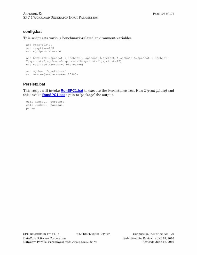
APPENDIX E: Page 106 of 107 SPC-1 WORKLOAD GENERATOR INPUT PARAMETERS
SPC BENCHMARK 1™ V1.14 FULL DISCLOSURE REPORT Submission Identifier: A00179 DataCore Software Corporation Submitted for Review: JUNE 15, 2016 DataCore Parallel Server(Dual Node, Fibre Channel SAN) Revised: June 17, 2016
config.bat This script sets various benchmark-related environment variables. set rate=102400 set ramptime=480 set spc2persist=true set hostlist=(spchost-1,spchost-2,spchost-3,spchost-4,spchost-5,spchost-6,spchost-7,spchost-8,spchost-9,spchost-10,spchost-11,spchost-12) set sdslist=(PServer-G,PServer-H) set spchost-5_setsize=6 set masterjavaparms=-Xmx20480m
Persist2.bat This script will invoke RunSPC1.bat to execute the Persistence Test Run 2 (read phase) and this invoke RunSPC1.bat again to ‘package’ the output. call RunSPC1 persist2 call RunSPC1 package pause
APPENDIX F: Page 107 of 107 THIRD-PARTY QUOTATION
SPC BENCHMARK 1™ V1.14 FULL DISCLOSURE REPORT Submission Identifier: A00179 DataCore Software Corporation Submitted for Review: JUNE 15, 2016 DataCore Parallel Server(Dual Node, Fibre Channel SAN) Revised: June 17, 2016
APPENDIX F: THIRD-PARTY QUOTATION
Priced Storage Configuration The third-party quotation is not embedded in this document due it size and format. The quotation is available via the following hyperlink: Third-Party Quotation