SPC-1_SPC-1E_v1.14.pdf - Storage Performance Council
125
SPC BENCHMARK 1 (SPC-1™) SPC BENCHMARK 1/ENERGY™ EXTENSION (SPC-1/E™) OFFICIAL SPECIFICATION Revision 1.14 – Effective May 12, 2013 “The First Industry Standard Storage Benchmark” Storage Performance Council (SPC) 643 Bair Island Road, Suite 103 Redwood City, CA 94063-2755 Phone (650) 556-9384 Fax (650) 556-9385 www.storageperformance.org [email protected] Copyright © 2012 Storage Performance Council
-
Upload
khangminh22 -
Category
Documents
-
view
6 -
download
0
Transcript of SPC-1_SPC-1E_v1.14.pdf - Storage Performance Council

SPC BENCHMARK 1 (SPC-1™)
SPC BENCHMARK 1/ENERGY™ EXTENSION (SPC-1/E™)
OFFICIAL SPECIFICATION
Revision 1.14 – Effective May 12, 2013
“The First Industry Standard Storage Benchmark”
Storage Performance Council (SPC) 643 Bair Island Road, Suite 103 Redwood City, CA 94063-2755
Phone (650) 556-9384 Fax (650) 556-9385
www.storageperformance.org [email protected]
Copyright © 2012 Storage Performance Council

SPC Benchmark-1 (SPC-1) Version 1.14 Page ii of 125 Official Specification Effective - May 12, 2013
SPC Membership (as of March 2013)
ADATA Technology Co., Ltd. Austin Automation Center
– Department of Veteran Affairs DataDirect Networks Dell Compellent Dot Hill Systems Corp. EMC Corporation Foundation for Research and Technology
– Institute of Computer Science Fujitsu Computer Systems Corporation The George Washington University Hewlett-Packard Company Hitachi Data Systems Hongik University Huawei Technologies Co., Ltd. IBM Corporation Infortrend Technology, Inc. Jabil Circuit, Inc. Kaminario, Inc. Korea Advanced Institute of Science and Technology
Link_A_Media Devices Corporation LSI Corporation NEC Corporation NetApp, Inc. Nimbus Data Systems, Inc. Oracle Corporation Pennsylvania State University Samsung Information Systems, America SanDisk Corporation Seagate Technology LLC Silicon Graphics International SolidFire, Inc. STEC, Inc. Toshiba America Information Systems, Inc. University of California, Santa Cruz Violin Memory, Inc. Western Digital Corporation X-IO Technologies
DOCUMENT HISTORY Effective Date Version Description 9 October 2001 1.0 The first official release of the SPC Benchmark-1™ (SPC-1)
specification. Approved unanimously by the SPC membership. 16 October 2001 1.0.1 Editorial changes
01 January 2002 1.1 Editorial changes to 3.2.1 New clause 3.4 (Address Range Selection Function-ARF) Changes to Tables 3.1 and 3.2 based on ARF
29 January 2002 1.2 Revisions to support Offered and Measured Load requirements and constraints 13 March 2002 1.3 Revisions to support “open model” workload – Clause 3 Revision to clarify the use of non-TSC components – (4.1.1) Revisions to clarify Test Phase transitions (5.4.2, 5.4.3) Revision to Ramp Test Run duration (5.4.2.3.2) Revision to delete the BC power cycle requirement in the Repeatability Test (5.4.3.14) 9 July 2002 1.4 Addition of Price-Performance as a primary metric Revisions to ASU-LV Mappings requirements (Approved 8 May 2002)
9 September 2002 1.5 Updated SPC membership list Clarification for republished results – Clause 10.7 Added an FDR revision history – Clause 9.2.4.3.2 Added the Repeatability test data to the FDR – Clause 9.2.4.6.4 Clarification of the Audit – Clause 10 Revision of Remote Audit requirements – Clause 10.6

SPC Benchmark-1 (SPC-1) Version 1.14 Page iii of 125 Official Specification Effective - May 12, 2013
Various editorial revisions (Approved 11 July 2002)
Effective Date Version Description 20 January 2003 1.6 Updated SPC membership list Editorial changes to Clauses 5.3.2, 5.4.2.1.3, 5.4.2.2.8, 5.4.2.3.6
5.4.3.3, 9.2.4.3.5, 9.2.4.7.1, 9.2.4.7.2, 9.2.4.7.3, and 9.2.4.7.4. Clarification of Physical Storage Capacity in and what is
included (Clauses 2.2.1 and 2.2.2).
Clarification of the roles of SPC-1 Toolkit documentation (Clause 5.3.1).
Clarification of terms and test sequencing (Clause 5.4.1) (specification revision approved on 21 November 2002)
Clarification of Repeatability Test Phase sequencing (Clause 5.4.3)
Revision of Customer Tunable Parameter and Options documentation (Clause 9.2.4.5.1).
Added Storage Capacities and Relationships diagram requirement (Clause 9.2.4.6.1).
Clarification of the transition from the Sustainability Test Phase to the IOPS Test Phase (5.4.2.2).
20 July 2003 1.7 (Approved 21 May 2003)
Addition of Parity (RAID5)/User Data Copy (Mirroring), Required Storage, Global Storage Overhead, and Unused Storage (Clause 2.1, Figure 2-1, Clauses 2.2.3, 2.2.4, and 2.3.2)
Clarification of excluded storage (Clause 2.2.5). Change Transfer Alignment from N/A to 8 (Clause 3.5.3, Table
3-3).
Require an unchanged Benchmark Configuration between Tests, Test Phases, and Test Runs (Clauses 5.3.3 and 6.3.5).
Clarify requirements for documenting logical TSC creation (Clause 9.2.4.5.2).
Require disclosure of SPC-1 Workload Generator configuration file (Clause 9.2.4.5.3).
Clarified storage capacity reporting (Clauses 9.2.4.3.3, 9.2.4.6.1, and 9.2.4.6.2).
Revised to include User Data Copy/Parity, Required Storage, Global Storage Overhead, and Unused Storage (Clause 9.2.4.6.1, Table 9-9).
New table to disclose storage ratios (Clause 9.2.4.6.1, Table 9-10).
10 January 2004 1.8.0 Approved 29 July 2003
Revised Figure 2-1 and Clauses 2.2.4, 2.3.2, and 2.4.3 to clarify Unused Storage.
Revised to correspond to the above revised Figure 2-1.
Added a new Data Protection Level, Other Protection Level, and renamed Unrestricted to Unprotected (Clause 2).

SPC Benchmark-1 (SPC-1) Version 1.14 Page iv of 125 Official Specification Effective - May 12, 2013
Revised Clause 9.4.3.3.3, footnote #6 to require a description of the data protection provided when Other Protection Level is selected.
Revised Clause 9.4.3.6.1, Table 9-11, and Table 9-12 to report separately any storage capacity used for parity and/or user data copy when Other Protection Level is selected.
Effective Date Version Description Approved 16 September 2003 Revised Clause 6.4 so that when specific conditions are met the
Test Sponsor is not required to shutdown and power cycle the Host System(s) as a part of the Persistence Test.
Revised Clause 0.2 to include a definition of ‘Test Sponsor’. Revised Clauses 9.4.3.2 and 10.7.1 to require specific content
and format for the Test Sponsor Letter of Good Faith. Revised Appendix D (page 124) from an example to a template
for the Letter of Good Faith, consistent with the above revisions to 9.4.3.2 and 10.7.1.
Revised Clause 8.1 to change ‘Benchmarked TSC’ to ‘TSC’ and ‘Priced TSC’ to Priced Storage Configuration. (TSC=Tested Storage Configuration)
Added Clauses 9.2.4.3.6 and 9.2.4.11.3 to require the disclosure of any differences between the TSC and Priced Storage Configuration.
Revised Clause 10.7.9 to verify that any differences between the TSC and Priced Storage Configuration would not result in the Priced Storage Configuration providing less than the reported performance of the TSC.
Consolidated the disclosure of the Availability Date/Availability into to a single clause by combining the intent of Clauses 9.4.3.9 and 9.2.4.12 into a single clause, 9.4.3.9, and deleting the remaining clause, 9.2.4.12.
Revised Clause 10.7.10 to require the Auditor review of the Full Disclosure Reports addresses both completeness and accuracy.
Approved 11 November 2003 Revised Table 9-16 to document when the Host System is not
shutdown and power cycled as part of the Persistence Test. Revised Clause 10.7.7 to include the audit requirements when
the Host System is not shutdown and power cycled as part of the Persistence Test.
Revised Clauses 9.4.3.1, 9.4.3.3.8, and 9.4 to clarify the disclosure requirements for revisions to an existing FDR.
New Clause 10.8 to clarify the requirements when a revised FDR results in component changes to the original Priced Storage Configuration.
Revised Clause 10.3 to include a Peer Review of revisions to an existing FDR.
New Clause 9.4.3.3.5 to include Table 9-11: SPC-1 Storage Capacities in the Executive Summary.
Effective Date Version Description

SPC Benchmark-1 (SPC-1) Version 1.14 Page v of 125 Official Specification Effective - May 12, 2013
13 March 2005 1.9.0 Approved 12 January 2005 Revised Clause 3.1.3 to define “decimal” (powers of ten) and
“binary” (powers of two) measurement units. Revised Transfer Alignment in Table 3.2 to be 8 (512 byte
blocks) rather than 16 (512 byte blocks). Added the specific unit of measure for Transfer Alignment and
Transfer Size in Table 3.1, 3.2, and 3.3 New Clause 4.3.2.3 to allow System Software to provide RAID 0
(striping) and/or data protection functionality to the TSC.
Revised Clause 4.3.2.4 to explicitly exclude caching/pre-fetching by System Software.
Revised 4.5.1, describing the conditions that cause a Host System to become a priced TSC component.
Revised Clause 4.5.2 to clarify the use of multiple, independent storage subsystem configurations.
Revised Clauses 9.2.4.4.1 and 9.2.4.4.2 to remove the requirement for a separate storage network diagram if sufficient detail is provided in the BC configuration.
New Clause 4.6.8, which excludes the use of all file system functionality rather than just file cache functionality.
Various revisions to Clause 4 to more clearly describe Benchmark Configuration, Tested Storage Configuration, Host System(s), and System Software.
Revised Clause 5.3.3 to clarify that the Benchmark Configuration is to remain unchanged across Tests, Test Phases, and Test Runs.
Revised Clause 5.4.2 and added Clause 5.4.3 to require a specific, uninterrupted SPC-1 Test sequence.
Revised Clauses 5.4.3, 5.4.3.2.12, 5.4.3.3.9, 5.4.3.3.10, 5.4.4, and 5.4.4.1 in support of the above requirement.
Revised Clause 9.2.4.7.1 to require the FDR contain a Response Time Frequency Distribution graph and table as well as an Average Response Time Distribution graph and table.
Revised Clauses 4.5.1, 8.1.1.2, and 8.1.2 to clarify when a Host System is included as a priced TSC component, specifically with regards to Logical Volume Manager functionality.

SPC Benchmark-1 (SPC-1) Version 1.14 Page vi of 125 Official Specification Effective - May 12, 2013
Effective Date Version Description
19 March 2006 1.10.0 Approved 18 January 2006 Revised Clause 8.1.1.2 to remove the requirement for pricing
maintenance for HBAs included in the Priced Storage Configuration.
Revised Clause 9.2.4.9 to all the use of “Currently Available” for the SPC-1 Availability Date in the case where all components that comprise the Priced Storage Configuration are currently available for customer order and shipment.
Revise Clause 4.3 and add Clause 4.6 to introduce and define the term “Tested Storage Product”, which will become the focal point of SPC-1 results and the source of labeling for each result.
Added Clauses 4.6.1 and 4.6.2 to define two categories of SPC-1 results based on the absence or presence of all storage devices as a standard part of the Tested Storage Product.
Revised Clause 4.5.1 to be consistent with the introduction of a Tested Storage Product as the focal point for each SPC-1 result.
Added Clause 7.2.6 to require statement of the appropriate TSP category when there is a public reference to a specific SPC-1 result.
Revised Clause 9.2.3 to use the formal TSP name on the FDR title page rather than the TSC name.
Revised Clause 9.2.4.3.3 and Table 9.8 to include an entry for the appropriate TSC category value.
27 September 2006 1.10.1 Approved 27 September 2006 Revised Clauses 4.6.1 and 4.6.2 to clarify the SPC-1 Results
categorization requirements.
Added Clause 9.2.4.3.3 to require a brief description of the Tested Storage Product in the Executive Summary.
May 12, 2013 1.11 Approved 20 May 2009 12 September 2009 1.12 Approved 14 July 2009 Added Clause 11: Energy Extension
18 November 2012 1.13 Approved 19 September 2012 Clause 2.2: Revised to allow Physical Storage Capacity to be
reported either as formatted capacity or capacity available for application use.
Clause 2.7: Revised to define two levels of data protection: Protected 1 and Protected 2.
Clause 5.3.3: New wording to require all three ASUs to be completely filled with specified content prior to audited Test Run execution (ASU pre-fill).
Clause 5.3.16: New wording to allow Adaptive Data Migration.
Clause 5.4.4: Revised to allow the Sustainability Test Run to have an independent Start-Up duration.
Clause 5.4.4.1.1: Revised to require Measurement Interval duration for the Sustainability Test Run to be a minimum of 8 hours.

SPC Benchmark-1 (SPC-1) Version 1.14 Page vii of 125 Official Specification Effective - May 12, 2013
Clause 6.5: New wording to allow use of the SPC-2 Persistence Test with auditor approval.
Clause 7.4.1: New wording listing the requirements for public reference when using a non-local currency.
Clause 7.4.2.1, Clause 7.4.4: Revised to require “current as of” date.
Clause 7.4.4: Revised to address comparisons of SPC-1 Price-Performance and SPC-1 Total Price with regards to pricing currency and the “target country”.
Clause 8.1.1.2: Revised to require inclusion of applicable tariffs, duties, and import fees if not included listed product pricing and to exclude any shipping costs.
Clause 8.1.2.4: New wording to required appropriate racking/cabinetry and power distribution if the Priced Storage Configuration is greater than 20U.
Clauses 8.2.1.4 and 8.2.1.5: Deleted requirement for local currency pricing.
Clause 8.2.2.2: Revised to reference the specified “target country”.
Clause 8.2.2.5: Deleted because of redundancy.
Clause 8.2.3: New wording to define the “target country” and requirements for pricing.
Clause 8.2.4: New wording to define local and non-local currency pricing and requirements.
Clause 8.3.1.4: Revised to require the total price to be stated in the minimum level of negotiable detail for the selected pricing currency.
Clause 8.3.2: Deleted because of redundancy. Clause 9.4.3.3.2: Revised to require FDR revision details to be
highlighted when appropriate. Clause 9.4.3.3.4, Table 9-8: Revised to include the SPC-1
Submission Identifier, Currency Used, and “Target Country”.
Clause 9.4.3.3.7: New wording requiring the Executive Summary to include the basis (type and justification) of discounts included in the pricing.
Clause 9.4.3.4.1: Revised to delete the “UID” and “WG” annotations.
Clause 9.4.3.6.1: Revised to require an annotation that addresses reserved system overhead storage capacity that might not be included in the reported Physical Storage Capacity.

SPC Benchmark-1 (SPC-1) Version 1.14 Page viii of 125 Official Specification Effective - May 12, 2013
12 May 2013 1.14 Approved 13 March 2013 Clause 5.3.3.3: New wording to explicitly require the ASU pre-
fill to be executed as the first step in the uninterrupted benchmark execution sequence.
Clause 5.3.5: Start-Up duration requirement for all Test Runs deleted and address in Clause 5.4.4 (Primary Metrics Test) and Clause 5.4.5.5 (Repeatability Test).
Clause 5.3.12: Revised to allow a warm-up for caches and ASU data migration for multi-tiered configurations, defined in Clause 5.3.13.
Clause 5.3.13: New wording to allow one or more “Ramp-Up” Test Runs as a substitute for an initial, gradual Ramp-Up.
Clause 5.3.16: Revised wording to expand the use of Adaptive Data Migration.
Clause 5.4.4: Revised wording to define the minimum Start-Up duration for each Test Run in the Primary Metrics Test.
Clause 5.4.5.5: New wording to define the minimum Start-Up duration for each Test Run in the Repeatability Test.
Clause 9.4.3.3.8: Revised wording to clarify how differences between the Tested Storage Configuration and Priced Storage Configuration are documented.
Clause 9.4.3.4.4: Deleted and replaced by Clause 9.4.3.3.8.
Clause 9.4.3.6.1: Revised wording to replace storage capacities illustration with four charts.
Clause 9.4.3.7.1: New wording listing disclosure requirements when the “Ramp-Up” Test Runs are used.

SPC Benchmark-1 (SPC-1) Version 1.14 Page 9 of 125 Official Specification Effective - May 12, 2013
Table of Contents
CLAUSE 0 : INTRODUCTION ......................................................................................................................... 13
0.1 PREAMBLE ................................................................................................................................................. 13 0.2 GENERAL GUIDELINES ............................................................................................................................... 14 0.3 MEASUREMENT GUIDELINES ..................................................................................................................... 15 0.4 DISCLAIMER ............................................................................................................................................... 16 0.5 SPC BENCHMARK SERIES .......................................................................................................................... 16
CLAUSE 1 : WORKLOAD ENVIRONMENT .................................................................................................. 17
1.1 BUSINESS AND APPLICATION ENVIRONMENT ............................................................................................ 17 1.2 HIGH-LEVEL WORKLOAD MODEL .............................................................................................................. 17
CLAUSE 2 : DATA REPOSITORY ................................................................................................................... 18
2.1 SPC-1 STORAGE HIERARCHY ..................................................................................................................... 18 2.2 PHYSICAL STORAGE CAPACITY (PSC) ........................................................................................................ 18 2.3 CONFIGURED STORAGE CAPACITY (CSC) .................................................................................................. 19 2.4 ADDRESSABLE STORAGE CAPACITY (ASC) ................................................................................................ 19 2.5 LOGICAL VOLUMES (LV) ............................................................................................................................ 20 2.6 APPLICATION STORAGE UNITS (ASUS) ...................................................................................................... 20 2.7 DATA PROTECTION ..................................................................................................................................... 22 2.8 CAPACITY UTILIZATION ............................................................................................................................. 22
CLAUSE 3 : WORKLOAD AND I/O OPERATION PROFILE ..................................................................... 23
3.1 DEFINITIONS .............................................................................................................................................. 23 3.2 SPC-1 WORKLOAD ..................................................................................................................................... 24 3.3 SPC-1 PARAMETER TYPES ......................................................................................................................... 24 3.4 SPC-1 WORKLOAD PARAMETERS ............................................................................................................... 27 3.5 TECHNICAL WORKLOAD DESCRIPTION ...................................................................................................... 30
CLAUSE 4 : BENCHMARK CONFIGURATION (BC), TESTED STORAGE CONFIGURATION (TSC), AND WORKLOAD GENERATOR .................................................................... 34
4.1 OVERVIEW .................................................................................................................................................. 34 4.2 BENCHMARK CONFIGURATION COMPONENT AVAILABILITY AND SUPPORT ............................................... 34 4.3 BENCHMARK CONFIGURATION COMPONENTS ........................................................................................... 34 4.4 BENCHMARK CONFIGURATION (BC) EXAMPLES ........................................................................................ 35 4.5 TESTED STORAGE CONFIGURATION (TSC) ................................................................................................ 36 4.6 TESTED STORAGE PRODUCT (TSP) ............................................................................................................ 41 4.7 SPC-1 WORKLOAD GENERATOR ................................................................................................................ 42
CLAUSE 5 : TEST MEASUREMENT REQUIREMENTS (EXECUTION RULES) ................................. 48
5.1 SUPPORTING DEFINITIONS ........................................................................................................................ 48 5.2 SYSTEM SCALING ....................................................................................................................................... 50 5.3 REQUIREMENTS AND CONSTRAINTS .......................................................................................................... 51 5.4 SPC-1 PERFORMANCE TESTS .................................................................................................................... 55
CLAUSE 6 : DATA PERSISTENCE REQUIREMENTS AND TEST ......................................................... 65
6.1 INTRODUCTION .......................................................................................................................................... 65 6.2 PERSISTENCE TEST VALIDATION ............................................................................................................... 65 6.3 SPC-1 PERSISTENCE TEST CONSTRAINTS ................................................................................................. 65 6.4 DATA PERSISTENCE TEST PROCEDURE ...................................................................................................... 65 6.5 DATA PERSISTENCE TEST SUBSTITUTION .................................................................................................. 66
CLAUSE 7 : REPORTED DATA ....................................................................................................................... 67

SPC Benchmark-1 (SPC-1) Version 1.14 Page 10 of 125 Official Specification Effective - May 12, 2013
7.1 SPC-1 REPORTED DATA ............................................................................................................................. 67 7.2 SPC-1 PRIMARY METRICS ......................................................................................................................... 67 7.3 SPC-1 ASSOCIATED DATA .......................................................................................................................... 67 7.4 SPC-1 RESULTS – PUBLIC USE REQUIREMENTS ....................................................................................... 68
CLAUSE 8 : PRICING ........................................................................................................................................ 70
8.1 PRICED COMPONENTS ................................................................................................................................ 70 8.2 PRICING METHODOLOGY ........................................................................................................................... 72 8.3 REQUIRED REPORTING .............................................................................................................................. 74
CLAUSE 9 : FULL DISCLOSURE ................................................................................................................... 76
9.1 SUPPORTING DEFINITIONS ........................................................................................................................ 76 9.2 FULL DISCLOSURE REPORT (FDR) REQUIREMENTS .................................................................................. 85 9.3 FULL DISCLOSURE REPORT AVAILABILITY ................................................................................................ 85 9.4 FULL DISCLOSURE REPORT CONTENT ....................................................................................................... 85 9.5 REVISIONS TO A PREVIOUSLY SUBMITTED FDR ...................................................................................... 107
CLAUSE 10 : MEASUREMENT, AUDIT, AND RESULTS SUBMISSION ............................................. 108
10.1 INTRODUCTION ..................................................................................................................................... 108 10.2 TYPES OF NEW SPC-1 RESULTS ........................................................................................................... 108 10.3 SPC-1 AUDITED MEASUREMENTS ........................................................................................................ 109 10.4 SPC-1 AUDIT ........................................................................................................................................ 109 10.5 SPC-1 MEASUREMENT SUBMISSION .................................................................................................... 110 10.6 SPC PEER REVIEW ............................................................................................................................... 111 10.7 AUDIT PROCEDURES ............................................................................................................................. 111 10.8 CREATING A NEW SPC-1 RESULT BASED ON AN EXISTING SPC-1 RESULT .......................................... 115 10.9 SPC-1 RESULT REVISIONS ................................................................................................................... 115
CLAUSE 11 : ENERGY EXTENSION ............................................................................................................ 117
11.1 OVERVIEW ............................................................................................................................................ 117 11.2 APPARATUS .......................................................................................................................................... 117 11.3 DISCLOSURE REQUIREMENTS .............................................................................................................. 117 11.4 MEASUREMENTS .................................................................................................................................. 117 11.5 POWER PROFILES ................................................................................................................................. 119 11.6 NAMING CONVENTION ......................................................................................................................... 120 11.7 SPC-1/E REPORTED DATA ................................................................................................................... 120 11.8 SPC-1/E FULL DISCLOSURE REPORT (FDR) REQUIREMENTS ............................................................. 123 11.9 SPC-1/E AUDIT REQUIREMENTS .......................................................................................................... 123
Appendix A: Letter of Good Faith Template ............................................................................ 124
Appendix B: The Hierarchical Reuse Random Walk .............................................................. 125

SPC Benchmark-1 (SPC-1) Version 1.14 Page 11 of 125 Official Specification Effective - May 12, 2013
Table of Figures
Figure 2-1: SPC-1 Storage Hierarchy ............................................................................................... 18
Figure 2-2: Sample ASU-to-Logical Volume Address Mappings ................................................ 21
Figure 4-1: Sample BC Configurations – Direct Attach Storage Controller ........................... 35
Figure 4-2: Sample Configurations – Network Storage .............................................................. 36
Figure 4-3: Embedded or External Controller – External Storage Devices ........................... 38
Figure 4-4: Embedded Storage Controller – Embedded Storage Devices ............................... 39
Figure 4-5: Network Storage –External Storage Controller and Storage Devices ............... 40
Figure 4-6: Workload Generator Functional Components ........................................................ 42
Figure 4-7: Workload Generator Components, I/O Streams and ASUs .................................... 43
Figure 4-8: ASU Relationship to Multiple Hosts ............................................................................ 45
Figure 4-9: Multi-Host Workload Requirements ........................................................................... 45
Figure 4-10: Measurement Boundary ............................................................................................... 46
Figure 4-11: Measurement Boundary in an UNIX System Implementation ........................... 47
Figure 5-1: Sample Test Run .............................................................................................................. 49
Figure 5-2: I/O Completion Types ...................................................................................................... 50
Figure 5-3: Key SPC-1 Test Objectives ............................................................................................. 55
Figure 5-4: Summary of SPC-1 Tests ................................................................................................ 57
Figure 5-5: Sustainability Test Phase .............................................................................................. 59
Figure 5-6: Sustainability & IOPS Test Phases .............................................................................. 60
Figure 5-7: Primary Metrics Test ...................................................................................................... 62
Figure 5-8: Repeatability Test ............................................................................................................ 64
Figure 9-1: Response Time Frequency Distribution (by occurrence) ...................................... 76
Figure 9-2: I/O Request Throughput Distribution ........................................................................ 78
Figure 9-3: Average Response Time Distribution ......................................................................... 79
Figure 9-4: Data Rate Distribution ................................................................................................... 80
Figure 9-5: Response Time Ramp Distribution ............................................................................. 82
Figure 9-6: Response Time/Throughput Function ........................................................................ 83
Figure 9-7: Simple Response Time Throughput Curve ............................................................... 84
Figure 9-8: BC/TSC Configuration Diagram ................................................................................... 93
Figure 9-9: Storage Network Configuration Diagram ................................................................. 95
Figure 9-10: SPC-1 Physical Storage Capacity ............................................................................ 100
Figure 9-11: SPC-1 Configured Storage Capacity ....................................................................... 100
Figure 9-12: SPC-1 Addressable Storage Capacity ..................................................................... 101
Figure 9-13: SPC-1 Total Unused Storage Capacity Ratio and Detail ................................... 101

SPC Benchmark-1 (SPC-1) Version 1.14 Page 12 of 125 Official Specification Effective - May 12, 2013
Table of Tables
Table 3-1: ASU 1 Parameter Types and Values .............................................................................. 32
Table 3-2: ASU 2 Parameter Types and Values .............................................................................. 32
Table 3-3: ASU 3 Parameter Types and Values .............................................................................. 33
Table 9-1: Response Time Frequency Distribution ..................................................................... 76
Table 9-2: I/O Request Throughput Distribution .......................................................................... 77
Table 9-3: Average Response Time Distribution ........................................................................... 79
Table 9-4: Data Rate Distribution ..................................................................................................... 81
Table 9-5: Response Time Ramp Distribution ............................................................................... 84
Table 9-6: Test Sponsor and Contact Information ........................................................................ 87
Table 9-7: Revision Information and Key Dates ............................................................................ 88
Table 9-8: Summary of Results ........................................................................................................... 89
Table 9-9: Priced Storage Configuration Components ................................................................ 91
Table 9-10: Host System(s) and Tested Storage Configuration ................................................. 96
Table 9-11: SPC-1 Storage Capacities ............................................................................................... 98
Table 9-13: SPC-1 Storage Capacity Utilization .......................................................................... 102
Table 9-14: Logical Volume Capacity and ASU Mapping .......................................................... 102
Table 9-15: Repeatability Test Results ........................................................................................... 104
Table 9-16: Data Persistence Test Results .................................................................................... 105
Table 9-17: Basis SPC-1 Result Information ................................................................................. 106

SPC Benchmark-1 (SPC-1) Version 1.14 Page 13 of 125 Official Specification Effective - May 12, 2013
Clause 0: Introduction
0.1 Preamble
The SPC Benchmark-1 (SPC-1) is a sophisticated performance measurement workload for storage subsystems. The benchmark simulates the demands placed upon on-line, non-volatile storage in a typical server class computer system. SPC-1 provides measurements in support of real world environments characterized by:
Demanding total I/O throughput requirements.
Sensitive I/O response time constraints.
Dynamic workload behaviors.
Substantial storage capacity requirements.
Diverse user populations and expectations.
Data persistence requirements to ensure preservation of data without corruption or loss.
SPC-1 is designed as a source of comparative storage subsystem performance information. It is intended to provide value throughout the storage product lifecycle (e.g. development of product requirements; product implementation; performance tuning; capacity planning, market positioning; and purchase evaluations).
In view of the broad applicability of the SPC-1 benchmark, it is anticipated that readers may wish to approach the present document via a variety of starting points. For example:
Readers who need only a quick overview of the benchmark itself can obtain one by examining Clause 1 (broad introduction to the benchmark structure) and Table 3-1, Table 3-2, and Table 3-3 (the I/O workload characteristics presented in tabular form).
Readers who wish a detailed understanding of the benchmark should, in addition, consult Clause 2 (organization of storage), Clause 3 (organization of I/O), and Clause 4 (benchmark usage in specific configurations).
Readers who are examining or referring to test results obtained by running the SPC-1 benchmark should minimally examine Clause 7 (reported metrics). Clause 5 (execution rules) is also recommended for such readers.
Readers who wish to actually run an SPC-1 benchmark test should minimally examine Clause 2, Clause 5, and Clause 7.
Finally, readers who wish to submit SPC-1 benchmark results for posting by the SPC must read the entire SPC-1 specification to ensure compliance with its provisions.
The SPC-1 specification is intended to be vendor and platform independent. Any vendor should be able to sponsor and publish an SPC-1 benchmark, provided their tested configuration satisfies the performance, integrity, and availability requirements of the specification. Further, the benchmark is intended to be meaningful across a broad range of system configurations and storage topologies including:
Different storage components: the specification allows virtually any combination of storage technologies in a system configuration. Implementers are free to use any combination of storage types and to select the level of redundancy and reliability that best showcases their solution.

SPC Benchmark-1 (SPC-1) Version 1.14 Page 14 of 125 Official Specification Effective - May 12, 2013
Various interconnect topologies: the benchmark has been designed to allow for all forms of system and network interconnection. New network-based solutions (i.e., SANs) and more traditional host-based systems can both produce accurate and meaningful benchmark results.
Varied task assignments: SPC-1 allows vendors to optimally demonstrate the performance features of their storage solutions. In addition and regardless of implementation choices, SPC-1 will provide a means of robust and reliable performance verification.
Adaptive scheduling, caching and resource allocation: By relying on a diverse and sophisticated model of the storage workload that systems will encounter in the field, SPC-1 will provide a fair evaluation of the quality of automated performance optimization algorithms throughout the storage subsystem.
Rather than requiring or favoring a particular implementation, it is the goal of the SPC-1 benchmark specification to provide a robust, verifiable, reproducible environment within which the relative strengths of differing design and configuration approaches can be evaluated.
0.2 General Guidelines
The purpose of SPC benchmarks is to provide objective, relevant, and verifiable data to purchasers of I/O subsystems. To that end, SPC specifications require that benchmark tests be implemented with system platforms and products that:
1. Are generally available to users.
2. A significant percentage of the users in the target market segment (server class systems) would implement.
3. Are relevant to the market segment that SPC-1 benchmark represents.
In addition, all SPC benchmark results are required to be sponsored by a distinctly identifiable entity, which is referred to as the Test Sponsor. The Test Sponsor is responsible for the submission of all required SPC benchmark results and materials. The Test Sponsor is responsible for the completeness, accuracy, and authenticity of those submitted results and materials as attested to in the required Letter of Good Faith (see Appendix D). A Test Sponsor is not required to be a SPC member and may be an individual, company, or organization.
The use of new systems, products, technologies (hardware or software) and pricing is encouraged so long as they meet the requirements above. Specifically prohibited are benchmark systems, products, pricing (hereafter referred to as "implementations") whose primary purpose is performance optimization of SPC benchmark results without any corresponding applicability to real-world applications and environments. In other words, all "benchmark specials," implementations that improve benchmark results but not general, real-world performance are prohibited.
The following characteristics should be used as a guide to judge whether a particular implementation is a “benchmark special”. It is not required that each point below be met, but that the cumulative weight of the evidence be considered to identify an unacceptable implementation. Absolute certainty or certainty beyond a reasonable doubt is not required to make a judgment on this complex issue. The question that must be answered is this: based on the available evidence, does the clear preponderance (the greater share or weight) of evidence indicate that this implementation is a “benchmark special”?

SPC Benchmark-1 (SPC-1) Version 1.14 Page 15 of 125 Official Specification Effective - May 12, 2013
The following characteristics should be used to judge whether a particular implementation is a benchmark special:
Is the implementation generally available, documented, and supported?
Does the implementation have significant restrictions on its use or applicability that limits its use beyond SPC benchmarks?
Is the implementation or part of the implementation poorly integrated into the larger product?
Does the implementation take special advantage of the limited nature of SPC benchmarks (e.g., I/O Request profile, I/O Request mix, I/O Request concurrency and/or resource contention) in a manner that would not be generally applicable to the environment the benchmark represents?
Is the use of the implementation discouraged by the vendor? (This includes failing to promote the implementation in a manner similar to the Test Sponsor’s other products and technologies.)
Does the implementation require uncommon sophistication on the part of the end-user, programmer, or system administrator?
Is the packaging or pricing unusual or non-customary for the vendor or unusual or non-customary to normal business practices? The following pricing practices are suspect:
Availability of a discount to a small subset of possible customers.
Discounts documented in an unusual or non-customary manner.
Pricing featured as a close-out or one-time special.
Unusual or non-customary restrictions on transferability of product, warranty or maintenance on discounted items.
Is the implementation being commonly used or purchased by a majority of end-users in the market area the benchmark represents? If the implementation is not currently being used by end-users, is there any evidence to indicate that it will be used by a significant number of users?
To assure the equitable application of this standard, the SPC has created a robust system of audit and peer review. It is the goal of the SPC to assure that only those results, which represent accurate and meaningful product performance, will be endorsed as official SPC results.
0.3 Measurement Guidelines
SPC benchmark results are expected to be accurate representations of subsystem performance. Therefore, stringent measurement, auditing, and reporting guidelines are mandated by this specification. In general, fidelity and candor must be maintained in reporting any anomalies in the results, even if not specified in the benchmark requirements.
More detailed measurement, evaluation and disclosure requirements can be found in the body of the specification.

SPC Benchmark-1 (SPC-1) Version 1.14 Page 16 of 125 Official Specification Effective - May 12, 2013
0.4 Disclaimer
While this workload models a rich multi-user environment that emulates a broad range of server applications, it neither represents the entire range of I/O requirements for server systems nor precisely mimics any particular application. In addition, the extent to which anyone is capable of achieving the results reported by a vendor is highly dependent upon how closely the customer’s application maps to the SPC-1 workload. The extrapolation of SPC-1 results to other environments is therefore not recommended.
Actual system performance is highly dependent upon specific workload characteristics, platform configuration, and application-specific tuning. Relative system performance will vary as a result of these and other factors. Thus, SPC-1 should not be used as a substitute for customer application benchmarking when critical performance requirements are called for.
SPC-1 uses terminology and metrics that are similar to other benchmarks. This similarity does not imply that results from this benchmark are comparable with other benchmarks.
0.5 SPC Benchmark Series
SPC-1 is the first of a series of storage oriented system benchmarks. It utilizes a framework within which all SPC benchmarks will operate. SPC-1 is the first instantiation of a benchmark within the SPC framework.

SPC Benchmark-1 (SPC-1) Version 1.14 Page 17 of 125 Official Specification Effective - May 12, 2013
Clause 1: Workload Environment
1.1 Business and Application Environment
SPC-1 is comprised of a set of I/O operations designed to demonstrate the performance of a storage subsystem while performing the typical functions of a business critical application. SPC-1 represents a segment of applications characterized by predominately random I/O operations and requiring both queries as well as update operations (for example: OLTP systems, database systems, or mail server applications).
1.2 High-Level Workload Model
The segment of applications represented by SPC-1 covers a broad range of user profiles, business functions and system configurations. Since the focus of SPC-1 is on the commonalties of those applications (e.g., high reliance on stored data, multi-user access, etc.), it was necessary to develop a model that would simplify the workload to the point that highlighted the similarities of its business segment while removing any conflicts and details that weren’t central to performance evaluation. The model used in SPC-1 has two central scaling components:
Business Scaling Units (BSUs)
Application Storage Units (ASUs)
1.2.1 Business Scaling Units (BSUs)
Business Scaling Units (BSUs) are the benchmark’s representation of an application’s user population. Each BSU represents the aggregate IO load created by a specified number of users. By focusing the benchmark on this aggregated IO load, SPC-1 is able to provide a scalable stimulus for the tested system that will provide a broad test of the storage configuration without getting lost in the detail that would be necessary for the accurate modeling of any one application. The result will be a workload that will retain its relevance across many generations of a particular application and through a broad spectrum of possible applications.
SPC-1 will be scaled by increasing or decreasing the number of BSUs. A more detailed technical description of BSUs may be found in Clause 4.
1.2.2 Application Storage Units (ASUs)
In the same way that the BSU generalizes the IO load presented to a tested system by an application, Application Storage Units (ASUs) are used to abstract the storage configuration that must respond to that IO load. An ASU is the logical entity identified by the application as the destination or source of data that requires persistence beyond the execution of the application. If the BSU can be thought of as the source of the benchmark workload, then the ASU becomes the sink, providing the logical environment in which the abstracted workload is run.
An ASU represents an abstraction of storage media and does not require a particular physical implementation. The physical implementation is determined by the Test Sponsor and must meet the storage configuration requirements stated in Clause 3.1.1. See Clause 4.3 for examples of supported configurations.

SPC Benchmark-1 (SPC-1) Version 1.14 Page 18 of 125 Official Specification Effective - May 12, 2013
Clause 2: Data Repository
2.1 SPC-1 Storage Hierarchy
The SPC-1 data repository segments storage components into five distinct roles:
Physical Storage Capacity (PSC) defined in Clause 2.2.
Configured Storage Capacity (CSC) defined in Clause 2.3.
Addressable Storage Capacity (ASC) defined in Clause 2.4.
Logical Volumes (LV) defined in Clause 2.5.
Application Storage Unit (ASU) Capacity defined in Clause 2.6.
The relationship between the different storage capacities is illustrated in Figure 2-1.
Included in the above storage capacities are:
Storage required for data protection.
Required Storage/Spares defined in Clause 2.3.2.
Global Storage Overhead defined in Clause 2.2.3.
Unused Storage defined in Clauses 2.2.4, 2.3.2, and 2.4.3.
Figure 2-1: SPC-1 Storage Hierarchy
2.2 Physical Storage Capacity (PSC)
2.2.1 Physical Storage Capacity is typically the formatted capacity of all Storage Devices that are physically present in the Tested Storage Configuration.
2.2.1.1 In cases where the formatted capacity of a configured Storage Device is not publicly available information, the reported value will be the capacity reported as available for application use.
2.2.1.2 In cases where both the formatted capacity and the capacity available for application use are publicly available information, the Test Sponsor will report either value. In such cases, the choice made by the Test Sponsor must be applied to all configured Storage Devices of the same model.
Unuse
d Storag
e
LV 1 LV 2 LV 3 LV 4
ASU 1 ASU 2 ASU 3
Application Storage Unit (ASU) Capacity
Addressable Storage Capacity
Parity (RAID5), User Data Copy (Mirroring)
or Other Protection Level
(parity/mirroring)
Req
uired S
torage/S
pares
Unuse
d Storag
e
Glob
al Stora
ge O
verhea
d
Unuse
d Storag
e
Configured Storage Capacity
Physical Storage Capacity

SPC Benchmark-1 (SPC-1) Version 1.14 Page 19 of 125 Official Specification Effective - May 12, 2013
2.2.1.3 If the Test Sponsor reconfigures the capacity of a Storage Device as documented in Clauses 2.2.1.1 or 2.2.1.2 so that the resultant capacity is less than the original value, the difference is reported as Global Storage Overhead, as described in 2.2.3, and included in the reported Physical Storage Capacity.
2.2.2 All physical storage present in the TSC must be included in Physical Storage Capacity, whether or not it is cabled in or powered up.
2.2.3 Global Storage Overhead consists of the Physical Storage Capacity that is required for system use, such as metadata, and unavailable for use by application programs such as the SPC-1 Workload Generator.
2.2.4 Unused Storage consists of the Physical Storage Capacity available for use but not included in the Required Storage/Spares, Parity/User Data Copy/Other Protection Level, Addressable Storage Capacity and Unused Storage described in Clauses 2.3.2 and 2.4.3.
2.2.5 Physical Storage Capacity excludes any storage, with the exception of Global Storage Overhead, that cannot be configured for use by the benchmark.
Comment: The intent of this clause is to accurately disclose the physical storage that could be configured for application use, plus the storage reserved for system use and unavailable for application use. For example, this would exclude the difference between unformatted and formatted storage or storage devices that have failed.
2.2.6 Physical Storage Capacity must be greater than or equal to Configured Storage Capacity.
2.3 Configured Storage Capacity (CSC)
2.3.1 Configured Storage includes the Addressable Storage Capacity and any other storage devices or components of storage devices necessary to implement the Addressable Storage Capacity described in Clause 2.4 (example: hot spares, parity disks, journal disks, log disks, etc.)
2.3.2 Unused Storage consists of the portion of Configured Storage Capacity available for use but not included in Required Storage/Spares, Parity/User Data Copy/Other Protection Level, Addressable Storage Capacity, and the Unused Storage described in Clause 2.4.3.
2.3.3 Required Storage/Spares consists of the amount of Configured Storage Capacity required to implement the Addressable Storage Capacity, excluding the storage required for the ASU and data protection.
Examples of Required Storage include storage for metadata, required or optionally selected spares, etc.
2.3.4 Configured Storage Capacity must be equal to or greater than Addressable Storage Capacity.
2.4 Addressable Storage Capacity (ASC)
2.4.1 Addressable Storage Capacity represents the total storage that can be read and written by application programs on Host Systems and thus, is directly available for use by application programs that implement this benchmark.
2.4.2 Addressable Storage Capacity excludes any portion of the Configured Storage that is not available for use by an application program on Host Systems in the Benchmark Configuration.

SPC Benchmark-1 (SPC-1) Version 1.14 Page 20 of 125 Official Specification Effective - May 12, 2013
Comment: The intent of this clause is to accurately disclose the storage that was configured for direct use by the benchmark as well as represent the amount of storage available for application use. For example, this would exclude the difference between the storage capacity used for storage management and not available for application use.
2.4.3 Unused Storage is the difference between Addressable Storage Capacity and ASU Storage Capacity if they are not equal. This difference is counted twice if the Addressable Storage Capacity is mirrored.
2.4.4 Addressable Storage Capacity must be less than or equal to the Configured Storage Capacity.
2.5 Logical Volumes (LV)
2.5.1 Logical Volumes (LV) represent the division of Addressable Storage Capacity into individually addressable logical units of storage used in the SPC-1 benchmark. Each Logical Volume must be implemented as a single contiguous address space.
2.5.2 Addressable Storage Capacity may contain one or more Logical Volumes.
2.5.3 The total capacity of all Logical volumes is equal to the Addressable Storage Capacity.
2.5.4 Examples of Logical Volumes include:
A single physical disk drive.
A partition on a single physical disk drive.
Multiple disk drives configured in an array.
A single logical partition on a multi-drive array.
Multiple, non-contiguous segments of one or more physical disk drives.
A virtual disk accessed via a Storage Area Network (SAN).
A RAM disk.
A hierarchy of any of the above.
2.6 Application Storage Units (ASUs)
2.6.1 An Application Storage Unit (ASU) represents a logical interface between the Data Repository and the host-based programs that implement this benchmark and provide the persistent non-volatile storage (see Clause 6) read and written in the course of executing the benchmark. All Logical Volume to ASU mappings are permissible provided they satisfy the requirements in Clauses 2.6.3 through 2.6.8. See Figure 2-2 for some example mappings.

SPC Benchmark-1 (SPC-1) Version 1.14 Page 21 of 125 Official Specification Effective - May 12, 2013
Figure 2-2: Sample ASU-to-Logical Volume Address Mappings
2.6.2 Each ASU must be contained in a unique address space that is addressable by the workload generator as a contiguous set of logical blocks numbered from zero (0).
2.6.3 If an ASU is implemented on more than one Logical Volume, each Logical Volume must be of equal size.
2.6.4 If an ASU is implemented on multiple Logical Volumes and the size of the ASU is smaller than the combined Logical Volumes, the ASU will be evenly distributed across the Logical Volumes.
2.6.5 In the case of an ASU that is mapped to multiple Logical Volumes, the address mapping is a simple concatenation of volumes, within the constraint of Clause 2.6.4.
2.6.6 ASU Capacity consists of the Logical Volume storage capacity used to implement the required ASUs. If any portion of a Logical Volume is not utilized by any ASU that portion of Logical Volume storage is not included in the ASU Capacity and is considered Unused Storage.
2.6.7 Total ASU Capacity must be less than or equal to total Logical Volume storage capacity.
2.6.8 SPC-1 defines three ASUs:
The Data Store (ASU-1) holds raw incoming data for the application system. As the application system processes the data it may temporarily remain in the data store, be transferred to the user store, or be deleted. The workload profile for the Data Store is defined in Clause 3.5.1. ASU-1 will hold 45.0% (+-0.5%) of the total ASU Capacity.
1-1
Application Storage Unit 1
Logical Volume
Application Storage Unit 2
Logical Volume
Application Storage Unit 3
Logical Volume
ApplicationStorage Unit 1
Logical Volume
Logical Volume
…
1-N
ApplicationStorage Unit 2
Logical Volume
Logical Volume
…
ApplicationStorage Unit 3
Logical Volume
Logical Volume
…
N-1
Application Storage Unit 1
Application Storage Unit 2
Logical Volume
Application Storage Unit 3

SPC Benchmark-1 (SPC-1) Version 1.14 Page 22 of 125 Official Specification Effective - May 12, 2013
The User Store (ASU-2) holds information processed by the application system and is stored in a self-consistent, secure, and organized state. The information is principally obtained from the data store, but may also consist of information created by the application or its users in the course of processing. Its workload profile for the User Store is defined in Clause 3.5.2. ASU-2 will hold 45.0% (+-0.5%) of the total ASU Capacity.
The Log (ASU-3) contains files written by the application system for the purpose of protecting the integrity of data and information the application system maintains in the Data and User stores. The workload profile for the Log is sequential and is defined in Clause 3.5.3. ASU-3 will hold 10.0% (+-0.5%) of the total ASU Capacity.
2.7 Data Protection
2.7.1 Data protection is required and may be configured at any level of the SPC-1 Storage Hierarchy.
2.7.2 Data protection will be categorized in one of the following Data Protection Levels:
Protected 1: The single point of failure of any storage device in the configuration will not result in permanent loss of access to or integrity of the SPC-1 Data Repository.
Protected 2: The single point of failure of any component in the configuration will not result in permanent loss of access to or integrity of the SPC-1 Data Repository.
2.7.3 Data protection capacity will consist of all storage capacity configured for data protection, both used and unused.
2.8 Capacity Utilization
2.8.1 Application Utilization is defined as Total ASU Capacity divided by Physical Storage Capacity.
2.8.2 Protected Application Utilization is defined as (Total ASU Capacity plus total Data Protection Capacity minus unused Data Protection Capacity) divided by Physical Storage Capacity.
2.8.3 Unused Storage Ratio is defined as Total Unused Capacity divided by Physical Storage Capacity and may not exceed 45%.

SPC Benchmark-1 (SPC-1) Version 1.14 Page 23 of 125 Official Specification Effective - May 12, 2013
Clause 3: Workload and I/O Operation Profile
3.1 Definitions
Although many parameters associated with an I/O workload are self-explanatory, there are several that are subject to interpretation, particularly when the intent of SPC-1 is to support multiple operating systems and hardware platforms. For this reason, some preliminary definitions are needed to avoid ambiguity and/or confusion. It should be noted that the scope of these definitions is limited to SPC-1.
3.1.1 Logical Block
A logical block is the smallest directly addressable unit of storage on the ASU. It is a fixed quantity of 512 bytes. For an ASU with a block size of b and a capacity of n logical blocks, the capacity in bytes is equal to the product of b and n.
3.1.2 Logical Block Address (LBA)
The logical block address (LBA), which is sometime known as the logical block number (LBN), specifies the absolute address of a logical block on an ASU. For an ASU with a capacity of n logical blocks, it is a discrete value that ranges from a value of 0 (zero) for the first logical block on the ASU to a high of n-1 for the last logical block on the ASU.
3.1.3 Measurement Units
3.1.3.1 “Decimal” (powers of ten) Measurement Units
In the storage industry, the terms “kilo”, “mega”, “giga“, “tera”, peta, and “exa” are commonly used prefixes for computing performance and capacity. For the purposes of the SPC workload definitions, all of these terms are defined in powers of 10. Specifically:
A kilobyte (KB) is equal to 1,000 (103) bytes.
A megabyte (MB) is equal to 1,000,000 ( 106) bytes.
A gigabyte (GB) is equal to 1,000,000,000 ( 109) bytes.
A terabyte (TB) is equal to 1,000,000,000,000 ( 1012) bytes.
A petabyte (PB) is equal to 1,000,000,000,000,000 ( 1015) bytes.
An exabyte (EB) is equal to 1,000,000,000,000,000,000 ( 1018) bytes.
3.1.3.2 “Binary” (powers of two) Measurement Units
The sizes reported by many operating system components use “power of two” measurements units rather than “power of ten” units. The following standardized definitions and terms are also valid and may be used in this specification.
A kibibyte (KiB) is equal to 1,024 (210) bytes.
A mebibyte (MiB) is equal to 1,048,576 (220) bytes.
A gigibyte (GiB) is equal to 1,073,741,824 (230) bytes.
A tebibyte (TiB) is equal to 1,099,511,627,776 (240) bytes.
A pebibyte (PiB) is equal to 1,125,899,906,842,624 (250) bytes.
A exbibyte (EiB) is equal to 1,152,921,504,606,846,967 (260) bytes.

SPC Benchmark-1 (SPC-1) Version 1.14 Page 24 of 125 Official Specification Effective - May 12, 2013
3.2 SPC-1 Workload
SPC-1 is comprised of several distinct components, layered from highest to lowest level as follows:
SPC-1 Workload: Three Application Storage Units.
Application Storage Unit Stream: Eight I/O Streams.
I/O Stream: A single, well-defined, sequence of I/O Commands.
I/O Command or I/O Request: A single atomic unit of work to an Application Storage Unit.
3.2.1 SPC-1 Workload
The SPC-1 workload consists of three Application Storage Unit streams and represents the entire I/O workload.
3.2.2 Application Storage Unit (ASU) Stream
An Application Storage Unit stream consists of one or more I/O streams, and completely defines the I/O sent to a given ASU.
3.2.3 I/O Stream
An I/O stream consists of a sequence of one or more I/O commands. This I/O stream is initiated at a specific point during the I/O workload, and has a specific life. The sequence of individual commands within the I/O stream is fully defined by the workload parameters associated with the SPC-1 workload. One definition is required for each I/O stream contained in the SPC-1 workload, and is sufficient to characterize every I/O associated with that I/O stream.
3.2.4 I/O Command or I/O Request
An I/O command (or I/O Request) is the lowest level in the SPC-1 workload hierarchy. It completely defines a single command that transfers data to or from an Application Storage Unit. It is an entity that contains sufficient information to enable the SPC workload generator to issue an I/O operation to the Application Storage Unit in conformance with the SPC-1 workload.
As an example, an I/O command might contain the following items:
Application Storage Unit identifier.
The starting address of the data transfer.
The byte count of the data transfer.
The type of data transfer (read or write).
A pointer to a buffer for transmission (writes) or reception (reads) of data.
3.3 SPC-1 Parameter Types
Each SPC-1 workload parameter is defined as being one of the following types.
3.3.1 Integer
An integer parameter is capable of storing discrete, signed values. The range is operating system and/or compiler dependent, but must be a minimum of 32 bits, including the sign bit (-2,147,483,648 to 2,147,483,647).
3.3.2 Long Integer

SPC Benchmark-1 (SPC-1) Version 1.14 Page 25 of 125 Official Specification Effective - May 12, 2013
A long integer parameter is capable of storing discrete, signed values. The range is operating system and/or compiler dependent, but must be a minimum of 64 bits, including the sign bit (-9,223,372,036,854,775,808 to 9,223,372,036,854,775,807).
3.3.3 Real
A real parameter is capable of storing positive and negative continuous values. The range is operating system and/or compiler dependent, but must have a minimum range of from –10-32 to 1032 with a minimum resolution of 16 significant digits.
3.3.4 ASCII string
An ASCII string parameter consists of a variable length sequence of ASCII characters (8 bits per character), with a zero byte terminating the string.
3.3.5 Distribution
The distribution is a special data type that has been implemented specifically for the SPC workload parameter list. This parameter contains sufficient information to characterize a distribution that may be used for certain parameters. This data type consists of several components.
3.3.5.1 Distribution type
The type of distribution is indicated by an integer variable. The legal types of distributions are:
0: Constant – A single number. The value of this number is contained in the first element of the distribution parameter list.
1: Uniform – A number that is uniformly distributed between (and including) two values. The lower of these values is contained in the first element of the distribution parameter list, and the upper value is contained in the second element.
2: Exponential – A number that is exponentially distributed with a mean value contained in the first element of the distribution parameter list.
3: Table – A table distribution is an n-dimensional array containing the discrete table values. There is no limit on the number of dimensions or entries in the array. The pointer component (section) of the distribution data type points to the start of the array. The contents of the array are undefined, and must be specified for each case.
4. Incremental: An ascending series of values. This distribution has four associated parameters, incremental (start, startvar, stride, length).
The first parameter “start”, which is required, defines the first value of a monotonically increasing sequence. “start” is a real number [0,1] representing the mean of the location within the ASU address range that the sequence begins, given as a fraction of the total address range, and modified by the “startvar” parameter. The sequence will increase to the highest possible value, and then begin again at a new first value, repeating.

SPC Benchmark-1 (SPC-1) Version 1.14 Page 26 of 125 Official Specification Effective - May 12, 2013
The second parameter “startvar”, which is optional, is a real number [0,1] representing the fraction of the total ASU extent through which the “start” value can be varied. If “startvar” is zero, the “start” value is always used when the first ASU address is required in a sequence. If “startvar” is nonzero, a new first value is computed each time the lowest ASU address is required, and is computed as a uniformly distributed random number within startvar/2 of the mean, “start”. If “start+startvar/2” is > 1, the value of 1 will be used for the upper limit of the first value in a sequence. If “start - startvar/2” is <= 0, the value of 0 will be used for the lower limit of the first value of a sequence. If “startvar” is not present, its value is assumed to be zero.
The third parameter, “stride”, which is optional, defines the gap between values in the series. “stride” is an integer representing the number of blocks between each value in the series. Since I/O transfer size is variable, even within a stream, “stride” must be related to the I/O size. A “stride” of zero is used to generate a sequence of values in which the next value = old value + transfer size. If “stride” is not supplied, a value of zero is assumed. A “stride > 0 implies the new value = old value + transfer size + stride. A stride <0 is always interpreted as a sequence of I/Os in which the address is always the same.
The fourth parameter, “length” which is optional, is used to define the upper extent of the generated sequence. “length” is a real number (0,1] representing the fraction of the total ASU address space over which the sequence is generated, relative to the first value of the sequence. “length” is added to each new computed first value to determine the upper extent of the series. If “length” is not present, the sequence will be generated from its start value, up to 1, and then will repeat beginning at the new start value.
If “Incremental” is used to generate a sequence of addresses for a stream of I/O references, the number of values in the sequence is controlled by the start and stop criteria of the I/O stream, which is a function of the stream link and termination criteria (3.4.12 and 3.4.13).
For example, incremental (0.35, 0.7, 8, 0.3) will generate a sequence with start address at 35% of the ASU extent, 35%. The sequence will have a gap of (8 blocks + Transfer size) between each I/O start address. The highest address generated will be 30% of the ASU extent higher than the first value, or at 70% of the ASU extent if the first value is at 40%. The sequence will continue until the stream is terminated through other means.
5: Random access pattern R1 – A random walk with “hierarchical reuse” behavior (see Appendix E), using a leaf size of 32768 bytes and parameters k=6, =.44. Upon the first read to a given leaf, the first 4096-byte block is read from that leaf. Subsequent reads to the leaf read the second block, the third block, and so on, wrapping back to the first block after reading the last. (Note: if multiple, logically distinct random walks are occurring concurrently within the same ASU, the first and subsequent reads to a given leaf are implemented as just described, regardless of whether they are associated with the same or with logically distinct random walks).

SPC Benchmark-1 (SPC-1) Version 1.14 Page 27 of 125 Official Specification Effective - May 12, 2013
6: Random access pattern W1 – Also a random walk with “hierarchical reuse” behavior, using a leaf size of 32768 bytes and parameters k=6, The leaf L0 initially selected in this manner, however, is then used to obtain the final leaf selection L = 8*Floor(L0/8). Within the selected leaf, the 4096-byte block to be written is determined as follows. With 50 percent probability, the 4096-byte block is chosen using a random uniform distribution across all blocks of this size contained in the leaf. With the remaining 50 percent probability, the most recently read block is chosen. Once the full address of the write operation is obtained, as just described, then with an 85 percent probability, a single write is performed to the selected address. With the remaining 15 percent probability, two writes are performed to this address (that is, an exception occurs to the random walk scheme, in that no step is taken prior to the second write of the pair).
As new distributions become necessary, they will be added to this list in a monotonically increasing sequence.
3.3.5.2 Result type
The result type indicates whether the resulting value from the distribution is integer or real. There are three possible values for this field:
0: Integer – The output of the distribution is an integer.
1: Long - The output of the distribution is a long integer.
2: Real – The output of the distribution is a real number.
3.3.5.3 Distribution parameter list
The distribution parameters consist of a list of ten real numbers. The values contained in these fields may be used as part of the distribution function. The number of values that are used is function dependent, and may range from none to all ten.
3.3.5.4 Extended pointer
The extended pointer is used when it is necessary to include more that ten discrete parameters or when a singly dimensioned list is not adequate. The primary use of this pointer is when a table distribution is required. The data structure that is pointed to by this element is not defined by this document.
3.4 SPC-1 Workload Parameters
A set of parameters is required for each I/O stream that is present in the SPC-1 workload. These parameters are passed to the workload generator. The set of parameters will enable the workload generator to create and submit a stream of individual I/O commands to the application storage unit.
Conceptually, the workload generator will examine the parameters, and by using the values contained in these parameters, generate a sequence of I/O commands, with each individual command being issued at the appropriate time. All SPC workload parameters are present, but may not be applicable.
3.4.1 ASU Transfer Alignment

SPC Benchmark-1 (SPC-1) Version 1.14 Page 28 of 125 Official Specification Effective - May 12, 2013
The ASU transfer alignment parameter determines whether the starting I/O address is aligned to any specific quantity. It is intended primarily for use with random accesses within a small range. This is due to the common practice of applications to only access data on certain address boundaries, such as database block size, page size, etc. In essence, this is a modulus operator that will, after a starting address has been determined, force that address to modulo n, where n is the ASU transfer alignment parameter, in blocks.
As an example, if the ASU transfer alignment parameter has a value of 16 (blocks), then each transfer address generated must be evenly divisible by 16.
3.4.1.1 Parameter type
The ASU transfer alignment parameter is an integer variable.
3.4.1.2 Acceptable values
The ASU transfer alignment parameter may take on any positive value greater than or equal to zero. The upper limit is set by media size and/or integer length. If the value of this parameter is zero, then ASU transfer alignment is disabled. If this parameter contains a non-zero value (n), then all transfer requests will be performed modulo n.
3.4.2 Data Re-reference
Data re-referencing occurs when an I/O references data that has been referenced previously. The purpose of the Data Re-reference specification is to allow those I/O streams that would benefit from a random access cache to realize those benefits by having the I/O stream perform the appropriate accesses.
3.4.2.1 Specification of Data Re-reference in SPC-1
In the SPC-1 benchmark, data re-reference is specified by applying an appropriate distribution to the selection of reference addresses. More specifically, certain streams of the SPC-1 benchmark, as specified in Clause 3.5, select the next reference address by performing a random walk. The sequence of addresses visited in the random walk includes both those where reads are performed, and those where writes are performed. The next step of the random walk is computed, based upon the most recent visit location, by applying distribution R1 when it is intended to perform a read, and distribution W1 when it is intended to perform a write.
3.4.3 Intensity Multiplier
The intensity multiplier indicates the ratio of the traffic intensity of this I/O stream relative to the total traffic intensity of all streams.
3.4.3.1 Parameter type
The intensity multiplier is a real (floating-point) variable.
3.4.3.2 Acceptable values
The intensity parameter may take on all positive values, including zero.
3.4.4 Memory Alignment
The memory alignment allows the data sent and received from the I/O operation to be placed in host computer memory on certain byte boundaries.
3.4.4.1 Parameter type
The memory alignment parameter is an integer variable specifying the byte alignment.

SPC Benchmark-1 (SPC-1) Version 1.14 Page 29 of 125 Official Specification Effective - May 12, 2013
3.4.4.2 Acceptable values
The memory alignment parameter may take on any positive value greater than or equal to zero, although the most common cases will specify a power of 2. There are two cases:
1. A value of zero indicates that memory alignment is disabled. 2. A value of n indicates that all data transfers to and from memory will begin at a memory
address that is evenly divisible by n bytes. As an example, in order to force quadword (64 bit) alignment, this parameter must be set to 8.
3.4.5 Model Type
The model type parameter indicates whether the I/O stream follows an open or closed model.
3.4.5.1 Parameter type
The model type is an integer variable.
3.4.5.2 Acceptable values
The model type parameter may take on one of the following values representing the workload type:
Open
Closed
3.4.6 Population
The population parameter specifies the number of execution instances associated with this stream (See Clause 4.7.2).
3.4.6.1 Parameter type
The population parameter is an integer variable.
3.4.6.2 Acceptable values
Each I/O stream of the SPC-1 benchmark has a population equal to the integer number of BSUs currently being run on the SUT.
3.4.7 Read Fraction
The read fraction parameter specifies the fraction of I/O commands that are reads.
3.4.7.1 Parameter type
The read fraction parameter is a distribution of real (floating-point) variables.
3.4.7.2 Acceptable values
The read fraction parameter may take on any positive real (floating point) value greater than or equal to zero and less than or equal to one.
3.4.8 Stream Identifier
The stream identifier, which is assigned by the SPC, is a value that uniquely identifies an I/O stream within a specific workload. The purpose of this parameter is to allow analysis programs to extract performance data for a specific I/O stream from a workload. Note that this value needs only to be unique within a workload; it is not required to be unique across all workloads.
3.4.8.1 Parameter type

SPC Benchmark-1 (SPC-1) Version 1.14 Page 30 of 125 Official Specification Effective - May 12, 2013
This parameter is a variable length, zero terminated, ASCII string.
3.4.8.2 Acceptable values
No restriction is placed on this parameter.
3.4.9 Transfer Address
The transfer address parameter determines the target address of the next I/O that will be issued to the ASU. Note that bounds checking must be performed to ensure that the resulting address is greater than or equal to zero, and that the sum of the address and transfer size is less than or equal to the capacity of the ASU.
3.4.9.1 Parameter type
The transfer address parameter is a distribution variable.
3.4.9.2 Acceptable values
The transfer address value must be greater than or equal to zero, and the sum of the transfer address and the transfer size must be less than or equal the capacity of the ASU.
3.4.10 Transfer Size
The transfer size parameter specifies the number of blocks to transfer.
3.4.10.1 Parameter type
The transfer size parameter is a distribution of long integer variables.
3.4.10.2 Acceptable values
In the SPC-1 benchmark, most streams use a transfer size specified as a positive integer constant. Other streams use a transfer size as specified using the following tabular distribution: SMIX = Table:{8,0.40}{16,0.24}{32,0.20}{64,0.08}{128,0.08}
3.4.11 Workload Identifier
The workload identifier, which is common to all I/O streams in the workload, is a unique value assigned by the SPC to identify a specific workload. The purpose of this parameter is to allow an analysis program to extract performance information for a specific workload from a test that includes more than one workload.
3.4.11.1 Parameter type
This parameter is a variable length, zero terminated, ASCII string.
3.4.11.2 Acceptable values
No restriction is placed on this parameter.
3.5 Technical Workload Description
SPC-1 is designed to demonstrate the performance of a storage system or storage components while performing the typical functions of a business application. SPC-1 represents a segment of applications characterized by predominately random I/O operations as typified by a mail server application but not limited to that specific application type.
The storage for the SPC-1 workload consists of three Application Storage Units:
ASU 1 - Data Store

SPC Benchmark-1 (SPC-1) Version 1.14 Page 31 of 125 Official Specification Effective - May 12, 2013
ASU 2 - User Store
ASU 3 – Log/Sequential Write
Each ASU is the target of an ASU stream that in turn is comprised of one or more distinct I/O streams. The I/O streams for each ASU are defined below by a set of parameters and parameter values.
Definitions and descriptions of each parameter type used to define the SPC-1 parameters may be found in Clause 3.4. Each SPC-1 parameter is defined and described in Clause 3.5.

SPC Benchmark-1 (SPC-1) Version 1.14 Page 32 of 125 Official Specification Effective - May 12, 2013
3.5.1 ASU 1 - Data Store
The Data Store has four parallel I/O streams associated with it. There is a read and write stream that is uniformly distributed over the entire address space, as well as some highly localized I/O to specific areas of the ASU. Additionally, there is a sequential read stream present. The I/O intensity for ASU 1 represents 59.6% of the total SPC-1 I/O command traffic.
Table 3-1: ASU 1 Parameter Types and Values
Parameter Type
I/O Stream 1
I/O Stream 2
I/O Stream 3
I/O Stream 4
ASU 1 1 1 1 Transfer alignment (512 byte blocks)
8 8 8 8
Data re-reference See Clause 3.4.2.1 See Clause 3.4.2.1 N/A See Clause 3.4.2.1 Intensity multiplier 0.035 0.281 0.070 0.210 Memory alignment 8 8 8 8 Model type Open Open Open Open Population =BSU =BSU =BSU =BSU Read fraction 0.5 0.5 1.0 0.5 Stream identifier “ASU 1-1” ASU 1-2” “ASU 1-3” “ASU 1-4” Transfer address Uniform: 0.0 – 1.0 R1/W1: 0.15 – 0.2 Incremental (0.4, 0.4, 0, 0.1) R1/W1: 0.7 – 0.75 Transfer size (512 byte blocks)
8 8 SMIX 8
Workload identifier “SPC-1.00” “SPC-1.00” “SPC-1.00” “SPC-1.00”
3.5.2 ASU 2 - User Store
There are three parallel I/O streams associated with ASU 2 - User Store. Similar to the ASU 1 - Data Store, the User Store also has read write streams that are randomly distributed across the entire address space of the ASU. There are also localized I/O streams, although there are fewer of these than are present on the Data Store. The I/O intensity for ASU 2 represents 12.3% of the total SPC-1 I/O command traffic.
Table 3-2: ASU 2 Parameter Types and Values
Parameter Type
I/O Stream 1
I/O Stream 2
I/O Stream 3
ASU 2 2 2 Transfer alignment (512 byte blocks)
8 8 8
Data re-reference N/A See Clause 3.4.2.1 N/A Intensity multiplier 0.018 0.070 0.035 Memory alignment 8 8 8 Model type Open Open Open Population =BSU =BSU =BSU Read fraction 0.3 0.3 1.0 Stream identifier “ASU 2-1” “ASU 2-2” “ASU 2-3” Transfer address Uniform: 0.0 – 1.0 R1/W1: 0.47 – 0.52 Incremental (0.4, 0.4, 0, 0.1) Transfer size (512 byte blocks)
8 8 SMIX
Workload identifier “SPC-1.00” “SPC-1.00” “SPC1.00”

SPC Benchmark-1 (SPC-1) Version 1.14 Page 33 of 125 Official Specification Effective - May 12, 2013
3.5.3 ASU 3 – Log/Sequential Write
This stream represents logging and other sequential write activity. The I/O intensity for ASU 3 accounts for 28.1% of the total SPC-1 I/O command traffic.
Table 3-3: ASU 3 Parameter Types and Values
Parameter Type
I/O Stream 1
ASU 3 Transfer alignment (512 byte blocks)
8
Data re-reference N/A Intensity multiplier 0.281 Memory alignment 8 Model type Open Population =BSU Read fraction 0.0 Stream identifier “ASU 3-1” Transfer address Incremental (0.35, 0.7, 0, 0.3) Transfer size (512 byte blocks)
SMIX
Workload identifier “SPC-1.00”

SPC Benchmark-1 (SPC-1) Version 1.14 Page 34 of 125 Official Specification Effective - May 12, 2013
Clause 4: Benchmark Configuration (BC), Tested Storage Configuration (TSC), and Workload Generator
4.1 Overview
The Benchmark Configuration (BC) consists of all hardware and software components used in the execution of the SPC-2 benchmark. The Tested Storage Configuration (TSC) consists of all software and hardware necessary to implement and support the three configured Application Storage Units (ASUs) as defined in Clause 2.6.
4.2 Benchmark Configuration Component Availability and Support
All hardware and software used in the Benchmark Configuration must be commercially available and supported either as individual items or as a part of a larger package. Hardware and software used in the Benchmark Configuration that is NOT included in the Tested Storage Configuration is exempt from the preceding requirement if it is no longer commercially available and/or supported due to obsolescence.
Comment: The intent is to allow the use of components in the Benchmark Configuration that were at one time commercially available and supported as long as the components are not a part of the Tested Storage Configuration.
4.3 Benchmark Configuration Components
The Benchmark Configuration consists of the following components:
1. One or more Host Systems as defined in Clause 4.3.1.
2. All hardware and software needed to communicate between the Host System(s) and Tested Storage Configuration.
3. System Software, as defined in Clause 4.3.2.
4. The Tested Storage Configuration (TSC), defined in Clause 4.5.
5. The Tested Storage Product (TSP), defined in Clause 4.6.
4.3.1 Host System(s)
The Host System(s) consist of one or more computer systems where the System Software resides and executes the SPC-1 Workload Generator.
4.3.2 System Software
4.3.2.1 System Software, which may include the Host System’s operating system, is responsible for presenting and managing unique names that instantiate the Application Storage Units (ASUs) to the SPC-1 Workload Generator, as well as organizing and managing the underlying Logical Volumes used to implement the ASUs.
4.3.2.2 System Software shall provide for error recovery, as well as all services needed to execute the SPC-1 Workload Generator on the Benchmark Configuration.
4.3.2.3 System Software may be used to implement RAID 0 (striping) and/or data protection functionality as defined in Clause 2.7.

SPC Benchmark-1 (SPC-1) Version 1.14 Page 35 of 125 Official Specification Effective - May 12, 2013
4.3.2.4 System Software, executing on the Host System(s), shall not cache or buffer any data associated with implementing the ASUs on the BC nor be used to cache or buffer any ASU data.
4.4 Benchmark Configuration (BC) Examples
SPC-1 Test Sponsors may utilize a wide range of Benchmark Configurations. The diagrams in Figure 4-1 and Figure 4-2 are examples of acceptable Benchmark Configurations, but should not be considered as the only valid Benchmark Configurations.
A Test Sponsor may utilize a configuration that is different from the examples illustrated below. In such a case, the Test Sponsor is encouraged to contact the SPC prior to engaging in an Audit to ensure the proposed configuration will meet the SPC-1 benchmark requirements.
Figure 4-1: Sample BC Configurations – Direct Attach Storage Controller
Host System
Embedded Storage Controller
Direct Attach Embedded Storage Controller
…
Device Bus (SCSI, FCAL, SSA, Etc.)
S-1h Host System
Adapter
Direct Attach External Storage Controller
…
External Storage Controller
S-n Host System
System I/O Interconnect
Adapter
Device Bus (SCSI, FCAL, SSA, Etc.)
… …
… System I/O Interconnect System I/O Interconnect

SPC Benchmark-1 (SPC-1) Version 1.14 Page 36 of 125 Official Specification Effective - May 12, 2013
…
…
S-1 Host System
Adapter
Network Storage with External Intelligent Storage Devices
S-n Host System
Adapter
Intelligent Devices
Network
…
…
S-1 Host System
Adapter
Network Storage with External Storage Controllers
…
S-n Host System
System I/O Interconnect
Adapter
SC-1 External Storage Controller
SC-n External Storage Controller
…
Network
Device Bus (SCSI, FCAL, SSA, Etc.)
… …
… …
System I/O Interconnect System I/O Interconnect System I/O Interconnect
Figure 4-2: Sample Configurations – Network Storage
4.5 Tested Storage Configuration (TSC)
The Tested Storage Configuration (TSC) consists of all software and hardware necessary to implement and support the configured Application Storage Units (ASUs) as defined in Clause 2.6.
4.5.1 Host System as a Tested Storage Configuration (TSC) Component
Each Host System in the Benchmark Configuration (BC) must be included as a priced Tested Storage Configuration (TSC) component if any of the following conditions are true:
The Host System contains an integral component that is a TSC hardware component, which cannot be unplugged and moved to a different Host System.
The Host System contains storage devices that are connected internally as integral Host System components.
System Software that provides data protection functionality, as defined in Clause 2.7, for the TSC.
An example of a TSC that includes the Host System as a priced TSC component is described in Clause 4.5.3.2 and illustrated in Figure 4-4.
System Software, executing on a Host System, which provides the following functionality for the TSC will not require the Host System to be included as a priced TSC component:

SPC Benchmark-1 (SPC-1) Version 1.14 Page 37 of 125 Official Specification Effective - May 12, 2013
Organize and manage the underlying Logical Volumes that comprise the Application Storage Units (ASUs). Data protection functionality is not included in this exemption.
Present and manage unique names that instantiate the ASUs to the SPC-1 Workload Generator.
Provide RAID 0 (striping).
Test Sponsors should request a recommendation from the Compliance Review Committee if the above wording does not clarify the TSC component status of a Host System in their Benchmark Configuration.
4.5.2 Multiple Storage Subsystem Configurations
A Test Sponsor may choose to configure multiple, independent storage subsystems in a Benchmark Configuration. In such a Benchmark Configuration, the multiple, independent storage subsystems must comprise an actual orderable storage configuration that a customer would purchase and not a collection of individually orderable products.
In such a configuration, the Application Storage Units will be configured across the storage subsystems and meet the requirements of Clause 2: Data Repository.
Comment: It is the intent of this clause that multiple, independent storage subsystems not be configured as a TSC solely for the purpose of this benchmark, which is prohibited in Clauses 0.2 and 8.2.2.1. A TSC that is a comprised of multiple, independent storage subsystems will be evaluated based on Clauses 0.2 and 8.2.2.1 for compliance with this clause.
4.5.3 Tested Storage Configuration (TSC) Examples
Clauses 4.5.3.1-4.5.3.3 describe and illustrate, in detail, several typical Tested Storage Configurations, including the boundary between the Host System and TSC (TSC Boundary). Those examples should not be considered the only valid Tested Storage Configurations.
A Test Sponsor may utilize a configuration that is different from the examples described and illustrated in Clauses 4.5.3.1-4.5.3.3. In such a case, the Test Sponsor is encouraged to contact the SPC prior to engaging in an Audit to ensure the proposed configuration will meet the SPC-1 benchmark requirements.
4.5.3.1 Embedded or External Storage Controller – External Storage Devices
Figure 4-3 illustrates two Benchmark Configurations (BCs). The first BC includes a Tested Storage Configuration (TSC) comprised of an embedded storage controller and external storage devices. The second BC includes a TSC comprised of an external storage controller and external storage devices

SPC Benchmark-1 (SPC-1) Version 1.14 Page 38 of 125 Official Specification Effective - May 12, 2013
Figure 4-3: Embedded or External Controller – External Storage Devices
The components that comprise the TSC typically include:
1. A storage controller that plugs into a system I/O interconnect on the Host System
2. Batteries used to maintain power to cache/memory in the Storage Controller in the event of unexpected power failure.
3. Cabling between the Storage Controller and the Storage Devices used to implement the ASUs.
4. All cabinetry used to house components of the TSC (excluding the cabinetry, cooling, power, and monitoring systems required to house the Storage Controller embedded in the Host System cabinet).
5. Environmental monitoring systems and related cabling used to monitor the health of components of the TSC.
6. Fans used to cool components of the TSC.
7. Power supplies and related cabling used to power components of the TSC.
8. Power distribution systems and related cabling in cabinetry used to route power to the individual component power supplies in the TSC.
9. All management software necessary to present the ASUs to the Workload Generator.
10. Storage devices (e.g., disks) to provide the various levels of storage described in Clause 2: Data Repository.
Adapter
Benchmark Configuration
…
External Storage Controller
Device Bus (SCSI, FCAL, SSA, Etc.)
… …
System I/O Interconnect
…
Tested Storage Configuration
S-1 Host System
Adapter
System I/O Interconnect
S-n Host System
Benchmark Configuration
External Storage Devices
System I/O Interconnect Storage Controller
Device Bus (SCSI, FCAL, SSA, Etc.)
Tested Storage Configuration
Host System

SPC Benchmark-1 (SPC-1) Version 1.14 Page 39 of 125 Official Specification Effective - May 12, 2013
4.5.3.2 Embedded Storage Controller – Embedded Storage Devices
A TSC that utilizes Host System components is illustrated in Figure 4-4.
Figure 4-4: Embedded Storage Controller – Embedded Storage Devices
The components that comprise the TSC typically include:
1. A storage controller that either plugs into a system I/O interconnect on the Host System or is an integral Host System component.
2. Batteries used to maintain power to cache/memory in the storage controller in the event of unexpected power failure.
3. Storage devices (e.g., disks) to provide the various levels of storage described in Clause 2: Data Repository. The storage devices may either be connected externally to the Host System or connected internally as an integral Host System component.
4. Cabling between the storage controller and the storage devices used to implement the ASUs.
5. All cabinetry used to house components of the TSC.
6. Environmental monitoring systems and related cabling used to monitor the health of components of the TSC.
7. Fans used to cool components of the TSC.
8. Power supplies and related cabling used to power components of the TSC.
9. Power distribution systems and related cabling in cabinetry used to route power to the individual component power supplies in the TSC.
10. All management software necessary to present the ASUs to the SPC-2 Workload Generator.
Host System
System I/O Interconnect
InternalStorageController
Device Bus(SCSI, FCAL,SSA, etc.)
Tested Storage Configuration
Benchmark Configuration
InternalStorageDevices

SPC Benchmark-1 (SPC-1) Version 1.14 Page 40 of 125 Official Specification Effective - May 12, 2013
4.5.3.3 Network Storage – External Storage Controller and External Storage Devices
A network storage TSC utilizing external storage controllers and external storage devices is illustrated in Figure 4-5.
Figure 4-5: Network Storage –External Storage Controller and Storage Devices
The TSC typically includes the following components:
1. One or more host bus adapters that connect the storage network into system I/O Interconnect(s) on Host System(s).
2. All network infrastructure including hubs, switches, bridges, routers, cables, connectors, as well as supporting cabinetry, cooling, power systems, and monitoring equipment/systems used to connect storage controllers the Host Systems
3. All software used to manage and maintain the network infrastructure.
4. External storage controllers or domain controllers including:
a) Batteries used to maintain power to write cache in the storage controller in the event of unexpected power failure.
b) Cabinetry used to house the storage controller.
c) Monitoring systems and related cabling used to monitor the health of the storage controller.
Benchmark Configuration
…
S-1Host System
Adapter
…
S-nHost System
System I/O Interconnect
Adapter
SC-1ExternalStorageController
SC-nExternalStorageController
…
Network
Device Bus(SCSI, FCAL, SSA, Etc.)
……
……
…System I/O Interconnect
Tested Storage Configuration
ExternalStorageDevices

SPC Benchmark-1 (SPC-1) Version 1.14 Page 41 of 125 Official Specification Effective - May 12, 2013
d) Equipment used to cool the storage controller.
e) Power supplies and related cabling used to power the storage controller.
f) Power distribution systems and related cabling used to route power to the storage controllers.
g) All management software necessary to allow the storage controller(s) to present ASUs to the Workload generator.
5. Storage devices (e.g., disks) to provide the various levels of storage described in Clause 2: Data Repository.
6. Cabling between the storage controller and the storage devices.
7. Cabinetry used to house the storage devices.
8. Monitoring systems and related cabling used to monitor the health of the storage devices.
9. Equipment used to cool storage devices.
10. Power supplies and related cabling used to power the storage devices.
11. Power distribution systems and related cabling in storage device cabinetry used to route power to the individual storage device power supplies.
12. All management software necessary to present and manage the ASUs to the Workload generator.
4.6 Tested Storage Product (TSP)
The Tested Storage Product (TSP) is a distinct, customer orderable product, which is the focal point of a SPC-1 result. Each SPC-1 result will be labeled with the formal name of the TSP (Clause 9.4.1).

SPC Benchmark-1 (SPC-1) Version 1.14 Page 42 of 125 Official Specification Effective - May 12, 2013
Stream Definitions
I/O Stream Generation
I/O Command Generation
I/O Command CompletionStatistics
Collection
ASUsASUs
Stream Definitions
I/O Stream Generation
I/O Command Generation
I/O Command CompletionStatistics
Collection
ASUsASUs
4.7 SPC-1 Workload Generator
A SPC-1 result must be produced using the current SPC-1-Workload Generator kit. The current SPC-1 Workload Generator kit is available from the SPC to Test Sponsors in machine executable format.
The SPC-1 Workload Generator is instantiated by one or more processes running on one or more Host Systems that are part of the BC and implements the workload as described in Clause 3. The SPC-1 Workload Generator is supplied to Test Sponsors in machine executable format by the SPC.
As a user-space application, the SPC-1 Workload Generator shall reference the Addressable Storage Capacity in the Tested Storage Configuration (TSC). The SPC-1 Workload Generator is capable of randomly referencing any block within the Logical Address Space of any ASU.
The functional components of the SPC-1 Workload Generator are illustrated below in Figure 4-6.
Figure 4-6: Workload Generator Functional Components
Specific functions of the SPC-1 Workload Generator include:
Generating parameters for I/O Requests to be issued to ASUs.
Issuing I/O Requests to ASUs in the TSC.
Receiving completed I/O Requests from ASUs on the TSC.
Performing error checking and time stamping for I/O Requests.
Computing statistics on completed I/O Requests and test runs.
Generating test results for each test run within the benchmark.
The SPC-1 Workload Generator must be implemented as a general-purpose application program on a Host System intended to run application programs.

SPC Benchmark-1 (SPC-1) Version 1.14 Page 43 of 125 Official Specification Effective - May 12, 2013
4.7.1 Workload Generator Description
Each I/O request of the SPC-1 workload is associated with a specific I/O Stream. The workload incorporates a number of distinct types of I/O Streams. The definitions of each stream type are presented in Clause 3.5.
Each I/O stream is made up of one or more concurrently executing instances that generate I/O commands for a specific ASU.
The relationships between the Workload Generator components, I/O streams and ASUs are illustrated in Figure 4-7.
Figure 4-7: Workload Generator Components, I/O Streams and ASUs
4.7.2 I/O Stream Generator Function
The I/O Stream Generator is responsible for generating a sequence of I/O requests for each instance of each ASU Stream as defined and described in Clauses 3.2.2, 3.2.3, and 3.5. As such, the I/O Stream Generator will compute the Transfer size, Transfer Address, type of I/O operation (Read or Write), and Transfer Alignment for each I/O request in each instance of each ASU I/O Stream.
ASU-1 ASU-2 ASU-3
ASU-1 Streams ASU-2 Streams ASU-3 Stream
S-2 S-3 S-4 S-1 S-2 S-3 S-1
I/O Stream Generator
I/O Command Generator I/O Requests I/O Requests I/O Requests
I/O Command Completion
Statistics Collection
S-1

SPC Benchmark-1 (SPC-1) Version 1.14 Page 44 of 125 Official Specification Effective - May 12, 2013
The number of concurrently executing instances of each I/O Stream, in a given benchmark run, is given by the number of BSUs selected for that run.
4.7.3 I/O Command Generator Function
The I/O Command Generator is responsible for submitting I/O requests in the sequence defined by the I/O Stream Generator. Each I/O request is time stamped (and the time stamp is recorded) just prior to submission to the operating system for execution.
4.7.4 I/O Command Completion Module
The I/O Command completion module is responsible for:
Receiving completed I/O Requests from System Software.
Time stamping the completed I/O Requests.
Recording any error conditions that may have occurred while executing the I/O Request.
Forwarding key metrics to the Statistics collection module.
4.7.5 Statistics Collection and Data Reduction Module
The Statistics Collection Module exists to reduce the CPU overhead and storage requirements needed to support the Workload Generator by computing key on-the-fly statistics for a test run of the SPC-1 benchmark. This functional module of the Workload Generator is also responsible for writing a Results File for each test executed in the course of the benchmark. Results files are used by Test Sponsors to report results and by the SPC Audit Service to verify results authenticity. Appendix A contains an example Results File from an SPC-1 Test Run.
Results file will be produced in a human-readable format and will include data necessary for audit authentication.
The data collected in Results Files is selected to reduce Workload Generator related CPU overhead during an SPC-1 Test Run. As a result, a separate stand-alone program/tool exists to transform the “raw” performance data in Results Files into a format that can be directly used to generate a Full Disclosure Report (a Summary Results File). An example Summary Results File from an SPC-1 Test Run can be found in Appendix C.
4.7.6 Multi-Host Workload Generator Implementation Considerations
Test Sponsors may choose to configure multiple Host Systems and multiple independent Storage Subsystems in a Benchmark Configuration (BC). In this case:
1. In a multi-host BC running multiple Workload Generators, the work presented to each ASU from all Host Systems shall preserve the workload parameters as stipulated in clause 3.5. See Figure 4-8 and Figure 4-9 as illustrations of this requirement.
2. ASUs implemented across multiple Storage Subsystems in the TSC must preserve the requirements expressed in Clause 2 (Data Repository).
Comment: It is the intent of this clause that multiple Workload Generators spread across multiple Host Systems effectively behave as a single Workload Generator relative to the workload offered to the TSC.

SPC Benchmark-1 (SPC-1) Version 1.14 Page 45 of 125 Official Specification Effective - May 12, 2013
S-1 Host System
Adapter
System I/O Bus
S-2 Host System
Adapter
System I/O Bus
… S-n Host System
Adapter
System I/O Bus
ASU 2ASU 1 ASU 3
Figure 4-8: ASU Relationship to Multiple Hosts
Figure 4-9: Multi-Host Workload Requirements
S-1 Host System (High Performance)
ASU-1
S-2Host System (Lower Performance)
ASU-2 ASU-3
ASU-1 Streams
ASU-3 Stream
I/O Command Generator
ASU-1 I/O Requests ASU-2
I/O Requests ASU-3
I/O Requests
1
I/O Stream Generator I/O Stream Generator
2 3 4 1 2 3 1
ASU-1 Streams ASU-3 Stream
1 2 3 4 1 2 3 1
I/O Command Generator
ASU-1 I/O RequestsASU-2
I/O Requests ASU-3
I/O Requests
ASU-2 Streams ASU-2 Streams

SPC Benchmark-1 (SPC-1) Version 1.14 Page 46 of 125 Official Specification Effective - May 12, 2013
4.7.7 Measurement Boundary
The Measurement Boundary for computing SPC-1 results is primarily defined by the implementation of the SPC-1 Workload Generator as illustrated in Figure 4-10 and Figure 4-11. The Measurement Boundary occurs within the SPC-1 Workload Generator where start and completion times of I/O Requests are recorded.
Figure 4-10: Measurement Boundary
4.7.8 Application Storage Unit (ASU) Access
The SPC-1 Workload Generator is not allowed to utilize any file system functionality, such as caching or pre-fetching, provided by the Host System(s) when accessing an ASU. As an example, the UNIX implementations of the SPC-1 Workload Generator will issue I/O Requests via the raw, unblocked I/O interface. Figure 4-11 illustrates that example.
All other operating system implementations of the SPC-1 Workload Generator will utilize the operating system’s mechanisms for performing I/O that matches as closely as possible the raw, unblocked I/O interface provided by UNIX.
Benchmark Configuration
Host System
System I/O Interconnect
Storage Controller
…
Device Bus (SCSI, FCAL, SSA, Etc.)
SPC-1 Workload Generator
System Software
Measurement
Boundary

SPC Benchmark-1 (SPC-1) Version 1.14 Page 47 of 125 Official Specification Effective - May 12, 2013
Figure 4-11: Measurement Boundary in an UNIX System Implementation
Measurement Boundary
SPC-1 Workload Generator
Application Programs (e.g. Oracle, SAP, etc.)
Journal File
System
Other File System Types
Logical Volume Manager (LVM)
Device Driver
Tested Storage Configuration
(TSC)

SPC Benchmark-1 (SPC-1) Version 1.14 Page 48 of 125 Official Specification Effective - May 12, 2013
Clause 5: Test Measurement Requirements (Execution Rules)
5.1 Supporting Definitions
5.1.1 Average Response Time: The sum of the Response Times for all Measured I/O Requests divided by the total number of Measured I/O Requests.
5.1.2 Completed I/O Request: An I/O Request with a Start Time and a Completion Time (see Figure 5-2).
5.1.3 Completion Time: The time recorded by the Workload Generator when an I/O Request is satisfied by the TSC as signaled by System Software.
5.1.4 Data Rate: The data transferred in all Measured I/O Requests in an SPC-1 Test Run divided by the length of the Test Run in seconds.
5.1.5 Expected I/O Count: For any given I/O Stream and Test Phase, the product of 50 times the BSU level, the duration of the test phase in seconds, and the Intensity Multiplier for that I/O stream as given in Clause 3.5.
5.1.6 Failed I/O Request: Any I/O Request issued by the Workload Generator that could not be completed or was signaled as failed by System Software. A Failed I/O Request has no Completion Time (see Figure 5-2).
5.1.7 I/O Request Throughput: The total number of Measured I/O requests in an SPC-1 Test Run divided by the duration of the Measurement Interval in seconds.
5.1.8 In-Flight I/O Request: An I/O Request issued by the I/O Command Generator to the TSC that has a recorded Start Time, but does not complete within the Measurement Interval (see Figure 5-2).
5.1.9 Measured I/O Request: A Completed I/O Request with a Completion Time occurring within the Measurement Interval (see Figure 5-2).
5.1.10 Measured Intensity Multiplier: The percentage of all Measured I/O Requests that were issued by a given I/O stream.
5.1.11 Measurement Interval: The finite and contiguous time period, after the TSC has reached Steady State, when data is collected by a Test Sponsor to generate an SPC-1 test result or support an SPC-1 test result.
5.1.12 Ramp-Up: The time required for the Benchmark Configuration (BC) to produce Steady State throughput after the Workload Generator begins submitting I/O Requests to the TSC for execution.
5.1.13 Ramp-Down: The time required for the BC to complete all I/O Requests issued by the Workload Generator. The Ramp-Down period begins when the Workload Generator ceases to issue new I/O Requests to the TSC.
5.1.14 Response Time: The Response Time of a Measured I/O Request is its Completion Time minus its Start Time.

SPC Benchmark-1 (SPC-1) Version 1.14 Page 49 of 125 Official Specification Effective - May 12, 2013
5.1.15 Start Time: The time recorded by the Workload Generator when an I/O Request is submitted, by the Workload Generator, to the System Software for execution on the Tested Storage Configuration (TSC).
5.1.16 Start-Up: The period that begins after the Workload Generator starts to submit I/O requests to the TSC and ends at the beginning of the Measurement Interval.
5.1.17 Shut-Down: The period between the end of the Measurement Interval and the time when all I/O Requests issued by the Workload Generator have completed or failed.
5.1.18 Steady State: The consistent and sustainable throughput of the TSC. During this period the load presented to the TSC by the Workload Generator is constant.
Comment: Steady Stated is achieved only after caches in the TSC have filled and as a result the I/O Request throughput of the TSC has stabilized.
5.1.19 Test: A collection of Test Phases and or Test Runs sharing a common objective.
5.1.20 Test Run: The execution of SPC-1 for the purpose of producing or supporting an SPC-1 test result. SPC-1 Test Runs may have a finite and measured Ramp-Up period, Start-Up period, Shut-Down period, and Ramp-Down period as illustrated in the Figure 5-1 below. All SPC-1 Test Runs shall have a Steady State period and a Measurement Interval.
Figure 5-1: Sample Test Run
5.1.21 Test Phase: A collection of one or more SPC-1 Test Runs sharing a common objective and intended to be run in a specific sequence.
I/O Request Throughput
Time
Measurement Interval
Ramp-Up Ramp-Down
Steady State Period
Shut-Down Start-Up

SPC Benchmark-1 (SPC-1) Version 1.14 Page 50 of 125 Official Specification Effective - May 12, 2013
Figure 5-2: I/O Completion Types
5.2 System Scaling
The SPC-1 benchmark synthesizes a community of users running against storage that is organized logically into the three SPC-1 Application Storage Units (ASUs). The test conditions of a given set of SPC-1 test results are characterized by the physical Benchmark Configuration (BC), the assigned storage capacity, and the size of the synthetic community of users executing against that storage capacity as reflected by the number of SPC-1 Business Scaling Units (BSUs).
5.2.1 Load Scaling (BSU)
In the synthetic framework of the SPC-1 benchmark, one SPC-1 BSU corresponds to a community of users who collectively generate up to 50 I/O's per second. The throughput of 50 I/O's per second for one SPC-1 BSU represents a best case, in which no significant contention occurs for storage resources. The actual throughput obtained for any given number of SPC-1 BSU's depends upon the unique characteristics of the Tested Storage Configuration (TSC). Thus, to obtain greater I/O Request Throughput the Test Sponsor will increase the number of BSU’s presented by the Workload Generator to the TSC.
Each TSC must be measured at a series of load points. Its corresponding number of SPC-1 BSU’s defines each load point.
5.2.2 Capacity Scaling (ASU)
The capacity selected by the Test Sponsor for Physical Storage Capacity, Configured Storage Capacity, Addressable Storage Capacity, and Application Unit Storage Capacity is at the discretion of the Test Sponsor subject to the requirements of Clause 2: Data Repository. Test Sponsors are encouraged to configure the maximum possible capacities for the TSC.
Shut-Down
Time
Measurement Interval Start-Up
Start Time Completion Time
Completed I/O
Measured I/O
Completed I/O
In-Flight I/O
Failed I/O
Failed I/O X Error or Failure

SPC Benchmark-1 (SPC-1) Version 1.14 Page 51 of 125 Official Specification Effective - May 12, 2013
5.3 Requirements and Constraints
5.3.1 SPC Approved Workload Generator
All SPC-1 results must be produced using the current SPC-approved Workload Generator kit. The documentation included with the kit is to be considered an extension of this benchmark specification and will describe the appropriate use of the Workload Generator kit. The procedures, requirements, and constraints described in the kit documentation must be adhered to in order to produce a SPC-1 result.
5.3.2 Audit
A SPC-1 benchmark measurement must successfully complete an Audit as defined in Clause 10.5 before it can be submitted to the SPC and become a SPC-1 result.
5.3.3 ASU Pre-Fill
5.3.3.1 Each of the three SPC-1 ASUs (ASU-1, ASU-2 and ASU-3) is required to be completely filled with specified content prior to execution of audited SPC-1 Tests. The content is required to consist of a random data pattern such as that produced by an SPC recommended tool.
5.3.3.2 If the Test Sponsor chooses to use a tool other than a SPC recommended tool, the Test Sponsor is required to provide adequate proof, to the Auditor satisfaction, that the resultant ASU content is equivalent to that produced by a SPC recommended tool as described above.
5.3.3.3 The required ASU pre-fill must be executed as the first step in the uninterrupted benchmark execution sequence described in Clause 5.4.3. That uninterrupted sequence will consist of: ASU Pre-Fill, optional “Ramp-Up” Test Runs, Primary Metrics, Repeatability and Persistence Test Run 1. The only exception to this requirement is described in Clause 5.3.3.4.
5.3.3.4 If approved by the Auditor, the Test Sponsor may complete the required ASU pre-fill prior to the execution of the audited SPC-1 Tests and not as part of the SPC-1 Tests execution sequence.
The Auditor will verify the required random data pattern content in each ASU prior to the execution of the audited SPC-1 Tests. If that verification fails, the Test Sponsor is required to reload the specified content to each ASU that failed the verification.
5.3.4 Benchmark Configuration (BC) Consistency
5.3.4.1 The physical and logical configuration of the BC shall not be changed across Tests, Test Phases or Test Runs.
5.3.4.2 Configuration and tuning parameters shall not be changed across Tests, Test Phases, or Test Runs with the exception of certain SPC-1 Workload Generator parameters as approved by the SPC Auditor.
5.3.5 Shut-Down Period
The Shut-Down period, configurable by the Test Sponsor, must be disclosed.
5.3.6 Measurement Resolution
The Measurement resolution for all reported Response Time results shall be 0.01 ms.

SPC Benchmark-1 (SPC-1) Version 1.14 Page 52 of 125 Official Specification Effective - May 12, 2013
5.3.7 Formatting, Pre-Filling, and Pre-Allocation Requirements
During the execution of each Test Run, all I/O Requests to read a block must be served by referencing the content of the block located on a configured Storage Device, or by providing a cached copy of the block that was previously staged from a configured Storage Device.
Comment: Specifically disallowed during the execution of each Test Run is any technique that causes a read I/O Request to respond as if the content of the referenced block is “initialized to zero” without actually obtaining the block image from a configured Storage Device. That may require formatting, pre-allocating, or pre-filling the configured Storage Device(s).
5.3.8 Failed I/O Requests
All I/O Requests initiated during any Test or Test Phase in the SPC-1 benchmark must complete. A Failed I/O Request shall result in an invalid SPC-1 test.
Comment: This requirement includes Start-Up and Shut-Down periods.
5.3.9 I/O Request Pre-generation
If the Workload Generator pre-generates I/O Requests to be issued to the TSC, the Test Sponsor shall not structure the execution or configuration of the BC to take advantage of the prior knowledge of the content of each pre-generated I/O request.
5.3.10 Repeatability and Reproducibility
Each reported SPC-1 performance metric must represent a level of performance that is repeatable and reproducible. It is the intent of this clause to allow any customer, consultant, or competitor to consistently reproduce an SPC-1 performance result.
5.3.11 Data Persistence
Data persistence properties and requirements as specified in Clause 6 will be maintained for all I/O requests.
5.3.12 No Warm-up
Other than booting/starting the host systems, bringing ASU’s on-line for use by the Workload Generator, and starting the Workload Generator, no substantive work shall be performed on the BC prior to or in between SPC-1 Tests, Test Phases, or Test Runs, except as defined in 5.3.13..
Comment: It is the specific intent of this clause that Test Sponsors NOT be allowed to optimize automated tuning parameters between a Test, Test Phase, or Test Run. Caches may be warmed up or ASU data initially migrated as described in 5.3.13.
5.3.13 Initial Ramp-Up
In order to warm-up caches or perform the initial ASU data migration in a multi-tier configuration, a Test Sponsor may perform a series of “Ramp-Up” Test Runs as a substitute for an initial, gradual Ramp-Up.
5.3.13.1 The Test Sponsor will select the number of “Ramp-Up” Test Runs and BSU level for each “Ramp-Up” Test Run to be executed.
5.3.13.2 The Test Sponsor will select the duration for each “Ramp-Up” Test Run. The duration of each “Ramp-Up” Test Run is not required to be identical.

SPC Benchmark-1 (SPC-1) Version 1.14 Page 53 of 125 Official Specification Effective - May 12, 2013
5.3.13.3 The “Ramp-Up” Test Runs will be executed in an uninterrupted sequence, using the ‘range’ command for each “Ramp-Up” Test Run.
5.3.13.4 The “Ramp-Up” Test Runs will immediately precede the Primary Metrics Test as part of the uninterrupted SPC-1 measurement sequence.
5.3.13.5 The reported throughput (SPC-1 IOPS) and average response time for the “Ramp-Up” Test Runs are not subject to any constraints.
5.3.14 Interpolation or Rounding
Final reported metrics shall not be interpolated or averaged across Test Runs. Results shall not be rounded for computing results, reporting results, or making comparisons across between different results.
5.3.15 I/O Profile Preservation
5.3.15.1 Each execution of a measurement interval during a test phase must produce Measured I/O Requests that reflect the workload profiles that are defined in Clause 3.5.
5.3.15.2 For each I/O stream executed during a test phase, the Measured Intensity Multiplier must satisfy at least one of following conditions:
a. The stream’s Measured Intensity Multiplier may differ from the Intensity Multiplier defined for that stream by no more than 5% of the value provided in Clause 3.5;
b. The number of Measured I/O Requests for that stream shall differ from the product of Intensity Multiplier (defined in Clause 5.1.10) and Measured I/O Requests (defined in Clause 5.1.9) by no more than 50 I/Os.
5.3.15.3 For each I/O stream executed during a test phase, the coefficient of variation for the Measured Intensity Multiplier may be no more than 0.2, when calculated from the Measured Intensity Multiplier reported at one minute intervals throughout the measurement interval of the test phase.
Coefficient of variation is defined to be:
)(
)(
CMean
CStDevV
where: V is the coefficient of variation StDev(C) is the standard deviation of the Measured Intensity Multiplier Mean(C) is the average of the Measured Intensity Multiplier
5.3.15.4 A benchmark execution that produces a Measured Intensity Multiplier that does not satisfy the requirements defined in Clauses 5.3.15.2 and 5.3.15.3 is not compliant with this specification.

SPC Benchmark-1 (SPC-1) Version 1.14 Page 54 of 125 Official Specification Effective - May 12, 2013
5.3.16 Adaptive Data Migration
Adaptive data migration will cause ASU data to be migrated to alternate storage locations for subsequent access during SPC-1 Test Runs.
5.3.16.1 Adaptive Data Migration Targeted Storage
The alternate storage locations, which are the destinations for migrated data, may be configured using any type of supported storage device, including a mixture of storage devices.
5.3.16.2 Adaptive Data Migration Requirements
5.3.16.2.1 The adaptive data migration can only occur during execution of the SPC-1 test sequence without any user/manual intervention.
5.3.16.2.2 Access to the migrated data, during the SPC-1 Test Runs, is transparent to the SPC-1 Workload Generator. The SPC-1 Workload Generator will always reference an ASU location and, when appropriate, the reference is transparently resolved to the location of the migrated data.
5.3.16.2.3 If the SPC-1 ASUs are configured to exclude the storage which contains the alternate storage locations, that storage must be configured with data protection (Clause 2.7.2). The type of configured data protection for that storage need not be identical to the data protection specified for the storage that comprises the SPC-1 ASUs.
5.3.16.2.4 If the SPC-1 ASUs are configured to exclude the storage which contains the alternate storage locations, that total storage capacity (available, protection and overhead) will be included in the Required Storage portion of the Configured Storage Capacity (Clause 2.3.3).
5.3.16.2.5 If the SPC-1 ASUs are configured to include the storage which contains the alternate storage locations, that storage will be included in the various storage capacity calculations (Clauses 2.2– 2.6), as appropriate.
5.3.16.2.6 All other SPC-1 Specification and SPC Policies requirements and constraints must be met.

SPC Benchmark-1 (SPC-1) Version 1.14 Page 55 of 125 Official Specification Effective - May 12, 2013
5.4 SPC-1 Performance Tests
5.4.1 Introduction
SPC-1 tests and resulting metrics are designed with an understanding there are generally two classes of environments critically dependent on storage subsystem performance:
1. Systems which have many applications or many simultaneous application execution threads which can saturate the total I/O Request processing potential (i.e., throughput) of a storage subsystem. An example of such an environment would be an on-line transaction processing (OLTP) system handling airline reservations. In this case, the success of the system rests on the ability of the Storage System to processes large numbers of I/O Requests while maintaining acceptable response time to the application(s) its supports. The maximum I/O Request Throughput capability of a storage subsystem in this environment is documented by the SPC-1 IOPS result as well as documented by a graph of Response Time versus Throughput at multiple benchmark load levels (i.e., a response time throughput curve).
2. Business critical Applications where success is dependent upon minimizing wall clock completion time but are required to issue thousands of synchronous I/O Requests (one after the completion of another) in order to complete. An example of such an environment would be a large database rebuild operation. In this case, the total I/O Request throughput on the storage subsystem is kept small in an effort to drive to bare minimum the time required to complete each I/O request and thus, achieve significantly reduced wall clock completion time for the application. The ultimate capabilities of a storage subsystem to provide minimum I/O request response times in this environment is documented by the SPC-1 LRT result.
Figure 5-3 illustrates the relationship of these two testing objectives via a response time throughput curve.
Figure 5-3: Key SPC-1 Test Objectives
Figure 1: Response Time/Throughput Curve
0
10
20
30
40
50
60
0 1000 2000 3000 4000 5000 6000
Throughput in I/O Requests per Second
Re
sp
on
se
Tim
e in
mill
ise
con
ds Response Time
Sensitive ApplicationsSPC-1 LRT
Throughput Sensitive SystemsSPC-1 IOPS
Increasing BSU Load
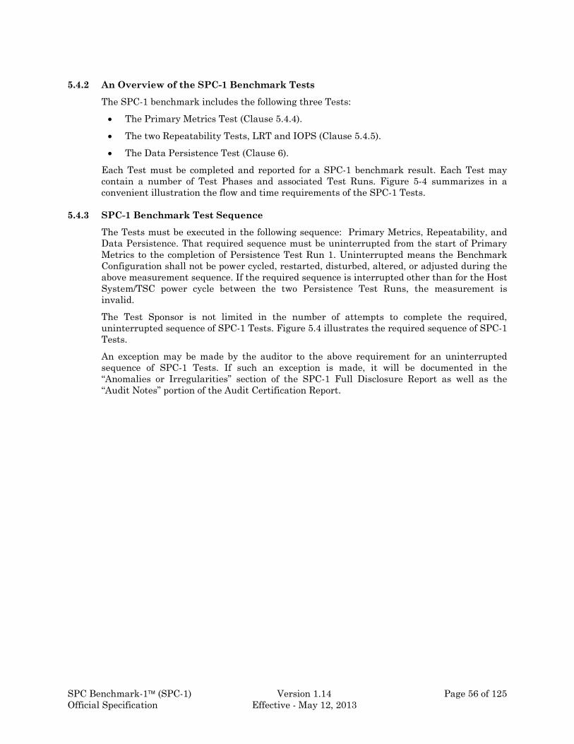
SPC Benchmark-1 (SPC-1) Version 1.14 Page 56 of 125 Official Specification Effective - May 12, 2013
5.4.2 An Overview of the SPC-1 Benchmark Tests
The SPC-1 benchmark includes the following three Tests:
The Primary Metrics Test (Clause 5.4.4).
The two Repeatability Tests, LRT and IOPS (Clause 5.4.5).
The Data Persistence Test (Clause 6).
Each Test must be completed and reported for a SPC-1 benchmark result. Each Test may contain a number of Test Phases and associated Test Runs. Figure 5-4 summarizes in a convenient illustration the flow and time requirements of the SPC-1 Tests.
5.4.3 SPC-1 Benchmark Test Sequence
The Tests must be executed in the following sequence: Primary Metrics, Repeatability, and Data Persistence. That required sequence must be uninterrupted from the start of Primary Metrics to the completion of Persistence Test Run 1. Uninterrupted means the Benchmark Configuration shall not be power cycled, restarted, disturbed, altered, or adjusted during the above measurement sequence. If the required sequence is interrupted other than for the Host System/TSC power cycle between the two Persistence Test Runs, the measurement is invalid.
The Test Sponsor is not limited in the number of attempts to complete the required, uninterrupted sequence of SPC-1 Tests. Figure 5.4 illustrates the required sequence of SPC-1 Tests.
An exception may be made by the auditor to the above requirement for an uninterrupted sequence of SPC-1 Tests. If such an exception is made, it will be documented in the “Anomalies or Irregularities” section of the SPC-1 Full Disclosure Report as well as the “Audit Notes” portion of the Audit Certification Report.

SPC Benchmark-1 (SPC-1) Version 1.14 Page 57 of 125 Official Specification Effective - May 12, 2013
Figure 5-4: Summary of SPC-1 Tests
5.4.4 Primary Metrics Test
The SPC-1 Primary Metrics Test uses the Workload Generator as described in Clause 4 to execute the Workload defined in Clause 3 against the Data Repository as defined in Clause 2.
The Primary Metrics Test has three Test Phases, which shall be executed in sequence:
1. Sustainability.
2. IOPS (I/Os Per Second)
3. Response Time Ramp.
The minimum specified Start-Up duration for each Test Run in the Primary Metrics Test is 180 seconds (3 minutes). The Start-Up duration for each Test Run in the Primary Metrics Test shall be identical with the exception of the Sustainability Test Run, which is allowed to have a different Start Up duration.
Primary Metrics Test
IOPS Test Phase: 10 Mins. SPC-1 IOPS Metric.
Req
uir
ed S
equ
ence
Sustainability Test Phase: 8 hours. Throughput sustainability over time.
Response Time Ramp Test Phase: Map the relationship between response time and throughput + produce the lightly load response time result.
Test Run: 10 Mins. 95% of Load Used for IOPS Result
Test Run: 10 Mins. 90% of Load Used for IOPS Result
Test Run: 10 Mins. 80% of Load Used for IOPS Result
Test Run: 10 Mins. 50% of Load Used for IOPS Result
Test Run: 10 Mins. 10% of Load (SPC-LRT Test Metric) Req
uir
ed S
equ
ence
Data Persistence Test (see Clause 6) Demonstrate that the BC provides non-volatile/persistent data storage.
Repeatability Test Prove that maximum I/O Request Throughput results are repeatable and reproducible.
Repeatability Test Run #1: Equal to or greater than 10 minutes.
Repeatability Test Run #2: Equal to or greater than 10 minutes.

SPC Benchmark-1 (SPC-1) Version 1.14 Page 58 of 125 Official Specification Effective - May 12, 2013
5.4.4.1 Sustainability Test Phase
5.4.4.1.1 The Sustainability Test Phase has exactly one Test Run and shall demonstrate the maximum sustainable I/O Request Throughput within at least a continuous eight (8) hour Measurement Interval. This Test Phase also serves to insure that the TSC has reached steady state prior to reporting the final maximum I/O Request Throughput result (SPC-1 IOPS).
Comment: It is the intent of this test that customers, consultants, or competitors be able to easily demonstrate that an IOPS result can be consistently maintained over long periods of time as would be expected in system environments with demanding long term I/O Request Throughput requirements.
5.4.4.1.2 The computed I/O Request Throughput of the Sustainability Test must be within 5% the reported SPC-1 IOPS result. Thus, the Sustainability Test Phase can constrain the reported IOPS result. The IOPS Test (that follows the Sustainability Test) must be run at the same BSU load level as the Sustainability Test.
5.4.4.1.3 The Measured Intensity Multiplier for each I/O stream in the Sustainability Test must satisfy the I/O mix requirements defined in Clause 5.3.15.
5.4.4.1.4 The Average Response Time, as defined in Clause 5.1.1, will be computed and reported for the Sustainability Test Run and cannot exceed 30 milliseconds. If the Average Response Time exceeds that 30-millisecond constraint, the measurement is invalid.
5.4.4.1.5 All Sustainability Test Phase results or data used to compute Sustainability Test Phase results shall be obtained from Workload Generator Results Files.
5.4.4.1.6 Workload Generator Results Files and Summary Results Files produced from Sustainability Test Phase shall be preserved and supplied to the SPC Audit Service. The format and distribution medium used to communicate this information to the SPC Audit Service shall be determined by the SPC Audit Service.
5.4.4.1.7 The Sustainability Test Phase will have a Start-Up, Ramp-Up, Steady State, Ramp Down, and Shut-Down period as well as a Measurement Interval.
5.4.4.1.8 Figure 5-5 illustrates the events and components of the Sustainability Test Phase.

SPC Benchmark-1 (SPC-1) Version 1.14 Page 59 of 125 Official Specification Effective - May 12, 2013
Figure 5-5: Sustainability Test Phase
5.4.4.2 IOPS Test Phase
5.4.4.2.1 The IOPS Test Phase has one Test Run and is intended to rigorously document the maximum attainable I/O Request Throughput of the Tested Storage Configuration (TSC) after achieving sustainable and consistent I/O Request Throughput.
5.4.4.2.2 The reported metric resulting from the IOPS test is SPC-1 IOPS, computed as the I/O Request Throughput for the Measurement Interval of the IOPS Test Run.
5.4.4.2.3 The Average Response Time, as defined in Clause 5.1.1, will be computed and reported for the IOPS Test Run and cannot exceed 30 milliseconds. If the Average Response Time exceeds that 30-millisecond constraint, the measurement is invalid.
5.4.4.2.4 See Figure 5-6 for an illustration of the events and components of the IOPS Test Phase and its relationship to other Test Phases. This illustration is not to scale.
5.4.4.2.5 The IOPS Test Phase immediately follows the Sustainability Test Phase.
Comment: It is the intent of this clause to insure that the BC and TSC have demonstrated Steady State in preparation for the reported IOPS result.
5.4.4.2.6 The IOPS Test Phase is run at the same BSU load level as the Sustainability Test.
5.4.4.2.7 The IOPS Test Phase will have a Start-Up, Ramp-Up, Steady State, Ramp-down, and Shutdown period as well as a Measurement Interval.
5.4.4.2.8 The Measured Intensity Multiplier for each I/O stream in the IOPS Test Run must satisfy the I/O mix requirements defined in Clause 5.3.15.
5.4.4.2.9 The BSU load presented by the Workload Generator to ASUs shall remain unchanged between the Sustainability Test Phase and IOPS Test Phase.
Time
I/O R
equ
est
Th
rou
gh
pu
t Steady State
Ramp Up
Measurement Interval Start-Up

SPC Benchmark-1 (SPC-1) Version 1.14 Page 60 of 125 Official Specification Effective - May 12, 2013
5.4.4.2.10 During the transition from the Sustainability Test Phase to IOPS Test Phase, the I/O Request Throughput shall not drop below 50% of the SPC-1 IOPS result. For example, if a Test Sponsor obtained an SPC-1 IOPS I/O Request Throughput result of 200, during the transition to the IOPS Test Phase, the I/O Request Throughput shall not have dropped below 100.
5.4.4.2.11 The duration of the Measurement Interval for the IOPS Test Phase is 10 minutes.
5.4.4.2.12 The Test Sponsor shall do nothing to impact the I/O Request Throughput between the end of the Sustainability Test Phase and the beginning of the IOPS Test Phase.
Comment: The intent of Clauses 5.4.4.2.9, 5.4.4.2.10, and 5.4.4.2.12 is to ensure the load presented to the TSC during the transition between the two Test Phases remains under the control of the Workload Generator, without any intervention from the test sponsor, while constraining the variance in I/O Request Throughput during each Test Phase transition
5.4.4.2.13 All IOPS Test Phase data used to compute IOPS Test Phase results shall be obtained from Workload Generator Results Files.
5.4.4.2.14 Workload Generator Results Files and Summary Results Files produced from the IOPS Test Phase shall be preserved and supplied to the SPC Audit Service. The format and distribution medium used to communicate this information to the SPC Audit Service shall be determined by the SPC Audit Service.
Figure 5-6: Sustainability & IOPS Test Phases
Time
I/O R
equ
est
Th
rou
gh
pu
t
Ramp Up
Steady State
Sustainability Test Phase
Measurement Interval
IOPS Test Phase Measurement
Interval

SPC Benchmark-1 (SPC-1) Version 1.14 Page 61 of 125 Official Specification Effective - May 12, 2013
5.4.4.3 Response Time Ramp Test Phase
5.4.4.3.1 This test phase shall measure Average Response Time and I/O Request Throughput for BSU load levels at 10%, 50%, 80%, 90%, and 95% of the BSU load level used to report the IOPS test result. As such this Test Phase has exactly five Test Runs. The objectives of this Test Phase are to demonstrate:
The relationship between Average Response Time and I/O Request Throughput for a Test Sponsor’s TSC (i.e., complete a response time/throughput curve).
The (optimal) Average Response Time of a lightly loaded TSC (the SPC-1 LRT result).
5.4.4.3.2 The BSU level required at a given load level in this test phase shall be the integer value resulting from truncating the product of the BSU level used to report the IOPS test result and the load level percentage.
5.4.4.3.3 The duration for each Measurement Interval shall be equal to 10 minutes.
5.4.4.3.4 The sequence of Test Runs in this Test Phase shall be:
1. 95% BSU load level.
2. 90% BSU load level.
3. 80% BSU load level.
4. 50% BSU load level.
5. 10% BSU load level (SPC-1 LRT Metric)
5.4.4.3.5 Each Test Run in this Test Phase shall have a Start-Up, Ramp-Up, Steady State, Ramp-down, and Shutdown period as well as a Measurement Interval.
5.4.4.3.6 The Measured Intensity Multiplier for each I/O stream in each Test Run must satisfy the I/O mix requirements defined in Clause 5.3.15.
5.4.4.3.7 See Figure 5-7 for an illustration of the events and components of the Response Time Ramp Test Phase and its relationship to other Test Phases in this Test. This figure illustrates all measurement intervals associated with the Primary Metrics Test. The figure is not to scale.
5.4.4.3.8 The Response Time Ramp Test Phase immediately follows the IOPS Test Phase.
5.4.4.3.9 The BC or TSC may not be restarted between the IOPS Test Phase and the Response Time Ramp Test Phase. In addition, the Test Sponsor shall do nothing to impact the I/O Request Throughput between the end of the IOPS Test Phase and the beginning of the Response Time Ramp Test Phase.
5.4.4.3.10 The Test Sponsor shall do nothing to impact the I/O Request Throughput between Test Runs of this Test Phase.
5.4.4.3.11 During the transition from one BSU load level to the next of the Response Time Ramp Test Phase, the I/O Request Throughput shall not drop below 50% of the next reported I/O Request Throughput Result. For example, if a Test Sponsor obtained an I/O Request Throughput result of 180 at the 90% BSU load level, during the transition to the 80% Load Level, the I/O Request Throughput shall not drop below 80.

SPC Benchmark-1 (SPC-1) Version 1.14 Page 62 of 125 Official Specification Effective - May 12, 2013
Comment: The intent of Clauses 5.4.4.3.7-5.4.4.3.10 is to ensure the load presented to the TSC during the transition between Test Runs remains under the control of the Workload Generator, without any intervention from the test sponsor, while constraining the variance in I/O Request Throughput during each Test Run transition.
5.4.4.3.12 The final reported SPC-1 LRT Metric is computed as the Average Response Time of the 10% BSU load level Test Run.
5.4.4.3.13 I/O Request Throughput and Average Response Time will be computed for the Measurement Interval of each Test Run in the Response Time Ramp Test Phase.
5.4.4.3.14 All Response Time Ramp Test Phase results or data used to compute Response Test Ramp Test Phase results shall be obtained from Workload Generator Results Files.
5.4.4.3.15 Workload Generator Results Files and Summary Results Files produced for all Test Runs of the Response Time Ramp Test Phase shall be preserved and supplied to the SPC Audit Service. The format and distribution medium used to communicate this information to the SPC Audit Service shall be determined by the SPC Audit Service.
Figure 5-7: Primary Metrics Test
I/O R
equ
est
Th
rou
gh
pu
t
Ramp Up
Sustainability Test Phase
Measurement Interval IOPS Test Phase
Measurement Interval
Time
Response Time Ramp Test Phase
95% BSU load level Measurement
Interval
90% BSU load level Measurement
Interval
80% BSU load level Measurement
Interval
50% BSU load level Measurement
Interval
10% BSU load level Measurement
Interval
Shut Down
Start Up

SPC Benchmark-1 (SPC-1) Version 1.14 Page 63 of 125 Official Specification Effective - May 12, 2013
5.4.5 Repeatability Test
The Repeatability Test demonstrates the repeatability and reproducibility of the SPC-1 IOPS and SPC-1 LRT. The test uses the Workload Generator as described in Clause 4 to execute the Workload defined in Clause 3 against the Data Repository as defined in Clause 2.
There are two identical Test Phases in the Repeatability Test. Each Test Phase contains two Test Runs. The first Test Run (SPC-1 LRT Repeatability Test Run) produces a SPC-1 LRT™ result. The second Test Run (SPC-1 IOPS Repeatability Test Run) produces a SPC-1 IOPS™ result. . If any Test Run in either of the two Test Phases is not compliant, both Test Phases must be repeated.
5.4.5.1 The Test Sponsor shall do nothing to impact the performance of the BC between Test Runs of the Repeatability Test.
5.4.5.2 Each Test Run in the Repeatability Test will contain a Start-Up, Ramp-Up, Steady State, Ramp-down, and Shut-down period as well as a Measurement Interval.
5.4.5.3 The Measured Intensity Multiplier for each I/O stream in the Repeatability Test must satisfy the I/O mix requirements defined in Clause 5.3.15.
5.4.5.4 The duration of the Start-Up and Measurement Interval will be identical for each Test Run in the Repeatability Test.
5.4.5.5 The minimum specified Start-Up duration is 180 seconds (3 minutes).
5.4.5.6 The minimum specified Measurement Interval duration is 600 seconds (10 minutes).
5.4.5.7 Figure 5-8 illustrates the sequence of events and components of the Repeatability Test.
5.4.5.8 Steady State for the first Test Run in each Test Phase is attained at the same BSU load level used in the Primary Metrics Test to produce the final reported SPC-1 LRT metric.
5.4.5.9 Steady State for the first second Test Run in each Test Phase is attained at the same BSU load level used in the Primary Metrics Test to produce the final reported SPC-1 IOPS metric.
5.4.5.10 The final reported SPC-1 IOPS metric is deemed reproducible and repeatable if the I/O Request Throughput for each of the two SPC-1 IOPS Repeatability Test Runs is greater than the reported SPC-1 IOPS metric minus 5%. As such, the Repeatability Test will constrain the final reported SPC-1 IOPS metric.
5.4.5.11 The Average Response Time, as defined in Clause 5.1.1, will be computed and reported for each of the two SPC-1 IOPs ™ Test Runs and cannot exceed 30 milliseconds. If the Average Response Time exceeds that 30-millisecond constraint, the measurement is invalid.
5.4.5.12 The final reported SPC-1 LRT metric is deemed reproducible and repeatable if the Average Response Time for each of the two SPC-1 LRT Repeatability Test Runs is either less than the reported SPC-1 LRT metric plus 5% or less than the reported SPC-1 LRT™ metric plus one (1) millisecond (ms). As such, the LRT Repeatability Test will constrain the final reported SPC-1 LRT metric.
5.4.5.13 All Repeatability Test data used to compute Repeatability Test results shall be obtained from Workload Generator Results Files.

SPC Benchmark-1 (SPC-1) Version 1.14 Page 64 of 125 Official Specification Effective - May 12, 2013
5.4.5.14 Workload Generator Results Files and Summary Results Files produced from each Test Run of the IOPS Repeatability Test shall be preserved and supplied to the SPC Audit Service. The format and distribution medium used to communicate this information to the SPC Audit Service shall be determined by the SPC Audit Service.
5.4.5.15 Each instance of the Repeatability Test shall be run with a statistically distinct sequence of I/O requests to assure that prior cache contents do not affect the results of the current test phase. The two Repeatability Test Phases may be run uninterrupted.
Figure 5-8: Repeatability Test
Steady State
Time
I/O R
equ
est
Th
rou
gh
pu
t
Ramp Down
Ramp Up
SPC-1 IOPS Measurement
Interval
Steady State
Ramp Up
SPC-1 LRT Measurement
Interval
Repeatability Test Phase #1
Steady State
Ramp Down
Ramp Up
SPC-1 IOPS Measurement
Interval
Steady State
SPC-1 LRT Measurement
Interval
Repeatability Test Phase #2
Ramp Up

SPC Benchmark-1 (SPC-1) Version 1.14 Page 65 of 125 Official Specification Effective - May 12, 2013
Clause 6: Data Persistence Requirements and Test
6.1 Introduction
Logical Volumes and related Application Storage Units (ASUs) must demonstrate the ability to preserve data across extended periods of power loss without corruption or loss. To provide this “Persistence” capability, the Tested Storage Configuration (TSC) must use Logical Volumes and related ASUs that:
Are capable of maintaining data integrity across power cycles or outages.
Ensure the transfer of data between Logical Volumes and host systems occurs without corruption or loss.
Data persistence does not guarantee data availability. Data loss may result from system component failure or unplanned catastrophe. The storage subsystem may, but need not, include mechanisms to protect against such failure modes. Testing or guaranteeing such failure modes and increased availability mechanisms in the test storage configuration are not within the mandate or the scope of this benchmark.
6.2 Persistence Test Validation
Validation that the SPC-1 Persistence Test completed successfully is provided by the SPC Audit Service, attesting to the fact that the test has been satisfactorily completed on the BC per the test requirements below.
6.3 SPC-1 Persistence Test Constraints
6.3.1 This test is performed in isolation from other SPC-1 Tests.
6.3.2 The SPC-1 Workload Generator shall be used to perform the SPC-1 Persistence Test.
6.3.3 Persistence Test Run 1 will execute for ten (10) minutes at greater than or equal to 25% of the BSU level used to generate the reported SPC-1 IOPS™ rate.
6.3.4 The results of the SPC-1 Persistence Test must successfully complete Audit Certification as defined in Clause 10.2.1 before they can be reported or accepted as official SPC results.
6.3.5 Any TSC that fails a Persistence Test can be rerun until it passes.
6.3.6 A TSC must successfully complete the Persistence Test in order for SPC-1 results to be valid.
6.3.7 Success or failure of the Persistence Test shall be determined solely by information obtained from an SPC-1 Workload Generator Results File.
6.3.8 All I/O Requests initiated during any part of the Persistence Test in the SPC-1 benchmark must complete. A Failed I/O Request shall render a Persistence Test invalid.
6.3.9 No other work shall be performed on the BC during the execution of the Persistence Test Procedure.
6.4 Data Persistence Test Procedure
The following sequence of steps must be followed to complete the Persistence Test.

SPC Benchmark-1 (SPC-1) Version 1.14 Page 66 of 125 Official Specification Effective - May 12, 2013
1. Execute Persistence Test Run 1, which will consist of the SPC-1 Workload Generator writing a specific pattern at randomly selected locations throughout the Total ASU Capacity. The SPC-1 Workload Generator will retain the information necessary to later validate the pattern written at each location.
2. Shutdown and power off the Tested Storage Configuration (TSC). Any TSC caches employing battery backup must be flushed/emptied.
3. If the TSC includes the Host System(s), shutdown and power off the Host System(s). Any TSC caches on the Host System(s) employing battery backup must be flushed/emptied. If the TSC does not include the Host System(s), there is no requirement for the Host System configuration to be shutdown and power cycled.
4. Restart the TSC and if the Host System(s) were shutdown, restart the Host System(s).
5. Execute Persistence Test Run 2, which will utilize the retained data from Persistence Test Run 1 to verify the bit patterns written in Persistence Test Run 1 and their corresponding location.
6. If the results of Persistence Test Run 2 verifies the bit patterns are correct and at the proper location, the Persistence Test completes successfully. If Persistence Test Run 2 reports any verification error, the Persistence Test fails..
7. The Workload Generator produces a Persistence Test Results File for each run of the Persistence Test. The format and distribution medium for these Results Files shall be determined by the SPC Audit Service. A copy of the Persistence Test Results File will be produced in a human-readable format.
6.5 Data Persistence Test Substitution
The Test Sponsor may request that the SPC-2 Persistence Test be substituted for the SPC-1 Persistence Test. In most cases, such requests will be due to the limited capacity of the current SPC-1 Workload Generator to test very large storage configuration.
If the auditor grants a request to use the SPC-2 Persistence Test, the Test Sponsor will be given the appropriate details and requirements to ensure the SPC-2 Persistence Test provides the appropriate test coverage for the Tested Storage Configuration.

SPC Benchmark-1 (SPC-1) Version 1.14 Page 67 of 125 Official Specification Effective - May 12, 2013
Clause 7: Reported Data
7.1 SPC-1 Reported Data
SPC-1 Reported Data consists of the following two groups of information: SPC-1 Primary Metrics and SPC-1 Associated Data.
7.2 SPC-1 Primary Metrics
The SPC-1 Primary Metrics consist of SPC-1 IOPS™, Total ASU Capacity, and SPC-1 Price-Performance™ as defined in the following clauses.
7.2.1 SPC-1 IOPS™
7.2.1.1 SPC-1 IOPS™ is the I/O Request Throughput reported for the IOPS Test Phase as described in Clause 5.4.4.2.
7.2.1.2 All public references to this metric must be labeled as “SPC-1 IOPS™”.
7.2.2 Total ASU Capacity
7.2.2.1 Total ASU Capacity is defined in Clauses 2.6.6 and 2.6.7.
7.2.2.2 All public references to this metric must be presented as “Capacity of xxx GB”.
7.2.3 SPC-1 Price-Performance™
7.2.3.1 SPC-1 Price-Performance is defined as the ratio of the Total System Price as defined in 8.1.1.2, to the SPC-1 IOPS™, the I/O Request Throughput of the TSC as established by the IOPS Test Phase in Clause 5.4.4.2.
7.2.3.2 SPC-1 Price-Performance must be reported to a resolution of the smallest negotiable whole unit of the pricing currency in which Total System Price is reported, per Clause 8.2.4. For example, configurations priced in US dollars would report SPC-1 Price-Performance to a resolution of $0.01.
7.2.3.3 All public references to this metric must be presented as “SPC-1 Price-Performance of xxx”.
7.3 SPC-1 Associated Data
The SPC-1 Associated Data consist of total price of the Priced Storage Configuration, SPC-1 LRT™, data protection level, Tested Storage Product (TSP) category, and SPC-1 Audit Identifier.
7.3.1 Total Price – Priced Storage Configuration
The total price of the Priced Storage Configuration is the three-year cost of ownership as defined in Clause 8.3.1.
7.3.2 SPC-1 LRT™
7.3.2.1 SPC-1 LRT™ is the Average Response Time reported for the 10% Response Time Ramp Test Run as described in Clause 5.4.4.3.12
7.3.2.2 All public references to this data must be labeled as “SPC-1 LRT™”.
7.3.3 Data Protection Level

SPC Benchmark-1 (SPC-1) Version 1.14 Page 68 of 125 Official Specification Effective - May 12, 2013
7.3.3.1 Data protection level is defined in Clause 2.7.
7.3.3.2 Public references to the data protection level of a SPC-1 Result must state either “Protected 1” or “Unprotected 2”, as appropriate.
7.3.4 SPC-1 Submission Identifier
The SPC-1 Submission Identifier is a unique identifier, assigned by the SPC Auditor, for each SPC-1 Result.
7.4 SPC-1 Results – Public Use Requirements
Section 11.2.1 of the SPC Policies and Guidelines defines the requirements for public use of SPC Results. The following clauses present public use requirements in the context of SPC-1 Results. Section 11.2.1 of the SPC Policies and Guidelines should be reviewed in its entirety to ensure compliance with the complete set of requirements.
7.4.1 Referencing Non-Local Currency Reported Data
A public reference, which includes SPC-1 Price-Performance and/or SPC-1 Total Price, for an SPC-1 Result that uses non-local currency pricing (Clause 8.2.4.2) must include a clear statement of the currency used and the “target country” (Clause 8.2.3). For example, “SPC-1 Pricing is in U.S. dollars for product availability, sales, and support in People’s Republic of China”.
7.4.2 Referencing a Single SPC-1 Result
7.4.2.1 A public reference to an SPC-1 Result is required include one of the following:
1. A complete URL (hyperlink) to the SPC-1 Result’s entry on the “SPC-1 Results” page of the SPC website.
2. The complete set of SPC-1 Reported Data, which consists of SPC-1 IOPS, Total ASU Capacity, SPC-1 Price-Performance, total price of the Priced Storage Configuration, formal currency name used in pricing, “target country”, data protection level, and SPC-1 Audit Identifier. This set of information must use the same font style, font size, and text clarity for item in the set. The set of information may appear as a text paragraph or table of information.
In either case, the public reference must include the “current as of” date.
7.4.2.2 Any of the SPC-1 Reported Data may be used in a public reference without stating the complete set of SPC-1 Reported Data as long as the following requirements are met:
1. The URL defined in Clause 7.4.2.1 is included in the public reference.
2. The public reference includes the “current as of” date.
7.4.3 Referencing Two or More SPC-1 Results
If a public reference of two or more SPC-1 Results does not include any comparison of SPC-1 Reported Data, the requirements in Clauses 7.4.1 and 7.4.2 are applicable.
7.4.4 Comparing Two or More SPC-1 Results
SPC-1 Reported Data may be used in a public reference to compare two or more SPC-1 Results under the following conditions:

SPC Benchmark-1 (SPC-1) Version 1.14 Page 69 of 125 Official Specification Effective - May 12, 2013
1. In addition to the SPC-1 Reported Data used in the comparison, each referenced SPC-1 Result must include either the complete set of SPC-1 Reported Data or the URL defined in Clause 7.4.2.1.
2. If the complete set of SPC-1 Reported Data is included for one of the referenced SPC-1 Results, the complete set of SPC-1 Reported Data must be included for all of the referenced results.
3. The public reference must include the “current as of” date.
4. If the public reference consists of printed or displayed materials, the required items in #1, #2 and #3 for each SPC-1 Result must use the same font style, font size, and text clarity.
5. The pricing currency and “target country” must both be identical when a comparison includes SPC-1 Price-Performance and/or SPC-1 Total Price.

SPC Benchmark-1 (SPC-1) Version 1.14 Page 70 of 125 Official Specification Effective - May 12, 2013
Clause 8: Pricing
This clause defines the components and methodology necessary to calculate required three-year pricing and the SPC-1 price-performance primary metric. The fundamental premise of this clause is that what is tested is priced and what is priced is tested.
8.1 Priced Components
The components to be priced include the hardware and software components present in the Tested Storage Configuration (TSC), any additional operational components required by the TSC, and three-year maintenance on all of the above components.
8.1.1 Tested Storage Configuration (TSC)
The TSC represents the physical configuration that is physically present during the benchmark measurement as defined in Clause 4.5. The TSC when used in pricing must represent a customer orderable configuration. To allow the use of a valid measurement configuration that may not represent a customer orderable configuration, this clause will distinguish between the TSC and Priced Storage Configuration.
8.1.1.1 Priced Storage Configuration
The Priced Storage Configuration represents a customer orderable configuration. If the TSC, without modification, is customer orderable, it is also the Priced Storage Configuration.
In cases where the TSC is a valid measurement configuration but not a customer orderable configuration, the TSC and Priced Storage Configuration will differ. In those cases, the Priced Storage Configuration will be comprised of the TSC with the appropriate components added or deleted to create a customer orderable configuration.
For example, consider a configuration in which a portion of the Physical Storage Capacity (Clause 2.2) is not physically connected to the TSC, and the TSC can be ordered without that unused storage. In this case, the Priced Storage Configuration would not include the unused storage.
A second example would be a configuration in which all of the Physical Storage Capacity is used in the benchmark, but that specific storage capacity is not orderable. The amount of storage included in the pricing would be adjusted to create an orderable configuration, again resulting in a Priced Storage Configuration that differs from the TSC.
In those cases where there is deletion or addition of components to create a customer orderable configuration, the Priced Storage Configuration must be capable of providing at least the same level of reported performance as the TSC. The intent of this requirement is to ensure that any component change to the TSC be performance-neutral.
8.1.1.2 Calculation of Total System Price
Calculation of the three-year pricing, known as Total System Price, includes:
The cost of the Priced Storage Configuration as defined in Clause 8.1.1.1.
The cost of additional hardware and/or software products as described in Clause 8.1.2.
Maintenance as defined in Clause 8.1.3
Host System(s) that are considered priced TSC components (Clause 4.5.1).

SPC Benchmark-1 (SPC-1) Version 1.14 Page 71 of 125 Official Specification Effective - May 12, 2013
All applicable tariffs, duties, and import fees, when appropriate, if those costs are not included in the listed product prices.
Specifically excluded from the pricing calculation are the following:
Components necessary for the execution of the benchmark but do not provide any storage functionality and do not enhance the measured performance of the Tested Storage Configuration.
System software, which is not a third-party product, that meets the exclusions listed in Clause 4.5.1.
The cost of maintenance for HBA(s) included in the Priced Storage Configuration.
Any associated shipping costs.
8.1.2 Additional Operational Components
8.1.2.1 Additional products explicitly required for the operation, administration, or maintenance of the Priced Storage Configuration must be included. This includes all required third-party software and hardware products.
8.1.2.2 Copies of the software used by the Priced Storage Configuration, on appropriate media, and a software load device, if required for initial load or maintenance updates, must be included.
8.1.2.3 The price of all cables used to connect components of the Priced Storage Configuration must be included.
8.1.2.4 If the Priced Storage Configuration is greater than 20U, the configuration must include the appropriate racking/cabinetry and power distribution.
8.1.3 Maintenance
8.1.3.1 Hardware maintenance and software support, no matter what it is called by the vendor, provides the following:
Acknowledgement of new and existing problems within four (4) hours.
On-site presence of a qualified maintenance engineer or provision of a customer replaceable part within four (4) hours of the above acknowledgement for any hardware failure that results in an inoperative Priced Storage Configuration that can be remedied by the repair or replacement of a Priced Storage Configuration component. In either case, the remedy will result in resumption of operation.
Comment: Resumption of operation means the Priced Storage Configuration must be returned to the same state/configuration that was present before the failure.
Commitment to fix software defects within a reasonable time.
8.1.3.2 The maintenance pricing must be independent of actual failure rates over the three-year period, no matter how many failures occur during that period. The use of Mean Time Between Failure (MTBF) data to directly compute the maintenance cost for this benchmark is precluded. The hardware maintenance pricing requirements cannot be met by pricing based on the cost to fix specific failures, even if the failure rate is calculated from MTBF data.

SPC Benchmark-1 (SPC-1) Version 1.14 Page 72 of 125 Official Specification Effective - May 12, 2013
8.1.3.3 Hardware maintenance and software support must be configured using standard pricing which covers 7 days per week, 24 hours per day coverage, either on-site, or if available as standard offering, via a central support facility for a duration of at least three years (36 months).
8.2 Pricing Methodology
The pricing methodology must reflect the cost of operation of the Benchmark Configuration using packages and discounts commonly practiced and generally available products. This cost must be disclosed in a line item fashion using local pricing.
8.2.1 Packages and Discounts
Packaging and pricing that are generally available to customers are acceptable. Promotional and/or limited availability offerings are explicitly excluded. Revenue discounts based on total price are permissible. Any discount must be only for the configuration being priced and cannot be based on past or future purchases. Individually negotiated discounts are not permitted. Special customer discounts (e.g., GSA schedule, educational schedule) are not permitted. The reported pricing represents a one time, stand-alone purchase.
8.2.1.1 Generally available discounts for the priced configuration are allowed.
8.2.1.2 Generally available packaged pricing is allowed.
8.2.1.3 Assumptions of other purchases, other sites with similar systems, or any other assumption that relies on the principle that the customer has made any other purchase from the Test Sponsor are specifically prohibited.
8.2.1.4 For all hardware components used in the priced system, the cost must be the price of a new component (i.e., not reconditioned or previously owned).
8.2.1.5 For a Test Sponsor who only has indirect sales channels, pricing must be actual generally available pricing from indirect channels that meet all other requirements of Clause 8.
8.2.1.6 Maintenance may be bundled as a component of package pricing. In that case, the maintenance component of the package must be clearly identified in the description of the bundle/package. A Test Sponsor may also include a standard multi-year maintenance option as a separately priced component. In cases where there is not such a ‘bundling’ of maintenance or a standard multi-year maintenance options is not available, the three-year maintenance cost shall be computed as three times the one-year maintenance cost. If maintenance is priced in that manner, a discount based on pre-payment in excess of 12 months is prohibited.
8.2.2 Product Availability
8.2.2.1 The Priced Storage Configuration is the actual configuration the customer would purchase. However, vendors may announce new products and disclose benchmark results before new products have actually shipped. This is allowed, but any use of benchmark-special implementations is specifically disallowed (Clause 0.2).
8.2.2.2 Clause 0.2 requirements must be fulfilled with respect to the set of possible customers in the specified “target country” (Clause 8.2.3).
8.2.2.3 All hardware and software used in the calculations must be announced and generally orderable by customers.

SPC Benchmark-1 (SPC-1) Version 1.14 Page 73 of 125 Official Specification Effective - May 12, 2013
8.2.2.4 Each product or collection of products that comprise the Priced Storage Configuration must have an Availability Date, which is a date such that it is committed that by that date all requirements of Clause 0.2 will be fulfilled for that product or collection, including delivery for general availability.
8.2.2.5 The Priced Storage Configuration Availability Date (Clause 8.2.2.4) must not exceed three months beyond the SPC-1 Full Disclosure Report submittal date.
Comment: The essence of the Priced Storage Configuration Availability Date is the ability to take physical delivery of an integrated configuration that is identical the Priced Storage Configuration, achieves the reported SPC-1 performance, and demonstrates fulfillment of all the requirements of Clause 0.2.
8.2.2.6 The Test Sponsor must disclose all effective dates of the reported prices
8.2.3 “Target Country” Requirements
8.2.3.1 The “target country” is the country in which the Priced Storage Configuration is available for sale no later than the Priced Storage Configuration Availability Date (Clause 8.2.2.4) and in which the required hardware maintenance and software support (Clause 8.1.3) is provided either directly from the Test Sponsor or indirectly via a third-party supplier.
8.2.3.2 Priced Storage Configuration pricing, as well as any included discounts, must be available to all customers in the “target country”.
8.2.4 Pricing Currency
8.2.4.1 Local Currency
SPC-1 pricing may be in the currency of the “target country” where the SPC-1 Priced Storage Configuration product availability, sales and support requirements would be met (Clause 8.2.3).
8.2.4.2 Non-Local Currency
SPC-1 pricing may be in a currency other than the currency of the “target country” if all of the following requirements are met.
8.2.4.2.1 The “target country” requirements (Clause 8.2.3) must be met.
8.2.4.2.2 The Test Sponsor must disclose the country that is the source of the non-local currency used in the SPC-1 pricing.
8.2.4.2.3 Public statement requirements that include SPC-1 Price-Performance and/or SPC-1 Total Price are listed in Clause 7.4.1.
8.2.5 Third-Party Pricing
8.2.5.1 In the event that any hardware, software, or maintenance is provided by a third party not involved as a Test Sponsor of the benchmark, the pricing must satisfy all requirements for general availability, standard volume discounts, and full disclosure.
8.2.5.2 The Test Sponsor is required to clearly identify all the items, components and services that are not acquired from the Test Sponsor. Any third party supplier's items and prices, including discounts, are subject to the same disclosure requirements as those components supplied by the Test Sponsor. Discounts shall not be dependent on purchases from any other suppliers.

SPC Benchmark-1 (SPC-1) Version 1.14 Page 74 of 125 Official Specification Effective - May 12, 2013
8.2.5.3 Any pricing that is not directly offered by the Test Sponsor and not derived from the third party supplier’s generally available pricing and discounts must be guaranteed by the third party in a written price quotation. The quotation must be valid for a period not less than 60 days from the date the results are submitted.
8.2.5.4 Third party's written quotations must be included in the Full Disclosure Report and must state:
That the quoted prices are generally available;
The time period for which the prices are valid;
The basis of all discounts;
Any terms and conditions that apply to the quoted prices.
8.3 Required Reporting
8.3.1 Pricing Spreadsheet
8.3.1.1 The pricing spreadsheet details how the three-year cost of ownership is computed. It contains the prices, discounts, warranty information, and maintenance cost for all the hardware and software components in the Priced Storage Configuration. Price disclosure shall be presented in a structured fashion to enhance clarity and comparability between test results.
8.3.1.2 The reference price of a component or subsystem is defined as the price at which it could be ordered individually from the vendor or designated third-party suppler.
8.3.1.3 The pricing spreadsheet must be included in the Full Disclosure Report (see Clause 9.4.3.3.5) and must include the following items for each component in the Priced TSC:
Part name or brief description
Part number
Source of the component, whether from a Test Sponsor or a third party (note: this can be a index into a list of component sources provided that list is included in the pricing spreadsheet)
Reference price of the component (see Clause 8.3.1.2)
Quantity of the component used in the priced configuration
The extended price of the component, based on the reference price of the component, the quantity included in the priced configuration and any component-level discounting
Three-year maintenance cost (including any discount for pre-payment, see Clause 8.2.1.6), or a notation that maintenance for the part is included in another maintenance charge.
If the component is a bundle/package of parts, as allowed by Clause 8.2.1, the above items apply to the bundle but each item in the bundle/package must be clearly identified in the description of bundle/package.
Components required to configure the Priced TSC that have an aggregate price less than 0.1% of the Priced TSC may be listed as a single line item with a description of the collection of components, e.g., "Miscellaneous Cables."

SPC Benchmark-1 (SPC-1) Version 1.14 Page 75 of 125 Official Specification Effective - May 12, 2013
8.3.1.4 The total price of the Priced Storage Configuration and its associated three-year maintenance cost must be included in the pricing spreadsheet. The total price must be stated in the minimum level of negotiable detail for the pricing currency, e.g. U.S. dollars and cents.
8.3.1.5 The percentage, amount, and basis (including type and justification) of all discounts listed must be disclosed. A tabular summary may be employed to simplify the presentation.
Comment: Thresholds for such discounts need not be disclosed.
8.3.1.6 While package pricing is allowed, the level of discount obtained through such packages shall be disclosed by reporting the individual reference price for each component in the pricing spreadsheet (see Clause 8.3.1.2).
Comment: This requirement does not apply to components that are not sold separately, other than as repair parts.

SPC Benchmark-1 (SPC-1) Version 1.14 Page 76 of 125 Official Specification Effective - May 12, 2013
Clause 9: Full Disclosure
9.1 Supporting Definitions
9.1.1 Response Time Frequency Distributions: This consists of one graph and supporting table that clearly illustrates the frequency distribution of response times that occurred during an SPC-1 Test Run. The graph (see Figure 9-1) illustrates the number of occurrences for each Response Time range. Each Response Time Frequency Distribution graph and table shall have the format, content, and appearance illustrated in Figure 9-1 and Table 9-1. The intent of this graph is to supply reviewers with a consistent, clear, and powerful means for quickly assessing the response time results from a given Test Run. Data used to compute or construct the Response Time Frequency Distribution shall be obtained from Workload Generator Results Files.
Figure 9-1: Response Time Frequency Distribution (by occurrence)
Response Time Frequency Distribution
0
500,000
1,000,000
1,500,000
2,000,000
2,500,000
3,000,000
3,500,000
4,000,000
4,500,000
0-0.
25
>0.2
5-0.
5
>0.5
-0.7
5
>0.75
-1.0
>1.0-
1.25
>1.25
-1.5
>1.5
-1.7
5
>1.7
5-2.
0
>2.0-
2.5
>2.5-
3.0
>3.0
-3.5
>3.5
-4.0
>4.0-
4.5
>4.5-
5.0
>5.0-
6.0
>6.0
-7.0
>7.0
-8.0
>8.0-
9.0
>9.0-
10.0
>10.0
-15.
0
>15.0
-20.
0
>20.
0-25
.0
>25.0
-30.
0
>30.
0
Response Time in Milliseconds
Nu
mb
er o
f O
ccu
rran
ces
Read Write All ASUs

SPC Benchmark-1 (SPC-1) Version 1.14 Page 77 of 125 Official Specification Effective - May 12, 2013
Table 9-1: Response Time Frequency Distribution
9.1.2 I/O Request Throughput Distribution: This consists of a graph and supporting table that clearly illustrates the I/O Request Throughput that occurred in each minute of an SPC-1 Test Run. Each I/O Request Throughput Distribution graph shall have the format, content, and appearance illustrated in Figure 9-2. The intent of this graph is to supply reviewers with a consistent, clear and powerful means for quickly assessing the I/O Request Throughput results from a given Test Run. Data used to compute or construct the I/O Request Throughput Distribution shall be obtained from Workload Generator Results Files.
A table containing the data used to generate the graph shall accompany each I/O Request Throughput Distribution graph. Each I/O Request Throughput Distribution table shall have the content and appearance illustrated in Table 9-2. Every whole minute in a Test Run shall have its data presented in the table and graph.
Table 9-2: I/O Request Throughput Distribution
Response Time (ms) 0-0.25 >0.25-0.5 >0.5-0.75 >0.75-1.0 >1.0-1.25 >1.25-1.5 >1.5-1.75 >1.75-2.0Read - 427,684 1,568,848 688,322 289,759 133,147 72,296 45,788 Write - 1,185 1,428,189 2,103,441 1,260,081 811,224 600,248 427,034 All ASUs - 428,869 2,997,037 2,791,763 1,549,840 944,371 672,544 472,822 ASU1 - 348,613 2,169,264 1,796,157 878,643 480,369 310,003 225,586 ASU2 - 80,166 541,694 360,062 162,715 84,627 53,551 38,136 ASU3 - 90 286,079 635,544 508,482 379,375 308,990 209,100 Response Time (ms) >2.0-2.5 >2.5-3.0 >3.0-3.5 >3.5-4.0 >4.0-4.5 >4.5-5.0 >5.0-6.0 >6.0-7.0Read 60,251 44,812 47,992 70,566 93,029 106,316 333,996 431,023 Write 553,921 366,406 283,861 244,716 224,737 214,345 409,998 399,645 All ASUs 614,172 411,218 331,853 315,282 317,766 320,661 743,994 830,668 ASU1 326,223 241,203 203,061 201,899 210,710 216,050 538,024 620,768 ASU2 55,301 42,287 36,843 35,926 36,875 37,461 79,169 88,670 ASU3 232,648 127,728 91,949 77,457 70,181 67,150 126,801 121,230 Response Time (ms) >7.0-8.0 >8.0-9.0 >9.0-10.0 >10.0-15.0 >15.0-20.0 >20.0-25.0 >25.0-30.0 >30.0Read 488,549 521,991 502,486 1,531,647 1,056,940 746,630 523,564 1,335,023 Write 384,779 364,630 343,662 1,387,838 998,125 765,555 609,606 2,896,247 All ASUs 873,328 886,621 846,148 2,919,485 2,055,065 1,512,185 1,133,170 4,231,270 ASU1 652,790 663,143 627,639 2,038,331 1,338,412 868,850 579,604 1,269,839 ASU2 103,457 109,509 105,637 342,079 203,873 173,019 137,119 562,153 ASU3 117,081 113,969 112,872 539,075 512,780 470,316 416,447 2,399,278
940 BSUs Start Stop Interval DurationStart-Up/Ramp-Up 13:08:12 13:11:13 0-2 0:03:01Measurement Interval 13:11:13 13:21:26 3-12 0:10:13
60 second intervals All ASUs ASU1 ASU2 ASU30 46,952.37 27,959.13 5,769.45 13,223.78 1 47,089.50 28,054.62 5,779.40 13,255.48 2 46,971.02 28,008.15 5,782.18 13,180.68 3 46,933.32 27,975.72 5,765.35 13,192.25 4 46,996.52 28,006.45 5,782.48 13,207.58 5 46,929.67 27,965.10 5,764.03 13,200.53 6 47,009.80 28,032.75 5,775.95 13,201.10 7 47,036.07 28,040.30 5,778.10 13,217.67 8 46,884.67 27,948.15 5,767.78 13,168.73 9 47,141.68 28,066.75 5,809.87 13,265.07
10 46,870.37 27,945.45 5,756.85 13,168.07 11 47,159.78 28,105.17 5,788.82 13,265.80 12 46,941.17 27,978.97 5,783.75 13,178.45
Average 46,990.30 28,006.48 5,777.30 13,206.53

SPC Benchmark-1 (SPC-1) Version 1.14 Page 78 of 125 Official Specification Effective - May 12, 2013
Figure 9-2: I/O Request Throughput Distribution
9.1.3 Average Response Time Distribution: This consists of a graph and supporting table that clearly illustrates the Average Response Time Distribution that occurred in each minute of an SPC-1 Test Run.
A table containing the data used to generate the graph shall accompany each Response Time Distribution graph. Each I/O Request Throughput Distribution table shall have the content and appearance illustrated in Table 9-3. Every whole minute in a Test Run shall have its data presented in the table and graph.
Each Average Response Time Distribution graph shall have the format, content, and appearance illustrated in Figure 9-3. The intent of this graph is to supply reviewers with a consistent, clear, and powerful means for quickly assessing the response time results from a given Test Run. Data used to compute or construct the Average Response Time Distribution shall be obtained from Workload Generator Results Files.
I/O Request Throughput Distribution
0
5,000
10,000
15,000
20,000
25,000
30,000
35,000
40,000
45,000
50,000
1 2 3 4 5 6 7 8 9 10 11 12 13
Test Run Minutes
I/O
Req
ues
ts p
er S
eco
nd
All ASUs ASU1 ASU2 ASU3
Startup Measurement Interval

SPC Benchmark-1 (SPC-1) Version 1.14 Page 79 of 125 Official Specification Effective - May 12, 2013
Table 9-3: Average Response Time Distribution
Figure 9-3: Average Response Time Distribution
Average Response Time Distribution
0
5
10
15
20
25
30
35
40
45
50
1 2 3 4 5 6 7 8 9 10 11 12 13
Test Run Minutes
Ave
rag
e R
esp
on
se T
ime
(ms)
All ASUs ASU1 ASU2 ASU3
Startup Measurement Interval
460 BSUs Start Stop Interval DurationStart-Up/Ramp-Up 12:35:45 12:38:46 0-2 0:03:01Measurement Interval 12:38:46 12:48:46 3-12 0:10:00
60 second intervals All ASUs ASU1 ASU2 ASU30 12.01 15.68 12.84 3.85 1 14.53 19.13 15.73 4.27 2 10.96 14.51 11.68 3.11 3 12.32 16.49 13.20 3.09 4 12.45 16.63 13.16 3.26 5 12.72 17.11 13.51 3.07 6 12.00 16.00 12.85 3.15 7 12.26 16.35 13.02 3.27 8 12.03 16.03 12.60 3.28 9 13.64 18.28 14.50 3.42
10 11.97 15.98 12.51 3.20 11 11.94 15.94 12.69 3.12 12 12.20 16.36 12.84 3.11
Average 12.35 16.52 13.09 3.20

SPC Benchmark-1 (SPC-1) Version 1.14 Page 80 of 125 Official Specification Effective - May 12, 2013
9.1.4 Data Rate Distribution: This consists of a graph and supporting table that clearly illustrates the Data Rate Distribution that occurred in each minute of an SPC-1 Test Run. Each Data Rate Distribution graph shall have the format, content, and appearance illustrated in Figure 9-4. The intent of this graph is to supply reviewers with a consistent, clear, and powerful means for quickly assessing Data Rate Throughput results from a given Test Run. Data used to compute or construct the Data Rate Distribution shall be obtained from Workload Generator Results Files.
Figure 9-4: Data Rate Distribution
Data Rate Distribution
0
50
100
150
200
250
1 7 13 19 25 31 37 43 49 55 61 67 73 79 85 91 97 103 109 115 121 127 133 139 145 151 157 163 169 175 181
Test Run Minutes
Dat
a R
ate
MB
ytes
/Sec
All ASUs ASU1 ASU2 ASU3
Measurement Interval

SPC Benchmark-1 (SPC-1) Version 1.14 Page 81 of 125 Official Specification Effective - May 12, 2013
A table containing the data used to generate the graph shall accompany each Data Rate Distribution graph. Each Data Rate Distribution table shall have the content and appearance illustrated in Table 9-4. Every whole minute in a Test Run shall have its data presented in the table and graph.
Table 9-4: Data Rate Distribution
Start Stop Interval Duration17:08:01 17:11:01 0-2 0:03:0017:11:01 20:11:01 3-182 3:00:00
Interval All ASUs ASU1 ASU2 ASU3 Interval All ASUs ASU1 ASU2 ASU3 Interval All ASUs ASU1 ASU2 ASU30 188.65 73.34 20.15 95.16 60 188.49 73.17 20.13 95.19 120 188.86 73.05 20.20 95.61 1 188.65 73.49 20.01 95.16 61 188.33 73.22 20.05 95.06 121 188.64 73.18 20.23 95.23 2 188.71 73.36 20.07 95.28 62 189.14 73.10 20.45 95.59 122 188.81 73.23 20.39 95.19 3 188.55 73.17 20.32 95.06 63 188.69 73.41 20.17 95.11 123 188.82 73.35 19.95 95.53 4 188.94 73.26 20.20 95.48 64 189.19 73.35 20.05 95.79 124 188.87 73.31 20.15 95.41 5 189.00 73.24 20.12 95.64 65 189.03 73.28 20.07 95.68 125 188.65 73.26 20.26 95.12 6 188.79 73.27 20.10 95.42 66 188.65 73.24 20.17 95.24 126 188.45 73.41 20.02 95.02 7 188.42 73.47 20.13 94.82 67 188.56 73.23 20.06 95.26 127 188.84 73.28 20.06 95.50 8 188.82 73.34 20.07 95.40 68 188.57 73.16 20.20 95.21 128 188.95 73.19 20.20 95.56 9 188.41 73.30 20.19 94.93 69 188.67 73.32 19.97 95.39 129 188.84 73.32 20.19 95.33
10 188.64 73.40 20.06 95.18 70 188.26 73.07 20.15 95.04 130 188.53 73.08 20.18 95.27 11 188.71 73.53 20.33 94.85 71 189.03 73.38 20.14 95.51 131 188.39 73.48 20.14 94.77 12 188.59 73.39 20.16 95.03 72 189.18 73.34 20.19 95.66 132 188.82 73.48 20.11 95.23 13 188.23 73.13 20.04 95.06 73 188.55 73.10 20.10 95.35 133 188.46 73.18 20.18 95.09 14 188.92 73.28 20.15 95.49 74 188.48 73.22 20.03 95.23 134 189.61 73.62 20.23 95.76 15 188.47 73.32 20.23 94.92 75 189.44 73.37 20.28 95.80 135 189.37 73.42 20.11 95.84 16 188.25 73.13 20.17 94.95 76 189.24 73.40 20.25 95.59 136 188.82 73.24 20.21 95.37 17 188.40 73.37 20.13 94.90 77 189.26 73.32 20.29 95.65 137 188.75 73.22 19.98 95.55 18 189.05 73.23 20.23 95.60 78 188.90 73.24 20.22 95.45 138 188.42 73.22 20.07 95.14 19 188.55 73.38 20.12 95.04 79 189.44 73.56 20.20 95.68 139 189.20 73.26 20.20 95.74 20 188.94 73.40 19.99 95.55 80 189.23 73.37 20.19 95.68 140 188.48 73.10 20.25 95.13 21 188.60 73.38 20.18 95.03 81 188.87 73.27 20.22 95.38 141 188.84 72.99 20.28 95.57 22 188.84 73.55 20.04 95.25 82 188.23 73.19 20.05 94.99 142 189.01 73.26 20.02 95.74 23 188.60 73.31 20.09 95.21 83 189.02 73.46 20.03 95.53 143 188.80 73.39 20.14 95.28 24 188.89 73.28 20.18 95.43 84 188.71 73.34 20.16 95.21 144 188.77 73.59 20.01 95.17 25 188.78 73.41 20.15 95.22 85 188.53 73.04 20.23 95.26 145 188.70 73.37 20.11 95.21 26 188.75 73.49 20.11 95.15 86 188.74 73.33 20.09 95.33 146 188.62 73.02 20.18 95.42 27 188.16 73.07 20.03 95.05 87 188.39 73.27 20.13 94.99 147 188.86 73.40 20.27 95.19 28 188.90 73.48 20.13 95.29 88 188.81 73.17 20.29 95.35 148 188.53 73.40 20.00 95.12 29 188.63 73.30 20.08 95.25 89 188.69 73.27 20.24 95.19 149 188.31 73.21 20.07 95.02 30 188.34 72.97 20.18 95.19 90 188.85 73.30 20.24 95.31 150 188.89 73.18 20.06 95.65 31 188.60 73.38 20.02 95.20 91 188.75 73.17 20.24 95.34 151 188.57 73.31 20.17 95.08 32 188.25 73.26 20.19 94.80 92 188.77 73.26 20.22 95.29 152 188.60 73.19 20.14 95.28 33 189.29 73.44 20.08 95.77 93 188.94 73.42 20.25 95.27 153 188.65 73.32 20.27 95.06 34 188.92 73.37 20.28 95.27 94 188.43 73.14 20.01 95.28 154 188.91 73.18 20.07 95.65 35 189.08 73.44 20.30 95.33 95 188.53 73.26 20.25 95.02 155 188.78 73.36 20.17 95.25 36 188.61 73.23 20.21 95.17 96 188.46 73.26 20.19 95.01 156 189.06 73.25 19.99 95.82 37 188.62 73.19 20.13 95.30 97 188.92 73.34 20.22 95.36 157 188.61 73.23 20.22 95.16 38 188.31 73.20 20.18 94.93 98 189.06 73.18 20.28 95.59 158 188.69 73.37 20.06 95.26 39 188.84 73.02 20.11 95.71 99 188.84 73.31 20.19 95.34 159 188.62 73.45 20.06 95.11 40 188.85 73.14 20.17 95.55 100 188.67 73.14 20.10 95.43 160 188.52 73.42 20.08 95.01 41 188.89 73.31 20.15 95.42 101 189.07 73.36 20.38 95.32 161 188.71 73.22 20.21 95.28 42 188.60 73.27 20.13 95.20 102 181.33 70.39 19.20 91.75 162 188.47 73.17 20.04 95.26 43 188.59 73.35 20.18 95.07 103 196.09 76.16 21.01 98.92 163 188.85 73.27 20.21 95.37 44 189.05 73.31 20.14 95.59 104 188.58 73.16 20.25 95.17 164 188.43 73.11 20.23 95.09 45 189.01 73.24 20.26 95.52 105 189.03 73.55 20.25 95.24 165 188.45 73.38 20.05 95.02 46 188.67 73.35 20.14 95.18 106 188.60 73.34 20.25 95.01 166 188.65 73.41 20.21 95.03 47 189.10 73.32 20.15 95.64 107 188.93 73.32 20.41 95.20 167 188.77 73.24 20.11 95.42 48 189.13 73.40 20.18 95.56 108 155.29 60.29 16.43 78.58 168 188.71 73.17 20.27 95.26 49 189.03 73.11 20.24 95.69 109 200.37 77.73 21.28 101.36 169 189.04 73.40 20.01 95.64 50 188.97 73.37 20.28 95.33 110 204.62 79.56 21.76 103.30 170 188.20 73.11 20.11 94.98 51 188.67 73.32 20.08 95.28 111 194.48 75.42 20.73 98.33 171 189.19 73.46 20.10 95.63 52 188.92 73.22 20.21 95.49 112 188.96 73.12 20.17 95.68 172 188.26 73.08 20.09 95.09 53 188.74 73.24 20.12 95.38 113 188.82 73.33 20.00 95.49 173 187.97 73.01 20.14 94.83 54 188.77 73.32 20.06 95.39 114 188.87 73.26 20.18 95.42 174 188.69 73.36 20.21 95.12 55 189.23 73.30 20.24 95.69 115 188.90 73.26 20.15 95.49 175 188.98 73.35 20.22 95.42 56 188.30 73.14 20.05 95.11 116 188.94 73.26 20.12 95.56 176 189.05 73.32 20.28 95.45 57 188.44 73.07 20.09 95.27 117 189.17 73.48 20.19 95.50 177 188.43 73.26 20.15 95.02 58 188.38 73.22 20.32 94.83 118 188.92 73.25 20.32 95.35 178 189.21 73.34 20.17 95.70 59 187.95 73.17 19.98 94.80 119 189.09 73.18 20.20 95.72 179 188.72 73.33 20.08 95.31
180 189.18 73.29 20.05 95.84 181 188.15 73.07 20.10 94.98 182 188.73 73.27 20.12 95.33
Ramp-Up/Start-UpMeasurement Interval

SPC Benchmark-1 (SPC-1) Version 1.14 Page 82 of 125 Official Specification Effective - May 12, 2013
9.1.5 Response Time Ramp Distribution: This consists of a graph that clearly illustrates the I/O Request Throughput that occurred in each minute of the Measurement Intervals during the SPC-1 Response Time Ramp Test Phase. Each Response Time Ramp Distribution graph shall have the format, content, and appearance illustrated in Figure 9-5. The intent of this graph is to supply reviewers with a consistent, clear, and powerful means for quickly assessing results. Data used to compute or construct the Response Time Ramp Distribution shall be obtained from Workload Generator Results Files.
Figure 9-5: Response Time Ramp Distribution
Response Time Ramp Test Phase
0
5000
10000
15000
20000
25000
1 3 5 7 9 11 13 15 17 19 21 23 25 27 29 31 33 35 37 39 41 43 45 47 49 51 53 55 57 59 61 63 65 67 69 71 73 75 77
Test Run Minutes
I/O
Req
ues
t T
hro
ug
hp
ut
All ASUs ASU1 ASU2 ASU3
100% 95% 90% 80% 50% 10%

SPC Benchmark-1 (SPC-1) Version 1.14 Page 83 of 125 Official Specification Effective - May 12, 2013
9.1.6 Response Time/Throughput Functions: Graphs and supporting table that clearly illustrate the relationship of Response Time to I/O Request Throughput during an SPC-1 Response Time Ramp Test Phase and IOPS Test shall be provided in the Full Disclosure Report. The graphs shall have the format, content, and appearance illustrated in Figure 9-6 and Figure 9-7. The intent of this graph is to supply reviewers with a consistent, clear, and powerful means for quickly assessing results. Data used to compute or construct the Response Time/Throughput Function shall be obtained from Workload Generator Results Files.
Figure 9-6: Response Time/Throughput Function
Full Response Time Throughput Function
0
5
10
15
20
25
30
Ramp 10% Ramp 50% Ramp 80% Ramp 90% Ramp 95% Ramp 100%
Load Level
Ave
rag
e R
esp
on
se T
ime
(ms)
All ASUs ASU1 ASU2 ASU3 Reads Writes

SPC Benchmark-1 (SPC-1) Version 1.14 Page 84 of 125 Official Specification Effective - May 12, 2013
Figure 9-7: Simple Response Time Throughput Curve
A table containing the data used to generate the graphs shall accompany each Response Time/Throughput Function. Each table shall have the content and appearance illustrated in Table 9-5.
Table 9-5: Response Time Ramp Distribution
10% Load 50% Load 80% Load 90% Load 95% Load 100% LoadI/O Request Throughput 1,998.06 10,051.11 16,050.13 18,003.36 19,054.29 20,096.97 Average Response Time (ms): All ASUs 2.36 4.03 9.73 13.43 15.81 24.18 ASU-1 3.12 5.35 11.05 14.72 17.60 27.04 ASU-2 3.12 5.12 10.11 13.05 14.41 18.78 ASU-3 0.41 0.74 6.77 10.89 12.63 20.46 Reads 5.43 9.10 13.63 16.17 18.69 26.67 Writes 0.36 0.73 7.20 11.65 13.94 22.55
Ramp Phase Response Time / Throughput Curve
100%
95%
90%
80%
50%
10%
0
5
10
15
20
25
30
0 5000 10000 15000 20000 25000
IO Requests per Second
Res
po
nse
Tim
e (m
s)

SPC Benchmark-1 (SPC-1) Version 1.14 Page 85 of 125 Official Specification Effective - May 12, 2013
9.1.7 Full Disclosure Report (FDR): A report submitted by a Test Sponsor to the SPC Administrator documenting the results, procedures, configuration, and equipment used for one execution of the SPC-1 benchmark on a single TSC.
9.2 Full Disclosure Report (FDR) Requirements
A Full Disclosure Report (FDR), submitted to the SPC Administrator, is required for each SPC-1 Result.
Comment: The intent of this disclosure is for a customer to be able to replicate the results of this benchmark given appropriate documentation and products.
9.2.1 Electronic PDF Format
The FDR must be submitted electronically as an Adobe PDF file after successful completion of the required SPC-1 Audit and prior to any public use of the benchmark information (Clause 10.5.1).
9.2.2 Document Format
The FDR will consist of the content described in Clause 9.4.
The FDR will be written in the English language. Each page of the FDR will be formatted with a minimum of one inch side and top margins, one-half inch bottom margins, and each page will be numbered.
9.3 Full Disclosure Report Availability
The Full Disclosure Report must be readily available to the public at a reasonable charge, similar to charges for similar documents by that Test Sponsor. The Test Sponsor must have on file with the SPC, submit with the FDR, or include as a part of the FDR, a release that allows public disclosure of the FDR content.
9.4 Full Disclosure Report Content
The Full Disclosure Report must be readily available to the public at a reasonable charge, similar to charges for similar documents by that Test Sponsor. The Test Sponsor must have on file with the SPC, submit with the FDR, or include as a part of the FDR, a release that allows public disclosure of the FDR content.
9.4.1 Title Page
The Title Page of the FDR will only contain the following information:
Title: “SPC-1 Benchmark Full Disclosure Report”
The applicable SPC-1 Benchmark Specification version
The Test Sponsor’s name and, optionally, a company logo
The formal Tested Storage Product (TSP) name.
The “Submitted for Review” notation and date, which designates the submission as a SPC-1 Result and the start of the 60-day Peer Review.
The SPC-1 Submission Identifier assigned to the SPC-1 Result.
When a SPC-1 benchmark result successfully completes the required 60-day SPC Peer Review (Clause 10.6), the Title Page of its FDR may be updated with the following information:
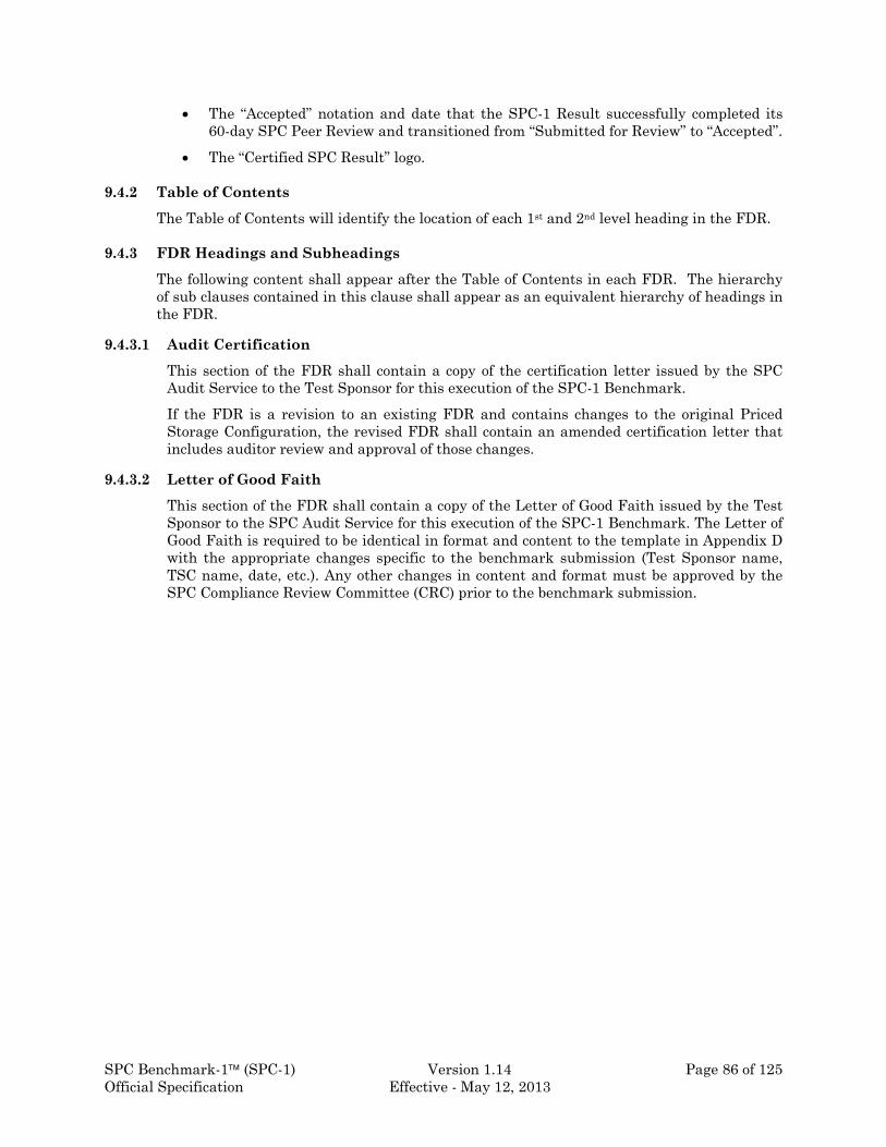
SPC Benchmark-1 (SPC-1) Version 1.14 Page 86 of 125 Official Specification Effective - May 12, 2013
The “Accepted” notation and date that the SPC-1 Result successfully completed its 60-day SPC Peer Review and transitioned from “Submitted for Review” to “Accepted”.
The “Certified SPC Result” logo.
9.4.2 Table of Contents
The Table of Contents will identify the location of each 1st and 2nd level heading in the FDR.
9.4.3 FDR Headings and Subheadings
The following content shall appear after the Table of Contents in each FDR. The hierarchy of sub clauses contained in this clause shall appear as an equivalent hierarchy of headings in the FDR.
9.4.3.1 Audit Certification
This section of the FDR shall contain a copy of the certification letter issued by the SPC Audit Service to the Test Sponsor for this execution of the SPC-1 Benchmark.
If the FDR is a revision to an existing FDR and contains changes to the original Priced Storage Configuration, the revised FDR shall contain an amended certification letter that includes auditor review and approval of those changes.
9.4.3.2 Letter of Good Faith
This section of the FDR shall contain a copy of the Letter of Good Faith issued by the Test Sponsor to the SPC Audit Service for this execution of the SPC-1 Benchmark. The Letter of Good Faith is required to be identical in format and content to the template in Appendix D with the appropriate changes specific to the benchmark submission (Test Sponsor name, TSC name, date, etc.). Any other changes in content and format must be approved by the SPC Compliance Review Committee (CRC) prior to the benchmark submission.

SPC Benchmark-1 (SPC-1) Version 1.14 Page 87 of 125 Official Specification Effective - May 12, 2013
9.4.3.3 Executive Summary
The following content shall appear in the Executive Summary per the sequence below.
9.4.3.3.1 Test Sponsor and Contact Information
The executive summary shall contain a table of contact information for the Test Sponsor as well as key entities and individuals responsible for the published result. The content, appearance, and format of this table are specified in Table 9-6.
Table 9-6: Test Sponsor and Contact Information
Test Sponsor and Contact Information
Test Sponsor Primary Contact (1)
Company, Company Web Address, Individual Name, Postal Address, Phone, FAX, Email Address.
Test Sponsor Alternate Contact (2)
Company, Company Web Address, Individual Name, Postal Address, Phone, FAX, Email Address.
Auditor (6) Company, Company Web Address, Individual Name, Postal Address, Phone, FAX, Email Address.
Footnotes to Table 9-6:
1. The primary entity and first contact responsible for the submitted FDR. Entity will be the first point of contact in administrating results through the SPC Review Process.
2. The primary entity and alternate contact(s) responsible for the submitted FDR. The Alternate contact will be contacted only if the Primary contact is not available.
3. Contact information for the Auditor used to certify the SPC-1 results.

SPC Benchmark-1 (SPC-1) Version 1.14 Page 88 of 125 Official Specification Effective - May 12, 2013
9.4.3.3.2 Revision Information and Key Dates
The executive summary shall contain a table of key dates and revision numbers associated with the published result. The content, appearance, and format of this table are specified in Table 9-7.
Where appropriate in both the Executive Summary and Full Disclosure Report, the revised details will be highlighted. For example, revised pricing line items.
Table 9-7: Revision Information and Key Dates
Revision Information and Key Dates
SPC-1 Specification revision number (1) NN.NN.NN
SPC-1 Workload Generator revision number (2) MM.MM.MM
Date Results were first used publicly (3) DD/MM/YYYY
Date FDR was submitted to the SPC (4) DD/MM/YYYY
Date revised FDR was submitted to the SPC (5) Current revision text: Revision History: dd/mm/yyyy – revision text dd/mm/yyyy – revision text
DD/MM/YYYY
Date the priced storage configuration is/was available for shipment to customers (6)
DD/MM/YYYY
Date the TSC completed audit certification (7) DD/MM/YYYY
Footnotes to Table 9-7:
1. The revision number of the SPC-1 Specification used to produce the results reported in this FDR.
2. The revision number of the Workload Generator used to produce the results reported in this FDR.
3. The calendar date that the results reported in this FDR were made public (i.e., used outside the Test Sponsors and Co-Sponsors companies).
4. The calendar date that the results reported in this FDR were submitted to the SPC.
5. The calendar date that a revised FDR was submitted to the SPC. The Revision History is a brief description of each revision.
6. The calendar date that the priced storage configuration reported in this FDR is/was first available to be shipped to a customer.
7. The date the TSC completed audit certification per the requirements in Clause 10. This is the date that the Audit Certification Letter was issued to the Test Sponsor.

SPC Benchmark-1 (SPC-1) Version 1.14 Page 89 of 125 Official Specification Effective - May 12, 2013
9.4.3.3.3 Tested Storage Product (TSP) Description
The executive summary shall contain a brief description of the Tested Storage Product (TSP). The description should include information that is consistent with the TSP categorization defined in Clause 4.6.
Features used in the benchmark by the TSP may be included in the description. For example, if the TSP is a software product that provides virtualization functionality used in the benchmark but does not include Storage Devices, the description should contain that information.
Features available in the TSP, but not used in the benchmark cannot be included in the description.
The description may include a website link to official product information available from the Test Sponsor.
9.4.3.3.4 Summary of Results
The executive summary shall contain a table of key results reported by the Test Sponsor. The content, appearance, and format of this table is specified in Table 9-8.
Table 9-8: Summary of Results
SPC-1 Reported Data
Tested Storage Product: AAAAAAAAAAAAAAAAA (1)
Title Value
SPC-1 Submission Identifier (2) Annnnn
SPC-1 IOPS (3) NNNNNN
SPC-1 Price-Performance (4) $XX.XX/SPC-1 IOPS™
Total ASU Capacity (5) XX,XXX GB
Data Protection Level (6) Protected 1/Protected 2
Priced Storage Configuration Price (7) $XXX,YYY,ZZZ
Currency Used (8) formal currency name
“Target Country” for availability, sales, and support (9)
“target country” name
Footnotes to Table 9-8:
1. The formal name of the Tested Storage Product as defined in Clause 4.6..
2. SPC-1 Submission Identifier assigned as part of the SPC-1 submission process.
3. Computed per Clause 5.4.4.2.2
4. Computed per Clause 7.1.
5. Computed per Clauses 2.6.6, and 2.6.7 (Total ASU Capacity). Must be stated in gigabytes (GB) as a truncated integer or a truncated value with
three significant digits, using the method that produces the more precise value.
6. The Data Protection Level that was selected per Clause 2.7. A brief description of the data protection must be included in the Executive Summary.

SPC Benchmark-1 (SPC-1) Version 1.14 Page 90 of 125 Official Specification Effective - May 12, 2013
7. Computed per Clause 8.1.1.2.
8. Formal name of the currency used in the Priced Storage Configuration pricing.
9. If non-local currency (Clause 8.2.4.2) was used, the name of the “target country” (Clause 8.2.3).
9.4.3.3.5 Storage Capacities and Relationship Diagram
The Executive Summary will contain a copy of Figure 9-10, Figure 9-11, Figure 9-12 and Figure 9-13, which document and illustrate the various SPC-1 storage capacities and relationships.
9.4.3.3.6 Pricing Spreadsheet
The Executive Summary shall contain a pricing spreadsheet as documented in Clause 8.3.1
9.4.3.3.7 Discounts
The Executive Summary shall describe the basis, including type and justification, of any discounts (Clause 8.3.1.5) included in the pricing spreadsheet.
9.4.3.3.8 Tested Storage Configuration (TSC) and Priced Storage Configuration Differences
The Executive Summary shall contain a list of all differences between the Tested Storage Configuration (TSC) and Priced Storage Configuration. Those differences will include substituted components (hardware and software), cosmetic changes to physical packaging, component identification responses, and other miscellaneous differences.
See Clause 8.1.1 for definitions of TSC and Priced Storage Configuration.
9.4.3.3.8.1 Republished SPC-1 Result
If a new SPC-1 benchmark result republishes an existing SPC-1 Result, all hardware and/or software differences between the original and new Priced Tested Storage Configurations must be listed. Component substitution between the TSC and Priced Storage Configuration, which would impact the existing SPC-1 Result’s reported performance, is not allowed.
See Clause 10.8 for the requirements for audit reuse.
9.4.3.3.8.2 OEM 1/OEM 2 SPC-1 Result
An OEM 1/OEM 2 SPC-1 Result is created when one SPC member company (OEM 1) produces an audited set of SPC-1 measurements that are used by another SPC member company (OEM 2) to become a new SPC-1 Result. The audited measurement will not be used by OEM 1 to produce an SPC-1 Result.
Component substitution between the TSC and Priced Storage Configuration, which would impact the existing SPC-1 Result’s reported performance, is not allowed.
9.4.3.3.9 Priced Storage Configuration Component Changes in a Revised Executive Summary
A revised Executive Summary will contain a list of all Priced Storage Configuration component changes that are included in the revision (see Clause 9.4). The list will contain the line item information of the original component, the line item information of the new component, and a brief description of the difference(s) between the two components.

SPC Benchmark-1 (SPC-1) Version 1.14 Page 91 of 125 Official Specification Effective - May 12, 2013
9.4.3.3.10 Response Time/Throughput Curve
The Executive Summary shall contain a Response Time/Throughput curve (see Figure 9-7) as well as a table (see Table 9-5) containing the data used to generate the Response Time/Throughput curve.
9.4.3.3.11 Priced Storage Configuration Diagram
The Executive Summary will contain a high-level diagram of the Priced Storage Configuration, which illustrates the major components of the configuration.
9.4.3.3.12 Priced Storage Configuration Table of Components
The Executive Summary will contain a table that lists the major components of the Priced Storage Configuration (Clause 8.1.1.1). Table 9-9 specifies the content, format, and appearance of the table.
Table 9-9: Priced Storage Configuration Components
Priced Storage Configuration:
Host Bus Adapter (HBA) information (1)
TSP formal product name (2)
Storage/Domain Controller information (3)
Storage device information (4)
All other major configuration components (5) (e.g. switches, enclosures, etc.)
Footnotes to Table 9-9:
1. The number, product/model name and description of all Host Bus Adapters installed on each Host System.
2. The Tested Storage Product’s formal product name and model (Clause 4.6).
3. The model/name and description of each storage/domain controller in the Priced Storage Configuration. The description will include:
The amount of memory and cache.
The type and total number of front-end physical connections.
The type and total number of back-end physical connections.
The number of configured Storage Devices (6) accessible by the storage/domain controller.
4. The number of Storage Devices in the Priced Storage Configuration and a description of each type of Storage Device. The description will include:
The type of device (disk drive, solid state device, etc.).
The formatted capacity of each Storage Device type.
The rotation speed, if appropriate, of each Storage Device type.
5. All other major Priced Storage Configuration components such as switches, enclosures, etc.

SPC Benchmark-1 (SPC-1) Version 1.14 Page 92 of 125 Official Specification Effective - May 12, 2013
9.4.3.4 Benchmark Configuration (BC)/Tested Storage Configuration (TSC)
9.4.3.4.1 BC/TSC Configuration Diagram
A one page BC/TSC Configuration Diagram (see example in Figure 9-8) shall be included in the FDR, and illustrate the following information:
1. All Host Systems and Management Appliances in the BC. Each Host System shall designate (in sequence):
The model or name of the product.
The number of CPUs or processors.
The amount of main memory in the system.
The type of System Software (i.e., operating system) running on the O.S.
The type of System I/O Interconnect.
The type of physical connections between Adapters (connected to the System I/O Interconnect) and any Storage Controllers or Storage Devices.
2. All Storage Controllers or Domain Controllers in the TSC. Each Controller shall designate (in sequence):
The model or name.
The amount of memory and cache.
The number of Front-end physical interconnects (unless there are none).
The type of Front-end interconnects (unless there are none).
The number of Back-end physical interconnects.
The type of Back-end physical interconnects.
The type of physical connections between Adapters (connected to the System I/O Interconnect) and any Storage Controllers or Storage Devices.
3. The number of Storage Device as well as their capacities.
4. An illustration and description of the networks used to implement the BC.
5. If the TSC contains network storage, the diagram will include the network configuration. If a single diagram is not sufficient to illustrate both the Benchmark Configuration and network configuration in sufficient detail, the Benchmark Configuration diagram will include a high-level network illustration as shown in Figure 9-8. In that case, a separate, detailed network configuration diagram will also be included as described in Clause 9.4.3.4.2.
The content, appearance, and format of this diagram are specified in Figure 9-8.
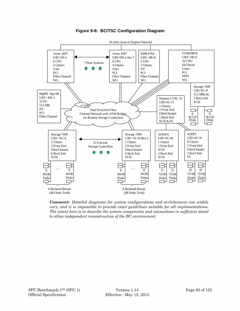
SPC Benchmark-1 (SPC-1) Version 1.14 Page 93 of 125 Official Specification Effective - May 12, 2013
Figure 9-8: BC/TSC Configuration Diagram
Comment: Detailed diagrams for system configurations and architectures can widely vary, and it is impossible to provide exact guidelines suitable for all implementations. The intent here is to describe the system components and connections in sufficient detail to allow independent reconstruction of the BC environment.
Acme 3497UID=HS-16 CPU4 GbytesUnixPCIFibre ChannelWG
Storage 7699UID= SC-A2 Gbytes 2 Front EndFibreChannel6 Back EndSCSI
Acme 3497UID=HS-2 thru 76 CPU4 Gbytes UnixPCIFibre ChannelWG
DDB 8764UID= HS-82 CPU1 Gbytes NTPCIFibre ChannelWG
FVBW9876UID= HS-932 CPU64 Gbytes LinuxPCIHPPIWG
Storage 7699UID= SC-B thru L2 Gbytes 2 Front EndFibreChannel6 Back EndSCSI
Domain CTRL 33UID=SC-O1 Gbytes 2 Front EndFibreChannel2 Back EndSCSI & FC
836GBDisks
7 Host Systems
345DFGUID=SC-M1 Gbytes 1 Front EndSCSI2 Back EndSCSI
ASDF1UID=SC-N8 Gbytes2 Front EndFibreChannel2 Back EndFC
MgMT App 6BUID= MA-11CPU512 MBNTPCIFibre Channel
Storage 7699UID=SC-P512 MBytes2 Back EndSCSI
Dual Switched FibreChannel Network with ATM Bridges
for Remote Storage Connection
12 External Storage Controllers
6 Backend Busses(48 Disks Total)
. . . 836GBDisks
836GBDisks
6 Backend Busses(48 Disks Total)
. . . 836GBDisks
1172GBDisks
836 GBDisks
836 GBDisks
10 mbit General Purpose Network
1172GBDisks
8772GBDisks
8772GBDisks

SPC Benchmark-1 (SPC-1) Version 1.14 Page 94 of 125 Official Specification Effective - May 12, 2013
9.4.3.4.2 Storage Network Configuration
If a storage network was configured as a part of the Tested Storage Configuration and the Benchmark Configuration diagram described in Clause 9.4.3.4.1 contains a high-level illustration of the network configuration, the FDR will contain a one page topology diagram of the storage network as illustrated in Figure 9-9.
1. Storage Controllers and Domain Controllers (see Clause 9.4.3.4.1)
2. Host Systems (see Clause 9.4.3.4.1)
3. Routers and Bridges
4. Hubs and Switches
5. HBAs to Host Systems and Front End Port to Storage Controllers.
Additionally the diagram shall:
Illustrate the physical connection between components.
Describe the type of each physical connection.
Describe the network protocol used over each physical connection.
The maximum theoretical transfer rate of each class of interconnect used in the configuration.
Correlate with the BC Configuration Diagram in Clause 9.4.3.4.1.
Comment: The intent of this clause is that anyone should be able to recreate the benchmark environment and obtain the results published by the Test Sponsor.

SPC Benchmark-1 (SPC-1) Version 1.14 Page 95 of 125 Official Specification Effective - May 12, 2013
Figure 9-9: Storage Network Configuration Diagram
The Test Sponsor shall additionally supply (referenced in an appendix) a wiring diagram of all physical connections and physical port assignments used in the storage network. This diagram should allow anyone to exactly replicate the physical configuration of the storage network.
9.4.3.4.3 Host System and Tested Storage Configuration (TSC) Table of Components
The FDR will contain a table that lists the major components of each Host System and the Tested Storage Configuration (TSC). Table 9-10 specifies the content, format, and appearance of the table.
Acme 3497UID= HS-1
Storage 7699UID=SC-A
Acme 3497UID=HS-2/7
DDB 8764UID=HS-8
FVBW9876UID= HS-9
Storage 7699UID=SC-B thru L
7 Host Systems
12 External Storage Controllers
Domain CTRL 33UID=SC-O
MgMTAppliance 6BUID=MA-1
16 Port FibreChannel Switch Pair
HBA-A HBA-B HBA-A HBA-B HBA-A HBA-B HBA-C HBA-D
FC to ATM Bridge
FC to ATM Bridge
FC to ATM Bridge
FC to ATM Bridge
16 Port FibreChannel Switch Pair
FC to SCSIRouter
8 Port FC Hub
FC to SCSIRouter
Port-A Port-BPort-A Port-B
Legend
Fibre Channel Send and Receive Pair using50 Micron Multi-mode cab le1 Gigabit per second.
SCSI Physical Connection16 Bit Parallel Cable160 MBytes per second.
ATM over Sonet 10 Gigabits/second.

SPC Benchmark-1 (SPC-1) Version 1.14 Page 96 of 125 Official Specification Effective - May 12, 2013
Table 9-10: Host System(s) and Tested Storage Configuration
Host System: Tested Storage Configuration (TSC):
Host System name/model (1) Host Bus Adapter (HBA) information (7)
CPU information (2) TSC product name (8)
Main Memory configuration (3) Storage/Domain Controller information (9)
Operating system name and version (4) Front-end interconnection information (10)
TSC System Software (5) Back-end interconnection information (11)
Storage device information (12)
All other major TSC components (13) (e.g. switches, enclosures, etc.)
Footnotes to Table 9-10:
1. The product name and model of each Host System used in the benchmark.
2. The number, product/model name, and description of the CPUs in each Host System. The description will include clock speed.
3. The amount of main memory configured in each Host System.
4. The operating system, version, and any specific patches/updates installed on each Host System.
5. Any System Software, other than the operating system, installed on the Host System that provided TSC functionality such as a volume manager.
6. The number, product/model name and description of all Host Bus Adapters installed on each Host System.
7. The Tested Storage Configuration’s product name and model.
8. The model/name and description of each storage/domain controller in the TSC. The description will include:
The amount of memory and cache.
The type and total number of front-end physical connections.
The type and total number of back-end physical connections.
The type of physical connection between the Host System and storage/domain controller
The number of configured Storage Devices (12) accessible by the storage/domain controller.
9. The number of physical front-end connections used in the benchmark.
10. The number of physical back-end physical connections used in the benchmark and the number of Storage Devices accessible by each connection.
11. The number of Storage Devices in the TSC and a description of each type of Storage Device. The description will include:
The type of device (disk drive, solid state device, etc.).
The formatted capacity of each Storage Device type.
The rotation speed, if appropriate, of each Storage Device type.
The amount of cache in each Storage Device type.
12. All other major TSC components such as switches, enclosures, etc.

SPC Benchmark-1 (SPC-1) Version 1.14 Page 97 of 125 Official Specification Effective - May 12, 2013
9.4.3.5 Benchmark Configuration (BC) Description
The intent of this clause is to require disclosure of information necessary to recreate the complete Benchmark Configuration (BC) and obtain the results published by the Test Sponsor.
9.4.3.5.1 Customer Tuning Parameters and Options
All Benchmark Configuration (BC) components with customer tunable parameters and options that have been altered from their default values must be listed in the FDR. The FDR entry for each of those components must include both the name of the component and the altered value of the parameter or option. If the parameter name is not self-explanatory to a knowledgeable practitioner, a brief description of the parameter’s use must also be included in the FDR entry.
Examples of customer tunable parameters and options include:
Options for each component used in a network used to connect Storage to Host Systems.
HBA Options.
Array Controller options.
Operating system, run time environment, and application configuration parameters.
Compilation and linkage options and run-time optimizations used to create/install any applications or the OS used on the BC.
9.4.3.5.2 Tested Storage Configuration Description
The FDR must include sufficient information to recreate the logical representation of the TSC. In addition to customer tunable parameters and options (Clause 4.2.4.5.3), that information must include, at a minimum:
A diagram and/or description of the following:
All physical components that comprise the TSC. Those components are also illustrated in the BC Configuration Diagram in Clause 9.4.3.4.1 and/or the Storage Network Configuration Diagram in Clause 9.4.3.4.2.
The logical representation of the TSC, configured from the above components that will be presented to the Workload Generator.
Listings of scripts used to create the logical representation of the TSC.
If scripts were not used, a description of the process used with sufficient detail to recreate the logical representation of the TSC.
9.4.3.5.3 SPC-1 Workload Generator Storage Configuration
The FDR must include all SPC-1 Workload Generator storage configuration commands and parameters. That information is typically contained in the ‘SPC1.cfg’ file.

SPC Benchmark-1 (SPC-1) Version 1.14 Page 98 of 125 Official Specification Effective - May 12, 2013
9.4.3.6 Data Repository
9.4.3.6.1 SPC-1 Storage Capacities and Relationships
Two tables and four charts documenting the storage capacities and relationships of the SPC-1 Storage Hierarchy (Clause 2.1) shall be included in the FDR. The content, appearance, and format of the tables are specified in Table 9-11 and Table 9-12. The content, appearance, and format of the charts are specified in Figure 9-10 – Figure 9-13. The capacity value in each chart may be listed as an integer value, for readability, rather than the decimal value listed in Table 9-11.
In addition, an annotation must be included with the table illustrated in Table 9-11 that documents the source of the value presented for Physical Storage Capacity. The source will be either formatted capacity or capacity reported as available for application use. If multiple Storage Device models are included in the Tested Storage Configuration, the annotation must detail the appropriate source for each model. The annotation must also include the following text:
“The configured Storage Devices may include additional storage capacity reserved for system overhead, which is not accessible for application use. That storage capacity may not be included in the value presented for Physical Storage Capacity”.
Table 9-11: SPC-1 Storage Capacities
SPC-1 Storage Capacities
Storage Hierarchy Component Units Capacity
Total ASU Capacity (1) GB nnn,nnn
Addressable Storage Capacity (2) GB n,nnn,nnn
Configured Storage Capacity (3) GB n,nnn,nnn
Physical Storage Capacity (4) GB n,nnn,nnn
Data Protection (5) GB nnn,nnn
Required Storage (6) GB nn
Global Storage Overhead (7) GB nn
Total Unused Storage (8) GB nn
Footnotes to Table 9-11.
1. Defined in Clause 2.6
2. Defined in Clause 2.4
3. Defined in Clause 2.3
4. Defined in Clause 2.2
5. Defined in Clause 2.7
6. Defined in Clause 2.3.2
7. Defined in Clause 2.2.3

SPC Benchmark-1 (SPC-1) Version 1.14 Page 99 of 125 Official Specification Effective - May 12, 2013
8. Sum of capacities defined in Clauses 2.2.4, 2.3.2, and 2.4.3
Capacities must be stated in gigabytes (GB) as a truncated integer or a truncated value with three significant digits, using the method that produces the more precise value.
Table 9-12: SPC-1 Storage Hierarchy Ratios
Addressable Storage Capacity
Configured Storage Capacity
Physical Storage Capacity
Total ASU Capacity (1) (2) (3)
Data Protection (4) (5)
Addressable Storage Capacity (6) (7)
Required Storage (8) (9)
Configured Storage Capacity (10)
Global Storage Overhead (11)
Unused Storage (12) (13) (14)
Footnotes to Table 9-12.
The values calculated below are to be represented as a percentage with two significant digits, truncating after the second significant digit.
1. Total ASU Capacity ÷ Addressable Storage Capacity
2. Total ASU Capacity ÷ Configured Storage Capacity
3. Total ASU Capacity ÷ Physical Storage Capacity
4. Data Protection ÷ Configured Storage Capacity
5. Data Protection ÷ Physical Storage Capacity
6. Addressable Storage Capacity ÷ Configured Storage Capacity
7. Addressable Storage Capacity ÷ Physical Storage Capacity
8. Required Storage ÷ Configured Storage Capacity
9. Required Storage ÷ Physical Storage Capacity
10. Configured Storage Capacity ÷ Physical Storage Capacity
11. Global Storage Overhead ÷ Physical Storage Capacity
12. Unused Storage (contained in Addressable Storage Capacity) ÷ Addressable Storage Capacity
13. Unused Storage (contained in Configured Storage Capacity) ÷ Configured Storage Capacity
14. Unused Storage (total)) ÷ Physical Storage Capacity

SPC Benchmark-1 (SPC-1) Version 1.14 Page 100 of 125 Official Specification Effective - May 12, 2013
Figure 9-10: SPC-1 Physical Storage Capacity
Figure 9-11: SPC-1 Configured Storage Capacity

SPC Benchmark-1 (SPC-1) Version 1.14 Page 101 of 125 Official Specification Effective - May 12, 2013
Figure 9-12: SPC-1 Addressable Storage Capacity
Figure 9-13: SPC-1 Total Unused Storage Capacity Ratio and Detail

SPC Benchmark-1 (SPC-1) Version 1.14 Page 102 of 125 Official Specification Effective - May 12, 2013
9.4.3.6.2 Storage Capacity Utilization
The FDR will include a table illustrating the storage capacity utilization values defined for Application Utilization (Clause 2.8.1), Protected Application Utilization (Clause 2.8.2), and Unused Storage Ratio (Clause 2.8.3). The content, appearance, and format of this table are specified in Table 9-13.
Table 9-13: SPC-1 Storage Capacity Utilization
SPC-1 Storage Capacity Utilization
Application Utilization (1) %
Protected Application Utilization (2) %
Unused Storage Ratio (3) %
Footnotes to Table 9-13.
1. Total ASU Capacity divided by Physical Storage Capacity (Clause 2.8.1).
2. (Total ASU Capacity plus total Data Protection Capacity minus unused Data Protection Capacity) divided by Physical Storage Capacity (Clause 2.8.2).
3. Total Unused Capacity divided by Physical Storage Capacity (Clause 2.8.3).
9.4.3.6.3 Logical Volume Capacity and ASU Mapping
A table illustrating the capacity of each ASU and the mapping of Logical Volumes to ASUs shall be provided in the FDR. Capacity must be stated in gigabytes (GB) as a truncated integer or a truncated value with three significant digits, using the method that produces the more precise value. Logical Volumes shall be sequenced in the table from top to bottom per its position in the contiguous address space of each ASU. The capacity of each Logical Volume shall be stated. Each Logical Volume identifier in the table shall be unique within the BC. The content, appearance, and format of this table are specified in Table 9-14. In conjunction with this table, the Test Sponsor shall provide a complete description of the type of data protection (see Clause 2.7) used on each Logical Volume.
Table 9-14: Logical Volume Capacity and ASU Mapping
Logical Volume Capacity and Mapping
ASU-1 (nnn,nnn GB) ASU-2 (nnn,nnn GB) ASU-3 (nnnGB)
Volume 1 (nnn GB) Volume 5 (nnn GB) Volume 7 (nnn GB)
Volume 2 (nnn GB) Volume 6 (nnn GB) Volume 8 (nnn GB)
Volume 3 (nnn GB) Volume 9 (nnn GB)
Volume 4 (nnn GB)

SPC Benchmark-1 (SPC-1) Version 1.14 Page 103 of 125 Official Specification Effective - May 12, 2013
9.4.3.7 SPC-1 Test Execution Results
9.4.3.7.1 Initial Ramp-Up – “Ramp-Up” Test Runs
If a series of “Ramp-Up” Test Runs (Clause 5.3.13) were included in the SPC-1 measurement sequence, the FDR shall report the duration (ramp-up and measurement interval), BSU level, SPC-1 IOPS and average response time for each “Ramp-Up” Test Run in an appropriate table.
9.4.3.7.2 Sustainability Test Phase
For the Sustainability Test Phase the FDR shall contain:
1. A Data Rate Distribution graph and data table (Clause 9.1.4).
2. I/O Request Throughput Distribution graph and data table (Clause 9.1.2).
3. A Response Time Frequency Distribution graph and table (Clause 9.1.1).
4. An Average Response Time Distribution graph and table (Clause 9.1.4).
5. The human readable Test Run Results File produced by the Workload Generator (may be included in an appendix).
6. A listing or screen image of all input parameters supplied to the Workload Generator (may be included in an appendix).
7. The Measured Intensity Multiplier for each I/O Stream.
8. The variability of the Measured Intensity Multiplier, as defined in Clause 5.3.15.3.
9.4.3.7.3 IOPS Test Phase
For the IOPS Test Phase the FDR shall contain:
1. I/O Request Throughput Distribution graph and table (Clause 9.1.2).
2. A Response Time Frequency Distribution graph and table (Clause 9.1.1).
3. An Average Response Time Distribution graph and table (Clause 9.1.4).
4. The human readable Test Run Results File produced by the Workload Generator (may be included in an appendix).
5. A listing or screen image of all input parameters supplied to the Workload Generator (may be included in an appendix).
6. The total number of I/O Requests completed in the measurement interval as well as the number of I/O Request with a Response Time less than or equal to 30.00 milliseconds and the number of I/O Requests with a Response Time greater than 30.00 milliseconds.
9.4.3.7.4 Response Time Ramp Test Phase
The following content shall appear in the FDR for the Response Time Ramp Test Phase:
1. A Response Time Ramp Distribution graph (Clause 9.1.5).
2. The human readable Test Run Results File produced by the Workload Generator for each Test Run within the Response Time Ramp Test Phase (may be included in an appendix).
3. For the 10% BSU Load Level Test Run (the SPC-1 LRT™ metric) an Average Response Time Distribution graph and table (Clause 9.1.4).

SPC Benchmark-1 (SPC-1) Version 1.14 Page 104 of 125 Official Specification Effective - May 12, 2013
4. A listing or screen image of all input parameters supplied to the Workload Generator (may be included in an appendix).
9.4.3.7.5 Repeatability Test
The following content shall appear in the FDR for each Test Run in the IOPS Repeatability Test:
1. A table containing the results of the Repeatability Test. The content, appearance, and format of the table are specified in Table 9-15.
2. I/O Request Throughput Distribution graph and table (Clause 9.1.2).
3. An Average Response Time Distribution graph and table (Clause 9.1.4).
4. The human readable Test Run Results File produced by the Workload Generator (may be included in an appendix).
5. A listing or screen image of all input parameters supplied to the Workload Generator (may be included in an appendix).
Table 9-15: Repeatability Test Results
IOPS LRT
Reported Metrics n,nnn.nn n.nn
Repeatability Test Phase 1 n,nnn.nn n.nn
Repeatability Test Phase 2 n,nnn.nn n.nn
9.4.3.8 Data Persistence Test Results
The following content shall appear in this section of the FDR:
1. A listing or screen image of all input parameters supplied to the Workload Generator (may be optionally referenced in an appendix).
2. For the successful Data Persistence Test Run, a table illustrating key results. The content, appearance, and format of this table are specified in Table 9-16. Information displayed in this table shall be obtained from the Test Run Results File referenced below in #3.
3. For the successful Data Persistence Test Run, the human readable Test Run Results File produced by the Workload Generator (may be contained in an appendix).

SPC Benchmark-1 (SPC-1) Version 1.14 Page 105 of 125 Official Specification Effective - May 12, 2013
Table 9-16: Data Persistence Test Results
Data Persistence Test Results
Data Persistence Test Run Number: N (1)
Total Number of Logical Blocks Written (2) XXX,XXX
Total Number of Logical Blocks Verified (3) YYY,YYY
Total Number of Logical Blocks that Failed Verification (4) ZZ
Time Duration for Writing Test Logical Blocks (5) MM:SS
Size in Bytes of each Logical Block (6) ZZ,ZZZ,ZZZ
Number of Failed I/O Requests in the process of the Test (7) R
Shutdown and power cycled Host System(s)? (8) Yes/No
Footnotes to Table 9-16:
1. Within the set of Data Persistence Test Runs executed to pass the Data Persistence Requirement, the Test Run Number. Tables in this section of the FDR shall be presented in the same sequence as the Test Runs performed by the Test Sponsor. Test Run Number shall be integer values beginning with the number one (1).
2. The total number of Logical Blocks written for this Test Run in step #1 of Clause 6.4.
3. The total number of Logical Blocks that passed verification in step #5 of Clause 6.4.
4. The total number of Logical Blocks that failed verification in step #5 of Clause 6.4.
5. Wall clock time in minutes and seconds required to complete step #1 of Clause 6.4.
6. The number of bytes per logical block in the TSC.
7. For all I/O Requests issued during the course of the Persistence Test the number of Failed I/O Requests per the definition in Clause 5.1.6.
8. If the Host System(s) were shutdown and power cycled enter ‘Yes’. If the Host System(s) were not shutdown and power cycled, per Clause 6.4 #3, enter ‘No’.
9.4.3.9 Priced Storage Configuration Availability Date
The committed delivery date for general availability (Availability Date) of all components that comprise the Priced Storage Configuration must be reported. When the Priced Storage Configuration includes products or components with different availability dates, the reported Availability Date for the Priced Storage Configuration must be the date at which all components are committed to be available. All availability dates, whether for individual components or for the PSC as a whole, must be disclosed to a precision of one day.
The Availability Date shall be stated in the FDR by either a combination of specific alphanumeric month, numeric day, and numeric year or as “Currently Available” in the case where all components that comprise the PSC are currently available for customer order and shipment.

SPC Benchmark-1 (SPC-1) Version 1.14 Page 106 of 125 Official Specification Effective - May 12, 2013
9.4.3.10 Anomalies or Irregularities in Obtaining SPC-1 Results
The FDR shall include a clear and complete description of any anomalies or irregularities encountered in the course of executing the SPC-1 benchmark that may in any way call into question the accuracy, verifiability, or authenticity of information published in this FDR.
9.4.4 Disclosure Requirements: New SPC-1 Result based on an existing SPC-1 Result
The following table is required in the FDR of a new SPC-1 Result that is based on an existing SPC-1 Result (referred to below as ‘Basis’). The required content and format of the table is specified in Table 9-17. The table will appear in the FDR, but not the Executive Summary, immediately after the Priced Storage Configuration diagram and components table (Clause 9.4.4.2).
Table 9-17: Basis SPC-1 Result Information
Test Sponsor and Contact Information
Basis Test Sponsor Primary Contact (1) Company, Company Web Address, Individual Name – Email Address Postal Address Phone, FAX
Basis SPC-1 Submission Identifier (2) Annnnn
Submission Date of Basis SPC-1 Result (3) mmmm dd, yyyy
Status of the Basis SPC-1 Result (4) {Submitted for Review/Accepted}
Date the Basis SPC-1 Result completed or will complete Peer Review (5)
mmmm dd, yyyy
Auditor for the Basis SPC-1 Result (6) Company, Company Web Address, Individual Name – Email Address Postal Address Phone, FAX
Footnotes to Table 9-17:
1. The Test Sponsor contact responsible for the Basis SPC-1 Result.
2. The SPC-1C Submission Identifier of the Basis SPC-1 Result.
3. The date the Basis SPC-1 Result was submitted to the SPC.
4. The current Peer Review status of the Basis SPC-1 Result.
5. The date the Basis SPC-1 Result successfully completed Peer Review and transitioned to “Accepted” status or the scheduled date for that to occur.
6. The Auditor for the Basis SPC-1 Result.

SPC Benchmark-1 (SPC-1) Version 1.14 Page 107 of 125 Official Specification Effective - May 12, 2013
9.4.4.1 Benchmark Configuration (BC)/Tested Storage Configuration (TSC) Diagram, Storage Network diagram, and Host System/TSC Component Table
The BC/TSC diagram (Clause 9.4.3.4.1), the storage network diagram (Clause 9.4.3.4.2), and the Host System/ TSC component table (Clause 9.4.3.4.3), from the Basis SPC-1 Result, are required for the FDR, and appear immediately after Table 9-17.
9.4.4.2 Priced Storage Configuration/Host System Diagram and Table
A Priced Storage Configuration diagram and components table for the new SPC-1 Result will appear in the Executive Summary as required by Clauses 9.4.3.3.11 and 9.4.3.3.12.
9.5 Revisions to a Previously Submitted FDR
Revisions to a previously submitted FDR result from revision of an SPC-1 Result as described in Clause 10.9.

SPC Benchmark-1 (SPC-1) Version 1.14 Page 108 of 125 Official Specification Effective - May 12, 2013
Clause 10: Measurement, Audit, and Results Submission
10.1 Introduction
All new SPC-1 Results will have successfully completed the SPC-1 Result Validation process. The SPC-1 Result Validation process will certify:
The required SPC-1 Test measurements have been successfully passed the required SPC-1 Audit (Clause 10.4).
The required Full Disclosure Report (FDR) submitted to the SPC is complete based on the requirements of Clause 9.2.
Information contained in the FDR is authentic. For example, ensure that SPC-1 Test measurement results files, produced by the SPC-1 Workload Generator, are unaltered and represent the actual execution of the SPC-1 Workload Generator.
Information contained in the FDR is accurate and meets the all of the requirements of this specification.
In addition, each new SPC-1 Result is subject to the SPC Peer Review described in Clause 10.6.
While it is not possible to preclude the possibility of an erroneous SPC-1 Result, the SPC-1 Result Validation and SPC Peer Review processes are designed to minimize the possibility that an SPC-1 Result could lead a consumer of that benchmark data to an erroneous or misleading conclusion about the Test Storage Product (Clause 4.6).
10.2 Types of new SPC-1 Results
A new SPC-1 Result may either be generated from an execution of the complete set of SPC-1 Tests (Clause 5.4), which has not been used in any other SPC-1 Result, or the new SPC-1 Result may be based on an existing SPC-1 result. In addition under certain conditions, an existing SPC-1 Result may be revised.
10.2.1 New, Original SPC-1 Result
The creation of a new, original SPC-1 Result requires completion of the SPC-1 Result Validation process (Clauses 10.3 and 10.4) and submission of all required materials to the SPC (Clause 10.5),
10.2.2 New SPC-1 Result based on an existing SPC-1 Result
In addition to creating a new SPC-1 Result as described above, an existing SPC-1 Result, under certain conditions, may be the basis of a submission to create a new SPC-1 Result for a Tested Storage Product (Clause 4.6) other than the original Tested Storage Product.
The SPC-1C Result Validation process for this type of new SPC-1 Result consists of the following:
Successful completion of an SPC-1 Audit (Clause 10.4).
Submission of all required materials to the SPC (Clause 10.5).
Additional details for creating this type of SPC-1 Result appear in Clause 10.8.

SPC Benchmark-1 (SPC-1) Version 1.14 Page 109 of 125 Official Specification Effective - May 12, 2013
10.3 SPC-1 Audited Measurements
The execution of the complete set of SPC-1 Tests (Clause 5.4) to create a complete set of SPC-1 Results Files, which will form the basis of an SPC-1 Result, is performed by the Test Sponsor in the course of either an Onsite or Remote SPC-1 Audit (Clause 10.4).
10.4 SPC-1 Audit
The SPC-1 Audit is defined as the execution of the procedures defined in Clause 10.5 using one of the audit methods defined in Clauses 10.4.2-10.4.3 The purpose of the SPC-1 Audit is to verify a benchmark result is eligible for submission. This verification would include:
The required Full Disclosure Report (FDR) is complete (Clause 9.2).
Information contained in the FDR is authentic. For example, verify that SPC-1 Test measurement results files produced by the SPC-1 Workload Generator are unaltered and represent the actual execution of the SPC-1 Workload Generator.
Information contained in the FDR is accurate and meets all of the requirements of this specification..
There are two types of SPC-1 Audits, onsite (Clause 10.4.2) and remote (Clause 10.4.3).
An SPC-1 Audit does not provide final certification that an SPC-1 Result is compliant with the specification. Certification that an SPC-1 Result is compliant with the specification is a function of the SPC Peer Review (Clause 10.6).
10.4.1 SPC Audit Service
The SPC Audit Service will provide an SPC Auditor who is responsible for the execution of the SPC-1 Audit.
10.4.1.1 SPC Auditor
The SPC Auditor will, in the course of the SPC-1 Audit, determine if the benchmark result is eligible for submission to the SPC.
10.4.1.2 SPC-1 Audit Certification
10.4.1.2.1 If the SPC Auditor determines the benchmark result is eligible for submission, the SPC Auditor will produce an SPC Audit Certification letter attesting to the successful completion of the SPC-1 Audit and issue that letter to the Test Sponsor.
10.4.1.2.2 The SPC-1 Audit Certification letter will document execution of the SPC-1 Audit procedures defined in Clause 10.7. The SPC-1 Audit Certification letter for a successful SPC-1 Audit will contain any anomalous or inconsistent element encountered during the audit. While those elements did not prevent successful completion of the audit, their presence warranted documentation.
10.4.1.2.3 If the benchmark result is eligible for submission to the SPC, the Test Sponsor may then submit the required materials to the SPC to establish a new SPC-1 Result (Clause 10.5.2) and begin the SPC Peer Review (Clause 10.6).
10.4.1.2.4 If the SPC Auditor determines the benchmark result is not eligible for submission, the Test Sponsor may request an SPC-1 Audit Report that documents the compliance issues encountered during the SPC-1 Audit. In addition, the SPC-1 Audit Report will include recommendations to address the eligibility issues.

SPC Benchmark-1 (SPC-1) Version 1.14 Page 110 of 125 Official Specification Effective - May 12, 2013
10.4.1.2.5 If the Test Sponsor disagrees with the SPC Auditor’s determination of eligibility, the Test Sponsor may submit an appeal to the SPC Compliance Review Committee.
10.4.2 SPC-1 On-Site Audit
10.4.2.1 A Test Sponsor may elect to satisfy the SPC-1 Audit requirements by means of an SPC-1 On-Site Audit and are responsible for the costs of the SPC-1 On-Site Audit.
Comment: It is the intent of this option to allow Test Sponsors to provide an additional level of credibility to their SPC-1 Results by requesting an SPC-1 On-Site Audit.
10.4.2.2 A Test Sponsor that fails an SPC-1 Remote Audit or submits a SPC-1 benchmark result that has been found non-compliant, as defined in the SPC Policies and Procedures, will be required to use an SPC-1 On-Site Audit for their next benchmark result submission. Additionally, a Test Sponsor may be required to undertake an SPC-1 On-Site Audit at the discretion of the SPC Audit Service. While this requirement will not be imposed unreasonably, it may be imposed at the sole discretion of the SPC Audit Service.
10.4.2.3 The protocol and results of an On-Site Audit must be summarized in either an SPC-1 Audit Certification letter (Clause 10.4.1.2.2) or an SPC-1 Audit Report (Clause 10.4.1.2.4) prepared by the SPC Auditor and submitted Test Sponsor as part of the SPC-1 Audit.
10.4.3 SPC-1 Remote Audit
10.4.3.1 An SPC-1 benchmark execution may satisfy SPC-1 Audit requirements, without the onsite presence of an SPC Auditor, subject to the limitations detailed below and the approval of an SPC Auditor. This is referred to as a SPC-1 Remote Audit.
10.4.3.2 In order to be eligible for an SPC-1 Remote Audit, the Benchmark Configuration (BC) to be audited and the Test Sponsor must satisfy the following criteria:
1. The Host Systems being benchmarked must be supported by the SPC-1 Workload Generator.
2. The SPC Workload Generator version that will be used in the SPC-1 Remote Audit has been validated in an SPC-1 On-Site Audit or via some other SPC Audit Service approved method.
10.4.3.3 A Test Sponsor who cannot satisfy the requirements of Clause 10.4.3.2 must complete an SPC-1 On-Site Audit. Additionally, if there are questions concerning completeness and/or authenticity of and SPC-1 Remote Audit submission, the SPC Audit Service may require an SPC-1 On-Site Audit. The costs of such an SPC-1 On-Site Audit are the responsibility of the Test Sponsor.
10.4.3.4 An SPC-1 Remote Audit requires submission of a complete set of SPC-1 Results Files resulting from the execution of the complete set of SPC-1 Tests, which are defined in Clause 5.4., along with other required audit and FDR materials, to the SPC Audit Service.
10.5 SPC-1 Measurement Submission
A Test Sponsor has the option, to prepare a complete SPC-1 measurement submission based on a successful SPC-1 Audit. That submission, when received by the SPC, creates a new SPC-1 Result.
10.5.1 SPC-1 Measurement Submission Materials
A complete SPC-1 measurement submission consists of the following items submitted to the SPC by the Test Sponsor:

SPC Benchmark-1 (SPC-1) Version 1.14 Page 111 of 125 Official Specification Effective - May 12, 2013
A PDF version of the audited SPC-1 Full Disclosure Report (FDR) and Executive Summary (Clause 9.2.1).
Payment to the SPC of all SPC-1 Audit costs and SPC-1 Result filing fee.
A release, if not previously submitted, allowing public disclosure of the SPC-1 Result and FDR.
10.5.2 New SPC-1 Result
When the SPC-1 measurement submission is successfully completed:
A unique SPC-1 Submission Identifier is created for the submitted SPC-1 measurement.
The submitted SPC-1 measurement becomes a new SPC-1 Result that is in “Submitted For Review” status.
A copy of both the SPC-1 Full Disclosure Report and Executive Summary are placed on the SPC website in the “Benchmark Results” section.
A notification email is sent to the SPC membership announcing the new SPC-1 result.
The SPC Peer Review begins (Clause 10.6).
10.5.3 SPC-1 Submission Identifier
An SPC-1 Submission Identifier takes the following format: Annnnn-N. Where:
Annnnn is a unique code assigned by the SPC that identifies an original SPC-1 Result and Audit.
N is the identifier for a republished SPC-1 result and Audit. The identifier will be omitted in the case of the original SPC-1 result and Audit (Submission Identifier -= Annnnn). The first reuse of a Submission Identifier will set the value of N to 1 (Submission Identifier = Annnnn-1). Each subsequent reuse will increment the value of N by 1.
10.6 SPC Peer Review
The SPC Peer Review of a new SPC-1 Result begins when the result is created (Clause 10.5.2) and encompasses all the information contained in the SPC-1 Full Disclosure Report submitted for the result.
SPC Peer Review of revisions to an existing SPC-1 Result begins when the revised SPC-1 Full Disclosure Report (FDR) is submitted to the SPC. The peer review, in this case, is limited to the revised information in the newly submitted FDR, which includes any component changes in the Priced Storage Configuration.
The SPC Peer Review is the final step to certify the SPC-1 Result’s compliance with this specification. Upon successfully completion of the SPC Peer Review, a new SPC-1 Results transitions from a “Submitted for Review” status to an “Accepted” status. Details of the SPC Peer Review are described in the SPC Policies and Procedures (Section 9.1,c).
10.7 Audit Procedures
10.7.1 Clause 0: Introduction Related Items

SPC Benchmark-1 (SPC-1) Version 1.14 Page 112 of 125 Official Specification Effective - May 12, 2013
Obtain a Letter of Good Faith from the Test Sponsor signed by an appropriate senior executive. The Letter of Good Faith is required to appear on company letterhead. The document must be identical in format and content to the template in Appendix D with the appropriate changes specific to the benchmark submission (Test Sponsor name, TSC name, date, etc.). Any other changes in content and format must be approved by the SPC Compliance Review Committee (CRC) prior to the benchmark submission.
10.7.2 Clause 1: Workload Environment Related Items
None
10.7.3 Clause 2: Data Repository Related Items
1. Verify the Physical Storage Capacity and requirements stated in Clause 2.2.
2. Verify the Configured Storage Capacity and requirements stated in Clause 2.3.
3. Verify the Addressable Storage Capacity and requirements stated in Clause 2.4.
4. Verify the capacity of each Logical Volume and requirements stated in Clause 2.5.
5. Verify the capacity of each Application Storage Unit (ASU) and requirements stated in Clause 2.6.
10.7.3.1 Remote Audit Related Items
Verification of the above capacities is done using one of the following methods:
A review of appropriate listings provided by the Test Sponsor.
Remote access to the Tested Storage Configuration.
A combination of listings and remote access.
Remote access is optionally supplied by the Test Sponsor and is not a requirement for a Remote Audit.
10.7.3.2 On-site Audit Related Items
Verification of the above capacities is done using one of the following methods:
A review of appropriate listings provided by the Test Sponsor.
Physical and remote access to the Tested Storage Configuration.
A combination of listings and physical access.
10.7.4 Clause 3: Workload and I/O Operation Profile Related Items
None
10.7.5 Clause 4: Benchmark Configuration (BC), Tested Storage Configuration (TSC), and Workload Generator Related Items
1. Obtain a copy of Figure 9-8 (BC/TSC Configuration Diagram). If a storage network is employed in the BC/TSC, obtain a copy of Figure 9-9 (Storage Network Configuration Diagram). Confirm the components illustrated in the two figures.

SPC Benchmark-1 (SPC-1) Version 1.14 Page 113 of 125 Official Specification Effective - May 12, 2013
2. Obtain a listing of all customer tunable parameters and options that have been altered from their default values. The listing must contain the name of each component with an altered parameter/option, the name of the parameter/option, and the altered value. .
3. Obtain information that is sufficient to recreate the logical representation of the TSC (Clause 9.4.3.5.2). That information must include, at a minimum, a diagram and/or description of the following
All physical components that comprise the TSC.
The logical representation of the TSC, configured from the above components, that was presented to the Workload Generator.
4. Verify the required configuration information for each Host System (Clause 9.4.3.4.3).
5. Verify the presence and version number of each Workload Generator on each Host System in the BC.
6. Verify the Tested Storage Configuration boundary within each Host System of the BC as documented in Clause 4.5 and as illustrated in Figure 4-3, Figure 4-4, and Figure 4-5.
7. In a multi-host configuration, verify compliance with Clause 4.7.6 #1 and #2.
8. In a multi-host configuration, verify that the execution of multiple Workload Generators on multiple Host Systems are synchronized in time and therefore support the requirements of Clause 4.7.6 #1.
Verification of items #6 and #7 may be done using the appropriate Test Results files.
10.7.5.1 Remote Audit Related Items
Verification of items #1-#5 is done using one of the following methods:
A review of appropriate listings provided by the Test Sponsor.
Remote access to the Tested Storage Configuration.
A combination of listings and remote access.
Remote access is optionally supplied by the Test Sponsor and is not a requirement for a Remote Audit.
10.7.5.2 On-Site Audit Related Items
Verification of items #1-#5 is done using the following methods:
A review of appropriate listings provided by the Test Sponsor.
Physical access to the Tested Storage Configuration.
10.7.6 Clause 5: Test Measurement Requirements (Execution Rules) Related Items
10.7.6.1 Remote Audit Related Items
1. Obtain Results Files and Summary Results Files for each Test Run.
2. Authenticate the Results Files and Summary Results Files obtained in #1.
3. Inspect each Summary Results File to determine compliance with all the constraints and requirements of Clause 4 and Clause 5.
10.7.6.2 On-Site Audit Related Items

SPC Benchmark-1 (SPC-1) Version 1.14 Page 114 of 125 Official Specification Effective - May 12, 2013
1. Observe the execution of each Test, Test Phase, and Test Run and determine compliance with the requirements and constraints of Clause 5.
2. Obtain Results Files and Summary Results Files for each Test Run.
3. Authenticate the Results Files and Summary Results Files obtained in #2.
4. Inspect each Summary Results File to determine compliance with all the constraints and requirements of Clause 4 and Clause 5.
10.7.7 Clause 6: Data Persistence Requirements and Test Related Items
If the Test Sponsor did not shutdown and power cycle the Host System(s), based on Clause 6.4 #3, the auditor may require additional information to ensure the submitted Persistence Test results are compliant. If, after reviewing all available information, compliance of the submitted Persistence Test results remains in question, the Test Sponsor will be required to re-run the Persistence Test and include the Host System(s) shutdown and power cycle step.
10.7.7.1 Remote Audit Related Items
1. Obtain the successful Persistence Test Results file.
2. Authenticate the successful Persistence Test Results File obtained in #1.
3. Inspect the Persistence Test Results File to determine compliance or non-compliance with all the constraints and requirements of Clause 6.
10.7.7.2 On-Site Audit Related Items
1. Observe the successful Persistence Test and determine its compliance with the requirements and constraints of Clause 6.
2. Obtain the Persistence Test Results File from each Test Run.
3. Authenticate the successful Persistence Test Results File obtained in #1.
4. Inspect the Persistence Test Results File to determine compliance or non-compliance with all the constraints and requirements of Clause 6.
5. Optional: Observe all runs (success or failure) or the Persistence Test.
10.7.8 Clause 7: Reported Data Related Items
None
10.7.9 Clause 8: Pricing Related Items
1. If the Tested Storage Configuration and Priced Storage Configuration are not identical, verify that the differences between the two configurations are disclosed and that the Priced Storage Configuration would be capable of providing at least the same level of reported performance as the TSC.
2. Review a preliminary copy of the pricing spreadsheet, described in Clause 8.3.1, and verify that it meets all the requirements and constraints of Clause 8. It is not required to review the final pricing prior to issuing the audit certification letter.
10.7.10 Clause 9: Full Disclosure Related Items

SPC Benchmark-1 (SPC-1) Version 1.14 Page 115 of 125 Official Specification Effective - May 12, 2013
For both On-Site and Remote Audits ensure the Full Disclosure Report (FDR) submitted is complete and accurate based on the requirements in Clause 9.
10.8 Creating a new SPC-1 Result based on an existing SPC-1 Result
An existing SPC-1 Result may be the basis of a submission to create a new SPC-1 Result if the following requirements are met:
a) The Tested Storage Product (TSP) for the new SPC-1 Result is not the same as the TSP in the existing SPC-1 Result.
b) The hardware and software components that comprise the Priced Storage Configuration (Clause 8.1.1.1) in the new SPC-C Result are materially the same as those used in the existing SPC-1 Result.
c) Any hardware and/or software differences between the existing and new Priced Storage Configurations do not impact the performance-related primary metrics.
d) All performance data disclosed in the new SPC-1 Full Disclosure Report (FDR) is identical to that which is contained in the original FDR.
e) The existing SPC-1 Result is either in “Submitted for Review” or “Accepted” status.
Comment: The intent of this clause is to allow a reseller of equipment from a given supplier to publish a result naming their particular brand or model number without requiring any additional performance testing.
10.8.1 SPC-1 Audit Requirements
The required SPC-1 Audit for a new SPC-1 Result based on an existing SPC-1 Result may not follow the complete set of procedures defined in Clause 10.7.
10.8.2 SPC-1 Full Disclosure Report Requirements
10.8.2.1 A new SPC-1 Result based on an existing SPC-1 Result must include in its Full Disclosure Report the table of required information described in Clause 9.4.4, which will contain key information about the existing SPC-1 Result.
10.8.2.2 All differences in hardware and software products that comprise the original and new Priced Storage Configurations must be listed in the Full Disclosure Report.
10.8.3 Withdrawal of the existing SPC-1 Result
If an SPC-1 Result successfully completes Peer Review and is subsequently withdrawn with no compliance issue outstanding, SPC-1 Results based on the withdrawn SPC-1 Result are not required to be withdrawn.
10.9 SPC-1 Result Revisions
Revisions to an existing SPC-1 Result can occur only under the following conditions:
Fully documented pricing changes to the Priced Storage Configuration.
A change in the SPC-1 Availability Date.
As directed by the SPC Policies.
In all cases, the resulting revised SPC-1 Full Disclosure Report is required to be reviewed and approved by an SPC Auditor prior to submission to the SPC (Clause 10.5.1).

SPC Benchmark-1 (SPC-1) Version 1.14 Page 116 of 125 Official Specification Effective - May 12, 2013
10.9.1 SPC-1 Pricing Revisions
Priced Storage Configuration pricing of an existing SPC-1 Result may be revised based on fully documented price changes (decreases and increases). If the cumulative price changes result in an increase of 5% or more from the reported SPC-1 Total Price (Clause 7.3.1), the Test Sponsor must submit a revised FDR with the new pricing information to the SPC within 30 days of the effective date of the price changes for the SPC-1 Result to remain compliant. Pricing changes below the 5% increase threshold are submitted at the discretion of the Test Sponsor. In either case, the SPC-1 measurement need not be re-executed to remain compliant if there are no changes in the Priced Storage Configuration components resulting from the revised pricing.
Comment: The intent of this clause is that published the SPC-1 Total Price- reflects the actual, current SPC-1 Total Price.
10.9.2 Priced Storage Configuration Availability Date Revisions
The original Availability Date for the Priced Storage Configuration may be revised consistent with the Availability requirement specified in Clause 8.2.2. The SPC-1 measurement need not be re-executed to remain compliant if there are no changes in the Priced Storage Configuration resulting from the revised Availability Date.
10.9.3 SPC Policies Directed Revisions
Revisions to an SPC-1 Result may result from provisions in the SPC Policies and Procedures such as in the case of a compliance issue identified during the SPC Peer Review.
10.9.4 Component Substitution in a revised SPC-1 Result
If a revision to an existing SPC-1 Result would result in a change to the Priced Storage Configuration documented in the corresponding SPC-1 Full Disclosure Report (FDR), the Test Sponsor must submit, for review by an SPC Auditor, a list of components that would be changed. The SPC Auditor may require additional information and/or specific tests to be executed to ensure the revised Priced Storage Configuration is capable of successfully completing the Persistence Test, as well as, providing at least the same level of reported performance as stated in the current FDR.
Examples of component substitutions include:
Replacement of a now obsolete component that was included in the existing Priced Storage Configuration.
Replacement of a component when a change in the component’s availability would extend the SPC-1 Availability Date beyond the period allowed by the specification (Clause 8.2.2.5).
If the Priced Storage Configuration component changes are approved by the SPC Auditor, an amended SPC-1 Audit Certification letter will be issued to the Test Sponsor for inclusion in a revised FDR, which will contain a list of all changes (Clause 9.4.3.3.9). If the auditor does not approve the component changes, the Test Sponsor may appeal that decision to the SPC Compliance Review Committee.

SPC Benchmark-1 (SPC-1) Version 1.14 Page 117 of 125 Official Specification Effective - May 12, 2013
Clause 11: Energy Extension
11.1 Overview
The ENERGY EXTENSION is an optional extension of the SPC-1 benchmark specification as described in the following clauses. By performing ENERGY EXTENSION measurements, the Test Sponsor will augment the SPC-1 Reported Data as described in Clause 9. The ENERGY
EXTENSION measurement and reporting may only be performed as part of the SPC-1 benchmark execution.
The purpose of the ENERGY EXTENSION measurements is to record data on the power consumption of the Tested Storage Configuration (TSC). An Idle Test is included as part of the ENERGY EXTENSION measurements, to determine TSC power consumption under idle conditions. Following the Idle Test, power consumption is also recorded throughout the Primary Metrics and Repeatability Tests.
11.2 Apparatus
The instruments or apparatus used to record power consumption must belong to the list “Power extension apparatus” that is provided on the SPC web site. Instruments shall be included in the “Power extension apparatus” list only after being recommended by the SPC Auditor and approved by vote of the SPC Council. The use of instruments during ENERGY
EXTENSION tests shall conform to any electrical or other restrictions, as stated in the documentation provided with each instrument.
All power supplies present in the TSC must be active. Concurrent power measurements must be taken at each active AC input, such that the total power requirement of the TSC is recorded.
11.3 Disclosure Requirements
When ENERGY EXTENSION measurements are taken, the test sponsor must disclose the following characteristics of the TSC:
Number of AC input(s) used for powering the TSC.
Voltage, amperage, and phase characteristics of the AC input(s) used for powering the TSC.
Number of power supplies present and active in the TSC.
Mutual failover capabilities of the configured power supplies, if any.
11.4 Measurements
11.4.1 Timekeeping
For the purpose of timekeeping, the system clock whose timekeeping is reflected in the workload generator output is considered to be the master clock. The time of each POWER
EXTENSION measurement must be reported by providing a complete time stamp, including both the date and the time of day. The reported times must agree with the timekeeping of the master clock to within +- 1 second.
11.4.2 Idle Test
11.4.2.1 When ENERGY EXTENSION tests are performed, the test sequence begins with a test of power use under idle conditions (Idle Test). If an SPC-1 test is performed without the ENERGY
EXTENSION, the Idle Test is not needed and is not performed.

SPC Benchmark-1 (SPC-1) Version 1.14 Page 118 of 125 Official Specification Effective - May 12, 2013
11.4.2.2 RMS power data (in watts) are collected at 5 second intervals during the Idle Test.
11.4.2.3 The Idle Test permits power data to be captured for either a single idle state, or multiple idle states. The intent of permitting measurements of multiple, distinct idle states is to reflect progressive reductions of power use that may occur after prolonged inactivity. For example, if a small storage system has the capability to spin down its disk drives after an extended period of idle conditions, then the system supports two idle states and both can be measured during the Idle Test.
The number of idle states is determined by the test sponsor. The operational states measured during the Idle Test are called Idle-0, Idle-1, Idle-2, …, Idle-L, where L>=0 is the number of the last (assumed to be deepest) idle state.
11.4.2.4 If it is desired to measure more than one idle state, the transitions between states must not require manual intervention. Such transitions may, however, be requested via the execution of a preprogrammed script, or can occur automatically as part of the routine operation of the TSC.
11.4.2.5 The Idle Test consists of the following phases, performed in sequence:
1. Conditioning Phase (duration: 10 minutes). The workload generator applies a number of BSU’s equal to that applied during the IOPS phase of the Primary Metrics test.
2. Phases Idle-0, Idle-1, … Idle-(L-1) (duration: specified by the test sponsor, but the same for all affected Idle phases and no less than 10 minutes). No work is applied by the workload generator.
3. Phase Idle-L (duration and start: specified by the test sponsor, but no less than 30 minutes). No work is applied by the workload generator.
4. Recovery Phase (duration: 10 minutes). The workload generator applies a number of BSU’s equal to that applied during the 10% BSU level run of the Response Time Ramp Test Phase.
The test sponsor may optionally include a transition period prior to each phase as just listed in (2) through (4). The transition period, if included, must be the same length prior to each phase, not to exceed 3 minutes.
11.4.3 Primary Metrics and Repeatability Tests
11.4.3.1 When ENERGY EXTENSION measurements are performed, the Primary Metrics Test, followed by the Repeatability Test, begins immediately after completion of the Idle Test.
11.4.3.2 When ENERGY EXTENSION measurements are performed, RMS power data (in watts) are collected at 5 second intervals during the Primary Metrics and Repeatability Tests
11.4.4 Temperature
The ambient temperature must be recorded at the following times:
During the first one minute of the Idle Test.
During the last one minute of the Primary Metrics Test.
These measurements are referred to as the initial and final ENERGY EXTENSION temperatures respectively. The temperature measurements must have a precision of at least +/- 0.1 C, and must be taken in near proximity to the TSC.
SPC Benchmark-1 (SPC-1) Version 1.14 Page 119 of 125 Official Specification Effective - May 12, 2013
11.5 Power Profiles
11.5.1 For the purpose of developing the reported data associated with the ENERGY EXTENSION, three power profiles are defined. The three profiles are referred to as PPLOW, PPMED, and PPHIGH. The intent of the three profiles is to describe anticipated conditions in environments that respectively impose light, moderate, or heavy demands upon the TSC.
11.5.2 Each power profile is a triplet of three numbers, as follows:
PPLOW = (0, 8, 16)
PPMED = (4, 14, 6)
PPHIGH = (18, 6, 0)
The interpretation of the three numbers is that they represent anticipated hours of heavy, moderate, or idle operation respectively during a given day. For example, PPMED_1 (the first member of the PPMED triplet) is 4. This means that in environments that impose moderate overall demand, we anticipate 4 hours per day of heavy operation.
For the purpose of applying the energy profiles, heavy operation is associated with measurements taken at the 80% BSU level run of the Response Time Ramp Test Phase; moderate operation is associated with measurements taken at the 50% BSU level run of the Response Time Ramp Test Phase; and idle operation is associated with measurements taken in the Idle-L test phase. The average number of watts observed in each of the measurement intervals just identified will be referred to respectively as W_heavy, W_mod, and W_idle. Similarly, the corresponding IOPS results observed in the first two of these measurement intervals will be referred to respectively as IOPS_heavy and IOPS_mod.
11.5.3 Nominal Operating Power (watts). The Nominal Operating Power is intended to reflect the average power draw computed across three selected environments, over the course of a day, taking into account hourly load variations. When ENERGY EXTENSION measurements are performed, the test result called Nominal Operating Power is defined to be: (PPLOW_1*W_heavy + PPLOW_2*W_mod + PPLOW_3*W_idle + PPMED_1*W_heavy + PPMED_2*W_mod + PPMED_3*W_idle + PPHIGH_1*W_heavy + PPHIGH_2*W_mod + PPHIGH_3*W_idle) / 72.
11.5.4 Nominal Traffic (IOPS). The Nominal Traffic is intended to reflect the average level of I/O traffic computed across three selected environments, over the course of a day, taking into account hourly load variations. When ENERGY EXTENSION measurements are performed, the test result called Nominal Traffic is defined to be: (PPLOW_1*IOPS_heavy + PPLOW_2*IOPS_mod + PPMED_1*IOPS_heavy + PPMED_2*IOPS_mod + PPHIGH_1*IOPS_heavy + PPHIGH_2*IOPS_mod) / 72.
11.5.5 Operating IOPS/watt. The Operating IOPS/watt assesses the overall efficiency with which I/O traffic can be supported, by taking the ratio of the Nominal Traffic versus the Nominal Operating Power. When ENERGY EXTENSION measurements are performed, the test result called Operating IOPS/watt is defined to be: (Nominal Traffic) / (Nominal Operating Power).
11.5.6 Annual Energy Use (kWh). The Annual Energy Use estimates the average energy use computed across three selected environments, over the course of a year. When ENERGY
EXTENSION measurements are performed, the test result called Annual Energy Use is defined to be: 0.365*24*(Nominal Operating Power).

SPC Benchmark-1 (SPC-1) Version 1.14 Page 120 of 125 Official Specification Effective - May 12, 2013
11.6 Naming Convention
All references to an SPC-1 Result that includes the SPC-1 Energy Extension shall use the terms SPC Benchmark 1/Energy™ or SPC-1/E™, as appropriate, rather than SPC Benchmark 1™ or SPC-1™.
11.7 SPC-1/E Reported Data
11.7.1 SPC-1/E Post-Processing Tool
SPC-1/E Reported Data can only be generated by the SPC-1/E Post-Processing Tool approved by the SPC-1 Maintenance Subcommittee.
11.7.1.1 The required input to generate SPC-1C/E Reported Data consists of:
1. The data collected during the Idle Test as defined in Clause A.4.2.2
2. The data collected during the Primary Metrics and Repeatability Tests as defined in Clause 11.4.3.2.
3. The official performance results files from the Idle Test Conditioning Phase (Clause 11.4.2.5, #1), the Idle Test Recovery Phase (Clause 11.4.2.5, #4), and each of the Test Runs that comprise the Primary Metrics and Repeatability Tests (Clause 6.4.3).
11.7.1.2 SPC-1/E Reported Data consists of:
1. A required graph produced by the SPC-1C/E Post Processing Tool, which reports and illustrates the performance in SPC-1C/E IOPS and average power consumption in RMS watts for Idle Test Conditioning Phase (Clause 1.4.2.5, #1), Idle Test Recovery Phase (Clause 11.4.2.5, #4),, and each of the Test Runs that comprise the Primary Metrics and Repeatability Tests (Clause 6.4.3). An example of that required graph appears below in Figure 11-1.
2. A required table produced by the SPC-1/E Post-Processing Tool, which reports the calculated power profile data (Clause 11.5). An example of that required table appears below in Table 11-1.
3. A required table produced by the SPC-1/E Post-Processing Tool, which reports the power data collected during the Idle Test (Clause 11.4.2.2) and the Primary Metrics Test (Clause 11.4.3.2). An example of a portion of that required table appears below in Table 11-2.

SPC Benchmark-1 (SPC-1) Version 1.14 Page 121 of 125 Official Specification Effective - May 12, 2013
Figure 11-1: Power / Performance Profile Data
Table 11-1: Power Profile Data
Power/Performance Profilecn
dtn
- 45
3.6
w, 6
950.
0 IO
PS
Idle-L - 23.4 w
rcvr
y -
411.
2 w
, 695
.5 IO
PS
sustain - 454.0 w , 7020.2 IOPS
r100
- 4
51.0
w, 6
962.
4 IO
PS
r95
- 45
4.8
w, 6
579.
9 IO
PS
r90
- 45
4.4
w, 6
301.
1 IO
PS
r80
- 45
5.2
w, 5
569.
4 IO
PS
r50
- 44
7.0
w, 3
497.
8 IO
PS
r10
- 40
5.7
w, 6
99.5
IOP
S
rp1-
10 -
406
.5 w
, 699
.8 IO
PS
rp1-
100
- 45
0.0
w, 6
798.
0 IO
PS
rp2-
10 -
405
.2 w
, 698
.9 IO
PS
rp2-
100
- 45
2.6
w, 6
945.
1 IO
PS
0
50
100
150
200
250
300
350
400
450
500
0:00
0:10
0:20
0:30
0:40
0:50
1:00
1:10
1:20
1:30
1:40
1:50
2:00
2:10
2:20
2:30
2:40
2:50
3:00
3:10
3:20
3:30
3:40
3:50
4:00
4:10
4:20
4:30
4:40
4:50
5:00
5:10
5:20
5:30
5:40
5:50
6:00
6:10
6:20
6:30
6:40
6:50
7:00
7:10
Relative Run Time
Po
wer
, w
atts
Pow er, W cndtn - 453.6 w , 6950.0 IOPS Idle-L - 23.4 w rcvry - 411.2 w , 695.5 IOPS sustain - 454.0 w , 7020.2 IOPS
r100 - 451.0 w , 6962.4 IOPS r95 - 454.8 w , 6579.9 IOPS r90 - 454.4 w , 6301.1 IOPS r80 - 455.2 w , 5569.4 IOPS r50 - 447.0 w , 3497.8 IOPS
r10 - 405.7 w , 699.5 IOPS rp1-10 - 406.5 w , 699.8 IOPS rp1-100 - 450.0 w , 6798.0 IOPS rp2-10 - 405.2 w , 698.9 IOPS rp2-100 - 452.6 w , 6945.1 IOPS
Average RMS Voltage: 206.64 Average Power Factor: 0.832
Nominal Nominal Nominal Nominal
Heavy Moderate Idle Power, W Traffic, IOPS IOPS/W Heat, BTU/hr
Low Daily Usage: 0 8 16 164.58 1165.93 7.08 561.56 Medium Daily Usage: 4 14 6 342.46 2968.61 8.67 1,168.51
High Daily Usage: 18 6 0 453.15 5051.52 11.15 1,546.18
Composite Metrics: 320.06 3,062.02 9.57 Annual Energy Use, kWh: 2,803.75
Energy Cost, $/kWh: 0.12$ Annual Energy Cost, $: 336.45$
Hours of Use per DayUsage Profile
Power Environment

SPC Benchmark-1 (SPC-1) Version 1.14 Page 122 of 125 Official Specification Effective - May 12, 2013
Table A-2: Power Consumption Data
Relative RealTime Time Run Name Power, W Voltage, V Current, A
0:00:31 12:00:31 Conditioning0:01:31 12:01:31 Conditioning 452.25 206.61 2.4137 0:02:31 12:02:31 Conditioning 454.28 206.61 2.4218 0:03:31 12:03:31 Conditioning 453.71 206.61 2.4194 0:04:31 12:04:31 Conditioning 454.64 206.61 2.4236 0:05:31 12:05:31 Conditioning 454.13 206.61 2.4214 0:06:31 12:06:31 Conditioning 453.82 206.61 2.4201 0:07:31 12:07:31 Conditioning 453.66 206.60 2.4196 0:08:31 12:08:31 Conditioning 453.42 206.60 2.4184 0:09:31 12:09:31 Conditioning 453.82 206.60 2.4202 0:10:31 12:10:31 Conditioning 453.56 206.60 2.4192 0:11:31 12:11:31 Conditioning 453.31 206.60 2.4189 0:12:31 12:12:31 Conditioning 453.34 206.60 2.4192 0:13:31 12:13:31 Conditioning 452.93 206.60 2.4167 0:14:31 12:14:31 Conditioning 453.69 206.60 2.4200 0:15:31 12:15:31 Startup Idle-L 452.93 206.61 2.4174 0:16:31 12:16:31 Startup Idle-L 411.96 206.64 2.2428 0:17:31 12:17:31 Startup Idle-L 401.26 206.65 2.1969 0:18:31 12:18:31 Startup Idle-L 407.95 206.65 2.2247 0:19:31 12:19:31 Startup Idle-L 410.10 206.64 2.2325 0:20:31 12:20:31 Startup Idle-L 410.50 206.64 2.2344 0:21:31 12:21:31 Startup Idle-L 410.96 206.64 2.2370 0:22:31 12:22:31 Startup Idle-L 411.39 206.64 2.2385 0:23:31 12:23:31 Startup Idle-L 411.51 206.64 2.2387 0:24:31 12:24:31 Startup Idle-L 411.66 206.64 2.2387 0:25:31 12:25:31 Startup Idle-L 411.86 206.64 2.2401 0:26:31 12:26:31 Startup Idle-L 412.09 206.64 2.2411 0:27:31 12:27:31 Startup Idle-L 411.78 206.64 2.2397 0:28:31 12:28:31 Startup Idle-L 412.16 206.64 2.2414 0:29:31 12:29:31 Startup Idle-L 316.11 206.73 1.8733 0:30:31 12:30:31 Startup Idle-L 63.58 206.96 0.8777 0:31:31 12:31:31 Startup Idle-L 24.11 206.97 0.8321 0:32:31 12:32:31 Startup Idle-L 24.12 206.97 0.8420 0:33:41 12:33:41 Idle-L 23.50 206.97 0.8096 0:34:41 12:34:41 Idle-L 23.42 206.98 0.8064 0:35:41 12:35:41 Idle-L 23.41 206.98 0.8070 0:36:41 12:36:41 Idle-L 23.40 206.99 0.8074 0:37:41 12:37:41 Idle-L 23.40 206.99 0.8081 0:38:41 12:38:41 Idle-L 23.38 206.99 0.8086 0:39:41 12:39:41 Idle-L 23.39 206.99 0.8088 0:40:41 12:40:41 Idle-L 23.38 206.99 0.8093 0:41:41 12:41:41 Idle-L 23.37 206.99 0.8095 0:42:41 12:42:41 Idle-L 23.36 207.00 0.8093 0:43:41 12:43:41 Idle-L 23.36 206.99 0.8093 0:44:41 12:44:41 Idle-L 23.33 206.99 0.8092 0:45:41 12:45:41 Idle-L 23.32 206.99 0.8091 0:46:41 12:46:41 Idle-L 23.35 206.99 0.8094 0:47:41 12:47:41 Idle-L 23.37 206.99 0.8095 0:48:41 12:48:41 Idle-L 23.37 206.99 0.8095 0:49:41 12:49:41 Idle-L 23.35 207.00 0.8095 0:50:41 12:50:41 Idle-L 23.35 206.99 0.8094 0:51:41 12:51:41 Idle-L 23.37 206.99 0.8093 0:52:41 12:52:41 Idle-L 23.35 206.99 0.8092 0:53:41 12:53:41 Idle-L 23.36 206.99 0.8093 0:54:41 12:54:41 Idle-L 23.36 206.99 0.8092 0:55:41 12:55:41 Idle-L 23.35 206.99 0.8091 0:56:41 12:56:41 Idle-L 23.36 206.99 0.8091 0:57:41 12:57:41 Idle-L 23.35 206.99 0.8090 0:58:41 12:58:41 Idle-L 23.36 206.99 0.8091 0:59:41 12:59:41 Idle-L 23.35 206.99 0.8087 1:00:41 13:00:41 Idle-L 23.38 206.99 0.8086 1:01:41 13:01:41 Idle-L 23.33 206.99 0.8085 1:02:41 13:02:41 Idle-L 23.33 206.99 0.8083 1:03:41 13:03:41 RunOut 31.16 206.98 0.8372 1:04:41 13:04:41 RunOut 139.30 206.88 1.1798 1:05:41 13:05:41 RunOut 362.57 206.68 2.0402 1:06:41 13:06:41 Recovery 420.92 206.66 2.2781 1:07:41 13:07:41 Recovery 405.05 206.68 2.2112 1:08:41 13:08:41 Recovery 400.61 206.68 2.1930 1:09:41 13:09:41 Recovery 403.19 206.67 2.2035 1:10:41 13:10:41 Recovery 407.70 206.66 2.2218 1:11:41 13:11:41 Recovery 414.39 206.65 2.2497 1:12:41 13:12:41 Recovery 415.88 206.65 2.2553 1:13:41 13:13:41 Recovery 415.56 206.65 2.2539 1:14:41 13:14:41 Recovery 410.45 206.65 2.2321 1:15:41 13:15:41 Recovery 408.10 206.65 2.2224 1:16:41 13:16:41 Recovery 412.83 206.64 2.2428 1:17:41 13:17:41 Recovery 410.77 206.65 2.2339 1:18:41 13:18:41 Recovery 407.88 206.65 2.2217 1:19:41 13:19:41 Recovery 407.96 206.66 2.2222 1:20:41 13:20:41 Recovery 407.88 206.65 2.2220 1:21:41 13:21:41 RunOut 412.20 206.65 2.2405 1:21:46 13:21:46 Startup Sustainabiltiy 413.95 206.65 2.2480 1:22:46 13:22:46 Startup Sustainabiltiy 457.47 206.61 2.4355 1:23:46 13:23:46 Startup Sustainabiltiy 455.72 206.61 2.4274 1:24:46 13:24:46 Startup Sustainabiltiy 455.27 206.61 2.4256 1:25:46 13:25:46 Startup Sustainabiltiy 454.25 206.61 2.4213

SPC Benchmark-1 (SPC-1) Version 1.14 Page 123 of 125 Official Specification Effective - May 12, 2013
11.8 SPC-1/E Full Disclosure Report (FDR) Requirements
In addition to the requirements and content defined in Clause 10, the SPC-1/E FDR shall include the content described in the following clauses.
11.8.1 Configuration Diagram
The FDR shall include a diagram of the electrical metering, illustrating the measurement apparatus used and the relationship between active AC inputs and the associated measurement apparatus inputs.
11.8.2 SPC-1/E Reported Data
All SPC-1/E Reported Data defined in Clause 11.7 shall be included in the FDR.
11.8.3 Temperature
The ambient temperature measurement data, defined in Clause 11.4.4, shall be included in the FDR.
11.9 SPC-1/E Audit Requirements
Execution of the complete set of SPC-1/E Tests (Clauses 6.4., 11.4.2, and 11.4.3), which will form the basis of an SPC-1/E Result, are performed during an onsite audit.
In the case of a successful audit, the SPC-1/E Audit Certification report (Clause 10.3.1.3) will enumerate and document the audit procedures used in the audit, which include the requirements and process defined in Clause 10 as well as the process used to ensure compliance with the Clauses 11.2 – 11.8.
Eligibility for SPC-1/E measurement submission to the SPC, the submission process for an SPC-1C/E measurement submission to the SPC, disposition in the case of an unsuccessful audit, and Test Sponsor appeal process in the case of an unsuccessful audit are defined in Clauses 10.3.1.2 – 10.3.1.6.

SPC Benchmark-1 (SPC-1) Version 1.14 Page 124 of 125 Official Specification Effective - May 12, 2013
Appendix A: Letter of Good Faith Template
The required Letter of Good Faith submitted by a Test Sponsor must be identical in format and content to the template listed below with the appropriate changes specific to the benchmark submission (Test Sponsor name, TSC name, date, etc.). Any other changes in content or format must be approved by the SPC Auditor prior to the benchmark submission.
Date: Date the benchmark result is submitted to the SPC Audit Service
From: Test Sponsor Name and Contact Information
To: SPC Auditor Name and Contact Information
Subject: SPC-1 Letter of Good Faith for the Tested Storage Configuration name
Test Sponsor Name is the SPC-1 Test Sponsor for the above listed product. To the best of our knowledge and belief, the required SPC-1 benchmark results and materials we have submitted for that product are complete, accurate, and in full compliance with Vn.n of the SPC-1 benchmark specification.
In addition, we have reported any items in the Benchmark Configuration and execution of the benchmark that affected the reported results even if the items are not explicitly required to be disclosed by the SPC-1 benchmark specification.
Signed: Date:
__________________________________________ ____________________________ Name and title of an appropriate Date of Signature Test Sponsor senior executive

SPC Benchmark-1 (SPC-1) Version 1.14 Page 125 of 125 Official Specification Effective - May 12, 2013
Appendix B: The Hierarchical Reuse Random Walk
This appendix describes the “hierarchical reuse” random walk, which is employed in the specifications of the two random access patterns R1 and W1. Readers desiring a more in-depth treatment of this subject are also referred to Chapter 2 of The Fractal Structure of Data Reference: Applications to the Memory Hierarchy, by Bruce McNutt (ISBN 0-7923-7945-4, available from Kluwer Academic Publishers).
The objective of the hierarchical reuse random walk is to produce a pattern of requests in which the probability of data reuse is inversely proportional to the time since the first use. This characteristic, which matches well with real-world data reference behavior, reflects a specific form of self-similarity in the distribution of re-use events.
The hierarchical reuse random walk is performed within the leaves of a symmetric binary tree. Each leaf (each storage location) is assigned a leaf number 0 <= l <= 2Hmax. The tree structure makes it possible to emulate the desired self-similar distribution of re-use events.
Starting from a given leaf li of the tree, the next leaf li+1 is determined as follows. First, climb a number of nodes 0 <= k << Hmax above leaf li. Then, with probability climb one node higher; with another probability of climb an additional node higher; and so on (but stop at the top of the tree). Finally, select a leaf at random from all of those belonging to the sub-tree under the current node.
No special data structure is needed to implement the random tree-climbing operation just described. Instead, it is only necessary to calculate the random height 0 <= H <= Hmax at which climbing terminates. The next leaf is then given by the formula:
li+1 = 2H [li / 2H ] + [2H R]
where R is a uniformly distributed random number in the range 0 <= R < 1, and where the brackets ([]) indicate truncation to an integer.