SPACE TURN LB3000 EX2-E-(18a)-700(Jan2021)
15
1-Saddle CNC Lathe
-
Upload
khangminh22 -
Category
Documents
-
view
0 -
download
0
Transcript of SPACE TURN LB3000 EX2-E-(18a)-700(Jan2021)

1-Saddle CNC Lathe
1 2
Machine photo shows optional specifications.
The machine against whichall others will be measured
● Application of Thermo-Friendly Concept
● Slanted-box bed construction
Highest Quality
● Equipped with new high-power, high-torque motor
● Combination of larger and faster spindle
● Large through-hole diameter, large working range
Super Fast and Rigid
● Abundant series variation
● NC tailstock standard equipment
Extreme Versatility
The Next-Generation Intelligent CNC
Easy Operation
Transcending the Legendary LBOkuma's best and long-selling LB Series, the spearhead of a wide range of CNC lathes, now provides new functionality for today's requirements, breakthrough possibilities for
the next generation, and more reliability to satisfy greater customer expectations. We are on a mission to "continuously enhance the LB to go beyond itself," and
achieve productivity improvements linked to new strategic value chains.
The SPACE TURN LB EX II Series. Offering improved machining quality, speed,
power and torque, process-intensive applications, automation . . .All of the above—driven by the never-ending story of craftsmanship from Okuma.

3 4
High accuracy specifications overall assuremachining with high dimensional stability
Highest Quality
0
-5
0
5
10
2 4 6 8 10 12 14 16 18 20 22 24
ø5 µm
OD dimensional change Ambient temperature change
OD
cha
nge
(øµm
)
8˚C changeRoomtemp
Elapsed time (Hr)
X-axis travel: 60 mm3 repetitions/cycle
� Cycle time: 60 sec
� Cutting conditions
� Workpiece material: BsB
Spindle speed: 4,000 min-1
Cutting depth: 0.05 mmFeed: 0.05 mm/rev
Machining dimensional change
over time: ø5 mActual data [LB3000 EX (L) turning] (ambient temperature: 8˚C change)
Okuma's Thermo-Friendly Concept is used on all the LB EX machines for extraordinary machining accuracy, using our unique machine design and thermal deformation control technology. Outstanding dimensional stability in long-time continuous operation, multitasking, front and back side machining with a subspindle, and even Y-axis machining without troublesome compensation or warming up.
Thermo-Friendly Concept forunparalleled dimensional stability
The next evolution of the slanted-box bed construction that has been highly praised as a "rugged, Okuma-like construction" in the SPACE TURN series. The primary units of headstock and turret on a box bed is optimally placed for outstanding dimensional stability and high rigidity. Exhibits stable machining accuracy even in heavy cutting.
Slanted-box bed configuration withsuperior construction and rigidity
� Roundness [Actual data*] � Tool nose uniformity (for better surface roughness) [Actual data*]
0 mm-2.0
-1.0
0.0
1.0
2.0(µm)
(µm)
0.50
0.2 µm
1.00
0 mm 0.50 1.00
1.50
1800 min-1 Outer perimeter
-4.0
-2.0
0.0
2.0
4.0
0.3 µm
3000 min-1 Outer perimeter
Material: BsB
� Sub-spindle:0.3 µm / 3,000 min-1
� Standard spindle:0.2 µm / 1,800 min-1
� Standard spindle0.3 µm / 1,800 min-1
� Sub-spindle0.3 µm / 4,000 min-1
0.3 µm
1,800 min-1
0.3 µm
4,000 min-1
Heat sources eliminated and thermal deformation suppressed from the machine's construction
Slanted-box bed achieves outstanding dimensional stability and high rigidity
Thermal deformation minimized on Z-axis
Optimized X-axis feed element
Standard spindle
Sub-spindle Material: BsB
Thermo-Friendly Concept
Simple machlneconstructionSymmetrically built
Thick walls
Highly Accurate Control Technology
(Equipped to Y-axis specs)TAS-C
Machine designs thatequalize ambient
temperaturesMachine covers
Peripheral equipment placementMachine “hot spots” diffused
Thermo-FriendlyConcept
* The “actual data” referred to above for this brochure represent examples, and may not be obtained due to differences in specifications, tooling, cutting and other conditions.

5 6
3.5 minutes (20% less)
Previous machine
* Previous machine comparison
LB3000 EX
0 500 1,000 (Sec)
18.4 minutes
14.9 minutesTurning Milling
Non-cutting time
ø120
ø40
6-M10, 20 deep
Workpiece
36106
Improved productivity: 20% shorter cycle time*
Super First and Rigid
Huge reduction in machining time with an originalhigh power motor and faster machine movements
Spindle with a larger bearing internal diameter of ø120 mm can accommodate larger workpieces, and a turning capacity of 4.4 mm2 is achieved with a high-speed,wide-area full power motor. Stable, high quality machining, from heavy to high speed cutting.
Cylindrical,heavy-
duty cutting
Drilling
Bearing ID ø120 (bore ø80)
5,000 min-1
22 kW (30 hp)
427 N-m (314 ft-lbf)
Built-in motor—Okuma's own powerful motor—retains full power over a wide area. There are no gears or belts that can cause vibration or bending, for stable machining without chatter.
JIS A2-6
(30/20 hp)
X: 25 m/min (984 ipm)
Z: 30 m/min (1,181 ipm)
3 sec (5,000 min-1)
0.1 sec/index
12 m/min (472 ipm)
Standard spindle High power specs Big-Bore specs
ø120, 5,000 min-1
22/15 kW (30 min/cont)427/346/281 N-m (10 min/20 min/cont)
ø120, 5,000 min-1
30/22 kW (15 min/cont)427/346/281 N-m (10 min/20 min/cont)
ø140, 4,200min-1
30/22 kW (30 min/cont)700/512 N-m (30 min/cont)
Turning 4.4 mm2
� Spindle size
� Rapid traverse
� Spindle start/stop
� Turret rotate
� NC tailstock rapids
� Spindle speed
� Output
� Torque
Spindle/motor variations
Powerful motor on the spindle gives turning capacity of 4.4 mm2
Reduced operation time achieved with higher speed machine movements
4.4 mm2 (0.007 in2)Cutting speed V: 150 m/min (492 fpm)Cutting depth t : 8 mm (0.31 in)Feedrate f : 0.55 mm/rev (0.02 ipr)
ø59 (ø2.32) carbide insert drillCutting speed V: 180 m/min (591 fpm)Feedrate f : 0.25 mm/rev (0.01 ipr)
(Actual data*)Motor output 22/15 kW
ø80
ø120
(ø3.
15)
(ø4.
73)
(Workpiece: S45C)
* The “actual data” referred to above for this brochure represent examples, and may not be obtained due to differences in specifications, tooling, cutting and other conditions.
Sp
ind
le t
orq
ue
N-m
100
50
10
500
300
50 500100 5,0001,000 50 500100 5,0001,00050 500100 5,0001,000
Spindle speed min-1 Spindle speed min-1 Spindle speed min-1
Mot
or o
utp
ut
kW
1
5
50
30
10
4,5001,10051045
427 N-m (10 min)346 N-m (20 min)
281 N-m (cont) 22 kW (30 min)
22.8 kW (10 min)18.5 kW (20 min)15 kW (cont)
15 kW (cont)
130 N-m (cont)191 N-m (30 min)
100
50
10
500
300
Sp
ind
le t
orq
ue
N-m
1
5
50
30
10100
50
10
500
300
1
5
50
30
10
1,200510 82045
427 N-m (10 min)
346 N-m (20 min)281 N-m (cont)
30 kW (30 min)
22.8 kW (10 min)18.5 kW (20 min)
15 kW (cont)
22 kW (cont)175 N-m (cont)239 N-m (30 min)
Mot
or o
utp
ut
kW
Mot
or o
utp
ut
Sp
ind
le t
orq
ue
N-m kW
700 N-m (30 min)512 N-m (cont)341 N-m (30 min)250 N-m (cont)
30 kW (30 min)22 kW (cont)
42 410 840 4,200

7 8
Compact, high-power, high-torque PREX motor also used for milling spindle of the multitasking V12 radial turret. This combined with a powerful, highly rigid bolt clamp system greatly increases multitasking speed.
6,000 min-1
PREX 7.1 kW (9.5 hp)
40.4 N-m (29.7 ft-lbf)
0.1 sec/ index
0.3 sec (6,000 min-1)
0.7 sec
Wide working range,new longitudinal expansion
End millingChip volume 200 cm3/min (12.2 in3/min)ø20 7-flute carbideCutting speed V: 200 m/min (7,874 ipm)Cutting depth t : 20 × 2.5 mm (0.79 × 0.10 in)Feedrate f : 1.26 mm/rev (0.05 ipr)
Drillingø20 carbide solid drillCutting speed V: 135 m/min (4,429 ipm)Feedrate f : 0.3 mm/rev (0.01 ipr)
TappingM20 P2.5(Synchronized tapping)
� M spindle
� Output
� Torque
� Turret rotate
� M-spindle start/stop
� M-M switch
Milling capacity 200 cm3/min
(Actual data*)
Milling tool spindle Max machining dia: ø410 mm (M turret: ø340 mm)
Spindle thru hole: Bigger
� Standard spindle JIS A2-6 8-in chuck, 10-in chuck� Big-Bore spindle JIS A2-8 10-in chuck, 12-in chuck� Super Big-Bore spindle JIS A2-11 15-in chuck
� Standard spindle: ø80 mm (ø3.15 in)
� Big-Bore spindle: ø91 mm (ø3.59 in)
� Super Big-Bore spindle: ø110 mm (ø4.33 in)
Distance between centers:� L · M specs 500 / 1,000 / 1,300 mm� MY specs 450 / 950 / 1,200 mm� W · MW · MYW spec 500 / 800 mm
Greater efficiency with highest milling performance in its class and fast tool change times
Compact new PREX motor gives milling performance of 200 cm3 /min
Reduced operation time achieved with higher speed machine movements
* The “actual data” referred to above for this brochure represent examples, and may not be obtained due to differences in specifications, tooling, cutting and other conditions.
6,000 min-1
PREX 7.1/4.1 kW (25 min/cont)40.4/23.4 N-m (25 min/cont)
Mot
or o
utp
ut
Sp
ind
le t
orq
ue
10
5
110
100
50
Spindle speed min-1
50 500100 5,000
5,560 6,0001,68045
1,000
N-m kW
40.4 N-m (25 min)
23.4 N-m (cont)
7.1 kW (25 min)
(Workpiece: S45C)
4.1 kW (cont)

9 10
Extreme Versatility
Providing rich variation and optimum ease of use
Up to 10 pairs of tailstock positions can be set, enabling continuous machining of workpieces with 10 different lengths without setup. In addition, thrust can be switched between high and low without resetting the workpiece. (Tailstock thrust high/low switch: Optional)High accuracy positioning is also possible with a high speed linear guide employing a ball screw guide.
NC tailstock that shortens setup andautomates center work is standardequipment
A variety of milling operations can be accommodated with high-accuracy, wide-range Y-axis travel using a double slide system. Achieves complete multitasking with a single chucking (MY, MYW specifications).
Complete multitasking with Y-axisfunctionsOne chuck machining even withirregularly shaped workpieces
By synchronizing with turret in NC part program, support is always provided near the place being cut, even with long or cantilevered workpieces (optional for 1300 DBC L/M, 1200 DBC MY specs).
More efficient turning of longworkpieces with auto follower rest
With these sub-spindle specifications, front and back machining can be done on a single LB3000 EX . Interference is not a worry even in back face machining with a multitasking V12 radial turret.(Compatible only with W, MW, MYW specs with distance between centers of 500 mm, 1,000 mm)
Integrated operations withsub-spindle
Note: Please select a hyrdraulic quill for face driver machiningapplications.
� Travel
� Y-axis rapid traverse
MY specs: 120 mm (+70 to -50)
MYW specs: 115 mm (+70 to -45)
12.5 m/min (492 ipm)
� Tailstock thrust
� Rapid traverse
� Approach
� Retract
0.5 to 5 kN (Opt: 1 to 7.5 kN)
12 m/min (472 ipm)
10 m/min (394 ipm)
12 m/min (472 ipm)
70
50
X-axis
Y-axis
Mot
or o
utp
ut
Sp
ind
le t
orq
ue
10
5
110
100
50
50 500100 5,000
2,700 6,000960
1,000
N-m kW
109 N-m (20 min)75 N-m (cont)
39 N-m (20 min)27 N-m (cont)
11 kW (20 min)
ø100 mm, 6,000 min-1
11/7.5 kW (20 min/cont)
109/75 N-m (20 min/cont)
Spindle speed min-1
Ys-axisYs-axis
� Sub-spindle
* Auto follower rest requires selection of auto tow-along tailstock and hydraulic tailstock
7.5 kW (cont)

11 12
The Next-Generation Intelligent CNC
Improvedutilization
Betterfunctionality
Betteroperability
Lowercost
Shorterlead times
Complete control — always at your fingertips
� With “suite apps” to resolve shop floor problems and maximize productivity
� “Suite operation” provides stress-free, smartphone-like touch control
� Connect Plan allows you to have visual control of your plant
� Okuma smart factories evolving with AI coupled to reliable security applications
The OSP suite is no longer a CNC that only controls machining. Based on Okuma’s Intelligent Technology and a passion for “craftsmanship service,” each manufacturing process is optimized by digital links to shop floorwork orders, setup information, cutting conditions, and operating status. Moreover, connections to plant equipment and maintenance information necessary for efficient factory operations, productivity of the entiremanufacturing system improves considerably.
The OSP suite transforms machine tools into smart machines, working together as a team and evolving into a smart factory. And that will openthe door to advances in manufacturing that have never before been possible.
CNC systems have evolved into a new form of cognitive computing
Enlarge
Connect, Visualize, Improve
Okuma’s Connect Plan is a system that provides analytics for improved utilization by connecting machine tools and visual control of factory operation results and machining records. Simply connect the OSP and a PC and install Connect Plan on the PC to see the machine operation status from the shop floor, from an office, from anywhere. The Connect Plan is an ideal solution for customers trying to raise their machine utilization.
Smart factories are using advanced digitization and networking (IIoT) in manufacturing to achieve enhanced productivity and added value.The OSP has evolved tremendously as a CNC suited to advanced intelligent technology. Okuma’s new control uses the latest CPUs for a tremendous boost in operability, rendering performance, and processing speed. The OSP suite also features a full range of useful apps that could only come from a machine tool manufacturer, making smart manufacturing a reality.
With revamped operation and responsiveness—ease of use for machine shops first!
Smooth, comfortable operation with the feeling of using a smart phone
Improved rendering performance and use of a multi-touch panel achieve intuitive graphical operation. Moving, enlarging, reducing, and rotating 3D models, as well as list views of tool data, programs, and other information can be accomplished through smooth, speedy operations with the same feel as using a smart phone. The screen display layout on the operation screen can also be changed to suit operator preferences and customized for the novice and/or veteran machinists.
“Just what we wanted.”— Refreshed OSP suite apps
This became possible through the addition of Okuma's machining expertise based on requests we heard from real, machine-shop customers. The brain power packed into the CNC, built by a machine tool manufacturer, will “empower shop floor” management.
The specified spindle output (red line: short time rating, green line: continuous rating) and the spindle output in current cutting (blue circle) are simultaneously displayed on the screen, for real-time view of power reserve during cutting.This allows speeding up cutting by increasing the spindle speed or feed rate while monitoring the graph to ensure that the blue circle does not cross the lines.
Connect
Machine tool�and PC
Smooth operations even
with wet or work-gloved
hands
Get Connected, Get Started, and Get Innovative with Okuma “Monozukuri”
The Next-Generation Intelligent CNC
Spindle Output MonitorIncreased productivity through visualization of motor power reserve
Scheduled Program EditorEasy programming without keying in code
E-mail NotificationMonitoring utilization status evenwhen away from the machine

13 14
Simultaneous display includes setup work, current position needed in confirming movement in trial machining, NC program, and graphic simulation.
� Operation screen split into four displays
Register data for all of your tools. Since the registered tool data is also used by Okuma auto programming (Advanced One-Touch IGF) and a collision check function (Collision Avoidance System), this screen will complete the entire registering process.When loading a tool in the machine, simply select it from among the registered tools.ATC manual operation does not require inputting the tool number. Just select the tool from the list and press the function key.
� Tool registration
Templates like this make it easy to set required jaw shape, tool, and cutting conditions. Part programming not required to do this.
� Forming soft jaws
A simple function key operation is all it takes to shift a zero offset to either the left or right end of a workpiece. The required zero offset will be calculated automatically based on jaw and workpiece lengths. (when the tool offset is set with reference to the turret tool mounting surface)
� Zero offsets
After simple cutting data inputs (interactively), the required machining processes are determined and a part program is created (automatically).
Interactive operations Advanced One-Touch IGF-L (Optional)
� Part program createTo run the machine directly from the interactive part program screen.When a problem is detected it can be quickly corrected and checked, speeding up first part machining.
� Advanced run
Directly change cutting conditions foreach process with this process sheet
Tables make it easy to make mid-cycle orindividual process starts
Machining shape
Ensuring smooth machining preparations
Continuous run Mid-cycle start (finishing repeated)
Individual run (machining repeated with this tool only)
Easy to operate
After ECO Idlling Stop
Varying the spindle speed in accordance with the best amplitude and period makes it possible to suppress chatter during turning operations. Tool life can be extended and machining time reduced with use of the optimum cutting conditions, producing significant effects in drilling/boring bar, threading, and grooving applications.
When chattering occurred during threading, it was common to lower the cutting conditions or use special tools that resist chattering. Okuma's Machining Navi T-g (Threading) breaks the vibration periodicity with a different spindle speed for each threading pass, and suppresses chatter growth. The machining capacity of your normally used tools can be maximized for stable machining.
Idling time can be stopped for individual spindle, feed drives, and peripheral equipment. By reducing the idling time, power consumption can also be reduced.
� Example of Power Monitor check
Before ECO Idling Stop
The displayed values are one example.
Okuma’s Intelligent Technology reduces operator burden
Power is shown individually for spindle, feed axes, and auxiliaries on the OSP operation screen. The energy-saving benefits from auxiliary equipment stopped with ECO Idling Stop can be confirmed on the spot.
� Example of equipment that can use Idling Stop
Chatter marks
MachiningNaviL-g
guided, harmonic spindle speed control
Normal threading Machining Navi T-g Threading
Smooth surface,clean finished threads
Harmonicamplitude
Spindlespeed
Time
Spindlespeed Passes
1, 2, 3, 4, …
Time
Spindlespeed
Time
Harmonic period Spindlespeed
Time
Passes 1, 3, 5, …
Passes 2, 4, 6, …
Harmonicamplitude
� ECO Power MonitorOn-the-spot check of energy savings
� ECO Idling StopOperation only for the time required for each unit
Next-Generation Energy-Saving System
MachiningNavi T-g
Threading
(Optional)(Optional)
A suite of energy saving applications for machine tools
Cutting condition search function for turning Cutting condition search in threading
Machining Navi L-g Machining Navi T-g Threading

15 16
Swing over bed
Swing over saddle
Distance between centers(W specs: DBN)
Max turning dia
Max work length
X axis
Z axis
Y axis
C axis (minimum control angle)
Speed
Speed ranges
Nose
Bore dia
Front bearing dia
Speed
Speed ranges
Nose
Bore dia
Front bearing dia
Type
No. of tools
OD tool shank
ID tool shank dia
Turret rotation
Spindle speed
Speed range
Rapid traverse
Tailstock rapids
Rapid traverse (W)
Rapid traverse (C)
Tapered bore type
Travel
Main spindle (30 min/cont)
Sub-spindle
Milling tool spindle
Axis drive
Tailstock travel
Sub-spindle travel
Coolant pump
(60 Hz / 50 Hz)
Height
Floor space*1
(side discharge L type tank)
Floor space*1
(side discharge I type tank)
Mass (w/ CNC)
mm (in)
mm (in)
mm (in)
mm (in)
mm (in)
mm (in)
mm (in)
mm (in)
deg
min-1
mm (in)
mm (in)
min-1
mm (in)
mm (in)
mm (in)
mm (in)
sec/index
min-1
m/min (ipm)
m/min (ipm)
m/min (ipm)
min-1
mm (in)
kW (hp)
kW (hp)
kW (hp)
kW (hp)
kW (hp)
kW (hp)
kW (hp)
mm (in)
mm (in)
mm (in)
kg (lb)
Model
565 (22.24)
1,824 (71.81)
2,764 × 1,790(108.82 × 70.47)
2,340 × 1,790(92.13 × 70.47)
ø580 (ø22.83)
ø470 (ø18.5)
260 (10.24)
45 to 5,000 {42 to 4,200} <28 to 2,800>
2 auto ranges (2 range motor coil switching)
JIS A2-6 {JIS A2-8} <JIS A2-11>
ø80 {ø91} <ø110> (ø3.15 {ø3.58} <ø4.33>)
ø120 {ø140} <ø150> (ø4.72 {ø5.51} <ø5.91>)
–
–
–
–
–
25 (1)
ø40 (1.57)
0.1
X: 25, Z: 30(984, 1,181)
22/15 (30/20) {30/22 (40/30)} [30/22 (40/30)] <22/15 (30/20)>
X: 2.8/Z: 3.5(3.8/4.7)
OSP-P300LA
LB3000 EX (M)Item
Capacity
Travels
Spindle
Sub-spindle
Turret
Milling tool
Feed rates
Tailstock
Motors
Machinesize
CNC
C × 1300
1,335 (52.59)
1,300 (51.18)
1,380 (54.33)
1,330 (52.36)
SD: 0.82/0.52(1.09/0.69)
1,975 (77.76)
4,344 × 2,185(171.02 × 86.02)
–
6,800(14,991)
T
–
250 (9.84)
–
–
–
–
4,250(9,350)
C × 500
520 (20.47)
500 (19.69)
515 (20.28)
SD: 0.25/0.25 (0.34/0.34)RD: 0.75/0.55 (1/0.73)
4,400(9,680)
LB3000 EX (L)
C × 1000
1,020 (40.16)
1,000 (39.37)
1,065 (41.93)
12 (472)
MT No. 5 (revolving center)
1,015 (39.96)
2.9 (3.92)
1,975 (77.76)
3,844 × 2,065(151.34 × 81.30)
3,420 × 2,065(134.65 × 81.30)
6,000(13,200)
T
–
250 (9.84)
–
–
–
–
4,350(9,570)
C × 500
520 (20.47)
500 (19.69)
515 (20.28)
SD: 0.25/0.25 (0.34/0.34)RD: 0.75/0.55 (1/0.73)
4,500(9,900)
C × 1000
1,020 (40.16)
1,000 (39.37)
1,065 (41.93)
12 (472)
MT No. 5 (revolving center)
1,015 (39.96)
2.9 (3.92)
1,975 (77.76)
3,844 × 2,065(151.34 × 81.30)
3,420 × 2,065(134.65 × 81.30
6,100(13,420)
C × 1300
1,335 (52.59)
1,300 (51.18)
1,380 (54.33)
1,330 (52.36)
SD: 0.82/0.52(1.09/0.69)
1,975 (77.76)
4,344 × 2,185(171.02 × 86.02)
–
6,700(14,740)
ø410 (16.14)
–
–
V12 NC turret
L: 12
–
–
–
–
–
–
–
565 (22.24)
1,824 (71.81)
2,764 × 1,790(108.82 × 70.47)
2,340 × 1,790(92.13 × 70.47)
C × 450
470 (18.5)
450 (17.72)
515 (20.28)
SD: 0.25/0.25 (0.34/0.34)RD: 0.75/0.55 (1/0.73)
5,000(11,022)
×800
1,085 (42.72)
1,010 (39.76)
2,455 (96.65)
3,844 × 2,065(151.34 × 81.30)
3,420 × 2,065(134.65 × 81.30)
6,850(15,070)
ø340 (13.39)
–
115 (+70 to -45)(4.53 (+2.76 to –1.77))
X: 25, Z: 30, Y: 12.5(984, 1,181, 492)
X: 3.5 / Z: 4.6, Ys: 3.5(4.7/6.1/4.7)
T
–
250 (9.84)
–
–
–
–
4,850(10,692)
510 (20.08)
2,250 (88.58)
2,764 × 1,785(108.82 × 70.28)
2,340 × 1,785(92.13 × 70.28)
C × 950
970 (38.19)
950 (37.4)
1,010 (39.76)
12 (472)
MT No. 5 (revolving center)
1,015 (39.96)
7.1/4.1 (9.5/5.5) (25 min/cont)
2,455 (96.65)
3,844 × 2,065(151.34 × 81.30)
3,420 × 2,065(134.65 × 81.30)
6,600(14,520)
×500
785 (30.91)
565 (22.24)
1,824 (71.81)
3,164 × 1,790(124.57 × 70.47)
2,740 × 1,790(107.87 × 70.47)
4,650(10,230)
×500
785 (30.91)
550 (21.65)
1,824 (71.81)
3,164 × 1,790(124.57 × 70.47)
2,740 × 1,790(107.87 × 70.47)
4,750(10,450)
×800
1,085 (42.72)
995 (39.17)
1,975 (77.76)
3,844 × 2,065(151.34 × 81.30)
3,420 × 2,065(134.65 × 81.30)
6,350(13,970)
×800
1,085 (42.72)
1,065 (41.93)
1,975 (77.76)
3,844 × 2,065(151.34 × 81.30)
3,420 × 2,065(134.65 × 81.30)
6,250(13,750)
LB3000 EX (MY) LB3000 EX (W) LB3000 EX (MW) LB3000 EX (MYW)
ø340 (13.39)
120 (+70 to -50)(4.72 (+2.76 to –1.97))
360 (0.001)
–
–
–
–
–
M-V12 NC turret
L / M: 12
45 to 6,000
Infinitely variable
X: 25, Z: 30, Y: 12.5(984, 1,181, 492)
–
200
–
X: 3.5/Z: 4.6, Ys: 3.5(4.7/6.1/4.7)
2.9 (3.92)
–
ø340 (13.39)
–
–
50 to 6,000
2 auto ranges (2 range motor coil switching)
ø140 flat
ø62 (2.44)
ø100 (3.94)
X: 25, Z: 30(984, 1,181)
–
30
–
–
11/7.5 (15/10) (20 min/cont)
X: 2.8 / Z: 3.5(3.8/4.7)
–
2.8 (3.75)
SD: 0.25/0.25 (0.34/0.34)RD: 0.82/0.52 (1.09/0.69)
C × 1200
1,220 (48.03)
1,200 (47.24)
1,255 (49.41)
1,330 (52.36)
SD: 0.82/0.52(1.09/0.69)
2,455 (96.65)
4,344 × 2,185(171.02 × 86.02)
–
7,400(16,280)
×450
785 (30.91)
510 (20.08)
2,250 (88.58)
3,274 × 1,790(128.90 × 70.47)
2,850 × 1,790(112.20 × 70.47)
5,250(11,550)
360 (0.001)
M-V12 NC turret
L / M: 12
45 to 6,000
Infinitely variable
200
7.1/4.1 (9.5/5.5) (25 min/cont)
� Machine Specifications
SD: side discharge, RD: rear discharge, DBN: Distance between noses
ø340 (13.39)
−
360 (0.001)
M-V12 NC turret
L / M: 12
45 to 6,000
Infinitely variable
–
200
−
7.1/4.1 (9.5/5.5) (25 min/cont)
–
ø580 (ø22.83)
ø470 (ø18.5)
ø410 (16.14)
–
260
–
–
45 to 5,000 {42 to 4,200} <28 to 2,800>
2 auto ranges (2 range motor coil switching)
JIS A2-6 {JIS A2-8} <JIS A2-11>
ø80 {ø91} <ø110> (ø3.15 {ø3.58} <ø4.33>)
ø120 {ø140} <ø150> (ø4.72 {ø5.51} <ø5.91>)
V12 NC turret
L: 12
25 (1)
ø40 (1.57)
0.1
–
–
X: 25, Z: 30(984, 1,181)
–
22/15 (30/20) {30/22 (40/30)} [30/22 (40/30)] <22/15 (30/20)>
–
X: 2.8 / Z: 3.5(3.8/4.7)
OSP-P300LA
{ }: Big-Bore specs < >: Super Big-Bore specs [ ]: With high power spec
*1: Includes standard spindle, side discharge specs; tank
17 18
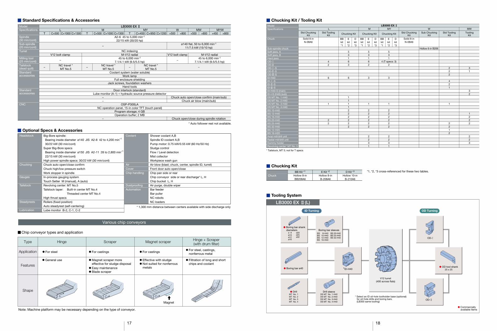
LB3000 EX (L)
� Chucking Kit
� Tooling System
� Boring bar shank diameters
� DrillMT No. 1MT No. 2MT No. 3MT No. 4
Drill sleeveDS MT No. 1-H40DS MT No. 2-H40DS MT No. 3-H40DS MT No. 4-H40
� Boring bar ø40 *ID-H40
OD-
� OD tool shank25 x 25
OD-
V12 turret(400 across flats)
Boring bar sleeves
ID Turning OD Turning
* Select an ID oil-hole toolholder base (optional)for oil-hole drills and boring bars.(LB300 same tooling)
ø 8ø10ø12ø16
ø20ø25ø32
BS 8-H40BS 10-H40BS 12-H40BS 16-H40
BS 20-H40BS 25-H40BS 32-H40
� Commercially available items
�
� Chucking Kit / Tooling KitModelSpecifications
Chuck
Sub-spindle chuckSoft jaws, ASoft jaws, BHard jawsOD-OD-OD- -SOD- -SOD- -SID-H40ID- -SID- -SID- -SID-H40-S (main)ID-I-S (H40) (sub)DS MT No. 1-H40DS MT No. 2-H40DS MT No. 3-H40DS MT No. 4-H40BS 10-H40BS 12-H40BS 16-H40BS 20-H40BS 25-H40BS 32-H40BS 12-H20BS 16-H20Axial mill/drill unitRadial mill/drill unitDummy holderRevolving center* MT No. 5
Std ChuckingKit
Solid 8-in Solid 8-in
Std ToolingKit
Chucking Kit Chucking Kit Chucking Kit
LB3000 EX
Std ChuckingKit
Sub ChuckingKit
WMY MWML
Std ToolingKit
ToolingKit
N-08A6
42
6
1
22
53163
6
1111222222
53162
3
1
222222
2231
531
4 (T specs: 3)2
3
1
222222
2231
N-08A6
Hollow 6-in B206
222
421
1
2212
31
32
1222
223
Chuck*1, *2, *3 cross-referenced for these two tables.E Kit *2
Hollow 8-inB-208A6
BB Kit *1
Hollow 8-inBB208A6
D Kit *3
Hollow 10-inB-210A6
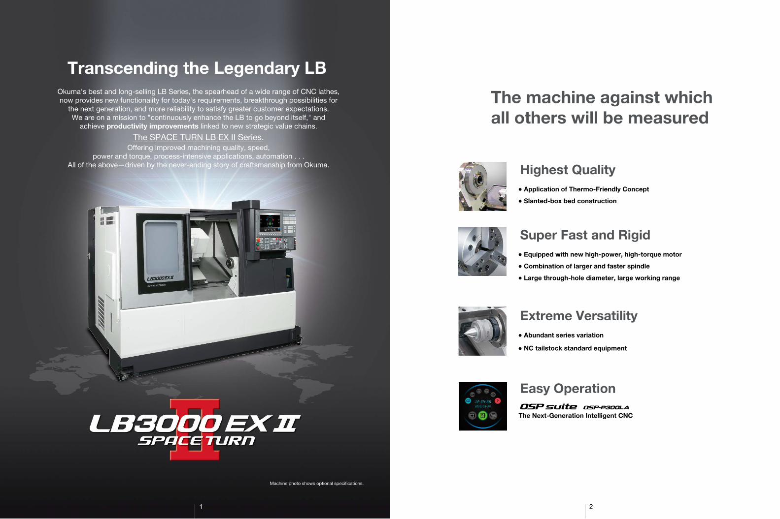
� Standard Specifications & AccessoriesModelSpecifications
Spindle(30 min/cont)Sub-spindle(20 min/cont)Turret
Milling tool(25 min/cont)Tailstock(dead quill)Standardaccessories
Standardaccessories
CNC
� Optional Specs & AccessoriesBig-Bore spindle: Bearing inside diameter ø140 JIS A2-8 42 to 4,200 min-1 30/22 kW (30 min/cont)Super Big-Bore specs Bearing inside diameter ø150 JIS A2-11 28 to 2,800 min-1 22/15 kW (30 min/cont)High power spindle specs: 30/22 kW (30 min/cont)Chuck auto open/close confirmChuck high/low pressure switchWork stopper in spindleIn-process gauging systemTouch Setter M (manual), A (auto)Revolving center: MT No.5Tailstock taper: Built-in center MT No.4 Threaded center MT No.4High thrust specsRollers (fixed position)Auto steadyrest (self-centering)Lube monitor B-2, C-1, C-2
Headstock
Chucking
Gauges
Tailstock
Steadyrests
Lubrication
Coolant
AirCoverChip handling
DustproofingAutomation
Shower coolant A,BSpindle ID coolant A,BPump motor: 0.75 kW/0.55 kW (60 Hz/50 Hz)Sludge controlFlow / Level detectionMist collectorWorkpiece wash gunAir blow (blast; chuck, center, spindle ID, turret)Front door auto open/closeChip pan side or rearChip conveyor side or rear discharge* L, HChip bucket L, HAir purge, double wiperBar feederBar pullerNC robotsNC loaders
MW
ø140 flat, 50 to 6,000 min-1
11/7.5 kW (15/10 hp)
−
Chuck auto open/close confirm (main/sub)Chuck air blow (main/sub)
Chuck open/close during spindle rotation
TA2-6 45 to 5,000 min-1
22/15 kW (30/20 hp)
NC indexingM-V12 radial
45 to 6,000 min-1
7.1/4.1 kW (9.5/5.5 hp)
−
Coolant system (water soluble)Work lamp
Full enclosure shieldingJack screws, foundation washers
Hand toolsDoor interlock (standard)
Lube monitor (A-1) + hydraulic source pressure detector
OSP-P300LANC operation panel, 15-in color TFT (touch panel)
Program storage; 4 GBOperation buffer; 2 MB
T
−
W
V12 bolt clamp
−
T
−
C×1000
NC travel *MT No.5
C×950
NC travel *MT No.5
L
V12 bolt clamp
−
LB3000 EX
C×500MY MYW
C×1300 C×500 C×1300 C×450 C×1200 ×500 ×800 ×500 ×800 ×450M
−
−−
−
C×1000
NC travel *MT No.5
M-V12 radial45 to 6,000 min-1
7.1/4.1 kW (9.5/5.5 hp)
×800
* Auto follower rest not available.
* 1,300 mm distance between centers available with side discharge only
* Tailstock, MT 5; not for T specs
Various chip conveyors
� Chip conveyor types and application
Type
Application
Features
Shape
Hinge Scraper Magnet scraper Hinge + Scraper(with drum filter)
Note: Machine platform may be necessary depending on the type of conveyor.
� Magnet scraper more effective for sludge disposal
� Easy maintenance � Blade scraper
� For steel � For castings � For castings� For steel, castings,
nonferrous metal
� General use � Effective with sludge � Not suited for nonferrous
metals
� Filtration of long and short chips and coolant
Magnet
BBkit*1
Ekit*2
Dkit*3
BBkit*1
Ekit*2
Dkit*3
BBkit*1
Ekit*2
Dkit*3

19 20
LB3000 EX � (MYW)
LB3000 EX � (W)
LB3000 EX � (M)
LB3000 EX � (MY)
LB3000 EX � (MW)
� Tool Interference DrawingsLB3000 EX � (L)
OD-
70
ø190
ø220
3535
30
ID-H40
ø40
Max turning
dia ø410
57
ø210OD-X-axis travel 260
20535200
X-axis travel 260 180440
55ø410
Max swing
dia ø634ø580 ø190
ø190
ø225
70 ø20
Axial mill/drill unit
OD-
ID-H40
90ø40
170
ø580
110X-axis travel
260280
ø235
75 3590
OD-
Max swing dia ø634 Max
turn
ing
dia
ø340
ø275ø220
OD-
Inner coverTelescoping cover
ø270
ø220
ø190 ø215
ø240
Spindle center
ø230
ø207.7ø200
Max swing dia ø634
ø58020010
ø240
ø240
ø210ø20
12.575
54.5
33 ø220
ø40
X-axis travel 260155 105
ø22085
Max turningdia ø410
5535
ø260
12.5
4530
ø210
ø240
ID- -S
OD- -S
OD- -S
ID- -S
OD- -S
ID- -S
45 200Spindle center
ø220
ø255
ø270
ø220
ø275
Max
turn
ing
dia
ø340
ø235
ø22590280
3575
X-axis travel 260110170
ø4090
ø20
70ø2
25
ø195
ø190
ø240
ø580ø215
ø190Max swing dia ø604
Axial mill/drill unit
ID-H40
OD-
OD-
X-axis travel 260105
90
70
17085
Spindlecenter
ID-H40-S
Axial mill/drill unit
Radial mill/drill unit
35
4545
70
ø225
ø580
Max swing dia ø604
ø215
ø195
ø20
ø190
80 67
ø190
ø215
ø250 ø230
ø220
ø215
ø270 M
ax tu
rnin
g di
a ø3
40
ø230
ø200
Inner cover Telescoping cover
OD- -S
(Sub side)
ID- -S
280
OD- -S
77
77
77
Drill sleevesDS MT No. 1-H40DS MT No. 2-H40DS MT No. 3-H40DS MT No. 4-H40
Boring bar sleevesBS 8-H40BS 10-H40BS 12-H40BS 16-H40
BS 20-H40BS 25-H40BS 32-H40
Boring bar sleeves
Drill sleeves DS MT No. 1-H40DS MT No. 2-H40DS MT No. 3-H40DS MT No. 4-H40
Boring bar sleeves
BS 8-H20BS 10-H20BS 12-H20BS 16-H20
BS 8-H40BS 10-H40BS 12-H40BS 16-H40
BS 20-H40BS 25-H40BS 32-H40
Multitasking V12 turret(340 across flats)
Drill sleeves DS MT No. 1-H40DS MT No. 2-H40DS MT No. 3-H40DS MT No. 4-H40
Boring bar sleevesBS 8-H40BS 10-H40BS 12-H40BS 16-H40
BS 20-H40BS 25-H40BS 32-H40
Multitasking V12 turret(340 across flats)
MW
MYW
* Select an ID oil-hole toolholder base (optional)for oil-hole drills and boring bars.(Not compatible with LB300-M)
* Select an ID oil-hole toolholder base (optional)for oil-hole drills and boring bars.(Not compatible with LB300-M)
ID- -S (H40)(main)
ID- -S (H20)(ID: main, sub)
ID- -S (H20)(ID: main, sub)
ID- -S (H20)(ID: main) (OD: sub)
OD-
OD-
ID-H40
Axial mill/drill unit
ø2 to ø20
ø2 to ø20
Dummy holder
Radial mill/drill unit
Axial mill/drill unit
Dummy holder
Radial mill/drill unit
ø40
ø40, ø25
ID- -Sø25
main
sub
ID-H40-S
OD- -S (W)
OD- -S (W)
OD- -S
ID- -S
* Select an ID oil-hole toolholder base (optional)for oil-hole drills and boring bars.(LB300-W same tooling)
LB3000 EX (W)
LB3000 EX (MW/MYW)
LB3000 EX (M/MY)
� Commercially available items
� Commercially available items
� Commercially available items
� Boring bar ø40
Turning
Mill/Drill
Turning
ID Turning
OD Turning
� Boring bar ø20
� Boring bar ø40
V12 turret(400 across flats)
Mill/Drill
OD- -S(OD, grooving: main)
OD- -S(OD: main, sub)
OD- -S(End: main, sub)
� Collets
� Collets
� Boring bar ø40
55
170
50
29
35105
70
67
2990
147
80
70
Max swing dia ø634
ø215
ø165
ø165
ø215
ø215
ø235
ø215
ø40
ø190
ø20ø20
ø235
ø235
ø235
ø175
ø310(turret body interference range)
Max turning dia ø340
ID- -S
ID- -S
OD- -S
OD-
77
X-axis travel 260Spindlecenter
Axial mill/drill unit
Radial mill/drill unit
Unit: mm

21 22
×800
×450
×800
×500OD-I
LB3000 EX �(MYW)
LB3000 EX �(MYW)
LB3000 EX �(MW)
LB3000 EX �(MW)
OD-I
OD-I-S
OD-II-S
� Working Ranges
595 sub-sp travel114
166 550 Z-axis travel137 41 203 70
B-206-01
5652
29
7
52100600
550 Z-axis travel39103
166
3570
275
170
70
ø210
260
X-a
xis
trav
el17
5 87.5
119.
5
85
17078554
33
Turret rotation center
76 145
MA
X 4
50M
IN 1
90
ø169
Sub-spretract position
B-208A601C
76
43
ID-I-S
203 86.5 39.54113713333.5
114 595 sub-sp travel 76
68.5
76
Turret rotation center
29
133
16.5
100600
39
785
103
5416.5
ø169
145
MA
X 4
50
5550
275
105
ø210
260
X-a
xis
trav
el17
5
150.
5
1730
103.
5
56.5
5585
53
170
50
170
MIN
190
Sub-spretract position
550 Z-axis travel
B-206-01B-208A601C
43
ID-I-STurret rotation center
MA
X 4
50M
IN 1
90
152
7629
26
166
1,044 100 331,08554
7
Sub-spretract position
B-208A601C
995 Z-axis travel
9276
9011070
19
10
20341166
184
16438
2716
3570
145
140
170
175
85
275
825 sub-sp travel
260
X-a
xis
trav
el
995 Z-axis travel
ø210
B-206-01
83839103
ø169
Turret rotation center
MA
X 4
50M
IN 1
90
145
170
5055
140
56.5
103.
515
Sub-spretract position
995 Z-axis travel
175
8527
526
0 X
-axi
s tr
avel
995 Z-axis travel
75.576
73.5110682720341438
17
1.5
18413332.5
825 sub-sp travel
ø210
1,0851,044 100
133 105 6.5
16.516.5
ø169
7629
39
54
838103
120
16B-208A601C
B-206-01
ø40
ID-II-S
B-208A601C
175
85260
X-a
xis
trav
el27
5
ø210
39 538103
ø169
Turret rotation center
MA
X 4
50M
IN 1
90
15226
7629
100600 33
78554
77
Sub-spretract position
510 Z-axis travel
76114
13583568388166579
56
3570
145
140
170
595 sub-sp travel
510 Z-axis travel 52
B-206-01B-208A601C
ø210
ø169
Sub-spretract position
510 Z-axis travel
135 4214
83568388
MA
X 4
50M
IN 1
90
145
140
B-206-01595 sub-sp travel
510 Z-axis travel
76114
68.513373.5
ø25
ø40
260
X-a
xis
trav
el26
0
190
70
538
Turret rotation center
100133
75
116.560016.516.5
78554
73.5
9045
4517
0
9
39103
ID-II-STurret rotation center
MA
X 4
50M
IN 1
90
152
7629
26
1,100 100
166
331,08554
5777
Sub-spretract position
B-208A601C
1,010 Z-axis travel
148
83 135 110 146
76184
166 388 83 569
57
3570
145
140
170
175
3188
6225
8527
5
825 sub-sp travel
260
X-a
xis
trav
el
1,010 Z-axis travelB-206-01
83839103
ø210
ø169
Turret rotation center54
73.5
MA
X 4
50M
IN 1
90
Sub-spretract position
B-208A601C
1,1001,085
1,010 Z-axis travel
1,010 Z-axis travel
83839103
ø210
ø40
260
X-a
xis
trav
el26
0
190
70
ø25
904545
100133 75
116.5
16.5120
76
5511
2 29
184 76
4783112135835614
131.5
145
140
825 sub-sp travel
B-206-01
ø169
839
38813373.5
170
7
17
LB3000 EX �(W)
LB3000 EX �(W) ×500
×500, ×1000, ×1300
×500, ×1000, ×1300
×450, ×950, ×1200
×800
LB3000 EX �(MY)
LB3000 EX �(M)
LB3000 EX �(L)
� Working Ranges
OD-I ID-H40
OD-I Axial mill/drill unit
Radial mill/drill unitY = 0
OD-III-S ID-III-S
Axial mill/drill unitY = 0
ID-III-SOD-III-S
172.7
260
ø210
170
90
3535
9
7020
027
0B-208A601C
515 (1,015) [1,330] Tailstock travel405 (905) [1,220] 160 215
147.320
Tailstockretract limit60
60
MA
X 4
40M
IN 1
80
835 (1,335)[ 1,650]
1172.7
X-axis travel39
5554
565 (1,065) [1,380] Z-axis travel 7 82
Turret rotation center
627 (1,127) [1,442]
103
515 (1,015) [1,330] Tailstock travel
B-208A601C
554 (1,054) [1,369]835 (1,335) [1,650]
173147.3
20
4160
Tailstockretract limit
22
11
4124
425021
026
0
8
w/ revolving center
w/o revolving centerand release nut
X-axis travel
20
60M
AX
440
MIN
180
82
Turret rotation center
200
230
6
ø210
120
30
565 (1,065) [1,380] Z-axis travel627 (1,127) [1,442]54
56
39103
172.7
( ): C × 1000[ ]: C × 1300
4826
24
172.7
B-208A601C
354 (854) [1,169]835 (1,335) [1,650]
211
572.7
147.3215
60
Tailstockretract limit
20
Turret rotationcenter
100653 (1,153) [1,468]
3948
103
54565 (1,065) [1,380] Z-axis travel
X-axis travel
55
150(
Tool
leng
th)
3575
280
170
26
7
60
170
260
ø210
90 8010
MA
X 4
50
515 (1,015) [1,330] Tailstock travel
8
MIN
190
Tailstockretract limit
835 (1,335) [1,650] 60
147.320
60
MA
X 4
50M
IN 1
90
170
240
210
260
ø210
50
70
82
3235
238515 (1,015) [1,330] Tailstock travel
w/ live center
172.7
B-208A601C
Turret rotationcenter
100
1343565 (1,065) [1,380] Z-axis travel32
103 39
653 (1,153) [1,468]54
X-axis travel
139.2
( ): C × 1000[ ]: C × 1300
( ): C × 950[ ]: C × 1200
X-axis travel
Sub-spretract position
Turret rotation center
B206 chuck: working ranges
54627
785
565 Z-axis travel
103 39 538
290
200
55
89.5
35.5
74.5
ø210 26
0
ø169
MA
X.4
40
140
MIN
180
35
82
9985 77
3532 32
29 76
6644774.56688285.5
565 Z-axis travel
9955
114 595 sub-sp travel 76B-208A601CB206 chuck:working ranges
X-axis travel
56 44 285.5
114
565 Z-axis travel
595 sub-sp travel 76
88 66 84.5 29 12057
165
230
260 21
0
ø210
50 95 35
140
13
457520
027
5
30
MA
X.4
40M
IN 1
80
ø169
Sub-spretract position
7629
60100
39445
Turret rotation center
7783
82
56538103 39
565 Z-axis travel627
78554
B-208A601C
Turret rotationcenter
8599
13476
49
76
83839103
29
8311274.5668855 585.57
184
821,12754 1,085
32 35
74
145
145
150
110
260
5535
290
140
60
Sub-sp retractposition
825 sub-sp travelB-208A601C
1,065 Z-axis travel
X-axis travel
1,065 Z-axis travel
200
ø210
B-206-01
ø169
MA
X 4
40 M
IN 1
80
32
7
1,065 Z-axis travel
B-208A601C
1,1271,08554
50
39 838103
210
9516
5260
230
X-axis travel
585.54456
184 825 sub-sp travel
1,065 Z-axis travel
ø210
Turret rotationcenter
MA
X 4
40M
IN 1
80
145
13
4530
75
275
200
35
140
157.
5
102
773944
83
10060
5
82
56
Sub-spretract position
8076
1123984.5668857
78
ø169
ø20
7629
B-206-01
20.5
14.5
All travel range drawings shown are with standard spindle specs. This will differ with Big-Bore and Super Big-Bore specs.
X-axis travel
MIN
190
MA
X45
0
158510 (1,010) [1,255] Z-axis travel
103 3969
100600 (1,100) [1,415]54
7024
017
0
Turret rotation center
X-axis travel
Turret rotation center
MIN
190
MA
X45
0
60
49
6723
717
0
96
213
260
100600 (1,100) [1,415]54
50510 (1,010) [1,255] Z-axis travel
140 (140) [210] 34 (34) [104]
172.7 147.3312.5 (812.5) [1,057.5] 69 185
88125.7
20
60835 (1,335) [1,650]
Tailstockretract limit
Tailstockretract limit
3937
103
125.5
ø210
B-208A601C B-208A601C3
ø90
ø79
47
52.5
w/o revolving centerand release nut
w/ revolving center
835 (1,335) [1,650] 60484 (984) [1,229] 291
147.3172.720438 (938) [1,183] 19.5
60
ø90
ø79
31.5
43
260 21
050ø2
10
26515 (1015) [1,330] Tailstock travel 515 (1015) [1,330] Tailstock travel
Unit: mmUnit: mm

NC
NC
NC
Maintenance space
Dimensional Installation Drawings Dimensional Installation DrawingsUnit: mm
LB3000 EX (L / M) ×500
LB3000 EX (L / M) ×1000
×1300
Drawings shown are with standard spindle specs.
LB3000 EX (L / M)
50 2,200 960
3,21070
0 891600
Chip bucket(option)
(option)
Chip conveyor(side discharge)
Operation panelV12 turret
Headstock
Hyd chuckpressure valve
Lube tank
Tailstock
3892253
8702,290
2,340
500Maintenance space
1,05
072
0
1,82
4
865
414 1,320615250
1,734 8652,599
Chip bucket(option)
(option)
Chip conveyorrear discharge
600
697
414
720500
585
1,32
070
4
642
Hydraulic unit
Coolant pump (rear)Spindle cooler
Power inletHeight from floor: 1,770 mm or 1,070 mm
Space for sidetank removal
910 1,290
63 (Door open)
*Big-Bore spindle specs
1700Space for rear chipconveyor removal
168
Chip bucket(option)
891
700600
449168703,4209603,330
500
Maintenance space
Hyd chuckpressure valve
Headstock
4,290
53
Lube tank
TailstockOperationpanel
1,158 9911,181
(Door open)
1,095 641(Dooropen)
63 V12turret Chip conveyor
(side discharge)(option)
223
514
1,23
81,
050
770
1,97
515
5
Chip bucket(option)
(option)
60070
0
865
1,700
Space for rear chipconveyor removal
Chip conveyorrear discharge
704
1,73
4
434
500
414
862
Spindle cooler
Space for sidetank removal
1,7341,320414 250 615
168697
375 910 1,790
Coolant pump (rear)
307
555
Hydraulic unit
255
891
700
1,158 1,196
1,09563
1,496 (Door open)
641 (Door open)
600
Operationpanel
TailstockChip conveyor(side discharge)
Chip bucket
Lube tank
V12 turret(option)
(option)
Headstock
Hyd chuckpressure valve
983
555
1,23
851
422
3
1,05
077
015
5
1,97
5
375 910
1,30
050
0
434
704
4602,105
3,850
428
Space for sidetank removal
Spindle cooler
Hydraulic unit
414
427
1,320
1,734
Drawings shown are with standard spindle specs.
LB3000 EX (MY)
LB3000 EX (MY)
LB3000 EX (MY)
×450
×950
×1200
Space for sidetank removal
Spindle cooler
Maintenance space
(option)Chip bucket (option)
Lube tank
Tailstock
Operation panelV12 turret
Headstock
Hyd chuckpressure valve
Coolant pump(side)
500 3,21050 2,290 870
922 38
600
700
700
891
Chip conveyor(side discharge)
53
Chip bucket (option)
(option)
2,25
01,
050
865
1,20
0
414 1,320 697250 615
1,734 8652,599
Space for rear chipconveyor removal
1,700
Chip conveyor (side discharge)
*Big-Bore spindle specs
910
704
1,32
041
478
054
058
5
Coolant pump (rear)
Hydraulic unit
1,290 50
500
48168
NC
735 642(Door open)
1,30
043
470
486
2
Spindle cooler
Coolant pump (rear)
Hydraulic unit
3,3803051,790910375
555
307
NC514
1,23
870
31,
250
1,05
015
52,
455
250414 615
600
700
865
168
1,700
6971,320
1,7342,599
Space for rear chipconveyor removal
(option)
Chip conveyor(side discharge)
(option)Chip bucket
44
Operation panel
Tailstock
Chip conveyor(side discharge)
Chip bucket
Lube tank
Headstock V12 turret
(option)
(option)Coolant pump (side)
Hyd chuckpressure valve
870
4,290
3,4203,330 960
916 53
600
700
891
Maintenance space500
V12 turretHeadstock
Hyd chuckpressure valve
Operationpanel
Tailstock Chip conveyor(side discharge)
Lube tank (option)
Chip bucket(option)
1,158
1,095
1,496 (Door open) 1,246
63
641 (Door open)
600
700
891
1,25
015
5
2,45
5
1,23
851
454
8
1,05
0
414
428
1,320
1,734
Coolant pump (side)
Space for sidetank removal
Spindle cooler
Hydraulic unit
1,30
043
370
4
375 910 4052,210
3,900
428
500
NC
983
555
Unit: mm
50* 200*
1,860
1,790
2,135
2,065
Power inletHeight from floor: 1,770 mm or 1,070 mm
3,850
500
Maintenance space
268896
670
70
5,014
4,344
2,2252,185
Power inletHeight from floor: 1,770 mm or 1,070 mm
50* 200*
1,855
1,785
Power inletHeight from floor: 1,770 mm or 1,070 mm
2,135
2,065 Power inletHeight from floor: 1,770 mm or 1,070 mm
500 5,014
3,850
4,344
896 268
670
70
2,2552,185
Power inletHeight from floor: 1,770 mm or 1,070 mm
Coolant pump(side)
Coolant pump(side)
2,599
2423

Dimensional Installation Drawings
Drawings shown are with standard spindle specs.
LB3000 EX (W / MW)
LB3000 EX (W / MW)
LB3000 EX (MYW)
LB3000 EX (MYW)
×500
×800
×450
×800
Operation panel
Chip conveyor(side discharge)
Chip bucket
Lube tank
HeadstockV12 turret
Sub-spindle
Sub-spindleHyd chuckpressure valve
(option)
(option)
600
700
891
388709602,550
2,640100
922
3,610500Maintenance space
Coolant pump(side)
Hyd chuckpressure valve
53
50
(option)
Chip conveyor(side discharge)
54
(option)Chip bucket
2,5991,734 865
414 1,320 697 168
615250 Space for rear chipconveyor removal
1,05
01,77
01,
824
720
865
1700
804
585
1,19
4
Space for sidetank removal
Spindle cooler
540
NC
*Big-Bore spindle specs
*MW, Big-Bore spindle specs
Coolant pump (rear)
Hydraulic unit
Spindle cooler(Sub-spindle)
1,290 3501,010
500 720 642100
63(Door open)
2551,010275 1,790
Coolant pump (rear)
Hydraulic unit
Sub-spindle fan
1,30
043
480
486
2 500
555
307
Spindle coolerSpace for sidetank removal
NCChip bucket(option)
(option)
600
514
1,23
822
377
01,
050
155
1,97
5
250414 615
700
865
168
1,700
6971,320
1,7342,599
Space for rear chipconveyor removal
Chip conveyor(side discharge)
44
Operation panel
Chip conveyor(side discharge)
Chip bucket
Lubetank
Sub-spindleHeadstock V12 turret
(option)
(option)
Hyd chuckpressure valve
Sub-spindleHyd chuckpressure valve
870
4,290
3,4203,330
500960
91653
600
700
891
Maintenance space
38
Operation panelSub-spindle
Chip conveyor(side discharge)
Chip bucket
Lube tank
Headstock
V12 turret
(option)
(option)
Hyd chuckpressure valve
Maintenance space
870
3,720
2,64021050
2,550500
960
92253
600
700
891
Sub-spindleHyd chuckpressure valve
348
250414 615697
1,3201,734
2,599
852
1,20
01,
050
2,25
0
600
700
865
168
1,700
Space for rear chipconveyor removal
(option)
Chip conveyor(side discharge)
(option)Chip bucket
500
1,2901,120
1,19
454
058
5
Spindle cooler
Space for sidetank removal
*Big-Bore spindle specs
3,3801,7901,120
Hydraulic unit
350
Coolant pump (rear)
Sub-spindle fanNC
Coolant pump (rear)
Hydraulic unit
1,30
0
305165
434
862 50
0
555
307
Spindle cooler
Sub-spindle fan
Space for sidetank removal
700
865
168
1,700
Space for rear chipconveyor removal
(option)
Chip conveyor(side discharge)
(option)Chip bucket NC51
41,
238
703
1,25
015
51,
050
2,45
5
250414
615
600
6978651,320
1,7342,599
44
Operation panelSub-spindle
Chip conveyor(side discharge)
Chip bucket
Lubetank
(option)
(option)
700
891
Sub-spindleHyd chuckpressure valve
Headstock
V12 turret
Hyd chuckpressure valve
870
4,290
3,4203,330
500960
91653
600
Coolant pump(side)
Maintenance space
Basic Specs
Operations
Communications/Networks
High speed/accuracy
Energy-saving function
Control
Position feedback
Min / Max command
Feed
Spindle control
Tool compensation
Display
Self-diagnostics
Program capacity
“suite apps”
“suite operation”
Easy Operation
Programming
Machineoperations
MacMan
ECO suite
Turning: X, Z simultaneous 2-axis, Multitasking: X, Z, C simultaneous 3-axis
OSP full range absolute position feedback (zero point return not required)
±99999.999 mm, 99,999.999° 8-digit decimal, command units: 0.001 mm, 0.01 mm, 1 mm, 0.001°, 0.01°, 1°
Override: 0 to 200%
Direct spindle speed commands, override 50 to 200%, constant cutting speed, optimum turning speed designate
Tool selection: 32 sets, tool offset: 32 sets
15-inch color display operational panel, Multi touch panel
Automatic diagnostics and display of program, operation, machine, and NC system problems
Program storage: 4 GB, operation buffer: 2 MB
Applications to graphically visualize and digitize information needed on the shop floor
Highly reliable touch panel suited to shop floors. One-touch access to suite apps.
“Single-mode operation” to complete a series of operations.
Program management, edit, scheduled programs, fixed cycles, special fixed cycles, tool nose R compensation,M-spindle synchronized tapping, fixed drilling cycles, arithmetic functions, logic statements, trig functions, variables, branch statements,auto programming (LAP4), programming help
MDI, manual (rapid traverse, pulse handle), load meter, operations help, alarm help, sequence restart, manual interrupt & auto return,
data I/O, oriented spindle stop (electric), easy setting of cycle time reductionMachining Management: machining results, machine utilization, fault data compile & report, external output
USB ports, Ethernet, DNC-T1
Hi-G control
ECO Idling Stop, ECO Power Monitor
�
�
�
�
�
�
�
�
�
�
�
�
�
�
�
�
�
�
�
�
�
�
�
�
�
�
�
�
�
�
�
�
�
�
�
�
�
�
�
�
�
�
�
�
�
�
�
�
�
�
�
�
�
�
�
�
�
�
�
�
�
�
�
�
ItemE D E D E D
NML 3D OT-IGF
E D
OTM
New Operations
Advanced One-Touch IGF-L *2
Advanced One-Touch IGF-L Multitasking *2
Programming
Circular threading
Program notes
User task 2 I/O variables, 8 each
Work coor- 10 setsdinate system 50 setsselect
100 se
Tool compen- Tool compensation 64 setssation Tool compensation 96 sets(Std: 32 sets)
Tool compensation 200 sets
Tool compensation 999 sets
Common variables 1,000 sets (Std: 200 sets)
Thread matching
Threading slide hold (G34, G35)
Variable Spindle Speed Threading (VSST)
Inverse time feed
Spindle Synchronized Tapping (rigid tapping)
Milling machine Coordinate convertspecs Profile generate
Flat turning
3-dimensional coordinate conversion
Coordinate calculate (w/NYCL commands)
Shift, rotate, copy coordinates
Profile helical cutting
C-axis torque skip function
Helical cutting (within 360 degrees)
Monitoring
Real 3-D Simulation
Cycle time over check
Load monitor (spindle, feed axis)
Load monitor no-load detection (load monitor ordered)
AI machine diagnostics (feed axes)
Machine Status Logger
Tool life management
Tool life warning
Operation end buzzer
Chucking miss detection
Work counters Count only
Cycle stop
Start disabled
Hour meters Power ON
Spindle rotation
NC operating
NC operation monitor (counter, totaling)
Status indicator (triple lamp) Type C [Type A, Type B]
ECO suite (energy saving function)
ECO Operation Chip conveyor intermittent/ linked operation
Mist collector intermittent/ linked operation
Spindle Power Peak Limiter
�
�
�
�
�
�
�
�
�
�
�
�
�
�
�
�
�
�
�
E D E D E D
NML 3D OT-IGF
E D
OTM
External Input/Output and Communication Functions
RS-232C connector
DNC link DNC-T3
DNC-C/Ethernet
DNC-DT
USB (additional) 2 additional ports possible
Measuring
In-process work gauging
Z-axis automatic zero offset by touch sensor
C-axis automatic zero offset by touch sensor
Y-axis gauging
Gauge data output File output
Post-process Set levels (5-level, 7-level)work gauging BCDinterface
RS-232C (dedicated channel)
Touch Setter [M, A]
Automation/Untended Operation
Auto power shutoff M02, alarm
Warm-up function (by calendar timer)
Tool retract cycle
External A (pushbutton) 8 typesprogram B (rotary switch) 8 typesselections
C (digital switch) BCD, 2-digit
C2 (external input) BCD, 4-digit
Okuma loader (OGL) interface
Third party robot Type B (machine)and loader Type C (robot and loader)interface *3
Type D
Type E
Bar feeders Interface
Cycle time Operation time reductionreduction *3 Spindle rotating chuck open/close
Spindle rotating tailstock advance/ retract
High-Speed/High-Accuracy Functions
0.1 µm control *3
Pitch error compensation
AbsoScale detection *3
Hi-Cut Pro
Other Functions
Collision Avoidance System (CAS)
One-Touch Spreadsheet
Machining Navi L-g
Machining Navi T-g (Threading)
Harmonic Spindle Speed Control (HSSC)
Spindle dead-slow cutting
Spindle speed setting
Manual cutting feed
Y-axis alignment compensation
Short circuit breaker
External M signals [2 sets, 4 sets, 8 sets, 16 sets]
Edit interlock
OSP-VPS (Virus Protection System)
Included in machine specs
Included in loader specs
Included in machine specs
Item
Included in machine specs
�
�
�
Unit: mm
Kit specs*1 Kit specs*1
The Next-Generation Intelligent CNC
*1. NML: Normal, 3D: Real 3D simulation, OT-IGF: One-Touch IGF, OTM: One-Touch ME: Economy, D: Deluxe
*2. Including 3-D simulation*3. Engineering discussions required.*Note: �Triangle items for M function (milling tool) machines only.
� Standard Specifications
� Optional Specifications
Height from floor: 1,770 mm or 1,070 mmPower inlet
50* 200*
1,860
1,790
2,135
2,065
1,120*
Height from floor: 1,770 mm or 1,070 mmPower inlet
50*
200*
1,860
1,790
530
Height from floor: 1,770 mm or 1,070 mmPower inlet
2,135
2,065
530
Height from floor: 1,770 mm or 1,070 mmPower inlet
2625

Oguchi-cho, Niwa-gun,Aichi 480-0193, JapanTEL: +81-587-95-7825 FAX: +81-587-95-6074
This product is subject to the Japanese government Foreign Exchange and Foreign Trade Control Act with regard to security controlled items; whereby Okuma Corporation should be notified prior to its shipment to another country.
When using O
kuma p
roducts, alw
ays read the safety p
recautionsm
entioned in the instruction m
anual and attached
to the prod
uct.
●The sp
ecifications, illustrations, and d
escriptions in this b
rochure vary in different m
arkets andare sub
ject to change without notice.
Pub
No.S
PAC
E TU
RN
LB3000 E
X �-E
-(18a)-700 (Jan 2021)