Some Issues in the Use of Refrigerant Mixtures
10
Purdue University Purdue e-Pubs International Refrigeration and Air Conditioning Conference School of Mechanical Engineering 1992 Some Issues in the Use of Refrigerant Mixtures R. R. Singh AlliedSignal H. T. Pham AlliedSignal I. R. Shankland AlliedSignal Follow this and additional works at: hp://docs.lib.purdue.edu/iracc is document has been made available through Purdue e-Pubs, a service of the Purdue University Libraries. Please contact [email protected] for additional information. Complete proceedings may be acquired in print and on CD-ROM directly from the Ray W. Herrick Laboratories at hps://engineering.purdue.edu/ Herrick/Events/orderlit.html Singh, R. R.; Pham, H. T.; and Shankland, I. R., "Some Issues in the Use of Refrigerant Mixtures" (1992). International Reigeration and Air Conditioning Conference. Paper 289. hp://docs.lib.purdue.edu/iracc/289
-
Upload
independent -
Category
Documents
-
view
2 -
download
0
Transcript of Some Issues in the Use of Refrigerant Mixtures

Purdue UniversityPurdue e-PubsInternational Refrigeration and Air ConditioningConference School of Mechanical Engineering
1992
Some Issues in the Use of Refrigerant MixturesR. R. SinghAlliedSignal
H. T. PhamAlliedSignal
I. R. ShanklandAlliedSignal
Follow this and additional works at: http://docs.lib.purdue.edu/iracc
This document has been made available through Purdue e-Pubs, a service of the Purdue University Libraries. Please contact [email protected] foradditional information.Complete proceedings may be acquired in print and on CD-ROM directly from the Ray W. Herrick Laboratories at https://engineering.purdue.edu/Herrick/Events/orderlit.html
Singh, R. R.; Pham, H. T.; and Shankland, I. R., "Some Issues in the Use of Refrigerant Mixtures" (1992). International Refrigerationand Air Conditioning Conference. Paper 289.http://docs.lib.purdue.edu/iracc/289

SOME ISSUES IN THE USE OF REFRIGERANT MIX11JRES
R.R. Singh, H.T. Pham and I.R. Shankland
AlliedSignal, Inc. Buffalo Research Laboratory
20 Peabody Street Buffalo, New York 14210
ABSTRACT
The use of refrigerant mixtures in refrigeration machines has been proposed in the technical literature. Some but not all of the arguments for and against the use of mixtures as refrigerants are examined in this study. An issue associated with use of blends is the segregation on leakage and the ensuing loss in capacity and performance change on repeated recharging with the original mixture. We have simulated this phenomenon by creating a variable vapor leak in a 30170 mixture of HFC-32/HFC-134a, which has been proposed recently as an R-22 replacement. The experiment shows that the fractionation depends on temperature and can give off potentially flammable vapors. The recharging process is simulated and the effect on refrigeration capacity is calculated as a function of leak rate and of numbers of recharging cycles. It is concluded that if leakage for 32-134a system is 10% of more of the charge, continual loss in capacity will occur even with recharging.
INTRODUCTION
The working fluids in the refrigeration industry have so far been either pure fluids or azeotropes which behave like pure fluids during the condensation and evaporation processes. The regulations on chlorofluorocarbons (CFCs) have prompted the development of environmentally acceptable replacements of these widely used working fluids in the refrigeration, solvent and foam industries. The HCFCs such as R-22 have been thought of as acceptable substitutes, but even these relatively benign molecules have now been targeted for eventual replacement. Due to this changing flux in the industry a large number of alternative schemes and ideas have been put forth, some of which involve use of mixtures as refrigerants. (Note: While azeotropes are also mixtures, in this paper we will use the word mixture or blend as one that denotes strictly nonazeotropic mixtures). The use of mixtures in refrigeration has been investigated for more than forty years<'x21<31<41
• Refrigerant mixtures may find some application eventually, e.g. in Meutzner cycle where equipment is modified to take advantage of their evaporation - condensation characteristics. Regardless of the cycle used, a problem associated with blends is universally recognised, i.e., the fact that mixtures, during a leak, lose one component preferentially which may effect the refrigeration capacity and performance even if the system is recharged with the original composition of the mixture. One may reasonably expect that the leaking vapor would be more enriched in the more volatile phase and the refrigerant mixture remaining, even after recharging, will have lower vapor pressure and will consequently have low refrigeration capacity. In this paper, we report on such a segregation experiment with a suggested R-22 replacement, the 30170 weight percent mixture of HFC-32/HFC-134a.
455

BLEND SEGREGATION MODEL
One consequence of the existence of a range of the condensation/evaporation temperature for a mixture is that there is always a certain amount of segregation, i.e., the vapor phase composition is enriched in the more volatile component compared to the liquid phase. During the course of vapor leak, the more volatile component is lost faster. If the system is recharged using the original composition, the vapor pressure of the resultant charge is still going to be lower than the original charge resulting in a loss in capacity. During several leak and recharge cycles, the problem of reduced capacity may get worse. While this phenomenon has been suggested before<3
l.. no quantitative data was reported. It was therefore decided to obtain quantitative estimates of the effect of leakage~recharge process on a model airconditioning cycle. The mixture was chosen as the 30170 weight percent mixture of 32/134a. This has been selected by an Air Conditioning &Refrigeration Institute working group as leading R-22 replacement candidate. This work was done in two parts. First, the mixture was loaded in a vessel at 15% liquid fill level<sJ and a controlled and measured leak was created. The experiment was done at two temperatures -20°C and 40°C. The composition of the leaking vapor and remaining liquid was measured as a function of temperature and leakage rate. In the second part, a cycle simulation program was constructed which was based on the Carnahan-Starling-DeSantis equation-of-state and measured interaction parameter between 32 and 134a. This was used to model an air conditioning unit, where typically R-22 is used. The average evaporator and condenser temperatures were used to define reference temperatures as discussed in references 3 and 5. The mean condenser temperature was ll0°F, evaporator was at 40°F with suction temperature of 60°F and the liquid was subcooled to 100°F. Figure 6 and 7 show the calculated COP and capacity versus composition.
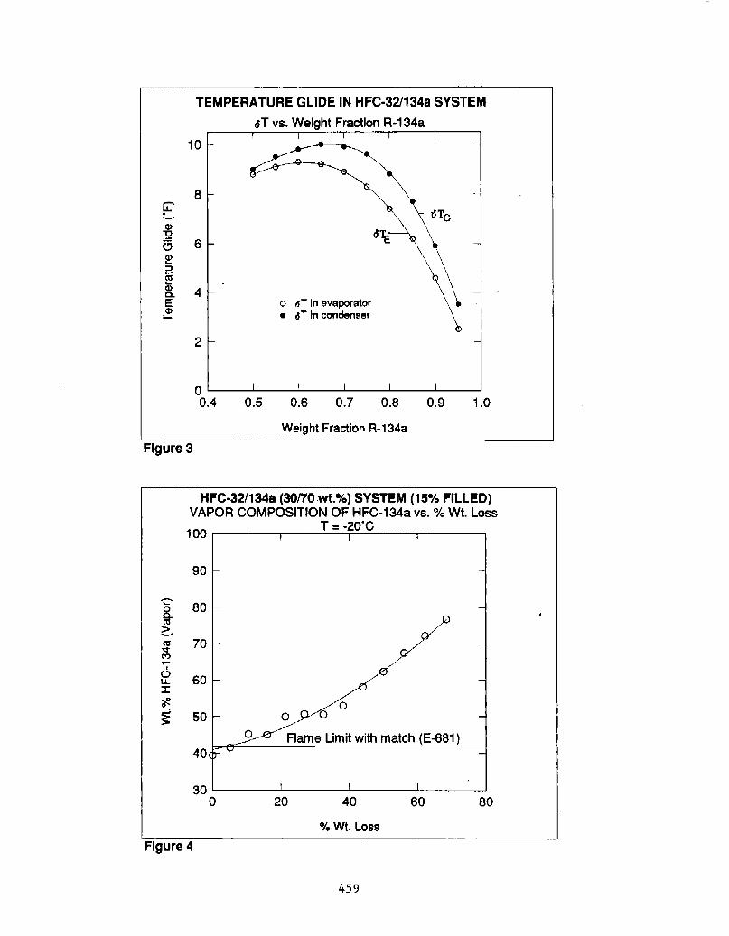
The refrigeration capacity of the mixture is plotted in figure I as a function of composition. As expected the capacity match with R-22 is good for a 30170 weight percent 32/I34a mixture. Figure 2 shows that the COP of the mixture is close to that of R-22. Based on these two figures, it is not surprizing why the 30170 weight percent 321134a mixture is chosen as one ofthe R-22 alternatives. Figure 3 gives the temperature glides as a function of temperature and composition.
The fractionation data obtained from the leakage experiment were used to calculate the decrease in capacity as a function of leakage. Figure 4 and 5 show the equilibrium vapor compositions during the leakage process. Figures 6 and 7 depict change in the composition of the remaining charge during the leakage process. The critical flammability ratio of the 32/134a is 42 wt% I34a at room temperature in an ASTM E-681 apparatus with match ignition source, which is the ASHRAE standard-34 test method for flammability of refrigerants. The equilibrium vapor composition contained enough 32 to be termed flammable as seen in figures 3 and 4. Clearly for a safe nonflammable refrigerant, the 32 content of the mixture may have to be lowered and therefore, as can be seen from figure I, the capacity match with R-22 will no longer exist.
The model calculation assumed that after a certain amount of leakage, the charge would be made up using the original composition. Figure 8 and 9 show the loss in capacity for a 10% and 20% loss by leakage followed by recharging by the original composition of the mixture without taking into account that the capacity is also lost due to loss of charge. Literature reports show that the refrigeration capacity also depends significantly on the total charge<5l • Figure 10 and II show that the loss in capacity is continous and irreversible if the make up charge has the original composition. The magnitude of this phenomenon of course depends on the segregation characteristics and the temperature at which leakage occurs. For the 32/134a mixture studied here, even if the leak rate is as small as 10% before it is noticed and the charge made up, more than 1% of the original capacity is lost at each such event. Theoretically a make-up charge enriched in 32 above 30% might compensate for this effect. But this would entail hazards traceable to handling a flammable product and may also be difficult to implement on a routine basis.
456

CONCLUSIONS
Some aspects of using blends in refrigeration machinery are considered. The mixture 32/l34a is studied as a R-22 replacement. The 30170 composition may have flammable vapors during operation. Also the segregation behavior and its influence on the operating characteristics was studied at 10% and 20% loss rate and subsequent make up of the charge with the original stock. In case of any leak rate whatsoever, continual loss in capacity was seen, with the higher loss rates showing higher permanent loss in the refrigeration capacity.
ACKNOWLEDGEMENT
Permission of the AlliedSignal, Inc. to publish this work is gratefully acknowledged. J. Batt and R.G. Richard provided the flammability data on 32/134a system.
REFERENCES
I. Ashley, C.M. Mixed Refrigerant System, U.S. Patent 2,492,725, Dec. 27, 1949.
2. McLinden, M.O. and Rademacher R., International Journal of Refrigeration, Nov. 1987.
3. Hughes, H.M. paper presented at International CFC and Halon Alternatives Conference, Dec. 1991.
4. Atwood, T. preprint Hl-85-18 No.1, ASHRAE Transactions 1985, V.91, Pt.2.
5. Mulroy, W.J. and Didion D.A., NIST Report NBSIR 83-2756 (April 1983).
457

'C' .s:::. :a ~ ~ ·o C!l a. C!l 0
·cAPACITY of HFC-32/134a (30170 wt.%) SYSTEM Capacity vs. Weight Fraction R-134a
120000
110000
100000
90000
80000
70000
0.4 0.5 0.6 0.7 0.8 0.9 1.0
Weight Fraction R-134a
Figure 1
COP of HFC-32/134a SYSTEM COP vs. Weight Fraction R-134a
7.0 I I I I I
6.5 - -
6.0 HCFC-22 ~~
~ ,.... ....... ,.... ,....
~ ~ ~
COP \;7 ~
5.5 -
5.0 1- -
4 I I I I I .5 L---~----~----~--~-----L--~ 0.4 0.5 0.6 0.7 0.6 0.9 1.0
Weight Fraction R-134a Figure 2
458
TEMPERATURE GLIDE IN HFC-32/134a SYSTEM
.sT vs. Weight Fraction R-134a
10
8 G:' -a> :2 a 6 2? 2 as a;
4 a. E 0 tJT In evaporator
~ • 6T In condenser
2
o~--~----~--~~---L----~--~
0.4 0.5 0.6 0.7 0.8 0.9 1.0
Weight Fraction R-134a
Figure 3
....
~ ~ as '<t (") ....
1
'-' u.. J: ~ 0
~
HFC-32/1348 (30/70 wt.%) SYSTEM (15% FILLED) VAPOR COMPOSITION OF HFC-134a vs.% Wt. Loss
100 T = -2o·c
90
80
70
60
50 0
Flame Limit with match (E-681) 40
30 0 20 40 60 80
% Wt. Loss
Figure 4
459

-... i <:.. ca -.:!'
'" ~ I
fi :I:
'# ~
HFC-32/134a (30170.wt.%) SYSTEM (15% FILLED)
VAPOR COMPOSITION OF HFC-134a vs.% Wt. Loss T = 4o.2·c
60 0
0
0
50
Flame Limit with match (E-681)
40
0
30
0 20 40 60 80
% Wt. Loss
Figure 5
HFC-321134a (30/70 wt.%) SYSTEM (15% FILLED)
Average Remaining Liquid Compositio'! of HFC-134a vs.% Wt. Loss
100 T=-20C
90
'8' ::J 80 c:n ! 70 ca -.:!'
'" ~ I
60 0 u.. :I: ~ 0
50 ~ Flame Limit with match (E-681)
40
30 0 20 40 60 80
% Wt. Loss
Figure 6
460

HFC·32/134a (30170 wt.%) SYSTEM (15% FILLED) Average Remaining Liquid Compo$1tlo~ of HFC-134a vs.% Wt. Loss
T:::40.2 C
80
tT 70 :.:::1 Cl > ~ ctl 60 ...,.
C'"J ..... I
f2 :I: 50 ~ 0
~ 40
30~------~----~------~------~ 0 20 40 60 80
% Wt. Loss
Figure 7
HFC·32/134a (30170 wt.%) SYSTEM (15% FILLED) CAPACITY vs. NUMBER OF RECHARGES AT 10% LEAK RATE
T = -2o.o·c I I I I I
100~
96r ~
~ ~-
-
-
92 t- -
88 -
I I I I I
0 1 2 3 4 5
Number of Recharges
Figure 8
461

HFC·32/134a (30170 wt.%) SYSTEM (15% FILLED) CAPACITY vs. NUMBER OF RECHARGES AT 20% LEAK RATE.
T = -20.0'C
100 ~
96 - ~
92 \
88 -
84
80
76L---~----~----L---~-----L~
0 1 2 3 4 5
Number of Recharges
Figure 9
HFC·32/134a (30170 wt.%) SYSTEM (15% FILLED) CAPACITY vs. NUMBER OF RECHARGES AT 10% LEAK RATE
T = -20.0'C
100 1-' ' I
' ' \ ' 95 1- \
\ ' \ ' \
90 1-
85 1-
80 -
I I I
}\ \ ~
\
' I \i
\, ! '\ I I I I I I \ I \
\ : \ I I \ \ I \ \ I \ \ I \
\ : \ \ : \
\i \., \1
" ..
I
t, .. \.,
\ \
\ \
\
\, \
\ \ \
I -
-
-t
-
\ -
?SL---~1 -----L-1 --~1-----L-1 --~1~ 0 1 2 3 4 5
Number of Recharges
Figure 10
462
HFC·32/134a (30170 wt.%) SYSTEM (15% FILLED) CAPACITY vs. NUMBER OF RECHARGES AT 20% LEAK RATE.
T = -2o.o·c 100,.... I I I I I
Figure 11
I I
\ I
\ I I I I
90- \ I
\
80 -
70-
I
\ I
\ \
I I
\ \: •
I
\ I I I I I I I
\ I
\ I I I I
+
'\ I
\ \
I
\ I I I
\ I
~ \ \ ~ \ :\ \ : \ f \ I \ I \ I \ I \ I \ I \
I I I I
\ I - I - I \ I \ I \ I
\
\ I II IL
I I I I
\ I
\ I
\i
\ : \ ! \ I \ I
\ : \ ! \ : \ :
\ : \ I
\ : \ ! \I \ I \I \ I \1 \ I
" I I • I I II li
so~-----~~----------~1 -----------~1 ----------L-~-----~~~ 0 1 2 3 4 5
Number of Recharges
463