Solubility Property of Condensable Gases of Trans-1-Chloro
8
123 Solubility Property of Condensable Gases of Trans-1-Chloro- 3,3,3-Trifluoropropene and Trans-1,3,3,3-Tetrafluoropropene in UV Nanoimprint Kenta Suzuki * , Sung-Won Youn, and Hiroshi Hiroshima Research Center for Ubiquitous MEMS and Micro Engineering, National Institute of Advanced Industrial Science and Technology (AIST), Tsukuba, Ibaraki 305-8564, Japan *[email protected] Bubble-free filling is required to realize high-throughput mass production in ultraviolet nanoimprint lithography (UV-NIL). UV-NIL in 1-chloro-3,3,3-trifluoropropene (CTFP) and trans-1,3,3,3-tetrafluoro-propene (TFP) gases has enabled bubble-free UV nanoimprinting of spin-coated films without a vacuum. We evaluate the amount of gas dissolution of 24 organic solvents, which was measured using an electronic balance in a glove box with saturated gases of CTFP and TFP, and use the Hansen solubility parameters (HSP) for analysis. Although the HSP teas graph indicated the same solubility trend in TFP and CTFP atmospheres, the amount of TFP gas dissolution was 1/5th that of CTFP. The pattern quality of acrylate UV-curable resins, which absorb well the condensable gases, was also demonstrated by altering the fraction of the introduced condensable gas mixture of TFP/CTFP. Fine line patterns with a width of 16 nm were obtained by UV-NIL with a high TFP fraction (>66%) in the TFP/CTFP mixed gas atmosphere. Keywords: UV nanoimprinting, Solubility property, Condensable gas, Trans-1-chloro- 3,3,3-trifluoropropene, Trans-1,3,3,3-tetrafluoropropene 1. Introduction Ultraviolet nanoimprint lithography (UV-NIL) [1–3] is a recently developed technology that facilitates low-cost nanofabrication. UV-NIL has a strong potential for application in the production of large-scale integrated circuits and wire grid polarizers [4,5]. Bubble-free filling is an important issue to achieve high-throughput mass production using UV-NIL. Although bubble-free filling can be accomplished by performing UV-NIL under vacuum, non-vacuum processes are desirable because of their lower equipment and operation costs. UV-NIL in a condensable gas has been recognized as one of the most promising methods for bubble-defect-free UV-NIL [6]. We have studied 1,1,1,3,3-pentafluoro-propane (PFP) for UV-NIL based on gas condensation [7,8]. The trapped PFP gas in the mold recess is compressed by the imprinting process. The volume of the trapped gas is inversely proportional to the gas pressure; however, this relationship breaks down when the pressure reaches the saturated vapor pressure of the trapped gas (e.g., 0.15 MPa for PFP). The pressure remains constant as the volume of the trapped gas decreases by condensation (liquefaction). The trapped gas then becomes completely liquefied. In the case of PFP, the liquid volume is 1/200th of the gas volume. Ambient PFP is not only a potential means of achieving quick and bubble-free cavity filling [9], but also has beneficial effects, such as decreases the viscosity of the UV-curable resin [10], decreases the amount of resin sticking to the mold during demolding [11], and reduces the demolding force to approximately one-third of that in the case of air [12]. However, there are also some drawbacks, such as the relatively large shrinkage of 22% (cf. 3% in air) [13] and the high line edge roughness of nanoimprinted features [14]. Nakagawa et al. determined the solubility property of PFP in acrylate Journal of Photopolymer Science and Technology Volume 32, Number 1 (2019) - Ⓒ2019SPST 123 130 April 4, 2019 May 24, 2019 Received Accepted
-
Upload
khangminh22 -
Category
Documents
-
view
0 -
download
0
Transcript of Solubility Property of Condensable Gases of Trans-1-Chloro
123
Solubility Property of Condensable Gases of Trans-1-Chloro-3,3,3-Trifluoropropene and Trans-1,3,3,3-Tetrafluoropropene in
UV Nanoimprint
Kenta Suzuki*, Sung-Won Youn, and Hiroshi Hiroshima
Research Center for Ubiquitous MEMS and Micro Engineering,
National Institute of Advanced Industrial Science and Technology (AIST), Tsukuba, Ibaraki 305-8564, Japan
Bubble-free filling is required to realize high-throughput mass production in ultraviolet
nanoimprint lithography (UV-NIL). UV-NIL in 1-chloro-3,3,3-trifluoropropene (CTFP) and trans-1,3,3,3-tetrafluoro-propene (TFP) gases has enabled bubble-free UV nanoimprinting of spin-coated films without a vacuum. We evaluate the amount of gas dissolution of 24 organic solvents, which was measured using an electronic balance in a glove box with saturated gases of CTFP and TFP, and use the Hansen solubility parameters (HSP) for analysis. Although the HSP teas graph indicated the same solubility trend in TFP and CTFP atmospheres, the amount of TFP gas dissolution was 1/5th that of CTFP. The pattern quality of acrylate UV-curable resins, which absorb well the condensable gases, was also demonstrated by altering the fraction of the introduced condensable gas mixture of TFP/CTFP. Fine line patterns with a width of 16 nm were obtained by UV-NIL with a high TFP fraction (>66%) in the TFP/CTFP mixed gas atmosphere. Keywords: UV nanoimprinting, Solubility property, Condensable gas, Trans-1-chloro-3,3,3-trifluoropropene, Trans-1,3,3,3-tetrafluoropropene
1. Introduction
Ultraviolet nanoimprint lithography (UV-NIL) [1–3] is a recently developed technology that facilitates low-cost nanofabrication. UV-NIL has a strong potential for application in the production of large-scale integrated circuits and wire grid polarizers [4,5]. Bubble-free filling is an important issue to achieve high-throughput mass production using UV-NIL. Although bubble-free filling can be accomplished by performing UV-NIL under vacuum, non-vacuum processes are desirable because of their lower equipment and operation costs.
UV-NIL in a condensable gas has been recognized as one of the most promising methods for bubble-defect-free UV-NIL [6]. We have studied 1,1,1,3,3-pentafluoro-propane (PFP) for UV-NIL based on gas condensation [7,8]. The trapped PFP gas in the mold recess is compressed by the imprinting process. The volume of the trapped gas
is inversely proportional to the gas pressure; however, this relationship breaks down when the pressure reaches the saturated vapor pressure of the trapped gas (e.g., 0.15 MPa for PFP). The pressure remains constant as the volume of the trapped gas decreases by condensation (liquefaction). The trapped gas then becomes completely liquefied. In the case of PFP, the liquid volume is 1/200th of the gas volume. Ambient PFP is not only a potential means of achieving quick and bubble-free cavity filling [9], but also has beneficial effects, such as decreases the viscosity of the UV-curable resin [10], decreases the amount of resin sticking to the mold during demolding [11], and reduces the demolding force to approximately one-third of that in the case of air [12]. However, there are also some drawbacks, such as the relatively large shrinkage of 22% (cf. 3% in air) [13] and the high line edge roughness of nanoimprinted features [14]. Nakagawa et al. determined the solubility property of PFP in acrylate
Journal of Photopolymer Science and Technology
Volume 32, Number 1 (2019) - Ⓒ 2019SPST123 130
April 4, 2019May 24, 2019
ReceivedAccepted

J. Photopolym. Sci. Technol., Vol. 32, No. 1, 2019
124
monomers by measuring the weights of seven acrylate monomers in a PFP atmosphere. The absorption of PFP depended on the chemical structure of the monomers. Large amounts of PFP are shown to be absorbed by organic compounds including monomers with a solubility parameter value of 18–22 (J/cm3)1/2 calculated using the Hoy solubility parameter method [15,16].
Meanwhile, the global warming potential (GWP) value of 1030 for PFP may prevent its industrial use because of environmental concerns. We have recently studied two condensable gases with a low GWP of <6 that have virtually zero ozone depletion potential. One is trans-1-chloro-3,3,3-trifluoropropene (CTFP) [17,18] which has similar properties to PFP, such as a vapor pressure of 0.13 MPa, as shown in Table 1. The other is trans-1,3,3,3-tetrafluoro-propene (TFP) [19,20], which has a higher saturated vapor pressure of 0.5 MPa in comparison with that of PFP. Bubble-free filling of UV-NIL has been successfully demonstrated in a TFP atmosphere despite it having a vapor pressure higher than the imprint pressure of 0.15 MPa, owing to capillary effects [21].
In this work, the UV-NIL process of the condensable gases (TFP/CTFP) was further studied to investigate the gas solubility property in organic compounds. In our experiments, the amount of dissolution of condensable gas against 24 organic solvents is measured, using an electronic balance in a glove box filled with condensable gases and analyzed by Hansen solubility parameters (HSP). HSP consider the solubility parameter as three parts: polar force parameter (δd), dispersion force parameter (δp), and hydrogen-bonding force parameter (δh) [22,23]. The pattern quality of acrylate UV-curable resins, which absorb well the condensable gases, was also demonstrated by altering the fraction of the introduced condensable gas mixture of TFP/CTFP.
2. Experimental
Each liquid (3.000±0.001 g) of organic solvents and UV-curable resin was put into a 6-mL glass vessel with an inside diameter of 16 mm, which was sealed. The organic solvents used are summarized in Table 2. UV-curable resins of PAK-01 (Toyo Gosei), PAK-02 (Toyo Gosei), Ormostamp (Micro Resist Technology), and Ormoclear FX (Micro Resist Technology) were also prepared to evaluate their solubility property in CTFP and TFP gas atmospheres. The sealed vessel was placed in a vacuum glove box (Unico, UN-
Table 1. Characteristics of PFP, CTFP, and TFP. PFP CTFP TFP
Molecular
formula
CHF2CH2
CF3 (E)CF3-
CH=CClH
trans- CF3CH=C
HF
Molecular
weight 134 130 114
Boiling point
(°C) 15.3 19.0 -19.0
Saturated vapor
pressure at
25 °C (MPa)
0.149 0.129 0.499
650L) equipped with an electronic balance (Shimadzu, UW-1020H). The glove box was filled with each condensable gas until the oxygen concentration was less than 1.0% at 25 °C. Condensable gases of PFP (1,1,1,3,3-pentafluoropropane, CHF2CH2CF3, HFC-245fa), CTFP ((E)CF3-CH=CClH, HFO-1233zd) and TFP (trans-CF3CH=CHF, HFO-1234ze) gases were used. Each glass vessel containing the liquid was weighed 10 min after opening the sealed vessel. To examine the influence of the volatilization of the organic solvents, the volatilization amount for 10 minutes was also measured in air at room temperature. The solubility parameters of the organic solvents were calculated using a Hansen solubility parameters software package (HSPiP).
A 10 × 10 mm2 quartz mold was prepared that comprised nanopatterns with widths of 22, 32, 45 nm and a depth of 45 nm. The mold was treated with an anti-adhesion reagent. A UV-curable resin (PAK-02) was spin-coated on 4-inch silicon wafers. The measured thickness of the resin after UV curing was 320 nm. UV-NIL was carried out using a UV-NIL stepper equipped with a gas introduction system and a conformable contact mechanism, known as a sample-on-flexible-thruster stage. The conditions used for UV-NIL were an imprint pressure of 0.1 MPa, contact time of 10 s, exposure dose of 100 mJ/cm2, and exposure time of 1 s. The introduction of the PFP, CTFP, and TFP gases was controlled by adjusting the flow rates of 0–1500 sccm by using two mass flow controllers. In a previously published paper [24], the delivered gas percentage was estimated to be approximately 90% at the gas flow rate of over 1000 sccm in our UV-NIL system.
Patterns fabricated by UV-NIL were inspected using a field-emission scanning electron microscope (SEM; Hitachi, S-4800) at an

J. Photopolym. Sci. Technol., Vol. 32, No. 1, 2019
125
acceleration voltage of 0.8 kV. To evaluate the line width, the SEM images were recorded without data compression in bitmap format with a resolution size of 1280 × 960 pixels. The corresponding size of a pixel for the SEM images obtained at a magnification of 60,000 was 1.64 nm. Three lines at a given position in each nanoimprint die were selected, and the average line widths were then calculated from the widths of the 800 scan lines analyzed with an edge detection program. The pattern height was measured using a scanning probe microscope (SPM; Hitachi High-Technologies SPA400). All images were taken in the dynamic force mode (DFM) with a commercially available high-aspect Si cantilever tip (Olympus, OMCL-AC160BN) with a spring constant of 40 N/m and a resonance frequency of 320 kHz. The scanning area was 0.8 × 0.2 µm2.
3. Results and discussion
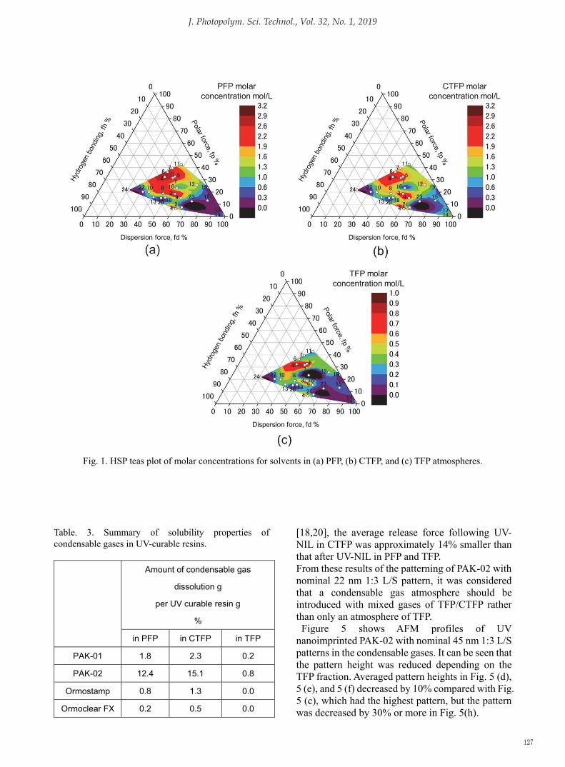
Table 2 summarizes the amount of gas dissolution in the solvent 10 min after exposure to the gas atmospheres, the molar concentration of the gas/solvent, and HSP of the solvents. The amount of gas dissolution in the solvent was corrected by subtracting the volatilization amount for 10 minutes in air. The number of solvents with a gas dissolution of over 2% were 16, 18, and 13 for PFP, CTFP, and TFP, respectively. In particular, it was found that large quantities of gas dissolution were observed in acetone, dimethyl formamide, and tetrahydrofuran. The largest amounts of TFP gas dissolution in the solvents were 1/5th of those of PFP and CTFP. The amounts of gas dissolution in CTFP atmosphere were comparable to those in PFP except for hexane, cyclohexane, and chlorohexane.
To intuitively assess the effect of solvent composition on gelation behavior, a Teas plot, derived from Hansen parameters [25], was used to examine the correlation between gelation behavior and the parameters. The parameters (fd, fp, and fh) can be calculated from the following equations:
𝑓𝑓� � ����������
� ��� (1)
𝑓𝑓� � ����������
� ��� (2)
𝑓𝑓� � ����������
� ��� (3)
where fd, fp, and fh are the dispersion component, polar component, and hydrogen-bonding component of the Teas parameters, respectively.
Figure 1 shows the HSP teas plot of the molar concentration for solvents in the condensable gases. High molar concentrations were observed in the ranges of fd = 40%–50%, fp = 50%–60%, and fh = 20%–40%, as shown in Figs. 1(a)–1(c). A correlation between the HSP and the amount of gas absorbed into the solvent was determined. The solubility property of TFP gas tended to be similar to those of PFP and CTFP gas, but the absorption amount was low. Because PFP and TFP gases are more likely to be liquefied compared with TFP, owing to its saturated vapor pressures near atmospheric pressure, we proposed that a large amount of absorption in the liquid state of the solvents was observed in the PFP and CTFP gas atmospheres compared with in a TFP atmosphere. Since the amount of TFP gas absorbed by the organic compounds was smaller than that of PFP and CTFP, we surmised that high-quality patterns could be obtained for any UV curable resins.
Table 3 provides a summary of the solubility property of condensable gases in commercial UV-curable resins. It was found that PAK-02 absorbed the most condensable gas, and the amounts of TFP gas dissolution in the resin were 1/10th those of PFP and CTFP. Although the chemical compositions of PAK-02 have not been determined, except for the fact that the resins contain acrylate monomers causing radical photopolymerization, it can be inferred that it contains a monomer that can easily absorb gas.
Further investigations were carried out by selecting PAK-02 as the UV curable resin, which exhibited the highest gas solubility. UV-NIL was performed under each atmosphere using a quartz mold with nanopatterns. The nanoimprint of the TFP/CTFP mixed condensable gas was also evaluated to be more practical. Figure 2 shows SEM images of the UV nanoimprinted PAK-02 with nominal 45 nm 1:3 L/S patterns in condensable gases. 45-nm-wide PAK-02 patterns were fabricated under most conditions, but pattern defects appeared, as shown in Figs. 2(b) and 2(h). The large amount of CTFP absorption was considered to be the cause of the pattern defects. As reported previously [26], the pattern line width changes according to the TFP/CTFP fraction in the case of using a PAK-02 resin.
Figure 3 shows SEM images of the UV nanoimprinted PAK-02 with nominal 32 nm 1:3 L/S patterns in the condensable gases. The patterning also failed under the conditions shown in Figs. 3 (a)

J. Photopolym. Sci. Technol., Vol. 32, No. 1, 2019
126
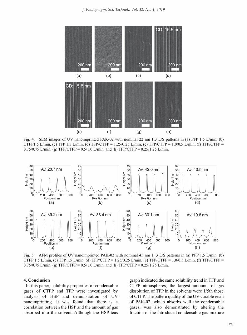
and 3 (g). The influence of the amount of condensable gas absorbed becomes greater as the size of the pattern becomes smaller. Figure 4 shows SEM images of the UV nanoimprinted PAK-02 with nominal 22 nm 1:3 L/S patterns in the condensable gases. Although the pattern was defective under most conditions, the pattern could be fabricated well, as shown in Figs. 4 (d) and 4 (e). The fine line patterns with a width of 16 nm were obtained by
UV-NIL with a high TFP fraction (>66%, TFP/CTFP= 1.25/0.25 L/min) in the TFP/CTFP mixed gas atmosphere. In Fig. 4 (c), under the condition of TFP 1.5 L/min, the line patterns collapsed from the observation of the pattern surface. As the cause of this, we considered that the patterns were stretched and collapsed owing to the problem in mold release. As reported in previously
Table 2. Summary of solubility properties of condensable gases in solvents and HSP of solvents.
No. Solvent Molecular
formula
Amount of condensable gas
dissolution g
per solvent g
%
Molar concentration
mol/L
HSP
[J/cm3]1/2
in PFP in CTFP in TFP in PFP in CTFP in TFP δd δp δh
1 Acetone C3H6O 69.4 59.9 15.4 2.9 2.6 1.0 15.5 10.4 7.0
2 Dimethyl Formamide C3H7NO 66.5 53.9 12.6 3.2 2.8 0.9 17.4 13.7 11.3
3 Tetrahydrofuran C4H8O 53.2 51.6 11.9 2.6 2.6 0.8 16.8 5.7 8.0
4 1,4-Dioxane C4H8O2 45.4 48.9 7.7 2.6 2.8 0.7 17.5 1.8 9.0
5 N-Methyl-2-Pyrrolidone C5H9NO 46.3 31.7 8.6 2.6 2.0 0.7 18.0 12.3 7.2
6 Dimethyl Sulfoxide C2H6OS 41.5 29.5 2.9 2.5 2.0 0.3 18.4 16.4 10.2
7 γ-Butyrolactone C4H6O2 34.6 23.8 2.5 2.2 1.7 0.2 18.0 16.6 7.4
8 1-Methoxy-2-propanol C4H10O2 27.3 29.3 5.3 1.6 1.7 0.4 15.6 6.3 11.6
9 Anisole C7H8O 24.1 38.3 3.2 1.5 2.2 0.3 17.8 4.4 6.9
10 Ethanol C2H6O 20.2 24.8 8.0 1.1 1.3 0.5 15.8 8.8 19.4
11 Propylene Carbonate C4H6O3 20.2 11.9 1.3 1.5 1.0 0.1 20.0 18.0 4.1
12 1-Chlorohexane C6H13Cl 15.0 33.7 5.9 0.9 1.8 0.4 16.1 6.2 1.7
13 2-Propanol C3H8O 13.9 20.1 5.8 0.8 1.1 0.4 15.8 6.1 16.4
14 Hexane C6H14 8.0 35.6 3.1 0.4 1.5 0.2 14.9 0.0 0.0
15 Methyl Nonafluorobutyl Ether C5H3F9O 6.3 6.3 1.4 0.7 0.7 0.2 13.7 2.2 1.0
16 Dichloromethane CH2Cl2 5.9 -0.1 -6.3 0.5 0.0 -0.8 17.0 7.3 7.1
17 Cyclohexane C6H12 1.9 27.3 1.7 0.1 1.4 0.1 16.8 0.0 0.2
18 1-Octanol C8H18O 1.6 7.2 0.4 0.1 0.4 0.0 16.0 5.0 11.2
19 Tetrachloroethylene C2Cl4 1.0 4.4 0.3 0.1 0.5 0.0 18.3 5.7 0.0
20 2-Phenoxy Ethanol C8H10O2 1.0 1.8 0.0 0.1 0.1 0.0 17.8 5.7 14.3
21 1-Bromonaphthalene C10H7Br 0.5 1.4 0.1 0.1 0.2 0.0 15.0 1.7 6.2
22 Ethylen Glycol C2H6O2 0.4 0.2 0.0 0.0 0.0 0.0 17.0 11.0 26.0
23 Diiodomethane CH2I2 0.3 0.2 0.1 0.1 0.1 0.0 22.0 3.9 5.5
24 Water H2O 0.0 0.0 0.0 0.0 0.0 0.0 15.5 16.0 42.3
J. Photopolym. Sci. Technol., Vol. 32, No. 1, 2019
127
Fig. 1. HSP teas plot of molar concentrations for solvents in (a) PFP, (b) CTFP, and (c) TFP atmospheres.
Table. 3. Summary of solubility properties of condensable gases in UV-curable resins.
Amount of condensable gas
dissolution g
per UV curable resin g
%
in PFP in CTFP in TFP
PAK-01 1.8 2.3 0.2
PAK-02 12.4 15.1 0.8
Ormostamp 0.8 1.3 0.0
Ormoclear FX 0.2 0.5 0.0
[18,20], the average release force following UV-NIL in CTFP was approximately 14% smaller than that after UV-NIL in PFP and TFP. From these results of the patterning of PAK-02 with nominal 22 nm 1:3 L/S pattern, it was considered that a condensable gas atmosphere should be introduced with mixed gases of TFP/CTFP rather than only an atmosphere of TFP.
Figure 5 shows AFM profiles of UV nanoimprinted PAK-02 with nominal 45 nm 1:3 L/S patterns in the condensable gases. It can be seen that the pattern height was reduced depending on the TFP fraction. Averaged pattern heights in Fig. 5 (d), 5 (e), and 5 (f) decreased by 10% compared with Fig. 5 (c), which had the highest pattern, but the pattern was decreased by 30% or more in Fig. 5(h).

J. Photopolym. Sci. Technol., Vol. 32, No. 1, 2019
128
Fig. 2. SEM images of UV nanoimprinted PAK-02 with nominal 45 nm 1:3 L/S patterns in (a) PFP 1.5 L/min, (b) CTFP1.5 L/min, (c) TFP 1.5 L/min, (d) TFP/CTFP = 1.25/0.25 L/min, (e) TFP/CTFP = 1.0/0.5 L/min, (f) TFP/CTFP = 0.75/0.75 L/min, (g) TFP/CTFP = 0.5/1.0 L/min, and (h) TFP/CTFP = 0.25/1.25 L/min.
Fig. 3. SEM images of UV nanoimprinted PAK-02 with nominal 32 nm 1:3 L/S patterns in (a) PFP 1.5 L/min, (b) CTFP 1.5 L/min, (c) TFP 1.5 L/min, (d) TFP/CTFP = 1.25/0.25 L/min, (e) TFP/CTFP = 1.0/0.5 L/min, (f) TFP/CTFP = 0.75/0.75 L/min, (g) TFP/CTFP = 0.5/1.0 L/min, and (h) TFP/CTFP = 0.25/1.25 L/min.
J. Photopolym. Sci. Technol., Vol. 32, No. 1, 2019
129
Fig. 4. SEM images of UV nanoimprinted PAK-02 with nominal 22 nm 1:3 L/S patterns in (a) PFP 1.5 L/min, (b) CTFP1.5 L/min, (c) TFP 1.5 L/min, (d) TFP/CTFP = 1.25/0.25 L/min, (e) TFP/CTFP = 1.0/0.5 L/min, (f) TFP/CTFP = 0.75/0.75 L/min, (g) TFP/CTFP = 0.5/1.0 L/min, and (h) TFP/CTFP = 0.25/1.25 L/min.
Fig. 5. AFM profiles of UV nanoimprinted PAK-02 with nominal 45 nm 1: 3 L/S patterns in (a) PFP 1.5 L/min, (b) CTFP 1.5 L/min, (c) TFP 1.5 L/min, (d) TFP/CTFP = 1.25/0.25 L/min, (e) TFP/CTFP = 1.0/0.5 L/min, (f) TFP/CTFP = 0.75/0.75 L/min, (g) TFP/CTFP = 0.5/1.0 L/min, and (h) TFP/CTFP = 0.25/1.25 L/min. 4. Conclusion
In this paper, solubility properties of condensable gases of CTFP and TFP were investigated by analysis of HSP and demonstration of UV nanoimprinting. It was found that there is a correlation between the HSP and the amount of gas absorbed into the solvent. Although the HSP teas
graph indicated the same solubility trend in TFP and CTFP atmospheres, the largest amounts of gas dissolution of TFP in the solvents were 1/5th those of CTFP. The pattern quality of the UV-curable resin of PAK-02, which absorbs well the condensable gases, was also demonstrated by altering the fraction of the introduced condensable gas mixture

J. Photopolym. Sci. Technol., Vol. 32, No. 1, 2019
130
of TFP/CTFP. Fine line patterns with a width of 16 nm were obtained by UV-NIL with a high TFP fraction (>66%) in the TFP/CTFP mixed gas atmosphere. Thus, the higher TFP fraction can be applied to finer pattern sizes. However, in terms of mold release, it was found the performing of UV-NIL in mixed condensable gas with a small amount of CTFP is desired, rather than only an atmosphere of TFP.
Acknowledgements This work was partly supported by the Japan
Society for the Promotion of Science (JSPS) KAKENHI (Grant Number 17K14575). We express our deep gratitude to the JSPS for financial assistance.
References 1. J. Haisma, M. Verheijen, K. Heuvel, and J. Berg,
J. Vac. Sci. Technol. B, 14 (1996) 4124.2. M. Colburn, S. Johnson, M. Stewart, S. Damle, T.
Bailey, B. Choi, M. Wedlake, T. Michaelson, S. V.Sreenivasan, J. Ekerdt, and C. G. Willson, Proc.SPIE, 3676 (1999) 379.
3. M. Komuro, J. Taniguchi, S. Inoue, N. Kimura, Y.Tokano, H. Hiroshima, and S. Matsui, Jpn. J.Appl. Phys., 39 (2000) 7075.
4. T. Higashiki, T. Nakasugi, and I. Yoneda, J. Micro/Nanolith. MEMS MOEMS, 10 (2011)043008.
5. K. Takano, H. Yokoyama, A. Ichii, I. Morimoto,and M. Hangyo, Opt. Lett., 36 (2011) 2665.
6. H. Hiroshima, M. Komuro, N. Kasahara, Y.Kurashima, and J. Taniguchi, Jpn. J. Appl. Phys., 42 (2003) 3849.
7. H. Hiroshima and M. Komuro, Jpn. J. Appl. Phys.,46 (2007) 6391.
8. H. Hiroshima, Q. Wang, and S.-W. Youn, J. Vac.Sci. Technol. B, 28 (2010) C6M12.
9. S.-W. Youn, Q. Wang, and H. Hiroshima, Jpn. J.Appl. Phys., 49 (2010) 06GL06.
10. H. Hiroshima, H. Atobe, and Q. Wang, J.Photopolym. Sci. Technol., 23 (2010) 45.
11. K. Kobayashi, S. Kubo, H. Hiroshima, S. Matsui,and M. Nakagawa, Jpn. J. Appl. Phys., 50 (2011)06GK02.
12. H. Hiroshima, J. Vac. Sci. Technol. B, 27 (2009)2862.
13. Q. Wang and H. Hiroshima, Jpn. J. Appl. Phys.,49 (2010) 06GL04.
14. H. Hiroshima and K. Suzuki, Jpn. J. Appl. Phys., 50 (2011) 06GK09.
15. S. Kaneko, K. Kobayashi, Y. Tsukidate, H.Hiroshima, S. Matsui, and M. Nakagawa, Jpn. J.Appl. Phys., 51 (2012) 06FJ05.
16. M. Nakagawa, Bull. Chem. Soc. Jpn., 89 (2016)786.
17. M. P. S. Andersen, O. J. Nielsen, M. D. Hurleyc,and T. J. Wallingtonc, Phys. Chem., 14 (2012)1735.
18. K. Suzuki, S.-W. Youn, and H. Hiroshima, Jpn. J. Appl. Phys., 55 (2016) 076502.
19. Honeywell Technical Report, “Honeywell HFO-1234ze Blowing Agent”, October 2008.
20. K. Suzuki, S.-W. Youn, and H. Hiroshima, Appl.Phys. Lett., 109 (2016) 143102.
21. H. Hiroshima and K. Suzuki, Jpn. J. Appl. Phys.,51 (2012) 06FJ10.
22. C. M. Hansen, Hansen Solubility Parameters,CRC Press, Boca Raton, FL, 2nd edn, 2007.
23. C. M. Hansen and A. L. Smith, Carbon, 42(2004) 1591.
24. Q. Wang, H. Hiroshima, K. Suzuki, and S. W.Youn, Jpn. J. Appl. Phys., 51 (2012) 118002.
25. J. Gao, S. Wu, and M. A. Rogers, J. Mater.Chem., 22 (2012) 12651.
26. K. Suzuki, S.-W. Youn, and H. Hiroshima, J.Photopolym. Sci. Technol., 29 (2016) 181.