
Solidification Class
51
Solidification and crystalline imperfections When molten alloys are cast, solidification starts at the walls of the mold as it is being cooled. The solidification of the alloy takes place not at a specific temperature but over a range of temperatures. While the alloy in the this range, it has a pasty form that consist of solid, tree-like structures called dendrites (meaning tree-like) and metal. The formation of Stable Nuclei in Liquid Metals The two main mechanism by which the nucleation of solid particles in liquid metal occurs are homogeneous nucleation and heterogeneous nucleation. Homogeneous Nucleation in a liquid melt occurs when the metal itself provides the atoms needed to form a nuclei. When a pre liquid metal is cooled below its equilibrium freezing temperature to a sufficient degree, many homogeneous nuclei are created by slow-moving atoms bonding together. For a nucleus to be stable so that it can grow into a crystal, it must reach a critical size. A cluster of atoms bonded together that is less than a critical size is called an embryo and one that is larger than the critical size is called a nucleus.
Transcript of Solidification Class

Solidification and crystalline imperfectionsWhen molten alloys are cast, solidification starts at the
walls of the mold as it is being cooled. The solidification of the alloy takes place not at a specific temperature but over a range of temperatures. While the alloy in the this range, it has a pasty form that consist of solid, tree-like structures called dendrites (meaning tree-like) and metal.The formation of Stable Nuclei in Liquid MetalsThe two main mechanism by which the nucleation of solid
particles in liquid metal occurs are homogeneous nucleation and heterogeneous nucleation.Homogeneous Nucleation in a liquid melt occurs when the metal itself provides the atoms needed to form a nuclei. When a pre liquid metal is cooled below its equilibrium freezing temperature to a sufficient degree, many homogeneous nuclei are created by slow-moving atoms bonding together. For a nucleus to be stable so that it can grow into a crystal, it must reach a critical size. A cluster of atoms bonded together that is less than a critical size is called an embryo and one that is larger than the critical size is called a nucleus.

Embryos• Small particles of a new phase formed by a phase (i. e. solidification) that are not of critical size and that can ressolve Nuclei
• Small particles of a new phase formed by a phase change (e . i . solidification) that can grow until the phase change is complete

• The formation of small regions of a new solid phase (called nuclei) in a pure metal that can grow until solidification is complete. The pure homogeneous metal itself provides the atoms that make up the nuclei.
Homogeneous Nucleation
Heterogeneous nucleation• The formation of very small regions of a new solid phase (called nuclei) of a new solid phase interfaces of solid impurities. These impurities lower the critical size at particular temperature of stable solid nuclei.

Critical radius r* of nucleus
• The minimum radius that particle of a new phase formed by nucleation must have to become a stable nucleus.

Grain• A single crystal in polycrystalline aggregatePolycrystalline structure
• A crystalline structure that contains many grains


Energies involved in Homogeneous NucleationIn the homogeneous nucleation two types of energies are
considered:(i)The volume (or bulk) free energy released by the
liquid-to-solid transformation and(ii) the surface energy required to form the new solid
surfaces of the solidified particles.When a pure liquid metal such as lead is cooled below its equilibrium freezing temperature, the driving energy for the liquid-to solid transformation is the difference in the volume (bulk) free energy ∆Gv of the liquid and that of the solid. If ∆Gv is the change in free energy between the liquid and solid per unit volume of metal, then the free-energy change for a spherical nucleus of radius r is
343 vr G
since the volume of a sphere is
343 r

The energy needed to create a surface for these spherical particles is
24sG r Where
Is the specific surface free energy of the particles
24 r Is the area of the
surface of the sphere.
So the total free-energy change for the formation of a spherical embryo or nucleus of radius r formed in a freezing pure metal is 3 24 43T vG r G r
The surface energy is definedas the surface excess free energy per unit area of a specific crystal face.
Energies involved in Homogeneous Nucleation-continued


The critical radius can be obtained by differentiating the equation The differential of the total free energy with respect to r is zero when r=r* since the total free energy versus radius of the embryo or nucleus plot is then at a maximum and the slope 0T
d Gdr
Thus
3 2
*2 *
*
4 4312 8 03
2
T v
v
v
d dG r G rdr dr
r G r
rG
The minimum radius that particle of a new phase formed by nucleation must have to become a stable nucleus.
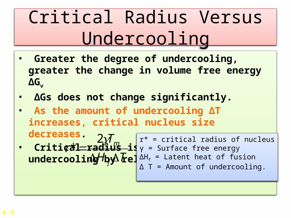
Critical Radius Versus Undercooling
• Greater the degree of undercooling, greater the change in volume free energy ΔGv
• ΔGs does not change significantly.• As the amount of undercooling ΔT increases, critical nucleus size decreases.
• Critical radius is related to undercooling by relation TH
Tr
f
m
2*r* = critical radius of nucleusγ = Surface free energyΔHf = Latent heat of fusionΔ T = Amount of undercooling.
4-6

Heterogeneous Nucleation
• Nucleation occurs in a liquid on the surfaces of structural material. Eg:- Insoluble impurities.
• These structures, called nucleating agents, lower the free energy required to form stable nuclei.
• Nucleating agents also lower the critical size.• Smaller amount of undercooling is required to solidify.
• Used excessively in industries.
Liquid
Solid
Nucleating agent
θ
4-7
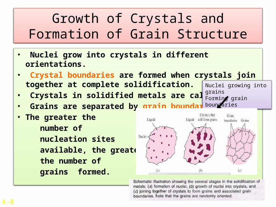
Growth of Crystals and Formation of Grain Structure
• Nuclei grow into crystals in different orientations.
• Crystal boundaries are formed when crystals join together at complete solidification.
• Crystals in solidified metals are called grains.• Grains are separated by grain boundaries.• The greater the number of nucleation sites available, the greater the number of grains formed.
Nuclei growing into grainsForming grain boundaries
4-8
Types of grainsEquiaxed
grainsIf the nucleation and growth conditions in the liquid metal during solidification are such that the crystals can grow equally about in all directions, equiaxed grains will be produced.Columnar grainsLong, thin grains in a solidified polycrystalline structure. These grains are formed in the interior of solidified metal ingots when heat flow is slow and during solidification.

Types of Grains• Equiaxed Grains:
Crystals, smaller in size, grow equally in all directions.
Formed at the sites of high concentration of nuclei.
Example:- Cold mold wall
• Columnar Grains: Long thin and coarse. Grow predominantly in one direction. Formed at the sites of slow cooling Example:- Grains that are away from the mold wall.
Mold
4-9
Columnar Grains
Equiaxed Grains

Single Crystal• A material formed from by the growth of a crystal nucleus without secondary nucleation a regular three-dimensional structure extends throughout the material is called single crystal.

Solidification of Single Crystal
• For some applications (Eg: Gas turbine blades-high temperature environment), single crystals are needed.
• Single crystals have high temperature creep (A slow longitudinal movement or deformation) resistance.
• Latent heat of solidification is conducted through solidifying crystal to grow single crystal.
• Growth rate is kept slow so that temperature at solid-liquid interface is slightly below melting point.
4-12
Figure 4.12Growth of singlecrystal for turbineairfoil.
(After Pratt and Whitney Co.)

• In this process high-purity polycrysalline silicon is first melted in a nonreactive crucible and held at a temperature just above the melting point. A high-quality seed crystal of silicon of the desired orientation is lowered into the melt while it is rotated. Part oft the surface of the seed crystal is melted in the liquid to remove the outer strained region and to produce a surface for the liquid to solidify on. The seed crystal continues to and to rotate and is slowly raised from the melt. As it is raised from the melt, silicon from the liquid in the crucible adheres and grows on the seed crystal, producing much larger diameter single crystal of silicon.
Czochralski Process

Solid Solution• A mixture of two or more metals or a metal (metals) and a nonmetal is called solid solution.
• The addition of impurity atoms to a metal results in the formation of a solid solution.
• The solvent represents the element that is present in the greatest amount (the host atoms). aluminum is the solvent and copper is the solute (present in minor concentration ).
• Solid solutions form when the solute atoms (Cu) are added to the solvent (Al), assuming the crystal structure is maintained and no new structures are formed.
• A solid solution is a homogenous composition throughout. 19

types of solid solution Solid Solution - continued
• The types of solid solution are (i) substitutional solid solution and (ii) interstitial solid solution.
20

Substitutional Solid Solution
• A solid solution in which solute atoms of one element can replace those of solvent atoms of another element. For example, in cu-Ni solid solution the copper atoms can replace the nickel atoms in the solid-solution crystal.
• Solute atoms substitute for parent solvent atom in a crystal lattice.
• The structure remains unchanged.• Lattice might get slightly distorted due to change in diameter of the atoms.
• Solute percentage in solvent can vary from fraction of a percentage to 100%
Solvent atoms
Solute atoms
4-15

Substitutional Solid Solution (Cont..)
• The solubility of solids is greater if The diameter of atoms does not differ by more than 15%
Crystal structures are similar. Not much difference in electronegativity (or compounds will be formed).
Have same valence.
• Examples:-
System
Atomic radiusDifference
Electro-
negativity
difference
SolidSolubility
Cu-Zn
3.9%
0.1
38.3%
Cu-Pb
36.7%
0.2
0.17%
Cu-Ni
2.3%
0 100%
4-16

Interstitial Solid Solution
• A solid solution formed in which the solute atoms can enter the interstices of or holes in the solvent-atom lattice.
• Solute atoms fit in between the voids (interstices) of solvent atoms.
• Solvent atoms in this case should be much larger than solute atoms.
• Example:- between 912 and 13940C, interstitial solid solution of carbon in γ iron (FCC) is formed.
• A maximum of 2.8% of carbon can dissolve interstitially in iron.
Carbon atoms r=0.075nm
Iron atoms r 00.129 nm
4-17Figure 4.15a

24
Crystalline Imperfections• If we assume a perfect crystal structure containing pure elements, then anything that deviated from this concept or intruded (enter uninvited) in this uniform homogeneity would be an imperfection.1. There are no perfect crystals.2. Many material properties are improved by the
presence of imperfections and deliberately modified (alloying and doping).
3. Imperfections affect mechanical properties, chemical properties and electrical properties.
• It is important to have knowledge about the types of imperfections that exist and the roles they play in affecting the behavior of materials

25
• Vacancy atoms• Interstitial atoms• Substitutional atoms
Point defects1-2 atoms
Types of Imperfections
• Dislocations Line defects1-dimensional
• Grain Boundaries Area defects2-dimensional
• So imperfections can be classified as
Zero dimensional point defects.
One dimensional / line defects (dislocations).
Two dimensional defects. Three dimensional defects (cracks).
26
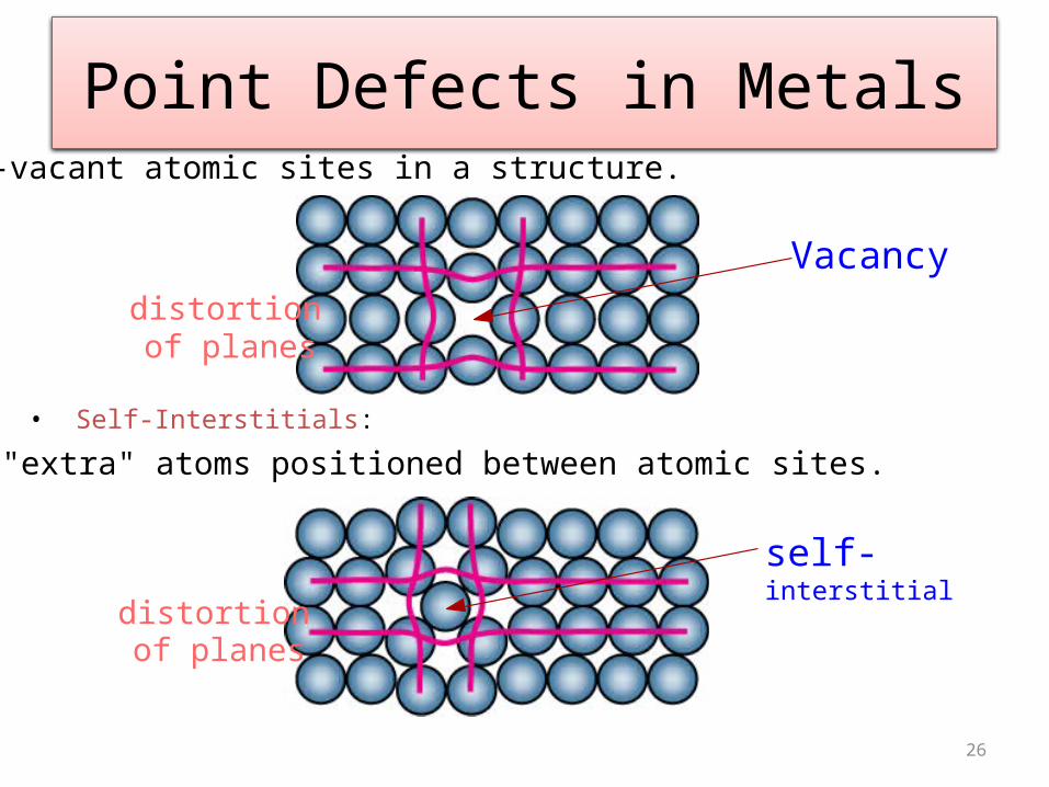
• Vacancies:-vacant atomic sites in a structure.
• Self-Interstitials:-"extra" atoms positioned between atomic sites.
Point Defects in Metals
Vacancydistortion of planes
self-interstitialdistortion
of planes

Point Defects – Vacancy • Vacancy is formed due to a missing atom.• Vacancy is formed (one in 10000 atoms) during crystallization or mobility of atoms.
• Energy of formation is 1 eV.• Mobility of vacancy results in cluster of vacancies.
• Also caused due to plastic defor- -mation, rapid cooling or particle bombardment.
Figure: Vacancies moving to form vacancy cluster4-19

Plastic Deformation
• When a material is stressed below its elastic limit, the resulting deformation or strain is temporary. Removal of stress results in a gradual return of the object to its original dimensions. When a material is stressed beyond its elastic limit, plastic or permanent deformation takes place, and it will not return to its original shape by the application of force alone. The ability of a metal to undergo plastic deformation is probably its most outstanding characteristic in comparison with other materials. Various machining operations such as milling, turning, sawing, and punching also involve plastic deformation.

Point Defects - Interstitially
• Atom in a crystal, sometimes, occupies interstitial site.
• This does not occur naturally.• Can be induced by irradiation.• This defects caused structural distortion.
4-20
Irradiation is the process by which an object is exposed to radiation.

Point Defects in Ionic Crystals
• Complex as electric neutrality has to be maintained.
• If two oppositely charged particles are missing, cation-anion di-vacancy is created. This is Scohttky defect.
• Frenkel defect is created when cataion moves to interstitial site.
• Impurity atoms are also considered as point defects.
4-21
Cation Interstitial Cation Vacancy
Anion Vacancy

• Cation Interstitial
• Cation Vacancy
• Anion Vacancy
Point Defects in Ionic Crystals

32
• Frenkel DefectTo maintain the charge neutrality, a cation vacancy-cation interstitial pair occur together. The cation leaves its normal position and moves to the interstitial site.
• Schottky DefectTo maintain the charge neutrality, remove 1 cation and 1 anion; this creates 2 vacancies.
Point Defects: Frenkel and Schottky
Schottky Defect
Frenkel Defect

• Dislocations are another type of defect in crystals. Dislocations are areas were the atoms are out of position in the crystal structure. Dislocations are generated and move when a stress is applied. The motion of dislocations allows slip – plastic deformation to occur.
• There are two basic types of dislocations, the edge dislocation and the screw dislocation. Actually, edge and screw dislocation
Line Defects – (Dislocations)

Line Defects – Continued
• Discrepancy is due to dislocations.
• Dislocations are lattice distortions centered around a line.
• Formed during Solidification Permanent Deformation Vacancy condensation
• Different types of line defects are
Edge dislocation Screw dislocation Mixed dislocation 4-22

• The edge defect can be easily visualized as an extra half-plane of atoms in a lattice. The dislocation is called a line defect because the locus of defective points produced in the lattice by the dislocation lie along a line. This line runs along the top of the extra half-plane.
Edge Dislocations
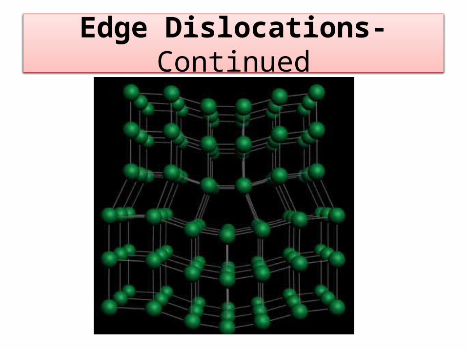
Edge Dislocations-Continued
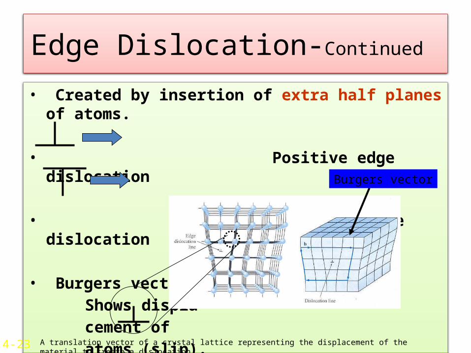
Edge Dislocation-Continued • Created by insertion of extra half planes of atoms.
• Positive edge dislocation
• Negative edge dislocation
• Burgers vector Shows displa- cement of atoms (slip).4-23
Burgers vector
A translation vector of a crystal lattice representing the displacement of the material to create a dislocation.

Burgers vector
A translation vector of a crystal lattice representing the displacement of the material to create a dislocation.

Edge Dislocation-Continued

Edge Dislocation-Continued
• As shown in the set of images above, the dislocation moves similarly moves a small amount at a time. The dislocation in the top half of the crystal is slipping one plane at a time as it moves to the right from its position in image (a) to its position in image (b) and finally image (c). In the process of slipping one plane at a time the dislocation propagates across the crystal. The movement of the dislocation across the plane eventually causes the top half of the crystal to move with respect to the bottom half. However, only a small fraction of the bonds are broken at any given time. Movement in this manner requires a much smaller force than breaking all the bonds across the middle plane simultaneously
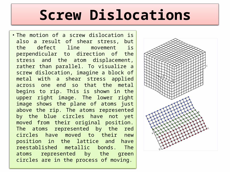
Screw Dislocations• The motion of a screw dislocation is also a result of shear stress, but the defect line movement is perpendicular to direction of the stress and the atom displacement, rather than parallel. To visualize a screw dislocation, imagine a block of metal with a shear stress applied across one end so that the metal begins to rip. This is shown in the upper right image. The lower right image shows the plane of atoms just above the rip. The atoms represented by the blue circles have not yet moved from their original position. The atoms represented by the red circles have moved to their new position in the lattice and have reestablished metallic bonds. The atoms represented by the green circles are in the process of moving.

Screw Dislocations-Continued

Screw Dislocations- Continued

Screw Dislocations-Continued

Mixed Dislocation • Most crystal have components of both edge and screw dislocation.
• Dislocation, since have irregular atomic arrangement will appear as dark lines when observed in electron microscope.
4-25
Dislocation structure of iron deformed14% at –1950C
The Scanning Electron Microscope
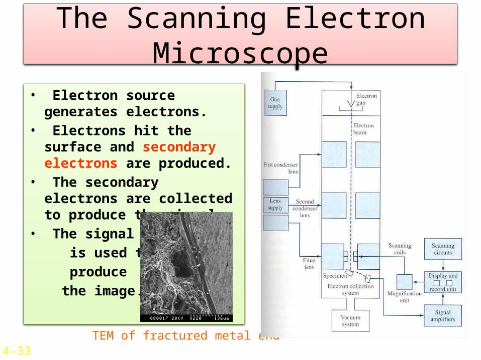
• Electron source generates electrons.
• Electrons hit the surface and secondary electrons are produced.
• The secondary electrons are collected to produce the signal.
• The signal is used to produce the image.
TEM of fractured metal end4-33

Grain Boundaries• Grain boundaries separate grains.• Formed due to simultaneously growing crystals meeting each other.
• Width = 2-5 atomic diameters. • Some atoms in grain boundaries have higher energy.
• Restrict plastic flow and prevent dislocation movement.
4-27
3D view ofgrains
Grain BoundariesIn 1018 steel

Grain Size• Affects the mechanical properties of the material
• The smaller the grain size, more are the grain boundaries.
• More grain boundaries means higher resistance to slip (plastic deformation occurs due to slip).
• More grains means more uniform the mechanical properties are.
4-30

Planar Defects• Grain boundaries, twins, low/high angle boundaries, twists and stacking faults
• Free surface is also a defect : Bonded to atoms on only one side and hence has higher state of energy Highly reactive
• Nanomaterials have small clusters of atoms and hence are highly reactive.

Twin Boundaries• Twin: A region in which mirror image pf structure exists across a boundary.
• Formed during plastic deformation and recrystallization.
• Strengthens the metal.
Twin
Twin Plane

Observing Grain Boundaries - Metallography
• To observe grain boundaries, the metal sample must be first mounted for easy handling
• Then the sample should be ground and polished with different grades of abrasive
paper and abrasive solution.• The surface is then etched chemically. • Tiny groves are produced at grain boundaries. • Groves do not intensely reflect light. Hence observed by optical microscope. 4-28