
Sole Diesel.pdf
68
-
Upload
khangminh22 -
Category
Documents
-
view
0 -
download
0
Transcript of Sole Diesel.pdf


CONTENTSCONTENTS
PAGE
49
50
Solé S.A. seeks to constantly improveits final products, and so the design,description, dimensions, configurationand other technical specifications givenherein, appear only for informationalpurposes and should not be takenas a binding offer with respect to thefinal product.
Technical specificationsand presentation are subjectto variations and modificationswithout previous notice.
C-243b, Km. 208760 Martorell (Barcelona). SpainTel. (34) 93 775 14 00Fax (34) 93 775 30 [email protected]
Design: www.espaigrafic-disseny.comEdition: September, 2012
2013 Catalogue
Spare Parts ServiceTel. (34) 93 775 44 05Fax (34) 93 776 53 [email protected]
PAGE
1. DIESEL MARINE ENGINESMINI-17MINI-29MINI-33MINI-44MINI-55MINI-62MINI-74SM-105SN-110SDZ-165SDZ-205SDZ-280OPTIONAL KITSENGINE MAINTENANCE KIT
2. ELECTRICAL SYSTEM - GENERATOR SETSDIGITAL GENERATOR SET PANEL (SCO 10)DIGITAL GENERATOR SET PANEL (MDA PLUS)ANALOGUE GENERATOR SET PANEL
3. GENERATOR SETSTHREE-PHASESINGLE PHASECANOPY
4. TRANSMISSIONSTMC 40P TECHNODRIVETMC 60E TECHNODRIVETMC 60A TECHNODRIVETMC 260 TECHNODRIVETM-345 TECHNODRIVETM-345A TECHNODRIVETM-93 TECHNODRIVETM-93A TECHNODRIVETM-170 TECHNODRIVETM-170A TECHNODRIVETM-880A TECHNODRIVETM-360 TECHNODRIVETM-265 TECHNODRIVETM-265A TECHNODRIVETM-200B TECHNODRIVETM-485A TECHNODRIVETM-1200 A TECHNODRIVESAIL DRIVE SPROP-60 TECHNODRIVESMI-R2 y SMI-R3ADAPTOR FLANGE SAE-7FLEXIBLE COUPLING
5. SHAFT LINESCLAMP-ON COUPLINGSHALF COUPLINGSCENTAFLEX TYPE FLEXIBLE COUPLINGSR&D TYPE FLEXIBLE COUPLINGSSHAFTSDOUBLE TAPER SHAFTSCOMPLETE STERNTUBE ASSEMBLIESRIGID STERNTUBESBEARING BUSHING ASSEMBLYFLOATING STUFFING BOXTEFLON PACKINGRUBBER BEARINGSSTRUTSPROPELLER NUT FASTENERZINC ANODE NUTS
6. PROPELLERSPROPELLERS FOR TECHNODRIVE SPROP60 SAIL DRIVEPROPELLERS FOR SELVA SAIL-DRIVESRX PROPELLERSPROPELLERSROPE CUTTERS FOR SAIL DRIVEROPE CUTTER
7. WATER INLET SYSTEMSEA WATER COCKSWATER FILTERSCOOLING WATER PUMPCOOLING PUMP IMPELLERWATER INLET HOSE
8. WATER EXHAUST SYSTEMWET EXHAUST HOSEWATERLOCKGOOSE NECKEXHAUST VENTTRANSOM EXHAUST CONNECTION
123456789
101112131415
16161717
18182022
24242425252626272728282929303031313232333334
35353637373839404041414142424242
43434344444949
494950505051
515151525252
PAGE
9. FUEL SYSTEMDIESEL FUEL FILTERSFUEL HOSE
10. CONTROL SYSTEMSHUT-DOWN CABLEPUSH-PULL CABLEREMOTE CONTROL LEVERS
11. ELECTRICAL SYSTEMELECTRICAL INSTRUMENTS
12. ANTI VIBRATION MOUNTSENGINE MOUNTSGENERATOR SET MOUNT
13. OTHER ACCESSORIESORIGINAL SOLÉ DIESEL ENGINE OILORIGINAL SOLÉ DIESEL ENGINE PAINTOIL EXTRACTION PUMPATF OIL
14. FORMSFOR PROPELLER ANALYSIS AND SELECTIONORDER FORM, DOUBLE TAPERED SHAFTS
15. APPENDIXAPPENDIX TO CHAPTER 4. GEAR BOXES
535353
53535354
5555
565657
5858585858
595960
6161
54 5243 525151 3553
56 2 24 36 38 40 42 49 4251

2 ENGINES
166 295 154615
Ø40
rpm
420
50
3
67.
5
480
Max
.86
Min
.75
99.5
33
516
8
201 235
TYPE A
1 DIESEL MARINE ENGINES
MINI-17. Mitsubishi base. 2-cylinder 16 HP (11.8 kW) at 3600 rpm
MITSUBISHI
Diesel, 4 stroke
2 in-line
Naturally Aspirated
76 x 70
635
23:1
16 CV (11.8 kW)
14.4 CV (10.6 kW)
Indirect
12 V - 40A
25º continuous / 30º intermittent
20 mm
8 mm
5 mm
EU RCD
TRANSMISSIONS AVAILABLE
Model
Manufacturer
Type
Shaft angle
Reduction ratios (pleasure)
Reduction ratios (heavy duty)
Engine weight with gearbox
TMC40
Technodrive
Mechanical
–
2.00:1 - 2.60:1
2.00:1 - 2.60:1
96 Kg
POWER
kW
10
5
0
rpm
500 1000 1500 2000 2500 3000 3600
N.m
50
40
30
20
10
0
FUEL CONSUMPTION
rpm
l/h
5
4
3
2
1
0
Deluxe instrument panel with:
• RPM Indicator• Hour Counter• Key start and stop with timed preheat
indication• Audible and visual alarm for high engine
temperature, low oil pressure and batterycharge
• Temperature Gauge, oil pressure Gaugeand Voltmeter
• Dimensions: 150 x 250 mm
Dimensions in mm
Note: Power rating per ISO 3046/1
500 1000 1500 2000 2500 3000 3600 1000 1500 2000 2500 3000 3600
1.8
TTMC35A2
Kanzaki
Mechanical
7º
2.33:1
2.33:1
99 Kg
SAILDRIVESPROP 60
Technodrive
Mechanical
–
2.15:1
–
125 Kg
GRAPHSENGINE TORQUE
OPTIONAL
• Twin instrument panel installation• Twin alternator• Two-pole electrical system• Dry exhaust system• Keel cooling• Power take-off shaft or pulley• Heater connections• Power train: Propeller, shaft, sterntube• Water and diesel fuel filters• Water, exhaust, and diesel fuel hoses
EQUIPMENT
STANDARD
• Instrument panel• 3 m electrical extension lead• Anti Vibration Mounts• Oil extraction pump• Owner’s Manual and Spare parts manual
Standard instrument panel with:
• RPM Indicator• Hour Counter• Temperature Gauge• Key start and stop with timed preheat indication• Audible and visual alarm for high engine
temperature, low oil pressure and batterycharge
• Dimensions: 180 x 150 mm
MNI-17 CON TMC 40
Note: Power rating per ISO 3046/1
Engine mount
Part number 616.31.100
TECHNICAL SPECIFICATIONSBase
Type
Cylinders
Intake system
Diameter x stroke (mm)
Total displacement (cc)
Compression ratio
Intermittent power rating (per ISO 3046/1)
Continuous output
Fuel injection system
Alternator
Maximum working angle
Int. Ø Salt water hose
Int. Ø Diesel fuel intake hose
Int. Ø Diesel fuel return hose
Certifications
15
11.8

3ENGINES
165 384 154703
Ø50
rpm
210
99
420
Max
.86
Min
.75
206 240
67,
5
642
210
482
189
235
34
317
15
32
TYPE A
1. DIESEL MARINE ENGINES
MINI-29. Mitsubishi base. 3-cylinder 27.2 HP (20 kW) at 3600 rpm
MITSUBISHI
Diesel, 4 stroke
3 in-line
Naturally Aspirated
76 x 70
952
22:1
27.2 CV (20 kW)
24.5 CV (18 kW)
Indirect
12 V - 40A
25° continuous / 30° intermittent
20 mm
8 mm
5 mm
EURCD
TRANSMISSIONS AVAILABLE
Model
Manufacturer
Type
Shaft angle
Reduction ratios (pleasure)
Reduction ratios (heavy duty)
Engine weight with gearbox
TMC40
Technodrive
Mechanical
–
2.00:1 - 2.60:1
2.00:1 - 2.60:1
101 kg
POWER
kW
10
5
0
rpm
500 1000 1500 2000 2500 3000 3600
N.m
50
40
30
20
10
0
FUEL CONSUMPTION
rpm
l/h
5
4
3
2
1
0
Dimensions in mm
500 1000 1500 2000 2500 3000 3600 1000 1500 2000 2500 3000 3600
TMC60
Technodrive
Mechanical
–
2.00:1 - 2.45:1
2.00:1 - 2.45:1
104 Kg
TTMC35A2
Kanzaki
Mechanical
7º
2.33:1
2.33:1
109 Kg
SAILDRIVESPROP 60
Technodrive
Mechanical
–
2.15:1
–
132 Kg
GRAPHSENGINE TORQUE
MNI-29 CON TMC 40
Note: Power rating per ISO 3046/1
Engine mount
Part number 616.31.100
TECHNICAL SPECIFICATIONSBase
Type
Cylinders
Intake system
Diameter x stroke (mm)
Total displacement (cc)
Compression ratio
Intermittent power rating (per ISO 3046/1)
Continuous output
Fuel injection system
Alternator
Maximum working angle
Int. Ø Salt water hose
Int. Ø Diesel fuel intake hose
Int. Ø Diesel fuel return hose
Certifications
20
EQUIPMENT
Deluxe instrument panel with:
• RPM Indicator• Hour Counter• Key start and stop with timed preheat
indication• Audible and visual alarm for high engine
temperature, low oil pressure and batterycharge
• Temperature Gauge, oil pressure Gaugeand Voltmeter
• Dimensions: 150 x 250 mm
OPTIONAL
• Twin instrument panel installation• Twin alternator• 110A alternator• Two-pole electrical system• Dry exhaust system• Keel cooling• Power take-off shaft or pulley• Heater inlet• Drivetrain: Propeller, shaft, sterntube• Water and diesel fuel filters• Water, exhaust, and diesel fuel hoses
STANDARD
• Instrument panel• 3 m electrical extension lead• Anti Vibration Mounts• Oil extraction pump• Owner’s Manual and Spare parts manual
Standard instrument panel with:
• RPM Indicator• Hour Counter• Temperature Gauge• Key start and stop with timed preheat indication• Audible and visual alarm for high engine
temperature, low oil pressure and batterycharge
• Dimensions: 180 x 150 mm
60

4 ENGINES
186 400 156742
rpm
230
Ø50
99,5
Max
.10
0M
in.8
5
260 271
67,
5
230
460
531
38
619
5
58
1
TYPE E
1. DIESEL MARINE ENGINES
MINI-33. Mitsubishi base. 3-cylinder 31.4 HP (23.1 kW) at 3000 rpm
MITSUBISHI
Diesel, 4 stroke
3 in-line
Naturally Aspirated
78 x 92
1318
22:1
31.4 CV (23.1 kW)
28.5 CV (20.9 kW)
Indirect
12 V - 50A
15° continuous / 30° intermittent
20 mm
8 mm
5 mm
EURCD
TRANSMISSIONS AVAILABLE
Model
Manufacturer
Type
Shaft angle
Reduction ratios (pleasure)
Reduction ratios (heavy duty)
Engine weight with gearbox
TMC40
Technodrive
Mechanical
–
2.00:1 - 2.60:1
2.00:1 - 2.60:1
159 Kg
POWER
kW
15
10
5
0
rpm
1000 1500 2000 2500 3000
FUEL CONSUMPTION
rpm
l/h
8
6
4
2
0
EQUIPMENT
Dimensions in mm
1000 1500 2000 2500 3000 1000 1500 2000 2500 3000
GRAPHSENGINE TORQUE
TMC60
Technodrive
Mechanical
–
2.00:1 - 2.45:1
2.00:1 - 2.45:1
165 Kg
SMI-R3
Solé Diesel
Mechanical
–
2.00:1 - 2.50:1 - 3:1
2.00:1 - 2.50:1 - 3:1
180 Kg
TTMC35A2
Kanzaki
Mechanical
7º
2.33:1
2.33:1
163 Kg
SAILDRIVESPROP 60
Technodrive
Mechanical
–
2.15:1
-
192 Kg
MNI-33 CON TMC 40
Note: Power rating per ISO 3046/1
Engine mount
Part number 616.73.000
N.m
90
80
70
60
50
0
TECHNICAL SPECIFICATIONSBase
Type
Cylinders
Intake system
Diameter x stroke (mm)
Total displacement (cc)
Compression ratio
Intermittent power rating (per ISO 3046/1)
Continuous output
Fuel injection system
Alternator
Maximum working angle
Int. Ø Salt water hose
Int. Ø Diesel fuel intake hose
Int. Ø Diesel fuel return hose
Certifications
25
20
7.2
23.1
Deluxe instrument panel with:
• RPM Indicator• Hour Counter• Key start and stop with timed preheat
indication• Audible and visual alarm for high engine
temperature, low oil pressure and batterycharge
• Temperature Gauge, oil pressure Gaugeand Voltmeter
• Dimensions: 150 x 250 mm
OPTIONAL
• Twin instrument panel installation• Twin alternator• 110A alternator• Two-pole electrical system• Dry exhaust system• Keel cooling• Power take-off shaft or pulley• Heater inlet• Drivetrain: Propeller, shaft, sterntube• Water and diesel fuel filters• Water, exhaust, and diesel fuel hoses
STANDARD
• Instrument panel• 3 m electrical extension lead• Anti Vibration Mounts• Oil extraction pump• Owner’s Manual and Spare parts manual
Standard instrument panel with:
• RPM Indicatorh• Hour Counter• Temperature Gauge• Key start and stop with timed preheat indication• Audible and visual alarm for high engine
temperature, low oil pressure and batterycharge
• Dimensions: 180 x 150 mm

5ENGINES
186 482 220
888
78,7
5
Ø50
58
1
38
619
5
rpm
230230
460
271260
531
Max
.10
0M
in.8
5
1. DIESEL MARINE ENGINES
MINI-44. Mitsubishi base. 4-cylinder 42 HP (30.9 kW) at 3000 rpm
TRANSMISSIONS AVAILABLE
Model
Manufacturer
Type
Shaft angle
Reduction ratios (pleasure)
Reduction ratios (heavy duty)
Engine weight with gearbox
TMC60
Technodrive
Mechanical
–
2.00:1 - 2.45:1
2.00:1
171 Kg
POWER
1000 1500 2000 2500 3000
kW
30
25
20
15
9.2
30.9
rpm
1000 1500 2000 2500 3000
FUEL CONSUMPTION
rpm
1000 1500 2000 2500 3000
l/h
8
6
4
2
0
9
EQUIPMENT
Dimensions in mm
10
GRAPHSENGINE TORQUE
SMI-R3
Solé Diesel
Mechanical
–
2.00:1 - 2.50:1 -3:1
2.00:1 - 2.50:1 -3:1
190 Kg
TTMC35A2
Kanzaki
Mechanical
7º
2.33:1
2.33:1
174 Kg
TM345
Technodrive
Hydraulic
–
2.00:1 - 2.47:1
2.00:1 - 2.47:1
185 Kg
TM345A
Technodrive
Hydraulic
8º
2.00:1 - 2.47:1
2.00:1 - 2.47:1
185 Kg
SAILDRIVESPROP 60
Technodrive
Mechanical
–
2.15:1
–
197 Kg
MNI-44 CON TMC 60
Note: Power rating per ISO 3046/1
TYPE EEngine mount
Part number 616.73.000
N.m
110
100
90
80
70
120
MITSUBISHI
Diesel, 4 stroke
4 in-line
Naturally Aspirated
78 x 92
1758
22:1
42 CV (30.9 kW)
38 CV (27.9 kW)
Indirect
12 V - 50A
15° continuous / 30° intermittent
20 mm
8 mm
5 mm
EURCD
TECHNICAL SPECIFICATIONSBase
Type
Cylinders
Intake system
Diameter x stroke (mm)
Total displacement (cc)
Compression ratio
Intermittent power rating (per ISO 3046/1)
Continuous output
Fuel injection system
Alternator
Maximum working angle
Int. Ø Salt water hose
Int. Ø Diesel fuel intake hose
Int. Ø Diesel fuel return hose
Certifications
Deluxe instrument panel with:
• RPM Indicator• Hour Counter• Key start and stop with timed preheat
indication• Audible and visual alarm for high engine
temperature, low oil pressure and batterycharge
• Temperature Gauge, oil pressure Gaugeand Voltmeter
• Dimensions: 150 x 250 mm
OPTIONAL
• Twin instrument panel installation• Twin alternator• 110A alternator• 24V electrical system• Two-pole electrical system• Dry exhaust system• Keel cooling• Power take-off shaft or pulley• Heater inlet• Drivetrain: Propeller, shaft, sterntube• Water and diesel fuel filters• Water, exhaust, and diesel fuel hoses
STANDARD
• Instrument panel• 3 m electrical extension lead• Anti Vibration Mounts• Oil extraction pump• Owner’s Manual and Spare parts manual
Standard instrument panel with:
• RPM Indicator• Hour Counter• Temperature Gauge• Key start and stop with timed preheat indication• Audible and visual alarm for high engine
temperature, low oil pressure and batterycharge
• Dimensions: 180 x 150 mm

6 ENGINES
193 482 220
895
78,7
5
Ø60
rpm
230230
460
277260
Max
.10
0M
in.8
5
195
412
1. DIESEL MARINE ENGINES
MINI-55. Mitsubishi base. 4-cylinder 52 HP (38.3 kW) at 3000 rpm
TRANSMISSIONS AVAILABLE
Model
Manufacturer
Type
Shaft angle
Reduction ratios (pleasure)
Reduction ratios (heavy duty)
Engine weight with gearbox
1000 1500 2000 2500 3000
kW
30
20
10
rpm
1000 1500 2000 2500 3000
N.m
130
120
110
100
90
FUEL CONSUMPTION
rpm
1000 1500 2000 2500 3000
l/h
8
6
4
2
0
10,1
EQUIPMENT
Dimensions in mm
11
MITSUBISHI
Diesel, 4 stroke
4 in-line
Turbo Charged
78 x 92
1758
22:1
52 HP (38.3 kW)
46.8 HP (34.4 kW)
Indirect
12 V - 50A
15° continuous / 30° intermittent
26 mm
8 mm
5 mm
EURCD
POWER
TMC60
Technodrive
Mechanical
–
2.00:1 - 2.45:1
2.00:1
176 Kg
SMI-R3
Solé Diesel
Mechanical
–
2.00:1 - 2.50:1
2.00:1 - 2.50:1
191 Kg
TTMC35A2
Kanzaki
Mechanical
7º
2.33:1
2.33:1
179 Kg
TM345
Technodrive
Hydraulic
–
2.00:1 - 2.47:1
2.00:1 - 2.47:1
190 Kg
TM345A
Technodrive
Hydraulic
8º
2.00:1 - 2.47:1
2.00:1 - 2.47:1
190 Kg
SAILDRIVESPROP 60
Technodrive
Mechanical
–
2.15:1
–
202 Kg
GRAPHSENGINE TORQUE
MNI-55 CON TMC 60
Note: Power rating per ISO 3046/1
TYPE EEngine mount
Part number 616.73.000
TECHNICAL SPECIFICATIONSBase
Type
Cylinders
Intake system
Diameter x stroke (mm)
Total displacement (cc)
Compression ratio
Intermittent power rating (per ISO 3046/1)
Continuous power rating
Fuel injection system
Alternator
Maximum working angle
Int. Ø Salt water hose
Int. Ø Diesel fuel intake hose
Int. Ø Diesel fuel return hose
Certifications
38,3
Deluxe instrument panel with:
• RPM Indicator• Hour Counter• Key start and stop with timed preheat
indication• Audible and visual alarm for high engine
temperature, low oil pressure and batterycharge
• Temperature Gauge, oil pressure Gaugeand Voltmeter
• Dimensions: 150 x 250 mm
OPTIONAL
• Twin instrument panel installation• Twin alternator• 110A alternator• 24V electrical system• Two-pole electrical system• Dry exhaust system• Keel cooling• Power take-off shaft or pulley• Heater inlet• Drivetrain: Propeller, shaft, sterntube• Water and diesel fuel filters• Water, exhaust, and diesel fuel hoses
STANDARD
• Instrument panel• 3 m electrical extension lead• Anti Vibration Mounts• Oil extraction pump• Owner’s Manual and Spare parts manual
Standard instrument panel with:
• RPM Indicator• Hour Counter• Temperature Gauge• Key start and stop with timed preheat indication• Audible and visual alarm for high engine
temperature, low oil pressure and batterycharge
• Dimensions: 180 x 150 mm

7ENGINES
219 515 246980
Ø60
rpm
250250
300
78,7
5 62
6
42
32
03
280 280Max
.10
0M
in.8
5
1. DIESEL MARINE ENGINES
MINI-62. Mitsubishi base. 4-cylinder 59 HP (43.4 kW) at 3000 rpm
MITSUBISHI
Diesel, 4 stroke
4 in-line
Naturally Aspirated
88 x 95
2311
22:1
59 HP (43.4 kW)
53 HP (38.9 kW)
Indirect
12 V - 50A
15° continuous / 20° intermittent
32 mm
8 mm
6 mm
EURCD
TRANSMISSIONS AVAILABLE
Model
Manufacturer
Type
Shaft angle
Reduction ratios (pleasure)
Reduction ratios (heavy duty)
Engine weight with gearbox
TMC60
Technodrive
Mechanical
–
2.00:1
–
228 Kg
POWER RATING
1000 1500 2000 2500 3000
kW
30
20
0
rpm
1000 1500 2000 2500 3000
FUEL CONSUMPTION
rpm
1000 1500 2000 2500 3000
l/h
10
8
6
4
2
0
12
EQUIPMENT
Dimensions in mm
10
40
SMI-R3
Solé Diesel
Mechanical
–
2:01 - 2.50:1
2:01 - 2.50:1
243 Kg
TM345
Technodrive
Hydraulic
–
2.00:1 - 2.47:1
2.00:1 - 2.47:1
240 Kg
TM345A
Technodrive
Hydraulic
8º
2.00:1 - 2.47:1
2.00:1 - 2.47:1
240 Kg
SAILDRIVESPROP 60
Technodrive
Mechanical
–
2.15:1
–
262 Kg
GRAPHSENGINE TORQUE
MNI-62 CON TMC 60
Note: Power rating per ISO 3046/1
TYPE EEngine mount
Part number 616.71.000
N.m
160
150
125
100
0
TECHNICAL SPECIFICATIONSBase
Type
Cylinders
Intake system
Diameter x stroke (mm)
Total displacement (cc)
Compression ratio
Intermittent power rating (per ISO 3046/1)
Continuous power rating
Fuel injection system
Alternator
Maximum working angle
Int. Ø Salt water hose
Int. Ø Diesel fuel intake hose
Int. Ø Diesel fuel return hose
Certifications
43,4
16.7
Deluxe instrument panel with:
• RPM Indicator• Hour Counter• Key start and stop with timed preheat
indication• Audible and visual alarm for high engine
temperature, low oil pressure and batterycharge
• Temperature Gauge, oil pressure Gaugeand Voltmeter
• Dimensions: 150 x 250 mm
OPTIONAL
• Twin instrument panel installation• Twin alternator• 110A alternator• 24V electrical system• Two-pole electrical system• Dry exhaust system• Keel cooling• Power take-off shaft or pulley• Heater inlet• Drivetrain: Propeller, shaft, sterntube• Water and diesel fuel filters• Water, exhaust, and diesel fuel hoses
STANDARD
• Instrument panel• 4 m electrical extension lead• Anti Vibration Mounts• Oil extraction pump• Owner’s Manual and Spare parts manual
Standard instrument panel with:
• RPM Indicator• Hour Counter• Temperature Gauge• Key start and stop with timed preheat indication• Audible and visual alarm for high engine
temperature, low oil pressure and batterycharge
• Dimensions: 180 x 150 mm

8 ENGINES
311 460 2601031
rpm
300
Ø75
Max
.10
0M
in.8
5
470
73300
3308
6,6
240
710
330
660
1. DIESEL MARINE ENGINES
MINI-74. Mitsubishi base. 4-cylinder 65 HP (47.9 kW) at 2500 rpm
MITSUBISHI
Diesel, 4 stroke
4 in-line
Naturally Aspirated
94 x 120
3331
22:1
65 HP (47.9 kW)
62 HP (45.6 kW)
Indirect
12 V - 110A
15° continuous / 25° intermittent
32 mm
8 mm
----
EURCD
TRANSMISSIONS AVAILABLE
Model
Manufacturer
Type
Shaft angle
Reduction ratios (pleasure)
Reduction ratios (heavy duty)
Engine weight with gearbox
SMI-R3
Solé Diesel
Mechanical
–
2.00:1
–
367 Kg
POWER RATING
kW
rpm
1000 1500 2000 2500
FUEL CONSUMPTION
rpm
l/h
16
12
8
4
0
Dimensions in mm
1000 1500 2000 2500 1000 1500 2000 2500 3000
EQUIPMENT
STANDARD
• Instrument panel• 4 m electrical extension lead• Anti Vibration Mounts• Oil extraction pump• Owner’s Manual and Spare parts manual
OPTIONAL
• Twin instrument panel installation• Twin alternator• 24V electrical system• Two-pole electrical system• Dry exhaust system• Keel cooling• Power take-off shaft or pulley• Heater inlet• Drivetrain: Propeller, shaft, sterntube• Water and diesel fuel filters• Water, exhaust, and diesel fuel hoses
Deluxe instrument panel with:
• RPM Indicator• Hour Counter• Key start and stop with timed preheat indication• Audible and visual alarm for high engine
temperature, low oil pressure and battery charge• Temperature Gauge, oil pressure Gauge and
Voltmeter• Dimensions: 150 x 250 mm
GRAPHSENGINE TORQUE
TM345
Technodrive
Hydraulic
–
2.00:1 - 2.47:1
–
362 Kg
TM345A
Technodrive
Hydraulic
8º
2.00:1 - 2.47:1
–
362 Kg
TM93
Technodrive
Hydraulic
–
2.09:1 - 2.40:1 - 2.77:1
2.09:1 - 2.40:1 - 2.77:1
394 Kg
TM93A
Technodrive
Hydraulic
8º
2.09:1 - 2.40:1
2.09:1 - 2.40:1
394 Kg
MNI-74 CON SMI-R3
Note: Power rating per ISO 3046/1
N.m
210
200
190
180
170
160
TYPE EEngine mount
Part number 616.82.000
TECHNICAL SPECIFICATIONSBase
Type
Cylinders
Intake system
Diameter x stroke (mm)
Total displacement (cc)
Compression ratio
Intermittent power rating (per ISO 3046/1)
Continuous power rating
Fuel injection system
Alternator
Maximum working angle
Int. Ø Salt water hose
Int. Ø Diesel fuel intake hose
Int. Ø Diesel fuel return hose
Certifications
55
30
20
40
10
47,9
1.8

9ENGINES
370 674 2581302
rpm
300
Ø75
470
330,5300
330
110
,4
30
0
770
330
1. DIESEL MARINE ENGINES
SM-105. Mitsubishi base. 6-cylinder 95 HP (69.9 kW) at 2500 rpm
OPTIONAL
• Twin instrument panel installation• Twin alternator• 24V electrical system• Two-pole electrical system• Dry exhaust system• Anti Vibration Mounts• Keel cooling• Power take-off shaft or pulley 4A or 4B• Heater inlet• Drivetrain: Propeller, shaft, sterntube• Water and diesel fuel filters• Water, exhaust, and diesel fuel hoses
STANDARD
• Instrument panel• 4 m electrical extension lead• Oil extraction pump• Owner’s Manual and Spare parts manual
Deluxe instrument panel with:
• RPM Indicator• Hour Counter• Key start and stop with timed preheat indication• Audible and visual alarm for high engine
temperature, low oil pressure and battery charge• Temperature Gauge, oil pressure Gauge and
Voltmeter• Dimensions: 150 x 250 mm TRANSMISSIONS AVAILABLE
Model
Manufacturer
Type
Shaft angle
Reduction ratios (pleasure)
Reduction ratios (heavy duty)
Engine weight with gearbox
TM93
Technodrive
Hydraulic
–
2.09:1 - 2.40:1 - 2.77:1
2.09:1 - 2.40:1 - 2.77:1
415 Kg
TECHNICAL SPECIFICATIONSBase
Type
Cylinders
Intake system
Diameter x stroke (mm)
Total displacement (cc)
Compression ratio
Intermittent power rating (per ISO 3046/1)
Continuous power rating
Fuel injection system
Alternator
Maximum working angle
Int. Ø Salt water hose
Int. Ø Diesel fuel intake hose
Int. Ø Diesel fuel return hose
Certifications
MITSUBISHI
Diesel, 4 stroke
6 in-line
Naturally Aspirated
94 x 120
4996
22:1
95 HP (69.9 kW)
87 HP (63.9 kW)
Indirect
12 V - 110A
15° continuous / 20° intermittent
32 mm
8 mm
----
EURCD
POWER RATING
kW
rpm
1000 1500 2000 2500
N.m
280
260
220
200
190
180
FUEL CONSUMPTION
rpm
l/h
20
15
10
5
0
EQUIPMENT
Dimensions in mm
1000 1500 2000 2500 1000 1500 2000 2500
Intermittent power ratingContinuous power rating
GRAPHSENGINE TORQUE
TM93A
Technodrive
Hydraulic
8º
2.09:1 - 2.40:1
–
415 Kg
TM170
Technodrive
Hydraulic
–
2.04:1 - 2.50:1 - 2.94:1
2.04:1 - 2.50:1 - 2.94:1
440 Kg
TM170A
Technodrive
Hydraulic
10º
2.08:1 - 2.60:1
2.08:1 - 2.60:1
440 Kg
SM-105 CON TM93
Note: Power rating per ISO 3046/1
TYPE DEngine mount
(OPTIONAL) Part number 616.65.200
50
30
20
60
40
69,963,9
2823

10 ENGINES
276 451 301
1028
rpm
242,5 242,5
485
670
86.6
Ø75
48
518
5
313
625
313
Máx
.10
0M
ín.8
5
1. DIESEL MARINE ENGINES
SN-110. NISSAN Base. 4-cylinder 101 HP (74.3 kW) at 3600 rpm
OPTIONAL
• Twin instrument panel installation• Twin alternator• Two-pole electrical system• Dry exhaust system• Keel cooling• Power take-off shaft• Drivetrain: Propeller, shaft, sterntube• Water and diesel fuel filters• Water, exhaust, and diesel fuel hoses
STANDARD
• Instrument panel• 4 m electrical extension lead• Oil extraction pump• Anti Vibration Mounts• Owner’s Manual and Spare parts manual• Heater inlet
Deluxe instrument panel with:
• RPM Indicator• Hour Counter• Key start and stop with timed preheat indication• Audible and visual alarm for high engine
temperature, low oil pressure and battery charge• Dimensions: 150 x 250 mm
TECHNICAL SPECIFICATIONSBase
Type
Cylinders
Intake system
Diameter x stroke (mm)
Total displacement (cc)
Compression ratio
Intermittent power rating (per ISO 3046/1)
Continuous output
Fuel injection system
Alternator
Maximum working angle
Int. Ø Salt water hose
Int. Ø Diesel fuel intake hose
Int. Ø Diesel fuel return hose
Certifications
NISSAN
Diesel, 4 stroke
4 in-line
Naturally Aspirated
99.2 x 10²
3153
22:1
101 HP (74.3 kW)
91 HP (66.9 kW)
Indirect
12 V - 110A
15° continuous / 20° intermittent
32 mm
8 mm
7 mm
EURCD
TRANSMISSIONS AVAILABLE
Model
Manufacturer
Type
Shaft angle
Reduction ratios (pleasure)
Reduction ratios (heavy duty)
Engine weight with gearbox
SMI-R3
Solé Diesel
Mechanical
–
2.00:1 - 2.50:1
–
316 Kg
POWER RATING
kW
GRAPHSENGINE TORQUE
rpm
800 1600 2400 3200 3600
N.m
240
220
200
180
160
140
FUEL CONSUMPTION
rpm
l/h
20
16
12
8
4
0
EQUIPMENT
Dimensions in mm
800 1600 2400 3200 3600 800 1600 2400 3200 3600
TM345
Technodrive
Hydraulic
–
2.00:1 - 2.47:1
2.00:1
314 Kg
TM345A
Technodrive
Hydraulic
8º
2.09:1 - 2.47:1
2.09:1
314 Kg
TM93
Technodrive
Hydraulic
–
2.09:1 - 2.40:1 - 2.77:1
2.09:1 - 2.40:1 - 2.77:1
344 Kg
TM93A
Technodrive
Hydraulic
8º
2.09:1 - 2.40:1
2.09:1 - 2.40:1
344 Kg
SN-110 CON SMI-R3
Note: Power rating per ISO 3046/1
TYPE EEngine mount
Part number 616.82.000
40
20
10
70
30
80
50
74.3
60

11ENGINES
107 721
310.6
1218
rpm
93
2
Ø90
Ø17
8
30
3
390
155.
4
345320
62
9
10º
320375
1. DIESEL MARINE ENGINES
SDZ-165. DEUTZ base. 4-cylinder 160 HP (118 kW) at 2300 rpm
TECHNICAL SPECIFICATIONSBase
Type
Cylinders
Intake system
Diameter x stroke (mm)
Total displacement (cc)
Compression ratio
Intermittent power rating (per ISO 3046/1)
Continuous output
Fuel injection system
Alternator
Maximum working angle
Int. Ø Salt water hose
Int. Ø Diesel fuel intake hose
Int. Ø Diesel fuel return hose
Certifications
DEUTZ
Diesel, 4 stroke
4 in-line
Turbocharged and intercooler
108 x 130
4764
17.6
160 CV (118 kW)
144 CV (106.2 kW)
Direct
24 V - 55A
10º
38 mm
12 mm
12 mm
EURCD
TRANSMISSIONS AVAILABLE
Model
Manufacturer
Type
Shaft angle
Reduction ratios (pleasure)
Reduction ratios (heavy duty)
Engine weight with gearbox
TM170
Technodrive
Hydraulic
–
2.04:1 - 2.50:1 - 2.94:1
2.04:1
679 Kg
POWER RATING
kW
120
100
80
60
40
GRAPHSENGINE TORQUE
rpm
1000 1250 1500 2000 2250 2300
N.m
550
500
450
FUEL CONSUMPTION
rpm
l/h
40
30
20
10
0
EQUIPMENT
Dimensions in mm
1000 1250 1500 2000 2250 2300 1000 1250 1500 2000 2250 2300
118
TM170A
Technodrive
Hydraulic
10º
2.08:1 - 2.60:1
–
679 Kg
TM265
Technodrive
Hydraulic
–
2.09:1 - 2.82:1
2.09:1 - 2.82:1
772 Kg
TM265A
Technodrive
Hydraulic
7º
2.00:1 - 2.30:1
2.00:1 - 2.30:1
772 Kg
TM200
Technodrive
Hydraulic
–
–
3.60:1 - 4.48:1
820 Kg
SDZ-165 CON TM170A
Note: Power rating per ISO 3046/1
TYPE CEngine mount
(OPTIONAL) Part number 616.90.000
OPTIONAL
• Twin instrument panel installation• Twin alternator• Two-pole electrical system• Dry exhaust system• Anti Vibration Mounts• Keel cooling• Power take-off shaft or pulley 4A or 4B• Heater inlet• Drivetrain: Propeller, shaft, sterntube• Water and diesel fuel filters• Water, exhaust, and diesel fuel hoses
STANDARD
• Instrument panel• 4 m electrical extension lead• Oil extraction pump• Owner’s Manual and Spare parts manual
Deluxe instrument panel with:
• RPM Indicator• Hour Counter• Key start and stop with timed preheat indication• Audible and visual alarm for high engine
temperature, low oil pressure and battery charge• Temperature Gauge, oil pressure Gauge
and Voltmeter• Dimensions: 150 x 250 mm

12 ENGINES
116 985 330,1
1489
rpm
94
2
Ø125
178
388
34
55
87
1422
345
320
391
320
26
3131,
6
1. DIESEL MARINE ENGINES
SDZ-205. DEUTZ base. 6-cylinder 197 HP (145 kW) at 2300 rpm
TECHNICAL SPECIFICATIONSBase
Type
Cylinders
Intake system
Diameter x stroke (mm)
Total displacement (cc)
Compression ratio
Intermittent power rating (per ISO 3046/1)
Continuous output
Fuel injection system
Alternator
Maximum working angle
Int. Ø Salt water hose
Int. Ø Diesel fuel intake hosel
Int. Ø Diesel fuel return hose
Certifications
DEUTZ
Diesel, 4 stroke
6 in-line
Turbocharged
108 x 130
7146
17.6:1
197 CV (145 kW)
175 CV (128.8 kW)
Direct
24 V - 55A
10º
38 mm
12 mm
12 mm
EU RCD
TRANSMISSIONS AVAILABLE
Model
Manufacturer
Type
Shaft angle
Reduction ratios (pleasure)
Reduction ratios (heavy duty)
Engine weight with gearbox
TM170
Technodrive
Hydraulic
–
2.04:1
2.04:1
787 Kg
POWER RATING
kW
160
140
120
100
80
60
GRAPHSENGINE TORQUE
rpm
1000 1250 1500 2000 2250 2300
N.m
700
650
600
550
FUEL CONSUMPTION
rpm
l/h
50
40
30
20
10
0
EQUIPMENT
Dimensions in mm
1000 1250 1500 2000 2250 2300 1000 1250 1500 2000 2250 2300
TM170A
Technodrive
Hydraulic
10º
2.08:1
–
787 Kg
TM265
Technodrive
Hydraulic
–
2.09:1 - 2.82:1
2.09:1 - 2.82:1
890 Kg
TM265A
Technodrive
Hydraulic
7º
2.00:1 - 2.30:1
–
890 Kg
SDZ-205 CON TM265
Note: Power rating per ISO 3046/1
TYPE CEngine mount
(OPTIONAL) Part number 616.91.000
575
145
OPTIONAL
• Twin instrument panel installation• Twin alternator• Two-pole electrical system• Dry exhaust system• Anti Vibration Mounts• Keel cooling• Power take-off shaft or pulley 4A or 4B• Heater inlet• Drivetrain: Propeller, shaft, sterntube• Water and diesel fuel filters• Water, exhaust, and diesel fuel hoses
STANDARD
• Instrument panel• 4 m electrical extension lead• Oil extraction pump• Owner’s Manual and Spare parts manual
Deluxe instrument panel with:
• RPM Indicator• Hour Counter• Key start and stop with timed preheat indication• Audible and visual alarm for high engine
temperature, low oil pressure and battery charge• Temperature Gauge, oil pressure Gauge
and Voltmeter• Dimensions: 150 x 250 mm

13ENGINES
116 985220
1610
rpm
62
9
Ø125
1422 40
Ø17
8
34
5
445.5509
64
9
64
9158
345
320
391
320
974
1. DIESEL MARINE ENGINES
SDZ-280. DEUTZ base. 6-cylinder 272 HP (200 kW) at 2300 rpm
TECHNICAL SPECIFICATIONSBase
Type
Cylinders
Intake system
Diameter x stroke (mm)
Total displacement (cc)
Compression ratio
Intermittent power rating (per ISO 3046/1)
Continuous output
Fuel injection system
Alternator
Maximum working angle
Int. Ø Salt water hose
Int. Ø Diesel fuel intake hose
Int. Ø Diesel fuel return hose
Certifications
DEUTZ
Diesel, 4 stroke
6 in-line
Turbocharged and intercooler
108 x 130
7150
17.5:1
272 CV (200 kW)
239 CV (175.9 kW)
Directa
24 V - 55A
10º
38 mm
12 mm
12 mm
EURCD
TRANSMISSIONS AVAILABLE
Model
Manufacturer
Type
Shaft angle
Reduction ratios (pleasure)
Reduction ratios (heavy duty)
Engine weight with gearbox
TM265
Technodrive
Hydraulic
–
2.09:1 - 2.82:1
2.09:1 - 2.82:1
932 Kg
POWER RATING
kW
200
180
160
140
120
100
GRAPHSENGINE TORQUE
rpm
1000 1250 1500 2000 2250 2300
N.m
900
850
800
750
FUEL CONSUMPTION
rpm
l/h
60
50
40
30
20
10
EQUIPMENT
Dimensions in mm
1000 1250 1500 2000 2250 2300 1000 1250 1500 2000 2250 2300
TM265A
Technodrive
Hydraulic
7º
2.00:1 - 2.30:1
–
932 Kg
SDZ-280 CON TM265
Note: Power rating per ISO 3046/1
Type CEngine mount
(OPTIONAL) Part number 616.91.000
95
OPTIONAL
• Twin instrument panel installation• Twin alternator• Two-pole electrical system• Dry exhaust system• Anti Vibration Mounts• Keel cooling• Power take-off shaft or pulley 4A or 4B• Heater inlet• Drivetrain: Propeller, shaft, sterntube• Water and diesel fuel filters• Water, exhaust, and diesel fuel hoses
STANDARD
• Instrument panel• 4 m electrical extension lead• Oil extraction pump• Owner’s Manual and Spare parts manual
Deluxe instrument panel with:
• RPM Indicator• Hour Counter• Key start and stop with timed preheat indication• Audible and visual alarm for high engine
temperature, low oil pressure and battery charge• Temperature Gauge, oil pressure Gauge
and Voltmeter• Dimensions: 150 x 250 mm

14 ENGINES
1. DIESEL MARINE ENGINES
OPTIONAL KITS.
ELECTRICAL SYSTEM
24V installations12 or 24V two-pole installations
2ND ALTERNATOR (FOR 12 OR24V INSTALLATIONS)
- 12v/70A alternator- 14V/90A alternator- 14V/110A alternator- 24V/55A alternator- 24V/140A alternator
EXHAUST SYSTEM
OTHERS
DRY EXHAUST
- Dry exhaust coupling- Dry exhaust elbow- Dry exhaust elbow + muffler
- Heater inlet- Trolling valve- Keel cooling- Double-walled injection pipes
We can offer you the following mounts for the full range of propulsion engines, according to your needs. * Other mounts - check availability
POWER TAKE-OFF
POWER TAKE-OFF SHAFT/PULLEY
- 2 A sections- 2 B sections- 4 A sections- 4 B sections- Power take-off shaft
- VOLVO SAILDRIVE 100S / 110S / 120SB / 120S / 130S- VOLVO SAILDRIVE 270 / 280 / 290- YANMAR SAILDRIVE SD 20- BUCK SAILDRIVE DV10 / DV20- BW GEARBOXES- HURTH 150A- TECHNODRIVE GEARBOXES
- DELUXE PANEL- DOUBLE PANEL- DELUXE DOUBLE PANEL
INSTRUMENT PANELCUSTOMIZATIONS TO OTHERGEARBOXES AND SAILDRIVES
MNI-29 ADAPTED FOR VOLVO 130S SAILDRIVE
SDZ-280 WITH FULL DRY EXHAUST
SM-105 WITH ALTERNATOR24V / 55A AUXILIARY
GENERATOR SET WITH CLUTCHHYDRAULIC PUMP DRIVE
SDZ-205 WITH V-FRONT PULLEY 4B

15ENGINES
138.40.110 MINI-17 13124051 13114022 31211008 31211003
138.40.110 MINI-29 13124051 13114022 31211008 31211003
138.40.110 MINI-33 13124051 13114022 31211008 31211003
138.40.110 MINI-44 13124051 13114022 31211008 31211003
177.40.110 MINI-55 13124051 13114022 35111008 35211003
171.40.110 MINI-62 13924051 17114022 34711008 34711003
174.40.110 MINI-74 17424051 17414022 34711008 34711003
187.40.110 SV-230 19024051 18524020 38611008 V45210035A
182.40.110 SN-85 18224051 18224022 34711008 34711003
182.40.110 SN-110 18224051 18224022 34711008 34711003
175.40.110 SM-105 17524051 17414022 34711008 34711003
194.40.110 SDZ-165 19424051 19424022 34711008 34711003
194.40.110 SDZ-205 19424051 19424022 34711008 34711003
194.40.110 SDZ-280 19424051 19424022 34711008 34711003
138.40.111
138.40.111
138.40.111
138.40.111
177.40.111
171.40.111
174.40.111
187.40.111
182.40.111
182.40.111
175.40.111
194.40.111
194.40.111
194.40.111
PART NR MODEL FILTER PUMP COVERWITHOUT BOX ENGINE OIL FILTER FUEL IMPELLER GASKET
PART NRWITH BOX
1. DIESEL MARINE ENGINES
ENGINE MAINTENANCE KIT
Basic maintenance kit with all theessential items for your engineannual check; oil filter, fuel filter,impeller and pump cover gasket.

16 ENGINES
The new digital panel SCO 10 offers a wide choice of integratedcontrol solutions for the marine gen-sets. Controllers are easyto use with an intuitive user interface and graphic display. TheSCO 10 panel offers a wide range of advantages, such as:
- History log- CAN bus information output with SAE J1939 protocol- Graphic LCD display with LED indicators- Multiple alarms possibilities- Configuration protected by password
2 GENERATOR SETS
DIGITAL GENERATOR SET PANEL (SCO 10)
TECHNICAL SPECIFICATIONS
* The specified function needs the current transformers (OptionalEquipment) for showing the information in SCO 10 panel display
Display Information
• Measurement
L1-L3 Voltage (V)
Frequency (Hz)
Oil Pressure (bar)
Coolant Temperature (ºC)
Battery Voltage (V DC)
rpm
Active Power* (kW)
Apparent Power* (kVA)
Current* (A)
PF*
• History log
Alarm Management
• Shut Downs (SD)
High coolant temperature
Low oil pressure
Overspeed
Overload*
Short circuit*
Overcurrent*
Over/Under voltage
Over/Under frequency
Emergency stop
• Warnings (WRN)
High coolant temperature
Low oil pressure
High/Low battery voltage
Maintenance request
• Sensor Fails (FLS)
Optional Equipment
• SCO 10 Double panel:
SCO 10 Double panel allows the same operation and functionality as Main SCO 10. They
are connected by RS485 port with a communication wire, available in 12/24/36 m.
• Current transformers:
Current (A), Active Power (kW), Apparent Power (kVA) and PF genset measures.
• Isolated transformers:
Voltage transformer unit to separate mains voltage and controller with voltage ratio 1:1.
• Binary Input/Output extension module
• IG-IB Internet communication bridge:
For Ethernet/Internet communications
General description
• Graphic LCD with light, 128 x 64 pixels display
• 2 LED indicators
• Genset Measures (see Display Information)
• Configuration protected by password
• Running hour indication
• Multilanguage
• Genset protections (see Alarm Management)
• Preheating function
• D+ pre-excitation Terminal
• CAN bus information output with SAE J1939 protocol
• Two multipurpose timers
Power Supply
Voltage supply: 12/24V DC with fuse protection
Consumption: 80/51mA
Dimensions and weight
Dimensions: 180 x 120 x 55 mm
Weight: 450g
Operating conditions
Operating temperature: -20 +70ºC
Humidity: 95% Without condensation
Protection front panel: IP65
Standard Conformity
• Low Voltage Directive
EN 61010-1:95 +A1:97
• Electromagnetic Compatibility
EN 50081-1:94, EN 50081-2:96
EN 50082-1:99, EN 50082-2:97
Function Description
OFF Mode
MAN Mode (manual start/stop engine)
AUT Mode (auto start/stop engine)

17GRUPOS
Panel developed by Solé Diesel. Controlled from anelectronic control unit, this unit is designed to start andstop a generator set manually. Once the engine is running,the unit monitors failure conditions and stops the engineautomatically in the event of an alarm. When the enginestops the corresponding alarm icon lights up on the frontpanel, as well as activating an audible alarm.
Only for the following models:G-8T-3, G-15T-3, G-6T-15, G-8M-3, G-15M-3, G-6M-15
2. GENERATOR SETS
ANALOGUE GENERATOR SET PANEL
COMPLIES WITH EU DIRECTIVES:
73/23/EEC and 93/68/EEC (low voltage).89/336/EEC, 92/31/EEC and 93/68/EEC (EMC).
TABLE OF TECHNICAL SPECIFICATIONS:Power: 12 to 24 VDC.
Energy consumption: 80 mA maximum (Relays disabled)
Load fault trip voltage: 8 VDC
50 / 60 Hz compatible
Operating temperature: -15 to 70 ºC
Storage temperature: -20 to 80 ºC
Maximum humidity: 95% non-condensing
Dimensions: A x B x C mm.
Weight: approximately 550 g
Installation: Front panel mounting
This panel is a complete unit designed to start and stop the generatorset manually or via remote control. The manual control consists ofthe front panel (green and red) buttons and the remote controlconsists of a timer that launches the starter signal.
Once the generator set is operating, the panel automatically controlsthe unit's stopping and starting, as well as monitoring internal andexternal alarm signals.
The MENU button may be used to obtain readings indicating thestatus of each parameter. It is possibleto monitor the panel's programming variables using a computerapplication.
Standard equipment in all but the following models:G-8T-3, G-15T-3, G-6T-15, G-8M-3, G-15M-3, G-6M-15
2. GENERATOR SETS
DIGITAL GENERATOR SET PANEL (MDA PLUS)
Optional auxiliary panel
TABLE OF CHARACTERISTICS:Manual and remote start-up
Engine control
Generator protection
Pre-alarms and alarms
Line-to-line voltage reading
Current reading for each phase
Engine oil pressure monitoring
Engine coolant temperature monitoring
Supplied power monitoring (kW)
Installation cos phi monitoring
Maintenance period notification
Generator set operating hours
Password option to prevent tampering with variables
RS-232 serial port
LED displays
Option to configure 2 analogue inputs
Option to configure 7 digital inputs
Option to configure 2 output relays. Total output relays: 4.
TABLE OF TECHNICAL SPECIFICATIONS:Generator voltage: 15-300 V-AC (phase/neutral).
Generator frequency: 0-100 Hz
Load fault trip voltage: 9.0 to 33.0 V-DC
Typical current consumption in standby: 100 mA-DC
Maximum current consumption while operating: 300 mA-DC (with open output relays)
Output relays: 10A / 28V
Excitation load current: 54 mA / 12 V-DC
Analogue signal input range: 0-5000 Ω
Serial ports: RS-232, 2400 baud, no parity, 1 bit per pulse.
Operating temperature: -20 to 70 ºC
Storage temperature: -30 to 80 ºC
Maximum humidity: 95% non-condensing
IP protection: IP65 (front panel), IP30 (back panel)
Dimensions: 155x 115 x 48 mm.
Weight: approximately 310 g
Housing material: ABS, resistant to high temperatures (UL94-V0, 110ºC).

18 GENERATOR SETS
C B
A
GENERATOR SETS
THREE-PHASE3
THREE-PHASE GENERATOR SETSat 3000 rpm 50 Hz
THREE-PHASE GENERATOR SETSat 1500 rpm 50 Hz
Engine technical specifications
Engine model
Base engine
Compression
Cylinders
Cooling systen
Diameter
Stroke
Total displacement
r.p.m
Intake system
Spec. Fuel consumption (l/h)
Engine voltage (V)
Engine alternator current (A)
Shut-down system ELECTRONIC
Fuel injection system
Panel type
Exhaust hose
Water hose
Fuel hose
Diesel fuel return hose
Housing (in)
Flywheel (in)
Alternator technical specifications
Brand
Model
Phases
Voltage (V)
VOLTAGE PHASES One phase
VOLTAGE PHASES Three phases STAR
VOLTAGE PHASES Three phases DELTA
VOLTAGE PHASES-NEUTRAL One phase
Frequency (Hz)
Type of regulator
Cos phi
Power rate (kVA)
Power rate (kW)
Alternator cooling
No. Of poles
Current (A)
Isolation Type
Dimensions and weight
A (mm)
B (mm)
C (mm)
Total weight (Kg)
G-8T-3
MINI-17
MITSUBISHI
23:1
2
Double Circuit
76
70
952
3000
Atmospheric
25%: 1,3
50%: 1,9
75%: 2,6
100%: 3,4
12
40
ETS
Indirect
Analogue
40
20
8
6,5
SAE 5
SAE 6 1/2
G-8T-3
MECCALTE
T20FS-130
Three phases
400 / 230
0
400
230
0
50
Regulating transformer
0,8
8
6,4
Air
2
12
H
547
482
889
165
G-15T-3
MINI-26
MITSUBISHI
23:1
3
Double Circuit
76
70
952
3000
Atmospheric
25%: 1,7
50%: 3
75%: 4,1
100%: 5
12
0
ETS
Indirect
Analogue
50
20
8
6,5
SAE 5
SAE 6 1/2
G-15T-3
MECCALTE
ECO3-1L/2
Three phases
400 / 230
0
400
230
0
50
DSR
0,8
15
12
Air
2
22 / 37,7
H
549
485
909
223
G-25T-0
MINI-44
MITSUBISHI
22:1
4
Double Circuit
78
92
1758
3000
Atmospheric
25%: 3,6
50%: 5,1
75%: 6,5
100%: 7,8
12
50
ETR
Indirect
MDA
50
20
8
6,5
SAE 5
SAE 7 1/2
G-25T-0
MECCALTE
ECO28-2L/2
Three phases
400 / 230
0
400
230
0
50
DSR
0,8
25
20
Air
2
37 / 62,8
H
619
560
1.214
352
G-6T-15
MINI-26
MITSUBISHI
23:1
3
Double Circuit
76
70
952
1500
Atmospheric
25%: 0,7
50%: 1,2
75%: 1,7
100%: 2
12
40
ETS
Indirect
MDA
50
20
8
6,5
SAE 5
SAE 6 1/2
G-6T-15
MECCALTE
ECO3-1SN/4
Three phases
400 / 230
0
400
230
0
50
DSR
0,8
6
4,8
Air
4
9 / 15,1
H
554
485
1001
196
G-10T-15
MINI-33
MITSUBISHI
22:1
3
Double Circuit
78
92
1318
1500
Atmospheric
25%: 1
50%: 1,3
75%: 1,6
100%: 2,1
12
50
ETR
Indirect
MDA
50
20
8
6,5
SAE 5
SAE 7 1/2
G-10T-15
MECCALTE
ECO3-1LN/4
Three phases
400 / 230
0
400
230
0
50
DSR
0,8
10
8
Air
4
15 / 25,2
H
596
505
1150
272

19GENERATOR SETS
Solé marine diesel generator sets generatefrom 6 kVA to 104 kVA at 50 Hz and upto 126 kVA at 60 Hz. These generator setsmeet the highest standards with respectto reliability, features and durability, all whilemaintaining excellent fuel economyand minimising polluting emissions.Bed-mounted generator sets includeAnti Vibration Mounts for stableand quiet operation.
Anti Vibration Mounts included
*Refer to model
G-20T-15 / G-20T-15X
MINI-62
MITSUBISHI
22:1
4
Double Circuit
88
95
2311
1500
Atmospheric
25%: 1,6
50%: 2,4
75%: 3,1
100%: 3,9
12
50
ETR (ETS Earth isolated version)
Indirect
MDA
60
32
8
6,5
SAE 5
SAE 8
G-20T-15 / G-20T-15X
MECCALTE
ECO28-1L/4
Three phase
400 / 230
0
400
230
0
50
DSR
0,8
20
16
Air
4
29 / 50,3
H
690
610
1.293
389
G-35T-15
MINI-74
MITSUBISHI
22:1
4
Double Circuit
94
120
3331
1500
Atmospheric
25%: 2,4
50%: 3,8
75%: 5,3
100%: 6,9
12
110
ETR
Indirect
MDA
75
32
8
8
SAE 3
SAE 11 1/2
G-35T-15
MECCALTE
ECO32-2S/4
Three phases
400 / 230
0
400
230
0
50
DSR
0,8
35
28
Air
4
51 / 87,9
H
768
700
1382
547
G-51T-15
SM-105
MITSUBISHI
22:1
6
Double Circuit
94
120
4996
1500
Atmospheric
25%: 3,4
50%: 5,5
75%: 7,8
100%: 10,3
12
110
ETR
Indirect
MDA
75
32
8
8
SAE 3
SAE 11 1/2
G-51T-15
MECCALTE
ECO32-1L/4
Three phases
400 / 230
0
400
230
0
50
AVR DSR electronic
0,8
50
40
Air
4
71 / 122,8
H
833
700
1.721
745
G-104T-15
SDZ-165
DEUTZ
19:1
4
Double Circuit
108
130
4764
1500
Turbocharged and intercooler
25%: 4,9
50%: 8,8
75%: 12,7
100%: 16,9
24
55
ETS
Indirect
MDA
90
38
12
12
SAE 2
SAE 11 1/2
G-104T-15
MECCALTE
ECP34-2S/4
Three phases
400 / 230
0
400
230
0
50
SR7/2 electronic
0,8
104
83,2
Air
4
151 / 261,1
H
996
840
1775
1158
G-15T-15
MINI-44
MITSUBISHI
22:1
4
Double Circuit
78
92
758
1500
Atmospheric
25%: 1,6
50%: 2,1
75%: 2,7
100%: 3,4
12
50
ETR
Indirect
MDA
50
20
8
6,5
SAE 5
SAE 7 1/2
G-15T-15
MECCALTE
ECO28-SN/4
Three phases
400 / 230
0
400
230
0
50
DSR
0,8
15
12
Air
4
22 / 37,7
H
619
560
1139
320
EQUIPMENT
STANDARD
• Flexible mounts*• 3/4 m extension lead*• Oil extraction pump• Owner’s Manual and Spare parts manual• Analogue / Digital*
OPTIONAL*
• Double panel• Dry exhaust system• Two-pole electrical installation• 24V electrical system• Power take-off• Keel cooling• Double-walled injection pipes
TYPE FMount

20 GENERATOR SETS
C B
A
3. GENERATOR SETS
SINGLE PHASE
THREE-PHASE GENERATOR SETSat 3000 rpm 50 Hz
Engine technical specifications
Engine model
Base engine
Compression
Cylinders
Cooling systen
Diameter
Stroke
Total displacement
r.p.m
Intake system
Spec. Fuel consumption (l/h)
Engine voltage (V)
Engine alternator current (A)
Shut-down system ELECTRONIC
Fuel injection system
Panel type
Exhaust hose
Water hose
Fuel hose
Diesel fuel return hose
Housing (in)
Flywheel (in)
Alternator technical specifications
Brand
Model
Phases
Voltage (V)
VOLTAGE PHASES One phase
VOLTAGE PHASES Three phases STAR
VOLTAGE PHASES Three phases DELTA
VOLTAGE PHASES-NEUTRAL One phase
Frequency (Hz)
Type of regulator
Cos phi
Power rate (kVA)
Power rate (kW)
Alternator cooling
No. Of poles
Current (A)
Isolation Type
Dimensions and weight
A (mm)
B (mm)
C (mm)
Total weight (Kg)
G-8M-3X
MINI-17
MITSUBISHI
23 :1
2
Double Circuit
76
70
952
3000
Atmospheric
25%: 1,3
50%: 1,9
75%: 2,6
100%: 3,4
12
40
ETS
Indirect
Analogue
40
20
8
6,5
SAE 5
SAE 6 1/2
G-8M-3X
MECCALTE
S20FS-130
One phase
230
230
0
0
115
50
Condenser regulation
1
8
8
Aire
2
35
H
547
482
889
163
G-15M-3
MINI-26
MITSUBISHI
23:1
3
Double Circuit
76
70
952
3000
Atmospheric
25%: 1,7
50%: 3
75%: 4,1
100%: 5
12
0
ETS
Indirect
Analogue
50
20
8
6,5
SAE 5
SAE 6 1/2
G-15M-3
MECCALTE
ECSO28-2L/2
One phase
230
230
0
0
115
50
DSR
1
15
15
Air
2
66
H
589
500
1.023
305
G-25M-3
MINI-44
MITSUBISHI
22:1
4
Double Circuit
78
92
1758
3000
Atmospheric
25%: 3,6
50%: 5,1
75%: 6,5
100%: 7,8
12
50
ETR
Indirect
MDA
50
20
8
6,5
SAE 5
SAE 7 1/2
G-25M-3
MECCALTE
ECSN-31SA
One phase
230
230
0
0
115
50
Regulating transformer
1
25
25
Air
2
109
H
605
524
1.295
420

21GENERATOR SETS
Solé marine diesel generator setsgenerate from 6 kVA to 104 kVA at 50 Hzand up to 126 kVA at 60 Hz. These generatorsets meet the highest standards withrespect to reliability, features and durability,all while maintaining excellent fuel economyand minimising polluting emissions.Bed-mounted Anti Vibration Mounts forstable and quiet operation.
Anti Vibration Mounts included
*Refer to model
SINGLE PHASE GENERATOR SETSat 1500 rpm 50 Hz
G-6M-15
MINI-26
MITSUBISHI
23:1
3
Double Circuit
76
70
952
1500
Atmospheric
25%: 0,8
50%: 1,1
75%: 1,5
100%: 1,9
12
40
ETS
Indirect
MDA
50
20
8
6,5
SAE 5
SAE 6 1/2
G-6M-15
MMECCALTE
ECP3-2S/4
One phase
230
230
0
0
115
50
DSR
0,8
6
6
Air
4
27
H
547
465
1003
215
G-10M-15
MINI-33
MITSUBISHI
22:1
3
Double Circuit
78
92
1318
1500
Atmospheric
25%: 1,2
50%: 1,6
75%: 2
100%: 2,5
12
50
ETR
Indirect
MDA
50
20
8
6,5
SAE 5
SAE 7 1/2
G-10M-15
MECCALTE
ECP3-3L/4
One phase
230
230
0
0
115
50
DSR
0,8
10
10
Air
4
44
H
596
505
1150
250
G-15M-15
MINI-44
MITSUBISHI
22:1
4
Double Circuit
78
92
1758
1500
Atmospheric
25%: 1,8
50%: 2,3
75%: 3
100%: 3,9
12
50
ETR
Indirect
MDA
50
20
8
6,5
SAE 5
SAE 7 1/2
G-15M-15
MECCALTE
ECO28-2L/4
One phase
230
230
0
0
115
50
DSR
1
15
15
Air
4
66
H
619
560
1.214
370
G-20M-15
MINI-62
MITSUBISHI
22:1
4
Double Circuit
88
95
2311
1500
Atmospheric
25%: 2,1
50%: 2,9
75%: 3,9
100%: 4,9
12
50
ETR (ETS Earth isolated version)
Indirect
MDA
60
32
8
6,5
SAE 5
SAE 8
G-20M-15
MECCALTE
ECO32-2S/4
One phase
230
230
0
0
115
50
DSR
0,8
20
20
Air
4
87
H
701
610
1.372
480
EQUIPMENT
STANDARD
• Flexible mounts*• 3/4 m extension lead*• Oil extraction pump• Owner’s Manual and Spare parts manual• Analogue / Digital*
OPTIONAL*
• Double panel• Dry exhaust system• Two-pole electrical installation• 24V electrical system• Power take-off• Keel cooling• Double-walled injection pipes
TYPE FMount

22 GENERATOR SETS
3. GENERATOR SETS
CANOPY
THREE-PHASE GENERATOR SETSWITH CANOPY at 1500 rpm 50 Hz
Engine technical specifications
Engine model
Base engine
Compression
Cylinders
Cooling systen
Diameter
Stroke
Total displacement
r.p.m
Intake system
Spec. Fuel consumption (l/h)
Engine voltage (V)
Engine alternator current (A)
Shut-down system ELECTRONIC
Fuel injection system
Panel type
Exhaust hose
Water hose
Fuel hose
Diesel fuel return hose
Housing (in)
Flywheel (in)
Alternator technical specifications
Brand
Model
Phases
Voltage (V)
VOLTAGE PHASES One phase
VOLTAGE PHASES Three phases STAR
VOLTAGE PHASES Three phases DELTA
VOLTAGE PHASES-NEUTRAL One phase
Frequency (Hz)
Type of regulator
Cos phi
Power rate (kVA)
Power rate (kW)
Alternator cooling
No. Of poles
Current (A)
Isolation Type
Dimensions and weight
A (mm)
B (mm)
C (mm)
Total weight (Kg)
29 GS
MINI-74
MITSUBISHI
22:1
4
Double Circuit
94
120
3331
1500
Atmospheric
25%: 2,4
50%: 4,2
75%: 6
100%: 8,2
12
110
ETR
Indirect
SCO 10
75
32
8
8
SAE 3
SAE 11 1/2
29 GS
MECCALTE
ECO32-1L/4
One phase
230
230
0
0
115
50
electrónico AVR DSR
0,8
34
27,2
Air
4
124
H
848
840
1875
0
7 GSC
MINI-26
MITSUBISHI
23:1
3
Double Circuit
76
70
952
1500
Atmospheric
25%: 0,8
50%: 1,1
75%: 1,5
100%: 1,9
12
40
ETS
Indirect
SCO 10
50
20
8
6,5
SAE 5
SAE 6 1/2
7 GSC
SINCRO
SK160SZ1
One phase
230
230
0
0
115
50
AVR BL4 electronic
1
6,6
6,6
Air
4
29
H
608
560
892
222
10 GSC
MINI-33
MITSUBISHI
22:1
3
Double Circuit
78
92
1318
1500
Atmospheric
25%: 1,2
50%: 1,6
75%: 2
100%: 2,5
12
50
ETR
Indirect
SCO 10
50
20
8
6,5
SAE 5
SAE 7 1/2
10 GSC
SINCRO
SK160CA1
One phase
230
230
0
0
115
50
AVR BL4 electronic
1
9,4
9,4
Air
4
41
H
668,5
580
1032
n/a
14 GSC
MINI-44
MITSUBISHI
22:1
4
Double Circuit
78
92
1758
1500
Atmospheric
25%: 1,8
50%: 2,3
75%: 3
100%: 3,9
12
50
ETR
Indirect
SCO 10
50
20
8
6,5
SAE 5
SAE 7 1/2
14 GSC
SINCRO
SK160MA1
One phase
230
230
0
0
115
50
AVR BL4 electronic
1
13,9
13,9
Air
4
61
H
668
580
1181
n/a
19 GSC
MINI-62
MITSUBISHI
22:1
4
Double Circuit
88
95
2311
1500
Atmospheric
25%: 2,1
50%: 2,9
75%: 3,9
100%: 4,9
12
50
ETR (ETS Earth isolated version)
Indirect
SCO 10
60
32
8
6,5
SAE 5
SAE 8
19 GSC
SINCRO
SK160LA1
One phase
230
230
0
0
115
50
AVR BL4 electronic
1
19
19
Air
4
83
H
698
610
1145
n/a
29 GSC
MINI-74
MITSUBISHI
22:1
4
Double Circuit
94
120
3331
1500
Atmospheric
25%: 3,3
50%: 5,4
75%: 7,7
100%: 10,9
12
110
ETR
Indirect
SCO 10
75
32
8
8
SAE 3
SAE 11 1/2
29 GSC
MECCALTE
ECO32-1L/4
One phase
230
230
0
0
115
50
AVR DSR electronic
0,8
34
27,2
Air
4
124
H
848
840
1875
n/a
C
A
B

23GENERATOR SETS
Solé marine diesel generator setsgenerate from 6 kVA to 104 kVA at 50 Hzand up to 126 kVA at 60 Hz. These generatorsets meet the highest standards withrespect to reliability, features and durability,all while maintaining excellent fuel economyand minimising polluting emissions.Bed-mounted Anti Vibration Mounts forstable and quiet operation.
Anti Vibration Mounts included
*Refer to model
SINGLE PHASE GENERATOR SETSWITH CANOPY at 1500 rpm 50 Hz
8 GTC
MINI-26
MITSUBISHI
23:1
3
Double Circuit
76
70
952
1500
Atmospheric
25%: 0,8
50%: 1,1
75%: 1,5
100%: 1,8
12
40
ETS
Indirect
SCO 10
50
20
8
6,5
SAE 5
SAE 6 1/2
8 GTC
SINCRO
SK160SA
Three phases
400 / 230
0
400
230
0
50
AVR BL4 electronic
0,8
7,8
6,3
Air
4
12 / 19,6
H
608
560
892
n/a
11 GTC
MINI-33
MITSUBISHI
22:1
3
Double Circuit
78
92
1318
1500
Atmospheric
25%: 1
50%: 1,3
75%: 1,6
100%: 2,1
12
50
ETR
Indirect
SCO 10
50
20
8
6,5
SAE 5
SAE 7 1/2
11 GTC
SINCRO
SK160CA
Three phases
400 / 230
0
400
230
0
50
AVR BL4 electronic
0,8
10,5
8,4
Air
4
16 / 26,4
H
668,5
580
1032
298
17 GTC
MINI-44
MITSUBISHI
22:1
4
Double Circuit
78
92
1758
1500
Atmospheric
25%: 1,6
50%: 2,1
75%: 2,7
100%: 3,4
12
50
ETR
Indirect
SCO 10
50
20
8
6,5
SAE 5
SAE 7 1/2
17 GTC
SINCRO
SK160MA
Three phases
400 / 230
0
400
230
0
50
AVR BL4 electronic
0,8
16,4
13,2
Air
4
24 / 41,2
H
668
580
1181
n/a
20 GTC
MINI-62
MITSUBISHI
22:1
4
Double Circuit
88
95
2311
1500
Atmospheric
25%: 1,6
50%: 2,4
75%: 3,1
100%: 3,9
12
50
ETR (ETS Earth isolated version)
Indirect
SCO 10
60
32
8
6,5
SAE 5
SAE 8
20 GTC
SINCRO
SK160MB
Three phases
400 / 230
0
400
230
0
50
AVR BL4 electronic
0,8
20
16
Air
4
29 / 50,3
H
698
610
1145
396
35 GT/GTC
MINI-74
MITSUBISHI
22:1
4
Double Circuit
94
120
3331
1500
Atmospheric
25%: 2,4
50%: 3,8
75%: 5,3
100%: 6,9
12
110
ETR
Indirect
SCO 10
75
32
8
8
SAE 3
SAE 11 1/2
35 GT/GTC
SINCRO
SK160WB
Three phases
400 / 230
0
400
230
0
50
AVR BL4 electronic
0,8
35
28
Air
4
51 / 87,9
H
788
630
1445
544
50 GTC
SM-105
MITSUBISHI
22:1
6
Double Circuit
94
120
4996
1500
Atmospheric
25%: 3,4
50%: 5,5
75%: 7,8
100%: 10,3
12
110
ETR
Indirect
SCO 10
75
32
8
8
SAE 3
SAE 11 1/2
50 GTC
MECCALTE
ECO32-1L/4
Three phases
400 / 230
0
400
230
0
50
AVR DSR electronic
0,8
50
40
Air
4
71 / 122,8
H
848
840
1875
795
85 GT/GTC
SDZ-109
DEUTZ
19:1
4
Double Circuit
108
130
4764
1500
Atmospheric
25%: 3,8
50%: 7,1
75%: 10,2
100%: 13,4
24
55
ETS
Indirect
SCO 10
90
38
12
12
SAE 2
SAE 11 1/2
85 GT/GTC
MECCALTE
ECP34-1S/4
Three phases
400 / 230
0
400
230
0
50
AVR DSR electronic
0,8
85
68
Air
4
123 / 213,4
H
1048
840
1965
n/a
115 GTC
SDZ-165
DEUTZ
19:1
4
Double Circuit
108
130
4764
1500
Turbocharged and intercooler
25%: 5,9
50%: 10,5
75%: 15,5
100%: 20,7
24
55
ETS
Indirect
SCO 10
90
38
12
12
SAE 2
SAE 11 1/2
115 GTC
MECCALTE
ECP34-1L/4
Three phases
400 / 230
0
400
230
0
50
AVR DSR electronic
0,8
115
92
Air
4
163 / 282,2
H
1048
840
1965
n/a
EQUIPMENT
STANDARD
• Flexible mounts*• 3/4 m extension lead*• Oil extraction pump• Owner’s Manual and Spare parts manual• Analogue / Digital*
OPTIONAL*
• Double panel• Dry exhaust system• Two-pole electrical installation• 24V electrical system• Power take-off• Keel cooling• Double-walled injection pipes
TYPE FMount

24 GEARBOXES
C
13255
60
75
6473
16.5
7.5
Ø6.
2
6
10875
=94=40
5622
4747
13319
23
nº6
fori
M8
prof
. 14
mm
TMC40P TECHNODRIVEGEARBOXES
The TECHNODRIVE TMC 40 P marinetransmission is equipped with mechanicallyactivated, servo-controlled tapered clutches;the gears have been specially designed toprovide quiet operation, and the bearingsare oversized.
4. GEARBOXES
TMC60E TECHNODRIVE
The TECHNODRIVE TMC 60 E marinetransmission is equipped with mechanicallyactivated, servo-controlled tapered clutches;the gears have been specially designed toprovide quiet operation, and the bearings areoversized. The transmission ratios of 2.00 and2.45 are suitable for turning the propeller tothe left or the right in forward gear, and so theTMC 60 E unit is especially appropriate fordual engine installations.
safety valveFiller capOil level dipstickThreaded bores for MorsemountingDrain plug
ABCD
E
DRAWING LEGEND
Part number Reduction ratio Note (Part number)
248.62.000P 1.45:1
248.63.000P 2.00:1 Housing Adaptor: SAE 7” BW.
248.64.000P 2.60:1 (Part number 225. 10.012)
PARTS NUMBERS TABLE
1.55/2.00/2.45:1
2.00/2.00/2.45:1
Mechanical
See technical appendix
See technical appendix
Bidirectional (except 1.55 forward ratio, clockwise)
14kg (See technical appendix)
0.65 l
ATF
95ºC
15º
Forward ratio
Reverse ratio
Type
Max. input torque (Nm)
Max. input speed
Direction of rotation, output shaft
Approximate weight (dry)
Oil capacity
Oil type
Max. operating temperature
Max installation angle
TECHNICAL SPECIFICATION
Part number Reduction ratio Note (Part number)
248.82.000 1.55:1
248.83.000 2.00:1 Housing Adaptor: SAE 7” BW.
248.84.000 2.45:1 (Part number 225. 10.012)
PARTS NUMBERS TABLE
22575155
5522
95
4
40 40 78.7
5Ø
102
14
5595
8221
129
810
x23x
29-D
IN 5
464Ø
88 h
8
nº2
M8x
15
AB
DC
E
4
A
B
D
E
235160
6338 50
115
75
nº2 M8x16
3126317.6
67.5
Ø10
2Ø
82.5
Ø63
.5H
8
53 Utile
B10
x23x
29 -
eg D
IN 5
464
Ø88
h8
nº4
fori
Ø10
.5
227
1615
5510
.522
4747
nº6
M8x
22
10556.5
134.5
=94=
115.5
5
27.7
57.
570
75.2
5
1.45/2.00/2.60:1
2.13:1
Mechanical
See technical appendix
See technical appendix
Clockwise
9kg (See technical appendix)
0.2 l
ATF
95ºC
15º
Forward ratio
Reverse ratio
Type
Max. input torque (Nm)
Max. input speed
Direction of rotation, output shaft
Approximate weight (dry)
Oil capacity
Oil type
Max oil temperature
Max installation angle
TECHNICAL SPECIFICATIONDRAWING LEGENDsafety valveFiller capOil level dipstickThreaded bores for MorsemountingDrain plug
ABCD
E

25GEARBOXES
4. GEARBOXES
TMC260 TECHNODRIVE
TMC 260 marine gearbox unit is equippedwith conical clutches mechanically operated,actuated by a servo-system; gears arespecially constructed for quiet operationand bearings are amply proportioned.
Safety valveFiller capOil level dipstickThreaded bores for MorsemountingDrain plug
ABCD
E
DRAWING LEGEND1.54/2.00/2.47/2.88
2.00/2.00/2.47/2.47
Mechanical
See technical appendix
See technical appendix
Bidirectional (except 1.54 y 2.88 forward ratio,
clockwise)
18Kg (See technical appendix)
1,2l
ATF
95ºc
15ª
Forward ratio
Reverse ratio
Type
Max. Input torque (Nm)
Max. Input speed
Direction of rotation
Approximate weight (dry)
Oil capacity
Oil type
Max. operating temperature
Max. installation angle
TECHNICAL SPECIFICATION
Part number Reduction ratio
248.92.000 1.54
248.93.000 2.00
248.95.000 2.47
248.95.000 2.88
PARTS NUMBERS TABLE
4. GEARBOXES
TMC60A TECHNODRIVE
TECHNODRIVE TMC 60 A marine gearboxunit is equipped with conical clutchesmechanically operated, actuated by servo-system; gears are specially constructed forquiet operation and bearings are amplyproportioned. This is a gear box, especiallydesigned for those installations whichrequires a 7º down angle installation
Safety valveFiller capOil level dipstickThreaded bores for MorsemountingDrain plug
ABCD
E
DRAWING LEGEND
Part number Reduction ratio Note
248.83.100 2.00 Housing adaptor: SAE 7" Ref. 225.10.012
248.84.100 2.45
PARTS NUMBERS TABLE
2.00 2.45
2.17 2.17
Mechanical
7º
See technical appendix
See technical appendix
Bidirectional (same ratio of 2.17 on reverse, with
both forward ratios)
15Kg (See technical appendix)
0,60l
ATF
95ºc
Forward ratio
Reverse ratio
Type
Angle
Max. Input torque (Nm)
Max. Input speed
Direction of rotation
Approximate weight (dry)
Oil capacity
Oil type
Max. operating temperature
Max. installation angle
TECHNICAL SPECIFICATION
A B
D
E
C
9 89,2
218
55
75
80 134,5
115,5
6
B10
x23x
2 9-e
8 D
IN 5
4 64ø 8
8
9 1 7 º
1 61 ,
57 6
,5
Ø10
,5
Ø63
,5h8
Ø82
,5Ø
10,2
Ø6,
2
6 67 ,
52 1
,8 7 1,8
C
D
BA
D
E
2258095
7028
95
150
105
242
137
6
118
94
Ø88 h8
85
6722
474 7
1 78
M8 x
2 2N
º6
2 52
1 45
Ø1 0
2Ø
2 ,5
+0 ,
1
Ø6 3
,5H
6
11
4
nº4
fori
ø 10 ,
5
3 4
6 5
Nº2
M8 x
1 6
2 0/ 4
0 D
.P. Z
=2 6

26 GEARBOXES
4. GEARBOXES
TM-345 TECHNODRIVE
The TM 345 marine transmission has analuminium alloy housing and is equippedwith hydraulically activated multiple diskclutches. The clutches and gears have beendesigned to transmit full power, with thesame transmission ratio in forward andreverse.
4. GEARBOXES
TM-345A TECHNODRIVE. Angle 8º
The TM 345A marine transmissionhas an aluminium alloy housing and isequipped with hydraulically activatedmultiple disk clutches. The clutches andgears have been designed to transmit fullpower, with the same transmission ratioin forward and reverse.
The 8º angle of depression of the outputshaft makes it possible to correctly installthe marine engine-transmission set onplanning or semi-displacement hulls.
Part number Reduction ratio Note
248.53.000 2.00:1 Idle valve kit (Part number 248.50.050)248.54.000 2.47:1 Housing: SAE 7” (type BW)
PARTS NUMBERS TABLE
2.00 2.47:1
2.00 2.47:1
Hydraulic
See technical appendix
See technical appendix
Bidirectional
25 kg (See technical appendix)
1.6 l
SAE 15W40
95ºC
15º
Forward ratio
Reverse ratio
Type
Max. input torque (Nm)
Max. input speed
Direction of rotation, output shaft
Approximate weight (dry)
Oil capacity
Oil type
Max. operating temperature
Max installation angle
TECHNICAL SPECIFICATION
Part number Reduction ratio Note
248.52.100 1.54:1 Idle valve kit (Part number 248.50.050)248.53.100 2.00:1 Housing: SAE 7” (type BW)
248.54.100 2.47:1
PARTS NUMBERS TABLE
1.54 2.00 2.47:1
1.54 2.00 2.47:1
Hydraulic
See technical appendix
See technical appendix
Bidirectional
25 kg (See technical appendix)
1.6 l
SAE 15W40
95ºC
8º
15º
Forward ratio
Reverse ratio
Type
Max. input torque (Nm)
Max. input speed
Direction of rotation, output shaft
Approximate weight (dry)
Oil capacity
Oil type
Max. operating temperature
Angle
Max installation angle
TECHNICAL SPECIFICATIONReturn oil line connection fromoil coolerOil line connection to oil coolerDead centre sensorFiller capsafety valveOil level dipstickOil filterControl leverDrain plug
A
BCDEFGHI
DRAWING LEGEND
DRAWING LEGEND
Return oil line connection fromoil coolerOil line connection to oil coolerDead centre sensorFiller capsafety valveOil level dipstickOil filterControl leverDrain plug
A
BCDEFGHI
A B DC E F G
298
192
272
80
H
I
Ø26
5Ø
235
(Bor
g W
arne
r)Ø
209.
520
/40
D.P
. Z=
26Ø
11
65 254197.5
97Ø
127
Ø10
8Ø
63.5
H8
255
12
Ø11
.5
A B DC E F G
298
19227
280
H
I
Ø26
5Ø
235
(Bor
g W
arne
r)Ø
209.
520
/40
D.P
. z=
26
Ø11
65 264197.5
224
12
Ø11
.5
Ø12
7
Ø10
8
Ø63
.5 H
8
5
111
8º

27GEARBOXES
4. GEARBOXES
TM-93A TECHNODRIVE. Angle 8º
The TM 93A marine transmission isequipped with hydraulically activatedmultiple disk clutches. The clutches andgears have been designed to transmit fullpower, with the same transmission ratioin forward gear and in reverse.
The 8º angle of depression of the outputshaft makes it possible to correctly installthe marine engine-transmission set onplaning or semi-displacement hulls.
DRAWING LEGEND
Part number Reduction ratio Note
248.12.100 1.51:1 Housing Adaptor: SAE 3” (x=12.5mm). Part number 248.10.021
248.13.100 2.09:1 Housing Adaptor: SAE 3” (Type BW). Part number 248.70.021
248.14.100 2.40:1 Idle valve kit. Part number 248.10.050
PARTS NUMBERS TABLE
1.51 2.09 2.40:1
1.51 2.09 2.40:1
Hydraulic
See technical appendix
See technical appendix
Bidirectional
53 kg (See technical appendix)
2.4 l
SAE 15W40
95ºC
8º
15º
Forward ratio
Reverse ratio
Type
Max. input torque (Nm)
Max. input speed
Direction of rotation, output shaft
Approximate weight (dry)
Oil capacity
Oil type
Max. operating temperature
Angle
Max installation angle
TECHNICAL SPECIFICATION
1.51 2.09 2.40 2.77:1
1.51 2.09 2.40 2.77:1
Hydraulic
See technical appendix
See technical appendix
Bidirectional
53 kg (See technical appendix)
2.4 l
SAE 15W40
95ºC
15º
Forward ratio
Reverse ratio
Type
Max. input torque (Nm)
Max. input speed
Direction of rotation, output shaft
Approximate weight (dry)
Oil capacity
Oil type
Max. operating temperature
Max installation angle
Dead centre sensorReturn oil line connection fromoil coolerOil level dipstickOil line connection to oil coolerDrain plugFiller capAdaptor flange (SAE 3" and BW).X (SAE 3" = 12.5 mm /BW = 13.5 mm)H= Control lever
AB
CDEFG
H
4. GEARBOXES
TM-93 TECHNODRIVE
The TM 93 marine transmission is equippedwith hydraulically activated multiple diskclutches. The clutches and gears have beendesigned to transmit full power, with thesame transmission ratio in forward andreverse.
TECHNICAL SPECIFICATION
Part number Reduction ratio Note
248.12.000 1.51:1
248.13.000 2.09:1 Housing Adaptor: SAE 3” (x=12.5mm). Part number 248.10.021
248.14.000 2.40:1 Housing Adaptor: SAE 7” (Type BW). Part number 248.70.021
248.15.000 2.77:1 Idle valve kit. Part number 248.10.050
PARTS NUMBERS TABLE
DRAWING LEGEND
A B DC
E
378
5587
.523
5.5
=335=
8512M
12
F
G
H
SA
E 20
/40
D.P
. Z=
26M
12
30
115 12257.5
Ø11
.5
Ø63
.5Ø
106
Ø12
711
0.5
78.5 297201.5
119
Dead centre sensorReturn oil line connection fromoil coolerOil level dipstickOil line connection to oil coolerDrain plugFiller capAdaptor flange (SAE 3" and BW).X (SAE 3" = 12.5mm /BW = 13.5mm)H= Control lever
AB
CDEFG
H
A B DC
E
381
235
87.5
58
78
335
M12
x20
8512
F
G
H
SA
E 2 0
/ 40
D.P
. Z=
26
M12
30
297201.578.5
125.
5
Ø12
7
Ø10
8
8º
Ø63
.6 H
8
Ø11
.5
245115
118

28 GEARBOXES
4. GEARBOXES
TM-170A TECHNODRIVE. Angle 10º
The TM 170A marine transmission isequipped with hydraulically activatedmultiple disk clutches. The clutches andgears have been designed to transmit fullpower, with the same transmission ratioin forward and reverse.
The 10º angle of depression of the outputshaft makes it possible to correctly installthe marine engine-transmission set onplaning or semi-displacement hulls.
Part number Reduction ratio Note
248.22.200 1.53:1 Housing Adaptor: SAE 3” (x=12.5mm). Part number 248.10.021
248.23.200 2.08:1 Housing Adaptor: SAE 7” (Type BW). Part number 248.10.022
248.24.200 2.60:1 Idle valve kit. Part number 248.20.050
PARTS NUMBERS TABLE
4. GEARBOXES
TM-170 TECHNODRIVE
The TM 170 marine transmission isequipped with hydraulically activatedmultiple disk clutches. The clutches andgears have been designed to transmit fullpower, with the same transmission ratioin forward and reverse.
Dead centre sensorReturn oil line connection fromoil coolerOil level dipstickOil line connection to oil coolerDrain plugFiller capsafety valveAdaptor flange (SAE 3" and BW).X (SAE 3" = 12.5mm /BW = 13.5mm)Control lever
AB
CDEFGH
I
DRAWING LEGEND1.50 2.04 2.50 2.94:1
1.50 2.04 2.50 2.94:1
Hydraulic
See technical appendix
See technical appendix
Bidirectional
75 kg (See technical appendix)
2.8 l
SAE 15W40
95ºC
15º
Forward ratio
Reverse ratio
Type
Max. input torque (Nm)
Max. input speed
Direction of rotation, output shaft
Approximate weight (dry)
Oil capacity
Oil type
Max. operating temperature
Max installation angle
TECHNICAL SPECIFICATION
Part number Reduction ratio Note
248.22.000 1.50:1
248.23.000 2.04:1 Housing Adaptor: SAE 3” (x=12.5mm). Part number 248.10.021
248.24.100 2.50:1Housing Adaptor: SAE 7” (Type BW). Part number 248.10.022
248.25.000 2.94:1Idle valve kit. Part number 248.20.050
PARTS NUMBERS TABLE
A B DC
E=385=
=78=
5590
263
408
114
M1220
F
G
I
H
SA
E 20
/40
D.P
. Z=
26M
12 30
78.5 325.5228.5
118
106267.5
Ø11
5Ø
63.5
H8
Ø1 0
8Ø
1 27 1 3
1.5
DRAWING LEGENDDead centre sensorReturn oil line connection fromoil coolerOil level dipstickOil line connection to oil coolerDrain plugFiller capsafety valveAdaptor flange (SAE 3" y BW).X (SAE 3" = 12.5mm /BW = 13.5mm)Control lever
AB
CDEFGH
I
A B DC
E
263
9055
408
=385=
=78=
20
114
M12
F
G
I
H
M12
SA
E 20
/40
D.P
. Z=
26
108249.5
78.5 325.5228.5
118
155.
510
º
Ø11
.5Ø
63.5
Ø10
8Ø
127
1.53 2.08 2.60:1
1.53 2.08 2.60:1
Hydraulic
See technical appendix
See technical appendix
Bidirectional
75 kg (See technical appendix)
2.8 l
SAE 15W40
95ºC
10º
15º
Forward ratio
Reverse ratio
Type
Max. input torque (Nm)
Max. input speed
Direction of rotation, output shaft
Approximate weight (dry)
Oil capacity
Oil type
Max. operating temperature
Angle
Max installation angle
TECHNICAL SPECIFICATION

29GEARBOXES
4. GEARBOXES
TM-880A TECHNODRIVE
TM 880A marine transmission is built withaluminium alloy housing and equipped withmultiple-disc clutches hydraulicallyoperated. Clutches and gears are properlyconstructed to transmit the full power withthe same ratio, both in forward and reverserunning. A 10º down angle output shaftprovides a proper engine-marine gearboxgroup installation on planning or semi-displacement boats.
Neutral indicatorOil from coolerOil dipstickOil to coolerOil drain plugFilling plugMounting flange SAE 3", SAE 4"(X=12, 5/33), BW (X=13,5)Actuating lever
ABCDEFG
H
DRAWING LEGEND
Part number Reduction ratio Note (Part number)
248.16.000 1.53 Kit trolling valve Ref. 248.90.050
248.17.000 2.08
248.18.000 2.60
PARTS NUMBERS TABLE
1.53/2.08/2.60
1.53/2.08/2.60
Hydraulic
10º
See technical appendix
See technical appendix
Bidirectional
54Kg (See technical appendix)
3,7l
SAE 15W40
95ºc
Forward ratio
Reverse ratio
Type
Angle
Max. Input torque (Nm)
Max. Input speed
Direction of rotation
Approximate weight (dry)
Oil capacity
Oil type
Max. operating temperature
TECHNICAL SPECIFICATION
4. GEARBOXES
TM-360 TECHNODRIVE
TM 360 marine gearbox is equipped withmulti-disc clutches hydraulically actuated.Casing is built with cast-iron and gears areof hight quality alloy steel, casehardenedand hardened. All TM 360 parts are widelysized for continuos duty. Clutches and gearsare properly constructed to transmit the fullpower with the same ratio, both in ahead orastern mode.
3.00/3.50/4.00/5.00
3.00/3.50/4.00/5.00
Hydraulic
See technical appendix
See technical appendix
Bidirectional
415Kg (See technical appendix)
14l
SAE 15W40
95ºc
15ª
Forward ratio
Reverse ratio
Type
Max. Input torque (Nm)
Max. Input speed
Direction of rotation
Approximate weight (dry)
Oil capacity
Oil type
Max. operating temperature
Max. installation angle
TECHNICAL SPECIFICATIONPart number Reduction ratio
248.26.000 3.00
248.27.000 3.50
248.28.000 4.00
248.27.000 5.00
PARTS NUMBERS TABLE
SAE 1
M16
X30
018,3 Nº8
15D
623
2125 85 85
529
5078
25,4
6
200
260
176
Ø2 4
0Ø
2 00
Ø1 6
0 0
6 38
Ø1 4
nº8
Ø4 6
6 .7 2
Ø4 3
8 ,2
540
-0,0
4
A B C D
E
G
F H
3 53
2 03
9 05 5
M12
M14
385
13,5108
249,5
40
30
M12
SA
E 2 0
/ 40
. z-2
6
78,5 328228,5
118
Ø11
5,5
10º
Ø12
7
Ø10
7,95
Ø63
,5 H
8 155,
5

30 GEARBOXES
4. GEARBOXES
TM-265 TECHNODRIVE
The TM 265 marine transmission isequipped with hydraulically activatedmultiple disk clutches. The clutches andgears have been designed to transmit fullpower, with the same transmission ratioin forward and reverse.
4. GEARBOXES
TM-265A TECHNODRIVE. Angle 10º
The TM 265A marine transmission isequipped with hydraulically activatedmultiple disk clutches. The clutches andgears have been designed to transmit fullpower, with the same transmission ratioin forward and reverse.
The 7º angle of depression of the outputshaft makes it possible to correctly installthe marine engine-transmission set onplaning or semi-displacement hulls.
1.50 2.09 2.81:1
1.50 2.09 2.81:1
Hydraulic
See technical appendix
See technical appendix
Bidirectional
165 kg (See technical appendix)
6.6 l
SAE 15W40
95ºC
15º
Forward ratio
Reverse ratio
Type
Max. input torque (Nm)
Max. input speed
Direction of rotation, output shaft
Approximate weight (dry)
Oil capacity
Oil type
Max. operating temperature
Max installation angle
TECHNICAL SPECIFICATIONFiller capReturn oil line connection fromoil coolerOil level dipstickOil line connection to oil coolerFlexible coupling (SAE 11" 1/2)Adaptor flange(SAE 3" . X= 12.5mm)Control leverDrain plug
AB
CDEF
GH
DRAWING LEGEND
Part number Reduction ratio Note
248.42.000 1.50:1 Idle valve kit. Part number 248.40.050
248.43.000 2.09:1 SAE FLYWHEEL = SAE 11.5” Part number 248.10.021
248.45.000 2.82:1 SAE HOUSING = SAE 3” Part number 248.70.021
PARTS NUMBERS TABLE
DRAWING LEGEND
Part number Reduction ratio Note
248.43.100 2.09:1 Idle valve kit. Part number 248.40.050
248.44.000 2.30:1 SAE FLYWHEEL = SAE 11.5” Part number 248.10.021
SAE Housing = SAE 3” Part number 248.70.021
PARTS NUMBERS TABLE
2.09 2.30:1
2.09 2.30:1
Hydraulic
See technical appendix
See technical appendix
Bidirectional
165 kg (See technical appendix)
6.6 l
SAE 15W40
95ºC
10º
15º
Forward ratio
Reverse ratio
Type
Max. input torque (Nm)
Max. input speed
Direction of rotation, output shaft
Approximate weight (dry)
Oil capacity
Oil type
Max. operating temperature
Angle
Max installation angle
TECHNICAL SPECIFICATIONFiller capReturn oil line connection fromoil coolerOil level dipstickOil line connection to oil coolerFlexible coupling (SAE 11" 1/2)Adaptor flange(SAE 3" . X= 12.5mm)Control leverDrain plug
AB
CDEF
GH
A B DC
H496
248 248
33645
0
114
M1 6
51 3
5
34
E F
G
155
50 405
Ø17315
408.5
9071
Ø76
.2Ø
120 .
6 5Ø
1 48 .
05
158
6070
45º45º
A B DC
H
248 248
450
336
114
M1 6
1 3534
5
E F
G
408
71 903
50 4057060
45º45º
15
Ø76
.2Ø
120.
65Ø
148.
05
175
10º

31GEARBOXES
4. GEARBOXES
TM-200B TECHNODRIVE
The TM 200B marine transmission isequipped with hydraulically activatedmultiple disk clutches. The case is madeof cast iron and the gears are high qualityalloy steel, cemented and tempered.All parts of the TM 200B unit have beenamply sized for ongoing use.
The clutches and gears have been designedto transmit full power, with the sametransmission ratio in forward and reverse.
4. GEARBOXES
TM-485A TECHNODRIVE. Angle 8º
The TM 485A marine transmission isequipped with hydraulically activatedmultiple disk clutches. The clutches andgears have been designed to transmit fullpower, with the same transmission ratioin forward and reverse.
The 8º angle of depression of the outputshaft makes it possible to correctly installthe marine engine-transmission set onplaning or semi-displacement hulls.
Return oil line connection from oilcoolerFiller capOil line connection to oil coolerControl leverFlexible coupling (SAE 11" 1/2)Adaptor flange(SAE 3" . X= 12.5mm)Drain plug
A
BCDEF
G
DRAWING LEGEND3.60 4.48:1
3.60 4.48:1
Hydraulic
See technical appendix
See technical appendix
Bidirectional
235 kg (See technical appendix)
13 l
SAE 15W40
95ºC
15º
Forward ratio
Reverse ratio
Type
Max. input torque (Nm)
Max. input speed
Direction of rotation, output shaft
Approximate weight (dry)
Oil capacity
Oil type
Max. operating temperature
Max installation angle
TECHNICAL SPECIFICATION
Part number Reduction ratio Note
248.36.100 3.60:1 SAE FLYWHEEL = SAE 11.5” Part number 248.10.021
248.37.000 4.48:1 SAE Housing = SAE 3” Part number 248.10.022
PARTS NUMBERS TABLE
Part number Reduction ratio Note
248.72.200.1 1,51:1
248.73.200.1 2,09:1 Housing Adaptor: SAE 7" (tipo BW)
248.74.200.1 2,40:1
PARTS NUMBERS TABLE
2.09:1
2.09:1
Hydraulic
See technical appendix
See technical appendix
Bidirectional
36 kg (See technical appendix)
2.7 l
SAE 15W40
95ºC
8º
15º
Forward ratio
Reverse ratio
Type
Max. input torque (Nm)
Max. input speed
Direction of rotation, output shaft
Approximate weight (dry)
Oil capacity
Oil type
Max. operating temperature
Angle
Max installation angle
TECHNICAL SPECIFICATION
27070
Ø11
.4
80
M12
Ø63
.50
H8
Ø10
7.95
Ø12
7
125.
7
341.5241
656
SA
E 20
/40
Z=
2 6
Ø2 0
9 .5
1 09
A B DC E
F
G
165 165
213
A B DC
G
5 65
5 48
4 40
1 08
159 5
nº 6 fori Ø16152.4570
F
Ø3 5
2 .4 2
Ø3 3
3 .4
n º 8
fori
Ø11
414E
343189
77.566
Ø6.251º 51º
220.
28
ø 18 0
ø 95 .
2 5
315
7575445040 344.5
394.5
M12 x 25 utile
Control leverReturn oil line connection from oilcoolerDead centre sensorOil level dipstickFiller capDrain plugOil line connection to oil cooler
AB
CDEFG
DRAWING LEGEND

32 GEARBOXES
The SEAPROP 60 transmission is intended foruse on recreational craft (displacement-hull craftused for recreation or amateur sail boats) or workcraft (sail boats with a heavily-used displacementhull, intended for hire and professional activities).The body of the sail drive can be turned 180°.Refer to engines on which it can be mounted.
The transmission is equipped with:• case• Anti Vibration Mounts support• retaining flange and water-tight membranes for
applications over the hull• water intake for cooling the engine
4. GEARBOXES
SAIL DRIVE SPROP-60 TECHNODRIVE
Ref Transmission Reduction ratio
248.13.500A SPROP-60 2.15:1
* Dimensions, refer to Solé Diesel
PARTS NUMBERS TABLERef. Note
248.13.509 Fiber bed glass for MINI-17/26/29
248.13.506 Fiber bed glass for MINI-33/44/55
248.13.507 Fiber bed glass for MINI-62
60514
520
0
18” max
4. GEARBOXES
TM-1200 A TECHNODRIVE
TM 1200A marine transmission is built withaluminium alloy casing and equipped withmulti-disc clutches hydraulically actuated.Clutches and gears are properly constructedto transmit the full power with the same ratio,both in ahead or astern mode. A 7º down angleon output shaft provides a proper engine-marine gearbox group installation on planningor semi-displacement boats.
Reduction ratio
1.44 Ref. 248.10.021.2
2.00
2.30
PARTS NUMBERS TABLE1.44/2.00/2.30
1.44/2.00/2.30
Hydraulic
7º
See technical appendix
See technical appendix
Bidirectional
120Kg (See technical appendix)
6,5l
SAE 15W40
95ºc
15ª
Forward ratio
Reverse ratio
Type
Angle
Max. Input torque (Nm)
Max. Input speed
Direction of rotation
Approximate weight (dry)
Oil capacity
Oil type
Max. operating temperature
Max. installation angle
TECHNICAL SPECIFICATION
510
333
328
84 451
42
513
5
SA
E 1 6
/ 32
2 9 t
M16 X 32
382
9070 16
Ø95
,3
3,5
Ø15
2,4
Ø16
,3X
8Ø
184,
2
178,
6
7 º
2.15:1
2.15:1
Mechanical
See technical appendix
See technical appendix
Bidirectional
35 kg (See technical appendix)
2.8 l
ATF
95ºC
0º
Forward ratio
Reverse ratio
Type
Max. input torque (Nm)
Max. input speed
Direction of rotation, output shaft
Approximate weight (dry)
Oil capacity
Oil type
Max. operating temperature
Max installation angle
TECHNICAL SPECIFICATION

33GEARBOXES
SEE GEARBOX APPENDIX ON PAGE 61
DEFINITION OF SERVICE TYPES
INFORMATION ABOUT THE APPLICATION
RESPONSIBILITIES
MECHANICAL GEARBOXES
PLEASUREINTERMEDIATE SERVICECONTINUOUS SERVICE
HYDRAULIC GEARBOXES
PLEASUREINTERMEDIATE SERVICECONTINUOUS SERVICE
Adaptor flange SAE-7 (BW type) formarine RONIM-V gearboxes, and SMImade of aluminium cast.
4. GEARBOXES
ADAPTOR FLANGE SAE-7
45º
6 Ta
l.Ø11
.5
45º47 47
Ø9 Ø88
74
Ø235
4747
22
159 6
Ø20
9.55
Ø2
65
Part number
225.10.012
PARTS NUMBERS TABLE
2.00
2.00
Mechanical
200
150
75
50
4000 rpm
*
Bidirectional
29 kg
1,3 l
ATF
95ºC
15º
Forward ratio
Reverse ratio
Type
Max Torque Pleasure
Input (Nm) Heavy duty
Pot. Max Pleasure
Input (kW) Heavy duty
Max. input speed
Output rotation direction
Direction of rotation, output shaft
Weight aproximado en seco
Oil capacity
Oil type
Max oil temperature
Max installation angle
2.50
2.50
200
150
75
50
3.00
3.00
110
80
45
30
* Anticlockwise/clockwise
The marine transmission type SMI consistsof a grey cast alloy housing of high mechanicalresistance and a sea water corrosion resistance,rectified gears with surface thermal treatmentthat provides high strength, and a clutch unitformed by a double bronze cone with ahardening surface treatment. It has beendesigned to minimise the effects of noise andvibrations.The SMI marine transmission can be coupledonly to anticlockwise rotation engines (asobserved from the flywheel side). Withreduction ratios 2:1 y 2.5:1 y 3:1. The reductiongearbox can transmit the total power inforward gear and reverse, making it suitablefor single and double engine installations. Asoptional equipment, the gearbox can besupplied with an adaptor flange SAE-7 (typeBW) and with flexible coupling.
4. GEARBOXES
SMI-R2 y SMI-R3
7510
4 6
17
Ø10
2 Ø8
2,5
Ø6
3,5
H8
Ø4
0,5
4 T
al. Ø
10,5
23878
86
.6
Ø2
9/2
3x1
0D
IN-5
46
4
22
4747
6 Tal.M8
Ø88 h7
62 6247 47
47 47
Ø13H7
TECHNICAL SPECIFICATION
Ref Reduction ratio Gearbox Notes
257.13.000 H 2:1 SMI-R3 With Hurthtype cover
257.14.000 H 2.5:1 SMI-R3
256.15.200 H 3:1 SMI-R2
PARTS NUMBERS TABLE
80
60
40
20
01000 2000 3000 4000 rpm
3:1
POWER GRAPHS (PLEASURE)
kW 2:12.5:1

34 GEARBOXES
A B C D SAE Torque Máx. (N x m) Type Part nr.
185 175 6x6.5 23 --- 76 A 138.10.040
185 175 6x6.5 23 --- 100 A 173.10.070
263.52 244.48 6x10.5 23 8 150 A 171.10.070
352.42 333.37 8x10.5 23 11 1/2 115 A 174.10.070
263.52 244.48 6x10.5 23 8 210 A 182.10.070
185 175 6x6.5 23 --- 130 A 147.10.070
Striated 029/23x10 DIN-5464
215.9 200 6xØ9 58 150 120 100 B 172.10.071
263.52 244.48 6XØ10.5 58 8" 258 200 150 B 171.10.071
263.52 244.48 6XØ10.5 58 8" 700 520 420 B 185.10.170
352.42 333.37 8XØ10.5 57 11" 1/2 700 520 420 C 165.10.170
263.5 244.47 6XØ10.5 51.5 8" 700 560 490 D 183.10.172
* ** ***
Service: * Pleasure / ** Intermediate / *** Heavy dutyStriated: SAE 20/40 DP Z=26
4. GEARBOXES
FLEXIBLE COUPLING (SAE 11” 1/2)Flexible coupling disk mounted on theengine's flywheel for gearboxes
TYPE A
TYPE B
TYPE C
TYPE D
TECHNICAL SPECIFICATION AND PART NUMBERS TABLE
RONIM-V, SMI,TMC40, TTMC35P,TTMC35A2,TMC-60 SPROP-60TMC-260,TM-345, TM-345ATM-93, TM-93ATM-170, TM-170A
FORGEARBOXES
nr. Of splines
10
10
10
10
10
10
26
26
26
26
26
DB
C
A
45º
A
C
B
D
C
B60º
A
D
60º
A
B
C
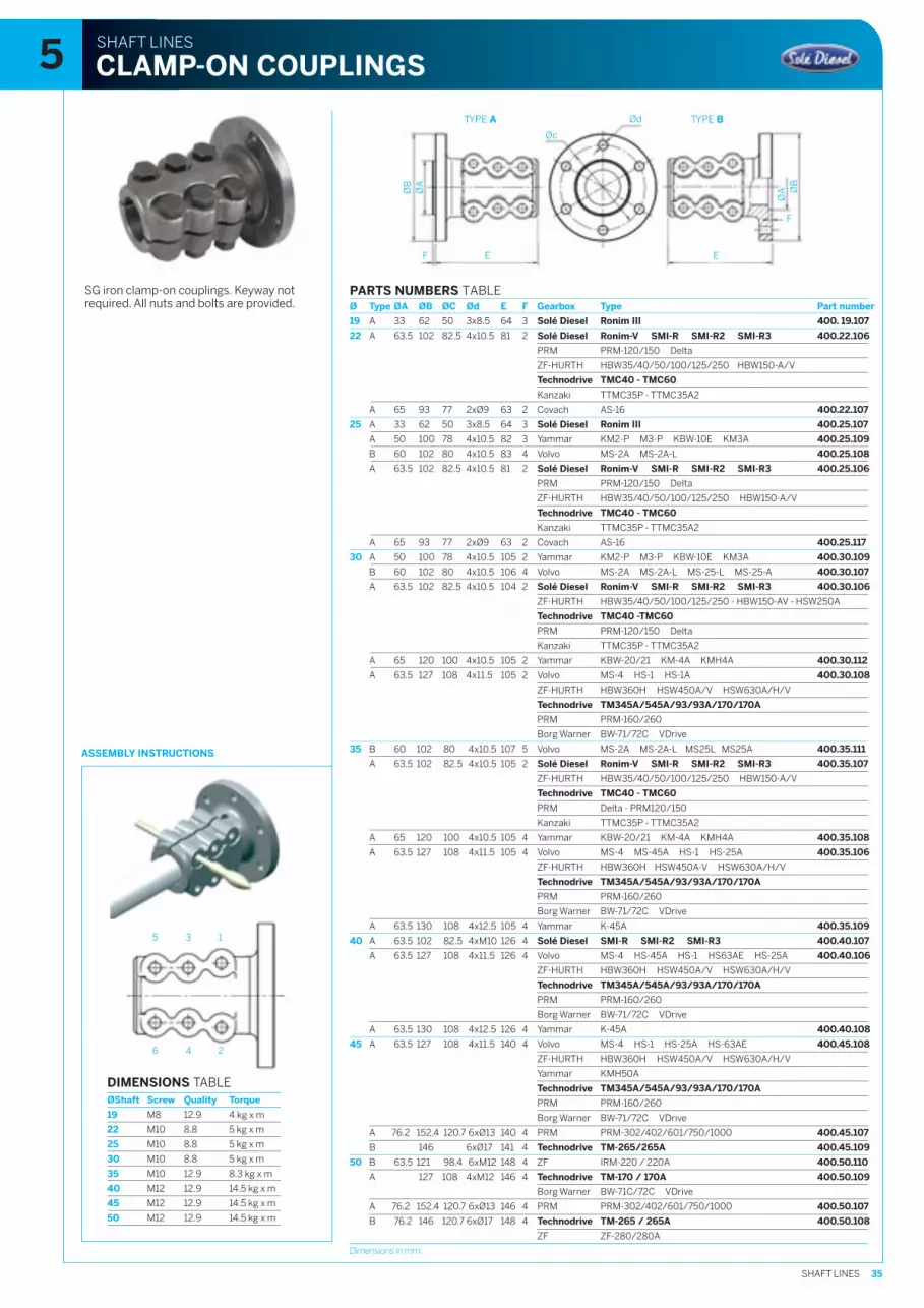
35SHAFT LINES
5 3 1
6 4 2
SHAFT LINES
CLAMP-ON COUPLINGS
TYPE A TYPE BØd
Øc
E
ØA
ØB
E
ØA Ø
B
F
F
ASSEMBLY INSTRUCTIONS
SG iron clamp-on couplings. Keyway notrequired. All nuts and bolts are provided.
PARTS NUMBERS TABLEØ Type ØA ØB ØC Ød E F Gearbox Type Part number
19 A 33 62 50 3x8.5 64 3 Solé Diesel Ronim III 400. 19.107
22 A 63.5 102 82.5 4x10.5 81 2 Solé Diesel Ronim-V SMI-R SMI-R2 SMI-R3 400.22.106
PRM PRM-120/150 Delta
ZF-HURTH HBW35/40/50/100/125/250 HBW150-A/V
Technodrive TMC40 - TMC60
Kanzaki TTMC35P - TTMC35A2
A 65 93 77 2xØ9 63 2 Covach AS-16 400.22.107
25 A 33 62 50 3x8.5 64 3 Solé Diesel Ronim III 400.25.107
A 50 100 78 4x10.5 82 3 Yammar KM2-P M3-P KBW-10E KM3A 400.25.109
B 60 102 80 4x10.5 83 4 Volvo MS-2A MS-2A-L 400.25.108
A 63.5 102 82.5 4x10.5 81 2 Solé Diesel Ronim-V SMI-R SMI-R2 SMI-R3 400.25.106
PRM PRM-120/150 Delta
ZF-HURTH HBW35/40/50/100/125/250 HBW150-A/V
Technodrive TMC40 - TMC60
Kanzaki TTMC35P - TTMC35A2
A 65 93 77 2xØ9 63 2 Covach AS-16 400.25.117
30 A 50 100 78 4x10.5 105 2 Yammar KM2-P M3-P KBW-10E KM3A 400.30.109
B 60 102 80 4x10.5 106 4 Volvo MS-2A MS-2A-L MS-25-L MS-25-A 400.30.107
A 63.5 102 82.5 4x10.5 104 2 Solé Diesel Ronim-V SMI-R SMI-R2 SMI-R3 400.30.106
ZF-HURTH HBW35/40/50/100/125/250 - HBW150-AV - HSW250A
Technodrive TMC40 -TMC60
PRM PRM-120/150 Delta
Kanzaki TTMC35P - TTMC35A2
A 65 120 100 4x10.5 105 2 Yammar KBW-20/21 KM-4A KMH4A 400.30.112
A 63.5 127 108 4x11.5 105 2 Volvo MS-4 HS-1 HS-1A 400.30.108
ZF-HURTH HBW360H HSW450A/V HSW630A/H/V
Technodrive TM345A/545A/93/93A/170/170A
PRM PRM-160/260
Borg Warner BW-71/72C VDrive
35 B 60 102 80 4x10.5 107 5 Volvo MS-2A MS-2A-L MS25L MS25A 400.35.111
A 63.5 102 82.5 4x10.5 105 2 Solé Diesel Ronim-V SMI-R SMI-R2 SMI-R3 400.35.107
ZF-HURTH HBW35/40/50/100/125/250 HBW150-A/V
Technodrive TMC40 - TMC60
PRM Delta - PRM120/150
Kanzaki TTMC35P - TTMC35A2
A 65 120 100 4x10.5 105 4 Yammar KBW-20/21 KM-4A KMH4A 400.35.108
A 63.5 127 108 4x11.5 105 4 Volvo MS-4 MS-45A HS-1 HS-25A 400.35.106
ZF-HURTH HBW360H HSW450A-V HSW630A/H/V
Technodrive TM345A/545A/93/93A/170/170A
PRM PRM-160/260
Borg Warner BW-71/72C VDrive
A 63.5 130 108 4x12.5 105 4 Yammar K-45A 400.35.109
40 A 63.5 102 82.5 4xM10 126 4 Solé Diesel SMI-R SMI-R2 SMI-R3 400.40.107
A 63.5 127 108 4x11.5 126 4 Volvo MS-4 HS-45A HS-1 HS63AE HS-25A 400.40.106
ZF-HURTH HBW360H HSW450A/V HSW630A/H/V
Technodrive TM345A/545A/93/93A/170/170A
PRM PRM-160/260
Borg Warner BW-71/72C VDrive
A 63.5 130 108 4x12.5 126 4 Yammar K-45A 400.40.108
45 A 63.5 127 108 4x11.5 140 4 Volvo MS-4 HS-1 HS-25A HS-63AE 400.45.108
ZF-HURTH HBW360H HSW450A/V HSW630A/H/V
Yammar KMH50A
Technodrive TM345A/545A/93/93A/170/170A
PRM PRM-160/260
Borg Warner BW-71/72C VDrive
A 76.2 152.4 120.7 6xØ13 140 4 PRM PRM-302/402/601/750/1000 400.45.107
B 146 6xØ17 141 4 Technodrive TM-265/265A 400.45.109
50 B 63.5 121 98.4 6xM12 148 4 ZF IRM-220 / 220A 400.50.110
A 127 108 4xM12 146 4 Technodrive TM-170 / 170A 400.50.109
Borg Warner BW-71C/72C VDrive
A 76.2 152.4 120.7 6xØ13 146 4 PRM PRM-302/402/601/750/1000 400.50.107
B 76.2 146 120.7 6xØ17 148 4 Technodrive TM-265 / 265A 400.50.108
ZF ZF-280/280A
DIMENSIONS TABLEØShaft Screw Quality Torque
19 M8 12.9 4 kg x m
22 M10 8.8 5 kg x m
25 M10 8.8 5 kg x m
30 M10 8.8 5 kg x m
35 M10 12.9 8.3 kg x m
40 M12 12.9 14.5 kg x m
45 M12 12.9 14.5 kg x m
50 M12 12.9 14.5 kg x m
Dimensions in mm.
5
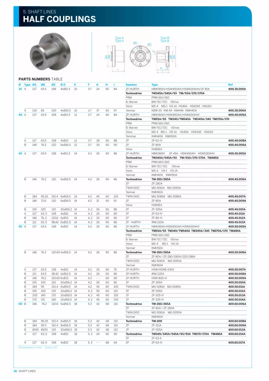
36 SHAFT LINES
ØCØD
ØA
ØB
GHI
I
ØA
ØB
Type AType A
Type BType B
5. SHAFT LINES
HALF COUPLINGS
E
F
PARTS NUMBERS TABLEØ Type ØA ØB ØC Ø D E F G H I Gearbox Type Ref
35 A 127 63.5 108 4xØ11.5 10 3.7 24 60 84 ZF-HURTH HBW360H/HSW450AH/HSW630AHV/ZF 45A 400.35.005A
Technodrive TM345A/545A/93 TM/93A/170/170A
PRM PRM-160/260
B. Warner BW-71C/72C VDrive
Volvo MS-4 MS-1 HS-1A HS45A HS63AE HS63IV
A 120 65 100 4xØ10.5 10 3.7 37 60 97 Yanmar KBW-20 KM-4A KMH4A KMH40A 400.35.006A
40 A 127 63.5 108 4xØ11.5 12 3.7 24 60 84 ZF-HURTH HBW360H/HSW450AH/HSW630AHV 400.40.005A
Technodrive TM93A/93 TM345/TM545A TM345A/345 TM170A/170
PRM PRM-160/260
B. Warner BW-71C/72C VDrive
Volvo MS-4 MS-1 HS-1A HS45A HS63AE HS63IV
Yammar KMH40A KMH50A
A 127 63,5 108 4xØ12 12 3.7 28 60 88 ZF ZF-63-IV 400.40.008A
B 146 76.2 120 6xØ16.5 12 3.7 30 60 90 ZF ZF-80A 400.40.006A
Volvo HS80EA
45 A 127 63.5 108 4xØ11.5 14 4.2 26 60 86 ZF-HURTH HBW360H ZF-45A HSW450AH HSW630AHV 400.45.005A
Technodrive TM345A/545A/93 TM/93A/170/170A TM485A
PRM PRM-160/260
B. Warner BW-71C/72C VDrive
Volvo MS-4 HS-1 HS-1A
Yanmar KMH40A KMH50A
B 146 76.2 120 6xØ16.5 14 4.2 26 60 86 Technodrive TM-265/265A 400.45.006A
ZF ZF-280A
TWIN DISC MG-5061A MG-5050A
Yanmar KMH60A
B 184 95.25 152.4 6xØ19.5 14 4.2 45 60 105 TWIN DISC MG-5085A MG-5085A 400.45.007A
B 146 72.6 120 6xØ16.5 14 4.2 31 60 91 ZF ZF-80A 400.45.009A
Volvo HS80EA
B 155 100 125 10xØ16.2 14 4, 2 26 60 86 ZF ZF-305A 400.45.010A
A 127 63, 5 108 4xØ12 14 4, 2 20 60 80 ZF ZF-63-IV 400.45.011A
B 146 76, 2 120,6 6xØ13 14 4, 2 20 60 80 ZF ZF-80-IV 400.45.012A
B 121 63, 5 98,42 6xØ12.5 14 4, 2 26 60 86 ZF - HURTH IRM 220A 400.45.013A
50 A 127 63.5 108 4xØ12 14 4.2 26 60 86 ZF-HURTH HBW360H/HSW450AH/HSW630AHV 400.50.005A
Technodrive TM93A/93 TM345/TM545A TM345A/345 TM170A/170 TM485A
PRM PRM-160/260
B. Warner BW-71C/72C VDrive
Volvo MS-4 MS-1 HS-1A
Yanmar KMH50A
B 146 76.2 120.65 6xØ16.5 14 4.2 26 60 86 Technodrive TM-265/265A 400.50.006A
ZF ZF-80A / ZF-280/280A/220/286A
TWIN DISC MG-5061A MG-5050A
Yanmar KMH60A
A 127 63.5 108 4xØ12 14 4.2 20 60 76 ZF-HURTH HSW/HSWE-630V 400.50.007A
B 121 63.5 98.42 6xØ12.5 14 4.2 26 60 86 ZF-HURTH IRM-220A 400.50.008A
B 146 76.2 120.65 6xØ13 14 4.2 - - - 60 80 ZF-HURTH HSW-800-VI 400.50.009A
B 155 100 125 10xØ16.2 14 4.2 26 60 86 ZF ZF-305A 400.50.010A
B 184 95 152.4 6xØ19.5 14 4.2 45 60 105 TWIN DISC MG-5081A MG-5085A 400.50.011A
B 155 100 125 10xØ16.2 14 4, 2 50 60 110 ZF ZF-305A 400.50.012A
B 205 140 170 10xØ18.5 14 4, 2 45 60 105 ZF ZF-325-IV 400.50.013A
B 170 115 140 12xØ16.5 14 4, 2 45 60 105 ZF ZF-325-IV 400.50.014A
60 B 146 76.2 120.6 6xØ16.5 18 5.3 42 68 110 Technodrive TM-265/265A 400.60.006A
ZF ZF-80A / ZF-280A
TWIN DISC MG-5061A MG-5050A
Yanmar KMH60A
B 184 95.25 152.4 6xØ16.5 18 5.3 42 68 110 Technodrive TM-200 400.60.008A
B 184 95.3 152.4 8xØ16.5 18 5.3 42 68 110 ZF ZF-311A 400.60.009A
B Ø155 Ø100 125 10xØ16.5 18 5.3 42 68 110 ZF ZF-305A 400.60.013A
A 127 63, 5 108 4xØ12 18 5, 3 24 66 90 Technodrive TM345/345A/545A/93/93A TM170/170A TM485A 400.60.014A
ZF ZF-63-A
A 127 63, 5 108 4xØ12 18 5, 3 --- 68 64 ZF ZF-63-IV 400.60.017A
Dimensions in mm. Cone 1:10
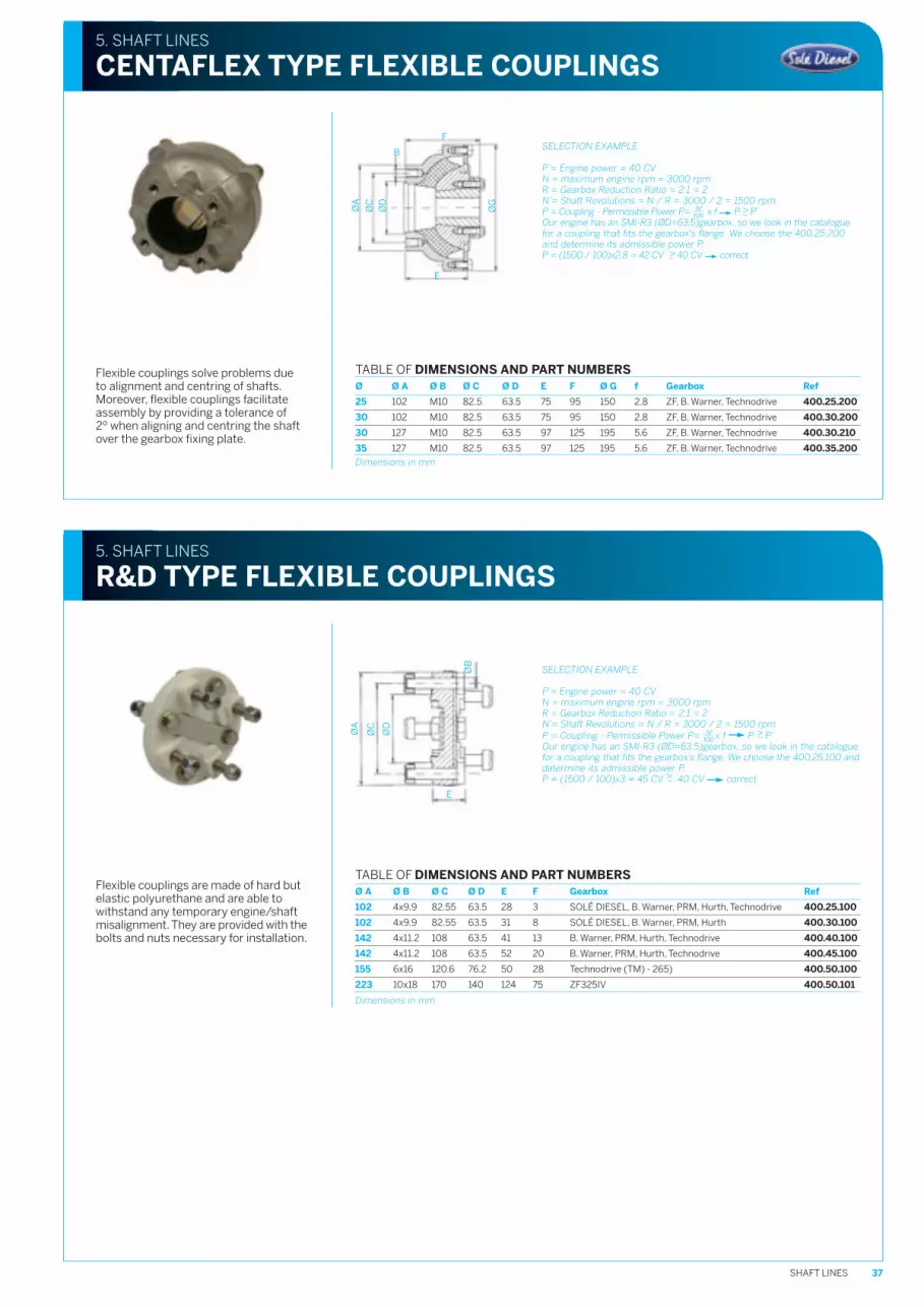
37SHAFT LINES
Flexible couplings are made of hard butelastic polyurethane and are able towithstand any temporary engine/shaftmisalignment. They are provided with thebolts and nuts necessary for installation.
SELECTION EXAMPLE
P’= Engine power = 40 CVN = maximum engine rpm = 3000 rpmR = Gearbox Reduction Ratio = 2:1 = 2N’= Shaft Revolutions = N / R = 3000 / 2 = 1500 rpmP = Coupling - Permissible Power P= x f P >– P’Our engine has an SMI-R3 (ØD=63.5)gearbox, so we look in the cataloguefor a coupling that fits the gearbox's flange. We choose the 400.25.100 anddetermine its admissible power P.P = (1500 / 100)x3 = 45 CV >– 40 CV correct
ØA
ØC
ØD
E
ØB
5. SHAFT LINES
R&D TYPE FLEXIBLE COUPLINGS
TABLE OF DIMENSIONS AND PART NUMBERSØ A Ø B Ø C Ø D E F Gearbox Ref
102 4x9.9 82.55 63.5 28 3 SOLÉ DIESEL, B. Warner, PRM, Hurth, Technodrive 400.25.100
102 4x9.9 82.55 63.5 31 8 SOLÉ DIESEL, B. Warner, PRM, Hurth 400.30.100
142 4x11.2 108 63.5 41 13 B. Warner, PRM, Hurth, Technodrive 400.40.100
142 4x11.2 108 63.5 52 20 B. Warner, PRM, Hurth, Technodrive 400.45.100
155 6x16 120.6 76.2 50 28 Technodrive (TM) - 265) 400.50.100
223 10x18 170 140 124 75 ZF325IV 400.50.101
Dimensions in mm
Flexible couplings solve problems dueto alignment and centring of shafts.Moreover, flexible couplings facilitateassembly by providing a tolerance of2º when aligning and centring the shaftover the gearbox fixing plate.
SELECTION EXAMPLE
P’= Engine power = 40 CVN = maximum engine rpm = 3000 rpmR = Gearbox Reduction Ratio = 2:1 = 2N’= Shaft Revolutions = N / R = 3000 / 2 = 1500 rpmP = Coupling - Permissible Power P= x f P >– P’Our engine has an SMI-R3 (ØD=63.5)gearbox, so we look in the cataloguefor a coupling that fits the gearbox's flange. We choose the 400.25.200and determine its admissible power P.P = (1500 / 100)x2.8 = 42 CV >– 40 CV correct
ØG
F
B
ØD
ØC
ØA
E
5. SHAFT LINES
CENTAFLEX TYPE FLEXIBLE COUPLINGS
TABLE OF DIMENSIONS AND PART NUMBERSØ Ø A Ø B Ø C Ø D E F Ø G f Gearbox Ref
25 102 M10 82.5 63.5 75 95 150 2.8 ZF, B. Warner, Technodrive 400.25.200
30 102 M10 82.5 63.5 75 95 150 2.8 ZF, B. Warner, Technodrive 400.30.200
30 127 M10 82.5 63.5 97 125 195 5.6 ZF, B. Warner, Technodrive 400.30.210
35 127 M10 82.5 63.5 97 125 195 5.6 ZF, B. Warner, Technodrive 400.35.200
Dimensions in mm

38 SHAFT LINES
E L
C B
A DØ
F
5. SHAFT LINES
SHAFTS
STANDARD PART NUMBERS TABLE
Diameter ØL (mm) 19 25 30 35 40 45 50 60
1000 403.19.100 403.25.100M 403.30.100M
1200 403.19.120 403.25.120M 403.30.120M
1400 403.19.140 403.25.140M 403.30.140M 403.35.140M
1600 403.19.160 403.25.160M 403.30.160M 403.35.160M 403.40.160M 403.45.160M
1700 403.50.170M
1800 403.19.180 403.25.180M 403.30.180M 403.35.180M 403.40.180M 403.45.180M
2000 403.19.200 403.25.200M 403.30.200M 403.35.200M 403.40.200M 403.45.200M 403.50.200M 403.60.200M
2250 403.19.225 403.25.225M 403.30.225M 403.35.225M 403.40.225M 403.45.225M 403.50.225M 403.60.225M
2500 403.19.250 403.25.250M 403.30.250M 403.35.250M 403.40.250M 403.45.250M 403.50.250M 403.60.250M
3000 403.25.300M 403.30.300M 403.35.300M 403.40.300M 403.45.300M 403.50.300M 403.60.300M
3500 403.25.350M 403.30.350M 403.35.350M 403.40.350M 403.45.350M 403.50.350M 403.60.350M
4000 403.60.400M
Dimensions in mm
DIMENSIONS TABLE
Diameter Ø19 25 30 35 40 45 50 60
A M14x1.5 M16x1.5 M20x1.5 M24x2 M24x2 M30x2 M36x3 M42x3
B 25 25 25 32 32 40 40 50
C 38 55 73 84 94 104 110 130
D Ø14.8 Ø19.5 Ø22.7 Ø26.6 Ø30.6 Ø34.6 Ø39 Ø47
E 5 6 8 10 12 14 14 18
F 5.2 3.5 4 4.5 4.5 5 5 6
Cone 3°30’ 1:10(2º52') 1:10(2º52') 1:10(2º52') 1:10(2º 52') 1:10(2º52') 1:10(2º52') 1:10(2º52')
TABLE OF PART NUMBERS AISI- 329
Diameter ØL (mm) 19 25 30 35 40 45 50 60
1000 403.25.100AM 403.30.100AM
1200 403.25.120AM 403.30.120AM
1400 403.25.140AM 403.30.140AM 403.35.140AM
1600 403.25.160AM 403.30.160AM 403.35.160AM 403.40.160AM 403.45.160AM
1700 403.50.170AM
1800 403.25.180AM 403.30.180AM 403.35.180AM 403.40.180AM 403.45.180AM
2000 403.25.200AM 403.30.200AM 403.35.200AM 403.40.200AM 403.45.200AM 403.50.200AM 403.60.200AM
2250 403.25.225AM 403.30.225AM 403.35.225AM 403.40.225AM 403.45.225AM 403.50.225AM 403.60.225AM
2500 403.25.250AM 403.30.250AM 403.35.250AM 403.40.250AM 403.45.250AM 403.50.250AM 403.60.250AM
3000 403.25.300AM 403.30.300AM 403.35.300AM 403.40.300AM 403.45.300AM 403.50.300AM 403.60.300AM
3500 403.25.350AM 403.30.350AM 403.35.350AM 403.40.350AM 403.45.350AM 403.50.350AM 403.60.350AM
4000 403.60.400AM
All shafts can be supplied with clockwise thread by ordering 404.__.__ instead of 403.__.__, except for Ø19 shafts/
Ground (h9 finish) standard or AISI-329stainless steel shafts machined on the endof the propeller, with propeller key, nut withanode and safety washer.Taper 1:10 according to norm ISO-4566.Except for 19 mm Ø shafts.
AISI 329 steel offers mechanical propertiesthat are superior to those of standard steel,allowing for a smaller-diameter shaftcapable of withstanding greater stresses.This becomes an advantage for shipsrequiring greater engine power withoutsacrificing the existing sterntube andpropeller strut, thus representing a majorsavings for the shipowner.

39SHAFT LINES
E
5. SHAFT LINES
DOUBLE TAPER SHAFTS
A
BCD
F Ø F
L
H
TYPE A
G
TYPE B
H
F F
C B
A
DJ
GI
Ø
L
All shafts can be supplied with clockwise thread byordering 410.__.__ instead of 409.__.__
Ground (h9 finish) standard or AISI-329stainless steel shafts machined on both ends,with key, nut and safety washer.Taper 1:10 according to norm ISO-4566
Solé Diesel can supply the tapered shaftswith a length in accordance with thecustomer's needs.(See form chapter)
AISI 329 steel offers mechanical propertiesthat are superior to those of standard steel,allowing for a smaller-diameter shaft capableof withstanding greater stresses. This becomesan advantage for ships requiring greater enginepower without sacrificing the existing sterntubeand propeller strut, thus representing a majorsavings for the shipbuilder.
DIMENSIONS TABLETYPE B TYPE A
Ø35 Ø40 Ø45 Ø50 Ø60
A M24x2 M24x2 M30x2 M36x2 M42x2
B 32 32 40 40 50
C 84 94 104 110 130
D 58 58 58 58 65
E 10 12 14 14 18
F 4.5 4.5 5 5 6
G Ø26.6 Ø30.6 Ø34.6 Ø39 Ø47
H Ø29.2 Ø34.2 Ø39.2 Ø44.2 Ø53.5
I M24x2 M24x2 M27x2 --- ---
J 25 25 27 --- ---
Cone 1:10 (2º52') 1:10 (2º52') 1:10 (2º52') 1:10 (2º 52') 1:10(2º52')
Dimensions in mm
STANDARD PART NUMBERS TABLEL (mm) Ø35 Ø40 Ø45 Ø50 Ø60
2000 409.35.200M 409.40.200M 409.45.200M 409.50.200M 409.60.200M
2250 409.35.225M 409.40.225M 409.45.225M 409.50.225M 409.60.225M
2500 409.35.250M 409.40.250M 409.45.250M 409.50.250M 409.60.250M
3000 409.35.300M 409.40.300M 409.45.300M 409.50.300M 409.60.300M
3500 409.35.350M 409.40.350M 409.45.350M 409.50.350M 409.60.350M
4000 409.35.400M 409.40.400M 409.45.400M 409.50.400M 409.60.400M
TABLE OF PART NUMBERS AISI - 329L (mm) Ø35 Ø40 Ø45 Ø50 Ø60
2000 409.35.200AM 409.40.200AM 409.45.200AM 409.50.200AM 409.60.200AM
2250 409.35.225AM 409.40.225AM 409.45.225AM 409.50.225AM 409.60.225AM
2500 409.35.250AM 409.40.250AM 409.45.250AM 409.50.250AM 409.60.250AM
3000 409.35.300AM 409.40.300AM 409.45.300AM 409.50.300AM 409.60.300AM
3500 409.35.350AM 409.40.350AM 409.45.350AM 409.50.350AM 409.60.350AM
4000 409.35.400AM 409.40.400AM 409.45.400AM 409.50.400AM 409.60.400AM

40 SHAFT LINES
Solé Diesel also has rigid sterntubes for shafts diameters 25, 30, 35, 45, 50 and 60.Queries concerning other features should be directed to the commercial department.
5. SHAFT LINES
RIGID STERNTUBES
Sterntube assembly with rubber bearingat stern support, stuffing box with fix studs(prepared for additional cooling) andstainless steel pipe.
A L D ECB
F
G
F
G
ØT
Sterntube assembly with rubber bearingat stern support, threaded stuffing box(prepared for additional cooling) andstainless steel pipe.
HF
G
A L B DC E
ØT
HF
G
5. SHAFT LINES
COMPLETE STERNTUBE ASSEMBLIES
PART NUMBERS TABLEØ 19 Ø 25 Ø 30 Ø 35
L(mm) Type A Type B Type A Type B Type A Type B
400 481.19.040 481.25.040A 481.25.040 481.30.040A 481.30.040 -- --
500 481.19.050 481.25.050A 481.25.050 481.30.050A 481.30.050 481.35.050A 481.35.050
600 481.19.060 481.25.060A 481.25.060 481.30.060A 481.30.060 481.35.060A 481.35.060
700 481.19.070 481.25.070A 481.25.070 481.30.070A 481.30.070 481.35.070A 481.35.070
800 481.19.080 481.25.080A 481.25.080 481.30.080A 481.30.080 481.35.080A 481.35.080
900 481.19.090 481.25.090A 481.25.090 481.30.090A 481.30.090 481.35.090A 481.35.090
1000 481.19.100 481.25.100A 481.25.100 481.30.100A 481.30.100 481.35.100A 481.35.100
1200 -- 481.25.120A 481.25.120 481.30.120A 481.30.120 481.35.120A 481.35.120
1400 -- -- -- -- -- 481.35.140A 481.35.140
Type A. Full sterntube with Type A bearing bushing. Type B. Full sterntube with Type B bearing bushing.
PART NUMBERS TABLEL(mm) Ø 40 Ø 45 Ø 50
600 481.40.060 481.45.060 --
700 481.40.070 481.45.070 --
800 481.40.080 481.45.080 481.50.080
900 481.40.090 481.45.090 481.50.090
1000 481.40.100 481.45.100 481.50.100
1100 481.40.110 481.45.110 --
1200 481.40.120 481.45.120 481.50.120
1300 481.40.130 481.45.130 --
1400 481.40.140 481.45.140 --
1500 481.40.150 481.50.150 481.50.150
1600 -- -- 481.50.160
2
1
1
2
DIMENSIONS TABLE
A B C D E ØT F G F G
Ø Type A Type B Type A Type B Type A Type B
19 100 --- 40 0 82 55 Ø28 2xØ9 68 2xØ9 --- 68 ---
25 120 80 23 15 104 75 Ø40 2xØ8.5 74 2xØ12 2xØ8.5 92 86
30 120 75 23 15 105 80 Ø44 2xØ8.5 78 2xØ12 2xØ8.5 98 94
35 160 105 23 15 95 80 Ø48.3 2xØ8.5 80 2xØ12 2xØ8.5 120 98
Dimensions in mm. ØT= ØTube
21
DIMENSIONS TABLE
Ø A B C D E ØT F G H F G H
40 114 60 15 110 91 Ø60 4xØ8.5 112 40 4xØ8.5 112 40
45 123 60 15 125 100 Ø60 4xØ8.5 112 40 4xØ8.5 112 40
50 141.2 75 15 105 105 Ø76.1 4xØ9 130 50 4xØ9 130 50
Dimensions in mm. ØT= ØTube
21
2 1
12

41SHAFT LINES
Bronze water-cooled stuffing box, withpacking, rubber sleeve, and stainless steelclamps. Additional direct cooling allowedby this system.
Sealed bronze oil-cooled stuffing box,self lubricated bearing, rubber sleeve,stainless steel clamps and plastic tank.(provided separately)
ØA
Part number
400.25.126 ØA = Ø6
400.30.126 ØA = Ø6
400.35.126 ØA = Ø6
Ø
25
30
35
Reference
400.25.037
Ø6
SAE 15W40 oil
5. SHAFT LINES
FLOATING STUFFING BOX
WATER-COOLED
OIL BATH COOLED
Part number
400.19.125
400.25.125A
400.30.125A
400.35.125A
Ø
19
25
30
35
Part number
400.40.125
400.45.125
400.50.125
Ø
40
45
50
Part number
400.40.020
400.45.020
400.50.020
Ø
40
45
50
TABLE OF DIMENSIONS AND PART NUMBERSStuffing box with fix studs Threaded stuffing box Special tool
Dimensions in mm
TABLE OF DIMENSIONS AND PART NUMBERS
Dimensions in mm
TECHNICAL SPECIFICATIONPressure 100 kg/cm2
Temperature 250 ºC
Speed 15 m/s
pH 1 - 13
Braided packing to achievesterntube water-tightness.Manufactured with acrylicfibre threads andlubricated with 40% Teflon.Supplied by the metre.
5. SHAFT LINES
PACKING
TABLE OF DIMENSIONSAND PART NUMBERSA x B Ø Shaft Ref
6 x 6 Ø19 - 25 - 35 M95200060
8 x 8 Ø30 - 40 - 45 - 50 M95200080
10 x 10 Ø60 M95200100
Dimensions in mm
Bearing bushing assembly equipped withseawater-lubricated rubber bearing.
ØB
5. SHAFT LINES
BEARING BUSHING ASSEMBLY
TYPE A
TYPE B
Dimensions in mm.
TABLE OF DIMENSIONS AND PART NUMBERSØ Shaft Type A ØB C D E L Ref
19 A --- 2 x Ø9 68 --- --- 93 400.19.165
25 A 48 2 x Ø12 92 --- 20 120 400.25.168A
B 55 2 x Ø8.5 86 --- 43 51 400.25.166
30 A 52 2 x Ø12 98 --- 20 120 400.30.168A
B 62 2 x Ø8.5 94 --- 50 60 400.30.166
35 A 56 2 x Ø12 120 --- 20 160 400.35.168A
B 66 2 x Ø10.5 98 --- 56 105 400.35.166
40 B 75 4 x Ø8.5 112 40 78 85 400.40.166
45 B 80 4 x Ø8.5 112 40 83 90 400.45.166
50 B 90 4 x Ø9 130 50 90 103 400.50.166
C
ØB
C C
D
ØA
E
L

42 SHAFT LINES
A
B
5. SHAFT LINES
ZINC ANODE NUTS
5. SHAFT LINES
STRUTS
Bronze struts. Includes the self-lubricatingrubber bearing.
ØGA B
S
D
EIF
H
J
C
TYPE ATYPE B
H
S
ITABLE OF DIMENSIONS AND PART NUMBERSØ Type A B C D E F G H I J S Ref
19 A --- --- --- --- --- --- --- 76 339 --- 18 400.19.580
25 A --- --- --- --- --- --- --- 102 370 --- 22 400.25.581
30 B 57 35 57 28 42 323 Ø18 115 400 10º 28 400.30.581
35 B 65 33 65 23 45 360 Ø25 142 450 10º 30 400.35.581
40 B 75 11 75 96 45 362 Ø25 165 450 10º 32 400.40.581
45 B 80 --- 80 92 50 460 Ø25 182 565 10º 36 400.45.581
50 B 90 --- 90 57 60 460 Ø25 205 565 10º 39 400.50.581
Dimensions in mm
Neoprene-based bearings with brasscover. Water-lubricated.
ØA
C
ØB
5. SHAFT LINES
RUBBER BEARINGSTABLE OF DIMENSIONSAND PART NUMBERSØA B (in) B (mm) C (in) C (mm) Ref
19 1 1/4" 31.75 3" 76.2 400.19.070
25 1 1/2" 38.1 4" 100.0 400.25.070
30 1 3/4" 44.45 4" 100.0 400.30.070
35 1 7/8" 47.62 5 1/2" 139.7 400.35.070
40 2 1/8" 54 6 1/2" 165.0 400.40.070
45 2 3/8" 60.3 7" 177.8 400.45.070
50 2 5/8" 66.7 8" 203.2 400.50.070
TABLE OF DIMENSIONS AND PART NUMBERSØShaft Ø A Ø B C Ref
19 32 14.5 5 400.19.090
25 40 17 5 400.25.090
30 48 21 7.5 400.30.090
35 60 27 9.5 400.35.090
40 60 27 9.5 400.35.090
45 66 31 13 400.45.090M
50 66 37 13 400.50.090M
60 90 43 17 400.60.090Made of standard-grade stainless steel.This part prevents the propeller nut fromcoming unthreaded.
C
ØB
ØA
5. SHAFT LINES
PROPELLER NUT FASTENER
Dimensions in mm
TABLE OF DIMENSIONS AND PART NUMBERS
Ref. NUT ASSEMBLYAnti-clockwise Clockwise
Ø Shaft A B thread1 thread 2
19
25 M16x1.5 58 400.25.193M 400.25.194M
30 M20x1.5 69 400.30.193M 400.30.194M
35 M24x2 85 400.35.193M 400.35.194M
40 M24x2 85 400.35.193M 400.35.194M
45 M30x2 110 400.45.193M 400.45.194M
50 M36x3 115 400.50.193M 400.50.194M
60 M42x3 147 400.60.193M 400.60.194M
Dimensions in mm.
1 Shaft-mounted for clockwise-turning propeller.2 Shaft-mounted for anticlockwise-turning propeller.
SCREW NUTØ Shaft A FASTENER Ref ANODE
19 M14x1.5
25 M16x1.5 541.03.157 400.25.092
30 M20x1.5 541.03.258 400.30.092
35 M24x2 541.03.258 400.35.092
40 M24x2 541.03.258 400.35.092
45 M30x2 541.03.310 400.45.092
50 M36x3 541.03.310 400.45.092
60 M42x3 541.03.310 400.60.092

43PROPELLERS
PROPELLERS
PROPELLERS FOR TECHNODRIVE SPROP60 SAIL DRIVE6
6. PROPELLERS
PROPELLERS FOR SELVA SAIL-DRIVE
ALL OF THESE PROPELLERS ARECOMPATIBLE WITH:Volvo 110S, Volvo 120S, Yanmar SD20/31/40-4T,BUCK, NANNI y SONIC Sail Drives
Dimensions in mm
Part number
Ø Pitch Surface LH
Part number
Ø Pitch Surface LH
TABLE OF DIMENSIONSAND PART NUMBERS
TABLE OF DIMENSIONSAND PART NUMBERS
TABLE OF DIMENSIONSAND PART NUMBERS
Part number
Ø Pitch Surface RH LH
TABLE OF DIMENSIONSAND PART NUMBERS
Part number
Ø Pitch Surface RH LH
Two-bladed folding propellers made of nickel-aluminium bronze. Statically and dynamicallybalanced. Reduce drag while sail sailing.Only available for the SELVA sail-drive striatedshaft.
Aluminium three-bladed fixed propellers, staticallyand dynamically balanced.Only available for SELVA sail-drive striated shafts.
Dimensions in mm
Dimensions in mm
44.00.1408
44.00.1410
14
14
2-BLADED FOLDINGPROPELLERS
42.00.1307
42.00.1507
42.00.1508
42.00.1510
42.00.1609
13
15
15
15
16
7
7
8
10
9
25%
25%
25%
25%
25%
THREE-BLADED FIXEDPROPELLERS
8
10
50%
50%
Two-bladed folding propellers made of nickel-aluminium bronze. Statically and dynamicallybalanced.Reduce drag significantly when sailing.Only available for the TECHNODRIVEstriated sail-drive shaft.
41.10.1408
41.10.1410
41.10.1810
41.10.1811
41.10.1812
41.10.1813
41.10.1814
14
15
18
18
18
18
18
TABLE OF DIMENSIONSAND PART NUMBERS
Part number
Ø Pitch Surface LH
Dimensions in mm
Dimensions in mm
2-BLADED FOLDINGPROPELLERS
8
10
10
11
12
13
14
25%
25%
25%
25%
25%
25%
25%
Aluminium three-bladed fixed propellers, staticallyand dynamically balanced.Only available for sail-drive striated shaft
THREE-BLADED FIXEDPROPELLERS
Aluminium two-bladed fixed propellers,statically and dynamically balanced.Only available for TECHNODRIVE sail-drivestriated shafts.
TWO-BLADED FIXEDPROPELLERS
41.11.1408
41.11.1409
41.11.1609
14
14
16
8
9
9
25%
25%
25%
43.10.1409
43.10.1410
43.10.1610
43.10.1611
43.10.1711
43.10.1712
43.10.1713
43.10.1714
14
14
16
16
17
17
17
17
9
10
10
11
11
12
13
14
50%
50%
50%
50%
50%
50%
50%
50%

44 PROPELLERS
Designed specifically for medium to fast boats(15-35 knots) or work boats that demand highperformance and have restrictions on diameterwhile requiring a higher pitch. Made of high tensilemanganese bronze. High-precision static anddynamic balance. High skew blades reducenoticeably noise and vibrations induced in theboat's rudder and hull. To achieve bestperformance, an ogival-airfoil mixed blade profilehas been designed to minimise cavitation whilstproviding smooth and effective thrust. Propellersmade with antisinging edge. Diameter and pitchin inches.
46504353RC 45504353RC
46504646RC
46504648RC
46504651RC 45504651RC
46504653RC
46504656RC 45504656RC
46504658RC 45504658RC
46504663RC
46504863RC 45504863RC
46505358RC
46505363RC
46604646RC
46604648RC
46604651RC 45604651RC
46604653RC
46604656RC 45604656RC
46604658RC 45604658RC
46604863RC 45604863RC
46605358RC
46605363RC
46706351RC 45706351RC
46906351RC 45906351RC
3- and 4-bladed manganese bronze propellers,statically and dynamically balanced, 1:10 tapered(except propellers Ø19, 3º30'). Diameter and pitchin inches.
44.15.2320
44.15.2628
44.15.3118
44.15.3120
44.15.3123
44.15.3125
43.16.3126
44.15.3320
44.15.3323
44.16.3325
44.15.3623
44.15.3626
43.16.3826
46.19.3328 46.19.3328
46204141RC
46304136RC
46304138RC
46304141RC 45304141RC
46304143RC
46304146RC 45304146RC
46304148RC 45304148RC
46304348RC 45304348RC
46304351RC
46304648RC
46304648RC
46304353RC 45304353RC
46304656RC 45304656RC
46404136RC
46404138RC
46404141RC 45404141RC
46404143RC
46404146RC 45404146RC
46404148RC 45404148RC
46404348RC 45404348RC
46404351RC
46404353RC 45404353RC
46404646RC
46404648RC
46404651RC 45404651RC
46404653RC
46404656RC 45404656RC
46404658RC
46404663RC
6. PROPELLERS
PROPELLERS
6. PROPELLERS
SRX PROPELLERS
Dimensions in mm
25
30
35
TABLE OF DIMENSIONS AND PART NUMBERSPart number
shaft Ø Pitch Surface RH LH
Part number
shaft Ø Pitch Surface RH LH
PROPELLERS FOR PLANINGOR PROFESSIONAL CRAFT
40
45
50
60
17
18
18
18
18
18
18
18
19
21
21
18
18
18
18
18
18
19
21
21
25
25
75%
75%
75%
75%
75%
75%
75%
75%
75%
75%
75%
75%
75%
75%
75%
75%
75%
75%
75%
75%
75%
16
16
16
16
16
16
16
17
17
17
18
18
18
16
16
16
16
16
16
17
17
17
18
18
18
18
18
18
18
16
14
15
16
17
18
19
19
20
21
19
22
22
14
15
16
17
18
19
19
20
21
18
19
20
21
22
23
25
75%
75%
75%
75%
75%
75%
75%
75%
75%
75%
75%
75%
75%
75%
75%
75%
75%
75%
75%
75%
75%
75%
75%
75%
75%
75%
75%
75%
21
18
19
20
21
22
23
25
25
23
25
18
19
20
21
22
23
25
23
25
20
20
19
TABLE OF DIMENSIONS AND PART NUMBERSPart number
Ø shatf (mm) Diameter Pitch Surface % RH LH
9
10
12
12
12
12
12
13
13
13
13
14
14
15
8
11
7
8
9
10
10.5
8
9
10
11
9
10
10
51%
55%
51%
Part number
Surface % RH LH
72%
3-BLADED PROPELLERS 4-BLADED PROPELLERS

45PROPELLERS
44.205.2320
44.205.2628
44.205.3118
44.205.3120
44.205.3123
44.205.3125
43.206.3126
44.205.3318
44.205.3320
44.205.3323
44.206.3325
44.206.3328 46.209.3328
46.209.3331
44.205.3620
44.205.3623 46.208.3624
44.205.3626 46.208.3626
44.205.3628
46.209.3633
46.209.3636
46.209.3641
44.206.3818
44.206.3823
44.206.3826 43.206.3826
44.206.3828
44.206.3831 43.206.3831
44.206.3833 43.206.3833
44.206.3836
44.206.4126
44.206.4128 43.206.4128 46.209.4128
44.206.4131 43.206.4131 46.209.4131
44.206.4133 43.206.4133 46.209.4133 45.209.4133
44.206.4136 43.206.4136 46.209.4136
44.206.4138 43.206.4138 46.209.4138
44.206.4141 46.209.4141 45.209.4141
44.206.4143 46.209.4143
44.206.4328
44.206.4331 43.206.4331
44.206.4333 46.209.4333
43.206.4336
44.206.4636
44.25.2320
44.25.2628
44.25.3118
44.25.3120
44.25.3123
44.25.3125
43.26.3126
44.25.3318
44.25.3320
44.25.3323
44.26.3325
44.26.3328 46.29.3328
46.29.3331
44.25.3620
44.25.3623 46.28.3624
44.25.3626 46.28.3626
44.25.3628
46.29.3633
46.29.3636
46.29.3641
44.26.3818
44.26.3823
44.26.3826 43.26.3826
44.26.3828
44.26.3831 43.26.3831
44.26.3833 43.26.3833
44.26.3836
44.26.4126
6. PROPELLERS
PROPELLERS
Dimensions in mm
22
TABLE OF DIMENSIONS AND PART NUMBERSPart number
Ø shatf (mm) Diameter Pitch Surface % RH LH
9
10
12
12
12
12
12
13
13
13
13
13
13
14
14
14
14
14
14
14
15
15
15
15
15
15
15
16
16
16
16
16
16
16
16
17
17
17
17
18
9
10
12
12
12
12
12
13
13
13
13
13
13
14
14
14
14
14
14
14
15
15
15
15
15
15
15
16
8
11
7
8
9
10
10.5
7
8
9
10
11
12
8
9
10
11
13
14
16
7
9
10
11
12
13
14
10
11
12
13
14
15
16
17
11
12
13
14
14
8
11
7
8
9
10
10.5
7
8
9
10
11
12
8
9
10
11
1
14
16
7
9
10
11
12
13
14
10
Part number
Surface % RH LH
72
72
69
69
72
72
72
72
72
72
72
72
72
72
72
72
72
72
72
69
69
72
73
72
25
51
51
51
51
51
51
55
51
51
51
55
55
55
51
51
51
51
51
51
51
55
55
55
55
55
55
55
55
55
55
55
55
55
55
55
55
55
55
55
55
51
51
51
51
51
51
55
51
51
51
55
55
55
51
51
51
51
51
51
51
55
55
55
55
55
55
55
55

46 PROPELLERS
44.35.3623
44.35.3626
46.39.3633
46.39.3636
46.39.3641
44.36.3823
44.36.3826 43.36.3826
44.36.3828 43.36.3828
44.36.3831 43.36.3831
44.36.3833 43.36.3833
44.36.3836 46.39.3836
44.36.4126
44.36.4128 43.36.4128 46.39.4128
44.36.4131 43.36.4131 46.39.4131
44.36.4133 43.36.4133 46.39.4133 45.39.4133
44.36.4136 43.36.4136 46.39.4136
44.36.4138 43.36.4138 46.394138 45.39.4138
44.36.4141 43.36.4141 46.39.4141 45.39.4141
44.36.4143 46.39.4143 45.39.4143
44.36.4328
44.36.4331 43.36.4331
44.36.4333 43.36.4333 46.39.4333
44.36.4336 43.36.4336 46.39.4336
44.36.4338 43.36.4338 46.39.4338
44.36.4340 43.36.4340
44.36.4343 43.36.4343
44.36.4633 43.36.4633
44.36.4636 43.36.4636 46.39.4636
44.36.4638 43.36.4638 46.39.4638
44.36.4641 46.39.4641
44.36.4643 46.39.4643
44.36.48.38 46.38.4831
44.36.4833
44.36.4836 46.39.4836
44.36.4838 46.39.4838
44.36.4841 43.36.4841 z46.39.4841
44.36.4843 43.36.4843
46.39.4846
46.39.4848
46.49.4128
46.49.4131
46.49.4133 45.49.4133
46.49.4136
46.49.4138 45.49.4138
46.49.4141 45.49.4141
46.49.4143 45.49.4143
6. PROPELLERS
PROPELLERS
Dimensions in mm
25
TABLE OF DIMENSIONS AND PART NUMBERSPart number
Ø shatf (mm) Diameter Pitch Surface % RH LH
Part number
Surface % RH LH
30 14
14
14
14
14
15
15
15
15
15
15
16
16
16
16
16
16
16
16
17
17
17
17
17
17
17
18
18
18
18
18
19
19
19
19
19
19
19
19
9
10
13
14
16
9
10
11
12
13
14
10
11
12
13
14
15
16
17
11
12
13
14
15
16
17
13
14
15
16
17
12
13
14
15
16
17
18
19
51
51
55
55
55
55
55
55
55
55
55
55
55
55
55
55
55
55
55
55
55
55
55
55
55
55
55
55
55
55
55
55
55
55
55
55
55
55
55
72
72
72
72
72
72
72
72
72
72
72
72
72
72
72
72
72
72
72
72
72
72
72
72
72
72
72
72
72
72
72
72
72
72
72
72
72
72
35 16
16
16
16
16
16
16
11
12
13
14
15
16
17
72
72
72
72
72
72
72
44.26.4128 43.26.4128 46.29.4128
44.26.4131 43.26.4131 46.29.4131
44.26.4133 43.26.4133 46.29.4133 45.29.4133
44.26.4136 43.26.4136 46.29.4136
44.26.4138 43.26.4138 46.29.4138
44.26.4141 46.29.4141 45.29.4141
44.26.4143 46.29.4143
44.26.4328
44.26.4331 43.26.4331
44.26.4333 46.29.4333
43.26.4336
44.26.4636
16
16
16
16
16
16
16
17
17
17
17
18
11
12
13
14
15
16
17
11
12
13
14
14
55
55
55
55
55
55
55
55
55
55
55
55
44.46.4328
44.46.4331 43.46.4331
44.46.4333 43.46.4333 46.49.4333
44.46.4336 43.46.4336 46.49.4336
44.46.4338 43.46.4338 46.49.4338
44.46.4340 43.46.4340
44.46.4343 43.46.4343
44.46.4633 43.46.4633 46.49.4633
44.46.4636 43.46.4636 46.49.4636
44.46.4638 43.46.4638 46.49.4638
44.46.4641 46.49.4641
17
17
17
17
17
17
17
18
18
18
18
11
12
13
14
15
16
17
13
14
15
16
55
55
55
55
55
55
55
55
55
55
55
72
72
72
72
72
72
72
72
72
72
72

47PROPELLERS
44.46.4643 46.49.4643
46.48.4831
44.46.4833
44.46.4836 46.49.4836
44.46.4838 43.46.4838 46.49.4838
44.46.4841 43.46.4841 46.49.4841
44.46.4843 43.46.4843
46.49.4846
46.49.4848
44.46.5133 43.46.5133
44.46.5138 43.46.5138
44.46.5141 43.46.5141
44.46.5143 43.46.5143
46.49.5153
44.46.5341 43.46.5341
44.46.5343 43.46.5343
44.46.5346 43.46.5346 46.49.5346
46.48.5537 45.48.5537
44.46.5641 43.46.5641
44.46.5643 43.46.5643 46.48.5543 45.48.5543
44.46.5646 43.46.5646 46.49.5646 45.49.5646
46.48.5648 45.48.5648
46.48.5851 45.48.5851
46.59.4633
46.59.4636
46.59.4638
46.59.4641
46.59.4643
46.59.4646
46.58.4831
46.59.4836
46.59.4838
46.59.4841
46.59.4846
46.59.4848
44.56.5133 43.56.5133
44.56.5138 43.56.5138
44.56.5141 43.56.5141
44.56.5143 43.56.5143
46.59.5153
44.56.5158 43.56.5158
44.56.5161
44.56.5341 43.56.5341
44.56.5343 43.56.5343
44.56.5346 43.56.5346 46.59.5346
44.56.5359 43.56.5359
46.58.5537 45.58.5537
44.56.5641 43.56.5641
44.56.5643 43.56.5643 46.58.5543 45.58.5543
44.56.5646 43.56.5646 46.59.5646 45.59.5646
46.58.5648 45.58.5648
46.58.5851 45.58.5851
44.56.6141 43.56.6141
46.59.6143 45.59.6143
44.56.6146 46.59.6146 45.59.6146
44.56.6148 46.59.6148
44.56.6151 46.59.6151 45.59.6151
46.59.6156 45.59.6156
46.58.6338
46.58.6341
46.58.6646
44.56.6648
44.56.6651 46.59.6651 45.59.6651
44.56.6654 46.58.6653
46.58.6656 45.58.6656
46.58.6661
46.58.6663
6. PROPELLERS
PROPELLERS
Dimensions in mm
35
TABLE OF DIMENSIONS AND PART NUMBERSPart number
Ø shatf (mm) Diameter Pitch Surface % RH LH
18
19
19
19
19
19
19
19
19
20
20
20
20
20
21
21
21
22
22
22
22
22
23
18
18
18
18
18
18
19
19
19
19
19
19
20
20
20
20
20
20
20
21
21
21
21
22
22
22
22
22
23
24
24
24
24
24
24
25
25
26
26
26
26
26
26
26
17
12
13
14
15
16
17
18
19
13
15
16
17
21
16
17
18
15
16
17
18
19
20
55
55
55
55
55
55
55
55
55
55
55
55
55
55
55
55
Part number
Surface % RH LH
72
69
72
72
72
72
72
72
72
72
72
72
72
72
72
72
69
69
69
72
69
69
69
72
72
72
72
72
69
69
69
69
69
69
69
69
69
40 13
14
15
16
17
18
12
14
15
16
18
19
13
15
16
17
21
23
24
16
17
18
23.5
15
16
17
18
19
20
16
17
18
19
20
22
15
16
18
19
20
21
22
24
25
55
55
55
55
55
55
55
55
55
55
55
55
55
55
55
55
55
55
55
55
55
55
55
55
55
55
55
55
55
55
55
55
55

48 PROPELLERS
46.68.4831M
46.69.5146M
46.69.5346M
46.68.5537M 45.68.5537M
46.68.5543M 45.68.5543M
46.69.5646M 45.69.5646M
46.68.5648M 45.68.5648M
46.68.5851M 45.68.5851M
44.66.6141M 43.66.6141M
46.69.6143M 45.69.6143M
44.66.6146M 46.69.6146M 45.69.6146M
44.66.6148M 46.69.6148M
44.66.6151M 46.69.6151M 45.69.6151M
46.69.6156M 45.69.6156M
46.68.6338M
46.68.6341M
46.68.6646M
44.66.6648M
44.66.6651M 46.69.6651M 45.69.6651M
44.66.6654M 43.66.6654M 46.68.6653M 45.69.6654M
46.68.6656M 45.68.6656M
46.68.6661M
46.68.6663M
46.68.7158M
46.68.7161M
46.68.7166M
46.68.7653M
46.785648 45.785648
46.78.5543 45.78.5543
46.78.5851 45.78.5851
46.79.6143 45.79.6143
46.79.6146 45.79.6146
46.79.6148
46.79.6151 45.79.6151
46.79.6156 45.79.6156
46.78.6338
46.78.6341
46.78.6646
46.79.6651 45.79.6651
46.78.6653 45.79.6654
46.78.6656 45.78.6656
46.78.6661
46.78.6663
46.78.6858
46.78.7153
46.78.7156
46.78.7158
46.78.7161
6. PROPELLERS
PROPELLERS
Dimensions in mm
TABLE OF DIMENSIONS AND PART NUMBERSPart number
Ø shatf (mm) Diameter Pitch Surface % RH LH
Part number
Surface % RH LH
45 19
20
21
22
22
22
22
23
24
24
24
24
24
24
25
25
26
26
26
26
26
26
26
28
28
28
30
12
18
18
15
17
18
19
20
16
17
18
19
20
22
15
16
18
19
20
21
22
24
25
23
24
26
21
55
55
55
55
55
55
55
55
55
55
55
55
55
55
55
55
69
72
72
69
69
72
69
69
69
72
72
72
72
69
69
69
69
69/72
69
69
69
69
69
69
69
50 22
22
22
23
24
24
24
24
24
25
25
26
26
26
26
26
26
27
28
28
28
28
17
19
22
20
17
18
19
20
22
15
16
18
20
21
22
24
25
23
21
22
23
24
69
69
69
72
72
72
72
69
69
69
69
69
69/72
69
69
69
69
69
69
69
69
46.78.7166
46.78.7653
46.78.7658
46.78.8550
46.99.6651 45.99.6651
46.98.6656 45.98.6656
46.98.6858
46.98.7156
46.98.7161
46.98.7166
46.98.7653
46.98.7658
46.98.7946
46.98.8550
28
30
30
33
26
21
23
20
69
69
60 26
26
27
28
28
28
30
30
31
33
20
22
23
22
24
26
21
23
18
20
72
69
69
69
69
69
69
69
69
69

49WATER INTAKE SYSTEM
Made of Stainless steel AISI-316L.There are several models availabledepending on shaft diameter, from 22mmto 70mm. This rope cutter cuts nylon ropes,plastic nets and flexible cable (maximum7mm), freeing the propeller and thusavoiding further damage. Easy assembly.(Use gloves, cutting edges).
A
BC
400.22.022
400.25.022
400.30.022
400.35.022
400.40.022
400.45.022
400.50.022
400.60.022
400.70.022
400.75.022
22
25
30
35
40
45
50
60
70
75
Ø80
Ø80
Ø80
Ø100
Ø100
Ø120
Ø120
Ø150
Ø180
Ø200
17
17
17
17
17
17
17
30
31.5
32.5
Ø53
Ø53
Ø53
Ø72
Ø72
Ø92
Ø92
Ø110
Ø128
Ø128
400.25.023
400.32.023
400.38.023
400.44.023
400.51.023
400.57.023
1”
1 1/4”
1 1/2”
1 3/4”
2”
2 1/4”
Ø80
Ø80
Ø100
Ø120
Ø120
Ø120
17
17
17
17
17
17
Ø53
Ø53
Ø72
Ø92
Ø82
Ø92
6. PROPELLERS
ROPE CUTTER
Made of Stainless steel AISI-316L.This rope cutter cuts nylon ropes, plasticnets and flexible cable of up to 7mm,freeing the propeller and thus preventingfurther damage. See assembly notes. Usegloves, cutting edges.
The threaded bores on the propellermust be machined. Rope cutter mountingscrews included.
In order to mount the rope cutters, thenew specified anodes must be mounted.
The rope cutter for the Volvo 130S isonly compatible with fixed bladepropellers.
A
B
C
6. PROPELLERS
ROPE CUTTERS FOR SAIL DRIVE
ANODEROPE CUTTER TABLE OF DIMENSIONS AND PART NUMBERS
Ø (mm) A B C Model Anode (A) Rope cutter (B) Set (A)+(B)
38 120 76.5 11 YANMAR SD20 / SD31 40039092.1 40039025.1 40039023
38 120 76.5 11 VOLVO 120S 40039092.2 40039025.1 40039022
38 120 76.5 11 VOLVO 130S --- 40039025.1 40039025
32 140 76.5 12 SPROP-60 (TechnoDrive) 24813500.84 40039024.1 40039024
Dimensions in mm.
Ø(mm) A B C Part number
TABLE OF DIMENSIONSAND PART NUMBERSØ(in) A B C Part number
TABLE OF DIMENSIONSAND PART NUMBERS
WATER INTAKE SYSTEM
SEA WATER COCKS7
Cooling sea water intake made of brass.The assembly consists of a water intake withfilter screen and hull transom, ball valve andconnecting sleeve. Must be installed withthe filter facing the stern.
601.21.000
601.32.000
601.51.000
601.46.000
601.67.000
Ø13
Ø19
Ø25
Ø32
Ø38
1/2’’
1/2’’
1’’
1’’
1/2’’
TABLE OF DIMENSIONSAND PART NUMBERSØ (in) A B Válvula Part number
Dimensions in mm.
Ø21
Ø21
Ø26.5
Ø33
Ø47.8
BA
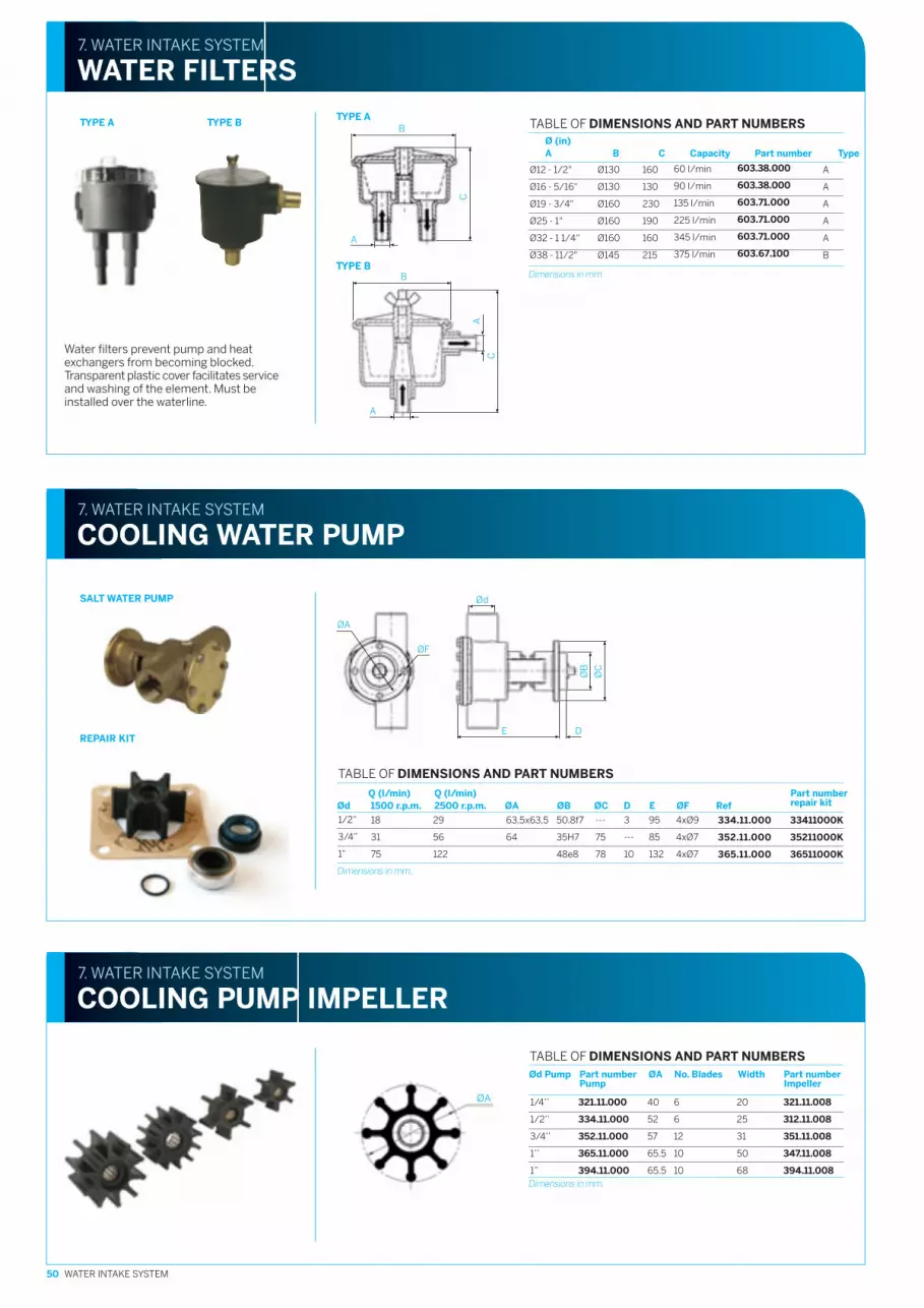
603.38.000
603.38.000
603.71.000
603.71.000
603.71.000
603.67.100
Ø12 - 1/2"
Ø16 - 5/16"
Ø19 - 3/4"
Ø25 - 1"
Ø32 - 1 1/4"
Ø38 - 11/2"
Ø130
Ø130
Ø160
Ø160
Ø160
Ø145
7. WATER INTAKE SYSTEM
COOLING WATER PUMP
7. WATER INTAKE SYSTEM
WATER FILTERS
Water filters prevent pump and heatexchangers from becoming blocked.Transparent plastic cover facilitates serviceand washing of the element. Must beinstalled over the waterline.
TYPE BTYPE A
TYPE B
Dimensions in mm.
TABLE OF DIMENSIONS AND PART NUMBERSØ (in)A B C Capacity Part number Type
60 I/min
90 I/min
135 l/min
225 l/min
345 l/min
375 l/min
160
130
230
190
160
215
50 WATER INTAKE SYSTEM
ØA 1/4’’ 321.11.000 40 6 20 321.11.008
1/2’’ 334.11.000 52 6 25 312.11.008
3/4’’ 352.11.000 57 12 31 351.11.008
1’’ 365.11.000 65.5 10 50 347.11.008
1” 394.11.000 65.5 10 68 394.11.008
7. WATER INTAKE SYSTEM
COOLING PUMP IMPELLER
Dimensions in mm.
TABLE OF DIMENSIONS AND PART NUMBERSØd Pump Part number ØA No. Blades Width Part number
Pump Impeller
A
A
A
A
A
B
C
A
B
B
A
C
A
TYPE A
1/2”
3/4”
1”
18
31
75
TABLE OF DIMENSIONS AND PART NUMBERS
Q (l/min) Q (l/min)Ød 1500 r.p.m. 2500 r.p.m. ØA ØB ØC D E ØF Ref
33411000K
35211000K
36511000K
29
56
122
63,5x63,5
64
50.8f7
35H7
48e8
---
75
78
3
---
10
95
85
132
4xØ9
4xØ7
4xØ7
ØC
ØB
DE
Ød
ØF
ØA
334.11.000
352.11.000
365.11.000
Part numberrepair kit
SALT WATER PUMP
REPAIR KIT
Dimensions in mm.

51WATER EXHAUST SYSTEM
8. WATER EXHAUST SYSTEM
WATERLOCK
The waterlock/muffler performs the taskof collecting the water from the exhausthose after the engine stops, therebypreventing water from entering it. Thewaterlock has a built-in muffler.
465
22
0
240
20
0
650
20
0
280
32
0
640
200
40
0
32
0
26
0
Rubber hose. Supplied in linear meters.The physical properties of the hose giveit an optimum level of flexibility andresistance.
7. WATER INTAKE SYSTEM
WATER INTAKE HOSE
Ø Int
Ø19
Ø25
Ø30
Ø32
Ø38
Ø40
Ø42
Part number
M87501927
M87502535
M87503040
M87503242
M87503848
M87504050
M87504252
Dimensions in mm.
Ø 40 mm 45 mm 50 mm 60 mm 75 mm 90 mm 102 mm 127mm
Part number M88504052 M88504557 M88505062 M88506072 M88507587 M885090102 M8850102114 M8850127139
WATER EXHAUST SYSTEM
WET EXHAUST HOSE8
High resistance fabric reinforced rubber hosewith steel spiral wire. Supplied in linear meters.The hose's mechanical properties providean optimum level of flexibility and resistanceto engine exhaust.
Part number Ø (mm) V (Iit.) Type
607.00.040 40/45/50 7 A
607.00.041 55/60/65 20 B
607.00.042 75/90 33 C
TYPE A TYPE B TYPE C

52 WATER EXHAUST SYSTEM
Stainless steel pipe
ØB
(m
m)
ØA
(m
m)
8. WATER EXHAUST SYSTEM
GOOSE NECK
The goose neck prevents seawaterfrom entering the engine.
8. WATER EXHAUST SYSTEM
AIR VENT
If the injection point of the cooling water in theexhaust system is situated at a height less than15 cm above the waterline there is a risk thatwhen the engine is stopped the cooling watermay enter the engine due to the siphoning effect.This problem can be solved by installing an airvent in the cooling water duct, about 40 cmabove the waterline (max. height 2 metres).The air vent is connected by means of tubeand hull transom (always mounted abovethe waterline), to vent to the outside. The airvent comes without hoses.
8. WATER EXHAUST SYSTEM
TRANSOM EXHAUST CONNECTION
607.00.241
607.00.260
A
B
TABLE OF DIMENSIONSAND PART NUMBERSPart number ØD (mm) Type
Dimensions in mm.
40/50/50
60
TYPE A
48
0
Ø5
0
110
ØD
TYPE B
ØD
182 135
ØD
Dimensions in mm.
607.30.013
607.30.011
16 -19 - 25 - 32
38
Ø (mm) Part number Type
A
B
Dimensions in mm.
607.00.145
607.00.152
607.00.176
607.00.182
607.00.177
A
A
B
A
B
TABLE OF DIMENSIONS AND PART NUMBERSType ØA (mm) ØB (mm) Part number
40 / 45 / 50
60
75
---
Ø60
Ø68
Ø10
Ø125
Ø90
TYPE BTYPE A
TYPE B
TYPE A
TYPE BTYPE A
Plastic transom exhaust connection.Assemble above the waterline.
TABLE OF DIMENSIONSAND PART NUMBERS

A B
THREADSAE 3/16”
THREADUNF 10 - 32h
Diesel fuel filter with waterseparator, equipped withconnectors.
FUEL SYSTEM
DIESEL FUEL FILTERS9
CONTROL SYSTEM
SHUT-DOWN CABLE
Made of steel cable with plastic sheath andbrass tips.
10. CONTROL SYSTEM
PUSH-PULL CABLE
Stainless steel cable with plastic sheath.No maintenance required.Thread type UNF 10 - 32h.
10
Type Flow Hose inside diameter Part number
A 50 l/h Ø 5 603.00.120(max.) Ø 6 603.00.110
Ø 8 603.00.101
Ø 10 603.00.125
B 240 l/h Ø 8 603.00.220(max.) Ø 10 603.00.210
Ø 12 603.00.230
TABLE OF PART NUMBERS
9. FUEL SYSTEM
FUEL HOSE
Black rubber fuel hose according to normISO-7840A1. Supplied in meter lengths.
Ø Int (mm) Ø Ext (mm) Part number
Ø 6 Ø 16 M81510616
Ø 8 Ø 17 M81510817
Ø 10 Ø 19 M81511019
Ø 12 Ø 22 M81511222
TABLE OF DIMENSIONS AND PART NUMBERS
L(m) Part number
0.50 609.00.405
1.00 609.00.410
1.50 609.00.415
2.00 609.00.420
2.50 609.00.425
3.00 609.00.430
3.50 609.00.435
4.00 609.00.440
4.50 609.00.445
5.00 609.00.450
6.00 609.00.460
TABLE OF PART NUMBERS
L(m) Part number
1.50 604.00.015
2.00 604.00.020
2.50 604.00.025
3.00 604.00.030
3.5 604.00.035
4.00 604.00.040
4.50 604.00.045
5.00 604.00.050
5.50 604.00.055
6.00 604.00.060
6.50 604.00.065
L(m) Part number
7.00 604.00.070
7.50 604.00.075
8.00 604.00.080
8.50 604.00.085
9.00 604.00.090
10.0 604.00.100
11.0 604.00.110
12.0 604.00.120
13.0 604.00.130
14.0 604.00.140Other lengths available, querythe commercial department.
TABLE OF PART NUMBERS
53WATER EXHAUST SYSTEM

54 CONTROL SYSTEM
SIDE ASSEMBLY FOR IDLE VALVE SIDE MOUNTING
SIDE MOUNTING FOR SAILING YACHTS. Stainless Steel SIDE MOUNTING FOR SAILING YACHTS.
TOP MOUNTING TOP MOUNTING FOR TWO ENGINES
10. CONTROL SYSTEM
REMOTE CONTROL LEVERS
R17
1
199
64
161
76 57
38
105 Min
Max 12
200
215
112
76 Min
Max 12
196
215
118
176
237
21017
62
37
8415
8
48
215
164
74
Panelmax 12
51
Invanding montering/Inside mount =66
Part number 604.20.101 Part number 604.00.001
Part number 604.20.002 Part number 604.00.004
Part number 604.00.002 Part number 604.00.003
MOUNTING FOR OUTBOARD ENGINES
R200
73300
150
Part number 604.00.005

55ELECTRICAL SYSTEM
RPM COUNTERELECTRONIC 4000 RPM
Operates with all the engines, regulatingeach model. No transmitter needed.Directly connected to the alternator.86 mm mounting diameter.
B
5/8-18 UNF
WATER TEMPERATURE GAUGE
This instrument operates with all the engines.The mounting diameter is 52mm.Temperature transmitter may be supplied.
A
M10x1
B
OIL PRESSURE GAUGE
This instrument operates with all engines.The mounting diameter is 52 mm. Can besupplied with the oil pressure transmitter.
A
VOLTMETER
This instrument operates with all engines.52 mm mounting diameter.
FUEL LEVEL GAUGE
This instrument operates with all engines.52 mm mounting diameter.
HOUR COUNTER
This instrument operates with all engines.52 mm mounting diameter.
24.4
44.5
37.4
Ø3.8
FUEL LEVEL SENSOR
For 4” to 24” tanks
Ø52Ø72
ELECTRICAL SYSTEM
ELECTRICAL INSTRUMENTS11
Dimensions in mm
DemisterDemister
Demister
DemisterDemister
Standard Part number
12V 609.00.910
TABLE OF PART NUMBERSStandard Part number A Part number B
12V 609.00.915 609.00.980
TABLE OF PART NUMBERSStandard Part number A Part number B
12V 609.00.920 609.00.985
TABLE OF PART NUMBERS
Standard Part number
12V 609.00.925
24V 609.00.926
TABLE OF PART NUMBERSStandard Part number
12V 609.00.950
TABLE OF PART NUMBERSStandard Part number
12V 609.00.918
TABLE OF PART NUMBERS
Standard Part number
12V 609.00.952
TABLE OF PART NUMBERS
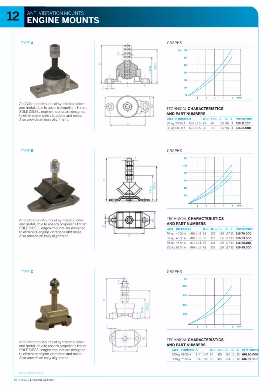
56 FLEXIBLE ENGINE MOUNTS
TYPE A
A
E
B M
in
B M
axC
TYPE B
TYPE C
Anti Vibration Mounts of synthetic rubberand metal, able to absorb propeller's thrust.SOLÉ DIESEL engine mounts are designedto eliminate engine vibrations and noise.Also provide an easy alignment.
ANTI VIBRATION MOUNTS
ENGINE MOUNTS12
D
50
A
C
B M
in B M
ax
D
E
65
E
A
B M
in
B M
ax
D
C
70
Dimensions in mm
Anti Vibration Mounts of synthetic rubberand metal, able to absorb propeller's thrust.SOLÉ DIESEL engine mounts are designedto eliminate engine vibrations and noise.Also provide an easy alignment.
Anti Vibration Mounts of synthetic rubberand metal, able to absorb propeller's thrust.SOLÉ DIESEL engine mounts are designedto eliminate engine vibrations and noise.Also provide an easy alignment.
Load Hardness A B Min. B Max. C D E Part number
50 kg 50 Sh A M14 x 1.5 75 86 108 98 11 616.31.100
60 kg 60 Sh A M16 x 1.5 75 100 125 98 11 616.51.000
TECHNICAL CHARACTERISTICSAND PART NUMBERS
60
50
40
30
20
10
01 2 3 4 5 mm
GRAPHS
kg
100
80
60
40
20
1 2 3 4 5 mm
GRAPHS
kg
Load Hardness A B Min. B Max. C D E Part number
70 kg 40 Sh A M16 x 1.5 93 115 136 127 13 616.70.000
85 kg 45 Sh A M16 x 1.5 93 115 136 127 13 616.53.000
85 kg 45 Sh A M20 x 1.5 93 115 136 127 13 616.65.100
100 kg 63 Sh A M16 x 1.5 93 115 136 127 13 616.85.000
300
250
200
150
1 2 3 4 5 mm
GRAPHS
kg
Load Hardness A B Min. B Max.C D E Part number
250kg 65 Sh A 3/4’’ UNF 80 115 164 101 12 616.90.000
300kg 75 Sh A 3/4’’ UNF 80 115 164 101 12 616.91.000
TECHNICAL CHARACTERISTICSAND PART NUMBERS
TECHNICAL CHARACTERISTICSAND PART NUMBERS

57FLEXIBLE ENGINE MOUNTS
TYPE D
90
75
60
45
30
15
01 2 3 4 5 mm
TYPE E
3.5 4.6
12. ANTI VIBRATION MOUNTS
ENGINE MOUNTS
E
A
B M
in
B M
ax
D
C
Ø F
60F
D
E
B M
inB
MaxC
A
Dimensions in mm
Anti Vibration Mounts of synthetic rubberand metal, able to absorb propeller's thrust.SOLÉ DIESEL engine mounts are designedto eliminate engine vibrations and noise.Also provide an easy alignment.
Anti Vibration Mounts of synthetic rubberand metal, able to absorb propeller's thrust.SOLÉ DIESEL engine mounts are designedto eliminate engine vibrations and noise.Also provide an easy alignment.
Anti Vibration Mounts of synthetic rubberand metal, able to absorb the propeller's thrust.SOLÉ DIESEL engine mounts are designedto eliminate engine vibrations as well as noise.They also provide for easy alignment.
Dimensions in mm
Load Hardness A B Min. B Max. C D E F Part number
90 kg 65 Sh A M14 x 1.5 55 75 95 98 11 61 616.39.000
90 kg 65 Sh A M16 x 1.5 75 86 108 98 11 61 616.61.000
225 kg 55 Sh A M16 x 1.5 62 75 105 140 13 75 616.52.000
150 kg 45 Sh A M16 x 1.5 62 75 105 140 13 75 616.52.010
300 kg 65 Sh A M20 x 1.5 65 75 120 140 13 75 616.65.000
300 kg 65 Sh A M16 x 1.5 62 75 110 140 13 75 616.65.200
320
280
240
200
160
120
80
40
01 2 3 4 5 mm
GRAPHS
kg
616.39.000616.61.000
616.65.000616.65.200
616.52.000
616.52.010
GRAPHS
kg
Load Hardness A B Min. B Max. C D E F Part number
70 kg 67 Sh A M16 x 1.5 90 105 145 175 13 18 616.71.000
50 kg 55 Sh A M16 x 1.5 90 105 145 175 13 18 616.72.000
60 kg 60 Sh A M16 x 1.5 90 105 145 175 13 18 616.73.000
85 kg 75 Sh A M16 x 1.5 90 105 145 175 13 18 616.82.000
616.72.000
616.82.000
616.71.000
616.73.000
800
600
400
200
1 2 3 4 5 6 7 mm
GRAPHS
kg
A B C D E F G Part number
34 12 15 10 94 123 150 616.73.001
41 16 19 12.5 107.5 143 169 616.74.001
35
12. ANTI VIBRATION MOUNTS - GENERATOR SET
GENERATOR SET MOUNT
TECHNICAL CHARACTERISTICSAND PART NUMBERS
TECHNICAL CHARACTERISTICSAND PART NUMBERS
TECHNICAL CHARACTERISTICSAND PART NUMBERS
B
A
C
D
F
G
E
TYPE F
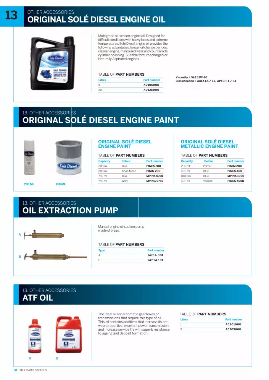
58 OTHER ACCESSORIES
Multigrade all-season engine oil. Designed fordifficult conditions with heavy loads and extremetemperatures. Solé Diesel engine oil provides thefollowing advantages: longer oil change periods,cleaner engine, minimised wear and counteractscylinder polishing. Suitable for turbocharged orNaturally Aspirated engines.
Classification / ACEA E5 / E3, API CH-4 / SJViscosity / SAE 15W-40
750 ML200 ML
A
B
5l1l
OTHER ACCESSORIES
ORIGINAL SOLÉ DIESEL ENGINE OIL13
13. OTHER ACCESSORIES
ORIGINAL SOLÉ DIESEL ENGINE PAINT
13. OTHER ACCESSORIES
OIL EXTRACTION PUMP
Manual engine oil suction pumpmade of brass.
13. OTHER ACCESSORIES
ATF OIL
The ideal oil for automatic gearboxes ortransmissions that require this type of oil.This oil contains additives that increase its anti-wear properties, excellent power transmission,and increase service life with superb resistanceto ageing and deposit formation.
TABLE OF PART NUMBERS
TABLE OF PART NUMBERS
A0105000
A0125000
5
20
TABLE OF PART NUMBERSLitres Part number
PINES 200
PININ 200
MPINA 0750
MPING 0750
200 ml
200 ml
750 ml
750 ml
TABLE OF PART NUMBERS
Capacity Colour Part number
Blue
Shop Mono
Blue
Grey
147.14.001
147.14.101
A
B
Type Part number
A0201000
A0205000
1
5
Litres Part number
PINIM 200
PINES 400
MPINA 1000
PINES 400B
200 ml
400 ml
1000 ml
400 ml
TABLE OF PART NUMBERS
Capacity Colour Part number
Primer
Blue
Blue
Varnish
ORIGINAL SOLÉ DIESELMETALLIC ENGINE PAINT
ORIGINAL SOLÉ DIESELENGINE PAINT
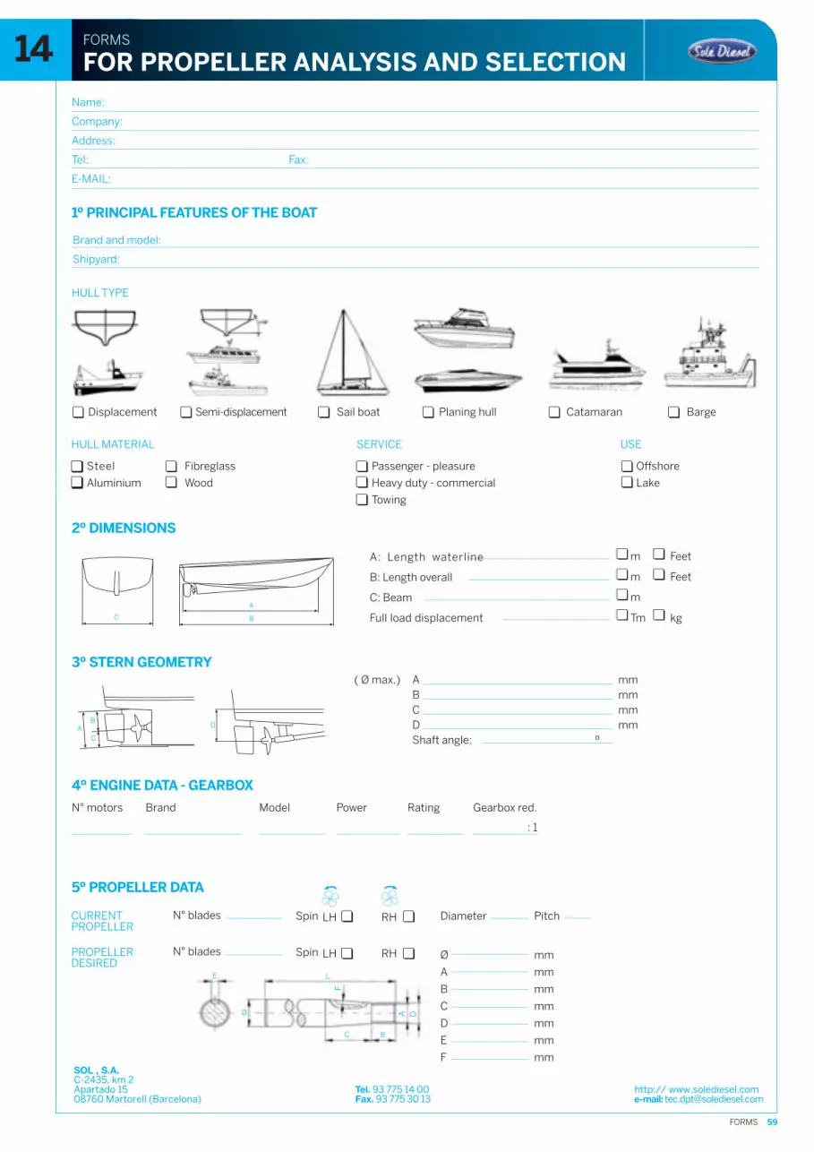
59FORMS
E L
F
A D
C B
Ø
Name:
Company:
Address:
Tel: Fax:
E-MAIL:
Brand and model:
Shipyard:
Semi-displacementDisplacement Sail boat Planing hull Catamaran Barge
Passenger - pleasure
SERVICE
Offshore
USE
Towing
Steel
Aluminium
Fibreglass
Wood Heavy duty - commercial Lake
m Feet
m Feet
m
A mmB mmC mmD mmShaft angle: º
( Ø max.)
N° blades Spin
N° blades Spin
Diameter Pitch
FORMS
FOR PROPELLER ANALYSIS AND SELECTION14
HULL TYPE
HULL MATERIAL
1º PRINCIPAL FEATURES OF THE BOAT
2º DIMENSIONS
A: Length waterline
B: Length overall
C: Beam
Full load displacement Tm kg
3º STERN GEOMETRY
4º ENGINE DATA - GEARBOX
N° motors Brand Model Power Rating Gearbox red.
: 1
LH RH
5º PROPELLER DATA
SOL , S.A.C-2435, km 2Apartado 15 Tel. 93 775 14 00 http:// www.solediesel.com08760 Martorell (Barcelona) Fax. 93 775 30 13 e-mail: [email protected]
CURRENTPROPELLER
LH RHPROPELLERDESIRED
Ø
A
B
C
D
E
F
mm
mm
mm
mm
mm
mm
mm
AB
C
D
C B
A
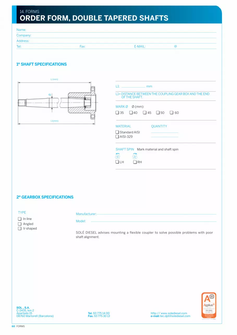
60 FORMS
Name:
Company:
Address:
Tel: Fax: E-MAIL: @
TYPE
Angled
In line
V-shaped
Manufacturer:
Model:
L1= DISTANCE BETWEEN THE COUPLING GEAR BOX AND THE ENDOF THE SHAFT.
SHAFT SPIN
MATERIAL
14. FORMS
ORDER FORM, DOUBLE TAPERED SHAFTS
35 40 45 50 60
1º SHAFT SPECIFICATIONS
L1: mm
Ø (mm):MARK Ø
Mark material and shaft spin
Standard AISIAISI-329
QUANTITY
LH RH
L (mm)
L1(mm)
Ø
2º GEARBOX SPECIFICATIONS
SOLÉ DIESEL advises mounting a flexible coupler to solve possible problems with poorshaft alignment.
SOL , S.A.C-2435, km 2Apartado 15 Tel. 93 775 14 00 http:// www.solediesel.com08760 Martorell (Barcelona) Fax. 93 775 30 13 e-mail: [email protected]

61APPENDIX
DEFINITION OF SERVICE TYPESRecreational craft service:Very intermittent use, with a broad range of demandsplaced on the engine. The maximum rated power indicatedis understood to be only for personal use of craft with aplaning hull for which the operating time at the maximumrating is less than 10% of the total time. For the remainingtime, the craft must be operated at a level equal to or lessthan 80% of its maximum rating. Mean limit of engineoperating hours:- 500 hours/year for hydraulic gear boxes (TM).- 300 hours/year for mechanical gearboxes (TMC).Typical applications: Private, non-charter use,sporting/recreational activities.
Intermediate service:Intermittent use, with a broad range of demands placedon the engine.Mean limit of engine operating hours: 2000 hours/year.Typical applications: Private and charter use,sporting/recreational activities. Planing, semi-displacement and displacement hulls.
Continuous service:Continuous use, with little or no variation in thepower demands placed on the engine. Unlimited hoursper year.Typical applications: Intensive use in fishing or commercialcraft.
IMPORTANT INFORMATIONABOUT THE APPLICATION
- Transmission ratios are based on the useof the gearbox in a system that is torsionallycompatible with a torque coupler of suitable input.
- The ratio applies to diesel engines.- Enquire with the factory about ratios that
are applicable to petrol engines or other applicationsnot included in the definitionof a given service class.
- The ratios apply to right-turning engines(anticlockwise rotation of the flywheel when viewingthe motor from the stern).
- The ratios are for full power in forward and reverse,unless otherwise indicated.
- The transmission ratios must be equal to or greaterthan those published for the engine for a givenapplication.1 kW = 1.34 HP.
- The data provided may be modified or correctedwith no previous notice.
RESPONSIBILITIES
Responsibility for assuring that the torsionalcompatibility of the propulsion system is satisfactorylies with the installer of the propulsion equipment.Twin Disc Technodrive accepts no liability for noise ormalfunctioning in the gear box, in the flexible couplingor in the transmission parts that may be caused bythis type of vibration.
For further information and assistance,contact Twin Disc Technodrive.
(*) Weight without oil.(1) The power rating given refers to forward gear. For reverse:
(2.1) TMC 60 E red. 1.55: 80% of the reduction ratio 2.00(2.2) TMC 60 E red. 2.00 and 2.45: 80% of the value indicated(2.3) TMC 60 E red. 2.83 : 80% of the reduction ratio 2.50(2.4) TMC 260 red. 1.54 and 2.00: 80% of the value indicated(2.5) TMC 260 red. 2.47 and 2.88: 80% of the reduction ratio 2.47
APPENDIX TO CHAPTER 4. GEAR BOXES
Notes
MECHANICAL GEARBOXES INTERMEDIATE SERVICE
TMC40P
TMC60E
TMC 60 A
TMC 260
SPROP 60
1,45
2,00
2,60
1,55
2,00
2,45
2,83
2,00
2,45
1,54
2,00
2,47
2,88
2,15
2,13
2,13
2,13
2,00
2,00
2,45
2,45
2,17
2,17
2,00
2,00
2,47
2,47
2,15
0,0108
0,0080
0,0064
0,0151
0,0133
0,0116
0,0090
0,0117
0,0117
0,0231
0,0231
0,0187
0,0160
0,0090
0,0145
0,0107
0,0085
0,0202
0,0178
0,0155
0,0121
0,0156
0,0156
0,0310
0,0310
0,0251
0,0214
0,0121
26
21
17
42
37
32
25
32
32
65
65
52
45
38
26
24
19
45
40
35
27
35
35
69
69
56
48
40
(35)
(32)
(25)
(61)
(53)
(47)
(36)
(47)
(47)
(93)
(93)
(75)
(64)
(55)
(35)
(30)
(24)
(57)
(50)
(44)
(34)
(43)
(43)
(87)
(87)
(70)
(60)
(52)
26
26
22
54
48
42
32
42
42
83
83
67
57
32
(35)
(35)
(30)
(73)
(64)
(56)
(43)
(56)
(56)
(111)
(111)
(90)
(77)
(43)
4500
4500
4500
5000
5000
5000
5000
4500
4500
5000
5000
5000
5000
3000
9
14
14
18
35
20
31
31
40
SAE 5, BW
Max input power 26 KW
Max power in reverse: 33% of listed ratings
SAE 4, SAE 5, BW
Max input power 60 KW
Max power in reverse: see note
SAE 4, SAE 5, BW
Max input power 52 KW
Max power in reverse: 33% of listed ratings
SAE 4, SAE 5, BW
Max input power 84 KW
Max power in reverse: see note
SAE 7” BW (ref. / part no. 24813501)
26
19
14
33
30
24
20
24
24
52
52
38
30
38
(35)
(25)
(18)
(44)
(40)
(33)
(27)
(33)
(33)
(69)
(69)
(51)
(40)
(51)
MECHANICAL GEARBOXES PLEASURE
TMC40P
TMC60E
TMC 60 A
TMC 260
SPROP 60
1,45
2,00
2,60
1,55
2,00
2,45
2,83
2,00
2,45
1,54
2,00
2,47
2,88
2,15
2,13
2,13
2,13
2,00
2,00
2,45
2,45
2,17
2,17
2,00
2,00
2,47
2,47
2,15
0,0099
0,0073
0,0052
0,0126
0,0115
0,0094
0,0078
0,0094
0,0094
0,0199
0,0199
0,0147
0,0115
0,0105
0,0133
0,0098
0,0070
0,0169
0,0154
0,0126
0,0105
0,0126
0,0126
0,0267
0,0267
0,0197
0,0154
0,0140
18
13
9
23
21
17
14
17
17
36
36
26
21
46
23
17
12
29
26
22
18
22
22
46
46
34
26
49
(31)
(23)
(16)
(39)
(35)
(29)
(24)
(49)
(49)
(61)
(61)
(45)
(35)
(66)
(24)
(18)
(13)
(30)
(28)
(23)
(19)
(23)
(23)
(48)
(48)
(35)
(28)
(62)
4500
4500
4500
5000
5000
5000
5000
4500
4500
5000
5000
5000
5000
3000
9
14
14
18
35
20
31
31
40
SAE 5, BW
Max input power 26 KW
Max power in reverse: 33% of listed ratings
SAE 4, SAE 5, BW
Max input power 60 KW
Max power in reverse: see note
SAE 4, SAE 5, BW
Max input power 52 KW
Max power in reverse: 33% of listed ratings
SAE 4, SAE 5, BW
Max input power 84 KW
Max power in reverse: see note
SAE 7” BW (ref. / part no. 24813501)
Model Reduction ratios Power rating/rpm Max. power rating -kW (Hp) Max (*) Weight Adaptors/comments
Forward Reverse kW Hp @2800 rpm @3000 rpm @3600 rpm kg lb
Model Reduction ratios Power rating/rpm Max. power rating -kW (Hp) Max (*) Weight Adaptors/comments
Forward Reverse kW Hp @2800 rpm @3000 rpm @3600 rpm kg lb

62 APPENDIX
APPENDIX TO CHAPTER 4. GEAR BOXES
MECHANICAL GEARBOXES CONTINUOUS SERVICE
TMC40P
TMC60E
TMC 60 A
TMC 260
1,45
2,00
2,60
1,55
2,00
2,45
2,83
2,00
2,45
1,54
2,00
2,47
2,88
2,13
2,13
2,13
2,00
2,00
2,45
2,45
2,17
2,17
2,00
2,00
2,47
2,47
0,0099
0,0073
0,0052
0,0126
0,0115
0,0094
0,0078
0,0094
0,0094
0,0199
0,0199
0,0147
0,0115
0,0133
0,0098
0,0070
0,0169
0,0154
0,0126
0,0105
0,0126
0,0126
0,0267
0,0267
0,0197
0,0154
18
13
9
23
21
17
14
17
17
36
36
26
21
23
17
12
29
26
22
18
22
22
46
46
34
26
(31)
(23)
(16)
(39)
(35)
(29)
(24)
(49)
(49)
(61)
(61)
(45)
(35)
(24)
(18)
(13)
(30)
(28)
(23)
(19)
(23)
(23)
(48)
(48)
(35)
(28)
26
19
14
33
30
24
20
24
24
52
52
38
30
(35)
(25)
(18)
(44)
(40)
(33)
(27)
(33)
(33)
(69)
(69)
(51)
(40)
4500
4500
4500
5000
5000
5000
5000
4500
4500
5000
5000
5000
5000
9
14
14
18
20
31
31
40
SAE 5, BW
Max input power 26 KW
Max power in reverse: 33% of listed ratings
SAE 4, SAE 5, BW
Max input power 44 KW
Max power in reverse: see note
SAE 4, SAE 5, BW
Max input power 52 KW
Max power in reverse: 33% of listed ratings
SAE 4, SAE 5, BW
Max input power 61 KW
Max power in reverse: see note
Model Reduction ratios Power rating/rpm Max. power rating -kW (Hp) Max (*) Weight Adaptors/comments
Forward Reverse kW Hp @2800 rpm @3000 rpm @3600 rpm kg lb
HYDRAULIC GEARBOXES PLEASURE
TM345
TM345A
(8º)
TM93
TM93A
(8º)
TM485A1
(8º)
TM170
TM170A
(10º)
TM880A
(10º)
TM265
TM265A
(7º)
TM200
TM360
TM1200A
(7º)
1,54
2,00
2,47
1,54
2,00
2,47
1,51
2,09
2,40
2,77
1,51
2,09
2,40
1,51
2,09
2,40
1,50
2,04
2,50
2,94
1,53
2,08
2,60
1,53
2,08
2,60
1,17
1,50
2,09
2,82
1,44
2,00
2,30
3,60
4,48
3,00
3,50
4,00
5,00
1,44
2,00
2,30
1,54
2,00
2,47
1,54
2,00
2,47
1,51
2,09
2,40
2,77
1,51
2,09
2,40
1,51
2,09
2,40
1,50
2,04
2,50
2,94
1,53
2,08
2,60
1,53
2,08
2,60
1,17
1,50
2,09
2,82
1,44
2,00
2,30
3,60
4,48
3,00
3,50
4,00
5,00
1,44
2,00
2,30
0,0361
0,0293
0,0220
0,0361
0,0293
0,0220
0,0534
0,0461
0,0408
0,0356
0,0492
0,0408
0,0356
0,0500
0,0500
0,0438
0,0785
0,0785
0,0628
0,0534
0,0785
0,0785
0,0628
0,0921
0,0921
0,0628
0,1109
0,1109
0,1109
0,1109
0,1109
0,1026
0,0932
0,1461
0,1461
0,1250
0,0484
0,0393
0,0295
0,0484
0,0393
0,0295
0,0716
0,0618
0,0547
0,0477
0,0659
80,054
0,0477
0,0670
0,0670
0,0587
0,1052
0,1052
0,0842
0,0716
0,1052
0,1052
0,0842
0,1234
0,1234
0,0842
0,1486
0,1486
0,1486
0,1486
0,1486
0,1375
0,1249
0,1957
0,1957
0,1675
94
76
57
94
76
57
139
120
106
93
128
106
93
130
130
114
204
204
163
139
204
204
163
239
239
163
288
288
288
288
288
267
242
380
380
325
101
82
62
101
82
62
150
129
114
100
138
114
100
140
140
123
220
220
176
150
220
220
176
258
258
176
311
311
311
311
311
287
261
409
409
469
135
110
83
135
110
83
200
173
153
134
185
153
134
188
188
164
295
295
236
200
295
295
236
346
346
236
416
416
416
416
416
385
350
548
548
469
126
102
77
126
102
77
186
161
142
124
171
142
124
174
174
153
273
273
219
186
273
273
219
321
321
219
386
386
386
386
386
357
325
509
509
435
110
97
73
110
97
73
176
152
135
117
162
135
117
165
165
145
257
257
207
176
157
157
207
295
295
207
147
130
97
147
130
97
236
204
180
157
218
180
157
221
221
194
344
34
278
236
344
344
278
395
395
278
4500
4500
4500
4500
4500
4000
4000
4000
3000
3000
3000
2600
3200
25
25
53
53
36
75
75
54
165
165
235
415
115
55
55
117
117
79
165
165
119
364
364
518
915
253
SAE 3, 4, 5, BW
max input power 110 kw
SAE 3, 4, YANMAR LH, BW
max input power 184 kw
SAE 3, 4, YANMAR 1 LH, BW
max input power 210 kw
SAE 3, 4, YANMAR LH, BW
max input power
r 1,50 / 2,04 257 kw
r 2,50 / 2,94 220 kw
max input power
r 1,53 / 2,08 257 kw
r 2,60 220 kw
SAE 3, 4, YANMAR LH, BW
max input power 295 kw
SAE 1, 2, 3
SAE 1, 2, 3
SAE 1, 2, 3
SAE 1, 2, 3
Model Reduction ratios Power rating/rpm Max. power rating -kW (Hp) Max (*) Weight Adaptors/comments
Forward Reverse kW Hp @2600 rpm @2800 rpm @3300 rpm kg lb
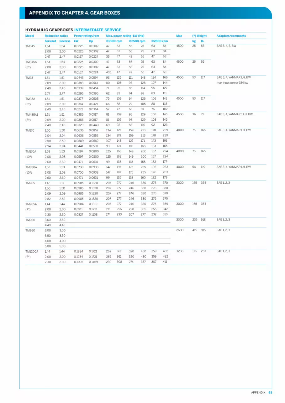
63APPENDIX
APPENDIX TO CHAPTER 4. GEAR BOXES
HYDRAULIC GEARBOXES INTERMEDIATE SERVICE
TM345
TM345A
(8º)
TM93
TM93A
(8º)
TM485A1
(8º)
TM170
TM170A
(10º)
TM880A
(10º)
TM265
TM265A
(7º)
TM200
TM360
TM1200A
(7º)
1,54
2,00
2,47
1,54
2,00
2,47
1,51
2,09
2,40
2,77
1,51
2,09
2,40
1,51
2,09
2,40
1,50
2,04
2,50
2,94
1,53
2,08
2,60
1,53
2,08
2,60
1,17
1,50
2,09
2,82
1,44
2,00
2,30
3,60
4,48
3,00
3,50
4,00
5,00
1,44
2,00
2,30
1,54
2,00
2,47
1,54
2,00
2,47
1,51
2,09
2,40
2,77
1,51
2,09
2,40
1,51
2,09
2,40
1,50
2,04
2,50
2,94
1,53
2,08
2,60
1,53
2,08
2,60
1,17
1,50
2,09
2,82
1,44
2,00
2,30
3,60
4,48
3,00
3,50
4,00
5,00
1,44
2,00
2,30
0,0225
0,0225
0,0167
0,0225
0,0225
0,0167
0,0443
0,0383
0,0339
0,0295
0,0377
0,0314
0,0272
0,0386
0,0386
0,0329
0,0636
0,0636
0,0509
0,0441
0,0597
0,0597
0,0471
0,0700
0,0700
0,0471
0,0985
0,0985
0,0985
0,0985
0,0984
0,0911
0,0827
0,1284
0,1284
0,1096
0,0302
0,0302
0,0224
0,0302
0,0302
0,0224
0,0594
0,0513
0,0454
0,0395
0,0505
0,0421
0,0364
0,0517
0,0517
0,0440
0,0852
0,0852
0,0682
0,0591
0,0800
0,0800
0,0631
0,0938
0,0938
0,0631
0,1320
0,1320
0,1320
0,1320
0,1319
0,1221
0,1108
0,1721
0,1721
0,1469
47
47
35
47
47
435
93
80
71
62
79
66
57
81
81
69
134
134
107
93
125
125
99
147
147
99
207
207
207
207
207
191
174
269
269
230
56
56
42
56
56
42
111
96
85
74
94
79
68
96
96
83
159
159
127
110
149
149
118
175
175
118
246
246
246
246
246
228
207
320
320
274
75
75
56
75
75
56
148
128
114
99
126
105
91
129
129
110
213
213
171
148
200
200
158
235
235
160
330
330
330
330
330
305
277
430
430
367
63
63
47
63
63
47
125
108
95
83
106
88
77
109
109
92
179
179
143
124
168
168
133
197
197
135
277
277
277
277
277
256
233
361
361
308
63
63
47
63
63
47
124
107
95
83
106
88
76
108
108
92
178
178
143
123
167
167
132
196
196
132
276
276
276
276
276
255
232
359
359
307
84
84
63
84
84
63
166
144
127
111
141
118
102
145
145
123
239
239
191
165
224
224
177
263
263
179
370
370
370
370
369
342
310
482
482
411
4500
4500
4500
4500
4500
4000
4000
4000
3000
3000
3000
2600
3200
25
25
53
53
36
75
75
54
165
165
235
415
115
55
55
117
117
79
165
165
119
364
364
518
915
253
SAE 3, 4, 5, BW
SAE 3, 4, YANMAR LH, BW
max input power 184 kw
SAE 3, 4, YANMAR 1 LH, BW
SAE 3, 4, YANMAR LH, BW
SAE 3, 4, YANMAR LH, BW
SAE 1, 2, 3
SAE 1, 2, 3
SAE 1, 2, 3
SAE 1, 2, 3
Model Reduction ratios Power rating/rpm Max. power rating -kW (Hp) Max (*) Weight Adaptors/comments
Forward Reverse kW Hp @2100 rpm @2500 rpm @2800 rpm kg lb

64 APPENDIX
APPENDIX TO CHAPTER 4. GEAR BOXES
HYDRAULIC GEARBOXES CONTINUOUS SERVICE
TM345
TM345A
(8º)
TM93
TM93A
(8º)
TM485A1
(8º)
TM170
TM170A
(10º)
TM880A
(10º)
TM265
TM265A
(7º)
TM200
TM360
TM1200A
(7º)
1,54
2,00
2,47
1,54
2,00
2,47
1,51
2,09
2,40
2,77
1,51
2,09
2,40
1,51
2,09
2,40
1,50
2,04
2,50
2,94
1,53
2,08
2,60
1,53
2,08
2,60
1,17
1,50
2,09
2,82
1,44
2,00
2,30
3,60
4,48
3,00
3,50
4,00
5,00
1,44
2,00
2,30
1,54
2,00
2,47
1,54
2,00
2,47
1,51
2,09
2,40
2,77
1,51
2,09
2,40
1,51
2,09
2,40
1,50
2,04
2,50
2,94
1,53
2,08
2,60
1,53
2,08
2,60
1,17
1,50
2,09
2,82
1,44
2,00
2,30
3,60
4,48
3,00
3,50
4,00
5,00
1,44
2,00
2,30
0,0194
0,0194
0,0147
0,0194
0,0194
0,0147
0,0408
0,0356
0,0319
0,0277
0,0261
0,0216
0,0189
0,0328
0,0328
0,0289
0,0576
0,0576
0,0461
0,0398
0,0416
0,0416
0,0333
0,0583
0,0583
0,0333
0,0869
0,0869
0,0869
0,0869
0,0588
0,0544
0,0494
0,0639
0,0639
0,1235
0,1235
0,1235
0,1235
0,0949
0,0949
0,0801
0,0260
0,0260
0,0197
0,0260
0,0260
0,0197
0,0547
0,0477
0,0427
0,0371
0,0350
0,0289
0,0253
0,0439
0,0439
0,0387
0,0772
0,0772
0,0618
0,0533
0,0557
0,0557
0,0446
0,0781
0,0781
0,0446
0,1164
0,1164
0,1164
0,1164
0,0788
0,0729
0,0662
0,0856
0,0856
0,1655
0,1655
0,1655
0,1655
0,1272
0,1272
0,1073
35
35
26
35
35
26
73
64
57
50
47
39
34
59
59
52
104
104
83
72
75
75
60
105
105
60
156
156
156
156
106
98
89
115
115
222
222
222
222
170
170
144
41
41
31
41
41
31
86
75
67
58
55
45
40
69
69
61
121
121
97
84
87
87
70
122
122
70
182
182
182
182
123
114
104
134
134
259
259
259
259
199
199
168
55
55
41
55
55
41
115
100
90
78
73
31
53
92
92
81
162
162
130
112
117
117
94
164
164
95
245
245
245
245
165
153
139
180
180
348
348
348
348
267
267
225
47
47
35
47
47
35
98
86
77
67
63
52
46
79
79
70
139
139
11
96
100
100
80
141
141
82
210
210
210
210
142
131
119
154
154
298
298
298
298
228
228
193
47
47
35
47
47
35
98
85
77
66
63
52
45
78
78
69
138
138
111
96
100
100
80
140
140
80
209
209
209
209
141
131
119
153
153
296
296
296
296
228
228
192
62
62
47
62
62
47
131
114
103
89
84
69
61
105
105
93
185
185
148
128
134
134
107
187
187
109
279
279
279
279
189
175
159
206
206
397
397
397
397
305
305
257
4500
4500
4500
4500
4500
4000
4000
4000
3000
3000
3000
2600
3200
25
25
53
53
36
75
75
54
165
165
235
415
115
55
55
117
117
79
165
165
119
364
364
518
915
253
SAE 3, 4, 5, BW
SAE 3, 4, YANMAR LH, BW
SAE 3, 4, YANMAR 1 LH, BW
SAE 3, 4, YANMAR LH, BW
SAE 3, 4, YANMAR LH, BW
SAE 1, 2, 3
SAE 1, 2, 3
SAE 1, 2, 3
SAE 1, 2, 3
Model Reduction ratios Power rating/rpm Max. power rating -kW (Hp) Max (*) Weight Adaptors/comments
Forward Reverse kW Hp 1800 rpm 2100 rpm 2400 rpm kg lb

CONTENTSCONTENTS
PAGE
49
50
Solé S.A. seeks to constantly improveits final products, and so the design,description, dimensions, configurationand other technical specifications givenherein, appear only for informationalpurposes and should not be takenas a binding offer with respect to thefinal product.
Technical specificationsand presentation are subjectto variations and modificationswithout previous notice.
C-243b, Km. 208760 Martorell (Barcelona). SpainTel. (34) 93 775 14 00Fax (34) 93 775 30 [email protected]
Design: www.espaigrafic-disseny.comEdition: September, 2012
2013 Catalogue
Spare Parts ServiceTel. (34) 93 775 44 05Fax (34) 93 776 53 [email protected]
PAGE
1. DIESEL MARINE ENGINESMINI-17MINI-29MINI-33MINI-44MINI-55MINI-62MINI-74SM-105SN-110SDZ-165SDZ-205SDZ-280OPTIONAL KITSENGINE MAINTENANCE KIT
2. ELECTRICAL SYSTEM - GENERATOR SETSDIGITAL GENERATOR SET PANEL (SCO 10)DIGITAL GENERATOR SET PANEL (MDA PLUS)ANALOGUE GENERATOR SET PANEL
3. GENERATOR SETSTHREE-PHASESINGLE PHASECANOPY
4. TRANSMISSIONSTMC 40P TECHNODRIVETMC 60E TECHNODRIVETMC 60A TECHNODRIVETMC 260 TECHNODRIVETM-345 TECHNODRIVETM-345A TECHNODRIVETM-93 TECHNODRIVETM-93A TECHNODRIVETM-170 TECHNODRIVETM-170A TECHNODRIVETM-880A TECHNODRIVETM-360 TECHNODRIVETM-265 TECHNODRIVETM-265A TECHNODRIVETM-200B TECHNODRIVETM-485A TECHNODRIVETM-1200 A TECHNODRIVESAIL DRIVE SPROP-60 TECHNODRIVESMI-R2 y SMI-R3ADAPTOR FLANGE SAE-7FLEXIBLE COUPLING
5. SHAFT LINESCLAMP-ON COUPLINGSHALF COUPLINGSCENTAFLEX TYPE FLEXIBLE COUPLINGSR&D TYPE FLEXIBLE COUPLINGSSHAFTSDOUBLE TAPER SHAFTSCOMPLETE STERNTUBE ASSEMBLIESRIGID STERNTUBESBEARING BUSHING ASSEMBLYFLOATING STUFFING BOXTEFLON PACKINGRUBBER BEARINGSSTRUTSPROPELLER NUT FASTENERZINC ANODE NUTS
6. PROPELLERSPROPELLERS FOR TECHNODRIVE SPROP60 SAIL DRIVEPROPELLERS FOR SELVA SAIL-DRIVESRX PROPELLERSPROPELLERSROPE CUTTERS FOR SAIL DRIVEROPE CUTTER
7. WATER INLET SYSTEMSEA WATER COCKSWATER FILTERSCOOLING WATER PUMPCOOLING PUMP IMPELLERWATER INLET HOSE
8. WATER EXHAUST SYSTEMWET EXHAUST HOSEWATERLOCKGOOSE NECKEXHAUST VENTTRANSOM EXHAUST CONNECTION
123456789
101112131415
16161717
18182022
24242425252626272728282929303031313232333334
35353637373839404041414142424242
43434344444949
494950505051
515151525252
PAGE
9. FUEL SYSTEMDIESEL FUEL FILTERSFUEL HOSE
10. CONTROL SYSTEMSHUT-DOWN CABLEPUSH-PULL CABLEREMOTE CONTROL LEVERS
11. ELECTRICAL SYSTEMELECTRICAL INSTRUMENTS
12. ANTI VIBRATION MOUNTSENGINE MOUNTSGENERATOR SET MOUNT
13. OTHER ACCESSORIESORIGINAL SOLÉ DIESEL ENGINE OILORIGINAL SOLÉ DIESEL ENGINE PAINTOIL EXTRACTION PUMPATF OIL
14. FORMSFOR PROPELLER ANALYSIS AND SELECTIONORDER FORM, DOUBLE TAPERED SHAFTS
15. APPENDIXAPPENDIX TO CHAPTER 4. GEAR BOXES
535353
53535354
5555
565657
5858585858
595960
6161