Software Engineering, 9th Edition - Facom/UFU
790
-
Upload
khangminh22 -
Category
Documents
-
view
2 -
download
0
Transcript of Software Engineering, 9th Edition - Facom/UFU


SOFTWARE ENGINEERING
Ninth Edition
Ian Sommerville
Addison-Wesley
Boston Columbus Indianapolis New York San Francisco Upper Saddle River
Amsterdam Cape Town Dubai London Madrid Milan Munich Paris Montreal Toronto
Delhi Mexico City São Paulo Sydney Hong Kong Seoul Singapore Taipei Tokyo

Editorial Director: Marcia Horton
Editor in Chief: Michael Hirsch
Acquisitions Editor: Matt Goldstein
Editorial Assistant: Chelsea Bell
Managing Editor: Jeff Holcomb
Senior Production Project Manager: Marilyn Lloyd
Director of Marketing: Margaret Waples
Marketing Coordinator: Kathryn Ferranti
Senior Manufacturing Buyer: Carol Melville
Text Designer: Susan Raymond
Cover Art Director: Elena Sidorova
Front Cover Photograph: © Jacques Pavlovsky/Sygma/Corbis
Interior Chapter Opener: © graficart.net/Alamy
Full-Service Project Management: Andrea Stefanowicz, GGS Higher Education Resources,
a Division of PreMedia Global, Inc.
Composition and Illustrations: GGS Higher Education Resources, a Division of PreMedia Global, Inc.
Printer/Binder: Edwards Brothers
Cover Printer: Lehigh-Phoenix Color/Hagerstown
Copyright © 2011, 2006, 2005, 2001, 1996 Pearson Education, Inc., publishing as Addison-Wesley. All
rights reserved. Manufactured in the United States of America. This publication is protected by copyright,
and permission should be obtained from the publisher prior to any prohibited reproduction, storage in a
retrieval system, or transmission in any form or by any means, electronic, mechanical, photocopying,
recording, or likewise. To obtain permission(s) to use material from this work, please submit a written
request to Pearson Education, Inc., Permissions Department, 501 Boylston Street, Suite 900, Boston,
Massachusetts 02116.
Many of the designations by manufacturers and seller to distinguish their products are claimed as trade-
marks. Where those designations appear in this book, and the publisher was aware of a trademark claim,
the designations have been printed in initial caps or all caps.
Library of Congress Cataloging-in-Publication Data
Sommerville, Ian
Software engineering / Ian Sommerville. — 9th ed.
p. cm.
Includes index.
ISBN-13: 978-0-13-703515-1
ISBN-10: 0-13-703515-2
1. Software engineering. I. Title.
QA76.758.S657 2011
005.1—dc22
2009053058
10 9 8 7 6 5 4 3 2 1–EB–14 13 12 11 10
ISBN 10: 0-13-703515-2
ISBN 13: 978-0-13-703515-1

PREFACE
As I was writing the final chapters in this book in the summer of 2009, I realized
that software engineering was 40 years old. The name ‘software engineering’ was
proposed in 1969 at a NATO conference to discuss software development problems—
large software systems were late, did not deliver the functionality needed by their
users, cost more than expected, and were unreliable. I did not attend that conference
but, a year later, I wrote my first program and started my professional life in software.
Progress in software engineering has been remarkable over my professional life-
time. Our societies could not function without large, professional software systems.
For building business systems, there is an alphabet soup of technologies—J2EE,
.NET, SaaS, SAP, BPEL4WS, SOAP, CBSE, etc.—that support the development and
deployment of large enterprise applications. National utilities and infrastructure—
energy, communications, and transport—all rely on complex and mostly reliable
computer systems. Software has allowed us to explore space and to create the World
Wide Web, the most significant information system in the history of mankind.
Humanity is now faced with a new set of challenges—climate change and extreme
weather, declining natural resources, an increasing world population to be fed and
housed, international terrorism, and the need to help elderly people lead satisfying
and fulfilled lives. We need new technologies to help us address these problems and,
for sure, software will play a central role in these technologies.
Software engineering is, therefore, a critically important technology for the future
of mankind. We must continue to educate software engineers and develop the disci-
pline so that we can create more complex software systems. Of course, there are still
problems with software projects. Software is still sometimes late and costs more
than expected. However, we should not let these problems conceal the real successes
in software engineering and the impressive software engineering methods and tech-
nologies that have been developed.
Software engineering is now such a huge area that it is impossible to cover the
whole subject in one book. My focus, therefore, is on key topics that are fundamental
iv Preface
to all development processes and topics concerned with the development of reliable,
distributed systems. There is an increased emphasis on agile methods and software
reuse. I strongly believe that agile methods have their place but so too does ‘tradi-
tional’ plan-driven software engineering. We need to combine the best of these
approaches to build better software systems.
Books inevitably reflect the opinions and prejudices of their authors. Some read-
ers will inevitably disagree with my opinions and with my choice of material. Such
disagreement is a healthy reflection of the diversity of the discipline and is essential
for its evolution. Nevertheless, I hope that all software engineers and software engi-
neering students can find something of interest here.
Integration with the Web
There is an incredible amount of information on software engineering available on the
Web and some people have questioned if textbooks like this one are still needed.
However, the quality of available information is very patchy, information is sometimes
presented badly and it can be hard to find the information that you need. Consequently,
I believe that textbooks still have an important role to play in learning. They serve as a
roadmap to the subject and allow information on method and techniques to be organized
and presented in a coherent and readable way. They also provide a starting point for
deeper exploration of the research literature and material available on the Web.
I strongly believe that textbooks have a future but only if they are integrated with
and add value to material on the Web. This book has therefore been designed as a
hybrid print/web text in which core information in the printed edition is linked to
supplementary material on the Web. Almost all chapters include specially written
‘web sections’ that add to the information in that chapter. There are also four ‘web
chapters’ on topics that I have not covered in the print version of the book.
The website that is associated with the book is:
http://www.SoftwareEngineering-9.com
The book’s web has four principal components:
1. Web sections These are extra sections that add to the content presented in each
chapter. These web sections are linked from breakout boxes in each chapter.
2. Web chapters There are four web chapters covering formal methods, interaction
design, documentation, and application architectures. I may add other chapters
on new topics during the lifetime of the book.
3. Material for instructors The material in this section is intended to support peo-
ple who are teaching software engineering. See the “Support Materials” section
in this Preface.
4. Case studies These provide additional information about the case studies used
in the book (insulin pump, mental health-care system, wilderness weather system)

Preface v
as well as information about further case studies, such as the failure of the
Ariane 5 launcher.
As well as these sections, there are also links to other sites with useful material on
software engineering, further reading, blogs, newsletters, etc.
I welcome your constructive comments and suggestions about the book and the
website. You can contact me at [email protected]. Please include
[SE9] in the subject of your message. Otherwise, my spam filters will probably
reject your mail and you will not receive a reply. I do not have time to help students
with their homework, so please don’t ask.
Readership
The book is primarily aimed at university and college students taking introductory
and advanced courses in software and systems engineering. Software engineers in
the industry may find the book useful as general reading and as a means of updating
their knowledge on topics such as software reuse, architectural design, dependability
and security, and process improvement. I assume that readers have completed an
introductory programming course and are familiar with programming terminology.
Changes from previous editions
This edition has retained the fundamental material on software engineering that was
covered in previous editions but I have revised and updated all chapters and have
included new material on many different topics. The most important changes are:
1. The move from a print-only book to a hybrid print/web book with the web mate-
rial tightly integrated with the sections in the book. This has allowed me to reduce
the number of chapters in the book and to focus on core material in each chapter.
2. Complete restructuring to make it easier to use the book in teaching software
engineering. The book now has four rather than eight parts and each part may be
used on its own or in combination with other parts as the basis of a software
engineering course. The four parts are an introduction to software engineering,
dependability and security, advanced software engineering, and software engi-
neering management.
3. Several topics from previous editions are presented more concisely in a single
chapter, with extra material moved onto the Web.
4. Additional web chapters, based on chapters from previous editions that I have
not included here, are available on the Web.

vi Preface
5. I have updated and revised the content in all chapters. I estimate that between
30% and 40% of the text has been completely rewritten.
6. I have added new chapters on agile software development and embedded systems.
7. As well as these new chapters, there is new material on model-driven engineer-
ing, open source development, test-driven development, Reason’s Swiss Cheese
model, dependable systems architectures, static analysis and model checking,
COTS reuse, software as a service, and agile planning.
8. A new case study on a patient record system for patients who are undergoing
treatment for mental health problems has been used in several chapters.
Using the book for teaching
I have designed the book so that it can be used in three different types of software
engineering courses:
1. General introductory courses in software engineering The first part of the book
has been designed explicitly to support a one-semester course in introductory
software engineering.
2. Introductory or intermediate courses on specific software engineering topics You
can create a range of more advanced courses using the chapters in Parts 2–4. For
example, I have taught a course in critical systems engineering using the chapters
in Part 2 plus chapters on quality management and configuration management.
3. More advanced courses in specific software engineering topics In this case, the
chapters in the book form a foundation for the course. These are then supple-
mented with further reading that explores the topic in more detail. For example,
a course on software reuse could be based around Chapters 16, 17, 18, and 19.
More information about using the book for teaching, including a comparison with
previous editions, is available on the book’s website.
Support materials
A wide range of support material is available to help people using the book for teach-
ing software engineering courses. This includes:
• PowerPoint presentations for all of the chapters in the book.
• Figures in PowerPoint.
Preface vii
• An instructor’s guide that gives advice on how to use the book in different courses
and explains the relationship between the chapters in this edition and previous
editions.
• Further information on the book’s case studies.
• Additional case studies that may be used in software engineering courses.
• Additional PowerPoint presentations on systems engineering.
• Four web chapters covering formal methods, interaction design, application
architectures, and documentation.
All of this material is available free to readers of the book from the book’s web-
site or from the Pearson support site below. Additional material for instructors is
available on a restricted basis to accredited instructors only:
• Model answers to selected end-of-chapter exercises.
• Quiz questions and answers for each chapter.
All support material, including restricted material, is available from:
http://www.pearsonhighered.com/sommerville/
Instructors using the book for teaching may obtain a password to access restricted
material by registering at the Pearson website, by contacting their local Pearson rep-
resentative, or by requesting a password by e-mail from [email protected].
Passwords are not available from the author.
Acknowledgments
A large number of people have contributed over the years to the evolution of this
book and I’d like to thank everyone (reviewers, students, and book users) who have
commented on previous editions and made constructive suggestions for change.
I’d particularly like to thank my family (Anne, Ali, and Jane) for their help and
support while the book was being written. A big thank-you especially to my daugh-
ter, Jane, who discovered a talent for proofreading and editing. She was tremen-
dously helpful in reading the entire book and did a great job spotting and fixing a
large number of typos and grammatical errors.
Ian Sommerville
October 2009

Contents at a glance
Preface iii
Part 1 Introduction to Software Engineering 1Chapter 1 Introduction 3
Chapter 2 Software processes 27
Chapter 3 Agile software development 56
Chapter 4 Requirements engineering 82
Chapter 5 System modeling 118
Chapter 6 Architectural design 147
Chapter 7 Design and implementation 176
Chapter 8 Software testing 205
Chapter 9 Software evolution 234
Part 2 Dependability and Security 261Chapter 10 Sociotechnical systems 263
Chapter 11 Dependability and security 289
Chapter 12 Dependability and security specification 309
Chapter 13 Dependability engineering 341
Chapter 14 Security engineering 366
Chapter 15 Dependability and security assurance 393
Part 3 Advanced Software Engineering 423Chapter 16 Software reuse 425
Chapter 17 Component-based software engineering 452
Chapter 18 Distributed software engineering 479
Chapter 19 Service-oriented architecture 508
Chapter 20 Embedded software 537
Chapter 21 Aspect-oriented software engineering 565
Part 4 Software Management 591Chapter 22 Project management 593
Chapter 23 Project planning 618
Chapter 24 Quality management 651
Chapter 25 Configuration management 681
Chapter 26 Process improvement 705
Glossary 733
Subject Index 749
Author Index 767

CONTENTS
Preface iii
Part 1 Introduction to Software Engineering 1
Chapter 1 Introduction 3
1.1 Professional software development 5
1.2 Software engineering ethics 14
1.3 Case studies 17
Chapter 2 Software processes 27
2.1 Software process models 29
2.2 Process activities 36
2.3 Coping with change 43
2.4 The rational unified process 50
Chapter 3 Agile software development 56
3.1 Agile methods 58
3.2 Plan-driven and agile development 62

x Contents
3.3 Extreme programming 64
3.4 Agile project management 72
3.5 Scaling agile methods 74
Chapter 4 Requirements engineering 82
4.1 Functional and non-functional requirements 84
4.2 The software requirements document 91
4.3 Requirements specification 94
4.4 Requirements engineering processes 99
4.5 Requirements elicitation and analysis 100
4.6 Requirements validation 110
4.7 Requirements management 111
Chapter 5 System modeling 118
5.1 Context models 121
5.2 Interaction models 124
5.3 Structural models 129
5.4 Behavioral models 133
5.5 Model-driven engineering 138
Chapter 6 Architectural design 147
6.1 Architectural design decisions 151
6.2 Architectural views 153
6.3 Architectural patterns 155
6.4 Application architectures 164
Chapter 7 Design and implementation 176
7.1 Object-oriented design using the UML 178
7.2 Design patterns 189

Contents xi
7.3 Implementation issues 193
7.4 Open source development 198
Chapter 8 Software testing 205
8.1 Development testing 210
8.2 Test-driven development 221
8.3 Release testing 224
8.4 User testing 228
Chapter 9 Software evolution 234
9.1 Evolution processes 237
9.2 Program evolution dynamics 240
9.3 Software maintenance 242
9.4 Legacy system management 252
Part 2 Dependability and Security 261
Chapter 10 Sociotechnical systems 263
10.1 Complex systems 266
10.2 Systems engineering 273
10.3 System procurement 275
10.4 System development 278
10.5 System operation 281
Chapter 11 Dependability and security 289
11.1 Dependability properties 291
11.2 Availability and reliability 295
11.3 Safety 299
11.4 Security 302

xii Contents
Chapter 12 Dependability and security specification 309
12.1 Risk-driven requirements specification 311
12.2 Safety specification 313
12.3 Reliability specification 320
12.4 Security specification 329
12.5 Formal specification 333
Chapter 13 Dependability engineering 341
13.1 Redundancy and diversity 343
13.2 Dependable processes 345
13.3 Dependable system architectures 348
13.4 Dependable programming 355
Chapter 14 Security engineering 366
14.1 Security risk management 369
14.2 Design for security 375
14.3 System survivability 386
Chapter 15 Dependability and security assurance 393
15.1 Static analysis 395
15.2 Reliability testing 401
15.3 Security testing 404
15.4 Process assurance 406
15.5 Safety and dependability cases 410
Part 3 Advanced Software Engineering 423
Chapter 16 Software reuse 425
16.1 The reuse landscape 428
16.2 Application frameworks 431

Contents xiii
16.3 Software product lines 434
16.4 COTS product reuse 440
Chapter 17 Component-based software engineering 452
17.1 Components and component models 455
17.2 CBSE processes 461
17.3 Component composition 468
Chapter 18 Distributed software engineering 479
18.1 Distributed systems issues 481
18.2 Client–server computing 488
18.3 Architectural patterns for distributed systems 490
18.4 Software as a service 501
Chapter 19 Service-oriented architecture 508
19.1 Services as reusable components 514
19.2 Service engineering 518
19.3 Software development with services 527
Chapter 20 Embedded software 537
20.1 Embedded systems design 540
20.2 Architectural patterns 547
20.3 Timing analysis 554
20.4 Real-time operating systems 558
Chapter 21 Aspect-oriented software engineering 565
21.1 The separation of concerns 567
21.2 Aspects, join points and pointcuts 571
21.3 Software engineering with aspects 576
xiv Contents
Part 4 Software Management 591
Chapter 22 Project management 593
22.1 Risk management 595
22.2 Managing people 602
22.3 Teamwork 607
Chapter 23 Project planning 618
23.1 Software pricing 621
23.2 Plan-driven development 623
23.3 Project scheduling 626
23.4 Agile planning 631
23.5 Estimation techniques 633
Chapter 24 Quality management 651
24.1 Software quality 655
24.2 Software standards 657
24.3 Reviews and inspections 663
24.4 Software measurement and metrics 668
Chapter 25 Configuration management 681
25.1 Change management 685
25.2 Version management 690
25.3 System building 693
25.4 Release management 699
Chapter 26 Process improvement 705
26.1 The process improvement process 708
26.2 Process measurement 711

Contents xv
26.3 Process analysis 715
26.4 Process change 718
26.5 The CMMI process improvement framework 721
Glossary 733
Subject Index 749
Author Index 767

This page intentionally left blank

PART
My aim in this part of the book is to provide a general introduction to
software engineering. I introduce important concepts such as software
processes and agile methods, and describe essential software development
activities, from initial software specification through to system evolution.
The chapters in this part have been designed to support a one-semester
course in software engineering.
Chapter 1 is a general introduction that introduces professional software
engineering and defines some software engineering concepts. I have
also written a brief discussion of ethical issues in software engineering.
I think that it is important for software engineers to think about the
wider implications of their work. This chapter also introduces three case
studies that I use in the book, namely a system for managing records of
patients undergoing treatment for mental health problems, a control
system for a portable insulin pump and a wilderness weather system.
Chapters 2 and 3 cover software engineering processes and agile devel-
opment. In Chapter 2, I introduce commonly used generic software
process models, such as the waterfall model, and I discuss the basic
activities that are part of these processes. Chapter 3 supplements this
with a discussion of agile development methods for software engineer-
ing. I mostly use Extreme Programming as an example of an agile method
but also briefly introduce Scrum in this chapter.
Introduct ionto Software Engineer ing1

The remainder of the chapters in this part are extended descriptions of
the software process activities that will be introduced in Chapter 2.
Chapter 4 covers the critically important topic of requirements engineer-
ing, where the requirements for what a system should do are defined.
Chapter 5 introduces system modeling using the UML, where I focus on
the use of use case diagrams, class diagrams, sequence diagrams, and
state diagrams for modeling a software system. Chapter 6 introduces
architectural design and I discuss the importance of architecture and the
use of architectural patterns in software design.
Chapter 7 introduces object-oriented design and the use of design pat-
terns. I also introduce important implementation issues here—reuse, con-
figuration management, and host-target development and discuss open
source development. Chapter 8 focuses on software testing from unit test-
ing during system development to the testing of software releases. I also
discuss the use of test-driven development—an approach pioneered in
agile methods but which has wide applicability. Finally, Chapter 9 pres-
ents an overview of software evolution issues. I cover evolution
processes, software maintenance, and legacy system management.
Introduction
1
Objectives
The objectives of this chapter are to introduce software engineering and
to provide a framework for understanding the rest of the book. When you
have read this chapter you will:
� understand what software engineering is and why it is important;
� understand that the development of different types of software
systems may require different software engineering techniques;
� understand some ethical and professional issues that are important
for software engineers;
� have been introduced to three systems, of different types, that will be
used as examples throughout the book.
Contents
1.1 Professional software development
1.2 Software engineering ethics
1.3 Case studies

4 Chapter 1 � Introduction
We can’t run the modern world without software. National infrastructures and utili-
ties are controlled by computer-based systems and most electrical products include a
computer and controlling software. Industrial manufacturing and distribution is
completely computerized, as is the financial system. Entertainment, including the
music industry, computer games, and film and television, is software intensive.
Therefore, software engineering is essential for the functioning of national and inter-
national societies.
Software systems are abstract and intangible. They are not constrained by the
properties of materials, governed by physical laws, or by manufacturing processes.
This simplifies software engineering, as there are no natural limits to the potential of
software. However, because of the lack of physical constraints, software systems can
quickly become extremely complex, difficult to understand, and expensive to change.
There are many different types of software systems, from simple embedded sys-
tems to complex, worldwide information systems. It is pointless to look for universal
notations, methods, or techniques for software engineering because different types
of software require different approaches. Developing an organizational information
system is completely different from developing a controller for a scientific instru-
ment. Neither of these systems has much in common with a graphics-intensive com-
puter game. All of these applications need software engineering; they do not all need
the same software engineering techniques.
There are still many reports of software projects going wrong and ‘software failures’.
Software engineering is criticized as inadequate for modern software development.
However, in my view, many of these so-called software failures are a consequence of
two factors:
1. Increasing demands As new software engineering techniques help us to build
larger, more complex systems, the demands change. Systems have to be built
and delivered more quickly; larger, even more complex systems are required;
systems have to have new capabilities that were previously thought to be impos-
sible. Existing software engineering methods cannot cope and new software
engineering techniques have to be developed to meet new these new demands.
2. Low expectations It is relatively easy to write computer programs without using
software engineering methods and techniques. Many companies have drifted
into software development as their products and services have evolved. They do
not use software engineering methods in their everyday work. Consequently,
their software is often more expensive and less reliable than it should be. We
need better software engineering education and training to address this problem.
Software engineers can be rightly proud of their achievements. Of course we still
have problems developing complex software but, without software engineering, we
would not have explored space, would not have the Internet or modern telecommuni-
cations. All forms of travel would be more dangerous and expensive. Software engi-
neering has contributed a great deal and I am convinced that its contributions in the
21st century will be even greater.
1.1 � Professional software development 5
History of software engineering
The notion of ‘software engineering’ was first proposed in 1968 at a conference held to discuss what was thencalled the ‘software crisis’ (Naur and Randell, 1969). It became clear that individual approaches to programdevelopment did not scale up to large and complex software systems. These were unreliable, cost more thanexpected, and were delivered late.
Throughout the 1970s and 1980s, a variety of new software engineering techniques and methods weredeveloped, such as structured programming, information hiding and object-oriented development. Tools andstandard notations were developed and are now extensively used.
http://www.SoftwareEngineering-9.com/Web/History/
1.1 Professional software development
Lots of people write programs. People in business write spreadsheet programs to
simplify their jobs, scientists and engineers write programs to process their experi-
mental data, and hobbyists write programs for their own interest and enjoyment.
However, the vast majority of software development is a professional activity where
software is developed for specific business purposes, for inclusion in other devices,
or as software products such as information systems, CAD systems, etc. Professional
software, intended for use by someone apart from its developer, is usually developed
by teams rather than individuals. It is maintained and changed throughout its life.
Software engineering is intended to support professional software development,
rather than individual programming. It includes techniques that support program
specification, design, and evolution, none of which are normally relevant for per-
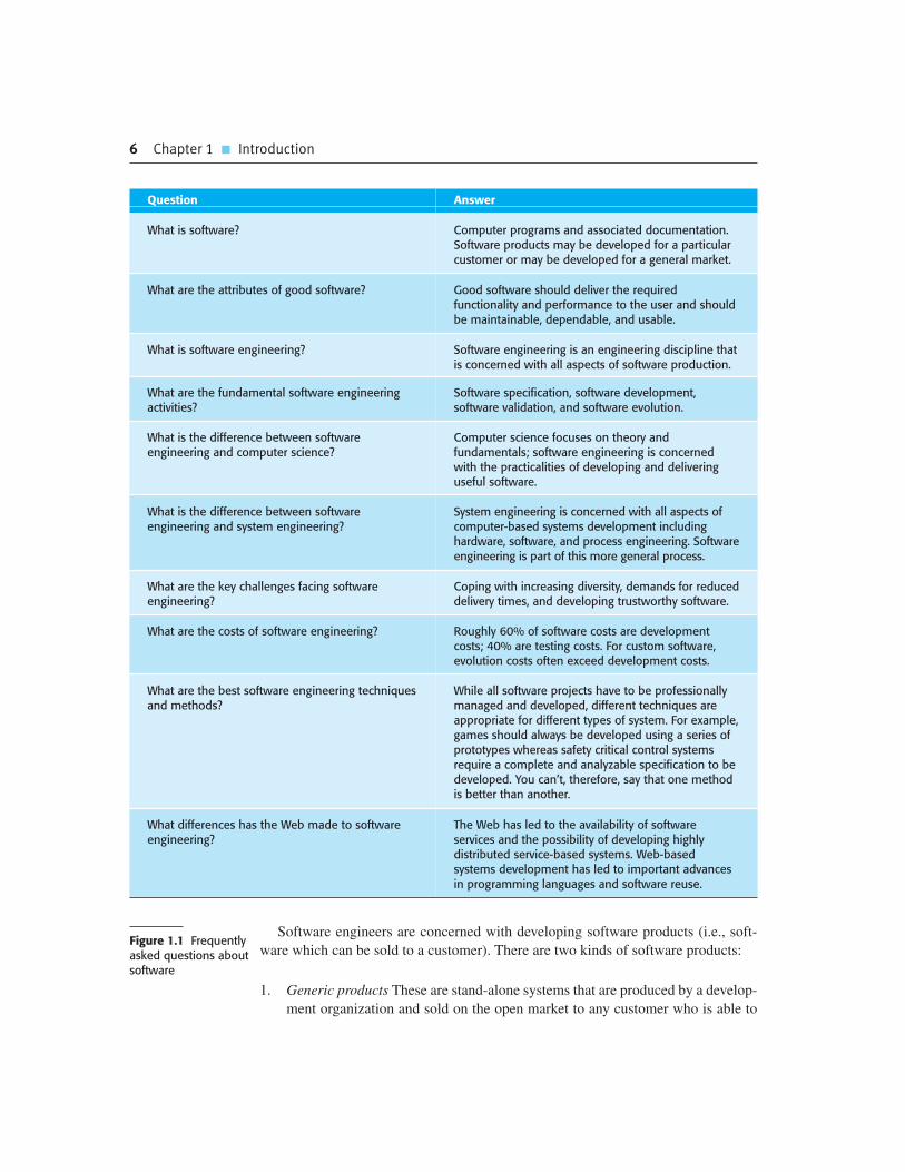
sonal software development. To help you to get a broad view of what software engi-
neering is about, I have summarized some frequently asked questions in Figure 1.1.
Many people think that software is simply another word for computer programs.
However, when we are talking about software engineering, software is not just the
programs themselves but also all associated documentation and configuration data
that is required to make these programs operate correctly. A professionally devel-
oped software system is often more than a single program. The system usually con-
sists of a number of separate programs and configuration files that are used to set up
these programs. It may include system documentation, which describes the structure
of the system; user documentation, which explains how to use the system, and web-
sites for users to download recent product information.
This is one of the important differences between professional and amateur soft-
ware development. If you are writing a program for yourself, no one else will use it
and you don’t have to worry about writing program guides, documenting the pro-
gram design, etc. However, if you are writing software that other people will use and
other engineers will change then you usually have to provide additional information
as well as the code of the program.
6 Chapter 1 � Introduction
Question Answer
What is software? Computer programs and associated documentation.Software products may be developed for a particularcustomer or may be developed for a general market.
What are the attributes of good software? Good software should deliver the requiredfunctionality and performance to the user and shouldbe maintainable, dependable, and usable.
What is software engineering? Software engineering is an engineering discipline thatis concerned with all aspects of software production.
What are the fundamental software engineeringactivities?
Software specification, software development,software validation, and software evolution.
What is the difference between softwareengineering and computer science?
Computer science focuses on theory andfundamentals; software engineering is concernedwith the practicalities of developing and deliveringuseful software.
What is the difference between softwareengineering and system engineering?
System engineering is concerned with all aspects ofcomputer-based systems development includinghardware, software, and process engineering. Softwareengineering is part of this more general process.
What are the key challenges facing softwareengineering?
Coping with increasing diversity, demands for reduceddelivery times, and developing trustworthy software.
What are the costs of software engineering? Roughly 60% of software costs are developmentcosts; 40% are testing costs. For custom software,evolution costs often exceed development costs.
What are the best software engineering techniquesand methods?
While all software projects have to be professionallymanaged and developed, different techniques areappropriate for different types of system. For example,games should always be developed using a series ofprototypes whereas safety critical control systemsrequire a complete and analyzable specification to bedeveloped. You can’t, therefore, say that one methodis better than another.
What differences has the Web made to softwareengineering?
The Web has led to the availability of softwareservices and the possibility of developing highlydistributed service-based systems. Web-basedsystems development has led to important advancesin programming languages and software reuse.
Software engineers are concerned with developing software products (i.e., soft-
ware which can be sold to a customer). There are two kinds of software products:
1. Generic products These are stand-alone systems that are produced by a develop-
ment organization and sold on the open market to any customer who is able to
Figure 1.1 Frequentlyasked questions aboutsoftware

1.1 � Professional software development 7
buy them. Examples of this type of product include software for PCs such as
databases, word processors, drawing packages, and project-management tools.
It also includes so-called vertical applications designed for some specific pur-
pose such as library information systems, accounting systems, or systems for
maintaining dental records.
2. Customized (or bespoke) products These are systems that are commissioned by
a particular customer. A software contractor develops the software especially
for that customer. Examples of this type of software include control systems for
electronic devices, systems written to support a particular business process, and
air traffic control systems.
An important difference between these types of software is that, in generic products,
the organization that develops the software controls the software specification. For cus-
tom products, the specification is usually developed and controlled by the organization
that is buying the software. The software developers must work to that specification.
However, the distinction between these system product types is becoming
increasingly blurred. More and more systems are now being built with a generic
product as a base, which is then adapted to suit the requirements of a customer.
Enterprise Resource Planning (ERP) systems, such as the SAP system, are the best
examples of this approach. Here, a large and complex system is adapted for a com-
pany by incorporating information about business rules and processes, reports
required, and so on.
When we talk about the quality of professional software, we have to take into
account that the software is used and changed by people apart from its developers.
Quality is therefore not just concerned with what the software does. Rather, it has to
include the software’s behavior while it is executing and the structure and organization
of the system programs and associated documentation. This is reflected in so-called
quality or non-functional software attributes. Examples of these attributes are the soft-
ware’s response time to a user query and the understandability of the program code.
The specific set of attributes that you might expect from a software system obvi-
ously depends on its application. Therefore, a banking system must be secure, an
interactive game must be responsive, a telephone switching system must be reliable,
and so on. These can be generalized into the set of attributes shown in Figure 1.2,
which I believe are the essential characteristics of a professional software system.
1.1.1 Software engineering
Software engineering is an engineering discipline that is concerned with all aspects of
software production from the early stages of system specification through to maintain-
ing the system after it has gone into use. In this definition, there are two key phrases:
1. Engineering discipline Engineers make things work. They apply theories, meth-
ods, and tools where these are appropriate. However, they use them selectively

8 Chapter 1 � Introduction
and always try to discover solutions to problems even when there are no appli-
cable theories and methods. Engineers also recognize that they must work to
organizational and financial constraints so they look for solutions within these
constraints.
2. All aspects of software production Software engineering is not just concerned
with the technical processes of software development. It also includes activities
such as software project management and the development of tools, methods,
and theories to support software production.
Engineering is about getting results of the required quality within the schedule
and budget. This often involves making compromises—engineers cannot be perfec-
tionists. People writing programs for themselves, however, can spend as much time
as they wish on the program development.
In general, software engineers adopt a systematic and organized approach to their
work, as this is often the most effective way to produce high-quality software.
However, engineering is all about selecting the most appropriate method for a set of
circumstances so a more creative, less formal approach to development may be
effective in some circumstances. Less formal development is particularly appropri-
ate for the development of web-based systems, which requires a blend of software
and graphical design skills.
Software engineering is important for two reasons:
1. More and more, individuals and society rely on advanced software systems. We
need to be able to produce reliable and trustworthy systems economically and
quickly.
Product characteristics Description
Maintainability Software should be written in such a way so that it can evolve tomeet the changing needs of customers. This is a critical attributebecause software change is an inevitable requirement of achanging business environment.
Dependability and security Software dependability includes a range of characteristicsincluding reliability, security, and safety. Dependable softwareshould not cause physical or economic damage in the event ofsystem failure. Malicious users should not be able to access ordamage the system.
Efficiency Software should not make wasteful use of system resources suchas memory and processor cycles. Efficiency therefore includesresponsiveness, processing time, memory utilization, etc.
Acceptability Software must be acceptable to the type of users for which it isdesigned. This means that it must be understandable, usable, andcompatible with other systems that they use.
Figure 1.2 Essentialattributes of goodsoftware

1.1 � Professional software development 9
2. It is usually cheaper, in the long run, to use software engineering methods and
techniques for software systems rather than just write the programs as if it was a
personal programming project. For most types of systems, the majority of costs
are the costs of changing the software after it has gone into use.
The systematic approach that is used in software engineering is sometimes called
a software process. A software process is a sequence of activities that leads to the
production of a software product. There are four fundamental activities that are com-
mon to all software processes. These activities are:
1. Software specification, where customers and engineers define the software that
is to be produced and the constraints on its operation.
2. Software development, where the software is designed and programmed.
3. Software validation, where the software is checked to ensure that it is what the
customer requires.
4. Software evolution, where the software is modified to reflect changing customer
and market requirements.
Different types of systems need different development processes. For example,
real-time software in an aircraft has to be completely specified before development
begins. In e-commerce systems, the specification and the program are usually devel-
oped together. Consequently, these generic activities may be organized in different
ways and described at different levels of detail depending on the type of software
being developed. I describe software processes in more detail in Chapter 2.
Software engineering is related to both computer science and systems engineering:
1. Computer science is concerned with the theories and methods that underlie com-
puters and software systems, whereas software engineering is concerned with the
practical problems of producing software. Some knowledge of computer science
is essential for software engineers in the same way that some knowledge of
physics is essential for electrical engineers. Computer science theory, however, is
often most applicable to relatively small programs. Elegant theories of computer
science cannot always be applied to large, complex problems that require a soft-
ware solution.
2. System engineering is concerned with all aspects of the development and evo-
lution of complex systems where software plays a major role. System engineer-
ing is therefore concerned with hardware development, policy and process
design and system deployment, as well as software engineering. System engi-
neers are involved in specifying the system, defining its overall architecture,
and then integrating the different parts to create the finished system. They are
less concerned with the engineering of the system components (hardware,
software, etc.).

10 Chapter 1 � Introduction
As I discuss in the next section, there are many different types of software. There is no
universal software engineering method or technique that is applicable for all of these.
However, there are three general issues that affect many different types of software:
1. Heterogeneity Increasingly, systems are required to operate as distributed systems
across networks that include different types of computer and mobile devices. As
well as running on general-purpose computers, software may also have to execute
on mobile phones. You often have to integrate new software with older legacy sys-
tems written in different programming languages. The challenge here is to develop
techniques for building dependable software that is flexible enough to cope with
this heterogeneity.
2. Business and social change Business and society are changing incredibly quickly
as emerging economies develop and new technologies become available. They
need to be able to change their existing software and to rapidly develop new soft-
ware. Many traditional software engineering techniques are time consuming and
delivery of new systems often takes longer than planned. They need to evolve so
that the time required for software to deliver value to its customers is reduced.
3. Security and trust As software is intertwined with all aspects of our lives, it is
essential that we can trust that software. This is especially true for remote soft-
ware systems accessed through a web page or web service interface. We have to
make sure that malicious users cannot attack our software and that information
security is maintained.
Of course, these are not independent issues. For example, it may be necessary to
make rapid changes to a legacy system to provide it with a web service interface. To
address these challenges we will need new tools and techniques as well as innovative
ways of combining and using existing software engineering methods.
1.1.2 Software engineering diversity
Software engineering is a systematic approach to the production of software that
takes into account practical cost, schedule, and dependability issues, as well as the
needs of software customers and producers. How this systematic approach is actu-
ally implemented varies dramatically depending on the organization developing the
software, the type of software, and the people involved in the development process.
There are no universal software engineering methods and techniques that are suit-
able for all systems and all companies. Rather, a diverse set of software engineering
methods and tools has evolved over the past 50 years.
Perhaps the most significant factor in determining which software engineering
methods and techniques are most important is the type of application that is being
developed. There are many different types of application including:
1. Stand-alone applications These are application systems that run on a local com-
puter, such as a PC. They include all necessary functionality and do not need to
1.1 � Professional software development 11
be connected to a network. Examples of such applications are office applica-
tions on a PC, CAD programs, photo manipulation software, etc.
2. Interactive transaction-based applications These are applications that execute
on a remote computer and that are accessed by users from their own PCs or
terminals. Obviously, these include web applications such as e-commerce appli-
cations where you can interact with a remote system to buy goods and services.
This class of application also includes business systems, where a business
provides access to its systems through a web browser or special-purpose client
program and cloud-based services, such as mail and photo sharing. Interactive
applications often incorporate a large data store that is accessed and updated in
each transaction.
3. Embedded control systems These are software control systems that control and
manage hardware devices. Numerically, there are probably more embedded sys-
tems than any other type of system. Examples of embedded systems include the
software in a mobile (cell) phone, software that controls anti-lock braking in a
car, and software in a microwave oven to control the cooking process.
4. Batch processing systems These are business systems that are designed to
process data in large batches. They process large numbers of individual inputs to
create corresponding outputs. Examples of batch systems include periodic
billing systems, such as phone billing systems, and salary payment systems.
5. Entertainment systems These are systems that are primarily for personal use and
which are intended to entertain the user. Most of these systems are games of one
kind or another. The quality of the user interaction offered is the most important
distinguishing characteristic of entertainment systems.
6. Systems for modeling and simulation These are systems that are developed by
scientists and engineers to model physical processes or situations, which
include many, separate, interacting objects. These are often computationally
intensive and require high-performance parallel systems for execution.
7. Data collection systems These are systems that collect data from their environ-
ment using a set of sensors and send that data to other systems for processing.
The software has to interact with sensors and often is installed in a hostile envi-
ronment such as inside an engine or in a remote location.
8. Systems of systems These are systems that are composed of a number of other
software systems. Some of these may be generic software products, such as a
spreadsheet program. Other systems in the assembly may be specially written
for that environment.
Of course, the boundaries between these system types are blurred. If you develop
a game for a mobile (cell) phone, you have to take into account the same constraints
(power, hardware interaction) as the developers of the phone software. Batch pro-
cessing systems are often used in conjunction with web-based systems. For example,
12 Chapter 1 � Introduction
in a company, travel expense claims may be submitted through a web application but
processed in a batch application for monthly payment.
You use different software engineering techniques for each type of system
because the software has quite different characteristics. For example, an embedded
control system in an automobile is safety-critical and is burned into ROM when
installed in the vehicle. It is therefore very expensive to change. Such a system needs
very extensive verification and validation so that the chances of having to recall cars
after sale to fix software problems are minimized. User interaction is minimal (or
perhaps nonexistent) so there is no need to use a development process that relies on
user interface prototyping.
For a web-based system, an approach based on iterative development and delivery
may be appropriate, with the system being composed of reusable components.
However, such an approach may be impractical for a system of systems, where
detailed specifications of the system interactions have to be specified in advance so
that each system can be separately developed.
Nevertheless, there are software engineering fundamentals that apply to all types
of software system:
1. They should be developed using a managed and understood development
process. The organization developing the software should plan the development
process and have clear ideas of what will be produced and when it will be com-
pleted. Of course, different processes are used for different types of software.
2. Dependability and performance are important for all types of systems. Software
should behave as expected, without failures and should be available for use
when it is required. It should be safe in its operation and, as far as possible,
should be secure against external attack. The system should perform efficiently
and should not waste resources.
3. Understanding and managing the software specification and requirements (what
the software should do) are important. You have to know what different customers
and users of the system expect from it and you have to manage their expectations
so that a useful system can be delivered within budget and to schedule.
4. You should make as effective use as possible of existing resources. This means
that, where appropriate, you should reuse software that has already been devel-
oped rather than write new software.
These fundamental notions of process, dependability, requirements, management,
and reuse are important themes of this book. Different methods reflect them in dif-
ferent ways but they underlie all professional software development.
You should notice that these fundamentals do not cover implementation and pro-
gramming. I don’t cover specific programming techniques in this book because these
vary dramatically from one type of system to another. For example, a scripting lan-
guage such as Ruby is used for web-based system programming but would be com-
pletely inappropriate for embedded systems engineering.

1.1 � Professional software development 13
1.1.3 Software engineering and the Web
The development of the World Wide Web has had a profound effect on all of our
lives. Initially, the Web was primarily a universally accessible information store and
it had little effect on software systems. These systems ran on local computers and
were only accessible from within an organization. Around 2000, the Web started to
evolve and more and more functionality was added to browsers. This meant that
web-based systems could be developed where, instead of a special-purpose user
interface, these systems could be accessed using a web browser. This led to the
development of a vast range of new system products that delivered innovative serv-
ices, accessed over the Web. These are often funded by adverts that are displayed on
the user’s screen and do not involve direct payment from users.
As well as these system products, the development of web browsers that could
run small programs and do some local processing led to an evolution in business and
organizational software. Instead of writing software and deploying it on users’ PCs,
the software was deployed on a web server. This made it much cheaper to change
and upgrade the software, as there was no need to install the software on every PC. It
also reduced costs, as user interface development is particularly expensive.
Consequently, wherever it has been possible to do so, many businesses have moved
to web-based interaction with company software systems.
The next stage in the development of web-based systems was the notion of web
services. Web services are software components that deliver specific, useful function-
ality and which are accessed over the Web. Applications are constructed by integrating
these web services, which may be provided by different companies. In principle, this
linking can be dynamic so that an application may use different web services each time
that it is executed. I cover this approach to software development in Chapter 19.
In the last few years, the notion of ‘software as a service’ has been developed. It
has been proposed that software will not normally run on local computers but will
run on ‘computing clouds’ that are accessed over the Internet. If you use a service
such as web-based mail, you are using a cloud-based system. A computing cloud is
a huge number of linked computer systems that is shared by many users. Users do
not buy software but pay according to how much the software is used or are given
free access in return for watching adverts that are displayed on their screen.
The advent of the web, therefore, has led to a significant change in the way that
business software is organized. Before the web, business applications were mostly
monolithic, single programs running on single computers or computer clusters.
Communications were local, within an organization. Now, software is highly distrib-
uted, sometimes across the world. Business applications are not programmed from
scratch but involve extensive reuse of components and programs.
This radical change in software organization has, obviously, led to changes in the
ways that web-based systems are engineered. For example:
1. Software reuse has become the dominant approach for constructing web-based
systems. When building these systems, you think about how you can assemble
them from pre-existing software components and systems.

14 Chapter 1 � Introduction
2. It is now generally recognized that it is impractical to specify all the require-
ments for such systems in advance. Web-based systems should be developed
and delivered incrementally.
3. User interfaces are constrained by the capabilities of web browsers. Although
technologies such as AJAX (Holdener, 2008) mean that rich interfaces can be
created within a web browser, these technologies are still difficult to use. Web
forms with local scripting are more commonly used. Application interfaces on
web-based systems are often poorer than the specially designed user interfaces
on PC system products.
The fundamental ideas of software engineering, discussed in the previous section,
apply to web-based software in the same way that they apply to other types of soft-
ware system. Experience gained with large system development in the 20th century
is still relevant to web-based software.
1.2 Software engineering ethics
Like other engineering disciplines, software engineering is carried out within a
social and legal framework that limits the freedom of people working in that area. As
a software engineer, you must accept that your job involves wider responsibilities
than simply the application of technical skills. You must also behave in an ethical
and morally responsible way if you are to be respected as a professional engineer.
It goes without saying that you should uphold normal standards of honesty and
integrity. You should not use your skills and abilities to behave in a dishonest way or
in a way that will bring disrepute to the software engineering profession. However,
there are areas where standards of acceptable behavior are not bound by laws but by
the more tenuous notion of professional responsibility. Some of these are:
1. Confidentiality You should normally respect the confidentiality of your employ-
ers or clients irrespective of whether or not a formal confidentiality agreement
has been signed.
2. Competence You should not misrepresent your level of competence. You should
not knowingly accept work that is outside your competence.
3. Intellectual property rights You should be aware of local laws governing the use
of intellectual property such as patents and copyright. You should be careful to
ensure that the intellectual property of employers and clients is protected.
4. Computer misuse You should not use your technical skills to misuse other
people’s computers. Computer misuse ranges from relatively trivial (game playing
on an employer’s machine, say) to extremely serious (dissemination of viruses or
other malware).

1.2 � Software engineering ethics 15
Professional societies and institutions have an important role to play in setting
ethical standards. Organizations such as the ACM, the IEEE (Institute of Electrical
and Electronic Engineers), and the British Computer Society publish a code of
professional conduct or code of ethics. Members of these organizations undertake to
follow that code when they sign up for membership. These codes of conduct are gen-
erally concerned with fundamental ethical behavior.
Professional associations, notably the ACM and the IEEE, have cooperated to
produce a joint code of ethics and professional practice. This code exists in both a
short form, shown in Figure 1.3, and a longer form (Gotterbarn et al., 1999) that adds
detail and substance to the shorter version. The rationale behind this code is summa-
rized in the first two paragraphs of the longer form:
Computers have a central and growing role in commerce, industry, government,
medicine, education, entertainment and society at large. Software engineers are
those who contribute by direct participation or by teaching, to the analysis, spec-
ification, design, development, certification, maintenance and testing of software
Software Engineering Code of Ethics and Professional Practice
ACM/IEEE-CS Joint Task Force on Software Engineering Ethics and Professional Practices
PREAMBLEThe short version of the code summarizes aspirations at a high level of the abstraction; the clauses that areincluded in the full version give examples and details of how these aspirations change the way we act assoftware engineering professionals. Without the aspirations, the details can become legalistic and tedious;without the details, the aspirations can become high sounding but empty; together, the aspirations and thedetails form a cohesive code.
Software engineers shall commit themselves to making the analysis, specification, design, development,testing and maintenance of software a beneficial and respected profession. In accordance with theircommitment to the health, safety and welfare of the public, software engineers shall adhere to the followingEight Principles:
1. PUBLIC — Software engineers shall act consistently with the public interest.
2. CLIENT AND EMPLOYER — Software engineers shall act in a manner that is in the
best interests of their client and employer consistent with the public interest.
3. PRODUCT — Software engineers shall ensure that their products and related
modifications meet the highest professional standards possible.
4. JUDGMENT — Software engineers shall maintain integrity and independence in their
professional judgment.
5. MANAGEMENT — Software engineering managers and leaders shall subscribe to and
promote an ethical approach to the management of software development and
maintenance.
6. PROFESSION — Software engineers shall advance the integrity and reputation of
the profession consistent with the public interest.
7. COLLEAGUES — Software engineers shall be fair to and supportive of their
colleagues.
8. SELF — Software engineers shall participate in lifelong learning regarding the
practice of their profession and shall promote an ethical approach to the
practice of the profession.
Figure 1.3 TheACM/IEEE Code ofEthics (© IEEE/ACM1999)

16 Chapter 1 � Introduction
systems. Because of their roles in developing software systems, software engi-
neers have significant opportunities to do good or cause harm, to enable others to
do good or cause harm, or to influence others to do good or cause harm. To
ensure, as much as possible, that their efforts will be used for good, software engi-
neers must commit themselves to making software engineering a beneficial and
respected profession. In accordance with that commitment, software engineers
shall adhere to the following Code of Ethics and Professional Practice.
The Code contains eight Principles related to the behaviour of and decisions
made by professional software engineers, including practitioners, educators,
managers, supervisors and policy makers, as well as trainees and students of
the profession. The Principles identify the ethically responsible relationships
in which individuals, groups, and organizations participate and the primary
obligations within these relationships. The Clauses of each Principle are illus-
trations of some of the obligations included in these relationships. These obli-
gations are founded in the software engineer’s humanity, in special care owed
to people affected by the work of software engineers, and the unique elements
of the practice of software engineering. The Code prescribes these as obliga-
tions of anyone claiming to be or aspiring to be a software engineer.
In any situation where different people have different views and objectives you
are likely to be faced with ethical dilemmas. For example, if you disagree, in princi-
ple, with the policies of more senior management in the company, how should you
react? Clearly, this depends on the particular individuals and the nature of the dis-
agreement. Is it best to argue a case for your position from within the organization or
to resign in principle? If you feel that there are problems with a software project,
when do you reveal these to management? If you discuss these while they are just a
suspicion, you may be overreacting to a situation; if you leave it too late, it may be
impossible to resolve the difficulties.
Such ethical dilemmas face all of us in our professional lives and, fortunately, in
most cases they are either relatively minor or can be resolved without too much dif-
ficulty. Where they cannot be resolved, the engineer is faced with, perhaps, another
problem. The principled action may be to resign from their job but this may well
affect others such as their partner or their children.
A particularly difficult situation for professional engineers arises when their
employer acts in an unethical way. Say a company is responsible for developing a
safety-critical system and, because of time pressure, falsifies the safety validation
records. Is the engineer’s responsibility to maintain confidentiality or to alert the
customer or publicize, in some way, that the delivered system may be unsafe?
The problem here is that there are no absolutes when it comes to safety. Although
the system may not have been validated according to predefined criteria, these crite-
ria may be too strict. The system may actually operate safely throughout its lifetime.
It is also the case that, even when properly validated, the system may fail and cause
an accident. Early disclosure of problems may result in damage to the employer and
other employees; failure to disclose problems may result in damage to others.

1.3 � Case studies 17
You must make up your own mind in these matters. The appropriate ethical posi-
tion here depends entirely on the views of the individuals who are involved. In this
case, the potential for damage, the extent of the damage, and the people affected by
the damage should influence the decision. If the situation is very dangerous, it may
be justified to publicize it using the national press (say). However, you should
always try to resolve the situation while respecting the rights of your employer.
Another ethical issue is participation in the development of military and nuclear
systems. Some people feel strongly about these issues and do not wish to participate in
any systems development associated with military systems. Others will work on mili-
tary systems but not on weapons systems. Yet others feel that national security is an
overriding principle and have no ethical objections to working on weapons systems.
In this situation, it is important that both employers and employees should make
their views known to each other in advance. Where an organization is involved in
military or nuclear work, they should be able to specify that employees must be will-
ing to accept any work assignment. Equally, if an employee is taken on and makes
clear that they do not wish to work on such systems, employers should not put pres-
sure on them to do so at some later date.
The general area of ethics and professional responsibility is becoming more
important as software-intensive systems pervade every aspect of work and everyday
life. It can be considered from a philosophical standpoint where the basic principles
of ethics are considered and software engineering ethics are discussed with reference
to these basic principles. This is the approach taken by Laudon (1995) and to a lesser
extent by Huff and Martin (1995). Johnson’s text on computer ethics (2001) also
approaches the topic from a philosophical perspective.
However, I find that this philosophical approach is too abstract and difficult to
relate to everyday experience. I prefer the more concrete approach embodied in codes
of conduct and practice. I think that ethics are best discussed in a software engineer-
ing context and not as a subject in their own right. In this book, therefore, I do not
include abstract ethical discussions but, where appropriate, include examples in the
exercises that can be the starting point for a group discussion on ethical issues.
1.3 Case studies
To illustrate software engineering concepts, I use examples from three different
types of systems throughout the book. The reason why I have not used a single case
study is that one of the key messages in this book is that software engineering prac-
tice depends on the type of systems being produced. I therefore choose an appropri-
ate example when discussing concepts such as safety and dependability, system
modeling, reuse, etc.
The three types of systems that I use as case studies are:
1. An embedded system This is a system where the software controls a hardware
device and is embedded in that device. Issues in embedded systems typically

18 Chapter 1 � Introduction
include physical size, responsiveness, power management, etc. The example of an
embedded system that I use is a software system to control a medical device.
2. An information system This is a system whose primary purpose is to manage
and provide access to a database of information. Issues in information systems
include security, usability, privacy, and maintaining data integrity. The example
of an information system that I use is a medical records system.
3. A sensor-based data collection system This is a system whose primary purpose
is to collect data from a set of sensors and process that data in some way. The
key requirements of such systems are reliability, even in hostile environmental
conditions, and maintainability. The example of a data collection system that
I use is a wilderness weather station.
I introduce each of these systems in this chapter, with more information about
each of them available on the Web.
1.3.1 An insulin pump control system
An insulin pump is a medical system that simulates the operation of the pancreas (an
internal organ). The software controlling this system is an embedded system, which
collects information from a sensor and controls a pump that delivers a controlled
dose of insulin to a user.
People who suffer from diabetes use the system. Diabetes is a relatively common
condition where the human pancreas is unable to produce sufficient quantities of a
hormone called insulin. Insulin metabolises glucose (sugar) in the blood. The con-
ventional treatment of diabetes involves regular injections of genetically engineered
insulin. Diabetics measure their blood sugar levels using an external meter and then
calculate the dose of insulin that they should inject.
The problem with this treatment is that the level of insulin required does not just
depend on the blood glucose level but also on the time of the last insulin injection.
This can lead to very low levels of blood glucose (if there is too much insulin) or very
high levels of blood sugar (if there is too little insulin). Low blood glucose is, in the
short term, a more serious condition as it can result in temporary brain malfunctioning
and, ultimately, unconsciousness and death. In the long term, however, continual high
levels of blood glucose can lead to eye damage, kidney damage, and heart problems.
Current advances in developing miniaturized sensors have meant that it is now pos-
sible to develop automated insulin delivery systems. These systems monitor blood sugar
levels and deliver an appropriate dose of insulin when required. Insulin delivery systems
like this already exist for the treatment of hospital patients. In the future, it may be pos-
sible for many diabetics to have such systems permanently attached to their bodies.
A software-controlled insulin delivery system might work by using a micro-
sensor embedded in the patient to measure some blood parameter that is proportional
to the sugar level. This is then sent to the pump controller. This controller computes
the sugar level and the amount of insulin that is needed. It then sends signals to a
miniaturized pump to deliver the insulin via a permanently attached needle.

1.3 � Case studies 19
Figure 1.4 shows the hardware components and organization of the insulin
pump. To understand the examples in this book, all you need to know is that the
blood sensor measures the electrical conductivity of the blood under different
conditions and that these values can be related to the blood sugar level. The
insulin pump delivers one unit of insulin in response to a single pulse from a con-
troller. Therefore, to deliver 10 units of insulin, the controller sends 10 pulses to
the pump. Figure 1.5 is a UML activity model that illustrates how the software
transforms an input blood sugar level to a sequence of commands that drive the
insulin pump.
Clearly, this is a safety-critical system. If the pump fails to operate or does not
operate correctly, then the user’s health may be damaged or they may fall into a
coma because their blood sugar levels are too high or too low. There are, therefore,
two essential high-level requirements that this system must meet:
1. The system shall be available to deliver insulin when required.
2. The system shall perform reliably and deliver the correct amount of insulin to
counteract the current level of blood sugar.
NeedleAssembly
Sensor
Display1 Display2
Alarm
Pump Clock
Controller
Power Supply
Insulin Reservoir
Figure 1.4 Insulinpump hardware
BloodSensor
InsulinPump
BloodSugar
Analyze SensorReading
ComputeInsulin
InsulinDose
InsulinLog
Log DoseCompute Pump
CommandsPumpData
Control InsulinPump
Figure 1.5 Activitymodel of the insulinpump

20 Chapter 1 � Introduction
The system must therefore be designed and implemented to ensure that the sys-
tem always meets these requirements. More detailed requirements and discussions
of how to ensure that the system is safe are discussed in later chapters.
1.3.2 A patient information system for mental health care
A patient information system to support mental health care is a medical informa-
tion system that maintains information about patients suffering from mental
health problems and the treatments that they have received. Most mental health
patients do not require dedicated hospital treatment but need to attend specialist
clinics regularly where they can meet a doctor who has detailed knowledge of
their problems. To make it easier for patients to attend, these clinics are not just
run in hospitals. They may also be held in local medical practices or community
centers.
The MHC-PMS (Mental Health Care-Patient Management System) is an informa-
tion system that is intended for use in clinics. It makes use of a centralized database of
patient information but has also been designed to run on a PC, so that it may be accessed
and used from sites that do not have secure network connectivity. When the local sys-
tems have secure network access, they use patient information in the database but they
can download and use local copies of patient records when they are disconnected. The
system is not a complete medical records system so does not maintain information
about other medical conditions. However, it may interact and exchange data with other
clinical information systems. Figure 1.6 illustrates the organization of the MHC-PMS.
The MHC-PMS has two overall goals:
1. To generate management information that allows health service managers to
assess performance against local and government targets.
2. To provide medical staff with timely information to support the treatment of
patients.
MHC-PMS Server
Patient Database
MHC-PMSLocal
MHC-PMSLocal
MHC-PMSLocal
Figure 1.6 Theorganization ofthe MHC-PMS

1.3 � Case studies 21
The nature of mental health problems is such that patients are often disorganized
so may miss appointments, deliberately or accidentally lose prescriptions and med-
ication, forget instructions, and make unreasonable demands on medical staff. They
may drop in on clinics unexpectedly. In a minority of cases, they may be a danger to
themselves or to other people. They may regularly change address or may be home-
less on a long-term or short-term basis. Where patients are dangerous, they may need
to be ‘sectioned’—confined to a secure hospital for treatment and observation.
Users of the system include clinical staff such as doctors, nurses, and health visi-
tors (nurses who visit people at home to check on their treatment). Nonmedical users
include receptionists who make appointments, medical records staff who maintain
the records system, and administrative staff who generate reports.
The system is used to record information about patients (name, address, age, next
of kin, etc.), consultations (date, doctor seen, subjective impressions of the patient,
etc.), conditions, and treatments. Reports are generated at regular intervals for med-
ical staff and health authority managers. Typically, reports for medical staff focus on
information about individual patients whereas management reports are anonymized
and are concerned with conditions, costs of treatment, etc.
The key features of the system are:
1. Individual care management Clinicians can create records for patients, edit the
information in the system, view patient history, etc. The system supports data
summaries so that doctors who have not previously met a patient can quickly
learn about the key problems and treatments that have been prescribed.
2. Patient monitoring The system regularly monitors the records of patients that
are involved in treatment and issues warnings if possible problems are detected.
Therefore, if a patient has not seen a doctor for some time, a warning may be
issued. One of the most important elements of the monitoring system is to keep
track of patients who have been sectioned and to ensure that the legally required
checks are carried out at the right time.
3. Administrative reporting The system generates monthly management reports
showing the number of patients treated at each clinic, the number of patients
who have entered and left the care system, number of patients sectioned, the
drugs prescribed and their costs, etc.
Two different laws affect the system. These are laws on data protection that govern
the confidentiality of personal information and mental health laws that govern the com-
pulsory detention of patients deemed to be a danger to themselves or others. Mental
health is unique in this respect as it is the only medical speciality that can recommend
the detention of patients against their will. This is subject to very strict legislative safe-
guards. One of the aims of the MHC-PMS is to ensure that staff always act in accor-
dance with the law and that their decisions are recorded for judicial review if necessary.
As in all medical systems, privacy is a critical system requirement. It is essential that
patient information is confidential and is never disclosed to anyone apart from author-
ized medical staff and the patient themselves. The MHC-PMS is also a safety-critical

22 Chapter 1 � Introduction
system. Some mental illnesses cause patients to become suicidal or a danger to other
people. Wherever possible, the system should warn medical staff about potentially sui-
cidal or dangerous patients.
The overall design of the system has to take into account privacy and safety
requirements. The system must be available when needed otherwise safety may be
compromised and it may be impossible to prescribe the correct medication to patients.
There is a potential conflict here—privacy is easiest to maintain when there is only a
single copy of the system data. However, to ensure availability in the event of server
failure or when disconnected from a network, multiple copies of the data should be
maintained. I discuss the trade-offs between these requirements in later chapters.
1.3.3 A wilderness weather station
To help monitor climate change and to improve the accuracy of weather forecasts in
remote areas, the government of a country with large areas of wilderness decides to
deploy several hundred weather stations in remote areas. These weather stations col-
lect data from a set of instruments that measure temperature and pressure, sunshine,
rainfall, wind speed, and wind direction.
Wilderness weather stations are part of a larger system (Figure 1.7), which is a
weather information system that collects data from weather stations and makes it
available to other systems for processing. The systems in Figure 1.7 are:
1. The weather station system This is responsible for collecting weather data,
carrying out some initial data processing, and transmitting it to the data manage-
ment system.
2. The data management and archiving system This system collects the data from
all of the wilderness weather stations, carries out data processing and analysis,
and archives the data in a form that can be retrieved by other systems, such as
weather forecasting systems.
3. The station maintenance system This system can communicate by satellite
with all wilderness weather stations to monitor the health of these systems and
provide reports of problems. It can update the embedded software in these
systems. In the event of system problems, this system can also be used to
remotely control a wilderness weather system.
«system»Data Management
and Archiving
«system»Station Maintenance
«system»Weather Station
Figure 1.7 The weatherstation’s environment

1.3 � Case studies 23
In Figure 1.7, I have used the UML package symbol to indicate that each system
is a collection of components and have identified the separate systems, using the
UML stereotype «system». The associations between the packages indicate there is
an exchange of information but, at this stage, there is no need to define them in any
more detail.
Each weather station includes a number of instruments that measure weather
parameters such as the wind speed and direction, the ground and air temperatures,
the barometric pressure, and the rainfall over a 24-hour period. Each of these instru-
ments is controlled by a software system that takes parameter readings periodically
and manages the data collected from the instruments.
The weather station system operates by collecting weather observations at fre-
quent intervals—for example, temperatures are measured every minute. However,
because the bandwidth to the satellite is relatively narrow, the weather station carries
out some local processing and aggregation of the data. It then transmits this aggre-
gated data when requested by the data collection system. If, for whatever reason, it is
impossible to make a connection, then the weather station maintains the data locally
until communication can be resumed.
Each weather station is battery-powered and must be entirely self-contained—there
are no external power or network cables available. All communications are through a rel-
atively slow-speed satellite link and the weather station must include some mechanism
(solar or wind power) to charge its batteries. As they are deployed in wilderness areas,
they are exposed to severe environmental conditions and may be damaged by animals.
The station software is therefore not just concerned with data collection. It must also:
1. Monitor the instruments, power, and communication hardware and report faults
to the management system.
2. Manage the system power, ensuring that batteries are charged whenever the
environmental conditions permit but also that generators are shut down in
potentially damaging weather conditions, such as high wind.
3. Allow for dynamic reconfiguration where parts of the software are replaced
with new versions and where backup instruments are switched into the system
in the event of system failure.
Because weather stations have to be self-contained and unattended, this means
that the software installed is complex, even though the data collection functionality
is fairly simple.

24 Chapter 1 � Introduction
K E Y P O I N T S
� Software engineering is an engineering discipline that is concerned with all aspects of software
production.
� Software is not just a program or programs but also includes documentation. Essential software
product attributes are maintainability, dependability, security, efficiency, and acceptability.
� The software process includes all of the activities involved in software development. The high-
level activities of specification, development, validation, and evolution are part of all software
processes.
� The fundamental notions of software engineering are universally applicable to all types of
system development. These fundamentals include software processes, dependability, security,
requirements, and reuse.
� There are many different types of systems and each requires appropriate software engineering
tools and techniques for their development. There are few, if any, specific design and
implementation techniques that are applicable to all kinds of systems.
� The fundamental ideas of software engineering are applicable to all types of software systems.
These fundamentals include managed software processes, software dependability and security,
requirements engineering, and software reuse.
� Software engineers have responsibilities to the engineering profession and society. They should
not simply be concerned with technical issues.
� Professional societies publish codes of conduct that set out the standards of behavior expected
of their members.
F U RT H E R R E A D I N G
‘No silver bullet: Essence and accidents of software engineering’. In spite of its age, this paper is a
good general introduction to the problems of software engineering. The essential message of the
paper still hasn’t changed. (F. P. Brooks, IEEE Computer, 20 (4), April 1987.)
http://doi.ieeecomputersociety.org/10.1109/MC.1987.1663532.
‘Software engineering code of ethics is approved’. An article that discusses the background to the
development of the ACM/IEEE Code of Ethics and that includes both the short and long form of the
code. (Comm. ACM, D. Gotterbarn, K. Miller, and S. Rogerson, October 1999.)
http://portal.acm.org/citation.cfm?doid=317665.317682.
Professional Issues in Software Engineering. This is an excellent book discussing legal and
professional issues as well as ethics. I prefer its practical approach to more theoretical texts on
ethics. (F. Bott, A. Coleman, J. Eaton and D. Rowland, 3rd edition, 2000, Taylor and Francis.)

Chapter 1 � Exercises 25
IEEE Software, March/April 2002. This is a special issue of the magazine devoted to the
development of Web-based software. This area has changed very quickly so some articles are a little
dated but most are still relevant. (IEEE Software, 19 (2), 2002.)
http://www2.computer.org/portal/web/software.
‘A View of 20th and 21st Century Software Engineering’. A backward and forward look at software
engineering from one of the first and most distinguished software engineers. Barry Boehm identifies
timeless software engineering principles but also suggests that some commonly used practices are
obsolete. (B. Boehm, Proc. 28th Software Engineering Conf., Shanghai. 2006.)
http://doi.ieeecomputersociety.org/10.1145/1134285.1134288.
‘Software Engineering Ethics’. Special issue of IEEE Computer, with a number of papers on the topic.
(IEEE Computer, 42 (6), June 2009.)
E X E R C I S E S
1.1. Explain why professional software is not just the programs that are developed for a customer.
1.2. What is the most important difference between generic software product development and
custom software development? What might this mean in practice for users of generic software
products?
1.3. What are the four important attributes that all professional software should have? Suggest
four other attributes that may sometimes be significant.
1.4. Apart from the challenges of heterogeneity, business and social change, and trust and
security, identify other problems and challenges that software engineering is likely to face in
the 21st century (Hint: think about the environment).
1.5. Based on your own knowledge of some of the application types discussed in section 1.1.2,
explain, with examples, why different application types require specialized software
engineering techniques to support their design and development.
1.6. Explain why there are fundamental ideas of software engineering that apply to all types of
software systems.
1.7. Explain how the universal use of the Web has changed software systems.
1.8. Discuss whether professional engineers should be certified in the same way as doctors or
lawyers.
1.9. For each of the clauses in the ACM/IEEE Code of Ethics shown in Figure 1.3, suggest an
appropriate example that illustrates that clause.
1.10. To help counter terrorism, many countries are planning or have developed computer systems
that track large numbers of their citizens and their actions. Clearly this has privacy
implications. Discuss the ethics of working on the development of this type of system.

26 Chapter 1 � Introduction
R E F E R E N C E S
Gotterbarn, D., Miller, K. and Rogerson, S. (1999). Software Engineering Code of Ethics is Approved.
Comm. ACM, 42 (10), 102–7.
Holdener, A. T. (2008). Ajax: The Definitive Guide. Sebastopol, Ca.: O’Reilly and Associates.
Huff, C. and Martin, C. D. (1995). Computing Consequences: A Framework for Teaching Ethical
Computing. Comm. ACM, 38 (12), 75–84.
Johnson, D. G. (2001). Computer Ethics. Englewood Cliffs, NJ: Prentice Hall.
Laudon, K. (1995). Ethical Concepts and Information Technology. Comm. ACM, 38 (12), 33–9.
Naur, P. and Randell, B. (1969). Software Engineering: Report on a Conference sponsored by the
NATO Science Committee, Garmisch, Germany. 7th to 11th October 1968.

Software processes
2
Objectives
The objective of this chapter is to introduce you to the idea of a software
process—a coherent set of activities for software production. When you
have read this chapter you will:
� understand the concepts of software processes and software process
models;
� have been introduced to three generic software process models and
when they might be used;
� know about the fundamental process activities of software
requirements engineering, software development, testing, and
evolution;
� understand why processes should be organized to cope with changes
in the software requirements and design;
� understand how the Rational Unified Process integrates good software
engineering practice to create adaptable software processes.
Contents
2.1 Software process models
2.2 Process activities
2.3 Coping with change
2.4 The Rational Unified Process
28 Chapter 2 � Software processes
A software process is a set of related activities that leads to the production of a soft-
ware product. These activities may involve the development of software from scratch
in a standard programming language like Java or C. However, business applications
are not necessarily developed in this way. New business software is now often devel-
oped by extending and modifying existing systems or by configuring and integrating
off-the-shelf software or system components.
There are many different software processes but all must include four activities
that are fundamental to software engineering:
1. Software specification The functionality of the software and constraints on its
operation must be defined.
2. Software design and implementation The software to meet the specification
must be produced.
3. Software validation The software must be validated to ensure that it does what
the customer wants.
4. Software evolution The software must evolve to meet changing customer needs.
In some form, these activities are part of all software processes. In practice, of
course, they are complex activities in themselves and include sub-activities such as
requirements validation, architectural design, unit testing, etc. There are also support-
ing process activities such as documentation and software configuration management.
When we describe and discuss processes, we usually talk about the activities in
these processes such as specifying a data model, designing a user interface, etc., and
the ordering of these activities. However, as well as activities, process descriptions
may also include:
1. Products, which are the outcomes of a process activity. For example, the out-
come of the activity of architectural design may be a model of the software
architecture.
2. Roles, which reflect the responsibilities of the people involved in the process.
Examples of roles are project manager, configuration manager, programmer, etc.
3. Pre- and post-conditions, which are statements that are true before and after a
process activity has been enacted or a product produced. For example, before
architectural design begins, a pre-condition may be that all requirements have
been approved by the customer; after this activity is finished, a post-condition
might be that the UML models describing the architecture have been reviewed.
Software processes are complex and, like all intellectual and creative processes,
rely on people making decisions and judgments. There is no ideal process and most
organizations have developed their own software development processes. Processes
have evolved to take advantage of the capabilities of the people in an organization
and the specific characteristics of the systems that are being developed. For some

2.1 � Software process models 29
systems, such as critical systems, a very structured development process is required.
For business systems, with rapidly changing requirements, a less formal, flexible
process is likely to be more effective.
Sometimes, software processes are categorized as either plan-driven or agile
processes. Plan-driven processes are processes where all of the process activities are
planned in advance and progress is measured against this plan. In agile processes,
which I discuss in Chapter 3, planning is incremental and it is easier to change the
process to reflect changing customer requirements. As Boehm and Turner (2003)
discuss, each approach is suitable for different types of software. Generally, you
need to find a balance between plan-driven and agile processes.
Although there is no ‘ideal’ software process, there is scope for improving the
software process in many organizations. Processes may include outdated techniques
or may not take advantage of the best practice in industrial software engineering.
Indeed, many organizations still do not take advantage of software engineering
methods in their software development.
Software processes can be improved by process standardization where the diver-
sity in software processes across an organization is reduced. This leads to improved
communication and a reduction in training time, and makes automated process sup-
port more economical. Standardization is also an important first step in introducing
new software engineering methods and techniques and good software engineering
practice. I discuss software process improvement in more detail in Chapter 26.
2.1 Software process models
As I explained in Chapter 1, a software process model is a simplified representation
of a software process. Each process model represents a process from a particular per-
spective, and thus provides only partial information about that process. For example,
a process activity model shows the activities and their sequence but may not show
the roles of the people involved in these activities. In this section, I introduce a num-
ber of very general process models (sometimes called ‘process paradigms’) and
present these from an architectural perspective. That is, we see the framework of the
process but not the details of specific activities.
These generic models are not definitive descriptions of software processes. Rather,
they are abstractions of the process that can be used to explain different approaches to
software development. You can think of them as process frameworks that may be
extended and adapted to create more specific software engineering processes.
The process models that I cover here are:
1. The waterfall model This takes the fundamental process activities of specifica-
tion, development, validation, and evolution and represents them as separate
process phases such as requirements specification, software design, implemen-
tation, testing, and so on.
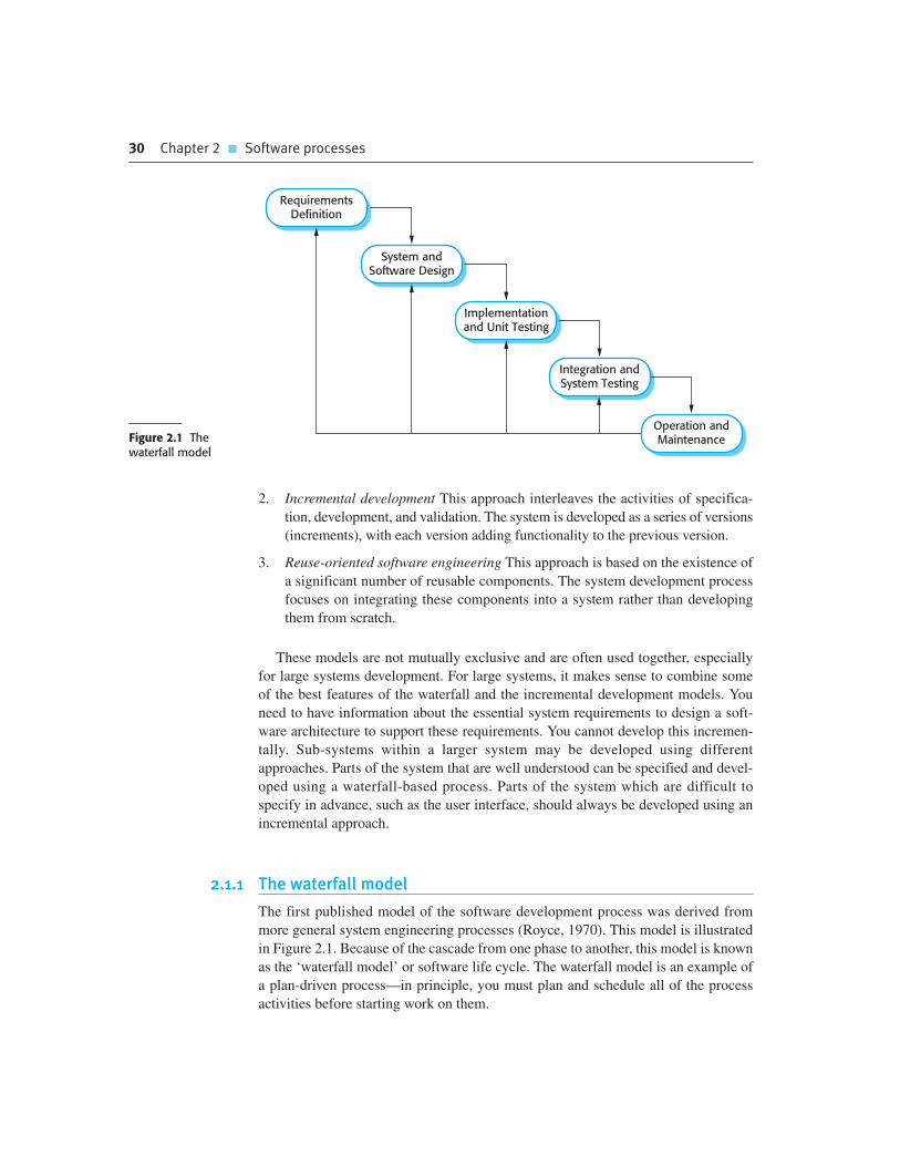
30 Chapter 2 � Software processes
2. Incremental development This approach interleaves the activities of specifica-
tion, development, and validation. The system is developed as a series of versions
(increments), with each version adding functionality to the previous version.
3. Reuse-oriented software engineering This approach is based on the existence of
a significant number of reusable components. The system development process
focuses on integrating these components into a system rather than developing
them from scratch.
These models are not mutually exclusive and are often used together, especially
for large systems development. For large systems, it makes sense to combine some
of the best features of the waterfall and the incremental development models. You
need to have information about the essential system requirements to design a soft-
ware architecture to support these requirements. You cannot develop this incremen-
tally. Sub-systems within a larger system may be developed using different
approaches. Parts of the system that are well understood can be specified and devel-
oped using a waterfall-based process. Parts of the system which are difficult to
specify in advance, such as the user interface, should always be developed using an
incremental approach.
2.1.1 The waterfall model
The first published model of the software development process was derived from
more general system engineering processes (Royce, 1970). This model is illustrated
in Figure 2.1. Because of the cascade from one phase to another, this model is known
as the ‘waterfall model’ or software life cycle. The waterfall model is an example of
a plan-driven process—in principle, you must plan and schedule all of the process
activities before starting work on them.
RequirementsDefinition
System andSoftware Design
Implementationand Unit Testing
Integration andSystem Testing
Operation andMaintenanceFigure 2.1 The
waterfall model

2.1 � Software process models 31
The principal stages of the waterfall model directly reflect the fundamental devel-
opment activities:
1. Requirements analysis and definition The system’s services, constraints, and
goals are established by consultation with system users. They are then defined
in detail and serve as a system specification.
2. System and software design The systems design process allocates the require-
ments to either hardware or software systems by establishing an overall system
architecture. Software design involves identifying and describing the fundamen-
tal software system abstractions and their relationships.
3. Implementation and unit testing During this stage, the software design is real-
ized as a set of programs or program units. Unit testing involves verifying that
each unit meets its specification.
4. Integration and system testing The individual program units or programs
are integrated and tested as a complete system to ensure that the software
requirements have been met. After testing, the software system is delivered to
the customer.
5. Operation and maintenance Normally (although not necessarily), this is the
longest life cycle phase. The system is installed and put into practical use.
Maintenance involves correcting errors which were not discovered in earlier
stages of the life cycle, improving the implementation of system units and
enhancing the system’s services as new requirements are discovered.
In principle, the result of each phase is one or more documents that are approved
(‘signed off’). The following phase should not start until the previous phase has fin-
ished. In practice, these stages overlap and feed information to each other. During
design, problems with requirements are identified. During coding, design problems
are found and so on. The software process is not a simple linear model but involves
feedback from one phase to another. Documents produced in each phase may then
have to be modified to reflect the changes made.
Because of the costs of producing and approving documents, iterations can be
costly and involve significant rework. Therefore, after a small number of iterations,
it is normal to freeze parts of the development, such as the specification, and to con-
tinue with the later development stages. Problems are left for later resolution,
ignored, or programmed around. This premature freezing of requirements may mean
that the system won’t do what the user wants. It may also lead to badly structured
systems as design problems are circumvented by implementation tricks.
During the final life cycle phase (operation and maintenance) the software is put
into use. Errors and omissions in the original software requirements are discovered.
Program and design errors emerge and the need for new functionality is identified.
The system must therefore evolve to remain useful. Making these changes (software
maintenance) may involve repeating previous process stages.

32 Chapter 2 � Software processes
Cleanroom software engineering
An example of a formal development process, originally developed by IBM, is the Cleanroom process. In theCleanroom process each software increment is formally specified and this specification is transformed into animplementation. Software correctness is demonstrated using a formal approach. There is no unit testing fordefects in the process and the system testing is focused on assessing the system’s reliability.
The objective of the Cleanroom process is zero-defects software so that delivered systems have a high levelof reliability.
http://www.SoftwareEngineering-9.com/Web/Cleanroom/
The waterfall model is consistent with other engineering process models and docu-
mentation is produced at each phase. This makes the process visible so managers can
monitor progress against the development plan. Its major problem is the inflexible par-
titioning of the project into distinct stages. Commitments must be made at an early stage
in the process, which makes it difficult to respond to changing customer requirements.
In principle, the waterfall model should only be used when the requirements are
well understood and unlikely to change radically during system development.
However, the waterfall model reflects the type of process used in other engineering
projects. As is easier to use a common management model for the whole project,
software processes based on the waterfall model are still commonly used.
An important variant of the waterfall model is formal system development, where
a mathematical model of a system specification is created. This model is then
refined, using mathematical transformations that preserve its consistency, into exe-
cutable code. Based on the assumption that your mathematical transformations are
correct, you can therefore make a strong argument that a program generated in this
way is consistent with its specification.
Formal development processes, such as that based on the B method (Schneider,
2001; Wordsworth, 1996) are particularly suited to the development of systems that
have stringent safety, reliability, or security requirements. The formal approach sim-
plifies the production of a safety or security case. This demonstrates to customers or
regulators that the system actually meets its safety or security requirements.
Processes based on formal transformations are generally only used in the devel-
opment of safety-critical or security-critical systems. They require specialized
expertise. For the majority of systems this process does not offer significant cost-
benefits over other approaches to system development.
2.1.2 Incremental development
Incremental development is based on the idea of developing an initial implementa-
tion, exposing this to user comment and evolving it through several versions until an
adequate system has been developed (Figure 2.2). Specification, development, and

2.1 � Software process models 33
validation activities are interleaved rather than separate, with rapid feedback across
activities.
Incremental software development, which is a fundamental part of agile
approaches, is better than a waterfall approach for most business, e-commerce, and
personal systems. Incremental development reflects the way that we solve prob-
lems. We rarely work out a complete problem solution in advance but move toward
a solution in a series of steps, backtracking when we realize that we have made a
mistake. By developing the software incrementally, it is cheaper and easier to make
changes in the software as it is being developed.
Each increment or version of the system incorporates some of the functionality
that is needed by the customer. Generally, the early increments of the system include
the most important or most urgently required functionality. This means that the
customer can evaluate the system at a relatively early stage in the development to see
if it delivers what is required. If not, then only the current increment has to be
changed and, possibly, new functionality defined for later increments.
Incremental development has three important benefits, compared to the waterfall
model:
1. The cost of accommodating changing customer requirements is reduced. The
amount of analysis and documentation that has to be redone is much less than is
required with the waterfall model.
2. It is easier to get customer feedback on the development work that has been
done. Customers can comment on demonstrations of the software and see how
much has been implemented. Customers find it difficult to judge progress from
software design documents.
3. More rapid delivery and deployment of useful software to the customer is possi-
ble, even if all of the functionality has not been included. Customers are able to
use and gain value from the software earlier than is possible with a waterfall
process.
ConcurrentActivities
ValidationFinal
Version
DevelopmentIntermediate
Versions
SpecificationInitial
Version
OutlineDescription
Figure 2.2 Incrementaldevelopment

34 Chapter 2 � Software processes
Incremental development in some form is now the most common approach for the
development of application systems. This approach can be either plan-driven, agile,
or, more usually, a mixture of these approaches. In a plan-driven approach, the system
increments are identified in advance; if an agile approach is adopted, the early incre-
ments are identified but the development of later increments depends on progress and
customer priorities.
From a management perspective, the incremental approach has two problems:
1. The process is not visible. Managers need regular deliverables to measure
progress. If systems are developed quickly, it is not cost-effective to produce
documents that reflect every version of the system.
2. System structure tends to degrade as new increments are added. Unless time and
money is spent on refactoring to improve the software, regular change tends to
corrupt its structure. Incorporating further software changes becomes increas-
ingly difficult and costly.
The problems of incremental development become particularly acute for large,
complex, long-lifetime systems, where different teams develop different parts of the
system. Large systems need a stable framework or architecture and the responsibili-
ties of the different teams working on parts of the system need to be clearly defined
with respect to that architecture. This has to be planned in advance rather than devel-
oped incrementally.
You can develop a system incrementally and expose it to customers for comment,
without actually delivering it and deploying it in the customer’s environment.
Incremental delivery and deployment means that the software is used in real, opera-
tional processes. This is not always possible as experimenting with new software can
disrupt normal business processes. I discuss the advantages and disadvantages of incre-
mental delivery in Section 2.3.2.
Problems with incremental development
Although incremental development has many advantages, it is not problem-free. The primary cause of thedifficulty is the fact that large organizations have bureaucratic procedures that have evolved over time and theremay be a mismatch between these procedures and a more informal iterative or agile process.
Sometimes these procedures are there for good reasons—for example, there may be procedures to ensurethat the software properly implements external regulations (e.g., in the United States, the Sarbanes-Oxleyaccounting regulations). Changing these procedures may not be possible so process conflicts may beunavoidable.
http://www.SoftwareEngineering-9.com/Web/IncrementalDev/

2.1 � Software process models 35
2.1.3 Reuse-oriented software engineering
In the majority of software projects, there is some software reuse. This often happens
informally when people working on the project know of designs or code that are
similar to what is required. They look for these, modify them as needed, and incor-
porate them into their system.
This informal reuse takes place irrespective of the development process that is
used. However, in the 21st century, software development processes that focus on the
reuse of existing software have become widely used. Reuse-oriented approaches rely
on a large base of reusable software components and an integrating framework for
the composition of these components. Sometimes, these components are systems in
their own right (COTS or commercial off-the-shelf systems) that may provide spe-
cific functionality such as word processing or a spreadsheet.
A general process model for reuse-based development is shown in Figure 2.3.
Although the initial requirements specification stage and the validation stage are
comparable with other software processes, the intermediate stages in a reuse-
oriented process are different. These stages are:
1. Component analysis Given the requirements specification, a search is made for
components to implement that specification. Usually, there is no exact match and
the components that may be used only provide some of the functionality required.
2. Requirements modification During this stage, the requirements are analyzed using
information about the components that have been discovered. They are then mod-
ified to reflect the available components. Where modifications are impossible, the
component analysis activity may be re-entered to search for alternative solutions.
3. System design with reuse During this phase, the framework of the system is
designed or an existing framework is reused. The designers take into account the
components that are reused and organize the framework to cater for this. Some
new software may have to be designed if reusable components are not available.
4. Development and integration Software that cannot be externally procured is
developed, and the components and COTS systems are integrated to create the
new system. System integration, in this model, may be part of the development
process rather than a separate activity.
RequirementsSpecification
ComponentAnalysis
Developmentand Integration
System Designwith Reuse
RequirementsModification
SystemValidationFigure 2.3 Reuse-oriented
software engineering

36 Chapter 2 � Software processes
There are three types of software component that may be used in a reuse-oriented
process:
1. Web services that are developed according to service standards and which are
available for remote invocation.
2. Collections of objects that are developed as a package to be integrated with a
component framework such as .NET or J2EE.
3. Stand-alone software systems that are configured for use in a particular
environment.
Reuse-oriented software engineering has the obvious advantage of reducing the
amount of software to be developed and so reducing cost and risks. It usually also
leads to faster delivery of the software. However, requirements compromises are
inevitable and this may lead to a system that does not meet the real needs of users.
Furthermore, some control over the system evolution is lost as new versions of the
reusable components are not under the control of the organization using them.
Software reuse is very important and I have dedicated several chapters in the third
part of the book to this topic. General issues of software reuse and COTS reuse are
covered in Chapter 16, component-based software engineering in Chapters 17 and
18, and service-oriented systems in Chapter 19.
2.2 Process activities
Real software processes are interleaved sequences of technical, collaborative, and
managerial activities with the overall goal of specifying, designing, implementing,
and testing a software system. Software developers use a variety of different software
tools in their work. Tools are particularly useful for supporting the editing of different
types of document and for managing the immense volume of detailed information
that is generated in a large software project.
The four basic process activities of specification, development, validation, and evo-
lution are organized differently in different development processes. In the waterfall
model, they are organized in sequence, whereas in incremental development they are
interleaved. How these activities are carried out depends on the type of software,
people, and organizational structures involved. In extreme programming, for example,
specifications are written on cards. Tests are executable and developed before the
program itself. Evolution may involve substantial system restructuring or refactoring.
2.2.1 Software specification
Software specification or requirements engineering is the process of understanding
and defining what services are required from the system and identifying the con-
straints on the system’s operation and development. Requirements engineering is a

2.2 � Process activities 37
Software development tools
Software development tools (sometimes called Computer-Aided Software Engineering or CASE tools) areprograms that are used to support software engineering process activities. These tools therefore include designeditors, data dictionaries, compilers, debuggers, system building tools, etc.
Software tools provide process support by automating some process activities and by providing informationabout the software that is being developed. Examples of activities that can be automated include:
� The development of graphical system models as part of the requirements specification or the software design
� The generation of code from these graphical models
� The generation of user interfaces from a graphical interface description that is created interactively by the user
� Program debugging through the provision of information about an executing program
� The automated translation of programs written using an old version of a programming language to a morerecent version
Tools may be combined within a framework called an Interactive Development Environment or IDE. Thisprovides a common set of facilities that tools can use so that it is easier for tools to communicate and operatein an integrated way. The ECLIPSE IDE is widely used and has been designed to incorporate many differenttypes of software tools.
http://www.SoftwareEngineering-9.com/Web/CASE/
particularly critical stage of the software process as errors at this stage inevitably
lead to later problems in the system design and implementation.
The requirements engineering process (Figure 2.4) aims to produce an agreed
requirements document that specifies a system satisfying stakeholder requirements.
Requirements are usually presented at two levels of detail. End-users and customers
need a high-level statement of the requirements; system developers need a more
detailed system specification.
There are four main activities in the requirements engineering process:
1. Feasibility study An estimate is made of whether the identified user needs may be
satisfied using current software and hardware technologies. The study considers
whether the proposed system will be cost-effective from a business point of view
and if it can be developed within existing budgetary constraints. A feasibility
study should be relatively cheap and quick. The result should inform the decision
of whether or not to go ahead with a more detailed analysis.
2. Requirements elicitation and analysis This is the process of deriving the system
requirements through observation of existing systems, discussions with poten-
tial users and procurers, task analysis, and so on. This may involve the develop-
ment of one or more system models and prototypes. These help you understand
the system to be specified.
3. Requirements specification Requirements specification is the activity of trans-
lating the information gathered during the analysis activity into a document that
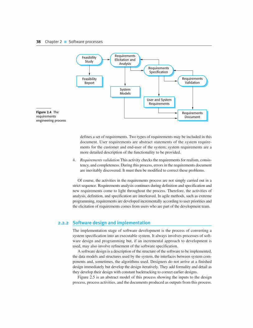
38 Chapter 2 � Software processes
defines a set of requirements. Two types of requirements may be included in this
document. User requirements are abstract statements of the system require-
ments for the customer and end-user of the system; system requirements are a
more detailed description of the functionality to be provided.
4. Requirements validation This activity checks the requirements for realism, consis-
tency, and completeness. During this process, errors in the requirements document
are inevitably discovered. It must then be modified to correct these problems.
Of course, the activities in the requirements process are not simply carried out in a
strict sequence. Requirements analysis continues during definition and specification and
new requirements come to light throughout the process. Therefore, the activities of
analysis, definition, and specification are interleaved. In agile methods, such as extreme
programming, requirements are developed incrementally according to user priorities and
the elicitation of requirements comes from users who are part of the development team.
2.2.2 Software design and implementation
The implementation stage of software development is the process of converting a
system specification into an executable system. It always involves processes of soft-
ware design and programming but, if an incremental approach to development is
used, may also involve refinement of the software specification.
A software design is a description of the structure of the software to be implemented,
the data models and structures used by the system, the interfaces between system com-
ponents and, sometimes, the algorithms used. Designers do not arrive at a finished
design immediately but develop the design iteratively. They add formality and detail as
they develop their design with constant backtracking to correct earlier designs.
Figure 2.5 is an abstract model of this process showing the inputs to the design
process, process activities, and the documents produced as outputs from this process.
FeasibilityStudy
RequirementsElicitation and
Analysis
RequirementsSpecification
RequirementsValidation
FeasibilityReport
SystemModels
User and SystemRequirements
RequirementsDocument
Figure 2.4 Therequirementsengineering process

2.2 � Process activities 39
The diagram suggests that the stages of the design process are sequential. In fact,
design process activities are interleaved. Feedback from one stage to another and
consequent design rework is inevitable in all design processes.
Most software interfaces with other software systems. These include the operating
system, database, middleware, and other application systems. These make up the ‘soft-
ware platform’, the environment in which the software will execute. Information about
this platform is an essential input to the design process, as designers must decide how
best to integrate it with the software’s environment. The requirements specification is a
description of the functionality the software must provide and its performance and
dependability requirements. If the system is to process existing data, then the description
of that data may be included in the platform specification; otherwise, the data description
must be an input to the design process so that the system data organization to be defined.
The activities in the design process vary, depending on the type of system being
developed. For example, real-time systems require timing design but may not
include a database so there is no database design involved. Figure 2.5 shows four
activities that may be part of the design process for information systems:
1. Architectural design, where you identify the overall structure of the system, the
principal components (sometimes called sub-systems or modules), their rela-
tionships, and how they are distributed.
2. Interface design, where you define the interfaces between system components.
This interface specification must be unambiguous. With a precise interface, a
component can be used without other components having to know how it is
implemented. Once interface specifications are agreed, the components can be
designed and developed concurrently.
SystemArchitecture
DatabaseSpecification
InterfaceSpecification
ComponentSpecification
InterfaceDesign
ComponentDesign
RequirementsSpecification
ArchitecturalDesign
PlatformInformation
DataDescription
Design Inputs
Design Activities
Design Outputs
Database Design
Figure 2.5 A generalmodel of the designprocess

40 Chapter 2 � Software processes
3. Component design, where you take each system component and design how it will
operate. This may be a simple statement of the expected functionality to be
implemented, with the specific design left to the programmer. Alternatively, it may
be a list of changes to be made to a reusable component or a detailed design model.
The design model may be used to automatically generate an implementation.
4. Database design, where you design the system data structures and how these are
to be represented in a database. Again, the work here depends on whether an
existing database is to be reused or a new database is to be created.
These activities lead to a set of design outputs, which are also shown in Figure 2.5.
The detail and representation of these vary considerably. For critical systems, detailed
design documents setting out precise and accurate descriptions of the system must be
produced. If a model-driven approach is used, these outputs may mostly be diagrams.
Where agile methods of development are used, the outputs of the design process may not
be separate specification documents but may be represented in the code of the program.
Structured methods for design were developed in the 1970s and 1980s and were
the precursor to the UML and object-oriented design (Budgen, 2003). They rely on
producing graphical models of the system and, in many cases, automatically generat-
ing code from these models. Model-driven development (MDD) or model-driven
engineering (Schmidt, 2006), where models of the software are created at different
levels of abstraction, is an evolution of structured methods. In MDD, there is greater
emphasis on architectural models with a separation between abstract implementation-
independent models and implementation-specific models. The models are developed
in sufficient detail so that the executable system can be generated from them. I discuss
this approach to development in Chapter 5.
The development of a program to implement the system follows naturally from the
system design processes. Although some classes of program, such as safety-critical
systems, are usually designed in detail before any implementation begins, it is more
common for the later stages of design and program development to be interleaved.
Software development tools may be used to generate a skeleton program from a
design. This includes code to define and implement interfaces, and, in many cases, the
developer need only add details of the operation of each program component.
Programming is a personal activity and there is no general process that is usually
followed. Some programmers start with components that they understand, develop
these, and then move on to less-understood components. Others take the opposite
Structured methods
Structured methods are an approach to software design in which graphical models that should be developed aspart of the design process are defined. The method may also define a process for developing the models and rulesthat apply to each model type. Structured methods lead to standardized documentation for a system and areparticularly useful in providing a development framework for less-experienced and less-expert software developers.
http://www.SoftwareEngineering-9.com/Web/Structured-methods/

2.2 � Process activities 41
approach, leaving familiar components till last because they know how to develop
them. Some developers like to define data early in the process then use this to drive
the program development; others leave data unspecified for as long as possible.
Normally, programmers carry out some testing of the code they have developed. This
often reveals program defects that must be removed from the program. This is called
debugging. Defect testing and debugging are different processes. Testing establishes the
existence of defects. Debugging is concerned with locating and correcting these defects.
When you are debugging, you have to generate hypotheses about the observable
behavior of the program then test these hypotheses in the hope of finding the fault that
caused the output anomaly. Testing the hypotheses may involve tracing the program
code manually. It may require new test cases to localize the problem. Interactive
debugging tools, which show the intermediate values of program variables and a trace
of the statements executed, may be used to support the debugging process.
2.2.3 Software validation
Software validation or, more generally, verification and validation (V&V) is
intended to show that a system both conforms to its specification and that it meets
the expectations of the system customer. Program testing, where the system is exe-
cuted using simulated test data, is the principal validation technique. Validation may
also involve checking processes, such as inspections and reviews, at each stage of the
software process from user requirements definition to program development.
Because of the predominance of testing, the majority of validation costs are incurred
during and after implementation.
Except for small programs, systems should not be tested as a single, monolithic
unit. Figure 2.6 shows a three-stage testing process in which system components are
tested then the integrated system is tested and, finally, the system is tested with the
customer’s data. Ideally, component defects are discovered early in the process, and
interface problems are found when the system is integrated. However, as defects are
discovered, the program must be debugged and this may require other stages in the
testing process to be repeated. Errors in program components, say, may come to light
during system testing. The process is therefore an iterative one with information
being fed back from later stages to earlier parts of the process.
The stages in the testing process are:
1. Development testing The components making up the system are tested by the
people developing the system. Each component is tested independently, without
other system components. Components may be simple entities such as functions
System TestingComponent
TestingAcceptance
Testing
Figure 2.6 Stagesof testing
42 Chapter 2 � Software processes
or object classes, or may be coherent groupings of these entities. Test automa-
tion tools, such as JUnit (Massol and Husted, 2003), that can re-run component
tests when new versions of the component are created, are commonly used.
2. System testing System components are integrated to create a complete system.
This process is concerned with finding errors that result from unanticipated
interactions between components and component interface problems. It is also
concerned with showing that the system meets its functional and non-functional
requirements, and testing the emergent system properties. For large systems,
this may be a multi-stage process where components are integrated to form sub-
systems that are individually tested before these sub-systems are themselves
integrated to form the final system.
3. Acceptance testing This is the final stage in the testing process before the system
is accepted for operational use. The system is tested with data supplied by the
system customer rather than with simulated test data. Acceptance testing may
reveal errors and omissions in the system requirements definition, because the
real data exercise the system in different ways from the test data. Acceptance
testing may also reveal requirements problems where the system’s facilities do
not really meet the user’s needs or the system performance is unacceptable.
Normally, component development and testing processes are interleaved.
Programmers make up their own test data and incrementally test the code as it is
developed. This is an economically sensible approach, as the programmer knows the
component and is therefore the best person to generate test cases.
If an incremental approach to development is used, each increment should be
tested as it is developed, with these tests based on the requirements for that incre-
ment. In extreme programming, tests are developed along with the requirements
before development starts. This helps the testers and developers to understand the
requirements and ensures that there are no delays as test cases are created.
When a plan-driven software process is used (e.g., for critical systems develop-
ment), testing is driven by a set of test plans. An independent team of testers works
from these pre-formulated test plans, which have been developed from the system
specification and design. Figure 2.7 illustrates how test plans are the link between
testing and development activities. This is sometimes called the V-model of develop-
ment (turn it on its side to see the V).
Acceptance testing is sometimes called ‘alpha testing’. Custom systems are
developed for a single client. The alpha testing process continues until the system
developer and the client agree that the delivered system is an acceptable implemen-
tation of the requirements.
When a system is to be marketed as a software product, a testing process called
‘beta testing’ is often used. Beta testing involves delivering a system to a number of
potential customers who agree to use that system. They report problems to the sys-
tem developers. This exposes the product to real use and detects errors that may not
have been anticipated by the system builders. After this feedback, the system is mod-
ified and released either for further beta testing or for general sale.

2.3 � Coping with change 43
2.2.4 Software evolution
The flexibility of software systems is one of the main reasons why more and more
software is being incorporated in large, complex systems. Once a decision has been
made to manufacture hardware, it is very expensive to make changes to the hardware
design. However, changes can be made to software at any time during or after the
system development. Even extensive changes are still much cheaper than correspon-
ding changes to system hardware.
Historically, there has always been a split between the process of software devel-
opment and the process of software evolution (software maintenance). People think
of software development as a creative activity in which a software system is devel-
oped from an initial concept through to a working system. However, they sometimes
think of software maintenance as dull and uninteresting. Although the costs of main-
tenance are often several times the initial development costs, maintenance processes
are sometimes considered to be less challenging than original software development.
This distinction between development and maintenance is increasingly irrelevant.
Hardly any software systems are completely new systems and it makes much more
sense to see development and maintenance as a continuum. Rather than two separate
processes, it is more realistic to think of software engineering as an evolutionary
process (Figure 2.8) where software is continually changed over its lifetime in
response to changing requirements and customer needs.
2.3 Coping with change
Change is inevitable in all large software projects. The system requirements change
as the business procuring the system responds to external pressures and management
priorities change. As new technologies become available, new design and implemen-
tation possibilities emerge. Therefore whatever software process model is used, it is
essential that it can accommodate changes to the software being developed.
RequirementsSpecification
SystemSpecification
AcceptanceTest
SystemIntegration Test
Sub-SystemIntegration Test
SystemDesign
DetailedDesign
Service
Module andUnit Codeand Test
AcceptanceTest Plan
SystemIntegrationTest Plan
Sub-SystemIntegrationTest Plan
Figure 2.7Testing phasesin a plan-drivensoftware process

44 Chapter 2 � Software processes
Change adds to the costs of software development because it usually means that
work that has been completed has to be redone. This is called rework. For example, if
the relationships between the requirements in a system have been analyzed and new
requirements are then identified, some or all of the requirements analysis has to be
repeated. It may then be necessary to redesign the system to deliver the new require-
ments, change any programs that have been developed, and re-test the system.
There are two related approaches that may be used to reduce the costs of rework:
1. Change avoidance, where the software process includes activities that can antic-
ipate possible changes before significant rework is required. For example, a pro-
totype system may be developed to show some key features of the system to
customers. They can experiment with the prototype and refine their require-
ments before committing to high software production costs.
2. Change tolerance, where the process is designed so that changes can be accom-
modated at relatively low cost. This normally involves some form of incremen-
tal development. Proposed changes may be implemented in increments that
have not yet been developed. If this is impossible, then only a single increment
(a small part of the system) may have to be altered to incorporate the change.
In this section, I discuss two ways of coping with change and changing system
requirements. These are:
1. System prototyping, where a version of the system or part of the system is developed
quickly to check the customer’s requirements and the feasibility of some design
decisions. This supports change avoidance as it allows users to experiment with the
system before delivery and so refine their requirements. The number of require-
ments change proposals made after delivery is therefore likely to be reduced.
2. Incremental delivery, where system increments are delivered to the customer for
comment and experimentation. This supports both change avoidance and
change tolerance. It avoids the premature commitment to requirements for the
whole system and allows changes to be incorporated into later increments at rel-
atively low cost.
The notion of refactoring, namely improving the structure and organization of a
program, is also an important mechanism that supports change tolerance. I discuss
this in Chapter 3, which covers agile methods.
Assess ExistingSystems
Define SystemRequirements
Propose SystemChanges
ModifySystems
NewSystem
ExistingSystemsFigure 2.8 System
evolution

2.3 � Coping with change 45
2.3.1 Prototyping
A prototype is an initial version of a software system that is used to demonstrate
concepts, try out design options, and find out more about the problem and its possi-
ble solutions. Rapid, iterative development of the prototype is essential so that costs
are controlled and system stakeholders can experiment with the prototype early in
the software process.
A software prototype can be used in a software development process to help
anticipate changes that may be required:
1. In the requirements engineering process, a prototype can help with the elicita-
tion and validation of system requirements.
2. In the system design process, a prototype can be used to explore particular soft-
ware solutions and to support user interface design.
System prototypes allow users to see how well the system supports their work.
They may get new ideas for requirements, and find areas of strength and weakness in
the software. They may then propose new system requirements. Furthermore, as the
prototype is developed, it may reveal errors and omissions in the requirements that
have been proposed. A function described in a specification may seem useful and well
defined. However, when that function is combined with other functions, users often
find that their initial view was incorrect or incomplete. The system specification may
then be modified to reflect their changed understanding of the requirements.
A system prototype may be used while the system is being designed to carry out
design experiments to check the feasibility of a proposed design. For example, a
database design may be prototyped and tested to check that it supports efficient data
access for the most common user queries. Prototyping is also an essential part of the
user interface design process. Because of the dynamic nature of user interfaces, tex-
tual descriptions and diagrams are not good enough for expressing the user interface
requirements. Therefore, rapid prototyping with end-user involvement is the only
sensible way to develop graphical user interfaces for software systems.
A process model for prototype development is shown in Figure 2.9. The objec-
tives of prototyping should be made explicit from the start of the process. These may
be to develop a system to prototype the user interface, to develop a system to validate
functional system requirements, or to develop a system to demonstrate the feasibility
EstablishPrototypeObjectives
DefinePrototype
Functionality
DevelopPrototype
EvaluatePrototype
PrototypingPlan
OutlineDefinition
ExecutablePrototype
EvaluationReport
Figure 2.9 The processof prototypedevelopment

46 Chapter 2 � Software processes
of the application to managers. The same prototype cannot meet all objectives. If the
objectives are left unstated, management or end-users may misunderstand the func-
tion of the prototype. Consequently, they may not get the benefits that they expected
from the prototype development.
The next stage in the process is to decide what to put into and, perhaps more
importantly, what to leave out of the prototype system. To reduce prototyping costs
and accelerate the delivery schedule, you may leave some functionality out of the
prototype. You may decide to relax non-functional requirements such as response
time and memory utilization. Error handling and management may be ignored unless
the objective of the prototype is to establish a user interface. Standards of reliability
and program quality may be reduced.
The final stage of the process is prototype evaluation. Provision must be made
during this stage for user training and the prototype objectives should be used to
derive a plan for evaluation. Users need time to become comfortable with a new sys-
tem and to settle into a normal pattern of usage. Once they are using the system nor-
mally, they then discover requirements errors and omissions.
A general problem with prototyping is that the prototype may not necessarily be
used in the same way as the final system. The tester of the prototype may not be typ-
ical of system users. The training time during prototype evaluation may be insuffi-
cient. If the prototype is slow, the evaluators may adjust their way of working and
avoid those system features that have slow response times. When provided with bet-
ter response in the final system, they may use it in a different way.
Developers are sometimes pressured by managers to deliver throwaway proto-
types, particularly when there are delays in delivering the final version of the soft-
ware. However, this is usually unwise:
1. It may be impossible to tune the prototype to meet non-functional requirements,
such as performance, security, robustness, and reliability requirements, which
were ignored during prototype development.
2. Rapid change during development inevitably means that the prototype is undoc-
umented. The only design specification is the prototype code. This is not good
enough for long-term maintenance.
3. The changes made during prototype development will probably have degraded
the system structure. The system will be difficult and expensive to maintain.
4. Organizational quality standards are normally relaxed for prototype development.
Prototypes do not have to be executable to be useful. Paper-based mock-ups of
the system user interface (Rettig, 1994) can be effective in helping users refine an
interface design and work through usage scenarios. These are very cheap to develop
and can be constructed in a few days. An extension of this technique is a Wizard of
Oz prototype where only the user interface is developed. Users interact with this
interface but their requests are passed to a person who interprets them and outputs
the appropriate response.
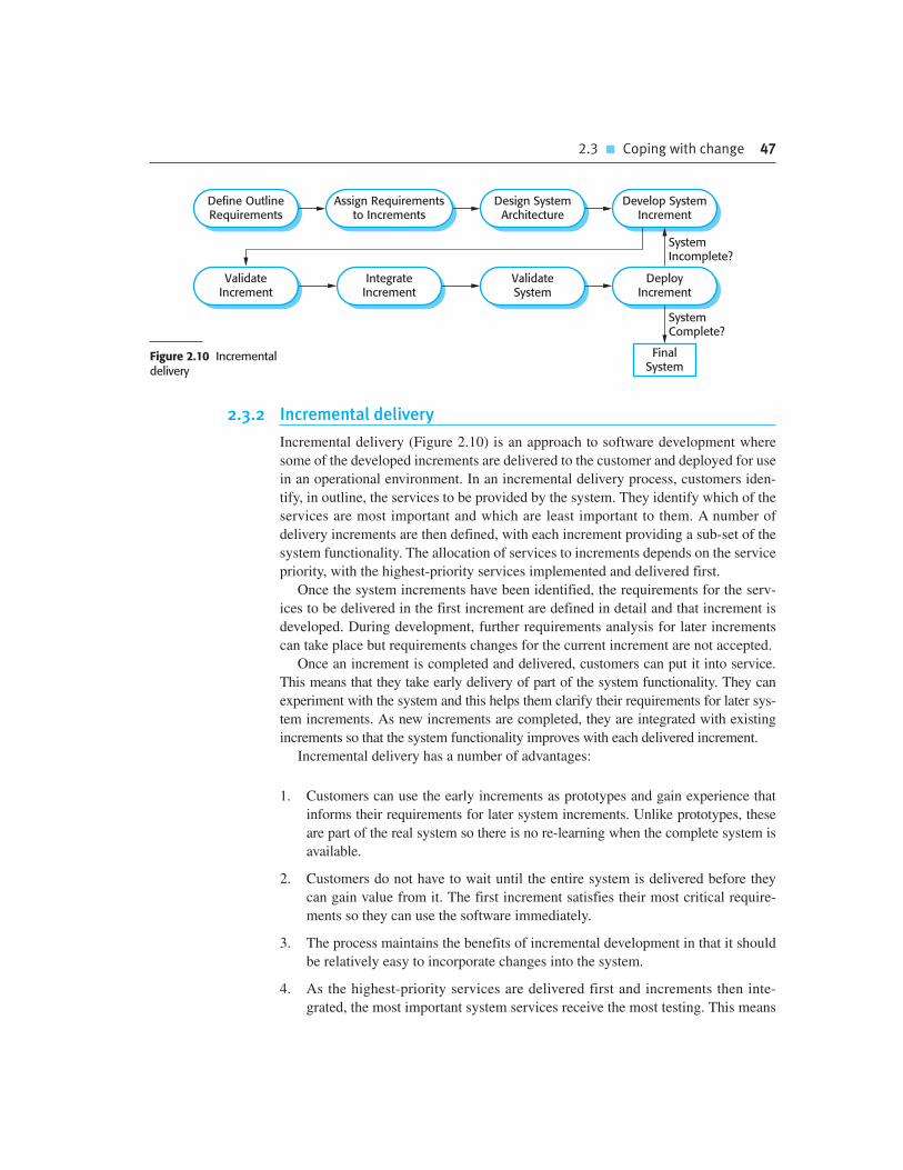
2.3 � Coping with change 47
2.3.2 Incremental delivery
Incremental delivery (Figure 2.10) is an approach to software development where
some of the developed increments are delivered to the customer and deployed for use
in an operational environment. In an incremental delivery process, customers iden-
tify, in outline, the services to be provided by the system. They identify which of the
services are most important and which are least important to them. A number of
delivery increments are then defined, with each increment providing a sub-set of the
system functionality. The allocation of services to increments depends on the service
priority, with the highest-priority services implemented and delivered first.
Once the system increments have been identified, the requirements for the serv-
ices to be delivered in the first increment are defined in detail and that increment is
developed. During development, further requirements analysis for later increments
can take place but requirements changes for the current increment are not accepted.
Once an increment is completed and delivered, customers can put it into service.
This means that they take early delivery of part of the system functionality. They can
experiment with the system and this helps them clarify their requirements for later sys-
tem increments. As new increments are completed, they are integrated with existing
increments so that the system functionality improves with each delivered increment.
Incremental delivery has a number of advantages:
1. Customers can use the early increments as prototypes and gain experience that
informs their requirements for later system increments. Unlike prototypes, these
are part of the real system so there is no re-learning when the complete system is
available.
2. Customers do not have to wait until the entire system is delivered before they
can gain value from it. The first increment satisfies their most critical require-
ments so they can use the software immediately.
3. The process maintains the benefits of incremental development in that it should
be relatively easy to incorporate changes into the system.
4. As the highest-priority services are delivered first and increments then inte-
grated, the most important system services receive the most testing. This means
Design SystemArchitecture
Define OutlineRequirements
Assign Requirementsto Increments
SystemIncomplete?
FinalSystem
Develop SystemIncrement
ValidateIncrement
IntegrateIncrement
ValidateSystem
DeployIncrement
SystemComplete?
Figure 2.10 Incrementaldelivery
48 Chapter 2 � Software processes
that customers are less likely to encounter software failures in the most impor-
tant parts of the system.
However, there are problems with incremental delivery:
1. Most systems require a set of basic facilities that are used by different parts of the
system. As requirements are not defined in detail until an increment is to be
implemented, it can be hard to identify common facilities that are needed by all
increments.
2. Iterative development can also be difficult when a replacement system is being
developed. Users want all of the functionality of the old system and are often
unwilling to experiment with an incomplete new system. Therefore, getting use-
ful customer feedback is difficult.
3. The essence of iterative processes is that the specification is developed in conjunc-
tion with the software. However, this conflicts with the procurement model of
many organizations, where the complete system specification is part of the system
development contract. In the incremental approach, there is no complete system
specification until the final increment is specified. This requires a new form of
contract, which large customers such as government agencies may find difficult to
accommodate.
There are some types of system where incremental development and delivery is
not the best approach. These are very large systems where development may involve
teams working in different locations, some embedded systems where the software
depends on hardware development and some critical systems where all the require-
ments must be analyzed to check for interactions that may compromise the safety or
security of the system.
These systems, of course, suffer from the same problems of uncertain and chang-
ing requirements. Therefore, to address these problems and get some of the benefits
of incremental development, a process may be used in which a system prototype is
developed iteratively and used as a platform for experiments with the system
requirements and design. With the experience gained from the prototype, definitive
requirements can then be agreed.
2.3.3 Boehm’s spiral model
A risk-driven software process framework (the spiral model) was proposed by
Boehm (1988). This is shown in Figure 2.11. Here, the software process is repre-
sented as a spiral, rather than a sequence of activities with some backtracking from
one activity to another. Each loop in the spiral represents a phase of the software
process. Thus, the innermost loop might be concerned with system feasibility, the
next loop with requirements definition, the next loop with system design, and so on.
The spiral model combines change avoidance with change tolerance. It assumes that

2.3 � Coping with change 49
changes are a result of project risks and includes explicit risk management activities
to reduce these risks.
Each loop in the spiral is split into four sectors:
1. Objective setting Specific objectives for that phase of the project are defined.
Constraints on the process and the product are identified and a detailed manage-
ment plan is drawn up. Project risks are identified. Alternative strategies,
depending on these risks, may be planned.
2. Risk assessment and reduction For each of the identified project risks, a detailed
analysis is carried out. Steps are taken to reduce the risk. For example, if there is a
risk that the requirements are inappropriate, a prototype system may be developed.
3. Development and validation After risk evaluation, a development model for the
system is chosen. For example, throwaway prototyping may be the best devel-
opment approach if user interface risks are dominant. If safety risks are the main
consideration, development based on formal transformations may be the most
appropriate process, and so on. If the main identified risk is sub-system integra-
tion, the waterfall model may be the best development model to use.
4. Planning The project is reviewed and a decision made whether to continue with
a further loop of the spiral. If it is decided to continue, plans are drawn up for the
next phase of the project.
Figure 2.11 Boehm’sspiral model of thesoftware process(©IEEE 1988)
RiskAnalysis
RiskAnalysis
RiskAnalysis
RiskAnalysis Proto-
type 1
Prototype 2
Prototype 3Operational Prototype
Concept ofOperation S/W
Requirements
RequirementValidation
DesignV&V
ProductDesign Detailed
Design
Code
Unit Test
IntegrationTest
AcceptanceTest
Service Develop, VerifyNext-Level Product
Evaluate Alternatives,Identify, Resolve Risks
Determine Objectives,Alternatives, and
Constraints
Plan Next Phase
Integrationand Test Plan
DevelopmentPlan
Requirements PlanLife-Cycle Plan
REVIEW
Simulations, Models, Benchmarks

50 Chapter 2 � Software processes
The main difference between the spiral model and other software process models is
its explicit recognition of risk. A cycle of the spiral begins by elaborating objectives
such as performance and functionality. Alternative ways of achieving these objec-
tives, and dealing with the constraints on each of them, are then enumerated. Each
alternative is assessed against each objective and sources of project risk are identi-
fied. The next step is to resolve these risks by information-gathering activities such
as more detailed analysis, prototyping, and simulation.
Once risks have been assessed, some development is carried out, followed by a plan-
ning activity for the next phase of the process. Informally, risk simply means something
that can go wrong. For example, if the intention is to use a new programming language,
a risk is that the available compilers are unreliable or do not produce sufficiently effi-
cient object code. Risks lead to proposed software changes and project problems such as
schedule and cost overrun, so risk minimization is a very important project management
activity. Risk management, an essential part of project management, is covered in
Chapter 22.
2.4 The Rational Unified Process
The Rational Unified Process (RUP) (Krutchen, 2003) is an example of a modern
process model that has been derived from work on the UML and the associated Unified
Software Development Process (Rumbaugh, et al., 1999; Arlow and Neustadt, 2005).
I have included a description here, as it is a good example of a hybrid process model.
It brings together elements from all of the generic process models (Section 2.1), illus-
trates good practice in specification and design (Section 2.2) and supports prototyping
and incremental delivery (Section 2.3).
The RUP recognizes that conventional process models present a single view of
the process. In contrast, the RUP is normally described from three perspectives:
1. A dynamic perspective, which shows the phases of the model over time.
2. A static perspective, which shows the process activities that are enacted.
3. A practice perspective, which suggests good practices to be used during the process.
Most descriptions of the RUP attempt to combine the static and dynamic perspec-
tives in a single diagram (Krutchen, 2003). I think that makes the process harder to
understand, so I use separate descriptions of each of these perspectives.
The RUP is a phased model that identifies four discrete phases in the software
process. However, unlike the waterfall model where phases are equated with process
activities, the phases in the RUP are more closely related to business rather than
technical concerns. Figure 2.11 shows the phases in the RUP. These are:
1. Inception The goal of the inception phase is to establish a business case for the
system. You should identify all external entities (people and systems) that will

2.4 � The Rational Unified Process 51
interact with the system and define these interactions. You then use this infor-
mation to assess the contribution that the system makes to the business. If this
contribution is minor, then the project may be cancelled after this phase.
2. Elaboration The goals of the elaboration phase are to develop an understanding
of the problem domain, establish an architectural framework for the system,
develop the project plan, and identify key project risks. On completion of this
phase you should have a requirements model for the system, which may be a set
of UML use-cases, an architectural description, and a development plan for the
software.
3. Construction The construction phase involves system design, programming, and
testing. Parts of the system are developed in parallel and integrated during this
phase. On completion of this phase, you should have a working software system
and associated documentation that is ready for delivery to users.
4. Transition The final phase of the RUP is concerned with moving the system
from the development community to the user community and making it work in
a real environment. This is something that is ignored in most software process
models but is, in fact, an expensive and sometimes problematic activity. On
completion of this phase, you should have a documented software system that is
working correctly in its operational environment.
Iteration within the RUP is supported in two ways. Each phase may be enacted in
an iterative way with the results developed incrementally. In addition, the whole set
of phases may also be enacted incrementally, as shown by the looping arrow from
Transition to Inception in Figure 2.12.
The static view of the RUP focuses on the activities that take place during the
development process. These are called workflows in the RUP description. There are
six core process workflows identified in the process and three core supporting work-
flows. The RUP has been designed in conjunction with the UML, so the workflow
description is oriented around associated UML models such as sequence models,
object models, etc. The core engineering and support workflows are described in
Figure 2.13.
The advantage in presenting dynamic and static views is that phases of the devel-
opment process are not associated with specific workflows. In principle at least, all
of the RUP workflows may be active at all stages of the process. In the early phases
of the process, most effort will probably be spent on workflows such as business
modelling and requirements and, in the later phases, in testing and deployment.
Inception Elaboration Construction
Phase Iteration
Transition
Figure 2.12 Phases inthe Rational UnifiedProcess

52 Chapter 2 � Software processes
The practice perspective on the RUP describes good software engineering prac-
tices that are recommended for use in systems development. Six fundamental best
practices are recommended:
1. Develop software iteratively Plan increments of the system based on customer
priorities and develop the highest-priority system features early in the develop-
ment process.
2. Manage requirements Explicitly document the customer’s requirements and
keep track of changes to these requirements. Analyze the impact of changes on
the system before accepting them.
3. Use component-based architectures Structure the system architecture into com-
ponents, as discussed earlier in this chapter.
4. Visually model software Use graphical UML models to present static and
dynamic views of the software.
5. Verify software quality Ensure that the software meets the organizational quality
standards.
Figure 2.13 Staticworkflows in theRational UnifiedProcess
Workflow Description
Business modelling The business processes are modelled using business use cases.
Requirements Actors who interact with the system are identified and usecases are developed to model the system requirements.
Analysis and design A design model is created and documented using architecturalmodels, component models, object models, and sequencemodels.
Implementation The components in the system are implemented andstructured into implementation sub-systems. Automatic codegeneration from design models helps accelerate this process.
Testing Testing is an iterative process that is carried out in conjunctionwith implementation. System testing follows the completion ofthe implementation.
Deployment A product release is created, distributed to users, and installedin their workplace.
Configuration and change management This supporting workflow manages changes to the system (seeChapter 25).
Project management This supporting workflow manages the system development(see Chapters 22 and 23).
Environment This workflow is concerned with making appropriate softwaretools available to the software development team.

Chapter 2 � Key points 53
K E Y P O I N T S
� Software processes are the activities involved in producing a software system. Software process
models are abstract representations of these processes.
� General process models describe the organization of software processes. Examples of these general
models include the waterfall model, incremental development, and reuse-oriented development.
� Requirements engineering is the process of developing a software specification. Specifications
are intended to communicate the system needs of the customer to the system developers.
� Design and implementation processes are concerned with transforming a requirements
specification into an executable software system. Systematic design methods may be used as
part of this transformation.
� Software validation is the process of checking that the system conforms to its specification and
that it meets the real needs of the users of the system.
� Software evolution takes place when you change existing software systems to meet new
requirements. Changes are continuous and the software must evolve to remain useful.
� Processes should include activities to cope with change. This may involve a prototyping phase
that helps avoid poor decisions on requirements and design. Processes may be structured for
iterative development and delivery so that changes may be made without disrupting the system
as a whole.
� The Rational Unified Process is a modern generic process model that is organized into phases
(inception, elaboration, construction, and transition) but separates activities (requirements,
analysis, and design, etc.) from these phases.
6. Control changes to software Manage changes to the software using a change
management system and configuration management procedures and tools.
The RUP is not a suitable process for all types of development, e.g., embedded
software development. However, it does represent an approach that potentially com-
bines the three generic process models discussed in Section 2.1. The most important
innovations in the RUP are the separation of phases and workflows, and the recogni-
tion that deploying software in a user’s environment is part of the process. Phases are
dynamic and have goals. Workflows are static and are technical activities that are not
associated with a single phase but may be used throughout the development to
achieve the goals of each phase.

54 Chapter 2 � Software processes
F U RT H E R R E A D I N G
Managing Software Quality and Business Risk. This is primarily a book about software management
but it includes an excellent chapter (Chapter 4) on process models. (M. Ould, John Wiley and Sons
Ltd, 1999.)
Process Models in Software Engineering. This is an excellent overview of a wide range of software
engineering process models that have been proposed. (W. Scacchi, Encyclopaedia of Software
Engineering, ed. J.J. Marciniak, John Wiley and Sons, 2001.) http://www.ics.uci.edu/~wscacchi/
Papers/SE-Encyc/Process-Models-SE-Encyc.pdf.
The Rational Unified Process—An Introduction (3rd edition). This is the most readable book
available on the RUP at the time of this writing. Krutchen describes the process well, but
I would like to have seen more on the practical difficulties of using the process. (P. Krutchen,
Addison-Wesley, 2003.)
E X E R C I S E S
2.1. Giving reasons for your answer based on the type of system being developed, suggest the
most appropriate generic software process model that might be used as a basis for managing
the development of the following systems:
A system to control anti-lock braking in a car
A virtual reality system to support software maintenance
A university accounting system that replaces an existing system
An interactive travel planning system that helps users plan journeys with the lowest
environmental impact
2.2. Explain why incremental development is the most effective approach for developing business
software systems. Why is this model less appropriate for real-time systems engineering?
2.3. Consider the reuse-based process model shown in Figure 2.3. Explain why it is essential to
have two separate requirements engineering activities in the process.
2.4. Suggest why it is important to make a distinction between developing the user
requirements and developing system requirements in the requirements engineering
process.
2.5. Describe the main activities in the software design process and the outputs of these
activities. Using a diagram, show possible relationships between the outputs of these
activities.
2.6. Explain why change is inevitable in complex systems and give examples (apart from
prototyping and incremental delivery) of software process activities that help predict changes
and make the software being developed more resilient to change.

2.7. Explain why systems developed as prototypes should not normally be used as production
systems.
2.8. Explain why Boehm’s spiral model is an adaptable model that can support both change
avoidance and change tolerance activities. In practice, this model has not been widely used.
Suggest why this might be the case.
2.9. What are the advantages of providing static and dynamic views of the software process as in
the Rational Unified Process?
2.10. Historically, the introduction of technology has caused profound changes in the labor market and,
temporarily at least, displaced people from jobs. Discuss whether the introduction of extensive
process automation is likely to have the same consequences for software engineers. If you don’t
think it will, explain why not. If you think that it will reduce job opportunities, is it ethical for the
engineers affected to passively or actively resist the introduction of this technology?
Chapter 2 � References 55
R E F E R E N C E S
Arlow, J. and Neustadt, I. (2005). UML 2 and the Unified Process: Practical Object-Oriented
Analysis and Design (2nd Edition). Boston: Addison-Wesley.
Boehm, B. and Turner, R. (2003). Balancing Agility and Discipline: A Guide for the Perplexed.
Boston: Addison-Wesley.
Boehm, B. W. (1988). ‘A Spiral Model of Software Development and Enhancement’. IEEE
Computer, 21 (5), 61–72.
Budgen, D. (2003). Software Design (2nd Edition). Harlow, UK.: Addison-Wesley.
Krutchen, P. (2003). The Rational Unified Process—An Introduction (3rd Edition). Reading, MA:
Addison-Wesley.
Massol, V. and Husted, T. (2003). JUnit in Action. Greenwich, Conn.: Manning Publications Co.
Rettig, M. (1994). ‘Practical Programmer: Prototyping for Tiny Fingers’. Comm. ACM, 37 (4), 21–7.
Royce, W. W. (1970). ‘Managing the Development of Large Software Systems: Concepts and
Techniques’. IEEE WESTCON, Los Angeles CA: 1–9.
Rumbaugh, J., Jacobson, I. and Booch, G. (1999). The Unified Software Development Process.
Reading, Mass.: Addison-Wesley.
Schmidt, D. C. (2006). ‘Model-Driven Engineering’. IEEE Computer, 39 (2), 25–31.
Schneider, S. (2001). The B Method. Houndmills, UK: Palgrave Macmillan.
Wordsworth, J. (1996). Software Engineering with B. Wokingham: Addison-Wesley.
Agile softwaredevelopment
3
Objectives
The objective of this chapter is to introduce you to agile software
development methods. When you have read the chapter, you will:
� understand the rationale for agile software development methods,
the agile manifesto, and the differences between agile and plan-
driven development;
� know the key practices in extreme programming and how these
relate to the general principles of agile methods;
� understand the Scrum approach to agile project management;
� be aware of the issues and problems of scaling agile development
methods to the development of large software systems.
Contents
3.1 Agile methods
3.2 Plan-driven and agile development
3.3 Extreme programming
3.4 Agile project management
3.5 Scaling agile methods

Chapter 3 � Agile software development 57
Businesses now operate in a global, rapidly changing environment. They have to
respond to new opportunities and markets, changing economic conditions, and the
emergence of competing products and services. Software is part of almost all busi-
ness operations so new software is developed quickly to take advantage of new
opportunities and to respond to competitive pressure. Rapid development and deliv-
ery is therefore now often the most critical requirement for software systems. In fact,
many businesses are willing to trade off software quality and compromise on
requirements to achieve faster deployment of the software that they need.
Because these businesses are operating in a changing environment, it is often prac-
tically impossible to derive a complete set of stable software requirements. The initial
requirements inevitably change because customers find it impossible to predict how a
system will affect working practices, how it will interact with other systems, and what
user operations should be automated. It may only be after a system has been delivered
and users gain experience with it that the real requirements become clear. Even then,
the requirements are likely to change quickly and unpredictably due to external fac-
tors. The software may then be out of date when it is delivered.
Software development processes that plan on completely specifying the requirements
and then designing, building, and testing the system are not geared to rapid software
development. As the requirements change or as requirements problems are discovered,
the system design or implementation has to be reworked and retested. As a consequence,
a conventional waterfall or specification-based process is usually prolonged and the final
software is delivered to the customer long after it was originally specified.
For some types of software, such as safety-critical control systems, where a com-
plete analysis of the system is essential, a plan-driven approach is the right one.
However, in a fast-moving business environment, this can cause real problems. By
the time the software is available for use, the original reason for its procurement may
have changed so radically that the software is effectively useless. Therefore, for busi-
ness systems in particular, development processes that focus on rapid software
development and delivery are essential.
The need for rapid system development and processes that can handle changing
requirements has been recognized for some time. IBM introduced incremental
development in the 1980s (Mills et al., 1980). The introduction of so-called fourth-
generation languages, also in the 1980s, supported the idea of quickly developing
and delivering software (Martin, 1981). However, the notion really took off in the
late 1990s with the development of the notion of agile approaches such as DSDM
(Stapleton, 1997), Scrum (Schwaber and Beedle, 2001), and extreme programming
(Beck, 1999; Beck, 2000).
Rapid software development processes are designed to produce useful software
quickly. The software is not developed as a single unit but as a series of increments, with
each increment including new system functionality. Although there are many
approaches to rapid software development, they share some fundamental characteristics:
1. The processes of specification, design, and implementation are interleaved.
There is no detailed system specification, and design documentation is mini-
mized or generated automatically by the programming environment used to

58 Chapter 3 � Agile software development
implement the system. The user requirements document only defines the most
important characteristics of the system.
2. The system is developed in a series of versions. End-users and other system
stakeholders are involved in specifying and evaluating each version. They may
propose changes to the software and new requirements that should be imple-
mented in a later version of the system.
3. System user interfaces are often developed using an interactive development
system that allows the interface design to be quickly created by drawing and plac-
ing icons on the interface. The system may then generate a web-based interface for
a browser or an interface for a specific platform such as Microsoft Windows.
Agile methods are incremental development methods in which the increments are
small and, typically, new releases of the system are created and made available to cus-
tomers every two or three weeks. They involve customers in the development process
to get rapid feedback on changing requirements. They minimize documentation by
using informal communications rather than formal meetings with written documents.
3.1 Agile methods
In the 1980s and early 1990s, there was a widespread view that the best way to
achieve better software was through careful project planning, formalized quality
assurance, the use of analysis and design methods supported by CASE tools, and
controlled and rigorous software development processes. This view came from the
software engineering community that was responsible for developing large, long-
lived software systems such as aerospace and government systems.
This software was developed by large teams working for different companies. Teams
were often geographically dispersed and worked on the software for long periods of
time. An example of this type of software is the control systems for a modern aircraft,
which might take up to 10 years from initial specification to deployment. These plan-
driven approaches involve a significant overhead in planning, designing, and document-
ing the system. This overhead is justified when the work of multiple development teams
has to be coordinated, when the system is a critical system, and when many different
people will be involved in maintaining the software over its lifetime.
However, when this heavyweight, plan-driven development approach is applied
to small and medium-sized business systems, the overhead involved is so large that it
dominates the software development process. More time is spent on how the system
should be developed than on program development and testing. As the system
requirements change, rework is essential and, in principle at least, the specification
and design has to change with the program.
Dissatisfaction with these heavyweight approaches to software engineering led a
number of software developers in the 1990s to propose new ‘agile methods’. These
allowed the development team to focus on the software itself rather than on its design

3.1 � Agile methods 59
and documentation. Agile methods universally rely on an incremental approach to soft-
ware specification, development, and delivery. They are best suited to application devel-
opment where the system requirements usually change rapidly during the development
process. They are intended to deliver working software quickly to customers, who can
then propose new and changed requirements to be included in later iterations of the sys-
tem. They aim to cut down on process bureaucracy by avoiding work that has dubious
long-term value and eliminating documentation that will probably never be used.
The philosophy behind agile methods is reflected in the agile manifesto that was
agreed on by many of the leading developers of these methods. This manifesto states:
We are uncovering better ways of developing software by doing it and helping
others do it. Through this work we have come to value:
Individuals and interactions over processes and tools
Working software over comprehensive documentation
Customer collaboration over contract negotiation
Responding to change over following a plan
That is, while there is value in the items on the right, we value the items on the
left more.
Probably the best-known agile method is extreme programming (Beck, 1999;
Beck, 2000), which I describe later in this chapter. Other agile approaches include
Scrum (Cohn, 2009; Schwaber, 2004; Schwaber and Beedle, 2001), Crystal
(Cockburn, 2001; Cockburn, 2004), Adaptive Software Development (Highsmith,
2000), DSDM (Stapleton, 1997; Stapleton, 2003), and Feature Driven Development
(Palmer and Felsing, 2002). The success of these methods has led to some integration
with more traditional development methods based on system modelling, resulting in
the notion of agile modelling (Ambler and Jeffries, 2002) and agile instantiations of
the Rational Unified Process (Larman, 2002).
Although these agile methods are all based around the notion of incremental devel-
opment and delivery, they propose different processes to achieve this. However, they
share a set of principles, based on the agile manifesto, and so have much in common.
These principles are shown in Figure 3.1. Different agile methods instantiate these prin-
ciples in different ways and I don’t have space to discuss all agile methods. Instead, I
focus on two of the most widely used methods: extreme programming (Section 3.3) and
Scrum (Section 3.4).
Agile methods have been very successful for some types of system development:
1. Product development where a software company is developing a small or
medium-sized product for sale.
2. Custom system development within an organization, where there is a clear com-
mitment from the customer to become involved in the development process and
where there are not a lot of external rules and regulations that affect the software.

60 Chapter 3 � Agile software development
As I discuss in the final section of this chapter, the success of agile methods has
meant that there is a lot of interest in using these methods for other types of software
development. However, because of their focus on small, tightly integrated teams,
there are problems in scaling them to large systems. There have also been experi-
ments in using agile approaches for critical systems engineering (Drobna et al.,
2004). However, because of the need for security, safety, and dependability analysis
in critical systems, agile methods require significant modification before they can be
routinely used for critical systems engineering.
In practice, the principles underlying agile methods are sometimes difficult to
realize:
1. Although the idea of customer involvement in the development process is an
attractive one, its success depends on having a customer who is willing and able
to spend time with the development team and who can represent all system
stakeholders. Frequently, the customer representatives are subject to other pres-
sures and cannot take full part in the software development.
2. Individual team members may not have suitable personalities for the intense
involvement that is typical of agile methods, and therefore not interact well with
other team members.
3. Prioritizing changes can be extremely difficult, especially in systems for which
there are many stakeholders. Typically, each stakeholder gives different priori-
ties to different changes.
4. Maintaining simplicity requires extra work. Under pressure from delivery
schedules, the team members may not have time to carry out desirable system
simplifications.
Figure 3.1 Theprinciples of agilemethods
Principle Description
Customer involvement Customers should be closely involved throughout the development process.Their role is provide and prioritize new system requirements and to evaluatethe iterations of the system.
Incremental delivery The software is developed in increments with the customer specifying therequirements to be included in each increment.
People not process The skills of the development team should be recognized and exploited. Teammembers should be left to develop their own ways of working withoutprescriptive processes.
Embrace change Expect the system requirements to change and so design the system toaccommodate these changes.
Maintain simplicity Focus on simplicity in both the software being developed and in thedevelopment process. Wherever possible, actively work to eliminate complexityfrom the system.
3.1 � Agile methods 61
5. Many organizations, especially large companies, have spent years changing
their culture so that processes are defined and followed. It is difficult for them to
move to a working model in which processes are informal and defined by devel-
opment teams.
Another non-technical problem—that is a general problem with incremental
development and delivery—occurs when the system customer uses an outside organ-
ization for system development. The software requirements document is usually part
of the contract between the customer and the supplier. Because incremental specifi-
cation is inherent in agile methods, writing contracts for this type of development
may be difficult.
Consequently, agile methods have to rely on contracts in which the customer pays
for the time required for system development rather than the development of a spe-
cific set of requirements. So long as all goes well, this benefits both the customer and
the developer. However, if problems arise then there may be difficult disputes over
who is to blame and who should pay for the extra time and resources required to
resolve the problems.
Most books and papers that describe agile methods and experiences with agile
methods talk about the use of these methods for new systems development.
However, as I explain in Chapter 9, a huge amount of software engineering effort
goes into the maintenance and evolution of existing software systems. There are only
a small number of experience reports on using agile methods for software mainte-
nance (Poole and Huisman, 2001). There are two questions that should be consid-
ered when considering agile methods and maintenance:
1. Are systems that are developed using an agile approach maintainable, given the
emphasis in the development process of minimizing formal documentation?
2. Can agile methods be used effectively for evolving a system in response to cus-
tomer change requests?
Formal documentation is supposed to describe the system and so make it easier
for people changing the system to understand. In practice, however, formal docu-
mentation is often not kept up to date and so does not accurately reflect the program
code. For this reason, agile methods enthusiasts argue that it is a waste of time to
write this documentation and that the key to implementing maintainable software is
to produce high-quality, readable code. Agile practices therefore emphasize the
importance of writing well-structured code and investing effort in code improve-
ment. Therefore, the lack of documentation should not be a problem in maintaining
systems developed using an agile approach.
However, my experience of system maintenance suggests that the key document
is the system requirements document, which tells the software engineer what the
system is supposed to do. Without such knowledge, it is difficult to assess the impact
of proposed system changes. Many agile methods collect requirements informally
and incrementally and do not create a coherent requirements document. In this

62 Chapter 3 � Agile software development
respect, the use of agile methods is likely to make subsequent system maintenance
more difficult and expensive.
Agile practices, used in the maintenance process itself, are likely to be effective,
whether or not an agile approach has been used for system development. Incremental
delivery, design for change and maintaining simplicity all make sense when software
is being changed. In fact, you can think of an agile development process as a process
of software evolution.
However, the main difficulty after software delivery is likely to be keeping cus-
tomers involved in the process. Although a customer may be able to justify the full-
time involvement of a representative during system development, this is less likely
during maintenance where changes are not continuous. Customer representatives are
likely to lose interest in the system. Therefore, it is likely that alternative mecha-
nisms, such as change proposals, discussed in Chapter 25, will be required to create
the new system requirements.
The other problem that is likely to arise is maintaining continuity of the develop-
ment team. Agile methods rely on team members understanding aspects of the
system without having to consult documentation. If an agile development team is
broken up, then this implicit knowledge is lost and it is difficult for new team mem-
bers to build up the same understanding of the system and its components.
Supporters of agile methods have been evangelical in promoting their use and
have tended to overlook their shortcomings. This has prompted an equally extreme
response, which, in my view, exaggerates the problems with this approach (Stephens
and Rosenberg, 2003). More reasoned critics such as DeMarco and Boehm
(DeMarco and Boehm, 2002) highlight both the advantages and disadvantages of
agile methods. They propose a hybrid approach where agile methods incorporate
some techniques from plan-driven development may be the best way forward.
3.2 Plan-driven and agile development
Agile approaches to software development consider design and implementation to be
the central activities in the software process. They incorporate other activities, such as
requirements elicitation and testing, into design and implementation. By contrast, a
plan-driven approach to software engineering identifies separate stages in the soft-
ware process with outputs associated with each stage. The outputs from one stage are
used as a basis for planning the following process activity. Figure 3.2 shows the dis-
tinctions between plan-driven and agile approaches to system specification.
In a plan-driven approach, iteration occurs within activities with formal docu-
ments used to communicate between stages of the process. For example, the require-
ments will evolve and, ultimately, a requirements specification will be produced.
This is then an input to the design and implementation process. In an agile approach,
iteration occurs across activities. Therefore, the requirements and the design are
developed together, rather than separately.

3.2 � Plan-driven and agile development 63
A plan-driven software process can support incremental development and deliv-
ery. It is perfectly feasible to allocate requirements and plan the design and develop-
ment phase as a series of increments. An agile process is not inevitably code-focused
and it may produce some design documentation. As I discuss in the following sec-
tion, the agile development team may decide to include a documentation ‘spike’,
where, instead of producing a new version of a system, the team produce system
documentation.
In fact, most software projects include practices from plan-driven and agile
approaches. To decide on the balance between a plan-based and an agile approach,
you have to answer a range of technical, human, and organizational questions:
1. Is it important to have a very detailed specification and design before moving to
implementation? If so, you probably need to use a plan-driven approach.
2. Is an incremental delivery strategy, where you deliver the software to customers
and get rapid feedback from them, realistic? If so, consider using agile methods.
3. How large is the system that is being developed? Agile methods are most effec-
tive when the system can be developed with a small co-located team who can
communicate informally. This may not be possible for large systems that require
larger development teams so a plan-driven approach may have to be used.
4. What type of system is being developed? Systems that require a lot of analysis
before implementation (e.g., real-time system with complex timing require-
ments) usually need a fairly detailed design to carry out this analysis. A plan-
driven approach may be best in those circumstances.
5. What is the expected system lifetime? Long-lifetime systems may require more
design documentation to communicate the original intentions of the system
RequirementsSpecification
RequirementsEngineering
Design andImplementation
Requirements ChangeRequests
Plan-Based Development
Agile Development
RequirementsEngineering
Design andImplementation
Figure 3.2 Plan-drivenand agile specification

64 Chapter 3 � Agile software development
developers to the support team. However, supporters of agile methods rightly
argue that documentation is frequently not kept up to date and it is not of much
use for long-term system maintenance.
6. What technologies are available to support system development? Agile methods
often rely on good tools to keep track of an evolving design. If you are develop-
ing a system using an IDE that does not have good tools for program visualiza-
tion and analysis, then more design documentation may be required.
7. How is the development team organized? If the development team is distributed
or if part of the development is being outsourced, then you may need to develop
design documents to communicate across the development teams. You may
need to plan in advance what these are.
8. Are there cultural issues that may affect the system development? Traditional
engineering organizations have a culture of plan-based development, as this is
the norm in engineering. This usually requires extensive design documentation,
rather than the informal knowledge used in agile processes.
9. How good are the designers and programmers in the development team? It is
sometimes argued that agile methods require higher skill levels than plan-based
approaches in which programmers simply translate a detailed design into code.
If you have a team with relatively low skill levels, you may need to use the best
people to develop the design, with others responsible for programming.
10. Is the system subject to external regulation? If a system has to be approved by an
external regulator (e.g., the Federal Aviation Authority [FAA] approve software
that is critical to the operation of an aircraft) then you will probably be required
to produce detailed documentation as part of the system safety case.
In reality, the issue of whether a project can be labelled as plan-driven or agile is
not very important. Ultimately, the primary concern of buyers of a software system
is whether or not they have an executable software system that meets their needs and
does useful things for the individual user or the organization. In practice, many com-
panies who claim to have used agile methods have adopted some agile practices and
have integrated these with their plan-driven processes.
3.3 Extreme programming
Extreme programming (XP) is perhaps the best known and most widely used of the
agile methods. The name was coined by Beck (2000) because the approach was
developed by pushing recognized good practice, such as iterative development, to
‘extreme’ levels. For example, in XP, several new versions of a system may be devel-
oped by different programmers, integrated and tested in a day.

3.3 � Extreme programming 65
In extreme programming, requirements are expressed as scenarios (called user
stories), which are implemented directly as a series of tasks. Programmers work in
pairs and develop tests for each task before writing the code. All tests must be suc-
cessfully executed when new code is integrated into the system. There is a short time
gap between releases of the system. Figure 3.3 illustrates the XP process to produce
an increment of the system that is being developed.
Extreme programming involves a number of practices, summarized in Figure 3.4,
which reflect the principles of agile methods:
1. Incremental development is supported through small, frequent releases of the
system. Requirements are based on simple customer stories or scenarios that are
used as a basis for deciding what functionality should be included in a system
increment.
2. Customer involvement is supported through the continuous engagement of the
customer in the development team. The customer representative takes part in the
development and is responsible for defining acceptance tests for the system.
3. People, not process, are supported through pair programming, collective owner-
ship of the system code, and a sustainable development process that does not
involve excessively long working hours.
4. Change is embraced through regular system releases to customers, test-first
development, refactoring to avoid code degeneration, and continuous integra-
tion of new functionality.
5. Maintaining simplicity is supported by constant refactoring that improves code
quality and by using simple designs that do not unnecessarily anticipate future
changes to the system.
In an XP process, customers are intimately involved in specifying and prioritizing
system requirements. The requirements are not specified as lists of required system
functions. Rather, the system customer is part of the development team and discusses
scenarios with other team members. Together, they develop a ‘story card’ that encap-
sulates the customer needs. The development team then aims to implement that sce-
nario in a future release of the software. An example of a story card for the mental
Break DownStories to Tasks
Select UserStories for this
ReleasePlan Release
ReleaseSoftware
EvaluateSystem
Develop/Integrate/
Test Software
Figure 3.3 The extremeprogramming releasecycle

66 Chapter 3 � Agile software development
health care patient management system is shown in Figure 3.5. This is a short
description of a scenario for prescribing medication for a patient.
The story cards are the main inputs to the XP planning process or the ‘planning
game’. Once the story cards have been developed, the development team breaks these
down into tasks (Figure 3.6) and estimates the effort and resources required for imple-
menting each task. This usually involves discussions with the customer to refine the
requirements. The customer then prioritizes the stories for implementation, choosing
those stories that can be used immediately to deliver useful business support. The
intention is to identify useful functionality that can be implemented in about two
weeks, when the next release of the system is made available to the customer.
Of course, as requirements change, the unimplemented stories change or may be
discarded. If changes are required for a system that has already been delivered, new
story cards are developed and again, the customer decides whether these changes
should have priority over new functionality.
Principle or practice Description
Incremental planning Requirements are recorded on Story Cards and the Stories to be included in arelease are determined by the time available and their relative priority. Thedevelopers break these Stories into development ‘Tasks’. See Figures 3.5 and 3.6.
Small releases The minimal useful set of functionality that provides business value is developedfirst. Releases of the system are frequent and incrementally add functionality tothe first release.
Simple design Enough design is carried out to meet the current requirements and no more.
Test-first development An automated unit test framework is used to write tests for a new piece offunctionality before that functionality itself is implemented.
Refactoring All developers are expected to refactor the code continuously as soon as possiblecode improvements are found. This keeps the code simple and maintainable.
Pair programming Developers work in pairs, checking each other’s work and providing the supportto always do a good job.
Collective ownership The pairs of developers work on all areas of the system, so that no islands ofexpertise develop and all the developers take responsibility for all of the code.Anyone can change anything.
Continuous integration As soon as the work on a task is complete, it is integrated into the whole system.After any such integration, all the unit tests in the system must pass.
Sustainable pace Large amounts of overtime are not considered acceptable as the net effect isoften to reduce code quality and medium term productivity
On-site customer A representative of the end-user of the system (the Customer) should beavailable full time for the use of the XP team. In an extreme programmingprocess, the customer is a member of the development team and is responsiblefor bringing system requirements to the team for implementation.
Figure 3.4 Extremeprogramming practices

3.3 � Extreme programming 67
Sometimes, during the planning game, questions that cannot be easily answered
come to light and additional work is required to explore possible solutions. The team
may carry out some prototyping or trial development to understand the problem and
solution. In XP terms, this is a ‘spike’, an increment where no programming is done.
There may also be ‘spikes’ to design the system architecture or to develop system
documentation.
Extreme programming takes an ‘extreme’ approach to incremental development.
New versions of the software may be built several times per day and releases are
delivered to customers roughly every two weeks. Release deadlines are never
slipped; if there are development problems, the customer is consulted and function-
ality is removed from the planned release.
When a programmer builds the system to create a new version, he or she must run
all existing automated tests as well as the tests for the new functionality. The new
build of the software is accepted only if all tests execute successfully. This then
becomes the basis for the next iteration of the system.
A fundamental precept of traditional software engineering is that you should
design for change. That is, you should anticipate future changes to the software and
design it so that these changes can be easily implemented. Extreme programming,
however, has discarded this principle on the basis that designing for change is often
wasted effort. It isn’t worth taking time to add generality to a program to cope with
change. The changes anticipated often never materialize and completely different
change requests may actually be made. Therefore, the XP approach accepts that
changes will happen and reorganize the software when these changes actually occur.
Figure 3.5 A‘prescribing medication’story.
Kate is a doctor who wishes to prescribe medication for a patient attending a clinic.The patient record is already displayed on her computer so she clicks on themedication field and can select current medication’, ‘new medication’ or ‘formulary’.
If she selects ‘current medication’, the system asks her to check the dose. If shewants to change the dose, she enters the dose and then confirms the prescription.
If she chooses ‘new medication’, the system assumes that she knows whichmedication to prescribe. She types the first few letters of the drug name. The systemdisplays a list of possible drugs starting with these letters. She chooses the requiredmedication and the system responds by asking her to check that the medicationselected is correct. She enters the dose and then confirms the prescription.
If she chooses ‘formulary’, the system displays a search box for the approvedformulary. She can then search for the drug required. She selects a drug and is askedto check that the medication is correct. She enters the dose and then confirms theprescription.
The system always checks that the dose is within the approved range. If it isn’t, Kateis asked to change the dose.
After Kate has confirmed the prescription, it will be displayed for checking. She eitherclicks ‘OK’ or ‘Change’. If she clicks ‘OK’, the prescription is recorded on the auditdatabase. If she clicks on ‘Change’, she reenters the ‘Prescribing medication’ process.
Prescribing Medication

68 Chapter 3 � Agile software development
A general problem with incremental development is that it tends to degrade the
software structure, so changes to the software become harder and harder to imple-
ment. Essentially, the development proceeds by finding workarounds to problems,
with the result that code is often duplicated, parts of the software are reused in inap-
propriate ways, and the overall structure degrades as code is added to the system.
Extreme programming tackles this problem by suggesting that the software
should be constantly refactored. This means that the programming team look for
possible improvements to the software and implement them immediately. When a
team member sees code that can be improved, they make these improvements even
in situations where there is no immediate need for them. Examples of refactoring
include the reorganization of a class hierarchy to remove duplicate code, the tidy-
ing up and renaming of attributes and methods, and the replacement of code with
calls to methods defined in a program library. Program development environments,
such as Eclipse (Carlson, 2005), include tools for refactoring which simplify the
process of finding dependencies between code sections and making global code
modifications.
In principle then, the software should always be easy to understand and change as
new stories are implemented. In practice, this is not always the case. Sometimes
development pressure means that refactoring is delayed because the time is devoted
to the implementation of new functionality. Some new features and changes cannot
readily be accommodated by code-level refactoring and require the architecture of
the system to be modified.
In practice, many companies that have adopted XP do not use all of the extreme
programming practices listed in Figure 3.4. They pick and choose according to their
local ways of working. For example, some companies find pair programming help-
ful; others prefer to use individual programming and reviews. To accommodate dif-
ferent levels of skill, some programmers don’t do refactoring in parts of the system
they did not develop, and conventional requirements may be used rather than user
stories. However, most companies who have adopted an XP variant use small
releases, test-first development, and continuous integration.
Figure 3.6 Examplesof task cards forprescribing medication.
Task 1: Change Dose of Prescribed Drug
Task 2: Formulary Selection
Task 3: Dose Checking
Dose checking is a safety precaution to check thatthe doctor has not prescribed a dangerously smallor large dose.
Using the formulary ID for the generic drug name,look up the formulary and retrieve the recommendedmaximum and minimum dose.
Check the prescribed dose against the minimum andmaximum. If outside the range, issue an errormessage saying that the dose is too high or too low.
If within the range, enable the ‘Confirm’ button.

3.3 � Extreme programming 69
3.3.1 Testing in XP
As I discussed in the introduction to this chapter, one of the important differences
between incremental development and plan-driven development is in the way that
the system is tested. With incremental development, there is no system specification
that can be used by an external testing team to develop system tests. As a conse-
quence, some approaches to incremental development have a very informal testing
process, in comparison with plan-driven testing.
To avoid some of the problems of testing and system validation, XP emphasizes
the importance of program testing. XP includes an approach to testing that reduces
the chances of introducing undiscovered errors into the current version of the system.
The key features of testing in XP are:
1. Test-first development,
2. incremental test development from scenarios,
3. user involvement in the test development and validation, and
4. the use of automated testing frameworks.
Test-first development is one of the most important innovations in XP. Instead of
writing some code and then writing tests for that code, you write the tests before you
write the code. This means that you can run the test as the code is being written and
discover problems during development.
Writing tests implicitly defines both an interface and a specification of behavior
for the functionality being developed. Problems of requirements and interface misun-
derstandings are reduced. This approach can be adopted in any process in which there
is a clear relationship between a system requirement and the code implementing that
requirement. In XP, you can always see this link because the story cards representing
the requirements are broken down into tasks and the tasks are the principal unit of
implementation. The adoption of test-first development in XP has led to more general
test-driven approaches to development (Astels, 2003). I discuss these in Chapter 8.
In test-first development, the task implementers have to thoroughly understand
the specification so that they can write tests for the system. This means that ambigu-
ities and omissions in the specification have to be clarified before implementation
begins. Furthermore, it also avoids the problem of ‘test-lag’. This may happen when
the developer of the system works at a faster pace than the tester. The implementa-
tion gets further and further ahead of the testing and there is a tendency to skip tests,
so that the development schedule can be maintained.
User requirements in XP are expressed as scenarios or stories and the user priori-
tizes these for development. The development team assesses each scenario and
breaks it down into tasks. For example, some of the task cards developed from the
story card for prescribing medication (Figure 3.5) are shown in Figure 3.6. Each task
generates one or more unit tests that check the implementation described in that task.
Figure 3.7 is a shortened description of a test case that has been developed to check
that the prescribed dose of a drug does not fall outside known safe limits.

70 Chapter 3 � Agile software development
The role of the customer in the testing process is to help develop acceptance tests
for the stories that are to be implemented in the next release of the system. As I dis-
cuss in Chapter 8, acceptance testing is the process where the system is tested using
customer data to check that it meets the customer’s real needs.
In XP, acceptance testing, like development, is incremental. The customer who is
part of the team writes tests as development proceeds. All new code is therefore val-
idated to ensure that it is what the customer needs. For the story in Figure 3.5, the
acceptance test would involve scenarios where (a) the dose of a drug was changed,
(b) a new drug was selected, and (c) the formulary was used to find a drug. In prac-
tice, a series of acceptance tests rather than a single test are normally required.
Relying on the customer to support acceptance test development is sometimes a
major difficulty in the XP testing process. People adopting the customer role have
very limited available time and may not be able to work full-time with the develop-
ment team. The customer may feel that providing the requirements was enough of a
contribution and so may be reluctant to get involved in the testing process.
Test automation is essential for test-first development. Tests are written as executable
components before the task is implemented. These testing components should be stand-
alone, should simulate the submission of input to be tested, and should check that the
result meets the output specification. An automated test framework is a system that
makes it easy to write executable tests and submit a set of tests for execution. Junit
(Massol and Husted, 2003) is a widely used example of an automated testing framework.
As testing is automated, there is always a set of tests that can be quickly and eas-
ily executed. Whenever any functionality is added to the system, the tests can be run
and problems that the new code has introduced can be caught immediately.
Test-first development and automated testing usually results in a large number of
tests being written and executed. However, this approach does not necessarily lead to
thorough program testing. There are three reasons for this:
1. Programmers prefer programming to testing and sometimes they take shortcuts
when writing tests. For example, they may write incomplete tests that do not
check for all possible exceptions that may occur.
Figure 3.7 Test casedescription for dosechecking
Input:1. A number in mg representing a single dose of the drug.2. A number representing the number of single doses per day.
Tests:1. Test for inputs where the single dose is correct but the frequency is too high.2. Test for inputs where the single dose is too high and too low.3. Test for inputs where the single dose × frequency is too high and too low.4. Test for inputs where single dose × frequency is in the permitted range.
Output:OK or error message indicating that the dose is outside the safe range.
Test 4: Dose Checking

3.3 � Extreme programming 71
2. Some tests can be very difficult to write incrementally. For example, in a com-
plex user interface, it is often difficult to write unit tests for the code that imple-
ments the ‘display logic’ and workflow between screens.
3. It difficult to judge the completeness of a set of tests. Although you may have a
lot of system tests, your test set may not provide complete coverage. Crucial
parts of the system may not be executed and so remain untested.
Therefore, although a large set of frequently executed tests may give the impres-
sion that the system is complete and correct, this may not be the case. If the tests are
not reviewed and further tests written after development, then undetected bugs may
be delivered in the system release.
3.3.2 Pair programming
Another innovative practice that has been introduced in XP is that programmers
work in pairs to develop the software. They actually sit together at the same worksta-
tion to develop the software. However, the same pairs do not always program
together. Rather, pairs are created dynamically so that all team members work with
each other during the development process.
The use of pair programming has a number of advantages:
1. It supports the idea of collective ownership and responsibility for the system.
This reflects Weinberg’s (1971) idea of egoless programming where the soft-
ware is owned by the team as a whole and individuals are not held responsible
for problems with the code. Instead, the team has collective responsibility for
resolving these problems.
2. It acts as an informal review process because each line of code is looked at by at
least two people. Code inspections and reviews (covered in Chapter 24) are very
successful in discovering a high percentage of software errors. However, they
are time consuming to organize and, typically, introduce delays into the devel-
opment process. Although pair programming is a less formal process that prob-
ably doesn’t find as many errors as code inspections, it is a much cheaper
inspection process than formal program inspections.
3. It helps support refactoring, which is a process of software improvement. The diffi-
culty of implementing this in a normal development environment is that effort in
refactoring is expended for long-term benefit. An individual who practices refac-
toring may be judged to be less efficient than one who simply carries on developing
code. Where pair programming and collective ownership are used, others benefit
immediately from the refactoring so they are likely to support the process.
You might think that pair programming would be less efficient than individual pro-
gramming. In a given time, a pair of developers would produce half as much code as

72 Chapter 3 � Agile software development
two individuals working alone. There have been various studies of the productivity of
paid programmers with mixed results. Using student volunteers, Williams and her
collaborators (Cockburn and Williams, 2001; Williams et al., 2000) found that pro-
ductivity with pair programming seems to be comparable with that of two people
working independently. The reasons suggested are that pairs discuss the software
before development so probably have fewer false starts and less rework. Furthermore,
the number of errors avoided by the informal inspection is such that less time is spent
repairing bugs discovered during the testing process.
However, studies with more experienced programmers (Arisholm et al., 2007;
Parrish et al., 2004) did not replicate these results. They found that there was a signifi-
cant loss of productivity compared with two programmers working alone. There were
some quality benefits but these did not fully compensate for the pair-programming
overhead. Nevertheless, the sharing of knowledge that happens during pair program-
ming is very important as it reduces the overall risks to a project when team members
leave. In itself, this may make pair programming worthwhile.
3.4 Agile project management
The principal responsibility of software project managers is to manage the project so
that the software is delivered on time and within the planned budget for the project.
They supervise the work of software engineers and monitor how well the software
development is progressing.
The standard approach to project management is plan-driven. As I discuss in
Chapter 23, managers draw up a plan for the project showing what should be deliv-
ered, when it should be delivered, and who will work on the development of the proj-
ect deliverables. A plan-based approach really requires a manager to have a stable
view of everything that has to be developed and the development processes.
However, it does not work well with agile methods where the requirements are
developed incrementally; where the software is delivered in short, rapid increments;
and where changes to the requirements and the software are the norm.
Like every other professional software development process, agile development
has to be managed so that the best use is made of the time and resources available to
the team. This requires a different approach to project management, which is
adapted to incremental development and the particular strengths of agile methods.
The Scrum approach (Schwaber, 2004; Schwaber and Beedle, 2001) is a general
agile method but its focus is on managing iterative development rather than specific
technical approaches to agile software engineering. Figure 3.8 is a diagram of the Scrum
management process. Scrum does not prescribe the use of programming practices such
as pair programming and test-first development. It can therefore be used with more tech-
nical agile approaches, such as XP, to provide a management framework for the project.
There are three phases in Scrum. The first is an outline planning phase where you
establish the general objectives for the project and design the software architecture.

3.4 � Agile project management 73
This is followed by a series of sprint cycles, where each cycle develops an increment
of the system. Finally, the project closure phase wraps up the project, completes
required documentation such as system help frames and user manuals, and assesses
the lessons learned from the project.
The innovative feature of Scrum is its central phase, namely the sprint cycles.
A Scrum sprint is a planning unit in which the work to be done is assessed, features
are selected for development, and the software is implemented. At the end of a
sprint, the completed functionality is delivered to stakeholders. Key characteristics
of this process are as follows:
1. Sprints are fixed length, normally 2–4 weeks. They correspond to the develop-
ment of a release of the system in XP.
2. The starting point for planning is the product backlog, which is the list of work
to be done on the project. During the assessment phase of the sprint, this is
reviewed, and priorities and risks are assigned. The customer is closely involved
in this process and can introduce new requirements or tasks at the beginning of
each sprint.
3. The selection phase involves all of the project team who work with the customer
to select the features and functionality to be developed during the sprint.
4. Once these are agreed, the team organizes themselves to develop the software.
Short daily meetings involving all team members are held to review progress
and if necessary, reprioritize work. During this stage the team is isolated from
the customer and the organization, with all communications channelled through
the so-called ‘Scrum master’. The role of the Scrum master is to protect the
development team from external distractions. The way in which the work is
done depends on the problem and the team. Unlike XP, Scrum does not make
specific suggestions on how to write requirements, test-first development, etc.
However, these XP practices can be used if the team thinks they are appropriate.
5. At the end of the sprint, the work done is reviewed and presented to stakeholders.
The next sprint cycle then begins.
The idea behind Scrum is that the whole team should be empowered to make
decisions so the term ‘project manager’, has been deliberately avoided. Rather, the
Outline Planningand Architectural
DesignProject Closure
Assess Select
Review Develop
Sprint Cycle
Figure 3.8 The Scrumprocess

74 Chapter 3 � Agile software development
‘Scrum master’ is a facilitator who arranges daily meetings, tracks the backlog of
work to be done, records decisions, measures progress against the backlog, and com-
municates with customers and management outside of the team.
The whole team attends the daily meetings, which are sometimes ‘stand-up’
meetings to keep them short and focused. During the meeting, all team members
share information, describe their progress since the last meeting, problems that have
arisen, and what is planned for the following day. This means that everyone on the
team knows what is going on and, if problems arise, can replan short-term work to
cope with them. Everyone participates in this short-term planning—there is no top-
down direction from the Scrum master.
There are many anecdotal reports of the successful use of Scrum available on the
Web. Rising and Janoff (2000) discuss its successful use in a telecommunication
software development environment, and they list its advantages as follows:
1. The product is broken down into a set of manageable and understandable
chunks.
2. Unstable requirements do not hold up progress.
3. The whole team has visibility of everything and consequently team communica-
tion is improved.
4. Customers see on-time delivery of increments and gain feedback on how the
product works.
5. Trust between customers and developers is established and a positive culture is
created in which everyone expects the project to succeed.
Scrum, as originally designed, was intended for use with co-located teams where
all team members could get together every day in stand-up meetings. However,
much software development now involves distributed teams with team members
located in different places around the world. Consequently, there are various experi-
ments going on to develop Scrum for distributed development environments (Smits
and Pshigoda, 2007; Sutherland et al., 2007).
3.5 Scaling agile methods
Agile methods were developed for use by small programming teams who could
work together in the same room and communicate informally. Agile methods have
therefore been mostly used for the development of small and medium-sized systems.
Of course, the need for faster delivery of software, which is more suited to customer
needs, also applies to larger systems. Consequently, there has been a great deal of
interest in scaling agile methods to cope with larger systems, developed by large
organizations.

3.5 � Scaling agile methods 75
Denning et al. (2008) argue that the only way to avoid common software engineer-
ing problems, such as systems that don’t meet customer needs and budget overruns, is
to find ways of making agile methods work for large systems. Leffingwell (2007) dis-
cusses which agile practices scale to large systems development. Moore and Spens
(2008) report on their experience of using an agile approach to develop a large med-
ical system with 300 developers working in geographically distributed teams.
Large software system development is different from small system development
in a number of ways:
1. Large systems are usually collections of separate, communicating systems,
where separate teams develop each system. Frequently, these teams are working
in different places, sometimes in different time zones. It is practically impossi-
ble for each team to have a view of the whole system. Consequently, their prior-
ities are usually to complete their part of the system without regard for wider
systems issues.
2. Large systems are ‘brownfield systems’ (Hopkins and Jenkins, 2008); that is
they include and interact with a number of existing systems. Many of the system
requirements are concerned with this interaction and so don’t really lend them-
selves to flexibility and incremental development. Political issues can also be
significant here—often the easiest solution to a problem is to change an existing
system. However, this requires negotiation with the managers of that system to
convince them that the changes can be implemented without risk to the system’s
operation.
3. Where several systems are integrated to create a system, a significant fraction of
the development is concerned with system configuration rather than original
code development. This is not necessarily compatible with incremental develop-
ment and frequent system integration.
4. Large systems and their development processes are often constrained by exter-
nal rules and regulations limiting the way that they can be developed, that
require certain types of system documentation to be produced, etc.
5. Large systems have a long procurement and development time. It is difficult to
maintain coherent teams who know about the system over that period as,
inevitably, people move on to other jobs and projects.
6. Large systems usually have a diverse set of stakeholders. For example, nurses and
administrators may be the end-users of a medical system but senior medical staff,
hospital managers, etc. are also stakeholders in the system. It is practically impos-
sible to involve all of these different stakeholders in the development process.
There are two perspectives on the scaling of agile methods:
1. A ‘scaling up’ perspective, which is concerned with using these methods for
developing large software systems that cannot be developed by a small team.

2. A ‘scaling out’ perspective, which is concerned with how agile methods can be
introduced across a large organization with many years of software development
experience.
Agile methods have to be adapted to cope with large systems engineering.
Leffingwell (2007) argues that it is essential to maintain the fundamentals of agile
methods—flexible planning, frequent system releases, continuous integration, test-
driven development, and good team communications. I believe that the critical adap-
tations that have to be introduced are as follows:
1. For large systems development, it is not possible to focus only on the code of the
system. You need to do more up-front design and system documentation. The
software architecture has to be designed and there has to be documentation pro-
duced to describe critical aspects of the system, such as database schemas, the
work breakdown across teams, etc.
2. Cross-team communication mechanisms have to be designed and used. This
should involve regular phone and video conferences between team members and
frequent, short electronic meetings where teams update each other on progress.
A range of communication channels such as e-mail, instant messaging, wikis,
and social networking systems should be provided to facilitate communications.
3. Continuous integration, where the whole system is built every time any devel-
oper checks in a change, is practically impossible when several separate pro-
grams have to be integrated to create the system. However, it is essential to
maintain frequent system builds and regular releases of the system. This may
mean that new configuration management tools that support multi-team soft-
ware development have to be introduced.
Small software companies that develop software products have been amongst the
most enthusiastic adopters of agile methods. These companies are not constrained by
organizational bureaucracies or process standards and they can change quickly to
adopt new ideas. Of course, larger companies have also experimented with agile
methods in specific projects, but it is much more difficult for them to ‘scale out’
these methods across the organization. Lindvall, et al. (2004) discuss some of the
problems in scaling-out agile methods in four large technology companies.
It is difficult to introduce agile methods into large companies for a number of
reasons:
1. Project managers who do not have experience of agile methods may be reluctant
to accept the risk of a new approach, as they do not know how this will affect
their particular projects.
2. Large organizations often have quality procedures and standards that all projects
are expected to follow and, because of their bureaucratic nature, these are likely to
be incompatible with agile methods. Sometimes, these are supported by software
76 Chapter 3 � Agile software development

Chapter 3 � Key points 77
K E Y P O I N T S
� Agile methods are incremental development methods that focus on rapid development, frequent
releases of the software, reducing process overheads, and producing high-quality code. They
involve the customer directly in the development process.
� The decision on whether to use an agile or a plan-driven approach to development should
depend on the type of software being developed, the capabilities of the development team, and
the culture of the company developing the system.
� Extreme programming is a well-known agile method that integrates a range of good
programming practices such as frequent releases of the software, continuous software
improvement, and customer participation in the development team.
� A particular strength of extreme programming is the development of automated tests before a
program feature is created. All tests must successfully execute when an increment is integrated
into a system.
tools (e.g., requirements management tools) and the use of these tools is mandated
for all projects.
3. Agile methods seem to work best when team members have a relatively high
skill level. However, within large organizations, there are likely to be a wide
range of skills and abilities, and people with lower skill levels may not be effec-
tive team members in agile processes.
4. There may be cultural resistance to agile methods, especially in those organizations
that have a long history of using conventional systems engineering processes.
Change management and testing procedures are examples of company proce-
dures that may not be compatible with agile methods. Change management is the
process of controlling changes to a system, so that the impact of changes is pre-
dictable and costs are controlled. All changes have to be approved in advance before
they are made and this conflicts with the notion of refactoring. In XP, any developer
can improve any code without getting external approval. For large systems, there are
also testing standards where a system build is handed over to an external testing
team. This may conflict with the test-first and test-often approaches used in XP.
Introducing and sustaining the use of agile methods across a large organization is
a process of cultural change. Cultural change takes a long time to implement and
often requires a change of management before it can be accomplished. Companies
wishing to use agile methods need evangelists to promote change. They must devote
significant resources to the change process. At the time of writing, few large compa-
nies have made a successful transition to agile development across the organization.
� The Scrum method is an agile method that provides a project management framework. It is
centered around a set of sprints, which are fixed time periods when a system increment is
developed. Planning is based on prioritizing a backlog of work and selecting the highest-
priority tasks for a sprint.
� Scaling agile methods for large systems is difficult. Large systems need up-front design and
some documentation. Continuous integration is practically impossible when there are several
separate development teams working on a project.
F U RT H E R R E A D I N G
Extreme Programming Explained. This was the first book on XP and is still, perhaps, the most
readable. It explains the approach from the perspective of one of its inventors and his
enthusiasm comes through very clearly in the book. (Kent Beck, Addison-Wesley, 2000.)
‘Get Ready for Agile Methods, With Care’. A thoughtful critique of agile methods that discusses
their strengths and weaknesses, written by a vastly experienced software engineer. (B. Boehm,
IEEE Computer, January 2002.) http://doi.ieeecomputersociety.org/10.1109/2.976920.
Scaling Software Agility: Best Practices for Large Enterprises. Although focused on issues of
scaling agile development, this book also includes a summary of the principal agile methods
such as XP, Scrum, and Crystal. (D. Leffingwell, Addison-Wesley, 2007.)
Running an Agile Software Development Project. Most books on agile methods focus on a
specific method but this book takes a different approach and discusses how to put XP into
practice in a project. Good, practical advice. (M. Holcombe, John Wiley and Sons, 2008.)
E X E R C I S E S
3.1. Explain why the rapid delivery and deployment of new systems is often more important
to businesses than the detailed functionality of these systems.
3.2. Explain how the principles underlying agile methods lead to the accelerated development
and deployment of software.
3.3. When would you recommend against the use of an agile method for developing a software
system?
3.4. Extreme programming expresses user requirements as stories, with each story written
on a card. Discuss the advantages and disadvantages of this approach to requirements
description.
78 Chapter 3 � Agile software development

Chapter 3 � Exercises 79
3.5. Explain why test-first development helps the programmer to develop a better understanding
of the system requirements. What are the potential difficulties with test-first development?
3.6. Suggest four reasons why the productivity rate of programmers working as a pair might be
more than half that of two programmers working individually.
3.7. Compare and contrast the Scrum approach to project management with conventional
plan-based approaches, as discussed in Chapter 23. The comparisons should be based
on the effectiveness of each approach for planning the allocation of people to projects,
estimating the cost of projects, maintaining team cohesion, and managing changes in
project team membership.
3.8. You are a software manager in a company that develops critical control software
for aircraft. You are responsible for the development of a software design support
system that supports the translation of software requirements to a formal software
specification (discussed in Chapter 13). Comment on the advantages and disadvantages
of the following development strategies:
a. Collect the requirements for such a system from software engineers and external
stakeholders (such as the regulatory certification authority) and develop the system
using a plan-driven approach.
b. Develop a prototype using a scripting language, such as Ruby or Python, evaluate
this prototype with software engineers and other stakeholders, then review the
system requirements. Redevelop the final system using Java.
c. Develop the system in Java using an agile approach with a user involved in the
development team.
3.9. It has been suggested that one of the problems of having a user closely involved with
a software development team is that they ‘go native’; that is, they adopt the outlook of
the development team and lose sight of the needs of their user colleagues. Suggest three
ways how you might avoid this problem and discuss the advantages and disadvantages
of each approach.
3.10. To reduce costs and the environmental impact of commuting, your company decides to
close a number of offices and to provide support for staff to work from home. However,
the senior management who introduce the policy are unaware that software is developed
using agile methods, which rely on close team working and pair programming. Discuss
the difficulties that this new policy might cause and how you might get around these
problems.

80 Chapter 3 � Agile software development
R E F E R E N C E S
Ambler, S. W. and Jeffries, R. (2002). Agile Modeling: Effective Practices for Extreme Programming
and the Unified Process. New York: John Wiley & Sons.
Arisholm, E., Gallis, H., Dyba, T. and Sjoberg, D. I. K. (2007). ‘Evaluating Pair Programming with
Respect to System Complexity and Programmer Expertise’. IEEE Trans. on Software Eng., 33 (2),
65–86.
Astels, D. (2003). Test Driven Development: A Practical Guide. Upper Saddle River, NJ:
Prentice Hall.
Beck, K. (1999). ‘Embracing Change with Extreme Programming’. IEEE Computer, 32 (10), 70–8.
Beck, K. (2000). extreme Programming explained. Reading, Mass.: Addison-Wesley.
Carlson, D. (2005). Eclipse Distilled. Boston: Addison-Wesley.
Cockburn, A. (2001). Agile Software Development. Reading, Mass.: Addison-Wesley.
Cockburn, A. (2004). Crystal Clear: A Human-Powered Methodology for Small Teams. Boston:
Addison-Wesley.
Cockburn, A. and Williams, L. (2001). ‘The costs and benefits of pair programming’. In Extreme
programming examined. (ed.). Boston: Addison-Wesley.
Cohn, M. (2009). Succeeding with Agile: Software Development Using Scrum. Boston:
Addison-Wesley.
Demarco, T. and Boehm, B. (2002). ‘The Agile Methods Fray’. IEEE Computer, 35 (6), 90–2.
Denning, P. J., Gunderson, C. and Hayes-Roth, R. (2008). ‘Evolutionary System Development’. Comm.
ACM, 51 (12), 29–31.
Drobna, J., Noftz, D. and Raghu, R. (2004). ‘Piloting XP on Four Mission-Critical Projects’. IEEE
Software, 21 (6), 70–5.
Highsmith, J. A. (2000). Adaptive Software Development: A Collaborative Approach to Managing
Complex Systems. New York: Dorset House.
Hopkins, R. and Jenkins, K. (2008). Eating the IT Elephant: Moving from Greenfield Development to
Brownfield. Boston, Mass.: IBM Press.
Larman, C. (2002). Applying UML and Patterns: An Introduction to Object-oriented Analysis and
Design and the Unified Process. Englewood Cliff, NJ: Prentice Hall.
Leffingwell, D. (2007). Scaling Software Agility: Best Practices for Large Enterprises. Boston:
Addison-Wesley.
Lindvall, M., Muthig, D., Dagnino, A., Wallin, C., Stupperich, M., Kiefer, D., May, J. and Kahkonen, T.
(2004). ‘Agile Software Development in Large Organizations’. IEEE Computer, 37 (12), 26–34.

Martin, J. (1981). Application Development Without Programmers. Englewood Cliffs, NJ:
Prentice-Hall.
Massol, V. and Husted, T. (2003). JUnit in Action. Greenwich, Conn.: Manning Publications Co.
Mills, H. D., O’Neill, D., Linger, R. C., Dyer, M. and Quinnan, R. E. (1980). ‘The Management of
Software Engineering’. IBM Systems. J., 19 (4), 414–77.
Moore, E. and Spens, J. (2008). ‘Scaling Agile: Finding your Agile Tribe’. Proc. Agile 2008
Conference, Toronto: IEEE Computer Society. 121–124.
Palmer, S. R. and Felsing, J. M. (2002). A Practical Guide to Feature-Driven Development.
Englewood Cliffs, NJ: Prentice Hall.
Parrish, A., Smith, R., Hale, D. and Hale, J. (2004). ‘A Field Study of Developer Pairs: Productivity
Impacts and Implications’. IEEE Software, 21 (5), 76–9.
Poole, C. and Huisman, J. W. (2001). ‘Using Extreme Programming in a Maintenance Environment’.
IEEE Software, 18 (6), 42–50.
Rising, L. and Janoff, N. S. (2000). ‘The Scrum Software Development Process for Small Teams’.
IEEE Software, 17 (4), 26–32.
Schwaber, K. (2004). Agile Project Management with Scrum. Seattle: Microsoft Press.
Schwaber, K. and Beedle, M. (2001). Agile Software Development with Scrum. Englewood Cliffs,
NJ: Prentice Hall.
Smits, H. and Pshigoda, G. (2007). ‘Implementing Scrum in a Distributed Software Development
Organization’. Agile 2007, Washington, DC: IEEE Computer Society.
Stapleton, J. (1997). DSDM Dynamic Systems Development Method. Harlow, UK: Addison-Wesley.
Stapleton, J. (2003). DSDM: Business Focused Development, 2nd ed. Harlow, UK: Pearson
Education.
Stephens, M. and Rosenberg, D. (2003). Extreme Programming Refactored. Berkley, Calif.: Apress.
Sutherland, J., Viktorov, A., Blount, J. and Puntikov, N. (2007). ‘Distributed Scrum: Agile Project
Management with Outsourced Development Teams’. 40th Hawaii Int. Conf. on System Sciences,
Hawaii: IEEE Computer Society.
Weinberg, G. (1971). The Psychology of Computer Programming. New York: Van Nostrand.
Williams, L., Kessler, R. R., Cunningham, W. and Jeffries, R. (2000). ‘Strengthening the Case for Pair
Programming’. IEEE Software, 17 (4), 19–25.
Chapter 3 � References 81

Requirementsengineering
4
Objectives
The objective of this chapter is to introduce software requirements and
to discuss the processes involved in discovering and documenting
these requirements. When you have read the chapter you will:
� understand the concepts of user and system requirements and
why these requirements should be written in different ways;
� understand the differences between functional and nonfunctional
software requirements;
� understand how requirements may be organized in a software
requirements document;
� understand the principal requirements engineering activities of
elicitation, analysis and validation, and the relationships between
these activities;
� understand why requirements management is necessary and how
it supports other requirements engineering activities.
Contents
4.1 Functional and non-functional requirements
4.2 The software requirements document
4.3 Requirements specification
4.4 Requirements engineering processes
4.5 Requirements elicitation and analysis
4.6 Requirements validation
4.7 Requirements management

Chapter 4 � Requirements engineering 83
The requirements for a system are the descriptions of what the system should do—
the services that it provides and the constraints on its operation. These requirements
reflect the needs of customers for a system that serves a certain purpose such as con-
trolling a device, placing an order, or finding information. The process of finding
out, analyzing, documenting and checking these services and constraints is called
requirements engineering (RE).
The term ‘requirement’ is not used consistently in the software industry. In some
cases, a requirement is simply a high-level, abstract statement of a service that a sys-
tem should provide or a constraint on a system. At the other extreme, it is a detailed,
formal definition of a system function. Davis (1993) explains why these differences
exist:
If a company wishes to let a contract for a large software development project,
it must define its needs in a sufficiently abstract way that a solution is not pre-
defined. The requirements must be written so that several contractors can bid
for the contract, offering, perhaps, different ways of meeting the client organi-
zation’s needs. Once a contract has been awarded, the contractor must write a
system definition for the client in more detail so that the client understands and
can validate what the software will do. Both of these documents may be called
the requirements document for the system.
Some of the problems that arise during the requirements engineering process are
a result of failing to make a clear separation between these different levels of
description. I distinguish between them by using the term ‘user requirements’ to
mean the high-level abstract requirements and ‘system requirements’ to mean the
detailed description of what the system should do. User requirements and system
requirements may be defined as follows:
1. User requirements are statements, in a natural language plus diagrams, of what
services the system is expected to provide to system users and the constraints
under which it must operate.
2. System requirements are more detailed descriptions of the software system’s
functions, services, and operational constraints. The system requirements docu-
ment (sometimes called a functional specification) should define exactly what is
to be implemented. It may be part of the contract between the system buyer and
the software developers.
Different levels of requirements are useful because they communicate informa-
tion about the system to different types of reader. Figure 4.1 illustrates the distinction
between user and system requirements. This example from a mental health care
patient management system (MHC-PMS) shows how a user requirement may be
expanded into several system requirements. You can see from Figure 4.1 that the
user requirement is quite general. The system requirements provide more specific
information about the services and functions of the system that is to be implemented.

84 Chapter 4 � Requirements engineering
1. The MHC-PMS shall generate monthly management reports showing the cost of drugs prescribed by each clinic during that month.
1.1 On the last working day of each month, a summary of the drugs prescribed, their cost, and the prescribing clinics shall be generated.
1.2 The system shall automatically generate the report for printing after 17.30 on the last working day of the month.
1.3 A report shall be created for each clinic and shall list the individual drug names, the total number of prescriptions, the number of doses prescribed, and the total cost of the prescribed drugs.
1.4 If drugs are available in different dose units (e.g., 10 mg, 20 mg) separate reports shall be created for each dose unit.
1.5 Access to all cost reports shall be restricted to authorized users listed on a management access control list.
User Requirement Definition
System Requirements Specification
Figure 4.1 User andsystem requirements
You need to write requirements at different levels of detail because different read-
ers use them in different ways. Figure 4.2 shows possible readers of the user and sys-
tem requirements. The readers of the user requirements are not usually concerned
with how the system will be implemented and may be managers who are not inter-
ested in the detailed facilities of the system. The readers of the system requirements
need to know more precisely what the system will do because they are concerned
with how it will support the business processes or because they are involved in the
system implementation.
In this chapter, I present a ‘traditional’ view of requirements rather than require-
ments in agile processes. For most large systems, it is still the case that there is a
clearly identifiable requirements engineering phase before the implementation of
the system begins. The outcome is a requirements document, which may be part of the
system development contract. Of course, there are usually subsequent changes to
the requirements and user requirements may be expanded into more detailed system
requirements. However, the agile approach of concurrently eliciting the require-
ments as the system is developed is rarely used for large systems development.
4.1 Functional and non-functional requirements
Software system requirements are often classified as functional requirements or non-
functional requirements:
1. Functional requirements These are statements of services the system should
provide, how the system should react to particular inputs, and how the system
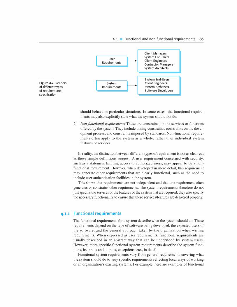
4.1 � Functional and non-functional requirements 85
should behave in particular situations. In some cases, the functional require-
ments may also explicitly state what the system should not do.
2. Non-functional requirements These are constraints on the services or functions
offered by the system. They include timing constraints, constraints on the devel-
opment process, and constraints imposed by standards. Non-functional require-
ments often apply to the system as a whole, rather than individual system
features or services.
In reality, the distinction between different types of requirement is not as clear-cut
as these simple definitions suggest. A user requirement concerned with security,
such as a statement limiting access to authorized users, may appear to be a non-
functional requirement. However, when developed in more detail, this requirement
may generate other requirements that are clearly functional, such as the need to
include user authentication facilities in the system.
This shows that requirements are not independent and that one requirement often
generates or constrains other requirements. The system requirements therefore do not
just specify the services or the features of the system that are required; they also specify
the necessary functionality to ensure that these services/features are delivered properly.
4.1.1 Functional requirements
The functional requirements for a system describe what the system should do. These
requirements depend on the type of software being developed, the expected users of
the software, and the general approach taken by the organization when writing
requirements. When expressed as user requirements, functional requirements are
usually described in an abstract way that can be understood by system users.
However, more specific functional system requirements describe the system func-
tions, its inputs and outputs, exceptions, etc., in detail.
Functional system requirements vary from general requirements covering what
the system should do to very specific requirements reflecting local ways of working
or an organization’s existing systems. For example, here are examples of functional
Client ManagersSystem End-UsersClient EngineersContractor ManagersSystem Architects
System End-UsersClient EngineersSystem ArchitectsSoftware Developers
UserRequirements
SystemRequirements
Figure 4.2 Readersof different typesof requirementsspecification

86 Chapter 4 � Requirements engineering
requirements for the MHC-PMS system, used to maintain information about patients
receiving treatment for mental health problems:
1. A user shall be able to search the appointments lists for all clinics.
2. The system shall generate each day, for each clinic, a list of patients who are
expected to attend appointments that day.
3. Each staff member using the system shall be uniquely identified by his or her
eight-digit employee number.
These functional user requirements define specific facilities to be provided by the
system. These have been taken from the user requirements document and they show
that functional requirements may be written at different levels of detail (contrast
requirements 1 and 3).
Imprecision in the requirements specification is the cause of many software engi-
neering problems. It is natural for a system developer to interpret an ambiguous
requirement in a way that simplifies its implementation. Often, however, this is not
what the customer wants. New requirements have to be established and changes
made to the system. Of course, this delays system delivery and increases costs.
For example, the first example requirement for the MHC-PMS states that a user shall
be able to search the appointments lists for all clinics. The rationale for this requirement
is that patients with mental health problems are sometimes confused. They may have an
appointment at one clinic but actually go to a different clinic. If they have an appoint-
ment, they will be recorded as having attended, irrespective of the clinic.
The medical staff member specifying this may expect ‘search’ to mean that, given
a patient name, the system looks for that name in all appointments at all clinics.
However, this is not explicit in the requirement. System developers may interpret the
requirement in a different way and may implement a search so that the user has to
choose a clinic then carry out the search. This obviously will involve more user input
and so take longer.
In principle, the functional requirements specification of a system should be both
complete and consistent. Completeness means that all services required by the user
should be defined. Consistency means that requirements should not have contradictory
Domain requirements
Domain requirements are derived from the application domain of the system rather than from the specificneeds of system users. They may be new functional requirements in their own right, constrain existingfunctional requirements, or set out how particular computations must be carried out.
The problem with domain requirements is that software engineers may not understand the characteristics ofthe domain in which the system operates. They often cannot tell whether or not a domain requirement hasbeen missed out or conflicts with other requirements.
http://www.SoftwareEngineering-9.com/Web/Requirements/DomainReq.html
FPO

4.1 � Functional and non-functional requirements 87
definitions. In practice, for large, complex systems, it is practically impossible to
achieve requirements consistency and completeness. One reason for this is that it is easy
to make mistakes and omissions when writing specifications for complex systems.
Another reason is that there are many stakeholders in a large system. A stakeholder is a
person or role that is affected by the system in some way. Stakeholders have different—
and often inconsistent—needs. These inconsistencies may not be obvious when the
requirements are first specified, so inconsistent requirements are included in the specifi-
cation. The problems may only emerge after deeper analysis or after the system has
been delivered to the customer.
4.1.2 Non-functional requirements
Non-functional requirements, as the name suggests, are requirements that are not
directly concerned with the specific services delivered by the system to its users.
They may relate to emergent system properties such as reliability, response time, and
store occupancy. Alternatively, they may define constraints on the system implemen-
tation such as the capabilities of I/O devices or the data representations used in inter-
faces with other systems.
Non-functional requirements, such as performance, security, or availability, usually
specify or constrain characteristics of the system as a whole. Non-functional require-
ments are often more critical than individual functional requirements. System users can
usually find ways to work around a system function that doesn’t really meet their needs.
However, failing to meet a non-functional requirement can mean that the whole system
is unusable. For example, if an aircraft system does not meet its reliability requirements,
it will not be certified as safe for operation; if an embedded control system fails to meet
its performance requirements, the control functions will not operate correctly.
Although it is often possible to identify which system components implement
specific functional requirements (e.g., there may be formatting components that
implement reporting requirements), it is often more difficult to relate components to
non-functional requirements. The implementation of these requirements may be dif-
fused throughout the system. There are two reasons for this:
1. Non-functional requirements may affect the overall architecture of a system
rather than the individual components. For example, to ensure that performance
requirements are met, you may have to organize the system to minimize com-
munications between components.
2. A single non-functional requirement, such as a security requirement, may generate
a number of related functional requirements that define new system services that
are required. In addition, it may also generate requirements that restrict existing
requirements.
Non-functional requirements arise through user needs, because of budget con-
straints, organizational policies, the need for interoperability with other software or

88 Chapter 4 � Requirements engineering
hardware systems, or external factors such as safety regulations or privacy legisla-
tion. Figure 4.3 is a classification of non-functional requirements. You can see from
this diagram that the non-functional requirements may come from required charac-
teristics of the software (product requirements), the organization developing the soft-
ware (organizational requirements), or from external sources:
1. Product requirements These requirements specify or constrain the behavior of the
software. Examples include performance requirements on how fast the system
must execute and how much memory it requires, reliability requirements that set
out the acceptable failure rate, security requirements, and usability requirements.
2. Organizational requirements These requirements are broad system requirements
derived from policies and procedures in the customer’s and developer’s organiza-
tion. Examples include operational process requirements that define how the sys-
tem will be used, development process requirements that specify the programming
language, the development environment or process standards to be used, and envi-
ronmental requirements that specify the operating environment of the system.
3. External requirements This broad heading covers all requirements that are
derived from factors external to the system and its development process. These
may include regulatory requirements that set out what must be done for the sys-
tem to be approved for use by a regulator, such as a central bank; legislative
requirements that must be followed to ensure that the system operates within the
law; and ethical requirements that ensure that the system will be acceptable to
its users and the general public.
PerformanceRequirements
SpaceRequirements
UsabilityRequirements
EfficiencyRequirements
DependabilityRequirements
SecurityRequirements
RegulatoryRequirements
EthicalRequirements
LegislativeRequirements
OperationalRequirements
DevelopmentRequirements
EnvironmentalRequirements
Safety/SecurityRequirements
AccountingRequirements
ProductRequirements
OrganizationalRequirements
ExternalRequirements
Non-FunctionalRequirements
Figure 4.3 Types ofnon-functionalrequirement

4.1 � Functional and non-functional requirements 89
Figure 4.4 shows examples of product, organizational, and external requirements
taken from the MHC-PMS whose user requirements were introduced in Section 4.1.1.
The product requirement is an availability requirement that defines when the system
has to be available and the allowed down time each day. It says nothing about the
functionality of MHC-PMS and clearly identifies a constraint that has to be consid-
ered by the system designers.
The organizational requirement specifies how users authenticate themselves to the
system. The health authority that operates the system is moving to a standard authenti-
cation procedure for all software where, instead of users having a login name, they
swipe their identity card through a reader to identify themselves. The external require-
ment is derived from the need for the system to conform to privacy legislation. Privacy
is obviously a very important issue in healthcare systems and the requirement specifies
that the system should be developed in accordance with a national privacy standard.
A common problem with non-functional requirements is that users or customers
often propose these requirements as general goals, such as ease of use, the ability of
the system to recover from failure, or rapid user response. Goals set out good inten-
tions but cause problems for system developers as they leave scope for interpretation
and subsequent dispute once the system is delivered. For example, the following sys-
tem goal is typical of how a manager might express usability requirements:
The system should be easy to use by medical staff and should be organized in
such a way that user errors are minimized.
I have rewritten this to show how the goal could be expressed as a ‘testable’ non-
functional requirement. It is impossible to objectively verify the system goal, but in
the description below you can at least include software instrumentation to count the
errors made by users when they are testing the system.
Medical staff shall be able to use all the system functions after four hours of
training. After this training, the average number of errors made by experi-
enced users shall not exceed two per hour of system use.
Whenever possible, you should write non-functional requirements quantitatively
so that they can be objectively tested. Figure 4.5 shows metrics that you can use to
specify non-functional system properties. You can measure these characteristics
Figure 4.4 Examplesof non-functionalrequirements in theMHC-PMS
PRODUCT REQUIREMENTThe MHC-PMS shall be available to all clinics during normal working hours (Mon–Fri, 08.30–17.30). Downtimewithin normal working hours shall not exceed five seconds in any one day.
ORGANIZATIONAL REQUIREMENTUsers of the MHC-PMS system shall authenticate themselves using their health authority identity card.
EXTERNAL REQUIREMENTThe system shall implement patient privacy provisions as set out in HStan-03-2006-priv.

90 Chapter 4 � Requirements engineering
when the system is being tested to check whether or not the system has met its non-
functional requirements.
In practice, customers for a system often find it difficult to translate their goals
into measurable requirements. For some goals, such as maintainability, there are no
metrics that can be used. In other cases, even when quantitative specification is pos-
sible, customers may not be able to relate their needs to these specifications. They
don’t understand what some number defining the required reliability (say) means in
terms of their everyday experience with computer systems. Furthermore, the cost of
objectively verifying measurable, non-functional requirements can be very high and
the customers paying for the system may not think these costs are justified.
Non-functional requirements often conflict and interact with other functional
or non-functional requirements. For example, the authentication requirement in
Figure 4.4 obviously requires a card reader to be installed with each computer
attached to the system. However, there may be another requirement that requests
mobile access to the system from doctors’ or nurses’ laptops. These are not normally
equipped with card readers so, in these circumstances, some alternative authentica-
tion method may have to be allowed.
It is difficult, in practice, to separate functional and non-functional requirements
in the requirements document. If the non-functional requirements are stated sepa-
rately from the functional requirements, the relationships between them may be hard
to understand. However, you should explicitly highlight requirements that are clearly
related to emergent system properties, such as performance or reliability. You can do
this by putting them in a separate section of the requirements document or by distin-
guishing them, in some way, from other system requirements.
Figure 4.5 Metricsfor specifyingnon-functionalrequirements
Property Measure
Speed Processed transactions/secondUser/event response timeScreen refresh time
Size MbytesNumber of ROM chips
Ease of use Training timeNumber of help frames
Reliability Mean time to failureProbability of unavailabilityRate of failure occurrenceAvailability
Robustness Time to restart after failurePercentage of events causing failureProbability of data corruption on failure
Portability Percentage of target dependent statementsNumber of target systems

4.2 � The software requirements document 91
FPO Requirements document standards
A number of large organizations, such as the U.S. Department of Defense and the IEEE, have defined standardsfor requirements documents. These are usually very generic but are nevertheless useful as a basis fordeveloping more detailed organizational standards. The U.S. Institute of Electrical and Electronic Engineers(IEEE) is one of the best-known standards providers and they have developed a standard for the structure ofrequirements documents. This standard is most appropriate for systems such as military command and controlsystems that have a long lifetime and are usually developed by a group of organizations.
http://www.SoftwareEngineering-9.com/Web/Requirements/IEEE-standard.html
Non-functional requirements such as reliability, safety, and confidentiality
requirements are particularly important for critical systems. I cover these require-
ments in Chapter 12, where I describe specific techniques for specifying dependabil-
ity and security requirements.
4.2 The software requirements document
The software requirements document (sometimes called the software requirements
specification or SRS) is an official statement of what the system developers should
implement. It should include both the user requirements for a system and a detailed
specification of the system requirements. Sometimes, the user and system require-
ments are integrated into a single description. In other cases, the user requirements
are defined in an introduction to the system requirements specification. If there are a
large number of requirements, the detailed system requirements may be presented in
a separate document.
Requirements documents are essential when an outside contractor is developing
the software system. However, agile development methods argue that requirements
change so rapidly that a requirements document is out of date as soon as it is written,
so the effort is largely wasted. Rather than a formal document, approaches such as
Extreme Programming (Beck, 1999) collect user requirements incrementally and
write these on cards as user stories. The user then prioritizes requirements for imple-
mentation in the next increment of the system.
For business systems where requirements are unstable, I think that this approach
is a good one. However, I think that it is still useful to write a short supporting docu-
ment that defines the business and dependability requirements for the system; it is
easy to forget the requirements that apply to the system as a whole when focusing on
the functional requirements for the next system release.
The requirements document has a diverse set of users, ranging from the senior
management of the organization that is paying for the system to the engineers
responsible for developing the software. Figure 4.6, taken from my book with Gerald
Kotonya on requirements engineering (Kotonya and Sommerville, 1998) shows
possible users of the document and how they use it.
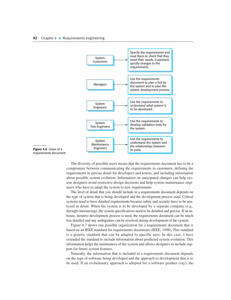
92 Chapter 4 � Requirements engineering
Use the requirements todevelop validation tests forthe system.
Use the requirementsdocument to plan a bid forthe system and to plan thesystem development process.
Use the requirements tounderstand what system isto be developed.
SystemTest Engineers
Managers
SystemEngineers
Specify the requirements andread them to check that theymeet their needs. Customersspecify changes to therequirements.
SystemCustomers
Use the requirements tounderstand the system andthe relationships betweenits parts.
SystemMaintenance
EngineersFigure 4.6 Users of arequirements document
The diversity of possible users means that the requirements document has to be a
compromise between communicating the requirements to customers, defining the
requirements in precise detail for developers and testers, and including information
about possible system evolution. Information on anticipated changes can help sys-
tem designers avoid restrictive design decisions and help system maintenance engi-
neers who have to adapt the system to new requirements.
The level of detail that you should include in a requirements document depends on
the type of system that is being developed and the development process used. Critical
systems need to have detailed requirements because safety and security have to be ana-
lyzed in detail. When the system is to be developed by a separate company (e.g.,
through outsourcing), the system specifications need to be detailed and precise. If an in-
house, iterative development process is used, the requirements document can be much
less detailed and any ambiguities can be resolved during development of the system.
Figure 4.7 shows one possible organization for a requirements document that is
based on an IEEE standard for requirements documents (IEEE, 1998). This standard
is a generic standard that can be adapted to specific uses. In this case, I have
extended the standard to include information about predicted system evolution. This
information helps the maintainers of the system and allows designers to include sup-
port for future system features.
Naturally, the information that is included in a requirements document depends
on the type of software being developed and the approach to development that is to
be used. If an evolutionary approach is adopted for a software product (say), the

4.2 � The software requirements document 93
Figure 4.7 Thestructure of arequirementsdocument
requirements document will leave out many of detailed chapters suggested above.
The focus will be on defining the user requirements and high-level, non-functional
system requirements. In this case, the designers and programmers use their judgment
to decide how to meet the outline user requirements for the system.
However, when the software is part of a large system project that includes interact-
ing hardware and software systems, it is usually necessary to define the requirements
Chapter Description
Preface This should define the expected readership of the document and describe itsversion history, including a rationale for the creation of a new version and asummary of the changes made in each version.
Introduction This should describe the need for the system. It should briefly describe thesystem’s functions and explain how it will work with other systems. It shouldalso describe how the system fits into the overall business or strategicobjectives of the organization commissioning the software.
Glossary This should define the technical terms used in the document. You should notmake assumptions about the experience or expertise of the reader.
User requirementsdefinition
Here, you describe the services provided for the user. The non-functionalsystem requirements should also be described in this section. Thisdescription may use natural language, diagrams, or other notations that areunderstandable to customers. Product and process standards that must befollowed should be specified.
System architecture This chapter should present a high-level overview of the anticipated systemarchitecture, showing the distribution of functions across system modules.Architectural components that are reused should be highlighted.
System requirementsspecification
This should describe the functional and non-functional requirements in moredetail. If necessary, further detail may also be added to the non-functionalrequirements. Interfaces to other systems may be defined.
System models This might include graphical system models showing the relationships betweenthe system components, the system, and its environment. Examples of possiblemodels are object models, data-flow models, or semantic data models.
System evolution This should describe the fundamental assumptions on which the system isbased, and any anticipated changes due to hardware evolution, changinguser needs, and so on. This section is useful for system designers as it mayhelp them avoid design decisions that would constrain likely future changesto the system.
Appendices These should provide detailed, specific information that is related to theapplication being developed; for example, hardware and database descriptions.Hardware requirements define the minimal and optimal configurations for thesystem. Database requirements define the logical organization of the data usedby the system and the relationships between data.
Index Several indexes to the document may be included. As well as a normalalphabetic index, there may be an index of diagrams, an index of functions,and so on.

94 Chapter 4 � Requirements engineering
to a fine level of detail. This means that the requirements documents are likely to be
very long and should include most if not all of the chapters shown in Figure 4.7. For
long documents, it is particularly important to include a comprehensive table of con-
tents and document index so that readers can find the information that they need.
4.3 Requirements specification
Requirements specification is the process of writing down the user and system
requirements in a requirements document. Ideally, the user and system requirements
should be clear, unambiguous, easy to understand, complete, and consistent. In prac-
tice, this is difficult to achieve as stakeholders interpret the requirements in different
ways and there are often inherent conflicts and inconsistencies in the requirements.
The user requirements for a system should describe the functional and non-
functional requirements so that they are understandable by system users who don’t have
detailed technical knowledge. Ideally, they should specify only the external behavior of
the system. The requirements document should not include details of the system archi-
tecture or design. Consequently, if you are writing user requirements, you should not
use software jargon, structured notations, or formal notations. You should write user
requirements in natural language, with simple tables, forms, and intuitive diagrams.
System requirements are expanded versions of the user requirements that are used
by software engineers as the starting point for the system design. They add detail and
explain how the user requirements should be provided by the system. They may be
used as part of the contract for the implementation of the system and should there-
fore be a complete and detailed specification of the whole system.
Ideally, the system requirements should simply describe the external behavior
of the system and its operational constraints. They should not be concerned with how
the system should be designed or implemented. However, at the level of detail
required to completely specify a complex software system, it is practically impossi-
ble to exclude all design information. There are several reasons for this:
1. You may have to design an initial architecture of the system to help structure the
requirements specification. The system requirements are organized according to
FPO Problems with using natural language for requirements specification
The flexibility of natural language, which is so useful for specification, often causes problems. There is scope forwriting unclear requirements, and readers (the designers) may misinterpret requirements because they have adifferent background to the user. It is easy to amalgamate several requirements into a single sentence andstructuring natural language requirements can be difficult.
http://www.SoftwareEngineering-9.com/Web/Requirements/NL-problems.html

4.3 � Requirements specification 95
the different sub-systems that make up the system. As I discuss in Chapters 6
and 18, this architectural definition is essential if you want to reuse software
components when implementing the system.
2. In most cases, systems must interoperate with existing systems, which constrain
the design and impose requirements on the new system.
3. The use of a specific architecture to satisfy non-functional requirements (such
as N-version programming to achieve reliability, discussed in Chapter 13) may
be necessary. An external regulator who needs to certify that the system is safe
may specify that an already certified architectural design be used.
User requirements are almost always written in natural language supplemented
by appropriate diagrams and tables in the requirements document. System
requirements may also be written in natural language but other notations based on
forms, graphical system models, or mathematical system models can also be
used. Figure 4.8 summarizes the possible notations that could be used for writing
system requirements.
Graphical models are most useful when you need to show how a state changes or
when you need to describe a sequence of actions. UML sequence charts and state
charts, described in Chapter 5, show the sequence of actions that occur in response
to a certain message or event. Formal mathematical specifications are sometimes
used to describe the requirements for safety- or security-critical systems, but are
rarely used in other circumstances. I explain this approach to writing specifications
in Chapter 12.
Figure 4.8 Ways ofwriting a systemrequirementsspecification
Notation Description
Natural language sentences The requirements are written using numbered sentences in naturallanguage. Each sentence should express one requirement.
Structured natural language The requirements are written in natural language on a standard form ortemplate. Each field provides information about an aspect of therequirement.
Design description languages This approach uses a language like a programming language, but withmore abstract features to specify the requirements by defining anoperational model of the system. This approach is now rarely usedalthough it can be useful for interface specifications.
Graphical notations Graphical models, supplemented by text annotations, are used to definethe functional requirements for the system; UML use case and sequencediagrams are commonly used.
Mathematical specifications These notations are based on mathematical concepts such as finite-statemachines or sets. Although these unambiguous specifications can reducethe ambiguity in a requirements document, most customers don’tunderstand a formal specification. They cannot check that it representswhat they want and are reluctant to accept it as a system contract.

96 Chapter 4 � Requirements engineering
4.3.1 Natural language specification
Natural language has been used to write requirements for software since the beginning
of software engineering. It is expressive, intuitive, and universal. It is also potentially
vague, ambiguous, and its meaning depends on the background of the reader. As a
result, there have been many proposals for alternative ways to write requirements.
However, none of these have been widely adopted and natural language will continue
to be the most widely used way of specifying system and software requirements.
To minimize misunderstandings when writing natural language requirements,
I recommend that you follow some simple guidelines:
1. Invent a standard format and ensure that all requirement definitions adhere to
that format. Standardizing the format makes omissions less likely and require-
ments easier to check. The format I use expresses the requirement in a single
sentence. I associate a statement of rationale with each user requirement to
explain why the requirement has been proposed. The rationale may also include
information on who proposed the requirement (the requirement source) so that
you know whom to consult if the requirement has to be changed.
2. Use language consistently to distinguish between mandatory and desirable
requirements. Mandatory requirements are requirements that the system must
support and are usually written using ‘shall’. Desirable requirements are not
essential and are written using ‘should’.
3. Use text highlighting (bold, italic, or color) to pick out key parts of the requirement.
4. Do not assume that readers understand technical software engineering language.
It is easy for words like ‘architecture’ and ‘module’ to be misunderstood. You
should, therefore, avoid the use of jargon, abbreviations, and acronyms.
5. Whenever possible, you should try to associate a rationale with each user
requirement. The rationale should explain why the requirement has been
included. It is particularly useful when requirements are changed as it may help
decide what changes would be undesirable.
Figure 4.9 illustrates how these guidelines may be used. It includes two require-
ments for the embedded software for the automated insulin pump, introduced in
Chapter 1. You can download the complete insulin pump requirements specification
from the book’s web pages.
3.2 The system shall measure the blood sugar and deliver insulin, if required, every 10 minutes. (Changes inblood sugar are relatively slow so more frequent measurement is unnecessary; less frequent measurementcould lead to unnecessarily high sugar levels.)
3.6 The system shall run a self-test routine every minute with the conditions to be tested and the associatedactions defined in Table 1. (A self-test routine can discover hardware and software problems and alert the userto the fact the normal operation may be impossible.)
Figure 4.9Example requirementsfor the insulin pumpsoftware system

4.3 � Requirements specification 97
4.3.2 Structured specifications
Structured natural language is a way of writing system requirements where the
freedom of the requirements writer is limited and all requirements are written in a
standard way. This approach maintains most of the expressiveness and understand-
ability of natural language but ensures that some uniformity is imposed on the
specification. Structured language notations use templates to specify system
requirements. The specification may use programming language constructs to
show alternatives and iteration, and may highlight key elements using shading or
different fonts.
The Robertsons (Robertson and Robertson, 1999), in their book on the
VOLERE requirements engineering method, recommend that user requirements be
initially written on cards, one requirement per card. They suggest a number of
fields on each card, such as the requirements rationale, the dependencies on other
requirements, the source of the requirements, supporting materials, and so on. This
is similar to the approach used in the example of a structured specification shown
in Figure 4.10.
To use a structured approach to specifying system requirements, you define one or
more standard templates for requirements and represent these templates as structured
forms. The specification may be structured around the objects manipulated by the sys-
tem, the functions performed by the system, or the events processed by the system. An
example of a form-based specification, in this case, one that defines how to calculate the
dose of insulin to be delivered when the blood sugar is within a safe band, is shown in
Figure 4.10.
Insulin Pump/Control Software/SRS/3.3.2
Function Compute insulin dose: Safe sugar level.
Description Computes the dose of insulin to be delivered when the current measured sugar level is inthe safe zone between 3 and 7 units.
Inputs Current sugar reading (r2), the previous two readings (r0 and r1).
Source Current sugar reading from sensor. Other readings from memory.
Outputs CompDose—the dose in insulin to be delivered.
Destination Main control loop.
Action CompDose is zero if the sugar level is stable or falling or if the level is increasing but therate of increase is decreasing. If the level is increasing and the rate of increase isincreasing, then CompDose is computed by dividing the difference between the currentsugar level and the previous level by 4 and rounding the result. If the result, is rounded tozero then CompDose is set to the minimum dose that can be delivered.
Requirements Two previous readings so that the rate of change of sugar level can be computed.
Pre-condition The insulin reservoir contains at least the maximum allowed single dose of insulin.
Post-condition r0 is replaced by r1 then r1 is replaced by r2.
Side effects None.
Figure 4.10A structuredspecificationof a requirement foran insulin pump

98 Chapter 4 � Requirements engineering
When a standard form is used for specifying functional requirements, the follow-
ing information should be included:
1. A description of the function or entity being specified.
2. A description of its inputs and where these come from.
3. A description of its outputs and where these go to.
4. Information about the information that is needed for the computation or other
entities in the system that are used (the ‘requires’ part).
5. A description of the action to be taken.
6. If a functional approach is used, a pre-condition setting out what must be true
before the function is called, and a post-condition specifying what is true after
the function is called.
7. A description of the side effects (if any) of the operation.
Using structured specifications removes some of the problems of natural lan-
guage specification. Variability in the specification is reduced and requirements are
organized more effectively. However, it is still sometimes difficult to write require-
ments in a clear and unambiguous way, particularly when complex computations
(e.g., how to calculate the insulin dose) are to be specified.
To address this problem, you can add extra information to natural language
requirements, for example, by using tables or graphical models of the system. These
can show how computations proceed, how the system state changes, how users inter-
act with the system, and how sequences of actions are performed.
Tables are particularly useful when there are a number of possible alternative sit-
uations and you need to describe the actions to be taken for each of these. The insulin
pump bases its computations of the insulin requirement on the rate of change of
blood sugar levels. The rates of change are computed using the current and previous
readings. Figure 4.11 is a tabular description of how the rate of change of blood
sugar is used to calculate the amount of insulin to be delivered.
Condition Action
Sugar level falling (r2 � r1) CompDose � 0
Sugar level stable (r2 � r1) CompDose � 0
Sugar level increasing and rate of increase
decreasing ((r2 � r1) � (r1 � r0))
CompDose � 0
Sugar level increasing and rate of increase stable or
increasing ((r2 � r1) � (r1 � r0))CompDose � round ((r2 � r1)/4)
If rounded result � 0 thenCompDose � MinimumDose
Figure 4.11 Tabularspecification ofcomputation foran insulin pump

4.4 � Requirements engineering processes 99
RequirementsSpecification
RequirementsValidation
RequirementsElicitation
System RequirementsSpecification and
Modeling
SystemReq.
Elicitation
User RequirementsSpecification
UserRequirements
Elicitation
Business RequirementsSpecification
Prototyping
FeasibilityStudy
Reviews
System RequirementsDocument
Start
4.4 Requirements engineering processes
As I discussed in Chapter 2, requirements engineering processes may include four
high-level activities. These focus on assessing if the system is useful to the business
(feasibility study), discovering requirements (elicitation and analysis), converting
these requirements into some standard form (specification), and checking that the
requirements actually define the system that the customer wants (validation). I have
shown these as sequential processes in Figure 2.6. However, in practice, require-
ments engineering is an iterative process in which the activities are interleaved.
Figure 4.12 shows this interleaving. The activities are organized as an iterative
process around a spiral, with the output being a system requirements document.
The amount of time and effort devoted to each activity in each iteration depends on
the stage of the overall process and the type of system being developed. Early in
the process, most effort will be spent on understanding high-level business and
Figure 4.12 A spiralview of therequirementsengineering process
100 Chapter 4 � Requirements engineering
FPO Feasibility studies
A feasibility study is a short, focused study that should take place early in the RE process. It should answer threekey questions: a) does the system contribute to the overall objectives of the organization? b) can the system beimplemented within schedule and budget using current technology? and c) can the system be integrated withother systems that are used?
If the answer to any of these questions is no, you should probably not go ahead with the project.
http://www.SoftwareEngineering-9.com/Web/Requirements/FeasibilityStudy.html
non-functional requirements, and the user requirements for the system. Later in the
process, in the outer rings of the spiral, more effort will be devoted to eliciting and
understanding the detailed system requirements.
This spiral model accommodates approaches to development where the require-
ments are developed to different levels of detail. The number of iterations around the
spiral can vary so the spiral can be exited after some or all of the user requirements
have been elicited. Agile development can be used instead of prototyping so that the
requirements and the system implementation are developed together.
Some people consider requirements engineering to be the process of applying a
structured analysis method, such as object-oriented analysis (Larman, 2002). This
involves analyzing the system and developing a set of graphical system models, such
as use case models, which then serve as a system specification. The set of models
describes the behavior of the system and is annotated with additional information
describing, for example, the system’s required performance or reliability.
Although structured methods have a role to play in the requirements engineering
process, there is much more to requirements engineering than is covered by these
methods. Requirements elicitation, in particular, is a human-centered activity and
people dislike the constraints imposed on it by rigid system models.
In virtually all systems, requirements change. The people involved develop a bet-
ter understanding of what they want the software to do; the organization buying the
system changes; modifications are made to the system’s hardware, software, and
organizational environment. The process of managing these changing requirements
is called requirements management, which I cover in Section 4.7.
4.5 Requirements elicitation and analysis
After an initial feasibility study, the next stage of the requirements engineering
process is requirements elicitation and analysis. In this activity, software engineers
work with customers and system end-users to find out about the application domain,
what services the system should provide, the required performance of the system,
hardware constraints, and so on.

4.5 � Requirements elicitation and analysis 101
Requirements elicitation and analysis may involve a variety of different kinds of
people in an organization. A system stakeholder is anyone who should have some
direct or indirect influence on the system requirements. Stakeholders include end-
users who will interact with the system and anyone else in an organization who will
be affected by it. Other system stakeholders might be engineers who are developing
or maintaining other related systems, business managers, domain experts, and trade
union representatives.
A process model of the elicitation and analysis process is shown in Figure 4.13.
Each organization will have its own version or instantiation of this general model
depending on local factors such as the expertise of the staff, the type of system being
developed, the standards used, etc.
The process activities are:
1. Requirements discovery This is the process of interacting with stakeholders of the
system to discover their requirements. Domain requirements from stakeholders and
documentation are also discovered during this activity. There are several comple-
mentary techniques that can be used for requirements discovery, which I discuss
later in this section.
2. Requirements classification and organization This activity takes the unstruc-
tured collection of requirements, groups related requirements, and organizes
them into coherent clusters. The most common way of grouping requirements is
to use a model of the system architecture to identify sub-systems and to associ-
ate requirements with each sub-system. In practice, requirements engineering
and architectural design cannot be completely separate activities.
3. Requirements prioritization and negotiation Inevitably, when multiple stake-
holders are involved, requirements will conflict. This activity is concerned with
prioritizing requirements and finding and resolving requirements conflicts
through negotiation. Usually, stakeholders have to meet to resolve differences
and agree on compromise requirements.
1. RequirementsDiscovery
2. RequirementsClassification and
Organization
3. RequirementsPrioritization and
Negotiation
4. RequirementsSpecification
Figure 4.13 Therequirements elicitationand analysis process

102 Chapter 4 � Requirements engineering
4. Requirements specification The requirements are documented and input into the
next round of the spiral. Formal or informal requirements documents may be
produced, as discussed in Section 4.3.
Figure 4.13 shows that requirements elicitation and analysis is an iterative
process with continual feedback from each activity to other activities. The process
cycle starts with requirements discovery and ends with the requirements documenta-
tion. The analyst’s understanding of the requirements improves with each round of
the cycle. The cycle ends when the requirements document is complete.
Eliciting and understanding requirements from system stakeholders is a difficult
process for several reasons:
1. Stakeholders often don’t know what they want from a computer system except
in the most general terms; they may find it difficult to articulate what they want
the system to do; they may make unrealistic demands because they don’t know
what is and isn’t feasible.
2. Stakeholders in a system naturally express requirements in their own terms and
with implicit knowledge of their own work. Requirements engineers, without
experience in the customer’s domain, may not understand these requirements.
3. Different stakeholders have different requirements and they may express these
in different ways. Requirements engineers have to discover all potential sources
of requirements and discover commonalities and conflict.
4. Political factors may influence the requirements of a system. Managers may
demand specific system requirements because these will allow them to increase
their influence in the organization.
5. The economic and business environment in which the analysis takes place is
dynamic. It inevitably changes during the analysis process. The importance of
particular requirements may change. New requirements may emerge from new
stakeholders who were not originally consulted.
Inevitably, different stakeholders have different views on the importance and pri-
ority of requirements and, sometimes, these views are conflicting. During the
process, you should organize regular stakeholder negotiations so that compromises
can be reached. It is impossible to completely satisfy every stakeholder but if some
stakeholders feel that their views have not been properly considered then they may
deliberately attempt to undermine the RE process.
At the requirements specification stage, the requirements that have been elicited
so far are documented in such a way that they can be used to help with requirements
discovery. At this stage, an early version of the system requirements document may
be produced with missing sections and incomplete requirements. Alternatively, the
requirements may be documented in a completely different way (e.g., in a spread-
sheet or on cards). Writing requirements on cards can be very effective as these are
easy for stakeholders to handle, change, and organize.

4.5 � Requirements elicitation and analysis 103
FPO Viewpoints
A viewpoint is way of collecting and organizing a set of requirements from a group of stakeholders who havesomething in common. Each viewpoint therefore includes a set of system requirements. Viewpoints might comefrom end-users, managers, etc. They help identify the people who can provide information about theirrequirements and structure the requirements for analysis.
http://www.SoftwareEngineering-9.com/Web/Requirements/Viewpoints.html
4.5.1 Requirements discovery
Requirements discovery (sometime called requirements elicitation) is the process of
gathering information about the required system and existing systems, and distilling
the user and system requirements from this information. Sources of information dur-
ing the requirements discovery phase include documentation, system stakeholders,
and specifications of similar systems. You interact with stakeholders through inter-
views and observation and you may use scenarios and prototypes to help stakehold-
ers understand what the system will be like.
Stakeholders range from end-users of a system through managers to external stake-
holders such as regulators, who certify the acceptability of the system. For example,
system stakeholders for the mental healthcare patient information system include:
1. Patients whose information is recorded in the system.
2. Doctors who are responsible for assessing and treating patients.
3. Nurses who coordinate the consultations with doctors and administer some
treatments.
4. Medical receptionists who manage patients’ appointments.
5. IT staff who are responsible for installing and maintaining the system.
6. A medical ethics manager who must ensure that the system meets current ethi-
cal guidelines for patient care.
7. Healthcare managers who obtain management information from the system.
8. Medical records staff who are responsible for ensuring that system information
can be maintained and preserved, and that record keeping procedures have been
properly implemented.
In addition to system stakeholders, we have already seen that requirements may
also come from the application domain and from other systems that interact with the
system being specified. All of these must be considered during the requirements
elicitation process.
These different requirements sources (stakeholders, domain, systems) can all be
represented as system viewpoints with each viewpoint showing a subset of the

104 Chapter 4 � Requirements engineering
requirements for the system. Different viewpoints on a problem see the problem in
different ways. However, their perspectives are not completely independent but usu-
ally overlap so that they have common requirements. You can use these viewpoints
to structure both the discovery and the documentation of the system requirements.
4.5.2 Interviewing
Formal or informal interviews with system stakeholders are part of most require-
ments engineering processes. In these interviews, the requirements engineering team
puts questions to stakeholders about the system that they currently use and the sys-
tem to be developed. Requirements are derived from the answers to these questions.
Interviews may be of two types:
1. Closed interviews, where the stakeholder answers a pre-defined set of questions.
2. Open interviews, in which there is no pre-defined agenda. The requirements
engineering team explores a range of issues with system stakeholders and hence
develop a better understanding of their needs.
In practice, interviews with stakeholders are normally a mixture of both of these.
You may have to obtain the answer to certain questions but these usually lead on to
other issues that are discussed in a less structured way. Completely open-ended dis-
cussions rarely work well. You usually have to ask some questions to get started and
to keep the interview focused on the system to be developed.
Interviews are good for getting an overall understanding of what stakeholders do,
how they might interact with the new system, and the difficulties that they face with
current systems. People like talking about their work so are usually happy to get
involved in interviews. However, interviews are not so helpful in understanding the
requirements from the application domain.
It can be difficult to elicit domain knowledge through interviews for two reasons:
1. All application specialists use terminology and jargon that are specific to a
domain. It is impossible for them to discuss domain requirements without using
this terminology. They normally use terminology in a precise and subtle way
that is easy for requirements engineers to misunderstand.
2. Some domain knowledge is so familiar to stakeholders that they either find it
difficult to explain or they think it is so fundamental that it isn’t worth mention-
ing. For example, for a librarian, it goes without saying that all acquisitions are
catalogued before they are added to the library. However, this may not be obvi-
ous to the interviewer, and so it isn’t taken into account in the requirements.
Interviews are also not an effective technique for eliciting knowledge about orga-
nizational requirements and constraints because there are subtle power relationships
between the different people in the organization. Published organizational structures
4.5 � Requirements elicitation and analysis 105
rarely match the reality of decision making in an organization but interviewees may
not wish to reveal the actual rather than the theoretical structure to a stranger. In gen-
eral, most people are generally reluctant to discuss political and organizational
issues that may affect the requirements.
Effective interviewers have two characteristics:
1. They are open-minded, avoid pre-conceived ideas about the requirements, and
are willing to listen to stakeholders. If the stakeholder comes up with surprising
requirements, then they are willing to change their mind about the system.
2. They prompt the interviewee to get discussions going using a springboard question,
a requirements proposal, or by working together on a prototype system. Saying to
people ‘tell me what you want’ is unlikely to result in useful information. They find
it much easier to talk in a defined context rather than in general terms.
Information from interviews supplements other information about the system from
documentation describing business processes or existing systems, user observations,
etc. Sometimes, apart from the information in the system documents, the interview
information may be the only source of information about the system requirements.
However, interviewing on its own is liable to miss essential information and so it
should be used in conjunction with other requirements elicitation techniques.
4.5.3 Scenarios
People usually find it easier to relate to real-life examples rather than abstract
descriptions. They can understand and criticize a scenario of how they might interact
with a software system. Requirements engineers can use the information gained
from this discussion to formulate the actual system requirements.
Scenarios can be particularly useful for adding detail to an outline requirements
description. They are descriptions of example interaction sessions. Each scenario
usually covers one or a small number of possible interactions. Different forms of
scenarios are developed and they provide different types of information at different
levels of detail about the system. The stories used in extreme programming, dis-
cussed in Chapter 3, are a type of requirements scenario.
A scenario starts with an outline of the interaction. During the elicitation process,
details are added to this to create a complete description of that interaction. At its
most general, a scenario may include:
1. A description of what the system and users expects when the scenario starts.
2. A description of the normal flow of events in the scenario.
3. A description of what can go wrong and how this is handled.
4. Information about other activities that might be going on at the same time.
5. A description of the system state when the scenario finishes.

106 Chapter 4 � Requirements engineering
Scenario-based elicitation involves working with stakeholders to identify scenar-
ios and to capture details to be included in these scenarios. Scenarios may be written
as text, supplemented by diagrams, screen shots, etc. Alternatively, a more structured
approach such as event scenarios or use cases may be used.
As an example of a simple text scenario, consider how the MHC-PMS may be
used to enter data for a new patient (Figure 4.14). When a new patient attends a
clinic, a new record is created by a medical receptionist and personal information
(name, age, etc.) is added to it. A nurse then interviews the patient and collects med-
ical history. The patient then has an initial consultation with a doctor who makes a
diagnosis and, if appropriate, recommends a course of treatment. The scenario
shows what happens when medical history is collected.
4.5.4 Use cases
Use cases are a requirements discovery technique that were first introduced in the
Objectory method (Jacobson et al., 1993). They have now become a fundamental
feature of the unified modeling language. In their simplest form, a use case identifies
INITIAL ASSUMPTION:The patient has seen a medical receptionist who has created a record in the system and collected the patient’spersonal information (name, address, age, etc.). A nurse is logged on to the system and is collecting medical history.
NORMAL:The nurse searches for the patient by family name. If there is more than one patient with the same surname,the given name (first name in English) and date of birth are used to identify the patient.
The nurse chooses the menu option to add medical history.
The nurse then follows a series of prompts from the system to enter information about consultations elsewhereon mental health problems (free text input), existing medical conditions (nurse selects conditions from menu),medication currently taken (selected from menu), allergies (free text), and home life (form).
WHAT CAN GO WRONG:The patient’s record does not exist or cannot be found. The nurse should create a new record and recordpersonal information.
Patient conditions or medication are not entered in the menu. The nurse should choose the ‘other’ option andenter free text describing the condition/medication.
Patient cannot/will not provide information on medical history. The nurse should enter free text recording thepatient’s inability/unwillingness to provide information. The system should print the standard exclusion formstating that the lack of information may mean that treatment will be limited or delayed. This should be signedand handed to the patient.
OTHER ACTIVITIES:Record may be consulted but not edited by other staff while information is being entered.
SYSTEM STATE ON COMPLETION:User is logged on. The patient record including medical history is entered in the database, a record is added tothe system log showing the start and end time of the session and the nurse involved.
Figure 4.14 Scenariofor collecting medicalhistory in MHC-PMS
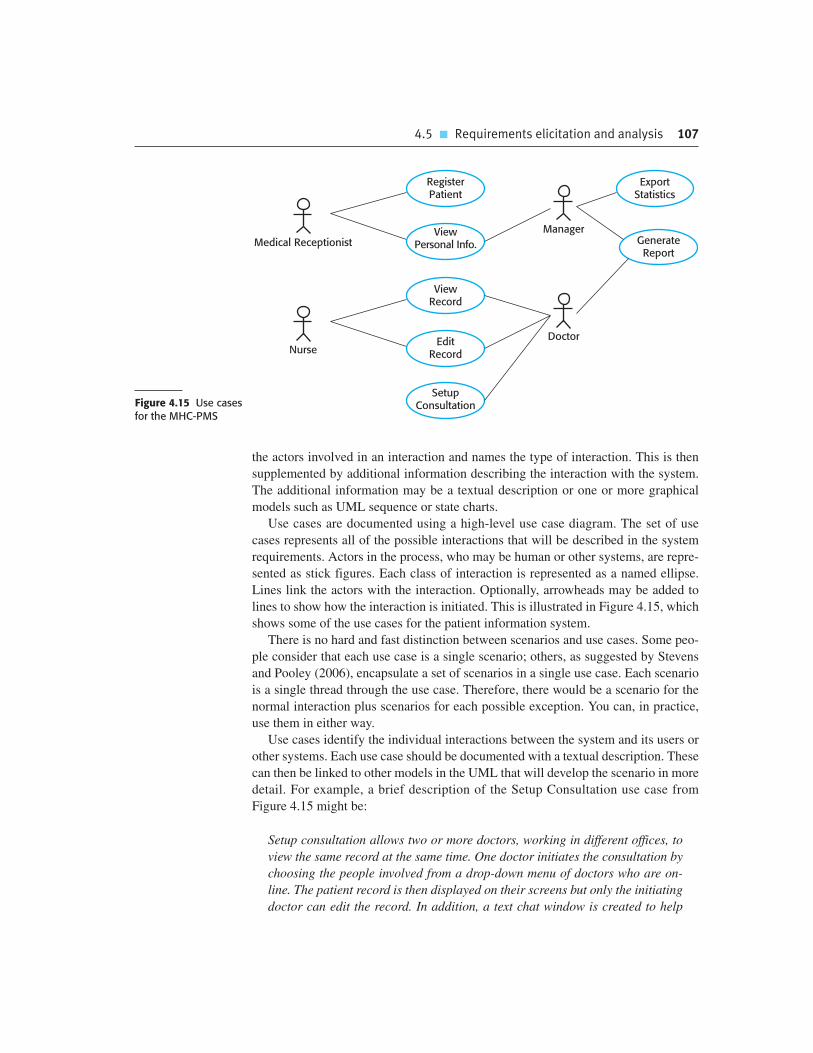
4.5 � Requirements elicitation and analysis 107
the actors involved in an interaction and names the type of interaction. This is then
supplemented by additional information describing the interaction with the system.
The additional information may be a textual description or one or more graphical
models such as UML sequence or state charts.
Use cases are documented using a high-level use case diagram. The set of use
cases represents all of the possible interactions that will be described in the system
requirements. Actors in the process, who may be human or other systems, are repre-
sented as stick figures. Each class of interaction is represented as a named ellipse.
Lines link the actors with the interaction. Optionally, arrowheads may be added to
lines to show how the interaction is initiated. This is illustrated in Figure 4.15, which
shows some of the use cases for the patient information system.
There is no hard and fast distinction between scenarios and use cases. Some peo-
ple consider that each use case is a single scenario; others, as suggested by Stevens
and Pooley (2006), encapsulate a set of scenarios in a single use case. Each scenario
is a single thread through the use case. Therefore, there would be a scenario for the
normal interaction plus scenarios for each possible exception. You can, in practice,
use them in either way.
Use cases identify the individual interactions between the system and its users or
other systems. Each use case should be documented with a textual description. These
can then be linked to other models in the UML that will develop the scenario in more
detail. For example, a brief description of the Setup Consultation use case from
Figure 4.15 might be:
Setup consultation allows two or more doctors, working in different offices, to
view the same record at the same time. One doctor initiates the consultation by
choosing the people involved from a drop-down menu of doctors who are on-
line. The patient record is then displayed on their screens but only the initiating
doctor can edit the record. In addition, a text chat window is created to help
Medical ReceptionistManager
RegisterPatient
ViewPersonal Info. Generate
Report
ExportStatistics
NurseDoctor
ViewRecord
EditRecord
SetupConsultationFigure 4.15 Use cases
for the MHC-PMS

108 Chapter 4 � Requirements engineering
coordinate actions. It is assumed that a phone conference for voice communica-
tion will be separately set up.
Scenarios and use cases are effective techniques for eliciting requirements from
stakeholders who interact directly with the system. Each type of interaction can be
represented as a use case. However, because they focus on interactions with the sys-
tem, they are not as effective for eliciting constraints or high-level business and non-
functional requirements or for discovering domain requirements.
The UML is a de facto standard for object-oriented modeling, so use cases and
use case–based elicitation are now widely used for requirements elicitation. I discuss
use cases further in Chapter 5 and show how they are used alongside other system
models to document a system design.
4.5.5 Ethnography
Software systems do not exist in isolation. They are used in a social and organiza-
tional context and software system requirements may be derived or constrained by
that context. Satisfying these social and organizational requirements is often critical
for the success of the system. One reason why many software systems are delivered
but never used is that their requirements do not take proper account of how the social
and organizational context affects the practical operation of the system.
Ethnography is an observational technique that can be used to understand opera-
tional processes and help derive support requirements for these processes. An ana-
lyst immerses himself or herself in the working environment where the system will
be used. The day-to-day work is observed and notes made of the actual tasks in
which participants are involved. The value of ethnography is that it helps discover
implicit system requirements that reflect the actual ways that people work, rather
than the formal processes defined by the organization.
People often find it very difficult to articulate details of their work because it is
second nature to them. They understand their own work but may not understand its
relationship to other work in the organization. Social and organizational factors that
affect the work, but which are not obvious to individuals, may only become clear
when noticed by an unbiased observer. For example, a work group may self-organize
so that members know of each other’s work and can cover for each other if someone
is absent. This may not be mentioned during an interview as the group might not see
it as an integral part of their work.
Suchman (1987) pioneered the use of ethnography to study office work. She
found that the actual work practices were far richer, more complex, and more
dynamic than the simple models assumed by office automation systems. The differ-
ence between the assumed and the actual work was the most important reason why
these office systems had no significant effect on productivity. Crabtree (2003)
discusses a wide range of studies since then and describes, in general, the use of
ethnography in systems design. In my own research, I have investigated methods of

4.5 � Requirements elicitation and analysis 109
integrating ethnography into the software engineering process by linking it with
requirements engineering methods (Viller and Sommerville, 1999; Viller and
Sommerville, 2000) and documenting patterns of interaction in cooperative systems
(Martin et al., 2001; Martin et al., 2002; Martin and Sommerville, 2004).
Ethnography is particularly effective for discovering two types of requirements:
1. Requirements that are derived from the way in which people actually work,
rather than the way in which process definitions say they ought to work. For
example, air traffic controllers may switch off a conflict alert system that
detects aircraft with intersecting flight paths, even though normal control
procedures specify that it should be used. They deliberately put the aircraft
on conflicting paths for a short time to help manage the airspace. Their con-
trol strategy is designed to ensure that these aircrafts are moved apart before
problems occur and they find that the conflict alert alarm distracts them from
their work.
2. Requirements that are derived from cooperation and awareness of other people’s
activities. For example, air traffic controllers may use an awareness of other
controllers’ work to predict the number of aircrafts that will be entering their
control sector. They then modify their control strategies depending on that pre-
dicted workload. Therefore, an automated ATC system should allow controllers
in a sector to have some visibility of the work in adjacent sectors.
Ethnography can be combined with prototyping (Figure 4.16). The ethnography
informs the development of the prototype so that fewer prototype refinement cycles
are required. Furthermore, the prototyping focuses the ethnography by identifying
problems and questions that can then be discussed with the ethnographer. He or she
should then look for the answers to these questions during the next phase of the sys-
tem study (Sommerville et al., 1993).
Ethnographic studies can reveal critical process details that are often missed by
other requirements elicitation techniques. However, because of its focus on the
end-user, this approach is not always appropriate for discovering organizational or
domain requirements. They cannot always identify new features that should be
added to a system. Ethnography is not, therefore, a complete approach to elicita-
tion on its own and it should be used to complement other approaches, such as use
case analysis.
EthnographicAnalysis
DebriefingMeetings
FocusedEthnography
PrototypeEvaluation
Generic SystemDevelopment
SystemPrototyping
Figure 4.16Ethnography andprototyping forrequirementsanalysis

110 Chapter 4 � Requirements engineering
Requirements reviews
A requirements review is a process where a group of people from the system customer and the systemdeveloper read the requirements document in detail and check for errors, anomalies, and inconsistencies. Oncethese have been detected and recorded, it is then up to the customer and the developer to negotiate how theidentified problems should be solved.
http://www.SoftwareEngineering-9.com/Web/Requirements/Reviews.html
4.6 Requirements validation
Requirements validation is the process of checking that requirements actually define
the system that the customer really wants. It overlaps with analysis as it is concerned
with finding problems with the requirements. Requirements validation is important
because errors in a requirements document can lead to extensive rework costs when
these problems are discovered during development or after the system is in service.
The cost of fixing a requirements problem by making a system change is usually
much greater than repairing design or coding errors. The reason for this is that a
change to the requirements usually means that the system design and implementa-
tion must also be changed. Furthermore the system must then be re-tested.
During the requirements validation process, different types of checks should be
carried out on the requirements in the requirements document. These checks include:
1. Validity checks A user may think that a system is needed to perform certain func-
tions. However, further thought and analysis may identify additional or different
functions that are required. Systems have diverse stakeholders with different
needs and any set of requirements is inevitably a compromise across the stake-
holder community.
2. Consistency checks Requirements in the document should not conflict. That is,
there should not be contradictory constraints or different descriptions of the
same system function.
3. Completeness checks The requirements document should include requirements
that define all functions and the constraints intended by the system user.
4. Realism checks Using knowledge of existing technology, the requirements
should be checked to ensure that they can actually be implemented. These checks
should also take account of the budget and schedule for the system development.
5. Verifiability To reduce the potential for dispute between customer and contrac-
tor, system requirements should always be written so that they are verifiable.
This means that you should be able to write a set of tests that can demonstrate
that the delivered system meets each specified requirement.

4.7 � Requirements management 111
There are a number of requirements validation techniques that can be used
individually or in conjunction with one another:
1. Requirements reviews The requirements are analyzed systematically by a team
of reviewers who check for errors and inconsistencies.
2. Prototyping In this approach to validation, an executable model of the system in
question is demonstrated to end-users and customers. They can experiment with
this model to see if it meets their real needs.
3. Test-case generation Requirements should be testable. If the tests for the
requirements are devised as part of the validation process, this often reveals
requirements problems. If a test is difficult or impossible to design, this usually
means that the requirements will be difficult to implement and should be recon-
sidered. Developing tests from the user requirements before any code is written
is an integral part of extreme programming.
You should not underestimate the problems involved in requirements validation.
Ultimately, it is difficult to show that a set of requirements does in fact meet a user’s
needs. Users need to picture the system in operation and imagine how that system
would fit into their work. It is hard even for skilled computer professionals to per-
form this type of abstract analysis and harder still for system users. As a result, you
rarely find all requirements problems during the requirements validation process. It
is inevitable that there will be further requirements changes to correct omissions and
misunderstandings after the requirements document has been agreed upon.
4.7 Requirements management
The requirements for large software systems are always changing. One reason for this is
that these systems are usually developed to address ‘wicked’ problems—problems that
cannot be completely defined. Because the problem cannot be fully defined, the soft-
ware requirements are bound to be incomplete. During the software process, the stake-
holders’ understanding of the problem is constantly changing (Figure 4.17). The system
requirements must then also evolve to reflect this changed problem view.
Time
ChangedUnderstanding
of Problem
InitialUnderstanding
of Problem
ChangedRequirements
InitialRequirementsFigure 4.17
Requirementsevolution

112 Chapter 4 � Requirements engineering
Enduring and volatile requirements
Some requirements are more susceptible to change than others. Enduring requirements are the requirements thatare associated with the core, slow-to-change activities of an organization. Enduring requirements are associatedwith fundamental work activities. Volatile requirements are more likely to change. They are usually associated withsupporting activities that reflect how the organization does its work rather than the work itself.
http://www.SoftwareEngineering-9.com/Web/Requirements/EnduringReq.html
Once a system has been installed and is regularly used, new requirements inevitably
emerge. It is hard for users and system customers to anticipate what effects the new
system will have on their business processes and the way that work is done. Once end-
users have experience of a system, they will discover new needs and priorities. There
are several reasons why change is inevitable:
1. The business and technical environment of the system always changes after
installation. New hardware may be introduced, it may be necessary to interface
the system with other systems, business priorities may change (with consequent
changes in the system support required), and new legislation and regulations
may be introduced that the system must necessarily abide by.
2. The people who pay for a system and the users of that system are rarely the
same people. System customers impose requirements because of organizational
and budgetary constraints. These may conflict with end-user requirements and,
after delivery, new features may have to be added for user support if the system
is to meet its goals.
3. Large systems usually have a diverse user community, with many users having
different requirements and priorities that may be conflicting or contradictory.
The final system requirements are inevitably a compromise between them and,
with experience, it is often discovered that the balance of support given to differ-
ent users has to be changed.
Requirements management is the process of understanding and controlling
changes to system requirements. You need to keep track of individual requirements
and maintain links between dependent requirements so that you can assess the
impact of requirements changes. You need to establish a formal process for making
change proposals and linking these to system requirements. The formal process of
requirements management should start as soon as a draft version of the requirements
document is available. However, you should start planning how to manage changing
requirements during the requirements elicitation process.
4.7.1 Requirements management planning
Planning is an essential first stage in the requirements management process. The
planning stage establishes the level of requirements management detail that is
required. During the requirements management stage, you have to decide on:

4.7 � Requirements management 113
ChangeImplementation
Change Analysisand Costing
Problem Analysis andChange Specification
IdentifiedProblem
RevisedRequirements
Figure 4.18Requirements changemanagement
1. Requirements identification Each requirement must be uniquely identified so
that it can be cross-referenced with other requirements and used in traceability
assessments.
2. A change management process This is the set of activities that assess the impact
and cost of changes. I discuss this process in more detail in the following section.
3. Traceability policies These policies define the relationships between each require-
ment and between the requirements and the system design that should be recorded.
The traceability policy should also define how these records should be maintained.
4. Tool support Requirements management involves the processing of large amounts
of information about the requirements. Tools that may be used range from specialist
requirements management systems to spreadsheets and simple database systems.
Requirements management needs automated support and the software tools for
this should be chosen during the planning phase. You need tool support for:
1. Requirements storage The requirements should be maintained in a secure, man-
aged data store that is accessible to everyone involved in the requirements engi-
neering process.
2. Change management The process of change management (Figure 4.18) is sim-
plified if active tool support is available.
3. Traceability management As discussed above, tool support for traceability
allows related requirements to be discovered. Some tools are available which
use natural language processing techniques to help discover possible relation-
ships between requirements.
For small systems, it may not be necessary to use specialized requirements man-
agement tools. The requirements management process may be supported using the
facilities available in word processors, spreadsheets, and PC databases. However,
for larger systems, more specialized tool support is required. I have included links
to information about requirements management tools in the book’s web pages.
4.7.2 Requirements change management
Requirements change management (Figure 4.18) should be applied to all proposed
changes to a system’s requirements after the requirements document has been approved.
Change management is essential because you need to decide if the benefits of imple-
menting new requirements are justified by the costs of implementation. The advantage of

114 Chapter 4 � Requirements engineering
using a formal process for change management is that all change proposals are treated
consistently and changes to the requirements document are made in a controlled way.
There are three principal stages to a change management process:
1. Problem analysis and change specification The process starts with an identified
requirements problem or, sometimes, with a specific change proposal. During
this stage, the problem or the change proposal is analyzed to check that it is
valid. This analysis is fed back to the change requestor who may respond with a
more specific requirements change proposal, or decide to withdraw the request.
2. Change analysis and costing The effect of the proposed change is assessed
using traceability information and general knowledge of the system require-
ments. The cost of making the change is estimated both in terms of modifica-
tions to the requirements document and, if appropriate, to the system design and
implementation. Once this analysis is completed, a decision is made whether or
not to proceed with the requirements change.
3. Change implementation The requirements document and, where necessary, the
system design and implementation, are modified. You should organize the
requirements document so that you can make changes to it without extensive
rewriting or reorganization. As with programs, changeability in documents is
achieved by minimizing external references and making the document sections
as modular as possible. Thus, individual sections can be changed and replaced
without affecting other parts of the document.
If a new requirement has to be urgently implemented, there is always a temptation to
change the system and then retrospectively modify the requirements document. You
should try to avoid this as it almost inevitably leads to the requirements specification and
the system implementation getting out of step. Once system changes have been made, it
is easy to forget to include these changes in the requirements document or to add infor-
mation to the requirements document that is inconsistent with the implementation.
Agile development processes, such as extreme programming, have been designed
to cope with requirements that change during the development process. In these
processes, when a user proposes a requirements change, this change does not go
through a formal change management process. Rather, the user has to prioritize that
change and, if it is high priority, decide what system features that were planned for the
next iteration should be dropped.
FPO Requirements traceability
You need to keep track of the relationships between requirements, their sources, and the system design so that you can analyze the reasons for proposed changes and the impact that these changes are likely to have onother parts of the system. You need to be able to trace how a change ripples its way through the system. Why?
http://www.SoftwareEngineering-9.com/Web/Requirements/ReqTraceability.html
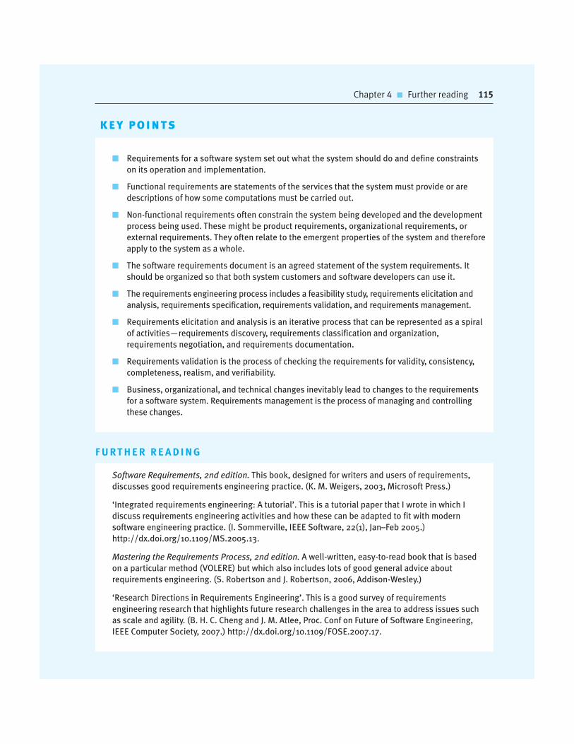
Chapter 4 � Further reading 115
K E Y P O I N T S
� Requirements for a software system set out what the system should do and define constraints
on its operation and implementation.
� Functional requirements are statements of the services that the system must provide or are
descriptions of how some computations must be carried out.
� Non-functional requirements often constrain the system being developed and the development
process being used. These might be product requirements, organizational requirements, or
external requirements. They often relate to the emergent properties of the system and therefore
apply to the system as a whole.
� The software requirements document is an agreed statement of the system requirements. It
should be organized so that both system customers and software developers can use it.
� The requirements engineering process includes a feasibility study, requirements elicitation and
analysis, requirements specification, requirements validation, and requirements management.
� Requirements elicitation and analysis is an iterative process that can be represented as a spiral
of activities—requirements discovery, requirements classification and organization,
requirements negotiation, and requirements documentation.
� Requirements validation is the process of checking the requirements for validity, consistency,
completeness, realism, and verifiability.
� Business, organizational, and technical changes inevitably lead to changes to the requirements
for a software system. Requirements management is the process of managing and controlling
these changes.
F U RT H E R R E A D I N G
Software Requirements, 2nd edition. This book, designed for writers and users of requirements,
discusses good requirements engineering practice. (K. M. Weigers, 2003, Microsoft Press.)
‘Integrated requirements engineering: A tutorial’. This is a tutorial paper that I wrote in which I
discuss requirements engineering activities and how these can be adapted to fit with modern
software engineering practice. (I. Sommerville, IEEE Software, 22(1), Jan–Feb 2005.)
http://dx.doi.org/10.1109/MS.2005.13.
Mastering the Requirements Process, 2nd edition. A well-written, easy-to-read book that is based
on a particular method (VOLERE) but which also includes lots of good general advice about
requirements engineering. (S. Robertson and J. Robertson, 2006, Addison-Wesley.)
‘Research Directions in Requirements Engineering’. This is a good survey of requirements
engineering research that highlights future research challenges in the area to address issues such
as scale and agility. (B. H. C. Cheng and J. M. Atlee, Proc. Conf on Future of Software Engineering,
IEEE Computer Society, 2007.) http://dx.doi.org/10.1109/FOSE.2007.17.
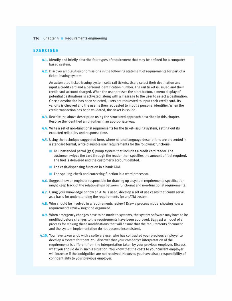
E X E R C I S E S
4.1. Identify and briefly describe four types of requirement that may be defined for a computer-
based system.
4.2. Discover ambiguities or omissions in the following statement of requirements for part of a
ticket-issuing system:
An automated ticket-issuing system sells rail tickets. Users select their destination and
input a credit card and a personal identification number. The rail ticket is issued and their
credit card account charged. When the user presses the start button, a menu display of
potential destinations is activated, along with a message to the user to select a destination.
Once a destination has been selected, users are requested to input their credit card. Its
validity is checked and the user is then requested to input a personal identifier. When the
credit transaction has been validated, the ticket is issued.
4.3. Rewrite the above description using the structured approach described in this chapter.
Resolve the identified ambiguities in an appropriate way.
4.4. Write a set of non-functional requirements for the ticket-issuing system, setting out its
expected reliability and response time.
4.5. Using the technique suggested here, where natural language descriptions are presented in
a standard format, write plausible user requirements for the following functions:
� An unattended petrol (gas) pump system that includes a credit card reader. The
customer swipes the card through the reader then specifies the amount of fuel required.
The fuel is delivered and the customer’s account debited.
� The cash-dispensing function in a bank ATM.
� The spelling-check and correcting function in a word processor.
4.6. Suggest how an engineer responsible for drawing up a system requirements specification
might keep track of the relationships between functional and non-functional requirements.
4.7. Using your knowledge of how an ATM is used, develop a set of use cases that could serve
as a basis for understanding the requirements for an ATM system.
4.8. Who should be involved in a requirements review? Draw a process model showing how a
requirements review might be organized.
4.9. When emergency changes have to be made to systems, the system software may have to be
modified before changes to the requirements have been approved. Suggest a model of a
process for making these modifications that will ensure that the requirements document
and the system implementation do not become inconsistent.
4.10. You have taken a job with a software user who has contracted your previous employer to
develop a system for them. You discover that your company’s interpretation of the
requirements is different from the interpretation taken by your previous employer. Discuss
what you should do in such a situation. You know that the costs to your current employer
will increase if the ambiguities are not resolved. However, you have also a responsibility of
confidentiality to your previous employer.
116 Chapter 4 � Requirements engineering

Chapter 4 � References 117
R E F E R E N C E S
Beck, K. (1999). ‘Embracing Change with Extreme Programming’. IEEE Computer, 32 (10), 70–8.
Crabtree, A. (2003). Designing Collaborative Systems: A Practical Guide to Ethnography. London:
Springer-Verlag.
Davis, A. M. (1993). Software Requirements: Objects, Functions and States. Englewood Cliffs, NJ:
Prentice Hall.
IEEE. (1998). ‘IEEE Recommended Practice for Software Requirements Specifications’. In IEEE
Software Engineering Standards Collection. Los Alamitos, Ca.: IEEE Computer Society Press.
Jacobson, I., Christerson, M., Jonsson, P. and Overgaard, G. (1993). Object-Oriented Software
Engineering. Wokingham: Addison-Wesley.
Kotonya, G. and Sommerville, I. (1998). Requirements Engineering: Processes and Techniques.
Chichester, UK: John Wiley and Sons.
Larman, C. (2002). Applying UML and Patterns: An Introduction to Object-oriented Analysis and
Design and the Unified Process. Englewood Cliff, NJ: Prentice Hall.
Martin, D., Rodden, T., Rouncefield, M., Sommerville, I. and Viller, S. (2001). ‘Finding Patterns in
the Fieldwork’. Proc. ECSCW’01. Bonn: Kluwer. 39–58.
Martin, D., Rouncefield, M. and Sommerville, I. (2002). ‘Applying patterns of interaction to work
(re)design: E-government and planning’. Proc. ACM CHI’2002, ACM Press. 235–42.
Martin, D. and Sommerville, I. (2004). ‘Patterns of interaction: Linking ethnomethodology and
design’. ACM Trans. on Computer-Human Interaction, 11 (1), 59–89.
Robertson, S. and Robertson, J. (1999). Mastering the Requirements Process. Harlow, UK:
Addison-Wesley.
Sommerville, I., Rodden, T., Sawyer, P., Bentley, R. and Twidale, M. (1993). ‘Integrating
ethnography into the requirements engineering process’. Proc. RE’93, San Diego CA.: IEEE
Computer Society Press. 165–73.
Stevens, P. and Pooley, R. (2006). Using UML: Software Engineering with Objects and
Components, 2nd ed. Harlow, UK: Addison Wesley.
Suchman, L. (1987). Plans and Situated Actions. Cambridge: Cambridge University Press.
Viller, S. and Sommerville, I. (1999). ‘Coherence: An Approach to Representing Ethnographic
Analyses in Systems Design’. Human-Computer Interaction, 14 (1 & 2), 9–41.
Viller, S. and Sommerville, I. (2000). ‘Ethnographically informed analysis for software engineers’.
Int. J. of Human-Computer Studies, 53 (1), 169–96.

System modeling
5
Objectives
The aim of this chapter is to introduce some types of system model
that may be developed as part of the requirements engineering and
system design processes. When you have read the chapter, you will:
� understand how graphical models can be used to represent
software systems;
� understand why different types of model are required and the
fundamental system modeling perspectives of context, interaction,
structure, and behavior;
� have been introduced to some of the diagram types in the Unified
Modeling Language (UML) and how these diagrams may be used in
system modeling;
� be aware of the ideas underlying model-driven engineering, where a
system is automatically generated from structural and behavioral
models.
Contents
5.1 Context models
5.2 Interaction models
5.3 Structural models
5.4 Behavioral models
5.5 Model-driven engineering

Chapter 5 � System modeling 119
System modeling is the process of developing abstract models of a system, with each
model presenting a different view or perspective of that system. System modeling
has generally come to mean representing the system using some kind of graphical
notation, which is now almost always based on notations in the Unified Modeling
Language (UML). However, it is also possible to develop formal (mathematical)
models of a system, usually as a detailed system specification. I cover graphical
modeling using the UML in this chapter and formal modeling in Chapter 12.
Models are used during the requirements engineering process to help derive the
requirements for a system, during the design process to describe the system to engi-
neers implementing the system and after implementation to document the system’s
structure and operation. You may develop models of both the existing system and the
system to be developed:
1. Models of the existing system are used during requirements engineering. They
help clarify what the existing system does and can be used as a basis for dis-
cussing its strengths and weaknesses. These then lead to requirements for the
new system.
2. Models of the new system are used during requirements engineering to help
explain the proposed requirements to other system stakeholders. Engineers use
these models to discuss design proposals and to document the system for imple-
mentation. In a model-driven engineering process, it is possible to generate a
complete or partial system implementation from the system model.
The most important aspect of a system model is that it leaves out detail. A model
is an abstraction of the system being studied rather than an alternative representation
of that system. Ideally, a representation of a system should maintain all the informa-
tion about the entity being represented. An abstraction deliberately simplifies and
picks out the most salient characteristics. For example, in the very unlikely event of
this book being serialized in a newspaper, the presentation there would be an abstrac-
tion of the book’s key points. If it were translated from English into Italian, this
would be an alternative representation. The translator’s intention would be to main-
tain all the information as it is presented in English.
You may develop different models to represent the system from different perspec-
tives. For example:
1. An external perspective, where you model the context or environment of the system.
2. An interaction perspective where you model the interactions between a system
and its environment or between the components of a system.
3. A structural perspective, where you model the organization of a system or the
structure of the data that is processed by the system.
4. A behavioral perspective, where you model the dynamic behavior of the system
and how it responds to events.

120 Chapter 5 � System modeling
These perspectives have much in common with Krutchen’s 4 + 1 view of system
architecture (Kruchten, 1995), where he suggests that you should document a sys-
tem’s architecture and organization from different perspectives. I discuss this 4 + 1
approach in Chapter 6.
In this chapter, I use diagrams defined in UML (Booch et al., 2005; Rumbaugh
et al., 2004), which has become a standard modeling language for object-oriented
modeling. The UML has many diagram types and so supports the creation of many
different types of system model. However, a survey in 2007 (Erickson and Siau,
2007) showed that most users of the UML thought that five diagram types could
represent the essentials of a system:
1. Activity diagrams, which show the activities involved in a process or in data
processing.
2. Use case diagrams, which show the interactions between a system and its envi-
ronment.
3. Sequence diagrams, which show interactions between actors and the system and
between system components.
4. Class diagrams, which show the object classes in the system and the associa-
tions between these classes.
5. State diagrams, which show how the system reacts to internal and external events.
As I do not have space to discuss all of the UML diagram types here, I focus on
how these five key types of diagram are used in system modeling.
When developing system models, you can often be flexible in the way that the
graphical notation is used. You do not always need to stick rigidly to the details of a
notation. The detail and rigor of a model depends on how you intend to use it. There
are three ways in which graphical models are commonly used:
1. As a means of facilitating discussion about an existing or proposed system.
2. As a way of documenting an existing system.
3. As a detailed system description that can be used to generate a system
implementation.
In the first case, the purpose of the model is to stimulate the discussion
amongst the software engineers involved in developing the system. The models
may be incomplete (so long as they cover the key points of the discussion) and
they may use the modeling notation informally. This is how models are normally
used in so-called ‘agile modeling’ (Ambler and Jeffries, 2002). When models are
used as documentation, they do not have to be complete as you may only wish to
develop models for some parts of a system. However, these models have to be
correct—they should use the notation correctly and be an accurate description of
the system.

5.1 � Context models 121
In the third case, where models are used as part of a model-based development
process, the system models have to be both complete and correct. The reason for this
is that they are used as a basis for generating the source code of the system.
Therefore, you have to be very careful not to confuse similar symbols, such as stick
and block arrowheads, that have different meanings.
5.1 Context models
At an early stage in the specification of a system, you should decide on the system
boundaries. This involves working with system stakeholders to decide what func-
tionality should be included in the system and what is provided by the system’s envi-
ronment. You may decide that automated support for some business processes
should be implemented but others should be manual processes or supported by dif-
ferent systems. You should look at possible overlaps in functionality with existing
systems and decide where new functionality should be implemented. These deci-
sions should be made early in the process to limit the system costs and the time
needed for understanding the system requirements and design.
In some cases, the boundary between a system and its environment is relatively
clear. For example, where an automated system is replacing an existing manual or
computerized system, the environment of the new system is usually the same as the
existing system’s environment. In other cases, there is more flexibility, and you
decide what constitutes the boundary between the system and its environment during
the requirements engineering process.
For example, say you are developing the specification for the patient information
system for mental healthcare. This system is intended to manage information about
patients attending mental health clinics and the treatments that have been prescribed.
In developing the specification for this system, you have to decide whether the sys-
tem should focus exclusively on collecting information about consultations (using
other systems to collect personal information about patients) or whether it should
also collect personal patient information. The advantage of relying on other systems
for patient information is that you avoid duplicating data. The major disadvantage,
however, is that using other systems may make it slower to access information. If
these systems are unavailable, then the MHC-PMS cannot be used.
The Unified Modeling Language is a set of 13 different diagram types that may be used to model softwaresystems. It emerged from work in the 1990s on object-oriented modeling where similar object-orientednotations were integrated to create the UML. A major revision (UML 2) was finalized in 2004. The UML isuniversally accepted as the standard approach for developing models of software systems. Variants have beenproposed for more general system modeling.
http://www.SoftwareEngineering-9.com/Web/UML/
The Unified Modeling Language

122 Chapter 5 � System modeling
«system»MHC-PMS
«system»Patient Record
System
«system»Appointments
System
«system»Admissions
System
«system»Management
ReportingSystem
«system»Prescription
System
«system»HC Statistics
System
Figure 5.1 The contextof the MHC-PMS
The definition of a system boundary is not a value-free judgment. Social and
organizational concerns may mean that the position of a system boundary may be
determined by non-technical factors. For example, a system boundary may be delib-
erately positioned so that the analysis process can all be carried out on one site; it
may be chosen so that a particularly difficult manager need not be consulted; it may
be positioned so that the system cost is increased and the system development divi-
sion must therefore expand to design and implement the system.
Once some decisions on the boundaries of the system have been made, part of the
analysis activity is the definition of that context and the dependencies that a system
has on its environment. Normally, producing a simple architectural model is the first
step in this activity.
Figure 5.1 is a simple context model that shows the patient information system
and the other systems in its environment. From Figure 5.1, you can see that the
MHC-PMS is connected to an appointments system and a more general patient
record system with which it shares data. The system is also connected to systems for
management reporting and hospital bed allocation and a statistics system that col-
lects information for research. Finally, it makes use of a prescription system to gen-
erate prescriptions for patients’ medication.
Context models normally show that the environment includes several other auto-
mated systems. However, they do not show the types of relationships between the
systems in the environment and the system that is being specified. External systems
might produce data for or consume data from the system. They might share data with
the system, or they might be connected directly, through a network or not connected
at all. They might be physically co-located or located in separate buildings. All of
these relations may affect the requirements and design of the system being defined
and must be taken into account.
Therefore, simple context models are used along with other models, such as
business process models. These describe human and automated processes in which
particular software systems are used.

5.1 � Context models 123
Figure 5.2 is a model of an important system process that shows the processes in
which the MHC-PMS is used. Sometimes, patients who are suffering from mental
health problems may be a danger to others or to themselves. They may therefore
have to be detained against their will in a hospital so that treatment can be adminis-
tered. Such detention is subject to strict legal safeguards—for example, the decision
to detain a patient must be regularly reviewed so that people are not held indefinitely
without good reason. One of the functions of the MHC-PMS is to ensure that such
safeguards are implemented.
Figure 5.2 is a UML activity diagram. Activity diagrams are intended to show the
activities that make up a system process and the flow of control from one activity to
another. The start of a process is indicated by a filled circle; the end by a filled circle
inside another circle. Rectangles with round corners represent activities, that is, the spe-
cific sub-processes that must be carried out. You may include objects in activity charts.
In Figure 5.2, I have shown the systems that are used to support different processes.
I have indicated that these are separate systems using the UML stereotype feature.
In a UML activity diagram, arrows represent the flow of work from one activity to
another. A solid bar is used to indicate activity coordination. When the flow from
more than one activity leads to a solid bar then all of these activities must be com-
plete before progress is possible. When the flow from a solid bar leads to a number
of activities, these may be executed in parallel. Therefore, in Figure 5.2, the activities
to inform social care and the patient’s next of kin, and to update the detention regis-
ter may be concurrent.
Arrows may be annotated with guards that indicate the condition when that flow
is taken. In Figure 5.2, you can see guards showing the flows for patients who are
ConfirmDetentionDecision
Find SecurePlace
Admit toHospital
Transfer toPolice Station
Transfer toSecure
Hospital
«system»Admissions
System
Inform Nextof Kin
InformSocial Care
UpdateRegister
«system»MHC-PMS
«system»MHC-PMS
InformPatient of
Rights
RecordDetentionDecision
[Dangerous]
[Not Available]
[NotDangerous]
[Available]
Figure 5.2 Processmodel of involuntarydetention

124 Chapter 5 � System modeling
dangerous and not dangerous to society. Patients who are dangerous to society must
be detained in a secure facility. However, patients who are suicidal and so are a
danger to themselves may be detained in an appropriate ward in a hospital.
5.2 Interaction models
All systems involve interaction of some kind. This can be user interaction, which
involves user inputs and outputs, interaction between the system being developed
and other systems or interaction between the components of the system. Modeling
user interaction is important as it helps to identify user requirements. Modeling sys-
tem to system interaction highlights the communication problems that may arise.
Modeling component interaction helps us understand if a proposed system structure
is likely to deliver the required system performance and dependability.
In this section, I cover two related approaches to interaction modeling:
1. Use case modeling, which is mostly used to model interactions between a
system and external actors (users or other systems).
2. Sequence diagrams, which are used to model interactions between system
components, although external agents may also be included.
Use case models and sequence diagrams present interaction at different levels of
detail and so may be used together. The details of the interactions involved in a high-
level use case may be documented in a sequence diagram. The UML also includes
communication diagrams that can be used to model interactions. I don’t discuss
these here as they are an alternative representation of sequence charts. In fact, some
tools can generate a communication diagram from a sequence diagram.
5.2.1 Use case modeling
Use case modeling was originally developed by Jacobson et al. (1993) in the 1990s
and was incorporated into the first release of the UML (Rumbaugh et al., 1999). As
I have discussed in Chapter 4, use case modeling is widely used to support require-
ments elicitation. A use case can be taken as a simple scenario that describes what a
user expects from a system.
Each use case represents a discrete task that involves external interaction with a
system. In its simplest form, a use case is shown as an ellipse with the actors
involved in the use case represented as stick figures. Figure 5.3 shows a use case
from the MHC-PMS that represents the task of uploading data from the MHC-PMS
to a more general patient record system. This more general system maintains sum-
mary data about a patient rather than the data about each consultation, which is
recorded in the MHC-PMS.

5.2 � Interaction models 125
Medical Receptionist Patient Record System
Transfer Data
Figure 5.3 Transfer-data use case
Notice that there are two actors in this use case: the operator who is transferring
the data and the patient record system. The stick figure notation was originally
developed to cover human interaction but it is also now used to represent other exter-
nal systems and hardware. Formally, use case diagrams should use lines without
arrows as arrows in the UML indicate the direction of flow of messages. Obviously,
in a use case messages pass in both directions. However, the arrows in Figure 5.3 are
used informally to indicate that the medical receptionist initiates the transaction and
data is transferred to the patient record system.
Use case diagrams give a fairly simple overview of an interaction so you have to
provide more detail to understand what is involved. This detail can either be a simple
textual description, a structured description in a table, or a sequence diagram as dis-
cussed below. You chose the most appropriate format depending on the use case and
the level of detail that you think is required in the model. I find a standard tabular
format to be the most useful. Figure 5.4 shows a tabular description of the ‘Transfer
data’ use case.
As I have discussed in Chapter 4, composite use case diagrams show a number
of different use cases. Sometimes, it is possible to include all possible interactions
with a system in a single composite use case diagram. However, this may be impos-
sible because of the number of use cases. In such cases, you may develop several
diagrams, each of which shows related use cases. For example, Figure 5.5 shows all
of the use cases in the MHC-PMS in which the actor ‘Medical Receptionist’ is
involved.
MHC-PMS: Transfer data
Actors Medical receptionist, patient records system (PRS)
Description A receptionist may transfer data from the MHC-PMS to a general patient record database thatis maintained by a health authority. The information transferred may either be updatedpersonal information (address, phone number, etc.) or a summary of the patient’s diagnosisand treatment.
Data Patient’s personal information, treatment summary
Stimulus User command issued by medical receptionist
Response Confirmation that PRS has been updated
Comments The receptionist must have appropriate security permissions to access the patient informationand the PRS.
Figure 5.4 Tabulardescription of the‘Transfer data’ use case
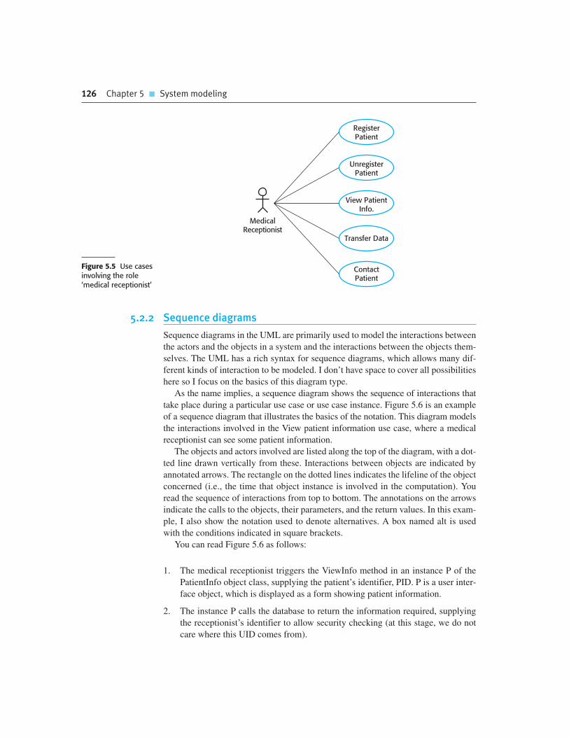
126 Chapter 5 � System modeling
MedicalReceptionist
RegisterPatient
Transfer Data
ContactPatient
View PatientInfo.
UnregisterPatient
Figure 5.5 Use casesinvolving the role‘medical receptionist’
5.2.2 Sequence diagrams
Sequence diagrams in the UML are primarily used to model the interactions between
the actors and the objects in a system and the interactions between the objects them-
selves. The UML has a rich syntax for sequence diagrams, which allows many dif-
ferent kinds of interaction to be modeled. I don’t have space to cover all possibilities
here so I focus on the basics of this diagram type.
As the name implies, a sequence diagram shows the sequence of interactions that
take place during a particular use case or use case instance. Figure 5.6 is an example
of a sequence diagram that illustrates the basics of the notation. This diagram models
the interactions involved in the View patient information use case, where a medical
receptionist can see some patient information.
The objects and actors involved are listed along the top of the diagram, with a dot-
ted line drawn vertically from these. Interactions between objects are indicated by
annotated arrows. The rectangle on the dotted lines indicates the lifeline of the object
concerned (i.e., the time that object instance is involved in the computation). You
read the sequence of interactions from top to bottom. The annotations on the arrows
indicate the calls to the objects, their parameters, and the return values. In this exam-
ple, I also show the notation used to denote alternatives. A box named alt is used
with the conditions indicated in square brackets.
You can read Figure 5.6 as follows:
1. The medical receptionist triggers the ViewInfo method in an instance P of the
PatientInfo object class, supplying the patient’s identifier, PID. P is a user inter-
face object, which is displayed as a form showing patient information.
2. The instance P calls the database to return the information required, supplying
the receptionist’s identifier to allow security checking (at this stage, we do not
care where this UID comes from).
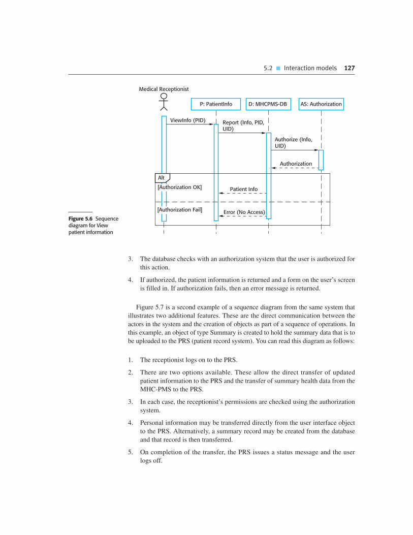
5.2 � Interaction models 127
3. The database checks with an authorization system that the user is authorized for
this action.
4. If authorized, the patient information is returned and a form on the user’s screen
is filled in. If authorization fails, then an error message is returned.
Figure 5.7 is a second example of a sequence diagram from the same system that
illustrates two additional features. These are the direct communication between the
actors in the system and the creation of objects as part of a sequence of operations. In
this example, an object of type Summary is created to hold the summary data that is to
be uploaded to the PRS (patient record system). You can read this diagram as follows:
1. The receptionist logs on to the PRS.
2. There are two options available. These allow the direct transfer of updated
patient information to the PRS and the transfer of summary health data from the
MHC-PMS to the PRS.
3. In each case, the receptionist’s permissions are checked using the authorization
system.
4. Personal information may be transferred directly from the user interface object
to the PRS. Alternatively, a summary record may be created from the database
and that record is then transferred.
5. On completion of the transfer, the PRS issues a status message and the user
logs off.
P: PatientInfo
ViewInfo (PID) Report (Info, PID,UID)
Authorize (Info,UID)
Patient Info
D: MHCPMS-DB AS: Authorization
Authorization
Error (No Access)
[Authorization OK]
[Authorization Fail]
Medical Receptionist
Alt
Figure 5.6 Sequencediagram for View patient information

128 Chapter 5 � System modeling
Authorization
Authorize (TF, UID)
P: PatientInfo
Login ( )
D: MHCPMS-DB AS: Authorization
[SendInfo]
[SendSummary]
Medical Receptionist PRS
OK
UpdateInfo( ) Update PRS (UID )
Update (PID)
Update OKMessage (OK)
Summarize (UID )
Authorization
Authorize (TF, UID)
:Summary
Update (PID)
UpdateSummary( )
Logout ( )
Update OKMessage (OK)
Alt
Figure 5.7 Sequencediagram for transferdata
Unless you are using sequence diagrams for code generation or detailed docu-
mentation, you don’t have to include every interaction in these diagrams. If you
develop system models early in the development process to support requirements
engineering and high-level design, there will be many interactions which depend on
implementation decisions. For example, in Figure 5.7 the decision on how to get the
user’s identifier to check authorization is one that can be delayed. In an implementa-
tion, this might involve interacting with a User object but this is not important at this
stage and so need not be included in the sequence diagram.

5.3 � Structural models 129
Object-oriented requirements analysis
In object-oriented requirements analysis, you model real-world entities using object classes. You may createdifferent types of object model, showing how object classes are related to each other, how objects areaggregated to form other objects, how objects interact with other objects, and so on. These each presentunique information about the system that is being specified.
http://www.SoftwareEngineering-9.com/Web/OORA/
5.3 Structural models
Structural models of software display the organization of a system in terms of the
components that make up that system and their relationships. Structural models may
be static models, which show the structure of the system design or dynamic models,
which show the organization of the system when it is executing. These are not the
same things—the dynamic organization of a system as a set of interacting threads
may be very different from a static model of the system components.
You create structural models of a system when you are discussing and designing
the system architecture. Architectural design is a particularly important topic in soft-
ware engineering and UML component, package, and deployment diagrams may all
be used when presenting architectural models. I cover different aspects of software
architecture and architectural modeling in Chapters 6, 18, and 19. In this section, I
focus on the use of class diagrams for modeling the static structure of the object
classes in a software system.
5.3.1 Class diagrams
Class diagrams are used when developing an object-oriented system model to show
the classes in a system and the associations between these classes. Loosely, an object
class can be thought of as a general definition of one kind of system object. An asso-
ciation is a link between classes that indicates that there is a relationship between
these classes. Consequently, each class may have to have some knowledge of its
associated class.
When you are developing models during the early stages of the software engi-
neering process, objects represent something in the real world, such as a patient, a
prescription, a doctor, etc. As an implementation is developed, you usually need to
define additional implementation objects that are used to provide the required sys-
tem functionality. Here, I focus on the modeling of real-world objects as part of the
requirements or early software design processes.
Class diagrams in the UML can be expressed at different levels of detail. When you
are developing a model, the first stage is usually to look at the world, identify the
essential objects, and represent these as classes. The simplest way of writing these is to
write the class name in a box. You can also simply note the existence of an association

130 Chapter 5 � System modeling
PatientPatientRecord
1 1Figure 5.8 UML classes and association
PatientGeneral
Practitioner
Consultation
Consultant
Medication
Treatment
HospitalDoctor
ConditionReferred-by
Referred-to
Diagnosed-with
Attends
Prescribes
PrescribesRuns
1..*
1
1..* 11..*
1..*
1..*
1..*
1..4
1..*
1..*
1..*
1..*
Figure 5.9 Classesand associations in theMHC-PMS
by drawing a line between classes. For example, Figure 5.8 is a simple class diagram
showing two classes: Patient and Patient Record with an association between them.
In Figure 5.8, I illustrate a further feature of class diagrams—the ability to show
how many objects are involved in the association. In this example, each end of the
association is annotated with a 1, meaning that there is a 1:1 relationship between
objects of these classes. That is, each patient has exactly one record and each record
maintains information about exactly one patient. As you can see from later exam-
ples, other multiplicities are possible. You can define that an exact number of objects
are involved or, by using a *, as shown in Figure 5.9, that there are an indefinite num-
ber of objects involved in the association.
Figure 5.9 develops this type of class diagram to show that objects of class Patient
are also involved in relationships with a number of other classes. In this example, I
show that you can name associations to give the reader an indication of the type of
relationship that exists. The UML also allows the role of the objects participating in
the association to be specified.
At this level of detail, class diagrams look like semantic data models. Semantic
data models are used in database design. They show the data entities, their associated
attributes, and the relations between these entities. This approach to modeling was
first proposed in the mid-1970s by Chen (1976); several variants have been devel-
oped since then (Codd, 1979; Hammer and McLeod, 1981; Hull and King, 1987), all
with the same basic form.
The UML does not include a specific notation for this database modeling as it
assumes an object-oriented development process and models data using objects and
their relationships. However, you can use the UML to represent a semantic data
model. You can think of entities in a semantic data model as simplified object classes

5.3 � Structural models 131
(they have no operations), attributes as object class attributes and relations as named
associations between object classes.
When showing the associations between classes, it is convenient to represent
these classes in the simplest possible way. To define them in more detail, you add
information about their attributes (the characteristics of an object) and operations
(the things that you can request from an object). For example, a Patient object will
have the attribute Address and you may include an operation called ChangeAddress,
which is called when a patient indicates that they have moved from one address to
another. In the UML, you show attributes and operations by extending the simple
rectangle that represents a class. This is illustrated in Figure 5.10 where:
1. The name of the object class is in the top section.
2. The class attributes are in the middle section. This must include the attribute
names and, optionally, their types.
3. The operations (called methods in Java and other OO programming languages)
associated with the object class are in the lower section of the rectangle.
Figure 5.10 shows possible attributes and operations on the class Consultation. In
this example, I assume that doctors record voice notes that are transcribed later to
record details of the consultation. To prescribe medication, the doctor involved must
use the Prescribe method to generate an electronic prescription.
5.3.2 Generalization
Generalization is an everyday technique that we use to manage complexity. Rather than
learn the detailed characteristics of every entity that we experience, we place these enti-
ties in more general classes (animals, cars, houses, etc.) and learn the characteristics of
Consultation
DoctorsDateTimeClinicReasonMedication PrescribedTreatment PrescribedVoice NotesTranscript...
New ( )Prescribe ( )RecordNotes ( )Transcribe ( )...Figure 5.10 The
consultation class

132 Chapter 5 � System modeling
Doctor
GeneralPractitioner
HospitalDoctor
Consultant Team Doctor
TraineeDoctor
QualifiedDoctor
Figure 5.11 A generalizationhierarchy
these classes. This allows us to infer that different members of these classes have some
common characteristics (e.g., squirrels and rats are rodents). We can make general state-
ments that apply to all class members (e.g., all rodents have teeth for gnawing).
In modeling systems, it is often useful to examine the classes in a system to see
if there is scope for generalization. This means that common information will be
maintained in one place only. This is good design practice as it means that, if
changes are proposed, then you do not have to look at all classes in the system to
see if they are affected by the change. In object-oriented languages, such as Java,
generalization is implemented using the class inheritance mechanisms built into the
language.
The UML has a specific type of association to denote generalization, as illus-
trated in Figure 5.11. The generalization is shown as an arrowhead pointing up to
the more general class. This shows that general practitioners and hospital doctors
can be generalized as doctors and that there are three types of Hospital Doctor—
those that have just graduated from medical school and have to be supervised
(Trainee Doctor); those that can work unsupervised as part of a consultant’s team
(Registered Doctor); and consultants, who are senior doctors with full decision-
making responsibilities.
In a generalization, the attributes and operations associated with higher-level
classes are also associated with the lower-level classes. In essence, the lower-level
classes are subclasses inherit the attributes and operations from their superclasses.
These lower-level classes then add more specific attributes and operations. For
example, all doctors have a name and phone number; all hospital doctors have a staff
number and a department but general practitioners don’t have these attributes as they
work independently. They do however, have a practice name and address. This is
illustrated in Figure 5.12, which shows part of the generalization hierarchy that I
have extended with class attributes. The operations associated with the class Doctor
are intended to register and de-register that doctor with the MHC-PMS.

5.4 � Behavioral models 133
5.3.3 Aggregation
Objects in the real world are often composed of different parts. For example, a study
pack for a course may be composed of a book, PowerPoint slides, quizzes, and rec-
ommendations for further reading. Sometimes in a system model, you need to illus-
trate this. The UML provides a special type of association between classes called
aggregation that means that one object (the whole) is composed of other objects (the
parts). To show this, we use a diamond shape next to the class that represents the
whole. This is shown in Figure 5.13, which shows that a patient record is a composi-
tion of Patient and an indefinite number of Consultations.
5.4 Behavioral models
Behavioral models are models of the dynamic behavior of the system as it is executing.
They show what happens or what is supposed to happen when a system responds to a
stimulus from its environment. You can think of these stimuli as being of two types:
1. Data Some data arrives that has to be processed by the system.
2. Events Some event happens that triggers system processing. Events may have
associated data but this is not always the case.
Doctor
NamePhone #E-mail
Register ( )De-Register ( )
Hospital Doctor
Staff #Pager #
General Practitioner
PracticeAddress
Figure 5.12A generalizationhierarchy with added detail
PatientRecord
Patient Consultation
11
1 1..*
Figure 5.13 Theaggregation association

134 Chapter 5 � System modeling
Many business systems are data processing systems that are primarily driven by
data. They are controlled by the data input to the system with relatively little external
event processing. Their processing involves a sequence of actions on that data and the
generation of an output. For example, a phone billing system will accept information
about calls made by a customer, calculate the costs of these calls, and generate a bill
to be sent to that customer. By contrast, real-time systems are often event driven with
minimal data processing. For example, a landline phone switching system responds to
events such as ‘receiver off hook’ by generating a dial tone, or the pressing of keys on
a handset by capturing the phone number, etc.
5.4.1 Data-driven modeling
Data-driven models show the sequence of actions involved in processing input data
and generating an associated output. They are particularly useful during the analysis
of requirements as they can be used to show end-to-end processing in a system. That
is, they show the entire sequence of actions that take place from an input being
processed to the corresponding output, which is the system’s response.
Data-driven models were amongst the first graphical software models. In the
1970s, structured methods such as DeMarco’s Structured Analysis (DeMarco, 1978)
introduced data-flow diagrams (DFDs) as a way of illustrating the processing steps
in a system. Data-flow models are useful because tracking and documenting how the
data associated with a particular process moves through the system helps analysts
and designers understand what is going on. Data-flow diagrams are simple and intu-
itive and it is usually possible to explain them to potential system users who can then
participate in validating the model.
The UML does not support data-flow diagrams as they were originally proposed and
used for modeling data processing. The reason for this is that DFDs focus on system
functions and do not recognize system objects. However, because data-driven systems
are so common in business, UML 2.0 introduced activity diagrams, which are similar to
data-flow diagrams. For example, Figure 5.14 shows the chain of processing involved in
the insulin pump software. In this diagram, you can see the processing steps (repre-
sented as activities) and the data flowing between these steps (represented as objects).
An alternative way of showing the sequence of processing in a system is to use UML
sequence diagrams. You have seen how these can be used to model interaction but, if
Data-flow diagrams
Data-flow diagrams (DFDs) are system models that show a functional perspective where each transformationrepresents a single function or process. DFDs are used to show how data flows through a sequence of processingsteps. For example, a processing step could be the filtering of duplicate records in a customer database. The datais transformed at each step before moving on to the next stage. These processing steps or transformationsrepresent software processes or functions where data-flow diagrams are used to document a software design.
http://www.SoftwareEngineering-9.com/Web/DFDs

5.4 � Behavioral models 135
you draw these so that messages are only sent from left to right, then they show the
sequential data processing in the system. Figure 5.15 illustrates this, using a sequence
model of the processing of an order and sending it to a supplier. Sequence models high-
light objects in a system, whereas data-flow diagrams highlight the functions. The
equivalent data-flow diagram for order processing is shown on the book’s web pages.
5.4.2 Event-driven modeling
Event-driven modeling shows how a system responds to external and internal events. It is
based on the assumption that a system has a finite number of states and that events (stim-
uli) may cause a transition from one state to another. For example, a system controlling a
valve may move from a state ‘Valve open’ to a state ‘Valve closed’ when an operator
command (the stimulus) is received. This view of a system is particularly appropriate for
real-time systems. Event-based modeling was introduced in real-time design methods
such as those proposed by Ward and Mellor (1985) and Harel (1987, 1988).
The UML supports event-based modeling using state diagrams, which were based on
Statecharts (Harel, 1987, 1988). State diagrams show system states and events that cause
:Order
Fillin ( )
Purchase Officer
Validate ( )
[Validation OK]
«datastore»OrdersBudget
Update (Amount)
Save ( )
Supplier
Send ( ) Figure 5.14 An activitymodel of the insulinpump’s operation
Blood SugarSensor
Blood SugarLevel
InsulinRequirement
Pump ControlCommands
InsulinPump
Get SensorValue
CalculatePump
Commands
SensorData
ComputeSugar Level
CalculateInsulinDelivery
ControlPump
Figure 5.15 Orderprocessing

136 Chapter 5 � System modeling
transitions from one state to another. They do not show the flow of data within the system
but may include additional information on the computations carried out in each state.
I use an example of control software for a very simple microwave oven to illus-
trate event-driven modeling. Real microwave ovens are actually much more complex
than this system but the simplified system is easier to understand. This simple
microwave has a switch to select full or half power, a numeric keypad to input the
cooking time, a start/stop button, and an alphanumeric display.
I have assumed that the sequence of actions in using the microwave is:
1. Select the power level (either half power or full power).
2. Input the cooking time using a numeric keypad.
3. Press Start and the food is cooked for the given time.
For safety reasons, the oven should not operate when the door is open and, on
completion of cooking, a buzzer is sounded. The oven has a very simple alphanu-
meric display that is used to display various alerts and warning messages.
In UML state diagrams, rounded rectangles represent system states. They may
include a brief description (following ‘do’) of the actions taken in that state. The
labeled arrows represent stimuli that force a transition from one state to another. You
can indicate start and end states using filled circles, as in activity diagrams.
From Figure 5.16, you can see that the system starts in a waiting state and
responds initially to either the full-power or the half-power button. Users can change
Enabled
FullPower
HalfPower
HalfPower
FullPower
Number
DoorOpen
DoorClosed
Door Closed
DoorOpen
Start
Half Power
Do: Set Power = 300
Set Time
Do: Get NumberExit: Set Time
Disabled
Cancel
Waiting
Do: Display Time
Waiting
Do: Display Time
Full Power
Do: Set Power = 600
Operation
Do: Operate Oven
Do: Display 'Ready'
Do: Display 'Waiting'
Timer
Timer
Figure 5.16 State diagram of a microwave oven

5.4 � Behavioral models 137
their mind after selecting one of these and press the other button. The time is set and,
if the door is closed, the Start button is enabled. Pushing this button starts the oven
operation and cooking takes place for the specified time. This is the end of the cook-
ing cycle and the system returns to the waiting state.
The UML notation lets you indicate the activity that takes place in a state. In a
detailed system specification you have to provide more detail about both the stimuli
and the system states. I illustrate this in Figure 5.17, which shows a tabular descrip-
tion of each state and how the stimuli that force state transitions are generated.
The problem with state-based modeling is that the number of possible states
increases rapidly. For large system models, therefore, you need to hide detail in the
State Description
Waiting The oven is waiting for input. The display shows the current time.
Half power The oven power is set to 300 watts. The display shows ‘Half power’.
Full power The oven power is set to 600 watts. The display shows ‘Full power’.
Set time The cooking time is set to the user’s input value. The display showsthe cooking time selected and is updated as the time is set.
Disabled Oven operation is disabled for safety. Interior oven light is on.Display shows ‘Not ready’.
Enabled Oven operation is enabled. Interior oven light is off. Display shows‘Ready to cook’.
Operation Oven in operation. Interior oven light is on. Display shows the timercountdown. On completion of cooking, the buzzer is sounded forfive seconds. Oven light is on. Display shows ‘Cooking complete’while buzzer is sounding.
Stimulus Description
Half power The user has pressed the half-power button.
Full power The user has pressed the full-power button.
Timer The user has pressed one of the timer buttons.
Number The user has pressed a numeric key.
Door open The oven door switch is not closed.
Door closed The oven door switch is closed.
Start The user has pressed the Start button.
Cancel The user has pressed the Cancel button.
Figure 5.17 Statesand stimuli for themicrowave oven

138 Chapter 5 � System modeling
models. One way to do this is by using the notion of a superstate that encapsulates a
number of separate states. This superstate looks like a single state on a high-level
model but is then expanded to show more detail on a separate diagram. To illustrate
this concept, consider the Operation state in Figure 5.15. This is a superstate that can
be expanded, as illustrated in Figure 5.18.
The Operation state includes a number of sub-states. It shows that operation starts
with a status check and that if any problems are discovered an alarm is indicated and
operation is disabled. Cooking involves running the microwave generator for the
specified time; on completion, a buzzer is sounded. If the door is opened during
operation, the system moves to the disabled state, as shown in Figure 5.15.
5.5 Model-driven engineering
Model-driven engineering (MDE) is an approach to software development where mod-
els rather than programs are the principal outputs of the development process (Kent,
2002; Schmidt, 2006). The programs that execute on a hardware/software platform are
then generated automatically from the models. Proponents of MDE argue that this raises
the level of abstraction in software engineering so that engineers no longer have to be
concerned with programming language details or the specifics of execution platforms.
Model-driven engineering has its roots in model-driven architecture (MDA) which
was proposed by the Object Management Group (OMG) in 2001 as a new software
development paradigm. Model-driven engineering and model-driven architecture are
often seen as the same thing. However, I think that MDE has a wider scope than
TurntableFault
EmitterFault
Timeout
Cook
Do: Run Generator
Done
Do: Buzzer Onfor 5 Secs.
Waiting
Alarm
Do: Display Event
Do: Check Status
Checking
Disabled
OK
Time
Door Open
Operation
Cancel
Figure 5.18 Microwaveoven operation

5.5 � Model-driven engineering 139
MDA. As I discuss later in this section, MDA focuses on the design and implementa-
tion stages of software development whereas MDE is concerned with all aspects of
the software engineering process. Therefore, topics such as model-based require-
ments engineering, software processes for model-based development, and model-
based testing are part of MDE but not, currently, part of MDA.
Although MDA has been in use since 2001, model-based engineering is still at an
early stage of development and it is unclear whether or not it will have a significant
effect on software engineering practice. The main arguments for and against MDE are:
1. For MDE Model-based engineering allows engineers to think about systems at a
high level of abstraction, without concern for the details of their implementa-
tion. This reduces the likelihood of errors, speeds up the design and implemen-
tation process, and allows for the creation of reusable, platform-independent
application models. By using powerful tools, system implementations can be
generated for different platforms from the same model. Therefore, to adapt the
system to some new platform technology, it is only necessary to write a transla-
tor for that platform. When this is available, all platform-independent models
can be rapidly rehosted on the new platform.
2. Against MDE As I discussed earlier in this chapter, models are a good way of
facilitating discussions about a software design. However, it does not always
follow that the abstractions that are supported by the model are the right abstrac-
tions for implementation. So, you may create informal design models but then
go on to implement the system using an off-the-shelf, configurable package.
Furthermore, the arguments for platform independence are only valid for large
long-lifetime systems where the platforms become obsolete during a system’s
lifetime. However, for this class of systems, we know that implementation is not
the major problem—requirements engineering, security and dependability, inte-
gration with legacy systems, and testing are more significant.
There have been significant MDE success stories reported by the OMG on their
Web pages (www.omg.org/mda/products_success.htm) and the approach is used
within large companies such as IBM and Siemens. The techniques have been used suc-
cessfully in the development of large, long-lifetime software systems such as air traffic
management systems. Nevertheless, at the time of writing, model-driven approaches
are not widely used for software engineering. Like formal methods of software engi-
neering, which I discuss in Chapter 12, I believe that MDE is an important develop-
ment. However, as is also the case with formal methods, it is not clear whether the
costs and risks of model-driven approaches outweigh the possible benefits.
5.5.1 Model-driven architecture
Model-driven architecture (Kleppe, et al., 2003; Mellor et al., 2004; Stahl and
Voelter, 2006) is a model-focused approach to software design and implementation
that uses a sub-set of UML models to describe a system. Here, models at different

140 Chapter 5 � System modeling
levels of abstraction are created. From a high-level platform independent model it is
possible, in principle, to generate a working program without manual intervention.
The MDA method recommends that three types of abstract system model should
be produced:
1. A computation independent model (CIM) that models the important domain
abstractions used in the system. CIMs are sometimes called domain models.
You may develop several different CIMs, reflecting different views of the sys-
tem. For example, there may be a security CIM in which you identify important
security abstractions such as an asset and a role and a patient record CIM, in
which you describe abstractions such as patients, consultations, etc.
2. A platform independent model (PIM) that models the operation of the system
without reference to its implementation. The PIM is usually described using
UML models that show the static system structure and how it responds to exter-
nal and internal events.
3. Platform specific models (PSM) which are transformations of the platform-
independent model with a separate PSM for each application platform. In
principle, there may be layers of PSM, with each layer adding some platform-
specific detail. So, the first-level PSM could be middleware-specific but
database independent. When a specific database has been chosen, a database-
specific PSM can then be generated.
As I have said, transformations between these models may be defined and applied
automatically by software tools. This is illustrated in Figure 5.19, which also shows
a final level of automatic transformation. A transformation is applied to the PSM to
generate executable code that runs on the designated software platform.
At the time of writing, automatic CIM to PIM translation is still at the research pro-
totype stage. It is unlikely that completely automated translation tools will be available
in the near future. Human intervention, indicated by a stick figure in Figure 5.19, will
be needed for the foreseeable future. CIMs are related and part of the translation
PlatformSpecificModel
PlatformIndependent
Model
ExecutableCode
Translator Translator Translator
Domain SpecificGuidelines
PlatformSpecific Patterns
and Rules
LanguageSpecificPatterns
ComputationIndependent
Model
Figure 5.19 MDAtransformations

5.5 � Model-driven engineering 141
process may involve linking concepts in different CIMs. For example, the concept of a
role in a security CIM may be mapped onto the concept of a staff member in a hospital
CIM. Mellor and Balcer (2002) give the name ‘bridges’ to the information that sup-
ports mapping from one CIM to another.
The translation of PIMs to PSMs is more mature and several commercial tools are
available that provide translators from PIMs to common platforms such as Java and
J2EE. These rely on an extensive library of platform-specific rules and patterns to
convert the PIM to the PSM. There may be several PSMs for each PIM in the system.
If a software system is intended to run on different platforms (e.g., J2EE and .NET),
then it is only necessary to maintain the PIM. The PSMs for each platform are auto-
matically generated. This is illustrated in Figure 5.20.
Although MDA-support tools include platform-specific translators, it is often
the case that these will only offer partial support for the translation from PIMs to
PSMs. In the vast majority of cases, the execution environment for a system is
more than the standard execution platform (e.g., J2EE, .NET, etc.). It also
includes other application systems, application libraries that are specific to a
company, and user interface libraries. As these vary significantly from one com-
pany to another, standard tool support is not available. Therefore, when MDA is
introduced, special purpose translators may have to be created that take the char-
acteristics of the local environment into account. In some cases (e.g., for user
interface generation), completely automated PIM to PSM translation may be
impossible.
There is an uneasy relationship between agile methods and model-driven archi-
tecture. The notion of extensive up-front modeling contradicts the fundamental ideas
in the agile manifesto and I suspect that few agile developers feel comfortable with
model-driven engineering. The developers of MDA claim that it is intended to sup-
port an iterative approach to development and so can be used within agile methods
(Mellor, et al., 2004). If transformations can be completely automated and a com-
plete program generated from a PIM, then, in principle, MDA could be used in an
agile development process as no separate coding would be required. However, as far
as I am aware, there are no MDA tools that support practices such as regression test-
ing and test-driven development.
PlatformIndependent
Model
Java Program
C# CodeGenerator
Java CodeGenerator
J2EE Translator
.Net Translator C# Program
J2EE SpecificModel
.NET SpecificModel
Figure 5.20 Multipleplatform-specificmodels

K E Y P O I N T S
� A model is an abstract view of a system that ignores some system details. Complementary system
models can be developed to show the system’s context, interactions, structure, and behavior.
� Context models show how a system that is being modeled is positioned in an environment with
other systems and processes. They help define the boundaries of the system to be developed.
� Use case diagrams and sequence diagrams are used to describe the interactions between user
the system being designed and users/other systems. Use cases describe interactions between a
system and external actors; sequence diagrams add more information to these by showing
interactions between system objects.
142 Chapter 5 � System modeling
5.5.2 Executable UML
The fundamental notion behind model-driven engineering is that completely automated
transformation of models to code should be possible. To achieve this, you have to be
able to construct graphical models whose semantics are well defined. You also need a
way of adding information to graphical models about the ways in which the operations
defined in the model are implemented. This is possible using a subset of UML 2, called
Executable UML or xUML (Mellor and Balcer, 2002). I don’t have space here to
describe the details of xUML, so I simply present a short overview of its main features.
UML was designed as a language for supporting and documenting software
design, not as a programming language. The designers of UML were not concerned
with semantic details of the language but with its expressiveness. They introduced
useful notions such as use case diagrams that help with the design but which are too
informal to support execution. To create an executable sub-set of UML, the number
of model types has therefore been dramatically reduced to three key model types:
1. Domain models identify the principal concerns in the system. These are defined
using UML class diagrams that include objects, attributes, and associations.
2. Class models, in which classes are defined, along with their attributes and
operations.
3. State models, in which a state diagram is associated with each class and is used
to describe the lifecycle of the class.
The dynamic behavior of the system may be specified declaratively using the
object constraint language (OCL) or may be expressed using UML’s action lan-
guage. The action language is like a very high-level programming language where
you can refer to objects and their attributes and specify actions to be carried out.

� Structural models show the organization and architecture of a system. Class diagrams are
used to define the static structure of classes in a system and their associations.
� Behavioral models are used to describe the dynamic behavior of an executing system. This
can be modeled from the perspective of the data processed by the system or by the events
that stimulate responses from a system.
� Activity diagrams may be used to model the processing of data, where each activity
represents one process step.
� State diagrams are used to model a system’s behavior in response to internal or external
events.
� Model-driven engineering is an approach to software development in which a system is
represented as a set of models that can be automatically transformed to executable code.
F U RT H E R R E A D I N G
Requirements Analysis and System Design. This book focuses on information systems analysis
and discusses how different UML models can be used in the analysis process. (L. Maciaszek,
Addison-Wesley, 2001.)
MDA Distilled: Principles of Model-driven Architecture .This is a concise and accessible
introduction to the MDA method. It is written by enthusiasts so the book says very little about
possible problems with this approach. (S. J. Mellor, K. Scott and D. Weise, Addison-Wesley, 2004.)
Using UML: Software Engineering with Objects and Components, 2nd ed. A short, readable
introduction to the use of the UML in system specification and design. This book is excellent for
learning and understanding the UML, although it is not a full description of the notation.
(P. Stevens with R. Pooley, Addison-Wesley, 2006.)
E X E R C I S E S
5.1. Explain why it is important to model the context of a system that is being developed. Give
two examples of possible errors that could arise if software engineers do not understand
the system context.
5.2. How might you use a model of a system that already exists? Explain why it is not always
necessary for such a system model to be complete and correct. Would the same be true if
you were developing a model of a new system?
Chapter 5 � Exercises 143

144 Chapter 5 � System modeling
5.3. You have been asked to develop a system that will help with planning large-scale events
and parties such as weddings, graduation celebrations, birthday parties, etc. Using an
activity diagram, model the process context for such a system that shows the activities
involved in planning a party (booking a venue, organizing invitations, etc.) and the system
elements that may be used at each stage.
5.4. For the MHC-PMS, propose a set of use cases that illustrates the interactions between a
doctor, who sees patients and prescribes medicine and treatments, and the MHC-PMS.
5.5. Develop a sequence diagram showing the interactions involved when a student registers
for a course in a university. Courses may have limited enrollment, so the registration
process must include checks that places are available. Assume that the student accesses
an electronic course catalog to find out about available courses.
5.6. Look carefully at how messages and mailboxes are represented in the e-mail system that
you use. Model the object classes that might be used in the system implementation to
represent a mailbox and an e-mail message.
5.7. Based on your experience with a bank ATM, draw an activity diagram that models the data
processing involved when a customer withdraws cash from the machine.
5.8. Draw a sequence diagram for the same system. Explain why you might want to develop
both activity and sequence diagrams when modeling the behavior of a system.
5.9. Draw state diagrams of the control software for:
� An automatic washing machine that has different programs for different types of
clothes.
� The software for a DVD player.
� A telephone answering system that records incoming messages and displays the
number of accepted messages on an LED. The system should allow the telephone
customer to dial in from any location, type a sequence of numbers (identified as tones),
and play any recorded messages.
5.10. You are a software engineering manager and your team proposes that model-driven
engineering should be used to develop a new system. What factors should you take into
account when deciding whether or not to introduce this new approach to software
development?

R E F E R E N C E S
Ambler, S. W. and Jeffries, R. (2002). Agile Modeling: Effective Practices for Extreme
Programming and the Unified Process. New York: John Wiley & Sons.
Booch, G., Rumbaugh, J. and Jacobson, I. (2005). The Unified Modeling Language User Guide,
2nd ed. Boston: Addison-Wesley.
Chen, P. (1976). ‘The entity relationship model—Towards a unified view of data’. ACM Trans. on
Database Systems, 1 (1), 9–36.
Codd, E. F. (1979). ‘Extending the database relational model to capture more meaning’. ACM
Trans. on Database Systems, 4 (4), 397–434.
DeMarco, T. (1978). Structured Analysis and System Specification. New York: Yourdon Press.
Erickson, J. and Siau, K. (2007). ‘Theoretical and practical complexity of modeling methods’.
Comm. ACM, 50 (8), 46–51.
Hammer, M. and McLeod, D. (1981). ‘Database descriptions with SDM: A semantic database
model’. ACM Trans. on Database Sys., 6 (3), 351–86.
Harel, D. (1987). ‘Statecharts: A visual formalism for complex systems’. Sci. Comput.
Programming, 8 (3), 231–74.
Harel, D. (1988). ‘On visual formalisms’. Comm. ACM, 31 (5), 514–30.
Hull, R. and King, R. (1987). ‘Semantic database modeling: Survey, applications and research
issues’. ACM Computing Surveys, 19 (3), 201–60.
Jacobson, I., Christerson, M., Jonsson, P. and Overgaard, G. (1993). Object-Oriented Software
Engineering. Wokingham.: Addison-Wesley.
Kent, S. (2002). ‘Model-driven engineering’. Proc. 3rd Int. Conf. on Integrated Formal Methods,
286–98.
Kleppe, A., Warmer, J. and Bast, W. (2003). MDA Explained: The Model Driven Architecture—
Practice and Promise. Boston: Addison-Wesley.
Kruchten, P. (1995). ‘The 4 + 1 view model of architecture’. IEEE Software, 11 (6), 42–50.
Mellor, S. J. and Balcer, M. J. (2002). Executable UML. Boston: Addison-Wesley.
Mellor, S. J., Scott, K. and Weise, D. (2004). MDA Distilled: Principles of Model-driven
Architecture. Boston: Addison-Wesley.
Rumbaugh, J., Jacobson, I. and Booch, G. (1999). The Unified Modeling Language Reference
Manual. Reading, Mass.: Addison-Wesley.
Chapter 5 � References 145

Rumbaugh, J., Jacobson, I. and Booch, G. (2004). The Unified Modeling Language Reference Manual,
2nd ed. Boston: Addison-Wesley.
Schmidt, D. C. (2006). ‘Model-Driven Engineering’. IEEE Computer, 39 (2), 25–31.
Stahl, T. and Voelter, M. (2006). Model-Driven Software Development: Technology, Engineering,
Management. New York: John Wiley & Sons.
Ward, P. and Mellor, S. (1985). Structured Development for Real-time Systems. Englewood Cliffs,
NJ: Prentice Hall.
146 Chapter 5 � System modeling

Architectural design
6
Objectives
The objective of this chapter is to introduce the concepts of software
architecture and architectural design. When you have read the chapter,
you will:
� understand why the architectural design of software is important;
� understand the decisions that have to be made about the system
architecture during the architectural design process;
� have been introduced to the idea of architectural patterns, well-tried
ways of organizing system architectures, which can be reused in
system designs;
� know the architectural patterns that are often used in different types
of application system, including transaction processing systems and
language processing systems.
Contents
6.1 Architectural design decisions
6.2 Architectural views
6.3 Architectural patterns
6.4 Application architectures

148 Chapter 6 � Architectural design
Architectural design is concerned with understanding how a system should be
organized and designing the overall structure of that system. In the model of the soft-
ware development process, as shown in Chapter 2, architectural design is the first
stage in the software design process. It is the critical link between design and
requirements engineering, as it identifies the main structural components in a system
and the relationships between them. The output of the architectural design process is
an architectural model that describes how the system is organized as a set of commu-
nicating components.
In agile processes, it is generally accepted that an early stage of the development
process should be concerned with establishing an overall system architecture.
Incremental development of architectures is not usually successful. While refactor-
ing components in response to changes is usually relatively easy, refactoring a sys-
tem architecture is likely to be expensive.
To help you understand what I mean by system architecture, consider Figure 6.1.
This shows an abstract model of the architecture for a packing robot system that
shows the components that have to be developed. This robotic system can pack dif-
ferent kinds of object. It uses a vision component to pick out objects on a conveyor,
identify the type of object, and select the right kind of packaging. The system then
moves objects from the delivery conveyor to be packaged. It places packaged objects
on another conveyor. The architectural model shows these components and the links
between them.
In practice, there is a significant overlap between the processes of requirements
engineering and architectural design. Ideally, a system specification should not
include any design information. This is unrealistic except for very small systems.
Architectural decomposition is usually necessary to structure and organize the spec-
ification. Therefore, as part of the requirements engineering process, you might pro-
pose an abstract system architecture where you associate groups of system functions
or features with large-scale components or sub-systems. You can then use this
decomposition to discuss the requirements and features of the system with stake-
holders.
You can design software architectures at two levels of abstraction, which I call
architecture in the small and architecture in the large:
1. Architecture in the small is concerned with the architecture of individual pro-
grams. At this level, we are concerned with the way that an individual program
is decomposed into components. This chapter is mostly concerned with pro-
gram architectures.
2. Architecture in the large is concerned with the architecture of complex enter-
prise systems that include other systems, programs, and program compo-
nents. These enterprise systems are distributed over different computers,
which may be owned and managed by different companies. I cover architec-
ture in the large in Chapters 18 and 19, where I discuss distributed systems
architectures.

Chapter 6 � Architectural design 149
VisionSystem
ObjectIdentification
System
ArmController
GripperController
PackagingSelectionSystem
PackingSystem
ConveyorController
Figure 6.1 Thearchitecture of a packingrobot control system
Software architecture is important because it affects the performance, robustness,
distributability, and maintainability of a system (Bosch, 2000). As Bosch discusses,
individual components implement the functional system requirements. The non-
functional requirements depend on the system architecture—the way in which these
components are organized and communicate. In many systems, non-functional
requirements are also influenced by individual components, but there is no doubt
that the architecture of the system is the dominant influence.
Bass et al. (2003) discuss three advantages of explicitly designing and document-
ing software architecture:
1. Stakeholder communication The architecture is a high-level presentation of the sys-
tem that may be used as a focus for discussion by a range of different stakeholders.
2. System analysis Making the system architecture explicit at an early stage in the
system development requires some analysis. Architectural design decisions
have a profound effect on whether or not the system can meet critical require-
ments such as performance, reliability, and maintainability.
3. Large-scale reuse A model of a system architecture is a compact, manageable
description of how a system is organized and how the components interoperate.
The system architecture is often the same for systems with similar requirements
and so can support large-scale software reuse. As I explain in Chapter 16, it may
be possible to develop product-line architectures where the same architecture is
reused across a range of related systems.
150 Chapter 6 � Architectural design
Hofmeister et al. (2000) propose that a software architecture can serve firstly as a
design plan for the negotiation of system requirements, and secondly as a means of
structuring discussions with clients, developers, and managers. They also suggest
that it is an essential tool for complexity management. It hides details and allows the
designers to focus on the key system abstractions.
System architectures are often modeled using simple block diagrams, as in Figure 6.1.
Each box in the diagram represents a component. Boxes within boxes indicate that the
component has been decomposed to sub-components. Arrows mean that data and or con-
trol signals are passed from component to component in the direction of the arrows. You
can see many examples of this type of architectural model in Booch’s software architec-
ture catalog (Booch, 2009).
Block diagrams present a high-level picture of the system structure, which people
from different disciplines, who are involved in the system development process, can
readily understand. However, in spite of their widespread use, Bass et al. (2003) dis-
like informal block diagrams for describing an architecture. They claim that these
informal diagrams are poor architectural representations, as they show neither the
type of the relationships among system components nor the components’ externally
visible properties.
The apparent contradictions between practice and architectural theory arise
because there are two ways in which an architectural model of a program is used:
1. As a way of facilitating discussion about the system design A high-level
architectural view of a system is useful for communication with system stake-
holders and project planning because it is not cluttered with detail. Stake-
holders can relate to it and understand an abstract view of the system. They
can then discuss the system as a whole without being confused by detail. The
architectural model identifies the key components that are to be developed
so managers can start assigning people to plan the development of these
systems.
2. As a way of documenting an architecture that has been designed The aim here
is to produce a complete system model that shows the different components in
a system, their interfaces, and their connections. The argument for this is that
such a detailed architectural description makes it easier to understand and evolve
the system.
Block diagrams are an appropriate way of describing the system architecture dur-
ing the design process, as they are a good way of supporting communications
between the people involved in the process. In many projects, these are often the
only architectural documentation that exists. However, if the architecture of a system
is to be thoroughly documented then it is better to use a notation with well-defined
semantics for architectural description. However, as I discuss in Section 6.2, some
people think that detailed documentation is neither useful, nor really worth the cost
of its development.

6.1 � Architectural design decisions 151
6.1 Architectural design decisions
Architectural design is a creative process where you design a system organization
that will satisfy the functional and non-functional requirements of a system. Because
it is a creative process, the activities within the process depend on the type of system
being developed, the background and experience of the system architect, and the
specific requirements for the system. It is therefore useful to think of architectural
design as a series of decisions to be made rather than a sequence of activities.
During the architectural design process, system architects have to make a number
of structural decisions that profoundly affect the system and its development
process. Based on their knowledge and experience, they have to consider the follow-
ing fundamental questions about the system:
1. Is there a generic application architecture that can act as a template for the sys-
tem that is being designed?
2. How will the system be distributed across a number of cores or processors?
3. What architectural patterns or styles might be used?
4. What will be the fundamental approach used to structure the system?
5. How will the structural components in the system be decomposed into sub-
components?
6. What strategy will be used to control the operation of the components in the system?
7. What architectural organization is best for delivering the non-functional require-
ments of the system?
8. How will the architectural design be evaluated?
9. How should the architecture of the system be documented?
Although each software system is unique, systems in the same application
domain often have similar architectures that reflect the fundamental concepts of the
domain. For example, application product lines are applications that are built around
a core architecture with variants that satisfy specific customer requirements. When
designing a system architecture, you have to decide what your system and broader
application classes have in common, and decide how much knowledge from these
application architectures you can reuse. I discuss generic application architectures in
Section 6.4 and application product lines in Chapter 16.
For embedded systems and systems designed for personal computers, there is
usually only a single processor and you will not have to design a distributed architec-
ture for the system. However, most large systems are now distributed systems in
which the system software is distributed across many different computers. The
choice of distribution architecture is a key decision that affects the performance and
152 Chapter 6 � Architectural design
reliability of the system. This is a major topic in its own right and I cover it sepa-
rately in Chapter 18.
The architecture of a software system may be based on a particular architectural
pattern or style. An architectural pattern is a description of a system organization
(Garlan and Shaw, 1993), such as a client–server organization or a layered architecture.
Architectural patterns capture the essence of an architecture that has been used in dif-
ferent software systems. You should be aware of common patterns, where they can be
used, and their strengths and weaknesses when making decisions about the architec-
ture of a system. I discuss a number of frequently used patterns in Section 6.3.
Garlan and Shaw’s notion of an architectural style (style and pattern have come to
mean the same thing) covers questions 4 to 6 in the previous list. You have to choose
the most appropriate structure, such as client–server or layered structuring, that will
enable you to meet the system requirements. To decompose structural system units,
you decide on the strategy for decomposing components into sub-components. The
approaches that you can use allow different types of architecture to be implemented.
Finally, in the control modeling process, you make decisions about how the execu-
tion of components is controlled. You develop a general model of the control rela-
tionships between the various parts of the system.
Because of the close relationship between non-functional requirements and soft-
ware architecture, the particular architectural style and structure that you choose for
a system should depend on the non-functional system requirements:
1. Performance If performance is a critical requirement, the architecture should
be designed to localize critical operations within a small number of com-
ponents, with these components all deployed on the same computer rather than
distributed across the network. This may mean using a few relatively large com-
ponents rather than small, fine-grain components, which reduces the number of
component communications. You may also consider run-time system organiza-
tions that allow the system to be replicated and executed on different processors.
2. Security If security is a critical requirement, a layered structure for the architec-
ture should be used, with the most critical assets protected in the innermost lay-
ers, with a high level of security validation applied to these layers.
3. Safety If safety is a critical requirement, the architecture should be designed so
that safety-related operations are all located in either a single component or in a
small number of components. This reduces the costs and problems of safety val-
idation and makes it possible to provide related protection systems that can
safely shut down the system in the event of failure.
4. Availability If availability is a critical requirement, the architecture should be
designed to include redundant components so that it is possible to replace and
update components without stopping the system. I describe two fault-tolerant
system architectures for high-availability systems in Chapter 13.
5. Maintainability If maintainability is a critical requirement, the system architec-
ture should be designed using fine-grain, self-contained components that may
6.2 � Architectural views 153
readily be changed. Producers of data should be separated from consumers and
shared data structures should be avoided.
Obviously there is potential conflict between some of these architectures. For
example, using large components improves performance and using small, fine-grain
components improves maintainability. If both performance and maintainability are
important system requirements, then some compromise must be found. This can
sometimes be achieved by using different architectural patterns or styles for different
parts of the system.
Evaluating an architectural design is difficult because the true test of an architec-
ture is how well the system meets its functional and non-functional requirements
when it is in use. However, you can do some evaluation by comparing your design
against reference architectures or generic architectural patterns. Bosch’s (2000)
description of the non-functional characteristics of architectural patterns can also be
used to help with architectural evaluation.
6.2 Architectural views
I explained in the introduction to this chapter that architectural models of a software
system can be used to focus discussion about the software requirements or design.
Alternatively, they may be used to document a design so that it can be used as a basis
for more detailed design and implementation, and for the future evolution of the sys-
tem. In this section, I discuss two issues that are relevant to both of these:
1. What views or perspectives are useful when designing and documenting a sys-
tem’s architecture?
2. What notations should be used for describing architectural models?
It is impossible to represent all relevant information about a system’s architecture in
a single architectural model, as each model only shows one view or perspective of the
system. It might show how a system is decomposed into modules, how the run-time
processes interact, or the different ways in which system components are distributed
across a network. All of these are useful at different times so, for both design and doc-
umentation, you usually need to present multiple views of the software architecture.
There are different opinions as to what views are required. Krutchen (1995), in
his well-known 4+1 view model of software architecture, suggests that there should
be four fundamental architectural views, which are related using use cases or scenar-
ios. The views that he suggests are:
1. A logical view, which shows the key abstractions in the system as objects or
object classes. It should be possible to relate the system requirements to entities
in this logical view.
154 Chapter 6 � Architectural design
2. A process view, which shows how, at run-time, the system is composed of inter-
acting processes. This view is useful for making judgments about non-
functional system characteristics such as performance and availability.
3. A development view, which shows how the software is decomposed for devel-
opment, that is, it shows the breakdown of the software into components that are
implemented by a single developer or development team. This view is useful for
software managers and programmers.
4. A physical view, which shows the system hardware and how software compo-
nents are distributed across the processors in the system. This view is useful for
systems engineers planning a system deployment.
Hofmeister et al. (2000) suggest the use of similar views but add to this the notion
of a conceptual view. This view is an abstract view of the system that can be the basis
for decomposing high-level requirements into more detailed specifications, help
engineers make decisions about components that can be reused, and represent
a product line (discussed in Chapter 16) rather than a single system. Figure 6.1,
which describes the architecture of a packing robot, is an example of a conceptual
system view.
In practice, conceptual views are almost always developed during the design
process and are used to support architectural decision making. They are a way of
communicating the essence of a system to different stakeholders. During the design
process, some of the other views may also be developed when different aspects of
the system are discussed, but there is no need for a complete description from all per-
spectives. It may also be possible to associate architectural patterns, discussed in the
next section, with the different views of a system.
There are differing views about whether or not software architects should use
the UML for architectural description (Clements, et al., 2002). A survey in 2006
(Lange et al., 2006) showed that, when the UML was used, it was mostly applied in
a loose and informal way. The authors of that paper argued that this was a bad thing.
I disagree with this view. The UML was designed for describing object-oriented
systems and, at the architectural design stage, you often want to describe systems at
a higher level of abstraction. Object classes are too close to the implementation to be
useful for architectural description.
I don’t find the UML to be useful during the design process itself and prefer infor-
mal notations that are quicker to write and which can be easily drawn on a white-
board. The UML is of most value when you are documenting an architecture in
detail or using model-driven development, as discussed in Chapter 5.
A number of researchers have proposed the use of more specialized architectural
description languages (ADLs) (Bass et al., 2003) to describe system architectures.
The basic elements of ADLs are components and connectors, and they include rules
and guidelines for well-formed architectures. However, because of their specialized
nature, domain and application specialists find it hard to understand and use ADLs.
This makes it difficult to assess their usefulness for practical software engineering.
ADLs designed for a particular domain (e.g., automobile systems) may be used as a

6.3 � Architectural patterns 155
basis for model-driven development. However, I believe that informal models and
notations, such as the UML, will remain the most commonly used ways of docu-
menting system architectures.
Users of agile methods claim that detailed design documentation is mostly
unused. It is, therefore, a waste of time and money to develop it. I largely agree with
this view and I think that, for most systems, it is not worth developing a detailed
architectural description from these four perspectives. You should develop the views
that are useful for communication and not worry about whether or not your architec-
tural documentation is complete. However, an exception to this is when you are
developing critical systems, when you need to make a detailed dependability analy-
sis of the system. You may need to convince external regulators that your system
conforms to their regulations and so complete architectural documentation may be
required.
6.3 Architectural patterns
The idea of patterns as a way of presenting, sharing, and reusing knowledge about
software systems is now widely used. The trigger for this was the publication of a
book on object-oriented design patterns (Gamma et al., 1995), which prompted the
development of other types of pattern, such as patterns for organizational design
(Coplien and Harrison, 2004), usability patterns (Usability Group, 1998), interaction
(Martin and Sommerville, 2004), configuration management (Berczuk and
Name MVC (Model-View-Controller)
Description Separates presentation and interaction from the system data. The system is structured intothree logical components that interact with each other. The Model component managesthe system data and associated operations on that data. The View component defines andmanages how the data is presented to the user. The Controller component manages userinteraction (e.g., key presses, mouse clicks, etc.) and passes these interactions to the Viewand the Model. See Figure 6.3.
Example Figure 6.4 shows the architecture of a web-based application system organized using theMVC pattern.
When used Used when there are multiple ways to view and interact with data. Also used when thefuture requirements for interaction and presentation of data are unknown.
Advantages Allows the data to change independently of its representation and vice versa. Supportspresentation of the same data in different ways with changes made in one representationshown in all of them.
Disadvantages Can involve additional code and code complexity when the data model and interactionsare simple.
Figure 6.2 The model-view-controller (MVC)pattern

156 Chapter 6 � Architectural design
Appleton, 2002), and so on. Architectural patterns were proposed in the 1990s under
the name ‘architectural styles’ (Shaw and Garlan, 1996), with a five-volume series of
handbooks on pattern-oriented software architecture published between 1996 and
2007 (Buschmann et al., 1996; Buschmann et al., 2007a; Buschmann et al., 2007b;
Kircher and Jain, 2004; Schmidt et al., 2000).
In this section, I introduce architectural patterns and briefly describe a selection
of architectural patterns that are commonly used in different types of systems. For
more information about patterns and their use, you should refer to published pattern
handbooks.
You can think of an architectural pattern as a stylized, abstract description of good
practice, which has been tried and tested in different systems and environments. So,
an architectural pattern should describe a system organization that has been success-
ful in previous systems. It should include information of when it is and is not appro-
priate to use that pattern, and the pattern’s strengths and weaknesses.
For example, Figure 6.2 describes the well-known Model-View-Controller pattern.
This pattern is the basis of interaction management in many web-based systems. The
stylized pattern description includes the pattern name, a brief description (with an
associated graphical model), and an example of the type of system where the pattern
is used (again, perhaps with a graphical model). You should also include information
about when the pattern should be used and its advantages and disadvantages.
Graphical models of the architecture associated with the MVC pattern are shown in
Figures 6.3 and 6.4. These present the architecture from different views—Figure 6.3
is a conceptual view and Figure 6.4 shows a possible run-time architecture when this
pattern is used for interaction management in a web-based system.
In a short section of a general chapter, it is impossible to describe all of the
generic patterns that can be used in software development. Rather, I present some
selected examples of patterns that are widely used and which capture good architec-
tural design principles. I have included some further examples of generic architec-
tural patterns on the book’s web pages.
Controller View
Model
ViewSelection
StateChange
ChangeNotification
StateQuery
User Events
Maps User Actionsto Model UpdatesSelects View
Renders ModelRequests Model UpdatesSends User Events toController
Encapsulates ApplicationStateNotifies View of StateChanges
Figure 6.3 Theorganization of the MVC

6.3 � Architectural patterns 157
Browser
ControllerForm toDisplay
UpdateRequest
ChangeNotification Refresh
Request
User Events
HTTP Request ProcessingApplication-Specific LogicData Validation
Dynamic PageGenerationForms Management
Business LogicDatabase
View
Model
Figure 6.4 Webapplication architectureusing the MVC pattern
6.3.1 Layered architecture
The notions of separation and independence are fundamental to architectural design
because they allow changes to be localized. The MVC pattern, shown in Figure 6.2,
separates elements of a system, allowing them to change independently. For exam-
ple, adding a new view or changing an existing view can be done without any
changes to the underlying data in the model. The layered architecture pattern is
another way of achieving separation and independence. This pattern is shown in
Figure 6.5. Here, the system functionality is organized into separate layers, and each
layer only relies on the facilities and services offered by the layer immediately
beneath it.
This layered approach supports the incremental development of systems. As a
layer is developed, some of the services provided by that layer may be made avail-
able to users. The architecture is also changeable and portable. So long as its inter-
face is unchanged, a layer can be replaced by another, equivalent layer. Furthermore,
when layer interfaces change or new facilities are added to a layer, only the adjacent
layer is affected. As layered systems localize machine dependencies in inner layers,
this makes it easier to provide multi-platform implementations of an application sys-
tem. Only the inner, machine-dependent layers need be re-implemented to take
account of the facilities of a different operating system or database.
Figure 6.6 is an example of a layered architecture with four layers. The lowest
layer includes system support software—typically database and operating system
support. The next layer is the application layer that includes the components
concerned with the application functionality and utility components that are used
by other application components. The third layer is concerned with user interface
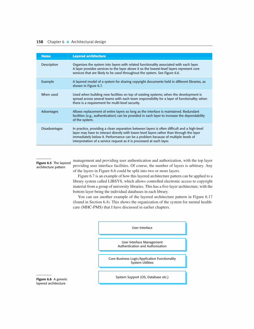
158 Chapter 6 � Architectural design
Figure 6.5 The layeredarchitecture pattern
User Interface
Core Business Logic/Application FunctionalitySystem Utilities
System Support (OS, Database etc.)
User Interface ManagementAuthentication and Authorization
Figure 6.6 A genericlayered architecture
management and providing user authentication and authorization, with the top layer
providing user interface facilities. Of course, the number of layers is arbitrary. Any
of the layers in Figure 6.6 could be split into two or more layers.
Figure 6.7 is an example of how this layered architecture pattern can be applied to a
library system called LIBSYS, which allows controlled electronic access to copyright
material from a group of university libraries. This has a five-layer architecture, with the
bottom layer being the individual databases in each library.
You can see another example of the layered architecture pattern in Figure 6.17
(found in Section 6.4). This shows the organization of the system for mental health-
care (MHC-PMS) that I have discussed in earlier chapters.
Name Layered architecture
Description Organizes the system into layers with related functionality associated with each layer. A layer provides services to the layer above it so the lowest-level layers represent coreservices that are likely to be used throughout the system. See Figure 6.6.
Example A layered model of a system for sharing copyright documents held in different libraries, asshown in Figure 6.7.
When used Used when building new facilities on top of existing systems; when the development isspread across several teams with each team responsibility for a layer of functionality; whenthere is a requirement for multi-level security.
Advantages Allows replacement of entire layers so long as the interface is maintained. Redundantfacilities (e.g., authentication) can be provided in each layer to increase the dependabilityof the system.
Disadvantages In practice, providing a clean separation between layers is often difficult and a high-levellayer may have to interact directly with lower-level layers rather than through the layerimmediately below it. Performance can be a problem because of multiple levels ofinterpretation of a service request as it is processed at each layer.

6.3 � Architectural patterns 159
Web Browser Interface
Library Index
DistributedSearch
DocumentRetrieval
RightsManager
Accounting
DB1 DB2 DB3 DB4 DBn
LIBSYSLogin
Forms andQuery Manager
PrintManager
Figure 6.7 Thearchitecture of theLIBSYS system
6.3.2 Repository architecture
The layered architecture and MVC patterns are examples of patterns where the view
presented is the conceptual organization of a system. My next example, the
Repository pattern (Figure 6.8), describes how a set of interacting components can
share data.
The majority of systems that use large amounts of data are organized around a
shared database or repository. This model is therefore suited to applications in which
Name Repository
Description All data in a system is managed in a central repository that is accessible to all systemcomponents. Components do not interact directly, only through the repository.
Example Figure 6.9 is an example of an IDE where the components use a repository of system design information. Each software tool generates information whichis then available for use by other tools.
When used You should use this pattern when you have a system in which large volumes ofinformation are generated that has to be stored for a long time. You may also use it indata-driven systems where the inclusion of data in the repository triggers an action or tool.
Advantages Components can be independent—they do not need to know of the existence of othercomponents. Changes made by one component can be propagated to all components. Alldata can be managed consistently (e.g., backups done at the same time) as it is all in oneplace.
Disadvantages The repository is a single point of failure so problems in the repository affect the wholesystem. May be inefficiencies in organizing all communication through the repository.Distributing the repository across several computers may be difficult.
Figure 6.8 Therepository pattern

160 Chapter 6 � Architectural design
ProjectRepository
DesignTranslator
UMLEditors
CodeGenerators
DesignAnalyser
ReportGenerator
JavaEditor
PythonEditor
Figure 6.9 A repositoryarchitecture for an IDE
data is generated by one component and used by another. Examples of this type of
system include command and control systems, management information systems,
CAD systems, and interactive development environments for software.
Figure 6.9 is an illustration of a situation in which a repository might be used.
This diagram shows an IDE that includes different tools to support model-driven
development. The repository in this case might be a version-controlled environment
(as discussed in Chapter 25) that keeps track of changes to software and allows roll-
back to earlier versions.
Organizing tools around a repository is an efficient way to share large amounts of
data. There is no need to transmit data explicitly from one component to another.
However, components must operate around an agreed repository data model.
Inevitably, this is a compromise between the specific needs of each tool and it may
be difficult or impossible to integrate new components if their data models do not fit
the agreed schema. In practice, it may be difficult to distribute the repository over a
number of machines. Although it is possible to distribute a logically centralized
repository, there may be problems with data redundancy and inconsistency.
In the example shown in Figure 6.9, the repository is passive and control is the
responsibility of the components using the repository. An alternative approach,
which has been derived for AI systems, uses a ‘blackboard’ model that triggers com-
ponents when particular data become available. This is appropriate when the form of
the repository data is less well structured. Decisions about which tool to activate can
only be made when the data has been analyzed. This model is introduced by Nii
(1986). Bosch (2000) includes a good discussion of how this style relates to system
quality attributes.
6.3.3 Client–server architecture
The repository pattern is concerned with the static structure of a system and does not
show its run-time organization. My next example illustrates a very commonly used
run-time organization for distributed systems. The Client–server pattern is described
in Figure 6.10.

6.3 � Architectural patterns 161
A system that follows the client–server pattern is organized as a set of services
and associated servers, and clients that access and use the services. The major com-
ponents of this model are:
1. A set of servers that offer services to other components. Examples of servers
include print servers that offer printing services, file servers that offer file man-
agement services, and a compile server, which offers programming language
compilation services.
2. A set of clients that call on the services offered by servers. There will normally
be several instances of a client program executing concurrently on different
computers.
3. A network that allows the clients to access these services. Most client–server
systems are implemented as distributed systems, connected using Internet
protocols.
Client–server architectures are usually thought of as distributed systems architec-
tures but the logical model of independent services running on separate servers can
be implemented on a single computer. Again, an important benefit is separation and
independence. Services and servers can be changed without affecting other parts of
the system.
Clients may have to know the names of the available servers and the services that
they provide. However, servers do not need to know the identity of clients or how
many clients are accessing their services. Clients access the services provided by a
server through remote procedure calls using a request-reply protocol such as the http
Name Client–server
Description In a client–server architecture, the functionality of the system is organized into services,with each service delivered from a separate server. Clients are users of these services andaccess servers to make use of them.
Example Figure 6.11 is an example of a film and video/DVD library organized as a client–serversystem.
When used Used when data in a shared database has to be accessed from a range of locations.Because servers can be replicated, may also be used when the load on a system isvariable.
Advantages The principal advantage of this model is that servers can be distributed across a network.General functionality (e.g., a printing service) can be available to all clients and does notneed to be implemented by all services.
Disadvantages Each service is a single point of failure so susceptible to denial of service attacks orserver failure. Performance may be unpredictable because it depends on the networkas well as the system. May be management problems if servers are owned by differentorganizations.
Figure 6.10 Theclient–server pattern

162 Chapter 6 � Architectural design
CatalogueServer
LibraryCatalogue
VideoServer
Film Store
PictureServer
Photo Store
WebServer
Film andPhoto Info.
Client 1 Client 2 Client 3 Client 4
Internet
Figure 6.11 A client—server architecture for a film library
protocol used in the WWW. Essentially, a client makes a request to a server and
waits until it receives a reply.
Figure 6.11 is an example of a system that is based on the client–server model. This
is a multi-user, web-based system for providing a film and photograph library. In this
system, several servers manage and display the different types of media. Video frames
need to be transmitted quickly and in synchrony but at relatively low resolution. They
may be compressed in a store, so the video server can handle video compression and
decompression in different formats. Still pictures, however, must be maintained at a
high resolution, so it is appropriate to maintain them on a separate server.
The catalog must be able to deal with a variety of queries and provide links into
the web information system that includes data about the film and video clips, and an
e-commerce system that supports the sale of photographs, film, and video clips. TheFigure 6.12 The pipeand filter pattern
Name Pipe and filter
Description The processing of the data in a system is organized so that each processing component(filter) is discrete and carries out one type of data transformation. The data flows (as in apipe) from one component to another for processing.
Example Figure 6.13 is an example of a pipe and filter system used for processing invoices.
When used Commonly used in data processing applications (both batch- and transaction-based)where inputs are processed in separate stages to generate related outputs.
Advantages Easy to understand and supports transformation reuse. Workflow style matches thestructure of many business processes. Evolution by adding transformations isstraightforward. Can be implemented as either a sequential or concurrent system.
Disadvantages The format for data transfer has to be agreed upon between communicatingtransformations. Each transformation must parse its input and unparse its output to theagreed form. This increases system overhead and may mean that it is impossible to reusefunctional transformations that use incompatible data structures.

6.3 � Architectural patterns 163
client program is simply an integrated user interface, constructed using a web
browser, to access these services.
The most important advantage of the client–server model is that it is a distributed
architecture. Effective use can be made of networked systems with many distributed
processors. It is easy to add a new server and integrate it with the rest of the system
or to upgrade servers transparently without affecting other parts of the system.
I discuss distributed architectures, including client–server architectures and distrib-
uted object architectures, in Chapter 18.
6.3.4 Pipe and filter architecture
My final example of an architectural pattern is the pipe and filter pattern. This is a
model of the run-time organization of a system where functional transformations
process their inputs and produce outputs. Data flows from one to another and is trans-
formed as it moves through the sequence. Each processing step is implemented as a
transform. Input data flows through these transforms until converted to output. The
transformations may execute sequentially or in parallel. The data can be processed by
each transform item by item or in a single batch.
The name ‘pipe and filter’ comes from the original Unix system where it was pos-
sible to link processes using ‘pipes’. These passed a text stream from one process to
another. Systems that conform to this model can be implemented by combining Unix
commands, using pipes and the control facilities of the Unix shell. The term ‘filter’
is used because a transformation ‘filters out’ the data it can process from its input
data stream.
Variants of this pattern have been in use since computers were first used for auto-
matic data processing. When transformations are sequential with data processed in
batches, this pipe and filter architectural model becomes a batch sequential model, a
common architecture for data processing systems (e.g., a billing system). The archi-
tecture of an embedded system may also be organized as a process pipeline, with
each process executing concurrently. I discuss the use of this pattern in embedded
systems in Chapter 20.
An example of this type of system architecture, used in a batch processing appli-
cation, is shown in Figure 6.13. An organization has issued invoices to customers.
Once a week, payments that have been made are reconciled with the invoices. For
Read IssuedInvoices
IdentifyPayments
IssueReceipts
Find PaymentsDue
Receipts
Issue PaymentReminder
Reminders
Invoices Payments
Figure 6.13 Anexample of the pipeand filter architecture

164 Chapter 6 � Architectural design
those invoices that have been paid, a receipt is issued. For those invoices that have
not been paid within the allowed payment time, a reminder is issued.
Interactive systems are difficult to write using the pipe and filter model because
of the need for a stream of data to be processed. Although simple textual input
and output can be modeled in this way, graphical user interfaces have more complex
I/O formats and a control strategy that is based on events such as mouse clicks or
menu selections. It is difficult to translate this into a form compatible with the
pipelining model.
6.4 Application architectures
Application systems are intended to meet a business or organizational need. All busi-
nesses have much in common—they need to hire people, issue invoices, keep
accounts, and so on. Businesses operating in the same sector use common sector-
specific applications. Therefore, as well as general business functions, all phone
companies need systems to connect calls, manage their network, issue bills to
customers, etc. Consequently, the application systems used by these businesses also
have much in common.
These commonalities have led to the development of software architectures
that describe the structure and organization of particular types of software sys-
tems. Application architectures encapsulate the principal characteristics of a
class of systems. For example, in real-time systems, there might be generic archi-
tectural models of different system types, such as data collection systems or
monitoring systems. Although instances of these systems differ in detail, the
common architectural structure can be reused when developing new systems of
the same type.
The application architecture may be re-implemented when developing new
systems but, for many business systems, application reuse is possible without re-
implementation. We see this in the growth of Enterprise Resource Planning (ERP)
systems from companies such as SAP and Oracle, and vertical software packages
(COTS) for specialized applications in different areas of business. In these systems,
a generic system is configured and adapted to create a specific business application.
Architectural patterns for control
There are specific architectural patterns that reflect commonly used ways of organizing control in a system.These include centralized control, based on one component calling other components, and event-based control,where the system reacts to external events.
http://www.SoftwareEngineering-9.com/Web/Architecture/ArchPatterns/

6.4 � Application architectures 165
For example, a system for supply chain management can be adapted for different
types of suppliers, goods, and contractual arrangements.
As a software designer, you can use models of application architectures in a num-
ber of ways:
1. As a starting point for the architectural design process If you are unfamiliar with
the type of application that you are developing, you can base your initial design
on a generic application architecture. Of course, this will have to be specialized
for the specific system being developed, but it is a good starting point for design.
2. As a design checklist If you have developed an architectural design for an appli-
cation system, you can compare this with the generic application architecture.
You can check that your design is consistent with the generic architecture.
3. As a way of organizing the work of the development team The application archi-
tectures identify stable structural features of the system architectures and in
many cases, it is possible to develop these in parallel. You can assign work to
group members to implement different components within the architecture.
4. As a means of assessing components for reuse If you have components you
might be able to reuse, you can compare these with the generic structures to see
whether there are comparable components in the application architecture.
5. As a vocabulary for talking about types of applications If you are discussing a spe-
cific application or trying to compare applications of the same types, then you can
use the concepts identified in the generic architecture to talk about the applications.
There are many types of application system and, in some cases, they may seem to
be very different. However, many of these superficially dissimilar applications actu-
ally have much in common, and thus can be represented by a single abstract applica-
tion architecture. I illustrate this here by describing the following architectures of
two types of application:
1. Transaction processing applications Transaction processing applications are
database-centered applications that process user requests for information and
update the information in a database. These are the most common type of inter-
active business systems. They are organized in such a way that user actions can’t
interfere with each other and the integrity of the database is maintained. This
Application architectures
There are several examples of application architectures on the book’s website. These include descriptions ofbatch data-processing systems, resource allocation systems, and event-based editing systems.
http://www.SoftwareEngineering-9.com/Web/Architecture/AppArch/
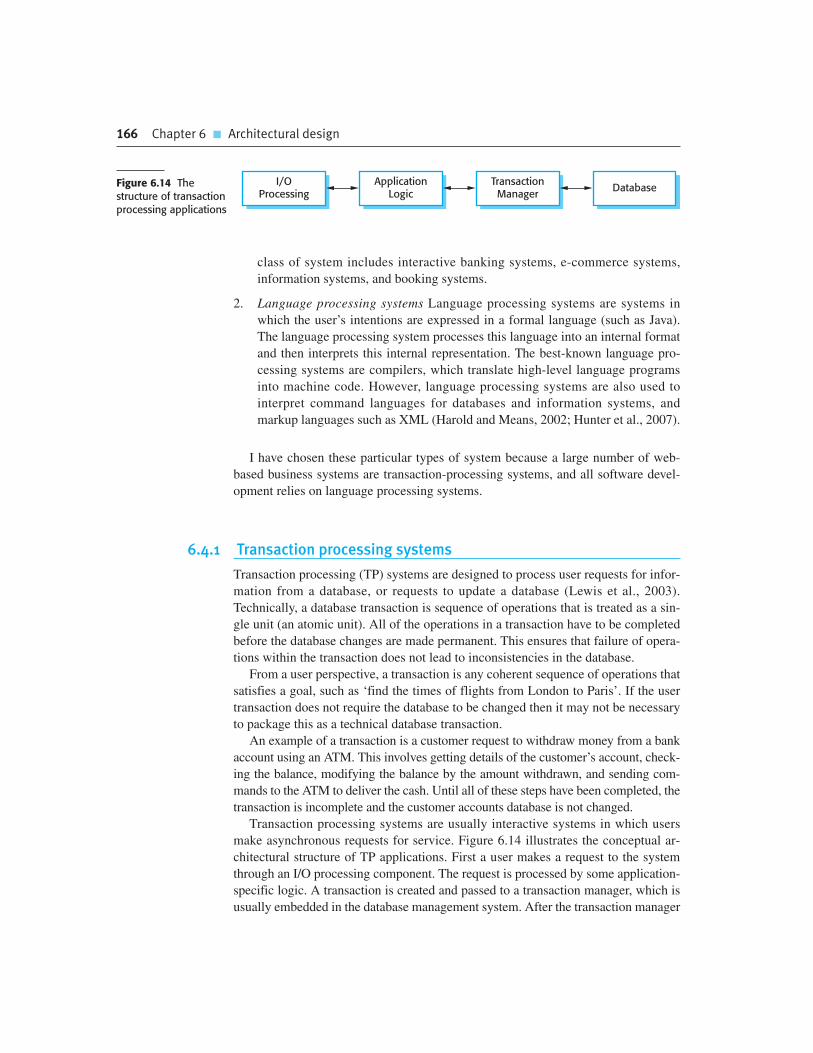
166 Chapter 6 � Architectural design
class of system includes interactive banking systems, e-commerce systems,
information systems, and booking systems.
2. Language processing systems Language processing systems are systems in
which the user’s intentions are expressed in a formal language (such as Java).
The language processing system processes this language into an internal format
and then interprets this internal representation. The best-known language pro-
cessing systems are compilers, which translate high-level language programs
into machine code. However, language processing systems are also used to
interpret command languages for databases and information systems, and
markup languages such as XML (Harold and Means, 2002; Hunter et al., 2007).
I have chosen these particular types of system because a large number of web-
based business systems are transaction-processing systems, and all software devel-
opment relies on language processing systems.
6.4.1 Transaction processing systems
Transaction processing (TP) systems are designed to process user requests for infor-
mation from a database, or requests to update a database (Lewis et al., 2003).
Technically, a database transaction is sequence of operations that is treated as a sin-
gle unit (an atomic unit). All of the operations in a transaction have to be completed
before the database changes are made permanent. This ensures that failure of opera-
tions within the transaction does not lead to inconsistencies in the database.
From a user perspective, a transaction is any coherent sequence of operations that
satisfies a goal, such as ‘find the times of flights from London to Paris’. If the user
transaction does not require the database to be changed then it may not be necessary
to package this as a technical database transaction.
An example of a transaction is a customer request to withdraw money from a bank
account using an ATM. This involves getting details of the customer’s account, check-
ing the balance, modifying the balance by the amount withdrawn, and sending com-
mands to the ATM to deliver the cash. Until all of these steps have been completed, the
transaction is incomplete and the customer accounts database is not changed.
Transaction processing systems are usually interactive systems in which users
make asynchronous requests for service. Figure 6.14 illustrates the conceptual ar-
chitectural structure of TP applications. First a user makes a request to the system
through an I/O processing component. The request is processed by some application-
specific logic. A transaction is created and passed to a transaction manager, which is
usually embedded in the database management system. After the transaction manager
I/OProcessing
ApplicationLogic
TransactionManager
DatabaseFigure 6.14 Thestructure of transactionprocessing applications

6.4 � Application architectures 167
has ensured that the transaction is properly completed, it signals to the application
that processing has finished.
Transaction processing systems may be organized as a ‘pipe and filter’ architec-
ture with system components responsible for input, processing, and output. For
example, consider a banking system that allows customers to query their accounts
and withdraw cash from an ATM. The system is composed of two cooperating soft-
ware components—the ATM software and the account processing software in the
bank’s database server. The input and output components are implemented as soft-
ware in the ATM and the processing component is part of the bank’s database server.
Figure 6.15 shows the architecture of this system, illustrating the functions of the
input, process, and output components.
6.4.2 Information systems
All systems that involve interaction with a shared database can be considered to be
transaction-based information systems. An information system allows controlled
access to a large base of information, such as a library catalog, a flight timetable, or
the records of patients in a hospital. Increasingly, information systems are web-based
systems that are accessed through a web browser.
Figure 6.16 a very general model of an information system. The system is mod-
eled using a layered approach (discussed in Section 6.3) where the top layer supports
the user interface and the bottom layer is the system database. The user communica-
tions layer handles all input and output from the user interface, and the information
retrieval layer includes application-specific logic for accessing and updating the
database. As we shall see later, the layers in this model can map directly onto servers
in an Internet-based system.
As an example of an instantiation of this layered model, Figure 6.17 shows the
architecture of the MHC-PMS. Recall that this system maintains and manages details
of patients who are consulting specialist doctors about mental health problems. I have
Input Process Output
ATM Database ATM
Print Details
Return Card
Dispense Cash
Query Account
Update Account
Get CustomerAccount ID
Validate Card
Select Service
Figure 6.15 Thesoftware architecture of an ATM system

168 Chapter 6 � Architectural design
added detail to each layer in the model by identifying the components that support
user communications and information retrieval and access:
1. The top layer is responsible for implementing the user interface. In this case, the
UI has been implemented using a web browser.
2. The second layer provides the user interface functionality that is delivered
through the web browser. It includes components to allow users to log in to the
system and checking components that ensure that the operations they use are
allowed by their role. This layer includes form and menu management compo-
nents that present information to users, and data validation components that
check information consistency.
3. The third layer implements the functionality of the system and provides compo-
nents that implement system security, patient information creation and updating,
import and export of patient data from other databases, and report generators
that create management reports.
User Interface
Information Retrieval and Modification
Transaction ManagementDatabase
UserCommunications
Authenticationand Authorization
Figure 6.16 Layeredinformation systemarchitecture
Web Browser
ReportGeneration
Transaction ManagementPatient Database
LoginForm and Menu
ManagerData
ValidationRole Checking
SecurityManagement
Patient Info.Manager
Data Importand Export
Figure 6.17 Thearchitecture of theMHC-PMS

6.4 � Application architectures 169
4. Finally, the lowest layer, which is built using a commercial database manage-
ment system, provides transaction management and persistent data storage.
Information and resource management systems are now usually web-based systems
where the user interfaces are implemented using a web browser. For example,
e-commerce systems are Internet-based resource management systems that accept elec-
tronic orders for goods or services and then arrange delivery of these goods or services
to the customer. In an e-commerce system, the application-specific layer includes addi-
tional functionality supporting a ‘shopping cart’ in which users can place a number of
items in separate transactions, then pay for them all together in a single transaction.
The organization of servers in these systems usually reflects the four-layer
generic model presented in Figure 6.16. These systems are often implemented as
multi-tier client server/architectures, as discussed in Chapter 18:
1. The web server is responsible for all user communications, with the user inter-
face implemented using a web browser;
2. The application server is responsible for implementing application-specific
logic as well as information storage and retrieval requests;
3. The database server moves information to and from the database and handles
transaction management.
Using multiple servers allows high throughput and makes it possible to handle
hundreds of transactions per minute. As demand increases, servers can be added at
each level to cope with the extra processing involved.
6.4.3 Language processing systems
Language processing systems translate a natural or artificial language into another
representation of that language and, for programming languages, may also execute
the resulting code. In software engineering, compilers translate an artificial program-
ming language into machine code. Other language-processing systems may translate
an XML data description into commands to query a database or to an alternative
XML representation. Natural language processing systems may translate one natural
language to another e.g., French to Norwegian.
A possible architecture for a language processing system for a programming lan-
guage is illustrated in Figure 6.18. The source language instructions define the pro-
gram to be executed and a translator converts these into instructions for an abstract
machine. These instructions are then interpreted by another component that fetches
the instructions for execution and executes them using (if necessary) data from the
environment. The output of the process is the result of interpreting the instructions
on the input data.

170 Chapter 6 � Architectural design
Of course, for many compilers, the interpreter is a hardware unit that processes
machine instructions and the abstract machine is a real processor. However, for
dynamically typed languages, such as Python, the interpreter may be a software
component.
Programming language compilers that are part of a more general programming
environment have a generic architecture (Figure 6.19) that includes the following
components:
1. A lexical analyzer, which takes input language tokens and converts them to an
internal form.
2. A symbol table, which holds information about the names of entities (variables,
class names, object names, etc.) used in the text that is being translated.
3. A syntax analyzer, which checks the syntax of the language being translated. It
uses a defined grammar of the language and builds a syntax tree.
4. A syntax tree, which is an internal structure representing the program being
compiled.
SourceLanguage
Instructions
Data Results
Translator
Interpreter
Abstract m/cInstructions
Check SyntaxCheck SemanticsGenerate
FetchExecute
Figure 6.18 Thearchitecture of alanguage processingsystem
LexicalAnalysis
SyntacticAnalysis
SemanticAnalysis
CodeGeneration
Symbol Table
Syntax Tree
Figure 6.19 A pipe andfilter compilerarchitecture

6.4 � Application architectures 171
5. A semantic analyzer that uses information from the syntax tree and the symbol
table to check the semantic correctness of the input language text.
6. A code generator that ‘walks’ the syntax tree and generates abstract machine code.
Other components might also be included which analyze and transform the syn-
tax tree to improve efficiency and remove redundancy from the generated machine
code. In other types of language processing system, such as a natural language trans-
lator, there will be additional components such as a dictionary, and the generated
code is actually the input text translated into another language.
There are alternative architectural patterns that may be used in a language pro-
cessing system (Garlan and Shaw, 1993). Compilers can be implemented using a
composite of a repository and a pipe and filter model. In a compiler architecture, the
symbol table is a repository for shared data. The phases of lexical, syntactic, and
semantic analysis are organized sequentially, as shown in Figure 6.19, and commu-
nicate through the shared symbol table.
This pipe and filter model of language compilation is effective in batch environ-
ments where programs are compiled and executed without user interaction; for
example, in the translation of one XML document to another. It is less effective
when a compiler is integrated with other language processing tools such as a struc-
tured editing system, an interactive debugger or a program prettyprinter. In this
situation, changes from one component need to be reflected immediately in other
components. It is better, therefore, to organize the system around a repository, as
shown in Figure 6.20.
This figure illustrates how a language processing system can be part of an integrated
set of programming support tools. In this example, the symbol table and syntax tree act
as a central information repository. Tools or tool fragments communicate through it.
Other information that is sometimes embedded in tools, such as the grammar definition
and the definition of the output format for the program, have been taken out of the tools
and put into the repository. Therefore, a syntax-directed editor can check that the syntax
of a program is correct as it is being typed and a prettyprinter can create listings of the
program in a format that is easy to read.
Reference architectures
Reference architectures capture important features of system architectures in a domain. Essentially, they includeeverything that might be in an application architecture although, in reality, it is very unlikely that any individualapplication would include all the features shown in a reference architecture. The main purpose of referencearchitectures is to evaluate and compare design proposals, and to educate people about architecturalcharacteristics in that domain.
http://www.SoftwareEngineering-9.com/Web/Architecture/RefArch.html

K E Y P O I N T S
� A software architecture is a description of how a software system is organized. Properties of a
system such as performance, security, and availability are influenced by the architecture used.
� Architectural design decisions include decisions on the type of application, the distribution of
the system, the architectural styles to be used, and the ways in which the architecture should be
documented and evaluated.
� Architectures may be documented from several different perspectives or views. Possible views
include a conceptual view, a logical view, a process view, a development view, and a physical view.
� Architectural patterns are a means of reusing knowledge about generic system architectures.
They describe the architecture, explain when it may be used, and discuss its advantages and
disadvantages.
� Commonly used architectural patterns include Model-View-Controller, Layered Architecture,
Repository, Client–server, and Pipe and Filter.
� Generic models of application systems architectures help us understand the operation of
applications, compare applications of the same type, validate application system designs, and
assess large-scale components for reuse.
� Transaction processing systems are interactive systems that allow information in a database to
be remotely accessed and modified by a number of users. Information systems and resource
management systems are examples of transaction processing systems.
� Language processing systems are used to translate texts from one language into another and
to carry out the instructions specified in the input language. They include a translator and an
abstract machine that executes the generated language.
SyntaxAnalyzer
LexicalAnalyzer
SemanticAnalyzer
AbstractSyntax Tree
GrammarDefinition
SymbolTable
OutputDefinition
Pretty-Printer
Editor
Optimizer
CodeGenerator
Repository
Figure 6.20 Arepository architecturefor a languageprocessing system
172 Chapter 6 � Architectural design

F U RT H E R R E A D I N G
Software Architecture: Perspectives on an Emerging Discipline. This was the first book on
software architecture and has a good discussion on different architectural styles. (M. Shaw and
D. Garlan, Prentice-Hall, 1996.)
Software Architecture in Practice, 2nd ed. This is a practical discussion of software architectures that
does not oversell the benefits of architectural design. It provides a clear business rationale
explaining why architectures are important. (L. Bass, P. Clements and R. Kazman, Addison-Wesley,
2003.)
‘The Golden Age of Software Architecture’ This paper surveys the development of software
architecture from its beginnings in the 1980s through to its current usage. There is little technical
content but it is an interesting historical overview. (M. Shaw and P. Clements, IEEE Software,
21 (2), March–April 2006.) http://dx.doi.org/10.1109/MS.2006.58.
Handbook of Software Architecture. This is a work in progress by Grady Booch, one of the
early evangelists for software architecture. He has been documenting the architectures of a range of
software systems so you can see reality rather than academic abstraction. Available on the Web and
intended to appear as a book. http://www.handbookofsoftwarearchitecture.com/.
E X E R C I S E S
6.1. When describing a system, explain why you may have to design the system architecture
before the requirements specification is complete.
6.2. You have been asked to prepare and deliver a presentation to a non-technical manager to
justify the hiring of a system architect for a new project. Write a list of bullet points setting out
the key points in your presentation. Naturally, you have to explain what is meant by system
architecture.
6.3. Explain why design conflicts might arise when designing an architecture for which
both availability and security requirements are the most important non-functional
requirements.
6.4. Draw diagrams showing a conceptual view and a process view of the architectures of the
following systems:
An automated ticket-issuing system used by passengers at a railway station.
A computer-controlled video conferencing system that allows video, audio, and computer data
to be visible to several participants at the same time.
A robot floor cleaner that is intended to clean relatively clear spaces such as corridors. The
cleaner must be able to sense walls and other obstructions.
Chapter 6 � Exercises 173

174 Chapter 6 � Architectural design
6.5. Explain why you normally use several architectural patterns when designing the architecture
of a large system. Apart from the information about patterns that I have discussed in this
chapter, what additional information might be useful when designing large systems?
6.6. Suggest an architecture for a system (such as iTunes) that is used to sell and distribute music
on the Internet. What architectural patterns are the basis for this architecture?
6.7. Explain how you would use the reference model of CASE environments (available on the
book’s web pages) to compare the IDEs offered by different vendors of a programming
language such as Java.
6.8. Using the generic model of a language processing system presented here, design the
architecture of a system that accepts natural language commands and translates these into
database queries in a language such as SQL.
6.9. Using the basic model of an information system, as presented in Figure 6.16, suggest the
components that might be part of an information system that allows users to view information
about flights arriving and departing from a particular airport.
6.10. Should there be a separate profession of ‘software architect’ whose role is to work
independently with a customer to design the software system architecture? A separate
software company would then implement the system. What might be the difficulties of
establishing such a profession?
R E F E R E N C E S
Bass, L., Clements, P. and Kazman, R. (2003). Software Architecture in Practice, 2nd ed. Boston:
Addison-Wesley.
Berczuk, S. P. and Appleton, B. (2002). Software Configuration Management Patterns: Effective
Teamwork, Practical Integration. Boston: Addison-Wesley.
Booch, G. (2009). ‘Handbook of software architecture’. Web publication.
http://www.handbookofsoftwarearchitecture.com/.
Bosch, J. (2000). Design and Use of Software Architectures. Harlow, UK: Addison-Wesley.
Buschmann, F., Henney, K. and Schmidt, D. C. (2007a). Pattern-oriented Software Architecture
Volume 4: A Pattern Language for Distributed Computing. New York: John Wiley & Sons.
Buschmann, F., Henney, K. and Schmidt, D. C. (2007b). Pattern-oriented Software Architecture
Volume 5: On Patterns and Pattern Languages. New York: John Wiley & Sons.
Buschmann, F., Meunier, R., Rohnert, H. and Sommerlad, P. (1996). Pattern-oriented Software
Architecture Volume 1: A System of Patterns. New York: John Wiley & Sons.

Chapter 6 � Exercises 175
Clements, P., Bachmann, F., Bass, L., Garlan, D., Ivers, J., Little, R., Nord, R. and Stafford, J. (2002).
Documenting Software Architectures: Views and Beyond. Boston: Addison-Wesley.
Coplien, J. H. and Harrison, N. B. (2004). Organizational Patterns of Agile Software Development.
Englewood Cliffs, NJ: Prentice Hall.
Gamma, E., Helm, R., Johnson, R. and Vlissides, J. (1995). Design Patterns: Elements of Reusable
Object-Oriented Software. Reading, Mass.: Addison-Wesley.
Garlan, D. and Shaw, M. (1993). ‘An introduction to software architecture’. Advances in Software
Engineering and Knowledge Engineering, 1 1–39.
Harold, E. R. and Means, W. S. (2002). XML in a Nutshell. Sebastopol. Calif.: O‘Reilly.
Hofmeister, C., Nord, R. and Soni, D. (2000). Applied Software Architecture. Boston: Addison-
Wesley.
Hunter, D., Rafter, J., Fawcett, J. and Van Der Vlist, E. (2007). Beginning XML, 4th ed. Indianapolis,
Ind.: Wrox Press.
Kircher, M. and Jain, P. (2004). Pattern-Oriented Software Architecture Volume 3: Patterns for
Resource Management. New York: John Wiley & Sons.
Krutchen, P. (1995). ‘The 4+1 view model of software architecture’. IEEE Software, 12 (6), 42–50.
Lange, C. F. J., Chaudron, M. R. V. and Muskens, J. (2006). ‘UML software description and
architecture description’. IEEE Software, 23 (2), 40–6.
Lewis, P. M., Bernstein, A. J. and Kifer, M. (2003). Databases and Transaction Processing: An
Application-oriented Approach. Boston: Addison-Wesley.
Martin, D. and Sommerville, I. (2004). ‘Patterns of interaction: Linking ethnomethodology and
design’. ACM Trans. on Computer-Human Interaction, 11 (1), 59–89.
Nii, H. P. (1986). ‘Blackboard systems, parts 1 and 2’. AI Magazine, 7 (3 and 4), 38–53 and 62–9.
Schmidt, D., Stal, M., Rohnert, H. and Buschmann, F. (2000). Pattern-Oriented Software
Architecture Volume 2: Patterns for Concurrent and Networked Objects. New York: John Wiley &
Sons.
Shaw, M. and Garlan, D. (1996). Software Architecture: Perspectives on an Emerging Discipline.
Englewood Cliffs, NJ: Prentice Hall.
Usability group. (1998). ‘Usability patterns’. Web publication.
http://www.it.bton.ac.uk/cil/usability/patterns/.
Design andimplementation
7
Objectives
The objectives of this chapter are to introduce object-oriented software
design using the UML and highlight important implementation concerns.
When you have read this chapter, you will:
� understand the most important activities in a general, object-
oriented design process;
� understand some of the different models that may be used to
document an object-oriented design;
� know about the idea of design patterns and how these are a way
of reusing design knowledge and experience;
� have been introduced to key issues that have to be considered when
implementing software, including software reuse and open-source
development.
Contents
7.1 Object-oriented design using the UML
7.2 Design patterns
7.3 Implementation issues
7.4 Open source development

Chapter 7 � Design and implementation 177
Software design and implementation is the stage in the software engineering process
at which an executable software system is developed. For some simple systems, soft-
ware design and implementation is software engineering, and all other activities are
merged with this process. However, for large systems, software design and imple-
mentation is only one of a set of processes (requirements engineering, verification
and validation, etc.) involved in software engineering.
Software design and implementation activities are invariably interleaved.
Software design is a creative activity in which you identify software components and
their relationships, based on a customer’s requirements. Implementation is the
process of realizing the design as a program. Sometimes, there is a separate design
stage and this design is modeled and documented. At other times, a design is in the
programmer’s head or roughly sketched on a whiteboard or sheets of paper. Design
is about how to solve a problem, so there is always a design process. However, it
isn’t always necessary or appropriate to describe the design in detail using the UML
or other design description language.
Design and implementation are closely linked and you should normally take
implementation issues into account when developing a design. For example, using
the UML to document a design may be the right thing to do if you are programming
in an object-oriented language such as Java or C#. It is less useful, I think, if you are
developing in a dynamically typed language like Python and makes no sense at all if
you are implementing your system by configuring an off-the-shelf package. As I dis-
cussed in Chapter 3, agile methods usually work from informal sketches of the
design and leave many design decisions to programmers.
One of the most important implementation decisions that has to be made at an
early stage of a software project is whether or not you should buy or build the appli-
cation software. In a wide range of domains, it is now possible to buy off-the-shelf
systems (COTS) that can be adapted and tailored to the users’ requirements. For
example, if you want to implement a medical records system, you can buy a package
that is already used in hospitals. It can be cheaper and faster to use this approach
rather than developing a system in a conventional programming language.
When you develop an application in this way, the design process becomes con-
cerned with how to use the configuration features of that system to deliver the sys-
tem requirements. You don’t usually develop design models of the system, such as
models of the system objects and their interactions. I discuss this COTS-based
approach to development in Chapter 16.
I assume that most readers of this book will have had experience of program
design and implementation. This is something that you acquire as you learn to pro-
gram and master the elements of a programming language like Java or Python. You
will have probably learned about good programming practice in the programming
languages that you have studied, as well as how to debug programs that you have
developed. Therefore, I don’t cover programming topics here. Instead, this chapter
has two aims:
1. To show how system modeling and architectural design (covered in Chapters 5
and 6) are put into practice in developing an object-oriented software design.
178 Chapter 7 � Design and implementation
2. To introduce important implementation issues that are not usually covered in
programming books. These include software reuse, configuration management,
and open source development.
As there are a vast number of different development platforms, the chapter is not
biased towards any particular programming language or implementation technology.
Therefore, I have presented all examples using the UML rather than in a program-
ming language such as Java or Python.
7.1 Object-oriented design using the UML
An object-oriented system is made up of interacting objects that maintain their own
local state and provide operations on that state. The representation of the state is pri-
vate and cannot be accessed directly from outside the object. Object-oriented design
processes involve designing object classes and the relationships between these
classes. These classes define the objects in the system and their interactions. When
the design is realized as an executing program, the objects are created dynamically
from these class definitions.
Object-oriented systems are easier to change than systems developed using func-
tional approaches. Objects include both data and operations to manipulate that data.
They may therefore be understood and modified as stand-alone entities. Changing the
implementation of an object or adding services should not affect other system objects.
Because objects are associated with things, there is often a clear mapping between real-
world entities (such as hardware components) and their controlling objects in the sys-
tem. This improves the understandability, and hence the maintainability, of the design.
To develop a system design from concept to detailed, object-oriented design,
there are several things that you need to do:
1. Understand and define the context and the external interactions with the system.
2. Design the system architecture.
FPO
Structured design methods propose that software design should be tackled in a methodical way. Designing asystem involves following the steps of the method and refining the design of a system at increasingly detailedlevels. In the 1990s, there were a number of competing methods for object-oriented design. However, theinventors of the most commonly used methods came together and invented the UML, which unified thenotations used in the different methods.
Rather than focus on methods, most discussions now are about processes where design is seen as part of theoverall software development process. The Rational Unified Process (RUP) is a good example of a genericdevelopment process.
http://www.SoftwareEngineering-9.com/Web/Structured-methods/
Structured design methods

7.1 � Object-oriented design using the UML 179
3. Identify the principal objects in the system.
4. Develop design models.
5. Specify interfaces.
Like all creative activities, design is not a clear-cut, sequential process. You
develop a design by getting ideas, proposing solutions, and refining these solutions
as information becomes available. You inevitably have to backtrack and retry when
problems arise. Sometimes you explore options in detail to see if they work; at other
times you ignore details until late in the process. Consequently, I have deliberately
not illustrated this process as a simple diagram because that would imply design can
be thought of as a neat sequence of activities. In fact, all of the above activities are
interleaved and so influence each other.
I illustrate these process activities by designing part of the software for the wilder-
ness weather station that I introduced in Chapter 1. Wilderness weather stations are
deployed in remote areas. Each weather station records local weather information and
periodically transfers this to a weather information system, using a satellite link.
7.1.1 System context and interactions
The first stage in any software design process is to develop an understanding of the
relationships between the software that is being designed and its external environ-
ment. This is essential for deciding how to provide the required system functionality
and how to structure the system to communicate with its environment. Understanding
of the context also lets you establish the boundaries of the system.
Setting the system boundaries helps you decide what features are implemented
in the system being designed and what features are in other associated systems. In
this case, you need to decide how functionality is distributed between the control
system for all of the weather stations, and the embedded software in the weather
station itself.
System context models and interaction models present complementary views of
the relationships between a system and its environment:
1. A system context model is a structural model that demonstrates the other sys-
tems in the environment of the system being developed.
2. An interaction model is a dynamic model that shows how the system interacts
with its environment as it is used.
The context model of a system may be represented using associations. Associations
simply show that there are some relationships between the entities involved in the
association. The nature of the relationships is now specified. You may therefore docu-
ment the environment of the system using a simple block diagram, showing the entities
in the system and their associations. This is illustrated in Figure 7.1, which shows that

180 Chapter 7 � Design and implementation
WeatherInformation
System
WeatherStation
Satellite
ControlSystem
Satellite
1
11
1
1
1
1 1..n
1..n
1..n
Figure 7.1 Systemcontext for the weatherstation
the systems in the environment of each weather station are a weather information sys-
tem, an onboard satellite system, and a control system. The cardinality information on
the link shows that there is one control system but several weather stations, one satellite,
and one general weather information system.
When you model the interactions of a system with its environment you should use
an abstract approach that does not include too much detail. One way to do this is to
use a use case model. As I discussed in Chapters 4 and 5, each use case represents an
interaction with the system. Each possible interaction is named in an ellipse and the
external entity involved in the interaction is represented by a stick figure.
The use case model for the weather station is shown in Figure 7.2. This shows
that the weather station interacts with the weather information system to report
weather data and the status of the weather station hardware. Other interactions are
with a control system that can issue specific weather station control commands. As I
explained in Chapter 5, a stick figure is used in the UML to represent other systems
as well as human users.
Each of these use cases should be described in structured natural language. This
helps designers identify objects in the system and gives them an understanding of
what the system is intended to do. I use a standard format for this description that
clearly identifies what information is exchanged, how the interaction is initiated, and
Report weather—send weather data to the weather information system
Report status—send status information to the weather information system
Restart—if the weather station is shut down, restart the system
Shutdown—shut down the weather station
Reconfigure—reconfigure the weather station software
Powersave—put the weather station into power-saving mode
Remote control—send control commands to any weather station subsystem
http://www.SoftwareEngineering-9.com/Web/WS/Usecases.html
Weather station use cases

7.1 � Object-oriented design using the UML 181
so on. This is shown in Figure 7.3, which describes the Report weather use case from
Figure 7.2. Examples of some other use cases are on the Web.
7.1.2 Architectural design
Once the interactions between the software system and the system’s environment
have been defined, you use this information as a basis for designing the system
architecture. Of course, you need to combine this with your general knowledge of
the principles of architectural design and with more detailed domain knowledge.
Shutdown
ReportWeather
Restart
ReportStatus
Reconfigure
WeatherInformation
System
ControlSystem Powersave
RemoteControlFigure 7.2 Weather
station use cases
System Weather station
Use case Report weather
Actors Weather information system, Weather station
Dat The weather station sends a summary of the weather data that has been collected fromthe instruments in the collection period to the weather information system. The data sentare the maximum, minimum, and average ground and air temperatures; the maximum,minimum, and average air pressures; the maximum, minimum, and average wind speeds;the total rainfall; and the wind direction as sampled at five-minute intervals.
Stimulus The weather information system establishes a satellite communication link with theweather station and requests transmission of the data.
Response The summarized data are sent to the weather information system.
Comments Weather stations are usually asked to report once per hour but this frequency may differfrom one station to another and may be modified in the future.
Figure 7.3 Use casedescription—Reportweather

182 Chapter 7 � Design and implementation
You identify the major components that make up the system and their interactions,
and then may organize the components using an architectural pattern such as a lay-
ered or client–server model. However, this is not essential at this stage.
The high-level architectural design for the weather station software is shown in
Figure 7.4. The weather station is composed of independent subsystems that com-
municate by broadcasting messages on a common infrastructure, shown as the
Communication link in Figure 7.4. Each subsystem listens for messages on that
infrastructure and picks up the messages that are intended for them. This is
another commonly used architectural style in addition to those described in
Chapter 6.
For example, when the communications subsystem receives a control com-
mand, such as shutdown, the command is picked up by each of the other subsys-
tems, which then shut themselves down in the correct way. The key benefit of this
architecture is that it is easy to support different configurations of subsystems
because the sender of a message does not need to address the message to a partic-
ular subsystem.
Figure 7.5 shows the architecture of the data collection subsystem, which is
included in Figure 7.4. The Transmitter and Receiver objects are concerned with
managing communications and the WeatherData object encapsulates the information
that is collected from the instruments and transmitted to the weather information
system. This arrangement follows the producer-consumer pattern, discussed in
Chapter 20.
7.1.3 Object class identification
By this stage in the design process, you should have some ideas about the essen-
tial objects in the system that you are designing. As your understanding of the
design develops, you refine these ideas about the system objects. The use case
description helps to identify objects and operations in the system. From the
description of the Report weather use case, it is obvious that objects representing
the instruments that collect weather data will be required, as will an object
representing the summary of the weather data. You also usually need a high-level
«subsystem»Data Collection
«subsystem»Communications
«subsystem»Configuration Manager
«subsystem»Fault Manager
«subsystem»Power Manager
«subsystem»Instruments
Communication Link
Figure 7.4 High-levelarchitecture of theweather station

7.1 � Object-oriented design using the UML 183
system object or objects that encapsulate the system interactions defined in the
use cases. With these objects in mind, you can start to identify the object classes
in the system.
There have been various proposals made about how to identify object classes in
object-oriented systems:
1. Use a grammatical analysis of a natural language description of the system to be
constructed. Objects and attributes are nouns; operations or services are verbs
(Abbott, 1983).
2. Use tangible entities (things) in the application domain such as aircraft, roles
such as manager or doctor, events such as requests, interactions such as meet-
ings, locations such as offices, organizational units such as companies, and
so on (Coad and Yourdon, 1990; Shlaer and Mellor, 1988; Wirfs-Brock
et al., 1990).
3. Use a scenario-based analysis where various scenarios of system use are identi-
fied and analyzed in turn. As each scenario is analyzed, the team responsible for
the analysis must identify the required objects, attributes, and operations (Beck
and Cunningham, 1989).
In practice, you have to use several knowledge sources to discover object classes.
Object classes, attributes, and operations that are initially identified from the infor-
mal system description can be a starting point for the design. Further information
from application domain knowledge or scenario analysis may then be used to refine
and extend the initial objects. This information can be collected from requirements
documents, discussions with users, or from analyses of existing systems.
In the wilderness weather station, object identification is based on the tangible
hardware in the system. I don’t have space to include all the system objects here, but
I have shown five object classes in Figure 7.6. The Ground thermometer,
Anemometer, and Barometer objects are application domain objects, and the
WeatherStation and WeatherData objects have been identified from the system
description and the scenario (use case) description:
1. The WeatherStation object class provides the basic interface of the weather
station with its environment. Its operations reflect the interactions shown in
Data Collection
Transmitter Receiver
WeatherDataFigure 7.5 Architectureof data collectionsystem

184 Chapter 7 � Design and implementation
Figure 7.3. In this case, I use a single object class to encapsulate all of these
interactions, but in other designs you could design the system interface as sev-
eral different classes.
2. The WeatherData object class is responsible for processing the report weather
command. It sends the summarized data from the weather station instruments to
the weather information system.
3. The Ground thermometer, Anemometer, and Barometer object classes are
directly related to instruments in the system. They reflect tangible hardware
entities in the system and the operations are concerned with controlling that
hardware. These objects operate autonomously to collect data at the specified
frequency and store the collected data locally. This data is delivered to the
WeatherData object on request.
You use knowledge of the application domain to identify other objects, attributes,
and services. We know that weather stations are often located in remote places and
include various instruments that sometimes go wrong. Instrument failures should be
reported automatically. This implies that you need attributes and operations to check
the correct functioning of the instruments. There are many remote weather stations
so each weather station should have its own identifier.
At this stage in the design process, you should focus on the objects themselves, with-
out thinking about how these might be implemented. Once you have identified the
objects, you then refine the object design. You look for common features and then
design the inheritance hierarchy for the system. For example, you may identify an
Instrument superclass, which defines the common features of all instruments, such as an
identifier, and get and test operations. You may also add new attributes and operations to
the superclass, such as an attribute that maintains the frequency of data collection.
Figure 7.6 Weatherstation objects
identifier
reportWeather ( )reportStatus ( )powerSave (instruments)remoteControl (commands)reconfigure (commands)restart (instruments)shutdown(instruments)
WeatherStation
airTemperaturesgroundTemperatureswindSpeedswindDirectionspressuresrainfall
collect ( )summarize ( )
WeatherData
Anemometer
get ( )test ( )
an_IdentwindSpeedwindDirection
Barometer
get ( )test ( )
bar_Identpressureheight
GroundThermometer
get ( )test ( )
gt_Identtemperature

7.1 � Object-oriented design using the UML 185
7.1.4 Design models
Design or system models, as I discussed in Chapter 5, show the objects or object classes
in a system. They also show the associations and relationships between these entities.
These models are the bridge between the system requirements and the implementation
of a system. They have to be abstract so that unnecessary detail doesn’t hide the rela-
tionships between them and the system requirements. However, they also have to
include enough detail for programmers to make implementation decisions.
Generally, you get around this type of conflict by developing models at different
levels of detail. Where there are close links between requirements engineers, design-
ers, and programmers, then abstract models may be all that are required. Specific
design decisions may be made as the system is implemented, with problems resolved
through informal discussions. When the links between system specifiers, designers,
and programmers are indirect (e.g., where a system is being designed in one part of
an organization but implemented elsewhere), then more detailed models are likely to
be needed.
An important step in the design process, therefore, is to decide on the design
models that you need and the level of detail required in these models. This depends
on the type of system that is being developed. You design a sequential data-process-
ing system in a different way from an embedded real-time system, so you will need
different design models. The UML supports 13 different types of models but, as I
discussed in Chapter 5, you rarely use all of these. Minimizing the number of mod-
els that are produced reduces the costs of the design and the time required to com-
plete the design process.
When you use the UML to develop a design, you will normally develop two kinds
of design model:
1. Structural models, which describe the static structure of the system using object
classes and their relationships. Important relationships that may be documented
at this stage are generalization (inheritance) relationships, uses/used-by rela-
tionships, and composition relationships.
2. Dynamic models, which describe the dynamic structure of the system and show
the interactions between the system objects. Interactions that may be docu-
mented include the sequence of service requests made by objects and the state
changes that are triggered by these object interactions.
In the early stages of the design process, I think there are three models that are
particularly useful for adding detail to use case and architectural models:
1. Subsystem models, which that show logical groupings of objects into coherent
subsystems. These are represented using a form of class diagram with each sub-
system shown as a package with enclosed objects. Subsystem models are static
(structural) models.

186 Chapter 7 � Design and implementation
2. Sequence models, which show the sequence of object interactions. These are
represented using a UML sequence or a collaboration diagram. Sequence
models are dynamic models.
3. State machine model, which show how individual objects change their state in
response to events. These are represented in the UML using state diagrams.
State machine models are dynamic models.
A subsystem model is a useful static model as it shows how a design is organized into
logically related groups of objects. I have already shown this type of model in Figure 7.4
to show the subsystems in the weather mapping system. As well as subsystem models,
you may also design detailed object models, showing all of the objects in the systems
and their associations (inheritance, generalization, aggregation, etc.). However, there is
a danger in doing too much modeling. You should not make detailed decisions about the
implementation that really should be left to the system programmers.
Sequence models are dynamic models that describe, for each mode of interaction,
the sequence of object interactions that take place. When documenting a design, you
should produce a sequence model for each significant interaction. If you have devel-
oped a use case model then there should be a sequence model for each use case that
you have identified.
Figure 7.7 is an example of a sequence model, shown as a UML sequence dia-
gram. This diagram shows the sequence of interactions that take place when an
external system requests the summarized data from the weather station. You read
sequence diagrams from top to bottom:
1. The SatComms object receives a request from the weather information system
to collect a weather report from a weather station. It acknowledges receipt of
:SatComms
request (report)
acknowledgereportWeather ( )
get (summary)
reply (report)
acknowledge
:WeatherStation :Commslink
summarize ( )
:WeatherData
acknowledge
send (report)
acknowledge
WeatherInformation System
Figure 7.7 Sequencediagram describing data collection

7.1 � Object-oriented design using the UML 187
this request. The stick arrowhead on the sent message indicates that the external
system does not wait for a reply but can carry on with other processing.
2. SatComms sends a message to WeatherStation, via a satellite link, to create a
summary of the collected weather data. Again, the stick arrowhead indicates
that SatComms does not suspend itself waiting for a reply.
3. WeatherStation sends a message to a Commslink object to summarize the
weather data. In this case, the squared-off style of arrowhead indicates that the
instance of the WeatherStation object class waits for a reply.
4. Commslink calls the summarize method in the object WeatherData and waits for
a reply.
5. The weather data summary is computed and returned to WeatherStation via the
Commslink object.
6. WeatherStation then calls the SatComms object to transmit the summarized
data to the weather information system, through the satellite communications
system.
The SatComms and WeatherStation objects may be implemented as concurrent
processes, whose execution can be suspended and resumed. The SatComms object
instance listens for messages from the external system, decodes these messages and
initiates weather station operations.
Sequence diagrams are used to model the combined behavior of a group of
objects but you may also want to summarize the behavior of an object or a subsystem
in response to messages and events. To do this, you can use a state machine model
that shows how the object instance changes state depending on the messages that it
receives. The UML includes state diagrams, initially invented by Harel (1987) to
describe state machine models.
Figure 7.8 is a state diagram for the weather station system that shows how it
responds to requests for various services.
You can read this diagram as follows:
1. If the system state is Shutdown then it can respond to a restart(), a reconfigure(),
or a powerSave() message. The unlabeled arrow with the black blob indicates
that the Shutdown state is the initial state. A restart() message causes a transition
to normal operation. Both the powerSave() and reconfigure() messages cause a
transition to a state in which the system reconfigures itself. The state diagram
shows that reconfiguration is only allowed if the system has been shut down.
2. In the Running state, the system expects further messages. If a shutdown() mes-
sage is received, the object returns to the shutdown state.
3. If a reportWeather() message is received, the system moves to the Summarizing
state. When the summary is complete, the system moves to a Transmitting state
where the information is transmitted to the remote system. It then returns to the
Running state.

188 Chapter 7 � Design and implementation
4. If a reportStatus() message is received, the system moves to the Testing state,
then the Transmitting state, before returning to the Running state.
5. If a signal from the clock is received, the system moves to the Collecting state,
where it collects data from the instruments. Each instrument is instructed in turn
to collect its data from the associated sensors.
6. If a remoteControl() message is received, the system moves to a controlled state
in which it responds to a different set of messages from the remote control
room. These are not shown on this diagram.
State diagrams are useful high-level models of a system or an object’s operation.
You don’t usually need a state diagram for all of the objects in the system. Many of
the objects in a system are relatively simple and a state model adds unnecessary
detail to the design.
7.1.5 Interface specification
An important part of any design process is the specification of the interfaces between
the components in the design. You need to specify interfaces so that objects and sub-
systems can be designed in parallel. Once an interface has been specified, the devel-
opers of other objects may assume that interface will be implemented.
Interface design is concerned with specifying the detail of the interface to an
object or to a group of objects. This means defining the signatures and semantics of
transmission done
remoteControl ( )
reportStatus ( )restart ( )
shutdown( )
test complete
weathersummarycomplete
clock collectiondone
Operation
reportWeather ( )
reconfigure ( )powerSave ( )
configuration done
Shutdown Running Testing
Transmitting
Collecting
Summarizing
Controlled
Configuring
Figure 7.8 Weatherstation state diagram

7.2 � Design patterns 189
the services that are provided by the object or by a group of objects. Interfaces can be
specified in the UML using the same notation as a class diagram. However, there is
no attribute section and the UML stereotype ‹‹interface›› should be included in the
name part. The semantics of the interface may be defined using the object constraint
language (OCL). I explain this in Chapter 17, where I cover component-based soft-
ware engineering. I also show an alternative way to represent interfaces in the UML.
You should not include details of the data representation in an interface design,
as attributes are not defined in an interface specification. However, you should
include operations to access and update data. As the data representation is hidden, it
can be easily changed without affecting the objects that use that data. This leads to
a design that is inherently more maintainable. For example, an array representation
of a stack may be changed to a list representation without affecting other objects
that use the stack. By contrast, it often makes sense to expose the attributes in a
static design model, as this is the most compact way of illustrating essential charac-
teristics of the objects.
There is not a simple 1:1 relationship between objects and interfaces. The same
object may have several interfaces, each of which is a viewpoint on the methods that
it provides. This is supported directly in Java, where interfaces are declared sepa-
rately from objects and objects ‘implement’ interfaces. Equally, a group of objects
may all be accessed through a single interface.
Figure 7.9 shows two interfaces that may be defined for the weather station. The
left-hand interface is a reporting interface that defines the operation names that are
used to generate weather and status reports. These map directly to operations in the
WeatherStation object. The remote control interface provides four operations, which
map onto a single method in the WeatherStation object. In this case, the individual
operations are encoded in the command string associated with the remoteControl
method, shown in Figure 7.6.
7.2 Design patterns
Design patterns were derived from ideas put forward by Christopher Alexander
(Alexander et al., 1977), who suggested that there were certain common patterns of
building design that were inherently pleasing and effective. The pattern is a description
of the problem and the essence of its solution, so that the solution may be reused in
«interface»Remote Control
startInstrument (instrument): iStatusstopInstrument (instrument): iStatuscollectData (instrument): iStatusprovideData (instrument): string
«interface»Reporting
weatherReport (WS-Ident): WreportstatusReport (WS-Ident): Sreport
Figure 7.9 Weatherstation interfaces

190 Chapter 7 � Design and implementation
different settings. The pattern is not a detailed specification. Rather, you can think of it
as a description of accumulated wisdom and experience, a well-tried solution to a com-
mon problem.
A quote from the Hillside Group web site (http://hillside.net), which is dedicated
to maintaining information about patterns, encapsulates their role in reuse:
Patterns and Pattern Languages are ways to describe best practices, good
designs, and capture experience in a way that it is possible for others to reuse
this experience.
Patterns have made a huge impact on object-oriented software design. As well as
being tested solutions to common problems, they have become a vocabulary for talk-
ing about a design. You can therefore explain your design by describing the patterns
that you have used. This is particularly true for the best-known design patterns that
were originally described by the ‘Gang of Four’ in their patterns book, (Gamma et al.,
1995). Other particularly important pattern descriptions are those published in a series
of books by authors from Siemens, a large European technology company
(Buschmann et al., 1996; Buschmann et al., 2007a; Buschmann et al., 2007b; Kircher
and Jain, 2004; Schmidt et al., 2000).
Design patterns are usually associated with object-oriented design. Published
patterns often rely on object characteristics such as inheritance and polymorphism to
provide generality. However, the general principle of encapsulating experience in a
Pattern name: ObserverDescription: Separates the display of the state of an object from the object itself and allows alternative displays
to be provided. When the object state changes, all displays are automatically notified and updated to reflectthe change.
Problem description: In many situations, you have to provide multiple displays of state information, such as a graphical display and a tabular display. Not all of these may be known when the information isspecified. All alternative presentations should support interaction and, when the state is changed, all displaysmust be updated.
This pattern may be used in all situations where more than one display format for state information isrequired and where it is not necessary for the object that maintains the state information to know about thespecific display formats used.
Solution description: This involves two abstract objects, Subject and Observer, and two concrete objects,ConcreteSubject and ConcreteObject, which inherit the attributes of the related abstract objects. The abstractobjects include general operations that are applicable in all situations. The state to be displayed ismaintained in ConcreteSubject, which inherits operations from Subject allowing it to add and removeObservers (each observer corresponds to a display) and to issue a notification when the state has changed.
The ConcreteObserver maintains a copy of the state of ConcreteSubject and implements the Update()interface of Observer that allows these copies to be kept in step. The ConcreteObserver automaticallydisplays the state and reflects changes whenever the state is updated.The UML model of the pattern is shown in Figure 7.12.
Consequences: The subject only knows the abstract Observer and does not know details of the concrete class.Therefore there is minimal coupling between these objects. Because of this lack of knowledge, optimizationsthat enhance display performance are impractical. Changes to the subject may cause a set of linked updatesto observers to be generated, some of which may not be necessary.
Figure 7.10 TheObserver pattern

7.2 � Design patterns 191
pattern is one that is equally applicable to any kind of software design. So, you could
have configuration patterns for COTS systems. Patterns are a way of reusing the
knowledge and experience of other designers.
The four essential elements of design patterns were defined by the ‘Gang of Four’
in their patterns book:
1. A name that is a meaningful reference to the pattern.
2. A description of the problem area that explains when the pattern may be
applied.
3. A solution description of the parts of the design solution, their relationships, and
their responsibilities. This is not a concrete design description. It is a template
for a design solution that can be instantiated in different ways. This is often
expressed graphically and shows the relationships between the objects and
object classes in the solution.
4. A statement of the consequences—the results and trade-offs—of applying the
pattern. This can help designers understand whether or not a pattern can be used
in a particular situation.
Gamma and his co-authors break down the problem description into motivation
(a description of why the pattern is useful) and applicability (a description of situations
in which the pattern may be used). Under the description of the solution, they describe
the pattern structure, participants, collaborations, and implementation.
To illustrate pattern description, I use the Observer pattern, taken from the book
by Gamma et al. (Gamma et al., 1995). This is shown in Figure 7.10. In my descrip-
tion, I use the four essential description elements and also include a brief statement
of what the pattern can do. This pattern can be used in situations where different
presentations of an object’s state are required. It separates the object that must be
displayed from the different forms of presentation. This is illustrated in Figure 7.11,
which shows two graphical presentations of the same data set.
Graphical representations are normally used to illustrate the object classes in
patterns and their relationships. These supplement the pattern description and add
Observer 1 Observer 2A: 40B: 25C: 15D: 20
Subject
0
50
25
A B C DB
C
DA
Figure 7.11 Multipledisplays

192 Chapter 7 � Design and implementation
detail to the solution description. Figure 7.12 is the representation in UML of the
Observer pattern.
To use patterns in your design, you need to recognize that any design problem
you are facing may have an associated pattern that can be applied. Examples of such
problems, documented in the ‘Gang of Four’s original patterns book, include:
1. Tell several objects that the state of some other object has changed (Observer
pattern).
2. Tidy up the interfaces to a number of related objects that have often been devel-
oped incrementally (Façade pattern).
3. Provide a standard way of accessing the elements in a collection, irrespective of
how that collection is implemented (Iterator pattern).
4. Allow for the possibility of extending the functionality of an existing class at
run-time (Decorator pattern).
Patterns support high-level, concept reuse. When you try to reuse executable
components you are inevitably constrained by detailed design decisions that have
been made by the implementers of these components. These range from the
particular algorithms that have been used to implement the components to the
objects and types in the component interfaces. When these design decisions con-
flict with your particular requirements, reusing the component is either
impossible or introduces inefficiencies into your system. Using patterns means
that you reuse the ideas but can adapt the implementation to suit the system that
you are developing.
When you start designing a system, it can be difficult to know, in advance, if you
will need a particular pattern. Therefore, using patterns in a design process often
involves developing a design, experiencing a problem, and then recognizing that a
pattern can be used. This is certainly possible if you focus on the 23 general-purpose
Subject Observer
Attach (Observer)Detach (Observer)Notify ( )
Update ( )
ConcreteSubject
GetState ( )
subjectState
ConcreteObserver
Update ( )
observerState
observerState =subject -> GetState ( )return subjectState
for All o in observerso -> Update ( )
Figure 7.12 A UMLmodel of the Observerpattern

7.3 � Implementation issues 193
patterns documented in the original patterns book. However, if your problem is a dif-
ferent one, you may find it difficult to find an appropriate pattern amongst the hun-
dreds of different patterns that have been proposed.
Patterns are a great idea but you need experience of software design to use them
effectively. You have to recognize situations where a pattern can be applied.
Inexperienced programmers, even if they have read the pattern books, will always
find it hard to decide whether they can reuse a pattern or need to develop a special-
purpose solution.
7.3 Implementation issues
Software engineering includes all of the activities involved in software development
from the initial requirements of the system through to maintenance and manage-
ment of the deployed system. A critical stage of this process is, of course, system
implementation, where you create an executable version of the software.
Implementation may involve developing programs in high- or low-level programming
languages or tailoring and adapting generic, off-the-shelf systems to meet the specific
requirements of an organization.
I assume that most readers of this book will understand programming principles
and will have some programming experience. As this chapter is intended to offer a
language-independent approach, I haven’t focused on issues of good programming
practice as this has to use language-specific examples. Instead, I introduce some
aspects of implementation that are particularly important to software engineering
that are often not covered in programming texts. These are:
1. Reuse Most modern software is constructed by reusing existing components or
systems. When you are developing software, you should make as much use as
possible of existing code.
2. Configuration management During the development process, many different
versions of each software component are created. If you don’t keep track of
these versions in a configuration management system, you are liable to include
the wrong versions of these components in your system.
3. Host-target development Production software does not usually execute on the
same computer as the software development environment. Rather, you develop
it on one computer (the host system) and execute it on a separate computer (the
target system). The host and target systems are sometimes of the same type but,
often they are completely different.
7.3.1 Reuse
From the 1960s to the 1990s, most new software was developed from scratch, by
writing all code in a high-level programming language. The only significant reuse or
194 Chapter 7 � Design and implementation
software was the reuse of functions and objects in programming language libraries.
However, costs and schedule pressure meant that this approach became increasingly
unviable, especially for commercial and Internet-based systems. Consequently, an
approach to development based around the reuse of existing software emerged and is
now generally used for business systems, scientific software, and, increasingly, in
embedded systems engineering.
Software reuse is possible at a number of different levels:
1. The abstraction level At this level, you don’t reuse software directly but rather
use knowledge of successful abstractions in the design of your software. Design
patterns and architectural patterns (covered in Chapter 6) are ways of represent-
ing abstract knowledge for reuse.
2. The object level At this level, you directly reuse objects from a library rather
than writing the code yourself. To implement this type of reuse, you have to find
appropriate libraries and discover if the objects and methods offer the function-
ality that you need. For example, if you need to process mail messages in a Java
program, you may use objects and methods from a JavaMail library.
3. The component level Components are collections of objects and object classes
that operate together to provide related functions and services. You often have to
adapt and extend the component by adding some code of your own. An example
of component-level reuse is where you build your user interface using a frame-
work. This is a set of general object classes that implement event handling, dis-
play management, etc. You add connections to the data to be displayed and
write code to define specific display details such as screen layout and colors.
4. The system level At this level, you reuse entire application systems. This usually
involves some kind of configuration of these systems. This may be done by
adding and modifying code (if you are reusing a software product line) or by
using the system’s own configuration interface. Most commercial systems are
now built in this way where generic COTS (commercial off-the-shelf) systems
are adapted and reused. Sometimes this approach may involve reusing several
different systems and integrating these to create a new system.
By reusing existing software, you can develop new systems more quickly, with
fewer development risks and also lower costs. As the reused software has been tested
in other applications, it should be more reliable than new software. However, there
are costs associated with reuse:
1. The costs of the time spent in looking for software to reuse and assessing
whether or not it meets your needs. You may have to test the software to make
sure that it will work in your environment, especially if this is different from its
development environment.
2. Where applicable, the costs of buying the reusable software. For large off-the-
shelf systems, these costs can be very high.

7.3 � Implementation issues 195
3. The costs of adapting and configuring the reusable software components or sys-
tems to reflect the requirements of the system that you are developing.
4. The costs of integrating reusable software elements with each other (if you are
using software from different sources) and with the new code that you have
developed. Integrating reusable software from different providers can be diffi-
cult and expensive because the providers may make conflicting assumptions
about how their respective software will be reused.
How to reuse existing knowledge and software should be the first thing you should
think about when starting a software development project. You should consider the
possibilities of reuse before designing the software in detail, as you may wish to adapt
your design to reuse existing software assets. As I discussed in Chapter 2, in a reuse-
oriented development process, you search for reusable elements then modify your
requirements and design to make best use of these.
For a large number of application systems, software engineering really means
software reuse. I therefore devote several chapters in the software technologies sec-
tion of the book to this topic (Chapters 16, 17, and 19).
7.3.2 Configuration management
In software development, change happens all the time, so change management is
absolutely essential. When a team of people are developing software, you have to
make sure that team members don’t interfere with each others’ work. That is, if two
people are working on a component, their changes have to be coordinated. Otherwise,
one programmer may make changes and overwrite the other’s work. You also have to
ensure that everyone can access the most up-to-date versions of software components,
otherwise developers may redo work that has already been done. When something
goes wrong with a new version of a system, you have to be able to go back to a work-
ing version of the system or component.
Configuration management is the name given to the general process of managing
a changing software system. The aim of configuration management is to support the
system integration process so that all developers can access the project code and doc-
uments in a controlled way, find out what changes have been made, and compile and
link components to create a system. There are, therefore, three fundamental configu-
ration management activities:
1. Version management, where support is provided to keep track of the different
versions of software components. Version management systems include facili-
ties to coordinate development by several programmers. They stop one devel-
oper overwriting code that has been submitted to the system by someone else.
2. System integration, where support is provided to help developers define what
versions of components are used to create each version of a system. This
description is then used to build a system automatically by compiling and link-
ing the required components.

196 Chapter 7 � Design and implementation
3. Problem tracking, where support is provided to allow users to report bugs and
other problems, and to allow all developers to see who is working on these prob-
lems and when they are fixed.
Software configuration management tools support each of the above activities.
These tools may be designed to work together in a comprehensive change management
system, such as ClearCase (Bellagio and Milligan, 2005). In integrated configuration
management systems, version management, system integration, and problem-tracking
tools are designed together. They share a user interface style and are integrated through
a common code repository.
Alternatively, separate tools, installed in an integrated development environment,
may be used. Version management may be supported using a version management
system such as Subversion (Pilato et al., 2008), which can support multi-site, multi-
team development. System integration support may be built into the language or rely
on a separate toolset such as the GNU build system. This includes what is perhaps
the best-known integration tool, Unix make. Bug tracking or issue tracking systems,
such as Bugzilla, are used to report bugs and other issues and to keep track of
whether or not these have been fixed.
Because of its importance in professional software engineering, I discuss change
and configuration management in more detail in Chapter 25.
7.3.3 Host-target development
Most software development is based on a host-target model. Software is developed on
one computer (the host), but runs on a separate machine (the target). More generally,
we can talk about a development platform and an execution platform. A platform is
more than just hardware. It includes the installed operating system plus other support-
ing software such as a database management system or, for development platforms,
an interactive development environment.
Sometimes, the development and execution platforms are the same, making it possi-
ble to develop the software and test it on the same machine. More commonly, however,
they are different so that you need to either move your developed software to the execu-
tion platform for testing or run a simulator on your development machine.
Simulators are often used when developing embedded systems. You simulate hard-
ware devices, such as sensors, and the events in the environment in which the system
will be deployed. Simulators speed up the development process for embedded systems
as each developer can have their own execution platform with no need to download the
software to the target hardware. However, simulators are expensive to develop and so
are only usually available for the most popular hardware architectures.
If the target system has installed middleware or other software that you need to
use, then you need to be able to test the system using that software. It may be imprac-
tical to install that software on your development machine, even if it is the same as
the target platform, because of license restrictions. In those circumstances, you need
to transfer your developed code to the execution platform to test the system.

7.3 � Implementation issues 197
A software development platform should provide a range of tools to support soft-
ware engineering processes. These may include:
1. An integrated compiler and syntax-directed editing system that allows you to
create, edit, and compile code.
2. A language debugging system.
3. Graphical editing tools, such as tools to edit UML models.
4. Testing tools, such as JUnit (Massol, 2003) that can automatically run a set of
tests on a new version of a program.
5. Project support tools that help you organize the code for different development
projects.
As well as these standard tools, your development system may include more special-
ized tools such as static analyzers (discussed in Chapter 15). Normally, development
environments for teams also include a shared server that runs a change and con-
figuration management system and, perhaps, a system to support requirements
management.
Software development tools are often grouped to create an integrated develop-
ment environment (IDE). An IDE is a set of software tools that supports different
aspects of software development, within some common framework and user inter-
face. Generally, IDEs are created to support development in a specific programming
language such as Java. The language IDE may be developed specially, or may be an
instantiation of a general-purpose IDE, with specific language-support tools.
A general-purpose IDE is a framework for hosting software tools that provides data
management facilities for the software being developed, and integration mechanisms,
that allow tools to work together. The best-known general-purpose IDE is the Eclipse
environment (Carlson, 2005). This environment is based on a plug-in architecture so
that it can be specialized for different languages and application domains (Clayberg and
Rubel, 2006). Therefore, you can install Eclipse and tailor it for your specific needs by
adding plug-ins. For example, you may add a set of plug-ins to support networked sys-
tems development in Java or embedded systems engineering using C.
As part of the development process, you need to make decisions about how the
developed software will be deployed on the target platform. This is straightforward
UML deployment diagrams
UML deployment diagrams show how software components are physically deployed on processors; thatis, the deployment diagram shows the hardware and software in the system and the middleware usedto connect the different components in the system. Essentially, you can think of deployment diagrams asa way of defining and documenting the target environment.
http://www.SoftwareEngineering-9.com/Web/Deployment/

198 Chapter 7 � Design and implementation
for embedded systems, where the target is usually a single computer. However, for
distributed systems, you need to decide on the specific platforms where the compo-
nents will be deployed. Issues that you have to consider in making this decision are:
1. The hardware and software requirements of a component If a component is
designed for a specific hardware architecture, or relies on some other software
system, it must obviously be deployed on a platform that provides the required
hardware and software support.
2. The availability requirements of the system High-availability systems may
require components to be deployed on more than one platform. This means that,
in the event of platform failure, an alternative implementation of the component
is available.
3. Component communications If there is a high level of communications traffic
between components, it usually makes sense to deploy them on the same plat-
form or on platforms that are physically close to one other. This reduces
communications latency, the delay between the time a message is sent by one
component and received by another.
You can document your decisions on hardware and software deployment using UML
deployment diagrams, which show how software components are distributed across
hardware platforms.
If you are developing an embedded system, you may have to take into account
target characteristics, such as its physical size, power capabilities, the need for real-
time responses to sensor events, the physical characteristics of actuators, and its real-
time operating system. I discuss embedded systems engineering in Chapter 20.
7.4 Open source development
Open source development is an approach to software development in which the
source code of a software system is published and volunteers are invited to partici-
pate in the development process (Raymond, 2001). Its roots are in the Free Software
Foundation (http://www.fsf.org), which advocates that source code should not be
proprietary but rather should always be available for users to examine and modify as
they wish. There was an assumption that the code would be controlled and devel-
oped by a small core group, rather than users of the code.
Open source software extended this idea by using the Internet to recruit a much
larger population of volunteer developers. Many of them are also users of the code.
In principle at least, any contributor to an open source project may report and fix
bugs and propose new features and functionality. However, in practice, successful
open source systems still rely on a core group of developers who control changes to
the software.

7.4 � Open source development 199
The best-known open source product is, of course, the Linux operating system
which is widely used as a server system and, increasingly, as a desktop environment.
Other important open source products are Java, the Apache web server, and the
mySQL database management system. Major players in the computer industry such
as IBM and Sun support the open source movement and base their software on open
source products. There are thousands of other, lesser known open source systems
and components that may also be used.
It is usually fairly cheap or free to acquire open source software. You can nor-
mally download open source software without charge. However, if you want docu-
mentation and support, then you may have to pay for this, but costs are usually fairly
low. The other key benefit of using open source products is that mature open source
systems are usually very reliable. The reason for this is that they have a large popu-
lation of users who are willing to fix problems themselves rather than report these
problems to the developer and wait for a new release of the system. Bugs are discov-
ered and repaired more quickly than is usually possible with proprietary software.
For a company involved in software development, there are two open source
issues that have to be considered:
1. Should the product that is being developed make use of open source components?
2. Should an open source approach be used for the software’s development?
The answers to these questions depend on the type of software that is being devel-
oped and the background and experience of the development team.
If you are developing a software product for sale, then time to market and reduced
costs are critical. If you are developing in a domain in which there are high-quality
open source systems available, you can save time and money by using these systems.
However, if you are developing software to a specific set of organizational require-
ments, then using open source components may not be an option. You may have to
integrate your software with existing systems that are incompatible with available
open source systems. Even then, however, it could be quicker and cheaper to modify
the open source system rather than redevelop the functionality that you need.
More and more product companies are using an open source approach to develop-
ment. Their business model is not reliant on selling a software product but rather on
selling support for that product. They believe that involving the open source commu-
nity will allow software to be developed more cheaply, more quickly, and will create
a community of users for the software. Again, however, this is really only applicable
for general software products rather than specific organizational applications.
Many companies believe that adopting an open source approach will reveal confi-
dential business knowledge to their competitors and so are reluctant to adopt this
development model. However, if you are working in a small company and you open
source your software, this may reassure customers that they will be able to support
the software if your company goes out of business.
Publishing the source code of a system does not mean that people from the wider
community will necessarily help with its development. Most successful open source

200 Chapter 7 � Design and implementation
products have been platform products rather than application systems. There are a
limited number of developers who might be interested in specialized application sys-
tems. As such, making a software system open source does not guarantee commu-
nity involvement.
7.4.1 Open source licensing
Although a fundamental principle of open-source development is that source code
should be freely available, this does not mean that anyone can do as they wish with
that code. Legally, the developer of the code (either a company or an individual) still
owns the code. They can place restrictions on how it is used by including legally
binding conditions in an open source software license (St. Laurent, 2004). Some
open source developers believe that if an open source component is used to develop
a new system, then that system should also be open source. Others are willing to
allow their code to be used without this restriction. The developed systems may be
proprietary and sold as closed source systems.
Most open source licenses are derived from one of three general models:
1. The GNU General Public License (GPL). This is a so-called ‘reciprocal’ license
that, simplistically, means that if you use open source software that is licensed
under the GPL license, then you must make that software open source.
2. The GNU Lesser General Public License (LGPL). This is a variant of the GPL
license where you can write components that link to open source code without
having to publish the source of these components. However, if you change the
licensed component, then you must publish this as open source.
3. The Berkley Standard Distribution (BSD) License. This is a non-reciprocal
license, which means you are not obliged to republish any changes or modifica-
tions made to open source code. You can include the code in proprietary systems
that are sold. If you use open source components, you must acknowledge the
original creator of the code.
Licensing issues are important because if you use open-source software as part of
a software product, then you may be obliged by the terms of the license to make your
own product open source. If you are trying to sell your software, you may wish to
keep it secret. This means that you may wish to avoid using GPL-licensed open
source software in its development.
If you are building software that runs on an open source platform, such as Linux,
then licenses are not a problem. However, as soon as you start including open source
components in your software you need to set up processes and databases to keep
track of what’s been used and their license conditions. Bayersdorfer (2007) suggests
that companies managing projects that use open source should:
1. Establish a system for maintaining information about open source components
that are downloaded and used. You have to keep a copy of the license for each

Chapter 7 � Key points 201
component that was valid at the time the component was used. Licenses may
change so you need to know the conditions that you have agreed to.
2. Be aware of the different types of licenses and understand how a component is
licensed before it is used. You may decide to use a component in one system but
not in another because you plan to use these systems in different ways.
3. Be aware of evolution pathways for components. You need to know a bit about
the open source project where components are developed to understand how
they might change in future.
4. Educate people about open source. It’s not enough to have procedures in place
to ensure compliance with license conditions. You also need to educate develop-
ers about open source and open source licensing.
5. Have auditing systems in place. Developers, under tight deadlines, might be
tempted to break the terms of a license. If possible, you should have software in
place to detect and stop this.
6. Participate in the open source community. If you rely on open source products,
you should participate in the community and help support their development.
The business model of software is changing. It is becoming increasingly difficult
to build a business by selling specialized software systems. Many companies prefer
to make their software open source and then sell support and consultancy to software
users. This trend is likely to accelerate, with increasing use of open source software
and with more and more software available in this form.
K E Y P O I N T S
� Software design and implementation are interleaved activities. The level of detail in the design
depends on the type of system being developed and whether you are using a plan-driven or
agile approach.
� The process of object-oriented design includes activities to design the system architecture,
identify objects in the system, describe the design using different object models, and document
the component interfaces.
� A range of different models may be produced during an object-oriented design process. These
include static models (class models, generalization models, association models) and dynamic
models (sequence models, state machine models).
� Component interfaces must be defined precisely so that other objects can use them. A UML
interface stereotype may be used to define interfaces.
� When developing software, you should always consider the possibility of reusing existing
software, either as components, services, or complete systems.
202 Chapter 7 � Design and implementation
� Configuration management is the process of managing changes to an evolving software system.
It is essential when a team of people are cooperating to develop software.
� Most software development is host-target development. You use an IDE on a host machine to
develop the software, which is transferred to a target machine for execution.
� Open source development involves making the source code of a system publicly available. This
means that many people can propose changes and improvements to the software.
F U RT H E R R E A D I N G
Design Patterns: Elements of Reusable Object-oriented Software. This is the original software
patterns handbook that introduced software patterns to a wide community. (E. Gamma, R. Helm,
R. Johnson and J. Vlissides, Addison-Wesley, 1995.)
Applying UML and Patterns: An Introduction to Object-oriented Analysis and Design and Iterative
Development, 3rd edition. Larman writes clearly on object-oriented design and, as well as
discussing the use of the UML. This is a good introduction to using patterns in the design process.
(C. Larman, Prentice Hall, 2004.)
Producing Open Source Software: How to Run a Successful Free Software Project. His book is a
comprehensive guide to the background to open source software, licensing issues, and the
practicalities of running an open source development project. (K. Fogel, O’Reilly Media Inc., 2008.)
Further reading on software reuse is suggested in Chapter 16 and on configuration management
in Chapter 25.
E X E R C I S E S
7.1. Using the structured notation shown in Figure 7.3, specify the weather station use cases for
Report status and Reconfigure. You should make reasonable assumptions about the
functionality that is required here.
7.2. Assume that the MHC-PMS is being developed using an object-oriented approach. Draw a use
case diagram showing at least six possible use cases for this system.
7.3. Using the UML graphical notation for object classes, design the following object classes,
identifying attributes and operations. Use your own experience to decide on the attributes
and operations that should be associated with these objects.
� a telephone
� a printer for a personal computer
� a personal stereo system
� a bank account
� a library catalog

7.4. Using the weather station objects identified in Figure 7.6 as a starting point, identify further
objects that may be used in this system. Design an inheritance hierarchy for the objects that
you have identified.
7.5. Develop the design of the weather station to show the interaction between the data collection
subsystem and the instruments that collect weather data. Use sequence diagrams to show
this interaction.
7.6. Identify possible objects in the following systems and develop an object-oriented design for
them. You may make any reasonable assumptions about the systems when deriving the design.
� A group diary and time management system is intended to support the timetabling of
meetings and appointments across a group of co-workers. When an appointment is to be
made that involves a number of people, the system finds a common slot in each of their
diaries and arranges the appointment for that time. If no common slots are available, it
interacts with the user to rearrange his or her personal diary to make room for the
appointment.
� A filling station (gas station) is to be set up for fully automated operation. Drivers
swipe their credit card through a reader connected to the pump; the card is verified by
communication with a credit company computer, and a fuel limit is established. The driver
may then take the fuel required. When fuel delivery is complete and the pump hose is
returned to its holster, the driver’s credit card account is debited with the cost of the fuel
taken. The credit card is returned after debiting. If the card is invalid, the pump returns it
before fuel is dispensed.
7.7. Draw a sequence diagram showing the interactions of objects in a group diary system when a
group of people are arranging a meeting.
7.8. Draw a UML state diagram showing the possible state changes in either the group diary or the
filling station system.
7.9. Using examples, explain why configuration management is important when a team of people
are developing a software product.
7.10. A small company has developed a specialized product that it configures specially for each
customer. New customers usually have specific requirements to be incorporated into their
system, and they pay for these to be developed. The company has an opportunity to bid for a new
contract, which would more than double its customer base. The new customer also wishes to
have some involvement in the configuration of the system. Explain why, in these circumstances, it
might be a good idea for the company owning the software to make it open source.
Chapter 7 � References 203
R E F E R E N C E S
Abbott, R. (1983). ‘Program Design by Informal English Descriptions’. Comm. ACM, 26 (11), 882–94.
Alexander, C., Ishikawa, S. and Silverstein, M. (1977). A Pattern Language: Towns, Building,
Construction. Oxford: Oxford University Press.
Bayersdorfer, M. (2007). ‘Managing a Project with Open Source Components’. ACM Interactions,
14 (6), 33–4.
Beck, K. and Cunningham, W. (1989). ‘A Laboratory for Teaching Object-Oriented Thinking’. Proc.
OOPSLA’89 (Conference on Object-oriented Programming, Systems, Languages and Applications),
ACM Press. 1–6.
Bellagio, D. E. and Milligan, T. J. (2005). Software Configuration Management Strategies and IBM
Rational Clearcase: A Practical Introduction. Boston: Pearson Education (IBM Press).
Buschmann, F., Henney, K. and Schmidt, D. C. (2007a). Pattern-oriented Software Architecture
Volume 4: A Pattern Language for Distributed Computing. New York: John Wiley & Sons.
Buschmann, F., Henney, K. and Schmidt, D. C. (2007b). Pattern-oriented Software Architecture
Volume 5: On Patterns and Pattern Languages. New York: John Wiley & Sons.
Buschmann, F., Meunier, R., Rohnert, H. and Sommerlad, P. (1996). Pattern-oriented Software
Architecture Volume 1: A System of Patterns. New York: John Wiley & Sons.
Carlson, D. (2005). Eclipse Distilled. Boston: Addison-Wesley.
Clayberg, E. and Rubel, D. (2006). Eclipse: Building Commercial-Quality Plug-Ins. Boston: Addison
Wesley.
Coad, P. and Yourdon, E. (1990). Object-oriented Analysis. Englewood Cliffs, NJ: Prentice Hall.
Gamma, E., Helm, R., Johnson, R. and Vlissides, J. (1995). Design Patterns: Elements of Reusable
Object-Oriented Software. Reading, Mass.: Addison-Wesley.
Harel, D. (1987). ‘Statecharts: A Visual Formalism for Complex Systems’. Sci. Comput. Programming,
8 (3), 231–74.
Kircher, M. and Jain, P. (2004). Pattern-Oriented Software Architecture Volume 3: Patterns for
Resource Management. New York: John Wiley & Sons.
Massol, V. (2003). JUnit in Action. Greenwich, CT: Manning Publications.
Pilato, C., Collins-Sussman, B. and Fitzpatrick, B. (2008). Version Control with Subversion.
Sebastopol, Calif.: O’Reilly Media Inc.
Raymond, E. S. (2001). The Cathedral and the Bazaar: Musings on Linux and Open Source by an
Accidental Revolutionary. Sebastopol. Calif.: O’Reilly Media, Inc.
Schmidt, D., Stal, M., Rohnert, H. and Buschmann, F. (2000). Pattern-Oriented Software Architecture
Volume 2: Patterns for Concurrent and Networked Objects. New York: John Wiley & Sons.
Shlaer, S. and Mellor, S. (1988). Object-Oriented Systems Analysis: Modeling the World in Data.
Englewood Cliffs, NJ: Yourdon Press.
St. Laurent, A. (2004). Understanding Open Source and Free Software Licensing. Sebastopol, Calif.:
O’Reilly Media Inc.
Wirfs-Brock, R., Wilkerson, B. and Weiner, L. (1990). Designing Object-Oriented Software.
Englewood Cliffs, NJ: Prentice Hall.
204 Chapter 7 � Design and implementation

Software testing
8
Objectives
The objective of this chapter is to introduce software testing and
software testing processes. When you have read the chapter, you will:
� understand the stages of testing from testing, during development
to acceptance testing by system customers;
� have been introduced to techniques that help you choose test
cases that are geared to discovering program defects;
� understand test-first development, where you design tests before
writing code and run these tests automatically;
� know the important differences between component, system,
and release testing and be aware of user testing processes and
techniques.
Contents
8.1 Development testing
8.2 Test-driven development
8.3 Release testing
8.4 User testing

206 Chapter 8 � Software testing
Testing is intended to show that a program does what it is intended to do and to dis-
cover program defects before it is put into use. When you test software, you execute
a program using artificial data. You check the results of the test run for errors, anom-
alies, or information about the program’s non-functional attributes.
The testing process has two distinct goals:
1. To demonstrate to the developer and the customer that the software meets its
requirements. For custom software, this means that there should be at least one
test for every requirement in the requirements document. For generic software
products, it means that there should be tests for all of the system features, plus
combinations of these features, that will be incorporated in the product release.
2. To discover situations in which the behavior of the software is incorrect, unde-
sirable, or does not conform to its specification. These are a consequence of
software defects. Defect testing is concerned with rooting out undesirable sys-
tem behavior such as system crashes, unwanted interactions with other systems,
incorrect computations, and data corruption.
The first goal leads to validation testing, where you expect the system to perform
correctly using a given set of test cases that reflect the system’s expected use. The
second goal leads to defect testing, where the test cases are designed to expose
defects. The test cases in defect testing can be deliberately obscure and need not
reflect how the system is normally used. Of course, there is no definite boundary
between these two approaches to testing. During validation testing, you will find
defects in the system; during defect testing, some of the tests will show that the pro-
gram meets its requirements.
The diagram shown in Figure 8.1 may help to explain the differences between
validation testing and defect testing. Think of the system being tested as a black
box. The system accepts inputs from some input set I and generates outputs in an
output set O. Some of the outputs will be erroneous. These are the outputs in set Oe
that are generated by the system in response to inputs in the set Ie. The priority in
defect testing is to find those inputs in the set Ie because these reveal problems with
the system. Validation testing involves testing with correct inputs that are outside Ie.
These stimulate the system to generate the expected correct outputs.
Testing cannot demonstrate that the software is free of defects or that it will
behave as specified in every circumstance. It is always possible that a test that you
have overlooked could discover further problems with the system. As Edsger
Dijkstra, an early contributor to the development of software engineering, eloquently
stated (Dijkstra et al., 1972):
Testing can only show the presence of errors, not their absence
Testing is part of a broader process of software verification and validation (V & V).
Verification and validation are not the same thing, although they are often confused.

Chapter 8 � Software testing 207
Barry Boehm, a pioneer of software engineering, succinctly expressed the difference
between them (Boehm, 1979):
� ‘Validation: Are we building the right product?’
� ‘Verification: Are we building the product right?’
Verification and validation processes are concerned with checking that software
being developed meets its specification and delivers the functionality expected by the
people paying for the software. These checking processes start as soon as requirements
become available and continue through all stages of the development process.
The aim of verification is to check that the software meets its stated functional and
non-functional requirements. Validation, however, is a more general process. The aim
of validation is to ensure that the software meets the customer’s expectations. It goes
beyond simply checking conformance with the specification to demonstrating that the
software does what the customer expects it to do. Validation is essential because, as
I discussed in Chapter 4, requirements specifications do not always reflect the real
wishes or needs of system customers and users.
The ultimate goal of verification and validation processes is to establish confi-
dence that the software system is ‘fit for purpose’. This means that the system must
be good enough for its intended use. The level of required confidence depends on the
system’s purpose, the expectations of the system users, and the current marketing
environment for the system:
1. Software purpose The more critical the software, the more important that it is
reliable. For example, the level of confidence required for software used to con-
trol a safety-critical system is much higher than that required for a prototype
that has been developed to demonstrate new product ideas.
2. User expectations Because of their experiences with buggy, unreliable software,
many users have low expectations of software quality. They are not surprised
when their software fails. When a new system is installed, users may tolerate
Output Test Results Outputs Which Revealthe Presence ofDefects
Oe
Input Test Data
System
Inputs CausingAnomalousBehavior
Ie
Figure 8.1 Aninput-output model of program testing

208 Chapter 8 � Software testing
failures because the benefits of use outweigh the costs of failure recovery.
In these situations, you may not need to devote as much time to testing the soft-
ware. However, as software matures, users expect it to become more reliable so
more thorough testing of later versions may be required.
3. Marketing environment When a system is marketed, the sellers of the system
must take into account competing products, the price that customers are willing
to pay for a system, and the required schedule for delivering that system. In a
competitive environment, a software company may decide to release a program
before it has been fully tested and debugged because they want to be the first
into the market. If a software product is very cheap, users may be willing to tol-
erate a lower level of reliability.
As well as software testing, the verification and validation process may involve
software inspections and reviews. Inspections and reviews analyze and check the
system requirements, design models, the program source code, and even proposed
system tests. These are so-called ‘static’ V & V techniques in which you don’t need
to execute the software to verify it. Figure 8.2 shows that software inspections and
testing support V & V at different stages in the software process. The arrows indicate
the stages in the process where the techniques may be used.
Inspections mostly focus on the source code of a system but any readable repre-
sentation of the software, such as its requirements or a design model, can be
inspected. When you inspect a system, you use knowledge of the system, its applica-
tion domain, and the programming or modeling language to discover errors.
There are three advantages of software inspection over testing:
1. During testing, errors can mask (hide) other errors. When an error leads to
unexpected outputs, you can never be sure if later output anomalies are due to
a new error or are side effects of the original error. Because inspection is a
static process, you don’t have to be concerned with interactions between
errors. Consequently, a single inspection session can discover many errors in a
system.
UML DesignModels
SoftwareArchitecture
RequirementsSpecification
DatabaseSchemas
Program
SystemPrototype
Testing
Inspections
Figure 8.2 Inspectionsand testing

Chapter 8 � Software testing 209
2. Incomplete versions of a system can be inspected without additional costs. If
a program is incomplete, then you need to develop specialized test harnesses
to test the parts that are available. This obviously adds to the system develop-
ment costs.
3. As well as searching for program defects, an inspection can also consider
broader quality attributes of a program, such as compliance with standards,
portability, and maintainability. You can look for inefficiencies, inappropriate
algorithms, and poor programming style that could make the system difficult to
maintain and update.
Program inspections are an old idea and there have been several studies and
experiments that have demonstrated that inspections are more effective for defect
discovery than program testing. Fagan (1986) reported that more than 60% of the
errors in a program can be detected using informal program inspections. In the
Cleanroom process (Prowell et al., 1999), it is claimed that more than 90% of defects
can be discovered in program inspections.
However, inspections cannot replace software testing. Inspections are not good
for discovering defects that arise because of unexpected interactions between dif-
ferent parts of a program, timing problems, or problems with system perfor-
mance. Furthermore, especially in small companies or development groups, it can
be difficult and expensive to put together a separate inspection team as all poten-
tial members of the team may also be software developers. I discuss reviews and
inspections in more detail in Chapter 24 (Quality Management). Automated static
analysis, where the source text of a program is automatically analyzed to discover
anomalies, is explained in Chapter 15. In this chapter, I focus on testing and
testing processes.
Figure 8.3 is an abstract model of the ‘traditional’ testing process, as used in plan-
driven development. Test cases are specifications of the inputs to the test and the
expected output from the system (the test results), plus a statement of what is being
tested. Test data are the inputs that have been devised to test a system. Test data can
sometimes be generated automatically, but automatic test case generation is impossi-
ble, as people who understand what the system is supposed to do must be involved to
specify the expected test results. However, test execution can be automated. The
expected results are automatically compared with the predicted results so there is no
need for a person to look for errors and anomalies in the test run.
Test planning
Test planning is concerned with scheduling and resourcing all of the activities in the testing process. It involvesdefining the testing process, taking into account the people and the time available. Usually, a test plan will becreated, which defines what is to be tested, the predicted testing schedule, and how tests will be recorded. Forcritical systems, the test plan may also include details of the tests to be run on the software.
http://www.SoftwareEngineering-9.com/Web/Testing/Planning.html

210 Chapter 8 � Software testing
Design TestCases
Prepare TestData
Run Programwith Test Data
Compare Resultsto Test Cases
TestCases
TestData
TestResults
TestReports
Figure 8.3 A modelof the software testingprocess
Typically, a commercial software system has to go through three stages of testing:
1. Development testing, where the system is tested during development to discover
bugs and defects. System designers and programmers are likely to be involved
in the testing process.
2. Release testing, where a separate testing team tests a complete version of the
system before it is released to users. The aim of release testing is to check that
the system meets the requirements of system stakeholders.
3. User testing, where users or potential users of a system test the system in their
own environment. For software products, the ‘user’ may be an internal market-
ing group who decide if the software can be marketed, released, and sold.
Acceptance testing is one type of user testing where the customer formally tests
a system to decide if it should be accepted from the system supplier or if further
development is required.
In practice, the testing process usually involves a mixture of manual and auto-
mated testing. In manual testing, a tester runs the program with some test data and
compares the results to their expectations. They note and report discrepancies to the
program developers. In automated testing, the tests are encoded in a program that is
run each time the system under development is to be tested. This is usually faster
than manual testing, especially when it involves regression testing—re-running pre-
vious tests to check that changes to the program have not introduced new bugs.
The use of automated testing has increased considerably over the past few years.
However, testing can never be completely automated as automated tests can only
check that a program does what it is supposed to do. It is practically impossible to use
automated testing to test systems that depend on how things look (e.g., a graphical
user interface), or to test that a program does not have unwanted side effects.
8.1 Development testing
Development testing includes all testing activities that are carried out by the team
developing the system. The tester of the software is usually the programmer who
developed that software, although this is not always the case. Some development
processes use programmer/tester pairs (Cusamano and Selby, 1998) where each

8.1 � Development testing 211
Debugging
Debugging is the process of fixing errors and problems that have been discovered by testing. Using informationfrom the program tests, debuggers use their knowledge of the programming language and the intendedoutcome of the test to locate and repair the program error. This process is often supported by interactivedebugging tools that provide extra information about program execution.
http://www.SoftwareEngineering-9.com/Web/Testing/Debugging.html
programmer has an associated tester who develops tests and assists with the testing
process. For critical systems, a more formal process may be used, with a separate
testing group within the development team. They are responsible for developing tests
and maintaining detailed records of test results.
During development, testing may be carried out at three levels of granularity:
1. Unit testing, where individual program units or object classes are tested. Unit
testing should focus on testing the functionality of objects or methods.
2. Component testing, where several individual units are integrated to create com-
posite components. Component testing should focus on testing component
interfaces.
3. System testing, where some or all of the components in a system are integrated
and the system is tested as a whole. System testing should focus on testing com-
ponent interactions.
Development testing is primarily a defect testing process, where the aim of testing
is to discover bugs in the software. It is therefore usually interleaved with debugging—
the process of locating problems with the code and changing the program to fix these
problems.
8.1.1 Unit testing
Unit testing is the process of testing program components, such as methods or object
classes. Individual functions or methods are the simplest type of component. Your
tests should be calls to these routines with different input parameters. You can use
the approaches to test case design discussed in Section 8.1.2, to design the function
or method tests.
When you are testing object classes, you should design your tests to provide cov-
erage of all of the features of the object. This means that you should:
• test all operations associated with the object;
• set and check the value of all attributes associated with the object;
• put the object into all possible states. This means that you should simulate all
events that cause a state change.

212 Chapter 8 � Software testing
identifier
reportWeather ( )reportStatus ( )powerSave (instruments)remoteControl (commands)reconfigure (commands)restart (instruments)shutdown(instruments)
WeatherStation
Figure 8.4 The weatherstation object interface
Consider, for example, the weather station object from the example that I discussed
in Chapter 7. The interface of this object is shown in Figure 8.4. It has a single attribute,
which is its identifier. This is a constant that is set when the weather station is installed.
You therefore only need a test that checks if it has been properly set up. You need to
define test cases for all of the methods associated with the object such as reportWeather,
reportStatus, etc. Ideally, you should test methods in isolation but, in some cases, some
test sequences are necessary. For example, to test the method that shuts down the
weather station instruments (shutdown), you need to have executed the restart method.
Generalization or inheritance makes object class testing more complicated. You
can’t simply test an operation in the class where it is defined and assume that it will
work as expected in the subclasses that inherit the operation. The operation that is
inherited may make assumptions about other operations and attributes. These may
not be valid in some subclasses that inherit the operation. You therefore have to test
the inherited operation in all of the contexts where it is used.
To test the states of the weather station, you use a state model, such as the one
shown in Figure 7.8 in the previous chapter. Using this model, you can identify
sequences of state transitions that have to be tested and define event sequences to
force these transitions. In principle, you should test every possible state transition
sequence, although in practice this may be too expensive. Examples of state
sequences that should be tested in the weather station include:
Shutdown → Running → Shutdown
Configuring → Running → Testing → Transmitting → Running
Running → Collecting → Running → Summarizing → Transmitting → Running
Whenever possible, you should automate unit testing. In automated unit testing,
you make use of a test automation framework (such as JUnit) to write and run your
program tests. Unit testing frameworks provide generic test classes that you extend
to create specific test cases. They can then run all of the tests that you have imple-
mented and report, often through some GUI, on the success or failure of the tests. An
entire test suite can often be run in a few seconds so it is possible to execute all the
tests every time you make a change to the program.
An automated test has three parts:
1. A setup part, where you initialize the system with the test case, namely the
inputs and expected outputs.

8.1 � Development testing 213
2. A call part, where you call the object or method to be tested.
3. An assertion part where you compare the result of the call with the expected
result. If the assertion evaluates to true, the test has been successful; if false,
then it has failed.
Sometimes the object that you are testing has dependencies on other objects that
may not have been written or which slow down the testing process if they are used.
For example, if your object calls a database, this may involve a slow setup process
before it can be used. In these cases, you may decide to use mock objects. Mock
objects are objects with the same interface as the external objects being used that
simulate its functionality. Therefore, a mock object simulating a database may have
only a few data items that are organized in an array. They can therefore be accessed
quickly, without the overheads of calling a database and accessing disks. Similarly,
mock objects can be used to simulate abnormal operation or rare events. For exam-
ple, if your system is intended to take action at certain times of day, your mock
object can simply return those times, irrespective of the actual clock time.
8.1.2 Choosing unit test cases
Testing is expensive and time consuming, so it is important that you choose effective
unit test cases. Effectiveness, in this case, means two things:
1. The test cases should show that, when used as expected, the component that you
are testing does what it is supposed to do.
2. If there are defects in the component, these should be revealed by test cases.
You should therefore write two kinds of test case. The first of these should reflect
normal operation of a program and should show that the component works. For
example, if you are testing a component that creates and initializes a new patient
record, then your test case should show that the record exists in a database and that
its fields have been set as specified. The other kind of test case should be based on
testing experience of where common problems arise. It should use abnormal inputs
to check that these are properly processed and do not crash the component.
I discuss two possible strategies here that can be effective in helping you choose
test cases. These are:
1. Partition testing, where you identify groups of inputs that have common charac-
teristics and should be processed in the same way. You should choose tests from
within each of these groups.
2. Guideline-based testing, where you use testing guidelines to choose test cases.
These guidelines reflect previous experience of the kinds of errors that program-
mers often make when developing components.

214 Chapter 8 � Software testing
System
Possible Inputs
Input Equivalence Partitions
Possible Outputs
CorrectOutputs
Output Partitions
Figure 8.5 Equivalencepartitioning
The input data and output results of a program often fall into a number of differ-
ent classes with common characteristics. Examples of these classes are positive
numbers, negative numbers, and menu selections. Programs normally behave in a
comparable way for all members of a class. That is, if you test a program that does a
computation and requires two positive numbers, then you would expect the program
to behave in the same way for all positive numbers.
Because of this equivalent behavior, these classes are sometimes called equiva-
lence partitions or domains (Bezier, 1990). One systematic approach to test case
design is based on identifying all input and output partitions for a system or compo-
nent. Test cases are designed so that the inputs or outputs lie within these partitions.
Partition testing can be used to design test cases for both systems and components.
In Figure 8.5, the large shaded ellipse on the left represents the set of all possible
inputs to the program that is being tested. The smaller unshaded ellipses represent
equivalence partitions. A program being tested should process all of the members of
an input equivalence partitions in the same way. Output equivalence partitions are
partitions within which all of the outputs have something in common. Sometimes
there is a 1:1 mapping between input and output equivalence partitions. However,
this is not always the case; you may need to define a separate input equivalence par-
tition, where the only common characteristic of the inputs is that they generate out-
puts within the same output partition. The shaded area in the left ellipse represents
inputs that are invalid. The shaded area in the right ellipse represents exceptions that
may occur (i.e., responses to invalid inputs).
Once you have identified a set of partitions, you choose test cases from each of
these partitions. A good rule of thumb for test case selection is to choose test cases
on the boundaries of the partitions, plus cases close to the midpoint of the partition.
The reason for this is that designers and programmers tend to consider typical values
of inputs when developing a system. You test these by choosing the midpoint of the
partition. Boundary values are often atypical (e.g., zero may behave differently from
other non-negative numbers) so are sometimes overlooked by developers. Program
failures often occur when processing these atypical values.

8.1 � Development testing 215
Between 10000 and 99999Less than 10000 More than 99999
9999
10000 50000
100000
99999
Input Values
Between 4 and 10Less than 4 More than 10
3 11
104 7
Number of Input Values
Figure 8.6 Equivalencepartitions
You identify partitions by using the program specification or user documentation
and from experience where you predict the classes of input value that are likely to
detect errors. For example, say a program specification states that the program
accepts 4 to 8 inputs which are five-digit integers greater than 10,000. You use this
information to identify the input partitions and possible test input values. These are
shown in Figure 8.6.
When you use the specification of a system to identify equivalence partitions, this
is called ‘black-box testing’. Here, you don’t need any knowledge of how the system
works. However, it may be helpful to supplement the black-box tests with ‘white-
box testing’, where you look at the code of the program to find other possible tests.
For example, your code may include exceptions to handle incorrect inputs. You can
use this knowledge to identify ‘exception partitions’—different ranges where the
same exception handling should be applied.
Equivalence partitioning is an effective approach to testing because it helps
account for errors that programmers often make when processing inputs at the edges
of partitions. You can also use testing guidelines to help choose test cases.
Guidelines encapsulate knowledge of what kinds of test cases are effective for dis-
covering errors. For example, when you are testing programs with sequences, arrays,
or lists, guidelines that could help reveal defects include:
1. Test software with sequences that have only a single value. Programmers natu-
rally think of sequences as made up of several values and sometimes they embed
this assumption in their programs. Consequently, if presented with a single-
value sequence, a program may not work properly.
2. Use different sequences of different sizes in different tests. This decreases the
chances that a program with defects will accidentally produce a correct output
because of some accidental characteristics of the input.
3. Derive tests so that the first, middle, and last elements of the sequence are
accessed. This approach is reveals problems at partition boundaries.

216 Chapter 8 � Software testing
Path testing
Path testing is a testing strategy that aims to exercise every independent execution path through a componentor program. If every independent path is executed, then all statements in the component must have beenexecuted at least once. All conditional statements are tested for both true and false cases. In an object-orienteddevelopment process, path testing may be used when testing the methods associated with objects.
http://www.SoftwareEngineering-9.com/Web/Testing/PathTest.html
Whittaker’s book (2002) includes many examples of guidelines that can be used
in test case design. Some of the most general guidelines that he suggests are:
� Choose inputs that force the system to generate all error messages;
� Design inputs that cause input buffers to overflow;
� Repeat the same input or series of inputs numerous times;
� Force invalid outputs to be generated;
� Force computation results to be too large or too small.
As you gain experience with testing, you can develop your own guidelines about
how to choose effective test cases. I give more examples of testing guidelines in the
next section of this chapter.
8.1.3 Component testing
Software components are often composite components that are made up of several
interacting objects. For example, in the weather station system, the reconfiguration
component includes objects that deal with each aspect of the reconfiguration. You
access the functionality of these objects through the defined component interface.
Testing composite components should therefore focus on showing that the compo-
nent interface behaves according to its specification. You can assume that unit tests
on the individual objects within the component have been completed.
Figure 8.7 illustrates the idea of component interface testing. Assume that compo-
nents A, B, and C have been integrated to create a larger component or subsystem.
The test cases are not applied to the individual components but rather to the interface
of the composite component created by combining these components. Interface errors
in the composite component may not be detectable by testing the individual objects
because these errors result from interactions between the objects in the component.
There are different types of interface between program components and, conse-
quently, different types of interface error that can occur:
1. Parameter interfaces These are interfaces in which data or sometimes function
references are passed from one component to another. Methods in an object
have a parameter interface.

8.1 � Development testing 217
2. Shared memory interfaces These are interfaces in which a block of memory is
shared between components. Data is placed in the memory by one subsystem
and retrieved from there by other sub-systems. This type of interface is often
used in embedded systems, where sensors create data that is retrieved and
processed by other system components.
3. Procedural interfaces These are interfaces in which one component encapsu-
lates a set of procedures that can be called by other components. Objects and
reusable components have this form of interface.
4. Message passing interfaces These are interfaces in which one component
requests a service from another component by passing a message to it. A return
message includes the results of executing the service. Some object-oriented sys-
tems have this form of interface, as do client–server systems.
Interface errors are one of the most common forms of error in complex systems
(Lutz, 1993). These errors fall into three classes:
� Interface misuse A calling component calls some other component and makes an
error in the use of its interface. This type of error is common with parameter inter-
faces, where parameters may be of the wrong type or be passed in the wrong
order, or the wrong number of parameters may be passed.
� Interface misunderstanding A calling component misunderstands the specifica-
tion of the interface of the called component and makes assumptions about its
behavior. The called component does not behave as expected which then causes
unexpected behavior in the calling component. For example, a binary search
method may be called with a parameter that is an unordered array. The search
would then fail.
� Timing errors These occur in real-time systems that use a shared memory or a
message-passing interface. The producer of data and the consumer of data may
Test Cases
A B
CFigure 8.7 Interfacetesting

218 Chapter 8 � Software testing
operate at different speeds. Unless particular care is taken in the interface design,
the consumer can access out-of-date information because the producer of the
information has not updated the shared interface information.
Testing for interface defects is difficult because some interface faults may only
manifest themselves under unusual conditions. For example, say an object imple-
ments a queue as a fixed-length data structure. A calling object may assume that the
queue is implemented as an infinite data structure and may not check for queue over-
flow when an item is entered. This condition can only be detected during testing by
designing test cases that force the queue to overflow and cause that overflow to cor-
rupt the object behavior in some detectable way.
A further problem may arise because of interactions between faults in different
modules or objects. Faults in one object may only be detected when some other object
behaves in an unexpected way. For example, an object may call another object to
receive some service and assume that the response is correct. If the called service is
faulty in some way, the returned value may be valid but incorrect. This is not immedi-
ately detected but only becomes obvious when some later computation goes wrong.
Some general guidelines for interface testing are:
1. Examine the code to be tested and explicitly list each call to an external compo-
nent. Design a set of tests in which the values of the parameters to the external
components are at the extreme ends of their ranges. These extreme values are
most likely to reveal interface inconsistencies.
2. Where pointers are passed across an interface, always test the interface with null
pointer parameters.
3. Where a component is called through a procedural interface, design tests that
deliberately cause the component to fail. Differing failure assumptions are one
of the most common specification misunderstandings.
4. Use stress testing in message passing systems. This means that you should
design tests that generate many more messages than are likely to occur in prac-
tice. This is an effective way of revealing timing problems.
5. Where several components interact through shared memory, design tests that
vary the order in which these components are activated. These tests may reveal
implicit assumptions made by the programmer about the order in which the
shared data is produced and consumed.
Inspections and reviews can sometimes be more cost effective than testing for
discovering interface errors. Inspections can concentrate on component interfaces
and questions about the assumed interface behavior asked during the inspection
process. A strongly typed language such as Java allows many interface errors to be
trapped by the compiler. Static analyzers (see Chapter 15) can detect a wide range
of interface errors.

8.1 � Development testing 219
Incremental integration and testing
System testing involves integrating different components then testing the integrated system that you have created.You should always use an incremental approach to integration and testing (i.e., you should integrate a component,test the system, integrate another component, test again, and so on). This means that if problems occur, it is probablydue to interactions with the most recently integrated component.
Incremental integration and testing is fundamental to agile methods such as XP, where regression tests (see Section8.2) are run every time a new increment is integrated.
http://www.SoftwareEngineering-9.com/Web/Testing/Integration.html
8.1.4 System testing
System testing during development involves integrating components to create a ver-
sion of the system and then testing the integrated system. System testing checks that
components are compatible, interact correctly and transfer the right data at the right
time across their interfaces. It obviously overlaps with component testing but there
are two important differences:
1. During system testing, reusable components that have been separately devel-
oped and off-the-shelf systems may be integrated with newly developed compo-
nents. The complete system is then tested.
2. Components developed by different team members or groups may be integrated
at this stage. System testing is a collective rather than an individual process. In
some companies, system testing may involve a separate testing team with no
involvement from designers and programmers.
When you integrate components to create a system, you get emergent behavior.
This means that some elements of system functionality only become obvious when
you put the components together. This may be planned emergent behavior, which
has to be tested. For example, you may integrate an authentication component with a
component that updates information. You then have a system feature that restricts
information updating to authorized users. Sometimes, however, the emergent
behavior is unplanned and unwanted. You have to develop tests that check that the
system is only doing what it is supposed to do.
Therefore system testing should focus on testing the interactions between the
components and objects that make up a system. You may also test reusable compo-
nents or systems to check that they work as expected when they are integrated with
new components. This interaction testing should discover those component bugs that
are only revealed when a component is used by other components in the system.
Interaction testing also helps find misunderstandings, made by component develop-
ers, about other components in the system.
Because of its focus on interactions, use case–based testing is an effective
approach to system testing. Typically, each use case is implemented by several com-
ponents or objects in the system. Testing the use case forces these interactions to

220 Chapter 8 � Software testing
SatComms
request (report)
acknowledgereportWeather ( )
get (summary)
reply (report)
acknowledge
WeatherStation Commslink
summarise ( )
WeatherData
acknowledge
send (Report)
acknowledge
WeatherInformation System
Figure 8.8 Collectweather datasequence chart
occur. If you have developed a sequence diagram to model the use case implementa-
tion, you can see the objects or components that are involved in the interaction.
To illustrate this, I use an example from the wilderness weather station system
where the weather station is asked to report summarized weather data to a remote
computer. The use case for this is described in Figure 7.3 (see previous chapter).
Figure 8.8 (which is a copy of Figure 7.7) shows the sequence of operations in the
weather station when it responds to a request to collect data for the mapping system.
You can use this diagram to identify operations that will be tested and to help design
the test cases to execute the tests. Therefore, issuing a request for a report will result
in the execution of the following thread of methods:
SatComms:request → WeatherStation:reportWeather → Commslink:Get(summary)
→ WeatherData:summarize
The sequence diagram helps you design the specific test cases that you need as it
shows what inputs are required and what outputs are created:
1. An input of a request for a report should have an associated acknowledgment.
A report should ultimately be returned from the request. During testing, you
should create summarized data that can be used to check that the report is
correctly organized.
2. An input request for a report to WeatherStation results in a summarized report
being generated. You can test this in isolation by creating raw data corre-
sponding to the summary that you have prepared for the test of SatComms and
checking that the WeatherStation object correctly produces this summary. This
raw data is also used to test the WeatherData object.

8.2 � Test-driven development 221
Of course, I have simplified the sequence diagram in Figure 8.8 so that it does not
show exceptions. A complete use case/scenario test must also take these into account
and ensure that objects correctly handle exceptions.
For most systems, it is difficult to know how much system testing is essential and
when you should to stop testing. Exhaustive testing, where every possible program
execution sequence is tested, is impossible. Testing, therefore, has to be based on a
subset of possible test cases. Ideally, software companies should have policies for
choosing this subset. These policies might be based on general testing policies, such
as a policy that all program statements should be executed at least once.
Alternatively, they may be based on experience of system usage and focus on testing
the features of the operational system. For example:
1. All system functions that are accessed through menus should be tested.
2. Combinations of functions (e.g., text formatting) that are accessed through the
same menu must be tested.
3. Where user input is provided, all functions must be tested with both correct and
incorrect input.
It is clear from experience with major software products such as word processors
or spreadsheets that similar guidelines are normally used during product testing.
When features of the software are used in isolation, they normally work. Problems
arise, as Whittaker (2002) explains, when combinations of less commonly used fea-
tures have not been tested together. He gives the example of how, in a commonly
used word processor, using footnotes with a multicolumn layout causes incorrect
layout of the text.
Automated system testing is usually more difficult than automated unit or compo-
nent testing. Automated unit testing relies on predicting the outputs then encoding
these predictions in a program. The prediction is then compared with the result.
However, the point of implementing a system may be to generate outputs that are
large or cannot be easily predicted. You may be able to examine an output and check
its credibility without necessarily being able to create it in advance.
8.2 Test-driven development
Test-driven development (TDD) is an approach to program development in which
you interleave testing and code development (Beck, 2002; Jeffries and Melnik,
2007). Essentially, you develop the code incrementally, along with a test for that
increment. You don’t move on to the next increment until the code that you have
developed passes its test. Test-driven development was introduced as part of agile
methods such as Extreme Programming. However, it can also be used in plan-driven
development processes.

222 Chapter 8 � Software testing
The fundamental TDD process is shown in Figure 8.9. The steps in the process
are as follows:
1. You start by identifying the increment of functionality that is required. This
should normally be small and implementable in a few lines of code.
2. You write a test for this functionality and implement this as an automated test.
This means that the test can be executed and will report whether or not it has
passed or failed.
3. You then run the test, along with all other tests that have been implemented.
Initially, you have not implemented the functionality so the new test will fail.
This is deliberate as it shows that the test adds something to the test set.
4. You then implement the functionality and re-run the test. This may involve
refactoring existing code to improve it and add new code to what’s already there.
5. Once all tests run successfully, you move on to implementing the next chunk of
functionality.
An automated testing environment, such as the JUnit environment that supports
Java program testing (Massol and Husted, 2003), is essential for TDD. As the code
is developed in very small increments, you have to be able to run every test each time
that you add functionality or refactor the program. Therefore, the tests are embedded
in a separate program that runs the tests and invokes the system that is being tested.
Using this approach, it is possible to run hundreds of separate tests in a few seconds.
A strong argument for test-driven development is that it helps programmers clarify
their ideas of what a code segment is actually supposed to do. To write a test, you need
to understand what is intended, as this understanding makes it easier to write the
required code. Of course, if you have incomplete knowledge or understanding, then
test-driven development won’t help. If you don’t know enough to write the tests, you
won’t develop the required code. For example, if your computation involves division,
you should check that you are not dividing the numbers by zero. If you forget to write
a test for this, then the code to check will never be included in the program.
As well as better problem understanding, other benefits of test-driven develop-
ment are:
1. Code coverage In principle, every code segment that you write should have at
least one associated test. Therefore, you can be confident that all of the code in
Identify NewFunctionality
Write Test Run TestImplement
Functionality andRefactor
Fail
Pass
Figure 8.9 Test-drivendevelopment
8.2 � Test-driven development 223
the system has actually been executed. Code is tested as it is written so defects
are discovered early in the development process.
2. Regression testing A test suite is developed incrementally as a program is devel-
oped. You can always run regression tests to check that changes to the program
have not introduced new bugs.
3. Simplified debugging When a test fails, it should be obvious where the problem
lies. The newly written code needs to be checked and modified. You do not need
to use debugging tools to locate the problem. Reports of the use of test-driven
development suggest that it is hardly ever necessary to use an automated debug-
ger in test-driven development (Martin, 2007).
4. System documentation The tests themselves act as a form of documentation that
describe what the code should be doing. Reading the tests can make it easier to
understand the code.
One of the most important benefits of test-driven development is that it reduces
the costs of regression testing. Regression testing involves running test sets that have
successfully executed after changes have been made to a system. The regression test
checks that these changes have not introduced new bugs into the system and that the
new code interacts as expected with the existing code. Regression testing is very
expensive and often impractical when a system is manually tested, as the costs in
time and effort are very high. In such situations, you have to try and choose the most
relevant tests to re-run and it is easy to miss important tests.
However, automated testing, which is fundamental to test-first development, dra-
matically reduces the costs of regression testing. Existing tests may be re-run
quickly and cheaply. After making a change to a system in test-first development, all
existing tests must run successfully before any further functionality is added. As a
programmer, you can be confident that the new functionality that you have added has
not caused or revealed problems with existing code.
Test-driven development is of most use in new software development where the
functionality is either implemented in new code or by using well-tested standard
libraries. If you are reusing large code components or legacy systems then you need
to write tests for these systems as a whole. Test-driven development may also be
ineffective with multi-threaded systems. The different threads may be interleaved at
different times in different test runs, and so may produce different results.
If you use test-driven development, you still need a system testing process to val-
idate the system; that is, to check that it meets the requirements of all of the system
stakeholders. System testing also tests performance, reliability, and checks that the
system does not do things that it shouldn’t do, such as produce unwanted outputs,
etc. Andrea (2007) suggests how testing tools can be extended to integrate some
aspects of system testing with TDD.
Test-driven development has proved to be a successful approach for small and
medium-sized projects. Generally, programmers who have adopted this approach are
happy with it and find it a more productive way to develop software (Jeffries and

224 Chapter 8 � Software testing
Melnik, 2007). In some trials, it has been shown to lead to improved code quality; in
others, the results have been inconclusive. However, there is no evidence that TDD
leads to poorer quality code.
8.3 Release testing
Release testing is the process of testing a particular release of a system that is
intended for use outside of the development team. Normally, the system release is for
customers and users. In a complex project, however, the release could be for other
teams that are developing related systems. For software products, the release could
be for product management who then prepare it for sale.
There are two important distinctions between release testing and system testing
during the development process:
1. A separate team that has not been involved in the system development should be
responsible for release testing.
2. System testing by the development team should focus on discovering bugs in the
system (defect testing). The objective of release testing is to check that the system
meets its requirements and is good enough for external use (validation testing).
The primary goal of the release testing process is to convince the supplier of the
system that it is good enough for use. If so, it can be released as a product or deliv-
ered to the customer. Release testing, therefore, has to show that the system delivers
its specified functionality, performance, and dependability, and that it does not fail
during normal use. It should take into account all of the system requirements, not
just the requirements of the end-users of the system.
Release testing is usually a black-box testing process where tests are derived from
the system specification. The system is treated as a black box whose behavior can
only be determined by studying its inputs and the related outputs. Another name for
this is ‘functional testing’, so-called because the tester is only concerned with func-
tionality and not the implementation of the software.
8.3.1 Requirements-based testing
A general principle of good requirements engineering practice is that requirements
should be testable; that is, the requirement should be written so that a test can be
designed for that requirement. A tester can then check that the requirement has been
satisfied. Requirements-based testing, therefore, is a systematic approach to test case
design where you consider each requirement and derive a set of tests for it.
Requirements-based testing is validation rather than defect testing—you are trying
to demonstrate that the system has properly implemented its requirements.

8.3 � Release testing 225
For example, consider related requirements for the MHC-PMS (introduced in
Chapter 1), which are concerned with checking for drug allergies:
If a patient is known to be allergic to any particular medication, then prescrip-
tion of that medication shall result in a warning message being issued to the
system user.
If a prescriber chooses to ignore an allergy warning, they shall provide a
reason why this has been ignored.
To check if these requirements have been satisfied, you may need to develop sev-
eral related tests:
1. Set up a patient record with no known allergies. Prescribe medication for aller-
gies that are known to exist. Check that a warning message is not issued by the
system.
2. Set up a patient record with a known allergy. Prescribe the medication to that the
patient is allergic to, and check that the warning is issued by the system.
3. Set up a patient record in which allergies to two or more drugs are recorded.
Prescribe both of these drugs separately and check that the correct warning for
each drug is issued.
4. Prescribe two drugs that the patient is allergic to. Check that two warnings are
correctly issued.
5. Prescribe a drug that issues a warning and overrule that warning. Check that the
system requires the user to provide information explaining why the warning was
overruled.
You can see from this that testing a requirement does not mean just writing a sin-
gle test. You normally have to write several tests to ensure that you have coverage of
the requirement. You should also maintain traceability records of your requirements-
based testing, which link the tests to the specific requirements that are being tested.
8.3.2 Scenario testing
Scenario testing is an approach to release testing where you devise typical scenarios
of use and use these to develop test cases for the system. A scenario is a story that
describes one way in which the system might be used. Scenarios should be realistic
and real system users should be able to relate to them. If you have used scenarios as
part of the requirements engineering process (described in Chapter 4), then you may
be able to reuse these as testing scenarios.
In a short paper on scenario testing, Kaner (2003) suggests that a scenario test
should be a narrative story that is credible and fairly complex. It should motivate
stakeholders; that is, they should relate to the scenario and believe that it is important

226 Chapter 8 � Software testing
that the system passes the test. He also suggests that it should be easy to evaluate.
If there are problems with the system, then the release testing team should recognize
them. As an example of a possible scenario from the MHC-PMS, Figure 8.10
describes one way that the system may be used on a home visit.
It tests a number of features of the MHC-PMS:
1. Authentication by logging on to the system.
2. Downloading and uploading of specified patient records to a laptop.
3. Home visit scheduling.
4. Encryption and decryption of patient records on a mobile device.
5. Record retrieval and modification.
6. Links with the drugs database that maintains side-effect information.
7. The system for call prompting.
If you are a release tester, you run through this scenario, playing the role of
Kate and observing how the system behaves in response to different inputs. As
‘Kate’, you may make deliberate mistakes, such as inputting the wrong key
phrase to decode records. This checks the response of the system to errors. You
should carefully note any problems that arise, including performance problems. If
a system is too slow, this will change the way that it is used. For example, if it
takes too long to encrypt a record, then users who are short of time may skip this
stage. If they then lose their laptop, an unauthorized person could then view the
patient records.
When you use a scenario-based approach, you are normally testing several require-
ments within the same scenario. Therefore, as well as checking individual requirements,
you are also checking that combinations of requirements do not cause problems.
Figure 8.10 A usagescenario for the MHC-PMS
Kate is a nurse who specializes in mental health care. One of her responsibilities is to visit patients at home tocheck that their treatment is effective and that they are not suffering from medication side effects.
On a day for home visits, Kate logs into the MHC-PMS and uses it to print her schedule of home visits for thatday, along with summary information about the patients to be visited. She requests that the records for thesepatients be downloaded to her laptop. She is prompted for her key phrase to encrypt the records on the laptop.
One of the patients that she visits is Jim, who is being treated with medication for depression. Jim feels thatthe medication is helping him but believes that it has the side effect of keeping him awake at night. Kate looksup Jim’s record and is prompted for her key phrase to decrypt the record. She checks the drug prescribed andqueries its side effects. Sleeplessness is a known side effect so she notes the problem in Jim’s record andsuggests that he visits the clinic to have his medication changed. He agrees so Kate enters a prompt to call himwhen she gets back to the clinic to make an appointment with a physician. She ends the consultation and thesystem re-encrypts Jim’s record.
After, finishing her consultations, Kate returns to the clinic and uploads the records of patients visited to thedatabase. The system generates a call list for Kate of those patients who she has to contact for follow-upinformation and make clinic appointments.

8.3 � Release testing 227
8.3.3 Performance testing
Once a system has been completely integrated, it is possible to test for emergent prop-
erties, such as performance and reliability. Performance tests have to be designed to
ensure that the system can process its intended load. This usually involves running a
series of tests where you increase the load until the system performance becomes
unacceptable.
As with other types of testing, performance testing is concerned both with
demonstrating that the system meets its requirements and discovering problems and
defects in the system. To test whether performance requirements are being
achieved, you may have to construct an operational profile. An operational profile
(see Chapter 15) is a set of tests that reflect the actual mix of work that will be han-
dled by the system. Therefore, if 90% of the transactions in a system are of type A;
5% of type B; and the remainder of types C, D, and E, then you have to design the
operational profile so that the vast majority of tests are of type A. Otherwise, you
will not get an accurate test of the operational performance of the system.
This approach, of course, is not necessarily the best approach for defect testing.
Experience has shown that an effective way to discover defects is to design tests
around the limits of the system. In performance testing, this means stressing the sys-
tem by making demands that are outside the design limits of the software. This is
known as ‘stress testing’. For example, say you are testing a transaction processing
system that is designed to process up to 300 transactions per second. You start by
testing this system with fewer than 300 transactions per second. You then gradually
increase the load on the system beyond 300 transactions per second until it is well
beyond the maximum design load of the system and the system fails. This type of
testing has two functions:
1. It tests the failure behavior of the system. Circumstances may arise through an
unexpected combination of events where the load placed on the system exceeds
the maximum anticipated load. In these circumstances, it is important that sys-
tem failure should not cause data corruption or unexpected loss of user services.
Stress testing checks that overloading the system causes it to ‘fail-soft’ rather
than collapse under its load.
2. It stresses the system and may cause defects to come to light that would not nor-
mally be discovered. Although it can be argued that these defects are unlikely to
cause system failures in normal usage, there may be unusual combinations of
normal circumstances that the stress testing replicates.
Stress testing is particularly relevant to distributed systems based on a network of
processors. These systems often exhibit severe degradation when they are heavily
loaded. The network becomes swamped with coordination data that the different
processes must exchange. The processes become slower and slower as they wait for
the required data from other processes. Stress testing helps you discover when the
degradation begins so that you can add checks to the system to reject transactions
beyond this point.

228 Chapter 8 � Software testing
8.4 User testing
User or customer testing is a stage in the testing process in which users or customers
provide input and advice on system testing. This may involve formally testing a sys-
tem that has been commissioned from an external supplier, or could be an informal
process where users experiment with a new software product to see if they like it and
that it does what they need. User testing is essential, even when comprehensive sys-
tem and release testing have been carried out. The reason for this is that influences
from the user’s working environment have a major effect on the reliability, perfor-
mance, usability, and robustness of a system.
It is practically impossible for a system developer to replicate the system’s work-
ing environment, as tests in the developer’s environment are inevitably artificial. For
example, a system that is intended for use in a hospital is used in a clinical environ-
ment where other things are going on, such as patient emergencies, conversations
with relatives, etc. These all affect the use of a system, but developers cannot include
them in their testing environment.
In practice, there are three different types of user testing:
1. Alpha testing, where users of the software work with the development team to
test the software at the developer’s site.
2. Beta testing, where a release of the software is made available to users to allow
them to experiment and to raise problems that they discover with the system
developers.
3. Acceptance testing, where customers test a system to decide whether or not it is
ready to be accepted from the system developers and deployed in the customer
environment.
In alpha testing, users and developers work together to test a system as it is being
developed. This means that the users can identify problems and issues that are not
readily apparent to the development testing team. Developers can only really work
from the requirements but these often do not reflect other factors that affect the prac-
tical use of the software. Users can therefore provide information about practice that
helps with the design of more realistic tests.
Alpha testing is often used when developing software products that are sold as
shrink-wrapped systems. Users of these products may be willing to get involved in
the alpha testing process because this gives them early information about new sys-
tem features that they can exploit. It also reduces the risk that unanticipated changes
to the software will have disruptive effects on their business. However, alpha testing
may also be used when custom software is being developed. Agile methods, such as
XP, advocate user involvement in the development process and that users should
play a key role in designing tests for the system.
Beta testing takes place when an early, sometimes unfinished, release of a soft-
ware system is made available to customers and users for evaluation. Beta testers

8.4 � User testing 229
may be a selected group of customers who are early adopters of the system.
Alternatively, the software may be made publicly available for use by anyone who is
interested in it. Beta testing is mostly used for software products that are used in
many different environments (as opposed to custom systems which are generally
used in a defined environment). It is impossible for product developers to know and
replicate all the environments in which the software will be used. Beta testing is
therefore essential to discover interaction problems between the software and fea-
tures of the environment where it is used. Beta testing is also a form of marketing—
customers learn about their system and what it can do for them.
Acceptance testing is an inherent part of custom systems development. It takes
place after release testing. It involves a customer formally testing a system to decide
whether or not it should be accepted from the system developer. Acceptance implies
that payment should be made for the system.
There are six stages in the acceptance testing process, as shown in Figure 8.11.
They are:
1. Define acceptance criteria This stage should, ideally, take place early in the
process before the contract for the system is signed. The acceptance criteria
should be part of the system contract and be agreed between the customer and
the developer. In practice, however, it can be difficult to define criteria so early
in the process. Detailed requirements may not be available and there may be sig-
nificant requirements change during the development process.
2. Plan acceptance testing This involves deciding on the resources, time, and
budget for acceptance testing and establishing a testing schedule. The accep-
tance test plan should also discuss the required coverage of the requirements and
the order in which system features are tested. It should define risks to the testing
process, such as system crashes and inadequate performance, and discuss how
these risks can be mitigated.
3. Derive acceptance tests Once acceptance criteria have been established, tests
have to be designed to check whether or not a system is acceptable. Acceptance
tests should aim to test both the functional and non-functional characteristics
(e.g., performance) of the system. They should, ideally, provide complete cover-
age of the system requirements. In practice, it is difficult to establish completely
objective acceptance criteria. There is often scope for argument about whether
or not a test shows that a criterion has definitely been met.
DefineAcceptance
Criteria
TestCriteria
PlanAcceptance
Testing
DeriveAcceptance
Tests
RunAcceptance
Tests
NegotiateTest Results
Accept orRejectSystem
TestPlan
TestsTest
ResultsTestingReport
Figure 8.11 Theacceptance testingprocess

230 Chapter 8 � Software testing
4. Run acceptance tests The agreed acceptance tests are executed on the system.
Ideally, this should take place in the actual environment where the system will
be used, but this may be disruptive and impractical. Therefore, a user testing
environment may have to be set up to run these tests. It is difficult to automate
this process as part of the acceptance tests may involve testing the interactions
between end-users and the system. Some training of end-users may be required.
5. Negotiate test results It is very unlikely that all of the defined acceptance tests will
pass and that there will be no problems with the system. If this is the case, then
acceptance testing is complete and the system can be handed over. More com-
monly, some problems will be discovered. In such cases, the developer and the
customer have to negotiate to decide if the system is good enough to be put into
use. They must also agree on the developer’s response to identified problems.
6. Reject/accept system This stage involves a meeting between the developers
and the customer to decide on whether or not the system should be accepted. If
the system is not good enough for use, then further development is required
to fix the identified problems. Once complete, the acceptance testing phase is
repeated.
In agile methods, such as XP, acceptance testing has a rather different meaning. In
principle, it shares the notion that users should decide whether or not the system is
acceptable. However, in XP, the user is part of the development team (i.e., he or she
is an alpha tester) and provides the system requirements in terms of user stories.
He or she is also responsible for defining the tests, which decide whether or not the
developed software supports the user story. The tests are automated and development
does not proceed until the story acceptance tests have passed. There is, therefore, no
separate acceptance testing activity.
As I have discussed in Chapter 3, one problem with user involvement is ensuring
that the user who is embedded in the development team is a ‘typical’ user with gen-
eral knowledge of how the system will be used. It can be difficult to find such a user,
and so the acceptance tests may actually not be a true reflection of practice.
Furthermore, the requirement for automated testing severely limits the flexibility of
testing interactive systems. For such systems, acceptance testing may require groups
of end-users to use the system as if it was part of their everyday work.
You might think that acceptance testing is a clear-cut contractual issue. If a sys-
tem does not pass its acceptance tests, then it should not be accepted and payment
should not be made. However, the reality is more complex. Customers want to use
the software as soon as they can because of the benefits of its immediate deploy-
ment. They may have bought new hardware, trained staff, and changed their
processes. They may be willing to accept the software, irrespective of problems,
because the costs of not using the software are greater than the costs of working
around the problems. Therefore, the outcome of negotiations may be conditional
acceptance of the system. The customer may accept the system so that deployment
can begin. The system provider agrees to repair urgent problems and deliver a new
version to the customer as quickly as possible.

Chapter 8 � Further reading 231
K E Y P O I N T S
� Testing can only show the presence of errors in a program. It cannot demonstrate that there are
no remaining faults.
� Development testing is the responsibility of the software development team. A separate team
should be responsible for testing a system before it is released to customers. In the user testing
process, customers or system users provide test data and check that tests are successful.
� Development testing includes unit testing, in which you test individual objects and methods;
component testing, in which you test related groups of objects; and system testing, in which
you test partial or complete systems.
� When testing software, you should try to ‘break’ the software by using experience and guidelines
to choose types of test cases that have been effective in discovering defects in other systems.
� Wherever possible, you should write automated tests. The tests are embedded in a program that
can be run every time a change is made to a system.
� Test-first development is an approach to development where tests are written before the code to
be tested. Small code changes are made and the code is refactored until all tests execute
successfully.
� Scenario testing is useful because it replicates the practical use of the system. It involves
inventing a typical usage scenario and using this to derive test cases.
� Acceptance testing is a user testing process where the aim is to decide if the software is good
enough to be deployed and used in its operational environment.
F U RT H E R R E A D I N G
‘How to design practical test cases’. A how-to article on test case design by an author from a
Japanese company that has a very good reputation for delivering software with very few faults.
(T. Yamaura, IEEE Software, 15(6), November 1998.) http://dx.doi.org/10.1109/52.730835.
How to Break Software: A Practical Guide to Testing. This is a practical, rather than theoretical, book
on software testing in which the author presents a set of experience-based guidelines on designing
tests that are likely to be effective in discovering system faults. (J. A. Whittaker, Addison-Wesley,
2002.)
‘Software Testing and Verification’. This special issue of the IBM Systems Journal includes a number
of papers on testing, including a good general overview, papers on test metrics, and test
automation. (IBM Systems Journal, 41(1), January 2002.)
‘Test-driven development’. This special issue on test-driven development includes a good general
overview of TDD as well as experience papers on how TDD has been used for different types of
software. (IEEE Software, 24 (3) May/June 2007.)
232 Chapter 8 � Software testing
E X E R C I S E S
8.1. Explain why it is not necessary for a program to be completely free of defects before it is
delivered to its customers.
8.2. Explain why testing can only detect the presence of errors, not their absence.
8.3. Some people argue that developers should not be involved in testing their own code but that
all testing should be the responsibility of a separate team. Give arguments for and against
testing by the developers themselves.
8.4. You have been asked to test a method called ‘catWhiteSpace’ in a ‘Paragraph’ object that,
within the paragraph, replaces sequences of blank characters with a single blank character.
Identify testing partitions for this example and derive a set of tests for the ‘catWhiteSpace’
method.
8.5. What is regression testing? Explain how the use of automated tests and a testing framework
such as JUnit simplifies regression testing.
8.6. The MHC-PMS is constructed by adapting an off-the-shelf information system. What do you
think are the differences between testing such a system and testing software that is
developed using an object-oriented language such as Java?
8.7. Write a scenario that could be used to help design tests for the wilderness weather station
system.
8.8. What do you understand by the term ‘stress testing’? Suggest how you might stress test the
MHC-PMS.
8.9. What are the benefits of involving users in release testing at an early stage in the testing
process? Are there disadvantages in user involvement?
8.10. A common approach to system testing is to test the system until the testing budget is
exhausted and then deliver the system to customers. Discuss the ethics of this approach
for systems that are delivered to external customers.
R E F E R E N C E S
Andrea, J. (2007). ‘Envisioning the Next Generation of Functional Testing Tools’. IEEE Software, 24
(3), 58–65.
Beck, K. (2002). Test Driven Development: By Example. Boston: Addison-Wesley.
Bezier, B. (1990). Software Testing Techniques, 2nd edition. New York: Van Nostrand Rheinhold.
Boehm, B. W. (1979). ‘Software engineering; R & D Trends and defense needs.’ In Research
Directions in Software Technology. Wegner, P. (ed.). Cambridge, Mass.: MIT Press. 1–9.
Cusamano, M. and Selby, R. W. (1998). Microsoft Secrets. New York: Simon and Shuster.

Chapter 8 � References 233
Dijkstra, E. W., Dahl, O. J. and Hoare, C. A. R. (1972). Structured Programming. London: Academic
Press.
Fagan, M. E. (1986). ‘Advances in Software Inspections’. IEEE Trans. on Software Eng., SE-12 (7),
744–51.
Jeffries, R. and Melnik, G. (2007). ‘TDD: The Art of Fearless Programming’. IEEE Software, 24, 24–30.
Kaner, C. (2003). ‘The power of ‘What If . . .’ and nine ways to fuel your imagination: Cem Kaner on
scenario testing’. Software Testing and Quality Engineering, 5 (5), 16–22.
Lutz, R. R. (1993). ‘Analyzing Software Requirements Errors in Safety-Critical Embedded Systems’.
RE’93, San Diego, Calif.: IEEE.
Martin, R. C. (2007). ‘Professionalism and Test-Driven Development’. IEEE Software, 24 (3), 32–6.
Massol, V. and Husted, T. (2003). JUnit in Action. Greenwich, Conn.: Manning Publications Co.
Prowell, S. J., Trammell, C. J., Linger, R. C. and Poore, J. H. (1999). Cleanroom Software Engineering:
Technology and Process. Reading, Mass.: Addison-Wesley.
Whittaker, J. W. (2002). How to Break Software: A Practical Guide to Testing. Boston: Addison-
Wesley.

Software evolution
9
Objectives
The objectives of this chapter are to explain why software evolution is
an important part of software engineering and to describe software
evolution processes. When you have read this chapter, you will:
� understand that change is inevitable if software systems are to
remain useful and that software development and evolution may
be integrated in a spiral model;
� understand software evolution processes and influences on these
processes;
� have learned about different types of software maintenance and
the factors that affect maintenance costs; and
� understand how legacy systems can be assessed to decide
whether they should be scrapped, maintained, reengineered,
or replaced.
Contents
9.1 Evolution processes
9.2 Program evolution dynamics
9.3 Software maintenance
9.4 Legacy system management

Chapter 9 � Software evolution 235
Software development does not stop when a system is delivered but continues
throughout the lifetime of the system. After a system has been deployed, it inevitably
has to change if it is to remain useful. Business changes and changes to user expec-
tations generate new requirements for the existing software. Parts of the software
may have to be modified to correct errors that are found in operation, to adapt it for
changes to its hardware and software platform, and to improve its performance or
other non-functional characteristics.
Software evolution is important because organizations have invested large
amounts of money in their software and are now completely dependent on these sys-
tems. Their systems are critical business assets and they have to invest in system
change to maintain the value of these assets. Consequently, most large companies
spend more on maintaining existing systems than on new systems development.
Based on an informal industry poll, Erlikh (2000) suggests that 85–90% of organiza-
tional software costs are evolution costs. Other surveys suggest that about two-thirds
of software costs are evolution costs. For sure, the costs of software change are a
large part of the IT budget for all companies.
Software evolution may be triggered by changing business requirements, by
reports of software defects, or by changes to other systems in a software system’s
environment. Hopkins and Jenkins (2008) have coined the term ‘brownfield software
development’ to describe situations in which software systems have to be developed
and managed in an environment where they are dependent on many other software
systems.
Therefore, the evolution of a system can rarely be considered in isolation.
Changes to the environment lead to system change that may then trigger further
environmental changes. Of course, the fact that systems have to evolve in a ‘systems-
rich’ environment often increases the difficulties and costs of evolution. As well as
understanding and analyzing an impact of a proposed change on the system itself,
you may also have to assess how this may affect other systems in the operational
environment.
Useful software systems often have a very long lifetime. For example, large mili-
tary or infrastructure systems, such as air traffic control systems, may have a lifetime
of 30 years or more. Business systems are often more than 10 years old. Software
cost a lot of money so a company has to use a software system for many years to get
a return on its investment. Obviously, the requirements of the installed systems
change as the business and its environment change. Therefore, new releases of the
systems, incorporating changes, and updates, are usually created at regular intervals.
You should, therefore, think of software engineering as a spiral process with
requirements, design, implementation, and testing going on throughout the lifetime
of the system (Figure 9.1). You start by creating release 1 of the system. Once deliv-
ered, changes are proposed and the development of release 2 starts almost immedi-
ately. In fact, the need for evolution may become obvious even before the system is
deployed so that later releases of the software may be under development before the
current version has been released.
This model of software evolution implies that a single organization is responsible
for both the initial software development and the evolution of the software. Most
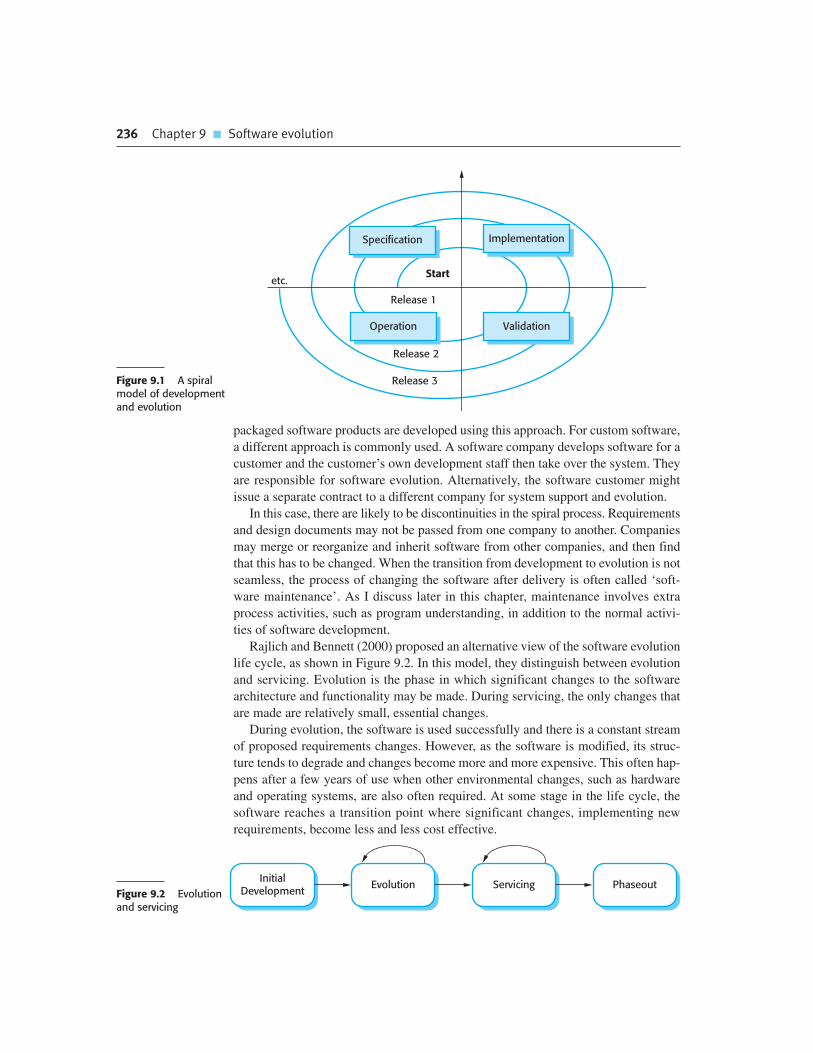
236 Chapter 9 � Software evolution
packaged software products are developed using this approach. For custom software,
a different approach is commonly used. A software company develops software for a
customer and the customer’s own development staff then take over the system. They
are responsible for software evolution. Alternatively, the software customer might
issue a separate contract to a different company for system support and evolution.
In this case, there are likely to be discontinuities in the spiral process. Requirements
and design documents may not be passed from one company to another. Companies
may merge or reorganize and inherit software from other companies, and then find
that this has to be changed. When the transition from development to evolution is not
seamless, the process of changing the software after delivery is often called ‘soft-
ware maintenance’. As I discuss later in this chapter, maintenance involves extra
process activities, such as program understanding, in addition to the normal activi-
ties of software development.
Rajlich and Bennett (2000) proposed an alternative view of the software evolution
life cycle, as shown in Figure 9.2. In this model, they distinguish between evolution
and servicing. Evolution is the phase in which significant changes to the software
architecture and functionality may be made. During servicing, the only changes that
are made are relatively small, essential changes.
During evolution, the software is used successfully and there is a constant stream
of proposed requirements changes. However, as the software is modified, its struc-
ture tends to degrade and changes become more and more expensive. This often hap-
pens after a few years of use when other environmental changes, such as hardware
and operating systems, are also often required. At some stage in the life cycle, the
software reaches a transition point where significant changes, implementing new
requirements, become less and less cost effective.
InitialDevelopment
Evolution Servicing PhaseoutFigure 9.2 Evolutionand servicing
Specification Implementation
ValidationOperation
Start
Release 1
Release 2
Release 3
etc.
Figure 9.1 A spiralmodel of developmentand evolution

9.1 � Evolution processes 237
At that stage, the software moves from evolution to servicing. During the servic-
ing phase, the software is still useful and used but only small tactical changes are
made to it. During this stage, the company is usually considering how the software
can be replaced. In the final stage, phase-out, the software may still be used but no
further changes are being implemented. Users have to work around any problems
that they discover.
9.1 Evolution processes
Software evolution processes vary depending on the type of software being main-
tained, the development processes used in an organization and the skills of the peo-
ple involved. In some organizations, evolution may be an informal process where
change requests mostly come from conversations between the system users and
developers. In other companies, it is a formalized process with structured documen-
tation produced at each stage in the process.
System change proposals are the driver for system evolution in all organizations.
Change proposals may come from existing requirements that have not been imple-
mented in the released system, requests for new requirements, bug reports from system
stakeholders, and new ideas for software improvement from the system development
team. The processes of change identification and system evolution are cyclic and
continue throughout the lifetime of a system (Figure 9.3).
Change proposals should be linked to the components of the system that have to
be modified to implement these proposals. This allows the cost and the impact of the
change to be assessed. This is part of the general process of change management,
which also should ensure that the correct versions of components are included in
each system release. I cover change and configuration management in Chapter 25.
Software EvolutionProcess
Change ProposalsNew System
Change IdentificationProcess
Figure 9.3 Changeidentification andevolution processes

238 Chapter 9 � Software evolution
ReleasePlanning
ChangeImplementation
SystemRelease
ImpactAnalysis
ChangeRequests
PlatformAdaptation
SystemEnhancement
Fault Repair
Figure 9.4 Thesoftware evolutionprocess
Figure 9.4, adapted from Arthur (1988), shows an overview of the evolution process.
The process includes the fundamental activities of change analysis, release planning,
system implementation, and releasing a system to customers. The cost and impact of
these changes are assessed to see how much of the system is affected by the change and
how much it might cost to implement the change. If the proposed changes are accepted,
a new release of the system is planned. During release planning, all proposed changes
(fault repair, adaptation, and new functionality) are considered. A decision is then made
on which changes to implement in the next version of the system. The changes are
implemented and validated, and a new version of the system is released. The process
then iterates with a new set of changes proposed for the next release.
You can think of change implementation as an iteration of the development
process, where the revisions to the system are designed, implemented, and tested.
However, a critical difference is that the first stage of change implementation may
involve program understanding, especially if the original system developers are not
responsible for change implementation. During this program understanding phase,
you have to understand how the program is structured, how it delivers functionality,
and how the proposed change might affect the program. You need this understanding
to make sure that the implemented change does not cause new problems when it is
introduced into the existing system.
Ideally, the change implementation stage of this process should modify the sys-
tem specification, design, and implementation to reflect the changes to the system
(Figure 9.5). New requirements that reflect the system changes are proposed, ana-
lyzed, and validated. System components are redesigned and implemented and the
system is retested. If appropriate, prototyping of the proposed changes may be car-
ried out as part of the change analysis process.
During the evolution process, the requirements are analyzed in detail and implica-
tions of the changes emerge that were not apparent in the earlier change analysis
process. This means that the proposed changes may be modified and further cus-
tomer discussions may be required before they are implemented.
Change requests sometimes relate to system problems that have to be tackled
urgently. These urgent changes can arise for three reasons:
1. If a serious system fault occurs that has to be repaired to allow normal operation
to continue.

9.1 � Evolution processes 239
2. If changes to the systems operating environment have unexpected effects that
disrupt normal operation.
3. If there are unanticipated changes to the business running the system, such as
the emergence of new competitors or the introduction of new legislation that
affects the system.
In these cases, the need to make the change quickly means that you may not be
able to follow the formal change analysis process. Rather than modify the require-
ments and design, you make an emergency fix to the program to solve the immedi-
ate problem (Figure 9.6). However, the danger is that the requirements, the software
design, and the code become inconsistent. Although you may intend to document
the change in the requirements and design, additional emergency fixes to the soft-
ware may then be needed. These take priority over documentation. Eventually, the
original change is forgotten and the system documentation and code are never
realigned.
Emergency system repairs usually have to be completed as quickly as possible.
You chose a quick and workable solution rather than the best solution as far as sys-
tem structure is concerned. This accelerates the process of software ageing so that
future changes become progressively more difficult and maintenance costs increase.
Ideally, when emergency code repairs are made the change request should remain
outstanding after the code faults have been fixed. It can then be reimplemented more
carefully after further analysis. Of course, the code of the repair may be reused. An
alternative, better solution to the problem may be discovered when more time is
available for analysis. In practice, however, it is almost inevitable that these improve-
ments will have a low priority. They are often forgotten and, if further system
changes are made, it then becomes unrealistic to redo the emergency repairs.
Agile methods and processes, discussed in Chapter 3, may be used for program
evolution as well as program development. In fact, because these methods are based
on incremental development, making the transition from agile development to post-
delivery evolution should be seamless. Techniques such as automated regression testing
are useful when system changes are made. Changes may be expressed as user stories
and customer involvement can prioritize changes that are required in an operational
system. In short, evolution simply involves continuing the agile development process.
RequirementsUpdating
SoftwareDevelopment
RequirementsAnalysis
ProposedChangesFigure 9.5 Change
implementation
ModifySource Code
Deliver ModifiedSystem
AnalyzeSource Code
ChangeRequests
Figure 9.6 Theemergency repairprocess

240 Chapter 9 � Software evolution
However, problems may arise in situations in which there is a handover from a
development team to a separate team responsible for evolution. There are two poten-
tially problematic situations:
1. Where the development team has used an agile approach but the evolution team
is unfamiliar with agile methods and prefers a plan-based approach. The evolu-
tion team may expect detailed documentation to support evolution and this is
rarely produced in agile processes. There may be no definitive statement of the
system requirements that can be modified as changes are made to the system.
2. Where a plan-based approach has been used for development but the evolution
team prefers to use agile methods. In this case, the evolution team may have to
start from scratch developing automated tests and the code in the system may
not have been refactored and simplified as is expected in agile development. In
this case, some reengineering may be required to improve the code before it can
be used in an agile development process.
Poole and Huisman (2001) report on their experiences in using Extreme Programming
for maintaining a large system that was originally developed using a plan-based
approach. After reengineering the system to improve its structure, XP was used very
successfully in the maintenance process.
9.2 Program evolution dynamics
Program evolution dynamics is the study of system change. In the 1970s and 1980s,
Lehman and Belady (1985) carried out several empirical studies of system change
with a view to understanding more about characteristics of software evolution. The
work continued in the 1990s as Lehman and others investigated the significance of
feedback in evolution processes (Lehman, 1996; Lehman et al., 1998; Lehman et al.,
2001). From these studies, they proposed ‘Lehman’s laws’ concerning system change
(Figure 9.7).
Lehman and Belady claim these laws are likely to be true for all types of large
organizational software systems (what they call E-type systems). These are systems
in which the requirements are changing to reflect changing business needs. New
releases of the system are essential for the system to provide business value.
The first law states that system maintenance is an inevitable process. As the sys-
tem’s environment changes, new requirements emerge and the system must be mod-
ified. When the modified system is reintroduced to the environment, this promotes
more environmental changes, so the evolution process starts again.
The second law states that, as a system is changed, its structure is degraded. The only
way to avoid this happening is to invest in preventative maintenance. You spend time
improving the software structure without adding to its functionality. Obviously, this
means additional costs, over and above those of implementing required system changes.

9.2 � Program evolution dynamics 241
The third law is, perhaps, the most interesting and the most contentious of
Lehman’s laws. It suggests that large systems have a dynamic of their own that is
established at an early stage in the development process. This determines the gross
trends of the system maintenance process and limits the number of possible system
changes. Lehman and Belady suggest that this law is a consequence of structural fac-
tors that influence and constrain system change, and organizational factors that
affect the evolution process.
The structural factors that affect the third law come from the complexity of large
systems. As you change and extend a program, its structure tends to degrade. This is
true of all types of system (not just software) and it occurs because you are adapting
a structure intended for one purpose for a different purpose. This degradation, if
unchecked, makes it more and more difficult to make further changes to the pro-
gram. Making small changes reduces the extent of structural degradation and so
lessens the risks of causing serious system dependability problems. If you try and
make large changes, there is a high probability that these will introduce new faults.
These then inhibit further program changes.
The organizational factors that affect the third law reflect the fact that large sys-
tems are usually produced by large organizations. These companies have internal
bureaucracies that set the change budget for each system and control the decision-
making process. Companies have to make decisions on the risks and value of the
Figure 9.7 Lehman’slaws
Law Description
Continuing change A program that is used in a real-world environment must necessarilychange, or else become progressively less useful in that environment.
Increasing complexity As an evolving program changes, its structure tends to become morecomplex. Extra resources must be devoted to preserving and simplifyingthe structure.
Large program evolution Program evolution is a self-regulating process. System attributes suchas size, time between releases, and the number of reported errors isapproximately invariant for each system release.
Organizational stability Over a program’s lifetime, its rate of development is approximately constantand independent of the resources devoted to system development.
Conservation of familiarity Over the lifetime of a system, the incremental change in each release isapproximately constant.
Continuing growth The functionality offered by systems has to continually increase tomaintain user satisfaction.
Declining quality The quality of systems will decline unless they are modified to reflectchanges in their operational environment.
Feedback system Evolution processes incorporate multiagent, multiloop feedback systemsand you have to treat them as feedback systems to achieve significantproduct improvement.

242 Chapter 9 � Software evolution
changes and the costs involved. Such decisions take time to make and, sometimes, it
takes longer to decide on the changes to be made than change implementation. The
speed of the organization’s decision-making processes therefore governs the rate of
change of the system.
Lehman’s fourth law suggests that most large programming projects work in a
‘saturated’ state. That is, a change to resources or staffing has imperceptible effects
on the long-term evolution of the system. This is consistent with the third law, which
suggests that program evolution is largely independent of management decisions.
This law confirms that large software development teams are often unproductive
because communication overheads dominate the work of the team.
Lehman’s fifth law is concerned with the change increments in each system
release. Adding new functionality to a system inevitably introduces new system
faults. The more functionality added in each release, the more faults there will be.
Therefore, a large increment in functionality in one system release means that this
will have to be followed by a further release in which the new system faults are
repaired. Relatively little new functionality should be included in this release. This
law suggests that you should not budget for large functionality increments in each
release without taking into account the need for fault repair.
The first five laws were in Lehman’s initial proposals; the remaining laws were
added after further work. The sixth and seventh laws are similar and essentially say
that users of software will become increasingly unhappy with it unless it is main-
tained and new functionality is added to it. The final law reflects the most recent
work on feedback processes, although it is not yet clear how this can be applied in
practical software development.
Lehman’s observations seem generally sensible. They should be taken into
account when planning the maintenance process. It may be that business considera-
tions require them to be ignored at any one time. For example, for marketing rea-
sons, it may be necessary to make several major system changes in a single release.
The likely consequences of this are that one or more releases devoted to error repair
are likely to be required. You often see this in personal computer software when a
major new release of an application is often quickly followed by a bug repair update.
9.3 Software maintenance
Software maintenance is the general process of changing a system after it has been
delivered. The term is usually applied to custom software in which separate develop-
ment groups are involved before and after delivery. The changes made to the software
may be simple changes to correct coding errors, more extensive changes to correct
design errors, or significant enhancements to correct specification errors or accom-
modate new requirements. Changes are implemented by modifying existing system
components and, where necessary, by adding new components to the system.
There are three different types of software maintenance:

9.3 � Software maintenance 243
1. Fault repairs Coding errors are usually relatively cheap to correct; design errors
are more expensive as they may involve rewriting several program components.
Requirements errors are the most expensive to repair because of the extensive
system redesign which may be necessary.
2. Environmental adaptation This type of maintenance is required when some
aspect of the system’s environment such as the hardware, the platform operating
system, or other support software changes. The application system must be
modified to adapt it to cope with these environmental changes.
3. Functionality addition This type of maintenance is necessary when the system
requirements change in response to organizational or business change. The scale
of the changes required to the software is often much greater than for the other
types of maintenance.
In practice, there is not a clear-cut distinction between these types of mainte-
nance. When you adapt the system to a new environment, you may add functionality
to take advantage of new environmental features. Software faults are often exposed
because users use the system in unanticipated ways. Changing the system to accom-
modate their way of working is the best way to fix these faults.
These types of maintenance are generally recognized but different people some-
times give them different names. ‘Corrective maintenance’ is universally used to
refer to maintenance for fault repair. However, ‘adaptive maintenance’ sometimes
means adapting to a new environment and sometimes means adapting the software to
new requirements. ‘Perfective maintenance’ sometimes means perfecting the soft-
ware by implementing new requirements; in other cases it means maintaining the
functionality of the system but improving its structure and its performance. Because
of this naming uncertainty, I have avoided the use of all of these terms in this chapter.
There have been several studies of software maintenance which have looked at
the relationships between maintenance and development and between different
maintenance activities (Krogstie et al., 2005; Lientz and Swanson, 1980; Nosek and
Palvia, 1990; Sousa, 1998). Because of differences in terminology, the details of
these studies cannot be compared. In spite of changes in technology and different
application domains, it seems that there has been remarkably little change in the dis-
tribution of evolution effort since the 1980s.
The surveys broadly agree that software maintenance takes up a higher proportion
of IT budgets than new development (roughly two-thirds maintenance, one-third
development). They also agree that more of the maintenance budget is spent on
implementing new requirements than on fixing bugs. Figure 9.8 shows an approxi-
mate distribution of maintenance costs. The specific percentages will obviously vary
from one organization to another but, universally, repairing system faults is not the
most expensive maintenance activity. Evolving the system to cope with new environ-
ments and new or changed requirements consumes most maintenance effort.
The relative costs of maintenance and new development vary from one applica-
tion domain to another. Guimaraes (1983) found that the maintenance costs for busi-
ness application systems are broadly comparable with system development costs.

244 Chapter 9 � Software evolution
For embedded real-time systems, maintenance costs were up to four times more than
development costs. The high reliability and performance requirements of these sys-
tems mean that modules have to be tightly linked and hence difficult to change.
Although these estimates are more than 25 years old, it is unlikely that the cost dis-
tributions for different types of system have significantly changed.
It is usually cost effective to invest effort in designing and implementing a system to
reduce the costs of future changes. Adding new functionality after delivery is expensive
because you have to spend time learning the system and analyzing the impact of the pro-
posed changes. Therefore, work done during development to make the software easier
to understand and change is likely to reduce evolution costs. Good software engineering
techniques, such as precise specification, the use of object-oriented development, and
configuration management, contribute to maintenance cost reduction.
Figure 9.9 shows how overall lifetime costs may decrease as more effort is
expended during system development to produce a maintainable system. Because of
the potential reduction in costs of understanding, analysis, and testing, there is a sig-
nificant multiplier effect when the system is developed for maintainability. For
System 1, extra development costs of $25,000 are invested in making the system
more maintainable. This results in a savings of $100,000 in maintenance costs over
FunctionalityAddition orModification
(65%)
Fault Repair(17%)
EnvironmentalAdaptation
(18%)
Figure 9.8Maintenance effortdistribution
0 50 100 150 200 250 300 350 400 450 500
System 1
System 2
Development Costs Maintenance Costs
$Figure 9.9Development andmaintenance costs

9.3 � Software maintenance 245
Legacy systems
Legacy systems are old systems that are still useful and are sometimes critical to business operation. They maybe implemented using outdated languages and technology or may use other systems that are expensive tomaintain. Often their structure has been degraded by change and documentation is missing or out of date.Nevertheless, it may not be cost effective to replace these systems. They may only be used at certain timesof the year or it may be too risky to replace them because the specification has been lost.
http://www.SoftwareEngineering-9.com/Web/LegacySys/
the lifetime of the system. This assumes that a percentage increase in development
costs results in a comparable percentage decrease in overall system costs.
These estimates are hypothetical but there is no doubt that developing software to
make it more maintainable is cost effective, when the whole life costs of the software
are taken into account. This is the rationale for refactoring in agile development.
Without refactoring, the code becomes more and more difficult and expensive to
change. However, in plan-based development, the reality is that additional invest-
ment in code improvement is rarely made during development. This is mostly due to
the ways most organizations run their budgets. Investing in maintainability leads to
short-term cost increases, which are measurable. Unfortunately, the long-term gains
can’t be measured at the same time so companies are reluctant to spend money for an
unknown future return.
It is usually more expensive to add functionality after a system is in operation than
it is to implement the same functionality during development. The reasons for this are:
1. Team stability After a system has been delivered, it is normal for the develop-
ment team to be broken up and for people to work on new projects. The new
team or the individuals responsible for system maintenance do not understand
the system or the background to system design decisions. They need to spend
time understanding the existing system before implementing changes to it.
2. Poor development practice The contract to maintain a system is usually separate
from the system development contract. The maintenance contract may be given
to a different company rather than the original system developer. This factor,
along with the lack of team stability, means that there is no incentive for a devel-
opment team to write maintainable software. If a development team can cut cor-
ners to save effort during development it is worthwhile for them to do so, even if
this means that the software is more difficult to change in the future.
3. Staff skills Maintenance staff are often relatively inexperienced and unfamiliar with
the application domain. Maintenance has a poor image among software engineers.
It is seen as a less-skilled process than system development and is often allocated to
the most junior staff. Furthermore, old systems may be written in obsolete program-
ming languages. The maintenance staff may not have much experience of develop-
ment in these languages and must learn these languages to maintain the system.

246 Chapter 9 � Software evolution
Documentation
System documentation can help the maintenance process by providing maintainers with information about thestructure and organization of the system and the features that it offers to system users. Although proponents ofagile approaches such as XP suggest that the code should be the principal documentation, higher-level designmodels and information about dependencies and constraints can make it easier to understand and makechanges to the code.
I have written a separate chapter on documentation that you can download.
http://www.SoftwareEngineering-9.com/Web/ExtraChaps/Documentation.pdf
4. Program age and structure As changes are made to programs, their structure
tends to degrade. Consequently, as programs age, they become harder to under-
stand and change. Some systems have been developed without modern software
engineering techniques. They may never have been well structured and were
perhaps optimized for efficiency rather than understandability. System docu-
mentation may be lost or inconsistent. Old systems may not have been subject to
stringent configuration management so time is often wasted finding the right
versions of system components to change.
The first three of these problems stem from the fact that many organizations still
consider development and maintenance to be separate activities. Maintenance is seen
as a second-class activity and there is no incentive to spend money during development
to reduce the costs of system change. The only long-term solution to this problem is to
accept that systems rarely have a defined lifetime but continue in use, in some form,
for an indefinite period. As I suggested in the introduction, you should think of sys-
tems as evolving throughout their lifetime through a continual development process.
The fourth issue, the problem of degraded system structure, is the easiest problem
to address. Software reengineering techniques (described later in this chapter) may
be applied to improve the system structure and understandability. Architectural
transformations can adapt the system to new hardware. Refactoring can improve the
quality of the system code and make it easier to change.
9.3.1 Maintenance prediction
Managers hate surprises, especially if these result in unexpectedly high costs. You
should therefore try to predict what system changes might be proposed and what
parts of the system are likely to be the most difficult to maintain. You should also
try to estimate the overall maintenance costs for a system in a given time period.
Figure 9.10 shows these predictions and associated questions.
Predicting the number of change requests for a system requires an understanding
of the relationship between the system and its external environment. Some systems
have a very complex relationship with their external environment and changes to that

9.3 � Software maintenance 247
environment inevitably result in changes to the system. To evaluate the relationships
between a system and its environment, you should assess:
1. The number and complexity of system interfaces The larger the number of inter-
faces and the more complex these interfaces, the more likely it is that interface
changes will be required as new requirements are proposed.
2. The number of inherently volatile system requirements As I discussed in Chapter 4,
requirements that reflect organizational policies and procedures are likely to be
more volatile than requirements that are based on stable domain characteristics.
3. The business processes in which the system is used As business processes
evolve, they generate system change requests. The more business processes that
use a system, the more the demands for system change.
For many years, researchers have looked at the relationships between program com-
plexity, as measured by metrics such as cyclomatic complexity (McCabe, 1976), and
maintainability (Banker et al., 1993; Coleman et al., 1994; Kafura and Reddy, 1987;
Kozlov et al., 2008). It is not surprising that these studies have found that the more
complex a system or component, the more expensive it is to maintain. Complexity
measurements are particularly useful in identifying program components that are
likely to be expensive to maintain. Kafura and Reddy (1987) examined a number of
system components and found that maintenance effort tended to be focused on a small
number of complex components. To reduce maintenance costs, therefore, you should
try to replace complex system components with simpler alternatives.
After a system has been put into service, you may be able to use process data to
help predict maintainability. Examples of process metrics that can be used for
assessing maintainability are as follows:
PredictingMaintainability
Predicting SystemChanges
PredictingMaintenance
Costs
What will be the lifetimemaintenance costs of this
system?
What will be the costs ofmaintaining this system
over the next year?
What parts of the systemwill be the most expensive
to maintain?
How many changerequests can be
expected?
What parts of the system aremost likely to be affected by
change requests?
Figure 9.10Maintenance prediction
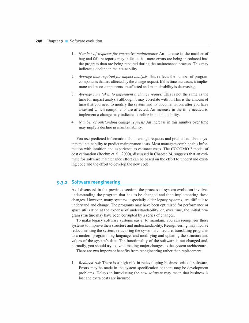
248 Chapter 9 � Software evolution
1. Number of requests for corrective maintenance An increase in the number of
bug and failure reports may indicate that more errors are being introduced into
the program than are being repaired during the maintenance process. This may
indicate a decline in maintainability.
2. Average time required for impact analysis This reflects the number of program
components that are affected by the change request. If this time increases, it implies
more and more components are affected and maintainability is decreasing.
3. Average time taken to implement a change request This is not the same as the
time for impact analysis although it may correlate with it. This is the amount of
time that you need to modify the system and its documentation, after you have
assessed which components are affected. An increase in the time needed to
implement a change may indicate a decline in maintainability.
4. Number of outstanding change requests An increase in this number over time
may imply a decline in maintainability.
You use predicted information about change requests and predictions about sys-
tem maintainability to predict maintenance costs. Most managers combine this infor-
mation with intuition and experience to estimate costs. The COCOMO 2 model of
cost estimation (Boehm et al., 2000), discussed in Chapter 24, suggests that an esti-
mate for software maintenance effort can be based on the effort to understand exist-
ing code and the effort to develop the new code.
9.3.2 Software reengineering
As I discussed in the previous section, the process of system evolution involves
understanding the program that has to be changed and then implementing these
changes. However, many systems, especially older legacy systems, are difficult to
understand and change. The programs may have been optimized for performance or
space utilization at the expense of understandability, or, over time, the initial pro-
gram structure may have been corrupted by a series of changes.
To make legacy software systems easier to maintain, you can reengineer these
systems to improve their structure and understandability. Reengineering may involve
redocumenting the system, refactoring the system architecture, translating programs
to a modern programming language, and modifying and updating the structure and
values of the system’s data. The functionality of the software is not changed and,
normally, you should try to avoid making major changes to the system architecture.
There are two important benefits from reengineering rather than replacement:
1. Reduced risk There is a high risk in redeveloping business-critical software.
Errors may be made in the system specification or there may be development
problems. Delays in introducing the new software may mean that business is
lost and extra costs are incurred.

9.3 � Software maintenance 249
2. Reduced cost The cost of reengineering may be significantly less than the cost
of developing new software. Ulrich (1990) quotes an example of a commercial
system for which the reimplementation costs were estimated at $50 million. The
system was successfully reengineered for $12 million. I suspect that, with mod-
ern software technology, the relative cost of reimplementation is probably less
than this but will still considerably exceed the costs of reengineering.
Figure 9.11 is a general model of the reengineering process. The input to the
process is a legacy program and the output is an improved and restructured version
of the same program. The activities in this reengineering process are as follows:
1. Source code translation Using a translation tool, the program is converted from
an old programming language to a more modern version of the same language
or to a different language.
2. Reverse engineering The program is analyzed and information extracted from it.
This helps to document its organization and functionality. Again, this process is
usually completely automated.
3. Program structure improvement The control structure of the program is ana-
lyzed and modified to make it easier to read and understand. This can be par-
tially automated but some manual intervention is usually required.
4. Program modularization Related parts of the program are grouped together and,
where appropriate, redundancy is removed. In some cases, this stage may
involve architectural refactoring (e.g., a system that uses several different data
stores may be refactored to use a single repository). This is a manual process.
5. Data reengineering The data processed by the program is changed to reflect
program changes. This may mean redefining database schemas and converting
existing databases to the new structure. You should usually also clean up the
ReverseEngineering
ProgramDocumentation
ProgramStructure
Improvement
ProgramModularization
RestructuredProgram
DataReengineering
ReengineeredData
Original DataReengineered
ProgramOriginalProgram
Source CodeTranslation
Figure 9.11 Thereengineering process

250 Chapter 9 � Software evolution
data. This involves finding and correcting mistakes, removing duplicate records,
etc. Tools are available to support data reengineering.
Program reengineering may not necessarily require all of the steps in Figure 9.11.
You don’t need source code translation if you still use the application’s programming
language. If you can do all reengineering automatically, then recovering documenta-
tion through reverse engineering may be unnecessary. Data reengineering is only
required if the data structures in the program change during system reengineering.
To make the reengineered system interoperate with the new software, you may
have to develop adaptor services, as discussed in Chapter 19. These hide the original
interfaces of the software system and present new, better-structured interfaces that
can be used by other components. This process of legacy system wrapping is an
important technique for developing large-scale reusable services.
The costs of reengineering obviously depend on the extent of the work that is
carried out. There is a spectrum of possible approaches to reengineering, as shown
in Figure 9.12. Costs increase from left to right so that source code translation is
the cheapest option. Reengineering as part of architectural migration is the most
expensive.
The problem with software reengineering is that there are practical limits to how
much you can improve a system by reengineering. It isn’t possible, for example, to con-
vert a system written using a functional approach to an object-oriented system. Major
architectural changes or radical reorganizing of the system data management cannot be
carried out automatically, so they are very expensive. Although reengineering can
improve maintainability, the reengineered system will probably not be as maintainable
as a new system developed using modern software engineering methods.
9.3.3 Preventative maintenance by refactoring
Refactoring is the process of making improvements to a program to slow down degra-
dation through change (Opdyke and Johnson, 1990). It means modifying a program to
improve its structure, to reduce its complexity, or to make it easier to understand.
Refactoring is sometimes considered to be limited to object-oriented development but
the principles can be applied to any development approach. When you refactor a pro-
gram, you should not add functionality but should concentrate on program improve-
ment. You can therefore think of refactoring as ‘preventative maintenance’ that reduces
the problems of future change.
Automated Restructuringwith Manual Changes
Automated SourceCode Conversion
Restructuring PlusArchitectural Changes
Automated ProgramRestructuring
Program and DataRestructuring
Increased Cost
Figure 9.12Reengineering approaches

9.3 � Software maintenance 251
Although reengineering and refactoring are both intended to make software easier
to understand and change, they are not the same thing. Reengineering takes place
after a system has been maintained for some time and maintenance costs are increas-
ing. You use automated tools to process and reengineer a legacy system to create a
new system that is more maintainable. Refactoring is a continuous process of
improvement throughout the development and evolution process. It is intended to
avoid the structure and code degradation that increases the costs and difficulties of
maintaining a system.
Refactoring is an inherent part of agile methods such as extreme programming
because these methods are based around change. Program quality is therefore liable to
degrade quickly so agile developers frequently refactor their programs to avoid this
degradation. The emphasis on regression testing in agile methods lowers the risk of
introducing new errors through refactoring. Any errors that are introduced should be
detectable as previously successful tests should then fail. However, refactoring is not
dependent on other ‘agile activities’ and can be used with any approach to development.
Fowler et al. (1999) suggest that there are stereotypical situations (he calls them
‘bad smells’) in which the code of a program can be improved. Examples of bad
smells that can be improved through refactoring include:
1. Duplicate code The same of very similar code may be included at different
places in a program. This can be removed and implemented as a single method
or function that is called as required.
2. Long methods If a method is too long, it should be redesigned as a number of
shorter methods.
3. Switch (case) statements These often involve duplication, where the switch
depends on the type of some value. The switch statements may be scattered
around a program. In object-oriented languages, you can often use polymor-
phism to achieve the same thing.
4. Data clumping Data clumps occur when the same group of data items (fields in
classes, parameters in methods) reoccur in several places in a program. These
can often be replaced with an object encapsulating all of the data.
5. Speculative generality This occurs when developers include generality in a
program in case it is required in future. This can often simply be removed.
Fowler, in his book and website, also suggests some primitive refactoring trans-
formations that can be used singly or together to deal with the bad smells. Examples
of these transformations include Extract method, where you remove duplication and
create a new method; Consolidate conditional expression, where you replace a
sequence of tests with a single test; and Pull up method, where you replace similar
methods in subclasses with a single method in a super class. Interactive development
environments, such as Eclipse, include refactoring support in their editors. This
makes it easier to find dependent parts of a program that have to be changed to
implement the refactoring.

252 Chapter 9 � Software evolution
Refactoring, carried out during program development, is an effective way to
reduce the long-term maintenance costs of a program. However, if you take over a
program for maintenance whose structure has been significantly degraded, then it
may be practically impossible to refactor the code alone. You may also have to think
about design refactoring, which is likely to be a more expensive and difficult prob-
lem. Design refactoring involves identifying relevant design patterns (discussed in
Chapter 7) and replacing existing code with code that implements these design pat-
terns (Kerievsky, 2004). I don’t have space to discuss this here.
9.4 Legacy system management
For new software systems developed using modern software engineering processes,
such as incremental development and CBSE, it is possible to plan how to integrate
system development and evolution. More and more companies are starting to under-
stand that the system development process is a whole life-cycle process and that an
artificial separation between software development and software maintenance is
unhelpful. However, there are still many legacy systems that are critical business sys-
tems. These have to be extended and adapted to changing e-business practices.
Most organizations usually have a portfolio of legacy systems that they use, with
a limited budget for maintaining and upgrading these systems. They have to decide
how to get the best return on their investment. This involves making a realistic
assessment of their legacy systems and then deciding on the most appropriate strat-
egy for evolving these systems. There are four strategic options:
1. Scrap the system completely This option should be chosen when the system is
not making an effective contribution to business processes. This commonly
occurs when business processes have changed since the system was installed
and are no longer reliant on the legacy system.
2. Leave the system unchanged and continue with regular maintenance This
option should be chosen when the system is still required but is fairly stable and
the system users make relatively few change requests.
3. Reengineer the system to improve its maintainability This option should be
chosen when the system quality has been degraded by change and where a new
change to the system is still being proposed. This process may include develop-
ing new interface components so that the original system can work with other,
newer systems.
4. Replace all or part of the system with a new system This option should be cho-
sen when factors, such as new hardware, mean that the old system cannot con-
tinue in operation or where off-the-shelf systems would allow the new system to
be developed at a reasonable cost. In many cases, an evolutionary replacement
strategy can be adopted in which major system components are replaced by off-
the-shelf systems with other components reused wherever possible.

9.4 � Legacy system management 253
Naturally, these options are not exclusive. When a system is composed of several
programs, different options may be applied to each program.
When you are assessing a legacy system, you have to look at it from a business
perspective and a technical perspective (Warren, 1998). From a business perspective,
you have to decide whether or not the business really needs the system. From a tech-
nical perspective, you have to assess the quality of the application software and the
system’s support software and hardware. You then use a combination of the business
value and the system quality to inform your decision on what to do with the legacy
system.
For example, assume that an organization has 10 legacy systems. You should
assess the quality and the business value of each of these systems. You may then cre-
ate a chart showing relative business value and system quality. This is shown in
Figure 9.13.
From Figure 9.13, you can see that there are four clusters of systems:
1. Low quality, low business value Keeping these systems in operation will be
expensive and the rate of the return to the business will be fairly small. These
systems should be scrapped.
2. Low quality, high business value These systems are making an important busi-
ness contribution so they cannot be scrapped. However, their low quality means
that it is expensive to maintain them. These systems should be reengineered to
improve their quality. They may be replaced, if a suitable off-the-shelf system is
available.
3. High quality, low business value These are systems that don’t contribute much
to the business but which may not be very expensive to maintain. It is not worth
replacing these systems so normal system maintenance may be continued if
expensive changes are not required and the system hardware remains in use.
If expensive changes become necessary, the software should be scrapped.
12
3 45
6
7
89
10
System Quality
Busi
ness
Val
ue
High Business ValueLow Quality High Business Value
High Quality
Low Business ValueLow Quality
Low Business ValueHigh Quality
Figure 9.13 Anexample of a legacysystem assessment

254 Chapter 9 � Software evolution
4. High quality, high business value These systems have to be kept in operation.
However, their high quality means that you don’t have to invest in transforma-
tion or system replacement. Normal system maintenance should be continued.
To assess the business value of a system, you have to identify system stakehold-
ers, such as end-users of the system and their managers, and ask a series of questions
about the system. There are four basic issues that you have to discuss:
1. The use of the system If systems are only used occasionally or by a small num-
ber of people, they may have a low business value. A legacy system may have
been developed to meet a business need that has either changed or that can now
be met more effectively in other ways. You have to be careful, however, about
occasional but important use of systems. For example, in a university, a student
registration system may only be used at the beginning of each academic year.
However, it is an essential system with a high business value.
2. The business processes that are supported When a system is introduced, busi-
ness processes are designed to exploit the system’s capabilities. If the system is
inflexible, changing these business processes may be impossible. However, as
the environment changes, the original business processes may become obsolete.
Therefore, a system may have a low business value because it forces the use of
inefficient business processes.
3. The system dependability System dependability is not only a technical problem
but also a business problem. If a system is not dependable and the problems
directly affect the business customers or mean that people in the business are
diverted from other tasks to solve these problems, the system has a low business
value.
4. The system outputs The key issue here is the importance of the system outputs to
the successful functioning of the business. If the business depends on these out-
puts, then the system has a high business value. Conversely, if these outputs can
be easily generated in some other way or if the system produces outputs that are
rarely used, then its business value may be low.
For example, let’s assume that a company provides a travel ordering system that
is used by staff responsible for arranging travel. They can place orders with an
approved travel agent. Tickets are then delivered and the company is invoiced for
these. However, a business value assessment may reveal that this system is only used
for a fairly small percentage of travel orders placed. People making travel arrange-
ments find it cheaper and more convenient to deal directly with travel suppliers
through their websites. This system may still be used, but there is no real point in
keeping it. The same functionality is available from external systems.
Conversely, say a company has developed a system that keeps track of all previ-
ous customer orders and automatically generates reminders for customers to reorder
goods. This results in a large number of repeat orders and keeps customers satisfied

9.4 � Legacy system management 255
because they feel that their supplier is aware of their needs. The outputs from such a
system are very important to the business and this system therefore has a high
business value.
To assess a software system from a technical perspective, you need to consider
both the application system itself and the environment in which the system operates.
The environment includes the hardware and all associated support software (compil-
ers, development environments, etc.) that are required to maintain the system. The
environment is important because many system changes result from changes to the
environment, such as upgrades to the hardware or operating system.
If possible, in the process of environmental assessment, you should make meas-
urements of the system and its maintenance processes. Examples of data that may be
useful include the costs of maintaining the system hardware and support software,
the number of hardware faults that occur over some time period and the frequency of
patches and fixes applied to the system support software.
Factors that you should consider during the environment assessment are shown in
Figure 9.14. Notice that these are not all technical characteristics of the environment.
You also have to consider the reliability of the suppliers of the hardware and support
software. If these suppliers are no longer in business, there may not be support for
their systems.
To assess the technical quality of an application system, you have to assess a
range of factors (Figure 9.15) that are primarily related to the system dependability,
Figure 9.14 Factorsused in environmentassessment
Factor Questions
Supplier stability Is the supplier still in existence? Is the supplier financially stable and likely tocontinue in existence? If the supplier is no longer in business, does someone elsemaintain the systems?
Failure rate Does the hardware have a high rate of reported failures? Does the supportsoftware crash and force system restarts?
Age How old is the hardware and software? The older the hardware and support software,the more obsolete it will be. It may still function correctly but there could be significanteconomic and business benefits to moving to a more modern system.
Performance Is the performance of the system adequate? Do performance problems have asignificant effect on system users?
Support requirements What local support is required by the hardware and software? If there are highcosts associated with this support, it may be worth considering systemreplacement.
Maintenance costs What are the costs of hardware maintenance and support software licences? Olderhardware may have higher maintenance costs than modern systems. Supportsoftware may have high annual licensing costs.
Interoperability Are there problems interfacing the system to other systems? Can compilers, forexample, be used with current versions of the operating system? Is hardwareemulation required?

256 Chapter 9 � Software evolution
the difficulties of maintaining the system and the system documentation. You may
also collect data that will help you judge the quality of the system. Data that may be
useful in quality assessment are:
1. The number of system change requests System changes usually corrupt the sys-
tem structure and make further changes more difficult. The higher this accumu-
lated value, the lower the quality of the system.
2. The number of user interfaces This is an important factor in forms-based sys-
tems where each form can be considered as a separate user interface. The more
interfaces, the more likely that there will be inconsistencies and redundancies in
these interfaces.
3. The volume of data used by the system The higher the volume of data (number
of files, size of database, etc.), the more likely that it is that there will be data
inconsistencies that reduce the system quality.
Ideally, objective assessment should be used to inform decisions about what to do
with a legacy system. However, in many cases, decisions are not really objective but
are based on organizational or political considerations. For example, if two businesses
merge, the most politically powerful partner will usually keep its systems and scrap
Figure 9.15 Factorsused in applicationassessment
Factor Questions
Understandability How difficult is it to understand the source code of the current system? Howcomplex are the control structures that are used? Do variables havemeaningful names that reflect their function?
Documentation What system documentation is available? Is the documentation complete,consistent, and current?
Data Is there an explicit data model for the system? To what extent is data duplicatedacross files? Is the data used by the system up-to-date and consistent?
Performance Is the performance of the application adequate? Do performance problemshave a significant effect on system users?
Programming language Are modern compilers available for the programming language used todevelop the system? Is the programming language still used for new systemdevelopment?
Configuration management Are all versions of all parts of the system managed by a configurationmanagement system? Is there an explicit description of the versions ofcomponents that are used in the current system?
Test data Does test data for the system exist? Is there a record of regression testscarried out when new features have been added to the system?
Personnel skills Are there people available who have the skills to maintain the application?Are there people available who have experience with the system?

Chapter 9 � Further reading 257
the other systems. If senior management in an organization decide to move to a new
hardware platform, then this may require applications to be replaced. If there is no
budget available for system transformation in a particular year, then system mainte-
nance may be continued, even though this will result in higher long-term costs.
K E Y P O I N T S
� Software development and evolution can be thought of as an integrated, iterative process
that can be represented using a spiral model.
� For custom systems, the costs of software maintenance usually exceed the software
development costs.
� The process of software evolution is driven by requests for changes and includes change
impact analysis, release planning, and change implementation.
� Lehman’s laws, such as the notion that change is continuous, describe a number of insights
derived from long-term studies of system evolution.
� There are three types of software maintenance, namely bug fixing, modifying the software to
work in a new environment, and implementing new or changed requirements.
� Software reengineering is concerned with restructuring and redocumenting software to make
it easier to understand and change.
� Refactoring, making small program changes that preserve functionality, can be thought of as
preventative maintenance.
� The business value of a legacy system and the quality of the application software and its
environment should be assessed to determine whether the system should be replaced,
transformed, or maintained.
F U RT H E R R E A D I N G
‘Software Maintenance and Evolution: A Roadmap’. As well as discussing research challenges,
this paper is a good, short overview of software maintenance and evolution by leading
researchers in this area. The research problems that they identify have not yet been solved.
(V. Rajlich and K.H. Bennett, Proc. 20th Int. Conf. on Software Engineering, IEEE Press, 2000.)
http://doi.acm.org/10.1145/336512.336534.
Modernizing Legacy Systems: Software Technologies, Engineering Processes, and Business
Practices. This excellent book covers general issues of software maintenance and evolution as
well as legacy system migration. The book is based on a large case study of the transformation
of a COBOL system to a Java-based client-server system. (R. C. Seacord, D. Plakosh and G. A. Lewis,
Addison-Wesley, 2003.)

Working Effectively with Legacy Code. Solid practical advice on the problems and difficulties of
dealing with legacy systems. (M. Feathers, John Wiley & Sons, 2004.)
E X E R C I S E S
9.1. Explain why a software system that is used in a real-world environment must change or
become progressively less useful.
9.2. Explain the rationale underlying Lehman’s laws. Under what circumstances might the laws
break down?
9.3. From Figure 9.4, you can see that impact analysis is an important subprocess in the
software evolution process. Using a diagram, suggest what activities might be involved in
change impact analysis.
9.4. As a software project manager in a company that specializes in the development of
software for the offshore oil industry, you have been given the task of discovering the
factors that affect the maintainability of the systems developed by your company. Suggest
how you might set up a program to analyze the maintenance process and discover
appropriate maintainability metrics for your company.
9.5. Briefly describe the three main types of software maintenance. Why is it sometimes difficult
to distinguish between them?
9.6. What are the principal factors that affect the costs of system reengineering?
9.7. Under what circumstances might an organization decide to scrap a system when the system
assessment suggests that it is of high quality and of high business value.
9.8. What are the strategic options for legacy system evolution? When would you normally
replace all or part of a system rather than continue maintenance of the software?
9.9. Explain why problems with support software might mean that an organization has to
replace its legacy systems.
9.10. Do software engineers have a professional responsibility to produce code that can be
maintained and changed even if this is not explicitly requested by their employer?
258 Chapter 9 � Software evolution
R E F E R E N C E S
Arthur, L. J. (1988). Software Evolution. New York: John Wiley & Sons.
Banker, R. D., Datar, S. M., Kemerer, C. F. and Zweig, D. (1993). ‘Software Complexity and
Maintenance Costs’. Comm. ACM, 36 (11), 81–94.
Boehm, B. W., Abts, C., Brown, A. W., Chulani, S., Clark, B. K., Horowitz, E., Madachy, R., Reifer, D. and
Steece, B. (2000). Software Cost Estimation with COCOMO II. Upper Saddle River, NJ: Prentice Hall.

Chapter 9 � References 259
Coleman, D., Ash, D., Lowther, B. and Oman, P. (1994). ‘Using Metrics to Evaluate Software System
Maintainability’. IEEE Computer, 27 (8), 44–49.
Erlikh, L. (2000). ‘Leveraging legacy system dollars for E-business’. IT Professional, 2 (3),
May/June 2000, 17–23.
Fowler, M., Beck, K., Brant, J., Opdyke, W. and Roberts, D. (1999). Refactoring: Improving the
Design of Existing Code. Boston: Addison-Wesley.
Guimaraes, T. (1983). ‘Managing Application Program Maintenance Expenditures’. Comm. ACM,
26 (10), 739–46.
Hopkins, R. and Jenkins, K. (2008). Eating the IT Elephant: Moving from Greenfield Development
to Brownfield. Boston: IBM Press.
Kafura, D. and Reddy, G. R. (1987). ‘The use of software complexity metrics in software
maintenance’. IEEE Trans. on Software Engineering, SE-13 (3), 335–43.
Kerievsky, J. (2004). Refactoring to Patterns. Boston: Addison Wesley.
Kozlov, D., Koskinen, J., Sakkinen, M. and Markkula, J. (2008). ‘Assessing maintainability change
over multiple software releases’. J. of Software Maintenance and Evolution, 20 (1), 31–58.
Krogstie, J., Jahr, A. and Sjoberg, D. I. K. (2005). ‘A longitudinal study of development and
maintenance in Norway: Report from the 2003 investigation’. Information and Software
Technology, 48 (11), 993–1005.
Lehman, M. M. (1996). ‘Laws of Software Evolution Revisited’. Proc. European Workshop on
Software Process Technology (EWSPT’96), Springer-Verlag. 108–24.
Lehman, M. M. and Belady, L. (1985). Program Evolution: Processes of Software Change. London:
Academic Press.
Lehman, M. M., Perry, D. E. and Ramil, J. F. (1998). ‘On Evidence Supporting the FEAST Hypothesis
and the Laws of Software Evolution’. Proc. Metrics ‘98, Bethesda. Maryland: IEEE Computer
Society Press. 84–8.
Lehman, M. M., Ramil, J. F. and Sandler, U. (2001). ‘An Approach to Modelling Long-term Growth
Trends in Software Systems’. Proc. Int. Conf. on Software Maintenance, Florence, Italy: 219–28.
Lientz, B. P. and Swanson, E. B. (1980). Software Maintenance Management. Reading, Mass.:
Addison-Wesley.
McCabe, T. J. (1976). ‘A complexity measure’. IEEE Trans. on Software Engineering., SE-2 (4),
308–20.
Nosek, J. T. and Palvia, P. (1990). ‘Software maintenance management: changes in the last
decade’. Software Maintenance: Research and Practice, 2 (3), 157–74.
Opdyke, W. F. and Johnson, R. E. (1990). ‘Refactoring: An Aid in Designing Application Frameworks
and Evolving Object-Oriented Systems’. 1990 Symposium on Object-Oriented Programming
Emphasizing Practical Applications (SOOPPA ‘90), Poughkeepsie, New York.
Poole, C. and Huisman, J. W. (2001). ‘Using Extreme Programming in a Maintenance Environment’.
IEEE Software, 18 (6), 42–50.

Rajlich, V. T. and Bennett, K. H. (2000). ‘A Staged Model for the Software Life Cycle’. IEEE
Computer, 33 (7), 66–71.
Sousa, M. J. (1998). ‘A Survey on the Software Maintenance Process’. 14th IEEE International
Conference on Software Maintenance (ICSM ’98), Washington, D.C.: 265–74.
Ulrich, W. M. (1990). ‘The Evolutionary Growth of Software Reengineering and the Decade Ahead’.
American Programmer, 3 (10), 14–20.
Warren, I. E. (1998). The Renaissance of Legacy Systems. London: Springer.
260 Chapter 9 � Software evolution

PART
As software systems increase in size and complexity, I strongly believe that
the most significant challenge that we face in software engineering is
ensuring that we can trust these systems. To trust a system, we must have
confidence that it will be available when required and perform as expected.
It must be secure so that our computers or data are not threatened by it.
This means that issues of system dependability and security are often more
important than the details of system functionality. This part of the book has
therefore been designed to introduce students and practising software
engineers to the important topics of dependability and security.
The first chapter in this section, Chapter 10, covers sociotechnical systems,
which at first sight, may not appear to have much to do with software
dependability. However, many security and dependability failures stem
from human and organizational causes and we cannot ignore these when
considering system dependability and security. Software engineers must
be aware of this and should not imagine that better techniques and tech-
nology can ensure that our systems are completely dependable and secure.
Chapter 11 introduces the basic concepts of dependability and security and
explains the fundamental principles of avoidance, detection, and recovery
that are used to build dependable systems. Chapter 12 supplements
Chapter 4, which covers requirements engineering, with a discussion of
specific approaches that are used for deriving and specifying system
Dependabilityand Security2
requirements for security and dependability. I briefly introduce the use of
formal specification in Chapter 12, and an additional chapter on this topic
is available on the Web.
Chapters 13 and 14 are concerned with software engineering techniques
for the development of dependable and secure systems. I cover depend-
ability engineering and security engineering separately, but they have
much in common. I discuss the importance of software architectures and
present design guidelines and programming techniques that help
achieve dependability and security. I also explain why it is important to
use redundancy and diversity to ensure that systems can cope with fail-
ures and external attacks. I introduce the increasingly important topic of
software survivability or resilience, which allows systems to continue to
deliver essential services while their security is being threatened.
Finally, in this section, Chapter 15 is concerned with dependability and
security assurance. I explain the use of static analysis and model check-
ing for system verification and fault detection. These techniques have
been successfully used in critical systems engineering. I also cover spe-
cific approaches to testing the dependability and security of systems and
explain why a dependability case may be necessary to convince an exter-
nal regulator that a system is safe and secure.

Sociotechnical systems
10
Objectives
The objectives of this chapter are to introduce the concept of a
sociotechnical system—a system that includes people, software,
and hardware—and to show that you need to take a systems
perspective on security and dependability. When you have read
this chapter, you will:
� know what is meant by a sociotechnical system and understand
the difference between a technical, computer-based system and
a sociotechnical system;
� have been introduced to the concept of emergent system
properties, such as reliability, performance, safety, and security;
� know about the procurement, development, and operational
activities that are involved in the systems engineering process;
� understand why software dependability and security should not be
considered in isolation and how they are affected by systems
issues, such as operator errors.
Contents
10.1 Complex systems
10.2 Systems engineering
10.3 System procurement
10.4 System development
10.5 System operation

264 Chapter 10 � Sociotechnical systems
In a computer system, the software and the hardware are interdependent. Without
hardware, a software system is an abstraction, which is simply a representation of
some human knowledge and ideas. Without software, hardware is a set of inert elec-
tronic devices. However, if you put them together to form a system, you create a
machine that can carry out complex computations and deliver the results of these
computations to its environment.
This illustrates one of the fundamental characteristics of a system—it is more than
the sum of its parts. Systems have properties that only become apparent when their
components are integrated and operate together. Therefore software engineering is
not an isolated activity, but is an intrinsic part of more general systems engineering
processes. Software systems are not isolated systems but rather essential components
of more extensive systems that have some human, social, or organizational purpose.
For example, the wilderness weather system software controls the instruments in a
weather station. It communicates with other software systems and is a part of wider
national and international weather forecasting systems. As well as hardware and soft-
ware, these systems include processes for forecasting the weather, people who operate
the system and analyze its outputs. The system also includes the organizations that
depend on the system to help them provide weather forecasts to individuals, government,
industry, etc. These broader systems are sometimes called sociotechnical systems. They
include nontechnical elements such as people, processes, regulations, etc., as well as
technical components such as computers, software, and other equipment.
Sociotechnical systems are so complex that it is practically impossible to
understand them as a whole. Rather, you have to view them as layers, as shown in
Figure 10.1. These layers make up the sociotechnical systems stack:
1. The equipment layer This layer is composed of hardware devices, some of
which may be computers.
2. The operating system layer This layer interacts with the hardware and provides
a set of common facilities for higher software layers in the system.
3. The communications and data management layer This layer extends the operat-
ing system facilities and provides an interface that allows interaction with more
extensive functionality, such as access to remote systems, access to a system
database, etc. This is sometimes called middleware, as it is in between the appli-
cation and the operating system.
4. The application layer This layer delivers the application-specific functionality
that is required. There may be many different application programs in this layer.
5. The business process layer At this level, the organizational business processes,
which make use of the software system, are defined and enacted.
6. The organizational layer This layer includes higher-level strategic processes as well
as business rules, policies, and norms that should be followed when using the system.
7. The social layer At this layer, the laws and regulations of society that govern the
operation of the system are defined.

Chapter 10 � Sociotechnical systems 265
In principle, most interactions are between neighboring layers, with each layer
hiding the detail of the layer below from the layer above. In practice, this is not
always the case. There can be unexpected interactions between layers, which result
in problems for the system as a whole. For example, say there is a change in the law
governing access to personal information. This comes from the social layer. It leads
to new organizational procedures and changes to the business processes. However,
the application system may not be able to provide the required level of privacy so
changes have to be implemented in the communications and data management
layer.
Thinking holistically about systems, rather than simply considering software in
isolation, it is essential when considering software security and dependability.
Software failure, in itself, rarely has serious consequences because software is intan-
gible and, even when damaged, is easily and cheaply restored. However, when these
software failures ripple through other parts of the system, they affect the software’s
physical and human environment. Here, the consequences of failure are more signif-
icant. People may have to do extra work to contain or recover from the failure; for
example, there may be physical damage to equipment, data may be lost or corrupted,
or confidentiality may be breached with unknown consequences.
You must, therefore, take a system-level view when you are designing software
that has to be secure and dependable. You need to understand the consequences of
software failures for other elements in the system. You also need to understand how
these other system elements may be the cause of software failures and how they can
help to protect against and recover from software failures.
Therefore, it is a system rather than a software failure that is the real problem.
This means that you need to examine how the software interacts with its immediate
environment to ensure that:
1. Software failures are, as far as possible, contained within the enclosing layers of
the system stack and do not seriously affect the operation of adjoining layers. In
particular, software failures should not lead to system failures.
Equipment
Operating System
Communications and Data Management
Application System
Business Processes
Organization
Society
SystemsEngineering
SoftwareEngineering
Figure 10.1 Thesociotechnical systemsstack

266 Chapter 10 � Sociotechnical systems
2. You understand how faults and failures in the non-software layers of the systems
stack may affect the software. You may also consider how checks may be built
into the software to help detect these failures, and how support can be provided
for recovering from failure.
As software is inherently flexible, unexpected system problems are often left to
software engineers to solve. Say a radar installation has been sited so that ghosting of
the radar image occurs. It is impractical to move the radar to a site with less interfer-
ence, so the systems engineers have to find another way of removing this ghosting.
Their solution may be to enhance the image-processing capabilities of the software to
remove the ghost images. This may slow down the software so that its performance
becomes unacceptable. The problem may then be characterized as a ‘software failure’,
whereas, in fact, it is a failure in the design process for the system as a whole.
This sort of situation, in which software engineers are left with the problem of
enhancing software capabilities without increasing hardware costs, is very common.
Many so-called software failures are not a consequence of inherent software prob-
lems but rather are the result of trying to change the software to accommodate mod-
ified system engineering requirements. A good example of this was the failure of the
Denver airport baggage system (Swartz, 1996), where the controlling software was
expected to deal with limitations of the equipment used.
Systems engineering (Stevens et al., 1998; Thayer, 2002; Thomé, 1993; White
et al., 1993) is the process of designing entire systems—not just the software in these
systems. Software is the controlling and integrating element in these systems and
software engineering costs are often the main cost component in the overall system
costs. As a software engineer, it helps if you have a broader awareness of how soft-
ware interacts with other hardware and software systems, and how it is supposed to
be used. This knowledge helps you understand the limits of software, to design bet-
ter software, and to participate in a systems engineering group.
10.1 Complex systems
The term ‘system’ is one that is universally used. We talk about computer systems, oper-
ating systems, payment systems, the education system, the system of government, and so
on. These are all obviously quite different uses of the word ‘system’, although they share
the characteristic that, somehow, the system is more than simply the sum of its parts.
Abstract systems, such as the system of government, are outside the scope of this
book. Rather, I focus on systems that include computers and that have some specific
purpose such as to enable communication, support navigation, or compute salaries.
A useful working definition of these types of systems is as follows:
A system is a purposeful collection of interrelated components, of different
kinds, which work together to achieve some objective.
This general definition embraces a vast range of systems. For example, a simple
system, such as laser pointer, may include a few hardware components plus a small
10.1 � Complex systems 267
amount of control software. By contrast, an air traffic control system includes thou-
sands of hardware and software components plus human users who make decisions
based on information from that computer system.
A characteristic of all complex systems is that the properties and behavior of the
system components are inextricably intermingled. The successful functioning of
each system component depends on the functioning of other components. Thus, soft-
ware can only operate if the processor is operational. The processor can only carry
out computations if the software system defining these computations has been suc-
cessfully installed.
Complex systems are usually hierarchical and so include other systems. For
example, a police command and control system may include a geographical infor-
mation system to provide details of the location of incidents. These included systems
are called ‘subsystems’. Subsystems can operate as independent systems in their
own right. For example, the same geographical information system may be used in
systems for transport logistics and emergency command and control.
Systems that include software fall into two categories:
1. Technical computer-based systems These are systems that include hardware and
software components but not procedures and processes. Examples of technical
systems include televisions, mobile phones, and other equipment with embed-
ded software. Most software for PCs, computer games, etc., also falls into this
category. Individuals and organizations use technical systems for a particular
purpose but knowledge of this purpose is not part of the system. For example,
the word processor I am using is not aware that is it being used to write a book.
2. Sociotechnical systems These include one or more technical systems but, cru-
cially, also include people who understand the purpose of the system within the
system itself. Sociotechnical systems have defined operational processes and
people (the operators) are inherent parts of the system. They are governed by
organizational policies and rules and may be affected by external constraints
such as national laws and regulatory policies. For example, this book was cre-
ated through a sociotechnical publishing system that includes various processes
and technical systems.
Sociotechnical systems are enterprise systems that are intended to help deliver a
business goal. This might be to increase sales, reduce material used in manufactur-
ing, collect taxes, maintain a safe airspace, etc. Because they are embedded in an
organizational environment, the procurement, development, and use of these sys-
tems are influenced by the organization’s policies and procedures, and by its work-
ing culture. The users of the system are people who are influenced by the way the
organization is managed and by their interactions with other people inside and out-
side of the organization.
When you are trying to develop sociotechnical systems, you need to understand
the organizational environment in which they are used. If you don’t, the systems may
not meet business needs and users and their managers may reject the system.

268 Chapter 10 � Sociotechnical systems
Organizational factors from the system’s environment that may affect the require-
ments, design, and operation of a sociotechnical system include:
1. Process changes The system may require changes to the work processes in the
environment. If so, training will certainly be required. If changes are significant,
or if they involve people losing their jobs, there is a danger that the users will
resist the introduction of the system.
2. Job changes New systems may de-skill the users in an environment or cause
them to change the way they work. If so, users may actively resist the
introduction of the system into the organization. Designs that involve managers
having to change their way of working to fit a new computer system are often
resented. The managers may feel that their status in the organization is being
reduced by the system.
3. Organizational changes The system may change the political power structure in
an organization. For example, if an organization is dependent on a complex sys-
tem, those who control access to that system have a great deal of political power.
Sociotechnical systems have three characteristics that are particularly important
when considering security and dependability:
1. They have emergent properties that are properties of the system as a whole,
rather than associated with individual parts of the system. Emergent properties
depend on both the system components and the relationships between them.
Given this complexity, the emergent properties can only be evaluated once the
system has been assembled. Security and dependability are emergent system
properties.
2. They are often nondeterministic. This means that when presented with a specific
input, they may not always produce the same output. The system’s behavior
depends on the human operators and people do not always react in the same
way. Furthermore, use of the system may create new relationships between the
system components and hence change its emergent behavior. System faults and
failures may therefore be transient, and people may disagree about whether or
not a failure has actually occurred.
3. The extent to which the system supports organizational objectives does not just
depend on the system itself. It also depends on the stability of these objectives,
the relationships, and conflicts between organizational objectives and how peo-
ple in the organization interpret these objectives. New management may reinter-
pret the organizational objectives that a system was designed to support so that
a ‘successful’ system may then be seen as a ‘failure’.
Sociotechnical considerations are often critical in determining whether or not a
system has successfully met its objectives. Unfortunately, taking these into account
is very difficult for engineers who have little experience of social or cultural studies.

10.1 � Complex systems 269
To help understand the effects of systems on organizations, various methodologies
have been developed, such as Mumford’s sociotechnics (1989) and Checkland’s Soft
Systems Methodology (1981; Checkland and Scholes, 1990). There have also been
sociological studies of the effects of computer-based systems on work (Ackroyd
et al., 1992; Anderson et al., 1989; Suchman, 1987).
10.1.1 Emergent system properties
The complex relationships between the components in a system mean that a system
is more than simply the sum of its parts. It has properties that are properties of the
system as a whole. These ‘emergent properties’ (Checkland, 1981) cannot be attrib-
uted to any specific part of the system. Rather, they only emerge once the system
components have been integrated. Some of these properties, such as weight, can be
derived directly from the comparable properties of subsystems. More often, how-
ever, they result from complex subsystem interrelationships. The system property
cannot be calculated directly from the properties of the individual system compo-
nents. Examples of some emergent properties are shown in Figure 10.2.
There are two types of emergent properties:
1. Functional emergent properties when the purpose of a system only emerges
after its components are integrated. For example, a bicycle has the functional
property of being a transportation device once it has been assembled from its
components.
2. Non-functional emergent properties, which relate to the behavior of the system
in its operational environment. Reliability, performance, safety, and security are
examples of emergent properties. These are critical for computer-based systems,
as failure to achieve a minimum defined level in these properties usually makes
Figure 10.2Examples of emergent properties
Property Description
Volume The volume of a system (the total space occupied) varies depending on how thecomponent assemblies are arranged and connected.
Reliability System reliability depends on component reliability but unexpected interactions can causenew types of failures and therefore affect the reliability of the system.
Security The security of the system (its ability to resist attack) is a complex property that cannot beeasily measured. Attacks may be devised that were not anticipated by the system designersand so may defeat built-in safeguards.
Repairability This property reflects how easy it is to fix a problem with the system once it has beendiscovered. It depends on being able to diagnose the problem, access the components thatare faulty, and modify or replace these components.
Usability This property reflects how easy it is to use the system. It depends on the technical systemcomponents, its operators, and its operating environment.

270 Chapter 10 � Sociotechnical systems
the system unusable. Some users may not need some of the system functions,
so the system may be acceptable without them. However, a system that is
unreliable or too slow is likely to be rejected by all its users.
Emergent dependability properties, such as reliability, depend on both the proper-
ties of individual components and their interactions. The components in a system are
interdependent. Failures in one component can be propagated through the system
and affect the operation of other components. However, it is often difficult to antici-
pate how these component failures will affect other components. It is, therefore,
practically impossible to estimate overall system reliability from data about the
reliability of system components.
In a sociotechnical system, you need to consider reliability from three perspectives:
1. Hardware reliability What is the probability of hardware components failing
and how long does it take to repair a failed component?
2. Software reliability How likely is it that a software component will produce an
incorrect output? Software failure is distinct from hardware failure in that soft-
ware does not wear out. Failures are often transient. The system carries on
working after an incorrect result has been produced.
3. Operator reliability How likely is it that the operator of a system will make an
error and provide an incorrect input? How likely is it that the software will fail
to detect this error and propagate the mistake?
Hardware, software, and operator reliability are not independent. Figure 10.3
shows how failures at one level can be propagated to other levels in the system.
Hardware failure can generate spurious signals that are outside the range of inputs
expected by the software. The software can then behave unpredictably and produce
unexpected outputs. These may confuse and consequently stress the system operator.
Operator error is most likely when the operator is feeling stressed. So a hardware
failure may then mean that the system operator makes mistakes which, in turn, could
lead to further software problems or additional processing. This could overload the
Figure 10.3 Failurepropagation
Hardware
Software
Operation
InitialFailure
FailurePropagation
FailureConsequence

10.1 � Complex systems 271
hardware, causing more failures and so on. Thus, the initial failure, which might be
recoverable, can rapidly develop into a serious problem that may result in a complete
shutdown of the system.
The reliability of a system depends on the context in which that system is used.
However, the system’s environment cannot be completely specified, nor can the sys-
tem designers place restrictions on that environment for operational systems. Different
systems operating within an environment may react to problems in unpredictable
ways, thus affecting the reliability of all of these systems.
For example, say a system is designed to operate at normal room temperature. To
allow for variations and exceptional conditions, the electronic components of a sys-
tem are designed to operate within a certain range of temperatures, say from 0
degrees to 45 degrees. Outside this temperature range, the components will behave
in an unpredictable way. Now assume that this system is installed close to an air con-
ditioner. If this air conditioner fails and vents hot gas over the electronics, then the
system may overheat. The components, and hence the whole system, may then fail.
If this system had been installed elsewhere in that environment, this problem
would not have occurred. When the air conditioner worked properly there were no
problems. However, because of the physical closeness of these machines, an unantic-
ipated relationship existed between them that led to system failure.
Like reliability, emergent properties such as performance or usability are hard to
assess but can be measured after the system is operational. Properties, such as safety
and security, however, are not measurable. Here, you are not simply concerned with
attributes that relate to the behavior of the system but also with unwanted or unac-
ceptable behavior. A secure system is one that does not allow unauthorized access to
its data. However, it is clearly impossible to predict all possible modes of access and
explicitly forbid them. Therefore, it may only be possible to assess these ‘shall not’
properties by default. That is, you only know that a system is not secure when some-
one manages to penetrate the system.
10.1.2 Non-determinism
A deterministic system is one that is completely predictable. If we ignore timing
issues, software systems that run on completely reliable hardware and that are pre-
sented with a sequence of inputs will always produce the same sequence of outputs.
Of course, there is no such thing as completely reliable hardware, but hardware is
usually reliable enough to think of hardware systems as deterministic.
People, on the other hand, are nondeterministic. When presented with exactly the
same input (say a request to complete a task), their responses will depend on their
emotional and physical state, the person making the request, other people in the
environment, and whatever else they are doing. Sometimes they will be happy to do
the work and, at other times, they will refuse.
Sociotechnical systems are non-deterministic partly because they include people
and partly because changes to the hardware, software, and data in these systems are
so frequent. The interactions between these changes are complex and so the behavior

272 Chapter 10 � Sociotechnical systems
of the system is unpredictable. This is not a problem in itself but, from a dependabil-
ity perspective, it can make it difficult to decide whether or not a system failure has
occurred, and to estimate the frequency of system failures.
For example, say a system is presented with a set of 20 test inputs. It processes
these inputs and the results are recorded. At some later time, the same 20 test inputs
are processed and the results compared to the previous stored results. Five of them
are different. Does this mean that there have been five failures? Or are the differ-
ences simply reasonable variations in the system’s behavior? You can only find this
out by looking at the results in more depth and making judgments about the way the
system has handled each input.
10.1.3 Success criteria
Generally, complex sociotechnical systems are developed to tackle what are some-
times called ‘wicked problems’ (Rittel and Webber, 1973). A wicked problem is a
problem that is so complex and which involves so many related entities that there is
no definitive problem specification. Different stakeholders see the problem in differ-
ent ways and no one has a full understanding of the problem as a whole. The true
nature of the problem may only emerge as a solution is developed. An extreme
example of a wicked problem is earthquake planning. No one can accurately predict
where the epicenter of an earthquake will be, what time it will occur, or what effect
it will have on the local environment. It is impossible to specify in detail how to deal
with a major earthquake.
This makes it difficult to define the success criteria for a system. How do you
decide if a new system contributes, as planned, to the business goals of the company
that paid for the system? The judgment of success is not usually made against the
original reasons for procuring and developing the system. Rather, it is based on
whether or not the system is effective at the time it is deployed. As the business envi-
ronment can change very quickly, the business goals may have changed significantly
during the development of the system.
The situation is even more complex when there are multiple conflicting goals that
are interpreted differently by different stakeholders. For instance, the system on
which the MHC-PMS (discussed in Chapter 1) is based was designed to support two
distinct business goals:
1. Improve the quality of care for sufferers from mental illness.
2. Increase income by providing detailed reports of care provided and the costs of
that care.
Unfortunately, these proved to be conflicting goals because the information
required to satisfy the reporting goal meant that doctors and nurses had to provide
additional information, over and above the health records that are normally main-
tained. This reduced the quality of care for patients as it meant that clinical staff had

10.2 � Systems engineering 273
less time to talk with them. From a doctor’s perspective, this system was not an
improvement on the previous manual system; from a manager’s perspective, it was.
The nature of security and dependability attributes sometimes makes it even more
difficult to decide if a system is successful. The intention of a new system may be to
improve security by replacing an existing system with a more secure data environ-
ment. Say, after installation, the system is attacked, a security breach occurs, and
some data is corrupted. Does this mean that the system is a failure? We cannot tell,
because we don’t know the extent of the losses that would have occurred with the old
system, given the same attacks.
10.2 Systems engineering
Systems engineering encompasses all of the activities involved in procuring, speci-
fying, designing, implementing, validating, deploying, operating, and maintaining
sociotechnical systems. Systems engineers are not just concerned with software but
also with hardware and the system’s interactions with users and its environment.
They must think about the services that the system provides, the constraints under
which the system must be built and operated, and the ways in which the system is
used to fulfill its purpose or purposes.
There are three overlapping stages (Figure 10.4) in the lifetime of large and com-
plex sociotechnical systems:
1. Procurement or acquisition During this stage, the purpose of a system is
decided; high-level system requirements are established; decisions are made on
how functionality will be distributed across hardware, software, and people; and
the components that will make up the system are purchased.
2. Development During this stage, the system is developed. Development
processes include all of the activities involved in system development such as
requirements definition, system design, hardware and software engineering,
system integration, and testing. Operational processes are defined and the train-
ing courses for system users are designed.
3. Operation At this stage, the system is deployed, users are trained, and the sys-
tem is brought into use. The planned operational processes usually then have to
change to reflect the real working environment where the system is used. Over
time, the system evolves as new requirements are identified. Eventually, the sys-
tem declines in value and it is decommissioned and replaced.
These stages are not independent. Once the system is operational, new equipment
and software may have to be procured to replace obsolete system components, to
provide new functionality, or to cope with increased demand. Similarly, requests for
changes during operation require further system development.

274 Chapter 10 � Sociotechnical systems
The overall security and dependability of a system is influenced by activities at
all of these stages. Design options may be restricted by procurement decisions on
the scope of the system and on its hardware and software. It may be impossible to
implement some kinds of system safeguards. They may introduce vulnerabilities
that could lead to future system failures. Human errors made during the specifica-
tion, design, and development stages may mean that faults are introduced into the
system. Inadequate testing may mean that faults are not discovered before a sys-
tem is deployed. During operation, errors in configuring the system for deploy-
ment may lead to further vulnerabilities. System operators may make mistakes in
using the system. Assumptions made during the original procurement may be for-
gotten when system changes are made and, again, vulnerabilities can be intro-
duced into the system.
An important difference between systems and software engineering is the
involvement of a range of professional disciplines throughout the lifetime of the sys-
tem. For example, the technical disciplines that may be involved in the procurement
and development of a new system for air traffic management are shown in Figure 10.5.
Architects and civil engineers are involved because new air traffic management sys-
tems usually have to be installed in a new building. Electrical and mechanical engi-
neers are involved to specify and maintain the power and air conditioning. Electronic
engineers are concerned with computers, radars, and other equipment. Ergonomists
design the controller workstations and software engineers and user interface designers
are responsible for the software in the system.
The involvement of a range of professional disciplines is essential because there
are so many different aspects of complex sociotechnical systems. However, differ-
ences between disciplines can introduce vulnerabilities into systems and so compro-
mise the security and dependability of the system being developed:
1. Different disciplines use the same words to mean different things.
Misunderstandings are common in discussions between engineers from differ-
ent backgrounds. If these are not discovered and resolved during system devel-
opment, they can lead to errors in delivered systems. For example, an electronic
engineer who may know a little bit about C# programming may not understand
that a method in Java is comparable to a function in C.
Figure 10.4 Stages ofsystems engineering
Procurement
Development
Operation
Deployment
Equipment andsoftware updates
Systemevolution

10.3 � System procurement 275
2. Each discipline makes assumptions about what can or can’t be done by other
disciplines. These are often based on an inadequate understanding of what is
actually possible. For example, a user interface designer may propose a graphi-
cal UI for an embedded system that requires a great deal of processing and so
overloads the processor in the system.
3. Disciplines try to protect their professional boundaries and may argue for cer-
tain design decisions because these decisions will call for their professional
expertise. Therefore, a software engineer may argue for a software-based door
locking system in a building, although a mechanical, key-based system may be
more reliable.
10.3 System procurement
The initial phase of systems engineering is system procurement (sometimes called
system acquisition). At this stage, decisions are made on the scope of a system that
is to be purchased, system budgets and timescales, and the high-level system require-
ments. Using this information, further decisions are then made on whether to procure
a system, the type of system required, and the supplier or suppliers of the system.
The drivers for these decisions are:
1. The state of other organizational systems If the organization has a mixture of
systems that cannot easily communicate or that are expensive to maintain, then
procuring a replacement system may lead to significant business benefits.
2. The need to comply with external regulations Increasingly, businesses are regu-
lated and have to demonstrate compliance with externally defined regulations
(e.g., Sarbanes-Oxley accounting regulations in the United States). This may
require the replacement of noncompliant systems or the provision of new sys-
tems specifically to monitor compliance.
3. External competition If a business needs to compete more effectively or maintain
a competitive position, investment in new systems that improve the efficiency of
Figure 10.5Professional disciplinesinvolved in systemsengineering
SystemsEngineering
ElectricalEngineering
MechanicalEngineering
Ergonomics
SoftwareEngineering
CivilEngineering
Architecture
User InterfaceDesign
ElectronicEngineering

276 Chapter 10 � Sociotechnical systems
business processes may be advisable. For military systems, the need to improve
capability in the face of new threats is an important reason for procuring new
systems.
4. Business reorganization Businesses and other organizations frequently restruc-
ture with the intention of improving efficiency and/or customer service.
Reorganizations lead to changes in business processes that require new systems
support.
5. Available budget The budget available is an obvious factor in determining the
scope of new systems that can be procured.
In addition, new government systems are often procured to reflect political
changes and political policies. For example, politicians may decide to buy new sur-
veillance systems, which they claim will counter terrorism. Buying such systems
shows voters that they are taking action. However, such systems are often procured
without a cost-benefit analysis, where the benefits that result from different spending
options are compared.
Large, complex systems usually consist of a mixture of off-the-shelf and specially
built components. One reason why more and more software is included in systems is
that it allows more use of existing hardware components, with the software acting as
‘glue’ to make these hardware components work together effectively. The need to
develop this ‘glueware’ is one reason why the savings from using off-the-shelf com-
ponents are sometimes not as great as anticipated.
Figure 10.6 shows a simplified model of the procurement process for both COTS
system components and system components that have to be specially designed and
developed. Important points about the process shown in this diagram are:
1. Off-the-shelf components do not usually match requirements exactly, unless the
requirements have been written with these components in mind. Therefore,
choosing a system means that you have to find the closest match between the
system requirements and the facilities offered by off-the-shelf systems. You
may then have to modify the requirements. This can have knock-on effects on
other subsystems.
Figure 10.6 Systemprocurement processes
Off-the-ShelfSystem Available
Custom SystemRequired
Define BusinessRequirements
Survey Market forExisting Systems
AdaptRequirements
DefineRequirements
Issue Requestto Tender
SelectTender
Assess ExistingSystems
Choose SystemSupplier
NegotiateContract

10.3 � System procurement 277
2. When a system is to be built specially, the specification of requirements is part
of the contract for the system being acquired. It is therefore a legal as well as a
technical document.
3. After a contractor has been selected, to build a system, there is a contract nego-
tiation period where you may have to negotiate further changes to the require-
ments and discuss issues such as the cost of changes to the system. Similarly,
once a COTS system has been selected, you may negotiate with the supplier on
costs, licence conditions, possible changes to the system, etc.
The software and hardware in sociotechnical systems are usually developed by
a different organization (the supplier) from the organization that is procuring the
overall sociotechnical system. The reason for this is that the customer’s business is
rarely software development so its employees do not have the skills needed to
develop the systems themselves. In fact, very few companies have the capabilities
to design, manufacture, and test all the components of a large, complex sociotech-
nical system.
Consequently, the system supplier, who is usually called the principal contractor,
often contracts out the development of different subsystems to a number of subcon-
tractors. For large systems, such as air traffic control systems, a group of suppliers
may form a consortium to bid for the contract. The consortium should include all of
the capabilities required for this type of system. This includes computer hardware
suppliers, software developers, peripheral suppliers, and suppliers of specialist
equipment such as radar systems.
The procurer deals with the contractor rather than the subcontractors so that there
is a single procurer/supplier interface. The subcontractors design and build parts of
the system to a specification that is produced by the principal contractor. Once com-
pleted, the principal contractor integrates these different components and delivers
them to the customer. Depending on the contract, the procurer may allow the princi-
pal contractor a free choice of subcontractors or may require the principal contractor
to choose subcontractors from an approved list.
Decisions and choices made during system procurement have a profound effect
on the security and dependability of a system. For example, if a decision is made to
procure an off-the-shelf system, then the organization has to accept that they have
very limited influence over the security and dependability requirements of this sys-
tem. These largely depend on decisions made by system vendors. In addition, off-the-
shelf systems may have known security weaknesses or require complex configuration.
Configuration errors, where entry points to the system are not properly secured, are
a major source of security problems.
On the other hand, a decision to procure a custom system means that significant
effort must be devoted to understanding and defining security and dependability
requirements. If a company has limited experience in this area, this is quite a difficult
thing to do. If the required level of dependability as well as acceptable system per-
formance is to be achieved, then the development time may have to be extended and
the budget increased.

278 Chapter 10 � Sociotechnical systems
10.4 System development
The goals of the system development process are to develop or acquire all of the
components of a system and then to integrate these components to create the final
system. The requirements are the bridge between the procurement and the develop-
ment processes. During procurement, business and high-level functional and non-
functional system requirements are defined. You can think of this as the start of
development, hence the overlapping processes shown in Figure 10.4. Once contracts
for the system components have been agreed, more detailed requirements engineer-
ing then takes place.
Figure 10.7 is a model of the systems development process. This systems engi-
neering process was an important influence on the ‘waterfall’ model of the software
process that I discussed in Chapter 2. Although it is now accepted that the ‘waterfall’
model is not usually appropriate for software development, most systems develop-
ment processes are plan-driven processes that still follow this model.
Plan-driven processes are used in systems engineering because different parts of
the system are being developed at the same time. For systems that include hardware
and other equipment, changes during development can be very expensive or, some-
times, practically impossible. It is essential therefore, that the system requirements
are fully understood before hardware development or building work begins.
Reworking the system design to solve hardware problems is rarely possible. For this
reason, more and more system functionality is being assigned to the system soft-
ware. This allows some changes to be made during system development, in response
to new system requirements that inevitably arise.
One of the most confusing aspects of systems engineering is that companies use
different terminology for each stage of the process. The process structure also varies.
Sometimes, requirements engineering is part of the development process and some-
times it is a separate activity. However, there are essentially six fundamental activities
in systems development:
1. Requirements development The high-level and business requirements identified
during the procurement process have to be developed in more detail.
Requirements may have to be allocated to hardware, software, or processes and
prioritized for implementation.
SubsystemEngineering
SystemDesign
RequirementsDevelopment
SystemDeployment
SystemTesting
SystemIntegrationFigure 10.7 Systems
development

10.4 � System development 279
2. System design This process overlaps significantly with the requirements devel-
opment process. It involves establishing the overall architecture of the system,
identifying the different system components and understanding the relationships
between them.
3. Subsystem engineering This stage involves developing the software components
of the system; configuring off-the-shelf hardware and software, designing, if
necessary, special-purpose hardware; defining the operational processes for the
system; and redesigning essential business processes.
4. System integration During this stage, the components are put together to create
a new system. Only then do the emergent system properties become apparent.
5. System testing This is usually an extensive, prolonged activity where problems
are discovered. The subsystem engineering and system integration phases are
reentered to repair these problems, tune the performance of the system, and
implement new requirements. System testing may involve both testing by the
system developer and acceptance/user testing by the organization that has pro-
cured the system.
6. System deployment This is the process of making the system available to its
users, transferring data from existing systems, and establishing communications
with other systems in the environment. The process culminates with a ‘go live’
after which users start to use the system to support their work.
Although the overall process is plan driven, the processes of requirements devel-
opment and system design are inextricably linked. The requirements and the high-
level design are developed concurrently. Constraints posed by existing systems may
limit design choices and these choices may be specified in the requirements. You
may have to do some initial design to structure and organize the requirements engi-
neering process. As the design process continues, you may discover problems with
existing requirements and new requirements may emerge. Consequently, you can
think of these linked processes as a spiral, as shown in Figure 10.8.
The spiral reflects the reality that requirements affect design decisions and vice
versa, and so it makes sense to interleave these processes. Starting in the center, each
round of the spiral may add detail to the requirements and the design. Some rounds
may focus on requirements, and some on design. Sometimes new knowledge col-
lected during the requirements and design process means that the problem statement
itself has to be changed.
For almost all systems, there are many possible designs that meet the require-
ments. These cover a range of solutions that combine hardware, software, and
human operations. The solution that you choose for further development may be the
most appropriate technical solution that meets the requirements. However, wider
organizational and political considerations may influence the choice of solution. For
example, a government client may prefer to use national rather than foreign suppli-
ers for its system, even if national products are technically inferior. These influences
usually take effect in the review and assessment phase of the spiral model where
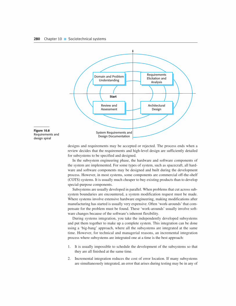
280 Chapter 10 � Sociotechnical systems
designs and requirements may be accepted or rejected. The process ends when a
review decides that the requirements and high-level design are sufficiently detailed
for subsystems to be specified and designed.
In the subsystem engineering phase, the hardware and software components of
the system are implemented. For some types of system, such as spacecraft, all hard-
ware and software components may be designed and built during the development
process. However, in most systems, some components are commercial off-the-shelf
(COTS) systems. It is usually much cheaper to buy existing products than to develop
special-purpose components.
Subsystems are usually developed in parallel. When problems that cut across sub-
system boundaries are encountered, a system modification request must be made.
Where systems involve extensive hardware engineering, making modifications after
manufacturing has started is usually very expensive. Often ‘work-arounds’ that com-
pensate for the problem must be found. These ‘work-arounds’ usually involve soft-
ware changes because of the software’s inherent flexibility.
During systems integration, you take the independently developed subsystems
and put them together to make up a complete system. This integration can be done
using a ‘big-bang’ approach, where all the subsystems are integrated at the same
time. However, for technical and managerial reasons, an incremental integration
process where subsystems are integrated one at a time is the best approach:
1. It is usually impossible to schedule the development of the subsystems so that
they are all finished at the same time.
2. Incremental integration reduces the cost of error location. If many subsystems
are simultaneously integrated, an error that arises during testing may be in any of
Figure 10.8Requirements anddesign spiral
System Requirements andDesign Documentation
Review andAssessment
ArchitecturalDesign
Start
RequirementsElicitation and
Analysis
Domain and ProblemUnderstanding

10.5 � System operation 281
these subsystems. When a single subsystem is integrated with an already work-
ing system, errors that occur are probably in the newly integrated subsystem or in
the interactions between the existing subsystems and the new subsystem.
As more and more systems are built by integrating COTS hardware and software
components, the distinction between implementation and integration is increasingly
blurred. In some cases, there is no need to develop new hardware or software and the
integration is, essentially, the implementation phase of the system.
During and after the integration process, the system is tested. This testing should
focus on testing the interfaces between components and the behavior of the system
as a whole. Inevitably, this will also reveal problems with individual subsystems that
have to be repaired.
Subsystem faults that are a consequence of invalid assumptions about other subsys-
tems are often revealed during system integration. This may lead to disputes between
the contractors responsible for implementing different subsystems. When problems are
discovered in subsystem interaction, the contractors may argue about which subsystem
is faulty. Negotiations on how to solve the problems can take weeks or months.
The final stage of the system development process is system delivery and deploy-
ment. The software is installed on the hardware and is readied for operation. This
may involve more system configuration to reflect the local environment where it is
used, the transfer of data from existing systems, and the preparation of user docu-
mentation and training. At this stage, you may also have to reconfigure other systems
in the environment to ensure that the new system interoperates with them.
Although straightforward in principle, many difficulties can arise during deploy-
ment. The user environment may be different from that anticipated by the system
developers and adapting the system to cope with diverse user environments can be
difficult. The existing data may require extensive cleanup and parts of it may be
missing. The interfaces to other systems may not be properly documented.
The influence of system development processes on dependability and security
is obvious. It is during these processes that decisions are made on dependability and
security requirements and on trade-offs between costs, schedule, performance,
and dependability. Human errors at all stages of the development process may lead
to the introduction of faults into the system which, in operation, can lead to system
failure. Testing and validation processes are inevitably constrained by the costs and
time available. As a result, the system may not be properly tested. Users are left to
test the system as it is being used. Finally, problems in system deployment may
mean that there is a mismatch between the system and its operational environment.
These can lead to human errors when using the system.
10.5 System operation
Operational processes are the processes that are involved in using the system for its
defined purpose. For example, operators of an air traffic control system follow spe-
cific processes when aircraft enter and leave airspace, when they have to change

282 Chapter 10 � Sociotechnical systems
height or speed, when an emergency occurs, and so on. For new systems, these oper-
ational processes have to be defined and documented during the system development
process. Operators may have to be trained and other work processes adapted to make
effective use of the new system. Undetected problems may arise at this stage because
the system specification may contain errors or omissions. Although the system may
perform to specification, its functions may not meet the real operational needs.
Consequently, the operators may not use the system as its designers intended.
The key benefit of having system operators is that people have a unique capabil-
ity of being able to respond effectively to unexpected situations, even when they
have never had direct experience of these situations. Therefore, when things go
wrong, the operators can often recover the situation although this may sometimes
mean that the defined process is violated. Operators also use their local knowledge to
adapt and improve processes. Normally, the actual operational processes are differ-
ent from those anticipated by the system designers.
Consequently, you should design operational processes to be flexible and adapt-
able. The operational processes should not be too constraining, they should not
require operations to be done in a particular order, and the system software should
not rely on a specific process being followed. Operators usually improve the process
because they know what does and does not work in a real situation.
A problem that may only emerge after the system goes into operation is the oper-
ation of the new system alongside existing systems. There may be physical problems
of incompatibility or it may be difficult to transfer data from one system to another.
More subtle problems might arise because different systems have different user
interfaces. Introducing a new system may increase the operator error rate, as the
operators use user interface commands for the wrong system.
10.5.1 Human error
I suggested earlier in the chapter that non-determinism was an important issue in
sociotechnical systems and that one reason for this is that the people in the system do
not always behave in the same way. Sometimes they make mistakes in using the sys-
tem and this has the potential to cause system failure. For example, an operator may
forget to record that some action has been taken so that another operator (erro-
neously) repeats that action. If the action is to debit or credit a bank account, say,
then a system failure occurs as the amount in the account is then incorrect.
As Reason discusses (2000) human errors will always occur and there are two
ways to view the problem of human error:
1. The person approach. Errors are considered to be the responsibility of the indi-
vidual and ‘unsafe acts’ (such as an operator failing to engage a safety barrier)
are a consequence of individual carelessness or reckless behavior. People who
adopt this approach believe that human errors can be reduced by threats of dis-
ciplinary action, more stringent procedures, retraining, etc. Their view is that
the error is the fault of the individual responsible for making the mistake.

10.5 � System operation 283
2. The systems approach. The basic assumption is that people are fallible and will
make mistakes. The errors that people make are often a consequence of system
design decisions that lead to erroneous ways of working, or of organizational
factors, which affect the system operators. Good systems should recognize the
possibility of human error and include barriers and safeguards that detect human
errors and allow the system to recover before failure occurs. When a failure does
occur, the issue is not finding an individual to blame but to understand how and
why the system defences did not trap the error.
I believe that the systems approach is the right one and that systems engineers
should assume that human errors will occur during system operation. Therefore, to
improve the security and dependability of a system, designers have to think about the
defenses and barriers to human error that should be included in a system. They
should also think about whether these barriers should be built into the technical com-
ponents of the system. If not, they could be part of the processes and procedures for
using the system or could be operator guidelines that are reliant on human checking
and judgment.
Examples of defenses that may be included in a system are:
1. An air traffic control system may include an automated conflict alert system.
When a controller instructs an aircraft to change its speed or altitude, the system
extrapolates its trajectory to see if it could intersect with any other aircraft. If so,
it sounds an alarm.
2. The same system may have a clearly defined procedure to record the control
instructions that have been issued. These procedures help the controller check if
they have issued the instruction correctly and make the information available to
others for checking.
3. Air traffic control usually involves a team of controllers who constantly monitor
each other’s work. Therefore, when a mistake is made, it is likely that it will be
detected and corrected before an incident occurs.
Inevitably, all barriers have weaknesses of some kind. Reason calls these ‘latent
conditions’ as they usually only contribute to system failure when some other prob-
lem occurs. For example, in the above defenses, a weakness of a conflict alert system
is that it may lead to many false alarms. Controllers may therefore ignore warnings
from the system. A weakness of a procedural system may be that unusual but essen-
tial information can’t be easily recorded. Human checking may fail when all of the
people involved are under stress and make the same mistake.
Latent conditions lead to system failure when the defenses built into the system
do not trap an active failure by a system operator. The human error is a trigger for
the failure but should not be considered to be the sole cause of the failure. Reason
explains this using his well-known ‘Swiss cheese’ model of system failure
(Figure 10.9).

284 Chapter 10 � Sociotechnical systems
In this model, the defenses built into a system are compared to slices of Swiss
cheese. Some types of Swiss cheese, such as Emmental, have holes and so the anal-
ogy is that the latent conditions are comparable to the holes in cheese slices. The
position of these holes is not static but changes depending on the state of the overall
sociotechnical system. If each slice represents a barrier, failures can occur when the
holes line up at the same time as a human operational error. An active failure of sys-
tem operation gets through the holes and leads to an overall system failure.
Normally, of course, the holes should not be aligned so operational failures are
trapped by the system. To reduce the probability that system failure will result from
human error, designers should:
1. Design a system so that different types of barriers are included. This means that
the ‘holes’ will probably be in different places and so there is less chance of the
holes lining up and failing to trap an error.
2. Minimize the number of latent conditions in a system. Effectively, this means
reducing the number and size of system ‘holes’.
Of course, the design of the system as a whole should also attempt to avoid the
active failures that can trigger a system failure. This may involve designing the oper-
ational processes and the system to ensure that operators are not overworked, dis-
tracted, or presented with excessive amounts of information.
10.5.2 System evolution
Large, complex systems have a very long lifetime. During their life, they are
changed to correct errors in the original system requirements and to implement new
requirements that have emerged. The system’s computers are likely to be replaced
with new, faster machines. The organization that uses the system may reorganize
itself and hence use the system in a different way. The external environment of the
system may change, forcing changes to the system. Hence evolution, where the sys-
tem changes to accommodate environmental change, is a process that runs alongside
normal system operational processes. System evolution involves reentering the
development process to make changes and extensions to the system’s hardware, soft-
ware, and operational processes.
Figure 10.9Reason’s Swiss cheesemodel of system failure System Failure
Active Failure(Human Error)
Barriers

10.5 � System operation 285
Legacy systems
Legacy systems are sociotechnical computer-based systems that have been developed in the past, often usingolder or obsolete technology. These systems include not only hardware and software but also legacy processesand procedures—old ways of doing things that are difficult to change because they rely on legacy software.Changes to one part of the system inevitably involve changes to other components. Legacy systems are oftenbusiness-critical systems. They are maintained because it is too risky to replace them.
http://www.SoftwareEngineering-9.com/LegacySys/
System evolution, like software evolution (discussed in Chapter 9), is inherently
costly for several reasons:
1. Proposed changes have to be analyzed very carefully from a business and a tech-
nical perspective. Changes have to contribute to the goals of the system and
should not simply be technically motivated.
2. Because subsystems are never completely independent, changes to one subsys-
tem may adversely affect the performance or behavior of other subsystems.
Consequent changes to these subsystems may therefore be needed.
3. The reasons for original design decisions are often unrecorded. Those responsi-
ble for the system evolution have to work out why particular design decisions
were made.
4. As systems age, their structure typically becomes corrupted by change so the
costs of making further changes increases.
Systems that have evolved over time are often reliant on obsolete hardware and soft-
ware technology. If they have a critical role in an organization, they are known as
‘legacy systems’. These are usually systems that the organization would like to
replace but don’t do so as the risks or costs of replacement cannot be justified.
From a dependability and security perspective, changes to a system are often a
source of problems and vulnerabilities. If the people implementing the change are dif-
ferent from those who developed the system, they may be unaware that a design deci-
sion was made for dependability and security reasons. Therefore, they may change the
system and lose some safeguards that were deliberately implemented when the system
was built. Furthermore, as testing is so expensive, complete retesting may be impossi-
ble after every system change. Adverse side effects of changes that introduce or
expose faults in other system components may not then be discovered.

286 Chapter 10 � Sociotechnical systems
K E Y P O I N T S
� Sociotechnical systems include computer hardware, software, and people, and are situated within
an organization. They are designed to support organizational or business goals and objectives.
� Human and organizational factors such as organizational structure and politics have a
significant effect on the operation of sociotechnical systems.
� The emergent properties of a system are characteristics of the system as a whole rather than of its
component parts. They include properties such as performance, reliability, usability, safety, and
security. The success or failure of a system is often dependent on these emergent properties.
� The fundamental systems engineering processes are system procurement, system development,
and system operation.
� System procurement covers all of the activities involved in deciding what system to buy and who
should supply that system. High-level requirements are developed as part of the procurement
process.
� System development includes requirements specification, design, construction, integration, and
testing. System integration, where subsystems from more than one supplier must be made to
work together, is particularly critical.
� When a system is put into use, the operational processes and the system itself have to change
to reflect changing business requirements.
� Human errors are inevitable and systems should include barriers to detect these errors before
they lead to system failure. Reason’s Swiss cheese model explains how human error plus latent
defects in the barriers can lead to system failure.
F U RT H E R R E A D I N G
‘Airport 95: Automated baggage system’. An excellent, readable case study of what can go wrong
with a systems engineering project and how software tends to get the blame for wider systems
failures. (ACM Software Engineering Notes, 21, March 1996.)
http://doi.acm.org/10.1145/227531.227544.
‘Software system engineering: A tutorial’. A good general overview of systems engineering,
although Thayer focuses exclusively on computer-based systems and does not discuss
sociotechnical issues. (R. H. Thayer. IEEE Computer, April 2002.)
http://dx.doi.org/10.1109/MC.2002.993773.
Trust in Technology: A Socio-technical Perspective. This book is a set of papers that are all
concerned, in some way, with the dependability of sociotechnical systems. (K. Clarke,
G. Hardstone, M. Rouncefield and I. Sommerville (eds.), Springer, 2006.)
‘Fundamentals of Systems Engineering’. This is the introductory chapter in NASA’s systems
engineering handbook. It presents an overview of the systems engineering process for space

Chapter 10 � Exercises 287
systems. Although these are mostly technical systems, there are sociotechnical issues to be
considered. Dependability is obviously critically important. (In NASA Systems Engineering
Handbook, NASA-SP2007-6105, 2007.) http://education.ksc.nasa.gov/esmdspacegrant/
Documents/NASA%20SP-2007-6105%20Rev%201%20Final%2031Dec2007.pdf.
E X E R C I S E S
10.1. Give two examples of government functions that are supported by complex sociotechnical
systems and explain why, in the foreseeable future, these functions cannot be completely
automated.
10.2. Explain why the environment in which a computer-based system is installed may have
unanticipated effects on the system that lead to system failure. Illustrate your answer with
a different example from that used in this chapter.
10.3. Why is it impossible to infer the emergent properties of a complex system from the
properties of the system components?
10.4. Why is it sometimes difficult to decide whether or not there has been a failure in a
sociotechnical system? Illustrate your answer by using examples from the MHC-PMS that
has been discussed in earlier chapters.
10.5. What is a ‘wicked problem’? Explain why the development of a national medical records
system should be considered a ‘wicked problem’.
10.6. A multimedia virtual museum system offering virtual experiences of ancient Greece is to be
developed for a consortium of European museums. The system should provide users with
the facility to view 3-D models of ancient Greece through a standard web browser and
should also support an immersive virtual reality experience. What political and
organizational difficulties might arise when the system is installed in the museums that
make up the consortium?
10.7. Why is system integration a particularly critical part of the systems development process?
Suggest three sociotechnical issues that may cause difficulties in the system integration
process.
10.8. Explain why legacy systems may be critical to the operation of a business.
10.9. What are the arguments for and against considering system engineering as a profession in
its own right, like electrical engineering or software engineering?
10.10. You are an engineer involved in the development of a financial system. During installation,
you discover that this system will make a significant number of people redundant. The
people in the environment deny you access to essential information to complete the system
installation. To what extent should you, as a systems engineer, become involved in this
situation? Is it your professional responsibility to complete the installation as contracted?
Should you simply abandon the work until the procuring organization has sorted out the
problem?

288 Chapter 10 � Sociotechnical systems
R E F E R E N C E S
Ackroyd, S., Harper, R., Hughes, J. A. and Shapiro, D. (1992). Information Technology and Practical
Police Work. Milton Keynes: Open University Press.
Anderson, R. J., Hughes, J. A. and Sharrock, W. W. (1989). Working for Profit: The Social
Organization of Calculability in an Entrepreneurial Firm. Aldershot: Avebury.
Checkland, P. (1981). Systems Thinking, Systems Practice. Chichester: John Wiley & Sons.
Checkland, P. and Scholes, J. (1990). Soft Systems Methodology in Action. Chichester: John Wiley
& Sons.
Mumford, E. (1989). ‘User Participation in a Changing Environment—Why we need it’. In
Participation in Systems Development. Knight, K. (ed.). London: Kogan Page.
Reason, J. (2000). ‘Human error: Models and management’. British Medical J., 320 768–70.
Rittel, H. and Webber, M. (1973). ‘Dilemmas in a General Theory of Planning’. Policy Sciences,
4, 155–69.
Stevens, R., Brook, P., Jackson, K. and Arnold, S. (1998). Systems Engineering: Coping with
Complexity. London: Prentice Hall.
Suchman, L. (1987). Plans and situated actions: the problem of human-machine communication.
New York: Cambridge University Press.
Swartz, A. J. (1996). ‘Airport 95: Automated Baggage System?’ ACM Software Engineering Notes,
21 (2), 79–83.
Thayer, R. H. (2002). ‘Software System Engineering: A Tutorial.’ IEEE Computer, 35 (4), 68–73.
Thomé, B. (1993). ‘Systems Engineering: Principles and Practice of Computer-based Systems
Engineering’. Chichester: John Wiley & Sons.
White, S., Alford, M., Holtzman, J., Kuehl, S., McCay, B., Oliver, D., Owens, D., Tully, C. and Willey, A.
(1993). ‘Systems Engineering of Computer-Based Systems’. IEEE Computer, 26 (11), 54–65.

Dependability and security
11
Objectives
The objective of this chapter is to introduce software dependability and
security. When you have read this chapter, you will:
� understand why dependability and security are usually more
important than the functional characteristics of a software system;
� understand the four principal dimensions of dependability, namely
availability, reliability, safety, and security;
� be aware of the specialized terminology that is used when discussing
security and dependability;
� understand that to achieve secure, dependable software, you need to
avoid mistakes during the development of a system, to detect and
remove errors when the system is in use, and to limit the damage
caused by operational failures.
Contents
11.1 Dependability properties
11.2 Availability and reliability
11.3 Safety
11.4 Security

290 Chapter 11 � Dependability and security
As computer systems have become deeply embedded in our business and personal
lives, the problems that result from system and software failure are increasing.
A failure of server software in an e-commerce company could lead to a major loss of
revenue, and possibly also customers for that company. A software error in an
embedded control system in a car could lead to expensive recalls of that model for
repair and, in the worst case, could be a contributory factor in accidents. The infec-
tion of company PCs with malware requires expensive cleanup operations to sort out
the problem and could result in the loss or damage to sensitive information.
Because software-intensive systems are so important to governments, companies,
and individuals, it is essential that widely used software is trustworthy. The software
should be available when required and should operate correctly and without undesir-
able side effects, such as unauthorized information disclosure. The term ‘depend-
ability’ was proposed by Laprie (1995) to cover the related systems attributes of
availability, reliability, safety, and security. As I discuss in Section 11.1, these prop-
erties are inextricably linked, so having a single term to cover them all makes sense.
The dependability of systems is now usually more important than their detailed
functionality for the following reasons:
1. System failures affect a large number of people. Many systems include function-
ality that is rarely used. If this functionality were left out of the system, only a
small number of users would be affected. System failures, which affect the
availability of a system, potentially affect all users of the system. Failure may
mean that normal business is impossible.
2. Users often reject systems that are unreliable, unsafe, or insecure. If users find
that a system is unreliable or insecure, they will refuse to use it. Furthermore,
they may also refuse to buy or use other products from the same company that
produced the unreliable system, because they believe that these products are
also likely to be unreliable or insecure.
3. System failure costs may be enormous. For some applications, such as a reactor
control system or an aircraft navigation system, the cost of system failure is
orders of magnitude greater than the cost of the control system.
4. Undependable systems may cause information loss. Data is very expensive to collect
and maintain; it is usually worth much more than the computer system on which it is
processed. The cost of recovering lost or corrupt data is usually very high.
As I discussed in Chapter 10, software is always part of a broader system. It exe-
cutes in an operational environment that includes the hardware on which the soft-
ware executes, the human users of that software, and the organizational or business
processes where the software is used. When designing a dependable system, you
therefore have to consider:
1. Hardware failure System hardware may fail because of mistakes in its design,
because components fail as a result of manufacturing errors, or because the
components have reached the end of their natural life.

11.1 � Dependability properties 291
2. Software failure System software may fail because of mistakes in its
specification, design, or implementation.
3. Operational failure Human users may fail to use or operate the system correctly.
As hardware and software have become more reliable, failures in operation are
now, perhaps, the largest single cause of system failures.
These failures are often interrelated. A failed hardware component may mean
system operators have to cope with an unexpected situation and additional workload.
This puts them under stress and people under stress often make mistakes. This can
cause the software to fail, which means more work for the operators, even more
stress, and so on.
As a result, it is particularly important that designers of dependable, software-
intensive systems take a holistic systems perspective, rather than focus on a single
aspect of the system such as its software or hardware. If hardware, software, and
operational processes are designed separately, without taking into account the poten-
tial weaknesses of other parts of the system, then it is more likely that errors will
occur at the interfaces between the different parts of the system.
11.1 Dependability properties
All of us are familiar with the problem of computer system failure. For no obvious
reason, our computers sometimes crash or go wrong in some way. Programs running
on these computers may not operate as expected and occasionally may corrupt the
data that is managed by the system. We have learned to live with these failures but
few of us completely trust the personal computers that we normally use.
The dependability of a computer system is a property of the system that reflects
its trustworthiness. Trustworthiness here essentially means the degree of confidence
a user has that the system will operate as they expect, and that the system will not
‘fail’ in normal use. It is not meaningful to express dependability numerically.
Critical systems
Some classes of system are ‘critical systems’ where system failure may result in injury to people, damage to theenvironment, or extensive economic losses. Examples of critical systems include embedded systems in medicaldevices, such as an insulin pump (safety-critical), spacecraft navigation systems (mission-critical), and onlinemoney transfer systems (business critical).
Critical systems are very expensive to develop. Not only must they be developed so that failures are very rarebut they must also include recovery mechanisms that are used if and when failures occur.
http://www.SoftwareEngineering-9.com/Web/Dependability/CritSys.html

292 Chapter 11 � Dependability and security
Rather, we use relative terms such as ‘not dependable,’ ‘very dependable,’ and
‘ultra-dependable’ to reflect the degrees of trust that we might have in a system.
Trustworthiness and usefulness are not, of course, the same thing. I don’t think
that the word processor that I used to write this book is a very dependable system.
It sometimes freezes and has to be restarted. Nevertheless, because it is very useful,
I am prepared to tolerate occasional failure. However, to reflect my lack of trust in
the system I save my work frequently and keep multiple backup copies of it. I com-
pensate for the lack of system dependability by actions that limit the damage that
could result from system failure.
There are four principal dimensions to dependability, as shown in Figure 11.1.
1. Availability Informally, the availability of a system is the probability that it will
be up and running and able to deliver useful services to users at any given time.
2. Reliability Informally, the reliability of a system is the probability, over a given
period of time, that the system will correctly deliver services as expected by
the user.
3. Safety Informally, the safety of a system is a judgment of how likely it is that the
system will cause damage to people or its environment.
4. Security Informally, the security of a system is a judgment of how likely it is that
the system can resist accidental or deliberate intrusions.
The dependability properties shown in Figure 11.1 are complex properties that
can be broken down into a number of other, simpler properties. For example, secu-
rity includes ‘integrity’ (ensuring that the systems program and data are not
damaged) and ‘confidentiality’ (ensuring that information can only be accessed by
people who are authorized). Reliability includes ‘correctness’ (ensuring the system
services are as specified), ‘precision’ (ensuring information is delivered at an appro-
priate level of detail), and ‘timeliness’ (ensuring that information is delivered when
it is required).
Figure 11.1Principaldependabilityproperties
Dependability
The ability of the systemto deliver services when
requested
The ability of the systemto deliver services as
specified
The ability of the systemto operate withoutcatastrophic failure
The ability of the systemto protect itelf against
accidental or deliberateintrusion
Reliability SafetyAvailability Security

11.1 � Dependability properties 293
Of course, these dependability properties are not all applicable to all systems. For
the insulin pump system, introduced in Chapter 1, the most important properties are
availability (it must work when required), reliability (it must deliver the correct dose
of insulin), and safety (it must never deliver a dangerous dose of insulin). Security is
not an issue as the pump will not maintain confidential information. It is not net-
worked and so cannot be maliciously attacked. For the wilderness weather system,
availability and reliability are the most important properties because the costs of
repair may be very high. For the patient information system, security is particularly
important because of the sensitive private data that is maintained.
As well as these four main dependability properties, you may also think of other
system properties as dependability properties:
1. Repairability System failures are inevitable, but the disruption caused by failure
can be minimized if the system can be repaired quickly. For that to happen, it
must be possible to diagnose the problem, access the component that has failed,
and make changes to fix that component. Repairability in software is enhanced
when the organization using the system has access to the source code and has
the skills to make changes to it. Open source software makes this easier but the
reuse of components can make it more difficult.
2. Maintainability As systems are used, new requirements emerge and it is impor-
tant to maintain the usefulness of a system by changing it to accommodate these
new requirements. Maintainable software is software that can be adapted eco-
nomically to cope with new requirements, and where there is a low probability
that making changes will introduce new errors into the system.
3. Survivability A very important attribute for Internet-based systems is survivability
(Ellison et al., 1999b). Survivability is the ability of a system to continue to
deliver service whilst under attack and, potentially, whilst part of the system is
disabled. Work on survivability focuses on identifying key system components
and ensuring that they can deliver a minimal service. Three strategies are used to
enhance survivability—resistance to attack, attack recognition, and recovery
from the damage caused by an attack (Ellison et al., 1999a; Ellison et al., 2002).
I discuss this in more detail in Chapter 14.
4. Error tolerance This property can be considered as part of usability and reflects
the extent to which the system has been designed so that user input errors are
avoided and tolerated. When user errors occur, the system should, as far as pos-
sible, detect these errors and either fix them automatically or request the user to
reinput their data.
The notion of system dependability as an encompassing property was introduced
because the dependability properties of availability, security, reliability, and safety are
closely related. Safe system operation usually depends on the system being available
and operating reliably. A system may become unreliable because an intruder has cor-
rupted its data. Denial of service attacks on a system are intended to compromise the

294 Chapter 11 � Dependability and security
system’s availability. If a system is infected with a virus, you cannot then be confident
in its reliability or safety because the virus may change its behavior.
To develop dependable software, you therefore need to ensure that:
1. You avoid the introduction of accidental errors into the system during software
specification and development.
2. You design verification and validation processes that are effective in discovering
residual errors that affect the dependability of the system.
3. You design protection mechanisms that guard against external attacks that can
compromise the availability or security of the system.
4. You configure the deployed system and its supporting software correctly for its
operating environment.
In addition, you should usually assume that your software is not perfect and
that software failures may occur. Your system should therefore include recovery
mechanisms that make it possible to restore normal system service as quickly as
possible.
The need for fault tolerance means that dependable systems have to include
redundant code to help them monitor themselves, detect erroneous states, and
recover from faults before failures occur. This affects the performance of systems, as
additional checking is required each time the system executes. Therefore, designers
usually have to trade off performance and dependability. You may need to leave
checks out of the system because these slow the system down. However, the conse-
quential risk here is that some failures occur because a fault has not been detected.
Because of extra design, implementation, and validation costs, increasing the
dependability of a system significantly increases development costs. In particular,
validation costs are high for systems that must be ultra-dependable such as safety-
critical control systems. As well as validating that the system meets its requirements,
the validation process may have to prove to an external regulator that the system is
safe. For example, aircraft systems have to demonstrate to regulators, such as the
Federal Aviation Authority, that the probability of a catastrophic system failure that
affects aircraft safety is extremely low.
Figure 11.2 shows that the relationship between costs and incremental improve-
ments in dependability. If your software is not very dependable, you can get signifi-
cant improvements at relatively low costs by using better software engineering.
However, if you are already using good practice, the costs of improvement are much
greater and the benefits from that improvement are less. There is also the problem of
testing your software to demonstrate that it is dependable. This relies on running
many tests and looking at the number of failures that occur. As your software
becomes more dependable, you see fewer and fewer failures. Consequently, more
and more tests are needed to try and assess how many problems remain in the
software. As testing is very expensive, this dramatically increases the cost of
high-dependability systems.

11.2 � Availability and reliability 295
11.2 Availability and reliability
System availability and reliability are closely related properties that can both be
expressed as numerical probabilities. The availability of a system is the probability
that the system will be up and running to deliver these services to users on request.
The reliability of a system is the probability that the system’s services will be deliv-
ered as defined in the system specification. If, on average, 2 inputs in every 1,000
cause failures, then the reliability, expressed as a rate of occurrence of failure, is
0.002. If the availability is 0.999, this means that, over some time period, the system
is available for 99.9% of that time.
Reliability and availability are closely related but sometimes one is more impor-
tant than the other. If users expect continuous service from a system then the system
has a high availability requirement. It must be available whenever a demand is made.
However, if the losses that result from a system failure are low and the system can
recover quickly then failures don’t seriously affect system users. In such systems, the
reliability requirements may be relatively low.
A telephone exchange switch that routes phone calls is an example of a system where
availability is more important than reliability. Users expect a dial tone when they pick
up a phone, so the system has high availability requirements. If a system fault occurs
while a connection is being set up, this is often quickly recoverable. Exchange switches
can usually reset the system and retry the connection attempt. This can be done very
quickly and phone users may not even notice that a failure has occurred. Furthermore,
even if a call is interrupted, the consequences are usually not serious. Therefore, avail-
ability rather than reliability is the key dependability requirement for this type of system.
System reliability and availability may be defined more precisely as follows:
1. Reliability The probability of failure-free operation over a specified time, in
a given environment, for a specific purpose.
Cost
Low Medium High VeryHigh
Ultra-High
Dependability
Figure 11.2Cost/dependabilitycurve

296 Chapter 11 � Dependability and security
2. Availability The probability that a system, at a point in time, will be operational
and able to deliver the requested services.
One of the practical problems in developing reliable systems is that our intuitive
notions of reliability and availability are sometimes broader than these limited defi-
nitions. The definition of reliability states that the environment in which the system
is used and the purpose that it is used for must be taken into account. If you measure
system reliability in one environment, you can’t assume that the reliability will be
the same if the system is used in a different way.
For example, let’s say that you measure the reliability of a word processor in an
office environment where most users are uninterested in the operation of the soft-
ware. They follow the instructions for its use and do not try to experiment with the
system. If you then measure the reliability of the same system in a university envi-
ronment, then the reliability may be quite different. Here, students may explore the
boundaries of the system and use the system in unexpected ways. This may result in
system failures that did not occur in the more constrained office environment.
These standard definitions of availability and reliability do not take into account
the severity of failure or the consequences of unavailability. People often accept
minor system failures but are very concerned about serious failures that have high
consequential costs. For example, computer failures that corrupt stored data are less
acceptable than failures that freeze the machine and that can be resolved by
restarting the computer.
A strict definition of reliability relates the system implementation to its specifica-
tion. That is, the system is behaving reliably if its behavior is consistent with that
defined in the specification. However, a common cause of perceived unreliability is
that the system specification does not match the expectations of the system users.
Unfortunately, many specifications are incomplete or incorrect and it is left to soft-
ware engineers to interpret how the system should behave. As they are not domain
experts, they may not, therefore, implement the behavior that users expect. It is also
true, of course, that users don’t read system specifications. They may therefore have
unrealistic expectations of the system.
Availability and reliability are obviously linked as system failures may crash the
system. However, availability does not just depend on the number of system crashes,
but also on the time needed to repair the faults that have caused the failure.
Therefore, if system A fails once a year and system B fails once a month then A is
clearly more reliable then B. However, assume that system A takes three days to
restart after a failure, whereas system B takes 10 minutes to restart. The availability
of system B over the year (120 minutes of down time) is much better than that of
system A (4,320 minutes of down time).
The disruption caused by unavailable systems is not reflected in the simple avail-
ability metric that specifies the percentage of time that the system is available. The
time when the system fails is also significant. If a system is unavailable for an hour
each day between 3 am and 4 am, this may not affect many users. However, if the
same system is unavailable for 10 minutes during the working day, system
unavailability will probably have a much greater effect.

11.2 � Availability and reliability 297
System reliability and availability problems are mostly caused by system failures.
Some of these failures are a consequence of specification errors or failures in other
related systems such as a communications system. However, many failures are a
consequence of erroneous system behavior that derives from faults in the system.
When discussing reliability, it is helpful to use precise terminology and distinguish
between the terms ‘fault,’ ‘error,’ and ‘failure.’ I have defined these terms in
Figure 11.3 and have illustrated each definition with an example from the wilderness
weather system.
When an input or a sequence of inputs causes faulty code in a system to be exe-
cuted, an erroneous state is created that may lead to a software failure. Figure 11.4,
derived from Littlewood (1990), shows a software system as a mapping of a set of
inputs to a set of outputs. Given an input or input sequence, the program responds by
producing a corresponding output. For example, given an input of a URL, a web
browser produces an output that is the display of the requested web page.
Most inputs do not lead to system failure. However, some inputs or input combi-
nations, shown in the shaded ellipse Ie in Figure 11.4, cause system failures or erro-
neous outputs to be generated. The program’s reliability depends on the number of
system inputs that are members of the set of inputs that lead to an erroneous output.
If inputs in the set Ie are executed by frequently used parts of the system, then fail-
ures will be frequent. However, if the inputs in Ie are executed by code that is rarely
used, then users will hardly ever see failures.
Because each user of a system uses it in different ways, they have different percep-
tions of its reliability. Faults that affect the reliability of the system for one user may
never be revealed under someone else’s mode of working (Figure 11.5). In Figure 11.5,
the set of erroneous inputs correspond to the ellipse labeled Ie in Figure 11.4. The set
of inputs produced by User 2 intersects with this erroneous input set. User 2 will
Figure 11.3Reliability terminology
Term Description
Human error or mistake Human behavior that results in the introduction of faults into a system. Forexample, in the wilderness weather system, a programmer might decide that theway to compute the time for the next transmission is to add 1 hour to thecurrent time. This works except when the transmission time is between 23.00and midnight (midnight is 00.00 in the 24-hour clock).
System fault A characteristic of a software system that can lead to a system error. The fault isthe inclusion of the code to add 1 hour to the time of the last transmission,without a check if the time is greater than or equal to 23.00.
System error An erroneous system state that can lead to system behavior that is unexpectedby system users. The value of transmission time is set incorrectly (to 24.XX ratherthan 00.XX) when the faulty code is executed.
System failure An event that occurs at some point in time when the system does not deliver a service as expected by its users. No weather data is transmitted because thetime is invalid.

298 Chapter 11 � Dependability and security
therefore experience some system failures. User 1 and User 3, however, never use
inputs from the erroneous set. For them, the software will always be reliable.
The practical reliability of a program depends on the number of inputs causing erro-
neous outputs (failures) during normal use of the system by most users. Software faults
that only occur in exceptional situations have little practical effect on the system’s reli-
ability. Consequently, removing software faults may not significantly improve the
overall reliability of the system. Mills et al. (1987) found that removing 60% of known
errors in their software led to a 3% reliability improvement. Adams (1984), in a study
of IBM software products, noted that many defects in the products were only likely to
cause failures after hundreds or thousands of months of product usage.
System faults do not always result in system errors and system errors do not nec-
essarily result in system failures. The reasons for this are as follows:
1. Not all code in a program is executed. The code that includes a fault (e.g., the
failure to initialize a variable) may never be executed because of the way that the
software is used.
PossibleInputs
User1
User3
User2
ErroneousInputs
Figure 11.5 Softwareusage patterns
Output Set ErroneousOutputs
Oe
Input Set
Program
Inputs CausingErroneous Outputs
Ie
Figure 11.4A system as aninput/outputmapping

11.3 � Safety 299
2. Errors are transient. A state variable may have an incorrect value caused by the
execution of faulty code. However, before this is accessed and causes a system fail-
ure, some other system input may be processed that resets the state to a valid value.
3. The system may include fault detection and protection mechanisms. These
ensure that the erroneous behavior is discovered and corrected before the sys-
tem services are affected.
Another reason why the faults in a system may not lead to system failures is that,
in practice, users adapt their behavior to avoid using inputs that they know cause
program failures. Experienced users ‘work around’ software features that they have
found to be unreliable. For example, I avoid certain features, such as automatic num-
bering in the word processing system that I used to write this book. When I used
auto-numbering, it often went wrong. Repairing the faults in unused features makes
no practical difference to the system reliability. As users share information on prob-
lems and work-arounds, the effects of software problems are reduced.
The distinction between faults, errors, and failures, explained in Figure 11.3,
helps identify three complementary approaches that are used to improve the reliabil-
ity of a system:
1. Fault avoidance Development techniques are used that either minimize the
possibility of human errors and/or that trap mistakes before they result in the
introduction of system faults. Examples of such techniques include avoiding
error-prone programming language constructs such as pointers and the use of
static analysis to detect program anomalies.
2. Fault detection and removal The use of verification and validation techniques
that increase the chances that faults will be detected and removed before the
system is used. Systematic testing and debugging is an example of a fault-
detection technique.
3. Fault tolerance These are techniques that ensure that faults in a system do not
result in system errors or that system errors do not result in system failures. The
incorporation of self-checking facilities in a system and the use of redundant
system modules are examples of fault tolerance techniques.
The practical application of these techniques is discussed in Chapter 13, which
covers techniques for dependable software engineering.
11.3 Safety
Safety-critical systems are systems where it is essential that system operation is
always safe; that is, the system should never damage people or the system’s environ-
ment even if the system fails. Examples of safety-critical systems include control

300 Chapter 11 � Dependability and security
and monitoring systems in aircraft, process control systems in chemical and
pharmaceutical plants, and automobile control systems.
Hardware control of safety-critical systems is simpler to implement and analyze
than software control. However, we now build systems of such complexity that they
cannot be controlled by hardware alone. Software control is essential because of the
need to manage large numbers of sensors and actuators with complex control laws. For
example, advanced, aerodynamically unstable, military aircraft require continual
software-controlled adjustment of their flight surfaces to ensure that they do not crash.
Safety-critical software falls into two classes:
1. Primary safety-critical software This is software that is embedded as a con-
troller in a system. Malfunctioning of such software can cause a hardware
malfunction, which results in human injury or environmental damage. The
insulin pump software, introduced in Chapter 1, is an example of a primary
safety-critical system. System failure may lead to user injury.
2. Secondary safety-critical software This is software that can indirectly result in
an injury. An example of such software is a computer-aided engineering design
system whose malfunctioning might result in a design fault in the object being
designed. This fault may cause injury to people if the designed system malfunc-
tions. Another example of a secondary safety-critical system is the mental
health care management system, MHC-PMS. Failure of this system, whereby an
unstable patient may not be treated properly, could lead to that patient injuring
themselves or others.
System reliability and system safety are related but a reliable system can be
unsafe and vice versa. The software may still behave in such a way that the resultant
system behavior leads to an accident. There are four reasons why software systems
that are reliable are not necessarily safe:
1. We can never be 100% certain that a software system is fault-free and fault-
tolerant. Undetected faults can be dormant for a long time and software
failures can occur after many years of reliable operation.
2. The specification may be incomplete in that it does not describe the required
behavior of the system in some critical situations. A high percentage of system
malfunctions (Boehm et al., 1975; Endres, 1975; Lutz, 1993; Nakajo and Kume,
1991) are the result of specification rather than design errors. In a study of errors
in embedded systems, Lutz concludes:
. . . difficulties with requirements are the key root cause of the safety-
related software errors, which have persisted until integration and system
testing.
3. Hardware malfunctions may cause the system to behave in an unpredictable
way, and present the software with an unanticipated environment. When compo-
nents are close to physical failure, they may behave erratically and generate
signals that are outside the ranges that can be handled by the software.

11.3 � Safety 301
4. The system operators may generate inputs that are not individually incorrect but
which, in some situations, can lead to a system malfunction. An anecdotal
example of this occurred when an aircraft undercarriage collapsed whilst the
aircraft was on the ground. Apparently, a technician pressed a button that
instructed the utility management software to raise the undercarriage. The soft-
ware carried out the mechanic’s instruction perfectly. However, the system
should have disallowed the command unless the plane was in the air.
A specialized vocabulary has evolved to discuss safety-critical systems and it is
important to understand the specific terms used. Figure 11.6 summarizes some defi-
nitions of important terms, with examples taken from the insulin pump system.
The key to assuring safety is to ensure either that accidents do not occur or that
the consequences of an accident are minimal. This can be achieved in three comple-
mentary ways:
1. Hazard avoidance The system is designed so that hazards are avoided. For
example, a cutting system that requires an operator to use two hands to press
Figure 11.6Safety terminology
Term Definition
Accident (or mishap) An unplanned event or sequence of events which results in humandeath or injury, damage to property, or to the environment. Anoverdose of insulin is an example of an accident.
Hazard A condition with the potential for causing or contributing to anaccident. A failure of the sensor that measures blood glucose is anexample of a hazard.
Damage A measure of the loss resulting from a mishap. Damage can range frommany people being killed as a result of an accident to minor injury orproperty damage. Damage resulting from an overdose of insulin couldbe serious injury or the death of the user of the insulin pump.
Hazard severity An assessment of the worst possible damage that could result from aparticular hazard. Hazard severity can range from catastrophic, wheremany people are killed, to minor, where only minor damage results.When an individual death is a possibility, a reasonable assessment ofhazard severity is ‘very high.’
Hazard probability The probability of the events occurring which create a hazard.
Probability values tend to be arbitrary but range from ‘probable’ (say
1/100 chance of a hazard occurring) to ‘implausible’ (no conceivable
situations are likely in which the hazard could occur). The probability of
a sensor failure in the insulin pump that results in an overdose is
probably low.
Risk This is a measure of the probability that the system will cause anaccident. The risk is assessed by considering the hazard probability, thehazard severity, and the probability that the hazard will lead to anaccident. The risk of an insulin overdose is probably medium to low.

302 Chapter 11 � Dependability and security
separate buttons simultaneously avoids the hazard of the operator’s hands being
in the blade pathway.
2. Hazard detection and removal The system is designed so that hazards are
detected and removed before they result in an accident. For example, a chemical
plant system may detect excessive pressure and open a relief valve to reduce
these pressures before an explosion occurs.
3. Damage limitation The system may include protection features that minimize
the damage that may result from an accident. For example, an aircraft engine
normally includes automatic fire extinguishers. If a fire occurs, it can often be
controlled before it poses a threat to the aircraft.
Accidents most often occur when several things go wrong at the same time. An
analysis of serious accidents (Perrow, 1984) suggests that they were almost all due to
a combination of failures in different parts of a system. Unanticipated combinations
of subsystem failures led to interactions that resulted in overall system failure. For
example, failure of an air-conditioning system could lead to overheating, which then
causes the system hardware to generate incorrect signals. Perrow also suggests that it
is impossible to anticipate all possible combinations of failures. Accidents are there-
fore an inevitable part of using complex systems.
Some people have used this as an argument against software control. Because of
the complexity of software, there are more interactions between the different parts of
a system. This means that there will probably be more combinations of faults that
could lead to system failure.
However, software-controlled systems can monitor a wider range of conditions
than electro-mechanical systems. They can be adapted relatively easily. They use
computer hardware, which has very high inherent reliability and which is physically
small and lightweight. Software-controlled systems can provide sophisticated safety
interlocks. They can support control strategies that reduce the amount of time people
need to spend in hazardous environments. Although software control may introduce
more ways in which a system can go wrong, it also allows better monitoring and pro-
tection and hence can contribute to improvements in system safety.
In all cases, it is important to maintain a sense of proportion about system safety.
It is impossible to make a system 100% safe and society has to decide whether or not
the consequences of an occasional accident are worth the benefits that come from the
use of advanced technologies. It is also a social and political decision about how to
deploy limited national resources to reduce risk to the population as a whole.
11.4 Security
Security is a system attribute that reflects the ability of the system to protect itself
from external attacks, which may be accidental or deliberate. These external attacks
are possible because most general-purpose computers are now networked and are

11.4 � Security 303
therefore accessible by outsiders. Examples of attacks might be the installation of
viruses and Trojan horses, unauthorized use of system services or unauthorized
modification of a system or its data. If you really want a secure system, it is best not
to connect it to the Internet. Then, your security problems are limited to ensuring that
authorized users do not abuse the system. In practice, however, there are huge bene-
fits from networked access for most large systems so disconnecting from the Internet
is not cost effective.
For some systems, security is the most important dimension of system depend-
ability. Military systems, systems for electronic commerce, and systems that involve
the processing and interchange of confidential information must be designed so that
they achieve a high level of security. If an airline reservation system is unavailable,
for example, this causes inconvenience and some delays in issuing tickets. However,
if the system is insecure then an attacker could delete all bookings and it would be
practically impossible for normal airline operations to continue.
As with other aspects of dependability, there is a specialized terminology associ-
ated with security. Some important terms, as discussed by Pfleeger (Pfleeger and
Pfleeger, 2007), are defined in Figure 11.7. Figure 11.8 takes the security concepts
described in Figure 11.7 and shows how they relate to the following scenario taken
from the MHC-PMS:
Clinic staff log on to the MHC-PMS with a username and password. The sys-
tem requires passwords to be at least eight letters long but allows any pass-
word to be set without further checking. A criminal finds out that a well-paid
sports star is receiving treatment for mental health problems. He would like
to gain illegal access to information in this system so that he can blackmail
the star.
Term Definition
Asset Something of value which has to be protected. The asset may be the software system itselfor data used by that system.
Exposure Possible loss or harm to a computing system. This can be loss or damage to data, or canbe a loss of time and effort if recovery is necessary after a security breach.
Vulnerability A weakness in a computer-based system that may be exploited to cause loss or harm.
Attack An exploitation of a system’s vulnerability. Generally, this is from outside the system and isa deliberate attempt to cause some damage.
Threats Circumstances that have potential to cause loss or harm. You can think of these as asystem vulnerability that is subjected to an attack.
Control A protective measure that reduces a system’s vulnerability. Encryption is an example of a control that reduces a vulnerability of a weak access control system.
Figure 11.7Security terminology

304 Chapter 11 � Dependability and security
By posing as a concerned relative and talking with the nurses in the mental
health clinic, he discovers how to access the system and personal information
about the nurses. By checking name badges, he discovers the names of some of
the people allowed access. He then attempts to log on to the system by using
these names and systematically guessing possible passwords (such as chil-
dren’s names).
In any networked system, there are three main types of security threats:
1. Threats to the confidentiality of the system and its data These can disclose infor-
mation to people or programs that are not authorized to have access to that
information.
2. Threats to the integrity of the system and its data These threats can damage or
corrupt the software or its data.
3. Threats to the availability of the system and its data These threats can restrict
access to the software or its data for authorized users.
These threats are, of course, interdependent. If an attack makes the system
unavailable, then you will not be able to update information that changes with
time. This means that the integrity of the system may be compromised. If an
attack succeeds and the integrity of the system is compromised, then it may have
to be taken down to repair the problem. Therefore, the availability of the system
is reduced.
In practice, most vulnerabilities in sociotechnical systems result from human fail-
ings rather than technical problems. People choose easy-to-guess passwords or write
Figure 11.8Examples of securityterminology
Term Example
Asset The records of each patient that is receiving or has received treatment.
Exposure Potential financial loss from future patients who do not seek treatment because they do nottrust the clinic to maintain their data. Financial loss from legal action by the sports star. Lossof reputation.
Vulnerability A weak password system which makes it easy for users to set guessable passwords. User idsthat are the same as names.
Attack An impersonation of an authorized user.
Threat An unauthorized user will gain access to the system by guessing the credentials (login nameand password) of an authorized user.
Control A password checking system that disallows user passwords that are proper names or wordsthat are normally included in a dictionary.

11.4 � Security 305
down their passwords in places where they can be found. System administrators
make errors in setting up access control or configuration files and users don’t install
or use protection software. However, as I discussed in Section 10.5, we have to be
very careful when classifying a problem as a user error. Human problems often
reflect poor systems design decisions that require, for example, frequent password
changes (so that users write down their passwords) or complex configuration
mechanisms.
The controls that you might put in place to enhance system security are compara-
ble to those for reliability and safety:
1. Vulnerability avoidance Controls that are intended to ensure that attacks are
unsuccessful. The strategy here is to design the system so that security problems
are avoided. For example, sensitive military systems are not connected to public
networks so that external access is impossible. You should also think of encryp-
tion as a control based on avoidance. Any unauthorized access to encrypted data
means that it cannot be read by the attacker. In practice, it is very expensive and
time consuming to crack strong encryption.
2. Attack detection and neutralization Controls that are intended to detect and
repel attacks. These controls involve including functionality in a system that
monitors its operation and checks for unusual patterns of activity. If these are
detected, then action may be taken, such as shutting down parts of the system,
restricting access to certain users, etc.
3. Exposure limitation and recovery Controls that support recovery from prob-
lems. These can range from automated backup strategies and information
‘mirroring’ to insurance policies that cover the costs associated with a success-
ful attack on the system.
Without a reasonable level of security, we cannot be confident in a system’s
availability, reliability, and safety. Methods for certifying availability,
reliability, and security assume that the operational software is the same as the
software that was originally installed. If the system has been attacked and the
software has been compromised in some way (for example, if the software has
been modified to include a worm), then the reliability and safety arguments no
longer hold.
Errors in the development of a system can lead to security loopholes. If a sys-
tem does not respond to unexpected inputs or if array bounds are not checked,
then attackers can exploit these weaknesses to gain access to the system. Major
security incidents such as the original Internet worm (Spafford, 1989) and the
Code Red worm more than 10 years later (Berghel, 2001) took advantage of the
same vulnerability. Programs in C# do not include array bound checking, so it is
possible to overwrite part of memory with code that allows unauthorized access
to the system.

306 Chapter 11 � Dependability and security
K E Y P O I N T S
� Failure of critical computer systems can lead to large economic losses, serious information loss,
physical damage, or threats to human life.
� The dependability of a computer system is a system property that reflects the user’s degree of
trust in the system. The most important dimensions of dependability are availability, reliability,
safety, and security.
� The availability of a system is the probability that the system will be able to deliver services to
its users when requested to do so. Reliability is the probability that system services will be
delivered as specified.
� Perceived reliability is related to the probability of an error occurring in operational use.
A program may contain known faults but may still be experienced as reliable by its users. They
may never use features of the system that are affected by the faults.
� The safety of a system is a system attribute that reflects the system’s ability to operate,
normally or abnormally, without injury to people or damage to the environment.
� Security reflects the ability of a system to protect itself against external attacks. Security
failures may lead to loss of availability, damage to the system or its data, or the leakage of
information to unauthorized people.
� Without a reasonable level of security, the availability, reliability, and safety of the system may
be compromised if external attacks damage the system. If a system is unreliable, it is difficult to
ensure system safety or security, as they may be compromised by system failures.
F U RT H E R R E A D I N G
‘The evolution of information assurance’. An excellent article discussing the need to protect critical
information in an organization from accidents and attacks. (R. Cummings, IEEE Computer, 35 (12),
December 2002.) http://dx.doi.org/10.1109/MC.2002.1106181.
‘Designing Safety Critical Computer Systems’. This is a good introduction to the field of safety-
critical systems, which discusses the fundamental concepts of hazards and risks. More accessible
than Dunn’s book on safety-critical systems. (W. R. Dunn, IEEE Computer, 36 (11), November 2003.)
http://dx.doi.org/10.1109/MC.2003.1244533.
Secrets and Lies: Digital Security in a Networked World. An excellent, very readable book on
computer security which approaches the subject from a sociotechnical perspective. Schneier’s
columns on security issues in general (URL below) are also very good. (B. Schneier, John Wiley &
Sons, 2004.) http://www.schneier.com/essays.html.

Chapter 11 � Exercises 307
E X E R C I S E S
11.1. Suggest six reasons why software dependability is important in most sociotechnical
systems.
11.2. What are the most important dimensions of system dependability?
11.3. Why do the costs of assuring dependability increase exponentially as the reliability
requirement increases?
11.4. Giving reasons for your answer, suggest which dependability attributes are likely to be most
critical for the following systems:
An Internet server provided by an ISP with thousands of customers
A computer-controlled scalpel used in keyhole surgery
A directional control system used in a satellite launch vehicle
An Internet-based personal finance management system
11.5. Identify six consumer products that are likely to be controlled by safety-critical software
systems.
11.6. Reliability and safety are related but distinct dependability attributes. Describe the most
important distinction between these attributes and explain why it is possible for a reliable
system to be unsafe and vice versa.
11.7. In a medical system that is designed to deliver radiation to treat tumors, suggest one hazard
that may arise and propose one software feature that may be used to ensure that the
identified hazard does not result in an accident.
11.8. In computer security terms, explain the differences between an attack and a threat.
11.9. Using the MHC-PMS as an example, identify three threats to this system (in addition to the
threat shown in Figure 11.8). Suggest controls that might be put in place to reduce the
chances of a successful attack based on these threats.
11.10. As an expert in computer security, you have been approached by an organization that
campaigns for the rights of torture victims and have been asked to help the organization
gain unauthorized access to the computer systems of an American company. This will help
them confirm or deny that this company is selling equipment that is used directly in the
torture of political prisoners. Discuss the ethical dilemmas that this request raises and how
you would react to this request.

R E F E R E N C E S
Adams, E. N. (1984). ‘Optimizing preventative service of software products’. IBM J. Res & Dev.,
28 (1), 2–14.
Berghel, H. (2001). ‘The Code Red Worm’. Comm. ACM, 44 (12), 15–19.
Boehm, B. W., McClean, R. L. and Urfig, D. B. (1975). ‘Some experience with automated aids to the
design of large-scale reliable software’. IEEE Trans. on Software Engineering., SE-1 (1), 125–33.
Ellison, R., Linger, R., Lipson, H., Mead, N. and Moore, A. (2002). ‘Foundations of Survivable Systems
Engineering’. Crosstalk: The Journal of Defense Software Engineering, 12, 10–15.
Ellison, R. J., Fisher, D. A., Linger, R. C., Lipson, H. F., Longstaff, T. A. and Mead, N. R. (1999a).
‘Survivability: Protecting Your Critical Systems’. IEEE Internet Computing, 3 (6), 55–63.
Ellison, R. J., Linger, R. C., Longstaff, T. and Mead, N. R. (1999b). ‘Survivable Network System
Analysis: A Case Study’. IEEE Software, 16 (4), 70–7.
Endres, A. (1975). ‘An analysis of errors and their causes in system programs’. IEEE Trans. on
Software Engineering., SE-1 (2), 140–9.
Laprie, J.-C. (1995). ‘Dependable Computing: Concepts, Limits, Challenges’. FTCS- 25: 25th IEEE
Symposium on Fault-Tolerant Computing, Pasadena, Calif.: IEEE Press.
Littlewood, B. (1990). ‘Software Reliability Growth Models’. In Software Reliability Handbook. Rook,
P. (ed.). Amsterdam: Elsevier. 401–412.
Lutz, R. R. (1993). ‘Analysing Software Requirements Errors in Safety-Critical Embedded Systems’.
RE'93, San Diego, Calif: IEEE.
Mills, H. D., Dyer, M. and Linger, R. (1987). ‘Cleanroom Software Engineering’. IEEE Software, 4 (5),
19–25.
Nakajo, T. and Kume, H. (1991). ‘A Case History Analysis of Software Error-Cause Relationships’.
IEEE Trans. on Software Eng., 18 (8), 830–8.
Perrow, C. (1984). Normal Accidents: Living with High-Risk Technology. New York: Basic Books.
Pfleeger, C. P. and Pfleeger, S. L. (2007). Security in Computing, 4th edition. Boston: Addison-
Wesley.
Spafford, E. (1989). ‘The Internet Worm: Crisis and Aftermath’. Comm. ACM, 32 (6), 678–87.
308 Chapter 11 � Dependability and security

Dependability andsecurity specification
12
Objectives
The objective of this chapter is to explain how to specify functional and
non-functional dependability and security requirements. When you have
read this chapter, you will:
� understand how a risk-driven approach can be used for identifying
and analyzing safety, reliability, and security requirements;
� understand how fault trees can be used to help analyze risks and
derive safety requirements;
� have been introduced to metrics for reliability specification and how
these are used to specify measurable reliability requirements;
� know the different types of security requirements that may be required
in a complex system;
� be aware of the advantages and disadvantages of using formal,
mathematical specifications of a system.
Contents
12.1 Risk-driven requirements specification
12.2 Safety specification
12.3 Reliability specification
12.4 Security specification
12.5 Formal specification

310 Chapter 12 � Dependability and security specification
In September 1993, a plane landed at Warsaw airport in Poland during a thunder-
storm. For nine seconds after landing, the brakes on the computer-controlled braking
system did not work. The braking system had not recognized that the plane had
landed and assumed that the aircraft was still airborne. A safety feature on the air-
craft had stopped the deployment of the reverse thrust system, which slows down the
aircraft, because this can be dangerous if the plane is in the air. The plane ran off the
end of the runway, hit an earth bank, and caught fire.
The inquiry into the accident showed that the braking system software had oper-
ated according to its specification. There were no errors in the program. However,
the software specification was incomplete and had not taken into account a rare situ-
ation, which arose in this case. The software worked but the system failed.
This illustrates that system dependability does not just depend on good engineer-
ing. It also requires attention to detail when the system requirements are derived and
the inclusion of special software requirements that are geared to ensuring the
dependability and security of a system. Those dependability and security require-
ments are of two types:
1. Functional requirements, which define checking and recovery facilities that
should be included in the system and features that provide protection against
system failures and external attacks.
2. Non-functional requirements, which define the required reliability and avail-
ability of the system.
The starting point for generating functional dependability and security require-
ments is often high-level business or domain rules, policies, or regulations. These are
high-level requirements that are perhaps best described as ‘shall not’ requirements.
By contrast, with normal functional requirements that define what the system shall
do, ‘shall not’ requirements define system behavior that is unacceptable. Examples
of ‘shall not’ requirements are:
“The system shall not allow users to modify access permissions on any files that
they have not created.” (security)
“The system shall not allow reverse thrust mode to be selected when the aircraft is
in flight.” (safety)
“The system shall not allow the simultaneous activation of more than three alarm
signals.” (safety)
These ‘shall not’ requirements cannot be implemented directly but have to be
decomposed into more specific software functional requirements. Alternatively, they
may be implemented through system design decisions such as a decision to use
particular types of equipment in the system.
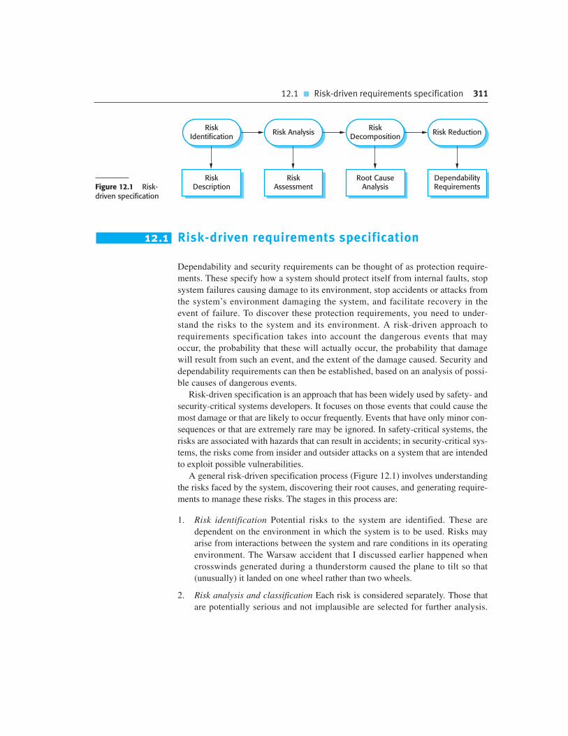
12.1 � Risk-driven requirements specification 311
12.1 Risk-driven requirements specification
Dependability and security requirements can be thought of as protection require-
ments. These specify how a system should protect itself from internal faults, stop
system failures causing damage to its environment, stop accidents or attacks from
the system’s environment damaging the system, and facilitate recovery in the
event of failure. To discover these protection requirements, you need to under-
stand the risks to the system and its environment. A risk-driven approach to
requirements specification takes into account the dangerous events that may
occur, the probability that these will actually occur, the probability that damage
will result from such an event, and the extent of the damage caused. Security and
dependability requirements can then be established, based on an analysis of possi-
ble causes of dangerous events.
Risk-driven specification is an approach that has been widely used by safety- and
security-critical systems developers. It focuses on those events that could cause the
most damage or that are likely to occur frequently. Events that have only minor con-
sequences or that are extremely rare may be ignored. In safety-critical systems, the
risks are associated with hazards that can result in accidents; in security-critical sys-
tems, the risks come from insider and outsider attacks on a system that are intended
to exploit possible vulnerabilities.
A general risk-driven specification process (Figure 12.1) involves understanding
the risks faced by the system, discovering their root causes, and generating require-
ments to manage these risks. The stages in this process are:
1. Risk identification Potential risks to the system are identified. These are
dependent on the environment in which the system is to be used. Risks may
arise from interactions between the system and rare conditions in its operating
environment. The Warsaw accident that I discussed earlier happened when
crosswinds generated during a thunderstorm caused the plane to tilt so that
(unusually) it landed on one wheel rather than two wheels.
2. Risk analysis and classification Each risk is considered separately. Those that
are potentially serious and not implausible are selected for further analysis.
RiskAssessment
DependabilityRequirements
Root CauseAnalysis
RiskDescription
RiskIdentification
Risk AnalysisRisk
DecompositionRisk Reduction
Figure 12.1 Risk-driven specification

312 Chapter 12 � Dependability and security specification
At this stage, risks may be eliminated because they are unlikely to arise or
because they cannot be detected by the software (e.g., an allergic reaction to the
sensor in the insulin pump system).
3. Risk decomposition Each risk is analyzed to discover potential root causes of
that risk. Root causes are the reasons why a system may fail. They may be soft-
ware or hardware errors or inherent vulnerabilities that result from system
design decisions.
4. Risk reduction Proposals for ways in which the identified risks may be
reduced or eliminated are made. These contribute to the system dependability
requirements that define the defenses against the risk and how the risk will be
managed.
For large systems, risk analysis may be structured into phases (Leveson, 1995),
where each phase considers different types of risks:
1. Preliminary risk analysis, where major risks from the system’s environment are
identified. These are independent from the technology used for system develop-
ment. The aim of preliminary risk analysis is to develop an initial set of security
and dependability requirements for the system.
2. Life-cycle risk analysis, which takes place during system development and
which is mostly concerned with risks that arise from system design decisions.
Different technologies and system architectures have their own associated
risks. At this stage, you should extend the requirements to protect against
these risks.
3. Operational risk analysis, which is concerned with the system user interface and
risks from operator errors. Again, once decisions have been made on the user
interface design, further protection requirements may have to be added.
These phases are necessary because it is impossible to make all dependability and
security decisions without complete information about the system implementation.
Security and dependability requirements are particularly affected by technology
choices and design decisions. System checks may have to be included to ensure that
third-party components have operated correctly. Security requirements may have to
be modified because they conflict with the security features that are provided by an
off-the-shelf system.
For example, a security requirement may be that users should identify themselves
to a system using a pass phrase rather than a password. Pass phrases are considered
to be more secure than passwords. They are harder for an attacker to guess or to dis-
cover using an automated password cracking system. However, if a decision is made
to use an existing system that only supports password-based authentication, then this
security requirement cannot be supported. It may then be necessary to include addi-
tional functionality in the system to compensate for the increased risks of using
passwords rather than pass phrases.

12.2 � Safety specification 313
12.2 Safety specification
Safety-critical systems are systems in which failures may affect the environment of
the system and cause injury or death to the people in that environment. The principal
concern of safety specification is to identify requirements that will minimize the
probability that such system failures will occur. Safety requirements are primarily
protection requirements and are not concerned with normal system operation. They
may specify that the system should be shut down so that safety is maintained. In
deriving safety requirements, you therefore need to find an acceptable balance
between safety and functionality and avoid overprotection. There is no point in
building a very safe system if it does not operate in a cost-effective way.
Recall from the discussion in Chapter 10 that safety-critical systems use a spe-
cialized terminology where a hazard is something that could (but need not) result in
death or injury to a person, and a risk is the probability that the system will enter
a hazardous state. Therefore safety specification is usually focused on the hazards
that may arise in a given situation, and the events that can lead to these hazards.
The activities in the general risk-based specification process, shown in Figure 12.1,
map onto the safety specification process as follows:
1. Risk identification In safety specification, this is the hazard identification
process that identifies hazards that may threaten the system.
2. Risk analysis This is a process of hazard assessment to decide which hazards are
the most dangerous and/or the most likely to occur. These should be prioritized
when deriving safety requirements.
3. Risk decomposition This process is concerned with discovering the events that
can lead to the occurrence of a hazard. In safety specification, the process is
known as hazard analysis.
4. Risk reduction This process is based on the outcome of hazard analysis and
leads to identification of safety requirements. These may be concerned with
ensuring that a hazard does not arise or lead to an accident or that if an accident
does occur, the associated damage is minimized.
The IEC standard for safety management
The IEC (International Electrotechnical Commission) has defined a standard for safety management forprotection systems (i.e., systems that are intended to trigger safeguards when some dangerous situation arises).An example of a protection system is a system that automatically stops a train if it goes through a red signal.This standard includes extensive guidance on the process of safety specification.
http://www.SoftwareEngineering-9.com/Web/SafetyLifeCycle/

314 Chapter 12 � Dependability and security specification
12.2.1 Hazard identification
In safety-critical systems, the principal risks come from hazards that can lead to an
accident. You can tackle the hazard identification problem by considering different
types of hazards, such as physical hazards, electrical hazards, biological hazards,
radiation hazards, service failure hazards, and so on. Each of these classes can then
be analyzed to discover specific hazards that could occur. Possible combinations of
hazards that are potentially dangerous must also be identified.
The insulin pump system that I have used as an example in earlier chapters is a
safety-critical system, because failure can cause injury or even death to the system
user. Accidents that may occur when using this machine include the user suffering
from long-term consequences of poor blood sugar control (eye, heart, and kidney
problems); cognitive dysfunction as a result of low blood sugar levels; or the occur-
rence of some other medical conditions, such as an allergic reaction.
Some of the hazards in the insulin pump system are:
• insulin overdose computation (service failure);
• insulin underdose computation (service failure);
• failure of the hardware monitoring system (service failure);
• power failure due to exhausted battery (electrical);
• electrical interference with other medical equipment such as a heart pacemaker
(electrical);
• poor sensor and actuator contact caused by incorrect fitting (physical);
• parts of machine breaking off in patient’s body (physical);
• infection caused by introduction of machine (biological);
• allergic reaction to the materials or insulin used in the machine (biological).
Experienced engineers, working with domain experts and professional safety
advisers, identify hazards from previous experience and from an analysis of the appli-
cation domain. Group working techniques such as brainstorming may be used, where
a group of people exchange ideas. For the insulin pump system, people who may be
involved include doctors, medical physicists, and engineers and software designers.
Software-related hazards are normally concerned with failure to deliver a system
service, or with the failure of monitoring and protection systems. Monitoring and
protection systems are included in a device to detect conditions, such as low battery
levels, which could lead to device failure.
12.2.2 Hazard assessment
The hazard assessment process focuses on understanding the probability that a haz-
ard will occur and the consequences if an accident or incident associated with that
hazard should occur. You need to make this analysis to understand whether a hazard

12.2 � Safety specification 315
is a serious threat to the system or environment. The analysis also provides a basis
for deciding on how to manage the risk associated with the hazard.
For each hazard, the outcome of the analysis and classification process is a state-
ment of acceptability. This is expressed in terms of risk, where the risk takes into
account the likelihood of an accident and its consequences. There are three risk cat-
egories that you can use in hazard assessment:
1. Intolerable risks in safety-critical systems are those that threaten human life.
The system must be designed so that such hazards either cannot arise or, that if
they do, features in the system will ensure that they are detected before they
cause an accident. In the case of the insulin pump, an intolerable risk is that an
overdose of insulin should be delivered.
2. As low as reasonably practical (ALARP) risks are those that have less serious con-
sequences or that are serious but have a very low probability of occurrence. The
system should be designed so that the probability of an accident arising because of
a hazard is minimized, subject to other considerations such as cost and delivery.
An ALARP risk for an insulin pump might be the failure of the hardware monitor-
ing system. The consequences of this are, at worst, a short-term insulin underdose.
This is a situation that would not lead to a serious accident.
3. Acceptable risks are those where the associated accidents normally result in
minor damage. System designers should take all possible steps to reduce
‘acceptable’ risks, so long as these do not increase costs, delivery time, or other
non-functional system attributes. An acceptable risk in the case of the insulin
pump might be the risk of an allergic reaction arising in the user. This usually
causes only minor skin irritation. It would not be worth using special, more
expensive materials in the device to reduce this risk.
Figure 12.2 (Brazendale and Bell, 1994), developed for safety-critical systems,
shows these three regions. The shape of the diagram reflects the costs of ensuring
risks do not result in incidents or accidents. The cost of system design to cope with
Unacceptable RegionRisk Cannot be Tolerated
Risk Tolerated Only ifRisk Reduction is Impracticalor Excessively Expensive
AcceptableRegion
Negligible Risk
ALARPRegion
Figure 12.2The risk triangle

316 Chapter 12 � Dependability and security specification
the risk is indicated by the width of the triangle. The highest costs are incurred by
risks at the top of the diagram, the lowest costs by risks at the apex of the triangle.
The boundaries between the regions in Figure 12.2 are not technical but rather
depend on social and political factors. Over time, society has become more risk-
averse so the boundaries have moved downwards. Although the financial costs of
accepting risks and paying for any resulting accidents may be less than the costs
of accident prevention, public opinion may demand that money be spent to reduce
the likelihood of a system accident, thus incurring additional costs.
For example, it may be cheaper for a company to clean up pollution on the rare
occasion it occurs, rather than to install systems for pollution prevention. However,
because the public and the press will not tolerate such accidents, clearing up the
damage rather than preventing the accident is no longer acceptable. Such events
may also lead to a reclassification of risk. For example, risks that were thought to be
improbable (and hence in the ALARP region) may be reclassified as intolerable
because of events, such as terrorist attacks, or accidents that have occurred.
Hazard assessment involves estimating hazard probability and risk severity. This is
usually difficult as hazards and accidents are uncommon so the engineers involved may
not have direct experience of previous incidents or accidents. Probabilities and severities
are assigned using relative terms such as ‘probable,’ ‘unlikely,’ and ‘rare’ and ‘high,’
‘medium,’ and ‘low’. It is only possible to quantify these terms if enough accident and
incident data is available for statistical analysis.
Figure 12.3 shows a risk classification for the hazards identified in the previous
section for the insulin delivery system. I have separated the hazards that relate to the
Identified hazard Hazard probability Accident severity Estimated risk Acceptability
1. Insulin overdosecomputation
Medium High High Intolerable
2. Insulin underdosecomputation
Medium Low Low Acceptable
3. Failure of hardwaremonitoring system
Medium Medium Low ALARP
4. Power failure High Low Low Acceptable
5. Machine incorrectly fitted High High High Intolerable
6. Machine breaks inpatient
Low High Medium ALARP
7. Machine causes infection Medium Medium Medium ALARP
8. Electrical interference Low High Medium ALARP
9. Allergic reaction Low Low Low Acceptable
Figure 12.3 Riskclassification for theinsulin pump

12.2 � Safety specification 317
incorrect computation of insulin into an insulin overdose and an insulin underdose.
An insulin overdose is potentially more serious than an insulin underdose in the
short term. Insulin overdose can result in cognitive dysfunction, coma, and ulti-
mately death. Insulin underdoses lead to high levels of blood sugar. In the short term,
these cause tiredness but are not very serious; in the longer term, however, they can
lead to serious heart, kidney, and eye problems.
Hazards 4–9 in Figure 12.3 are not software related, but software nevertheless has
a role to play in hazard detection. The hardware monitoring software should monitor
the system state and warn of potential problems. The warning will often allow the
hazard to be detected before it causes an accident. Examples of hazards that might be
detected are power failure, which is detected by monitoring the battery, and incorrect
placement of machine, which may be detected by monitoring signals from the blood
sugar sensor.
The monitoring software in the system is, of course, safety related. Failure to
detect a hazard could result in an accident. If the monitoring system fails but the
hardware is working correctly then this is not a serious failure. However, if the mon-
itoring system fails and hardware failure cannot then be detected, then this could
have more serious consequences.
12.2.3 Hazard analysis
Hazard analysis is the process of discovering the root causes of hazards in a safety-
critical system. Your aim is to find out what events or combination of events could
cause a system failure that results in a hazard. To do this, you can use either a top-
down or a bottom-up approach. Deductive, top-down techniques, which tend to be
easier to use, start with the hazard and work up from that to the possible system failure.
Inductive, bottom-up techniques start with a proposed system failure and identify
what hazards might result from that failure.
Various techniques have been proposed as possible approaches to hazard decom-
position or analysis. These are summarized by Storey (1996). They include reviews
and checklists, formal techniques such as Petri net analysis (Peterson, 1981), formal
logic (Jahanian and Mok, 1986), and fault tree analysis (Leveson and Stolzy, 1987;
Storey, 1996). As I don’t have space to cover all of these techniques here, I focus on
a widely used approach to hazard analysis based on fault trees. This technique is
fairly easy to understand without specialist domain knowledge.
To do a fault tree analysis, you start with the hazards that have been identified.
For each hazard, you then work backwards to discover the possible causes of that
hazard. You put the hazard at the root of the tree and identify the system states that
can lead to that hazard. For each of these states, you then identify further system
states that can lead to them. You continue this decomposition until you reach the root
cause(s) of the risk. Hazards that can only arise from a combination of root causes
are usually less likely to lead to an accident than hazards with a single root cause.
Figure 12.4 is a fault tree for the software-related hazards in the insulin delivery sys-
tem that could lead to an incorrect dose of insulin being delivered. In this case, I have

318 Chapter 12 � Dependability and security specification
merged insulin underdose and insulin overdose into a single hazard, namely ‘incorrect
insulin dose administered.’ This reduces the number of fault trees that are required. Of
course, when you specify how the software should react to this hazard, you have to dis-
tinguish between an insulin underdose and an insulin overdose. As I have said, they are
not equally serious—in the short term, an overdose is the more serious hazard.
From Figure 12.4, you can see that:
1. There are three conditions that could lead to the administration of an incorrect
dose of insulin. The level of blood sugar may have been incorrectly measured so
the insulin requirement has been computed with an incorrect input. The delivery
system may not respond correctly to commands specifying the amount of
insulin to be injected. Alternatively, the dose may be correctly computed but it is
delivered too early or too late.
2. The left branch of the fault tree, concerned with incorrect measurement of the
blood sugar level, looks at how this might happen. This could occur either
Figure 12.4 Anexample of a fault tree
IncorrectSugar LevelMeasured
IncorrectInsulin DoseAdministered
or
Correct DoseDelivered atWrong Time
SensorFailure
or
SugarComputation
Error
TimerFailure
PumpSignals
Incorrect
or
InsulinComputation
Incorrect
DeliverySystemFailure
ArithmeticError
or
AlgorithmError
ArithmeticError
or
AlgorithmError

12.2 � Safety specification 319
because the sensor that provides an input to calculate the sugar level has failed
or because the calculation of the blood sugar level has been carried out
incorrectly. The sugar level is calculated from some measured parameter, such
as the conductivity of the skin. Incorrect computation can result from either an
incorrect algorithm or an arithmetic error that results from the use of floating
point numbers.
3. The central branch of the tree is concerned with timing problems and concludes
that these can only result from system timer failure.
4. The right branch of the tree, concerned with delivery system failure, examines
possible causes of this failure. These could result from an incorrect computation
of the insulin requirement, or from a failure to send the correct signals to the
pump that delivers the insulin. Again, an incorrect computation can result from
algorithm failure or arithmetic errors.
Fault trees are also used to identify potential hardware problems. Hardware fault
trees may provide insights into requirements for software to detect and, perhaps, cor-
rect these problems. For example, insulin doses are not administered at a very high
frequency, no more than two or three times per hour and sometimes less often than
this. Therefore, processor capacity is available to run diagnostic and self-checking
programs. Hardware errors such as sensor, pump, or timer errors can be discovered
and warnings issued before they have a serious effect on the patient.
12.2.4 Risk reduction
Once potential risks and their root causes have been identified, you are then able to
derive safety requirements that manage the risks and ensure that incidents or acci-
dents do not occur. There are three possible strategies that you can use:
1. Hazard avoidance The system is designed so that the hazard cannot occur.
2. Hazard detection and removal The system is designed so that hazards are
detected and neutralized before they result in an accident.
3. Damage limitation The system is designed so that the consequences of an acci-
dent are minimized.
Normally, designers of critical systems use a combination of these approaches. In
a safety-critical system, intolerable hazards may be handled by minimizing their
probability and adding a protection system that provides a safety backup. For exam-
ple, in a chemical plant control system, the system will attempt to detect and avoid
excess pressure in the reactor. However, there may also be an independent protection
system that monitors the pressure and opens a relief valve if high pressure is detected.
In the insulin delivery system, a ‘safe state’ is a shutdown state where no insulin
is injected. Over a short period this is not a threat to the diabetic’s health. For the

320 Chapter 12 � Dependability and security specification
software failures that could lead to an incorrect dose of insulin are considered, the
following ‘solutions’ might be developed:
1. Arithmetic error This may occur when an arithmetic computation causes a rep-
resentation failure. The specification should identify all possible arithmetic
errors that may occur and state that an exception handler must be included for
each possible error. The specification should set out the action to be taken for
each of these errors. The default safe action is to shut down the delivery system
and activate a warning alarm.
2. Algorithmic error This is a more difficult situation as there is no clear program
exception that must be handled. This type of error could be detected by comparing
the required insulin dose computed with the previously delivered dose. If it is much
higher, this may mean that the amount has been computed incorrectly. The system
may also keep track of the dose sequence. After a number of above-average doses
have been delivered, a warning may be issued and further dosage limited.
Some of the resulting safety requirements for the insulin pump software are
shown in Figure 12.5. These are user requirements and, naturally, they would be
expressed in more detail in the system requirements specification. In Figure 12.5, the
references to Tables 3 and 4 relate to tables that are included in the requirements
document—they are not shown here.
12.3 Reliability specification
As I discussed in Chapter 10, the overall reliability of a system depends on the hard-
ware reliability, the software reliability, and the reliability of the system operators.
The system software has to take this into account. As well as including requirements
Figure 12.5Examples of safetyrequirements
SR1: The system shall not deliver a single dose of insulin that is greater than a specified maximum
dose for a system user.
SR2: The system shall not deliver a daily cumulative dose of insulin that is greater than a specified
maximum daily dose for a system user.
SR3: The system shall include a hardware diagnostic facility that shall be executed at least four
times per hour.
SR4: The system shall include an exception handler for all of the exceptions that are identified
in Table 3.
SR5: The audible alarm shall be sounded when any hardware or software anomaly is discovered
and a diagnostic message, as defined in Table 4, shall be displayed.
SR6: In the event of an alarm, insulin delivery shall be suspended until the user has reset the
system and cleared the alarm.

12.3 � Reliability specification 321
that compensate for software failure, there may also be related reliability requirements
to help detect and recover from hardware failures and operator errors.
Reliability is different from safety and security in that it is a measurable system
attribute. That is, it is possible to specify the level of reliability that is required, mon-
itor the system’s operation over time, and check if the required reliability has been
achieved. For example, a reliability requirement might be that system failures that
require a reboot should not occur more than once per week. Every time such a fail-
ure occurs, it can be logged and you can check if the required level of reliability has
been achieved. If not, you either modify your reliability requirement or submit a
change request to address the underlying system problems. You may decide to
accept a lower level of reliability because of the costs of changing the system to
improve reliability or because fixing the problem may have adverse side effects,
such as lower performance or throughput.
By contrast, both safety and security are about avoiding undesirable situations,
rather than specifying a desired ‘level’ of safety or security. Even one such situation
in the lifetime of a system may be unacceptable and, if it occurs, system changes
have to be made. It makes no sense to make statements like ‘system faults should
result in fewer than 10 injuries per year.’ As soon as one injury occurs, the system
problem must be rectified.
Reliability requirements are, therefore, of two kinds:
1. Non-functional requirements, which define the number of failures that are
acceptable during normal use of the system, or the time in which the system is
unavailable for use. These are quantitative reliability requirements.
2. Functional requirements, which define system and software functions that
avoid, detect, or tolerate faults in the software and so ensure that these faults do
not lead to system failure.
Quantitative reliability requirements lead to related functional system require-
ments. To achieve some required level of reliability, the functional and design
requirements of the system should specify the faults to be detected and the actions
that should be taken to ensure that these faults do not lead to system failures.
The process of reliability specification can be based on the general risk-driven
specification process shown in Figure 12.1:
1. Risk identification At this stage, you identify the types of system failures that
may lead to economic losses of some kind. For example, an e-commerce system
may be unavailable so that customers cannot place orders, or a failure that cor-
rupts data may require time to restore the system database from a backup and
rerun transactions that have been processed. The list of possible failure types,
shown in Figure 12.6, can be used as a starting point for risk identification.
2. Risk analysis This involves estimating the costs and consequences of different
types of software failure and selecting high-consequence failures for further
analysis.
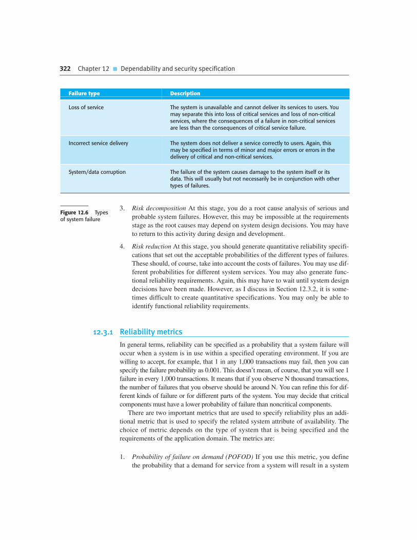
322 Chapter 12 � Dependability and security specification
3. Risk decomposition At this stage, you do a root cause analysis of serious and
probable system failures. However, this may be impossible at the requirements
stage as the root causes may depend on system design decisions. You may have
to return to this activity during design and development.
4. Risk reduction At this stage, you should generate quantitative reliability specifi-
cations that set out the acceptable probabilities of the different types of failures.
These should, of course, take into account the costs of failures. You may use dif-
ferent probabilities for different system services. You may also generate func-
tional reliability requirements. Again, this may have to wait until system design
decisions have been made. However, as I discuss in Section 12.3.2, it is some-
times difficult to create quantitative specifications. You may only be able to
identify functional reliability requirements.
12.3.1 Reliability metrics
In general terms, reliability can be specified as a probability that a system failure will
occur when a system is in use within a specified operating environment. If you are
willing to accept, for example, that 1 in any 1,000 transactions may fail, then you can
specify the failure probability as 0.001. This doesn’t mean, of course, that you will see 1
failure in every 1,000 transactions. It means that if you observe N thousand transactions,
the number of failures that you observe should be around N. You can refine this for dif-
ferent kinds of failure or for different parts of the system. You may decide that critical
components must have a lower probability of failure than noncritical components.
There are two important metrics that are used to specify reliability plus an addi-
tional metric that is used to specify the related system attribute of availability. The
choice of metric depends on the type of system that is being specified and the
requirements of the application domain. The metrics are:
1. Probability of failure on demand (POFOD) If you use this metric, you define
the probability that a demand for service from a system will result in a system
Figure 12.6 Typesof system failure
Failure type Description
Loss of service The system is unavailable and cannot deliver its services to users. Youmay separate this into loss of critical services and loss of non-criticalservices, where the consequences of a failure in non-critical servicesare less than the consequences of critical service failure.
Incorrect service delivery The system does not deliver a service correctly to users. Again, thismay be specified in terms of minor and major errors or errors in thedelivery of critical and non-critical services.
System/data corruption The failure of the system causes damage to the system itself or itsdata. This will usually but not necessarily be in conjunction with othertypes of failures.

12.3 � Reliability specification 323
failure. So, POFOD � 0.001 means that there is a 1/1,000 chance that a failure
will occur when a demand is made.
2. Rate of occurrence of failures (ROCOF) This metric sets out the probable
number of system failures that are likely to be observed relative to a certain time
period (e.g., an hour), or to the number of system executions. In the example
above, the ROCOF is 1/1,000. The reciprocal of ROCOF is the mean time to
failure (MTTF), which is sometimes used as a reliability metric. MTTF is the
average number of time units between observed system failures. Therefore,
a ROCOF of two failures per hour implies that the mean time to failure is
30 minutes.
3. Availability (AVAIL) The availability of a system reflects its ability to deliver
services when requested. AVAIL is the probability that a system will be opera-
tional when a demand is made for service. Therefore, an availability of 0.9999,
means that, on average, the system will be available for 99.99% of the operating
time. Figure 12.7 shows what different levels of availability mean in practice.
POFOD should be used as a reliability metric in situations where a failure on
demand can lead to a serious system failure. This applies irrespective of the fre-
quency of the demands. For example, a protection system that monitors a chemical
reactor and shuts down the reaction if it is overheating should have its reliability
specified using POFOD. Generally, demands on a protection system are infrequent
as the system is a last line of defense, after all other recovery strategies have failed.
Therefore a POFOD of 0.001 (1 failure in 1,000 demands) might seem to be risky,
but if there are only two or three demands on the system in its lifetime, then you will
probably never see a system failure.
ROCOF is the most appropriate metric to use in situations where demands on sys-
tems are made regularly rather than intermittently. For example, in a system that han-
dles a large number of transactions, you may specify a ROCOF of 10 failures per
day. This means that you are willing to accept that an average of 10 transactions per
day will not complete successfully and will have to be canceled. Alternatively, you
may specify ROCOF as the number of failures per 1,000 transactions.
If the absolute time between failures is important, you may specify the reliability
as the mean time between failures. For example, if you are specifying the required
Figure 12.7Availabilityspecification
Availability Explanation
0.9 The system is available for 90% of the time. This means that, in a 24-hour period(1,440 minutes), the system will be unavailable for 144 minutes.
0.99 In a 24-hour period, the system is unavailable for 14.4 minutes.
0.999 The system is unavailable for 84 seconds in a 24-hour period.
0.9999 The system is unavailable for 8.4 seconds in a 24-hour period. Roughly, one minute per week.

324 Chapter 12 � Dependability and security specification
reliability for a system with long transactions (such as a computer-aided design sys-
tem), you should specify the reliability with a long mean time to failure. The MTTF
should be much longer than the average time that a user works on his or her models
without saving their results. This would mean that users would be unlikely to lose
work through a system failure in any one session.
To assess the reliability of a system, you have to capture data about its operation.
The data required may include:
1. The number of system failures given a number of requests for system services.
This is used to measure the POFOD.
2. The time or the number of transactions between system failures plus the total
elapsed time or total number of transactions. This is used to measure ROCOF
and MTTF.
3. The repair or restart time after a system failure that leads to loss of service. This
is used in the measurement of availability. Availability does not just depend on
the time between failures but also on the time required to get the system back
into operation.
The time units that may be used are calendar time or processor time or a discrete
unit such as number of transactions. In systems that spend much of their time wait-
ing to respond to a service request, such as telephone switching systems, the time
unit that should be used is processor time. If you use calendar time, then this will
include the time when the system was doing nothing.
You should use calendar time for systems that are in continuous operation.
Monitoring systems, such as alarm systems, and other types of process control sys-
tems fall into this category. Systems that process transactions such as bank ATMs or
airline reservation systems have variable loads placed on them depending on the time
of day. In these cases, the unit of ‘time’ used could be the number of transactions (i.e.,
the ROCOF would be number of failed transactions per N thousand transactions).
12.3.2 Non-functional reliability requirements
Non-functional reliability requirements are quantitative specifications of the
required reliability and availability of a system, calculated using one of the metrics
described in the previous section. Quantitative reliability and availability specifica-
tion has been used for many years in safety-critical systems but is only rarely used in
business critical systems. However, as more and more companies demand 24/7 ser-
vice from their systems, it is likely that such techniques will be increasingly used.
There are several advantages in deriving quantitative reliability specifications:
1. The process of deciding what required level of the reliability helps to clarify
what stakeholders really need. It helps stakeholders understand that there are
different types of system failure, and it makes clear to them that high levels of
reliability are very expensive to achieve.

12.3 � Reliability specification 325
2. It provides a basis for assessing when to stop testing a system. You stop when
the system has achieved its required reliability level.
3. It is a means of assessing different design strategies intended to improve the reli-
ability of a system. You can make a judgment about how each strategy might
lead to the required levels of reliability.
4. If a regulator has to approve a system before it goes into service (e.g., all systems
that are critical to flight safety on an aircraft are regulated), then evidence that
a required reliability target has been met is important for system certification.
To establish the required level of system reliability, you have to consider the asso-
ciated losses that could result from a system failure. These are not simply financial
losses, but also loss of reputation for a business. Loss of reputation means that cus-
tomers will go elsewhere. Although the short-term losses from a system failure may
be relatively small, the longer-term losses may be much more significant. For exam-
ple, if you try to access an e-commerce site and find that it is unavailable, you may
try to find what you want elsewhere rather than wait for the system to become avail-
able. If this happens more than once, you will probably not shop at that site again.
The problem with specifying reliability using metrics such as POFOD, ROCOF,
and AVAIL is that it is possible to overspecify reliability and thus incur high devel-
opment and validation costs. The reason for this is that system stakeholders find it
difficult to translate their practical experience into quantitative specifications. They
may think that a POFOD of 0.001 (1failure in 1,000 demands) represents a relatively
unreliable system. However, as I have explained, if demands for a service are
uncommon, it actually represents a very high level of reliability.
If you specify reliability as a metric, it is obviously important to assess that the
required level of reliability has been achieved. You do this assessment as part of sys-
tem testing. To assess the reliability of a system statistically, you have to observe a
number of failures. If you have, for example, a POFOD of 0.0001 (1 failure in
10,000 demands), then you may have to design tests that make 50 or 60 thousand
demands on a system and where several failures are observed. It may be practically
impossible to design and implement this number of tests. Therefore, overspecifica-
tion of reliability leads to very high testing costs.
When you specify the availability of a system, you may have similar problems.
Although a very high level of availability may seem to be desirable, most systems
have very intermittent demand patterns (e.g., a business system will mostly be used
during normal business hours) and a single availability figure does not really reflect
user needs. You need high availability when the system is being used but not at other
times. Depending, of course, on the type of system, there may be no real practical
difference between an availability of 0.999 and an availability of 0.9999.
A fundamental problem with overspecification is that it may be practically
impossible to show that a very high level of reliability or availability has been
achieved. For example, say a system was intended for use in a safety-critical appli-
cation and was therefore required to never fail over its total lifetime. Assume that
1,000 copies of the system are to be installed and the system is executed 1,000

326 Chapter 12 � Dependability and security specification
times per second. The projected lifetime of the system is 10 years. The total number
of system executions is therefore approximately 3*1014. There is no point in speci-
fying that the rate of occurrence of failure should be 1/1015 executions (this allows
for some safety factor) as you cannot test the system for long enough to validate this
level of reliability.
Organizations must therefore be realistic about whether it is worth specifying and
validating a very high level of reliability. High reliability levels are clearly justified
in systems where reliable operation is critical, such as telephone switching systems,
or where system failure may result in large economic losses. They are probably not
justified for many types of business or scientific systems. Such systems have modest
reliability requirements, as the costs of failure are simply processing delays and it is
straightforward and relatively inexpensive to recover from these.
There are a number of steps that you can take to avoid the overspecification of
system reliability:
1. Specify the availability and reliability requirements for different types of fail-
ures. There should be a lower probability of serious failures occurring than
minor failures.
2. Specify the availability and reliability requirements for different services sepa-
rately. Failures that affect the most critical services should be specified as less
probable than those with only local effects. You may decide to limit the quanti-
tative reliability specification to the most critical system services.
3. Decide whether you really need high reliability in a software system or whether
the overall system dependability goals can be achieved in other ways. For exam-
ple, you may use error detection mechanisms to check the outputs of a system
and have processes in place to correct errors. There may then be no need for
a high level of reliability in the system that generates the outputs.
To illustrate this latter point, consider the reliability requirements for a bank ATM
system that dispenses cash and provides other services to customers. If there are
hardware or software ATM problems, then these lead to incorrect entries in the cus-
tomer account database. These could be avoided by specifying a very high level of
hardware and software reliability in the ATM.
However, banks have many years of experience of how to identify and correct
incorrect account transactions. They use accounting methods to detect when things
have gone wrong. Most transactions that fail can simply be canceled, resulting in no
loss to the bank and minor customer inconvenience. Banks that run ATM networks
therefore accept that ATM failures may mean that a small number of transactions are
incorrect but they think it more cost effective to fix these later rather than to incur
very high costs in avoiding faulty transactions.
For a bank (and for the bank’s customers), the availability of the ATM network is
more important than whether or not individual ATM transactions fail. Lack of avail-
ability means more demand on counter services, customer dissatisfaction, engineer-
ing costs to repair the network, etc. Therefore, for transaction-based systems, such as

12.3 � Reliability specification 327
banking and e-commerce systems, the focus of reliability specification is usually on
specifying the availability of the system.
To specify the availability of an ATM network, you should identify the system
services and specify the required availability for each of these. These are:
• the customer account database service;
• the individual services provided by an ATM such as ‘withdraw cash,’ ‘provide
account information,’ etc.
Here, the database service is most critical as failure of this service means that all
of the ATMs in the network are out of action. Therefore, you should specify this to
have a high level of availability. In this case, an acceptable figure for database avail-
ability (ignoring issues such as scheduled maintenance and upgrades) would proba-
bly be around 0.9999, between 7 am and 11 pm. This means a down time of less than
one minute per week. In practice, this would mean that very few customers would be
affected and would only lead to minor customer inconvenience.
For an individual ATM, the overall availability depends on mechanical reliability
and the fact that it can run out of cash. Software issues are likely to have less effect
than factors such as these. Therefore, a lower level of availability for the ATM soft-
ware is acceptable. The overall availability of the ATM software might therefore be
specified as 0.999, which means that a machine might be unavailable for between
one and two minutes each day.
To illustrate failure-based reliability specification, consider the reliability require-
ments for the control software in the insulin pump. This system delivers insulin a
number of times per day and monitors the user’s blood glucose several times per
hour. Because the use of the system is intermittent and failure consequences are seri-
ous, the most appropriate reliability metric is POFOD (probability of failure on
demand).
There are two possible types of failure in the insulin pump:
1. Transient software failures that can be repaired by user actions such as resetting
or recalibrating the machine. For these types of failures, a relatively low value of
POFOD (say 0.002) may be acceptable. This means that one failure may occur
in every 500 demands made on the machine. This is approximately once every
3.5 days, because the blood sugar is checked about five times per hour.
2. Permanent software failures that require the software to be reinstalled by the
manufacturer. The probability of this type of failure should be much lower.
Roughly once a year is the minimum figure, so POFOD should be no more than
0.00002.
However, failure to deliver insulin does not have immediate safety implications, so
commercial factors rather than the safety factors govern the level of reliability required.
Service costs are high because users need fast repair and replacement. It is in the
manufacturer’s interest to limit the number of permanent failures that require repair.

328 Chapter 12 � Dependability and security specification
12.3.3 Functional reliability specification
Functional reliability specification involves identifying requirements that define
constraints and features that contribute to system reliability. For systems where the
reliability has been quantitatively specified, these functional requirements may be
necessary to ensure that a required level of reliability is achieved.
There are three types of functional reliability requirements for a system:
1. Checking requirements These requirements identify checks on inputs to the sys-
tem to ensure that incorrect or out-of-range inputs are detected before they are
processed by the system.
2. Recovery requirements These requirements are geared to helping the system
recover after a failure has occurred. Typically, these requirements are concerned
with maintaining copies of the system and its data and specifying how to restore
system services after a failure.
3. Redundancy requirements These specify redundant features of the system that
ensure that a single component failure does not lead to a complete loss of service.
I discuss this in more detail in the next chapter.
In addition, the reliability requirements may include process requirements
for reliability. These are requirements to ensure that good practice, known to
reduce the number of faults in a system, is used in the development process.
Some examples of functional reliability and process requirements are shown in
Figure 12.8.
There are no simple rules for deriving functional reliability requirements. In
organizations that develop critical systems, there is usually organizational knowl-
edge about possible reliability requirements and how these impact the actual reliability
of a system. These organizations may specialize in specific types of system such as
railway control systems, so the reliability requirements can be reused across a range
of systems.
Figure 12.8Examples offunctionalreliabilityrequirements
RR1: A pre-defined range for all operator inputs shall be defined and the system shall check
that all operator inputs fall within this pre-defined range. (Checking)
RR2: Copies of the patient database shall be maintained on two separate servers that are not
housed in the same building. (Recovery, redundancy)
RR3: N-version programming shall be used to implement the braking control system.
(Redundancy)
RR4: The system must be implemented in a safe subset of Ada and checked using static analysis.
(Process)

12.4 � Security specification 329
12.4 Security specification
The specification of security requirements for systems has something in common
with safety requirements. It is impractical to specify them quantitatively, and secu-
rity requirements are often ‘shall not’ requirements that define unacceptable system
behavior rather than required system functionality. However, security is a more chal-
lenging problem than safety, for a number of reasons:
1. When considering safety, you can assume that the environment in which the
system is installed is not hostile. No one is trying to cause a safety-related inci-
dent. When considering security, you have to assume that attacks on the system
are deliberate and that the attacker may have knowledge of system weaknesses.
2. When system failures occur that pose a risk to safety, you look for the errors or
omissions that have caused the failure. When deliberate attacks cause system
failures, finding the root cause may be more difficult as the attacker may try to
conceal the cause of the failure.
3. It is usually acceptable to shut down a system or to degrade system services to
avoid a safety-related failure. However, attacks on a system may be so-called
denial of service attacks, which are intended to shut down the system. Shutting
down the system means that the attack has been successful.
4. Safety-related events are not generated by an intelligent adversary. An attacker
can probe a system’s defenses in a series of attacks, modifying the attacks as he
or she learns more about the system and its responses.
These distinctions mean that security requirements usually have to be more exten-
sive than safety requirements. Safety requirements lead to the generation of func-
tional system requirements that provide protection against events and faults that
could cause safety-related failures. They are mostly concerned with checking for
problems and taking actions if these problems occur. By contrast, there are many
types of security requirements that cover the different threats faced by a system.
Firesmith (2003) has identified 10 types of security requirements that may be
included in a system specification:
1. Identification requirements specify whether or not a system should identify its
users before interacting with them.
2. Authentication requirements specify how users are identified.
3. Authorization requirements specify the privileges and access permissions of
identified users.
4. Immunity requirements specify how a system should protect itself against
viruses, worms, and similar threats.
5. Integrity requirements specify how data corruption can be avoided.
330 Chapter 12 � Dependability and security specification
6. Intrusion detection requirements specify what mechanisms should be used to
detect attacks on the system.
7. Non-repudiation requirements specify that a party in a transaction cannot deny
its involvement in that transaction.
8. Privacy requirements specify how data privacy is to be maintained.
9. Security auditing requirements specify how system use can be audited and
checked.
10. System maintenance security requirements specify how an application can pre-
vent authorized changes from accidentally defeating its security mechanisms.
Of course, you will not see all of these types of security requirements in every
system. The particular requirements depend on the type of system, the situation of
use, and the expected users.
The risk analysis and assessment process discussed in Section 12.1 may be used
to identify system security requirements. As I discussed, there are three stages to this
process:
1. Preliminary risk analysis At this stage, decisions on the detailed system require-
ments, the system design, or the implementation technology have not been
made. The aim of this assessment process is to derive security requirements for
the system as a whole.
2. Life-cycle risk analysis This risk assessment takes place during the system
development life cycle after design choices have been made. The additional
security requirements take account of the technologies used in building the sys-
tem and system design and implementation decisions.
3. Operational risk analysis This risk assessment considers the risks posed by
malicious attacks on the operational system by users, with or without insider
knowledge of the system.
The risk assessment and analysis processes used in security requirements specifi-
cation are variants of the generic risk-driven specification process discussed in
Security risk management
Safety is a legal issue and businesses cannot decide to opt out of producing safe systems. However, someaspects of security are business issues—a business can decide not to implement some security measures and tocover the losses that may result from this decision. Risk management is the process of deciding what assetsmust be protected and how much can be spent on protecting them.
http://www.SoftwareEngineering-9.com/Web/Security/RiskMan.html
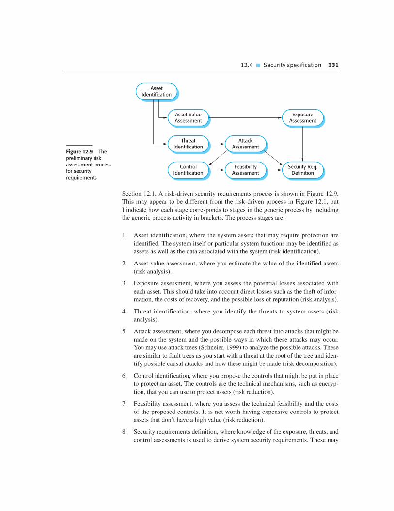
12.4 � Security specification 331
Section 12.1. A risk-driven security requirements process is shown in Figure 12.9.
This may appear to be different from the risk-driven process in Figure 12.1, but
I indicate how each stage corresponds to stages in the generic process by including
the generic process activity in brackets. The process stages are:
1. Asset identification, where the system assets that may require protection are
identified. The system itself or particular system functions may be identified as
assets as well as the data associated with the system (risk identification).
2. Asset value assessment, where you estimate the value of the identified assets
(risk analysis).
3. Exposure assessment, where you assess the potential losses associated with
each asset. This should take into account direct losses such as the theft of infor-
mation, the costs of recovery, and the possible loss of reputation (risk analysis).
4. Threat identification, where you identify the threats to system assets (risk
analysis).
5. Attack assessment, where you decompose each threat into attacks that might be
made on the system and the possible ways in which these attacks may occur.
You may use attack trees (Schneier, 1999) to analyze the possible attacks. These
are similar to fault trees as you start with a threat at the root of the tree and iden-
tify possible causal attacks and how these might be made (risk decomposition).
6. Control identification, where you propose the controls that might be put in place
to protect an asset. The controls are the technical mechanisms, such as encryp-
tion, that you can use to protect assets (risk reduction).
7. Feasibility assessment, where you assess the technical feasibility and the costs
of the proposed controls. It is not worth having expensive controls to protect
assets that don’t have a high value (risk reduction).
8. Security requirements definition, where knowledge of the exposure, threats, and
control assessments is used to derive system security requirements. These may
AssetIdentification
Asset ValueAssessment
ThreatIdentification
AttackAssessment
ExposureAssessment
Security Req.Definition
ControlIdentification
FeasibilityAssessment
Figure 12.9 Thepreliminary riskassessment processfor securityrequirements

332 Chapter 12 � Dependability and security specification
be requirements for the system infrastructure or the application system (risk
reduction).
An important input to the risk assessment and management process is the organi-
zational security policy. An organizational security policy applies to all systems and
should set out what should and what should not be allowed. For example, one aspect
of a military security policy may state ‘Readers may only examine documents whose
classification is the same as or below the reader’s vetting level.’ This means that if a
reader has been vetted to a ‘secret’ level, they may access documents that are classed
as ‘secret,’ ‘confidential,’ or ‘open’ but not documents classed as ‘top secret.’
The security policy sets out conditions that should always be maintained by a
security system and so helps identify threats that might arise. Threats are any-
thing that could threaten business security. In practice, security policies are usu-
ally informal documents that define what is and what isn’t allowed. However,
Bishop (2005) discusses the possibility of expressing security policies in a formal
language and generating automated checks to ensure that the policy is being
followed.
To illustrate this process of security risk analysis, consider the hospital informa-
tion system for mental health care, MHC-PMS. I don’t have space to discuss a com-
plete risk assessment here but rather draw on this system as a source of examples.
I have shown these as a fragment of a report (Figures 12.10 and 12.11) that might be
generated from the preliminary risk assessment process. This preliminary risk analysis
report is used in defining the security requirements.
From the risk analysis for the hospital information system, you can derive secu-
rity requirements. Some examples of these requirements are:
1. Patient information shall be downloaded, at the start of a clinic session, from the
database to a secure area on the system client.
Figure 12.10 Assetanalysis in apreliminary riskassessment reportfor the MHC-PMS
Asset Value Exposure
The information system High. Required to support allclinical consultations. Potentiallysafety-critical.
High. Financial loss as clinics mayhave to be canceled. Costs ofrestoring system. Possible patientharm if treatment cannot beprescribed.
The patient database High. Required to support allclinical consultations. Potentiallysafety-critical.
High. Financial loss as clinics mayhave to be canceled. Costs ofrestoring system. Possible patientharm if treatment cannot beprescribed.
An individual patient record Normally low although may behigh for specific high-profilepatients.
Low direct losses but possible lossof reputation.
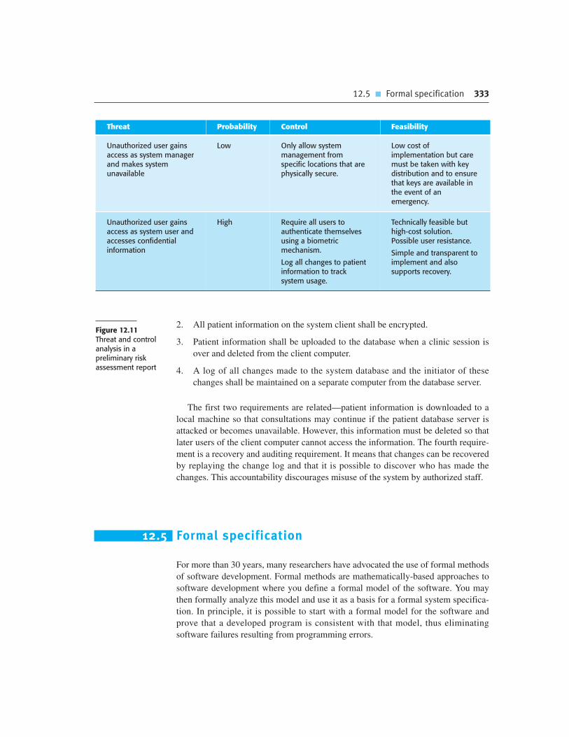
12.5 � Formal specification 333
2. All patient information on the system client shall be encrypted.
3. Patient information shall be uploaded to the database when a clinic session is
over and deleted from the client computer.
4. A log of all changes made to the system database and the initiator of these
changes shall be maintained on a separate computer from the database server.
The first two requirements are related—patient information is downloaded to a
local machine so that consultations may continue if the patient database server is
attacked or becomes unavailable. However, this information must be deleted so that
later users of the client computer cannot access the information. The fourth require-
ment is a recovery and auditing requirement. It means that changes can be recovered
by replaying the change log and that it is possible to discover who has made the
changes. This accountability discourages misuse of the system by authorized staff.
12.5 Formal specification
For more than 30 years, many researchers have advocated the use of formal methods
of software development. Formal methods are mathematically-based approaches to
software development where you define a formal model of the software. You may
then formally analyze this model and use it as a basis for a formal system specifica-
tion. In principle, it is possible to start with a formal model for the software and
prove that a developed program is consistent with that model, thus eliminating
software failures resulting from programming errors.
Threat Probability Control Feasibility
Unauthorized user gainsaccess as system managerand makes systemunavailable
Low Only allow systemmanagement fromspecific locations that arephysically secure.
Low cost ofimplementation but caremust be taken with keydistribution and to ensurethat keys are available inthe event of anemergency.
Unauthorized user gainsaccess as system user andaccesses confidentialinformation
High Require all users toauthenticate themselvesusing a biometricmechanism.
Log all changes to patientinformation to tracksystem usage.
Technically feasible buthigh-cost solution.Possible user resistance.
Simple and transparent toimplement and alsosupports recovery.
Figure 12.11Threat and controlanalysis in apreliminary riskassessment report

334 Chapter 12 � Dependability and security specification
The starting point for all formal development processes is a formal system model,
which serves as a system specification. To create this model, you translate the sys-
tem’s user requirements, which are expressed in natural language, diagrams, and
tables, into a mathematical language which has formally defined semantics. The for-
mal specification is an unambiguous description of what the system should do.
Using manual or tool-supported methods, you can check that a program’s behavior is
consistent with the specification.
Formal specifications are not just essential for a verification of the design and
implementation of software. They are the most precise way of specifying systems,
and so reduce the scope for misunderstanding. Furthermore, constructing a formal
specification forces a detailed analysis of the requirements and this is an effective
way of discovering requirements problems. In a natural language specification,
errors can be concealed by the imprecision of the language. This is not the case if the
system is formally specified.
Formal specifications are usually developed as part of a plan-based software
process, where the system is completely specified before development. The system
requirements and design are defined in detail and are carefully analyzed and checked
before implementation begins. If a formal specification of the software is developed,
this usually comes after the system requirements have been specified but before the
detailed system design. There is a tight feedback loop between the detailed require-
ments specification and the formal specification.
Figure 12.12 shows the stages of software specification and its interface with soft-
ware design in a plan-based software process. As it is expensive to develop formal
specifications, you may decide to limit the use of this approach to those components
that are critical to the system’s operation. You identify these in the architectural
design of the system.
Over the past few years, automated support for analyzing a formal specification has
been developed. Model checkers (Clarke et al., 2000) are software tools that take a
state-based formal specification (a system model) as an input, along with the specifica-
tion of some formally expressed desirable property, such as ‘there are no unreachable
states.’ The model checking program exhaustively analyzes the specification and either
reports that the system property is satisfied by the model or presents an example
that shows it is not satisfied. Model checking is closely related to the notion of static
analysis and I discuss these general approaches to system verification in Chapter 15.
Formal specification techniques
Formal system specifications may be expressed using two fundamental approaches, either as models of thesystem interfaces (algebraic specifications) or as models of the system state. You can download an extra webchapter on this topic, where I show examples of both of these approaches. The chapter includes a formalspecification of part of the insulin pump system.
http://www.SoftwareEngineering-9.com/Web/ExtraChaps/FormalSpec.pdf

12.5 � Formal specification 335
The advantages of developing a formal specification and using this in a formal
development process are:
1. As you develop a formal specification in detail, you develop a deep and detailed
understanding of the system requirements. Even if you do not use the specifica-
tion in a formal development process, requirements error detection is a potent
argument for developing a formal specification (Hall, 1990). Requirements
problems that are discovered early are usually much cheaper to correct than if
they are found at later stages in the development process.
2. As the specification is expressed in a language with formally defined semantics,
you can analyze it automatically to discover inconsistencies and incompleteness.
3. If you use a method such as the B method, you can transform the formal speci-
fication into a program through a sequence of correctness-preserving transfor-
mations. The resulting program is therefore guaranteed to meet its specification.
4. Program testing costs may be reduced because you have verified the program
against its specification.
In spite of these advantages, formal methods have had limited impact on practical
software development, even for critical systems. Consequently, there is very little
experience in the community of developing and using formal system specifica-
tions. The arguments that are put forward against developing a formal system
specification are:
1. Problem owners and domain experts cannot understand a formal specification
so they cannot check that it accurately represents their requirements. Software
engineers, who understand the formal specification, may not understand the
application domain so they too cannot be sure that the formal specification is an
accurate reflection of the system requirements.
2. It is fairly easy to quantify the costs of creating a formal specification, but more
difficult to estimate the possible cost savings that will result from its use. As a
result, managers are unwilling to take the risk of adopting this approach.
Increasing Contractor Involvement
Decreasing Client Involvement
Specification
Design
UserRequirements
Definition
SystemRequirementsSpecification
ArchitecturalDesign
FormalSpecification
High-LevelDesign
Figure 12.12 Formalspecification in a plan-based softwareprocess

336 Chapter 12 � Dependability and security specification
Formal specification costs
Developing a formal specification is an expensive process as quite a lot of time is needed to translate therequirements into a formal language and check the specification. Experience has shown that savings can bemade in system testing and verification and it seems that specifying a system formally does not significantlyincrease the overall development costs. However, the balance of costs changes, with more costs incurred earlyin the development process.
http://www.SoftwareEngineering-9.com/Web/FormalSpecCosts/
3. Most software engineers have not been trained to use formal specification lan-
guages. Hence, they are reluctant to propose their use in development processes.
4. It is difficult to scale current approaches to formal specification up to very large
systems. When formal specification is used, it is mostly for specifying critical
kernel software rather than complete systems.
5. Formal specification is not compatible with agile methods of development.
Nevertheless, at the time of writing, formal methods have been used in the devel-
opment of a number of safety- and security-critical applications. They may also be
used cost effectively in the development and validation of critical parts of a larger,
more complex software system (Badeau and Amelot, 2005; Hall, 1996; Hall and
Chapman, 2002; Miller et al., 2005; Wordworth, 1996). They are the basis of tools
used in static verification such as the driver verification system used by Microsoft
(Ball et al., 2004; Ball et al., 2006) and the SPARK/Ada language (Barnes, 2003) for
critical systems engineering.
K E Y P O I N T S
� Risk analysis is an important activity in the specification of security and dependability
requirements. It involves identifying risks that can result in accidents or incidents. System
requirements are then generated to ensure that these risks do not occur and, if they do, that
they do not lead to an incident or accident.
� A hazard-driven approach may be used to understand the safety requirements for a system. You
identify potential hazards and decompose these (using methods such as fault tree analysis) to
discover their root causes. You then specify requirements to avoid or recover from these problems.
� Reliability requirements can be defined quantitatively in the system requirements specification.
Reliability metrics include probability of failure on demand (POFOD), rate of occurrence of
failure (ROCOF), and availability (AVAIL).
Chapter 12 � Exercises 337
� It is important not to overspecify the required system reliability as this leads to unnecessary
additional costs in the development and validation processes.
� Security requirements are more difficult to identify than safety requirements because a system
attacker can use knowledge of system vulnerabilities to plan a system attack, and can learn
about vulnerabilities from unsuccessful attacks.
� To specify security requirements, you should identify the assets that are to be protected and
define how security techniques and technology should be used to protect these assets.
� Formal methods of software development rely on a system specification that is expressed as a
mathematical model. Developing a formal specification has the key benefit of stimulating a
detailed examination and analysis of the system requirements.
F U RT H E R R E A D I N G
Safeware: System Safety and Computers. This is a thorough discussion of all aspects of safety-
critical systems. It is particularly strong in its description of hazard analysis and the derivation of
requirements from this. (N. Leveson, Addison-Wesley, 1995.)
‘Security Use Cases.’ A good article, available on the Web, that focuses on how use cases can be
used in security specification. The author also has a number of good articles on security
specification that are referenced in this article. (D. G. Firesmith, Journal of Object Technology, 2 (3),
May–June 2003.) http://www.jot.fm/issues/issue_2003_05/column6/.
‘Ten Commandments of Formal Methods . . .Ten Years Later.’ This is a set of guidelines for the use of
formal methods that was first proposed in 1996 and which are revisited in this paper. It is a good
summary of the practical issues around the use of formal methods. (J. P. Bowen and M. G. Hinchey,
IEEE Computer, 39 (1), January 2006.) http://dx.doi.org/10.1109/MC.2006.35.
‘Security Requirements for the Rest of Us: A Survey.’ A good starting point for reading about security
requirements specification. The authors focus on lightweight rather than formal approaches. (I. A.
Tøndel, M. G. Jaatun, and P. H. Meland, IEEE Software, 25 (1), January/February 2008.)
http://dx.doi.org/10.1109/MS.2008.19.
E X E R C I S E S
12.1. Explain why the boundaries in the risk triangle shown in Figure 12.12 are liable to change with
time and changing social attitudes.
12.2. Explain why the risk-based approach is interpreted in different ways when specifying safety
and security.

338 Chapter 12 � Dependability and security specification
12.3. In the insulin pump system, the user has to change the needle and insulin supply at regular
intervals and may also change the maximum single dose and the maximum daily dose that
may be administered. Suggest three user errors that might occur and propose safety
requirements that would avoid these errors resulting in an accident.
12.4. A safety-critical software system for treating cancer patients has two principal components:
� A radiation therapy machine that delivers controlled doses of radiation to tumor sites. This
machine is controlled by an embedded software system.
� A treatment database that includes details of the treatment given to each patient.
Treatment requirements are entered in this database and are automatically downloaded to
the radiation therapy machine.
Identify three hazards that may arise in this system. For each hazard, suggest a defensive
requirement that will reduce the probability that these hazards will result in an accident.
Explain why your suggested defense is likely to reduce the risk associated with the hazard.
12.5. Suggest appropriate reliability metrics for the classes of software systems below. Give
reasons for your choice of metric. Predict the usage of these systems and suggest appropriate
values for the reliability metrics.
� a system that monitors patients in a hospital intensive care unit
� a word processor
� an automated vending machine control system
� a system to control braking in a car
� a system to control a refrigeration unit
� a management report generator
12.6. A train protection system automatically applies the brakes of a train if the speed limit for
a segment of track is exceeded, or if the train enters a track segment that is currently signaled
with a red light (i.e., the segment should not be entered). Giving reasons for your answer,
choose a reliability metric that might be used to specify the required reliability for such
a system.
12.7. There are two essential safety requirements for the train protection system:
� The train shall not enter a segment of track that is signaled with a red light.
� The train shall not exceed the specified speed limit for a section of track.
Assuming that the signal status and the speed limit for the track segment are transmitted to
onboard software on the train before it enters the track segment, propose five possible
functional system requirements for the onboard software that may be generated from the
system safety requirements.
338 Chapter 12 � Dependability and security specification
Chapter 12 � References 339
12.8. Explain why there is a need for both preliminary security risk assessment and life-cycle
security risk assessment during the development of a system.
12.9. Extend the table in Figure 12.11 to identify two further threats to the MHC-PMS, along with
associated controls. Use these as a basis for generating further software security
requirements that implement the proposed controls.
12.10. Should software engineers working on the specification and development of safety-related
systems be professionally certified in some way? Explain your reasoning.
R E F E R E N C E S
Badeau, F. and Amelot, A. (2005). ‘Using B as a High Level Programming Language in an Industrial
Project: Roissy VAL’. Proc. ZB 2005: Formal Specification and Development in Z and B, Guildford,
UK: Springer.
Ball, T., Bounimova, E., Cook, B., Levin, V., Lichtenberg, J., McGarvey, C., Ondrusek, B., Rajamani, S. K.
and Ustuner, A. (2006). ‘Thorough Static Analysis of Device Drivers’. Proc. EuroSys 2006, Leuven,
Belgium.
Ball, T., Cook, B., Levin, V. and Rajamani, S. K. (2004). ‘SLAM and Static Driver Verifier: Technology
Transfer of Formal Methods Inside Microsoft’. Proc. Integrated Formal Methods 2004, Canterbury,
UK: Springer.
Barnes, J. P. (2003). High-integrity Software: The SPARK Approach to Safety and Security. Harlow,
UK: Addison-Wesley.
Bishop, M. (2005). Introduction to Computer Security. Boston: Addison-Wesley.
Brazendale, J. and Bell, R. (1994). ‘Safety-related control and protection systems: standards
update’. IEE Computing and Control Engineering J., 5 (1), 6–12.
Clarke, E. M., Grumberg, O. and Peled, D. A. (2000). Model Checking. Cambridge, Mass.: MIT Press.
Firesmith, D. G. (2003). ‘Engineering Security Requirements’. Journal of Object Technology, 2 (1),
53–68.
Hall, A. (1990). ‘Seven Myths of Formal Methods’. IEEE Software, 7 (5), 11–20.
Hall, A. (1996). ‘Using Formal methods to Develop an ATC Information System’. IEEE Software,
13 (2), 66–76.
Hall, A. and Chapman, R. (2002). ‘Correctness by Construction: Developing a Commercially Secure
System’. IEEE Software, 19 (1), 18–25.
Jahanian, F. and Mok, A. K. (1986). ‘Safety analysis of timing properties in real-time systems’. IEEE
Trans.on Software Engineering., SE-12 (9), 890–904.

340 Chapter 12 � Dependability and security specification
Leveson, N. and Stolzy, J. (1987). ‘Safety analysis using Petri nets’. IEEE Transactions on Software
Engineering, 13 (3), 386–397.
Leveson, N. G. (1995). Safeware: System Safety and Computers. Reading, Mass.: Addison-Wesley.
Miller, S. P., Anderson, E. A., Wagner, L. G., Whalen, M. W. and Heimdahl, M. P. E. (2005). ‘Formal
Verification of Flight Control Software’. Proc. AIAA Guidance, Navigation and Control Conference,
San Francisco.
Peterson, J. L. (1981). Petri Net Theory and the Modeling of Systems. New York: McGraw-Hill.
Schneier, B. (1999). ‘Attack Trees’. Dr Dobbs Journal, 24 (12), 1–9.
Storey, N. (1996). Safety-Critical Computer Systems. Harlow, UK: Addison-Wesley.
Wordsworth, J. (1996). Software Engineering with B. Wokingham: Addison-Wesley.
340 Chapter 12 � Dependability and security specification
Dependabilityengineering
13
Objectives
The objective of this chapter is to discuss processes and techniques for
developing highly dependable systems. When you have read this chapter
you will:
� understand how system dependability can be achieved by using
redundant and diverse components;
� know how dependable software processes contribute to the
development of dependable software;
� understand how different architectural styles may be used to
implement software redundancy and diversity;
� be aware of good programming practice that should be used in
dependable systems engineering.
Contents
13.1 Redundancy and diversity
13.2 Dependable processes
13.3 Dependable system architectures
13.4 Dependable programming

342 Chapter 13 � Dependability engineering
The use of software engineering techniques, better programming languages, and better
quality management has led to significant improvements in dependability for most
software. Nevertheless, system failures may still occur that affect the system’s avail-
ability or lead to incorrect results being produced. In some cases, these failures simply
cause minor inconvenience. System vendors may simply decide to live with these fail-
ures, without correcting the errors in their systems. However, in some systems, failure
can lead to loss of life or significant economic or reputational losses. These are known
as ‘critical systems’, for which a high level of dependability is essential.
Examples of critical systems include process control systems, protection systems
that shut down other systems in the event of failure, medical systems, telecommunica-
tions switches, and flight control systems. Special development tools and techniques
may be used to enhance the dependability of the software in a critical system. These
tools and techniques usually increase the costs of system development but they reduce
the risk of system failure and the losses that may result from such a failure.
Dependability engineering is concerned with the techniques that are used to
enhance the dependability of both critical and non-critical systems. These techniques
support three complementary approaches that are used in developing dependable
software:
1. Fault avoidance The software design and implementation process should use
approaches to software development that help avoid design and programming
errors and so minimize the number of faults that are likely to arise when the sys-
tem is executing. Fewer faults mean less chance of run-time failures.
2. Fault detection and correction The verification and validation processes are
designed to discover and remove faults in a program, before it is deployed for
operational use. Critical systems require very extensive verification and valida-
tion to discover as many faults as possible before deployment and to convince
the system stakeholders that the system is dependable. I cover this topic in
Chapter 15.
3. Fault tolerance The system is designed so that faults or unexpected system
behavior during execution are detected at run-time and are managed in such a
way that system failure does not occur. Simple approaches to fault tolerance
based on built-in run-time checking may be included in all systems. However,
more specialized fault-tolerance techniques (such as the use of fault-tolerant
system architectures) are generally only used when a very high level of system
availability and reliability is required.
Unfortunately, applying fault-avoidance, fault-detection, and fault-tolerance tech-
niques leads to a situation of diminishing returns. The cost of finding and removing the
remaining faults in a software system rises exponentially as program faults are discov-
ered and removed (Figure 13.1). As the software becomes more reliable, you need to
spend more and more time and effort to find fewer and fewer faults. At some stage,
even for critical systems, the costs of this additional effort become unjustifiable.

13.1 � Redundancy and diversity 343
As a result, software development companies accept that their software will
always contain some residual faults. The level of faults depends on the type of sys-
tem. Shrink-wrapped products have a relatively high level of faults, whereas critical
systems usually have a much lower fault density.
The rationale for accepting faults is that, if and when the system fails, it is cheaper
to pay for the consequences of failure than it would be to discover and remove the
faults before system delivery. However, as discussed in Chapter 11, the decision to
release faulty software is not simply an economic decision. The social and political
acceptability of system failure must also be taken into account.
Many critical systems, such as aircraft systems, medical systems, and accounting
systems, are used in regulated domains such as air transport, medicine, and finance.
National governments define regulations that apply in these domains and appoint a
regulatory body to ensure that companies follow these regulations. In practice, this
means that the regulator often has to be convinced that critical software systems can be
trusted and this requires clear evidence that shows that these systems are dependable.
Therefore, the development process for critical systems is not just concerned with
producing a dependable system; it must also produce the evidence that can convince
a regulator that the system is dependable. Producing such evidence consumes a high
proportion of the development costs for critical systems and so is an important con-
tributory factor to the high costs of critical systems. I discuss the issues of producing
safety and dependability cases in Chapter 15.
13.1 Redundancy and diversity
Redundancy and diversity are fundamental strategies for enhancing the dependabil-
ity of any type of system. Redundancy means that spare capacity is included in a
system that can be used if part of that system fails. Diversity means that redundant
Cost
per
Err
or
Dete
cted
Few
Number of Residual Errors
Many Very FewFigure 13.1 Theincreasing costs ofresidual fault removal

344 Chapter 13 � Dependability engineering
The Ariane 5 explosion
In 1996, the European Space Agency’s Ariane 5 rocket exploded 37 seconds after liftoff on its maiden flight. The faultwas caused by a software systems failure. There was a backup system but this was not diverse and so the softwarein the backup computer failed in exactly the same way. The rocket and its satellite payload were destroyed.
http://www.SoftwareEngineering-9.com/Web/DependabilityEng/Ariane/
components of the system are of different types, thus increasing the chances that
they will not fail in exactly the same way.
We use redundancy and diversity to enhance dependability in our everyday lives.
As an example of redundancy, most people keep spare light bulbs in their homes so
that they can quickly recover from the failure of a light bulb that is in use.
Commonly, to secure our homes we use more than one lock (redundancy) and, usu-
ally, the locks used are of different types (diversity). This means that if an intruder
finds a way to defeat one of the locks, they have to find a different way of defeating
the other lock before they can gain entry. As a matter of routine, we should all back
up our computers and so maintain redundant copies of our data. To avoid problems
with disk failure, backups should be kept on a separate, diverse, external device.
Software systems that are designed for dependability may include redundant com-
ponents that provide the same functionality as other system components. These are
switched into the system if the primary component fails. If these redundant compo-
nents are diverse (i.e., not the same as other components), a common fault in replicated
components will not result in a system failure. Redundancy may also be provided by
including additional checking code, which is not strictly necessary for the system to
function. This code can detect some kinds of faults before they cause failures. It can
invoke recovery mechanisms to ensure that the system continues to operate.
In systems for which availability is a critical requirement, redundant servers are
normally used. These automatically come into operation if a designated server fails.
Sometimes, to ensure that attacks on the system cannot exploit a common vulnera-
bility, these servers may be of different types and may run different operating sys-
tems. Using different operating systems is one example of software diversity and
redundancy, where comparable functionality is provided in different ways. I discuss
software diversity in more detail in Section 13.3.4.
Diversity and redundancy may also be also used to achieve dependable processes
by ensuring that process activities, such as software validation, do not rely on a sin-
gle process or method. This improves software dependability because it reduces the
chances of process failure, where human errors made during the software develop-
ment process lead to software errors. For example, validation activities may include
program testing, manual program inspections, and static analysis as fault-finding
techniques. These are complementary techniques in that any one technique might
find faults that are missed by the other methods. Furthermore, different team mem-
bers may be responsible for the same process activity (e.g., a program inspection).

13.2 � Dependable processes 345
People tackle tasks in different ways depending on their personality, experience, and
education, so this kind of redundancy provides a diverse perspective on the system.
As I discuss in Section 13.3.4, achieving software diversity is not straightforward.
Diversity and redundancy make systems more complex and usually harder to under-
stand. Not only is there more code to write and check, additional functionality must also
be added to the system to detect component failure and to switch control to alternative
components. This additional complexity means that it is more likely that programmers
will make errors and less likely that people checking the system will find these errors.
As a consequence, some people think that it is best to avoid software redundancy
and diversity. Their view is that the best approach is to design the software to be as sim-
ple as possible, with extremely rigorous software verification and validation proce-
dures (Parnas et al., 1990). More can be spent on verification and validation because of
the savings that result from not having to develop redundant software components.
Both approaches are used in commercial, safety-critical systems. For example,
the Airbus 340 flight control hardware and software is both diverse and redundant
(Storey, 1996). The flight control software on the Boeing 777 is based on a redun-
dant hardware but each computer runs the same software, which has been exten-
sively validated. The Boeing 777 flight control system designers have focused on
simplicity rather than redundancy. Both of these aircraft are very reliable, so both the
diverse and the simple approach to dependability can clearly be successful.
13.2 Dependable processes
Dependable software processes are software processes that are designed to produce
dependable software. A company using a dependable process can be sure that the
process has been properly enacted and documented and that appropriate development
techniques have been used for critical systems development. The rationale for invest-
ing in dependable processes is that a good software process is likely to lead to deliv-
ered software that contains fewer errors and is therefore less likely to fail in execution.
Figure 13.2 shows some of the attributes of dependable software processes.
The evidence that a dependable process has been used is often important in con-
vincing a regulator that the most effective software engineering practice has been
applied in developing the software. System developers will normally present a
model of the process to a regulator, along with evidence that the process has been
Dependable operational processes
This chapter discusses dependable development processes but an equally important contributor to systemdependability is a system’s operational processes. In designing these operational processes, you have to takeinto account human factors and always bear in mind that people are liable to make mistakes when using asystem. A dependable process should be designed to avoid human errors and, when mistakes are made, thesoftware should detect the mistakes and allow them to be corrected.
http://www.SoftwareEngineering-9.com/Web/DependabilityEng/HumanFactors/

346 Chapter 13 � Dependability engineering
Figure 13.2Attributes ofdependableprocesses
Process Characteristic Description
Documentable The process should have a defined process model that sets out the activitiesin the process and the documentation that is to be produced during theseactivities.
Standardized A comprehensive set of software development standards covering softwareproduction and documentation should be available.
Auditable The process should be understandable by people apart from process participants,who can check that process standards are being followed and make suggestionsfor process improvement.
Diverse The process should include redundant and diverse verification and validationactivities.
Robust The process should be able to recover from failures of individual processactivities.
followed. The regulator also has to be convinced that the process is used consistently
by all of the process participants and that it can be used in different development
projects. This means that the process must be explicitly defined and repeatable:
1. An explicitly defined process is one that has a defined process model that is used
to drive the software production process. There must be data collected during
the process that demonstrates that all of the necessary steps in the process model
have been enacted.
2. A repeatable process is one that does not rely on individual interpretation and
judgment. Rather, the process can be repeated across projects and with different
team members, irrespective of who is involved in the development. This is par-
ticularly important for critical systems, which often have a long development
cycle during which there are often significant changes in the development team.
Dependable processes make use of redundancy and diversity to achieve reliabil-
ity. They often include different activities that have the same aim. For example, pro-
gram inspections and testing aim to discover errors in a program. The approaches are
complementary so that together they are likely to discover a higher proportion of
errors than would be found using one technique on its own.
The activities that are used in dependable processes obviously depend on the type
of software that is being developed. In general, however, these activities should be
geared to avoiding the introduction of errors into a system, detecting and removing
errors, and maintaining information about the process itself. Examples of activities
that might be included in a dependable process include:
1. Requirements reviews to check that the requirements are, as far as possible,
complete and consistent.

13.2 � Dependable processes 347
2. Requirements management to ensure that changes to the requirements are con-
trolled and that the impact of proposed requirements changes is understood by
all developers affected by the change.
3. Formal specification, where a mathematical model of the software is created
and analyzed. I discussed the benefits of formal specification in Chapter 12.
Perhaps its most important benefit is that it forces a very detailed analysis of the
system requirements. This analysis itself is likely to discover requirements
problems that may have been missed in requirements reviews.
4. System modeling, where the software design is explicitly documented as a set of
graphical models, and the links between the requirements and these models are
explicitly documented.
5. Design and program inspections, where the different descriptions of the system
are inspected and checked by different people. Inspections are often driven by
checklists of common design and programming errors.
6. Static analysis, where automated checks are carried out on the source code of
the program. These look for anomalies that could indicate programming errors
or omissions. I discuss static analysis in Chapter 15.
7. Test planning and management, where a comprehensive set of system tests is
designed. The testing process has to be carefully managed to demonstrate that
these tests provide coverage of the system requirements and have been correctly
applied in the testing process.
As well as process activities that focus on system development and testing, there
must also be well-defined quality management and change management processes.
Although the specific activities in a dependable process may vary from one company
to another, the need for effective quality and change management is universal.
Quality management processes (discussed in Chapter 24) establish a set of process
and product standards. They also include activities that capture process information
to demonstrate that these standards have been followed. For example, there may be a
standard defined for carrying out program inspections. The inspection team leader is
responsible for documenting the process to show that the inspection standard has
been followed.
The safety life cycle
The International Electrotechnical Commission has devised a process standard (IEC 61508) for protectionsystems engineering. This is based around the notion of a safety life cycle, which makes a clear distinctionbetween safety engineering and system engineering. The first stages of the IEC 61508 safety life cycle define thescope of the system, assess the potential system hazards, and estimate the risks they pose. This is followed bythe specification of the safety requirements and the allocation of these safety requirements to differentsubsystems. The idea is to limit the extent of safety-critical functionality to allow specific techniques for criticalsystems engineering to be applied to the development of the safety-critical system.
http://www.SoftwareEngineering-9.com/Web/SafetyLifeCycle/

348 Chapter 13 � Dependability engineering
Change management, discussed in Chapter 25, is concerned with managing
changes to a system, ensuring that accepted changes are actually implemented and
confirming that planned releases of the software include the planned changes. One
common problem with software is that the wrong components are included in a system
build. This can lead to a situation where an executing system includes components that
have not been checked during the development process. Configuration management
procedures must be defined as part of the change management process to ensure that
this does not happen.
There is a widely held view that agile approaches, as discussed in Chapter 3, are
not really suitable for dependable processes (Boehm, 2002). Agile approaches focus
on developing the software rather than on documenting what has been done. They
often have a fairly informal approach to change and quality management. Plan-based
approaches to dependable systems development, which create documentation that
regulators and other external system stakeholders can understand, are generally pre-
ferred. Nevertheless, the benefits of agile approaches are equally applicable to criti-
cal systems. There have been reports of successes in applying agile methods in this
area (Lindvall, et al., 2004) and it is likely that variants of agile methods that are suit-
able for critical systems engineering will be developed.
13.3 Dependable system architectures
As I have discussed, dependable systems development should be based around a
dependable process. However, although you probably need a dependable process to
create dependable systems, this is not enough in itself to ensure dependability. You
also need to design a system architecture for dependability, especially when fault tol-
erance is required. This means that the architecture has to be designed to include
redundant components and mechanisms that allow control to be switched from one
component to another.
Examples of systems that may need fault-tolerant architectures are systems in air-
craft that must be in operation throughout the duration of the flight, telecommunica-
tion systems, and critical command and control systems. Pullum (2001) describes
different types of fault-tolerant architecture that have been proposed and Torres-
Pomales surveys software fault-tolerance techniques (2000).
The simplest realization of a dependable architecture is in replicated servers, where
two or more servers carry out the same task. Requests for processing are channeled
through a server management component that routes each request to a particular server.
This component also keeps track of server responses. In the event of server failure,
which is usually detected by a lack of response, the faulty server is switched out of the
system. Unprocessed requests are resubmitted to other servers for processing.
This replicated server approach is widely used for transaction processing systems
where it is easy to maintain copies of transactions to be processed. Transaction
processing systems are designed so that data is only updated once a transaction has
finished correctly so delays in processing do not affect the integrity of the system.

13.3 � Dependable system architectures 349
It can be an efficient way of using hardware if the backup server is one that is nor-
mally used for low-priority tasks. If a problem occurs with a primary server, its pro-
cessing is transferred to the backup server, which gives that work the highest priority.
Replicated servers provide redundancy but not usually diversity. The hardware is
usually identical and they run the same version of the software. Therefore, they can
cope with hardware failures and software failures that are localized to a single
machine. They cannot cope with software design problems that cause all versions of
the software to fail at the same time. To handle software design failures, a system has
to include diverse software and hardware, as I have discussed in Section 13.1.
Software diversity and redundancy can be implemented in a number of different
architectural styles. I describe some of these in the remainder of this section.
13.3.1 Protection systems
A protection system is a specialized system that is associated with some other sys-
tem. This is usually a control system for some process, such as a chemical manufac-
turing process or an equipment control system, such as the system on a driverless
train. An example of a protection system might be a system on a train that detects if
the train has gone through a red signal. If so, and there is no indication that the train
control system is decelerating the train, then the protection system automatically
applies the train brakes to bring it to a halt. Protection systems independently moni-
tor their environment and, if the sensors indicate a problem that the controlled sys-
tem is not dealing with, then the protection system is activated to shut down the
process or equipment.
Figure 13.3 illustrates the relationship between a protection system and a con-
trolled system. The protection system monitors both the controlled equipment and
the environment. If a problem is detected, it issues commands to the actuators to shut
down the system or invoke other protection mechanisms such as opening a pressure-
release valve. Notice that there are two sets of sensors. One set is used for normal
system monitoring and the other specifically for the protection system. In the event
of sensor failure, there are backups that will allow the protection system to continue
in operation. There may also be redundant actuators in the system.
A protection system only includes the critical functionality that is required to
move the system from a potentially unsafe state to a safe state (system shutdown). It
is an instance of a more general fault-tolerant architecture in which a principal sys-
tem is supported by a smaller and simpler backup system that only includes essential
functionality. For example, the U.S. space shuttle control software has a backup sys-
tem that includes ‘get you home’ functionality; that is, the backup system can land
the vehicle if the principal control system fails.
The advantage of this kind of architecture is that protection system software can be
much simpler than the software that is controlling the protected process. The only
function of the protection system is to monitor operation and to ensure that the system
is brought to a safe state in the event of an emergency. Therefore, it is possible to invest
more effort in fault avoidance and fault detection. You can check that the software
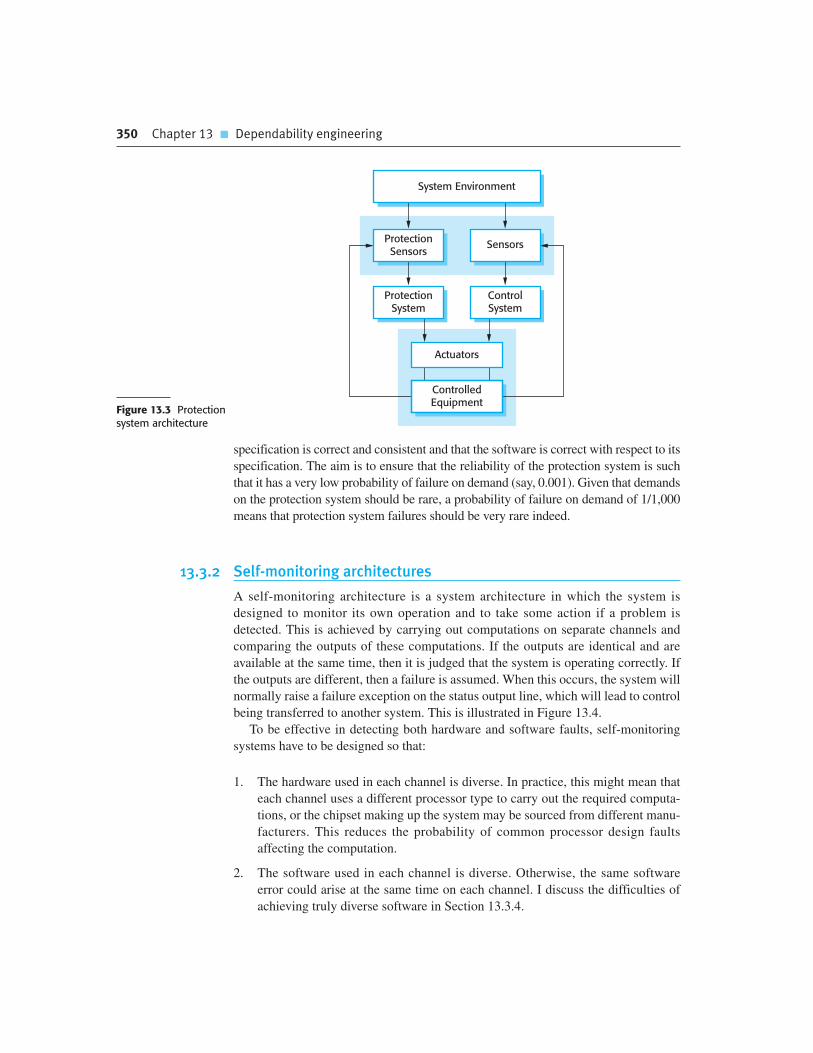
350 Chapter 13 � Dependability engineering
specification is correct and consistent and that the software is correct with respect to its
specification. The aim is to ensure that the reliability of the protection system is such
that it has a very low probability of failure on demand (say, 0.001). Given that demands
on the protection system should be rare, a probability of failure on demand of 1/1,000
means that protection system failures should be very rare indeed.
13.3.2 Self-monitoring architectures
A self-monitoring architecture is a system architecture in which the system is
designed to monitor its own operation and to take some action if a problem is
detected. This is achieved by carrying out computations on separate channels and
comparing the outputs of these computations. If the outputs are identical and are
available at the same time, then it is judged that the system is operating correctly. If
the outputs are different, then a failure is assumed. When this occurs, the system will
normally raise a failure exception on the status output line, which will lead to control
being transferred to another system. This is illustrated in Figure 13.4.
To be effective in detecting both hardware and software faults, self-monitoring
systems have to be designed so that:
1. The hardware used in each channel is diverse. In practice, this might mean that
each channel uses a different processor type to carry out the required computa-
tions, or the chipset making up the system may be sourced from different manu-
facturers. This reduces the probability of common processor design faults
affecting the computation.
2. The software used in each channel is diverse. Otherwise, the same software
error could arise at the same time on each channel. I discuss the difficulties of
achieving truly diverse software in Section 13.3.4.
Actuators
ControlledEquipment
System Environment
ControlSystem
ProtectionSystem
ProtectionSensors
Sensors
Figure 13.3 Protectionsystem architecture

13.3 � Dependable system architectures 351
On its own, this architecture may be used in situations where it is important for
computations to be correct, but where availability is not essential. If the answers
from each channel differ, the system simply shuts down. For many medical treatment
and diagnostic systems, reliability is more important than availability as an incorrect
system response could lead to the patient receiving incorrect treatment. However, if
the system simply shuts down in the event of an error, this is an inconvenience but
the patient will not usually be harmed by the system.
In situations where high availability is required, you have to use several self-
checking systems in parallel. You need a switching unit that detects faults and selects
a result from one of the systems, where both channels are producing a consistent
response. Such an approach is used in the flight control system for the Airbus 340
series of aircraft, in which five self-checking computers are used. Figure 13.5 is a
simplified diagram illustrating this organization.
In the Airbus flight control system, each of the flight control computers carry out
the computations in parallel, using the same inputs. The outputs are connected to
hardware filters that detect if the status indicates a fault and, if so, that the output from
that computer is switched off. The output is then taken from an alternative system.
Therefore, it is possible for four computers to fail and for the aircraft operation to con-
tinue. In more than 15 years of operation, there have been no reports of situations
where control of the aircraft has been lost due to total flight control system failure.
The designers of the Airbus system have tried to achieve diversity in a number of
different ways:
1. The primary flight control computers use a different processor from the second-
ary flight control systems.
2. The chipset that is used in each channel in the primary and secondary systems is
supplied by a different manufacturer.
3. The software in the secondary flight control systems provides critical function-
ality only—it is less complex than the primary software.
4. The software for each channel in both the primary and the secondary systems is
developed using different programming languages and by different teams.
5. Different programming languages are used in the secondary and primary systems.
As I discuss in the following section, these do not guarantee diversity but they
reduce the probability of common failures in different channels.
Channel 1
Channel 2
Splitter ComparatorInput Value
Output Value
Status
Figure 13.4 Self-monitoring architecture

352 Chapter 13 � Dependability engineering
13.3.3 N-version programming
Self-monitoring architectures are examples of systems in which multiversion pro-
gramming is used to provide software redundancy and diversity. This notion of mul-
tiversion programming has been derived from hardware systems where the notion of
triple modular redundancy (TMR) has been used for many years to build systems
that are tolerant of hardware failures (Figure 13.6).
In a TMR system, the hardware unit is replicated three (or sometimes more)
times. The output from each unit is passed to an output comparator that is usually
implemented as a voting system. This system compares all of its inputs and, if two or
more are the same, then that value is output. If one of the units fails and does not pro-
duce the same output as the other units, its output is ignored. A fault manager may
try to repair the faulty unit automatically but if this is impossible, the system is auto-
matically reconfigured to take the unit out of service. The system then continues to
function with two working units.
This approach to fault tolerance relies on most hardware failures being the result
of component failure rather than design faults. The components are therefore likely
to fail independently. It assumes that, when fully operational, all hardware units per-
form to specification. There is therefore a low probability of simultaneous compo-
nent failure in all hardware units.
Channel 1
Channel 2
Splitter ComparatorOutput
Status
Primary Flight Control System 1
Secondary Flight Control System 1
Primary Flight Control System 2
Primary Flight Control System 3
Input
Filter
Output
Output
Status
Filter
Output
Status
Filter
Secondary Flight Control System 2 Output
Status
Filter
Channel 1
Channel 2
Splitter ComparatorOutput
Status
Filter
Figure 13.5Airbus flightcontrolsystemarchitecture

13.3 � Dependable system architectures 353
Of course, the components could all have a common design fault and thus all pro-
duce the same (wrong) answer. Using hardware units that have a common specifica-
tion but which are designed and built by different manufacturers reduces the chances
of such a common mode failure. It is assumed that the probability of different teams
making the same design or manufacturing error is small.
A similar approach can be used for fault-tolerant software where N diverse ver-
sions of a software system execute in parallel (Avizienis, 1985; Avizienis,1995).
This approach to software fault tolerance, illustrated in Figure 13.7, has been used in
railway signaling systems, aircraft systems, and reactor protection systems.
Using a common specification, the same software system is implemented by a
number of teams. These versions are executed on separate computers. Their outputs
are compared using a voting system, and inconsistent outputs or outputs that are not
produced in time are rejected. At least three versions of the system should be avail-
able so that two versions should be consistent in the event of a single failure.
N-version programming may be less expensive that self-checking architectures in sys-
tems for which a high level of availability is required. However, it still requires several
different teams to develop different versions of the software. This leads to very high soft-
ware development costs. As a result, this approach is only used in systems where it is
impractical to provide a protection system that can guard against safety-critical failures.
13.3.4 Software diversity
All of the above fault-tolerant architectures rely on software diversity to achieve fault
tolerance. This is based on the assumption that diverse implementations of the same
specification (or a part of the specification, for protection systems) are independent.
They should not include common errors and so will not fail in the same way, at the
A1
A2
A3
OutputSelector
Input
Figure 13.6 Triplemodular redundancy
Version 1
Version 2
Version 3
OutputSelector
N Software Versions
AgreedResult
FaultManager
Input
Figure 13.7 N-versionprogramming
354 Chapter 13 � Dependability engineering
same time. This requires the software to be written by different teams who should not
communicate during the development process, therefore reducing the chances of
common misunderstandings or misinterpretations of the specification.
The company that is procuring the system may include explicit diversity policies that
are intended to maximize the differences between the system versions. For example:
1. By including requirements that different design methods should be used. For
example, one team may be required to produce an object-oriented design and
another team may produce a function-oriented design.
2. By stipulating that the implementations are to be written in different program-
ming languages. For example, in a three-version system, Ada, C++, and Java
could be used to write the software versions.
3. By requiring the use of different tools and development environments for the system.
4. By explicitly requiring different algorithms to be used in some parts of the
implementation. However, this limits the freedom of the design team and may
be difficult to reconcile with system performance requirements.
Each development team should work with a detailed system specification (some-
times called the V-spec) that has been derived from the system requirements specifi-
cation (Avizienis, 1995). This should be sufficiently detailed to ensure that there are
no ambiguities in the specification. As well as specifying the functionality of the
system, the detailed specification should define where system outputs for compari-
son should be generated.
Ideally, the diverse versions of the system should have no dependencies and so
should fail in completely different ways. If this is the case, then the overall reliabil-
ity of a diverse system is obtained by multiplying the reliabilities of each channel.
So, if each channel has a probability of failure on demand of 0.001, then the overall
POFOD of a three-channel system (with all channels independent) is a million times
greater than the reliability of a single-channel system.
In practice, however, achieving complete channel independence is impossible. It
has been shown experimentally that independent design teams often make the same
mistakes or misunderstand the same parts of the specification (Brilliant, et., 1990;
Knight and Leveson, 1986; Leveson, 1995). There are several reasons for this:
1. Members of different teams are often from the same cultural background and may
have been educated using the same approach and textbooks. This means that they
may find the same things difficult to understand and have common difficulties in
communicating with domain experts. It is quite possible that they will, independ-
ently, make the same mistakes and design the same algorithms to solve a problem.
2. If the requirements are incorrect or they are based on misunderstandings about
the environment of the system, then these mistakes will be reflected in each
implementation of the system.
3. In a critical system, the V-spec is a detailed document based on the system’s
requirements, which provides full details to the teams on how the system should

13.4 � Dependable programming 355
behave. There cannot be scope for interpretation by the software developers. If
there are errors in this document, then these will be presented to all of the devel-
opment teams and implemented in all versions of the system.
One way to reduce the possibility of common specification errors is to develop
detailed specifications for the system independently, and to define the specifications
in different languages. One development team might work from a formal specifica-
tion, another from a state-based system model, and a third from a natural language
specification. This helps avoid some errors of specification interpretation, but does
not get around the problem of specification errors. It also introduces the possibility of
errors in the translation of the requirements, leading to inconsistent specifications.
In an analysis of the experiments, Hatton (1997), concluded that a three-channel sys-
tem was somewhere between five to nine times more reliable than a single-channel
system. He concluded that improvements in reliability that could be obtained by devot-
ing more resources to a single version could not match this and so N-version approaches
were likely to lead to more reliable systems than single version approaches.
What is unclear, however, is whether the improvements in reliability from a mul-
tiversion system are worth the extra development costs. For many systems, the extra
costs may not be justifiable as a well-engineered single version system may be good
enough. It is only in safety and mission critical systems, where the costs of failure
are very high, that multiversion software may be required. Even in such situations
(e.g., a spacecraft system), it may be enough to provide a simple backup with limited
functionality until the principal system can be repaired and restarted.
13.4 Dependable programming
Generally, I have avoided discussions of programming in this book because it is
almost impossible to discuss programming without getting into the details of a spe-
cific programming language. There are now so many different approaches and lan-
guages used for software development that I have avoided using a single language
for examples in this book. However, when considering dependability engineering,
there is a set of accepted good programming practices that are fairly universal and
which help reduce faults in delivered systems.
A list of good practice guidelines is shown in Figure 13.8. They can be applied in
whatever programming language is used for systems development, although the way
they are used depends on the specific languages and notations that are used for system
development.
Guideline 1: Control the visibility of information in a program
A security principle that is adopted by military organizations is the ‘need to know’
principle. Only those individuals who need to know a particular piece of information
in order to carry out their duties are given that information. Information that is not
directly relevant to their work is withheld.
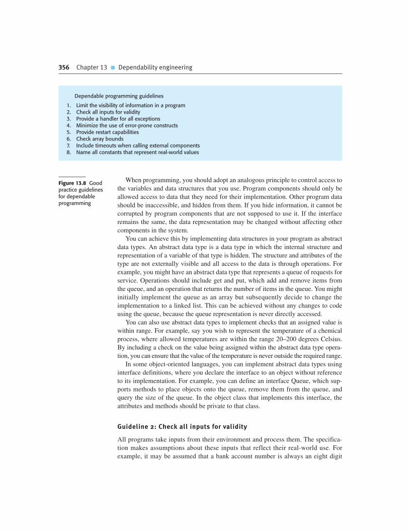
356 Chapter 13 � Dependability engineering
When programming, you should adopt an analogous principle to control access to
the variables and data structures that you use. Program components should only be
allowed access to data that they need for their implementation. Other program data
should be inaccessible, and hidden from them. If you hide information, it cannot be
corrupted by program components that are not supposed to use it. If the interface
remains the same, the data representation may be changed without affecting other
components in the system.
You can achieve this by implementing data structures in your program as abstract
data types. An abstract data type is a data type in which the internal structure and
representation of a variable of that type is hidden. The structure and attributes of the
type are not externally visible and all access to the data is through operations. For
example, you might have an abstract data type that represents a queue of requests for
service. Operations should include get and put, which add and remove items from
the queue, and an operation that returns the number of items in the queue. You might
initially implement the queue as an array but subsequently decide to change the
implementation to a linked list. This can be achieved without any changes to code
using the queue, because the queue representation is never directly accessed.
You can also use abstract data types to implement checks that an assigned value is
within range. For example, say you wish to represent the temperature of a chemical
process, where allowed temperatures are within the range 20–200 degrees Celsius.
By including a check on the value being assigned within the abstract data type opera-
tion, you can ensure that the value of the temperature is never outside the required range.
In some object-oriented languages, you can implement abstract data types using
interface definitions, where you declare the interface to an object without reference
to its implementation. For example, you can define an interface Queue, which sup-
ports methods to place objects onto the queue, remove them from the queue, and
query the size of the queue. In the object class that implements this interface, the
attributes and methods should be private to that class.
Guideline 2: Check all inputs for validity
All programs take inputs from their environment and process them. The specifica-
tion makes assumptions about these inputs that reflect their real-world use. For
example, it may be assumed that a bank account number is always an eight digit
Figure 13.8 Goodpractice guidelinesfor dependableprogramming
Dependable programming guidelines
1. Limit the visibility of information in a program2. Check all inputs for validity3. Provide a handler for all exceptions4. Minimize the use of error-prone constructs5. Provide restart capabilities6. Check array bounds7. Include timeouts when calling external components8. Name all constants that represent real-world values
13.4 � Dependable programming 357
positive integer. In many cases, however, the system specification does not define
what actions should be taken if the input is incorrect. Inevitably, users will make
mistakes and will sometimes enter the wrong data. Sometimes, as I discuss in
Chapter 14, malicious attacks on a system rely on deliberately entering incorrect
input. Even when the input comes from sensors or other systems, these systems can
go wrong and provide incorrect values.
You should therefore always check the validity of inputs as soon as these are read
from the program’s operating environment. The checks involved obviously depend
on the inputs themselves but possible checks that may be used are as follows:
1. Range checks You may expect inputs to be within a particular range. For exam-
ple, an input that represents a probability should be within the range 0.0 to 1.0;
an input that represents the temperature of a liquid water should be between 0
degrees Celsius and 100 degrees Celsius, and so on.
2. Size checks You may expect inputs to be a given number of characters (e.g.,
eight characters to represent a bank account). In other cases, the size may not be
fixed but there may be a realistic upper limit. For example, it is unlikely that a
person’s name will have more than 40 characters.
3. Representation checks You may expect an input to be of a particular type,
which is represented in a standard way. For example, people’s names do not
include numeric characters, e-mail addresses are made up of two parts, separated
by a @ sign, etc.
4. Reasonableness checks Where an input is one of a series and you know some-
thing about the relationships between the members of the series, then you can
check that an input value is reasonable. For example, if the input value repre-
sents the readings of a household electricity meter, then you would expect the
amount of electricity used to be approximately the same as in the corresponding
period in the previous year. Of course, there will be variations but order of mag-
nitude differences suggest that a problem has arisen.
The actions that you take if an input validation check fails depend on the type of
system being implemented. In some cases, you report the problem to the user and
request that the value be reinput. Where a value comes from a sensor, you might use
the most recent valid value. In embedded real-time systems, you might have to esti-
mate the value based on history, so that the system can continue in operation.
Guideline 3: Provide a handler for all exceptions
During program execution, errors or unexpected events inevitably occur. These may
arise because of a program fault or may be a result of unpredictable external circum-
stances. An error or an unexpected event that occurs during the execution of a program
is called an ‘exception’. Examples of exceptions might be a system power failure, an
attempt to access non-existent data, or numeric overflow or underflow.

358 Chapter 13 � Dependability engineering
Exceptions may be caused by hardware or software conditions. When an excep-
tion occurs, it must be managed by the system. This can be done within the program
itself or may involve transferring control to a system exception handling mechanism.
Typically, the system’s exception management mechanism reports the error and
shuts down execution. Therefore, to ensure that program exceptions do not cause
system failure, you should define an exception handler for all possible exceptions
that may arise, and make sure that all exceptions are detected and explicitly handled.
In programming languages such as C, if-statements must be used to detect excep-
tions and to transfer control to the exception handling code. This means that you
have to explicitly check for exceptions wherever in the program they may occur.
However, this approach adds significant complexity to the task of exception han-
dling, increasing the chances that you will make mistakes and therefore mishandle
the exception.
Some programming languages, such as Java, C++, and Ada, include constructs that
support exception handling so that you do not need extra conditional statements to
check for exceptions. These programming languages include a special built-in type
(often called Exception) and different exceptions may be declared to be of this type.
When an exceptional situation occurs, the exception is signaled and the language run-
time system transfers control to an exception handler. This is a code section that states
exception names and appropriate actions to handle each exception (Figure 13.9).
Notice that the exception handler is outside the normal flow of control and that this
normal control flow does not resume after the exception has been handled.
Exception handlers usually do one or more of three things:
1. Signal to a higher-level component that an exception has occurred, and provide
information to that component about the type of exception. You use this
approach when one component calls another and the calling component needs to
know if the called component has executed successfully. If not, it is up to the
calling component to take action to recover from the problem.
2. Carry out some alternative processing to that which was originally intended.
Therefore, the exception handler takes some actions to recover from the
problem. Processing may then continue as normal or the exception handler
Code Section
Exception Handling Code
Normal Flowof Control
Exception Detected
Normal Exit
ExceptionProcessing
Figure 13.9 Exceptionhandling
13.4 � Dependable programming 359
may indicate that an exception has occurred so that a calling component is
aware of the problem.
3. Pass control to a run-time support system that handles the exception. This is
often the default when faults occur in a program (e.g., when a numeric value
overflows). The usual action of the run-time system is to halt processing. You
should only use this approach when it is possible to move the system to a safe
and quiescent state, before handing control to the run-time system.
Handling exceptions within a program makes it possible to detect and recover
from some input errors and unexpected external events. As such, it provides a degree
of fault tolerance—the program detects faults and can take action to recover from
these. As most input errors and unexpected external events are usually transient, it is
often possible to continue normal operation after the exception has been processed.
Guideline 4: Minimize the use of error-prone constructs
Faults in programs, and therefore many program failures, are usually a consequence
of human error. Programmers make mistakes because they lose track of the numer-
ous relationships between the state variables. They write program statements that
result in unexpected behavior and system state changes. People will always make
mistakes, but in the late 1960s it became clear that some approaches to programming
were more likely to introduce errors into a program than others.
Some programming language constructs and programming techniques are inher-
ently error prone and so should be avoided or, at least, used as little as possible.
Potentially error-prone constructs include:
1. Unconditional branch (go-to) statements The dangers of go-to statements were
recognized as long ago as 1968 (Dijkstra, 1968) and, as a consequence, these
have been excluded from modern programming languages. However, they are
still allowed in languages such as C. The use of go-to statements leads to
‘spaghetti code’ that is tangled and difficult to understand and debug.
2. Floating-point numbers The representation of floating-point numbers in a fixed-
length memory word is inherently imprecise. This is a particular problem when
numbers are compared because representation imprecision may lead to invalid
comparisons. For example, 3.00000000 may sometimes be represented as
2.99999999 and sometimes as 3.00000001. A comparison would show these to
be unequal. Fixed-point numbers, where a number is represented to a given
number of decimal places, are generally safer because exact comparisons are
possible.
3. Pointers Programming languages such as C and C++ support low-level con-
structs called pointers, which hold addresses that refer directly to areas of the
machine memory (they point to a memory location). Errors in the use of point-
ers can be devastating if they are set incorrectly and therefore point to the wrong

360 Chapter 13 � Dependability engineering
area of memory. They also make bound checking of arrays and other structures
harder to implement.
4. Dynamic memory allocation Program memory may be allocated at run-time
rather than at compile-time. The danger with this is that the memory may not be
properly deallocated, so eventually the system runs out of available memory.
This can be a very difficult error to detect because the system may run success-
fully for a long time before the problem occurs.
5. Parallelism When processes are executing concurrently, there can be subtle tim-
ing dependencies between them. Timing problems cannot usually be detected
by program inspection, and the peculiar combination of circumstances that
cause a timing problem may not occur during system testing. Parallelism may
be unavoidable, but its use should be carefully controlled to minimize inter-
process dependencies.
6. Recursion When a procedure or method calls itself or calls another procedure,
which then calls the original calling procedure, this is ‘recursion’. The use of
recursion can result in concise programs; however it can be difficult to follow
the logic of recursive programs. Programming errors are therefore more difficult
to detect. Recursion errors may result in the allocation of all the system’s mem-
ory as temporary stack variables are created.
7. Interrupts These are a means of forcing control to transfer to a section of code
irrespective of the code currently executing. The dangers of this are obvious; the
interrupt may cause a critical operation to be terminated.
8. Inheritance The problem with inheritance in object-oriented programming is that
the code associated with an object is not all in one place. This makes it more dif-
ficult to understand the behavior of the object. Hence, it is more likely that pro-
gramming errors will be missed. Furthermore, inheritance, when combined with
dynamic binding, can cause timing problems at run-time. Different instances of a
method may be bound to a call, depending on the parameter types. Consequently,
different amounts of time will be spent searching for the correct method instance.
9. Aliasing This occurs when more than one name is used to refer to the same
entity in a program; for example, if two pointers with different names point to
the same memory location. It is easy for program readers to miss statements that
change the entity when they have several names to consider.
10. Unbounded arrays In languages like C, arrays are simply ways of accessing
memory and you can make assignments beyond the end of an array. The run-
time system does not check that assignments actually refer to elements in the
array. Buffer overflow, where an attacker deliberately constructs a program to
write memory beyond the end of a buffer that is implemented as an array, is a
known security vulnerability.
11. Default input processing Some systems provide a default for input processing,
irrespective of the input that is presented to the system. This is a security loophole

13.4 � Dependable programming 361
that an attacker may exploit by presenting the program with unexpected inputs
that are not rejected by the system.
Some standards for safety-critical systems development completely prohibit the
use of these constructs. However, such an extreme position is not normally practical.
All of these constructs and techniques are useful, though they must be used with
care. Wherever possible, their potentially dangerous effects should be controlled by
using them within abstract data types or objects. These act as natural ‘firewalls’ lim-
iting the damage caused if errors occur.
Guideline 5: Provide restart capabilities
Many organizational information systems are based around short transactions where
processing user inputs takes a relatively short time. These systems are designed so
that changes to the system’s database are only finalized after all other processing has
been successfully completed. If something goes wrong during processing, the
database is not updated and so does not become inconsistent. Virtually all
e-commerce systems, where you only commit to your purchase on the final screen,
work in this way.
User interactions with e-commerce systems usually last a few minutes and
involve minimal processing. Database transactions are short, and are usually com-
pleted in less than a second. However, other types of systems such as CAD systems
and word processing systems involve long transactions. In a long transaction system,
the time between starting to use the system and finishing work may be several min-
utes or hours. If the system fails during a long transaction, then all of the work may
be lost. Similarly, in computationally intensive systems such as some e-science sys-
tems, minutes or hours of processing may be required to complete the computation.
All of this time is lost in the event of a system failure.
In all of these types of systems, you should provide a restart capability that is
based on keeping copies of data that is collected or generated during processing. The
restart facility should allow the system to restart using these copies, rather than hav-
ing to start all over from the beginning. These copies are sometimes called check-
points. For example:
1. In an e-commerce system, you can keep copies of forms filled in by a user and
allow them to access and submit these forms without having to fill them in again.
2. In a long transaction or computationally intensive system, you can automatically
save data every few minutes and, in the event of a system failure, restart with the
most recently saved data. You should also allow for user error and provide a way
for users to go back to the most recent checkpoint and start again from there.
If an exception occurs and it is impossible to continue normal operation, you can
handle the exception using backward error recovery. This means that you reset the state
of the system to the saved state in the checkpoint and restart operation from that point.

362 Chapter 13 � Dependability engineering
Guideline 6: Check array bounds
All programming languages allow the specification of arrays—sequential data struc-
tures that are accessed using a numeric index. These arrays are usually laid out in
contiguous areas within the working memory of a program. Arrays are specified to
be of a particular size, which reflects how they are used. For example, if you wish to
represent the ages of up to 10,000 people, then you might declare an array with
10,000 locations to hold the age data.
Some programming languages, such as Java, always check that when a value is
entered into an array, the index is within that array. So, if an array A is indexed from
0 to 10,000, an attempt to enter values into elements A [-5] or A [12345] will lead to
an exception being raised. However, programming languages such as C and C++ do
not automatically include array bound checks and simply calculate an offset from the
beginning of the array. Therefore, A [12345] would access the word that was 12345
locations from the beginning of the array, irrespective of whether or not this was part
of the array.
The reason why these languages do not include automatic array-bound checking
is that this introduces an overhead every time the array is accessed. The majority of
array accesses are correct so the bound check is mostly unnecessary and increases
the execution time of the program. However, the lack of bound checking leads to
security vulnerabilities, such as buffer overflow, which I discuss in Chapter 14. More
generally, it introduces a vulnerability into the system that can result in system fail-
ure. If you are using a language that does not include array-bound checking, you
should always include extra code that ensures the array index is within bounds. This
is easily accomplished by implementing the array as an abstract data type, as I have
discussed in Guideline 1.
Guideline 7: Include timeouts when calling external components
In distributed systems, components of the system execute on different computers and
calls are made across the network from component to component. To receive some
service, component A may call component B. A waits for B to respond before con-
tinuing execution. However, if component B fails to respond for some reason, then
component A cannot continue. It simply waits indefinitely for a response. A person
who is waiting for a response from the system sees a silent system failure, with no
response from the system. They have no alternative but to kill the waiting process
and restart the system.
To avoid this, you should always include timeouts when calling external com-
ponents. A timeout is an automatic assumption that a called component has failed
and will not produce a response. You define a time period during which you expect
to receive a response from a called component. If you have not received a response
in that time, you assume failure and take back control from the called component.
You can then attempt to recover from the failure or tell the system user what has
happened and allow them to decide what to do.

Chapter 13 � Key points 363
Guideline 8: Name all constants that represent real-world values
All non-trivial programs include a number of constant values that represent the val-
ues of real-world entities. These values are not modified as the program executes.
Sometimes, these are absolute constants and never change (e.g., the speed of light)
but more often they are values that change relatively slowly over time. For example,
a program to calculate personal tax will include constants that are the current tax
rates. These change from year to year and so the program must be updated with the
new constant values.
You should always include a section in your program in which you name all real-
world constant values that are used. When using the constants, you should refer to
them by name rather than by their value. This has two advantages as far as depend-
ability is concerned:
1. You are less likely to make mistakes and use the wrong value. It is easy to mistype
a number and the system will often be unable to detect a mistake. For example,
say a tax rate is 34%. A simple transposition error might lead to this being
mistyped as 43%. However, if you mistype a name (such as Standard-tax-rate),
this is usually detected by the compiler as an undeclared variable.
2. When a value changes, you do not have to look through the whole program to
discover where you have used that value. All you need do is to change the value
associated with the constant declaration. The new value is then automatically
included everywhere that it is needed.
K E Y P O I N T S
� Dependability in a program can be achieved by avoiding the introduction of faults, by detecting
and removing faults before system deployment, and by including fault-tolerance facilities that
allow the system to remain operational after a fault has caused a system failure.
� The use of redundancy and diversity in hardware, software processes, and software systems is
essential to the development of dependable systems.
� The use of a well-defined, repeatable process is essential if faults in a system are to be
minimized. The process should include verification and validation activities at all stages, from
requirements definition through to system implementation.
� Dependable system architectures are system architectures that are designed for fault tolerance.
There are a number of architectural styles that support fault tolerance including protection
systems, self-monitoring architectures, and N-version programming.
� Software diversity is difficult to achieve because it is practically impossible to ensure that each
version of the software is truly independent.

364 Chapter 13 � Dependability engineering
� Dependable programming relies on the inclusion of redundancy in a program to check the
validity of inputs and the values of program variables.
� Some programming constructs and techniques, such as go-to statements, pointers, recursion,
inheritance, and floating-point numbers, are inherently error prone. You should try to avoid
these constructs when developing dependable systems.
F U RT H E R R E A D I N G
Software Fault Tolerance Techniques and Implementation. A comprehensive discussion of
techniques to achieve software fault tolerance and fault-tolerant architectures. The book also covers
general issues of software dependability. (L. L. Pullum, Artech House, 2001.)
‘Software Reliability Engineering: A Roadmap’. This survey paper by a leading researcher in software
reliability summarizes the state of the art in software reliability engineering as well as discussing
future research challenges. (M. R. Lyu, Proc. Future of Software Engineering, IEEE Computer Society,
2007.) http://dx.doi.org/10.1109/FOSE.2007.24.
E X E R C I S E S
13.1. Give four reasons why it is hardly ever cost effective for companies to ensure that their
software is free of faults.
13.2. Explain why it is reasonable to assume that the use of dependable processes will lead to the
creation of dependable software.
13.3. Give two examples of diverse, redundant activities that might be incorporated into
dependable processes.
13.4. What is the common characteristic of all architectural styles that are geared to supporting
software fault tolerance?
13.5. Imagine you are implementing a software-based control system. Suggest circumstances in
which it would be appropriate to use a fault-tolerant architecture, and explain why this
approach would be required.
13.6. You are responsible for the design of a communications switch that has to provide 24/7
availability, but which is not safety-critical. Giving reasons for your answer, suggest an
architectural style that might be used for this system.
13.7. It has been suggested that the control software for a radiation therapy machine, used to treat
patients with cancer, should be implemented using N-version programming. Comment on
whether or not you think this is a good suggestion.
364 Chapter 13 � Dependability engineering

13.8. Give two reasons why different versions of a system based around software diversity may fail
in a similar way.
13.9. Explain why you should explicitly handle all exceptions in a system that is intended to have a
high level of availability.
13.10. The use of techniques for the production of safe software, as discussed in this chapter,
obviously includes considerable extra costs. What extra costs can be justified if 100 lives
would be saved over the 15-year lifetime of a system? Would the same costs be justified if 10
lives were saved? How much is a life worth? Do the earning capabilities of the people affected
make a difference to this judgment?
R E F E R E N C E S
Avizienis, A. (1985). ‘The N-Version Approach to Fault-Tolerant Software’. IEEE Trans. on Software
Eng., SE-11 (12), 1491–501.
Avizienis, A. A. (1995). ‘A Methodology of N-Version Programming’. In Software Fault Tolerance.
Lyu, M. R. (ed.). Chichester: John Wiley & Sons. 23–46.
Boehm, B. (2002). ‘Get Ready for Agile Methods, With Care’. IEEE Computer, 35 (1), 64–9.
Brilliant, S. S., Knight, J. C. and Leveson, N. G. (1990). ‘Analysis of Faults in an N-Version Software
Experiment’. IEEE Trans. On Software Engineering, 16 (2), 238–47.
Dijkstra, E. W. (1968). ‘Goto statement considered harmful’. Comm. ACM., 11 (3), 147–8.
Hatton, L. (1997). ‘N-version design versus one good version’. IEEE Software, 14 (6), 71–6.
Knight, J. C. and Leveson, N. G. (1986). ‘An experimental evaluation of the assumption of
independence in multi-version programming’. IEEE Trans. on Software Engineering., SE-12 (1),
96–109.
Leveson, N. G. (1995). Safeware: System Safety and Computers. Reading, Mass.: Addison-Wesley.
Lindvall, M., Muthig, D., Dagnino, A., Wallin, C., Stupperich, M., Kiefer, D., May, J. and Kahkonen, T.
(2004). ‘Agile Software Development in Large Organizations’. IEEE Computer, 37 (12), 26–34.
Parnas, D. L., Van Schouwen, J. and Shu, P. K. (1990). ‘Evaluation of Safety-Critical Software’. Comm.
ACM, 33 (6), 636–51.
Pullum, L. L. (2001). Software Fault Tolerance Techniques and Implementation. Norwood, Mass.:
Artech House.
Storey, N. (1996). Safety-Critical Computer Systems. Harlow, UK: Addison-Wesley.
Torres-Pomales, W. (2000). ‘Software Fault Tolerance: A Tutorial.’
http://ntrs.nasa.gov/archive/nasa/casi./20000120144_2000175863.pdf.
Chapter 13 � References 365

Security engineering
14
Objectives
The objective of this chapter is to introduce issues that should be
considered when you are designing secure application systems. When
you have read this chapter, you will:
� understand the difference between application security and
infrastructure security;
� know how life-cycle risk assessment and operational risk assessment
are used to understand security issues that affect a system design;
� be aware of software architectures and design guidelines for secure
systems development;
� understand the notion of system survivability and why survivability
analysis is important for complex software systems.
Contents
14.1 Security risk management
14.2 Design for security
14.3 System survivability

Chapter 14 � Security engineering 367
The widespread use of the Internet in the 1990s introduced a new challenge for soft-
ware engineers—designing and implementing systems that were secure. As more
and more systems were connected to the Internet, a variety of different external
attacks were devised to threaten these systems. The problems of producing depend-
able systems were hugely increased. Systems engineers had to consider threats from
malicious and technically skilled attackers as well as problems resulting from acci-
dental mistakes in the development process.
It is now essential to design systems to withstand external attacks and to recover from
such attacks. Without security precautions, it is almost inevitable that attackers will com-
promise a networked system. They may misuse the system hardware, steal confidential
data, or disrupt the services offered by the system. System security engineering is there-
fore an increasingly important aspect of the systems engineering process.
Security engineering is concerned with the development and evolution of systems
that can resist malicious attacks, which are intended to damage the system or its data.
Software security engineering is part of the more general field of computer security.
This has become a priority for businesses and individuals as more and more crimi-
nals try to exploit networked systems for illegal purposes. Software engineers should
be aware of the security threats faced by systems and ways in which these threats can
be neutralized.
My intention in this chapter is to introduce security engineering to software engi-
neers, with a focus on design issues that affect application security. The chapter is
not about computer security as a whole and so doesn’t cover topics such as encryp-
tion, access control, authorization mechanisms, viruses and Trojan horses, etc. These
are described in detail in general texts on computer security (Anderson, 2008;
Bishop, 2005; Pfleeger and Pfleeger, 2007).
This chapter adds to the discussion of security elsewhere in the book. You should
read the material here along with:
• Section 10.1, where I explain how security and dependability are closely related;
• Section 10.4, where I introduce security terminology;
• Section 12.1, where I introduce the general notion of risk-driven specification;
• Section 12.4, where I discuss general issues of security requirements specification;
• Section 15.3, where I explain a number of approaches to security testing.
When you consider security issues, you have to consider both the application
software (the control system, the information system, etc.) and the infrastructure on
which this system is built (Figure 14.1). The infrastructure for complex applications
may include:
• an operating system platform, such as Linux or Windows;
• other generic applications that run on that system, such as web browsers and
e-mail clients;
• a database management system;

368 Chapter 14 � Security engineering
• middleware that supports distributed computing and database access;
• libraries of reusable components that are used by the application software.
The majority of external attacks focus on system infrastructures because infra-
structure components (e.g., web browsers) are well known and widely available.
Attackers can probe these systems for weaknesses and share information about vul-
nerabilities that they have discovered. As many people use the same software,
attacks have wide applicability. Infrastructure vulnerabilities may lead to attackers
gaining unauthorized access to an application system and its data.
In practice, there is an important distinction between application security and
infrastructure security:
1. Application security is a software engineering problem where software engi-
neers should ensure that the system is designed to resist attacks.
2. Infrastructure security is a management problem where system managers con-
figure the infrastructure to resist attacks. System managers have to set up the
infrastructure to make the most effective use of whatever infrastructure security
features are available. They also have to repair infrastructure security vulnera-
bilities that come to light as the software is used.
System security management is not a single task but includes a range of activities
such as user and permission management, system software deployment and mainte-
nance, and attack monitoring, detection and recovery:
1. User and permission management includes adding and removing users from the
system, ensuring that appropriate user authentication mechanisms are in place
and setting up the permissions in the system so that users only have access to the
resources that they need.
2. System software deployment and maintenance includes installing system soft-
ware and middleware and configuring these properly so that security vulnera-
bilities are avoided. It also involves updating this software regularly with new
versions or patches, which repair security problems that have been discovered.
Operating system
Generic, Shared Applications (Browsers, E-mail, Etc.)
Database Management
Middleware
Reusable Components and Libraries
Application
Figure 14.1 Systemlayers where securitymay be compromised

14.1 � Security risk management 369
Insider attacks and social engineering
Insider attacks are attacks on a system carried out by a trusted individual (an insider) who abuses that trust. Forexample, a nurse, working in a hospital may access confidential medical records of patients that he or she is notcaring for. Insider attacks are difficult to counter because the extra security techniques that may be used woulddisrupt trustworthy system users.
Social engineering is a way of fooling accredited users into disclosing their credentials. An attacker can thereforebehave as an insider when accessing the system.
http://www.SoftwareEngineering-9.com/Web/SecurityEng/insiders.html
3. Attack monitoring, detection and recovery includes activities which monitor the
system for unauthorized access, detect, and put in place strategies for resisting
attacks, and backup activities so that normal operation can be resumed after an
external attack.
Security management is vitally important, but it is not usually considered to be
part of application security engineering. Rather, application security engineering is
concerned with designing a system so that it is as secure as possible, given budget
and usability constraints. Part of this process is ‘design for management’, where you
design systems to minimize the chance of security management errors leading to
successful attacks on the system.
For critical control systems and embedded systems, it is normal practice to
select an appropriate infrastructure to support the application system. For exam-
ple, embedded system developers usually choose a real-time operating system
that provides the embedded application with the facilities that it needs. Known
vulnerabilities and security requirements can be taken into account. This means
that an holistic approach can be taken to security engineering. Application secu-
rity requirements may be implemented through the infrastructure or the applica-
tion itself.
However, application systems in an organization are usually implemented using
the existing infrastructure (operating system, database, etc.). Therefore, the risks of
using that infrastructure and its security features must be taken into account as part
of the system design process.
14.1 Security risk management
Security risk assessment and management is essential for effective security engi-
neering. Risk management is concerned with assessing the possible losses that might
ensue from attacks on assets in the system, and balancing these losses against the
370 Chapter 14 � Security engineering
costs of security procedures that may reduce these losses. Credit card companies do
this all the time. It is relatively easy to introduce new technology to reduce credit
card fraud. However, it is often cheaper for them to compensate users for their losses
due to fraud than to buy and deploy fraud-reduction technology. As costs drop and
attacks increase, this balance may change. For example, credit card companies are
now encoding information on an on-card chip instead of a magnetic strip. This
makes card copying much more difficult.
Risk management is a business issue rather than a technical issue so software
engineers should not decide what controls should be included in a system. It is up
to senior management to decide whether or not to accept the cost of security or the
exposure that results from a lack of security procedures. Rather, the role of soft-
ware engineers is to provide informed technical guidance and judgment on secu-
rity issues. They are, therefore, essential participants in the risk management
process.
As I explained in Chapter 12, a critical input to the risk assessment and man-
agement process is the organizational security policy. The organizational secu-
rity policy applies to all systems and should set out what should and should not
be allowed. The security policy sets out conditions that should always be main-
tained by a security system and so helps to identify risks and threats that might
arise. The security policy therefore defines what is and what is not allowed.
In the security engineering process, you design the mechanisms to implement
this policy.
Risk assessment starts before the decision to acquire the system has been made
and should continue throughout the system development process and after the sys-
tem has gone into use (Alberts and Dorofee, 2002). I also introduced, in Chapter 12,
the idea that this risk assessment is a staged process:
1. Preliminary risk assessment At this stage, decisions on the detailed system
requirements, the system design, or the implementation technology have not
been made. The aim of this assessment process is to decide if an adequate level
of security can be achieved at a reasonable cost. If this is the case, you can then
derive specific security requirements for the system. You do not have informa-
tion about potential vulnerabilities in the system or the controls that are included
in reused system components or middleware.
2. Life-cycle risk assessment This risk assessment takes place during the system
development life cycle and is informed by the technical system design and
implementation decisions. The results of the assessment may lead to changes to
the security requirements and the addition of new requirements. Known and
potential vulnerabilities are identified and this knowledge is used to inform
decision making about the system functionality and how it is to be implemented,
tested, and deployed.
3. Operational risk assessment After a system has been deployed and put into
use, risk assessment should continue to take account of how the system is

14.1 � Security risk management 371
used and proposals for new and changed requirements. Assumptions about
the operating requirement made when the system was specified may be incor-
rect. Organizational changes may mean that the system is used in different
ways from those originally planned. Operational risk assessment therefore
leads to new security requirements that have to be implemented as the system
evolves.
Preliminary risk assessment focuses on deriving security requirements. In
Chapter 12, I show how an initial set of security requirements may be derived from a
preliminary risk assessment. In this section, I concentrate on life cycle and opera-
tional risk assessment to illustrate how the specification and design of a system are
influenced by technology and the way that the system is used.
To carry out a risk assessment, you need to identify the possible threats to a sys-
tem. One way to do this, is to develop a set of ‘misuse cases’ (Alexander, 2003;
Sindre and Opdahl, 2005). I have already discussed how use cases—typical interac-
tions with a system—may be used to derive system requirements. Misuse cases are
scenarios that represent malicious interactions with a system. You can use these to
discuss and identify possible threats and, therefore also determine the system’s secu-
rity requirements. They can be used alongside use cases when deriving the system
requirements.
Pfleeger and Pfleeger (2007) characterize threats under four headings, which may
be used as a starting point for identifying possible misuse cases. These headings are
as follows:
1. Interception threats that allow an attacker to gain access to an asset. So, a possi-
ble misuse case for the MHC-PMS might be a situation where an attacker gains
access to the records of an individual celebrity patient.
2. Interruption threats that allow an attacker to make part of the system unavail-
able. Therefore, a possible misuse case might be a denial of service attack on a
system database server.
3. Modification threats that allow an attacker to tamper with a system asset. In the
MHC-PMS, this could be represented by a misuse case where an attacker
changes the information in a patient record.
4. Fabrication threats that allow an attacker to insert false information into a sys-
tem. This is perhaps not a credible threat in the MHC-PMS but would certainly
be a threat in a banking system, where false transactions might be added to the
system that transfer money to the perpetrator’s bank account.
Misuse cases are not just useful in preliminary risk assessment but may be used
for security analysis in life-cycle risk analysis and operational risk analysis. They
provide a useful basis for playing out hypothetical attacks on the system and assess-
ing the security implications of design decisions that have been made.

372 Chapter 14 � Security engineering
14.1.1 Life-cycle risk assessment
Based on organizational security policies, preliminary risk assessment should iden-
tify the most important security requirements for a system. These reflect how the
security policy should be implemented in that application, identify the assets to be
protected, and decide what approach should be used to provide that protection.
However, maintaining security is about paying attention to detail. It is impossible for
the initial security requirements to take all details that affect security into account.
Life-cycle risk assessment identifies the design and implementation details that
affect security. This is the important distinction between life-cycle risk assessment
and preliminary risk assessment. Life-cycle risk assessment affects the interpretation
of existing security requirements, generates new requirements, and influences the
overall design of the system.
When assessing risks at this stage, you should have much more detailed information
about what needs to be protected, and you also will know something about the vulnera-
bilities in the system. Some of these vulnerabilities will be inherent in the design choices
made. For example, a vulnerability in all password-based systems is that an authorized
user reveals their password to an unauthorized user. Alternatively, if an organization has
a policy of developing software in C, you will know that the application may have vul-
nerabilities because the language does not include array bound checking.
Security risk assessment should be part of all life-cycle activities from require-
ments engineering to system deployment. The process followed is similar to the pre-
liminary risk assessment process with the addition of activities concerned with
design vulnerability identification and assessment. The outcome of the risk assess-
ment is a set of engineering decisions that affect the system design or implementa-
tion, or limit the way in which it is used.
A model of the life-cycle risk analysis process, based on the preliminary risk
analysis process that I described in Figure 12.9, is shown in Figure 14.2. The most
Asset ValueAssessment
ThreatIdentification
AttackAssessment
ExposureAssessment
Design andRequirements
Changes
TechnologyChoices
Asset Representationand Organization
AvailableControls
ControlIdentification
Figure 14.2 Life-cyclerisk analysis

14.1 � Security risk management 373
important difference between these processes is that you now have information
about information representation and distribution and the database organization for
the high-level assets that have to be protected. You are also aware of important
design decisions such as the software to be reused, infrastructure controls and pro-
tection, etc. Based on this information, your analysis identifies changes to the secu-
rity requirements and the system design to provide additional protection for the
important system assets.
Two examples illustrate how protection requirements are influenced by decisions
on information representation and distribution:
1. You may make a design decision to separate personal patient information and
information about treatments received, with a key linking these records. The
treatment information is much less sensitive than the personal patient informa-
tion so may not need as extensive protection. If the key is protected, then an
attacker will only be able to access routine information, without being able to
link this to an individual patient.
2. Assume that, at the beginning of a session, a design decision is made to copy
patient records to a local client system. This allows work to continue if the
server is unavailable. It makes it possible for a health-care worker to access
patient records from a laptop, even if no network connection is available.
However, you now have two sets of records to protect and the client copies are
subject to additional risks, such as theft of the laptop computer. You, therefore,
have to think about what controls should be used to reduce risk. For example,
client records on the laptop may have to be encrypted.
To illustrate how decisions on development technologies influence security,
assume that the health-care provider has decided to build a MHC-PMS using an off-
the-shelf information system for maintaining patient records. This system has to be
configured for each type of clinic in which it is used. This decision has been made
because it appears to offer the most extensive functionality for the lowest develop-
ment cost and fastest deployment time.
When you develop an application by reusing an existing system, you have to
accept the design decisions made by the developers of that system. Let us assume
that some of these design decisions are as follows:
1. System users are authenticated using a login name/password combination. No
other authentication method is supported.
2. The system architecture is client-server, with clients accessing data through a
standard web browser on a client PC.
3. Information is presented to users as an editable web form. They can change
information in place and upload the revised information to the server.

374 Chapter 14 � Security engineering
For a generic system, these design decisions are perfectly acceptable, but a life-
cycle risk analysis reveals that they have associated vulnerabilities. Examples of pos-
sible vulnerabilities are shown in Figure 14.3.
Once vulnerabilities have been identified, you then have to make a decision on
what steps that you can take to reduce the associated risks. This will often involve
making decisions about additional system security requirements or the operational
process of using the system. I don’t have space here to discuss all the requirements
that might be proposed to address the inherent vulnerabilities, but some examples of
requirements might be the following:
1. A password checker program shall be made available and shall be run daily.
User passwords that appear in the system dictionary shall be identified and users
with weak passwords reported to system administrators.
2. Access to the system shall only be allowed to client computers that have been
approved and registered with the system administrators.
3. All client computers shall have a single web browser installed as approved by
system administrators.
As an off-the-shelf system is used, it isn’t possible to include a password checker in
the application system itself, so a separate system must be used. Password checkers ana-
lyze the strength of user passwords when they are set up, and notify users if they have
chosen weak passwords. Therefore, vulnerable passwords can be identified reasonably
Login/PasswordAuthentication
Users SetGuessablePasswords
Authorized Users Revealtheir Passwords toUnauthorised Users
Technology Choice Vulnerabilities
Client/ServerArchitecture Using
Web Browser
Server Subject toDenial of Service
Attack
Confidential InformationMay be Left in Browser
Cache
Browser SecurityLoopholes Lead to
Unauthorized Access
Use of EditableWeb Forms
Fine-Grain Loggingof Changes isImpossible
Authorization can’tbe Varied According
to User’s Role
Figure 14.3Vulnerabilitiesassociated withtechnology choices
14.2 � Design for security 375
quickly after they have been set up, and action can then be taken to ensure that users
change their password.
The second and third requirements mean that all users will always access the sys-
tem through the same browser. You can decide what is the most secure browser when
the system is deployed and install that on all client computers. Security updates are
simplified because there is no need to update different browsers when security vul-
nerabilities are discovered and fixed.
14.1.2 Operational risk assessment
Security risk assessment should continue throughout the lifetime of the system to
identify emerging risks and system changes that may be required to cope with these
risks. This process is called operational risk assessment. New risks may emerge
because of changing system requirements, changes in the system infrastructure, or
changes in the environment in which the system is used.
The process of operational risk assessment is similar to the life-cycle risk assess-
ment process, but with the addition of further information about the environment in
which the system is used. The environment is important because characteristics of
the environment can lead to new risks to the system. For example, say a system is
being used in an environment in which users are frequently interrupted. A risk is that
the interruption will mean that the user has to leave their computer unattended. It
may then be possible for an unauthorized person to gain access to the information in
the system. This could then generate a requirement for a password-protected screen
saver to be run after a short period of inactivity.
14.2 Design for security
It is generally true that it is very difficult to add security to a system after it has been
implemented. Therefore, you need to take security issues into account during the
systems design process. In this section, I focus primarily on issues of system design,
because this topic isn’t given the attention it deserves in computer security books.
Implementation issues and mistakes also have a major impact on security but these
are often dependent on the specific technology used. I recommend Viega and
McGraw’s book (2002) as a good introduction to programming for security.
Here, I focus on a number of general, application-independent issues relevant to
secure systems design:
1. Architectural design—how do architectural design decisions affect the security
of a system?
2. Good practice—what is accepted good practice when designing secure systems?
3. Design for deployment—what support should be designed into systems to avoid
the introduction of vulnerabilities when a system is deployed for use?
376 Chapter 14 � Security engineering
Denial of service attacks
Denial of service attacks attempt to bring down a networked system by bombarding it with a huge number ofservice requests. These place a load on the system for which it was not designed and they exclude legitimaterequests for system service. Consequently, the system may become unavailable either because it crashes withthe heavy load or has to be taken offline by system managers to stop the flow of requests.
http://www.SoftwareEngineering-9.com/Web/Security/DoS.html
Of course, these are not the only design issues that are important for security. Every
application is different and security design also has to take into account the purpose,
criticality, and operational environment of the application. For example, if you are
designing a military system, you need to adopt their security classification model
(secret, top secret, etc.). If you are designing a system that maintains personal infor-
mation, you may have to take into account data protection legislation that places
restrictions on how data is managed.
There is a close relationship between dependability and security. The use of
redundancy and diversity, which is fundamental for achieving dependability, may
mean that a system can resist and recover from attacks that target specific design or
implementation characteristics. Mechanisms to support a high level of availability
may help the system to recover from so-called denial of service attacks, where the
aim of an attacker is to bring down the system and stop it working properly.
Designing a system to be secure inevitably involves compromises. It is certainly
possible to design multiple security measures into a system that will reduce the
chances of a successful attack. However, security measures often require a lot of
additional computation and so affect the overall performance of a system. For exam-
ple, you can reduce the chances of confidential information being disclosed by
encrypting that information. However, this means that users of the information have
to wait for it to be decrypted and this may slow down their work.
There are also tensions between security and usability. Security measures some-
times require the user to remember and provide additional information (e.g., multi-
ple passwords). However, sometimes users forget this information, so the additional
security means that they can’t use the system. Designers therefore have to find a bal-
ance between security, performance, and usability. This will depend on the type of
system and where it is being used. For example, in a military system, users are famil-
iar with high-security systems and so are willing to accept and follow processes that
require frequent checks. In a system for stock trading, however, interruptions of
operation for security checks would be completely unacceptable.
14.2.1 Architectural design
As I have discussed in Chapter 11, the choice of software architecture can have
profound effects on the emergent properties of a system. If an inappropriate
architecture is used, it may be very difficult to maintain the confidentiality and
14.2 � Design for security 377
integrity of information in the system or to guarantee a required level of system
availability.
In designing a system architecture that maintains security, you need to consider
two fundamental issues:
1. Protection—how should the system be organized so that critical assets can be
protected against external attack?
2. Distribution—how should system assets be distributed so that the effects of a
successful attack are minimized?
These issues are potentially conflicting. If you put all your assets in one place,
then you can build layers of protection around them. As you only have to build a
single protection system, you may be able to afford a strong system with several
protection layers. However, if that protection fails, then all your assets are compro-
mised. Adding several layers of protection also affects the usability of a system so
it may mean that it is more difficult to meet system usability and performance
requirements.
On the other hand, if you distribute assets, they are more expensive to protect
because protection systems have to be implemented for each copy. Typically, then,
you cannot afford as many protection layers. The chances are greater that the protec-
tion will be breached. However, if this happens, you don’t suffer a total loss. It may
be possible to duplicate and distribute information assets so that if one copy is cor-
rupted or inaccessible, then the other copy can be used. However, if the information
is confidential, keeping additional copies increases the risk that an intruder will gain
access to this information.
For the patient record system, it is appropriate to use a centralized database archi-
tecture. To provide protection, you use a layered architecture with the critical pro-
tected assets at the lowest level in the system, with various layers of protection
around them. Figure 14.4 illustrates this for the patient record system in which the
critical assets to be protected are the records of individual patients.
In order to access and modify patient records, an attacker has to penetrate three
system layers:
1. Platform-level protection The top level controls access to the platform on which
the patient record system runs. This usually involves a user signing on to a par-
ticular computer. The platform will also normally include support for maintain-
ing the integrity of files on the system, backups, etc.
2. Application-level protection The next protection level is built into the applica-
tion itself. It involves a user accessing the application, being authenticated, and
getting authorization to take actions such as viewing or modifying data.
Application-specific integrity management support may be available.
3. Record-level protection This level is invoked when access to specific records is
required, and involves checking that a user is authorized to carry out the
requested operations on that record. Protection at this level might also involve

378 Chapter 14 � Security engineering
encryption to ensure that records cannot be browsed using a file browser.
Integrity checking using, for example, cryptographic checksums, can detect
changes that have been made outside the normal record update mechanisms.
The number of protection layers that you need in any particular application depends
on the criticality of the data. Not all applications need protection at the record level
and, therefore, coarser-grain access control is more commonly used. To achieve
security, you should not allow the same user credentials to be used at each level.
Ideally, if you have a password-based system, then the application password should
be different from both the system password and the record-level password. However,
multiple passwords are difficult for users to remember and they find repeated
requests to authenticate themselves irritating. You often, therefore, have to compro-
mise on security in favor of system usability.
If protection of data is a critical requirement, then a client–server architecture
should be used, with the protection mechanisms built into the server. However, if the
protection is compromised, then the losses associated with an attack are likely to be
high, as are the costs of recovery (e.g., all user credentials may have to be reissued).
The system is vulnerable to denial of service attacks, which overload the server and
make it impossible for anyone to access the system database.
If you think that denial of service attacks are a major risk, you may decide to use
a distributed object architecture for the application. In this situation, illustrated in
Figure 14.5, the system’s assets are distributed across a number of different plat-
forms, with separate protection mechanisms used for each of these. An attack on one
node might mean that some assets are unavailable but it would still be possible to
Platform-Level Protection
Application-Level Protection
Record-Level Protection
Patient Records
SystemAuthentication
SystemAuthorization
File IntegrityManagement
DatabaseLogin
DatabaseAuthorization
TransactionManagement
DatabaseRecovery
Record AccessAuthorization
RecordEncryption
Record IntegrityManagement
Figure 14.4 A layeredprotectionarchitecture

14.2 � Design for security 379
provide some system services. Data can be replicated across the nodes in the system
so that recovery from attacks is simplified.
Figure 14.5 shows the architecture of a banking system for trading in stocks and
funds on the New York, London, Frankfurt, and Hong Kong markets. The system is
distributed so that data about each market is maintained separately. Assets required
to support the critical activity of equity trading (user accounts and prices) are repli-
cated and available on all nodes. If a node of the system is attacked and becomes
unavailable, the critical activity of equity trading can be transferred to another coun-
try and so can still be available to users.
I have already discussed the problem of finding a balance between security and
system performance. A problem of secure system design is that in many cases, the
architectural style that is most suitable for meeting the security requirements may
not be the best one for meeting the performance requirements. For example, say an
Euro. Equity DataEuro. Trading
History
InternationalEquity Prices
Euro. Funds Data
European UserAccounts
InternationalUser Accounts
Frankfurt Trading System
Authentication and Authorization
Asian Equity DataHK Trading
History
InternationalEquity Prices
Asian Funds Data
HK UserAccounts
InternationalUser Accounts
Hong Kong Trading System
Authentication and Authorization
US Equity DataUS Trading
History
InternationalEquity Prices
US Funds Data
US UserAccounts
InternationalUser Accounts
New York Trading System
Authentication and Authorization
UK Equity DataUK Trading
History
InternationalEquity Prices
UK Funds Data
UK UserAccounts
InternationalUser Accounts
London Trading System
Authentication and Authorization
Figure 14.5Distributed assets in an equity tradingsystem

380 Chapter 14 � Security engineering
application has one absolute requirement to maintain the confidentiality of a large
database and another requirement for very fast access to that data. A high level of
protection suggests that layers of protection are required, which means that there
must be communications between the system layers. This has an inevitable perform-
ance overhead, thus will slow down access to the data. If an alternative architecture
is used, then implementing protection and guaranteeing confidentiality may be more
difficult and expensive. In such a situation, you have to discuss the inherent conflicts
with the system client and agree on how these are to be resolved.
14.2.2 Design guidelines
There are no hard and fast rules about how to achieve system security. Different
types of systems require different technical measures to achieve a level of security
that is acceptable to the system owner. The attitudes and requirements of different
groups of users profoundly affect what is and is not acceptable. For example, in a
bank, users are likely to accept a higher level of security, and hence more intrusive
security procedures than, say, in a university.
However, there are general guidelines that have wide applicability when design-
ing system security solutions, which encapsulate good design practice for secure
systems engineering. General design guidelines for security, such as those discussed,
below, have two principal uses:
1. They help raise awareness of security issues in a software engineering team.
Software engineers often focus on the short-term goal of getting the software
working and delivered to customers. It is easy for them to overlook security
issues. Knowledge of these guidelines can mean that security issues are consid-
ered when software design decisions are made.
2. They can be used as a review checklist that can be used in the system validation
process. From the high-level guidelines discussed here, more specific questions
can be derived that explore how security has been engineered into a system.
The 10 design guidelines, summarized in Figure 14.6, have been derived from a
range of different sources (Schneier, 2000; Viega and McGraw, 2002; Wheeler,
2003). I have focused here on guidelines that are particularly applicable to the soft-
ware specification and design processes. More general principles, such as ‘Secure
the weakest link in a system’, ‘Keep it simple’, and ‘Avoid security through obscu-
rity’ are also important but are less directly relevant to engineering decision making.
Guideline 1: Base security decisions on an explicit security policy
A security policy is a high-level statement that sets out fundamental security condi-
tions for an organization. It defines the ‘what’ of security rather than the ‘how’, so
the policy should not define the mechanisms to be used to provide and enforce secu-
rity. In principle, all aspects of the security policy should be reflected in the system

14.2 � Design for security 381
requirements. In practice, especially if a rapid application development process is
used, this is unlikely to happen. Designers, therefore, should consult the security pol-
icy as it provides a framework for making and evaluating design decisions.
For example, say you are designing an access control system for the MHC-PMS.
The hospital security policy may state that only accredited clinical staff may modify
electronic patient records. Your system therefore has to include mechanisms that
check the accreditation of anyone attempting to modify the system and that reject
modifications from people who are not accredited.
The problem that you may face is that many organizations do not have an explicit
systems security policy. Over time, changes may have been made to systems in
response to identified problems, but with no overarching policy document to guide
the evolution of a system. In such situations, you need to work out and document the
policy from examples, and confirm it with managers in the company.
Guideline 2: Avoid a single point of failure
In any critical system, it is good design practice to try to avoid a single point of fail-
ure. This means that a single failure in part of the system should not result in an over-
all systems failure. In security terms, this means that you should not rely on a single
mechanism to ensure security, rather you should employ several different tech-
niques. This is sometimes called ‘defense in depth’.
For example, if you use a password to authenticate users to a system, you might
also include a challenge/response authentication mechanism where users have to
pre-register questions and answers with the system. After password authentication,
they must then answer questions correctly before being allowed access. To protect
Figure 14.6 Designguidelines for securesystems engineering
Security guidelines
1 Base security decisions on an explicit security policy
2 Avoid a single point of failure
3 Fail securely
4 Balance security and usability
5 Log user actions
6 Use redundancy and diversity to reduce risk
7 Validate all inputs
8 Compartmentalize your assets
9 Design for deployment
10 Design for recoverability

382 Chapter 14 � Security engineering
the integrity of data in a system, you might keep an executable log of all changes
made to the data (see Guideline 5). In the event of a failure, you can replay the log to
re-create the data set. You might also make a copy of all data that is modified before
the change is made.
Guideline 3: Fail securely
System failures are inevitable in all systems and, in the same way that safety-critical
systems should always fail-safe, security critical systems should always ‘fail-
secure’. When the system fails, you should not use fallback procedures that are less
secure than the system itself. Nor should system failure mean that an attacker can
access data that would not normally be allowed.
For example, in the patient information system, I suggested a requirement that
patient data should be downloaded to a system client at the beginning of a clinic session.
This speeds up access and means that access is possible if the server is unavailable.
Normally, the server deletes this data at the end of the clinic session. However, if the
server has failed, then there is the possibility that the information will be maintained on
the client. A fail-secure approach in those circumstances is to encrypt all patient data
stored on the client. This means that an unauthorized user cannot read the data.
Guideline 4: Balance security and usability
The demands of security and usability are often contradictory. To make a system secure,
you have to introduce checks that users are authorized to use the system and that they
are acting in accordance with security policies. All of these inevitably make demands on
users—they may have to remember login names and passwords, only use the system
from certain computers, and so on. These mean that it takes users more time to get
started with the system and use it effectively. As you add security features to a system,
it is inevitable that it will become less usable. I recommend Cranor and Garfinkel’s book
(2005) that discusses a wide range of issues in the general area of security and usability.
There comes a point where it is counterproductive to keep adding on new security
features at the expense of usability. For example, if you require users to input multi-
ple passwords or to change their passwords to impossible-to-remember character
strings at frequent intervals, they will simply write down these passwords. An
attacker (especially an insider) may then be able to find the passwords that have been
written down and gain access to the system.
Guideline 5: Log user actions
If it is practically possible to do so, you should always maintain a log of user actions.
This log should, at least, record who did what, the assets used, and the time and date
of the action. As I discuss in Guideline 2, if you maintain this as a list of executable
commands, you have the option of replaying the log to recover from failures. Of
course, you also need tools that allow you to analyze the log and detect potentially
anomalous actions. These tools can scan the log and find anomalous actions, and
thus help detect attacks and trace how the attacker gained access to the system.

14.2 � Design for security 383
Apart from helping recover from failure, a log of user actions is useful because it
acts as a deterrent to insider attacks. If people know that their actions are being
logged, then they are less likely to do unauthorized things. This is most effective for
casual attacks, such as a nurse looking up patient records, or for detecting attacks
where legitimate user credentials have been stolen through social engineering. Of
course, this is not foolproof, as technically skilled insiders can also access and
change the log.
Guideline 6: Use redundancy and diversity to reduce risk
Redundancy means that you maintain more than one version of software or data in a
system. Diversity, when applied to software, means that the different versions should
not rely on the same platform or be implemented using the same technologies.
Therefore, a platform or technology vulnerability will not affect all versions and so
lead to a common failure. I explained in Chapter 13 how redundancy and diversity
are the fundamental mechanisms used in dependability engineering.
I have already discussed examples of redundancy—maintaining patient informa-
tion on both the server and the client, firstly in the mental health-care system, and
then in the distributed equity trading system shown in Figure 14.5. In the patient
records system, you could use diverse operating systems on the client and the server
(e.g., Linux on the server, Windows on the client). This ensures that an attack based
on an operating system vulnerability will not affect both the server and the client. Of
course, you have to trade off such benefits against the increased management cost of
maintaining different operating systems in an organization.
Guideline 7: Validate all inputs
A common attack on a system involves providing the system with unexpected inputs
that cause it to behave in an unanticipated way. These may simply cause a system
crash, resulting in a loss of service, or the inputs could be made up of malicious code
that is executed by the system. Buffer overflow vulnerabilities, first demonstrated in
the Internet worm (Spafford, 1989) and commonly used by attackers (Berghel,
2001), may be triggered using long input strings. So-called ‘SQL poisoning’, where
a malicious user inputs an SQL fragment that is interpreted by a server, is another
fairly common attack.
As I explained in Chapter 13, you can avoid many of these problems if you design
input validation into your system. Essentially, you should never accept any input
without applying some checks to it. As part of the requirements, you should define
the checks that should be applied. You should use knowledge of the input to define
these checks. For example, if a surname is to be input, you might check that there are
no embedded spaces and that the only punctuation used is a hyphen. You might also
check the number of characters input and reject inputs that are obviously too long.
For example, no one has a family name with more than 40 characters and no
addresses are more than 100 characters long. If you use menus to present allowed
inputs, you avoid some of the problems of input validation.

384 Chapter 14 � Security engineering
Guideline 8: Compartmentalize your assets
Compartmentalizing means that you should not provide all-or-nothing access to
information in a system. Rather, you should organize the information in a system
into compartments. Users should only have access to the information that they need,
rather than to all of the information in a system. This means that the effects of an
attack may be contained. Some information may be lost or damaged but it is unlikely
that all of the information in the system will be affected.
For example, in the patient information system, you should design the system so
that at any one clinic, the clinic staff normally only have access to the records of
patients that have an appointment at that clinic. They should not normally have
access to all patient records in the system. Not only does this limit the potential loss
from insider attacks, it also means that if an intruder steals their credentials, then the
amount of damage that they can cause is limited.
Having said this, you also may have to have mechanisms in the system to grant unex-
pected access—say to a patient who is seriously ill and requires urgent treatment with-
out an appointment. In those circumstances, you might use some alternative secure
mechanism to override the compartmentalization in the system. In such situations,
where security is relaxed to maintain system availability, it is essential that you use a
logging mechanism to record system usage. You can then check the logs to trace any
unauthorized use.
Guideline 9: Design for deployment
Many security problems arise because the system is not configured correctly when it is
deployed in its operational environment. You should therefore always design your
system so that facilities are included to simplify deployment in the customer’s environ-
ment and to check for potential configuration errors and omissions in the deployed
system. This is an important topic, which I cover in detail later in Section 14.2.3.
Guideline 10: Design for recoverability
Irrespective of how much effort you put into maintaining systems security, you
should always design your system with the assumption that a security failure could
occur. Therefore, you should think about how to recover from possible failures and
restore the system to a secure operational state. For example, you may include a
backup authentication system in case your password authentication is compromised.
For example, say an unauthorized person from outside the clinic gains access to
the patient records system and you don’t know how they obtained a valid login/
password combination. You need to reinitialize the authentication system and not
just change the credentials used by the intruder. This is essential because the intruder
may also have gained access to other user passwords. You need, therefore, to ensure
that all authorized users change their passwords. You also must ensure that the unau-
thorized person does not have access to the password changing mechanism.
You therefore have to design your system to deny access to everyone until they
have changed their password and to authenticate real users for password change,

14.2 � Design for security 385
assuming that their chosen passwords may not be secure. One way of doing this is to
use a challenge/response mechanism, where users have to answer questions for
which they have pre-registered answers. This is only invoked when passwords are
changed, allowing for recovery from the attack with relatively little user disruption.
14.2.3 Design for deployment
The deployment of a system involves configuring the software to operate in an opera-
tional environment, installing the system on the computers in that environment, and then
configuring the installed system for these computers (Figure 14.7). Configuration may
be a simple process that involves setting some built-in parameters in the software to
reflect user preferences. Sometimes, however, configuration is complex and requires the
specific definition of business models and rules that affect the execution of the software.
It is at this stage of the software process that vulnerabilities in the software are
often accidentally introduced. For example, during installation, software often has
to be configured with a list of allowed users. When delivered, this list simply con-
sists of a generic administrator login such as ‘admin’ and a default password, such
as ‘password’. This makes it easy for an administrator to set up the system. Their
first action should be to introduce a new login name and password, and to delete the
generic login name. However, it’s easy to forget to do this. An attacker who knows
of the default login may then be able to gain privileged access to the system.
Configuration and deployment are often seen as system administration issues and
so are considered to be outside the scope of software engineering processes.
Certainly, good management practice can avoid many security problems that arise
from configuration and deployment mistakes. However, software designers have the
responsibility to ‘design for deployment’. You should always provide built-in sup-
port for deployment that will reduce the probability that system administrators (or
users) will make mistakes when configuring the software.
I recommend four ways to incorporate deployment support in a system:
1. Include support for viewing and analyzing configurations You should always
include facilities in a system that allow administrators or permitted users to exam-
ine the current configuration of the system. This facility is, surprisingly, lacking
from most software systems and users are frustrated by the difficulties of finding
configuration settings. For example, in the version of the word processor that
I used to write this chapter, it is impossible to see or print the settings of all system
Understand and Definethe Software’s Operational
Environment
Configure Software withEnvironment Details
Install Software onComputers Where it
Will Operate
Configure Software withComputer Details
Figure 14.7 Softwaredeployment

386 Chapter 14 � Security engineering
preferences on a single screen. However, if an administrator can get a complete
picture of a configuration, they are more likely to spot errors and omissions.
Ideally, a configuration display should also highlight aspects of the configuration
that are potentially unsafe—for example, if a password has not been set up.
2. Minimize default privileges You should design software so that the default con-
figuration of a system provides minimum essential privileges. This way, the
damage that any attacker can do can be limited. For example, the default system
administrator authentication should only allow access to a program that enables
an administrator to set up new credentials. It should not allow access to any
other system facilities. Once the new credentials have been set up, the default
login and password should be deleted automatically.
3. Localize configuration settings When designing system configuration support,
you should ensure that everything in a configuration that affects the same part of
a system is set up in the same place. To use the word processor example again,
in the version that I use, I can set up some security information, such as a pass-
word to control access to the document, using the Preferences/Security menu.
Other information is set up in the Tools/Protect Document menu. If configura-
tion information is not localized, it is easy to forget to set it up or, in some cases,
not even be aware that some security facilities are included in the system.
4. Provide easy ways to fix security vulnerabilities You should include straightfor-
ward mechanisms for updating the system to repair security vulnerabilities that
have been discovered. These could include automatic checking for security
updates, or downloading of these updates as soon as they are available. It is
important that users cannot bypass these mechanisms as, inevitably, they will
consider other work to be more important. There are several recorded examples
of major security problems that arose (e.g., complete failure of a hospital net-
work) because users did not update their software when asked to do so.
14.3 System survivability
So far, I have discussed security engineering from the perspective of an application that is
under development. The system procurer and developer have control over all aspects of
the system that might be attacked. In reality, as I suggested in Figure 14.1, modern dis-
tributed systems inevitably rely on an infrastructure that includes off-the-shelf systems
and reusable components that have been developed by different organizations. The secu-
rity of these systems does not just depend on local design decisions. It is also affected by
the security of external applications, web services, and the network infrastructure.
This means that, irrespective of how much attention is paid to security, it cannot be
guaranteed that a system will be able to resist external attacks. Consequently, for com-
plex networked systems, you should assume that penetration is possible and that the
integrity of the system cannot be guaranteed. You should therefore think about how to
make the system resilient so that it survives to deliver essential services to users.
14.3 � System survivability 387
Survivability or resilience (Westmark, 2004) is an emergent property of a system
as a whole, rather than a property of individual components, which may not them-
selves be survivable. The survivability of a system reflects its ability to continue to
deliver essential business or mission-critical services to legitimate users while it is
under attack or after part of the system has been damaged. The damage could be
caused by an attack or by a system failure.
Work on system survivability was prompted by the fact that our economic and social
lives are dependent on a computer-controlled critical infrastructure. This includes the
infrastructure for delivering utilities (power, water, gas, etc.) and, equally critically, the
infrastructure for delivering and managing information (telephones, Internet, postal
service, etc.). However, survivability is not simply a critical infrastructure issue. Any
organization that relies on critical networked computer systems should be concerned
with how its business would be affected if their systems did not survive a malicious
attack or catastrophic system failure. Therefore, for business critical systems, surviv-
ability analysis and design should be part of the security engineering process.
Maintaining the availability of critical services is the essence of survivability.
This means that you have to know:
• the system services that are the most critical for a business;
• the minimal quality of service that must be maintained;
• how these services might be compromised;
• how these services can be protected;
• how you can recover quickly if the services become unavailable.
For example, in a system that handles ambulance dispatch in response to emergency
calls, the critical services are those concerned with taking calls and dispatching ambu-
lances to the medical emergency. Other services, such as call logging and ambulance
location management, are less critical, either because they do not require real-time pro-
cessing or because alternative mechanisms may be used. For example, to find an ambu-
lance’s location you can call the ambulance crew and ask them where they are.
Ellison and colleagues (1999a; 1999b; 2002) have designed a method of analysis
called Survivable Systems Analysis. This is used to assess vulnerabilities in systems
and to support the design of system architectures and features that promote system
survivability. They argue that achieving survivability depends on three complemen-
tary strategies:
1. Resistance Avoiding problems by building capabilities into the system to repel
attacks. For example, a system may use digital certificates to authenticate users,
thus making it more difficult for unauthorized users to gain access.
2. Recognition Detecting problems by building capabilities into the system to detect
attacks and failures and assess the resultant damage. For example, checksums may
be associated with critical data so that corruptions to that data can be detected.
3. Recovery Tolerating problems by building capabilities into the system to deliver
essential services while under attack, and to recover full functionality after an

388 Chapter 14 � Security engineering
attack. For example, fault tolerance mechanisms using diverse implementations
of the same functionality may be included to cope with a loss of service from
one part of the system.
Survivable systems analysis is a four-stage process (Figure 14.8) that analyzes the
current or proposed system requirements and architecture; identifies critical serv-
ices, attack scenarios, and system ‘softspots’; and proposes changes to improve the
survivability of a system. The key activities in each of these stages are as follows:
1. System understanding For an existing or proposed system, review the goals of
the system (sometimes called the mission objectives), the system requirements,
and the system architecture.
2. Critical service identification The services that must always be maintained and
the components that are required to maintain these services are identified.
3. Attack simulation Scenarios or use cases for possible attacks are identified along
with the system components that would be affected by these attacks.
4. Survivability analysis Components that are both essential and compromisable
by an attack are identified and survivability strategies based on resistance,
recognition, and recovery are identified.
Ellison and his colleagues present an excellent case study of the method based on
a system to support mental health treatment (1999b). This system is similar to the
MHC-PMS that I have used as an example in this book. Rather than repeat their
analysis, I use the equity trading system, as shown in Figure 14.5, to illustrate some
of the features of survivability analysis.
As you can see from Figure 14.5, this system already has already made some provi-
sion for survivability. User accounts and equity prices are replicated across servers so that
orders can be placed even if the local server is unavailable. Let’s assume that the capabil-
ity for authorized users to place orders for stock is the key service that must be main-
tained. To ensure that users trust the system, it is essential that integrity be maintained.
Orders must be accurate and reflect the actual sales or purchases made by a system user.
1. Review SystemRequirements and
Architecture
2. Identify CriticalServices andComponents
3. Identify Attacksand Compromisable
Components
4. Identify Softspotsand Survivability
Strategies
Figure 14.8 Stages insurvivability analysis

14.3 � System survivability 389
To maintain this ordering service, there are three components of the system that
are used:
1. User authentication This allows authorized users to log on to the system.
2. Price quotation This allows the buying and selling price of a stock to be quoted.
3. Order placement This allows buy and sell orders at a given price to be made.
These components obviously make use of essential data assets such as a user
account database, a price database, and an order transaction database. These must
survive attacks if service is to be maintained.
There are several different types of attack on this system that might be made.
Let’s consider two possibilities here:
1. A malicious user has a grudge against an accredited system user. He gains access
to the system using their credentials. Malicious orders are placed and stock is
bought and sold, with the intention of causing problems for the authorized user.
2. An unauthorized user corrupts the database of transactions by gaining permis-
sion to issue SQL commands directly. Reconciliation of sales and purchases is
therefore impossible.
Figure 14.9 shows examples of resistance, recognition, and recovery strategies
that might be used to help counter these attacks.
Attack Resistance Recognition Recovery
Unauthorized userplaces maliciousorders
Require a dealingpassword that isdifferent from thelogin password toplace orders.
Send copy of order by e-mail to authorized userwith contact phonenumber (so that they candetect malicious orders).
Maintain user’s orderhistory and check forunusual trading patterns.
Provide mechanism toautomatically ‘undo’trades and restore useraccounts.
Refund users for lossesthat are due to malicioustrading.
Insure againstconsequential losses.
Corruption oftransactions database
Requireprivileged usersto be authorizedusing a strongerauthenticationmechanism,such as digitalcertificates.
Maintain read-only copiesof transactions for anoffice on an internationalserver. Periodicallycompare transactions tocheck for corruption.
Maintain cryptographicchecksum with alltransaction records todetect corruption.
Recover database frombackup copies.
Provide a mechanismto replay trades from aspecified time to re-createthe transactions database.
Figure 14.9Survivability analysisin an equity tradingsystem

390 Chapter 14 � Security engineering
Increasing the survivability or resilience of a system of course costs money.
Companies may be reluctant to invest in survivability if they have never suffered a
serious attack or associated loss. However, just as it is best to buy good locks and an
alarm before rather than after your house is burgled, it is best to invest in survivabil-
ity before, rather than after, a successful attack. Survivability analysis is not yet part
of most software engineering processes but, as more and more systems become busi-
ness critical, such analyzes are likely to become more widely used.
K E Y P O I N T S
� Security engineering focuses on how to develop and maintain software systems that can resist
malicious attacks intended to damage a computer-based system or its data.
� Security threats can be threats to the confidentiality, integrity, or availability of a system or its data.
� Security risk management involves assessing the losses that might ensue from attacks on a system,
and deriving security requirements that are aimed at eliminating or reducing these losses.
� Design for security involves designing a secure system architecture, following good practice for
secure systems design, and including functionality to minimize the possibility of introducing
vulnerabilities when the system is deployed.
� Key issues when designing a secure systems architecture include organizing the system
structure to protect key assets and distributing the system assets to minimize the losses from
a successful attack.
� Security design guidelines sensitize system designers to security issues that they may not have
considered. They provide a basis for creating security review checklists.
� To support secure deployment you should provide a way of displaying and analyzing system
configurations, localize configuration settings so that important configurations are not
forgotten, minimize default privileges assigned to system users, and provide ways to repair
security vulnerabilities.
� System survivability reflects the ability of a system to continue to deliver essential business or
mission-critical services to legitimate users while it is under attack, or after part of the system
has been damaged.
F U RT H E R R E A D I N G
‘Survivable Network System Analysis: A Case Study.’ An excellent paper that introduces the
notion of system survivability and uses a case study of a mental health record treatment system to
illustrate the application of a survivability method. (R. J. Ellison, R. C. Linger, T. Longstaff and
N. R. Mead, IEEE Software, 16 (4), July/August 1999.)

Chapter 14 � References 391
Building Secure Software: How to Avoid Security Problems the Right Way. A good practical book
covering security from a programming perspective. (J. Viega and G. McGraw, Addison-Wesley, 2002.)
Security Engineering: A Guide to Building Dependable Distributed Systems, 2nd edition. This is a
thorough and comprehensive discussion of the problems of building secure systems. The focus is on
systems rather than software engineering with extensive coverage of hardware and networking,
with excellent examples drawn from real system failures. (R. Anderson, John Wiley & Sons, 2008.)
E X E R C I S E S
14.1. Explain the important differences between application security engineering and
infrastructure security engineering.
14.2. For the MHC-PMS, suggest an example of an asset, exposure, vulnerability, attack, threat,
and control.
14.3. Explain why there is a need for risk assessment to be a continuing process from the early
stages of requirements engineering through to the operational use of a system.
14.4. Using your answers to question 2 about the MHC-PMS, assess the risks associated with that
system and propose two system requirements that might reduce these risks.
14.5. Explain, using an analogy drawn from a non-software engineering context, why a layered
approach to asset protection should be used.
14.6. Explain why it is important to use diverse technologies to support distributed systems in
situations where system availability is critical.
14.7. What is social engineering? Why is it difficult to protect against it in large organizations?
14.8. For any off-the-shelf software system that you use (e.g., Microsoft Word), analyze the
configuration facilities included and discuss any problems that you find.
14.9. Explain how the complementary strategies of resistance, recognition, and recovery may be
used to enhance the survivability of a system.
14.10. For the equity trading system discussed in Section 14.2.1, whose architecture is shown in
Figure 14.5, suggest two further plausible attacks on the system and propose possible
strategies that could counter these attacks.
R E F E R E N C E S
Alberts, C. and Dorofee, A. (2002). Managing Information Security Risks: The OCTAVE Approach.
Boston: Addison-Wesley.
Alexander, I. (2003). ‘Misuse Cases: Use Cases with Hostile Intent’. IEEE Software, 20 (1), 58–66.

392 Chapter 14 � Security engineering
Anderson, R. (2008). Security Engineering, 2nd edition. Chichester: John Wiley & Sons.
Berghel, H. (2001). ‘The Code Red Worm’. Comm. ACM, 44 (12), 15–19.
Bishop, M. (2005). Introduction to Computer Security. Boston: Addison-Wesley.
Cranor, L. and Garfinkel, S. (2005). Security and Usability: Designing secure systems that people can
use. Sebastopol, Calif.: O’Reilly Media Inc.
Ellison, R., Linger, R., Lipson, H., Mead, N. and Moore, A. (2002). ‘Foundations of Survivable Systems
Engineering’. Crosstalk: The Journal of Defense Software Engineering, 12, 10–15.
Ellison, R. J., Fisher, D. A., Linger, R. C., Lipson, H. F., Longstaff, T. A. and Mead, N. R. (1999a).
‘Survivability: Protecting Your Critical Systems’. IEEE Internet Computing, 3 (6), 55–63.
Ellison, R. J., Linger, R. C., Longstaff, T. and Mead, N. R. (1999b). ‘Survivable Network System Analysis:
A Case Study’. IEEE Software, 16 (4), 70–7.
Pfleeger, C. P. and Pfleeger, S. L. (2007). Security in Computing, 4th edition. Boston: Addison-Wesley.
Schneier, B. (2000). Secrets and Lies: Digital Security in a Networked World. New York:
John Wiley & Sons.
Sindre, G. and Opdahl, A. L. (2005). ‘Eliciting Security Requirements through Misuse Cases’.
Requirements Engineering, 10 (1), 34–44.
Spafford, E. (1989). ‘The Internet Worm: Crisis and Aftermath’. Comm ACM, 32 (6), 678–87.
Viega, J. and McGraw, G. (2002). Building Secure Software. Boston: Addison-Wesley.
Westmark, V. R. (2004). ‘A Definition for Information System Survivability’. 37th Hawaii Int. Conf.
on System Sciences, Hawaii: 903–1003.
Wheeler, D. A. (2003). Secure Programming for Linux and UNix HOWTO. Web published:
http://www.dwheeler.com/secure-programs/Secure-Programs-HOWTO/index.html.

Dependability andsecurity assurance
15
Objectives
The objective of this chapter is to describe the verification and validation
techniques that are used in the development of critical systems. When
you have read this chapter, you will:
� understand how different approaches to static analysis may be used in
the verification of critical software systems;
� understand the basics of reliability and security testing and the
inherent problems of testing critical systems;
� know why process assurance is important, especially for software that
has to be certified by a regulator;
� have been introduced to safety and dependability cases that present
arguments and evidence of system safety and dependability.
Contents
15.1 Static analysis
15.2 Reliability testing
15.3 Security testing
15.4 Process assurance
15.5 Safety and dependability cases

394 Chapter 15 � Dependability and security assurance
Dependability and security assurance is concerned with checking that a critical sys-
tem meets its dependability requirements. This requires verification and validation
(V & V) processes that look for specification, design, and program errors that may
affect the availability, safety, reliability, or security of a system.
The verification and validation of a critical system has much in common with the
validation of any other software system. The V & V processes should demonstrate
that the system meets its specification and that the system services and behavior sup-
port the customer’s requirements. In doing so, they usually uncover requirements
and design errors and program bugs that have to be repaired. However, critical sys-
tems require particularly stringent testing and analysis for two reasons:
1. Costs of failure The costs and consequences of critical systems failure are
potentially much greater than for non-critical systems. You lower the risks of
system failure by spending more on system verification and validation. It is usu-
ally cheaper to find and remove defects before the system is delivered than to
pay for the consequent costs of accidents or disruptions to system service.
2. Validation of dependability attributes You may have to make a formal case to
customers and a regulator that the system meets its specified dependability require-
ments (availability, reliability, safety, and security). In some cases, external regula-
tors, such as national aviation authorities, may have to certify that the system is safe
before it can be deployed. To obtain this certification, you have to demonstrate how
the system has been validated. To do so, you may also have to design and carry out
special V & V procedures that collect evidence about the system’s dependability.
For these reasons, verification and validation costs for critical systems are usually
much higher than for other classes of systems. Typically, more than half of a critical
system’s development costs are spent on V & V.
Although V & V costs are high, they are justified as they are usually signifi-
cantly less than the losses that result from an accident. For example, in 1996,
a mission-critical software system on the Ariane 5 rocket failed and several satel-
lites were destroyed. No one was injured but the total losses from this accident were
hundreds of millions of dollars. The subsequent enquiry discovered that deficien-
cies in system V & V were partly responsible for this failure. More effective
reviews, which would have been relatively cheap, could have discovered the
problem that caused the accident.
Although the primary focus of dependability and security assurance is on the val-
idation of the system itself, related activities should verify that the defined system
development process has been followed. As I explained in Chapter 13, system qual-
ity is affected by the quality of processes used to develop the system. In short, good
processes lead to good systems.
The outcome of dependability and security assurance processes is a body of tangi-
ble evidence, such as review reports, test results, etc., about the dependability of a
system. This evidence may subsequently be used to justify a decision that this system
is dependable and secure enough to be deployed and used. Sometimes, the evidence

15.1 � Static analysis 395
of system dependability is assembled in a dependability or safety case. This is used to
convince a customer or an external regulator that the developer’s confidence in the
system’s dependability or safety is justified.
15.1 Static analysis
Static analysis techniques are system verification techniques that don’t involve exe-
cuting a program. Rather, they work on a source representation of the software—
either a model of the specification or design, or the source code of the program.
Static analysis techniques can be used to check the specification and design models
of a system to pick up errors before an executable version of the system is available.
They also have the advantage that the presence of errors does not disrupt system
checking. When you test a program, defects can mask or hide other defects so you
have to remove a detected defect then repeat the testing process.
As I discussed in Chapter 8, perhaps the most commonly used static analysis tech-
nique is peer review and inspection, where a specification, design, or program is
checked by a group of people. They examine the design or code in detail, looking for
possible errors or omissions. Another technique is using design modeling tools to check
for anomalies in the UML, such as the same name being used for different objects.
However, for critical systems, additional static analysis techniques may be used:
1. Formal verification, where you produce mathematically rigorous arguments that
a program conforms to its specification.
2. Model checking, where a theorem prover is used to check a formal description
of the system for inconsistencies.
3. Automated program analysis, where the source code of a program is checked for
patterns that are known to be potentially erroneous.
These techniques are closely related. Model checking relies on a formal model of
the system that may be created from a formal specification. Static analyzers may use
formal assertions embedded in a program as comments to check that the associated
code is consistent with these assertions.
15.1.1 Verification and formal methods
Formal methods of software development, as I discussed in Chapter 12, rely on a for-
mal model of the system that serves as a system specification. These formal methods
are mainly concerned with a mathematical analysis of the specification; with trans-
forming the specification to a more detailed, semantically equivalent representation;
or with formally verifying that one representation of the system is semantically
equivalent to another representation.

396 Chapter 15 � Dependability and security assurance
Cleanroom development
Cleanroom software development is based on formal software verification and statistical testing. The objectiveof the Cleanroom process is zero-defects software to ensure that delivered systems have a high level ofreliability. In the Cleanroom process each software increment is formally specified and this specification istransformed into an implementation. Software correctness is demonstrated using a formal approach. There isno unit testing for defects in the process and the system testing is focused on assessing the system’s reliability.
http://www.SoftwareEngineering-9.com/Web/Cleanroom/
Formal methods may be used at different stages in the V & V process:
1. A formal specification of the system may be developed and mathematically ana-
lyzed for inconsistency. This technique is effective in discovering specification
errors and omissions. Model checking, discussed in the next section, is one
approach to specification analysis.
2. You can formally verify, using mathematical arguments, that the code of a software
system is consistent with its specification. This requires a formal specification. It is
effective in discovering programming and some design errors.
Because of the wide semantic gap between a formal system specification and pro-
gram code, it is difficult to prove that a separately developed program is consistent
with its specification. Work on program verification is now, therefore, based on trans-
formational development. In a transformational development process, a formal speci-
fication is transformed through a series of representations to program code. Software
tools support the development of the transformations and help verify that correspon-
ding representations of the system are consistent. The B method is probably the most
widely used formal transformational method (Abrial, 2005; Wordsworth, 1996). It
has been used for the development of train control systems and avionics software.
Proponents of formal methods claim that the use of these methods leads to more
reliable and safer systems. Formal verification demonstrates that the developed pro-
gram meets its specification and that implementation errors will not compromise the
dependability of the system. If you develop a formal model of concurrent systems
using a specification written in a language such as CSP (Schneider, 1999), you can
discover conditions that might result in deadlock in the final program, and be able to
address these. This is very difficult to do by testing alone.
However, formal specification and proof do not guarantee that the software will
be reliable in practical use. The reasons for this are as follows:
1. The specification may not reflect the real requirements of system users. As I dis-
cussed in Chapter 12, system users rarely understand formal notations so they
cannot directly read the formal specification to find errors and omissions. This
means that there is a significant likelihood that the formal specification contains
errors and is not an accurate representation of the system requirements.

15.1 � Static analysis 397
2. The proof may contain errors. Program proofs are large and complex, so, like
large and complex programs, they usually contain errors.
3. The proof may make incorrect assumptions about the way that the system is
used. If the system is not used as anticipated, the proof may be invalid.
Verifying a non-trivial software system takes a great deal of time and requires
mathematical expertise and specialized software tools, such as theorem provers. It is
therefore an expensive process and, as the system size increases, the costs of formal
verification increase disproportionately. Many software engineers therefore think
that formal verification is not cost effective. They believe that the same level of con-
fidence in the system can be achieved more cheaply by using other validation tech-
niques, such as inspections and system testing.
In spite of their disadvantages, my view is that formal methods and formal verifi-
cation have an important role to play in the development of critical software systems.
Formal specifications are very effective in discovering those specification problems
that are the most common causes of system failure. Although formal verification is
still impractical for large systems, it can be used to verify critical-safety and security-
critical components.
15.1.2 Model checking
Formally verifying programs using a deductive approach is difficult and expensive
but alternative approaches to formal analysis have been developed that are based on
a more restricted notion of correctness. The most successful of these approaches is
called model checking (Baier and Katoen, 2008). This has been widely used to check
hardware systems designs and is increasingly being used in critical software systems
such as the control software in NASA’s Mars exploration vehicles (Regan and
Hamilton, 2004) and telephone call processing software (Chandra et al., 2002).
Model checking involves creating a model of a system and checking the correct-
ness of that model using specialized software tools. Many different model-checking
tools have been developed—for software, the most widely used is probably SPIN
(Holzmann, 2003). The stages involved in model checking are shown in Figure 15.1.
The model-checking process involves building a formal model of a system, usu-
ally as an extended finite state machine. Models are expressed in the language of
whatever model-checking system is used—for example, the SPIN model checker
uses a language called Promela. A set of desirable system properties are identified
and written in a formal notation, usually based on temporal logic. An example of
such a property in the wilderness weather system might be that the system will
always reach the ‘transmitting’ state from the ‘recording’ state.
The model checker then explores all paths through the model (i.e., all possible
state transitions), checking that the property holds for each path. If it does, then the
model checker confirms that the model is correct with respect to that property. If it
does not hold for a particular path, the model checker outputs a counter-example
illustrating where the property is not true. Model checking is particularly useful in

398 Chapter 15 � Dependability and security assurance
the validation of concurrent systems, which are notoriously difficult to test because
of their sensitivity to time. The checker can explore interleaved, concurrent transi-
tions and discover potential problems.
A key issue in model checking is the creation of the system model. If the model
has to be created manually (from a requirements or design document), it is an expen-
sive process as model creation takes a great deal of time. In addition, there is the pos-
sibility that the model created will not be an accurate model of the requirements or
design. It is, therefore, best if the model can be created automatically from the pro-
gram source code. The Java Pathfinder system (Visser et al., 2003) is an example of
a model-checking system that works directly from a representation of Java code.
Model checking is computationally very expensive because it uses an exhaustive
approach to check all paths through the system model. As the size of the system
increases, so too does the number of states, with a consequent increase in the number
of paths to be checked. This means that, for large systems, model checking may be
impractical, due to the computer time required to run the checks.
However, as algorithms for identifying those parts of the state that do not have
explored to check a particular property improve, it will become increasingly practi-
cal to use model-checking routinely in critical systems development. It is not really
applicable to data-oriented organizational systems, but it can be used to verify
embedded software systems that are modeled as state machines.
15.1.3 Automatic static analysis
As I discussed in Chapter 8, program inspections are often driven by checklists
of errors and heuristics. These identify common errors in different programming
languages. For some errors and heuristics, it is possible to automate the process
of checking programs against these lists, which has resulted in the development of
automated static analyzers that can find code fragments that may be incorrect.
Static analysis tools work on the source code of a system and, for some types of
analysis at least, no further inputs are required. This means that programmers do not
need to learn specialized notations to write program specifications so the benefits of
analysis can be immediately clear. This makes automated static analysis easier to
introduce into a development process than formal verification or model checking. It
is, therefore, probably the most widely used static analysis technique.
ModelBuilding
Requirements,Design, orProgram
PropertySpecification
ExtendedFinite-State
Model of System
Desired SystemProperties
ModelChecker
Confirmation orCounter-Examples
Figure 15.1Model checking

Automated static analyzers are software tools that scan the source text of a pro-
gram and detect possible faults and anomalies. They parse the program text and thus
recognize the different types of statements in a program. They can then detect
whether or not statements are well formed, make inferences about the control flow in
the program, and, in many cases, compute the set of all possible values for program
data. They complement the error detection facilities provided by the language com-
piler, and can be used as part of the inspection process or as a separate V & V process
activity. Automated static analysis is faster and cheaper than detailed code reviews.
However, it cannot discover some classes of errors that could be identified in pro-
gram inspection meetings.
The intention of automatic static analysis is to draw a code reader’s attention to
anomalies in the program, such as variables that are used without initialization, vari-
ables that are unused, or data whose value could go out of range. Examples of the
problems that can be detected by static analysis are shown in Figure 15.2. Of course,
the specific checks made are programming-language specific and depend on what is
and isn’t allowed in the language. Anomalies are often a result of programming
errors or omissions, so they highlight things that could go wrong when the program
is executed. However, you should understand that these anomalies are not necessar-
ily program faults; they may be deliberate constructs introduced by the programmer,
or the anomaly may have no adverse consequences.
There are three levels of checking that may be implemented in static analyzers:
1. Characteristic error checking At this level, the static analyzer knows about
common errors that are made by programmers in languages such as Java or C.
The tool analyzes the code looking for patterns that are characteristic of that
Fault class Static analysis check
Data faults Variables used before initializationVariables declared but never usedVariables assigned twice but never used between assignmentsPossible array bound violationsUndeclared variables
Control faults Unreachable codeUnconditional branches into loops
Input/output faults Variables output twice with no intervening assignment
Interface faults Parameter-type mismatchesParameter number mismatchesNon-usage of the results of functionsUncalled functions and procedures
Storage management faults Unassigned pointersPointer arithmeticMemory leaks
Figure 15.2Automated staticanalysis checks
15.1 � Static analysis 399

400 Chapter 15 � Dependability and security assurance
problem and highlights these to the programmer. Although relatively simple,
analysis based on common errors can be very cost effective. Zheng and his col-
laborators (2006) studied the use of static analysis against a large code base in
C and C++ and discovered that 90% of the errors in the programs resulted from
10 types of characteristic error.
2. User-defined error checking In this approach, the users of the static analyzer
may define error patterns, thus extending the types of error that may be detected.
This is particularly useful in situations where ordering must be maintained (e.g.,
method A must always be called before method B). Over time, an organization
can collect information about common bugs that occur in their programs and
extend the static analysis tools to highlight these errors.
3. Assertion checking This is the most general and most powerful approach to
static analysis. Developers include formal assertions (often written as stylized
comments) in their program that state relationships that must hold at that point
in a program. For example, an assertion might be included that states that the
value of some variable must lie in the range x..y. The analyzer symbolically exe-
cutes the code and highlights statements where the assertion may not hold. This
approach is used in analyzers such as Splint (Evans and Larochelle, 2002) and
the SPARK Examiner (Croxford and Sutton, 2006).
Static analysis is effective in finding errors in programs but commonly generates
a large number of ‘false positives’. These are code sections where there are no errors
but where the static analyzer’s rules have detected a potential for errors. The number
of false positives can be reduced by adding more information to the program in the
form of assertions but, obviously, this requires additional work by the developer of
the code. Work has to be done in screening out these false positives before the code
itself can be checked for errors.
Static analysis is particularly valuable for security checking (Evans and
Larochelle, 2002). Static analyzers can be tailored to check for well-known prob-
lems, such as buffer overflow or unchecked inputs, which can be exploited by attack-
ers. Checking for well-known problems is effective for improving security as most
attackers base their attacks on common vulnerabilities.
As I discuss later, security testing is difficult because attackers often do unexpected
things that testers find difficult to anticipate. Static analyzers can incorporate detailed
security expertise that testers may not have and may be applied before a program is
tested. If you use static analysis, you can make claims that are true for all possible pro-
gram executions, not just those that correspond to the tests that you have designed.
Static analysis is now routinely used by many organizations in their software devel-
opment processes. Microsoft introduced static analysis in the development of device
drivers (Larus, et al., 2003) where program failures can have a serious effect. They
have now extended the approach across a much wider range of their software to look
for security problems as well as errors that affect program reliability (Ball, et al.,
2006). Many critical systems, including avionics and nuclear systems, are routinely
statically analyzed as part of the V & V process (Nguyen and Ourghanlian, 2003).

15.2 � Reliability testing 401
15.2 Reliability testing
Reliability testing is a testing process that aims to measure the reliability of a system. As
I explained in Chapter 10, there are several reliability metrics such as POFOD, probabil-
ity of failure on demand and ROCOF, the rate of occurrence of failure. These may be
used to quantitatively specify the required software reliability. You can check in the reli-
ability testing process if the system has achieved that required reliability level.
The process of measuring the reliability of a system is illustrated in Figure 15.3.
This process involves four stages:
1. You start by studying existing systems of the same type to understand how these
are used in practice. This is important as you are trying to measure the reliabil-
ity as it is seen by a system user. Your aim is to define an operational profile. An
operational profile identifies classes of system inputs and the probability that
these inputs will occur in normal use.
2. You then construct a set of test data that reflects the operational profile. This
means that you create test data with the same probability distribution as the test
data for the systems that you have studied. Normally, you will use a test data
generator to support this process.
3. You test the system using these data and count the number and type of failures that
occur. The times of these failures are also logged. As I discussed in Chapter 10,
the time units chosen should be appropriate for the reliability metric used.
4. After you have observed a statistically significant number of failures, you can com-
pute the software reliability and work out the appropriate reliability metric value.
This four-step approach is sometimes called ‘statistical testing’. The aim of statisti-
cal testing is to assess system reliability. This contrasts with defect testing, discussed in
Chapter 8, where the aim is to discover system faults. Prowell et al. (1999) give a good
description of statistical testing in their book on Cleanroom software engineering.
This conceptually attractive approach to reliability measurement is not easy to
apply in practice. The principal difficulties that arise are:
1. Operational profile uncertainty The operational profiles based on experience with
other systems may not be an accurate reflection of the real use of the system.
2. High costs of test data generation It can be very expensive to generate the large
volume of data required in an operational profile unless the process can be
totally automated.
ComputeObservedReliability
Apply Teststo System
Prepare TestData Set
IdentifyOperational
ProfilesFigure 15.3 Reliabilitymeasurement

402 Chapter 15 � Dependability and security assurance
3. Statistical uncertainty when high reliability is specified You have to generate a
statistically significant number of failures to allow accurate reliability measure-
ments. When the software is already reliable, relatively few failures occur and it
is difficult to generate new failures.
4. Recognizing failure It is not always obvious whether or not a system failure has
occurred. If you have a formal specification, you may be able to identify deviations
from that specification but, if the specification is in natural language, there may be
ambiguities that mean observers could disagree on whether the system has failed.
By far the best way to generate the large data set required for reliability measure-
ment is to use a test data generator, which can be set up to automatically generate
inputs matching the operational profile. However, it is not usually possible to automate
the production of all test data for interactive systems because the inputs are often a
response to system outputs. Data sets for these systems have to be generated manually,
with correspondingly higher costs. Even where complete automation is possible, writ-
ing commands for the test data generator may take a significant amount of time.
Statistical testing may be used in conjunction with fault injection to gather data
about how effective the process of defect testing has been. Fault injection (Voas,
1997) is the deliberate injection of errors into a program. When the program is exe-
cuted, these lead to program faults and associated failures. You then analyze the fail-
ure to discover if the root cause is one the errors that you have added to the program.
If you find that X% of the injected faults lead to failures, then proponents of fault
injection argue that this suggests that the defect testing process will also have discov-
ered X% of the actual faults in the program.
This, of course, assumes that the distribution and type of injected faults matches
the actual faults that arise in practice. It is reasonable to think that this might be true
for faults due to programming errors, but fault injection is not effective in predicting
the number of faults that stem from requirements or design errors.
Statistical testing often reveals errors in the software that have not been discov-
ered by other V & V processes. These errors may mean that a system’s reliability
falls short of requirements and repairs have to be made. After these repairs are com-
plete, the system can be retested to reassess its reliability. After this repair and retest
process has been repeated several times, it may be possible to extrapolate the results
and predict when some required level of reliability will be achieved. This requires
fitting the extrapolated data to a reliability growth model, which shows how reliabil-
ity tends to improve over time. This helps with the planning of testing. Sometimes, a
growth model may reveal that a required level of reliability will never be achieved,
so the requirements have to be renegotiated.
15.2.1 Operational profiles
The operational profile of a software system reflects how it will be used in practice.
It consists of a specification of classes of input and the probability of their occur-
rence. When a new software system replaces an existing automated system, it is

15.2 � Reliability testing 403
reasonably easy to assess the probable pattern of usage of the new software. It should
correspond to the existing usage, with some allowance made for the new functionality
that is (presumably) included in the new software. For example, an operational profile
can be specified for telephone switching systems because telecommunication compa-
nies know the call patterns that these systems have to handle.
Typically, the operational profile is such that the inputs that have the highest proba-
bility of being generated fall into a small number of classes, as shown on the left of
Figure 15.4. There is a very large number of classes where inputs are highly improba-
ble but not impossible. These are shown on the right of Figure 15.4. The ellipsis (. . .)
means that there are many more of these unusual inputs than are shown.
Musa (1998) discusses the development of operational profiles in telecommunica-
tion systems. As there is a long history of collecting usage data in that domain, the
process of operational profile development is relatively straightforward. It simply
reflects the historical usage data. For a system that required about 15 person-years of
development effort, an operational profile was developed in about 1 person-month. In
other cases, operational profile generation took longer (2–3 person-years) but the cost
was spread over a number of system releases. Musa reckons that his company had at
least a 10-fold return on the investment required to develop an operational profile.
However, when a software system is new and innovative, it is difficult to anticipate
how it will be used. Consequently, it is practically impossible to create an accurate
operational profile. Many different users with different expectations, backgrounds, and
experience may use the new system. There is no historical usage database. These users
may make use of systems in ways that were not anticipated by the system developers.
Developing an accurate operational profile is certainly possible for some types of
system, such as telecommunication systems, that have a standardized pattern of use.
For other system types, however, there are many different users who each have their
own ways of using the system. As I discussed in Chapter 10, different users can get
quite different impressions of reliability because they use the system in different ways.
The problem is further compounded because operational profiles are not static but
change as the system is used. As users learn about a new system and become more
confident with it, they start to use it in more sophisticated ways. Because of this, it is
often impossible to develop a trustworthy operational profile. Consequently, you
cannot be confident about the accuracy of any reliability measurements, as they may
be based on incorrect assumptions about the ways in which the system is used.
Reliability growth modeling
A reliability growth model is a model of how the system reliability changes over time during the testing process.As system failures are discovered, the underlying faults causing these failures are repaired so that the reliabilityof the system should improve during system testing and debugging. To predict reliability, the conceptualreliability growth model must then be translated into a mathematical model.
http://www.SoftwareEngineering-9.com/Web/DepSecAssur/RGM.html

404 Chapter 15 � Dependability and security assurance
15.3 Security testing
The assessment of system security is increasingly important as more and more criti-
cal systems are Internet-enabled and so can be accessed by anyone with a network
connection. There are daily stories of attacks on web-based systems, and viruses and
worms are regularly distributed using Internet protocols.
All of this means that the verification and validation processes for web-based sys-
tems must focus on security assessment, where the ability of the system to resist dif-
ferent types of attack is tested. However, as Anderson explains (2001), this type of
security assessment is very difficult to carry out. Consequently, systems are often
deployed with security loopholes. Attackers use these to gain access to the system or
to cause damage to the system or its data.
Fundamentally, there are two reasons why security testing is so difficult:
1. Security requirements, like some safety requirements, are ‘shall not’ require-
ments. That is, they specify what should not happen rather than system func-
tionality or required behavior. It is not usually possible to define this unwanted
behavior as simple constraints to be checked by the system.
If resources are available, you can demonstrate, in principle at least, that a sys-
tem meets its functional requirements. However, it is impossible to prove that a
system does not do something. Irrespective of the amount of testing, security
vulnerabilities may remain in a system after it has been deployed. You may, of
course, generate functional requirements that are designed to guard the system
against some known types of attack. However, you cannot derive requirements
for unknown or unanticipated types of attack. Even in systems that have been in
use for many years, an ingenious attacker can discover a new form of attack and
can penetrate what was thought to be a secure system.
. . .
Num
ber
of In
puts
Input ClassesFigure 15.4 Anoperational profile

15.3 � Security testing 405
2. The people attacking a system are intelligent and are actively looking for vulnera-
bilities that they can exploit. They are willing to experiment with the system and
to try things that are far outside normal activity and system use. For example, in a
surname field they may enter 1,000 characters with a mixture of letters, punctua-
tion, and numbers. Furthermore, once they find a vulnerability, they can exchange
information about this and so increase the number of potential attackers.
Attackers may try to discover the assumptions made by system developers and
then contradict these assumptions to see what happens. They are in a position to use
and explore a system over a period of time and analyze it using software tools to dis-
cover vulnerabilities that they may be able to exploit. They may, in fact, have more
time to spend on looking for vulnerabilities than system test engineers, as testers
must also focus on testing the system.
For this reason, static analysis can be particularly useful as a security testing tool.
A static analysis of a program can quickly guide the testing team to areas of a pro-
gram that may include errors and vulnerabilities. Anomalies revealed in the static
analysis can be directly fixed or can help identify tests that need to be done to reveal
whether or not these anomalies actually represent a risk to the system.
To check the security of a system, you can use a combination of testing, tool-
based analysis, and formal verification:
1. Experience-based testing In this case, the system is analyzed against types of
attack that are known to the validation team. This may involve developing test
cases or examining the source code of a system. For example, to check that the
system is not susceptible to the well-known SQL poisoning attack, you might
test the system using inputs that include SQL commands. To check that buffer
overflow errors will not occur, you can examine all input buffers to see if the
program is checking that assignments to buffer elements are within bounds.
This type of validation is usually carried out in conjunction with tool-based val-
idation, where the tool gives you information that helps focus system testing.
Checklists of known security problems may be created to assist with the
process. Figure 15.5 gives some examples of questions that might be used to
drive experience-based testing. Checks on whether the design and programming
guidelines for security (Chapter 14) have been followed might also be included
in a security problem checklist.
2. Tiger teams This is a form of experience-based testing where it is possible to draw
on experience from outside the development team to test an application system.
You set up a ‘tiger team’ who are given the objective of breaching the system secu-
rity. They simulate attacks on the system and use their ingenuity to discover new
ways to compromise the system security. Tiger team members should have previ-
ous experience with security testing and finding security weaknesses in systems.
3. Tool-based testing For this method, various security tools such as password
checkers are used to analyze the system. Password checkers detect insecure
passwords such as common names or strings of consecutive letters. This
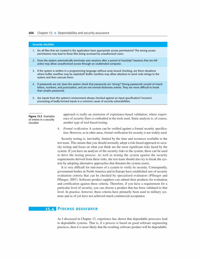
406 Chapter 15 � Dependability and security assurance
approach is really an extension of experience-based validation, where experi-
ence of security flaws is embodied in the tools used. Static analysis is, of course,
another type of tool-based testing.
4. Formal verification A system can be verified against a formal security specifica-
tion. However, as in other areas, formal verification for security is not widely used.
Security testing is, inevitably, limited by the time and resources available to the
test team. This means that you should normally adopt a risk-based approach to secu-
rity testing and focus on what you think are the most significant risks faced by the
system. If you have an analysis of the security risks to the system, these can be used
to drive the testing process. As well as testing the system against the security
requirements derived from these risks, the test team should also try to break the sys-
tem by adopting alternative approaches that threaten the system assets.
It is very difficult for end-users of a system to verify its security. Consequently,
government bodies in North America and in Europe have established sets of security
evaluation criteria that can be checked by specialized evaluators (Pfleeger and
Pfleeger, 2007). Software product suppliers can submit their products for evaluation
and certification against these criteria. Therefore, if you have a requirement for a
particular level of security, you can choose a product that has been validated to that
level. In practice, however, these criteria have primarily been used in military sys-
tems and as of yet have not achieved much commercial acceptance.
15.4 Process assurance
As I discussed in Chapter 13, experience has shown that dependable processes lead
to dependable systems. That is, if a process is based on good software engineering
practices, then it is more likely that the resulting software product will be dependable.
Figure 15.5 Examplesof entries in a securitychecklist
Security checklist
1. Do all files that are created in the application have appropriate access permissions? The wrong accesspermissions may lead to these files being accessed by unauthorized users.
2. Does the system automatically terminate user sessions after a period of inactivity? Sessions that are leftactive may allow unauthorized access through an unattended computer.
3. If the system is written in a programming language without array bound checking, are there situationswhere buffer overflow may be exploited? Buffer overflow may allow attackers to send code strings to thesystem and then execute them.
4. If passwords are set, does the system check that passwords are ‘strong’? Strong passwords consist of mixedletters, numbers, and punctuation, and are not normal dictionary entries. They are more difficult to breakthan simple passwords.
5. Are inputs from the system’s environment always checked against an input specification? Incorrectprocessing of badly formed inputs is a common cause of security vulnerabilities.
15.4 � Process assurance 407
Of course, a good process does not guarantee dependability. However, evidence that a
dependable process has been used increases overall confidence that a system is
dependable. Process assurance is concerned with collecting information about
processes used during system development, and the outcomes of these processes.
This information provides evidence of the analyses, reviews, and tests that have been
carried out during software development.
Process assurance is concerned with two things:
1. Do we have the right processes? Do the system development processes used in
the organization include appropriate controls and V & V subprocesses for the
type of system being developed?
2. Are we doing the processes right? Has the organization carried out the develop-
ment work as defined in its software process descriptions and have the defined
outcomes from the software processes been produced?
Companies that have extensive experience of critical systems engineering have
evolved their processes to reflect good verification and validation practice. In some
cases, this has involved discussions with the external regulator to agree on what
processes should be used. Although there is a great deal of process variation between
companies, activities that you would expect to see in critical systems development
processes include requirements management, change management and configuration
control, system modeling, reviews and inspections, test planning, and test coverage
analysis. The notion of process improvement, where good practice is introduced and
institutionalized in processes, is covered in Chapter 26.
The other aspect of process assurance is checking that processes have been
properly enacted. This normally involves ensuring that processes are properly
documented and checking this process documentation. For example, part of a
dependable process may involve formal program inspections. The documentation
for each inspection should include the checklists used to drive the inspection, a
list of the people involved, the problems identified during the inspection, and the
actions required.
Demonstrating that a dependable process has been used therefore involves pro-
ducing a lot of documentary evidence about the process and the software being
developed. The need for this extensive documentation means that agile processes are
Regulation of software
Regulators are created by governments to ensure that private industry does not profit by failing to follownational standards for safety, security, and so on. There are regulators in many different industries such asnuclear power, aviation, and banking. As software systems have become increasingly important in the criticalinfrastructure of countries, these regulators have become increasingly concerned with safety and dependabilitycases for software systems.
http://www.SoftwareEngineering-9.com/Web/DepSecAssur/Regulation.html
408 Chapter 15 � Dependability and security assurance
rarely used in systems where safety or dependability certification is required. Agile
processes focus on the software itself and (rightly) argue that a great deal of process
documentation is never actually used after it has been produced. However, you have
to create evidence and document process activities when process information is used
as part of a system safety or dependability case.
15.4.1 Processes for safety assurance
Most work on process assurance has been done in the area of safety-critical systems
development. It is important that a safety-critical systems development process
include V & V processes that are geared to safety analysis and assurance for two
reasons:
1. Accidents are rare events in critical systems and it may be practically impossible
to simulate them during the testing of a system. You can’t rely on extensive test-
ing to replicate the conditions that can lead to an accident.
2. Safety requirements, as I discussed in Chapter 12, are sometimes ‘shall not’
requirements that exclude unsafe system behavior. It is impossible to demon-
strate conclusively through testing and other validation activities that these
requirements have been met.
Specific safety assurance activities should be included at all stages in the software
development process. These safety assurance activities record the analyses that have
been carried out and the person or people responsible for these analyses. Safety assur-
ance activities that are incorporated into software processes may include the following:
1. Hazard logging and monitoring, which trace hazards from preliminary hazard
analysis through to testing and system validation.
2. Safety reviews, which are used throughout the development process.
3. Safety certification, where the safety of critical components is formally
certified. This involves a group external to the system development team
Licensing of software engineers
In some areas of engineering, safety engineers must be licensed engineers. Inexperienced, poorly qualifiedengineers are not allowed to take responsibility for safety. This does not currently apply to software engineers,although there has been extensive discussion on the licensing of software engineers in several states in theUnited States (Knight and Leveson, 2002). However, future process standards for safety-critical softwaredevelopment may require that project safety engineers should be licensed engineers, with a defined minimumlevel of qualifications and experience.
http://www.SoftwareEngineering-9.com/Web/DepSecAssur/Licensing.html

15.4 � Process assurance 409
examining the available evidence and deciding whether or not a system or
component should be considered to be safe before it is made available
for use.
To support these safety assurance processes, project safety engineers should be
appointed who have explicit responsibility for the safety aspects of a system. This
means that these individuals will be held responsible if a safety-related system fail-
ure occurs. They must be able to demonstrate that the safety assurance activities have
been properly carried out.
Safety engineers work with quality managers to ensure that a detailed configu-
ration management system is used to track all safety-related documentation and
keep it in step with the associated technical documentation. This is essential in all
dependable processes. There is little point in having stringent validation proce-
dures if a failure of configuration management means that the wrong system is
delivered to the customer. Configuration and quality management are covered in
Chapters 24 and 25.
The hazard analysis process that is an essential part of safety-critical systems
development is an example of a safety assurance process. Hazard analysis is con-
cerned with identifying hazards, their probability of occurrence, and the probability
of each hazard leading to an accident. If there is program code that checks for and
handles each hazard, then you can argue that these hazards will not result in acci-
dents. Such arguments may be supplemented by safety arguments, as discussed later
in this chapter. Where external certification is required before a system is used (e.g.,
in an aircraft), it is usually a condition of certification that this traceability can be
demonstrated.
The central safety document that should be produced is the hazard log. This doc-
ument provides evidence of how identified hazards have been taken into account
during software development. This hazard log is used at each stage of the software
development process to document how that development stage has taken the hazards
into account. A simplified example of a hazard log entry for the insulin delivery sys-
tem is shown in Figure 15.6. This form documents the process of hazard analysis and
shows design requirements that have been generated during this process. These
design requirements are intended to ensure that the control system can never deliver
an insulin overdose to a user of the insulin pump.
As shown in Figure 15.6, individuals who have safety responsibilities should be
explicitly identified. This is important for two reasons:
1. When people are identified, they can be held accountable for their actions. This
means that they are likely to take more care because any problems can be traced
back to their work.
2. In the event of an accident, there may be legal proceedings or an enquiry. It is
important to be able to identify who was responsible for safety assurance so that
they can account for their actions.

410 Chapter 15 � Dependability and security assurance
15.5 Safety and dependability cases
Security and dependability assurance processes generate a lot of information. This
may include test results, information about the development processes used, records
of review meetings, etc. This information provides evidence about the security and
dependability of a system, and is used to help decide whether or not the system is
dependable enough for operational use.
Safety and dependability cases are structured documents setting out detailed
arguments and evidence that a system is safe or that a required level of security or
dependability has been achieved. They are sometimes called assurance cases.
Essentially, a safety or dependability case pulls together all of the available evidence
that demonstrates that a system is trustworthy. For many types of critical system, the
production of a safety case is a legal requirement. The case must satisfy a regulator
or certification body before the system can be deployed.
The responsibility of a regulator is to check that a completed system is as safe
or dependable as practicable, so their role primarily comes into play when a
Figure 15.6 A simpli-fied hazard log entry
Hazard Log Page 4: Printed 20.02.2009
System: Insulin Pump System Safety Engineer: James Brown
File: InsulinPump/Safety/HazardLogLog version: 1/3
Identified Hazard Insulin overdose delivered to patient
Identified by Jane Williams
Criticality class 1
Identified risk High
Fault tree identified YES Date 24.01.07 Location Hazard Log, Page 5
Fault tree creators Jane Williams and Bill Smith
Fault tree checked YES Date 28.01.07 Checker James Brown
System safety design requirements
1. The system shall include self-testing software that will test the sensor system, the clock, and the insulindelivery system.
2. The self-checking software shall be executed once per minute.3. In the event of the self-checking software discovering a fault in any of the system components, an audible
warning shall be issued and the pump display shall indicate the name of the component where the fault hasbeen discovered. The delivery of insulin shall be suspended.
4. The system shall incorporate an override system that allows the system user to modify the computed dose ofinsulin that is to be delivered by the system.
5. The amount of override shall be no greater than a pre-set value (maxOverride), which is set when thesystem is configured by medical staff.

15.5 � Safety and dependability cases 411
development project is complete. However, regulators and developers rarely work
in isolation; they communicate with the development team to establish what has
to be included in the safety case. The regulator and developers jointly examine
processes and procedures to make sure that these are being enacted and docu-
mented to the regulator’s satisfaction.
Dependability cases are usually developed during and after the system development
process. This can sometimes cause problems if the development process activities do
not produce evidence for the system’s dependability. Graydon et al. (2007) argue that
the development of a safety and dependability case should be tightly integrated with
system design and implementation. This means that system design decisions may be
influenced by the requirements of the dependability case. Design choices that may add
significantly to the difficulties and costs of case development can be avoided.
Dependability cases are generalizations of system safety cases. A safety case is a
set of documents that includes a description of the system to be certified, information
about the processes used to develop the system and, critically, logical arguments that
demonstrate that the system is likely to be safe. More succinctly, Bishop and
Bloomfield (1998) define a safety case as:
A documented body of evidence that provides a convincing and valid argument
that a system is adequately safe for a given application in a given environment.
The organization and contents of a safety or dependability case depend on the type
of system that is to be certified and its context of operation. Figure 15.7 shows one
possible structure for a safety case but there are no widely used industrial standards in
this area for safety cases. Safety case structures vary, depending on the industry and
the maturity of the domain. For example, nuclear safety cases have been required for
many years. They are very comprehensive and presented in a way that is familiar to
nuclear engineers. However, safety cases for medical devices have been introduced
much more recently. Their structure is more flexible and the cases themselves are less
detailed than nuclear cases.
Of course, software itself is not dangerous. It is only when it is embedded in a large
computer-based or sociotechnical system that software failures can result in failures
of other equipment or processes that can cause injury or death. Therefore, a software
safety case is always part of a wider system safety case that demonstrates the safety of
the overall system. When constructing a software safety case, you have to relate soft-
ware failures to wider system failures and demonstrate either that these software fail-
ures will not occur or that they will not be propagated in such a way that dangerous
system failures may occur.
15.5.1 Structured arguments
The decision on whether or not a system is sufficiently dependable to be used should
be based on logical arguments. These should demonstrate that the evidence pre-
sented supports the claims about a system’s security and dependability. These claims
may be absolute (event X will or will not happen) or probabilistic (the probability of
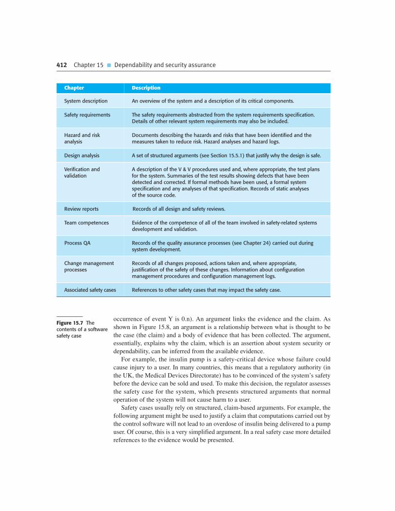
412 Chapter 15 � Dependability and security assurance
occurrence of event Y is 0.n). An argument links the evidence and the claim. As
shown in Figure 15.8, an argument is a relationship between what is thought to be
the case (the claim) and a body of evidence that has been collected. The argument,
essentially, explains why the claim, which is an assertion about system security or
dependability, can be inferred from the available evidence.
For example, the insulin pump is a safety-critical device whose failure could
cause injury to a user. In many countries, this means that a regulatory authority (in
the UK, the Medical Devices Directorate) has to be convinced of the system’s safety
before the device can be sold and used. To make this decision, the regulator assesses
the safety case for the system, which presents structured arguments that normal
operation of the system will not cause harm to a user.
Safety cases usually rely on structured, claim-based arguments. For example, the
following argument might be used to justify a claim that computations carried out by
the control software will not lead to an overdose of insulin being delivered to a pump
user. Of course, this is a very simplified argument. In a real safety case more detailed
references to the evidence would be presented.
Figure 15.7 Thecontents of a softwaresafety case
Chapter Description
System description An overview of the system and a description of its critical components.
Safety requirements The safety requirements abstracted from the system requirements specification.Details of other relevant system requirements may also be included.
Hazard and riskanalysis
Documents describing the hazards and risks that have been identified and themeasures taken to reduce risk. Hazard analyses and hazard logs.
Design analysis A set of structured arguments (see Section 15.5.1) that justify why the design is safe.
Verification andvalidation
A description of the V & V procedures used and, where appropriate, the test plansfor the system. Summaries of the test results showing defects that have beendetected and corrected. If formal methods have been used, a formal systemspecification and any analyses of that specification. Records of static analysesof the source code.
Review reports Records of all design and safety reviews.
Team competences Evidence of the competence of all of the team involved in safety-related systemsdevelopment and validation.
Process QA Records of the quality assurance processes (see Chapter 24) carried out duringsystem development.
Change managementprocesses
Records of all changes proposed, actions taken and, where appropriate,justification of the safety of these changes. Information about configurationmanagement procedures and configuration management logs.
Associated safety cases References to other safety cases that may impact the safety case.

15.5 � Safety and dependability cases 413
Claim: The maximum single dose computed by the insulin pump will not
exceed maxDose, where maxDose has been assessed as a safe single dose for a
particular patient.
Evidence: Safety argument for insulin pump software control program (I discuss
safety arguments later in this section).
Evidence: Test data sets for insulin pump. In 400 tests, the value of currentDose
was correctly computed and never exceeded maxDose.
Evidence: Static analysis report for insulin pump control program. The static
analysis of the control software revealed no anomalies that affected the value of
currentDose, the program variable that holds the dose of insulin to be delivered.
Argument: The evidence presented shows that the maximum dose of insulin that
can be computed is equal to maxDose.
It is therefore reasonable to assume, with a high level of confidence, that the evi-
dence justifies the claim that the insulin pump will not compute a dose of insulin
to be delivered that exceeds the maximum single dose.
Notice that the evidence presented is both redundant and diverse. The software is
checked using several different mechanisms with significant overlap between
them. As I discussed in Chapter 13, the use of redundant and diverse processes
increases confidence. If there are omissions and mistakes that are not detected by
one validation process, there is a good chance that these will be found by one of
the others.
Of course, there will normally be many claims about the dependability and secu-
rity of a system, with the validity of one claim often depending on whether or not
other claims are valid. Therefore, claims may be organized in a hierarchy. Figure 15.9
shows part of this claim hierarchy for the insulin pump. To demonstrate that a high-
level claim is valid, you first have to work through the arguments for lower-level
claims. If you can show that each of these lower-level claims is justified, then you
may be able to infer that the higher-level claims are justified.
<< ARGUMENT >> ClaimSupports
Supports
Supports
JustifiesEvidence
Evidence
EvidenceFigure 15.8 Structuredarguments
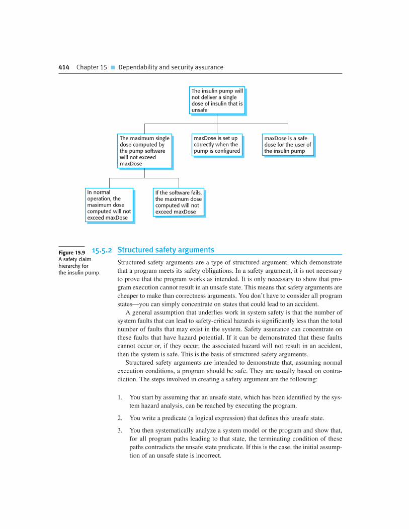
414 Chapter 15 � Dependability and security assurance
15.5.2 Structured safety arguments
Structured safety arguments are a type of structured argument, which demonstrate
that a program meets its safety obligations. In a safety argument, it is not necessary
to prove that the program works as intended. It is only necessary to show that pro-
gram execution cannot result in an unsafe state. This means that safety arguments are
cheaper to make than correctness arguments. You don’t have to consider all program
states—you can simply concentrate on states that could lead to an accident.
A general assumption that underlies work in system safety is that the number of
system faults that can lead to safety-critical hazards is significantly less than the total
number of faults that may exist in the system. Safety assurance can concentrate on
these faults that have hazard potential. If it can be demonstrated that these faults
cannot occur or, if they occur, the associated hazard will not result in an accident,
then the system is safe. This is the basis of structured safety arguments.
Structured safety arguments are intended to demonstrate that, assuming normal
execution conditions, a program should be safe. They are usually based on contra-
diction. The steps involved in creating a safety argument are the following:
1. You start by assuming that an unsafe state, which has been identified by the sys-
tem hazard analysis, can be reached by executing the program.
2. You write a predicate (a logical expression) that defines this unsafe state.
3. You then systematically analyze a system model or the program and show that,
for all program paths leading to that state, the terminating condition of these
paths contradicts the unsafe state predicate. If this is the case, the initial assump-
tion of an unsafe state is incorrect.
The maximum singledose computed bythe pump softwarewill not exceedmaxDose
maxDose is set upcorrectly when thepump is configured
maxDose is a safedose for the user ofthe insulin pump
The insulin pump willnot deliver a singledose of insulin that isunsafe
In normaloperation, themaximum dosecomputed will notexceed maxDose
If the software fails,the maximum dosecomputed will notexceed maxDose
Figure 15.9A safety claim hierarchy for the insulin pump

15.5 � Safety and dependability cases 415
4. When you have repeated this analysis for all identified hazards then you have
strong evidence that the system is safe.
Structured safety arguments can be applied at different levels, from requirements
through design models to code. At the requirements level, you are trying to demon-
strate that there are no missing safety requirements and that the requirements do not
make invalid assumptions about the system. At the design level, you might analyze a
state model of the system to find unsafe states. At the code level, you consider all of
the paths through the safety-critical code to show that the execution of all paths leads
to a contradiction.
As an example, consider the code in Figure 15.10, which might be part of the
implementation of the insulin delivery system. The code computes the dose of
insulin to be delivered then applies some safety checks to reduce the probability than
an overdose of insulin will be injected. Developing a safety argument for this code
involves demonstrating that the dose of insulin administered is never greater than the
maximum safe level for a single dose. This is established for each individual diabetic
user in discussions with their medical advisors.
To demonstrate safety, you do not have to prove that the system delivers the ‘cor-
rect’ dose, merely that it never delivers an overdose to the patient. You work on the
assumption that maxDose is the safe level for that system user.
To construct the safety argument, you identify the predicate that defines the
unsafe state, which is that currentDose � maxDose. You then demonstrate that all
program paths lead to a contradiction of this unsafe assertion. If this is the case, the
Figure 15.10 Insulindose computation withsafety checks
— The insulin dose to be delivered is a function of
— blood sugar level, the previous dose delivered and
— the time of delivery of the previous dose
currentDose = computeInsulin () ;
// Safety check–adjust currentDose if necessary.
// if statement 1
if (previousDose == 0)
{
if (currentDose > maxDose/2)
currentDose = maxDose/2 ;
}
else
if (currentDose > (previousDose * 2) )
currentDose = previousDose * 2 ;
// if statement 2
if ( currentDose < minimumDose )
currentDose = 0 ;
else if ( currentDose > maxDose )
currentDose = maxDose ;
administerInsulin (currentDose) ;

416 Chapter 15 � Dependability and security assurance
unsafe condition cannot be true. If you can do this, you can be confident that the pro-
gram will not compute an unsafe dose of insulin. You can structure and present the
safety arguments graphically, as shown in Figure 15.11.
To construct a structured argument for a program does not make an unsafe
computation, you first identify all possible paths through the code that could lead to
the potentially unsafe state. You work backwards from this unsafe state and consider
the last assignment to all of the state variables on each path leading to this unsafe
state. If you can show that none of the values of these variables is unsafe, then you
have shown that your initial assumption (that the computation is unsafe) is incorrect.
Working backwards is important because it means you can ignore all states
apart from the final states that lead to the exit condition for the code. The previ-
ous values don’t matter to the safety of the system. In this example, all you need
to be concerned with is the set of possible values of currentDose immediately
currentDose = 0
currentDose = 0
If Statement 2Then Branch
Executed
currentDose =maxDose
currentDose =maxDose
If Statement 2Else BranchExecuted
If Statement 2Not Executed
currentDose >= minimumDose andcurrentDose <= maxDose
or
currentDose>maxDose
AdministerInsulin
Contradiction
Contradiction Contradiction
Pre-Conditionfor Unsafe State
OverdoseAdministered
Assign Assign
Figure 15.11 Informalsafety argument basedon demonstratingcontradictions

Chapter 15 � Key points 417
before the administerInsulin method is executed. You can ignore computations,
such as if-statement 1 in Figure 15.10, in the safety argument because their results
are over-written in later program statements.
In the safety argument shown in Figure 15.11, there are three possible program
paths that lead to the call to the administerInsulin method. You have to show that the
amount of insulin delivered never exceeds maxDose. All possible program paths to
administerInsulin are considered:
1. Neither branch of if-statement 2 is executed. This can only happen if
currentDose is either greater than or equal to minimumDose and less than or
equal to maxDose. This is the post-condition—an assertion that is true after the
statement has been executed.
2. The then-branch of if-statement 2 is executed. In this case, the assignment
setting currentDose to zero is executed. Therefore, its post-condition is
currentDose � 0.
3. The else-if-branch of if-statement 2 is executed. In this case, the assignment set-
ting currentDose to maxDose is executed. Therefore, after this statement has
been executed, we know that the post-condition is currentDose � maxDose.
In all three cases, the post-conditions contradict the unsafe pre-condition that the
dose administered is greater than maxDose. We can therefore claim that the compu-
tation is safe.
Structured arguments can be used in the same way to demonstrate that certain
security properties of a system are true. For example, if you wish to show that a com-
putation will never lead to the permissions on a resource being changed, you may be
able to use a structured security argument to show this. However, the evidence from
structured arguments is less reliable for security validation. This is because there is a
possibility that the attacker may corrupt the code of the system. In such a case, the
code executed is not the code that you have claimed is secure.
K E Y P O I N T S
� Static analysis is an approach to V & V that examines the source code (or other representation)
of a system, looking for errors and anomalies. It allows all parts of a program to be checked, not
just those parts that are exercised by system tests.
� Model checking is a formal approach to static analysis that exhaustively checks all states in a
system for potential errors.
� Statistical testing is used to estimate software reliability. It relies on testing the system with a
test data set that reflects the operational profile of the software. Test data may be generated
automatically.

418 Chapter 15 � Dependability and security assurance
� Security validation is difficult because security requirements state what should not happen in a
system, rather than what should. Furthermore, system attackers are intelligent and may have
more time to probe for weaknesses than is available for security testing.
� Security validation may be carried out using experience-based analysis, tool-based analysis, or
‘tiger teams’ that simulate attacks on a system.
� It is important to have a well-defined, certified process for safety-critical systems development.
The process must include the identification and monitoring of potential hazards.
� Safety and dependability cases collect all of the evidence that demonstrates a system is safe
and dependable. Safety cases are required when an external regulator must certify the system
before it is used.
� Safety cases are usually based on structured arguments. Structured safety arguments show that
an identified hazardous condition can never occur by considering all program paths that lead to
an unsafe condition, and showing that the condition cannot hold.
F U RT H E R R E A D I N G
Software Reliability Engineering: More Reliable Software, Faster and Cheaper, 2nd edition. This is
probably the definitive book on the use of operational profiles and reliability models for reliability
assessment. It includes details of experiences with statistical testing. (J. D. Musa, McGraw-Hill,
2004.)
‘NASA’s Mission Reliable’. A discussion of how NASA has used static analysis and model checking
for assuring the reliability of spacecraft software. (P. Regan and S. Hamilton, IEEE Computer, 37 (1),
January 2004.) http://dx.doi.org/10.1109/MC.2004.1260727.
Dependability cases. An example-based introduction to defining a dependability case. (C. B.
Weinstock, J. B. Goodenough, J. J. Hudak, Software Engineering Institute, CMU/SEI-2004-TN-016,
2004.) http://www.sei.cmu.edu/publications/documents/04.reports/04tn016.html.
How to Break Web Software: Functional and Security Testing of Web Applications and Web Services.
A short book that provides good practical advice on how to run security tests on networked
applications. (M. Andrews and J. A. Whittaker, Addison-Wesley, 2006.)
‘Using static analysis to find bugs’. This paper describes Findbugs, a Java static analyzer that uses
simple techniques to find potential security violations and runtime errors. (N. Ayewah et al., IEEE
Software, 25 (5), Sept/Oct 2008.) http://dx.doi.org/10.1109/MS.2008.130.
E X E R C I S E S
15.1. Explain when it may be cost effective to use formal specification and verification in the
development of safety-critical software systems. Why do you think that critical systems
engineers are against the use of formal methods?
15.2. Suggest a list of conditions that could be detected by a static analyzer for Java, C++, or any
another programming language that you use. Comment on this list compared to the list given
in Figure 15.2.
15.3. Explain why it is practically impossible to validate reliability specifications when these are
expressed in terms of a very small number of failures over the total lifetime of a system.
15.4. Explain why ensuring system reliability is not a guarantee of system safety.
15.5. Using examples, explain why security testing is a very difficult process.
15.6. Suggest how you would go about validating a password protection system for an application
that you have developed. Explain the function of any tools that you think may be useful.
15.7. The MHC-PMS has to be secure against attacks that might reveal confidential patient
information. Some of these attacks have been discussed in Chapter 14. Using this information,
extend the checklist in Figure 15.5 to guide testers of the MHC-PMS.
15.8. List four types of systems that may require software safety cases, explaining why safety cases
are required.
15.9. The door lock control mechanism in a nuclear waste storage facility is designed for safe
operation. It ensures that entry to the storeroom is only permitted when radiation shields
are in place or when the radiation level in the room falls below some given value
(dangerLevel). So:
i. If remotely controlled radiation shields are in place within a room, an authorized operator
may open the door.
ii. If the radiation level in a room is below a specified value, an authorized operator may open
the door.
iii. An authorized operator is identified by the input of an authorized door entry code.
The code shown in Figure 15.12 (see below) controls the door-locking mechanism. Note that
the safe state is that entry should not be permitted. Using the approach discussed in section
15.5.2, develop a safety argument for this code. Use the line numbers to refer to specific
statements. If you find that the code is unsafe, suggest how it should be modified to make
it safe.
Chapter 15 � Exercises 419
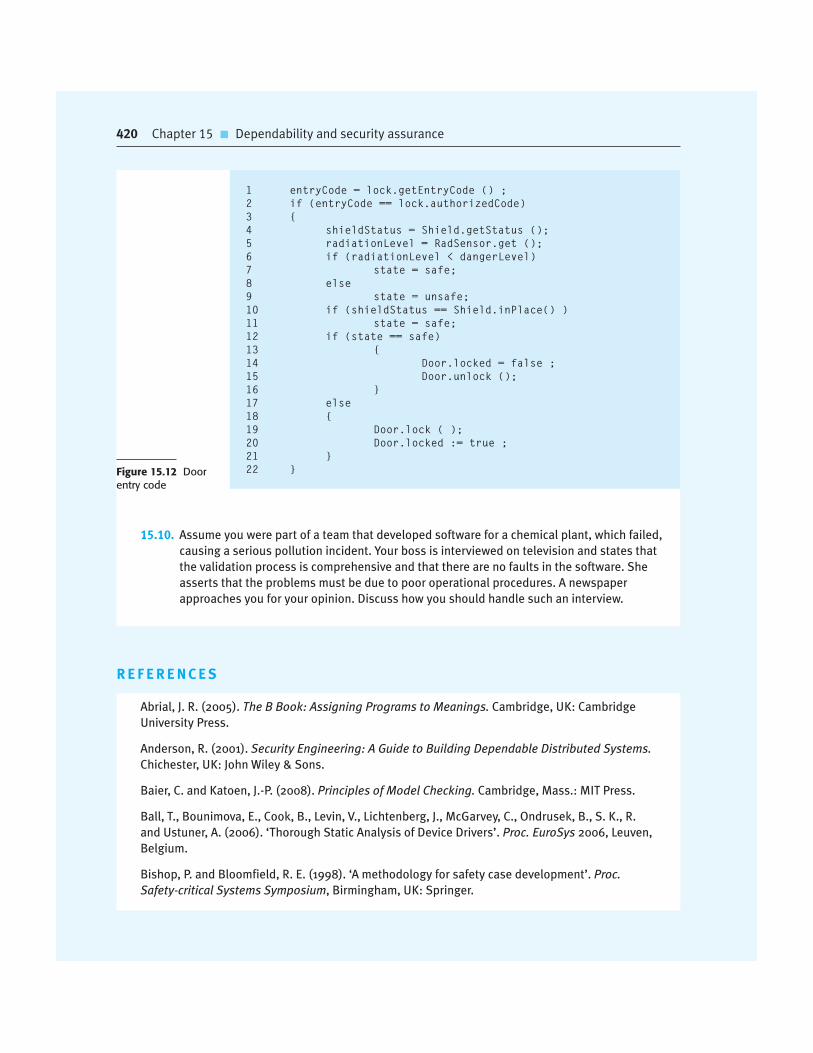
420 Chapter 15 � Dependability and security assurance
Figure 15.12 Doorentry code
15.10. Assume you were part of a team that developed software for a chemical plant, which failed,
causing a serious pollution incident. Your boss is interviewed on television and states that
the validation process is comprehensive and that there are no faults in the software. She
asserts that the problems must be due to poor operational procedures. A newspaper
approaches you for your opinion. Discuss how you should handle such an interview.
1 entryCode = lock.getEntryCode () ;
2 if (entryCode == lock.authorizedCode)
3 {
4 shieldStatus = Shield.getStatus ();
5 radiationLevel = RadSensor.get ();
6 if (radiationLevel < dangerLevel)
7 state = safe;
8 else
9 state = unsafe;
10 if (shieldStatus == Shield.inPlace() )
11 state = safe;
12 if (state == safe)
13 {
14 Door.locked = false ;
15 Door.unlock ();
16 }
17 else
18 {
19 Door.lock ( );
20 Door.locked := true ;
21 }
22 }
R E F E R E N C E S
Abrial, J. R. (2005). The B Book: Assigning Programs to Meanings. Cambridge, UK: Cambridge
University Press.
Anderson, R. (2001). Security Engineering: A Guide to Building Dependable Distributed Systems.
Chichester, UK: John Wiley & Sons.
Baier, C. and Katoen, J.-P. (2008). Principles of Model Checking. Cambridge, Mass.: MIT Press.
Ball, T., Bounimova, E., Cook, B., Levin, V., Lichtenberg, J., McGarvey, C., Ondrusek, B., S. K., R.
and Ustuner, A. (2006). ‘Thorough Static Analysis of Device Drivers’. Proc. EuroSys 2006, Leuven,
Belgium.
Bishop, P. and Bloomfield, R. E. (1998). ‘A methodology for safety case development’. Proc.
Safety-critical Systems Symposium, Birmingham, UK: Springer.

Chapter 15 � References 421
Chandra, S., Godefroid, P. and Palm, C. (2002). ‘Software model checking in practice: An industrial
case study’. Proc. 24th Int. Conf. on Software Eng. (ICSE 2002), Orland, Fla.: IEEE Computer Society,
431–41.
Croxford, M. and Sutton, J. (2006). ‘Breaking Through the V and V Bottleneck’. Proc. 2nd Int.
Eurospace—Ada-Europe Symposium on Ada in Europe, Frankfurt, Germany: Springer-LNCS,
344–54.
Evans, D. and Larochelle, D. (2002). ‘Improving Security Using Extensible Lightweight Static
Analysis’. IEEE Software, 19 (1), 42–51.
Graydon, P. J., Knight, J. C. and Strunk, E. A. (2007). ‘Assurance Based Development of Critical
Systems’. Proc. 37th Annual IEEE Conf. on Dependable Systems and Networks, Edinburgh, Scotland:
347–57.
Holzmann, G. J. (2003). The SPIN Model Checker. Boston: Addison-Wesley.
Knight, J. C. and Leveson, N. G. (2002). ‘Should software engineers be licensed?’ Comm. ACM,
45 (11), 87–90.
Larus, J. R., Ball, T., Das, M., Deline, R., Fahndrich, M., Pincus, J., Rajamani, S. K. and Venkatapathy, R.
(2003). ‘Righting Software’. IEEE Software, 21 (3), 92–100.
Musa, J. D. (1998). Software Reliability Engineering: More Reliable Software, Faster Development
and Testing. New York: McGraw-Hill.
Nguyen, T. and Ourghanlian, A. (2003). ‘Dependability assessment of safety-critical system software
by static analysis methods’. Proc. IEEE Conf. on Dependable Systems and Networks (DSN’2003),
San Francisco, Calif.: IEEE Computer Society, 75–9.
Pfleeger, C. P. and Pfleeger, S. L. (2007). Security in Computing, 4th edition. Boston:
Addison-Wesley.
Prowell, S. J., Trammell, C. J., Linger, R. C. and Poore, J. H. (1999). Cleanroom Software Engineering:
Technology and Process. Reading, Mass.: Addison-Wesley.
Regan, P. and Hamilton, S. (2004). ‘NASA’s Mission Reliable’. IEEE Computer, 37 (1), 59–68.
Schneider, S. (1999). Concurrent and Real-time Systems: The CSP Approach. Chichester, UK: John
Wiley and Sons.
Visser, W., Havelund, K., Brat, G., Park, S. and Lerda, F. (2003). ‘Model Checking Programs’.
Automated Software Engineering J., 10 (2), 203–32.
Voas, J. (1997). ‘Fault Injection for the Masses’. IEEE Computer, 30 (12), 129–30.
Wordsworth, J. (1996). Software Engineering with B. Wokingham: Addison-Wesley.
Zheng, J., Williams, L., Nagappan, N., Snipes, W., Hudepohl, J. P. and Vouk, M. A. (2006). ‘On the
value of static analysis for fault detection in software’. IEEE Trans. on Software Eng., 32 (4), 240–5.

This page intentionally left blank
PART
I have entitled this part of the book ‘Advanced Software Engineering’
because you have to understand the basics of the discipline, covered in
Chapters 1–9, to benefit from the material covered here. Many of the topics
discussed here reflect industrial software engineering practice in the devel-
opment of distributed and real-time systems.
Software reuse has now become the dominant development paradigm
for web-based information systems and enterprise systems. The most
common approach to reuse is COTS reuse where a large system is config-
ured for the needs of an organization and little or no original software
development is required. I introduce the general topic of reuse in Chapter
16 and focus in this chapter on the reuse of COTS systems.
Chapter 17 is also concerned with the reuse of software components rather
than entire software systems. Component-based software engineering is a
process of component composition, with new code being developed to
integrate reusable components. In this chapter, I explain what is meant by
a component and why standard component models are needed for effec-
tive component reuse. I also discuss the general process of component-
based software engineering and the problems of component composition.
The majority of large systems are now distributed systems and Chapter 18
covers issues and problems of building distributed systems. I introduce the
AdvancedSoftwareEngineer ing3

client–server approach as a fundamental paradigm of distributed systems
engineering, and explain various ways of implementing this architectural
style. The final section in this chapter explains how providing software as a
distributed application service will radically change the market for soft-
ware products.
Chapter 19 introduces the related topic of service-oriented architectures,
which link the notions of distribution and reuse. Services are reusable
software components whose functionality can be accessed over the
Internet and made available to a range of clients. In this chapter, I explain
what is involved in creating services (service engineering) and composing
services to create new software systems.
Embedded systems are the most widely used instances of software sys-
tems and Chapter 20 covers this important topic. I introduce the idea of a
real-time embedded system and describe three architectural patterns
that are used in embedded systems design. I then go on to explain the
process of timing analysis and conclude the chapter with a discussion of
real-time operating systems.
Finally, Chapter 21 covers aspect-oriented software development (AOSD).
AOSD is also related to reuse and proposes a new approach, based on
aspects, to organizing and structuring software systems. Although not yet
mainstream software engineering, AOSD has the potential to signifi-
cantly improve our current approaches to software implementation.

Software reuse
16
Objectives
The objectives of this chapter are to introduce software reuse and to
describe approaches to system development based on large-scale system
reuse. When you have read this chapter, you will:
� understand the benefits and problems of reusing software when
developing new systems;
� understand the concept of an application framework as a set of
reusable objects and how frameworks can be used in application
development;
� have been introduced to software product lines, which are made up of
a common core architecture and configurable, reusable components;
� have learned how systems can be developed by configuring and
composing off-the-shelf application software systems.
Contents
16.1 The reuse landscape
16.2 Application frameworks
16.3 Software product lines
16.4 COTS product reuse

426 Chapter 16 � Software reuse
Reuse-based software engineering is a software engineering strategy where the devel-
opment process is geared to reusing existing software. Although reuse was proposed
as a development strategy more than 40 years ago (McIlroy, 1968), it is only since
2000 that ‘development with reuse’ has become the norm for new business systems.
The move to reuse-based development has been in response to demands for lower
software production and maintenance costs, faster delivery of systems, and increased
software quality. More and more companies see their software as a valuable asset.
They are promoting reuse to increase their return on software investments.
The availability of reusable software has increased dramatically. The open source
movement has meant that there is a huge reusable code base available at low cost.
This may be in the form of program libraries or entire applications. There are many
domain-specific application systems available that can be tailored and adapted to the
needs of a specific company. Some large companies provide a range of reusable com-
ponents for their customers. Standards, such as web service standards, have made it
easier to develop general services and reuse them across a range of applications.
Reuse-based software engineering is an approach to development that tries to
maximize the reuse of existing software. The software units that are reused may be
of radically different sizes. For example:
1. Application system reuse The whole of an application system may be reused by
incorporating it without changing into other systems or by configuring the
application for different customers. Alternatively, application families that have
a common architecture, but which are tailored for specific customers, may be
developed. I cover application system reuse later in this chapter.
2. Component reuse Components of an application, ranging in size from subsys-
tems to single objects, may be reused. For example, a pattern-matching system
developed as part of a text-processing system may be reused in a database man-
agement system. I cover component reuse in Chapters 17 and 19.
3. Object and function reuse Software components that implement a single function,
such as a mathematical function, or an object class may be reused. This form of
reuse, based around standard libraries, has been common for the past 40 years.
Many libraries of functions and classes are freely available. You reuse the classes
and functions in these libraries by linking them with newly developed application
code. In areas such as mathematical algorithms and graphics, where specialized
expertise is needed to develop efficient objects and functions, this is a particularly
effective approach.
Software systems and components are potentially reusable entities, but their
specific nature sometimes means that it is expensive to modify them for a new
situation. A complementary form of reuse is ‘concept reuse’ where, rather than reuse
a software component, you reuse an idea, a way, or working or an algorithm. The con-
cept that you reuse is represented in an abstract notation (e.g., a system model), which
does not include implementation detail. It can, therefore, be configured and adapted
for a range of situations. Concept reuse can be embodied in approaches such as design

Chapter 16 � Software reuse 427
patterns (covered in Chapter 7), configurable system products, and program genera-
tors. When concepts are reused, the reuse process includes an activity where the
abstract concepts are instantiated to create executable reusable components.
An obvious advantage of software reuse is that overall development costs should
be reduced. Fewer software components need to be specified, designed, implemented,
and validated. However, cost reduction is only one advantage of reuse. In Figure 16.1,
I have listed other advantages of reusing software assets.
However, there are costs and problems associated with reuse (Figure 16.2). There
is a significant cost associated with understanding whether or not a component is
suitable for reuse in a particular situation, and in testing that component to ensure its
dependability. These additional costs mean that the reductions in overall develop-
ment costs through reuse may be less than anticipated.
As I discussed in Chapter 2, software development processes have to be adapted
to take reuse into account. In particular, there has to be a requirements refinement
stage where the requirements for the system are modified to reflect the reusable soft-
ware that is available. The design and implementation stages of the system may also
include explicit activities to look for and evaluate candidate components for reuse.
Software reuse is most effective when it is planned as part of an organization-wide
reuse program. A reuse program involves the creation of reusable assets and the
adaptation of development processes to incorporate these assets in new software.
The importance of reuse planning has been recognized for many years in Japan
(Matsumoto, 1984), where reuse is an integral part of the Japanese ‘factory’ approach
Figure 16.1 Benefitsof software reuse
Benefit Explanation
Increased dependability Reused software, which has been tried and tested in working systems, shouldbe more dependable than new software. Its design and implementation faultsshould have been found and fixed.
Reduced process risk The cost of existing software is already known, whereas the costs of developmentare always a matter of judgment. This is an important factor for projectmanagement because it reduces the margin of error in project cost estimation.This is particularly true when relatively large software components such assubsystems are reused.
Effective use of specialists Instead of doing the same work over and over again, application specialists candevelop reusable software that encapsulates their knowledge.
Standards compliance Some standards, such as user interface standards, can be implemented as a set ofreusable components. For example, if menus in a user interface are implementedusing reusable components, all applications present the same menu formats tousers. The use of standard user interfaces improves dependability because usersmake fewer mistakes when presented with a familiar interface.
Accelerated development Bringing a system to market as early as possible is often more important thanoverall development costs. Reusing software can speed up system productionbecause both development and validation time may be reduced.

428 Chapter 16 � Software reuse
Problem Explanation
Increased maintenance costs If the source code of a reused software system or component is not available,then maintenance costs may be higher because the reused elements of thesystem may become increasingly incompatible with system changes.
Lack of tool support Some software tools do not support development with reuse. It may bedifficult or impossible to integrate these tools with a component librarysystem. The software process assumed by these tools may not take reuseinto account. This is particularly true for tools that support embeddedsystems engineering, less so for object-oriented development tools.
Not-invented-here syndrome Some software engineers prefer to rewrite components because theybelieve they can improve on them. This is partly to do with trust and partlyto do with the fact that writing original software is seen as morechallenging than reusing other people’s software.
Creating, maintaining, andusing a component library
Populating a reusable component library and ensuring the softwaredevelopers can use this library can be expensive. Development processeshave to be adapted to ensure that the library is used.
Finding, understanding, andadapting reusablecomponents
Software components have to be discovered in a library, understood and,sometimes, adapted to work in a new environment. Engineers must bereasonably confident of finding a component in the library before theyinclude a component search as part of their normal development process.
to software development (Cusamano, 1989). Companies such as Hewlett-Packard
have also been very successful in their reuse programs (Griss and Wosser, 1995), and
their experience has been documented in a book by Jacobson et al. (1997).
16.1 The reuse landscape
Over the past 20 years, many techniques have been developed to support software
reuse. These techniques exploit the facts that systems in the same application domain
are similar and have potential for reuse; that reuse is possible at different levels from
simple functions to complete applications; and that standards for reusable compo-
nents facilitate reuse. Figure 16.3 sets out a number of possible ways of implement-
ing software reuse, with each described briefly in Figure 16.4.
Given this array of techniques for reuse, the key question is “which is the most
appropriate technique to use in a particular situation?” Obviously, this depends on
the requirements for the system being developed, the technology and reusable assets
available, and the expertise of the development team. Key factors that you should
consider when planning reuse are:
1. The development schedule for the software If the software has to be developed
quickly, you should try to reuse off-the-shelf systems rather than individual
components. These are large-grain reusable assets. Although the fit to
Figure 16.2 Problemswith reuse

16.1 � The reuse landscape 429
requirements may be imperfect, this approach minimizes the amount of devel-
opment required.
2. The expected software lifetime If you are developing a long-lifetime system, you
should focus on the maintainability of the system. You should not just think
about the immediate benefits of reuse but also of the long-term implications.
Over its lifetime, you will have to adapt the system to new requirements, which
will mean making changes to parts of the system. If you do not have access to
the source code, you may prefer to avoid off-the-shelf components and systems
from external suppliers; suppliers may not be able to continue support for the
reused software.
3. The background, skills, and experience of the development team All reuse tech-
nologies are fairly complex and you need quite a lot of time to understand and
use them effectively. Therefore, if the development team has skills in a particu-
lar area, this is probably where you should focus.
4. The criticality of the software and its non-functional requirements For a critical
system that has to be certified by an external regulator, you may have to create a
dependability case for the system (discussed in Chapter 15). This is difficult if
you don’t have access to the source code of the software. If your software has
stringent performance requirements, it may be impossible to use strategies such
as generator-based reuse, where you generate the code from a reusable domain-
specific representation of a system. These systems often generate relatively
inefficient code.
5. The application domain In some application domains, such as manufacturing
and medical information systems, there are several generic products that may be
reused by configuring them to a local situation. If you are working in such a
domain, you should always consider these as an option.
DesignPatterns
Component-BasedSoftware Engineering
ApplicationFrameworks
Service-OrientedSystems
COTSIntegration
Software ProductLines
Legacy SystemWrapping
ProgramLibraries
ProgramGenerators
Aspect-OrientedSoftware Development
Configurable VerticalApplications
ArchitecturalPatterns
ERP Systems
Model-DrivenEngineering
Figure 16.3 The reuselandscape

430 Chapter 16 � Software reuse
Approach Description
Architectural patterns Standard software architectures that support common types ofapplication systems are used as the basis of applications.Described in Chapters 6, 13, and Chapter 20.
Design patterns Generic abstractions that occur across applications arerepresented as design patterns showing abstract and concreteobjects and interactions. Described in Chapter 7.
Component-based development Systems are developed by integrating components (collections ofobjects) that conform to component-model standards. Describedin Chapter 17.
Application frameworks Collections of abstract and concrete classes are adapted andextended to create application systems.
Legacy system wrapping Legacy systems (see Chapter 9) are ‘wrapped’ by defining a setof interfaces and providing access to these legacy systemsthrough these interfaces.
Service-oriented systems Systems are developed by linking shared services, which may beexternally provided. Described in Chapter 19.
Software product lines An application type is generalized around a common architectureso that it can be adapted for different customers.
COTS product reuse Systems are developed by configuring and integrating existingapplication systems.
ERP systems Large-scale systems that encapsulate generic businessfunctionality and rules are configured for an organization.
Configurable vertical applications Generic systems are designed so that they can be configured tothe needs of specific system customers.
Program libraries Class and function libraries that implement commonly usedabstractions are available for reuse.
Model-driven engineering Software is represented as domain models and implementationindependent models and code is generated from these models.Described in Chapter 5.
Program generators A generator system embeds knowledge of a type of applicationand is used to generate systems in that domain from a user-supplied system model.
Aspect-oriented software development Shared components are woven into an application at differentplaces when the program is compiled. Described in Chapter 21.
Figure 16.4Approaches that support software reuse
6. The platform on which the system will run Some components models, such as
.NET, are specific to Microsoft platforms. Similarly, generic application sys-
tems may be platform-specific and you may only be able to reuse these if your
system is designed for the same platform.

16.2 � Application frameworks 431
The range of available reuse techniques is such that, in most situations, there is
the possibility of some software reuse. Whether or not reuse is achieved is often a
managerial rather than a technical issue. Managers may be unwilling to compromise
their requirements to allow reusable components to be used. They may not under-
stand the risks associated with reuse as well as they understand the risks of original
development. Although the risks of new software development may be higher, some
managers may prefer known to unknown risks.
16.2 Application frameworks
Early enthusiasts for object-oriented development suggested that one of the key
benefits of using an object-oriented approach was that objects could be reused in dif-
ferent systems. However, experience has shown that objects are often too small and
are specialized for a particular application. It takes longer to understand and adapt
the object than to reimplement it. It has now become clear that object-oriented reuse
is best supported in an object-oriented development process through larger-grain
abstractions called frameworks.
As the name suggests, a framework is a generic structure that is extended to cre-
ate a more specific subsystem or application. Schmidt et al. (2004) define a frame-
work to be:
“. . . an integrated set of software artefacts (such as classes, objects and com-
ponents) that collaborate to provide a reusable architecture for a family of
related applications.”
Frameworks provide support for generic features that are likely to be used in all
applications of a similar type. For example, a user interface framework will provide
support for interface event handling and will include a set of widgets that can be used
to construct displays. It is then left to the developer to specialize these by adding
specific functionality for a particular application. For example, in a user interface
framework, the developer defines display layouts that are appropriate to the applica-
tion being implemented.
Frameworks support design reuse in that they provide a skeleton architecture for
the application as well as the reuse of specific classes in the system. The architecture
Generator-based reuse
Generator-based reuse involves incorporating reusable concepts and knowledge into automated tools andproviding an easy way for tool users to integrate specific code with this generic knowledge. This approach isusually most effective in domain-specific applications. Known solutions to problems in that domain areembedded in the generator system and selected by the user to create a new system.
http://www.SoftwareEngineering-9.com/Web/Reuse/Generator.html

432 Chapter 16 � Software reuse
is defined by the object classes and their interactions. Classes are reused directly and
may be extended using features such as inheritance.
Frameworks are implemented as a collection of concrete and abstract object
classes in an object-oriented programming language. Therefore, frameworks are
language-specific. There are frameworks available in all of the commonly used
object-oriented programming languages (e.g., Java, C#, C++, as well as dynamic
languages such as Ruby and Python). In fact, a framework can incorporate several
other frameworks, where each of these is designed to support the development of
part of the application. You can use a framework to create a complete application or
to implement part of an application, such as the graphical user interface.
Fayad and Schmidt (1997) discuss three classes of frameworks:
1. System infrastructure frameworks These frameworks support the development
of system infrastructures such as communications, user interfaces, and compil-
ers (Schmidt, 1997).
2. Middleware integration frameworks These consist of a set of standards and
associated object classes that support component communication and informa-
tion exchange. Examples of this type of framework include Microsoft’s .NET
and Enterprise Java Beans (EJB). These frameworks provide support for stan-
dardized component models, as discussed in Chapter 17.
3. Enterprise application frameworks These are concerned with specific applica-
tion domains such as telecommunications or financial systems (Baumer, et al.,
1997). These embed application domain knowledge and support the develop-
ment of end-user applications.
Web application frameworks (WAFs) are a more recent and very important type
of framework. WAFs that support the construction of dynamic websites are now
widely available. The architecture of a WAF is usually based on the Model-View-
Controller (MVC) composite pattern (Gamma et al., 1995), shown in Figure 16.5.
The MVC pattern was originally proposed in the 1980s as an approach to GUI
design that allowed for multiple presentations of an object and separate styles of inter-
action with each of these presentations. It allows for the separation of the application
Controller Methods View Methods
UserInputs
View ModificationMessages
ModelEdits
Model Queriesand Updates
Controller State View State
Model Methods
Model State
Figure 16.5 TheModel-View-Controllerpattern

16.2 � Application frameworks 433
state from the user interface to application. An MVC framework supports the presen-
tation of data in different ways and allows interaction with each of these presenta-
tions. When the data is modified through one of the presentations, the system model
is changed and the controllers associated with each view update their presentation.
Frameworks are often implementations of design patterns, as discussed in
Chapter 7. For example, an MVC framework includes the Observer pattern, the
Strategy pattern, the Composite pattern, and a number of others that are discussed by
Gamma et al. (1995). The general nature of patterns and their use of abstract and
concrete classes allows for extensibility. Without patterns, frameworks would,
almost certainly, be impractical.
Web application frameworks usually incorporate one or more specialized frame-
works that support specific application features. Although each framework includes
slightly different functionality, most web application frameworks support the follow-
ing features:
1. Security WAFs may include classes to help implement user authentication
(login) and access control to ensure that users can only access permitted func-
tionality in the system.
2. Dynamic web pages Classes are provided to help you define web page templates
and to populate these dynamically with specific data from the system database.
3. Database support Frameworks don’t usually include a database but rather
assume that a separate database, such as MySQL, will be used. The framework
may provide classes that provide an abstract interface to different databases.
4. Session management Classes to create and manage sessions (a number of inter-
actions with the system by a user) are usually part of a WAF.
5. User interaction Most web frameworks now provide AJAX support (Holdener,
2008), which allows more interactive web pages to be created.
To extend a framework you do not change the framework code. Rather, you add
concrete classes that inherit operations from abstract classes in the framework. In
addition, you may have to define callbacks. Callbacks are methods that are called in
response to events recognized by the framework. Schmidt et al. (2004) call this
‘inversion of control’. The framework objects, rather than the application-specific
objects, are responsible for control in the system. In response to events from the user
interface, database, etc., these framework objects invoke ‘hook methods’ that are
then linked to user-provided functionality. The application-specific functionality
responds to the event in an appropriate way (Figure 16.6). For example, a framework
will have a method that handles a mouse click from the environment. This method
calls the hook method, which you must configure to call the appropriate application
methods to handle the mouse click.
Applications that are constructed using frameworks can be the basis for further
reuse through the concept of software product lines or application families. Because
these applications are constructed using a framework, modifying family members to

434 Chapter 16 � Software reuse
Application-Specific Classes
DatabaseEventLoop
Callbacks Callbacks
Callbacks
PlatformEventLoop
GUIEventLoop
Figure 16.6 Inversionof control in frameworks
create instances of the system is often a straightforward process. It involves rewriting
concrete classes and methods that you have added to the framework.
However, frameworks are usually more general than software product lines,
which focus on a specific family of application system. For example, you can use a
web-based framework to build different types of web-based applications. One of
these might be a software product line that supports web-based help desks. This
‘help desk product line’ may then be further specialized to provide particular types
of help desk support.
Frameworks are an effective approach to reuse, but are expensive to introduce
into software development processes. They are inherently complex and it can take
several months to learn to use them. It can be difficult and expensive to evaluate
available frameworks to choose the most appropriate one. Debugging framework-
based applications is difficult because you may not understand how the framework
methods interact. This is a general problem with reusable software. Debugging tools
may provide information about the reused system components, which a developer
does not understand.
16.3 Software product lines
One of the most effective approaches to reuse is to create software product lines or
application families. A software product line is a set of applications with a common
architecture and shared components, with each application specialized to reflect dif-
ferent requirements. The core system is designed to be configured and adapted to
suit the needs of different system customers. This may involve the configuration of
some components, implementing additional components, and modifying some of the
components to reflect new requirements.

16.3 � Software product lines 435
Developing applications by adapting a generic version of the application means
that a high proportion of the application code is reused. Furthermore, application
experience is often transferable from one system to another. Consequently, when
software engineers join a development team, their learning process is shortened.
Testing is simplified because tests for large parts of the application may also be
reused, thus reducing the overall application development time.
Software product lines usually emerge from existing applications. That is, an
organization develops an application then, when a similar system is required, infor-
mally reuses code from this in the new application. The same process is used as other
similar applications are developed. However, change tends to corrupt application
structure so, as more new instances are developed, it becomes increasingly difficult to
create a new version. Consequently, a decision to design a generic product line may
then be made. This involves identifying common functionality in product instances
and including this in a base application, which is then used for future development.
This base application is deliberately structured to simplify reuse and reconfiguration.
Application frameworks and software product lines obviously have much in com-
mon. They both support a common architecture and components, and require new
development to create a specific version of a system. The main differences between
these approaches are as follows:
1. Application frameworks rely on object-oriented features such as inheritance and
polymorphism to implement extensions to the framework. Generally, the frame-
work code is not modified and the possible modifications are limited to whatever is
allowed by the framework. Software product lines are not necessarily created using
an object-oriented approach. Application components are changed, deleted, or
rewritten. There are no limits, in principle at least, to the changes that can be made.
2. Application frameworks are primarily focused on providing technical rather
than domain-specific support. For example, there are application frameworks to
create web-based applications. A software product line usually embeds detailed
domain and platform information. For example, there could be a software prod-
uct line concerned with web-based applications for health record management.
3. Software product lines are often control applications for equipment. For exam-
ple, there may be a software product line for a family of printers. This means
that the product line has to provide support for hardware interfacing.
Application frameworks are usually software-oriented and they rarely provide
support for hardware interfacing.
4. Software product lines are made up of a family of related applications, owned
by the same organization. When you create a new application, your starting
point is often the closest member of the application family, not the generic core
application.
If you are developing a software product line using an object-oriented programming
language, then you may use an application framework as a basis for the system. You
create the core of the product line by extending the framework with domain-specific

436 Chapter 16 � Software reuse
components using its built-in mechanisms. There is then a second phase of development
where versions of the system for different customers are created.
Various types of specialization of a software product line may be developed:
1. Platform specialization Versions of the application are developed for different
platforms. For example, versions of the application may exist for Windows,
Mac OS, and Linux platforms. In this case, the functionality of the application is
normally unchanged; only those components that interface with the hardware
and operating system are modified.
2. Environment specialization Versions of the application are created to handle
particular operating environments and peripheral devices. For example, a
system for the emergency services may exist in different versions, depending
on the vehicle communications system. In this case, the system components
are changed to reflect the functionality of the communications equipment
used.
3. Functional specialization Versions of the application are created for specific
customers who have different requirements. For example, a library automation
system may be modified depending on whether it is used in a public library, a
reference library, or a university library. In this case, components that imple-
ment functionality may be modified and new components added to the system.
4. Process specialization The system is adapted to cope with specific business
processes. For example, an ordering system may be adapted to cope with a cen-
tralized ordering process in one company and a distributed process in another.
The architecture of a software product line often reflects a general,
application-specific architectural style or pattern. For example, consider a prod-
uct line system that is designed to handle vehicle despatching for emergency
services. Operators of this system take calls about incidents, find the appropriate
vehicle to respond to the incident and dispatch the vehicle to the incident site. The
developers of such a system may market versions of this for police, fire, and
ambulance services.
This vehicle despatching system is an example of a resource management archi-
tecture (Figure 16.7). You can see how this four-layer structure is instantiated in
Figure 16.8, which shows the modules that might be included in a vehicle despatch-
ing system product line. The components at each level in the product line system are
as follows:
1. At the interaction level, there are components providing an operator display
interface and an interface with the communications systems used.
2. At the I/O management level (level 2), there are components that handle
operator authentication, generate reports of incidents and vehicles despatched,
support map output and route planning, and provide a mechanism for operators
to query the system databases.
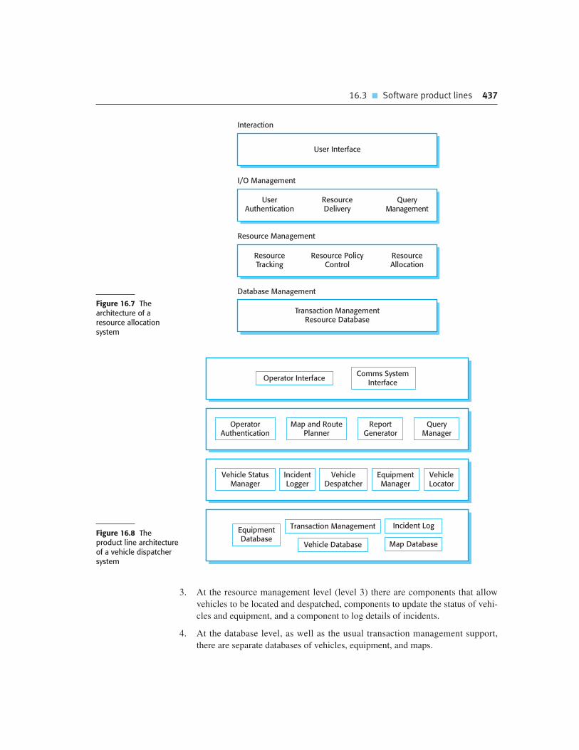
16.3 � Software product lines 437
User Interface
ResourceTracking
Resource PolicyControl
ResourceAllocation
UserAuthentication
QueryManagement
ResourceDelivery
Transaction ManagementResource Database
Interaction
I/O Management
Resource Management
Database Management
Figure 16.7 Thearchitecture of aresource allocationsystem
OperatorAuthentication
Vehicle StatusManager
IncidentLogger
VehicleDespatcher
EquipmentManager
VehicleLocator
Map and RoutePlanner
QueryManager
ReportGenerator
Operator InterfaceComms System
Interface
EquipmentDatabase
Vehicle Database Map Database
Incident LogTransaction ManagementFigure 16.8 Theproduct line architectureof a vehicle dispatchersystem
3. At the resource management level (level 3) there are components that allow
vehicles to be located and despatched, components to update the status of vehi-
cles and equipment, and a component to log details of incidents.
4. At the database level, as well as the usual transaction management support,
there are separate databases of vehicles, equipment, and maps.

438 Chapter 16 � Software reuse
To create a specific version of this system, you may have to modify individual
components. For example, the police have a large number of vehicles but a small
number of vehicle types, whereas the fire service has many types of specialized
vehicles. Therefore, you may have to define a different vehicle database structure
when implementing a system for these different services.
Figure 16.9 shows the steps involved in extending a software product line to cre-
ate a new application. The steps involved in this general process are as follows:
1. Elicit stakeholder requirements You may start with a normal requirements engi-
neering process. However, because a system already exists, you will need to
demonstrate the system and have stakeholders experiment with it, expressing
their requirements as modifications to the functions provided.
2. Select the existing system that is the closest fit to the requirements When creat-
ing a new member of a product line, you may start with the nearest product
instance. The requirements are analyzed and the family member that is the clos-
est fit is chosen for modification.
3. Renegotiate requirements As more details of required changes emerge and the
project is planned, there may be some requirements renegotiation to minimize
the changes that are needed.
4. Adapt existing system New modules are developed for the existing system and
existing system modules are adapted to meet the new requirements.
5. Deliver new family member The new instance of the product line is delivered to
the customer. At this stage, you should document its key features so that it may
be used as a basis for other system developments in the future.
When you create a new member of product line you may have to find a compro-
mise between reusing as much of the generic application as possible and satisfying
detailed stakeholder requirements. The more detailed the system requirements, the
less likely it is that the existing components will meet these requirements. However,
if stakeholders are willing to be flexible and to limit the system modifications that
are required, you can usually deliver the system more quickly and at a lower cost.
Software product lines are designed to be reconfigured and this reconfiguration
may involve adding or removing components from the system, defining parameters
and constraints for system components, and including knowledge of business
ElicitStakeholder
Requirements
ChooseClosest-Fit
System Instance
Deliver NewSystem Instance
RenegotiateRequirements
Adapt ExistingSystem
Figure 16.9 Productinstance development
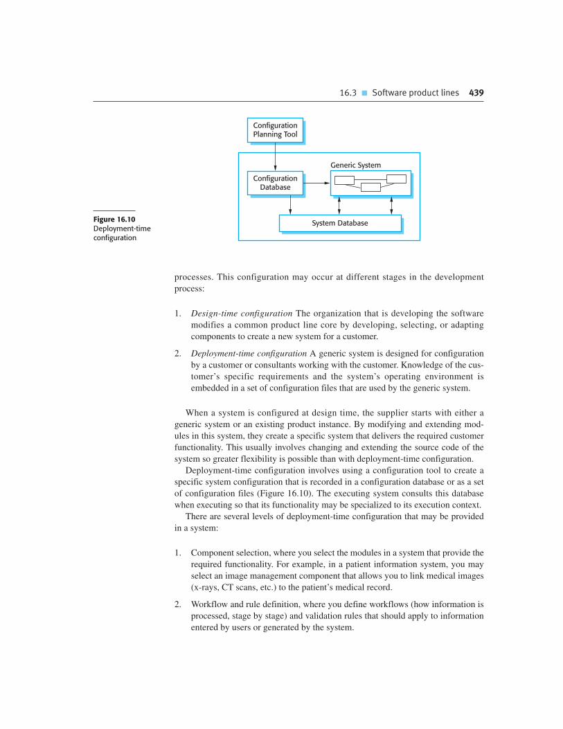
16.3 � Software product lines 439
processes. This configuration may occur at different stages in the development
process:
1. Design-time configuration The organization that is developing the software
modifies a common product line core by developing, selecting, or adapting
components to create a new system for a customer.
2. Deployment-time configuration A generic system is designed for configuration
by a customer or consultants working with the customer. Knowledge of the cus-
tomer’s specific requirements and the system’s operating environment is
embedded in a set of configuration files that are used by the generic system.
When a system is configured at design time, the supplier starts with either a
generic system or an existing product instance. By modifying and extending mod-
ules in this system, they create a specific system that delivers the required customer
functionality. This usually involves changing and extending the source code of the
system so greater flexibility is possible than with deployment-time configuration.
Deployment-time configuration involves using a configuration tool to create a
specific system configuration that is recorded in a configuration database or as a set
of configuration files (Figure 16.10). The executing system consults this database
when executing so that its functionality may be specialized to its execution context.
There are several levels of deployment-time configuration that may be provided
in a system:
1. Component selection, where you select the modules in a system that provide the
required functionality. For example, in a patient information system, you may
select an image management component that allows you to link medical images
(x-rays, CT scans, etc.) to the patient’s medical record.
2. Workflow and rule definition, where you define workflows (how information is
processed, stage by stage) and validation rules that should apply to information
entered by users or generated by the system.
ConfigurationDatabase
System Database
Generic System
ConfigurationPlanning Tool
Figure 16.10Deployment-timeconfiguration

440 Chapter 16 � Software reuse
3. Parameter definition, where you specify the values of specific system parame-
ters that reflect the instance of the application that you are creating. For exam-
ple, you may specify the maximum length of fields for data input by a user or
the characteristics of hardware attached to the system.
Deployment-time configuration can be very complex and it may take many
months to configure the system for a customer. Large configurable systems may sup-
port the configuration process by providing software tools, such as a configuration
planning tools, to support the configuration process. I discuss deployment-time con-
figuration further in Section 16.4.1. This covers the reuse of COTS systems that have
to be configured to work in different operational environments.
Design-time configuration is used when it is impossible to use the existing
deployment-time configuration facilities in a system to develop a new system ver-
sion. However, over time, when you have created several family members with
comparable functionality, you may decide to refactor the core product line to
include functionality that has been implemented in several application family
members. You then make that new functionality configurable when the system is
deployed.
16.4 COTS product reuse
A commercial-off-the-shelf (COTS) product is a software system that can be
adapted to the needs of different customers without changing the source code of the
system. Virtually all desktop software and a wide variety of server products are
COTS software. Because this software is designed for general use, it usually
includes many features and functions. It therefore has the potential to be reused in
different environments and as part of different applications. Torchiano and Morisio
(2004) also discovered that using open source products were often used as COTS
products. That is, the open source systems were used without change and without
looking at the source code.
COTS products are adapted by using built-in configuration mechanisms that
allow the functionality of the system to be tailored to specific customer needs. For
example, in a hospital patient record system, separate input forms and output reports
might be defined for different types of patient. Other configuration features may
allow the system to accept plug-ins that extend functionality or check user inputs to
ensure that they are valid.
This approach to software reuse has been very widely adopted by large companies
over the last 15 or so years, as it offers significant benefits over customized software
development:
1. As with other types of reuse, more rapid deployment of a reliable system may be
possible.

16.4 � COTS product reuse 441
2. It is possible to see what functionality is provided by the applications and so it is
easier to judge whether or not they are likely to be suitable. Other companies
may already use the applications so experience of the systems is available.
3. Some development risks are avoided by using existing software. However, this
approach has its own risks, as I discuss below.
4. Businesses can focus on their core activity without having to devote a lot of
resources to IT systems development.
5. As operating platforms evolve, technology updates may be simplified as these
are the responsibility of the COTS product vendor rather than the customer.
Of course, this approach to software engineering has its own problems:
1. Requirements usually have to be adapted to reflect the functionality and mode
of operation of the COTS product. This can lead to disruptive changes to exist-
ing business processes.
2. The COTS product may be based on assumptions that are practically impossible
to change. The customer must therefore adapt their business to reflect these
assumptions.
3. Choosing the right COTS system for an enterprise can be a difficult process,
especially as many COTS products are not well documented. Making the wrong
choice could be disastrous as it may be impossible to make the new system work
as required.
4. There may be a lack of local expertise to support systems development.
Consequently, the customer has to rely on the vendor and external consultants
for development advice. This advice may be biased and geared to selling prod-
ucts and services, rather than meeting the real needs of the customer.
5. The COTS product vendor controls system support and evolution. They may go
out of business, be taken over, or may make changes that cause difficulties for
customers.
Software reuse based on COTS has become increasingly common. The vast
majority of new business information processing systems are now built using
COTS rather than using an object-oriented approach. Although there are often
problems with this approach to system development (Tracz, 2001), success stories
(Baker, 2002; Balk and Kedia, 2000; Brownsword and Morris, 2003; Pfarr and
Reis, 2002) show that COTS-based reuse reduces effort and the time to deploy the
system.
There are two types of COTS product reuse, namely COTS-solution systems and
COTS-integrated systems. COTS-solution systems consist of a generic application
from a single vendor that is configured to customer requirements. COTS-integrated
systems involve integrating two or more COTS systems (perhaps from different

442 Chapter 16 � Software reuse
vendors) to create an application system. Figure 16.11 summarizes the differences
between these different approaches.
16.4.1 COTS-solution systems
COTS-solution systems are generic application systems that may be designed to
support a particular business type, business activity, or sometimes, a complete
business enterprise. For example, a COTS-solution system may be produced for
dentists that handles appointments, dental records, patient recall, etc. At a larger
scale, an Enterprise Resource Planning (ERP) system may support all of the man-
ufacturing, ordering, and customer relationship management activities in a large
company.
Domain-specific COTS-solution systems, such as systems to support a business
function (e.g., document management), provide functionality that is likely to be
required by a range of potential users. However, they also incorporate built-in
assumptions about how users work and these may cause problems in specific situa-
tions. For example, a system to support student registration in a university may
assume that students will be registered for one degree at one university. However, if
universities collaborate to offer joint degrees, then it may be practically impossible
to represent this in the system.
ERP systems, such as those produced by SAP and BEA, are large-scale inte-
grated systems designed to support business practices such as ordering and invoic-
ing, inventory management, and manufacturing scheduling (O’Leary, 2000). The
configuration process for these systems involves gathering detailed information
about the customer’s business and business processes, and embedding this in a con-
figuration database. This often requires detailed knowledge of configuration nota-
tions and tools and is usually carried out by consultants working alongside system
customers.
A generic ERP system includes a number of modules that may be composed
in different ways to create a system for a customer. The configuration process
Figure 16.11 COTS-solution and COTS-integrated systems
COTS-solution systems COTS-integrated systems
Single product that provides the functionalityrequired by a customer
Several heterogeneous system products areintegrated to provide customized functionality
Based around a generic solution and standardizedprocesses
Flexible solutions may be developed for customerprocesses
Development focus is on system configuration Development focus is on system integration
System vendor is responsible for maintenance System owner is responsible for maintenance
System vendor provides the platform for the system System owner provides the platform for the system

16.4 � COTS product reuse 443
involves choosing which modules are to be included, configuring these
individual modules, defining business processes and business rules, and defining
the structure and organization of the system database. A model of the overall archi-
tecture of an ERP system that supports a range of business functions is shown in
Figure 16.12.
The key features of this architecture are:
1. A number of modules to support different business functions. These are large-
grain modules that may support entire departments or divisions of the business.
In the example shown in Figure 16.12, the modules that have been selected for
inclusion in the system are a module to support purchasing, a module to support
supply chain management, a logistics module to support the delivery of goods,
and a customer relationship management (CRM) module to maintain customer
information.
2. A defined set of business processes, associated with each module, which relate
to activities in that module. For example, there may be a definition of the order-
ing process that defines how orders are created and approved. This will specify
the roles and activities involved in placing an order.
3. A common database that maintains information about all related business func-
tions. This means that it should not be necessary to replicate information, such
as customer details, in different parts of the business.
4. A set of business rules that apply to all data in the database. Therefore, when
data is input from one function, these rules should ensure that it is consistent
with the data required by other functions. For example, there may be a business
rule that all expense claims have to be approved by someone more senior than
the person making the claim.
ERP systems are used in almost all large companies to support some or all of their
functions. They are, therefore, a very widely used form of software reuse. However,
the obvious limitation of this approach to reuse is that the functionality of the system
System Database
Business Rules
Purchasing
Processes
Supply Chain
Processes
Logistics
Processes
CRM
Processes
Figure 16.12 Thearchitecture of an ERPsystem

444 Chapter 16 � Software reuse
is restricted to the functionality of the generic core. Furthermore, a company’s
processes and operations have to be expressed in the system configuration language,
and there may be a mismatch between the concepts in the business and the concepts
supported in the configuration language.
For example, in an ERP system that was sold to a university, the concept of a cus-
tomer had to be defined. This caused great difficulties when configuring the system.
However, universities have multiple types of customers, such as students, research
funding agencies, educational charities, etc., each of which have different character-
istics. None of them are really comparable to the notion of a commercial customer
(i.e., a person or business that buys products or services). A serious mismatch
between the business model used by the system and that of the buyer of the system
makes it highly probable that the ERP system will not meet the buyer’s real needs
(Scott, 1999).
Both domain-specific COTS products and ERP systems usually require extensive
configuration to adapt them to the requirements of each organization where they are
installed. This configuration may involve:
1. Selecting the required functionality from the system (e.g., by deciding what
modules should be included).
2. Establishing a data model that defines how the organization’s data will be struc-
tured in the system database.
3. Defining business rules that apply to that data.
4. Defining the expected interactions with external systems.
5. Designing the input forms and the output reports generated by the system.
6. Designing new business processes that conform to the underlying process
model supported by the system.
7. Setting parameters that define how the system is deployed on its underlying
platform.
Once the configuration settings are completed, a COTS-solution system is then
ready for testing. Testing is a major problem when systems are configured rather
than programmed using a conventional language. Because these systems are built
using a reliable platform, obvious system failures and crashes are relatively rare.
Rather the problems are often subtle and relate to the interactions between the oper-
ational processes and the system configuration. These may only be detectable by
end-users and so may not be discovered during the system testing process.
Furthermore, automated unit testing, supported by testing frameworks such as JUnit,
cannot be used. The underlying system is unlikely to support any kind of test
automation and there may be no complete system specification that can be used to
derive system tests.

16.4 � COTS product reuse 445
16.4.2 COTS-integrated systems
COTS-integrated systems are applications that include two or more COTS products
or, sometimes, legacy application systems. You may use this approach when there is
no single COTS system that meets all of your needs or when you wish to integrate a
new COTS product with systems that you already use. The COTS products may
interact through their APIs (Application Programming Interfaces) or service inter-
faces if these are defined. Alternatively, they may be composed by connecting the
output of one system to the input of another or by updating the databases used by the
COTS applications.
To develop systems using COTS products, you have to make a number of design
choices:
1. Which COTS products offer the most appropriate functionality? Typically, there
will be several COTS products available, which can be combined in different
ways. If you don’t already have experience with a COTS product, it can be dif-
ficult to decide which product is the most suitable.
2. How will data be exchanged? Different products normally use unique data
structures and formats. You have to write adaptors that convert from one repre-
sentation to another. These adaptors are run-time systems that operate alongside
the COTS products.
3. What features of a product will actually be used? COTS products may include
more functionality than you need and functionality may be duplicated across
different products. You have to decide which features in what product are most
appropriate for your requirements. If possible, you should also deny access to
unused functionality because this can interfere with normal system operation.
The failure of the first flight of the Ariane 5 rocket (Nuseibeh, 1997) was a con-
sequence of a failure in an inertial navigation system that was reused from the
Ariane 4 system. However, the functionality that failed was not actually
required in Ariane 5.
Consider the following scenario as an illustration of COTS integration. A large
organization intends to develop a procurement system that allows staff to place
orders from their desk. By introducing this system across the organization, the com-
pany estimates that it can save $5 million per year. By centralizing buying, the new
procurement system can ensure that orders are always made from suppliers who
offer the best prices and should reduce the paperwork costs associated with orders.
As with manual systems, the system involves choosing the goods available from a
supplier, creating an order, having the order approved, sending the order to a sup-
plier, receiving the goods, and confirming that payment should be made.
The company has a legacy ordering system that is used by a central procure-
ment office. This order processing software is integrated with an existing invoic-
ing and delivery system. To create the new ordering system, the legacy system is
integrated with a web-based e-commerce platform and an e-mail system that
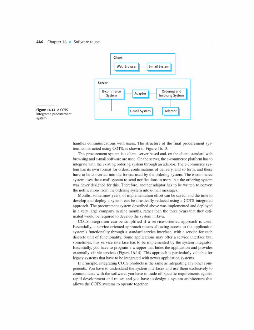
446 Chapter 16 � Software reuse
handles communications with users. The structure of the final procurement sys-
tem, constructed using COTS, is shown in Figure 16.13.
This procurement system is a client–server based and, on the client, standard web
browsing and e-mail software are used. On the server, the e-commerce platform has to
integrate with the existing ordering system through an adaptor. The e-commerce sys-
tem has its own format for orders, confirmations of delivery, and so forth, and these
have to be converted into the format used by the ordering system. The e-commerce
system uses the e-mail system to send notifications to users, but the ordering system
was never designed for this. Therefore, another adaptor has to be written to convert
the notifications from the ordering system into e-mail messages.
Months, sometimes years, of implementation effort can be saved, and the time to
develop and deploy a system can be drastically reduced using a COTS-integrated
approach. The procurement system described above was implemented and deployed
in a very large company in nine months, rather than the three years that they esti-
mated would be required to develop the system in Java.
COTS integration can be simplified if a service-oriented approach is used.
Essentially, a service-oriented approach means allowing access to the application
system’s functionality through a standard service interface, with a service for each
discrete unit of functionality. Some applications may offer a service interface but,
sometimes, this service interface has to be implemented by the system integrator.
Essentially, you have to program a wrapper that hides the application and provides
externally visible services (Figure 16.14). This approach is particularly valuable for
legacy systems that have to be integrated with newer application systems.
In principle, integrating COTS products is the same as integrating any other com-
ponents. You have to understand the system interfaces and use them exclusively to
communicate with the software; you have to trade off specific requirements against
rapid development and reuse; and you have to design a system architecture that
allows the COTS systems to operate together.
Client
Web Browser E-mail System
Server
E-commerceSystem
Ordering andInvoicing System
Adaptor
AdaptorE-mail SystemFigure 16.13 A COTS-integrated procurementsystem

16.4 � COTS product reuse 447
However, the fact that these products are usually large systems in their own right,
and are often sold as separate standalone systems, introduces additional problems.
Boehm and Abts (1999) discuss four important COTS system integration problems:
1. Lack of control over functionality and performance Although the published
interface of a product may appear to offer the required facilities, these may not
be properly implemented or may perform poorly. The product may have hidden
operations that interfere with its use in a specific situation. Fixing these prob-
lems may be a priority for the COTS product integrator but may not be of real
concern for the product vendor. Users may simply have to find work-arounds to
problems if they wish to reuse the COTS product.
2. Problems with COTS system interoperability It is sometimes difficult to get COTS
products to work together because each product embeds its own assumptions
about how it will be used. Garlan et al. (1995), reporting on their experience of
trying to integrate four COTS products, found that three of these products were
event-based but each used a different model of events. Each system assumed that
it had exclusive access to the event queue. As a consequence, integration was very
difficult. The project required five times as much effort as originally predicted.
The schedule was extended to two years rather than the predicted six months. In a
retrospective analysis of their work 10 years later, Garlan et al. (2009) concluded
that the integration problems that they discovered had not been solved. Torchiano
and Morisio (2004) found that lack of compliance with standards in some COTS
products meant that integration was more difficult than anticipated.
3. No control over system evolution Vendors of COTS products make their own
decisions on system changes, in response to market pressures. For PC products,
in particular, new versions are often produced frequently and may not be com-
patible with all previous versions. New versions may have additional unwanted
functionality, and previous versions may become unavailable and unsupported.
4. Support from COTS vendors The level of support available from COTS vendors
varies widely. Vendor support is particularly important when problems arise as
ApplicationSystem
Service Wrapper
ServicesServicesFigure 16.14Application wrapping
448 Chapter 16 � Software reuse
K E Y P O I N T S
� Most new business software systems are now developed by reusing knowledge and code from
previously implemented systems.
� There are many different ways to reuse software. These range from the reuse of classes and
methods in libraries to the reuse of complete application systems.
� The advantages of software reuse are lower costs, faster software development, and lower risks.
System dependability is increased. Specialists can be used more effectively by concentrating
their expertise on the design of reusable components.
� Application frameworks are collections of concrete and abstract objects that are designed for
reuse through specialization and the addition of new objects. They usually incorporate good
design practice through design patterns.
� Software product lines are related applications that are developed from one or more base
applications. A generic system is adapted and specialized to meet specific requirements for
functionality, target platform, or operational configuration.
� COTS product reuse is concerned with the reuse of large-scale, off-the-shelf systems. These
provide a lot of functionality and their reuse can radically reduce costs and development time.
Systems may be developed by configuring a single, generic COTS product or by integrating two
or more COTS products.
� Enterprise Resource Planning systems are examples of large-scale COTS reuse. You create an
instance of an ERP system by configuring a generic system with information about the customer’s
business processes and rules.
� Potential problems with COTS-based reuse include lack of control over functionality and
performance, lack of control over system evolution, the need for support from external vendors,
and difficulties in ensuring that systems can interoperate.
developers do not have access to the source code and detailed documentation of
the system. Although vendors may commit to providing support, changing mar-
ket and economic circumstances may make it difficult for them to deliver this
commitment. For example, a COTS system vendor may decide to discontinue a
product because of limited demand, or they may be taken over by another com-
pany that does not wish to support all of the products that have been acquired.
Boehm and Abts reckon that, in many cases, the cost of system maintenance and
evolution may be greater for COTS-integrated systems. All of the above difficulties
are life-cycle problems; they don’t just affect the initial development of the system.
The further removed the people involved in the system maintenance become from
the original system developers, the more likely it is that real difficulties will arise
with the integrated COTS products.

Chapter 16 � Exercises 449
F U RT H E R R E A D I N G
Reuse-based Software Engineering. A comprehensive discussion of different approaches to
software reuse. The authors cover technical reuse issues and managing reuse processes.
(H. Mili, A. Mili, S. Yacoub and E. Addy, John Wiley & Sons, 2002.)
‘Overlooked Aspects of COTS-Based Development’. An interesting article that discusses
a survey of developers using a COTS-based approach, and the problems that they encountered.
(M. Torchiano and M. Morisio, IEEE Software, 21 (2), March–April 2004.)
http://dx.doi.org/10.1109/MS.2004.1270770.
‘Construction by Configuration: A New Challenge for Software Engineering’. This is an invited
paper that I wrote in which I discuss the problems and difficulties of constructing a new
application by configuring existing systems. (I. Sommerville, Proc. 19th Australian Software
Engineering Conference, 2008.) http://dx.doi.org/10.1109/ASWEC.2008.75.
‘Architectural Mismatch: Why Reuse Is Still So Hard’. This article looks back on an earlier paper
that discussed the problems of reusing and integrating a number of COTS systems. The authors
concluded that, although some progress has been made, there were still problems in conflicting
assumptions made by the designers of the individual systems. (D. Garlan et al., IEEE Software,
26 (4), July–August 2009.) http://dx.doi.org//10.1109/MS.2009.86.
E X E R C I S E S
16.1. What are the major technical and nontechnical factors that hinder software reuse? Do you
personally reuse much software and, if not, why not?
16.2. Suggest why the savings in cost from reusing existing software are not simply proportional
to the size of the components that are reused.
16.3. Give four circumstances where you might recommend against software reuse.
16.4. Explain what is meant by ‘inversion of control’ in application frameworks. Explain why
this approach could cause problems if you integrated two separate systems that were
originally created using the same application framework.
16.5. Using the example of the weather station system described in Chapters 1 and
Chapter 7, suggest a product line architecture for a family of applications that are
concerned with remote monitoring and data collection. You should present your
architecture as a layered model, showing the components that might be included
at each level.
16.6. Most desktop software, such as word processing software, can be configured in a number
of different ways. Examine software that you regularly use and list the configuration
options for that software. Suggest difficulties that users might have in configuring the
software. If you use Microsoft Office or Open Office, these are good examples to use for
this exercise.

450 Chapter 16 � Software reuse
16.7. Why have many large companies chosen ERP systems as the basis for their organizational
information system? What problems may arise when deploying a large-scale ERP system in
an organization?
16.8. Identify six possible risks that can arise when systems are constructed using COTS. What
steps can a company take to reduce these risks?
16.9. Explain why adaptors are usually needed when systems are constructed by integrating COTS
products. Suggest three practical problems that might arise in writing adaptor software to
link two COTS application products.
16.10. The reuse of software raises a number of copyright and intellectual property issues. If a
customer pays a software contractor to develop a system, who has the right to reuse the
developed code? Does the software contractor have the right to use that code as a basis for
a generic component? What payment mechanisms might be used to reimburse providers of
reusable components? Discuss these issues and other ethical issues associated with the
reuse of software.
R E F E R E N C E S
Baker, T. (2002). ‘Lessons Learned Integrating COTS into Systems’. Proc. ICCBSS 2002 (1st Int. Conf
on COTS-based Software Systems), Orlando, Fla:: Springer, 21–30.
Balk, L. D. and Kedia, A. (2000). ‘PPT: A COTS Integration Case Study’. Proc. Int. Conf. on Software
Eng., Limerick, Ireland: ACM Press, 42–9.
Baumer, D., Gryczan, G., Knoll, R., Lilienthal, C., Riehle, D. and Zullighoven, H. (1997). ‘Framework
Development for Large Systems’. Comm. ACM, 40 (10), 52–9.
Boehm, B. and Abts, C. (1999). ‘COTS Integration: Plug and Pray?’ IEEE Computer, 32 (1), 135–38.
Brownsword, L. and Morris, E. (2003). ‘The Good News about COTS’. http://www.sei.cmu.edu/
news-at-sei/features/2003/1q03/feature-1-1q03.htm
Cusamano, M. (1989). ‘The Software Factory: A Historical Interpretation’. IEEE Software, 6 (2), 23–30.
Fayad, M. E. and Schmidt, D. C. (1997). ‘Object-oriented Application Frameworks’. Comm. ACM, 40
(10), 32–38.
Gamma, E., Helm, R., Johnson, R. and Vlissides, J. (1995). Design Patterns: Elements of Reusable
Object-Oriented Software. Reading, Mass.: Addison-Wesley.
Garlan, D., Allen, R. and Ockerbloom, J. (1995). ‘Architectural Mismatch: Why Reuse is so Hard’.
IEEE Software, 12 (6), 17–26.
Garlan, D., Allen, R. and Ockerbloom, J. (2009). ‘Architectural Mismatch: Why Reuse is Still so Hard’.
IEEE Software, 26 (4), 66–9.
Griss, M. L. and Wosser, M. (1995). ‘Making reuse work at Hewlett-Packard’. IEEE Software, 12 (1), 105–7.

Chapter 16 � References 451
Holdener, A. T. (2008). Ajax: The Definitive Guide. Sebastopol, Calif.: O’Reilly and Associates.
Jacobson, I., Griss, M. and Jonsson, P. (1997). Software Reuse. Reading, Mass.: Addison-Wesley.
Matsumoto, Y. (1984). ‘Some Experience in Promoting Reusable Software: Presentation in Higher
Abstract Levels’. IEEE. Trans. on Software Engineering, SE-10 (5), 502–12.
McIlroy, M. D. (1968). ‘Mass-produced software components’. Proc. NATO Conf. on Software Eng.,
Garmisch, Germany: Springer-Verlag.
Nuseibeh, B. (1997). ‘Ariane 5: Who Dunnit?’ IEEE Software, 14 (3), 15–6.
O’Leary, D. E. (2000). Enterprise Resource Planning Systems: Systems, Life Cycle, Electronic
Commerce and Risk. Cambridge, UK: Cambridge University Press.
Pfarr, T. and Reis, J. E. (2002). ‘The Integration of COTS/GOTS within NASA’s HST Command and
Control System’. Proc. ICCBSS 2002 (1st Int. Conf on COTS-based Software Systems), Orlando, Fla.:
Springer, 209–21.
Schmidt, D. C. (1997). ‘Applying design patterns and frameworks to develop object-oriented
communications software’. In Handbook of Programming Languages, Vol. 1. (ed.). New York:
Macmillan Computer Publishing.
Schmidt, D. C., Gokhale, A. and Natarajan, B. (2004). ‘Leveraging Application Frameworks’. ACM
Queue, 2 (5 (July/August)), 66–75.
Scott, J. E. (1999). ‘The FoxMeyer Drug’s Bankruptcy: Was it a Failure of ERP’. Proc. Association for
Information Systems 5th Americas Conf. on Information Systems, Milwaukee, WI.
Torchiano, M. and Morisio, M. (2004). ‘Overlooked Aspects of COTS-Based Development’.
IEEE Software, 21 (2), 88–93.
Tracz, W. (2001). ‘COTS Myths and Other Lessons Learned in Component-Based Software
Development’. In Component-based Software Engineering. Heineman, G. T. and Councill, W. T.
(ed.). Boston: Addison-Wesley, 99–112.
Component-basedsoftware engineering
17
Objectives
The objective of this chapter is to describe an approach to software reuse
based on the composition of reusable, standardized components. When
you have read this chapter you will:
� know that component-based software engineering is concerned with
developing standardized components based on a component model,
and composing these into application systems;
� understand what is meant by a component and a component model;
� know the principal activities in the CBSE process for reuse and the
CBSE process with reuse;
� understand some of the difficulties and problems that arise during the
process of component composition.
Contents
17.1 Components and component models
17.2 CBSE processes
17.3 Component composition
Chapter 17 � Component-based software engineering 453
As I explained in Chapter 16, many new business systems are now developed by con-
figuring off-the-shelf systems. However, when a company cannot use an off-the-shelf
system because it does not meet their requirements, the software they need has to be
specially developed. For custom software, component-based software engineering is
an effective, reuse-oriented way to develop new enterprise systems.
Component-based software engineering (CBSE) emerged in the late 1990s as an
approach to software systems development based on reusing software components. Its
creation was motivated by designers’ frustration that object-oriented development had
not led to extensive reuse, as had been originally suggested. Single object classes were
too detailed and specific, and often had to be bound with an application at compile
time. You had to have detailed knowledge of the classes to use them, and this usually
meant that you had to have the component source code. This meant that selling or dis-
tributing objects as individual reusable components was practically impossible.
Components are higher-level abstractions than objects and are defined by their
interfaces. They are usually larger than individual objects and all implementation
details are hidden from other components. CBSE is the process of defining, imple-
menting, and integrating or composing loosely coupled, independent components
into systems. It has become as an important software development approach because
software systems are becoming larger and more complex. Customers are demanding
more dependable software that is delivered and deployed more quickly. The only
way that we can cope with complexity and deliver better software more quickly is to
reuse rather than reimplement software components.
The essentials of component-based software engineering are:
1. Independent components that are completely specified by their interfaces. There
should be a clear separation between the component interface and its implemen-
tation. This means that one implementation of a component can be replaced by
another, without changing other parts of the system.
2. Component standards that facilitate the integration of components. These stan-
dards are embodied in a component model. They define, at the very minimum,
how component interfaces should be specified and how components communi-
cate. Some models go much further and define interfaces that should be imple-
mented by all conformant components. If components conform to standards, then
their operation is independent of their programming language. Components writ-
ten in different languages can be integrated into the same system.
3. Middleware that provides software support for component integration. To make
independent, distributed components work together, you need middleware support
that handles component communications. Middleware for component support han-
dles low-level issues efficiently and allows you to focus on application-related
problems. In addition, middleware for component support may provide support for
resource allocation, transaction management, security, and concurrency.
4. A development process that is geared to component-based software engineering.
You need a development process that allows requirements to evolve, depending
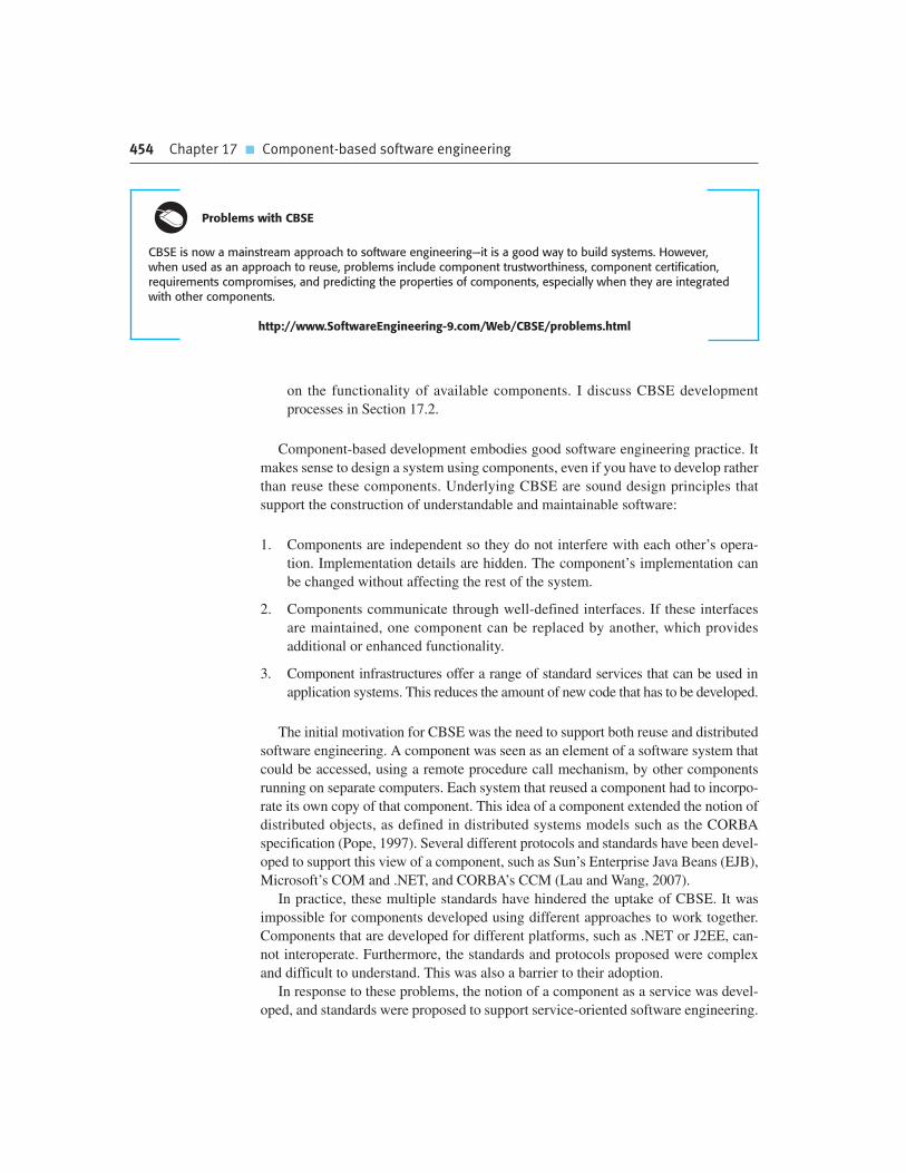
454 Chapter 17 � Component-based software engineering
Problems with CBSE
CBSE is now a mainstream approach to software engineering—it is a good way to build systems. However,when used as an approach to reuse, problems include component trustworthiness, component certification,requirements compromises, and predicting the properties of components, especially when they are integratedwith other components.
http://www.SoftwareEngineering-9.com/Web/CBSE/problems.html
on the functionality of available components. I discuss CBSE development
processes in Section 17.2.
Component-based development embodies good software engineering practice. It
makes sense to design a system using components, even if you have to develop rather
than reuse these components. Underlying CBSE are sound design principles that
support the construction of understandable and maintainable software:
1. Components are independent so they do not interfere with each other’s opera-
tion. Implementation details are hidden. The component’s implementation can
be changed without affecting the rest of the system.
2. Components communicate through well-defined interfaces. If these interfaces
are maintained, one component can be replaced by another, which provides
additional or enhanced functionality.
3. Component infrastructures offer a range of standard services that can be used in
application systems. This reduces the amount of new code that has to be developed.
The initial motivation for CBSE was the need to support both reuse and distributed
software engineering. A component was seen as an element of a software system that
could be accessed, using a remote procedure call mechanism, by other components
running on separate computers. Each system that reused a component had to incorpo-
rate its own copy of that component. This idea of a component extended the notion of
distributed objects, as defined in distributed systems models such as the CORBA
specification (Pope, 1997). Several different protocols and standards have been devel-
oped to support this view of a component, such as Sun’s Enterprise Java Beans (EJB),
Microsoft’s COM and .NET, and CORBA’s CCM (Lau and Wang, 2007).
In practice, these multiple standards have hindered the uptake of CBSE. It was
impossible for components developed using different approaches to work together.
Components that are developed for different platforms, such as .NET or J2EE, can-
not interoperate. Furthermore, the standards and protocols proposed were complex
and difficult to understand. This was also a barrier to their adoption.
In response to these problems, the notion of a component as a service was devel-
oped, and standards were proposed to support service-oriented software engineering.

17.1 � Components and component models 455
The most significant difference between a component as a service and the original
notion of a component is that services are stand-alone entities that are external to a
program using them. When you build a service-oriented system, you reference the
external service rather than including a copy of that service in your system.
Service-oriented software engineering, which I discuss in Chapter 19, is therefore
a type of component-based software engineering. It uses a simpler notion of a com-
ponent than that originally proposed in CBSE. It has been driven, from the outset, by
standards. In situations where COTS-based reuse is impractical, service-oriented
CBSE is becoming the dominant approach for the development of business systems.
17.1 Components and component models
There is general agreement in the CBSE community that a component is an inde-
pendent software unit that can be composed with other components to create a soft-
ware system. Beyond that, however, people have proposed varying definitions of a
software component. Councill and Heineman (2001) define a component as:
“A software element that conforms to a standard component model and can be
independently deployed and composed without modification according to a
composition standard.”
This definition is essentially based on standards so that a software unit that
conforms to these standards is a component. Szyperski (2002), however, does not
mention standards in his definition of a component but focuses instead on the key
characteristics of components:
“A software component is a unit of composition with contractually-specified
interfaces and explicit context dependencies only. A software component can
be deployed independently and is subject to composition by third parties.”
Both of these definitions are based on the notion of a component as an element
that is included in a system, rather than a service that is referenced by the system.
However, they are also compatible with the idea of a service as a component.
Szyperski also states that a component has no externally observable state. This
means that copies of components are indistinguishable. However, some component
models, such as the Enterprise Java Beans model, allow stateful components, so
these do not correspond with Szyperski’s definition. Although stateless components
are certainly simpler to use, there are some systems where stateful components are
more convenient and reduce system complexity.
What the above definitions have in common is that they agree that components
are independent, and that they are the fundamental unit of composition in a system.
In my view, a better definition of a component can be derived by combining these

456 Chapter 17 � Component-based software engineering
Figure 17.1Componentcharacteristics
proposals. Figure 17.1 shows what I consider to be the essential characteristics of a
component as used in CBSE.
A useful way of thinking about a component is as a provider of one or more serv-
ices. When a system needs a service, it calls on a component to provide that service
without caring about where that component is executing or the programming lan-
guage used to develop the component. For example, a component in a library system
might provide a search service that allows users to search different library catalogs.
A component that converts from one graphical format to another (e.g., TIFF to
JPEG) provides a data conversion service, etc.
Viewing a component as a service provider emphasizes two critical characteris-
tics of a reusable component:
1. The component is an independent executable entity that is defined by its inter-
faces. You don’t need any knowledge of its source code to use it. It can either be
referenced as an external service or included directly in a program.
2. The services offered by a component are made available through an interface and
all interactions are through that interface. The component interface is expressed
in terms of parameterized operations and its internal state is never exposed.
Component Characteristic Description
Standardized Component standardization means that a component used in aCBSE process has to conform to a standard component model. Thismodel may define component interfaces, component metadata,documentation, composition, and deployment.
Independent A component should be independent—it should be possible tocompose and deploy it without having to use other specificcomponents. In situations where the component needs externallyprovided services, these should be explicitly set out in a ‘requires’interface specification.
Composable For a component to be composable, all external interactions musttake place through publicly defined interfaces. In addition, it mustprovide external access to information about itself, such as itsmethods and attributes.
Deployable To be deployable, a component has to be self-contained. It must beable to operate as a stand-alone entity on a component platformthat provides an implementation of the component model. Thisusually means that the component is binary and does not have tobe compiled before it is deployed. If a component is implementedas a service, it does not have to be deployed by a user of acomponent. Rather, it is deployed by the service provider.
Documented Components have to be fully documented so that potential userscan decide whether or not the components meet their needs. Thesyntax and, ideally, the semantics of all component interfacesshould be specified.

17.1 � Components and component models 457
Requires Interface
Defines the servicesthat are needed andshould be providedby other components
Provides Interface
Defines the servicesthat are providedby the componentto other components
ComponentFigure 17.2Componentinterfaces
Component and objects
Components are often implemented in object-oriented languages and, in some cases, accessing the ‘provides’interface of a component is done through method calls. However, components and object classes are not thesame thing. Unlike object classes, components are independently deployable, do not define types, arelanguage-independent, and are based on a standard component model.
http://www.SoftwareEngineering-9.com/Web/CBSE/objects.html
Components have two related interfaces, as shown in Figure 17.2. These inter-
faces reflect the services that the component provides and the services that the com-
ponent requires to operate correctly:
• The ‘provides’ interface defines the services provided by the component. This
interface, essentially, is the component API. It defines the methods that can be
called by a user of the component. In a UML component diagram, the ‘provides’
interface for a component is indicated by a circle at the end of a line from the
component icon.
• The ‘requires’ interface specifies what services must be provided by other compo-
nents in the system if a component is to operate correctly. If these are not available,
then the component will not work. This does not compromise the independence or
deployability of a component because the ‘requires’ interface does not define how
these services should be provided. In the UML, the symbol for a ‘requires’ inter-
face is a semicircle at the end of a line from the component icon. Notice that ‘pro-
vides’ and ‘requires’ interface icons can fit together like a ball and socket.
To illustrate these interfaces, Figure 17.3 shows a model of a component that has
been designed to collect and collate information from an array of sensors. It runs
autonomously to collect data over a period of time and, on request, provides collated
data to a calling component. The ‘provides’ interface includes methods to add,
remove, start, stop, and test sensors. The report method returns the sensor data that
has been collected, and the listAll method provides information about the attached
sensors. Although I have not shown this here, these methods have associated param-
eters specifying the sensor identifiers, locations, and so on.
The ‘requires’ interface is used to connect the component to the sensors. It assumes
that sensors have a data interface, accessed through sensorData, and a management

458 Chapter 17 � Component-based software engineering
sensorData
sensorManagement
addSensor
removeSensor
startSensor
stopSensor
testSensor
listAll
report
initialize
Provides InterfaceRequires Interface
Data Collector
Figure 17.3 A model of a data collectorcomponent
interface, accessed through sensorManagement. This interface has been designed to
connect to different types of sensor so it does not include specific sensor operations
such as Test, provideReading, etc. Instead, the commands used by a specific type of
sensor are embedded in a string, which is a parameter to the operations in the ‘requires’
interface. Adaptor components parse this string and translate the embedded commands
into the specific control interface of each type of sensor. I discuss the use of adaptors
later in this chapter, where I show how the data collector component is linked to a sen-
sor (Figure 17.12).
A critical difference between a component as an external service and a compo-
nent as a program element is that services are completely independent entities. They
do not have a ‘requires’ interface. Different programs can use these services without
the need to implement any additional support required by the service.
17.1.1 Component models
A component model is a definition of standards for component implementation, doc-
umentation, and deployment. These standards are for component developers to
ensure that components can interoperate. They are also for providers of component
execution infrastructures who provide middleware to support component operation.
Many component models have been proposed, but the most important models are
now the WebServices model, Sun’s Enterprise Java Beans (EJB) model, and
Microsoft’s .NET model (Lau and Wang, 2007).
The basic elements of an ideal component model are discussed by Weinreich and
Sametinger (2001). I summarize these model elements in Figure 17.4. This diagram
shows that the elements of a component model define the component interfaces, the
information that you need to use the component in a program, and how a component
should be deployed:
1. Interfaces Components are defined by specifying their interfaces. The compo-
nent model specifies how the interfaces should be defined and the elements, such
as operation names, parameters, and exceptions, which should be included in the
interface definition. The model should also specify the language used to define
the component interfaces. For web services, this is WSDL, which I discuss in

17.1 � Components and component models 459
Chapter 19; EJB is Java-specific so Java is used as the interface definition lan-
guage; in .NET, interfaces are defined using the Common Intermediate Language
(CIL). Some component models require specific interfaces that must be defined
by a component. These are used to compose the component with the component
model infrastructure, which provides standardized services such as security and
transaction management.
2. Usage In order for components to be distributed and accessed remotely, they
need to have a unique name or handle associated with them. This has to be glob-
ally unique—for example, in EJB, a hierarchical name is generated with the root
based on an Internet domain name. Services have a unique URI (Uniform
Resource Identifier).
Component meta-data is data about the component itself, such as information
about its interfaces and attributes. The meta-data is important because it allows
users of the component to find out what services are provided and required.
Component model implementations normally include specific ways (such as the
use of a reflection interface in Java) to access this component meta-data.
Components are generic entities and, when deployed, they have to be config-
ured to fit into an application system. For example, you could configure the
Data collector component (Figure 17.2) by defining the maximum number of
sensors in a sensor array. The component model may therefore specify how the
binary components can be customized for a particular deployment environment.
3. Deployment The component model includes a specification of how components
should be packaged for deployment as independent, executable entities.
Because components are independent entities, they have to be packaged with all
supporting software that is not provided by the component infrastructure, or is
not defined in a ‘requires’ interface. Deployment information includes informa-
tion about the contents of a package and its binary organization.
Inevitably, as new requirements emerge, components will have to be changed or
replaced. The component model may therefore include rules governing when
and how component replacement is allowed. Finally, the component model may
Component Model
UsageInformation
InterfaceDefinition
SpecificInterfaces
Composition
NamingConvention
Meta-DataAccess
Customization
Packaging
Documentation
EvolutionSupport
InterfacesDeployment
and UseFigure 17.4 Basicelements of acomponent model

460 Chapter 17 � Component-based software engineering
define the component documentation that should be produced. This is used to
find the component and to decide whether it is appropriate.
For components that are implemented as program units rather than external serv-
ices, the component model sets out the services to be provided by the middleware that
supports the executing components. Weinreich and Sametinger (2001) use the anal-
ogy of an operating system to explain component models. An operating system pro-
vides a set of generic services that can be used by applications. A component model
implementation provides comparable shared services for components. Figure 17.5
shows some of the services that may be provided by an implementation of a compo-
nent model.
The services provided by a component model implementation fall into two
categories:
1. Platform services, which enable components to communicate and interoperate
in a distributed environment. These are the fundamental services that must be
available in all component-based systems.
2. Support services, which are common services that are likely to be required by
many different components. For example, many components require authentica-
tion to ensure that the user of component services is authorized. It makes sense
to provide a standard set of middleware services for use by all components. This
reduces the costs of component development and potential component incom-
patibilities can be avoided.
The middleware implements the component services and provides interfaces to
these services. To make use of the services provided by a component model infra-
structure, you can think of the components as being deployed in a ‘container’.
A container is an implementation of the support services plus a definition of the
interfaces that a component must provide to integrate it with the container. Including
the component in the container means that the component can access the support
services and the container can access the component interfaces. When in use, the
component interfaces themselves are not accessed directly by other components;
Platform Services
Support Services
Concurrency
ComponentManagement
TransactionManagement
Persistence Security
ResourceManagement
AddressingInterfaceDefinition
ComponentCommunications
ExceptionManagement
Figure 17.5Middleware servicesdefined in a componentmodel

17.2 � CBSE processes 461
rather, they are accessed through a container interface that invokes code to access the
interface of the embedded component.
Containers are large and complex and, when you deploy a component in a container,
you get access to all middleware services. However, simple components may not need
all of the facilities offered by the supporting middleware. The approach taken in web
services to common service provision is therefore rather different. For web services,
standards have been defined for common services such as transaction management and
security and these standards have been implemented as program libraries. If you are
implementing a service component, you only use the common services that you need.
17.2 CBSE processes
CBSE processes are software processes that support component-based software engi-
neering. They take into account the possibilities of reuse and the different process
activities involved in developing and using reusable components. Figure 17.6
(Kotonya, 2003) presents an overview of the processes in CBSE. At the highest level,
there are two types of CBSE processes:
1. Development for reuse This process is concerned with developing components
or services that will be reused in other applications. It usually involves general-
izing existing components.
2. Development with reuse This is the process of developing new applications
using existing components and services.
These processes have different objectives and therefore, include different activi-
ties. In the development for reuse process, the objective is to produce one or more
reusable components. You know the components that you will be working with and
you have access to their source code to generalize them. In development with reuse,
you don’t know what components are available, so you need to discover these com-
ponents and design your system to make the most effective use of them. You may not
have access to the component source code.
You can see from Figure 17.6 that the basic processes of CBSE with and for reuse
have supporting processes that are concerned with component acquisition, compo-
nent management, and component certification:
1. Component acquisition is the process of acquiring components for reuse or devel-
opment into a reusable component. It may involve accessing locally developed
components or services or finding these components from an external source.
2. Component management is concerned with managing a company’s reusable
components, ensuring that they are properly cataloged, stored, and made avail-
able for reuse.

462 Chapter 17 � Component-based software engineering
3. Component certification is the process of checking a component and certifying
that it meets its specification.
Components maintained by an organization may be stored in a component repos-
itory that includes both the components and information about their use.
17.2.1 CBSE for reuse
CBSE for reuse is the process of developing reusable components and making them
available for reuse through a component management system. The vision of early
supporters of CBSE (Szyperski, 2002) was that a thriving component marketplace
would develop. There would be specialist component providers and component ven-
dors who would organize the sale of components from different developers.
Software developers would buy components to include in a system or pay for serv-
ices as they were used. However, this vision has not been realized. There are rela-
tively few component suppliers and buying components is uncommon. At the time
of writing, the service market is also undeveloped although there are predictions that
it will expand significantly over the next few years.
Consequently, CBSE for reuse is most likely to take place within an organization
that has made a commitment to reuse-driven software engineering. They wish to
exploit the software assets that have been developed in different parts of the com-
pany. However, these internally developed components are not usually reusable
without change. They often include application-specific features and interfaces that
are unlikely to be required in other programs where the component is reused.
CBSE Processes
Specifier,Designer,Integrator,Maintainer
Librarian,Vendor,Broker
Librarian
Local orExternalCertifier
ExternalSource
Domain Analyst,Designer,Implementor,Maintainer,Market Analyst
CBSE forReuse
CBSE withReuse
ComponentAcquisition
ComponentCertification
ComponentRepository
ComponentManagement
Figure 17.6 CBSEprocesses
17.2 � CBSE processes 463
To make components reusable, you have to adapt and extend the application-
specific components to create more generic and therefore more reusable versions.
Obviously, this adaptation has an associated cost. Thus you have to decide first,
whether a component is likely to be reused and second, whether the cost savings
from future reuse justify the costs of making the component reusable.
To answer the first of these questions, you have to decide whether or not the com-
ponent implements one or more stable domain abstractions. Stable domain abstrac-
tions are fundamental elements of the application domain that change slowly. For
example, in a banking system, domain abstractions might include accounts, account
holders, and statements. In a hospital management system, domain abstractions
might include patients, treatments, and nurses. These domain abstractions are some-
times called ‘business objects’. If the component is an implementation of a com-
monly used domain abstraction or group of related business objects, it can probably
be reused.
To answer the question about the cost effectiveness, you have to assess the costs
of changes that are required to make the component reusable. These costs are the
costs of component documentation, component validation, and making the compo-
nent more generic. Changes that you may make to a component to make it more
reusable include:
• removing application-specific methods;
• changing names to make them more general;
• adding methods to provide more complete functional coverage;
• making exception handling consistent for all methods;
• adding a ‘configuration’ interface to allow the component to be adapted to differ-
ent situations of use;
• integrating required components to increase independence.
The problem of exception handling is a particularly difficult one. Components
should not handle exceptions themselves, because each application will have its own
requirements for exception handling. Rather, the component should define what
exceptions can arise and should publish these as part of the interface. For example, a
simple component implementing a stack data structure should detect and publish
stack overflow and stack underflow exceptions. In practice, however, there are two
problems with this:
1. Publishing all exceptions leads to bloated interfaces that are harder to under-
stand. This may put off potential users of the component.
2. The operation of the component may depend on local exception handling,
and changing this may have serious implications for the functionality of the
component.

464 Chapter 17 � Component-based software engineering
Mili et al. (2002) discuss ways of estimating the costs of making a component
reusable and the returns from that investment. The benefits of reusing rather than
redeveloping a component are not simply productivity gains. There are also quality
gains, because a reused component should be more dependable, and time-to-market
gains. These are the increased returns that accrue from deploying the software more
quickly. Mili et al. present various formulas for estimating these gains, as does
the COCOMO model discussed in Chapter 23 (Boehm, et al., 2000). However, the
parameters of these formulas are difficult to estimate accurately, and the formulas
must be adapted to local circumstances, making them difficult to use. I suspect that
few software project managers use these models to estimate the return on investment
from component reusability.
Obviously, whether or not a component is reusable depends on its application
domain and functionality. As you add generality to a component, you increase its
reusability. However, this normally means that the component has more operations
and is more complex, which makes the component harder to understand and use.
There is, therefore, an inevitable trade-off between reusability and usability of a
component. To make a component reusable you have to provide a set of generic
interfaces with operations that cater to all of the ways in which the component could
be used. Making the component usable means providing a simple, minimal interface
that is easy to understand. Reusability adds complexity and hence reduces compo-
nent understandability. It is therefore more difficult to decide when and how to reuse
that component. When designing a reusable component, you must, therefore, find a
compromise between generality and understandability.
A potential source of components is existing legacy systems. As I discussed in
Chapter 9, these are systems that fulfill an important business function but are writ-
ten using obsolete software technologies. Because of this, it may be difficult to use
them with new systems. However, if you convert these old systems to components,
their functionality can be reused in new applications.
Of course, these legacy systems do not normally have clearly defined ‘requires’
and ‘provides’ interfaces. To make these components reusable, you have to create a
wrapper that defines the component interfaces. The wrapper hides the complexity of
the underlying code and provides an interface for external components to access serv-
ices that are provided. Although this wrapper is a fairly complex piece of software,
the cost of wrapper development is often much less than the cost of reimplementing
the legacy system. I discuss this approach in more detail in Chapter 19, where
I explain how the features in a legacy system can be accessed through services.
Once you have developed and tested a reusable component or service, this then
has to be managed for future reuse. Management involves deciding how to classify
the component so that it can be discovered, making the component available either in
a repository or as a service, maintaining information about the use of the component
and keeping track of different component versions. If the component is open source,
you may make it available in a public repository such as Sourceforge. If it is intended
for use in a company, then you may use an internal repository system.
A company with a reuse program may carry out some form of component certifi-
cation before the component is made available for reuse. Certification means that
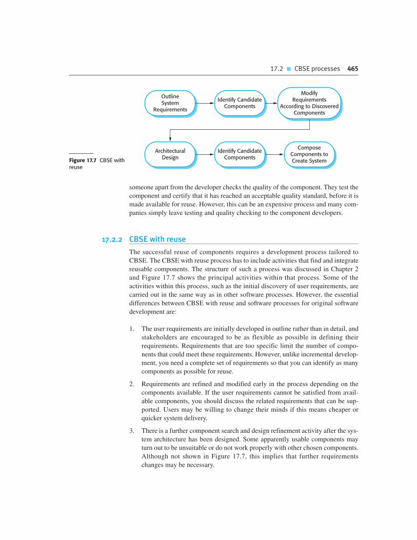
17.2 � CBSE processes 465
someone apart from the developer checks the quality of the component. They test the
component and certify that it has reached an acceptable quality standard, before it is
made available for reuse. However, this can be an expensive process and many com-
panies simply leave testing and quality checking to the component developers.
17.2.2 CBSE with reuse
The successful reuse of components requires a development process tailored to
CBSE. The CBSE with reuse process has to include activities that find and integrate
reusable components. The structure of such a process was discussed in Chapter 2
and Figure 17.7 shows the principal activities within that process. Some of the
activities within this process, such as the initial discovery of user requirements, are
carried out in the same way as in other software processes. However, the essential
differences between CBSE with reuse and software processes for original software
development are:
1. The user requirements are initially developed in outline rather than in detail, and
stakeholders are encouraged to be as flexible as possible in defining their
requirements. Requirements that are too specific limit the number of compo-
nents that could meet these requirements. However, unlike incremental develop-
ment, you need a complete set of requirements so that you can identify as many
components as possible for reuse.
2. Requirements are refined and modified early in the process depending on the
components available. If the user requirements cannot be satisfied from avail-
able components, you should discuss the related requirements that can be sup-
ported. Users may be willing to change their minds if this means cheaper or
quicker system delivery.
3. There is a further component search and design refinement activity after the sys-
tem architecture has been designed. Some apparently usable components may
turn out to be unsuitable or do not work properly with other chosen components.
Although not shown in Figure 17.7, this implies that further requirements
changes may be necessary.
Identify CandidateComponents
OutlineSystem
Requirements
ModifyRequirements
According to DiscoveredComponents
ArchitecturalDesign
ComposeComponents toCreate System
Identify CandidateComponentsFigure 17.7 CBSE with
reuse

466 Chapter 17 � Component-based software engineering
4. Development is a composition process where the discovered components are
integrated. This involves integrating the components with the component model
infrastructure and, often, developing adaptors that reconcile the interfaces
of incompatible components. Of course, additional functionality may also be
required over and above that provided by reused components.
The architectural design stage is particularly important. Jacobson et al. (1997)
found that defining a robust architecture is critical for successful reuse. During the
architectural design activity, you may choose a component model and implementa-
tion platform. However, many companies have a standard development platform
(e.g., .NET) so the component model is pre-determined. As I discussed in Chapter 6,
you also establish the high-level organization of the system at this stage and make
decisions about system distribution and control.
An activity that is unique to the CBSE process is identifying candidate compo-
nents or services for reuse. This involves a number of subactivities, as shown in
Figure 17.8. Initially, your focus should be on search and selection. You need to con-
vince yourself that there are components available to meet your requirements.
Obviously, you should do some initial checking that the component is suitable but
detailed testing may not be required. In the later stage, after the system architecture
has been designed, you should spend more time on component validation. You need
to be confident that the identified components are really suited to your application; if
not, then you have to repeat the search and selection processes.
The first step in identifying components is to look for components that are avail-
able locally or from trusted suppliers. As I said in the previous section, there are rel-
atively few component vendors so you are therefore most likely to be looking for
components that have been developed in your own company. Software development
companies can build their own database of reusable components without the risks
inherent in using components from external suppliers. Alternatively, you may decide
to search code libraries available on the Web, such as Sourceforge or Google Code,
to see if source code for the component that you need is available. If you are looking
for services, then there are a number of specialized web search engines available that
can discover public web services.
Once the component search process has identified possible components, you have
to select candidate components for assessment. In some cases, this will be a straight-
forward task. Components on the list will directly implement the user requirements
and there will not be competing components that match these requirements. In other
cases, however, the selection process is much more complex. There will not be a clear
mapping of requirements onto components and you may find that several components
have to be integrated to meet a specific requirement or group of requirements.
ComponentValidation
ComponentSelection
ComponentSearch
Figure 17.8 Thecomponentidentificationprocess

17.2 � CBSE processes 467
You, therefore, have to decide which component compositions provide the best cover-
age of the requirements.
Once you have selected components for possible inclusion in a system, you
should then validate them to check that they behave as advertised. The extent of the
validation required depends on the source of the components. If you are using a
component that has been developed by a known and trusted source, you may decide
that component testing is unnecessary. You simply test the component when it is
integrated with other components. On the other hand, if you are using a component
from an unknown source, you should always check and test that component before
including it in your system.
Component validation involves developing a set of test cases for a component (or,
possibly, extending test cases supplied with that component) and developing a test
harness to run component tests. The major problem with component validation is
that the component specification may not be sufficiently detailed to allow you to
develop a complete set of component tests. Components are usually specified infor-
mally, with the only formal documentation being their interface specification. This
may not include enough information for you to develop a complete set of tests that
would convince you that the component’s advertised interface is what you require.
As well as testing that a component for reuse does what you require, you may also
have to check that the component does not include any malicious code or functional-
ity that you don’t need. Professional developers rarely use components from
untrusted sources, especially if these sources do not provide source code. Therefore,
the malicious code problem does not usually arise. However, components may often
contain functionality that you don’t need and you have to check that this functional-
ity will not interfere with your use of the component.
The problem with unnecessary functionality is that it may be activated by the
component itself. This can slow down the component, cause it to produce surprising
results or, in some cases, cause serious system failures. Figure 17.9 summarizes a sit-
uation where unnecessary functionality in a reused system caused a catastrophic
software failure.
Figure 17.9 Anexample of validationfailure with reusedsoftware
The Ariane 5 launcher Failure
While developing the Ariane 5 space launcher, the designers decided to reuse the inertial reference softwarethat had performed successfully in the Ariane 4 launcher. The inertial reference software maintains the stabilityof the rocket. They decided to reuse this without change (as you would do with components), although itincluded additional functionality that was not required in Ariane 5.
In the first launch of Ariane 5, the inertial navigation software failed and the rocket could not be controlled.Ground controllers instructed the launcher to self-destruct and the rocket and its payload were destroyed. Thecause of the problem was an unhandled exception when a conversion of a fixed-point number to an integerresulted in a numeric overflow. This caused the run-time system to shut down the inertial reference system andlauncher stability could not be maintained. The fault had never occurred in Ariane 4 because it had lesspowerful engines and the value that was converted could not be large enough for the conversion to overflow.
The fault occurred in code that was not required for Ariane 5. The validation tests for the reused software werebased on Ariane 5 requirements. Because there were no requirements for the function that failed, no tests weredeveloped. Consequently, the problem with the software was never discovered during launch simulation tests.

468 Chapter 17 � Component-based software engineering
The problem in the Ariane 5 launcher arose because the assumptions made about
the software for Ariane 4 were invalid for Ariane 5. This is a general problem with
reusable components. They are originally implemented for an application environ-
ment and, naturally, embed assumptions about that environment. These assumptions
are rarely documented so, when the component is reused, it is impossible to derive
tests to check if the assumptions are still valid. If you are reusing a component in a
different environment, you may not discover the embedded environmental assump-
tions until you use the component in an operational system.
17.3 Component composition
Component composition is the process of integrating components with each other, and
with specially written ‘glue code’ to create a system or another component. There are
several different ways in which you can compose components, as shown in Figure 17.10.
From left to right these diagrams illustrate sequential composition, hierarchical composi-
tion and additive composition. In the discussion below, I assume that you are composing
two components (A and B) to create a new component:
1. Sequential composition is situation (a) in Figure 17.10. You create a new compo-
nent from 2 existing components by calling the existing components in sequence.
You can think of the composition as a composition of the ‘provides interfaces’.
That is, the services offered by component A are called and the results returned
by A are then used in the call to the services offered by component B. The com-
ponents do not call each other in sequential composition. Some extra glue code is
required to call the component services in the right order and to ensure that the
results delivered by component A are compatible with the inputs expected by
component B. The ‘provides’ interface of the composition depends on the com-
bined functionality of A and B but will not normally be a composition of their
‘provides interfaces’. This type of composition may be used with components
that are program elements or components that are services.
2. Hierarchical composition is situation (b) in Figure 17.10. This type of composi-
tion occurs when one component calls directly on the services provided by
another component. The called component provides the services that are required
by the calling component. Therefore, the ‘provides’ interface of the called compo-
nent must be compatible with the ‘requires’ interface of the calling component.
Component A calls on component B directly and, if their interfaces match, there
may be no need for additional code. However, if there is a mismatch between the
‘requires’ interface of A and the ‘provides’ interface of B, then some conversion
code may be required. As services do not have a ‘requires’ interface, this mode of
composition is not used when components are implemented as web services.
3. Additive composition corresponds to situation (c) in Figure 17.10. This occurs
when two or more components are put together (added) to create a new component,
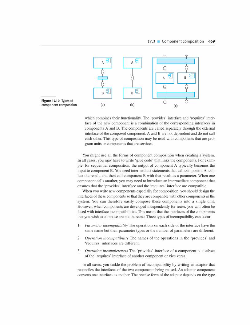
17.3 � Component composition 469
which combines their functionality. The ‘provides’ interface and ‘requires’ inter-
face of the new component is a combination of the corresponding interfaces in
components A and B. The components are called separately through the external
interface of the composed component. A and B are not dependent and do not call
each other. This type of composition may be used with components that are pro-
gram units or components that are services.
You might use all the forms of component composition when creating a system.
In all cases, you may have to write ‘glue code’ that links the components. For exam-
ple, for sequential composition, the output of component A typically becomes the
input to component B. You need intermediate statements that call component A, col-
lect the result, and then call component B with that result as a parameter. When one
component calls another, you may need to introduce an intermediate component that
ensures that the ‘provides’ interface and the ‘requires’ interface are compatible.
When you write new components especially for composition, you should design the
interfaces of these components so that they are compatible with other components in the
system. You can therefore easily compose these components into a single unit.
However, when components are developed independently for reuse, you will often be
faced with interface incompatibilities. This means that the interfaces of the components
that you wish to compose are not the same. Three types of incompatibility can occur:
1. Parameter incompatibility The operations on each side of the interface have the
same name but their parameter types or the number of parameters are different.
2. Operation incompatibility The names of the operations in the ‘provides’ and
‘requires’ interfaces are different.
3. Operation incompleteness The ‘provides’ interface of a component is a subset
of the ‘requires’ interface of another component or vice versa.
In all cases, you tackle the problem of incompatibility by writing an adaptor that
reconciles the interfaces of the two components being reused. An adaptor component
converts one interface to another. The precise form of the adaptor depends on the type
(a)
A A
BB
(b) (c)
A B
Figure 17.10 Types ofcomponent composition

470 Chapter 17 � Component-based software engineering
of composition. Sometimes, as in the next example, the adaptor takes a result from one
component and converts it into a form where it can be used as an input to another. In
other cases, the adaptor may be called by component A as a proxy for component B.
This situation occurs if A wishes to call B but the details of the ‘requires’ interface of
A do not match the details of the ‘provides’ interface of B. The adaptor reconciles
these differences by converting its input parameters from A into the required input
parameters for B. It then calls B to deliver the services required by A.
To illustrate adaptors, consider the two components shown in Figure 17.11,
whose interfaces are incompatible. These might be part of a system used by the
emergency services. When the emergency operator takes a call, the phone number
is input to the addressFinder component to locate the address. Then, using the
mapper component, the operator prints a map to be sent to the vehicle dispatched
to the emergency. In fact, the components would have more complex interfaces
than those shown here, but the simplified version illustrates the concept of an
adaptor.
The first component, addressFinder, finds the address that matches a phone num-
ber. It can also return the owner of the property associated with the phone number and
the type of property. The mapper component takes a post code (in the United States,
a standard ZIP code with the additional four digits identifying property location) and
displays or prints a street map of the area around that code at a specified scale.
These components are composable in principle because the property location
includes the post or ZIP code. However, you have to write an adaptor component
called postCodeStripper that takes the location data from addressFinder and
strips out the post code. This post code is then used as an input to mapper and the
street map is displayed at a scale of 1:10,000. The following code, which is an
example of sequential composition, illustrates the sequence of calls that is required
to implement this:
address = addressFinder.location (phonenumber) ;
postCode = postCodeStripper.getPostCode (address) ;
mapper.displayMap(postCode, 10000) ;
phoneDatabase (string command)
string location (string pn)
string owner (string pn)
string propertyType (string pn)
mapDB (string command)
displayMap (string postCode, scale)
printMap (string postCode, scale)
addressFinder
mapperFigure 17.11Components withincompatible interfaces

17.3 � Component composition 471
Another case in which an adaptor component may be used is in hierarchical com-
position, where one component wishes to make use of another but there is an incom-
patibility between the ‘provides’ interface and ‘requires’ interface of the components
in the composition. I have illustrated the use of an adaptor in Figure 17.12 where an
adaptor is used to link a data collector and a sensor component. These could be used
in the implementation of a wilderness weather station system, as discussed in
Chapter 7.
The sensor and data collector components are composed using an adapter that
reconciles the ‘requires’ interface of the data collection component with the
‘provides’ interface of the sensor component. The data collector component has
been designed with a generic ‘requires’ interface that supports sensor data
collection and sensor management. For each of these operations, the parameter
is a text string representing the specific sensor commands. For example, to issue
a collect command, you would say sensorData(“collect”). As I have shown in
Figure 17.12, the sensor itself has separate operations such as start, stop, and
getdata.
The adaptor parses the input string, identifies the command (e.g., collect) and
then calls Sensor.getdata to collect the sensor value. It then returns the result (as a
character string) to the data collector component. This interface style means that the
data collector can interact with different types of sensor. A separate adaptor, which
converts the sensor commands from Data collector to the actual sensor interface, is
implemented for each type of sensor.
The above discussion of component composition assumes you can tell from
the component documentation whether or not interfaces are compatible. Of
course, the interface definition includes the operation name and parameter types,
so you can make some assessment of the compatibility from this. However, you
depend on the component documentation to decide whether the interfaces are
semantically compatible.
To illustrate this problem, consider the composition shown in Figure 17.13. These
components are used to implement a system that downloads images from a digital
camera and stores them in a photograph library. The system user can provide
additional information to describe and catalog the photograph. To avoid clutter,
addSensor
removeSensor
startSensor
stopSensor
testSensor
listAll
report
initialize
sensorManagement
sensorData
AdapterSensor
start
getdata
stopData Collector
Figure 17.12 Anadaptor linking a datacollector and a sensor

472 Chapter 17 � Component-based software engineering
PhotoLibrary
AdaptorImage
Manager
getImage
UserInterface
getCatalogEntry
addItem
retrieve
catEntry
Figure 17.13 Photolibrary composition
I have not shown all interface methods here. Rather, I simply show the methods that
are needed to illustrate the component documentation problem. The methods in the
interface of Photo Library are:
public void addItem (Identifier pid ; Photograph p; CatalogEntry
photodesc) ;
public Photograph retrieve (Identifier pid) ;
public CatalogEntry catEntry (Identifier pid);
Assume that the documentation for the addItem method in Photo Library is:
This method adds a photograph to the library and associates the photograph
identifier and catalogue descriptor with the photograph.
This description appears to explain what the component does, but consider the
following questions:
• What happens if the photograph identifier is already associated with a photograph
in the library?
• Is the photograph descriptor associated with the catalog entry as well as the pho-
tograph? That is, if you delete the photograph, do you also delete the catalog
information?
There is not enough information in the informal description of addItem to answer
these questions. Of course, it is possible to add more information to the natural lan-
guage description of the method, but in general, the best way to resolve ambiguities
is to use a formal language to describe the interface. The specification shown in
Figure 17.14 is part of the description of the interface of Photo Library that adds
information to the informal description.
The specification in Figure 17.14 uses pre- and post-conditions that are defined in
a notation based on the object constraint language (OCL), which is part of the UML
(Warmer and Kleppe, 2003). OCL is designed to describe constraints in UML object
models; it allows you to express predicates that must always be true, that must be
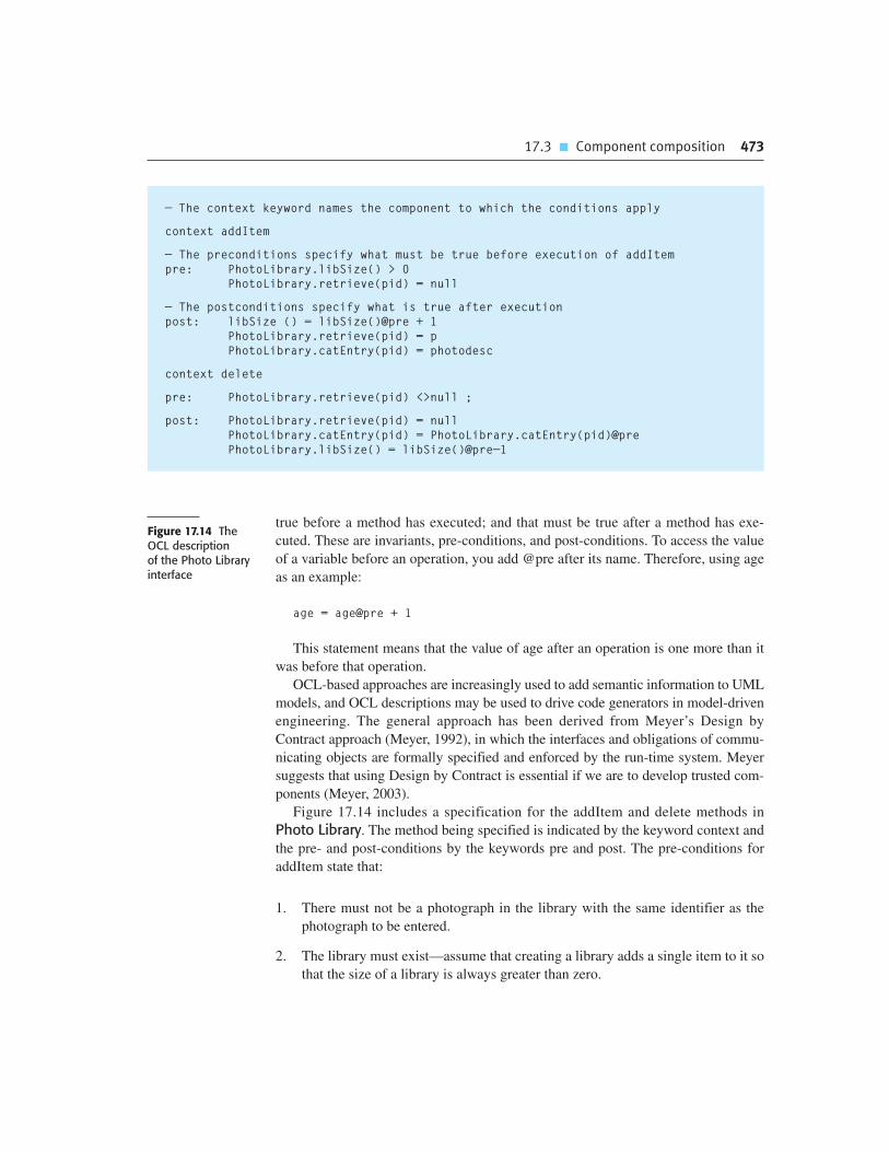
17.3 � Component composition 473
true before a method has executed; and that must be true after a method has exe-
cuted. These are invariants, pre-conditions, and post-conditions. To access the value
of a variable before an operation, you add @pre after its name. Therefore, using age
as an example:
age = age@pre + 1
This statement means that the value of age after an operation is one more than it
was before that operation.
OCL-based approaches are increasingly used to add semantic information to UML
models, and OCL descriptions may be used to drive code generators in model-driven
engineering. The general approach has been derived from Meyer’s Design by
Contract approach (Meyer, 1992), in which the interfaces and obligations of commu-
nicating objects are formally specified and enforced by the run-time system. Meyer
suggests that using Design by Contract is essential if we are to develop trusted com-
ponents (Meyer, 2003).
Figure 17.14 includes a specification for the addItem and delete methods in
Photo Library. The method being specified is indicated by the keyword context and
the pre- and post-conditions by the keywords pre and post. The pre-conditions for
addItem state that:
1. There must not be a photograph in the library with the same identifier as the
photograph to be entered.
2. The library must exist—assume that creating a library adds a single item to it so
that the size of a library is always greater than zero.
Figure 17.14 The OCL description of the Photo Libraryinterface
— The context keyword names the component to which the conditions apply
context addItem
— The preconditions specify what must be true before execution of addItem
pre: PhotoLibrary.libSize() > 0
PhotoLibrary.retrieve(pid) = null
— The postconditions specify what is true after execution
post: libSize () = libSize()@pre + 1
PhotoLibrary.retrieve(pid) = p
PhotoLibrary.catEntry(pid) = photodesc
context delete
pre: PhotoLibrary.retrieve(pid) <>null ;
post: PhotoLibrary.retrieve(pid) = null
PhotoLibrary.catEntry(pid) = PhotoLibrary.catEntry(pid)@pre
PhotoLibrary.libSize() = libSize()@pre—1

474 Chapter 17 � Component-based software engineering
3. The post-conditions for addItem state that:
The size of the library has increased by 1 (so only a single entry has been made).
If you retrieve using the same identifier, then you get back the photograph
that you added.
If you look up the catalogue using that identifier, you get back the catalogue
entry that you made.
The specification of delete provides further information. The pre-condition states
that to delete an item, it must be in the library and, after deletion, the photo can no
longer be retrieved and the size of the library is reduced by 1. However, delete does
not delete the catalogue entry—you can still retrieve it after the photo has been
deleted. The reason for this is that you may wish to maintain information in the cat-
alog about why a photo was deleted, its new location, and so on.
When you create a system by composing components, you may find that there are
potential conflicts between functional and non-functional requirements, the need to
deliver a system as quickly as possible and the need to create a system that can
evolve as requirements change. The decisions where you may have to take trade-offs
into account are:
1. What composition of components is most effective for delivering the functional
requirements for the system?
2. What composition of the components will make it easier to adapt the composite
component when its requirements change?
3. What will be the emergent properties of the composed system? These are prop-
erties such as performance and dependability. You can only assess these once
the complete system is implemented.
Unfortunately, there are many situations where the solutions to the composition
problems may conflict. For example, consider a situation such as that illustrated in
Figure 17.15, where a system can be created through two alternative compositions.
The system is a data collection and reporting system where data is collected from
different sources, stored in a database and then different reports summarizing that
data are produced.
Here, there is a potential conflict between adaptability and performance.
Composition (a) is more adaptable but composition (b) is perhaps faster and more
reliable. The advantages of composition (a) are that reporting and data management
are separate, so there is more flexibility for future change. The data management
system could be replaced and, if reports are required that the current reporting com-
ponent cannot produce, that component can also be replaced without having to
change the data management component.
In composition (b), a database component with built-in reporting facilities (e.g.,
Microsoft Access) is used. The key advantage of composition (b) is that there are fewer
components, so this will be a faster implementation because there are no component

Chapter 17 � Key points 475
communication overheads. Furthermore, data integrity rules that apply to the database
will also apply to reports. These reports will not be able to combine data in incorrect
ways. In composition (a), there are no such constraints so errors in reports could occur.
In general, a good composition principle to follow is the principle of separation of
concerns. That is, you should try to design your system in such a way that each com-
ponent has a clearly defined role and that, ideally, these roles should not overlap.
However, it may be cheaper to buy one multi-functional component rather than two
or three separate components. Furthermore, there may be dependability or perform-
ance penalties when multiple components are used.
(a)Data
Collection
(b)
DataManagement
ReportGenerator
DataCollection
Data Base
Report
Report
Figure 17.15 Datacollection and reportgeneration components
K E Y P O I N T S
� Component-based software engineering is a reuse-based approach to defining, implementing,
and composing loosely coupled independent components into systems.
� A component is a software unit whose functionality and dependencies are completely defined by
a set of public interfaces. Components can be composed with other components without
knowledge of their implementation and can be deployed as an executable unit.
� Components may be implemented as program units that are included in a system or as external
services that are referenced from within a system.
� A component model defines a set of standards for components, including interface standards,
usage standards, and deployment standards. The implementation of the component model
provides a set of common services that may be used by all components.
� During the CBSE process, you have to interleave the processes of requirements engineering and
system design. You have to trade off desirable requirements against the services that are
available from existing reusable components.
� Component composition is the process of ‘wiring’ components together to create a system.
Types of composition include sequential composition, hierarchical composition, and additive
composition.
476 Chapter 17 � Component-based software engineering
� When composing reusable components that have not been written for your application, you
may need to write adaptors or ‘glue code’ to reconcile the different component interfaces.
� When choosing compositions, you have to consider the required functionality of the system,
the non-functional requirements and the ease with which one component can be replaced when
the system is changed.
F U RT H E R R E A D I N G
Component-based Software Engineering: Putting the Pieces Together. This book is a collection of
papers from various authors on different aspects of CBSE. Like all collections, it is rather mixed but
it has better coverage of general issues of software engineering with components than Szyperski’s
book. (G. T. Heineman and W. T. Councill, Addison-Wesley, 2001.)
Component Software: Beyond Object-Oriented Programming, 2nd ed. This updated edition of the
first book on CBSE covers technical and nontechnical issues in CBSE. It has more detail on specific
technologies than Heineman and Councill’s book and includes a thorough discussion of market
issues. (C. Szyperski, Addison-Wesley, 2002.)
‘Specification, Implementation and Deployment of Components’. A good introduction to the
fundamentals of CBSE. The same issue of the CACM includes articles on components and
component-based development. (I. Crnkovic, B. Hnich, T. Jonsson and Z. Kiziltan, Comm. ACM,
45 (10), October 2002.) http://dx.doi.org/10.1145/570907.570928.
‘Software Component Models’. This is a comprehensive discussion of commercial and research
component models that classifies these models and explains the differences between them. (K-K.
Lau and Z. Wang, IEEE Transactions on Software Engineering, 33 (10), October 2007.)
http://dx.doi.org/10.1109/TSE.2007.70726.
E X E R C I S E S
17.1. Why is it important that all component interactions are defined through ‘requires’ and
‘provides’ interfaces?
17.2. The principle of component independence means that it ought to be possible to replace one
component with another that is implemented in a completely different way. Using an example,
explain how such component replacement could have undesired consequences and may lead
to system failure.

Chapter 17 � References 477
17.3. What are the fundamental differences between components as program elements and
components as services?
17.4. Why is it important that components should be based on a standard component model?
17.5. Using an example of a component that implements an abstract data type such as a stack or a
list, show why it is usually necessary to extend and adapt components for reuse.
17.6. Explain why it is difficult to validate a reusable component without the component source
code. In what ways would a formal component specification simplify the problems of
validation?
17.7. Design the ‘provides’ interface and the ‘requires’ interface of a reusable component that may
be used to represent a patient in the MHC-PMS.
17.8. Using examples, illustrate the different types of adaptor needed to support sequential
composition, hierarchical composition, and additive composition.
17.9. Design the interfaces of components that might be used in a system for an emergency
control room. You should design interfaces for a call-logging component that records calls
made, and a vehicle discovery component that, given a post code (zip code) and an incident
type, finds the nearest suitable vehicle to be despatched to the incident.
17.10. It has been suggested that an independent certification authority should be established.
Vendors would submit their components to this authority, which would validate that the
component was trustworthy. What would be the advantages and disadvantages of such a
certification authority?
R E F E R E N C E S
Boehm, B. W., Abts, C., Brown, A. W., Chulani, S., Clark, B. K., Horowitz, E., Madachy, R., Reifer, D. and
Steece, B. (2000). Software Cost Estimation with COCOMO II. Upper Saddle River, NJ.: Prentice Hall.
Councill, W. T. and Heineman, G. T. (2001). ‘Definition of a Software Component and its Elements’. In
Component-based Software Engineering. Heineman, G. T. and Councill, W. T. (ed.). Boston: Addison-
Wesley, 5–20.
Jacobson, I., Griss, M. and Jonsson, P. (1997). Software Reuse. Reading, Mass.: Addison-Wesley.
Kotonya, G. (2003). ‘The CBSE Process: Issues and Future Visions’. Proc. 2nd CBSEnet workshop,
Budapest, Hungary.
Lau, K.-K. and Wang, Z. (2007). ‘Software Component Models’. IEEE Trans. on Software Eng., 33 (10),
709–24.
Meyer, B. (1992). ‘Design by Contract’. IEEE Computer, 25 (10), 40–51.
Meyer, B. (2003). ‘The Grand Challenge of Trusted Components’. ICSE 25: Int. Conf. on Software Eng.,
Portland, Oregon: IEEE Press.

478 Chapter 17 � Component-based software engineering
Mili, H., Mili, A., Yacoub, S. and Addy, E. (2002). Reuse-based Software Engineering. New York: John
Wiley & Sons.
Pope, A. (1997). The CORBA Reference Guide: Understanding the Common Object Request Broker
Architecture. Harlow, UK: Addison-Wesley.
Szyperski, C. (2002). Component Software: Beyond Object-oriented Programming, 2nd ed. Harlow,
UK: Addison-Wesley.
Warmer, J. and Kleppe, A. (2003). The Object Constraint Language: Getting your models ready for
MDA. Boston: Addison-Wesley.
Weinreich, R. and Sametinger, J. (2001). ‘Component Models and Component Services: Concepts and
Principles’. In Component-Based Software Engineering. Heineman, G. T. and Councill, W. T. (ed.).
Boston: Addison-Wesley, 33–48.

Distributed softwareengineering
18
Objectives
The objective of this chapter is to introduce distributed systems
engineering and distributed systems architectures. When you have read
this chapter, you will:
� know the key issues that have to be considered when designing and
implementing distributed software systems;
� understand the client–server computing model and the layered
architecture of client–server systems;
� have been introduced to commonly used patterns for distributed
systems architectures and know the types of system for which each
architecture is most applicable;
� understand the notion of software as a service, providing web-based
access to remotely deployed application systems.
Contents
18.1 Distributed systems issues
18.2 Client–server computing
18.3 Architectural patterns for distributed systems
18.4 Software as a service

480 Chapter 18 � Distributed software engineering
Virtually all large computer-based systems are now distributed systems. A distrib-
uted system is one involving several computers, in contrast with centralized systems
where all of the system components execute on a single computer. Tanenbaum and
Van Steen (2007) define a distributed system to be:
“. . .a collection of independent computers that appears to the user as a single
coherent system.”
Obviously, the engineering of distributed systems has a great deal in common
with the engineering of any other software. However, there are specific issues that
have to be taken into account when designing this type of system. These arise
because the system components may be running on independently managed comput-
ers and they communicate across a network.
Coulouris et al. (2005) identify the following advantages of using a distributed
approach to systems development:
1. Resource sharing A distributed system allows the sharing of hardware and soft-
ware resources—such as disks, printers, files, and compilers—that are associ-
ated with computers on a network.
2. Openness Distributed systems are normally open systems, which means that
they are designed around standard protocols that allow equipment and software
from different vendors to be combined.
3. Concurrency In a distributed system, several processes may operate at the same
time on separate computers on the network. These processes may (but need not)
communicate with each other during their normal operation.
4. Scalability In principle at least, distributed systems are scalable in that the capa-
bilities of the system can be increased by adding new resources to cope with
new demands on the system. In practice, the network linking the individual
computers in the system may limit the system scalability.
5. Fault tolerance The availability of several computers and the potential for repli-
cating information means that distributed systems can be tolerant of some hard-
ware and software failures (see Chapter 13). In most distributed systems, a
degraded service can be provided when failures occur; complete loss of service
only occurs when there is a network failure.
For large-scale organizational systems, these advantages mean that distributed
systems have largely replaced mainframe legacy systems that were developed in the
1990s. However, there are many personal computer application systems (e.g., photo
editing systems) that are not distributed and which run on a single computer system.
Most embedded systems are also single processor systems.
Distributed systems are inherently more complex than centralized systems. This
makes them more difficult to design, implement, and test. It is harder to understand
the emergent properties of distributed systems because of the complexity of the

18.1 � Distributed systems issues 481
interactions between system components and the system infrastructure. For example,
rather than the performance of the system being dependent on the execution speed of
one processor, it depends on the network bandwidth, the network load, and the speed
of all of the computers that are part of the system. Moving resources from one part of
the system to another can significantly affect the system’s performance.
Furthermore, as all users of the WWW know, distributed systems are unpredictable
in their response. The response time depends on the overall load on the system, its archi-
tecture and the network load. As all of these may change over a short time, the time
taken to respond to a user request may vary dramatically from one request to another.
The most important development that has affected distributed software systems in
the past few years is the service-oriented approach. Much of this chapter focuses on
general issues of distributed systems, but I cover the notion of applications deployed
as services in Section 18.4. This complements the material in Chapter 19, which
focuses on services as components in a service-oriented architecture, and more gen-
eral issues of service-oriented software engineering.
18.1 Distributed systems issues
As I discussed in the introduction to this chapter, distributed systems are more com-
plex than systems that run on a single processor. This complexity arises because it is
practically impossible to have a top-down model of control of these systems. The
nodes in the system that deliver functionality are often independent systems with no
single authority in charge of them. The network connecting these nodes is a sepa-
rately managed system. It is a complex system in its own right and cannot be con-
trolled by the owners of systems using the network. There is therefore an inherent
unpredictability in the operation of distributed systems that has to be taken into
account by the system designer.
Some of the most important design issues that have to be considered in distributed
systems engineering are:
1. Transparency To what extent should the distributed system appear to the user
as a single system? When it is useful for users to understand that the system is
distributed?
2. Openness Should a system be designed using standard protocols that support
interoperability or should more specialized protocols be used that restrict the
freedom of the designer?
3. Scalability How can the system be constructed so that it is scaleable? That is,
how can the overall system be designed so that its capacity can be increased in
response to increasing demands made on the system?
4. Security How can usable security policies be defined and implemented that
apply across a set of independently managed systems?

482 Chapter 18 � Distributed software engineering
5. Quality of service How should the quality of service that is delivered to system
users be specified and how should the system be implemented to deliver an
acceptable quality of service to all users?
6. Failure management How can system failures be detected, contained (so that
they have minimal effects on other components in the system), and repaired?
In an ideal world, the fact that a system is distributed would be transparent to
users. This means that users would see the system as a single system whose behavior
is not affected by the way that the system is distributed. In practice, this is impossi-
ble to achieve. Central control of a distributed system is impossible and, as a result,
individual computers in a system may behave differently at different times.
Furthermore, because it always takes a finite length of time for signals to travel
across a network, network delays are unavoidable. The length of these delays
depends on the location of resources in the system, the quality of the user’s network
connection, and the network load.
The design approach to achieving transparency depends on creating abstractions
of the resources in a distributed system so that the physical realization of these
resources can be changed without having to make changes in the application system.
Middleware (discussed in Section 18.1.2) is used to map the logical resources refer-
enced by a program onto the actual physical resources, and to manage the interac-
tions between these resources.
In practice, it is impossible to make a system completely transparent and users,
generally, are aware that they are dealing with a distributed system. You may there-
fore decide that it is best to expose the distribution to users. They can then be pre-
pared for some of the consequences of distribution such as network delays, remote
node failures, etc.
Open distributed systems are systems that are built according to generally
accepted standards. This means that components from any supplier can be integrated
into the system and can interoperate with the other system components. At the
networking level, openness is now taken for granted with systems conforming to
Internet protocols but at the component level, openness is still not universal.
Openness implies that system components can be independently developed in any
programming language and, if these conform to standards, they will work with other
components.
CORBA – Common Object Request Broker Architecture
CORBA is a well-known specification for a middleware system that was developed in the 1990s by the ObjectManagement Group. It was intended as an open standard that would allow the development of middleware tosupport distributed component communications and execution, plus provide a set of standard services thatcould be used by these components.
Several implementations of CORBA were produced but the system never achieved critical mass. Users preferredproprietary systems or moved to service-oriented architectures.
http://www.SoftwareEngineering-9.com/Web/DistribSys/Corba.html
18.1 � Distributed systems issues 483
The CORBA standard (Pope, 1997) developed in the 1990s, was intended to
achieve this but this never achieved a critical mass of adopters. Rather, many compa-
nies chose to develop systems using proprietary standards for components from
companies such as Sun and Microsoft. These provided better implementations and
support software and better long-term support for industrial protocols.
Web service standards (discussed in Chapter 19) for service-oriented architec-
tures were developed to be open standards. However, there is significant resistance
to these standards because of their perceived inefficiency. Some developers of serv-
ice-based systems have opted instead for so-called RESTful protocols as these have
an inherently lower overhead than web service protocols.
The scalability of a system reflects its ability to deliver a high quality of service
as demands on the system increase. Neuman (1994) identifies three dimensions of
scalability:
1. Size It should be possible to add more resources to a system to cope with
increasing numbers of users.
2. Distribution It should be possible to geographically disperse the components of
a system without degrading its performance.
3. Manageability It should be possible to manage a system as it increases in size,
even if parts of the system are located in independent organizations.
In terms of size, there is a distinction between scaling up and scaling out. Scaling up
means replacing resources in the system with more powerful resources. For example,
you may increase the memory in a server from 16 GB to 64 GB. Scaling out means
adding additional resources to the system (e.g., an extra web server to work alongside
an existing server). Scaling out is often more cost effective than scaling up but usually
means that the system has to be designed so that concurrent processing is possible.
I have discussed general security issues and issues of security engineering in Part 2
of this book. However, when a system is distributed, the number of ways that the sys-
tem may be attacked is significantly increased, compared to centralized systems. If a
part of the system is successfully attacked then the attacker may be able to use this as
a ‘back door’ into other parts of the system.
The types of attacks that a distributed system must defend itself against are the
following:
1. Interception, where communications between parts of the system are inter-
cepted by an attacker so that there is a loss of confidentiality.
2. Interruption, where system services are attacked and cannot be delivered as
expected. Denial of service attacks involve bombarding a node with illegitimate
service requests so that it cannot deal with valid requests.
3. Modification, where data or services in the system are changed by an attacker.
4. Fabrication, where an attacker generates information that should not exist and
then uses this to gain some privileges. For example, an attacker may generate a
false password entry and use this to gain access to a system.

484 Chapter 18 � Distributed software engineering
The major difficulty in distributed systems is establishing a security policy
that can be reliably applied to all of the components in a system. As I discussed
in Chapter 11, a security policy sets out the level of security to be achieved by a
system. Security mechanisms, such as encryption and authentication, are used to
enforce the security policy. The difficulties in a distributed system arise because
different organizations may own parts of the system. These organizations may
have mutually incompatible security policies and security mechanisms. Security
compromises may have to be made in order to allow the systems to work
together.
The quality of service (QoS) offered by a distributed system reflects the system’s
ability to deliver its services dependably and with a response time and throughput
that is acceptable to its users. Ideally, the QoS requirements should be specified in
advance and the system designed and configured to deliver that QoS. Unfortunately,
this is not always practicable, for two reasons:
1. It may not be cost effective to design and configure the system to deliver a high
QoS under peak load. This could involve making resources available that are
unused for much of the time. One of the main arguments for ‘cloud computing’
is that it partially addresses this problem. Using a cloud, it is easy to add
resources as demand increases.
2. The QoS parameters may be mutually contradictory. For example, increased
reliability may mean reduced throughput, as checking procedures are intro-
duced to ensure that all system inputs are valid.
QoS is particularly critical when the system is dealing with time-critical data
such as sound or video streams. In these circumstances, if the QoS falls below a
threshold value then the sound or video may become so degraded that it is
impossible to understand. Systems dealing with sound and video should include
QoS negotiation and management components. These should evaluate the QoS
requirements against the available resources and, if these are insufficient, nego-
tiate for more resources or for a reduced QoS target.
In a distributed system, it is inevitable that failures will occur, so the system has to
be designed to be resilient to these failures. Failure is so ubiquitous that one flippant
definition of a distributed system suggested by Leslie Lamport, a prominent distrib-
uted systems researcher, is:
“You know that you have a distributed system when the crash of a system that
you’ve never heard of stops you getting any work done.”
Failure management involves applying the fault tolerance techniques discussed in
Chapter 13. Distributed systems should therefore include mechanisms for discover-
ing if a component of the system has failed, should continue to deliver as many serv-
ices as possible in spite of that failure and, as far as possible, should automatically
recover from the failure.

18.1 � Distributed systems issues 485
18.1.1 Models of interaction
There are two fundamental types of interaction that may take place between the com-
puters in a distributed computing system: procedural interaction and message-based
interaction. Procedural interaction involves one computer calling on a known service
offered by some other computer and (usually) waiting for that service to be delivered.
Message-based interaction involves the ‘sending’ computer defining information
about what is required in a message, which is then sent to another computer.
Messages usually transmit more information in a single interaction than a procedure
call to another machine.
To illustrate the difference between procedural and message-based interaction,
consider a situation where you are ordering a meal in a restaurant. When you have a
conversation with the waiter, you are involved in a series of synchronous, procedural
interactions that define your order. You make a request; the waiter acknowledges that
request; you make another request, which is acknowledged; and so on. This is com-
parable to components interacting in a software system where one component calls
methods from other components. The waiter writes down your order along with the
order of other people with you. He or she then passes this order, which includes
details of everything that has been ordered, to the kitchen to prepare the food.
Essentially, the waiter is passing a message to the kitchen staff defining the food to
be prepared. This is message-based interaction.
I have illustrated this in Figure 18.1, which shows the synchronous ordering
process as a series of calls and in Figure 18.2, which shows a hypothetical XML
message that defines an order made by the table of three people. The difference
between these forms of information exchange is clear. The waiter takes the order as
a series of interactions, with each interaction defining part of the order. However,
Tomato soup please
Waiter Diner
What would you like?
And to follow?
Fillet steak
How would you like it cooked?
Rare please
With salad or french fries?
Salad please
Etc.
Figure 18.1 Proceduralinteraction between adiner and a waiter

486 Chapter 18 � Distributed software engineering
the waiter has a single interaction with the kitchen where the message defines the
complete order.
Procedural communication in a distributed system is usually implemented
using remote procedure calls (RPCs). In RPC one component calls another compo-
nent as if it was a local procedure or method. The middleware in the system inter-
cepts this call and passes it to a remote component. This carries out the required
computation and, via the middleware, returns the result to the calling component.
In Java, remote method invocations (RMI) are comparable with, though not identi-
cal to, RPCs. The RMI framework handles the invocation of remote methods in a
Java program.
RPCs require a ‘stub’ for the called procedure to be accessible on the computer
that is initiating the call. The stub is called and it translates the procedure parameters
into a standard representation for transmission to the remote procedure. Through the
middleware, it then sends the request for execution to the remote procedure. The
remote procedure uses library functions to convert the parameters into the required
format, carries out the computation, and then communicates the results via the ‘stub’
that is representing the caller.
Message-based interaction normally involves one component creating a message
that details the services required from another component. Through the system
middleware, this is sent to the receiving component. The receiver parses the mes-
sage, carries out the computations, and creates a message for the sending component
with the required results. This is then passed to the middleware for transmission to
the sending component.
A problem with the RPC approach to interaction is that both the caller and the
callee need to be available at the time of the communication, and they must know
how to refer to each other. In essence, an RPC has the same requirements as a local
procedure or method call. By contrast, in a message-based approach, unavailability
can be tolerated as the message simply stays in a queue until the receiver becomes
available. Furthermore, it is not necessary for the sender and receiver of the message
to be aware of each other. They simply communicate with the middleware, which is
responsible for ensuring that messages are passed to the appropriate system.
Figure 18.2Message-basedinteractionbetween awaiter and thekitchen staff
<starter>
<dish name = “soup” type = “tomato” />
<dish name = “soup” type = “fish” />
<dish name = “pigeon salad” />
</starter>
<main course>
<dish name = “steak” type = “sirloin” cooking = “medium” />
<dish name = “steak” type = “fillet” cooking = “rare” />
<dish name = “sea bass”>
</main>
<accompaniment>
<dish name = “french fries” portions = “2” />
<dish name = “salad” portions = “1” />
</accompaniment>

18.1 � Distributed systems issues 487
18.1.2 Middleware
The components in a distributed system may be implemented in different program-
ming languages and may execute on completely different types of processor. Models
of data, information representation, and protocols for communication may all be dif-
ferent. A distributed system therefore requires software that can manage these
diverse parts, and ensure that they can communicate and exchange data.
The term ‘middleware’ is used to refer to this software—it sits in the middle
between the distributed components of the system. This is illustrated in Figure 18.3,
which shows that middleware is a layer between the operating system and appli-
cation programs. Middleware is normally implemented as a set of libraries, which
are installed on each distributed computer, plus a run-time system to manage
communications.
Bernstein (1996) describes types of middleware that are available to support dis-
tributed computing. Middleware is general-purpose software that is usually bought
off the shelf rather than written specially by application developers. Examples of
middleware include software for managing communications with databases, transac-
tion managers, data converters, and communication controllers.
In a distributed system, middleware normally provides two distinct types of support:
1. Interaction support, where the middleware coordinates interactions between dif-
ferent components in the system. The middleware provides location trans-
parency in that it isn’t necessary for components to know the physical locations
of other components. It may also support parameter conversion if different pro-
gramming languages are used to implement components, event detection, and
communication, etc.
2. The provision of common services, where the middleware provides reusable
implementations of services that may be required by several components in the
distributed system. By using these common services, components can easily
interoperate and provide user services in a consistent way.
LogicalInteraction
InformationExchange and
Common Services
CoordinatedOperation
Application Components
Middleware
Operating System
Networking
System 1
Application Components
Middleware
Operating System
Networking
System 2
PhysicalConnectivityFigure 18.3
Middleware in adistributed system

488 Chapter 18 � Distributed software engineering
I have already given examples of the interaction support that middleware can pro-
vide in Section 18.1.1. You use middleware to support remote procedure and
remote method calls, message exchange, etc.
Common services are those services that may be required by different compo-
nents irrespective of the functionality of these components. As I discussed in
Chapter 17, these may include security services (authentication and authorization),
notification and naming services, and transaction management services, etc. You
can think of these common services as being provided by a middleware container.
You then deploy your component in that container and it can access and use these
common services.
18.2 Client–server computing
Distributed systems that are accessed over the Internet are normally organized as
client–server systems. In a client–server system, the user interacts with a program
running on their local computer (e.g., a web browser or phone-based application).
This interacts with another program running on a remote computer (e.g., a web
server). The remote computer provides services, such as access to web pages, which
are available to external clients. This client–server model, as I discussed in Chapter 6,
is a very general architectural model of an application. It is not restricted to applica-
tions distributed across several machines. You can also use it as a logical interaction
model where the client and the server run on the same computer.
In a client–server architecture, an application is modeled as a set of services that
are provided by servers. Clients may access these services and present results to end
users (Orfali and Harkey, 1998). Clients need to be aware of the servers that are
available but do not know of the existence of other clients. Clients and servers are
separate processes, as shown in Figure 18.4. This illustrates a situation in which
there are four servers (s1–s4), that deliver different services. Each service has a set of
associated clients that access these services.
s1
s2 s3
s4c1
c2 c3 c4
c5
c6c7 c8
c9
c10
c11
c12
Client Process
Server Process
Figure 18.4 Client–serverinteraction
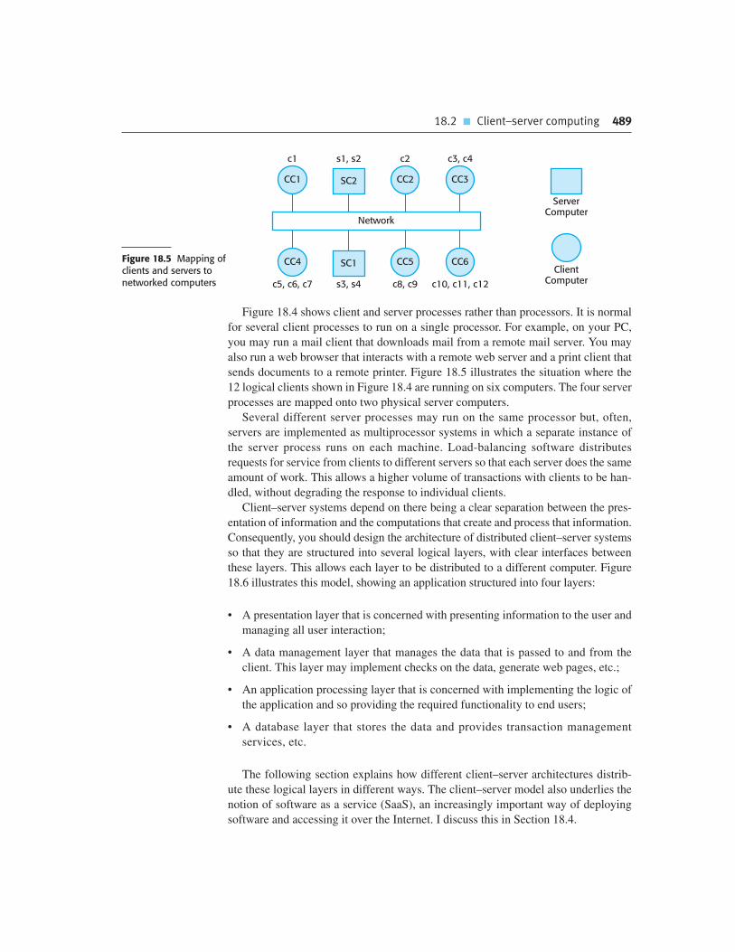
18.2 � Client–server computing 489
Figure 18.4 shows client and server processes rather than processors. It is normal
for several client processes to run on a single processor. For example, on your PC,
you may run a mail client that downloads mail from a remote mail server. You may
also run a web browser that interacts with a remote web server and a print client that
sends documents to a remote printer. Figure 18.5 illustrates the situation where the
12 logical clients shown in Figure 18.4 are running on six computers. The four server
processes are mapped onto two physical server computers.
Several different server processes may run on the same processor but, often,
servers are implemented as multiprocessor systems in which a separate instance of
the server process runs on each machine. Load-balancing software distributes
requests for service from clients to different servers so that each server does the same
amount of work. This allows a higher volume of transactions with clients to be han-
dled, without degrading the response to individual clients.
Client–server systems depend on there being a clear separation between the pres-
entation of information and the computations that create and process that information.
Consequently, you should design the architecture of distributed client–server systems
so that they are structured into several logical layers, with clear interfaces between
these layers. This allows each layer to be distributed to a different computer. Figure
18.6 illustrates this model, showing an application structured into four layers:
• A presentation layer that is concerned with presenting information to the user and
managing all user interaction;
• A data management layer that manages the data that is passed to and from the
client. This layer may implement checks on the data, generate web pages, etc.;
• An application processing layer that is concerned with implementing the logic of
the application and so providing the required functionality to end users;
• A database layer that stores the data and provides transaction management
services, etc.
The following section explains how different client–server architectures distrib-
ute these logical layers in different ways. The client–server model also underlies the
notion of software as a service (SaaS), an increasingly important way of deploying
software and accessing it over the Internet. I discuss this in Section 18.4.
Network
CC1 CC3CC2SC2
CC4 CC6CC5SC1
ServerComputer
ClientComputer
c1 c2 c3, c4s1, s2
c5, c6, c7 c8, c9 c10, c11, c12s3, s4
Figure 18.5 Mapping ofclients and servers tonetworked computers

490 Chapter 18 � Distributed software engineering
18.3 Architectural patterns for distributed systems
As I explained in the introduction to this chapter, designers of distributed systems
have to organize their system designs to find a balance between performance,
dependability, security, and manageability of the system. There is no universal
model of system organization that is appropriate for all circumstances so various dis-
tributed architectural styles have emerged. When designing a distributed application,
you should choose an architectural style that supports the critical non-functional
requirements of your system.
In this section, I discuss five architectural styles:
1. Master-slave architecture, which is used in real-time systems in which guaran-
teed interaction response times are required.
2. Two-tier client–server architecture, which is used for simple client–server systems,
and in situations where it is important to centralize the system for security reasons.
In such cases, communication between the client and server is normally encrypted.
3. Multitier client–server architecture, which is used when there is a high volume
of transactions to be processed by the server.
4. Distributed component architecture, which is used when resources from differ-
ent systems and databases need to be combined, or as an implementation model
for multi-tier client–server systems.
5. Peer-to-peer architecture, which is used when clients exchange locally stored infor-
mation and the role of the server is to introduce clients to each other. It may also be
used when a large number of independent computations may have to be made.
18.3.1 Master-slave architectures
Master-slave architectures for distributed systems are commonly used in real-
time systems where there may be separate processors associated with data acqui-
sition from the system’s environment, data processing, and computation and
Application Processing Layer
Data Management Layer
Presentation Layer
Database LayerFigure 18.6 Layeredarchitectural model forclient–server application

18.3 � Architectural patterns for distributed systems 491
actuator management. Actuators, as I discuss in Chapter 20, are devices con-
trolled by the software system that act to change the system’s environment. For
example, an actuator may control a valve and change its state from ‘open’ to
‘closed’. The ‘master’ process is usually responsible for computation, coordina-
tion, and communications and it controls the ‘slave’ processes. ‘Slave’ processes
are dedicated to specific actions, such as the acquisition of data from an array of
sensors.
Figure 18.7 illustrates this architectural model. It is a model of a traffic control
system in a city and has three logical processes that run on separate processors. The
master process is the control room process, which communicates with separate slave
processes that are responsible for collecting traffic data and managing the operation
of traffic lights.
A set of distributed sensors collects information on the traffic flow. The sen-
sor control process polls the sensors periodically to capture the traffic flow infor-
mation and collates this information for further processing. The sensor processor
is itself polled periodically for information by the master process that is con-
cerned with displaying traffic status to operators, computing traffic light
sequences and accepting operator commands to modify these sequences. The
control room system sends commands to a traffic light control process that con-
verts these into signals to control the traffic light hardware. The master control
room system is itself organized as a client–server system, with the client
processes running on the operator’s consoles.
You use this master-slave model of a distributed system in situations where you
can predict the distributed processing that is required, and where processing can be
easily localized to slave processors. This situation is common in real-time systems,
where it is important to meet processing deadlines. Slave processors can be used for
computationally intensive operations, such as signal processing and the management
of equipment controlled by the system.
Traffic Lights
LightControlProcess
Traffic Light ControlProcessor
Operator Consoles
Traffic Flow Sensorsand Cameras
Slave
Coordinationand Display
Process
Control RoomProcessor
MasterSensorControlProcess
SensorProcessor
Slave
Figure 18.7 A trafficmanagement systemwith a master-slavearchitecture

492 Chapter 18 � Distributed software engineering
18.3.2 Two-tier client–server architectures
In Section 18.2, I discussed the general form of client–server systems in which part of
the application system runs on the user’s computer (the client), and part runs on a
remote computer (the server). I also presented a layered application model (Figure 18.6)
where the different layers in the system may execute on different computers.
A two-tier client–server architecture is the simplest form of client–server archi-
tecture. The system is implemented as a single logical server plus an indefinite num-
ber of clients that use that server. This is illustrated in Figure 18.8, which shows two
forms of this architectural model:
1. A thin-client model, where the presentation layer is implemented on the client
and all other layers (data management, application processing, and database) are
implemented on a server. The client software may be a specially written pro-
gram on the client to handle presentation. More often, however, a web browser
on the client computer is used for presentation of the data.
2. A fat-client model, where some or all of the application processing is carried out on
the client. Data management and database functions are implemented on the server.
The advantage of the thin-client model is that it is simple to manage the clients.
This is a major issue if there are a large number of clients, as it may be difficult and
expensive to install new software on all of them. If a web browser is used as the
client, there is no need to install any software.
The disadvantage of the thin-client approach, however is that it may place a heavy
processing load on both the server and the network. The server is responsible for all
computation and this may lead to the generation of significant network traffic
between the client and the server. Implementing a system using this model may
therefore require additional investment in network and server capacity. However,
browsers may carry out some local processing by executing scripts (e.g., Javascript)
in the web page that is accessed by the browser.
The fat-client model makes use of available processing power on the computer
running the client software, and distributes some or all of the application processing
Thin-ClientModel
Fat-ClientModel
Client
Client
Server
DatabaseData ManagementApplication Processing
Presentation
Server
DatabaseData Management
PresentationApplication Processing
Figure 18.8 Thin- andfat-client architecturalmodels
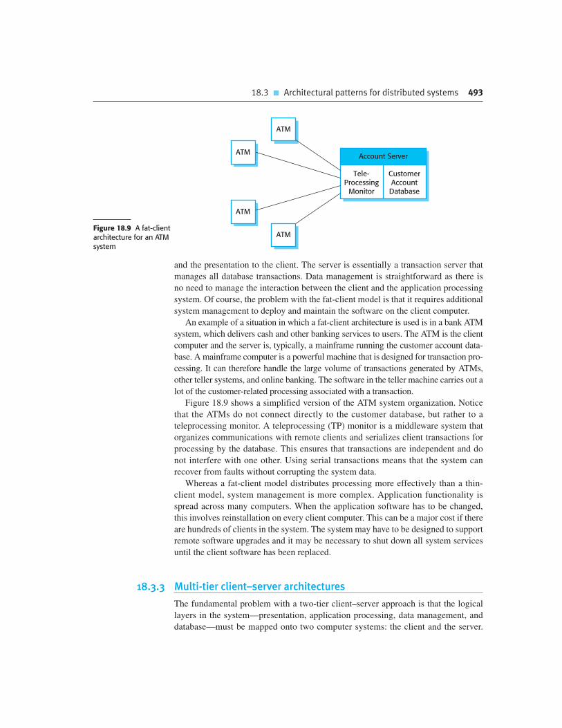
18.3 � Architectural patterns for distributed systems 493
and the presentation to the client. The server is essentially a transaction server that
manages all database transactions. Data management is straightforward as there is
no need to manage the interaction between the client and the application processing
system. Of course, the problem with the fat-client model is that it requires additional
system management to deploy and maintain the software on the client computer.
An example of a situation in which a fat-client architecture is used is in a bank ATM
system, which delivers cash and other banking services to users. The ATM is the client
computer and the server is, typically, a mainframe running the customer account data-
base. A mainframe computer is a powerful machine that is designed for transaction pro-
cessing. It can therefore handle the large volume of transactions generated by ATMs,
other teller systems, and online banking. The software in the teller machine carries out a
lot of the customer-related processing associated with a transaction.
Figure 18.9 shows a simplified version of the ATM system organization. Notice
that the ATMs do not connect directly to the customer database, but rather to a
teleprocessing monitor. A teleprocessing (TP) monitor is a middleware system that
organizes communications with remote clients and serializes client transactions for
processing by the database. This ensures that transactions are independent and do
not interfere with one other. Using serial transactions means that the system can
recover from faults without corrupting the system data.
Whereas a fat-client model distributes processing more effectively than a thin-
client model, system management is more complex. Application functionality is
spread across many computers. When the application software has to be changed,
this involves reinstallation on every client computer. This can be a major cost if there
are hundreds of clients in the system. The system may have to be designed to support
remote software upgrades and it may be necessary to shut down all system services
until the client software has been replaced.
18.3.3 Multi-tier client–server architectures
The fundamental problem with a two-tier client–server approach is that the logical
layers in the system—presentation, application processing, data management, and
database—must be mapped onto two computer systems: the client and the server.
Account Server
CustomerAccountDatabase
Tele-Processing
Monitor
ATM
ATM
ATM
ATMFigure 18.9 A fat-clientarchitecture for an ATMsystem

494 Chapter 18 � Distributed software engineering
This may lead to problems with scalability and performance if the thin-client model
is chosen, or problems of system management if the fat-client model is used. To
avoid some of these problems, a ‘multi-tier client–server’ architecture can be used.
In this architecture, the different layers of the system, namely presentation, data
management, application processing, and database, are separate processes that may
execute on different processors.
An Internet banking system (Figure 18.10) is an example of a multi-tier
client–server architecture, where there are three tiers in the system. The bank’s cus-
tomer database (usually hosted on a mainframe computer as discussed above) pro-
vides database services. A web server provides data management services such as
web page generation and some application services. Application services such as
facilities to transfer cash, generate statements, pay bills, and so on are implemented
in the web server and as scripts that are executed by the client. The user’s own com-
puter with an Internet browser is the client. This system is scalable because it is rel-
atively easy to add servers (scale out) as the number of customers increase.
In this case, the use of a three-tier architecture allows the information transfer
between the web server and the database server to be optimized. The communica-
tions between these systems can use fast, low-level data exchange protocols.
Efficient middleware that supports database queries in SQL (Structured Query
Language) is used to handle information retrieval from the database.
The three-tier client–server model can be extended to a multi-tier variant, where
additional servers are added to the system. This may involve using a web server for
data management and separate servers for application processing and database serv-
ices. Multi-tier systems may also be used when applications need to access and use
data from different databases. In this case, you may need to add an integration server
to the system. The integration server collects the distributed data and presents it to
the application server as if it were from a single database. As I discuss in the follow-
ing section, distributed component architectures may be used to implement multi-
tier client–server systems.
Multi-tier client–server systems that distribute the application processing
across several servers are inherently more scalable than two-tier architectures. The
Web ServerClient
Client
Account ServiceProvision
Database Server
CustomerAccountDatabase
SQLSQL Query
HTTPS Interaction
Client
Client
Tier 1. Presentation
Tier 2. ApplicationProcessing and Data
Management
Tier 3. DatabaseProcessing
Figure 18.10 Three-tierarchitecture for anInternet banking system
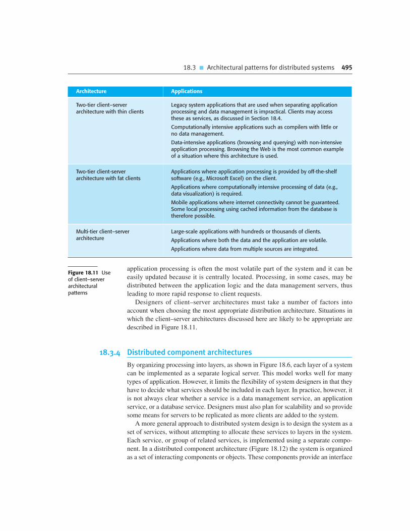
18.3 � Architectural patterns for distributed systems 495
application processing is often the most volatile part of the system and it can be
easily updated because it is centrally located. Processing, in some cases, may be
distributed between the application logic and the data management servers, thus
leading to more rapid response to client requests.
Designers of client–server architectures must take a number of factors into
account when choosing the most appropriate distribution architecture. Situations in
which the client–server architectures discussed here are likely to be appropriate are
described in Figure 18.11.
18.3.4 Distributed component architectures
By organizing processing into layers, as shown in Figure 18.6, each layer of a system
can be implemented as a separate logical server. This model works well for many
types of application. However, it limits the flexibility of system designers in that they
have to decide what services should be included in each layer. In practice, however, it
is not always clear whether a service is a data management service, an application
service, or a database service. Designers must also plan for scalability and so provide
some means for servers to be replicated as more clients are added to the system.
A more general approach to distributed system design is to design the system as a
set of services, without attempting to allocate these services to layers in the system.
Each service, or group of related services, is implemented using a separate compo-
nent. In a distributed component architecture (Figure 18.12) the system is organized
as a set of interacting components or objects. These components provide an interface
Architecture Applications
Two-tier client–serverarchitecture with thin clients
Legacy system applications that are used when separating applicationprocessing and data management is impractical. Clients may accessthese as services, as discussed in Section 18.4.
Computationally intensive applications such as compilers with little orno data management.
Data-intensive applications (browsing and querying) with non-intensiveapplication processing. Browsing the Web is the most common exampleof a situation where this architecture is used.
Two-tier client-serverarchitecture with fat clients
Applications where application processing is provided by off-the-shelfsoftware (e.g., Microsoft Excel) on the client.
Applications where computationally intensive processing of data (e.g.,data visualization) is required.
Mobile applications where internet connectivity cannot be guaranteed.Some local processing using cached information from the database istherefore possible.
Multi-tier client–serverarchitecture
Large-scale applications with hundreds or thousands of clients.
Applications where both the data and the application are volatile.
Applications where data from multiple sources are integrated.
Figure 18.11 Useof client–serverarchitecturalpatterns

496 Chapter 18 � Distributed software engineering
to a set of services that they provide. Other components call on these services
through middleware, using remote procedure or method calls.
Distributed component systems are reliant on middleware, which manages com-
ponent interactions, reconciles differences between types of the parameters passed
between components, and provides a set of common services that application com-
ponents can use. CORBA (Orfali et al., 1997) was an early example of such middle-
ware but is now not widely used. It has been largely supplanted by proprietary soft-
ware such as Enterprise Java Beans (EJB) or .NET.
The benefits of using a distributed component model for implementing distrib-
uted systems are the following:
1. It allows the system designer to delay decisions on where and how services
should be provided. Service-providing components may execute on any node of
the network. There is no need to decide in advance whether a service is part of a
data management layer, an application layer, etc.
2. It is a very open system architecture that allows new resources to be added as
required. New system services can be added easily without major disruption to
the existing system.
3. The system is flexible and scalable. New components or replicated components
can be added as the load on the system increases, without disrupting other parts
of the system.
4. It is possible to reconfigure the system dynamically with components migrating
across the network as required. This may be important where there are fluctuating
patterns of demand on services. A service-providing component can migrate to
the same processor as service-requesting objects, thus improving the performance
of the system.
A distributed component architecture can be used as a logical model that allows you
to structure and organize the system. In this case, you think about how to provide appli-
cation functionality solely in terms of services and combinations of services. You then
work out how to provide these services using a set of distributed components. For
Communication Middleware
Comp 1
CommonServices
Comp 2
CommonServices
Comp 3
CommonServices
Comp 4
CommonServices
Client ClientClientClient
Figure 18.12A distributedcomponentarchitecture

18.3 � Architectural patterns for distributed systems 497
example, in a retail application there may be application components concerned with
stock control, customer communications, goods ordering, and so on.
Data mining systems are a good example of a type of system in which a distrib-
uted component architecture is the best architectural pattern to use. A data mining
system looks for relationships between the data that is stored in a number of data-
bases (Figure 18.13). Data mining systems usually pull in information from several
separate databases, carry out computationally intensive processing, and display their
results graphically.
An example of such a data mining application might be a system for a retail busi-
ness that sells food and books. The marketing department wants to find relationships
between a customer’s food and book purchases. For instance, a relatively high pro-
portion of people who buy pizzas might also buy crime novels. With this knowledge,
the business can specifically target customers who make specific food purchases
with information about new novels when they are published.
In this example, each sales database can be encapsulated as a distributed component
with an interface that provides read-only access to its data. Integrator components are
each concerned with specific types of relationships, and they collect information from
all of the databases to try to deduce the relationships. There might be an integrator
component that is concerned with seasonal variations in goods sold, and another that is
concerned with relationships between different types of goods.
Visualizer components interact with integrator components to produce a visuali-
zation or a report on the relationships that have been discovered. Because of the large
volumes of data that are handled, visualizer components normally present their
results graphically. Finally, a display component may be responsible for delivering
the graphical models to clients for final presentation.
A distributed component architecture rather than a layered architecture is appro-
priate for this type of application because you can add new databases to the system
Clients
Database 1
Database 2
Database 3
Integrator 1
Integrator 2
Report gen.
Visualizer
Display
Figure 18.13A distributedcomponentarchitecture for a data mining system
498 Chapter 18 � Distributed software engineering
without major disruption. Each new database is simply accessed by adding another
distributed component. The database access components provide a simplified inter-
face that controls access to the data. The databases that are accessed may reside on
different machines. The architecture also makes it easy to mine new types of rela-
tionship by adding new integrator components.
Distributed component architectures suffer from two major disadvantages:
1. They are more complex to design than client–server systems. Multi-layer
client–server systems appear to be a fairly intuitive way to think about systems.
They reflect many human transactions where people request and receive serv-
ices from other people who specialize in providing these services. By contrast,
distributed component architectures are more difficult for people to visualize
and understand.
2. Standardized middleware for distributed component systems has never been
accepted by the community. Rather different vendors, such as Microsoft and
Sun, have developed different, incompatible middleware. This middleware is
complex and reliance on it increases the overall complexity of distributed com-
ponent systems.
As a result of these problems, service-oriented architectures (discussed in
Chapter 19) are replacing distributed component architectures in many situations.
However, distributed component systems have performance benefits over service-
oriented systems. RPC communications are usually faster than the message-based
interaction used in service-oriented systems. Component-based architectures are
therefore more appropriate for high-throughput systems in which large numbers of
transactions have to be processed quickly.
18.3.5 Peer-to-peer architectures
The client–server model of computing that I have discussed in previous sections of
the chapter makes a clear distinction between servers, which are providers of serv-
ices and clients, which are receivers of services. This model usually leads to an
uneven distribution of load on the system, where servers do more work than clients.
This may lead to organizations spending a lot on server capacity while there is
unused processing capacity on the hundreds or thousands of PCs that are used to
access the system servers.
Peer-to-peer (p2p) systems are decentralized systems in which computations may
be carried out by any node on the network. In principle at least, no distinctions are
made between clients and servers. In peer-to-peer applications, the overall system is
designed to take advantage of the computational power and storage available across
a potentially huge network of computers. The standards and protocols that enable
communications across the nodes are embedded in the application itself and each
node must run a copy of that application.

18.3 � Architectural patterns for distributed systems 499
Peer-to-peer technologies have mostly been used for personal rather than business
systems (Oram, 2001). For example, file-sharing systems based on the Gnutella and
BitTorrent protocols are used to exchange files on users’ PCs. Instant messaging sys-
tems such as ICQ and Jabber provide direct communications between users without
an intermediate server. SETI@home is a long-running project to process data from
radio telescopes on home PCs to search for indications of extraterrestrial life.
Freenet is a decentralized database that has been designed to make it easier to pub-
lish information anonymously, and to make it difficult for authorities to suppress this
information. Voice over IP (VOIP) phone services, such as Skype, rely on peer-to-
peer communication between the parties involved in the phone call or conference.
However, peer-to-peer systems are also being used by businesses to harness the
power in their PC networks (McDougall, 2000). Intel and Boeing have both imple-
mented p2p systems for computationally intensive applications. This takes advan-
tage of unused processing capacity on local computers. Instead of buying expensive
high-performance hardware, engineering computations can be run overnight when
desktop computers are unused. Businesses also make extensive use of commercial
p2p systems, such as messaging and VOIP systems.
It is appropriate to use a peer-to-peer architectural model for a system in two cir-
cumstances:
1. Where the system is computationally intensive and it is possible to separate the
processing required into a large number of independent computations. For
example, a peer-to-peer system that supports computational drug discovery dis-
tributes computations that look for potential cancer treatments by analyzing a
huge number of molecules to see if they have the characteristics required to sup-
press the growth of cancers. Each molecule can be considered separately so
there is no need for the peers in the system to communicate.
2. Where the system primarily involves the exchange of information between individ-
ual computers on a network and there is no need for this information to be centrally
stored or managed. Examples of such applications include file-sharing systems that
allow peers to exchange local files such as music and video files, and phone sys-
tems that support voice and video communications between computers.
In principle, every node in a p2p network could be aware of every other node.
Nodes could connect to and exchange data directly with any other node in the net-
work. In practice, of course, this is impossible, so nodes are organized into ‘locali-
ties’ with some nodes acting as bridges to other node localities. Figure 18.14 shows
this decentralized p2p architecture.
In a decentralized architecture, the nodes in the network are not simply functional
elements but are also communications switches that can route data and control sig-
nals from one node to another. For example, assume that Figure 18.14 represents a
decentralized, document-management system. This system is used by a consortium
of researchers to share documents, and each member of the consortium maintains his
or her own document store. However, when a document is retrieved, the node retriev-
ing that document also makes it available to other nodes.
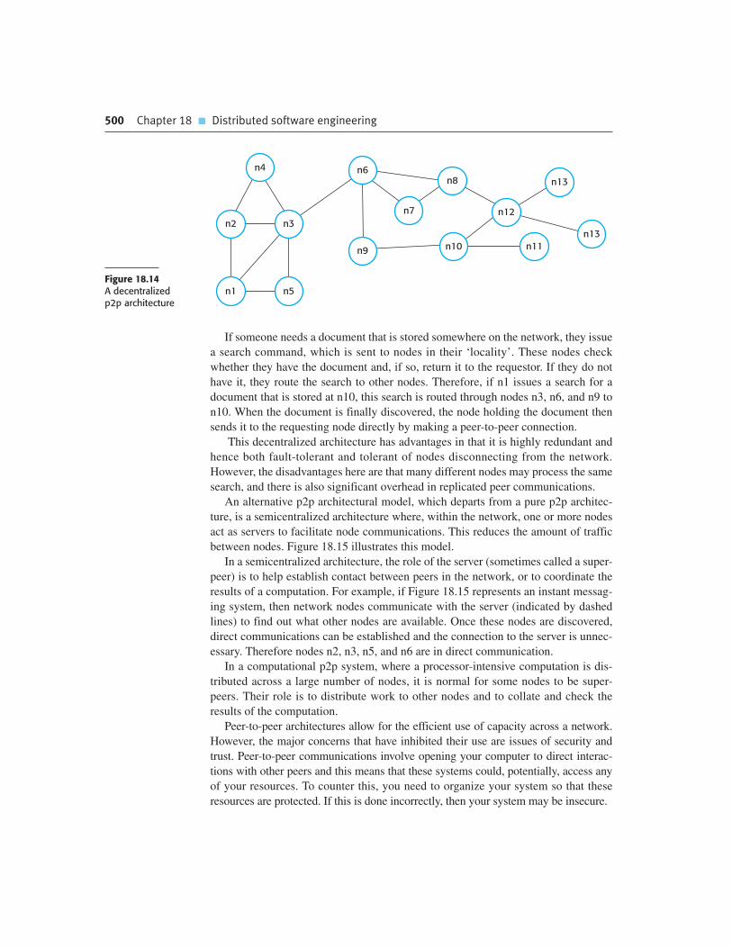
500 Chapter 18 � Distributed software engineering
If someone needs a document that is stored somewhere on the network, they issue
a search command, which is sent to nodes in their ‘locality’. These nodes check
whether they have the document and, if so, return it to the requestor. If they do not
have it, they route the search to other nodes. Therefore, if n1 issues a search for a
document that is stored at n10, this search is routed through nodes n3, n6, and n9 to
n10. When the document is finally discovered, the node holding the document then
sends it to the requesting node directly by making a peer-to-peer connection.
This decentralized architecture has advantages in that it is highly redundant and
hence both fault-tolerant and tolerant of nodes disconnecting from the network.
However, the disadvantages here are that many different nodes may process the same
search, and there is also significant overhead in replicated peer communications.
An alternative p2p architectural model, which departs from a pure p2p architec-
ture, is a semicentralized architecture where, within the network, one or more nodes
act as servers to facilitate node communications. This reduces the amount of traffic
between nodes. Figure 18.15 illustrates this model.
In a semicentralized architecture, the role of the server (sometimes called a super-
peer) is to help establish contact between peers in the network, or to coordinate the
results of a computation. For example, if Figure 18.15 represents an instant messag-
ing system, then network nodes communicate with the server (indicated by dashed
lines) to find out what other nodes are available. Once these nodes are discovered,
direct communications can be established and the connection to the server is unnec-
essary. Therefore nodes n2, n3, n5, and n6 are in direct communication.
In a computational p2p system, where a processor-intensive computation is dis-
tributed across a large number of nodes, it is normal for some nodes to be super-
peers. Their role is to distribute work to other nodes and to collate and check the
results of the computation.
Peer-to-peer architectures allow for the efficient use of capacity across a network.
However, the major concerns that have inhibited their use are issues of security and
trust. Peer-to-peer communications involve opening your computer to direct interac-
tions with other peers and this means that these systems could, potentially, access any
of your resources. To counter this, you need to organize your system so that these
resources are protected. If this is done incorrectly, then your system may be insecure.
n4
n2 n3
n6
n7
n10
n8
n12
n11n13
n13
n9
n1 n5Figure 18.14A decentralizedp2p architecture

18.4 � Software as a service 501
Problems may also occur when peers on a network deliberately behave in a mali-
cious way. For example, there have been cases where music companies who believe
that their copyright is being abused have deliberately made ‘poisoned peers’ avail-
able. When another peer downloads what they think is a piece of music, the actual
file delivered is malware that may be a deliberately corrupted version of the music or
a warning to the user of copyright infringement.
18.4 Software as a service
In the previous sections, I discussed client–server models and how functionality may
be distributed between the client and the server. To implement a client–server sys-
tem, you may have to install a program on the client computer, which communicates
with the server, implements client-side functionality and manages the user interface.
For example, a mail client, such as Outlook or Mac Mail, provides mail management
features on your own computer. This avoids the problem of some thin-client systems
where all of the processing is carried out at the server.
However, the problems of server overload can be significantly reduced by using a
modern browser as the client software. Web technologies, such as AJAX (Holdener,
2008), support efficient management of web page presentation and local computa-
tion through scripts. This means that a browser can be configured and used as a
client, with significant local processing. The application software can be thought of
as a remote service, which can be accessed from any device that can run a standard
browser. Well-known examples of this are web-based mail systems, such as Yahoo!
and Gmail and office applications, such as Google docs.
This notion of SaaS involves hosting the software remotely and providing access
to it over the Internet. The key elements of SaaS are the following:
1. Software is deployed on a server (or more commonly a number of servers) and
is accessed through a web browser. It is not deployed on a local PC.
2. The software is owned and managed by a software provider, rather than the
organizations using the software.
n1
n6
n2
n3
n5
n4
Discovery Server(Super-Peer)
Figure 18.15A semicentralizedp2p architecture

502 Chapter 18 � Distributed software engineering
3. Users may pay for the software according to the amount of use they make of it
or through an annual or monthly subscription. Sometimes, the software is free
for anyone to use but users must then agree to accept advertisements, which
fund the software service.
For software users, the benefit of SaaS is that the costs of management of
software are transferred to the provider. The provider is responsible for fixing bugs
and installing software upgrades, dealing with changes to the operating system
platform, and ensuring that hardware capacity can meet demand. Software licence
management costs are zero. If someone has several computers, there is no need to
licence software for all of these. If a software application is only used occasionally,
the pay-per-use model may be cheaper than buying an application. The software may
be accessed from mobile devices, such as smart phones, from anywhere in the world.
Of course, this model of software provision has some disadvantages. The main
problem, perhaps, is the costs of data transfer to the remote service. Data transfer
takes place at network speeds and so transferring a large amount of data takes a lot of
time. You may also have to pay the service provider according to the amount trans-
ferred. Other problems are lack of control over software evolution (the provider may
change the software when they wish) and problems with laws and regulations. Many
countries have laws governing the storage, management, preservation, and accessi-
bility of data and moving data to a remote service may breach these laws.
The notion of SaaS and service-oriented architectures (SOAs), discussed in
Chapter 19, are obviously related but they are not the same:
1. SaaS is a way of providing functionality on a remote server with client access
through a web browser. The server maintains the user’s data and state during an
interaction session. Transactions are usually long transactions (e.g., editing a
document).
2. SOA is an approach to structuring a software system as a set of separate, state-
less services. These may be provided by multiple providers and may be distrib-
uted. Typically, transactions are short transactions where a service is called,
does something, and then returns a result.
SaaS is a way of delivering application functionality to users, whereas SOA is an
implementation technology for application systems. The functionality implemented
using SOA need not appear to users as services. Similarly, user services do not have to
be implemented using SOA. However, if SaaS is implemented using SOA, it becomes
possible for applications to use service APIs to access the functionality of other applica-
tions. They can then be integrated into more complex systems. These are called
mashups and represent another approach to software reuse and rapid software
development.
From a software development perspective, the process of service development
has much in common with other types of software development. However, service
construction is not usually driven by user requirements, but by the service provider’s
assumptions about what users need. The software therefore needs to be able to
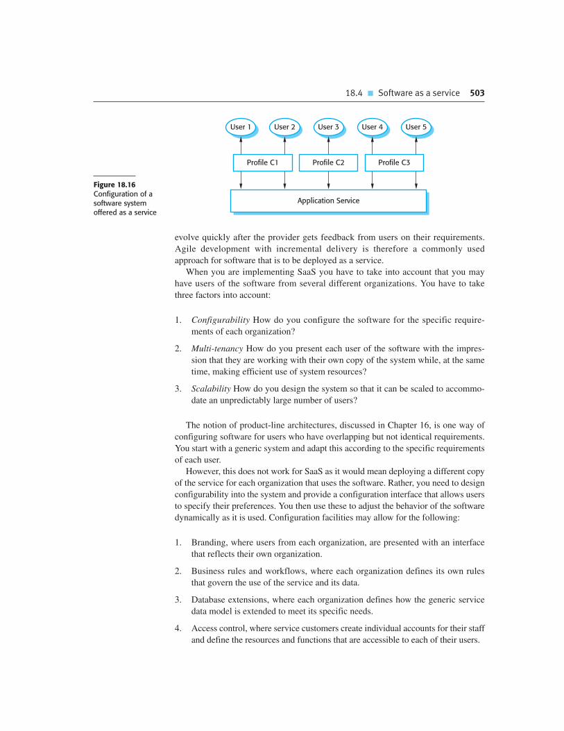
18.4 � Software as a service 503
evolve quickly after the provider gets feedback from users on their requirements.
Agile development with incremental delivery is therefore a commonly used
approach for software that is to be deployed as a service.
When you are implementing SaaS you have to take into account that you may
have users of the software from several different organizations. You have to take
three factors into account:
1. Configurability How do you configure the software for the specific require-
ments of each organization?
2. Multi-tenancy How do you present each user of the software with the impres-
sion that they are working with their own copy of the system while, at the same
time, making efficient use of system resources?
3. Scalability How do you design the system so that it can be scaled to accommo-
date an unpredictably large number of users?
The notion of product-line architectures, discussed in Chapter 16, is one way of
configuring software for users who have overlapping but not identical requirements.
You start with a generic system and adapt this according to the specific requirements
of each user.
However, this does not work for SaaS as it would mean deploying a different copy
of the service for each organization that uses the software. Rather, you need to design
configurability into the system and provide a configuration interface that allows users
to specify their preferences. You then use these to adjust the behavior of the software
dynamically as it is used. Configuration facilities may allow for the following:
1. Branding, where users from each organization, are presented with an interface
that reflects their own organization.
2. Business rules and workflows, where each organization defines its own rules
that govern the use of the service and its data.
3. Database extensions, where each organization defines how the generic service
data model is extended to meet its specific needs.
4. Access control, where service customers create individual accounts for their staff
and define the resources and functions that are accessible to each of their users.
User 3User 2User 1 User 4 User 5
Application Service
Profile C1 Profile C2 Profile C3
Figure 18.16Configuration of asoftware system offered as a service

504 Chapter 18 � Distributed software engineering
Figure 18.16 illustrates this situation. This diagram shows five users of the appli-
cation service, who work for three different customers of the service provider. Users
interact with the service through a customer profile that defines the service configu-
ration for their employer.
Multi-tenancy is a situation in which many different users access the same system
and the system architecture is defined to allow the efficient sharing of system
resources. However, it must appear to each user that they have the sole use of the
system. Multi-tenancy involves designing the system so that there is an absolute sep-
aration between the system functionality and the system data. You should, therefore,
design the system so that all operations are stateless. Data should either be provided
by the client or should be available in a storage system or database that can be
accessed from any system instance. Relational databases are not ideal for providing
multi-tenancy and large service providers, such as Google, have implemented a sim-
pler database for user data.
A particular problem in multi-tenant systems is data management. The simplest
way to provide data management is for each customer to have their own database,
which they may use and configure as they wish. However, this requires the service
provider to maintain many different database instances (one per customer) and to
make these available on demand. This is inefficient in terms of server capacity and
increases the overall cost of the service.
As an alternative, the service provider can use a single database with different
users being virtually isolated within that database. This is illustrated in Figure 18.17,
where you can see that database entries also have a ‘tenant identifier’, which links
these entries to specific users. By using database views, you can extract the entries
for each service customer and so present users from that customer with a virtual, per-
sonal database. This can be extended to meet specific customer needs using the con-
figuration features discussed above.
Scalability is the ability of the system to cope with increasing numbers of users
without reducing the overall QoS that is delivered to any user. Generally, when con-
sidering scalability in the context of SaaS, you are considering ‘scaling out’, rather
than ‘scaling up’. Recall that ‘scaling out’ means adding additional servers and so
also increasing the number of transactions that can be processed in parallel.
Scalability is a complex topic that I cannot cover in detail here, but some general
guidelines for implementing scalable software are:
1. Develop applications where each component is implemented as a simple state-
less service that may be run on any server. In the course of a single transaction,
Tenant Key Name Address
234 C100 XYZ Corp 43, Anystreet, Sometown
234 C110 BigCorp 2, Main St, Motown
435 X234 J. Bowie 56, Mill St, Starville
592 PP37 R. Burns Alloway, Ayrshire
Figure 18.17A multi-tenant database

Chapter 18 � Key points 505
a user may therefore interact with instances of the same service that are running
on several different servers.
2. Design the system using asynchronous interaction so that the application does
not have to wait for the result of an interaction (such as a read request). This
allows the application to carry on doing useful work while it is waiting for the
interaction to finish.
3. Manage resources, such as network and database connections, as a pool so that
no single server is likely to run out of resources.
4. Design your database to allow fine-grain locking. That is, do not lock out whole
records in the database when only part of a record is in use.
The notion of SaaS is a major paradigm shift for distributed computing. Rather
than an organization hosting multiple applications on their servers, SaaS allows
these applications to be externally provided by different vendors. We are in the midst
of a transition from one model to another and, in the future, this is likely to have a
very significant effect on the engineering of enterprise software systems.
K E Y P O I N T S
� The benefits of distributed systems are that they can be scaled to cope with increasing demand,
can continue to provide user services (even if some parts of the system fail), and they enable
resources to be shared.
� Issues to be considered in the design of distributed systems include transparency, openness,
scalability, security, quality of service, and failure management.
� Client–server systems are distributed systems in which the system is structured into layers, with
the presentation layer implemented on a client computer. Servers provide data management,
application, and database services.
� Client–server systems may have several tiers, with different layers of the system distributed to
different computers.
� Architectural patterns for distributed systems include master-slave architectures, two-tier and multi-
tier client–server architectures, distributed component architectures, and peer-to-peer architectures.
� Distributed component systems require middleware to handle component communications and to
allow components to be added to and removed from the system.
� Peer-to-peer architectures are decentralized architectures in which there are no distinguished
clients and servers. Computations can be distributed over many systems in different organizations.
� Software as a service is a way of deploying applications as thin client–server systems, where the
client is a web browser.
506 Chapter 18 � Distributed software engineering
F U RT H E R R E A D I N G
‘Middleware: A model for distributed systems services ’. Although a little dated in places, this is an
excellent overview paper that summarizes the role of middleware in distributed systems and
discusses the range of middleware services that may be provided. (P. A. Bernstein, Comm. ACM,
39 (2), February 1996.) http://dx.doi.org/10.1145/230798.230809.
Peer-to-Peer: Harnessing the Power of Disruptive Technologies. Although this book does not have a
lot of information on p2p architectures, it is an excellent introduction to p2p computing and discusses
the organization and approach used in a number of p2p systems. (A. Oram (ed.), O’Reilly and
Associates Inc., 2001.)
‘Turning software into a service ’. A good overview paper that discusses the principles of service-
oriented computing. Unlike many papers on this topic, it does not conceal these principles behind a
discussion of the standards involved. (M. Turner, D. Budgen and P. Brereton, IEEE Computer, 36 (10),
October 2003.) http://dx.doi.org/10.1109/MC.2003.1236470.
Distributed Systems: Principles and Paradigms, 2nd edition. A comprehensive textbook that
discusses all aspects of distributed systems design and implementation. However, it does not include
much discussion of the service-oriented paradigm. (A.S. Tanenbaum and M. Van Steen, Addison-
Wesley, 2007.)
‘Software as a Service; The Spark that will Change Software Engineering. ’ A short paper that argues
that the advent of SaaS will push all software development to an iterative model. (G. Goth,
Distributed Systems Online, 9 (7), July 2008.) http://dx.doi.org/10.1109/MDSO.2008.21.
E X E R C I S E S
18.1. What do you understand by ‘scalability ’? Discuss the differences between ‘scaling up’ and
‘scaling out’ and explain when these different approaches to scalability may be used.
18.2. Explain why distributed software systems are more complex than centralized software systems,
where all of the system functionality is implemented on a single computer.
18.3. Using an example of a remote procedure call, explain how middleware coordinates the
interaction of computers in a distributed system.
18.4. What is the fundamental difference between a fat-client and a thin-client approach to
client–server systems architectures?
18.5. You have been asked to design a secure system that requires strong authentication and
authorization. The system must be designed so that communications between parts of the
system cannot be intercepted and read by an attacker. Suggest the most appropriate
client–server architecture for this system and, giving reasons for your answer, propose how
functionality should be distributed between the client and the server systems.
18.6. Your customer wants to develop a system for stock information where dealers can access
information about companies and evaluate various investment scenarios using a simulation

Chapter 18 � References 507
system. Each dealer uses this simulation in a different way, according to his or her experience and
the type of stocks in question. Suggest a client–server architecture for this system that shows
where functionality is located. Justify the client–server system model that you have chosen.
18.7. Using a distributed component approach, propose an architecture for a national theater
booking system. Users can check seat availability and book seats at a group of theaters. The
system should support ticket returns so that people may return their tickets for last-minute
resale to other customers.
18.8. Give two advantages and two disadvantages of decentralized and semicentralized peer-to-peer
architectures.
18.9. Explain why deploying software as a service can reduce the IT support costs for a company.
What additional costs might arise if this deployment model is used?
18.10. Your company wishes to move from using desktop applications to accessing the same
functionality remotely as services. Identify three risks that might arise and suggest how these
risks may be reduced.
R E F E R E N C E S
Bernstein, P. A. (1996). ‘Middleware: A Model for Distributed System Services’. Comm. ACM, 39 (2),
86–97.
Coulouris, G., Dollimore, J. and Kindberg, T. (2005). Distributed Systems: Concepts and Design, 4th
edition. Harlow, UK.: Addison-Wesley.
Holdener, A. T. (2008). Ajax: The Definitive Guide. Sebastopol, Calif.: O’Reilly and Associates.
McDougall, P. (2000). ‘The Power of Peer-To-Peer’. Information Week (August 28th, 2000).
Neuman, B. C. (1994). ‘Scale in Distributed Systems’. In Readings in Distributed Computing Systems.
Casavant, T. and Singal, M. (ed.). Los Alamitos, Calif.: IEEE Computer Society Press.
Oram, A. (2001). ‘Peer-to-Peer: Harnessing the Benefits of a Disruptive Technology’.
Orfali, R. and Harkey, D. (1998). Client/server Programming with Java and CORBA. New York: John
Wiley & Sons.
Orfali, R., Harkey, D. and Edwards, J. (1997). Instant CORBA. Chichester, UK: John Wiley & Sons.
Pope, A. (1997). The CORBA Reference Guide: Understanding the Common Request Broker
Architecture. Boston: Addison-Wesley.
Tanenbaum, A. S. and Van Steen, M. (2007). Distributed Systems: Principles and Paradigms, 2nd
edition. Upper Saddle River, NJ: Prentice Hall.

Service-orientedarchitecture
19
Objectives
The objective of this chapter is to introduce service-oriented software
architecture as a way of building distributed applications using web
services. When you have read this chapter, you will:
� understand the basic notions of a web service, web service standards,
and service-oriented architecture;
� understand the service engineering process that is intended to
produce reusable web services;
� have been introduced to the notion of service composition as a means
of service-oriented application development;
� understand how business process models may be used as a basis for
the design of service-oriented systems.
Contents
19.1 Services as reusable components
19.2 Service engineering
19.3 Software development with services

Chapter 19 � Service-oriented architecture 509
The development of the Web in the 1990s revolutionized organizational information
exchange. Client computers could gain access to information on remote servers out-
side their own organizations. However, access was solely through a web browser and
direct access to the information by other programs was not practical. This meant that
opportunistic connections between servers where, for example, a program queried a
number of catalogs from different suppliers, were not possible.
To get around this problem, the notion of a web service was proposed. Using a
web service, organizations that wish to make their information accessible to other
programs can do so by defining and publishing a web service interface. This
interface defines the data available and how it can be accessed. More generally, a
web service is a standard representation for some computational or information
resource that can be used by other programs. These may be information resources,
such as a parts catalog; computer resources, such as a specialized processor; or
storage resources. For example, an archive service could be implemented that
permanently and reliably stores organizational data that, by law, has to be
maintained for many years.
A web service is an instance of a more general notion of a service, which is
defined (Lovelock et al., 1996) as:
“an act or performance offered by one party to another. Although the process
may be tied to a physical product, the performance is essentially intangible
and does not normally result in ownership of any of the factors of production”.
The essence of a service, therefore, is that the provision of the service is independ-
ent of the application using the service (Turner et al., 2003). Service providers can
develop specialized services and offer these to a range of service users from different
organizations.
Service-oriented architectures (SOAs) are a way of developing distributed
systems where the system components are stand-alone services, executing on geo-
graphically distributed computers. Standard XML-based protocols, such as SOAP
and WSDL, have been designed to support service communication and information
exchange. Consequently, services are platform and implementation-language inde-
pendent. Software systems can be constructed by composing local services and
external services from different providers, with seamless interaction between the
services in the system.
Figure 19.1 encapsulates the idea of a SOA. Service providers design and
implement services and specify the interface to these services. They also publish
information about these services in an accessible registry. Service requestors
(sometimes called service clients) who wish to make use of a service discover the
specification of that service and locate the service provider. They can then bind
their application to that specific service and communicate with it, using standard
service protocols.
From the outset, there has been an active standardization process for SOA,
working alongside technical developments. All of the major hardware and
software companies are committed to these standards. As a result, SOA have not

510 Chapter 19 � Service-oriented architecture
ServiceRegistry
ServiceProvider
ServiceRequestor
Service
Find Publish
Bind (SOAP)(WSDL)
Figure 19.1 Service-oriented architecture
suffered from the incompatibilities that normally arise with technical innovations,
where different suppliers maintain their proprietary version of the technology.
Figure 19.2 shows the stack of key standards that have been established to support
web services. Because of this early standardization, problems, such as the multiple
incompatible component models in CBSE, discussed in Chapter 17, have not
arisen in service-oriented system development.
Web service protocols cover all aspects of SOAs, from the basic mechanisms
for service information exchange (SOAP) to programming language standards
(WS-BPEL). These standards are all based on XML, a human and machine-readable
notation that allows the definition of structured data where text is tagged with a mean-
ingful identifier. XML has a range of supporting technologies, such as XSD for
schema definition, which are used to extend and manipulate XML descriptions. Erl
(2004) provides a good summary of XML technologies and their role in web services.
Briefly, the key standards for web SOAs are as follows:
1. SOAP This is a message interchange standard that supports the communication
between services. It defines the essential and optional components of messages
passed between services.
2. WSDL The Web Service Definition Language (WSDL) is a standard for service
interface definition. It sets out how the service operations (operation names,
parameters, and their types) and service bindings should be defined.
3. WS-BPEL This is a standard for a workflow language that is used to define
process programs involving several different services. I discuss the notion of
process programs in Section 19.3.
A service discovery standard, UDDI, was also proposed but this has not been
widely adopted. The UDDI (Universal Description, Discovery and Integration)
standard defines the components of a service specification, which may be used to
discover the existence of a service. These include information about the service
provider, the services provided, the location of the WSDL description of the serv-
ice interface, and information about business relationships. The intention was that
this standard would allow companies to set up registries with UDDI descriptions
defining the services that they offered.

Chapter 19 � Service-oriented architecture 511
Transport (HTTP, HTTPS, SMTP, ...)
Messaging (SOAP)
Service Definition (UDDI, WSDL)
Process (WS-BPEL)
Support (WS-Security, WS-Addressing, ...)
XML Technologies (XML, XSD, XSLT, ....)
Figure 19.2 Webservice standards
A number of companies, such as Microsoft, set up UDDI registries in the early
years of the 21st century but these have now all closed. Improvements in search
engine technology have made them redundant. Service discovery using a standard
search engine to search for appropriately commented WSDL descriptions is now the
preferred approach for discovering external services.
The principal SOA standards are supported by a range of supporting standards
that focus on more specialized aspects of SOA. There are a very large number of
supporting standards because they are intended to support SOA in different types of
enterprise application. Some examples of these standards include the following:
1. WS-Reliable Messaging, a standard for message exchange that ensures messages
will be delivered once and once only.
2. WS-Security, a set of standards supporting web service security including stan-
dards that specify the definition of security policies and standards that cover the
use of digital signatures.
3. WS-Addressing, which defines how address information should be represented
in a SOAP message.
4. WS-Transactions, which defines how transactions across distributed services
should be coordinated.
Web service standards are a huge topic and I don’t have space to discuss them in
detail here. I recommend Erl’s books (2004; 2005) for an overview of these standards.
Their detailed descriptions are also available as public documents on the Web.
Current web services standards have been criticized as being ‘heavyweight’ stan-
dards that are over-general and inefficient. Implementing these standards requires a
considerable amount of processing to create, transmit, and interpret the associated
XML messages. For this reason, some organizations, such as Amazon, use a simpler,
more efficient approach to service communication using so-called RESTful services
(Richardson and Ruby, 2007). The RESTful approach supports efficient service
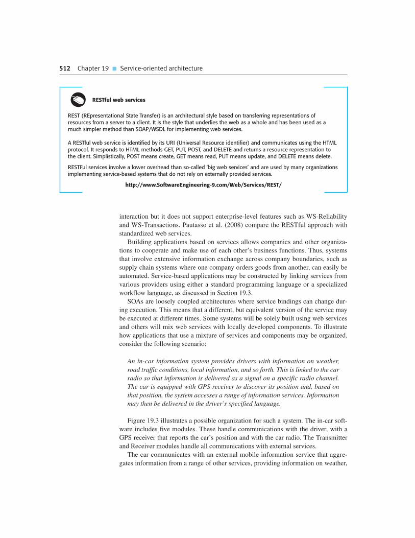
512 Chapter 19 � Service-oriented architecture
interaction but it does not support enterprise-level features such as WS-Reliability
and WS-Transactions. Pautasso et al. (2008) compare the RESTful approach with
standardized web services.
Building applications based on services allows companies and other organiza-
tions to cooperate and make use of each other’s business functions. Thus, systems
that involve extensive information exchange across company boundaries, such as
supply chain systems where one company orders goods from another, can easily be
automated. Service-based applications may be constructed by linking services from
various providers using either a standard programming language or a specialized
workflow language, as discussed in Section 19.3.
SOAs are loosely coupled architectures where service bindings can change dur-
ing execution. This means that a different, but equivalent version of the service may
be executed at different times. Some systems will be solely built using web services
and others will mix web services with locally developed components. To illustrate
how applications that use a mixture of services and components may be organized,
consider the following scenario:
An in-car information system provides drivers with information on weather,
road traffic conditions, local information, and so forth. This is linked to the car
radio so that information is delivered as a signal on a specific radio channel.
The car is equipped with GPS receiver to discover its position and, based on
that position, the system accesses a range of information services. Information
may then be delivered in the driver’s specified language.
Figure 19.3 illustrates a possible organization for such a system. The in-car soft-
ware includes five modules. These handle communications with the driver, with a
GPS receiver that reports the car’s position and with the car radio. The Transmitter
and Receiver modules handle all communications with external services.
The car communicates with an external mobile information service that aggre-
gates information from a range of other services, providing information on weather,
RESTful web services
REST (REpresentational State Transfer) is an architectural style based on transferring representations ofresources from a server to a client. It is the style that underlies the web as a whole and has been used as amuch simpler method than SOAP/WSDL for implementing web services.
A RESTful web service is identified by its URI (Universal Resource identifier) and communicates using the HTMLprotocol. It responds to HTML methods GET, PUT, POST, and DELETE and returns a resource representation tothe client. Simplistically, POST means create, GET means read, PUT means update, and DELETE means delete.
RESTFul services involve a lower overhead than so-called ‘big web services’ and are used by many organizationsimplementing service-based systems that do not rely on externally provided services.
http://www.SoftwareEngineering-9.com/Web/Services/REST/
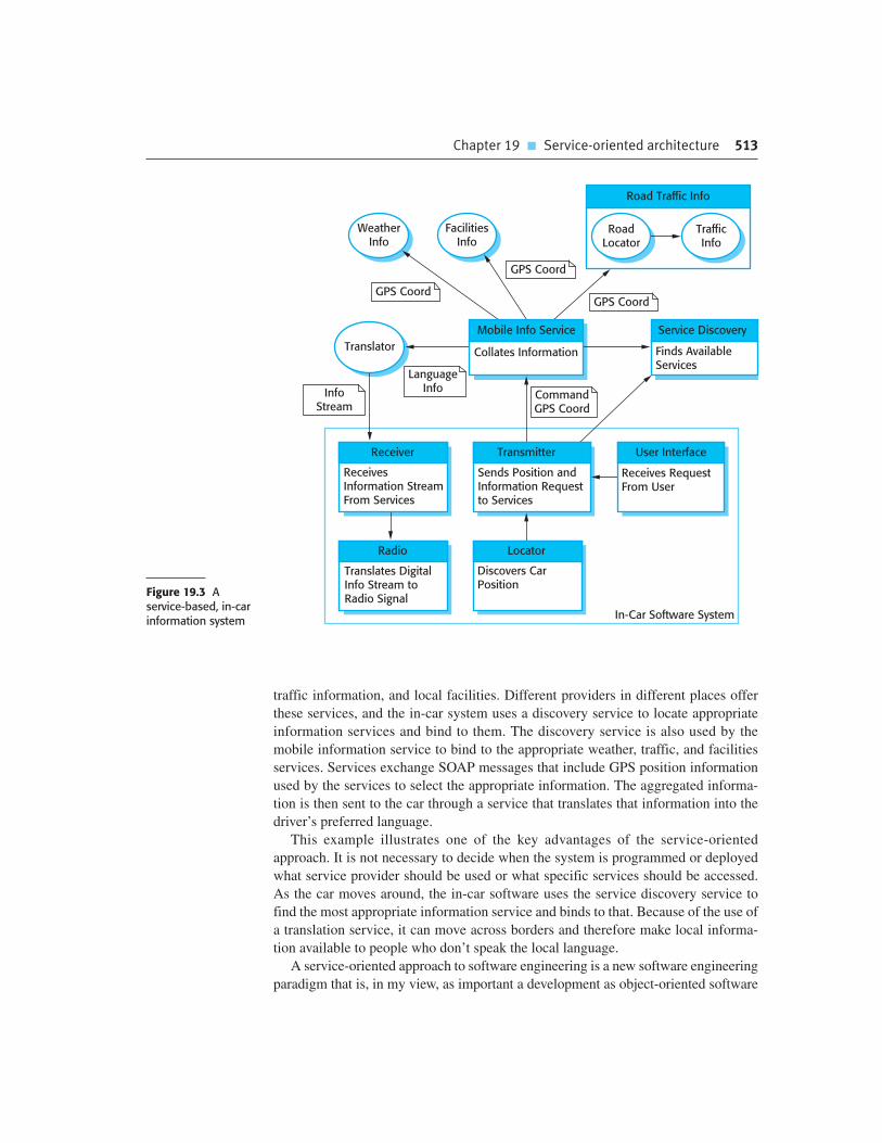
Chapter 19 � Service-oriented architecture 513
traffic information, and local facilities. Different providers in different places offer
these services, and the in-car system uses a discovery service to locate appropriate
information services and bind to them. The discovery service is also used by the
mobile information service to bind to the appropriate weather, traffic, and facilities
services. Services exchange SOAP messages that include GPS position information
used by the services to select the appropriate information. The aggregated informa-
tion is then sent to the car through a service that translates that information into the
driver’s preferred language.
This example illustrates one of the key advantages of the service-oriented
approach. It is not necessary to decide when the system is programmed or deployed
what service provider should be used or what specific services should be accessed.
As the car moves around, the in-car software uses the service discovery service to
find the most appropriate information service and binds to that. Because of the use of
a translation service, it can move across borders and therefore make local informa-
tion available to people who don’t speak the local language.
A service-oriented approach to software engineering is a new software engineering
paradigm that is, in my view, as important a development as object-oriented software
Figure 19.3 Aservice-based, in-carinformation system
WeatherInfo
In-Car Software System
FacilitiesInfo
Translator
CommandGPS Coord
LanguageInfoInfo
Stream
Road Traffic Info
RoadLocator
TrafficInfo
Mobile Info Service
Collates Information
Service Discovery
Finds AvailableServices
Locator
Discovers CarPosition
User Interface
Receives RequestFrom User
Receiver
ReceivesInformation StreamFrom Services
Transmitter
Sends Position andInformation Requestto Services
Radio
Translates DigitalInfo Stream toRadio Signal
GPS Coord
GPS Coord
GPS Coord

514 Chapter 19 � Service-oriented architecture
Service-oriented and component-oriented software engineering
Services and components obviously have much in common. They are both reusable elements and, as I discussed in Chapter 17, it is possible to think of a component as a provider of services. However, there areimportant differences between services and components, and between a service-oriented and a component-oriented approach to software engineering.
http://www.SoftwareEngineering-9.com/Web/Services/Comps.html
engineering. This paradigm shift will be accelerated by the development of ‘cloud
computing’ (Carr, 2009), where services are offered on a utility computing infrastruc-
ture hosted by major providers, such as Google and Amazon. This has had and will
continue to have profound effects on systems products and business processes.
Newcomer and Lomow (2005), in their book on SOA, summarize the potential of
service-oriented approaches:
“Driven by the convergence of key technologies and the universal adoption of
Web services, the service-oriented enterprise promises to significantly improve
corporate agility, speed time-to-market for new products and services, reduce
IT costs and improve operational efficiency.”
We are still at a relatively early stage in the development of service-oriented
applications that are accessed over the Web. However, we are already seeing major
changes in the ways that software is implemented and deployed, with the emergence
of systems such as Google Apps and Salesforce.com. Service-oriented approaches at
both the application and the implementation level means that the Web is evolving
from an information store to a systems implementation platform.
19.1 Services as reusable components
In Chapter 17, I introduced component-based software engineering (CBSE), in
which software systems are constructed by composing software components that are
based on a standard component model. Services are a natural development of soft-
ware components where the component model is, in essence, a set of standards asso-
ciated with web services. A service can therefore be defined as the following:
A loosely-coupled, reusable software component that encapsulates discrete
functionality, which may be distributed and programmatically accessed.
A web service is a service that is accessed using standard Internet and XML-
based protocols.

19.1 � Services as reusable components 515
A critical distinction between a service and a software component, as defined in
CBSE, is that services should be independent and loosely coupled; that is, they
should always operate in the same way, irrespective of their execution environment.
Their interface is a ‘provides’ interface that allows access to the service functional-
ity. Services are intended to be independent and usable in different contexts.
Therefore, they do not have a ‘requires’ interface that, in CBSE, defines the other
system components that must be present.
Services communicate by exchanging messages, expressed in XML, and these mes-
sages are distributed using standard Internet transport protocols such as HTTP and
TCP/IP. I have discussed this message-based approach to component communication
in Section 18.1.1. A service defines what it needs from another service by setting out
its requirements in a message and sending it to that service. The receiving service
parses the message, carries out the computation and, on completion, sends a reply, as a
message, to the requesting service. This service then parses the reply to extract the
required information. Unlike software components, services do not use remote proce-
dure or method calls to access functionality associated with other services.
When you intend to use a web service, you need to know where the service is
located (its URI) and the details of its interface. These are described in a service
description expressed in an XML-based language called WSDL. The WSDL specifi-
cation defines three things about a web service: what the service does, how it
communicates, and where to find it:
1. The ‘what’ part of a WSDL document, called an interface, specifies what oper-
ations the service supports, and defines the format of the messages that are sent
and received by the service.
2. The ‘how’ part of a WSDL document, called a binding, maps the abstract inter-
face to a concrete set of protocols. The binding specifies the technical details of
how to communicate with a web service.
3. The ‘where’ part of a WSDL document describes the location of a specific web
service implementation (its endpoint).
The WSDL conceptual model (Figure 19.4) shows the elements of a service
description. Each of these is expressed in XML and may be provided in separate
files. These parts are:
1. An introductory part that usually defines the XML namespaces used and which
may include a documentation section providing additional information about
the service.
2. An optional description of the types used in the messages exchanged by the
service.
3. A description of the service interface; that is, the operations that the service pro-
vides for other services or users.
4. A description of the input and output messages processed by the service.

516 Chapter 19 � Service-oriented architecture
5. A description of the binding used by the service (i.e., the messaging protocol
that will be used to send and receive messages). The default is SOAP but other
bindings may also be specified. The binding sets out how the input and output
messages associated with the service should be packaged into a message, and
specifies the communication protocols used. The binding may also specify how
supporting information, such as security credentials or transaction identifiers, is
included.
6. An endpoint specification which is the physical location of the service,
expressed as a Uniform Resource Identifier (URI)—the address of a resource
that can be accessed over the Internet.
Complete service descriptions, written in XML, are long, detailed, and tedious to
read. They usually include definitions of XML namespaces, which are qualifiers for
names. A namespace identifier may precede any identifier used in the XML descrip-
tion, making it possible to distinguish between identifiers with the same name that
have been defined in different parts of an XML description. You don’t have to under-
stand the details of namespaces to understand the examples here. You only need to
know that names may be prefixed with a namespace identifier and that the name-
space:name pair should be unique.
WSDL specifications are now rarely written by hand and most of the information
in a specification can be automatically generated. You don’t need to know the details
of a specification to understand the principles of WSDL so I focus here on the
description of the abstract interface. This is the part of a WSDL specification that
equates to the ‘provides’ interface of a software component. Figure 19.5 shows part
of the interface for a simple service that, given a date and a place, specified as a town
within a country, returns the maximum and minimum temperature recorded in that
place on that date. The input message also specifies whether these temperatures are
to be returned in degrees Celsius or degrees Fahrenheit.
In Figure 19.5, the first part of the description shows part of the element and type
definition that is used in the service specification. This defines the elements
PlaceAndDate, MaxMinTemp, and InDataFault. I have only included the specification
of PlaceAndDate, which you can think of as a record with three fields—town, country,
and date. A similar approach would be used to define MaxMinTemp and InDataFault.
WSDL Service Definition
XML Namespace Declarations
Type DeclarationsInterface DeclarationsMessage Declarations
Binding DeclarationsEndpoint Declarations
Intro
Abstract Interface
ConcreteImplementation
Figure 19.4 Organizationof a WSDL specification

19.1 � Services as reusable components 517
The second part of the description shows how the service interface is defined. In
this example, the service weatherInfo has a single operation, although there are no
restrictions on the number of operations that may be defined. The weatherInfo
operation has an associated in-out pattern meaning that it takes one input message
and generates one output message. The WSDL 2.0 specification allows for a
number of different message exchange patterns such as in-only, in-out, out-only,
in-optional-out, out-in, etc. The input and output messages, which refer to the
definitions made earlier in the types section, are then defined.
The major problem with WSDL is that the definition of the service interface does
not include any information about the semantics of the service or its non-functional
characteristics, such as performance and dependability. It is simply a description of
the service signature (i.e., the operations and their parameters). The programmer
Define some of the types used. Assume that the namespace prefix ‘ws’ refers
to the namespace URI for XML schemas and the namespace prefix associated
with this definition is weathns.
<types>
<xs: schema targetNameSpace = “http://.../weathns”
xmlns: weathns = “http://.../weathns” >
<xs:element name = “PlaceAndDate” type = “pdrec” />
<xs:element name = “MaxMinTemp” type = “mmtrec” />
<xs:element name = “InDataFault” type = “errmess” />
<xs:complexType name = “pdrec”
<xs:sequence>
<xs:element name = “town” type = “xs:string”/>
<xs:element name = “country” type = “xs:string”/>
<xs:element name = “day” type = “xs:date” />
</xs:complexType>
Definitions of MaxMinType and InDataFault here
</schema>
</types>
Now define the interface and its operations. In this case, there is only a
single operation to return maximum and minimum temperatures.
<interface name = “weatherInfo” >
<operation name = “getMaxMinTemps” pattern = “wsdlns: in-out”>
<input messageLabel = “In” element = “weathns: PlaceAndDate” />
<output messageLabel = “Out” element = “weathns:MaxMinTemp” />
<outfault messageLabel = “Out” element = “weathns:InDataFault” />
</operation>
</interface>
Figure 19.5 Part ofa WSDL description fora web service

518 Chapter 19 � Service-oriented architecture
who plans to use the service has to work out what the service actually does and what
the different fields in the input and output messages mean. The performance and
dependability have to be discovered by experimenting with the service. Meaningful
names and documentation help with understanding the functionality that is offered
but it is still possible for readers to misunderstand the service.
19.2 Service engineering
Service engineering is the process of developing services for reuse in service-
oriented applications. It has much in common with component engineering. Service
engineers have to ensure that the service represents a reusable abstraction that could
be useful in different systems. They must design and develop generally useful func-
tionality associated with that abstraction and ensure that the service is robust and
reliable. They have to document the service so that it can be discovered and under-
stood by potential users.
There are three logical stages in the service engineering process, as shown in
Figure 19.6. These are as follows:
1. Service candidate identification, where you identify possible services that might
be implemented and define the service requirements.
2. Service design, where you design the logical and WSDL service interfaces.
3. Service implementation and deployment, where you implement and test the
service and make it available for use.
As I discussed in Chapter 16, the development of a reusable component may start
with an existing component that has already been implemented and used in an applica-
tion. The same is true for services—the starting point for this process will often be an
existing service or a component that is to be converted to a service. In this situation, the
design process involves generalizing the existing component so that application-
specific features are removed. Implementation means adapting the component by
adding service interfaces and implementing the required generalizations.
19.2.1 Service candidate identification
The basic notion of service-oriented computing is that services should support
business processes. As every organization has a wide range of processes, there are
therefore many possible services that may be implemented. Service candidate iden-
tification therefore involves understanding and analyzing the organization’s busi-
ness processes to decide which reusable services could be implemented to support
these processes.

19.2 � Service engineering 519
Erl suggests that there are three fundamental types of service that may be identified:
1. Utility services These are services that implement some general functionality
that may be used by different business processes. An example of a utility service
is a currency conversion service that can be accessed to compute the conversion
of one currency (e.g., dollars) to another (e.g., euros).
2. Business services These are services that are associated with a specific business
function. An example of a business function in a university would be the regis-
tration of students for a course.
3. Coordination or process services These are services that support a more general
business process which usually involves different actors and activities. An
example of a coordination service in a company is an ordering service that
allows orders to be placed with suppliers, goods accepted, and payments made.
Erl also suggests that services can be thought of as task-oriented or entity-
oriented. Task-oriented services are those associated with some activity, whereas
entity-oriented services are like objects. They are associated with a business entity
such as, for example, a job application form. Figure 19.7 shows some examples of
services that are task- or entity-oriented. Utility or business services may be entity-or
task-oriented but coordination services are always task-oriented.
Your goal in service candidate identification should be to identify services that
are logically coherent, independent, and reusable. Erl’s classification is helpful in
this respect as it suggests how to discover reusable services by looking at business
entities and business activities. However, identifying service candidates is some-
times difficult because you have to envisage how the services will be used. You have
to think of possible candidates then ask a series of questions about them to see if they
are likely to be useful services. Possible questions that you might ask to identify
potentially reusable services are:
1. For an entity-oriented service, is the service associated with a single logical
entity that is used in different business processes? What operations are normally
performed on that entity that must be supported?
Service DesignService
CandidateIdentification
ServiceImplementationand Deployment
ServiceRequirements
Service InterfaceSpecification
Validated andDeployed ServiceFigure 19.6 The service
engineering process

520 Chapter 19 � Service-oriented architecture
2. For a task-oriented service, is the task one that is carried out by different people
in the organization? Will they be willing to accept the inevitable standardization
that occurs when a single support service is provided?
3. Is the service independent (i.e., to what extent does it rely on the availability of
other services)?
4. For its operation, does the service have to maintain state? Services are stateless,
which means that they do not maintain internal state. If state information is
required, a database has to be used and this can limit service reusability. In gen-
eral, services where the state is passed to the service are easier to reuse, as no
database binding is required.
5. Could the service be used by clients outside of the organization? For example,
an entity-oriented service associated with a catalog could be accessed by both
internal and external users.
6. Are different users of the service likely to have different nonfunctional require-
ments? If they do, then this suggests that more than one version of a service
should perhaps be implemented.
The answers to these questions help you select and refine abstractions that can be
implemented as services. However, there is no formulaic way of deciding which are
the best services and so service identification is a skill- and experience-based process.
The output of the service selection process is a set of identified services and asso-
ciated requirements for these services. The functional service requirements should
define what the service should do. The non-functional requirements should define
the security, performance, and availability requirements of the service.
To help you understand the process of service candidate identification and imple-
mentation, consider the following example:
A large company, which sells computer equipment, has arranged special prices
for approved configurations for some customers. To facilitate automated order-
ing, the company wishes to produce a catalog service that will allow customers
to select the equipment that they need. Unlike a consumer catalog, orders are
not placed directly through a catalog interface. Instead, goods are ordered
through the web-based procurement system of each company that accesses the
catalog as a web service. Most companies have their own budgeting and
Figure 19.7 Serviceclassification
Utility Business Coordination
Task Currency converterEmployee locator
Validate claim formCheck credit rating
Process expense claimPay external supplier
Entity Document style checkerWeb form to XML converter
Expenses formStudent application form

19.2 � Service engineering 521
approval procedures for orders and their own ordering process must be fol-
lowed when an order is placed.
The catalog service is an example of an entity-oriented service that supports busi-
ness operations. The functional catalog service requirements are as follows:
1. A specific version of the catalog shall be provided for each user company. This
shall include the configurations and equipment that may be ordered by employ-
ees of the customer company and the agreed prices for catalog items.
2. The catalog shall allow a customer employee to download a version of the cata-
log for offline browsing.
3. The catalog shall allow users to compare the specifications and prices of up to
six catalog items.
4. The catalog shall provide browsing and search facilities for users.
5. Users of the catalog shall be able to discover the predicted delivery date for a
given number of specific catalog items.
6. Users of the catalog shall be able to place ‘virtual orders’ where the items
required will be reserved for them for 48 hours. Virtual orders must be con-
firmed by a real order placed by a procurement system. This must be received
within 48 hours of the virtual order.
In addition to these functional requirements, the catalog has a number of non-
functional requirements:
1. Access to the catalog service shall be restricted to employees of accredited
organizations.
2. The prices and configurations offered to one customer shall be confidential and
shall not be available to employees of any other customer.
3. The catalog shall be available without disruption of service from 0700 GMT to
1100 GMT.
4. The catalog service shall be able to process up to 10 requests per second peak load.
Notice that there is no non-functional requirement related to the response time of
the catalog service. This depends on the size of the catalog and the expected number
of simultaneous users. As this is not a time-critical service, there is no need to spec-
ify it at this stage.
19.2.2 Service interface design
Once you have selected candidate services, the next stage in the service engineering
process is to design the service interfaces. This involves defining the operations
associated with the service and their parameters. You also have to think carefully

522 Chapter 19 � Service-oriented architecture
about the design of the service operations and messages. Your aim should be to min-
imize the number of message exchanges that must take place to complete the service
request. You have to ensure that as much information as possible is passed to the
service in a message rather than using synchronous service interactions.
You should also remember that services are stateless and managing service-
specific application state is the responsibility of the service user rather than the
service itself. You may, therefore, have to pass this state information to and from
services in input and output messages.
There are three stages to service interface design:
1. Logical interface design, where you identify the operations associated with
the service, their inputs and outputs and the exceptions associated with these
operations.
2. Message design, where you design the structure of the messages that are sent
and received by the service.
3. WSDL development, where you translate your logical and message design to an
abstract interface description written in WSDL.
The first stage, logical interface design, starts with the service requirements and
defines the operation names and parameters. At this stage, you should also define the
exceptions that may arise when a service operation is invoked. Figure 19.8 and
Figure 19.9 show the operations that implement the requirements and the inputs, out-
puts, and exceptions for each of the catalog operations. At this stage, there is no need
for these to be specified in detail—you add detail at the next stage of the design
process.
Defining exceptions and how these can be communicated to service users is par-
ticularly important. Service engineers do not know how their services will be used.
Operation Description
MakeCatalog Creates a version of the catalog tailored for a specific customer. Includes an optionalparameter to create a downloadable PDF version of the catalog.
Compare Provides a comparison of up to six characteristics (e.g., price, dimensions, processorspeed, etc.) of up to four catalog items.
Lookup Displays all of the data associated with a specified catalog item.
Search This operation takes a logical expression and searches the catalog according to thatexpression. It displays a list of all items that match the search expression.
CheckDelivery Returns the predicted delivery date for an item if ordered that day.
MakeVirtualOrder Reserves the number of items to be ordered by a customer and provides iteminformation for the customer’s own procurement system.
Figure 19.8 Functionaldescriptions of catalogservice operations

19.2 � Service engineering 523
It is usually unwise to make assumptions that service users will have completely
understood the service specification. Input messages may be incorrect so you should
define exceptions that report incorrect inputs to the service client. It is generally
good practice in reusable component development to leave all exception handling to
the user of the component. The service developer should not impose their views on
how exceptions should be handled.
Once you have established an informal logical description of what the service
should do, the next stage is to define the structure of the input and output mes-
sages and the types used in these messages. XML is an awkward notation to use
at this stage. I think it is better to represent the messages as objects and either
define them using the UML or in a programming language, such as Java. They
can then be manually or automatically converted to XML. Figure 19.10 shows
the structure of the input and output messages for the getDelivery operation in the
catalog service.
Notice how I have added detail to the description by annotating the UML diagram
with constraints. These define the length of the strings representing the company and
the catalog item, and specify that the number of items must be greater than zero and
that delivery must be after the current date. The annotations also show which error
codes are associated with each possible fault.
The final stage of the service design process is to translate the service inter-
face design into WSDL. As I discussed in the previous section, a WSDL repre-
sentation is long and detailed and hence it is easy to make mistakes at this stage
if you do this manually. However, most programming environments that support
service-oriented development (e.g., the ECLIPSE environment) include tools
that can translate a logical interface description into its corresponding WSDL
representation.
gdIn
cID: stringcatNum: stringnumItems: integer
size (cID) = 6size (catNum) = 10numItems > 0
gdOut
catNum: stringdelivDate: date
size (catNum) = 10delivDate > Today
gdFault
errCode: integer
Invalid company id errCode = 1Invalid catalog number errCode = 2No availability errCode = 3Zero items requested errCode = 4 Figure 19.9 Catalog
interface design

524 Chapter 19 � Service-oriented architecture
19.2.3 Service implementation and deployment
Once you have identified candidate services and designed their interfaces, the final
stage of the service engineering process is service implementation. This implemen-
tation may involve programming the service using a standard programming lan-
guage such as Java or C#. Both of these languages include libraries with extensive
support for service development.
Alternatively, services may be developed by implementing service interfaces to
existing components or, as I discuss below, to legacy systems. This means that software
assets that have already proved to be useful can be made more widely available. In the
case of legacy systems, it may mean that the system functionality can be accessed by
new applications. You can also develop new services by defining compositions of
existing services. I cover this approach to service development in Section 19.3.
Once a service has been implemented, it then has to be tested before it is
deployed. This involves examining and partitioning the service inputs (as explained
Figure 19.10 UMLdefinition of input andoutput messages
Operation Inputs Outputs Exceptions
MakeCatalog mcInCompany idPDF-flag
mcOutURL of the catalog forthat company
mcFaultInvalid company id
Compare compInCompany idEntry attribute (up to 6)Catalog number (up to 4)
compOutURL of page showing
comparison table
compFaultInvalid company idInvalid catalog numberUnknown attribute
Lookup lookInCompany idCatalog number
lookOutURL of page with the
item information
lookFaultInvalid company idInvalid catalog number
Search searchInCompany idSearch string
searchOutURL of web page withsearch results
searchFaultInvalid company idBadly formed search string
CheckDelivery gdInCompany idCatalog number
Number of items required
gdOutCatalog numberExpected delivery date
gdFaultInvalid company idInvalid catalog numberNo availabilityZero items requested
PlaceOrder poInCompany idNumber of items requiredCatalog number
poOutCatalog numberNumber of items
requiredPredicted delivery dateUnit price estimateTotal price estimate
poFaultInvalid company idInvalid catalog numberZero items requested

19.2 � Service engineering 525
in Chapter 8), creating input messages that reflect these input combinations, then
checking that the outputs are expected. You should always try to generate exceptions
during the test to check that the service can cope with invalid inputs. Testing tools
are available that allow services to be examined and tested, and that generate tests
from a WSDL specification. However, these can only test the conformity of the serv-
ice interface to the WSDL. They cannot test that the service’s functional behavior.
Service deployment, the final stage of the process, involves making the service avail-
able for use on a web server. Most server software makes this very simple. You only have
to install the file containing the executable service in a specific directory. It then automat-
ically becomes available for use. If the service is intended to be publicly available, you
then have to provide information for external users of the service. This information helps
potential external users to decide if the service is likely to meet their needs and if they
can trust you, as a service provider, to deliver the service reliably and securely.
Information that you may include in a service description might be the following:
1. Information about your business, contact details, etc. This is important for trust
reasons. Users of a service have to be confident that it will not behave mali-
ciously. Information about the service provider allows them to check their
credentials with business information agencies.
2. An informal description of the functionality provided by the service. This helps
potential users to decide if the service is what they want. However, the func-
tional description is in natural language, so it is not an unambiguous semantic
description of what the service does.
3. A detailed description of the interface types and semantics.
4. Subscription information that allows users to register for information about
updates to the service.
As I have discussed, a general problem with service specifications is that the func-
tional behavior of the service is usually specified informally, as a natural language
description. Natural language descriptions are easy to read, but they are subject to mis-
interpretation. To address this problem, there is an active research community con-
cerned with investigating how the semantics of services may be specified. The most
promising approach to semantic specification is based on an ontology-based descrip-
tion, where the specific meaning of terms in a description is defined in an ontology.
Ontologies are a way of standardizing the ways that terminology is used and they define
the relationships between different terms. They are becoming increasingly used to help
assign semantics to natural language descriptions. A language called OWL-S has been
developed for describing web service ontologies (OWL_Services_Coalition, 2003).
19.2.4 Legacy system services
Legacy systems are old software systems that are used by an organization. Usually,
they rely on obsolete technology but are still essential to the business. It may not be
cost effective to rewrite or replace these systems and many organizations would like

526 Chapter 19 � Service-oriented architecture
to use them in conjunction with more modern systems. One of the most important
uses of services is to implement ‘wrappers’ for legacy systems that provide access to
a system’s functions and data. These systems can then be accessed over the Web and
integrated with other applications.
To illustrate this, imagine that a large company maintains an inventory of its
equipment and an associated database that keeps track of equipment maintenance
and repairs. This keeps track of what maintenance requests have been made for dif-
ferent pieces of equipment, what regular maintenance is scheduled, when mainte-
nance was carried out, how much time was spent on maintenance, etc. This legacy
system was originally used to generate daily job lists for maintenance staff but, over
time, new facilities have been added. These provide data about how much has been
spent on maintenance for each piece of equipment and information to help to cost
maintenance work to be carried out by external contractors. The system runs as a
client–server system with special-purpose client software running on a PC.
The company now wishes to provide real-time access to this system from portable
terminals used by maintenance staff. They will update the system directly with the
time and resources spent on maintenance and will query the system to find their next
maintenance job. In addition, call center staff require access to the system to log
maintenance requests and to check their status.
It is practically impossible to enhance the system to support these requirements so
the company decides to provide new applications for maintenance and call center
staff. These applications rely on the legacy system, which is to be used as a basis for
implementing a number of services. This is illustrated in Figure 19.11, where I have
used a UML stereotype to indicate a service. New applications exchange messages
with these services to access the legacy system functionality.
Some of the services provided are the following:
1. A maintenance service This includes operations to retrieve a maintenance job
according to its job number, priority, and geographical location, and to upload
details of maintenance that has been carried out to the maintenance database.
Maintenance SupportLegacy Application
«service»Maintenance
getJobsuspendJobcompleteJob
«service»Facilities
addEquipmentdeleteEquipmenteditEquipment
«service»Logging
addRequestdeleteRequestqueryRequests
Figure 19.11 Servicesproviding access to alegacy system

19.3 � Software development with services 527
The service also provides operations that allow a maintenance job that has
started but is incomplete to be suspended and restarted.
2. A facilities service This includes operations to add and delete new equipment
and to modify the information associated with equipment in the database.
3. A logging service This includes operations to add a new request for service,
delete maintenance requests, and query the status of outstanding requests.
Notice that the existing legacy system is not simply represented as a single serv-
ice. Rather, the services that are developed to access the legacy system are coherent
and support a single area of functionality. This reduces their complexity and makes
them easier to understand and reuse in other applications.
19.3 Software development with services
The development of software using services is based around the idea that you com-
pose and configure services to create new, composite services. These may be inte-
grated with a user interface implemented in a browser to create a web application, or
may be used as components in some other service composition. The services involved
in the composition may be specially developed for the application, may be business
services developed within a company, or may be services from an external provider.
Many companies are now converting their enterprise applications into service-
oriented systems, where the basic application building block is a service rather than
a component. This opens up the possibility of more widespread reuse within the
company. The next stage will be the development of interorganizational applications
between trusted suppliers, who will use each other’s services. The final realization of
the long-term vision of SOAs will rely on the development of a ‘services market’,
where services are bought from external suppliers.
Service composition may be used to integrate separate business processes to pro-
vide an integrated process offering more extensive functionality. Say an airline
wishes to provide a complete vacation package for travelers. As well as booking
their flights, travelers can also book hotels in their preferred location, arrange car
rentals or book a taxi from the airport, browse a travel guide, and make reservations
to visit local attractions. To create this application, the airline composes its own
booking service with services offered by a hotel booking agency, car rental and taxi
companies, and reservation services offered by owners of local attractions. The end
result is a single service that integrates the services from different providers.
You can think of this process as a sequence of separate steps as shown in
Figure 19.12. Information is passed from one step to the next—for example, the car
rental company is informed of the time that the flight is scheduled to arrive. The
sequence of steps is called a workflow—a set of activities ordered in time, with each
activity carrying out some part of the work. A workflow is a model of a business

528 Chapter 19 � Service-oriented architecture
process (i.e., sets out the steps involved in reaching a particular goal that is important
for a business). In this case, the business process is the vacation booking service,
offered by the airline.
Workflow is a simple idea and the above scenario of booking a vacation seems to
be straightforward. In practice, service composition is much more complex than this
simple model implies. For example, you have to consider the possibility of service
failure and incorporate mechanisms to handle these failures. You also have to take
into account exceptional demands made by users of the application. For example,
say a traveler was disabled and required a wheelchair to be rented and delivered to
the airport. This would require extra services to be implemented and composed, and
additional steps to be added to the workflow.
You must be able to cope with situations where the workflow has to be changed
because the normal execution of one of the services usually results in an incompati-
bility with some other service execution. For example, say a flight is booked to leave
on June 1st and return on June 7th. The workflow then proceeds to the hotel booking
stage. However, the resort is hosting a major convention until June 2nd, so no hotel
rooms are available. The hotel booking service reports this lack of availability. This
is not a failure; lack of availability is a common situation. You, therefore, then have
to ‘undo’ the flight booking and pass the information about lack of availability back
to the user. He or she then has to decide whether to change their dates or their resort.
In workflow terminology, this is called a ‘compensation action’. Compensation
actions are used to undo actions that have already been completed but which must be
changed as a result of later workflow activities.
The process of designing new services by reusing existing services is essentially
a process of software design with reuse (Figure 19.13). Design with reuse inevitably
involves requirements compromises. The ‘ideal’ requirements for the system have to
be modified to reflect the services that are actually available, whose costs fall within
budget and whose quality of service is acceptable.
In Figure 19.13, I have shown six key stages in the process of service construction
by composition:
1. Formulate outline workflow In this initial stage of service design, you use the
requirements for the composite service as a basis for creating an ‘ideal’ service
design. You should create a fairly abstract design at this stage with the intention
of adding details once you know more about available services.
2. Discover services During this stage of the process, you search service registries
or catalogs to discover what services exist, who provides these services, and the
details of the service provision.
BookFlights
BookHotel
ArrangeCar or Taxi
BrowseAttractions
BookAttractions
Arrival/DepartureDates/Times Hotel Location
Dates/PreferencesFigure 19.12 Vacationpackage workflow
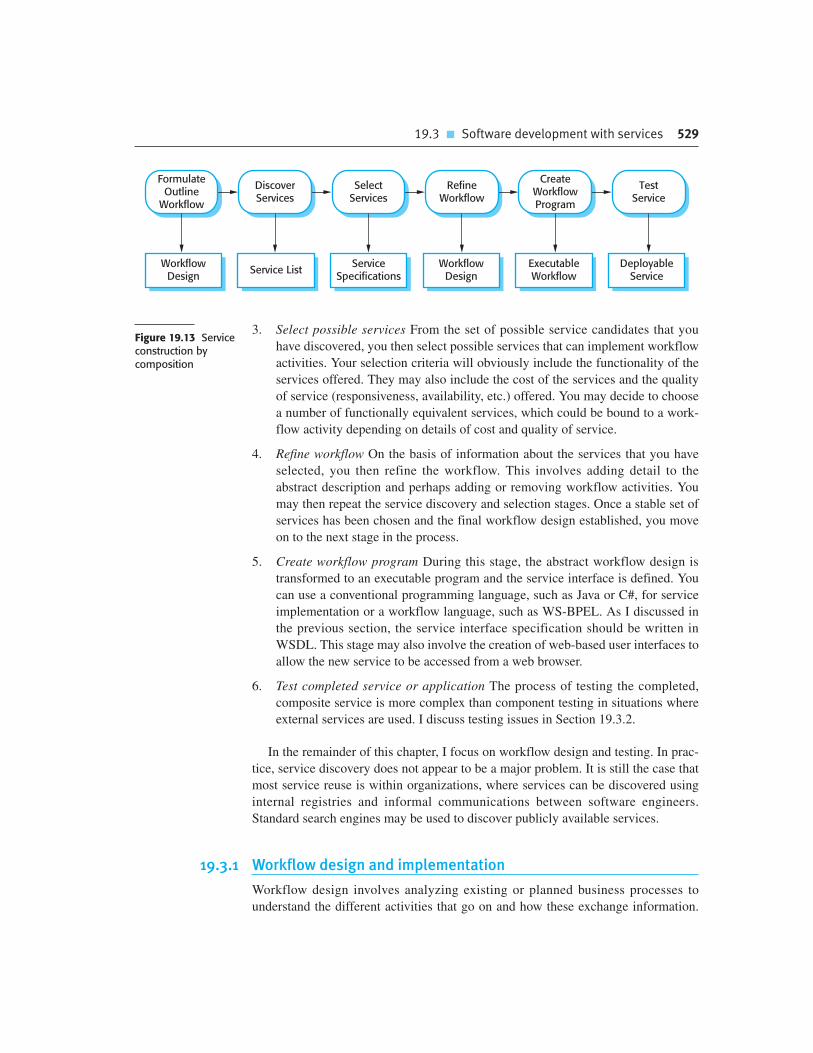
19.3 � Software development with services 529
3. Select possible services From the set of possible service candidates that you
have discovered, you then select possible services that can implement workflow
activities. Your selection criteria will obviously include the functionality of the
services offered. They may also include the cost of the services and the quality
of service (responsiveness, availability, etc.) offered. You may decide to choose
a number of functionally equivalent services, which could be bound to a work-
flow activity depending on details of cost and quality of service.
4. Refine workflow On the basis of information about the services that you have
selected, you then refine the workflow. This involves adding detail to the
abstract description and perhaps adding or removing workflow activities. You
may then repeat the service discovery and selection stages. Once a stable set of
services has been chosen and the final workflow design established, you move
on to the next stage in the process.
5. Create workflow program During this stage, the abstract workflow design is
transformed to an executable program and the service interface is defined. You
can use a conventional programming language, such as Java or C#, for service
implementation or a workflow language, such as WS-BPEL. As I discussed in
the previous section, the service interface specification should be written in
WSDL. This stage may also involve the creation of web-based user interfaces to
allow the new service to be accessed from a web browser.
6. Test completed service or application The process of testing the completed,
composite service is more complex than component testing in situations where
external services are used. I discuss testing issues in Section 19.3.2.
In the remainder of this chapter, I focus on workflow design and testing. In prac-
tice, service discovery does not appear to be a major problem. It is still the case that
most service reuse is within organizations, where services can be discovered using
internal registries and informal communications between software engineers.
Standard search engines may be used to discover publicly available services.
19.3.1 Workflow design and implementation
Workflow design involves analyzing existing or planned business processes to
understand the different activities that go on and how these exchange information.
FormulateOutline
Workflow
WorkflowDesign
DiscoverServices
Service ListService
Specifications
SelectServices
WorkflowDesign
RefineWorkflow
CreateWorkflowProgram
ExecutableWorkflow
TestService
DeployableService
Figure 19.13 Serviceconstruction bycomposition
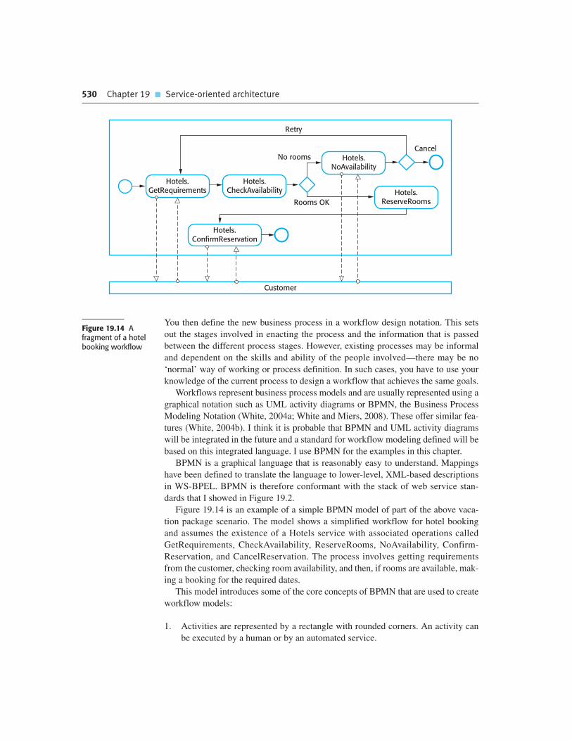
530 Chapter 19 � Service-oriented architecture
You then define the new business process in a workflow design notation. This sets
out the stages involved in enacting the process and the information that is passed
between the different process stages. However, existing processes may be informal
and dependent on the skills and ability of the people involved—there may be no
‘normal’ way of working or process definition. In such cases, you have to use your
knowledge of the current process to design a workflow that achieves the same goals.
Workflows represent business process models and are usually represented using a
graphical notation such as UML activity diagrams or BPMN, the Business Process
Modeling Notation (White, 2004a; White and Miers, 2008). These offer similar fea-
tures (White, 2004b). I think it is probable that BPMN and UML activity diagrams
will be integrated in the future and a standard for workflow modeling defined will be
based on this integrated language. I use BPMN for the examples in this chapter.
BPMN is a graphical language that is reasonably easy to understand. Mappings
have been defined to translate the language to lower-level, XML-based descriptions
in WS-BPEL. BPMN is therefore conformant with the stack of web service stan-
dards that I showed in Figure 19.2.
Figure 19.14 is an example of a simple BPMN model of part of the above vaca-
tion package scenario. The model shows a simplified workflow for hotel booking
and assumes the existence of a Hotels service with associated operations called
GetRequirements, CheckAvailability, ReserveRooms, NoAvailability, Confirm-
Reservation, and CancelReservation. The process involves getting requirements
from the customer, checking room availability, and then, if rooms are available, mak-
ing a booking for the required dates.
This model introduces some of the core concepts of BPMN that are used to create
workflow models:
1. Activities are represented by a rectangle with rounded corners. An activity can
be executed by a human or by an automated service.
Hotels.GetRequirements
Customer
Hotels.CheckAvailability
Hotels.NoAvailability
Hotels.ReserveRooms
Hotels.ConfirmReservation
Retry
Cancel
Rooms OK
No rooms
Figure 19.14 Afragment of a hotelbooking workflow

19.3 � Software development with services 531
2. Events are represented by circles. An event is something that happens during a
business process. A simple circle is used to represent a starting event and a
darker circle to represent an end event. A double circle (not shown) is used to
represent an intermediate event. Events can be clock events, thus allowing
workflows to be executed periodically or timed out.
3. A diamond is used to represent a gateway. A gateway is a stage in the process
where some choice is made. For example, in Figure 19.14, there is a choice
made on the basis of whether rooms are available or not.
4. A solid arrow is used to show the sequence of activities; a dashed arrow repre-
sents message flow between activities. In Figure 19.14, these messages are
passed between the hotel booking service and the customer.
These key features are enough to describe the essence of most workflows.
However, BPMN includes many additional features that I don’t have space to
describe here. These add information to a business process description that allows it
to be automatically translated into an executable service. Therefore, web services,
based on service compositions described in BPMN, can be generated directly from a
business process model.
Figure 19.14 shows the process that is enacted in one organization, the company
that provides a booking service. However, the key benefit of a service-oriented
approach is that it supports interorganizational computing. This means that a compu-
tation involves services in different companies. This is represented in BPMN by
developing separate workflows for each of the organizations involved with interac-
tions between them.
To illustrate this, I use a different example, drawn from high-performance com-
puting. A service-oriented approach has been proposed to allow resources such as
high-performance computers to be shared. In this example, assume that a vector
processing computer (a machine that can carry out parallel computations on arrays
of values) is offered as a service (VectorProcService) by a research laboratory. This
is accessed through another service called SetupComputation. These services and
their interactions are shown in Figure 19.15.
In this example, the workflow for the SetupComputation service requests access
to a vector processor and, if a processor is available, establishes the computation
required and downloads data to the processing service. Once the computation is
complete, the results are stored on the local computer. The workflow for
VectorProcService checks if a processor is available, allocates resources for the
computation, initializes the system, carries out the computation, and returns the
results to the client service.
In BPMN terms, the workflow for each organization is represented in a separate
pool. It is shown graphically by enclosing the workflow for each participant in the
process in a rectangle, with the name written vertically on the left edge. The work-
flows defined in each pool are coordinated by exchanging messages; sequence
flow between the activities in different pools is not allowed. In situations where
different parts of an organization are involved in a workflow, this can be shown by

532 Chapter 19 � Service-oriented architecture
separating pools into named ‘lanes’. Each lane shows the activities in that part of
the organization.
Once a business process model has been designed, this has to be refined depend-
ing on the services that have been discovered. As I suggested in the discussion of
Figure 19.13, the model may go through a number of iterations until a design that
allows the maximum possible reuse of available services has been created.
Once the final design is available, it must then be converted to an executable pro-
gram. This may involve two activities:
1. Implementing the services that are not available for reuse. As services are
implementation-language independent, these services can be written in any lan-
guage. Both Java and C# development environments provide support for web
service composition.
2. Generating an executable version of the workflow model. This normally
involves translating the model into WS-BPEL, either automatically or by hand.
Although there are several tools available to automate the BPMN-WS-BPEL
process, there are some circumstances where it is difficult to generate readable
WS-BPEL code from a workflow model.
To provide direct support for the implementation of web service compositions,
several web service standards have been developed. As I explained in the chapter
introduction, the standard XML-based language is WS-BPEL (Business Process
Execution Language) which is a ‘programming language’ to control interactions
RequestProcessor
Setup JobParameters
DownloadData
StartComputation
StoreResults
ReportCompletion
Restart
Fail
Setu
p C
om
puta
tion
CheckAvailability
AllocateResources
Initialize Compute
ReturnResults
OK
No Processor
OK
Vect
orP
rocS
erv
ice
Figure 19.15Interacting workflows

19.3 � Software development with services 533
between services. This is supported by additional standards such as WS-
Coordination (Cabrera et al., 2005), which is used to specify how services are coor-
dinated, and WS-CDL (Choreography Description Language) (Kavantzas et al.,
2004), which is a means of defining the message exchanges between participants
(Andrews et al., 2003).
19.3.2 Service testing
Testing is important in all system development processes as it demonstrates that a
system meets its functional and non-functional requirements and to detect defects
that have been introduced during the development process. Many testing techniques,
such as program inspections and coverage testing, rely on analysis of the software
source code. However, when services are offered by an external provider, source
code of the service implementation is not available. Service-based system testing
cannot therefore use proven source code–based techniques.
As well as problems of understanding the implementation of the service, testers
may also face further difficulties when testing services and service compositions:
1. External services are under the control of the service provider rather than the
user of the service. The service provider may withdraw these services at any
time or may make changes to them, which invalidates any previous application
testing. These problems are handled in software components by maintaining
different versions of the component. Currently, however, there are no standards
proposed to deal with service versions.
2. The long-term vision of SOAs is for services to be bound dynamically to
service-oriented applications. This means that an application may not always
use the same service each time that it is executed. Therefore, tests may be
successful when an application is bound to a particular service, but it cannot
be guaranteed that that service will be used during an actual execution of the
system.
3. The non-functional behavior of a service is not simply dependent on how it is
used by the application that is being tested. A service may perform well during
testing because it is not operating under a heavy load. In practice, the observed
service behavior may be different because of the demands made by other serv-
ice users.
4. The payment model for services could make service testing very expensive.
There are different possible payment models—some services may be freely
available, some paid for by subscription, and others paid for on a per-use basis.
If services are free, then the service provider will not wish them to be loaded by
applications being tested; if a subscription is required, then a service user may
be reluctant to enter into a subscription agreement before testing the service.
Similarly, if the usage is based on payment for each use, service users may find
the cost of testing to be prohibitive.

534 Chapter 19 � Service-oriented architecture
5. I have discussed the notion of compensation actions that are invoked when an
exception occurs and previous commitments that have been made (such as a
flight reservation) have to be revoked. There is a problem in testing such actions
as they may depend on the failure of other services. Ensuring that these services
actually fail during the testing process may be very difficult.
These problems are particularly acute when external services are used. They are less
serious when services are used within the same company or where cooperating com-
panies trust services offered by their partners. In such cases, source code may be
available to guide the testing process and payment for services is unlikely to be a
problem. Resolving these testing problems and producing guidelines, tools, and tech-
niques for testing service-oriented applications remains an important research issue.
K E Y P O I N T S
� Service-oriented architecture is an approach to software engineering where reusable,
standardized services are the basic building blocks for application systems.
� Service interfaces may be defined in an XML-based language called WSDL. A WSDL specification
includes a definition of the interface types and operations, the binding protocol used by the
service and the service location.
� Services may be classified as utility services that provide a general-purpose functionality,
business services that implement part of a business process, or coordination services that
coordinate the execution of other services.
� The service engineering process involves identifying candidate services for implementation,
defining the service interface and implementing, and testing and deploying the service.
� Service interfaces may be defined for legacy software systems that continue to be useful for an
organization. The functionality of the legacy system may then be reused in other applications.
� The development of software using services is based around the idea that programs are created
by composing and configuring services to create new composite services.
� Business process models define the activities and information exchange that takes place in
a business process. Activities in the business process may be implemented by services so that
the business process model represents a service composition.
F U RT H E R R E A D I N G
There is an immense amount of tutorial material on the Web covering all aspects of web services.
However, I found the following two books by Thomas Erl to be the best overview and description
of services and service standards. Unlike most books, Erl includes some discussion of software

Chapter 19 � Exercises 535
E X E R C I S E S
19.1. What are the most important distinctions between services and software components?
19.2. Explain why SOAs should be based on standards.
19.3. Using the same notation, extend Figure 19.5 to include definitions for MaxMinType and
InDataFault. The temperatures should be represented as integers with an additional field
indicating whether the temperature is in degrees Fahrenheit or degrees Celsius. InDataFault
should be a simple type consisting of an error code.
19.4. Define an interface specification for the Currency Converter and Check credit rating services
shown in Figure 19.7.
19.5. Design possible input and output messages for the services shown in Figure 19.11. You may
specify these in the UML or in XML.
19.6. Giving reasons for your answer, suggest two important types of applications where you
would not recommend the use of service-oriented architecture.
19.7. In Section 19.2.1, I introduced an example of a company that has developed a catalog service
that is used by customers’ web-based procurement systems. Using BPMN, design a workflow
that uses this catalog service to look up and place orders for computer equipment.
19.8. Explain what is meant by a ‘compensation action’ and, using an example, show why these
actions may have to be included in workflows.
19.9. For the example of the vacation package reservation service, design a workflow that will
book ground transportation for a group of passengers arriving at an airport. They should be
given the option of booking either a taxi or renting a car. You may assume that the taxi and
car rental companies offer web services to make a reservation.
19.10. Using an example, explain in detail why the thorough testing of services that include
compensation actions is difficult.
engineering issues in service-oriented computing. He has also written more specialized books on the
design of services and SOA design patterns, although these are generally aimed at readers with
experience of implementing SOA.
Service-Oriented Architecture: A Field Guide to Integrating XML and Web Services. The primary focus
of this book is the underlying XML-based technologies (SOAP, WSDL, BPEL, etc.) that are a framework
for SOA. (T. Erl, Prentice Hall, 2004.)
Service-Oriented Architecture: Concepts, Technology and Design. This is a more general book on
the engineering of service-oriented systems. There is a little bit of overlap with the text above but
Erl mostly concentrates on discussing how a service-oriented approach may be used at all stages of
the software process. (T. Erl, Prentice Hall, 2005.)
‘SOA realization: Service design principles’. This short web article is an excellent overview of the
issues to be considered in designing services. (D. J. N. Artus, IBM, 2006.)
http://www.ibm.com/developerworks/webservices/library/ws-soa-design/.

536 Chapter 19 � Service-oriented architecture
R E F E R E N C E S
Andrews, T., Curbera, F., Goland, Y., Klein, J. and Al., E. (2003). ‘Business Process Execution Language
for Web Services’. http://www-128.ibm.com/developerworks/library/ws-bpel/.
Cabrera, L. F., Copeland, G. and Al., E. 2005. ‘Web Services Coordination (WS-Coordination)’.
ftp://www6.software.ibm.com/software/developer/library/WS-Coordination.pdf.
Carr, N. (2009). The Big Switch: Rewiring the World from Edison to Google, Reprint edition. New York:
W.W. Norton & Co.
Erl, T. (2004). Service-Oriented Architecture: A Field Guide to Integrating XML and Web Services.
Upper Saddle River, NJ: Prentice Hall.
Erl, T. (2005). Service-Oriented Architecture: Concepts, Technology and Design. Upper Saddle River,
NJ: Prentice Hall.
Kavantzas, N., Burdett, D. and Ritzinger, G. 2004. ‘Web Services Choreography Description Language
Version 1.0’. http://www.w3.org/TR/2004/WD-ws-cdl-10-20040427/.
Lovelock, C., Vandermerwe, S. and Lewis, B. (1996). Services Marketing. Englewood Cliffs, NJ: Prentice
Hall.
Newcomer, E. and Lomow, G. (2005). Understanding SOA with Web Services. Boston: Addison-Wesley.
Owl_Services_Coalition. 2003. ‘OWL-S: Semantic Markup for Web Services’.
http://www.daml.org/services/owl-s/1.0/owl-s.pdf.
Pautasso, C., Zimmermann, O. and Leymann, F. (2008). ‘RESTful Web Services vs “Big” Web Services:
Making the Right Architectural Decision’. Proc. WWW 2008, Beijing, China: 805–14.
Richardson, L. and Ruby, S. (2007). RESTful Web Services. Sebastopol, Calif.: O’Reilly Media Inc.
Turner, M., Budgen, D. and Brereton, P. (2003). ‘Turning Software into a Service’. IEEE Computer, 36
(10), 38–45.
White, S. A. (2004a). ‘An Introduction to BPMN’.
http://www.bpmn.org/Documents/Introduction%20to%20BPMN.
White, S. A. (2004b). ‘Process Modelling Notations and Workflow Patterns’. In Workflow Handbook
2004. Fischer, L. (ed.). Lighthouse Point, Fla.: Future Strategies Inc. 265–294.
White, S. A. and Miers, D. (2008). BPMN Modeling and Reference Guide: Understanding and Using
BPMN. Lighthouse Point, Fla.: Future Strategies Inc.
Embedded software
20
Objectives
The objective of this chapter is to introduce some of the characteristic
features of embedded real-time systems and real-time software
engineering. When you have read this chapter, you will:
� understand the concept of embedded software, which is used to
control systems that must react to external events in their
environment;
� have been introduced to a design process for real-time systems, where
the software systems are organized as a set of cooperating processes;
� understand three architectural patterns that are commonly used in
embedded real-time systems design;
� understand the organization of real-time operating systems and the
role that they play in an embedded, real-time system.
Contents
20.1 Embedded systems design
20.2 Architectural patterns
20.3 Timing analysis
20.4 Real-time operating systems

538 Chapter 20 � Embedded software
Computers are used to control a wide range of systems from simple domestic
machines, through games controllers, to entire manufacturing plants. These comput-
ers interact directly with hardware devices. Their software must react to events gen-
erated by the hardware and, often, issue control signals in response to these events.
These signals result in an action, such as the initiation of a phone call, the movement
of a character on the screen, the opening of a valve, or the display of the system
status. The software in these systems is embedded in system hardware, often in read-
only memory, and usually responds, in real time, to events from the system’s envi-
ronment. By real time, I mean that the software system has a deadline for responding
to external events. If this deadline is missed, then the overall hardware–software
system will not operate correctly.
Embedded software is very important economically because almost every electri-
cal device now includes software. There are therefore many more embedded soft-
ware systems than other types of software system. If you look around your house
you may have three or four personal computers. But you probably have 20 or 30
embedded systems, such as systems in phones, cookers, microwaves, etc.
Responsiveness in real time is the critical difference between embedded systems
and other software systems, such as information systems, web-based systems, or per-
sonal software systems, whose main purpose is data processing. For non-real-time
systems, the correctness of a system can be defined by specifying how system inputs
map to corresponding outputs that should be produced by the system. In response to
an input, a corresponding output should be generated by the system and, often, some
data should be stored. For example, if you choose a create command in a patient
information system, then the correct system response is to create a new patient record
in a database, and to confirm that this has been done. Within reasonable limits, it does
not matter how long this takes.
However, in a real-time system, the correctness depends both on the response to
an input and the time taken to generate that response. If the system takes too long to
respond, then the required response may be ineffective. For example, if embedded
software controlling a car braking system is too slow, then an accident may occur
because it is impossible to stop the car in time.
Therefore, time is inherent in the definition of a real-time software system:
A real-time software system is a system whose correct operation depends on
both the results produced by the system and the time at which these results are
produced. A ‘soft real-time system’ is a system whose operation is degraded if
results are not produced according to the specified timing requirements. If
results are not produced according to the timing specification in a ‘hard real-
time system’, this is considered to be a system failure.
Timely response is an important factor in all embedded systems but not all
embedded systems require a very fast response. For example, the insulin pump soft-
ware that I have used as an example in several chapters of this book is an embedded
system. However, although it needs to check the glucose level at periodic intervals, it
does not need to respond very quickly to external events. The wilderness weather

Chapter 20 � Embedded software 539
station software is also an embedded system but, again, it does not require a fast
response to external events.
As well as the need for real-time response, there are other important differences
between embedded systems and other types of software system:
1. Embedded systems generally run continuously and do not terminate. They start
when the hardware is switched on and must execute until the hardware is
switched off. This means that techniques for reliable software engineering, as
discussed in Chapter 13, may have to be used to ensure continuous operation.
The real-time system may include update mechanisms that support dynamic
reconfiguration so that the system can be updated while it is in service.
2. Interactions with the system’s environment are uncontrollable and unpre-
dictable. In interactive systems, the pace of the interaction is controlled by the
system and, by limiting user options, the events to be processed are known in
advance. By contrast, real-time embedded systems must be able to respond to
unexpected events at any time. This leads to a design for real-time systems
based on concurrency, with several processes executing in parallel.
3. There may be physical limitations that affect the design of a system. Examples
of these include limitations on the power available to the system and on the
physical space taken up by the hardware. These limitations may generate
requirements for the embedded software, such as the need to conserve power
and so prolong battery life. Size and weight limitations may mean that the soft-
ware has to take over some hardware functions because of the need to limit the
number of chips used in the system.
4. Direct hardware interaction may be necessary. In interactive systems and infor-
mation systems, there is a layer of software (the device drivers) that hides the
hardware from the operating system. This is possible because you can only con-
nect a few types of device to these systems, such as keyboards, mice, displays,
etc. By contrast, embedded systems may have to interact with a wide range of
hardware devices that do not have separate device drivers.
5. Issues of safety and reliability may dominate the system design. Many embed-
ded systems control devices whose failure may have high human or economic
costs. Therefore, dependability is critical and the system design has to ensure
safety-critical behavior at all times. This often leads to a conservative approach
to design where tried and tested techniques are used instead of newer techniques
that may introduce new failure modes.
Embedded systems can be thought of as reactive systems; that is, they must react
to events in their environment at the speed of that environment (Berry, 1989; Lee,
2002). Response times are often governed by the laws of physics rather than chosen
for human convenience. This is in contrast to other types of software where the sys-
tem controls the speed of the interaction. For example, the word processor that I am
540 Chapter 20 � Embedded software
using to write this book can check spelling and grammar and there are no practical
limits on the time taken to do this.
20.1 Embedded systems design
The design process for embedded systems is a systems engineering process in
which the software designers have to consider in detail the design and perform-
ance of the system hardware. Part of the system design process may involve
deciding which system capabilities are to be implemented in software and which
in hardware. For many real-time systems embedded in consumer products, such
as the systems in cell phones, the costs, and power consumption of the hardware
are critical. Specific processors designed to support embedded systems may be
used and, for some systems, special-purpose hardware may have to be designed
and built.
This means that a top-down software design process, in which the design starts
with an abstract model that is decomposed and developed in a series of stages, is
impractical for most real-time systems. Low-level decisions on hardware, support
software, and system timing must be considered early in the process. These limit the
flexibility of system designers and may mean that additional software functionality,
such as battery and power management, has to be included in the system.
Given that embedded systems are reactive systems that react to events in their
environment, the most general approach to embedded, real-time software design is
based on a stimulus-response model. A stimulus is an event occurring in the software
system’s environment that causes the system to react in some way; a response is a
signal or message that is sent by the software to its environment.
You can define the behavior of a real-time system by listing the stimuli received
by the system, the associated responses, and the time at which the response must be
produced. For example, Figure 20.1 shows possible stimuli and system responses for
a burglar alarm system. I give more information about this system in Section 20.2.1.
Stimuli fall into two classes:
1. Periodic stimuli These occur at predictable time intervals. For example, the sys-
tem may examine a sensor every 50 milliseconds and take action (respond)
depending on that sensor value (the stimulus).
2. Aperiodic stimuli These occur irregularly and unpredictably and are usually sig-
naled using the computer’s interrupt mechanism. An example of such a stimulus
would be an interrupt indicating that an I/O transfer was complete and that data
was available in a buffer.
Stimuli come from sensors in the system’s environment and responses are sent to
actuators, as shown in Figure 20.2. A general design guideline for real-time systems
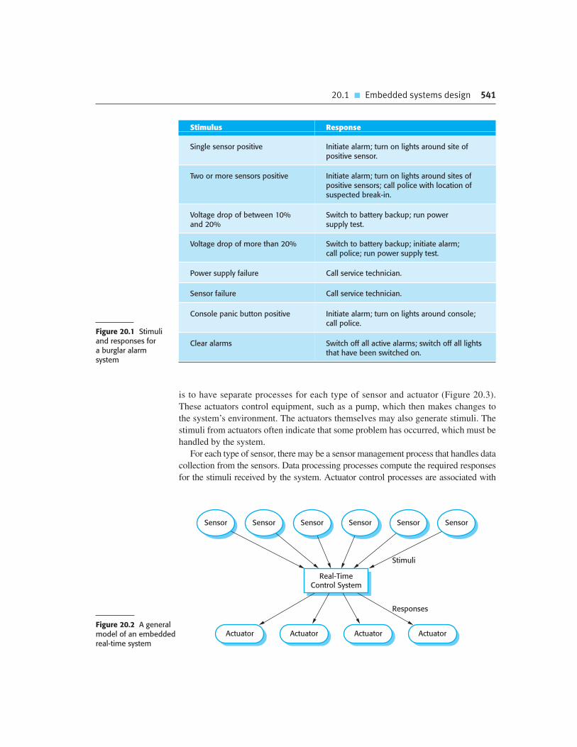
20.1 � Embedded systems design 541
Figure 20.1 Stimuliand responses for a burglar alarm system
is to have separate processes for each type of sensor and actuator (Figure 20.3).
These actuators control equipment, such as a pump, which then makes changes to
the system’s environment. The actuators themselves may also generate stimuli. The
stimuli from actuators often indicate that some problem has occurred, which must be
handled by the system.
For each type of sensor, there may be a sensor management process that handles data
collection from the sensors. Data processing processes compute the required responses
for the stimuli received by the system. Actuator control processes are associated with
Stimulus Response
Single sensor positive Initiate alarm; turn on lights around site ofpositive sensor.
Two or more sensors positive Initiate alarm; turn on lights around sites ofpositive sensors; call police with location ofsuspected break-in.
Voltage drop of between 10%and 20%
Switch to battery backup; run power supply test.
Voltage drop of more than 20% Switch to battery backup; initiate alarm; call police; run power supply test.
Power supply failure Call service technician.
Sensor failure Call service technician.
Console panic button positive Initiate alarm; turn on lights around console;call police.
Clear alarms Switch off all active alarms; switch off all lightsthat have been switched on.
Real-TimeControl System
ActuatorActuatorActuator Actuator
SensorSensorSensor SensorSensorSensor
Stimuli
Responses
Figure 20.2 A generalmodel of an embeddedreal-time system

542 Chapter 20 � Embedded software
each actuator and manage the operation of that actuator. This model allows data to be
collected quickly from the sensor (before it is overwritten by the next input) and allows
processing and the associated actuator response to be carried out later.
A real-time system has to respond to stimuli that occur at different times. You
therefore have to organize the system architecture so that, as soon as a stimulus is
received, control is transferred to the correct handler. This is impractical in sequen-
tial programs. Consequently, real-time software systems are normally designed as a
set of concurrent, cooperating processes. To support the management of these
processes, the execution platform on which the real-time system executes may
include a real-time operating system (discussed in Section 20.4). The functions pro-
vided by this operating system are accessed through the run-time support system for
the real-time programming language that is used.
There is no standard embedded system design process. Rather, different processes
are used that depend on the type of system, available hardware, and the organization
that is developing the system. The following activities may be included in a real-time
software design process:
1. Platform selection In this activity, you choose an execution platform for the
system (i.e., the hardware and the real-time operating system to be used).
Factors that influence these choices include the timing constraints on the
system, limitations on power available, the experience of the development team,
and the price target for the delivered system.
2. Stimuli/response identification This involves identifying the stimuli that the sys-
tem must process and the associated response or responses for each stimulus.
3. Timing analysis For each stimulus and associated response, you identify the tim-
ing constraints that apply to both stimulus and response processing. These are
used to establish the deadlines for the processes in the system.
4. Process design At this stage, you aggregate the stimulus and response process-
ing into a number of concurrent processes. A good starting point for designing
the process architecture is the architectural patterns that I describe in Section
20.2. You then optimize the process architecture to reflect the specific require-
ments that you have to implement.
5. Algorithm design For each stimulus and response, you design algorithms to
carry out the required computations. Algorithm designs may have to be
DataProcessor
ActuatorControl
Actuator
SensorControl
Sensor
Stimulus Response
Figure 20.3 Sensor andactuator processes

20.1 � Embedded systems design 543
developed relatively early in the design process to give an indication of the
amount of processing required and the time needed to complete that process-
ing. This is especially important for computationally intensive tasks, such as
signal processing.
6. Data design You specify the information that is exchanged by processes and the
events that coordinate information exchange, and design data structures to man-
age this information exchange. Several concurrent processes may share these
data structures.
7. Process scheduling You design a scheduling system that will ensure that
processes are started in time to meet their deadlines.
The order of these activities in the real-time software design process depends on
the type of system being developed, as well as its process and platform requirements.
In some cases, you may be able to follow a fairly abstract approach where you start
with the stimuli and associated processing, and decide on the hardware and execution
platforms late in the process. In other cases, the choice of hardware and operating sys-
tem is made before the software design starts. In such a situation, you have to design
the software to take account of the constraints imposed by the hardware capabilities.
Processes in a real-time system have to be coordinated and share information.
Process coordination mechanisms ensure mutual exclusion to shared resources.
When one process is modifying a shared resource, other processes should not be able
to change that resource. Mechanisms for ensuring mutual exclusion include sema-
phores (Dijkstra, 1968), monitors (Hoare, 1974), and critical regions (Brinch-
Hansen, 1973). These process synchronization mechanisms are described in most
operating system texts (Silberschatz et al., 2008; Tanenbaum, 2007).
When designing the information exchange between processes, you have to take
into account the fact that these processes may be running at different speeds. One
process is producing information; the other process is consuming that information. If
the producer is running faster than the consumer, new information could overwrite a
previously read information item before the consumer process has read the original
information. If the consumer process is running faster than the producer process, the
same item could be read twice.
To get around this problem, you should implement information exchange using a
shared buffer and use mutual exclusion mechanisms to control access to that buffer. This
means that information can’t be overwritten before it has been read and that information
cannot be read twice. Figure 20.4 illustrates the notion of a shared buffer. This is usually
implemented as a circular queue, so that mismatches in speed between the producer and
consumer processes can be accommodated without having to delay process execution.
The producer process always enters data in the buffer location at the tail of the
queue (represented as v10 in Figure 20.4). The consumer process always retrieves
information from the head of the queue (represented as v1 in Figure 20.4). After the
consumer process has retrieved the information, the head of the list is adjusted to
point at the next item (v2). After the producer process has added information, the tail
of the list is adjusted to point at the next free slot in the list.

544 Chapter 20 � Embedded software
Obviously, it is important to ensure that the producer and consumer process do
not attempt to access the same item at the same time (i.e., when Head = Tail). You
also have to ensure that the producer process does not add items to a full buffer and
that the consumer process does not take items from an empty buffer. To do this, you
implement the circular buffer as a process with Get and Put operations to access the
buffer. The Put operation is called by the producer process and the Get operation by
the consumer process. Synchronization primitives, such as semaphores or critical
regions, are used to ensure that the operation of Get and Put are synchronized, so that
they don’t access the same location at the same time. If the buffer is full, the Put
process has to wait until a slot is free; if the buffer is empty, the Get process has to
wait until an entry has been made.
Once you have chosen the execution platform for the system, designed a process
architecture, and decided on a scheduling policy, you may need to check that the sys-
tem will meet its timing requirements. You can do this through static analysis of the
system using knowledge of the timing behavior of components, or through simula-
tion. This analysis may reveal that the system will not perform adequately. The
process architecture, the scheduling policy, the execution platform, or all of these
may then have to be redesigned to improve the performance of the system.
Timing constraints or other requirements may sometimes mean that it is best to
implement some system functions, such as signal processing, in hardware. Modern
hardware components, such as FPGAs, are flexible and can be adapted to different
functions. Hardware components deliver much better performance than the equiva-
lent software. System processing bottlenecks can be identified and replaced by hard-
ware, thus avoiding expensive software optimization.
20.1.1 Real-time system modeling
The events that a real-time system must react to often cause the system to move from
one state to another. For this reason, state models, which I introduced in Chapter 5,
are often used to describe real-time systems. A state model of a system assumes that,
ConsumerProcess
ProducerProcess
Circular Buffer
Head
Tail
v1
v2
v3v4v5
v6
v7
v8
v9
v10
Figure 20.4 Producer/consumer processessharing a circular buffer

20.1 � Embedded systems design 545
at any time, the system is in one of a number of possible states. When a stimulus is
received, this may cause a transition to a different state. For example, a system con-
trolling a valve may move from a state ‘Valve open’ to a state ‘Valve closed’ when an
operator command (the stimulus) is received.
State models are a language-independent way of representing the design of a real-
time system and are therefore an integral part of real-time system design methods
(Gomaa, 1993). The UML supports the development of state models based on
Statecharts (Harel, 1987; Harel, 1988). Statecharts are formal state machine models
that support hierarchical states, so that groups of states can be considered as a single
entity. Douglass discusses the use of the UML in real-time systems development
(Douglass, 1999). State models are used in model-driven engineering, which I dis-
cussed in Chapter 5, to define the operation of a system. They can be transformed
automatically to an executable program.
I have already illustrated this approach to system modeling in Chapter 5 where
I used an example of a model of a simple microwave oven. Figure 20.5 is another
example of a state machine model that shows the operation of a fuel delivery soft-
ware system embedded in a petrol (gas) pump. The rounded rectangles represent
system states and the arrows represent stimuli that force a transition from one state to
another. The names chosen in the state machine diagram are descriptive. The associ-
ated information indicates actions taken by the system actuators or information that
is displayed. Notice that this system never terminates but idles in a waiting state
when the pump is not operating.
Figure 20.5 Statemachine model of apetrol (gas) pump
Card Insertedinto Reader
Timeout
Resetting
do: displayCC error
Initializing
do: initializedisplay
Stopped
Reading
do: get CCdetails
Waiting
do: displaywelcome
Paying
do:deliver fuelupdate display
Payment ack.
ReadyDelivering
NozzleTrigger On
NozzleTriggerOff
NozzleTriggerOn
Hose in Holster
do: validatecredit card
Validating
InvalidCard
CardRemoved
Card OK
Hose Outof Holster
Hose inHolster
Timeout
do: debitCC account

546 Chapter 20 � Embedded software
The fuel delivery system is designed to allow unattended operation. The buyer
inserts a credit card into a card reader built into the pump. This causes a transition to
a Reading state where the card details are read and the buyer is then asked to remove
the card. Removal of the card triggers a transition to a Validating state where the card
is validated. If the card is valid, the system initializes the pump and, when the fuel
hose is removed from its holster, transitions to the Delivering state, where it is ready
to deliver fuel. Activating the trigger on the nozzle causes fuel to be pumped; this
stops when the trigger is released (for simplicity, I have ignored the pressure switch
that is designed to stop fuel spillage). After the fuel delivery is complete and the
buyer has replaced the hose in its holster, the system moves to a Paying state where
the user’s account is debited. After payment, the pump software returns to the
Waiting state.
20.1.2 Real-time programming
Programming languages for real-time systems development have to include facilities
to access system hardware, and it should be possible to predict the timing of particular
operations in these languages. Hard real-time systems are still sometimes programmed
in assembly language so that tight deadlines can be met. Systems-level languages, such
as C, which allow efficient code to be generated are also widely used.
The advantage of using a systems programming language like C is that it allows
the development of very efficient programs. However, these languages do not
include constructs to support concurrency or the management of shared resources.
Concurrency and resource management are implemented through calls to primitives
provided by the real-time operating system, such as semaphores for mutual exclu-
sion. These calls cannot be checked by the compiler, so programming errors are
more likely. Programs are also often more difficult to understand because the lan-
guage does not include real-time features. As well as understanding the program, the
reader also has to know how real-time support is provided using system calls.
Because real-time systems must meet their timing constraints, you may not be able
to use object-oriented development for hard real-time systems. Object-oriented devel-
opment involves hiding data representations and accessing attribute values through
operations defined with the object. This means that there is a significant performance
overhead in object-oriented systems because extra code is required to mediate access
to attributes and handle calls to operations. The consequent loss of performance may
make it impossible to meet real-time deadlines.
A version of Java has been designed for embedded systems development (Dibble,
2008), with implementations from different companies such as IBM and Sun. This lan-
guage includes a modified thread mechanism, which allows threads to be specified that
will not be interrupted by the language garbage collection mechanism. Asynchronous
event handling and timing specification has also been included. However, at the time of
writing, this has mostly been used on platforms that have significant processor and
memory capacity (e.g., a cell phone) rather than simpler embedded systems, with more
limited resources. These systems are still usually implemented in C.

20.2 � Architectural patterns 547
20.2 Architectural patterns
Architectural patterns, which I introduced in Chapter 6, are abstract, stylized descrip-
tions of good design practice. They encapsulate knowledge about the organization of
system architectures, when these architectures should be used and their advantages
and disadvantages. You should not, however, think of an architectural pattern as a
generic design to be instantiated. Rather, you use the pattern to understand an archi-
tecture and as starting point for creating your own specific architectural design.
As you might expect, the differences between embedded and interactive software
means that different architectural patterns are used for embedded systems, rather
than the architectural patterns discussed in Chapter 6. Embedded systems’ patterns
are process-oriented rather than object- or component-oriented. In this section, I dis-
cuss three real-time architectural patterns that are commonly used:
1. Observe and React This pattern is used when a set of sensors are routinely mon-
itored and displayed. When the sensors show that some event has occurred (e.g.,
an incoming call on a cell phone), the system reacts by initiating a process to
handle that event.
2. Environmental Control This pattern is used when a system includes sensors,
which provide information about the environment and actuators that can change
the environment. In response to environmental changes detected by the sensor,
control signals are sent to the system actuators.
3. Process Pipeline This pattern is used when data has to be transformed from one
representation to another before it can be processed. The transformation is
implemented as a sequence of processing steps, which may be carried out con-
currently. This allows for very fast data processing, because a separate core or
processor can execute each transformation.
These patterns can of course be combined and you will often see more than
one of them in a single system. For example, when the Environmental Control
pattern is used, it is very common for the actuators to be monitored using the
Observe and React pattern. In the event of an actuator failure, the system may
Real-time Java
The Java programming language has been modified in a number of ways to make it suitable for real-timesystems development. These modifications include asynchronous communications; the addition of time,including absolute and relative time; a new thread model where threads cannot be interrupted by garbagecollection; and a new memory management model that avoids the unpredictable delays that can result fromgarbage collection.
http://www.SoftwareEngineering-9.com/Web/RTS/Java.html

548 Chapter 20 � Embedded software
react by displaying a warning message, shutting down the actuator, switching in a
backup system, etc.
The patterns that I discuss here are architectural patterns that describe the overall
structure of an embedded system. Douglass (2002) describes lower-level, real-time
design patterns that are used to help you make more detailed design decisions. These
patterns include design patterns for execution control, communications, resource
allocation, and safety and reliability.
These architectural patterns should be the starting point for an embedded systems
design; however they are not design templates. If you use them as such, you will
probably end up with an inefficient process architecture. You therefore have to opti-
mize the process structure to ensure that you do not have too many processes. You
also should ensure that there is a clear correspondence between the processes and the
sensors and actuators in the system.
20.2.1 Observe and React
Monitoring systems are an important class of embedded real-time systems. A moni-
toring system examines its environment through a set of sensors and, usually, dis-
plays the state of the environment in some way. This could be on a built-in screen, on
special-purpose instrument displays or on a remote display. If some exceptional
event or sensor state is detected by the system, the monitoring system takes some
action. Often, this involves raising an alarm to draw an operator’s attention to the
event. Sometimes the system may initiate some other preventative action, such as
shutting down the system to preserve it from damage.
The Observe and React pattern (Figure 20.6 and Figure 20.7) is a pattern that is
commonly used in monitoring systems. The values of sensors are observed and when
Figure 20.6 TheObserve and Reactpattern
Name Observe and React
Description The input values of a set of sensors of the sametypes are collected and analyzed. These values aredisplayed in some way. If the sensor values indicatethat some exceptional condition has arisen, thenactions are initiated to draw the operator’s attentionto that value and, in certain cases, to take actions inresponse to the exceptional value.
Stimuli Values from sensors attached to the system.
Responses Outputs to display, alarm triggers, signals to reactingsystems.
Processes Observer, Analysis, Display, Alarm, Reactor.
Used in Monitoring systems, alarm systems.

20.2 � Architectural patterns 549
particular values are detected, the system reacts in some way. Monitoring systems
may be composed of several instantiations of the Observe and React pattern, one for
each type of sensor in the system. Depending on the system requirements, you may
then optimize the design by combining processes (e.g., you may use a single display
process to display the information from all of the different types of sensors).
As an example of the use of this pattern, consider the design of a burglar alarm
system that might be installed in an office building:
A software system is to be implemented as part of a burglar alarm system for
commercial buildings. This uses several different types of sensors. These
include movement detectors in individual rooms, door sensors that detect cor-
ridor doors opening, and window sensors on ground-floor windows that can
detect when a window has been opened.
When a sensor detects the presence of an intruder, the system automatically
calls the local police and, using a voice synthesizer, reports the location of the
alarm. It switches on lights in the rooms around the active sensor and sets off
an audible alarm. The sensor system is normally powered by mains power but
is equipped with a battery backup. Power loss is detected using a separate
power circuit monitor that monitors the mains voltage. If a voltage drop is
detected, the system assumes that intruders have interrupted the power supply
so an alarm is raised.
A possible process architecture for the alarm system is shown in Figure 20.8. In this
diagram, the arrows represent signals sent from one process to another. This system is
a ‘soft’ real-time system that does not have stringent timing requirements. The sensors
do not need to detect high-speed events, so they need only be polled relatively infre-
quently. The timing requirements for this system are covered in Section 20.3.
I have already introduced the stimuli and responses in this alarm system in
Figure 20.1. These are used as a starting point for the system design. The Observe
AnalysisProcess
ObserverProcess
ReactorProcess
AlarmProcess
SensorValues Display
Process
DisplayValues
DisplaySensors
AlarmOther Equipment
Figure 20.7 Observeand React processstructure

550 Chapter 20 � Embedded software
and React pattern is used in this design. There are observer processes associated
with each type of sensor and reactor processes for each type of reaction. There is a
single analysis process that checks the data from all of the sensors. The display
processes in the pattern are combined into a single display process.
20.2.2 Environmental Control
Perhaps the most widespread use of embedded software is in control systems. In
these systems, the software controls the operation of equipment, based on stimuli
from the equipment’s environment. For example, an anti-skid braking system in a car
monitors the car’s wheels and brake system (the system’s environment). It looks for
signs that the wheels are skidding when brake pressure is applied. If this is the case,
the system adjusts the brake pressure to stop the wheels locking and reduce the like-
lihood of a skid.
Control systems may make use of the Environmental Control pattern, which is a
general control pattern that includes sensor and actuator processes. This pattern is
described in Figure 20.9, with the process architecture shown in Figure 20.10. A
variant of this pattern leaves out the display process. This variant is used in situations
where there is no requirement for user intervention or where the rate of control is so
high that a display would not be meaningful.
This pattern can be the basis for a control system design with an instantiation of
the Environmental Control pattern for each actuator (or actuator type) that is being
controlled. You then optimize the design to reduce the number of processes. For
example, you may combine actuator monitoring and actuator control processes, or
may have a single monitoring and control process for several actuators. The opti-
mizations that you choose depend on the timing requirements. You may need to
monitor sensors more frequently than you send control signals, in which case it may
be impractical to combine control and monitoring processes. There may also be
Lighting ControlProcess
External AlertProcess
SystemController
Console DisplayProcess
Door SensorProcess
Voltage MonitorProcess
MovementDetector Process
Window SensorProcess
Audible AlarmProcess
Control PanelProcess
Testing Process
Power ManagementProcess
Figure 20.8 Processstructure for a burglaralarm system
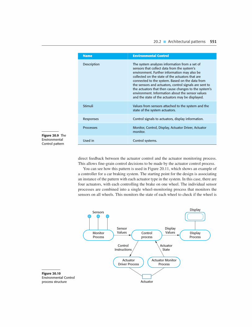
20.2 � Architectural patterns 551
direct feedback between the actuator control and the actuator monitoring process.
This allows fine-grain control decisions to be made by the actuator control process.
You can see how this pattern is used in Figure 20.11, which shows an example of
a controller for a car braking system. The starting point for the design is associating
an instance of the pattern with each actuator type in the system. In this case, there are
four actuators, with each controlling the brake on one wheel. The individual sensor
processes are combined into a single wheel-monitoring process that monitors the
sensors on all wheels. This monitors the state of each wheel to check if the wheel is
Figure 20.9 TheEnvironmentalControl pattern
Name Environmental Control
Description The system analyzes information from a set ofsensors that collect data from the system’senvironment. Further information may also becollected on the state of the actuators that areconnected to the system. Based on the data from the sensors and actuators, control signals are sent tothe actuators that then cause changes to the system’senvironment. Information about the sensor valuesand the state of the actuators may be displayed.
Stimuli Values from sensors attached to the system and thestate of the system actuators.
Responses Control signals to actuators, display information.
Processes Monitor, Control, Display, Actuator Driver, Actuatormonitor.
Used in Control systems.
Display
Controlprocess
MonitorProcess
Actuator MonitorProcess
ActuatorDriver Process
SensorValues Display
Process
DisplayValues
Sensors
Actuator
ControlInstructions
ActuatorState
Figure 20.10Environmental Controlprocess structure

552 Chapter 20 � Embedded software
turning or locked. A separate process monitors the pressure on the brake pedal
exerted by the car driver.
The system includes an anti-skid feature, which is triggered if the sensors indicate
that a wheel is locked when the brake has been applied. This means that there is
insufficient friction between the road and the tyre; in other words, the car is skidding.
If the wheel is locked, the driver cannot steer that wheel. To counteract this, the sys-
tem sends a rapid sequence of on/off signals to the brake on that wheel, which allows
the wheel to turn and control to be regained.
20.2.3 Process Pipeline
Many real-time systems are concerned with collecting data from the system’s envi-
ronment, then transforming that data from its original representation into some other
digital representation that can be more readily analyzed and processed by the sys-
tem. The system may also convert digital data to analog data, which it then sends to
its environment. For example, a software radio accepts incoming packets of digital
data representing the radio transmission and transforms these into a sound signal that
people can listen to.
The data processing that is involved in many of these systems has to be carried
out very quickly. Otherwise, incoming data may be lost and outgoing signals may be
broken up because essential information is missing. The Process Pipeline pattern
makes this rapid processing possible by breaking down the required data processing
into a sequence of separate transformations, with each transformation carried out by
an independent process. This is a very efficient architecture for systems that use mul-
tiple processors or multicore processors. Each process in the pipeline can be associ-
ated with a separate processor or core, so that the processing steps can be carried out
in parallel.
AnalysisProcess
WheelMonitor
PedalMonitor
Brake 1Process
Brake 3Process
Brake 1
Brake 3
Brake 2Process
Brake 4Process
Brake 2
Brake 4
Pedal Pressure Sensor
Wheel Sensors
Figure 20.11 Controlsystem architecture foran anti-skid brakingsystem

20.2 � Architectural patterns 553
Figure 20.12 is a brief description of the data pipeline pattern, and Figure 20.13
shows the process architecture for this pattern. Notice that the processes involved
may produce and consume information. They are linked by synchronized buffers, as
discussed in Section 20.1. This allows producer and consumer processes to operate
at different speeds without data losses.
An example of a system that may use a process pipeline is a high-speed data
acquisition system. Data acquisition systems collect data from sensors for subse-
quent processing and analysis. These systems are used in situations where the sen-
sors are collecting a lot of data from the system’s environment and it isn’t possible or
necessary to process that data in real time. Rather, it is collected and stored for later
analysis. Data acquisition systems are often used in scientific experiments and
process control systems where physical processes, such as chemical reactions, are
very rapid. In these systems, the sensors may be generating data very quickly and the
data acquisition system has to ensure that a sensor reading is collected before the
sensor value changes.
Figure 20.14 is a simplified model of a data acquisition system than might be
part of the control software in a nuclear reactor. This is a system that collects data
from sensors monitoring the neutron flux (the density of neutrons) in the reactor.
The sensor data is placed in a buffer from which it is extracted and processed. The
average flux level is displayed on an operator’s display and stored for future
processing.
Figure 20.12 TheProcess Pipeline pattern
Name Process Pipeline
Description A pipeline of processes is set up with data moving in sequencefrom one end of the pipeline to another. The processes areoften linked by synchronized buffers to allow the producer andconsumer processes to run at different speeds. The culminationof a pipeline may be display or data storage or the pipeline mayterminate in an actuator.
Stimuli Input values from the environment or some other process
Responses Output values to the environment or a shared buffer
Processes Producer, Buffer, Consumer
Used in Data acquisition systems, multimedia systems
BufferProcess
ProducerProcess
ProducedData Consumer
Process
ConsumedData
...
Figure 20.13 ProcessPipeline processstructure

554 Chapter 20 � Embedded software
20.3 Timing analysis
As I discussed in the introduction, the correctness of a real-time system depends not
just on the correctness of its outputs but also on the time at which these outputs were
produced. This means that an important activity in the embedded, real-time software
development process is timing analysis. In such an analysis, you calculate how often
each process in the system must be executed to ensure that all inputs are processed
and all system responses are produced in a timely way. The results of the timing
analysis are used to decide how frequently each process should execute and how
these processes should be scheduled by the real-time operating system.
Timing analysis for real-time systems is particularly difficult when the systems
must deal with a mixture of periodic and aperiodic stimuli and responses. Because
aperiodic stimuli are unpredictable, you have to make assumptions about the proba-
bility of these stimuli occurring and therefore requiring service at any particular
time. These assumptions may be incorrect and system performance after delivery
may not be adequate. Cooling’s book (2003) discusses techniques for real-time sys-
tem performance analysis that takes aperiodic events into account.
However, as computers have become faster it has become possible, in many sys-
tems, to design using only periodic stimuli. When processors were slow, aperiodic
stimuli had to be used to ensure that critical events were processed before their dead-
line, as delays in processing usually involved some loss to the system. For example,
the failure of a power supply in an embedded system may mean that the system has
to shut down attached equipment in a controlled way, within a very short time (say
50 milliseconds). This could be implemented as a ‘power fail’ interrupt. However, it
can also be implemented using a periodic process that runs very frequently and
checks the power. So long as the time between process invocations is short, there is
still time to perform a controlled shutdown of the system before the lack of power
causes damage. For this reason, I focus on timing issues for periodic processes.
When you are analyzing the timing requirements of embedded real-time systems
and designing systems to meet these requirements, there are three key factors that
you have to consider:
1. Deadlines The times by which stimuli must be processed and some response
produced by the system. If the system does not meet a deadline then, if it is a
Flux ValueBuffer
FluxProcessing
Raw DataBuffer
A-DConvertor
SensorIdentifier and
Flux ValueProcessedFlux Level
Storage
Display
Neutron Flux Sensors
Figure 20.14 Neutronflux data acquisition

20.3 � Timing analysis 555
hard-real time system, this is a system failure; in a soft real-time system, it
results in degraded system service.
2. Frequency The number of times per second that a process must execute so that
you are confident that it can always meet its deadlines.
3. Execution time The time required to process a stimulus and produce a response.
Often, you have to take two execution times into account—the average execu-
tion time of a process and the worst-case execution time for that process.
Execution time is not always the same because of the conditional execution of
code, delays waiting for other processes, etc. In a hard real-time system, you
may have to make assumptions based on the worst-case execution time to ensure
that deadlines are not missed. In soft real-time systems, you may be able to base
your calculations on the average execution time.
To continue the example of a power supply failure, let’s assume that, after a failure
event, it takes 50 ms for the supplied voltage to drop to a level where the equipment may
be damaged. Therefore, the equipment shutdown process must begin within 50 ms of a
power failure event. In such cases, it would be prudent to set a shorter deadline of 40 ms,
because of physical variations in the equipment. This means that shutdown instructions
for all attached equipment that is at risk must be issued and processed within 40 ms,
assuming that the equipment is also dependent on the failing power supply.
If you detect power failure by monitoring a voltage level, you have to make more
than one observation to detect that the voltage is dropping. If you run the process 250
times per second, this means that it runs every 4 ms and you may require up to two
periods to detect the voltage drop. Therefore, it takes up to 8 ms to detect the prob-
lem. Consequently, the worst-case execution time of the shutdown process should
not exceed 16 ms, to ensure that the deadline of 40 ms is met. This figure is calcu-
lated by subtracting the process periods (8 ms) from the deadline (40 ms) and divid-
ing the result by two, as two process executions are necessary.
In reality, you would normally aim for something considerably less than 16 ms
to give you a safety margin in case your calculations were wrong. In fact, the time
required to examine a sensor and check that there has been no significant voltage
loss should be much less than 16 ms. It only involves a simple comparison of two
values. The average execution time of the power monitor process should be less
than 1 ms.
The starting point for timing analysis in a real-time system is the timing requirements,
which should set out the deadlines for each required response in the system. Figure 20.15
shows possible timing requirements for the office building burglar alarm system dis-
cussed in Section 20.2.1. To simplify this example, let us ignore stimuli generated by sys-
tem testing procedures and external signals to reset the system in the event of a false
alarm. This means there are only two types of stimulus to be processed by the system:
1. Power failure This is detected by observing a voltage drop of more than 20%.
The required response is to switch the circuit to backup power by signaling an
electronic power-switching device, which switches the mains power to battery
backup.

556 Chapter 20 � Embedded software
2. Intruder alarm This is a stimulus generated by one of the system sensors. The
response to this stimulus is to compute the room number of the active sensor, set
up a call to the police, initiate the voice synthesizer to manage the call, and
switch on the audible intruder alarm and building lights in the area.
As shown in Figure 20.15, you should list the timing constraints for each class of
sensor separately, even when (as in this case) they are the same. By considering them
separately, you leave scope for future change and make it easier to compute the num-
ber of times the controlling process has to be executed each second.
Allocating the system functions to concurrent processes is the next design stage.
There are four types of sensors that must be polled periodically, each with an associ-
ated process. These are the voltage sensor, door sensors, window sensors, and move-
ment detectors. Normally, the processes associated with the sensor will execute very
quickly as all they are doing is checking whether or not a sensor has changed its sta-
tus (e.g., from off to on). It is reasonable to assume that the execution time to check
and assess the state of one sensor is no more than 1 ms.
To ensure that you meet the deadlines defined by the timing requirements, you
then have to decide how frequently the related processes have to run and how many
sensors should be examined during each execution of the process. There are obvious
trade-offs here between frequency and execution time:
1. If you examine one sensor during each process execution, then if there are N sensors
of a particular type, you must schedule the process 4N times per second to ensure
that you meet the deadline of detecting a change of state within 0.25 seconds.
Figure 20.15 Timingrequirements for theburglar alarm system
Stimulus/Response Timing Requirements
Power failure The switch to backup power must be completed within adeadline of 50 ms.
Door alarm Each door alarm should be polled twice per second.
Window alarm Each window alarm should be polled twice per second.
Movement detector Each movement detector should be polled twice per second.
Audible alarm The audible alarm should be switched on within half asecond of an alarm being raised by a sensor.
Lights switch The lights should be switched on within half a second ofan alarm being raised by a sensor.
Communications The call to the police should be started within 2 secondsof an alarm being raised by a sensor.
Voice synthesizer A synthesized message should be available within 2 seconds of an alarm being raised by a sensor.

20.3 � Timing analysis 557
2. If you examine four sensors, say, during each process execution, then the execu-
tion time is increased to 4 ms, but you need only run the process N times/second
to meet the timing requirement.
In this case, because the system requirements define actions when two or more
sensors are positive, it may be sensible to examine sensors in groups, with groups
based on the physical proximity of the sensors. If an intruder has entered the build-
ing then it will probably be adjacent sensors that are positive.
When you have completed the timing analysis, you may then annotate the process
model with information about frequency of execution and their expected execution
time (see Figure 20.16 as an example). Here, periodic processes are annotated with
their frequency, processes that are started in response to a stimulus are annotated
with R, and the testing process is a background process, annotated with B. This
means that it only runs when processor time is available. In general, it is simpler to
design a system so that there are a small number of process frequencies. The execu-
tion times represent the required worst-case execution times of the processes.
The final step in the design process is to design a scheduling system that will
ensure that a process will always be scheduled to meet its deadlines. You can only do
this if you know the scheduling approaches that are supported by the real-time oper-
ating system used (Burns and Wellings, 2009). The scheduler in the real-time OS
allocates a process to a processor for a given amount of time. The time can be fixed,
or may vary depending on the priority of the process.
In allocating process priorities, you have to consider the deadlines of each process
so that processes with short deadlines receive processor time to meet these deadlines.
For example, the voltage monitor process in the burglar alarm needs to be scheduled
so that voltage drops can be detected and a switch made to backup power before the
system fails. This should therefore have a higher priority than the processes that
check sensor values, as these have fairly relaxed deadlines compared to their
expected execution time.
Figure 20.16 Alarmprocess timing
B
Lighting ControlProcess
External AlertProcess
SystemController
Console DisplayProcess
Door SensorProcess
Voltage MonitorProcess
MovementDetector Process
Window SensorProcess
Audible AlarmProcess
Control PanelProcess
Testing Process
Power ManagementProcess
50 Hz (0.5 ms)
50 Hz (1 ms)
250 Hz (0.5 ms)
50 Hz (0.5 ms)
50 Hz (0.5 ms)
250 Hz (1 ms)
R (5 ms) R (5 ms) R (10 ms)
R (20 ms)
50 Hz (1 ms)

558 Chapter 20 � Embedded software
20.4 Real-time operating systems
The execution platform for most application systems is an operating system that
manages shared resources and provides features such as a file system, run-time
process management, etc. However, the extensive functionality in a conventional
operating system takes up a great deal of space and slows down the operation of pro-
grams. Furthermore, the process management features in the system may not be
designed to allow fine-grain control over the scheduling of processes.
For these reasons, standard operating systems, such as Linux and Windows, are
not normally used as the execution platform for real-time systems. Very simple
embedded systems may be implemented as ‘bare metal’ systems. The systems them-
selves include system startup and shutdown, process and resource management, and
process scheduling. More commonly, however, embedded applications are built on
top of a real-time operating system (RTOS), which is an efficient operating system
that offers the features needed by real-time systems. Examples of RTOS are
Windows/CE, Vxworks, and RTLinux.
A real-time operating system manages processes and resource allocation for a real-
time system. It starts and stops processes so that stimuli can be handled and allocates
memory and processor resources. The components of an RTOS (Figure 20.17)
depend on the size and complexity of the real-time system being developed. For all
except the simplest systems, they usually include:
1. A real-time clock, which provides the information required to schedule
processes periodically.
2. An interrupt handler, which manages aperiodic requests for service.
3. A scheduler, which is responsible for examining the processes that can be exe-
cuted and choosing one of these for execution.
4. A resource manager, which allocates appropriate memory and processor
resources to processes that have been scheduled for execution.
5. A dispatcher, which is responsible for starting the execution of processes.
Real-time operating systems for large systems, such as process control or telecom-
munication systems, may have additional facilities, namely disk storage management,
fault management facilities that detect and report system faults, and a configuration
manager that supports the dynamic reconfiguration of real-time applications.
20.4.1 Process management
Real-time systems have to handle external events quickly and, in some cases, meet
deadlines for processing these events. This means that the event-handling processes
must be scheduled for execution in time to detect the event. They must also be allocated

20.4 � Real-time operating systems 559
sufficient processor resources to meet their deadline. The process manager in an RTOS
is responsible for choosing processes for execution, allocating processor and memory
resources, and starting and stopping process execution on a processor.
The process manager has to manage processes with different priorities. For some
stimuli, such as those associated with certain exceptional events, it is essential that
their processing should be completed within the specified time limits. Other processes
may be safely delayed if a more critical process requires service. Consequently, the
RTOS has to be able to manage at least two priority levels for system processes:
1. Interrupt level This is the highest priority level. It is allocated to processes that
need a very fast response. One of these processes will be the real-time clock
process.
2. Clock level This level of priority is allocated to periodic processes.
There may be a further priority level allocated to background processes (such as a
self-checking process) that do not need to meet real-time deadlines. These processes
are scheduled for execution when processor capacity is available.
Within each of these priority levels, different classes of process may be allocated
different priorities. For example, there may be several interrupt lines. An interrupt
from a very fast device may have to pre-empt processing of an interrupt from a
slower device to avoid information loss. The allocation of process priorities so that
all processes are serviced in time usually requires extensive analysis and simulation.
Process ResourceRequirements
Scheduler
SchedulingInformation
ResourceManager
Dispatcher
Real-TimeClock
ProcessesAwaiting
Resources
ReadyList
InterruptHandler
AvailableResource
List
ProcessorList
Executing Process
ReadyProcesses
ReleasedResources
Figure 20.17Componentsof a real-time operating system

560 Chapter 20 � Embedded software
Periodic processes are processes that must be executed at specified time intervals
for data acquisition and actuator control. In most real-time systems, there will be
several types of periodic process. Using the timing requirements specified in the
application program, the RTOS arranges the execution of periodic processes so that
they can all meet their deadlines.
The actions taken by the operating system for periodic process management are
shown in Figure 20.18. The scheduler examines the list of periodic processes and
selects a process to be executed. The choice depends on the process priority, the
process periods, the expected execution times, and the deadlines of the ready
processes. Sometimes, two processes with different deadlines should be executed at
the same clock tick. In such a situation, one process must be delayed. Normally, the
system will choose to delay the process with the longest deadline.
Processes that have to respond quickly to asynchronous events may be interrupt-
driven. The computer’s interrupt mechanism causes control to transfer to a pre-
determined memory location. This location contains an instruction to jump to a
simple and fast interrupt service routine. The service routine disables further inter-
rupts to avoid being interrupted itself. It then discovers the cause of the interrupt and
initiates, with a high priority, a process to handle the stimulus causing the interrupt.
In some high-speed data acquisition systems, the interrupt handler saves the data that
the interrupt signaled was available in a buffer for later processing. Interrupts are
then enabled again and control is returned to the operating system.
At any one time, there may be several processes, all with different priorities, that
could be executed. The process scheduler implements system-scheduling policies
that determine the order of process execution. There are two commonly used sched-
uling strategies:
1. Non-pre-emptive scheduling Once a process has been scheduled for execution it
runs to completion or until it is blocked for some reason, such as waiting for input.
This can cause problems, however, when there are processes with different priori-
ties and a high-priority process has to wait for a low-priority process to finish.
2. Pre-emptive scheduling The execution of an executing process may be stopped
if a higher-priority process requires service. The higher-priority process pre-
empts the execution of the lower-priority process and is allocated to a processor.
Within these strategies, different scheduling algorithms have been developed.
These include round-robin scheduling, where each process is executed in turn;
Resource Manager
Allocate Memoryand Processor
Scheduler
Choose Processfor Execution
Dispatcher
Start Execution on anAvailable Processor
Process Queue Memory Map Processor List Ready List
Figure 20.18 RTOSactions required to start a process

Chapter 20 � Key Points 561
rate monotonic scheduling, where the process with the shortest period (highest
frequency) is given priority; and shortest deadline first scheduling, where the
process in the queue with the shortest deadline is scheduled (Burns and
Wellings, 2009).
Information about the process to be executed is passed to the resource man-
ager. The resource manager allocates memory and, in a multiprocessor system,
also adds a processor to this process. The process is then placed on the ‘ready
list’, a list of processes that are ready for execution. When a processor finishes
executing a process and becomes available, the dispatcher is invoked. It scans the
ready list to find a process that can be executed on the available processor and
starts its execution.
K E Y P O I N T S
� An embedded software system is part of a hardware/software system that reacts to events in
its environment. The software is ‘embedded’ in the hardware. Embedded systems are normally
real-time systems.
� A real-time system is a software system that must respond to events in real time. System
correctness does not just depend on the results it produces, but also on the time when these
results are produced.
� Real-time systems are usually implemented as a set of communicating processes that react to
stimuli to produce responses.
� State models are an important design representation for embedded real-time systems. They are
used to show how the system reacts to its environment as events trigger changes of state in the
system.
� There are several standard patterns that can be observed in different types of embedded
systems. These include a pattern for monitoring the system’s environment for adverse events,
a pattern for actuator control and a data-processing pattern.
� Designers of real-time systems have to do a timing analysis, which is driven by the deadlines for
processing and responding to stimuli. They have to decide how often each process in the system
should run and the expected and worst-case execution time for processes.
� A real-time operating system is responsible for process and resource management. It always
includes a scheduler, which is the component responsible for deciding which process should be
scheduled for execution.

562 Chapter 20 � Embedded software
F U RT H E R R E A D I N G
Software Engineering for Real-Time Systems. Written from an engineering rather than a computer
science perspective, this book is a good practical guide to real-time systems engineering. It has
good coverage of hardware issues, so is an excellent complement to Burns and Wellings’ book
(see below). (J. Cooling, Addison-Wesley, 2003.)
Real-time Systems and Programming Language: Ada, Real-time Java and C/Real-time POSIX,
4th edition. An excellent and comprehensive text that provides broad coverage of all aspects of
real-time systems. (A. Burns and A. Wellings, Addison-Wesley, 2009.)
‘Trends in Embedded Software Engineering’. This article suggests that model-driven development
(as discussed in Chapter 5 of this book), will become an important approach to embedded systems
development. This is part of a special issue on embedded systems and you may find that other
articles are also useful reading. (IEEE Software, 26 (3), May–June 2009.)
http://dx.doi.org/10.1109/MS.2009.80.
E X E R C I S E S
20.1. Using examples, explain why real-time systems usually have to be implemented using
concurrent processes.
20.2. Identify possible stimuli and the expected responses for an embedded system that controls a
home refrigerator or a domestic washing machine.
20.3. Using the state-based approach to modeling, as discussed in Section 20.1.1, model the
operation of an embedded software system for a voice mail system included in a landline
phone. This should display the number of recorded messages on an LED display and should
allow the user to dial in and listen to the recorded messages.
20.4. Explain why an object-oriented approach to software development may not be suitable for
real-time systems.
20.5. Show how the Environmental Control pattern could be used as the basis of the design of a
system to control the temperature in a greenhouse. The temperature should be between
10 and 30 degrees Celsius. If it falls below 10 degrees, the heating system should be switched
on; if it goes above 30, the windows should be automatically opened.
20.6. Design a process architecture for an environmental monitoring system that collects data from
a set of air quality sensors situated around a city. There are 5,000 sensors organized into
100 neighborhoods. Each sensor must be interrogated four times per second. When more than
30% of the sensors in a particular neighborhood indicate that the air quality is below an
acceptable level, local warning lights are activated. All sensors return the readings to a central
computer, which generates reports every 15 minutes on the air quality in the city.

Chapter 20 � Exercises 563
20.7. A train protection system automatically applies the brakes of a train if the speed limit for a
segment of track is exceeded or if the train enters a track segment that is currently signaled
with a red light (i.e., the segment should not be entered). Details are shown in Figure 20.19.
Identify the stimuli that must be processed by the onboard train control system and the
associated responses to these stimuli.
20.8. Suggest a possible process architecture for this system.
20.9. If a periodic process in the onboard train protection system is used to collect data from the
trackside transmitter, how often must it be scheduled to ensure that the system is
guaranteed to collect information from the transmitter? Explain how you arrived at your
answer.
20.10. Why are general-purpose operating systems, such as Linux or Windows, not suitable as
real-time system platforms? Use your experience of using a general-purpose system to help
answer this question.
Train protection system
• The system acquires information on the speed limit of a segment from a trackside transmitter, whichcontinually broadcasts the segment identifier and its speed limit. The same transmitter also broadcastsinformation on the status of the signal controlling that track segment. The time required to broadcast tracksegment and signal information is 50 ms.
• The train can receive information from the trackside transmitter when it is within 10 m of a transmitter.• The maximum train speed is 180 kph.• Sensors on the train provide information about the current train speed (updated every 250 ms) and the train
brake status (updated every 100 ms).• If the train speed exceeds the current segment speed limit by more than 5 kph, a warning is sounded in the
driver’s cabin. If the train speed exceeds the current segment speed limit by more than 10 kph, the train’sbrakes are automatically applied until the speed falls to the segment speed limit. Train brakes should beapplied within 100 ms of the time when the excessive train speed has been detected.
• If the train enters a track signaled that is signaled with a red light, the train protection system applies the trainbrakes and reduces the speed to zero. Train brakes should be applied within 100 ms of the time when the redlight signal is received.
• The system continually updates a status display in the driver’s cabin.
Figure 20.19Requirements for a trainprotection system

564 Chapter 20 � Embedded software
R E F E R E N C E S
Berry, G. (1989). ‘Real-time programming: Special-purpose or general-purpose languages’.
In Information Processing. Ritter, G. (ed.). Amsterdam: Elsevier Science Publishers, 11–17.
Brinch-Hansen, P. (1973). Operating System Principles. Englewood Cliffs, NJ: Prentice-Hall.
Burns, A. and Wellings, A. (2009). Real-Time Systems and Programming Languages: Ada,
Real-Time Java and C/Real-Time POSIX. Boston: Addison-Wesley.
Cooling, J. (2003). Software Engineering for Real-Time Systems. Harlow, UK: Addison-Wesley.
Dibble, P. C. (2008). Real-time Java Platform Programming, 2nd edition. Charleston, SC:
Booksurge Publishing.
Dijkstra, E. W. (1968). ‘Cooperating Sequential Processes’. In Programming Languages.
Genuys, F. (ed.). London: Academic Press, 43–112.
Douglass, B. P. (1999). Real-Time UML: Developing Efficient Objects for Embedded Systems,
2nd edition. Boston: Addison-Wesley.
Douglass, B. P. (2002). Real-Time Design Patterns: Robust Scalable Architecture for Real-Time
Systems. Boston: Addison-Wesley.
Gomaa, H. (1993). Software Design Methods for Concurrent and Real-Time Systems. Reading,
Mass.: Addison-Wesley.
Harel, D. (1987). ‘Statecharts: A Visual Formalism for Complex Systems’. Sci. Comput.
Programming, 8 (3), 231–74.
Harel, D. (1988). ‘On Visual Formalisms’. Comm. ACM, 31 (5), 514–30.
Hoare, C. A. R. (1974). ‘Monitors: an operating system structuring concept’. Comm. ACM,
21 (8), 666–77.
Lee, E. A. (2002). ‘Embedded Software’. In Advances in Computers. Zelkowitz, M. (ed.).
London: Academic Press.
Silberschatz, A., Galvin, P. B. and Gagne, G. (2008). Operating System Concepts, 8th edition.
New York: John Wiley & Sons.
Tanenbaum, A. S. (2007). Modern Operating Systems, 3rd edition. Englewood Cliffs, NJ:
Prentice Hall.

Aspect-oriented softwareengineering
21
Objectives
The objective of this chapter is to introduce you to aspect-oriented
software development, which is based on the separation of concerns.
When you have read this chapter, you will:
� understand why the separation of concerns is a good guiding principle
for software development;
� have been introduced to the fundamental ideas underlying aspects
and aspect-oriented software development;
� understand how an aspect-oriented approach may be used for
requirements engineering, software design, and programming;
� be aware of the difficulties of testing aspect-oriented systems.
Contents
21.1 The separation of concerns
21.2 Aspects, join points, and pointcuts
21.3 Software engineering with aspects

566 Chapter 21 � Aspect-oriented software engineering
In most large systems, the relationships between the requirements and the program
components are complex. A single requirement may be implemented by a number of
components and each component may include elements of several requirements.
In practice, this means that implementing a change to the requirements may involve
understanding and changing several components. Alternatively, a component may
provide some core functionality but also include code that implements several system
requirements. Even when there appears to be significant reuse potential, it may be
expensive to reuse such components. Reuse may involve modifying them to remove
extra code that is not associated with the core functionality of the component.
Aspect-oriented software engineering (AOSE) is an approach to software devel-
opment that is intended to address this problem and so make programs easier to
maintain and reuse. AOSE is based around abstractions called aspects, which
implement system functionality that may be required at several different places in a
program. Aspects encapsulate functionality that cross-cuts and coexists with other
functionality that is included in a system. They are used alongside other abstrac-
tions such as objects and methods. An executable aspect-oriented program is
created by automatically combining (weaving) objects, methods, and aspects,
according to specifications that are included in the program source code.
An important characteristic of aspects is that they include a definition of where
they should be included in a program, as well as the code implementing the cross-
cutting concern. You can specify that the cross-cutting code should be included
before or after a specific method call or when an attribute is accessed. Essentially,
the aspect is woven into the core program to create a new augmented system.
The key benefit of an aspect-oriented approach is that it supports the separation of
concerns. As I explain in Section 21.1, separating concerns into independent ele-
ments rather than including different concerns in the same logical abstraction is good
software engineering practice. By representing cross-cutting concerns as aspects,
these concerns can be understood, reused, and modified independently, without
regard for where the code is used. For example, user authentication may be repre-
sented as an aspect that requests a login name and password. This can be automati-
cally woven into the program wherever authentication is required.
Say you have a requirement that user authentication is required before any change
to personal details is made in a database. You can describe this in an aspect by stat-
ing that the authentication code should be included before each call to methods that
update personal details. Subsequently, you may extend the requirement for authenti-
cation to all database updates. This can easily be implemented by modifying the
aspect. You simply change the definition of where the authentication code is to be
woven into the system. You do not have to search through the system looking for all
occurrences of these methods. You are therefore less likely to make mistakes and
introduce accidental security vulnerabilities into your program.
Research and development in aspect-orientation has primarily focused on aspect-
oriented programming. Aspect-oriented programming languages such as AspectJ
(Colyer and Clement, 2005; Colyer et al., 2005; Kiczales, et al., 2001; Laddad,
2003a; Laddad, 2003b) have been developed that extend object-oriented program-
ming to include aspects. Major companies have used aspect-oriented programming

21.1 � The separation of concerns 567
in their software production processes (Colyer and Clement, 2005). However, cross-
cutting concerns are equally problematic at other stages of the software development
process. Researchers are now investigating how to utilize aspect-orientation in sys-
tem requirements engineering and system design, and how to test and verify aspect-
oriented programs.
I have included a discussion of AOSE here because its focus on separating con-
cerns is an important way of thinking about and structuring a software system.
Although some large-scale systems have been implemented using an aspect-oriented
approach, the use of aspects is still not part of mainstream software engineering. As
with all new technologies, advocates focus on the benefits rather than the problems
and costs. Although it will be some time before AOSE is routinely used alongside
other approaches to software engineering, the idea of separating concerns that under-
lies AOSE are important. Thinking about the separation of concerns is a good gen-
eral approach to software engineering.
In the remaining sections of the chapter, I therefore focus on the concepts that are
part of AOSE and discuss the advantages and disadvantages of using an aspect-
oriented approach at different stages of the software development process. As my
aim is to help you understand the concepts underlying AOSE, I do not go into detail
of any specific approach or aspect-oriented programming language.
21.1 The separation of concerns
The separation of concerns is a key principle of software design and implementation.
It means that you should organize your software so that each element in the program
(class, method, procedure, etc.) does one thing and one thing only. You can then
focus on that element without regard for the other elements in the program. You can
understand each part of the program by knowing its concern, without the need to
understand other elements. When changes are required, they are localized to a small
number of elements.
The importance of separating concerns was recognized at an early stage in the
history of computer science. Subroutines, which encapsulate a unit of functionality,
were invented in the early 1950s and subsequent program structuring mechanisms
such as procedures and object classes have been designed to provide better mecha-
nisms for realizing the separation of concerns. However, all of these mechanisms
have problems in dealing with certain types of concern that cut across other con-
cerns. These cross-cutting concerns cannot be localized using structuring mecha-
nisms such as objects or functions. Aspects have been invented to help manage these
cross-cutting concerns.
Although it is generally agreed that separating concerns is good software engineer-
ing practice, it is harder to pin down what is actually meant by a concern. Sometimes
it is defined as a functional notion (i.e., a concern is some element of functionality in
a system). Alternatively, it may be defined very broadly as ‘any piece of interest or

568 Chapter 21 � Aspect-oriented software engineering
focus in a program’. Neither of these definitions is particularly useful in practice.
Concerns certainly are more than simply functional elements but the more general
definition is so vague that it is practically useless.
In my view, most attempts to define concerns are problematic because they
attempt to relate concerns to programs. In fact, as discussed by Jacobson and Ng
(2004), concerns are really reflections of the system requirements and priorities of
stakeholders in the system. System performance may be a concern because users
want to have a rapid response from a system; some stakeholders may be concerned
that the system should include particular functionality; companies who are support-
ing a system may be concerned that it is easy to maintain. A concern can therefore be
defined as something that is of interest or significance to a stakeholder or a group of
stakeholders.
If you think of concerns as a way of organizing requirements, you can see why an
approach to implementation that separates concerns into different program elements is
good practice. It is easier to trace concerns, expressed as a requirement or a related set
of requirements, to the program components that implement these concerns. If the
requirements change, then the part of the program that has to be changed is obvious.
There are several different types of stakeholder concern:
1. Functional concerns, which are related to the specific functionality to be included
in a system. For example, in a train control system, a specific functional concern
is train braking.
2. Quality of service concerns, which are related to the non-functional behavior of
a system. These include characteristics such as performance, reliability, and
availability.
3. Policy concerns, which are related to the overall policies that govern the use of
a system. Policy concerns include security and safety concerns and concerns
related to business rules.
4. System concerns, which are related to attributes of the system as a whole, such
as its maintainability or its configurability.
5. Organizational concerns, which are related to organizational goals and priori-
ties. These include producing a system within budget, making use of existing
software assets, and maintaining the reputation of the organization.
The core concerns of a system are those functional concerns that relate to its pri-
mary purpose. Therefore, for a hospital patient information system, the core func-
tional concerns are the creation, editing, retrieval, and management of patient records.
In addition to core concerns, large systems also have secondary functional concerns.
These may involve functionality that shares information with the core concerns, or
which is required so that the system can satisfy its non-functional requirements.
For example, consider a system that has a requirement to provide concurrent
access to a shared buffer. One process adds data to the buffer and another process

21.1 � The separation of concerns 569
takes data from the same buffer. This shared buffer is part of a data acquisition sys-
tem where a producer process puts data in the buffer and a consumer process takes
data from the buffer. The core concern here is to maintain a shared buffer so the core
functionality is associated with adding and removing elements from the buffer.
However, to ensure that the producer and consumer processes do not interfere with
each other, there is an essential secondary concern of synchronization. The system
must be designed so that the producer process cannot overwrite data that has not
been consumed and the consumer process cannot take data from an empty buffer.
In addition to these secondary concerns, other concerns such as quality of service
and organizational policies reflect essential system requirements. In general, these
are system concerns—they apply to the system as a whole rather than to individual
requirements or to the realization of these requirements in a program. These are
called cross-cutting concerns to distinguish them from core concerns. Secondary
functional concerns may also be cross-cutting although they do not always cross-cut
the entire system; rather, they are associated with groupings of core concerns that
provide related functionality.
Cross-cutting concerns are shown in Figure 21.1, which is based on an example
of an Internet banking system. This system has requirements relating to new cus-
tomers such as credit checking and address verification. It also has requirements
related to the management of existing customers and the management of customer
accounts. All of these are core concerns that are associated with the system’s pri-
mary purpose—the provision of an Internet banking service. However, the system
also has security requirements based on the bank’s security policy, and recovery
requirements to ensure that data is not lost in the event of a system failure. These are
cross-cutting concerns as they may influence the implementation of all of the other
system requirements.
Programming language abstractions, such as procedures and classes, are the
mechanism that you normally use to organize and structure the core concerns of a
system. However, the implementation of the core concerns in conventional program-
ming languages usually includes additional code to implement the cross-cutting,
functional, quality of service, and policy concerns. This leads to two undesirable
phenomena: tangling and scattering.
Security Requirements
Recovery Requirements
Core Concerns
New CustomerRequirements
CustomerManagementRequirements
AccountRequirements
Cross-cuttingConcerns
Figure 21.1 Cross-cutting concerns

570 Chapter 21 � Aspect-oriented software engineering
Tangling occurs when a module in a system includes code that implements
different system requirements. The example in Figure 21.2, which is a simplified
implementation of part of the code for a bounded buffer system, illustrates this phe-
nomenon. Figure 21.2 is an implementation of the put operation that adds an item
for the buffer. However, if the buffer is full, it has to wait until a corresponding get
operation removes an item from the buffer. The details are unimportant; essentially
the wait () and notify () calls are used to synchronize the put and get operations. The
code supporting the primary concern (in this case, putting a record into the buffer),
is tangled with code implementing synchronization. Synchronization code, which is
associated with the secondary concern of ensuring mutual exclusion, has to be
included in all methods that access the shared buffer. Code associated with the syn-
chronization concern is shown as shaded code in Figure 21.2.
The related phenomenon of scattering occurs when the implementation of a sin-
gle concern (a logical requirement or set of requirements) is scattered across several
components in a program. This is likely to occur when requirements related to sec-
ondary functional concerns or policy concerns are implemented.
For example, say a medical record management system, such as the MHC-PMS,
has a number of components concerned with managing personal information, med-
ication, consultations, medical images, diagnoses, and treatments. These implement
the core concern of the system: maintaining records of patients. The system can be
configured for different types of clinic by selecting the components that provide the
functionality needed for the clinic.
However, assume there is also an important secondary concern which is the main-
tenance of statistical information; the health code provider wishes to record details of
how many patients were admitted and discharged each month, how many patients
died, what medications were issued, the reasons for consultations, and so on. These
requirements have to be implemented by adding code that anonymizes the data
(to maintain patient privacy) and writes it to a statistical database. A statistics compo-
nent processes the statistical data and generates the statistic reports that are required.
Figure 21.2 Tangling of buffer managementand synchronizationcode
synchronized void put (SensorRecord rec )
{
// Check that there is space in the buffer; wait if not
if ( numberOfEntries == bufsize)
wait () ;
// Add record at end of buffer
store [back] = new SensorRecord (rec.sensorId, rec.sensorVal) ;
back = back + 1 ;
// If at end of buffer, next entry is at the beginning
if (back == bufsize)
back = 0 ;
numberOfEntries = numberOfEntries + 1 ;
// indicate that buffer is available
notify () ;
} // put

21.2 � Aspects, join points, and pointcuts 571
This is illustrated in Figure 21.3. This diagram shows examples of three classes
that might be included in the patient record system along with some of the core
methods for managing patient information. The shaded area shows the methods that
are required to implement the secondary statistics concern. You can see that this sta-
tistics concern is scattered throughout the other core concerns.
Problems with scattering and tangling occur when the initial system requirements
change. For example, say new statistical data had to be collected in the patient record
system. The changes to the system are not all located in one place and so you have to
spend time looking for the components in the system that have to be changed. You
then have to change each of these components to incorporate the required changes.
This may be expensive because of the time required to analyze the components and
then make and test the changes. There is always the possibility that you will miss
some code that should be changed and so the statistics will be incorrect.
Furthermore, as several changes have to be made, this increases the chances that you
will make a mistake and introduce errors into the software.
21.2 Aspects, join points, and pointcuts
In this section, I introduce the most important new concepts associated with aspect-
oriented software development and illustrate these using examples from the MHC-
PMS. The terminology that I use was introduced by the developers of AspectJ in the
late 1990s. However, the concepts are generally applicable and not specific to the
AspectJ programming language. Figure 21.4 summarizes the key terms that you
need to understand.
A medical records system such as the MHC-PMS includes components that handle
logically related patient information. The patient component maintains personal infor-
mation about a patient, the medication component holds information about medications
that may be prescribed, and so on. By designing the system using a component-based
approach, different instantiations of the system can be configured. For example, a ver-
sion could be configured for each type of clinic with doctors only allowed to prescribe
Figure 21.3 Scatteringof methodsimplementingsecondary concerns
Patient
getName ()editName ()getAddress ()editAddress ()...anonymize ()...
<attribute decls>
Image
getModality ()archive ()getDate ()editDate ()...saveDiagnosis ()saveType ()...
<attribute decls>
Consultation
makeAppoint ()cancelAppoint ()assignNurse ()bookEquip ()...anonymize ()saveConsult ()...
<attribute decls>

572 Chapter 21 � Aspect-oriented software engineering
medication relevant to that clinic. This simplifies the job of clinical staff and reduces the
chances that a doctor will mistakenly prescribe the wrong medication.
However, this organization means that information in the database has to be
updated from a number of different places in the system. For example, patient infor-
mation may be modified when their personal details change, when their assigned
medication changes, when they are assigned to a new specialist, etc. For simplicity,
assume that all components in the system use a consistent naming strategy and that
all database updates are implemented by methods starting with ‘update’. There are
therefore methods in the system such as:
updatePersonalInformation (patientId, infoupdate)
updateMedication (patientId, medicationupdate)
The patient is identified by patientId and the changes to be made are encoded in
the second parameter; the details of this encoding are not important for this example.
Updates are made by hospital staff, who are logged into the system.
Imagine that a security breach occurs in which patient information is maliciously
changed. Perhaps someone has accidentally left his or her computer logged on and
an unauthorized person has gained access to the system. Alternatively, an authorized
insider may have gained access and maliciously changed the patient information. To
reduce the probability of this happening again, a new security policy is introduced.
Before any change to the patient database is made, the person requesting the change
must reauthenticate himself or herself to the system. Details of who made the change
are also logged in a separate file. This helps trace problems if they reoccur.
One way of implementing this new policy is to modify the update method in each
component to call other methods to do the authentication and logging. Alternatively,
Figure 21.4Terminology used inaspect-orientedsoftware engineering
Term Definition
advice The code implementing a concern.
aspect A program abstraction that defines a cross-cutting concern.It includes the definition of a pointcut and the adviceassociated with that concern.
join point An event in an executing program where the adviceassociated with an aspect may be executed.
join point model The set of events that may be referenced in a pointcut.
pointcut A statement, included in an aspect, that defines the joinpoints where the associated aspect advice should beexecuted.
weaving The incorporation of advice code at the specified joinpoints by an aspect weaver.

21.2 � Aspects, join points, and pointcuts 573
the system could be modified so that each time an update method is called, method
calls are added before the call to do the authentication, and then after to log the
changes made. However, neither of these is a very good solution to this problem:
1. The first approach leads to a tangled implementation. Logically, updating a
database, authenticating the originator of an update, and logging details of the
update are separate, unrelated concerns. You may wish to include authentication
elsewhere in the system without logging or may wish to log actions apart from
the update action. The same authentication and logging code has to be included
within several different methods.
2. The alternative approach leads to a scattered implementation. If you explicitly
include method calls to do authentication and logging before and after every call
to the update methods, then this code is included at several different places in
the system.
Authentication and logging cut across the core concerns of the system and may
have to be included in several different places. In an aspect-oriented system, you can
represent these cross-cutting concerns as separate aspects. An aspect includes a
specification of where the cross-cutting concern is to be woven into the program, and
code to implement that concern. This is illustrated in Figure 21.5, which defines an
authentication aspect. The notation that I use in this example follows the style of
AspectJ but uses a simplified syntax, which should be understandable without
knowledge of either Java or AspectJ.
Aspects are completely different from other program abstractions in that the
aspect itself includes a specification of where it should be executed. With other
aspect authentication
{
before: call (public void update* (..)) // this is a pointcut
{
// this is the advice that should be executed when woven into // the
executing system
int tries = 0 ;
string userPassword = Password.Get ( tries ) ;
while (tries < 3 && userPassword != thisUser.password ( ) )
{
// allow 3 tries to get the password right
tries = tries + 1 ;
userPassword = Password.Get ( tries ) ;
}
if (userPassword != thisUser.password ( )) then
//if password wrong, assume user has forgotten to logout
System.Logout (thisUser.uid) ;
}
} // authentication
Figure 21.5 Anauthentication aspect
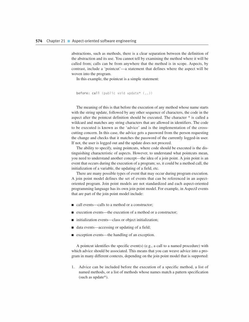
574 Chapter 21 � Aspect-oriented software engineering
abstractions, such as methods, there is a clear separation between the definition of
the abstraction and its use. You cannot tell by examining the method where it will be
called from; calls can be from anywhere that the method is in scope. Aspects, by
contrast, include a ‘pointcut’—a statement that defines where the aspect will be
woven into the program.
In this example, the pointcut is a simple statement:
before: call (public void update* (..))
The meaning of this is that before the execution of any method whose name starts
with the string update, followed by any other sequence of characters, the code in the
aspect after the pointcut definition should be executed. The character * is called a
wildcard and matches any string characters that are allowed in identifiers. The code
to be executed is known as the ‘advice’ and is the implementation of the cross-
cutting concern. In this case, the advice gets a password from the person requesting
the change and checks that it matches the password of the currently logged-in user.
If not, the user is logged out and the update does not proceed.
The ability to specify, using pointcuts, where code should be executed is the dis-
tinguishing characteristic of aspects. However, to understand what pointcuts mean,
you need to understand another concept—the idea of a join point. A join point is an
event that occurs during the execution of a program; so, it could be a method call, the
initialization of a variable, the updating of a field, etc.
There are many possible types of event that may occur during program execution.
A join point model defines the set of events that can be referenced in an aspect-
oriented program. Join point models are not standardized and each aspect-oriented
programming language has its own join point model. For example, in AspectJ events
that are part of the join point model include:
� call events—calls to a method or a constructor;
� execution events—the execution of a method or a constructor;
� initialization events—class or object initialization;
� data events—accessing or updating of a field;
� exception events—the handling of an exception.
A pointcut identifies the specific event(s) (e.g., a call to a named procedure) with
which advice should be associated. This means that you can weave advice into a pro-
gram in many different contexts, depending on the join point model that is supported:
1. Advice can be included before the execution of a specific method, a list of
named methods, or a list of methods whose names match a pattern specification
(such as update*).

21.2 � Aspects, join points, and pointcuts 575
2. Advice can be included after the normal or exceptional return from a method.
In the example shown in Figure 21.5, you could define a pointcut that would
execute the logging code after all calls to update methods.
3. Advice can be included when a field in an object is modified; you can include
advice to monitor or change that field.
The inclusion of advice at the join points specified in the pointcuts is the respon-
sibility of an aspect weaver. Aspect weavers are extensions to compilers that process
the definition of aspects and the object classes and methods that define the system.
The weaver then generates a new program with the aspects included at the specified
join points. The aspects are integrated so that the cross-cutting concerns are executed
at the right places in the final system.
Figure 21.6 illustrates this aspect weaving for the authentication and logging
aspects that should be included in the MHC-PMS. There are three different
approaches to aspect weaving:
1. Source code pre-processing, where a weaver takes source code input and gener-
ates new source code in a language such as Java or C++, which can then be com-
piled using the standard language compiler. This approach has been adopted for
the AspectX language with its associated XWeaver (Birrer et al., 2005).
2. Link time weaving, where the compiler is modified to include an aspect weaver.
An aspect-oriented language such as AspectJ is processed and standard Java
bytecode is generated. This can then be executed directly by a Java interpreter or
further processed to generate native machine code.
3. Dynamic weaving at execution time. In this case, join points are monitored and
when an event that is referenced in a pointcut occurs, the corresponding advice
is integrated with the executing program.
The most commonly used approach to aspect weaving is link time weaving, as this
allows for the efficient implementation of aspects without a large run-time overhead.
Dynamic weaving is the most flexible approach but can incur significant performance
penalties during program execution. Source code pre-processing is now rarely used.
Authentication Aspect
Logging Aspect
Patient...updateDetails (...)...
Aspect Weaver
Patient...authentication codeupdateDetails (...)logging code...
Figure 21.6 Aspectweaving

576 Chapter 21 � Aspect-oriented software engineering
21.3 Software engineering with aspects
Aspects were originally introduced as a programming language construct but, as I
have discussed, the notion of concerns is one that really comes from the system
requirements. Therefore, it makes sense to adopt an aspect-oriented approach at all
stages of the system development process. In the early stages of software engineer-
ing, adopting an aspect-oriented approach means using the notion of separating con-
cerns as a basis for thinking about the requirements and the system design.
Identifying and modeling concerns should be part of the requirements engineering
and design processes. Aspect-oriented programming languages then provide the
technological support to maintain the separation of concerns in your implementation
of the system.
When designing a system, Jacobson and Ng (2004) suggest that you should think of
a system that supports different stakeholder concerns as a core system plus extensions.
I have illustrated this in Figure 21.7, where I have used UML packages to represent
both the core and the extensions. The core system is a set of system features that imple-
ments the essential purpose of a system. Therefore, if the purpose of a particular
system is to maintain information on patients in a hospital, then the core system pro-
vides a means of creating, editing, managing, and accessing a database of patient
records. The extensions to the core system reflect additional stakeholder concerns,
which must be integrated with the core system. For example, it is important that a med-
ical information system maintains the confidentiality of patient information, so one
extension might be concerned with access control, another with encryption, etc.
There are several different types of extension that are derived from the different
types of concern that I discussed in Section 21.1.
1. Secondary functional extensions These add additional capabilities to the function-
ality provided in the core system. For instance, using the example of the MHC-
PMS, the production of reports on the drugs prescribed in the previous month
would be a secondary functional extension to a patient information system.
2. Policy extensions These add functional capabilities to support organizational
policies. Extensions that add security features are examples of policy extensions.
3. QoS extensions These add functional capabilities to help attain the quality of
service requirements that have been specified for the system. For example, an
extension might implement a cache to reduce the number of database accesses
or automated backups for recovery in the event of a system failure.
4. Infrastructure extensions These extensions add functional capabilities to support
the implementation of a system on some specific implementation platform. For
example, in a patient information system, infrastructure extensions might be used
to implement the interface to the underlying database management system.
Changes to this interface can be made by modifying the associated infrastructure
extensions.

21.3 � Software engineering with aspects 577
Extensions always add some kind of functionality or additional features to the
core system. Aspects are a way to implement these extensions and they can be com-
posed with the core system functionality using the weaving facilities in the aspect-
oriented programming environment.
21.3.1 Concern-oriented requirements engineering
As I suggested in Section 21.1, concerns reflect the requirements of stakeholders.
These concerns may reflect the functionality required by a stakeholder, the quality of
system service, organizational policies or issues that are related to the attributes of
the system as a whole. It therefore makes sense to adopt an approach to requirements
engineering that identifies and specifies the different stakeholder concerns. The term
‘early aspects’ is sometimes used to refer to the use of aspects at early stages in the
software lifecycle where the separation of concerns is emphasized.
The importance of separating concerns during requirements engineering has been
recognized for many years. Viewpoints that represent different system perspectives
have been incorporated into a number of requirements engineering methods
(Easterbrook and Nuseibeh, 1996; Finkelstein et al., 1992; Kotonya and Sommerville,
1996). These methods separate the concerns of different stakeholders. Viewpoints
reflect the distinct functionality that is required by different stakeholder groups.
However, there are also requirements which cross-cut all viewpoints, as shown
in Figure 21.8. This diagram shows that viewpoints may be of different types but
cross-cutting concerns (such as regulation, dependability, and security) generate
requirements that may impact on all of the system viewpoints. This was the major
consideration in the work which I did in the development of the PreView method
(Sommerville and Sawyer, 1997; Sommerville et al., 1998), which included steps to
identify cross-cutting, non-functional concerns.
To develop a system that is organized in the style shown in Figure 21.7, you
should identify requirements for the core system plus the requirements for the sys-
tem extensions. A viewpoint-oriented approach to requirements engineering, where
each viewpoint represents the requirements of related groups of stakeholders, is one
Core System
Extension 1 Extension 2 Extension 3
Extension 4 Extension 5 Extension 6Figure 21.7 Coresystem with extensions

578 Chapter 21 � Aspect-oriented software engineering
way to separate core and secondary concerns. If you organize the requirements
according to stakeholder viewpoint, you can then analyze them to discover related
requirements that appear in all or most viewpoints. These represent the core
functionality of the system. Other viewpoint requirements may be requirements that
are specific to that viewpoint. These can be implemented as extensions to the core
functionality.
For example, imagine that you are developing a software system to keep track of
specialized equipment used by the emergency services. Equipment is located at
different places across a region or state and, in the event of an emergency such as a
flood or earthquake, the emergency services use the system to discover what equip-
ment is available close to the site of the problem. Figure 21.9 shows outline require-
ments from three possible viewpoints for such a system.
You can see from this example that stakeholders from all of the different view-
points need to be able to find specific items of equipment, browse the equipment
available at each location, and check in/check out equipment from the store. These
are therefore requirements for the core system. The secondary requirements support
the more specific needs of each viewpoint. There are secondary requirements for
system extensions supporting equipment use, management, and maintenance.
The secondary functional requirements that are identified from any one viewpoint
do not, necessarily, cross-cut the requirements from other viewpoints. For example,
only the maintenance viewpoint is interested in completing maintenance records.
These requirements reflect the needs of that viewpoint and those concerns may not
be shared with other viewpoints. In addition to the secondary functional require-
ments, however, there are cross-cutting concerns that generate requirements of
importance to some or all viewpoints. These often reflect policy and quality of serv-
ice requirements that apply to the system as a whole. As I discussed in Chapter 4,
these are non-functional requirements such as requirements for security, perform-
ance, and cost.
In the equipment inventory system, an example of a cross-cutting concern is system
availability. Emergencies may happen with little or no warning. Saving lives may
require essential equipment to be deployed as quickly as possible. Therefore, the
Viewpoints
Equipment
Users
Managers
Organization
Society
Regulation
Concerns
Security Dependability
THE SYSTEM
Figure 21.8 Viewpointsand Concerns

21.3 � Software engineering with aspects 579
dependability requirements for the equipment inventory system include requirements
for a high level of system availability. Some examples of these dependability require-
ments, with associated rationale, are shown in Figure 21.10. Using these requirements,
you can then identify extensions to the core functionality for transaction logging and sta-
tus reporting. These make it easier to identify problems and switch to a backup system.
The outcome of the requirements engineering process should be a set of require-
ments that are structured around the notion of a core system plus extensions. For
example, in the inventory system, examples of core requirements might be:
C.1 The system shall allow authorized users to view the description of any item of
equipment in the emergency services inventory.
Figure 21.9Viewpoints on anequipment inventorysystem
1. Emergency service users
1.1 Find a specified type of equipment (e.g., heavy lifting gear)1.2 View equipment available in a specified store1.3 Check-out equipment1.4 Check-in equipment1.5 Arrange equipment to be transported to emergency1.6 Submit damage report1.7 Find store close to emergency
2. Emergency planners
2.1 Find a specified type of equipment2.2 View equipment available in a specified location2.3 Check in/check out equipment from a store2.4 Move equipment from one store to another2.6 Order new equipment
3. Maintenance staff
3.1 Check in/check out equipment for maintenance3.2 View equipment available at each store3.3 Find a specified type of equipment3.4 View maintenance schedule for an equipment item3.5 Complete maintenance record for an equipment item3.6 Show all items in a store requiring maintenance
Figure 21.10Availability-relatedrequirements for theequipment inventorysystem
AV.1 There shall be a ‘hot standby’ system available in a location that is geographically well-separatedfrom the principal system.
Rationale: The emergency may affect the principal location of the system.
AV.1.1 All transactions shall be logged at the site of the principal system and at the remote standby site.Rationale: This allows these transactions to be replayed and the system databases made consistent.
AV.1.2 The system shall send status information to the emergency control room system every fiveminutes.
Rationale: The operators of the control room system can switch to the hot standby if the principal system isunavailable.

580 Chapter 21 � Aspect-oriented software engineering
C.2 The system shall include a search facility to allow authorized users to search
either individual inventories or the complete inventory for a specific item of
equipment or a specific type of equipment.
The system may also include an extension that is intended to support equipment
procurement and replacement. Requirements for this extension might be:
E1.1 It shall be possible for authorized users to place orders with accredited sup-
pliers for replacement items of equipment.
E1.1.1 When an item of equipment is ordered, it should be allocated to a specific
inventory and flagged in that inventory as ‘on order’.
As a general rule, you should avoid having too many concerns or extensions to
the system. These simply confuse the reader and may lead to premature design. This
limits the freedom of designers and may result in a system design that cannot meet
its quality of service requirements.
21.3.2 Aspect-oriented design and programming
Aspect-oriented design is the process of designing a system that makes use of
aspects to implement the cross-cutting concerns and extensions that are identified
during the requirements engineering process. At this stage, you need to translate the
concerns that relate to the problem to be solved to corresponding aspects in the pro-
gram that is implementing the solution. You also need to understand how these
aspects will be composed with other system components and ensure that composi-
tion ambiguities do not arise.
The high-level statement of requirements provides a basis for identifying some
system extensions that may be implemented as aspects. You then need to develop
these in more detail to identify further extensions and to understand the functional-
ity that is required. One way to do this is to identify a set of use cases, (discussed in
Chapters 4 and 5) associated with each viewpoint. Use case models are interaction-
focused and more detailed than the user requirements. You can think of them as a
bridge between the requirements and the design. In a use case model, you describe
Viewpoints
I introduced the notion of viewpoints in Chapter 4, where I explained how viewpoints could be used as a wayof structuring the requirements from different stakeholders. Using viewpoints, you can identify the requirementsfor the core system from each stakeholder grouping.
http://www.SoftwareEngineering-9.com/Web/Requirements/Viewpoints.html

21.3 � Software engineering with aspects 581
the steps of each user interaction and so start to identify and define the classes in the
system.
Jacobson and Ng (2004) have written a book that discusses how use cases can be
used in aspect-oriented software engineering. They suggest that each use case repre-
sents an aspect and propose extensions to the use case approach to support join
points and pointcuts. They also introduce the notion of use case slices and use case
modules. These include fragments of classes that implement an aspect. They can be
composed to create the complete system.
Figure 21.11 shows examples of three use cases that might be part of the inven-
tory management system. These reflect the concerns of adding equipment to an
inventory and ordering equipment. Equipment ordering and adding equipment to a
store are related concerns. Once ordered items have been delivered, they must be
added to the inventory and delivered to one of the equipment stores.
The UML already includes the notion of extension use cases. An extension use
case extends the functionality of another use case. Figure 21.12 shows how the
placing of an equipment order extends the core use case for adding equipment to
a specific store. If the equipment to be added does not exist, it can be ordered and
added to the store when the equipment is delivered. During the development of
use case models, you should look for common features and, where possible,
structure the use cases as core cases plus extensions. Cross-cutting features, such
as the logging of all transactions, can also be represented as extension use cases.
Jacobsen and Ng discuss how extensions of this type can be implemented
as aspects.
Add Equipmentto Store
Operator
Remove EquipmentFrom Store
Place EquipmentOrder
Figure 21.11 Use casesfrom the inventorymanagement system
Add Equipmentto Store
Place EquipmentOrder
Operator
«extend»
Figure 21.12 Extensionuse cases

582 Chapter 21 � Aspect-oriented software engineering
Developing an effective process for aspect-oriented design is essential if aspect-
oriented design is to be accepted and used. I suggest that an aspect-oriented design
process should include the activities shown in Figure 21.13. These activities are:
1. Core system design At this stage, you design the system architecture to support
the core functionality of the system. The architecture must also take into
account quality of service requirements such as performance and dependability
requirements.
2. Aspect identification and design Starting with the extensions identified in the
system requirements, you should analyze these to see if they are aspects in
themselves or if they should be broken down into several aspects. Once aspects
have been identified, these can then be separately designed, taking into account
the design of the core system features.
3. Composition design At this stage, you analyze the core system and aspect
designs to discover where the aspects should be composed with the core system.
Essentially, you are identifying the join points in a program at which aspects
will be woven.
4. Conflict analysis and resolution A problem with aspects is that they may inter-
fere with each other when they are composed with the core system. Conflicts
occur when there is a pointcut clash with different aspects specifying that they
should be composed at the same point in the program. However, there may be
more subtle conflicts. When aspects are designed independently, they may make
assumptions about the core system functionality that has to be modified.
However, when several aspects are composed, one aspect may affect the func-
tionality of the system in a way that was not anticipated by other aspects. The
overall system behavior may then not be as expected.
5. Name design This is an important design activity that defines standards for nam-
ing entities in the program. This is essential to avoid the problem of accidental
pointcuts. These occur when, at some program join point, the name accidentally
matches that in a pointcut pattern. The advice is therefore unintentionally
applied at that point. Obviously this is undesirable and can lead to unexpected
program behavior. Therefore, you should design a naming scheme that mini-
mizes the likelihood of this happening.
SoftwareRequirements
Program NamingStandards
DesignModels
Core SystemDesign
AspectIdentificationand Design
CompositionDesign
Conflict Analysisand Resolution
Name Design
Figure 21.13 A genericaspect-oriented designprocess

21.3 � Software engineering with aspects 583
This process is, naturally, an iterative process in which you make initial design pro-
posals then refine them as you analyze and understand the design issues. Normally,
you would expect to refine the extensions identified in the requirements to a larger
number of aspects.
The outcome of the aspect-oriented design process is an aspect-oriented design
model. This may be expressed in an extended version of the UML which includes
new, aspect-specific constructs such as those proposed by Clarke and Baniassad
(2005) and Jacobson and Ng (2004). The essential elements of ‘aspect UML’ are a
means of modeling aspects and of specifying the join points at which the aspect
advice should be composed with the core system.
Figure 21.14 is an example of an aspect-oriented design model. I have used the
UML stereotype for an aspect proposed by Jacobson and Ng. Figure 21.14 shows the
core system for an emergency services inventory plus some aspects that might be
composed with that core. I have shown some core system classes and some aspects.
This is a simplified picture; a complete model would include more classes and
aspects. Notice how I have used UML notes to provide additional information about
the classes that are cross-cut by some aspects.
Figure 21.15 is a more detailed model of an aspect. Obviously, before you design
aspects, you have to have a core system design. As I don’t have space to show this
here, I have made a number of assumptions about classes and methods in the core
system.
The first section of the aspect sets out the pointcuts that specify where it will be
composed with the core system. For example, the first pointcut specifies that the
aspect may be composed at the call getItemInfo (..) join point. The following section
defines the extensions that are implemented by the aspect. In the example here, the
extension statement can be read as:
“In the method viewItem, after the call to the method getItemInfo, a call to
the method displayHistory should be included to display the maintenance
record.”
Inventory
«aspect»Monitor
Equipment
Store
Location
Log
«aspect»Maintenance
«aspect»Ordering
«aspect»Availability
Platform
DB
«joinpoint»EquipmentLocation
«joinpoint»Platform
Figure 21.14 Anaspect-orienteddesign model

584 Chapter 21 � Aspect-oriented software engineering
Aspect-oriented programming (AOP) started at Xerox’s PARC laboratories in
1997, with the development of the AspectJ programming language. This remains the
most widely used aspect-oriented language, although aspect-oriented extensions of
other languages, such as C# and C++, have also been implemented. Other experi-
mental languages have also been developed to support the explicit separation of con-
cerns and concern composition and there are experimental implementation of AOP
in the .NET framework. Aspect-oriented programming is covered extensively in
other books (Colyer et al., 2005; Gradecki and Lezeiki, 2003; Laddad, 2003b).
If you have followed an aspect-oriented approach to designing your system, you
will already have identified the core functionality and the extensions to that function-
ality to be implemented as cross-cutting aspects. The focus of the programming
process should then be to write code implementing the core and extension function-
ality and, critically, to specify the pointcuts in the aspects so that the aspect advice is
woven into the base code at the correct places.
Correctly specifying pointcuts is very important as these define where the aspect
advice will be composed with the core functionality. If you make a mistake in point-
cut specification, then the aspect advice will be woven into the program in the wrong
place. This could lead to unexpected and unpredictable program behavior.
Adherence to the naming standards established during system design is essential.
You also have to review all of the aspects to ensure that aspect interference will not
occur if two or more aspects are woven into the core system at the same join point.
In general, it is best to avoid this completely but, occasionally, it might be the best
way to implement a concern. In those circumstances, you have to ensure that the
aspects are completely independent. The program’s behavior should not depend on
the order that the aspects are woven into the program.
21.3.3 Verification and validation
As I discussed in Chapter 8, verification and validation is the process of demonstrating
that a program meets its specification (verification) and meets the real needs of its
stakeholders (validation). Static verification techniques focus on manual or automated
«aspect»Maintenance
PointcutsviewMain = call getItemInfo (..)mainco = call removeItem (..)mainci = call addItem (..)
Class Extensions
ViewMaintenance History
<viewItem> {after (<viewMain>)displayHistory}
More Extensions HereFigure 21.15 Part of amodel of an aspect
21.3 � Software engineering with aspects 585
analysis of the source code of the program. Dynamic validation or testing is used to
discover defects in the program or to demonstrate that the program meets its require-
ments. When defect detection is the objective, the testing process may be guided by
knowledge of the program’s source code. Test coverage metrics show the effectiveness
of tests in causing source code statements to be executed.
For aspect-oriented systems, the processes of validation testing are no different
than for any other system. The final executable program is treated as a black box
and tests are devised to show whether or not the system meets its requirements.
However, the use of aspects causes real problems with program inspections and white-
box testing, where the program source code is used to identify potential defect tests.
Program inspections, which I describe in Chapter 24, involve a team of readers
looking at the source code of a program to discover defects that have been intro-
duced by the programmer. It is a very effective technique of defect discovery.
However, aspect-oriented programs cannot be read sequentially (i.e., from top to
bottom). They are therefore more difficult for people to understand.
A general guideline for program understandability is that a reader should be able
to read a program from left to right, top to bottom without having to switch attention
to other parts of the code. This makes it easier for readers and also makes it less
likely that programmers will make mistakes as their attention is focused on a single
section of code. Improving program readability was a key reason for the introduction
of structured programming (Dijkstra et al., 1972) and the elimination of uncondi-
tional branch (go-to) statements from high-level programming languages.
In an aspect-oriented system, sequential code reading is impossible. The reader
has to examine each aspect, understand its pointcuts (which may be patterns). and
the join point model of the aspect-oriented language. When reading the program, he
or she then has to identify every potential join point and switch attention to the
aspect code to see if it may be woven at that point. Their attention then returns to
the main flow of control of the base code. In reality, this is cognitively impossible
and the only possible way to inspect an aspect-oriented program is through the use
of code-reading tools.
Code-reading tools can be written that ‘flatten’ an aspect-oriented program and
present a program to the reader with the aspects ‘woven’ into the program at the
specified join points. However, this is not a complete solution to the code-reading
problem. The join point model in an aspect-oriented programming language may be
dynamic rather than static and it may be impossible to demonstrate that the flattened
program will behave in exactly the same way as the program that will execute.
Furthermore, because it is possible for different aspects to have the same pointcut
specification, the program-reading tool must know how the aspect weaver handles
these ‘competing’ aspects and how the composition will be ordered.
White-box or structural testing is a systematic approach to testing where knowl-
edge of the program source code is used to design defect tests. The aim is to design
tests that provide some level of program coverage. That is, the set of tests should
ensure that every logical path through the program is executed, with the consequence
that each program statement is executed at least once. Program execution analyzers
may be used to demonstrate that this level of test coverage has been achieved.

586 Chapter 21 � Aspect-oriented software engineering
In an aspect-oriented system, there are two problems with this approach:
1. How can knowledge of the program code be used to systematically derive pro-
gram tests?
2. What exactly does test coverage mean?
To design tests in a structured program (e.g., tests of the code of a method) with-
out unconditional branches, you can derive a program flow graph, which reveals
every logical execution path through that program. You then examine the code and,
for each path through the flow graph, choose input values that will cause that path to
be executed.
However, an aspect-oriented program is not a structured program. The flow of
control is interrupted by ‘come from’ statements (Constantinos et al., 2004). At
some join point in the execution of the base code, an aspect may be executed. I am
not sure that it is possible to construct a structured flow diagram in such a situation.
It is therefore difficult to systematically design program tests that ensure that all
combinations of base code and aspects are executed.
In an aspect-oriented program, there is also the problem of deciding what ‘test
coverage’ means. Does it mean that the code of each aspect is executed at least once?
This is a very weak condition because of the interaction between aspects and the
base code at the join points where the aspects are woven. Should the idea of test cov-
erage be extended so that the code of the aspect is executed at least once at every join
point specified in the aspect pointcut? In such situations, what happens if different
aspects define the same pointcut? These are both theoretical and practical problems.
We need tools to support aspect-oriented program testing which will help assess the
extent of test coverage of a system.
As I discuss in Chapter 24, large projects normally have a separate quality assur-
ance team who set testing standards and who require a formal assurance that pro-
gram reviews and testing have been completed to these standards. The problems of
inspecting and deriving tests for aspect-oriented programs are a significant barrier
to the adoption of aspect-oriented software development in such large software
projects.
As well as problems with inspections and white-box testing, Katz (2005) identi-
fied additional problems in testing aspect-oriented programs:
1. How should aspects be specified so that tests for these aspects may be derived?
2. How can aspects be tested independently of the base system with which they
should be woven?
3. How can aspect interference be tested? As I have discussed, aspect interference
occurs when two or more aspects use the same pointcut specification.
4. How can tests be designed so that all program join points are executed and
appropriate aspect tests applied?

Chapter 21 � Further reading 587
Fundamentally, these testing problems occur because aspects are tightly rather
than loosely integrated with the base code of a system. They are therefore difficult to
test in isolation. Because they may be woven into a program in many different
places, you can’t be sure that an aspect that works successfully at one join point will
necessarily work at all join points. All of these remain research problems for aspect-
oriented software development.
K E Y P O I N T S
� The main benefit of an aspect-oriented approach to software development is that it supports the
separation of concerns. By representing cross-cutting concerns as aspects, individual concerns
can be understood, reused, and modified without changing other parts of the program.
� Tangling occurs when a module in a system includes code that implements different system
requirements. The related phenomenon of scattering occurs when the implementation of a
single concern is scattered across several components in a program.
� Aspects include a pointcut—a statement that defines where the aspect will be woven into the
program, and advice—the code to implement the cross-cutting concern. Join points are the
events that can be referenced in a pointcut.
� To ensure the separation of concerns, systems can be designed as a core system that
implements the primary concerns of stakeholders, and a set of extensions that implement
secondary concerns.
� To identify concerns, you may use a viewpoint-oriented approach to requirements engineering
to elicit stakeholder requirements and to identify cross-cutting quality of service and policy
concerns.
� The transition from requirements to design can be made by identifying use cases, where each
use case represents a stakeholder concern. The design may be modeled using an extended
version of the UML with aspect stereotypes.
� The problems of inspecting and deriving tests for aspect-oriented programs are a significant
barrier to the adoption of aspect-oriented software development in large software projects.
F U RT H E R R E A D I N G
‘Aspect-oriented programming’. This special issue of the CACM has a number of articles for a
general audience, which are a good starting point for reading about aspect-oriented programming
(Comm. ACM, 44 (10), October 2001.) http://dx.doi.org/10.1145/383845.383846.

588 Chapter 21 � Aspect-oriented software engineering
Aspect-oriented Software Development. A multiauthor book with a wide range of papers on aspect-
oriented software development, written by many of the leading researchers in the field. (R. E.
Filman, T. Elrad, S. Clarke and M. Aksit, Addison-Wesley, 2005.)
Aspect-oriented Software Development with Use cases. This is a practical book for software
designers. The authors discuss how to use use cases to manage the separation of concerns, and to
use these as the basis of an aspect-oriented design. (I. Jacobson and P. Ng, Addison-Wesley, 2005.)
E X E R C I S E S
21.1. What are the different types of stakeholder concern that may arise in a large system? How
can aspects support the implementation of each of these types of concern?
21.2. Summarize what is meant by tangling and scattering. Using examples, explain why tangling
and scattering can cause problems when system requirements change.
21.3. What is the difference between a join point and a pointcut? Explain how these facilitate the
weaving of code into a program to handle cross-cutting concerns.
21.4. What assumptions underlie the idea that a system should be organized as a core system
that implements the essential requirements, plus extensions that implement additional
functionality? Can you think of systems where this model would not be appropriate?
21.5. What viewpoints should be considered when developing a requirements specification for the
MHC-PMS? What are likely to be the most important cross-cutting concerns?
21.6. Using the outline functionality for each viewpoint shown in Figure 21.9, identify six further
use cases for the equipment inventory system, in addition to those shown in Figure 21.11.
Where appropriate, show how some of these might be organized as extension use cases.
21.7. Using the aspect stereotype notation illustrated in Figure 21.15, develop in more detail the
Ordering and Monitor aspects, shown in Figure 21.14.
21.8. Explain how aspect interference can arise and suggest what should be done during the
system design process to reduce the problems of aspect interference.
21.9. Explain why expressing pointcut specifications as patterns increases the problems of testing
aspect-oriented programs. To answer this, think about how program testing normally
involves comparing the expected output to the actual output produced by a program.
21.10. Suggest how you could use aspects to simplify the debugging of programs.

R E F E R E N C E S
Birrer, I., Pasetti, A. and Rohlik, O. (2005). ‘The XWeaver Project: Aspect-oriented Programming
for On-Board Applications’. http://control.ee.ethz.ch/index.cgi?page=publications;action=
details;id=2361
Clark, S. and Baniassad, E. (2005). Aspect-Oriented Analysis and Design: The Theme Approach.
Harlow, UK: Addison-Wesley.
Colyer, A. and Clement, A. (2005). ‘Aspect-oriented programming with AspectJ’. IBM Systems J.,
44 (2), 301–8.
Colyer, A., Clement, A., Harley, G. and Webster, M. (2005). eclipse AspectJ. Upper Saddle River,
NJ: Addison-Wesley.
Constantinos, C., Skotiniotis, T. and Stoerzer, T. (2004). ‘AOP considered harmful’. European
Interactive Workshop on Aspects in Software (EIWAS’04), Berlin, Germany.
Dijkstra, E. W., Dahl, O. J. and Hoare, C. A. R. (1972). Structured Programming. London:
Academic Press.
Easterbrook, S. and Nuseibeh, B. (1996). ‘Using ViewPoints for inconsistency management’.
BCS/IEE Software Eng. J., 11 (1), 31–43.
Finkelstein, A., Kramer, J., Nuseibeh, B. and Goedicke, M. (1992). ‘Viewpoints: A Framework for
Integrating Multiple Perspectives in System Development’. Int. J. of Software Engineering and
Knowledge Engineering, 2 (1), 31–58.
Gradecki, J. D. and Lezeiki, N. (2003). Mastering AspectJ: Aspect-Oriented Programming in Java.
New York: John Wiley & Sons.
Jacobson, I. and Ng, P-W. (2004). Aspect-oriented Software Development with Use Cases.
Boston: Addison-Wesley.
Katz, S. (2005). ‘A Survey of Verification and Static Analysis for Aspects’. http://www.aosd-europe.net/
documents/verificM81.pdf
Kiczales, G., Hilsdale, E., Hugunin, J., Kersten, M., Palm, J. and Griswold, W. G. (2001). ‘Getting
Started with AspectJ’. Comm. ACM, 44 (10), 59–65.
Kotonya, G. and Sommerville, I. (1996). ‘Requirements engineering with viewpoints’.
BCS/IEE Software Eng. J., 11 (1), 5–18.
Laddad, R. (2003a). AspectJ in Action. Greenwich, Conn.: Manning Publications Co.
Laddad, R. (2003b). AspectJ in Action: Practical Aspect-Oriented Programming. Greenwich,
Conn.: Manning Publications.
Sommerville, I. and Sawyer, P. (1997). ‘Viewpoints: principles, problems and a practical approach
to requirements engineering’. Annals of Software Engineering, 3 101–30.
Sommerville, I., Sawyer, P. and Viller, S. (1998). ‘Viewpoints for requirements elicitation: a practical
approach’. 3rd Int. Conf. on Requirements Engineering. Colorado: IEEE Computer Society Press, 74–81.
Chapter 21 � References 589

This page intentionally left blank
PART
4 SoftwareManagement
It is sometimes suggested that the key difference between software engi-
neering and other types of programming is that software engineering is a
managed process. By this, I mean that the software development takes
place within an organization and is subject to a range of schedule, budget,
and organizational constraints. Management is therefore very important to
software engineering. I introduce a range of management topics in this part
of the book with a focus on technical management issues rather than
‘softer’ management issues such as people management, or the more
strategic management of enterprise systems.
Chapter 22 introduces software project management and its first major sec-
tion is concerned with risk management. Along with project planning, risk
management, where managers identify what might go wrong and plan what
they might do about it, is a key project management responsibility. This
chapter also includes sections on people management and team working.
Chapter 23 covers project planning and estimation. I introduce bar charts
as fundamental planning tools and explain why plan-driven development
will remain an important development approach, in spite of the success
of agile methods. I also discuss issues that influence the price charged
for a system and techniques of software cost estimation. I use the
COCOMO family of cost models to describe algorithmic cost modeling
and explain the benefits and disadvantages of this approach.
Chapters 24 to 26 are concerned with issues of quality management.
Quality management is concerned with processes and techniques for
ensuring and improving the quality of software and I introduce this topic
in Chapter 24. I discuss the importance of standards in quality manage-
ment, the use of reviews and inspections in the quality assurance
process, and the role of software measurement in quality management.
Chapter 25 discusses configuration management. This is an issue that is
important for all large systems, which are developed by teams.
However, the need for configuration management is not always obvi-
ous to students who have only been concerned with personal software
development, so I describe the various aspects of this topic here,
including configuration planning, version management, system building,
and change management.
Finally, Chapter 26 covers software process improvement—how can
processes be modified so that both product and process attributes are
improved? I discuss the stages of a generic process improvement
process, namely, process measurement, process analysis, and process
change. I then go on to cover the SEI’s capability-based approach to
process improvement and briefly explain capability maturity models.
Project management
22
Objectives
The objective of this chapter is to introduce software project management
and two important management activities, namely risk management and
people management. When you have read the chapter you will:
� know the principal tasks of software project managers;
� have been introduced to the notion of risk management and some of
the risks that can arise in software projects;
� understand factors that influence personal motivation and what these
might mean for software project managers;
� understand key issues that influence team working, such as team
composition, organization, and communication.
Contents
22.1 Risk management
22.2 Managing people
22.3 Teamwork
594 Chapter 22 � Project management
Software project management is an essential part of software engineering. Projects
need to be managed because professional software engineering is always subject to
organizational budget and schedule constraints. The project manager’s job is to ensure
that the software project meets and overcomes these constraints as well as delivering
high-quality software. Good management cannot guarantee project success. However,
bad management usually results in project failure: the software may be delivered late,
cost more than originally estimated, or fail to meet the expectations of customers.
The success criteria for project management obviously vary from project to proj-
ect but, for most projects, important goals are:
1. Deliver the software to the customer at the agreed time.
2. Keep overall costs within budget.
3. Deliver software that meets the customer’s expectations.
4. Maintain a happy and well-functioning development team.
These goals are not unique to software engineering but are the goals of all engi-
neering projects. However, software engineering is different from other types of
engineering in a number of ways that make software management particularly chal-
lenging. Some of these differences are:
1. The product is intangible A manager of a shipbuilding or a civil engineering
project can see the product being developed. If a schedule slips, the effect on
the product is visible—parts of the structure are obviously unfinished.
Software is intangible. It cannot be seen or touched. Software project managers
cannot see progress by simply looking at the artifact that is being constructed.
Rather, they rely on others to produce evidence that they can use to review the
progress of the work.
2. Large software projects are often ‘one-off’ projects Large software projects are
usually different in some ways from previous projects. Therefore, even man-
agers who have a large body of previous experience may find it difficult to antic-
ipate problems. Furthermore, rapid technological changes in computers and
communications can make a manager’s experience obsolete. Lessons learned
from previous projects may not be transferable to new projects.
3. Software processes are variable and organization-specific The engineering
process for some types of system, such as bridges and buildings, is well under-
stood. However, software processes vary quite significantly from one organization
to another. Although there has been significant progress in process standardization
and improvement, we still cannot reliably predict when a particular software
process is likely to lead to development problems. This is especially true when the
software project is part of a wider systems engineering project.
Because of these issues, it is not surprising that some software projects are late,
over budget, and behind schedule. Software systems are often new and technically

22.1 � Risk management 595
innovative. Engineering projects (such as new transport systems) that are innovative
often also have schedule problems. Given the difficulties involved, it is perhaps
remarkable that so many software projects are delivered on time and to budget!
It is impossible to write a standard job description for a software project manager.
The job varies tremendously depending on the organization and the software product
being developed. However, most managers take responsibility at some stage for
some or all of the following activities:
1. Project planning Project managers are responsible for planning, estimating and
scheduling project development, and assigning people to tasks. They supervise
the work to ensure that it is carried out to the required standards and monitor
progress to check that the development is on time and within budget.
2. Reporting Project managers are usually responsible for reporting on the
progress of a project to customers and to the managers of the company develop-
ing the software. They have to be able to communicate at a range of levels, from
detailed technical information to management summaries. They have to write
concise, coherent documents that abstract critical information from detailed
project reports. They must be able to present this information during progress
reviews.
3. Risk management Project managers have to assess the risks that may affect a
project, monitor these risks, and take action when problems arise.
4. People management Project managers are responsible for managing a team of
people. They have to choose people for their team and establish ways of work-
ing that lead to effective team performance.
5. Proposal writing The first stage in a software project may involve writing a pro-
posal to win a contract to carry out an item of work. The proposal describes the
objectives of the project and how it will be carried out. It usually includes cost
and schedule estimates and justifies why the project contract should be awarded
to a particular organization or team. Proposal writing is a critical task as the sur-
vival of many software companies depends on having enough proposals
accepted and contracts awarded. There can be no set guidelines for this task;
proposal writing is a skill that you acquire through practice and experience.
In this chapter, I focus on risk management and people management. Project
planning is an important topic in its own right, which I discuss in Chapter 23.
22.1 Risk management
Risk management is one of the most important jobs for a project manager. Risk
management involves anticipating risks that might affect the project schedule or the
quality of the software being developed, and then taking action to avoid these risks

596 Chapter 22 � Project management
(Hall, 1998; Ould, 1999). You can think of a risk as something that you’d prefer not
to have happen. Risks may threaten the project, the software that is being developed,
or the organization. There are, therefore, three related categories of risk:
1. Project risks Risks that affect the project schedule or resources. An example of
a project risk is the loss of an experienced designer. Finding a replacement
designer with appropriate skills and experience may take a long time and, con-
sequently, the software design will take longer to complete.
2. Product risks Risks that affect the quality or performance of the software being
developed. An example of a product risk is the failure of a purchased component
to perform as expected. This may affect the overall performance of the system
so that it is slower than expected.
3. Business risks Risks that affect the organization developing or procuring the
software. For example, a competitor introducing a new product is a business
risk. The introduction of a competitive product may mean that the assumptions
made about sales of existing software products may be unduly optimistic.
Of course, these risk types overlap. If an experienced programmer leaves a
project this can be a project risk because, even if they are immediately replaced,
the schedule will be affected. It inevitably takes time for a new project member
to understand the work that has been done, so they cannot be immediately pro-
ductive. Consequently, the delivery of the system may be delayed. The loss of a
team member can also be a product risk because a replacement may not be as
experienced and so could make programming errors. Finally, it can be a business
risk because that programmer’s experience may be crucial in winning new
contracts.
You should record the results of the risk analysis in the project plan along with a
consequence analysis, which sets out the consequences of the risk for the project,
product, and business. Effective risk management makes it easier to cope with
problems and to ensure that these do not lead to unacceptable budget or schedule
slippage.
The specific risks that may affect a project depend on the project and the orga-
nizational environment in which the software is being developed. However, there
are also common risks that are not related to the type of software being developed
and these can occur in any project. Some of these common risks are shown in
Figure 22.1.
Risk management is particularly important for software projects because of the
inherent uncertainties that most projects face. These stem from loosely defined
requirements, requirements changes due to changes in customer needs, difficulties in
estimating the time and resources required for software development, and differ-
ences in individual skills. You have to anticipate risks; understand the impact of
these risks on the project, the product, and the business; and take steps to avoid these
risks. You may need to draw up contingency plans so that, if the risks do occur, you
can take immediate recovery action.

22.1 � Risk management 597
An outline of the process of risk management is illustrated in Figure 22.2. It
involves several stages:
1. Risk identification You should identify possible project, product, and business
risks.
2. Risk analysis You should assess the likelihood and consequences of these risks.
3. Risk planning You should make plans to address the risk, either by avoiding it or
minimizing its effects on the project.
4. Risk monitoring You should regularly assess the risk and your plans for risk
mitigation and revise these when you learn more about the risk.
You should document the outcomes of the risk management process in a risk
management plan. This should include a discussion of the risks faced by the project,
an analysis of these risks, and information on how you propose to manage the risk if
it seems likely to be a problem.
The risk management process is an iterative process that continues throughout the
project. Once you have drawn up an initial risk management plan, you monitor the
situation to detect emerging risks. As more information about the risks becomes avail-
able, you have to reanalyze the risks and decide if the risk priority has changed. You
may then have to change your plans for risk avoidance and contingency management.
Risk Affects Description
Staff turnover Project Experienced staff will leave the project before itis finished.
Management change Project There will be a change of organizationalmanagement with different priorities.
Hardware unavailability Project Hardware that is essential for the project will notbe delivered on schedule.
Requirements change Project and product There will be a larger number of changes to therequirements than anticipated.
Specification delays Project and product Specifications of essential interfaces are notavailable on schedule.
Size underestimate Project and product The size of the system has been underestimated.
CASE tool underperformance Product CASE tools, which support the project, do notperform as anticipated.
Technology change Business The underlying technology on which the systemis built is superseded by new technology.
Product competition Business A competitive product is marketed before thesystem is completed.
Figure 22.1Examples of commonproject, product, and business risks

598 Chapter 22 � Project management
22.1.1 Risk identification
Risk identification is the first stage of the risk management process. It is concerned
with identifying the risks that could pose a major threat to the software engineering
process, the software being developed, or the development organization. Risk identi-
fication may be a team process where a team get together to brainstorm possible
risks. Alternatively, the project manager may simply use his or her experience to
identify the most probable or critical risks.
As a starting point for risk identification, a checklist of different types of risk may
be used. There are at least six types of risk that may be included in a risk checklist:
1. Technology risks Risks that derive from the software or hardware technologies
that are used to develop the system.
2. People risks Risks that are associated with the people in the development team.
3. Organizational risks Risks that derive from the organizational environment
where the software is being developed.
4. Tools risks Risks that derive from the software tools and other support software
used to develop the system.
5. Requirements risks Risks that derive from changes to the customer requirements
and the process of managing the requirements change.
6. Estimation risks Risks that derive from the management estimates of the
resources required to build the system.
Figure 22.3 gives some examples of possible risks in each of these categories.
When you have finished the risk identification process, you should have a long list of
risks that could occur and which could affect the product, the process, and the busi-
ness. You then need to prune this list to a manageable size. If you have too many
risks, it is practically impossible to keep track of all of them.
22.1.2 Risk analysis
During the risk analysis process, you have to consider each identified risk and make
a judgment about the probability and seriousness of that risk. There is no easy way to
do this. You have to rely on your own judgment and experience of previous projects
RiskIdentification
RiskAnalysis
RiskPlanning
RiskMonitoring
List of PotentialRisks
Prioritized RiskList
Risk Avoidanceand Contingency
Plans
RiskAssessment
Figure 22.2The riskmanagementprocess

22.1 � Risk management 599
Figure 22.3Examples of differenttypes of risks
and the problems that arose in them. It is not possible to make precise, numeric
assessment of the probability and seriousness of each risk. Rather, you should assign
the risk to one of a number of bands:
1. The probability of the risk might be assessed as very low (� 10%), low
(10–25%), moderate (25–50%), high (50–75%), or very high (� 75%).
2. The effects of the risk might be assessed as catastrophic (threaten the survival of
the project), serious (would cause major delays), tolerable (delays are within
allowed contingency), or insignificant.
You should then tabulate the results of this analysis process using a table ordered
according to the seriousness of the risk. Figure 22.4 illustrates this for the risks that I
have identified in Figure 22.3. Obviously, the assessment of probability and serious-
ness is arbitrary here. To make this assessment, you need detailed information about
the project, the process, the development team, and the organization.
Of course, both the probability and the assessment of the effects of a risk may
change as more information about the risk becomes available and as risk manage-
ment plans are implemented. Therefore, you should update this table during each
iteration of the risk process.
Once the risks have been analyzed and ranked, you should assess which of these
risks are most significant. Your judgment must depend on a combination of the
probability of the risk arising and the effects of that risk. In general, catastrophic
risks should always be considered, as should all serious risks that have more than a
moderate probability of occurrence.
Risk type Possible risks
Technology The database used in the system cannot process as many transactions per second asexpected. (1)Reusable software components contain defects that mean they cannot be reused asplanned. (2)
People It is impossible to recruit staff with the skills required. (3)Key staff are ill and unavailable at critical times. (4)Required training for staff is not available. (5)
Organizational The organization is restructured so that different management are responsible for theproject. (6)Organizational financial problems force reductions in the project budget. (7)
Tools The code generated by software code generation tools is inefficient. (8)Software tools cannot work together in an integrated way. (9)
Requirements Changes to requirements that require major design rework are proposed. (10)Customers fail to understand the impact of requirements changes. (11)
Estimation The time required to develop the software is underestimated. (12)The rate of defect repair is underestimated. (13)The size of the software is underestimated. (14)

600 Chapter 22 � Project management
Figure 22.4 Risk typesand examples
Boehm (1988) recommends identifying and monitoring the top 10 risks, but I
think that this figure is rather arbitrary. The right number of risks to monitor must
depend on the project. It might be 5 or it might be 15. However, the number of risks
chosen for monitoring should be manageable. A very large number of risks would
simply require too much information to be collected. From the risks identified in
Figure 22.4, it is appropriate to consider the 8 risks that have catastrophic or serious
consequences (Figure 22.5).
22.1.3 Risk planning
The risk planning process considers each of the key risks that have been identified,
and develops strategies to manage these risks. For each of the risks, you have to think
of actions that you might take to minimize the disruption to the project if the problem
identified in the risk occurs. You also should think about information that you might
need to collect while monitoring the project so that problems can be anticipated.
Risk Probability Effects
Organizational financial problems force reductions in the project budget (7).
Low Catastrophic
It is impossible to recruit staff with the skills required for the project (3).
High Catastrophic
Key staff are ill at critical times in the project (4). Moderate Serious
Faults in reusable software components have to be repaired beforethese components are reused. (2).
Moderate Serious
Changes to requirements that require major design rework areproposed (10).
Moderate Serious
The organization is restructured so that different management areresponsible for the project (6).
High Serious
The database used in the system cannot process as many transactionsper second as expected (1).
Moderate Serious
The time required to develop the software is underestimated (12). High Serious
Software tools cannot be integrated (9). High Tolerable
Customers fail to understand the impact of requirements changes (11). Moderate Tolerable
Required training for staff is not available (5). Moderate Tolerable
The rate of defect repair is underestimated (13). Moderate Tolerable
The size of the software is underestimated (14). High Tolerable
Code generated by code generation tools is inefficient (8). Moderate Insignificant

22.1 � Risk management 601
Again, there is no simple process that can be followed for contingency planning. It
relies on the judgment and experience of the project manager.
Figure 22.5 shows possible risk management strategies that have been identified
for the key risks (i.e., those that are serious or intolerable) shown in Figure 22.4.
These strategies fall into three categories:
1. Avoidance strategies Following these strategies means that the probability that
the risk will arise will be reduced. An example of a risk avoidance strategy is the
strategy for dealing with defective components shown in Figure 22.5.
2. Minimization strategies Following these strategies means that the impact of the
risk will be reduced. An example of a risk minimization strategy is the strategy
for staff illness shown in Figure 22.5.
3. Contingency plans Following these strategies means that you are prepared for
the worst and have a strategy in place to deal with it. An example of a contin-
gency strategy is the strategy for organizational financial problems that I have
shown in Figure 22.5.
You can see a clear analogy here with the strategies used in critical systems to
ensure reliability, security, and safety, where you must avoid, tolerate, or recover
from failures. Obviously, it is best to use a strategy that avoids the risk. If this is not
possible, you should use a strategy that reduces the chances that the risk will have
serious effects. Finally, you should have strategies in place to cope with the risk if it
arises. These should reduce the overall impact of a risk on the project or product.
Risk Strategy
Organizational financialproblems
Prepare a briefing document for senior management showing how the project ismaking a very important contribution to the goals of the business and presentingreasons why cuts to the project budget would not be cost-effective.
Recruitment problems Alert customer to potential difficulties and the possibility of delays; investigatebuying-in components.
Staff illness Reorganize team so that there is more overlap of work and people thereforeunderstand each other’s jobs.
Defective components Replace potentially defective components with bought-in components of knownreliability.
Requirements changes Derive traceability information to assess requirements change impact; maximizeinformation hiding in the design.
Organizationalrestructuring
Prepare a briefing document for senior management showing how the project ismaking a very important contribution to the goals of the business.
Database performance Investigate the possibility of buying a higher-performance database.
Underestimateddevelopment time
Investigate buying-in components; investigate use of a program generator.
Figure 22.5 Strategiesto help manage risk

602 Chapter 22 � Project management
Figure 22.6 Riskindicators
22.1.4 Risk monitoring
Risk monitoring is the process of checking that your assumptions about the product,
process, and business risks have not changed. You should regularly assess each of
the identified risks to decide whether or not that risk is becoming more or less prob-
able. You should also think about whether or not the effects of the risk have changed.
To do this, you have to look at other factors, such as the number of requirements
change requests, which give you clues about the risk probability and its effects.
These factors are obviously dependent on the types of risk. Figure 22.6 gives some
examples of factors that may be helpful in assessing these risk types.
You should monitor risks regularly at all stages in a project. At every management
review, you should consider and discuss each of the key risks separately. You should
decide if the risk is more or less likely to arise and if the seriousness and conse-
quences of the risk have changed.
22.2 Managing people
The people working in a software organization are its greatest assets. It costs a lot to
recruit and retain good people and it is up to software managers to ensure that the
organization gets the best possible return on its investment. In successful companies
and economies, this is achieved when people are respected by the organization and
are assigned responsibilities that reflect their skills and experience.
It is important that software project managers understand the technical issues
that influence the work of software development. Unfortunately, however, good
software engineers are not necessarily good people managers. Software engineers
often have strong technical skills but may lack the softer skills that enable them to
Risk type Potential indicators
Technology Late delivery of hardware or support software; many reportedtechnology problems.
People Poor staff morale; poor relationships amongst team members;high staff turnover.
Organizational Organizational gossip; lack of action by senior management.
Tools Reluctance by team members to use tools; complaints aboutCASE tools; demands for higher-powered workstations.
Requirements Many requirements change requests; customer complaints.
Estimation Failure to meet agreed schedule; failure to clear reporteddefects.

22.2 � Managing people 603
motivate and lead a project development team. As a project manager, you should be
aware of the potential problems of people management and should try to develop
people management skills.
In my view, there are four critical factors in people management:
1. Consistency People in a project team should all be treated in a comparable way.
No one expects all rewards to be identical but people should not feel that their
contribution to the organization is undervalued.
2. Respect Different people have different skills and managers should respect these
differences. All members of the team should be given an opportunity to make a
contribution. In some cases, of course, you will find that people simply don’t fit
into a team and they cannot continue, but it is important not to jump to conclu-
sions about this at an early stage in the project.
3. Inclusion People contribute effectively when they feel that others listen to them
and take account of their proposals. It is important to develop a working envi-
ronment where all views, even those of the most junior staff, are considered.
4. Honesty As a manager, you should always be honest about what is going well
and what is going badly in the team. You should also be honest about your level
of technical knowledge and willing to defer to staff with more knowledge when
necessary. If you try to cover up ignorance or problems you will eventually be
found out and will lose the respect of the group.
People management, in my view, is something that has to be based on experience,
rather than learned from a book. My aim in this section and the following section on
teamwork is simply to introduce some of the most important people and team manage-
ment problems that affect software project management. I hope the material here will
sensitize you to some of the problems that managers may encounter when dealing with
teams of technically talented individuals.
22.2.1 Motivating people
As a project manager, you need to motivate the people that work with you so that
they contribute to the best of their abilities. Motivation means organizing the work
and the working environment to encourage people to work as effectively as possible.
If people are not motivated, they will not be interested in the work they are doing.
They will work slowly, be more likely to make mistakes, and will not contribute to
the broader goals of the team or the organization.
To provide this encouragement, you should understand a little about what moti-
vates people. Maslow (1954) suggests that people are motivated by satisfying their
needs. These needs are arranged in a series of levels, as shown in Figure 22.7. The
lower levels of this hierarchy represent fundamental needs for food, sleep, and so on,
and the need to feel secure in an environment. Social needs are concerned with the
need to feel part of a social grouping. Esteem needs represent the need to feel

604 Chapter 22 � Project management
respected by others, and self-realization needs are concerned with personal develop-
ment. People need to satisfy lower-level needs like hunger before the more abstract,
higher-level needs.
People working in software development organizations are not usually hungry or
thirsty or physically threatened by their environment. Therefore, making sure that
people’s social, esteem, and self-realization needs are satisfied is most important
from a management point of view.
1. To satisfy social needs, you need to give people time to meet their co-workers
and provide places for them to meet. This is relatively easy when all of the
members of a development team work in the same place but, increasingly, team
members are not located in the same building or even the same town or state.
They may work for different organizations or from home most of the time.
Social networking systems and teleconferencing can be used to facilitate com-
munications but my experience with electronic systems is that they are most
effective once people know each other. You therefore need to arrange some
face-to-face meetings early in the project so that people can directly interact
with other members of the team. Through this direct interaction, people become
part of a social group and accept the goals and priorities of that group.
2. To satisfy esteem needs, you need to show people that they are valued by the
organization. Public recognition of achievements is a simple yet effective way
of doing this. Obviously, people must also feel that they are paid at a level that
reflects their skills and experience.
3. Finally, to satisfy self-realization needs, you need to give people responsibility
for their work, assign them demanding (but not impossible) tasks, and provide a
training programme where people can develop their skills. Training is an impor-
tant motivating influence as people like to gain new knowledge and learn new
skills.
In Figure 22.8, I illustrate a problem of motivation that managers often have to
face. In this example, a competent group member loses interest in the work and in
Physiological Needs
Safety Needs
Social Needs
Esteem Needs
Self-Realization Needs
Figure 22.7 Humanneeds hierarchy

22.2 � Managing people 605
Figure 22.8 Individualmotivation
the group as a whole. The quality of her work falls and becomes unacceptable. This
situation has to be dealt with quickly. If you don’t sort out the problem, the other
group members will become dissatisfied and feel that they are doing an unfair share
of the work.
In this example, Alice tries to find out if Dorothy’s personal circumstances could
be the problem. Personal difficulties commonly affect motivation because people
cannot concentrate on their work. You may have to give them time and support to
resolve these issues, although you also have to make it clear that they still have a
responsibility to their employer.
Dorothy’s motivation problem is one that is quite common when projects develop
in an unexpected direction. People who expect to do one type of work may end up
doing something completely different. This becomes a problem when team members
want to develop their skills in a way that is different from that taken by the project.
In those circumstances, you may decide that the team member should leave the team
and find opportunities elsewhere. In this example, however, Alice decides to try to
convince Dorothy that broadening her experience is a positive career step. She gives
Dorothy more design autonomy and organizes training courses in software engineer-
ing that will give her more opportunities after her current project has finished.
Case study: Motivation
Alice is a software project manager working in a company that develops alarm systems.This company wishes to enter the growing market of assistive technology to helpelderly and disabled people live independently. Alice has been asked to lead a team of 6 developers than can develop new products based around the company’s alarmtechnology.
Alice’s assistive technology project starts well. Good working relationships developwithin the team and creative new ideas are developed. The team decides to develop a peer-to-peer messaging system using digital televisions linked to the alarm networkfor communications. However, some months into the project, Alice notices thatDorothy, a hardware design expert, starts coming into work late, the quality of her workdeteriorates and, increasingly, that she does not appear to be communicating withother members of the team.
Alice talks about the problem informally with other team members to try to find outif Dorothy’s personal circumstances have changed, and if this might be affecting herwork. They don’t know of anything, so Alice decides to talk with Dorothy to try tounderstand the problem.
After some initial denials that there is a problem, Dorothy admits that she has lost interest in the job. She expected that she would be able to develop and use herhardware interfacing skills. However, because of the product direction that has beenchosen, she has little opportunity for this. Basically, she is working as a C programmerwith other team members.
Although she admits that the work is challenging, she is concerned that she is not developing her interfacing skills. She is worried that finding a job that involveshardware interfacing will be difficult after this project. Because she does not want toupset the team by revealing that she is thinking about the next project, she has decidedthat it is best to minimize conversation with them.

606 Chapter 22 � Project management
Maslow’s model of motivation is helpful up to a point but I think that a problem
with it is that it takes an exclusively personal viewpoint on motivation. It does not
take adequate account of the fact that people feel themselves to be part of an organi-
zation, a professional group, and one or more cultures. This is not simply a question
of satisfying social needs—people can be motivated through helping a group achieve
shared goals.
Being a member of a cohesive group is highly motivating for most people. People
with fulfilling jobs often like to go to work because they are motivated by the people
they work with and the work that they do. Therefore, as well as thinking about indi-
vidual motivation you also have to think about how a group as a whole can be moti-
vated to achieve the organization’s goals. I discuss group management issues in the
next section.
Personality type also influences motivation. Bass and Dunteman (1963) classify
professionals into three types:
1. Task-oriented people, who are motivated by the work they do. In software engi-
neering, these are people who are motivated by the intellectual challenge of
software development.
2. Self-oriented people, who are principally motivated by personal success and
recognition. They are interested in software development as a means of achiev-
ing their own goals. This does not mean that these people are selfish and think
only of their own concerns. Rather, they often have longer-term goals, such as
career progression, that motivate them and they wish to be successful in their
work to help realize these goals.
3. Interaction-oriented people, who are motivated by the presence and actions of
co-workers. As software development becomes more user-centered, interaction-
oriented individuals are becoming more involved in software engineering.
Interaction-oriented personalities usually like to work as part of a group, whereas
task-oriented and self-oriented people usually prefer to act as individuals. Women
are more likely to be interaction-oriented than men. They are often more effective
communicators. I discuss the mix of these different personality types in groups in the
case study in Figure 22.10.
The People Capability Maturity Model
The People Capability Maturity Model (P-CMM) is a framework for assessing how well organizations managethe development of their staff. It highlights best practice in people management and provides a basis fororganizations to improve their people management processes.
http://www.SoftwareEngineering-9.com/Web/Management/P-CMM.html

22.3 � Teamwork 607
Each individual’s motivation is made up of elements of each class but one type
of motivation is usually dominant at any one time. However, individuals can
change. For example, technical people who feel they are not being properly
rewarded can become self-oriented and put personal interests before technical con-
cerns. If a group works particularly well, self-oriented people can become more
interaction-oriented.
22.3 Teamwork
Most professional software is developed by project teams that range in size from two
to several hundred people. However, as it is clearly impossible for everyone in a
large group to work together on a single problem, large teams are usually split into
a number of groups. Each group is responsible for developing part of the overall
system. As a general rule, software engineering project groups should not have more
than 10 members. When small groups are used, communication problems are
reduced. Everyone knows everyone else and the whole group can get around a table
for a meeting to discuss the project and the software that they are developing.
Putting together a group that has the right balance of technical skills, experience,
and personalities is a critical management task. However, successful groups are
more than simply a collection of individuals with the right balance of skills. A good
group is cohesive and has a team spirit. The people involved are motivated by the
success of the group as well as by their own personal goals.
In a cohesive group, members think of the group as more important than the indi-
viduals who are group members. Members of a well-led, cohesive group are loyal to
the group. They identify with group goals and other group members. They attempt to
protect the group, as an entity, from outside interference. This makes the group
robust and able to cope with problems and unexpected situations.
The benefits of creating a cohesive group are:
1. The group can establish its own quality standards Because these standards are
established by consensus, they are more likely to be observed than external stan-
dards imposed on the group.
2. Individuals learn from and support each other People in the group learn from
each other. Inhibitions caused by ignorance are minimized as mutual learning is
encouraged.
3. Knowledge is shared Continuity can be maintained if a group member leaves.
Others in the group can take over critical tasks and ensure that the project is not
unduly disrupted.
4. Refactoring and continual improvement is encouraged Group members work
collectively to deliver high-quality results and fix problems, irrespective of the
individuals who originally created the design or program.

608 Chapter 22 � Project management
Good project managers should always try to encourage group cohesiveness. They
may organize social events for group members and their families, try to establish a
sense of group identity by naming the group and establishing a group identity and
territory, or they may get involved in explicit group-building activities such as sports
and games.
One of the most effective ways of promoting cohesion is to be inclusive. This
means that you should treat group members as responsible and trustworthy, and
make information freely available. Sometimes, managers feel that they cannot reveal
certain information to everyone in the group. This invariably creates a climate of
mistrust. Simple information exchange is an effective way of making people feel val-
ued and that they are part of a group.
You can see an example of this in the case study in Figure 22.9. Alice arranges
regular informal meetings where she tells the other group members what is going on.
She makes a point of involving people in the product development by asking them to
come up with new ideas derived from their own family experiences. The ‘away days’
are also good ways of promoting cohesion—people relax together while they help
each other learn about new technologies.
Whether or not a group is effective depends, to some extent, on the nature of the
project and the organization doing the work. If an organization is in a state of turmoil
with constant reorganizations and job insecurity, it is very difficult for team members
to focus on software development. However, apart from project and organizational
issues, there are three generic factors that affect team working:
1. The people in the group You need a mix of people in a project group as software
development involves diverse activities such as negotiating with clients, program-
ming, testing, and documentation.
Figure 22.9 Groupcohesion
Case study: Team spirit
Alice, an experienced project manager, understands the importance of creating acohesive group. As they are developing a new product, she takes the opportunity of involving all group members in the product specification and design by getting them to discuss possible technology with elderly members of their families. She alsoencourages them to bring these family members to meet other members of thedevelopment group.
Alice also arranges monthly lunches for everyone in the group. These lunches are an opportunity for all team members to meet informally, talk around issues of concern,and get to know each other. At the lunch, Alice tells the group what she knows aboutorganizational news, policies, strategies, and so forth. Each team member then brieflysummarizes what they have been doing and the group discusses a general topic, suchas new product ideas from elderly relatives.
Every few months, Alice organizes an ‘away day’ for the group where the teamspends two days on ‘technology updating’. Each team member prepares an update ona relevant technology and presents it to the group. This is an off-site meeting in a goodhotel and plenty of time is scheduled for discussion and social interaction.

22.3 � Teamwork 609
2. The group organization A group should be organized so that individuals can
contribute to the best of their abilities and tasks can be completed as expected.
3. Technical and managerial communications Good communications between
group members, and between the software engineering team and other project
stakeholders, is essential.
As with all management issues, getting the right team cannot guarantee project
success. Too many other things can go wrong, including changes to the business and
the business environment. However, if you don’t pay attention to group composition,
organization, and communications, you increase the likelihood that your project will
run into difficulties.
22.3.1 Selecting group members
A manager or team leader’s job is to create a cohesive group and organize their
group so that they can work together effectively. This involves creating a group with
the right balance of technical skills and personalities, and organizing that group so
that the members work together effectively. Sometimes, people are hired from out-
side the organization; more often, however, software engineering groups are put
together from current employees who have experience on other projects. However,
managers rarely have a completely free hand in team selection. They often have to
use the people who are available in the company, even when they may not be the
ideal people for the job.
As I discussed in Section 22.2.1, many software engineers are motivated prima-
rily by their work. Software development groups, therefore, are often composed of
people who have their own ideas about how technical problems should be solved.
This is reflected in regularly reported problems of interface standards being ignored,
systems being redesigned as they are coded, unnecessary system embellishments,
and so on.
A group that has complementary personalities may work better than a group that
is selected solely on technical ability. People who are motivated by the work are
likely to be the strongest technically. People who are self-oriented will probably be
best at pushing the work forward to finish the job. People who are interaction-
oriented help facilitate communications within the group. I think that it is particu-
larly important to have interaction-oriented people in a group. They like to talk to
people and can detect tensions and disagreements at an early stage, before these have
a serious impact on the group.
In the case study in Figure 22.10, I have suggested how Alice, the project man-
ager, has tried to create a group with complementary personalities. This particular
group has a good mix of interaction- and task-oriented people but I have already dis-
cussed, in Figure 22.8, how Dorothy’s self-oriented personality has caused problems
because she has not been doing the work that she expected. Fred’s part-time role in
the group as a domain expert might also be a problem. He is mostly interested in

610 Chapter 22 � Project management
technical challenges, so he may not interact well with other group members. The
fact that he is not always part of the team means that he may not relate well to the
team’s goals.
It is sometimes impossible to choose a group with complementary personalities.
If this is the case, the project manager has to control the group so that individual
goals do not take precedence over organizational and group objectives. This control
is easier to achieve if all group members participate in each stage of the project.
Individual initiative is most likely when group members are given instructions with-
out being aware of the part that their task plays in the overall project.
For example, say a software engineer is given a program design for coding and
notices what appears to be possible improvements that could be made to the design.
If he or she implements these improvements without understanding the rationale for
the original design, any changes, though well intentioned, might have adverse impli-
cations for other parts of the system. If all the members of the group are involved in
the design from the start, they will understand why design decisions have been made.
They may then identify with these decisions rather than oppose them.
22.3.2 Group organization
The way that a group is organized affects the decisions that are made by that group,
the ways that information is exchanged, and the interactions between the develop-
ment group and external project stakeholders. Important organizational questions for
project managers include:
1. Should the project manager be the technical leader of the group? The technical
leader or system architect is responsible for the critical technical decisions made
Figure 22.10 Groupcomposition
Case study: Group composition
In creating a group for assistive technology development, Alice is aware of theimportance of selecting members with complementary personalities. Wheninterviewing potential group members, she tried to assess whether they were task-oriented, self-oriented, or interaction-oriented. She felt that she was primarily a self-oriented type because she considered the project to be a way of getting noticedby senior management and possibly promoted. She therefore looked for one orperhaps two interaction-oriented personalities, with task-oriented individuals tocomplete the team. The final assessment that she arrived at was:
Alice—self-orientedBrian—task-orientedBob—task-orientedCarol—interaction-orientedDorothy—self-orientedEd—interaction-orientedFred—task-oriented
22.3 � Teamwork 611
during software development. Sometimes, the project manager has the skill and
experience to take on this role. However, for large projects, it is best to appoint
a senior engineer to be the project architect, who will take responsibility for
technical leadership.
2. Who will be involved in making critical technical decisions, and how will these
be made? Will decisions be made by the system architect, the project manager,
or by reaching consensus amongst a wider range of team members?
3. How will interactions with external stakeholders and senior company manage-
ment be handled? In many cases, the project manager will be responsible for
these interactions, assisted by the system architect if there is one. However, an
alternative organizational model is to create a dedicated role concerned with
external liaison, and appoint someone with appropriate interaction skills to
that role.
4. How can groups integrate people who are not colocated? It is now common for
groups to include members from different organizations and people to work
from home as well as in a shared office. This has to be taken into account in
group decision-making processes.
5. How can knowledge be shared across the group? Group organization affects
information sharing as certain methods of organization are better for sharing
than others. However, you should avoid too much information sharing as people
become overloaded and excessive information distracts them from their work.
Small programming groups are usually organized in a fairly informal way. The
group leader gets involved in the software development with the other group mem-
bers. In an informal group, the work to be carried out is discussed by the group as a
whole, and tasks are allocated according to ability and experience. More senior
group members may be responsible for the architectural design. However, detailed
design and implementation is the responsibility of the team member who is allocated
to a particular task.
Extreme programming groups (Beck, 2000) are always informal groups. XP
enthusiasts claim that formal structure inhibits information exchange. In XP, many
Hiring the right people
Project managers are often responsible for selecting the people in the organization who will join their softwareengineering team. Getting the best possible people in this process is very important as poor selection decisionsmay be a serious risk to the project.
Key factors that should influence the selection of staff are education and training, application domain andtechnology experience, communication ability, adaptability, and problem-solving ability.
http://www.SoftwareEngineering-9.com/Web/Management/Selection.html

612 Chapter 22 � Project management
decisions that are usually seen as management decisions (such as decisions on
schedule) are devolved to group members. Programmers work together in pairs to
develop code and take joint responsibility for the programs that are developed.
Informal groups can be very successful, particularly when most group members
are experienced and competent. Such a group makes decisions by consensus, which
improves cohesiveness and performance. However, if a group is composed mostly of
inexperienced or incompetent members, informality can be a hindrance because no
definite authority exists to direct the work, causing a lack of coordination between
group members and, possibly, eventual project failure.
Hierarchical groups are groups that have a hierarchical structure with the group
leader at the top of the hierarchy. He or she has more formal authority than the group
members and so can direct their work. There is a clear organizational structure and
decisions are made towards the top of the hierarchy and implemented by people
lower down the hierarchy. Communications are primarily instructions from senior
staff and there is relatively little ‘upward’ communication from the lower levels to
the upper levels in the hierarchy.
This approach can work well when a well-understood problem can be easily
broken into subproblems with subproblem solutions developed in different parts of
the hierarchy. In those situations, relatively little communication across the hierar-
chy is required. However, such situations are relatively rare in software engineering
for the following reasons:
1. Changes to the software often require changes to several parts of the system and
this requires discussion and negotiation at all levels in the hierarchy.
2. Software technologies change so fast that more junior staff often know more
about the technology than experienced staff. Top-down communications may
mean that the project manager does not find out about the opportunities of using
new technologies. More junior staff may become frustrated because of what
they see as old-fashioned technologies being used for development.
Democratic and hierarchic group organizations do not formally recognize that
there may be very large differences in technical ability between group members. The
best programmers may be up to 25 times more productive as the worst programmers.
It makes sense to use the best people in the most effective way and to provide them
with as much support as possible. An early organizational model that was intended
to provide this support was the chief programmer team.
To make the most effective use of highly skilled programmers, Baker (1972)
and others (Aron, 1974; Brooks, 1975) suggested that teams should be built
around an individual, highly skilled chief programmer. The underlying principle of
the chief programmer team is that skilled and experienced staff should be respon-
sible for all software development. They should not be concerned with routine
matters and should have good technical and administrative support for their work.
They should focus on the software to be developed and not spend a lot of time in
external meetings.

22.3 � Teamwork 613
However, the chief programmer team organization is, in my view, overdependent
on the chief programmer and their assistant. Other team members who are not given
sufficient responsibility may become demotivated because they feel their skills are
underused. They do not have the information to cope if things go wrong and are not
given the opportunity to participate in decision making. There are significant project
risks associated with this group organization and these may outweigh any benefits
that this kind of organization might bring.
22.3.3 Group communications
It is absolutely essential that group members communicate effectively and efficiently
with each other and with other project stakeholders. Group members must exchange
information on the status of their work, the design decisions that have been made, and
changes to previous design decisions. They have to resolve problems that arise with
other stakeholders and inform these stakeholders of changes to the system, the group,
and delivery plans. Good communication also helps strengthen group cohesiveness.
Group members come to understand the motivations, strengths, and weaknesses of
other people in the group.
The effectiveness and efficiency of communications is influenced by:
1. Group size As a group gets bigger, it gets harder for members to communicate
effectively. The number of one-way communication links is n * (n � 1), where
n is the group size, so, with a group of eight members, there are 56 possible
communication pathways. This means that it is quite possible that some people
will rarely communicate with each other. Status differences between group
members mean that communications are often one-way. Managers and experi-
enced engineers tend to dominate communications with less experienced staff,
who may be reluctant to start a conversation or make critical remarks.
2. Group structure People in informally structured groups communicate more
effectively than people in groups with a formal, hierarchical structure. In hierar-
chical groups, communications tend to flow up and down the hierarchy. People
at the same level may not talk to each other. This is a particular problem in a
The physical work environment
The environment in which people work affects both group communications and individual productivity.Individual workspaces are better for concentration on detailed technical work as people are less likely to bedistracted by interruptions. However, shared workspaces are better for communications. A well-designed workenvironment takes both of these needs into account.
http://www.SoftwareEngineering-9.com/Web/Management/workspace.html
614 Chapter 22 � Project management
large project with several development groups. If people working on different
subsystems only communicate through their managers, then there are more
likely to be delays and misunderstandings.
3. Group composition People with the same personality types (discussed in
Section 22.2) may clash and, as a result, communications can be inhibited.
Communication is also usually better in mixed-sex groups (Marshall and
Heslin, 1975) than in single-sex groups. Women are often more interaction-
oriented than men and may act as interaction controllers and facilitators for the
group.
4. The physical work environment The organization of the workplace is a major
factor in facilitating or inhibiting communications. See the book’s webpage for
more information.
5. The available communication channels There are many different forms of
communication—face-to-face, e-mail messages, formal documents, tele-
phone, and Web 2.0 technologies such as social networking and wikis. As
project teams become increasingly distributed, with team members working
remotely, you need to make use of a range of technologies to facilitate
communications.
Project managers usually work to tight deadlines and, consequently, they may try to
use communication channels that don’t take up too much of their time. They may
therefore rely on meetings and formal documents to pass on information to project
staff and stakeholders. Although this may be an efficient approach to communication
from a project manager’s perspective, it is not usually very effective. There are often
good reasons why people can’t attend meetings and so they don’t hear the presentation.
Long documents are often never read because readers don’t know if the documents are
relevant. When several versions of the same document are produced, readers find it
difficult to keep track of the changes.
Effective communication is achieved when communications are two way, and the
people involved can discuss issues and information and establish a common under-
standing of proposals and problems. This can be done through meetings, although
these are often dominated by powerful personalities. It is sometimes impractical to
arrange meetings at short notice. More and more project teams include remote mem-
bers, which also makes meetings more difficult.
To counter these problems, you may make use of web technologies such as wikis
and blogs to support information exchange. Wikis support the collaborative
creation and editing of documents, and blogs support threaded discussions about
questions and comments made by group members. Wikis and blogs allow project
members and external stakeholders to exchange information, irrespective of their
location. They help manage information and keep track of discussion threads,
which often become confusing when conducted by e-mail. You can also use instant
messaging and teleconferences, which can be easily arranged, to resolve issues that
need discussion.

K E Y P O I N T S
� Good software project management is essential if software engineering projects are to be
developed on schedule and within budget.
� Software management is distinct from other engineering management. Software is intangible.
Projects may be novel or innovative so there is no body of experience to guide their
management. Software processes are not as mature as traditional engineering processes.
� Risk management is now recognized as one of the most important project management tasks.
� Risk management involves identifying and assessing major project risks to establish the
probability that they will occur and the consequences for the project if that risk does arise.
You should make plans to avoid, manage, or deal with likely risks if or when they arise.
� People are motivated by interaction with other people, the recognition of management and
their peers, and by being given opportunities for personal development.
� Software development groups should be fairly small and cohesive. The key factors that
influence the effectiveness of a group are the people in that group, the way that it is
organized, and the communication between group members.
� Communications within a group are influenced by factors such as the status of group
members, the size of the group, the gender composition of the group, personalities, and
available communication channels.
F U RT H E R R E A D I N G
The Mythical Man Month (Anniversary Edition). The problems of software management remain
largely unchanged since the 1960s and this is one of the best books on the topic. An interesting
and readable account of the management of one of the first very large software projects, the IBM
OS/360 operating system. The anniversary edition (published 20 years after the original edition
in 1975) includes other classic papers by Brooks. (F. P. Brooks, 1995, Addison-Wesley.)
Software Project Survival Guide. This is a very pragmatic account of software management that
contains good practical advice for project managers with a software engineering background.
It is easy to read and understand. (S. McConnell, 1998, Microsoft Press.)
Peopleware: Productive Projects and Teams, 2nd edition. This is a new edition of the classic book
on the importance of treating people properly when managing software projects. It is one of the
few books that recognizes the importance of the place where people work. Strongly
recommended. (T. DeMarco and T. Lister, 1999, Dorset House.)
Waltzing with Bears: Managing Risk on Software Projects. A very practical and easy-to-read
introduction to risks and risk management. (T. DeMarco and T. Lister, 2003, Dorset House.)
Chapter 22 � Further reading 615

616 Chapter 22 � Project management
E X E R C I S E S
22.1. Explain why the intangibility of software systems poses special problems for software project
management.
22.2. Explain why the best programmers do not always make the best software managers. You may
find it helpful to base your answer on the list of management activities in Section 22.1.
22.3. Using reported instances of project problems in the literature, list management difficulties
and errors that occurred in these failed programming projects. (I suggest that you start with
The Mythical Man Month, by Fred Brooks)
22.4. In addition to the risks shown in Figure 22.1, identify at least six other possible risks that could
arise in software projects.
22.5. Fixed-price contracts, where the contractor bids a fixed price to complete a system
development, may be used to move project risk from client to contractor. If anything goes
wrong, the contractor has to pay. Suggest how the use of such contracts may increase the
likelihood that product risks will arise.
22.6. Explain why keeping all members of a group informed about progress and technical decisions
in a project can improve group cohesiveness.
22.7. What problems do you think might arise in extreme programming teams where many
management decisions are devolved to the team members?
22.8. Write a case study in the style used here to illustrate the importance of communications in
a project team. Assume that some team members work remotely and it is not possible to get
the whole team together at short notice.
22.9. You are asked by your manager to deliver software to a schedule that you know can only be
met by asking your project team to work unpaid overtime. All team members have young
children. Discuss whether you should accept this demand from your manager or whether you
should persuade your team to give their time to the organization rather than to their families.
What factors might be significant in your decision?
22.10. As a programmer, you are offered promotion to a project management position but you feel
that you can make a more effective contribution in a technical rather than a managerial role.
Discuss whether you should accept the promotion.
R E F E R E N C E S
Aron, J. D. (1974). The Program Development Process. Reading, Mass.: Addison-Wesley.
Baker, F. T. (1972). ‘Chief Programmer Team Management of Production Programming’. IBM Systems J.,
11 (1), 56–73.

Bass, B. M. and Dunteman, G. (1963). ‘Behaviour in groups as a function of self, interaction and
task orientation’. J. Abnorm. Soc. Psychology., 66 (4), 19–28.
Beck, K. (2000). extreme Programming Explained. Reading, Mass.: Addison-Wesley.
Boehm, B. W. (1988). ‘A Spiral Model of Software Development and Enhancement’.
IEEE Computer, 21 (5), 61–72.
Brooks, F. P. (1975). The Mythical Man Month. Reading, Mass.: Addison-Wesley.
Hall, E. (1998). Managing Risk: Methods for Software Systems Development. Reading, Mass.:
Addison-Wesley.
Marshall, J. E. and Heslin, R. (1975). ‘Boys and Girls Together. Sexual composition and the effect
of density on group size and cohesiveness’. J. of Personality and Social Psychology, 35 (5),
952–61.
Maslow, A. A. (1954). Motivation and Personality. New York: Harper and Row.
Ould, M. (1999). Managing Software Quality and Business Risk. Chichester: John Wiley & Sons.
Chapter 22 � References 617

Project planning
23
Objectives
The objective of this chapter is to introduce project planning, scheduling,
and cost estimation. When you have read the chapter, you will:
� understand the fundamentals of software costing and reasons
why the price of the software may not be directly related to its
development cost;
� know what sections should be included in a project plan that is
created within a plan-driven development process;
� understand what is involved in project scheduling and the use of bar
charts to present a project schedule;
� have been introduced to the ‘planning game’, which is used to support
project planning in extreme programming;
� understand how the COCOMO II model can be used for algorithmic
cost estimation.
Contents
23.1 Software pricing
23.2 Plan-driven development
23.3 Project scheduling
23.4 Agile planning
23.5 Estimation techniques

Chapter 23 � Project planning 619
Project planning is one of the most important jobs of a software project manager. As
a manager, you have to break down the work into parts and assign these to project
team members, anticipate problems that might arise, and prepare tentative solutions
to those problems. The project plan, which is created at the start of a project, is used
to communicate how the work will be done to the project team and customers, and to
help assess progress on the project.
Project planning takes place at three stages in a project life cycle:
1. At the proposal stage, when you are bidding for a contract to develop or provide
a software system. You need a plan at this stage to help you decide if you have
the resources to complete the work and to work out the price that you should
quote to a customer.
2. During the project startup phase, when you have to plan who will work on the
project, how the project will be broken down into increments, how resources
will be allocated across your company, etc. Here, you have more information
than at the proposal stage, and can therefore refine the initial effort estimates
that you have prepared.
3. Periodically throughout the project, when you modify your plan in light of expe-
rience gained and information from monitoring the progress of the work. You
learn more about the system being implemented and capabilities of your devel-
opment team. This information allows you to make more accurate estimates of
how long the work will take. Furthermore, the software requirements are likely
to change and this usually means that the work breakdown has to be altered and
the schedule extended. For traditional development projects, this means that the
plan created during the startup phase has to be modified. However, when an
agile approach is used, plans are shorter term and continually change as the soft-
ware evolves. I discuss agile planning in Section 23.4.
Planning at the proposal stage is inevitably speculative, as you do not usually
have a complete set of requirements for the software to be developed. Rather, you
have to respond to a call for proposals based on a high-level description of the soft-
ware functionality that is required. A plan is often a required part of a proposal, so
you have to produce a credible plan for carrying out the work. If you win the con-
tract, you then usually have to replan the project, taking into account changes since
the proposal was made.
When you are bidding for a contract, you have to work out the price that you will
propose to the customer for developing the software. As a starting point for calcu-
lating this price, you need to draw up an estimate of your costs for completing the
project work. Estimation involves working out how much effort is required to com-
plete each activity and, from this, calculating the total cost of activities. You should
always calculate software costs objectively, with the aim of accurately predicting
the cost of developing the software. Once you have a reasonable estimate of the
likely costs, you are then in a position to calculate the price that you will quote to
620 Chapter 23 � Project planning
the customer. As I discuss in the next section, many factors influence the pricing of
a software project—it is not simply cost + profit.
There are three main parameters that you should use when computing the costs of
a software development project:
• effort costs (the costs of paying software engineers and managers);
• hardware and software costs, including maintenance;
• travel and training costs.
For most projects, the biggest cost is the effort cost. You have to estimate the total
effort (in person-months) that is likely to be required to complete the work of a proj-
ect. Obviously, you have limited information to make such an estimate, so you have
to make the best possible estimate and then add significant contingency (extra time
and effort) in case your initial estimate is optimistic.
For commercial systems, you normally use commodity hardware, which is
relatively cheap. However, software costs can be significant if you have to license
middleware and platform software. Extensive travel may be needed when a project
is developed at different sites. Although travel costs themselves are usually a small
fraction of the effort costs, the time spent traveling is often wasted and adds signif-
icantly to the effort costs of the project. Electronic meeting systems and other soft-
ware that supports remote collaboration can reduce the amount of travel required.
The time saved can be devoted to more productive project work.
Once a contract to develop a system has been awarded, the outline project plan for
the project has to be refined to create a project startup plan. At this stage, you should
know more about the requirements for this system. However, you may not have a
complete requirements specification, especially if you are using an agile approach to
development. Your aim at this stage should be to create a project plan that can be
used to support decision making about project staffing and budgeting. You use the
plan as a basis for allocating resources to the project from within the organization
and to help decide if you need to hire new staff.
The plan should also define project monitoring mechanisms. You must keep track
of the progress of the project and compare actual and planned progress and costs.
Although most organizations have formal procedures for monitoring, a good
Overhead costs
When you estimate the costs of effort on a software project, you don’t simply multiply the salaries of the peopleinvolved by the time spent on the project. You have to take into account all of the organizational overheads(office space, administration, etc.) that must be covered by the income from a project. You calculate the costs bycomputing these overheads and adding a proportion to the costs of each engineer working on a project.
http://www.SoftwareEngineering-9.com/Web/Planning/overheadcosts.html

23.1 � Software pricing 621
manager should be able to form a clear picture of what is going on through informal
discussions with project staff. Informal monitoring can predict potential project
problems by revealing difficulties as they occur. For example, daily discussions with
project staff might reveal a particular problem in finding a software fault. Rather
than waiting for a schedule slippage to be reported, the project manager could then
immediately assign an expert to the problem, or decide to program around it.
The project plan always evolves during the development process. Development
planning is intended to ensure that the project plan remains a useful document for staff
to understand what is to be achieved and when it is to be delivered. Therefore, the
schedule, cost estimate, and risks all have to be revised as the software is developed.
If an agile method is used, there is still a need for a project startup plan, as regard-
less of the approach used, the company still needs to plan how resources will be
allocated to a project. However, this is not a detailed plan and should include only
limited information about the work breakdown and project schedule. During devel-
opment, an informal project plan and effort estimates are drawn up for each release
of the software, with the whole team involved in the planning process.
23.1 Software pricing
In principle, the price of a software product to a customer is simply the cost of devel-
opment plus profit for the developer. In practice, however, the relationship between
the project cost and the price quoted to the customer is not usually so simple. When
calculating a price, you should take broader organizational, economic, political, and
business considerations into account, such as those shown in Figure 23.1. You need
to think about organizational concerns, the risks associated with the project, and the
type of contract that will be used. These may cause the price to be adjusted upwards
or downwards. Because of the organizational considerations involved, deciding on a
project price should be a group activity involving marketing and sales staff, senior
management, and project managers.
To illustrate some of the project pricing issues, consider the following scenario:
A small software company, PharmaSoft, employs 10 software engineers. It has
just finished a large project but only has contracts in place that require five
development staff. However, it is bidding for a very large contract with a major
pharmaceutical company that requires 30 person-years of effort over two
years. The project will not start for at least 12 months but, if granted, it will
transform the finances of the company.
PharmaSoft gets an opportunity to bid on a project that requires six people
and has to be completed in 10 months. The costs (including overheads of this
project) are estimated at $1.2 million. However, to improve its competitive
position, PharmaSoft decides to bid a price to the customer of $0.8 million.

622 Chapter 23 � Project planning
This means that, although it loses money on this contract, it can retain special-
ist staff for the more profitable future projects that are likely to come on stream
in a year’s time.
As the cost of a project is only loosely related to the price quoted to a customer,
‘pricing to win’ is a commonly used strategy. Pricing to win means that a company has
some idea of the price that the customer expects to pay and makes a bid for the contract
based on the customer’s expected price. This may seem unethical and unbusinesslike,
but it does have advantages for both the customer and the system provider.
A project cost is agreed on the basis of an outline proposal. Negotiations then take
place between client and customer to establish the detailed project specification.
This specification is constrained by the agreed cost. The buyer and seller must agree
on what is acceptable system functionality. The fixed factor in many projects is not
the project requirements but the cost. The requirements may be changed so that the
cost is not exceeded.
For example, say a company (OilSoft) is bidding for a contract to develop a fuel
delivery system for an oil company that schedules deliveries of fuel to its service sta-
tions. There is no detailed requirements document for this system, so OilSoft
estimates that a price of $900,000 is likely to be competitive and within the oil com-
pany’s budget. After they are granted the contract, OilSoft then negotiates the
detailed requirements of the system so that basic functionality is delivered. They
then estimate the additional costs for other requirements. The oil company does not
necessarily lose here because it has awarded the contract to a company that it can
Figure 23.1 Factorsaffecting softwarepricing
Factor Description
Market opportunity A development organization may quote a low price because it wishes to move into a new segment of the software market. Accepting a lowprofit on one project may give the organization the opportunity to makea greater profit later. The experience gained may also help it developnew products.
Cost estimate uncertainty If an organization is unsure of its cost estimate, it may increase its priceby a contingency over and above its normal profit.
Contractual terms A customer may be willing to allow the developer to retain ownershipof the source code and reuse it in other projects. The price chargedmay then be less than if the software source code is handed over tothe customer.
Requirements volatility If the requirements are likely to change, an organization may lower itsprice to win a contract. After the contract is awarded, high prices can becharged for changes to the requirements.
Financial health Developers in financial difficulty may lower their price to gain a contract.It is better to make a smaller than normal profit or break even than togo out of business. Cash flow is more important than profit in difficulteconomic times.

23.2 � Plan-driven development 623
trust. The additional requirements may be funded from a future budget, so that the
oil company’s budgeting is not disrupted by a high initial software cost.
23.2 Plan-driven development
Plan-driven or plan-based development is an approach to software engineering
where the development process is planned in detail. A project plan is created that
records the work to be done, who will do it, the development schedule, and the work
products. Managers use the plan to support project decision making and as a way of
measuring progress. Plan-driven development is based on engineering project man-
agement techniques and can be thought of as the ‘traditional’ way of managing large
software development projects. This contrasts with agile development, where many
decisions affecting the development are delayed and made later, as required, during
the development process.
The principal argument against plan-driven development is that many early deci-
sions have to be revised because of changes to the environment in which the software
is to be developed and used. Delaying such decisions is sensible because it avoids
unnecessary rework. The arguments in favor of a plan-driven approach are that early
planning allows organizational issues (availability of staff, other projects, etc.) to be
closely taken into account, and that potential problems and dependencies are discov-
ered before the project starts, rather than once the project is under way.
In my view, the best approach to project planning involves a judicious mixture of
plan-based and agile development. The balance depends on the type of project and
skills of the people who are available. At one extreme, large security and safety-
critical systems require extensive up-front analysis and may have to be certified
before they are put into use. These should be mostly plan-driven. At the other
extreme, small to medium-size information systems, to be used in a rapidly changing
competitive environment, should be mostly agile. Where several companies are
involved in a development project, a plan-driven approach is normally used to coor-
dinate the work across each development site.
23.2.1 Project plans
In a plan-driven development project, a project plan sets out the resources available
to the project, the work breakdown, and a schedule for carrying out the work. The
plan should identify risks to the project and the software under development, and the
approach that is taken to risk management. Although the specific details of project
plans vary depending on the type of project and organization, plans normally include
the following sections:
1. Introduction This briefly describes the objectives of the project and sets out the
constraints (e.g., budget, time, etc.) that affect the management of the project.
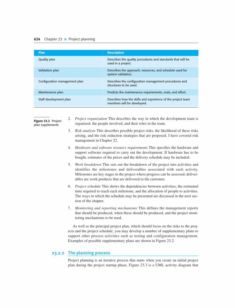
624 Chapter 23 � Project planning
2. Project organization This describes the way in which the development team is
organized, the people involved, and their roles in the team.
3. Risk analysis This describes possible project risks, the likelihood of these risks
arising, and the risk reduction strategies that are proposed. I have covered risk
management in Chapter 22.
4. Hardware and software resource requirements This specifies the hardware and
support software required to carry out the development. If hardware has to be
bought, estimates of the prices and the delivery schedule may be included.
5. Work breakdown This sets out the breakdown of the project into activities and
identifies the milestones and deliverables associated with each activity.
Milestones are key stages in the project where progress can be assessed; deliver-
ables are work products that are delivered to the customer.
6. Project schedule This shows the dependencies between activities, the estimated
time required to reach each milestone, and the allocation of people to activities.
The ways in which the schedule may be presented are discussed in the next sec-
tion of the chapter.
7. Monitoring and reporting mechanisms This defines the management reports
that should be produced, when these should be produced, and the project moni-
toring mechanisms to be used.
As well as the principal project plan, which should focus on the risks to the proj-
ects and the project schedule, you may develop a number of supplementary plans to
support other process activities such as testing and configuration management.
Examples of possible supplementary plans are shown in Figure 23.2.
23.2.2 The planning process
Project planning is an iterative process that starts when you create an initial project
plan during the project startup phase. Figure 23.3 is a UML activity diagram that
Figure 23.2 Projectplan supplements
Plan Description
Quality plan Describes the quality procedures and standards that will beused in a project.
Validation plan Describes the approach, resources, and schedule used forsystem validation.
Configuration management plan Describes the configuration management procedures andstructures to be used.
Maintenance plan Predicts the maintenance requirements, costs, and effort.
Staff development plan Describes how the skills and experience of the project teammembers will be developed.

23.2 � Plan-driven development 625
shows a typical workflow for a project planning process. Plan changes are inevitable.
As more information about the system and the project team becomes available during
the project, you should regularly revise the plan to reflect requirements, schedule, and
risk changes. Changing business goals also leads to changes in project plans. As busi-
ness goals change, this could affect all projects, which may then have to be replanned.
At the beginning of a planning process, you should assess the constraints affecting
the project. These constraints are the required delivery date, staff available, overall
budget, available tools, and so on. In conjunction with this, you should also identify
the project milestones and deliverables. Milestones are points in the schedule against
which you can assess progress, for example, the handover of the system for testing.
Deliverables are work products that are delivered to the customer (e.g., a require-
ments document for the system).
The process then enters a loop. You draw up an estimated schedule for the project
and the activities defined in the schedule are initiated or given permission to con-
tinue. After some time (usually about two to three weeks), you should review
progress and note discrepancies from the planned schedule. Because initial estimates
of project parameters are inevitably approximate, minor slippages are normal and
you will have to make modifications to the original plan.
It is important to be realistic when you are creating a project plan. Problems of
some description nearly always arise during a project, and these can lead to project
delays. Your initial assumptions and scheduling should therefore be pessimistic
rather than optimistic. There should be sufficient contingency built into your plan so
that the project constraints and milestones don’t need to be renegotiated every time
you go around the planning loop.
If there are serious problems with the development work that are likely to lead to
significant delays, you need to initiate risk mitigation actions to reduce the risks of
project failure. In conjunction with these actions, you also have to replan the project.
Figure 23.3 The project planningprocess
Define ProjectSchedule
IdentifyRisks
IdentifyConstraints
DefineMilestones
andDeliverables
«system»Project Planner
[no problems]
[minor problems and slippages]
[projectfinished][unfinished]
[seriousproblems]
Initiate RiskMitigation Actions
ReplanProject
Do the Work
Monitor ProgressAgainst Plan
626 Chapter 23 � Project planning
This may involve renegotiating the project constraints and deliverables with the cus-
tomer. A new schedule of when work should be completed also has to be established
and agreed with the customer.
If this renegotiation is unsuccessful or the risk mitigation actions are ineffective, then
you should arrange for a formal project technical review. The objectives of this review
are to find an alternative approach that will allow the project to continue, and to check
whether the project and the goals of the customer and software developer are still
aligned.
The outcome of a review may be a decision to cancel a project. This may be a
result of technical or managerial failings but, more often, is a consequence of exter-
nal changes that affect the project. The development time for a large software project
is often several years. During that time, the business objectives and priorities
inevitably change. These changes may mean that the software is no longer required
or that the original project requirements are inappropriate. Management may then
decide to stop software development or to make major changes to the project to
reflect the changes in the organizational objectives.
23.3 Project scheduling
Project scheduling is the process of deciding how the work in a project will be
organized as separate tasks, and when and how these tasks will be executed. You
estimate the calendar time needed to complete each task, the effort required, and
who will work on the tasks that have been identified. You also have to estimate the
resources needed to complete each task, such as the disk space required on a
server, the time required on specialized hardware, such as a simulator, and what
the travel budget will be. In terms of the planning stages that I discussed in the
introduction of this chapter, an initial project schedule is usually created during the
project startup phase. This schedule is then refined and modified during develop-
ment planning.
Both plan-based and agile processes need an initial project schedule, although the
level of detail may be less in an agile project plan. This initial schedule is used to
plan how people will be allocated to projects and to check the progress of the project
against its contractual commitments. In traditional development processes, the
complete schedule is initially developed and then modified as the project progresses.
In agile processes, there has to be an overall schedule that identifies when the major
phases of the project will be completed. An iterative approach to scheduling is then
used to plan each phase.
Scheduling in plan-driven projects (Figure 23.4) involves breaking down the total
work involved in a project into separate tasks and estimating the time required to
complete each task. Tasks should normally last at least a week, and no longer than
2 months. Finer subdivision means that a disproportionate amount of time must be
spent on replanning and updating the project plan. The maximum amount of time for

23.3 � Project scheduling 627
any task should be around 8 to 10 weeks. If it takes longer than this, the task should
be subdivided for project planning and scheduling.
Some of these tasks are carried out in parallel, with different people working on
different components of the system. You have to coordinate these parallel tasks and
organize the work so that the workforce is used optimally and you don’t introduce
unnecessary dependencies between the tasks. It is important to avoid a situation
where the whole project is delayed because a critical task is unfinished.
If a project is technically advanced, initial estimates will almost certainly be opti-
mistic even when you try to consider all eventualities. In this respect, software
scheduling is no different from scheduling any other type of large advanced project.
New aircraft, bridges, and even new models of cars are frequently late because of
unanticipated problems. Schedules, therefore, must be continually updated as better
progress information becomes available. If the project being scheduled is similar to
a previous project, previous estimates may be reused. However, projects may use dif-
ferent design methods and implementation languages, so experience from previous
projects may not be applicable in the planning of a new project.
As I have already suggested, when you are estimating schedules, you must take
into account the possibility that things will go wrong. People working on a project
may fall ill or leave, hardware may fail, and essential support software or hardware
may be delivered late. If the project is new and technically advanced, parts of it may
turn out to be more difficult and take longer than originally anticipated.
A good rule of thumb is to estimate as if nothing will go wrong, then increase your
estimate to cover anticipated problems. A further contingency factor to cover unantici-
pated problems may also be added to the estimate. This extra contingency factor depends
on the type of project, the process parameters (deadline, standards, etc.), and the quality
and experience of the software engineers working on the project. Contingency estimates
may add 30% to 50% to the effort and time required for the project.
23.3.1 Schedule representation
Project schedules may simply be represented in a table or spreadsheet showing the
tasks, effort, expected duration, and task dependencies (Figure 23.5). However, this
style of representation makes it difficult to see the relationships and dependencies
Activity charts
An activity chart is a project schedule representation that shows which tasks can be carried out in parallel andthose that must be executed in sequence, due to their dependencies on earlier activities. If a task is dependenton several other tasks then all of these must finish before it can start. The ‘critical path’ through the activity chartis the longest sequence of dependent tasks. This defines the project duration.
http://www.SoftwareEngineering-9.com/Web/Planning/activities.html

628 Chapter 23 � Project planning
between the different activities. For this reason, alternative graphical representations
of project schedules have been developed that are often easier to read and under-
stand. There are two types of representation that are commonly used:
1. Bar charts, which are calendar-based, show who is responsible for each activity,
the expected elapsed time, and when the activity is scheduled to begin and end.
Bar charts are sometimes called ‘Gantt charts’, after their inventor, Henry Gantt.
2. Activity networks, which are network diagrams, show the dependencies
between the different activities making up a project.
Normally, a project planning tool is used to manage project schedule information.
These tools usually expect you to input project information into a table and will then
create a database of project information. Bar charts and activity charts can then be
generated automatically from this database.
Project activities are the basic planning element. Each activity has:
1. A duration in calendar days or months.
2. An effort estimate, which reflects the number of person-days or person-months
to complete the work.
3. A deadline by which the activity should be completed.
4. A defined endpoint. This represents the tangible result of completing the activ-
ity. This could be a document, the holding of a review meeting, the successful
execution of all tests, etc.
When planning a project, you should also define milestones; that is, each stage
in the project where a progress assessment can be made. Each milestone should be
documented by a short report that summarizes the progress made and the work done.
Milestones may be associated with a single task or with groups of related activities.
For example, in Figure 23.5, milestone M1 is associated with task T1 and milestone
M3 is associated with a pair of tasks, T2 and T4.
A special kind of milestone is the production of a project deliverable. A deliver-
able is a work product that is delivered to the customer. It is the outcome of a signif-
icant project phase such as specification or design. Usually, the deliverables that are
Estimate Resourcesfor Activities
Identify ActivityDependencies
IdentifyActivities
Allocate Peopleto Activities
Software requirementsand design information
Bar charts describingthe project schedule
Create ProjectCharts
Figure 23.4 The project schedulingprocess

23.3 � Project scheduling 629
required are specified in the project contract and the customer’s view of the project’s
progress depends on these deliverables.
To illustrate how bar charts are used, I have created a hypothetical set of tasks as
shown in Figure 23.5. This table shows tasks, estimated effort, duration, and task
interdependencies. From Figure 23.5, you can see that task T3 is dependent on task
T1. Task T1 must, therefore, be completed before T3 starts. For example, T1 might
be the preparation of a component design and T3, the implementation of that design.
Before implementation starts, the design should be complete. Notice that the esti-
mated duration for some tasks is more than the effort required and vice versa. If the
effort is less than the duration, this means that the people allocated to that task are
not working full-time on it. If the effort exceeds the duration, this means that several
team members are working on the task at the same time.
Figure 23.6 takes the information in Figure 23.5 and presents the project schedule
in a graphical format. It is a bar chart showing a project calendar and the start and
finish dates of tasks. Reading from left to right, the bar chart clearly shows when
tasks start and end. The milestones (M1, M2, etc.) are also shown on the bar chart.
Notice that tasks that are independent are carried out in parallel (e.g., tasks T1, T2,
and T4 all start at the beginning of the project).
As well as planning the delivery schedule for the software, project managers have
to allocate resources to tasks. The key resource is, of course, the software engineers
who will do the work, and they have to be assigned to project activities. The resource
allocation can also be input to project management tools and a bar chart generated,
which shows when staff are working on the project (Figure 23.7). People may be
Task Effort (person-days) Duration (days) Dependencies
T1 15 10
T2 8 15
T3 20 15 T1 (M1)
T4 5 10
T5 5 10 T2, T4 (M3)
T6 10 5 T1, T2 (M4)
T7 25 20 T1 (M1)
T8 75 25 T4 (M2)
T9 10 15 T3, T6 (M5)
T10 20 15 T7, T8 (M6)
T11 10 10 T9 (M7)
T12 20 10 T10, T11 (M8)
Figure 23.5 Tasks,durations, anddependencies

630 Chapter 23 � Project planning
working on more than one task at the same time and, sometimes, they are not work-
ing on the project. They may be on holiday, working on other projects, attending
training courses, or engaging in some other activity. I show part-time assignments
using a diagonal line crossing the bar.
Large organizations usually employ a number of specialists who work on a proj-
ect when needed. In Figure 23.7, you can see that Mary is a specialist, who works on
only a single task in the project. This can cause scheduling problems. If one project
is delayed while a specialist is working on it, this may have a knock-on effect on
other projects where the specialist is also required. These may then be delayed
because the specialist is not available.
If a task is delayed, this can obviously affect later tasks that are dependent on
it. They cannot start until the delayed task is completed. Delays can cause serious
problems with staff allocation, especially when people are working on several proj-
ects at the same time. If a task (T) is delayed, the people allocated may be assigned
to other work (W). To complete this may take longer than the delay but, once
assigned, they cannot simply be reassigned back to the original task, T. This may
then lead to further delays in T as they complete W.
Week 0 1 2 3 4 5 6 7 8 9 10 11
T4
T1
T2
(M1/T1)
T7
T3
(M5/T3 & T6)
T8
(M4/T1& T2)
T6
T5
(M2/T4)
T9
(M7/T 9)
T10
(M6/T7 & T8)
T11
(M8/T10 & T11)
T12
Start
Finish
(M3/T2 & T4)
Figure 23.6Activity bar chart

23.4 � Agile planning 631
23.4 Agile planning
Agile methods of software development are iterative approaches where the software
is developed and delivered to customers in increments. Unlike plan-driven
approaches, the functionality of these increments is not planned in advance but is
decided during the development. The decision on what to include in an increment
depends on progress and on the customer’s priorities. The argument for this
approach is that the customer’s priorities and requirements change so it makes sense
to have a flexible plan that can accommodate these changes. Cohn’s book {Cohn,
2005 ##1735} is a comprehensive discussion of planning issues in agile projects.
The most commonly used agile approaches such as Scrum (Schwaber, 2004)
and extreme programming (Beck, 2000) have a two-stage approach to planning,
corresponding to the startup phase in plan-driven development and development
planning:
1. Release planning, which looks ahead for several months and decides on the fea-
tures that should be included in a release of a system.
2. Iteration planning, which has a shorter-term outlook, and focuses on planning
the next increment of a system. This is typically 2 to 4 weeks of work for the
team.
T1 T3 T9Jane
T3
T10Geetha
T7Hong
T5Mary
T4 T8Fred
T1 T8Ali
T12
T2
T6
Maya T8
T10
T6
T11 T12
T8
Week 0 1 2 3 4 5 6 7 8 9 10 11
T7
Figure 23.7 Staffallocation chart

632 Chapter 23 � Project planning
I have already discussed the Scrum approach to planning in Chapter 3, so I con-
centrate here on planning in extreme programming (XP). This is called the ‘planning
game’ and it usually involves the whole development team, including customer rep-
resentatives. Figure 23.8 shows the stages in the planning game.
The system specification in XP is based on user stories that reflect the features
that should be included in the system. At the start of the project, the team and the
customer try to identify a set of stories, which covers all of the functionality that will
be included in the final system. Some functionality will inevitably be missing, but
this is not important at this stage.
The next stage is an estimation stage. The project team reads and discusses the
stories and ranks them in order of the amount of time they think it will take to imple-
ment the story. This may involve breaking large stories into smaller stories. Relative
estimation is often easier than absolute estimation. People often find it difficult to
estimate how much effort or time is needed to do something. However, when they are
presented with several things to do, they can make judgments about which stories will
take the longest time and most effort. Once the ranking has been completed, the team
then allocates notional effort points to the stories. A complex story may have 8 points
and a simple story 2 points. You do this for all of the stories in the ranked list.
Once the stories have been estimated, the relative effort is translated into the first
estimate of the total effort required by using the notion of ‘velocity’. In XP, velocity
is the number of effort points implemented by the team, per day. This can be esti-
mated either from previous experience or by developing one or two stories to see
how much time is required. The velocity estimate is approximate, but is refined dur-
ing the development process. Once you have a velocity estimate, you can calculate
the total effort in person-days to implement the system.
Release planning involves selecting and refining the stories that will reflect the
features to be implemented in a release of a system and the order in which the stories
should be implemented. The customer has to be involved in this process. A release
date is then chosen and the stories are examined to see if the effort estimate is consis-
tent with that date. If not, stories are added or removed from the list.
Iteration planning is the first stage into the iteration development process. Stories
to be implemented for that iteration are chosen, with the number of stories reflecting
the time to deliver an iteration (usually 2 or 3 weeks) and the team’s velocity. When
the iteration delivery date is reached, that iteration is complete, even if all of the sto-
ries have not been implemented. The team considers the stories that have been
implemented and adds up their effort points. The velocity can then be recalculated
and this is used in planning the next release of the system.
At the start of each iteration, there is a more detailed planning stage where the
developers break stories down into development tasks. A development task should
ReleasePlanning
InitialEstimation
StoryIdentification
IterationPlanning
TaskPlanning
Figure 23.8Planning in XP

23.5 � Estimation techniques 633
take 4–16 hours. All of the tasks that must be completed to implement all of the sto-
ries in that iteration are listed. The individual developers then sign up for the specific
tasks that they will implement. Each developer knows their individual velocity so
should not sign up for more tasks than they can implement in the time.
There are two important benefits from this approach to task allocation:
1. The whole team gets an overview of the tasks to be completed in an iteration.
They therefore have an understanding of what other team members are doing
and who to talk to if task dependencies are identified.
2. Individual developers choose the tasks to implement; they are not simply allo-
cated tasks by a project manager. They therefore have a sense of ownership in
these tasks and this is likely to motivate them to complete the task.
Halfway though an iteration, progress is reviewed. At this stage, half of the story
effort points should have been completed. So, if an iteration involves 24 story points and
36 tasks, 12 story points and 18 tasks should have been completed. If this is not the case,
then the customer has to be consulted and some stories removed from the iteration.
This approach to planning has the advantage that the software is always released
as planned and there is no schedule slippage. If the work cannot be completed in the
time allowed, the XP philosophy is to reduce the scope of the work rather than
extend the schedule. However, in some cases, the increment may not be enough to be
useful. Reducing the scope may create extra work for customers if they have to use
an incomplete system or change their work practices between one release of the sys-
tem and another.
A major difficulty in agile planning is that it is reliant on customer involvement
and availability. In practice, this can be difficult to arrange, as the customer represen-
tative must sometimes give priority to other work. Customers may be more familiar
with traditional project plans and may find it difficult to engage in an agile planning
project.
Agile planning works well with small, stable development teams that can get
together and discuss the stories to be implemented. However, where teams are large
and/or geographically distributed, or when team membership changes frequently, it
is practically impossible for everyone to be involved in the collaborative planning
that is essential for agile project management. Consequently, large projects are usu-
ally planned using traditional approaches to project management.
23.5 Estimation techniques
Project schedule estimation is difficult. You may have to make initial estimates on the
basis of a high-level user requirements definition. The software may have to run on
unfamiliar computers or use new development technology. The people involved in the
project and their skills will probably not be known. There are so many uncertainties
634 Chapter 23 � Project planning
that it is impossible to estimate system development costs accurately during the early
stages of a project.
There is even a fundamental difficulty in assessing the accuracy of different
approaches to cost and effort estimation. Project estimates are often self-fulfilling.
The estimate is used to define the project budget and the product is adjusted so that
the budget figure is realized. A project that is within budget may have achieved this
at the expense of features in the software being developed.
I do not know of any controlled experiments with project costing where the esti-
mated costs were not used to bias the experiment. A controlled experiment would
not reveal the cost estimate to the project manager. The actual costs would then be
compared with the estimated project costs. Nevertheless, organizations need to make
software effort and cost estimates. There are two types of technique that can be used
to do this:
1. Experience-based techniques The estimate of future effort requirements is
based on the manager’s experience of past projects and the application domain.
Essentially, the manager makes an informed judgment of what the effort
requirements are likely to be.
2. Algorithmic cost modeling In this approach, a formulaic approach is used to
compute the project effort based on estimates of product attributes, such as size,
and process characteristics, such as experience of staff involved.
In both cases, you need to use your judgment to estimate either the effort directly,
or estimate the project and product characteristics. In the startup phase of a project,
these estimates have a wide margin of error. Based on data collected from a large
number of projects, Boehm, et al. (1995) discovered that startup estimates vary sig-
nificantly. If the initial estimate of effort required is x months of effort, they found
that the range may be from 0.25x to 4x of the actual effort as measured when the sys-
tem was delivered. During development planning, estimates become more and more
accurate as the project progresses (Figure 23.9).
Experience-based techniques rely on the manager’s experience of past projects
and the actual effort expended in these projects on activities that are related to soft-
ware development. Typically, you identify the deliverables to be produced in a proj-
ect and the different software components or systems that are to be developed. You
document these in a spreadsheet, estimate them individually, and compute the total
effort required. It usually helps to get a group of people involved in the effort estima-
tion and to ask each member of the group to explain their estimate. This often reveals
factors that others have not considered and you then iterate towards an agreed group
estimate.
The difficulty with experience-based techniques is that a new software project
may not have much in common with previous projects. Software development
changes very quickly and a project will often use unfamiliar techniques such as web
services, COTS-based development, or AJAX. If you have not worked with these
techniques, your previous experience may not help you to estimate the effort
required, making it more difficult to produce accurate costs and schedule estimates.

23.5 � Estimation techniques 635
23.5.1 Algorithmic cost modeling
Algorithmic cost modeling uses a mathematical formula to predict project costs
based on estimates of the project size; the type of software being developed; and
other team, process, and product factors. An algorithmic cost model can be built by
analyzing the costs and attributes of completed projects, and finding the closest-fit
formula to actual experience.
Algorithmic cost models are primarily used to make estimates of software devel-
opment costs. However, Boehm and his collaborators (2000) discuss a range of other
uses for these models, such as the preparation of estimates for investors in software
companies; alternative strategies to help assess risks; and to informed decisions
about reuse, redevelopment, or outsourcing.
Algorithmic models for estimating effort in a software project are mostly based
on a simple formula:
Effort � A � SizeB� M
A is a constant factor which depends on local organizational practices and the type
of software that is developed. Size may be either an assessment of the code size of
the software or a functionality estimate expressed in function or application points.
The value of exponent B usually lies between 1 and 1.5. M is a multiplier made by
combining process, product, and development attributes, such as the dependability
requirements for the software and the experience of the development team.
The number of lines of source code (SLOC) in the delivered system is the funda-
mental size metric that is used in many algorithmic cost models. Size estimation may
involve estimation by analogy with other projects, estimation by converting function
or application points to code size, estimation by ranking the sizes of system compo-
nents and using a known reference component to estimate the component size, or it
may simply be a question of engineering judgment.
x
2x
4x
0.5x
0.25x
Feasibility Requirements Design Code Delivery
Figure 23.9Estimate uncertainty

636 Chapter 23 � Project planning
Most algorithmic estimation models have an exponential component (B in the above
equation) that is related to the size and complexity of the system. This reflects the fact
that costs do not usually increase linearly with project size. As the size and complexity of
the software increases, extra costs are incurred because of the communication overhead
of larger teams, more complex configuration management, more difficult system integra-
tion, and so on. The more complex the system, the more these factors affect the cost.
Therefore, the value of B usually increases with the size and complexity of the system.
All algorithmic models have similar problems:
1. It is often difficult to estimate Size at an early stage in a project, when only
the specification is available. Function-point and application-point estimates
(see later) are easier to produce than estimates of code size but are still often
inaccurate.
2. The estimates of the factors contributing to B and M are subjective. Estimates
vary from one person to another, depending on their background and experience
of the type of system that is being developed.
Accurate code size estimation is difficult at an early stage in a project because the
size of the final program depends on design decisions that may not have been made
when the estimate is required. For example, an application that requires high-
performance data management may either implement its own data management
system or use a commercial database system. In the initial cost estimation, you are
unlikely to know if there is a commercial database system that performs well enough
to meet the performance requirements. You therefore don’t know how much data
management code will be included in the system.
The programming language used for system development also affects the number of
lines of code to be developed. A language like Java might mean that more lines of code
are necessary than if C (say) was used. However, this extra code allows more compile-
time checking so validation costs are likely to be reduced. How should this be taken into
account? Furthermore, it may be possible to reuse a significant amount of code from
previous projects and the size estimate has to be adjusted to take this into account.
Algorithmic cost models are a systematic way to estimate the effort required to
develop a system. However, these models are complex and difficult to use. There are
many attributes and considerable scope for uncertainty in estimating their values.
This complexity discourages potential users and hence the practical application of
algorithmic cost modeling has been limited to a small number of companies.
Another barrier that discourages the use of algorithmic models is the need for cal-
ibration. Model users should calibrate their model and the attribute values using their
own historical project data, as this reflects local practice and experience. However,
very few organizations have collected enough data from past projects in a form that
supports model calibration. Practical use of algorithmic models, therefore, has to
start with the published values for the model parameters. It is practically impossible
for a modeler to know how closely these relate to their own organization.
If you use an algorithmic cost estimation model, you should develop a range of esti-
mates (worst, expected, and best) rather than a single estimate and apply the costing

23.5 � Estimation techniques 637
formula to all of them. Estimates are most likely to be accurate when you understand
the type of software that is being developed, have calibrated the costing model using
local data, or when programming language and hardware choices are predefined.
23.5.2 The COCOMO II model
Several similar models have been proposed to help estimate the effort, schedule, and
costs of a software project. The model that I discuss here is the COCOMO II model.
This is an empirical model that was derived by collecting data from a large number
of software projects. These data were analyzed to discover the formulae that were
the best fit to the observations. These formulae linked the size of the system and
product, project and team factors to the effort to develop the system. COCOMO II is
a well-documented and nonproprietary estimation model.
COCOMO II was developed from earlier COCOMO cost estimation models,
which were largely based on original code development (Boehm, 1981; Boehm and
Royce, 1989). The COCOMO II model takes into account more modern approaches
to software development, such as rapid development using dynamic languages,
development by component composition, and use of database programming.
COCOMO II supports the spiral model of development, described in Chapter 2, and
embeds submodels that produce increasingly detailed estimates.
The submodels (Figure 23.10) that are part of the COCOMO II model are:
1. An application-composition model This models the effort required to
develop systems that are created from reusable components, scripting, or
Number ofApplication Points
Number of FunctionPoints
Based on Used for
Used for
Used for
Used for
Based on
Based on
Based on
Number of Lines ofCode Reused or
Generated
Number of Lines ofSource Code
ApplicationComposition Model
Early Design Model
Reuse Model
Post-ArchitectureModel
Systems DevelopedUsing DynamicLanguages, DB
Programming, etc.
Initial EffortEstimation Based onSystem Requirementsand Design Options
Effort to IntegrateReusable Components
or AutomaticallyGenerated Code
Development EffortBased on System
Design Specification
Figure 23.10COCOMO estimationmodels

638 Chapter 23 � Project planning
database programming. Software size estimates are based on application
points, and a simple size/productivity formula is used to estimate the effort
required. The number of application points in a program is a weighted esti-
mate of the number of separate screens that are displayed, the number of
reports that are produced, the number of modules in imperative programming
languages (such as Java), and the number of lines of scripting language or
database programming code.
2. An early design model This model is used during early stages of the system
design after the requirements have been established. The estimate is based on
the standard estimation formula that I discussed in the introduction, with a sim-
plified set of seven multipliers. Estimates are based on function points, which
are then converted to number of lines of source code. Function points are a
language-independent way of quantifying program functionality. You compute
the total number of function points in a program by measuring or estimating the
number of external inputs and outputs, user interactions, external interfaces, and
files or database tables used by the system.
3. A reuse model This model is used to compute the effort required to integrate
reusable components and/or automatically generated program code. It is nor-
mally used in conjunction with the post-architecture model.
4. A post-architecture model Once the system architecture has been designed, a
more accurate estimate of the software size can be made. Again, this model uses
the standard formula for cost estimation discussed above. However, it includes a
more extensive set of 17 multipliers reflecting personnel capability, product, and
project characteristics.
Of course, in large systems, different parts of the system may be developed
using different technologies and you may not have to estimate all parts of the
system to the same level of accuracy. In such cases, you can use the appropriate
Software productivity
Software productivity is an estimate of the average amount of development work that software engineerscomplete in a week or a month. It is therefore expressed as lines of code/month, function points/month, etc.
However, whilst productivity can be easily measured where there is a tangible outcome (e.g., a clerk processesN invoices/day), software productivity is more difficult to define. Different people may implement the samefunctionality in different ways, using different numbers of lines of code. The quality of the code is also importantbut is, to some extent, subjective. Productivity comparisons between software engineers are, therefore,unreliable and so are not very useful for project planning.
http://www.SoftwareEngineering-9.com/Web/Planning/productivity.html
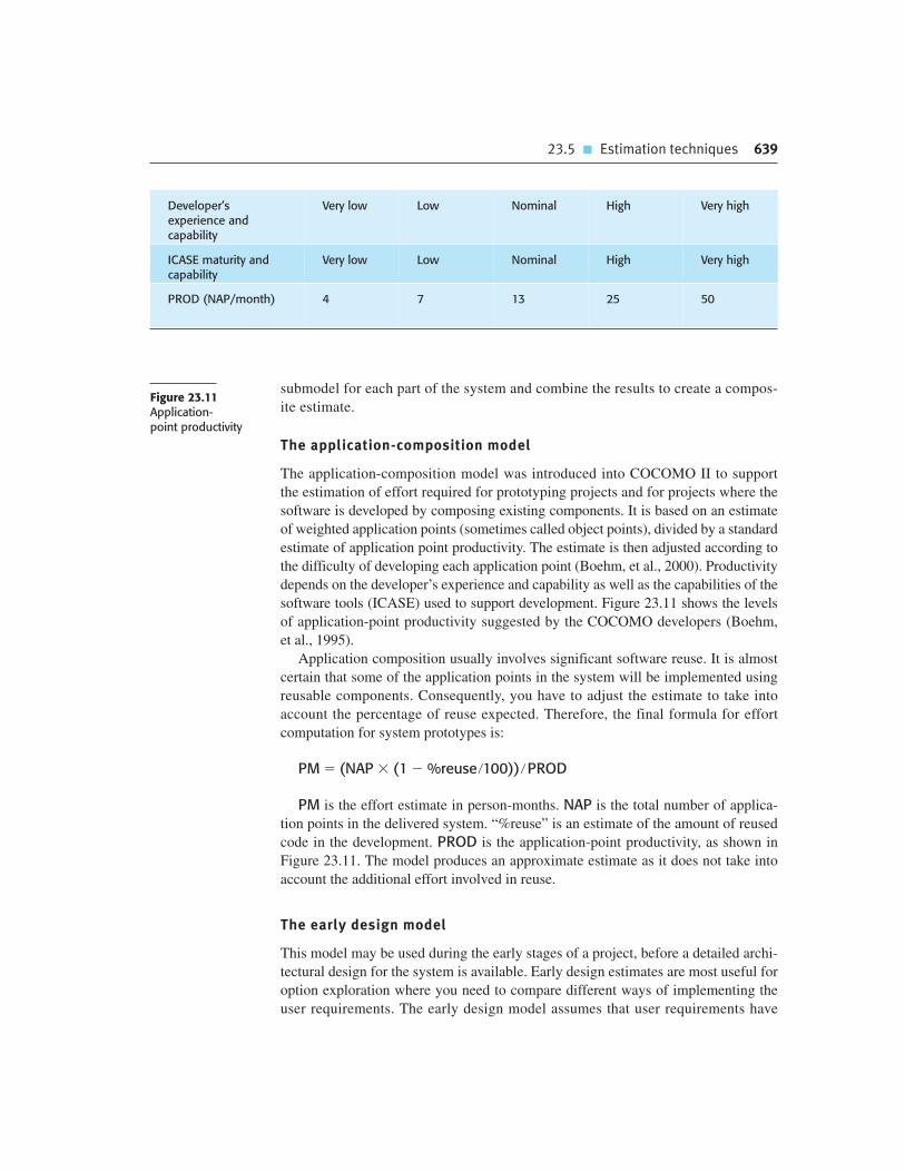
23.5 � Estimation techniques 639
submodel for each part of the system and combine the results to create a compos-
ite estimate.
The application-composition model
The application-composition model was introduced into COCOMO II to support
the estimation of effort required for prototyping projects and for projects where the
software is developed by composing existing components. It is based on an estimate
of weighted application points (sometimes called object points), divided by a standard
estimate of application point productivity. The estimate is then adjusted according to
the difficulty of developing each application point (Boehm, et al., 2000). Productivity
depends on the developer’s experience and capability as well as the capabilities of the
software tools (ICASE) used to support development. Figure 23.11 shows the levels
of application-point productivity suggested by the COCOMO developers (Boehm,
et al., 1995).
Application composition usually involves significant software reuse. It is almost
certain that some of the application points in the system will be implemented using
reusable components. Consequently, you have to adjust the estimate to take into
account the percentage of reuse expected. Therefore, the final formula for effort
computation for system prototypes is:
PM � (NAP � (1 � %reuse �100)) � PROD
PM is the effort estimate in person-months. NAP is the total number of applica-
tion points in the delivered system. “%reuse” is an estimate of the amount of reused
code in the development. PROD is the application-point productivity, as shown in
Figure 23.11. The model produces an approximate estimate as it does not take into
account the additional effort involved in reuse.
The early design model
This model may be used during the early stages of a project, before a detailed archi-
tectural design for the system is available. Early design estimates are most useful for
option exploration where you need to compare different ways of implementing the
user requirements. The early design model assumes that user requirements have
Developer’sexperience andcapability
Very low Low Nominal High Very high
ICASE maturity andcapability
Very low Low Nominal High Very high
PROD (NAP/month) 4 7 13 25 50
Figure 23.11Application-point productivity

640 Chapter 23 � Project planning
been agreed and initial stages of the system design process are under way. Your goal
at this stage should be to make a quick and approximate cost estimate. Therefore,
you have to make simplifying assumptions, for example, that the effort involved in
integrating reusable code is zero.
The estimates produced at this stage are based on the standard formula for algo-
rithmic models, namely:
Effort � A � SizeB� M
Based on his own large data set, Boehm proposed that the coefficient A should be
2.94. The size of the system is expressed in KSLOC, which is the number of thousands
of lines of source code. You calculate KSLOC by estimating the number of function
points in the software. You then use standard tables that relate software size to function
points for different programming languages, to compute an initial estimate of the sys-
tem size in KSLOC.
The exponent B reflects the increased effort required as the size of the project
increases. This can vary from 1.1 to 1.24 depending on the novelty of the project, the
development flexibility, the risk resolution processes used, the cohesion of the devel-
opment team, and the process maturity level (see Chapter 26) of the organization.
I discuss how the value of this exponent is calculated using these parameters in the
description of the COCOMO II post-architecture model.
This results in an effort computation as follows:
PM � 2.94 � Size(1.1 � 1.24)� M
where
M � PERS × RCPX × RUSE × PDIF × PREX × FCIL × SCED
The multiplier M is based on seven project and process attributes that increase or
decrease the estimate. The attributes used in the early design model are product reli-
ability and complexity (RCPX), reuse required (RUSE), platform difficulty (PDIF),
personnel capability (PERS), personnel experience (PREX), schedule (SCED), and
support facilities (FCIL). I explain these attributes on the book’s webpages. You
estimate values for these attributes using a six-point scale, where 1 corresponds to
‘very low’ and 6 corresponds to ‘very high’.
The reuse model
As I have discussed in Chapter 16, software reuse is now common. Most large sys-
tems include a significant amount of code that has been reused from previous devel-
opment projects. The reuse model is used to estimate the effort required to integrate
reusable or generated code.
COCOMO II considers two types of reused code. ‘Black-box’ code is code that
can be reused without understanding the code or making changes to it. The develop-
ment effort for black-box code is taken to be zero. ‘White box’ code has to be
adapted to integrate it with new code or other reused components. Development

23.5 � Estimation techniques 641
effort is required for reuse because the code has to be understood and modified
before it can work correctly in the system.
Many systems include automatically generated code from system models, as dis-
cussed in Chapter 5. A model (often in UML) is analyzed and code is generated to
implement the objects specified in the model. The COCOMO II reuse model
includes a formula to estimate the effort required to integrate this generated code:
PMAuto � (ASLOC � AT/100) / ATPROD // Estimate for generated code
ASLOC is the total number of lines of reused code, including code that is automat-
ically generated.
AT is the percentage of reused code that is automatically generated.
ATPROD is the productivity of engineers in integrating such code.
Boehm, et al. (2000) have measured ATPROD to be about 2,400 source statements
per month. Therefore, if there are a total of 20,000 lines of reused source code in a
system and 30% of this is automatically generated, then the effort required to inte-
grate the generated code is:
(20,000 � 30/100) / 2400 � 2.5 person-months // Generated code
A separate effort computation is used to estimate the effort required to integrate
the reused code from other systems. The reuse model does not compute the effort
directly from an estimate of the number of reused components. Rather, based on
the number of lines of code that are reused, the model provides a basis for calculat-
ing the equivalent number of lines of new code (ESLOC). This is based on the
number of lines of reusable code that have to be changed and a multiplier that
reflects the amount of work you need to do to reuse the components. The formula
to compute ESLOC takes into account the effort required for software understand-
ing, making changes to the reused code, and making changes to the system to inte-
grate that code.
The following formula is used to calculate the number of equivalent lines of
source code:
ESLOC � ASLOC � AAM
ESLOC is the equivalent number of lines of new source code.
ASLOC is the number of lines of code in the components that have to be changed.
AAM is an Adaptation Adjustment Multiplier, as discussed below.
Reuse is never free and some costs are incurred even if no reuse proves to be
possible. However, reuse costs decrease as the amount of code reused increases.
The fixed understanding and assessment costs are spread across more lines of
code. The Adaptation Adjustment Multiplier (AAM) adjusts the estimate to reflect

642 Chapter 23 � Project planning
the additional effort required to reuse code. Simplistically, AAM is the sum of three
components:
1. An adaptation component (referred to as AAF) that represents the costs of
making changes to the reused code. The adaptation component includes sub-
components that take into account design, code, and integration changes.
2. An understanding component (referred to as SU) that represents the costs of
understanding the code to be reused and the familiarity of the engineer with the
code. SU ranges from 50 for complex unstructured code to 10 for well-written,
object-oriented code.
3. An assessment factor (referred to as AA) that represents the costs of reuse deci-
sion making. That is, some analysis is always required to decide whether or not
code can be reused, and this is included in the cost as AA. AA varies from 0 to 8
depending on the amount of analysis effort required.
If some code adaptation can be done automatically, this reduces the effort
required. You therefore adjust the estimate by estimating the percentage of auto-
matically adapted code (AT) and using this to adjust ASLOC. Therefore, the final
formula is:
ESLOC � ASLOC � (1 � AT�100) � AAM
Once ESLOC has been calculated, you then apply the standard estimation formula
to calculate the total effort required, where the Size parameter = ESLOC. You then
add this to the effort to integrate automatically generated code that you have already
computed, thus computing the total effort required.
The post-architecture level
The post-architecture model is the most detailed of the COCOMO II models.
It is used once an initial architectural design for the system is available so the
COCOMO II cost drivers
COCOMO II cost drivers are attributes that reflect some of the product, team, process, and organizational factorsthat affect the amount of effort needed to develop a software system. For example, if a high level of reliability isrequired, extra effort will be needed; if there is a need for rapid delivery, extra effort will be required; if the teammembers change, extra effort will be required.
There are 17 of these attributes in the COCOMO II model, which have been assigned values by the modeldevelopers.
http://www.SoftwareEngineering-9.com/Web/Planning/costdrivers.html
23.5 � Estimation techniques 643
subsystem structure is known. You can then make estimates for each part of the
system.
The starting point for estimates produced at the post-architecture level is the same
basic formula used in the early design estimates:
PM � A � SizeB� M
By this stage in the process, you should be able to make a more accurate estimate
of the project size as you know how the system will be decomposed into objects or
modules. You make this estimate of the code size using three parameters:
1. An estimate of the total number of lines of new code to be developed (SLOC).
2. An estimate of the reuse costs based on an equivalent number of source lines of
code (ESLOC), calculated using the reuse model.
3. An estimate of the number of lines of code that are likely to be modified because
of changes to the system requirements.
You add the values of these parameters to compute the total code size, in KSLOC,
that you use in the effort computation formula. The final component in the estimate—
the number of lines of modified code—reflects the fact that software requirements
always change. This leads to rework and development of extra code, which you have
to take into account. Of course there will often be even more uncertainty in this figure
than in the estimates of new code to be developed.
The exponent term (B) in the effort computation formula is related to the levels
of project complexity. As projects become more complex, the effects of increasing
system size become more significant. However, good organizational practices and
procedures can control the diseconomy of scale that is a consequence of increasing
complexity. The value of the exponent B is therefore based on five factors, as
shown in Figure 23.12. These factors are rated on a six-point scale from 0 to 5,
where 0 means ‘extra high’ and 5 means ‘very low’. To calculate B, you add the
ratings, divide them by 100, and add the result to 1.01 to get the exponent that
should be used.
For example, imagine that an organization is taking on a project in a domain in
which it has little previous experience. The project client has not defined the process
to be used or allowed time in the project schedule for significant risk analysis. A new
development team must be put together to implement this system. The organization
has recently put in place a process improvement program and has been rated as a
Level 2 organization according to the SEI capability assessment, as discussed in
Chapter 26. Possible values for the ratings used in exponent calculation are therefore:
1. Precedentedness, rated low (4). This is a new project for the organization.
2. Development flexibility, rated very high (1). No client involvement in the devel-
opment process so there are few externally imposed changes.

644 Chapter 23 � Project planning
3. Architecture/risk resolution, rated very low (5). There has been no risk analysis
carried out.
4. Team cohesion, rated nominal (3). This is a new team so there is no information
available on cohesion.
5. Process maturity, rated nominal (3). Some process control is in place.
The sum of these values is 16. You then calculate the exponent by dividing this by
100 and adding the result to 0.01. The adjusted value of B is therefore 1.17.
The overall effort estimate is refined using an extensive set of 17 product,
process, and organizational attributes (cost drivers), rather than the seven attributes
used in the early design model. You can estimate values for these attributes because
you have more information about the software itself, its non-functional require-
ments, the development team, and the development process.
Figure 23.13 shows how the cost driver attributes can influence effort estimates.
I have taken a value for the exponent of 1.17 as discussed in the previous example
and assumed that RELY, CPLX, STOR, TOOL, and SCED are the key cost drivers in
the project. All of the other cost drivers have a nominal value of 1, so they do not
affect the computation of the effort.
In Figure 23.13, I have assigned maximum and minimum values to the key cost
drivers to show how they influence the effort estimate. The values taken are those
from the COCOMO II reference manual (Boehm, 2000). You can see that high
values for the cost drivers lead an effort estimate that is more than three times the
initial estimate, whereas low values reduce the estimate to about one-third of the
original. This highlights the significant differences between different types of proj-
ects and the difficulties of transferring experience from one application domain to
another.
Scale factor Explanation
[[Tinformaltable4]]Precedentedness Reflects the previous experience of the organization with this type ofproject. Very low means no previous experience; extra-high means that theorganization is completely familiar with this application domain.
Development flexibility Reflects the degree of flexibility in the development process. Very lowmeans a prescribed process is used; extra-high means that the client setsonly general goals.
Architecture/risk resolution Reflects the extent of risk analysis carried out. Very low means littleanalysis; extra-high means a complete and thorough risk analysis.
Team cohesion Reflects how well the development team knows each other and worktogether. Very low means very difficult interactions; extra-high means anintegrated and effective team with no communication problems.
Process maturity Reflects the process maturity of the organization. The computation of thisvalue depends on the CMM Maturity Questionnaire, but an estimate can beachieved by subtracting the CMM process maturity level from 5.
Figure 23.12 Scalefactors used in theexponent computationin the post-architecturemodel

23.5 � Estimation techniques 645
23.5.3 Project duration and staffing
As well as estimating the overall costs of a project and the effort that is required to
develop a software system, project managers must also estimate how long the soft-
ware will take to develop, and when staff will be needed to work on the project.
Increasingly, organizations are demanding shorter development schedules so that
their products can be brought to market before their competitor’s.
The COCOMO model includes a formula to estimate the calendar time required
to complete a project:
TDEV � 3 � (PM) (0.33 0.2*(B � 1.01)
TDEV is the nominal schedule for the project, in calendar months, ignoring any
multiplier that is related to the project schedule.
PM is the effort computed by the COCOMO model.
B is the complexity-related exponent, as discussed in Section 23.5.2.
If B = 1.17 and PM = 60 then
TDEV � 3 � (60)0.36� 13 months
Figure 23.13The effect of cost drivers on effort estimates
Exponent value 1.17
System size (including factors for reuse andrequirements volatility)
128,000 DSI
Initial COCOMO estimate without cost drivers 730 person-months
Reliability Very high, multiplier = 1.39
Complexity Very high, multiplier = 1.3
Memory constraint High, multiplier = 1.21
Tool use Low, multiplier = 1.12
Schedule Accelerated, multiplier = 1.29
Adjusted COCOMO estimate 2,306 person-months
Reliability Very low, multiplier = 0.75
Complexity Very low, multiplier = 0.75
Memory constraint None, multiplier = 1
Tool use Very high, multiplier = 0.72
Schedule Normal, multiplier = 1
Adjusted COCOMO estimate 295 person-months

646 Chapter 23 � Project planning
However, the nominal project schedule predicted by the COCOMO model and
the schedule required by the project plan are not necessarily the same thing. There
may be a requirement to deliver the software earlier or (more rarely) later than the
date suggested by the nominal schedule. If the schedule is to be compressed, this
increases the effort required for the project. This is taken into account by the SCEDmultiplier in the effort estimation computation.
Assume that a project estimated TDEV as 13 months, as suggested above, but the
actual schedule required was 11 months. This represents a schedule compression of
approximately 25%. Using the values for the SCED multiplier as derived by
Boehm’s team, the effort multiplier for such a schedule compression is 1.43.
Therefore, the actual effort that will be required if this accelerated schedule is to be
met is almost 50% more than the effort required to deliver the software according to
the nominal schedule.
There is a complex relationship between the number of people working on a proj-
ect, the effort that will be devoted to the project, and the project delivery schedule. If
four people can complete a project in 13 months (i.e., 52 person-months of effort),
then you might think that by adding one more person, you can complete the work in
11 months (55 person-months of effort). However, the COCOMO model suggests that
you will, in fact, need six people to finish the work in 11 months (66 person-months
of effort).
The reason for this is that adding people actually reduces the productivity of
existing team members and so the actual increment of effort added is less than one
person. As the project team increases in size, team members spend more time com-
municating and defining interfaces between the parts of the system developed by
other people. Doubling the number of staff (for example) therefore does not mean
that the duration of the project will be halved. If the development team is large, it is
sometimes the case that adding more people to a project increases rather than
reduces the development schedule. Myers (1989) discusses the problems of schedule
acceleration. He suggests that projects are likely to run into significant problems if
they try to develop software without allowing sufficient calendar time to complete
the work.
You cannot simply estimate the number of people required for a project team by
dividing the total effort by the required project schedule. Usually, a small number
of people are needed at the start of a project to carry out the initial design. The
team then builds up to a peak during the development and testing of the system,
and then declines in size as the system is prepared for deployment. A very rapid
buildup of project staff has been shown to correlate with project schedule slippage.
Project managers should therefore avoid adding too many staff to a project early in
its lifetime.
This effort buildup can be modeled by what is called a Rayleigh curve (Londeix,
1987). Putnam’s estimation model (1978), which incorporates a model of project
staffing, is based around these Rayleigh curves. This model also includes develop-
ment time as a key factor. As development time is reduced, the effort required to
develop the system grows exponentially.

K E Y P O I N T S
� The price charged for a system does not just depend on its estimated development costs and the
profit required by the development company. Organizational factors may mean that the price is
increased to compensate for increased risk or decreased to gain competitive advantage.
� Software is often priced to gain a contract and the functionality of the system is then
adjusted to meet the estimated price.
� Plan-driven development is organized around a complete project plan that defines the project
activities, the planned effort, the activity schedule, and who is responsible for each activity.
� Project scheduling involves the creation of various graphical representations of part of the
project plan. Bar charts, which show the activity duration and staffing timelines, are the most
commonly used schedule representations.
� A project milestone is a predictable outcome of an activity or set of activities. At each
milestone, a formal report of progress should be presented to management. A deliverable is
a work product that is delivered to the project customer.
� The XP planning game involves the whole team in project planning. The plan is developed
incrementally and, if problems arise, it is adjusted so that software functionality is reduced
instead of delaying the delivery of an increment.
� Estimation techniques for software may be experience-based, where managers judge the
effort required, or algorithmic, where the effort required is computed from other estimated
project parameters.
� The COCOMO II costing model is a mature algorithmic cost model that takes project, product,
hardware, and personnel attributes into account when formulating a cost estimate.
Chapter 23 � Further reading 647
F U R T H E R R E A D I N G
Software Cost Estimation with COCOMO II. This is the definitive book on the COCOMO II model.
It provides a complete description of the model with many examples, and includes software that
implements the model. It’s extremely detailed and not light reading. (B. Boehm et al., Prentice Hall,
2000.)
‘Ten unmyths of project estimation’. A pragmatic article that discusses the practical difficulties of
project estimation and challenges some fundamental assumptions in this area. (P. Armour, Comm.
ACM, 45 (11), November 2002.)
Agile Estimating and Planning. This book is a comprehensive description of story-based planning as
used in XP, as well as a rationale for using an agile approach to project planning. However, it also
includes a good, general introduction to project planning issues. (M. Cohn, Prentice Hall, 2005.)

648 Chapter 23 � Project planning
‘Achievements and Challenges in Cocomo-based Software Resource Estimation’. This article
presents a history of the COCOMO models and influences on these models, and discusses the
variants of these models that have been developed. It also identifies further possible developments
in the COCOMO approach. (B. W. Boehm and R. Valeridi, IEEE Software, 25 (5), September/October
2008.) http://dx.doi.org/10.1109/MS.2008.133.
E X E R C I S E S
23.1. Under what circumstances might a company justifiably charge a much higher price for a
software system than the software cost estimate plus a reasonable profit margin?
23.2. Explain why the process of project planning is iterative and why a plan must be continually
reviewed during a software project.
23.3. Briefly explain the purpose of each of the sections in a software project plan.
23.4. Cost estimates are inherently risky, irrespective of the estimation technique used. Suggest four
ways in which the risk in a cost estimate can be reduced.
23.5. Figure 23.14 sets out a number of tasks, their durations, and their dependencies. Draw a bar
chart showing the project schedule.
23.6. Figure 23.14 shows the task durations for software project activities. Assume that a serious,
unanticipated setback occurs and instead of taking 10 days, task T5 takes 40 days. Draw up
new bar charts showing how the project might be reorganized.
23.7. The XP planning game is based around the notion of planning to implement the stories that
represent the system requirements. Explain the potential problems with this approach when
software has high performance or dependability requirements.
23.8. A software manager is in charge of the development of a safety-critical software system, which
is designed to control a radiotherapy machine to treat patients suffering from cancer. This
system is embedded in the machine and must run on a special-purpose processor with a fixed
amount of memory (256 Mbytes). The machine communicates with a patient database system
to obtain the details of the patient and, after treatment, automatically records the radiation
dose delivered and other treatment details in the database.
The COCOMO method is used to estimate the effort required to develop this system and an
estimate of 26 person-months is computed. All cost driver multipliers were set to 1 when
making this estimate.
Explain why this estimate should be adjusted to take project, personnel, product, and
organizational factors into account. Suggest four factors that might have significant effects on
the initial COCOMO estimate and propose possible values for these factors. Justify why you
have included each factor.

Chapter 23 � References 649
Figure 23.14Scheduling example
23.9. Some very large software projects involve writing millions of lines of code. Explain why the
effort estimation models, such as COCOMO, might not work well when applied to very large
systems.
23.10. Is it ethical for a company to quote a low price for a software contract knowing that the
requirements are ambiguous and that they can charge a high price for subsequent changes
requested by the customer?
Task Duration (days) Dependencies
T1 10
T2 15 T1
T3 10 T1, T2
T4 20
T5 10
T6 15 T3, T4
T7 20 T3
T8 35 T7
T9 15 T6
T10 5 T5, T9
T11 10 T9
T12 20 T10
T13 35 T3, T4
T14 10 T8, T9
T15 20 T2, T14
T16 10 T15
R E F E R E N C E S
Beck, K. (2000). extreme Programming Explained. Reading, Mass.: Addison-Wesley.
Boehm, B. 2000. ‘COCOMO II Model Definition Manual’. Center for Software Engineering, University
of Southern California. http://csse.usc.edu/csse/research/COCOMOII/cocomo2000.0/CII_
modelman2000.0.pdf.

650 Chapter 23 � Project planning
Boehm, B., Clark, B., Horowitz, E., Westland, C., Madachy, R. and Selby, R. (1995). ‘Cost models for
future life cycle processes: COCOMO 2’. Annals of Software Engineering, 1 57–94.
Boehm, B. and Royce, W. (1989). ‘Ada COCOMO and the Ada Process Model’. Proc. 5th COCOMO
Users’ Group Meeting, Pittsburgh: Software Engineering Institute.
Boehm, B. W. (1981). Software Engineering Economics. Englewood Cliffs, NJ: Prentice Hall.
Boehm, B. W., Abts, C., Brown, A. W., Chulani, S., Clark, B. K., Horowitz, E., Madachy, R., Reifer, D. and
Steece, B. (2000). Software Cost Estimation with COCOMO II. Upper Saddle River, NJ: Prentice Hall.
Londeix, B. (1987). Cost Estimation for Software Development. Wokingham: Addison-Wesley.
Myers, W. (1989). ‘Allow Plenty of Time for Large-Scale Software’. IEEE Software, 6 (4), 92–9.
Putnam, L. H. (1978). ‘A General Empirical Solution to the Macro Software Sizing and Estimating
Problem’. IEEE Trans. on Software Engineering., SE-4 (3), 345–61.
Schwaber, K. (2004). Agile Project Management with Scrum. Seattle: Microsoft Press.
Quality management
24
Objectives
The objectives of this chapter are to introduce software quality
management and software measurement. When you have read the
chapter, you will:
� have been introduced to the quality management process and know
why quality planning is important;
� understand that software quality is affected by the software
development process used;
� be aware of the importance of standards in the quality management
process and know how standards are used in quality assurance;
� understand how reviews and inspections are used as a mechanism for
software quality assurance;
� understand how measurement may be helpful in assessing some
software quality attributes and the current limitations of software
measurement.
Contents
24.1 Software quality
24.2 Software standards
24.3 Reviews and inspections
24.4 Software measurement and metrics

652 Chapter 24 � Quality management
Problems with software quality were initially discovered in the 1960s with the devel-
opment of the first large software systems, and continued to plague software engi-
neering throughout the 20th century. Delivered software was slow and unreliable,
difficult to maintain and hard to reuse. Dissatisfaction with this situation led to the
adoption of formal techniques of software quality management, which have been
developed from methods used in the manufacturing industry. These quality manage-
ment techniques, in conjunction with new software technologies and better software
testing, have led to significant improvements in the general level of software quality.
Software quality management for software systems has three principal concerns:
1. At the organizational level, quality management is concerned with establishing
a framework of organizational processes and standards that will lead to high-
quality software. This means that the quality management team should take
responsibility for defining the software development processes to be used and
standards that should apply to the software and related documentation, includ-
ing the system requirements, design, and code.
2. At the project level, quality management involves the application of specific
quality processes, checking that these planned processes have been followed,
and ensuring that the project outputs are conformant with the standards that are
applicable to that project.
3. Quality management at the project level is also concerned with establishing a
quality plan for a project. The quality plan should set out the quality goals for
the project and define what processes and standards are to be used.
The terms ‘quality assurance’ and ‘quality control’ are widely used in manufac-
turing industry. Quality assurance (QA) is the definition of processes and standards
that should lead to high-quality products and the introduction of quality processes
into the manufacturing process. Quality control is the application of these quality
processes to weed out products that are not of the required level of quality.
In the software industry, different companies and industry sectors interpret quality
assurance and quality control in different ways. Sometimes, quality assurance simply
means the definition of procedures, processes, and standards that are aimed at ensur-
ing that software quality is achieved. In other cases, quality assurance also includes all
configuration management, verification, and validation activities that are applied after
a product has been handed over by a development team. In this chapter, I use the term
‘quality assurance’ to include verification and validation and the processes of check-
ing that quality procedures have been properly applied. I have avoided the term
‘quality control’ as this term is not widely used in the software industry.
The QA team in most companies is responsible for managing the release testing
process. As I discussed in Chapter 8, this means that they manage the testing of the
software before it is released to customers. They are responsible for checking that
the system tests provide coverage of the requirements and that proper records are
maintained of the testing process. As I have covered release testing in Chapter 8, I do
not cover this aspect of quality assurance here.

Chapter 24 � Quality management 653
Quality management provides an independent check on the software development
process. The quality management process checks the project deliverables to ensure
that they are consistent with organizational standards and goals (Figure 24.1). The
QA team should be independent from the development team so that they can take an
objective view of the software. This allows them to report on software quality with-
out being influenced by software development issues.
Ideally, the quality management team should not be associated with any particu-
lar development group, but should rather have organization-wide responsibility for
quality management. They should be independent and report to management above
the project manager level. The reason for this is that project managers have to main-
tain the project budget and schedule. If problems arise, they may be tempted to com-
promise on product quality so that they meet their schedule. An independent quality
management team ensures that the organizational goals of quality are not compro-
mised by short-term budget and schedule considerations. In smaller companies,
however, this is practically impossible. Quality management and software develop-
ment are inevitably intertwined with people having both development and quality
responsibilities.
Quality planning is the process of developing a quality plan for a project. The
quality plan should set out the desired software qualities and describe how these are
to be assessed. It therefore defines what ‘high-quality’ software actually means for a
particular system. Without this definition, engineers may make different and
sometimes conflicting assumptions about which product attributes reflect the most
important quality characteristics. Formalized quality planning is an integral part of
plan-based development processes. Agile methods, however, adopt a less formal
approach to quality management.
Humphrey (1989), in his classic book on software management, suggests an out-
line structure for a quality plan. This includes:
1. Product introduction A description of the product, its intended market, and the
quality expectations for the product.
2. Product plans The critical release dates and responsibilities for the product,
along with plans for distribution and product servicing.
Software DevelopmentProcess
Quality ManagementProcess
D1 D2 D3 D4 D5
Standards andProcedures
QualityPlan
Quality Review Reports
Figure 24.1 Qualitymanagementand softwaredevelopment

654 Chapter 24 � Quality management
3. Process descriptions The development and service processes and standards that
should be used for product development and management.
4. Quality goals The quality goals and plans for the product, including an identifi-
cation and justification of critical product quality attributes.
5. Risks and risk management The key risks that might affect product quality and
the actions to be taken to address these risks.
Quality plans, which are developed as part of the general project planning
process, differ in detail depending on the size and the type of system that is being
developed. However, when writing quality plans, you should try to keep them as
short as possible. If the document is too long, people will not read it and this will
defeat the purpose of producing the quality plan.
Some people think that software quality can be achieved through prescriptive
processes that are based around organizational standards and associated quality
procedures that check that these standards are followed by the software develop-
ment team. Their argument is that standards embody good software engineering
practice and that following this good practice will lead to high-quality products.
In practice, however, I think that there is much more to quality management than
standards and the associated bureaucracy to ensure that these have been
followed.
Standards and processes are important but quality managers should also aim to
develop a ‘quality culture’ where everyone responsible for software development
is committed to achieving a high level of product quality. They should encourage
teams to take responsibility for the quality of their work and to develop new
approaches to quality improvement. Although standards and procedures are the
basis of quality management, good quality managers recognize that there are
intangible aspects to software quality (elegance, readability, etc.) that cannot
be embodied in standards. They should support people who are interested in the
intangible aspects of quality and encourage professional behavior in all team
members.
Formalized quality management is particularly important for teams that are devel-
oping large, long-lifetime systems that take several years to develop. Quality docu-
mentation is a record of what has been done by each subgroup in the project. It helps
people check that important tasks have not been forgotten or that one group has not
made incorrect assumptions about what other groups have done. The quality docu-
mentation is also a means of communication over the lifetime of a system. It allows
the groups responsible for system evolution to trace the tests and checks that have
been implemented by the development team.
For smaller systems, quality management is still important but a more informal
approach can be adopted. Not as much paperwork is needed because a small devel-
opment team can communicate informally. The key quality issue for small systems
development is establishing a quality culture and ensuring that all team members
have a positive approach to software quality.

24.1 � Software quality 655
24.1 Software quality
The fundamentals of quality management were established by manufacturing indus-
try in a drive to improve the quality of the products that were being made. As part of
this, they developed a definition of ‘quality’, which was based on conformance with a
detailed product specification (Crosby, 1979) and the notion of tolerances. The
underlying assumption was that products could be completely specified and proce-
dures could be established that could check a manufactured product against its spec-
ification. Of course, products will never exactly meet a specification so some
tolerance was allowed. If the product was ‘almost right’, it was classed as acceptable.
Software quality is not directly comparable with quality in manufacturing. The
idea of tolerances is not applicable to digital systems and, for the following reasons,
it may be impossible to come to an objective conclusion about whether or not a soft-
ware system meets its specification:
1. As I discussed in Chapter 4, which covered requirements engineering, it is diffi-
cult to write complete and unambiguous software specifications. Software
developers and customers may interpret the requirements in different ways and
it may be impossible to reach agreement on whether or not software conforms to
its specification.
2. Specifications usually integrate requirements from several classes of stakehold-
ers. These requirements are inevitably a compromise and may not include the
requirements of all stakeholder groups. The excluded stakeholders may there-
fore perceive the system as a poor quality system, even though it implements the
agreed requirements.
3. It is impossible to measure certain quality characteristics (e.g., maintainability)
directly and so they cannot be specified in an unambiguous way. I discuss the
difficulties of measurement in Section 24.4.
Because of these problems, the assessment of software quality is a subjective
process where the quality management team has to use their judgment to decide if an
acceptable level of quality has been achieved. The quality management team has to
consider whether or not the software is fit for its intended purpose. This involves
answering questions about the system’s characteristics. For example:
1. Have programming and documentation standards been followed in the develop-
ment process?
2. Has the software been properly tested?
3. Is the software sufficiently dependable to be put into use?
4. Is the performance of the software acceptable for normal use?

656 Chapter 24 � Quality management
5. Is the software usable?
6. Is the software well structured and understandable?
There is a general assumption in software quality management that the system
will be tested against its requirements. The judgment on whether or not it delivers
the required functionality should be based on the results of these tests. Therefore, the
QA team should review the tests that have been developed and examine the test
records to check that testing has been properly carried out. In some organizations,
the quality management team is responsible for system testing but, sometimes, a sep-
arate system testing group is made responsible for this.
The subjective quality of a software system is largely based on its non-functional
characteristics. This reflects practical user experience—if the software’s functional-
ity is not what is expected, then users will often just work around this and find other
ways to do what they want to do. However, if the software is unreliable or too slow,
then it is practically impossible for them to achieve their goals.
Therefore software quality is not just about whether the software functionality
has been correctly implemented, but also depends on non-functional system attrib-
utes. Boehm, et al. (1978) suggested that there were 15 important software quality
attributes, as shown in Figure 24.2. These attributes relate to the software depend-
ability, usability, efficiency, and maintainability. As I have discussed in Chapter 11, I
believe that dependability attributes are usually the most important quality attributes
of a system. However, the software’s performance is also very important. Users will
reject software that is too slow.
It is not possible for any system to be optimized for all of these attributes—for
example, improving robustness may lead to loss of performance. The quality plan
should therefore define the most important quality attributes for the software that is
being developed. It may be that efficiency is critical and other factors have to be sacri-
ficed to achieve this. If you have stated this in the quality plan, the engineers working
on the development can cooperate to achieve this. The plan should also include a defi-
nition of the quality assessment process. This should be an agreed way of assessing
whether some quality, such as maintainability or robustness, is present in the product.
An assumption that underlies software quality management is that the quality of
software is directly related to the quality of the software development process. This
again comes from manufacturing systems where product quality is intimately related
Figure 24.2 Softwarequality attributes
Safety Understandability Portability
Security Testability Usability
Reliability Adaptability Reusability
Resilience Modularity Efficiency
Robustness Complexity Learnability

24.2 � Software standards 657
to the production process. A manufacturing process involves configuring, setting up,
and operating the machines involved in the process. Once the machines are operating
correctly, product quality naturally follows. You measure the quality of the product
and change the process until you achieve the quality level that you need. Figure 24.3
illustrates this process-based approach to achieving product quality.
There is a clear link between process and product quality in manufacturing
because the process is relatively easy to standardize and monitor. Once manufactur-
ing systems are calibrated, they can be run again and again to output high-quality
products. However, software is not manufactured—it is designed. In software devel-
opment, therefore, the relationship between process quality and product quality is
more complex. Software development is a creative rather than a mechanical process,
so the influence of individual skills and experience is significant. External factors,
such as the novelty of an application or commercial pressure for an early product
release, also affect product quality irrespective of the process used.
There is no doubt that the development process used has a significant influence
on the quality of the software and that good processes are more likely to lead to good
quality software. Process quality management and improvement can lead to fewer
defects in the software being developed. However, it is difficult to assess software
quality attributes, such as maintainability, without using the software for a long
period. Consequently, it is hard to tell how process characteristics influence these
attributes. Furthermore, because of the role of design and creativity in the software
process, process standardization can sometimes stifle creativity, which leads to
poorer rather than better quality software.
24.2 Software standards
Software standards play a very important role in software quality management. As
I have discussed, an important part of quality assurance is the definition or selection
of standards that should apply to the software development process or software prod-
uct. As part of this QA process, tools and methods to support the use of these stan-
dards may also be chosen. Once standards have been selected for use, project-specific
Define ProcessDevelopProduct
Assess ProductQuality
StandardizeProcess
ImproveProcess
QualityOK
No Yes
Figure 24.3 Process-based quality
658 Chapter 24 � Quality management
processes have to be defined to monitor the use of the standards and check that they
have been followed.
Software standards are important for three reasons:
1. Standards capture wisdom that is of value to the organization. They are based on
knowledge about the best or most appropriate practice for the company. This
knowledge is often only acquired after a great deal of trial and error. Building it into
a standard helps the company reuse this experience and avoid previous mistakes.
2. Standards provide a framework for defining what ‘quality’ means in a particular
setting. As I have discussed, software quality is subjective, and by using stan-
dards you establish a basis for deciding if a required level of quality has been
achieved. Of course, this depends on setting standards that reflect user expecta-
tions for software dependability, usability, and performance.
3. Standards assist continuity when work carried out by one person is taken up and
continued by another. Standards ensure that all engineers within an organization
adopt the same practices. Consequently, the learning effort required when start-
ing new work is reduced.
There are two related types of software engineering standard that may be defined
and used in software quality management:
1. Product standards These apply to the software product being developed. They
include document standards, such as the structure of requirements documents,
documentation standards, such as a standard comment header for an object class
definition, and coding standards, which define how a programming language
should be used.
2. Process standards These define the processes that should be followed during
software development. They should encapsulate good development practice.
Process standards may include definitions of specification, design and valida-
tion processes, process support tools, and a description of the documents that
should be written during these processes.
Documentation standards
Project documents are a tangible way of describing the different representations of a software system(requirements, UML, code, etc.) and its production process. Documentation standards define the organization ofdifferent types of documents as well as the document format. They are important because they make it easierto check that important material has not been omitted from documents and ensure that project documentshave a common ‘look and feel’. Standards may be developed for the process of writing documents, for thedocuments themselves, and for document exchange.
http://www.SoftwareEngineering-9.com/Web/QualityMan/docstandards.html

24.2 � Software standards 659
Standards have to deliver value, in the form of increased product quality. There is
no point in defining standards that are expensive in terms of time and effort to apply
that only lead to marginal improvements in quality. Product standards have to be
designed so that they can be applied and checked in a cost-effective way, and process
standards should include the definition of processes that check that product stan-
dards have been followed.
The development of international software engineering standards is usually a
prolonged process where those interested in the standard meet, produce drafts for
comment, and finally agree on the standard. National and international bodies such
as the U.S. DoD, ANSI, BSI, NATO, and the IEEE support the production of stan-
dards. These are general standards that can be applied across a range of projects.
Bodies such as NATO and other defense organizations may require that their own
standards be used in the development contracts that they place with software
companies.
National and international standards have been developed covering software
engineering terminology, programming languages such as Java and C++, notations
such as charting symbols, procedures for deriving and writing software require-
ments, quality assurance procedures, and software verification and validation
processes (IEEE, 2003). More specialized standards, such as IEC 61508 (IEC,
1998), have been developed for safety and security-critical systems.
Quality management teams that are developing standards for a company should
normally base these company standards on national and international standards.
Using international standards as a starting point, the quality assurance team should
draw up a standards ‘handbook’. This should define the standards that are needed by
their organization. Examples of standards that could be included in such a handbook
are shown in Figure 24.4.
Software engineers sometimes consider standards to be overprescriptive and not
really relevant to the technical activity of software development. This is particularly
likely when project standards require tedious documentation and work recording.
Although they usually agree about the general need for standards, engineers often
find good reasons why standards are not necessarily appropriate to their particular
Product standards Process standards
Design review form Design review conduct
Requirements document structure Submission of new code for system building
Method header format Version release process
Java programming style Project plan approval process
Project plan format Change control process
Change request form Test recording processFigure 24.4 Productand process standards
660 Chapter 24 � Quality management
project. To minimize dissatisfaction and to encourage buy-in to standards, quality
managers who set the standards should therefore take the following steps:
1. Involve software engineers in the selection of product standards If developers
understand why standards have been selected, they are more likely to be com-
mitted to these standards. Ideally, the standards document should not just set out
the standard to be followed, but should also include commentary explaining
why standardization decisions have been made.
2. Review and modify standards regularly to reflect changing technologies
Standards are expensive to develop and they tend to be enshrined in a company
standards handbook. Because of the costs and discussion required, there is often
a reluctance to change them. A standards handbook is essential but it should
evolve to reflect changing circumstances and technology.
3. Provide software tools to support standards Developers often find standards to
be a bugbear when conformance to them involves tedious manual work that
could be done by a software tool. If tool support is available, very little effort is
required to follow the software development standards. For example, document
standards can be implemented using word processor styles.
Different types of software need different development processes so standards
have to be adaptable. There is no point in prescribing a particular way of working if
it is inappropriate for a project or project team. Each project manager should have
the authority to modify process standards according to individual circumstances.
However, when changes are made, it is important to ensure that these changes do not
lead to a loss of product quality. This will affect an organization’s relationship with
its customers and will probably lead to increased project costs.
The project manager and the quality manager can avoid the problems of inappro-
priate standards by careful quality planning early in the project. They should decide
which of the organizational standards should be used without change, which should
be modified, and which should be ignored. New standards may have to be created in
response to customer or project requirements. For example, standards for formal
specifications may be required if these have not been used in previous projects.
24.2.1 The ISO 9001 standards framework
There is an international set of standards that can be used in the development of qual-
ity management systems in all industries, called ISO 9000. ISO 9000 standards can
be applied to a range of organizations from manufacturing through to service indus-
tries. ISO 9001, the most general of these standards, applies to organizations that
design, develop, and maintain products, including software. The ISO 9001 standard
was originally developed in 1987, with its most recent revision in 2008.
The ISO 9001 standard is not itself a standard for software development but is a
framework for developing software standards. It sets out general quality principles,

24.2 � Software standards 661
describes quality processes in general, and lays out the organizational standards and
procedures that should be defined. These should be documented in an organizational
quality manual.
The major revision of the ISO 9001 standard in 2000 reoriented the standard
around nine core processes (Figure 24.5). If an organization is to be ISO 9001 con-
formant, it must document how its processes relate to these core processes. It must
also define and maintain records that demonstrate that the defined organizational
processes have been followed. The company quality manual should describe the
relevant processes and the process data that has to be collected and maintained.
The ISO 9001 standard does not define or prescribe the specific quality processes
that should be used in a company. To be conformant with ISO 9001, a company must
have defined the types of process shown in Figure 24.5 and have procedures in place
that demonstrate that its quality processes are being followed. This allows flexibility
across industrial sectors and company sizes. Quality standards can be defined that
are appropriate for the type of software being developed. Small companies can have
unbureaucratic processes and still be ISO 9001 compliant. However, this flexibility
means that you cannot make assumptions about the similarities or differences
between the processes in different ISO 9001–compliant companies. Some compa-
nies may have very rigid quality processes that keep detailed records, whereas others
may be much less formal, with minimal additional documentation.
The relationships between ISO 9001, organizational quality manuals, and indi-
vidual project quality plans are shown in Figure 24.6. This diagram has been derived
from a model given by Ince (1994), who explains how the general ISO 9001 standard
can be used as a basis for software quality management processes. Bamford and
Dielbler (2003) explain how the later ISO 9001: 2000 standard can be applied in
software companies.
BusinessAcquisition
Design andDevelopment
Test
Production andDelivery
Service andSupport
BusinessManagement
SupplierManagement
InventoryManagement
ConfigurationManagement
Product Delivery Processes Supporting Processes
Figure 24.5ISO 9001 coreprocesses

662 Chapter 24 � Quality management
Some software customers demand that their suppliers should be ISO 9001 certi-
fied. The customers can then be confident that the software development company
has an approved quality management system in place. Independent accreditation
authorities examine the quality management processes and process documentation
and decide if these processes cover all of the areas specified in ISO 9001. If so, they
certify that a company’s quality processes, as defined in the quality manual, conform
to the ISO 9001 standard.
Some people think that ISO 9001 certification means that the quality of the
software produced by certified companies will be better than that from uncertified
companies. This is not necessarily true. The ISO 9001 standard focuses on ensur-
ing that the organization has quality management procedures in place and it
follows these procedures. There is no guarantee that ISO 9001 certified companies
use the best software development practices or that their processes lead to
high-quality software.
For example, a company could define test coverage standards specifying that
all methods in objects must be called at least once. Unfortunately, this standard
can be met by incomplete software testing, which does not run tests with differ-
ent method parameters. So long as the defined testing procedures were followed
and records kept of the testing carried out, the company could be ISO 9001 cer-
tified. The ISO 9001 certification defines quality to be the conformance to stan-
dards, and takes no account of the quality as experienced by users of the
software.
Agile methods, which avoid documentation and focus on the code being developed,
have little in common with the formal quality processes that are discussed in ISO 9001.
There has been some work done on reconciling these approaches (Stalhane and
Hanssen, 2008), but the agile development community is fundamentally opposed to
what they see as the bureaucratic overhead of standards conformance. For this reason,
is used to develop instantiated as
instantiated as
documents
Supports
Project 1Quality Plan
Project 2Quality Plan
Project 3QualityPlan
Project QualityManagement
OrganizationQuality Manual
ISO 9001Quality Models
OrganizationQuality Process
Figure 24.6ISO 9001 and qualitymanagement

24.3 � Reviews and inspections 663
companies that use agile development methods are rarely concerned with ISO 9001
certification.
24.3 Reviews and inspections
Reviews and inspections are QA activities that check the quality of project deliver-
ables. This involves examining the software, its documentation and records of the
process to discover errors and omissions and to see if quality standards have been
followed. As I discussed in Chapters 8 and 15, reviews and inspections are used
alongside program testing as part of the general process of software verification and
validation.
During a review, a group of people examine the software and its associated
documentation, looking for potential problems and non-conformance with stan-
dards. The review team makes informed judgments about the level of quality of
a system or project deliverable. Project managers may then use these assess-
ments to make planning decisions and allocate resources to the development
process.
Quality reviews are based on documents that have been produced during the soft-
ware development process. As well as software specifications, designs, or code,
process models, test plans, configuration management procedures, process stan-
dards, and user manuals may all be reviewed. The review should check the consis-
tency and completeness of the documents or code under review and make sure that
quality standards have been followed.
However, reviews are not just about checking conformance to standards. They are
also used to help discover problems and omissions in the software or project docu-
mentation. The conclusions of the review should be formally recorded as part of the
quality management process. If problems have been discovered, the reviewers’ com-
ments should be passed to the author of the software or whoever is responsible for
correcting errors or omissions.
The purpose of reviews and inspections is to improve software quality, not to assess
the performance of people in the development team. Reviewing is a public process of
error detection, compared with the more private component-testing process. Inevitably,
mistakes that are made by individuals are revealed to the whole programming team. To
ensure that all developers engage constructively with the review process, project man-
agers have to be sensitive to individual concerns. They must develop a working culture
that provides support without blame when errors are discovered.
Although a quality review provides information for management about the soft-
ware being developed, quality reviews are not the same as management progress
reviews. As I discussed in Chapter 23, progress reviews compare the actual progress
in a software project against the planned progress. Their prime concern is whether or
not the project will deliver useful software on time and on budget. Progress reviews
take external factors into account, and changed circumstances may mean that soft-
ware under development is no longer required or has to be radically changed.

664 Chapter 24 � Quality management
Projects that have developed high-quality software may have to be canceled because
of changes to the business or its operating environment.
24.3.1 The review process
Although there are many variations in the details of reviews, the review process
(Figure 24.7) is normally structured into three phases:
1. Pre-review activities These are preparatory activities that are essential for the
review to be effective. Typically, pre-review activities are concerned with review
planning and review preparation. Review planning involves setting up a review
team, arranging a time and place for the review, and distributing the documents
to be reviewed. During review preparation, the team may meet to get an
overview of the software to be reviewed. Individual review team members read
and understand the software or documents and relevant standards. They work
independently to find errors, omissions, and departures from standards.
Reviewers may supply written comments on the software if they cannot attend
the review meeting.
2. The review meeting During the review meeting, an author of the document or
program being reviewed should ‘walk through’ the document with the review
team. The review itself should be relatively short—two hours at most. One
team member should chair the review and another should formally record all
review decisions and actions to be taken. During the review, the chair is
responsible for ensuring that all written comments are considered. The review
chair should sign a record of comments and actions agreed during the review.
3. Post-review activities After a review meeting has finished, the issues and prob-
lems raised during the review must be addressed. This may involve fixing soft-
ware bugs, refactoring software so that it conforms to quality standards, or
rewriting documents. Sometimes, the problems discovered in a quality review
are such that a management review is also necessary to decide if more resources
should be made available to correct them. After changes have been made, the
review chair may check that the review comments have all been taken into
account. Sometimes, a further review will be required to check that the changes
made cover all of the previous review comments.
Post-Review ActivitiesPost-Review Activities
ReviewMeeting
IndividualPreparation
GroupPreparation
Planning
Follow-UpChecks
Improvement
ErrorCorrection
Figure 24.7 Thesoftware review process

24.3 � Reviews and inspections 665
Review teams should normally have a core of three to four people who are
selected as principal reviewers. One member should be a senior designer who will
take the responsibility for making significant technical decisions. The principal
reviewers may invite other project members, such as the designers of related subsys-
tems, to contribute to the review. They may not be involved in reviewing the whole
document but should concentrate on those sections that affect their work.
Alternatively, the review team may circulate the document and ask for written com-
ments from a broad spectrum of project members. The project manager need not be
involved in the review, unless problems are anticipated that require changes to the
project plan.
The above review process relies on all members of a development team being
colocated and available for a team meeting. However, project teams are now often
distributed, sometimes across countries or continents, so it is often impractical for
team members to meet in the same room. In such situations, document editing tools
may be used to support the review process. Team members use these to annotate the
document or software source code with comments. These comments are visible to
other team members who may then approve or reject them. A phone discussion may
only be required when disagreements between reviewers have to be resolved.
The review process in agile software development is usually informal. In Scrum,
for example, there is a review meeting after each iteration of the software has been
completed (a sprint review), where quality issues and problems may be discussed. In
extreme programming, as I discuss in the next section, pair programming ensures
that code is constantly being examined and reviewed by another team member.
General quality issues are also considered at daily team meetings but XP relies on
individuals taking the initiative to improve and refactor code. Agile approaches are
not usually standards-driven, so issues of standards compliance are not usually
considered.
The lack of formal quality procedures in agile methods means that there can be
problems in using agile approaches in companies that have developed detailed qual-
ity management procedures. Quality reviews can slow down the pace of software
development and they are best used within a plan-driven development process. In a
plan-driven process, reviews can be planned and other work scheduled in parallel
with them. This is impractical in agile approaches that focus single-mindedly on
code development.
Roles in the inspection process
When program inspection was first established in IBM (Fagan, 1976; Fagan, 1986), there were a number offormal roles defined for members of the inspection team. These included moderator, code reader, and scribe.Other users of inspections have modified these roles but it is generally accepted that an inspection shouldinvolve the code author, an inspector, and a scribe and should be chaired by a moderator.
http://www.SoftwareEngineering-9.com/Web/QualityMan/roles.html

666 Chapter 24 � Quality management
24.3.2 Program inspections
Program inspections are ‘peer reviews’ where team members collaborate to find
bugs in the program that is being developed. As I discussed in Chapter 8, inspections
may be part of the software verification and validation processes. They complement
testing as they do not require the program to be executed. This means that incom-
plete versions of the system can be verified and that representations such as UML
models can be checked. Gilb and Graham (1993) suggest that one of the most effec-
tive ways to use inspections is to review the test cases for a system. Inspections can
discover problems with tests and so improve the effectiveness of these tests in detect-
ing program bugs.
Program inspections involve team members from different backgrounds who
make a careful, line-by-line review of the program source code. They look for
defects and problems and describe these at an inspection meeting. Defects may be
logical errors, anomalies in the code that might indicate an erroneous condition or
features that have been omitted from the code. The review team examines the design
models or the program code in detail and highlights anomalies and problems for
repair.
During an inspection, a checklist of common programming errors is often
used to focus the search for bugs. This checklist may be based on examples
from books or from knowledge of defects that are common in a particular appli-
cation domain. You use different checklists for different programming lan-
guages because each language has its own characteristic errors. Humphrey
(1989), in a comprehensive discussion of inspections, gives a number of
examples of inspection checklists.
Possible checks that might be made during the inspection process are shown in
Figure 24.8. Gilb and Graham (1993) emphasize that each organization should
develop its own inspection checklist based on local standards and practices.
These checklists should be regularly updated, as new types of defects are found.
The items in the checklist vary according to programming language because of
the different levels of checking that are possible at compile-time. For example, a
Java compiler checks that functions have the correct number of parameters; a C
compiler does not.
Most companies that have introduced inspections have found that they are very
effective in finding bugs. Fagan (1986) reported that more than 60 percent of the
errors in a program can be detected using informal program inspections. Mills et al.
(1987) suggest that a more formal approach to inspection, based on correctness argu-
ments, can detect more than 90% of the errors in a program. McConnell (2004) com-
pares unit testing, where the defect detection rate is about 25%, with inspections,
where the defect detection rate was 60%. He also describes a number of case studies
including an example where the introduction of peer reviews led to a 14% increase in
productivity and a 90% decrease in program defects.
In spite of their well-publicized cost effectiveness, many software development
companies are reluctant to use inspections or peer reviews. Software engineers with
experience of program testing are sometimes unwilling to accept that inspections can
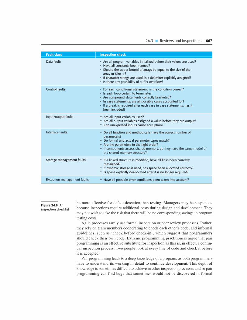
24.3 � Reviews and inspections 667
be more effective for defect detection than testing. Managers may be suspicious
because inspections require additional costs during design and development. They
may not wish to take the risk that there will be no corresponding savings in program
testing costs.
Agile processes rarely use formal inspection or peer review processes. Rather,
they rely on team members cooperating to check each other’s code, and informal
guidelines, such as ‘check before check-in’, which suggest that programmers
should check their own code. Extreme programming practitioners argue that pair
programming is an effective substitute for inspection as this is, in effect, a contin-
ual inspection process. Two people look at every line of code and check it before
it is accepted.
Pair programming leads to a deep knowledge of a program, as both programmers
have to understand its working in detail to continue development. This depth of
knowledge is sometimes difficult to achieve in other inspection processes and so pair
programming can find bugs that sometimes would not be discovered in formal
Fault class Inspection check
Data faults • Are all program variables initialized before their values are used?• Have all constants been named?• Should the upper bound of arrays be equal to the size of the
array or Size -1?• If character strings are used, is a delimiter explicitly assigned?• Is there any possibility of buffer overflow?
Control faults • For each conditional statement, is the condition correct?• Is each loop certain to terminate?• Are compound statements correctly bracketed?• In case statements, are all possible cases accounted for?• If a break is required after each case in case statements, has it
been included?
Input/output faults • Are all input variables used?• Are all output variables assigned a value before they are output?• Can unexpected inputs cause corruption?
Interface faults • Do all function and method calls have the correct number ofparameters?
• Do formal and actual parameter types match?• Are the parameters in the right order?• If components access shared memory, do they have the same model of
the shared memory structure?
Storage management faults • If a linked structure is modified, have all links been correctlyreassigned?
• If dynamic storage is used, has space been allocated correctly?• Is space explicitly deallocated after it is no longer required?
Exception management faults • Have all possible error conditions been taken into account?
Figure 24.8 Aninspection checklist

668 Chapter 24 � Quality management
inspections. However, pair programming can also lead to mutual misunderstandings
of requirements, where both members of the pair make the same mistake.
Furthermore, pairs may be reluctant to look for errors because the pair does not want
to slow down the progress of the project. The people involved cannot be as objective
as an external inspection team and their ability to discover defects is likely to be
compromised by their close working relationship.
24.4 Software measurement and metrics
Software measurement is concerned with deriving a numeric value or profile for an
attribute of a software component, system, or process. By comparing these values to
each other and to the standards that apply across an organization, you may be able to
draw conclusions about the quality of software, or assess the effectiveness of soft-
ware processes, tools, and methods.
For example, say an organization intends to introduce a new software-testing tool.
Before introducing the tool, you record the number of software defects discovered in
a given time. This is a baseline for assessing the effectiveness of the tool. After using
the tool for some time, you repeat this process. If more defects have been found in
the same amount of time, after the tool has been introduced, then you may decide
that it provides useful support for the software validation process.
The long-term goal of software measurement is to use measurement in place of
reviews to make judgments about software quality. Using software measurement, a
system could ideally be assessed using a range of metrics and, from these measure-
ments, a value for the quality of the system could be inferred. If the software had
reached a required quality threshold, then it could be approved without review.
When appropriate, the measurement tools might also highlight areas of the software
that could be improved. However, we are still quite a long way from this ideal situa-
tion and, there are no signs that automated quality assessment will become a reality
in the foreseeable future.
A software metric is a characteristic of a software system, system documentation,
or development process that can be objectively measured. Examples of metrics
include the size of a product in lines of code; the Fog index (Gunning, 1962), which
is a measure of the readability of a passage of written text; the number of reported
faults in a delivered software product; and the number of person-days required to
develop a system component.
Software metrics may be either control metrics or predictor metrics. As the names
imply, control metrics support process management, and predictor metrics help you
predict characteristics of the software. Control metrics are usually associated with
software processes. Examples of control or process metrics are the average effort
and the time required to repair reported defects. Predictor metrics are associated with
the software itself and are sometimes known as ‘product metrics’. Examples of pre-
dictor metrics are the cyclomatic complexity of a module (discussed in Chapter 8),

24.4 � Software measurement and metrics 669
the average length of identifiers in a program, and the number of attributes and oper-
ations associated with object classes in a design.
Both control and predictor metrics may influence management decision making,
as shown in Figure 24.9. Managers use process measurements to decide if process
changes should be made, and predictor metrics to help estimate the effort required to
make software changes. In this chapter, I mostly discuss predictor metrics, whose
values are assessed by analyzing the code of a software system. I discuss control
metrics and how they are used in process improvement in Chapter 26.
There are two ways in which measurements of a software system may be used:
1. To assign a value to system quality attributes By measuring the characteristics
of system components, such as their cyclomatic complexity, and then aggregat-
ing these measurements, you can assess system quality attributes, such as
maintainability.
2. To identify the system components whose quality is substandard Measurements
can identify individual components with characteristics that deviate from the
norm. For example, you can measure components to discover those with
the highest complexity. These are most likely to contain bugs because the com-
plexity makes them harder to understand.
Unfortunately, it is difficult to make direct measurements of many of the software
quality attributes shown in Figure 24.2. Quality attributes such as maintainability,
understandability, and usability are external attributes that relate to how developers
and users experience the software. They are affected by subjective factors, such as
user experience and education, and they cannot therefore be measured objectively.
To make a judgment about these attributes, you have to measure some internal attrib-
utes of the software (such as its size, complexity, etc.) and assume that these are
related to the quality characteristics that you are concerned with.
Figure 24.10 shows some external software quality attributes and internal attrib-
utes that could, intuitively, be related to them. The diagram suggests that there may
be relationships between external and internal attributes, but it does not say how
ManagementDecisions
Control MetricMeasurements
SoftwareProcess
Predictor MetricMeasurements
SoftwareProduct
Figure 24.9 Predictorand controlmeasurements

670 Chapter 24 � Quality management
these attributes are related. If the measure of the internal attribute is to be a useful
predictor of the external software characteristic, three conditions must hold
(Kitchenham, 1990):
1. The internal attribute must be measured accurately. This is not always straight-
forward and it may require special-purpose tools to make the measurements.
2. A relationship must exist between the attribute that can be measured and the
external quality attribute that is of interest. That is, the value of the quality
attribute must be related, in some way, to the value of the attribute than can be
measured.
3. This relationship between the internal and external attributes must be under-
stood, validated, and expressed in terms of a formula or model. Model formula-
tion involves identifying the functional form of the model (linear, exponential,
etc.) by analysis of collected data, identifying the parameters that are to be
included in the model, and calibrating these parameters using existing data.
Internal software attributes, such as the cyclomatic complexity of a component,
are measured by using software tools that analyze the source code of the software.
Open source tools are available that can be used to make these measurements.
Although intuition suggests that there could be a relationship between the complex-
ity of a software component and the number of observed failures in use, it is difficult
to objectively demonstrate that this is the case. To test this hypothesis, you need fail-
ure data for a large number of components and access to the component source code
for analysis. Very few companies have made a long-term commitment to collecting
data about their software, so failure data for analysis is rarely available.
In the 1990s, several large companies such as Hewlett-Packard (Grady, 1993),
AT&T (Barnard and Price, 1994), and Nokia (Kilpi, 2001) introduced metrics
Reliability
Depth of Inheritance Tree
Cyclomatic Complexity
Program Size in Linesof Code
Number of ErrorMessages
Length of User Manual
Maintainability
Usability
Reusability
External Quality Attributes Internal Attributes
Figure 24.10Relationships betweeninternal and externalsoftware

24.4 � Software measurement and metrics 671
programs. They made measurements of their products and processes and used these
in their quality management processes. Most of the focus was on collecting metrics
on program defects and the verification and validation processes. Offen and Jeffrey
(1997) and Hall and Fenton (1997) discuss the introduction of metrics programs in
industry in more detail.
There is little information publicly available about the current use of systematic
software measurement in industry. Many companies do collect information about
their software, such as the number of requirements change requests or the number of
defects discovered in testing. However, it is not clear if they then use these measure-
ments systematically to compare software products and processes or assess the
impact of changes to software processes and tools. There are several reasons why
this is difficult:
1. It is impossible to quantify the return on investment of introducing an organiza-
tional metrics program. There have been significant improvements in software
quality over the past few years without the use of metrics so it is difficult to justify
the initial costs of introducing systematic software measurement and assessment.
2. There are no standards for software metrics or standardized processes for meas-
urement and analysis. Many companies are reluctant to introduce measurement
programs until such standards and supporting tools are available.
3. In many companies, software processes are not standardized and are poorly
defined and controlled. As such, there is too much process variability within the
same company for measurements to be used in a meaningful way.
4. Much of the research on software measurement and metrics has focused on
code-based metrics and plan-driven development processes. However, more and
more software is now developed by configuring ERP systems or COTS, or by
using agile methods. We don’t know, therefore, if previous research is applica-
ble to these software development techniques.
5. Introducing measurement adds additional overhead to processes. This contra-
dicts the aims of agile methods, which recommend the elimination of process
activities that are not directly related to program development. Companies that
have adopted agile methods are therefore not likely to adopt a metrics program.
Software measurement and metrics are the basis of empirical software engineer-
ing (Endres and Rombach, 2003). This is a research area in which experiments on
software systems and the collection of data about real projects has been used to form
and validate hypotheses about software engineering methods and techniques.
Researchers working in this area argue that we can only be confident of the value of
software engineering methods and techniques if we can provide concrete evidence
that they actually provide the benefits that their inventors suggest.
Unfortunately, even when it is possible to make objective measurements and draw
conclusions from them, these will not necessarily convince decision makers. Rather,
decision making is often influenced by subjective factors, such as novelty, or the

672 Chapter 24 � Quality management
extent to which techniques are of interest to practitioners. I think, therefore, that it
will be many years before the results from empirical software engineering have a
significant effect on software engineering practice.
24.4.1 Product metrics
Product metrics are predictor metrics that are used to measure internal attributes of a
software system. Examples of product metrics include the system size, measured in
lines of code, or the number of methods associated with each object class.
Unfortunately, as I have explained earlier in this section, software characteristics that
can be easily measured, such as size and cyclomatic complexity, do not have a clear
and consistent relationship with quality attributes such as understandability and
maintainability. The relationships vary depending on the development processes
and technology used and the type of system that is being developed.
Product metrics fall into two classes:
1. Dynamic metrics, which are collected by measurements made of a program in
execution. These metrics can be collected during system testing or after the sys-
tem has gone into use. An example might be the number of bug reports or the
time taken to complete a computation.
2. Static metrics, which are collected by measurements made of representations of
the system, such as the design, program, or documentation. Examples of static
metrics are the code size and the average length of identifiers used.
These types of metric are related to different quality attributes. Dynamic metrics
help to assess the efficiency and reliability of a program. Static metrics help assess
the complexity, understandability, and maintainability of a software system or sys-
tem components.
There is usually a clear relationship between dynamic metrics and software qual-
ity characteristics. It is fairly easy to measure the execution time required for partic-
ular functions and to assess the time required to start up a system. These relate
directly to the system’s efficiency. Similarly, the number of system failures and the
type of failure can be logged and related directly to the reliability of the software, as
discussed in Chapter 15.
As I have discussed, static metrics, such as those shown in Figure 24.11, have an
indirect relationship with quality attributes. A large number of different metrics have
been proposed and many experiments have tried to derive and validate the relation-
ships between these metrics and attributes such as system complexity and maintain-
ability. None of these experiments have been conclusive but program size and
control complexity seem to be the most reliable predictors of understandability,
system complexity, and maintainability.
The metrics in Figure 24.11 are applicable to any program but more specific
object-oriented (OO) metrics have also been proposed. Figure 24.12 summarizes

24.4 � Software measurement and metrics 673
Chidamber and Kemerer’s suite (sometimes called the CK suite) of six object-
oriented metrics (1994). Although these were originally proposed in the early 1990s,
they are still the most widely used OO metrics. Some UML design tools automati-
cally collect values for these metrics as UML diagrams are created.
El-Amam (2001), in an excellent review of object-oriented metrics, discusses the
CK metrics and other OO metrics, and concludes that we do not yet have sufficient
evidence to understand how these and other object-oriented metrics relate to external
software qualities. This situation has not really changed since his analysis in 2001.
We still don’t know how to use measurements of object-oriented programs to draw
reliable conclusions about their quality.
24.4.2 Software component analysis
A measurement process that may be part of a software quality assessment process is
shown in Figure 24.13. Each system component can be analyzed separately using a
range of metrics. The values of these metrics may then be compared for different
Software metric Description
Fan-in/Fan-out Fan-in is a measure of the number of functions or methods that callanother function or method (say X). Fan-out is the number of functionsthat are called by function X. A high value for fan-in means that X is tightlycoupled to the rest of the design and changes to X will have extensiveknock-on effects. A high value for fan-out suggests that the overallcomplexity of X may be high because of the complexity of the controllogic needed to coordinate the called components.
Length of code This is a measure of the size of a program. Generally, the larger the size ofthe code of a component, the more complex and error-prone thatcomponent is likely to be. Length of code has been shown to be one ofthe most reliable metrics for predicting error-proneness in components.
Cyclomatic complexity This is a measure of the control complexity of a program. This controlcomplexity may be related to program understandability. I discusscyclomatic complexity in Chapter 8.
Length of identifiers This is a measure of the average length of identifiers (names for variables,classes, methods, etc.) in a program. The longer the identifiers, the morelikely they are to be meaningful and hence the more understandable theprogram.
Depth of conditional nesting This is a measure of the depth of nesting of if-statements in a program.Deeply nested if-statements are hard to understand and potentiallyerror-prone.
Fog index This is a measure of the average length of words and sentences indocuments. The higher the value of a document’s Fog index, the moredifficult the document is to understand.
Figure 24.11 Staticsoftware productmetrics
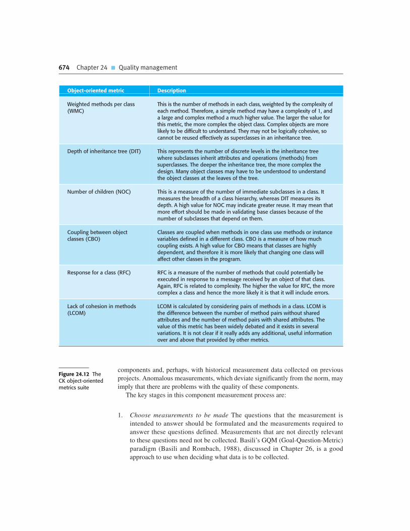
674 Chapter 24 � Quality management
components and, perhaps, with historical measurement data collected on previous
projects. Anomalous measurements, which deviate significantly from the norm, may
imply that there are problems with the quality of these components.
The key stages in this component measurement process are:
1. Choose measurements to be made The questions that the measurement is
intended to answer should be formulated and the measurements required to
answer these questions defined. Measurements that are not directly relevant
to these questions need not be collected. Basili’s GQM (Goal-Question-Metric)
paradigm (Basili and Rombach, 1988), discussed in Chapter 26, is a good
approach to use when deciding what data is to be collected.
Object-oriented metric Description
Weighted methods per class(WMC)
This is the number of methods in each class, weighted by the complexity ofeach method. Therefore, a simple method may have a complexity of 1, anda large and complex method a much higher value. The larger the value forthis metric, the more complex the object class. Complex objects are morelikely to be difficult to understand. They may not be logically cohesive, socannot be reused effectively as superclasses in an inheritance tree.
Depth of inheritance tree (DIT) This represents the number of discrete levels in the inheritance treewhere subclasses inherit attributes and operations (methods) fromsuperclasses. The deeper the inheritance tree, the more complex thedesign. Many object classes may have to be understood to understandthe object classes at the leaves of the tree.
Number of children (NOC) This is a measure of the number of immediate subclasses in a class. Itmeasures the breadth of a class hierarchy, whereas DIT measures itsdepth. A high value for NOC may indicate greater reuse. It may mean thatmore effort should be made in validating base classes because of thenumber of subclasses that depend on them.
Coupling between objectclasses (CBO)
Classes are coupled when methods in one class use methods or instancevariables defined in a different class. CBO is a measure of how muchcoupling exists. A high value for CBO means that classes are highlydependent, and therefore it is more likely that changing one class willaffect other classes in the program.
Response for a class (RFC) RFC is a measure of the number of methods that could potentially beexecuted in response to a message received by an object of that class.Again, RFC is related to complexity. The higher the value for RFC, the morecomplex a class and hence the more likely it is that it will include errors.
Lack of cohesion in methods(LCOM)
LCOM is calculated by considering pairs of methods in a class. LCOM isthe difference between the number of method pairs without sharedattributes and the number of method pairs with shared attributes. Thevalue of this metric has been widely debated and it exists in severalvariations. It is not clear if it really adds any additional, useful informationover and above that provided by other metrics.
Figure 24.12 The CK object-orientedmetrics suite

24.4 � Software measurement and metrics 675
2. Select components to be assessed You may not need to assess metric values for
all of the components in a software system. Sometimes, you can select a repre-
sentative selection of components for measurement, allowing you to make an
overall assessment of system quality. At other times, you may wish to focus on
the core components of the system that are in almost constant use. The quality
of these components is more important than the quality of components that are
only rarely used.
3. Measure component characteristics The selected components are measured and
the associated metric values computed. This normally involves processing the
component representation (design, code, etc.) using an automated data collec-
tion tool. This tool may be specially written or may be a feature of design tools
that are already in use.
4. Identify anomalous measurements After the component measurements have
been made, you then compare them with each other and to previous measure-
ments that have been recorded in a measurement database. You should look for
unusually high or low values for each metric, as these suggest that there could
be problems with the component exhibiting these values.
5. Analyze anomalous components When you have identified components that
have anomalous values for your chosen metrics, you should examine them to
decide whether or not these anomalous metric values mean that the quality of
the component is compromised. An anomalous metric value for complexity
(say) does not necessarily mean a poor quality component. There may be some
other reason for the high value, so may not mean that there are component
quality problems.
You should always maintain collected data as an organizational resource and
keep historical records of all projects even when data has not been used during a
particular project. Once a sufficiently large measurement database has been
established, you can then make comparisons of software quality across projects
and validate the relations between internal component attributes and quality
characteristics.
MeasureComponent
Characteristics
IdentifyAnomalous
Measurements
SelectComponents to
be Assessed
AnalyzeAnomalous
Components
ChooseMeasurements
to be Made
Figure 24.13 Theprocess of productmeasurement
676 Chapter 24 � Quality management
24.4.3 Measurement ambiguity
When you collect quantitative data about software and software processes, you have
to analyze that data to understand its meaning. It is easy to misinterpret data and to
make inferences that are incorrect. You cannot simply look at the data on its own—
you must also consider the context where the data is collected.
To illustrate how collected data can be interpreted in different ways, consider the
scenario below, which is concerned with the number of change requests made by
users of a system:
A manager decides to monitor the number of change requests submitted by cus-
tomers based on an assumption that there is a relationship between these change
requests and product usability and suitability. She assumes that the higher the
number of change requests, the less the software meets the needs of the customer.
Handling change requests and changing the software is expensive. The organiza-
tion therefore decides to modify its process with the aim of improving customer sat-
isfaction and, at the same time, reduce the costs of making changes. The intent is
that the process changes will result in better products and fewer change requests.
Process changes are initiated to increase customer involvement in the software
design process. Beta testing of all products is introduced and customer-
requested modifications are incorporated in the delivered product. New ver-
sions of products, developed with this modified process, are delivered. In some
cases, the number of change requests is reduced. In others, it is increased. The
manager is baffled and finds it impossible to assess the effects of the process
changes on the product quality.
To understand why this kind of ambiguity can occur, you have to understand the
reasons why users might make change requests:
1. The software is not good enough and does not do what customers want it to do.
They therefore request changes to deliver the functionality that they require.
2. Alternatively, the software may be very good and so it is widely and heavily
used. Change requests may be generated because there are many software users
who creatively think of new things that could be done with the software.
Therefore, increasing the customer involvement in the process may reduce the
number of change requests for products where the customers were unhappy. The
process changes have been effective and have made the software more usable and
suitable. Alternatively, however, the process changes may not have worked and cus-
tomers may have decided to look for an alternative system. The number of change
requests might decrease because the product has lost market share to a rival product
and there are consequently fewer product users.
On the other hand, the process changes might lead to many new, happy customers
who wish to participate in the product development process. They therefore generate

Chapter 24 � Key points 677
more change requests. Changes to the process of handling change requests may con-
tribute to this increase. If the company is more responsive to customers, they may
generate more change requests because they know that these requests will be taken
seriously. They believe that their suggestions will probably be incorporated in later
versions of the software. Alternatively, the number of change requests might have
increased because the beta-test sites were not typical of most usage of the program.
To analyze the change request data, you do not simply need to know the number
of change requests. You need to know who made the request, how they use the soft-
ware, and why the request was made. You also need information about external fac-
tors such as modifications to the change request procedure or market changes that
might have an effect. With this information, it is then possible to find out if the
process changes have been effective in increasing product quality.
This illustrates the difficulties of understanding the effects of changes and the
‘scientific’ approach to this problem is to reduce the number of factors that might
affect the measurements made. However, processes and products that are being
measured are not insulated from their environment. The business environment is
constantly changing and it is impossible to avoid changes to work practice just
because they may make comparisons of data invalid. As such, quantitative data about
human activities cannot always be taken at face value. The reasons why a measured
value changes are often ambiguous. These reasons must be investigated in detail
before drawing conclusions from any measurements that have been made.
K E Y P O I N T S
� Software quality management is concerned with ensuring that software has a low number of
defects and that it reaches the required standards of maintainability, reliability, portability, and
so on. It includes defining standards for processes and products and establishing processes to
check that these standards have been followed.
� Software standards are important for quality assurance as they represent an identification of
‘best practice’. When developing software, standards provide a solid foundation for building
good quality software.
� You should document a set of quality assurance procedures in an organizational quality manual.
This may be based on the generic model for a quality manual suggested in the ISO 9001
standard.
� Reviews of the software process deliverables involve a team of people who check that quality
standards are being followed. Reviews are the most widely used technique for assessing quality.
� In a program inspection or peer review, a small team systematically checks the code. They read
the code in detail and look for possible errors and omissions. The problems detected are then
discussed at a code review meeting.

� Software measurement can be used to gather quantitative data about software and the software
process. You may be able to use the values of the software metrics that are collected to make
inferences about product and process quality.
� Product quality metrics are particularly useful for highlighting anomalous components that may
have quality problems. These components should then be analyzed in more detail.
F U RT H E R R E A D I N G
678 Chapter 24 � Quality management
Metrics and Models for Software Quality Engineering, 2nd edition. This is a very comprehensive
discussion of software metrics covering process-, product-, and object-oriented metrics. It also
includes some background on the mathematics required to develop and understand models based
on software measurement. (S. H. Kan, Addison-Wesley, 2003.)
Software Quality Assurance: From Theory to Implementation. An excellent, up-to-date look at the
principles and practice of software quality assurance. It includes a discussion of standards such as
ISO 9001. (D. Galin, Addison-Wesley, 2004.)
‘A Practical Approach for Quality-Driven Inspections’. Many articles on inspections are now rather
old and do not take modern software development practice into account. This relatively recent
article describes an inspection method that addresses some of the problems of using inspection
and suggests how inspection can be used in a modern development environment. (C. Denger, F.
Shull, IEEE Software, 24 (2), March–April 2007.) http://dx.doi.org/10.1109/MS.2007.31
‘Misleading Metrics and Unsound Analyses’. An excellent article by leading metrics researchers
that discusses the difficulties of understanding what measurements really mean. (B. Kitchenham,
R. Jeffrey and C. Connaughton, IEEE Software, 24 (2), March–April 2007.) http://dx.doi.org/10.
1109/MS.2007.49.
‘The Case for Quantitative Project Management’. This is an introduction to a special section in the
magazine that includes two other articles on quantitative project management. It makes an
argument for further research in metrics and measurement to improve software project
management. (B. Curtis et al., IEEE Software, 25 (3), May–June 2008.) http://dx.doi.org/10.1109/
MS.2008.80.
E X E R C I S E S
24.1. Explain why a high-quality software process should lead to high-quality software products.
Discuss possible problems with this system of quality management.
24.2. Explain how standards may be used to capture organizational wisdom about effective
methods of software development. Suggest four types of knowledge that might be captured in
organizational standards.
24.3. Discuss the assessment of software quality according to the quality attributes shown in
Figure 24.2. You should consider each attribute in turn and explain how it might be
assessed.
24.4. Design an electronic form that may be used to record review comments and which could
be used to electronically mail comments to reviewers.
24.5. Briefly describe possible standards that might be used for:
• The use of control constructs in C, C#, or Java;
• Reports which might be submitted for a term project in a university;
• The process of making and approving program changes (see Chapter 26);
• The process of purchasing and installing a new computer.
24.6. Assume you work for an organization that develops database products for individuals and
small businesses. This organization is interested in quantifying its software development.
Write a report suggesting appropriate metrics and suggest how these can be collected.
24.7. Explain why program inspections are an effective technique for discovering errors in a
program. What types of error are unlikely to be discovered through inspections?
24.8. Explain why design metrics are, by themselves, an inadequate method of predicting
design quality.
24.9. Explain why it is difficult to validate the relationships between internal product attributes,
such as cyclomatic complexity and external attributes, such as maintainability.
24.10. A colleague who is a very good programmer produces software with a low number of
defects but consistently ignores organizational quality standards. How should her
managers react to this behavior?
R E F E R E N C E S
Bamford, R. and Deibler, W. J. (eds.) (2003). ‘ISO 9001:2000 for Software and Systems Providers:
An Engineering Approach’. Boca Raton, Fla.: CRC Press.
Barnard, J. and Price, A. (1994). ‘Managing Code Inspection Information’. IEEE Software, 11 (2),
59–69.
Basili, V. R. and Rombach, H. D. (1988). ‘The TAME project: Towards Improvement-Oriented
Software Environments’. IEEE Trans. on Software Eng., 14 (6), 758–773.
Boehm, B. W., Brown, J. R., Kaspar, H., Lipow, M., Macleod, G. and Merrit, M. (1978).
Characteristics of Software Quality. Amsterdam: North-Holland.
Chidamber, S. and Kemerer, C. (1994). ‘A Metrics Suite for Object-Oriented Design’. IEEE Trans. on
Software Eng., 20 (6), 476–93.
Chapter 24 � References 679

Crosby, P. (1979). Quality is Free. New York: McGraw-Hill.
El-Amam, K. 2001. ‘Object-oriented Metrics: A Review of Theory and Practice’. National Research
Council of Canada. http://seg.iit.nrc.ca/English/abstracts/NRC44190.html .
Endres, A. and Rombach, D. (2003). Empirical Software Engineering: A Handbook of Observations,
Laws and Theories. Harlow, UK: Addison-Wesley.
Fagan, M. E. (1976). ‘Design and code inspections to reduce errors in program development’. IBM
Systems J., 15 (3), 182–211.
Fagan, M. E. (1986). ‘Advances in Software Inspections’. IEEE Trans. on Software Eng., SE-12 (7),
744–51.
Gilb, T. and Graham, D. (1993). Software Inspection. Wokingham: Addison-Wesley.
Grady, R. B. (1993). ‘Practical Results from Measuring Software Quality’. Comm. ACM, 36 (11), 62–8.
Gunning, R. (1962). Techniques of Clear Writing. New York: McGraw-Hill.
Hall, T. and Fenton, N. (1997). ‘Implementing Effective Software Metrics Programs’. IEEE Software, 14
(2), 55–64.
Humphrey, W. (1989). Managing the Software Process. Reading, Mass.: Addison-Wesley.
IEC. 1998. ‘Standard IEC 61508: Functional safety of electrical/electronic/programmable electronic
safety-related systems’. International Electrotechnical Commission: Geneva.
IEEE. (2003). IEEE Software Engineering Standards Collection on CD-ROM. Los Alamitos, Ca.: IEEE
Computer Society Press.
Ince, D. (1994). ISO 9001 and Software Quality Assurance. London: McGraw-Hill.
Kilpi, T. (2001). ‘Implementing a Software Metrics Program at Nokia’. IEEE Software, 18 (6), 72–7.
Kitchenham, B. (1990). ‘Measuring Software Development’. In Software Reliability Handbook.
Rook, P. (ed.). Amsterdam: Elsevier, 303–31.
McConnell, S. (2004). Code Complete: A Practical Handbook of Software Construction, 2nd edition.
Seattle: Microsoft Press.
Mills, H. D., Dyer, M. and Linger, R. (1987). ‘Cleanroom Software Engineering’. IEEE Software, 4 (5),
19–25.
Offen, R. J. and Jeffrey, R. (1997). ‘Establishing Software Measurement Programs’. IEEE Software, 14
(2), 45–54.
Stalhane, T. and Hanssen, G. K. (2008). ‘The application of ISO 9001 to agile software development’.
9th International Conference on Product Focused Software Process Improvement, PROFES 2008,
Monte Porzio Catone, Italy: Springer.
680 Chapter 24 � Quality management

Configurationmanagement
25
Objectives
The objective of this chapter is to introduce you to configuration
management processes and tools. When you have read the chapter,
you will:
� understand the processes and procedures involved in software change
management;
� know the essential functionality that must be provided by a version
management system, and the relationships between version
management and system building;
� understand the differences between a system version and a system
release, and know the stages in the release management process.
Contents
25.1 Change management
25.2 Version management
25.3 System building
25.4 Release management

682 Chapter 25 � Configuration management
Software systems always change during development and use. Bugs are discovered
and have to be fixed. System requirements change, and you have to implement these
changes in a new version of the system. New versions of hardware and system plat-
forms become available and you have to adapt your systems to work with them.
Competitors introduce new features in their system that you have to match. As
changes are made to the software, a new version of a system is created. Most sys-
tems, therefore, can be thought of as a set of versions, each of which has to be main-
tained and managed.
Configuration management (CM) is concerned with the policies, processes, and
tools for managing changing software systems. You need to manage evolving sys-
tems because it is easy to lose track of what changes and component versions have
been incorporated into each system version. Versions implement proposals for
change, corrections of faults, and adaptations for different hardware and operating
systems. There may be several versions under development and in use at the same
time. If you don’t have effective configuration management procedures in place, you
may waste effort modifying the wrong version of a system, deliver the wrong version
of a system to customers, or forget where the software source code for a particular
version of the system or component is stored.
Configuration management is useful for individual projects as it is easy for one
person to forget what changes have been made. It is essential for team projects where
several developers are working at the same time on a software system. Sometimes
these developers are all working in the same place but, increasingly, development
teams are distributed with members in different locations across the world. The
use of a configuration management system ensures that teams have access to infor-
mation about a system that is under development and do not interfere with each
other’s work.
The configuration management of a software system product involves four
closely related activities (Figure 25.1):
1. Change management This involves keeping track of requests for changes to
the software from customers and developers, working out the costs and impact
of making these changes, and deciding if and when the changes should be
implemented.
2. Version management This involves keeping track of the multiple versions of
system components and ensuring that changes made to components by different
developers do not interfere with each other.
3. System building This is the process of assembling program components, data, and
libraries, and then compiling and linking these to create an executable system.
4. Release management This involves preparing software for external release and
keeping track of the system versions that have been released for customer use.
Configuration management involves dealing with a large volume of information
and many configuration management tools have been developed to support CM

Chapter 25 � Configuration management 683
ReleaseManagement
ChangeProposals
ChangeManagement
SystemReleases
ComponentVersions
SystemVersions
VersionManagement
SystemBuilding
Figure 25.1Configurationmanagement activities
processes. These range from simple tools that support a single configuration man-
agement task, such as bug tracking, to complex and expensive integrated toolsets
that support all configuration management activities.
Configuration management policies and processes define how to record and
process proposed system changes, how to decide what system components to
change, how to manage different versions of the system and its components, and
how to distribute changes to customers. Configuration management tools are
used to keep track of change proposals, store versions of system components,
build systems from these components, and track the releases of system versions
to customers.
Configuration management is sometimes considered to be part of software
quality management (covered in Chapter 24), with the same manager having
both quality management and configuration management responsibilities. When
a new version of the software has been implemented, it is handed over by the
development team to the quality assurance (QA) team. The QA team checks that
the system quality is acceptable. If so, it then becomes a controlled system,
which means that all changes to the system have to be agreed on and recorded
before they are implemented.
The definition and use of configuration management standards is essential for
quality certification in both the ISO 9000 and the CMM and CMMI standards
(Ahern et al., 2001; Bamford and Deibler, 2003; Paulk et al., 1995; Peach, 1996).
These CM standards can be based on generic CM standards that have been devel-
oped by bodies such as the IEEE. For example, standard IEEE 828-1998 is a stan-
dard for configuration management plans. These standards focus on CM processes
and the documents produced during the CM process. Using the external standards
as a starting point, companies then develop more detailed, company-specific stan-
dards that are tailored to their specific needs.
One of the problems of configuration management is that different compa-
nies talk about the same concepts using different terms. There are historical

684 Chapter 25 � Configuration management
reasons for this. Military software systems were probably the first systems in
which configuration management was used and the terminology for these sys-
tems reflected the processes and procedures already in place for hardware con-
figuration management. Commercial systems developers were not familiar
with the military procedures or terminology and so often invented their own
terms. Agile methods also have devised new terminology, sometimes intro-
duced deliberately to distinguish the agile approach from traditional CM meth-
ods. Figure 25.2 defines the configuration management terminology that I use
in this chapter.
Figure 25.2 CMterminology
Term Explanation
Configuration item orsoftware configurationitem (SCI)
Anything associated with a software project (design, code, test data, document,etc.) that has been placed under configuration control. There are often differentversions of a configuration item. Configuration items have a unique name.
Configuration control The process of ensuring that versions of systems and components are recorded andmaintained so that changes are managed and all versions of components areidentified and stored for the lifetime of the system.
Version An instance of a configuration item that differs, in some way, from other instancesof that item. Versions always have a unique identifier, which is often composed ofthe configuration item name plus a version number.
Baseline A baseline is a collection of component versions that make up a system. Baselines arecontrolled, which means that the versions of the components making up the systemcannot be changed. This means that it should always be possible to re-create a baselinefrom its constituent components.
Codeline A codeline is a set of versions of a software component and other configurationitems on which that component depends.
Mainline A sequence of baselines representing different versions of a system.
Release A version of a system that has been released to customers (or other users in anorganization) for use.
Workspace A private work area where software can be modified without affecting otherdevelopers who may be using or modifying that software.
Branching The creation of a new codeline from a version in an existing codeline. The newcodeline and the existing codeline may then develop independently.
Merging The creation of a new version of a software component by merging separateversions in different codelines. These codelines may have been created by aprevious branch of one of the codelines involved.
System building The creation of an executable system version by compiling and linking theappropriate versions of the components and libraries making up the system.
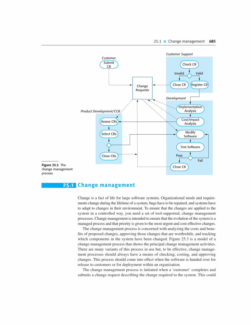
25.1 � Change management 685
Figure 25.3 The change managementprocess
25.1 Change management
Change is a fact of life for large software systems. Organizational needs and require-
ments change during the lifetime of a system, bugs have to be repaired, and systems have
to adapt to changes in their environment. To ensure that the changes are applied to the
system in a controlled way, you need a set of tool-supported, change management
processes. Change management is intended to ensure that the evolution of the system is a
managed process and that priority is given to the most urgent and cost-effective changes.
The change management process is concerned with analyzing the costs and bene-
fits of proposed changes, approving those changes that are worthwhile, and tracking
which components in the system have been changed. Figure 25.3 is a model of a
change management process that shows the principal change management activities.
There are many variants of this process in use but, to be effective, change manage-
ment processes should always have a means of checking, costing, and approving
changes. This process should come into effect when the software is handed over for
release to customers or for deployment within an organization.
The change management process is initiated when a ‘customer’ completes and
submits a change request describing the change required to the system. This could
Customer Support
Development
SubmitCR
Customer
Product Development/CCB
ChangeRequests
Select CRs
Close CRs
Assess CRs
ValidInvalid
Register CRClose CR
Check CR
Pass
Fail
Close CR
ImplementationAnalysis
Cost/ImpactAnalysis
ModifySoftware
Test Software

686 Chapter 25 � Configuration management
Figure 25.4 A partiallycompleted changerequest form
be a bug report, where the symptoms of the bug are described, or a request for
additional functionality to be added to the system. Some companies handle bug
reports and new requirements separately but, in principle, these are both simply
change requests. Change requests may be submitted using a change request form
(CRF). I use the term ‘customer’ here to include any stakeholder who is not part of
the development team, so changes may be suggested, for example, by the market-
ing department in a company.
Electronic change request forms record information that is shared between all
groups involved in change management. As the change request is processed, infor-
mation is added to the CRF to record decisions made at each stage of the process. At
any time, it therefore represents a snapshot of the state of the change request. As well
as recording the change required, the CRF records the recommendations regarding
the change; the estimated costs of the change; and the dates when the change was
requested, approved, implemented, and validated. The CRF may also include a sec-
tion where a developer outlines how the change may be implemented.
An example of a partially completed change request form is shown in Figure 25.4.
This is an example of a type of CRF that might be used in a large complex systems
engineering project. For smaller projects, I recommend that change requests should
be formally recorded and the CRF should focus on describing the change required,
with less emphasis on implementation issues. As a system developer, you decide how
to implement that change and estimate the time required for this.
Change Request Form
Project: SICSA/AppProcessing Number: 23/02Change requester: I. Sommerville Date: 20/01/09Requested change: The status of applicants (rejected, accepted, etc.) should be shownvisually in the displayed list of applicants.
Change analyzer: R. Looek Analysis date: 25/01/09Components affected: ApplicantListDisplay, StatusUpdater
Associated components: StudentDatabase
Change assessment: Relatively simple to implement by changing the display coloraccording to status. A table must be added to relate status to colors. No changes toassociated components are required.
Change priority: MediumChange implementation:Estimated effort: 2 hoursDate to SGA app. team: 28/01/09 CCB decision date: 30/01/09Decision: Accept change. Change to be implemented in Release 1.2Change implementor: Date of change:Date submitted to QA: QA decision:Date submitted to CM:Comments:
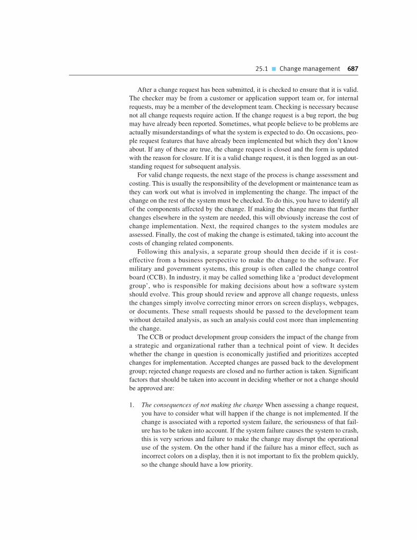
25.1 � Change management 687
After a change request has been submitted, it is checked to ensure that it is valid.
The checker may be from a customer or application support team or, for internal
requests, may be a member of the development team. Checking is necessary because
not all change requests require action. If the change request is a bug report, the bug
may have already been reported. Sometimes, what people believe to be problems are
actually misunderstandings of what the system is expected to do. On occasions, peo-
ple request features that have already been implemented but which they don’t know
about. If any of these are true, the change request is closed and the form is updated
with the reason for closure. If it is a valid change request, it is then logged as an out-
standing request for subsequent analysis.
For valid change requests, the next stage of the process is change assessment and
costing. This is usually the responsibility of the development or maintenance team as
they can work out what is involved in implementing the change. The impact of the
change on the rest of the system must be checked. To do this, you have to identify all
of the components affected by the change. If making the change means that further
changes elsewhere in the system are needed, this will obviously increase the cost of
change implementation. Next, the required changes to the system modules are
assessed. Finally, the cost of making the change is estimated, taking into account the
costs of changing related components.
Following this analysis, a separate group should then decide if it is cost-
effective from a business perspective to make the change to the software. For
military and government systems, this group is often called the change control
board (CCB). In industry, it may be called something like a ‘product development
group’, who is responsible for making decisions about how a software system
should evolve. This group should review and approve all change requests, unless
the changes simply involve correcting minor errors on screen displays, webpages,
or documents. These small requests should be passed to the development team
without detailed analysis, as such an analysis could cost more than implementing
the change.
The CCB or product development group considers the impact of the change from
a strategic and organizational rather than a technical point of view. It decides
whether the change in question is economically justified and prioritizes accepted
changes for implementation. Accepted changes are passed back to the development
group; rejected change requests are closed and no further action is taken. Significant
factors that should be taken into account in deciding whether or not a change should
be approved are:
1. The consequences of not making the change When assessing a change request,
you have to consider what will happen if the change is not implemented. If the
change is associated with a reported system failure, the seriousness of that fail-
ure has to be taken into account. If the system failure causes the system to crash,
this is very serious and failure to make the change may disrupt the operational
use of the system. On the other hand if the failure has a minor effect, such as
incorrect colors on a display, then it is not important to fix the problem quickly,
so the change should have a low priority.

688 Chapter 25 � Configuration management
2. The benefits of the change Is the change something that will benefit many users
of the system or is it simply a proposal that will primarily be of benefit to the
change proposer?
3. The number of users affected by the change If only a few users are affected, then
the change may be assigned a low priority. In fact, making the change may be
inadvisable if it could have adverse effects on the majority of system users.
4. The costs of making the change If making the change affects many system com-
ponents (hence increasing the chances of introducing new bugs) and/or takes a
lot of time to implement, then the change may be rejected, given the elevated
costs involved.
5. The product release cycle If a new version of the software has just been released
to customers, it may make sense to delay the implementation of the change until
the next planned release (see Section 25.3).
Change management for software products (e.g., a CAD system product) rather
than systems that are specifically developed for a certain customer, has to be handled
in a slightly different way. In software products, the customer is not directly involved
in decisions about system evolution, so the relevance of the change to the customer’s
business is not an issue. Change requests for these products come from the customer
support team, the company marketing team and the developers themselves. These
requests may reflect suggestions and feedback from customers or analyses of what is
offered by competing products.
The customer support team may submit change requests associated with bugs that
have been discovered and reported by customers after the software has been
released. Customers may use a webpage or e-mail to report bugs. A bug manage-
ment team then checks that the bug reports are valid and translates them into formal
system change requests. Marketing staff meet with customers and investigate com-
petitive products. They may suggest changes that should be included to make it eas-
ier to sell a new version of a system to new and existing customers. The system
developers themselves may have some good ideas about new features that can be
added to the system.
The change request process shown in Figure 25.3 is used after a system has been
released to customers. During development, when new versions of the system are
Customers and changes
Agile methods emphasize the importance of involving customers in the change prioritization process. Thecustomer representative helps the team decide on the changes that should be implemented in the nextdevelopment iteration. Although this can be effective for systems that are in development for a single customer,it can be a problem in product development where there is no real customer working with the team. In thosecases, the team has to make their own decisions on change prioritization.
http://www.SoftwareEngineering-9.com/Web/CM/agilechanges.html

25.1 � Change management 689
created through daily (or more frequent) system builds, a simpler change manage-
ment process is normally used. Problems and changes must still be recorded, but
changes that only affect individual components and modules need not be independ-
ently assessed. They are passed directly to the system developer. The system devel-
oper either accepts them or makes a case for why they are not required. However, an
independent authority, such as the system architect, should assess and prioritize
changes that affect those system modules that have been produced by different
development teams.
In some agile methods, such as extreme programming, customers are directly
involved in deciding whether a change should be implemented. When they propose a
change to the system requirements, they work with the team to assess the impact of
that change and then decide whether the change should take priority over the fea-
tures planned for the next increment of the system. However, changes that involve
software improvement are left to the discretion of the programmers working on the
system. Refactoring, where the software is continually improved, is not seen as an
overhead but rather as a necessary part of the development process.
As the development team changes software components, they should maintain a
record of the changes made to each component. This is sometimes called the deriva-
tion history of a component. A good way to keep the derivation history is in a stan-
dardized comment at the beginning of the component source code (Figure 25.5).
This comment should reference the change request that triggered the software
change. You can then write simple scripts that scan all components and process the
derivation histories to produce component change reports. For documents, records of
changes incorporated in each version are usually maintained in a separate page at the
front of the document. I discuss this in the web chapter on documentation.
Change management is usually supported by specialized software tools. These
may be relatively simple web-based tools such as Bugzilla, which is used to report
problems with many open source systems. Alternatively, more complex tools may be
used to automate the entire process of handling change requests from initial customer
proposal to change approval.
Figure 25.5Derivation history
// SICSA project (XEP 6087)//// APP-SYSTEM/AUTH/RBAC/USER_ROLE//// Object: currentRole// Author: R. Looek// Creation date: 13/11/2009//// © St Andrews University 2009//// Modification history// Version Modifier Date Change Reason// 1.0 J. Jones 11/11/2009 Add header Submitted to CM// 1.1 R. Looek 13/11/2009 New field Change req. R07/02
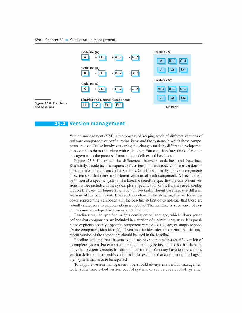
690 Chapter 25 � Configuration management
Baseline - V1
A B1.2 C1.1
L1 L2 Ex1
Baseline - V2
A1.3 B1.2 C1.2
L1 L2 Ex2
MainlineL1 L2 Ex1 Ex2
Codeline (A)
Codeline (B)
Codeline (C)
Libraries and External Components
C C1.1 C1.2 C1.3
B B1.1 B1.2 B1.3
A A1.1 A1.2 A1.3
Figure 25.6 Codelinesand baselines
25.2 Version management
Version management (VM) is the process of keeping track of different versions of
software components or configuration items and the systems in which these compo-
nents are used. It also involves ensuring that changes made by different developers to
these versions do not interfere with each other. You can, therefore, think of version
management as the process of managing codelines and baselines.
Figure 25.6 illustrates the differences between codelines and baselines.
Essentially, a codeline is a sequence of versions of source code with later versions in
the sequence derived from earlier versions. Codelines normally apply to components
of systems so that there are different versions of each component. A baseline is a
definition of a specific system. The baseline therefore specifies the component ver-
sions that are included in the system plus a specification of the libraries used, config-
uration files, etc. In Figure 25.6, you can see that different baselines use different
versions of the components from each codeline. In the diagram, I have shaded the
boxes representing components in the baseline definition to indicate that these are
actually references to components in a codeline. The mainline is a sequence of sys-
tem versions developed from an original baseline.
Baselines may be specified using a configuration language, which allows you to
define what components are included in a version of a particular system. It is possi-
ble to explicitly specify a specific component version (X.1.2, say) or simply to spec-
ify the component identifier (X). If you use the identifier, this means that the most
recent version of the component should be used in the baseline.
Baselines are important because you often have to re-create a specific version of
a complete system. For example, a product line may be instantiated so that there are
individual system versions for different customers. You may have to re-create the
version delivered to a specific customer if, for example, that customer reports bugs in
their system that have to be repaired.
To support version management, you should always use version management
tools (sometimes called version control systems or source code control systems).

25.2 � Version management 691
These tools identify, store, and control access to the different versions of compo-
nents. There are many different version management systems available, including
widely used open source systems such as CVS and Subversion (Pilato et al., 2004;
Vesperman, 2003).
Version management systems normally provide a range of features:
1. Version and release identification Managed versions are assigned identifiers
when they are submitted to the system. These identifiers are usually based on
the name of the configuration item (e.g., ButtonManager), followed by one or
more numbers. So ButtonManager 1.3 means the third version in codeline 1 of
the ButtonManager component. Some CM systems also allow the association
of attributes with versions (e.g., mobile, smallscreen), which can also be used
for version identification. A consistent identification system is important
because it simplifies the problem of defining configurations. It makes it simpler
to use shorthand references (e.g., *.V2 meaning version 2 of all components).
2. Storage management To reduce the storage space required by multiple versions
of components that differ only slightly, version management systems usually
provide storage management facilities. Instead of keeping a complete copy of
each version, the system stores a list of differences (deltas) between one version
and another. By applying these to a source version (usually the most recent ver-
sion), a target version can be re-created. This is illustrated in Figure 25.7.
3. Change history recording All of the changes made to the code of a system or
component are recorded and listed. In some systems, these changes may be used
to select a particular system version. This involves tagging components with
keywords describing the changes made. You then use these tags to select the
components to be included in a baseline.
4. Independent development Different developers may be working on the same
component at the same time. The version management system keeps track of
components that have been checked out for editing and ensures that changes
made to a component by different developers do not interfere.
5. Project support A version management system may support the development of
several projects, which share components. In project support systems, such as
Creation DateVersion Sequence
Most Recent
Storage Structure
Version1.0
Version1.1
Version1.2
Version1.3
D1 D2 D3V1.3 Source
CodeFigure 25.7 Storagemanagement usingdeltas
692 Chapter 25 � Configuration management
CVS (Vesperman, 2003), it is possible to check in and check out all of the files
associated with a project rather than having to work with one file or directory at
a time.
When version management systems were first developed, storage management
was one of their most important functions. The storage management features in a ver-
sion control system reduce the disk space required to maintain all system versions.
When a new version is created, the system simply stores a delta (a list of differences)
between the new version and the older version used to create that new version (shown
in the bottom part of Figure 25.7). In Figure 25.7, the shaded boxes represent earlier
versions of a component that are automatically re-created from the most recent
component version. Deltas are usually stored as lists of changed lines and, by
applying these automatically, one version of a component can be created from
another. As it is most likely that the most recent version of a component will be
used, most systems store that version in full. The deltas then define how to re-create
earlier system versions.
Most software development is a team activity, so situations often arise where dif-
ferent team members work on the same component at the same time. For example,
let’s say Alice is making some changes to a system, which involves changing com-
ponents A, B, and C. At the same time, Bob is working on changes and these require
making changes to components X, Y, and C. Both Alice and Bob are therefore
changing C. It’s important to avoid these changes interfering with each other—Bob’s
changes to C overwriting Alice’s or vice versa.
To support independent development without interference, version management
systems use the concept of a public repository and a private workspace. Developers
check out components from the public repository into their private workspace and
may change these as they wish in their private workspace. When their changes are
complete, they check in the components to the repository. This is illustrated in
Figure 25.8. If two or more people are working on a component at the same time,
each must check out the component from the repository. If a component has been
checked out, the version management system will normally warn other users wanting
Version Management System
Alice Bob
Workspace (U2)
check_incheck_in check_out check_out
C
A B
C
X Y
A CB XZ R
Y P QA1.1 C1.1B1.1
Workspace (U1)
Figure 25.8 Check-inand check-out from aversion repository

25.3 � System building 693
Codeline 1
Codeline 2
<branch>
<branch>
<merge>
Codeline 2.1
V1.0 V1.1 V1.2
V2.2 V2.3
V2.1.1 V2.1.2
V2.0 V2.1 V2.4
Figure 25.9 Branchingand merging
to check out that component that it has been checked out by someone else. The sys-
tem will also ensure that when the modified components are checked in, the different
versions are assigned different version identifiers and are separately stored.
A consequence of the independent development of the same component is that
codelines may branch. Rather than a linear sequence of versions that reflect changes to
the component over time, there may be several independent sequences, as shown in
Figure 25.9. This is normal in system development, where different developers work
independently on different versions of the source code and change it in different ways.
At some stage, it may be necessary to merge codeline branches to create a new
version of a component that includes all changes that have been made. This is also
shown in Figure 25.9 where versions 2.1.2 and 2.3 of the component are merged to
create version 2.4. If the changes made involve completely different parts of the
code, the component versions may be merged automatically by the version manage-
ment system by combining the deltas that apply to the code. More often, there are
overlaps between the changes made and they interfere with each other. A developer
has to check for clashes and modify the changes so that they are compatible.
25.3 System building
System building is the process of creating a complete, executable system by compil-
ing and linking the system components, external libraries, configuration files, etc.
System building tools and version management tools must communicate as the build
process involves checking out component versions from the repository managed by
the version management system. The configuration description used to identify a
baseline is also used by the system building tool.
Building is a complex process, which is potentially error-prone, as there may be
three different system platforms involved (Figure 25.10):
1. The development system, which includes development tools such as compilers,
source code editors, etc. Developers check out code from the version manage-
ment system into a private workspace before making changes to the system.
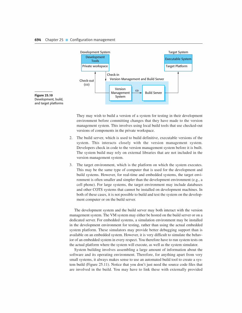
694 Chapter 25 � Configuration management
They may wish to build a version of a system for testing in their development
environment before committing changes that they have made to the version
management system. This involves using local build tools that use checked-out
versions of components in the private workspace.
2. The build server, which is used to build definitive, executable versions of the
system. This interacts closely with the version management system.
Developers check in code to the version management system before it is built.
The system build may rely on external libraries that are not included in the
version management system.
3. The target environment, which is the platform on which the system executes.
This may be the same type of computer that is used for the development and
build systems. However, for real-time and embedded systems, the target envi-
ronment is often smaller and simpler than the development environment (e.g., a
cell phone). For large systems, the target environment may include databases
and other COTS systems that cannot be installed on development machines. In
both of these cases, it is not possible to build and test the system on the develop-
ment computer or on the build server.
The development system and the build server may both interact with the version
management system. The VM system may either be hosted on the build server or on a
dedicated server. For embedded systems, a simulation environment may be installed
in the development environment for testing, rather than using the actual embedded
system platform. These simulators may provide better debugging support than is
available on an embedded system. However, it is very difficult to simulate the behav-
ior of an embedded system in every respect. You therefore have to run system tests on
the actual platform where the system will execute, as well as the system simulator.
System building involves assembling a large amount of information about the
software and its operating environment. Therefore, for anything apart from very
small systems, it always makes sense to use an automated build tool to create a sys-
tem build (Figure 25.11). Notice that you don’t just need the source code files that
are involved in the build. You may have to link these with externally provided
Development System
co
Version Management and Build Server
Target System
Executable System
Target Platform
Check-out(co)
Check-in
DevelopmentTools
Private workspace
VersionManagement
SystemBuild Server
Figure 25.10Development, build,and target platforms

25.3 � System building 695
libraries, data files (such as a file of error messages), and configuration files that
define the target installation. You may have to specify the versions of the compiler
and other software tools that are to be used in the build. Ideally, you should be able
to build a complete system with a single command or mouse click.
There are many build tools available and a build system may provide some or all
of the following features:
1. Build script generation If necessary, the build system should analyze the pro-
gram that is being built, identify dependent components, and automatically gen-
erate a build script (sometimes called a configuration file). The system should
also support the manual creation and editing of build scripts.
2. Version management system integration The build system should check out the
required versions of components from the version management system.
3. Minimal recompilation The build system should work out what source code
needs to be recompiled and set up compilations if required.
4. Executable system creation The build system should link the compiled object
code files with each other and with other required files, such as libraries and
configuration files, to create an executable system.
5. Test automation Some build systems can automatically run automated tests
using test automation tools such as JUnit. These check that the build has not
been ‘broken’ by changes.
6. Reporting The build system should provide reports about the success or failure
of the build and the tests that have been run.
7. Documentation generation The build system may be able to generate release
notes about the build and system help pages.
The build script is a definition of the system to be built. It includes information
about components and their dependencies, and the versions of tools used to compile
and link the system. The build script includes the configuration specification so the
scripting language used is often the same as the configuration description language.
SourceCode Files
Data Files
Libraries
ExecutableTests
ExecutableTarget System
Test Results
ConfigurationFiles
AutomatedBuild System
Compilersand ToolsFigure 25.11 System
building

696 Chapter 25 � Configuration management
The configuration language includes constructs to describe the system components
to be included in the build and their dependencies.
As compilation is a computationally intensive process, tools to support system
building are usually designed to minimize the amount of compilation that is required.
They do this by checking if a compiled version of a component is available. If so, there
is no need to recompile that component. Therefore, there has to be a way of unambigu-
ously linking the source code of a component with its equivalent object code.
The way that this is done is to associate a unique signature with each file where a
source code component is stored. The corresponding object code, which has been
compiled from the source code, has a related signature. The signature identifies each
source code version and is changed when the source code is edited. By comparing
the signatures on the source and object code files, it is possible to decide if the source
code component was used to generate the object code component.
There are two types of signatures that may be used:
1. Modification timestamps The signature on the source code file is the time and
date when that file was modified. If the source code file of a component has
been modified after the related object code file, then the system assumes that
recompilation to create a new object code file is necessary.
For example, say components Comp.java and Comp.class have modification
signatures of 17:03:05:02:14:2009 and 16:34:25:02:12:2009, respectively. This
means that the Java code was modified at 3 minutes and 5 seconds past 5 on the
14th of February 2009 and the compiled version was modified at 34 minutes and
25 seconds past 4 on the 12th of February 2009. In this case, the system would
automatically recompile Comp.java because the compiled version does not
include changes made to the source code since 12th of February.
2. Source code checksums The signature on the source code file is a checksum calcu-
lated from data in the file. A checksum function calculates a unique number using
the source text as input. If you change the source code (even by one character), this
will generate a different checksum. You can therefore be confident that source code
files with different checksums are actually different. The checksum is assigned to
the source code just before compilation and uniquely identifies the source file. The
build system then tags the generated object code file with the checksum signature.
If there is no object code file with the same signature as the source code file to be
included in a system, then recompilation of the source code is necessary.
As object code files are not normally versioned, the first approach means that
only the most recently compiled object code file is maintained in the system. This is
normally related to the source code file by name (i.e., it has the same name as the
source code file but with a different suffix). Therefore, the source file Comp.Java
may generate the object file Comp.class. Because source and object files are linked
by name rather than an explicit source file signature, it is not usually possible to
build different versions of a source code component into the same directory at the
same time, as these would generate object files with the same name.

25.3 � System building 697
The checksum approach has the advantage of allowing many different versions of
the object code of a component to be maintained at the same time. The signature
rather than the file name is the link between source and object code. The source code
and object code files have the same signature. Therefore, when you recompile a
component, it does not overwrite the object code, as would normally be the case
when the timestamp is used. Rather, it generates a new object code file and tags it
with the source code signature. Parallel compilation is possible and different ver-
sions of a component may be compiled at the same time.
Agile methods recommend that very frequent system builds should be carried out
with automated testing (sometimes called smoke tests) to discover software prob-
lems. Frequent builds may be part of a process of continuous integration, as shown in
Figure 25.12. In keeping with the agile methods notion of making many small
changes, continuous integration involves rebuilding the mainline frequently, after
small source code changes have been made. The steps in continuous integration are:
1. Check out the mainline system from the version management system into the
developer’s private workspace.
2. Build the system and run automated tests to ensure that the built system passes
all tests. If not, the build is broken and you should inform whoever checked in
the last baseline system. They are responsible for repairing the problem.
3. Make the changes to the system components.
4. Build the system in the private workspace and rerun system tests. If the tests fail,
continue editing.
5. Once the system has passed its tests, check it into the build system but do not
commit it as a new system baseline.
Tests Fail
Tests OK
OK
Tests FailCheck-outMainline
Build andTest System
Build andTest System
MakeChanges
Check-in toBuild Server
Build andTest System
CommitChanges to VM
VersionManagement
SystemBuild Server
PrivateWorkspace
VersionManagement
System
Figure 25.12Continuous integration

698 Chapter 25 � Configuration management
6. Build the system on the build server and run the tests. You need to do this in case
others have modified components since you checked out the system. If this is
the case, check out the components that have failed and edit these so that tests
pass on your private workspace.
7. If the system passes its tests on the build system, then commit the changes you
have made as a new baseline in the system mainline.
The argument for continuous integration is that it allows problems caused by the
interactions between different developers to be discovered and repaired as soon as
possible. The most recent system in the mainline is the definitive working system.
However, although continuous integration is a good idea, it is not always possible to
implement this approach to system building. The reasons for this are:
1. If the system is very large, it may take a long time to build and test. It is there-
fore impractical to build that system several times per day.
2. If the development platform is different from the target platform, it may not
be possible to run system tests in the developer’s private workspace. There may
be differences in hardware, operating system, or installed software. Therefore
more time is required for testing the system.
For large systems or for systems where the execution platform is not the same as
the development platform, continuous integration may be impractical. In those cir-
cumstances, a daily build system may be used. Features of this are as follows:
1. The development organization sets a delivery time (say 2 P.M.) for system com-
ponents. If developers have new versions of the components that they are writ-
ing, they must deliver them by that time. Components may be incomplete but
should provide some basic functionality that can be tested.
2. A new version of the system is built from these components by compiling and
linking them to form a complete system.
3. This system is then delivered to the testing team, which carries out a set of
predefined system tests. At the same time, the developers are still working on
their components, adding to the functionality and repairing faults discovered
in previous tests.
4. Faults that are discovered during system testing are documented and returned to
the system developers. They repair these faults in a subsequent version of the
component.
The advantages of using frequent builds of software are that the chances of find-
ing problems stemming from component interactions early in the process are
increased. Frequent building encourages thorough unit testing of components.
Psychologically, developers are put under pressure not to ‘break the build’; that is,
25.4 � Release management 699
they try to avoid checking in versions of components that cause the whole system to
fail. They are therefore reluctant to deliver new component versions that have not
been properly tested. Consequently, less time is spent during system testing discov-
ering and coping with software faults that could have been found by the developer.
25.4 Release management
A system release is a version of a software system that is distributed to customers.
For mass- market software, it is usually possible to identify two types of release
namely major releases, which deliver significant new functionality, and minor
releases, which repair bugs and fix customer problems that have been reported. For
example, this book is being written on an Apple Mac computer where the operating
system is OS 10.5.8. This means minor release 8 of major release 5 of OS 10. Major
releases are very important economically to the software vendor as customers have
to pay for these. Minor releases are usually distributed free of charge.
For custom software or software product lines, managing system releases is a
complex process. Special releases of the system may have to be produced for each
customer and individual customers may be running several different releases of the
system at the same time. This means that a software company selling a specialized
software product may have to manage tens or even hundreds of different releases of
that product. Their configuration management systems and processes have to be
designed to provide information about which customers have which releases of the
system and the relationship between releases and system versions. In the event of a
problem, it may be necessary to reproduce exactly the software that has been deliv-
ered to a particular customer.
Therefore when a system release is produced, it must be documented to ensure
that it can be re-created exactly in the future. This is particularly important for cus-
tomized, long-lifetime embedded systems, such as those that control complex
machines. Customers may use a single release of these systems for many years and
may require specific changes to a particular software system long after its original
release date.
To document a release, you have to record the specific versions of the source code
components that were used to create the executable code. You must keep copies of
the source code files, corresponding executables, and all data and configuration files.
You should also record the versions of the operating system, libraries, compilers, and
other tools used to build the software. These may be required to build exactly the
same system at some later date. This may mean that you have to store copies of the
platform software and the tools used to create the system in the version management
system along with the source code of the target system.
Preparing and distributing a system release is an expensive process, particularly
for mass-market software products. As well as the technical work involved in creat-
ing a release distribution, advertising and publicity material have to be prepared and
marketing strategies put in place to convince customers to buy the new release of the

700 Chapter 25 � Configuration management
system. Careful thought must be given to release timing. If releases are too frequent
or require hardware upgrades, customers may not move to the new release, espe-
cially if they have to pay for it. If system releases are too infrequent, market share
may be lost as customers move to alternative systems.
The various technical and organizational factors that you should take into account
when deciding on when to release a new version of a system are shown in Figure 25.13.
A system release is not just the executable code of the system. The release may
also include:
• configuration files defining how the release should be configured for particular
installations;
• data files, such as files of error messages, that are needed for successful system
operation;
• an installation program that is used to help install the system on target hardware;
• electronic and paper documentation describing the system;
• packaging and associated publicity that have been designed for that release.
Release creation is the process of creating the collection of files and documenta-
tion that includes all of the components of the system release. The executable code of
Figure 25.13 Factorsinfluencing systemrelease planning
Factor Description
Technicalquality of thesystem
If serious system faults are reported which affect the way in which many customers usethe system, it may be necessary to issue a fault repair release. Minor system faults may berepaired by issuing patches (usually distributed over the Internet) that can be applied tothe current release of the system.
Platformchanges
You may have to create a new release of a software application when a new version of theoperating system platform is released.
Lehman’s fifthlaw (seeChapter 9)
This ‘law’ suggests that if you add a lot of new functionality to a system; you will alsointroduce bugs that will limit the amount of functionality that may be included in the nextrelease. Therefore, a system release with significant new functionality may have to befollowed by a release that focuses on repairing problems and improving performance.
Competition For mass-market software, a new system release may be necessary because a competingproduct has introduced new features and market share may be lost if these are notprovided to existing customers.
Marketingrequirements
The marketing department of an organization may have made a commitment for releasesto be available at a particular date.
Customerchangeproposals
For custom systems, customers may have made and paid for a specific set of systemchange proposals, and they expect a system release as soon as these have beenimplemented.

25.4 � Release management 701
the programs and all associated data files must be identified in the version manage-
ment system and tagged with the release identifier. Configuration descriptions may
have to be written for different hardware and operating systems and instructions pre-
pared for customers who need to configure their own systems. If machine-readable
manuals are distributed, electronic copies must be stored with the software. Scripts
for the installation program may have to be written. Finally, when all information is
available, an executable master image of the software must be prepared and handed
over for distribution to customers or sales outlets.
When planning the installation of new system releases, you cannot assume that
customers will always install new system releases. Some system users may be
happy with an existing system. They may consider that it is not worth the cost of
changing to a new release. New releases of the system cannot, therefore, rely on the
installation of previous releases. To illustrate this problem, consider the following
scenario:
1. Release 1 of a system is distributed and put into use.
2. Release 2 requires the installation of new data files, but some customers do not
need the facilities of release 2 so remain with release 1.
3. Release 3 requires the data files installed in release 2 and has no new data files
of its own.
The software distributor cannot assume that the files required for release 3 have
already been installed in all sites. Some sites may go directly from release 1 to
release 3, skipping release 2. Some sites may have modified the data files associated
with release 2 to reflect local circumstances. Therefore, the data files must be distrib-
uted and installed with release 3 of the system.
The marketing and packaging costs associated with new releases of software
products are high so product vendors usually only create new releases for new plat-
forms or to add significant new functionality. They then charge users for this new
software. When problems are discovered in an existing release, the software vendors
make patches to repair the existing software available on a website to be downloaded
by customers.
The problem with using downloadable patches is that many customers may
never discover the existence of these problem repairs and may not understand
why they should be installed. They may instead continue using their existing,
faulty system with the consequent risks to their business. In some situations,
where the patch is designed to repair security loopholes, the risks of failing to
install the patch can mean that the business is susceptible to external attacks. To
avoid these problems, mass-market software vendors, such as Adobe, Apple, and
Microsoft, usually implement automatic updating where systems are updated
whenever a new minor release becomes available. However, this does not usually
work for custom systems because these systems do not exist in a standard
version for all customers.

702 Chapter 25 � Configuration management
K E Y P O I N T S
� Configuration management is the management of an evolving software system. When
maintaining a system, a CM team is put in place to ensure that changes are incorporated into
the system in a controlled way and that records are maintained with details of the changes that
have been implemented.
� The main configuration management processes are concerned with change management,
version management, system building, and release management. Software tools are available to
support all of these processes.
� Change management involves assessing proposals for changes from system customers and
other stakeholders and deciding if it is cost-effective to implement these in a new version of a
system.
� Version management involves keeping track of the different versions of software components
that are created as changes are made to them.
� System building is the process of assembling system components into an executable program to
run on a target computer system.
� Software should be frequently rebuilt and tested immediately after a new version has been
built. This makes it easier to detect bugs and problems that have been introduced since the last
build.
� System releases include executable code, data files, configuration files, and documentation.
Release management involves making decisions on system release dates, preparing all
information for distribution, and documenting each system release.
F U RT H E R R E A D I N G
Configuration Management Principles and Practice. This very comprehensive book covers standards
and traditional approaches to CM as well as CM approaches that are more appropriate to modern
processes, such as agile software development. (Anne Mette Jonassen Hass, Addison-Wesley, 2002.)
Software Configuration Management Patterns: Effective Teamwork, Practical Integration. A relatively
short, easy-to-read book that gives good practical advice on configuration management practice,
especially for agile methods of development. (S. P. Berczuk with B. Appleton, Addison-Wesley, 2003.)
‘High-level Best Practices in Software Configuration Management’. This web article, written by staff
at a CM tool supplier, is an excellent introduction to good practice in software configuration
management (L. Wingerd and C. Seiwald, 2006.) http://www.perforce.com/perforce/papers/
bestpractices.html.
Chapter 25 � Exercises 703
‘Agile Configuration Management for Large Organizations’. This web article describes configuration
management practices that can be used in agile development processes, with a particular emphasis
on how these can scale to large projects and companies. (P. Schuh, 2007.) http://www.ibm.com/
developerworks/rational/library/mar07/schuh/index.html.
E X E R C I S E S
25.1. Suggest five possible problems that could arise if a company does not develop effective
configuration management policies and processes.
25.2. What are the benefits of using a change request form as the central document in the change
management process?
25.3. Describe six essential features that should be included in a tool to support change
management processes.
25.4. Explain why it is essential that every version of a component should be uniquely identified.
Comment on the problems of using a version identification scheme that is simply based on
version numbers.
25.5. Imagine a situation where two developers are simultaneously modifying three different
software components. What difficulties might arise when they try to merge the changes that
they have made?
25.6. Software is increasingly being developed by teams where the team members are working at
different locations. Suggest features in a version management system that may be required to
support this distributed software development.
25.7. Describe the difficulties that may arise when building a system from its components. What
particular problems might occur when a system is built on a host computer for some target
machine?
25.8. With reference to system building, explain why you may sometimes have to maintain obsolete
computers on which large software systems were developed.
25.9. A common problem with system building occurs when physical file names are incorporated
in system code and the file structure implied in these names differs from that of the target
machine. Write a set of programmer’s guidelines that helps avoid this and any other system-
building problems that you can think of.
25.10. Describe five factors that should be taken into account by engineers during the process of
building a release of a large software system.

704 Chapter 25 � Configuration management
R E F E R E N C E S
Ahern, D. M., Clouse, A. and Turner, R. (2001). CMMI Distilled. Reading, Mass.: Addison-Wesley.
Bamford, R. and Deibler, W. J. (2003). ‘ ISO 9001:2000 for Software and Systems Providers: An
Engineering Approach’. Boca Raton, FL: CRC Press.
Paulk, M. C., Weber, C. V., Curtis, B. and Chrissis, M. B. (1995). The Capability Maturity Model:
Guidelines for Improving the Software Process. Reading, Mass.: Addison-Wesley.
Peach, R. W. (1996). The ISO 9000 Handbook, 3rd edition. New York: Irwin Professional Pub.
Pilato, C. M., Collins-Sussman, B. and Fitzpatrick, B. W. (2004). Version Control with Subversion.
Sebastopol, Calif.: O‘Reilly Media Inc.
Vesperman, J. (2003). Essential CVS. Sebastopol, Calif.: O‘Reilly and Associates.

Process improvement
26
Objectives
The objective of this chapter is to introduce software process
improvement as a way of increasing software quality and reducing
development costs. When you have read the chapter, you will:
� understand the rationale for software process improvement as a
means of improving both product quality and the efficiency and
effectiveness of software processes;
� understand the principles of software process improvement and the
cyclic process improvement process;
� know how the Goal-Question-Metric approach may be used to guide
process measurement;
� have been introduced to the ideas of process capability and process
maturity, and the general form of the SEI’s CMMI model for process
improvement.
Contents
26.1 The process improvement process
26.2 Process measurement
26.3 Process analysis
26.4 Process change
26.5 The CMMI process improvement framework

706 Chapter 26 � Process improvement
Nowadays, there is a constant demand from industry for cheaper, better software,
which has to be delivered to ever-tighter deadlines. Consequently, many software
companies have turned to software process improvement as a way of enhancing the
quality of their software, reducing costs, or accelerating their development processes.
Process improvement means understanding existing processes and changing these
processes to increase product quality and/or reduce costs and development time.
Two quite different approaches to process improvement and change are used:
1. The process maturity approach, which has focused on improving process and
project management and introducing good software engineering practice into
an organization. The level of process maturity reflects the extent to which good
technical and management practice has been adopted in organizational soft-
ware development processes. The primary goals of this approach are improved
product quality and process predictability.
2. The agile approach, which has focused on iterative development and the reduction
of overheads in the software process. The primary characteristics of agile methods
are rapid delivery of functionality and responsiveness to changing customer
requirements.
Adherents of each of these approaches are generally skeptical of the benefits of
the other. The process maturity approach is rooted in plan-driven development and
usually requires increased ‘overhead’, in the sense that activities are introduced that
are not directly relevant to programming. Agile approaches focus on the code being
developed and deliberately minimize formality and documentation.
I have discussed agile methods in Chapter 3 and elsewhere in the book, so I focus
in this chapter on process management and maturity-based process improvement.
This does not mean that I prefer this approach to agile methods. In fact, I am con-
vinced that, for small to medium-sized projects, adopting agile practices is likely to
be the most cost-effective process improvement strategy. However for large systems,
critical systems, and systems involving developers in different companies, manage-
ment issues are often the reasons why projects run into problems. For companies
whose business is large, complex systems engineering, a maturity-focused approach
to process improvement should be considered.
As I discussed in Chapter 24, the development process that was used to create a
software system influences the quality of that system. Therefore, many people
believe that improving the software development process will lead to better quality
software. This notion of process improvement is the brainchild of American engi-
neer W. E. Deming, who worked with Japanese industry after World War II to help
improve quality. Japanese industry has been committed to continuous process
improvement for many years, which has led to the acknowledged high quality of
Japanese manufactured goods.
Deming (and others) introduced the idea of statistical quality control. This is
based on measuring the number of product defects and relating these defects to the
process. The aim is to reduce the number of product defects by analyzing and

Chapter 26 � Process improvement 707
ProductQuality
DevelopmentTechnology
Cost, Time andSchedule
ProcessQuality
PeopleQuality
Figure 26.1 Factorsaffecting softwareproduct
modifying the process so that the chances of introducing defects are reduced and
defect detection is improved. Once a lower defect count has been achieved, the
process is standardized and a further improvement cycle then begins.
Humphrey (1988), in his seminal book on process management, argues that the
same techniques can be applied to software engineering. He states:
“W. E. Deming, in his work with the Japanese industry after World War II,
applied the concepts of statistical process control to industry. While there are
important differences, these concepts are just as applicable to software as they
are to automobiles, cameras, wristwatches and steel.”
Although there are clearly similarities, I do not agree with Humphrey that results
from manufacturing engineering can be transferred easily to software engineering.
Where manufacturing is involved, the process/product relationship is obvious.
Manufacturing usually involves setting up automated tools and product checking
processes. If someone makes a mistake in calibrating a machine, this will affect all of
the products produced by that machine. Avoiding mistakes in setting up machines
and introducing more effective checking processes clearly improves product quality.
This process quality/product quality relationship is less obvious when the product
is intangible and dependent, to some extent, on intellectual processes that cannot be
automated. Software quality is not influenced by its manufacturing process but by its
design process, where people’s skills and experience are significant. In some cases,
the process used may be the most significant determinant of product quality.
However, for innovative applications in particular, the people involved in the process
have more influence on quality than the process used.
For software products, or any other intellectual products such as books or films
where the quality of the product depends on its design, there are four important fac-
tors that affect product quality. These are shown in Figure 26.1.
The influence of each of these factors depends on the size and type of the proj-
ect. For very large systems that include separate subsystems, developed by teams
who may be working in different locations, the principal factor that affects product
quality is the software process. The major problems with large projects are integra-
tion, project management, and communications. There is usually a mix of abilities

708 Chapter 26 � Process improvement
and experience in the team members and, because the development process usually
takes place over a number of years, the development team is volatile. It may change
completely over the lifetime of the project.
For small projects, however, where there are only a few team members, the quality
of the development team is more important than the development process used. Hence,
the agile manifesto proclaims the importance of people rather than process. If the team
has a high level of ability and experience, the quality of the product is likely to be high,
irrespective of the process used. If the team is inexperienced and unskilled, a good
process may limit the damage but will not, in itself, lead to high-quality software.
Where teams are small, good development technology is particularly important.
The small team cannot devote a lot of time to tedious administrative procedures. The
team members spend most of their time designing and programming the system, so
good tools significantly affect their productivity. For large projects, a basic level of
development technology is essential for information management. Paradoxically,
however, sophisticated software tools are less important in large projects. Team
members spend a smaller proportion of their time in development activities and more
time communicating and understanding other parts of the system. Development
tools make no difference to this. However, Web 2.0 tools that support communica-
tions, such as wikis and blogs, can significantly improve communications between
members of distributed teams.
Irrespective of people, process, or tool factors, if a project has an inadequate budget
or is planned with an unrealistic delivery schedule, product quality will be affected. A
good process requires resources for its effective implementation. If these resources are
insufficient, the process cannot be really effective. If resources are inadequate, only
excellent people can save a project. Even then, if the deficit is too great, the product
quality will be degraded. If there is not enough time for development, the delivered soft-
ware is likely to have reduced functionality or lower levels of reliability or performance.
All too often, the real cause of software quality problems is not poor management,
inadequate processes, or poor quality training. Rather, it is the fact that organizations
must compete to survive. To gain a contract, a company may underestimate the effort
required or promise rapid delivery of a system. In an attempt to meet these commit-
ments, an unrealistic development schedule may be agreed upon. Consequently, the
quality of the software is adversely affected.
26.1 The process improvement process
In Chapter 2, I introduced the general idea of a software process as a sequence of activ-
ities that, when executed, lead to the production of a software system. I described
generic processes, such as the waterfall model and reuse-based development, and I dis-
cussed the most important process activities. These generic processes are instantiated
within an organization to create the particular process that they use to develop software.
Software processes can be observed in all organizations, from one-person compa-
nies to large multinationals. These processes are of different types depending on the

26.1 � The process improvement process 709
degree of formality of the process, the types of products developed, the size of the
organization, and so on. There is no such thing as an ‘ideal’ or ‘standard’ software
process that is applicable in all organizations or for all software products of a partic-
ular type. Each company has to develop its own process depending on its size, the
background and skills of its staff, the type of software being developed, customer
and market requirements, and the company culture.
Process improvement, therefore, does not simply mean adopting particular methods
or tools or using a published, generic process. Although organizations that develop the
same type of software clearly have much in common, there are always local organiza-
tional factors, procedures, and standards that influence the process. You will rarely be
successful in introducing process improvements if you simply attempt to change the
process to one that is used elsewhere. You must always consider the local environment
and culture and how this may be affected by process change proposals.
You also have to consider what aspects of the process that you want to improve.
Your goal might be to improve software quality and so you may wish to introduce
new process activities that change the way software is developed and tested. You
may be interested in improving some attribute of the process itself and you have to
decide which process attributes are the most important to your company. Examples
of process attributes that may be targets for improvement are shown in Figure 26.2.
Process characteristic Key issues
Understandability To what extent is the process explicitly defined and how easy is it tounderstand the process definition?
Standardization To what extent is the process based on a standard generic process? This maybe important for some customers who require conformance with a set ofdefined process standards. To what extent is the same process used in all partsof a company?
Visibility Do the process activities culminate in clear results, so that the progress of theprocess is externally visible?
Measurability Does the process include data collection or other activities that allow processor product characteristics to be measured?
Supportability To what extent can software tools be used to support the process activities?
Acceptability Is the defined process acceptable to and usable by the engineers responsiblefor producing the software product?
Reliability Is the process designed in such a way that process errors are avoided ortrapped before they result in product errors?
Robustness Can the process continue in spite of unexpected problems?
Maintainability Can the process evolve to reflect changing organizational requirements oridentified process improvements?
Rapidity How fast can the process of delivering a system from a given specification becompleted?
Figure 26.2 Processattributes

710 Chapter 26 � Process improvement
These attributes are obviously related, sometimes positively and sometimes nega-
tively. Therefore, a process that scores highly on the visibility attribute will probably
also be understandable. A process observer can infer the existence of activities from
the outputs produced. On the other hand, process visibility may be inversely related
to rapidity. Making a process visible requires the people involved to produce infor-
mation about the process itself. This may slow down software production because of
the time it takes to produce these documents.
It is not possible to make process improvements that optimize all process attributes
simultaneously. For example, if your aim is to have a rapid development process, then
you may have to reduce the process visibility. If you wish to make a process more
maintainable, then you may have to adopt procedures and tools that reflect broader
organizational practice and that are used in different parts of the company. This may
reduce the local acceptability of the process. Engineers may have introduced local
procedures and non-standard tools to support their way of working. As these are
effective, they may not wish to give them up in favor of a standardized process.
The process of process improvement is a cyclical process, as shown in Figure 26.3.
It involves three subprocesses:
1. Process measurement Attributes of the current project or the product are measured.
The aim is to improve the measures according to the goals of the organization
involved in process improvement. This forms a baseline that helps you decide if
process improvements have been effective.
2. Process analysis The current process is assessed, and process weaknesses and
bottlenecks are identified. Process models (sometimes called process maps)
that describe the process may be developed during this stage. The analysis
may be focused by considering process characteristics such as rapidity and
robustness.
3. Process change Process changes are proposed to address some of the identified
process weaknesses. These are introduced and the cycle resumes to collect data
about the effectiveness of the changes.
Measure
AnalyzeChange
Figure 26.3 The processimprovement cycle

26.2 � Process measurement 711
Without concrete data on a process or the software developed using that process,
it is impossible to assess the value of process improvement. However, companies
starting the process improvement process are unlikely to have process data available
as an improvement baseline. Therefore, as part of the first cycle of changes, you may
have to introduce process activities to collect data about the software process and to
measure software product characteristics.
Process improvement is a long-term activity, so each of the stages in the
improvement process may last several months. It is also a continuous activity as,
whatever new processes are introduced, the business environment will change and
the new processes will themselves have to evolve to take these changes into
account.
26.2 Process measurement
Process measurements are quantitative data about the software process, such as the
time taken to perform some process activity. For example, you may measure the time
required to develop program test cases. Humphrey (1989), in his book on process
improvement, argues that the measurement of process and product attributes is
essential for process improvement. He also suggests that measurement has an impor-
tant role to play in small-scale personal process improvement (Humphrey, 1995),
where individuals try to become more productive.
Process measurements can be used to assess whether or not the efficiency of a
process has been improved. For example, the effort and time devoted to testing can
be monitored. Effective improvements to the testing process should reduce the effort
and/or testing time. However, process measurements on their own cannot be used to
determine if product quality has improved. Product quality data (see Chapter 24)
must also be collected and related to the process activities.
Three types of process metrics can be collected:
1. The time taken for a particular process to be completed This can be the total
time devoted to the process, calendar time, the time spent on the process by
particular engineers, and so on.
2. The resources required for a particular process Resources might include total
effort in person-days, travel costs, or computer resources.
3. The number of occurrences of a particular event Examples of events that might
be monitored include the number of defects discovered during code inspection,
the number of requirements changes requested, and the average number of lines
of code modified in response to a requirements change.
The first two types of measurement can be used to discover if process changes
have improved the efficiency of a process. Say there are fixed points in a software

712 Chapter 26 � Process improvement
development process, such as the acceptance of requirements, the completion of
architectural design or the completion of test data generation. You may be able to
measure the time and effort required to move from one of these fixed points to
another. After changes have been introduced, measurements of system attributes can
show if the process changes have been successful in reducing the time or effort
required.
Measurements of the number of events that occur have a more direct bearing on
software quality. For example, increasing the number of defects discovered by chang-
ing the program inspection process will probably be reflected in improved product
quality. However, this has to be confirmed by subsequent product measurements.
A fundamental difficulty in process measurement is knowing what information
about the process should be collected to support process improvement. Basili and
Rombach (1988) proposed what they call the GQM (Goal-Question-Metric) paradigm,
which has become widely used in software and process measurement. Basili and
Green (1993) describe how this approach has been used in a long-term, measurement-
based process improvement program in the U.S. space agency NASA.
The GQM paradigm (Figure 26.4) is used in process improvement to help answer
three critical questions:
1. Why are we introducing process improvement?
2. What information do we need to help identify and assess improvements?
3. What process and product measurements are required to provide this information?
These questions are directly related to the abstractions (goals, questions, metrics)
in the GQM paradigm:
1. Goals A goal is something that the organization is trying to achieve. It should not
be directly concerned with process attributes but rather with how the process
affects products or the organization itself. Examples of goals might be an improved
Goals to be Achieved
Questions to be Asked
Things to be Measured
Goal 1 Goal 2
Q2 Q3 Q4Q1 Q7Q5 Q6
M5 M6M4M3M1 M2Figure 26.4 The GQMparadigm

level of process maturity (see Section 26.5), shorter product development time, or
increased product reliability.
2. Questions These are refinements of goals where specific areas of uncertainty
related to the goals are identified. Normally, a goal will have a number of asso-
ciated questions that need to be answered. Examples of questions related to the
goal of shortening product development times might be “Where are the bottle-
necks in our current process?”, “How can the time required to finalize product
requirements with customers be reduced?”, and “How many of our tests are
effective in discovering product defects?”
3. Metrics These are the measurements that need to be collected to help answer
the questions and to confirm whether or not process improvements have
achieved the desired goal. To help answer the above questions, you might col-
lect data on the time taken to complete each process activity (normalized by
system size), the number of formal communications between clients and cus-
tomers for each requirements change, and the number of defects discovered
per test run.
The advantage of using the GQM approach in process improvement is that it sep-
arates organizational concerns (the goals) from specific process concerns (the ques-
tions). It provides a basis for deciding what data should be collected and suggests
that collected data should be analyzed in different ways, depending on the question it
is intended to answer.
The GQM approach has been developed and combined with the SEI’s capability
maturity model (Paulk et al., 1995) in the AMI (Analyze, Measure, Improve) method
of software process improvement. The developers of the AMI method propose a
staged approach to process improvement, where measurement is started after an
organization has introduced some standardization into its processes, as opposed to
beginning measurement straight away. The AMI handbook (Pulford et al., 1996)
provides guidelines and practical advice on implementing measurement-based
process improvement.
As I discussed in Chapter 24, interpreting what measurements actually mean is
sometimes problematic. For example, say you measure the average time taken to
repair reported bugs in software that has been delivered for external testing. This is
the time between the team receiving an error report and the time when this report is
formally marked as ‘cleared’. You introduce a new web-based tool for error report-
ing and, after this tool has been in use for some time, you observe that the time to
repair reported bugs has been reduced.
You may then assert that the introduction of the error reporting tools has actu-
ally reduced the time to repair bugs. When you observe changes to a metric, it is
always tempting to attribute these changes to the process changes that you have
introduced. However, it is dangerous to make simplistic assumptions about
improvements. Changes in a metric could be caused by something completely dif-
ferent, such as a change of the people in the project team, changes to the project
26.2 � Process measurement 713

714 Chapter 26 � Process improvement
schedule, or management changes. It may also be the case that the team’s practice
changes simply because it is being measured. In the case of the error reporting
tools, some of the reasons why the change has been observed include:
1. The new system may have reduced overhead and so more time is available to
repair bugs. This has led to a reduction in average ‘bug repair’ times. The
process improvement may have made a genuine difference.
2. The new system may have made no difference to the actual time taken to fix
bugs but it may have made it easier to record information. Therefore, the bug
repair times are more accurately measured with the new system. There has been
no actual change in the average time to fix bugs.
3. The measurements before the new system was introduced were, perhaps,
made part way through the testing of a system. The bugs that were easiest and
quickest to fix had already been fixed and only ‘hard bugs’ remained that took
longer to repair. However, after the bug reporting system was introduced,
measurements were made at the beginning of the testing of the new system
and the bugs being fixed were the ‘easy bugs’, which could be repaired
quickly.
4. A new manager of the testing team may have instructed team members to report
user interface inconsistencies as bugs, whereas before these were ignored. This
meant that many more ‘easy bugs’ were reported that could be fixed quickly.
Measurement is a way of generating evidence about a process and process
changes. However, this evidence has to be interpreted along with other information
about the process before you can be sure that process changes are effective. You
should always use measurement in conjunction with qualitative assessment of
changes. This involves talking to the people involved in the process about the
changes that have been introduced and getting their impression of the effectiveness
of these changes. Not only does this reveal other factors that may have influenced the
process, it reveals the extent to which the team has adopted the proposed changes
and how these have affected actual development practice.
Analysis of process practice
One approach to process analysis is to use questionnaires to discover the extent to which good softwareengineering practices are used. Therefore, for some stage in the process, such as requirements engineering, youmay identify what practices are most appropriate for the type of system being developed in a company and askquestions about how widely these are used. This is the approach that I suggested in my book on requirementsengineering process improvement (Sommerville and Sawyer, 1997).
http://www.SoftwareEngineering-9.com/Web/ProcImp/goodpractice.html
26.3 � Process analysis 715
26.3 Process analysis
Process analysis is the study of processes to help understand their key characteristics
and how such processes are performed in practice by the people involved. I have sug-
gested in Figure 26.3 that process analysis follows process measurement. This is a
simplification because, in reality, these activities are intertwined. You need to carry
out some analysis to know what to measure, and, when making measurements, you
inevitably develop a deeper understanding of the process being measured.
Process analysis has a number of closely related objectives:
1. To understand the activities involved in the process and the relationships
between these activities.
2. To understand the relationships between the process activities and the measure-
ments that have been made.
3. To relate the specific process or processes that you are analyzing to comparable
processes elsewhere in the organization, or to idealized processes of the same type.
During process analysis you are trying to understand what is going on in a process.
You are looking for information about that process’s problems and inefficiencies. You
should also be interested in the extent that the process is used, the software tools used
to support the process, and how the process is influenced by organizational con-
straints. Figure 26.5 shows some of the aspects of the process that you may investi-
gate during process analysis.
The most commonly used techniques of process analysis are:
1. Questionnaires and interviews The engineers and managers working on a
project are questioned about what actually goes on. The answers to a formal
questionnaire are refined during personal interviews with those involved in the
process. As I discuss below, the discussion may be structured around models of
software processes.
2. Ethnographic studies Ethnographic studies (see Chapter 4), where process
participants are observed as they work, may be used to understand the nature of
software development as a human activity. Such analysis reveals subtleties and
complexities that may not be revealed by questionnaires and interviews.
Each of these approaches has advantages and disadvantages. Questionnaire-based
analysis can be carried out fairly quickly once the right questions have been identified.
However, if the questions are badly worded or inappropriate, you may end up with an
incomplete or inaccurate understanding of the process. Furthermore, questionnaire-
based analysis may appear to them as a form of assessment or appraisal. The engineers
being questioned may therefore give the answers that they think you want to hear
rather than the truth about the process used.

716 Chapter 26 � Process improvement
Figure 26.5 Aspectsof process analysis
Interviews with the people involved in the process are more open-ended than ques-
tionnaires. You start with a prepared script of questions but adapt these according to
the responses that you get from different people. If you give participants an opportu-
nity to discuss issues more widely, you may find that the process participants talk
about process problems, the ways that the process is changed in practice, and so on.
In almost all processes, the people involved make local changes to adapt the
process to suit local circumstances. Ethnographic analysis is more likely than inter-
views to discover the true process used. However, this type of analysis can be a pro-
longed activity that can last several months. It relies on external observation of the
process as it is being enacted. To do a complete analysis, you have to be involved
from the initial stages of a project through to product delivery and maintenance. For
Process aspect Questions
Adoption and standardization Is the process documented and standardized across the organization? Ifnot, does this mean that any measurements made are specific only to asingle process instance? If processes are not standardized, then changes toone process may not be transferable to comparable processes elsewherein the company.
Software engineering practice Are there known, good software engineering practices that are notincluded in the process? Why are they not included? Does the lack of thesepractices affect product characteristics, such as the number of defects in adelivered software system?
Organizational constraints What are the organizational constraints that affect the process design andthe ways that the process is performed? For example, if the processinvolves dealing with classified material, there may be activities in theprocess to check that classified information is not included in any materialdue to be released to external organizations. Organizational constraintsmay mean that possible process changes cannot be made.
Communications How are communications managed in the process? How docommunication issues relate to the process measurements that have beenmade? Communication problems are a major issue in many processes andcommunication bottlenecks are often the reasons for project delays.
Introspection Is the process reflective (i.e., do the actors involved in the process explicitlythink about and discuss the process and how it might be improved)? Arethere mechanisms through which process actors can propose processimprovements?
Learning How do people joining a development team learn about the softwareprocesses used? Does the company have process manuals and processtraining programs?
Tool support What aspects of the process are and aren’t supported by software tools?For unsupported areas, are there tools that could be deployed cost-effectively to provide support? For supported areas, are the tools effectiveand efficient? Are better tools available?
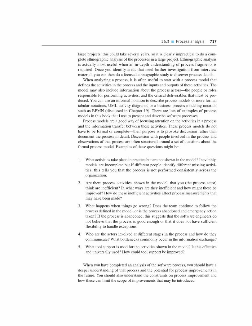
large projects, this could take several years, so it is clearly impractical to do a com-
plete ethnographic analysis of the processes in a large project. Ethnographic analysis
is actually most useful when an in-depth understanding of process fragments is
required. Once you identify areas that need further investigation from interview
material, you can then do a focused ethnographic study to discover process details.
When analyzing a process, it is often useful to start with a process model that
defines the activities in the process and the inputs and outputs of these activities. The
model may also include information about the process actors—the people or roles
responsible for performing activities, and the critical deliverables that must be pro-
duced. You can use an informal notation to describe process models or more formal
tabular notations, UML activity diagrams, or a business process modeling notation
such as BPMN (discussed in Chapter 19). There are lots of examples of process
models in this book that I use to present and describe software processes.
Process models are a good way of focusing attention on the activities in a process
and the information transfer between these activities. These process models do not
have to be formal or complete—their purpose is to provoke discussion rather than
document the process in detail. Discussion with people involved in the process and
observations of that process are often structured around a set of questions about the
formal process model. Examples of these questions might be:
1. What activities take place in practice but are not shown in the model? Inevitably,
models are incomplete but if different people identify different missing activi-
ties, this tells you that the process is not performed consistently across the
organization.
2. Are there process activities, shown in the model, that you (the process actor)
think are inefficient? In what ways are they inefficient and how might these be
improved? How do these inefficient activities affect process measurements that
may have been made?
3. What happens when things go wrong? Does the team continue to follow the
process defined in the model, or is the process abandoned and emergency action
taken? If the process is abandoned, this suggests that the software engineers do
not believe that the process is good enough or that it does not have sufficient
flexibility to handle exceptions.
4. Who are the actors involved at different stages in the process and how do they
communicate? What bottlenecks commonly occur in the information exchange?
5. What tool support is used for the activities shown in the model? Is this effective
and universally used? How could tool support be improved?
When you have completed an analysis of the software process, you should have a
deeper understanding of that process and the potential for process improvements in
the future. You should also understand the constraints on process improvement and
how these can limit the scope of improvements that may be introduced.
26.3 � Process analysis 717

718 Chapter 26 � Process improvement
26.3.1 Process exceptions
Software processes are complex entities. There may be a defined process model in
an organization but this can only represent the situation where the development team
is not faced with any unanticipated problems. In reality, unanticipated problems are
a fact of everyday life for project managers. The ‘ideal’ process model must be mod-
ified dynamically as solutions to these problems are found. Examples of the kinds of
exception that a project manager may have to deal with include:
• several key people becoming ill at the same time, just before a critical project
review;
• a serious breach in computer security that means all external communications are
out of action for several days;
• a company reorganization, which means that managers have to spend much of
their time working on organizational matters rather than on project management;
• an unanticipated request to write a proposal for a new project that means effort
must be transferred from the current project to proposal writing.
Essentially, an exception will affect and usually alter, in some way, the resources,
budgets, or schedules of a project. It is difficult to predict all exceptions in advance
and to incorporate them into a formal process model. You therefore often have to
work out how to handle exceptions and then dynamically change the ‘standard’
process to cope with these unexpected circumstances.
26.4 Process change
Process change involves making modifications to the existing process. As I have sug-
gested, you may do this by introducing new practices, methods, or tools; changing the
ordering of process activities; introducing or removing deliverables from the process;
improving communications; or by introducing new roles and responsibilities. Process
Software process modeling
Software process modeling started in the early 1980s (Osterweil, 1987) with the long-term objective of usingprocess models as a way of organizing and coordinating tool support for the process. A process model shouldinclude information about process activities, inputs and outputs, and the actors involved in the process. Special-purpose software process modeling notations were developed but these have been largely supplanted bynotations for business process modeling such as BPMN (White, 2004) or UML activity models.
http://www.SoftwareEngineering-9.com/Web/ProcImp/spm.html
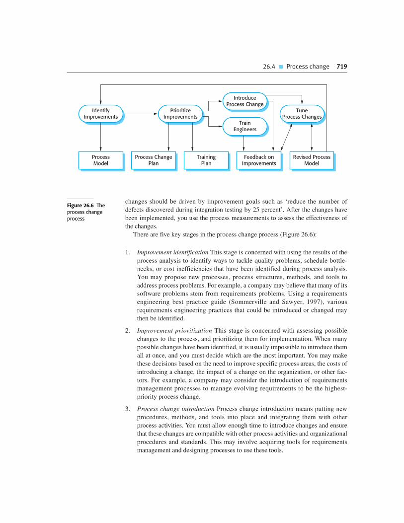
26.4 � Process change 719
ProcessModel
Process ChangePlan
TrainingPlan
Feedback onImprovements
Revised ProcessModel
IdentifyImprovements
PrioritizeImprovements
TuneProcess Changes
IntroduceProcess Change
TrainEngineers
Figure 26.6 The process change process
changes should be driven by improvement goals such as ‘reduce the number of
defects discovered during integration testing by 25 percent’. After the changes have
been implemented, you use the process measurements to assess the effectiveness of
the changes.
There are five key stages in the process change process (Figure 26.6):
1. Improvement identification This stage is concerned with using the results of the
process analysis to identify ways to tackle quality problems, schedule bottle-
necks, or cost inefficiencies that have been identified during process analysis.
You may propose new processes, process structures, methods, and tools to
address process problems. For example, a company may believe that many of its
software problems stem from requirements problems. Using a requirements
engineering best practice guide (Sommerville and Sawyer, 1997), various
requirements engineering practices that could be introduced or changed may
then be identified.
2. Improvement prioritization This stage is concerned with assessing possible
changes to the process, and prioritizing them for implementation. When many
possible changes have been identified, it is usually impossible to introduce them
all at once, and you must decide which are the most important. You may make
these decisions based on the need to improve specific process areas, the costs of
introducing a change, the impact of a change on the organization, or other fac-
tors. For example, a company may consider the introduction of requirements
management processes to manage evolving requirements to be the highest-
priority process change.
3. Process change introduction Process change introduction means putting new
procedures, methods, and tools into place and integrating them with other
process activities. You must allow enough time to introduce changes and ensure
that these changes are compatible with other process activities and organizational
procedures and standards. This may involve acquiring tools for requirements
management and designing processes to use these tools.
720 Chapter 26 � Process improvement
4. Process training Without training, it is not possible to gain the full benefits of
process changes. The engineers involved need to understand the changes that
have been proposed and how to perform the new and changed processes. All too
often, process changes are imposed without adequate training and the effect of
these changes is to degrade rather than improve product quality. In the case of
requirements management, the training might involve a discussion of the value
of requirements management, an explanation of the process activities, and an
introduction to the tools that have been selected.
5. Change tuning Proposed process changes will never be completely effective as
soon as they are introduced. You need a tuning phase where minor problems can
be discovered, and modifications to the process can be proposed and introduced.
This tuning phase should last for several months until the development engineers
are happy with the new process.
It is generally unwise to introduce too many changes at the same time. Apart from
the training difficulties that this causes, introducing too many changes makes it
impossible to assess the effect of each change on the process. Once a change has
been introduced, the improvement process can iterate, with further analysis used to
identify process problems, propose improvements, and so on.
As well as the difficulties of assessing the effectiveness of changed processes that
I have discussed, there are two major difficulties that those involved in change
processes may have to face:
1. Resistance to change Team members or project managers may resist the intro-
duction of process changes and propose reasons why changes will not work, or
delay the introduction of changes. They may, in some cases, deliberately obstruct
process changes and interpret data to show the ineffectiveness of proposed
process changes.
2. Change persistence Although it may be possible to introduce process changes
initially, it is common for process innovations to be discarded after a short time
and for the processes to revert to their previous state.
Resistance to change may come from both project managers and the engineers
involved in the process that is being changed. Project managers often resist process
change because any innovation has unknown risks associated with it. Process
changes may be intended to speed up software production or reduce software
defects. However, there is always the danger that these process changes will be inef-
fective or that the time required to introduce the changes will be longer than the time
saved. Project managers are judged according to whether or not their project pro-
duces software on time and to budget. Therefore, they may prefer an inefficient but
predictable process to an improved process that has organizational benefits, but
which may also have short-term risks associated with it.
Engineers may resist the introduction of new processes for similar reasons, or
because they see these processes as threatening their professionalism. That is, they

26.5 � The CMMI process improvement framework 721
may feel that the new predefined process gives them less discretion and does not rec-
ognize the value of their skills and experience. They may think that the new process
will mean that fewer people will be required and that they may lose their job. They
may not wish to learn new skills, tools, or ways of working.
As a manager, you have to be sensitive to the feelings of the people affected when
introducing process change. You have to involve the team all the way through the
change process, understand their doubts, and involve them in planning the new
process. By making them stakeholders in the process change, it is much more likely
that they will want to make it work. Business process reengineering (Hammer, 1990;
Ould, 1995), a fashion of the 1990s which involved making radical process changes,
was largely unsuccessful because it failed to take the legitimate concerns of the
people involved into account.
To address the concerns of project managers that process change will adversely
affect project schedules and costs, you have to increase project budgets to allow for
additional costs and delays resulting from the change. You also have to be realistic
about the short-term benefits of the change. Changes are unlikely to lead to large-
scale, immediate improvements. The benefits of process change are long term rather
than short term so you have to support the process changes over several projects.
The problem of changes being introduced then subsequently discarded is a com-
mon one. Changes may be proposed by an ‘evangelist’ who believes strongly that the
changes will lead to improvement. He or she may work hard to ensure the changes
are effective and the new process is accepted. However, if the ‘evangelist’ leaves,
then he or she may be replaced by someone who is less committed to the new
process. The people involved may therefore simply revert to the previous ways of
doing things. This is particularly likely if the changes that have been introduced have
not been universally adopted and the full benefits of the process changes have not yet
been realized.
Because of problems of change persistence, the CMMI model, discussed in
Section 26.5, argues strongly for the institutionalization of process change. This
means that process change is not dependent on individuals but that the changes
become part of standard practice in the company, with company-wide support and
training.
26.5 The CMMI process improvement framework
The U.S. Software Engineering Institute (SEI) was established to improve the
capabilities of the American software industry. In the mid-1980s, the SEI initi-
ated a study of ways to assess the capabilities of software contractors. The out-
come of this capability assessment was the SEI Software Capability Maturity
Model (CMM) (Paulk et al., 1993; Paulk et al., 1995). This has been tremen-
dously influential in convincing the software engineering community to take
process improvement seriously. The Software CMM was followed by a range of

722 Chapter 26 � Process improvement
other capability maturity models, including the People Capability Maturity
Model (P-CMM) (Curtis et al., 2001) and the Systems Engineering Capability
Model (Bate, 1995).
Other organizations have also developed comparable process maturity models.
The SPICE approach to capability assessment and process improvement (Paulk and
Konrad, 1994) is more flexible than the SEI model. It includes maturity levels com-
parable with the CMM levels, but also identifies processes, such as customer-
supplier processes, that cut across these levels. As the level of maturity increases, the
performance of these cross-cutting processes must also improve.
The Bootstrap project in the 1990s had the goal of extending and adapting the SEI
maturity model to make it applicable across a wider range of companies. This model
(Haase et al., 1994; Kuvaja, et al., 1994) uses the SEI’s maturity levels (discussed in
Section 26.5.1). It also proposes a base process model (based on the model used in
the European Space Agency) that may be used as a starting point for local process
definition. It includes guidelines for developing a company-wide quality system to
support process improvement.
In an attempt to integrate the plethora of capability models based on the notion of
process maturity (including its own models), the SEI embarked on a new program to
develop an integrated capability model (CMMI). The CMMI framework supersedes
the Software and Systems Engineering CMMs and integrates other capability matu-
rity models. It has two instantiations, staged and continuous, and addresses some of
the reported weaknesses in the Software CMM.
The CMMI model (Ahern et al., 2001; Chrissis et al., 2007) is intended to be a
framework for process improvement that has broad applicability across a range of
companies. Its staged version is compatible with the Software CMM and allows an
organization’s system development and management processes to be assessed and
assigned a maturity level from 1 to 5. Its continuous version allows for a finer-grain
classification of process maturity. This model provides a way of rating 22 process
areas (see Figure 26.7) on a scale from 0 to 5.
The CMMI model is very complex, with more than 1,000 pages of description.
I have radically simplified it for discussion here. The principal model components are:
1. A set of process areas that are related to software process activities. The CMMI
identifies 22 process areas that are relevant to software process capability and
improvement. These are organized into four groups in the continuous CMMI
model. These groups and related process areas are listed in Figure 26.7.
2. A number of goals, which are abstract descriptions of a desirable state that
should be attained by an organization. The CMMI has specific goals that are
associated with each process area and define the desirable state for that area. It
also defines generic goals that are associated with the institutionalization of
good practice. Figure 26.8 shows examples of specific and generic goals in the
CMMI.
3. A set of good practices, which are descriptions of ways of achieving a goal. Several
specific and generic practices may be associated with each goal within a process

Figure 26.7 Processareas in the CMMI
Category Process area
Process management Organizational process definition (OPD)
Organizational process focus (OPF)
Organizational training (OT)
Organizational process performance (OPP)
Organizational innovation and deployment (OID)
Project management Project planning (PP)
Project monitoring and control (PMC)
Supplier agreement management (SAM)
Integrated project management (IPM)
Risk management (RSKM)
Quantitative project management (QPM)
Engineering Requirements management (REQM)
Requirements development (RD)
Technical solution (TS)
Product integration (PI)
Verification (VER)
Validation (VAL)
Support Configuration management (CM)
Process and product quality management (PPQA)
Measurement and analysis (MA)
Decision analysis and resolution (DAR)
Causal analysis and resolution (CAR)
area. Some examples of recommended practices are shown in Figure 26.9.
However, the CMMI recognizes that it is the goal rather than the way that the goal
is reached that is important. Organizations may use any appropriate practices to
achieve any of the CMMI goals—they do not have to adopt the practices recom-
mended in the CMMI.
Generic goals and practices are not technical but are associated with the institu-
tionalization of good practice. What this means depends on the maturity of the
organization. At an early stage of maturity development, institutionalization may
mean ensuring that plans are established and processes are defined for all software
development in the company. However, for an organization with more mature,
advanced processes, institutionalization may mean introducing process control using
statistical and other quantitative techniques across the organization.
26.5 � The CMMI process improvement framework 723

724 Chapter 26 � Process improvement
A CMMI assessment involves examining the processes in an organization and rat-
ing these processes or process areas on a six-point scale that relates to the level of
maturity in each process area. The idea is that the more mature a process, the better
it is. The six-point scale assigns a level of maturity to a process area as follows:
1. Incomplete At least one of the specific goals associated with the process area is
not satisfied. There are no generic goals at this level as institutionalization of an
incomplete process does not make sense.
2. Performed The goals associated with the process area are satisfied, and for all
processes the scope of the work to be performed is explicitly set out and com-
municated to the team members.
3. Managed At this level, the goals associated with the process area are met and
organizational policies are in place that define when each process should be
used. There must be documented project plans that define the project goals.
Resource management and process monitoring procedures must be in place
across the institution.
4. Defined This level focuses on organizational standardization and deployment
of processes. Each project has a managed process that is adapted to the project
requirements from a defined set of organizational processes. Process assets
and process measurements must be collected and used for future process
improvements.
5. Quantitatively managed At this level, there is an organizational responsibil-
ity to use statistical and other quantitative methods to control subprocesses;
that is, collected process and product measurements must be used in process
management.
6. Optimizing At this highest level, the organization must use the process and prod-
uct measurements to drive process improvement. Trends must be analyzed and
the processes adapted to changing business needs.
Figure 26.8 Processareas in the CMMI
Goal Process area
Corrective actions are managed to closure when theproject’s performance or results deviate significantlyfrom the plan.
Project monitoring and control (specific goal)
Actual performance and progress of the project aremonitored against the project plan.
Project monitoring and control (specific goal)
The requirements are analyzed and validated, and adefinition of the required functionality is developed.
Requirements development (specific goal)
Root causes of defects and other problems aresystematically determined.
Causal analysis and resolution (specific goal)
The process is institutionalized as a defined process. Generic goal

This is a very simplified description of the capability levels and, to put these into
practice, you need to work with more detailed descriptions. The levels are progres-
sive, with explicit process descriptions at the lowest levels, through process standard-
ization, to process change and improvement driven by measurements of the process
and the software at the highest level. To improve its processes, a company should aim
to increase the maturity level of the process groups that are relevant to its business.
26.5.1 The staged CMMI model
The staged CMMI model is comparable with the Software Capability Maturity
Model in that it provides a means to assess an organization’s process capability at
one of five levels, and prescribes the goals that should be achieved at each of these
levels. Process improvement is achieved by implementing practices at each level,
moving from the lower to the higher levels in the model.
The five levels in the staged CMMI model are shown in Figure 26.10. They cor-
respond to capability levels 1 to 5 in the continuous model. The key difference
between the staged and the continuous CMMI models is that the staged model is
used to assess the capability of the organization as a whole, whereas the continuous
model measures the maturity of specific process areas within the organization.
Each maturity level has an associated set of process areas and generic goals.
These reflect good software engineering and management practice and the institu-
tionalization of process improvement. The lower maturity levels may be achieved by
Goal Associated practices
The requirements are analyzed and validated, and adefinition of the required functionality is developed.
Analyze derived requirements systematically toensure that they are necessary and sufficient.
Validate requirements to ensure that the resultingproduct will perform as intended in the user’senvironment, using multiple techniques asappropriate.
Root causes of defects and other problems aresystematically determined.
Select the critical defects and other problems foranalysis.
Perform causal analysis of selected defects andother problems and propose actions to addressthem.
The process is institutionalized as a defined process. Establish and maintain an organizational policy forplanning and performing the requirementsdevelopment process.
Assign responsibility and authority for performingthe process, developing the work products, andproviding the services of the requirementsdevelopment process.
Figure 26.9 Goals andassociated practices inthe CMMI
26.5 � The CMMI process improvement framework 725

726 Chapter 26 � Process improvement
introducing good practice; however, higher levels require a commitment to process
measurement and improvement.
For example, the process areas as defined in the model associated with the second
level (the managed level) are:
1. Requirements management Manage the requirements of the project’s products and
product components, and identify inconsistencies between those requirements and
the project’s plans and work products.
2. Project planning Establish and maintain plans that define project activities.
3. Project monitoring and control Provide understanding into the project’s
progress so that appropriate corrective actions can be taken when the project’s
performance deviates significantly from the plan.
4. Supplier agreement management Manage the acquisition of products and services
from suppliers external to the project for which a formal agreement exists.
5. Measurement and analysis Develop and sustain a measurement capability that is
used to support management information needs.
6. Process and product quality assurance Provide staff and management with
objective insight into the processes and associated work products.
7. Configuration management Establish and maintain the integrity of work products
using configuration identification, configuration control, configuration status
accounting, and configuration audits.
As well as these specific practices, organizations operating at the second level in
the CMMI model should have achieved the generic goal of institutionalizing each of
Level 3Defined
Level 2Managed
Level 1Initial
Level 4Quantitatively
Managed
Level 5Optimizing
Figure 26.10 The CMMIstaged maturity model

the processes as a managed process. Examples of institutional practices associated
with project planning that lead to the project planning process being a managed
process are:
• Establish and maintain an organizational policy for planning and performing the
project planning process.
• Provide adequate resources for performing the project management process,
developing the work products, and providing the services of the process.
• Monitor and control the project planning process against the plan and take
appropriate corrective action.
• Review the activities, status, and results of the project planning process with
high-level management, and resolve any issues.
The advantage of the staged CMMI is that it is compatible with the software capa-
bility maturity model that was proposed in the late 1980s. Many companies understand
and are committed to using this model for process improvement. It is therefore
straightforward for them to make a transition from this to the staged CMMI model.
Furthermore, the staged model defines a clear improvement pathway for organizations.
They can plan to move from the second to the third level and so on.
The major disadvantage of the staged model (and of the Software CMM), how-
ever, is its prescriptive nature. Each maturity level has its own goals and practices.
The staged model assumes that all of the goals and practices at one level are imple-
mented before the transition to the next level. However, organizational circumstances
may be such that it more appropriate to implement goals and practices at higher levels
before lower-level practices. When an organization does this, a maturity assessment
will give a misleading picture of its capability.
26.5.2 The continuous CMMI model
Continuous maturity models do not classify an organization according to discrete
levels. Rather, they are finer-grained models that consider individual or groups of
practices and assess the use of good practice within each process group. The matu-
rity assessment is not, therefore, a single value but a set of values showing the orga-
nization’s maturity for each process or process group.
The continuous CMMI considers the process areas shown in Figure 26.7 and
assigns a capability assessment level from 0 to 5 (as described earlier) to each process
area. Normally, organizations operate at different maturity levels for different process
areas. Consequently, the result of a continuous CMMI assessment is a capability pro-
file showing each process area and its associated capability assessment. A fragment
of a capability profile that shows processes at different capability levels is shown in
Figure 26.11. This shows that the level of maturity in configuration management, for
example, is high, but that risk management maturity is low. A company may develop
26.5 � The CMMI process improvement framework 727

actual and target capability profiles where the target profile reflects the capability
level that they would like to reach for that process area.
The principal advantage of the continuous model is that companies can pick and
choose processes for improvement according to their own needs and requirements.
In my experience, different types of organization have different requirements for
process improvement. For example, a company that develops software for the aero-
space industry may focus on improvements in system specification, configuration
management, and validation, whereas a web development company may be more
concerned with customer-facing processes. The staged model requires companies to
focus on the different stages in turn. By contrast, the continuous CMMI permits dis-
cretion and flexibility, while still allowing companies to work within the CMMI
improvement framework.
Project Monitoringand Control
Supplier AgreementManagement
RiskManagement
ConfigurationManagement
RequirementsManagement
Verification
Validation
1 2 3 4 5Figure 26.11 A processcapability profile
K E Y P O I N T S
� The goals of process improvement are higher product quality, reduced process costs, and faster
delivery of software.
� The principal approaches to process improvement are agile approaches, geared to reducing
process overheads, and maturity-based approaches based on better process management and
the use of good software engineering practice.
728 Chapter 26 � Process improvement

� The process improvement cycle involves process measurement, process analysis and
modeling, and process change.
� Process models, which show the activities in a process and their relationships with software
products, are used for process description. In practice, however, engineers involved in
software development always adapt models to their local circumstances.
� Measurement should be used to answer specific questions about the software process used.
These questions should be based on organizational improvement goals.
� Three types of process metrics used in the measurement process are time metrics, resource
utilization metrics, and event metrics.
� The CMMI process maturity model is an integrated process improvement model that
supports both staged and continuous process improvement.
� Process improvement in the CMMI model is based on reaching a set of goals related to good
software engineering practice and describing, standardizing, and controlling the practices
used to achieve these goals. The CMMI model includes recommended practices that may be
used, but these are not obligatory.
Chapter 26 � Further reading 729
F U RT H E R R E A D I N G
‘Can you trust software capability evaluations?’ This article takes a skeptical look at the
subject of capability evaluation, where a company’s process maturity is assessed, and
discusses why these evaluations may not give a true picture of an organization’s maturity.
(E. O’Connell and H. Saiedian, IEEE Computer, 33 (2), February 2000) http://dx.doi.org/
10.1109/2.820036.
Software Process Improvement: Results and Experience from the Field. This book is a
collection of papers focusing on process improvement case studies in several small and
medium-sized Norwegian companies. It also includes a good introduction to the general
issues of process improvement. (Conradi, R., Dybå, T., Sjøberg, D., Ulsund, T. (eds.),
Springer, 2006.)
CMMI: Guidelines for Process Integration and Product Improvement, 2nd edition. A comprehensive
description of the CMMI. The CMMI is large and complex and it is practically impossible to make it
easy to read and understand. This book does a reasonable job by including some anecdotal and
historical material, but it’s still sometimes tough going. (M. B. Chrissis, M. Konrad, S. Shrum,
Addison-Wesley, 2007.)

730 Chapter 26 � Process improvement
E X E R C I S E S
26.1. What are the important differences between the agile approach and the process maturity
approach to software process improvement?
26.2. Under what circumstances is product quality likely to be determined by the quality of the
development team? Give examples of the types of software product that are particularly
dependent on individual talent and ability.
26.3. Suggest three specialized software tools that might be developed to support a process
improvement program in an organization.
26.4. Assume that the goal of process improvement in an organization is to increase the
number of reusable components that are produced during development. Suggest three
questions in the GQM paradigm that this might lead to.
26.5. Describe three types of software process metric that may be collected as part of a process
improvement process. Give one example of each type of metric.
26.6. Design a process for assessing and prioritizing process change proposals. Document this
process as a process model showing the roles involved in this process. You should use
UML activity diagrams or BPMN to describe the process.
26.7. Give two advantages and two disadvantages of the approach to process assessment and
improvement that is embodied in the process improvement frameworks such as the
CMMI.
26.8. Under what circumstances would you recommend the use of the staged representation of
the CMMI?
26.9. What are the advantages and disadvantages of using a process maturity model that
focuses on goals to be achieved, rather than good practices to be introduced?
26.10. Do you think that process improvement programs, which involve measuring the work of
people in the process and introducing changes into that process, can be inherently
dehumanizing? What resistance to a process improvement program might arise and why?
R E F E R E N C E S
Ahern, D. M., Clouse, A. and Turner, R. (2001). CMMI Distilled. Reading, Mass.: Addison-Wesley.
Basili, V. and Green, S. (1993). ‘Software Process Improvement at the SEL’. IEEE Software, 11 (4),
58–66.
Basili, V. R. and Rombach, H. D. (1988). ‘The TAME Project: Towards Improvement-Oriented
Software Environments’. IEEE Trans. on Software Eng., 14 (6), 758–773.

Bate, R. 1995. ‘A Systems Engineering Capability Maturity Model Version 1.1’. Software
Engineering Institute.
Chrissis, M. B., Konrad, M. and Shrum, S. (2007). CMMI: Guidelines for Process Integration and
Product Improvement, 2nd edition. Boston: Addison-Wesley.
Curtis, B., Hefley, W. E. and Miller, S. A. (2001). The People Capability Model: Guidelines for
Improving the Workforce. Boston: Addison-Wesley.
Haase, V., Messnarz, R., Koch, G., Kugler, H. J. and Decrinis, P. (1994). ‘Bootstrap: Fine Tuning
Process Assessment’. IEEE Software, 11 (4), 25–35.
Hammer, M. (1990). ‘Reengineering Work: Don’t Automate, Obliterate’. Harvard Business Review,
July–August 1990, 104–112.
Humphrey, W. (1989). Managing the Software Process. Reading, Mass.: Addison-Wesley.
Humphrey, W. S. (1988). ‘Characterizing the Software Process’. IEEE Software, 5 (2), 73–79.
Humphrey, W. S. (1995). A Discipline for Software Engineering. Reading, Mass.: Addison-Wesley.
Kuvaja, P., Similä, J., Krzanik, L., Bicego, A., Saukkonen, S. and Koch, G. (1994). Software Process
Assessment and Improvement: The BOOTSTRAP Approach. Oxford: Blackwell Publishers.
Osterweil, L. (1987). ‘Software Processes are Software Too’. 9th Int. Conf. on Software
Engineering, IEEE Press, 2–12.
Ould, M. A. (1995). Business Processes: Modeling and Analysis for Re-engineering and
Improvement. Chichester: John Wiley & Sons.
Paulk, M. C., Curtis, B., Chrissis, M. B. and Weber, C. V. (1993). ‘Capability Maturity Model,
Version 1.1’. IEEE Software, 10 (4), 18–27.
Paulk, M. C. and Konrad, M. (1994). ‘An Overview of ISO’s SPICE Project’. IEEE Computer, 27 (4),
68–70.
Paulk, M. C., Weber, C. V., Curtis, B. and Chrissis, M. B. (1995). The Capability Maturity Model:
Guidelines for Improving the Software Process. Reading, Mass.: Addison-Wesley.
Pulford, K., Kuntzmann-Combelles, A. and Shirlaw, S. (1996). A Quantitative Approach to
Software Management. Wokingham: Addison-Wesley.
Sommerville, I. and Sawyer, P. (1997). Requirements Engineering: A Good Practice Guide.
Chichester: John Wiley & Sons.
White, S. A. 2004. ‘An Introduction to BPMN’. http://www.bpmn.org/Documents/
Introduction%20to%20BPMN.
Chapter 26 � References 731

This page intentionally left blank

abstract data type
A type that is defined by its operations rather than its representation. The represen-
tation is private and may only be accessed by the defined operations.
activity (PERT) chart
A chart used by project managers to show the dependencies between tasks that have
to be completed. The chart shows the tasks, the time expected to complete these
tasks, and the task dependencies. The critical path is the longest path (in terms of
the time required to complete the tasks) through the activity chart. The critical path
defines the minimum time required to complete the project.
Ada
A programming language that was developed for the U.S. Department of Defense
in the 1980s as a standard language for developing military software. It is based on
programming language research from the 1970s and includes constructs such as
abstract data types and support for concurrency. It is still used for large, complex
military and aerospace systems.
agile manifesto
A set of principles encapsulating the ideas underlying agile methods of software
development.
agile methods
Methods of software development that are geared to rapid software delivery. The
software is developed and delivered in increments, and process documentation and
bureaucracy are minimized. The focus of development is on the code itself, rather
than supporting documents.
Glossary

734 Glossary
algorithmic cost modeling
An approach to software cost estimation where a formula is used to estimate the
project cost. The parameters in the formula are attributes of the project and the
software itself.
application family
A set of software application programs that have a common architecture and
generic functionality. These can be tailored to the needs of specific customers by
modifying components and program parameters.
application framework
A set of reusable concrete and abstract classes that implement features common to
many applications in a domain (e.g., user interfaces). The classes in the application
framework are specialized and instantiated to create an application.
Application Program Interface (API)
An interface, generally specified as a set of operations, that allows access to
an application program’s functionality. This means that this functionality can
be called on directly by other programs and not just accessed through the user
interface.
architectural pattern (style)
An abstract description of a software architecture that has been tried and tested
in a number of different software systems. The pattern description includes
information about where it is appropriate to use the pattern and the organization
of the components of the architecture.
aspect-oriented software development
An approach to software development that combines generative and component-
based development. Cross-cutting concerns are identified in a program and the
implementation of these concerns is defined as aspects. Aspects include a definition
of where they are to be incorporated into a program. An aspect weaver then weaves
the aspects into the appropriate places in the program.
aspect weaver
A program that is usually part of a compilation system that processes an aspect-ori-
ented program and modifies the code to include the defined aspects at the specified
points in the program.
availability
The readiness of a system to deliver services when requested. Availability is usually
expressed as a decimal number, so an availability of 0.999 means that the system
can deliver services for 999 out of 1,000 time units.
bar chart
A chart used by project managers to show the project tasks, the schedule associated
with these tasks, and the people who will work on them. It shows the tasks’ start
and end dates and the staff allocations against a timeline.

Glossary 735
BEA
A U.S. vendor of ERP systems.
black-box testing
An approach to testing where the testers have no access to the source code of a
system or its components. The tests are derived from the system specification.
BPMN
Business Process Modeling Notation. A notation for defining workflows.
brownfield software development
The development of software for an environment where there are several existing
systems that the software being developed must integrate with.
C
A programming language that was originally developed to implement the Unix
system. C is a relatively low-level system implementation language that allows access
to the system hardware and which can be compiled to efficient code. It is widely used
for low-level systems programming and embedded systems development.
C++
An object-oriented programming language that is a superset of C.
C#
An object-oriented programming language, developed by Microsoft, that has much
in common with C++, but which includes features that allow more compile-time
type checking.
CASE (Computer-Aided Software Engineering)
The process of developing software using automated support.
CASE tool
A software tool, such as a design editor or a program debugger, used to support an
activity in the software development process.
CASE workbench
An integrated set of CASE tools that work together to support a major process
activity such as software design or configuration management.
change management
A process to record, check, analyze, estimate, and implement proposed changes to
a software system.
class diagram
A UML diagram types that shows the object classes in a system and their relation-
ships.
client–server architecture
An architectural model for distributed systems where the system functionality
is offered as a set of services provided by a server. These are accessed by client

736 Glossary
computers that make use of the services. Variants of this approach, such as three-
tier client–server architectures, use multiple servers.
Cleanroom software engineering
An approach to software development where the aim is to avoid introducing faults
into the software (by analogy with a cleanroom used in semiconductor fabrication).
The process involves formal software specification, structured transformation of a
specification to a program, the development of correctness arguments, and statisti-
cal program testing.
cloud computing
The provision of computing and/or application services over the Internet using a
‘cloud’ of servers from an external provider. The ‘cloud’ is implemented using a
large number of commodity computers and virtualization technology to make
effective use of these systems.
CMM
The Software Engineering Institute’s Capability Maturity Model, which is used to
assess the level of software development maturity in an organization. It has now
been superseded by CMMI, but is still widely used.
CMMI
An integrated approach to process capability maturity modeling based on the adop-
tion of good software engineering practice and integrated quality management. It
supports discrete and continuous maturity modeling and integrates systems and
software engineering process maturity models.
code of ethics and professional practice
A set of guidelines that set out expected ethical and professional behavior for
software engineers. This was defined by the major U.S. professional societies
(the ACM and the IEEE) and defines ethical behavior under eight headings:
public, client and employer, product, judgment, management, colleagues,
profession, and self.
COM+
A component model and supporting middleware designed for use on Microsoft
platforms; now superseded by .NET.
Common Request Broker Architecture (CORBA)
A set of standards proposed by the Object Management Group (OMG) that defines
distributed object models and object communications; influential in the develop-
ment of distributed systems but now rarely used.
component
A deployable, independent unit of software that is completely defined and accessed
through a set of interfaces.
component model
A set of standards for component implementation, documentation and deployment.
These cover the specific interfaces that may be provided by a component, component

Glossary 737
naming, component interoperation, and component composition. Component models
provide the basis for middleware to support executing components.
component-based software engineering (CBSE)
The development of software by composing independent, deployable software com-
ponents that are consistent with a component model.
configuration item
A machine-readable unit, such as a document or a source code file, that is subject to
change and where the change has to be controlled by a configuration management
system.
configuration management
The process of managing the changes to an evolving software product.
Configuration management involves configuration planning, version management,
system building, and change management.
Constructive Cost Modeling (COCOMO)
A family of algorithmic cost estimation models. COCOMO was first proposed in
the early-1980s and has been modified and updated since then to reflect new tech-
nology and changing software engineering practice.
CORBA component model
A component model designed for use for the CORBA platform.
control metric
A software metric that allows managers to make planning decisions based on infor-
mation about the software process or the software product that is being developed.
Most control metrics are process metrics.
critical system
A computer system whose failure can result in significant economic, human, or
environmental losses.
CVS
A widely-used, open source software tool used for version management.
data processing system
A system that aims to process large amounts of structured data. These systems usu-
ally process the data in batches and follow an input-process-output model. Examples
of data processing systems are billing and invoicing systems, and payment systems.
denial of service attack
An attack on a web-based software system that attempts to overload the system so
that it cannot provide its normal service to users.
dependability
The dependability of a system is an aggregate property that takes into account the
system’s safety, reliability, availability, security, and other attributes. The depend-
ability of a system reflects the extent to which it can be trusted by its users.

738 Glossary
dependability case
A structured document that is used to back up claims made by a system developer
about the dependability of a system.
dependability requirement
A system requirement that is included to help achieve the required dependability for
a system. Nonfunctional dependability requirements specify dependability attribute
values; functional dependability requirements are functional requirements that
specify how to avoid, detect, tolerate, or recover from system faults and failures.
design pattern
A well-tried solution to a common problem that captures experience and good
practice in a form that can be reused. It is an abstract representation than can be
instantiated in a number of ways.
distributed system
A software system where the software subsystems or components execute on differ-
ent processors.
domain
A specific problem or business area where software systems are used. Examples of
domains include real-time control, business data processing, and telecommunica-
tions switching.
domain model
A definition of domain abstractions, such as policies, procedures, objects, relation-
ships, and events. It serves as a base of knowledge about some problem area.
DSDM
Dynamic System Development Method; claimed to be one of the first agile
development methods.
embedded system
A software system that is embedded in a hardware device (e.g., the software system
in a cell phone). Embedded systems are usually real-time systems and so have to
respond in a timely way to events occurring in their environment.
emergent property
A property that only becomes apparent once all of the components of the system
have been integrated to create the system.
enterprise Java beans (EJB)
A Java-based component model.
enterprise resource planning (ERP) system
A large-scale software system that includes a range of capabilities to support
the operation of business enterprises and which provides a means of sharing
information across these capabilities. For example, an ERP system may include
support for supply chain management, manufacturing, and distribution. ERP
systems are configured to the requirements of each company using the system.

Glossary 739
ethnography
An observational technique that may be used in requirements elicitation and
analysis. The ethnographer immerses him- or herself in the users’ environment
and observes their day-to-day work habits. Requirements for software support
can be inferred from these observations.
event-based systems
Systems where the control of operation is determined by events that are generated
in the system’s environment. Most real-time systems are event-based systems.
extreme programming (XP)
A widely used agile method of software development that includes practices such
as scenario-based requirements, test-first development, and pair programming.
fault avoidance
Developing software in such a way that faults are not introduced into that software.
fault detection
The use of processes and run-time checking to detect and remove faults in a program
before these result in a system failure.
fault tolerance
The ability of a system to continue in execution even after faults have occurred.
formal methods
Methods of software development where the software is modeled using formal
mathematical constructs such as predicates and sets. Formal transformation
converts this model to code. Mostly used in the specification and development
of critical systems.
Gantt chart
An alternative name for a bar chart.
incremental development
An approach to software development where the software is delivered and deployed
in increments.
information hiding
Using programming language constructs to conceal the representation of data struc-
tures and to control external access to these structures.
inspection
See program inspection.
insulin pump
A software-controlled medical device that can deliver controlled doses of insulin to
people suffering from diabetes. Used as a case study in several chapters in this book.
interface
A specification of the attributes and operations associated with a software component.
The interface is used as the means of accessing the component’s functionality.
740 Glossary
ISO 9000/9001
A set of standards for quality management processes that is defined by the
International Standards Organization (ISO). ISO 9001 is the ISO standard that
is most applicable to software development. These may be used to certify the
quality management processes in an organization.
iterative development
An approach to software development where the processes of specification, design,
programming, and testing are interleaved.
J2EE
Java 2 Platform Enterprise Edition. A complex middleware system that supports the
development of component-based web applications in Java. It includes a compo-
nent model for Java components, APIs, services, etc.
Java
A widely used object-oriented programming language that was designed by Sun
with the aim of platform independence.
language processing system
A system that translates one language into another. For example, a compiler
is a language-processing system that translates program source code to object
code.
legacy system
A sociotechnical system that is useful or essential to an organization but which has
been developed using obsolete technology or methods. Because legacy systems
often perform critical business functions, they have to be maintained.
Lehman’s laws
A set of hypotheses about the factors that influence the evolution of complex
software systems.
maintenance
The process of making changes to a system after it has been put into operation.
make
One of the first system building tools; still widely used in Unix/Linux systems.
mean time to failure (MTTF)
The average time between observed system failures; used in reliability specification.
MHC-PMS
Mental Health Care Patient Management System; used as a case study in several
chapters.
middleware
The infrastructure software in a distributed system. It helps manage interactions
between the distributed entities in the system and the system databases. Examples
of middleware are an object request broker and a transaction management system.

Glossary 741
model checking
A method of static verification where a state model of a system is exhaustively
analyzed in an attempt to discover unreachable states.
model-driven architecture (MDA)
An approach to software development based on the construction of a set of system
models, which can be automatically or semiautomatically processed to generate an
executable system.
model-driven development (MDD)
An approach to software engineering centered around system models that are
expressed in the UML, rather than programming language code. This extends
MDA to consider activities other than development such as requirements engi-
neering and testing.
.NET
A very extensive framework used to develop applications for Microsoft Windows
systems; includes a component model that defines standards for components in
Windows systems and associated middleware to support component execution.
object class
An object class defines the attributes and operations of objects. Objects are created
at run-time by instantiating the class definition. The object class name can be used
as a type name in some object-oriented languages.
object constraint language (OCL)
A language that is part of the UML, used to define predicates that apply to object
classes and interactions in a UML model. The use of the OCL to specify compo-
nents is a fundamental part of model-driven development.
Object Management Group (OMG)
A group of companies formed to develop standards for object-oriented develop-
ment. Examples of standards promoted by the OMG are CORBA, UML, and
MDA.
object model
A model of a software system that is structured and organized as a set of object
classes and the relationships between these classes. Various different perspectives
on the model may exist such as a state perspective and a sequence perspective.
object-oriented (OO) development
An approach to software development where the fundamental abstractions in the
system are independent objects. The same type of abstraction is used during speci-
fication, design and development.
open source
An approach to software development where the source code for a system is made
public and external users are encouraged to participate in the development of the
system.
742 Glossary
pair programming
A development situation where programmers work in pairs, rather than individu-
ally, to develop code; a fundamental part of extreme programming.
peer-to-peer system
A distributed system where there is no distinction between clients and servers.
Computers in the system can act as both clients and servers. Peer-to-peer applica-
tions include file sharing, instant messaging, and cooperation support systems.
People Capability Maturity Model (P-CMM)
A process maturity model that reflects how effective an organization is at managing
the skills, training, and experience of the people in that organization.
predictor metric
A software metric that is used as a basis for making predictions about the character-
istics of a software system, such as its reliability or maintainability.
probability of failure on demand (POFOD)
A reliability metric that is based on the likelihood of a software system failing
when a demand for its services is made.
process improvement
Changing a software development process with the aim of making that process
more efficient or improving the quality of its outputs. For example, if your aim is to
reduce the number of defects in the delivered software, you might improve a
process by adding new validation activities.
process maturity model
A model of the extent to which a process includes good practice and reflective and
measurement capabilities that are geared to process improvement.
process model
An abstract representation of a process. Process models may be developed from
various perspectives and can show the activities involved in a process, the artifacts
used in the process, constraints that apply to the process, and the roles of the people
enacting the process.
program evolution dynamics
The study of the ways in which an evolving software system changes. It is claimed
that Lehman’s laws govern the dynamics of program evolution.
program generator
A program that generates another program from a high-level, abstract specification.
The generator embeds knowledge that is reused in each generation activity.
program inspection
A review where a group of inspectors examine a program, line by line, with the aim
of detecting program errors. Inspections are often driven by a checklist of common
programming errors.

Glossary 743
Python
A programming language with dynamic types, which is particularly well suited to
the development of web-based systems; extensively used by Google.
quality assurance (QA)
The overall process of defining how software quality can be achieved and how the
organization developing the software knows that the software has met the required
level of quality.
quality plan
A plan that defines the quality processes and procedures that should be used. This
involves selecting and instantiating standards for products and processes and defin-
ing the system quality attributes that are most important.
rapid application development (RAD)
An approach to software development aimed at rapid delivery of the software. It
often involves the use of database programming and development support tools
such as screen and report generators.
rate of occurrence of failure (ROCOF)
A reliability metric that is based on the number of observed failures of a system in a
given time period.
Rational Unified Process (RUP)
A generic software process model that presents software development as a four-
phase iterative activity, where the phases are inception, elaboration, construction,
and transition. Inception establishes a business case for the system, elaboration
defines the architecture, construction implements the system, and transition deploys
the system in the customer’s environment.
real-time system
A system that has to recognize and process external events in ‘real-time’. The cor-
rectness of the system does not just depend on what it does but also on how quickly
it does it. Real-time systems are usually organized as a set of cooperating sequential
processes.
reengineering
The modification of a software system to make it easier to understand and change.
Reengineering often involves software and data restructuring and organization,
program simplification, and redocumentation.
reengineering, business process
Changing a business process to meet a new organizational objective such as
reduced cost and faster execution.
reference architecture
A generic, idealized architecture that includes all the features that systems might
incorporate. It is a way of informing designers about the general structure of that
class of system rather than a basis for creating a specific system architecture.
744 Glossary
release
A version of a software system that is made available to system customers.
reliability
The ability of a system to deliver services as specified. Reliability can be specified
quantitatively as a probability of failure on demand or as the rate of occurrence of
failure.
reliability growth modeling
The development of a model of how the reliability of a system changes (improves)
as it is tested and program defects are removed.
requirement, functional
A statement of some function or feature that should be implemented in a system.
requirement, non-functional
A statement of a constraint or expected behavior that applies to a system. This con-
straint may refer to the emergent properties of the software that is being developed
or to the development process.
requirements management
The process of managing changes to requirements to ensure that the changes made
are properly analyzed and tracked through the system.
REST
REST is derived from Representational State Transfer, which is a style of develop-
ment based around simply client/server interaction, and which uses the HTTP
protocol. REST is based around the idea of an identifiable resource, which has a
URI. All interaction with resources is based on HTTP POST, GET, PUT, and
DELETE. It is now widely used for implementing low overhead web services.
risk
An undesirable outcome that poses a threat to the achievement of some objective. A
process risk threatens the schedule or cost of a process; a product risk is a risk that
may mean that some of the system requirements may not be achieved.
risk management
The process of identifying risks, assessing their severity, planning measures to put in
place if the risks arise, and monitoring the software and the software process for risks.
Ruby
A programming language with dynamic types that is particularly well suited to web
application programming.
safety
The ability of a system to operate without catastrophic failure.
safety case
A structured argument that a system is safe and/or secure. Many critical systems
must have associated safety cases that are assessed and approved by external
regulators before the system is certified for use.

Glossary 745
SAP
A German company that has developed a well-known and widely used ERP system.
It also refers to the name given to the ERP system itself.
scenario
A description of one typical way in which a system is used or a user carries out
some activity.
Scrum
An agile method of development, which is based on sprints—short development,
cycles. Scrum may be used as a basis for agile project management alongside other
agile methods such as XP.
security
The ability of a system to protect itself against accidental or deliberate intrusion.
Security includes confidentiality, integrity, and availability.
SEI
Software Engineering Institute. A software engineering research and technology
transfer center, founded with the aim of improving the standard of software engi-
neering in U.S. companies.
sequence diagram
A diagram that shows the sequence of interactions required to complete some
operation. In the UML, sequence diagrams may be associated with use cases.
server
A program that provides a service to other (client) programs.
service
See web service.
sociotechnical system
A system, including hardware and software components, that has defined
operational processes followed by human operators and which operates within
an organization. It is therefore influenced by organizational policies, procedures,
and structures.
software architecture
A model of the fundamental structure and organization of a software system.
software life cycle
Often used as another name for the software process; originally coined to refer to
the waterfall model of the software process.
software metric
An attribute of a software system or process that can be expressed numerically and
measured. Process metrics are attributes of the process such as the time taken to
complete a task; product metrics are attributes of the software itself such as size or
complexity.
746 Glossary
software product line
See application family.
software process
The related set of activities and processes that is involved in developing and
evolving a software system.
spiral model
A model of a development process where the process is represented as a spiral, with
each round of the spiral incorporating the different stages in the process. As you move
from one round of the spiral to another, you repeat all of the stages of the process.
state diagram
A UML diagram type that shows the states of a system and the events that trigger
a transition from one state to another.
static analysis
Tool-based analysis of a program’s source code to discover errors and anomalies.
Anomalies, such as successive assignments to a variable with no intermediate use,
may be indicators of programming errors.
structured method
A method of software design that defines the system models that should be devel-
oped, the rules and guidelines that should apply to these models, and a process to
be followed in developing the design.
Structured Query Language (SQL)
A standard language used for relational database programming.
Subversion
A widely used, open source system building tool that is available on a range of
platforms.
system building
The process of compiling the components or units that make up a system and link-
ing these with other components to create an executable program. System building
is normally automated so that recompilation is minimized. This automation may be
built into the language processing system (as in Java) or may involve software tools
to support system building.
systems engineering
A process that is concerned with specifying a system, integrating its components
and testing that the system meets its requirements. System engineering is concerned
with the whole sociotechnical system—software, hardware, and operational
processes—not just the system software.
test coverage
The effectiveness of system tests in testing the code of an entire system. Some com-
panies have standards for test coverage (e.g., the system tests shall ensure that all
program statements are executed at least once).

Glossary 747
test-driven development
An approach to software development where executable tests are written before
the program code. The set of tests are run automatically after every change to the
program.
transaction
A unit of interaction with a computer system. Transactions are independent and
atomic (they are not broken down into smaller units) and are a fundamental unit of
recovery, consistency, and concurrency.
transaction processing system
A system that ensures that transactions are processed in such a way so that they do
not interfere with each other and so that individual transaction failure does not
affect other transactions or the system’s data.
Unified Modeling Language (UML)
A graphical language used in object-oriented development that includes several
types of system models that provide different views of a system. The UML has
become a de facto standard for object-oriented modeling.
use case
A specification of one type of interaction with a system.
user interface design
The process of designing the way in which system users can access system func-
tionality, and the way that information produced by the system is displayed.
validation
The process of checking that a system meets the needs and expectations of the
customer.
verification
The process of checking that a system meets its specification.
version management
The process of managing changes to a software system and its components so
that it is possible to know which changes have been implemented in each version
of the component/system, and also to recover/re-create previous versions of the
component/system.
waterfall model
A software process model that involves discrete development stages: specification,
design, implementation, testing, and maintenance. In principle, one stage must be
complete before progress to the next stage is possible. In practice, there is signifi-
cant iteration between stages.
web service
An independent software component that can be accessed through the Internet using
standard protocols. It is completely self-contained without external dependencies.
XML-based standards such as SOAP (Standard Object Access Protocol), for web

748 Glossary
service information exchange, and WSDL (Web Service Definition Language), for
the definition of web service interfaces, have been developed. However, the REST
approach may also be used for web service implementation.
white-box testing
An approach to program testing where the tests are based on knowledge of the
structure of the program and its components. Access to source code is essential for
white-box testing.
wilderness weather system
A system to collect data about the weather conditions in remote areas. Used as a
case study in several chapters in this book.
workflow
A detailed definition of a business process that is intended to accomplish a certain
task. The workflow is usually expressed graphically and shows the individual
process activities and the information that is produced and consumed by each
activity.
WSDL
An XML-based notation for defining the interface of web services.
XML
Extended Markup Language. XML is a text markup language that supports the
interchange of structured data. Each data field is delimited by tags that give infor-
mation about that field. XML is now very widely used and has become the basis of
protocols for web services.
XP
A commonly used abbreviation for Extreme Programming.
Z
A model-based, formal specification language developed at the University of
Oxford in England.

A
abstraction level (reuse), 194
acceptability, 8, 24, 315, 316
acceptance testing, 42, 70, 228–30
accidents, 301, 302
ACM/IEEE-CS Joint Task Force on Software
Engineering Ethics and Professional Practices,
15–16
acquisition/procurement stage (sociotechnical systems),
273–74, 275–77, 286
activities (software engineering activities), 6, 9, 28, 36
activity charts (planning), 627, 630
activity diagrams (UML), 19, 29, 120, 135, 143, 718
actuators, 198, 300, 349, 350, 491, 540, 541, 545
Adaptive Software Development, 59, 80
adaptors, 468–71, 476
ADLs (architectural description languages), 154
advanced software engineering, 423–24
advice (AOSE), 572, 587
aggregation, 133, 186
agile methods, 29, 56–81
architectural design and, 148
change and, 60, 65, 114
critical systems and, 60, 348
customer involvement and, 60, 62, 65, 239, 633
design outputs and, 40
documentation and, 61, 63–64, 155
evolution and, 239
formal specification and, 336
incremental development and, 33, 58
manifesto, 56, 59, 60, 141, 688, 708
MDA and, 141
overview, 58–62
‘people, not process’ and, 60, 65, 688
plan-driven approach v., 62–64, 77, 623
principles of, 60
process improvement and, 706, 728
project management, 72–74
project planning, 631–33
requirements and, 84
scaling, 74–77, 78
Scrum approach and, 56, 57, 59, 72–74, 78,
631, 632
agile modeling, 59, 80, 120, 145
Airbus 340 flight control system, 345, 351–52
aircraft systems failure, 294
air traffic management systems, 139, 274
AJAX, 14, 26, 433, 451, 501, 507, 634
ALARP (as low as reasonably practical) risks, 315
algebraic specifications, 334
algorithmic cost modeling, 634, 635–37
aliasing, 360
alpha testing, 42, 228
ambiguity, measurements and, 676–77, 713
AMI (Analyze, Measure, Improve) method, 713
analysis and design workflow, 52
Analyze, Measure, Improve (AMI) method, 713
anti-skid braking system, 552
AOSE. See aspect-oriented software engineering
aperiodic stimuli, 540–41
application system
architectures, 164–71, 172
Subject Index

750 Subject Index
assessment, 256
application system reuse, 426
application wrapping, 447
application-composition model, 639
application frameworks, 431–34, 448
application-level protection, 377
architectural description languages (ADLs), 154
architectural design, 39, 147–75
Booch’s architecture catalog and, 150, 173, 174
decisions, 151–53, 172
4+1 view model, 120, 145, 153, 175
object-oriented design and, 181–82
security and, 152, 376–80
architectural modeling, 40, 122, 129
architectural patterns (styles), 155–64, 172, 490–501
embedded software and, 547–53
architectural views, 153–55, 172
architectures (software architectures)
application, 164–71, 172
architecture in the large, 148
architecture in the small, 148
defined, 172
distributed, 151, 163
pipe and filter compiler, 170–71
reference, 171
resource management system, 437
system, 348–55
systems engineering and, 275
Ariane 5 explosion, 344, 394, 445, 467, 468
arithmetic error, 320
array bounds, checking, 362
arrays, unbounded, 360
AspectJ programming language, 566, 571, 573, 574,
575, 584
aspect-oriented design and programming, 580–84
aspect-oriented software engineering (AOSE), 430,
565–89
benefits of, 566, 587
MHC-PMS and, 571–75
separation of concerns and, 567–71
terminology, 572
aspects, 571–87
assertion checking, 400
asset identification and assessment (security
requirements), 331
assets, 303, 304
assurance (dependability/security assurance),
393–421. See also process assurance
ATMs (automated teller machines), 166, 167, 324,
326, 327, 493
attack, 303, 304, 306, 383, 405, 483
assessment (security requirements), 331
detection and neutralization, 305
attributes, of software, 6, 8, 24
auditable processes, 346
authentication requirements, 329
authorization requirements, 329
automated activities, 37
automated teller machines. See ATMs
automated testing, 42, 69, 70, 77, 212–13, 231,
444, 695
automated translation tools, 140
automatic static analysis, 398–400
availability (system availability), 152, 292, 295–99
availability metric (AVAIL), 332–34, 336
avoidance
change, 44
fault, 299, 342
hazard, 301–2, 319
single point of failure, 381–82
strategies (risk management), 601
vulnerability, 305
B
bad smells, 251
banking system, Internet, 494
baselines, 684, 690
batch processing systems, 11, 163
behavioral models, 133–38, 143
bespoke products, 7
beta testing, 42, 228
‘big bang’ approach, 280
black-box testing, 215
block diagrams, 150, 179
B method, 32, 55, 335, 396
Boehm’s spiral model. See spiral models
Booch’s software architecture catalog, 150, 173, 174
Bootstrap project, 722, 731
boundaries (system boundaries), 121, 122, 142, 179,
296
BPMN (Business Process Modeling Notation), 530,
531, 532, 535, 536, 717, 718, 730, 731
brainstorming, 314, 598
braking system, anti-skid, 552
branching, 684, 693
broadcast models, 182

Subject Index 751
brownfield software development, 75, 235
BSD (Berkeley Standard Distribution) license, 200
bug fixing, 257
Bugzilla, 196, 689
building. See system building
build script generation, 695
burglar alarm system, 540, 541, 549, 550, 551, 555,
556
business-critical systems, 248, 291, 324, 387, 390
businesses
modeling workflow, 52
open source software and, 201
process reengineering, 721
rapid software development and, 57–58
reorganization, 276
social change and, 10
software systems, 13, 28, 29, 54, 448, 505
Web and, 13
Business Process Modeling Notation (BPMN), 530–2,
535–6, 717–8, 730–1
business process models, 534
business risks, 596–97
business services, 519, 534
C
callbacks, 433
car information system, 512–13
CASE (Computer-Aided Software Engineering) tools,
37, 58, 174, 597, 602
catalog interface design, 523
catalog service operations, 522
CBSE. See component-based software engineering
centralized control, 164
change, 43–45. See also process change
agile methods and, 60, 65, 114
resistance to, 720
social change, 10
XP and, 67
change avoidance, 44
change control board (CCB), 685, 686, 687
change implementation, 238, 239
change management, 77, 196, 348, 682, 685–89, 702
agile methods and, 77
history recording, 691
requirements change management, 113–14
request form (CRF), 686
terminology, 684
change persistence, 720
change proposals, 62, 237–38
change tolerance, 44
change tuning (process change process), 720
characteristic error checking, 399–400
check-in/check-out process, 692
checking array bounds, 362
checking requirements (functional reliability
requirement), 328
checklists
inspection, 667
/reviews (hazard analysis), 317
security, 406
Chidamber and Kemerer’s (CK) metrics suite, 673–4
CIMs (computation independent models), 140, 141
circular buffer, 544
class diagrams, 120, 129–31
Cleanroom process, 32, 209, 233, 308, 396, 401,
421, 680
ClearCase, 196, 204
client-server systems, 160–63, 172, 488–89, 505
cloud computing, 11, 13, 484, 514
CM. See configuration management
CMMI process improvement framework, 721–28, 729
CMM Maturity model. See People Capability Maturity
Model; Software CMM Maturity model
COCOMO II model, 248, 464, 637–45
codelines, 684, 690
Code of Ethics and Professional Practice (software
engineering), 15–16
Code Red worm, 305
codes of conduct, 15–17, 24
collective ownership, 65, 66, 71
commercial-off-the-shelf systems. See COTS systems
communications (process analysis), 716
compartmentalization, 384
competence, 14
compilers, 166
completeness, 86, 87, 110
complex systems, 266–73
component analysis (reuse-based development), 35
component-based software engineering (CBSE), 189,
452–78
components (software components), 35–36, 455–58,
475
communications, 152, 198, 453, 460, 482, 505
composition, 468–75, 475
design, 40
interfaces, 188–89, 201, 216–18
models, 458–61, 475
reuse, 35–36, 194, 426
752 Subject Index
components (continued)
services v., 514–18
testing, 216–19
computation independent models (CIMs), 140, 141
Computer-Aided Software Engineering tools. See
CASE tools
computer misuse, 14
concept reuse, 192, 426–27
conceptual views, 154, 172
concern-oriented requirements engineering, 577–80
concerns, separation of, 567–71
confidentiality, 14
configuration control, 684
configuration item, 684
configuration management (CM), 193, 195–96, 202,
681–704. See also change management
activities of, 195–96
architectural patterns and, 155
release management and, 682, 699–701, 702
system building and, 682, 684, 693–99, 702
version management and, 195, 682, 690–93, 702
workflow for, 52
consistency, 86, 87, 110, 603
constants, naming of, 363
construction phase (RUP), 51
consumer/producer processes (circular buffer), 544
context models, 121–24, 142, 179–81
contingency plans (risk management), 601
continuous CMMI model, 727–28
continuous integration, 65, 66, 68, 76, 78, 697, 698
control
application frameworks and, 434
security and, 303, 304
control identification (security requirements), 331
Controller component (MVC), 155
control/predictor measurements, 669
controls, architectural patterns for, 164
coordination services, 519, 534
copyright infringement, 14, 158, 450, 501
CORBA (Common Object Request Broker
Architecture), 454, 478, 482, 483, 496, 507
costs. See also estimation techniques
COCOMO II and, 642
dependability and, 294–95
fault removal, 343
formal specification, 336
maintenance/development, 244, 257
overhead, 620
software engineering, 6
software reuse and, 448
system failure, 290
COTS-based reuse, 36, 440–48
COTS-integrated systems, 445–48
COTS-solution systems, 442–44
COTS (commercial-off-the-shelf) systems, 35, 177,
276–77
CRF (change request form), 686
critical systems
agile methods and, 60, 348
business, 248, 291, 324, 387, 390
defined, 291
failure of, 290–91, 306
process assurance and, 407
SPARK/Ada language and, 336
critical systems engineering, 60, 336, 347, 348, 407, 419
Crystal, 59, 78, 80
customer involvement (agile methods), 60, 62, 65,
239, 633
customization
component model and, 459
COTS and, 440, 442
embedded systems and, 699
software products and, 7, 440
CVS, 691, 692, 704
cyclomatic complexity, 247, 668, 669, 670, 672,
673, 679
D
damage limitation, 302, 319
damages, 301
data acquisition systems, 553, 554, 560, 569
database design, 40
database support (WAFs), 433
data clumping, 251
data collection system architecture (weather station),
182, 183
data collection systems, 11
data-driven modeling, 134–35
data-flow diagrams (DFDs), 134
data management and communications layer, 264–65
data mining, 497
data reengineering, 249, 250
debugging, 41, 211, 223
decentralized P2P architecture, 500
Decorator pattern, 192
default input processing, 360–61
defect testing, 41, 206, 211, 224, 227, 401, 402, 585
demands, software failures and, 4

Subject Index 753
DeMarco’s Structured Analysis, 134
denial of service attacks, 376
Denver airport baggage system, 266
dependability (software dependability), 289–95
assurance, 393–421
cases, 410–17, 418
defined, 291, 306
engineering, 341–65
properties, 291–94
security and, 8, 12, 24, 292
specification, 309–40
dependable operational processes, 345
dependable programming guidelines, 355–63
dependable software processes, 345–48
dependable system architectures, 348–55
deployment
design for, 384, 385–86
secure, 390
service, 524–25
system, 279, 281
UML deployment diagrams, 129, 197, 198
workflow, 52
deployment-time configuration, 439–40
derivation history, 689
design (software design), 24, 28, 38–41, 53, 176–78
aspect-oriented, 580–84
for deployment, 384, 385–86
embedded systems, 540–47
implementation and, 38–41, 53, 176–78, 193–98,
201
life-cycle phase, 31
patterns, 189–93
for recoverability, 384–85
/requirements, spiral model of, 279–80
reuse and, 35
user interface, 45, 274, 275, 312
workflow, 52, 529–33
design description languages, 95
design refactoring, 252
deterministic system, 271
development
evolution v., 43, 235–36, 257
/maintenance costs, 244, 257
maintenance v., 43
professional software, 5–14, 24
reuse and, 35
reuse for (CBSE process), 461, 462–65
reuse with (CBSE process), 461, 465–68
services and, 527–34
sociotechnical systems), 273–74, 278–81, 286
spiral model and, 49, 235–36, 257
testing, 41–42, 210–21
view, 154, 172
DFDs (data-flow diagrams), 134
distributed architectures, 151, 163
distributed component architectures, 495–98
distributed software engineering, 479–507
distributed systems, 480–81
advantages of, 480, 505
architectural patterns for, 490–501
client-server systems, 160–63, 172, 488–89, 505
issues, 481–88
diversity
redundancy and, 343–44, 363, 383
software, 344, 345, 349, 353–55, 363
documentation, 5, 24, 246
agile methods and, 61, 63–64, 155
architectures and, 154–55
build system and, 695
online chapter, 246
process characteristic and, 346
standards, 658
TDD and, 223
domain, 103, 214
requirements, 86, 101, 104, 108–9
dose checking test case, 69, 70
driver verification system, 336, 400
DSDM, 57, 59, 81
duplicate code, 68, 251
dynamic memory allocation, 360
dynamic perspective (RUP), 50
dynamic web pages, 433
E
early design model, 639–40
ECLIPSE environment, 37, 68, 80, 197, 204, 251, 523
efficiency, 8, 12, 24
egoless programming, 71
EJB (Enterprise Java Beans), 432, 454, 455, 458, 496
elaboration phase (RUP), 51
elicitation/analysis (requirements elicitation/analysis),
37, 100–110, 115
embedded software systems, 11, 17–18, 537–64. See
also real-time systems
architectural patterns and, 547–53
customization and, 699
host-target development and, 198

754 Subject Index
embedded software systems, (continued)
RUP and, 53
simulators and, 196
embedded systems design, 540–47
embrace change (agile manifesto), 60
emergent system properties, 268, 269–71, 286
enduring requirements, 112
enterprise application frameworks, 432
Enterprise Java Beans (EJB), 432, 454, 455, 458, 496
Enterprise Resource Planning systems. See ERP
systems
entertainment systems, 11
entity-oriented services, 519
environmental adaptation, 243–44
Environmental Control pattern, 548, 550–52
environment assessment, 255
environments (see also IDEs)
architectural patterns and, 156
CASE tools and, 37, 58, 174, 597, 602
environment workflows, 52
work, 613
environment specialization (software product lines), 436
equipment inventory system, 579
equity trading system, 379, 389
equivalence partitioning, 214–15
ergonomics, systems engineering and, 275
ERP (Enterprise Resource Planning) systems, 7, 429,
430, 442, 443, 444, 448, 450, 451, 671
error-prone constructs, 359–61, 364
errors
human, 282–84, 286, 297
operator, 263, 270, 282, 312, 321
timing, 217–18
error tolerance, 293
esteem needs, 604
estimation risks, 598, 599
estimation techniques (project planning), 633–46
algorithmic cost modeling, 634, 635–37
COCOMO II model, 248, 464, 637–45
experience-based techniques, 634
ethical/professional responsibility, 14–17, 24
ethnography, 108–9, 715
E-type systems, 240
event-based controls, 164
event-driven modeling, 135–38
event metrics, 711–12, 729
evolution (software evolution), 6, 9, 24, 28, 43,
234–60
defined, 53
development v., 43, 235–36, 257
diagram, 44
maintenance and, 8, 24, 43
processes, 237–40
program evolution dynamics, 240–42
refactoring and, 44, 66, 71, 250–52
servicing and, 236–37
spiral model of, 235–36, 257
system evolution v., 284–85
exceptions
handlers for, 357–59
process, 718
executable system creation, 695
Executable UML (xUML), 142
experience-based techniques (estimation techniques), 634
experience-based testing, 405
explicit security policies, 380–81
exposure, 303, 304
exposure assessment (security requirements), 331
exposure limitation and recovery, 305
extensions, core systems with, 576–77
external requirements, 88–89
extreme programming (XP), 64–72, 77
acceptance testing and, 230
agile methods and, 59
continuous integration and, 65, 66, 68, 76, 78, 697,
698
principles/practices, 66
project planning and, 632–33
release cycle in, 65
requirements engineering and, 36, 38
test-first development and, 66, 68, 69–70, 223, 231
user requirements in, 69, 78
F
Façade pattern, 192
failure propagation, 270
failures
hardware, 290
human errors and, 282–84, 286, 297
operational, 263, 270, 282, 291, 312, 321
software, 4, 12, 48, 265–66, 270, 290, 291, 294, 297,
300, 320, 321, 327, 333, 349, 411, 467, 480
fat-client model, 492
fault (system faults), 297
avoidance, 299, 342
detection and removal, 299, 342
repair, 243–44
tolerance, 299, 342

Subject Index 755
fault tree analysis, 317–19, 336
feasibility assessment (security requirements), 331
feasibility studies, 37, 100
film library, 162
floating-point numbers, 359
formal logic (hazard analysis), 317
formal methods (software development), 32, 49, 95,
139, 333, 337, 396
B method, 32, 55, 335, 396
MDE and, 139
system models, 334
verification and, 395–97
formal specifications, 95, 333–36, 337
formal verification, 340, 396, 397, 398, 405,
406
4+1 view model, 120, 145, 153, 175
functional emergent properties, 269–71
functional reliability specification, 328
functional requirements, 84–87, 115, 310
functional specialization (software product lines),
436
function reuse, 426
G
‘Gang of Four,’ 190, 191, 192
gas pump (state machine model), 545
generalization 131–33, 185–6, 190, 201
generator-based reuse, 431
generic development process, 53, 178
generic software products, 6–7
glue code, 468, 469, 476
GNU build system, 196
GNU General Public License (GPL), 200
Gnutella, 499
Goal-Question-Metric (GQM), 674, 712–13,
730
go-to statements, 359, 364, 585
GPS receiver, 512, 513
GQM (Goal-Question-Metric), 674, 712–13,
730
graphical models. See models
groups, 607–14
communications, 613–14
composition (case study), 610
organization, 610–13
growth modeling, reliability, 402–3
guideline-based testing, 213
guidelines
hiring, 611
dependable programming, 355–63
system security, 380–85
H
handlers, exceptions, 357–59
hardware reliability, 270
hazard, 301
assessment, 314–17
avoidance, 301–2, 319
detection and removal, 302, 319
identification, 314
logs, 409–10
probability, 301
severity, 301
hazard-driven approach to requirements derivation,
336
heterogeneity challenge, 10
high-availability systems, 152, 198, 295,
325, 351
high speed data acquisition systems, 553, 554,
560, 569
honesty (people management), 603
host-target development, 193, 196–98, 202
human errors, 282–84, 286, 297
human needs hierarchy, 604
I
ICASE, 639
identification requirements, 329
IDEs (Interactive Development Environments)
defined, 37, 197
ECLIPSE environment and, 37, 68, 80, 197, 204,
251, 523
general-purpose, 197
host-target development and, 193, 196–98, 197,
202
repository architecture for, 159, 160
IEC 61508 safety life cycle, 347
IEC (International Electrotechnical Commission)
standard for safety management, 313
immunity requirements, 329

756 Subject Index
implementation (system implementation), 10, 12, 24,
28, 38–41, 53, 193–98
design and, 38–41, 53, 176–78, 193–98, 201
issues, 193–98
life-cycle phase, 31
workflow, 52, 529–33
improvement. See process improvement
improvement identification and prioritization (process
change process), 719
in-car information system, 512–13
inception phase (RUP), 50–51
incremental delivery, 34, 44, 47–48, 60
incremental development, 30, 32–34, 53, 58, 67, 69
incremental integration, testing and, 219
incremental planning (XP), 66
independent development, 691
informal safety argument (insulin pump), 416–17
information systems, 18, 167–69
inheritance, 132, 184, 185, 186, 190, 203, 212, 360,
364, 432, 435, 670, 674
input/output mapping, 298
input/output messages (UML), 524
input processing, default, 360–61
inputs, validity checks of, 356–57, 383
insider attacks, 369
inspection checklist, 667
inspections, 208–9, 218, 585, 663–68. See also
reviews
insulin pump control system, 18–20
activity model of, 19, 135
dependability properties for, 293
failure in, 327
fault tree analysis for, 317–19
formal specification for, 334
hardware components (diagram), 19
hazard log for, 410
hazards in, 314
informal safety argument and, 416–17
insulin dose computation (with safety checks) in,
415
order processing diagram in, 135
requirements specification for, 96
risk classification for, 316–17
safety claim hierarchy for, 414
safety requirements for, 320
structured arguments and, 412–13
structured requirement specification of, 97
tabular specification and, 98
integration, reuse and, 35
integrity requirements, 329
intellectual property rights, 14
interaction models, 124–28, 179–81, 485–86
interaction-oriented people, 606
Interactive Development Environments. See IDEs
interactive transaction-based applications, 11
interception, 483
interface design, 39, 188, 189
interface misunderstanding, 217
interface misuse, 217
interfaces
component, 188–89, 201, 216–18
service, 534
interface specification, 188–89
interface testing, 217
internal/external software relationships, 670
International Electrotechnical Commission (IEC)
standard for safety management, 313
Internet banking system, 494
Internet worm, 305, 308, 383, 392
interpreting measurements, 676–77, 713
interrupts, 360, 483
interviewing, 104–5, 715
intolerable risks, 315
introspection (process analysis), 716
intrusion detection requirements, 330
inventory management system, 581
inversion of control, in frameworks, 434
ISO 92001 standards framework, 660–63
iterative development/delivery, 45, 52, 53
Iterator pattern, 192
J
J2EE, 36, 141, 454
Java
embedded systems development and, 546
program testing, 222
real-time systems development and, 547
join points, 571–75, 587
JUnit, 42, 55, 70, 81, 197, 212, 222, 232, 444, 695
L
language processing systems, 166, 169–72
latent conditions, 283
layered architecture pattern, 157–59, 167–69, 172

Subject Index 757
layered protection architecture, 378
learning (process analysis), 716
legacy systems
management, 245, 252–57, 285
service interfaces and, 525–27, 534
wrapping, 250, 430, 464, 526
Lehman’s laws, 240–42, 257
Lesser General Public License, GNU, 200
LIBSYS, 158–59
licensing
open source, 200–201
software engineers and, 408
life cycles
risk analysis, 312, 330
safety, 347
software, 30–32
Linux, 199, 200, 204, 367, 383, 392, 436,
558, 563
logical view, 153, 172
logs, 382–83, 409–10
M
mainline, 684
maintainability, 8, 18, 24, 90, 149, 152, 178, 209, 244,
245, 247, 293, 709
maintenance (software maintenance), 8, 24, 43,
242–52
agile methods and, 61–62
architectural design and, 152–53
/development costs, 244, 257
development v., 43
effort distribution, 244
life-cycle phase, 31
prediction, 246–48
types of, 243, 257
make utility (Unix), 196
malware, 14, 290, 501
management (software management), 12, 24, 591–92.
See also configuration management; people
management; process improvement; project
management; project planning; quality
management
manifesto, agile, 56, 59, 60, 141, 688, 708
master-slave architectures, 490–91
mathematical specifications, 95. See also formal
methods.
MDA. See model-driven architecture
MDD. See model-driven development
MDE. See model-driven engineering
measurement. See also metrics
ambiguity in, 676–77, 713
controller/predictor, 669
interpreting, 676–77, 713
process measurement, 711–14, 729
medical records system. See MHC-PMS
Mental Health Care-Patient Management System. See
MHC-PMS
merging, 684, 693
message passing interfaces, 217
metrics
AVAIL, 332–34, 336
event, 711–12, 729
GQM approach, 674, 712–13, 730
for non-functional requirements, 90
product, 672–73
for reliability, 322–24, 336
resource utilization, 711–12, 729
software measurement and, 668–77
static software product, 673
time, 711–12, 729
MHC-PMS (Mental Health Care-Patient Management
System), 20–22
aggregation association in, 133
AOSE and, 571–75
asset analysis (risk assessment report) for,
332–33
class diagrams and, 130, 131
context model of, 122
dose checking test case, 69, 70
functional requirements in, 83, 84, 85, 86
generalization hierarchy and, 132, 133
goals of, 20–21, 272
key features of, 21
layered architecture pattern in, 158, 167–69
non-functional requirements in, 89
organization (diagram) of, 20
privacy and, 21–22
process model of involuntary detention in, 123
requirements-based testing and, 225
safety and, 21–22
scenario in, 106
scenario testing and, 226
security concepts and, 303–4
sequence diagrams and, 126–28
stakeholders for, 103
story cards and, 66, 67
success criteria and, 272–73
task cards and, 68, 69

758 Subject Index
MHC-PMS (continued)
threat and control analysis for, 333
use case modeling and, 124, 125, 126
use cases for, 107
Microsoft driver verification system, 336, 400
microwave oven, 11, 136–38, 538, 545
middleware, 196, 264, 432, 487–88
minimization strategies (risk management), 601
model checking, 334, 339, 395, 396, 397–98, 417
Model component (MVC), 155
model-driven architecture (MDA), 138–41
model-driven development (MDD), 40
model-driven engineering (MDE), 138–42,
143, 430
models, 11, 95, 118–46
activity, 19, 29, 120, 135, 143, 718
agile modeling, 59, 80, 120, 145
algorithmic cost modeling, 635–37
behavioral, 133–38, 143
broadcast, 182
component, 458–61
context, 121–24, 142, 179–81
continuous CMMI, 727–28
data-driven, 134–35
dynamic, 129, 179, 185, 186, 201
event-driven, 135–38
fat-client, 492
formal system, 334
generalization, 131–33, 201
interaction, 124–28, 179–81, 485–86
P-CMM, 606, 722
process, 29–36, 53, 718, 729
real-time system, 544–46
reliability growth, 402, 403
semantic data, 93, 130, 145
Software CMM Maturity model, 644, 683, 721,
722, 727
staged CMMI, 725–27
state machine, 186, 187, 201, 397, 398, 545
static, 129, 186, 201
structural, 129–33, 143, 185
subsystem, 185, 186
‘Swiss cheese,’ 283–84, 286
Systems Engineering Capability Model, 722, 731
of testing process, 210
thin-client, 492
use case, 100, 120, 124–26, 142, 180, 181
Model-View-Controller. See MVC
modification attack, 483
modification timestamps, 696
motivation (people management), 603–7
multi-tier client-server architectures, 493–95
MVC (Model-View-Controller), 155, 156, 157, 159,
432–33
MySQL, 199, 433
N
natural language specification, 94, 96–97
.NET framework, 36, 141, 430, 432, 454, 458, 459,
466, 496, 584
neutron flux data acquisition, 554
non-determinism, 268, 271–72, 282
non-functional
emergent properties, 269–71
reliability requirements, 324–28
requirements, 85, 87–91, 115, 310
non-repudiation requirements, 330
nuclear systems, 17
N-version programming, 95, 352–53
O
object classes, 182–84, 189
object constraint language (OCL), 142, 189, 472–73
objective setting (spiral model), 49
object level reuse, 194, 426
Object Management Group (OMG), 138, 139
object-oriented
design, 178–89, 201
requirements analysis, 100, 129
Objectory method, 106
Observe and React pattern, 547, 548–60
Observer pattern, 190, 191, 192, 433
OCL (object constraint language), 142, 189, 472–73
OilSoft example, 622–23
OMG (Object Management Group), 138, 139
on-site customers (XP), 66
open source development, 198–201, 202
operational profiles, 227, 402–3, 404, 417, 418
operation incompatibility, 469
operation incompleteness, 469
operation/maintenance (life-cycle phase), 31
operation stage (sociotechnical systems), 273–74,
281–85, 286
operator errors, 263, 270, 282, 291, 312, 321

Subject Index 759
operator reliability, 270
Oracle, 164
organizational constraints (process analysis), 716
organizational design patterns, 155
organizational requirements, 88–89
organizational risks, 598, 599
organizational security policy, 332
overhead costs, 620
OWL-S, 525, 536
P
p2p architectures. See peer-to-peer architectures
packing robot control system, 148, 149
pair programming, 66, 71–72
parallelism, 360
parameter incompatibility, 469
parameter interfaces, 216
partition testing, 213–15
password checkers, 405
path testing, 216
patient information system. See MHC-PMS
patient records system (PRS), 125, 127, 128
patterns (design patterns), 189–93, 430
P-CMM (People Capability Maturity Model), 606, 722
peer-to-peer (p2p) architectures, 498–501
People Capability Maturity Model (P-CMM), 606, 722
people management, 595, 602–7
people risks, 598, 599
performance
architectural design and, 152
testing, 227
periodic stimuli, 540–41
personality types, 606
person approach (human errors), 282
Petri net analysis, 317
petrol pump (state machine model), 545
PharmaSoft example, 621–22
photo library, 472–74
physical view, 154, 172
physiological needs, 604
PIMs (platform independent models), 140, 141
pipe and filter compiler architecture, 170, 171
pipe and filter pattern, 162, 163–64, 172
plan-driven development
agile methods v., 62–64, 77, 623
processes, 29, 30, 42, 43, 62–64, 77
project planning and, 623–26
planning. See also project planning
incremental, 66
requirements management planning, 112–13
risk, 597, 600–602
Scrum and, 56, 57, 59, 72–74, 78, 631, 632
spiral model and, 49
test, 209, 349, 407
planning game, 632–33
platform independent models (PIMs), 140, 141
platform-level protection, 377, 378
platform specialization (software product lines), 436
platform specific models (PSMs), 140, 141
plug-ins, 197, 440
POFOD (probability of failure on demand), 322–24,
336
pointcuts, 571–75, 587
pointers, 359–60
polymorphism, 190, 251, 435
post-architecture model, 642–45
post/pre-conditions (software processes), 28
practice perspective (RUP), 50, 52–53
prediction, maintenance, 246–48
predictor/controller measurements, 669
preliminary risk analysis, 312, 330
pre/post-conditions (software processes), 28
preventative maintenance. See refactoring
primary safety-critical software, 300
privacy
MHC-PMS and, 21–22
requirements, 330
probability of failure on demand (POFOD), 322–24,
336
problem tracking, 196
procedural interfaces, 217
process (software processes), 12, 27–55
activities, 6, 9, 28, 36
analysis, 710, 714, 715–18
assurance, 406–10
change, 710, 718–21
agile manifesto and, 60, 65
CBSE, 461–68
characteristics, 346, 709
defined, 9, 24, 53
dependable, 345–48
evolution, 237–40
for safety assurance, 408–10
standardization and, 29, 346, 658, 659, 709
exceptions, 718
process improvement, 29, 705–31
agile methods and, 706, 728
approaches to, 706, 728

760 Subject Index
process (continued)
CMMI process improvement framework, 721–28,
729
goals of, 709, 728
improvement cycle, 710–11, 729
improvement process, 708–11
maturity approach, 706, 728
measurement, 710, 711–14, 729
models, 29–36, 53, 718, 729
Process Pipeline pattern, 548, 552–53
quality (process-based), 657
specialization (software product lines), 436
standards, 29, 346, 658, 659
training stage, 720
view, 154, 172
procurement/acquisition stage (sociotechnical systems),
273–74, 275–77, 286
producer-consumer pattern, 182, 544
product instance development, 438
productivity, software, 638
product
metrics, 672–73
requirements, 88–89
risks, 596–97
software processes outouts, 28
standards, 658, 659
professional/ethical responsibility, 14–17, 24
professional software development. See development
profiles, operational, 227, 402–3, 404, 417, 418
program architectures. See application architectures
program evolution dynamics, 240–42
program generators, 430
program inspections, 208–9, 218, 585, 666–68. See
also reviews
program libraries, 430
programmer/tester pairs, 210–11
programming. See also extreme programming
aspect-oriented, 580–84
egoless, 71
guidelines, 355–63
real-time, 546
techniques/activities, 12, 40–41
program structure improvement, 249
project duration/staffing (COCOMO II), 645–46
project management, 593–617
activities of, 595
agile, 72–74
workflow, 52
project planning, 595, 618–50
agile methods and, 631–33
estimation techniques, 633–46
plan-driven development and, 623–26
process, 624–26
scheduling and, 626–30
software pricing and, 621–23
supplements, 624
project plans, 623–24
project risks, 596–97
proposal writing, 595
protection architecture, layered, 378
protection systems, 349–50
prototyping (system prototyping), 44, 45–46, 53, 109,
111
PSMs (platform specific models), 140, 141
Python, 79, 160, 170, 177, 178, 432
Q
QoS. See quality of service
quality management, 651–80
software measurement/metrics and, 668–77
software quality and, 655–57
software standards and, 657–63
quality of service (QoS), 484, 504
quality of service extensions, 576
quantitative reliability specifications, 324–26
questionnaires, 714, 715
R
range checks, 357
rapid software development, 57–58
rate of occurrence of failure (ROCOF), 332–34,
336
Rational Unified Process. See RUP
realism checks, 110
real-time operating systems (RTOS), 558–61
real-time systems, 538–39, 561
design, 540–44
modeling, 544–46
programming, 546
timing analysis, 554–57
reasonableness checks, 357
recognition strategy (survivability), 387, 389
recoverability, design for, 384–85
recovery requirements (functional reliability
requirement), 328

Subject Index 761
recovery strategy (survivability), 387–88, 389
recursion, 360
redundancy, diversity and, 343–44, 363, 383
redundancy requirements (functional reliability
requirement), 328
reengineering (software reengineering), 248–50,
257
refactoring, 44, 66, 71, 250–52, 257
reference architectures, 171
regression testing, 223
regulation, of software, 407
release, 684
release management, 682, 699–701, 702
release testing, 224–27
reliability (system reliability), 4, 5, 8, 269, 270–71,
295–99, 306
growth modeling, 402, 403
metrics, 322–24, 336
requirements, 324–28, 336
specification, 320–28
testing, 401–4
remote procedure calls (RPCs), 486, 498
repairability, 269, 293
replicated architectures, 348
reporting, 595, 695
repository architectural pattern, 159–60, 172
representation checks, 357
requirements (software requirements), 12, 83
agile methods and, 84
analysis and definition (life-cycle phase), 31
change management, 113–14
classification and organization, 101
definition of, 83, 115
design spiral, 279–80
development, 278
discovery, 101, 103–4
document (software requirements specification),
91–94, 115
elicitation/analysis, 37, 100–110, 115
enduring, 112
evolution, 111
functional, 84–87, 115, 310
management, 100, 111–14, 115
modification (reuse-based development), 35
non-functional, 85, 87–91, 115, 310
prioritization and negotiation, 101
reviews, 110, 111, 346, 347
risks, 598, 599
specification, 37–38, 84, 85, 86, 94–96, 102
testing (requirements-based), 224–25
traceability, 113, 114, 225, 409, 601
validation, 38, 99, 110–11, 115
volatile, 112
requirements engineering, 6, 9, 12, 24, 28, 36–38, 53,
82–117
agile methods and, 63
concern-oriented, 577–80
defined, 53
resistance strategy (survivability), 387, 389
resource allocation system, architecture of, 437
resource management systems, 167–69, 172, 436, 437,
460, 546, 558, 561
resource utilization metrics, 711–12, 729
respect (people management), 603
responsibility, ethical/professional, 14–17, 24
restart capabilities, 361
RESTful services, 483, 511, 512, 536
reuse (software reuse), 12, 24, 30, 35–36, 53, 190,
193–95, 201, 425–51
reuse model (COCOMO II), 640–42
reuse-oriented software engineering, 30, 35–36, 53,
426–28, 453
reverse engineering, 249, 250
reviews, 208, 218
/checklists (hazard analysis), 317
inspections and, 663–68
review process, 664–65
rework, 31, 39, 44, 57, 58, 72, 110, 278, 599, 600,
623, 643
risk, 301. See also specific risks
analysis, 311–12, 313, 321, 330–32, 336, 597,
598–600
decomposition stage, 312, 313, 322
driven requirements specification, 311–12
driven security requirements process, 330–32
identification, 311, 313, 321, 597, 598
indicators, 602
management, 49, 50, 330, 595–602
monitoring, 597, 602
planning, 597, 600–602
reduction, 312, 313, 319–20, 322
triangle, 315–16
types, 600
robot control system, 148, 149
robustness (process characteristic), 346, 709
ROCOF (rate of occurrence of failure), 332–34,
336
roles (software processes), 28
RPCs (remote procedure calls), 486, 498
RTOS. See real-time operating systems
Ruby, 12, 79, 432
RUP (Rational Unified Process), 50–53, 178

762 Subject Index
S
SaaS. See software as a service
safety, 299–302
architectural design and, 152
assurance processes, 408–10
defined, 306
ethics and, 16–17
MHC-PMS and, 20–21
requirements, 320, 337
security risk management and, 330
specification, 313–20
terminology, 301
safety claim hierarchy (insulin pump control
system), 414
safety-critical systems, 299–302
development process and, 418
risk triangle for, 315–16
system failure and, 300
safety/dependability cases, 410–17, 418
safety needs (human needs hierarchy), 604
SAP, 7, 164, 442
Sarbanes-Oxley accounting regulations,
34, 275
scaling agile methods, 74–77, 78
scattering, 569–70, 587
scenario-based analysis, 183
scenarios, 105–6
testing, 225–26
schedule representation, 627–30
scheduling (project planning), 626–30
SCI (software configuration item), 684
Scrum, 56, 57, 59, 72–74, 78, 631, 632
secure deployment, 390
secure systems design, 375–86, 390
security, 302–5
architectural design and, 152, 376–80
assurance, 393–421
auditing requirements, 330
checklist, 406
defined, 306
dependability and, 8, 12, 24, 292
design for, 375–86
as emergent property, 269
engineering, 366–92
failure, 382
guidelines, 380–85
loopholes, 305
policies, 380–81
requirements, 329–33, 337
risk management, 330, 369–75, 390
specification, 329–33
terminology, 303
testing, 404–6, 418
threats, 390
trust and, 8, 10
/usability guideline, 382
validation, 418
self-monitoring architectures, 350–52
self-oriented people, 606
self-realization needs, 604
semantic data models, 93, 130, 145
semicentralized P2P architecture, 501
sensor-based data collection systems, 18
separation of concerns, 567–71
sequence diagrams, 120, 124, 126–28, 186
service candidate identification, 518–21
service engineering process, 518–27, 534
service implementation/deployment, 524–25
service interface design, 521–24
service interfaces, 534
service-oriented architectures (SOAs),
498, 508–36
defined, 534
SaaS v., 502
software reuse and, 430
services, 13, 36, 509, 514
business, 519, 534
business process model and, 534
classification of, 520, 534
components v., 514–18
construction (by composition) of, 528–29
coordination, 519, 534
defined, 509, 515
as reusable components, 514–18
software development and, 527–34
testing, 533–34
utility, 519, 534
servicing, evolution and, 236–37
shared memory interfaces, 217
simplicity (agile methods), 60, 65, 66
simulation, 11
simulators, 196, 626, 694
single point of failure (avoidance), 381–82
size checks, 357
Skype, 499
small releases (XP), 66
SOAP, 509, 510, 511, 512, 513, 516, 535
SOAs. See service-oriented architectures
social change, business and, 10
social engineering, 369, 383, 391

Subject Index 763
social layer, 264–65
social needs, 604
sociotechnical systems, 263–88
software
attributes, 6, 8, 24
defined, 5, 6, 24
efficiency, 8, 12, 24
failures, 4, 12
internal/external relationships, 670
issues with, 10
product types, 6–7, 10–12, 24
regulation of, 407
zero-defects, 32, 396
software architecture catalog, Booch’s, 150, 173, 174
software as a service (SaaS), 13, 501–5
Software CMM Maturity model, 644, 683, 721,
722, 727
software component analysis, 673–75
software components. See components
software configuration item (SCI), 684
‘software crisis’, 5
software development tools. See CASE tools
software diversity, 344, 345, 349, 353–55, 363
software engineering
activities of, 6, 9, 28, 36
with aspects, 576–87
challenges for, 4, 6, 10
computer science v., 6, 9
costs of, 6
defined, 6, 7–8
diversity, 10–12
ethical responsibility and, 14–17, 24
fundamental notions in, 12, 24, 28
history of, 5
importance of, 8–9
licensing and, 408
process analysis and, 716
reuse-oriented, 30, 35–36, 53, 426–28, 453
systems engineering v., 6, 9, 266, 274
Web and, 6, 13–14
software life cycle, 30–32. See also waterfall model
software measurement/metrics, 668–77
software pricing (project planning), 621–23
software processes. See processes
software productivity, 638
software product lines, 434–40, 448
software reengineering. See reengineering
software reliability. See reliability
software requirements specification (SRS), 91–94, 115
software reuse. See reuse
software systems. See systems
source code checksums, 696
source code translation, 249
SPARK/Ada language, 336
specifications (software specifications), 6, 9, 12, 24,
28, 36–38, 309–40
speculative generality, 251
SPICE approach, 722
spikes, 67
SPIN model checker, 397
spiral models, 48–50, 99–100, 235–36, 257, 279–80
sprints (Scrum), 73, 78, 665
SQL (Structured Query Language), 174, 199, 383,
389, 405, 433, 494
SQL poisoning attack, 383, 405
SRS (software requirements specification), 91–94, 115
staff allocation chart, 631
staged CMMI model, 725–27
stakeholders, 103
stand-alone applications, 10–11, 36
standards
documentation, 658
ISO 92001 standards framework, 660–63
process, 29, 346, 658, 659, 709
product, 658, 659
software, 657–63
web service, 36, 386, 426, 461, 483, 510
Statecharts, 135, 545
state diagrams (UML), 120, 135, 136, 143, 186, 187,
188, 203
state machine models, 186, 187, 201, 397, 398, 545
static analysis, 395–400, 417
static analyzers, 197, 218, 334, 395, 398–400
static models, 129, 186, 201
static perspective (RUP), 50
static software product metrics, 673
static verification, 336
statistical testing, 417
stimulus/response (embedded systems), 540–41
storage management, 691
story cards, 65, 66, 67, 69
stress testing, 218, 227, 232
structural models, 129–33, 143, 185
structural testing, 585, 586
structured analysis methods, 100, 134
structured arguments, 411–13, 418
structured design methods, 40, 178
structured natural language, 95
Structured Query Language. See SQL
structured safety arguments, 414–17, 418
structured specifications, 97–98
subsystem engineering, 279, 280

764 Subject Index
subsystem models, 185, 186
subsystems, 267
Subversion, 196, 204, 691, 704
success criteria (sociotechnical systems), 268, 272–73
survivability, 293, 386–90
Survivable Systems Analysis, 387, 388–90
sustainable pace (XP), 66
Swiss cheese model, 283–84, 286
system architectures, 348–55
system availability. See availability
system boundaries, 121, 122, 142, 179, 296
system building, 682, 684, 693–99, 702
system deployment, 279, 281
system design, 279
system development, 273–74, 278–81, 286
system documentation. See documentation
system error, 297
system evolution, 284–85
system failures
aircraft systems and, 294
availability and, 295–97
computer, 291
costs of, 290
critical systems and, 291
defined, 297
dependability/security and, 8, 274, 290
human errors and, 281, 282–84, 286
nondeterminism and, 272
performance testing and, 227
reliability and, 271, 295–97
reparability and, 293
safety-critical systems and, 300
secure, 382
software failures and, 265
system errors and, 298
system faults and, 299
types of, 322
system faults, 297
system infrastructure frameworks, 432
system integration, 195, 279
system level (reuse), 194
system maintenance security requirements, 330
system modeling. See models
system operation, 273–74, 281–85
system procurement (system acquisition), 273–74,
275–77, 286
system requirements, 38, 83
systems (software systems). See also distributed
systems
complex, 266–73
defined, 266–67
with extensions, 576–77
sociotechnical, 263–88
systems of, 11
types of, 4, 6–7, 10–12, 24, 266–67
systems approach (human errors), 283
system security design, 375–86
systems engineering, 6, 9, 266, 273–75
Systems Engineering Capability Model, 722,
731
system specification (V-spec), 354
system testing, 42, 219–21, 279
T
tangling, 569–70, 587
task cards, 68, 69
task-oriented people, 606
task-oriented services, 519
TDD. See test-driven development
team spirit (case study), 608
teamwork, 607–14
technology risks, 598, 599
test automation, 42, 70, 212, 231, 444, 695
test case
design, 216
generation, 111
test-driven development (TDD), 221–24
test-first development, 66, 68, 69–70, 223, 231
testing (software testing), 205–33
acceptance, 42, 70, 228–30
agile methods and, 77
alpha, 42, 228
automated, 42, 69, 70, 77, 212–13, 231,
444, 695
beta, 42, 228
debugging v., 41
defect, 41, 206, 211, 224, 227, 401, 402, 585
development, 41–42, 210–21
goals of, 206
inspections v., 208–9
model of, 210
reliability, 401–3
security, 404–6, 418
stages in, 41–43
structural, 585, 586
system, 42, 219–21
validation and, 41

Subject Index 765
white-box, 585, 586
in XP, 69
test planning, 209, 349, 407
thin-client model, 492
threat identification (security requirements), 331
threats, 303, 304
throwaway prototyping, 46
tiger teams, 405, 418
time metrics, 711–12, 729
timeouts, 362
timing analysis (real-time systems), 554–57
timing errors, 217–18
TMR (triple modular redundancy), 352
tool-based checking, 405–6
tools risks, 598, 599
tool support (process analysis), 716
traceability (requirements traceability), 113, 114, 225,
409, 601
traffic management system, 491
transaction processing systems, 165–67, 172, 227, 348,
493
transformational development process, 396
transition phase (RUP), 51
translation tools, 37, 140, 141, 249
triple modular redundancy (TMR), 352
trust, 8, 10, 291–92
two-tier client-server architectures, 492–93
U
UML (Unified Modeling Language)
architectural design and, 154
defined, 121
deployment diagrams, 129, 197, 198
diagram types, 120, 185
input/output messages and, 524
object-oriented design with, 178–89
RUP and, 50, 52
state models and, 545
xUML and, 142
unbounded arrays, 360
Unified Modeling Language. See UML
Unified Software Development Process, 50, 55
unit testing, 31, 211–16
Universal Description, Discovery, and Integration
(UDDI), 510, 511
universal resource identifiers (URIs), 512
Unix make utility, 196
URIs (universal resource identifiers), 512
usability
as emergent property, 269
patterns, 155, 175
/security guideline, 382
use cases, 106–8, 142, 180
elicitation, 108
modeling, 100, 120, 124–26, 142, 180, 181
testing, 219
user actions, logging, 382–83
user-defined error checking, 400
user interaction (WAFs), 433
user interface design, 45, 274, 275, 312
user requirements, 38, 69, 78, 83
user stories, 65, 68, 91, 230, 239, 632
user testing, 228–30
utility services, 519, 534
V
vacation package workflow, 528
validation (software validation), 6, 9, 24, 28,
41–43
AOSE and, 584–87
defined, 53
goal of, 207
requirements validation, 38, 99, 110–11, 115
spiral model and, 49
verification v., 206–7
validity checks, 110, 356–57, 383
vehicle dispatcher system, 437
verifiability, 110
verification (software verification)
AOSE and, 584–87
formal, 340, 396, 397, 398, 405, 406
formal methods and, 395–97
goal of, 207
validation v., 206–7
version instance, 684
version management (VM), 195, 682, 690–93, 702
version repository, 692
vertical software packages, 164, 430
View component (MVC), 155
viewpoints, 103, 104, 578, 580, 587
views, architectural, 153–55, 172
viruses, 14, 294, 303, 329, 367, 404
visualizer components, 497

766 Subject Index
VM. See version management
volatile requirements, 112
VOLERE requirements engineering method, 97, 115
V-spec, 354
avoidance, 305
V & V (verification and validation), 208, 394
AOSE and, 584–87
W
waterfall model, 29, 30–32, 53
weather information system, 22
weather stations. See wilderness weather stations
weaving (AOSE), 572
web application frameworks (WAFs), 432, 433
web-based systems, 13–14
Web Service Definition Language. See WSDL
web services, 13, 36, 509, 514. See also services;
WSDL
business, 519, 534
business process model and, 534
classification of, 520, 534
components v., 514–18
construction (by composition) of, 528–29
coordination, 519, 534
defined, 13, 509, 515
interfaces, 11
RESTful approach and, 483, 511, 512, 536
as reusable components, 514–18
software development and, 527–34
standards, 36, 386, 426, 461, 483, 510
testing, 533–34
utility, 519, 534
WSDL and, 458
white-box testing, 585, 586
wicked problems, 111, 272, 287
wilderness weather stations, 22–23
‘collect weather data’ sequence chart for, 220
context model for, 180
data collection (sequence diagram) in, 186
data collection system architecture in, 182, 183
environment of, 22–23
high-level architecture of, 182
interfaces, 189
object identification in, 183–84
object interface of, 212
objects, 184
state diagram, 187, 188
use case model for, 180, 181
Wizard of Oz prototype, 46
work environments, 613
workflows, 51–52, 529–33
workspace, 684
worms, 305, 308, 329, 383, 392, 404
wrapping
application, 447
legacy system, 250, 430, 464, 526
WS-BPEL, 510, 511, 529, 530, 532
WSDL (Web Service Definition Language), 458, 509,
510, 511, 512, 515, 516, 517, 522, 523, 525,
529, 534, 535
X
XML, 510
language processing systems and, 166, 169, 171
message (example), 485
XML-based protocols, 509
XP. See extreme programming
xUML (Executable UML), 142
Z
zero-defects software, 32, 396

Author Index
A
Abbot, R., 183, 203
Abrial, J. R., 396, 420
Abts, C., 258, 447, 448, 450, 477, 650
Ackroyd, S., 269, 288
Adams, E. N., 298, 308
Addy, E., 449, 478
Ahern, D. M., 683, 704, 722, 730
Aksit, M., 588
Alberts, C., 370, 391
Alexander, C., 189, 203
Alexander, I., 371, 391
Ambler, S. W., 59, 80, 120, 145
Amelot, A., 336, 339
Anderson, E. A., 340
Anderson, R., 367, 391, 392, 404, 420
Anderson, R. J., 269, 288
Andrea, J., 223, 232
Andrews, M., 418
Andrews, T., 533, 536
Appleton, B., 156, 174, 702
Arisholm, E., 72, 80
Arlow, J., 50, 55
Armour, P., 647
Aron, J. D., 612, 616
Arthur, L. J., 238, 258
Artus, D. J. N., 535
Astels, D., 69, 80
Atlee, J. M., 115
Avizienis, A. A., 353, 354, 365
Ayewah, N., 418
B
Badeau, F., 336, 339
Baier, C., 397, 420
Baker, F. T., 612, 616
Baker, T., 441, 450
Balcer, M. J., 141, 142, 145
Balk, L. D., 441, 450
Ball, T., 336, 339, 400, 420, 421
Bamford, R., 661, 679, 683, 704
Baniassad, E., 583, 589
Banker, R. D., 247, 258
Barnard, J., 670, 679
Barnes, J. P., 336, 339
Basili, V. R., 674, 679, 712, 730
Bass, B. M., 606, 617
Bass, L., 149, 150, 154, 173, 174
Bate, R., 722, 731
Baumer, D., 432, 450
Bayersdorfer, M., 200, 203
Beck, K., 57, 59, 64, 78, 80, 91, 117, 183, 204, 221,
232, 259, 611, 617, 631, 649
Beedle, M., 57, 59, 72, 81
Belady, L., 240, 241, 259
Bell, R., 315, 339
Bellagio, D. E., 196, 204
Bennett, K. H., 236, 257, 260
Berczuk, S. P., 155, 174, 702
Berghel, H., 305, 308, 383, 392
Bernstein, P. A., 175, 487, 506, 507
Berry, G., 539, 564
Bezier, B., 214, 232

768 Author Index
Birrer, I., 575, 589
Bishop, M., 332, 339, 367, 392
Bishop, P., 411, 420
Bloomfield, R. E., 411, 420
Boehm, B. W., 25, 29, 48, 49, 55, 62, 78, 80, 207,
232, 248, 258, 300, 308, 348, 365, 447, 448,
450, 464, 477, 600, 617, 634, 635, 637, 639,
640, 641, 644, 646, 647, 649, 650, 656, 679
Booch, G., 55, 120, 145, 146, 150, 173, 174
Bosch, J., 149, 153, 160, 174
Bott, F., 24
Bowen, J. P., 337
Brazendale, J., 315, 339
Brereton, P., 506, 536
Brilliant, S. S., 354, 365
Brinch-Hansen, P., 543, 564
Brooks, F. P., 24, 612, 615, 616
Brownsword, L., 441, 450
Budgen, D., 40, 55, 506, 536
Burns, A., 504, 557, 561, 562, 564
Buschmann, F., 156, 174, 175, 190, 204
C
Cabrera, L. F., 533, 536
Carlson, D., 68, 80, 197, 204
Carr, N., 514, 536
Chandra, S., 397, 421
Checkland, P., 269, 288
Chen, P., 130, 145
Cheng, B. H. C., 115
Chidamber, S., 673, 679
Chrissis, M. B., 704, 722, 729, 731
Clarke, E. M., 334, 339
Clarke, K., 286
Clarke, S., 583, 588
Clayberg, E., 197, 204
Clement, A., 566, 567, 589
Clements, P., 154, 173, 174, 175
Clouse, A., 704, 730
Coad, P., 183, 204
Cockburn, A., 59, 72, 80
Codd, E. F., 130, 145
Cohn, M., 59, 80, 631, 647
Coleman, A., 24
Coleman, D., 247, 259
Collins-Sussman, B., 204, 704
Colyer, A., 566, 567, 584, 589
Connaughton, C., 678
Conradi, R., 729
Constantinos, C., 586, 589
Cooling, J., 554, 562, 564
Coplien, J. H., 155, 175
Coulouris, G., 480, 507
Councill, W. T., 451, 455, 476, 477, 478
Crabtree, A., 108, 117
Cranor, L., 382, 392
Crnkovic, I., 476
Crosby, P., 655, 680
Croxford, M., 400, 421
Cummings, R., 306
Cunningham, W., 81, 183, 204
Curtis, B., 678, 704, 722, 731
Cusamano, M., 210, 232, 428, 450
D
Dahl, O. J., 233, 589
Davis, A. M., 83, 117
Deibler, W. J., 661, 679, 683, 704
Demarco, T., 62, 80, 134, 145, 615
Denger, C., 678
Denning, P. J., 75, 80
Dibble, P. C., 546, 564
Dijkstra, E. W., 206, 233, 359, 365, 543, 564, 585, 589
Dorofee, A., 370, 391
Douglass, B. P., 545, 548, 564
Drobna, J., 60, 80
Dunn, W. R., 306
Dunteman, G., 606, 617
Dybå, T., 729
Dyer, M., 81, 308, 680
E
Easterbrook, S., 577, 589
Eaton, J., 24
Edwards, J., 507
El-Amam, K., 673, 680
Ellison, R., 293, 308, 387, 388, 390, 392
Elrad, T., 588
Endres, A., 300, 308, 671, 680
Erickson, J., 120, 145

Author Index 769
Erl, T., 510, 519, 534, 535, 536
Erlikh, L., 235, 259
Evans, D., 400, 421
F
Fagan, M. E., 209, 233, 665, 666, 680
Fayad, M. E., 432, 450
Felsing, J. M., 59, 81
Fenton, N., 671, 680
Filman, R. E., 588
Finkelstein, A., 577, 589
Firesmith, D. G., 329, 337, 339
Fitzpatrick, B. W., 204, 704
Fogel, K., 202
Fowler, M., 251, 259
G
Galin, D., 678
Gamma, E., 155, 175, 190, 191, 202, 204, 432, 433, 450
Garfinkel, S., 382, 392
Garlan, D., 152, 156, 171, 173, 175, 447, 449, 450
Gilb, T., 666, 680
Gomaa, H., 545, 564
Goodenough, J. B., 418
Goth, G., 506
Gotterbarn, D., 15, 24, 26
Gradecki, J. D., 584, 589
Grady, R. B., 670, 680
Graham, D., 666, 680
Graydon, P. J., 411, 421
Green, S., 712, 730
Griss, M. L., 428, 450, 451, 477
Guimaraes, T., 243, 259
Gunning, R., 668, 680
H
Haase, V., 722, 731
Hall, A., 335, 336, 339
Hall, E., 596, 617
Hall, T., 411, 420, 671, 680
Hamilton, S., 397, 418, 421
Hammer, M., 130, 145, 721, 731
Hanssen, G. K., 662, 680
Hardstone, G., 286
Harel, D., 135, 145, 187, 204, 545, 564
Harkey, D., 488, 507
Harold, E. R., 166, 175
Harrison, N. B., 155, 175
Hass, A. M. J., 702
Hatton, L., 355, 365
Heineman, G. T., 451, 455, 476, 477, 478
Helm, R., 155, 175, 190, 191, 202, 204, 432, 433, 450
Henney, K., 174, 204
Heslin, R., 614, 617
Highsmith, J. A., 59, 80
Hinchey, M. G., 337
Hnich, B., 476
Hoare, C. A. R., 233, 543, 564, 589
Hofmeister, C., 150, 154, 175
Holcombe, M., 78
Holdener, A. T., 14, 26, 433, 451, 501, 507
Holzmann, G. J., 397, 421
Hopkins, R., 75, 80, 235, 259
Hudak, J. J., 418
Huff, C., 17, 26
Huisman, J. W., 61, 81, 240, 259
Hull, R., 130, 145
Humphrey, W., 653, 666, 680, 707, 711, 731
Hunter, D., 166, 175
Husted, T., 42, 55, 70, 81, 222, 233
I
Ince, D., 661, 680
J
Jaatun, M. G., 337
Jacobson, I., 55, 106, 117, 124, 145, 146, 428, 451,
466, 477, 568, 576, 581, 583, 588, 589
Jahanian, F., 317, 339
Jain, P., 156, 175, 190, 204
Janoff, N. S., 74, 81
Jeffrey, R., 671, 678, 680

770 Author Index
Jeffries, R., 59, 80, 120, 145, 221, 223, 233
Jenkins, K., 75, 80, 235, 259
Johnson, D. G., 26
Johnson, R., 155, 175, 190, 191, 202, 204, 432, 433,
450
Johnson, R. E., 250, 259
Jonsson, P., 117, 145, 451, 477
Jonsson, T., 476
K
Kafura, D., 247, 259
Kan, S. H., 678
Kaner, C., 225, 233
Katoen, J. -P., 397, 420
Katz, S., 586, 589
Kavantzas, N., 533, 536
Kazman, R., 173, 174
Kedia, A., 441, 450
Kemerer, C., 258, 673, 679
Kent, S., 138, 145
Kerievsky, J., 252, 259
Kiczales, G., 566, 589
Kilpi, T., 670, 680
King, R., 130, 145
Kircher, M., 156, 175, 190, 204
Kitchenham, B., 670, 678, 680
Kiziltan, Z., 476
Kleppe, A., 139, 145, 472, 478
Knight, J. C., 354, 365, 408, 421
Konrad, M., 722, 729, 731
Kotonya, G., 91, 117, 461, 477, 577, 589
Kozlov, D., 247, 259
Krogstie, J., 243, 259
Krutchen, P., 50, 54, 55, 120, 153, 175
Kume, H., 300, 308
Kuvaja, P., 722, 731
L
Lange, C. F. J., 154, 175
Laprie, J. -C., 290, 308
Larman, C., 59, 80, 100, 117, 202
Larochelle, D., 400, 421
Larus, J. R., 400, 421
Lau, K. -K., 454, 458, 476, 477
Laudon, K., 17, 26
Lee, E. A., 539, 564
Leffingwell, D., 75, 76, 78, 80
Lehman, M. M., 240, 241, 242, 257, 258, 259, 700
Leveson, N. G., 312, 317, 337, 338, 340, 354, 365,
408, 421
Lewis, B., 536
Lewis, G. A., 257
Lewis, P. M., 166, 175
Lezeiki, N., 584, 589
Lientz, B. P., 243, 259
Lindvall, M., 76, 80, 348, 365
Linger, R. C., 81, 233, 308, 390, 392, 421, 680
Lister, T., 615
Littlewood, B., 297, 308
Lomow, G., 514, 536
Londeix, B., 646, 650
Longstaff, T., 308, 390, 392
Lovelock, C., 509, 536
Lutz, R. R., 217, 233, 300, 308
Lyu, M. R., 364, 365
M
Maciaszek, L., 143
Marshall, J. E., 614, 617
Martin, C. D., 17, 26
Martin, D., 109, 117, 155, 175
Martin, J., 57, 80
Martin, R. C., 223, 233
Maslow, A. A., 603, 617
Massol, V., 42, 55, 70, 81, 197, 204, 222, 233
Matsumoto, Y., 427, 451
McCabe, T. J., 247, 259
McConnell, S., 615, 666, 680
McDougall, P., 499, 507
McGraw, G., 375, 380, 391, 392
McIlroy, M. D., 426, 451
McLeod, D., 130, 145
Mead, N. R., 308, 390, 392
Means, W. S., 166, 175
Meland, P. H., 337
Mellor, S. J., 135, 139, 141, 142, 143, 145, 146,
183, 204

Author Index 771
Melnik, G., 221, 224, 233
Meyer, B., 473, 477
Miers, D., 530, 536
Mili, A., 449, 464, 478
Mili, H., 449, 464, 478
Miller, K., 24, 26
Miller, S. A., 731
Miller, S. P., 336, 340
Milligan, T. J., 196, 204
Mills, H. D., 51, 81, 298, 308, 666, 680
Mok, A. K., 317, 339
Moore, A., 308, 392
Moore, E., 75, 81
Morisio, M., 440, 447, 449, 451
Morris, E., 441, 450
Mumford, E., 269, 288
Musa, J. D., 403, 418, 421
Myers, W., 646, 650
N
Nakajo, T., 300, 308
Naur, P., 5, 26
Neuman, B. C., 483, 507
Neustadt, I., 50, 55
Newcomer, E., 514, 536
Ng, P. -W., 568, 576, 581, 583, 588, 589
Nguyen, T., 400, 421
Nii, H. P., 160, 175
Nosek, J. T., 243, 259
Nuseibeh, B., 445, 451, 577, 589
O
O’Connell, E., 729
Offen, R. J., 671, 680
O’Leary, D. E., 442, 451
Opdahl, A. L., 371, 392
Opdyke, W. F., 250, 259
Oram, A., 499, 506, 507
Orfali, R., 488, 496, 507
Osterweil, L., 731
Ould, M., 54, 596, 617, 721, 731
Ourghanlian, A., 400, 421
Overgaard, G., 117, 145
Owl_Services_Coalition, 536
P
Palmer, S. R., 59, 81
Palvia, P., 243, 259
Parnas, D. L., 345, 365
Parrish, A., 72, 81
Paulk, M. C., 683, 704, 713, 722, 731
Pautasso, C., 512, 536
Peach, R. W., 683, 704
Perrow, C., 302, 308
Peterson, J. L., 317, 340
Pfarr, T., 441, 451
Pfleeger, C. P., 303, 308, 367, 371, 392, 406, 421
Pfleeger, S. L., 303, 308, 367, 371, 392, 406, 421
Pilato, C., 196, 204, 691, 704
Plakosh, D., 257
Poole, C., 61, 81, 240, 259
Pooley, R., 107, 117, 143
Pope, A., 454, 478, 483, 507
Price, A., 670, 679
Prowell, S. J., 209, 233, 401, 421
Pshigoda, G., 74, 81
Pulford, K., 713, 731
Pullum, L. L., 348, 364, 365
R
Rajlich, V., 236, 257, 260
Randell, B., 5, 26
Raymond, E. S., 198, 204
Reason, J., 282, 283, 284, 286, 288
Reddy, G. R., 247, 259
Regan, P., 397, 418, 421
Reis, J. E., 441, 451
Rettig, M., 46, 55
Richardson, L., 511, 536
Rising, L., 74, 81
Rittel, J., 272, 288
Robertson, J., 97, 115, 117
Robertson, S., 97, 115, 117

772 Author Index
Rogerson, S., 24, 26
Rombach, H. D., 671, 674, 679, 680, 712, 730
Rosenberg, D., 62, 81
Rouncefield, M., 286
Rowland, D., 24
Royce, W. W., 30, 55, 637, 650
Rubel, D., 197, 204
Ruby, S., 511, 536
Rumbaugh J., 50, 55, 120, 124, 145, 146
S
Saiedian, H., 729
Sametinger, J., 458, 460, 478
Sawyer, P., 117, 577, 589, 714, 719, 731
Scacchi, W., 54
Schmidt, D. C., 40, 55, 138, 146, 156, 174, 175, 190,
204, 431, 432, 433, 450, 451
Schneider, S., 32, 55, 396, 421
Schneier, B., 306, 331, 340, 380, 392
Scholes, J., 269, 288
Schuh, P., 703
Schwaber, K., 57, 59, 72, 81, 631, 650
Scott, J. E., 444, 451
Scott, K., 143, 145
Seacord, R. C., 257
Seiwald, C., 702
Selby, R. W., 210, 232
Shaw, M., 152, 156, 171, 173, 175
Shlaer, S., 183, 204
Shrum, S., 729, 731
Shull, F., 678
Siau, K., 120, 145
Silberschatz, A., 543, 564
Sindre, G., 371, 392
Sjøberg, D., 729
Smits, H., 74, 81
Sommerville, I., 91, 109, 115, 117, 155, 175, 286,
449, 577, 589, 685, 714, 719, 731
Sousa, M. J., 243, 260
Spafford, E., 305, 308, 383, 392
Spens, J., 75, 81
St. Laurent, A., 200, 204
Stahl, T., 139, 146
Stalhane, T., 662, 680
Stapleton, J., 57, 59, 81
Stephens, M., 62, 81
Stevens, P., 107, 117, 143
Stevens, R., 266, 288
Stolzy, J., 317, 340
Storey, N., 317, 340, 345, 365
Suchman, L., 108, 117, 269, 288
Sutherland, J., 74, 81
Sutton, J., 400, 421
Swanson, E. B., 243, 259
Swartz, A. J., 266, 288
Szyperski, C., 455, 462, 476, 478
T
Tanenbaum, A. S., 480, 506, 507, 543, 564
Thayer, R. H., 266, 286, 288
Thomé, B., 266, 288
Tøndel, I. A., 337
Torchiano, M., 440, 447, 449, 451
Torres-Pomales, W., 348, 365
Tracz, W., 441, 451
Turner, M., 506, 509, 536
Turner, R., 29, 55, 704, 730
U
Ulrich, W. M., 249, 260
Ulsund, T., 729
V
Valeridi, R., 648
Van Steen, M., 480, 506, 507
Vesperman, J., 704
Viega, J., 375, 380, 391, 392
Viller, S., 109, 117, 589
Visser, W., 398, 421
Vlissides, J., 155, 175, 190, 191, 202, 204, 432, 433, 450
Voas, J., 402, 421
Voelter, M., 139, 146

Author Index 773
W
Wang, Z., 454, 458, 476, 477
Ward, P., 135, 146
Warmer, J., 145, 472, 478
Warren, I. E., 253, 260
Weber, C. V., 704, 731
Weigers, K. M., 115
Weinberg, G., 71, 81
Weinreich, R., 458, 460, 478
Weinstock, C. B., 418
Weise, D., 143, 145
Wellings, A., 557, 561, 562, 564
Westmark, V. R., 387, 392
Wheeler, D. A., 380, 392
White, S., 266, 288
White, S. A., 530, 536, 718, 731
Whittaker, J. A., 216, 221, 231, 233, 418
Williams, L., 72, 80, 81, 421
Wingerd, L., 702
Wirfs-Brock, R., 183, 204
Wordsworth, J., 32, 55, 340, 396, 421
Wosser, M., 428, 450
Y
Yacoub, S., 449, 478
Yamaura, T., 231
Yourdon, E., 183, 204
Z
Zheng, J., 400, 421