SML Specifier's Manual - Environmental Expert
80
DRAINAGE TECHNOLOGY SML Specifier‘s Manual Düker cast iron drainage pipe systems for building drainage made in Germany
-
Upload
khangminh22 -
Category
Documents
-
view
1 -
download
0
Transcript of SML Specifier's Manual - Environmental Expert
DRAINAGE TECHNOLOGY
SML Specifi er‘s ManualDüker cast iron drainage pipe systemsfor building drainage
LL L
t
madeinGermany

Düker SMl Pipe System
2

3
TaBle oF conTenTS
general information
pageApplication, features, planning, guarantee and quality 5 – 8 Fire protection 9 – 12 Noise protection 13 Material properties 15
01 SMl Delivery Programme
SML pipes and fittings – construction dimensions 17 SML pipes 17 SML reducers 18 SML down pipe supports and bearing rings 18 SML bends 19 – 21 SML offsets/S-bends 22 – 23 Bends combinations 23 – 24 SML branches and installation examples 25 – 29 SML inspection pipes 30 SML plugs 30 SML siphons, installation examples and combinations 31 – 33 SML rain water stand pipes 33 SML adapter with clamp flange and wall flange 34 SML pipe with wall flange 34 SML roof penetration 34 – 35 SML wash basin connecting bends 36 Rubber connectors 37 WC connectors and connection examples 37 – 41 SML boss pipes 42 SML connectors 42 Connecting SML pipes to other soil pipes 43
02 couplings Programme
Dükorapid® coupling 45 MLetec Rapid coupling 45 Rapid Inox coupling 46 Rapid MSM coupling 46CV coupling 47 CE coupling 47 CE dual ring coupling 48Ductile cast iron coupling 48 Connect-F Inox coupling 49 Connect-G Inox coupling 49 Kombi grip collar 50 CV grip collar 50Düker grip collar 51
02 couplings Programme
pageRekord grip collar 51 SVE coupling 52 Düker EK Fix Coupling 52 Konfix Multi coupling 53 Multiquick coupling 53 Transition coupling 54 Düker fire protection link BSV 90 54 SML couplings – fields of application 55
03 assembly and installation instructions
Assembly and installation regulations 57 – 58Dükorapid® coupling 59Rapid Inox coupling 59MLetec Rapid coupling 59Rapid MSM coupling 59CV/CE coupling 60 Ductile cast iron coupling 60Connect-F Inox coupling 61Connect-G Inox coupling 61Kombi grip collar EK 62Düker grip collar 62CV grip collar 62Rekord grip collar 62SVE coupling 63Düker EK Fix Coupling 64Konfix Multi coupling 64Multiquick coupling 65Transition coupling 66Cutting of pipe ends 67
04 laying instructions
Imbedding cast iron pipes in concrete 69General rules for fixing SML pipes 70 – 71Flow capacities 72Aquaperfect siphonic system 74 – 77

application, Features, Planning
4

aPPlicaTion, FeaTUreS, Planning
5
areas of application
The European standard EN 877 is valid for prefabricated parts of cast iron pipes for construction - normally as non-pressure pipe-lines - of building drainage systems as well as connecting drains. The nominal diameter range covers DN 40 up to and including DN 600. This standard contains requirements for material, dimensions and tolerances, mechanical features, composition, standard coatings for cast iron pipes, fittings and accessories. Further it contains functional requirements for all prefabrica-ted parts including couplings. It is valid for pipes, fittings and accessories which are manufactured by casting process, no matter which type, or from cast parts, and for the corresponding couplings. Düker SML drainage pipe systems are in accordance with this standard and exceed its requirements by far in many respects. Also the demands of DIN 19522 and ISO 6594 are sur-passed.
The Material Features
Düker drainage pipe systems are manufactured of grey cast iron GG according to EN 1561 - type at least EN-GJL-150 (formerly GG 15 according to DIN 1691) which means an iron and carbon alloy with high graphite content which is integrated in lamellaform and finely distributed within the metallic base compound. This Düker-typical crystalline structure gives the material high strength, wear and temperature resistance, excellent corrosion resistance, and a very high damping capacity. Düker SML drai-nage pipes distinguish themselves by robustness, durability, fire resistance and silent operation – even without special insulation or soundproofing.
SMl coating
The SML drainage pipes are coated with a reddish brown base coat on the outside according to the current standard. On the inside, the pipes are provided with a permanent cross-linked epoxy coating which distinguishes itself by high resistance against chemical and mechanical influences. The features of this high-quality coating go beyond the requirements of EN 877. This particularly protects Düker SML drainage pipe systems against domestic effluents which are becoming increasingly aggressive because of the new regulation that rain water and waste water must be disposed of separately, which means that pipe coatings are facing new challenges. The Düker hot perma-nent mould entrifugal casting process used in the production of our pipes guarantees a uniform, non-porous interior coating with fully cross-linked, elastic and epoxy material.
It also makes for an extremely smooth interior surface.SML fittings are given an interior and exterior dip coating with high proof cross-linked epoxy.
Planning and installation
Planning and installation of SML pipelines follow the technical regulations and stipulations of
• EN 12056 Gravity drainage systems inside buildings • EN 752 Drain and sewer systems outside buildings • EN 1610 Construction and testing of drains and sewers
and other applicable European, national or local standards and regulations.
applicable Product Standards
Düker SML meets the requirements of
• ISO 6594• EN 877• DIN 19522
and other international standards.

6
aPPlicaTion, FeaTUreS, Planning
Excerpt from the test criteria Table 1-3. from RAL-GZ 698
approvals
Düker SML is officially approved in
Australia No. WMKT 20057 Czech Republic No. J-30-20817-04 Finland No. YM 110/6221/2006France (NF) No. 4/1-01 Germany No. 110001436/01/01Hungary No. A-725/2004Norway No. 0401 and 0408 Russia No. POCC DE. E01.B34909 Sweden No. 0041/04 Switzerland No. 23005 Ukraine No. UA1.070.0075668-09 United Kingdom BBA Agrément No. 04/4189
and numerous other countries.
ce conformity
In 2008, the relevant product standard EN 877 for cast iron drainage pipe systems became a so-called harmonised standard. This means that
it now contains an annex ZA with details about the product cha-racteristics and testing required for CE marking. The manufacturers are now required to apply the CE marking to their products as per EN 877 in order to confirm the product‘s suitability for the free trade inside the EU. The CE marking re-places certain national marks such as the German „Ü“ conformity mark. The manufacturers have been granted a certain period of time to organize the new marking. This period may vary between coun-tries; in Germany it expired on 31 August 2009. The application of the CE marking must be based on a conformity declaration issued by the manufacturer. The Düker conformity declaration can be downloaded from www.dueker.de. However, unlike former “Ü” mark, the CE marking on cast iron drainage pipe products is not based on any third-party quality tests. All tests (with the exception of a fire test for the European classification „non-combustible“) are carried out and confirmed only by the manufacturer himself. For this product, the CE mar-king is not an effective statement about product quality.
geg Quality association cast iron Drainage Technology
In order to fulfil the increasing safety requirements of our partners in plumbing, trade, planning and authorities, the Euro-pean cast iron pipe industry as well as suppliers of accessories founded the IZEG. IZEG and the integrated quality associati-
on GEG award a RAL quality label to cast iron drainage pipes and fittings that have passed a number of tests defined in the RAL GEG quality directives. Those awarded with the RAL GEG quality label are subject to an initial test as well as regular third-party surveillance by an authorized institute. The requirements for this label are consi-derably higher than those of EN 877, particularly regarding the resistance of the inside coating. Unlike the CE marking, this qua-lity label guarantees users a permanently high product quality.
Additional requirements for the testing of interior coatings
Medium/solution concentration pH-value duration of test
temperature in °C
Phosphoric acid 25% 1.0 72h 40
Acetic acid 10% 2.0 48h 25
Hydrogene pyroxide solution 10% 3.5 48h 25
Sulphuric acid 0.1 N 1.0 30d 50
Lactic acid 1% 2.0 48h 25
Citric acid 5% 1.5 30d 50
Waste water according to EN 877 7.0 30d 50
Natriumhydrogencarbonat 0.1N 11.4 30d 50
Salt water 5.6 10d 50
(Completely desalted) water 6.4 30d 50
Salt spray 1500h 35
N= normal solution; d=days; h= hours

7
aPPlicaTion, FeaTUreS, Planning
cost considerations
Cost comparisons between SML pipeline systems and alternative materials must not only compare the cost of pipe per meter. An evaluation must also consider the following advantages of SML: • Easy and fast installation with no specialists required; normal plumber’s skills are sufficient. • No special equipment required. • No costly fire protection collars. • Lower fire insurance premiums. • Fewer brackets due to superior stability. • No thermal expansion sockets. • No calculation of deflection legs with anchored and sliding fixings. • Excellent sound absorption, no overall noise insulation or additional noise protection walls necessary. • High resistance to positive and negative pressure, axial restraint up to 10 bar possible, therefore no need to change material in sensitive areas. • Lower maintenance costs for damages by use or vandalism. • Full recyclability means lower removal costs at the end of the lifetime of the building.
Düker QM System as per en iSo 9001:2008
Düker was one of the first companies of the trade to achieve the ISO 9001 certification and was even awarded the „Bava-rian Quality Award“ in 1999. This quality award encourages us to continue doing what we started decades ago: keeping the quality standard of cast iron drainage pipes at a high level with continual new ideas, dependable system solutions and first-class finish of our products.
SMl Drainage Pipe Systems - guarantee
Düker guarantees that the pipes, fittings and couplings supplied have been manufactured in accordance with the standards and approvals valid at the time of manufacturing. In the case of defects, Düker will, during a period of 5 years, replace the defective parts free of charge. Without specific agreement, Düker will not accept liability for consequential losses.
SMl Drainage Pipe Systems and environmental Protection
Grey cast iron - the material from which Düker SML pipes are manufactured - is 100 % recyclable. Pipe cuttings can be inclu-ded in the recycling circle without any trouble of waste disposal, also because the coating is free of benzo(e)pyrene and other environmentally dangerous chemicals.

8
Fire Protection

9
Fire ProTecTion
Why Use Cast Iron Drainage Pipe Systems for Fire Protection? non-combustibility
Düker drainage pipes consist of grey cast iron with lamellar graphite and are certified to correspond to EN 877.
Annex F of EN 877 says thatCast iron products in accordance with this European Standard are non-flammable and non-combustible. When exposed to fire they will maintain their functional characteristics and integrity for several hours, i.e. their walls will remain impervious to flames and gases and there will be no fracture, collapse or significant deformation. The integrity of connections through walls and cei-lings is maintained.
In order that the pipeline can be installed openly, the following conditions must be fulfilled:• thickness of outer coating no more than 0.5 mm • minor combustible materials for joints and clamps are admissible (rubber gaskets) • pipes must be fixed with metal plugs • possible insulations must be made of non-combustible material
Thermal loads
With Düker drainage pipes it is not necessary to consider thermal loads - defined as the energy quantity emitted by a material by combustion. In necessary gangways a maximum of 7 kWh/m used to be allowed, but the latest German regulations forbid any thermal load in gangways and escape routes.
For comparison: polyethylene (PE) emits 12 kWh per kg, fuel oil 11.7 kWh per kg.
Smoke generation
If installed with couplings whose rubber gaskets are completely covered by stainless steel collars (e.g. Dükorapid®), the pipe system remains closed in case of fire. Any smoke generated by heat effects on the inner coating remains in the pipeline and is then evacuated through the ventilation openings over the roof.
For comparison: 10 kg of polyethylene (PE) or polypropylene (PP) generate approx. 23,000 m³ of poisonous smoke consisting of carbon monoxide, carbon dioxide and soot. With that quantity, 100 large apartments with 100 m³ each can be filled with enough smoke to leave the inhabitants no chance of survival.**taken from Bernd Prümer „Brandschutz in der Haustechnik“ Gentner Verlag
length expansion
The length expansion coefficient of cast iron is only 0.0105 mm/(m·K). In case of a temperature change of 50 K and a pipeline length of 10 m, the length expansion is only 5.25 mm. This expansion is compensated by the normal couplings.
For comparison: A 10 m polyethylene pipe in the same circum-stances has a length expansion of 45 mm. Therefore special expansion compensators are required.

10
Fire ProTecTion
European Fire Protection Standards for Building Products reaction to Fire
The term „reaction to fire“ describes how much heat, smoke etc. a building product contributes to a fire. Düker SML pipes and fittings have been tested against • EN 13823 Reaction to fire tests for building products; Single Burning Item Test (SBI Test) • EN ISO 1716 Fire technical testing of building products – Determination of calorific potential. Based on the results of these tests, the Düker SML pipe system was classified as per EN 13501-1 Fire classification of construc-tion products and building elements - Part 1: Classification using data from reaction to fire tests The Düker SML pipe system has been certified to correspond to A1 non-combustible. A1 is the best existing reaction to fire classification as per EN 13501-1. For A1, the further criteria s (for smoke generation) and d (for flaming droplets) do not apply.
Fire resistance
Fire resistance indicates how well and how long a building component can hold back the fire and prevent it from penetrating from one room to another. For pipelines, this feature is tested as per EN 1366-3 fire resi-stance tests for service installations – Part 3: Penetration seals. For pipe penetrations through ceilings and walls, the basic criteria are: E integrity (capacity to remain intact) I insulation (capacity to maintain a low temperature on the unexposed side of the building element)
A pipe sealing fulfilling these criteria for e.g. 30 minutes will be classified EI 30.
It is up to the local or national building authorities to define which classification is required in the various building types. Typical fire ratings in many countries are EI 90 or EI 120. It is also up to the national authorities in Europe to define how existing national fire ratings correspond to the new European ratings. For cast iron drainage pipelines, the „E“ criterion is easy to pass. On condition that Rapid couplings are used in the area of fire-rated penetrations, the pipeline will remain intact even in a fire. However, in order to fulfil the „I“ criterion, special measures may have to be taken. There are approved solutions with certified fire ratings for cast iron drainage pipe systems, some of which we will present to you here.
Wall or ceiling Penetrations
In general, any openings must be kept as small as possible. The opening remaining after pipe installation must be closed with a non-flammable building material.
Even if there is no EI rating, we do not recommend to simply use cement mortar or concrete, as this causes structure-borne sound transmission. We recommend to use mineral wool with a density of 90 kg/m³ and a fusion temperature ≥ 1000 °C.
The distance from the outer pipe edge to the wall opening should be:
• no more than 50 mm in case of closing with mineral wool• no more than 15 mm in case of intumescent material
If a branch is required directly above the ceiling, we recommend to use branches with long spigot, which facilitate the application of the mineral wool. However, it is entirely admissible to place a coupling in the ceiling.
50 1550

11
Fire ProTecTion
Solutions Tested as per en 1366-3 with ei rating
At present, penetration seals are tested against the standard EN 1366-3. The test certificates are still mostly based on nati-onal regulations, as the European certificates (ETA, European Technical Approvals) are not yet common practice.
Among others, the following solutions have received an EI rating in these tests:
Düker Fire Protection coupling BSV 90
For vertical ceiling perforations, we recommend the Düker fire protection coupling BSV 90.
Inside the coupling, the cast iron pipeline is interrupted by a piece of plastic pipe. Around that pipe piece, the coupling con-tains intumescent material, which increases its volume enor-mously when subjected to heat.
In case of a fire, the heat transmitted through the cast iron pipe-line makes the plastic melt away and at the same time makes the intumescent material expand, so the pipe diameter is closed down. The expanded material ensures thermal insulation - and therefore prevents excessive heat transmission - and prevents any possible chimney effect.
Another strip of intumescent material on the outside of the coupling closes down the gap between the pipe and the wall perforation, so a standard combustible PE noise insulation can be used.
The Düker fire protection coupling, thanks to its inferior outside diameter and height, hardly impairs the pipeline shape. A branch above the ceiling can be placed just as low as if there was no fire-rated sealing. The connection of a plastic pipe is possible without problems.
ei 90 with Düker cast iron Pipes Between Dn 80 and Dn 150
intumescent material
intumescent material in several layers
rubber sealing collar
plastic collar
rubber sealing collar
stainless steel casing
ceiling with fire rating, thickness min. 15 cm concrete, armoured concrete or cellular concrete
sound insulation
Rapid couplings
optional EK Düker Fix coupling and plastic pipe connection
BSV 90 to be installed with the upper 40 mm (strip of intumescent material) protruding into the ceiling from below

12
Fire ProTecTion
Further Fire-rated ceiling and Wall Penetrations
We can also recommend the following fire-rated sealings by the company Rockwool:
ei 120 with Düker cast iron Pipes up to Dn 300
ei 120 with Düker cast iron Pipes up to Dn 150
ei 120 with Düker cast iron Pipes up to Dn 150
ei 120 with Düker cast iron Pipes up to Dn 300
concrete or cement mortar
up to DN 150:Rockwool Klimarockmineral wool mattresses
Here a combustible pipe can be connected
up to DN 300:Rockwool 800 or 810 mineral wool mattresses
a >_ 1000 mmb >_ 30 mm up to DN 150 40 mm up to DN 300
a >_ 200 mmb >_ 80 mmc >_ 500 mm
couplings:Rapid couplings
a = wall thicknessb >_ 1000 mmc >_ 20 mm up to DN 100 30 mm up to DN 150 40 mm up to DN 300
d <_ 600 mm between wall and suspension * similar solutions for other
wall types available
gas concrete wall*fire rating at least EI 120
solid ceiling thickness at least 150 mm
concrete or cement mortar
gas concrete ceilingfire rating at least EI 120
concrete or cement mortar
solid ceiling thickness at least 150 mm
Rockwool Klimarock mineral wool mattressesthickness >_ 30 mm
Rockwool Klimarock mineral wool mattressesthickness >_ 30 mm
pipes up to DN 100a >_ 80 mmb >_ 333 mmc >_ 100 mm
RockwoolConlit 150 Umineral wool pipe shells thickness >_ 30 mm
couplings:Rapid couplings
RockwoolConlit 150 Umineral wool pipe shells thickness >_ 30 mm
RockwoolConlit 150 Umineral wool pipe shells
up to DN 150:Rockwool Klimarock mineral wool mattresses
up to DN 300:Rockwool 800 or 810 mineral wool mattresses
pipes up to DN 150a >_ 80 mmb >_ 500 mmc >_ 180 mm*
* the vertical part of the branch must be insulated completely
Rockwool Conlit 150 U mineral wool pipe shells
a
a ab
b
d
a
d
concrete or cement mortar
c
bb
c
b
c
a
a
b

13
acoUSTic ProTecTion
Düker cast iron Pipe Systems and acoustic Protection
Annex F of EN 877 says: Cast iron pipe systems due to their high mass per unit area of their pipe walls as well as the joint design characteristics provide considerable noise reduction benefits when evacuating waste water within buildings. As a rule additional protection is therefore not required.
levels of acoustic Protection
German standards define the maximum admissible noise level from water and waste water installations as follows: • up to 30 dB(A) in living rooms and bedrooms • up to 35 dB(A) in classrooms and workrooms note: these values apply only to neighbouring apartments, never to the apartment where the noise originates. This standard noise protection should be no problem for correctly installed SML pipe systems. In order to observe elevated sound damping requirements, e.g. 5 dB(A) lower than the standard va-lues, the whole building structure should be checked. The actual noise level will depend largely on correct installation, but also on the water quantities and on the density of walls and ceilings. However, cast iron drainage pipes are at present the drainage pipes best suited for noise-damping.
Measures to obtain or improve the acoustic Protection
Structure-borne sound
In order to avoid structure-born sound, contact to the masonry must be avoided:
• the pipe system should not touch walls or ceilings at any point. Wall or ceiling penetrations should be closed with non-combustible mineral wool. Shafts should be stuffed with mineral wool or be lined with noise-absorbing material. • fixing brackets should be rubber-lined. When closing the brackets, the rubber lining should not be pressed too tightly to the pipe. Plastic spacers between the two bracket halves may help reduce the pressure.
• in very sensitive areas, it may be advisable to use special noise-damping fixing brackets; e.g. acoustic dampeners that are fixed to the thread rod of the bracket. • in vertical pipes, down pipe supports should not be spaced too far apart in order to avoid too high pressure on the rubber ring.
Airborne sound
The water flow in the pipes must be eased to reduce flow noises:
• the transition from a down pipe of a height of 10 m or more to a horizontal pipe should be carried out using a bend with steadying distance • sideways offsets of a down pipe must also be carried out with bends with steadying distance, both above and below • the connection of a down pipe to a horizontal line must be carried out with 45° branch and 45° bend • the connection of a horizontal pipe to a down pipe should be carried out with 88° branch with 45° access angle.
Tests and certificates
As certified by certificate No. P-BA 443/1995 of Fraunhofer insti-tute, Düker cast iron pipes reached a noise level of 19.9 dB(A) in the room diagonally across from the pipeline. This was measured with walls of 220 kg/m² and a water volume of 4.0 l/s.
Fraunhofer Test Assembly
test water volume:a) 0.5 l/sb) 1.0 l/sc) 2.0 l/sd) 4.0 l/s
lower storeytest results :a) 6.1 dB(A)b) 9.7 dB(A)c) 14.5 dB(A)d) 19.9 dB(A)
basementtest results :a) 12.1 dB(A )b) 16.3 dB(A )c) 20.1 dB(A )d) 24.9 dB(A )
receptacle
upper storey
14
Material Properties

15
MaTerial ProPerTieS
resistance exceeding EN 877requirements of EN 877
Material characteristics
DENSITY:Approx. 7.2 kg/dm3 (71.5 KN/m3)
MINIMUM TENSILE STRENGTH:150 MPa for fittings,200 MPa for pipes
COMPRESSIVE STRENGTH:Approx. 3 to 4 times the value ofthe minimum tensile strength
SHEARING STRENGTH:1.1 to 1.6 times the value of theminimum tensile strength
CRUSHING STRENGTH:350 MPa (for DN < 250)or 332 MPa (for DN ≥ 250)
POISSON’S NUMBER: 0.3
COEFFICIENT OF LENGTHEXPANSION:0.0105 mm/mK (between 0° and 100 °C)
THERMAL CONDUCTION COEFFICIENT:50 - 60 W/mK (at 20°C)
MODULUS OF ELASTICITY:8 x 10⁴ to 12 x 104 N/mm2
CHEMICAL RESISTANCE:For use with domestic effluentswithin a range of ph 2 - ph 12.Well above the values required by EN 877.
For non-domestic applications andfor aggressive waste water werecommend to consult with Dükerand where applicable to use a differentcoating such as Düker MLK-protec.
hubless cast iron Drainage Pipes by Düker
Since 1913 Düker has been offering all material-related advan-tages which are proven in cast iron - high strength of material and resistance to wear, excellent temperature and corrosion resistance, considerable sound damping ability and above all the non-combustibility - in cast iron drainage pipes.
Düker revolutionised the market in terms of building and laying techniques by developing cast iron spigot end drainage pipes which were approved for Düker for the first time in 1967 with the test certificate PA-I 1609. Just as before, the SML drainage pipe system today distinguishes itself by reliability and quality. For use in high-quality building drainage and on the basis of EN 877.
interior coating resistance of Düker SMl Pipes for Domestic applications with Discontinuous Use
en 8
77
up to 23 °c up to 50 °c up to 80 °c
pH 0
pH 1 (except organic acids)
pH 2 (except organic acids)
lime-dissolving substancesl
cleaning products
detergents
disinfectants
stain removers
oxidants
water, salts
drain clearing products
solvents
pH 12
pH 13
pH 14

01 SMl DeliVery PrograMMe
16

17
01 SMl DeliVery PrograMMe
nominal diameter exterior diameter wall thickness insertion lengths pipe weight surface
pipes and fittings sealing zone empty ca. m2
Dn kg item no.
40 10,5 660744
50 15,9 660004
70* 18,3 660094
80 20,6 235145
100 25,4 660184
125 33,3 660274
150 42,1 660364
200 72,7 660454
250 96,3 660654
300 135,3 660664
400 192,2 660604
500**
600**
* obsolete model, ** on request (see MLB programme)
l = 3000 mm SMl pipe Din 19522 SMl Pipes
40 48 +2/-1 3,0 2,5 30 3,5 0,15 50 58 +2/-1 3,5 3,0 30 5,3 0,18
70* +2/-1 3,5 3,0 35 5,9 0,25
801) 83 +2/-1 3,5 3,0 35 6,9 0,26 100 110 +2/-1 3,5 3,0 40 8,5 0,35 125 135 +2/-2 4,0 3,5 45 11,1 0,42
150 160 +2/-2 4,0 3,5 50 14,0 0,50
200 210 +2,5/-2,5 5,0 4,0 60 24,2 0,65
250 274 +2,5/-2,5 5,5 4,5 70 32,1 0,85
300 326 +2,5/-2,5 6,0 5,0 80 45,1 1,02
400 429 +2/-3 6,3 5,0 80 64,1 1,35
500**
600**All dimensions in mm
* obsolete model, ** on request (see MLB programm)1) ) The nominal diameter DN 80 with a minimum interior diameter of 75 mm corresponds to DN 80 as per EN 12056-2 as well as to DN 75 as per EN 877 (product standard)
construction dimensions:Pipe diameterWall thicknessesInsertion lengths (sealing zone)Pipe weightsSurface
ung t
F rmstück
L
SMl pipes and SMl fittings (en 877 and Din 19 522)
Dn De tolerance nominal minimum t ca. kg/m per m
coupling t
fitting
DE
e pipe
8
L
cBA
78

18
SMl DeliVery PrograMMe 01
L
Ø D
x8
D1
D2
13 *
cBA
SMl reducer Din 19522 Dn a l kg item no.
50 x 40 5 65 0,5 662484
70 x 50* 10 75 0,5 662504
80 x 50 12,5 80 0,7 235159
100 x 50 25 80 0,9 662514
100 x 70* 16 85 0,9 662524
100 x 80 13,5 90 1,1 235161
125 x 50 38,5 85 1,4 662534
125 x 70* 28,5 90 1,5 662544
125 x 80 26 95 1,7 235162
125 x 100 12,5 95 1,5 662554
150 x 50 51 95 2,0 662564
150 x 70* 41 100 2,0 662574
150 x 80 37,5 100 2,3 235417
150 x 100 25 105 2,2 662584
150 x 125 12,5 110 2,2 662594
200 x 100 50 115 4,1 662604
200 x 125 37,5 120 4,1 662614
200 x 150 25 125 4,3 662624
250 x 150 57 140 6,8 662634
250 x 200 32 145 7,0 662644
300 x 150 83 150 10,7 662494
300 x 200 58 160 11,4 662714
300 x 250 26 170 12,4 662724
400 x 300** 51,5 180 15,0 662444
* obsolete model, ** on request
SMl down pipe support Din 19522
Dn D X l kg item no. support without support without support incl. bearing ring bearing ring bearing ring
50 87 96 200 1,3 661544 223825
70* 106 96 200 1,6 661554 223830
80 114 96 200 1,8 235164 235343
100 145 96 200 2,3 661564 223834
125 170 96 200 3,0 661574 223839
150 195 96 200 4,0 661584 223841
200 245 96 200 6,0 661594 223843
250 340 146 300 19,5 100242 230053
300 390 146 300 25,5 100244 230054
* obsolete model
L
8
L
A
Bearing rings with rubber for down pipe supports
reducers
SMl Down Pipe Supports
Dn D2 D1 a B c * kg item no.
50 61 93 193 148 25 33 0,8 666314
70* 81,5 114 214 166 26 33 1,0 666324
80 86,5 120 214 166 31 32 1,0 235344
100 115 147 250 202 28 33 1,3 666334
125 138 171 275 225,5 28 33 1,5 666344
150 163 199 301 253,5 30 33 2,0 666354
200 215 250 360 310,5 30 36 3,0 666374
250 280 344 442 392 34 40 5,6 227152
300 332 393 495 445 39 40 7,4 227153
* obsolete model
installation example with console (available in the trade)
Bearing rings

19
01 SMl DeliVery PrograMMe
SMl bend Din 19522
Dn X kg item no.
40 70 0,5 661414
50 75 0,7 661054
70* 90 1,1 661114
80 95 1,4 235150
100 110 2,1 661174
125 125 3,2 661234
150 145 4,9 661294
200 180 8,8 662784
250** 225 13,8 233621
300** 260 28,0 233622
SMl Bends 88°
x
x
88°
SMl Bends 68° 50 65 0,7 661034
70* 75 1,1 661094
80 80 1,2 235149
100 90 1,9 661154
125 105 2,9 661214
150 120 4,9 661274
200 145 7,7 661334
Dn X kg item no.
x
x68°
SMl Bends 45° 40 50 0,4 661404
50 50 0,5 661024
70* 60 0,9 661084
80 60 1,0 235148
100 70 1,6 661144
125 80 2,3 661204
150 90 3,5 661264
200 110 6,5 661324
250 130 10,3 661374
300 155 17,3 661394
400** 257 36,0 661284
Dn X kg item no.
45°
x
x
SMl Bends 30° 50 45 0,5 661014
70* 50 0,7 661074
80 60 0,8 235147
100 60 1,3 661134
125 70 2,0 661194
150 80 3,0 661254
200 95 5,4 661314
250 110 9,7 661364
300 130 15,5 661384
Dn X kg item no.
30°
x
x
SMl Bends 15° 50 40 0,4 661004
70* 45 0,6 661064
80 50 0,7 235146
100 50 1,0 661124
125 60 1,7 661184
150 65 2,5 661244
200 80 4,6 661304
* obsolete model, ** on request
Dn X kg item no.
4
x
15°
xx

20
44°
44°X2
X3
X3
X1
X1 SMl bend with long spigot 88° Din 19522
Dn X1 X2 K** kg item no.
70* 250 90 160 2,8 662064
80 250 95 155 2,6 236348
100 250 110 140 4,6 662084
* obsolete model, ** dimension for maximum cut-back
SMl bend with long spigot 45° Din 19522
Dn X1 X2 K** kg item no.
70* 250 60 190 2,6 662054
80 250 60 190 2,5 236347
100 250 70 180 4,2 662074
* obsolete model, ** dimension for maximum cut-back
SMl double bend 88° Din 19522
Dn X1 X2 X3 kg item no.
50 50 100 121 1,2 661484
70* 60 120 145 1,8 661494 80 60 120 145 2,0 235151 100 70 140 170 3,2 661504
125 80 160 195 4,6 661514
150 90 180 219 7,0 661524
* obsolete model
SMl Bends 88°with 250 mm spigot
SMl Bends 45°with 250 mm spigot
SMl Double Bends 88°from 2 bends 44°
K
X1
X288
°
X2
°X
K
X1
X2
45°
1
As per German DIN 1986, turns of base and collecting pipes may only be carried out with pre- manufactured bends. Each single bend may only have 45°.
Normally, two bends 45° must be installed for this case. With the double bend, one coupling is no longer necessary and installation is simplified. Furthermore, this fitting offers the possibility of fixing a bracket in the middle.
The bend is also suitable for transition from a down pipe to a horizontal pipe and vice versa.
SMl DeliVery PrograMMe 01
SMl Bends 135°for ventilation
Lx
L
x
KK
r67
45°
SMl bend 135° for ventilation Din 19522
Dn X K** l kg item no.
100 312 100 150 5,0 662774
** dimensions for maximum cut-back
(see installation hint on page 24)
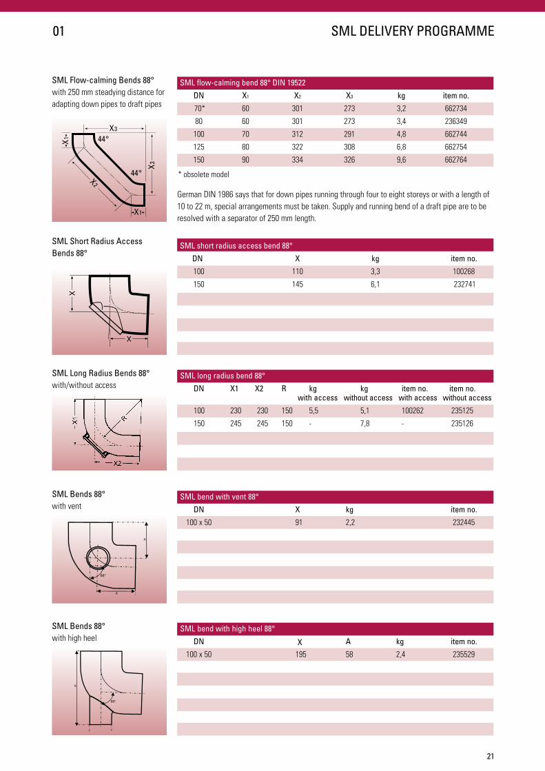
SMl flow-calming bend 88° Din 19522
Dn X1 X2 X3 kg item no.
70* 60 301 273 3,2 662734
80 60 301 273 3,4 236349
100 70 312 291 4,8 662744
125 80 322 308 6,8 662754
150 90 334 326 9,6 662764
* obsolete model
SMl Flow-calming Bends 88° with 250 mm steadying distance for adapting down pipes to draft pipes
44°X
1
X1
X1 44°
44°X2
X3
X3
German DIN 1986 says that for down pipes running through four to eight storeys or with a length of 10 to 22 m, special arrangements must be taken. Supply and running bend of a draft pipe are to be resolved with a separator of 250 mm length.
01 SMl DeliVery PrograMMe
SMl long radius bend 88°
Dn X1 X2 r kg kg item no. item no. with access without access with access without access
100 230 230 150 5,5 5,1 100262 235125
150 245 245 150 - 7,8 - 235126
SMl short radius access bend 88°
Dn X kg item no.
100 110 3,3 100268
150 145 6,1 232741
x
x
SMl bend with vent 88°
Dn kg item no.
100 x 50 91 2,2 232445
SMl bend with high heel 88°
Dn a kg item no.
100 x 50 195 58 2,4 235529
X
X
88°
88°
X
SMl Short radius access Bends 88°
SMl long radius Bends 88°with/without access
SMl Bends 88°with vent
SMl Bends 88°with high heel
21
X
X

22
SMl DeliVery PrograMMe 01
Dn X a l
50 45 48 172
70 60 60 224
80 60 60 224
100 60 63 228
125 70 73 266
150 80 83 303
200 95 98 359
250 110 113 415
300 130 133 489
SMl S-Bends made of 2 SML bends 30°A
30°x
x
A
L
Fitting/bend combinations
Dn X a l
50 40 27 162
70 50 26 197
80 50 26 197
100 50 27 201
125 60 32 241
150 65 35 260
200 80 43 319
SMl S-Bends made of 2 SML bends 15°
x 15°
x
A
L
x
Lx
L
SMl S-bend 65 mm Din 19522
Dn X l kg item no.
100 70 340 4,5 662884
SMl S-Bendsoffset = 200 mm
200
Lx
x
SMl S-bend 65 mm Din 19522
Dn X l kg item no.
100 70 270 3,5 662874
SMl S-Bendsoffset = 130 mm
L
130
xx
SMl S-Bendsoffset = 65 mm
xL
65
xx
L SMl S-bend 65 mm Din 19522
Dn X l kg item no.
100 70 205 2,5 662864

23
01 SMl DeliVery PrograMMe
Dn X a l
50 50 74 174
70 60 85 205
80 60 85 205
100 70 103 243
125 80 117 277
150 90 131 311
200 110 159 379
250 130 187 447
300 155 223 533
SMl S-Bends made of 2 SML bends 45°
x
A
45°xx
A
L
L
Bend combinationsSMl S-Bends made of 2 SML bends 45° with 250 mm spigots
2 x 45°
K
A
L
Dn a max. a min. l max. l min. K*
70 223 88 533 398 190
80 223 88 533 398 190
100 230 103 550 423 180
* Dimension for maximum cut-back
Bends with 250 mm spigots can be reduced by the K-dimension at the most. This allows optimum adaptation of the pipes to the solidium. A reducing quotient of 1:1.5 can be used in site practice for 45° bends. This means: for a decrease of the distance dimensions A and L by 1 cm, the diagonallyrunning longer spigot is to be shortened by 1.5 cm. In the above chart, 5 mm were added for thedistance of the coupling. Because of the simple calculation method we dispense with the illustration of the three further combination possibilities of these bends (long spigots with long, short with short or one long spigot above).
2 x 45°
K
A
L
Dn a max. a min. l max. l min. K*
70 283 148 473 338 190
80 283 148 473 338 190
100 300 173 480 353 180
* Dimension for maximum cut-back
Due to cut-back possibilities, even the deviation made of 2 SML bends 45° with 250 mm spigots shown here allows good adaptation of the pipes to the solidium. Reducing quotient as in the previ-ous example 1:1.5. This also is only one example out of 4 different combination possibilities.
These combinations equal a hydraulically favourable and installation-friendly pipe direction with all deviations: vertical-horizontal, horizontal-vertical and horizontal-horizontal. The overall lengths ”L” can also be lessened by cutting back the long supplying or draining spigots.
Deviation made of 2 SML bends 45° with 250 mm spigots
Bend combinations

24
Kbranch 45°
L
bend 45°
B
A
combinations of SMl bends and SMl branches (bend with 250 mm spigot)combination examplesbranch 45° - bend 45° branch 45° bend 45° a a B B l K*
Dn Dn max. min. max. min.
70 x 70 70 283 149 398 264 200 190 80 x 80 80 293 159 418 284 225 190
100 x 70 70 301 166 406 271 215 190
100 x 80 80 304 170 419 285 230 190
100 x 100 100 315 187 455 327 260 180
125 x 70 70 311 177 411 277 225 190
125 x 80 80 322 187 422 287 240 190
125 x 100 100 329 202 459 332 270 180
* Dimension for maximum cut-back
The reducing quotient 1:1.5 in site praxis is also permitted here. When decreasing the distances A and B by 1 cm (both change at the same time), the bend must be cut back by 1.5 cm.
SMl DeliVery PrograMMe 01
combination examplesbranch 88° - bend 88°
L
K
ranch 88° bend 88°
B
A
8
Lx
L
x
KK
r67
45°
45°
max./min.
L X2
X3
X1
combinations of SMl branches 45° and SMl bends 135° for bypasses
branch 88° bend 88° a a B l K* Dn Dn max. min.
70 x 70 70 350 190 187 180 160 80 x 80 80 350 195 197 180 155
100 x 80 80 365 210 207 190 155
100 x 100 100 370 230 225 220 140
125 x 80 80 380 225 213 205 155
125 x 100 100 385 245 235 235 140
* Dimension for maximum cut-back
Dn max. min.
100 x 100 370 300
125 x 100 380 310
150 x 100 395 325
200 x 100 410 340
branch 45°
L
bend 45°
B
A
K
In this case, the reducing quotient is 1:1. The distance A changes identically to the reduction of the bend. Dimensional tolerances for distance B which theoretically result from the descent are unimportant for installation practice.
German DIN 1986-100 requires bypass lines for ventilation purposes in the following cases:• down pipes over 10 m height with a sideways offset of more than 2m• down pipes over 22 m height at any offsets and at the transition into a horizontal lineThe upper connection between the bypass and the downpipe is executed with a 135° bend.
combinations of SMl bends and SMl branches (bend with 250 mm spigot)
branch 45° bend 45° a a B B l K* Dn Dn max. min. max. min.
70 x70 70 343 209 338 204 200 190 80 x 80 80 353 219 358 224 225 190
100 x 70 70 361 226 346 212 215 190
100 x 80 80 364 230 359 225 230 190
100 x 100 100 385 257 385 257 260 180
125 x 70 70 371 237 351 217 225 190
125 x 80 80 382 247 362 227 240 190
125 x 100 100 399 272 389 262 270 180
combination examplesbranch 45° - bend 45°
combination examplesbranch 45° - bend 135°

25
01 SMl DeliVery PrograMMe
SMl double branch 45°
Dn X1 X2 X3 kg item no.
100 x 100 260 190 190 4,0 100260
125 x 100 280 220 220 6,5 237737
150 x 100 280 225 225 8,4 661444
45°
X1
X2
X3
45°
L X2
X3
X1
SMl single branch 45° Din 19522 Dn X1 X2 X3 l kg item no.
40 x 40 45 115 115 160 1,0 664544
50 x 40 45 115 115 160 1,1 664554
50 x 50 50 (45) 135 (115) 135 (115) 185 (160) 1,4 (1,2) 663004
70 x 50* 40 150 (130) 150 (130) 190 (170) 1,6 663034
80 x 50 50 140 140 190 1,8 235152
70 x 70* 55 160 (145) 160 (145) 215 (200) 2,3 (2,1) 663064
80 x 80 65 160 160 225 2,4 235154
100 x 50 35 (30) 165 (150) 165 (150) 200 (180) 2,5 (2,3) 663094
100 x 70* 50 (45) 185 (170) 185 (170) 235 (215) 3,3 (3,0) 663124
100 x 80 55 175 175 230 3,3 235156
100 x 100 70 205 (190) 205 (190) 275 (260) 4,2 (3,8) 663154
125 x 50 20 185 (170) 185 (170) 205 (190) 3,4 (3,2) 663184
125 x 70* 40 200 (185) 200 (185) 240 (225) 4,3 (4,0) 663214
125 x 80 40 200 200 240 4,4 235342
125 x 100 60 220 (210) 220 (210) 280 (270) 5,2 (5,0) 663244
125 x 125 80 (75) 240 (230) 240 (230) 320 (305) 6,4 (6,1) 663274
150 x 70* 30 215 (205) 215 (205) 245 (235) 5,6 (5,3) 663334
150 x 80 30 215 215 245 5,9 235415
150 x 100 55 240 (225) 240 (225) 295 (280) 6,8 (6,5) 663364
150 x 125 70 255 (245) 255 (245) 325 (315) 8,0 (7,7) 663394
150 x 150 90 265 265 355 9,2 663424
200 x 70* 15 240 (235) 240 (235) 255 (250) 8,1 (8,0) 663484
200 x 80 15 240 240 255 8,5 235416
200 x 100 40 265 (260) 265 (260) 305 (300) 10,0 (9,8) 663514
200 x 125 55 280 280 335 11,9 663544
200 x 150 75 300 300 375 13,3 663574
200 x 200 115 340 340 455 17,2 663604
250 x 100 15 310 (305) 310 (305) 325 (320) 15,4 663634
250 x 125 35 335 (330) 335 (330) 370 (365) 17,7 664504
250 x 150 55 350 350 405 20,2 664514
250 x 200 90 385 (380) 385 (380) 475 (470) 25,1 (24,8) 663644
250 x 250 130 430 430 560 31,5 663654
300 x 100 5 345 345 350 22,0 663664
300 x 125 15 360 360 375 23,9 664524
300 x 150 35 380 380 415 26,9 664534
300 x 200 70 415 440 485 34,0 664444
300 x 250 115 465 465 580 42,1 663674
300 x 300 155 505 505 660 50,1 663684
400 x 300** 105 555 565 660 60,0 663694
* obsolete model, ** on request
Due to the appearance of theEuropean standard for SML pipesand fittings EN 877, the new versionof German DIN 19522 also had to be changed regarding dimensions and measures of SML-fittings (values in brackets=old standard version)
SMl Branches 45°
SMl Double Branches 45°
Düker produces these items ex- clusively as per the latest versionof DIN 19522. Due to possible stocks of the old standard versionplease check the actual dimensions of delivered fittings when pre-manufacturing or preinstalling.

26
SMl DeliVery PrograMMe 01
SMl single branch 70°
Dn X1 X2 X3 l kg item no.
50 x 50 55 80 80 135 0,9 663014
70 x 50* 55 90 90 145 1,2 663044
70 x 70* 70 100 100 170 1,6 663074
100 x 50* 55 110 100 155 1,9 663104
100 x 70* 70 120 110 180 2,3 663134
100 x 100 85 130 130 215 3,0 663164
125 x 50* 55 120 110 165 2,7 663194
125 x 70* 70 130 120 190 3,2 663224
125 x 100 85 145 140 225 4,8 663254
125 x 125* 100 155 155 255 4,8 663284
150 x 100* 85 155 150 235 5,3 663374
150 x 125* 100 170 165 265 6,2 663404
150 x 150* 115 180 180 295 7,2 663434
* obsolete model
SMl double branch 70°
Dn X1 X2 X3 l kg item no.
100 x 100 x 100 85 130 130 215 3,5 663864
125 x 100 x 100 85 145 140 225 5,0 663954
important note on 70° branches!
As per German DIN 1986, for connection of horizontal pipes up to DN 70 to down pipes, branches of 88° are to be used. This is to prevent negative pressure in the connecting pipes. SML branches 88° with an access angle of 45° also allow to connect larger diameters from DN 100 up to the down pipe. This is space-saving and guarantees connecting pipes without negative pressure. Therefore 70° branches are no longer required and are no longer contained in German DIN 19522. As 70° branches are however still on demand, we sell a reduced range of 70° branches until further notice.
SMl Branches 70°
SMl Double Branches 70°X
X2
70°
X1X3
L
DN 1
DN 2
DN 3
L2
LX
0°
X
X
XX5 4N2 DN3
X1X3L
X2
70°
X
DN
X2X2
4
12
27
01 SMl DeliVery PrograMMe
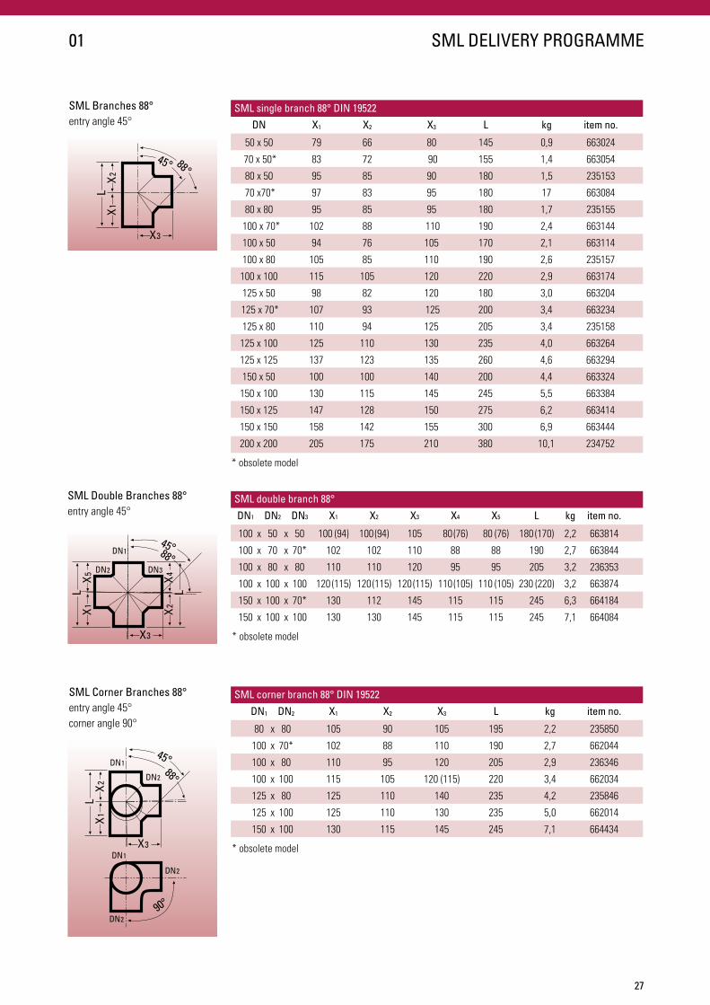
SMl single branch 88° Din 19522
Dn X1 X2 X3 l kg item no.
50 x 50 79 66 80 145 0,9 663024
70 x 50* 83 72 90 155 1,4 663054
80 x 50 95 85 90 180 1,5 235153
70 x70* 97 83 95 180 17 663084
80 x 80 95 85 95 180 1,7 235155
100 x 70* 102 88 110 190 2,4 663144
100 x 50 94 76 105 170 2,1 663114
100 x 80 105 85 110 190 2,6 235157
100 x 100 115 105 120 220 2,9 663174
125 x 50 98 82 120 180 3,0 663204
125 x 70* 107 93 125 200 3,4 663234
125 x 80 110 94 125 205 3,4 235158
125 x 100 125 110 130 235 4,0 663264
125 x 125 137 123 135 260 4,6 663294
150 x 50 100 100 140 200 4,4 663324
150 x 100 130 115 145 245 5,5 663384
150 x 125 147 128 150 275 6,2 663414
150 x 150 158 142 155 300 6,9 663444
200 x 200 205 175 210 380 10,1 234752
* obsolete model
SMl Branches 88°entry angle 45°
LX2
X3
45°
X1
88°
SMl double branch 88°
Dn1 Dn2 Dn3 X1 X2 X3 X4 X5 l kg item no.
100 x 50 x 50 100 (94) 100 (94) 105 80 (76) 80 (76) 180 (170) 2,2 663814
100 x 70 x 70* 102 102 110 88 88 190 2,7 663844
100 x 80 x 80 110 110 120 95 95 205 3,2 236353
100 x 100 x 100 120 (115) 120 (115) 120 (115) 110 (105) 110 (105) 230 (220) 3,2 663874
150 x 100 x 70* 130 112 145 115 115 245 6,3 664184
150 x 100 x 100 130 130 145 115 115 245 7,1 664084
* obsolete modelX3
88°
LX5
X1
LX4
X2
DN2 DN3
DN145°
L2
X
8DN
DN
SMl Double Branches 88°entry angle 45°
SMl corner Branches 88°entry angle 45°corner angle 90°
SMl corner branch 88° Din 19522
Dn1 Dn2 X1 X2 X3 l kg item no.
80 x 80 105 90 105 195 2,2 235850
100 x 70* 102 88 110 190 2,7 662044
100 x 80 110 95 120 205 2,9 236346
100 x 100 115 105 120 (115) 220 3,4 662034
125 x 80 125 110 140 235 4,2 235846
125 x 100 125 110 130 235 5,0 662014
150 x 100 130 115 145 245 7,1 664434
* obsolete model
X
3
XL
X2
X3
X1
88°
45°DN1
DN2
DN1
DN2
DN2
90°
2X
45°
KK

28
SMl DeliVery PrograMMe 01
SMl parallel branch Din 19522
Dn X1 X2 X3 X4 l K* kg item no.
100 x70** 100 300 175 125 400 125 6,5 664474
100 x 80 100 300 175 125 400 125 6,9 236354
* dimension for maximum cut-back, ** obsolete model
especially suited for ceiling penetrations
SMl Branches 88°with long spigotentry angle 45°
SMl single branch 88° long Din 19522 Dn X1 X2 X3 l K* kg item no.
100 x 100 325 105 115 430 210 4,6 664454
* dimension for maximum cut-back
especially suited for ceiling penetrations
SMl corner branch 88° long Din 19522 Dn X1 X2 X3 l K* kg item no.
100 x 100 x 100 325 105 115 430 210 5,2 664464
* dimension for maximum cut-back especially suited for ceiling penetrations
SMl corner Branches 88°with long spigotentry angle 45°corner angle 90°
SMl Parallel Branches
SMl Swept entry Branches 88°
LX2
X3
45°
X1
88°
KDN 1
DN 2
22
4
LX2
X3
45°
X1
88°
K
LX2
K
90°
X1
X3
X4
SMl swept entry access branch 88°
Dn X1 X2 X3 kg item no.
100 x 100 270 102 150 4,3 100269
X3
X1
X2
88°
29
01 SMl DeliVery PrograMMe
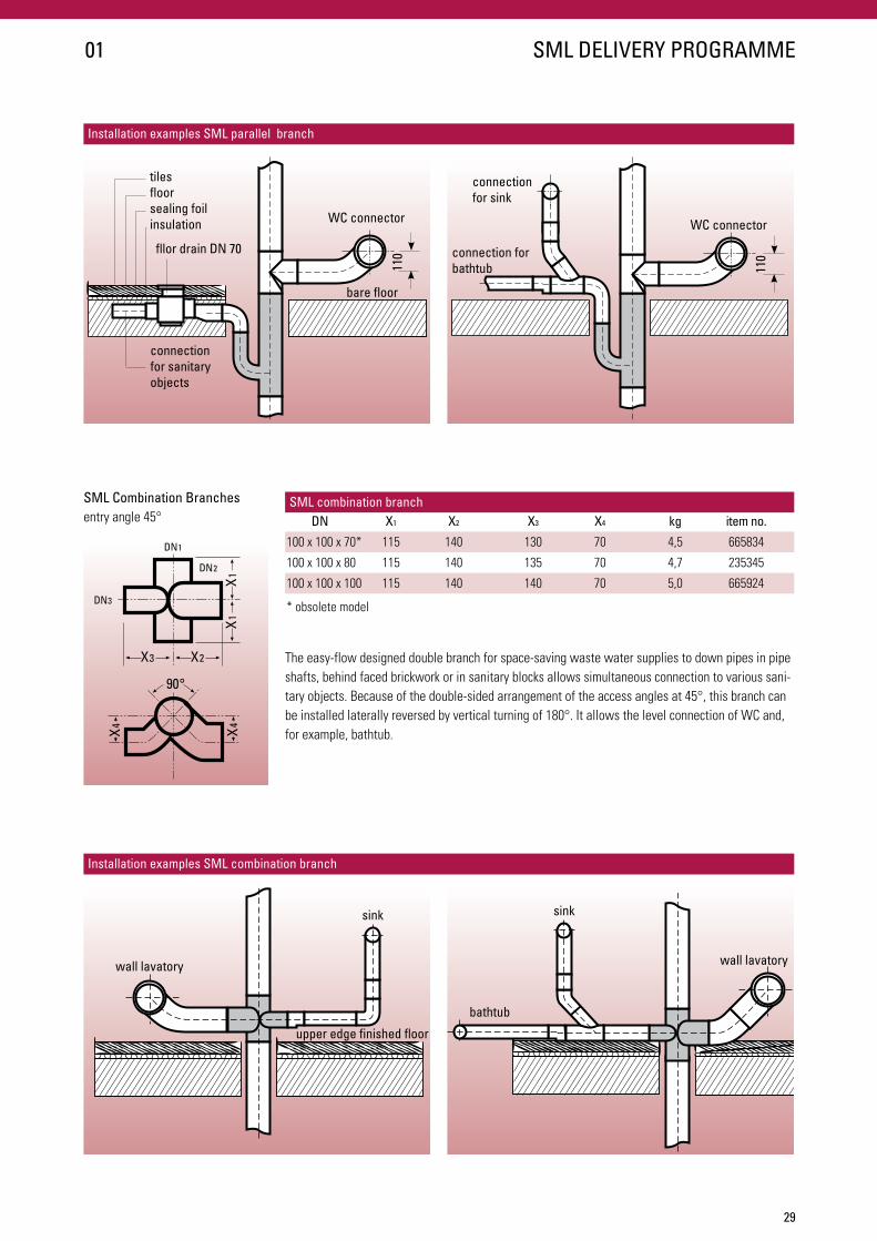
SMl combination Branchesentry angle 45°
DN3
X1X1
X2X3
DN1
DN2
X4 X4
90°
wall lavatory wall lavatory
sink sink
bathtub
upper edge finished floor
connection forbathtub
connectionfor sink
Wc connector
110
tilesfloorsealing foilinsulation
fllor drain Dn 70
connection for sanitary objects
Wc connector
bare floor
110
SMl combination branch Dn X1 X2 X3 X4 kg item no.
100 x 100 x 70* 115 140 130 70 4,5 665834
100 x 100 x 80 115 140 135 70 4,7 235345
100 x 100 x 100 115 140 140 70 5,0 665924
* obsolete model
The easy-flow designed double branch for space-saving waste water supplies to down pipes in pipe shafts, behind faced brickwork or in sanitary blocks allows simultaneous connection to various sani-tary objects. Because of the double-sided arrangement of the access angles at 45°, this branch can be installed laterally reversed by vertical turning of 180°. It allows the level connection of WC and, for example, bathtub.
installation examples SMl parallel branch
installation examples SMl combination branch
30
SMl DeliVery PrograMMe 01
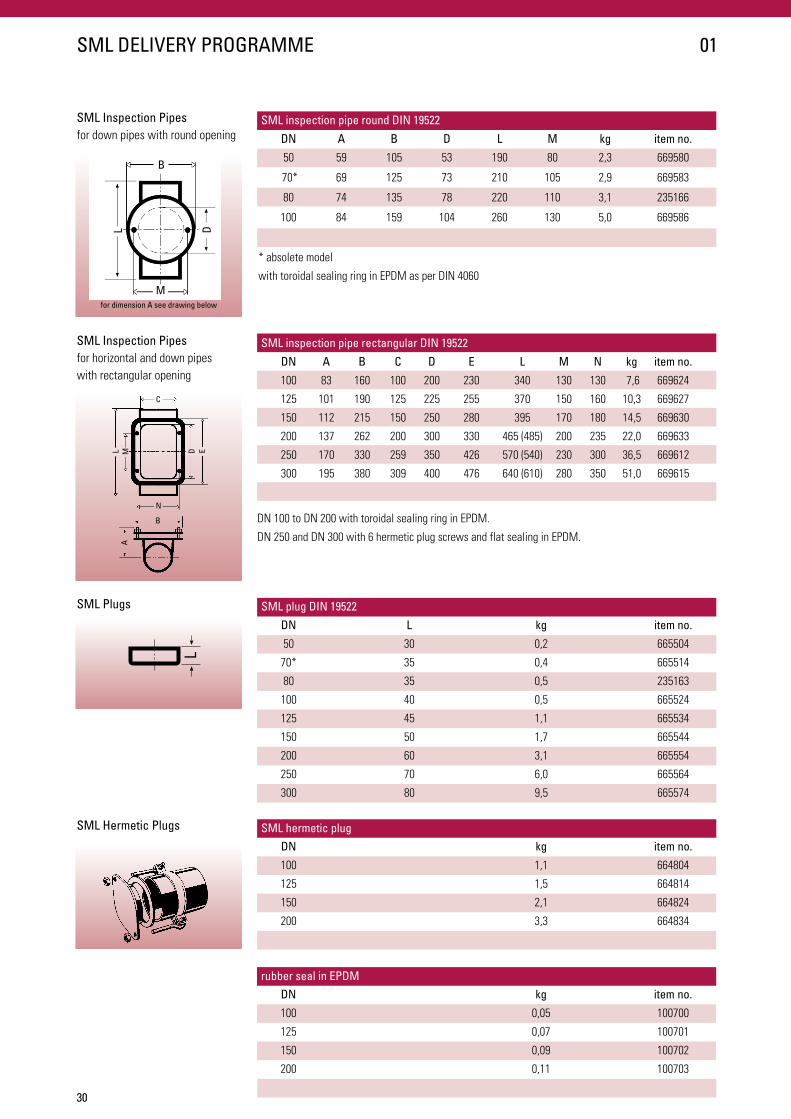
SMl inspection pipe round Din 19522
Dn a B D l M kg item no.
50 59 105 53 190 80 2,3 669580
70* 69 125 73 210 105 2,9 669583
80 74 135 78 220 110 3,1 235166
100 84 159 104 260 130 5,0 669586
* absolete model
with toroidal sealing ring in EPDM as per DIN 4060
SMl inspection pipe rectangular Din 19522
Dn a B c D e l M n kg item no.
100 83 160 100 200 230 340 130 130 7,6 669624
125 101 190 125 225 255 370 150 160 10,3 669627
150 112 215 150 250 280 395 170 180 14,5 669630
200 137 262 200 300 330 465 (485) 200 235 22,0 669633
250 170 330 259 350 426 570 (540) 230 300 36,5 669612
300 195 380 309 400 476 640 (610) 280 350 51,0 669615
DN 100 to DN 200 with toroidal sealing ring in EPDM.
DN 250 and DN 300 with 6 hermetic plug screws and flat sealing in EPDM.
SMl plug Din 19522
Dn l kg item no.
50 30 0,2 665504
70* 35 0,4 665514
80 35 0,5 235163
100 40 0,5 665524
125 45 1,1 665534
150 50 1,7 665544
200 60 3,1 665554
250 70 6,0 665564
300 80 9,5 665574
SMl hermetic plug
rubber seal in ePDM
Dn kg item no.
100 1,1 664804
125 1,5 664814
150 2,1 664824
200 3,3 664834
Dn kg item no.
100 0,05 100700
125 0,07 100701
150 0,09 100702
200 0,11 100703
SMl inspection Pipesfor horizontal and down pipeswith rectangular opening
SMl Plugs
A
L
SMl hermetic Plugs
B
l D
M
c
la
M D e
n
B
for dimension a see drawing below
SMl inspection Pipesfor down pipes with round opening

31
01 SMl DeliVery PrograMMe
The supplying side of the SML odour traps DN 50 to DN 200 may be connected either to the horizon-tal or the vertical pipe. Bends can guide the outlet into different directions. The supply opening not used is to be closed with a hermetic plug with press-sealing automatically supplied.
100 mm sealing height, vertical version with upper and lower cleaning hole for installation in rain water down pipes. Use of this odour trap is necessary when run-off areas (e.g. balcony or patio drainage) are connected to the rain water pipes which join mixed water pipes. Installation must be carried out in a frost-protected area - we advise above the cleaning hole before junction of the down pipe into the base pipe.
cleaning trap for Dn 50 to 150below; for Dn 200 above.
SMl down pipe odour trap Din 19522
Dn a b l2 l3 l1 kg item no. 70* 195 90 80 312 472 9,0 669557 80 195 90 70 333 472 9,6 236357
100 276 124 90 408 588 18,5 669558
125 344 144 100 487 687 28,5 669559
150 374 179 110 522 742 38,0 669560
SMl Down Pipe odour Traps(rain water siphon)for vertical connection
SMl odour Traps (siphons)for horizontal or vertical connection
horizontal supply Dn 200 version0
H
vertical supply
HX2
X1
LX3 X4
w
l3l1l2
l2b
a
100
SMl odour trap horizontal/vertical Din 19522
Dn l h X1 X2 X3 X4 W kg item no.
50 190 250 182 68 122 68 60 2,8 669562
70* 265 293 200 93 172 93 60 5,0 669563
80 265 285 190 95 170 95 80 5,8 235165
100 325 392 282 110 215 110 100 8,5 669564
125 390 446 316 130 260 130 100 13,0 669565
150 470 493 348 145 325 145 100 19,5 669566
200 600 600 420 180 400 200 100 33,7 669567
installation examples
32
SMl DeliVery PrograMMe 01
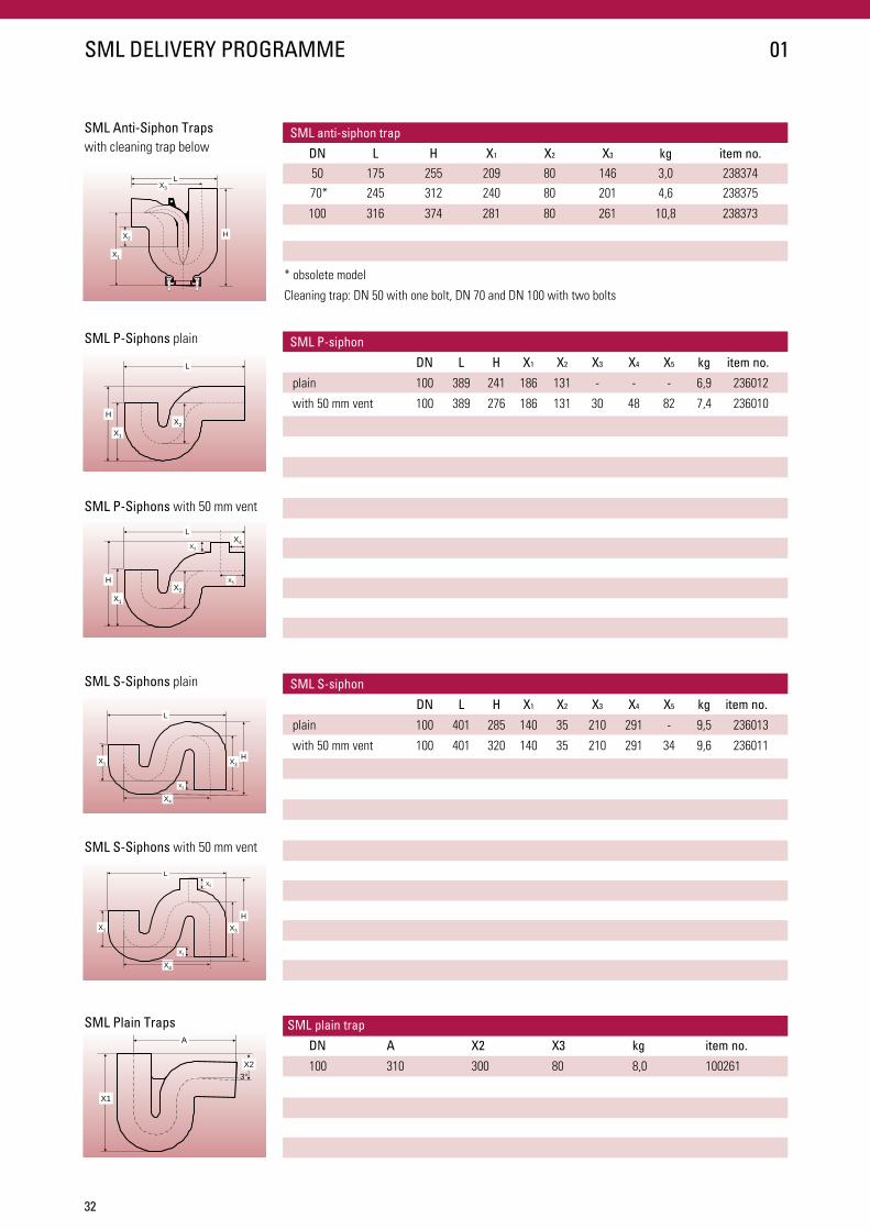
SMl plain trap
Dn a X2 X3 kg item no.
100 310 300 80 8,0 1002613°
A
X1
X2
H
X1
X2
LX3
H
L
X1
X2
X1
X4
X3
X2
L
H
X1
X4
X3
X2
L
H
X5
SMl anti-siphon trap
Dn l h X1 X2 X3 kg item no. 50 175 255 209 80 146 3,0 238374 70* 245 312 240 80 201 4,6 238375
100 316 374 281 80 261 10,8 238373
* obsolete model
Cleaning trap: DN 50 with one bolt, DN 70 and DN 100 with two bolts
SMl P-siphon
Dn l h X1 X2 X3 X4 X5 kg item no.
plain 100 389 241 186 131 - - - 6,9 236012
with 50 mm vent 100 389 276 186 131 30 48 82 7,4 236010
SMl S-siphon
Dn l h X1 X2 X3 X4 X5 kg item no.
plain 100 401 285 140 35 210 291 - 9,5 236013
with 50 mm vent 100 401 320 140 35 210 291 34 9,6 236011
SMl anti-Siphon Trapswith cleaning trap below
SMl P-Siphons plain
SMl S-Siphons plain
SMl P-Siphons with 50 mm vent
SMl S-Siphons with 50 mm vent
SMl Plain Traps
H
L
X1
X2
X3
X4
X5
33
01 SMl DeliVery PrograMMe
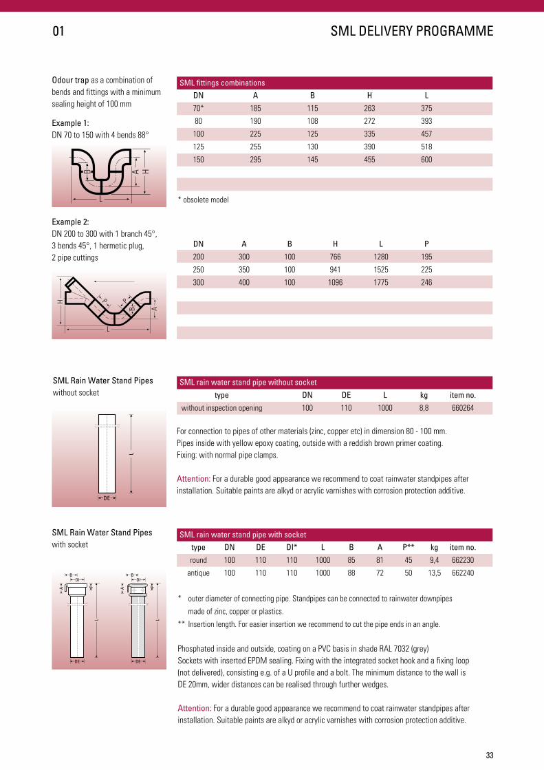
SMl fittings combinationsodour trap as a combination of bends and fittings with a minimum sealing height of 100 mm
example 1:DN 70 to 150 with 4 bends 88°
Dn a B h l
70* 185 115 263 375
80 190 108 272 393
100 225 125 335 457
125 255 130 390 518
150 295 145 455 600
* obsolete model
example 2: DN 200 to 300 with 1 branch 45°, 3 bends 45°, 1 hermetic plug, 2 pipe cuttings
Dn a B h l P
200 300 100 766 1280 195
250 350 100 941 1525 225
300 400 100 1096 1775 246
HB
L
AB A
H
L
PP
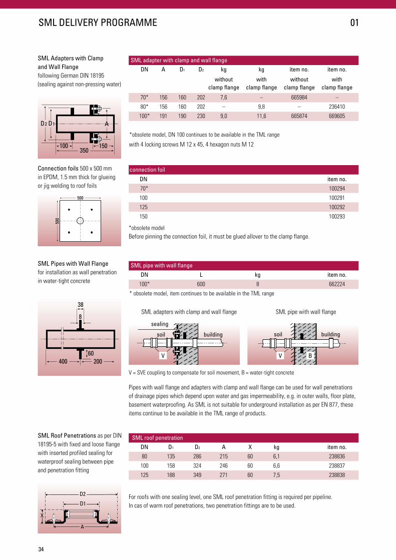
SMl rain Water Stand Pipeswithout socket
SMl rain Water Stand Pipeswith socket
SMl rain water stand pipe without socket
type Dn De l kg item no.
without inspection opening 100 110 1000 8,8 660264
SMl rain water stand pipe with socket type Dn De Di* l B a P** kg item no.
round 100 110 110 1000 85 81 45 9,4 662230
antique 100 110 110 1000 88 72 50 13,5 662240
* outer diameter of connecting pipe. Standpipes can be connected to rainwater downpipes
made of zinc, copper or plastics.
** Insertion length. For easier insertion we recommend to cut the pipe ends in an angle.
Phosphated inside and outside, coating on a PVC basis in shade RAL 7032 (grey)Sockets with inserted EPDM sealing. Fixing with the integrated socket hook and a fixing loop(not delivered), consisting e.g. of a U profile and a bolt. The minimum distance to the wall isDE 20mm, wider distances can be realised through further wedges.
attention: For a durable good appearance we recommend to coat rainwater standpipes after installation. Suitable paints are alkyd or acrylic varnishes with corrosion protection additive.
DE
DIB
A PL
DE
DIB
A PL
DE
L
For connection to pipes of other materials (zinc, copper etc) in dimension 80 - 100 mm.Pipes inside with yellow epoxy coating, outside with a reddish brown primer coating. Fixing: with normal pipe clamps.
attention: For a durable good appearance we recommend to coat rainwater standpipes after installation. Suitable paints are alkyd or acrylic varnishes with corrosion protection additive.
34
SMl DeliVery PrograMMe 01
SMl adapter with clamp and wall flange Dn a D1 D2 kg kg item no. item no.
without with without with clamp flange clamp flange clamp flange clamp flange
70* 156 160 202 7,6 – 665984 –
80* 156 160 202 – 9,8 – 236410
100* 191 190 230 9,0 11,6 665874 669605
*obsolete model, DN 100 continues to be available in the TML range
SMl Pipes with Wall Flange for installation as wall penetration in water-tight concrete
SMl roof Penetrations as per DIN 18195-5 with fixed and loose flange with inserted profiled sealing for waterproof sealing between pipe and penetration fitting
SMl adapters with clamp and Wall Flange following German DIN 18195(sealing against non-pressing water)
with 4 locking screws M 12 x 45, 4 hexagon nuts M 12
Pipes with wall flange and adapters with clamp and wall flange can be used for wall penetrations of drainage pipes which depend upon water and gas impermeability, e.g. in outer walls, floor plate, basement waterproofing. As SML is not suitable for underground installation as per EN 877, these items continue to be available in the TML range of products.
V = SVE coupling to compensate for soil movement, B = water-tight concrete
For roofs with one sealing level, one SML roof penetration fitting is required per pipeline. In cas of warm roof penetrations, two penetration fittings are to be used.
connection foils 500 x 500 mm in EPDM, 1.5 mm thick for glueing or jig welding to roof foils
150
a
100350
D1D2
38
1500035
400 20060
8
38
20
500
500
SMl pipe with wall flange
Dn l kg item no.
100* 600 8 662224
* obsolete model, item continues to be available in the TML range
connection foil Dn item no.
70* 100294
100 100291
125 100292
150 100293
SMl roof penetration
Dn D1 D2 a X kg item no.
80 135 286 215 60 6,1 238836
100 158 324 246 60 6,6 238837
125 188 349 271 60 7,5 238838
D1
D2
X
A
SML adapters with clamp and wall flange SML pipe with wall flange
soil
sealing
building buildingsoil
V BV
*obsolete modelBefore pinning the connection foil, it must be glued allover to the clamp flange.

35
01 SMl DeliVery PrograMMe
Sealings to pinch in highly polymeric roofing paper
For each SML roof penetration, two sealings are to be used.
sealing for SMl roof penetration
Dn kg item no.
ePDM nBr
80 0,2 238830 238833
100 0,3 238831 238834
125 0,3 238832 238835
roofwaterproofing
moisturebarrier
thermalinsulation
roof
instal ation example
Dn D1 D2 l M De kg item no.
100 144 125,5 250 40 110 3,3 662194
125 172 151,5 250 42,5 135 4,6 662204
150 201 178,5 250 45 160 6,1 662214
SMl connection with short socket
example no. 1:Pipe openings are easily tripped over, whichcan lead to injuries or damage.
example no. 2:the space is saved for the coupling. Anenlargement is usually inevitable.
example no. 3:The socket connection piece is imbedded inconcrete at the same level with the upperedge of the bare ceiling and protected by asealing hood. The inserted sealing guaranteesan easy and unproblematic later continuation.
SMl connections with short socket and inserted rubber profile seal
SMl connections at the bare ceiling. SML pipe imbedded in concrete, where the continuation above the bare ceiling can only be carried out later.
D2
SML pipe
DE
D1D2
LM
D1
1
1 2 3

36
SMl DeliVery PrograMMe 01
SMl connecting Bends 90°for sinks and urinals
SMl connecting bend long Din 19522
Dn K1* K2* kg item no.
1 2
50 x 40 long 120 20 1,4 661744
50 x 50 long 120 25 1,5 661754
50 x 60 long 120 30 1,5 661764
* dimension for maximum cut-back
DN1DN2
K1200
K2 110
SMl connecting Bends 90°for wash basins, sinks and bidets
SMl connecting bend short Din 19522
Dn kg item no.
1 2
40 x 50 short 0,8 661734
K1
DN1
DN2
60
70
SMl connecting y-pipe Din 19522
Dn K1* K2* kg item no.
1 2 3
50 x 50 x 50 125 85 2,5 661794
* dimension for maximum cut-back
SMl connecting y-Pipes 90°for wash basins etc.
K2
DN1
DN2
DN3
K1
K2
200
160
rubber connections rubber connections for SMl-bend D2 D marks** item no.
Dn (connecting pipe)
50 x 40 40 28-34 40 / 30 klein 100088
50 x 50 / 40 x 50 50 28-34 40 / 30 groß 100125
50 x 50 / 40 x 50 50 38-44 40 / 40 100089
50 x 60 60 28-34 50 / 30 100092
50 x 60 60 38-44 50 / 40 100091
50 x 60 60 48-54 50 / 50 100090
** Please note: the rubber push-in connectors for the bends 40x50, 50x50 and 50x60 bear marks which differ from the nominal widths.
N
D
D 2

37
01 SMl DeliVery PrograMMe
SMl Manifold connectors
Further connection possibilities for sanitary objects to SMl Dn 50, 70 and 80
SMl fittings connection connecting pipe (outer diameter)
SML bends 88°, DN 50 rubber connector size 40/30 groß (large) 28-34 mm
SML branches 88° rubber connector size 40/40 38-44 mm
with DN 50 outlets Düker EK Fix connector DN 50 40-56 mm
SML bends 88°, DN 70
SML bends 88°, DN 70 with long spigot Düker EK Fix connector DN 70 56-75 mm
SML branches 88° with DN 70 outlets
SML bends 88°, DN 80 Düker EK Fix connector DN 80 56-75 mm / 75-90 mm
SML bends 88° with DN 80 outlets
SMl manifold connector
Dn a a1 a2 B c c1, c2 kg item no.
100 234 65 169 110 145 40 1,8 214089A
ø 42
A1 A2B
C
C1
C2
SMl Wc pipe 225 mm length
DN plastic pipe L K* kg item no. connection DN
100 100 225 170 4,2 663734
SMl Wc Pipes
K
L
SMl Wc bend 150 mm length DN plastic pipe X A B C kg item no. connection DN
80 90 150 98 55 15 2,2 662794
100 100 150 84 44 – 2,6 662684
SMl Wc Bends 90°
Wc connections Dn 100 with Special Sockets and rubber Seals as per Din 4060
Dn 80 Dn 100a a
c
X X
B B
38
SMl DeliVery PrograMMe 01
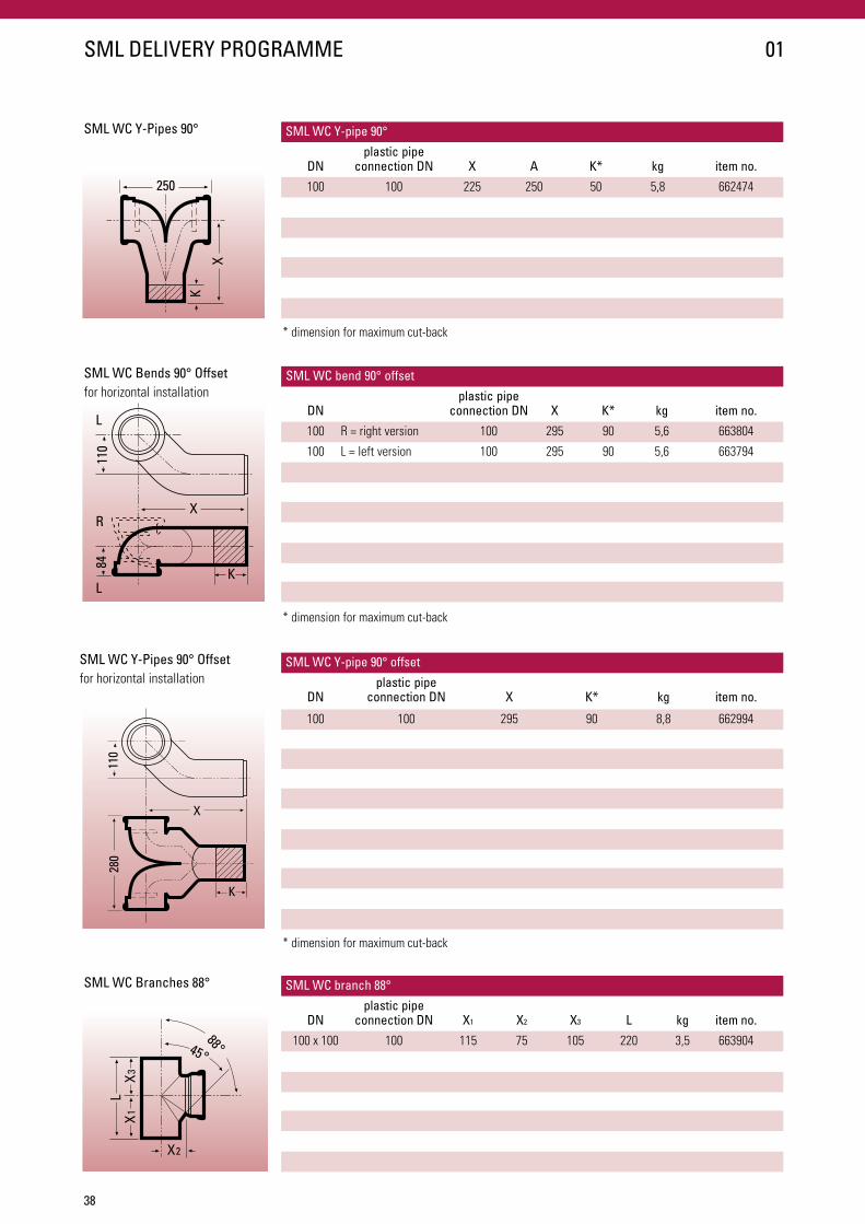
SMl Wc bend 90° offset
plastic pipe Dn connection Dn X K* kg item no.
100 R = right version 100 295 90 5,6 663804
100 L = left version 100 295 90 5,6 663794
* dimension for maximum cut-back
SMl Wc y-pipe 90° offset
plastic pipe Dn connection Dn X K* kg item no.
100 100 295 90 8,8 662994
* dimension for maximum cut-back
SMl Wc branch 88°
plastic pipe Dn connection Dn X1 X2 X3 l kg item no.
100 x 100 100 115 75 105 220 3,5 663904
SMl Wc Bends 90° offsetfor horizontal installation
SMl Wc Branches 88°
K
X
8411
0
R
L
L
X
0
X
110
K
280
45
8
0
L
L
X2
X1X3
45°
88°
SMl Wc y-pipe 90°
plastic pipe Dn connection Dn X a K* kg item no.
100 100 225 250 50 5,8 662474
* dimension for maximum cut-back
SMl Wc y-Pipes 90°
X
250K
SMl Wc y-Pipes 90° offsetfor horizontal installation

39
01 SMl DeliVery PrograMMe
SMl Wc branch for modernisation
plastic pipe Dn version connection Dn kg item no.
100 left 100 7,0 662164
100 right 100 7,0 662174
illustration: right version
Wc-socket for plastic pipe connection Dn 90item no. rubber joints separately: 236685
Wc-socket for plastic pipe connection Dn 100item no.rubber joints separately: 100000
SML WC branch for modernisation of old buildings. This special branch is meant for connecting a standing WC when laying SML pipe onto an already finished floor (e.g. when modernising an old building). With use of this WC branch, it is possible to lay the collective connec-ting pipe onto the existing floor. The top coat in the area of the branch (down pipe) must be omitted. The connection height of a standing WC with horizontal outlet is generally 180 mm from the middle of the WC outlet to the upper edge of the finished floor. A customary WC connecting piece (outer dimension 110 mm, in plastic) is necessary for the connection of the WC outlet to the SML connecting socket.
139 32070
233
27050
130
Ø11
0
example 1:Installation of the branch into a collective connecting pipe forconnection of a standing WC with horizontal outlet.
Wc
sink
Please note!omit the top coat in the area of the branch
(down pipe) or of the Wc branch
bathtub/shower
finished floor
* Installation guideline for waste water down pipes as per German DIN 1986: „Foot bends of 88° ± 2° are permitted for down pipes which do not run through more than three storeys or which are not longer than 10 m and which pass
over to horizontal pipes.“ However, we recommend using the 2 x 44° double bend for sound insulation reasons.
Wc
110
180
sink
*2 x 44° SMl double bend
bathtub/showereK-Düker-Fix connection
finished floor
Dimensions of Special Sockets and rubber Joints
SMl Wc Branches for Modernisation of old buildings
example 2:Installation of a branch into a down pipe for the connection of a standing WC with horizontal exit. Only surface-cistern, close-coupled cistern or flushing valve possible.
installation examples
26,5
Ø 114
Ø 85,6Ø 99,5
Ø 95,5
25 35
26,5
Ø 125,5
Ø 134
Ø 111,5
Ø 119,5
Ø 115,5
Ø 119,3
1,5
25 40
Ø 99,3
1,5
Ø 105,5

40
SMl DeliVery PrograMMe 01
installation notes for Wc connectors
In general: When connecting WC connectorsto down pipes we recommend SML branches 88° with 45° access angle which offer the best draining conditions.
Wc connectors should be inserted into the down pipes so that the difference in height between the water level of the Wc siphon and the base of the connec-ting pipe at the junction into the down pipe is at least the Dn (100 mm for Dn 100). Please always note this rule when connecting lavatories with horizontal outlets to the wall.
As per current state of the art, standing WCs are only supplied with vertical or horizontal outlet. Plastic WC connecting pieces Ø 110 mm with sealing lips or compression connec-tions are used for joining the WC outlet to the cast iron (bend 22°, 45° and 90° as well as straight connecting pieces).
1. Standing WC with hidden vertical outlet. Connection to a cast iron WC connection bend with a plastic WC connection piece.
2. Standing WC with horizontal outlet. Connection to a cast iron WC connection bend with a plastic WC connection bend 90°.
4. Standing WC with horizontal exit.Wall connection on the side with the down pipe. The necessary difference in height in the connecting pipe is achieved by a cast iron WC bend which shows an offset of 110 mm. The WC with a straight plastic WC connection piece is connected to this bend.
3. Standing WC with horizontal outlet. Wall connection to a cast iron WC branch 88° in a down pipe. The difference in height of 100 mm between the water level of the WC odour trap and the base of the connecting pipe necessary in this case is achieved by putting two plastic connecting pipes 45° into one another. The normal SML branch DN 100 88° with Düker-Fix connection can be used for wall connection instead of the WC branch.
connection examples standing Wc

41
01 SMl DeliVery PrograMMe
Wall WC connections are carried out byjoining straight plastic WC connectionpieces Ø 110 mm and sealing lips to castiron WC connection pieces with specialsocket and sealing ring.
The connection may not be carried outdirectly to the down pipe, but only viabends or bend combinations which considerthe difference in height of at least100 mm.
The cast iron WC connection bends whichshow an offset of 110 mm and can be connected (almost) horizontally to a SML branch 88° guarantee an optimum of drai-ning conditions. The simple WC connection bends should only be used when the given difference in height is reached due to the arrangement of the connecting pipe (refer to installation example no. 7). The simple WC double socket connector for the double-sided connection of wall WC is only intended for vertical arrangement since otherwise washing-ins from both sides would occur.
5. Connection detail: Plastic WC connection piece, cast iron WC connection bend with special socket and rubber seal.
6. Wall WC connection with cast iron WC connection bend and plastic WC connection pieces.
7. Wall WC connection with cast iron WC connection bend, a SML bend 88° with spigot and a plastic WC connection piece.
8. Standing WC with 4.5 or 6 l flush tankwith plastic bend DN 90, EK-Düker-Fixcoupling DN 80 and branch 45° DN 80.Both horizontal and down pipe are also inDN 80.
attention: this solution is not approved in all countries. If DN 80 cast iron pipes are not admissible for toilet drainage in your country, we recommend to connect the DN 90 plastic bend to a DN 100 cast iron branch via a transition coupling by Mücher (www.muecher.com).
connection examples standing Wc / wall Wc

42
SMl DeliVery PrograMMe 01
SMl single/double boss pipe 88°
Dn X1 X2 X3 l kg kg item no. item no. single double single double
100 77,5 80 77,5 155 2,1 2,2 100267 100266*
150 87,7 104 87,5 175 3,8 3,8 232746 237738
* obsolete model
SMl corner boss pipe 88°
Dn X1 X2 X3 l kg item no.
100 75 80 75 150 2,9 100318*
* obsolete model
SMl Boss Pipes 88°
SMl corner Boss Pipes 88°
SMl connector with flange Din 19522
Dn D1 D2 B K* screws kg item no.
per 8 pcs
100 220 18 24 180 M16 5,8 665934
125 250 18 26 210 M16 8,0 665944
150 285 22 26 240 M20 9,8 665954
200 340 22 26 295 M20 14,5 665964
Delivery without screws and seals
* 8 holes, PN6/PN10 as per EN 1092-2
SMl connection for stoneware Din 19522
Dn d kg item no.
100 159 ± 2,0 4,9 664924
125 187 ± 3,5 6,7 664934
150 218 ± 3,5 9,7 664944
200 278 ± 3,5 13,3 664954
Connections for these: stoneware-A-ring or Tecotect-se-S seal
SMl connectors with Flange
SMl connections for Stoneware
D2
d
140 70
DN
D1K
D2
B
D1
150
43
01 SMl DeliVery PrograMMe
Stoneware transition ring „stoneware-Ü-Ring“ EN 295 (UR) for connecting SML to stoneware withpush-in socket „L“ as per EN 295, not suitable for push-in socket „K“.
Tecotect-se-Ü-seal for connecting SML to stoneware without pre-finished sealing.
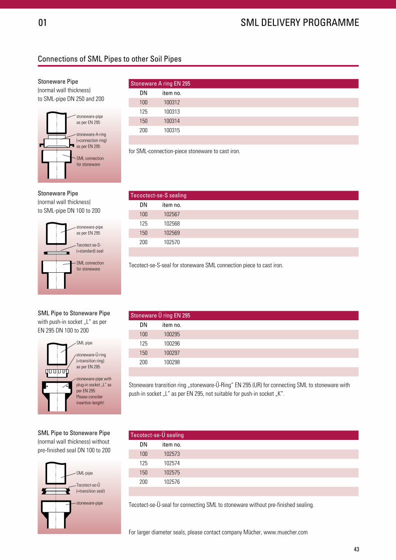
for SML-connection-piece stoneware to cast iron.
Tecotect-se-S-seal for stoneware SML connection piece to cast iron.
For larger diameter seals, please contact company Mücher, www.muecher.com
Dn item no.
100 100295
125 100296
150 100297
200 100298
Dn item no.
100 102573
125 102574
150 102575
200 102576
SMl Pipe to Stoneware Pipe with push-in socket „L“ as per EN 295 DN 100 to 200
Dn item no.
100 100312
125 100313
150 100314
200 100315
Dn item no.
100 102567
125 102568
150 102569
200 102570
Stoneware Pipe (normal wall thickness)to SML-pipe DN 250 and 200
Stoneware Pipe (normal wall thickness)to SML-pipe DN 100 to 200
stoneware-pipe as per EN 295
stoneware-A-ring (=connection ring)as per EN 295
SML connectionfor stoneware
stoneware-pipe as per EN 295
Tecotect-se-S- (=standard) seal
SML connection for stoneware
SML-pipe
Tecotect-se-Ü (=transition seal)
stoneware-pipe
Stoneware Ü ring en 295
Tecotect-se-Ü sealing
Stoneware a ring en 295
Tecoctect-se-S sealing
connections of SMl Pipes to other Soil Pipes
SMl Pipe to Stoneware Pipe (normal wall thickness) without pre-finished seal DN 100 to 200
SML pipe
stoneware-Ü-ring (=transition ring)as per EN 295
stoneware-pipe with plug-in socket „L“ as per EN 295 Please consider insertion length!
02 couplings Delivery Programme
44

45
02 coUPlingS DeliVery PrograMMe
One screw coupling German Approval no.: DN 50–150: ABP Nr. P-11 0002488-01/01 DN 40 und 200: ABP Nr. P-110002011Material metal collar: W2, stabilised stainless steel, 1.4510/11 as per EN 10088Material locking parts: lock 1.4301 or 1.4510/11 DN 50-150: screw and square nut steel with zinc lamellae coating, washer A2 as per DIN 125 DN 40 and 200: screw, washer and square nut galvanised, yellow-chromatedMaterial sealing: EPDMAxial restraint: up to 0.5 barScrew size: DN 40: M5; DN 50-150: M8; DN 200:M10Torque: DN 50-150: 10-20 Nm
DN 40 and 200: until both locks come together
Installation instructions see page 59.
H
D L
Dükorapid® coupling
Dn D≈ h≈ l≈ item no.
40 60 72 41 659623
50 71 83 47 218592
70* 91 103 45 218593
80 96 107 47 235494
100 123 135 47 214405
125 152 164 54 218594
150 177 189 54 218595
200 227 244 70 659556
* obsolete model, ≈ maximum dimensions after installation
Mletec rapid coupling
Dn D≈ h≈ l≈ item no.
100* 123 137 54 235487
125* 150 164 63 235488
150* 175 189 63 235489
* obsolete model, ≈ maximum dimensions after installation
One screw coupling with elevated axial restraint
German Approval no.: ABP Nr. 110002089Material metal collar: W2, stabilised stainless steel, 1.4510/11 as per EN 10088Material locking parts: lock austenitic steel 1.4301, screw, washer, square nut galvanised, yellow-chromated Material sealing: EPDM silicon-free. NBR on request for waste water containing oil, animal grease, solvents or petrolAxial restraint: up to 1 barScrew size: M8 screw with 8.8 hexagon socketTorque: 15-25 Nm
Also available as inox version on request
Installation instructions see page 59.
L
D
H
oUr recoMMenDaTion!!
do not tighten any more ; if the locks should come together

coUPlingS DeliVery PrograMMe 02
46
Dn D≈ h≈ l≈ item no.
40 60 72 41 235493
50 70 80 39,5 234826
70* 90 100 39,5 234827
80 95 105 39,5 235472
100 125 135 45,4 234828
125 147 162 54,5 234829
150 172 187 54,5 234830
200 227 244 70,0 234831
250 278 306 91 234832
300 330 359 91 234833
One screw coupling for soil installation without additional corrosion protection and for installation outside of buildingsAttention: particularly aggressive soils may call for an additional corrosion protection (e.g. shrinking hose)
German Approval no.: Ü DIN EN 877Material metal collar: W5, austenitic stainless steel, 1.4571 as per EN 10088Material locking parts: austenitic stainless steel 1.4571 as per EN 10088; screw, washer and square nut A4Material sealing: EPDM. NBR on request for waste water containing oil, animal grease, solvents or petrolAxial restraint: DN 40 - 200: up to 0.5 bar; DN 250 - 300: up to 0.3 barScrew size: hexagon socket screw; DN 40: M 5; DN 50 - 150: M 8; DN 200: M 10Torque: until both fastening heads come togetherMarking: Marking W5 on the metal collar
Installation instructions see page 59.
* obsolete model, ≈ maximum dimensions after installation
rapid inox coupling
rapid MSM coupling
Dn D≈ h≈ l≈ item no.
50 70 80 40 239357
70* 90 100 40 239358
80 95 105 40 239359
100 125 135 46 239360
125 147 162 55 239361
150 172 187 55 239362
200 227 244 70 239363
* obsolete model, ≈ maximum dimensions after installation
One-screw coupling with hooked-in catch, particularly suited for repairs as it can be laid around the pipe as an alternative to push-on installation
German Approval no.: ABP Nr. P-110002011Material metal collar: stainless steel W2, stabilised chromium steel, 14510/11 as per EN 10088Material locking parts: lock 1.4301 or 14510/11, hexagon socket screw with special washer and square nut, steel with surface protectionMaterial sealing: EPDM Axial restraint: up to 0.5 barScrew size: DN 50-150: M8; DN 200: M10 Torque: until both fastening heads come together
Installation instructions see page 59.
oUr recoMMenDaTion!!
For inSTallaTion UnDergroUnD anD oUTSiDe
oF BUilDingS
02 coUPlingS DeliVery PrograMMe
47
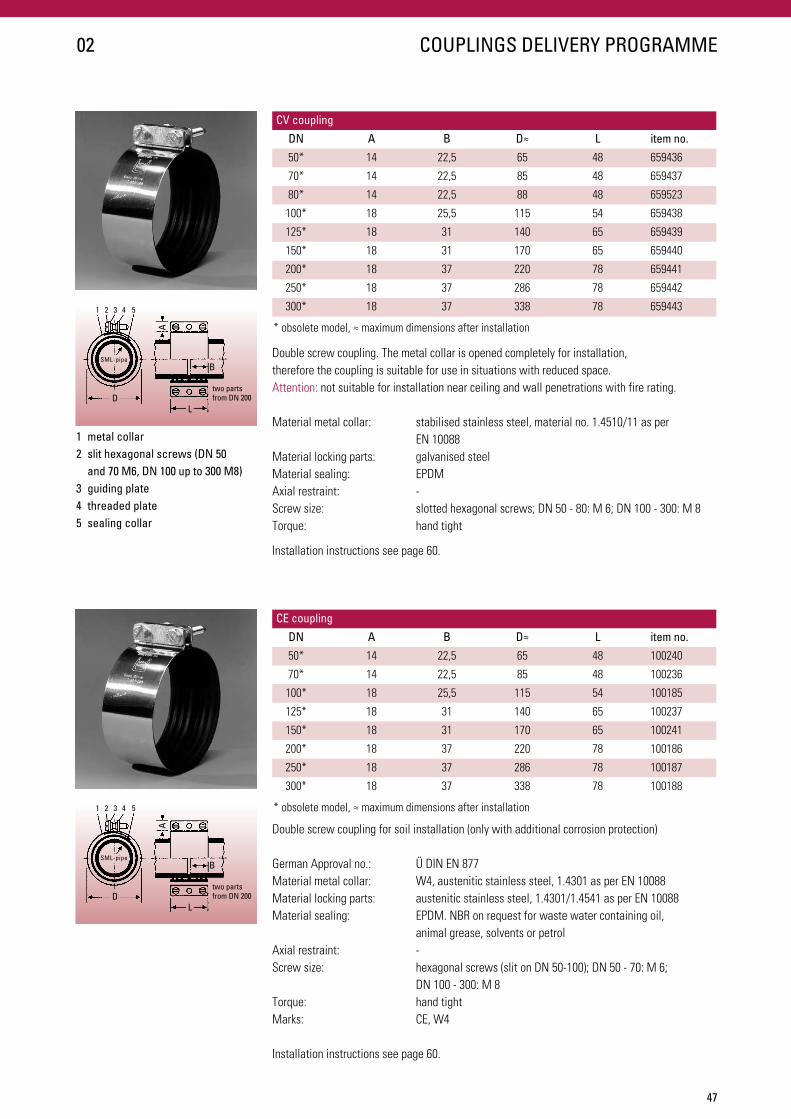
1 metal collar2 slit hexagonal screws (Dn 50 and 70 M6, Dn 100 up to 300 M8)3 guiding plate4 threaded plate5 sealing collar
cV coupling
Dn a B D≈ l item no.
50* 14 22,5 65 48 659436
70* 14 22,5 85 48 659437
80* 14 22,5 88 48 659523
100* 18 25,5 115 54 659438
125* 18 31 140 65 659439
150* 18 31 170 65 659440
200* 18 37 220 78 659441
250* 18 37 286 78 659442
300* 18 37 338 78 659443
* obsolete model, ≈ maximum dimensions after installation
Double screw coupling. The metal collar is opened completely for installation, therefore the coupling is suitable for use in situations with reduced space. Attention: not suitable for installation near ceiling and wall penetrations with fire rating.
Material metal collar: stabilised stainless steel, material no. 1.4510/11 as per EN 10088Material locking parts: galvanised steel Material sealing: EPDM Axial restraint: - Screw size: slotted hexagonal screws; DN 50 - 80: M 6; DN 100 - 300: M 8 Torque: hand tight
Installation instructions see page 60.
ce coupling
Dn a B D≈ l item no.
50* 14 22,5 65 48 100240
70* 14 22,5 85 48 100236
100* 18 25,5 115 54 100185
125* 18 31 140 65 100237
150* 18 31 170 65 100241
200* 18 37 220 78 100186
250* 18 37 286 78 100187
300* 18 37 338 78 100188
* obsolete model, ≈ maximum dimensions after installation
Double screw coupling for soil installation (only with additional corrosion protection)
German Approval no.: Ü DIN EN 877Material metal collar: W4, austenitic stainless steel, 1.4301 as per EN 10088Material locking parts: austenitic stainless steel, 1.4301/1.4541 as per EN 10088Material sealing: EPDM. NBR on request for waste water containing oil, animal grease, solvents or petrolAxial restraint: -Screw size: hexagonal screws (slit on DN 50-100); DN 50 - 70: M 6; DN 100 - 300: M 8Torque: hand tightMarks: CE, W4
Installation instructions see page 60.
two partsfrom Dn 200
1
Dl
B
a
SMl-pipe
2 3 4 5
two partsfrom Dn 200
1
Dl
B
a
SMl-pipe
2 3 4 5
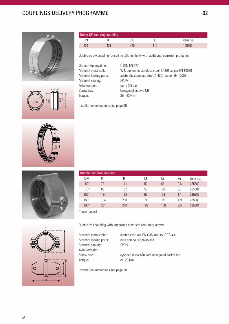
48
Düker ce dual ring coupling
Dn D D2 l item no.
400 431 445 110 100307
Ductile cast iron coupling
Dn h D l1 l2 kg item no.
50* 79 111 50 68 0,6 235880
70* 89 132 50 68 0,7 235881
100* 134 168 60 78 1,1 235882
150* 184 230 71 89 1,9 235883
200* 231 278 82 100 3,5 235884
*upon request
D2 pipe
pipe
L
D
H
D
L1L2
Double screw coupling for soil installation (only with additional corrosion protection)
German Approval no.: Ü DIN EN 877Material metal collar: W4, austenitic stainless steel 1.4301 as per EN 10088Material locking parts: austenitic stainless steel, 1.4301 as per EN 10088Material sealing: EPDMAxial restraint: up to 0.5 barScrew size: hexagonal screws M8Torque: 35 - 40 Nm
Installation instructions see page 60.
Ductile iron coupling with integrated electrical continuity screws
Material metal collar: ductile cast iron EN-GJS-400-15 (GGG 40)Material locking parts: nuts and bolts galvanisedMaterial sealing: EPDMAxial restraint: -Screw size: cylinder screw M8 with hexagonal socket 8.8Torque: ca. 20 Nm
Installation instructions see page 60.
coUPlingS DeliVery PrograMMe 02
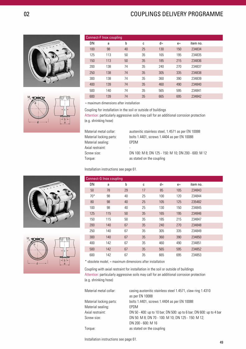
49
connect-F inox coupling
Dn a b c d≈ e≈ item no.
100 98 40 25 130 150 234834
125 113 50 35 165 195 234835
150 113 50 35 185 215 234836
200 138 74 35 240 270 234837
250 138 74 35 305 335 234838
300 138 74 35 360 390 234839
400 139 74 35 460 490 234840
500 140 74 35 565 595 234841
600 139 74 35 665 695 234842
≈ maximum dimensions after installation
d
e
M
c
ba
Coupling for installation in the soil or outside of buildingsAttention: particularly aggressive soils may call for an additional corrosion protection (e.g. shrinking hose)
Material metal collar: austenitic stainless steel, 1.4571 as per EN 10088Material locking parts: bolts 1.4401, screws 1.4404 as per EN 10088Material sealing: EPDMAxial restraint: -Screw size: DN 100: M 8; DN 125 - 150: M 10; DN 200 - 600: M 12Torque: as stated on the coupling
Installation instructions see page 61.
d
e
M
c
ba
connect-g inox coupling
Dn a b c d≈ e≈ item no.
50 78 29 17 85 105 234843
70* 98 40 25 100 120 234844
80 98 40 25 105 125 235482
100 98 40 25 130 150 234845
125 115 50 35 165 195 234846
150 115 50 35 185 215 234847
200 140 67 35 240 270 234848
250 140 67 35 305 335 234849
300 140 67 35 360 390 234850
400 142 67 35 460 490 234851
500 142 67 35 565 595 234852
600 142 67 35 665 695 234853
* obsolete model, ≈ maximum dimensions after installation
Coupling with axial restraint for installation in the soil or outside of buildingsAttention: particularly aggressive soils may call for an additional corrosion protection (e.g. shrinking hose)
Material metal collar: casing austenitic stainless steel 1.4571, claw ring 1.4310 as per EN 10088Material locking parts: bolts 1.4401, screws 1.4404 as per EN 10088Material sealing: EPDMAxial restraint: DN 50 - 400: up to 10 bar; DN 500: up to 6 bar; DN 600: up to 4 barScrew size: DN 50: M 8; DN 70 - 100: M 10; DN 125 - 150: M 12; DN 200 - 600: M 16Torque: as stated on the coupling
Installation instructions see page 61.
02 coUPlingS DeliVery PrograMMe

50
D = outer diameter of the closed grip collar including bars
Düker Kombi grip collar
Dn D l item no.
40 105 62 237283
50 124 72 235360
80 149 72 235498
100 180 85 235280
125 210 98 235315
150 230 98 235316
200 287 111 235281
250 367 130 216888
300 419 130 100304
Security collar with axial restraint for CV/CE couplings
German Approval no.: ABP Nr. P-110002011Material metal collar: galvanised steel with hardened claw insertMaterial locking parts: galvanised steelAxial restraint: up to 3 barScrew size: DN 50 - 70: M 8; DN 100 - 200: M 10;Torque: DN 50 - 70: 10-12 Nm; DN 100 - 150: 18-20 Nm; DN 200: 25-30 Nm,
Installation instructions see page 62.
D = outer diameter of the closed grip collar
cV grip collar
Dn a D l item no.
50* 23 73 69 659485
70* 23 94 71 659486
100* 23 126 87 659487
125* 23 151 98 659488
150* 23 179 98 659489
200* 23 229 111 659490
* obsolete model
Dn 50 Dn 100 - 250
oUr recoMMenDaTion!!
For increaSeD inSiDe PreSSUre
L
D
L
A
DA
L
D
L
D
DN 40 - 150 DN 200 - 300
coUPlingS DeliVery PrograMMe 02
Security collar with axial restraint for all Rapid and CV/CE couplings
German Approval no.: DN 50-200: ABP No. P-110003361/01 (new version) or P-11002089 (old version)Material metal collar: galvanised steelMaterial locking parts: galvanised steel, yellow chromated 8 μ 8.8Material sealing: -Axial restraint: DN 40-100: up to 10 bar; DN 125-150: up to 5 bar; DN 250-300: up to 1 barScrew size: DN 40-80: round head screws with hexagon socket with washers M 8 x 30; DN 100-150: round head screws with hexagon socket with washers M 10 x 35;DN 200: hexagonal screw with washers and self-locking nut galvanised M 10 x 30, DN 250-300: M 12 x 30Torque: DN 40 and 70: 23-25 Nm; DN 50 and 80: 17-23 Nm; DN 100: 28-30 Nm; DN 125-150: 25-30 Nm; DN 200: 40-50 Nm, DN 250-300: 50-55 Nm
The Kombi grip collar has recently been modified. You may receive items of the old or of the new series. Therefore, please observe the torques stated on the installation instructions delivered with the product. General installation instructions see page 62.

51
rekord grip collar
Dn a D l item no.
40* 21 65 66 232413
50* 23 75 69 659550
70* 23 95 69 659551
100* 25 135 87 659552
125* 25 160 95 659553
150* 25 185 95 659554
200* 30 235 111 659555
* obsolete model
Düker grip collar
Dn a D l item no.
400 30 460 160 100305
L
DA
Security collar with axial restraint for CE dual ring coupling
Material metal collar: galvanised steelMaterial locking parts: galvanised steelAxial restraint: up to 1 barScrew size: hexagonal screw with washers and self-locking nut galvanised M 12 x 40 5.6Torque: 65-70 Nm Installation instructions see page 62.
Security collar with axial restraint for Rapid couplings
German Approval no.: ABP Nr. P-110002011Material metal collar: galvanised steel with hardened claw insertMaterial locking parts: guiding plates and threaded plates and screws galvanised steel, yellow-chromatedAxial restraint: DN 40 - 100: up to 10 bar; DN 125 - 150: up to 5 bar; DN 200: up to 3 barScrew size: DN 40 - 70: M 8; DN 100-150: M 10; DN 200: M 12Torque: DN 40 - 70: 12-15 Nm; DN 100: 25-30 Nm; DN 125-150: 30-35 Nm; DN 200: 60-65 Nm
Installation instructions see page 62.
l
aD
02 coUPlingS DeliVery PrograMMe

52
Düker eK Fix coupling
Dn D1 D2 D3 D4 D5 l l1 l2 Ø connection item no.
50 72 56 30 57 67,5 63 19 40 40-56 100270
70* 92 75 41 77 86,5 77 19 52,5 56-75 100271
80 108 75 41 81 91 83 20 52,5 56-75 236756
80** 108 90 57 81 91 83 20 55 75-90 235346
100 128 110 78 108 118 95 21 65 104-110 100272
125 145 125 90 132 145 103 26 72 125 100273
* obsolete model
** reducing DN 90 plastic pipe to DN 80 cast iron pipe is only admissible on a WC connection bend, but not in all countries.!
D2D3
D1D2D3D5 D4
L2L1
L
For connecting pipes of PE-HD/PP to cast iron sewage pipes
German Approval no.: Z-42.5-299Material: EPDMMaterial locking parts: W2, worm thread clamp stainless steel 1.4016, screw free of chrome (VI)Axial restraint: -Screw size: cross-slit screw, width 7Torque: ca. 2 NmInsertion lengths: DN 50: 42 mm; DN 70: 55 mm; DN 80: 55-60 mm; DN 100: 65 mm; DN 125: 75 mm
Installaton instructions see page 64.
SVe coupling
Dn D l l1 a item no.
50 77 60 29 2 659468
80 103,5 65,5 32 2 235483
100 134 82 39,5 3 659478
125 161 103 50 3 659479
150 186 103 50 3 659480
200 238 114 55,5 3 659481
Plug connector for soil installation
German Approval no.: Z-42.5-273Material metal collar: Polypropylene-COMaterial locking parts: -Material sealing: sealing lips NR-SBRAxial restraint: -Screw size: -Torque: -
Installaton instructions see page 63.
ll1
a D
coUPlingS DeliVery PrograMMe 02
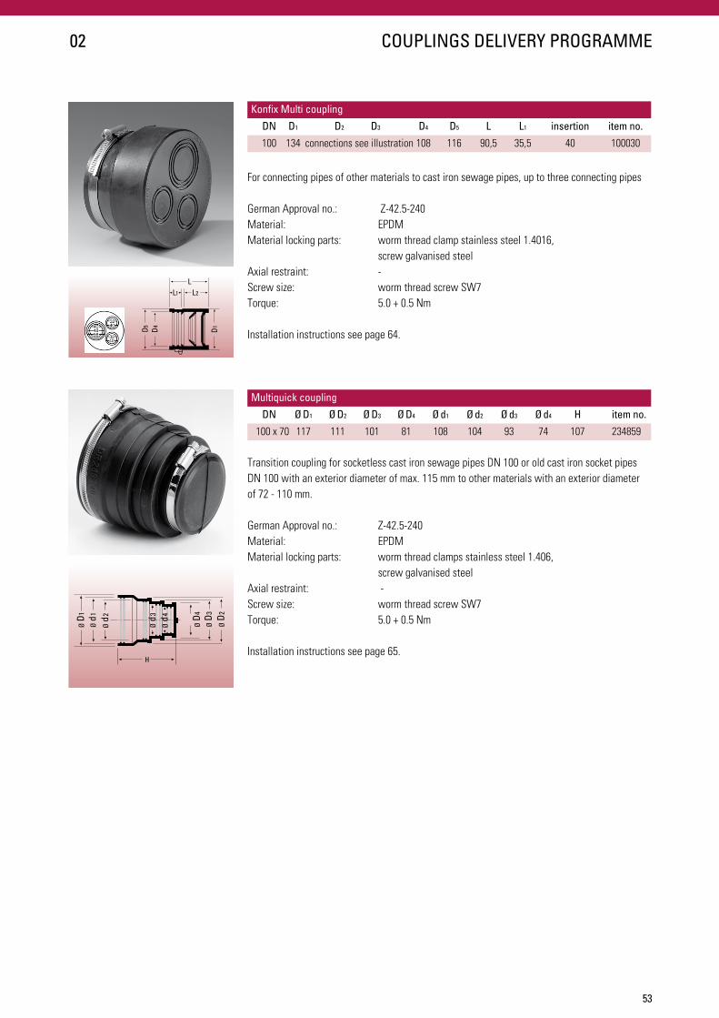
53
Multiquick coupling
Dn Ø D1 Ø D2 Ø D3 Ø D4 Ø d1 Ø d2 Ø d3 Ø d4 h item no.
100 x 70 117 111 101 81 108 104 93 74 107 234859
ØD2
ØD3
ØD4
Ød2
Ød1
ØD1
H
Ød3
Ød4
Transition coupling for socketless cast iron sewage pipes DN 100 or old cast iron socket pipesDN 100 with an exterior diameter of max. 115 mm to other materials with an exterior diameterof 72 - 110 mm.
German Approval no.: Z-42.5-240Material: EPDMMaterial locking parts: worm thread clamps stainless steel 1.406, screw galvanised steelAxial restraint: -Screw size: worm thread screw SW7Torque: 5.0 + 0.5 Nm
Installation instructions see page 65.
Konfix Multi coupling
Dn D1 D2 D3 D4 D5 l l1 insertion item no.
100 134 connections see illustration 108 116 90,5 35,5 40 100030
For connecting pipes of other materials to cast iron sewage pipes, up to three connecting pipes
German Approval no.: Z-42.5-240Material: EPDMMaterial locking parts: worm thread clamp stainless steel 1.4016, screw galvanised steelAxial restraint: -Screw size: worm thread screw SW7Torque: 5.0 + 0.5 Nm
Installation instructions see page 64.D1D5 D4
L2L1
L
02 coUPlingS DeliVery PrograMMe
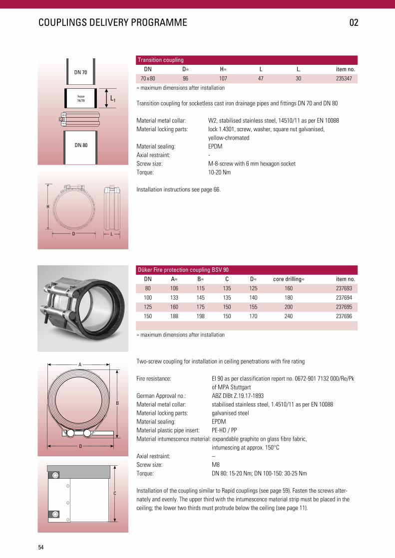
54
Transition coupling
Dn D≈ h≈ l l1 item no.
70 x80 96 107 47 30 235347
≈ maximum dimensions after installation
Transition coupling for socketless cast iron drainage pipes and fittings DN 70 and DN 80
Material metal collar: W2, stabilised stainless steel, 14510/11 as per EN 10088Material locking parts: lock 1.4301, screw, washer, square nut galvanised, yellow-chromatedMaterial sealing: EPDMAxial restraint: -Screw size: M-8-screw with 6 mm hexagon socketTorque: 10-20 Nm
Installation instructions see page 66.
Düker Fire protection coupling BSV 90
Dn a≈ B≈ c D≈ core drilling≈ item no.
80 106 115 135 125 160 237693
100 133 145 135 140 180 237694
125 160 175 150 155 200 237695
150 188 198 150 170 240 237696
≈ maximum dimensions after installation
Two-screw coupling for installation in ceiling penetrations with fire rating
Fire resistance: EI 90 as per classification report no. 0672-901 7132 000/Re/Pk of MPA StuttgartGerman Approval no.: ABZ DIBt Z.19.17-1893Material metal collar: stabilised stainless steel, 1.4510/11 as per EN 10088Material locking parts: galvanised steelMaterial sealing: EPDMMaterial plastic pipe insert: PE-HD / PPMaterial intumescence material: expandable graphite on glass fibre fabric, intumescing at approx. 150°CAxial restraint: –Screw size: M8Torque: DN 80: 15-20 Nm; DN 100-150: 30-25 Nm
Installation of the coupling similar to Rapid couplings (see page 59). Fasten the screws alter-nately and evenly. The upper third with the intumescence material strip must be placed in the ceiling; the lower two thirds must protrude below the ceiling (see page 11).
H
D L
B
D
A
C
coUPlingS DeliVery PrograMMe 02
DN 70
DN 80
hose74/79 L1

55
02 coUPlingS DeliVery PrograMMe
nom
inal
size
Dn
axia
l res
train
t up
to ..
. bar
in co
ncre
tein
the
soil
flat r
oof d
rain
age
(siph
onic
syst
em)
Conn
ectio
n
to p
last
ic
roof
dra
inou
tsid
e of
bui
ldin
g
conn
ectio
n to
pl
astic
pip
esin
the
build
ing
***
* w
ith c
orro
sion
pro
tec
tio
n, e
.g. t
ar w
rapp
ing
In c
ase
of u
ncla
rity
plea
se c
onsu
lt w
ith th
e fa
ctor
y
40-2
00*
100-
150
40-2
00*/
250-
300
50-2
00*
50-3
00
50-3
00
400
100-
600
50-4
00/5
00/6
00
50-2
00
50-1
25
100
40-1
00/1
25-1
50/2
00/2
50-3
00
40-1
00/1
25-1
50/2
00
50-2
00
400
*DN
200
: g
rip c
olla
rs o
f cha
nges
of d
irect
ion
0,5 1
0,5/
0,3
0,5 – – – –
10/6
/4
– – –
10/5
/3/1
10/5
/3
3
1.
Düko
rapi
d® co
uplin
g
2.
MLe
tec
Rapi
d co
uplin
g
3.
Rapi
d-In
ox co
uplin
g
4.
Rapi
d M
SM co
uplin
g
5.
Düke
r CV
coup
ling
6.
CE co
uplin
g
7.
Düke
r CE
dual
ring
coup
ling
8.
Conn
ect-F
Inox
coup
ling
9.
Conn
ect-G
Inox
coup
ling
10.
SVE
coup
ling
11.
Düke
r EK
Fix co
uplin
g
12.
Mul
tiqui
ck co
uplin
g
13.
Düke
r Kom
bi g
rip co
llar
14.
Reko
rd gr
ip co
llar f
or R
apid
coup
ling
15.
CV gr
ip co
llar f
or C
E and
CE c
oupli
ng
16.
Düke
r grip
colla
r for
CE d
ual r
ing co
uplin
g
SMl
coup
lings
: rec
omm
ende
d ap
plic
atio
n ar
eas

56
03 installation instructions

57
03 inSTallaTion inSTrUcTionS
assembling and installation instructions for Düker couplings
Waste water and ventilation pipelines are on principle sloping pipelines without interior pressures. However, it is not impossi-ble for pressure to develop in the pipelines under certain circum-stances.
The installation standard says the following:
en 12056-1, section 5.4.2, water and gas tightness:Drainage systems shall be water and gas tight against the ope-rational pressures. Pipework systems installed inside buildings shall not release vapours and foul air into the building.
en 12056-5, section 6.3, fixing and supporting:Pipelines with joints, which allow longitudinal movement, shall be fixed and/or supported in such a way as to ensure that during service the joint cannot become unintentionally disconnected. Reaction forces shall be considered
according to en 877 (product standard), section 4.75 water tightness, couplings may not exhibit any visible leakage under test conditions with hydrostatic inside pressure, under the following conditions:
• all tests are done in a strain-relieved state, i.e. the pipes are secured against excessive axial displacement
• joints up to and including DN 200, aligned or deflected up to 3°: up to 5 bar
• joints surpassing DN 200, aligned or deflected up to 1°45‘: up to 3 bar
• joints subject to shear force of 10 DN in newtons, aligned: up to 1 bar
• joints which will only carry limited pressures because of the intended use and installation, aligned or deflected up to 3°: up to 0.5 bar.
• joints connecting to sanitary ware: up to 0.1 bar
As these tests are carried out while the pipes are secured against axial displacement, these test pressures cannot be ap-plied directly to installations in a building. For the actual applica-tion, rather than the pressure tightness, what counts is the thrust resistance or axial restraint of the couplings, or the information what measure can be taken in order to obtain the required axial restraint. These measures can be grip collars, fixings, abutments etc. The table of page 55 gives the required information.
installation instructions and admissible pressure loads on Düker SMl couplingsSpecial requirements are to be considered for drainage pipelines which can be exposed to higher inside pressures than 0.5 bar. This concerns e.g.
• pipelines in the back water area • overload areas of rain water pipelines inside buildings• pipelines of a siphonic system• waste water pipelines leading through several basement storeys without further outlets• pressure pipelines at waste water pumps
Pipelines in the Back Water area
Pressure that is caused by a backflow from the canalisation can make connections slip. Therefore pipelines below the back water level must be treated as follows:
Waste water up to 0.5 bar: On Düker couplings DN 100 to DN 150, no additional measures are required. On Düker Rapid coup-lings DN 200, changes of directions must be secured with appro-priate Düker grip collars.
Waste water above 0.5 bar: All Düker couplings must be secured with appropriate grip collars.
Waste water pipelines connected to a mixed water canalization: All Düker couplings must be secured with appropriate grip collars.
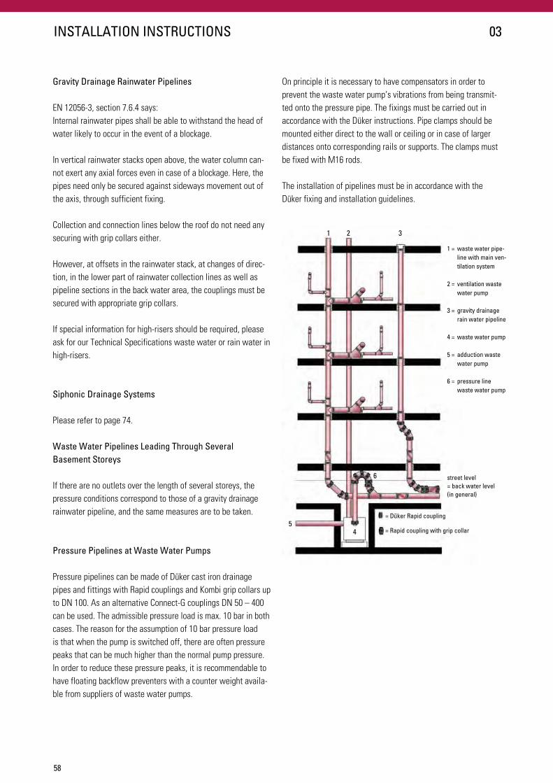
inSTallaTion inSTrUcTionS 03
58
On principle it is necessary to have compensators in order to prevent the waste water pump‘s vibrations from being transmit-ted onto the pressure pipe. The fixings must be carried out in accordance with the Düker instructions. Pipe clamps should be mounted either direct to the wall or ceiling or in case of larger distances onto corresponding rails or supports. The clamps must be fixed with M16 rods.
The installation of pipelines must be in accordance with the Düker fixing and installation guidelines.
gravity Drainage rainwater Pipelines
EN 12056-3, section 7.6.4 says:Internal rainwater pipes shall be able to withstand the head of water likely to occur in the event of a blockage.
In vertical rainwater stacks open above, the water column can-not exert any axial forces even in case of a blockage. Here, the pipes need only be secured against sideways movement out of the axis, through sufficient fixing.
Collection and connection lines below the roof do not need any securing with grip collars either.
However, at offsets in the rainwater stack, at changes of direc-tion, in the lower part of rainwater collection lines as well as pipeline sections in the back water area, the couplings must be secured with appropriate grip collars.
If special information for high-risers should be required, please ask for our Technical Specifications waste water or rain water in high-risers.
Siphonic Drainage Systems
Please refer to page 74.
Waste Water Pipelines leading Through Several Basement Storeys
If there are no outlets over the length of several storeys, the pressure conditions correspond to those of a gravity drainage rainwater pipeline, and the same measures are to be taken.
Pressure Pipelines at Waste Water Pumps
Pressure pipelines can be made of Düker cast iron drainage pipes and fittings with Rapid couplings and Kombi grip collars up to DN 100. As an alternative Connect-G couplings DN 50 – 400 can be used. The admissible pressure load is max. 10 bar in both cases. The reason for the assumption of 10 bar pressure load is that when the pump is switched off, there are often pressure peaks that can be much higher than the normal pump pressure.In order to reduce these pressure peaks, it is recommendable to have floating backflow preventers with a counter weight availa-ble from suppliers of waste water pumps.
1 = waste water pipe- line with main ven-tilation system
2 = ventilation waste water pump
3 = gravity drainage rain water pipeline
4 = waste water pump
5 = adduction waste water pump
6 = pressure line waste water pump
street level= back water level (in general)
= Düker rapid coupling
= rapid coupling with grip collar45
6
1 2 3

59
03 inSTallaTion inSTrUcTionS
installation instructions rapid MSM for repairs; rapid inox Dn 250-300:
installation instructions:
1. Slide the complete coupling onto the end of the pipe or fitting, up to the central ring of the sealing.
1. Slide the rubber sealing onto the pipe, up to the central ring of the sealing.
2. Push in the second pipe end or fitting and set it onto the central ring.
3. Lay the metal collar around the sealing. The collar may be opened no more than twice onto a width of 120% of the pipe outside diameter.
5. Tighten the hexagon socket screw with a screw wrench, a ratchet or an impact wrench until both fastening heads come together.
4. Insert the bolt head with the washer disc into the fastening head.
2. Push the second pipe or fitting into the other end of the coupling.
3. Tighten the hexagon socket screw with a screw wrench, a ratchet or a customary powered screw driver. Dükorapid® DN 50–150: 10–20 Nm
Dükorapid® DN 40 und 200, Rapid MSM: until both fastening heads come together MLetec Rapid: 15–25 Nm
Dükorapid® / rapid inox Mletec® rapid rapid MSM coupling
Dükorapid® coupling / Mletec rapid coupling / rapid inox coupling / rapid MSM coupling
do not tighten any more if the locks should come together
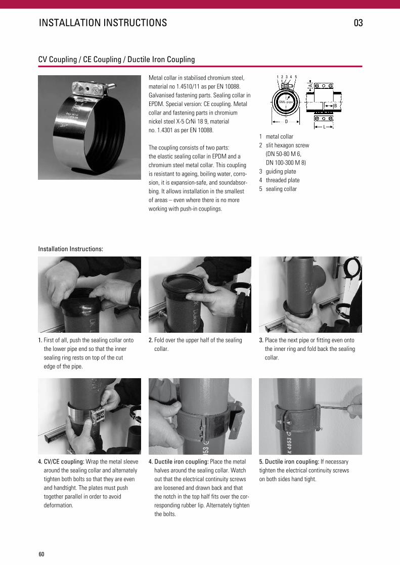
60
1 metal collar2 slit hexagon screw (DN 50-80 M 6, DN 100-300 M 8)3 guiding plate4 threaded plate5 sealing collar
Metal collar in stabilised chromium steel, material no 1.4510/11 as per EN 10088.Galvanised fastening parts. Sealing collar in EPDM. Special version: CE coupling. Metal collar and fastening parts in chromiumnickel steel X-5 CrNi 18 9, materialno. 1.4301 as per EN 10088.
The coupling consists of two parts:the elastic sealing collar in EPDM and a chromium steel metal collar. This coupling is resistant to ageing, boiling water, corro-sion, it is expansion-safe, and soundabsor-bing. It allows installation in the smallest of areas – even where there is no more working with push-in couplings.
cV coupling / ce coupling / Ductile iron coupling
installation instructions:
1. First of all, push the sealing collar onto the lower pipe end so that the inner sealing ring rests on top of the cut edge of the pipe.
3. Place the next pipe or fitting even onto the inner ring and fold back the sealing collar.
4. Ductile iron coupling: Place the metal halves around the sealing collar. Watch out that the electrical continuity screws are loosened and drawn back and that the notch in the top half fits over the cor-responding rubber lip. Alternately tighten the bolts.
5. Ductile iron coupling: If necessary tighten the electrical continuity screwson both sides hand tight.
2. Fold over the upper half of the sealing collar.
4. cV/ce coupling: Wrap the metal sleeve around the sealing collar and alternately tighten both bolts so that they are even and handtight. The plates must push together parallel in order to avoid deformation.
1
Dl
B
a
SMl-pipe
2 3 4 5
inSTallaTion inSTrUcTionS 03

61
Connect-F: not resistant to axial forces; pressure-resistant up to 10 bar if the axial forces are absorbed by anchorage.
Connect-G: resistant to axial forces up to 10 bar
installation instructions:
1. Remove any burrs and clean the pipe ends thoroughly in the sealing zones.
2. Mark half the coupling‘s width on both pipe ends.
3. Slide the coupling on one pipe and push the other pipe end into it. Align the cou-pling between the marks. Tighten the bolts loosely and alternately with a rat-chet spanner or an Allen key. Connect-G may not be twisted after the teeth have engaged with the pipe. Tighten the bolts alternately with the torque wrench in accordance with the torque stated on the type plate (see coupling).
connect-F inox/connect-g inox
1/2Nm
03 inSTallaTion inSTrUcTionS

Düker Kombi grip collarSecurity collar with axial restraint for all Rapid, CV and CE couplings at more than 0.5 bar internal pressure
cV grip collarSecurity collar with axial restraint for all CV and CE couplings at more than 0.5 bar internal pressure
rekord grip collarSecurity collar with axial restraint for Rapid couplings at more than 0.5 bar internal pressure
The axial force resistance necessary forSML pipes and fittings is obtained by theadded protection of the coupling with agrip collar.These security collars with axial restrainttake up the reaction forces which mayoccur at an internal pressure load of up to10 bar (see table) = 100 m water column.This means: the SML pipes and fittingswhich are connected with a coupling andadditionally with a grip collar are protectedagainst slipping due to internal pressure without need of a special fastening to the solidium at the connections. If pressures up to 0.5 bar are to be expected, it is sufficient to protect the coupling at changes of direc-tion, e.g. with a grip collar, or to use Rapid couplings.If pressures of more than 0.5 bar are to be expected, all Rapid, CV and CE couplingsin the pressure-stressed areas are to be secured with grip collars unless the pipe components are otherwise secured thrust-resistant.
Düker Kombi grip collar / cV grip collar / Düker grip collar / rekord grip collar
item Dn axialrestraint up
to ... bar
no. ofseg-
ments
scews screwdimension
torquenm
Düker Kombi-
grip collar
40-70 10 2 round head screwswith hexagon socket
with washers*
M8 x 30 23-25**
80 10 2 M8 x 30 17-23**
100 10 2 M 10x35 28-30**
125-150 5 2 M 10x35 25-30**
200 3 3 hexagonal screw with washers* and selflocking
nut
M 10x30 40-50**
250-300 1 3 M 12x30 50-55**
cV grip collar
50-70 3 2 hexagonal screws and nuts with
washers*
M 8 10-12
100-150 3 3 M 10 18-20
200 3 3 M 10 25-30
Düker grip collar
400 1 4 hexagonal screw with washers* and selflocking
nut
M 12 65-70
rekord grip collar
40-70 10 2 hexagon socketscrews
M 8 12-15
100 10 2 M 10 25-30
125-150 5 2 M 10 30-35
200 3 2 M 12 60-65
installation instructions
1. The claw segments must evenly wrap around the pipe couplings. Therefore screw the segments together loosely at first and watch out that the claw inserts do not touch the metal collar of the coupling.
2. Then alternately crosswise tighten the screws or nuts, so that the fastening parts are drawn together parallel and with the same distances. Adhere to the torques stated in the table for each screw, even if the fastening parts already touch at inferior torques.
62
inSTallaTion inSTrUcTionS 03
* important: do not forget to insert the washers under the screw heads and nuts! ** The Kombi grip collar has recently been modified. You may receive items of the old or of the new
series. Therefore, please observe the torques stated on the installation instructions delivered with the product.
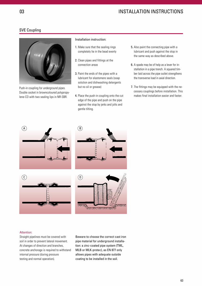
63
attention:Straight pipelines must be covered withsoil in order to prevent lateral movement.At changes of direction and branches,concrete anchorage is required to withstandinternal pressure (during pressuretesting and normal operation).
a B
c D
Push-in coupling for underground pipes. Double socket in browncoloured polypropy-lene-CO with two sealing lips in NR-SBR.
1. Make sure that the sealing rings completely lie in the bead evenly
2. Clean pipes and fittings at the connection areas
3. Paint the ends of the pipes with a lubricant for elastomere seals (soap solution and dishwashing detergents but no oil or grease)
4. Place the push-in coupling onto the cut edge of the pipe and push on the pipe against the stop by jerks and jolts and gentle tilting.
5. Also paint the connecting pipe with a lubricant and push against the stop in the same way as described above.
6. A spade may be of help as a lever for in-stallation in a pipe trench. A squared tim-ber laid across the pipe outlet strengthens the transverse load in axial direction.
7. The fittings may be equipped with the ne-cessary couplings before installation. This makes final installation easier and faster.
Beware to choose the correct cast iron pipe material for underground installa-tion: a zinc-coated pipe system (TMl, MlB or MlK-protec), as en 877 only allows pipes with adequate outside coating to be installed in the soil.
SVe coupling
installation instruction:
03 inSTallaTion inSTrUcTionS

64
Düker EK Fix coupling in EPDM;worm thread clamp in chromium steel 1.4016; for connecting pipes in other materials to SML.
Konfix Multi CouplingDüker EK Fix Coupling
With the Düker EK Fix coupling, pipes anddrainage pieces of PP as per EN 1451-1 and DIN 19560-10 as well as PE-HD as per EN 1519-1 and DIN 19535-10 can be connected easily and safely to SML pipes DN 50 to DN 125. The connecting pipe is securely in place thanks to the double lip sealing and large insertion depths.Material: hot water resistant synthetic rubber EPDM. The Düker EK Fix couplings DN 100 and DN 125 are especially suited for connecting plastic roof drains.
1. Push the Düker EK Fix coupling with opened clamp onto the SML pipe against the stop, then secure to the pipe with the clamp.
2. Grip the projecting rubber neck with a pair of tongs and carefully pull it out so that the opening is set free.
(Konfix Multi coupling only: use a knife to cut into the grooved front, choosing the groove according to the exterior diameter of the connecting pipe, and without injuring the sealing lip underneath, and open)
SMl pipe connecting pipe insertion Dn outside-Ø depth
50 40–56 mm 42 80 56–75 mm 55 80 75–90 mm 60 100 104–110 mm 65 125 125 mm 75
3. Mark the connecting pipe at the depth of insertion, apply lubricant and insert into the coupling.
4. The plastic pipe used illustrates the installation process. Attention: Please observe the table of acceptable outside diameters of pipes.
attention:The connecting pipe may have to be fixed in order to avoid slipping due to internal pressure.
Düker eK Fix coupling / Konfix Multi coupling
installation instructions:
inSTallaTion inSTrUcTionS 03

65
connection possibilitiesDüker SML pipes and fittings DN 100 to inherently stable other materials with an exterior diameter of 72 up to 110 mm. Düker SML pipes and fittings DN 100 to cast iron socket pipes DN 100 with an ex-terior diameter up to 115 mm. The coupling is delivered with two identical worm thread clamps, which are both adequate for the large diameter tolerance.
1. Push the open end of the Multiquick coupling over the cast iron pipe end and position the worm thread clamp in the groove intended for it. Then tighten the worm thread clamp without displacing it. Use a knife to cut open the closed side or to cut the coupling back according to the outer diameter of the connecting pipe. Cut the coupling in front of the step to the required diameter.
3. Watch out for a flawless and clean ealing zone on the pipes or fittings. Paint lumps or mortar must be removed completely with sand paper. The worm thread clamps must be tightened exclusively by hand with a screw driver in order to avoid damages to the Multiquick coupling.
2. Now slide the second worm thread clamp over the connecting pipe, push the pipe into the Multiquick coupling and tighten the worm thread clamp in the intended position.
installation instructions:
Multiquick coupling
attention:The connecting pipe may have to be fixed in order to avoid slipping due to internalpressure.
03 inSTallaTion inSTrUcTionS

66
applicationTransition coupling for SML pipe systems as per EN 877 DN 70 to DN 80 (also called DN 75/80).
attention: The transition from DN 80 to DN 70 in the flow direction is only admissible for repair and modernization of old DN 70 lines where DN 70 is no longer available.
Materialmetal collar stainless steelmaterial no. 1.4510/11 W2EPDM rubber
Transition coupling Dn 70 – Dn 80 for SMl-Pipe Systems as per Din en 877 and Din 19522
installation instructions:
1. Push the Dükorapid® coupling DN 80 onto the SML pipe or fitting DN 80
2. Push hose 74/79 onto the SML pipe or fitting DN 70
3. Push SML-pipe DN 70 with the hose into the coupling DN 80
4. Tighten the screw on the Dükorapid® coupling (10 – 20 Nm)
inSTallaTion inSTrUcTionS 03
DN 70
DN 80
hose74/79 L1

67
Düker hubless cast iron drainage pipes can be cut readily with the following tools:
cutting Pipes
1. Belt sawPortable belt saws cut pipes perfectly
2. Powered disc cutterThe best results with a powered disc cutter can be achieved with a disc appropriate forcast iron and a guidance as shown
3. Wheel cutterFor use without electricity
Düker cast iron drainage pipes are sup-plied in standard lengths of 3m. These pipes can be cut to the required length by the plumber.
Wheel cutters, offered e.g. by Ridgid or Virax, are suitable for swift, clean and right-angled cutting.
Powered disc cutters with discs for cast iron should only be used with guidance devices, where the pipe is held and mov- ed safely, and a right-angled cut is gua-ranteed.
Further possible cutting tools are electric belt saws with clamping device or electric hack saws, which are fixed to the pipe with a console and thus guarantee a clean cut.
It is important that the cut is always at a right angle to the pipe axis.
Attention: Change the cutting discs and saw belts regularly!
03 inSTallaTion inSTrUcTionS

68
04 Fixings

69
04 FiXingS
On principle, cast iron drainage pipes can be imbedded in con-crete. The cast iron expansion coefficient practically corresponds to that of concrete. As concrete passivates iron, no special pro-tection against corrosion is necessary for SML pipelines as well as couplings. The standard single screw or twin screw couplings can be used. The pipes must be surrounded by 5 cm concrete all around. When imbedding the pipeline in concrete and during prior pressure testing of the pipeline, considerable forces mayoccur. In addition, when imbedding in base plates usually only little declivity is available and therefore the pipeline must be perfectly adjusted. The arising forces (which would be the weight including the water filling) should be taken in with brackets and transferred to the lower concrete, soil or the intended rein-forcement. Use of threaded rods simplifies the arrangement of the usually short descent. The pipeline will tend to float to the surface when pouring in concrete. Therefore it must be secured with brackets. We recommend to fill the pipeline with water before imbedding it in concrete. If SML pipelines are imbedded in waterproof concrete bottoms, it is usually expected that the concrete must surround the pipe all around with 20 cm. If many fittings are strung together and therefore bracket fastening isnot possible, then grip collars will have to be used.
imbedding SMl main pipelines in the concrete bottom isrecommended for:
1. high groundwater levelAdvantage: • leading pipes through waterproof floor plates is reduced. • the pipeline itself is protected against any possibly aggressive groundwater.
2. non-bearing groundAdvantage: • not having to carry out the necessary floor exchange or floor improvement and saving costly constructions for fastening of the pipe lines below the floor plate.
If the thickness of the concrete slab is insufficient for installingthe pipeline, the concrete slab must be reinforced at this pointwith a concrete haunch.
haunch in a concrete slab
cV coupling concrete bottom
1200 mm1000 mm
SMl pipe Dn 150
expansion gap = predetermined breakingpoint pipe lining with notch
Settling of max. 50 mm
plastic pipe lining Dn 250
expansion gap
expansion gapIn order to avoid any differences in settling, joints made up of pipe cuttings (0.5 - 1.0 m) are arranged at the expansion gaps. These pipe cuttings are placed movable with help of a pipe lining or a polystyrene casing. According to EN 877, the permittedangling of SML couplings for the nominal widths is approximate-ly: up to DN 200 3 cm/m DN 250 - 500 1.5 cm/m overall length.
A predetermined breaking point (notched or cut through) is to be added to the pipe lining where the expansion gap is. Trickling of concrete into the cut-through pipe lining should be avoided by sealing with adhesive tape. It should also be sufficiently faste-ned in order to avoid slipping.
imbedding cast iron Pipes in concrete
concrete haunch
reinforced constructional concete(raft foundation)
SMl
lower concretesliding layer 0,
21,
40
permanently elastic sealing

2500
2500
ma
x. 2
000
ma
x. 2
000
down pipesupport
ca. 100 - 200max. 750max. 750 max. 2000
SML adapters with clamp andwall flange
max. 750
ma
x. 7
50
pipe installation: side view
pipe installation: top view
all dimensions in mm
FiXingS 04
70
71
general rulesThe distances of the fixings should be even and should not ex-ceed a length of 2 m. 2 to 3 m long pipes should be fixed twice - short pipes, according to the nominal width (or pipe weight) should be fixed once or twice. Fixing is to be carried out in regu-lar distances between the couplings whereas the distance before and after each coupling should not be larger than 0,75 m.
horizontal pipes must be securely fastened at all changes of direction and branches. Pipes which are pendant-fixed are to be secured against any type of movement in distances of 10 to 15 m with special fixed-point holding devices. This guarantees an excellent directional stability and avoids pushing out of the planned direction by other subassemblies.
Down pipes are also to be fastened at a maximum distance of 2 m. If a storey is 2.50 m high, then fastening is needed twice per storey, among that once directly at all branches that may be installed.
BracketsUse the customary pipe brackets with the corresponding fastening elements and supports. We recommend brackets with threaded connections M12 for SML pipes DN 50 to 150 - possibly M 8 for SML pipes up to DN 100. Rain water pipes and SML pipes under pressure should be fastened with brackets with threaded rods M 16. It might be useful to consult the manufacturer of pipe fixings.
SMl down pipe supports should be fastened as close to the wall as possible in order to avoid large bending moment to the brackets.
Down pipe supports must carry the weight of the down pipe and should be fastened at the lowest possible point. They can carry as much vertical length as the wall can carry and the plugs can transmit to the wall. After this height, a further down pipe sup-port is to be arranged.
In general we recommend to install a down pipe support in down pipes of DN 100 or larger above the basement ceiling, and further down pipe supports in intervals of 5 storeys.
SMl-pipes under pressureWaste water pipes without thrust-resistant couplings must be secured against separation or slipping from the axis if internal pressure loads are to be expected. The demanded axial restraint can be obtained by thrust-resistant grip collars (see table on page 55).
Fixing SMl-Pipes
04 FiXingS

FloW caPaciTieS 04
72
Dn 70 Dn 80 Dn 100 Dn 125 Dn 150 Dn 200 Dn 250 Dn 300 di=71 di=75 di=103 di=127 di=152 di=200 di=263 di=314SMl
J Q V Q V Q V Q V Q V Q V Q V Q V cm/m l/s m/s l/s m/s l/s m/s l/s m/s l/s m/s l/s m/s l/s m/s l/s m/s 0,5 0,8 0,4 0,9 0,4 2,1 0,5 3,7 0,6 6,0 0,7 12,5 0,8 25,8 1,0 41,3 1,1 0,6 0,9 0,4 1,0 0,4 2,3 0,6 4,1 0,6 6,6 0,7 13,7 0,9 28,3 1,0 45,3 1,2 0,7 0,9 0,5 1,1 0,5 2,5 0,6 4,4 0,7 7,1 0,8 14,8 0,9 30,6 1,1 48,9 1,3 0,8 1,0 0,5 1,1 0,5 2,7 0,6 4,7 0,7 7,6 0,8 15,8 1,0 32,7 1,2 52,3 1,4 0,9 1,1 0,5 1,2 0,6 2,9 0,7 5,0 0,8 8,1 0,9 16,8 1,1 34,7 1,3 55,5 1,4 1,0 1,1 0,6 1,3 0,6 3,0 0,7 5,3 0,8 8,5 0,9 17,7 1,1 36,6 1,3 58,5 1,5 1,1 1,2 0,6 1,4 0,6 3,2 0,8 5,5 0,9 8,9 1,0 18,6 1,2 38,4 1,4 61,4 1,6 1,2 1,2 0,6 1,4 0,6 3,3 0,8 5,8 0,9 9,4 1,0 19,4 1,2 40,1 1,5 64,2 1,7 1,3 1,3 0,6 1,5 0,7 3,4 0,8 6,0 1,0 9,7 1,1 20,2 1,3 41,8 1,5 66,8 1,7 1,4 1,3 0,7 1,5 0,7 3,6 0,9 6,3 1,0 10,1 1,1 21,0 1,3 43,4 1,6 69,3 1,8 1,5 1,4 0,7 1,6 0,7 3,7 0,9 6,5 1,0 10,5 1,2 21,7 1,4 44,9 1,7 71,8 1,9 1,6 1,4 0,7 1,6 0,7 3,8 0,9 6,7 1,1 10,8 1,2 22,4 1,4 46,4 1,7 74,1 1,9 1,7 1,5 0,7 1,7 0,8 3,9 0,9 6,9 1,1 11,1 1,2 23,1 1,5 47,8 1,8 76,4 2,0 1,8 1,5 0,8 1,7 0,8 4,1 1,0 7,1 1,1 11,5 1,3 23,8 1,5 49,2 1,8 78,7 2,0 1,9 1,5 0,8 1,8 0,8 4,2 1,0 7,3 1,2 11,8 1,3 24,5 1,6 50,6 1,9 80,8 2,1 2,0 1,6 0,8 1,8 0,8 4,3 1,0 7,5 1,2 12,1 1,3 25,1 1,6 51,9 1,9 82,9 2,1 2,5 1,8 0,9 2,0 0,9 4,8 1,2 8,4 1,3 13,5 1,5 28,1 1,8 58,0 2,1 92,8 2,4 3,0 1,9 1,0 2,2 1,0 5,3 1,3 9,2 1,5 14,8 1,6 30,8 2,0 63,6 2,3 101,7 2,6
Filling level 50 % (h/d = 0,5)
Dn 70 Dn 80 Dn 100 Dn 125 Dn 150 Dn 200 Dn 250 Dn 300 di=51 di=75 di=103 di=127 di=152 di=200 di=263 di=314SMl
J Q V Q V Q V Q V Q V Q V Q V Q V cm/m l/s m/s l/s m/s l/s m/s l/s m/s l/s m/s l/s m/s l/s m/s l/s m/s 0,5 1,6 0,4 1,8 0,4 4,2 0,5 7,4 0,6 12,0 0,7 24,9 0,8 51,6 1,0 82,6 1,1 0,6 1,7 0,4 2,0 0,4 4,7 0,6 8,2 0,6 13,2 0,7 27,4 0,9 56,6 1,0 90,5 1,2 0,7 1,9 0,5 2,1 0,5 5,0 0,6 8,8 0,7 14,2 0,8 29,6 0,9 61,2 1,1 97,8 1,3 0,8 2,0 0,5 2,3 0,5 5,4 0,6 9,4 0,7 15,2 0,8 31,6 1,0 65,4 1,2 104,6 1,4 0,9 2,1 0,5 2,4 0,6 5,7 0,7 10,0 0,8 16,2 0,9 33,6 1,1 69,4 1,3 111,0 1,4 1,0 2,2 0,6 2,6 0,6 6,0 0,7 10,6 0,8 17,1 0,9 35,4 1,1 73,2 1,3 117,1 1,5 1,1 2,3 0,6 2,7 0,6 6,3 0,8 11,1 0,9 17,9 1,0 37,1 1,2 76,8 1,4 122,8 1,6 1,2 2,4 0,6 2,8 0,6 6,6 0,8 11,6 0,9 18,7 1,0 38,8 1,2 80,3 1,5 128,3 1,7 1,3 2,5 0,6 2,9 0,7 6,9 0,8 12,1 1,0 19,5 1,1 40,4 1,3 83,6 1,5 133,6 1,7 1,4 2,6 0,7 3,1 0,7 7,2 0,9 12,5 1,0 20,2 1,1 41,9 1,3 86,7 1,6 138,7 1,8 1,5 2,7 0,7 3,2 0,7 7,4 0,9 13,0 1,0 20,9 1,2 43,4 1,4 89,8 1,7 143,6 1,9 1,6 2,8 0,7 3,3 0,7 7,7 0,9 13,4 1,1 21,6 1,2 44,9 1,4 92,8 1,7 148,3 1,9 1,7 2,9 0,7 3,4 0,8 7,9 0,9 13,8 1,1 22,3 1,2 46,3 1,5 95,6 1,8 152,9 2,0 1,8 3,0 0,8 3,5 0,8 8,1 1,0 14,2 1,1 22,9 1,3 47,6 1,5 98,4 1,8 157,3 2,0 1,9 3,1 0,8 3,6 0,8 8,3 1,0 14,6 1,2 23,6 1,3 48,9 1,6 101,1 1,9 161,7 2,1 2,0 3,2 0,8 3,7 0,8 8,6 1,0 15,0 1,2 24,2 1,3 50,2 1,6 103,8 1,9 165,9 2,1 2,5 3,5 0,9 4,1 0,9 9,6 1,2 16,8 1,3 27,1 1,5 56,2 1,8 116,1 2,1 185,6 2,4 3,0 3,9 1,0 4,5 1,0 10,5 1,3 18,4 1,5 29,7 1,6 61,6 2,0 127,2 2,3 203,3 2,6
Filling level 100% (h/d=1,0)
Dn 70 Dn 80 Dn 100 Dn 125 Dn 150 Dn 200 Dn 250 Dn 300 di=71 di=75 di=103 di=127 di=152 di=200 di=263 di=314SMl
J Q V Q V Q V Q V Q V Q V Q V Q V cm/m l/s m/s l/s m/s l/s m/s l/s m/s l/s m/s l/s m/s l/s m/s l/s m/s 0,5 1,3 0,4 1,5 0,5 3,6 0,6 6,2 0,7 10,1 0,7 20,8 0,9 43,1 1,1 68,9 1,2 0,6 1,4 0,5 1,7 0,5 3,9 0,6 6,8 0,7 11,0 0,8 22,9 1,0 47,2 1,2 75,5 1,3 0,7 1,6 0,5 1,8 0,5 4,2 0,7 7,4 0,8 11,9 0,9 24,7 1,1 51,1 1,3 81,6 1,4 0,8 1,7 0,6 1,9 0,6 4,5 0,7 7,9 0,8 12,7 0,9 26,4 1,1 54,6 1,3 87,3 1,5 0,9 1,8 0,6 2,1 0,6 4,8 0,8 8,4 0,9 13,5 1,0 28,1 1,2 58,0 1,4 92,6 1,6 1,0 1,9 0,6 2,2 0,7 5,1 0,8 8,8 0,9 14,3 1,1 29,6 1,3 61,1 1,5 97,6 1,7 1,1 2,0 0,7 2,3 0,7 5,3 0,9 9,3 1,0 15,0 1,1 31,0 1,3 64,1 1,6 102,4 1,8 1,2 2,0 0,7 2,4 0,7 5,5 0,9 9,7 1,0 15,6 1,2 32,4 1,4 67,0 1,6 107,0 1,8 1,3 2,1 0,7 2,5 0,7 5,8 0,9 10,1 1,1 16,3 1,2 33,8 1,4 69,7 1,7 111,4 1,9 1,4 2,2 0,7 2,6 0,8 6,0 1,0 10,5 1,1 16,9 1,2 35,0 1,5 72,4 1,8 115,6 2,0 1,5 2,3 0,8 2,7 0,8 6,2 1,0 10,9 1,1 17,5 1,3 36,3 1,5 74,9 1,8 119,7 2,1 1,6 2,4 0,8 2,7 0,8 6,4 1,0 11,2 1,2 18,1 1,3 37,5 1,6 77,4 1,9 123,7 2,1 1,7 2,4 0,8 2,8 0,9 6,6 1,1 11,6 1,2 18,6 1,4 38,6 1,6 79,8 2,0 127,5 2,2 1,8 2,5 0,8 2,9 0,9 6,8 1,1 11,9 1,3 19,2 1,4 39,8 1,7 82,1 2,0 131,2 2,3 1,9 2,6 0,9 3,0 0,9 7,0 1,1 12,2 1,3 19,7 1,5 40,9 1,7 84,4 2,1 134,8 2,3 2,0 2,7 0,9 3,1 0,9 7,2 1,2 12,5 1,3 20,2 1,5 41,9 1,8 86,6 2,1 138,3 2,4 2,5 3,0 1,0 3,4 1,0 8,0 1,3 14,0 1,5 22,6 1,7 46,9 2,0 96,9 2,4 154,7 2,7 3,0 3,3 1,1 3,8 1,1 8,8 1,4 15,4 1,6 24,8 1,8 51,4 2,2 106,1 2,6 169,6 2,9
Filling level 70% (h/d=0,7)
Attention: please observe the minimum slope defined in EN 12056.

73
04

aQUaPerFecT 04
74
Normal roof drain Drain for Aquaperfect siphonic system with air sieve when the calculation rainfall is reached
Differences to gravity Drainage
In a normal gravity roof drainage, the rain water is drained to the public sewage through partly filled pipelines. The filling level of these pipelines is generally at a maximum of 70% in order to ensure air circulation and pressure-free drainage.
In the Aquaperfect siphonic system, starting at a certain rain water quantity (calculation rainfall quantity), the pipeline works without air and with negative pressure. The intake of air is avo-ided by an air sieve in the roof drain, which prevents the forming of a vortex (Coriolis force).
advantages and application
The collection lines in the Aquaperfect siphonic system are installed without slope and therefore save space below the roof construction. Nevertheless, the elevated flow velocities ensure a good selfcleaning effect. Smaller nominal widths, inferior ma-terial requirements and the avoidance of pipe trenches and base pipelines save cost and installation time.
Cast iron distinguishes itself by a low thermal expansion coef-ficient and does not add combustion loads to the building. Very important is the resistance to high negative pressure in the pipe, so it is not necessary to over-dimension the pipelines.
The Aquaperfect siphonic system ought to be considered in the following cases:
• large roof areas, min. 150 m2 per drain• a difference in height of at least 4.2 m between the roof and the back water level• limited installation space below the ceiling• long collection pipelines
Standards
The planning and execution of siphonic systems is based on:• EN 12056-3 (Layout and calculationn of roof drainage) • DIN 1986-100 (German supplement to EN 12056) • VDI 3806 (German regulation for siphonic roof drainage)• EN 1253 (roof drains)
Aquaperfect siphonic system
Gravity drainage
aquaperfect Siphonic Flat roof Drainage

75
04 aQUaPerFecT
Functioning
The pressure height corresponds to the difference in height between the roof surface and the gravity drainage part of the rain water installation, which is at or above the back water level (street level). Contrary to this force acts the pressure loss caused by pipe friction and the individual pressure resistance of the pipeline components. At the zero point, both forces cancel each other out, here the negative pressure converts to a positive pressure. After a relaxation length, the drainage has to transform into a gravity drainage at the back water level or in some cases above that level.
The strongest negative pressure is normally to be found at the so-called critical point, the turning of the horizontal collection pipe into the down pipe. The negative pressure may amount to a maximum of -900 mbar.The flow velocity in the negative pres-sure area should be at least 0.5 m/s. In the transition area from the siphonic to gravity drainage, the elevated kinetic energy of the siphonic flow must be considered when installing the pipe-line (e.g. abutments, grip collars, down pipe support etc.). The drainage volume of the single roof drains ought to be prac-tically identical within tight tolerances in order to avoid flow breaks, which would lead to delays in reaching the full flow.
The calculation rainfall quantity is to be defined based on local statistical values. For economical reasons and in order to ensure the self-cleansing effect, the full flow calculation is based on the highest rainfall quantity during five minutes which falls statisti-cally within a period of five years (e.g. 300 l /(s·ha)). The highest five-minutes rainfall quantity which is to be expected statistically within a period of 100 years – the so-called century rain (e.g. 600 l/(s·ha)) – cannot be drained through the siphonic pipeline system and might endanger the flat roof construction due to its weight. In case of flat roofs in light-weight construction, emer-gency drains must be installed for this contingency in any case.
For other roof constructions this must be examined in each case. The drainage is done either by side drains over the facade, or with roof drains with height extensions which allow for the cor-responding water level on the roof and dispose of a separate pipeline system. The water will be drained to surfaces near the building that can be flooded without danger.
calculation
The pressure ratio, flow velocities and drainage volumes must be calculated for each pipeline section and for each drain separate-ly and then adjusted to the requirements. A calculation by hand is possible using among other things the Bernoulli equation. However, this calculating work is time-consuming, error-prone and troublesome: if the required values are not reached, the pipeline must be changed and the calculation must be repeated, if necessary several times. Larger building projects practicallyhave to be planned with an appropriate computer software.Aquaperfect partners – Düker and Aco Passavant – offer you the service of planning and calculating siphonic systems for spe-cific building projects.
The specifier receives:• pipeline section table and complete hydraulic calculation• list of materials• pipeline drawing• specifying text
Data required for the calculation • horizontal sections• sections• detail of roof construction and insulation• roof view with notation of the low-level points for drainage• position of the back water level• position of the connection points to the gravity system (base or collection pipes) and connection diameters • Calculation rainfall quantity and roof material calculation value • position of emergency drains • effective drainage height, considering the admissible loads on the roof surface
In case of constructional modifications, the siphonic system must be re-calculated!

aQUaPerFecT 04
76
drawing not to scale
max. 0,75 m
max. 0,75 m
max. 0,75 m
2,00 m
0,75 m
down pipe supportdistance to ceiling < 0,5 m 0,5 - 1m fixed point distance 12 m 6 m
fixed point distance see tablemax.
2,00 m
roof drain
negative pressure areapositive pressure area
drawing not to scale
acceleration line
connection line
collection pipe
45° branches
Dükorapid®
Dükorapid® with grip collar on all connections
critical pointhighest negative pressure
down pipe
expansion pointtransition to gravity drainage
relaxation distancepositive pressure
zero-pointpressure conversion
88° bends
2 bends, 45° each or double bend
Dükorapid®
with grip collar at changes of direction and reductions

77
04 aQUaPerFecT
general rules for Planning
The following hints make planning easier:• The pipeline nets ought to be symmetrical where possible.• The acceleration line ought to be at least 0.4 m.• The connection pipeline must be sufficiently long and be
connected horizontally to the collection pipe.• The overall length of the longest flow distance
(from the roof drain to the base pipeline) should be no more than ten times the height of the down pipe, but in any case no more than 100 m.
• The roof surface per down pipe should be no more than 5000 m2.• The distance between two drains should not surpass 20 m.• Roof surfaces with a height difference of more than 1 m or
with different roof material values should not be connected to the same down pipe.
rules for Fixing and installing
The installation must follow EN 12056 part 1, paragraph 5.4.2, part 3, paragraph 7.6.2 as well as German DIN 1986 part 100, sections 5.1.3 and 6.4.
On principle, the pipeline directions, diameters and lengths stated in the specifications must be observed, as otherwise the calculated pressures and volumes will not be reached. The ma-terial type must be observed as other materials differ regarding pressure loss and reaction to negative pressure. A minimum of 6 m of the gravity drainage must also be installed in cast iron material. The pipelines in the negative pressure area can be installed without slope.
FittingsAt branchings, branches with 45° angles must be used, for turns bends with 45°, or double bends. Only at the end of the accele-ration line (below the roof drain) and at the transition into the down pipe, 88° bends are used.
couplingsOn principle Rapid couplings should be used at all connections.
In the area of negative pressure, all turns, branchings, reductions and the complete acceleration line must be secured with grip collars. In the area of positive pressure, all couplings must be secured with grip collars. Where the gravity drainage starts, on a length of 6 m all changes of direction are to be secured with grip collars. In case of down pipes of more than 30 m height, the bends must be secured in any case.
Fixings
The basic rules of page 70/71 are to be observed.
Fixed-point devices are to be installed with an inbetween dis-tance of no more than 12 m (distance to the ceiling < 0.5 m) or 6 m (distance to the ceiling 0.5 – 1 m). The fixed points can be executed with threaded rods at an angle of at least 30° to the vertical fixing, or with consoles.
Pipelines with risk of water condensation
Pipelines that can be subject to condensation or frost must be insulated accordingly. We recommend using the preinsulated compound pipe system VML.
Start-off and Maintenance
After installation the roof surface is to be cleaned thoroughly. If considerable dirt accumulation on the roof surface is to be expected later on, it is recommendable to use gravel as a filter layer. Unless the gravel is used on the whole roof, a gravel edge with a width of 0.5 m should be applied around the roof drain. A maintenance contract covering the removal of dirt, plant rowth and dead leaves and the check of the drain components is recommendable.
contactFor the calculation of Aquaperfect siphonic systems and in case of technical questions please contact our hotline at +49 9353 791-280.

78
noTeS

79
noTeS

233040 / 03.10 Specifications subject to change without notice.
Drainage Technology
engineering
glaSS lining TechnologieS
JoBBing FoUnDry
FiTTingS anD ValVeS
Düker gmbh & co. Kgaa
Würzburger Straße 10D-97753 Karlstadt /Main
germany
Phone +49 9353 791-0Fax +49 9353 791-198
internet: www.dueker.dee-Mail: [email protected]