BUILDING INTEGRATED PHOTOVOLTAICS EXPERT
48
BUILDING INTEGRATED PHOTOVOLTAICS EXPERT BIPV TECHNOLOGIES INNOVATION PV RESEARCH AND IMPLEMENTATION
-
Upload
khangminh22 -
Category
Documents
-
view
2 -
download
0
Transcript of BUILDING INTEGRATED PHOTOVOLTAICS EXPERT

B U I L D I N G I N T E G R A T E D
P H O T O V O LTA I C S E X P E R T
BIPV TECHNOLOGIES INNOVATION PV RESEARCH AND IMPLEMENTATION

WE CREATE THE FUTURE2
ONE OF THE FIRST BIPV COMPANIES IN EUROPE
PATENTED PRODUCTS
AVARD WINNING SOLAR PROJECTS
UNIQUE AND CUSTOMIZED PROJECTS
The main directions of activity of the company

3
BIPV MODULES ....................................................................................................................................... 4
BIPV CELLS ............................................................................................................................................... 5
PHOTOVOLTAIC IGUS ............................................................................................................................. 6
NOFROST MODULES ............................................................................................................................. 7
ML LAMELA PHOTOVOLTAIC SUNSHADES ..................................................................................... 8
Fixed / Mobile .................................................................................................................. 8
PHOTOVOLTAIC VENTILATED FAÇADE ............................................................................................. 10
ML W20 .............................................................................................................................. 10
ML W20L ............................................................................................................................ 12
PHOTOVOLTAIC POST & BEAM FAÇADE .......................................................................................... 14
Standard ............................................................................................................................ 14
Structural .......................................................................................................................... 16
PHOTOVOLTAIC OUTER SKIN .............................................................................................................. 18
Point-fastened ................................................................................................................ 18
Cascade-fastened .......................................................................................................... 20
PHOTOVOLTAIC SKYLIGHTS ................................................................................................................ 22
PHOTOVOLTAIC TERRACE SHELTERS ............................................................................................... 24
PHOTOVOLTAIC CARPORTS ................................................................................................................. 26
Steel / Aluminium ........................................................................................................... 26
PHOTOVOLTAIC BALUSTRADES ......................................................................................................... 28
PHOTOVOLTAIC ROOFTOP SYSTEMS ............................................................................................... 30
Flush anchored and ballast anchored ..................................................................... 30
PHOTOVOLTAIC EQUIPMENT FOR SMALL ARCHITECTURE ....................................................... 32
Photovoltaic bus stop ................................................................................................... 32
Park benches .................................................................................................................... 32
Bicycle ports ..................................................................................................................... 32
Staircase canopies ......................................................................................................... 32
PHOTOVOLTAIC LAMP ........................................................................................................................... 34
PHOTOVOLTAIC HEATING PANE ......................................................................................................... 36
STANDARD PHOTOVOLTAIC MODULES ........................................................................................... 37
PRINTED PHOTOVOLTAIC MODULES ................................................................................................ 38
R&D CENTRE FOR PHOTOVOLTAICS ................................................................................................. 40
ENERGY MANAGEMENT SYSTEM ..................................................................................................... 42
BMS / SECURITY SYSTEMS ................................................................................................................. 44
SELECTED PROJECTS ............................................................................................................................. 46

WE CREATE THE FUTURE4
BIPV is currently an independent and interdisciplinary
field of science and architecture; unfortunately, BIPV sys-
tems still form merely 1% of the PV market. The new archi-
tecture forming strategies are more attempts at finding the
balance between the demands of developing civilisation,
technological progress, and environmental protection.
The concept behind BIPV systems is to adapt PV mod-
ules to various building applications, primarily as alterna-
tives to traditional construction materials used for building
roofs, façades (e.g. roofing, glass façade and roof systems,
and façade cladding systems), fronts, curtain wall louvres,
skylights, balustrades and specific window joinery panes.
BIPV MODULES
GLASS-TO-GLASS
The essential component of BIPV is the system of glass-
to-glass modules. Bonding two glass panes with plastic
films produces safety glass, a product that is very popular
in civil engineering and architecture, where its applications
span partitions, balustrades, canopies, etc. The plastic
films used in bonding the glass panes encapsulate the PV
cells to protect them from the external factors.
PV integrated glass laminates may com-
prise any combination of the following glass types
• UNTEMPERED
• TEMPERED
• SEMI-TEMPERED
• STAINED
All BIPV module types are available in various thick-
nesses and forms, depending on the vision of the architects
(to adapt to the installation method and building form).

5
BIPV CELLS
BIPV CELLS
The BIPV-dedicated cells can
be installed in curtain wall louvre
lamellas, infills of post and beam
façades, skylights, balustrades
and other joinery details.
The images illustrate a selec-
tion of PV cells.Printed cell Amorphous tinted coat cell
Monocrystalline cellwith tinted back coat
Thin-layer cell,5% transparency
Thin-layer cell,10% transparency
Semi-transparent cellPolycrystalline diamond
Thin-layer cell,15% transparency
Polycrystalline cellSilver tint
Semi-transparent cellPolycrystalline disk
Thin-layer cell,20% transparency
Monocrystalline cell Polycrystalline cellGold tint
Semi-transparent cellMonocrystalline,
Polycrystalline cellGreen tint
Polycrystalline cellRed tint
Polycrystalline cellGreen tint
Polycrystalline cellGrey tint
Polycrystalline cellBlue tint
Monocrystalline cell back contact

WE CREATE THE FUTURE6
SINGLE AND TWO-CHAMBER INSULATED GLASS UNITS
Insulated Glass Unit (IGU) based glazing units are in-
stalled as infills in post and beam façades and skylights
due to the required thermal insulating performance. These
designs can also be deployed with PV cells installed with-
in the laminated pane to form the first coating on the IGU
outer side.
These solutions are usually applied with various types
of low-emission coatings that improve the overall IGU
thermal insulation performance. A single-chamber IGU is
a standard solution boasting U = ~1.1 W/m2K, which means
sufficient protection from heat loss to the outside.
Two-chamber IGUs are intended for buildings which re-
quire very high thermal insulation performance, as is the
case in passive housing. The two-chamber IGUs boast ca.
U = 0.8 W/m2K.
Single- and two-chamber PV IGUs are available in dif-
ferent configurations, determined by their functionalities:
• SUNBLOCK INSULATED GLASS UNIT
The IGU features a sunblock layer which reduces the
exposure to heat from sunlight.
• SOUNDPROOF INSULATED GLASS UNIT
This IGU insulates from outdoor noise and its perfor-
mance is designed according to the nature of the noise.
• SAFETY INSULATED GLASS UNIT
The IGU has an improved impact and crash resistance,
so that, if cracked, the glass splinters are not pro-
pelled out of the panes.
• ANTI-BURGLARY INSULATED GLASS UNIT
The laminated glass pane design is adjusted to suit the
required anti-burglary class.
PHOTOVOLTAIC INSULATED GLASS UNIT
2-chamber PV IGU1-chamber PV IGU

7
NoFrost MODULE
NoFrost has secured the INNOWATOR PODKARPACIA
2013 (2013 Podkarpacie Innovator) award for ML System.
We have created an innovative BIPV module which pre-
vents the layering of snow and frost.
NoFrost modules can be installed on roofs, skylights
and similar structural solutions. One of the panes in the
glass-to-glass panel has an additional deposited coat
which heats up when connected to an electrical voltage.
The generated heat penetrates the module front and the
layer of frost, ice or snow. The frost/ice/snow layer melts
and uncovers the PV cell underneath.
Thermal image of NoFrost modules Rzeszów / National Archives / NoFrost modules installed in a skylight
Roof / NoFrost section running online
NOFROST MODULES
NoFrost PRODUCT BENEFITS:
• Removes the problem of snow loads on roof struc-
tures. The NoFrost modules can clear snow from roof
slopes (e.g. carports, halls, airport buildings, border
crossing units, warehousing units, train or bus sta-
tions, or stadiums)
• An (extra) heat source for indoor rooms; also helps
removing steam from glass fronts (e.g. for swimming
pools)
• Short time to reach the operating temperature, which
is uniformly distributed across the PV panel
• 3 times less power consumed than by resistive wire
mats
NoFrost MODULE FEATURES
• Uniform temperature distribution across the PV mod-
ule surface
• Only the outer layer is heated
• Short time to reach the operating temperature
• The PV module does not have to be heated across its
thickness
• No need for additional melting snow layers: the
NoFrost system prevents snow from settling
• The NoFrost module system can be operated in sec-
tors i.e. without using the entire installed power

WE CREATE THE FUTURE8
PHOTOVOLTAIC SUNSHADESML LAMELA FIXED/MOBILE
Sunshades are important architectural details
that have the incredible potential to create the out-
er appearance of buildings as well as the interi-
or design aesthetics. They are also key to climate
comfort and the energy efficiency of buildings. The pho-
tovoltaic cells available and applied in the sunshade
lamella system are 1st generation cells (poly- and mo-
no-crystalline, including back-contact cells) and 2nd gen-
eration cells (thin layer) of various level of transparency
and available in a wide colour range for even the most so-
phisticated of architectonic concepts.
System technical specifications
*For detailed information please contact the Technical Department of ML System. The given advantages occur when using NoFrost system. To calculate the payback time has been adopted the difference in value relative to substitute in form of a traditional technical solution.
50 000,0
100 000,0
150 000,0
200 000,0
250 000,0
300 000,0
350 000,0
400 000,0
450 000,0
va
lue
(P
LN)
0 1 2 3 4 5 6 7 8......................................................................
Investment value Profit
Payback time*
time (year)
Unit power
PV cell efficiency
Module types
max. 170 Wp/ m
max. 22,5 %
monocrystalline incl. back -contact
polycrystalline
thin layer
Optional bifacial
transparent
NoFrost
printed
2
Advantages of photovoltaic shunshades*
Reducing overheating of rooms
A wide range of transparency and colours of lamellas
Any adjustment of the tilt angle of lamellas
Generation of electricity
Stable construction, modern design
Easy maintenance, generating savings
No need for snow removal
Custom application
By using of the ultralight materials, the load of the building façade is lower
Substucture material
Support post width
aluminium AW 6063 / AW 6060 alloy
Lamella width
50 mm
Max. support post spacing
4000 mm
Structure colour see RAL palette
380/429 mm
Lamella thickness 1,5 to 20 mm
Lamella tilt adjustment
10 deg. pitch - Manual/smooth power actuators
9
Gliwice / City Road Authority Budomierz / Roadway State Border Checkpoint
Budomierz / Roadway State Border Checkpoint Krakow / Jagiellonian University

WE CREATE THE FUTURE10
ML W20 PHOTOVOLTAIC VENTILATED FAÇADE SYSTEM
The ventilated façade system is a substitute for outer
aluminium shells, composite boards and stone lining. Aside
from the unquestionably effective appearance, it also gen-
erates electric power for the building's heating, ventilation
and air conditioning systems or other loads as required.
This system is excellent for both new civil engineering
projects and refurbished buildings. The unique solution
makes it possible to hot swap any module without the need
to remove any adjacent modules.
System technical specifications
*For detailed information please contact the Technical Department of ML System. The given advantages occur when using NoFrost system. To calculate the payback time has been adopted the difference in value relative to substitute in form of a traditional technical solution.
50 000,0
100 000,0
150 000,0
200 000,0
250 000,0
300 000,0
350 000,0
400 000,0
va
lue
(P
LN)
Payback time*
Profit
Investment value
0 1 2 3 4 5 6 7 8 9.......................................................................................time (year)
Module to module gap V/H
Substructure material
20 mm
Maximum module size
3500 x 2020 mm
aluminium AW 6063 / AW 6060 alloy
Structure colour
see RAL palette
Module thickness 3 to 22 mm
Unit power
PV cell efficiency
max. 200 Wp/m
max. 22,5 %
Module types
polycrystalline
thin layer
2
Max operating voltage
1000 V DC
monocrystalline incl. back - contact
Optional transparent
printed
Free electricity, generating savings
Stable construction, modern design
Custom application
Possibility of remote access to the system work
By using of the ultralight glass, the façades become lighter, more resistant to dirt and degradation
Advantages of photovoltaic
façades *
Cooling of the modules and temperature reduction of the façade through the ventilation effect.
Reduction of the costs of operating air conditioning

11
Katowice / Katowice School of TechnologyNiepołomice / Indoor swimming pool
Wilkowice / Pol-Lab Gliwice / Tauron Dystrybucja

WE CREATE THE FUTURE12
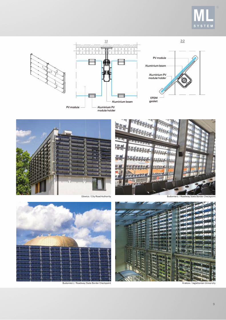
ML W20L PHOTOVOLTAIC VENTILATED FAÇADE SYSTEM
This is a twin version of the ML W20, intended for venti-
lated façades with glass-to-glass PV modules. This façade
system solution is flexible and can accommodate various
PV module sizes in one installation plane, as well as differ-
entiated performance parameters or appearance. The PV
modules can be created with regular glass panes in a sin-
gle facade plane (i.e. without any PV cells; the regular glass
panes can be tinted or laminated with colour film) to pro-
duce a uniform glass surface finish without any inner struc-
tural components being visible (in opaque projects), or even
highly expose the substructure (in transparent projects).
The entire façade installation is automated and mainte-
nance free. Combining the photovoltaic cells with the ven-
tilated façade structure enables the consumption of energy
from RES. Unlike roof-installed solar panels, the installa-
tion fasteners do not cause the risk of breaching the roof
skin or overloading the roof structure with blocked snow
heaps in winter. The photovoltaic ventilated façade system
has passed a large number of stringent tests to prove its
suitability on buildings with different roof heights and in
various geographical locations (where wind loads, snow
loads, frost resistance, soft body impact and hard body im-
pact were assessed, among others).
50 000,0
100 000,0
150 000,0
200 000,0
250 000,0
300 000,0
350 000,0
400 000,0
0 1 2 3 4 5 6 7 8 ................................................................................
Payback time*
Profit
Investment value
*For detailed information please contact the Technical Department of ML System. The given advantages occur when using NoFrost system. To calculate the payback time has been adopted the difference in value relative to substitute in form of a traditional technical solution.
System technical specifications
va
lue
(P
LN)
time (year)
Unit power
PV cells efficiency
Module types
max. 200 Wp/ m
max. 22,5 %
monocrystalline incl. back-contact
polycrystalline
thin layer
Optional transparent
printed
Max. operating voltage
1000 V DC
2 Substructure material
Module to module gap V/H
aluminium AW 6063 / AW 6060 alloy
10 mm
Structure colour
see RAL palette
Module thickness 3 to 22 mm
Maximum module size
2500 x 1600 mm
Advantages of photovoltaic
façades *
Free electricity
By using of the ultralight materials, the load of the building façade is lower
Possibility of remote access to the generated yields and generated savings
Generating savings
Easy maintenance, custom application
Modern and individual design, stable construction
13
Kielce / Kielce Technology Park
Zaczernie / ML System S.A.
WE CREATE THE FUTURE14
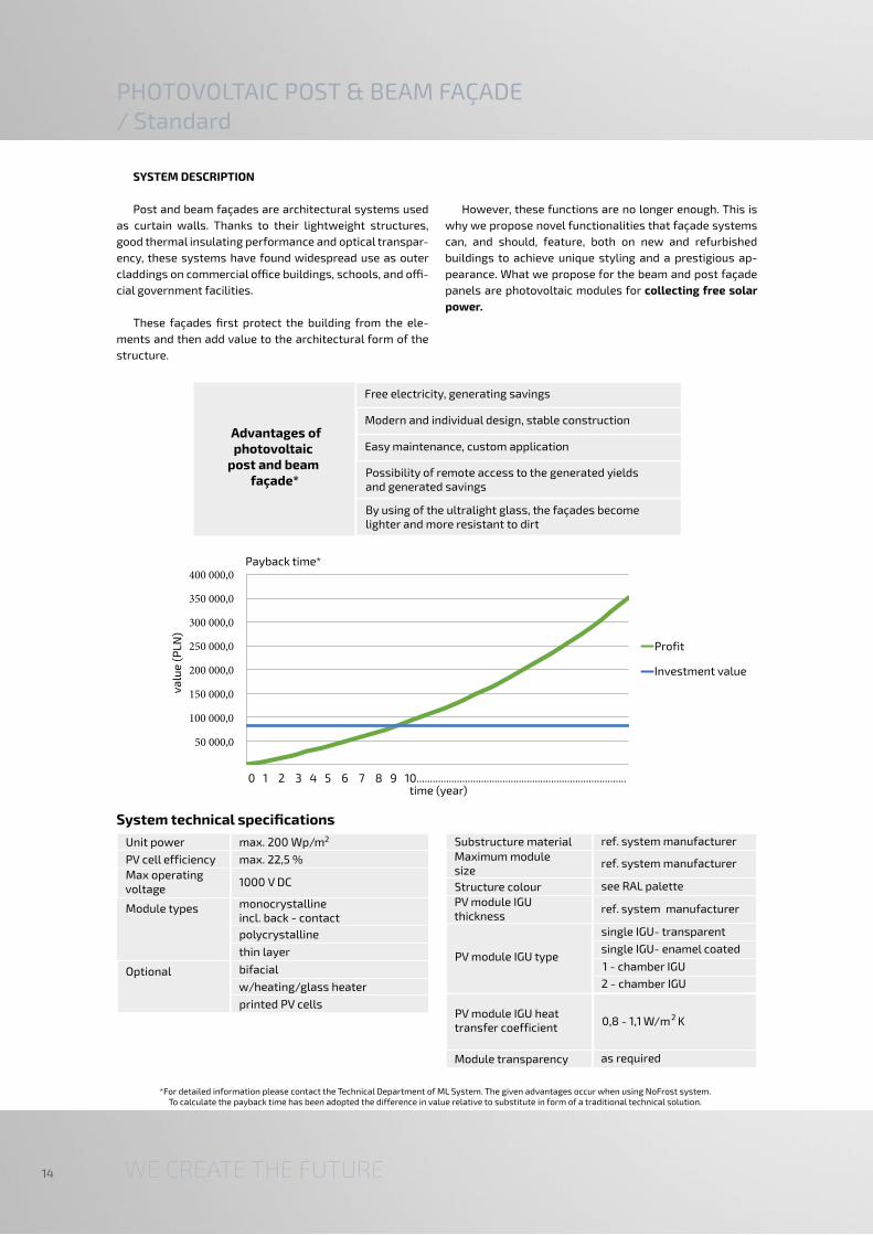
PHOTOVOLTAIC POST & BEAM FAÇADE/ Standard
SYSTEM DESCRIPTION
Post and beam façades are architectural systems used
as curtain walls. Thanks to their lightweight structures,
good thermal insulating performance and optical transpar-
ency, these systems have found widespread use as outer
claddings on commercial office buildings, schools, and offi-
cial government facilities.
These façades first protect the building from the ele-
ments and then add value to the architectural form of the
structure.
However, these functions are no longer enough. This is
why we propose novel functionalities that façade systems
can, and should, feature, both on new and refurbished
buildings to achieve unique styling and a prestigious ap-
pearance. What we propose for the beam and post façade
panels are photovoltaic modules for collecting free solar
power.
50 000,0
100 000,0
150 000,0
200 000,0
250 000,0
300 000,0
350 000,0
400 000,0
0 1 2 3 4 5 6 7 8 9 10..............................................................................
Payback time*
Profit
Investment value
System technical specifications
*For detailed information please contact the Technical Department of ML System. The given advantages occur when using NoFrost system. To calculate the payback time has been adopted the difference in value relative to substitute in form of a traditional technical solution.
va
lue
(P
LN)
time (year)
Unit power max. 200 Wp/m
Module types
Max operating voltage
1000 V DC
monocrystalline incl. back - contact
Optional
2
PV cell efficiency max. 22,5 %
polycrystalline
thin layer
bifacial
w/heating/glass heater
printed PV cells
Advantages of photovoltaic
post and beam façade*
Free electricity, generating savings
By using of the ultralight glass, the façades become lighter and more resistant to dirt
Possibility of remote access to the generated yields and generated savings
Easy maintenance, custom application
Modern and individual design, stable construction
Maximum module size
PV module IGU type
PV module IGU heat transfer coefficient
0,8 - 1,1 W/m K2
ref. system manufacturer Substructure material
ref. system manufacturer
see RAL palette Structure colour PV module IGU thickness
ref. system manufacturer
single IGU- transparent
single IGU- enamel coated
1 - chamber IGU
2 - chamber IGU
as required Module transparency

15
Warsaw / Medical University of WarsawWarsaw / Medical University of Warsaw
Krakow / Jagiellonian University Rzeszów / University of Law and Public Administration
WE CREATE THE FUTURE16
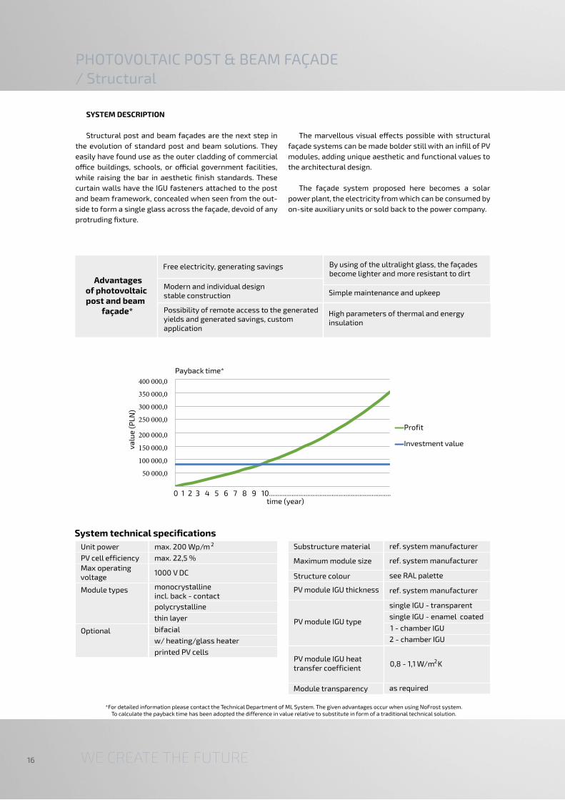
PHOTOVOLTAIC POST & BEAM FAÇADE/ Structural
SYSTEM DESCRIPTION
Structural post and beam façades are the next step in
the evolution of standard post and beam solutions. They
easily have found use as the outer cladding of commercial
office buildings, schools, or official government facilities,
while raising the bar in aesthetic finish standards. These
curtain walls have the IGU fasteners attached to the post
and beam framework, concealed when seen from the out-
side to form a single glass across the façade, devoid of any
protruding fixture.
The marvellous visual effects possible with structural
façade systems can be made bolder still with an infill of PV
modules, adding unique aesthetic and functional values to
the architectural design.
The façade system proposed here becomes a solar
power plant, the electricity from which can be consumed by
on-site auxiliary units or sold back to the power company.
*For detailed information please contact the Technical Department of ML System. The given advantages occur when using NoFrost system. To calculate the payback time has been adopted the difference in value relative to substitute in form of a traditional technical solution.
System technical specifications
50 000,0
100 000,0
150 000,0
200 000,0
250 000,0
300 000,0
350 000,0
400 000,0
0 1 2 3 4 5 6 7 8 9 10......................................................................
Profit
Investment value
Payback time*
va
lue
(P
LN)
time (year)
Maximum module size
PV module IGU type
PV module IGU heat transfer coefficient
0,8 - 1,1 W/m K2
ref. system manufacturer Substructure material
ref. system manufacturer
see RAL palette Structure colour
PV module IGU thickness ref. system manufacturer
single IGU - transparent
single IGU - enamel coated
1 - chamber IGU
2 - chamber IGU
as required Module transparency
Advantages of photovoltaic post and beam
façade*
Free electricity, generating savings By using of the ultralight glass, the façades become lighter and more resistant to dirt
Possibility of remote access to the generated yields and generated savings, custom application
Simple maintenance and upkeepModern and individual design stable construction
High parameters of thermal and energy insulation
Unit power max. 200 Wp/m
Module types
Max operating voltage
1000 V DC
monocrystalline incl. back - contact
Optional
2
PV cell efficiency max. 22,5 %
polycrystalline
thin layer
bifacial
w/ heating/glass heater
printed PV cells

17
Łódź / Provincial Fund for Environmental Protection and Water ManagementWarsaw / Medical University of Warsaw
Rzeszów / University of Law and Public Administration Warsaw / Medical University of Warsaw

WE CREATE THE FUTURE18
The point fastening system has the immense potential
to create very bold architectural solutions with uniquely el-
egant appearances and a long service lives. The solutions
based on the point fastening system are perfect for large
buildings, small (street) architecture or custom projects.
The range is complemented by dedicated fastening systems
for outer louvres, ventilated façades or roof structures.
BIPV inextricably binds PV modules to the fastening systems.
The point fastening is excellent for entrance canopies, es-
pecially when combined with the NoFrost PV modules to
prevent snow from settling on the shelter top. ML System
carries an entire range of fastening solutions for even the
most unique design requirements.
PHOTOVOLTAIC OUTER SKIN/ Point-fastened
-
50 000,0
100 000,0
150 000,0
200 000,0
250 000,0
300 000,0
350 000,0
400 000,0
0 1 2 3 4 5 6 7 8 9 10...................................................................................
Payback time*
Profit
Investment value
System technical specifications
*For detailed information please contact the Technical Department of ML System. The given advantages occur when using NoFrost system. To calculate the payback time has been adopted the difference in value relative to substitute in form of a traditional technical solution.
va
lue
(P
LN)
time (year)
Substructure material
Maximum module size
3000 mm x 1600 mm
aluminium/stainless steel
Module to module gap V/H min. 10 mm
Structure colour
see RAL palette
Module thickness 3 to 22 mm
Unit power
PV cell efficiency
max. 200 Wp/m
max. 22,5 %
Module types
polycrystalline
thin layer
Max. operating voltage
1000 V DC
monocrystalline incl. back - contact
Optional transparent
printed
2
Advantages of photovoltaic
outer skin*
Free electricity
By using of the ultralight glass, the systems become lighter and more resistant to dirt
No need for snow removal, protection against weather conditions
Generating savings
Simple maintenance and upkeep
Modern and individual design stable construction
Custom application

19
Rzeszów / Rzeszów PhilharmonicRzeszów / Rzeszów Philharmonic
Rzeszów / University of Law and Public Administration Rzeszów / University of Law and Public Administration

WE CREATE THE FUTURE20
on nurseries, playschools (kindergartens) or schools,
where additional regulatory sun exposure requirements
apply.
If there is a risk of the build up of icicles on the struc-
tural parts in winter, or when the solution is installed on
horizontal substructures, you can combine the PV outer
skin with the NoFrost snow-clearing system (to prevent
snow settling and to ensure continuous power generation
in winter).
The solution allows PV modules to be installed in cas-
cades across the building façade. The PV modules are
not arranged in a vertical plane, but tilted at a small an-
gle from the building wall (the angle depends on the PV
module height). The cascade layout is a great compo-
sition for entire façade surfaces or portions thereof to
provide a striking accent here and there. The cascade
fastening solutions are excellent for building a shading
layer that reduces the heating needed for indoor spaces.
The selectable transparency ratios enable installation
CASCADE SYSTEM
*For detailed information please contact the Technical Department of ML System. The given advantages occur when using NoFrost system. To calculate the payback time has been adopted the difference in value relative to substitute in form of a traditional technical solution.
System technical specifications
50 000,0
100 000,0
150 000,0
200 000,0
250 000,0
300 000,0
350 000,0
400 000,0
0 1 2 3 4 5 6 7 8 9 10..............................................................................
Payback time*
Profit
Investment valueva
lue
(P
LN)
time (year)
Unit power
PV cell efficiency
Module types
max. 200 Wp/ m
max. 22,5 %
monocrystalline incl. back-contact
polycrystalline
thin layer
Optional transparent
printed
Max. operating voltage
1000 V DC
2 Substructure material
aluminium AW 6063 / AW 6060 alloy
Structure colour see RAL palette
Module thickness 3 to 20 mm
Maximum module size
2500 x 1600 mm
Advantages of photovoltaic
cascade system*
Free electricity
By using of the ultralight glass, the systems become lighter and more resistant to dirt anddegradation
No need for snow removal, protection against weather conditions
Generating savings
Simple maintenance and upkeep
Modern and individual design, stable construction
Custom application

21
Cascade fastening
Cascade fastening

WE CREATE THE FUTURE22
PHOTOVOLTAIC SKYLIGHT
SYSTEM DESCRIPTION
As we can deduce from the word, skylights are archi-
tectural details which provide extra illumination indoors,
and this has been their primary function until now. The de-
velopment of innovative PV cells lets us expand skylight
functionality to turn them into small power plants. The PV
skylights can be delivered in both standard and structural
versions.
Skylights are structures that are usually based on a
framework of rafters and purlins, and usually infilled with
single or two-chamber IGUs (Insulated glass units), or poly-
carbonate panes. This is not enough today. To provide sky-
lights with the added value of power generation, the outer
IGU pane is replaced with a PV module.
*For detailed information please contact the Technical Department of ML System. The given advantages occur when using NoFrost system. To calculate the payback time has been adopted the difference in value relative to substitute in form of a traditional technical solution.
System technical specifications
450 000,0
500 000,0
400 000,0
350 000,0
300 000,0
250 000,0
200 000,0
150 000,0
100 000,0
50 000,0
va
lue
(P
LN)
Payback time*
0 1 2 3 4 5 6 7 8 9 10..............................................................................................time (year)
Profit
Investment value
Unit power
PV cell efficiency
max. 200 Wp/m
max. 22,5 %
Module types
polycrystalline
thin layer
Max. operating voltage
1000 V DC
monocrystalline incl. back-contact
Optional bifacial
NoFrost
2
printed
Substructure material
Structure colour
ref. system manufacturer
see RAL palette
PV module IGU type
single IGU - enamel-coated
1 - chamber IGU
Maximum module size
ref. system manufacturer
PV module IGU thickness ref. system manufacturer
single IGU - transparente
2 - chamber IGU
PV module IGU heat transfer coefficient
0.8-1.1 W/m K2
Module transparency as required
Advantages of photovoltaic
skylights*
Free electricity
By using of the ultralight glass, the implementation of the structures on the roofs is possible because of their low carrying capacity
No need for snow removal, protection against weather conditions
Generating savings
Generation of more electricity in winter
Choice of transparency level
Stable construction, modern design, simple maintenance custom application

23
Rzeszów / National ArchivesKatowice / Katowice School of Technology
Łódź / Provincial Fund for Environmental Protection and Water Management Kielce / Kielce Technology Park

WE CREATE THE FUTURE24
The shelters for patios and conservatories made of
glass in aluminium frames allow you to enjoy nature and
open your home to its natural surroundings.
IGUs, which form an integral part of the shelter sys-
tem, help you to enjoy the natural world and marvel at its
changes through the seasons.
PHOTOVOLTAIC TERRACE SHELTERS
System technical specifications
*For detailed information please contact the Technical Department of ML System. The given advantages occur when using NoFrost system. To calculate the payback time has been adopted the difference in value relative to substitute in form of a traditional technical solution.
This is a unique form of protection from the rain, snow
and sun. The integration of IGUs with photovoltaic systems
add the benefit of producing green power, and this power
can be consumed locally, e.g. by home appliances, and the
surplus sold back to the grid.
Profit
Investment value
Payback time*
time (year)0 1 2 3 4 5 6 7 8 9 10..................................................................................
90 000,0
100 000,0
80 000,0
70 000,0
60 000,0
50 000,0
40 000,0
30 000,0
20 000,0
10 000,0
va
lue
(P
LN)
Unit power
PV cell efficiency
max. 200 Wp/ m
max. 22,5 %
Module types
polycrystalline
thin layer
Max. operating voltage
1000 V DC
monocrystalline incl. back-contact
Optional bifacial
transparent
2
NoFrost (roof)
printed
NoFrost (wall)
Maximum module size ref. system manufacturer
PV module IGU type
PV module IGU heat transfer coefficient 0,8 - 1,1 W/m K
single IGU - transparent
single IGU - enamel-coated
1 - chamber IGU
2 - chamber IGU
2
Module transparency as required
Module thickness 3 to 22 mm
Structure colour see RAL palette
Substructure material ref. system manufacturer
Advantages of photovoltaic
terrace shelters*
Free electricity
Generating savings
Easy installation and low installation costs
No need for snow removal
Custom application, easy maintenance
Stable construction, modern design
By using of the ultralight glass, the structure becomes more resistant to weather conditions
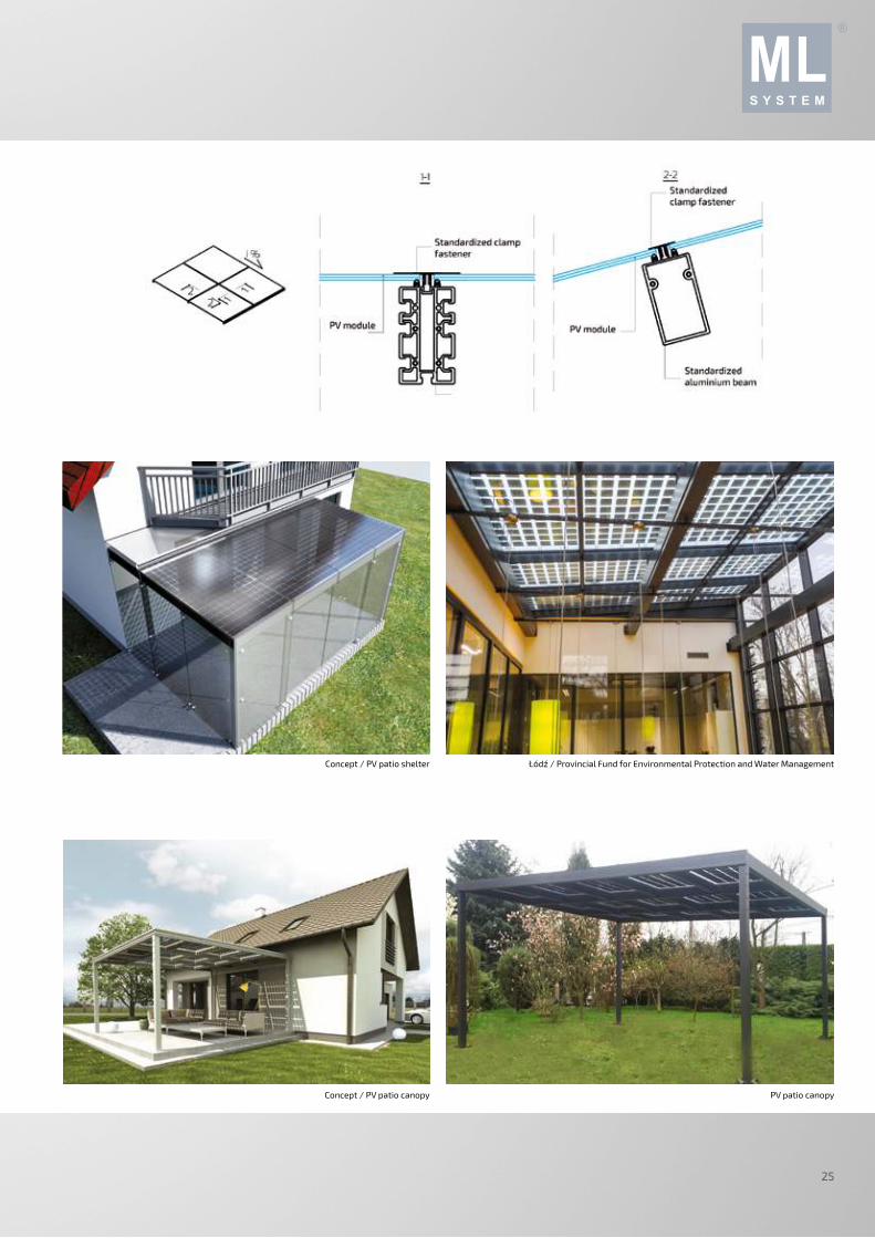
25
Concept / PV patio shelter
Concept / PV patio canopy
Łódź / Provincial Fund for Environmental Protection and Water Management
PV patio canopy

WE CREATE THE FUTURE26
Car parks are truly a natural place for photovoltaic cells,
where they can be installed as carports. This enables gen-
eration of electricity from solar energy from a surface that
already has a specific utility function, and shading the park-
ing places improves the comfort of drivers as they leave or
return to their vehicles. The compatibility with various con-
struction technologies help to adapt the solution to specific
project investor demands.
The solutions offered here are excellent ideas for shel-
tering single parking spots or large car parks (including in
public areas, where special safety requirements apply by
law). A natural complement to the photovoltaic projects for
parking lots are the increasingly popular e-vehicle charging
stations; hence photovoltaic carports can help popularize
ecological eVs and contribute to a cleaner environment.
PHOTOVOLTAIC CARPORTS
System technical specifications
*For detailed information please contact the Technical Department of ML System. The given advantages occur when using NoFrost system. To calculate the payback time has been adopted the difference in value relative to substitute in form of a traditional technical solution.
90 000,0
100 000,0
80 000,0
70 000,0
60 000,0
50 000,0
40 000,0
30 000,0
20 000,0
10 000,0
0 1 2 3 4 5 6 7 8 9 10..................................................................................
Payback time*
va
lue
(P
LN)
Profit
Investment value
time (year)
Unit power max. 200 Wp/ m
Module types
Max. operating voltage
1000 V DC
monocrystalline incl. back-contact
Optional
2
eV recharging system
PV cell efficiency max. 22,5%
polycrystalline
thin layer
bifacial
transparent
NoFrost
opaque modules
printed modules
integrated LEDs
Carport type sealed
louvre
cascade
Single, double or multiple parking places
Substructure material
steel
aluminium AW 6063/AW 6060 alloy
bonded laminated timber
Structure colour
see RAL palette
natural timber/stained
Module thickness 3 to 22 mm
Advantages of photovoltaic
carports *
Free electricity
Stable construction, modern design, simple maintenance, easy installation and transportation
Generating savings
Possibility of roofing over multiple parking places
No need for snow removal
Protection from rainfall, carports shading
By using of the ultralight glass, the structure becomes lighter and more resistant to dirt
Possibility of remote access to the system work

27
Rzeszów / University of Law and Public AdministrationZaczernie / ML System S.A.
Lutoryż / Carport Jasionka / Podkarpackie Science and Technology Park
Jasionka / Podkarpackie Science and Technology ParkRzeszów / University of Law and Public Administration
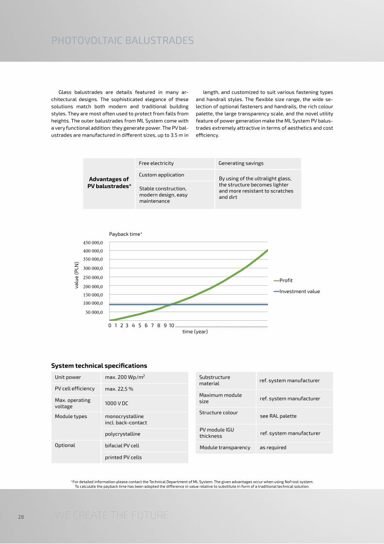
WE CREATE THE FUTURE28
Glass balustrades are details featured in many ar-
chitectural designs. The sophisticated elegance of these
solutions match both modern and traditional building
styles. They are most often used to protect from falls from
heights. The outer balustrades from ML System come with
a very functional addition: they generate power. The PV bal-
ustrades are manufactured in different sizes, up to 3.5 m in
length, and customized to suit various fastening types
and handrail styles. The flexible size range, the wide se-
lection of optional fasteners and handrails, the rich colour
palette, the large transparency scale, and the novel utility
feature of power generation make the ML System PV balus-
trades extremely attractive in terms of aesthetics and cost
efficiency.
PHOTOVOLTAIC BALUSTRADES
*For detailed information please contact the Technical Department of ML System. The given advantages occur when using NoFrost system. To calculate the payback time has been adopted the difference in value relative to substitute in form of a traditional technical solution.
System technical specifications Substructure material
Maximum module size
ref. system manufacturer
ref. system manufacturer
Structure colour see RAL palette
Module transparency as required
PV module IGU thickness
ref. system manufacturer
Profit
Investment value
Payback time*
450 000,0
400 000,0
350 000,0
300 000,0
250 000,0
200 000,0
150 000,0
100 000,0
50 000,0
0 1 2 3 4 5 6 7 8 9 10 ..............................................................................
va
lue
(P
LN)
time (year)
Unit power
PV cell efficiency
max. 200 Wp/ m
max. 22,5 %
Module types
polycrystalline
Max. operating voltage
1000 V DC
monocrystalline incl. back-contact
Optional
printed PV cells
2
bifacial PV cell
Advantages of PV balustrades*
Free electricity
Generating savings
Custom application
Stable construction, modern design, easy maintenance
By using of the ultralight glass, the structure becomes lighter and more resistant to scratches and dirt

29
Kraków / DLJM Office & Commercial Centre
Rzeszów / University of Law and Public AdministrationRzeszów / University of Law and Public Administration

WE CREATE THE FUTURE30
PHOTOVOLTAIC ROOFTOP SYSTEMS/ Flush anchored and ballast anchored
Currently photovoltaic roof systems are the most pop-
ular and widely available solutions in the BIPV market.
When designing roof-mounted PV modules, the criteria
of wind resistance (and detachment by wind) become of
utmost importance, along with the verification of roofing
load capacity; more often than not, the roofing structure
cannot withstand any loads larger than for which they
were originally designed. With this risk in mind, ML Sys-
tem provides PV modules with standardised substructure
systems the strength of which is adequate to the actual
external loads. The PV modules can be installed on roofs by
flush anchoring or ballast anchoring. High roof slopes re-
quire flush anchoring. Flat or low incline rooftops can have
the PV modules anchored by ballasting. The flat rooftop
aluminium substructure system comprises lengthwise
mounting rails, lightweight triangular stands, and stainless
hardware and accessories. The aluminium grid work can
be anchored directly with concrete blocks. This mounting
system prevents piercing the roofing insulation layers and
keeps the PV installation impervious to gusts of wind.
System technical specifications
*For detailed information please contact the Technical Department of ML System. The given advantages occur when using NoFrost system. To calculate the payback time has been adopted the difference in value relative to substitute in form of a traditional technical solution.
20 000,0
40 000,0
60 000,0
80 000,0
100 000,0
120 000,0
Profit
Investment value
time (year)0 1 2 3 4 5 6 7 8 9 10....................................................................................
Payback time*
va
lue
(P
LN)
galvanized steel
Substructure material
aluminium AW 6063/AW 6060 alloy
Flat roofs typical
cascade
Maximum module size
2500 mm x 1600 mm
Module thickness 3 to 22 mm
Module inclination
as required
Pitched roof cascade
flush anchoring
ballast anchoring
Unit power max. 200 Wp/ m
Max. operating voltage
1000 V DC
Optional
2
Module types monocrystalline incl. back-contact
PV cell efficiency max. 22,5 %
polycrystalline
thin layer
transparent
NoFrost
Advantages of photovoltaic
rooftop systems*
Free electricity
Generating savings, modern design
Custom application, stable construction
Ultralight glass allows the installation of the system on roofs with lower load capacity
Generation of more electricity in winter, easy maintenance

31
Krakow / Jagiellonian UniversityKrakow / Jagiellonian University
Katowice / Katowice School of Technology Niepołomice / Indoor swimming pool
Rzeszów / University of Law and Public AdministrationKrakow / Jagiellonian University
WE CREATE THE FUTURE32
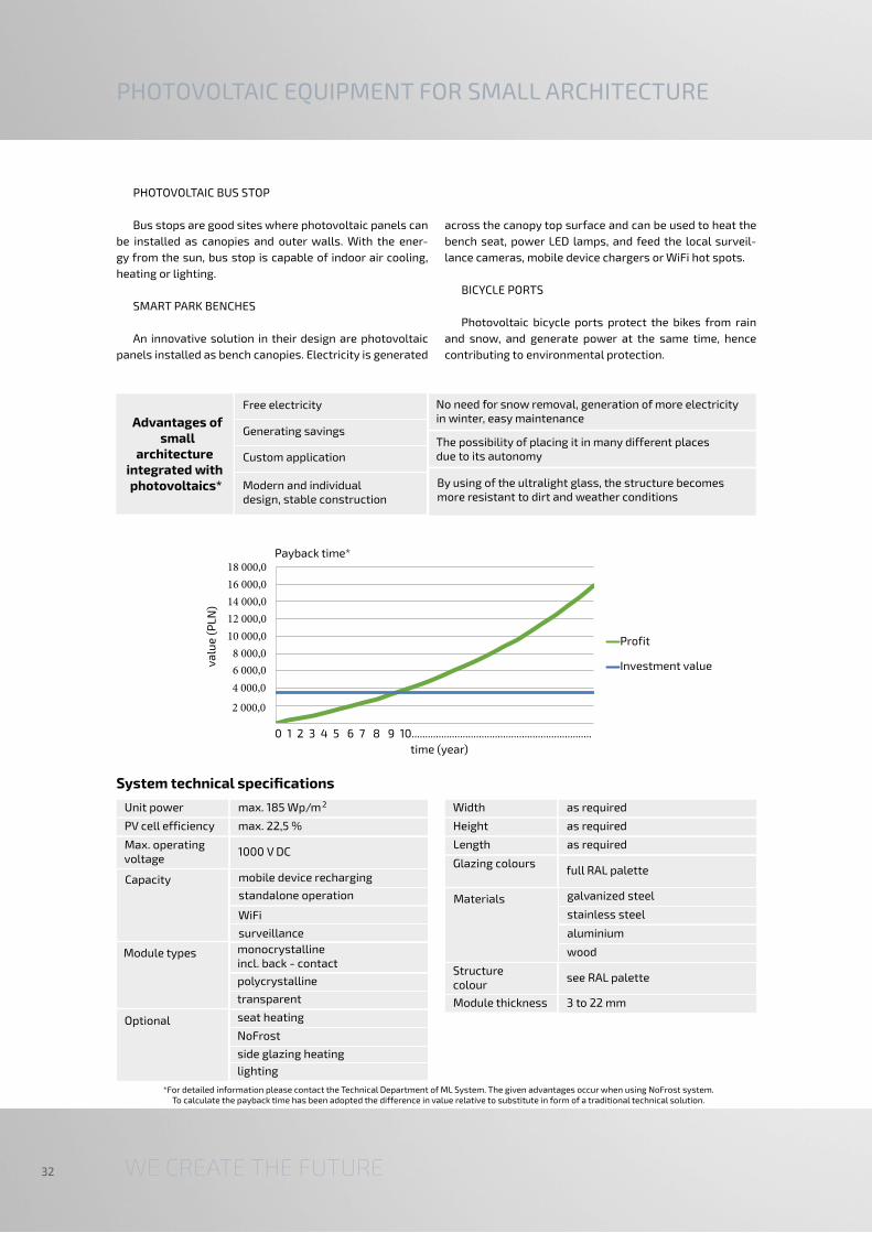
PHOTOVOLTAIC BUS STOP
Bus stops are good sites where photovoltaic panels can
be installed as canopies and outer walls. With the ener-
gy from the sun, bus stop is capable of indoor air cooling,
heating or lighting.
SMART PARK BENCHES
An innovative solution in their design are photovoltaic
panels installed as bench canopies. Electricity is generated
across the canopy top surface and can be used to heat the
bench seat, power LED lamps, and feed the local surveil-
lance cameras, mobile device chargers or WiFi hot spots.
BICYCLE PORTS
Photovoltaic bicycle ports protect the bikes from rain
and snow, and generate power at the same time, hence
contributing to environmental protection.
PHOTOVOLTAIC EQUIPMENT FOR SMALL ARCHITECTURE
System technical specifications
*For detailed information please contact the Technical Department of ML System. The given advantages occur when using NoFrost system. To calculate the payback time has been adopted the difference in value relative to substitute in form of a traditional technical solution.
0 1 2 3 4 5 6 7 8 9 10...................................................................
2 000,0
4 000,0
6 000,0
8 000,0
10 000,0
12 000,0
14 000,0
16 000,0
18 000,0Payback time*
va
lue
(P
LN)
Profit
Investment value
time (year)
Width as required
Glazing colours full RAL palette
Materials
Height as required
galvanized steel
stainless steel
aluminium
Length as required
wood
Structure colour
see RAL palette
Module thickness 3 to 22 mm
Advantages of small
architecture integrated with photovoltaics*
Free electricity
The possibility of placing it in many different places due to its autonomy
No need for snow removal, generation of more electricity in winter, easy maintenance
Generating savings
Modern and individual design, stable construction
Custom application
By using of the ultralight glass, the structure becomes more resistant to dirt and weather conditions
Unit power max. 185 Wp/m
Module types
Max. operating voltage
1000 V DC
monocrystalline incl. back - contact
Optional
2
Capacity
PV cell efficiency max. 22,5 %
mobile device recharging
WiFi
surveillance
polycrystalline
transparent
seat heating
NoFrost
side glazing heating
lighting
standalone operation

33
1 .
Concept / Photovoltaic bench SMART
Concept / PV Smart Bench with mobile device charger Concept / Positive energy PV-enabled public convenience
PV bus stopConcept / PV bus stop
Stalowa Wola/Photovoltaic tree
WE CREATE THE FUTURE34
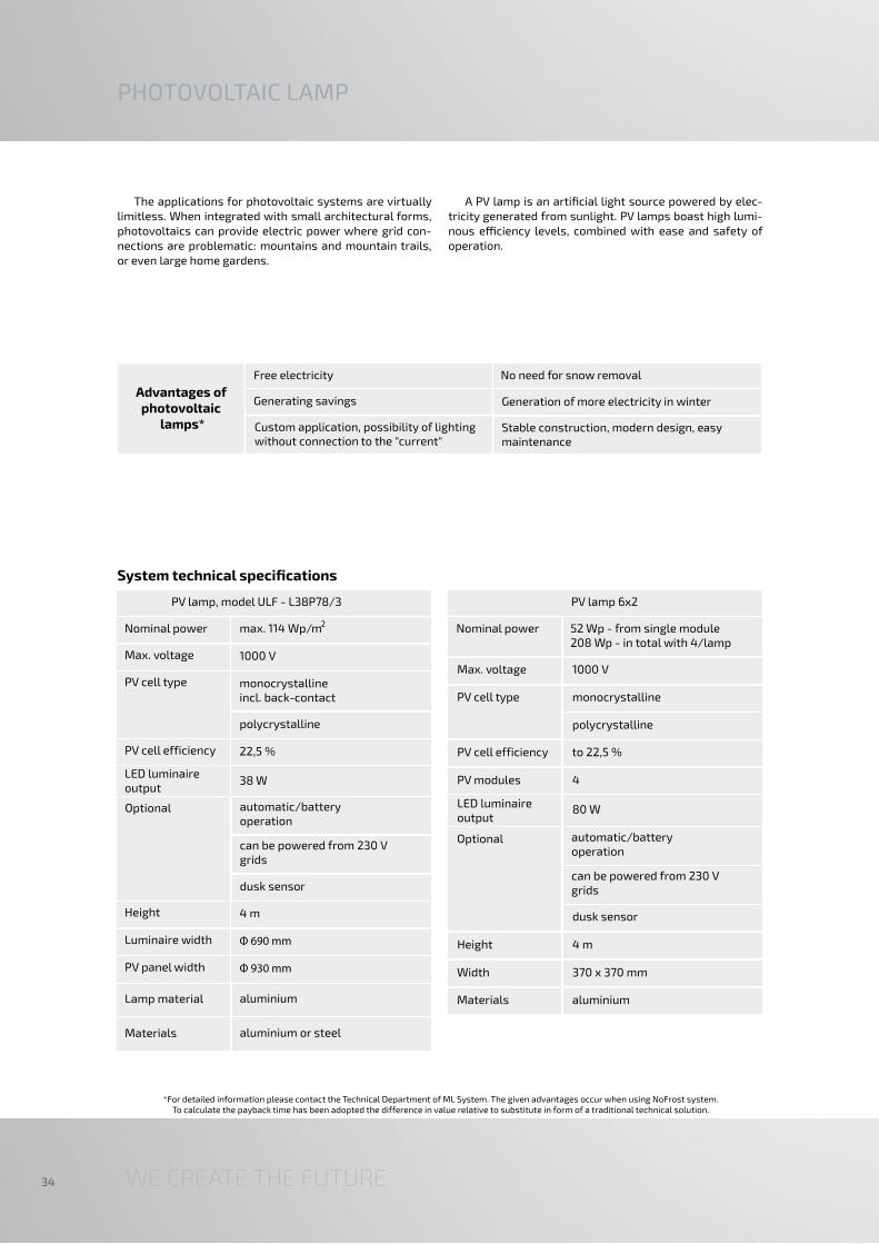
PHOTOVOLTAIC LAMP
The applications for photovoltaic systems are virtually limitless. When integrated with small architectural forms, photovoltaics can provide electric power where grid con-nections are problematic: mountains and mountain trails, or even large home gardens.
A PV lamp is an artificial light source powered by elec-tricity generated from sunlight. PV lamps boast high lumi-nous efficiency levels, combined with ease and safety of operation.
*For detailed information please contact the Technical Department of ML System. The given advantages occur when using NoFrost system. To calculate the payback time has been adopted the difference in value relative to substitute in form of a traditional technical solution.
System technical specifications
Nominal power
Max. voltage
max. 114 Wp/m
1000 V
Optional
PV cell type
automatic/battery operation
Lamp material
2
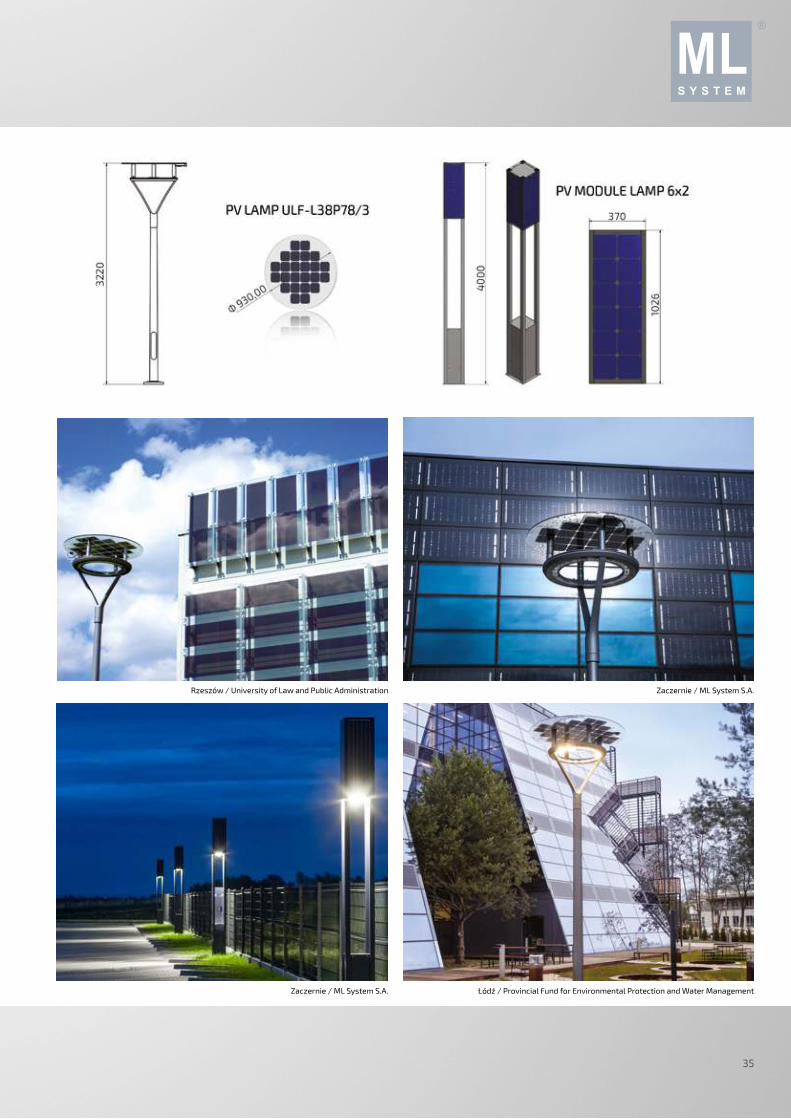
PV lamp, model ULF - L38P78/3
monocrystalline incl. back-contact
polycrystalline
PV cell efficiency 22,5 %
LED luminaire output
38 W
can be powered from 230 V grids
dusk sensor
Height 4 m
Luminaire width
PV panel width
aluminium
Materials aluminium or steel
Nominal power
Max. voltage 1000 V
Optional
dusk sensor
PV lamp 6x2
52 Wp - from single module 208 Wp - in total with 4/lamp
PV cell type monocrystalline
polycrystalline
PV cell efficiency to 22,5 %
PV modules 4
LED luminaire output
80 W
automatic/battery operation
can be powered from 230 V grids
Height 4 m
Width 370 x 370 mm
Materials aluminium
Advantages of photovoltaic
lamps*
Free electricity
Generating savings
No need for snow removal
Generation of more electricity in winter
Stable construction, modern design, easy maintenance
Custom application, possibility of lighting without connection to the "current"
35
Zaczernie / ML System S.A.Rzeszów / University of Law and Public Administration
Łódź / Provincial Fund for Environmental Protection and Water ManagementZaczernie / ML System S.A.
WE CREATE THE FUTURE36
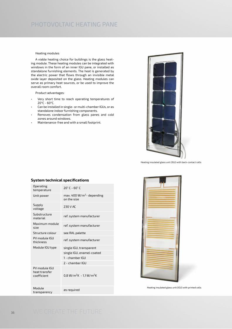
Heating modules
A viable heating choice for buildings is the glass heat-ing module. These heating modules can be integrated with windows in the form of an inner IGU pane, or installed as standalone furnishing elements. The heat is generated by the electric power that flows through an invisible metal oxide layer deposited on the glass. Heating modules can serve as primary heat sources, or be used to improve the overall room comfort.
Product advantages:
• Very short time to reach operating temperatures of 20°C - 60°C.
• Can be installed in single- or multi-chamber IGUs, or as standalone indoor furnishing components.
• Removes condensation from glass panes and cold zones around windows.
• Maintenance-free and with a small footprint.
PHOTOVOLTAIC HEATING PANE
System technical specifications
Heating insulated glass unit (IGU) with printed cells
Heating insulated glass unit (IGU) with back-contact cells
Structure colour see RAL palette
Module IGU type single IGU, transparent
Operating temperature
Module transparency
as required
Unit power max. 400 W/m - depending on the size
Supply voltage
230 V AC
single IGU, enamel-coated
1 - chamber IGU
2 - chamber IGU
PV module IGU heat transfer coefficient 0,8 W/m K - 1,1 W/m K2
2
Substructure material
ref. system manufacturer
Maximum module size
ref. system manufacturer
PV module IGU thickness
ref. system manufacturer
2

37
The standard product from ML System is the PV module, available in the single size of 1801 mm x 997 mm. The ba-sic components of the PV module is the monocrystalline or polycrystalline silicon modules (depending on the specific versions). The PV cells are laminated between two plastic films for long life. The PV module sealing and protection is ensured by tempered glass on one side and a Tedlar film (or another glass pane) on the other side. The entire assembly is held together by an aluminium frame which makes the structure stiff and facilitates mounting on support struc-tures, e.g. rooftops or open ground.
The glass-to-glass PV modules with the cells protected by glass panes from both sides require no framing.
The ultralight special versions are built using an ul-trathin tempered glass pane on the front side and a Tedlar film on the back. The assembly is surrounded by a frame which provides structural stiffness. The solution reduces the weight of the module to a mere 10 kg while retaining the stiffness and mechanical strength of the structure.
The ML System standard PV modules are compatible with the majority of PV mounts available on the market and are designed for flat roofs, pitched roofs and ground installations.
System technical specifications
STANDARD PHOTOVOLTAIC MODULES
SunPol module
SunMon module
Max. operating voltage
1000 V DC
Power rating 275 W
ML - SunPol 275
Cell technology polycrystalline
ML SunMon 300
Power rating 300 W
Max. voltage monocrystalline
Max. operating voltage
1000 V DC
Cells 66
Cells size 6”
Structure glass-to-glass
glass/Tedlar
ultrathin glass/Tedlar
Build 38 mm aluminium frame
no-frame
Weight 10-25 kg
Size 1801 x 997 mm

WE CREATE THE FUTURE38
DSSCs (Dye Sensitized Solar Cells) are also known as
3rd generation PV cells. They use a reversible photochemi-
cal process with a dye as a solar radiation absorber. Nature
has long been the inspiration for humans, and photosyn-
thesis is one of the most wonderful of natural phenomena.
In this process plant organisms convert solar radiation into
highly energetic organic compounds. The discovery of the
principle of photosynthesis stimulated the minds of sci-
entists to seek ways of applying solar energy to generate
efficient renewable energy.
The DSSCs are 3rd generation photovoltaic cells based
on organic compounds, without the p-n junction typical of
1st and 2nd generation solutions. The dye based solar cells
feature special chemicals, capable of capturing quants of
solar radiation and turning them into electric power.
The design of DSSCs is layered and comprises two
transparent panes made of TCO glass arranged in parallel
with about a 40 µm gap. A light-sensitive layer of TiO2 is
deposited on one of the glass panes and coated with a met-
al-organic photosensitive dye (called the sensibiliser). This
subsystem acts as the photo anode of the cell. The other
TCO pane surface is usually coated with nanoscale plati-
num which serves as a catalyst and the cathode of the cell
system. The void between the parallel glass panes is filled
with an electrolytic medium, being an I-/I3
- redox system.
DSSC technology is an object of intense development in
order to improve the efficiency of photovoltaic conversion
in outdoor conditions. The current efficiency of DSSCs in
laboratory conditions is around 15% and comparable with
commercially available 2nd generation cells, and slightly
below the performance of 1st generation ones. However,
unlike silicon-based PV cells, the DSSCs feature much im-
proved aesthetic values and lower efficiency loss in poor
sun exposure conditions. The undisputed advantages of
DSSCs include high transparency, customizable colours,
and low power output drop vs. sunlight incidence. These
features have paved the way for DSSCs into BIPV (Building
Integrated Photovoltaics) to make eco-friendly civil engi-
neering a reality. The printed design can be customized. An
example of the technical parameters is shown below.
System technical specifications
PRINTED PHOTOVOLTAIC MODULES
DSSC module 30 cells DSSC-based process
Size 1000 x 380 mm
Weight 7 kg
DC wiring 2 x 1000 mm
Applications louvres/lightbreaks
IGU composition 2 glass panes bound with a spacer frame
Frame type aluminium spacer frame 10 or 18 mm
AC/DC connectors MC-4 (male/female), IP65
Front glass 3 mm tempered FLOAT
Back glass 3 mm tempered FLOAT
Colours customizable
Ambient temp. -40˚C to +85˚C
Max. load 5400 Pa front / e.g. snow
2400 Pa front and back/e.g. wind
Operating conditions
Max. permissible voltage
ref. IEC
Impact strenght Hail: 25 mm at 23 m/s
Electrical specifications
600 V
Supply voltage VMPP 3,7 V
Operating current I MPP 0,36 A
Open circuit voltage
V 6,8 Voc
Short-circuit current
ISC 0,45 A

39
Module DSSCInsulated glass unit (IGU) with integrated printed PV cells
Printed modules
38
0
1000 2200

WE CREATE THE FUTURE40
R&D CENTRE FOR PHOTOVOLTAICS
R&D CENTRE FOR PHOTOVOLTAICS
Operated as a part of the ML System organisation since
2012, the Centre does research and development into and
for proprietary and commissioned projects, and largely in
the field of nanotechnology:
• Electrochemical properties of nanomaterials
• Morphology of the thin-film surface
• Spectral and structural research of bulk and low-di-
mensional materials
• Electron structure of radiation converters
• External and Internal Quantum Efficiency measure-
ments of low dimensional structures
• Crystalline structures of solids
• Rheological characterization
• Physical and chemical properties of nanomaterials
• Charge transfer coefficient
• Electrical parameters of PV cells (including printed
cells)
• Solid stress measurement
The PV cell market is a still developing industry with a
relatively short track record, novel solutions are still re-
searched to optimise the electrical efficiency of its cells
with sustained high quality and reliability, and to improve
surface unit power generation. Note that ML System is
one of a few companies in its industry in Poland that has
been carrying out advanced research into the properties
of prototype PVs. The novel research fields at R&D Cen-
tre include industrial research and development related to
semiconductor zero-dimensional structures (i.e. quantum
dots), perovskites, and the applications of luminophores.
The R&D results in numerous patent claims with do-
mestic and European authorities, as well as scientific co-
operation with leading Polish and foreign research centres,
including Fraunhofer - Institut für Solare Energiesysteme
ISE, the Polish Academy of Sciences Institute of Low Tem-
perature and Structure Research, the AGH University of
Science and Technology in Krakow, the Universities of
Technology in Krakow, Wroclaw and Rzeszow, the Wroclaw
Research Centre EIT+, the University of Rzeszow, and the
Jagiellonian University.
The R&D Centre for Photovoltaics range is for business-
es who seek services in R&D and the improvement of ma-
terial component selection, scientific units, and PV system
manufacturers who seek quality certification of their tech-
nologies and materials.
R&D Centre has state of the art testing and measure-
ment equipment for comprehensive research in material
engineering, nanotechnology and photovoltaics.
RESEARCH ACTIVITIES OF R&D CENTRE FOR
PHOTOVOLTAICS:
• Comprehensive testing of PV cell voltage and current
characteristics
• Advanced tests of concentration and mobility of
charge carriers in a function of field and temperature
• Testing of PV cell characteristics and spectral re-
sponse
• Microscopic and topographic surface testing with 3D
imaging
• Determining the depth profile of chemical composition
and dopant concentration of thin layers
• Morphology testing in powders and suspensions
• Rheology testing
• Comprehensive electrochemical tests
• UV-Vis-NIR spectrophotometry
• Deposition of semiconducting, metallic, and passiva-
tion thin layers by PVD methods
• Measurements of thickness of thin film and their opti-
cal coefficients (n & k)
• Non-destructive determination of the chemical com-
position and phases of the materials
• Heat treatment
• Thermal conductivity tests
• Ageing and weathering tests of PV cells and panels
• Cutting and ion polishing of the surface
• Prototyping and production of electronic structures
domestic and foreign business and top R&D bodies, ML
System provides services for the development of custom
solutions for special projects and customer requirements.
The total of ML System's R&D work is valued at ca. 23 mil-
lion PLN, R&D works in progress are valued at ca. 13 million
PLN, and the investment projects based on own R&D are
valued at ca. 120 million PLN.
Research and development are not just a first step to
a new product or service launch on the market, they are
the essential stage of marketing innovation on which
to build a sustained competitive edge. We build it effec-
tively for ourselves and our customers alike by providing
R&D at the highest level. Thanks to the investments into
proprietary product research, and cooperation with

41
Probe array on a test benchUltrasonic soldering station
Bentham PVE 300 spectral analyser for solar cells Testing of PV cell characteristics and spectral response
Solar simulator for single PV cell testingSystem for deposition of the thin layers with the gloves box

WE CREATE THE FUTURE42
The monitoring software layer is a noteworthy element
of the entire design and execution process – and often ig-
nored. ML System carries a proprietary software suite for
online visualisation of the energy gain from photovoltaic
and other systems, and capable of communication with
master monitoring systems. The suite provides PV system
monitoring and control in the form of an Energy Manage-
ment System for building technical personnel.
The EMS core is a server workstation which communi-
cates directly with the field controllers. The field objects in
the EMS can also be monitored and managed via a WLAN
over TCP/IP and Ethernet. The EMS software enable re-
al-time access to the PV system from monitoring centres. A
system of user authentication passwords and system pro-
tections based on TCP/IP ensure that only authorised per-
sonnel can access specific installations. The Energy Man-
agement System synchronises the power supplied to the
building power grid by controlling the power and reducing
the active and reactive power in the inverter system. The
EMS also supervises the operation of NoFrost heating PV
modules in assigned sectors (if available). The EMS server
has a centralized automated control and diagnostics cab-
inet. The field controllers can be communicated with via
fibre-optic lines or copper lines rated at 50 Mbps.
An Energy Management System (EMS) has been imple-
mented to monitor a PV system for proper performance.
The EMS facilitates online display of energy gain from the
photovoltaic system and visualises the CO2 footprint re-
duction relative to conventional power generation technol-
ogies (hard coal based), converted according to the stand-
ards: ISO 50001 and ISO 14064. The EMS monitoring and
management is possible over TCP/IP Ethernet. Only per-
sonnel with the proper authorisation, in the form of secu-
rity passwords, may access the detailed data of the PV sys-
tem. The main system component is a software suite which
communicates with field controllers. Its main purpose is to
collect and process the data on the operation of the PV sys-
tem and devices interfaced with the PV systems, e.g. grid
analysers, weather stations, PLC controllers and PV invert-
ers. The connections between individual components of the
system are based on a communication bus (network). The
EMS software, which visualises the data, is server based.
Energy Management System tasks:
• Status visualisation of every inverter connected to the
PV system
• Energy gain visualisation
• Diagnostics of every inverter connected to the PV sys-
tem
• Web-based access to the EMS interface by multiple
operators
• Anonymous, password-free access to visualise the
energy gain on a public website, e.g. to present the CO2
footprint reduction
• Storage of measurement and statistical data in a se-
cure SQL database
• Integration with power grid analysers installed in the
PV system
• Supervision of the PV module de-icing system, and
weather-based optimisation of de-icing control (with
the data from weather stations)
• PV module de-icing parameter control
• Power generation and inverter cos Ф control
• Trucker control
• Louvre control
ENERGY MANAGEMENT SYSTEM

43
Krakow / Jagiellonian UniversityTauron Dystrybucja
Gliwice / City Road Authority
Krakow / Jagiellonian UniversityRzeszów / University of Law and Public Administration

WE CREATE THE FUTURE44
BMS / SECURITY SYSTEMS
ML System designs and implements advanced end-to-
end building solutions. We carry out low voltage and high
power system installations, including:
• BMS (Building Management Systems): Advanced solu-
tions for the monitoring, supervision and control of
HVAC, lighting, PV systems and electrical installations.
The deployed system facilitates building operations
and bring high savings on building maintenance.
• INTELLIGENT TRANSPORTATION SYSTEMS (ITS): Mod-
ern transportation systems are based on very ad-
vanced technologies which facilitate monitoring, traf-
fic control supervision and management of transport
processes. The development of communication sys-
tems helps integrating these tasks into the ITS (Intelli-
gent/Integrated Transportation Systems).
• ELECTRICAL INSTALLATIONS: We are an experienced
designer and builder of electrical installations for in-
dustrial, public, shopping and commercial facilities,
and our design engineers have full design and execu-
tion licenses.
• SAP: This system is deployed to detect fire as soon as
possible. This is done with a network of detectors that
sense various fire parameters, e.g. smoke, tempera-
ture, and UV radiation.
• CCTV SYSTEMS: Also known as video surveillance sys-
tems, these are used by large and small companies, as
well as at homes or shops.
• SOUND ALARM SYSTEMS: The Sound Alarm Systems
are wired systems for warning on-site personnel and
visitors of health and life hazards, especially during
fire or other emergency conditions that require prompt
evacuation of large numbers of people.
• ACCESS CONTROL SYSTEMS: AC systems allow the
restriction of access to various on-site zones only to
authorised personnel.
• PUBLIC ADDRESS SYSTEMS: PA systems are wired
loudspeaker systems for broadcasting verbal messag-
es or advertising.
• SMOKE VENTING SYSTEMS: These systems comprise
equipment for venting of smoke and hot air to remove
or at least minimise the concentration of toxic volatile
substances in hazardous areas.
• STRUCTURAL CABLING SYSTEMS: Based on screened
and non-screened modules (with all categories avail-
able, i.e. Cat5, Cat6 and Cat7) and optical fibres.
• IDS: Intrusion Detection Systems are based on motion
sensors which monitor the security zones. An IDS can
be interfaced with AC systems, video surveillance, and
work time monitoring systems.
• LIGHTING CONTROL SYSTEMS
• FIRE PREVENTION SYSTEMS: These systems help re-
duce oxygen concentrations in controlled rooms to
levels so low that they prevent fire. These systems are
often used in server rooms or archive facilities.

45
Server room
Warsaw / Okęcie Airport
Extinguishing a transformer substationBudomierz / Roadway State Border Checkpoint – video surveillance
Warsaw / Okęcie Airport
CCTV

WE CREATE THE FUTURE46
SELECTED PROJECTS
Rzeszów / University of Law and Public Administration
Krakow / Jagiellonian University

47
Niepołomice/ The Royal castle
Krakow / University of Agriculture

ML System S.A.
Tel. No. 17 77 88 266
Fax No. 17 85 35 877
e-mail: [email protected]
www.mlsystem.pl
VAT No.: 517-02-04-997
The information contained in this catalog does not constitute an offer within the meaning of the Civil Code.
All rights reserved. Copying and distribution without written permission is prohibited.
Product edition 2/2016