
A Study on the Effect of Metabolic Heat Generation on Biological Tissue Freezing
Upload
khangminh22Category
view
2download
0
IAEA-TECDOC-1172
Small power and heat generationsystems on the basis of
propulsion and innovativereactor technologies
Proceedings of an Advisory Group meetingheld in Obninsk, Russian Federation, 20-24 July 1998
INTERNATIONAL ATOMIC-ENERGY AGENCY
September 2000
The IAEA does not normally maintain stocks of reports in this series. They are howevercollected by the International Nuclear Information System (INIS) as non-conventional literature.Should a document be out of print, a copy on microfiche or in electronic format can bepurchased from the INIS Document Delivery Services:
INIS ClearinghouseInternational Atomic Energy AgencyWagramer Strasse 5P.O. Box 100A-1400 Vienna, Austria
Telephone: (43) 1 2600 22880 or 22866Fax: (43) 1 2600 29882E-mail: chouse(5)iaea.orq
Orders should be accompanied by prepayment of 100 Austrian Schillings in the form of acheque or credit card (VISA, Mastercard).
More information on the INIS Document Delivery Services and a list of national documentdelivery services where these reports can also be ordered can be found on the INIS Web site athttp://www.iaea.orq/inis/dd srv.htm.

Please be aware that all of the Missing Pages in this document wereoriginally blank pages

The originating Section of this publication in the IAEA was:
Nuclear Power Technology Development SectionInternational Atomic Energy Agency
Wagramer Strasse 5P.O. Box 100
A-1400 Vienna, Austria
SMALL POWER AND HEAT GENERATION SYSTEMS ON THE BASIS OF PROPULSIONAND INNOVATIVE REACTOR TECHNOLOGIES
IAEA, VIENNA, 2000IAEA-TECDOC-1172
ISSN 1011-4289
© IAEA, 2000
Printed by the IAEA in AustriaSeptember 2000

FOREWORD
In the future for developing regions and remote areas one or two power reactors in the50 MW(e) to 100 MW(e) range could be appropriately applied for electricity and heat production.Introducing and managing such a small programme with conventional reactor systems would require amature supporting technological infrastructure and many skilled and highly trained staff at the site,which might be a problem for some countries. An increased number of small conventional reactors(e.g. with on-site refuelling) would increase the burden and expenditure for assuring security and non-proliferation. To this end, the time has come to develop an innovative small reactor concept that meetsthe following requirements: reliable, safe operation with a minimum of maintenance and supportinginfrastructure, economic competitiveness with alternative energy sources available to the candidatesites, and significant improvements in proliferation resistance relative to existing reactor systems.
Successful resolution of such a problem requires a comprehensive systems approach thatconsiders all aspects of manufacturing, transportation, operation, and ultimate disposal. Someelements of this approach have been used previously in the development of propulsion (ship andspace) nuclear power systems, with consideration given to many diverse requirements such as highlyautonomous operation for a long period of time, no planned maintenance, no on-site refuelling andultimate disposition.
It is with this focus that the IAEA convened the Advisory Group on Propulsion ReactorTechnologies for Civilian Applications in Obninsk, Russian Federation.
This meeting, which included participants from ten countries (Canada, China, Egypt, France,India, Indonesia, Japan, the Republic of Korea, the Russian Federation and the United States ofAmerica) brought together a group of international experts to review and assess the propulsion reactordesign features and operational experience, mode of its alternative application, as well as to discussthe systems approach and requirements for innovative small reactors and rationale for selecting them.
The IAEA would like to express its thanks to all those who took part in the AGM, andparticularly to the Institute of Physics and Power Engineering (IPPE) for hosting the meeting. Specialthanks go to V. Chitaykin (IPPE, Obninsk, Russian Federation) and to S. Kazakov (JSC MalayaEnergetika, Moscow) for assisting in the preparation of this publication.
The IAEA officer responsible for this publication was A. Rineiskii of the Division of NuclearPower.

EDITORIAL NOTE
This publication has been prepared from the original material as submitted by the authors. The viewsexpressed do not necessarily reflect those of the IAEA, the governments of the nominating MemberStates or the nominating organizations.
The use of particular designations of countries or territories does not imply any judgement by thepublisher, the IAEA, as to the legal status of such countries or territories, of their authorities andinstitutions or of the delimitation of their boundaries.
The mention of names of specific companies or products (whether or not indicated as registered) doesnot imply any intention to infringe proprietary rights, nor should it be construed as an endorsement orrecommendation on the part of the IAEA.
The authors are responsible for having obtained the necessary permission for the IAEA to reproduce,translate or use material from sources already protected by copyrights.
CONTENTS
Summary 1
Operational experience with propulsion nuclear plants 11V. Polunichev
A multi-purpose reactor 21Changwen Ma
Basic safety principles of KLT-40C reactor plants 29V. Beliaev, V. Polunichev
A floating desalination/co-generation system using the KLT-40 reactor and CanadianRO desalination technology 41J.R. Humphries, K. Davies
Implementation of the project for the construction and operation of a nuclear heatand power plant on the basis of a floating power unit with KLT-40C reactors 53
A.K. Polushkin, E.A. Kuzin, V.M. Vorobiov, DM. Klykov, J.K. PanovThe use of engineering features and schematic solutions of propulsion
nuclear steam supply systems for floating nuclear power plant design 67A.N. Achkasov, G.I. Grechko, V.N. Pepa, V.A. Shishkin
Design features of SMART for barge mounted application 75Doo-Jeong Lee, Ju-Hyeon Yoon, Ju-Pyung Kim, Jong-In Kim, Moon-Hee Chang
Advanced marine reactor MRX and its application for electricity andheat co-generation 85T. Ishida, M. Ochiai, T. Hoshi
Civilian application of propulsion reactor in Indonesia 107M. Djokolelono, B. Arbie, A.N. Lasman
New concepts for small power reactors without on-site refuelling fornon-proliferation 115N. W. Brown, J.A. Hasberger
Use of Russian technology of ship reactors with lead-bismuth coolant innuclear power 127A. V. Zrodnikov, V.I. Chitaykin, B.F. Gromov, O.G. Grigoryv, A.V. Dedoul,G.I. Toshinsky, Yu.G. Dragunov, V.S. Stepanov
Advanced 4S (super safe, small and simple) LMR 157A. Minato, N. Honda
Use of nuclear space technology of direct energy conversion forterrestrial application 177V.I. Chitaykin, Ye.A.Meleta, V.I. Yarygin, A.S. Mikheyev, S.M. Tulin
Development of a neutron therapy treatment complex 185A. V. Zrodnikov, Eh.E. Petrov, IN. Leonov, E.A. Ivanov, V.A. Khoromskij,A.F. Tcyb, Ju.S. Mardynskij
List of Participants 193
SUMMARY
1. INTRODUCTION
The Advisory Group Meeting (AGM) on "Propulsion Reactor Technologies for CivilianApplications" was held in Obninsk, Russian Federation, 20-24 July 1998. The AGM was convened bythe International Atomic Energy Agency (IAEA) and was hosted by the Federal Scientific Centre,Institute of Physics and Power Engineering (IPPE).
This meeting was organized as a forum for experts of Member States to advise the IAEA on thedifferent types of water and liquid metal cooled ship propulsion reactors, barge mounted powerreactors and innovative reactor concepts which do not require on-site refuelling, and other similarreactor types presently in existence or under consideration in their countries. The purpose of themeeting was also to obtain advice from Member States on their needs and interests in the context ofthe IAEA's small and medium reactor programme.
Attendance at this AGM included thirty-five participants and observers from ten countries(Canada, China, Egypt, France, India, Indonesia, Japan, Republic of Korea, the Russian Federationand the United States of America). Sixteen presentations were made by the participants on a myriad ofpropulsion reactors design and operational experience, and alternative applications (floating and land-based), as well as on a technical approach for developing small nuclear systems for use in developingregions and remote areas. Each presentation was followed by general discussion and the AGMconcluded with a round table evaluation of future small reactor technology requirements andexploration of areas for enhanced international co-operation.
2. SUMMARY OF TECHNICAL SESSIONS
2.1. Ship propulsion reactors: operational experience, new development and alternativeapplications
The Russian Federation possesses a powerful ice breaker transport fleet which offers a solutionfor important socio-economic tasks of the country's northern regions by maintaining year-roundnavigation along the Arctic sea route.
Progressive design-constructional solutions being perfected continuously during four decades ofnuclear powered ships development in the Russian Federation and well proven technology of allcomponents used in the marine nuclear reactors give grounds to recommend improved marine nuclearsteam supply systems (NSSSs) of KLT-40 type as energy sources for heat and power co-generationplants and seawater desalination complexes, particularly as floating installations.
Co-generation stations are considered for deployment in the extreme north of Russia. Nuclearfloating desalination complexes can be used for drinkable water production in coastal regions.
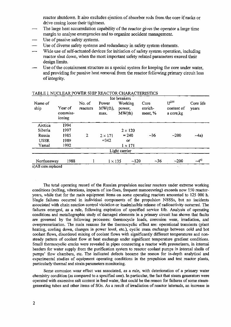
The first nuclear ice breaker was laid in 1956 and commissioned in 1959. This year (1999)becomes the 40th in the history of the Russian civil nuclear powered fleet, which consists of sevennuclear ice breakers and one transport (lighter carrier) ship. Nuclear powered ship reactorcharacteristics are presented in Table I.
All Russian nuclear powered ice breakers use a KLT-40 reactor type design, the safety featuresof which are as follows:— Self-protection, self-regulation and self-limitation of power due to negative reactivity
coefficients over the whole range of reactor parameter variation.— Natural circulation through primary and secondary circuits ensuring heat removal from
the core following the reactor shutdown.— The weight of control rods (CR) and the energy accumulated in the compressed spring
of the CR drives assure downward movement from any position at de-energization for
reactor shutdown. It also excludes ejection of absorber rods from the core if racks ordrive casing loose their tightness.
— The large heat accumulation capability of the reactor gives the operator a large timemargin to analyse emergencies and to organize accident management.
— Use of passive safety systems.— Use of diverse safety systems and redundancy in safety system elements.— Wide use of self-actuated devices for initiation of safety system operation, including
reactor shut down, when the most important safety related parameters exceed theirdesign limits.
— Use of the containment structure as a special system for keeping the core under water,and providing for passive heat removal from the reactor following primary circuit lossof integrity.
TABLE I. NUCLEAR POWER SHIP REACTOR CHARACTERISTICS
Name ofship
ArcticaSiberiaRussiaUSSRYamal
No. ofYear of reactorscommiss-ioning
199419971985 219891992
Northseaway 1988 1
IcePowerMW(th),max.
2x 171=342
breakersWorkingpower,MW(th)
2 x 120= 240
or1 x 171
Light carrier
l x 135 -120
Coreenrich-ment, %
-36
-36
U235 Core lifecontent of yearsa core,kg
-200 ~4a)
-200 ~4a)
a)AH core replaced
The total operating record of the Russian propulsion nuclear reactors under extreme workingconditions (rolling, vibrations, impacts of ice-floes, frequent manoeuvring) exceeds now 150 reactor-years, while that for the main equipment items on some operating reactors amounted to 125 000 h.Single failures occurred in individual components of the propulsion NSSSs, but no incidentsassociated with chain reaction control violation or inadmissible release of radioactivity occurred. Thefailures emerged, as a rule, following expiration of specified service life. Analysis of operatingconditions and metallographic study of damaged elements in a primary circuit has shown that faultsare governed by the following processes: thermocycle loads, corrosion wear, irradiation, andoverpressurization. The main reasons for the thermocyclic effect are: operational transients (plantheating, cooling down, changes in power level, etc.), cyclic mass exchange between cold and hotcoolant flows, disordered mixing of coolant flows with significantly different temperatures and non-steady pattern of coolant flow at heat exchange under significant temperature gradient conditions.Small thermocyclic cracks were revealed in pipes connecting a reactor with pressurizers, in internalheaders for water supply from the purification system to reactor coolant pumps in internal shells ofpumps' flow chambers, etc. The indicated defects became the reason for in-depth analytical andexperimental studies of equipment operating conditions in the propulsion and test reactor plants,particularly thermal and strain parameters monitoring.
Some corrosion wear effect was associated, as a rule, with deterioration of a primary waterchemistry condition (as compared to a specified one). In particular, the fact that steam generators wereoperated with excessive salt content in feed water, that could be the reason for failures of some steam-generating tubes and other items of SGs. As a result of irradiation of reactor internals, an increase in
the force required to be applied to movement of reactivity control rods was observed by the end of thespecified lifetime.
Due to systematic work on improvement of equipment and systems optimizations of theiroperating modes the reactor plant main equipment specified lifetime has been increased from(25-30) x 103hrs for the first NSSSs up to (100-120) x 103hrs for the modern ones. In order to furtherincrease this performance indicator, extensive work is currently performed for the inspections of the.most loaded items in equipment and piping during the decommissioning of the first ice breaker reactorplant. In particular, samples are cut out from the reactor pressure vessel, the nozzle connecting theRPV to steam generator the pressurizer, heat exchanger, RPV closure head, pressurizing system pipes,etc. It is also planned to inspect items of the SG, RCP, CRDM and other key components.Metallographic tests of cutted-out samples and analysis of obtained results are currently proceeded.Based on the comprehensive inspection program a decision on extension of running equipment to thespecified lifetime will be adopted, eventually up to the vessel hulls' service life.
Japan Atomic Energy Research Institute (JAERI) conducted feasibility studies on a concept of acompact light weight marine reactor for thermal power of 100 MW on the basis of conventionaltechnologies with three types: an integral type reactor, a semi-integral type reactor, and an integraltype reactor with a self-pressurized pressurizer. At the same time, JAERI surveyed cargo ships andtankers requirements for a nuclear powered system which could be competitive with the conventionalengines of ships.
The studies revealed that all these reactor system concept designs need to become more compactand light weight For example, for the Japanese nuclear powered ship Mutsu, the radiation shieldingoccupied 70% of the weight of the whole reactor system and the secondary shielding 88% of theweight of the total shielding. As a result, it is one of the key design considerations for the compact andlight weight reactor to make the radiation shielding component to be as compact as possible.
For the simplification of the reactor system, there is some room for improvement even in theland-based PWRs. The Japanese designers proposed a simplified PWR concept named JPSR featuringa full range self-power-controllability and a passive engineered-safety-features-system. They considerthat the simplification of the reactor system is very effective in improving the reliability of the system,reduced required qualified manpower in operation and maintenance, improving safety and alsoreducing construction and operation cost. In order to simplify the system, the JPSR adopts a largepressurizer, canned pumps, passive residual heat removal system, and eliminates the functions ofvolume and boron concentration control system, seal water supply from the chemical and volumecontrol system (CVCS), and so on.
In the marine reactor, the chemical shim reactor power control system is basically not adoptedthus avoiding criticality due to seawater possibly entering in the case of the ship sinking. In this point,the marine reactor system is simpler than that of the present land-based PWR. However, necessities ofthe system simplification together with application of automatic operation system in the marine reactorare rather strong under the circumstance of a limited number of operators and the absence of supportfrom land, which are more disadvantageous than for the land-based PWRs. These circumstancesrequire the marine reactor system to have less possibility of accidents, to maintain core integrity and toremove decay heat by a simple and reliable way without manual operation in case of accident. That is,by some ingenious contrivance so that an accident has no potential to occur or by means of a passiveengineered-safety system.
In order to create an advanced marine reactor system which is lightweight, compact, simple andsafe, JAERI has developed an innovative integral type reactor system named MRX. Several newtechnologies are adopted in the MRX to suit the above mentioned proposals: a water filledcontainment, an in-vessel type control rod drive mechanism (CRDM), a passive decay heat removalsystem and so on. Feasibility of the MRX design concept for a commercial ship was evaluated bychecking compatibility of the systems, and evaluating safety and economics in the whole system. Newtechnologies adopted in the MRX such as the in-vessel type CRDM have been under development.The possible output range of the MRX is about 50 to 300 MW(th). The MRX can be used not only as a
marine power source but also can serve multipurposes such as seawater desalination, heat supply, andelectric power generation for distance district in floating and land-based modes.
Bhabha Atomic Research Centre (India) conducted feasibility studies for a 100 MW(th)pressurized water reactor which is being developed for cargo ship propulsion'. It is expected that theplant will generate a shaft horsepower of 29 000 and will be able to propel a ship, having a totaldisplacement of 50 000 t, at a speed of about 17 knots. Apart from this, India has a long coastline andsome of the coastal areas experience severe water shortage. Most of the coastal areas are away fromcoalmines and the regions have both water and electricity shortage. As India has very small oil and gasreserves, producing nuclear power in the region is a viable alternative both for power generation andseawater desalination. A preliminary feasibility study indicates that typically a ship with nuclearpropulsion will weigh about 30 to 35% more than the conventional ship. This increased weight canadversely affect the cargo-carrying capacity. However, the study indicates that beyond a cruisingradius of about 15 000 miles the amount of fuel which is required to be carried in a conventional shipwill offset the disadvantage of higher plant weight in a nuclear ship. The study also indicates that atypical cost of such a plant is likely to be about 100 million US dollars.
Desirable features of India multipurpose reactor are as follows:
(i) Compactness and lower weight of plant. The components are arranged near the reactorpressure vessel to ensure compactness of design.
(ii) Higher system reliability. Each primary system loop is provided with two pumps. This willresult in a relatively larger availability of primary system and thereby increase the reliabilityof basic heat transfer mode.
(iii) Larger core life. The core consists of 150 fuel assemblies arranged with a core edge of1077 mm. Fuel assemblies are hexagonal in shape having a dimension of 63 mm across flat.Active core height is 1400 mm. For reactivity control, 19 control rods are provided.Preliminary study indicates that a fissile material inventory of about 140 kg should result in acore life of about 20 000 MW(d). Design is yet to be optimized for increasing the core life.
(iv) Reducing effect of accidents and restricting radioactivity release to a lower value. Thecontainment vessel has a diameter of 8.7 m and a height of 10.5 m. The plant is provided intotal with eight primary heat transport pumps. This will ensure primary water circulation, inthe event that some of the pumps are not available. In addition the steam generator is placed ata higher elevation than the core. This will ensure water circulation by thermo-siphoningshould complete power supply be lost. In the event of loss of coolant accident all theradioactive leakage can be contained in the containment vessel. This vessel will be designed towithstand the pressure build up, subsequent to such an accident.
It was pointed out that such a plant could also find use in of barge-mounted floating nuclearpower plants.
The Institute of Nuclear Energy Technology, Tsinghua University, China conducteddevelopments of a multipurpose small reactor (200 MW(th)). The reactor can be installed into a ship,and can be used for seawater desalination, electricity and heat production. The basic innovatingfeatures are as follows:
- Integrated arrangement, self-pressurization;- Dual pressure vessel structure;- Low operating temperature and pressure, and low power density reactor design which provided
increased operating margins and improved fuel economy,- Reactor core cooling with simple, passive means which use "natural" driving forces only;- Adopting innovative hydraulic system to drive the control rods;
1 At the meeting, these features were presented by CEA,Cadarache,but no paper was provided for publication in theproceedings.
- State of the art digital instrumentation and control systems and an advanced man-machineinterface control room, console-type work stations, software controls and integrated, prioritizedalarms and procedures;
- Innovative design of the plant arrangement and advanced construction concept adopted tominimize cost, to shorten the construction schedule and to meet safety, operational andmaintenance criteria.
The Korea Atomic Energy Research Institute (KAERI) is carrying out the programme for theSMART (system-integrated modular advanced reactor) to be utilized in small scale electricity and heatgeneration and for barge-mounted application. The design combines well established commercialreactor design with new, advanced technology. A substantial part of the technology and designfeatures of SMART has already been proven in industry and new innovative features will be proventhrough various tests. Despite disadvantages in the power production cost due to the small poweroutput (~80 MW(e)), SMART can derive economic advantages from:
(a) a simplified system with a reduced number of pumps and valves, piping, instrumentation andwiring, etc.,
(b) flexible operation,(c) modularized components,(d) on-shop fabrication of components,(e) better match to the grid, and(f) low financial risk, etc. SMART is expected to fully satisfy the Korean as well as the international
safety and licensing requirements.
CEA and TECHNICATOM (France) have about 200 reactor-years of experience frompropulsion and small experimental reactors. Special design features for a future small reactor areformulated as follows:
(a) use of proven technology in which France has already had wide experience;(b) integrated primary circuit operating at about 140°C and 10 bars, hence use of simpler and more
reliable techniques and shorter construction times;(c) introduction of passive features;(d) suppression of soluble boron; and(e) intrinsic simplicity of design and automatisms leading to reduced number of personnel for
operation.
The small reactor is designed with low pressure and low primary coolant temperature incomparison with standard 900 MW(e) reactors. It was pointed out that lower primary temperatureleads to:
(a) reduction of the fuel enrichment due to higher moderating ratio through increased density;(b) possibility of high (60-70 GWd/t) or very high burnups (<100 GWd/t) due to considerably
reduced corrosion and fission gas release through decreased temperature;(c) reduced occupational exposure in the maintenance zones, and(d) increased safety margins in accident situations. French estimations show that, with innovative
architecture, systems simplifications and use of new technologies the overall kW h costs of theseSMRs could be of the same order of magnitude as large sized plants currently in operation.
2.2. Floating (barge-mounted) nuclear power plants: needs and status of development
The National Atomic Energy Agency (BATAN), Indonesia has concluded that to cope with theenergy requirements in the remote islands and less developed regions of Indonesia small or very smallnuclear reactors producing electricity and/or process heat could be appropriately applied. The bargemounted gas-turbine power plants, constructed in Surabaya shipyard, have been operating so far toprovide temporary power for Balikpapan city. By size requirement, a nuclear propulsion reactor is themost attractive example so far envisionaged. Economic competitiveness despite the small size is thefirst issue to resolve. It is understood that small and very small power reactors have certain advantages
in general (such as adaptation to small grid, less financing required, more manageable for domesticparticipation, etc.), but the cost of generated electricity per kW h is usually high. While for thedeployment at remote areas or at the less developed regions the main criterion for the small and verysmall reactor alternatives in principle remains, the least generating cost, additionally the following areconsideredr(a) the largest social gain, (b) zero or the least government subsidy and (c) a smaller cost toupgrade the infrastructure and transportation means in order to remove the "remoteness" qualification.These competitiveness criteria are applied, for both conventional financing, and for BOO (build-own-operate) or other non-conventional financing schemes (e.g. barter supplement). In principle anevaluation based on "profit and risk sharing" is considered.
The Russian State Concern for Electric and Thermal Energy Production of the RussianFederation Ministry for Atomic Energy plans to construct several floating nuclear power plants(FNPP) and the first one will be constructed in the North of Russia at Peveck, Chukotska Region. TheFNPPP includes two KLT-40C reactor plants, electrical equipment complex, stand-by diesel andboiler plants and coastal infrastructure. An international competition was held by the Russian NuclearSociety for the best design of a small NPP. The twin KLT40C reactor FNPP won the first prize.Economic analysis has shown that for the extreme north of Russian a floating NPP on the basis of theship propulsion reactor is 25-30% more economical than with alternative fossil-fuelled sources ofenergy. Two KLT-40C reactors in a rated mode of operation will generate -75 MW(e). Spent fuel andradioactive waste are stored on board the FNPP. Thus, the autonomous operation period (operationwithout supplies replenishment) of the FNPP is determined by the capacity of spent fuel storage. Theautonomous operation of the FNPP is ensured by four nuclear core sets and lasts ~15 years. After thelapse of this period the FNPP is to be towed to the dock for overhaul, fuel unloading and hull docking.Two overhauls and three operating cycles are planned. After the completion of the third cycle theFNPP is to be towed from the site to the premises of the specialised dock for decommissioning. Thefeasibility study for the construction of a FNPP with two KLT-40C reactors in Perek is completed.The industry is about to commence manufacture of the main equipment of the FNPP.
A Canadian company, CANDESAL Enterprises Ltd. evaluated an FNPP containing two KLT-40 reactors, as a source of electrical energy and waste heat for RO (reverse-osmosis) desalination. Thiscompany envisages implementation of the newest seawater desalination technology which allows asignificant reduction in both the specific energy consumption for the desalination process and in thecost of drinkable water produced. The Russian MINATOM and CANDESAL developed a joint designof a FNPP desalination complex.
2.3. A new innovative approach to small reactor system design
Some AGM participants pointed out that small reactor concepts which are currently developedare based on downsizing today's large reactor technology. They consider that the infrastructurenecessary to support conventional nuclear power development is very expensive, and beyond theresources of most developing countries. A new innovative approach to system design is to be used toreduce the need for such an infrastructure. The efforts should be focused on the development of thereactor systems with joint consideration of the overall fuel cycle, waste issues proliferation, simplifiedoperation, simplified and minimised system maintenance. Several organizations presented theirpreliminary studies on innovative small reactor concepts.
The LLNL (USA) initiated an evaluation of an innovative concept of reactors and fuel cycles fordeveloping countries. The leading criteria guiding this evaluation are:
(a) proliferation — resistance(b) economic competitiveness with alternative energy sources available to the candidate sites;(c) inherent safety and;(d) ease of operation and maintenance.
Non-proliferating ingredients identified include lack of refuelling (no storage of either fresh orspent fuel) on-site and use of U-235 (enrichment <20wt. %) for fissile fuel. The first criterion may bestbe achieved if the core can be designed with one fuel load per life and the reactor can be delivered to
the site pre-assembled and pre-fuelled. The Japanese 4 S (super safe small and simple) — sodiumcooled fast reactor concept was the first selected for evaluation because it appeared to have thepromise of achieving the no refuelling requirement. It was pointed out that one of the major challengeswould be to accomplish a small reactor innovative goal with an economically viable system. Today'seconomic approach to nuclear power is through economies of scale. Some meeting participantsconsider that the small reactor economic problem could be resolved through economics of massproduction, coupled with cost saving achieved from dramatically reduced on-site installation,operation and decommissioning costs, reduced site infrastructure requirements and simplifiedlicensing to overcome the loss of economies of scale. Small systems with no on-site refuelling andreplaceable reactor modules reduce proliferation concerns, and infrastructure burden due to theelimination of fresh and spent fuel storages, as well as technological operations with fuel on-site.
While many of these requirements and design features have, in principle, been met by spacepower systems, practical land or barge based systems that might meet this challenge will be orders ofmagnitude larger than space systems, but may need to be one to two orders of magnitude smaller thanthe current LWRs. It was pointed out that other complex systems such as a modern gas turbine orcombined cycle plants meet many similar requirements including standardized factory fabrication,simple installation and startup, and highly automated operation
Principle safety objectives for innovative small reactor system have been identified:
- all operational and severe accidents to be considered in the design basis should be passivelyeliminated and not result in life-limiting damage of reactor system and radiological consequencesto the on-site staff;
- the reactor design is to be provided core debris retention, its coolability and subcriticality;- all postulated severe accidents considered in the beyond design basis should not result in loss of
the use site due to contamination.
To achieve these objectives, an effective design must incorporate innovative solutions. Thegeneral question to be resolved is to create a reactor design with passive, inherent physical responsesto achieve self-regulation, heat production and heat removal in balance. NPP's safety with aninherently controlled reactor could be less dependent on correct control action and less vulnerable toautomatic control system fault and/or to operator or maintenance errors because the power wouldeventually passively adjust itself, thus minimizes the potential for human error initiation.
The 4S FR concept was proposed and developed by CRIEPI — Toshiba (Japan). The mainfeatures of reactor design are a tall thin reactor core (an equivalent diameter ~90 cm, length ~4 m) andaxially moveable radial reflector for compensation of burnup reactivity. Its reference design of~50 MW(e) was for 10 years of electric power output without refuelling and without the use of thesafety rod for burn up reactivity control. Now, the CRIEPI — Toshiba team has proposed a newdesign variant for 24 years of full power operation without refuelling. It uses part of the reactivityworth of the safety-rod in addition to the radial reflector segments for burnup reactivity control.
It was pointed out that although most of the technologies used in the 4S are already proven orunder development, further R&D work is required for some key technologies. These are criticalityexperiments of the metallic core with reflector, higher reliability of the reflector driving mechanismand fuel performance of a long fuel slug. A full-scale critical experiment is important to evaluate thecalculated results such as reactivity coefficients and critical conditions. As neutron leakage isenhanced in the 4S core, the conventional calculation method is not sufficient to accurately predict thecore characteristics. A critical experiment is thus the most urgent R&D item. All reactivity duringplant operation is controlled just by moving the reflector without feedback control systems. Thus, finemovements of the reflector are required. The technologies proposed for this purpose are all new to thenuclear industry, but are tried and tested in other fields. Reliability experiments are needed. Thefeasibility of keeping a long metallic fuel slug in the core for a long time needs to be carefullyexamined. The preliminary assessment of creep deformation after ten years operation by the metallicfuel performance code shows about 5% deformation and is within the allowable value. However, theperformance of longer fuel slugs must be demonstrated.
Studies of lead-bismuth fast reactors are being carried out in the Russian Federationorganizations IPPE and GIDROPRESS, in which a great deal of experience has been accumulated inthe course of the development and operation of submarine reactors cooled with lead-bismuth eutectic.However, bismuth is expensive and the resources are limited. It is possible that its use must beconfined to special applications, such as small reactors or to a limited number of fast reactors. For thisreason lead cooling is also being studied.
The advantages of lead-bismuth and lead cooling are high boiling temperatures and the relativeinertness compared with sodium. The melting and boiling points of sodium are 98°C and 883°C. Forlead-bismuth eutectic the figures are 123.5°C and 1670°C and for lead 327°C and 1740°C atatmospheric pressure. However, in the core of a lead-bismuth or lead cooled reactor the pressure ofcoolant above the core can increase the boiling point to about 2300°C. The boiling points are wellabove cladding failure temperatures. The specific heats per unit volume of lead-bismuth and lead aresimilar to those of sodium but the conductivities are about a factor of 4 smaller.
The y radioactivity induced in the coolant is small so that access can be made to the coolantcircuit after a shutdown period of about 24 hrs. However the production of a radioactive 210Po frombismuth, and to a lesser extent from lead, poses problems because of its migration from the coolant tothe cover gas and its formation of aerosols. 210Po are volatile, so that any leakage from the cover gasposes a hazard to the plant operators and the environment. In the early stages of development, theformation of deposits of lead oxide and other impurities posed problems.
A careful control of the purity of the coolant is required to avoid the formation of such deposits.It was necessary to develop corrosion resistant steels and to pre-treat the surfaces of components andalso to use special inhibitors in the lead-bismuth coolant. More extensive studies are required for leadcoolant to demonstrate the corrosion-resistance of structural materials.
Two design concepts have been discussed, SVBR-75/100 and ANGSTREM. SVBR-75/100 isdesigned to produce 75-100 MW(e). The study explores the feasibility of designing an SVBR-likereactor core to operate for 10 years without refuelling. A transportable version of the reactor calledANGSTREM can produce 30 MW(th) or 6 MW(e) or a combination of heat and electricity. A versionproducing up to 25 MW(e) has also been discussed.
A study has also been made of a lead-bismuth cooled reactor operating with an open fuel cycle.The fuel volume fraction should be above 60% and should be a high density fuel. A large core (4 mdiameter and 1.2 m high) is proposed. Following an initial loading with 10-15% enriched uraniumfuel it is possible to move towards reloading with depleted uranium fuel. The burnup target is greaterthan 20%.
Lead-bismuth alloy is inflammable in air or water. In principle, a Pb-Bi cooled reactor wouldnot have to have an intermediate circuit between the primary coolant and the steam, however it wassaid that there had been severe incidents with Pb-Bi cooled reactors due to water/steam leaks occurredin the submarine steam generators. As a result of one leak some areas of the reactor core were pluggedby the products of water and Pu-Bi interaction, causing meltdown of the core. Therefore theelimination of the intermediate circuit between the primary coolant (Pb-Bi) and the water/steam isquestionable and needs additional R&D.
2.4. Application of space reactor technology in gas industry and medicine
The design features and technology of very small Russian space propulsion reactors, whichuse a direct conversion of nuclear heat into electric energy, were discussed. An innovativethermoelectric plant to convert heat from fired natural gas into electricity was created by IPPE(Russia). Its main objectives is to ensure effective electrochemical rust protection of a large gaspipeline located in the remote arctic regions. One of the unique features of this system is thecombination of the cathodic protection with a number of additional service possibilities, among them;the use of natural gas directly from the high pressure gas pipeline as a source of heat, the remotemonitoring, etc. Starting in February 1998, the plant has been under field-testing.
A lively discussion took place on design and main parameters of a very small (-100 kW)reactor for neutron and neutron-capture therapy developed on the basis of space nuclear technology by
IPPE and the Radiological Centre of the Medical Academy (Russian Federation). For such a reactorthe problem was to provide maximum emission of neutrons from the reflector surface, because thefraction of emitted neutrons per fission is an important parameter for reactor type selection.
3. CONCLUSIONS AND RECOMMENDATIONS
1. Status and prospects of propulsion reactor (PR) applications. The PRs for ice-breakers and shipshave accumulated about 150 reactor-years of successful operation. Recent developments in theRussian Federation, Canada, China and other countries have demonstrated, that power reactorsoriginally designed for ship propulsion could be used for electricity and heat generation. Use ofproven PR technology and new developments on small reactor (SR) presents a broader nuclearpower options to meet individual Member States' needs for land-based and floating SRs.
2. The adaptation of PR technologies for SR requirements. It was agreed that any PR proposed forelectricity or heat generation will have to satisfy the general requirements and specifications ofnuclear reactors as defined by international bodies such as the IAEA and by national safetyauthorities. It was agreed also that reactors mounted on barges will have to demonstrate that theymeet safety criteria under specific conditions such as storms, sinking or tilting, which will have tobe made by the plant owner. The owner should also clearly show that the propulsion reactor plant,provided as land-based or floating SR, has been sufficiently modified so that the buyer countriescannot reproduce the technology for non-civilian applications.
3. The requirements for SRs deployment in developing countries. Issues needing further deliberationand clarification include the following:
3.1. Peculiarities in design of floating version
- Compliance to international codes & standards in marine engineering and maritimerules.
- Additional items in safety analysis, e.g. initiating events like collision, sinking, fuelrecovery after sinking accident, extent of security ad safeguards implied in thedesign of plant and ports.
3.2. Peculiarity in licensing
- Licensability in the country of origin.
- Extent of development testing and operational experience.
- Scope of liabilities and insurance coverage.
3.3. Peculiarity in economic assessment
Apart from criteria for least generation cost and capital cost:
- Cost of remoteness related to construction, O&M;
- Cost of storage of fuel reserve related to longer operating periods in comparison withfossil fuel plant alternatives.
3.4. Financing
If the ownership of the reactor and fuel is intended to remain with the vendor, the BOO(build-own-operate) scheme is the most appropriate.
3.5. Domestic participation
Since the design of NSSS or the whole plant shall be compact and modularized, domesticparticipation in construction of the nuclear portions of the plant may be quite limited.Domestic participation foreseen in:
- Research and development (still needed);
- Design;

- Construction of on-land/auxiliaries, living compartments of large ship/bargemaintenance.
4. New design principles, innovative architecture, and specific features that only small size can offermay lead to the development of this type of reactors which could be cost competitive with largersized traditional nuclear reactors. The programmes for developing countries should be centered ona new innovative approach to system design to be based on experience gained over the past fortyyears with four types of nuclear technologies (LWR, LMR, HTGR and MSR).
5. The proliferation of nuclear energy in the future could supply many developing countries with oneor two nuclear power plants. Managing even such small programme might lead to proliferation offissile materials in the world. Time has, therefore, come to give a fresh look to the idea of reactorswithout on-sit refueling, and barge-mounted systems shipped to an internationally monitoring sitefor refurbishment, recycling and waste disposal.
10
OPERATIONAL EXPERIENCE WITH PROPULSION NUCLEAR PLANTS
V. POLUNICHEVOKB Mechanical Engineering, XA0056264Nizhny Novgorod,Russian Federation
Abstract
Russia possesses a powerful icebreaker transport fleet which offers a solution forimportant socio-economic tasks of the country's northern regions by maintaining a year-round navigation along the Arctic Sea route. The total operating record of the propulsionnuclear reactors till now exceeds 150 reactor-years, their main equipment items operatinglife amounted to 120,000h. Progressive design-constructional solutions being perfectedcontinuously during 40 years of nuclear-powered ships creation in Russia and well proventechnology of all components used in the marine nuclear reactors give grounds torecommend marine NSSSs of KLT-40 type as energy sources for heat and power co-generation plants and sea water desalination complexes, particularly as floatinginstallations. Co-generation stations are considered for deployment in the extreme north ofRussia. Nuclear floating desalination complexes can be used for drinkable water productionin coastal regions of Northern Africa, the Near East, India etc.
1. STEPS IN DEVELOPMENT OF TECHNOLOGY
Russia is a single country in the world which now operates a nuclear-poweredicebreaker-transport fleet which offers a solution for vital social-economic tasks of thecountry's northern regions by maintaining a year-round navigation along the Arctic Searoute.
The first nuclear icebreaker "Lenin" - was laid in 1956 and commissioned in 1959 as apilot commercial vessel registered to the Murmansk shipping company. Experience of itsfirst sailing seasons (1959-1964) had shown significant advantages of icebreakers withnuclear propulsion plant in the Arctic, particularly their practically unrestricted seaendurance and ice breaking capability. [1].
Up to the date, three degeneration of nuclear propulsion plants have been created andgone through comprehensive verification by long-term exploitation under severe operatingconditions (Table 1).
The first triple-reactor propulsion plant with a loop-type configuration had beenoperated during six years in the icebreaker "Lenin". By the end of that period an operatingrecord of its main components did not exceed 25,000 h. The experience gained with thatvessel had shown the expediency to construct a whole series of nuclear-powered icebreakersfor extensive operations in the Arctic seas. With that aim a new twin-reactor propulsionplant of a modular type had been developed. Its pilot specimen was installed in theicebreaker "Lenin" instead of the first nuclear plant. Successful operation and highperformance indicators of the plant allowed it to be recommended as a basis one forsubsequent icebreakers "Aretica" (Fig. 1), "Sibir", "Russia", "Sovetsky Sojus" and "Yamal".In 1994 the next capital icebreaker "50th Anniversary of Victory" was launched, which iscurrently being completed the construction.
11
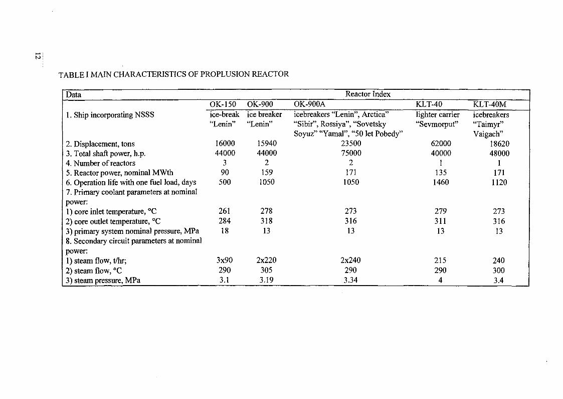
TABLE I MAIN CHARACTERISTICS OF PROPLUSION REACTOR
Data
1. Ship incorporating NSSS
2. Displacement, tons3. Total shaft power, h.p.4. Number of reactors5. Reactor power, nominal MWth6. Operation life with one fuel load, days7. Primary coolant parameters at nominalpower:1) core inlet temperature, °C2) core outlet temperature, °C3) primary system nominal pressure, MPa8. Secondary circuit parameters at nominalpower:1) steam flow, t/hr;2) steam flow, °C3) steam pressure, MPa
OK-150ice-break"Lenin"
1600044000
390500
26128418
3x902903.1
OK-900ice breaker"Lenin"
1594044000
21591050
27831813
2x2203053.19
Reactor IndexOK-900Aicebreakers "Lenin", Arctica""Sibir", Rossiya", "SovetskySoyuz" "Yamal", "50 let Pobedy"
2350075000
2171
1050
27331613
2x2402903.34
KLT-40lighter carrier"Sevmorput"
6200040000
11351460
27931113
2152904
KLT-40Micebreakers"Taimyr"Vaigach"
1862048000
1171
1120
27331613
2403003.4
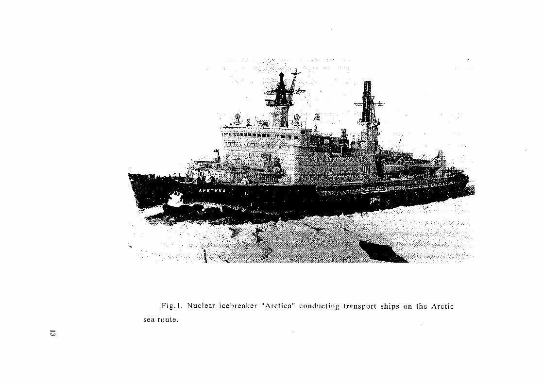
Fig.l. Nuclear icebreaker "Arctica" conducting transport ships on the Arctic
sea route.
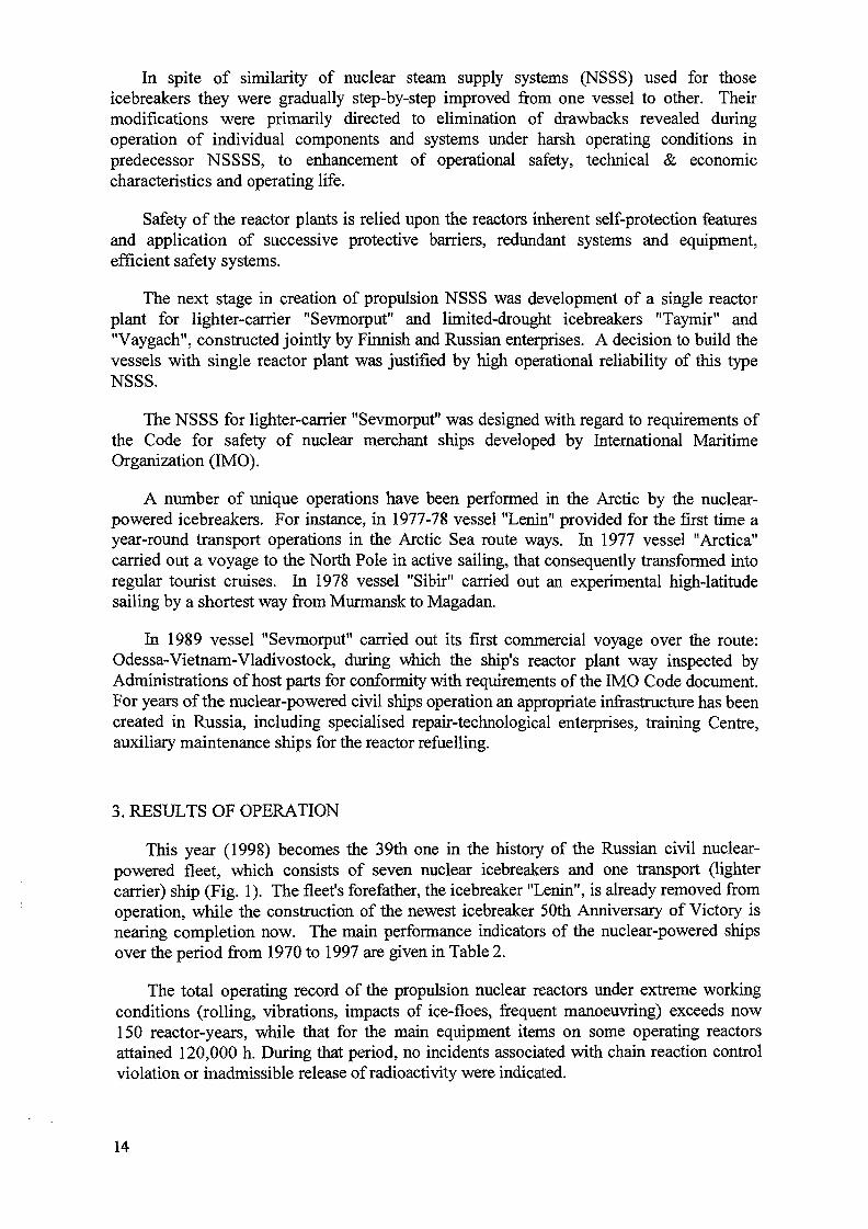
In spite of similarity of nuclear steam supply systems (NSSS) used for thoseicebreakers they were gradually step-by-step improved from one vessel to other. Theirmodifications were primarily directed to elimination of drawbacks revealed duringoperation of individual components and systems under harsh operating conditions inpredecessor NSSSS, to enhancement of operational safety, technical & economiccharacteristics and operating life.
Safety of the reactor plants is relied upon the reactors inherent self-protection featuresand application of successive protective barriers, redundant systems and equipment,efficient safety systems.
The next stage in creation of propulsion NSSS was development of a single reactorplant for lighter-carrier "Sevmorput" and limited-drought icebreakers "Taymir" and"Vaygach", constructed jointly by Finnish and Russian enterprises. A decision to build thevessels with single reactor plant was justified by high operational reliability of this typeNSSS.
The NSSS for lighter-carrier "Sevmorput" was designed with regard to requirements ofthe Code for safety of nuclear merchant ships developed by International MaritimeOrganization (IMO).
A number of unique operations have been performed in the Arctic by the nuclear-powered icebreakers. For instance, in 1977-78 vessel "Lenin" provided for the first time ayear-round transport operations in the Arctic Sea route ways. In 1977 vessel "Arctica"carried out a voyage to the North Pole in active sailing, that consequently transformed intoregular tourist cruises. In 1978 vessel "Sibir" carried out an experimental high-latitudesailing by a shortest way from Murmansk to Magadan.
In 1989 vessel "Sevmorput" carried out its first commercial voyage over the route:Odessa-Vietnam-Vladivostock, during which the ship's reactor plant way inspected byAdministrations of host parts for conformity with requirements of the IMO Code document.For years of the nuclear-powered civil ships operation an appropriate infrastructure has beencreated in Russia, including specialised repair-technological enterprises, training Centre,auxiliary maintenance ships for the reactor refuelling.
3. RESULTS OF OPERATION
This year (1998) becomes the 39th one in the history of the Russian civil nuclear-powered fleet, which consists of seven nuclear icebreakers and one transport (lightercarrier) ship (Fig. 1). The fleet's forefather, the icebreaker "Lenin", is already removed fromoperation, while the construction of the newest icebreaker 50th Anniversary of Victory isnearing completion now. The main performance indicators of the nuclear-powered shipsover the period from 1970 to 1997 are given in Table 2.
The total operating record of the propulsion nuclear reactors under extreme workingconditions (rolling, vibrations, impacts of ice-floes, frequent manoeuvring) exceeds now150 reactor-years, while that for the main equipment items on some operating reactorsattained 120,000 h. During that period, no incidents associated with chain reaction controlviolation or inadmissible release of radioactivity were indicated.
14
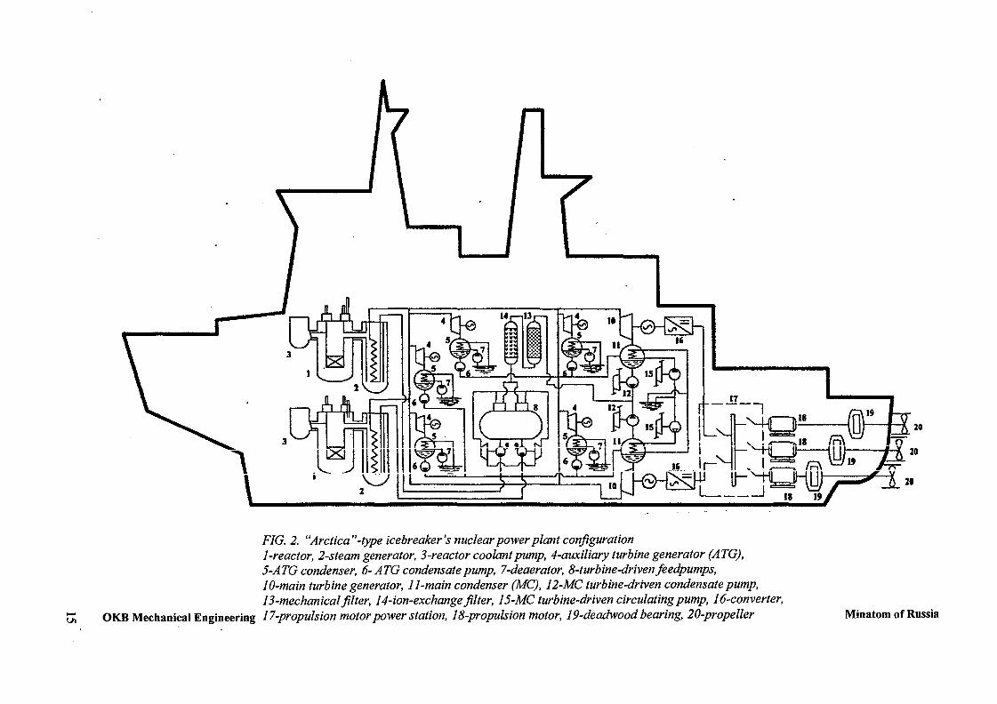
F7G. 2. "Arctica"-type icebreaker's nuclear power plant configuration1-reactor, 2-steam generator, 3-reactor coolant pump, 4-auxiliary turbine generator (ATG),5-ATG condenser, 6-ATG condensate pump, 7-deaerator, 8-turbine-driven feedpumps,10-main turbine generator, 11-main condenser (MC), 12-MC turbine-driven condensate pump,13-mechanical filter, 14-ion-exchange filter, 15-MC turbine-driven circulating pump, 16-converter,
OKB Mechanical Engineering 17-propulsion motor power station, 18-propulsion motor, 19-deadwood bearing, 20-propeller Minatom of Russia
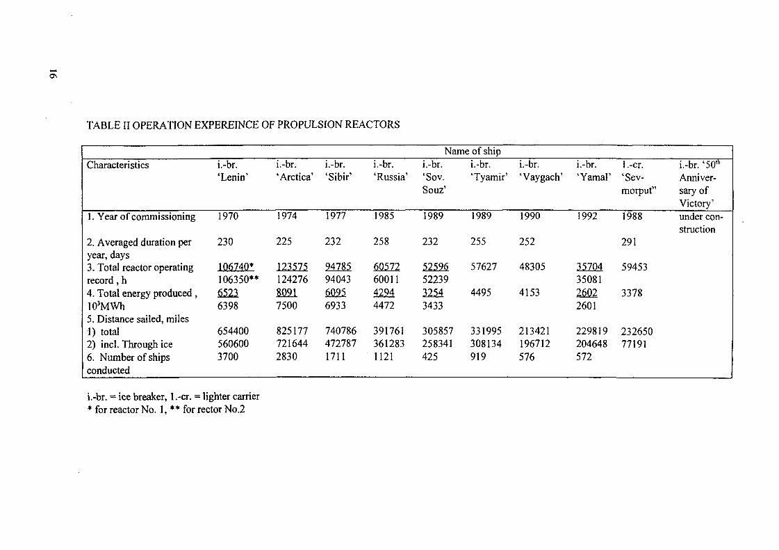
TABLE II OPERATION EXPEREINCE OF PROPULSION REACTORS
Characteristics
1. Year of commissioning
2. Averaged duration peryear, days3. Total reactor operatingrecord, h4. Total energy produced ,10'MWh5. Distance sailed, miles1) total2) incl. Through ice6. Number of shipsconducted
i.-br.'Lenin'
1970
230
106740*106350**65236398
6544005606003700
i.-br.'Arctica'
1974
225
12357512427680917500
8251777216442830
i.-br.'Sibir'
1977
232
947859404360956933
7407864727871711
i.-br.'Russia'
1985
258
605726001142944472
3917613612831121
Name of shipi.-br.'Sov.Souz'
1989
232
525965223932543433
305857258341425
i.-br.'Tyamir'
1989
255
57627
4495
331995308134919
i.-br.'Vaygach'
1990
252
48305
4153
213421196712576
i.-br.'Yamal'
1992
357043508126022601
229819204648572
1 .-cr.'Sev-morput"
1988
291
59453
3378
23265077191
i.-br. '50lh
Anniver-sary ofVictory'under con-struction
i.-br. = ice breaker, 1 .-cr. = lighter carrier• for reactor No. 1, ** for rector No.2
However, single failures were taken place in individual equipment pieces of thepropulsion NSSSS, including small leaks of primary coolant into the environs andinterfacing systems. The failures emerged as a rule following expiration of specifiedservice life. Analysis of operating conditions and metallographic study of damagedelements in a primary circuit have shown that faults are governed by the followingprocesses:
- thermocyclic loads;- corrosion wear;- irradiation;- overpressurization.
Main reasons of thermocyclic effect are:
- operational transients (plant heating, cooling down, changes in power level, etc.);cyclic mass exchange between cold and hot coolant flows;disordered mixing of coolant flows with significantly different temperatures;
- non-steady pattern of coolant flow at heat exchange under significant temperaturegradient conditions.
Thermocyclic cracks were revealed in pipes connecting a reactor with pressurizers, ininternal headers for water supply from purification system to reactor coolant pumps, ininternal shells of pumps' flow chambers, etc. The indicated defects became the reason forin-depth analytical and experimental studies of equipment operating conditions in thepropulsion and test reactor plants, particularly thermal and strain parameters monitoring.
Corrosion wears effect associated, as a rule, with deterioration of a primary waterchemistry regime (as compared to a specified one). In particular, the steam generators wereoperated with excessive salt content in feed water that could be the reason of failures ofsome steam-generating tubes and other items of SGs.
Resulting from irradiation of reactor internals increase in forces to be applied formovement of reactivity control members was observed by the end of a specified lifetime.
The operating experience has shown that abrupt changes in a primary pressure can bethe reason of damages in internal structures made as semi-closed plena which walls werenot designed for the primary coolant pressure. That was the reason of failure of a partitionin the reactor coolant pump of icebreaker "Arctica".
Guides on optimal running of operational transients were developed for improvementof equipment operating conditions, and some modification was introduced in the equipmentstructures.
4. DESIGNER SUPERVISORY ACTIVITY, INSPECTIONS, LIFE EXTENSION
During the entire period of the NSSSs operation a supervisory activity has been carriedout by the design organization as concerned reactor-related equipment and systems. Eachfailure or mis-operation event was thoroughly analysed, and recommendations for theirelimination were then developed. Remarks of the plants personnel on operation ofindividual equipment items and systems were analysed and quickly removed; new improvedarrangements were tested; the plants operating modes were optimised, etc. Inspections ofequipment were carried out, weak points were identified and then removed in both
17
operating and newly designed NSSS. Resulting from the supervisory activity actualoperation models were determined, according which more precise calculations were carriedout aiming at damage parameters corrections and residual service life prediction.
Due to systematic activity on improvement of equipment and systems, optimizations oftheir operating modes the reactor plant main equipment specified lifetime has beenincreased from (25-30)x 103hrs for the first NSSSs up to (100-120)x KPhrs for the modernones.
In order to further increase this performance indicator extensive work is currentlyperformed for the inspections of most loaded items in equipment and piping of thedecommissioned icebreaker "Lenin" reactor plant. Particularly, samples are cut out fromthe reactor pressure vessel, nozzle connecting the RPV to steam generator, the pressurizer,heat exchanger, RPV closure head, pressurizing system pipes, etc. It is also planned toinspect items of the SG, RCP, CRDM and other key components. Metallographic tests ofcutted-out samples and analysis of obtained results are currently proceeded. Resulting fromthe comprehensive inspection program fulfillment a decision on extension of runningequipment specified lifetime will be adopted, eventually up to the vessel hulls service life.
Presently, the reactor cores are nearing their specified energy production potential of2.1-2.3TWh. There is a prospect to increase this value, and consequently to improve aneconomic effectiveness of the reactor plants operation.
Long-term monitoring of the environment (sampling and laboratory tests of snow, soil,air, vegetation, etc.) in the area of the nuclear-powered ship homeport has no revealed anyradiological effects of the ships. Obtained data are on the background level. Averageannual dose to individuals of the ship personnel does not exceed 5mSv.
Available safeguard barriers and confinement systems practically completely eliminateradioactivity release, even in the most severe design accidents.
The Russian nuclear-powered ships are operated by highly qualified and experiencedspecialists, which along with their direct duties perform significant scope of research workaiming at enhancement of the reactor plants safety.
Actual level of nuclear and environmental safety of the latest modifications of NSSSsmeets modern requirements of domestic and international regulatory documents, and henceremoves restrictions on the nuclear-powered ships deployment. It is also demonstrated bethe commercial cruises of the icebreakers with passengers.
5. PROSPECTS OF NUCLEAR PROPULSION PLANTS UTILIZATION
The application of progressive solutions for constructional and technologicalprovisions, continuous perfection of safety systems with an Account of updated regulatoryrequirements for nuclear safety, and improvement of equipment items on the basis ofoperational experience feedbacks give grounds to recommend the propulsion nuclearreactors as advanced heat sources for co-generation power stations and sea waterdesalination complexes [2].
18
Operations along the Arctic Sea route seem to be problematic without vigorous work ofthe nuclear icebreakers. They provide pilotage of up to 80% of vessels there. Therefore thedecommissioned nuclear icebreaker should be replaced for new ones.
The far north and similar remote regions of Russian occupy more than half of thecountry's territory where the major part of mineral and energy resources are located,including oil, natural gas, nickel, gold, diamonds and rare metals. However, most places inthese regions are not provided with a centralised power supply, have no fuel-energy resourcesexpedient for effective utilization, and while fossil fuel delivery there entails greatdifficulties and expenses. For these regions, the application of NPPS, especially floatingones, becomes justifiable and prospective.
Creation of nuclear-powered icebreakers, cargo vessels and floating NPPs withstandardized reactor plants for servicing Russia's northern regions represents a promisingand economically efficient task, since the available integrated maintenance infrastructurecan be used for new ships maintenance too.
Creation of floating power-desalination complexes is another prospective application ofthe propulsion reactor plants. It is a fact that drinkable water production has become anacute problem for many regions of the world, e.g., North Africa, the Near East, India etc.Drinkable water is also expensive in northern regions of Russia.
Among a number of different projects, IAEA is considering floating power desalinationcomplexes, in particular those with the marine nuclear reactor plant of KLT-40 type anddesalination facilities of distillation and reverse-osmosis types. The appropriate distillationfacilities in Russia are designed by the Sverd Nil ChimMash Institute (Ecaterinburg), whilereverse-osmosis facilities are produced in particular by the Canadian firm "Candesal Inc".
In 1995 Memorandum on mutual understanding in the development of a desalinationcomplex was signed by "Candesal Inc." and MinAtom of Russia (it was prolonged in 1997).By present a draft prospect on joint power-desalination complex is prepared [3].
High reliability and safety levels of the reactor plants are verified by their longoperation experience. Projects of nuclear co-generation stations and power desalinationcomplex based on the propulsion-type reactor plants represent a certain commercial interestand can be attractive for domestic and foreign investors.
6. CONCLUSIONS
(i) Powerful icebreaker - transport nuclear-powered fleet and adequate maintenanceinfrastructure have been created in Russia by the date,
(ii) Unique multiyear operation experience has been accumulated with the propulsionnuclear reactor plants, and their operational safety and reliability are convincinglyconfirmed,
(iii) Causes of rare typical failures of equipment and systems have been identified, andproper countermeasures were undertaken for their complete or partial neutralisation,
(iv) The reactor plants have gone through multistage evolutionary modernisation, so thattheir equipment and systems have now a long specified lifetime.
The KLT-40 NSSSs are still attractive for fast realization in new icebreakers, cargovessels, floating heat and power co-generation stations and power desalination complexes.
19
REFERENCES
[1] Mitenkov F., Mellnikov E., Polunihev V., Jakovlev O. — "Creational and
operational experience NSSS of civilian ships". Presented to Russian Nuclear
Society seminar "Nuclear power for sea. Ecology and safety." IAE "Kurchatov
Institute", 1991
[2] Mitenkov F., Polunihev V. — "Small nuclear heat and power cogeneration
stations and water desalination complexes on the basic of marine reactor plants"
Nuclear Engineering and Design, 173 (1997) 183-191,
[3] Humphries J., Davies K. — "A floating co-generation system using the
Russian KLT-40 reactor and Canadian reverse osmosis water purification
technology". IAEA-TECDOC-940 (1997), 39-45.
20
XA0056265A MULTI-PURPOSE REACTOR
CHANGWEN MAInstitute of Nuclear Energy Technology,Tsinghua University Beijing,Beijing, China
Abstract
A integrated Natural circulation self pressurized reactor can be used for sea water desalination,
electrogeneration, ship propulsion and district or process heating. The reactor can be used for ship propulsion
because it has following advantages: It is a integrated reactor. Whole primary loop is included in a size
limited pressure vessel. For a 200MW reactor the diameter of the pressure vessel is about 5m. It is
convenient to arranged on a ship; Hydraulic driving facility of control rods is used on the reactor. It notably
decreases the height of the reactor. For ship propulsion, smaller diameter and smaller height are important.
Besides these, the operation reliability of the reactor is enough high, because there is no rotational machine
(for example, circulating pump) in safety systems. Reactor systems are simple. There are no emergency water
injection system and boron concentration regulating system. These features for ship propulsion reactor are
valuable. Design of the reactor is on the base of existed demonstration district heating reactor design. The
mechanic design principles are the same. But boiling is introduced in the reactor core. Several variants to use
the reactor as a movable seawatwer desalination plant are presented in the paper. When die sea water
desalination plant is working to produce fresh water, the reactor can supply electricity at the same time to the
local electricity network. Some analyses for comprehensive application of the reactor have been done. Main
features and parameters of the small (Thermopower 200MW) reactor are given in the paper.
1. A CONCEPT OF USING THE HEATING REACTOR FOR PROPULSION
Originally, the purpose of the heating reactor is to supply heat for Buildings in cities. Now we want to
extended its application to propulsion, heat-electro-cogeneration, sea water desalination and refrigeration (for
air condition) etc.
In the regions, where fresh water resources are deficient, transport of fresh water is need. Usually ship
transport is used. This way to transport water is not convenient. If a reactor is mounted on a ship, as a
desalination power source, at the same time as a propulsion power resource, that would be a interesting
solution.
For example, in China for several islands fresh water is need. A movable desalination plant is a
feasible solution. When the plant arrived the island, it can supply some additional electro- power to the local
network. This isn't negligible in China.
Heat and power cogeneration (for sea water desalination and propulsion) will improve the economic
features of the reactor.
(1). Multi- purpose ,extends applications of the Heating Reactor.
(2). As a power source, the reactor can work whole year. From view point of economy, it much better
than only supply heat for buildings in cities.
21
2. HEATING REACTOR IS APPROPRIATE AS A PROPULSION POWERRESOURCE
As a propulsion power source Heating Reactor has following advantages:(1) Sizes are limited. Heating Reactor adopted integrated arrangement. Whole primary loop is
included in a pressure vessel. Sizes of the pressure vessel are limited. A compact arrangement for the shippropulsion power source is a important factor.
(2) Height is less. Hydraulic driving facility is used in the Hearing Reactor. It makes the Height of theHeating Reactor much less than ordinal power reactor. This feature is beneficial for its application on ships.
(3) High reliability. In main safety systems of the Heating Reactor, there are no rotationalcomponents (for example, pumps). This feature improves the reliability of the reactor. As a propulsionreactor, it may work faraway from land base, so the reliability is important.
(4) Simple systems. Because of higher level inherent safety, there is no safety class electro-powersource,. As well as high pressure and low pressure injection systems.
Burnable poison is adopted in the reactor, so boron concentration control and regulation system is
need no longer.(5) High Safety. Following features make the reactor more safe during its operation: double pressure
vessel, natural circulation (There is no big sized penetration on the pressure vessel), self pressurizer, gravityboron injection and residual heat removing system with natural circulation etc.
This kind of reactor is proper for operation far away from land bases.
3. DESIGN SOLUTIONS
3.1 Design principles(1) Reactor design will be Improved, but only on the base of existed Heating Reactor design, in order
to minimize R & D work. (The Heating Reactor Sections, Systems and parameters are shown in Fig. 1 -3 and
Tab. 1.)TABLE 1 MAIN PARAMETERS OF THE NHR-200
Reactor power
Coolant pressure
Coolant temperature
Pressure of secondary
loop
Temperature of 2nd loop
Temperature of the heat grid
200MWt
2.5MPa
21O/145"C
3.0MPa
145/95
130/80T:
Core power density
Height of the core
Core eq. diameter
Number of heat exchangers
Length of the H/Exg.
RPV diameter
Height
36.2kw/L
1.9m
-1.9m
6
6.5m
5.0m
13.6m
(2) Main safety features will be kept: including low pressure, low temperature, low power density andinherent safety systems.
3.2 Main design variants
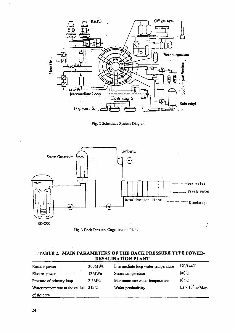
(1) Back pressure type power and heat cogeneration plant.Using the heat, generated from the Heating Reactor to drive a back pressure turbine. Then the steam
goes to the sea water desalination plant to produce fresh water.
The temperature, at the outlet of the reactor core is 213°C.the in let temperature is 154'C, in the case of
fresh water productivity 1.2 * lO^m^/day. The power can be used for propulsion is about 12000KW.Main parameters of the cogeneration plant are as follows (see Tab. 2):
22
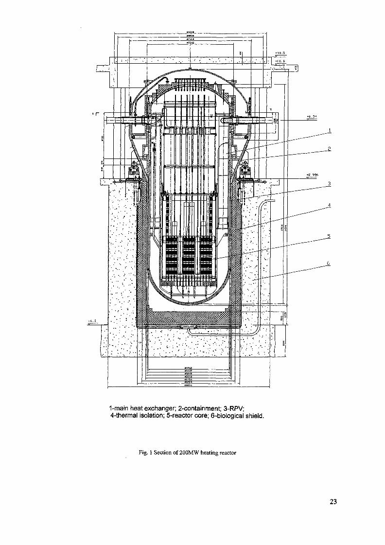
1-main heat exchanger; 2-containment; 3-RPV;4-thermal isolation; 5-reactor core; 6-biological shield.
Fig. 1 Section of 200MW heating reactor
23
RHRS Offgassyst.
a
Liq. west S. -
Fig. 2 Schematic System Diagram
Steam Generator
HR-200
J
turbine
Desalination Plant I
- -Sea water
Fresh water
Discharge
Fig. 3 Back Pressure Cogeneration Plant
TABLE 2. MAIN PARAMETERS OF THE BACK PRESSURE TYPE POWER-DESALINATION PLANT
Reactor power .
Electro-power
Pressure of primary loop
Water temperature at the outlet 213 °C
of the core
200MWt Intermediate loop water temperature 170/144 °C
12MWe Steam temperature 140 *C
2.5MPa Maximum sea water temperature 105*C
Water productivity 1.2 * 105m3/day.
24
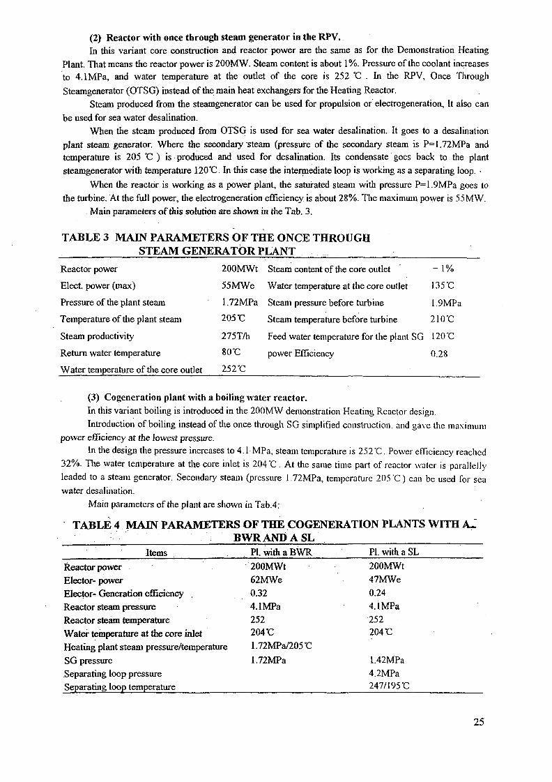
(2) Reactor with once through steam generator in the RPV.In this variant core construction and reactor power are the same as for the Demonstration Heating
Plant. That means the reactor power is 200MW. Steam content is about 1%. Pressure of the coolant increases
to 4.1MPa, and water temperature at the outlet of the core is 252 °C . In the RPV, Once Through
Steamgenerator (OTSG) instead of the main heat exchangers for the Heating Reactor.
Steam produced from the steamgenerator can be used for propulsion or electrogeneration, It also can
be used for sea water desalination.
When the steam produced from OTSG is used for sea water desalination. It goes to a desalination
plant steam generator. Where the secondary steam (pressure of the secondary steam is P=1.72MPa and
temperature is 205 °C ) is produced and used for desalination. Its condensate goes back to the plant
steamgenerator with temperature 120*C. In this case the intermediate loop is working as a separating loop. •
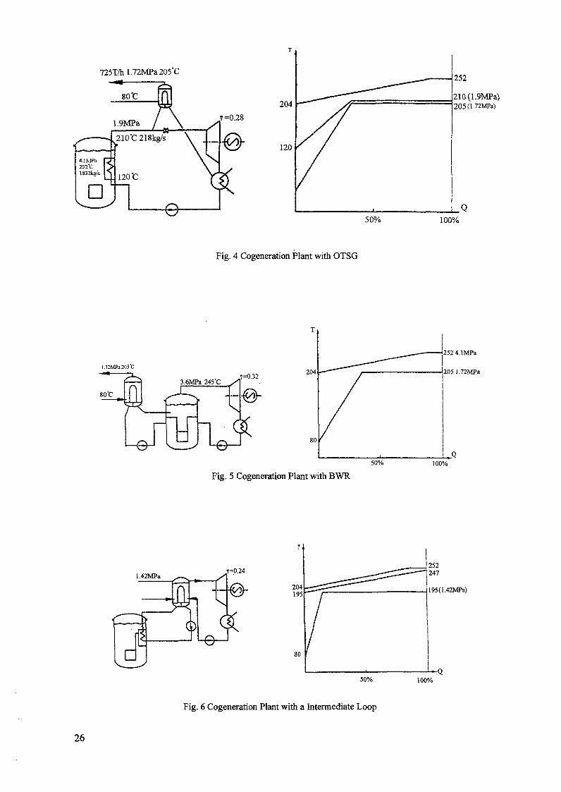
When the reactor is working as a power plant, the saturated steam with pressure P= 1.9MPa goes to
the turbine. At the full power, die electrogeneration efficiency is about 28%. The maximum power is 55MW.
Main parameters of this solution are shown in the Tab. 3.
TABLE 3 MAIN PARAMETERS OF THE ONCE THROUGHSTEAM GENERATOR PLANT
Reactor power 200MWt Steam content of the core outlet ~ 1%
Elect, power (max) 55MWe Water temperature at the core outlet 135 *C
Pressure of the plant steam 1.72MPa Steam pressure before turbine 1.9MPa
Temperature of the plant steam 205 °C Steam temperature before turbine 2 ICC
Steam productivity 275T/h Feed water temperature for the plant SG 120"C
Return water temperature 80 "C power Efficiency 0.28
Water temperature of the core outlet 252 "C
(3) Cogeneration plant with a boiling water reactor.
In this variant boiling is introduced in the 200MW demonstration Heating Reactor design.
Introduction of boiling instead of the once through SG simplified construction, and gave the maximum
power efficiency at the lowest pressirre.
In the design the pressure increases to 4.1 MPa, steam temperature is 252 "C. Power efficiency readied
32%. The water temperature at the core inlet is 204 "C . At the same time part of reactor waler is parallelly
leaded to a steam generator. Secondary steam (pressure 1 72MPa, temperature 205 "C) can be used for sea
water desalination.
Main parameters of the plant are shown in Tab.4:
TABLE 4 MAIN PARAMETERS OF THE COGENERATION PLANTS WITH A-BWRANDASL
Items
Reactor power
Elector- powerElector* Generation efficiencyReactor steam pressureReactor steam temperatureWater temperature at the core inletHeating plant steam pressure/temperature
SG pressure
Separating loop pressure
Separating loop temperature
Pl.withaBWR
200MWt62MWe
0.32
4.1MPa252204 'C
1.72MPa/205'C
1.72MPa
PI. with a SL
200MWt
47MWe
0.24
4.1MPa
252204 'C
l.42MPa
4.2MPa247/195 °C
25
725T/hl.72MPa205°C
7=0.28
204
120
252
210{1.9MPa)205(l-72MPa)
50% 100%
l.72MPa2O5"C
Fig. 4 Cogeneration Plant with OTSG
7=0.32204
80
50%
Fig. 5 Cogeneration Plant with BWR
252 4.lMPa
205 I.72MPa
<i100%
1.42MPa7=0.24
204195
50%
. 195(1.42MPa)
100%
Fig. 6 Cogeneration Plant with a Intermediate Loop
26
(4) Cogeneration plant with a Separating loop.In order to effectively separate the power loops from reactor radioactive primary loop,, as in the
Demonstration Heating Plant, a intermediate loop solution is adopted in this design variant.
In this variant, reactor work pressure increased to 4.1 MPa. Steam content at the core outlet is about1%, water temperature 252°C. At the core inlet water temperature is 204 °C.
Secondary loop is a separating loop, its pressure 4.2MPa, consisted of main heat exchanger, steam
generator (SG) and circulating pumps. In the primary side of the SG temperature are 247/195 °C , in the
secondary side (lie steam pressure is L42MPa, temperature 195 °C . Part of steam is used for power
generation. The other part of steam is used for desalination or heating. Quantify of heat and power can be
regulated by a distribution valve.
If all steam is used for power generation, the maximum power is 47MW and elector-generation
efficiency is about 24%.
This variant is more close to the existed Heating Reactor design. Changes are very small. Radioactive
water leakage is almost impossible and power productivity is enough high.
Main parameters of the cogeneration Plant with a Separation Loop (SL) are shown is Tab. 4.
4. COMPARISON AND CONCLUSION
In above variants, the first one under the same pressure (=2.5MPa) as for the existed Heating Reactor
design, the reactor can supply some quantity power, but the quantity is small and power efficiency is low (see
variant O).
If pressure is increased to 4.1MPa, and boiling is introduced in the reactor core, the power
productivity will be reasonable increased. In these variants the variant with separating loop more close lo
original Heating Reactor design. It will be easier to go through the license procedure. But it power efficiency
only about 24%.
Once Through Steam Generator variant gives a higher efficiency of but the height of the reactor will
be increased, because the steam generator is longer than original heat exchanger.
Boiling water reactor variant gives highest efficiency. But introduce of boiling with a lower pressure
requires some additional R & D work. The construction of the core has to do some changes.
At the time being we are working for the variant with a separating loop.
27
BASIC SAFETY PRINCIPLES OF KLT-40C REACTOR PLANTS
V. BELIAEV, V. POLUNICHEVOKB Mechanical Engineering, XA0056266Nizhny Novgorod,Russian Federation
Abstract
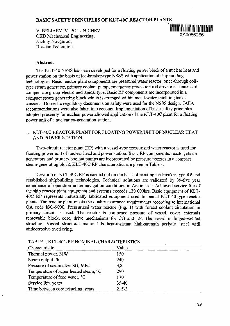
The KLT-40 NSSS has been developed for a floating power block of a nuclear heat andpower station on the basis of ice-breaker-type NSSS with application of shipbuildingtechnologies. Basic reactor plant components are pressured water reactor, once-through coil-type steam generator, primary coolant pump, emergency protection rod drive mechanisms ofcompensate group-electromechanical type. Basic RP components are incorporated in acompact steam generating block which is arranged within metal-water shielding tank'scaissons. Domestic regulatory documents on safety were used for the NSSS design. IAEArecommendations were also taken into account. Implementation of basic safety principlesadopted presently for nuclear power allowed application of the KLT-40C plant for a floatingpower unit of a nuclear co-generation station.
1. KLT-40C REACTOR PLANT FOR FLOATING POWER UNIT OF NUCLEAR HEATAND POWER STATION
Two-circuit reactor plant (RP) with a vessel-type pressurized water reactor is used forfloating power unit of nuclear head and power station. Basic RP components: reactor, steamgenerators and primary coolant pumps are incorporated by pressure nozzles in a compactsteam-generating block. KLT-40C RP characteristics are given in Table 1.
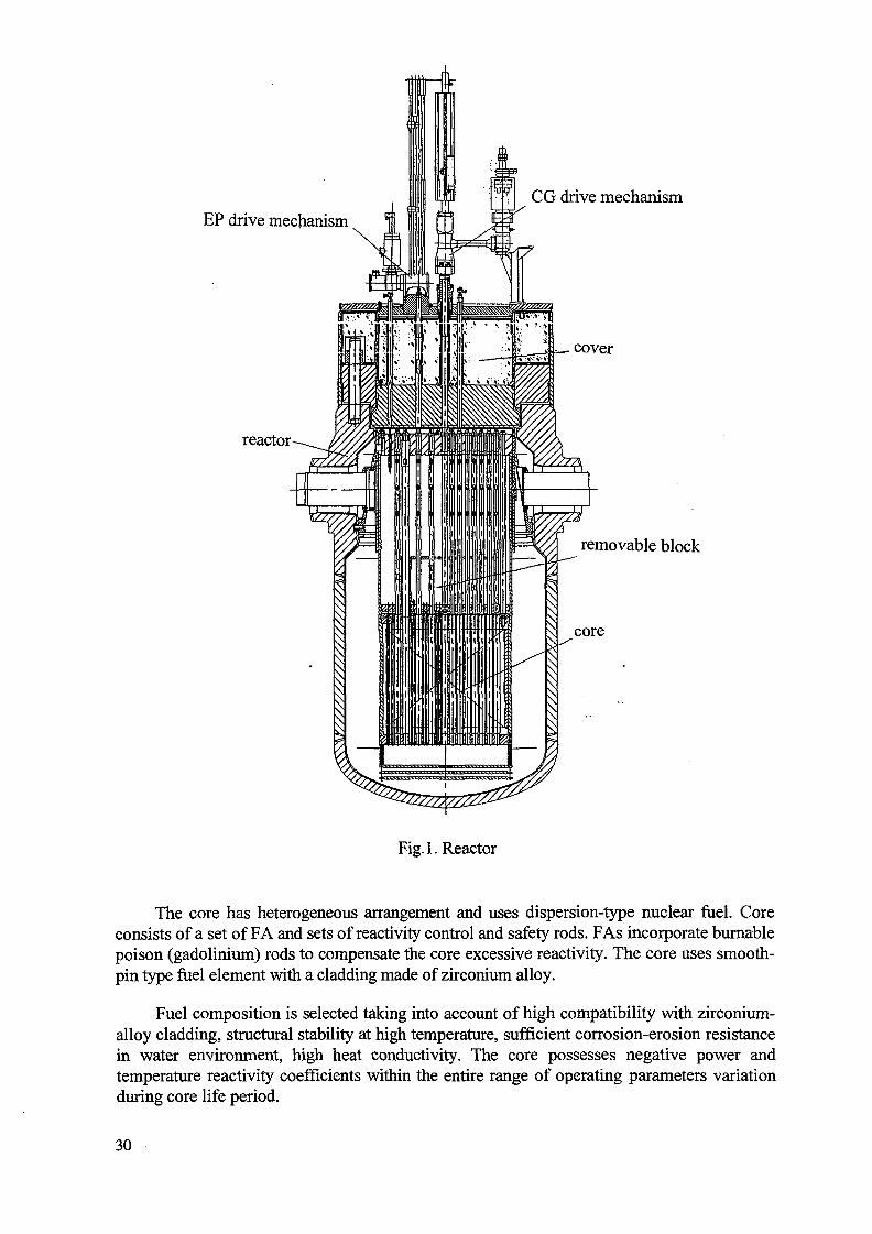
Creation of KLT-40C RP is carried out on the basis of existing ice-breaker-type RP andestablished shipbuilding technologies. Technical solutions are validated by 39-five yearexperience of operation under navigation conditions in Arctic seas. Achieved service life ofthe ship reactor plant equipment and systems exceeds 130 OOOhrs. Basic equipment of KLT-40C RP represents industrially fabricated equipment used for serial KLT-40-type reactorplants. The reactor plant meets the quality assurance requirements according to internationalQA code ISO-9000. Pressurized water reactor (Fig. 1) with forced coolant circulation inprimary circuit is used. The reactor is composed pressure of vessel, cover, internalsremovable block, core, drive mechanisms for CG and EP. The vessel is forged-weldedstructure. Vessel structural material is heat-resistant high-strength perlytic steel with"ahticorrosive overlaying.
TABLE I. KLT-40C RP NOMINAL CHARACTERISTICSCharacteristic ValueThermal power, MW 15 0Steam output t/h 240Pressure of steam after SG, MPa 3,8Temperature of super heated steam, °C 290Temperature of feed water, °C 170Service life, years 35-40Time between core refueling, years 2, 5-3
29
EP drive mechanism
reactor-
CG drive mechanism
=_ cover
removable block
core
Fig. 1. Reactor
The core has heterogeneous arrangement and uses dispersion-type nuclear fuel. Coreconsists of a set of FA and sets of reactivity control and safety rods. FAs incorporate burnablepoison (gadolinium) rods to compensate the core excessive reactivity. The core uses smooth-pin type fuel element with a cladding made of zirconium alloy.
Fuel composition is selected taking into account of high compatibility with zirconium-alloy cladding, structural stability at high temperature, sufficient corrosion-erosion resistancein water environment, high heat conductivity. The core possesses negative power andtemperature reactivity coefficients within the entire range of operating parameters variationduring core life period.
30
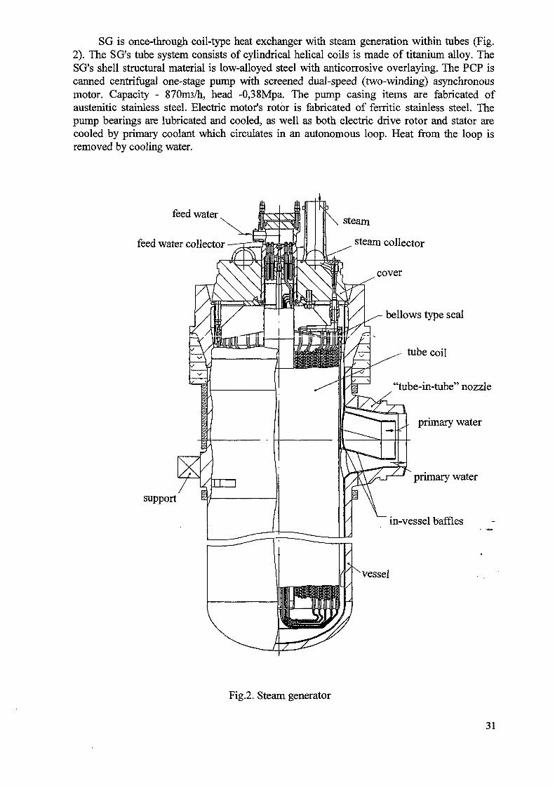
SG is once-through coil-type heat exchanger with steam generation within tubes (Fig.2). The SG's tube system consists of cylindrical helical coils is made of titanium alloy. TheSG's shell structural material is low-alloyed steel with anticorrosive overlaying. The PCP iscanned centrifugal one-stage pump with screened dual-speed (two-winding) asynchronousmotor. Capacity - 870m3/h, head -0,38Mpa. The pump casing items are fabricated ofaustenitic stainless steel. Electric motor's rotor is fabricated of ferritic stainless steel. Thepump bearings are lubricated and cooled, as well as both electric drive rotor and stator arecooled by primary coolant which circulates in an autonomous loop. Heat from the loop isremoved by cooling water.
feed water
feed water collector
steam
steam collector
cover
support
bellows type seal
tube coil
'tube-in-tube" nozzle
primary water
primary water
in-vessel baffles
vessel
Fig.2. Steam generator
31
The emergency protection rod drive mechanism is an electromechanical type actuatorconsisting of rack mechanism with a spring, asynchronous motor and electromagnet. Scramtime is not more than 0,5s. Absorber rods are inserted under spring action when holdingelectromagnets are de-energizated.
The drive mechanism of compensate group consists of, screwed reducer, steppedelectric motor, movement sensor, reference points sensors. Working speed is 2mm/s.Emergency speed of lowering by electric motor on trip signals is 4mm/s. Average speed oflowering under gravity is 30 to 130mm/s.
The steam-generating block is arranged within metal-water shielding tank's caissons(Fig. 3). Auxiliary equipment items including pressurizes, filter, heat exchangers are alsolocated in the tank's caissons. All radiation sources are surrounded by shielding. RP shieldingconsists of the tank, removable of dry shielding blocks and peripheral shielding on protectiveenclosure walls.
Main codes are used:
"General Principles of Safety Provision for NPPS" (OPB-88).- "Rules of Nuclear Safety for Nuclear Reactor Plants of NPPS" (PBYA RU AS-89).- Norms of Radiological Safety NRB-96. Hygiene's standards GN 2.6.1.054-96 Law of
Russian Federation "Radiological safety of population".- Rules of nuclear ships classification and building for Russia's sea ship navigation
register.
Other effective guides and rules for nuclear stations. IAEA recommendations are takeninto account at KLT-40 RP development:
- basic principles of safety referring to safety control and full-scope realization of in-depthprotection strategy;
- main technical principles including the use of approved engineering-technical practice,assuring quality, account of man-factor, systemic analysis, evaluation and substantiationof safety using deterministic and probabilistic methods, analysis, account of analoguesoperation experience;
- execution of measures on radiation protection of personnel, population, on environmentunder normal operation and at emergencies including postulated severe accident withcore damage;
- recommendations on specific engineering decisions referring to all-sided development ofintrinsic safety, use of safe failure principle, redundancy, diversity, spatial separation, of/means and systems important to safety, use of passive systems and self-acting safetydevices, assurance of accident control capabilities.
- recommendations on specific engineering decisions referring to all-sided development ofintrinsic safety, use of safe failure principle, redundancy, diversity, spatial separation ofmeans and systems important to safety, use of passive systems and self-acting safetydevices, assurance of accident control capabilities.
2. MAIN SAFETY PRINCIPLES
Next main safety principles are taken into account at KLT-40 RP:- use of pressurized water reactor with developed intrinsic safety provided by core feed
back, reactor thermal inertia, coolant natural circulation in emergency situations, etc.
32
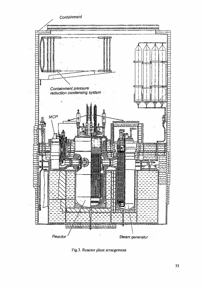
Containment
Containment pressurereduction condensing system
WIWKWW
Reactor Steam generator
Fig. 3. Reactor plant arrangement
33

- Provision of in-depth functional and physical protection by effective safety barriers andisolation systems eliminating the discharge of radioactive products beyond FPUboundaries at most severe accidents accompanied by additional failures (Fig. 4).
- establishment of protection against inner and outer impacts.- Use of conservative approach when developing physical barriers, safety systems, choice
and substantiation of initial events of accidents and their development scenarios.- Use of physically separated safety systems of both active and principle of operation
without use of external power sources and without personnel intervention.- Use of highly reliable self-diagnosing automatic control systems and operator logical
information support systems.- Use of diagnostic control systems allowing to determine the actual state and remaining
life of the nuclear plant most responsible equipment and pipelines.- Realization of maximally attainable reactor plant waste-free technology limiting
formation of liquid radioactive waste during the reactor plant operation.
Primary circuit system (Fig. 5) includes:
- main circulation circuit;- pressurization system;- purification and cooldown system,
Next safety systems are used at KLT-40 RP:
- reactor trip system;- emergency cooldown system;- emergency core cooling system;- containment emergency pressure reduction system; containment system;- reactor caisson water filling system.
Reactor trip system includes;
- four independent groups of safety rods with individual drive mechanisms actuatedpassively under compressed springs action;
- five independent compensating groups (CG) with individual drive mechanisms ensurereactor trip on the control system signals by:
- lowering by electric drive with emergency speed; lowering under gravity; liquid absorberinjection system (back up system).
It is provided for lowering under gravity using safety devices for CG-drives de-energization executing by increase of primary circuit pressure.
Emergency cooldown system consists of:
- active cooldown train through primary circuit purification system's heat exchanger withheat transfer via third circuit to ambient sea water;
- active cooldown train through steam generators with heat removal to process condenserand then to sea water;
- two passive cooldown trains through steam generators with heat removal to emergencycooldown water tank heat exchanger and then to the atmosphere by means of waterevaporation in tank.
The system is actuated both control system and direct action of process parameter, i.e.by increased primary pressure using hydraulically- controlled air distributors.
34
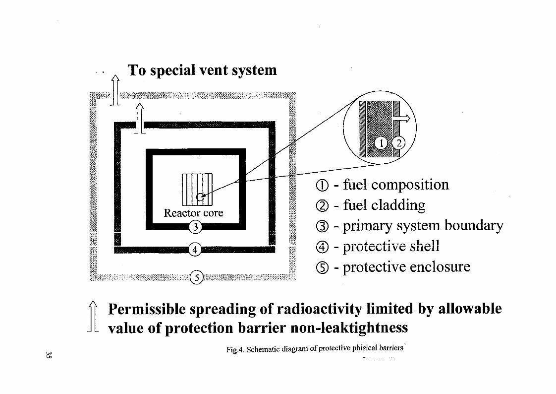
To special vent system
Reactor core3
- fuel composition- fuel cladding- primary system boundary- protective shell- protective enclosure
A Permissible spreading of radioactivity limited by allowablevalue of protection barrier non-leaktightness
Fig.4. Schematic diagram of protective phisical barriers'
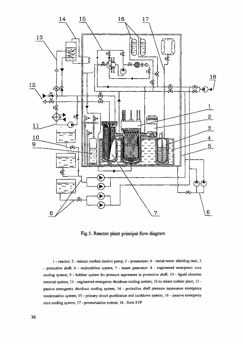
14 15
13
Fig. 5. Reactor plant principal flow diagram
1 - reactor; 2 - reactor coolant electric pump; 3 - pressurizer; 4 - metal-water shielding tank; 5
- protective shell; 6 - recirculation system; 7 - steam generator: 8 - engineered emergency core
cooling system; 9 - bubbler system for pressure supressure in protective shell; 10 - liguid absorber
removal system; 11 - engineered emergency shutdoun cooling system; 12-to steam turbine plant; 13 -
passive emergency shutdoun cooling system; 14 - protective shell pressure supressure emergency
condensation system; 15 - primary circuit purification and cooldown system; 16 - passive emergency
core cooling system; 17 - pressurization system; 18 - from STP
36
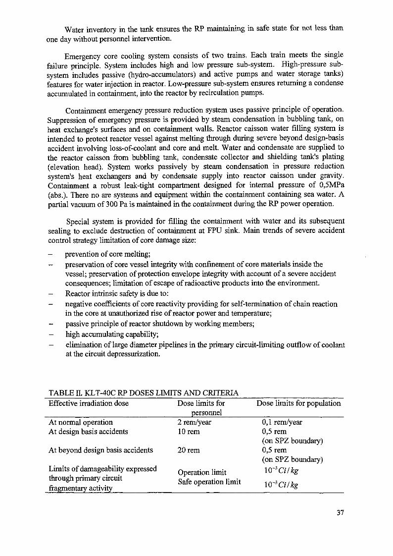
Water inventory in the tank ensures the RP maintaining in safe state for not less thanone day without personnel intervention.
Emergency core cooling system consists of two trains. Each train meets the singlefailure principle. System includes high and low pressure sub-system. High-pressure sub-system includes passive (hydro-accumulators) and active pumps and water storage tanks)features for water injection in reactor. Low-pressure sub-system ensures returning a condenseaccumulated in containment, into the reactor by recirculation pumps.
Containment emergency pressure reduction system uses passive principle of operation.Suppression of emergency pressure is provided by steam condensation in bubbling tank, onheat exchange's surfaces and on containment walls. Reactor caisson water filling system isintended to protect reactor vessel against melting through during severe beyond design-basisaccident involving loss-of-coolant and core and melt. Water and condensate are supplied tothe reactor caisson from bubbling tank, condensate collector and shielding tank's plating(elevation head). System works passively by steam condensation in pressure reductionsystem's heat exchangers and by condensate supply into reactor caisson under gravity.Containment a robust leak-tight compartment designed for internal pressure of 0,5MPa(abs.). There no are systems and equipment within the containment containing sea water. Apartial vacuum of 300 Pa is maintained in the containment during the RP power operation.
Special system is provided for filling the containment with water and its subsequentsealing to exclude destruction of containment at FPU sink. Main trends of severe accidentcontrol strategy limitation of core damage size:
- prevention of core melting;- preservation of core vessel integrity with confinement of core materials inside the
vessel; preservation of protection envelope integrity with account of a severe accidentconsequences; limitation of escape of radioactive products into the environment.
- Reactor intrinsic safety is due to:- negative coefficients of core reactivity providing for self-termination of chain reaction
in the core at unauthorized rise of reactor power and temperature;- passive principle of reactor shutdown by working members;- high accumulating capability;- elimination of large diameter pipelines in the primary circuit-limiting outflow of coolant
at the circuit depressurization.
TABLE II. KLT-40C RP DOSES LIMITS AND CRITERIAEffective irradiation dose
At normal operationAt design basis accidents
At beyond design basis accidents
Limits of damageability expressed
through primary circuitfragmentary activity
Dose limits forpersonnel
2 rem/year10 rem
20 rem
Operation limitSafe operation limit
Dose limits for population
0,1 rem/year0,5 rem(on SPZ boundary)0,5 rem(on SPZ boundary)
10~3 Cilkg
1 1 1 1 7 / iTCT
37
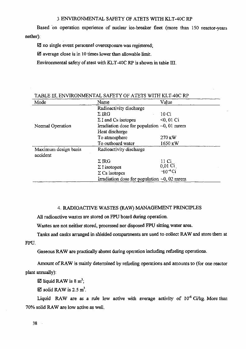
3 ENVIRONMENTAL SAFETY OF ATETS WITH KLT-40C RP
Based on operation experience of nuclear ice-breaker fleet (more than 150 reactor-years
nether):
0 no single event personnel overexposure was registered;
0 average close is in 10 times lower than allowable limit.
Environmental safety of atest with KLT-40C RP is shown in table HI.
TABLE m. ENVIRONMENTAL SAFETY OF ATETS WITH KLT-40C RPMode
Normal Operation
Maximum design basisaccident
NameRadioactivity dischargeSIRG£ I and Cs isotopesIrradiation dose for populationHeat dischargeTo atmosphereTo outboard waterRadioactivity discharge
2IRG2 I isotopes2 Cs isotopesIrradiation dose for population
Value
10 Ci<0, 01 Ci~0,01 mrem
270 KW
1 6 5 0 K W
11 Ci0,01 Ci i
~10~6Ci~0,02 mrem
4. RADIOACTIVE WASTES (RAW) MANAGEMENT PRINCIPLES
All radioactive wastes are stored on FPU board during operation.
Wastes are not neither stored, processed nor disposed FPU sitting water area.
Tanks and casks arranged in shielded compartments are used to collect RAW and store them at
FPU.
Gaseous RAW are practically absent during operation including refueling operations.
Amount of RAW is mainly determined by refueling operations and amounts to (for one reactor
plant annually):
0 liquid RAW is 8 m3;
0 solid RAW is 2.5 m3.
Liquid RAW are as a rule low active with average activity of 10"6 Ci/kg. More than
70% solid RAW are low active as well.
38
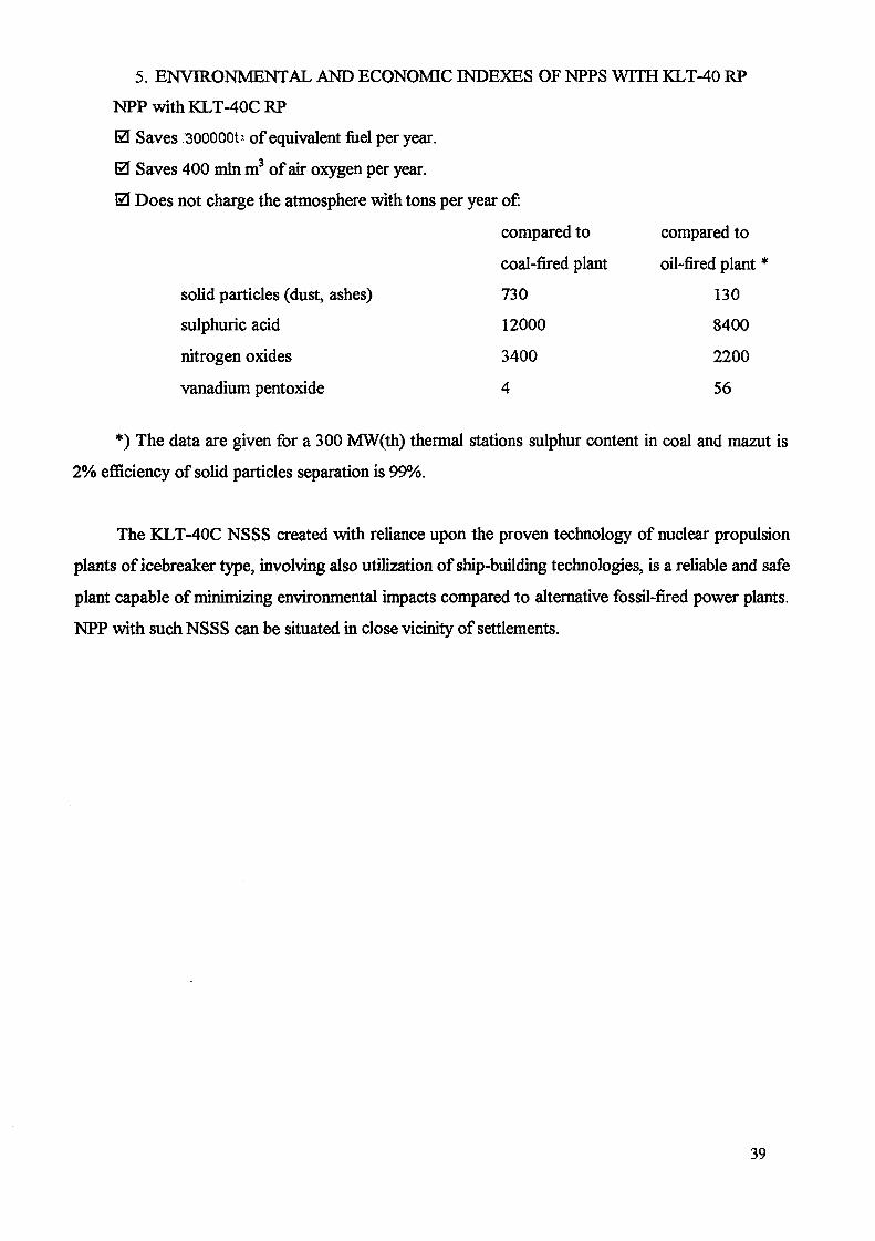
5. ENVIRONMENTAL AND ECONOMIC INDEXES OF NPPS WITH KLT-40 RP
NPPwithKLT-40CRP
0 Saves 300000t' of equivalent fuel per year.
0 Saves 400 mm m3 of air oxygen per year.
0 Does not charge the atmosphere with tons per year of:
compared to compared to
coal-fired plant oil-fired plant *
solid particles (dust, ashes) 730 130
sulphuric acid 12000 8400
nitrogen oxides 3400 2200
vanadium pentoxide 4 56
*) The data are given for a 300 MW(th) thermal stations sulphur content in coal and mazut is
2% efficiency of solid particles separation is 99%.
The KLT-40C NSSS created with reliance upon the proven technology of nuclear propulsion
plants of icebreaker type, involving also utilization of ship-building technologies, is a reliable and safe
plant capable of minimizing environmental impacts compared to alternative fossil-fired power plants.
NPP with such NSSS can be situated in close vicinity of settlements.
39

A FLOATING DESALINATION/CO-GENERATION SYSTEM USING THEKLT-40 REACTOR AND CANADIAN RO DESALINATION TECHNOLOGY
J.R. HUMPHRIES, K. DAVIESCandesal Enterprises Ltd, XA0056267Ottawa, Canada
Abstract
As the global consumption of water increases with growing populations and rising levels ofindustrialization, major new sources of potable water production must be developed. To address thisissue efficiently and economically, a new approach has been developed in Canada for the integrationof reverse osmosis (RO) desalination systems with nuclear reactors as an energy source. The resultingnuclear desalination/cogeneration plant makes use of waste heat from the electrical generationprocess to preheat the RO feedwater, advanced feedwater pre-treatment and sophisticated systemdesign integration and optimization techniques. These innovations have led to improved waterproduction efficiency, lower water production costs and reduced environmental impact.
The Russian Federation is developing the KL T-40 reactor for application as a Floating Power Unit(FPU). The reactor is ideally suited for such purposes, having had many years of successful operationas a marine propulsion reactor aboardffoating nuclear powered icebreakers and other nuclearpropelled vessels. Under the terms of a cooperation agreement with the Russian Federation Ministryof Atomic Energy, CANDESAL Enterprises Ltd. has evaluated the FPU, containing two KLT-40reactors, as a source of electrical energy and waste heat for RO desalination. A design concept for affoating nuclear desalination complex consisting of the FPU and a barge mounted RO desalinationunit has been analyzed to establish preliminary performance characteristics for the complex.
The FPU, operating as a barge mounted electrical generating station, provides electricity to thedesalination barge. In addition, the condenser cooling water from the FPU is used as a source ofpreheated feedwater for the RO system on the desalination barge. The waste heat produced by theelectrical generating process is sufficient to provide RO feedwater at a temperature of about 10°Cabove ambient seawater temperature. Preliminary design studies have indicated that under theseconditions approximately 100,000 ms/d of potable water can be produced. The use of preheatedfeedwater results in an improvement in water production efficiency of up to about 15% relative to asystem operating at the ambient seawater temperature.
This preliminary design study has shown that significant improvements in the cost of water productioncan be achieved through this "marriage " of Russian small reactor technology and Canadian ROtechnology. The potential beneffts warrant further detailed evaluation followed by a demonstrationproject.
A FLOATING DESALINATION/COGENERATION SYSTEM USING THE
KLT-40 REACTOR AND CANADIAN RO DESALINATION TECHNOLOGY
1. INTRODUCTION
In many regions of the world the supply of renewable water resources is inadequate to meet currentneeds, and that from non-renewable sources is being rapidly depleted. Since the worldwide demandfor potable water is steadily growing, the result is water shortages that are already reaching seriousproportions in many regions, with the threat of global water starvation continuing to grow. To mitigate
41
the stress being placed on water resources, additional fresh water production capability must bedeveloped. For many regions seawater desalination is the best alternative. The main drawback ofdesalination, however, is that it is an energy intensive process. Therefore, the increasing globaldemand for desalted water creates a tremendous collateral demand for new sources of electrical power.Since water is an undeniable life sustaining resource, improvements in the efficiency of energyutilization must be considered a significant benefit to both the environment and the consumer.CANDESAL Enterprises Ltd. is a Canadian company working internationally to improve the energyefficiency and economics of fresh water production and to deliver that technology to markets wheresuch facilities are most required.
In December 1994 the International Atomic Energy Agency (IAEA) sponsored one of a series ofconferences on nuclear desalination in Cairo, Egypt. The Russian delegation at that conference metwith the CANDESAL delegation to discuss a project that was in the planning stages by the Ministry ofAtomic Energy's (MINATOM) Design and Engineering Bureau, OKBM. The project was to designand build a series of floating barges using nuclear reactors for electrical generation and as an energysource for desalination. The initial objective was to meet the requirements of the resource industriesworking in Russia's northern littoral, and then to use these floating desalination/cogeneration barges tohelp meet the world demand for additional energy and water production, particularly in the Middleand Far East. In the conceptual stages of the project, primarily distillation systems were beingconsidered. However, the work done by CANDESAL was clearly showing the potential forsignificantly reducing the production costs of potable water through the use of reverse osmosis (RO)technology. In view of the potential benefits, it was agreed that a cooperative venture should beundertaken to evaluate the use of RO desalination with the Russian power barges. Following thesepreliminary discussions a Memorandum of Understanding (MOU) between MINATOM andCANDESAL was signed in 1995 for a period of two years. This MOU has recently been extended fora period of five years.
2. WATER SCARCITY, A GROWING GLOBAL CONCERN
There is a growing international recognition that the shortage of adequate supplies of potable water,which has already reached critical proportions in many areas of the world, is one of the majorproblems facing society as the 21st century approaches. There is also an acknowledged need foradditional electrical generation capacity throughout the developing world. Frequently, these shortagesin potable water supply and electrical energy exist together.
The supply of naturally occurring fresh water available for human use is limited. It consists of non-renewable sources such as aquifers and other reservoirs that are not recharged as they are used, andrenewable sources such as lakes, rivers, reservoirs and other sources that are replenished by the annualwater, or hydrologic, cycle. However, the amount of water available in a given location as a result ofthe natural water cycle is essentially fixed. Thus as the population increases, the annual water supplyper person, which is a general indicator of water security, decreases. The per capita water suppliesworldwide are approximately one third less now than in 1970 due to population growth since thattime.111 The water supply crises which already exist and are projected over the next few decades havereceived much attention recently.tl6! Population Action International expressed the concern quite
succinctly when they stated161 that "without water, economic development becomes virtuallyimpossible and conflict over scarce resources virtually inevitable" and "availability of and access toclean water and sanitation are among the most important determinants of the health of individualhuman beings."
Figure l m illustrates the percentage of urban populations with access to safe drinking water. It isestimated that around the world approximately one billion people do not have access to safe water, and1.8 billion do not have adequate sanitary facilities. The lack of water is a detriment to human health tothese people.
42

Access to Safe Drinking Water
* 4,
PEDCEN? Oe WtPUl XilOltlN*IRBAH ARFA5 HftVlhSfi «TFSSi "t»C U AN WtfftS
- V 9 5 QB WOftE
Figure 1Percentage of Urban Population Having Access to Safe Drinking Water
Hydrologists have adopted the concept of a "water stress index" based on an approximate minimumlevel of water required per capita to maintain an adequate quality of life in a moderately developedcountry in an arid zone. Although the indicators are only approximate, it has been found that a countryor region whose renewable fresh water availability exceeds about 1700-2000 m3 per person per yearwill suffer only occasional or local water problems. Below this threshold the lack of water begins tobecome a serious problem. Two rough benchmark levels have been adopted:
•- Water Stressed: A country or region is considered water stressed if the availability ofrenewable fresh water supplies falls between 1000 and 2000 m3 per person per year.
•= Water Scarce: A country or region is considered water scarce if the availability ofrenewable fresh water supplies is less than 1000 m3 per person per year. At this level, thechronic lack of water begins to hamper human health and well being, and is a severe restrainton food production, economic development and protection of natural systems. Below 500 m3
per person per year, there is considered to be an absolute scarcity of fresh water.
Since renewable fresh water resources are essentially constant, the per capita availability falls aspopulation rises, pushing more and more countries over time into water stress and water scarcity.Figure 2 illustrates on a global basis the countries projected to experience water stress or waterscarcity by the year 2025, based on a United Nations medium population projection.'61
3. DESALINATION AS A SOURCE O F POTABLE WATER
Seawater is the largest source of available water. It is estimated that only 2.5% of the earth's1.4 billion km3 of water is fresh water, and 69% of that is in the form of ice (polar ice caps andglaciers) or in underground aquifers too deep to tap. The amount of fresh water that is available isessentially fixed, and as the population continues to grow, the per capita availability shrinks. Seawater,on the other hand, is available in essentially unlimited quantities in the foreseeable future, and is stillrelatively unpolluted compared with natural fresh water sources many regions of the world.
As other sources of water have become increasingly scarce and increasingly expensive to makeavailable, desalination of seawater has become a more attractive option for the production of potablewater. By the late 1960s commercial units of up to 8,000 m3/d were beginning to be installed invarious parts of the world. These were primarily thermal distillation units, but by the 1970scommercial membrane processes were also becoming available. Figure 3 illustrates the rapid growth
43

Figure 2Population and Water Availability
of desalination as a source of potable water since that time. As of 1995, there were about 20 millionm3/d of desalination capacity either installed or contracted for around the world. That number isexpected18'91 to increase to well over 35 million m3/d over the next ten years.
re
afaI&
1IB
m
4U •
35 -
3 0 -
25 -
2 0 -
15 -
10
5
n -
\
i ]
j j
• • |
] !
<
i
t s
/
/
\\
1960 1965 1970 1975 1980 1985 1990 1995 2000 2005
Figure 3Worldwide Contracted Cumulative Seawater Desalination Capacity
2010
44
Recognizing the severity of the problem of global water shortages and the immensity of the energyrequirement necessary to adequately address the problem, the International Atomic Energy Agency(IAEA) has been working since 1989 to assess the technical and economic potential for using nuclearreactors as a source of energy for seawater desalination. The results of studies18"101 carried out by theIAEA and its Member States have shown that the use of nuclear energy for desalination is technicallyfeasible and in general economically competitive with fossil-fueled energy sources. As a result of thesuccess of its efforts to date, the IAEA is expanding its nuclear desalination program, and is activelysupporting efforts amongst Member States to introduce nuclear desalination demonstration projects.
4. A FLOATING NUCLEAR DESALINATION/COGENERATION SYSTEM
4.1 Development of the C ANDESAL Design Approach
Because of the pressing need for additional large scale water production capability, the focus ofCANDESAL's early design concept development work was placed first on the use of the CANDUnuclear reactor as an energy source for desalination. Two approaches were considered in preliminarystudies: the use of electrical energy for reverse osmosis (RO) and the use of process steam from thenuclear steam supply system to provide the energy for a multi-effect distillation system. This latterapproach was found to require changes to the balance of plant design that were both expensive toimplement and led to reduced electrical generating efficiency to such a degree that the total water andelectrical production capacity was not as great as that which could be achieved using RO.
Having selected the RO process, it was then recognized that improvements in the efficiency of energyutilization could be achieved by taking advantage of waste heat normally discharged from the reactorthrough the condenser cooling system. Use of the condenser cooling water as preheated feedwater tothe RO system improves the efficiency of the RO process, and therefore the economics of waterproduction. As the development work progressed, it was also found that further improvements couldbe achieved by taking a systems approach to optimizing the design. Hence a strong emphasis has beenplaced on the integration of the energy and water production systems into a single, optimized designfor the cogeneration of both water and electricity. Details of the CANDESAL approach to theapplication of RO seawater desalination technology have been described elsewhere'11"151.
This approach to the integration of seawater desalination systems with nuclear reactors has theadvantage of maximizing the benefits of system integration while at the same time minimizing theimpact of physical interaction between the two systems. In essence, the reactor operates without"knowing" that there is a desalination plant associated with it. Transients in the desalination plant donot have a feedback effect on reactor operation. This is extremely important, since there must be ahigh degree of assurance that unanticipated operating transients in the desalination unit do not have anadverse impact on either reactor safety or operational reliability. Conversely, it would also beundesirable to have reactor shutdowns, whether unanticipated or for planned maintenance, that wouldrequire shutdown of the water production plant.
Hence as the CANDESAL nuclear desalination/cogeneration system design has developed, it hasevolved in a direction which allows standardized reactor systems to be used without modification,while at the same time accruing significant benefits from the systems integration due to improvedperformance characteristics and energy utilization. Furthermore, because of the "loose" coupling tothe reactor system, the use of RO with preheated feedwater is ideally suited for application with smallmarine reactors such as the Russian KLT-40, since it allows the economic benefits of integrating theenergy generation and desalination systems without sacrificing the flexibility of the smaller reactors,including its use in floating systems.
4.2 The Floating Nuclear Seawater Desalination/Cogeneration Complex
The floating nuclear seawater desalination/cogeneration plant consists of two floating structures: afloating power unit (FPU) and an RO seawater desalination barge. This arrangement, which separatespower generation and potable water production, has certain advantages over an arrangement in which
45
they are combined on one floating structure. It allows either of the two systems to be usedindependently, and it allows manufacture in two separate shipyards if desired. It also simplifies asolution to the problem of preserving efficient potable water production from the complex when thereactors are shutdown by supplying the desalination ship with electric energy from a shore grid.Advantages of a floating desalination/cogeneration complex relative to a shore-based installationinclude:
•= the possibility of plant manufacture and testing at a shipyard in the Supplier country;
•= high fabrication quality at a shipyard and "turn-key" delivery in a short period of time;
•- convenient maintenance by a floating base at a mooring site and decommissioning by tuggingto the Supplier's country;
•= commercial production and long-term confirmation of service life characteristics of theKLT-40-type reactor plants and desalination units;
•= the possibility of installation in different coastal regions of the world; and
•= ease of redeployment of the facility to other locations if the need should arise.
The design and industrial enterprises of Russia are working on the development of the floating nuclearpower station for the country's northern regions. This can serve as a prototype for application of theFNPS in a desalination/cogeneration complex.
The second structure, the desalination barge, is a non-self-propelled structure housing systems andequipment providing for the supply of seawater to the desalination system, pretreatment of the feedsupply, desalination, supply of desalinated water to the on-shore distribution system, and cleaning ofthe desalination units.
Based on this two barge concept, OKBM has established design and performance characteristics forthe FPU sufficient to allow preliminary design work to proceed on the desalination barge. Thesecharacteristics have been provided to CANDESAL for use in the desalination system analysis. Theconditions taken as input to the analysis were:
Reactor/Condenser Design Parameters•= Number of reactors per system 2•= Electrical power production, per reactor 35 MWe*- Total electrical production 70 MWe•= Electrical power consumed as "house load" 5 MWe• = Condenser cooling water flow rate, per reactor 5400 m3/hr• = Total condenser cooling water flow rate 10,800 m3/hr•- Temperature rise across condenser 10°C
Seawater Conditions•~ Seawater temperature (design value) 18°C•= Seawater total dissolved solids (TDS) 38,500 ppm
4.3 RO System Conceptual Design Analysis
The RO system design is based on using spiral wound Dow FilmTec high rejection membranes forseawater desalination. Condenser cooling water being discharged from the reactor's condenser coolingwater system at a temperature 10°C above ambient seawater temperature is used as feedwater for thesystem. The water first passes through ultrafiltration (UF) pretreatment modules. The filtrate from theUF units is sent to capacitance tanks, from which suction is taken for the RO modules. The feedwateris pumped to high pressure (1000 psi) and then passes through the RO modules. The permeate fromthe RO membranes is discharged temporarily into potable water storage tanks, and from there goes to
46
an off-ship distribution system. Brine concentrate from the RO system is discharged back into the sea.Chemical pretreatment of feedwater and post-treatment of potable water is included as necessary.
The RO system design has been for optimum water production at 28°C, while still maintaining thecapability for water production within the design specification of the RO membranes when operatingat ambient seawater temperature. Based on the design inputs specified above, the desalination plant,consisting of a UF pre-treatment system and the RO desalination system has the followingcharacteristics:
UF System<
<<
<
»= Feed flow into UF modules»= UF system recovery•= UF filtrate flow»= Number of UF vessels»= UF membranes per vessel»= Total number of UF membranes
RO System
<<
<
<
»= Feed flow into RO system (UF filtrate)»= RO system design temperature•= RO system operating pressure• = RO system recovery (at 28 °C)•= Permeate flow»- Number of RO vessels•=• RO membranes per vessel»= Total number of RO membranes
259,000 m3/d90%233,000 m3/d180047200
233,000 m3/d28 °C1000 psi43.3 %101,000 m3/d1500710,500
Overall System Characteristics•- Number of 10 vessel by 10 vessel UF arrays 18•= Dimensions of 10x10 UF array 4mW x 5mH x 14mL
(Includes 4m x 5m x 6m space at end of array for pumps, headers, etc.)•= Number of 10 vessel by 10 vessel RO arrays 15•= Dimensions of 10x10 RO array 4mW x 5mH x 14mL
(Includes 4m x 5m x 6m space at end of array for pumps, headers, etc.)•= Weight of membrane and vessel arrays 1000 metric tons
(Includes water contained in the membranes/vessels)• = Total weight of system 15,00-20,00 metric tons•= Electrical power consumption for water production 18-19 MWe
4.4 High Ambient Seawater Temperatures
The above design characteristics are based on 18°C seawater. Calculations have also been carried outfor seawater temperatures of 30°C (40°C preheated RO feedwater), which is more representative oftemperatures along the coastline of some of the countries where a floating nuclear desalination systemwould have potential application. Analysis results are very similar, except that only 1200 RO vessels,containing a total of 8400 membranes, would be required. Hence only 12 RO arrays would be requiredunder these conditions. However, since it is important that the design be able to accommodate a rangeof seawater temperatures, at this preliminary stage the 18°C seawater temperature has been retained asa design basis. The UF section remains essentially unchanged at the higher temperatures.
4.5 Performance Analysis
In order to ensure that the RO system design meets all specified design conditions over the entirerange of operating temperatures, without exceeding any design or performance limitations imposed on
47
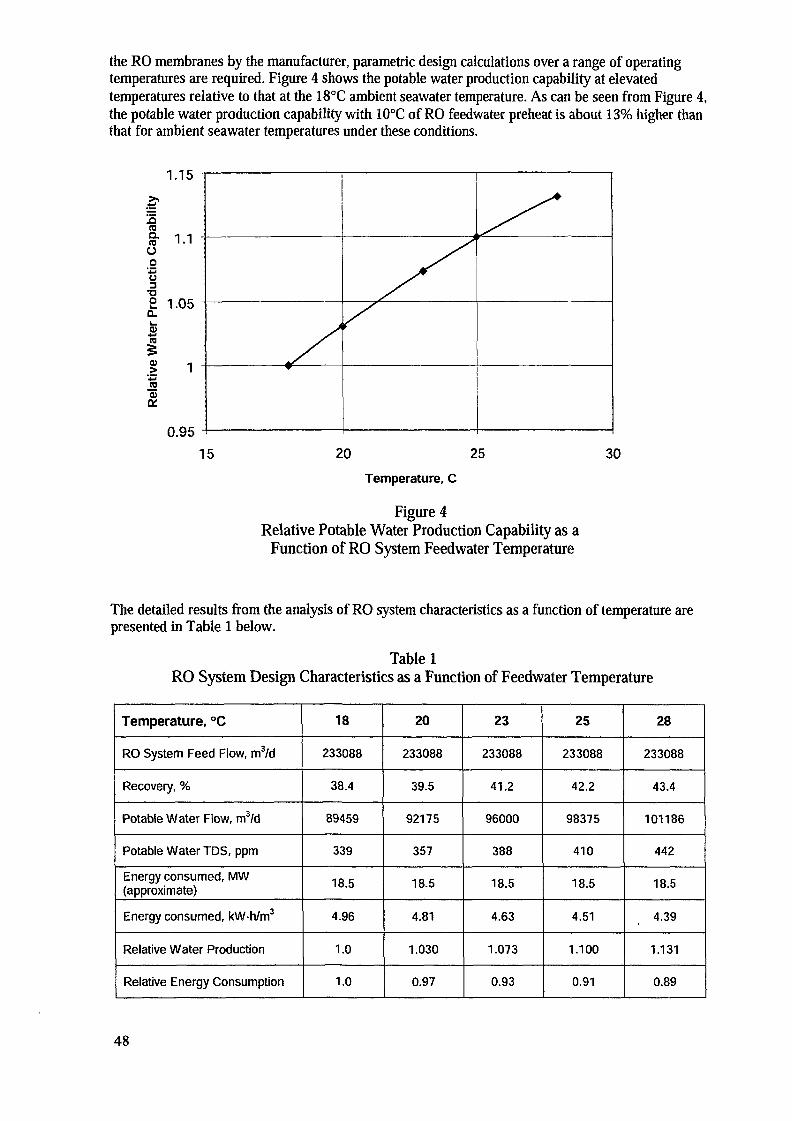
the RO membranes by the manufacturer, parametric design calculations over a range of operatingtemperatures are required. Figure 4 shows the potable water production capability at elevatedtemperatures relative to that at the 18°C ambient seawater temperature. As can be seen from Figure 4,the potable water production capability with 10°C of RO feedwater preheat is about 13% higher thanthat for ambient seawater temperatures under these conditions.
1.15
Q.raO
u
2 1.05
1% 1
0.9515 20 25 30
Temperature, C
Figure 4Relative Potable Water Production Capability as a
Function of RO System Feedwater Temperature
The detailed results from the analysis of RO system characteristics as a function of temperature arepresented in Table 1 below.
Table 1RO System Design Characteristics as a Function of Feedwater Temperature
Temperature, °C
RO System Feed Flow, m3/d
Recovery, %
Potable Water Flow, m3/d
Potable Water TDS, ppm
Energy consumed, MW(approximate)
Energy consumed, kWh/m3
Relative Water Production
Relative Energy Consumption
18
233088
38.4
89459
339
18.5
4.96
1.0
1.0
20
233088
39.5
92175
357
18.5
4.81
1.030
0.97
23
233088
41.2
96000
388
18.5
4.63
1.073
0.93
25
233088
42.2
98375
410
18.5
4.51
1.100
0.91
28
233088
43.4
101186
442
18.5
4.39
1.131
0.89
48
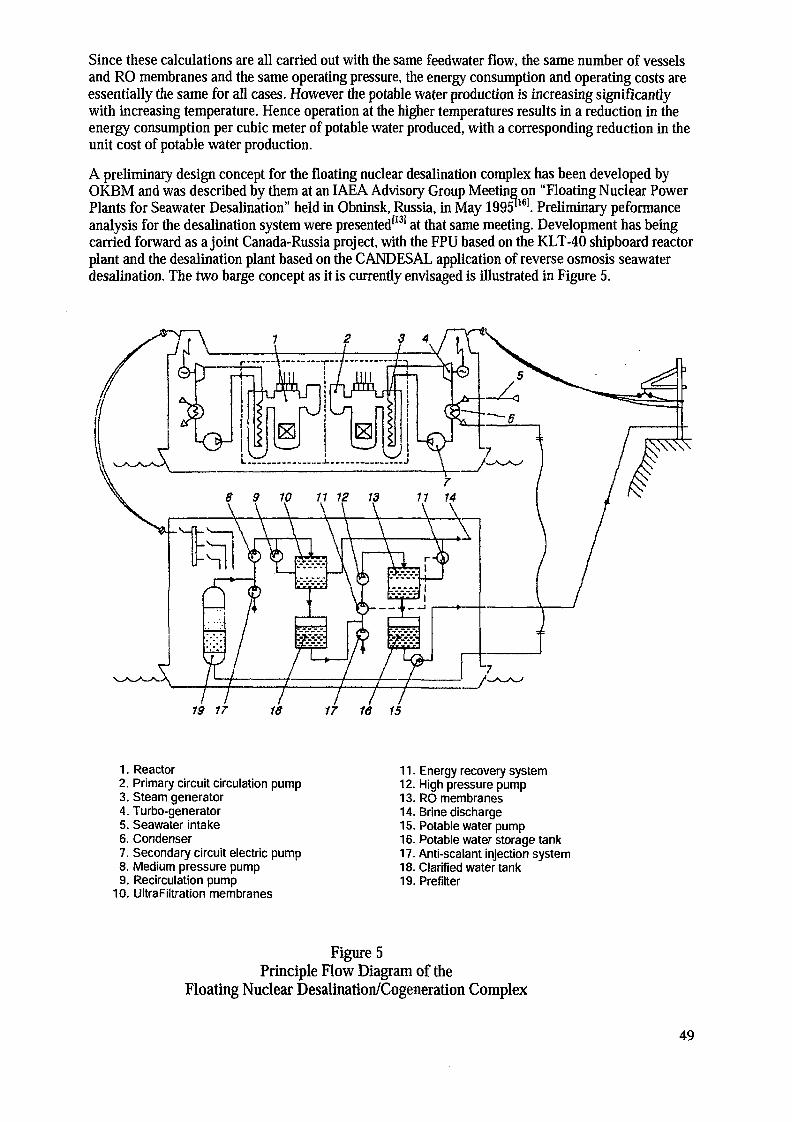
Since these calculations are all carried out with the same feedwater flow, the same number of vesselsand RO membranes and the same operating pressure, the energy consumption and operating costs areessentially the same for all cases. However the potable water production is increasing significantlywith increasing temperature. Hence operation at the higher temperatures results in a reduction in theenergy consumption per cubic meter of potable water produced, with a corresponding reduction in theunit cost of potable water production.
A preliminary design concept for the floating nuclear desalination complex has been developed byOKBM and was described by them at an IAEA Advisory Group Meeting on "Floating Nuclear PowerPlants for Seawater Desalination" held in Obninsk, Russia, in May 1995"161. Preliminary peformanceanalysis for the desalination system were presented'131 at that same meeting. Development has beingcarried forward as a joint Canada-Russia project, with the FPU based on the KLT-40 shipboard reactorplant and the desalination plant based on the CANDESAL application of reverse osmosis seawaterdesalination. The two barge concept as it is currently envisaged is illustrated in Figure 5.
6 9 10 11 12 13\ \ \ \ \ \
\^«^AAA
/ / /19 17 18
1. Reactor2. Primary circuit circulation pump3. Steam generator4. Turbo-generator5. Seawater intake6. Condenser7. Secondary circuit electric pump8. Medium pressure pump9. Recirculation pump
10. UltraFiltration membranes
/17 1 I16 15
11. Energy recovery system12. High pressure pump13. RO membranes14. Brine discharge15. Potable water pump16. Potable water storage tank17. Anti-sealant injection system18. Clarified water tank19. Prefilter
Figure 5Principle Flow Diagram of the
Floating Nuclear Desalination/Cogeneration Complex
49
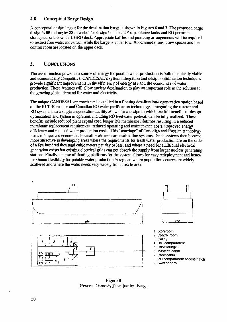
4.6 Conceptual Barge Design
A conceptual design layout for the desalination barge is shown in Figures 6 and 7. The proposed bargedesign is 96 m long by 28 m wide. The design includes UF capacitance tanks and RO permeatestorage tanks below the UF/RO deck. Appropriate baffles and pumping arrangements will be requiredto restrict free water movement while the barge is under tow. Accommodations, crew spaces and thecontrol room are located on the upper deck.
5. CONCLUSIONS
The use of nuclear power as a source of energy for potable water production is both technically viableand economically competitive. CANDESAL's system integration and design optimization techniquesprovide significant improvements in the efficiency of energy use and the economics of waterproduction. These features will allow nuclear desalination to play an important role in the solution tothe growing global demand for water and electricity.
The unique C ANDES AL approach can be applied in a floating desalination/cogeneration station basedon the KLT-40 reactor and Canadian RO water purification technology. Integrating the reactor andRO systems into a single cogeneration facility allows for a design in which the full benefits of designoptimization and system integration, including RO feedwater preheat, can be fully realized. Thesebenefits include reduced plant capital cost, longer RO membrane lifetimes resulting in a reducedmembrane replacement requirement, reduced operating and maintenance costs, improved energyefficiency and reduced water production costs. This "marriage" of Canadian and Russian technologyleads to improved economics in small-scale nuclear desalination systems. Such systems then becomemore attractive in developing areas where the requirements for fresh water production are on the orderof a few hundred thousand cubic meters per day or less, and where a need for additional electricalgeneration exists but existing electrical grids can not absorb the supply from larger nuclear generatingstations. Finally, the use of floating platforms for the system allows for easy redeployment and hencemaximum flexibility for potable water production in regions where population centres are widelyscattered and where the water needs vary widely from area to area.
n
96n
1. Storeroom2. Control room3. Galley4. D/G compartment5. Crew lounge6. Master's cabin7. Crew cabin8. RO compartment access hatch9. Switchboard
Figure 6Reverse Osmosis Desalination Barge
50

111
3
oooooo
oooo
oo
111
111
oooooo
I . -u uoooo
11
1
1
1
oooooo
oooo
oo
222
222
oooooo
oooooo
22
22
oooooo
oooooo
222
oooooo
n 1C 122
no
A-A
\ ^75 6 7
ndf
5
1. Reverse osmosis module2. UltraFilatration module3. Service area4. Crew accomodations5. UF capacitance tanks6. Potable water storage tanks7. Piping well
Figure 7Desalination Barge
Desalination Plant Layout
REFERENCES
[1 j S. Postal, Last Oasis: Facing Water Scarcity, WW Norton & Comapany, New York, 1992.
[2] World Resources 1992-93, a report by The World Resources Institute in collaboration withThe United Nations Environment Programme and The United Nations developmentProgramme, Oxford University Press, Oxford, 1992.
[3] E. Goldsmith, N. Hildyard, P. McCully and P. Bunyard, IMPERILED PLANET - RestoringOur Endangered Ecosystems, The MIT Press, Cambridge, MA, 1990.
[4] R. Clarke, Water: The International Crisis, MIT Press, Cambridge, 1993.
[5] P. H. Gleick, ed., Water in Crisis: A Guide to the World's Fresh Water Resources, OxfordUniversity Press, New York, 1993.
[6] R. Engelman, P. LeRoy, Sustaining Water: Population and the Future of Renewable WaterSupplies, Population Action International, Washington, 1993.
[7] Scientific American, p. 38, November 1997.
[8] International Atomic Energy Agency, Use of Nuclear Reactors for Seawater Desalination,IAEA-TECDOC-574, Vienna, 1990.
51
[9] International Atomic Energy Agency, Technical and economic evaluation of potable waterproduction through desalination of seawater by using nuclear energy and other means, IAEA-TECDOC-666, Vienna, 1992.
[10] International Atomic Energy Agency, Thermodynamic and economic evaluation of co-production plants for electricity and potable water, IAEA-TECDOC-942, Vienna, May 1997.
[11] Based on data to 1993 from " 1994 IDA Worldwide Desalting Plants Inventory", projectionsof desalination experts as documented in Reference 15, and an IAEA estimate of 10 yeardoubling time.
[12] Sweeney, C. B., Humphries, J. R., Local Participation in the CANDESAL NuclearDesalination System. Proceedings of the IAEA Advisory Group Meeting on NuclearDesalination, Cairo, December 1994.
[13] Humphries, J. R., Davies, K., A Floating Cogeneration System Using the Russian KLT-40Reactor and Canadian Reverse Osmosis Water Purification Technology, paper presented atthe IAEA Technical Committee Meeting on Floating Nuclear Energy Plants for SeawaterDesalination, Obninsk, Russian Federation, May 1995.
[14] J. R. Humphries, The Application of Nuclear Energy For Seawater Desalination: TheCANDESAL Nuclear Desalination System, a presentation at the IAEA Advisory GroupMeeting on "Non-Electric Applications of Nuclear Energy", Jakarta, 21-23 November 1995.
[15] CANDESAL Enterprises Ltd. (with contributions from AECL, BPPT and BATAN), ATechnical And Economic Evaluation Of The CANDSAL Approach In Indonesia Using ReverseOsmosis And Waste Heat From The CANDU 6 Nuclear Power Plant, Revision 1, March 1998.
[16] K. V. Zverev, V. I. Polunichev, Y. A. Sergeev, "Floating Nuclear Power Station of APWSType for Electricity Generation and Fresh Water Production", paper presented at the IAEATechnical Committee Meeting on Floating Nuclear Energy Plants for Seawater Desalination,Obninsk, Russian Federation, May 1995.
52
IMPLEMENTATION OF THE PROJECT FOR THE CONSTRUCTION ANDOPERATION OF A NUCLEAR HEAT AND POWER PLANT ON THE BASIS OF AFLOATING POWER UNIT WITH KLT-40C REACTORS
A.K. POLUSHKIN, E.A. KUZINJSC Malaya Energetika, Moscow
V.M. VOROBIOVJSC Atomenergo, St. Petersburg
D.M. KLYKOVJSC Iceberg, St. Petersburg
J.K. PANOVOKBM, Nizhny Novgorod
Russian Federation
Abstract
This paper presents the results of research and development on floating nuclearpower plant (FNPP) for electricity and heat production for remote locations and small islandor coastal communities. Evaluations of construction period, social and economic factors aswell as safety and operational issues of the non-self-propelled barge-mounted NPP is given.
1. INTRODUCTION
The development of small-scale power for isolated regions of Russia has longslipped the attention of the public and specialists. Development of the United Power Systemof Russia, creation of high capacity generating facilities and construction of giant powerplants and complexes have been considered top priorities over the past years.
The decentralized power supply territory occupies about two thirds of Russia. It ismainly populated by small ethnic groups including the peoples of the North whose livingstandards are dozens of years backward as compared with those of such groups ofpopulation in the similar climatic zones of North America and Europe.
On the other hand, this territory is very rich in all kinds of mineral resources whichare not mined at the present time as there are no required conditions or infrastructure, wemean power supply, communication and transport, first of all. For this is a very scarcelypopulated territory the border of which practically coincides with the permafrost zoneboundary it is obviously impossible to solve a power development problem by means oflarge-scale network construction.
As a result of the defense industry conversion a number of small-scale powerprojects became available for civil applications. These Projects were developed for marineand submarine fleet, spacecraft and other scientific purposes, being notable for their noveltyand advanced technological level in comparison with similar projects either in Russia orabroad.
At the present moment according to the IAEA surveys nuclear desalination - i.e.using nuclear reactors as sources of electricity or heat for desalination plants - is consideredto be the most promising line of development. The present lack of potable water in some
53
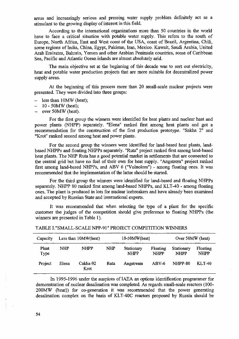
areas and increasingly serious and pressing water supply problem definitely act as astimulant to the growing display of interest in this field.
According to the international organizations more than 50 countries in the worldhave to face a critical situation with potable water supply. This refers to the south ofEurope, North Africa, East and West coast of the USA, coast of Brazil, Argentina, Chili,some regions of India, China, Egypt, Pakistan, Iran, Mexico. Kuwait, Saudi Arabia, UnitedArab Emirates, Bahrain, Yemen and other Arabian Peninsula countries, some of CaribbeanSea, Pacific and Atlantic Ocean islands are almost absolutely arid.
The main objective set at the beginning of this decade was to sort out electricity,heat and potable water production projects that are more suitable for decentralized powersupply areas.
At the beginning of this process more than 20 small-scale nuclear projects werepresented. They were divided into three groups:
- less than 1OMW (heat);- 10 - 50MW (heat);- over 50MW (heat).
For the first group the winners were identified for heat plants and nuclear heat andpower plants (NHPP) separately. "Elena" ranked first among heat plants and got arecommendation for the construction of the first production prototype. "Sakha 2" and"Krot" ranked second among heat and power plants.
For the second group the winners were identified for land-based heat plants, land-based NHPPs and floating NHPPs separately. "Ruta" project ranked first among land-basedheat plants. The NHP Ruta has a good potential market in settlements that are connected tothe central grid but have no fuel of their own for heat supply. "Angstrem" project rankedfirst among land-based NHPPs, and ABV 6 ("Volnolom") - among floating ones. It wasrecommended that the implementation of the latter should be started.
For the third group the winners were identified for land-based and floating NHPPsseparately. NHPP 80 ranked first among land-based NHPPs, and KLT-40 - among floatingones. The plant is produced in lots for nuclear icebreakers and have already been examinedand accepted by Russian State and international experts.
It was recommended that when selecting the type of a plant for the specificcustomer the judges of the competition should give preference to floating NHPPs (thewinners are presented in Table 1).
TABLE I."SMALL-SCALE NPP-91" PROJECT COMPETITION WINNERS
Capacity Less than lOMW(heat) 10-50MW(heat) Over 50MW (heat)
Plant NHP NHPP NHP Stationary Floating Stationary FloatingType NHPP NHPP NHPP NHPP
Project Elena Cakha-92 Ruta Angstream ABV-6 NHPP-80 KLT-40Krot
In 1995-1996 under the auspices of IAEA an options identification programmer fordemonstration of nuclear desalination was completed. As regards small-scale reactors (100-200MW (heat)) for co-generation it was recommended that the power generatingdesalination complex on the basis of KLT-40C reactors proposed by Russia should be
54
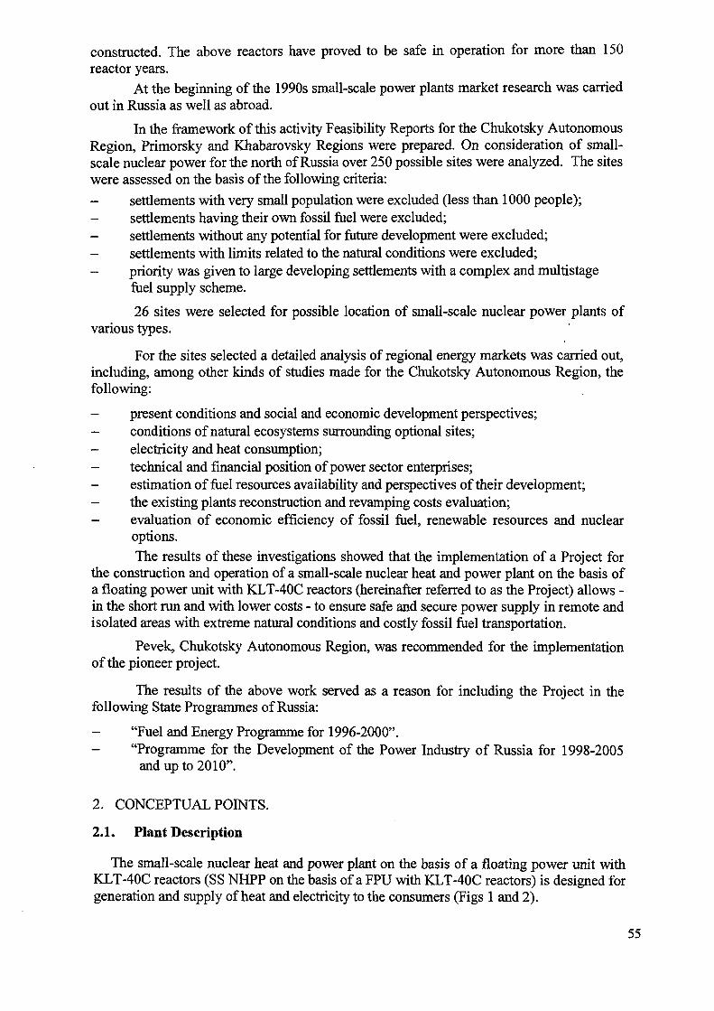
constructed. The above reactors have proved to be safe in operation for more than 150reactor years.
At the beginning of the 1990s small-scale power plants market research was carriedout in Russia as well as abroad.
In the framework of this activity Feasibility Reports for the Chukotsky AutonomousRegion, Primorsky and Khabarovsky Regions were prepared. On consideration of small-scale nuclear power for the north of Russia over 250 possible sites were analyzed. The siteswere assessed on the basis of the following criteria:
- settlements with very small population were excluded (less than 1000 people);- settlements having their own fossil fuel were excluded;
settlements without any potential for future development were excluded;- settlements with limits related to the natural conditions were excluded;- priority was given to large developing settlements with a complex and multistage
fuel supply scheme.
26 sites were selected for possible location of small-scale nuclear power plants ofvarious types.
For the sites selected a detailed analysis of regional energy markets was carried out,including, among other kinds of studies made for the Chukotsky Autonomous Region, thefollowing:
- present conditions and social and economic development perspectives;- conditions of natural ecosystems surrounding optional sites;- electricity and heat consumption;- technical and financial position of power sector enterprises;- estimation of fuel resources availability and perspectives of their development;- the existing plants reconstruction and revamping costs evaluation;- evaluation of economic efficiency of fossil fuel, renewable resources and nuclear
options.The results of these investigations showed that the implementation of a Project for
the construction and operation of a small-scale nuclear heat and power plant on the basis ofa floating power unit with KLT-40C reactors (hereinafter referred to as the Project) allows -in the short run and with lower costs - to ensure safe and secure power supply in remote andisolated areas with extreme natural conditions and costly fossil fuel transportation.
Pevek, Chukotsky Autonomous Region, was recommended for the implementationof the pioneer project.
The results of the above work served as a reason for including the Project in thefollowing State Programmes of Russia:
"Fuel and Energy Programme for 1996-2000".- "Programme for the Development of the Power Industry of Russia for 1998-2005
and up to 2010".
2. CONCEPTUAL POINTS.
2.1. Plant Description
The small-scale nuclear heat and power plant on the basis of a floating power unit withKLT-40C reactors (SS NHPP on the basis of a FPU with KLT-40C reactors) is designed forgeneration and supply of heat and electricity to the consumers (Figs 1 and 2).
55
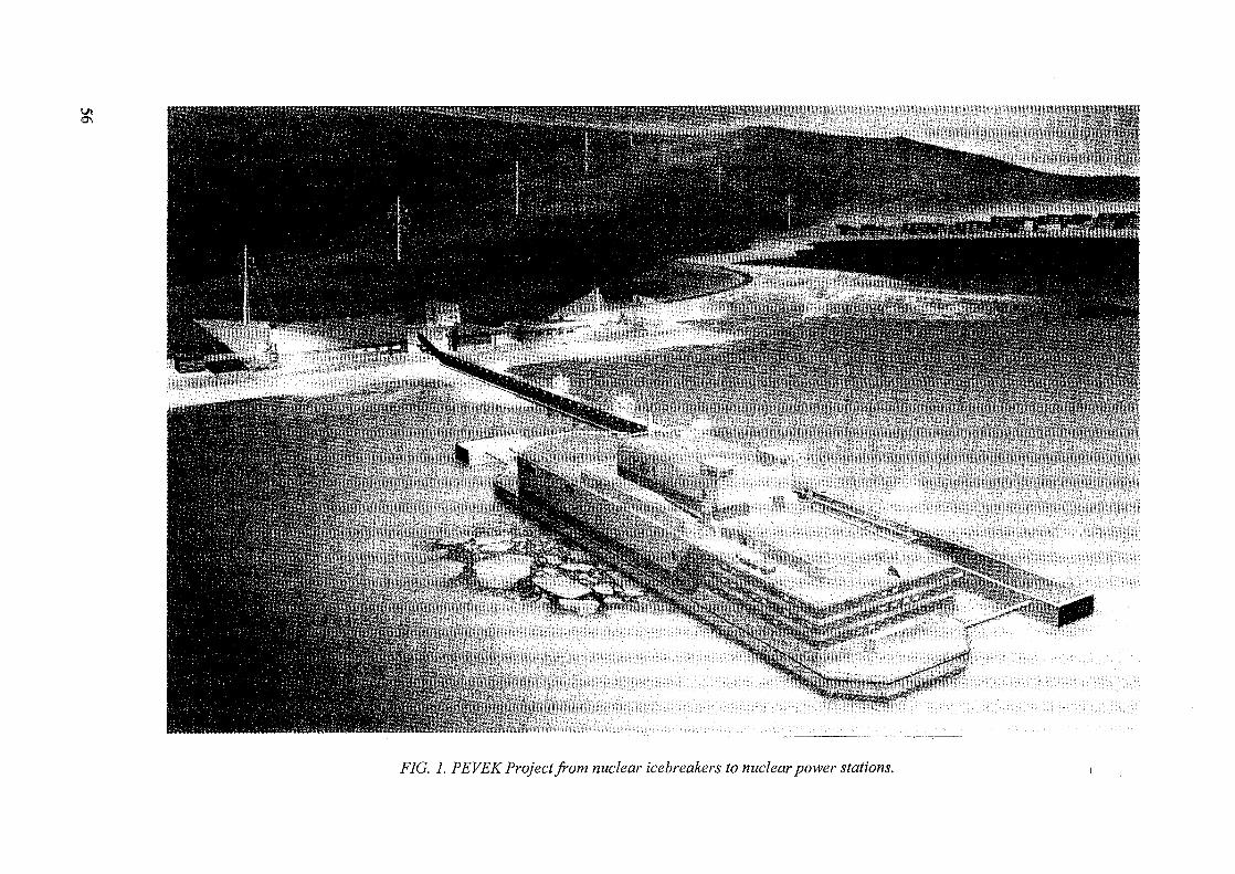
F/G. 7. PEVEK Project from nuclear icebreakers to nuclear power stations.
Fig. 2 FPU longitudinal cut-away view:1 - living section3 - auxiliary compartment5 - spent fuel and waste storage7 - refueling compartment9 - helicopter landing site
2 - control room4 - reactor compartment6 - reactor division8 - turbine-generator compartment10 - compartment for electric transformer and
switchgear
SS NHPP on the basis of a FPU with KLT-40C reactors consists of a floating powerunit, hydraulic structures and a shore-based infrastructure.
The floating power unit is to generate heat and electricity and supply electricity and heatsupply water to the shore-based facilities.
The hydraulic structures are designed to connect the FPU to the shore. Mooring facilitiesprovide technical connection between the FPU and the shore. Vessels for supplying thePlant with material and equipment or other maintenance means can be moored to the FPU.
The shore-based structures comprise facilities for the transmission of heat and electricityto consumers and office and other buildings.
Basic characteristics of a small-scale nuclear heat and power plant on the basis of afloating power unit with KLT-40C reactors are given in Tables 2-5.
TABLE II.BASIC CHARACTERISTICS OF A SS NHPP ON THE BASIS OF A FPUWITH KLT-40C REACTORS
Nominal Co-generation Operation « _-Nnom, MW _ 25Qnom, Gcal/hourNominal Heat Generation Operation, Nnom, MW 2x35Maximum Electric Generating Capacity, MW 2x38,5Maximum Heat Generating Capacity, Gcal/hour 2x41,8Auxiliary Electricity Consumption, MW 4-6Auxiliary Heat Consumption, MW (heat) 3,2Water into the Heat Supply System, m3/hour 2x240Intermediate Circuit Water Temperature Curve for nominal operation, °C 130/70Intermediate Circuit Water Temperature Curve for peak load operation, °C 170/70Water Pressure in the Intermediate Circuit, MPa 1,6Shore Territory, hectares 1,5Surrounding Water Area, hectares 6,0
The FPU is being manufactured at a special shipbuilding dock with a very strictcontrol of the quality of production in compliance with the quality assurance proceduresestablished for nuclear vessels. As soon as the required testing is completed the FPU is tobe towed to the site complete and ready for operation.
The FPU accommodates two KLT-40C reactor plants with pressurized waterreactors, two steam turbine plants with TK - 35/38 - 3.4 turbines of a co-generation type andTAG8123EUL5B electric generators, facilities for nuclear fuel management and solid andliquid radioactive wastes storage, ecological section.
The FPU ecological section is designed for discharge water and oil contaminatedwater treatment, solid domestic and food waste collection, treatment and disposal.
58
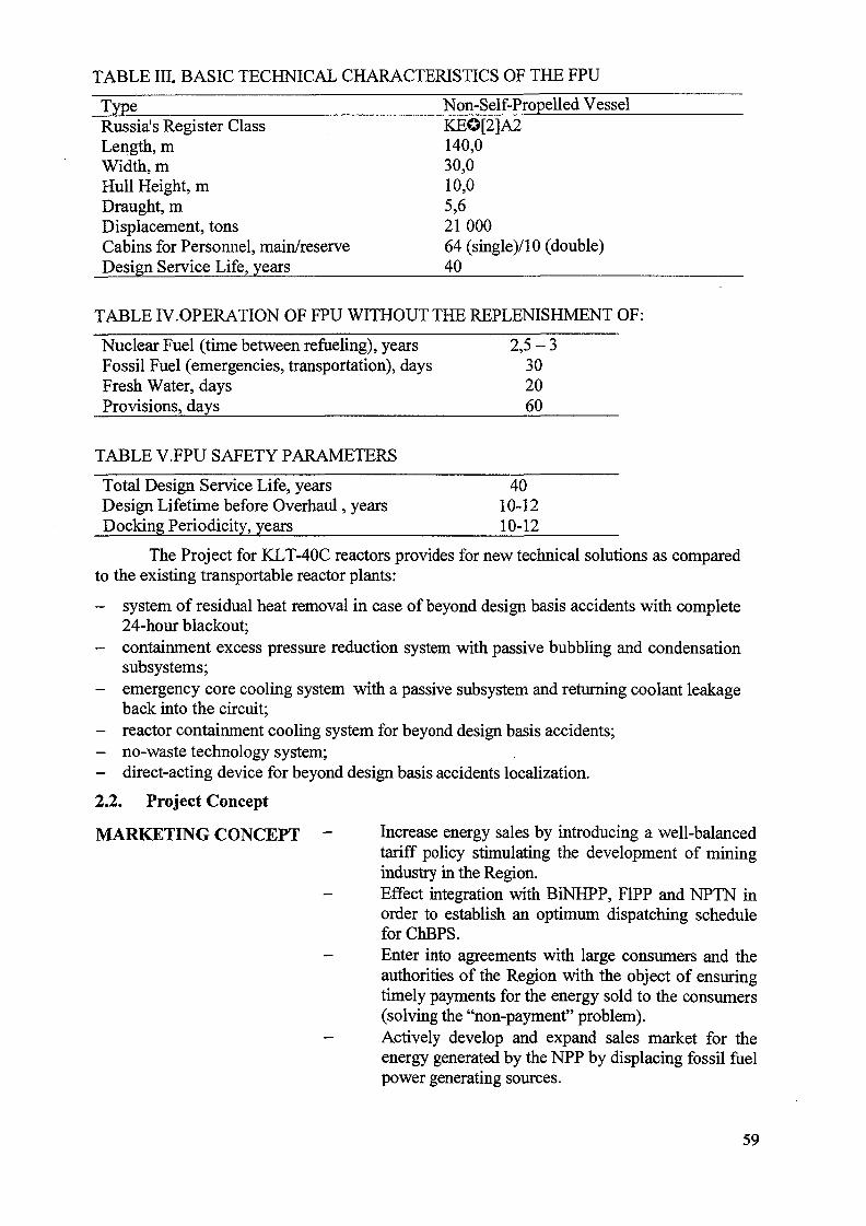
TABLE IIL BASIC TECHNICAL CHARACTERISTICS OF THE FPU
Type Non-Self-Propelled VesseTRussia's Register ClassLength, mWidth, mHull Height, mDraught, mDisplacement, tonsCabins for Personnel, main/reserveDesign Service Life, years
KEO[2]A2140,030,010,05,62100064 (single)/10 (double)40
TABLE IV.OPERATION OF FPU WITHOUT THE REPLENISHMENT OF:
Nuclear Fuel (time between refueling), years 2,5 - 3Fossil Fuel (emergencies, transportation), days 30Fresh Water, days 20Provisions, days 60
TABLE V.FPU SAFETY PARAMETERS
Total Design Service Life, years 40Design Lifetime before Overhaul, years 10-12Docking Periodicity, years 10-12
The Project for KLT-40C reactors provides for new technical solutions as comparedto the existing transportable reactor plants:
- system of residual heat removal in case of beyond design basis accidents with complete24-hour blackout;
- containment excess pressure reduction system with passive bubbling and condensationsubsystems;
- emergency core cooling system with a passive subsystem and returning coolant leakageback into the circuit;
- reactor containment cooling system for beyond design basis accidents;- no-waste technology system;- direct-acting device for beyond design basis accidents localization.
2.2. Project Concept
MARKETING CONCEPT - Increase energy sales by introducing a well-balancedtariff policy stimulating the development of miningindustry in the Region.Effect integration with BiNHPP, F1PP and NPTN inorder to establish an optimum dispatching scheduleforChBPS.
- Enter into agreements with large consumers and theauthorities of the Region with the object of ensuringtimely payments for the energy sold to the consumers(solving the "non-payment" problem).
- Actively develop and expand sales market for theenergy generated by the NPP by displacing fossil fuelpower generating sources.
59
COMMERCIALCONCEPT
OPERATING CONCEPT _
TECHNICAL CONCEPT _
SOCIAL ANDECONOMIC CONCEPT
Implement the Project using "Build-Own-Operate"scheme, which will allow to remove the heavy burdenof intensive capital investment from energyconsumers while, at the same time, the Companyretains the rights of property.
Operate the NHPP with specially staffed and trainedwatch crews of highly qualified specialists, whichguarantees safety and efficiency of operation andrelieves the social burden in the area of NHPPlocation.
At all stages of implementation, such as design andengineering, equipment manufacturing, constructionand operation, apply technical solutions proved bymany years of trouble-free operation, which willallow to reduce the amount of work, includingassembly, installation, erection and repair work at thesite, and also to a maximum possible extent assuresafe nuclear waste and spent fuel management inorder to ensure nuclear and radiation safety of theNHPP.
Safe and secure power supply of consumers,reduction of fossil fuel requirements and, as a result,of the volume of fuel transportation under the severeconditions of the Arctic.Reduce the need for budgetary appropriations for thepower sector, create conditions prerequisite for thedevelopment of industrial and agricultural sectorswith high potential and simultaneously reduce thenumber of people employed in coal mining industry,transport and power industry.Improve social and ecological conditions in theRegion where the Plant is to be located.
2.3. Project Implementation Model
It is proposed that the Project should be implemented using BOO (Build - Own -Operate) model.
Rosenergoatom Concern will finance the construction of the floating power unit, actas the owner and operating organization of the SS NHPP and sell the heat and electricitygenerated.
A long-term power purchase agreement for selling (buying) energy at a certain tariffwill be signed with consumers. The principal provisions of the power purchase agreement -such as the term of validity, tariff rates, risk insurance terms, guarantees etc.- are supposedto be defined when negotiating to agree upon the Feasibility Study results to substantiatethe required investment.
The construction period was calculated on the basis of data on the construction ofsingle elements similar to that of the same kind of plants with geographical, climatic,hydrological and other conditions taken into account.
60
The period of hydraulic structures and shore-based facilities construction stipulatedin the Project is 2-3 years.
The main FPU equipment manufacturing period stipulated in the Project wasdefined on the basis of norms and standards established for nuclear vessels with thefollowing taken into account:
in prospect - construction of a series of SS NHPPs in order to ensure the continuityof operation of the plant at a certain site;
- time required for manufacturing of certain types of equipment and organization of acontinuous production process at the manufacturing plants.
The Plant construction period is 6 years with an allowance for 1 year of assembly,erection, startup and adjustment.
2.4. NHPP Operating Model
The operating model was developed on the basis of design performancecharacteristics of the complete operating cycle of the NHPP.
The Project provides for the installation of facilities for nuclear refueling and spentnuclear fuel storage on board the FPU without using special service vessels. Radioactiveproduction waste is also stored on board the FPU. Thus, the design autonomous operationperiod (operation without supplies replenishment) of the FPU is determined by the capacityof spent nuclear fuel and radioactive waste storage tanks and periodicity of docking. With-0.54 load factor, which corresponds to the pessimistic consumption forecast, theautonomous operation of the FPU is ensured by four nuclear core sets and makes 13-15years. After the lapse of this period the FPU is replaced with a similar one.
As an FPU can be replaced the NHPP operation can continue as long as you likewithin the limits of hydraulic structures and shore-based facilities service life.
The following procedures are provided for during the Plant operation:
- 50% two-month load decrease for reactor plants refueling taken in turn every 2-3years;
- complete interruption of power supply every 13-15 years for FPU replacement.
After the replacement the FPU with full radioactive waste and spent fuel storagetanks is to be towed to specialized repair works at the dock for overhaul, fuel unloading andhull docking.
The overhaul includes the following:
unloading of spent nuclear fuel from reactor plants and spent nuclear fuel storagefacilities;
- complete control of central power compartment equipment and steam turbines anda range of work in order to provide their further operation;
- control of the craft and general ship systems with necessary repair and preventivemaintenance;
- FPU hull checkup and repair;- carrying out a range of work for the FPU to meet the regulatory safety
requirements;- refueling;
complex testing of all FPU systems and equipment;- preparing the FPU for transportation to the site.
61
The overhaul period stipulated in the Project is 1 year with an allowance fortransportation time. The Project provides for two overhauls and three operating cycles.
After the completion of the third operating cycle the FPU is to be decommissioned,i.e. towed from the site to the premises of the specialized dock for dismantling anddisassembly of ship nuclear equipment.
The practical implementation of the accepted model is ensured by FPU mobility.
The Project technical decisions and the FPU operating model allow to:
- carry out all refueling between overhauls onboard the FPU;- store all radioactive waste and nuclear fuel onboard the FPU;- assure high quality of repair work;- ensure safe and secure FPU decommissioning.
3. CONSTRUCTION PERIOD
The construction period was calculated on the basis of data on the construction ofsingle elements similar to that of the same kind of plants with geographical, climatic,hydrological and other conditions taken into account.
The remoteness of the Region and its severe climatic conditions determine theseasonal character of equipment deliveries and construction work. The period of hydraulicstructures and shore-based facilities construction stipulated in the Project, therefore, is 3years.
The period of the main FPU equipment manufacturing was defined on the analogyof nuclear icebreakers.
The total FPU construction period is 5 years. Transportation of the FPU to the siteand startup and adjustment take 0,5-̂ 1 year. The plant construction period from obtainingthe construction license is 6 years. With design and development taken into account theinvestment period makes 7 years.
The approved production and technological NHPP construction scheme consists ofthree main stages (see Fig.3):
FPU Manufacturing:
- manufacturing of the FPU hull at a specialized shipbuilding yard;- simultaneous manufacturing of the central power compartment equipment and its
sectional assembly as part of the FPU;manufacturing and testing of turbine generators at a specialized plant and theirsubsequent delivery to the manufacturer of the FPU to be assembled and mounted;assembly, mounting and testing of the FPU including reaching the design capacityat a shipbuilding yard;
- construction of the hydraulic structures and shore-based facilities on the site beforethe FPU arrival;Putting NHPP into Operation:towing the complete and ready FPU to the site;
- assembly, startup and adjustment of the whole complex of the FPU elementstogether with the shore-based power transmission network;
- putting the Plant into trial-commercial operation.
62
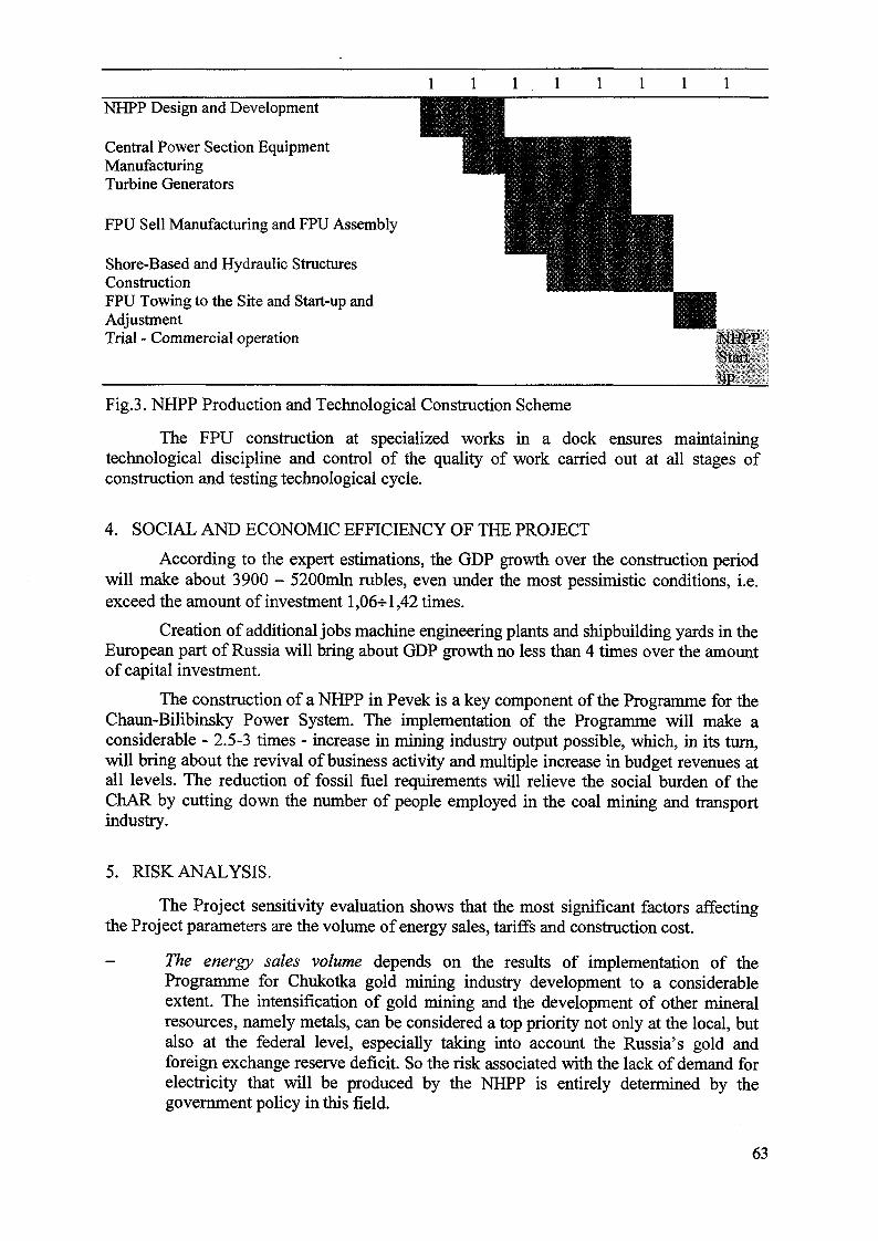
NHPP Design and Development
Central Power Section EquipmentManufacturingTurbine Generators
FPU Sell Manufacturing and FPU Assembly
Shore-Based and Hydraulic StructuresConstructionFPU Towing to the Site and Start-up andAdjustmentTrial - Commercial operation
Fig.3. NHPP Production and Technological Construction Scheme
The FPU construction at specialized works in a dock ensures maintainingtechnological discipline and control of the quality of work carried out at all stages ofconstruction and testing technological cycle.
4. SOCIAL AND ECONOMIC EFFICIENCY OF THE PROJECT
According to the expert estimations, the GDP growth over the construction periodwill make about 3900 - 5200mln rubles, even under the most pessimistic conditions, i.e.exceed the amount of investment 1,06-5-1,42 times.
Creation of additional jobs machine engineering plants and shipbuilding yards in theEuropean part of Russia will bring about GDP growth no less than 4 times over the amountof capital investment.
The construction of a NHPP in Pevek is a key component of the Programme for theChaun-Bilibinsky Power System. The implementation of the Programme will make aconsiderable - 2.5-3 times - increase in mining industry output possible, which, in its turn,will bring about the revival of business activity and multiple increase in budget revenues atall levels. The reduction of fossil fuel requirements will relieve the social burden of theChAR by cutting down the number of people employed in the coal mining and transportindustry.
5. RISK ANALYSIS.
The Project sensitivity evaluation shows that the most significant factors affectingthe Project parameters are the volume of energy sales, tariffs and construction cost.
- The energy sales volume depends on the results of implementation of theProgramme for Chukotka gold mining industry development to a considerableextent. The intensification of gold mining and the development of other mineralresources, namely metals, can be considered a top priority not only at the local, butalso at the federal level, especially taking into account the Russia's gold andforeign exchange reserve deficit. So the risk associated with the lack of demand forelectricity that will be produced by the NHPP is entirely determined by thegovernment policy in this field.
63
- all the above said equally refers to tariff rates, as the local power industry systemhas no internal market mechanisms to fix prices. Tariffs are established by theauthorities. Their level is determined by production and transmission costs and thepolicy of local authorities. Taking into account the fact that the authorities areinterested in the implementation of the Project and ready to participate in financing,tariff policy is anticipated to support and promote the Project in order to improveits technical and economic performance.
- The cost factor is of particular importance under the conditions of the economiccrisis. On the one hand, price rise makes the Project more costly which can put themain obstacle to its implementation; on the other hand, the same rise is a cause ofincrease in energy tariffs. Under the conditions of inflation and political instabilitynon-fulfilment of obligations to repay foreign currency credits, but in the givenProject this risk is reduced to a minimum as the foreign currency component ofconstruction cost is only 10%.
It should be noted that this Project is to be the first one of a series of floating nuclearpower projects. Some of them are to be exported as floating power stations withdesalinating plants. Company's activity diversification, getting access to internationalmarkets, complex approach to the management of a series of Projects for the constructionof a series of floating power plants allow to reduce risks of each single Projectconsiderably.
Thus, the main risk factors are to a certain extent manageable and their possiblenegative impact upon the Project can promptly be eliminated. The risks will be managed byan organization to be established under the framework of the Programme for the ChBPSDevelopment. This organization is to integrate the interests of large industrial consumers,primary power generating companies, power transmission companies and the authorities ofthe Region.
6. PROJECT STATUS
At the present time the Feasibility Study for the Project for the construction of aNHPP on the basis of a FPU with KLT-40C reactors in Pevek, Chukotsky AutonomousRegion, is completed.
Two materials, namely "A Report on the Present Situation and Conditions of PowerIndustry in the Chaun-Bilibinsky Power System of the Chulotsky Autonomous Region" and"The Programme for Power Stabilization and Development in the Chaun-Bilibinsky PowerSystem of the Chukotsky Autonomous Region up to 2015", were developed.
The preliminary agreement has been reached on the approval of Pevek site for theNHPP to be constructed.
The Feasibility Study accompanied by the above materials was submitted to theFederal Executive Authorities for expert evaluation, approval and licensing (expert opinionof the Federal Medical and Biological and Extreme Problems has been already obtained).
Declaration of Intention of the construction of a NHPP on the basis of a FPU withKLT-40C reactors in:
- the city of Dudinka, Taymyr (Dolgano-Nenetsky) Autonomous Region;- the city of Viliuchinsk, Kamchatka Autonomous Region.
During the period May 11 - 21,1999 an expert of ECTI acting in the framework ofTACIS Programme assessed and evaluated the Project. The expert particularly pointed out
64
that the floating application as part of a nuclear power plant benefiting from all theadvantages of power generation proved by many years of experience of icebreakersoperation can be considered as innovative at the world level, as the first Project of this kindimplemented in the world. In case of its successful implementation with all safety andnuclear fuel and radioactive waste management requirements met during the operation theProject will be the first reference to demonstrate the opening new possibilities andperspectives as regards the potential development of isolated and remote northern territoriesof Russia and foreign countries.
7. CONCLUSION
The Project is oriented towards secure and efficient power supply and offersthoroughly selected optimum solutions of energy supply problem; transparent tariff policyand the consequent solution of the "non-payment" problem; optimization of the existingelectricity and heat generation and distribution patterns.
In case of the Project successful implementation final consumers will benefit fromthe stable and efficient operation of the power supply system and thus, become moreconfident for paying energy bills. As a result they could be less reluctant to energy savingmeasures and behavior.
The Project, when implemented with successful operation, will constitute the firstworld reference for security of energy supply to very isolated areas with extremely severeconditions, allowing stabilization, economic development and social welfare for regionssimilar to the Chain-Bilibinsky District and ChAO.
Besides, it will also create conditions prerequisite for the efficient use of financialresources, stable operation and efficient performance of the economic systems of the regionand local improvement of wealth and welfare.
Replication of this reference Project for new sites will open the market for the keycomponent of the station, which is a small-scale floating nuclear power unit with KLT-40Creactors, reducing production investment and logistics costs that will drop by serial effectfor the implementation of the given Project as well as for any further ones of this series.
The Project implemented will allow to reduce fossil fuel consumption fueltransportation costs; reduce the negative impact upon the environment; improve social andeconomic conditions in the Region; develop the scientific and technical potential of thecountry; retain the existing and create new jobs in the European part of Russia; expandnuclear industry's importing and international cooperation in the field of nuclear energy use;contribute to improvement of the positive image of nuclear energy for civilian application.
65
XA0056269THE USE OF ENGINEERING FEATURES AND SCHEMATICSOLUTIONS OF PROPULSION NUCLEAR STEAM SUPPLYSYSTEMS FOR FLOATING NUCLEAR POWER PLANT DESIGN
A.N. ACHKASOV, G.I. GRECHKO, V.N. PEP A, V.A. SHISHKINResearch and Development Institute of Power Engineering,Moscow, Russian Federation
Abstract
In the recent years many countries and the international community represented by theIAEA have shown a notable interest in designing small and medium size nuclear power plantsintended for electricity and heat generation for remote areas. These power plants can be also usedfor desalination purposes. As these nuclear plants are planned for the use in the areas withoutwell-developed power grid, the design shall account for their transportation to the site incomplete preparedness for operation.
Since the late 80s Research and Development Institute of Power Engineering (RDIPE)has carried out the active efforts in designing the reactor facilities for floating nuclear powerplants. This work relies on the long-term experience of RDIPE engineers in designing thepropulsion NSSS. Advantages can be gained from the specific engineering solutions that arealready applied in the design of propulsion NSSS or from development of new design based onthe proven technologies.
Successful implementation of the experience has been made easier owing to rather similardesign requirements prescribed to ship-mounted NSSS and floating NPP. The common designtargets are, in particular, minimization of mass and dimensions, resistance to such externalimpacts as rolling, heel and trim, operability in case of running aground or collision with otherships, etc.
: DESCRIPTION OF DESIGN FEATURES
2.1.The NSSS is equipped with an integral water-cooled water-moderated reactor with inherentsafety and the following unique features:
- negative coefficients of reactivity in the whole operating range of parameters;- high rate of natural circulation of the coolant which affords effective cooling and heat
removal from the core during design-basis and beyond design-basis accidents;- high heat storage capacity of metal structures and a large mass of coolant in the reactor which
result in a relatively slow progression of transients during accidents with upset heat removalfrom the core.
Figs. 1 and 2 show general view of the reactor and schematic of primary coolant motion.As is clear from the figures, all components of the primary circuit (i.e., the core and control rods,steam generator, main coolant pumps, pressurizer) are located in a single cylindrical vessel.
Primary coolant circulation is provided by main coolant pumps (MCP) with cannedasynchronous motors that are installed on the reactor cover. As an additional benefit, simpleconfiguration and short length of the primary circuit path permit to sustain high flow rate of
67
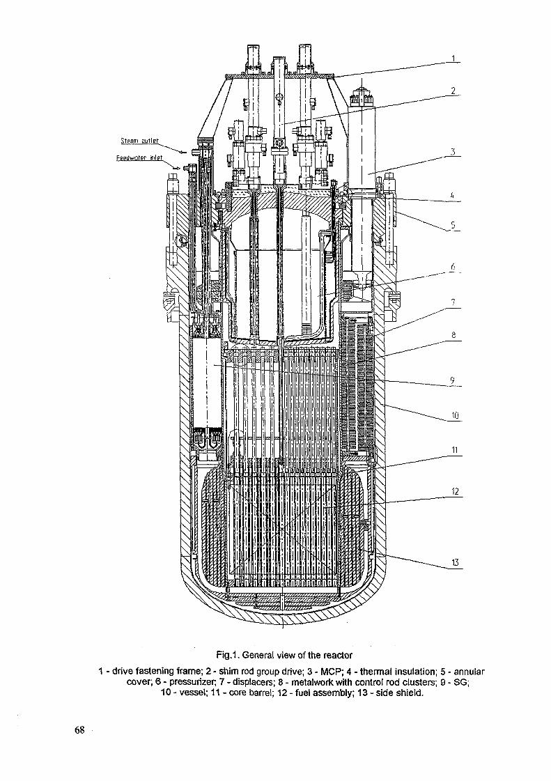
Steam millet
Fepdwoter- inlet
Fig.1. General view of the reactor
1 - drive fastening frame; 2 - shim rod group drive; 3 - MCP; 4 - thermal insulation; 5 - annularcover; 6 - pressurizer; 7 - displacers; 8 - metalwork with control rod clusters; 9 - SG;
10 - vessel; 11 - core barrel; 12 - fuel assembly; 13 - side shield.
68
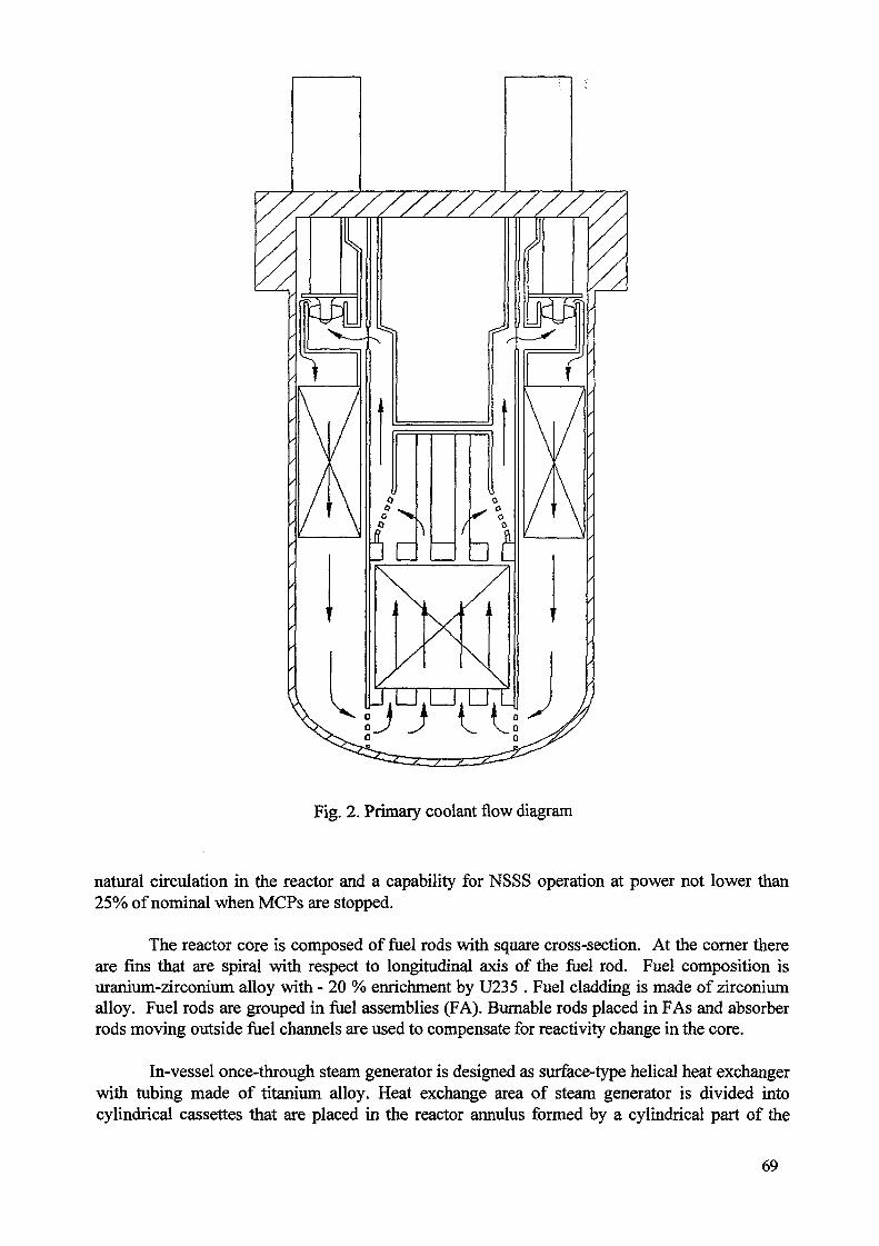
JJ It
Fig. 2. Primary coolant flow diagram
natural circulation in the reactor and a capability for NSSS operation at power not lower than25% of nominal when MCPs are stopped.
The reactor core is composed of fuel rods with square cross-section. At the corner thereare fins that are spiral with respect to longitudinal axis of the fuel rod. Fuel composition isuranium-zirconium alloy with - 20 % enrichment by U235 . Fuel cladding is made of zirconiumalloy. Fuel rods are grouped in fuel assemblies (FA). Burnable rods placed in FAs and absorberrods moving outside fuel channels are used to compensate for reactivity change in the core.
In-vessel once-through steam generator is designed as surface-type helical heat exchangerwith tubing made of titanium alloy. Heat exchange area of steam generator is divided intocylindrical cassettes that are placed in the reactor annulus formed by a cylindrical part of the
69
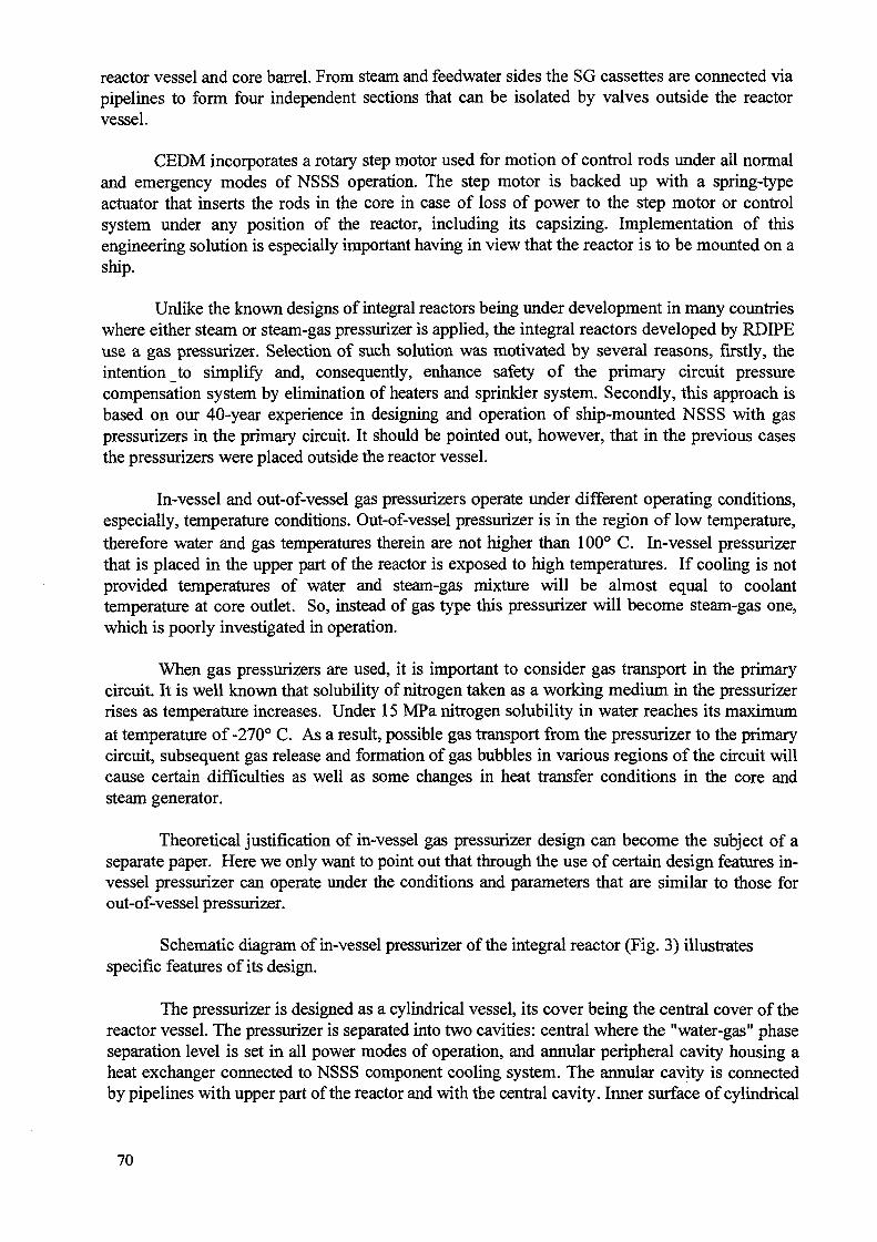
reactor vessel and core barrel. From steam and feedwater sides the SG cassettes are connected viapipelines to form four independent sections that can be isolated by valves outside the reactorvessel.
CEDM incorporates a rotary step motor used for motion of control rods under ail normaland emergency modes of NSSS operation. The step motor is backed up with a spring-typeactuator that inserts the rods in the core in case of loss of power to the step motor or controlsystem under any position of the reactor, including its capsizing. Implementation of thisengineering solution is especially important having in view that the reactor is to be mounted on aship.
Unlike the known designs of integral reactors being under development in many countrieswhere either steam or steam-gas pressurizer is applied, the integral reactors developed by RDIPEuse a gas pressurizer. Selection of such solution was motivated by several reasons, firstly, theintention to simplify and, consequently, enhance safety of the primary circuit pressurecompensation system by elimination of heaters and sprinkler system. Secondly, this approach isbased on our 40-year experience in designing and operation of ship-mounted NSSS with gaspressurizers in the primary circuit. It should be pointed out, however, that in the previous casesthe pressurizers were placed outside the reactor vessel.
In-vessel and out-of-vessel gas pressurizers operate under different operating conditions,especially, temperature conditions. Out-of-vessel pressurizer is in the region of low temperature,therefore water and gas temperatures therein are not higher than 100° C. In-vessel pressurizerthat is placed in the upper part of the reactor is exposed to high temperatures. If cooling is notprovided temperatures of water and steam-gas mixture will be almost equal to coolanttemperature at core outlet. So, instead of gas type this pressurizer will become steam-gas one,which is poorly investigated in operation.
When gas pressurizers are used, it is important to consider gas transport in the primarycircuit. It is well known that solubility of nitrogen taken as a working medium in the pressurizerrises as temperature increases. Under 15 MPa nitrogen solubility in water reaches its maximumat temperature of -270° C. As a result, possible gas transport from the pressurizer to the primarycircuit, subsequent gas release and formation of gas bubbles in various regions of the circuit willcause certain difficulties as well as some changes in heat transfer conditions in the core andsteam generator.
Theoretical justification of in-vessel gas pressurizer design can become the subject of aseparate paper. Here we only want to point out that through the use of certain design features in-vessel pressurizer can operate under the conditions and parameters that are similar to those forout-of-vessel pressurizer.
Schematic diagram of in-vessel pressurizer of the integral reactor (Fig. 3) illustrates; features of its design.specific features of its design
The pressurizer is designed as a cylindrical vessel, its cover being the central cover of thereactor vessel. The pressurizer is separated into two cavities: central where the "water-gas" phaseseparation level is set in all power modes of operation, and annular peripheral cavity housing aheat exchanger connected to NSSS component cooling system. The annular cavity is connectedby pipelines with upper part of the reactor and with the central cavity. Inner surface of cylindrical
70
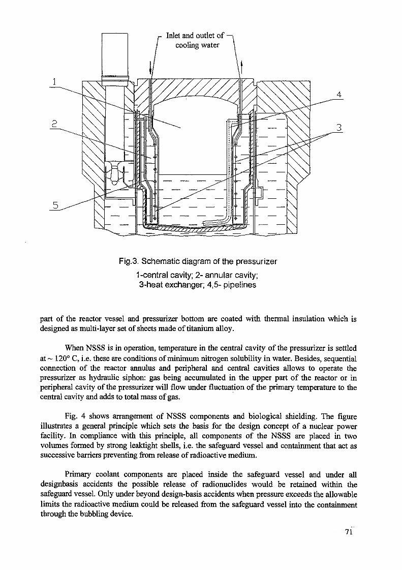
Inlet and outlet of —,cooling water
4
Fig.3. Schematic diagram of the pressurizer
1-central cavity; 2- annular cavity;3-heat exchanger; 4,5- pipelines
part of the reactor vessel and pressurizer bottom are coated with thermal insulation which isdesigned as multi-layer set of sheets made of titanium alloy.
When NSSS is in operation, temperature in the central cavity of the pressurizer is settledat ~ 120° C, i.e. these are conditions of minimum nitrogen solubility in water. Besides, sequentialconnection of the reactor annulus and peripheral and central cavities allows to operate thepressurizer as hydraulic siphon: gas being accumulated in the upper part of the reactor or inperipheral cavity of the pressurizer will flow under fluctuation of the primary temperature to thecentral cavity and adds to total mass of gas.
Fig. 4 shows arrangement of NSSS components and biological shielding. The figureillustrates a general principle which sets the basis for the design concept of a nuclear powerfacility. In compliance with this principle, all components of the NSSS are placed in twovolumes formed by strong leaktight shells, i.e. the safeguard vessel and containment that act assuccessive barriers preventing from release of radioactive medium.
Primary coolant components are placed inside the safeguard vessel and under alldesignbasis accidents the possible release of radionuclides would be retained within thesafeguard vessel. Only under beyond design-basis accidents when pressure exceeds the allowablelimits the radioactive medium could be released from the safeguard vessel into the containmentthrough the bubbling device.
71
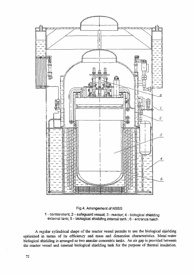
Fig.4. Arrangement of NSSS
1 - containment; 2 - safeguard vessel; 3 - reactor; 4 - biological shieldingexternal tank; 5 - biological shielding internal tank; 6 - entrance hatch
A regular cylindrical shape of the reactor vessel permits to use the biological shieldingoptimized in terms of its efficiency and mass and dimension characteristics. Metal-waterbiological shielding is arranged as two annular concentric tanks. An air gap is provided betweenthe reactor vessel and internal biological shielding tank for the purpose of thermal insulation.
72
Under the accidents caused by primary coolant leak this gap is filled with water therebyproviding adequate heat removal from the reactor vessel. That excludes the probability of reactorvessel meltdown under postulated beyond design-basis accidents involving the core dryout.
Among the safety-related design features it is important to point out the extensive use ofpassive systems and safety features whose operation is based on natural processes with no needfor external power supply.
Such systems include:
CPS drives whose design assures insertion of control rods into the core by gravity anddrop springs;passive systems for emergency residual heat removal;a safeguard vessel which ensures core coverage with coolant and heat removal under allsevere accidents, and guarantees radioactivity confinement in case of a leak in theprimary circuit;a containment which limits radioactive releases from an open safeguard vessel and underbeyond design-basis accidents;metal and water biological shielding which apart from its direct functions serves asbubbler tanks with cooling water and provides heat removal from the reactor vessel toavoid its meltdown under a postulated beyond design-basis accident with core dryout.
73

DESIGN FEATURES OF SMART FOR BARGE MOUNTED APPLICATION
DOO-JEONG LEE, JU-HYEON YOON, JU-PYUNG KIM,JONG-IN KIM, MOON-HEE CHANG XA0056270Korea Atomic Energy Research Institute,Taejon, Republic of Korea
Abstract
SMART is an integral reactor of 330MWt capacity with passive safety featuresbeing developed for a wide range of applications including the barge mounted co-generationplant. Its design strives to combine the firmly-established commercial reactor design withnew advanced technologies. Thus the use of the industry proven KOFA (Korea OptimizedFuel Assembly) based nuclear fuels is pursued while such radically new technologies as self-pressurizing pressurizer, helical once-through steam generators, and advanced controlconcepts are being developed.
The safety of SMART centers around enhancing the inherent safety characteristicsof the reactor and salient features include low core power density, integral arrangement toeliminate large break loss of coolant accident, etc. The progression of emergency situationsinto accidents is prevented with a number of advanced engineered safety features such asPassive Residual Heat Removal System, Passive Emergency Core Cooling System, Safe-guard Vessel, Passive Containment Over-pressure Protection. This paper presents the statusof current SMART development, characteristics of SMART safety systems and the possibil-ity of SMART application to barge mounted environment.
1. OVERVIEW OF SMART
SMART (System-integrated Modular Advanced ReacTor) is an advanced integralPWR(Pressurized Water Reactor) that produces 330MWt at full power. Major primary com-ponents are housed within a single pressure vessel. New, advanced and innovative featuresare incorporated in the design to provide the reactor with significant enhancements in safety,reliability, performance, and operability. Major design and safety characteristics of SMARTcan be summarized as follows:
a) inherent safetyb) simplification of systemsc) passive engineered safety systemsd) no large break of loss of coolant accidente) new generation of man-machine interface systemsf) low core power densityg) large negative moderator temperature coefficient due to soluble boron free coreh) integrated arrangement of primary systemsi) large volume of primary coolant providing large thermal inertia and long response timej) large volume of passive PZR to accommodate wide range of pressure transientsk) canned motor pumps remove the need of MCP seal1) low level fast neutron fluence on the RPVm) passive removal of the core decay heat by the naturaln) The core melt-down frequency is expected to one hundredth of that of conventional
reactor.
75
The design combines firmly established commercial reactor design with new ad-vanced technology. Thus substantial part of the technology and design features of SMARThas already been proven in the industries, and new innovative features will be proven throughvarious tests.
Despite disadvantages in the power production cost due to the small power output,SMART can derive the economical advantages from;
a) simplified system with reduced number of pumps and valves, piping, instrumentationand wiring, etc.
b) flexible operationc) modularized componentsd) on-shop fabrication of componentse) better match to the gridf) low financial risks, etc.
The overall design parameters of the SMART is shown in Table 1. SMART is ex-pected to fully satisfy the Korean as well as the international safety and licensing require-ments. The program for the SMART and its application system development is being carriedout jointly by KAERI (Korea Atomic Energy Research Institute), and several nuclear organi-zations and universities in Korea.
2. SMART REACTOR ASSEMBLY
SMART is an integral type reactor and all of the major primary system componentssuch as fuel and core, twelve steam generators (SG), pressurizer (PZR), four main coolantpumps (MCP), and forty-one control element drive mechanisms (CEDM) are housed in asingle pressurized reactor vessel (PRV). The section view diagram of SMART reactor as-sembly is shown in Fig. 1. With this integral arrang-ement, there is no large size pipe con-nection and thus no possibility of large break loss of coolant accidents. The primary coolantflows up through the core and then through the MCPs to enters the shell side of SG from thetop. The secondary side feedwater enters tube side of the helically coiled SG tubes from thebottom and flows upward. The heat is removed from the primary and superheated steamexits the SGs. Large volumes at the top part of RPV constitute the pressurizer. The pressur-izer volumes are occupied by water, steam and nitrogen gas. The pressure is determined bythe the partial pressures of steam and gas. These pressures vary in correspondence to thechange in the core exit temperature and thus to reactor power. With appropriate combinationof MTC and pressurizer size and conditions, the pressurizer can self-regulate the pressure at adesired level without any active control. Twelve SG cassettes are situated at equal-spacing inthe annlus region between the RPV and support barrel. To provide sufficient driving forcefor the natural circulation of the coolant, SGs are located relatively high above the core. Thisdesign feature and the low flow resistance endows the system with 25% full power operationcapability with natural circulation. The internal shieldings surrounding the core at sides andbottom reduces the neutron fluence of the RPV.
2.1. Fuel and Reactor Core
SMART core consists of fifty-seven (57) fuel assemblies which are based on the in-dustry proven u7xU7 square array Korea Optimized Fuel Assembly (KOFA). Each fuel as-sembly holds 264 fuel rods, 2U guide tubes for control rods, and 4 instrumentation thimbles.A fixed incore instrumentation is located in one of the 4 thimbles. 5 space grids hold the fuelrods in position. Top and bottom spacer grids are made of inconel, and the 3 middle spacegrids are made of zircaloy. Specially designed bottom end piece offers improved resistance to
76
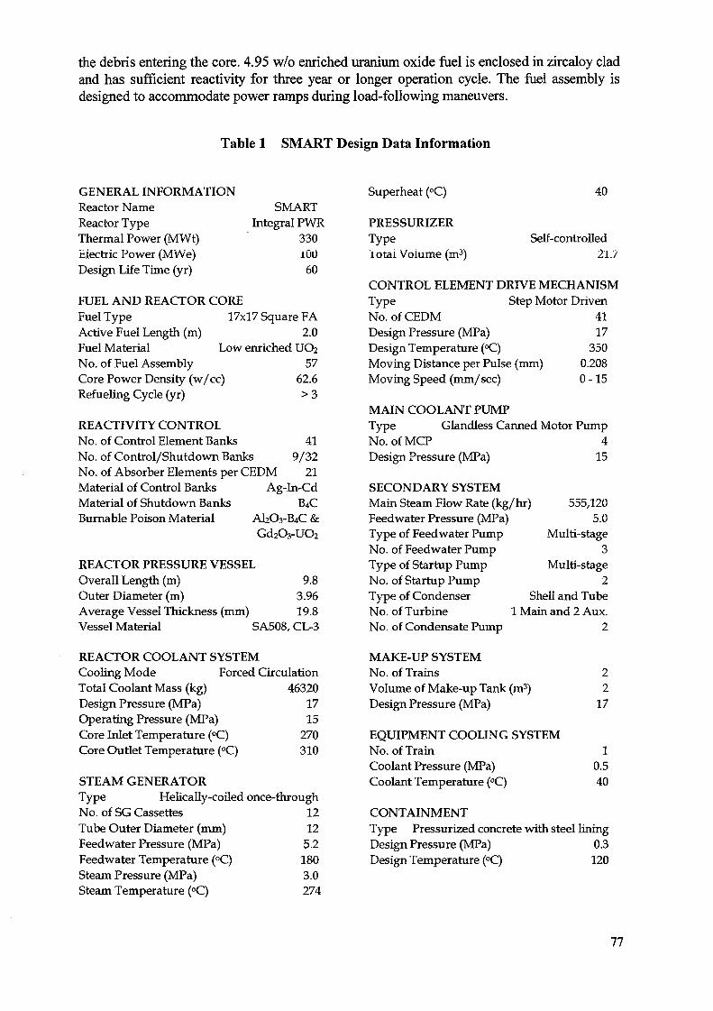
the debris entering the core. 4.95 w/o enriched uranium oxide fuel is enclosed in zircaloy cladand has sufficient reactivity for three year or longer operation cycle. The fuel assembly isdesigned to accommodate power ramps during load-following maneuvers.
Table 1 SMART Design Data Information
GENERAL INFORMATIONReactor NameReactor TypeThermal Power (MWt)Electric Power (MWe)Design Life Time (yr)
SMARTIntegral PWR
33010060
Superheat (°C)
PRESSURIZERTypeiotai Volume (m3)
40
Self-controlled21.7
FUEL AND REACTOR COREFuel Type 17x17 Square FAActive Fuel Length (m) 2.0Fuel Material Low enriched UO2No. of Fuel Assembly 57Core Power Density (w/cc) 62.6Refueling Cycle (yr) > 3
REACTIVITY CONTROLNo. of Control Element Banks 41No. of Control/Shutdown Banks 9/32No. of Absorber Elements per CEDM 21Material of Control Banks Ag-In-CdMaterial of Shutdown Banks B4CBurnable Poison Material AI2O3-B4C &
Gd2O3-UO2
REACTOR PRESSURE VESSELOverall Length (m) 9.8Outer Diameter (m) 3.96Average Vessel Thickness (mm) 19.8Vessel Material SA508, CL-3
REACTOR COOLANT SYSTEMCooling Mode Forced CirculationTotal Coolant Mass (kg) 46320Design Pressure (MPa) 17Operating Pressure (MPa) 15Core Inlet Temperature (°C) 270Core Outlet Temperature (°C) 310
STEAM GENERATORType Helically-coiled once-throughNo. of SG Cassettes 12Tube Outer Diameter (mm) 12Feedwater Pressure (MPa) 5.2Feedwater Temperature (°C) 180Steam Pressure (MPa) 3.0Steam Temperature (°C) 274
CONTROL ELEMENT DRIVE MECHANISMType Step Motor DrivenNo. of CEDM 41Design Pressure (MPa) 17Design Temperature (°C) 350Moving Distance per Pulse (mm) 0.208Moving Speed (mm/sec) 0-15
MAIN COOLANT PUMPType Glandless Canned Motor PumpNo.ofMCP 4Design Pressure (MPa) 15
SECONDARY SYSTEMMain Steam Flow Rate (kg/hr)Feedwater Pressure (MPa)Type of Feedwater PumpNo. of Feedwater PumpType of Startup PumpNo. of Startup PumpType of CondenserNo. of TurbineNo. of Condensate Pump
555,1205.0
Multi-stage3
Multi-stage2
Shell and Tube1 Main and 2 Aux.
2
MAKE-UP SYSTEMNo. of Trains 2Volume of Make-up Tank (m3) 2Design Pressure (MPa) 17
EQUIPMENT COOLING SYSTEMNo. of Train 1Coolant Pressure (MPa) 0.5Coolant Temperature (°C) 40
CONTAINMENTType Pressurized concrete with steel liningDesign Pressure (MPa) 0.3Design Temperature (°C) 120
77
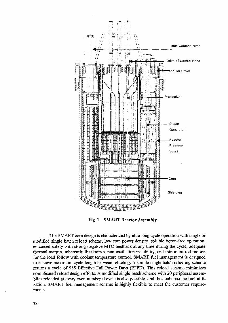
' / : : : : : " ' i !~ \ \
Main Coolant Pump
= Drive of Control Rods
-Annular Cover
Steam
Generator
Shielding
Fig. 1 SMART Reactor Assembly
The SMART core design is characterized by ultra long cycle operation with single ormodified single batch reload scheme, low core power density, soluble boron-free operation,enhanced safety with strong negative MTC feedback at any time during the cycle, adequatethermal margin, inherently free from xenon oscillation instability, and minimum rod motionfor the load follow with coolant temperature control. SMART fuel management is designedto achieve maximum cycle length between refueling. A simple single batch refueling schemereturns a cycle of 985 Effective Full Power Days (EFPD). This reload scheme minimizescomplicated reload design efforts. A modified single batch scheme with 20 peripheral assem-blies reloaded at every even numbered cycle is also possible, and thus enhance the fuel utili-zation. SMART fuel management scheme is highly flexible to meet the customer require-ments.
78
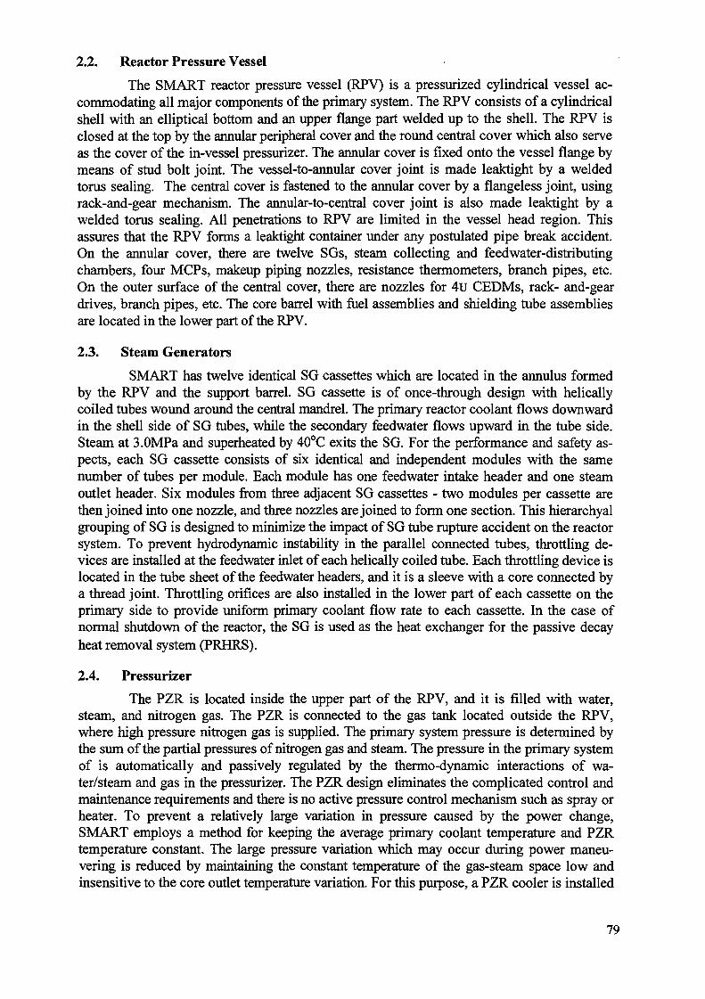
2.2. Reactor Pressure Vessel
The SMART reactor pressure vessel (RPV) is a pressurized cylindrical vessel ac-commodating all major components of the primary system. The RPV consists of a cylindricalshell with an elliptical bottom and an upper flange part welded up to the shell. The RPV isclosed at the top by the annular peripheral cover and the round central cover which also serveas the cover of the in-vessel pressurizer. The annular cover is fixed onto the vessel flange bymeans of stud bolt joint. The vessel-to-annular cover joint is made leaktight by a weldedtorus sealing. The central cover is fastened to the annular cover by a flangeless joint, usingrack-and-gear mechanism. The annular-to-central cover joint is also made leaktight by awelded torus sealing. All penetrations to RPV are limited in the vessel head region. Thisassures that the RPV forms a leaktight container under any postulated pipe break accident.On the annular cover, there are twelve SGs, steam collecting and feedwater-distributingchambers, four MCPs, makeup piping nozzles, resistance thermometers, branch pipes, etc.On the outer surface of the central cover, there are nozzles for 4u CEDMs, rack- and-geardrives, branch pipes, etc. The core barrel with fuel assemblies and shielding tube assembliesare located in the lower part of the RPV.
2.3. Steam Generators
SMART has twelve identical SG cassettes which are located in the annulus formedby the RPV and the support barrel. SG cassette is of once-through design with helicallycoiled tubes wound around the central mandrel. The primary reactor coolant flows downwardin the shell side of SG tubes, while the secondary feedwater flows upward in the tube side.Steam at 3.0MPa and superheated by 40°C exits the SG. For the performance and safety as-pects, each SG cassette consists of six identical and independent modules with the samenumber of tubes per module. Each module has one feedwater intake header and one steamoutlet header. Six modules from three adjacent SG cassettes - two modules per cassette arethen joined into one nozzle, and three nozzles are joined to form one section. This hierarchyalgrouping of SG is designed to minimize the impact of SG tube rupture accident on the reactorsystem. To prevent hydrodynamic instability in the parallel connected tubes, throttling de-vices are installed at the feedwater inlet of each helically coiled tube. Each throttling device islocated in the tube sheet of the feedwater headers, and it is a sleeve with a core connected bya thread joint. Throttling orifices are also installed in the lower part of each cassette on theprimary side to provide uniform primary coolant flow rate to each cassette. In the case ofnormal shutdown of the reactor, the SG is used as the heat exchanger for the passive decayheat removal system (PRHRS).
2.4. Pressurizer
The PZR is located inside the upper part of the RPV, and it is filled with water,steam, and nitrogen gas. The PZR is connected to the gas tank located outside the RPV,where high pressure nitrogen gas is supplied. The primary system pressure is determined bythe sum of the partial pressures of nitrogen gas and steam. The pressure in the primary systemof is automatically and passively regulated by the thermo-dynamic interactions of wa-ter/steam and gas in the pressurizer. The PZR design eliminates the complicated control andmaintenance requirements and there is no active pressure control mechanism such as spray orheater. To prevent a relatively large variation in pressure caused by the power change,SMART employs a method for keeping the average primary coolant temperature and PZRtemperature constant. The large pressure variation which may occur during power maneu-vering is reduced by maintaining the constant temperature of the gas-steam space low andinsensitive to the core outlet temperature variation. For this purpose, a PZR cooler is installed
79
to maintain low PZR temperature and a wet thermal insulator is placed between the PZR andthe primary system to reduce conductive heat transfer.
2.5. Control Element Drive Mechanism
The SMART Control Element Drive Mechanism (CEDM) is designed for fine-stepmovement and consists of a linear pulse motor (LPM), choke rack with top and bottom limitswitches which also act as control element assembly (CEA) position indicator, hydro-dampers, locking device, and extension shaft connecting CEDM and CEA. The CEDMmovement is accomplished with a combination of four phases. As a control command comesto the LPM control unit, the LPM phase I gets off and phase II gets on. After that, phase IIgets off and phase HI gets on, etc. The direction of the armature movement depends on thecommunication sequence of the LPM phases. The normal travel length of the control rod is4mm per pulse, and the travel speed is in the range of 0 - 50 mm/sec. The drives separate unitis joined to each other on the flanges with studs and nuts. The drives are located on the reac-tor central cover and fastened to the cover by means of flange joints with studs and nuts.Sealing is provided with the use of copper gaskets rectangular in section.
2.6. Main Coolant Pump
The SMART MCP is a canned motor pump which does not require the need ofpump seals. This characteristics basically eliminates a small break Loss of Coolant Accidentassociated with the pump seal failure which becomes one of design bases events in the reac-tors using conventional pump. SMART has four MCPs vertically installed on the top annularcover of the RPV. Each MCP is an integral unit consisted of canned asynchronous three-phase motor and an axial-flow single- stage pump. The motor and the pump are connected bya common shaft rotating on three radials and one axial thrust bearing. The bearings use aspecialized graphite-based material, and the axial bearing performs the function of sealing.The cooling of pumps is accomplished with the component cooling water. The rotationalspeed of the pump rotor is controlled by a sensor installed in the upper part of the motor. Toavoid the reverse rotation of the pump rotor, an anti-reverse device is installed at the motorshaft near the middle radial bearing.
3. SAFETY SYSTEMS
Besides it is inherent safety characteristics of SMART, further enhanced safety isaccomplished with highly reliable engineered safety systems. The engineered safety systemsdesigned to function passively on the demand consist of reactor shutdown system, passiveresidual heat removal system, emergency core cooling system, safeguard vessel, and con-tainment overpressure protection system. Additional engineered safety systems include thereactor overpressure protection system and the severe accident mitigation system. The sche-matic diagram of the SMART safety system is shown in Fig. 2.
3.1. Reactor Shutdown System
The shutdown of SMART can be achieved by a function of one of two independentsystems. The primary shutdown system is 32 shutdown banks of CEA of which absorbingmaterial is B4C. The control banks are dropped into the reactor core by the gravity force andimmediately stops the neutron chain reactions. These control banks have sufficient shutdownmargin to bring the reactor from hot full power to hot shutdown, even with a most reactivebank stuck out of the core. For the case of failure of the primary shutdown system, the emer-gency boron injection system is provided as a backup system and consists of two tanks, 6m3
80
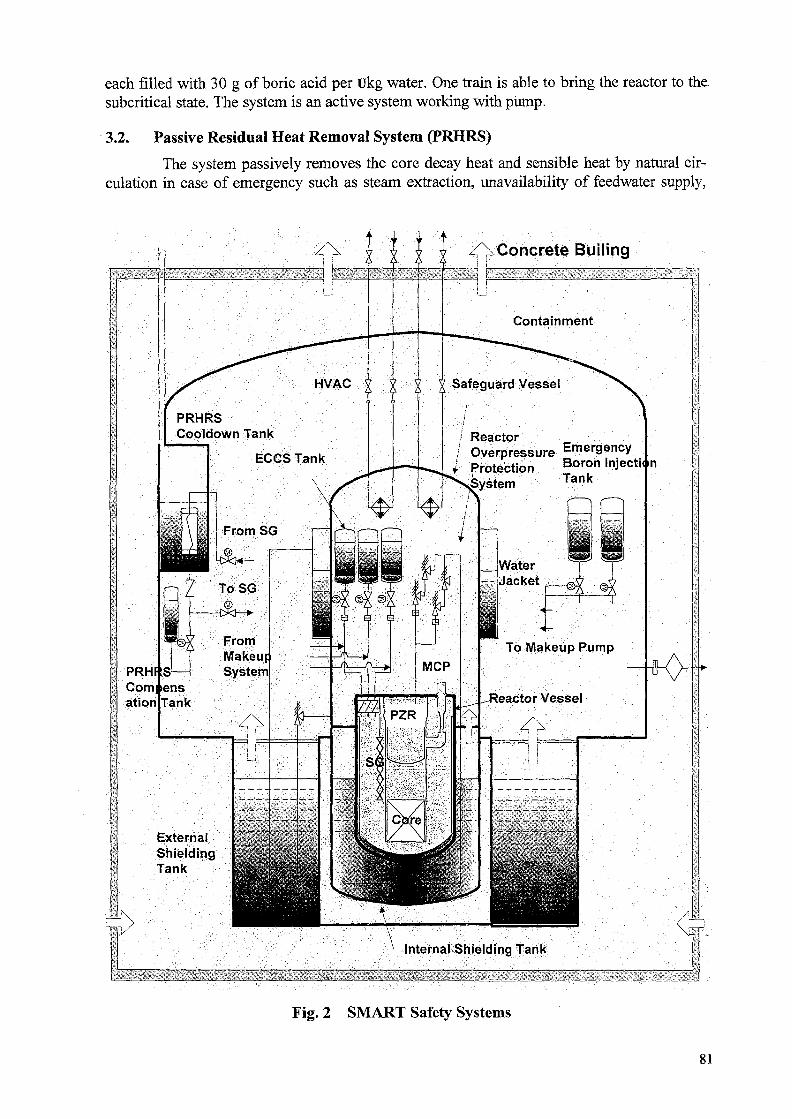
each filled with 30 g of boric acid per Ukg water. One train is able to bring the reactor to thesubcritical state. The system is an active system working with pump.
3.2. Passive Residual Heat Removal System (PRHRS)
The system passively removes the core decay heat and sensible heat by natural cir-culation in case of emergency such as steam extraction, unavailability of feedwater supply,
/\Concrete Builing
PRHRSCooldown Tank
, Overpressure EmergencyI Protection Boron Inject!
Tank
PRHf :SCom|ensation
ExternalShieldingTank
Internal Shielding Tank
Fig. 2 SMART Safety Systems
81
and station black out. Besides, the PRHRS may also be used in case of long-term cooling forrepair or refueling. The PRHRS consists of 4 independent trains with 50% capacity each.Two trains are sufficient to remove the decay heat. Each train is composed of an emergencycooldown tank, a heat exchanger and a compensating tank. The system is designed to keepthe core un-damaged for 72hrs without any corrective actions by operators at the postulateddesign basis accidents. In case of normal shutdown of SMART, the residual heat is removedthrough the SG to the condenser with turbine bypass system.
3.3. Emergency Core Cooling System (ECCS)
The SMART design excludes any possibility of large break Loss of Coolant Acci-dent. The largest size of pipes connected to the outside of the RPV is 20mm. The ECCS isthus provided to protect the core uncovery by mitigating the consequences of design basisevents such as small break LOC A through make-up of the primary coolant inventory. Whenan initiating event occurs, the primary system is depressurized. The pressure difference be-tween the primary system and the ECCS breaks the rupture disc installed in the pipe of ECCSand the water immediately comes into the core by the gas pressure. The ECCS consists ofthree independent trains with UOO% capacity each. Each train includes a cylindrical watertank of 5m3 in volume pressurized with nitrogen gas, isolation and check valves, rupture disc,and a pipe of 20mm in diameter connected to RPV.
3.4. Safeguard Vessel
The safeguard vessel is a leaktight pressure retaining steel-made vessel intended forthe accommodation of all primary reactor systems including the reactor assembly, pressurizergas cylinders, and associated valves and pipings. The primary function of the safeguard ves-sel is to confine the radioactive products within the vessel and thus to protect any primarycoolant leakage to the containment. The vessel also has a function to keep the reactor coreundamaged during 72hrs without any corrective actions at the postulated design basis acci-dents including LOC A, with the operation of the PRHRS and ECCS. The steam releasedfrom the opening of the relief valve of the safeguard vessel at the postulated beyond designbasis accidents is sparged into the external shielding tanks and immediately condensed.
3.5. Containment Overpressure Protection System (COPS)
The containment is a steel structure with concrete building enclosing the safeguardvessel to confine the release of radioactive products to the outside environment under thepostulated beyond design basis accidents relating to the loss of integrity of the safeguardvessel. At any accident causing the temperature rise and thus the pressure rise in the contain-ment, the containment cooling is accomplished, in the passive manner, by removing the heatfrom the containment. The heat is removed through the steel structure itself and through theemergency cooldown tanks installed inside the containment. A rupture disc and a filteringsystem are also provided in the containment to protect the steel structure from overpressureand to purify the released radioactive products at the postulated beyond design basis acci-dents.
3.6. Reactor Overpressure Protection System (ROPS)
The function of the ROPS is to reduce the reactor pressure at the postulated beyonddesign basis accident related with a control system failure. The system consists of two paral-lel trains which are connected to the PZR through a single pipeline. Two trains are also com-bined to a single pipeline connected to the internal shielding tank. Each train is equipped with
82
a rupture disc and two relief valves. At the postulated beyond design basis accidents, therupture disc is broken and the relief valve is open by the passive means of flow thrust.
The steam is then discharged into the internal shielding tank through the spargingdevice and condensed.
3.7. Severe Accident Mitigation System (SAMS)
The function of the SAMS is to prevent the egress of molten corium resulting from asevere accident out of the containment. The egress of corium can be avoided due to the de-sign characteristics of safeguard vessel and containment together with the operation of thesafety systems. A small air gap under the reactor pressure vessel (RPV) is filled with waterfrom the Makeup system at the severe accident. The in-vessel cooling prevents the egress ofthe corium out of the RPV. In addition, the water in the internal shielding tank provides theexternal cooling of the RPV and prevents the egress of the corium out of the RPV. Hydrogenigniters are provided in the safeguard vessel to remove the explosive hydrogen generatedduring the severe accident.
4. SECONDARY SYSTEM
The secondary system of the plant with SMART has the same function of removingthe heat produced from the primary system, as of the conventional nuclear power plant.However, the secondary system generates superheated steam from the feed water. The sys-tem consists of in-vessel helically coiled steam generator, main steam and feedwater system,turbine generators and associated pipings and valves. The system is divided into four inde-pendent sections arranged in such a way to minimize the heat removal unbalance in the vesselwhen one section fails. The turbine generators consist of a main turbine generator and twoauxiliary turbine generators. One auxiliary turbine generator is standby and the other is inoperation to supply the house loads, while the main turbine is used for the offsite power sup-ply. The pressure of main steam line is always constant during power change transients. Theload change is done by the change of feedwater flow rate to the steam generator with thechange rate of 5%/min, or by the turbine bypass system when the load change is done imme-diately. The schematic diagram of the SMART safety system is shown in Fig. 3.
5. AUXILIARY SYSTEMS
The major auxiliary systems of SMART consist of equipment cooling system (ECS)and make-up system. The function of ECS is to remove the heat generated in the MCPs,CEDMs, PZR, and the internal shielding tank. The feedwater supplied from the condensatepump of the turbo-generator is used as coolant to remove the heat. The make-up system ofSMART performs the following functions; fill and make-up the primary coolant in case ofthe primary system leak, supply water to the compensating tanks for the PRHRS and supplywater to the gas filling tank during the scheduled shutdown processes. The make-up systemconsists of two independent trains, each train with one positive displacement makeup pump,a makeup tank, and piping & valves. The schematic diagram of the SMART safety system isshown in Fig. 4.
83

From —|S/G Main Steam __T
From —IS/G Main Steam _ T
To S/GFeedwater Header
To S/GFeedwater Header
Equipment *-Cooling System
TG bearingseals system
TG bearingseals system
Ejector
Fig. 3 SMART Secondary System
PRHRS Hx. (4x)
Equipment PRHRS
CEDM
uxiliary System
ConqensatePum
CondenStorage Tank
Gas Cylinder
Make-up System
r\
\j
Gas FillingTank
-**-
r-H rJ] Make-upr r I Pump
M H
Make-upTank
Fig. 4 SMART Auxiliary System
84
ADVANCED MARINE REACTOR MRX AND ITS APPLICATION FORELECTRICITY AND HEAT CO-GENERATION
T. ISHIDA, M. OCHIAI XA0056271Japan Atomic Energy Research Institute
T. HOSHIResearch Organization for Information Science & Technology
Tokai-mura, Naka-gun, Ibaraki-ken, Japan
Abstract
The basic concept of an innovative advanced marine reactor MRX has been established bydesign study toward the goals of light-weightiness, compactness, and safety and reliabilityimprovement with adoption of several new technologies. The MRX is the integral-type PWR aimedfor use of ship propulsion. Adoption of a water-filled containment makes the reactor light-weightedand compact greatly. The total weight and volume of the reactor are 1600 tons and 1210m3, whichare equivalent to halves of the Mutsu, although the reactor power of MRX is three times greater. Anengineered safety system of the MRX is a simplified passive system, function of which is confirmedby the safety analysis to be able to keep the reactor integrity even in a case of accident. Reliabilityof the system is evaluated by the PSA and revealed to have two orders smaller core damageoccurrence frequency than existing PWRs. The MRX can be applied to an energy supply system ofelectricity and heat co-generation. Concept of the nuclear energy supply system is designed togenerate electricity, heat and fresh water. The nuclear barge is shown to be a possible nuclear energysupply system with advantage of being movable easily.
1. INTRODUCTION
Small-scale reactors have more advantages than large-scale reactors in variety of energyutilization, construction, maintenance and adoption of innovative technologies, while the latter havescale merits in construction cost. The nuclear energy utilization of small-scale reactors are shippropulsion, electricity generation, heat supply, and sea water desalination, etc. Construction andmaintenance for small-scale reactors can be made in factories exclusive use for them, but not at thesite of the plant. In small-scale reactors, the safety can be enhanced sometimes by new technologies.
Japan atomic energy research institute (JAERI) have designed a small-scale integral typePWR with 100 MW of the thermal output for ship propulsion, called MRX (Marine Reactor). Highpriorities of design requirements are laid on being economical and reliable of the reactor system.Design goals of being light-weighted, compact, simple and safe were set up to meet the designrequirements, and these goals were achieved by several new technologies such as the water-filledcontainment, the in-vessel control rod drive mechanisms (CRDMs). Feasibility of the MRX designconcept for the commercial ship was surveyed by checking compatibility of the systems, andevaluating safety and economics in the whole system. Development of the new technologiesadopted in the MRX has mostly completed for the stage of principal function confirmation. TheMRX, therefore, can be realized if the economic and social circumstances allow the commercialnuclear power ships.
The MRX can be also used for a multi-purpose utilization such as electric powergeneration for a distance district, sea water desalination, and heat supply. Features of MRX, i.e.,being easy movable, light-weighted, compact, simple and safe can be also suitable for these multi-purpose utilization.
85
2. MRX FOR SHIP PROPULSION
2.1. Design goals and new technologies adopted in MRX
JAERI set up the design goals for MRX with 100 MW of thermal output which is installedinto the ship with 80,000 HP of the shaft power. The ship with two MRXs (100MWtx2) is to havecapabilities of ice-breaking for research of the climate of north pole region, together with role of acommercial ship. This forces the MRX reactor to bear severe external and internal conditions. Theconcept of nuclear icebreaker with two MRXs equipped is shown in Fig. 1. The concrete designgoals of the MRX are as follows:
1. Light-weightiness and compactnessTo realize the light weighted and compact reactor, the total weight including the reactor vessel,the containment and the shielding should be not greater than 1600 tons which is equivalent tonearly a half weight of the Mutsu, the first Japanese nuclear experimental ship. The totalvolume of the reactor system should be small as possible according to light weightiness. Thesegoals are decided so to be competitive with the conventional engine of commercial ships fromsurvey of needs on nuclear ship which was conducted by JAERI.
2. Simplification of the systemThe design goal for being simple is that the numbers of the sub-systems and the machineryadopted in the reactor system should be minimized and definitely less than those of other plant,for example, the conventional PWRs.
3. Safety and reliability improvementAt least, stability in the normal operation and safety in a case of postulated accident should beconfirmed by the transient analysis, and also reliability of the system by provability safetyanalysis.
4. Maintainability improvementFrom the economical point of view, the period for maintenance of the system or refueling of thecore is required to be short as long as possible. The design goals is set up with that the periodshould be less than one month.
Relationship between the goals and design improvements to attain these goals areillustrated in Fig. 2. Major adoptions for design improvement are as follows.
a) The integral type reactor
b) The in-vessel type control rod drive mechanism
c) The water-filled containment
d) Passive decay heat removal system
e) One-piece removal of the reactor system
Details of the MRX design with these improvements are presented in the followingchapter.
2.2. Design conditions for marine reactor
Design conditions of the MRX concerning the specific items of a marine reactor areintroduced as follows.
a) Even at the low temperature of 300K, the reactor should be able to be shut down without useof a soluble poison by taking account of ship sinking. That is, the control rods should haveability to maintain the reactivity Keff less than 0.99.
b) The reactor should have ability to generate over 30% of the rated output for steerageway(ship propelling with effective rudder), under condition of the one rod stuck.
c) The reactor should respond to a rapid and/or large shipload change such as turbine trip or aheadand astern maneuvering. The reactor should slave to the change from the base load (15% of the
86
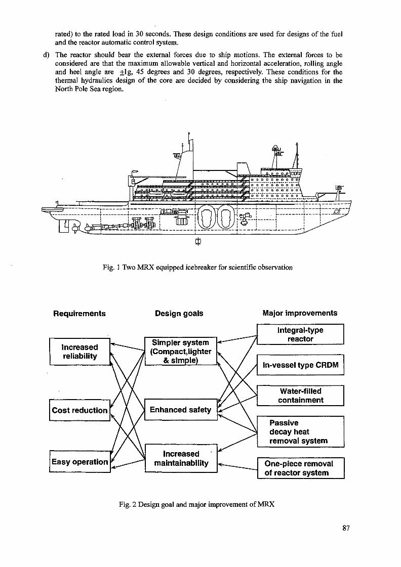
rated) to the rated load in 30 seconds. These design conditions are used for designs of the fueland the reactor automatic control system.
d) The reactor should bear the external forces due to ship motions. The external forces to beconsidered are that the maximum allowable vertical and horizontal acceleration, rolling angleand heel angle are +lg, 45 degrees and 30 degrees, respectively. These conditions for thethermal hydraulics design of the core are decided by considering the ship navigation in theNorth Pole Sea region.
Fig. 1 Two MRX equipped icebreaker for scientific observation
Requirements
Increasedreliability
Cost reduction
Easy operation
Design goals Major improvements
Simpler system(Compact.lighter
& simple)
Enhanced safety
Increasedmaintainability
Integral-typereactor
In-vessel type CRDM
Water-filledcontainment
Passivedecay heatremoval system
One-piece removalof reactor system
Fig. 2 Design goal and major improvement of MRX
87
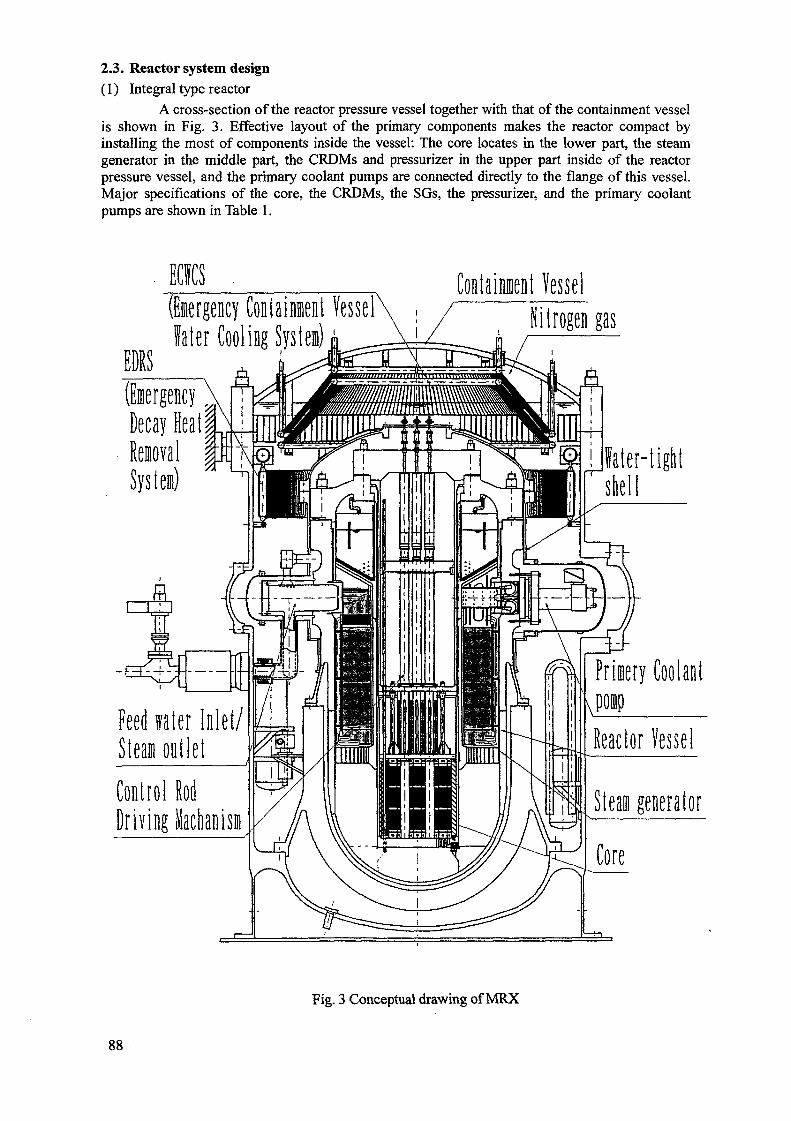
2.3. Reactor system design(1) Integral type reactor
A cross-section of the reactor pressure vessel together with that of the containment vesselis shown in Fig. 3. Effective layout of the primary components makes the reactor compact byinstalling the most of components inside the vessel: The core locates in the lower part, the steamgenerator in the middle part, the CRDMs and pressurizer in the upper part inside of the reactorpressure vessel, and the primary coolant pumps are connected directly to the flange of this vessel.Major specifications of the core, the CRDMs, the SGs, the pressurizer, and the primary coolantpumps are shown in Table 1.
(Emergency Containment Vessellater Cooling System) d:
Containment VesselNitrogen gas
Water-tightshell
(Emergency .Decay Heat
Feed water Inlet/Steam outletControl RodDriving Machanism
Fig. 3 Conceptual drawing of MRX
88
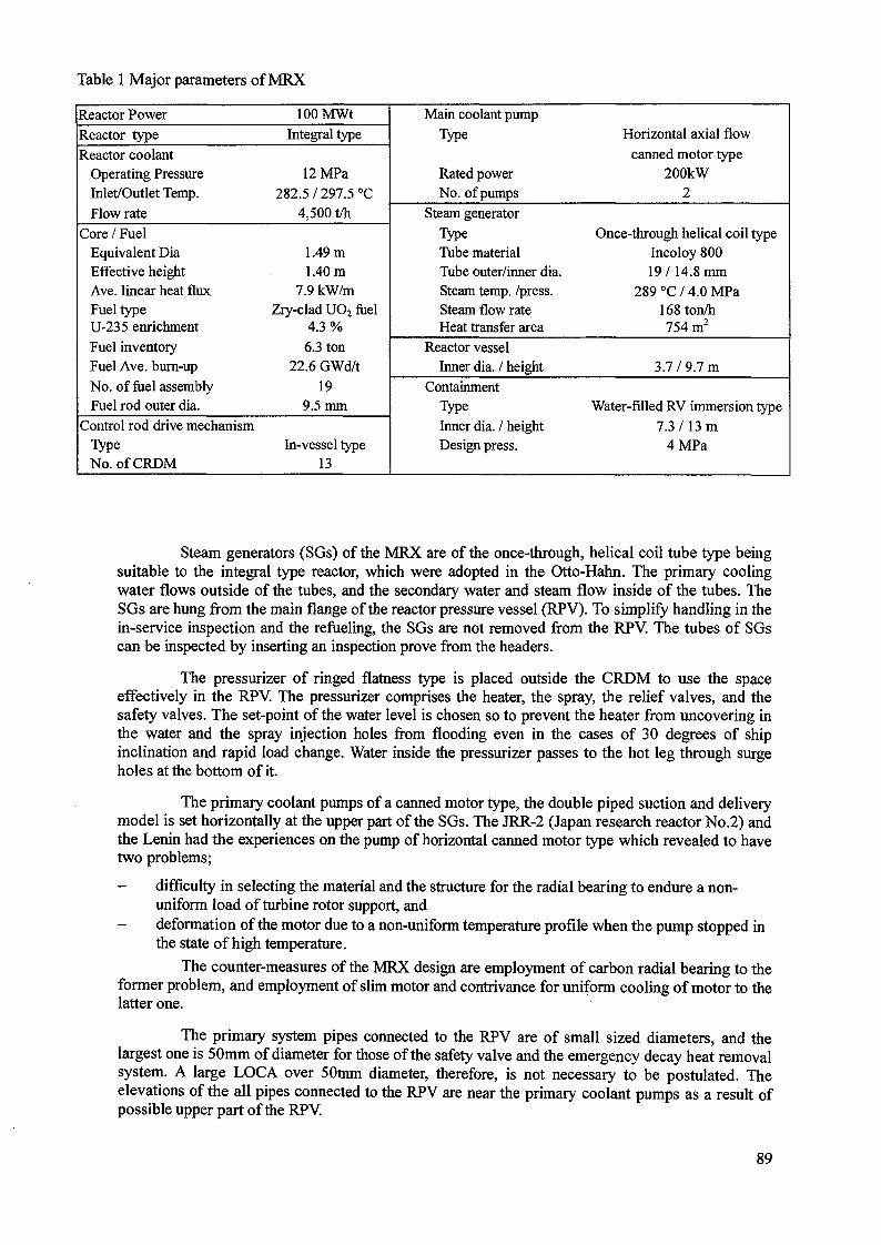
Table 1 Major parameters of MRX
Reactor PowerReactor typeReactor coolant
Operating PressureInlet/Outlet Temp.Flow rate
Core / FuelEquivalent DiaEffective heightAve. linear heat fluxFuel typeU-235 enrichment
Fuel inventoryFuel Ave. burn-upNo. of fuel assemblyFuel rod outer dia.
Control rod drive mechanismTypeNo. of CRDM
100 MWtIntegral type
12MPa282.5 / 297.5 °C
4,500 t/h
1.49 m1.40 m
7.9 kW/mZry-clad UO2 fuel
4.3 %
6.3 ton22.6 GWd/t
199.5 mm
In-vessel type13
Main coolant pumpType
Rated powerNo. of pumps
Steam generatorTypeTube materialTube outer/inner dia.Steam temp, /press.Steam flow rateHeat transfer area
Reactor vesselInner dia. / height
ContainmentTypeInner dia. / heightDesign press.
Horizontal axial flowcanned motor type
200kW2
Once-through helical coil typeIncoloy 80019/14.8 mm
289°C/4.0MPa168 ton/h754 m2
3.7/9.7 m
Water-filled RV immersion type7.3/13 m
4MPa
Steam generators (SGs) of the MRX are of the once-through, helical coil tube type beingsuitable to the integral type reactor, which were adopted in the Otto-Hahn. The primary coolingwater flows outside of the tubes, and the secondary water and steam flow inside of the tubes. TheSGs are hung from the main flange of the reactor pressure vessel (RPV). To simplify handling in thein-service inspection and the refueling, the SGs are not removed from the RPV. The tubes of SGscan be inspected by inserting an inspection prove from the headers.
The pressurizer of ringed flatness type is placed outside the CRDM to use the spaceeffectively in the RPV. The pressurizer comprises the heater, the spray, the relief valves, and thesafety valves. The set-point of the water level is chosen so to prevent the heater from uncovering inthe water and the spray injection holes from flooding even in the cases of 30 degrees of shipinclination and rapid load change. Water inside the pressurizer passes to the hot leg through surgeholes at the bottom of it.
The primary coolant pumps of a canned motor type, the double piped suction and deliverymodel is set horizontally at the upper part of the SGs. The JRR-2 (Japan research reactor No.2) andthe Lenin had the experiences on the pump of horizontal canned motor type which revealed to havetwo problems;
- difficulty in selecting the material and the structure for the radial bearing to endure a non-uniform load of turbine rotor support, and
- deformation of the motor due to a non-uniform temperature profile when the pump stopped inthe state of high temperature.
The counter-measures of the MRX design are employment of carbon radial bearing to theformer problem, and employment of slim motor and contrivance for uniform cooling of motor to thelatter one.
The primary system pipes connected to the RPV are of small sized diameters, and thelargest one is 50mm of diameter for those of the safety valve and the emergency decay heat removalsystem. A large LOCA over 50mm diameter, therefore, is not necessary to be postulated. Theelevations of the all pipes connected to the RPV are near the primary coolant pumps as a result ofpossible upper part of the RPV.
89
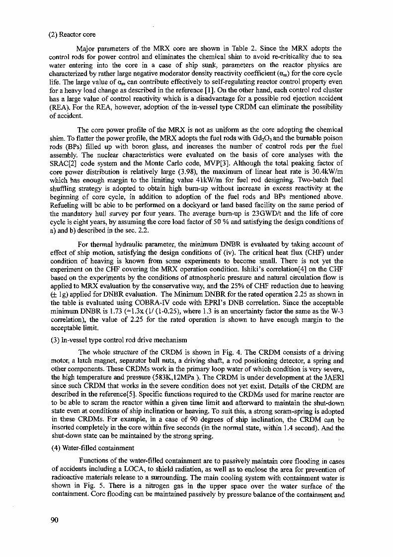
(2) Reactor core
Major parameters of the MRX core are shown in Table 2. Since the MRX adopts thecontrol rods for power control and eliminates the chemical shim to avoid re-criticality due to seawater entering into the core in a case of ship sunk, parameters on the reactor physics arecharacterized by rather large negative moderator density reactivity coefficient (otm) for the core cyclelife. The large value of dm can contribute effectively to self-regulating reactor control property evenfor a heavy load change as described in the reference [1]. On the other hand, each control rod clusterhas a large value of control reactivity which is a disadvantage for a possible rod ejection accident(REA). For the REA, however, adoption of the in-vessel type CRDM can eliminate the possibilityof accident.
The core power profile of the MRX is not as uniform as the core adopting the chemicalshim. To flatter the power profile, the MRX adopts the fuel rods with Gd2O3 and the burnable poisonrods (BPs) filled up with boron glass, and increases the number of control rods per the fuelassembly. The nuclear characteristics were evaluated on the basis of core analyses with theSRAC[2] code system and the Monte Carlo code, MVP[3]. Although the total peaking factor ofcore power distribution is relatively large (3.98), the maximum of linear heat rate is 30.4kW/mwhich has enough margin to the limiting value 41kW/m for fuel rod designing. Two-batch fuelshuffling strategy is adopted to obtain high burn-up without increase in excess reactivity at thebeginning of core cycle, in addition to adoption of the fuel rods and BPs mentioned above.Refueling will be able to be performed on a dockyard or land based facility on the same period ofthe mandatory hull survey per four years. The average bum-up is 23GWD/t and the life of corecycle is eight years, by assuming the core load factor of 50 % and satisfying the design conditions ofa) and b) described in the sec. 2.2.
For thermal hydraulic parameter, the minimum DNBR is evaluated by taking account ofeffect of ship motion, satisfying the design conditions of (iv). The critical heat flux (CHF) undercondition of heaving is known from some experiments to become small. There is not yet theexperiment on the CHF covering the MRX operation condition. Ishiki's correlation[4] on the CHFbased on the experiments by the conditions of atmospheric pressure and natural circulation flow isapplied to MRX evaluation by the conservative way, and the 25% of CHF reduction due to heaving(± lg) applied for DNBR evaluation. The Minimum DNBR for the rated operation 2.25 as shown inthe table is evaluated using COBRA-IV code with EPRI's DNB correlation. Since the acceptableminimum DNBR is 1.73 (=1.3x (1/ (1-0.25), where 1.3 is an uncertainty factor the same as the W-3correlation), the value of 2.25 for the rated operation is shown to have enough margin to theacceptable limit.
(3) In-vessel type control rod drive mechanism
The whole structure of the CRDM is shown in Fig. 4. The CRDM consists of a drivingmotor, a latch magnet, separator ball nuts, a driving shaft, a rod positioning detector, a spring andother components. These CRDMs work in the primary loop water of which condition is very severe,the high temperature and pressure (583K,12MPa ). The CRDM is under development at the JAERIsince such CRDM that works in the severe condition does not yet exist. Details of the CRDM aredescribed in the reference^]. Specific functions required to the CRDMs used for marine reactor areto be able to scram the reactor within a given time limit and afterward to maintain the shut-downstate even at conditions of ship inclination or heaving. To suit this, a strong scram-spring is adoptedin these CRDMs. For example, in a case of 90 degrees of ship inclination, the CRDM can beinserted completely in the core within five seconds (in the normal state, within 1.4 second). And theshut-down state can be maintained by the strong spring.
(4) Water-filled containment
Functions of the water-filled containment are to passively maintain core flooding in casesof accidents including a LOCA, to shield radiation, as well as to enclose the area for prevention ofradioactive materials release to a surrounding. The main cooling system with containment water isshown in Fig. 5. There is a nitrogen gas in the upper space over the water surface of thecontainment. Core flooding can be maintained passively by pressure balance of the containment and
90
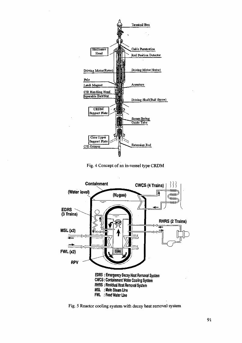
Terminal Box
CRDMSupport Hale
Core UppeiSupport Plate
Enclosure 1Head \ ^
Driving Motor(Rotor)
Pole1•
: \ _ Cable Penetration
^ Rod Poation Detector
Driving Motoi(Stalor)
Latch Magnet TtlllFC/R Handling Head wBLSeparable Ball/Nut [fiiffm
Armature
Driving Shaft(Ball Screw)
Scram SpringGuide Tube
C/R Gripper Extension Rod
Fig. 4 Concept of an in-vessel type CRDM
Containment
(Water level)
EDRS(3 Trains)
MSL(x2 )
FWL(x2 )
RPV
EDRS : Emergency Decay Heat Removal SystemCWCS: Containment Water Cooling SystemRHHS: Residual Heat Removal SystemMSL : Main Steam LineFWL :Feed Water Line
Fig. 5 Reactor cooling system with decay heat removal system
91
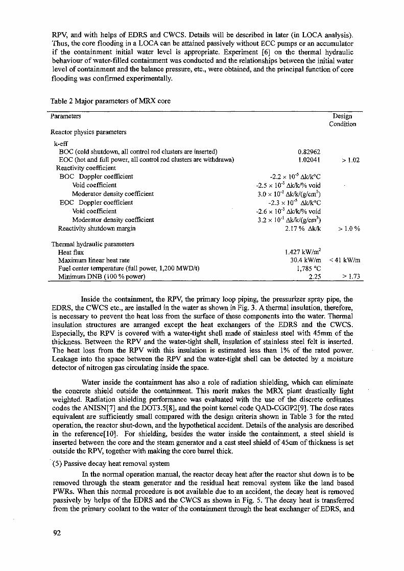
RPV, and with helps of EDRS and CWCS. Details will be described in later (in LOCA analysis).Thus, the core flooding in a LOCA can be attained passively without ECC pumps or an accumulatorif the containment initial water level is appropriate. Experiment [6] on the thermal hydraulicbehaviour of water-filled containment was conducted and the relationships between the initial waterlevel of containment and the balance pressure, etc., were obtained, and the principal function of coreflooding was confirmed experimentally.
Table 2 Major parameters of MRX core
Parameters
Reactor physics parameters
k-effBOC (cold shutdown, all control rod clusters are inserted)EOC (hot and full power, all control rod clusters are withdrawn)
Reactivity coefficientBOC Doppler coefficient
Void coefficientModerator density coefficient
EOC Doppler coefficientVoid coefficientModerator density coefficient
Reactivity shutdown margin
Thermal hydraulic parametersHeat fluxMaximum linear heat rateFuel center temperature (full power, 1,200 MWD/t)Minimum DNB (100 % power)
-23.
-23.
.50
.6
.2
-2.2 >xlO"3
x 10-'-2.3 xx 10-3
x 10"1
DesignCondition
0.829621.02041 >1.02
i W5 Ak/k°CAk/k/% voidAk/k/(g/cm3)10"5 Ak/k°CAk/k/% voidAk/k/(g/cm3)2.17% Ak/k > 1.0%
1.427kW/m2
30.4 kW/m <41kW/m1,785 °C
2.25 > 1.73
Inside the containment, the RPV, the primary loop piping, the pressurizer spray pipe, theEDRS, the CWCS etc., are installed in the water as shown in Fig. 3. A thermal insulation, therefore,is necessary to prevent the heat loss from the surface of these components into the water. Thermalinsulation structures are arranged except the heat exchangers of the EDRS and the CWCS.Especially, the RPV is covered with a water-tight shell made of stainless steel with 45mm of thethickness. Between the RPV and the water-tight shell, insulation of stainless steel felt is inserted.The heat loss from the RPV with this insulation is estimated less than 1% of the rated power.Leakage into the space between the RPV and the water-tight shell can be detected by a moisturedetector of nitrogen gas circulating inside the space.
Water inside the containment has also a role of radiation shielding, which can eliminatethe concrete shield outside the containment. This merit makes the MRX plant drastically lightweighted. Radiation shielding performance was evaluated with the use of the discrete ordinatescodes the ANISN[7] and the DOT3.5[8], and the point kernel code QAD-CGGP2[9]. The dose ratesequivalent are sufficiently small compared with the design criteria shown in Table 3 for the ratedoperation, the reactor shut-down, and the hypothetical accident. Details of the analysis are describedin the reference[10]. For shielding, besides the water inside the containment, a steel shield isinserted between the core and the steam generator and a cast steel shield of 45 cm of thickness is setoutside the RPV, together with making the core barrel thick.
(5) Passive decay heat removal system
In the normal operation manual, the reactor decay heat after the reactor shut down is to beremoved through the steam generator and the residual heat removal system like the land basedPWRs. When this normal procedure is not available due to an accident, the decay heat is removedpassively by helps of the EDRS and the CWCS as shown in Fig. 5. The decay heat is transferredfrom the primary coolant to the water of the containment through the heat exchanger of EDRS, and
92
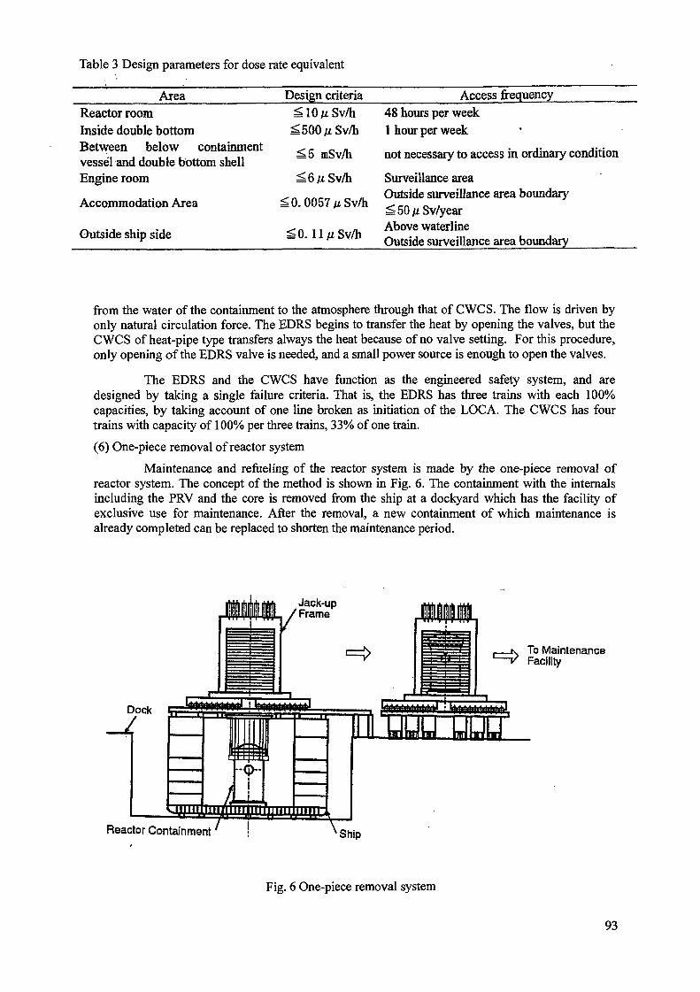
Table 3 Design parameters for dose rate equivalent
Area Design criteria Access frequency
Reactor roomInside double bottomBetween below containmentvessel and double bottom shellEngine room
Accommodation Area
Outside ship side
^ 5 mSv/h
^0.0057//Sv/h
^0. UfiSv/h
48 hours per week1 hour per week
not necessary to access in ordinary condition
Surveillance areaOutside surveillance area boundary^50/iSv/yearAbove waterlineOutside surveillance area boundary
from the water of the containment to the atmosphere through that of CWCS. The flow is driven byonly natural circulation force. The EDRS begins to transfer the heat by opening the valves, but theCWCS of heat-pipe type transfers always the heat because of no valve setting. For this procedure,only opening of the EDRS valve is needed, and a small power source is enough to open the valves.
The EDRS and the CWCS have function as the engineered safety system, and aredesigned by taking a single failure criteria. That is, the EDRS has three trains with each 100%capacities, by taking account of one line broken as initiation of the LOCA. The CWCS has fourtrains with capacity of 100% per three trains, 33% of one train.
(6) One-piece removal of reactor system
Maintenance and refueling of the reactor system is made by the one-piece removal ofreactor system. The concept of the method is shown in Fig. 6. The containment with the internalsincluding the PRV and the core is removed from the ship at a dockyard which has the facility ofexclusive use for maintenance. After the removal, a new containment of which maintenance isalready completed can be replaced to shorten the maintenance period.
, K To Maintenance— v Facility
Reactor Containment
Fig. 6 One-piece removal system
93

2.4. Characteristics of transient response
As described in the previous chapter, the MRX copes with anomaly including accidents byhelp of the engineered passive safety system: The core is flooded by the water-filled containmentand the decay heat is removed by the EDRS and the CWCS. To view the function and the transientbehavior, the LOCA analysis using RELAP5/mod2[ll] and COBRA-TV[12] codes is presented hereas followings.
Rupture of the EDRS pipe of 50mm diameter is presumed to initiate the LOCA. Thetransient is shown in Fig. 7. The reactor pressure decreases rapidly immediately after rupture, and itdoes slowly from about 40 seconds to 520 seconds due to change of break flow phase from thewater to the steam. Reactor scram is initiated by the signal of reactor pressure low level at 100seconds. The EDRS of an intact loop starts to operate at 300 seconds.
Reactor Water Level
Containment Pressure
0
350
300
250
2 200
I 150& 100
50
0
300 600 900
Time [sec]
1200
Core Outlet Temperature
Removed by EDRS
Decay Heat
Containment Water Temperature0
0 300 600 900
Time [sec]
1200 1500
Fig. 7 LOCA analysis for break of 50 mm diameter pipe
94

The containment pressure rises due to inflow of the primary coolant through the brokenpipe. Both of the containment pressure and the reactor pressure equal at 520 seconds, and afterwardsthey show almost a constant value. The containment pressure is under the design limit throughoutthe transient.
The water level of the core decreases due to outflow of the primary coolant. It, however,remains at about 2m high level over the top of the core when both of the pressure equals. The waterlevel 2m is enough for core flooding completely even if the ship inclines at 30 degrees, which is oneof the design conditions mentioned previously.
The decay heat is removed after the EDRS valve open as follows. The upper part of RPVis covered with the steam at this time. This steam flows into the EDRS, and be cooled to the state ofwater through passing the heat exchanger. The water returns to the down comer of the RPV. Thus anatural circulation loop is formed by the EDRS and the RPV, and the decay heat is transferred to thewater of containment. In the containment water, the heat is transferred by single-phase naturalcirculation from the EDRS to the CWCS. The CWCS transfers this heat to the atmosphere. After300 seconds, the heat removal rate is larger than the decay heat rate and the temperature of coreoutlet decreases gradually. After 600 seconds, the heats removed by the CWCS and the EDRSbalance, and the temperature of containment water remains to a constant.
During the transient, the fuel cladding temperatures are not higher than the initial value ofthe steady state and the core is flooded, so that the minimum DNBR never falls down from theinitial value. This leads to a greater contribution for demonstration of MRX's outstanding feature ofsafety. As a result, core flooding and decay heat removal are revealed to be done appropriately bythe engineered passive safety system.
On the other hand, in the normal operation, frequent severe load changes will induce theMRX. The analysis by RELAP5 shows that the MRX can operate stably for these load changeswithout calling the scram or relief valve operation of the pressurizer, though the results are notshown here.
2.5. Achievement of design goals(1) Light-weightiness and compactness
Breakdown of weights and volumes of the reactor plant components is shown in Table 4.The total weight and the volume of the MRX are approximately 1600 tons and 1210m3,respectively. The total weight is summation of all the structures in the containment vessel, the filledwater and the containment vessel itself. The weight is not greater than that set for the design goal,that is, light-weightiness is achieved. According the light-weightiness, the volume is also small asshown below.
Comparison with the MRX and Mutsu or the three trial designs[13] studied by JAERI isshown in Fig. 8. The MRX has a half weight of the Mutsu even though the reactor power of MRX isthree times greater than that of Mutsu, and also a half weight of the trial designs. Because thoseother than the MRX have the secondary shields, they are heavier than the MRX. The volume of theMRX is the half of that of Mutsu and 40% of that of the trial design studies.
Contributions to light-weightiness and compactness of the MRX are due to adoption ofintegral type reactor installing the steam generator and the pressurizer inside the RPV, and adoptionof water filled reactor containment vessel. The reactor room and reactor component room are notsubject to the goal in the present discussion, but the total volume of them in MRX is 3326m3, whichis almost the same volume as that of the Mutsu. Thus, the MRX has also the compact reactor roomand reactor component room, since the engineered safety system is greatly simplified, and thechemical shim for the reactivity control is not adopted.
(2) Simplification of the system
The systems of the MRX for the normal operation are almost the same as existing PWRsexcept the chemical processing system. Elimination of the chemical processing system makes thenormal operation system of the MRX be simple greatly.
95
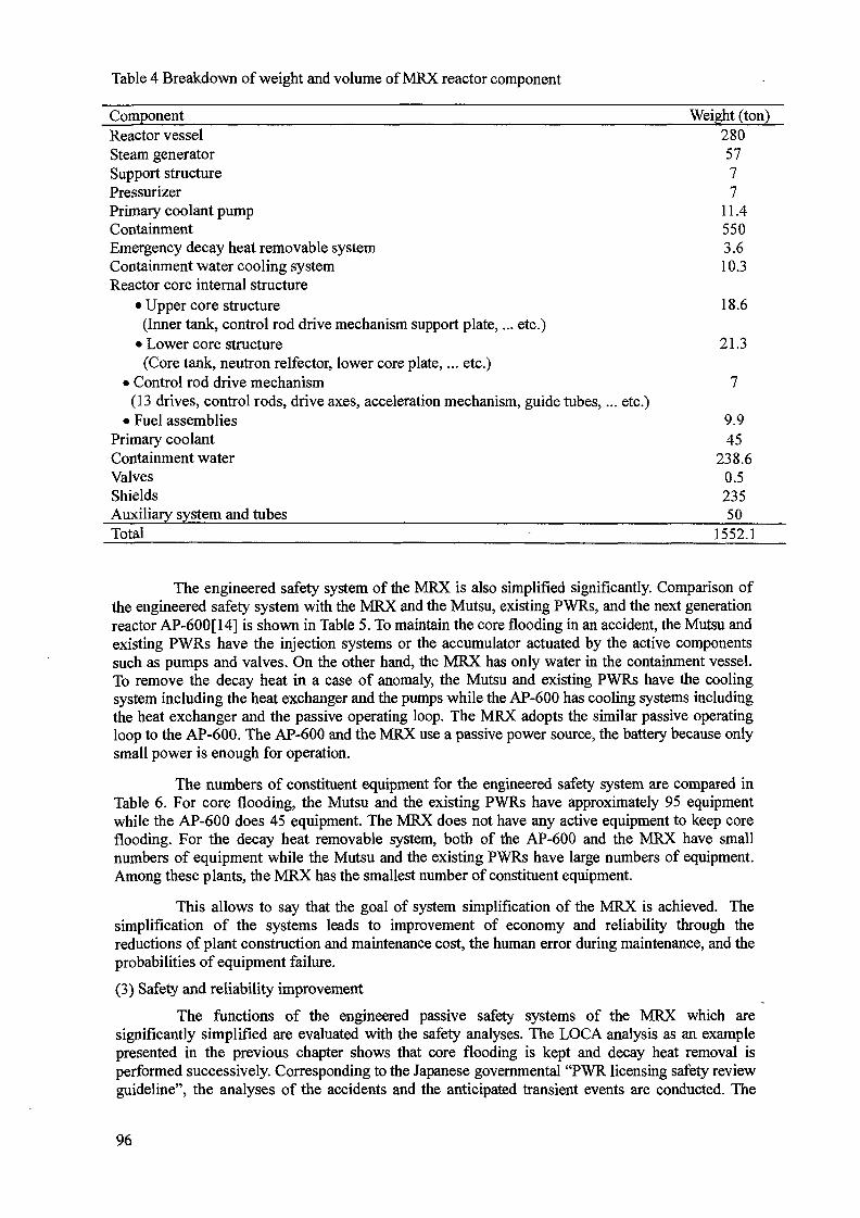
Table 4 Breakdown of weight and volume of MRX reactor component
Component Weight (ton)Reactor vessel 280Steam generator 57Support structure 7Pressurizer 7Primary coolant pump 11.4Containment 550Emergency decay heat removable system 3.6Containment water cooling system 10.3Reactor core internal structure
• Upper core structure 18.6(Inner tank, control rod drive mechanism support plate,... etc.)
• Lower core structure 21.3(Core tank, neutron relfector, lower core plate,... etc.)
• Control rod drive mechanism 7(13 drives, control rods, drive axes, acceleration mechanism, guide tubes,... etc.)
• Fuel assemblies 9.9Primary coolant 45Containment water 238.6Valves 0.5Shields 235Auxiliary system and tubes 50Total 1552.1
The engineered safety system of the MRX is also simplified significantly. Comparison ofthe engineered safety system with the MRX and the Mutsu, existing PWRs, and the next generationreactor AP-600[14] is shown in Table 5. To maintain the core flooding in an accident, the Mutsu andexisting PWRs have the injection systems or the accumulator actuated by the active componentssuch as pumps and valves. On the other hand, the MRX has only water in the containment vessel.To remove the decay heat in a case of anomaly, the Mutsu and existing PWRs have the coolingsystem including the heat exchanger and the pumps while the AP-600 has cooling systems includingthe heat exchanger and the passive operating loop. The MRX adopts the similar passive operatingloop to the AP-600. The AP-600 and the MRX use a passive power source, the battery because onlysmall power is enough for operation.
The numbers of constituent equipment for the engineered safety system are compared inTable 6. For core flooding, the Mutsu and the existing PWRs have approximately 95 equipmentwhile the AP-600 does 45 equipment. The MRX does not have any active equipment to keep coreflooding. For the decay heat removable system, both of the AP-600 and the MRX have smallnumbers of equipment while the Mutsu and the existing PWRs have large numbers of equipment.Among these plants, the MRX has the smallest number of constituent equipment.
This allows to say that the goal of system simplification of the MRX is achieved. Thesimplification of the systems leads to improvement of economy and reliability through thereductions of plant construction and maintenance cost, the human error during maintenance, and theprobabilities of equipment failure.
(3) Safety and reliability improvement
The functions of the engineered passive safety systems of the MRX which aresignificantly simplified are evaluated with the safety analyses. The LOCA analysis as an examplepresented in the previous chapter shows that core flooding is kept and decay heat removal isperformed successively. Corresponding to the Japanese governmental "PWR licensing safety reviewguideline", the analyses of the accidents and the anticipated transient events are conducted. The
96
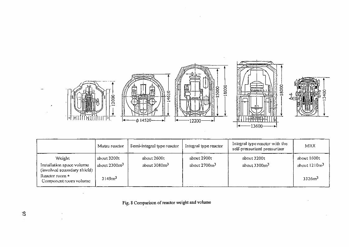
ooocs
Weight
Installation space volume(involved secondary shield)Reactor room +Component room volume
Mutsu reactor
about3200t
about 2300m3
3149m3
Semi-integral type reactor
about2600t
about 3080m3
Integral type reiictor
about2900t
about 2700m3
Integral type reactor with tineself-pressurized pressurizer
about3200t
about 3300m3
MRX
about 16001
about 1210m3
3326m3
Fig. 8 Comparison of reactor weight and volume
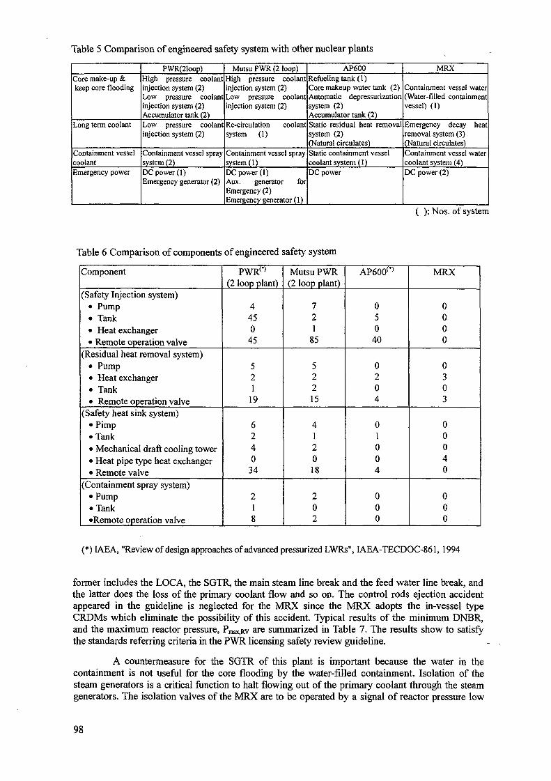
Table 5 Comparison of engineered safety system with other nuclear plants
Core make-up &keep core flooding
Long term coolant
Containment vesselcoolantEmergency power
PWR(21oop)High pressure coolantinjection system (2)Low pressure coolantinjection system (2)Accumulator tank (2)Low pressure coolantinjection system (2)
Containment vessel spraysystem (2)DC power (1)Emergency generator (2)
Mutsu PWR (2 loop)High pressure coolantinjection system (2)Low pressure coolantinjection system (2)
Re-circulation coolantsystem (1)
Containment vessel spraysystem (1)DC power (I)Aux. generator forEmergency (2)Emergency generator (1)
AP600Refueling tank (1)Core makeup water tank (2)Automatic depressurizationsystem (2)Accumulator tank (2)Static residual heat removalsystem (2)(Natural circulates)Static containment vesselcoolant system (1)DC power
MRX
Containment vessel water(Water-filled containmentvessel) (1)
Emergency decay heatremoval system (3)(Natural circulates)Containment vessel watercoolant system (4)DC power (2)
( ): Nos. of system
Table 6 Comparison of components of engineered safety system
Component
(Safety Injection system)• Pump• Tank• Heat exchanger• Remote operation valve
(Residual heat removal system)• Pump• Heat exchanger• Tank• Remote operation valve
(Safety heat sink system)• Pimp• Tank• Mechanical draft cooling tower• Heat pipe type heat exchanger• Remote valve
(Containment spray system)• Pump• Tank•Remote operation valve
PWR(<)
(2 loop plant)
4450
45
521
19
6240
34
218
Mutsu PWR(2 loop plant)
721
85
52215
412018
202
AP600 r )
050
40
0204
010
04
000
MRX
0000
0303
000
40
000
(*) IAEA, "Review of design approaches of advanced pressurized LWRs", IAEA-TECDOC-861, 1994
former includes the LOCA, the SGTR, the main steam line break and the feed water line break, andthe latter does the loss of the primary coolant flow and so on. The control rods ejection accidentappeared in the guideline is neglected for the MRX since the MRX adopts the in-vessel typeCRDMs which eliminate the possibility of this accident. Typical results of the minimum DNBR,and the maximum reactor pressure, Pmax,Rv are summarized in Table 7. The results show to satisfythe standards referring criteria in the PWR licensing safety review guideline.
A countermeasure for the SGTR of this plant is important because the water in thecontainment is not useful for the core flooding by the water-filled containment. Isolation of thesteam generators is a critical function to halt flowing out of the primary coolant through the steamgenerators. The isolation valves of the MRX are to be operated by a signal of reactor pressure low
98
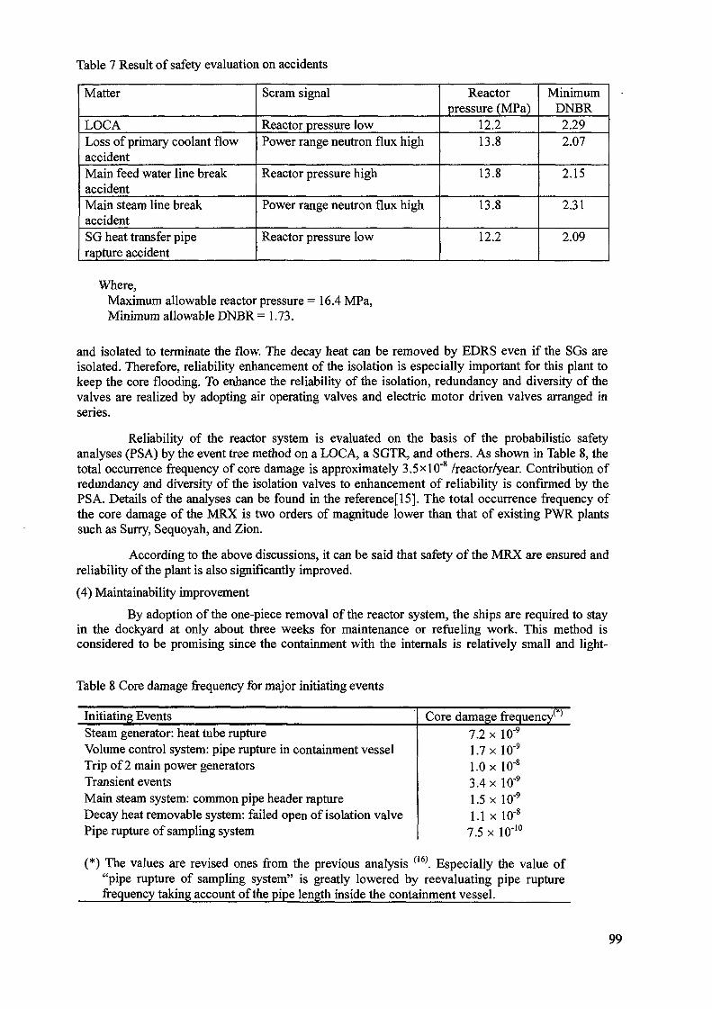
Table 7 Result of safety evaluation on accidents
Matter
LOCALoss of primary coolant flowaccidentMain feed water line breakaccidentMain steam line breakaccidentSG heat transfer piperapture accident
Scram signal
Reactor pressure lowPower range neutron flux high
Reactor pressure high
Power range neutron flux high
Reactor pressure low
Reactorpressure (MPa)
12.213.8
13.8
13.8
12.2
MinimumDNBR
2.292.07
2.15
2.31
2.09
Where,Maximum allowable reactor pressure =16.4 MPa,Minimum allowable DNBR = 1.73.
and isolated to terminate the flow. The decay heat can be removed by EDRS even if the SGs areisolated. Therefore, reliability enhancement of the isolation is especially important for this plant tokeep the core flooding. To enhance the reliability of the isolation, redundancy and diversity of thevalves are realized by adopting air operating valves and electric motor driven valves arranged inseries.
Reliability of the reactor system is evaluated on the basis of the probabilistic safetyanalyses (PSA) by the event tree method on a LOCA, a SGTR, and others. As shown in Table 8, thetotal occurrence frequency of core damage is approximately 3.5 xlO"8 /reactor/year. Contribution ofredundancy and diversity of the isolation valves to enhancement of reliability is confirmed by thePSA. Details of the analyses can be found in the reference[15]. The total occurrence frequency ofthe core damage of the MRX is two orders of magnitude lower than that of existing PWR plantssuch as Surry, Sequoyah, and Zion.
According to the above discussions, it can be said that safety of the MRX are ensured andreliability of the plant is also significantly improved.
(4) Maintainability improvement
By adoption of the one-piece removal of the reactor system, the ships are required to stayin the dockyard at only about three weeks for maintenance or refueling work. This method isconsidered to be promising since the containment with the internals is relatively small and light-
Table 8 Core damage frequency for major initiating events
Initiating EventsSteam generator: heat tube ruptureVolume control system: pipe rupture in containment vesselTrip of 2 main power generatorsTransient eventsMain steam system: common pipe header raptureDecay heat removable system: failed open of isolation valvePipe rupture of sampling system
Core damage frequency^7.2 x 10~9
1.7 x 10⁹
1.0 x 10'8
3.4 x 10'9
1.5 x 10'9
1.1 x 10⁸
7.5 x 10"10
(*) The values are revised ones from the previous analysis (l6). Especially the value of"pipe rupture of sampling system" is greatly lowered by reevaluating pipe rupturefrequency taking account of the pipe length inside the containment vessel.
99
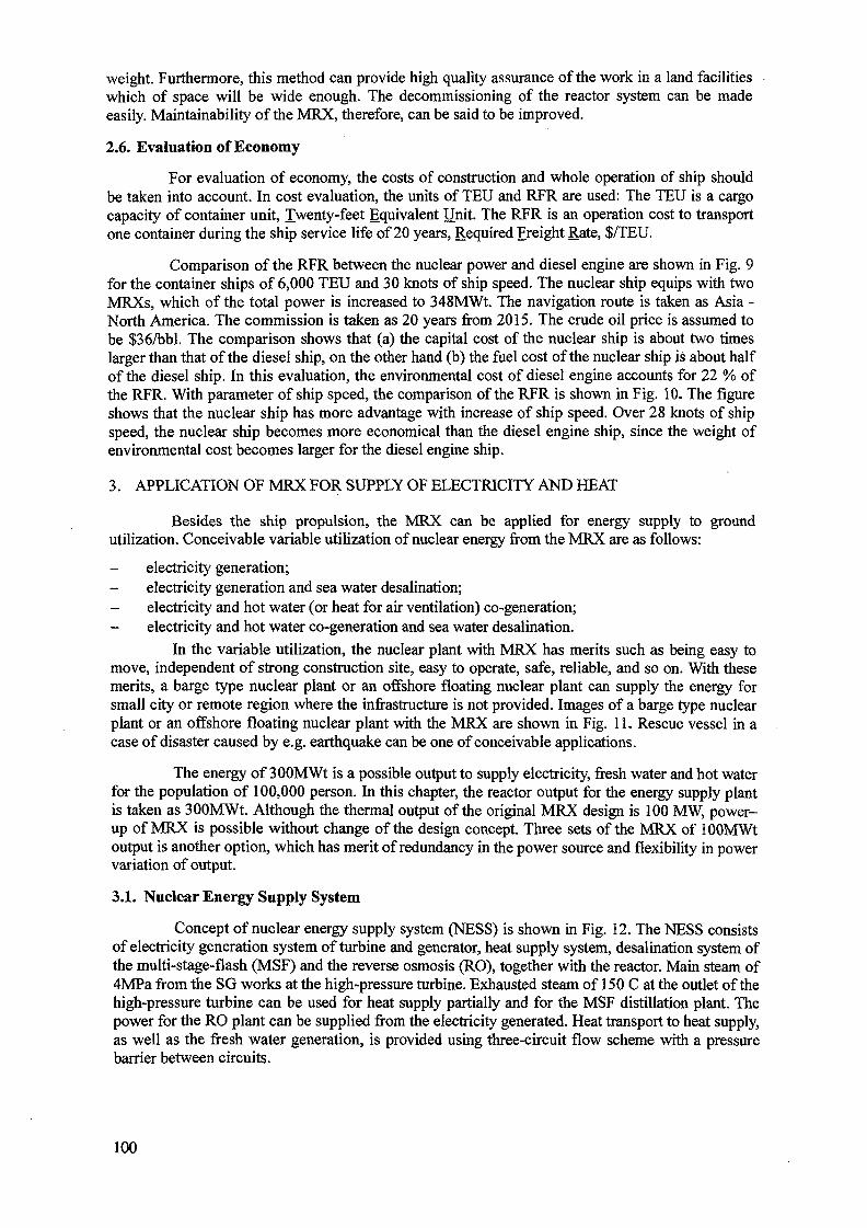
weight. Furthermore, this method can provide high quality assurance of the work in a land facilitieswhich of space will be wide enough. The decommissioning of the reactor system can be madeeasily. Maintainability of the MRX, therefore, can be said to be improved.
2.6. Evaluation of Economy
For evaluation of economy, the costs of construction and whole operation of ship shouldbe taken into account. In cost evaluation, the units of TEU and RFR are used: The TEU is a cargocapacity of container unit, Twenty-feet Equivalent Unit. The RFR is an operation cost to transportone container during the ship service life of 20 years, Required Freight Rate, $/TEU.
Comparison of the RFR between the nuclear power and diesel engine are shown in Fig. 9for the container ships of 6,000 TEU and 30 knots of ship speed. The nuclear ship equips with twoMRXs, which of the total power is increased to 348MWt. The navigation route is taken as Asia -North America. The commission is taken as 20 years from 2015. The crude oil price is assumed tobe $36/bbl. The comparison shows that (a) the capital cost of the nuclear ship is about two timeslarger than that of the diesel ship, on the other hand (b) the fuel cost of the nuclear ship is about halfof the diesel ship. In this evaluation, the environmental cost of diesel engine accounts for 22 % ofthe RFR. With parameter of ship speed, the comparison of the RFR is shown in Fig. 10. The figureshows that the nuclear ship has more advantage with increase of ship speed. Over 28 knots of shipspeed, the nuclear ship becomes more economical than the diesel engine ship, since the weight ofenvironmental cost becomes larger for the diesel engine ship.
3. APPLICATION OF MRX FOR SUPPLY OF ELECTRICITY AND HEAT
Besides the ship propulsion, the MRX can be applied for energy supply to groundutilization. Conceivable variable utilization of nuclear energy from the MRX are as follows:
- electricity generation;- electricity generation and sea water desalination;- electricity and hot water (or heat for air ventilation) co-generation;- electricity and hot water co-generation and sea water desalination.
In the variable utilization, the nuclear plant with MRX has merits such as being easy tomove, independent of strong construction site, easy to operate, safe, reliable, and so on. With thesemerits, a barge type nuclear plant or an offshore floating nuclear plant can supply the energy forsmall city or remote region where the infrastructure is not provided. Images of a barge type nuclearplant or an offshore floating nuclear plant with the MRX are shown in Fig. 11. Rescue vessel in acase of disaster caused by e.g. earthquake can be one of conceivable applications.
The energy of 300MWt is a possible output to supply electricity, fresh water and hot waterfor the population of 100,000 person. In this chapter, the reactor output for the energy supply plantis taken as 300MWt. Although the thermal output of the original MRX design is 100 MW, power-up of MRX is possible without change of the design concept. Three sets of the MRX of lOOMWtoutput is another option, which has merit of redundancy in the power source and flexibility in powervariation of output.
3.1. Nuclear Energy Supply System
Concept of nuclear energy supply system (NESS) is shown in Fig. 12. The NESS consistsof electricity generation system of turbine and generator, heat supply system, desalination system ofthe multi-stage-flash (MSF) and the reverse osmosis (RO), together with the reactor. Main steam of4MPa from the SG works at the high-pressure turbine. Exhausted steam of 150 C at the outlet of thehigh-pressure turbine can be used for heat supply partially and for the MSF distillation plant. Thepower for the RO plant can be supplied from the electricity generated. Heat transport to heat supply,as well as the fresh water generation, is provided using three-circuit flow scheme with a pressurebarrier between circuits.
100
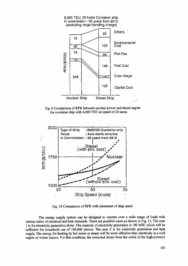
6,000 TEU, 30 knots Container shipIn commission : 20 years from 2015(excluding cargo handling charge)
sHI
RF
R($
/7
73
30
74
1H
O/1QC.HO
^ "
X
63
109
145
\Sk—
126
Others
EnvironmentalCost
Port Fee
Fuel Cost
Crew Wage
Capital Cost
Nuclear Ship Diesel Ship
Fig. 9 Comparison of RFR between nuclear power and diesel enginefor container ship with 6,000 TEU at speed of 30 knots
2000
111
rru.en
1750
1500
Type of ShipRouteIn Commission
: 6000TEU Container ship: Asia-North America: 20 years from 2015
, .Diesel(with env. cost)
, ... Diesel .•(without env. cost)
25 30Ship Speed (knots)
35
Fig. 10 Comparison of RFR with parameter of ship speed
The energy supply system can be designed to operate over a wide range of loads withvarious ratios of electrical and heat demands. There are possible cases as shown in Fig. 13. The case1 is for electricity generation alone. The capacity of electricity generation is 100 MW, which will besufficient for household use of 100,000 person. The case 2 is for electricity generation and heatsupply. The energy for heating by hot water or steam will be more effective than electricity in a coldregion or winter season. For this condition, the extracted steam from the outlet of the high-pressure
101
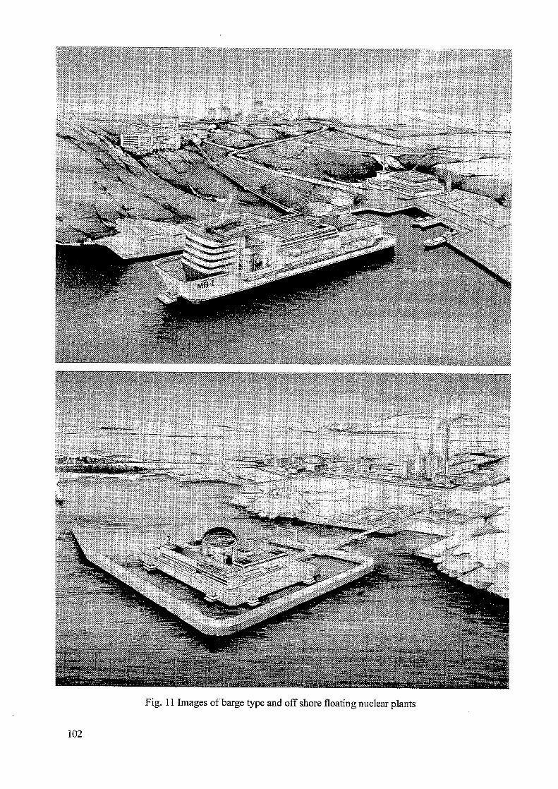
Fig. 11 Images of barge type and offshore floating nuclear plants
102
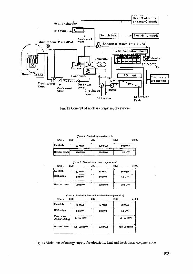
Heat exchanger
Feed water
Heat (Hot wateror Steam) supply
CondcnsatedMain steam (P = 4MPa) w a t e r
Switch boad ^Electricity supply
Exhausted steam (~ 1 5 0*C)
Flesh waterproduction
Flesh waterHeatei
Condensatedwater
pump | 'Sea water Sea water
Drain
Fig. 12 Concept of nuclear energy supply system
(Case 1 : Electricity generation only)
Time= 0:00 9:00 17:00 24:00
Electricity
Reactor power
50MWe
150 MWt
100 MWe
300 MWt
50 MWe
150 MWt
Time;
(Case 2 : Electricity and heat co-generation)
0:00 9:00 17:00 24:00
Electricity
Heat supply
Reactor power
50 MWe
50 MWt
200 MWt
83 MWe
50 MWt
300 MWt
50 MWe
50 MWt
200 MWt
(Case 3 : Electricity, heat and freash water co-generation)
Time= 0:00 9:00 17:00 24:00
Electricity
Heat supply
Fresh water(35,000m3/day)
Reactor power
30 MWe
50 MWt
30-50 MWt
180-200 MWt
83 MWe
50 MWt
300 MWt
30 MWe
50 MWt
30-50 MWt
180-200 MWt
Fig. 13 Variations of energy supply for electricity, heat and fresh water co-generation
103
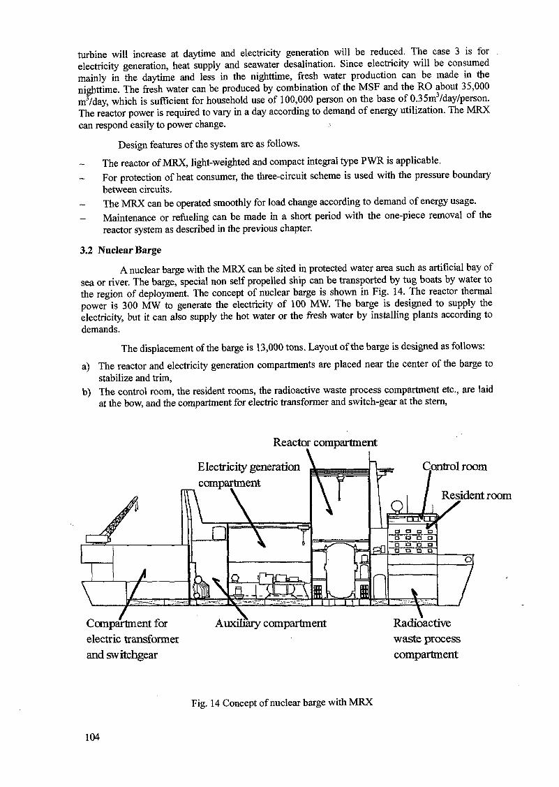
turbine will increase at daytime and electricity generation will be reduced. The case 3 is forelectricity generation, heat supply and seawater desalination. Since electricity will be consumedmainly in the daytime and less in the nighttime, fresh water production can be made in thenighttime. The fresh water can be produced by combination of the MSF and the RO about 35,000m3/day, which is sufficient for household use of 100,000 person on the base of 0.35m3/day/person.The reactor power is required to vary in a day according to demand of energy utilization. The MRXcan respond easily to power change.
Design features of the system are as follows.
The reactor of MRX, light-weighted and compact integral type PWR is applicable.For protection of heat consumer, the three-circuit scheme is used with the pressure boundarybetween circuits.The MRX can be operated smoothly for load change according to demand of energy usage.Maintenance or refueling can be made in a short period with the one-piece removal of thereactor system as described in the previous chapter.
3.2 Nuclear Barge
A nuclear barge with the MRX can be sited in protected water area such as artificial bay ofsea or river. The barge, special non self propelled ship can be transported by tug boats by water tothe region of deployment. The concept of nuclear barge is shown in Fig. 14. The reactor thermalpower is 300 MW to generate the electricity of 100 MW. The barge is designed to supply theelectricity, but it can also supply the hot water or the fresh water by installing plants according todemands.
The displacement of the barge is 13,000 tons. Layout of the barge is designed as follows:
a) The reactor and electricity generation compartments are placed near the center of the barge tostabilize and trim,
b) The control room, the resident rooms, the radioactive waste process compartment etc., are laidat the bow, and the compartment for electric transformer and switch-gear at the stern,
Reactor compartment
Electricity" generationcompartment
Control room
Resident room
Compartment forelectric transformerand switchgear
Auxiliary compartment Radioactivewaste processcompartment
Fig. 14 Concept of nuclear barge with MRX
104
c) Upper part of reactor compartment is used for carrying of the fuel and an open space foroverhaul of the reactor system,
d) The boiler and auxiliary electricity supply system is set at the auxiliary compartment formaintenance or the periodical inspection.
Mooring of the barge is one of important design subjects and depends on the condition ofsite. A possible mooring facility is made by a hydraulic shock-absorbing mechanism using thedolphin which can be used for large floating structures.
Maintenance and refueling of the reactor system can be done by the way of the one-pieceremoval of the reactor system at a dockyard, and replaced with another one.
4. CONCLUSION
(1) For a light-weighted and compact reactor, the radiation shield structure is critically important.The weight of MRX is reduced greatly by eliminating the secondary shield due to adoption ofthe water- filled containment. The integral type reactor is also effective for a compact reactor.Compactness of MRX is obtained by adoption of the integral type reactor with arrangement ofalmost all components inside the RPV.
(2) The engineered safety system of MRX is greatly simplified by adoption of the water-filledcontainment and the passive decay heat removable system relied on the natural circulation.Comparing the numbers of the sub-systems and equipment in the engineered safety system withother nuclear plants, the number of is decreased significantly.
(3) The MRX simplified passive safety system can ensure safety of the reactor, which is confirmedby the safety analysis. It is noteworthy that the MRX never uncover the core by help of thewater-filled containment even in a LOCA.
(4) Simplification of the system can also contribute to improvement of reliability. Reliability of theMRX system is confirmed by the PSA and found the total core damage occurrence frequency istwo orders smaller than that of existing PWR plants on land.
(5) The MRX can be used for not only a ship but also a wide range and multi purpose. The nuclearenergy supply system with the MRX of 300MWt can provide enough electricity, fresh water tothe population of 100,000 person.
(6) The nuclear barge with displacement of 13,000 ton is introduced as a possible application forenergy supply.
ACKNOWLEDGEMENTS
The authors would like to express their appreciation to Mr. T. Kusunoki, Dr. N. Odano,Mr. T. Yoritune, Mr. Y. Fukuhara and Mr. T. Nakazawa of JAERI for supply of manuscriptinformation.
REFERENCES
[1] ISHIDA, T., et al:. J.'Nucl. Sci. Technol, 30,116 (1993).[2] TSUCHIHASHI, K., et ah: JAERI 1302, (1986).[3] MORI, T., NAKAGAWA, M.: JAERI-Data/Code 94-007, (1994) [in Japanese].[4] ISSHIKI, N.: Nucl. Eng. Des., 4,138 (1966).[5] ISHIZUKA, Y., et al.: 11th National Conference on SmiRT, Tokyo, 1991[6] KUSUNOKI, T., et ah: J. At. Energy Soc. Japan, 40, 135 (1998) [in Japanese].[7] ENGLE, Jr., W. W.: K-1693, (1967).[8] RHODES, W. A.: ORNL-TM-4280, (1973); NEA-CPL, (1977).[9] SAKAMOTO, Y, TANAKA, S.: JAERJ-M 90-110, (1990).
105

[10] YAMAJI, A., SAKO, K.: J. Nucl. Sci. Technol, 31, 510 (1994).[11] DIMENNA, R.A., et al.: NUREG/CR-5194 EGG-2531, (1988). [RELPA5/mod2][12] WHEELER, C. L., et al.: BNWL-1962, (1976).[13] Japanese Atomic Energy Research Institute, JAERI-M 88-048(1988)[14] MclNTYRE, B. A., BECK, R. K.: Nuclear Safety, 33, 36 (1992).[15] FUKUHARA, Y, et al.: JAERI-Tech [To be published, in Japanese].[16] MATSUOKA, T., et al.: Proc. PSAM-IV, Int. Conference on Probabilistic Safety Assessment
and Management, p. 1296 (1998).
106
XA0056272CIVILIAN APPLICATION OF PROPULSIONREACTOR IN INDONESIA
M. DJOKOLELONO, B. ARBIE, A.N. LASMANNational Atomic Energy Agency (BATAN),Indonesia
Abstract
It has been learned that to cope with energy requirement in the remote islands and lessdeveloped regions of Indonesia small or very small nuclear reactors producing electricityand/or process heat could be appropriately applied. The barge mounted propulsion powerreactors are the attractive examples so far envisioned, and technology information of which isbeing exposed to the world these last years. The solutions for least maintenance and no on-siterefueling, no radioactive discharge, and no radioactive waste to remain in the user country areamong the attractions for further deliberations. It has been understood, however, that there aremany uncertainties to overcome, especially for the developing countries to introduce this novelapplication. International acceptance is the most crucial, availability of first-of-the-kindengineering, prototype or reference plant that would prove licensibility in the vendor's countryis the second, and economic competitiveness due to very small size is the third among issues toenlighten. The relevant regulations concerning marine nuclear safety, and of marinetransportation, and proliferation of information, as well as international forums to justify thefeasibility of related transfer of technology are the items that the IAEA could help to provide tosmoothen any possible international transaction. Indonesia supports this AGM as one of theappropriate IAEA efforts on this line, and expects from it positive international consensus andpossible studies/R&D work that this country could participate.
1. INTRODUCTION
In the national industrial plan, numbers of industrial centers are being developedthroughout Indonesia. The industrial centers located on the Jawa Island are able to rely on theavailable infrastructure for on-land transportation means and electricity supply by the Jawa-Baligrid. Whereas those on the big islands as Kalimantan and Sumatra, the industries are able to relyon the primary energy sources (oil, gas, or coal), which are indigenous on their island. But thoseindustrial centers, located more distantly from the energy sources will have to depend on theenergy transported and delivered, which are expensive unreliable.
It has been learned that to cope with energy requirement in the remote islands and lessdeveloped regions of Indonesia small or very small nuclear reactors producing electricity and/orprocess heat could be appropriately applied. The barge mounted gas-turbine power plants,constructed in Surabaya shipyard, have been operating so far to provide temporary power forBalikpapan city. By size requirement, a nuclear propulsion reactor is the most attractiveexample so far envisioned. A modest quantity of technology information on floating small NPPshave been obtained and learnt.
PWRs and BWRs were earlier being developed for naval and civilian purposes in theindustrially developed countries. Whereas in Russia naval pressurized water reactors have beenknown since longer time to be utilized in icebreakers and container ships. Earlier this year,presentations of Russian representatives were explaining these technologies for stationary (in-land) as well as floating power plants of PWR type to the BATAN and general audiences inIndonesia.
The first information on civilian design of liquid-metal fast reactor on barge was introducedto the authors of this paper in 1996 during the week of ICENES-96 Conference here in Obninsk.
107
This Pb-Bi cooled fast reactors, which previously used for submarines, are later to be designedon barge and said to be capable of providing electricity in full power for 4-6 years continuously.Advantages and improvement being pursued are mentioned in the references.
2. REQUIREMENTS
Short version of User Requirements on Small and Medium Reactors for Indonesia waspresented in the IAEA conference in Dubrovnik, June this year [I]. It includes also requirementsfor small and very small size reactors, for production of electricity and possible use of processheat, sited land based or floating, for deployment in remote areas. It covers technical, safety,economic and financial requirements and general consideration typically applied for Indonesia,a developing country. Below are some points, which are related to the topics of this AGM.
2.1. Siting
Figure 1 shows map of Indonesia with centers of industrial activities. The lessdeveloped or remote areas are dipersed mostly at the eastern part of Indonesia. Industrialzones to be developed in the East Regions of Indonesia cover such areas as Bima (WestNusa Tenggara) as center of agro-business and agro-industry, Mbay (East Nusa Tenggara),Benaviq (Betano-Natarbora-Viqueque, East Timor). Whereas the industrial zones Pare-pare (Cental Sulawesi), Manado-Bitung (North Sulawesi) is to be developed as industrialcenters based on marine resource, as well as agro-business and agro-industry.
Figure 2 shows the map of Indonesia with isoseismic lines and zones of subduction.Some isolated or less developed areas, which are at the East Regions of Indonesia may belocated in the high seismic areas. The isoseismic lines shows for the Nusa Tenggara Timur,South of Maluku and Irian Jaya the horizontal ground acceleration are between 0.05 to0.25 g, whereas for Sulawesi and North of Maluku are at the less end of the span.
Therefore, the barge mounted installation that would stand to the seismicdisturbances and possible related tsunamis, as well as for simplicity in the remote areaconstruction and operation would be preferable. Although in-land, stationary types, if theyare assured complying the seismic requirements as the floating ones, are well appreciated.
As characteristics of the potential sites as well as their load and other technicaldemands may differ from site to site, detail requirements on design characteristics varysubstantially. It is, therefore, significant that information on "envelope designcharacteristics" of proposed plant, i.e. the span in which the plants are designed, also bepresented, so as to simplify the appropriateness of a site.
2.2. Possible options
Due to limited information on other designs at the authors' side, only two Russianreactor types are mentioned in this paper: the pressurized water KLT-40C and the liquid-metal (Pb-Bi) fast reactor Cruse-50 variants. As mentioned above the floating/bargeversion would look to be promising for remote areas or less developed regions [2"6).
The features of long core life (couples of years), minimal on-site construction, leastmaintenance and no on-site refueling, long campaign time, low environmental radioactivedischarge during operation and no refueling at site are announced to contribute tosimplicity of application.
By the build-own-operate (BOO) scheme the vendor would tow the NPP barge, withcool shutdown reactors in it to the construction site. And at the end of each operatingcampaign the vendor would replace the NPP with new one and tow back fully used cores
108
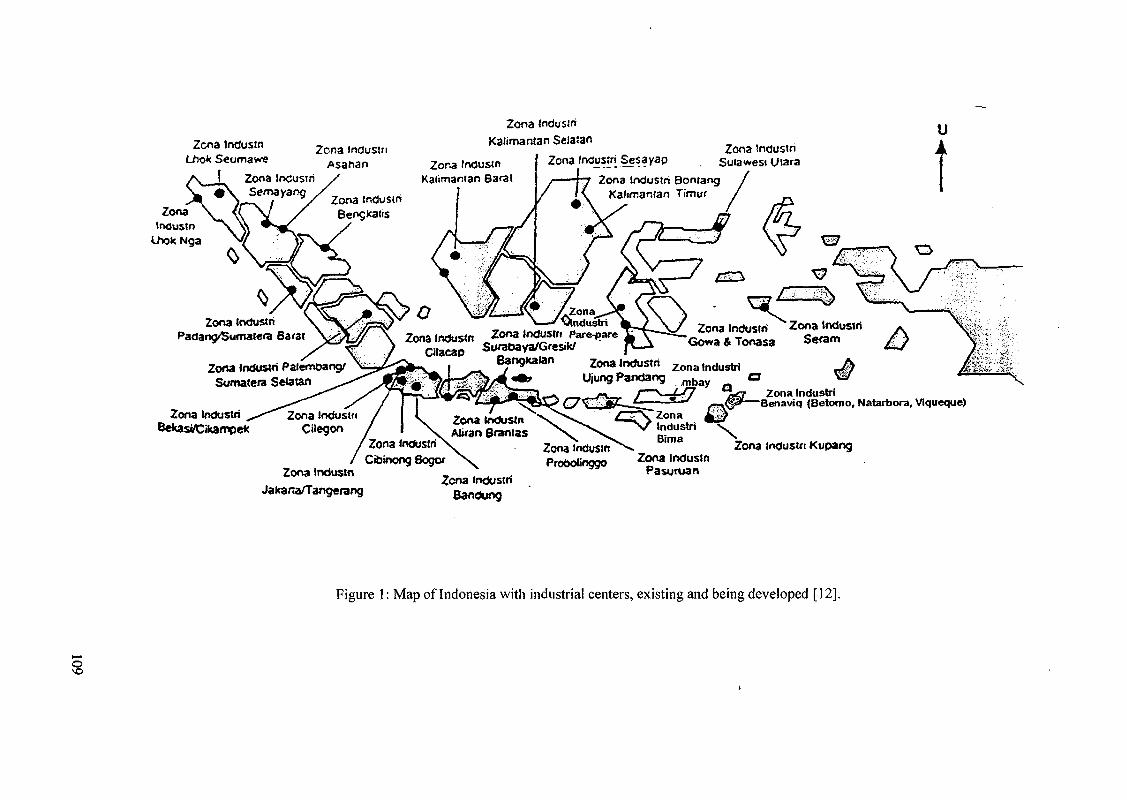
Zcna IndusinLhok Seumawe
/ \ ( Zona inCustri>w 5 \ Semayaog
Zcna tnduslnAsanan
Zonatnoustn \ ^
Noa \ffLhok Nga
Zor.aKalimantan Barat
ZonaKalimantan SelaJan
Zona tnCosiri Sesayap
Zona (ndustriPadan^/Sumatera Barat
Zona Indoswi PaJemOang/Sumatera SeOtan
Zona IndustriBefcasi/Cikampe<c
Zona IndustriSulawesi Uiara
Zona Industri BontangKalimantan Timu'
I
Zona IndustriCitacap
>IndustriZona IndUSWi Pare-pare Zona indusln
~Gowa 4 Tonasa
Zona Industri Z o n a IndustriUjungPandang m b a y
Zona InduslnAJiran 8rantas
Zona InduslriCibinong Sogor
Zona tndusmProboJinggo
Zona IndustriBenaviq (Betomo, Natarbora, Viqueque)
Zona Industn
Jakana/TangerangIndustri
Bandung
Zona industnPasuruan
Zona industri Kupang
Figure 1: Map of Indonesia with industrial centers, existing and being developed [12].
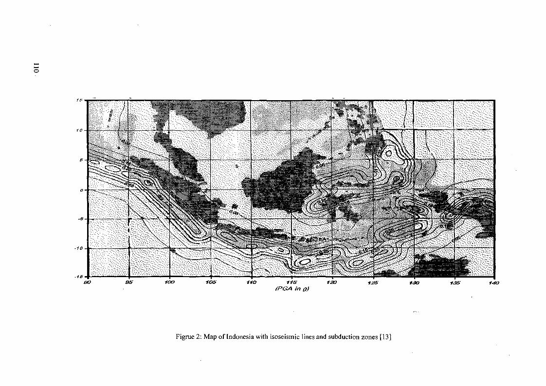
-10
-1S
so us(PGA hi g)
120 12s ISO 13S 1-4O
Figrue 2: Map of Indonesia with isoseismic lines and subduction zones [13]
to the home country. In this way no irradiated fuels and radioactive wastes would remain inthe user country. And this is one of the most attractions for further deliberations.
These advantages gained in 160 reactor years of KLT-40C operation t5J are derivedfrom an advanced core design requiring uranium fuel with enrichment more than 20%U235 (HEU), and/or plutonium fuel. Some efforts, however, to reduce the enrichment toless than 20% (LEU) are being exercised, which would result an entirely new core.
The information on the KLT-40C reactors in its possible deployment in Pevek or nearSt. Petersburg has been widely publicized. On the other hand since the liquid metal fastreactor type has not proceeded into the market, it remains to the BATAN the leastinformed. It is anticipated that recent progress will be presented in the forum.
2.3. Licensibility in the country of origin
In the Indonesian Atomic Energy Act there is no specific difference in the presentlicensing steps for large-, medium-, small- and very small-sized nuclear power plants. Theadoption of passive safety concept, non-active components, and other improvement ofengineered safety features will be taken into consideration in making possiblesimplification of the licensing process.
The SMRs including the nuclear desalination plant (or process heat installation) shallbe licensable in the country of origin. Meanwhile, to simplify the licensing process inIndonesia, adoption of passive safety concept, non-active components, and otherimprovement of engineered safety features should be taken into consideration as much aspossible in designing the plant.
2.4. Economic criteria
Economic competitiveness due to very small size is the third among issues toenlighten. It is understood that small and very small power reactors has certain advantagesin general (such as adaptation to small grid, less financing required, more manageable fordomestic participation, etc.171), but the cost of generated electricity per KWh is usuallyhigh. While for the deployment at remote areas or at the less developed regions theeconomic criteria for the Small and Very Small Reactor alternatives in principle remain theleast generating cost, but additionally the following are considered:
• the largest social gain,• zero or the least government subsidy, and• smaller than the cost to upgrade the infrastructure and transportation means in order
to remove the "remoteness" qualification.
These competitiveness criteria are applied, for both conventional financing, and forBOO or other non-conventional financing schemes (e.g. with barter supplement). Inprinciple an evaluation based on "profit and risk sharing" is considered.
2.5. Domestic participation
As usual requirement in the developing countries, maximal utilization of locallyavailable materials, manufacturing capabilities and readily made products, as well asIndonesian nationals for labour, skilled workers and supervisory services are encouragedfor the construction, operation and maintenance works, as far as they meet the specifiedquality. Indonesian companies are encouraged to participate and take the transfer oftechnology. But in the case where the plant would operate under a BOO scheme, in whichthe Independent Power Producer (IPP) alone would own the floating module of nuclear
111
plant including nuclear fuels, the domestic participation is likely limited to the on-landfacilities: switchyard, transmission, distribution and other supporting facilities.
These on-land facilities should be assigned with participation to the Indonesiancompanies. Whilst operation and maintenance participation would be optimized by the IPPitself. Local non-nuclear maintenance obviously could be executed by local shipyard orengineering companies. Other options of domestic participation could be expected in thedesign participation of Indonesian engineers in the vendor country, including for examplethe design of interfaces and non-nuclear auxilliaries.
2.6. R&D Cooperation
Participation in the R&D on certain design verification, first-of-the-kind engineering orthe one having ultimate objective in the constructing of a prototype or demonstration plantin Indonesia might be of possible option. The user contribution in this case may cover theR&D site, available manpower, licensing and accompanying public relations. Laterexperiences would benefit all participating sides and create regional market of their own.With this scheme of cooperation a process of gaining licensibility or a reference plant mightbe aimed.
3. INTERNATIONAL ISSUES
3.1. Acceptance
It is understood that the highly enriched fuels and/or plutonium were used to achievecompact configuration of the core as well as long core life without refueling at the plantsite. If the highly enriched uranium fuels be used, therefore, international utilization of thisspecial materials should be put forward into an international consensus, before anydeveloping country could step forward. On the other hand, when the LEU conversion fromthe HEU have been readily obtained the newly designed core would need proveness in theoperating experience.
International acceptance is the crucial issue that one country should foresee, since itinvolves non-proliferation and safeguards. In possible scheme of Build-Own-Operate(BOO) the whole barge with the nuclear fuel will stay and remain within the supplier'spossession before, during and after the use in the reactor. This might solve the problem ofownership of such materials within the territory of a user country, unless otherwise does notaccord to the local regulations.
The extent of security that required for the safeguarding highly enriched uraniumand/or plutonium fuels within the plant and during transport through international waterwaywould likely need international consent. Similar consideration would apply to themovement of floating reactors having whole irradiated cores containing full spectrum ofradioactivities.
3.2. Assistance
The relevant regulations concerning marine nuclear safety, and of ocean nucleartransportation, are the least exposed to the Indonesian entities. Other topics relate to anyparticularities, e.g. of the liability and insurance coverage of such floating plants, comparedto stationary ones recently discussed in Dubrovnik conference II0). The facts that on theBOO scheme the owner of the reactor & fuel, operator on one hand and the utility on theother hand may belong to different country with respective own regulations.
112
There have been long lists of IAEA information highlighting and promoting thevarious ways of SMR's application; some of them quoted here as reference [7-11].Moreover there have been numbers of IAEA expertise being sent to developing countriesto assist in evaluating possible options of nuclear power plant introduction. Nevertheless,further assistance of expertise and dissemination of technical information that once wasnon-civilian, as well as international forums to help assess the feasibility of relatedtechnologies are the items the IAEA could organize.
4. CONCLUDING-REMARKS
The application of civilian version of nuclear propulsion reactors in Indonesia looksrealistic for the coming intermediate terms although some uncertain points shall be clarified.Indonesia supports this forum as one of the appropriate IAEA efforts on promoting propulsionnuclear reactors for civilian application, and expects from it positive international consensus onvarious points discussed above. Possible studies or R&D works that this country couldparticipate in are anticipated.
REFERENCES
[I] ARBIE, B. et al - "User Requirement Document for Small and Medium Reactors inIndonesia", 2nd International Seminar on Nuclear Options in Countries with Small andmedium Electricity Grids, Dubrovnik, June 15-18, 1998.
[2] TOSHINSKY, G. - "Nuclear Power Facility with Lead-Bismuth Coolant". White LandChapter Conference, St. Petersburg, Russia, February 4-7, 1996.
[3] OKB HIDROPRESS, "ATEC Angstrem. Power Source of Assured Safety for RemoteAreas and Areas of Difficult Access". Podolsk, Russia.
[4] BELIAEV, V. - "KLT-40C Reactor Plant. Description and Safety Principles". Russian-Indonesian Seminar on Nuclear Technologies, 23-30 April 1998.
[5] VOROBYEV, V.M., ZLOBIN, P.B., KUZIN, E.A. - "Nuclear Heat-Electric Station onthe Base of Floating Nuclear Power Unit with Reactor Plants of KLT-40C Type.Problems of Arrangement". Russian- Indonesian Seminar on Nuclear Technologies, 23-30 April 1998.
[6] SERGEEV, Y.A. - "Status and Perspectives of the Development of Small Size NuclearPower". J. Power Construction, February 1995 (In Russian).
[7] INTERNATIONAL ATOMIC ENERGY AGENCY. "Introduction of Small and MediumReactors in Developing Countries" - Proceedings of IAEA-AGM, Rabat, Morocco, 23-27October 1995 and Tunis, Tunisia, 3-6 September 1996. IAEA-TECDOC-999.
[8] INTERNATIONAL ATOMIC ENERGY AGENCY. "Non-electric Applications ofNuclear Energy". IAEA AGM Proceedings. Jakarta, November 1995.
[9] INTERNATIONAL ATOMIC ENERGY AGENCY. "Options Identification Programmefor Demonstration of Nuclear Desalination". IAEA-TECDOC-898. August 1996.
[10] INTERNATIONAL ATOMIC ENERGY AGENCY. "Nuclear Option in Countries withSmall and Medium Electricity Grids". Proceedings of International Conference.Dubrovnik, Croatia. June 15-18, 1998.
[II] INTERNATIONAL ATOMIC ENERGY AGENCY."Nuclear Fuel Cycle and ReactorStrategies: Adjusting to New Realities". IAEA Proceedings Series. STI/PUB/1026. 1997:Vienna, Austria.
[12] AGENCY FOR ASSESSMENT AND APPLICATION OF TECHNOLOGY (BPPT),INDONESIA. Communication. 1998.
[13] PUSPITO, N. et al. Communication. 1998.Bandung Institute of Technology (ITB).
113
NEW CONCEPTS FOR SMALL POWER REACTORS WITHOUT ON-SITEREFUELLING FOR NON-PROLIFERATION
N.W. BROWN, J.A. HASBERGER XA0056273Lawrence Livermore National Laboratory,Livermore, California, United States of America
Abstract
•" The report discusses the preliminary requirements and a technical approach for developingsmall reactors and the rationale for selecting them. It then discusses the four nuclear systemtechnologies and how they might proceed to meet the requirements. Brief discussions are providedon the approaches to stimulating the appropriate international and industrial participation necessaryto finance development of a design with improved proliferation resistance that is useful to thedeveloping countries.
EXECUTIVE SUMMARY
Energy demand in developing countries is increasing to support growing populations andeconomies. This demand is expected to continue growing at a rapid pace well into the next century.Because current power sources, including fossil, renewable, and nuclear, cannot meet energydemands, many developing countries are interested in building a new generation of small reactorsystems to help meet their needs.
The U.S. recognizes the need for energy in the developing countries. In its 1998Comprehensive Energy Strategy, the Department of Energy calls for "research into low-cost,proliferation-resistant, nuclear reactor technologies" to ensure that this demand can be met in amanner consistent with U.S. non-proliferation goals and policies. This research has two primarythrusts: first, the development of a small proliferation-resistant nuclear system (i.e., a technologyfocus); second, the continuation of open communication with the international community throughearly engagement and cooperation on small reactor development.
A system that meets developing country requirements must:
- achieve reliably safe operation with a minimum of maintenance and supportinginfrastructure
- offer economic competitiveness with alternative energy sources available to the candidatesites
- demonstrate significant improvements in proliferation resistance relative to existing reactorsystems
These challenges are the most significant driving forces behind the LLNL proposedprogram for development of a new, small nuclear reactor system.
This report describes a technical approach for developing small nuclear power systems foruse in developing countries. The approach being proposed will establish a preliminary set ofrequirements that, if met, will cause new innovative approaches to system design to be used. Theproposed approach will borrow from experience gained over the past forty years with four types ofnuclear reactor technologies (LWR, LMR, HTGR, and MSR) to develop four or more pre-conceptual designs. The pre-conceptual designs will be used to confirm the adequacy of therequirements through iteration and trade studies. A down selection to a preferred and backupconcept would be made following a 12-18-month design effort. The selected designs, systemdesign specifications, and the necessary R&D programs would be developed in greater detail overthe next three and one-half years.
115
resistance, and will maximize the reliance on passive safety features to reduce the risk of seriousaccidents and their consequences, simplify operations and maintenance, and reduce the need for thedeveloping country to establish a sophisticated and expensive nuclear infrastructure.
In particular, to eliminate all on-site refueling, the reactor will be equipped with a long-lifecore that will be returned to the supplier when spent. This process will be managed underinternational control to further both overall non-proliferation objectives and to reduce theinfrastructure burden on the developing country. It will also reduce the anticipated burden andexpense to the International Atomic Energy Agency for assuring security associated with expandedinternational use of nuclear energy. An integral part of the program will be the development of newapproaches for implementing international safeguards applicable to the entire fuel cycle includingrecycling and waste disposal.
1. INTRODUCTON
Energy demand in developing countries, particularly in Asia, is increasing rapidly tosupport growing populations and economies. These trends are projected to continue well into thenext century. This demand will be met by a combination of fossil, renewable, and nuclear sources.However, the current mix of these energy sources does not, and cannot, satisfy all demands for newenergy. Fossil fueled sources add to the accumulation of greenhouse gases and are of limited supplyin many areas. Renewables, including hydro, are in limited supply, or are at an insufficient level oftechnical readiness to play a major role in meeting energy demands. Today's nuclear systems aretoo large and expensive for many areas, especially those lacking the necessary institutionalinfrastructure, expertise, capital or large established power grid. A small nuclear power systemcould provide a credible solution for meeting the growing energy demands of many regions.
U.S. foreign policy on nuclear issues is dominated by proliferation and nuclear safetyconcerns. Recent events in India and Pakistan have served to refocus world attention on the threatof proliferation. We are proposing to develop a new nuclear system that meets stringentrequirements for a high degree of safety and proliferation resistance, and also deals directly withthe related nuclear waste and spent fuel management issues.
Development of a small, modular nuclear power system offers promise as a viablealternative to either the capital intensive large nuclear systems or the environmentally problematicfossil fuel systems. Our vision is to develop a system featuring unique design elements thatovercome many of the barriers to implementation of nuclear power systems in many parts of theworld. Elimination of on-site refueling through a combination of long-life cores and small systemswith replaceable modules reduces proliferation concerns, especially those related to spend fuelstorage. Small size, transportability, modularity and the requirement for a high degree ofautonomously safe operation reduce infrastructure and construction requirements of the hostcountry, and contribute significant reductions in initial capital and operating costs. Small unitpower levels make the system appropriate in areas lacking the large electrical grids normallyassociated with today's large nuclear systems.
A recent survey completed by the International Atomic Energy Agency (IAEA)Ul not onlyconfirmed the need for such systems, but projected that by the year 2015, developing countries willneed 70-80 small and medium-sized reactor systems. Currently, several countries are developingsmall reactors for this potential commercial market. For example, South Korea has been developinga concept known as SMART; Argentina has been developing a concept known as CAREM. Bothsystems are based on down-sizing today's large light-water reactor technology to make it suitablefor small power levels. China is developing a small, high-temperature gas-cooled reactor forseawater desalination and process heat. Russia is proposing several small reactor systems based onmarine propulsion experience for use in developing countries, as well as remote regions of Russia.The efforts of these countries tend to focus on the development of the reactor without integratedconsiderations of the overall fuel cycle, proliferation, or waste issues.
116
2. DESCRIPTION OF SCENARIO SELECTION PROCEDURES
The system being proposed is targeted for developing regions such as South East Asia,Sub-Saharan Africa and South and Central America. There are countries within these regions withhigh population growth with goals to raise the standard of living. The electric power grids in someof these areas are minimal. In addition, because of geographical isolation or lack of indigenousalternatives, nuclear power may be a viable alternative. Several countries (Russia, South Korea,Argentina, and China) are developing concepts for small systems that could be used in these areas.
Projected population growth for these countries will be well over 250 million by 2025. Fortheir standard of living to improve to half the average of the developed countries, they will needapproximately Ikw of new generating capacity per person. This means that they will needapproximately 250 Gwe new capacity, the equivalent of 250 1000-MW plants, or 2,500 100-MWplants. Continued growth in population and standard of living will double this estimate by 2050.Much of this capacity will be met with conventional technologies, including large nuclear systems.Even with large systems in place, the IAEA estimates that 70-80 small and medium-sized reactorsystems will be required by 2015. With even greater growth anticipated beyond 2015, the potentialoutlook for such systems is optimistic, and could require production rates on the order of 10 ormore plants per year.
Successful development of a small reactor system requires a comprehensive systemsapproach that considers all aspects of manufacturing, transportation, operation, and ultimatedisposal. This approach has been used previously in the development of a U.S. space nuclear powersystem, with consideration given to many diverse requirements such as no planned maintenance,highly reliable autonomous operation for a long period of time, no refueling, and ultimatedisposition. While the engineering designs used for space nuclear power systems are not directlyapplicable to terrestrial applications, the systems approach itself offers insight into the developmentof a new terrestrial system suitable for developing countries. The U.S. aircraft industry also uses asystems approach in the production of new aircraft that may be suitable for small reactor modules.
Applying this system design concept to development of small nuclear power systemsrequires that planners consider the entire system lifecycle, including waste issues. This will lead tosignificant reductions in the generation of radioactive waste for the system as a whole, where, withother methods of planning, one waste minimization activity often increases wastes farther along inthe system.
By considering the complete fuel cycle and impeding access to the fuel by eliminating on-site refueling, there appears to be a potential for significantly improving proliferation resistance.Such a system would simplify safeguarding the fuel and could provide a basis for development ofnew policies for addressing the storage and disposal issues of the fuel cycle.
3. SYSTEM REQUIREMENTS
Our principle objective is to develop a system that provides an affordable, safe and secureenergy supply to countries with critical energy needs but insufficient resources to support moretraditional energy solutions. The following requirements outline how this objective may beachieved. The "system concept" can be specified by key system requirements, including:
3.1 Reactor delivered pre-assembled and pre-fueled
The nuclear reactor should be delivered to the site pre-assembled and pre-fueled. Ifshipping a pre-fueled reactor is precluded by safety or technical considerations, fueling must beaccomplished under strict international control. Procedures to seal fuel in the vessel and eliminatefurther on-site access into the vessel must be established.
3.2 Highly autonomous operation
All operations, from initial startup to final shutdown, must be as autonomous as possible.Operator functions could be limited to pressing a button to start the nuclear system and performingthose duties necessary to operate the power conversion or other non-nuclear systems. For the most
117
part, an operator should only be required to monitor the status of the system. Advancedinstrumentation and control technologies, coupled with the anticipated improvements in inherentreactor control mechanisms in these low-power systems, makes potential realization of such goalspossible. It is recognized that this requirement is very demanding and it may become more complexas the program progresses. Significant cost savings will be associated with reductions in thenumber of highly trained staff required at the site.
3.3 Reliance on passive safety mechanisms
All credible failures should be safely terminated (1) by passive mechanisms in the nuclearsystem and (2) without the release of radioactivity to the power system site. Postulated severeaccidents should be terminated without requiring emergency off-site responses. Plans for siterecovery following such postulated situations should also be identified. Passive safety mechanismsare a necessary corollary to achieving the anticipated staff reductions.
3.4 Limited planned maintenance
Planned maintenance will be limited to non-nuclear, or electrical and control components easilyaccessed outside the reactor enclosure. Special attention must be given to eliminatinginstrumentation that is inherently short lived because of temperature or radiation damage.
3.5 Replacement and disposal of the reactor and its contained fuel must be integratedinto system design
No on-site refueling means that at the end of a reactor core's life, the entire reactor moduleis replaced. This feature will help ensure that nonproliferation goals are met. A careful design willincorporate the replacement, reconditioning and disposal of expended reactor modules, includingdisposition of spent fuel.
These demanding goals are likely to be achievable only with systems of relatively lowpower compared to the lOOOMWe plants commonly used today, with the added benefit of greatersecurity, safety, and public acceptance of the expanded use of nuclear power within developingcountries.
We recognize that one of the major challenges will be to accomplish these goals with aneconomically viable system. Today's economic approach to nuclear power is through economies ofscale. Our concept approaches the economic issue from a different perspective: we rely on theeconomics of mass production, coupled with cost savings achieved from dramatically reduced on-site installation, operation and decommissioning costs, reduced site infrastructure requirements,and simplified "type" licensing to overcome the loss of economies of scale.
While many of these goals have, in principle, been met by space power systems, practicalterrestrial systems that might meet this challenge will be orders of magnitudes larger than spacesystems, but may need to be one to two orders of magnitude smaller than the current LWRs. Evenso, these requirements—while challenging—are not impossible; other complex systems such as amodern gas turbine or combined cycle plants meet many of them, including standardized factoryfabrication, simple installation and startup, and highly automated operation.
4. SAFETY CONCEPT
Two very demanding safety requirements have been identified. First, all credible accidents(those considered to be within the design basis) should be safely terminated by passive mechanismsin the nuclear system. By "safely terminated" we mean not only that the consequences of suchevents are limited to the site, but such events must not result in life-limiting damage to the systemsor radiological consequences to the on-site staff. Second, postulated severe accidents (those beyondthe design basis) must be terminated without requiring emergency off-site responses. Thesepostulated events should be consistent with known physical principles, and include operationalfailures coupled with postulated failures of protective features and equipment. An approach torecover from such postulated events, one that permits ultimate recovery of the site, should also beidentified. That is, bounding accidents should not result in loss of the use of the site due to
118
contamination. These two requirements are key to achieving the operational and designsimplifications desired in the small nuclear system.
The small unit size and low unit cost of this approach presents a unique opportunity toperform a much broader range of safety verification testing than is afforded by conventionalnuclear designs. This level of testing would provide a full-scale demonstration of the ability of thedesign to achieve the required safety envelope. Certification of the design by testing, includingsevere accident testing, would contribute to broad acceptance of the system in developingcountries. Such an approach also supports licensing certification by test as once proposed to theNRC[2].
Safety certification of the design would be completed by the supplier, similar to procedureswith commercial aircraft. Licensing the use of a factory-fabricated standard design in manydifferent countries would then be similar to approving the use of certified aircraft. The regulatoryburden on the user country would be substantially reduced.
Reliance on a high degree of autonomous operation, achieved through a combination ofpassive, inherent physical responses and advanced control systems, minimizes the potential forhuman error initiating or exacerbating off-normal events or accidents. It also reduces the trainingand regulatory burden on the user country. Far fewer nuclear specialists are necessary to approveand operate such systems. Similarly, eliminating the need for on-site refueling and minimizing on-site maintenance further reduces the need for a supporting infrastructure in the host country; suchmaintenance services may be handled by a single supplier service organization consisting of veryhighly trained and skilled professionals who would provide essentially all repair and maintenancefunctions for the entire fleet of these standardized facilities.
5. OPERATIONAL CONCEPT
The infrastructure necessary to support conventional nuclear power development is veryexpensive, and beyond the resources of most developing countries. One of the primary goals of theproposed approach is to reduce the need for such an infrastructure. The system requirements ofhighly autonomous operation, simplified and minimized system maintenance, and elimination of allon-site refueling all significantly contribute to this goal.
To some extent, the complex nature of today's large-scale nuclear energy systems is aresult of the many support and safety systems, often redundant, needed to ensure the safety of thesevery large, high-power systems. Many of these systems can be reduced or eliminated with smallersystems, where natural forces (such as natural circulation flow) are sufficiently strong to satisfymany safety and operational criteria. A more aggressive approach to automated operations is beingproposed to support both large reductions of on-site staff and the technological infrastructurenecessary to support operation, maintenance, and regulation. If the very high levels of reliabilityand simplicity of operations can be achieved, it may be possible to reduce the nuclear staff to acouple of people per shift in the main control center and a minimal electrical maintenance staff.
Nuclear instrumentation and control systems present a greater challenge. Even though itmay be possible to develop a system that is inherently controlled by temperature for all normaloperations, it appears that it will always be necessary to include control devices andinstrumentation in the nuclear system to adequately control and monitor startup from coldshutdown, total shutdown, and possibly to compensate for fuel burnup. Design configurations thatreduce the number and complexity of these instrumentation and control systems and componentsneed to be developed.
Typically, the conventional power conversion components of a plant include dynamicmachinery and numerous active control mechanisms. It will be nearly impossible to avoid plannedperiodic maintenance on this equipment. Even though it might be desirable to simplify and reducethe staff and infrastructure needed for this portion of the plant, the technical expertise andinfrastructure required for effective maintenance and operation of these systems could be sharedwith that needed by other, more conventional power-generating systems the developing countrywill also have. Depending on the specific configuration of the system, however, there may be a cost
119
or operational benefit that may demand supplier servicing of selected components within the powerconversion portion of the plant.
6. MANUFACTURING
The importance of a totally new approach to manufacturing of the small reactors, not justmodularization, cannot be over-emphasized. The concept of "designed-in manufacturability" canresult in significant cost savings, particularly when amortized over a number of systems. The goalof producing a system that can be easily transported and installed can also contribute tomanufacturability, as this goal leads directly to components having more "reasonable" size andmass than most of today's large nuclear power systems.
An aggressive approach to factory assembly of the plant and shipment of modules that canbe quickly installed at the site will be necessary to keep costs within an acceptable range. Thefactory production line will need to be designed as an integral part of the product—similar to theapproach taken by Boeing Airplane Company to produce their 777 model.
The plant design would be based on production of many hundreds of essentially identicalmodules. Ideally, three or four major assemblies would be fabricated, quality inspected, and testedprior to shipment. With exception of the nuclear assembly and its auxiliary systems andcomponents, these types of major production assemblies have been demonstrated in the large dieseland combined cycle plants operating under much the same technological complexity as theproposed nuclear plant.
Simplification of the system design coupled with factory manufacturing of standardmodules may make it possible to challenge the economy of scale with the economy of massproduction. As discussed later, it will be necessary to identify a large stable market to support thisapproach.
7. DELIVERY AND INSTALLATION CONCEPTS
Transportation and installation of barge- or ship-mounted small nuclear power systems isclearly feasible. Designs for barge-mounted "conventional" nuclear systems was near reality in theearly 1970s, and even today, ship-mounted small reactor concepts are being proposed.
However, it is also desirable develop a system concept that is also amenable to land-basedsiting, including the need to transport the modules over land. This desire will place additionalconstraints on the size and mass of the individual modules making up a full system, especiallywhen one considers that supporting transportation infrastructures in the developing countries(roads, railways, etc.) may be substandard or even non-existent. These considerations stronglysuggest that design of special transport and handling equipment and procedures be integrated intothe overall system design.
While it is likely that barge- or ship-mounted systems can be optimized at larger powersthan their land-based cousins, we believe the advantages provided by mass production of verystandardized units will eliminate any minor cost advantage a larger system might enjoy for barge-mounted applications.
The transport systems for removing the spent reactor modules present the greatestchallenge. The problem of shipping a highly radioactive component either on land or by sea mustbe addressed, and associated environmental concerns will influence how the nuclear system isdesigned. For example, capability for recovery of a sunk shipment from the ocean bottom may be arequirement, and could have a strong influence on the nuclear module designs, even for thoseinstalled in barges or submersibles. The possible need for additional shielding, especially foroverland transportation, could have an impact on the size of the nuclear module originally installedand could cause it to be quite small.
Another important requirement, related to the removal transportation, is the time period
permitted between final shutdown and required removal. Because of the intensity of radioactivity
and decay heat in the nuclear module immediately following shutdown, it would be preferable to
leave the shutdown module in place for many months. While potentially unavoidable, such a post-
120
shutdown delay would likely complicate replacement of the reactor module, particularly for siteswith limited real estate. Although there may be a slight reduction in proliferation risk by removingthe spent nuclear module soon after shutdown (as opposed to later), we believe that the difficultyassociated with removing or accessing a spent reactor module to be a sufficient deterrent. Rapidremoval/replacement of a spent reactor module might be accomplished sooner with the barge- orship-based systems, but unless the installation allows separation and replacement of the nuclearsystem, it would mean a significant investment in unused power conversion equipment duringtransport or refurbishment. This may not be a great penalty if the on-station time for the system istens of years.
These and many other broad system issues will be the topics of the trade studies necessaryto identify the preferred system. It is clear that manufacturing, delivery, and installation will havean important impact on size selection of the reactor system; the size may vary depending on thesystem technology.
8. RECYCLING AND WASTE DISPOSAL
One of the important aspects of our systems approach is the integration of wastedisposition and component recycling into the design of the overall system, including materialsselection and mechanical design. It is our intent that the nuclear reactor module or the entire plant(a possibility in the case of barge-mounted systems) be shipped to an internationally monitored sitefor refurbishment of useable components, recycling of highly valued materials, and the preparationof waste materials for permanent disposal.
The characteristics of the "refurbishing" site and its facilities must also be integrated intothe overall design, and will take into account spent fuel processing, waste treatment, anddisposition of other materials and components. The extent to which other equipment is refurbishedmay also influence the character of the site. A barge-mounted system might be entirely refurbished;therefore, the site design would need to consider this entire refurbishment activity.
One of the more difficult issues associated with recycling and waste disposal is not atechnical issue; rather, it is a political and institutional issue of how to deal with wastes, especiallynuclear waste, resulting from operations in a foreign country. The U.S., and most other countries,have restrictions on the acceptance of nuclear waste from other countries. It is possible that newnational and international policies, treaties, and laws may be necessary to gain all the advantagesthat a centralized approach might afford.
9. SYSTEM SAFEGUARDS
Nonproliferation safeguards will be part of the proposed system to provide (1) assurancethat facilities and materials are not used for illicit purposes, and (2) timely warning of an eventtaking, or having taken place. The proliferation risk associated with a nuclear system derives fromthe following four issues:
- attractiveness of fissile materials,
- accessibility of the materials,
- utility of the facility for illicit purposes (for example, irradiation of fertile materials), and
- size and character of the infrastructure needed to support the nuclear system.
Traditional large-scale nuclear power systems are quite proliferation-resistant. The freshLEU fuel is of too low enrichment to be directly used in a weapon. The reactors are ill-suited forillicit irradiation and production of weapons material. Plutonium in spent fuel has poor isotopics forweapons applications, and is inherently protected by the significant radiation field arising from thefission product inventory. Even so, safeguards of LWR plants are needed because none of thesebarriers to proliferation risk is, by itself, completely effective. Diverted fresh fuel could be used toreduce the enrichment effort, given appropriate facilities. Fertile materials could, with difficulty, beirradiated in LWRs. The radiation barrier inherent to spent fuel decays with time, and plutoniumfrom LWR spent fuel is considered a weapons-useable material, even if not ideal.
121
The elimination of on-site refueling directly attacks the two greatest proliferation risks ofthe traditional power reactor: accessibility of materials and use of the facility for illicit purposes.Elimination of on-site refueling removes easy access to both fresh and spent fuel from the reactorsite. Fissile material is found only inside the reactor, where it is protected by both limitations ofphysical access and a very intense inherent radiation barrier. The only period where fissilematerials might be considered at risk is during transportation and set up, and during early operationwhere the fission product buildup is limited. Access to fissile materials and use of the reactor forillicit irradiation is further complicated by the lack of physical features and infrastructure to openthe reactor vessel.
In addition to the direct reduction of proliferation risk resulting from the elimination of on-site refueling, the need and complexity of on-site surveillance can also be reduced. With theabsence of on-site fresh or spent fuel storage, the need for active and/or periodic monitoring of fuelstores is eliminated. The very lack of a refueling infrastructure implies that the time necessary foropening the reactor vessel to gain access to fissile materials would be so long that the very act ofshutting the reactor down may serve as the primary alert indicator. This offers potential forsimplified safeguards and security that might only require monitoring to ensure the reactor isindeed operating. This could even be accomplished or augmented remotely, perhaps using satelliteplatforms to monitor the IR signature of the facility.
The high degree of automation desired for these systems offers three additional safeguards.First, such autonomous operation offers opportunities for remote monitoring and diagnostics thatmay be exploitable to assist safeguards monitoring. Second, such design offers the potential forreductions in system transients and resulting shut-downs. In such an environment, any off-normalevent becomes a potential safeguards alarm. Finally, the combination of autonomous operation andelimination of on-site refueling reduces the infrastructure, including personnel, available to supportillicit activities.
10. TECHNOLOGY OPTIONS
This section summarizes a preliminary assessment of the design and technologicalapproaches that might be taken to achieve the requirements. The discussion is based on apreliminary assessment of the strengths and weaknesses each technology offers in meeting therequirements, and a cursory look at how these strengths and weaknesses might be exploited ormitigated. This assessment is only intended to provide an approximate prioritization of theconcepts; each concept will be reviewed in greater detail as part of the overall program. Thetechnologies are addressed in their current order of preference, based on their likelihood of meetingthe no on-site refueling requirement with practical limits on development cost and schedules.
10.1 Liquid metal cooled systems
Liquid metal cooled reactors (LMR) have been under development for more than 40 years,and several have been built and operated on commercial power grids. Sodium has been generallyused as the coolant in these systems, and experience with this technology has been mixed. Sodiumleaks have been the most notable technical issue, and the fact that sodium is very chemicallyreactive with air and water has contributed to most of the concerns about LMRs. The technology isclearly still developmental even though there is considerable valuable experience.
Concepts based on fast LMRs have high internal conversion of fertile to fissile materialand therefore have the potential for long core life without initially high reactivity that requiressome form of poison compensation. LLNL and the University of California have developed somevariations on the Japanese 4S concept that could extend its neutronic life to more than 15 years f3>4, 5, 6]. Although there are unanswered concerns about the clad and structural damage from largeneutron irradiation, the results of preliminary work are encouraging.
Fuel systems for LMRs are well developed. Oxide, carbide, nitride or metal fuel have beendemonstrated and provide many options for addressing the long life requirement for the fuel. Metalfuels, in particular, offer promise of improved safety characteristics.
122
Liquid, metal-cooled systems operate at low pressure and have very large thermal marginsrelative to their boiling temperature. There is negligible thermal energy stored in the coolantavailable for release in the event of a leak or accident. This translates to the potential for compactsystem designs, including containment. In addition, the large thermal expansion coefficients ofliquid metal coolants inherently support good thermal characteristics for natural circulation coolingand provide very favorable passive safety characteristics.
As mentioned above, the sodium coolant used by most LMR developers has created somesafety concerns because of its chemical reactivity with air and water. Lead, lead-bismuth or otheralloys of lead appear to eliminate these concerns because the chemical reactivity of this coolantwith air and water is very low. The Russians have extensive experience with this coolant and, whencombined with the Japanese 4S configuration, it conceptually is a very attractive system. Severalmajor issues must be addressed, however, including what appears to be the most important:materials corrosion. This is a serious issue, and although the Russians have had success in this area,long-term materials compatibility must yet be established.
Extensive development and demonstration work, beyond that required for a small LWR-based concept, may be required. These reactors also require fuel that is enriched to nearly 20% andtherefore fuel recycling may be necessary to achieve economic performance. Because of thedevelopmental uncertainties and the possible need to include fuel recycling in the system, the costof implementing a system design based on liquid metal coolant is uncertain.
10.2 Gas-cooled Systems
Gas-cooled reactors, although not extensively used for electric power generation, havecontinued to be used and receive developmental attention. There have been many years ofsuccessful power operation on the power grid in England. Helium has become the coolant of choicein the high-temperature versions of this technology. Recently, development work has focused onmodular reactors coupled to gas turbines to improve both economics and the passive safetycharacteristics. Considerable effort has been invested in development of graphite-coated fuelparticles that are imbedded in a graphite matrix. However, there is also considerable experiencewith cermet fuels which have fuel particles imbedded in a metal matrix. This later technology hasnot received much commercial attention, although extensive development is completed forapplication in aircraft and space systems.
There is some continuing interest in gas-cooled reactors in South Africa, China, andRussia. ESKOM, the South African state-operated utility, is interested in a high-temperature, gas-cooled reactor combined with a direct cycle gas turbine for powering rural areas that are currentlywithout electricity. They have developed a preliminary design for a system based on the pebble bedreactors developed in Germany. General Atomic and Russia, in cooperation with others, have alsocompleted a study on design of a gas-cooled gas turbine plant for use in Russia. China has operateda 5 MWt gas-cooled reactor and has plans for construction of a 200 MWt which is intended forprocess heat applications.
Since gas-cooled reactors are predominantly thermal spectrum reactors, the challenge willbe to develop a concept for extending core life. De-rating the fuel and operating the reactor at lowerpower densities than under optimum operating conditions is one possibility. This could have anunfavorable impact on economics. Thorium fuel cycles applied to these types of reactors could beused to contribute to increased core lifetime. However, on-line refueling—in which pebbles areadded and removed on a frequent basis—has been the emphasis in the pebble bed reactors. Someconceptual designs for pebble bed reactors specify that the reactor vessel is only partially filled atthe start of life. Fuel is gradually added, thus extending reactor life. Consideration could be givento hardening the spectrum and improving the internal conversion, possibly even using cermet fuelin a fast spectrum reactor.
The modular designs studied in recent years have very favorable passive safetycharacteristics. Both the Russian and ESKOM designs incorporate robust passive safety capability.Although the systems run at high pressure, there is little energy stored in the single phase coolantand the thermal margins in the fuel are very large. Thus, a loss of coolant during an accident may
123
be accommodated passively. However, containment design continues to be a question and may addto system size and complexity.
The direct cycle gas turbine is the most attractive configuration for the gas technology.Inclusion of steam generators contributes complexity and decreases efficiency and reliability. Eventhough there has been no operational experience with a direct cycle gas turbine HTGR (andtherefore development costs and risks are high), once developed it is expected to be veryeconomical. This is a viable candidate that has seen considerable progress in the developmentphase but awaits demonstration.
10.3 Light Water Cooled Systems
The LWR is the most highly developed and deployed reactor and fuel cycle system in theworld. Many small versions have been designed and even deployed, although most have beenlimited to submarine versions and other special purposes where economics has been a secondaryrequirement. The possibility of adapting various highly developed marine systems to small electricgenerator designs is being seriously considered as a viable option.
The main challenge facing this technology will be to extend the refueling interval muchbeyond two years while maintaining the inherent safety objectives. Power de-rating, similar to thegas reactor, can extend core life at the expense of increases in power cost and physical size. Thereare efforts underway to extend fuel life to three years, but to make this technology viable, it islikely that fuel life will need to be extended further. Long-term autonomous control may also be achallenge, partly due to reactivity changes over the life of the plant and other technical issues, suchas the need to maintain water chemistry and pressure control.
The small units can be made simpler and include large margins to safety. Naturalcirculation cooling at full power is possible. However, because of the large amount of stored energyin the coolant, a pressure-retaining containment is necessary to meet the safety objectives. It is alsolikely that active safety components such as isolation valves may be required.
LWR technology is the most developed technology and therefore may have very lowdevelopment costs. Yet the significant development needed to achieve long fuel lifetimes requiredhere may offset the economics afforded by the mature underlying technology base. Additionally,the high system pressure and significant thermal energy stored in the coolant complicates safetyand containment design, and is expected to increase system size, mass, and cost.
10.4 Molten Salt Systems
One molten-salt reactor system has been constructed, and although its experimentaloperations were successful, there have been no others. The interest has been largely academic, butconceptual designs of commercial plants have been developed. This technology would require thelargest development and demonstration program, and with no licensing experience, could prove tobe a difficult option to implement.
One of the major concerns about this technology, besides the limited technology base, isthe lack of materials with demonstrated long-term compatibility. Long-life operation will requireon-line chemistry control and processing of the molten-salt fuel, and although demonstrated at thelaboratory level, such processing remains a development issue.
Interest in the molten salt system is based on the promise of long reactor life throughautomated fuel processing and management. Automated additions of fuel and removal of the fissionproducts, if possible, could eliminate fuel life as a limiting factor to system life. Such automation isclearly a major challenge.
Because the reactor can be designed with very little excess reactivity in the core and themolten salt has very good heat transport characteristics, the potential for achieving passive safetyobjectives also exists. The fact that (1) the molten-salt reactor is a low pressure system, and (2) thecoolant is very chemically stable and does not react with air or water also support the passive safetycharacteristics of this concept.
124
However, the fact that the fuel is both mobile and unclad raises serious concerns about fuelleakage and containment and control of the gaseous fission products. These concerns will impactthe designs of containment and fuel chemistry management systems, and may require significantdevelopmental efforts to demonstrate.
This technology is clearly very speculative and would likely require the most developmentand demonstration. The cost and schedule for implementing a concept based on this technologymay also be the most demanding. With innovative use of automation, however, it may be possibleto realize a design concept that best addresses functional requirements.
10.5 Other Technologies
We have briefly reviewed other technologies, such as heavy water reactors, but have not identifiedany with sufficient merit to warrant consideration. The CANDU-HWR is well developed but useson-line refueling which is contrary to the objective of excluding on-site refueling.
There are LWR and LMR advanced fuel-cycle schemes being investigated with potential toimprove the proliferation resistance of current reactors. However, they usually require extensivefuel shuffling or fuel modifications to make the fuel less suitable for weapons application. Theseapproaches may be found suitable for large reactors, but they do not appear compatible with smallreactors that have a requirement for no on-site refueling.
11. R&D ISSUES
The proposed program for designing a new, proliferation-resistant reactor is based onsystematic, requirements-driven evaluations. That is, we believe it imperative to develop aconsistent, well thought set of performance, design, and operational criteria that truly reflect thegoals of the program rather than to make marginal improvements to existing systems. Even thoughthe latter approach has clear short-term advantages in terms of development effort, cost, andschedule, we believe the marginal improvements in both proliferation resistance and fundamentalsafety are insufficient to support broad institutional acceptance of such designs.
While it is possible that systems based on existing technologies may be conceived thatmeet the objectives, it is likely that an extensive R&D effort will be required. Without clearlydefined concepts, we can only outline the general scope of such a program. In fact, the developmentof system concepts is the first major program objective.
Clearly, systems designed for long-term operation without refueling will place newdemands on fuels and in-core materials compatibility and performance, and will demand improvedanalytic techniques, including nuclear analysis and structural performance methods. Desirability oftransportable designs may require new methods of manufacturing, transport, and installation. Newapproaches to siting and design certification, perhaps through new international institutions, couldfacilitate a broader acceptance of such systems and installations, and minimize infrastructuredevelopment in the host country. Implementation of highly reliable automated controls that rely ona minimum of instrument signals will need to be developed.
12. APPROACHES TO FINANCING
Financing the initial research necessary to realize a small reactor concept for developingcountries is under discussion with the U.S. Department of Energy (DOE). We are seeking to recruitinternational advisors early in the program, and build international participation as the programmatures and funding increases. The program being proposed would include two major phaseslasting approximately 12 years. The first five-year phase would lead to a conceptual design of apreferred and backup system. The first phase would be financed by the participating governments.During the second phase, a prototype would be developed for certification testing. During thisphase, it is expected that support for certification testing would come from major governments,while support for establishing the production facilities would come from commercial participants.These facilities would be used to produce the prototype as well as the subsequent production
125
models. It is envisioned that the program would shift from largely government-supported laboratoryresearch into a partnership with industry that would then lead to industry-operated facilities subjectto international monitoring. These facilities would include factories and production lines used toproduce standard assemblies suitable for use at many sites.
REFERENCES
[1] "Introduction of Small and Medium Reactors in Developing Countries," Proceedings oftwo Advisory Group meetings held in Rabat, Morocco, 23-27 October 1995 and Tunis,Tunisia, 3-6 September 1996.
[2] N. W. Brown et al. "An Innovative Approach to Nuclear Reactor Design Certification,"ASME 87-JPGC-NE-3, 1987.
[3] N. W. Brown et al. "Proliferation Resistant Fission Energy Systems," Proceedings ofthe Global-97: International Conference on Future Nuclear Systems, Yokohama, Japan,October 5-10, 1997, pp. 879-884.
[4] S. Hattori and N. Handa. "Use of Super-Safe, Small and Simple LMRs to Create GreenBelts in Decertification Area," Transactions of the American Nuclear Society, 60:437(1989).
[5] S. Kasai Aoki and S. Hattori. "Design of Small and Simple LMR Cores for PowerGeneration in Remote Communities," Proceedings of the 3rd ASME-JSMEInternational Conference on Nuclear Engineering, ICONE-3, Tokyo, Japan, October1995.
[6] Ehud Greenspan et al. "Compact Long-Life Reactors for Developing Countries,"International Conference on Emerging Nuclear Energy Systems, Tel Aviv, Israel, June1998.
126
USE OF RUSSIAN TECHNOLOGY OF SHIP REACTORS WITHLEAD-BISMUTH COOLANT IN NUCLEAR POWER
A.V. ZRODNIKOV, V.I. CHITAYKIN, B.F. GROMOV, O.G. GRIGORYV,A.V. DEDOUL, G.I. TOSHINSKYInstitute of Physics and Power Engineering,Obninsk, Kaluga Region XA0056274
YU.G. DRAGUNOV, V.S. STEPANOVEDO "Gidropress",Podoolsk, Moscow
Russian Federation
Abstract
The experience of using lead-bismuth coolant in Russian nuclear submarine reactors has beenpresented. The fundamental statements of the concept of using the reactors cooled by lead-bismuthalloy in nuclear power have been substantiated. The key results of developments for using lead-bismuth coolant in nuclear power have been presented.
1. INTRODUCTION
In the beginning of the 1950s nearly at the same time the USA and USSR launched thedevelopment of the nuclear power installations (NPI) for nuclear submarines (NS). In both countriesthe work was carried out for two types of NPIs: with pressurized water reactors and reactors cooledby liquid metal coolant (LMC).
In the USA sodium was chosen as LMC as it possessed the better thermo-hydrauliccharacteristics. The ground-based test facility-prototype of the NPI and the experimental nuclearsubmarine "Sea Wolf were constructed. Yet the operation experience has pointed that the choice ofcoolant which was chemically active with respect to oxygen and water has not justified itself. Afterseveral sodium\water interaction, the RI was decommissioned together with the compartment andreplaced by the pressurized water RI.
In the USSR the lead-bismuth eutectic alloy was chosen as LMC [1].
In the USA the scientific and research development works were conducted on using lead-bismuth coolant (LBC), but the alternative to solving the problem of corrosion resistance ofstructure materials and maintenance of coolant quality (the coolant technology) did not give anypositive results and those works were stopped.
In our country the comprehensive problem on coolant technology, structure materialscorrosion and mass transfer has been solved as a result of systematic work of several organizations(IPPE, TSNII KM "Prometey", EDO "Gidropress", OKBM, NITI and some others) for about 15years. (Some failures happened in early days of mastering the new technology). The solution to thisproblem has ensured long and reliable operation of NPIs using LMC at the NSs.
Proceeding from the experience gained from design and operation of NPIs using LBC, therehave been developed both the concept of exploiting the reactors cooled by LBC for nuclear powerplants (NPP) and a number of proposals for using LBC in nuclear power (NP).
127
2. THE ANALYSIS OF EXPERIENCE OF OPERATING THE REACTOR INSTALLATIONSUSING LEAD-BISMUTH COOLANT AND THE ACCIDENTS HAPPENED
When the last NS with the RI cooled by LBC was removed from the Navy, the specific phase ofship nuclear power development had been completed. The innovative nuclear power technology whichcould not be comparable with any other one in the world was demonstrated to our industry.
Due to ongoing developments of the RIs using LBC for civilian NPPs the experience gainedneeds for the thorough analysis and control in these designs in order to make the best use of the LBCadvantages (high boiling point, chemical inertness, etc.) and to minimize the effect of itsdisadvantages (melting point is ~ 125°C).
The operation experience also accompanied by the number of accidents which are inevitable forany new technology mastering (the history of technique has demonstrated it) and revealed thedifficulties of servicing these RIs at their base places and refueling has received inconclusiveassessment by the experts, who have been familiarized with it more or less.
Some authors, who have been familiarized with this experience only by "hearsay", allege intheir memoirs that for the NSs adoption of Projects 705 & 705K (class "Alpha" according to theNATO terminology) of RIs using LBC was a tragic error.
Below there is the presentation of the key results of operating the RIs using LBC, the results ofanalysis of the deadly serious accidents happened, causes of the difficulties in servicing the RIs at thebase places and fuel reloading and at the other phases of RIs life time, measures which have beenrealized in the designs of the RIs using LBC and which eliminates the accidents causes and operationdifficulties. This presentation enables us to make an unbiased assessment of the experience gained [2].
2.1. The Analysis of the Accidents Happened and Difficulties of RIs Base Serving
In the course of design and operation of RIs using LBC there were accidents at three NSs, thatwas the cause of impossibility of further NSs operation. These were the RI accident at the left side ofthe NS of Project 645 in 1968 [3] when the core was melted partially, the OK-550 RI accident at theNS of Project 705 (task order 900) in 1971 when the additional pipelines of the primary circuit losttheir tightness and the BM-40/A RI accident at the NS of Project 705K (task order 105) in 1982 whenthe global corrosion damage of steam generator (SG) pipe system of the water-steam circuit happenedand there was about 150 1 spill of radioactive coolant into the compartment [2].
One of the difficulties of RI servicing at the NS base places and refueling is the necessity ofcontinuous steam ingress into the steam heating system (SHS) of the primary circuit in order toprovide the liquid form of coolant and join up periodically the RI with the base installation to performthe maintenance works on coolant technology.
As far as the RIs of the NPPs are concerned, the problem on coolant liquid form maintenance isnot so urgent because of existing the outside power sources and stationary arrangement of RIs.
Below there is given the description of the accidents mentioned in the course of their progress,the analysis of their origin causes and technical measures on their elimination.
2.1.1. The RI Accident at the NS of Project 645.
It was the only accident the cause of which is concerned with LBC using. As a result of lowstudying physical and chemical coolant operation processes, the substantiated specifications onimpurity compositions in coolant, instrumentation for coolant quality control and equipment toprovide the maintenance of required coolant qualities in the course of operation have been lacked.This level of LBC knowledge can be compared with that of water coolant when it was allowed toconvey water from the water pipeline into the steam boiler.
128
As a result of that operation, uncontrollable accumulation of significant masses of lead oxides inthe primary circuit happened, they could have formed when the pipelines of the primary circuit gassystem, which were necessary for its repair, were depressurized, and thus the air penetrated into theprimary circuit. Besides that, the primary circuit was contaminated by products of oil pyrolysis, whichwas the working medium for seals of rotational shafts of pumps that provided the gas leak proofhessof the primary circuit. Masses of oil were spilled into the primary circuit because the oil seals had notbeen reliable enough.
When the rate of SG leakage increased suddenly (it had started some time before the accident),the oxides accumulated and other impurities filled the core, that was the cause of the violent declineof heat removal. Negative temperature reactivity effect was the cause of transfer the automatic powercontrol rod up to the upper switch terminal and spontaneous power reducing to 7% of nominal one.This was the first symptom of the accident.
But the operational documentation did not include any necessary instructions for the operatorhow to act when that kind of situation arose. Instead of resetting the emergency protection (EP) at theleft side reactor, he followed the commander's directions (it occurred in the course of navy training)and tried to maintain the given power level by continuous removal of compensative rods (CR) out ofthe core. All reactivity reserve for 12 CR was released in about 30 minutes, though it was intended toprovide for the power reserve generation about 4000 efficient hours. When CR were removed, the fuelin the local core area, where heat removal was deteriorated, melted and left the core together with thecoolant flow. Signals of radiation hazard in the compartment that called for shutting down the RJ andremoving the crew into the compartments being distantly removed from the RI were not taken intoaccount.
After this accident the works on the coolant technology problem have been launched. For manyyears these works have been carried out at the number of organizations under the scientificsupervision of SSC RF IPPE. As a result, the problem has been solved successfully and the many-yearexperience of the following RIs operation has corroborated it.
Later the NS of Project 645 was withdrawn from the Navy and after special preservation of theRI and reactor compartment sunk in the Kara Sea.
It is necessary to point out the main technical measures for eliminating the causes of suchaccidents:
- in order to eliminate the accumulation of oxides the maintenance of some excess inert gaspressure in the gas system of the primary circuit has been provided when repair works of equipmentand fuel reload are to be performed. In order to eliminate the possibility of air penetration into theprimary circuit and the radioactivity yield into the environment the most possible tightness of it hasbeen provided. For this purpose special repairing and refueling equipment have been developed;
- the sensors of thermodynamic oxygen activity which enable to control the content of oxygendissolved in LBC and detect alloy oxidizing at the very early phases have been designed andintroduced;
- rejecting the use of the oil seals of the pumps shafts and adoption of water seals or gas-tightelectric drivers of the primary circuit pumps. This eliminates the oil penetration into the primarycircuit and contamination of LBC by the products of oil pyrolysis ;
- using the ejection system of high-temperature hydrogen regeneration that has been built intothe RI and ensures chemical recovery of lead oxides by hydrogen (the explosion proof compound ofhelium and hydrogen is used) and enables, if necessary, to purify even hard contaminated circuit fromlead-oxides;
- using the continuously operated system of coolant purification from irreducible impurities onthe glass fabric filters;
- using the automatic system of coolant quality control which is equipped by sensors ofcontinuous control of coolant quality and protective gas, ensures the preservation of oxide films on the
129
surfaces of the primary circuit structure materials contacting with coolant and eliminates theircorrosion deterioration as well as ensures the early diagnostics of sabnormal states.
2.1.2. The RI Failure at the NS of Project 705 (Task Order 900)
Since the beginning of the RI testings in 1970 and its further operation in 1971 and in 1972, theRI operation has been accompanied by the higher content of moisture in the air of the tightcompartment (TC) where the RI was mounted. The tests have demonstrated that the causes ofmoisture were bad air-tightness of the seal of one SG cover because of the flaw in the nickel gasket,that was changed then, and steam leakage through the steam heating system welds which have beenmade unsoundly, and there was no possibility to eliminate this leakage because of compact assembly.
As a result of cold surface sweating inside TC, forming water drops were the cause of wettingthe heat insulator and "dry" protection materials which involved chlorides.The drops of watersaturated with chlorides touched the primary circuit hot ancillary pipelines made from austenite steeland gave rise to their corrosion cracking on the outside surface that has been fully verified by theresults of the RI inspection performed. Through corrosion damages of the primary circuit ancillarypipelines at two of three heatexchanger loops and impossibility of their repair because of compactassembly caused the decision of removing this NS out of the Navy and carrying out the RI inspection.
Thus, this accident is not concerned with LBC use. Similar accidents followed by the RI failurehappened with pressurized water reactors when sea water touched the rustproof pipelines of theprimary circuit.
Technical measures eliminating the causes of such accidents are the following.*
In the designed perspective RI it has been used the pool type integral system of the primarycircuit arrangement, which eliminates fully any primary circuit pipelines out of the monoblock unitvessel including comparatively thin-wall ancillary pipelines of small diameter, there are no valves.Therefore, ramified system of steam heating is eliminated. Fabricating the RI monoblock unit underthe plant conditions ensures high quality and delivery of the reactor block available for operation. Theintegral arrangement almost completely eliminates the possibility of coolant leakage. Besides that, theuse of safety vessel is provided. The looser RI arrangement at NPP ensures the better conditions forperforming the assembly works and controlling their quality.
2.1.3. The RI Accident at the NS of Project 705K (Task Order 105)
Global corrosion damage of the SG evaporation sections pipes made from perlite steel occurredas a result of not meeting the requirements for the water-chemical regime (WCR) for feeding water ofthe SG. It was the result of the fact that under real operation conditions the way of reducing theoxygen content in feeding water by electron-ion-exchanging filter with copper-containing charge,which was provided by the Project, caused to copper escape into the secondary circuit that was thecause of severe electric-chemical corrosion of the piping system of the SG evaporation sections.
As a result of through pipes damage, steam from the secondary circuit began to penetrate intothe primary circuit, where after separation from coolant it condensed in the emergency condenser(EC) specially provided in gas system in case of leakage in the SG. As internal volume of the EC hadbeen filled by the condensate step by step, according to the signal the operator many times drained theEC by removing the condensate accumulated into the suitable reservoir, and thus he eliminated theessential pressure increase in the primary circuit gas system.
However, the EC drainage was stopped because of not clear reasons. Heatexchanging surface ofthe EC was completely flooded by water and condensation of steam penetrating stopped. The pressureincrease began at the primary circuit gas system. The strength of the gas system and primary circuitcould bear the full working pressure of the secondary circuit. That is why in that case there could notbe any tightness loss of the primary circuit.
130
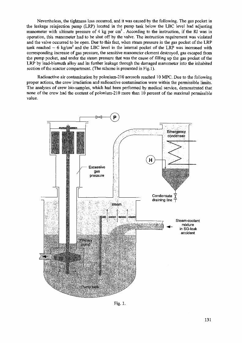
Nevertheless, the tightness loss occurred, and it was caused by the following. The gas pocket inthe leakage reinjection pump (LRP) located in the pump tank below the LBC level had adjustingmanometer with ultimate pressure of 4 kg per cm2. According to the instruction, if the RI was inoperation, this manometer had to be shut off by the valve. The instruction requirement was violatedand the valve occurred to be open. Due to this fact, when steam pressure in the gas pocket of the LRPtank reached ~ 6 kg/cm2 and the LBC level in the internal pocket of the LRP was increased withcorresponding increase of gas pressure, the sensitive manometer element destroyed, gas escaped fromthe pump pocket, and under the steam pressure that was the cause of filling up the gas pocket of theLRP by lead-bismuth alloy and its further leakage through the damaged manometer into the inhabitedsection of the reactor compartment. (The scheme is presented in Fig.l).
Radioactive air contamination by polonium-210 aerosols reached 10 MPC. Due to the followingproper actions, the crew irradiation and radioactive contamination were within the permissible limits.The analyses of crew bio-samples, which had been performed by medical service, demonstrated thatnone of the crew had the content of polonium-210 more than 10 percent of the maximal permissiblevalue.
Steam-coolantmixture
in SG-leakaccident
Fig. 1.
131
RI examining showed that it could be reconditioned. However, another decision was accepted. Itwas decided to change the whole reactor compartment of this NS by the new one fabricated earlier.The motive for this decision was the following. In the course of this RI fabrication at the Machine-building plant in Podolsk there was faulty change of the SHS pipes fabricated from high-nickelcorrosion-resistant steel by the pipes made from common stainless steel of the same size.
This error was found out after the RI unit was fabricated and it was impossible to change thepipes. Because the service life of stainless steel pipes was restricted by corrosion conditions, therewas accepted the decision to limit the service life time of reactor unit up to 25000 hours and fabricatethe reserve RI unit in order to use it for changing off-spec one in the course of the NS overhaul period.In 1982 the service life of the SHS stainless steel pipes had to be expired, and that was the motive forchanging the NS reactor compartment.
The analysis performed has demonstrated that the cause of this accident and the accident at theNS of task order 900 is not concerned with the use of LBC.
The following technical measures ensure elimination of such accidents at the newgeneration RIs:
eliminating copper-containing materials out of water-steam circuit;using more corrosion-resistant steel as material for SG pipes under water -steam conditionsinstead of low-alloyed steel of perlite class;providing passive drainage of the EC when it is filling up by the condensate up to the given level;uniting the gas volume inside the pump electric motor with the total one above the free coolantlevel;providing the great extent of control-fitness and repair-fitness of the RI.
2.2. The Problems of Mastering the RIs Cooled by LBC
Among the key problems which have been solved in the course of design and operation of thistype installations we must emphasize the LBC technology problem - i.e., development of systemsand devices ensuring measurement and maintenance of the LBC quality required during its long-timeoperation both under normal conditions of leak-proof circuit and in the case of partial tightness loss oftightness of the circuit in the courses of repair works and reactor reload. Functioning those systemsand devices is necessary for eliminating structure materials corrosion and slagging the circuit by leadoxides [4]. It should be pointed out that in the early days of mastering LBC, when the necessity ofdeveloping and implementing the measures on the coolant technology had not been realized, therewere cases of reducing the coolant cross sections up to the full blockage of coolant flow rate becauseof depositing lead oxides and other impurities and all the resulted consequences (see 2.1.1.).
Corrosion resistance of structure materials have been ensured by using special steel alloyage,applying protective films to them in advance and maintaining necessary concentration of corrosioninhibitor - dissolved oxygen - in LBC [5]. The importance of these measures has been corroborated bythe fact that when the necessary coolant quality was maintained, for several thousands of hours underthe 650°C temperature there were no corrosion of fuel element steel cladding. However, when thedissolved oxygen concentration was inadequate (under the specially provided conditions), it tookabout 20 hours for through corrosion damage of the 5 mm thickness pipe under the same temperature.
Melting point of LBC is about 125°C. LBC maintaining in liquid state under all RI operationregimes is ensured by using the SG with multiple circulation over the secondary circuit, besides that,the inlet temperature of the water supplied to the SG is higher than LBC melting point. For initialheating-up and maintaining the primary circuit under hot condition at a low level of power release inthe core the system of steam or electrical heating may be used.
The substantiation of the possibility of multiple coolant "freezing-defreezing" in the RIwas an important practical problem. Low shrinkage of LBC during solidifying and rather highplasticity with low strength in solid state facilitate the elimination of RI damage when alloy istransiting from liquid to solid form and its further cooling down up to the ambient temperature. A
132
special order of the temperature-time heating regime has been developed for safe RI "defreezing".This problem is dealt with in paper [6].
The specific feature of LBC is the formation of Ct-active polonium-210 radionuclide witha half-life of- 138 days when bismuth is irradiated with neutrons.
The major reason for its radiation danger is the formation of radioactive polonium aerosolswhen hot LBC contacts with air. It could happen under conditions of emergency tightness loss of theprimary circuit and coolant spillage. In this case, as the RI operation experience at the NS hasdisplayed, the yield of Po aerosols and air radioactivity (according to the thermodynamics laws)reduce quickly with temperature decreasing and spilled alloy solidifying. Fast solidification of spilledLBC restricts the area of radioactive contamination and simplifies its removal in the form of solidradioactive wastes.
Low polonium concentration in the coolant (at the level of 10"8 of at.%) and formation ofthermodynamically proof chemical polonium-lead compound, which additionally reduces thepolonium pressure by 1000 times, individual and collective protection personnel's facilities developed,methods for equipment decontamination and recording activity on the surfaces, methods ofperforming repair works have lead to that fact that for a long-term period of operating the reactorusing LBC including the repair works of the primary circuit equipment and removal of coolantleakage (also in the case of LBC penetrating into the secondary circuit as a result of NS crew errors),there have been no cases of personnel extrairradiation by this radionuclide above the permissiblelimits. This positive practical result agrees with conclusions of foreign experts who have investigatedthe polonium hazard problem if LBC is used for nuclear reactor cooling [7], [8]. Paper [9] is focusedon the analysis of this important problem
The following characteristics have been obtained in the course of NPI tests and operation:power and parameters of installation, the campaign lifetime, the reactivity margin, reactivitycoefficients, poisoning effects, temperature distributions, dynamic parameters, coolant radioactivity,dose rates of neutron and y-radiation behind the shield. They were in sufficiently good agreement withcalculation results.
Among the positive properties of the RI using LBC, which have been discovered in the courseof operation, one can point out the simplicity of control, high manoeuvrability and short time ofreaching the power regime out of subcritical reactor state, the possibility of RI operation if there issmall leakage in the SG pipe system, high repair-fitness of the SG by plugging the depressurizedpipes, the possibility of RI stable operation at any low power levels, the possibility of quick changingthe circulation regime of coolant with essential change of its flow rate, almost complete generation ofdesigned power by cores under normal and acceptable conditions of leak-proofness of fuel rodcladdings.
While performing repair works and reactor reloading, it is not necessary to carry out primarycircuit decontamination which is concerned with collecting, storing, transporting and reprocessingmasses of liquid radioactive wastes (LRW).
The cores and absorbing rods of the control and protection system (CPS), which have ensuredtotal design power service, have demonstrated high operation serviceability.
During the last 10 years of NPIs operation there have been no problems with either structurematerials corrosion in the primary circuit or the deviations from specifications on the circuit purity.
Experience of development and operation of NPIs using LBC at the NSs and ground-basedfacilities-prototypes enables to make a number of practically important conclusions on thearrangement and equipment of the primary circuit for reactors cooled by LBC for NPPs [10] .
The best engineering and economical parameters should be expected if the arrangement of theprimary circuit equipment is integral one.
133
The most convenient design scheme of the SG is that one in which liquid metal circulation isperformed in the interpipe space and that of water or steam is carried out in pipes. That design ensuresthe possibility of repairing the SG by plugging the separate pipe, which has lost its tightness, withoutdismantling the SG or breaking the primary circuit.
Shut-down regimes, the regimes of start-up and cooling down are realized in the easiest way ifthe SG operates by using multiple circulation in the water -steam circuit.
Both mechanical upright pumps with a turbine or electric driver and electromagnetic pumpsmay be used for coolant circulation.
During last period eight NSs with RIs using liquid metal coolant (LMC) have been constructed[11]. The first experimental NS of Project 645 had two reactors. Other seven NSs of Project 705(according to the NATO terminology - "Alpha") had one reactor. Due to its high-speed qualities thisNS was put down into the Guinness Book of Records. Besides that, two full-scale ground-basedreactor test facilities were constructed and put into operation (the prototypes of NPIs at NSs at IPPE inObninsk and at NITI in Sosnovy Bor). The total RI operating time added up to about 80 reactor-years.
3. THE CONCEPT OF USING REACTORS COOLED BY LBC INNUCLEAR POWER
3.1. The Fundamental Statements of Safety Concept
Priority for realizing the safety requirements in comparison with the other has become obviousafter happening the Chernobyl accident.
An intensive development of NPP new concepts for the future has been launched all over theworld, their safety would be more based on RI inherent self-protection allowing to eliminatedeterministically the possibility of the severest accidents which result in catastrophic consequencesnot only in the event of failing the safety technical systems and personnel's errors but also in the eventof ill-intentioned actions (terrorism, diversions, military attacks) and natural disasters.
Nowadays there are two approaches to ensuring the RI safety.
The first approach is traditional and is based on increasing the amount and efficiency of variousprotecting and localizing systems which reduce the possibility of severe accidents and hazardousfactor of their results. Practical realization of this approach, theoretically based on probabalistic safetyanalysis (PSA), results in more complicated and expensive installation, deterioration of its othercharacteristics and, nevertheless, in principle, does not exclude the possibility of severe accident withcatastrophic consequences because there have not been eliminated the internal causes of arising theaccident.
The second approach is based on the concept of the RI with inherent safety ensuring its self-protection in which the causes of arising the severe accidents with catastrophic consequences havebeen deterministically eliminated by nature laws. This approach does not require the construction a lotof protecting and localizing systems, which, in some cases, themselves may become the causes ofaccidents.
There is no need in complex substantiations of safety either by using many calculative andexperimental works in the frameworks of abstract scenarios for severe accidents in progress, byconstracting expensive large-scale test facilities. Most consistently this approach has been developedin the USA by Prof. A. Weinberg [12], and in Russia by Prof. V.V. Orlov[13].
Neither the first approach nor the second one is realized in its pure form. Each of thempossesses the elements of the other. Nevertheless, proceeding from the concept "SAFETYCULTURE" [14], when developing the advanced RI, it seems necessary to use the approach mostbased on the inherent safety.
It is due to the fact, that the large-scale advanced RI must meet the stricter safety requirementsbecause the probability of severe accident specified in active standard documentation gives the
134
socially acceptable expected value of frequency of its realization only for today's level of the NPPreactors service time, which is less than 10000 reactor-years.
If in the future this factor increases ten times, it will take us to reduce this probability ten timesfor 1 reactor-year in order to keep today's expected value of frequency of severe accident realization[15].
For traditional types of NPPs, which safety is usually substantiated by PSA methods, it takes usto increase the amount of protective barriers (double containment), localizing systems (corium trap),etc. The result of it will be inevitable going up the NPPs cost and losing their competitive ability incomparison with electric plants that use organic fuel. We are watching the symptoms of that processeven now.
Inadequacy in substantiating NPPs safety for future NP by using PSA methods is the result ofthe fact that the PSA considers failures of technical devices and operational personnel's errors to beoccasional events, which probability may be estimated only with high uncertainty. Low probability ofthe severe accident is neither the proof of its impossibility nor the evidence of the fact that it mighthappen not earlier than thousands or tens of thousands of years later. Besides that, if there werepeople's ill-intentioned actions, that should be taken into account, these events would not beoccasional but programmed in advance. In that case the PSA conclusions lose their validitycompletely.
3.2. Substantiation of Choosing the Fast Reactor Cooled by LBC
Liquid metal cooled fast reactors are classified as RIs which safety is ensured principally due totheir inherent self-protection. It is associated with a number of their internal features.
Absence of poisoning effects in the fast reactor (FR), low value of negative temperaturereactivity coefficient, compensation of fuel burn-up and slagging processes by plutonium generationas well as partial reloadings enable to ensure the operative reactivity margin to be less than delayedneutron share and to diminish or eliminate the probability of runaway by prompt neutrons in thereactor under operation conditions.
LMC used for FR cooling motivates considerably constructional and thermal scheme of the RI,technical and economical characteristics of the NPP.
Among the LMCs used in NP sodium is the most commonly used.
Choosing this LMC for fast reactors was caused by its possibility of intensive heat removal dueto its good thermal and physical properties. It enabled to provide short plutonium doubling time thatwas obligatory requirement at the early phases of designing the fast breeder reactors in the 60s and70s years, and was caused by the fact of unproved forecast of very high NP development rate and,therefore, need for fuel self-providing. That was the reason why in the 50s AcademicianAl.Leypunsky, who considered various LMC for cooling the FRs, preferred sodium, though LBC wasinitially considered for these purposes [16].
At present and in the foreseeable future there is no need for such short plutonium doubling timewhich can maintain the FR cooled by sodium. The necessity for designing fast breeder reactors hasbeen postponed to many decades [17]. It enables us to return to the opportunity of using LBC forcooling the FR, one should take into account many-year experience we have gained by using thiscoolant in the NS reactors designed under the IPPE scientific supervision.
It should be highlighted that the experience of using sodium coolant has been gained under theconditions of industrial operation of power reactors at NPPs and could be used at once, whereas theexperience of using LBC has been gained under the conditions of RI operation at the NS, which weredifferent from those at NPP in scale factor, and requires applicable adaptation to new conditions.However, these circumstances should not be the reason for not using LBC in NP if it has weightybackgrounds.
135
These backgrounds are the following:- Enhancing reactor safety due to elimination of coolant boiling (coolant boiling point is ~ 1670°C,
boiling point of sodium is ~ 870°C) in the most heat stressed fuel subassemblies (FSA) even in thecase of the severest accidents. It makes the realization of coolant positive void reactivity effectpractically impossible. Besides that, the use of chemically inert LBC eliminates occurrence ofexplosions and fires if there is coolant contacting with air and water which is possible in emergencysituations;
- Improving technical and economical parameters due to using two-circuit scheme of heat removal,eliminating some safety systems, systems of accident localization, simplifying the technology ofmanaging the SNF;
- Solving the number of principal problems on RIs reliability and safety: ensuring the propercoolant quality and its maintenance in the course of operation, ensuring radiation safety associatedwith forming alfha-active polonium-210 radionuclide, etc. These tasks have been developed for theNS's RIs.
The expediency of using eutectic lead-bismuth alloy as primary circuit coolant in nuclearreactors is due to its physical and chemical and thermodynamical characteristics which enable to meetthe safety requirements the most completely.
Extremely high boiling point about 1670°C allows low pressure in the primary circuit with the400...500°C outlet reactor coolant temperature that ensures high steam parameters. Thus the RIstructure is simplified and its reliability increases.
Natural properties of LBC such as high boiling point practically eliminate the possibility of theprimary circuit overpressurization and reactor thermal explosion if coolant is accidentally overheated,because there is no pressure increasing in this case.
Impossibility of coolant boiling enhances the reliability of heat removal from the core andsafety because there is no phenomenon of heat removal crisis.
Low pressure in the primary circuit enables to reduce the thickness of reactor vessel walls andto use for its fabricating less strong austenite steel being resistant to radiation embrittlement underoperation conditions and eliminate the possibility of vessel brittle damage. This enhances safety andeliminates the restrictions on temperature change rate on conditions of thermocycling strength andradiation life time of reactor vessel.
Loss of coolant with its circulation interruption through the core if there is failure of the mainreactor vessel tightness (postulated accident) with suggested integral design of the RI can beeliminated by introducing the safe-guard shell, small free volume between the main reactor vessel andthe safe-guard shell and impossibility of coolant boiling-up off in the case of loss of tightness byprimary circuit gas system.
In the case of failing all systems of emergency cooling down (postulated accident,) eliminationof core melting down under heat decay effect and keeping the vessel of small and medium-sizedpower reactors intact is ensured completely by passive way with large margin to boiling due toaccumulation of heat in internal reactor structures and in coolant with short-time increase of itstemperature. In this case heat is removed through the reactor vessel (which temperature increasescorrespondingly) to the tank of water storage around the reactor vessel and after its boiling away (inthe case of full switching off and interruption of cooling down systems work) into the ambient air byits natural circulation.
In the case of emergency overheating and simultaneous postulated failure of emergencyprotection systems (EPS) down to the level which does not cause the core damage the reactor powerdecrease is ensured by reactivity negative feed backs.
In the core and within the RI there are no materials which yield hydrogen as a result of thermaland radiation exposures and chemical reactions with coolant. The coolant itself reacts with water and
136
air very slightly, their contact is possible if the circuit has lost its tightness. Thus, the possibility ofarising chemical explosions and fires caused by internal reasons is eliminated completely.
Slight chemical activity of LBC enables to realize two-circuit scheme of heat removal, so theRIs become simpler and cheaper. The emergency processes associated with tightness loss by primarycircuit pipes and intercircuit SG leaks occur without hydrogen yield and any fire and explosionhazards.
The elimination of water or steam penetration into the core (if the SG leakage is large) andconsequent overpressurizing the reactor vessel designed for maximal possible pressure, if thataccident occurs, are ensured by coolant circulation scheme. In this scheme steam bubbles and waterdrops are thrown out on the free coolant level by upgoing coolant flow. Thereby steam effectiveseparation occurs in the gas space of the primary circuit above the coolant level, whence steam goes tothe system of emergency condensers operating passively, and through the ruptural membranes it goesto bubbler if these condensers fail postulatedly.
The operation experience of the RI using LBC at the NS has illustrated the possibility of RI safeoperation during some time under conditions of small SG leakage, which does not cause anysignificant deviations of the designed engineering parameters. This fact allows to realize necessaryrepair works not urgently but at the convenient time.
The coolant does not boil if the primary circuit loses its tightness, and has the property to retainiodine, as a rule, its radionuclides represent the major factor of radiation danger just after the accidentas well as the other fission products (inert gases are exception) and actinides. This reduces sharply ascale of radiation consequences of that accident in comparison with pressurized water reactors.
The containment above reactor serves as the additional safety system barrier. Its main purposeis the protection against external effects. Low storage of potential energy in the primary circuitrestricts the RI destruction scale to only external impacts.
Extremely high safety potential peculiar to this type of the RI is characterized by the fact thateven when such initial events as containment destruction and primary circuit loss of tightnesscoincide, neither reactor runaway, nor explosion and fire occur, and the radioactivity yield is lowerthan that one which requires the population evacuation.
Taking into account that energy stored in the coolant (heating, chemical and compressionpotential energy) is minimal in comparison with other coolants used and previously mentionedphysical special characteristics of fast reactors and RI integral design, one could look forward todesigning the RI of ultimately achievable self-protection.
It makes possible and expedient the use of that type reactors not only for electric powergeneration at the NPP but also for simultaneous heat generation at the NHPP with their locating nearlarge cities or for sea water desalination. On the base of such reactors NP would become not onlysocially acceptable for population but also socially attractive if it gained economical competitiveability with heat electric generation plants using organic fuel (we have all backgrounds for it).
The high level of self-protection of reactors considered makes expedient their use for nucleartransmuting NP long-lived radioactive waste.
3.3. The Problems of Increasing the Overall Bismuth Production and Using the LeadCoolant
The factor limiting LBC use in large-scale future NP depends on deficiency of today's bismuthmanufacturing which has been determined by its consumption level.
Today's bismuth situation looks like uranium one during the period from 1906 to 1940 whenonly 40001 of uranium were mined over the 34 years. But in 1980 the world's uranium mining (exceptthe ex-USSR) reached 400001 per year [18]. The explored uranium resources increased greatly too.
137
One should point out that bismuth content in the Earth's crust is one-fifth as high as that of lead[19]. However, deposits of bismuth with high content of about 5-25% are very rare and locate inBolivia, Tasmania, Peru and Spain. That is why 90% of world bismuth has been manufactured fromthe wastes of lead-refining, copper-smelting and tinning plants.
The experience of the USA and Japan has revealed that equipping copper-smelting, tungstenand lead plants with dust-catching and dust-utilizing systems can essentially enhance bismuthextraction and has great significance for the environment.
If the problem of developing the future large-scale NP with that type of reactors is solvedpositively, it is necessary to carry out bismuth geology works that have not been performed innecessary scale until today because of lacking demands.
In Russia that work can be launched at MINATOM enterprises being the members ofAO "Atomredmetzoloto". According to VNIPI Promtechnologia information, the production ofbismuth of about 2500-3000 tons per year, together with gold and other metals, may be organized inthe south-east of Chita Region where the resources of gold-bismuth ore have already been explored.That volume of bismuth production will ensure the year input of 2,5-3,0 GWe for the NPP using RISVBR-75 and 1 GWe for the NPP using SVBR-600 (if aggregate power of the RI increases, specificexpenditure of bismuth increases too).
The cost of bismuth is ten times as much as that of lead and is a very small part of capital costsfor NPP construction. It should be taken into account, that coolant is not spent and could be usedagain in other RIs.
RDIPE proposes to consider lead coolant as an alternative to lead-bismuth alloy because thescales of lead production do not limit the rate of large-scale NP development.
However, use of lead coolant is associated with some engineering problems. Due to the higherlead melting point (it is 327°C in comparison with 125°C for eutectic coolant), lead coolanttemperature must be increased significantly. It complicates the solution to the problem on coolanttechnology, structure materials corrosion and mass transfer. Being applied to the lead-bismuthcoolant, the problem has taken about 15 years for its solving. It will demand changes from existingsteam parameters to overcritical ones which have not been used at the NPP. Besides that, it results inmore complicated RI operation because of great possibility of forming solid "sows" in the primarycircuit under transitive regimes, accidents, repairs, refueling. Nowadays the works on mastering thelead coolant are at their initial phase.
Taking into account all mentioned above, use of lead coolant would be justified only if the ratesof power capacities increase for the NPPs with the RIs considered were high enough, andexpenditures for increasing the annual bismuth production and its cost were put up as much that theincrease of specific capital costs of NPP construction would not be economically reasonable.
It should be highlighted that there is no sharp boundary between lead-bismuth eutectic alloy andpure lead. As bismuth has been in deficiency, one can consider non-eutectic alloy with bismuthcontent decreased up to 10% (versus 56% in eutectic alloy). Being compared with lead coolant, itsmelting temperature is decreased by 77°C (to 250°C) and that facilitates RI operation and reducesmaximal temperatures of fuel elements claddings up to the values tested for eutectic coolant under theconditions of long-term operation tests.
Mastering the technology of alloy with 10% of bismuth content further ensures, if necessary,gradually to introduce lead coolant use.
138
4.PROPOSALS ON USING LEAD-BISMUTH COOLANT
4.1. The Near-Term Prospect up to the year 2030(On the Basis of Multipurposed Reactor Module SVBR-75/100)
Currently the NP development meets significant difficulties in many countries. First of all itrelates to complicating and cost rising of NPPs due to essential enhancing the safety requirements.
Increasing the unit power of the nuclear power units with light water reactors aimed at specificcapital costs reducing enhances the total cost of the construction and the constructing term. This isunfavorable for receiving a credit.
The possibility and expediency of developing the NP based on unified small power reactormodules SVBR-75/100 with fast neutron reactors cooled by lead-bismuth eutectic coolant (LBC) issubstantiated for the nearest decades in the paper.
The properties of self-protecting the RIs using LBC allow to create ecologically pure nuclearpower sources of enhanced safety.
For the small power RIs using LBC long-term passive heat removal through the reactor vesselinto the environment is ensured without core damage in postulated accident with complete failure ofheat removal and emergency protection systems.
Characteristic features of small nuclear power plants (SNPP) are- transportable or modular-transportable design if SNPP is assembled by using completed units
with possibility of their transporting by any kind of transport;- improved (in comparison with RIs of other types) weight and overall dimensions parameters
of SNPP and its separate units;- long work without refueling (about ten years) that enables not to reload fuel at the site of
SNPP operation if there is no suitable infrastructure (this possibility is realized in the RI with thepower lower than 100 MWe), and reduces the risk of unauthorized plutonium proliferation;
- the possibility of SNPP reactor unit transportation in order to reload fuel and, after serving itsterm, to the central base of technical service under the conditions of nuclear and radiation safety andadditional physical protection (coolant and fuel assemblies "freezing" in the reactor);
- economical competitive ability with other types of SNPP.
The project of that SNPP "Angstrem") gained the first place among its power group in theSNPP project competition held by Nuclear Society [20].
The closeness of scale factors of the RI at SNPP and the NPI at the NS ensures continuity ofmain engineering solutions and enables creation of SNPP in very short terms if there is a certaincustomer. SNPPs of the type considered satisfy the principle which is the most acceptable for thecustomer: "I build, own, operate, decommission up to the "green" lawn".
The great interest to SNPP of 50-150 MWe power was revealed at the IAEA working groupmeeting on using ship reactor technologies for civilian needs (July 1998, Obninsk, Russia) such asproducing electric energy, desalinated water and heat generation [21
It is followed from the USA Report, in which demand for such reactors is valued to be 50-70after 2015. The USA suggests to organize the international cooperation on realizing the design thatsatisfies these requirements the most completely.
The analysis of unique experience of operating the NPIs using LBC, that has been performed byRussian experts, has testified that in developing small and medium-sized power reactors for civilianNP needs the causes of the accidents happened and the operation difficulties have been eliminated.
The designs considered have shown that NPPs with reactors cooled by LBC satisfy the modernsafety requirements, non-proliferation of Pu and can be economically competitive with traditionalNPPs. For those NPPs entering the market of nuclear technologies (they could be attractive for
139
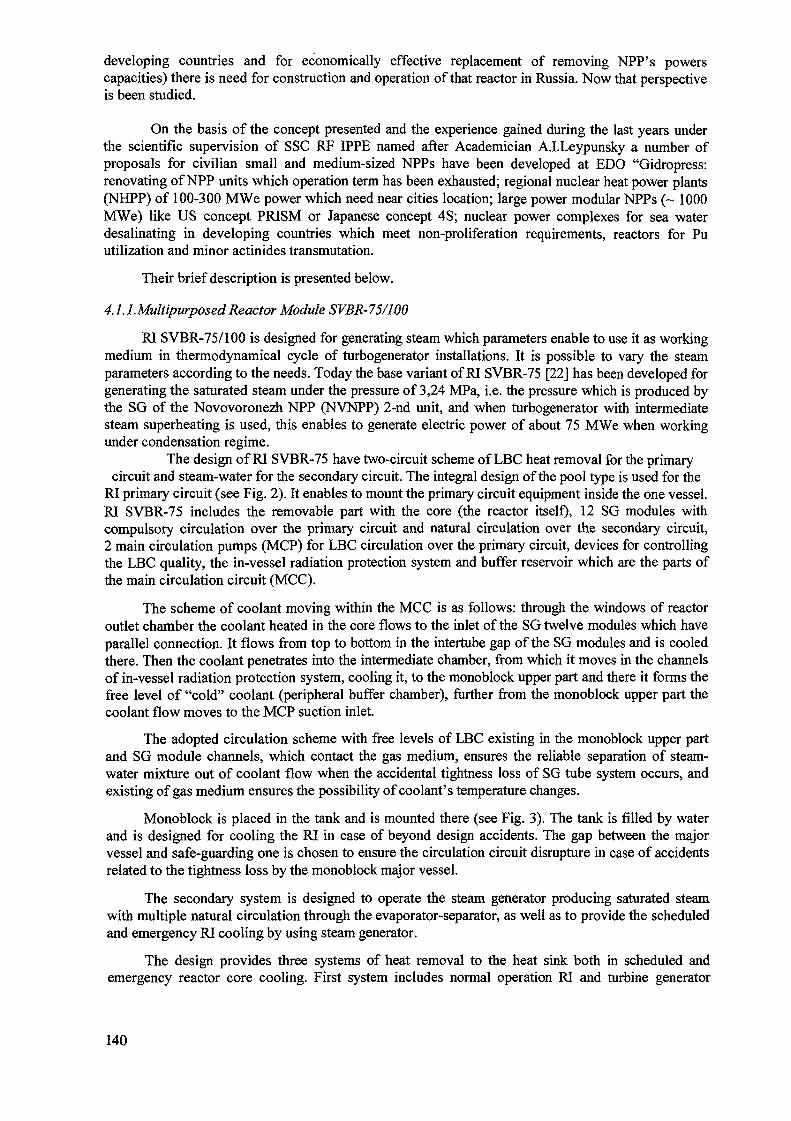
developing countries and for economically effective replacement of removing NPP's powerscapacities) there is need for construction and operation of that reactor in Russia. Now that perspectiveis been studied.
On the basis of the concept presented and the experience gained during the last years underthe scientific supervision of SSC RF IPPE named after Academician A.I.Leypunsky a number ofproposals for civilian small and medium-sized NPPs have been developed at EDO "Gidropress:renovating of NPP units which operation term has been exhausted; regional nuclear heat power plants(NHPP) of 100-300 MWe power which need near cities location; large power modular NPPs (~ 1000MWe) like US concept PRISM or Japanese concept 4S; nuclear power complexes for sea waterdesalinating in developing countries which meet non-proliferation requirements, reactors for Puutilization and minor actinides transmutation.
Their brief description is presented below.
4.l.l.MultipurposedReactor Module SVBR-75/100
RI SVBR-75/100 is designed for generating steam which parameters enable to use it as workingmedium in thermodynamical cycle of turbogenerator installations. It is possible to vary the steamparameters according to the needs. Today the base variant of RI SVBR-75 [22] has been developed forgenerating the saturated steam under the pressure of 3,24 MPa, i.e. the pressure which is produced bythe SG of the Novovoronezh NPP (NVNPP) 2-nd unit, and when turbogenerator with intermediatesteam superheating is used, this enables to generate electric power of about 75 MWe when workingunder condensation regime.
The design of RI SVBR-75 have two-circuit scheme of LBC heat removal for the primarycircuit and steam-water for the secondary circuit. The integral design of the pool type is used for the
RI primary circuit (see Fig. 2). It enables to mount the primary circuit equipment inside the one vessel.RI SVBR-75 includes the removable part with the core (the reactor itself), 12 SG modules withcompulsory circulation over the primary circuit and natural circulation over the secondary circuit,2 main circulation pumps (MCP) for LBC circulation over the primary circuit, devices for controllingthe LBC quality, the in-vessel radiation protection system and buffer reservoir which are the parts ofthe main circulation circuit (MCC).
The scheme of coolant moving within the MCC is as follows: through the windows of reactoroutlet chamber the coolant heated in the core flows to the inlet of the SG twelve modules which haveparallel connection. It flows from top to bottom in the intertube gap of the SG modules and is cooledthere. Then the coolant penetrates into the intermediate chamber, from which it moves in the channelsof in-vessel radiation protection system, cooling it, to the monoblock upper part and there it forms thefree level of "cold" coolant (peripheral buffer chamber), further from the monoblock upper part thecoolant flow moves to the MCP suction inlet.
The adopted circulation scheme with free levels of LBC existing in the monoblock upper partand SG module channels, which contact the gas medium, ensures the reliable separation of steam-water mixture out of coolant flow when the accidental tightness loss of SG tube system occurs, andexisting of gas medium ensures the possibility of coolant's temperature changes.
Monoblock is placed in the tank and is mounted there (see Fig. 3). The tank is filled by waterand is designed for cooling the RI in case of beyond design accidents. The gap between the majorvessel and safe-guarding one is chosen to ensure the circulation circuit disrupture in case of accidentsrelated to the tightness loss by the monoblock major vessel.
The secondary system is designed to operate the steam generator producing saturated steamwith multiple natural circulation through the evaporator-separator, as well as to provide the scheduledand emergency RI cooling by using steam generator.
The design provides three systems of heat removal to the heat sink both in scheduled andemergency reactor core cooling. First system includes normal operation RI and turbine generator
140
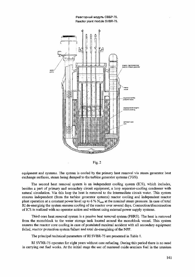
PeaiaopHbiM MOflynb CBBP-75.Reactor plant module SVBR-75.
J ^y naporeHepBTopa\_A module of steam generator
Fig. 2
equipment and systems. The system is cooled by the primary heat removal via steam generator heatexchange surfaces, steam being dumped to the turbine generator systems (TGS).
The second heat removal system is an independent cooling system (ICS), which includes,besides a part of primary and secondary circuit equipment, a loop separator-cooling condenser withnatural circulation. Via this loop the heat is removed to the intermediate circuit water. This systemensures independent (from the turbine generator systems) reactor cooling and independent reactorplant operation at a constant power level up to 6 % Nnom at the nominal steam pressure. In case of totalRI de-energizig the system ensures cooling of the reactor over several days. Connection/disconnectionof ICS is realized with no operator action and without using external power supply systems.
Third core heat removal system is a passive heat removal system (PHRS). The heat is removedfrom the monoblock to the water storage tank located around the monoblock vessel. This systemensures the reactor core cooling in case of postulated maximal accident with all secondary equipmentfailed, reactor protection system failure and total de-energizing of the NPP.
The principal technical parameters of RI SVBR-75 are presented in Table 1.
RI SVBR-75 operates for eight years without core refueling. During this period there is no needin carrying out fuel works. At the initial stage the use of mastered oxide uranium fuel in the uranium
141
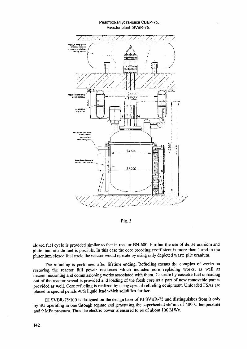
PeaKropHaa ycraHOBKa CBBP-75.Reactor plant SVBR-75.
Fig. 3
closed fuel cycle is provided similar to that in reactor BN-600. Further the use of dense uranium andplutonium nitride fuel is possible. In this case the core breeding coefficient is more than 1 and in theplutonium closed fuel cycle the reactor would operate by using only depleted waste pile uranium.
The refueling is performed after lifetime ending. Refueling means the complex of works onrestoring the reactor full power resources which includes core replacing works, as well asdecommissioning and commissioning works associated with them. Cassette by cassette fuel unloadingout of the reactor vessel is provided and loading of the fresh core as a part of new removable part isprovided as well. Core refueling is realized by using special refueling equipment. Unloaded FSAs areplaced in special penals with liquid lead which solidifies further.
RI SVBR-75/100 is designed on the design base of RI SVBR-75 and distinguishes from it onlyby SG operating in one through regime and generating the superheated ste°am of 400°C temperatureand 9 MPa pressure. Thus the electric power is ensured to be of about 100 MWe.
142
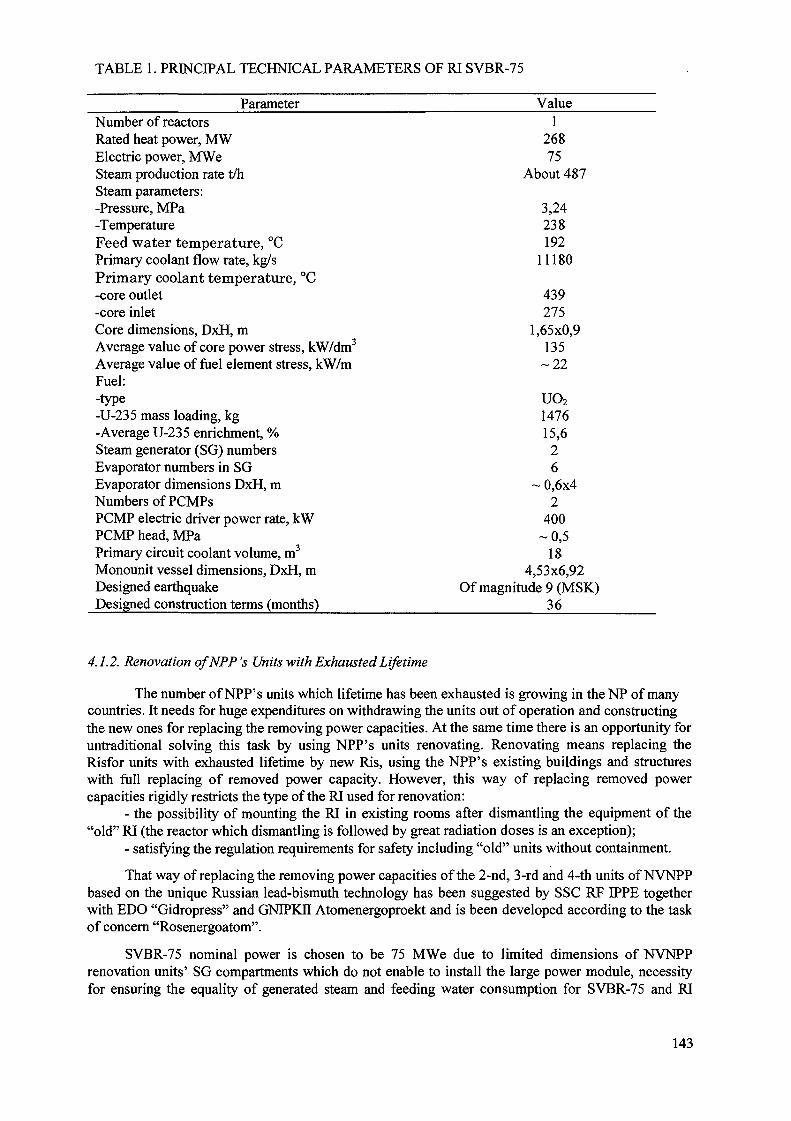
TABLE 1. PRINCIPAL TECHNICAL PARAMETERS OF RI SVBR-75
ParameterNumber of reactorsRated heat power, MWElectric power, MWeSteam production rate t/hSteam parameters:-Pressure, MPa-TemperatureFeed water temperature, °CPrimary coolant flow rate, kg/sPrimary coolant temperature, °C-core outlet-core inletCore dimensions, DxH, mAverage value of core power stress, kW/dm3
Average value of fuel element stress, kW/mFuel:-type-U-235 mass loading, kg-Average U-235 enrichment, %Steam generator (SG) numbersEvaporator numbers in SGEvaporator dimensions DxH, mNumbers of PCMPsPCMP electric driver power rate, kWPCMP head, MPaPrimary circuit coolant volume, m3
Monounit vessel dimensions, DxH, mDesigned earthquakeDesigned construction terms (months)
Value1
26875
About 487
3,24238192
11180
439275
1,65x0,9135
- 2 2
uo2147615,6
26
~ 0,6x42
400-0 ,5
184,53x6,92
Of magnitude 9 (MSK)36
4.1.2. Renovation of NPP's Units with Exhausted Lifetime
The number of NPP's units which lifetime has been exhausted is growing in the NP of manycountries. It needs for huge expenditures on withdrawing the units out of operation and constructingthe new ones for replacing the removing power capacities. At the same time there is an opportunity foruntraditional solving this task by using NPP's units renovating. Renovating means replacing theRisfor units with exhausted lifetime by new Ris, using the NPP's existing buildings and structureswith full replacing of removed power capacity. However, this way of replacing removed powercapacities rigidly restricts the type of the RI used for renovation:
- the possibility of mounting the RI in existing rooms after dismantling the equipment of the"old" RI (the reactor which dismantling is followed by great radiation doses is an exception);
- satisfying the regulation requirements for safety including "old" units without containment.
That way of replacing the removing power capacities of the 2-nd, 3-rd and 4-th units of NVNPPbased on the unique Russian lead-bismuth technology has been suggested by SSC RF IPPE togetherwith EDO "Gidropress" and GNIPKII Atomenergoproekt and is been developed according to the taskof concern "Rosenergoatom".
SVBR-75 nominal power is chosen to be 75 MWe due to limited dimensions of NVNPPrenovation units' SG compartments which do not enable to install the large power module, necessityfor ensuring the equality of generated steam and feeding water consumption for SVBR-75 and RI
143
VVER-440 SG, possibility of reactor module complete plant fabrication and its transportation by therailway, as well as closeness of the scale factor to NS's RIs that enables to use some developedtechnical solutions and reduce R&D. For replacing the power capacities of the 2-nd unit four SVBR-75 modules are installed in SG compartments, and six modules are installed for each of 3-rd and 4-thunits.
Arrangement of modules in SG compartments of the MCP of NVNPP's 2-nd unit is presentedin Fig. 4.
The great economical efficiency of renovating the "old" units is expected: specific capitalrenovation cost is 560 dollars per kWe, that is half as many as that for constructing the new NPPblock[23]
4.1.3. Regional NHPP Based on Module R-75/100
In the world many regions and first of all medium-sized and large cities face with seriousdifficulties in energy supplying especially heat supplying in winter.
One way for solving this problem is use of nuclear heat power plants (NHPP). However, use oftraditional type RIs (which use water under the high pressure for reactor cooling) for these purposesneeds designing the number of additional safety systems if compared with those accepted for NPPssituated at the distance of 25 km or more from the cities. This results in going up the NHPP cost andat the same time does not eliminate the principal possibility of scarcely probable nuclear accident withsevere consequences because the high pressure in the reactor, which is the internal cause of its arising,is not eliminated.
The high level of SVBR-75/100 reactor module inherent safety makes it possible and expedientto use it simultaneously for producing electric energy at the NPP and for heat generating at the NHPPwhich needs near city's location. So we eliminate the possibility of arising severe accidentsaccompanied by explosions, fires with unpermitable radioactivity exhausts which require populationevacuation beyond the NHPP site not only if there are personnel's errors and equipment failures but ifthey coincide, if there are terrorist groups' actions. We can construct NHPPs of 100-300 MWe byusing these standard modules.
For the major vessel of regional NHPP unit for RI SVBR-75/100 the principal design solutionsdistinguish from those for traditional type reactors. Small dimensions of monoblock SVBR-75/100and developed properties of inherent safety of FRs with LBC require the RI protection from onlythose external effects: aircraft falling, shock waves, maximal computated earthquake (MCE). There isno need for designing the tight shell withstanding significant internal pressure. Small dimensions ofprotected reactor compartment and simple scheme of RI enable to reduce the terms of NHPP unitconstruction and significantly reduce the construction cost.
The simplicity of automated control system (ACS) conditioned by using passive systems forcooling down the RI facilitates the construction cost reducing.
As it has been assessed by experts, the economical competitive ability with HPP using fossilfuel will be ensured due to the following facts: almost lack of expenditures on nuclear fueltransportation; long lifetime of the fast reactor core, which ensures without refueling RI operationduring about 8 years; low cost of spent nuclear fuel storing; almost lack of liquid radioactive wasteand expenditures for its recycling; complete plant fabricating of the RI and possibility of itstransportation by car, railway or sea to the NHPP constructing site that reduces the constructing termsand approaches them to those of traditional HPPs and reduces the investment cycle; sharp reduction ofexpenditures for designing safety ensuring systems due to RIs' high inherent safety; high commercialproduction due to great demand for these NHPPs; possibility of export delivery of these RIs. The costof these NHPPs is one-fifth - one-tenth as many as that of large NPPs.
144
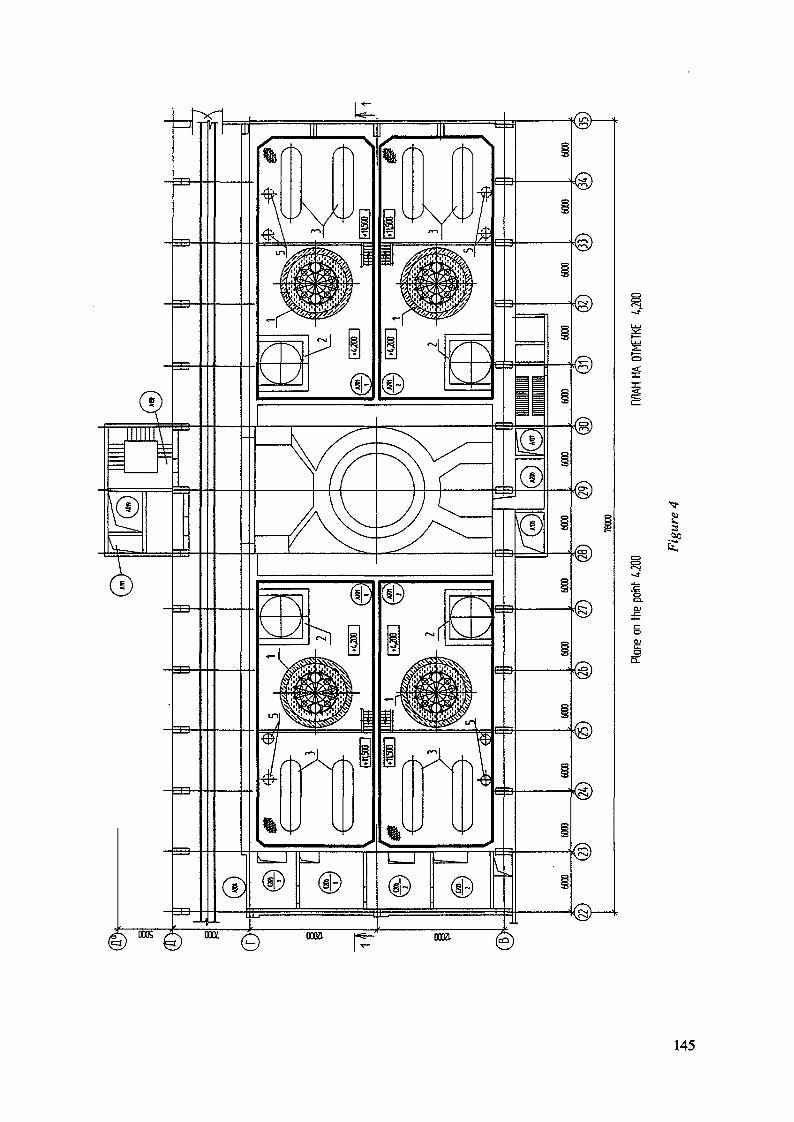
- J -
3
Ic
I
145
4.1.4. Large Power Modular NPP
On the basis of commercially produced modules SVBR-75/100 it is expedient to develop thedesign of modular NPP of large power (1 GW and more at the same unit). The prospect for thatprinciple of designing NPP is shown in conceptual design developed in the USA (PRISM) [24] and inJapan (4S) [25]. However, use of this principle for LBC cooled reactors is the most effective.
The economical gain is achieved due to: constructing volumes reduction because of eliminatingthe number of safety systems and localizing systems, reducing the specific material expenditure(including bismuth demands) as compared to traditional reactors of large power, reducing thefabricating cost due to high commercial production, reducing the NPP constructing terms whenreactor modules are delivered to the constructing site in high plant readiness. It enables to improve theconditions of credit receiving and repayment and to increase the competitive ability of NPP. Thepreliminary assessments have revealed that the capital cost of constructing such NPP is expected to benot more than that for constructing the NPP's VVER-1000 unit.
4.1.5. Dual-purpose nuclear desalinating power complex for developing countries
Many developing countries in Africa an Asia suffer from deficiency of fresh water and electricenergy. The majority of these countries do not have sufficient own resources of fossil fuel, which canmeet their demands. In some countries fuel transporting is difficult, there are no powerful electricpower transmission lines. The marketing researches conducted recently by IAEA [26] have revealedthat in many cases nuclear power sources of 100 MWe small power can be used economicallyeffective for these purposes.
However, the developing countries' particularities concerned with not sufficiently high level ofeducation, technical culture, social and economical development, as well as possibilities of arisinglocal military conflicts, put forward special requirements to the nuclear power technology which arestricter than those for developed countries.
First of all, these requirements are RI inherent safety against severe accidents that is based onRI inherent properties ensuring safety not only in cases of personnel's errors and multiple failures oftechnical systems coincidences, but in cases of sabotage terrorist actions, etc. Besides, they must meetstrict non-proliferation requirements [21], including that refueling in the country-user must beeliminated and due to this fact the lifetime duration must be 10 years or more. The opportunity forreactor unit transportation to the country-manufacturer in the state of nuclear and radiation safety forrefueling and then transporting it to the country-user again must be ensured. Thefts of fuel must betechnically eliminated as well. Besides, the competitive ability to the alternative resources ofreceiving fresh water and electric energy must be ensured.
RI SVBR-75/100 meets these requirements the most completely. It has extremely high safetypotential, lifetime duration needed, ensures the regime of non-proliferation due to the following:
- use of uranium with enrichment less than 20%,- lack of refueling in the country-user,- opportunity of transporting the reactor module after ending its lifetime to the country-
manufacturer in the state of nuclear and radiation safety with LBC "frozen" in the reactor.
4.1.6. Plutonium Utilization and Long-lived Minor Actinides Transmutation
In different countries the policy on managing plutonium, which quantity increases steadily, isdifferent. It is determined by the fact that on the one hand Pu is very valuable fuel for the future NPusing FRs. On the other hand it can be used for political and military purposes. Besides, Pu is highradiotoxic material and is considered to be NP dangerous radioactivity waste. Long-lived minoractinides belong to it too.
For the first case the issue of Pu managing (both extracted one and that is contained in spentnuclear fuel) results in long reliably controlled storing.
146

The second case results in the task of Pu transmuting into the form that reduces the risk of itsunauthorized proliferation or its complete burning up and minor actinides nuclear transmutation.
For solving this task the works on mastering the new nuclear technology using accelerator-driven systems are carried out. The main stimulus for developing this technology is Pu and minoractinides blanket subcriticality that eliminates the prompt neutrons runaway nuclear accident.
Along with it, this task can be solved on the basis of already mastered technology. For example,during eight years one reactor module SVBR-75/100 can transmute about 1000 kg of Pu (weapon orreactor one) into the form protected against unauthorized proliferation ("spent fuel standard") atreducing its quality as a weapon material compared to the weapon Pu. In terms of 1 GWe - year1,25 tons of Pu will be utilized in those reactors. If minor actinides (first of all amerithium) isintroduced into fuel, their transmutation into short-lived radioactive wastes will take place.
The safety level needed will be ensured due to developed propertied of RI SVBR-75/100inherent safety which have been mentioned above.
5. THE DISTANT FUTURE TASK (AFTER THE YEAR 2030)LONG-TERM NP DEVELOPMENT IN CONDITIONS OF LIMITEDNATURE URANIUM RESOURCES
The development of power and NP especially is very sluggish. That is why many countries,where there is developing NP, consider conditions under which NP can exist and develop in themiddle of the next century. As far as Russia conditions are concerned, this time period would becharacterized by the fact that available nature and enriched uranium resources which enable todevelop NP and ensure export supplies without large costs for uranium mining and enriching wouldbe exhausted. It would result into the necessity of searching, mining and developing new uraniumdeposits at hard-reached areas or into the orientation towards scale uranium import that would be thecause of increasing the fuel component of the cost of electric power generated by NPPs with thermalneutrons reactors.
The problem of NP fuel supplying could be solved by FR operating in closed nuclear fuel cycle(NFC) and enabling to involve effectively uranium-238 into power generation.
However, nuclear fuel-power complex development on this base inevitably yields to increasingspecific capital costs and duration of investment cycle in comparison with modern and promising HPPusing organic fuel. Under the market economy conditions when construction should be performed onthe base of credits repayment it can deteriorate the NP competitive ability if consumers have freeaccess to the wholesale electric energy and power market. Now this situation is forming in the USA,where constructed NPPs with light water reactors (LWR) is not putting into operation because of theirlow profits, even under conditions of the absence of the costs for fuel recycling and fuel elementsrefabricating. The situation is not going to improve even if weapon plutonium is involved into NFCwith not complete fuel cycle closing (the absence of costs for reprocessing, minimal radiationcharacteristics during fabricating).
At the next century in the course of NP development based on the evolutionary improvement oftraditional reactors the situation would be deteriorated because in order to keep up the value of severeaccident risk at the today's existing socially acceptable level, the probability of that accident shouldbe reduced inversely proportional to the number of reactor-years generated by the NPP units. It wouldinevitably yield to increasing the capital costs for increasing the NPP safety.
NP situation may be improved in more distant future when the resources of cheap natural gashave to be exhausted (the share of natural gas is the dominant one in electric energy production),quotas on releasing the greenhouse gases, significant increasing the cost of electric energy producedby HPP, controlling the environment have to be introduced.
There might be the long time interval (50-100 years) between the moment when NP loses itscompetitive ability after exhausting cheap uranium resources and that one when NP with closed NFC
147
can be assuredly competed with that using organic fuel. Then NP would be less economicallyeffective in comparison with power industry using organic fuel ("gas pause").
The circumstances considered make it actual to search for the concept of NP developmentduring the "gas pause" period, which enables to overcome arising difficulties. One of possibleconcepts has been designed by SSC RF IPPE [27]. The main concept goal is to increase sharply theefficiency of natural uranium energy potential utilization without radio-chemical fuel reprocessing andfuel cycle closing for "gas pause" elimination.
5.1. Fast Reactor Operation in the Open NFC (Physical Concept)
FRs are commonly dealt with in the closed NFC in which they operate under the breederregime. And plutonium is mainly accumulated in zones of its reprocessing from depleted uranium.The breeding ratio is less than that one in the core. The core make-up under partial refuelings isperformed by fuel with fissile material content as that was in start-up load fuel. For providing corereactor make-up by built-up plutonium, closing the NFC with fuel reprocessing and fuel elementsrefabricating by exploitation of released plutonium is needed.
However, FR operation may be performed in non-traditional regime, its realization wouldenable to close the "gas pause". It is the FR with so called "without chemistry processing" fuel cyclethat was first theoretically considered by S.M. Feynberg and E.P. Kunegin ("Kurchatov Institute",Russia) in 1958 [28] and then by K.Fucks and H.Hessel (Germany) in 1961 [29].
The fast reactor operation under that regime is not in conformity with the existing view pointson the FR role in NP, as in this case built-up plutonium is neither extracted nor reused, but mainlyutilized directly inside the reactor. This is the reason for reconsideration of traditional FRs.
In the reactor under consideration the start-up load of core consisting of fuel subassemblies(FSA) with comparatively high enriched uranium fuel (10... 12%) is realized only once. (Certainly,there may be used U-Pu fuel containing weapon plutonium if the problem of its utilization is actual oryielded energetic plutonium). In the course of reactor operation the FSA of start-up load under partialrefuelings are being replaced gradually by previously loaded make-up FSA where plutonium has beenalready built up, and their place is occupied by fresh make-up FSA with depleted or slightly-enricheduranium. There are no separate breeding blankets in that reactor.
The principal condition of ensuring reactor operation under that regime is core breeding ratio(CBR) being more than one. It enables the criticality to be maintained due to plutonium built-up.Thus, on the one hand, it is necessary the average plutonium concentration in the core to be more thancritical one. On the other hand, this concentration should not exceed the equilibrium value, which isdetermined by the equality of the rate of forming plutonium out of uranium-238 and that of itsburning-up. The reactor parameters and the regime of partial refuelings should be selected in such away that the reactivity loss after partial refueling should be compensated by the reactivity increaseduring the operation period between refuelings. This reactivity increase is compensated byintroducing the absorbing rods into the core. After partial refueling the reactor must be critical withthe absorbing rods extracted.
Carrying out these conditions must meet the number of reactor requirements. The core must beof large dimensions. The volume share of fuel and its uranium density should be high. The share ofFSA reloaded per one cycle of partial refuelings must be low (high refueling multiplicity).
The chosen scheme of partial FSA refuelings and reshufflings should also provide smoothingthe energy yield distribution in the core. The problem is complicated because simultaneously in thecore there are both FSA with large plutonium content that is close to equilibrium one and fresh make-up FSA without plutonium with very low energy yield. That is why zones with high and lowplutonium content must be alternated.
After unloading the last FSA of start-up load out of the core the reactor goes into the self-maintaining operation regime. Thus criticality is maintained mainly by own plutonium and reactor
148
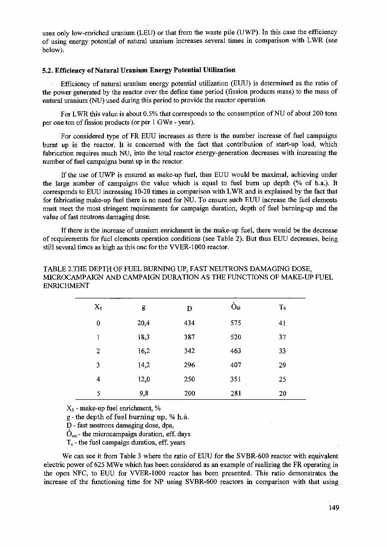
uses only low-enriched uranium (LEU) or that from the waste pile (UWP). In this case the efficiencyof using energy potential of natural uranium increases several times in comparison with LWR (seebelow).
5.2. Efficiency of Natural Uranium Energy Potential Utilization
Efficiency of natural uranium energy potential utilization (EUU) is determined as the ratio ofthe power generated by the reactor over the define time period (fission products mass) to the mass ofnatural uranium (NU) used during this period to provide the reactor operation.
For LWR this value is about 0.5% that corresponds to the consumption of NU of about 200 tonsper one ton of fission products (or per 1 GWe - year).
For considered type of FR EUU increases as there is the number increase of fuel campaignsburnt up in the reactor. It is concerned with the fact that contribution of start-up load, whichfabrication requires much NU, into the total reactor energy-generation decreases with increasing thenumber of fuel campaigns burnt up in the reactor.
If the use of UWP is ensured as make-up fuel, thus EUU would be maximal, achieving underthe large number of campaigns the value which is equal to fuel burn up depth (% of h.a.). Itcorresponds to EUU increasing 10-20 times in comparison with LWR and is explained by the fact thatfor fabricating make-up fuel there is no need for NU. To ensure such EUU increase the fuel elementsmust meet the most stringent requirements for campaign duration, depth of fuel burning-up and thevalue of fast neutrons damaging dose.
If there is the increase of uranium enrichment in the make-up fuel, there would be the decreaseof requirements for fuel elements operation conditions (see Table 2). But thus EUU decreases, beingstill several times as high as this one for the VVER-1000 reactor.
TABLE 2.THE DEPTH OF FUEL BURNING UP, FAST NEUTRONS DAMAGING DOSE,MICROCAMPAIGN AND CAMPAIGN DURATION AS THE FUNCTIONS OF MAKE-UP FUELENRICHMENT
x5
0
1
2
3
4
5
g
20,4
18,3
16,2
14,2
12,0
9,8
D
434
387
342
296
250
200
Oie
575
520
463
407
351
281
Te
41
37
33
29
25
20
X5 - make-up fuel enrichment, %g - the depth of fuel burning up, % h.a.D - fast neutrons damaging dose, dpa,6mc - the microcampaign duration, eff. daysTc - the fuel campaign duration, eff. years
We can see it from Table 3 where the ratio of EUU for the SVBR-600 reactor with equivalentelectric power of 625 MWe which has been considered as an example of realizing the FR operating inthe open NFC, to EUU for VVER-1000 reactor has been presented. This ratio demonstrates theincrease of the functioning time for NP using SVBR-600 reactors in comparison with that using
149
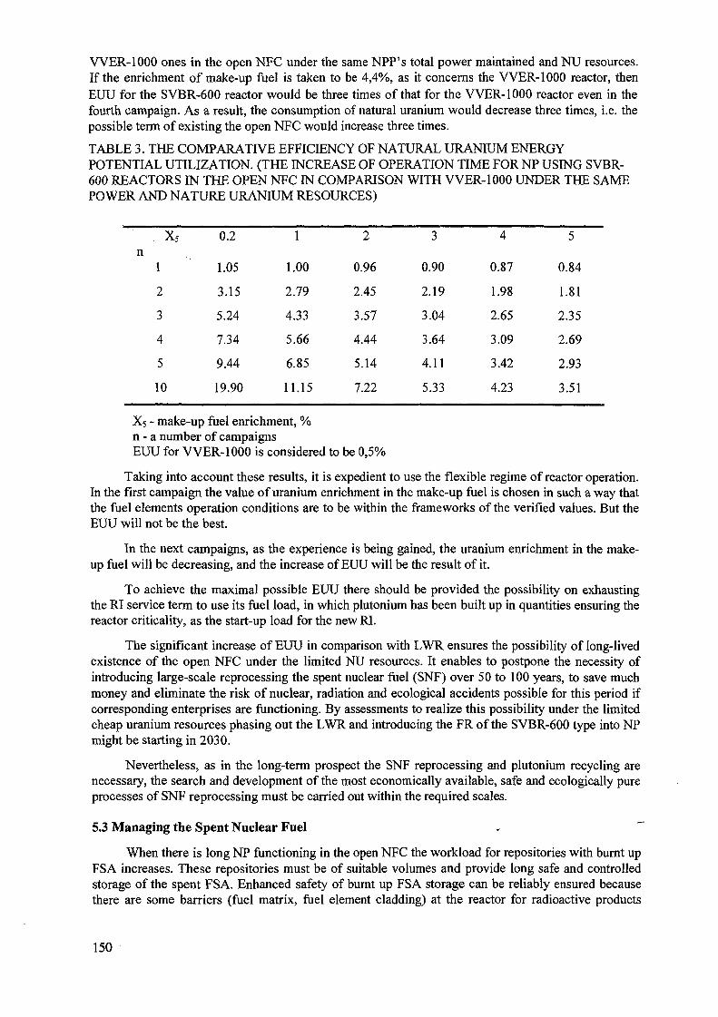
WER-1000 ones in the open NFC under the same NPP's total power maintained and NU resources.If the enrichment of make-up fuel is taken to be 4,4%, as it concerns the VVER-1000 reactor, thenEUU for the SVBR-600 reactor would be three times of that for the VVER-1000 reactor even in thefourth campaign. As a result, the consumption of natural uranium would decrease three times, i.e. thepossible term of existing the open NFC would increase three times.
TABLE 3. THE COMPARATIVE EFFICIENCY OF NATURAL URANIUM ENERGYPOTENTIAL UTILIZATION. (THE INCREASE OF OPERATION TIME FORNP USING SVBR-600 REACTORS IN THE OPEN NFC IN COMPARISON WITH VVER-1000 UNDER THE SAMEPOWER AND NATURE URANIUM RESOURCES)
x5n
1
2
3
4
5
10
0.2
1.05
3.15
5.24
7.34
9.44
19.90
1
1.00
2.79
4.33
5.66
6.85
11.15
2
0.96
2.45
3.57
4.44
5.14
7.22
3
0.90
2.19
3.04
3.64
4.11
5.33
4
0.87
1.98
2.65
3.09
3.42
4.23
5
0.84
1.81
2.35
2.69
2.93
3.51
X5 - make-up fuel enrichment, %n - a number of campaignsEUU for VVER-1000 is considered to be 0,5%
Taking into account these results, it is expedient to use the flexible regime of reactor operation.In the first campaign the value of uranium enrichment in the make-up fuel is chosen in such a way thatthe fuel elements operation conditions are to be within the frameworks of the verified values. But theEUU will not be the best.
In the next campaigns, as the experience is being gained, the uranium enrichment in the make-up fuel will be decreasing, and the increase of EUU will be the result of it.
To achieve the maximal possible EUU there should be provided the possibility on exhaustingthe RI service term to use its fuel load, in which plutonium has been built up in quantities ensuring thereactor criticality, as the start-up load for the new RI.
The significant increase of EUU in comparison with LWR ensures the possibility of long-livedexistence of the open NFC under the limited NU resources. It enables to postpone the necessity ofintroducing large-scale reprocessing the spent nuclear fuel (SNF) over 50 to 100 years, to save muchmoney and eliminate the risk of nuclear, radiation and ecological accidents possible for this period ifcorresponding enterprises are functioning. By assessments to realize this possibility under the limitedcheap uranium resources phasing out the LWR and introducing the FR of the SVBR-600 type into NPmight be starting in 2030.
Nevertheless, as in the long-term prospect the SNF reprocessing and plutonium recycling arenecessary, the search and development of the most economically available, safe and ecologically pureprocesses of SNF reprocessing must be carried out within the required scales.
5.3 Managing the Spent Nuclear Fuel - ~~
When there is long NP functioning in the open NFC the workload for repositories with burnt upFSA increases. These repositories must be of suitable volumes and provide long safe and controlledstorage of the spent FSA. Enhanced safety of burnt up FSA storage can be reliably ensured becausethere are some barriers (fuel matrix, fuel element cladding) at the reactor for radioactive products
150
release from FSA into the environment, and the additional ones can be designed (e.g., the capsule withburnt up FSA is filled by liquid lead and then "frozen"). If the spent fuel is stored in the "dry"repositories, it is not exposed to any attacks resulting in damage of protective barriers. Comparativelylow volume of the spent FSA per 1 GW(e)-year, in comparison with VVER-1000, caused by 3 or 4times deeper fuel burning up, facilitates the designing reliable physical protection resistant to externalattacks and reduces the repository cost.
In addition to it, the reactor operation in the open NFC almost eliminates the possibility ofunauthorized plutonium proliferation and utilization of built-up plutonium for the war purposesbecause it exists in the spent fuel together with high-radioactive fission products ("spent fuelstandard").
It will be promoting to the rise of political stability in the world. It should be also highlightedthat the risk of unauthorized plutonium prolifiration out of the SNF repositories after accumulating thethreshold plutonium quantity making the fabrication of several hundreds of nuclear charges availabledoes not increase proportionally to the total quantity of plutonium in the repository.
Turning over the spent nuclear fuel repositories (SNFR) to the International Guaranteesfacilitates to reducing the risk of plutonium thefts.
5.4. The Key Results of the Investigations Performed
Results of the investigations carried out have corroborated the feasibility of FR operation withmake-up under partial refuelings by slightly enriched or depleted uranium. In this case the EUU
highest value is achieved if the core dimensions are: (D x H^ 4.0 m x 1.4 m), fuel volumetric fractionis not lower than 60%, there is utilization of fuel with high uranium density (~11 g/cm3 ) andformation of possibly harder neutron spectrum in the core (there is lack of light nuclei).
The formation of harder neutron spectrum has been influenced by LBC using, thus the highervalue of CBR has been provided, which has had a key part in reaching the EUU biggest value. Thecalculations have demonstrated that for sodium coolant, which can moderate neutrons moreeffectively, it is hard to provide the reactor criticality if it has been made up by depleted uranium.
In the case of using metal alloyed (10% of Zr) uranium fuel with 75% effective density oftheoretical one, the reactor can utilize waste uranium as the make-up. Thus the highest EUU isensured (about 20%). In this case the burn-up depth achieves about 20% of h.a. (that is justified atexperimental assemblies of EBR-2 reactor), fast neutron damaging dose on the fuel element claddingmaterial accounts for approximately 430 dpa (it is twice the value that has been achieved by tests forferritic and martensitic steels), the total operation period of FEA is about 30 years (that is three timesover that gained for RI operation at the NS).
As it has been mentioned above, increasing the make-up fuel enrichment reduces these demandsconsiderably. It should be also pointed out that the concepts of the core complete equipment, schemeand partial refuelings schedule, as they have been accepted in calculations at the phase of preliminarystudy, are not optimal. They need further multicriterion optimization by using calculational algorithmsin which reactor dimensions are reflected equivalently. It enables to reduce the requirements for fuelelements operation. One such method has been presented in paper [30].
On the base of the results obtained the engineering design of SVBR-600 RI of the 625 MWeelectric power has been carried out at EDO "Gidropress.", and the design of NPP using that RIs hasbeen carried out at VNEPIET. Their aim was to choose the principal engineering and designingapproaches and the preliminary assessment of their engineering and economical characteristics. _
The results of calculation of engineering and economical characteristics of the two-block NPPwith RI VVER-600 being compared with those of the two-block NPP with RI VVER-640 which hasthe highest safety characteristics for that type of RI, have demonstrated the following.
151
Capital costs for constructing the NPP along with the SNFR (the costs of initial fuel and coolantload calculated per 1 kW of electric power maintained have been taken into account) have beenalmost equal and the cost of electric energy has been 21% less than that of RI VVER-640.
The equality of specific capital costs, in spite of higher costs of FR start-up fuel load andcoolant which are typical for RI SVBR-600, has been accounted by simplier scheme of this RI andreduction of constructing volumes, which is caused by the total absence of the primary circuitpipelines and valves, significantly less quantity of ancillary systems and systems ensuring safety,significantly less (4 times) volume of the SNFR under the same power generation, almost totalabsence of LRW (by the experience of operating the RI using lead-bismuth coolant at the NS) and, asa result of this, significant reduction of special chemical water purification systems whichcompensates the factors pointed out above. The less electric energy cost for SVBR-600 is accountedfor the significantly more depth of fuel burning-up in the FR considered.
As a result of the investigations carried out, there have been gained the conclusions of theeconomical preference of the NPP using SVBR-600 RI in comparison with that using VVER-640 RI.Of course, these conclusions are preliminary because the level of studying the RI SVBR-600, thatcorresponds to the phase of engineering recommendations, defines the more error of engineering andeconomical calculations than that for WER-640. However, these conclusions point to the expediencyof further investigating the concept suggested along with the development of the NPP concept design.And the design of the NPP using VVER-1000 RI (V-392), that has the best engineering andeconomical characteristics, should be accepted as the comparison basis.
6. CONCLUSION
The analysis of experience of operating the RIs at the NSs and at the ground-based facilities-prototypes has demonstrated that it was only one accident that was caused by using LBC. Furtherwork has enabled to solve the problem of LBC technology and ensure the reliable exploitation of theRIs primary circuits. The causes of other accidents and emergency situations were not concerned withthe use of LBC, and similar accidents could have happened at any type of the RIs.
The developed measures on radiation safety have enabled to eliminate the personnel'sirradiation by polonium-210 above the permissible limits not only under the normal operationconditions, but also if there are refueling, repair works, emergency coolant spillage.
The problem of multiple coolant "freezing-defreesing" in the RI has been solved. It enables touse this regime for providing nuclear and radiation safety during the RI transportation (for low powerRIs) and long SNF storage.
The experience gained has enabled to design the number of small power RIs providing themost complete realization of the self-protection principle for the severest accidents and theirdeterministic elimination because of using the fast reactor, LBC and the primary circuit integraldesign (SVBR-75/100). On the basis of these RIs renovation of NPP's units served their lifetime canbe carried out, regional NPHPs for energy shortage regions can be built, large power NPPs of modulartype can be constructed, meeting IAEA requirements power complexes for electric energy producingand sea water desalinating can be built in developing and other countries, reactors for utilizing Pu andtransmuting the long-lived minor actinides can be designed.
In order to maintain the NP competitive ability on exhausting the cheap uranium resources andnecessity of using the FR with closed NFC and plutonium recycling (plutonium significantlydeteriorates the ecological characteristics) there has been developed the concept of the FR cooled byLBC and using the depleted uranium as the fuel make-up. It enables to postpone the large-scale SNFreprocessing with plutonium recycling over 50 to 100 years.
The existing scales of metal bismuth production which have been restricted by bismuth usagewill limit the rate of introducing the reactors cooled by LBC in NP. That is why after the period of
152

operating the demonstrative reactors using LBC and corroborating their practical reliability,economical efficiency and safety and accepting the decision of their wide introduction into NP, theactions on increasing the bismuth production must be taken. Further, when the bismuth cost begins todeteriorate noticeably the NPFs economical characteristics (as the exploiting mines are beingdepleted), it will be expedient to start using LBC with lower bismuth content (e.g., as low as 10%),and then pure lead coolant, which is more difficult to exploit and has not been mastered yet.
REFERENCES
[I] GROMOV, B.F., SUBBOTIN, V.I., TOSHINSKY, G.I., "Application of Lead-BismuthEutectic and Lead Melts as Nuclear Power Plant Coolant", (Atomnaya Energiya, July1992), Vol.73, Issue 1, Page 19.
[2] GROMOV, B.F., GRIGORIEV, O.G., DEDOUL, A.V., TOSHINSKY, G.I.,STEPANOV, V.S., NIKITIN, L.B., "The Analysis of Experience of Operating ReactorInstallations Using Lead-Bismuth Coolant and Accidents Happened", (Rep. Conf.HLMC-98, Obninsk).
[3] OSIPENKO, L., ZHILTSOV, L., MORMOUL, N., "Nuclear Submarine Epopee.Heroic Deeds, Failures, Catastrophes", (A/O "Borges" Publishing House, Moscow,1994).
[4] GROMOV, B.F, ORLOV, V.I., MARTYNOV, P.N., GOULEVSKY, V.A., "The Problemof Heavy Liquid Coolants Technology (Lead-Bismuth, Lead)", (Rep. Conf. HLMC-98,Obninsk).
[5] YACHMENEV, G.S., ROUSANOV, A.E., GROMOV, B.F, BELOMYTSEV, V.S,SKVORTSOV, N.S., DEMISHONKOV, A.P., "The Problems of Structure MaterialsCorrosion in Heavy Liquid Metal Coolant", (Rep. Conf. HLMC-98, Obninsk).
[6] PYLCHENKOV, E.H., "The Problems of Maintaining the RIs Operation Abilityunder the Regimes of Coolant (Lead-Bismuth Eutectic Alloy) Freezing-Unfreezing"(Rep. Conf. HLMC-98, Obninsk).
[7] TUPPER, R.B., MIMISHKIN, B.,. PETERS, F.E., KARDES, Z.L., " PoloniumHazards Associated with Lead Bismuth Used as a Reactor Coolant", (Proc. Conf.Kyoto, Japan,1991), VoLIY, 5-6.
[8] LAURIE D.WIGGS, CAROL A.COX-DE VORE, GEORGE L.VOELZ, "MortalityAmong a cohort of Workes Monitored for Po-210 Exposure: 1944-1972", (HealthPhysics, Nol, July 1991), Vol.61.
[9] PANCRATOV, D.V., YEFIMOV, E.I., BOLHOVITINOV, V.N., BOUGREEV, M.I.,KOURANOV, V.D., "Polonium Problems for Nuclear Power Installations UsingLead-Bismuth Coolant",(Rep. Conf. HLMC-98, Obninsk).
[10] GROMOV, B.F., TOSHINSKY, G.I., STEPANOV, V.S., "Use of Lead BismuthCoolant in Nuclear Reactors and Accelerator-Driven Systems", (Nuclear Engineeringand Design, 1997) Vol.173, 207-217.
[II] ASSOCIATION "BELLUNA"'S REPORT, "Radioactive Contamination Causes inMurmansk and Arkhangelsk Regions", (Boks 8874, Youngstorget N-0028, Oslo,Norway, Version 1, 1994).
[12] FORSBERG, C.W., WEINBERG, A.M., "Advanced Reactors, Passive Safety andAcceptance of Nuclear Energy", (Annual Rev., 1990, 15:133-52).
[13] Adamov, E.O., Orlov, V.V., "Requirements to a New Nuclear Technology for the_Lagre-Scale Power Industry", (Proc. Meet. Pittsburgh, 1994), Vol.2, p.636.
[14] "SAFETY CULTURE", Safety Series N 75-INSAG-4, IAEA, Vienna, 1990.[15] NOVIKOV, V.M., SLESAREV, I.S., ALEXEEV, P.N., et al., "Nuclear Reactors of
High Safety. (The Analysis of Concept Designs)", Moscow, Energoatomizdat, ISBN 5-283-03817-3, 1993,
153
[16] OSHINSKY, G.I., "A.I. Leypunsky. Selected Works. Reminiscences", Kiev, NaukovaDumka, 1990, p.225.
[17] FRANK VON HIPPEL, "Evolutionary Approach to Fission Power", (InternationalConference on Evaluation of Emerging Nuclear Fuel Cycle Systems Global-95,September 11-14, Versailles, France),. Vol.1, pp. 380-387
[18] SINEV, N.M., "The Nuclear Power Economy", Moscow, Energoatomizdat, 1987.[19] ENCYCLOPEDIA OF INORGANIC MATERIALS (TWO VOLUMES), 1977.[20] JURY FINAL REPORT ON THE NUCLEAR PLANTS OF LOW POWER DESIGNS
COMPETITION (NPLP), Nuclear Society, Moscow, 1994.[21] BROWN, N.W., HESSBERGER, J.A., "New concepts for small power reactors
without on-site refueling for non-proliferation", IAEA-AG-1021IWGER/97, Obninsk,Russian Federation, July 1998.
[22] STEPANOV, V.S., KLIMOV, N.N., KULIKOV, M.L., LEGUENKO, S.K.,.CHITAYKIN, V.I., GROMOV, B.F., TOSHINSKY, G.I., GRIGOREV, O.G.,"Application in Electric Power Industry Technology of Transport Reactors with lead-Bismuth Coolant", IAEA-AG-1021 IWGER/97, Obninsk, Russian Federation, July1998
[23] IGNATENKO, E.I., KORNIENKO, A.G., ZRODNIKOV, A.V, GROMOV, B.F.,TOSHINSKY, G.I., GRIGORIEV, O.G., CHITAIKIN, V.I., STEPANOV, V.S,KOOCKLIN, V.Z., et al., "Renovating the First Generation NPP's Units Removedfrom Operation after Exhausting Their Service Life by Placing Them in SteamGenerator Boxes of SVBR-75 RIs Using Liquid Metal Lead-Bismuth Coolant", (Rep.Conf. Ekaterinburg-Zarechny, 1997).
[24] BERGLUNG, R.C., TIPPETS, F.E., "PRISM, the Plant Design Concept for the U.S.Advanced Liquid Metal Reactor Program", (Conf., Chicago, 1989).
[25] HATTORI, S., MINATO, A., "A Large Modular LMR Power Station which MeetsCurrent Requirements", (Proc. ICONE-3, Kyoto, Japan, 1995), Vol.2, pp. 787-790.
[26] INTERNATIONAL ATOMIC ENERGY AGENCY, "Potential for Nuclear Desalinationas a Source of Low Cost Potable Water in North Africa", IAEA-TECDOC- 917,Vienna, (1996).
[27] TOSHINSKY, G.I., "Concept of the Self-Fuel-Providing Fast Reactor using LiquidMetal Coolant",(Rep. Conf. HLMC-98, Obninsk).
[28] FEYNBERG, S.M., KUNEGIN, E.P., (Proc. Conf., Geneva, 1958), Vol. 9, Part 2, pp.447-448.
[29] FUCHS, K, HESSEL, H., "Uder die Moglichkeiten des Betriebs einesNatururanbrutreaktors ohne Brennstoffaufbereitung, Kernenergie", (4, Jahrgang,Heft 8, ss. 619-623, 1961).
[30] TOSHINSKY, V., SEKIMOTO, H., TOSHINSKY, G., "Self-Fuel-Providing LMFBR:Design Problems and Their Possible Solutions", {Proc. ICENES'98, Tel-Aviv, Israel,1998), Vol.1, p. 43.
LIST OF ABBREVIATIONS
NPP - nuclear power plant;NPHP - nuclear power heating plant;RI - reactor installation;NPI - nuclear power installation;NS - nuclear submarine;LMC - liquid metal coolant;IPPE - Institute of Physics and Power Engineering;
154
LBC - lead-bismuth coolant;NP - nuclear power;SG - steam generator;SHS - steam heating system;EP - emergency protection;CR - compensative rods;TC - tight compartment;WCR - water-chemical regime;EC - emergency condenser;LRP - leakage reinjection pump;FR - fast reactor;MPC - maximal permissible concentration;FSA - fuel subassemblies;PSA - probabalistic safety analysis;SNF - spent nuclear fuel -EPS - emergency protection systems;SNPP - small nuclear power plant;HPP - heating power plant;MCP - main circulation pump;SRD - scientific and research developments;LRW - liquid radioactive waste;RAW - radioactive waste;NFC - nuclear fuel cycle;LWR - light water reactor;FEA - fuel elements assemblies;LEU - low-enriched uranium;CBR - core breeding ratio;UWP - uranium waste pile;
EUU - efficiency of natural uranium energy potential utilization;NU - natural uranium;SNFR - spent nuclear fuel repository;NVNPP - Novovoronezh nuclear power plant;RDIPE - Research and Design Institute of Power Engineering;NITI - Technological Research and Development Institute (Sosnovy Bor);TSNII KM Prometey - Central Research Institute of Structural Materials;OKBM - Experimental Design Bureau of Mechanical Engineering;EDO Gidropress - Gidropress Experimental and Design Bureau (Podolsk);SSC RFIPPE - State Scientific Center of Russian Federation Instituteof Physics and Power Engineering;St.P MBM "Malakhit - Malakhit Marine Engineering Design Bureau (St. Petersburg);GNIPKII Atomenergoproekt - All Russia Research and Design Institute;VNIPIET - All Russia Research and Design Institute for IntegratedPower Engineering Technology;
VNIPI Promtechnologya - All Russia Scientific Research and Design Institute.
155
ADVANCED 4S (SUPER SAFE, SMALL AND SIMPLE) LMR
A. MINATOCentral Research Institute of Electric Power Industry, XA0056275Tokyo
N. HANDAToshiba Co-operation,Power Systems & Services Company,Yokohama
Japan
Abstract
This paper describes a new nuclear power system which can be used for a greatervariety of applications. The 4S liquid metal reactor has high inherent safety and passivesafety characteristics. It is also easy to operate, maintain and inspect, faster to construct,more flexible in location, requires less initial investment, and is better suited to electricalgrid management. The reactor offers a new route through which to expand the use of safenuclear technology in the world.
1. INTRODUCTION
In the 21st century, we will be confronted with how to solve some very seriousproblems which have not been faced by mankind in the past. That is the so called trilemmaproblems energy security, environmental protection and socio-economic developmentwhich compete against each other.
Nuclear power appears to have the potential to help to solve these problems.However, to make it a reality, it is necessary to improve nuclear power technology to makeit more applicable to a greater variety of utilizations and locations.
To achieve this target, the following key items are essential.a) Enhancing the efficiency of nuclear power utilizationb) Increasing the flexibility of nuclear power sitingc) Assurance and improvement of safety and reliabilityd) Improving the economicse) Promoting public acceptance of nuclear powerf) Nuclear power utilization in developing countriesg) Improving the fuel cycle and waste managementh) Providing the high proliferation resistance
2. BASIC CONCEPT
Based on the requirements, one of the most promising nuclear reactor designs is asmall or medium size modular type nuclear reactor with high inherent safety and passivecharacteristics. It is preferable that the following features are taken into considerations;greater simplicity, easy to maintain, inspect and operate, less influence of human factors,high reliability, improved availability and capacity, design standardization, easier toconstruct, quicker to construct, more flexibility in siting, lower initial investment and betteradaptability to electrical grid management.
157

All these features of nuclear power plants make it very attractive for developingcountries to introduce nuclear power and for industrialized countries to expand nuclearpower usage. In addition, the need to improve the fuel cycle, waste management andnuclear proliferation resistance, requires special design characteristics and fuelmanagement provisions.
Our design efforts to satisfy these conditions have resulted in the development ofthe Super Safe, Small and Simple (4S) fast reactor with an electric power output of 50MWe.^'2)'3)>4)'5) There are several advantages of the 4S reactor:
a) The 4S will play an important role in accelerating nuclear power utilization throughoutthe world, because the reactor provides an effective power supply on isolated locations,and medium or large power stations are also feasible by the core or reactor moduleconfiguration.
b) Regarding site selection, the 4S has some favorable characteristics. First, the requiredsite boundary is 20m based on the source term evaluation and thus the 4S plant satisfiesthe required area by it's construction area. Second, the small reactor vessel has a highseismic resistance. The 4S can be constructed to withstand any earthquake conditionwithout changing the main design. Third, as the reactor is embedded, externalaccidents such as falling aircraft do not pose serious safety problems.
c) Higher safety can be achieved by designing all reactivity feedback coefficientsincluding coolant void reactivity to be negative and by controlling neutron leakage fromthe core by an annular reflector. The potential for super prompt criticality, particularlyduring start up, is completely excluded by using metallic fuel. A fully passive heatremoval system is employed in the 4S so that the auxiliary support system for the safetysystem can be eliminated, thus improving the reliability of the safety system.
d) The 4S is made more economical by simplifying the entire plant design. In the reactorassembly, control rod drive mechanisms, a rotating plug for refueling and a refuelingmachine are not necessary. All auxiliary systems in the nuclear building are eliminatedby removing heat by natural air circulation. No complex control system is required.These simplicities greatly reduce the cost of the 4S plant.
e) In order to allay public fears, "a sense of security" is essential, which means that aclearly safe concept, proven or easily demonstrable technology and small systemtechnology are preferable. The safety of the 4S can easily be demonstrated in a fullscale test because of its small size. As the 4S is a modular type reactor, the fulladvantages of modular reactors are directly applicable. We believe that a simplesystem like the 4S will be readily understood and accepted by the public.
f) In order to introduce nuclear power plants to developing countries, the plant should beeasy to operate and require less maintenance. These are both features of the 4S plant.Completely automatic operation is possible because any malfunctions during start upand power generating operation do not cause severe reactivity insertion. There are norotating parts which require frequent maintenance. The coolant can be driven byelectromagnetic pumps. Because the safety systems are passive, no active tests arerequired. These factors greatly reduce the number of operators required. In addition,the refueling interval is ten years, and this also reduces the fuel exchange workload onoperators. Other requirements for reactors in developing countries are related toenvironmental problems. Reactors need to address the problems faced by suchcountries in the future, which include rapid population growth, carbon dioxideproduction and desertification.
158
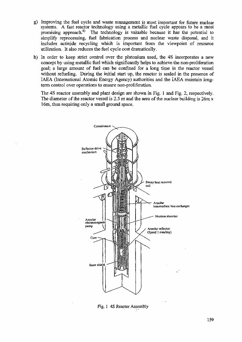
g) Improving the fuel cycle and waste management is most important for future nuclearsystems. A fast reactor technology using a metallic fuel cycle appears to be a mostpromising approach.6^ The technology is valuable because it has the potential tosimplify reprocessing, fuel fabrication process and nuclear waste disposal, and itincludes actinide recycling which is important from the viewpoint of resourceutilization. It also reduces the fuel cycle cost dramatically.
h) In order to keep strict control over the plutonium used, the 4S incorporates a newconcept by using metallic fuel which significantly helps to achieve the non-proliferationgoal; a large amount of fuel can be confined for a long time in the reactor vesselwithout refueling. During the initial start up, the reactor is sealed in the presence ofIAEA (International Atomic Energy Agency) authorities and the IAEA maintain long-term control over operations to ensure non-proliferation.
The 4S reactor assembly and plant design are shown in Fig. 1 and Fig. 2, respectively.The diameter of the reactor vessel is 2.5 m and the area of the nuclear building is 26m x16m, thus requiring only a small ground space.
Containment
Reflector drivemechanism
Decay heat removalcoil
Annularintermediate heat exchanger
Neutron absorberAnnularelectromagneticpump
Core
J / Annular reflectory y (Speed 1 mm/day)
Inner shield
Fig. 1 4S Reactor Assembly
159
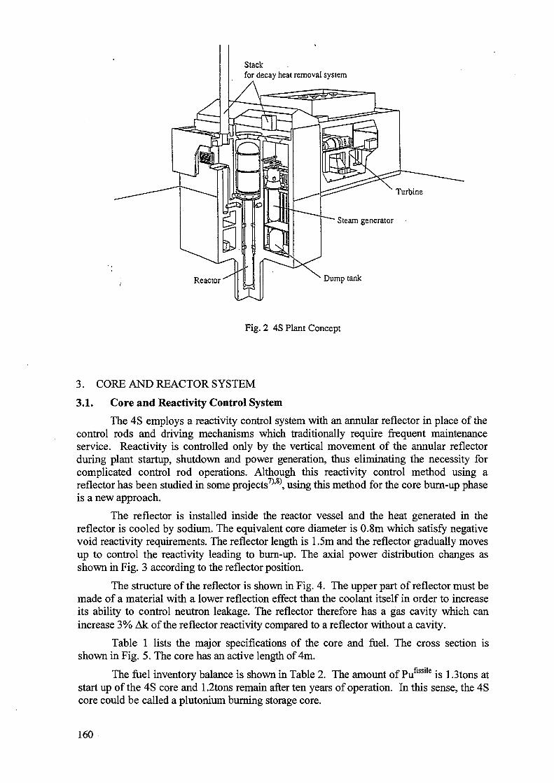
Stackfor decay heat removal system
Dump tank
Fig. 2 4S Plant Concept
3. CORE AND REACTOR SYSTEM
3.1. Core and Reactivity Control System
The 4S employs a reactivity control system with an annular reflector in place of thecontrol rods and driving mechanisms which traditionally require frequent maintenanceservice. Reactivity is controlled only by the vertical movement of the annular reflectorduring plant startup, shutdown and power generation, thus eliminating the necessity forcomplicated control rod operations. Although this reactivity control method using areflector has been studied in some projects7)>8), using this method for the core burn-up phaseis a new approach.
The reflector is installed inside the reactor vessel and the heat generated in thereflector is cooled by sodium. The equivalent core diameter is 0.8m which satisfy negativevoid reactivity requirements. The reflector length is 1.5m and the reflector gradually movesup to control the reactivity leading to burn-up. The axial power distribution changes asshown in Fig. 3 according to the reflector position.
The structure of the reflector is shown in Fig. 4. The upper part of reflector must bemade of a material with a lower reflection effect than the coolant itself in order to increaseits ability to control neutron leakage. The reflector therefore has a gas cavity which canincrease 3% Ak of the reflector reactivity compared to a reflector without a cavity.
Table 1 lists the major specifications of the core and fuel. The cross section isshown in Fig. 5. The core has an active length of 4m.
The fuel inventory balance is shown in Table 2. The amount of Puflsslle is 1.3tons atstart up of the 4S core and 1.2tons remain after ten years of operation. In this sense, the 4Score could be called a plutonium burning storage core.
160
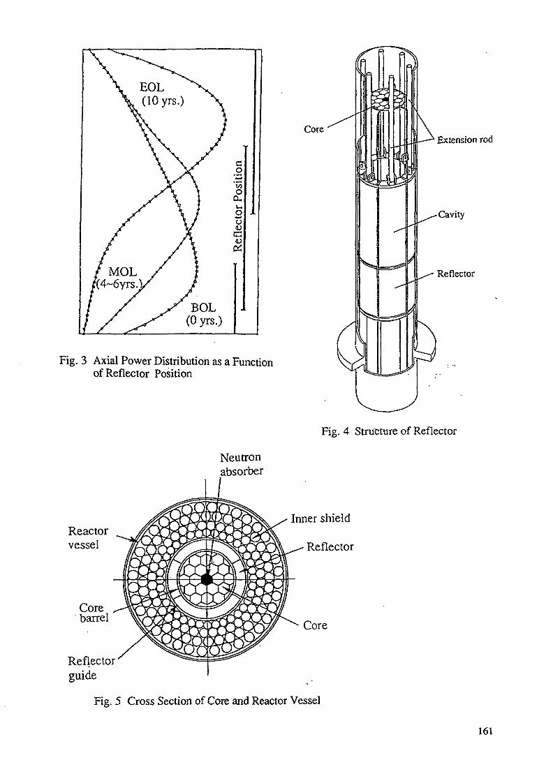
Fig. 3 Axial Power Distribution as a Functionof Reflector Position
Neutronabsorber
Reactorvessel
Corebarrel
Reflectorguide
Core
I• Extension rod
-Cavity
Reflector
Fig. 4 Structure of Reflector
Inner shield
Reflector
Core
Fig. 5 Cross Section of Core and Reactor Vessel
161

Table 1 Major Core Design Parameters
FUEL COMPOSITION(Metallic Fuel)
CONVERSION RATIO
VOID REACTIVITY
REFUELING INTERVAL
Pufiss INVENTORY
No. of SUB ASSEMBLIES
No.ofPINS/S/A
PIN DIAMETER
PIN LENGTH
UPu-Zr orU-Zr
0.7
-2.5$ (Diffusion Model)-1.0$ (Transport Model)
10 years
1.3 ton
18
217
1 cm
610 cm
Table 2 Fuel Inventory Balance
u 2 3 3
U°8
UTOTAL
pu2«l
r UToul
PuToul
TotalHeavyMetal
BOL(kg)
23.9
0
7946.0
7969.9
1272.9
520.7
38.9
96.4
1311.8
1928.9
9898.8
EOLOsp)
17.4
1.3
7621.2
7639.9
1143.6
510.6
37.8
88.7
1181.4
1780.7
9420.6
BOL-EOL(kg)
6.5
-1.3
324.8
330.0
129.3
10.1
1.1
7.7
130.4
148.2
478.2
FISSIONCAPTUREDECAY (kg)
6.5
324.8
331.3
389.1
72.4
34.6
10.0
423.7(0
506.1
FISSION(kg)
5.2
65.0
70.2
326.8
38.9
14.0
5.0
340.8
384.7
454.9
CONTRIBUTIONTO TOTALFISSION ( % )
1.1
14.3
(15.4)
71.8
8.6
3.1
1.1
(74.9)
(84.6)
100
CAPTURE(kg)
1.3
259.8 W
62.3
33.5W
2.3
5.0
DECAY(kg)
18.3
REMARKS
neutroncapture
neutroncapture
neutroncaptureneutroncaptureneutroncapture & decay
neutroncapture
129.3+259.8 Breding Rario=(c)
•=0.69
162
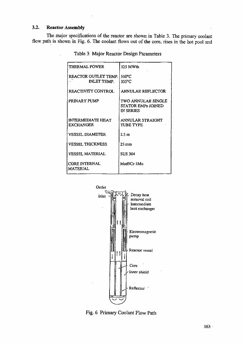
3.2. Reactor Assembly
The major specifications of the reactor are shown in Table 3. The primary coolantflow path is shown in Fig. 6. The coolant flows out of the core, rises in the hot pool and
Table 3 Major Reactor Design Parameters
THERMAL POWER
REACTOR OUTLET TEMP.INLETTEMP.
REACTIVITY CONTROL
PRINARY PUMP
INTERMEDIATE HEATEXCHANGER
VESSEL DIAMETER
VESSEL THICKNESS
VESSEL MATERIAL
CORE INTERNALMATERIAL
125 MWth
510°C355°C
ANNULAR REFLECTOR
TWO ANNULAR SINGLESTATOR EMPs JOINEDIN SERIES
ANNULAR STRAIGHTTUBE TYPE
2.5 m
25 mm
SUS3O4
Mod9Cr-lMo
Outlet
Inlet H 1 Decay heatremoval coil
- Intermediateheat exchanger
Electromagneticpump
Reactor vessel
Core
Inner shield
' Reflector "
Fig. 6 Primary Coolant Flow Path
163
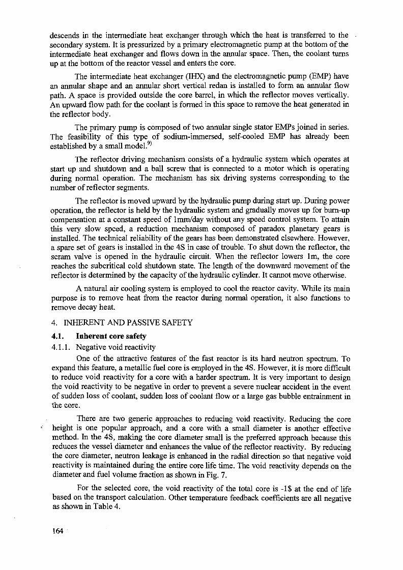
descends in the intermediate heat exchanger through which the heat is transferred to thesecondary system. It is pressurized by a primary electromagnetic pump at the bottom of theintermediate heat exchanger and flows down in the annular space. Then, the coolant turnsup at the bottom of the reactor vessel and enters the core.
The intermediate heat exchanger (IHX) and the electromagnetic pump (EMP) havean annular shape and an annular short vertical redan is installed to form an annular flowpath. A space is provided outside the core barrel, in which the reflector moves vertically.An upward flow path for the coolant is formed in this space to remove the heat generated inthe reflector body.
The primary pump is composed of two annular single stator EMPs joined in series.The feasibility of this type of sodium-immersed, self-cooled EMP has already beenestablished by a small model.9)
The reflector driving mechanism consists of a hydraulic system which operates atstart up and shutdown and a ball screw that is connected to a motor which is operatingduring normal operation. The mechanism has six driving systems corresponding to thenumber of reflector segments.
The reflector is moved upward by the hydraulic pump during start up. During poweroperation, the reflector is held by the hydraulic system and gradually moves up for burn-upcompensation at a constant speed of 1 mm/day without any speed control system. To attainthis very slow speed, a reduction mechanism composed of paradox planetary gears isinstalled. The technical reliability of the gears has been demonstrated elsewhere. However,a spare set of gears is installed in the 4S in case of trouble. To shut down the reflector, thescram valve is opened in the hydraulic circuit. When the reflector lowers lm, the corereaches the subcritical cold shutdown state. The length of the downward movement of thereflector is determined by the capacity of the hydraulic cylinder. It cannot move otherwise.
A natural air cooling system is employed to cool the reactor cavity. While its mainpurpose is to remove heat from the reactor during normal operation, it also functions toremove decay heat.
4. INHERENT AND PASSIVE SAFETY
4.1. Inherent core safety4.1.1. Negative void reactivity
One of the attractive features of the fast reactor is its hard neutron spectrum. Toexpand this feature, a metallic fuel core is employed in the 4S. However, it is more difficultto reduce void reactivity for a core with a harder spectrum. It is very important to designthe void reactivity to be negative in order to prevent a severe nuclear accident in the eventof sudden loss of coolant, sudden loss of coolant flow or a large gas bubble entrainment inthe core.
There are two generic approaches to reducing void reactivity. Reducing the coreheight is one popular approach, and a core with a small diameter is another effectivemethod. In the 4S, making the core diameter small is the preferred approach because thisreduces the vessel diameter and enhances the value of the reflector reactivity. By reducingthe core diameter, neutron leakage is enhanced in the radial direction so that negative voidreactivity is maintained during the entire core life time. The void reactivity depends on thediameter and fuel volume fraction as shown in Fig. 7.
For the selected core, the void reactivity of the total core is -1$ at the end of lifebased on the transport calculation. Other temperature feedback coefficients are all negativeas shown in Table 4.
164
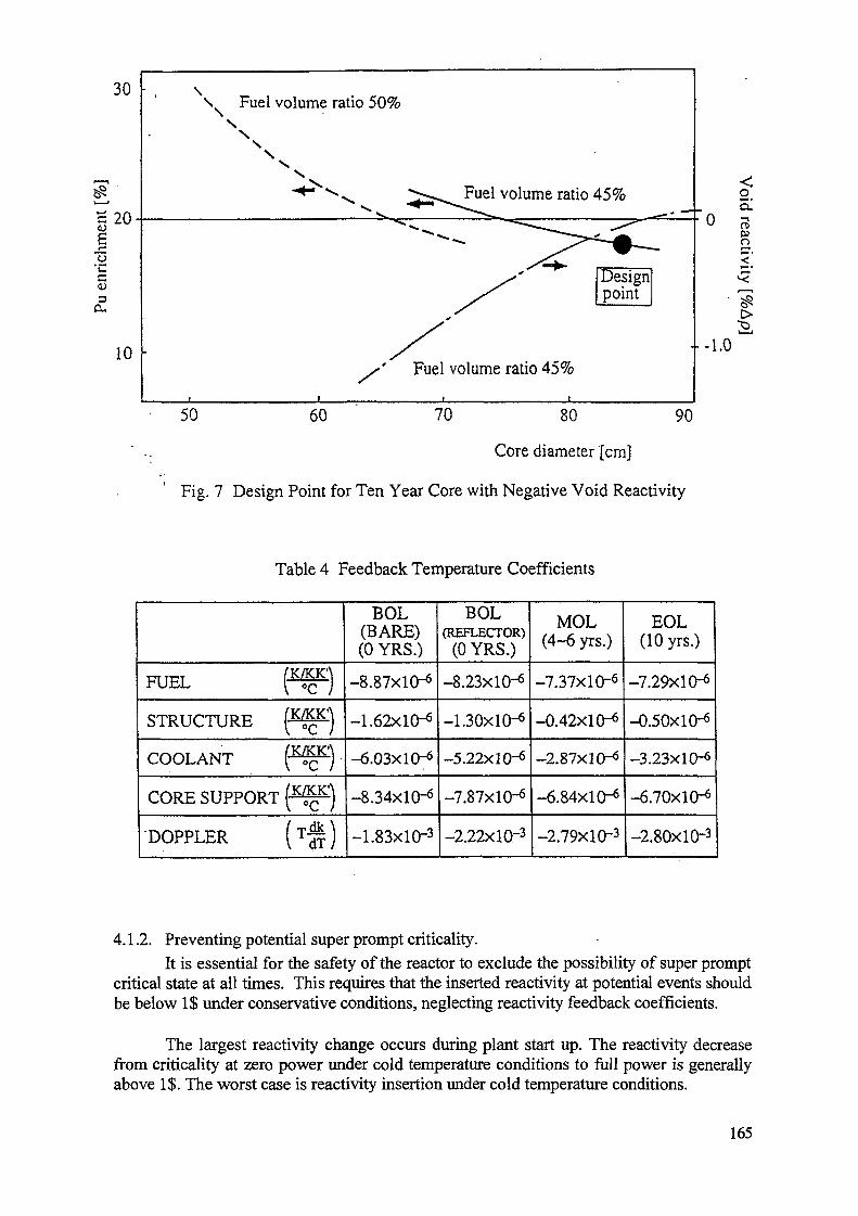
30
| 20
o'Cc
10
\ Fuel volume ratio 50%N
Ns
s
50
Fuel volume ratio 45%
Designpoint
Fuel volume ratio 45%
o
Ia.
• • - 1 . 0
60 70 80 90
Core diameter [cm]
Fig. 7 Design Point for Ten Year Core with Negative Void Reactivity
Table 4 Feedback Temperature Coefficients
FUEL ( ™ )
STRUCTURE (-™^)
COOLANT ( ^ F )
CORE SUPPORT p ^ p )
DOPPLER ( T ^ )
BOL(BARE)(0 YRS.)
-8.87X10"6
-1.62x10-*
-6.03x10⁻⁶
-8.34X10"6
-1.83X10⁻³
BOL(REFLECTOR)
(0 YRS.)
-8.23X1O-6
-1.30X10⁻⁶
-5.22X10"6
-7.87x10⁻⁶
-2.22X10"3
MOL(4-6 yrs.)
-7.37x10⁻⁶
-0.42x10⁻⁶
-2.87X10⁻⁶
-6.84x10⁻⁶
-2.79X10⁻³
EOL(10 yrs.)
-7.29x10⁻⁶
-0.50x10⁻⁶
-3.23x10⁻⁶
-6.70x10⁻⁶
-2.80X10⁻³
4.1.2. Preventing potential super prompt criticality.It is essential for the safety of the reactor to exclude the possibility of super prompt
critical state at all times. This requires that the inserted reactivity at potential events shouldbe below 1$ under conservative conditions, neglecting reactivity feedback coefficients.
The largest reactivity change occurs during plant start up. The reactivity decreasefrom criticality at zero power under cold temperature conditions to full power is generallyabove 1$. The worst case is reactivity insertion under cold temperature conditions.
165
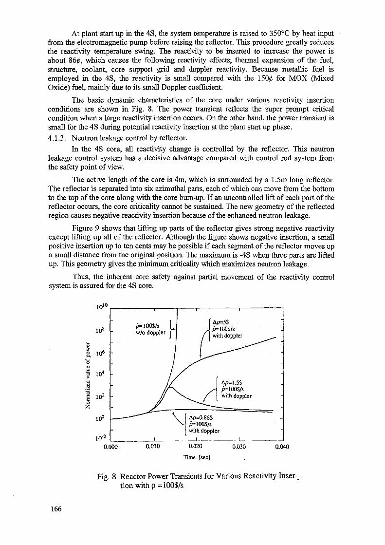
At plant start up in the 4S, the system temperature is raised to 350°C by heat inputfrom the electromagnetic pump before raising the reflector. This procedure greatly reducesthe reactivity temperature swing. The reactivity to be inserted to increase the power isabout 860, which causes the following reactivity effects; thermal expansion of the fuel,structure, coolant, core support grid and doppler reactivity. Because metallic fuel isemployed in the 4S, the reactivity is small compared with the 1500 for MOX (MixedOxide) fuel, mainly due to its small Doppler coefficient.
The basic dynamic characteristics of the core under various reactivity insertionconditions are shown in Fig. 8. The power transient reflects the super prompt criticalcondition when a large reactivity insertion occurs. On the other hand, the power transient issmall for the 4S during potential reactivity insertion at the plant start up phase.
4.1.3. Neutron leakage control by reflector.
In the 4S core, all reactivity change is controlled by the reflector. This neutronleakage control system has a decisive advantage compared with control rod system fromthe safety point of view.
The active length of the core is 4m, which is surrounded by a 1.5m long reflector.The reflector is separated into six azimuthal parts, each of which can move from the bottomto the top of the core along with the core burn-up. If an uncontrolled lift of each part of thereflector occurs, the core criticality cannot be sustained. The new geometry of the reflectedregion causes negative reactivity insertion because of the enhanced neutron leakage.
Figure 9 shows that lifting up parts of the reflector gives strong negative reactivityexcept lifting up all of the reflector. Although the figure shows negative insertion, a smallpositive insertion up to ten cents may be possible if each segment of the reflector moves upa small distance from the original position. The maximum is -4$ when three parts are liftedup. This geometry gives the minimum criticality which maximizes neutron leakage.
Thus, the inherent core safety against partial movement of the reactivity controlsystem is assured for the 4S core.
-.10
108
I 106o| 104
•o
i IO2
10°
10"2
, 1 ,- .. ,
p=100S/s 1w/o doppler J
p=100S/swith doppler ^^.
p=100S/swith doppler
Ap=0.86Sp=100S/swith doppler
i i
0.000 0.010 0.020
Time [sec]
0.030 0.040
Fig. 8 Reactor Power Transients for Various Reactivity Inser-tion with p =100$/s
166
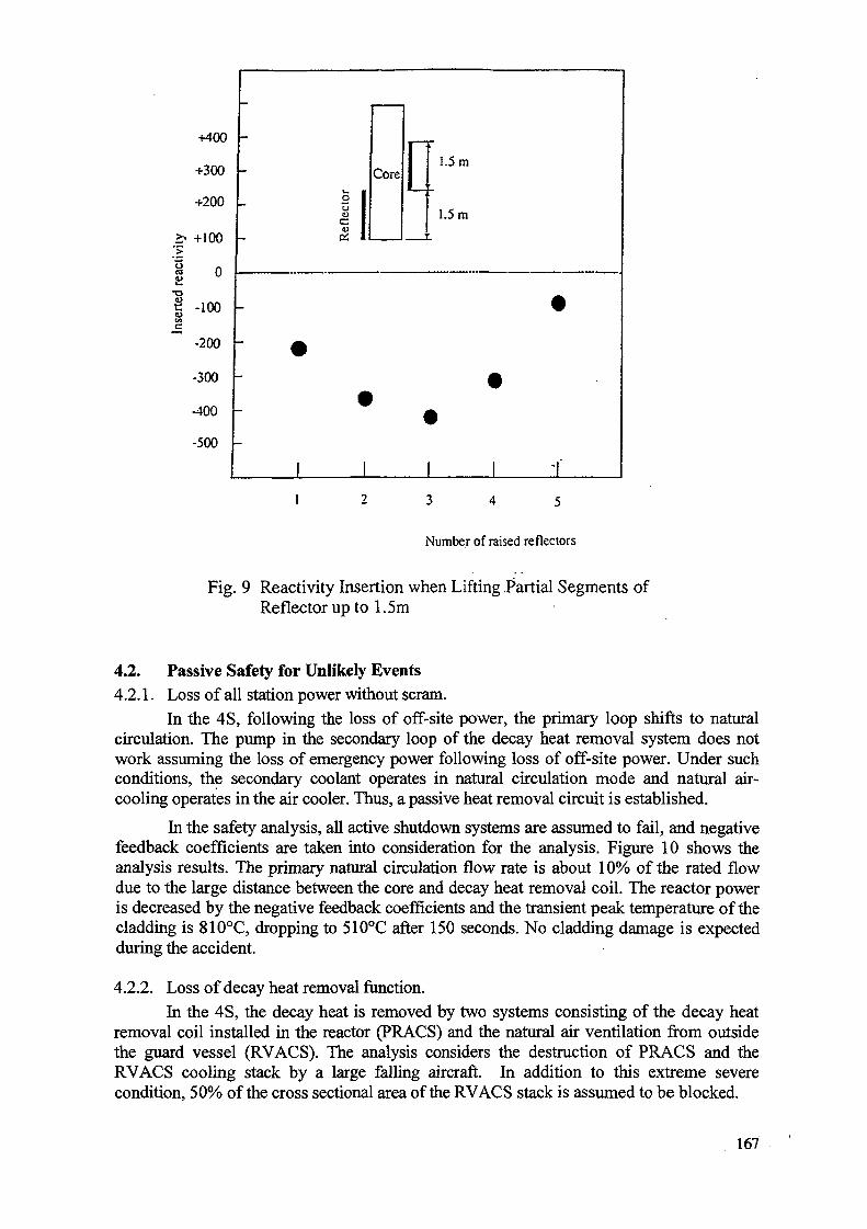
+400
+300
+200
£• +100*>
I -looCO
-200
-300
-400
-500
-
2 1
=o 1s: 1
Core
1 I
1.5 m
1.5 m
»
1 i
Number of raised reflectors
Fig. 9 Reactivity Insertion when Lifting Partial Segments ofReflector up to 1.5 m
4.2. Passive Safety for Unlikely Events4.2.1. Loss of all station power without scram.
In the 4S, following the loss of off-site power, the primary loop shifts to naturalcirculation. The pump in the secondary loop of the decay heat removal system does notwork assuming the loss of emergency power following loss of off-site power. Under suchconditions, the secondary coolant operates in natural circulation mode and natural air-cooling operates in the air cooler. Thus, a passive heat removal circuit is established.
In the safety analysis, all active shutdown systems are assumed to fail, and negativefeedback coefficients are taken into consideration for the analysis. Figure 10 shows theanalysis results. The primary natural circulation flow rate is about 10% of the rated flowdue to the large distance between the core and decay heat removal coil. The reactor poweris decreased by the negative feedback coefficients and the transient peak temperature of thecladding is 810°C, dropping to 510°C after 150 seconds. No cladding damage is expectedduring the accident.
4.2.2. Loss of decay heat removal function.In the 4S, the decay heat is removed by two systems consisting of the decay heat
removal coil installed in the reactor (PRACS) and the natural air ventilation from outsidethe guard vessel (RVACS). The analysis considers the destruction of PRACS and theRVACS cooling stack by a large falling aircraft. In addition to this extreme severecondition, 50% of the cross sectional area of the RVACS stack is assumed to be blocked.
167

1000.0
900.0
Zj 800.0
I 700.02
I* 600.0
500.0
0.5
0.0
3 -0.5u
-1.0
-1.5
Cladding temp. (Hot channel)
Cladding temp.(Coreav.)
^ /__
' Coolant flow (F)
Doppler reactivityFuel axial expansion
"Core radial expansion
"Net reactivity
50 100
Time [sec]
150 200
Fig. 10 Core Response for Loss of all Station Power withoutScram
Figure 11 shows the analysis results of the primary coolant temperature. Thecoolant temperature gradually rises and peaks at 700°C after 35hrs. The structural integrityis a major concern in this type of accident. However, a creep damage during the accident isless than 0.1 as the usage factor, and so the structural integrity is maintained.
4.2.3. Sodium-water reaction in steam generator.
The breakage of all heat transfer tubes in the steam generator was assumed, andprotective actions like water steam dumping were neglected to find the passive safetyfeatures against this type of accident.
The water leak rate increases as the tubes break, but is limited by the feedwaterpump capacity. After the water leak rate reaches the peak value, the main steam pressuredecreases because the turbine trips due to the reduction of the main steam flow rate, and thefeed water pump trips due to the reduction of its rotational frequency. Due to these quasi-passive features, the water leak rate decreases and adverse consequences can be avoided byproviding two pressure relief pipings with rupture disks at the bottom of the steamgenerator which operate at a pressure of 11 kg/cm2.
Figure 12 shows the pressure transients. The three lines show (1) water, steam sidepressure, (2) pressure without relief piping and (3) pressure in IHX with two relief pipings.The pressure of IHX in line (3) is found to be within the allowable pressure of 9 kg/cm2.
168
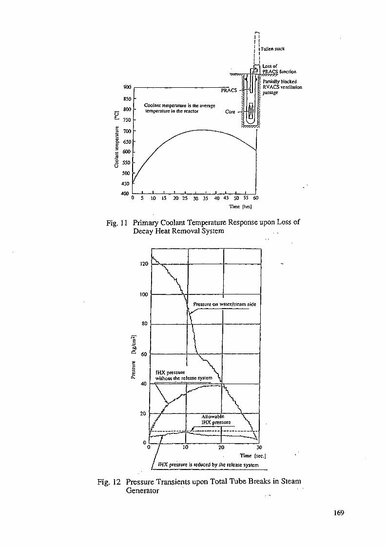
900
850
800
u
~ 750
I 700
| 650
= 600
! 550
500
450400
PRACS
Coolant temperature is the averagetemperature in the reactor Core
1
I Fallen suck1I1
Loss ofPRACS function
Partially blockedRVACS ventilationpassage
5 10 15 20 25 30 35 40 45 50 55 60
Time [hrs].
Fig. 11 Primary Coolant Temperature Response upon Loss ofDecay Heat Removal System
120
100
80
60
3
Pressure on water/sieam side
IHX pressurewithout the release system
30
Time [sec]
IHX pressure is reduced by the release system
Fig. 12 Pressure Transients upon Total Tube Breaks in SteamGenerator
169
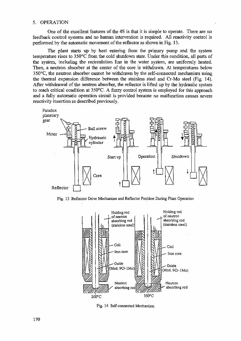
5. OPERATION
One of the excellent features of the 4S is that it is simple to operate. There are nofeedback control systems and no human intervention is required. All reactivity control isperformed by the automatic movement of the reflector as shown in Fig. 13.
The plant starts up by heat entering from the primary pump and the systemtemperature rises to 350°C from the cold shutdown state. Under this condition, all parts ofthe system, including the recirculation line in the water system, are uniformly heated.Then, a neutron absorber at the center of the core is withdrawn. At temperatures below350°C, the neutron absorber cannot be withdrawn by the self-connected mechanism usingthe thermal expansion difference between the stainless steel and Cr-Mo steel (Fig. 14).After withdrawal of the neutron absorber, the reflector is lifted up by the hydraulic systemto reach critical condition at 35O°C. A fuzzy control system is employed for this approachand a fully automatic operation circuit is provided because no malfunction causes severereactivity insertion as described previously.
Paradoxplanetarygear
MotorBall screw
_J5_JM^ Hydrauriccylinder
Reflector
Core
Startup
t
Fig. 13 Reflector Drive Mechanism and Reflector Position During Plant Operation
Holding rodof neutronabsorbing rod(stainless steel)1
Coil
Iron core
-Guide(Mod. 9Cr-lMo)
Neutronabsorbing rod
200°C
Fig. 14 Self-connected Mechanism
Holding rodof neutronabsorbing rod(stainless steel)
Coil
Iron core
Guide(Mod. 9Cr-lMo)
Neutronabsorbing rod
170
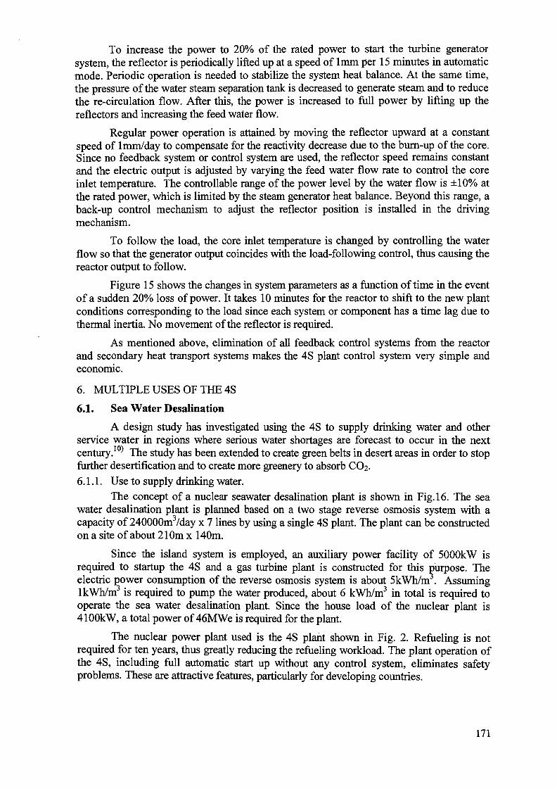
To increase the power to 20% of the rated power to start the turbine generatorsystem, the reflector is periodically lifted up at a speed of lmm per 15 minutes in automaticmode. Periodic operation is needed to stabilize the system heat balance. At the same time,the pressure of the water steam separation tank is decreased to generate steam and to reducethe re-circulation flow. After this, the power is increased to full power by lifting up thereflectors and increasing the feed water flow.
Regular power operation is attained by moving the reflector upward at a constantspeed of 1 mm/day to compensate for the reactivity decrease due to the burn-up of the core.Since no feedback system or control system are used, the reflector speed remains constantand the electric output is adjusted by varying the feed water flow rate to control the coreinlet temperature. The controllable range of the power level by the water flow is ±10% atthe rated power, which is limited by the steam generator heat balance. Beyond this range, aback-up control mechanism to adjust the reflector position is installed in the drivingmechanism.
To follow the load, the core inlet temperature is changed by controlling the waterflow so that the generator output coincides with the load-following control, thus causing thereactor output to follow.
Figure 15 shows the changes in system parameters as a function of time in the eventof a sudden 20% loss of power. It takes 10 minutes for the reactor to shift to the new plantconditions corresponding to the load since each system or component has a time lag due tothermal inertia. No movement of the reflector is required.
As mentioned above, elimination of all feedback control systems from the reactorand secondary heat transport systems makes the 4S plant control system very simple andeconomic.
6. MULTIPLE USES OF THE 4S
6.1. Sea Water Desalination
A design study has investigated using the 4S to supply drinking water and otherservice water in regions where serious water shortages are forecast to occur in the nextcentury.10) The study has been extended to create green belts in desert areas in order to stopfurther desertification and to create more greenery to absorb CO2.
6.1.1. Use to supply drinking water.The concept of a nuclear seawater desalination plant is shown in Fig. 16. The sea
water desalination plant is planned based on a two stage reverse osmosis system with acapacity of 240000m3/day x 7 lines by using a single 4S plant. The plant can be constructedon a site of about 210m x 140m.
Since the island system is employed, an auxiliary power facility of 5000kW isrequired to startup the 4S and a gas turbine plant is constructed for this purpose. Theelectric power consumption of the reverse osmosis system is about 5kWh/m . AssuminglkWh/m3 is required to pump the water produced, about 6 kWh/m3 in total is required tooperate the sea water desalination plant. Since the house load of the nuclear plant is4100kW, a total power of 46MWe is required for the plant.
The nuclear power plant used is the 4S plant shown in Fig. 2. Refueling is notrequired for ten years, thus greatly reducing the refueling workload. The plant operation ofthe 4S, including full automatic start up without any control system, eliminates safetyproblems. These are attractive features, particularly for developing countries.
171
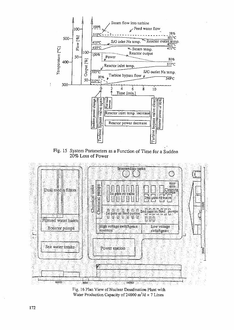
5 0 0 -
U0
2 400 -
300-
100-
3:o
Ii.
5 0 -
100-
3
O50-
100%Steam flow into turbine
y Feed water flow78%
501°C475°C inlet Na temp. Reactor outlet tejnp.
"*- Steam temp.\W?o : " " ' ^ Reactor output
Power:
472°C
. Reactor inlet temp. — ° c
355°C S/G outlet Na temp.2 0 % Turbine bypass flow
10°CI340°C
2 4f Time [min.]
"S
s 3
IIReactor inlet temp, increase
Reactor power decrease
Re
Fig. 15 System Parameters as a Function of Time for a Sudden20% Loss of Power
•Mimi
Ifftftw.
• I 'p :• 1 \ : \-1 • ̂ i 1̂ * i '1 -!;rJL::i^1i:0'):r:'P?!f::.i:.i;r::':'.:
: ^ . •'•:;• • H ' : . ; 1 . v : ; ! : " - U - , • .•• •';• : • • . ' : ' : ,
iiill^ i ^ i i i ^ t j ' i l i : t J i i j £ i : ••- ' ^ ; :• : « • • • • • ; : : . ; : : : . • • : ' • • ; ~ ' < : i " ' " • ' ' • • '
i n & ; r i ; : : • ; - : : •• •
• " • • • ' ; "••': r l^ONV ^yGi iES^C ' : -\V
65000 ;SSCOO;
Fig. 16 Plan View of Nuclear Desalination Plant withWater Production Capacity of 24000 m3/d x 7 Lines
172
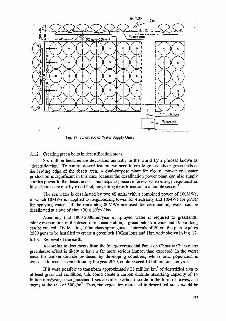
-200 m-t—200 m-r-200 m-t~200 m-i
Fig. 17 Schematic of Water Supply Units
6.1.2. Creating green belts in desertification areas.
Six million hectares are devastated annually in the world by a process known as"desertification". To control desertification, we need to create grasslands or green belts atthe leading edge of the desert area. A dual-purpose plant for electric power and waterproduction is significant in this case because the desalination power plant can also supplysurplus power to the desert areas. This helps to preserve forests when energy requirementsin such areas are met by wood fuel, preventing desertification in a double sense. '
The sea water is desalinated by two 4S units with a combined power of lOOMWe,of which lOMWe is supplied to neighbouring towns for electricity and lOMWe for powerfor spraying water. If the remaining 80MWe are used for desalination, water can bedesalinated at a rate of about 30 x 104m3/day.
Assuming that 1000-2000mm/year of sprayed water is required to grasslands,taking evaporation in the desert into consideration, a green belt lkm wide and 100km longcan be created. By locating 100m class spray guns at intervals of 200m, the plan requires2500 guns to be installed to create a green belt 100km long and lkm wide shown in Fig. 17.
6.1.3. Renewal of the earth.
According to documents from the Intergovernmental Panel on Climatic Change, thegreenhouse effect is likely to have a far more serious impact than expected. In the worstcase, the carbon dioxide produced by developing countries, whose total population isexpected to reach seven billion by the year 2030, could exceed 13 billion tons per year.
If it were possible to transform approximately 28 million km2 of desertified area toat least grassland condition, this could create a carbon dioxide absorbing capacity of 14billion tons/year, since grassland fixes absorbed carbon dioxide in the form of leaves, andstems at the rate of 500g/m2. Thus, the vegetation recreated in desertified areas would be
173
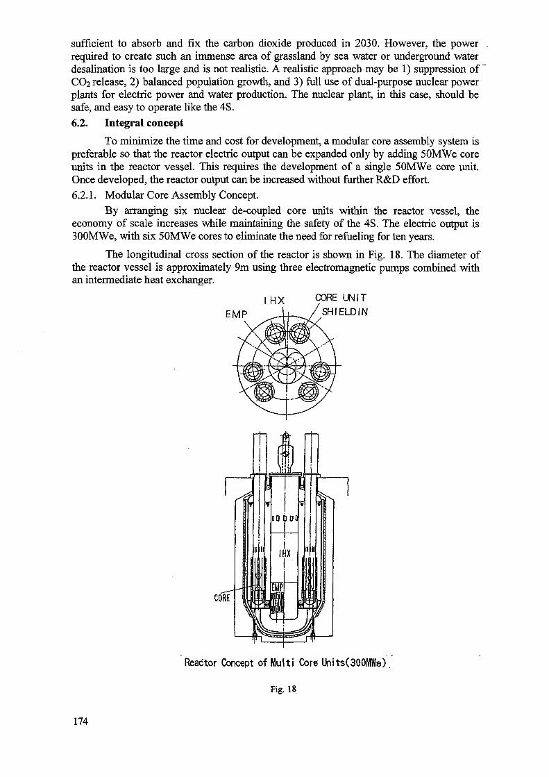
sufficient to absorb and fix the carbon dioxide produced in 2030. However, the powerrequired to create such an immense area of grassland by sea water or underground waterdesalination is too large and is not realistic. A realistic approach may be 1) suppression of"CO2 release, 2) balanced population growth, and 3) full use of dual-purpose nuclear powerplants for electric power and water production. The nuclear plant, in this case, should besafe, and easy to operate like the 4S.
6.2. Integral concept
To minimize the time and cost for development, a modular core assembly system ispreferable so that the reactor electric output can be expanded only by adding 50MWe coreunits in the reactor vessel. This requires the development of a single 50MWe core unit.Once developed, the reactor output can be increased without further R&D effort.
6.2.1. Modular Core Assembly Concept.
By arranging six nuclear de-coupled core units within the reactor vessel, theeconomy of scale increases while maintaining the safety of the 4S. The electric output is300MWe, with six 50MWe cores to eliminate the need for refueling for ten years.
The longitudinal cross section of the reactor is shown in Fig. 18. The diameter ofthe reactor vessel is approximately 9m using three electromagnetic pumps combined withan intermediate heat exchanger.
I HX
EMP
CORE UNIT
SHIELDIN
Reactor Concept of Mult i Core Units(300MWe)
Fig. 18
174
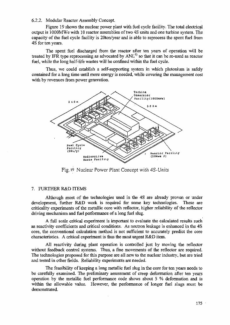
6.2.2. Modular Reactor Assembly Concept.
Figure 19 shows the nuclear power plant with fuel cycle facility. The total electricaloutput is lOOOMWe with 10 reactor assemblies of two 4S units and one turbine system. Thecapacity of the fuel cycle facility is 20ton/year and is able to reprocess the spent fuel from4S for ten years.
The spent fuel discharged from the reactor after ten years of operation will betreated by IFR type reprocessing as advocated by ANL6) so that it can be re-used as reactorfuel, while the long half-life wastes will be confined within the fuel cycle.
Thus, we could establish a self-supporting system in which plutonium is safelycontained for a long time until more energy is needed, while covering the management costwith by revenues from power generation.
Turbine.Generator
Faci l i ty UOOOMWe)2 < 0 m S' ^fCd@^^ \ / ^ ^
0 0m
Fual CycleFacility
<20t/y) ' ^ S S ^ ^ J ^ O * f " < Reactor FacilityRadloacLive ^ V s V ^ V ^ (SOMwa 2)Waste Facility
Fig. 19 Nuclear Power Plant Concept with 4S-Units
7. FURTHER R&D ITEMS
Although most of the technologies used in the 4S are already proven or underdevelopment, further R&D work is required for some key technologies. These arecriticality experiments of the metallic core with reflector, higher reliability of the reflectordriving mechanism and fuel performance of a long fuel slug.
A full scale critical experiment is important to evaluate the calculated results suchas reactivity coefficients and critical conditions. As neutron leakage is enhanced in the 4Score, the conventional calculation method is not sufficient to accurately predict the corecharacteristics. A critical experiment is thus the most urgent R&D item.
All reactivity during plant operation is controlled just by moving the reflectorwithout feedback control systems. Thus, a fine movements of the reflector are required.The technologies proposed for this purpose are all new to the nuclear industry, but are triedand tested in other fields. Reliability experiments are needed.
The feasibility of keeping a long metallic fuel slug in the core for ten years needs tobe carefully examined. The preliminary assessment of creep deformation after ten yearsoperation by the metallic fuel performance code shows about 5 % deformation and iswithin the allowable value. However, the performance of longer fuel slugs must bedemonstrated.
175
8. CONCLUSIONS
Efforts to develop nuclear power reactors have been focused on the enhancement ofsafety and reliability by using active safety systems with redundancy and diversity whileimproving economy through scale factor. Although the goals have been fairly achieved,traditional power reactors can be used only under the prerequisites and are thus usable for alimited area of application.
Efforts have focused in recent years on developing small and medium sized powerreactors with inherent, passive safety characteristics. Successful development of suchreactors will lead to a wider range of application of nuclear power.
The 4S is a new concept of fast reactor designed to meet the goals of nuclear powerand offers many attractive advantages. Commercial operation of the 4S is expected to solvea number of problems that humans will encounter in the 21st century.
Finally, the author would like to emphasize the need for worldwide cooperation onthe development of the 4S reactor.
REFERENCES
[1] S. Hattori, N. Handa, "Use of Super-Safe, Small and Simple LMRs to Create GreenBelts in Desertification Area", Trans. ANS. Vol.60 (1989) 437
[2] "Use of Nuclear Reactors for Seawater Desalination" IAEA-TECDOC-574 (1990)[3] 3)N. Ueda, A. Minato, N. Handa, "Super-Safe, Small and Simple Reactor for the
Global Energy Demand", Proc. of Int. Conf. on Fast Reactors and Related Fuel Cycles(1991) P5-7
[4] S. Hattori, A. Minato, "The Super Safe, Small and Simple Reactor (4S-50)" Proc. ofInt. Conf. Design and Safety of Advanced Nuclear Power Plants (1992) Vol.11, 16-3
[5] S. Hattori, A. Minato, "Current Status of 4S Plant Design" Proc. of the Second Int.Conf on Nuclear Engineering (ICON-2) Vol.2 (1993) 611
[6] C.E.Till, T. I. Chang, "Progress and Status of the Integral Fast Reactor (IFR) : FuelCycle Development", Proc. of Int. Conf. on Fast Reactors and Related Fuel Cycles(1991) 1-6
[7] J.G.Yevick, A. Amorosi editor, "Fast Reactor Technology", The M.I.T Press (1966)[8] T. A. Moss, E. B. Baumeiser, "A Liquid-Metal Reactor/Air Brayton-Cycle Option for a
Multimegawatt Terrestrial Power (MTP) Plant", Intersociety Energy ConversionEngineering Conf. (1987) 1596
[9] M. Nakazaki, J. Taguchi et al., "Development of Sodium-Immersed Self-CooledElectromagnetic Pump", Proc. Int. Conf. on Fast Reactors and Related Fuel Cycles,(1991)P2-16
176
USE OF NUCLEAR SPACE TECHNOLOGY OF DIRECT ENERGYCONVERSION FOR TERRESTRIAL APPLICATION
V.I. CHITAYKIN, Ye.A. MELETA, V.I. YARYGIN, XA0056276A.S. MIKHEYEV, S.M. TULINInstitute of Physics and Power Engineering,Obninsk, Kaluga Region, Russian Federation
Abstract
In due time the SSC RF-IPPE exercised the scientific supervision and directly participated inthe development, fabrication, space flight test and maintenance of the direct energy conversionnuclear power plants (NPP) for space application under the ,,BUK" and ,,TOPAZ" programs.We have used the acquired experience and the high technologies developed for the ,,BUK"NPP with a thermoelectric conversion of thermal (nuclear) energy into electrical one in thedevelopment under the order of RAO ,,GAZPROM" of the natural gas fired self containedthermoelectric current sources (AIT-500) and heat and electricity sources (TEP-500). Theseare intended for electrochemical rust protection of gas pipelines and for the electricity and heatsupply to the telemetric and microwave-link systems located along the gas pipelines.
Of special interest at the moment are the new developments of self contained current sourceswith the electrical output of -500 Wei for new gas pipelines being constructed under theprojects like the ,,Yamal - Europe" project. The electrochemical rust protection of gas pipe-lines laying on unsettled and non-electrified territory of arctic regions of Russia is performedby means of the so-called Cathodic Protection Stations (CPS). Accounting for a complex ofrather rigid requirements imposed by arctic operating conditions, the most attractive sources ofthe electricity supply to the CPS are the thermoelectric heat-into-electricity converters and thegenerators (TEG) on their basis. This paper deals with the essential results of the development,investigation and testing of unconventional TEGs using the low-temperature bismuth-telluriumthermoelectric batteries assembled together as tubular thermoelectric batteries with a radialring geometry built into the gas-heated thermoelectric modules, which are collected to makeup either the thermoelectric plants for heat and electricity supply or the self contained powersources. One of peculiarities of these plants is the combination of the CPS proper function witha number of additional service possibilities, among them the use of natural gas directly from thehigh pressure gas pipeline, the remote monitoring, the utilization of heat etc.
INTRODUCTION
To ensure effective cathodic protection (CP) of gas pipelines in the remote arctic regionsof Russia shown in Fig.l, where it would be uneconomic to run power lines and where con-ventional techniques such as small gas or diesel generators, wind and solar power plants fail, itis possible to use thermoelectric converters of heat into electricity and based on them stand-alone thermoelectric generators (TEG).
177
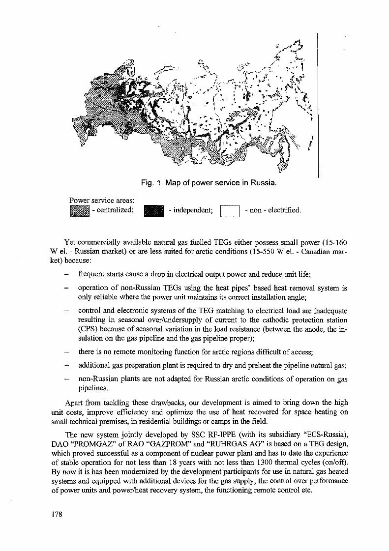
.*-:-€]/«>. ..,:*•- £.-_-- i"-' . '''
Fig. 1. Map of power service in Russia.
Power service areas:WW - centralized; - independent; - non - electrified.
Yet commercially available natural gas fuelled TEGs either possess small power (15-160W el. - Russian market) or are less suited for arctic conditions (15-550 W el. - Canadian mar-ket) because:
- frequent starts cause a drop in electrical output power and reduce unit life;
- operation of non-Russian TEGs using the heat pipes' based heat removal system isonly reliable where the power unit maintains its correct installation angle;
- control and electronic systems of the TEG matching to electrical load are inadequateresulting in seasonal over/undersupply of current to the cathodic protection station(CPS) because of seasonal variation in the load resistance (between the anode, the in-sulation on the gas pipeline and the gas pipeline proper);
- there is no remote monitoring function for arctic regions difficult of access;
- additional gas preparation plant is required to dry and preheat the pipeline natural gas;
- non-Russian plants are not adapted for Russian arctic conditions of operation on gaspipelines.
Apart from tackling these drawbacks, our development is aimed to bring down the highunit costs, improve efficiency and optimize the use of heat recovered for space heating onsmall technical premises, in residential buildings or camps in the field.
The new system jointly developed by SSC RF-IPPE (with its subsidiary "ECS-Russia),DAO "PROMGAZ" of RAO "GAZPROM" and "RUHRGAS AG" is based on a TEG design,which proved successful as a component of nuclear power plant and has to date the experienceof stable operation for not less than 18 years with not less than 1300 thermal cycles (on/off).By now it is has been modernized by the development participants for use in natural gas heatedsystems and equipped with additional devices for the gas supply, the control over performanceof power units and power/heat recovery system, the functioning remote control etc.
178
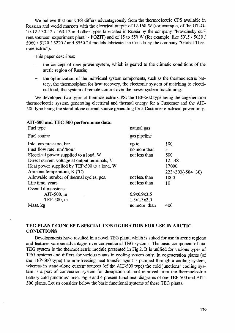
We believe that our CPS differs advantageously from the thermoelectric CPS available inRussian and world markets with the electrical output of 12-160 W (for example, of the GT-G-10-12/30-12/ 160-12 and other types fabricated in Russia by the company "Pravdinsky cur-rent sources' experiment plant" - POZIT) and of 15 to 550 W (for example, like 5015 / 5030 /5060 / 5120 / 5220 / and 8550-24 models fabricated in Canada by the company "Global Ther-moelectric").
This paper describes:
- the concept of new power system, which is geared to the climatic conditions of thearctic region of Russia;
- the optimization of the individual system components, such as the thermoelectric bat-tery, the thermosiphon for heat recovery, the electronic system of matching to electri-cal load, the system of remote control over the power system functioning.
We developed two types of thermoelectric CPS: the TEP-500 type being the cogenerationthermoelectric system generating electrical and thermal energy for a Customer and the AIT-500 type being the stand-alone current source generating for a Customer electrical power only.
AIT-500 and TEC-500 performance data:
Fuel type natural gas
Fuel source gas pipeline
Inlet gas pressure, barFuel flow rate, nm3/hourElectrical power supplied to a load, WDirect current voltage at output terminals, VHeat power supplied by TEP-500 to a load, WAmbient temperature, K (°C)Allowable number of thermal cycles, pcs.Life time, yearsOverall dimensions:
AIT-500,mTEP-500, m
Mass, kg
TEG-PLANT CONCEPT. SPECIAL CONFIGURATION FOR USE IN ARCTICCONDITIONS
Developments have resulted in a novel TEG plant, which is suited for use in arctic regionsand features various advantages over conventional TEG systems. The basic component of ourTEG system is the thermoelectric module presented in Fig.2. It is unified for various types ofTEG systems and differs for various plants in cooling system only. In cogeneration plants (ofthe TEP-500 type) the non-freezing heat transfer agent is pumped through a cooling system,whereas in stand-alone current sources (of the AIT-500 type) the cold junctions' cooling sys-tem is a part of convection system for dissipation of heat removed from the thermoelectricbattery cold junctions' area. Fig.3 and 4 present functional diagrams of our TEP-500 and AIT-500 plants. Let us consider below the basic functional systems of these TEG plants.
up tono more thannot less than
not less thannot less than
0,9x0,9x3,51,5x1,3x2,0no more than
100350012...4817000223+303(-50++30)100010
400
179
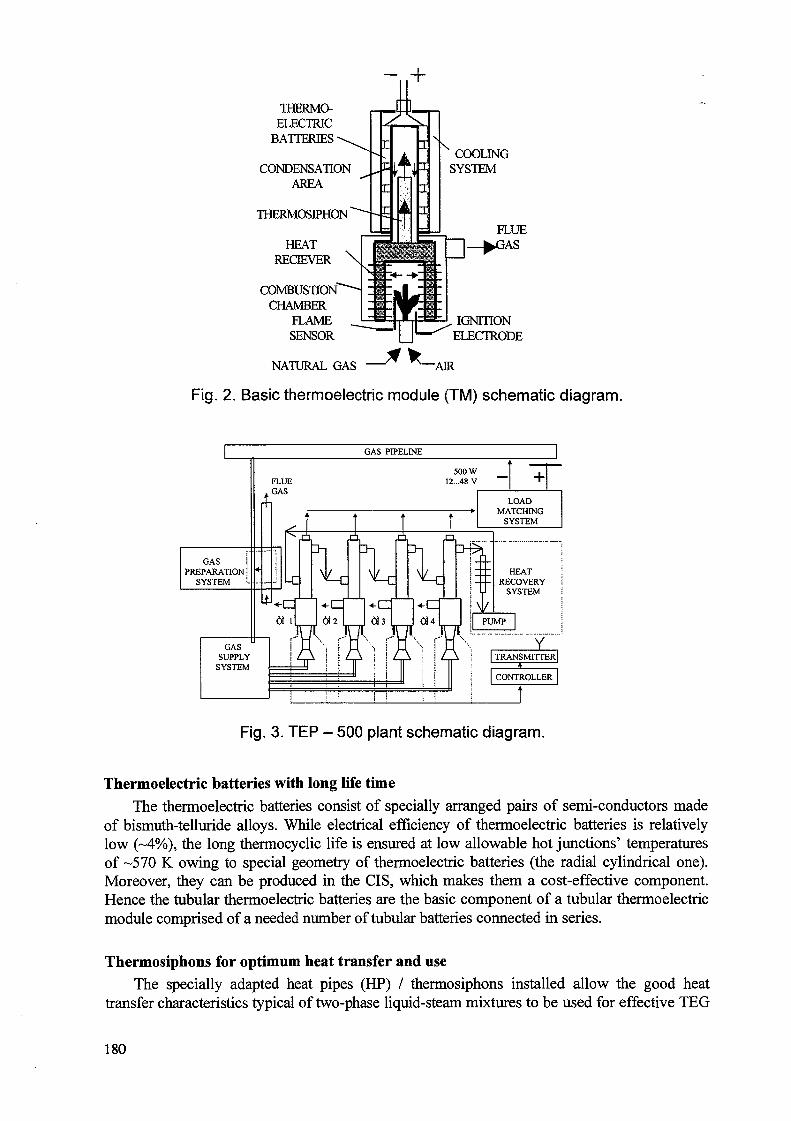
THERMO-ELECTRIC
BATTERIES \
CONDENSATIONAREA
THERMOSIPHON'
HEATRECBEVER \
COMBUSTIONCHAMBER
FLAMESENSOR
COOLINGSYSTEM
IGNITIONELECTRODE
NATURAL GAS " ""—AIR
Fig. 2. Basic thermoelectric module (TM) schematic diagram.
GAS PIPELINE
GAS iPREPARATION!
SYSTEM 5-
. GAS
GASSUPPLY
SYSTEM
Fig. 3. TEP - 500 plant schematic diagram.
Thermoelectric batteries with long life timeThe thermoelectric batteries consist of specially arranged pairs of semi-conductors made
of bismuth-telluride alloys. While electrical efficiency of thermoelectric batteries is relativelylow (-4%), the long thermocyclic life is ensured at low allowable hot junctions' temperaturesof -570 K owing to special geometry of thermoelectric batteries (the radial cylindrical one).Moreover, they can be produced in the CIS, which makes them a cost-effective component.Hence the tubular thermoelectric batteries are the basic component of a tubular thermoelectricmodule comprised of a needed number of tubular batteries connected in series.
Thermosiphons for optimum heat transfer and useThe specially adapted heat pipes (HP) / thermosiphons installed allow the good heat
transfer characteristics typical of two-phase liquid-steam mixtures to be used for effective TEG
180
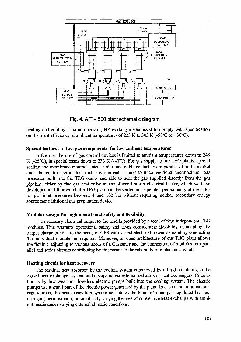
GASPREPARATION
SYSTEM
GAS PIPELINE
GASSUPPLYSYSTEM
LOADMATCHING
SYSTEM
HEATDISSIPATION
SYSTEM
YTRANSMITTER
CONTROLLER
Fig. 4. A I T - 500 plant schematic diagram.
heating and cooling. The non-freezing HP working media assist to comply with specificationon the plant efficiency at ambient temperatures of 223 K to 303 K (-50°C to +30°C).
Special features of fuel gas components for low ambient temperaturesIn Europe, the use of gas control devices is limited to ambient temperatures down to 248
K (-25°C), in special cases down to 233 K (-40°C). For gas supply to our TEG plants, specialsealing and membrane materials, steel bodies and noble contacts were purchased in the marketand adapted for use in this harsh environment. Thanks to unconventional thermosiphon gaspreheater built into the TEG plants and able to heat the gas supplied directly from the gaspipeline, either by flue gas heat or by means of small power electrical heater, which we havedeveloped and fabricated, the TEG plant can be started and operated permanently at the natu-ral gas inlet pressures between 4 and 100 bar without requiring neither secondary energysource nor additional gas preparation device.
Modular design for high operational safety and flexibilityThe necessary electrical output to the load is provided by a total of four independent TEG
modules. This warrants operational safety and gives considerable flexibility in adapting theoutput characteristics to the needs of CPS with varied electrical power demand by connectingthe individual modules as required. Moreover, an open architecture of our TEG plant allowsthe flexible adjusting to various needs of a Customer and the connection of modules into par-allel and series circuits contributing by this means to the reliability of a plant as a whole.
Heating circuit for heat recoveryThe residual heat absorbed by the cooling system is removed by a fluid circulating in the
closed heat exchanger system and dissipated via external radiators or heat exchangers. Circula-tion is by low-wear and low-loss electric pumps built into the cooling system. The electricpumps use a small part of the electric power generated by the plant. In case of stand-alone cur-rent sources, the heat dissipation system constitutes the tubular finned gas regulated heat ex-changer (thermosiphon) automatically varying the area of convective heat exchange with ambi-ent media under varying external climatic conditions.
181
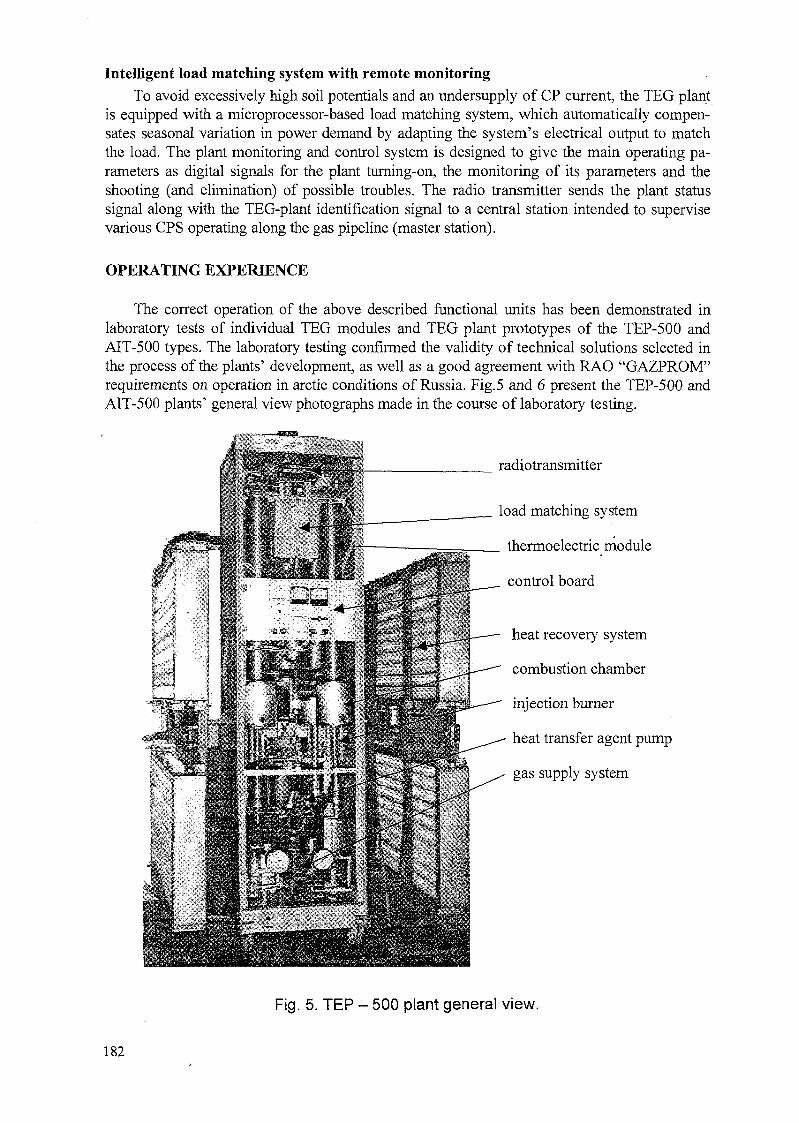
Intelligent load matching system with remote monitoringTo avoid excessively high soil potentials and an undersupply of CP current, the TEG plant
is equipped with a microprocessor-based load matching system, which automatically compen-sates seasonal variation in power demand by adapting the system's electrical output to matchthe load. The plant monitoring and control system is designed to give the main operating pa-rameters as digital signals for the plant turning-on, the monitoring of its parameters and theshooting (and elimination) of possible troubles. The radio transmitter sends the plant statussignal along with the TEG-plant identification signal to a central station intended to supervisevarious CPS operating along the gas pipeline (master station).
OPERATING EXPERIENCE
The correct operation of the above described functional units has been demonstrated inlaboratory tests of individual TEG modules and TEG plant prototypes of the TEP-500 andAIT-500 types. The laboratory testing confirmed the validity of technical solutions selected inthe process of the plants' development, as well as a good agreement with RAO "GAZPROM"requirements on operation in arctic conditions of Russia. Fig. 5 and 6 present the TEP-500 andAIT-500 plants' general view photographs made in the course of laboratory testing.
radiotransmitter
load matching system
thermoelectric module
control board
heat recovery system
combustion chamber
injection burner
heat transfer agent pump
gas supply system
Fig. 5. TEP - 500 plant general view.
182
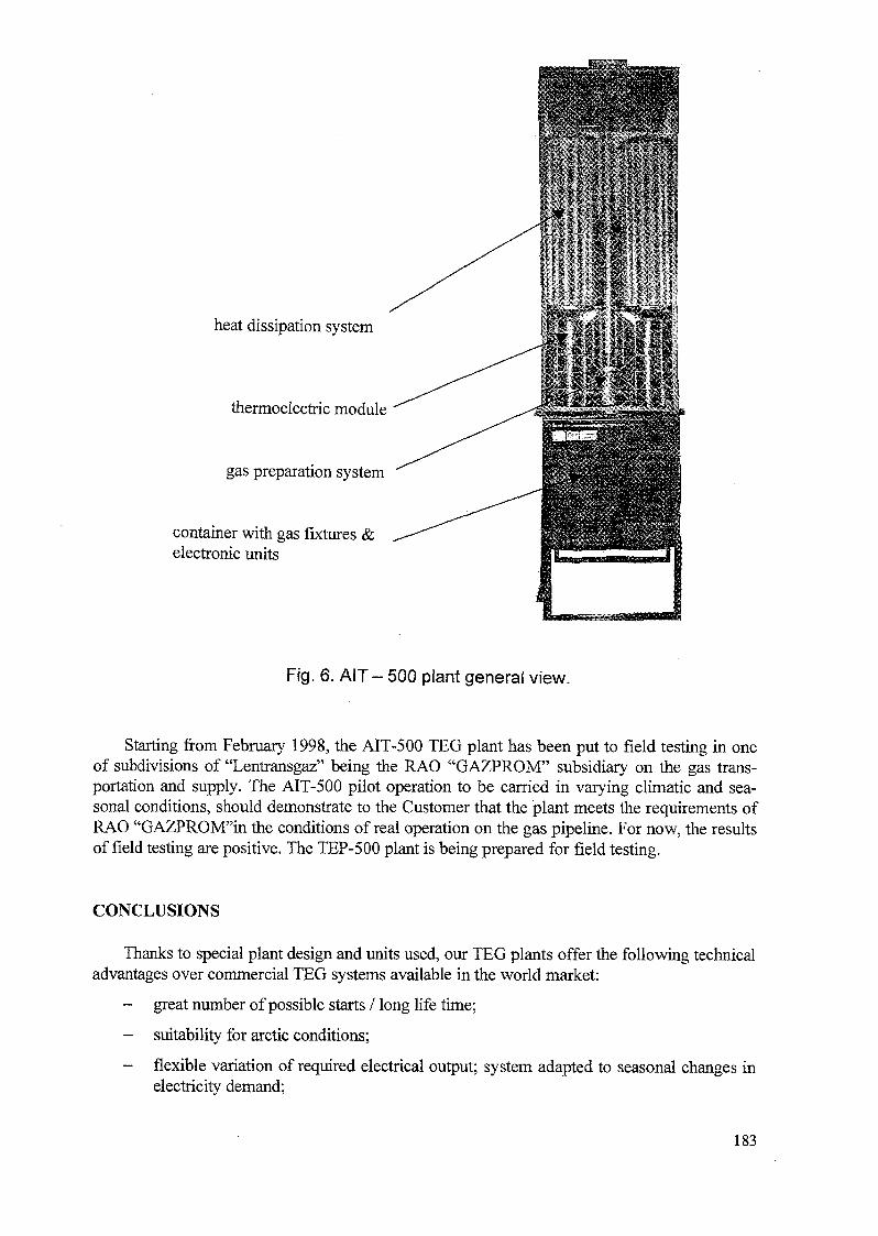
Sf
heat dissipation system
thermoelectric module
gas preparation system
container with gas fixtures &electronic units
Fig. 6. AIT - 500 plant general view.
Starting from February 1998, the AIT-500 TEG plant has been put to field testing in oneof subdivisions of "Lentransgaz" being the RAO "GAZPROM" subsidiary on the gas trans-portation and supply. The AIT-500 pilot operation to be carried in varying climatic and sea-sonal conditions, should demonstrate to the Customer that the plant meets the requirements ofRAO "GAZPROM"in the conditions of real operation on the gas pipeline. For now, the resultsof field testing are positive. The TEP-500 plant is being prepared for field testing.
CONCLUSIONS
Thanks to special plant design and units used, our TEG plants offer the following technicaladvantages over commercial TEG systems available in the world market:
- great number of possible starts / long life time;
- suitability for arctic conditions;
- flexible variation of required electrical output; system adapted to seasonal changes inelectricity demand;
183

- additional service functions for stand-alone CPS operated in regions difficult of ac-cess;
- optimum use of heat for indirect heating of natural gas from the gas pipeline and pos-sibility of heat recovery;
- secure operation irrespective of place of installation and installation angle;
- series production of plants possible without outside manufacturer, apparent flexibilityof plants in completing with standard components;
- plant costs are substantially lowered as compared to plants in the world market.
By this means, this design helps to overcome most of technical and economical obstaclesfacing TEGs where used in cathodic protection stations under arctic conditions. They aretherefore an important contribution to effective cathodic protection of natural gas pipelines andhence to the security of gas supply for RAO "GAZPROM" and its customers.
184

DEVELOPMENT OF A NEUTRON THERAPY TREATMENT COMPLEX
A.V. ZRODNIKOV, EhJE. PETROV, I.N. LEONOV,E.A. IVANOV, V.A. KHOROMSKIJ XA0056277Institute of Physics and Power EngineeringRussian Federation
A.F. TCYB, JU.S. MARDYNSKIJMedical Radiology Scientific Centre,
Obninsk, Kaluga Region, Russian Federation
Abstract
Oncological diseases are still among the most common causes of untimely deaths.Neutron and neutron-capture therapy are rather effective methods at treatment ofoncological diseases. Now these methods are practiced on expensive research reactors andaccelerators , which were not projected for medical purposes. Therefore there is theproblem of design of special reactor installation, intended for radiation therapy methods.
Such installation should provide necessary density of neutron beams, it should besafe and inexpensive.
In this paper two samples of irradiation installation for neutron and neutron-capturetherapy are submitted. The first irradiation installation is based on application of the water-water "pool" type reactor by power 1 lOkW, the second - on application of liquid-metal Na-K coolant reactor by power 40kW with zirconium hydride moderator.
The irradiation unit for both reactors has three channels: for fast neutron therapybeams, for neutron-capture therapy using thermal neutron beams, for therapy using mixedgamma-neutron beams. The cost of both installations low - about one million dollars.
1. INTRODUCTION
Oncological diseases are still among the most common causes of untimely deaths inindustrially advanced countries. A large percent of oncological patients need radiotherapy,the progress in which essentially depends on achievements in nuclear industry.
One of the most promising radiation therapy directions is connected with denselyionizing radiation. Recently much convincing evidence of successful neutron application inmalignant tumour radiation therapy have been obtained in USA, Russia, England, Germany,France, Japan and other countries. It should be noted that the beginning of fission-neutrontreatment began in Obninsk at the end of 1960's with experimental and clinical researchcarried out by both the Medical Radiology Science Centre (MRSC) of the RussianAcademy of Medical Science and the Institute of Physics and Power Engineering (IPPE)using the BR-10 reactor. During these studies, about 230 patients with widespreadmalignant tumours were cured, among them 139 neuro carvical and facial carcinoma, 59thoracic carcinoma and 20 sarcoma. The efficiency of neutron therapy methods is high.Survival rates 3+ years for cancer of the head and neck was increased from 68% (forgamma therapy) to 94% (for neutron therapy). For other cancers, positive results were alsoachieved and they are now in a stage of statistical processing.
185
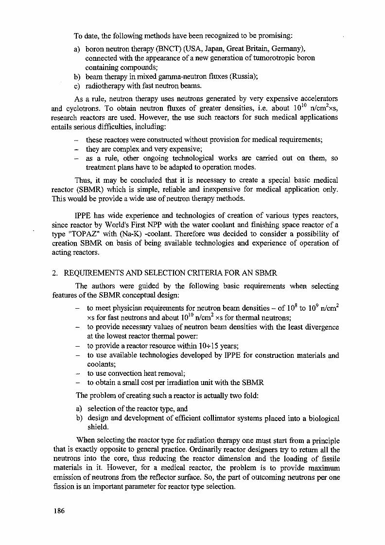
To date, the following methods have been recognized to be promising:
a) boron neutron therapy (BNCT) (USA, Japan, Great Britain, Germany),connected with the appearance of a new generation of tumorotropic boroncontaining compounds;
b) beam therapy in mixed gamma-neutron fluxes (Russia);c) radiotherapy with fast neutron beams.
As a rule, neutron therapy uses neutrons generated by very expensive acceleratorsand cyclotrons. To obtain neutron fluxes of greater densities, i.e. about 1010 n/cm2xs,research reactors are used. However, the use such reactors for such medical applicationsentails serious difficulties, including:
- these reactors were constructed without provision for medical requirements;- they are complex and very expensive;- as a rule, other ongoing technological works are carried out on them, so
treatment plans have to be adapted to operation modes.
Thus, it may be concluded that it is necessary to create a special basic medicalreactor (SBMR) which is simple, reliable and inexpensive for medical application only.This would be provide a wide use of neutron therapy methods.
IPPE has wide experience and technologies of creation of various types reactors,since reactor by World's First NPP with the water coolant and finishing space reactor of atype "TOPAZ" with (Na-K) -coolant. Therefore was decided to consider a possibility ofcreation SBMR on basis of being available technologies and experience of operation ofacting reactors.
2. REQUIREMENTS AND SELECTION CRITERIA FOR AN SBMR
The authors were guided by the following basic requirements when selectingfeatures of the SBMR conceptual design:
- to meet physician requirements for neutron beam densities - of 108 to 109 n/cm2
xs for fast neutrons and about 1010 n/cm2 xs for thermal neutrons;- to provide necessary values of neutron beam densities with the least divergence
at the lowest reactor thermal power:- to provide a reactor resource within 1 (M 5 years;- to use available technologies developed by IPPE for construction materials and
coolants;- to use convection heat removal;- to obtain a small cost per irradiation unit with the SBMR
The problem of creating such a reactor is actually two fold:
a) selection of the reactor type, andb) design and development of efficient collimator systems placed into a biological
shield.
When selecting the reactor type for radiation therapy one must start from a principlethat is exactly opposite to general practice. Ordinarily reactor designers try to return all theneutrons into the core, thus reducing the reactor dimension and the loading of fissilematerials in it. However, for a medical reactor, the problem is to provide maximumemission of neutrons from the reflector surface. So, the part of outcoming neutrons per onefission is an important parameter for reactor type selection.
186

Another selection parameter is the core size, since a smaller core provides a largerleakage of neutrons and, in addition, allows the formation of neutron beams with smallerdivergence.
Collimator selection is the key issue for radiation therapy. We selected a conicalconfiguration, which makes a possible to reduce reactor power by orders of magnitudewhile still providing: a) the same densities of neutron fluxes as those in research reactors,and b) normal dosimetrical conditions around the reactor.
Materials selection for the collimator system is an important problem, as it mustprovide an efficient means to return neutrons to the beam, slow down neutrons in a channelfor neutron-capture therapy, or multiply them by means of converter for fast neutrontherapy. It is worth nothing that the collimator problem is the same for any reactor type.
Taking into account all the requirements and criteria for reactor type and collimatorselection, we arrived at two potential: a) a water-water "poor-type reactor, and b) a reactorwith liquid-metal Na-K coolant. Both variants are simple to control, have increasedreliability and safety, the heat is removed by natural convection without the use of pumps.Manufacturing costs are very low.
3. REACTOR INSTALLATION WITH LIQUID-METAL COOLANT
The set-up and a table of main parameters of this version are presented in Fig. 1 andTable I respectively.
Table I. Base parameters of SBMR.
Parameter
NoG5
TDcore xH«ore
Sreflector
dfiielrod
Nfiid rod
N cylinder
AKcontrol rod
AK-temperature
A K H 2 0
AKvoidT Na-K1 inputT Na-K*max
-p water* input-T- water'max
"coreT airJmax
neutron leakageIbeams
<Pfast neutron
(Pepithamal neutron
DxHHstack
cost
Dimension
kWkg
yearcmcmcmunitunit
%kcfr
%keff
%keff
°C°C°C°Cat°C
n/fissionunit
l/cm2xsl/cm2xsl/cm2xs
mmillion USD
Water-water"pool" type
reactor1103.6
15+2025x24
120.91123S
-1.1-6—-15——8090
—
-0.83
3xlO9
4xlO9
4x6—-1
ValueReactor with Na-
K coolant
405
15*2025x25
120.911008
~1-3
-0.1-0.5360400——-1190~13
3xl09
4xlO9
4.7x610+15
~1
187
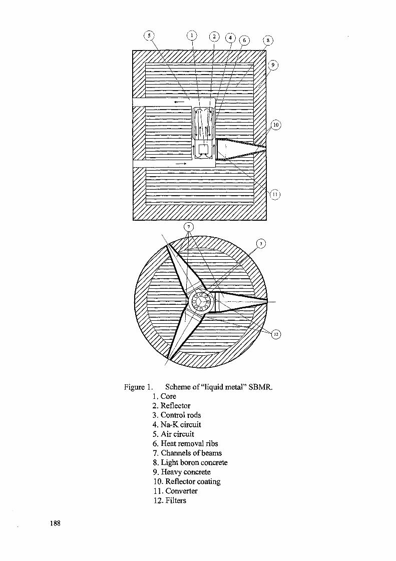
Figure 1. Scheme of "liquid metal" SBMR.l.Core2. Reflector3. Control rods4. Na-K circuit5. Air circuit6. Heat removal ribs7. Channels of beams8. Light boron concrete9. Heavy concrete10. Reflector coating11. Converter12. Filters
188
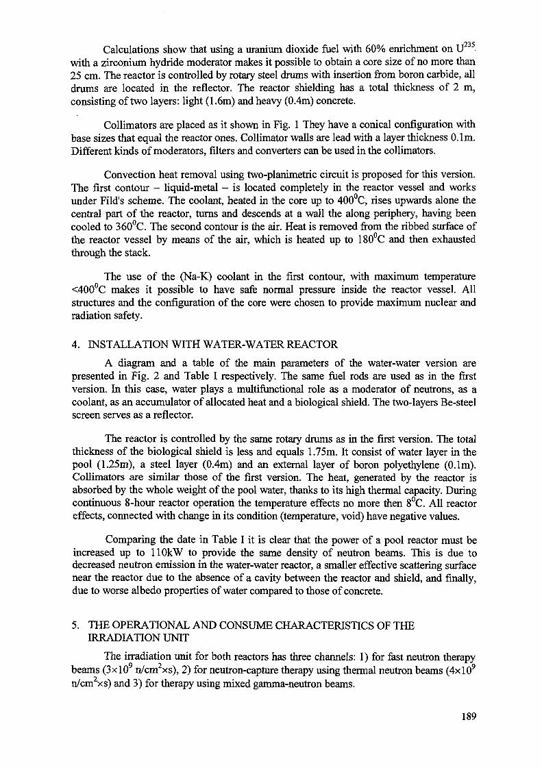
Calculations show that using a uranium dioxide fuel with 60% enrichment on Uwith a zirconium hydride moderator makes it possible to obtain a core size of no more than25 cm. The reactor is controlled by rotary steel drums with insertion from boron carbide, alldrums are located in the reflector. The reactor shielding has a total thickness of 2 m,consisting of two layers: light (1.6m) and heavy (0.4m) concrete.
Collimators are placed as it shown in Fig. 1 They have a conical configuration withbase sizes that equal the reactor ones. Collimator walls are lead with a layer thickness 0.1m.Different kinds of moderators, filters and converters can be used in the collimators.
Convection heat removal using two-planimetric circuit is proposed for this version.The first contour - liquid-metal - is located completely in the reactor vessel and worksunder Fild's scheme. The coolant, heated in the core up to 400°C, rises upwards alone thecentral part of the reactor, turns and descends at a wall the along periphery, having beencooled to 360°C. The second contour is the air. Heat is removed from the ribbed surface ofthe reactor vessel by means of the air, which is heated up to 180°C and then exhaustedthrough the stack.
The use of the (Na-K) coolant in the first contour, with maximum temperature<400°C makes it possible to have safe normal pressure inside the reactor vessel. Allstructures and the configuration of the core were chosen to provide maximum nuclear andradiation safety.
4. INSTALLATION WITH WATER-WATER REACTOR
A diagram and a table of the main parameters of the water-water version arepresented in Fig. 2 and Table I respectively. The same fuel rods are used as in the firstversion. In this case, water plays a multifunctional role as a moderator of neutrons, as acoolant, as an accumulator of allocated heat and a biological shield. The two-layers Be-steelscreen serves as a reflector.
The reactor is controlled by the same rotary drums as in the first version. The totalthickness of the biological shield is less and equals 1.75m. It consist of water layer in thepool (1.25m), a steel layer (0.4m) and an external layer of boron polyethylene (0.1m).Collimators are similar those of the first version. The heat, generated by the reactor isabsorbed by the whole weight of the pool water, thanks to its high thermal capacity. Duringcontinuous 8-hour reactor operation the temperature effects no more then 8°C. All reactoreffects, connected with change in its condition (temperature, void) have negative values.
Comparing the date in Table I it is clear that the power of a pool reactor must beincreased up to HOkW to provide the same density of neutron beams. This is due todecreased neutron emission in the water-water reactor, a smaller effective scattering surfacenear the reactor due to the absence of a cavity between the reactor and shield, and finally,due to worse albedo properties of water compared to those of concrete.
5. THE OPERATIONAL AND CONSUME CHARACTERISTICS OF THEIRRADIATION UNIT
The irradiation unit for both reactors has three channels: 1) for fast neutron therapybeams (3xl09 n/cm2xs), 2) for neutron-capture therapy using thermal neutron beams (4xlO9
n/cm2xs) and 3) for therapy using mixed gamma-neutron beams.
189
yyyyyyyyyyyyyyyyyyyyyyyyyyyy//
Figure 2. Scheme of "pool"- type SBMR.1. Core2. Reflector3. Control rods4. Water5. Steel6. Boron polyethylene7. Channels of beams8. Reflector coating9. Converter 10. Filter
190

The irradiation unit is designed for 15-r20 year lifetime without intermediaterefueling. Due to the convection method of heat removal and its rather small dimensions,the unit is simple to control and does not require large expenses for its construction. Thestaff is small - approximately 5 people without medical staff. An eight-hour work day isplanned. The duration of one session, with all beams functioning, equals 20 minutes, with apure irradiation time of no more than 5 minutes. The reactor can be switched on and offseveral times during the work day. The dose in adjacent rooms does not exceed extremelyacceptable value of 20mZv/year for professional staff. Selection of reactor parameters andconstructional materials will prevent the possibility that fuel rods could melt in hypotheticalaccidents. Cost estimates for the irradiation unit are < million US dollars for the reactortypes considered.
On the basis of the irradiation unit described above, it is possible to create atreatment complex with a clinic for 130 patients. As the treatment course consists of 10session for month, an annual possible number of patients to treat is 1600. It is known thatfor 1 million people there are 3 thousand oncological cases, and 10% of these cases areeffectively treated by fast neutron therapy. So, in order to satisfy the needs of medicine inthis direction, for example, for Moscow two treatment complexes would be needed, and forRussia in the whole about thirty.
Implementation of this project for wide use of neutron therapy would save tens ofthousands of lives annually.
191
LIST OF PARTICIPANTS
Canada
China
Egypt
France
India
J.R. HumphriesCandesal, Enterprises Ltd,472, Dawson Avenue, Ottawa, OntarioTel: 001 613 860 3434/613 722 6655Fax: 001 613 723 7635/613 722 6898E-mail: [email protected]
Yang ZhiminChina Institute of Atomic Energy,P.O. Box 275 (95), Beijing 102413Tel: 0086 10 935 8131Fax: 0086 10 6935 8126E-mail: [email protected]
Changwen MaInstitute of Nuclear Energy Technology,Tsinghua University, Beijing 100084Tel: 0086 10 6935 8131Fax: 0086 10 6935 8126E-mail: [email protected]
W.A.W. OmarNuclear Power Plants Authority,4, EL Nasr Avenue, Nasr City, Cairo,P.O. Box 108, Code No. 11381, ABBASIATel: 002 261 6272Fax: 002 261 6476
5. NisanCEA, DRN/DER/SIS,Cadarache Atomic Centre,F-13108 Saint Paul-lez-DuranceTel: 0033 4 42 25 4628Fax: 0033 4 42 25 4758E-mail: [email protected]
A.K. AnandReactor Project Group and Technical Cooperation &
International Relations Group,Bhabha Atomic Research Centre,Central Complex, Trombay, Mumbai 400 085Tel: 0091 22 5565 045Fax: 0091 22 5560 750E-mail: [email protected]
193
Indonesia
Japan
Republic of Korea
Russian Federation
M. DjokolelonoNational Atomic Energy Agency,Jl. Kuninganbarat, P.O. Box 4390, Jakarta Selatan 12043,Tel: 006 221 7 5443/525 1109/525 3803Fax: 006 221 5253 803/520 4243E-mail: [email protected]
Akio MinatoCentral Research Institute of Electric Power Industry,1-6-1, Ohtemachi, Chiyoda-ku, Tokyo 100-8126Tel: 0081 3 3202 6601Fax: 0081 3 3287 2841E-mail: [email protected]
Jong In KimKorea Atomic Energy Researcy Institue,P.O. Box 105, Yusung, Taejon 305-353Tel: 0082 42 868 8646Fax: 0082 42 868 8990E-mail: [email protected]
Doo-Jung LeeKorea Atomic Energy Research Institute,P.O.Box 105, Yusong, Taejon 305-600Tel: 0082 42 868 2000Fax: 0082 42 868 2702E-mail: [email protected]
Yu.D. BaranaevInstitute of Physics & Power Engineering,Bondarenko sq. 1, Obninsk, Kaluga Region 249020Tel: 007 83 439 98266 .Fax: 007 095 230 23 26E-mail: [email protected]
V.I. ChitaykinInstitute of Physics &Power Engineering,Bondarenko sq.l, Obninsk,Kaluga Region 249020Fax:007 095 8833112E-mail:[email protected]
O. GrigorievInstitute of Physics & Power Engineering,Bondarenko sq. 1, Obninsk, Kaluga Region 249020Tel: 007 83 439 983 62Fax: 007 095 230 23 26E-mail: [email protected]
194
Russian Federation S.B. Kazakov(cont.) NPP Construction Joint Stock Company "Malaja
Energetika", MoscowTel: 007 095 962 9 269Fax: 007 095 964 19 00E-mail: [email protected]
N.N. KlimovEDO "GIDROPRESS"Tel: 007 096 75 212 79Fax: 007 096 75 427 33
E.A. KuzinNPP Construction Joint Stock Company
"Malaja Energetika", MoscowTel: 007 095 962 9 269Fax: 007 095 964 19 00
K. LeguenkoMain Specialist, Rosenergoatomproekt,Podolskih Kursantov St., I, MoscowTel: 007 095 389 19 77
V.N. PepaResearch and Development Institute of Power
Engineering,M. Krasnoselskaya, 2/8,101000 MoscowTel: 007 095 975 20 19Fax: 007 095 268 92 53
V.I. PolunichevOKBM Mechanical Engineering,Burnakovsky proezd-15, Nizhny Novgorod, 603074Tel: 007 8312 41 8092Fax: 007 8312 41 8772E-mail: [email protected]
G.I. ToshinskyInstitute of Physics & Power Engineering,Bondarenko sq. 1, Obninsk, Kaluga Region 249020Tel: 007 83439 985 35Fax: 007 095 230 23 26E-mail: [email protected]
Yu.A. SergeevInstitute of Physics & Power Engineering,Bondarenko sq. 1, Obninsk, Kaluga Region 249020Tel: 007 83439 988 72Fax: 007 095 230 23 26E-mail: [email protected]
195
Russian Federation(cont.)
United States ofAmerica
IAEA
A.V. ZrodnikovInstitute of Physics & Power Engineering,Bondarenko sq.l, Obninsk, Kaluga Region 249020Tel:007 08439 98250Fax:007 08439 48338E-mail :[email protected] .ru
A.N. ZabudkoInstitute of Physics & Power Engineering,Bondarenko sq. 1, Obninsk, Kaluga Region 249020Tel: 007 83439 981 60Fax: 007 095 883 31 12
N. BrownLawrence Livermore National Laboratory,7000 East Ave., Livermore CA 94550Tel: 005 10 424 4019Fax: 005 10 422 5497E-mail: [email protected]
A. RineiskiiWagramer Strasse 5, P.O. Box 100,A-1400 Vienna, AustriaTel: 431 2060 22863Fax: 431 20607E-mail: [email protected]
196
XA0056553
SMALL POWER AND HEAT GENERATION SYSTEMS ON THE BASIS OFPROPULSION AND INNOVATIVE REACTOR TECHNOLOGIES
(IAEA-TECDOC-1172)
CORRIGENDUM
— Footnote 1 on page 4 should read:
" 'The results of the feasibility studies were presented by BARC at the meeting, but no paper was providedfor publication in these proceedings."
— On page 5, footnote 2 should be added to the following paragraph:
"CEA and TECHNICATOM (France) have about 200 reactor-years of experience frompropulsion and small experimental reactors. Special design features for a future small reactorare formulated as follows2:"
2At the meeting, these features were presented by CEA, Cadarache, but no paper was provided forpublication in these proceedings."
3 1 / 4 9
Copyright © 2022 FDOKUMEN