DM270s2021- Batch 3 Evaluators of SHS SLM (For Quarter 3 ...
Upload
khangminh22Category
view
0download
0
SLM-5650B Satellite Modem
Installation and Operation Manual
Part Number MN-SLM-5650B
Revision 3 For Firmware Version 1.1.2x
IMPORTANT NOTE: The information contained in this document supersedes all previously published information regarding this product. Product specifications are subject to change without prior notice.

SLM-5650B Satellite Modem Revision 3
MN-SLM-5650B
Copyright © 2019 Comtech EF Data. All rights reserved. Printed in the USA. Comtech EF Data, 2114 West 7th Street, Tempe, Arizona 85281 USA, 480.333.2200, FAX: 480.333.2161
Revision History
Rev Date Description
0 7-2017 Initial Release.
1 8-2017 Revised Chapter 5 Front Panel, Utility section. Updated Appendix C. Revised Sections 4.3, 4.4, 4.5, 7.2.3 and 7.4.3. Deleted Section 7.4.3.6; renumbered remaining section numbers. Revised Figures 7-6 through 7-9, and Figure 7-15. Added Figure 7-10 to show Configuration – CnC web page; renumbered remaining figures. Added Figure 7-12 to show Configuration – AHO web page; renumbered remaining figures.
2 10-2017 Updated wording for Spreading Option in Section 5.2.3.1 and 5.2.3.2. In Section 5.2.3.1, added GSN Option and Setting to CONFIG: Tx Spreading. Updated front panel display in the same area. In Section 5.2.3.2, added GSN Option and Setting to CONFIG: Rx Spreading. Updated front panel display in the same area. Removed note from Section B.1. In Appendix C, revised commands TSE, TSF, RSE, and RSF. Removed "up to" wording in Section D.9, paragraph 4.
3 8-2021 Added Key Generation for TRANSEC 2.2.4. Added STANAG, Carrier-in-Carrier, Antenna Handover, and Vipersat Network Applications and various locations throughout manual. Restructured document formatting and sequence to follow existing product line.
Note: Technical changes are shown with a revision bar in the left margin. Formatting changes do not have a revision bar.

SLM-5650B Satellite Modem Revision 3
Table of Contents TOC-1 MN-SLM-5650B
TABLE OF CONTENTS PREFACE ...................................................................................................................................................... I About this Manual ........................................................................................................................................ i Conventions and References...................................................................................................................... i
Patents and Trademarks ............................................................................................................................ i Related Documents .................................................................................................................................... i Military Standards ...................................................................................................................................... ii Warnings, Cautions, Notes, and References ............................................................................................. ii Examples of Multi-Hazard Notices ............................................................................................................. ii Recommended Standard Designations .................................................................................................... iii
Safety and Compliance .............................................................................................................................. iii Electrical Safety and Compliance ............................................................................................................. iii Electrical Installation ................................................................................................................................. iii Class I Pluggable Equipment Type A-Protective Earthing ........................................................................ iii Galvanic Isolator Use ................................................................................................................................ iv Restricted Access Location ....................................................................................................................... iv Battery Warning ......................................................................................................................................... v Operating Environment ............................................................................................................................. v
European Union Radio Equipment and Telecommunications Terminal Equipment (R&TTE) Directive (1999/5/EC) and EN 301 489-1 ............................................................................................................ v European Union Electromagnetic Compatibility (EMC) Directive (2004/108/EC) ................................ vi European Union Low Voltage Directive (LVD) (2006/95/EC) ................................................................ vi European Union RoHS Directive (2002/95/EC) .................................................................................... vi European Union Telecommunications Terminal Equipment Directive (91/263/EEC) .......................... vii CE Mark vii
Product Support ........................................................................................................................................ vii Comtech EF Data Headquarters .............................................................................................................. vii Warranty Policy ........................................................................................................................................ viii
Limitations of Warranty ............................................................................................................................ viii Exclusive Remedies .................................................................................................................................. ix
CHAPTER 1. INTRODUCTION ........................................................................................................... 1–1 1.1 Overview ...................................................................................................................................... 1–1 1.2 Functional Description ............................................................................................................... 1–2 1.3 Product Features ......................................................................................................................... 1–3
1.3.1 Operational Features ................................................................................................................ 1–4 1.3.1.1 Operating Modes ........................................................................................................... 1–4
1.3.1.1.1 Closed Networks ........................................................................................................ 1–4 1.3.1.1.2 Open Networks (Intelsat) ........................................................................................... 1–4 1.3.1.1.3 OM-73 Mode .............................................................................................................. 1–4
1.3.1.2 Secure Management Interfaces .................................................................................... 1–5 1.3.1.3 Data Interfaces .............................................................................................................. 1–5
1.3.1.3.1 TIA/EIA-530 Interface ................................................................................................ 1–5 1.3.1.3.2 TIA/EIA-613 High Speed Serial Interface (HSSI) ...................................................... 1–5 1.3.1.3.3 Network Processor (NP) Module Option ................................................................... 1–6 1.3.1.3.4 G.703 T1/E1, T2/E2 Module Option .......................................................................... 1–6 1.3.1.3.5 Low Voltage Differential Signaling (LVDS) Module Option ........................................ 1–6 1.3.1.3.6 10/100/1000BASE-T (Gigabit Ethernet) Module Option ............................................ 1–6
1.3.1.4 Independent Tx and Rx Function .................................................................................. 1–7 1.3.1.5 Verification ..................................................................................................................... 1–7 1.3.1.6 Updating Modem Firmware ........................................................................................... 1–7 1.3.1.7 Fully Accessible System Topology (FAST) .................................................................... 1–8
1.3.1.7.1 FAST Accessible Options .......................................................................................... 1–8

SLM-5650B Satellite Modem Revision 3
Table of Contents TOC-2 MN-SLM-5650B
1.3.1.8 Interoperability ............................................................................................................. 1–10 1.3.1.8.1 Legacy Modems ...................................................................................................... 1–10 1.3.1.8.2 Modem Switches ..................................................................................................... 1–10
1.4 Physical Features ...................................................................................................................... 1–11 1.4.1.1 Dimensional Envelope ................................................................................................ 1–11
1.4.2 Front Panel ............................................................................................................................. 1–12 1.4.3 Rear Panel .............................................................................................................................. 1–13
CHAPTER 2. SPECIFICATIONS ........................................................................................................ 2–1 2.1 Summary of Specifications ........................................................................................................ 2–1 2.2 BER Performance ........................................................................................................................ 2–6
2.2.1 BPSK/QPSK/Offset QPSK, Viterbi Decoding ........................................................................... 2–6 2.2.2 BPSK/QPSK/Offset QPSK, Viterbi Decoding and Reed-Solomon ........................................... 2–6 2.2.3 8PSK, Trellis Decoder ............................................................................................................... 2–6 2.2.4 8PSK, Trellis Decoder and Reed-Solomon .............................................................................. 2–7 2.2.5 16QAM, Viterbi Decoder and Reed-Solomon ........................................................................... 2–7 2.2.6 Turbo Product Code (TPC) Decoding ....................................................................................... 2–7 2.2.7 Sequential Decoding with/without Reed-Solomon .................................................................... 2–8 2.2.8 BER Performance with Symmetrical or Asymmetrical Adjacent Carriers ................................. 2–8 2.2.9 LDPC ULL Decoding ............................................................................................................... 2–10 2.2.10 LDPC LL Decoding ................................................................................................................. 2–10 2.2.11 LDPC HP Decoding ................................................................................................................ 2–10
CHAPTER 3. INSTALLATION............................................................................................................. 3–1 3.1 Unpacking and Inspection ......................................................................................................... 3–1 3.2 Installation ................................................................................................................................... 3–2
3.2.1 Optional Rear Support Bracket Kit ............................................................................................ 3–4 3.2.2 Optional Bearingless Rack Slide Set ........................................................................................ 3–6
3.3 Connect External Cables ............................................................................................................ 3–7 3.4 Configuration ............................................................................................................................... 3–7
CHAPTER 4. REAR PANEL CONNECTORS ..................................................................................... 4–1 4.1 Overview – Cabling Connection Types ..................................................................................... 4–1
4.1.1 Coaxial Cable Connections ...................................................................................................... 4–1 4.1.1.1 Type ‘BNC’ .................................................................................................................... 4–2 4.1.1.2 Type ‘TNC’ ..................................................................................................................... 4–2 4.1.1.3 Type ‘N’ ......................................................................................................................... 4–2
4.1.2 D-Subminiature Cable Connections ......................................................................................... 4–3 4.1.3 RJ-45, RJ-48 Cable Connections ............................................................................................. 4–3
4.2 Unit Connectors .......................................................................................................................... 4–4 4.3 AC Operation ............................................................................................................................. 4–11
4.3.1 Replace the Fuses .................................................................................................................. 4–11 4.3.2 Apply Power ............................................................................................................................ 4–12
4.4 Power Interface Module – Optional 24V DC Unit ................................................................... 4–13 4.4.1 Replace the Fuses .................................................................................................................. 4–13 4.4.2 Apply Power ............................................................................................................................ 4–13
CHAPTER 5. FIRMWARE UPDATE ................................................................................................... 5–1 5.1 Update Firmware via Web Pages ............................................................................................... 5–1
5.1.1 About Firmware Files, Naming, Versions, and Archive Formats .............................................. 5–2 5.2 Bulk Firmware Update Procedure ................................................................................................. 5–3 5.3 Network Processor (NP) Interface Module Update Procedure ............................................... 5–4 5.4 TRANSEC Module Firmware Update Procedure .................................................................... 5–10

SLM-5650B Satellite Modem Revision 3
Table of Contents TOC-3 MN-SLM-5650B
CHAPTER 6. FAST ACTIVATION PROCEDURE ............................................................................... 6–1 6.1 Overview ...................................................................................................................................... 6–1 6.2 FAST Activation Procedure via the Front Panel ...................................................................... 6–2 6.3 FAST Activation Procedure via the Base Modem Web Interface Pages ................................ 6–3
CHAPTER 7. FRONT PANEL OPERATION ....................................................................................... 7–1 Overview ...................................................................................................................................... 7–1
7.1.1 Keypad with Data Entry Array ................................................................................................... 7–2 7.1.2 LED Indicators .......................................................................................................................... 7–3 7.1.3 Vacuum Fluorescent Display (VFD) .......................................................................................... 7–4
7.1.3.1 Navigating the Menu Screens ....................................................................................... 7–5 Front Panel Operation ................................................................................................................ 7–6
7.2.1 Opening Screen ........................................................................................................................ 7–6 7.2.2 SELECT: (Main) Menu .............................................................................................................. 7–7 7.2.3 (SELECT:) Configure (Configuration) Menu Branch ................................................................. 7–8
7.2.3.1 CONFIG: Tx .................................................................................................................. 7–9 7.2.3.2 CONFIG: Rx ................................................................................................................ 7–16 7.2.3.3 CONFIG: Mode ........................................................................................................... 7–24 7.2.3.4 CONFIG: AUPC ........................................................................................................... 7–26 7.2.3.5 CONFIG: TRANSEC ................................................................................................... 7–29 7.2.3.6 CONFIG: AHO ............................................................................................................. 7–29 7.2.3.7 CONFIG: ODU ............................................................................................................ 7–30 7.2.3.8 CONFIG: Ref ............................................................................................................... 7–30 7.2.3.9 CONFIG: Mask ............................................................................................................ 7–31 7.2.3.10 CONFIG: Reset ........................................................................................................... 7–31 7.2.3.11 CONFIG: Remote ........................................................................................................ 7–32
7.2.4 SELECT: Monitor .................................................................................................................... 7–37 7.2.4.1 Monitor: Alarms ........................................................................................................... 7–37 7.2.4.2 Monitor: Event-Log ...................................................................................................... 7–41 7.2.4.3 Monitor: Rx-Params .................................................................................................... 7–42 7.2.4.4 Monitor: CnC (DoubleTalk® Carrier-in-Carrier®) .......................................................... 7–42 7.2.4.5 Monitor: Stats (Statistics) ............................................................................................ 7–43 7.2.4.6 Monitor: ITA ................................................................................................................. 7–44
7.2.5 SELECT: Test .......................................................................................................................... 7–45 7.2.5.1 Test: BERT .................................................................................................................. 7–45 7.2.5.2 Test: LampTest ............................................................................................................ 7–46
7.2.6 SELECT: Save/Load ............................................................................................................... 7–47 7.2.7 SELECT: Utility ........................................................................................................................ 7–48
7.2.7.1 Utility: RT-Clk ............................................................................................................... 7–48 7.2.7.2 Utility: RefAdjust .......................................................................................................... 7–48 7.2.7.3 Utility: ID ...................................................................................................................... 7–48 7.2.7.4 Utility: Display .............................................................................................................. 7–48 7.2.7.5 Utility: Temp ................................................................................................................. 7–49 7.2.7.6 Utility: AGC .................................................................................................................. 7–49 7.2.7.7 Utility: Alarm ................................................................................................................ 7–49 7.2.7.8 Utility: Firmware ........................................................................................................... 7–49 7.2.7.9 Utility: FAST ................................................................................................................. 7–51
CHAPTER 8. ETHERNET INTERFACE OPERATION ....................................................................... 8–1 8.1 Introduction ................................................................................................................................. 8–1 8.2 Ethernet Management Interfaces and Protocols ..................................................................... 8–1
8.2.1 Secure Ethernet Management Interfaces ................................................................................. 8–3 8.2.1.1 Base Modem Interface .................................................................................................. 8–3 8.2.1.2 Optional NP Interface Module ....................................................................................... 8–4 8.2.1.3 Base Modem + Optional NP Interface + Optional TRANSEC Module .......................... 8–4

SLM-5650B Satellite Modem Revision 3
Table of Contents TOC-4 MN-SLM-5650B
8.3 HTTP/HTTPS (Web Server) Interfaces ....................................................................................... 8–5 8.4 SNMP Interface ............................................................................................................................ 8–6
8.4.1 MIB Files ................................................................................................................................... 8–6 8.4.2 SNMP Community Strings ........................................................................................................ 8–7 8.4.3 SNMP Traps .............................................................................................................................. 8–7 8.4.4 SNMPv3 (Base Modem) ........................................................................................................... 8–8
8.5 Telnet Interface ............................................................................................................................ 8–9 8.5.1 Telnet Inerface via Windows Command Line ........................................................................... 8–9 8.5.2 Telnet Remote Control Operation via a Terminal Emulation Program .................................... 8–10
8.5.2.1 HyperTerminal ............................................................................................................. 8–10 8.5.2.2 TeraTerm ..................................................................................................................... 8–11 8.5.2.3 PuTTY ......................................................................................................................... 8–13
8.6 Secure Shell (SSH) Interface .................................................................................................... 8–15 8.6.1 Configure a SSH Session via TeraTerm ................................................................................. 8–15 8.6.2 Configure a SSH Session via PuTTY ..................................................................................... 8–17
CHAPTER 9. BASE MODEM HTTP/HTTPS INTERFACE OPERATION .......................................... 9–1 9.1 Overview ...................................................................................................................................... 9–1 9.2 Base Modem HTTP/HTTPS Interface Introduction................................................................... 9–1
9.2.1 User Login ................................................................................................................................. 9–1 9.2.2 Web Interface – Operational Features ...................................................................................... 9–3
Navigation ..................................................................................................................... 9–3 Web Page Tabs ............................................................................................................. 9–3 Execution Buttons ......................................................................................................... 9–3 Feature Selection .......................................................................................................... 9–3 Text or Data Entry .......................................................................................................... 9–3
9.2.3 Web Interface Menu Tree ......................................................................................................... 9–4 9.3 HTTPS Certificate ........................................................................................................................ 9–5 9.4 Base Modem Web Interface Page Descriptions ....................................................................... 9–6
9.4.1 Home Page ............................................................................................................................... 9–6 Home | Home ................................................................................................................ 9–6 Home | Contact ............................................................................................................. 9–7
9.4.2 Admin (Administration) Pages .................................................................................................. 9–8 Admin | Access .............................................................................................................. 9–8 Admin | Time ............................................................................................................... 9–11 Admin | SNMP ............................................................................................................. 9–12 Admin | FAST .............................................................................................................. 9–14 Admin | Upgrade ......................................................................................................... 9–15
9.4.3 Configuration (Modem Configuration) Pages ......................................................................... 9–16 Configuration | Modem ................................................................................................ 9–16 Configuration | Utils ..................................................................................................... 9–26 Configuration | LoadStore ........................................................................................... 9–29 Configuration | Spreading............................................................................................ 9–30 Configuration | CnC ..................................................................................................... 9–33 Configuration | AUPC .................................................................................................. 9–34 Configuration | AHO .................................................................................................... 9–35 Configuration | ODU .................................................................................................... 9–36 Configuration | ITA ....................................................................................................... 9–37
9.4.4 Status Pages ........................................................................................................................... 9–40 Status | Status ............................................................................................................. 9–40 Status | Info ................................................................................................................. 9–42 Status | Event Log ....................................................................................................... 9–43 Status | Modem Statistics ............................................................................................ 9–44 Status | Port Statistics ................................................................................................. 9–45 Status | Config Log ...................................................................................................... 9–47

SLM-5650B Satellite Modem Revision 3
Table of Contents TOC-5 MN-SLM-5650B
Status | Firmware ........................................................................................................ 9–48 Status | Constellation .................................................................................................. 9–49
CHAPTER 10. SERIAL REMOTE CONTROL .................................................................................... 10–1 10.1 Overview .................................................................................................................................... 10–1 10.2 EIA-485 ....................................................................................................................................... 10–1 10.3 EIA-232 ....................................................................................................................................... 10–2 10.4 Basic Protocol ........................................................................................................................... 10–2 10.5 Packet Structure ........................................................................................................................ 10–3
10.5.1 Start of Packet ........................................................................................................................ 10–3 10.5.2 Target Address ........................................................................................................................ 10–4 10.5.3 Address Delimiter .................................................................................................................... 10–4 10.5.4 Instruction Code ...................................................................................................................... 10–4 10.5.5 Instruction Code Qualifier ....................................................................................................... 10–5 10.5.6 Optional Message Arguments ................................................................................................. 10–6 10.5.7 End Of Packet ......................................................................................................................... 10–6
10.6 Remote Commands / Queries .................................................................................................. 10–7 10.6.1 Initial Setup – Priority Commands / Queries ......................................................................... 10–11 10.6.2 Modulator (Tx) Commands / Queries ................................................................................... 10–13 10.6.3 Demodulator (Rx) Commands / Queries .............................................................................. 10–20 10.6.4 Modem, Unit Commands / Queries ...................................................................................... 10–28 10.6.5 Bulk Configuration Commands / Queries ............................................................................. 10–41 10.6.6 Automatic Uplink Power Control (AUPC) Commands / Queries .......................................... 10–44 10.6.7 G.703 Interface Commands / Queries .................................................................................. 10–50 10.6.8 Gigabit Ethernet Interface Commands / Queries .................................................................. 10–52 10.6.9 Network Processor (NP) Interface Commands / Queries ..................................................... 10–53 10.6.10 TRANSEC Interface Commands / Queries .......................................................................... 10–55 10.6.11 STANAG Only Commands / Queries .................................................................................... 10–56
APPENDIX A. TROUBLESHOOTING ..................................................................................................A–1 A.1 Overview ..................................................................................................................................... A–1 A.2 System Checkout ....................................................................................................................... A–1
A.2.1 Interface Checkout .................................................................................................................... A–2 A.2.2 Modulator Checkout .................................................................................................................. A–3 A.2.3 Demodulator Checkout ............................................................................................................. A–6
A.3 Fault Isolation ............................................................................................................................. A–9 A.4 System Faults/Alarms .............................................................................................................. A–10 A.5 LED Indicator Faults ................................................................................................................ A–12
APPENDIX B. OPERATIONAL REFERENCE .....................................................................................B–1 B.1 Overview ..................................................................................................................................... B–1 B.2 Modes .......................................................................................................................................... B–2
B.2.1 OM-73 Mode ............................................................................................................................. B–2 B.2.2 MIL-STD-188-165A Mode ......................................................................................................... B–2 B.2.3 MIL-STD-188-165A Mode – Sequential .................................................................................... B–4 B.2.4 IESS-308 Mode – Standard Higher Rates ................................................................................ B–5 B.2.5 IESS-308 Mode – Extended ..................................................................................................... B–8 B.2.6 IESS-309 Mode – Extended (Closed Network) ...................................................................... B–10 B.2.7 IESS-310 Mode – Extended Rates ......................................................................................... B–11 B.2.8 Turbo Code Mode ................................................................................................................... B–11 B.2.9 16-QAM Mode ......................................................................................................................... B–12 B.2.10 AUPC Mode ............................................................................................................................ B–12 B.2.11 AUPC Mode – Sequential ....................................................................................................... B–13 B.2.12 AUPC Mode – Turbo ............................................................................................................... B–14

SLM-5650B Satellite Modem Revision 3
Table of Contents TOC-6 MN-SLM-5650B
B.2.13 NON-SPREAD LDPC Mode – Ultra Low Latency (ULL) ........................................................ B–14 B.2.14 NON-SPREAD LDPC Mode – Low Latency (LL) ................................................................... B–15 B.2.15 NON-SPREAD LDPC Mode – High Performance (HP) .......................................................... B–15 B.2.16 MIL-STD-188-165B or STANAG Mode ................................................................................... B–16
APPENDIX C. MODEM OPTIONS .......................................................................................................C–1 C.1 Forward Error Correction (FEC) Options ................................................................................. C–1 C.2 Viterbi .......................................................................................................................................... C–1 C.3 Trellis Coding (FAST Option) .................................................................................................... C–2 C.4 Reed-Solomon (R-S) Outer Codec............................................................................................ C–3 C.5 Closed Network Mode ................................................................................................................ C–4 C.6 Turbo Product Codec ................................................................................................................. C–5 C.7 Sequential (FAST Option) .......................................................................................................... C–6 C.8 Low Density Parity Check (LDPC) Coding (FAST Option) ..................................................... C–7
C.8.1 Introduction ...............................................................................................................................C–7 C.8.2 LDPC versus TPC .....................................................................................................................C–8
C.9 Direct Sequence Spread Spectrum (FAST Option) ............................................................... C–10
APPENDIX D. OPTIONAL DATA INTERFACE MODULES .................................................................D–1 D.1 Overview ..................................................................................................................................... D–1 D.2 Optional Data Interface Modules .............................................................................................. D–2
D.2.1 10/100/1000 BaseT (GbE) Interface Module ............................................................................D–2 D.2.1.1 Physical Description ......................................................................................................D–2 D.2.1.2 “J12” Connector Pinout .................................................................................................D–3 D.2.1.3 Specifications ................................................................................................................D–4
D.2.1.3.1 General Specifications ...............................................................................................D–4 D.2.1.3.2 Monitor & Control .......................................................................................................D–5 D.2.1.3.3 Physical and Environmental ......................................................................................D–6
D.2.1.4 10/100/1000 BaseT (GbE) Interface Module Removal and Installation ........................D–7 D.2.1.4.1 GbE Interface Module Removal Procedure ...............................................................D–8 D.2.1.4.2 GbE Interface Module Installation Procedure ............................................................D–8
D.2.2 G.703 T1/E1, T2/E2 Data Interface Module .............................................................................D–9 D.2.2.1 Physical Description ......................................................................................................D–9
D.2.2.1.1 G.703 Balanced “J1 | BAL DATA” Connector (DB-15F) ..........................................D–10 D.2.2.1.2 G.703 Unbalanced “J2” through “J4” BNC Connectors ........................................... D–11
D.2.2.2 Specifications .............................................................................................................. D–11 D.2.2.2.1 General Specifications ............................................................................................. D–11 D.2.2.2.2 Interfaces .................................................................................................................D–12 D.2.2.2.3 Physical and Environmental ....................................................................................D–12
D.2.2.3 G.703 T1/E1, T2/E2 Interface Module Removal and Installation ................................D–13 D.2.2.3.1 G.703 Interface Module Removal Procedure ..........................................................D–13 D.2.2.3.2 G.703 Interface Module Installation Procedure .......................................................D–14
D.2.3 Low Voltage Differential (LVDS) Interface Module..................................................................D–15 D.2.3.1 Physical Description ....................................................................................................D–15
D.2.3.1.1 “J1” Connector Pinout (DB-25F) ..............................................................................D–16 D.2.3.2 Specifications ..............................................................................................................D–17
D.2.3.2.1 General Specifications .............................................................................................D–17 D.2.3.2.2 Physical & Environmental ........................................................................................D–17
D.2.3.3 LVDS Interface Module Removal and Installation .......................................................D–18 D.2.3.3.1 LVDS Interface Module Removal Procedure ...........................................................D–18 D.2.3.3.2 LVDS Interface Module Installation Procedure ........................................................D–18
APPENDIX E. OPTIONAL NETWORK PROCESSOR (NP) INTERFACE MODULE ......................... E–1 E.1 Overview ...................................................................................................................................... E–1

SLM-5650B Satellite Modem Revision 3
Table of Contents TOC-7 MN-SLM-5650B
E.2 Functional Hardware Description .............................................................................................. E–2 E.2.1 Connector Pinout ...................................................................................................................... E–3
E.3 Interface Specifications .............................................................................................................. E–4 E.3.1 Physical Description.................................................................................................................. E–4 E.3.2 General Specifications .............................................................................................................. E–4
E.4 NP Interface Module Removal and Installation ........................................................................ E–5 E.4.1 NP Interface Module Removal Procedure ................................................................................ E–5 E.4.2 NP Interface Module Installation Procedure ............................................................................. E–5
E.5 Bridge Point-to-Multipoint (BPM) Mode .................................................................................... E–6 E.6 Important Operational Considerations ..................................................................................... E–7 E.7 Network Processor (NP) HTTP/HTTPS Interface...................................................................... E–8
E.7.1 HTTP/HTTPS Interface ............................................................................................................. E–8 E.7.1.1 HTTP/HTTPS Interface Introduction ............................................................................. E–8 E.7.1.2 HTTP/HTTPS Interface Availability via Secure Management Interfaces ...................... E–9
E.7.1.2.1 Secure Management – NP Interface Only ................................................................. E–9 E.7.1.2.2 Secure Management – NP Interface with TRANSEC Module Interface .................. E–10
E.7.2 User Login ............................................................................................................................... E–11 E.7.3 HTTP/HTTPS Interface – Operational Features ..................................................................... E–13 E.7.4 HTTP/HTTPS Menu Tree ....................................................................................................... E–13 E.7.5 HTTP/HTTPS Page Descriptions ........................................................................................... E–15
E.7.5.1 Info (Information) Page ............................................................................................... E–15 E.7.5.1.1 Info | Home .............................................................................................................. E–15 E.7.5.1.2 Info | Contact ............................................................................................................ E–16 E.7.5.1.3 Info | Log Off ............................................................................................................ E–16
E.7.5.2 Admin (Administration) Page ...................................................................................... E–17 E.7.5.2.1 Admin | Mode (FAST Feature Required) ................................................................. E–17 E.7.5.2.2 Admin | FAST Features ............................................................................................ E–20 E.7.5.2.3 Admin | Security (Account Information) ................................................................... E–21 E.7.5.2.4 Admin | SNMP ......................................................................................................... E–23 E.7.5.2.5 Admin | Upgrade ...................................................................................................... E–24 E.7.5.2.6 Upgrade ................................................................................................................... E–25 E.7.5.2.7 Admin | Defaults ....................................................................................................... E–25 E.7.5.2.8 Admin | Time (Date and Time) ................................................................................. E–26 E.7.5.2.9 Admin | Event Log.................................................................................................... E–27 E.7.5.2.10 Admin | Reboot ........................................................................................................ E–28
E.7.5.3 Modem Page ............................................................................................................... E–30 E.7.5.3.1 Modem | Config (Modem Configuration).................................................................. E–30 E.7.5.3.2 Modem | Monitor (Modem Status) ........................................................................... E–35 E.7.5.3.3 Modem | Events (Modem Events Log) .................................................................... E–36 E.7.5.3.4 Modem | Stats (Modem Statistics Log) .................................................................... E–37 E.7.5.3.5 Modem | Utility (Modem Utilities) ............................................................................. E–38
E.7.5.4 LAN Page .................................................................................................................... E–39 E.7.5.4.1 LAN | Interface ......................................................................................................... E–39 E.7.5.4.2 LAN | Ethernet Ports ................................................................................................ E–41 E.7.5.4.3 LAN | ARP (ARP Table) ........................................................................................... E–42
E.7.5.5 WAN Page ................................................................................................................... E–43 E.7.5.5.1 WAN | QoS (Quality of Service) ............................................................................... E–43 E.7.5.5.2 WAN | QoS Stats (Quality of Service Statistics) ...................................................... E–45 E.7.5.5.3 WAN | Loopback Test .............................................................................................. E–46
E.7.5.6 Routing Page ............................................................................................................... E–47 E.7.5.6.1 Routing | Routes ...................................................................................................... E–47 E.7.5.6.2 Routing | OSPF ........................................................................................................ E–51 E.7.5.6.3 Routing | IGMP ........................................................................................................ E–55
E.7.5.7 DSSS-MA Page ........................................................................................................... E–57 E.7.5.8 Stats (Statistics) Page ................................................................................................. E–58
E.7.5.8.1 Stats | Ethernet Tx ................................................................................................... E–58

SLM-5650B Satellite Modem Revision 3
Table of Contents TOC-8 MN-SLM-5650B
E.7.5.8.2 Stats | Ethernet Rx ................................................................................................... E–60 E.7.5.8.3 Stats | IP .................................................................................................................. E–62 E.7.5.8.4 Stats | WAN .............................................................................................................. E–65 E.7.5.8.5 Stats | Clear All ........................................................................................................ E–67
E.7.5.9 Redundancy Page ....................................................................................................... E–68 E.8 Telnet Overview ......................................................................................................................... E–69
E.8.1 Telnet User Access ................................................................................................................. E–70 E.8.1.1 Telnet Operational Guidelines ..................................................................................... E–70
E.8.2 SSH (Secure Shell) User Access ............................................................................................ E–70 E.9 Command Line Interface Pages............................................................................................... E–71
E.9.1 CLI Menu System – Parallel Functionality .............................................................................. E–71 E.9.2 CLI Menu – Common Information, Navigation, Operation Features ...................................... E–71 E.9.3 Main Menu .............................................................................................................................. E–73 E.9.4 Administration Menu Page (A) ................................................................................................ E–74
E.9.4.1 Administration Menu | Information Page (I) ................................................................. E–75 E.9.4.2 Administration Menu | System Working Mode (W) ..................................................... E–75 E.9.4.3 Administration Menu | BPM Mode (B) ......................................................................... E–75 E.9.4.4 Administration Menu | FAST Features (F) ................................................................... E–76 E.9.4.5 Administration Menu | Security (A) .............................................................................. E–77 E.9.4.6 Administration Menu | SNMP (P) ................................................................................ E–78 E.9.4.7 Administration Menu | Restore Factory Defaults (D) .................................................. E–79 E.9.4.8 Administration Menu | Set Time (T) ............................................................................. E–80 E.9.4.9 Administration Menu | Event Log (E) .......................................................................... E–81 E.9.4.10 Administration Menu | Reboot Now (R) ....................................................................... E–82
E.9.5 Satellite Modem Configuration (Modem Menu) (M) ................................................................ E–83 E.9.5.1 Satellite Modem Configuration | Modulator Menu (M) ................................................ E–84 E.9.5.2 Satellite Modem Configuration | Demodulator Menu (D) ............................................ E–85 E.9.5.3 Satellite Modem Configuration | Receive Monitor (R) ................................................. E–86 E.9.5.4 Satellite Modem Configuration | Events (E) ................................................................ E–87 E.9.5.5 Satellite Modem Configuration | Stats (T) ................................................................... E–88 E.9.5.6 Satellite Modem Configuration | Utility (U) .................................................................. E–89
E.9.6 LAN Menu (N) ......................................................................................................................... E–90 E.9.6.1 LAN Menu | Interface (I) .............................................................................................. E–91 E.9.6.2 LAN Menu | Ethernet Ports Menu (E) ......................................................................... E–92
E.9.6.2.1 LAN Menu | Ethernet Ports Menu | Ports 1-4 Speed/Duplex Configuration ............ E–92 E.9.6.3 LAN Menu | ARP Menu (A) ......................................................................................... E–93
E.9.7 WAN Menu (W) ....................................................................................................................... E–94 E.9.8 Routing Table (R) .................................................................................................................... E–95 E.9.9 OSPF Configuration (F) .......................................................................................................... E–96 E.9.10 IGMP Configuration (I) ............................................................................................................ E–97 E.9.11 Redundancy Configuration (E) ............................................................................................... E–98 E.9.12 Operations & Maintenance (O) ............................................................................................... E–99
E.9.12.1 Operations & Maintenance | Statistics (T) ................................................................. E–100
APPENDIX F. OPTIONAL TRANSEC MODULE OPERATION .......................................................... F–1 F.1 Overview ...................................................................................................................................... F–1 F.2 Introduction ................................................................................................................................. F–2
Secure Management – TRANSEC Module Plus NP Interface ................................................. F–2 Instructions for Older Browsers ................................................................................................ F–2 Operational Features ................................................................................................................ F–4
F.3 TRANSEC Module Interface – All Modes Except STANAG Mode ........................................... F–5 Menu Tree ................................................................................................................................. F–7 Page Descriptions ..................................................................................................................... F–8
F.3.2.1 Configure Page ............................................................................................................. F–8 F.3.2.2 Monitor Page ............................................................................................................... F–14

SLM-5650B Satellite Modem Revision 3
Table of Contents TOC-9 MN-SLM-5650B
F.3.2.3 Log Page ..................................................................................................................... F–16 F.3.2.4 Firmware Page ............................................................................................................ F–18 F.3.2.5 Upload Page ................................................................................................................ F–20 F.3.2.6 Firmware Update Procedure ....................................................................................... F–22
F.4 TRANSEC Module Interface – STANAG Mode ........................................................................ F–27 Menu Tree ............................................................................................................................... F–29 Page Descriptions ................................................................................................................... F–30
F.4.2.1 Configure Page ........................................................................................................... F–30 F.4.2.2 Monitor Page ............................................................................................................... F–33 F.4.2.3 Firmware Page ............................................................................................................ F–34 F.4.2.4 Upload Page ................................................................................................................ F–35
F.5 Command Line Interface (CLI) ................................................................................................. F–36 Overview ................................................................................................................................. F–36
F.5.1.1 SSH (Secure Shell) User Access ................................................................................ F–37 CLI Menu System – Parallel Functionality .............................................................................. F–38
F.5.2.1 CLI Menu – Common Information, Navigation, and Operation Features .................... F–38 Command Line Interface Pages ............................................................................................. F–40
F.5.3.1 Main Menu ................................................................................................................... F–40 F.5.3.2 Configuration [C] ......................................................................................................... F–41
F.5.3.2.1 Configuration | Active Encryption Key Menu [A] ...................................................... F–42 F.5.3.2.2 Configuration | Future Encryption Key Menu [F] ..................................................... F–43 F.5.3.2.3 Configuration | Encryption Menu [E] ........................................................................ F–44 F.5.3.2.4 Configuration | Network Menu [N] ............................................................................ F–45 F.5.3.2.5 Configuration | Credentials Menu [C] ....................................................................... F–46 F.5.3.2.6 Configuration | Key Generation Method Menu [K] ................................................... F–47 F.5.3.2.7 Configuration | SSH Console Menu [S] ................................................................... F–48 F.5.3.2.8 Configuration | HTTPS Console Menu [H] ............................................................... F–49
F.5.3.3 Module Status [M] ....................................................................................................... F–50 F.5.3.4 Event Log [E] ............................................................................................................... F–51 F.5.3.5 Firmware [ F ] .............................................................................................................. F–52
APPENDIX G. OPTIONAL DOUBLETALK CARRIER-IN-CARRIER (CNC) ..................................... G–1 G.1 Overview ..................................................................................................................................... G–1 G.2 Application Requirements ......................................................................................................... G–3
G.2.1 Operational Recommendations ............................................................................................... G–5 G.3 System Functionality and Operational Considerations ......................................................... G–6
G.3.1 Cancellation Process ............................................................................................................... G–8 G.3.2 Margin Requirements ............................................................................................................ G–10 G.3.3 Latency .................................................................................................................................. G–10 G.3.4 Link Design ............................................................................................................................ G–10
G.3.4.1 Symmetric Data Rate Link .......................................................................................... G–11 G.3.4.2 Asymmetric Data Rate Link ........................................................................................ G–13 G.3.4.3 Power Limited Links ................................................................................................... G–15
G.3.5 Commissioning and Deployment ........................................................................................... G–17 G.3.6 Validating CnC Performance ................................................................................................. G–18
G.4 Operational References ........................................................................................................... G–20 G.4.1 Link Budget Calculation ......................................................................................................... G–20 G.4.2 Estimating PSD Ratio ............................................................................................................ G–21
G.4.2.1 Estimating PSD Ratio from LST ................................................................................. G–21 G.4.2.2 Estimating PSD Ratio from Satmaster ....................................................................... G–22 G.4.2.3 Estimating PSD Ratio Using Spectrum Analyzer ....................................................... G–22
G.5 Specifications ........................................................................................................................... G–23 G.6 Summary ................................................................................................................................... G–24 G.7 Glossary of Terms .................................................................................................................... G–24
SLM-5650B Satellite Modem Revision 3
Table of Contents TOC-10 MN-SLM-5650B
APPENDIX H. VIPERSAT NETWORK APPLICATION EXAMPLES ...................................................H–1 H.1 Overview ..................................................................................................................................... H–1 H.2 OSPF v2 in a Shared Outbound Satellite Network.................................................................. H–2
H.2.1 Shared Outbound Satellite Network Overview .........................................................................H–2 H.2.2 OSPF Basics .............................................................................................................................H–3 H.2.3 OSPF Challenges .....................................................................................................................H–3 H.2.4 OSPF Maritime Use Cases .......................................................................................................H–3
H.2.4.1 OSPF Use Case: At Shore ............................................................................................H–4 H.2.4.2 OSPF Use Case: At Sea ...............................................................................................H–5
H.2.5 OSPF Deployment Solution ......................................................................................................H–6 H.2.5.1 OSPF Test Network .......................................................................................................H–6 H.2.5.2 OSPF Test Solution .......................................................................................................H–7 H.2.5.3 OSPFv2 Summary ........................................................................................................H–8
H.3 Network Processor (NP) Interface Bridge Point-to-Multipoint (BPM) Mode ........................ H–9 H.3.1 BPM Mode Functional Description ...........................................................................................H–9
H.3.1.1 Glossary of Terms ....................................................................................................... H–11 H.3.2 BPM Mode Configuration ........................................................................................................H–12 H.3.3 BPM Mode in Hub Data Traffic Networks ...............................................................................H–13 H.3.4 Dynamic Hub Demodulators in a Multiple TDM Hubs Configuration ......................................H–15 H.3.5 Remote Data Traffic Handling .................................................................................................H–16
APPENDIX I. OVERHEAD AND SYMBOL RATE CALCULATIONS .................................................. I–1 I.1 Overview ....................................................................................................................................... I–1 I.2 Processing Flow and Symbol Rate Calculation ........................................................................ I–2 I.3 Sources of Overhead ................................................................................................................... I–4
I.3.1 Framing Overhead ..................................................................................................................... I–4 I.3.1.1 Reed–Solomon/Outside FEC Codec Framing Factor .................................................... I–4 I.3.1.2 AUPC/ASYNC (ESC) and ACPC Channel Framing ....................................................... I–4 I.3.1.3 TRANSEC Framing ........................................................................................................ I–5
I.3.2 Total Framing Overhead ............................................................................................................. I–5 I.3.3 IP Traffic Encapsulation Overhead ............................................................................................. I–5
I.4 Product Support ........................................................................................................................... I–6
APPENDIX J. OPTIONAL 10/100/1000BASE-T (GBE) INTERFACE ............................................... J–1 J.1 Introduction ................................................................................................................................. J–1 J.2 Physical Description ................................................................................................................... J–1
J.2.1 Connector Pinout ...................................................................................................................... J–2 J.3 General Specifications ............................................................................................................... J–2

SLM-5650B Satellite Modem Revision 3
Table of Contents TOC-11 MN-SLM-5650B
LIST OF TABLES Table 1-1. FAST Accessible Options ......................................................................................................... 1–9 Table 1-2. Modem Switches .................................................................................................................... 1–10 Table 1-3. SLM-5650B Front Panel Features ......................................................................................... 1–12 Table 2-2. Summary of General Specifications ......................................................................................... 2–1 Table 2-3. Summary of Modulator Specifications...................................................................................... 2–2 Table 2-4. Summary of Demodulator Specifications ................................................................................. 2–3 Table 2-5. Summary of Coding Options .................................................................................................... 2–3 Table 2-6. Summary of Open Network Options ........................................................................................ 2–4 Table 2-7. Acquisition and Timing Performance Requirements ................................................................ 2–4 Table 2-8. Doppler Requirements ............................................................................................................. 2–5 Table 2-9. Data Quality Performance Specification .................................................................................. 2–5 Table 2-10. Viterbi Decoder BER .............................................................................................................. 2–6 Table 2-11. BSPK/QPSK/OQPSK Viterbi with Reed-Solomon Decoder BER Performance ................... 2–6 Table 2-12. 8PSK, Trellis Decoder BER Performance .............................................................................. 2–6 Table 2-13. 8PSK, Trellis Decoder with Reed-Solomon BER Performance ............................................ 2–7 Table 2-14. 16QAM, Viterbi Decoder with Reed-Solomon BER Performance ........................................ 2–7 Table 2-15. TPC Decoder BER Performance ........................................................................................... 2–7 Table 2-16. Sequential Decoding with / without Reed-Solomon BER Performance ................................ 2–8 Table 2-17. Acceptable ACI Degradation with Spacing Factor of 1.2 ....................................................... 2–9 Table 2-18. LDPC ULL Decoder BER Performance ............................................................................... 2–10 Table 2-19. LDPC LL Decoder BER Performance .................................................................................. 2–10 Table 2-20. LDPC HP Decoder BER Performance ................................................................................. 2–10 Table 7-1. SLM-5650B Front Panel Description........................................................................................ 7–1 Table 8-1. Alarms and Faults SNMPv1 Traps ........................................................................................... 8–7 Table 8-2. Alarms and Faults SNMPv2c/SNMPv3 Notification ................................................................. 8–8 Table 9-1. Summary of Counters for Port Statistics Pages ..................................................................... 9–46 Table A-1. Conversion to S/N and Eb/No Chart ........................................................................................ A–4 Table A-2. SLM-5650B Fault Tree ........................................................................................................... A–10 Table C-1. Viterbi Decoding Summary ..................................................................................................... C–2 Table C-2. 8-PSK/TCM Coding Summary ................................................................................................ C–3 Table C-3. Open Network Modes ............................................................................................................. C–4 Table C-4. Concatenated R-S Coding Summary ..................................................................................... C–4 Table C-5. Available TPC Modes ............................................................................................................. C–5 Table C-6. Sequential Decoding Summary .............................................................................................. C–6 Table D-1. “J12” Connector Pinout ........................................................................................................... D–3 Table D-2. “J1 | BAL. DATA” DB-15F Connector Pinout ........................................................................ D–10 Table D-3. G.703 Unbalanced Connectors ............................................................................................. D–11 Table D-4. “J1” DB-25F Connector Pinout ............................................................................................. D–16 Table E-1. LAN Interface Connector Pinout (Typical) ............................................................................... E–3 Table E-2. QoS Differentiated Services .................................................................................................. E–44 Table F-1. Event Log Message Types ..................................................................................................... F–17 Table F-2. Configuration Menu Options .............................................................................................. F–41 Table F-3. Active Encryption Key Menu Options ..................................................................................... F–42 Table F-4. Future Encryption Key Menu Options ............................................................................... F–43 Table F-5. Encryption Menu Options ....................................................................................................... F–44 Table F-6. Network Menu Options .......................................................................................................... F–45 Table F-7. Crypto Officer Credentials Menu Options .............................................................................. F–46 Table F-8. Key Generation Menu Options ............................................................................................... F–47 Table F-9. SSH Console Menu Options ............................................................................................... F–48 Table F-10. HTTPS Menu Options ........................................................................................................ F–49 Table F-11. Event Log Menu Options ...................................................................................................... F–51 Table F-12. Firmware (Unit Info) Menu Options ...................................................................................... F–52 Table G-1. Spectral Efficiency using CnC ................................................................................................ G–8

SLM-5650B Satellite Modem Revision 3
Table of Contents TOC-12 MN-SLM-5650B
Table J-1. Connector Pinout ...................................................................................................................... J–2

SLM-5650B Satellite Modem Revision 3
Table of Contents TOC-13 MN-SLM-5650B
LIST OF FIGURES Figure 1-1. SLM-5650B Satellite Modem .................................................................................................. 1–1 Figure 1-2. SLM-5650B Block Diagram .................................................................................................... 1–2 Figure 1-3. SLM-5650B Dimensional Envelope ...................................................................................... 1–11 Figure 1-4. SLM-5650B Front Panel ....................................................................................................... 1–12 Figure 1-5. SLM-5650B Rear Panel ........................................................................................................ 1–13 Figure 3-1. SLM-5650B Package Content ................................................................................................ 3–1 Figure 3-2. SLM-5650B Rack Enclosure Installation Example ................................................................. 3–3 Figure 3-3. Optional Rear Support Bracket Installation ............................................................................ 3–5 Figure 3-4. Optional Bearingless Rack Slide Set Installation ................................................................... 3–6 Figure 4-1. Coaxial Connector Examples ............................................................................................. 4–1 Figure 4-2. D-Subminiature Connector Examples ............................................................................... 4–3 Figure 4-3. RJ-45/RJ-48 Connector Example ....................................................................................... 4–3 Figure 4-5. SLM-5650B Rear Panel View ............................................................................................... 4–4 Figure 4-6. AC Fuse Replacement ......................................................................................................... 4–11 Figure 4-7. AC Power to the Unit ......................................................................................................... 4–12 Figure 5-1. Firmware Naming Format ....................................................................................................... 5–2 Figure 5-2. Admin | Upgrade Page............................................................................................................ 5–3 Figure 7-1. SLM-5650B Front Panel ......................................................................................................... 7–1 Figure 7-2. Keypad with Data Entry Array ................................................................................................. 7–2 Figure 7-3. LED Indicators ........................................................................................................................ 7–3 Figure 7-4. Vacuum Fluorescent Display .................................................................................................. 7–4 Figure 8-1. Telnet Interface Login Example .............................................................................................. 8–9 Figure 8-2. Telnet Remote Control Interface Example .............................................................................. 8–9 Figure 8-3. Configure HyperTerminal ...................................................................................................... 8–10 Figure 8-4. HyperTerminal Example ....................................................................................................... 8–11 Figure 9-1. Windows Security Password Screen ...................................................................................... 9–2 Figure 9-2. Base Modem Web Interface Home Page ............................................................................... 9–2 Figure 9-3. Base Modem Modem Home Page ......................................................................................... 9–6 Figure 9-4. Home | Contact Page ............................................................................................................. 9–7 Figure 9-5. Admin | Access Page .............................................................................................................. 9–8 Figure 9-6. Admin | Time Page ................................................................................................................ 9–11 Figure 9-7. Admin | SNMP Page ............................................................................................................. 9–12 Figure 9-8. Admin | FAST Page .............................................................................................................. 9–14 Figure 9-9. Admin | Upgrade Page.......................................................................................................... 9–15 Figure 9-10. Configuration | Modem Page – OM-73 Mode ..................................................................... 9–16 Figure 9-11. Configuration | Modem Page – MIL-165A Mode ................................................................ 9–17 Figure 9-12. Configuration | Modem Page – IESS-308 Mode ................................................................ 9–17 Figure 9-13. Configuration | Modem Page – IESS-309 Mode ................................................................ 9–18 Figure 9-14. Configuration | Modem Page – IESS-310 Mode ................................................................ 9–18 Figure 9-15. Configuration | Modem Page – Turbo Mode ...................................................................... 9–19 Figure 9-16. Configuration | Modem Page – 16QAM Mode ................................................................... 9–19 Figure 9-17. Configuration | Modem Page – AUPC Mode ...................................................................... 9–20 Figure 9-18. Configuration | Modem Page – Turbo-FA Mode ................................................................. 9–20 Figure 9-19. Configuration | Modem Page – LDPC Mode ...................................................................... 9–21 Figure 9-20. Configuration | Modem Page – STANAG Mode ................................................................. 9–21 Figure 9-21. Configuration | Utils Page ................................................................................................... 9–26 Figure 9-22. Configuration | Load/Store Page ........................................................................................ 9–29 Figure 9-23. Configuration | Spreading Page ......................................................................................... 9–30 Figure 9-24. Configuration | CnC Page ................................................................................................... 9–33 Figure 9-25. Configuration | AUPC Page – AUPC Mode ........................................................................ 9–34 Figure 9-26. Configuration | AUPC Page – STANAG Mode ................................................................... 9–34 Figure 9-27. Configuration | AHO Page .................................................................................................. 9–35 Figure 9-28. Configuration | ODU Page .................................................................................................. 9–36

SLM-5650B Satellite Modem Revision 3
Table of Contents TOC-14 MN-SLM-5650B
Figure 9-29. Configuration | ITA Page ..................................................................................................... 9–37 Figure 9-30. MODCOD BER at 1E-7 Spectral Efficiency ....................................................................... 9–38 Figure 9-31. Example Pruned List .......................................................................................................... 9–39 Figure 9-32. Status | Status Page ........................................................................................................... 9–40 Figure 9-33. Status | Info Page ............................................................................................................... 9–42 Figure 9-34. Status | Event Log Page ..................................................................................................... 9–43 Figure 9-35. Status | Modem Statistics Page .......................................................................................... 9–44 Figure 9-36. Status | Port Statistics Page ............................................................................................... 9–45 Figure 9-37. Status | Config Log Page .................................................................................................... 9–47 Figure 9-38. Status | Firmware Page ...................................................................................................... 9–48 Figure 9-39. Status | Constellation Page ................................................................................................ 9–49 Figure A-1. Fault Isolation Test Setup ....................................................................................................... A–2 Figure A-2. Typical Output Spectrum – with Noise ................................................................................... A–5 Figure A-3. Typical Output Spectrum – without Noise .............................................................................. A–5 Figure A-4. Typical Constellation Patterns – with Noise ........................................................................... A–7 Figure A-5. Typical Constellation Patterns – without Noise ...................................................................... A–8 Figure D-1. SLM-5650B Data Interface Module Slot (Empty) .................................................................. D–1 Figure D-2. 10/100/1000 BaseT (GbE) Interface Module (AS/11985) ..................................................... D–2 Figure D-3. GbE Interface Functional Block Diagram .............................................................................. D–2 Figure D-4. GbE Interface Module Removal / Installation ....................................................................... D–7 Figure D-5. GbE Interface Module Cable Connections ........................................................................... D–7 Figure D-6. G.703 T1/E1, T2/E2 Interface Module (AS/11579 shown) .................................................... D–9 Figure D-7. G.703T1/E1, T2/E2 Interface Functional Block Diagram ...................................................... D–9 Figure D-8. G.703 Interface Module Removal or Installation ................................................................. D–13 Figure D-9. Low Voltage Differential (LVDS) Interface Module (PL/12272-1) ........................................ D–15 Figure D-10. LVDS Interface Functional Block Diagram ........................................................................ D–15 Figure D-11. LVDS Interface Module Removal or Installation................................................................ D–18 Figure E-1. Network Processor (NP) Interface Module ............................................................................ E–1 Figure E-2. NP Interface Block Diagram ................................................................................................... E–2 Figure E-3. Network Processor (NP) Removal and Installation ................................................................ E–5 Figure E-4. Web Browser Address Line .................................................................................................. E–11 Figure E-5. Password Screen ................................................................................................................. E–11 Figure E-6. NP Opening Page ................................................................................................................ E–12 Figure E-7. Info | Home Page ................................................................................................................. E–15 Figure E-8. Info | Contact Page ............................................................................................................... E–16 Figure E-9. Info | Logoff Page ................................................................................................................. E–16 Figure E-10. Admin | Mode Page ............................................................................................................ E–17 Figure E-11. BPM NP Port 1 and 2 Diagram .......................................................................................... E–19 Figure E-12. Admin | FAST Features Page ............................................................................................. E–20 Figure E-13. Admin | Security (Management Security) Page ................................................................. E–21 Figure E-14. Admin | SNMP Page ........................................................................................................... E–23 Figure E-15. Admin | Upgrade Page ....................................................................................................... E–24 Figure E-16. Admin | Defaults (Factory Default Configurations) Page ................................................... E–25 Figure E-17. Admin | Time (Date & Time) Page ...................................................................................... E–26 Figure E-18. Admin | Event Log Page ..................................................................................................... E–27 Figure E-19. Admin | Reboot Page ......................................................................................................... E–28 Figure E-20. Modem | Config (Modem Configuration) Page .................................................................. E–30 Figure E-21. Modem | Monitor (Modem Status) Page ............................................................................ E–35 Figure E-22. Modem |Events (Modem Events Log) Page ...................................................................... E–36 Figure E-23. Modem | Stats (Modem Statistics Log) Page ..................................................................... E–37 Figure E-24. Modem | Utility (Modem Utilities) page .............................................................................. E–38 Figure E-25. LAN | Interface Page .......................................................................................................... E–39 Figure E-26. LAN | Ethernet Ports Page ................................................................................................. E–41 Figure E-27. LAN | ARP Page ................................................................................................................. E–42 Figure E-28. WAN | Quality of Service Page .......................................................................................... E–43 Figure E-29. WAN | Quality of Service Statistics Page ........................................................................... E–45

SLM-5650B Satellite Modem Revision 3
Table of Contents TOC-15 MN-SLM-5650B
Figure E-30. WAN | Loopback Test Page ............................................................................................... E–46 Figure E-31. Routing | Routes Page ....................................................................................................... E–47 Figure E-32. Routing | OSPF Page ......................................................................................................... E–51 Figure E-33. Routing | IGMP Page ......................................................................................................... E–55 Figure E-34. DSSS-MA Page .................................................................................................................. E–57 Figure E-35. Stats | Ethernet Tx Statistics Page ..................................................................................... E–58 Figure E-36. Stats | Ethernet Rx Statistics Page .................................................................................... E–60 Figure E-37. Stats | IP Statistics Page .................................................................................................... E–62 Figure E-38. Stats | WAN Statistics Page ............................................................................................... E–65 Figure E-39. Stats | Clear All Statistics Page .......................................................................................... E–67 Figure E-40. Redundancy | Redundancy Page ...................................................................................... E–68 Figure F-1. Tools | Internet Options | Advanced | Security Settings .......................................................... F–3 Figure F-2. Security Alert Page – All Modes Except STANAG ................................................................. F–5 Figure F-3. TRANSEC Login Page – All Modes Except STANAG ........................................................... F–6 Figure F-4. Configure Page – All Modes Except STANAG (Page 1 of 2) ................................................. F–8 Figure F-5. Configure Page – All Modes Except STANAG (Page 2 of 2) ................................................. F–9 Figure F-6. Monitor Page – All Modes Except STANAG ........................................................................ F–14 Figure F-7. Log Page – All Modes Except STANAG ............................................................................... F–16 Figure F-8. Event Log Page Cleared – All Modes Except STANAG ....................................................... F–17 Figure F-9. Firmware Unit Info Page – All Modes Except STANAG ....................................................... F–18 Figure F-10. Upload Page – All Modes Except STANAG ....................................................................... F–20 Figure F-11. Security Alert Page 1 – STANAG Mode ............................................................................. F–27 Figure F-12. Security Alert Page 2 – STANAG Mode ............................................................................. F–28 Figure F-13. TRANSEC Login Page – STANAG Mode .......................................................................... F–28 Figure F-14. Configure Page – STANAG Mode ...................................................................................... F–30 Figure F-15. Monitor Page – STANAG Mode ......................................................................................... F–33 Figure F-16. Firmware Page – STANAG Mode ...................................................................................... F–34 Figure F-17. Upload Page – STANAG Mode .......................................................................................... F–35 Figure F-18. PuTTY Examples ................................................................................................................ F–37 Figure F-19. Configuration Menu Page ............................................................................................... F–41 Figure F-20. Configuration | Active Encryption Key Menu Page ............................................................. F–42 Figure F-21. Configuration | Future Encryption Key Menu Page ..................................................... F–43 Figure F-22. Configuration | Encryption Menu Page ............................................................................... F–44 Figure F-23. Configuration | Network Menu Page .................................................................................. F–45 Figure F-24. Configuration | Crypto Officer Credentials Menu Page ...................................................... F–46 Figure F-25. Key Generation Menu Page ............................................................................................... F–47 Figure F-26. Configuration | SSH Console Menu Page ..................................................................... F–48 Figure F-27. Configuration | HTTPS Menu Page ................................................................................ F–49 Figure F-28. SSL Certificate Reset ...................................................................................................... F–49 Figure F-29. Event Log Menu Page ........................................................................................................ F–51 Figure F-30. Firmware (Unit Info) Menu Page ........................................................................................ F–52 Figure G-1. Conceptual Block Diagram ................................................................................................... G–4 Figure G-2. Conventional FDMA Link ...................................................................................................... G–6 Figure G-3. Same Link Using SLM-5650B and CnC ............................................................................... G–7 Figure G-4. Duplex Link Optimization ...................................................................................................... G–7 Figure G-5. CnC Signals .......................................................................................................................... G–9 Figure G-6. CnC Signal Processing Block Diagram ................................................................................ G–9 Figure H-1. Satellite Shared Outbound Network...................................................................................... H–2 Figure H-2. OSPF Support at Shore ........................................................................................................ H–4 Figure H-3. OSPF Support at Sea ........................................................................................................... H–5 Figure H-4. OSPF Laboratory Test Network ............................................................................................ H–6 Figure H-5. OSPF Test Solution ............................................................................................................... H–7 Figure H-6. Ethernet Port Configuration in BPM Mode ............................................................................ H–9 Figure H-7. Hub Data Traffic Network .................................................................................................... H–13 Figure H-8. Hub VLAN Configuration HTTP/HTTPS Interface Pages ................................................... H–15 Figure H-9. Remote (Spoke) Data Traffic Network ................................................................................ H–16

SLM-5650B Satellite Modem Revision 3
Table of Contents TOC-16 MN-SLM-5650B
Figure I-1. SLM-5650B – Feature Block Diagram ...................................................................................... I–2
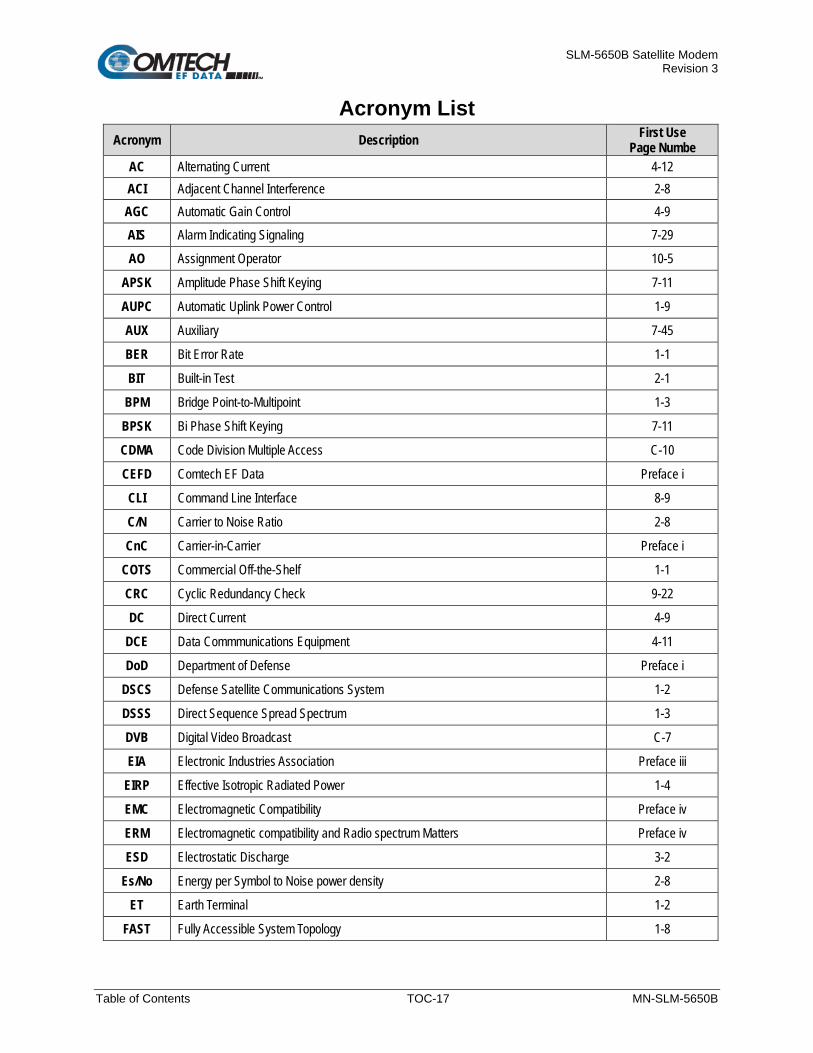
SLM-5650B Satellite Modem Revision 3
Table of Contents TOC-17 MN-SLM-5650B
Acronym List Acronym Description First Use
Page Numbe AC Alternating Current 4-12 ACI Adjacent Channel Interference 2-8 AGC Automatic Gain Control 4-9
AIS Alarm Indicating Signaling 7-29
AO Assignment Operator 10-5
APSK Amplitude Phase Shift Keying 7-11
AUPC Automatic Uplink Power Control 1-9
AUX Auxiliary 7-45
BER Bit Error Rate 1-1
BIT Built-in Test 2-1
BPM Bridge Point-to-Multipoint 1-3
BPSK Bi Phase Shift Keying 7-11
CDMA Code Division Multiple Access C-10
CEFD Comtech EF Data Preface i
CLI Command Line Interface 8-9
C/N Carrier to Noise Ratio 2-8
CnC Carrier-in-Carrier Preface i
COTS Commercial Off-the-Shelf 1-1
CRC Cyclic Redundancy Check 9-22
DC Direct Current 4-9
DCE Data Commmunications Equipment 4-11
DoD Department of Defense Preface i
DSCS Defense Satellite Communications System 1-2
DSSS Direct Sequence Spread Spectrum 1-3
DVB Digital Video Broadcast C-7
EIA Electronic Industries Association Preface iii
EIRP Effective Isotropic Radiated Power 1-4
EMC Electromagnetic Compatibility Preface iv
ERM Electromagnetic compatibility and Radio spectrum Matters Preface iv
ESD Electrostatic Discharge 3-2
Es/No Energy per Symbol to Noise power density 2-8
ET Earth Terminal 1-2
FAST Fully Accessible System Topology 1-8

SLM-5650B Satellite Modem Revision 3
Table of Contents TOC-18 MN-SLM-5650B
Acronym Description First Use Page Numbe
FCS Frame Check Sequence 9-22
FDMA Frequency Division Multiple Access 1-1
FEC Forward Error Correction 1-1
FIFO First In First Out 9-22
FIPS Federal Information Processing Standards F-1
FPGA Field-programmable Gate Array C-7
FTP File Transfer Protocol 5-1
GbE Gigabit Ethernet 1-6
GND Ground 4-12
HDLC High-level Data Link Control 1-6
HP High Performance 2-3
HSSI High Speed Serial Interface 1-5
IAW In Accordance with 1-4
IBS Intelsat Busincess Service 2-1
IDR Intelsat Intermediate Data Rate 2-1
IESS Intelsat Earth Station Standards 1-4
IF Intermediate Frequency 1-2
IGMP Internet Group Management Protocol E-47
ITA Information Throughput Adaption 7-10
LAN Local Area Network 1-6
LCD Liquid Crystal Display 7-4
LDPC Low Density Parity Check 1-3
LED Light Emitting Diode 1-12
LL Low Latency 2-3
LVD Low Voltage Directive Preface v
LVDS Low Voltage Differential Signaling 1-3
MAC Media Access Control 9-22
M&C Monitor and Control 4-11
MIB Management Information Base 8-2
MTU Maximum Transmit Unit E-54
NMS Network Management System 8-2
NP Network Processor 1-3
OID Object Identifier 8-5

SLM-5650B Satellite Modem Revision 3
Table of Contents TOC-19 MN-SLM-5650B
Acronym Description First Use Page Numbe
OSPF Open Shortest Path First E-6
PC Personal Computer 1-1
PCB Printed Circuit Board 4-1
PEM Privacy-enhanced Electronic Mail 9-5
PSK Phase Shift Keying 1-1
QO Query Operator 10-5
QoS Quality of Service E-15
QPSK Quadrature Phase Shift Key 7-11
RF Radio Frequency 1-7
RMA Return Material Authorization Preface vii
RoHS Restriction of Hazardous Substances in Electrical and Electronic Equipment Preface vi
R-S Reed Solomon 2-4
RSL Receive Signal Level 7-43
RTS Request to Send 7-13
SCPC Single Channel per Carrier 1-6
SCT Serial Clock Transmit Send Clock Timing
2-2 7-14
SEQ Sequential Encoder/Decoder 7-10
SLEP Satellite Life Enhancement Program 1-2
SNMP Simple Network Management Protocol 8-2
SSH Secure Shell 8-2
SSL Secure Socket Layer 8-2
STANAG North Atalantic Treaty Organization (NATO) Standardination Agreement 1-3
TCC Turbo Convolution Codes C-5
TCM Trellis Coded Modulation C-2
TEK Transmission Encryption Keys F-8
ToS Type of Service E-40
TPC Turbo Product Coding (or Codes) 2-3
TRANSEC Transmission Security 1-3
UART Universal Asynchronous Receiver Transmitter 10-2
UDP User Datagram Protocol D-4
ULL Ultra Low Latency 2-3
URL Uniform Resource Locator 9-5
VFD Vacuum Fluorescent Display 1-12
VLAN Virtual Local Area Network E-39

SLM-5650B Satellite Modem Revision 3
Table of Contents TOC-20 MN-SLM-5650B
Acronym Description First Use Page Numbe
VNMS Vipersat Network Management System 1-1
WAN Wide Area Network 1-6
WGS Wideband Global Satcom 1-2
1RU One Rack Unit 1-11
8 PSK 8 Phase Shift Keying 7-11
8 QAM 8 Quadrature Amplitude Modulation 7-11
16 QAM 16 Quadrature Amplitude Modulation 7-11
Units of Measurement
Unit / Symbol Definition Ω Ohm A Ampere
bps bits per second ˚C Celsius (degrees) Hz Hertz kHz kiloHertz dB decibel dBc Decibels relative to the carrier dBm Decibel-milliwatts ˚F Fahrenheit (degrees)
Kbps Kilobit per second kg kilogram
ksps Kilosymbols per second lbs. pounds mA Milli-amp
Mbps Megabit per second MHz Megahertz mm millimeter ms millisecond
Msps Megasymbols per second mW milliwatt in. inch
Ppm Packets per minute Pps Packets per second SR Symbols per second ųF 100 micro-farads W Watt V Volt

SLM-5650B Satellite Modem Revision 3
Preface i MN-SLM-5650B
PREFACE
About this Manual This manual describes the installation and operation procedures for the Comtech EF Data (CEFD) SLM-5650B Satellite Modem. This document is intended for the persons responsible for the operation and maintenance of the SLM-5650B.
Conventions and References
Patents and Trademarks See all CEFD's Patents and Patents Pending at http://patents.comtechefdata.com.
CEFD acknowledges that all trademarks are the property of the trademark owners.
• DoubleTalk® is licensed from “Raytheon Applied Signal Technology”.
• DoubleTalk® is a registered trademark of “Raytheon Applied Signal Technology”.
• Carrier-in-Carrier® is a registered trademark of Comtech EF Data.
Related Documents The following documents are referenced in this manual:
• Department of Defense (DOD) MIL-STD-188-114A, Electrical Characteristics of Digital Interface Circuits
• Department of Defense (DOD) MIL-STD-188-165A, Interoperability and Performance Standards for SHF Satellite Communications PSK Modems (FDMA Operation) (dated November 2005)
• Department of Defense (DOD) MIL-STD-461F, Requirements for the Control of Electromagnetic Interference Characteristics of Subsystems and Equipment
• Department of Defense (DOD) MIL-S-901D, Grade A, Requirements for Shock Tests High-Impact (H.I.) for Shipboard Machinery, Equipment, and Systems, Rev D
• INTELSAT Earth Station Standards IESS-308, -309, -310, and -315
• EUTELSAT SMS

SLM-5650B Satellite Modem Revision 3
Preface ii MN-SLM-5650B
Military Standards References to “MIL-STD-188” apply to the 114A series (i.e., MIL-STD-188-114A), which provides electrical and functional characteristics of the unbalanced and balanced voltage digital interface circuits applicable to both long haul and tactical communications. Specifically, these references apply to the MIL-STD-188-114A electrical characteristics for a balanced voltage digital interface circuit, Type 1 generator, for the full range of data rates. For more information, refer to the Department of Defense (DOD) MIL-STD-188-114A, Electrical Characteristics of Digital Interface Circuits.
Warnings, Cautions, Notes, and References
A WARNING indicates a potentially hazardous situation that, if not avoided, could result in death or serious injury.
A CAUTION indicates a hazardous situation that, if not avoided, may result in minor or moderate injury. CAUTION may also be used to indicate other unsafe practices or risks of property damage.
A NOTE: gives you important information about a task or the equipment.
A REFERENCE directs you to important operational information or details furnished elsewhere, either in the manual or in adjunct Comtech EF Data publications.
Examples of Multi-Hazard Notices

SLM-5650B Satellite Modem Revision 3
Preface iii MN-SLM-5650B
Recommended Standard Designations The Electronic Industries Association (EIA) designations supersede the Recommended Standard (RS) designations. References to the old designations may be shown when depicting actual text (e.g., RS-232) displayed on front panel menus, Web Server pages, serial remote interfaces, Telnet Command Line Interfaces (CLIs), or unit rear panels. All other references in the manual refer to EIA designations.
CAUTION Carefully review the following information.
Safety and Compliance
Electrical Safety and Compliance The unit complies with the EN 60950 Safety of Information Technology Equipment (Including Electrical Business Machines) safety standard.
Electrical Installation
CAUTION Connect the unit to a power system that has separate ground, line and neutral conductors. Do not connect the unit without a direct connection to ground.
Class I Pluggable Equipment Type A-Protective Earthing The cable distribution system/telecommunication network of this product relies on protective earthing and the integrity of the protective earthing must be ensured.
In Finnish: Tämän tuotteen kaapelijakelujärjestelmä / tietoliikenneverkko on suojattu maadoitukselta ja suojaavan maadoituksen eheys on varmistettava.
In German: Das Kabelverteilungssystem / Telekommunikationsnetz dieses Produkts beruht auf Schutzerdung und die Unversehrtheit der Schutzerdung muss gewährleistet sein.
In Norwegian: Kabelfordelingssystemet / telekommunikasjonsnettverket av dette produktet er avhengig av beskyttende jordforbindelse og integriteten til beskyttende jordforbindelse må sikres.
In Swedish: Kabeldistributionssystemet / telekommunikationsnätet för denna produkt är beroende av skyddande jordning och skyddskretsens integritet måste säkerställas.

SLM-5650B Satellite Modem Revision 3
Preface iv MN-SLM-5650B
Galvanic Isolator Use Equipment that is connected to protective earth via grounded wall socket and / or via other equipment and at the same time connected to cable TV networks may, in some cases, result in fire hazard. To avoid this, when connecting the equipment to the cable TV network, the galvanic insulator should be located between the equipment and the cable TV network.
In Finnish: Laitteet, jotka on liitetty suojaamaan maahan maadoitetun seinäpistokkeen ja / tai muiden laitteiden välityksellä ja jotka ovat samaan aikaan kytkettyinä kaapelitelevisioverkkoihin, voivat joissakin tapauksissa aiheuttaa tulipalovaaran. Tämän välttämiseksi galvaaninen eristin on sijoitettava laitteen ja kaapelitelevisioverkon välille kytkettäessä laitteita kaapelitelevisioverkkoon.
In German: Geräte, die über eine geerdete Wandsteckdose und / oder über andere Geräte mit Schutzerde verbunden sind und gleichzeitig an Kabelfernsehnetze angeschlossen sind, können in einigen Fällen eine Brandgefahr darstellen. Um dies zu vermeiden, sollte sich der galvanische Isolator beim Anschluss des Geräts an das Kabelfernsehnetz zwischen dem Gerät und dem Kabelfernsehnetz befinden.
In Norwegian: Utstyr som er koblet til beskyttende jord via jordet stikkontakt og / eller via annet utstyr og samtidig koblet til kabel-TV-nettverk, kan i noen tilfeller føre til brannfare. For å unngå dette, bør du montere galvanisk isolator mellom utstyret og kabel-TV-nettverket når du kobler utstyret til kabel-TV-nettverket.
In Swedish: Utrustning som är kopplad till skyddsjord via jordat vägguttag och/eller via annan utrustning och samtidigt är kopplad till kabel-TV nät kan i visa fall medfőra risk főr brand. Főr att undvika detta skall vid anslutning av utrustningen till kabel-TV nät galvanisk isolator finnas mellan utrustningen och kabel-TV nätet.
Restricted Access Location In Nordic Countries, equipotential bonding should be applied using the permanently connected ground stud by a qualified service person.

SLM-5650B Satellite Modem Revision 3
Preface v MN-SLM-5650B
Battery Warning
CAUTION Risk of explosion if battery is replaced by an incorrect type. Dispose of used batteries according to the instructions.
Operating Environment
CAUTION DO NOT OPERATE THE UNIT IN ANY OF THESE EXTREME OPERATING CONDITIONS:
• AMBIENT TEMPERATURES LESS THAN 0° C (32° F) OR MORE THAN 50°C (122°F) FOR STANDARD UNITS; FOR UNITS WITH THE EXTENDED TEMPERATURE OPTION, AMBIENT TEMPERATURES LESS THAN -32°C (-25°F) OR MORE THAN 50°C (122°F)
• PRECIPITATION, CONDENSATION, OR HUMID ATMOSPHERES OF MORE THAN 95% RELATIVE HUMIDITY
• UNPRESSURIZED ALTITUDES OF MORE THAN 2000 METRES (6561.7 FEET)
• EXCESSIVE DUST • FLAMMABLE GASES • CORROSIVE OR EXPLOSIVE ATMOSPHERES
European Union Radio Equipment and Telecommunications Terminal Equipment (R&TTE) Directive (1999/5/EC) and EN 301 489-1
Independent testing verifies that the unit complies with the European Union R&TTE Directive, its reference to EN 301 489-1 (Electromagnetic compatibility and Radio spectrum Matters [ERM]; ElectroMagnetic Compatibility [EMC] standard for radio equipment and services, Part 1: Common technical requirements), and the Declarations of Conformity for the applicable directives, standards, and practices that follow:

SLM-5650B Satellite Modem Revision 3
Preface vi MN-SLM-5650B
European Union Electromagnetic Compatibility (EMC) Directive (2004/108/EC)
• Emissions: EN 55022 Class B – Limits and Methods of Measurement of Radio Interference Characteristics of Information Technology Equipment.
• Immunity: EN 55024 – Information Technology Equipment: Immunity Characteristics, Limits, and Methods of Measurement.
• EN 61000-3-2 – Harmonic Currents Emission • EN 61000-3-3 – Voltage Fluctuations and Flicker. • Federal Communications Commission Federal Code of Regulation FCC Part 15,
Subpart B
CAUTION To ensure that the unit complies with these standards, obey the following instructions.
• Use coaxial cable that is of good quality for connections to the L-Band Type ‘N’ Rx (receive) female connector.
• Use Type 'D' connectors that have back-shells with continuous metallic shielding. Type ‘D’ cabling must have a continuous outer shield (either foil or braid, or both). The shield must be bonded to the back-shell.
• Operate the unit with its cover on at all times for air circulation/cooling.
European Union Low Voltage Directive (LVD) (2006/95/EC)
Symbol Description
<HAR> Type of power cord required for use in the European Community.
CAUTION: Double-pole/Neutral Fusing.
International Symbols
Symbol Definition Symbol Definition
Alternating Current Protective Earth
Fuse Chassis Ground
For additional symbols, refer to Warnings, Cautions, Notes and References listed earlier in this Preface.
European Union RoHS Directive (2002/95/EC) This unit satisfies (with exemptions) the requirements specified in the European Union Directive on the Restriction of Hazardous Substances in Electrical and Electronic Equipment (EU RoHS, Directive 2002/95/EC).
!

SLM-5650B Satellite Modem Revision 3
Preface vii MN-SLM-5650B
European Union Telecommunications Terminal Equipment Directive (91/263/EEC) In accordance with the European Union Telecommunications Terminal Equipment Directive 91/263/EEC, the unit should not be directly connected to the Public Telecommunications Network.
CE Mark Comtech EF Data declares that the unit meets the necessary requirements for the CE Mark.
Product Support For all product support, please call:
+1.240.243.1880
+1.866.472.3963 (toll free USA)
By email: [email protected]
Comtech EF Data Headquarters http://www.comtechefdata.com Comtech EF Data Corp. 2114 West 7th Street Tempe, Arizona USA 85281 +1.480.333.2200
SLM-5650B Satellite Modem Revision 3
Preface viii MN-SLM-5650B
Warranty Policy Comtech EF Data products are warranted against defects in material and workmanship for a specific period from the date of shipment, and this period varies by product. In most cases, the warranty period is two years. During the warranty period, Comtech EF Data will, at its option, repair or replace products that prove to be defective. Repairs are warranted for the remainder of the original warranty or a 90-day extended warranty, whichever is longer. Contact Comtech EF Data for the warranty period specific to the product purchased.
For equipment under warranty, the owner is responsible for freight to Comtech EF Data and all related customs, taxes, tariffs, insurance, etc. Comtech EF Data is responsible for the freight charges only for return of the equipment from the factory to the owner. Comtech EF Data will return the equipment by the same method (i.e., Air, Express, Surface) as the equipment was sent to Comtech EF Data.
All equipment returned for warranty repair must have a valid Return Material Authorization (RMA) number issued prior to return and be marked clearly on the return packaging. Comtech EF Data strongly recommends all equipment be returned in its original packaging.
Comtech EF Data Corporation’s obligations under this warranty are limited to repair or replacement of failed parts, and the return shipment to the buyer of the repaired or replaced parts.
Limitations of Warranty The warranty does not apply to any part of a product that has been installed, altered, repaired, or misused in any way that, in the opinion of Comtech EF Data Corporation, would affect the reliability or detracts from the performance of any part of the product, or is damaged as the result of use in a way or with equipment that had not been previously approved by Comtech EF Data Corporation.
The warranty does not apply to any product or parts thereof where the serial number or the serial number of any of its parts has been altered, defaced, or removed.
The warranty does not cover damage or loss incurred in transportation of the product. The warranty does not cover replacement or repair necessitated by loss or damage from any cause beyond the control of Comtech EF Data Corporation, such as lightning or other natural and weather related events or wartime environments.
The warranty does not cover any labor involved in the removal and or reinstallation of warranted equipment or parts on site, or any labor required to diagnose the necessity for repair or replacement.
The warranty excludes any responsibility by Comtech EF Data Corporation for incidental or consequential damages arising from the use of the equipment or products, or for any inability to use them either separate from or in combination with any other equipment or products.
A fixed charge established for each product will be imposed for all equipment returned for warranty repair where Comtech EF Data Corporation cannot identify the cause of the reported failure.

SLM-5650B Satellite Modem Revision 3
Preface ix MN-SLM-5650B
Exclusive Remedies Comtech EF Data Corporation’s warranty, as stated is in lieu of all other warranties, expressed, implied, or statutory, including those of merchantability and fitness for a particular purpose. The buyer shall pass on to any purchaser, lessee, or other user of Comtech EF Data Corporation’s products, the aforementioned warranty, and shall indemnify and hold harmless Comtech EF Data Corporation from any claims or liability of such purchaser, lessee, or user based upon allegations that the buyer, its agents, or employees have made additional warranties or representations as to product preference or use.
The remedies provided herein are the buyer’s sole and exclusive remedies. Comtech EF Data shall not be liable for any direct, indirect, special, incidental, or consequential damages, whether based on contract, tort, or any other legal theory.

SLM-5650B Satellite Modem Revision 3
Preface x MN-SLM-5650B
BLANK PAGE

SLM-5650B Satellite Modem Revision 3
Introduction 1–1 MN-SLM-5650B
Chapter 1. INTRODUCTION
1.1 Overview
Figure 1-1. SLM-5650B Satellite Modem
The SLM-5650B Satellite Modem (Figure 1-1), satisfies the requirements for government and military communications system applications that require state-of-the-art modulation and coding techniques to optimize satellite transponder bandwidth usage, while retaining backward compatibility.
The SLM-5650B:
• Supports baseband data rates up to 155.52 Mbps, and its flexible modulation and Forward Error Correction (FEC) capabilities ensure that the throughput and Bit Error Rate (BER) over the satellite is optimized.
• Is compliant with the provisions of Department of Defense (DoD) Standard MIL-STD-188-165A, Interoperability of SHF Satellite Communications PSK Modems (Frequency Division Multiple Access [FDMA] Operation).
• Is fully interoperable with legacy OM-73 modems and other Government owned Commercial Off-the-Shelf (COTS) and International Telecommunications Satellite Organization (Intelsat) compatible Phase Shift Keying (PSK) modems.
• Can be controlled and monitored from a variety of platforms, including its own front panel controls and indicators, and/or a co-located Personal Computer (PC), and remote control systems such as the Vipersat Network Management System (VNMS).

SLM-5650B Satellite Modem Revision 3
Introduction 1–2 MN-SLM-5650B
1.2 Functional Description
Figure 1-2. SLM-5650B Block Diagram
Figure 1-2 depicts the functional block diagram for the SLM-5650B. The modem has been designed to accommodate a wide range of currently required features, and to support both near- and far-term advances in software-defined radio technology as well as advances in FEC technology. It is designed for installation in fixed or mobile Earth Terminal (ET) facilities (sites) using Defense Satellite Communications System III (DSCS III), DSCS III/Satellite Life Enhancement Program (SLEP), Wideband Global Satcom (WGS), and commercial satellites.
The user has the ability to:
• Add or change modular data interfaces • Utilize an extensive array of built-in test capabilities • Easily upgrade the modem’s operational capabilities in the field • Easily update the modem’s firmware in the field • Use a wide range of flexible remote control options
As shown in Figure 1-2, the modem accepts signals from a selected digital signal source and modulates either a 70/140 MHz or L-Band Intermediate Frequency (IF) carrier with these signals. The demodulator receives the Rx signal from either the 70/140 MHz or L-Band IF input interface, then demodulates the IF carrier. Clock and data are recovered and output on a selected data interface.
The Tx and Rx functions are independent with respect to coding, interleaving, overhead, and scrambling. The modem does not allow simplex operation in the 70/140 and the L-Band IF interfaces at the same time. The modem allows duplex operation in either one of the two IF interfaces.
M&C – TX FPGA Lanes (1.8V)
TX FPGAAltera 10AX066H2F34
(1.2V & 1.8V I/O)
2 Ch DAC (DAC3482,
900mW)TX RF Front
2 Ch ADC(LTC2157-14,
650mW)RX RF Front
RF Loopback
Modulation I & Q
Symbols
Baseband Loopback
TX I & Q Samples (LVDS)
M&C MVF51NN151
(3.3V I/O)
25MHz
EIA-530Prim
ary Data Port
HSSI
Primary D
ata PortR
J45(M
odem C
ontrol)R
J45(G
igaBit Interface)
LVD
S / E
CL
Tran
slat
or(N
B100
LVEP
91)
3.3
/ 1.8
VTr
ansl
ator
Marvell Ethernet Switch
(88E6321)
EIA Pri TX (1.8V)
HSSI Pri TX (LVDS)
HSSI Pri RX (LVDS)
EIA Pri RX (1.8V)
20MHz System Reference
250MHz VCXO
PLL
70/140MHzTX RF Output
L-BandTX RF Output
70/140MHzRX RF Input
L-BandRX RF Input
PLL Reference Input(1, 2, 5 or 10MHz)
TRANSEC(3.3V I/O)
Turbo Codec(3.3V I/O)
DDR4
DDR4
Turbo TX
Turbo RX
3.3 / 1.8V Level Translator
3.3 / 1.8V Level TranslatorEIA-530
Overhead D
ata Port
3.3
/ 1.8
VTr
ansl
ator
RX FPGAAltera 10AX066H2F34
(1.2 & 1.8 I/O)
EIA OH TX (1.8V)
EIA OH RX (1.8V)
Alarms
Rem
oteAuxiliary
Unit AlarmsTX AlarmsRX Alarms M&C
LCMX02FPGA / CPLD
(3.3V I/O)
M&C Config (1.8V)
M&C Config (3.3V)
250MHzClock Distributor
IP RX (RGMII)
IP TX (RGMII)
UART TXUART RX
SD Card AdapterDDR 3
Front Panel Connector
M&C Config
High Speed Tranceivers
Quad 16-bit nanoDAC
(AD5685R)
Quad 16-bit nanoDAC
(AD5685R)AGC
3.3 / 1.8V Level Translator
3.3 / 1.8V Level Translator
1.8V SPI
1.8V SPI
RX I & Q Samples (LVDS)
1.8V SPI
1.8V SPI
AGC
Power Supply
0.9V
1.8V
2.5V
(for
DD
R4)
3.3V
+12V-3.3V
Option Card Connector
IP Traffic (SerDes)
25MHz
25MHz
1.2V
(for
DD
R4)
SCT DAC
SCT (LVDS & 1.8V)
SCT (LVD
S)
RXC (LVDS)
192MHz (LVDS)
SCT
RX C
lock
10MHz Ref (3.3V)
192MHz (LVDS)
MRAM
M&C Config (3.3V)
RX Clock DAC
24MHz
32.768kHz
3V
FIPS TX (LVDS)
FIPS RX (LVDS)
RXC (LVDS & 1.8V)
M&C – RX FPGA Lanes (1.8V)
M&C – RX FPGALanes (1.8V)
M&C – TX FPGALanes (1.8V)
M&C
Config (3.3V)
M&C Config (MDIO)IP Traffic (RMII)
M&C Config (1.8V)
IP Traffic (SerDes)
Diff
eren
tial /
Si
ngle
Buf
fer
Diff
eren
tial /
Si
ngle
Buf
fer
SCT (1.8V)RXC (1.8V)

SLM-5650B Satellite Modem Revision 3
Introduction 1–3 MN-SLM-5650B
1.3 Product Features The SLM-5650B incorporates the following features:
• MIL-STD-188-165A compliance (Types A, B, D, E, F) • Intelsat IESS-308, -309, -310, and -315 • A rugged, one-rack unit (1RU) enclosure • Low weight and low power dissipation • Selectable 70/140 MHz or L-Band (950 to 2000 MHz) IF interfaces • EIA-530/422 Data Interface (built-in, to 20 Mbps) • EIA-613/HSSI Data Interface (built-in, to 51.84 Mbps) • EIA-485/EIA-232 Interface for serial remote control • Ethernet Interface for remote control using Telnet, SNMP, HTTP, HTTPS, and SSH • Plug-in Data Interface supporting the optional Network Processor (NP), G.703, and Low
Voltage Differential Signaling (LVDS) modules • On board GigE Bridge • Asymmetrical Loop Timing • Data Source Bit Synchronization (Clock recovery for input data without an associated
transmit clock) • Full-featured, built-in BER test-set • Electrical and Ethernet Rx constellation monitor • Adaptive Equalizer for high order modulation types • 64 kbps to 155.52 Mbps (Modulation-, code rate-, and interface-dependent) • BPSK, QPSK, OQPSK, 8PSK, 8QAM, and 16QAM • FEC Rates: 5/16, 1/3, 1/4, 1/2, 2/3, 3/4, 5/6, 7/8, 21/44, 17/18, .378, .451, .541, and 1/1
Rate 19/20 is only available in the North Atlantic Treaty Organization (NATO) Standardization Agreement (STANAG) mode
• Viterbi and Reed-Solomon Codec • Turbo Product Codec • Low-Density Parity Check (LDPC) coding in three block sizes: ULL, LL, and HP (optional) • Direct Sequence Spread Spectrum (DSSS) (optional with LDPC) • Sequential FEC (optional) • Static Bridge, Router, and Bridge Point-to-Multipoint (BPM) Modes (via the optional NP
Interface) • TRANSEC Encryption (optional) • Firmware updating capability • 10 MHz BUC and LNB references • LNB Power

SLM-5650B Satellite Modem Revision 3
Introduction 1–4 MN-SLM-5650B
1.3.1 Operational Features
1.3.1.1 Operating Modes The SLM-5650B supports Closed Network, Open Network and OM-73 modes of operation.
1.3.1.1.1 Closed Networks Closed Networks refer to private networks with modem operational parameters that do not need to interoperate with modems developed for commercial open networks (as specified in accordance with (IAW) Intelsat Earth Station Standards (IESS) -308, IESS-309, and IESS-310 requirements for open network operation).
A Comtech EF Data (CEFD) overhead channel is provided so that the modem is capable of operating in such closed networks over commercial satellites IAW Intelsat requirements for use during closed network operation.
1.3.1.1.2 Open Networks (Intelsat) Open Networks refer to networks that must meet Intelsat specifications for Effective Isotropic Radiated Power (EIRP), EIRP stability, spurious emissions, intermodulation products, adjacent carrier interference, frequency tolerance, equalization, and modem parameters such as modulation, FEC, and scrambling.
The SLM-5650B meets Intelsat certification requirements and is capable of operating in such open networks over commercial satellites (as specified IAW IESS-308, IESS-309, and IESS-310 requirements for open network operation).
The modem supports the overhead framing integral to those modems, in order to be fully compatible with commercial modems complying with IESS-308, IESS-309, and IESS-310.
No access is provided to the overhead channel data or alarms.
1.3.1.1.3 OM-73 Mode The OM-73 Mode allows the SLM-5650B to be compatible with Linkabit’s OM-73 modem. This modem and its operational capabilities have become a de facto standard when operating over DSCS satellites. All OM-73 modes listed in MIL-STD-188-165A are supported.

SLM-5650B Satellite Modem Revision 3
Introduction 1–5 MN-SLM-5650B
1.3.1.2 Secure Management Interfaces
Chapter 8. ETHERNET MANAGEMENT Chapter 9. BASE MODEM HTTP/HTTPS INTERFACE Appendix E. OPTIONAL NETWORK PROCESSOR (NP) INTERFACE MODULE Appendix F. OPTIONAL TRANSEC MODULE OPERATION
The SLM-5650B supports secure management interfaces, as part of its Management Security option.
Detailed information about these configurations and modes, and their functional association with the Base Modem, NP Interface Module and/or the TRANSEC Module, is provided in the following chapters in this manual:
1.3.1.3 Data Interfaces
Appendix D. OPTIONAL DATA INTERFACE MODULES Appendix E. OPTIONAL NETWORK PROCESSOR (NP) INTERFACE MODULE
The SLM-5650B supports only one data interface at a time. The modem features two native data interfaces (TIA/EIA-530/422 and TIA/EIA-613 [HSSI]), plus an option slot for installation of a modular data interface. The optional modular interfaces available at this time are the Network Processor, G.703, LVDS, and GigE Bridge.
1.3.1.3.1 TIA/EIA-530 Interface The native TIA/EIA-530 interface supports the physical layer requirements for TIA/EIA-530. It also supports the TIA/EIA-422 electrical interface specification. This interface operates in duplex from 64 kbps to 20 Mbps.
1.3.1.3.2 TIA/EIA-613 High Speed Serial Interface (HSSI) The native TIA/EIA-613 interface supports the physical layer requirements for TIA/EIA-613. It also supports the TIA/EIA-612 electrical interface specification. This interface operates in duplex from 64 kbps to 51.84 Mbps.

SLM-5650B Satellite Modem Revision 3
Introduction 1–6 MN-SLM-5650B
1.3.1.3.3 Network Processor (NP) Module Option The optional NP Interface is CEFD’s third generation IP router, Ethernet bridge, and BPM device. The interface is designed to process more than 150,000 packets per second (pps) in Layer 2, Layer 3, or Brouter mode of operation. The NP Interface supports the following operating modes:
• Layer 2 Ethernet Bridge Mode • Layer 2 and Layer 3 Single Channel per Carrier (SCPC) Ethernet Router Mode • Layer 2 and Layer 3 Vipersat Router Mode • Layer 3 SCPC IP Router Mode • Layer 3 Vipersat STDMA Router Mode
1.3.1.3.4 G.703 T1/E1, T2/E2 Module Option The optional G.703 T1/E1, T2/E2 interface is designed for full duplex capability and is automatically configured for simplex transmit or simplex receive operation The interface operates at the digital hierarchy bit rates of 1.544, 2.048, 6.312, and 8.448 Mps as defined by ITU-T G.703.
1.3.1.3.5 Low Voltage Differential Signaling (LVDS) Module Option The optional LVDS interface provides a physical and electrical interface between an SLM-5650B modulator and demodulator and signal sources operating with LVDS electrical characteristics.
1.3.1.3.6 10/100/1000BASE-T (Gigabit Ethernet) Module Option
Appendix G. OPTIONAL 10/100/1000BASE-T (GBE) INTERFACE
The optional 10/100/1000BASE-T (Gigabit Ethernet, or GbE) interface performs a simple bridge function and passes IP packets, unaltered, in each direction between the Local Area Network (LAN) (10/100/1000BASE-T interface) and Wide Area Network (WAN) (SLM-5650B modulator/demodulator).
IP packet traffic is framed via High-level Data Link Control (HDLC) encapsulation by the SLM-5650B logic, and the SLM-5650B is both the origination and termination point for HDLC encapsulation. HDLC CRC-16 verification is performed on all received (from WAN) HDLC frames.

SLM-5650B Satellite Modem Revision 3
Introduction 1–7 MN-SLM-5650B
1.3.1.4 Independent Tx and Rx Function The Tx (modulator) and Rx (demodulator) sides of the modem are functionally independent and separately controllable. The baseband Tx and Rx sides of a communications channel passing through the modem are independently configurable, including the ability to select different parameters (to include data rate, modulation, and coding) in support of asymmetrical operation.
Data interfaces and IF interfaces are not independent. Example: If the TIA/EIA-530 interface is selected, DO NOT USE TIA/EIA-530 to transmit and a HSSI interface to receive. The same principle applies to the IF interfaces: If 70/140 is selected, DO NOT USE 70/140 to transmit and the L-Band interface to receive.
1.3.1.5 Verification The SLM-5650B includes test modes and loopbacks for rapid verification of the correct functioning of the modem. Of particular note is the IF loopback, which permits the user to perform a quick diagnostic test without having to disturb external cabling. During the loopback, the receive frequency is temporarily changed to match that of the Tx side, and an internal Radio Frequency (RF) switch connects the modulator output to the demodulator input. When normal operation is again selected, all of the previous values are restored.
1.3.1.6 Updating Modem Firmware
Chapter 5. FIRMWARE UPDATE
The SLM-5650B stores its firmware in flash memory, which allows the modem to upload firmware downloads from an external PC once Ethernet connectivity has been established. Firmware updates for the Base Modem and NP Interface Module may be obtained free from CEFD via the CEFD Web site or via e-mail from CEFD Customer Support during normal business hours.
TRANSEC Module firmware updates must be requested directly from CEFD Customer Support.

SLM-5650B Satellite Modem Revision 3
Introduction 1–8 MN-SLM-5650B
1.3.1.7 Fully Accessible System Topology (FAST)
Chapter 6. FAST ACTIVATION PROCEDURE
The SLM-5650B incorporates a number of optional features. In order to permit a lower initial cost, the unit may be purchased with only the desired features enabled.
If, at a later date, the user wishes to upgrade the functionality of a unit, CEFD provides Fully Accessible System Topology (FAST), a technology which permits the purchase and installation of options through special authorization codes. These unique FAST Access Codes may be purchased from CEFD during normal business hours, and then loaded into the unit using the front panel keypad.
FAST System Theory FAST allows an operator to order a unit precisely tailored for the initial application. When service requirements change, FAST allows the operator to upgrade the topology of the unit on-location, within minutes, and without having to remove the unit from the setup. This accelerated upgrade is possible due to FAST’s extensive use of the programmable logic devices incorporated into CEFD products.
FAST Implementation CEFD’s FAST system is factory-implemented in the modem. All FAST options are available through the basic platform unit at the time of order. FAST allows immediate activation of available options – first, upon entry of the FAST Access Code through the front panel keypad, and then by setting the desired operational parameters via the front panel, remote control, or Web Server interfaces.
1.3.1.7.1 FAST Accessible Options SLM-5650B hardware options can be ordered and installed either at the factory or in the field. The following FAST-accessible hardware options are available for the SLM-5650B:
• Network Processor Interface Module (Plug-in Card) • TRANSEC Module (Installed Card and FAST) • GigE Panel (default) • G.703 Interface (Plug-in Card) • LVDS Interface (Plug-in Card)
In the field, the operator can select FAST options that can be easily activated, depending on the current hardware configuration of the unit. The unique FAST Access Code that is purchased from CEFD enables configuration of the installed optional hardware. The available firmware-based FAST Options, as listed on the SLM-5650B Front Panel Utility: FAST View Options screens, are as follows:

SLM-5650B Satellite Modem Revision 3
Introduction 1–9 MN-SLM-5650B
Table 1-1. FAST Accessible Options
FAST Option
No. Description
01 Tx Data Rate <= 155.52 Mbps
02 Rx Data Rate <= 155.52 Mbps
03 8PSK/8QAM Modulation
04 16-QAM Modulation
05 TURBO FEC Option
06 LDPC FEC Option
07 Sequential Encoder/Decoder
08 Triple Viterbi
09 Reed-Solomon Coding
10 Spectrum Spreading
11 Reserved0
12 Reserved1
13 Automatic Uplink Power Control (AUPC) Overhead
14 ASYNC ESC
15 Demodulator Only
16 CnC Data Rate <= 155 Mbps
17 Network Processor I/F Card
18 Transec Module
19 Transec Data Rate <= 155 Mbps
20 NP QoS
21 NP Management Security
22 Vipersat Data Rate <= 155 Mbps
23 NP OW Serial Commands
24 NP BPM Mode
25 NP Antenna Handover
26 DSSS-MA Option
27 STANAG Waveforms

SLM-5650B Satellite Modem Revision 3
Introduction 1–10 MN-SLM-5650B
1.3.1.8 Interoperability
1.3.1.8.1 Legacy Modems The SLM-5650B is fully compatible and interoperable with all specified modes of operation of the following legacy modems:
• MD-1030B • MD-1340 (OM-73 interoperable mode only; orderwire not required) • MD-1352 (P)/U (BEM-7650) • OM-73 (V) • SLM-3650 • SLM-5650 • SLM-5650A • SLM-7650 • SLM-8650
The serial interface remote control protocol is NOT backwards compatible.
1.3.1.8.2 Modem Switches To ensure operational reliability, the SLM-5650B may be incorporated into a number of CEFD switching products. These switches are compatible only with CEFD modems; this switch/modem compatibility is further defined for the SLM-5650B as follows:
Table 1-2. Modem Switches
Compatible Non-compatible
• CRS-300 1:10 Redundancy Switch • CRS-311 1:1 Redundancy Switch • CRS-311-AH Antenna Handover Switch
• CRS-500 • SMS-300 Series Redundancy Switches • SMS-450 Series Satellite Switches • SMS-7000 Modem Protection Switch
For detailed information on using the SLM-5650B in 1:1/1:N redundancy or Antenna Handover applications, refer to the pertinent switch Installation and Operation Manual.

SLM-5650B Satellite Modem Revision 3
Introduction 1–11 MN-SLM-5650B
1.4 Physical Features
Chapter 2. SPECIFICATIONS Chapter 3. INSTALLATION
The SLM-5650B is constructed as a One Rack Unit (1RU) high, rack-mount chassis that can be free-standing as needed. Handles at the front ease removal from and placement into a rack.
1.4.1.1 Dimensional Envelope
Figure 1-3. SLM-5650B Dimensional Envelope

SLM-5650B Satellite Modem Revision 3
Introduction 1–12 MN-SLM-5650B
1.4.2 Front Panel
Chapter 7. FRONT PANEL OPERATION
Figure 1-4. SLM-5650B Front Panel
Table 1-3. SLM-5650B Front Panel Features
Item Description Function 1 USB Port Reserved for future software support 2 6-button keypad Local control via menu navigation 3 12-button array Manual data entry 4 10 Light-Emitting Diodes (LEDs) Overall status monitoring at a glance
5 40-character, 2-line Vacuum Fluorescent Display (VFD) Display of messages, menus and prompts
6 On/Off Power Switch (Illuminated switch optional) Unit power
7 Rack handles Eases installation into / removal from rack
Local control of the SLM-5650B is accomplished from the modem’s front panel (Figure 1-4). The function and behavior of the keypad/data entry array, Light Emitting Diode (LED) Indicators, and Vacuum Fluorescent Display (VFD) are described in detail in Chapter 7. FRONT PANEL OPERATION.
1 2 3 4 5 6 7

SLM-5650B Satellite Modem Revision 3
Introduction 1–13 MN-SLM-5650B
1.4.3 Rear Panel
Chapter 4. REAR PANEL CONNECTORS
Figure 1-5. SLM-5650B Rear Panel
External cables are attached to connectors on the SLM-5650B’s rear panel (Figure 1-5). Each connector is described in detail in Chapter 4. REAR PANEL CONNECTORS.

SLM-5650B Satellite Modem Revision 3
Introduction 1–14 MN-SLM-5650B
BLANK PAGE

SLM-5650B Satellite Modem Revision 3
Specifications 2–1 MN-SLM-5650B
Chapter 2. SPECIFICATIONS
2.1 Summary of Specifications Table 2-1. Summary of General Specifications
General Specifications
Parameter Specifications Operating Frequency Range 52 to 88, 104 to 176, 950 to 2000 MHz ( in 100 Hz steps) Modulation Types BPSK, QPSK, OQPSK, 8PSK, 8QAM, 16QAM Digital Data Rates • 64 kbps to 20 Mbps, in 1 bps steps (EIA-530, EIA-613)
• 64 kbps to 51.840 Mbps, in 1 bps steps (EIA-613, LVDS) • 64 kbps to 155.52 Mbps, in 1 bps steps (GbE, NP)
Symbol Rate Range 32 Ks/s to 64 Ms/s EXT REF Input TNC Connector, 1, 5, or 10 MHz selectable INT REF Stability 5 x 10⁻⁸ Scrambling V.35, OM-73, and Synchronous IDR/IBS Framing Compatibility Support for Intelsat Business Service (IBS) and Intermediate Data Rate (IDR)
framing. Allows basic IBS/IDR Open Network capable operation Built-in Test (BIT) Fault and status reporting, BER performance monitoring, IF Loop-back,
programmable test modes, built-in Fireberd emulation with all comprehensive BER measurements.
Summary Faults Reported via Front Panel LEDs, 9-pin D-sub Alarm connector, relay contacts for Tx, Rx, Common equipment faults, and Tx and RX alarms. Open collector faults on the 15-pin D-sub Aux connector. Both data interfaces have open collector faults available.
Monitor and Control EIA-485, EIA-232, 10/100BASE-T Ethernet with HTTP, HTTPS, Telnet, and SNMP
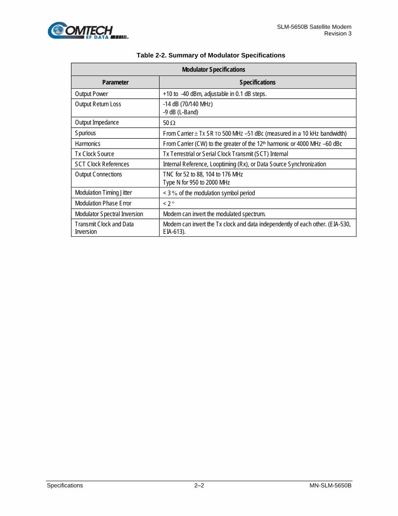
SLM-5650B Satellite Modem Revision 3
Specifications 2–2 MN-SLM-5650B
Table 2-2. Summary of Modulator Specifications
Modulator Specifications
Parameter Specifications Output Power +10 to -40 dBm, adjustable in 0.1 dB steps. Output Return Loss -14 dB (70/140 MHz)
-9 dB (L-Band) Output Impedance 50 Ω Spurious From Carrier ± TX SR TO 500 MHZ –51 dBc (measured in a 10 kHz bandwidth) Harmonics From Carrier (CW) to the greater of the 12th harmonic or 4000 MHz –60 dBc Tx Clock Source Tx Terrestrial or Serial Clock Transmit (SCT) Internal SCT Clock References Internal Reference, Looptiming (Rx), or Data Source Synchronization Output Connections TNC for 52 to 88, 104 to 176 MHz
Type N for 950 to 2000 MHz Modulation Timing Jitter < 3 % of the modulation symbol period Modulation Phase Error < 2 ° Modulator Spectral Inversion Modem can invert the modulated spectrum. Transmit Clock and Data Inversion
Modem can invert the Tx clock and data independently of each other. (EIA-530, EIA-613).

SLM-5650B Satellite Modem Revision 3
Specifications 2–3 MN-SLM-5650B
Table 2-3. Summary of Demodulator Specifications
Demodulator Specifications
Parameter Specifications
Input Power
Desired Carrier
For 70/140 MHz: +10 to -55 dBm
For L-Band: +10 to -55 dBm (SR>3.2 MSPS) +10 to 10·log10(SR/32000) -75 dBM (SR≤3.2 MSPS) where SR is in symbols per second
Maximum Composite +20 dBm or +40 dBc
Input Impedance 50 Ω Input Connectors TNC for 52 to 88, 104 to 176
Type N for 950 to 2000 MHz Carrier Acquisition Range ± 30 kHz, selectable Input Return Loss -14 dB (70/140 MHz)
-9 dB (L-Band) Buffer Clock INT, Tx Terrestrial, Rx Satellite Doppler Buffer 128 to 4,194,304 bits, or 2 to 60 mSec
Table 2-4. Summary of Coding Options
Coding Options
Parameter Specifications
Uncoded 1/1 Viterbi K=7, 1/2, 3/4, and 7/8 rates Viterbi + Reed-Solomon Closed Network, per IESS-308, and IESS-309 Trellis IESS-310 Trellis + Reed-Solomon IESS-310 Turbo Turbo Product Coding (TPC), per IESS-315 Turbo (STANAG) Per STANAG Specifications LDPC: • Ultra Low Latency (ULL), • Low Latency (LL), and • High Performance (HP)
Closed Network

SLM-5650B Satellite Modem Revision 3
Specifications 2–4 MN-SLM-5650B
Table 2-5. Summary of Open Network Options
Open Network Options
Parameter Specifications
IDR • INTELSAT IESS-308 (Framing only) • INTELSAT IESS-310 (Framing only)
IBS • INTELSAT IESS-310 (Framing only) • INTELSAT IESS-309 (Framing only)
Table 2-6. Acquisition and Timing Performance Requirements
Parameter Specification
The following reference Eb/No is defined as the required Eb/No corresponding to a BER of 1 x 10⁻³ with Reed-Solomon (R-S) FEC not enabled: Initial Acquisition The modem achieves initial acquisition within the times as specified within ± 30 kHz at
the reference Eb/No. • For baseband data rates between 64 kbps and ≤ 128 kbps, the maximum initial
acquisition time is 500 seconds. • For baseband data rates between 128kbps and ≤ 1544 kbps, the maximum initial
acquisition time is 30 seconds. • For baseband data rates > 1544 kbps, the maximum initial acquisition time is 1.5
seconds. Reacquisition Reacquisition is achieved, as follows, after a period of up to 15 minutes of the absence
of signal when the carrier returns to within 500 Hz of its original frequency. • For baseband data rates between 64 kbps and 128 kbps, the maximum
reacquisition time shall be 45 seconds. • For baseband data rates between 128 kbps and 1544 kbps, the maximum
reacquisition time shall be 20 seconds. • For baseband data rates greater than 1544 kbps, the maximum reacquisition time
shall be 1 second. BCI With Tx and Rx random data, the mean time to loss of BCI due to falsely adding or
deleting bits is at least 3 days at the reference Eb/No. In addition, the modem maintains BCI over 50 consecutive bits of all ones or zeros, which occur no more than once in 10,000 bits, without employing data scrambling.
System Retention Synchronization and BCI are maintained for all Eb/No above the reference Eb/No (BPSK / QPSK / OQPSK / 8PSK) for signal loss of up to 50 modulation symbol periods, with a probability of at least 90 percent.
Receive Timing Jitter The Rx output clock peak timing jitter cannot exceed ± 5 percent at the reference Eb/No when the modulated signal meets the modulation timing jitter requirement.
Doppler The modem meets the requirements with a Doppler shift, rate of change, and acceleration for satellite inclination up to ± 7° as presented in Table 1-10, and an additional 0.5 dB added to the reference Eb/No.

SLM-5650B Satellite Modem Revision 3
Specifications 2–5 MN-SLM-5650B
Table 2-7. Doppler Requirements
Parameter C-Band X-Band Ku-Band Ka-Band
Doppler Shift in Hz ± 2475 ± 3535 ± 6045 ± 11,810
Doppler Rate of Change in Hz/sec ± 226 ± 270 ± 490 ± 1046
Doppler Acceleration in Hz/sec2 ± 243 ± 290 ± 526 ± 1124
Table 2-8. Data Quality Performance Specification
Data Quality Performance Specification
Parameter Specification
OM-73 Compatible Mode Operating in the OM-73-compatible mode, SLM-5650B BER vs. Eb/No performance with differential encoding and data scrambling enabled does not exceed values shown in Table 2-10 through Table 2-15.
MIL-STD-188-165A Compatible Mode
Operating with BPSK, QPSK, or OQPSK modulation in the MIL-STD-188-165A compatible mode, SLM-5650B BER vs. Eb/No performance, with differential encoding and data scrambling enabled will not exceed the values shown in Table 2-10 (without R-S) or Table 2-11 (with R-S) as tested in an IF back-to-back configuration over the BER range 5 x 10⁻³ to 1 x 10⁻⁷. Operating with 8PSK modulation and rate 2/3 pragmatic Trellis coding (without R-S outer coding), SLM-5650B BER vs. Eb/No performance is less than or equal to the values shown in Table 2-12 when tested in an IF back-to-back configuration. Operating with 8PSK modulation, rate 2/3 pragmatic Trellis coding, and R-S (219,201) outer coding, SLM-5650B BER vs. Eb/No performance is better than or equal to the values shown in Table 2-13 when tested in an IF back-to-back configuration.
IESS-308 Compatible Mode
When operating in the IESS-308 Compatible Mode, SLM-5650B BER vs. Eb/No performance is as specified in IESS-308.
IESS-309 Compatible Mode
When operating in the IESS-309 Compatible Mode, SLM-5650B BER vs. Eb/No performance is as specified in IESS-309.
IESS-310 Compatible Mode
When operating in the IESS-310 Compatible Mode, SLM-5650B BER vs. Eb/No performance is as specified in IESS-310.
16QAM Coding Mode The SLM-5650B operating in the 16QAM mode provides back-to-back BER vs. Eb/No performance better than or equal to the values shown inTable 2-14 when using the modulation formats indicated.
Turbo Coding Mode The SLM-5650B operating in the Turbo Code Mode provides back-to-back BER vs. Eb/No performance better than or equal to the values shown in Table 2-15 when using the modulation formats indicated.
Sequential Mode The SLM-5650B operating in the Sequential Mode provides back-to-back BER vs. Eb/No performance better than or equal to the values shown in Table 2-16 when using the modulation formats indicated.
LDPC Coding Mode The SLM-5650B operating in an LDPC Mode provides back-to-back BER vs Eb/No performance better than or equal to the values shown in Table 2-18 through Table 2-20 when using the indicated block size and modulation formats.

SLM-5650B Satellite Modem Revision 3
Specifications 2–6 MN-SLM-5650B
2.2 BER Performance
2.2.1 BPSK/QPSK/Offset QPSK, Viterbi Decoding Table 2-9. Viterbi Decoder BER
Eb/No (dB) Specifications Viterbi Decoder
BER 1/2 3/4 7/8 Uncoded
10-3 3.8 5.0 6.3 ―
10-4 4.7 5.9 7.1 ―
10-5 5.3 6.6 7.8 10.8
10-6 5.9 7.2 8.4 11.6
10-7 6.5 7.8 9.0 12.4
10-8 7.1 8.3 9.5 13.0
2.2.2 BPSK/QPSK/Offset QPSK, Viterbi Decoding and Reed-Solomon Table 2-10. BSPK/QPSK/OQPSK Viterbi with Reed-Solomon Decoder BER Performance
Eb/No (dB) Specifications Viterbi Decoder with Reed-Solomon
BER 1/2 3/4 7/8
10-6 4.1 5.6 6.7
10-7 4.4 6.0 7.1
10-8 5.0 6.3 7.5
2.2.3 8PSK, Trellis Decoder Table 2-11. 8PSK, Trellis Decoder BER Performance
Eb/No (dB) Specifications Trellis Decoder
BER 2/3 5/6
10-3 6.5 8.7
10-4 7.3 9.4
10-5 8.1 10.1
10-6 8.9 10.8
10-7 9.6 11.6
10-8 10.2 12.3

SLM-5650B Satellite Modem Revision 3
Specifications 2–7 MN-SLM-5650B
2.2.4 8PSK, Trellis Decoder and Reed-Solomon Table 2-12. 8PSK, Trellis Decoder
with Reed-Solomon BER Performance
Eb/No (dB) Specifications Trellis Decoder with Reed-Solomon
BER 2/3 5/6
10-6 6.2 8.2
10-7 6.5 8.5
10-8 6.7 8.9
10-9 6.9 9.3
10-10 7.2 9.7
2.2.5 16QAM, Viterbi Decoder and Reed-Solomon Table 2-13. 16QAM, Viterbi Decoder
with Reed-Solomon BER Performance
Eb/No (dB) Specifications Viterbi Decoder with Reed-Solomon
BER 3/4 7/8
10-6 8.2 9.5
10-7 8.4 9.8
10-8 8.6 10.1
10-9 8.8 10.3
10-10 9.0 10.6
2.2.6 Turbo Product Code (TPC) Decoding Table 2-14. TPC Decoder BER Performance
Eb/No (dB) Specifications Turbo Product Code Decoder
BER BPSK QPSK/OQPSK 8PSK 16QAM
21/44 5/16 21/44 3/4 7/8 17/18 3/4 7/8 17/18 3/4 7/8 10-6 3.3 2.5 3.3 3.9 4.3 6.8 6.5 7.1 10.0 7.6 8.2 10-7 3.4 2.8 3.4 4.1 4.4 7.1 6.9 7.2 10.6 8.0 8.4 10-8 3.5 3.1 3.5 4.3 4.5 7.4 7.2 7.3 11.2 8.4 8.5 10-9 3.6 3.4 3.6 4.8 4.6 7.7 7.5 7.4 11.8 8.7 8.7 10-10 3.7 3.7 4.7 ― 7.8 7.5 ― 9.0 8.8

SLM-5650B Satellite Modem Revision 3
Specifications 2–8 MN-SLM-5650B
2.2.7 Sequential Decoding with/without Reed-Solomon Table 2-15. Sequential Decoding
with / without Reed-Solomon BER Performance
Eb/No (dB) Specifications Sequential Decoder with / without Reed-Solomon
DESCRIPTION BER BPSK QPSK/OQPSK
1/2 1/2 3/4 7/8
Sequential – 64 kbps 10-5 4.8 4.8 5.8 7.0 10-6 5.2 5.2 6.4 7.5 10-7 5.6 5.6 6.9 8.0
Sequential – 1544 kbps 10-5 5.2 5.2 5.9 7.2 10-6 5.7 5.7 6.5 7.7 10-7 6.1 6.1 7.0 8.3
Sequential+RS (225,205) 10-6 4.4 4.4 5.0 5.6 10-7 4.6 4.6 5.3 6.0 10-8 4.8 4.8 5.6 6.4
2.2.8 BER Performance with Symmetrical or Asymmetrical Adjacent Carriers
Symmetrical Adjacent Carriers
Operating in the presence of two adjacent symmetrical carriers (one lower in frequency and one higher in frequency with same modulation, data rate, and coding), the modem performance is not degraded more than as indicated in Table 2-17 Column 3, and a) and b) in this section. This performance is measured with the adjacent carrier’s center frequencies offset XRs Hz from the center frequency of the carrier under test, where X is the spacing factor and Rs is the modulation symbol rate in Hz of the symmetrical carriers.
The BER of the test carrier is measured at the specified carrier Ratio of Energy per Symbol to Noise Power Density in a 1 Hz Bandwidth (Es/No) Carrier to Noise Ratio (C/N) without the adjacent carriers. The adjacent carriers are applied at the specified center frequencies and Es/No and the BER of the test carrier is measured. The change in BER is equal to the change in Eb/No based on the characterization curve of the test carrier and the amount of Adjacent Channel Interference (ACI) degradation. For modulation symbol rates below 38.4 ksps, this paragraph does not apply.
a) For X (spacing factor) = 1.2, the symmetric degradation shall be IAW one of the values in Table 2-17 Column 3, and corresponding test carrier Es/No in Column 1. Select a test carrier Es/No that will yield timely results based on modulation and coding used in the test configuration. The adjacent carriers Es/No shall be set to corresponding value in Column 2.
b) For the case of X (spacing factor) = 1.4, the degradation is less than 0.2 dB.

SLM-5650B Satellite Modem Revision 3
Specifications 2–9 MN-SLM-5650B
Asymmetrical Adjacent Carriers
Operating in the presence of two adjacent asymmetrical carriers, one lower in frequency and one higher in frequency, and each adjacent carrier symbol rate (R"s) = 2.0 R's, the modem performance is not degraded more than indicated in Table 2-17 Column 4, and a) and b) in this section. Performance is measured with the adjacent carriers center frequencies offset (X/2) times (R's + R"s) Hz from the test carrier center frequency, where X is the spacing factor and R's is the modulation symbol rate in Hz of the test carrier, and R"s is the modulation symbol rate in Hz of each adjacent carrier. For modulation symbol rates below 38.4 ksps, this paragraph does not apply.
a) For X (spacing factor) = 1.2, and R"s = 2.0 R's, the asymmetric degradation shall be IAW one of the values in Table 2-17 Column 4, and the corresponding test carrier Es/No in Column 1. Select a test carrier Es/No that will yield timely results based on modulation and coding used in the test configuration. The adjacent carriers Es/No are set to the corresponding value in Column 2.
b) For the case of (1.4/2)(R's + R"s) Hz carrier spacing, the degradation is < 0.2 dB.
Table 2-16. Acceptable ACI Degradation with Spacing Factor of 1.2
Test Carrier Es/No (dB)
Adjacent Carriers Es/No (dB)
Eb/N0 Degradation (dB) Symmetric Case
Eb/N0 Degradation (dB) Asymmetric Case
5.5 18.5 < 0.36 < 0.41 6.0 19.0 < 0.38 < 0.43 8.0 21.0 < 0.48 < 0.56 8.4 21.4 < 0.51 < 0.60 10.0 23.0 < 0.64 < 0.77 12.0 25.0 < 0.88 < 1.10 12.7 25.7 < 0.99 < 1.21

SLM-5650B Satellite Modem Revision 3
Specifications 2–10 MN-SLM-5650B
2.2.9 LDPC ULL Decoding Table 2-17. LDPC ULL Decoder BER Performance
Eb/No (dB) Specification
BER BPSK QPSK
1/2 1/2 2/3 3/4 10-5 3.1 3.1 3.6 4.1 10-8 3.7 3.7 4.2 4.7
2.2.10 LDPC LL Decoding Table 2-18. LDPC LL Decoder BER Performance
Eb/No (dB) Specification
BER BPSK QPSK 8QAM 16QAM
.378 .451 .541 1/2 2/3 3/4 7/8 2/3 3/4 7/8 2/3 3/4 7/8 10-5 1.8 2.0 2.2 2.4 3.0 3.6 4.4 5.0 5.6 6.5 6.1 6.8 8.0 10-8 2.1 2.3 2.5 2.7 3.3 3.9 5.0 5.4 5.9 7.1 6.5 7.1 8.4
2.2.11 LDPC HP Decoding Table 2-19. LDPC HP Decoder BER Performance
Eb/No (dB) Specification
BER BPSK (O)QPSK 8QAM 16QAM
1/3 1/2 1/2 2/3 3/4 2/3 3/4 3/4 10-5 n/a 2.0 2.0 2.3 3.0 4.6 5.6 6.8 10-9 n/a 2.3 2.3 2.7 3.3 5.0 6.0 7.1

SLM-5650B Satellite Modem Revision 3
Installation 3–1 MN-SLM-5650B
Chapter 3. INSTALLATION
3.1 Unpacking and Inspection The SLM-5650B and its power cord are packaged and shipped in a reusable cardboard carton containing protective foam spacing. The Installation and Operation Manual can be found on the CEFD website, www.comtechefdata.com under the Download Manuals tab.
Item Description 1 Reusable cardboard carton and protective foam spacing 2 Packing Slip 3 Power Cord 4 SLM-5650B Satellite Modem
Figure 3-1. SLM-5650B Package Content

SLM-5650B Satellite Modem Revision 3
Installation 3–2 MN-SLM-5650B
The equipment contains parts and assemblies sensitive to damage by Electrostatic Discharge (ESD). Use ESD precautionary procedures when touching, removing, or inserting PCBs.
Step Task
1 Keep all shipping materials for storage or reshipment.
2 Check the packing list to ensure the shipment is complete.
3 Inspect the equipment for any possible damage incurred during shipment. Contact the carrier and CEFD immediately and submit a damage report if damage is evident to the shipment.
4 Read the manual.
3.2 Installation
When installing the SLM-5650B into a rack enclosure (Error! Reference source not found.): PROPER GROUNDING PROTECTION IS REQUIRED. The equipment must be connected to the protective earth connection at all times. It is therefore imperative that the unit is properly grounded, using the ground stud provided on the unit rear panel, during installation, configuration, and operation. PROPER AIR VENTILATION IS REQUIRED. In a rack system where there is high heat discharge, provide forced-air cooling with top- or bottom-mounted fans or blowers. Make sure there is adequate clearance inside the enclosure, especially at the sides for air ventilation.
Air temperature inside the rack enclosure should never exceed 50°C (122°F). For information about custom rack enclosures, contact CEFD Customer Support, or visit CEFD’s Web site (www.comtechefdata.com/support.asp).

SLM-5650B Satellite Modem Revision 3
Installation 3–3 MN-SLM-5650B
Figure 3-2. SLM-5650B Rack Enclosure Installation Example Install the SLM-5650B in its assigned position in the rack enclosure. Use, as required:
• A standard rack-mounted shelf • User-supplied screws to secure the front panel to the rack enclosure threaded front rails • CEFD’s optional KT/6228-2 Rear Support Bracket Kit • CEFD’s optional FP/SL006 Bearingless Rack Slide Set

SLM-5650B Satellite Modem Revision 3
Installation 3–4 MN-SLM-5650B
3.2.1 Optional Rear Support Bracket Kit Tools needed to install the Bracket Kit:
• A medium Phillips screwdriver • A 5/32-inch SAE Allen Wrench • An adjustable Crescent wrench.
To install the kit:
Step Description
1 Use the #10 flat washers, #10 split washers, and #10 hex nut to secure the #10 shoulder screws to the unit chassis through the rear right and left side slots as shown.
2 Use the #10 rack bracket bolts to install the rear support brackets onto the rack enclosure threaded rear rails.
3 Install the unit into the rack enclosure. Ensure that the shoulders of the #10 shoulder screws properly engage into the rear support bracket slots.
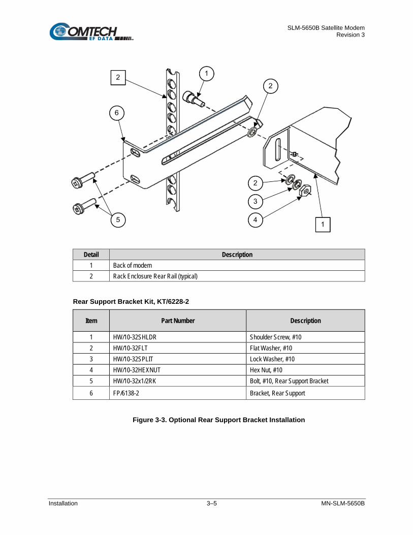
SLM-5650B Satellite Modem Revision 3
Installation 3–5 MN-SLM-5650B
Detail Description 1 Back of modem 2 Rack Enclosure Rear Rail (typical)
Rear Support Bracket Kit, KT/6228-2
Item Part Number Description
1 HW/10-32SHLDR Shoulder Screw, #10 2 HW/10-32FLT Flat Washer, #10 3 HW/10-32SPLIT Lock Washer, #10 4 HW/10-32HEXNUT Hex Nut, #10 5 HW/10-32x1/2RK Bolt, #10, Rear Support Bracket
6 FP/6138-2 Bracket, Rear Support
Figure 3-3. Optional Rear Support Bracket Installation

SLM-5650B Satellite Modem Revision 3
Installation 3–6 MN-SLM-5650B
3.2.2 Optional Bearingless Rack Slide Set The optional FP/SL0006 Bearingless Rack Slide Set may be installed into the equipment rack cabinet and onto the sides of the SLM-5650B as shown in Figure 3-4 and per the following procedure:
Step Task
1 Use the provided hardware to install one slide onto each side of the SLM-5650B chassis.
2 Use the provided hardware to install the slide rail components into each interior side of the equipment rack cabinet.
3 Install the unit into the front of the equipment rack. Ensure that the slides properly engage the cabinet-mounted slide rails.
4 Continue to slide the modem into the equipment rack to its final operating position. Then, use four user-provided screws to secure the modem to the equipment rack’s right and left threaded front rails (through the front panel slots).
CEFD Part Number Description
FP/SL0006 Bearingless Rack Slide Set – 26”
Figure 3-4. Optional Bearingless Rack Slide Set Installation
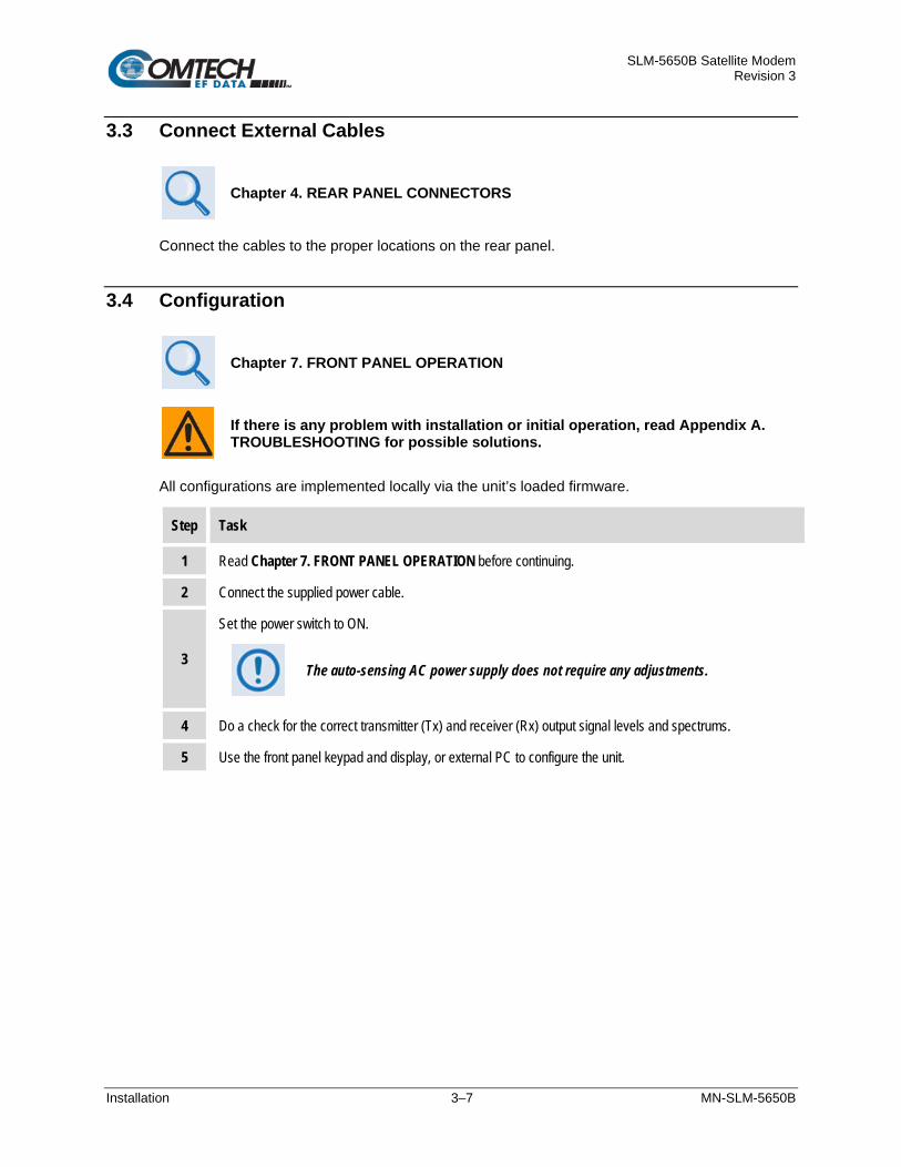
SLM-5650B Satellite Modem Revision 3
Installation 3–7 MN-SLM-5650B
3.3 Connect External Cables
Chapter 4. REAR PANEL CONNECTORS
Connect the cables to the proper locations on the rear panel.
3.4 Configuration
Chapter 7. FRONT PANEL OPERATION
If there is any problem with installation or initial operation, read Appendix A. TROUBLESHOOTING for possible solutions.
All configurations are implemented locally via the unit’s loaded firmware.
Step Task
1 Read Chapter 7. FRONT PANEL OPERATION before continuing.
2 Connect the supplied power cable.
3
Set the power switch to ON.
The auto-sensing AC power supply does not require any adjustments.
4 Do a check for the correct transmitter (Tx) and receiver (Rx) output signal levels and spectrums.
5 Use the front panel keypad and display, or external PC to configure the unit.

SLM-5650B Satellite Modem Revision 3
Installation 3–8 MN-SLM-5650B
BLANK PAGE

SLM-5650B Satellite Modem Revision 3
Rear Panel Connectors 4–1 MN-SLM-5650B
Chapter 4. REAR PANEL CONNECTORS
4.1 Overview – Cabling Connection Types The SLM-5650B uses a number of different cables. Each cable type is typically dedicated to a specific mode of operation.
Not all of these operational interface types may be available. The European EMC Directive (EN55022, EN50082-1) requires using properly shielded cables for DATA I/O. These cables must be double-shielded from end-to-end, ensuring a continuous ground shield.
4.1.1 Coaxial Cable Connections
(TOP) Bayonet Coupling Plug and Jack (Type ‘BNC’ Shown)
(BOTTOM) Threaded Coupling Plug and Jack (Type ‘N’ Shown) Figure 4-1. Coaxial Connector Examples

SLM-5650B Satellite Modem Revision 3
Rear Panel Connectors 4–2 MN-SLM-5650B
BNC plugs and jacks feature a Bayonet Coupling design.
Type ‘N’ connectors feature a Threaded Coupling design.
TNC plugs and jacks feature a Threaded Coupling design.
The types of coaxial cables used by CEFD are ‘BNC’, ‘TNC’, ‘N’, ‘F’, and ‘SMA’. Coaxial cables (plugs) and their mating connectors (jacks/sockets) are available in two coupling styles – Bayonet or Threaded:
Bayonet Coupling Style
The jack has a pair of guideposts that accommodate the plug’s lockdown slots. This lockdown design provides secure assembly without over-tightening the connection.
Threaded Coupling Style The jack features external threads. The plug shell features internal threads, and has either a knurled outer surface to permit hand-tightening of the connection, or hex flats to accommodate torqued installation.
Connection Instructions: Bayonet Coupling Connections
Use the plug slots to guide, and then slide the plug onto the jack posts. Then, turn the plug clockwise until the jack posts are fully seated within the plug slot.
Threaded Coupling Connections Engage the plug onto the jack threads, and then turn the plug clockwise until it is fully threaded onto the jack. Do not over-tighten the connection.
4.1.1.1 Type ‘BNC’
4.1.1.2 Type ‘TNC’
4.1.1.3 Type ‘N’

SLM-5650B Satellite Modem Revision 3
Rear Panel Connectors 4–3 MN-SLM-5650B
4.1.2 D-Subminiature Cable Connections
Type ‘D’ Cable with Jack Screws (Female Shown)
Type ‘D’ Chassis Receptacles with Jack Nuts: (TOP) Female
(BOTTOM) Male Figure 4-2. D-Subminiature Connector Examples
D-Subminiature connectors are also called Type ‘D’ or ‘D-Sub’ connectors. The cable plug and chassis receptacle each feature a D-shaped profile that interlock to ensure proper pin orientation and connector seating. The connector pair features multiple rows of pins (male side) coupled to mating sockets (female side).
Whether the gender is male or female, the cable plug features two jack screws for secure connection to the jack nuts provided on the mating chassis receptacle.
Connection Instructions: Orient the plug to the receptacle in the proper position. Press firmly into place. Hand tighten, or use a standard flat-blade screwdriver, to secure the plug jack screws to the receptacle jack nuts. Do not over-tighten.
About connector pinout tables: Figure 4-2 identifies the Pin 1 location for either gender connector. The connector pinout tables provided in this manual base the order of information (i.e., the “Pin #” column) on this orientation, except where noted.
4.1.3 RJ-45, RJ-48 Cable Connections
Figure 4-3. RJ-45/RJ-48 Connector Example
The plug for an RJ-45 or RJ-48 cable features a flexible tab. The RJ-45 or RJ-48 receptacle features a mating slot. This design configuration ensures a secure installation.
Connection Instructions (Figure 4-3): Press down the tab on the cable plug and then insert the plug into the receptacle. The connection is complete when the tab ‘clicks’ into position inside the receptacle.

SLM-5650B Satellite Modem Revision 3
Rear Panel Connectors 4–4 MN-SLM-5650B
4.2 Unit Connectors
Figure 4-4. SLM-5650B Rear Panel View
External cables are attached to connectors provided on the rear panel of the unit (Figure 4-5). These connectors serve power and ground, modem utility, terrestrial data interface, and IF functions.
Item No. Name Description
1 AC Power Connector
This connector is an IEC-60320 Type C14 (male) three-prong connector, for connection with an IEC-60320 Type C13 (female) three-prong plug. Note the following:
• Input Power: 130W maximum • Input Voltage: 90 to 132 V or 175 to 254 VAC. The unit switches voltage
ranges automatically. 2 Press-fit Fuse
Holder The fuse holder is press-fit into the body of the IEC power module. Two 5mm 1 Amp Slo-Blo type fuses are installed here for line and neutral fusing.
3 Unit Ground Connection
PROPER GROUNDING PROTECTION IS REQUIRED. You must connect the equipment to the protective earth connection at all times. Use this ground stud during installation, configuration, and operation.
The AC power interface provides the safety ground.
Use this #10-32 stud, located adjacent to the power interface module, for connecting a common chassis ground among equipment.
4 J1 This External Reference (Ext Ref) type TNC-F supplies a master external reference to the entire chassis. Functional features include:
• Frequency selectable at 1 MHz, 5 MHz, or 10 MHz • Input impedance to 50 Ω unbalanced • Voltage up to 3 V (rms) • Sine or square waveform (50% duty cycle)

SLM-5650B Satellite Modem Revision 3
Rear Panel Connectors 4–5 MN-SLM-5650B
Item No. Name Description
5 J5 This 8-pin 'RJ-45' 10/100 BaseT port provides access to the Ethernet Interface for remote control of the modem using using SNMP, HTTP/HTTPS or Telnet.
6 J6 This Type ‘D’ 25-pin female (DB-25F) connector conforms to the EIA-530 pinout for EIA-422 operation only.
Pin # Signal Function 1 Ground
14 SD_B 2 SD_A
15 ST_A 3 RD_A
16 RD_B 4 RS_A
17 RT_A 5 CS_A
18 MOD FLT OC 6 DM_A
19 RS_B 7 Ground
20 Not Used 8 RR_A
21 DMD FLT OC 9 RT_B
22 DM_B 10 RR_B
23 Not Used 11 TT_B
24 TT_A 12 ST_B
25 Not Used 13 CS_B

SLM-5650B Satellite Modem Revision 3
Rear Panel Connectors 4–6 MN-SLM-5650B
Item No. Name Description
7 P1 This Overhead Data Type ‘D’ 25-pin male (DB-25M) connector allows for connection of the EIA-422, EIA-485 and EIA-232 data interfaces used with overhead framing. It also supports signaling for tactical applications.
Pin # Signal Function Name 1 EIA-422 Transmit Data “A”, Input TX Data A
14 EIA-422 Transmit Data “B”, Input TX Data B 2 EIA-422 Transmit Clock “A”, Output TX Clk A
15 EIA-422 Transmit Clock “B”, Output TX Clk B 3 EIA-422 Transmit Byte Sync “A”, Output TX Sync A
16 EIA-422 Transmit Byte Sync “B”, Output TX Sync B 4 EIA-422 Receive Data “A”, Output RX Data A
17 EIA-422 Receive Data “B”, Output RX Data B 5 EIA-422 Receive Clock “A”, Output RX Clk A
18 EIA-422 Receive Clock “B”, Output RX Clk B 6 EIA-422 Receive Byte Sync “A”, Output RX Sync A
19 EIA-422 Receive Byte Sync “B”, Output RX Sync B 7 Shield Ground
20 EIA-485 Transmit Data “-“ 485 TX Data - 8 EIA-485 Transmit Data “+” 485 TX Data +
21 EIA-422 Transmit Handover Sync “A”, Input THS A 9 EIA-485 Receive Data “-“ 485 RX Data -
22 EIA-485 Receive Data “+” 485 RX Data + 10 EIA-422 Transmit Handover Sync “B”, Input THS B
23 EIA-232 Clear to Send 232 CTS 11 EIA-232 Receive Data 232 RX Data
24 EIA-232 Request to Send 232 RTS 12 EIA-232 Transmit Data 232 TX Data
25 EIA-422 Transmit Handover Control “A”, Input THC A 13 EIA-422 Transmit Handover Control “B”, Input THC B
* For EIA-485 2-Wire Operation, only two wires are required • Tie pins 8 and22 together (both +) • Tie pins 9 and 20 together (both -)

SLM-5650B Satellite Modem Revision 3
Rear Panel Connectors 4–7 MN-SLM-5650B
Item No. Name Description
8
J7 This is a HSSI Interface, 50-pin SCSI-2, female connector. Pins 21 and 45 are non-HSSI defined signals. On Cisco routers, there is no connection to these pins.
Fault Open No Fault Ground
Pin # Name 1 Ground
26 Ground 2 RT+
27 RT- 3 CA+
28 CA- 4 RD+
29 RD- 5 Not Used
30 Not Used 6 ST+
31 ST- 7 Ground
32 Ground 8 TA+
33 TA- 9 TT+
34 TT- 10 Not Used
35 Not Used 11 SD+
36 SD- 12 Not Used
37 Not Used 13 Ground
38 Ground 14 Not Used
39 Not Used 15 Not Used
40 Not Used 16 Not Used
41 Not Used 17 Not Used
42 Not Used 18 Not Used
43 Not Used 19 Not Used
44 Not Used

SLM-5650B Satellite Modem Revision 3
Rear Panel Connectors 4–8 MN-SLM-5650B
8 (cont)
20 Not Used 45 DEMOD Fault
21 MOD Fault 46 Not Used
22 Not Used 47 Not Used
23 Not Used 48 Not Used
24 Not Used 49 Not Used
25 Ground 50 Ground
9 J8 This Alarms Type ‘D’ 9-pin female (DB-9F) connector provides Form ‘C’ contact closures for alarm reporting. The three Form ‘C’ summary fault contacts are Modulator, Demodulator, and Common Equipment.
Pin # Signal Function Name 7 TX Alarm common COM
3 TX Alarm is not faulted NC 8 TX Alarm is faulted NO
1 Unit Alarm Common COM 6 Unit Alarm is not faulted NC
2 Unit Alarm is faulted NO 4 RX Alarm Common COM
9 RX Alarm is not faulted NC 5 RX Alarm is faulted NO

SLM-5650B Satellite Modem Revision 3
Rear Panel Connectors 4–9 MN-SLM-5650B
Item No. Name Description
10 J9 This Auxiliary ‘HD’ 15-pin female (HD-15F) connector is used for redundancy switch operations. It provides TTL (Transistor-to-Transistor Logic) open collector faults for the modulator and demodulator; a TTL input for external transmit carrier mute; an analog demodulator Q and I constellation monitor; and a programmable DC voltage monitor for the demodulator’s Automatic Gain Control (AGC).
Pin # Signal Function Name 1 Demod ‘I’ Channel I
6 Demod ‘Q’ Channel Q 11 Reserved for Redundancy Switch --
2 Spare -- 7 AGC Monitor Test Point AGC
12 Reserved for Redundancy Switch -- 3 Spare --
8 Spare -- 13 Tx TTL Fault TxFLT
4 Reserved for Redundancy Switch -- 9 Reserved for Redundancy Switch --
14 Rx TTL Fault RxFLT 5 Chassis Ground GND
10 Ext Carrier OFF EXT 15 Reserved for Redundancy Switch --
11
J10 This Remote Utility Type ‘D’ 9-pin female (DB-9F) connector interfaces the M&C functions to a remote location; the remote location can be an M&C computer located away from the modem, but attached via cable to the remote connector. This Data Communications Equipment (DCE) interface is user selectable for either EIA-232 or EIA-485.
EIA-232 EIA-485
Pin # Name Pin # Name
2-Wire 4-Wire 1 -- 1 GND GND
6 DSR 6 -- -- 2 RD 2 -- --
7 RTS 7 -- -- 3 TD 3 -- --
8 CTS 8 + TX/RX + RX 4 -- 4 + TX/ RX + TX
9 -- 9 - TX/ RX - RX 5 GND 5 - TX/ RX - TX

SLM-5650B Satellite Modem Revision 3
Rear Panel Connectors 4–10 MN-SLM-5650B
Item No. Name Description
11 (cont)
* For EIA-485 2-Wire Operation, only two wires are required • Tie pins 4 and 8 together (both +) • Tie pins 5 and 9 together (both -)
12 Data Interface Module Slot
Appendix D. OPTIONAL DATA INTERFACE MODULES (includes the optional 10/100/1000 BaseT Gigabit Ethernet (GbE), G.703, and LVDS modules) Appendix E. OPTIONAL NETWORK PROCESSOR (NP) INTERFACE MODULE
Install optional data interface modules into this rear panel option slot. 13 J2 The L-Band IF Interface connector uses a standard 50 Ω type “N” female connector.
This connector handles L-Band (950 MHz to 2000 MHz) Transmit (TX) output from the unit.
14 J4 The L-Band IF Interface connector uses a standard 50 Ω type “N” female connector. This connector handles L-Band (950 MHz to 2000 MHz) Receive (RX) input from the unit.
15 J11 This 70/140 MHz IF TNC-F Interface connector. This connector handles 70/140 MHz (52 to 88 MHz, 104 to 176 MHz) Transmit (TX) output from the unit.
16 J3 This 70/140 MHz IF TNC-F Interface connector. This connector handles 70/140 MHz (52 to 88 MHz, 104 to 176 MHz) Receive (RX) input into the unit.

SLM-5650B Satellite Modem Revision 3
Rear Panel Connectors 4–11 MN-SLM-5650B
4.3 AC Operation
4.3.1 Replace the Fuses
DISCONNECT THE POWER SUPPLY BEFORE PROCEEDING!
FOR CONTINUED OPERATOR SAFETY, ALWAYS REPLACE THE FUSES WITH THE CORRECT TYPE AND RATING.
Figure 4-5. AC Fuse Replacement
Do these steps to replace the AC fuses (Figure 4-6):
1. Unseat the fuse holder from the IEC power module.
a. Use the slot to pry the holder outward from the IEC power module.
b. Pull the holder straight out, and then swing the holder away from the module.
2. Remove and replace the fuses as needed. Use T1.00A 5mm fuses for 115V and 230V AC operation.
3. Re-seat the fuse holder in the IEC power module.

SLM-5650B Satellite Modem Revision 3
Rear Panel Connectors 4–12 MN-SLM-5650B
4.3.2 Apply Power
Figure 4-6. AC Power to the Unit
Do these steps to apply AC power to the unit (Figure 4-7):
1. Plug the provided AC power cord female end into the unit.
2. Plug the AC power cord male end into the user-supplied power source.
3. Switch the unit ON.

SLM-5650B Satellite Modem Revision 3
Rear Panel Connectors 4–13 MN-SLM-5650B
4.4 Power Interface Module – Optional 24V DC Unit Contact CEFD Product Support for detailed information about connecting and supplying power, and replacing the fuses for the optional DC-powered SLM-5650B.
4.4.1 Replace the Fuses
DISCONNECT THE POWER SUPPLY BEFORE PROCEEDING!
FOR CONTINUED OPERATOR SAFETY, ALWAYS REPLACE THE FUSES WITH THE CORRECT TYPE AND RATING.
For DC operation, the fuses are located on the rear panel in individual screw-in receptacles found adjacent to the terminal block.
Do these steps to replace the DC fuses:
1. Disconnect the power supply leads.
2. Unscrew either fuse holder from its receptacle.
3. Remove and replace the fuses as needed.
4. Screw the fuse holder back into its receptacle.
4.4.2 Apply Power Do these steps to apply DC power to the unit:
Number 18 AWG minimum wires are recommended.
1. Connect the user-supplied (+) and (–) DC power leads to their respective terminals.
2. Connect the user-supplied DC power leads to the user power source.
3. Energize the power source.
4. Switch the unit ON.

SLM-5650B Satellite Modem Revision 3
Rear Panel Connectors 4–14 MN-SLM-5650B
BLANK PAGE

SLM-5650B Satellite Modem Revision 3
Firmware Update 5–1 MN-SLM-5650B
Chapter 5. FIRMWARE UPDATE
5.1 Update Firmware via Web Pages
To ensure optimal performance, it is important to operate the SLM-5650B with its latest available firmware.
The SLM-5650B stores its firmware internally in flash memory, which simplifies the firmware updating process. After the firmware update has been acquired, it can be transferred from an external user PC, once Ethernet connectivity has been established with the modem.
FAST codes are retained after a firmware upgrade and do not need to be re-entered. The modem configuration is also retained.
This chapter outlines the complete firmware updating process as follows:
• Perform the update, without opening the SLM-5650B, by connecting the unit to the Ethernet port of the user PC.
• Transfer the firmware update, via the appropriate modules from the user PC to the SLM-5650B Web Server Interface automatically.

SLM-5650B Satellite Modem Revision 3
Firmware Update 5–2 MN-SLM-5650B
5.1.1 About Firmware Files, Naming, Versions, and Archive Formats The SLM-5650B is factory-shipped with the latest version of operating firmware. If a firmware update is needed, it can be acquired from CEFD Customer Support during normal business hours.
Figure 5-1. Firmware Naming Format
CEFD catalogues its firmware update files by product type (e.g., modem, converter, etc.) and specific model/optional configuration. The hyperlinks appear as per the example to the right. In this example, the FW-0021022_V### Base Modem firmware download hyperlink is shown, where ‘x’ denotes the revision letter and ### represents the firmware version. If applicable, one version prior to the current release is also available for download.
In addition to the download for the Base Modem bulk firmware, downloads are available for the SLM-5650B’s optional NP module. This module requires a separate firmware update.
To obtain the firmware update for the TRANSEC Module, contact CEFD Customer Support.
The firmware download files are available from CEFD in two archive file formats: *.exe (self extracting) and *.zip (compressed). Some firewalls will not allow the downloading of *.exe files; in this case, download the *.zip file instead. For additional help with "zipped" file types, refer to PKZIP for Windows, WinZip, or ZipCentral help files. PKZIP for DOS is not supported due to file naming conventions.

SLM-5650B Satellite Modem Revision 3
Firmware Update 5–3 MN-SLM-5650B
5.2 Bulk Firmware Update Procedure
Chapter 9. BASE MODEM HTTP/HTTPS INTERFACE
Refer to Chapter 9. BASE MODEM HTTP/HTTPS INTERFACE, Section 9.4.2.5 Admin | Upgrade for instructions on how to upgrade the bulk firmware.
Use this page to REFLASH the SLM-5650B and change the active firmware image.
Figure 5-2. Admin | Upgrade Page
Firmware File Upload Name Description
Firmware File Upload Use this area to browse and load file for upload. Select the *.zip file for the base modem firmware.
Click [Upload File] to load the selected file.
Firmware Image Config Name Description
ReFLASH Status Displays the ReFLASH status. Active Image Dispays 1 or 2 for the Active Image. Next Reboot Image Displays 1 or 2 for the Next Reboot Image.
Click [Extract Files] to extract the files from the firmware file upload. Click [Set Image 1] or [Set Image 2] to select the the Next Reboot Image. Click [Reboot Modem] to complete the process.

SLM-5650B Satellite Modem Revision 3
Firmware Update 5–4 MN-SLM-5650B
5.3 Network Processor (NP) Interface Module Update Procedure
Step Task
1 Identify the firmware number and version for download. The current modem M&C version can be viewed at the top-level menu of the front panel display (press the [CLR] key several times to view). The firmware information can also be found within the SELECT: Utility Firmware Info Image#1 or Image#2 menu trees. Using serial remote control, the firmware revision levels may be obtained with the <0/SWR? query. For more information, refer to Appendix C. REMOTE CONTROL. Note: To aid identification, when using the NP HTTP/HTTPS Interface the Bootrom, Image 1, and Image 2 firmware loads may be viewed after selecting the Upgrade hyperlink available from the Admin (Administration) page. For more information, refer to the pertinent sections in Appendix E. NETWORK PROCESSOR (NP) INTERFACE MODULE.
2 Create a temporary folder (directory) on an external PC (note that the drive letter c: is used in this example; any valid writable drive letter can be used): • For Windows Explorer: Select File > New > Folder to create a new folder, and then rename it from “New
Folder” to "temp" or another convenient, unused name. Assuming "temp" works, a "c:\temp" folder should now be created.
• For Windows Command-line: Click [Start] on the Windows taskbar, and then click the “Run...” icon (or, depending on Windows OS versions prior to Windows 95, click the “MS-DOS Prompt” icon from the Main Menu). Then, to open a Command-line window…
o For Windows 95 or Windows 98 – Type “command”. o For any Windows OS versions later than Windows 98 – Type “cmd” or “command”.
Alternately, from [Start], select All Programs > Accessories > Command Prompt. At the Command-line prompt (c:\>), type “mkdir temp” or “md temp” (without quotes – mkdir and md stand for make directory). This is the same as creating a new folder using Windows Explorer. There should now be a "c:\temp" subdirectory created.
3 Download the correct firmware file to this temporary folder, as shown in Step 2. The NP Module firmware for the modem is FW-0000051x, where "x" denotes the firmware revision letter. Refer to Section 5.1.1 for detailed information about firmware archive file formats.
4 Extract the file in the temporary folder on the PC: Fw-0000051x.bin, where "x" denotes the revision letter of the module bulk image file.
5 Confirm that the files have been extracted to the specified temporary folder on the PC. Using Command-line, type “cd c:\temp” to change to the temporary directory created in Step 2, then use the “dir” command to list the files extracted from the downloaded archive file.
6 Connect the PC to the modem Ethernet via a hub or a switch, via one of the four ports on the NP Module, or directly to a PC with a crossover cable.
7 Enable the NP Module. From the modem front panel: SELECT: Configure Mode Interface NetworkProc.

SLM-5650B Satellite Modem Revision 3
Firmware Update 5–5 MN-SLM-5650B
Step Task
8 Send a “ping” command – either to the NP Module’s Traffic IP address when in single mode, or to its Management IP address when in dual mode – to verify the connection and communication: • If in single address mode, to determine the IP address of the NP Module, from the modem front panel go to
the SELECT: Configure Remote EthernetConfig Option Card Addr Network Proc Traffic IP menu, then select Yes.
• If in dual address mode, to determine the IP address of the NP Module, from the modem front panel go to the SELECT: Configure Remote EthernetConfig Option Card Addr Network Proc Mgmt IP menu, then select Yes.
Then, using Command-line to “ping” the modem: At the prompt, type “ping xxx.xxx.xxx.xxx” (where ‘xxx.xxx.xxx.xxx’ is the NP Module’s IP address). The results should confirm whether or not the module is connected and communicating.
9 Initiate a Web session with the SLM-5650B’s NP Module using the PC and a supported Web browser. Note the following:
1. The browser and page examples that follow use Internet Explorer Version 7.0. 2. NP HTTP/HTTPS pages are shown with optional FAST Features installed.
Type the NP Module’s IP address into the browser’s Address box (where “xxx.xxx.xxx.xxx” represents the NP Module’s IP address).
Depending on the NP Module’s security level setting: • Type “http://xxx.xxx.xxx.xxx” for non-secure access (Low Security Mode); • Type “https:/xxx.xxx.xxx.xxx” for Secure access (High Security Mode). When prompted, enter the User
Name and Password to log in: o Factory Default User Name is comtech o Factory Default Password is comtech
The Web interface is disabled in Bridge Mode.

SLM-5650B Satellite Modem Revision 3
Firmware Update 5–6 MN-SLM-5650B
Step Task
10 To update the Network Processor Bulk firmware: a) Open the Admin | Upgrade page:
b) In the Upgrade section of the page, locate the update file downloaded to the PC during Steps 2 through 4:
• Click [Browse]. The Choose File dialog box will open. • Locate the folder created for the file download; double-click on the folder name to open the folder.
c) Select the update file, then click [Open]. The filename should appear in the Upgrade Image File text box. d) Click [Upload] to begin the Image Upgrade process.

SLM-5650B Satellite Modem Revision 3
Firmware Update 5–7 MN-SLM-5650B
Step Task
11 Wait while the file transfers. After [Upload] is clicked, the Image Upgrade page appears while the NP first transfers, and then uploads, the update file from the PC. Allow sufficient time for the file to be loaded into the NP Module – uploading will take approximately five minutes.
It is not necessary to wait five minutes before clicking [OK], but you MUST wait five minutes before rebooting the modem.
During the upload process, the page displays a transfer progress bar that provides the scrolling percentage of completion. During transfer, the message Please Wait… displays:
Upon successful completion of transfer, the progress bar reads 100%, and the Image Upgrade Complete message displays:
Click [OK] to exit the Image Upgrade page and return to the Admin | Upgrade page.

SLM-5650B Satellite Modem Revision 3
Firmware Update 5–8 MN-SLM-5650B
Step Task
12 Refresh the Admin | Upgrade page and verify that the newly-uploaded firmware is reported in the proper Network Processor Firmware Info Image slot. If not, open the Admin | Reboot page then, in the Network Processor Boot From section, use the drop-down menu to select Newest as needed to force the NP Module to boot using the firmware with the most recent build date. Click [Submit] when done.
13
Save all settings before rebooting to prevent loss of configuration settings. Go to the Save Configuration page, then click [Save Now]:

SLM-5650B Satellite Modem Revision 3
Firmware Update 5–9 MN-SLM-5650B
Step Task
14 After saving, return to the Admin | Reboot page, then click [Reboot Now] to boot the NP Module with the new firmware:
15 To load the second image, repeat Steps 10 through 12.

SLM-5650B Satellite Modem Revision 3
Firmware Update 5–10 MN-SLM-5650B
5.4 TRANSEC Module Firmware Update Procedure
Firmware updates for the TRANSEC Module (also referred to in front panel menu screens as the “Option Card”) are not available from the CEFD website, but they may be obtained from CEFD on an as-needed basis. To obtain these updates, contact CEFD Customer Support to request access to the modem firmware update files online using an FTP site. The CEFD Customer Support representative will arrange for full firmware access information and download privileges at that time.
Step Task
1 Contact CEFD Customer Support during normal business hours to request delivery of the TRANSEC Module firmware update files. The Customer Support representative will arrange for full firmware access information and download privileges at that time.
Note: To aid identification, use the TRANSEC Module HTTPS Interface > Firmware Info to see the Bootrom, Bulk1, and Bulk2 firmware loads information.
2 Create a temporary folder (directory) on an external PC (note that the drive letter c: is used in this example; any valid writable drive letter can be used):
• For Windows Explorer: Select File > New > Folder to create a new folder, and then rename it from “New Folder” to "temp" or another convenient, unused name. Assuming "temp" works, a "c:\temp" folder should now be created.
• For Windows Command-line: Click Start on the Windows taskbar, and then click the “Run...” icon (or, depending on Windows OS versions prior to Windows 95, click the “MS-DOS Prompt” icon from the Main Menu). Then, to open a Command-line window…
o For Windows 95 or Windows 98 – Type “command”.
o For any Windows OS versions later than Windows 98 – Type “cmd” or “command”.
Alternately, from Start, select All Programs > Accessories > Command Prompt. At the Command-line prompt (c:\>), type “mkdir temp” or “md temp” (without quotes – mkdir and md stand for make directory). This is the same as creating a new folder from Windows Explorer. There should now be a "c:\temp" subdirectory created.
3 Download the correct firmware file that was obtained from CEFD Customer Support to this temporary folder created in Step 2. The TRANSEC Module firmware is FW-0020567x, where "x" denotes the firmware revision letter.
4 Extract the file in the temporary folder on the PC:
Fw-0020567x.bin, where "x" denotes the revision letter of the module bulk image file.
5 Confirm that the files have been extracted to the specified temporary folder on the PC.
Using Command-line, type “cd c:\temp” to change to the temporary directory created in Step 2, then use the “dir” command to list the files extracted from the downloaded archive file.
6 Connect the PC to the modem’s Ethernet via a hub or a switch, or directly to the PC with a crossover cable.

SLM-5650B Satellite Modem Revision 3
Firmware Update 5–11 MN-SLM-5650B
Step Task
7 Send a “ping” command to the TRANSEC Module to verify the connection and communication.
First, determine the IP address of the TRANSEC Module from the front panel:
SELECT: Configure Transec Module IP Address menus.
Then, using Command-line to “ping” the modem – at the prompt, type “ping xxx.xxx.xxx.xxx” (where ‘xxx.xxx.xxx.xxx’ is the TRANSEC Module’s IP address). The results should confirm whether or not the module is connected and communicating.
8 Initiate a secure Web session with the TRANSEC Module via its HTTPS Interface. Refer to Section 10.3.
9 Update the TRANSEC Module bulk firmware: a) Open the Upload page:
b) In the Firmware section of the page, locate the update file downloaded to the PC during Steps 2
through 4 :
• Click Browse. The Choose File dialog box will open.
• Locate the folder created for the file download; double-click on the folder name to open the folder.
c) Select the update file, and then click Open. The filename should appear in the Replace stand-by firmware text box.
d) Click Upload to begin the Firmware Application Process.

SLM-5650B Satellite Modem Revision 3
Firmware Update 5–12 MN-SLM-5650B
Step Task
10 Wait while the file transfers. After Upload is clicked, the Image Upgrade Process page appears while the TRANSEC Module transfers, and then uploads the update file from the PC.
Allow sufficient time for the file to be uploaded – approximately five minutes is required for the process to be completed. During the upload process, the page displays a transfer progress bar that provides the scrolling percentage of completion. During transfer, the message Please Wait will display.
11
Any power failure during this process will result in failure of the TRANSEC Module.
In the event that an error occurs during the Image Upgrade Process, then a message stating that an error occurred will appear.
For troubleshooting purposes, three common reasons for disruption of the Firmware Application Process are:
• Power Failure; • Loss of Ethernet signal (e.g., disconnection of Ethernet cable);
Attempting to load firmware other than the TRANSEC Module bulk firmware (i.e., FW-0020567x.bin).
Upon successful completion of transfer, the progress bar shows 100%.
On the Firmware page, verify that the newly-uploaded firmware is reported in the proper Security Module Bulk Info slot. If not, update the Active Boot Slot Configuration by using the drop-down menu to select Newest to force the TRANSEC Module to boot using the firmware with the most recent build date. Click Submit when done.

SLM-5650B Satellite Modem Revision 3
Firmware Update 5–13 MN-SLM-5650B
Step Task
12 Click Reboot to boot the TRANSEC Module with the new firmware.
The modem will reboot with the new firmware.
It will be necessary to restart the TRANSEC Module HTTPS Interface session once the modem has returned online.
13 To load the second image, repeat Steps 9 through 11.

SLM-5650B Satellite Modem Revision 3
Firmware Update 5–14 MN-SLM-5650B
BLANK PAGE

SLM-5650B Satellite Modem Revision 3
FAST Activation Procedure 6–1 MN-SLM-5650B
Chapter 6. FAST ACTIVATION PROCEDURE
6.1 Overview
Chapter 1. INTRODUCTION Chapter 7. FRONT PANEL OPERATION Chapter 9. BASE MODEM HTTP/HTTPS INTERFACE OPERATION
The SLM-5650B incorporates a number of optional features. To permit an initial lower cost, the modem may be purchased with only the desired features enabled.
To upgrade the functionality of a modem at a later date, CEFD provides FAST, which permits the activation of options through special access codes once they are purchased. Contact CEFD Product Support to purchase these unique, register-specific FAST access codes, and then load these codes into the modem by using the front panel keypad.
FAST System Theory FAST facilitates on-site upgrade of the operating feature without removing a modem from the setup. FAST technology allows you to order a modem precisely tailored for your initial application. When your service requirements change, you can upgrade the topology of the unit to meet these requirements within minutes. This accelerated upgrade is possible because of FAST’s extensive use of the programmable logic devices incorporated into CEFD products.
FAST Implementation CEFD implements the FAST system in the modem at the factory. All FAST options are available through the basic platform unit at the time of order. FAST allows immediate activation of available options, after confirmation by CEFD, through the SLM-5650B front panel (Refer to Chapter 7. FRONT PANEL OPERATION) or the base modem web interface pages (Refer to Chapter 9. BASE MODEM HTTP/HTTPS INTERFACE OPERATION).
FAST Accessible Options The FAST access codes purchased from CEFD enables configuration of the available hardware that was either initially installed at the factory or installed at a later date on-site.

SLM-5650B Satellite Modem Revision 3
FAST Activation Procedure 6–2 MN-SLM-5650B
6.2 FAST Activation Procedure via the Front Panel
Chapter 7. FRONT PANEL OPERATION
Do these steps:
1. Before contacting CEFD Product Support to order FAST feature upgrades, obtain and record the modem’s motherboard serial number:
a. From the front panel main SELECT: menu, select UtilityFAST, and then press [ENT].
b. The modem’s 9-digit motherboard “S/N” is displayed on the UtilityFAST screen top line, to the right.
c. Record the Serial Number: ______________________________________
2. View the currently installed features. Proceed as follows:
a. From the front panel main SELECT: menu, select UtilityFAST, and then press [ENT].
b. From the SELECT: Utility FAST menu, select View Options, and then press [ENTER].
c. Use the up and down arrow keys () to scroll through the list of available FAST options – 01 through 30. Options are identified on each screen as ‘Installed’ or ‘Not Installed’. Any that are ‘Not Installed’ may be purchased as a FAST upgrade.
3. Contact CEFD Product Support to order features: a. Provide the unit Serial Number to the Product Support representative. b. Identify and purchase the desired FAST option(s). c. Obtain the invoice, the 20-digit FAST Access Code(s), and the FAST option
activation instructions. 4. Enter the FAST Access Code (each FAST Access Code is submitted separately):
a. Depending on the FAST option, press [CLR] until you return to the SELECT: UtilityFAST menu.
b. Use the arrow keys to select Enter Modem Code, and press [ENT]. c. Use the arrow keys ( ) to carefully enter each register-specific 20-
character FAST Access Code.
d. Press [ENT]. The modem responds with “Configured Successfully” if the FAST upgrade is accepted; the modem then resets to its newly-incorporated default configuration.
However, if an invalid code is entered, the following message displays:
That FAST code has been rejected.
(ENTER or CLEAR) Repeat the FAST Access Code entry procedure. Should the code entry error persist, contact CEFD Product Support for further assistance.
SLM-5650B Satellite Modem Revision 3
FAST Activation Procedure 6–3 MN-SLM-5650B
6.3 FAST Activation Procedure via the Base Modem Web Interface Pages
Chapter 9. BASE MODEM HTTP/HTTPS INTERFACE OPERATION
Refer to Chapter 9. BASE MODEM HTTP/HTTPS INTERFACE OPERATION, Section 9.4.2.4 for instructions on how to set the FAST codes using the Admin | FAST web interface page.

SLM-5650B Satellite Modem Revision 3
FAST Activation Procedure 6–4 MN-SLM-5650B
BLANK PAGE

SLM-5650B Satellite Modem Revision 3
Front Panel Operation 7–1 MN-SLM-5650B
Chapter 7. FRONT PANEL OPERATION
7.1 Overview
Chapter 9. BASE MODEM HTTP/HTTPS INTERFACE Chapter 10. SERIAL REMOTE CONTROL
The SLM-5650B front panel (Figure 7-1) allows the user to monitor the modem operating status (including clocking information) and to control modem configuration parameters.
Figure 7-1. SLM-5650B Front Panel
Table 7-1. SLM-5650B Front Panel Description
Item Description Function 1 USB Port Not Used 2 6-button keypad Local control via menu navigation 3 12-button array Manual data entry 4 10 Light-Emitting Diodes (LEDs) Overall status monitoring at a glance 5 40-character, 2-line Vacuum Fluorescent Display (VFD) Display of messages, menus and prompts 6 On/Off Power Switch Unit power 7 Rack handles Eases installation into / removal from rack

SLM-5650B Satellite Modem Revision 3
Front Panel Operation 7–2 MN-SLM-5650B
The front panel operating features (keypad/data entry array, LED Indicators, and VFD) and menus are described in detail in this chapter. For information about Web Server or Remote Control operation, refer to Chapter 9. BASE MODEM HTTP/HTTPS INTERFACE or Chapter 10. SERIAL REMOTE CONTROL, respectively.
7.1.1 Keypad with Data Entry Array
Figure 7-2. Keypad with Data Entry Array
The front panel keypad controls the local operation of the modem. This control section consists of 18 buttons (keys). Each key provides one or more logical functions.
Key Description
ENT (Enter) Use this key to select for editing an available function, or to execute a modem configuration change.
CLR (Clear) Use this key to back out of a selection, or to cancel a configuration change that has not been executed using [ENT]. Pressing [CLR] generally returns the display to the previous selection.
and (left and right)
Use these keys to move between the menu screen options, or to move the cursor on a space-by-space basis for certain editing functions (e.g., value settings such as frequencies, text identification strings, etc.).
and (up and down)
Use these keys primarily to scroll through and select pre-defined options, configuration data (numbers), or characters.
Alphanumeric Use the 12 keys comprising this section of the keypad for entry of alphanumeric parameters (e.g., value settings such as frequencies, text identification strings, etc.). The first three columns of keys are multi-function in purpose. Each successive push of multi-function key 1 through 9 selects the next choice. For example: The first time the ‘2’ key is pushed, it selects a ‘2’; the second time, an ’A’; the third time, a ‘B’; the fourth time, a ‘C’. Pushing the key a fifth time would start over with a ‘2’. Number-to-character assignment for this array are as follows:
COLUMN 1 COLUMN 2 COLUMN 3
1 – Space 2 – ABC 3 - DEF
4 – GHI 5 – JKL 6 – MNO
7 – PQRS 8 – TUV 9 - WXYZ
The last column of keys in this array function as follows: • Use the ‘+/-’ key to change signs (positive/negative);• Use the ‘.’ key to enter a decimal point;• Use the ‘0’ key to enter a zero.
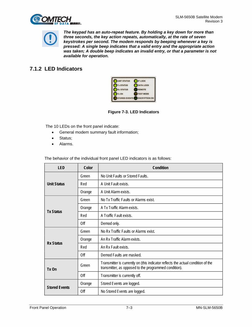
SLM-5650B Satellite Modem Revision 3
Front Panel Operation 7–3 MN-SLM-5650B
The keypad has an auto-repeat feature. By holding a key down for more than three seconds, the key action repeats, automatically, at the rate of seven keystrokes per second. The modem responds by beeping whenever a key is pressed: A single beep indicates that a valid entry and the appropriate action was taken; A double beep indicates an invalid entry, or that a parameter is not available for operation.
7.1.2 LED Indicators
Figure 7-3. LED Indicators
The 10 LEDs on the front panel indicate: • General modem summary fault information;• Status;• Alarms.
The behavior of the individual front panel LED indicators is as follows:
LED Color Condition
Unit Status
Green No Unit Faults or Stored Faults.
Red A Unit Fault exists.
Orange A Unit Alarm exists.
Tx Status
Green No Tx Traffic Faults or Alarms exist.
Orange A Tx Traffic Alarm exists.
Red A Traffic Fault exists.
Off Demod only.
Rx Status
Green No Rx Traffic Faults or Alarms exist.
Orange An Rx Traffic Alarm exists.
Red An Rx Fault exists.
Off Demod Faults are masked.
Tx On Green Transmitter is currently on (this indicator reflects the actual condition of the
transmitter, as opposed to the programmed condition).
Off Transmitter is currently off.
Stored Events Orange Stored Events are logged.
Off No Stored Events are logged.

SLM-5650B Satellite Modem Revision 3
Front Panel Operation 7–4 MN-SLM-5650B
LED Color Condition
IF Lock Green Demod has constellation lock.
Off No constellation lock.
Data Lock Green Decoder is locked.
Off Decoder is not locked.
Remote Green The modem is in Remote Communication Mode.
Off The modem is in Local Mode – remote monitoring is possible, but no remote control.
Test Mode Orange A Test Mode is selected (Example: IF Loopback).
Off No Test Mode is selected.
Encryption On Green Encryption is enabled.
Off Encryption is disabled.
7.1.3 Vacuum Fluorescent Display (VFD)
Figure 7-4. Vacuum Fluorescent Display
The SLM-5650B features an active VFD display, showing two lines of 40 characters each. It produces a blue light, the brightness of which can be controlled by the User. Compared to a Liquid Crystal Display (LCD), it has superior viewing characteristics and does not suffer problems of viewing angle or contrast.
On most menu screens, a flashing solid block cursor blinks at a once-per-second rate. This indicates the currently selected item, digit, or field. Where it might obscure the item being edited (e.g., a numeric field), the solid block cursor automatically changes to an underline cursor.

SLM-5650B Satellite Modem Revision 3
Front Panel Operation 7–5 MN-SLM-5650B
To prevent the display from becoming burnt by a constant image, the unit employs a screen saver feature that activates after 15 minutes. This message constantly scrolls and wraps across the screen. Sandwiched between the product display message “Comtech EF Data SLM-5650A Modem” and the user prompt “Press any key to continue”, the screen saver provides the following operating statistics:
Modem Status Code Description
01 Circuit Identification
02 Demodulator receive frequency offset from the nominal
03 Buffer fill status (%)
04 Receive signal level (dBm)
05 Estimated Eb/No
06 Estimated Corrected Bit Error Rate
07 Bit Error Rate reported by the internal Bit Error Rate Test set
Press any key to exit the screen saver mode and restore the previously active screen.
7.1.3.1 Navigating the Menu Screens Both single-function and multi-function menu screens are used throughout the front panel SELECT: menu interface. Both screen types display all available options and prompt the user to carry out a required action.
For the top-tiered menu screens, such as the SELECT: Configure menu branch screen and its nested SELECT: CONFIGTx menu screen, use the arrow keys to first select a menu item. Press [ENT] to open the nested submenu screen.
Nested submenu screens, such as the SELECT: CONFIGTx Mod submenu, provide multiple functional selections on a single screen, and therefore require additional navigation steps:
First, you must first use the arrow keys to navigate to an available option on the active screen. Press [ENT] to enable selection of that option’s available settings. Note that the cursor jumps from the select option name to its editable/selectable setting.
Then, unless otherwise noted, you must use the arrow keys to scroll through the available settings. Once the desired setting is selected, you must then press [ENT] to save that option setting. Note that the cursor jumps from the setting back to its select option name.
Repeat these steps as needed for each available option. Once all option settings are configured via the arrow keys and the [ENT] key, press [CLR] to exit the active menu screen and return to the previously selected menu.

SLM-5650B Satellite Modem Revision 3
Front Panel Operation 7–6 MN-SLM-5650B
7.2 Front Panel Operation
7.2.1 Opening Screen The front panel menu screens provide the visual means to fully control and monitor operation of the SLM-5650B. The first screen to display, after the modem power switch is turned on, is the read-only opening screen: Comtech SLM-5650B Modem State: GO
Firmware Version x.x.x Mode: TURBO
The top line identifies the product and its operational state. The bottom line displays the currently running firmware version, and the selected mode of operation. Press any key to continue to the SELECT: (Main) menu screen.
The user must first go to CONFIG: MODE to set the MODEM mode, the FREQBAND, and the INTERFACE type before proceeding with the rest of the modem configuration.

SLM-5650B Satellite Modem Revision 3
Front Panel Operation 7–7 MN-SLM-5650B
7.2.2 SELECT: (Main) Menu SELECT: Configure Monitor Test
Save/Load Utility (E)
The menu matrix on the next page identifies the content section in this chapter for each menu branch, and the functional description and available settings for each branch submenu.
Use the arrow keys to select any menu branch, and then press [ENT].
Menu Branch Sect. Function
Configure 7.2.3 Select to fully configure the modem.
Monitor 7.2.4 Select to monitor the alarm status of the modem, to view the log of stored events, and to display the Receive Parameters screen and clear all stored faults.
Test 7.2.5 Select to configure the modem into one of several Test modes.
Save/Load 7.2.6 Select to save and retrieve up to 10 different modem configurations.
Utility 7.2.7 Select to perform miscellaneous functions, such as setting the Real-Time Clock, adjusting the display brightness, etc.

SLM-5650B Satellite Modem Revision 3
Front Panel Operation 7–8 MN-SLM-5650B
7.2.3 (SELECT:) Configure (Configuration) Menu Branch CONFIG: Tx Rx Mode AUPC Transec
AHO ODU Ref Mask Reset Remote (E)
Use the arrow keys to select a configuration submenu, and then press [ENT].
Menu Branch Sect. Selectable Submenu / Description
Tx (Transmit) 7.2.3.1 Mod, DataRate, Overhead, Frequency, Power, Clocking, Misc, Spreading Use to configure, on a parameter-by-parameter basis, the Tx operation of the unit. For example, use these submenus if you wish to change only the Tx Frequency. This submenu is not accessible if modem operation has been set to Demod Only
Rx (Receive) 7.2.3.2 Demod, DataRate, Overhead, Frequency, Acquisition, Buffer, Misc, CnC, Spreading Use to configure, on a parameter-by-parameter basis, the Rx operation of the unit. For example, use these submenus if you wish to change only the Rx Frequency.
Mode 7.2.3.3 Mode, FreqBand, Interface Use to configure the modem operational mode, frequency band, interface types and their associated operating modes.
AUPC 7.2.3.4 Local, Remote, ASYNC, Logging Use to configure the Automatic Uplink Power Control functions. This menu is selectable only if the “Modem Type” has been set to AUPC.
TRANSEC 7.2.3.5 State, Module IP Address, Gateway Use to configure the optional TRANSEC (Transmission Security) Module features.
AHO 7.2.3.6 Use to configure the Antenna Handover features (when the SLM-5650B is used with the CRS-311-AH Antenna Handover Switch). This menu is selectable only if the Antenna Handover FAST option is installed.
ODU 7.2.3.7 LNB Power, Monitor, Low Current, High Current
Ref (Reference) 7.2.3.8
Modem, BUC, LNB Use to configure the internal 10 MHz Reference or allow the unit to phase lock to an External Reference of 1, 5, or 10 MHz. The unit reverts to Internal if the External Reference is not present or is faulted.
Mask 7.2.3.9 TxData, RxData, Eb/No Threshold, DemodFaults Use to configure how the modem handles alarms and faults.
Reset 7.2.3.10 Yes or No Use to reset the modem to its factory configurastion settings.
Remote (Remote Control)
7.2.3.11 Mode, SerialConfig, EthernetConfig (w/Option Cards) Use to configure whether the unit is being controlled locally or remotely.
The modem may be monitored over the remote control bus at any time. When in Local mode, however, configuration parameters may only be changed through the front panel. Conversely, when in Remote mode, the unit may be monitored from the front panel, but configuration parameters may only be changed via the remote control bus.
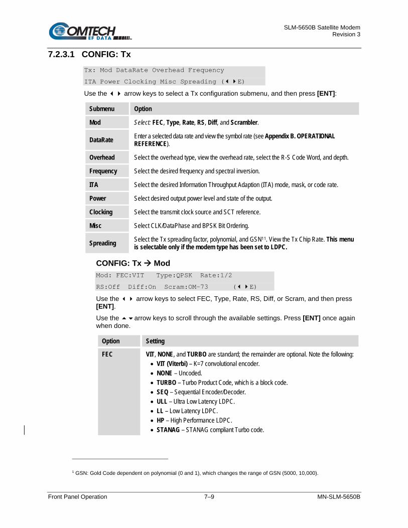
SLM-5650B Satellite Modem Revision 3
Front Panel Operation 7–9 MN-SLM-5650B
7.2.3.1 CONFIG: Tx Tx: Mod DataRate Overhead Frequency
ITA Power Clocking Misc Spreading (E)
Use the arrow keys to select a Tx configuration submenu, and then press [ENT]:
Submenu Option
Mod Select: FEC, Type, Rate, RS, Diff, and Scrambler.
DataRate Enter a selected data rate and view the symbol rate (see Appendix B. OPERATIONAL REFERENCE).
Overhead Select the overhead type, view the overhead rate, select the R-S Code Word, and depth.
Frequency Select the desired frequency and spectral inversion.
ITA Select the desired Information Throughput Adaption (ITA) mode, mask, or code rate.
Power Select desired output power level and state of the output.
Clocking Select the transmit clock source and SCT reference.
Misc Select CLK/DataPhase and BPSK Bit Ordering.
Spreading Select the Tx spreading factor, polynomial, and GSN11. View the Tx Chip Rate. This menu is selectable only if the modem type has been set to LDPC.
CONFIG: Tx Mod Mod: FEC:VIT Type:QPSK Rate:1/2
RS:Off Diff:On Scram:OM-73 (E)
Use the arrow keys to select FEC, Type, Rate, RS, Diff, or Scram, and then press [ENT]. Use the arrow keys to scroll through the available settings. Press [ENT] once again when done.
Option Setting
FEC VIT, NONE, and TURBO are standard; the remainder are optional. Note the following: • VIT (Viterbi) – K=7 convolutional encoder. • NONE – Uncoded. • TURBO – Turbo Product Code, which is a block code. • SEQ – Sequential Encoder/Decoder. • ULL – Ultra Low Latency LDPC. • LL – Low Latency LDPC. • HP – High Performance LDPC. • STANAG – STANAG compliant Turbo code.
1 GSN: Gold Code dependent on polynomial (0 and 1), which changes the range of GSN (5000, 10,000).

SLM-5650B Satellite Modem Revision 3
Front Panel Operation 7–10 MN-SLM-5650B
Option Setting
Type (Modulation)
BPSK, QPSK, or OQPSK are standard; 8PSK, 8QAM, or 16QAM are optional. Note the following: • BPSK – Bi Phase Shift Keying. • QPSK – Quadrature Phase Shift Keying. • OQPSK – Offset Quadrature Phase Shift Keying. • 8PSK – 8 Phase Shift Keying. • 8QAM – 8 Quadrature Amplitude Modulation. • 16QAM – 16 Quadrature Amplitude Modulation. • 16APSK – 16 Amplitude Phase Shift Keying.
Rate • Viterbi – 1/2, 2/3, 3/4, 5/6, or 7/8 • Uncoded – 1/1 • Turbo – 5/16, 3/4, 7/8, 17/18, or 21/44 • Sequential – 1/2, 3/4, 7/8 • ULL – 1/2, 2/3, ¾ • LL – .378, .451, .541, 1/2, 2/3, 3/4, 7/8 • HP – 1/3, 1/2, 2/3, 3/4 • STANAG – 1/2, 2/3, 3/4, 7/8, 19/20
RS Reed-Solomon Encoder: On or Off.
Diff Differential Encoder: On or Off.
Scram Scrambling (for energy dispersal): V.35, MOD-V.35, IBS, TURBO, OM73, Synch, or Off. Note the following: • V.35 – ITU standard. • MOD-V.35 (Modified V.35) – CEFD Closed Network with R-Scompatible. • IBS – Used for IESS-309 operation. • Turbo – Synchronous scrambler synchronized to the Turbo block. • OM73 – Linkabit OM-73 modem compatibility mode. • Synch – Synchronous scrambler synchronized to the R-S.
When changing modulation type, the data rate must be set to a rate supported by the modulation type or the change to the modulation type will not be allowed. Some choices will only be visible if the modem is set to a compatible mode, or if an option is installed or enabled.

SLM-5650B Satellite Modem Revision 3
Front Panel Operation 7–11 MN-SLM-5650B
CONFIG: Tx DataRate Tx Data Rate: 020000.000 kbps
Sym Rate: 0266666.666 ksps(E)
Use Method 1 or Method 2 to enter the desired Tx Data Rate (in kilobits per second):
Method Procedure
1 Use the number keypad and enter the desired data rate. (See Appendix B. OPERATIONAL REFERENCE)
2 Use the arrow keys to scroll through and select the desired data rate or symbol rate. When scrolling through the data rates the symbol rate is automatically recalculated and displayed.
When entering the data rate, the following interactions need to be taken into account: • If the modulation type selected is 8PSK, 8QAM, or 16QAM the minimum data
rate allowed is 256 kbps. • When changing certain parameters like modem type, the data rate will
default to 64 kbps or 256 kbps. • The calculated symbol rate is displayed for the user. This is helpful for
determining the occupied bandwidth required for the selected modulation type, code rate and overhead.
CONFIG: Tx Overhead All Modes Except STANAG: Tx: Overhead:None Rate: N/A
RS-CW:N/A Depth:N/A (E)
STANAG Mode: Tx: Overhead:None Rate: N/A
Embedded Channel: On (E)
Without STANAG: Use the arrow keys to select Overhead, Rate, RS-CW, and Depth, and then press [ENT]. With STANAG: Use the arrow keys to select Overhead, Rate, and Embedded Channel, and then press [ENT]. Use the arrow keys to scroll through the available settings. Press [ENT] once again when done.

SLM-5650B Satellite Modem Revision 3
Front Panel Operation 7–12 MN-SLM-5650B
Option Setting
Overhead IESS-308, IESS-309 are standard. AUPC is optional.
Rate 96 kbps (IESS-308); 1/15 (IESS-309); N/A (None), 1/15 (AUPC).
All Modes Except STANAG
RS-CW Reed-Solomon Code Word, N/K: 126/112, 194/178, 208/192, 219/201, 220/200, 225/205.
Depth Interleaving depth: 4, 8 or 16.
STANAG Mode
Embedded Channel Select ON or OFF
Some selections will only be visible if the modem is set to a compatible mode, or if an option is installed or enabled.
CONFIG: Tx Frequency Tx Frequency: 1955.0000 MHz
Spectrum: Normal (E)
Use the arrow keys to select Tx Frequency or Spectrum, and then press [ENT]. Use Method 1 or Method 2 to enter the desired Tx Frequency:
Method Procedure
1 Use the number keypad and enter the desired frequency. Press [ENT] when done.
2
Select the digit to be edited using thearrow keys, and then change the value of that digit by using the arrow keys. Press [ENT] when done. Note the following: For 70/140 MHz: Valid range is 52–88, 104–176 MHz (in 100 Hz steps). For L-Band: Valid range is 950–2000 MHz (in 100 Hz steps).
When entering an IF frequency, the M&C will check the occupied bandwidth calculated from the data rate, modulation type, code rate and overhead and will not allow an IF frequency to be entered if the occupied bandwidth falls outside of the minimum or maximum IF frequencies.
Select Spectrum to counteract frequency converters that invert the spectrum. Use the arrow keys to select Normal or Invert, and then press [ENT] when done.

SLM-5650B Satellite Modem Revision 3
Front Panel Operation 7–13 MN-SLM-5650B
CONFIG: Tx ITA Tx ITA: Mode: Off Mask: BPSK (E)
º1/2A º2/3A º3/4A º7/8A º19/20C
Use the arrow keys to select Mode or Mask, and then press [ENT].
Option Setting
Mode Use the arrow keys to select Off, Ether, or Mixed. Press [ENT] when done.
Mask Use the arrow keys to select BPSK, QPSK, 8PSK, or 16 APSK.
Code Rates
Use the arrow keys to select the code rate of 1/2, 2/3, 3/4, 7/8, or 19/20. The letter after the code rate reflects the status of the code rate as:
• A – Attainable • C- Current • U – Unattainable
Press [ENT] to store selections. The bubble will fill-in, showing the code rate that was selected.
CONFIG: Tx Power Tx Power: State:On Level:-20.0
Control: Normal Misc (E)
Use the arrow keys to select State, Level, Control,or Misc, and then press [ENT].
Option Setting
State Use the arrow keys to select On or Off. Press [ENT] when done.
Level To edit the Power Level from –40 dBm to +10 dBm in 0.1 dB steps: 1. Key in the desired number using the keypad –or– 2. Select the digit to be edited using thearrow keys, and then change the value of
that digit by using the arrow keys. 3. Press [ENT] when done.
Control Use the arrow keys to select Normal, RTS, or VSAT. Press [ENT] when done. Note the following: • RTS (Request to Send) is an interface signaling control. If enabled, RTS can be used
to control the output state of the modulator. Only available when using either the EIA-530 or HSSI interface.
• When VSAT is selected, the output state of the modulator is controlled by the demodulator carrier detect status. Modulator output will be enabled when the demodulator is detected, and disabled otherwise.
Misc This is reserved for future use.

SLM-5650B Satellite Modem Revision 3
Front Panel Operation 7–14 MN-SLM-5650B
CONFIG: Tx Clocking Tx Clocking: CLK Source: SCT (E)
SCT Ref: Reference
Use the arrow keys to select Clk Source or SCT Ref, and then press [ENT]. Then:
Option Setting
Clk Source
Use the arrow keys to select SCT or Tx-Terr. Press [ENT] when done. Note the following: • SCT (Send Clock Timing) – Selects the internally generated SCT clock as the Tx data
clock source. • Tx-Terr – Selects the incoming interface clock as the Tx data clock source.
SCT Ref
Use the arrow keys to select Reference, DataSrcSync, or LoopTiming. Press [ENT] when done. Note the following: • Reference – SCT will be generated from the modem’s 10 MHz reference. • DataSRCSync (Data Source Synchronization) – The clock is generated using transitions
on the incoming data interface. Not more than 50 consecutive “O”s are allowed in the data stream.
• LoopTiming – The clock generated from the received carrier is used as a reference for generating SCT. Select Rx-SAT for the Rx clock source when using LoopTiming.
CONFIG: Tx Misc All Modes Except STANAG:
Tx Misc: Clk/DataPhase BitOrdering (E)
Use the arrow keys to select Clk/DataPhase or BitOrdering, and then press [ENT]. STANAG Mode: Tx Misc: Clk/DataPhase BitOrdering GBEI (E)
Use the arrow keys to select Clk/DataPhase, BitOrdering, or GBEI, and then press [ENT].
CONFIG: Tx Misc Clk/DataPhase Tx Clock Phase: Normal
Data Phase: Normal (E)
Use the arrow keys to select Tx Clock Phase or Data Phase, and then press [ENT]. Use the arrow keys to select Normal or Invert. Press [ENT] when done.
CONFIG: Tx Misc Bit Ordering BPSK Bit Ordering: Standard
Non-Standard (E)
Use the arrow keys to select BPSK Bit Ordering (for BSPK compatibility) as Standard or Non-Standard, and then press [ENT].

SLM-5650B Satellite Modem Revision 3
Front Panel Operation 7–15 MN-SLM-5650B
STANAG Mode: CONFIG: Tx Misc GBEI
GBEI: FlowControl:Off
WanBufferSize: 020 mS (E)
Use the arrow keys to select Flow Control OFF or ON. Set the WAN buffer size 0 to 240 mS.
CONFIG: Tx Spreading
To use this menu, select the (CONFIG:) MODE submenu and then set the modem type as LDPC.
Tx Spreading: Factor:0001 Polyn:0 GSN:0000
ChipRate: 000065.881kcps (E)
Use the arrow keys to select Factor or Polyn, and then press [ENT]. Use the arrow keys to select GSN, and then press [ENT]. Use Method 1 or Method 2 to configure these options:
Method Procedure
1 Key in the desired value using the numbered keypad. Press [ENT] when done.
2 Select the digit to be edited using the arrow keys, and then change the value of that digit by using the arrow keys. Press [ENT] when done.
Note the Following:
Option Setting
Factor Tx Spreading Factor, which is settable from 1 to 512 in integer steps.
Polyn Select 0 or 1.
GSN Select 0 to 9999.

SLM-5650B Satellite Modem Revision 3
Front Panel Operation 7–16 MN-SLM-5650B
7.2.3.2 CONFIG: Rx Rx: Demod DataRate Overhead Frequency
ITA Acq Buffer Misc CnC Spreading (E)
Use the arrow keys to select Demod, DataRate, Overhead, Frequency, ITA, Acq, Buffer, Misc, or Spreading, and then press [ENT]:
Submenu Option
Demod Select FEC, Type, Rate, RS, Diff, or Descrambler.
DataRate Enter a selected data rate (see Appendix B. OPERATIONAL REFERENCE).
Overhead Select the overhead type, view the overhead rate, select the R-S Code Word, and depth.
Frequency Select desired frequency and spectral inversion.
ITA Select the desired ITA mode, mask, or code rate.
Acq Select the acquisition range.
Buffer Select buffer reference clock source, recenter, the buffer size, Bit mode or millisecond mode and external Framing for Plesiochronous operation.
Misc Select Clk and Data Phase, BPSK Bit Ordering, and Eb/No Threshold.
CnC Select Mode, Acquisition, or SearchDelay
Spreading Select the Rx spreading factor, polynomial, and GSN. View the Rx Chip Rate. This menu is selectable only if the modem type has been set to LDPC.
Note: Framing is applicable only when using externally framed data, with the following formats: T1 or E1 G.704; T2 G.743, G.704, G.707; and E2 G.742, G.704, G.745.
CONFIG: Rx Demod Demod: FEC:VIT Type:BPSK Rate:3/4
RS:N/A Diff:On Descram:OM-73 (E)
Use the arrow keys to select FEC, Type, Rate, RS, Diff, or Descram, and then press [ENT]. Use the arrow keys to scroll through the available settings. Press [ENT] once again when done.
Option Settings
FEC VIT, NONE, and TURBO are standard; the remainder are optional. Note the following: • VIT (Viterbi) – K=7 convolutional encoder. • NONE – Uncoded. • TURBO – Turbo Product Code, which is a block code. • SEQ – Sequential Encoder/Decoder. • ULL – Ultra Low Latency LDPC. • LL – Low Latency LDPC. • HP – High Performance LDPC. • STANAG – STANAG compliant Turbo code.

SLM-5650B Satellite Modem Revision 3
Front Panel Operation 7–17 MN-SLM-5650B
Option Settings
Type (Modulation)
BPSK, QPSK, or OQPSK are standard; 8PSK, 8QAM, or 16QAM are optional. Note the following: • BPSK – Bi Phase Shift Keying. • QPSK – Quadrature Phase Shift Keying. • OQPSK – Offset Quadrature Phase Shift Keying. • 8PSK – 8 Phase Shift Keying. • 8QAM – 8 Quadrature Amplitude Modulation. • 16QAM – 16 Quadrature Amplitude Modulation. • 16APSK – Amplitude Phase Shift Keying.
Rate • Viterbi – 1/2, 2/3, 3/4, 5/6, or 7/8 • Uncoded – 1/1 • Turbo – 5/16, 3/4, 7/8, 17/18, or 21/44 • Sequential – 1/2, 3/4, 7/8 • ULL – 1/2, 2/3, 3/4 • LL - .378, .451, .541, 1/2, 2/3, 3/4, 7/8 • HP – 1/3, 1/2, 2/3, 3/4 • STANAG – 1/2, 2/3, 3/4, 7/8, 19/20
RS Reed-Solomon Decoder: On or Off.
Diff Differential Decoder: On or Off.
Descram Descrambling: V.35, MOD-V.35, IBS, TURBO, OM73, Synch, or Off. Note the following: • V.35 – ITU standard. • MOD-V.35 (modified V.35) – CEFD Closed Network with R-S compatible. • IBS – Used for IESS-309 operation. • Turbo – Synchronous descrambler synchronized to the Turbo block. • OM-73 – OM-73 Linkabit modem compatibility mode. • Synch – Synchronous descrambler synchronized to the R-S frame.
When changing Modulation type, the data rate must be set to a rate supported by the modulation type, or the change to the modulation type will not be allowed. Some choices will only be visible if the modem is set to a compatible mode, or if an option is installed or enabled.

SLM-5650B Satellite Modem Revision 3
Front Panel Operation 7–18 MN-SLM-5650B
CONFIG: Rx DataRate Rx Data Rate: Serial Ethernet
Sym Rate: 0266666.666 ksps(E)
Use the arrow keys to select Serial or Ethernet, and then press [ENT]. The Symb Rate on the 2nd line shows the combined Serial and Ethernet rates.
Option Procedure
Serial Use the number keypad and enter the desired data rate (in kilobits per second): (see Appendix B. OPERATIONAL REFERENCE).
Ethernet Use the number keypad and enter the desired data rate (in kilobits per second): (see Appendix B. OPERATIONAL REFERENCE).
When entering the data rate, the following interactions need to be taken into account: • If the modulation type selected is 8PSK, 8QAM, or 16QAM the minimum data
rate allowed is 256 kbps. • When changing certain parameters like modem type, the data rate will default
to 64 kbps or 256 kbps. • The calculated symbol rate is displayed for the user. This is helpful for
determining the occupied bandwidth required for the selected modulation type, code rate and overhead.
CONFIG: Rx Overhead All Modes Except STANAG: Rx: Overhead:None Rate: N/A
RS-CW:N/A Depth:N/A (E)
STANAG Mode: Rx: Overhead:None Rate: N/A
Embedded Channel: On (E)
Without STANAG: Use the arrow keys to select Overhead, Rate, RS-CW, and Depth, and then press [ENT]. With STANAG: Use the arrow keys to select Overhead, Rate, and Embedded Channel, and then press [ENT]. Use the arrow keys to scroll through the available settings. Press [ENT] once again when done.

SLM-5650B Satellite Modem Revision 3
Front Panel Operation 7–19 MN-SLM-5650B
Option Setting
Overhead IESS-308, IESS-309 are standard. AUPC is optional.
Rate 96 kbps (IESS-308); 1/15 (IESS-309); N/A (None), 1/15 (AUPC).
All Modes Except STANAG
RS-CW Reed-Solomon Code Word, N/K: 126/112, 194/178, 208/192, 219/201, 220/200, 225/205.
Depth Interleaving depth: 4, 8 or 16.
STANAG Mode
Embedded Channel Select ON or OFF
Some selections will only be visible if the modem is set to a compatible mode, or if an option is installed or enabled.
CONFIG: Rx Frequency Rx Frequency: 1955.0000 MHz
Spectrum: Normal (E)
Use the arrow keys to select Rx Frequency or Spectrum, and then press [ENT]. Use Method 1 or Method 2 to enter the desired Rx Frequency:
Method Procedure
1 Use the number keypad and enter the desired frequency. Press [ENT] when done.
2 Select the digit to be edited using thearrow keys, and then change the value of that digit by using the arrow keys. Press [ENT] when done.
For 70/140 MHz: Valid range is 52–88, 104–176 MHz (in 100 Hz steps).
For L-Band: Valid range is 950–2000 MHz (in 100 Hz steps).
When entering an IF frequency, the M&C will check the occupied bandwidth calculated from the data rate, modulation type, code rate and overhead, and will not allow an IF frequency to be entered if the occupied bandwidth falls outside of the minimum or maximum IF frequencies.
Select Spectrum to counteract frequency converters that invert the spectrum.
Use the arrow keys to select Normal or Invert, and then press [ENT] when done.

SLM-5650B Satellite Modem Revision 3
Front Panel Operation 7–20 MN-SLM-5650B
CONFIG: Rx ITA Tx ITA: Mode: Off Mask: BPSK (E)
º1/2A º2/3A º3/4A º7/8A º19/20
Use the arrow keys to select Mode or Mask, and then press [ENT].
Option Setting
Mode Use the arrow keys to select Off, Ether, or Mixed. Press [ENT] when done.
Mask Use the arrow keys to select BPSK, QPSK, 8PSK, or 16 APSK. Press [ENT] when done.
Code Rates
Use the arrow keys to select the code rate of 1/2, 2/3, 3/4, 7/8, or 19/20. The letter after the code rate reflects the status of the code rate as:
• A – Attainable • C- Current • U – Unattainable
Press [ENT] to store selections. The bubble will fill-in, showing the code rate that was selected.
CONFIG: Rx Acq Acquisition: Range: 0001.000 KHz
(E)
Use the arrow keys to select Range, and then press [ENT]. Use Method 1 or Method 2 to configure these options:
Method Procedure
1 Key in the desired frequency using the numbered keypad. Press [ENT] when done
2 Select the digit to be edited using the arrow keys. Press [ENT] when done.
Note the following:
Option Settings
Range Demodulator Acquisition range: 0–60 kHz (in 1 Hz steps).

SLM-5650B Satellite Modem Revision 3
Front Panel Operation 7–21 MN-SLM-5650B
CONFIG: Rx Buffer Buffer: Src:RX-Sat Center: Y/N Ext Clk
Size: 00000384 Mode:Bits Framing (E)
Use the arrow keys to select Src, Center, ExtClk, Size, Mode, or Framing. Press [ENT]. Use the arrow keys to scroll through the available settings. Select your setting. Press [ENT] to finish.
Option Settings
SRC Select TX_Ter, RX-Sat, or Int.
Center Select Y or N.
ExtClk
Size Manually enter size.
Mode Select Bits or mSec.
Framing Select T1, E1, T2, or E2.
CONFIG: Rx Misc All Modes Except STANAG: Rx Misc: Clk/DataPhase BitOrdering
Eb/No Threshold (E)
Use the arrow keys to select Clk/DataPhase, BitOrdering, or Eb/No Threshold, and then press [ENT]. STANAG Mode: Tx Misc: Clk/DataPhase BitOrdering GBEI (E)
Use the arrow keys to select Clk/DataPhase, BitOrdering, or GBEI, and then press [ENT].
CONFIG: Rx Misc Clk/DataPhase Rx Clock Phase: Normal
Data Phase: Normal (E)
Use the arrow keys to select Rx Clock Phase or Data Phase, and then press [ENT]. Use the arrow keys to select Normal or Invert. Press [ENT] when done.
CONFIG: Rx Misc Bit Ordering BPSK Bit Ordering: Standard
Non-Standard (E)
Use the arrow keys to select BPSK Bit Ordering (for BSPK compatibility) as Standard or Non-Standard, and then press [ENT].

SLM-5650B Satellite Modem Revision 3
Front Panel Operation 7–22 MN-SLM-5650B
All Modes Except STANAG: CONFIG: Rx Misc Eb/No Threshold
Eb/No Threshold: 00.1 dB
(E)
Use the arrow keys to select a digit to edit, and then use the arrow keys to edit the value of that digit.
This sets an Eb/No threshold such that, when the received carrier Eb/No is less than the set value, the Rx threshold alarm is set. The valid range is 0.1–20 dB (in 0.1 dB steps). Press [ENT] when done.
STANAG Mode: CONFIG: Rx Misc GBEI
GBEI: FlowControl:Off
WanBufferSize: 020 mS (E)
Use the arrow keys to select Flow Control OFF or ON. Set the WAN buffer size 0 – 240 mS.
(CONFIG:) Rx CnC Carrier-in-Carrier(CnC): Mode:Off Acquisition SearchDelay (E)
Use the arrow keys to select Mode, Acquisition, or SearchDelay. Press [ENT]. If Mode is selected, use the arrow keys to select either On or Off. Press [ENT].
(CONFIG:) Rx CnC Acquisition CnC Acquisition: Range: 60.000 KHz
Reacq: 120 Sec (E)
Use the arrow keys to select Range or Reacq. Press [ENT].
Option Settings Range CnC Interfering Carrier Frequency Offset Search Range:
0-60 kHz (in 1 Hz steps). Reacq Holdoff time before the demodulator starts a new search.
Use Method 1 or Method 2 to configure these options:
Method Procedure
1 Key in the desired value using the numbered keypad. Press [ENT].
2 Use the arrow keys to select a digit to edit, and then use the arrow keys to change that digit. Press [ENT].

SLM-5650B Satellite Modem Revision 3
Front Panel Operation 7–23 MN-SLM-5650B
(CONFIG:) Rx CnC SearchDelay CnC Search Delay: Min: 000 mSec
Max: 290 mSec (E)
Set the Minimum Delay and Maximum Delay values to use when searching for the Interfering Carrier. Use the arrow keys to select Min or Max. Press [ENT].
Use Method 1 or Method 2 to configure either option:
Method Procedure
1 Key in the desired value using the numbered keypad. Press [ENT].
2 Use the arrow keys to select a digit to edit, and then use the arrow keys to change that digit. Press [ENT].
CONFIG: Rx Spreading
To use this menu, select the (CONFIG:) MODE submenu and then set the modem type as LDPC.
Rx Spreading: Factor:0001 Polyn:0 GSN:0000
ChipRate: 000065.881kcps (E)
Use the arrow keys to select Factor or Polyn, and then press [ENT]. Use the arrow keys to select GSN, and then press [ENT]. Use Method 1 or Method 2 to configure these options:
Method Procedure
1 Key in the desired value using the numbered keypad. Press [ENT] when done
2 Select the digit to be edited using the arrow keys, and then change the value of that digit by using the arrow keys. Press [ENT] when done.
Note the following:
Option Settings
Factor Rx Spreading Factor, which is settable from 1 to 512 in integer steps.
Polyn Select 0 or 1.
GSN Select 0 to 9999.

SLM-5650B Satellite Modem Revision 3
Front Panel Operation 7–24 MN-SLM-5650B
7.2.3.3 CONFIG: Mode Mode: Modem:MIL-165A FreqBand:L-Band
Interface:NetworkProc Mode:RtrPtop (E)
Use the arrow keys to select Modem Type, FreqBand, Interface, or (when applicable) the Network Processor Working Mode, and then press [ENT]. Use the arrow keys to scroll through the available settings. Press [ENT] once again when done.
Option Settings
Modem • MIL-165A – Select functionality defined by MIL-STD-188-165A. • OM-73 – Select Linkabit OM-73 modem compatibility mode. • SLM-9000C – This is a future option. • IESS-308V2 – This is a future option. • LDPC – Select Low Density Parity Check and Spreading. • RXBRSTFA – Select when unit is a Vipersat STDMA Hub Modem with its Acquisition Mode
set to “Long”. • TURBO-FA – Select when unit is in Vipersat SCPC operation. • TXBURST – Select when unit is a Vipersat Remote Modem. • RXBURST – Select when unit is a Vipersat STDMA Hub Modem with its Acquisition Mode
set to “Standard”. • AUPC – Automatic Uplink Power Control. • 16QAM – Select 16-QAM as a modulation type. • TURBO – Select functionality defined by IESS-315 plus CEFD Turbo mode interoperability. • IESS-310 – Select functionality defined by IESS-310, the Intelsat 8-PSK IDR standard. • IESS-309 – Select functionality defined by IESS-309, the IBS standard. • IESS-308 – Select functionality defined by IESS-308, the Intelsat IDR standard. • STANAG – Select or deselect. The modem will automatically reboot.
Note: With the NP card installed, STANAG only supports the GigaBit Bridge Mode.
FreqBand • 70/140 MHz (52–88 MHz, 104–176 MHz). • L-Band (950–2000 MHz).
Interface • HSSI – Native interface (standard equipment). • EIA-530 – Native interface (standard equipment). • LVDS – Optional data interface. • Network Processor – Optional data interface. • ASI – Internal test interface (Not Available). • GigaBit Ethernet – Optional data interface. • G.703 (BAL) – Optional data interface. • G.703 (UNBAL) – Optional data interface.

SLM-5650B Satellite Modem Revision 3
Front Panel Operation 7–25 MN-SLM-5650B
Option Settings
Mode Select N/A if the optional NP is not plugged in; otherwise, select the NP Working Mode, which supports the following modes: • RtrVSHub • RtrVSHEx • RtrVSRem • RtrVSREx • RtrMPHub • RtrMPRem • RtrPtop • Bridge
Vipersat mode should not be selected from the front panel under most circumstances. Refer to the supplementary Vipersat User Guide (CEFD P/N MN-0000035) for detailed information on configuring the Vipersat features. When selecting an IF frequency band, both transmit and receive operate in the selected band. Operation of transmit in one IF frequency band and the receive in the other IF frequency band is not permitted. When selecting a data interface type, a native interface can be selected even if an optional interface is installed, but an optional interface can only be selected if it is installed. Both transmit and receive must use the selected interface type. Transmitting using one interface type and receiving using another interface type is not permitted.

SLM-5650B Satellite Modem Revision 3
Front Panel Operation 7–26 MN-SLM-5650B
7.2.3.4 CONFIG: AUPC
To use this menu, select the (CONFIG:) MODE submenu and then set the modem type as AUPC.
All Modes Except STANAG: AUPC: Local Remote ASYNC
Logging (E)
Use the arrow keys to select Local, Remote, ASYNC, or Logging. Press [ENT]. STANAG Mode: AUPC: Local
(E)
Use the arrow keys to select Local. Press [ENT].
(CONFIG:) AUPC Local Local AUPC: Enable: Off Power Settings
Target Setting Carrier Loss Action (E)
Use the arrow keys to select Enable, Power Settings, Target Setting, or Carrier Loss Action. Press [ENT].
(CONFIG:) AUPC Local Enable Use the arrow keys to select to enable AUPC on the local modem as On or Off. Press [ENT].
(CONFIG:) AUPC Local Power Settings Local AUPC Power: Nominal: -10.0 dBm
Min: -30.0 dBm Max: -05.0 dBm (E)
Use thearrow keys to select Nominal:, Min:, or Max:. Press [ENT]. Typical for each setting, use thearrow keys to select a digit, and then use the arrow keys to change that digit. Press [ENT] to finish.
Option Settings
Nominal Nominal Output Power is -40 to +10 dB.
Min Minimum Output Power is -40 to +10 dB.
Max Maximum Output Power is -40 to +10 dB.

SLM-5650B Satellite Modem Revision 3
Front Panel Operation 7–27 MN-SLM-5650B
(CONFIG:) AUPC Local Target Settings All Modes Except STANAG: Target Settings: Eb/No: 0.60 dB
RateOfChange: 1.0 dB/Minute (E)
Use thearrow keys to select Eb/No or RateOfChange. Press [ENT]. Typical for either setting, use thearrow keys to select a digit, and then use the arrow keys to change that digit. Press [ENT] to finish.
Option Settings
Eb/No Set the target Eb/No for AUPC at 3.2 to 16.0 dB.
RateofChange Set the maximum tracking rate at 0.5 to 6.0 dB per minute (in 0.5 dB increments).
STANAG Mode: Target Settings: Es/No: 0.60 dB
(E)
Use thearrow keys to select Es/No. Press [ENT]. Use thearrow keys to select a digit, and then use the arrow keys to change that digit. Press [ENT] to finish.
Option Settings
Es/No Set the target Es/No for AUPC at 3.2 to 16.0 dB.
All Modes Except STANAG:
(CONFIG:) AUPC Local Carrier Loss Action Carrier Loss: Local: HOLD
Remote: HOLD (E)
Use thearrow keys to select Local or Remote. Press [ENT].
Option Settings
Local Sets the action of the local modem when it loses carrier detect.
Remote Sets the action of the local modem when the remote modem loses carrier detect.
For either option, use the arrow keys to select HOLD, NOMINAL, or MAXIMUM. Press [ENT] to finish.

SLM-5650B Satellite Modem Revision 3
Front Panel Operation 7–28 MN-SLM-5650B
(CONFIG:) AUPC Remote Remote AUPC: Enable: Off BasebandL: Off
Tx Pattern: Off BER: Loss (E)
Use the arrow keys to select Enable, BasebandL, Tx Pattern, or BER. Press [ENT].
Option Settings
Enable View or modify the status of the remote modem’s AUPC Enable.
BasebandL View or modify the status of the remote modem’s I/O Loopback #1 setting.
Tx Pattern View or modify the status of the remote modem’s Tx pattern substitution.
Note: In order to maintain compatibility with older CEFD modems, only 2047 pattern substitution is supported.
BER Monitor BER of the remote modem. The remote modem must have Tx Pattern set to On and the local modem must be transmitting a 2047 pattern.
Typical for all options, use the arrow keys to select operation as On or Off. Press [ENT] to finish.
(CONFIG:) AUPC ASYNC ASYNC: TxBaud:1200 TxFormat:7E2 (E)
Type:232 RxBaud:1200 RxFormat:7E2
Use thearrow keys to select TxBaud, TxFormat, Type, RxBaud, or RxFormat. Press [ENT]. Typical for each option, use the arrow keys to scroll through the available settings. Select your setting. Press [ENT] to finish.
Option Settings
TxBaud Select the Async Channel Tx Baud Rate: 110; 150; 300; 600; 1200; 2400; 4800; 9600; 19200; 38400.
TxFormat Select the Async Channel Tx Character Format: 7N1; 7E1; 7O1; 7N2; 7E2; 7O2; 8N1; 8E1; 8O1; 8N2; 8E2; 8O2.
Type Select the Async Channel communications protocol: 232; 485-2W; 485-4W.
RxBaud Select the Async Channel Rx Baud Rate: 110; 150; 300; 600; 1200; 2400; 4800; 9600; 19200; 38400.
RxFormat Select the Async Channel Rx Character Format: 7N1; 7E1; 7O1; 7N2; 7E2; 7O2; 8N1; 8E1; 8O1; 8N2; 8E2; 8O2.
Max Tx or Rx baud rate is limited to 1.875% of the primary data rate.

SLM-5650B Satellite Modem Revision 3
Front Panel Operation 7–29 MN-SLM-5650B
(CONFIG:) AUPC Logging AUPC Statistics: View Clear-All
Config (E)
Use the arrow keys to select View, Clear-All, or Config. Press [ENT].
Option Settings
View Use the arrow keys to view/scroll through the stored AUPC statistics. Press [CLR] or [ENT] to return to the previous menu.
Clear-All Use the arrow keys to select No or Yes to clear all stored AUPC statistics. Press [ENT].
Config Use the arrow keys to set the interval that the statistics are stored. Valid settings are 10 minutes through 90 minutes (in 10-minute increments), or Disabled. Press [ENT].
7.2.3.5 CONFIG: TRANSEC TRANSEC: State: Encrypted
Module IP Address Gateway (E)
Use the arrow keys to select State, Module IP Address, or Gateway, and then press [ENT].
Option Settings
State Select Encrypted or Bypass.
Module IP Address Set the TRANSEC Module’s Management IP Address and subnet mask length.
Gateway Set the TRANSEC Module’s IP Gateway.
7.2.3.6 CONFIG: AHO AntHndOvr: Mode: Off State: ONLINE
PwrOffset: +01.2 Delay: 040ms (E)
Use the arrow keys to select Mode, State, PwrOffset, or Delay. Press [ENT].
Option Function Mode Select the Antenna Handover Mode as Off, Man, or Auto. State Select the current modem state as ONLINE or OFFLINE. PwrOffset Select the offset that is added to the Tx power level to compensate for system loss. Delay Select the size of the buffer used during Handover events.

SLM-5650B Satellite Modem Revision 3
Front Panel Operation 7–30 MN-SLM-5650B
7.2.3.7 CONFIG: ODU ODU: LNB Power:Off Monitor (E)
Low Current:000 High Current: 000
Use the arrow keys to select Mode, State, PwrOffset, or Delay, and then press [ENT].
Setting Function
LNB Power Off, 13VDC, 18VDC, 19VDC, or 24VDC.
Monitor View LNB voltage and LNB current draw.
Low Current Configure Low Current alarm threshold.
High Current Configure High Current alarm threshold.
7.2.3.8 CONFIG: Ref Reference: Modem:Internal
BUC:Off LNB:Off (E)
Use the arrow keys to select Internal, Ext-1Mhz, Ext-5Mhz or Ext-1Mhz, and then press [ENT].
Setting Function
Internal Select the Internal high stability ovenized 10 MHz oscillator.
BUC Turn On/Off 10MHz clock reference to BUC.
LNB Turn On/Off 10MHz clock reference to LNB.

SLM-5650B Satellite Modem Revision 3
Front Panel Operation 7–31 MN-SLM-5650B
7.2.3.9 CONFIG: Mask Mask: TxData:Act RxData:Act (E)
Eb/No Threshold:Act DemodFaults:Act
Use the arrow keys to select TxData, RxData, Eb/No Threshold, or DemodFaults, and then press [ENT].
Option Settings
TxData This alarm monitors data activity on the transmit data interface: Select Masked, Activity, or AIS.
RxData This alarm monitors the received data activity: Select Masked, Activity, or AIS.
Eb/No Threshold
This alarm monitors the receive Eb/No of the demodulator and compares it to the Eb/No threshold value: Select Masked or Active.
Demod Faults This alarm will mask all demod faults and alarms: Select Masked or Active.
When selecting masked for a given alarm, if the condition occurs the alarm will not be set. Activity or active means the alarm is enabled. Alarm Indication Signaling(AIS) will put out all ones, allowing the connected equipment to recognize that there is an alarm condition.
7.2.3.10 CONFIG: Reset Are you sure that you want to default
the modem configuration? No (E)
Use the arrow keys to select No to retain all current configuration settings and return to the CONFIG: menu, and then press [ENT]. Otherwise, select Yes to immediately reboot the modem with is factory-shipped settings.
This reset only affects the Base Modem. This reset does not affect the TRANSEC or the NP card (if installed).

SLM-5650B Satellite Modem Revision 3
Front Panel Operation 7–32 MN-SLM-5650B
7.2.3.11 CONFIG: Remote Remote Control: Mode:Serial+ Ethernet
SerialConfig EthernetConfig (E)
Use the arrow keys to select Mode, SerialConfig, or EthernetConfig, and then press [ENT].
CONFIG: Remote Mode Use the arrow keys to select Local, Serial, or Serial+Ethernet, and then press [ENT].
The Local mode limits the remote control; it only allows access to monitor the status of the modem.
CONFIG: Remote SerialConfig Serial: Interface:RS232 Addr:0000
Format:8N1 Baudrate:38400 (E)
Use the arrow keys to select Interface, Format, or Baudrate, and then press [ENT].
CONFIG: Remote SerialConfig Interface M&C Bus Interface: RS232 RS485-2W
RS485-4W TTL(Switch) CRS-500 (E)
Use the arrow keys to select RS232, RS485-2W (2-wire), RS485-4W (4-wire), and then press [ENT].
When selecting RS-232, the local M&C Bus Address displays 0000. Addressing is not supported by RS-232 because it is not a multi-drop communication standard. If RS-485 is selected, the display will show address 0001 to 9999. This address can be changed using the front panel. The most significant digit is for CEFD redundancy switches.
CONFIG: Remote SerialConfig Format Local M&C Bus Format: 8N1
(E)
Use the arrow keys to select the character format 8N1 (default), 8E1,or 8O1, and then press [ENT].

SLM-5650B Satellite Modem Revision 3
Front Panel Operation 7–33 MN-SLM-5650B
CONFIG: Remote SerialConfig Baudrate Local M&C Bus Baud Rate:
38400 Baud (E)
Use the arrow keys to select a Baud Rate of 2400, 4800, 9600, 19200, 38400 (default), 57600, or 115200, and then press [ENT].
CONFIG: Remote Ethernet Config Ethernet Config: IP Address/Range MAC
Gateway SNMP Option Card Addr (E)
Use the arrow keys to select IP Address/Range, MAC, Gateway, SNMP, or Option Card Addr, and then press [ENT].
Option Function
IP Address/Range
Select the IP Address. Use the keypad to enter the IP Address and Mask. Example: 192.168.1.200.24 (The .24 is the subnet mask).
MAC Displays the modem’s MAC Address: This is programmed at the factory and is not user changeable. If installed, the Gigabit Ethernet Interface’s MAC Address will also be displayed.
Gateway The IP Gateway Address is the default address that the modem will send all IP responses when the message originated from a source outside the modems local attached network.
SNMP Select the Version, Communities or Traps. Detailed information follows.
Option Card Addr Select the NP Card Address Mode, Security, BPM, Traffic, IP, and Mgmt IP.
CONFIG: Remote EthernetConfig SNMP SNMP: Version Communities Traps
(E)
Use the arrow keys to select Version, Communities, or Traps, and then press [ENT].
CONFIG: Remote EthernetConfig SNMP Version SNMP Version: SNMP V1/V2c
(E)
Use the arrow keys to select SNMP V1/V2c or SNMP V3, and then press [ENT].
CONFIG: Remote EthernetConfig SNMP Communities SNMP Communities: Read Write
(E)
Use the arrow keys to select Read or Write, and then press [ENT].

SLM-5650B Satellite Modem Revision 3
Front Panel Operation 7–34 MN-SLM-5650B
CONFIG: Remote EthernetConfig SNMP Communities Read SNMP Read Community:
public (E)
Use thearrow keys to select the character to edit, and then use the arrow keys to edit that character.
Only the first 20 characters on the bottom line are available.
All printable ASCII characters are available with the exception of the backslash ‘/’ (ASCII code 92) and tilde ‘~’ (ASCII code 126).
Once the string has been composed, press [ENT]. All trailing spaces are removed from the Read Community string upon entry.
CONFIG: Remote EthernetConfig SNMP Communities Write SNMP Write Community:
private (E)
Use the arrow keys to select the character to edit, and then use the arrow keys to edit that character.
Only the first 20 characters on the bottom line are available.
All printable ASCII characters are available with the exception of the backslash ‘/’ (ASCII code 92) and tilde ‘~’ (ASCII code 126).
Once the string has been composed, press [ENT]. All trailing spaces are removed from the Write Community string upon entry.
CONFIG: Remote EthernetConfig SNMP Traps SNMP Traps: Address #1 Address#2
Community Version (E)
Use the arrow keys to select Address #1, Address #2, Community, or Version, and then press [ENT].

SLM-5650B Satellite Modem Revision 3
Front Panel Operation 7–35 MN-SLM-5650B
CONFIG: Remote EthernetConfig SNMP Traps Address #1/#2 SNMP Traps IP Address #X:
000.000.000.000 (E)
Where X indicates IP Address #1 or IP Address #2:
Use the arrow keys to select the digit to edit, and then use the arrow keys to edit the value of that digit. Press [ENT] when done.
If both Trap IP Addresses are 000.000.000.000, it means that Trap is disabled.
CONFIG: Remote EthernetConfig SNMP Traps Community SNMP Trap Community:
comtech (E)
Use the arrow keys to select the character to edit, and then use the arrow keys to edit that character.
Only the first 20 characters on the bottom line are available.
All printable ASCII characters are available with the exception of the backslash ‘/’ (ASCII code 92) and tilde ‘~’ (ASCII code 126).
Once the string has been composed, press [ENT]. All trailing spaces are removed from the Trap Community string upon entry.
CONFIG: Remote EthernetConfig SNMP Traps Version SNMP Version: SNMPv1 SNMPv2
(E)
Select SNMPv1 or SNMPv2 using the arrow keys, and then press [ENT].
CONFIG: Remote EthernetConfig Option Card Addr NP Card: AddrMode:Dual Security: Low
BPM:Off Traffic IP Mgmt IP (E)
Use the arrow keys to select AddrMode, Security, BPM, Traffic IP, or Mgmt IP, and then press [ENT].

SLM-5650B Satellite Modem Revision 3
Front Panel Operation 7–36 MN-SLM-5650B
CONFIG: Remote EthernetConfig Option Card AddrAddrMode Use the arrow keys to select the Address Mode as Single or Dual, and then press [ENT].
When in Single Address Mode, select Traffic IP to edit the NP Module’s Ethernet IP Address and Range.
When in Dual Address Mode, select Mgmt IP to edit the NP Module’s Ethernet IP Address and Range.
CONFIG: Remote EthernetConfig Option Card AddrSecurity
Use the arrow keys to select the FAST-enabled Management Security level as Low or High, and then press [ENT].
CONFIG: Remote EthernetConfig Option Card AddrBPM Use the arrow keys to select the FAST-enabled BPM mode as On or Off, and then press [ENT].
CONFIG: Remote EthernetConfig Option Card Addr Traffic IP Ethernet IP Address/Range:
192.168.001.054/24 (E)
When the module is in Single Address Mode, use the arrow keys to select the digit to edit, and then use the arrow keys to edit the value of that digit. Press [ENT] when done.
CONFIG: Remote EthernetConfig Option Card Addr Mgmt IP Ethernet IP Address/Range:
192.168.002.072/16 (E)
When the module is in Dual Address Mode, use the arrow keys to select the digit to edit, and then use the arrow keys to edit the value of that digit. Press [ENT] when done.
Use the keypad to enter the IP Address and Mask. Example: 192.168.1.200.24 (The .24 is the subnet mask).

SLM-5650B Satellite Modem Revision 3
Front Panel Operation 7–37 MN-SLM-5650B
7.2.4 SELECT: Monitor Monitor: Alarms Event-Log Rx-Params
CnC Stats ITA (E)
Use the arrow keys to select Alarms, Event-Log, Rx-Params, CnC, Stats, or ITA, and then press [ENT].
Menu Branch Sect. Selectable Submenu / Description
Alarms 7.2.4.1 Select and view Transmit, Receive, or Unit alarms
Event Log 7.2.4.2 Select to View or Clear-All stored events and view modem parameters.
Rx-Params 7.2.4.3 Select to view FC, RSL, BERT, Buffer, Eb/No, or BER.
CnC 7.2.4.4 Select to view the Carrier-in-Carrier feature.
Stats 7.2.4.5 Select to View, Clear-All or Config Modem statistics.
ITA 7.2.4.6 Select to view the ITA Mod and Demod code rates.
7.2.4.1 Monitor: Alarms Live Alarms: Transmit Receive Unit
(E)
Use the arrow keys to select Transmit, Receive, or Unit, and then press [ENT].
Monitor: Alarms Transmit Mod: ---- Press <ENT> for
Intf: ---- detailed status
Press [ENT] to enable access to the available read-only Modulator and Intf (Interface)Tx alarm status screens.

SLM-5650B Satellite Modem Revision 3
Front Panel Operation 7–38 MN-SLM-5650B
Use the arrow keys to then page through the available Modulator and Interface character positions (Mod#1 through #4, and Tx Intf#1 through #4). The status message to the right changes based on the current position, as per the following table:
Transmit (Tx) Alarm Position Description
Top Row Mod #1 Mod #2 Mod #3 Mod #4
Modulator symbol clock Phase Lock Loop status. Modulator RF Synthesizer Phase Lock Loop status. Modulator IQ activity status. Modulator Nyquist filter Over range.
Bottom Row
TX Intf #1 TX Intf #2 TX Intf #3 TX Intf #4 TX Intf #5 TX Intf #6
Transmit data interface clock Phase Lock Loop status. Transmit data interface terrestrial clock activity status. Transmit data interface SCT Phase Lock Loop status. Transmit data interface AIS status. Carrier-in-Carrier APC Home State status. CNC APC Home State power problem.
The examples that follow depict alarm status screens displayed for the Mod 1st and Intf Tx 1st character positions. If the Mod 1st character position is selected:
Mod: +--- Mod symbol clk
Intf: ---- not locked.
If the Intf Tx 1st character position is selected: Mod: ---- TXIntf data
Intf: +--- not locked.

SLM-5650B Satellite Modem Revision 3
Front Panel Operation 7–39 MN-SLM-5650B
Monitor: Alarms Receive Demod: --------- Press <ENT> for
Intf: ---------- detailed status
Press [ENT] to access the available read-only Demodulator and Intf (Interface) Rx alarm screens. Then, use the arrow keys to navigate through the displayed Demodulator and Interface character positions (Demod#1 through #6, and Rx Intf#1 through #10). The status message to the right changes based on the current cursor position, as per the following table:
Receive (Rx) Alarm Position
Description
Top row
Demod #1 Demod #2 Demod #3 Demod #4 Demod #5 Demod #6
Demodulator constellation lock status. Demodulator FEC (forward error correction) lock status. Demodulator RF Synthesizer Phase Lock Loop status. Demodulator IQ activity status. Composite Power exceeds 40 dBc. Composite Power exceeds 20 dBm.
Bottom row
Rx Intf #1 Rx Intf #2 Rx Intf #3 Rx Intf #4 Rx Intf #5 Rx Intf #6 Rx Intf #7 Rx Intf #8 Rx Intf #9
Rx Intf #10 Rx Intf #11 RX Intf #12 Rx Intf #13
Demultiplexer lock status. Doppler buffer status. Doppler buffer fill status. Doppler buffer overflow status. Doppler buffer underflow status. Doppler buffer Phase Lock Loop status. Doppler buffer reference clock activity status. Receive data interface AIS (alarm indication signal) status. Receive Eb/No lower than Eb/No threshold status. Internal BERT sync status. CnC APC band mismatch. LNB voltage fault. LNB current fault.
The examples that follow depict the alarm status screens displayed for the Demod 1st and Intf Rx 1st character positions. If the Demod 1st character position is selected: Demod: +--- Demod IF not
Intf: --------- locked.
If the Intf 1st character position is selected: Demod: ---- Demux not
Intf: +-------- locked

SLM-5650B Satellite Modem Revision 3
Front Panel Operation 7–40 MN-SLM-5650B
Monitor: Alarms Unit Unit: ---------------- Press <ENT> for
------- detailed status
Press [ENT] to access the available read-only alarm display.
Then, use the arrow keys to navigate through the displayed character positions (Unit#1 through #23). The status message to the right changes based on the current cursor position, as per the following table:
Unit Alarm Position Description
Top row
Unit #1 Unit #2 Unit #3 Unit #4 Unit #5 Unit #6 Unit #7 Unit #8 Unit #9
Unit #10 Unit #11 Unit #12 Unit #13 Unit #14
Internal power supply is out of range. 10 MHz reference Phase Lock Loop status. 250 MHz clock Phase Lock Loop status. External reference activity status. CPLD #1 configuration fault. CPLD #2 configuration fault. Modulator FPGA configuration fault. Demodulator FPGA configuration fault. Optional card FPGA configuration fault. TRANSEC card configuration fault. Internal temperature fault. Cooling fan fault. Network Processor mailbox communications error. TRANSEC mailbox communications error.
The example that follows depicts the alarm status screen displayed if the Unit 1st character position is selected: Unit: +------------- Int Power is
out of range.

SLM-5650B Satellite Modem Revision 3
Front Panel Operation 7–41 MN-SLM-5650B
7.2.4.2 Monitor: Event-Log Stored Events: View Clear-All
ModemParameters (E)
Use the arrow keys to select View, Clear-All, or ModemParameters, and then press [ENT].
Monitor: Event-Log View Event 001:003 1:43:02 27/09/05
Info: Clear Log (E)
To view the details of a stored fault, first use the arrow keys to scroll through the event numbers, and then press [ENT] to select. Then, use the arrow keys to navigate the listed fault character positions, displayed on the bottom line, to view the fault description If the faulted listed is Power On or Power Off, nothing will be displayed if that event is selected.
Monitor: Event-Log Clear-All Clear All Stored Events? No
(E)
Use the arrow keys to select No (to retain) or Yes (to clear all) stored faults, and then press [ENT].
Monitor: Event-Log ModemParameters Current Temp: +41 Max Temp: +63
Comp Power< -70.0 Max Power= -00.1 (E)
This read-only screen displays the unit’s Current Temperature, Max Temp, Comp Power and Max Power. Press [ENT] or [CLR] to return to the previous menu.

SLM-5650B Satellite Modem Revision 3
Front Panel Operation 7–42 MN-SLM-5650B
7.2.4.3 Monitor: Rx-Params Fc=+05917 RSL= N/A BERT=N/A
Buf=N/A Eb/No>20.0 dB EVM=29.0 (E)
This read-only screen displays the following Rx operating parameters:
Item Description
Fc Displays the received carrier frequency offset in Hz. The range is the same as the acquisition range of the modem – 60 kHz.
RSL Displays the signal level of the received carrier in dBm. The range supported is (+)15–(-60) dBm.
BERT Displays the measured BER. This requires that the modem be set to Test mode for Rx. If a Fireberd is supplying a data pattern, only the Test mode for the Rx needs to be turned on. The Fireberd data pattern and the modems data pattern must match to work properly.
Buf Displays the buffer fill status in a percentage format.
Eb/No Displays the estimated Eb/No of the received carrier. The range is threshold to 20 dB Eb/No.
EVM Displays the Error Vector Magnitude based on the demodulator’s estimate of the carrier to noise.ratio
Press [ENT] or [CLR] to return to the previous menu.
7.2.4.4 Monitor: CnC (DoubleTalk® Carrier-in-Carrier®) CnC: Delay=000,005uS FreqOff=008.7kHz
Eb/No=Loss Ratio<-10dB (E)
This read-only screen updates once every second. If enabled and locked, this screen monitors the CnC performance data:
• Delay displays the current search delay value. • FreqOff displays the current frequency offset between the outbound interferer and the
desired inbound. • Eb/No displays the estimated Eb/No of the received carrier. The range is threshold to 20
dB Eb/No. • Ratio displays the ratio of outbound interferer power to desired inbound power. The
range is ±10 dB.
Press [ENT] or [CLR] to return to the previous menu.

SLM-5650B Satellite Modem Revision 3
Front Panel Operation 7–43 MN-SLM-5650B
7.2.4.5 Monitor: Stats (Statistics) Link Statistics: View Clear-All
Config (E)
Use the arrow keys to select View, Clear-All, or Config, and then press [ENT].
Monitor: Stats View Event 001:003 1:43:02 27/09/11
(E)
Use the arrow keys to scroll through the stored statistics. The statistics are limited to Minimum, Average, and Maximum Eb/No. Press [ENT] or [CLR] to return to the previous menu.
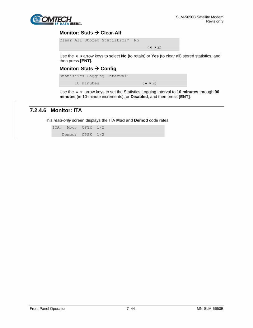
SLM-5650B Satellite Modem Revision 3
Front Panel Operation 7–44 MN-SLM-5650B
Monitor: Stats Clear-All Clear All Stored Statistics? No
(E)
Use the arrow keys to select No (to retain) or Yes (to clear all) stored statistics, and then press [ENT].
Monitor: Stats Config Statistics Logging Interval:
10 minutes (E)
Use the arrow keys to set the Statistics Logging Interval to 10 minutes through 90 minutes (in 10-minute increments), or Disabled, and then press [ENT].
7.2.4.6 Monitor: ITA This read-only screen displays the ITA Mod and Demod code rates.
ITA: Mod: QPSK 1/2
Demod: QPSK 1/2

SLM-5650B Satellite Modem Revision 3
Front Panel Operation 7–45 MN-SLM-5650B
7.2.5 SELECT: Test TEST: Carrier: Normal Loopback: IF
BERT LampTest (E)
Use the arrow keys to select Carrier, Loopback, BERT, or LampTest, and then press [ENT].
Submenu Function
Carrier Select Normal, Tx-CW, or Tx-1,0.
Loopback Select Normal or IFℓ.
BERT Select Tx, Rx, Pattern, Threshold, Reset, ErrIns, Errs, and BER.
LampTest Select LampTest to perform a diagnostic run on the front panel LEDs and VFD.
7.2.5.1 Test: BERT BERT: Tx:Off Rx:Off Pat:2047 Thrsh:Med
Reset Errins Errs:=000000 BER:NoSync
Use the arrow keys to select Tx, Rx, Pattern, Thrsh, Reset, ErrIns, Errs, or BER, and then press [ENT]. Use the arrow keys to select the desired setting. Press [ENT] to execute the test.
BERT Mode Description
Tx Select to turn the transmit test pattern generator On or Off.
Rx Select to turn On or Off the receive bit error test set.
Pattern Select from the available patterns: • Mark – All ones. • Space – All zeros. • 1:1 – A one followed by a zero and then repeats. • 1:2 – A one followed by two zero’s and then repeats. • 2E15-1 – A pseudo-random data pattern of 2^15 –1, compatible with standard
BERTs. • 2E20-1 – A pseudo-random data pattern of 2^20 –1, compatible with standard
BERTs. • 2E23-1 – A pseudo-random data pattern of 2^23 –1, compatible with standard
BERTs. • MIL188 – A modified pseudo-random data pattern of 2^11 –1, compatible with the
MIL-188-165 test data pattern requirement of a continuous stream of 50 zero’s every 10,000 bits. This pattern has 5 normal 2047 patterns, with the fifth patterns longest string of zero’s (11) stretched an additional 39 bits to create a lack of transitions for 50 bits approximately every 10,000 bits.
• 2047 – A pseudo-random data pattern of 2^11 –1, compatible with standard BERTs.
Thrsh Select to set Thrsh at Hi, Med, or Low.

SLM-5650B Satellite Modem Revision 3
Front Panel Operation 7–46 MN-SLM-5650B
BERT Mode Description
Reset Select to restart the BER test and clear the error and BER displays.
ErrIns Select to insert a single error into the data stream by pressing [ENT].
Errs Select to view the absolute number of errors counted.
BER Select to view the bit error rate as measured by the modem.
The BER function can work with a Fireberd supplying the transmit data test pattern, while only turning on the Rx BER tester. The transmit test pattern generator can be turned on at the far end of the link as long as the test patterns match the Rx BERT. An external bit error test set can be used even when the internal bit error test set is enabled. If AIS is enabled, the data will be overwritten with all ones.
7.2.5.2 Test: LampTest Select LampTest to perform a diagnostic run on the front panel LEDs and VFD.
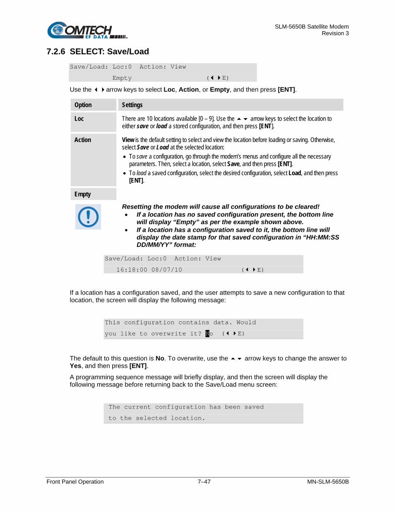
SLM-5650B Satellite Modem Revision 3
Front Panel Operation 7–47 MN-SLM-5650B
7.2.6 SELECT: Save/Load Save/Load: Loc:0 Action: View
Empty (E)
Use the arrow keys to select Loc, Action, or Empty, and then press [ENT].
Option Settings
Loc There are 10 locations available [0 – 9]. Use the arrow keys to select the location to either save or load a stored configuration, and then press [ENT].
Action View is the default setting to select and view the location before loading or saving. Otherwise, select Save or Load at the selected location: • To save a configuration, go through the modem’s menus and configure all the necessary
parameters. Then, select a location, select Save, and then press [ENT]. • To load a saved configuration, select the desired configuration, select Load, and then press
[ENT].
Empty
Resetting the modem will cause all configurations to be cleared! • If a location has no saved configuration present, the bottom line
will display “Empty” as per the example shown above. • If a location has a configuration saved to it, the bottom line will
display the date stamp for that saved configuration in “HH:MM:SS DD/MM/YY” format:
Save/Load: Loc:0 Action: View
16:18:00 08/07/10 (E)
If a location has a configuration saved, and the user attempts to save a new configuration to that location, the screen will display the following message:
This configuration contains data. Would
you like to overwrite it? No (E)
The default to this question is No. To overwrite, use the arrow keys to change the answer to Yes, and then press [ENT]. A programming sequence message will briefly display, and then the screen will display the following message before returning back to the Save/Load menu screen:
The current configuration has been saved
to the selected location.

SLM-5650B Satellite Modem Revision 3
Front Panel Operation 7–48 MN-SLM-5650B
7.2.7 SELECT: Utility UTIL: RT-Clk RefAdjust ID Display Temp
Agc Alarm Firmware FAST (E)
Use the arrow keys to select RT-Clk, RefAdjust, ID, Display, Temp, Agc, Alarm, Alarm, Firmware, or FAST, and then press [ENT].
7.2.7.1 Utility: RT-Clk RT-Clk: Time: 14:29:10
Date: 19/06/17 (E)
Use the arrow keys to select and set the Real-Time Clock. Hours are in 24 hour time (HH:MM:SS) format. The date is shown in DAY/MONTH/YEAR format in accordance with European format.
7.2.7.2 Utility: RefAdjust Internal 10 MHz Ref Freq
Fine Adjust: 3F3 (E)
Use the arrow keys to select and adjust the internal high stability 10 MHz oscillator to counteract aging. The control value is in hex – not decimal – and has a range of 000 to FFF. The typical calibration point for a modem is nominally around 400.
7.2.7.3 Utility: ID Edit Circuit ID: (E)
------------------------
Use the arrow keys to name the communications link. This name can be any combination of alphanumeric characters up to 24 characters in length.
Additional characters supported are: ( ) * + / . (period) , (comma) and space.
7.2.7.4 Utility: Display Edit Display Brightness:
100% (E)
Use the arrow keys to adjust the front panel display brightness. Valid settings are 25%, 50%, 75% or 100%.

SLM-5650B Satellite Modem Revision 3
Front Panel Operation 7–49 MN-SLM-5650B
7.2.7.5 Utility: Temp Modem Temp (Deg C): RF=+38 PS=+40
M&C=+43 Mod=+46/+36 Demod=+46/+38 (E)
This read-only screen allows the user to view the modem internal temperatures (RF, PS, M&C, Mod and Demod).
7.2.7.6 Utility: AGC AgcMan: Min Value: 00.0 Volts
Max Value: 10.0 Volts (E)
Use the arrow keys to select, and then set the Minimum and Maximum voltage levels for the external AGC monitor voltage that is available on the auxiliary (AUX) connector.
Option Setting
Min Value Specifies the voltage to output on the External AGC voltage signal when the demodulator RSL is at its minimum level.
Max Value Specifies the voltage to output when the demodulator RSL is at its maximum level.
7.2.7.7 Utility: Alarm Audible Alarm: Disable
(E)
Use the arrow keys to either Disable or Enable the alarm, and then press [ENT].
7.2.7.8 Utility: Firmware Firmware Images: Information
Select (E)
Use the arrow keys to select Information or Select, and then press [ENT].
Item Description
Information View information on the firmware residing in the Bootrom, Image#1, or Image#2 slots.
Select Select which image (Active Image) will be loaded into the modem: #1 or #2.
Utility: Firmware Information Firmware Info: Bootrom Image#1
Image#2 (E)
Use the arrow keys to select Bootrom, Image#1, or Image#2 to view information on the firmware and software used by the modem.

SLM-5650B Satellite Modem Revision 3
Front Panel Operation 7–50 MN-SLM-5650B
Utility: Firmware Information Bootrom Bootrom: 10/18/07
FW-0000029- 1.1.1 (E)
This screen displays the Bootrom release date, the Firmware number and the revision number. Press [ENT] or [CLR] to return to the previous menu.
Utility: Firmware Information Image#X Image#X: Bulk 06/14/17
FW-0021022- 1.1.1 (E)
Where Image #X denotes selection of Image#1 or Image#2, both images display similar information – the Firmware number with revision letter (shown as ‘x’), its release date (shown as MM/DD/YY), and version (shown as #.#.#) may differ for each firmware load.
Information is displayed as follows:
Image#X Item Example
Bulk (The bulk is the sum of all the individual pieces) FW-0021022-, MM/DD/YY, #.#.#
App FW-0021023-, MM/DD/YY, #.#.#
CPDL #1 FW-0020946-, MM/DD/YY, #.#.#
CPDL #2 FW-0020947-, MM/DD/YY, #.#.#
Mod FW-0020961-, MM/DD/YY, #.#.#
Demod FW-0020962-, MM/DD/YY, #.#.#
Utility: Firmware Select Current Active Image: #2
Next Reboot Image: #2 (E)
Use the to select Image #1 or #2, and then press [ENT].
To reboot the modem, cycle the power.

SLM-5650B Satellite Modem Revision 3
Front Panel Operation 7–51 MN-SLM-5650B
7.2.7.9 Utility: FAST
Chapter 6. FAST ACTIVATION PROCEDURE
FAST: Configuration S/N 000000012
View Options (E)
Select Configuration or View Options, and then press [ENT].
Utility: FAST Configuration FAST Configuration: Code1 Code2 Code3
Demo Mode: Off 604800 Secs remain (E)
Select New FAST Codes or Demo Mode, and then press [ENT].
Option Description
New FAST Codes This is a 20-digit code, purchased from CEFD, which permits upgrading the modem functionality. Legal characters are hexadecimal, 0-F.
Demo Mode This CEFD feature allows the user to try out any capability of the installed hardware for up to 168 hours (seven 24-hour days).
Utility: FAST View Options View Options: 01 Installed ()
Tx Data Rate <= 155.52 Mbps
Use the arrow keys to list the options that the modem supports, and identify whether or not they are installed/enabled. There are 27 options, listed as 01 – 27:

SLM-5650B Satellite Modem Revision 3
Front Panel Operation 7–52 MN-SLM-5650B
FAST Option
No. Description
01 Tx Data Rate <= 155.52 Mbps
02 Rx Data Rate <= 155.52 Mbps
03 8PSK/8QAM Modulation
04 16-QAM Modulation
05 TURBO FEC Option
06 LDPC FEC Option
07 Sequential Encoder/Decoder
08 Triple Viterbi
09 Reed-Solomon Coding
10 Spectrum Spreading
11 Reserved0
12 Reserved1
13 Automatic Uplink Power Control (AUPC) Overhead
14 ASYNC ESC
15 Demodulator Only
16 CnC Data Rate <= 155 Mbps
17 Network Processor I/F Card
18 Transec Module
19 Transec Data Rate <= 155 Mbps
20 NP QoS
21 NP Management Security
22 Vipersat Data Rate <= 155 Mbps
23 NP OW Serial Commands
24 NP BPM Mode
25 NP Antenna Handover
26 DSSS-MA Option
27 STANAG Waveforms

SLM-5650B Satellite Modem Revision 3
Ethernet Interface Operation 8–1 MN-SLM-5650B
Chapter 8. ETHERNET INTERFACE OPERATION
8.1 Introduction The SLM-5650B features a 10/100/1000Base-T RJ-45 ‘J5 Ethernet’ M&C interface port. This port operates in the Auto-Negotiation and Auto-Crossover mode.
Use the optional NP Interface Module as an alternate means for M&C access. The NP Interface Module features four 10/100/1000Base-T RJ-45 ports, labeled 1, 2, 3, and 4. The operational mode of these ports can be individually selected for Auto-Negotiation or fixed mode operation.
The internal systems of the SLM-5650B are interconnected with an internal Ethernet bus, which allows both the Base Modem ‘J5 Ethernet’ port and the NP Ports 1 through 4 to provide M&C access while the NP is operating in Router modes.
8.2 Ethernet Management Interfaces and Protocols
• Chapter 9. BASE MODEM HTTP INTERFACE • Appendix E. OPTIONAL NETWORK PROCESSOR (NP)
INTERFACE MODULE • Appendix F. OPTIONAL TRANSEC MODULE OPERATION
It is important to have the IP address of the Base Modem, Network Processor (NP), and TRANSEC module readily available, since they will be referred to frequenty when using Ethernet Interface Operations.
The following Ethernet M&C Protocols are supported by the SLM-5650B:
• Web Server HTTP (non-secure) or HTTPS (secure) Interface. These interface modes require a compatible user-supplied web browser such as Internet Explorer, FireFox, or Google Chrome. These protocols are supported by the following systems:
o Base Modem M&C (HTTP/HTTPS)
o NP Module M&C (HTTP/HTTPS)
o TRANSEC Module M&C (HTTPS only)

SLM-5650B Satellite Modem Revision 3
Ethernet Interface Operation 8–2 MN-SLM-5650B
• Simple Network Management Protocol (SNMP) with Public and Private Management Information Base (MIB). The non-secure (SNMPv1/v2c) or secure (SNMPv3) interface requires a user-supplied Network Management System (NMS) or a user-supplied MIB File Browser. This protocol is supported as follows:
o Base Modem M&C (SNMPv1/v2c or SNMPv3)
o NP Module M&C (SNMPv1/v2c)
SNMP is NOT supported by the TRANSEC module.
• Telnet Interface. This non-secure Base Modem interface requires use of the user PC’s Command Line Interface (CLI), or a user-supplied terminal emulation program such as HyperTerminal, PuTTY, or TeraTerm.
Telnet is NOT supported by the TRANSEC module.
• Secure Shell (SSH) Interface. This protocol requires the use of the users PC’s CLI, or a user-supplied terminal emulation program such as HyperTerminal, PuTTY, or TeraTerm.
This interface protocol is supported by the NP Interface Module and the TRANSEC Module.

SLM-5650B Satellite Modem Revision 3
Ethernet Interface Operation 8–3 MN-SLM-5650B
8.2.1 Secure Ethernet Management Interfaces
8.2.1.1 Base Modem Interface When Management Security is disabled (i.e. SNMPv1/2c is selected):
• Either HTTP or HTTPS protocols may be used.
• Telenet protocol may be used.
• SNMP v1/v2c protocol may be used.
Whem Management Security is enabled (i.e. Management Security option is installed and SNMPv3 is selected):
• Only HTTPS protocol may be used.
• Telnet protocol is disabled.
• FTP protocol is disabled.
• SNMPv3 protocol may be used.
The base modem management can be changed to a secure mode by changing the SNMP setting from SNMPv1/v2c to the SNMPv3 mode:
• The SNMP mode is available using the front panel menu: SELECT: Configure→Remote→EthernetConfig→SNMP→Version→SNMPv1/v2c or SNMPv3.
• Select SNMPv3 and reboot the modem. The HTTP, FTP, and Telnet access will be blocked. This operational change also forces the Trap mode to be SNMPv3Traps.
• The SNMP Trap Destination Port (default 164) can be changed to a user value in the SELECT:Configure→Remote→EthernetConfig→SNMP→ Traps→Port menu. Make sure to only use port values that are not already in use by other services.
• Change of the management mode to SNMPv3 is allowable via the HTTP (non-secure) interface, but you should be aware that, after the modem reboot, HTTP access will no longer be available. The SNMPv3 mode uses the Base Modem’s IP Address via the ‘J5 Ethernet’ port. The Base Modem HTTPS Interface is accessible by the NP IP Address or the TRANSEC IP Address.

SLM-5650B Satellite Modem Revision 3
Ethernet Interface Operation 8–4 MN-SLM-5650B
8.2.1.2 Optional NP Interface Module When Management Security is disabled (i.e. Low Level Security or SNMPv1/2c is selected):
• Non-secure Base Modem protocols are enabled, as described above.
• Non-secure Ethernet-based network management is supported over the NP Interface when operating in Router modes using using HTTP (non-secure) and SNMPv1/v2c protocols.
When Management Security is enabled (i.e. High Level Security or SNMPv3 is selected):
• Secure Base Modem protocols are enabled, as described above.
• Secure Ethernet-based network management is supported over the NP Interface when operating in Router modes using HTTPS and SSH protocols.
• The NP Interface M&C Interface is disabled when in Bridge Mode.
The NP Interface Module management can be changed to a secure mode by changing the Option Card security setting to High on the front panel:
SELECT: Configure→Remote→EthernetConfig→Option Card→Security→High.
8.2.1.3 Base Modem + Optional NP Interface + Optional TRANSEC Module Since the Base Modem supports HTTPS, the TRANSEC Module’s HTTPS Proxy is not supported in the SLM-5650B.
When Management Security is disabled (i.e. Low Level Security or SNMPv1/2c is selected):
• Non-secure Base Modem protocols are enabled, as described above.
• Non-secuire NP Module protocols are enabled, as described above.
• Secure Ethernet-based network management is supported over the TRANSEC Module Interface using HTTPS and SSH protocols.
When Management Security is enabled (i.e. High Level Security or SNMPv3 is selected):
• Secure Base Modem protocols are enabled, as described above.
• Secure NP Module protocols are enabled, as described above.
• Secure Ethernet-based network management is supported over the TRANSEC Module Interface using HTTPS and SSH protocols.

SLM-5650B Satellite Modem Revision 3
Ethernet Interface Operation 8–5 MN-SLM-5650B
8.3 HTTP/HTTPS (Web Server) Interfaces
Chapter 9. BASE MODEM HTTP/HTTPS INTERFACE Appendix E. NETWORK PROCESSOR (NP) INTERFACE MODULE Appendix F. TRANSEC MODULE OPERATION
The SLM-5650B’s embedded Web Server application provides the user with an easy to use interface to configure and monitor all aspects of the modem. At present, three independent Web Server Interfaces are available for the SLM-5650B, each designed for optimal performance when using the supported browsers:
• Base Modem HTTP/HTTPS Interface (standard) – Requires Microsoft’s Internet Explorer 7.0 (or higher), Mozilla Firefox 2.0 (or higher), and Chrome, via HTTP or HTTPS (depending on the modem’s security level setting). Refer to Chapter 9. BASE MODEM HTTP/HTTPS INTERFACE.
• Network Processor (NP) Interface (optional) – Available when the optional NP Interface is installed. This interface requires Microsoft’s Internet Explorer 7.0 (or higher), Mozilla Firefox 2.0 (or higher), and Chrome, via HTTP or HTTPS (depending on the modem’s security level setting). Refer to Appendix E. NETWORK PROCESSOR (NP) INTERFACE MODULE.
• TRANSEC Module HTTPS Interface (optional) – Available when the optional TRANSEC Module is installed. This interface requires Microsoft’s Internet Explorer 7.0 (or higher), Mozilla Firefox 2.0 (or higher), and Chrome, via HTTPS. Refer to Appendix F. TRANSEC MODULE OPERATION.
All Web Server Interfaces are accessible by typing (depending on the interface and/or management mode) “http://xxx.xxx.xxx.xxx” or “https://xxx.xxx.xxx.xxx” into the browser’s Address box (where “xxx.xxx.xxx.xxx” is the IP address of the modem or optional installed interface):
It is important to have the IP address of the Base Modem, Network Processor (NP), and TRANSEC module readily available, since they will be referred to frequenty when using Ethernet Interface Operations.
For all interfaces, the user is prompted to type in a valid User name and Password, whether via an integrated Web page or a dialog box similar to the one shown to the right.
For all interfaces, the default for both user name and password is comtech.

SLM-5650B Satellite Modem Revision 3
Ethernet Interface Operation 8–6 MN-SLM-5650B
8.4 SNMP Interface The SNMP is an Internet-standard protocol for managing devices on IP networks. An SNMP-managed network consists of three key components:
• The managed device. This includes the SLM-5650B Satellite Modem.
• The SNMP Agent. The software that runs on the SLM-5650B. The SLM-5650B SNMP Agent supports SNMPv1, SNMPv2c, and SNMPv3.
• The user-supplied NMS. The software that runs on the manager.
8.4.1 MIB Files MIB files are used for SNMP remote management of a unique device. A MIB file consists of a tree of nodes called Object Identifiers (OIDs). Each OID provides remote management of a particular function. These MIB files should be compiled in a user-supplied MIB Browser or SNMP Network Monitoring System server.
The following MIB files are associated with the SLM-5650B:
MIB File/Name
( ‘x’ indicates revision letter) Description
fw10874-2x.mib
ComtechEFData MIB file
CEFD MIB file gives the root tree for ALL CEFD products and consists of only the following OID: Name: comtechEFData Type: MODULE-IDENTITY OID: 1.3.6.1.4.1.6247 Full path: iso(1).org(3).dod(6).internet(1).private(4).enterprises(1).comtechEFData(6247)
Module: ComtechEFData
FW-0021072x_vYYY.MIB
SLM-5650B OID MIB File MIB file consists of all of the OID’s for management of the modem functions.
FW-0021073x_vYYY.MIB
SLM-5650B Traps MIB file Trap MIB file is provided for SNMPv1 traps common for base modems.

SLM-5650B Satellite Modem Revision 3
Ethernet Interface Operation 8–7 MN-SLM-5650B
8.4.2 SNMP Community Strings
In SNMP v1/v2c, the SNMP Community String is sent unencrypted in the SNMP packets. Caution must be taken by the network administrator to ensure that SNMP packets travel only over a secure and private network if security is a concern.
The SLM-5650B uses Community Strings as a password scheme that provides authentication before gaining access to the modem agent’s MIBs. They are used to authenticate users and determine access privileges to the SNMP agent.
Type the SNMP Community String into the user-supplied MIB Browser or Network Node Management software.
The user defines three Community Strings for SNMP access:
• Read Community default = public
• Write Community default = private
• Trap Community default = comtech
Note: Maximum number of characters for community strings shall not exceed 20. All printable ASCII characters, except ’\’ and ‘~’ are allowed. No trailing spaces for community strings.
For proper SNMP operation, the SLM-5650B MIB files must be used with the associated version of the SLM-5650B base modem M&C. Please refer to the SLM-5650B SW Release Notes for information on the required FW/SW compatibility.
8.4.3 SNMP Traps These include unit faults, TX faults, and RX faults. A trap is sent both when a fault occurs and is cleared.
The “Traps” file only needs to be compiled if SNMPv1 traps are to be used. Which style of traps the modem sends can be configured by the user using the slm5650SNMPTrapVersion OID.
The modem supports the following MIB2 SNMPv1traps / SNMPv2 notifications:
MIB2 SNMPv1 trap: Authentication Failure 5 MIB2 SNMPv2 notifications: Authentication Failure 1.3.6.1.6.3.1.1.5.5
The SLM-5650B supports the following Alarms and Faults SNMPv1 traps / SNMPv2 notifications:
Table 8-1. Alarms and Faults SNMPv1 Traps
slm5650UnitAlarmV1 62471081 slm5650TxTrafficAlarmV1 62471082 slm5650RxTrafficAlarmV1 62471083 slm5650RedundancyStateV1 62471084

SLM-5650B Satellite Modem Revision 3
Ethernet Interface Operation 8–8 MN-SLM-5650B
Table 8-2. Alarms and Faults SNMPv2c/SNMPv3 Notification
slm5650UnitAlarmV2 1.3.6.1.4.1.6247.108. 2.1.1 slm5650TxTrafficAlarmV2 1.3.6.1.4.1.6247.108. 2.1.2 slm5650RxTrafficAlarmV2 1.3.6.1.4.1.6247.108. 2.1.3 slm5650RedundancyStateV2 1.3.6.1.4.1.6247.108. 2.1.4
8.4.4 SNMPv3 (Base Modem)
Chapter 9. BASE MODEM HTTP/HTTPS INTERFACE
Refer to Chapter 9. BASE MODEM HTTP/HTTPS INTERFACE, Section 9.4.2.3 for set and return administration information for the SLM-5650B Simple Network Management Protocol (SNMP) feature.
When the user activates the SNMPv3 option, either by changing the SNMP mode or selecting the NP’s security mode to High, SNMPv1 and SNMPv2c are disabled. Instead of using the public and private community strings identified in Section 8.4.2, the modem uses the authPriv SNMPv3 Security mode. Authentication is performed using either the SHA or MDS protocols and a user name and password pair. The Authentication user name and password pair can be from any of the three System Accounts, described in Chapter 9. BASE MODEM HTTP/HTTPS INTERFACE, Section 9.4.2.1. Read-Only, Read/Write, and Admin access to the SNMP MIB variables wil be granted, depending on the account credentials used during authentication. Privacy is performed using either of the DES, AES-128-CFB, AES-192-CFB, AES-256-CFB, or 3DES encryption protocols. Encryption keys are generated using the user defined PrivPassword (Privacy Password).

SLM-5650B Satellite Modem Revision 3
Ethernet Interface Operation 8–9 MN-SLM-5650B
8.5 Telnet Interface
8.5.1 Telnet Inerface via Windows Command Line
Chapter 10. SERIAL INTERFACE OPERATION
A Telnet interface is provided for the purpose of equipment M&C via the Serial Remote Control protocol.
Once you log in to the Telnet interface, you have access to the standard serial-based Remote Control Interface. Figure 8-1 shows an example of the login process using Windows Command-line via the TeraTerm program.
The default name and password is: comtech.
Figure 8-1. Telnet Interface Login Example
Once logged into the Telnet interface, the standard remote control interface (as defined in Chapter 10. SERIAL REMOTE CONTROL) is accessible, as shown in Figure 8-2:
Figure 8-2. Telnet Remote Control Interface Example

SLM-5650B Satellite Modem Revision 3
Ethernet Interface Operation 8–10 MN-SLM-5650B
8.5.2 Telnet Remote Control Operation via a Terminal Emulation Program There is a disadvantage when using Windows Command line as a Telnet client with the optional Remote Control protocol. For the messages coming from the Telnet Server, Command line cannot translate a carriage return command (\r) to a carriage return + line feed command (\r\n). Therefore, any multi-line Target-to-Controller response (e.g., the response to the RNE? query) shows as one line, with the latter lines overwriting the previous lines.
To see the full response messages, you can use a terminal emulation program configured as a Telnet client. CEFD recommends using HyperTerminal, TeraTerm, or PuTTY, which the login process is detailed in the following sections.
8.5.2.1 HyperTerminal Configure HyperTerminal as follows:
1. Make sure to define the Connect To Telnet connection properties correctly (File Properties) (Figure 8-3):
a. Enter the SLM-5650B’s Traffic/Management IP Address as the “Host address” (e.g., 192.168.1.1).
b. Enter TCP Port 23 as the “Port number”. c. Set “Connect using” to TCP/IP (Winsock) instead of COM1 or COM2. d. Click [OK] to save your settings.
2. For ASCII Setup (File Properties Settings ASCII Setup) (Figure 8-3): a. Check the “Send line ends with line feeds” option in the ‘ASCII Sending’ section. b. Check the “Append line feeds to incoming line ends” option in the ‘ASCII
Receiving’ section. c. Click [OK] to save your settings.
Figure 8-3. Configure HyperTerminal

SLM-5650B Satellite Modem Revision 3
Ethernet Interface Operation 8–11 MN-SLM-5650B
6 0 00000000000000
Examples of login and remote command/query execution, when using HyperTerminal as the interface, appear as follows:
Figure 8-4. HyperTerminal Example
8.5.2.2 TeraTerm Configure TeraTerm as follows:
1. From the terminal emulation program’s folder, double-click the program filename (e.g., TeraTerm), shortcut, icon, etc. to open the application and its configuration window.
2. Type in the IP address of the NP Module interface in the Host Name (or IP Address) window. Select Telnet as the Service type. Verify that the TCP port # is 23. Select the Protocol as IPv4. Click [OK].

SLM-5650B Satellite Modem Revision 3
Ethernet Interface Operation 8–12 MN-SLM-5650B
3. A new session screen will open, and the login window will appear. Enter the name and password. The default for both user name and password is comtech.
The TeraTerm screen can be adjusted for viewing by clicking ‘Setup’ on the Menu bar, then altering the selections to meet the users preferences.
4. Once the login is accepted, the Main Menu screen appears.

SLM-5650B Satellite Modem Revision 3
Ethernet Interface Operation 8–13 MN-SLM-5650B
8.5.2.3 PuTTY Configure PuTTY as follows:
1. From the terminal emulation program’s folder, double-click the program filename (e.g., PuTTY), shortcut, icon, etc. to open the application and its configuration window.
2. Type in the IP address of the NP Module interface in the Host Name (or IP Address) window. Select Telnet as the Connection type. Verify that the port # is 23. Click [OPEN].
3. A new session screen will open, and the login window will appear. Enter the name and password. The default for both user name and password is comtech.
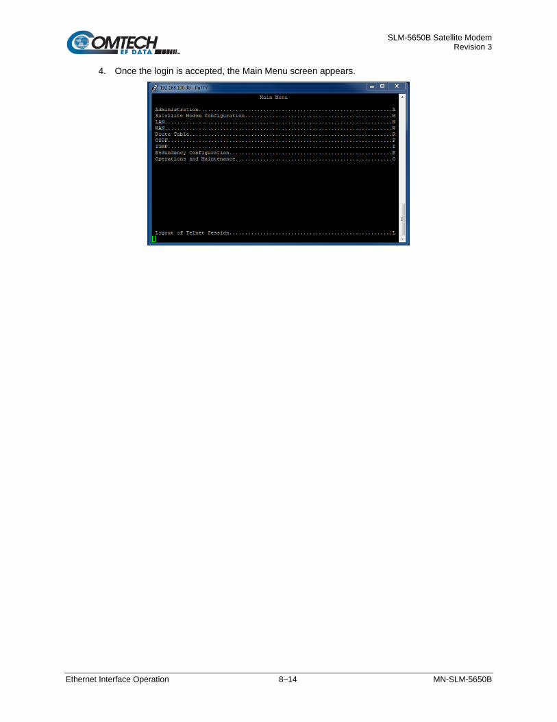
SLM-5650B Satellite Modem Revision 3
Ethernet Interface Operation 8–14 MN-SLM-5650B
4. Once the login is accepted, the Main Menu screen appears.

SLM-5650B Satellite Modem Revision 3
Ethernet Interface Operation 8–15 MN-SLM-5650B
8.6 Secure Shell (SSH) Interface
Appendix E. OPTIONAL NETWORK PROCESSOR (NP) INTERFACE MODULE Appendix F. OPTIONAL TRANSEC MODULE OPERATION
While the TRANSEC Module CLI main and nested screens will be identical across terminal emulator applications, setup may differ slightly. The user should be familiar with their preferred SSH interface.
When the modem is equipped with the optional NP or TRANSEC Module Interfaces, the security and encryption features for either require that administrative maintenance and control operations are accomplished using a SSH CLI.
8.6.1 Configure a SSH Session via TeraTerm Configure TeraTerm as follows:
1. From the terminal emulation program’s folder, double-click the program filename (e.g., TeraTerm), shortcut, icon, etc. to open the application and its configuration window.
2. Type in the IP address of the TRANSEC Module interface in the Host Name (or IP Address) window. Select SSH as the Service type. Verify that the TCP port # is 22. Select the Protocol as IPv4. Click [OK].
3. A Security Warning screen appears. Click [Continue].

SLM-5650B Satellite Modem Revision 3
Ethernet Interface Operation 8–16 MN-SLM-5650B
4. The SSH Authentication screen can now be accessed. Type in the user name and passphrase. The default for both user name and passphrase is comtech. Click [OK].
5. Once the login is accepted, the Main Menu screen appears.
The TeraTerm screen can be adjusted for viewing by clicking ‘Setup’ on the Menu bar, then altering the selections to meet the users preferences.
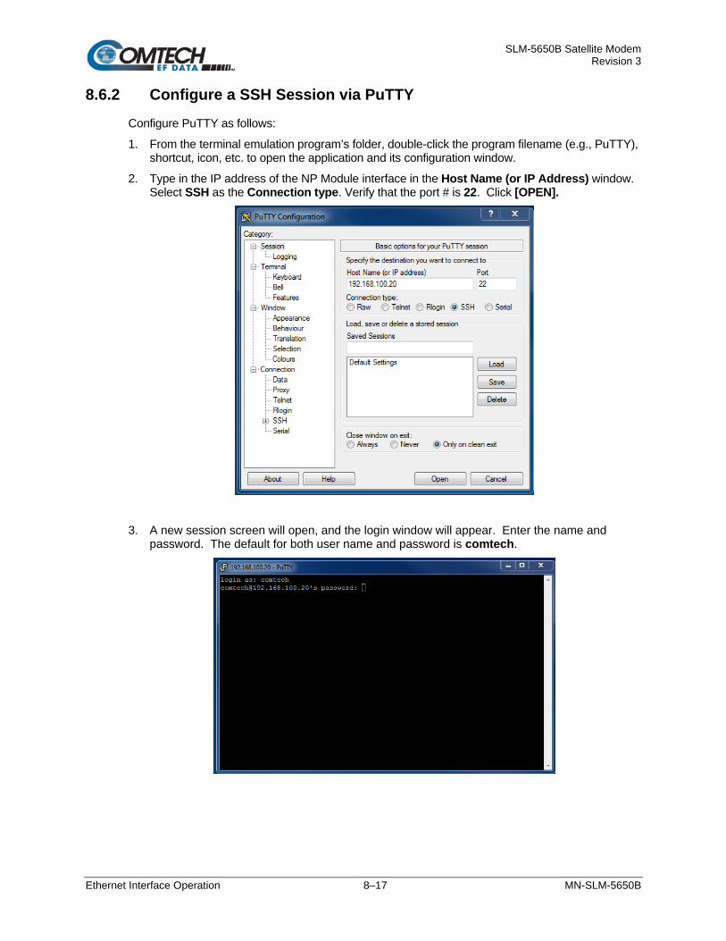
SLM-5650B Satellite Modem Revision 3
Ethernet Interface Operation 8–17 MN-SLM-5650B
8.6.2 Configure a SSH Session via PuTTY Configure PuTTY as follows:
1. From the terminal emulation program’s folder, double-click the program filename (e.g., PuTTY), shortcut, icon, etc. to open the application and its configuration window.
2. Type in the IP address of the NP Module interface in the Host Name (or IP Address) window. Select SSH as the Connection type. Verify that the port # is 22. Click [OPEN].
3. A new session screen will open, and the login window will appear. Enter the name and password. The default for both user name and password is comtech.

SLM-5650B Satellite Modem Revision 3
Ethernet Interface Operation 8–18 MN-SLM-5650B
4. Once the login is accepted, the Main Menu screen appears.

SLM-5650B Satellite Modem Revision 3
Base Modem HTTP/HTTPS Interface Operation 9–1 MN-SLM-5650B
Chapter 9. BASE MODEM HTTP/HTTPS INTERFACE
OPERATION
9.1 Overview This chapter describes the functionality of the SLM-5650B’s Base Modem HTTP/HTTPS Interface. The operational parameters available from these web pages complement the operation of the SLM-5650B’s front panel menus.
9.2 Base Modem HTTP/HTTPS Interface Introduction
Chapter 7. FRONT PANEL OPERATION Chapter 10. SERIAL REMOTE CONTROL
A user-supplied web browser allows the full M&C of the SLM-5650B from its Base Modem Web Interface. The SLM-5650B’s embedded web applications are designed for, and work best with, Microsoft’s Internet Explorer Version 7.0 or higher.
See Chapter 7. FRONT PANEL OPERATION and the Remote Commands Specifications tables found in Chapter 10. SERIAL REMOTE CONTROL for detailed descriptions of the configuration parameters featured on the individual web pages shown in this chapter.
9.2.1 User Login All Web Server Interfaces are accessible by typing (depending on the interface and/or management mode) “http://xxx.xxx.xxx.xxx” or “https://xxx.xxx.xxx.xxx” into the browser’s Address box (where “xxx.xxx.xxx.xxx” is the IP address of the modem or optional installed interface):

SLM-5650B Satellite Modem Revision 3
Base Modem HTTP/HTTPS Interface Operation 9–2 MN-SLM-5650B
For all interfaces, the user is prompted to type in a valid User name and Password, whether via an integrated Web page or a dialog box, like the one shown in Figure 9-1. For all interfaces, the default for both is comtech.
Figure 9-1. Windows Security Password Screen
Once the valid User name and Password is accepted, the browser window displays the Base Modem Web Interface “splash” (Home) page:
Figure 9-2. Base Modem Web Interface Home Page

SLM-5650B Satellite Modem Revision 3
Base Modem HTTP/HTTPS Interface Operation 9–3 MN-SLM-5650B
9.2.2 Web Interface – Operational Features
Navigation This manual uses a naming format for all web pages to indicate the depth of navigation needed to view the referenced page: “Top Level Tab | 2nd Level Tab.”
For example: “Admin | Access” is interpreted to mean “first click the top-level ‘Admin’ navigation tab; then, click the ‘Access’ Page tab.
Web Page Tabs
Chapter 7. FRONT PANEL OPERATION Chapter 10. SERIAL REMOTE CONTROL
Each page is divided into one or more operational content tabs.
This manual explains the purpose and operation for each web page on a per-page basis. For detailed information, see Chapter 7. FRONT PANEL OPERATION or Chapter 10. SERIAL REMOTE CONTROL.
Execution Buttons Configuration changes generally do not take effect until a selection has been saved to non-volatile memory. There may be one execution button per page or multiple execution buttons within a page section. The label for each of these buttons is generally self-explanatory, e.g., [Submit], [Clear], [Refresh], etc.
All execution buttons serve the same purpose – to save the configuration changes to non-volatile memory, or to execute an update of the active page display.
Always make sure to click the execution button before selecting another web page. Any changes made on that previous page will not be saved if the execution button for those functions is not clicked.
Feature Selection Drop-down lists provide access to multiple setting selections, where available, for a specific function. Move the cursor to the drop-down tab, and then left-click the tab. The drop-down will open and list the available selections. Move the cursor to the desired choice and then left-click once again to select that choice.
Text or Data Entry Text boxes are provided any time an alphanumeric entry is required for access or configuration.
Move the cursor to the text box, and then left-click anywhere inside the box. Then, use the keyboard to type in the desired alphanumeric string. Press Enter when done.

SLM-5650B Satellite Modem Revision 3
Base Modem HTTP/HTTPS Interface Operation 9–4 MN-SLM-5650B
9.2.3 Web Interface Menu Tree The following menu tree illustrates the options available via the Base Modem Web Interface for all modes except STANAG:
Home Admin Configuration Status
Home Access Modem Status
Contact Time Utils Info
SNMP LoadStore EventLog
FAST Spreading ModemStatistics
Upgrade CnC PortStatistics
AUPC ConfigLog
AHO Firmware
ODU Constellation
The following menu tree illustrates the options available via the Base Modem Web Interface with the STANAG mode:
Home Admin Configuration Status
Home Access Modem Status
Contact Time Utils Info
SNMP LoadStore EventLog
FAST AUPC ModemStatistics
Upgrade ODU PortStatistics
ITA* ConfigLog
Firmware
Constellation
* The ITA configuration activates only when the mode is set to STANAG.
This interface provides access to four navigation tabs (shown in blue):
Beyond this top-level row of navigation tabs, the diagram illustrates the available 2nd level tabs (shown in grey) that afford more specific user functionality.
Click any tab to continue.

SLM-5650B Satellite Modem Revision 3
Base Modem HTTP/HTTPS Interface Operation 9–5 MN-SLM-5650B
9.3 HTTPS Certificate The SLM-5650B’s firmware has a default HTTPS certificate installed. The default certificate is a self-signed certificate built with the modem's default IP Address of 192.168.1.1 with a one-year expiration date. Since most modern web browsers will flag certificate errors and may not even allow secure connections when errors exist, most users will want to load their own certificate. An X509 private key and certificate in Privacy-enhanced Electronic Mail (PEM) format may be loaded as follows:
1. Make sure that the modem is in Non-Secure Mode (SNMPv1/v2c is selected). 2. Open a "My Computer" (Windows Explorer, not Internet Explorer) window on the PC. 3. Open a web browser and browse to the modem's Admin | Upgrade web page. 4. Copy the Uniform Resource Locator (URL) shown under paragraph 2 from step 3 into the
address bar of the "My Computer" (Windows Explorer, not Internet Explorer) window and press Enter.
5. Windows Explorer will open an FTP connection the the modem and display a directory list with a single entry that says "README.TXT".
6. Open another "My Computer" (Windows Explorer, not Internet Explorer) window and navigate to the directory that includes the “.PEM” file. The first eight characters of the “.PEM” file must contain the letters "SLM5650B".
7. Click on the file and drag it to the "My Computer" (Windows Explorer, not Internet Explorer) window that displays the "README.TXT" and drop it in.
8. The modem will extract the key and certificate information and delete the “.PEM” file from the directory.
9. Browser to the Status | Info web page and check the 20 byte SSL Certificate Fingerprint (sometimes called the Thumbprint) shown there with the user certificate's fingerprint.
The user may now enable Secure Mode (SNMPv3 is selected), and reboot the modem.
Should a bad certificate get installed and HTTPS access is lost, do the following:
1. Go to the modem front panel. 2. Change the modem from Secure mode to Non-Secure mode using the following: • If no NP card is selected, use the Config->Remote->EthernetConfig->SNMP->Version
menu. • If the NP card is selected, use the Config->Remote->EthernetConfig->Option Card Addr
menu. 3. Reboot the modem. 4. Follow the procedure above to load another certificate.
To delete the loaded certificate and revert to the modem's default certificate, it is only necessary to perform a modem hard reset via the Config->Reset menu on the front panel.

SLM-5650B Satellite Modem Revision 3
Base Modem HTTP/HTTPS Interface Operation 9–6 MN-SLM-5650B
9.4 Base Modem Web Interface Page Descriptions
9.4.1 Home Page Select the Home tab to continue.
Home | Home From any location within the SLM-5650B Base Modem Web Interface, click the Home top navigation tab to return to this top-level page. Use this page to identify the product and its current operating firmware version.
Figure 9-3. Base Modem Modem Home Page
This page can also be used to view the Unit Status, Rx Status, and Tx Status faults by clicking on the light next to each item on the page header. Clicking on these lights will open a window showing the status faults. See Section 9.4.4.1, Status | Status Page.
Clicking the Events light will open the Events Log tab and display the same information from the tab. See Section 9.4.4.3, Status | Even Log Page.

SLM-5650B Satellite Modem Revision 3
Base Modem HTTP/HTTPS Interface Operation 9–7 MN-SLM-5650B
Home | Contact
Figure 9-4. Home | Contact Page

SLM-5650B Satellite Modem Revision 3
Base Modem HTTP/HTTPS Interface Operation 9–8 MN-SLM-5650B
9.4.2 Admin (Administration) Pages Use these pages to set up user access, manage the firmware load preferences, and monitor and control optional network features.
The ‘Admin’ pages are available only to users who have logged in using the Administrator Name and Password.
Click the Access, Time, SNMP, FAST, or Upgrade tabs to continue.
Admin | Access The following screen appears when the NP mode is enabled.
Figure 9-5. Admin | Access Page
When the GbE mode is selected, the Network Processor Interface section of the screen is not available.

SLM-5650B Satellite Modem Revision 3
Base Modem HTTP/HTTPS Interface Operation 9–9 MN-SLM-5650B
Modem Maintenance Name Description
Ping Reply Enabled or Disabled MAC Address This read-only description displays the MAC address. Serial Number This displays the serial number of the modem. IP Gateway This displays the modems IP gateway. IP Address This displays the modems IP address.
Network Processor Interface Name Description
MAC Address This read-only description displays the MAC address. IP Address Mode Single or Dual Secure Mode Low or High Traffic IP Address This displays the Traffic IP address. Management Addr This displays the Management address. Working Mode • N/A
• Vipersat Hub • Vipersat Hub Expansion • Vipersat Remote • Vipersat Remote Expansion • Multipoint Hub • Multipoint Remote • Point to Point • Gigabit Bridge • DSSS-M Hub • DSSS-M Hub Expansion • DSSS-M Remote

SLM-5650B Satellite Modem Revision 3
Base Modem HTTP/HTTPS Interface Operation 9–10 MN-SLM-5650B
System Account Access Information Name Description
Read Only Name Enter the “Read Only Name.” This can be any alphanumeric combination with a maximum length of 15 characters. The factory default is “monitor”.
Read/Write Name Enter the “Read/Write Name.” This can be any alphanumeric combination with a maximum length of 15 characters. The factory default is “opcenter”.
Admin Name Enter the “Admin Name” This can be any alphanumeric combination with a maximum length of 15 characters. The factory default is “comtech”.
Session Timeout Enter the amount of time a session will timeout, shown in seconds. Read Only Password Enter the “Read Only Password.” This can be any alphanumeric combination
with a maximum length of 15 characters. The factory default is “1234”.
Read/Write Password Enter the “Read/Write Password.” This can be any alphanumeric combination with a maximum length of 15 characters. The factory default is “1234”.
Admin Password Enter the “Admin Password.” This can be any alphanumeric combination with a maximum length of 15 characters. The factory default is “comtech”.
Host Access List Name Description
IP (1, 2, 3, or 4) / Mask Enter up to four IP addresses. Access List Disable or Enable
Click [Submit Admin] to save the selections.
Front Panel Control Name Description
Front Panel Control Select Enabled or Disabled to turn ON / OFF the front panel control.
Click [Submit] to save the selection.
SSL Certificate Upload Name Description
SSL Certificate Upload Use this area to browse and load file for upload.
Click [Upload File] to load the selected file.

SLM-5650B Satellite Modem Revision 3
Base Modem HTTP/HTTPS Interface Operation 9–11 MN-SLM-5650B
Admin | Time
Figure 9-6. Admin | Time Page
Modem Time Name Description
SNTP Server Address Enter the SNTP Server address. Local Time Offset Select the appropriate time, +/- GMT, for your area. Time Enter the time for your area, as HH:MM:SS.
Note: This time will only be set if SNTP is disabled. Date Enter the date for your area, as DD/MM/YY.
Click [Submit] to save the selection.
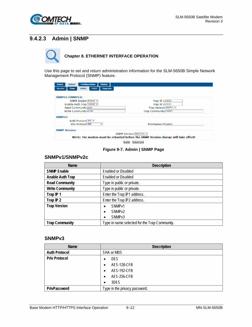
SLM-5650B Satellite Modem Revision 3
Base Modem HTTP/HTTPS Interface Operation 9–12 MN-SLM-5650B
Admin | SNMP
Chapter 8. ETHERNET INTERFACE OPERATION
Use this page to set and return administration information for the SLM-5650B Simple Network Management Protocol (SNMP) feature.
Figure 9-7. Admin | SNMP Page
SNMPv1/SNMPv2c Name Description
SNMP Enable Enabled or Disabled Anable Auth Trap Enabled or Disabled Read Community Type in public or private. Write Community Type in public or private. Trap IP 1 Enter the Trap IP1 address. Trap IP 2 Enter the Trap IP2 address. Trap Version • SNMPv1
• SNMPv2 • SNMPv3
Trap Community Type in name selected for the Trap Community.
SNMPv3 Name Description
Auth Protocol SHA or MD5 Priv Protocol • DES
• AES-128-CFB • AES-192-CFB • AES-256-CFB • 3DES
PrivPassword Type in the privacy password.

SLM-5650B Satellite Modem Revision 3
Base Modem HTTP/HTTPS Interface Operation 9–13 MN-SLM-5650B
SNMP Version Name Description
SNMP Version SNMPv1v2c or SNMPv3
Click [Submit] to save any changes made on this page.
Click [Reboot Now] to complete any SNMP version change.

SLM-5650B Satellite Modem Revision 3
Base Modem HTTP/HTTPS Interface Operation 9–14 MN-SLM-5650B
Admin | FAST Use this page to set the FAST codes.
Figure 9-8. Admin | FAST Page
FAST Upgrade Name Description
Set Code 1, 2, or 3 Enter the FAST Code provided by CEFD Customer Support. Click [Enter 1, 2 or 3] to save.
Demo Mode Name Description
Time Remaining This read-only description displays the time remaining until the demo mode expires.
Demo Mode • Off • On • Expired

SLM-5650B Satellite Modem Revision 3
Base Modem HTTP/HTTPS Interface Operation 9–15 MN-SLM-5650B
Admin | Upgrade Use this page to REFLASH the SLM-5650B and change the active firmware image.
Figure 9-9. Admin | Upgrade Page
Firmware File Upload Name Description
Firmware File Upload Use this area to browse and load file for upload. Select
Click [Upload File] to load the selected file.
Firmware Image Config Name Description
ReFLASH Status Displays the ReFLASH status. Active Image Dispays 1 or 2 for the Active Image. Next Reboot Image Displays 1 or 2 for the Next Reboot Image.
Click [Extract Files] to extract the files from the firmware file upload.
Click [Set Image 1] or [Set Image 2] to select the the Next Reboot Image.
Click [Reboot Modem] to complete the process.

SLM-5650B Satellite Modem Revision 3
Base Modem HTTP/HTTPS Interface Operation 9–16 MN-SLM-5650B
9.4.3 Configuration (Modem Configuration) Pages The Configuration pages are used to configure the Modulator, Demodulator, and Ethernet Bridge interface.
The tabs that appear depend on the modem type selected.
When any mode is selected except the STANAG mode, the Modem, Utils, LoadStore, CnC, AUPC, AHO, or ODU tabs will be active.
When the STANAG mode is selected, the Modem, Utils, LoadStore, AUPC, ODU, and ITA tabs will be active.
Configuration | Modem
The Configuration Pages may change slightly, depending on the modem type selected. Not all modem parameters are valid, and could be hidden, when certain modem types are selected.
The following modes are not available at this time:
• Rx Burst • Tx Burst • Rx Burst-FA • IESS308-V2 • SLM-9000C
Figure 9-10. Configuration | Modem Page – OM-73 Mode

SLM-5650B Satellite Modem Revision 3
Base Modem HTTP/HTTPS Interface Operation 9–17 MN-SLM-5650B
Figure 9-11. Configuration | Modem Page – MIL-165A Mode
Figure 9-12. Configuration | Modem Page – IESS-308 Mode

SLM-5650B Satellite Modem Revision 3
Base Modem HTTP/HTTPS Interface Operation 9–18 MN-SLM-5650B
Figure 9-13. Configuration | Modem Page – IESS-309 Mode
Figure 9-14. Configuration | Modem Page – IESS-310 Mode

SLM-5650B Satellite Modem Revision 3
Base Modem HTTP/HTTPS Interface Operation 9–19 MN-SLM-5650B
Figure 9-15. Configuration | Modem Page – Turbo Mode
Figure 9-16. Configuration | Modem Page – 16QAM Mode

SLM-5650B Satellite Modem Revision 3
Base Modem HTTP/HTTPS Interface Operation 9–20 MN-SLM-5650B
Figure 9-17. Configuration | Modem Page – AUPC Mode
Figure 9-18. Configuration | Modem Page – Turbo-FA Mode
Note: Spreading is not available in the TURBO-FA mode.

SLM-5650B Satellite Modem Revision 3
Base Modem HTTP/HTTPS Interface Operation 9–21 MN-SLM-5650B
Figure 9-19. Configuration | Modem Page – LDPC Mode
Figure 9-20. Configuration | Modem Page – STANAG Mode

SLM-5650B Satellite Modem Revision 3
Base Modem HTTP/HTTPS Interface Operation 9–22 MN-SLM-5650B
Modem Mode Selection Description
Modem Type
• OM-73: Linkabit OM-73 modem compatibility mode. • MIL-165A: Functionality defined by MIL-STD-188-165A. • IESS-308: Functionality defined by IESS-308, the Intelsat Intermediate Data Rate
standard. • IESS-309: Functionality defined by IESS-309, the Intelsat Business Services standard. • IESS-310: Functionality defined by IESS-310, the Intelsat 8-PSK Intermediate Data Rate
standard. • TURBO: Functionality defined by IESS-315 plus CEFD Turbo mode interoperability. • 16-QAM: 16-QAM is selected as a modulation type. • AUPC: Automatic Uplink Power Control is used. • RX-BURST: Not Available. • TX-BURST: Not Available. • TURBO-FA: The unit is a Vipersat Hub Expansion Modem. • RX-BURST-FA: Not Available. • LDPC: Low-density parity-check. • IESS-308V2: Not Available. • SLM-9000C: Not Available. • STANAG: This is selected as a modulation type. When this mode is selected, a new
page will appear.
Reference
• Internal: Internal high stability ovenized 10 MHz oscillator. • Ext-1MHz: an external 1 MHz reference, (accepts sine wave or square wave and locks
the internal reference to the 1 MHz). • Ext-5MHz: an external 5 MHz reference, (accepts sine wave or square wave and locks
the internal reference to the 5 MHz). • Ext-10MHz: an external 10 MHz reference, (accepts sine wave or square wave and locks
the internal reference to the 10 MHz). Click [Submit] to save the desired Reference setting type.
Interface Type
• EIA-530 • HSSI • G.703 Unbal • G.703 Bal • Gigabit Ethernet • Network Processor • LVDS
Frequency Band • 70/140 MHz: 52 – 88 MHz, 104 – 176 MHz • L-Band: 950 – 2000 MHz
Click [Submit Mode] to save.

SLM-5650B Satellite Modem Revision 3
Base Modem HTTP/HTTPS Interface Operation 9–23 MN-SLM-5650B
Transmit Selection Description
Overhead None.
FEC Type • Viterbi (standard): K = 7 convolutional encoder. • None (standard): Uncoded. • Turbo (optional): Turbo Product Code, which is a block code.
Modulation Type
• BPSK: Bi Phase Shift Keying • QPSK: Quadrature Phase Shift Keying. • OQPSK: Offset Quadrature Phase Shift Keying. • 8PSK: 8 Phase Shift Keying • 8QAM: 8 Quadrature Amplitude Modulation • 16APSK: 16 Amplitude Phase Shift Keying • 16QAM: 16 Quadrature Amplitude Modulation.
Code Rate • Viterbi: 1/2, 2/3, 3/4, 5/6, or 7/8 • Uncoded: 1/1 • Turbo: 5/16, 21/44, 3/4, 7/8, or 17/18
Data Rate (kbps) Enter a Transmit Data Rate (in kbps).
Frequency (MHz) • (70/140 MHz) 52-88, 104-176 MHz (in 100 Hz steps) • (L-Band) 950-2000 MHz (in 100 Hz steps)
Spectrum Normal, or Invert. Used to counteract frequency converters that invert the spectrum.
Scrambler
• V.35: ITU standard. • Modified-V.35: CEFD Closed Network with R-S compatible (modified V.35) • IBS: Used for IESS-309 and AUPC operation. • Turbo: Synchronous scrambler synchronized to the Turbo block. • OM73: Linkabit OM-73 modem compatibility mode. • Synch: Synchronous scrambler synchronized to the Reed-Solomon. • Off
When changing Modulation Type, the data rate must be set to a rate supported by the modulation type or the change to the modulation type will not be allowed. Some choices will only be visible if the modem is set to a compatible mode, or if an option is installed or enabled. When entering the data rate, several interactions need to be considered. If the modulation type selected is 8-PSK or 16-QAM, the minimum data rate allowed is 256 kbps. When changing certain parameters like modem type, the data rate will default to 64 kbps or 256 kbps. The calculated symbol rate is displayed for the user. This is helpful for determining the occupied bandwidth required for the selected modulation type, code rate and overhead. When entering an IF frequency, the M&C will check the occupied bandwidth calculated from the data rate, modulation type, code rate, and overhead. This will not allow an IF frequency to be entered if the occupied bandwidth falls outside of the minimum or maximum IF frequencies.
Click [Submit Tx] to save.

SLM-5650B Satellite Modem Revision 3
Base Modem HTTP/HTTPS Interface Operation 9–24 MN-SLM-5650B
Receive Selection Description
Overhead None.
FEC Type • Viterbi (standard): K = 7 convolutional encoder. • None (standard): Uncoded. • Turbo (optional): Turbo Product Code, which is a block code.
Demodulation Type
• BPSK: Bi Phase Shift Keying • QPSK: Quadrature Phase Shift Keying. • OQPSK: Offset Quadrature Phase Shift Keying. • 8PSK: 8 Phase Shift Keying • 8QAM: 8 Quadrature Amplitude Modulation • 16APSK: 16 Amplitude Phase Shift Keying • 16QAM: 16 Quadrature Amplitude Modulation.
Code Rate • Viterbi: 1/2, 2/3, 3/4, 5/6, or 7/8 • Uncoded: 1/1 • Turbo: 5/16, 21/44, 3/4, 7/8, or 17/18
Data Rate (kbps) Enter the Receive Data Rate (in kbps).
Frequency (MHz) • (70/140 MHz) 52-88, 104-176 MHz (in 100 Hz steps) • (L-Band) 950-2000 MHz (in 100 Hz steps)
Spectrum Normal, or Invert. Used to counteract frequency converters that invert the spectrum.
Descrambler
• V.35: ITU standard. • Modified-V.35: CEFD Closed Network with R-S compatible (modified V.35) • IBS: Used for IESS-309 and AUPC operation. • Turbo: Synchronous scrambler synchronized to the Turbo block. • OM73: Linkabit OM-73 modem compatibility mode. • Synch: Synchronous scrambler synchronized to the Reed-Solomon. • Off
Sweep Width (kHz) Enter the sweep width. Sweep Type Manual or Auto
When changing Demodulation type, the data rate must be set to a rate supported by the demodulation type or the change to the demodulation type will not be allowed. Some choices will only be visible if the modem is set to a compatible mode, or if an option is installed or enabled. When entering the data rate, several interactions need to be considered. If the modulation type selected is 8-PSK or 16-QAM, the minimum data rate allowed is 256 kbps. When changing certain parameters like modem type, the data rate will default to 64 kbps or 256 kbps. The calculated symbol rate is displayed for the user. This is helpful for determining the occupied bandwidth required for the selected modulation type, code rate and overhead. When entering an IF frequency, the M&C will check the occupied bandwidth calculated from the data rate, modulation type, code rate, and overhead. This will not allow an IF frequency to be entered if the occupied bandwidth falls outside of the minimum or maximum IF frequencies.
Click [Submit Rx] to save.

SLM-5650B Satellite Modem Revision 3
Base Modem HTTP/HTTPS Interface Operation 9–25 MN-SLM-5650B
Tx-Power
Selection Description Tx Power Level Enter a Power Level from –40 dBm to +10 dBm (in 0.1 dB steps).
Carrier State
• On • RTS: Request to Send. RTS is an interface signaling control. If enabled, RTS can be
used to control the output state of the modulator. Only available when using either the EIA-530 or HSSI interface.
• VSAT: This mode ties control of the Transmit Signal to the status of the receiver. If the receiver is Locked, the Transmitter is Enabled. If the receiver is Unlocked, the Transmitter will be disabled.
• Off
Click [Submit Power] to save.

SLM-5650B Satellite Modem Revision 3
Base Modem HTTP/HTTPS Interface Operation 9–26 MN-SLM-5650B
Configuration | Utils Use this page to configure modem operating parameters, including Date and Time; Test Modes; Miscellaneous Tx and Rx Parameters; and BERT.
Note that the BERT values are displayed in the Status | Status area, as shown in Section 9.4.4.1.
Figure 9-21. Configuration | Utils Page
Test Modes Selection Description
CW Mode • OFF • Tx-CW • Tx Alt-1, 0
IQ Monitor Point • Equalizer Output • NyqFilter Output • Despreader Output
Loopback OFF or ON
Click [Submit Test] to submit.

SLM-5650B Satellite Modem Revision 3
Base Modem HTTP/HTTPS Interface Operation 9–27 MN-SLM-5650B
Tx Misc Selection Description
GBEI Flow Control OFF or ON
TxData Mask • Masked • Active • AIS
Stats Sample Interval Disabled or 10 to 90 minutes, in 10-minute intervals
GBEI WAN Buffer Length (mSec) Enter the length between 20 and 240 mSec.
BPSK Bit Order Standard or Non-Standard
Click [Submit Tx Misc] to submit.
Rx Misc Selection Description
RxData Mask • Masked • Active • AIS
Eb/No Alarm Pt (dB) 0 to 20 db
T1 Framing None or G704
T2 Framing
• None • G704 • G743 • G747
BPSK Bit Order Standard or Non-Standard Demod Faults Mask Active or Masked
Eb/No Alarm Mask Active or Masked E1 Framing None or G704
E2 Framing
• None • G704 • G742 • G745
Click [Submit Rx Misc] to submit.
Circuit ID Selection Description
ID Number Enter the Circuit ID number.
Click [Submit CID] to submit.

SLM-5650B Satellite Modem Revision 3
Base Modem HTTP/HTTPS Interface Operation 9–28 MN-SLM-5650B
Built-In BERT Selection Description
Tx OFF or ON Rx OFF or ON
Pattern
• 2047 • MARK • SPACE • 1:1 • 1:2 • 2^15-1 • 2^20-1 • 2^23-1 • MIL-188
Threshold • Low • Medium • High
Click [Submit BERT] to submit.
Click [Reset] to reset BERT to the previous settings.
Click [Insert Err] to insert an error.

SLM-5650B Satellite Modem Revision 3
Base Modem HTTP/HTTPS Interface Operation 9–29 MN-SLM-5650B
Configuration | LoadStore Use this page to load or store modem configurations.
Figure 9-22. Configuration | Load/Store Page
Select the Config Number 0 – 9.
Click [Load] or [Store] to save any changes made on this page.

SLM-5650B Satellite Modem Revision 3
Base Modem HTTP/HTTPS Interface Operation 9–30 MN-SLM-5650B
Configuration | Spreading
Appendix D. OPTIONAL MODULES
Use this page to allow configuration of the DSSS application.
Figure 9-23. Configuration | Spreading Page
Modulator Spreading Calculator
Selection Description
Data Rate (kbps)
8 kbps to Max: • 8 kbps to 2000 kbps: 2x ULL • 8 kbps to 30.883 kbps: 1024x ULL • 8 kbps to 5000 kbps: 2x LL • 8 kbps to 33.793 kbps: 1024x LL • 8 kbps to 5000 kbps: 2x HP • 8 kbps to 31.25 kbps: 1024x HP
ModCod
Select from the drop-down list: • LDPC-ULL • LDPC-LL • LDPC-HP • BPSK • Rate 1/2
Symbol Rate (ksps) This is a read-only field that shows the Symbol Rate Spread Factor 2 to 1024 or 2 to 512 Chip Rate (kcps) Set the Chip Rate, Max 64000 kcps

SLM-5650B Satellite Modem Revision 3
Base Modem HTTP/HTTPS Interface Operation 9–31 MN-SLM-5650B
Selection Description Rolloff This is a read-only field that shows the Rolloff Occupied B/W (kHz) This is a read-only field that shows the Occupied Bandwidth
Overhead Not selectable Poly 0 or 1
GSN 0 to 9999 with Poly = 0 0 to 4095 with Poly = 1
Click [Calculate Tx] to calculate Tx.
Select from the drop-down list:
• Chip Rate • Data Rate
Click [Program Tx] to save settings.
Click [Reset Tx] to reset Tx.
Demodulator Spreading Calculator Selection Description
Data Rate (kbps)
8 kbps to Max: • 8 kbps to 2000 kbps: 2x ULL • 8 kbps to 30.883 kbps: 1024x ULL • 8 kbps to 5000 kbps: 2x LL • 8 kbps to 33.793 kbps: 1024x LL • 8 kbps to 5000 kbps: 2x HP • 8 kbps to 31.25 kbps: 1024x HP
ModCod
Select from the drop-down list: • LDPC-ULL • LDPC-LL • LDPC-HP • BPSK • Rate 1/2
Symbol Rate (ksps) This is a read-only field that shows the Symbol Rate Spread Factor 2 to 1024 or 2 to 512 Chip Rate (kcps) Set the Chip Rate, Max 64000 kcps Rolloff This is a read-only field that shows the Rolloff Occupied B/W (kHz) This is a read-only field that shows the Occupied Bandwidth
Overhead Not selectable Poly 0 or 1
GSN 0 to 9999 with Poly = 0 0 to 4095 with Poly = 1

SLM-5650B Satellite Modem Revision 3
Base Modem HTTP/HTTPS Interface Operation 9–32 MN-SLM-5650B
Click [Calculate Rx] to calculate Rx.
Select from drop-down list:
• Chip Rate • Data Rate
Click [Program Rx] to save settings.
Click [Reset Rx] to reset Rx.
View/Load/Store Configurations Selection Description
Config Number 0 to 9 Slot Empty or Time and Date if slot is used
Click [View], [Load], or [Store].

SLM-5650B Satellite Modem Revision 3
Base Modem HTTP/HTTPS Interface Operation 9–33 MN-SLM-5650B
Configuration | CnC
Figure 9-24. Configuration | CnC Page
CnC Name Description
Search Delay Type in the minimum and maximum minutes and seconds. Freq Offset Range Type in the kHz required. Mode Select the mode ON or OFF.
Click [Submit CnC].
Tx Power Name Description
Tx Power Level Type in the dBm level required. Carrier State Select the Carrier State from the dropdown list:
• On • Off • RTS • VSAT • MUTE • ROSS Inhibit
Click [Submit Power].

SLM-5650B Satellite Modem Revision 3
Base Modem HTTP/HTTPS Interface Operation 9–34 MN-SLM-5650B
Configuration | AUPC
AUPC and ITA cannot be used at the same time.
With all modes except the STANAG mode, AUPC provides only a monitor mode.
Figure 9-25. Configuration | AUPC Page – AUPC Mode
Click [Refresh] or [Clear Log].
With the STANAG mode selected, AUPC is enabled.
Figure 9-26. Configuration | AUPC Page – STANAG Mode
AUPC Params
Name Description AUPC Enabled Select Enabled or Disabled Nominal Power This is the power level setting at the start of the AUPC. Target Es/No This is the Es/No that the unit will maintain when the AUPC is enabled. Minimum Power This the Minimum Power level setting that is allowed when the AUPC is
enabled. Maximum Power This the Maximum Power level setting that is allowed when the AUPC is
enabled. Logging Interval When enabled, this logs the information based on the time interval selected.
Click [Submit AUPC], [Refresh], or [Clear Log].

SLM-5650B Satellite Modem Revision 3
Base Modem HTTP/HTTPS Interface Operation 9–35 MN-SLM-5650B
Configuration | AHO
Figure 9-27. Configuration | AHO Page
Antenna Handover
Name Description Operating Mode Select Off, Manual, or Auto State Select Offline or Online Power Offset Type in the dBm as required Delay Type in the time as required
Click [Submit] to save.

SLM-5650B Satellite Modem Revision 3
Base Modem HTTP/HTTPS Interface Operation 9–36 MN-SLM-5650B
Configuration | ODU Use this page to enable the LNB power, LNB reference, and BUC reference.
Figure 9-28. Configuration | ODU Page
ODU Control Name Description
BUC Reference Enable OFF or ON (10 MHz) LNB Reference Enable OFF or ON (10 MHz) LNB DC Power • OFF
• 13 V • 18 V • 19 V • 24 V
LNB Current Threshold Low Enter the Low Threshold, 0 to 500 mA, as the Alarm Threshold LNB Current Threshold High Enter the High Trheshold, 0 to 500 mA, as the Alarm Threshold
Click [Submit] to save the changes.
LNB Status This refreshes every 5 seconds and shows the LNB current (mA) and voltage (volts).

SLM-5650B Satellite Modem Revision 3
Base Modem HTTP/HTTPS Interface Operation 9–37 MN-SLM-5650B
Configuration | ITA
The modem must be in the STANAG mode to activate ITA.
The Ethernet rate cannot be changed directly while Ethernet is selected as the Mode drop-down list. To change the Ethernet rate:
1. Change the Mode to OFF in the Mode drop-down list. 2. Click on the Configuration tab. 3. Change the Ethernet rate on the Configuration page. Click [Submit Tx] or [Submit Rx]. 4. Click on the ITA tab. 5. Select Ethernet in the Mode drop-down list or select a new symbol rate.
Figure 9-29. Configuration | ITA Page

SLM-5650B Satellite Modem Revision 3
Base Modem HTTP/HTTPS Interface Operation 9–38 MN-SLM-5650B
The hyperlink at the bottom of the ITA page opens a Pruned MODCOD list. The page with the complete MODCOD list is shown in Figure 9-14.
The full table shown in Figure 9-30 is the MODCOD switching point based on 1E-07. The table has three unlabeled columns, which are MODCOD, Es/No, and Hysteresis. The Es/No value is where that MODCOD will have an error rate of 1E-6. The modem consistently monitors the currentl link quality for both modulator and demodulator. When the combined Es/No (that is noise) and hysteresis for a link direction changes, the modem evaluates if the current MODCOD should be changed.
Figure 9-30. MODCOD BER at 1E-7 Spectral Efficiency
Once symbol rates are selected through the transmit and receive switching table, the symbol rates change and the MODCOD list becomes “pruned” to only show the selected MODCODs.
There are three blocks of combined MODCODs that will show on the “pruned” specification rate page:
• 1k block; shows data rates up to 1024 • 4k block; shows data rates between 1024 and 4096 • 16k block; show data rates above 4096
Figure 9-30 shows that 8PSK 1/2 and BPSK 19/20 have the same BER performance at 7.2. Unlelecting BPSK 19/20 forces the modem to use the more efficient MODCOD and eliminates potential oscillation.

SLM-5650B Satellite Modem Revision 3
Base Modem HTTP/HTTPS Interface Operation 9–39 MN-SLM-5650B
A fully pruned list is shown in Figure 9-31, with assuming noice is the determing factor.
Figure 9-31. Example Pruned List
0.1
0.6
1.1
1.6
2.1
2.6
3.1
3.6
4.1
4.6
-2 0 2 4 6 8 10 12 14 16
Ban
dwid
th E
ffici
ency
(Inf
orm
atio
n B
its/S
ym)
Es/No (dB)
Pruned
ShannonBoundEBEM BPSK
EBEM QPSK
Shannon Bound

SLM-5650B Satellite Modem Revision 3
Base Modem HTTP/HTTPS Interface Operation 9–40 MN-SLM-5650B
9.4.4 Status Pages The Status pages provide read-only status windows: General operating and configuration information about the modem; Info about installed options; Event Log; Modem Statistics; Ethernet Port Statistics; Network Processor Statistucs, Configuration Log; and Firmware Information.
Select the Status, Info, EventLog, ModemStatistics, PortStatistics, ConfigLog, Firmware, or Constellation tabs to continue.
Status | Status When the mode is set to any mode except STANAG, this read-only page will display the modem’s current configuration and operation parameters:
• Alarms • Rx Parameters • Modem Symbol Rates • BERT • Modem Chip Rates • Modem General Status • Modem Internal Temperatures
Figure 9-32. Status | Status Page
The following is an example that shows three inserted bit errors.

SLM-5650B Satellite Modem Revision 3
Base Modem HTTP/HTTPS Interface Operation 9–41 MN-SLM-5650B
Under the Alarms area, click on the hyperlink next to Unit, Tx, or Rx to view the status faults. A window will appear listing the faults for the status selected.
When mode is set to STANAG, the page will display all the areas shown in Figure 9-32, and include a STANAG ITA area.

SLM-5650B Satellite Modem Revision 3
Base Modem HTTP/HTTPS Interface Operation 9–42 MN-SLM-5650B
Status | Info Use this read-only page to view general information about the modem and installed options.
Figure 9-33. Status | Info Page

SLM-5650B Satellite Modem Revision 3
Base Modem HTTP/HTTPS Interface Operation 9–43 MN-SLM-5650B
Status | Event Log Use this read-only page to view a scrollable display of recorded modem events.
Figure 9-34. Status | Event Log Page
Modem Event Log Name Description
(Event #) Date / Time The first three columns display the event by the order in which it was logged, along with the date and time the event was recorded.
Type The event is identified by its type in this column. Four event types are classified.
• Info • Unit • Tx Traffic • Rx Traffic
Code Click on a hyperlinked fault code to display a page that describes the error code bit positions.
Click [Refresh] to update the display with the most recently logged events.
Click [Clear Log] to clear the log. Once the log is cleared, the next time [Refresh] is clicked any new events are logged and numbered beginning with ‘1’.

SLM-5650B Satellite Modem Revision 3
Base Modem HTTP/HTTPS Interface Operation 9–44 MN-SLM-5650B
Status | Modem Statistics Use this read-only page view a scrollable display of recorded modem statistics.
Figure 9-35. Status | Modem Statistics Page
Modem Statistics Log
Selection Description (Statistic #) Date / Time
The first three columns display the statistics by the order in which it was logged, along with the date and time the event was recorded.
Min Eb/No This column displays the minimum Eb/No.
Avg Eb/No This column displays the average Eb/No.
Click [Refresh] to update the display with the most recently logged statistics.
Click [Clear Log] to clear the log of all visible statistics. Once the log is cleared, the next time [Refresh] is clicked any new statistics will be logged beginning with the number ‘1’.

SLM-5650B Satellite Modem Revision 3
Base Modem HTTP/HTTPS Interface Operation 9–45 MN-SLM-5650B
Status | Port Statistics Use this read-only page to view Ethernet Port Statistics. Available Ports are LAN, WAN, and FPGA.
Figure 9-36. Status | Port Statistics Page
Port Statistics The Port Statistics page consists of a table of 64-bit counters. Table 9-1 defines the individual counters.
The Port Statistics counter works only with the GbE mode. There are two ways to access the GbE mode:
1. GbE hardware is installed and the GbE mode is selected. 2. NP card with GbE is installed and GigaBit is selected. All other NP card selections are
not supported.
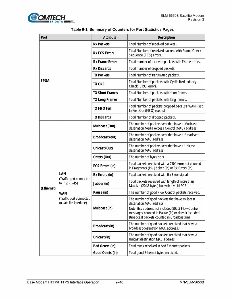
SLM-5650B Satellite Modem Revision 3
Base Modem HTTP/HTTPS Interface Operation 9–46 MN-SLM-5650B
Table 9-1. Summary of Counters for Port Statistics Pages
Port Attribute Description
FPGA
Rx Packets Total Number of received packets.
Rx FCS Errors Total Number of received packets with Frame Check Sequence (FCS) errors.
Rx Frame Errors Total number of received packets with Frame errors.
Rx Discards Total number of dropped packets.
TX Packets Total Number of transmitted packets.
TX CRC Total Number of packets with Cyclic Redundancy Check (CRC) errors.
TX Short Frames Total Number of packets with short frames.
TX Long Frames Total Number of packets with long frames.
TX FIFO Full Total Number of packets dropped because WAN First In First Out (FIFO) was full.
TX Discards Total Number of dropped packets.
(Ethernet)
LAN (Traffic port connected to J12 RJ-45) WAN (Traffic port connected to satellite interface)
Multicast (Out) The number of packets sent that have a Multicast destination Media Access Control (MAC) address.
Broadcast (out) The number of packets sent that have a Broadcast destination MAC address.
Unicast (Out) The number of packets sent that have a Unicast destination MAC address.
Octets (Out) The number of bytes sent
FCS Errors (in) Total packets received with a CRC error not counted in Fragments (In), Jabber (In) or Rx Errors (In).
Rx Errors (in) Total packets received with Rx Error signal.
Jabber (in) Total packets received with length of more than Maxsize (2048 bytes) but with invalid FCS.
Pause (in) The number of good Flow Control packets received.
Multicast (in)
The number of good packets that have multicast destination MAC address. Note: this address not included 802.3 Flow Control messages counted in Pause (In) or does it included Broadcast packets counted in Broadcast (in).
Broadcast (in) The number of good packets received that have a broadcast destination MAC address.
Unicast (in) The number of good packets received that have a Unicast destination MAC address
Bad Octets (in) Total bytes received in bad Ethernet packets.
Good Octets (in) Total good Ethernet bytes received.

SLM-5650B Satellite Modem Revision 3
Base Modem HTTP/HTTPS Interface Operation 9–47 MN-SLM-5650B
Status | Config Log Use this read-only page to view a scrollable display the configuration change log.
Figure 9-37. Status | Config Log Page
Configuration Change Log Select a logging level from the drop-down list, and then click [Refresh] to begin logging or to update the page. The selections are:
• Logging Off • Front Panel • Serial Remote • Web • SNMP • Telnet • NP Mailbox • TransecMailbox
When selecting the logging level, the modem will log changes from the current level and all prior levels. For example, selecting “Web” will enable logging for the Web pages, Serial Remote, and Front Panel.
The visible display provides the selected configuration change log information:
• Date / Time / Command • Date / Time / Response • Intf
Click [Clear Log] to clear the visible display.

SLM-5650B Satellite Modem Revision 3
Base Modem HTTP/HTTPS Interface Operation 9–48 MN-SLM-5650B
Status | Firmware Use this read-only page to view information about the boot firmware and bulk firmwares programmed into the modem.
The log is erased on power cycle or modem reboot.
Figure 9-38. Status | Firmware Page
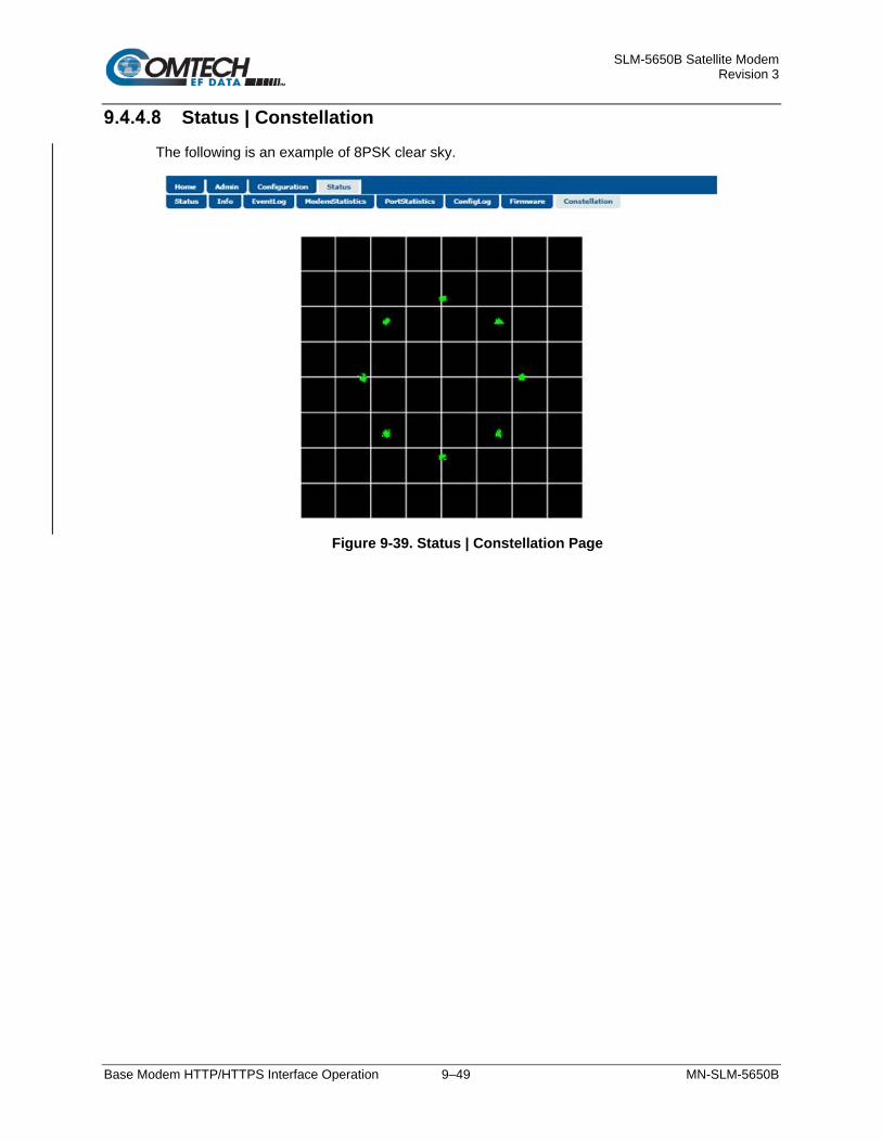
SLM-5650B Satellite Modem Revision 3
Base Modem HTTP/HTTPS Interface Operation 9–49 MN-SLM-5650B
Status | Constellation The following is an example of 8PSK clear sky.
Figure 9-39. Status | Constellation Page

SLM-5650B Satellite Modem Revision 3
Base Modem HTTP/HTTPS Interface Operation 9–50 MN-SLM-5650B
BLANK PAGE

SLM-5650B Satellite Modem Revision 3
Serial Remote Control 10–1 MN-SLM-5650B
Chapter 10. SERIAL REMOTE CONTROL
10.1 Overview This appendix describes the protocol and message command set for remote monitor and control of the SLM-5650B.
The electrical interface is either an EIA-485 multi-drop bus (for the control of many devices) or an EIA-232 connection (for the control of a single device), and data is transmitted in asynchronous serial form using ASCII characters. Control and status information is transmitted in packets of variable length in accordance with the structure and protocol defined in later sections.
10.2 EIA-485 For applications where multiple devices are to be monitored and controlled, a full-duplex (or 4-wire) EIA-485 is preferred. Half-duplex (2-wire) EIA-485 is possible, but is not preferred.
In full-duplex EIA-485 communication there are two separate, isolated, independent differential-mode twisted pairs, each handling serial data in different directions. It is assumed that there is a ‘Controller’ device (a PC or dumb terminal), which transmits data in a broadcast mode via one of the pairs. Many ‘Target’ devices are connected to this pair, which all simultaneously receive data from the Controller. The Controller is the only device with a line-driver connected to this pair – the Target devices only have line-receivers connected.
In the other direction, on the other pair each Target has a Tri-Stateable line driver connected, and the Controller has a line-receiver connected. All the line drivers are held in high-impedance mode until one – and only one – Target transmits back to the Controller.
Each Target has a unique address, and each time the Controller transmits in a framed ‘packet’ of data, the address of the intended recipient Target is included. All of the Targets receive the packet, but only one – the intended – will reply. The Target enables its output line driver and transmits its return data packet back to the Controller in the other direction, on the physically separate pair.

SLM-5650B Satellite Modem Revision 3
Serial Remote Control 10–2 MN-SLM-5650B
EIA-485 (full duplex) summary:
• Two differential pairs: one pair for Controller-to-Target, one pair for Target -to-Controller. • Controller-to-Target pair has one line driver (Controller), and all Target s have line-receivers. • Target-to-Controller pair has one line receiver (Controller), and all Targets have Tri-State drivers.
10.3 EIA-232 This is a much simpler configuration in which the Controller device is connected directly to the Target via a two-wire-plus-ground connection. Controller-to-Target data is carried via EIA-232 electrical levels on one conductor, and Target -to-Controller data is carried in the other direction on the other conductor.
10.4 Basic Protocol Whether in EIA-232 or EIA-485 mode, all data is transmitted as asynchronous serial characters suitable for transmission and reception by a Universal Asynchronous Receiver Transmitter (UART). In this case, the asynchronous character format supported is 8N1. The baud rate may vary between 2400 and 115,200 baud.
All data is transmitted in framed packets. The Controller is assumed to be a PC or ASCII dumb terminal, which is in charge of the process of M&C. The Controller is the only device which is permitted to initiate, at will, the transmission of data. Targets are only permitted to transmit when they have been specifically instructed to do so by the Controller.
All bytes within a packet are printable ASCII characters less than ASCII code 127. In this context, the Carriage Return and Line Feed characters are considered printable.
All messages from Controller-to-Target require a response, with one exception: this will be either to return data, which has been requested by the Controller, or to acknowledge reception of an instruction to change the configuration of the Target. The exception to this is when the Controller broadcasts a message (such as Set time/date) using Address 0, when the Target is set to EIA-485 mode.

SLM-5650B Satellite Modem Revision 3
Serial Remote Control 10–3 MN-SLM-5650B
10.5 Packet Structure
Controller-to-Target
Start of Packet Target Address Address Delimiter Instruction Code Code Qualifier Optional Arguments End of Packet
< ASCII code 60
(1 character)
(4 characters)
/ ASCII code 47
(1 character)
(3 characters)
= or ? ASCII codes 61 or 63
(1 character)
(n characters)
Carriage Return ASCII code 13
(1 character)
Example: <0135/TFQ=70.2345CR
Target-to-Controller
Start of Packet Target Address Address Delimiter Instruction Code Code Qualifier Optional Arguments End of Packet
> ASCII code 62
(1 character)
(4 characters)
/ ASCII code 47
(1 character)
(3 characters)
=, ?, !, or * ASCII codes
61, 63, 33, or 42
(1 character)
(From 0 to n characters)
Carriage Return, Line Feed
ASCII codes 13,10
(2 characters)
Example: >0654/RSW=32CRLF
10.5.1 Start of Packet Controller-to-Target: This is the character ‘<’ (ASCII code 60).
Target-to-Controller: This is the character ‘>’ (ASCII code 62).
Because this is used to provide a reliable indication of the start of packet, these two characters may not appear anywhere else within the body of the message.

SLM-5650B Satellite Modem Revision 3
Serial Remote Control 10–4 MN-SLM-5650B
10.5.2 Target Address Up to 9999 devices can be uniquely addressed. In EIA-232 applications, this value is set to 0. In EIA-485 applications, the permissible range of values is 1 to 9999. It is programmed into a Target unit using the front panel keypad.
The Controller sends a packet with the address of a Target – the destination of the packet. When the Target responds, the address used is the same address, to indicate to the Controller the source of the packet. The Controller does not have its own address.
10.5.3 Address Delimiter This is the “forward slash” character '/ ' (ASCII code 47).
10.5.4 Instruction Code This is a three-character alphabetic sequence, which identifies the subject of the message. Wherever possible, the instruction codes have been chosen to have some significance – e.g., TFQ for transmit frequency, RMD for receive modulation type, etc. This aids in the readability of the message, should it be displayed in its raw ASCII form. Only upper case alphabetic characters may be used (A to Z, ASCII codes 65 to 90).
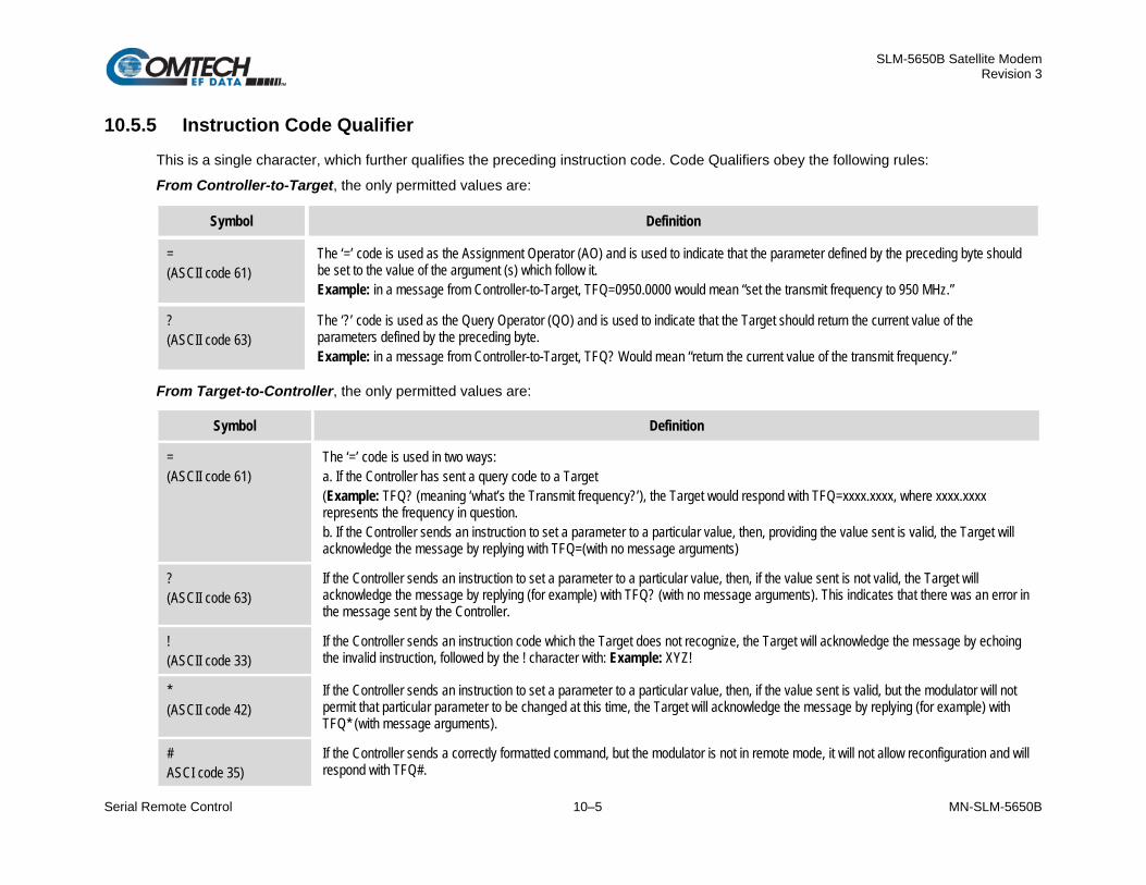
SLM-5650B Satellite Modem Revision 3
Serial Remote Control 10–5 MN-SLM-5650B
10.5.5 Instruction Code Qualifier This is a single character, which further qualifies the preceding instruction code. Code Qualifiers obey the following rules:
From Controller-to-Target, the only permitted values are:
Symbol Definition
= (ASCII code 61)
The ‘=’ code is used as the Assignment Operator (AO) and is used to indicate that the parameter defined by the preceding byte should be set to the value of the argument (s) which follow it. Example: in a message from Controller-to-Target, TFQ=0950.0000 would mean “set the transmit frequency to 950 MHz.”
? (ASCII code 63)
The ‘?’ code is used as the Query Operator (QO) and is used to indicate that the Target should return the current value of the parameters defined by the preceding byte. Example: in a message from Controller-to-Target, TFQ? Would mean “return the current value of the transmit frequency.”
From Target-to-Controller, the only permitted values are:
Symbol Definition
= (ASCII code 61)
The ‘=’ code is used in two ways: a. If the Controller has sent a query code to a Target (Example: TFQ? (meaning ‘what’s the Transmit frequency?’), the Target would respond with TFQ=xxxx.xxxx, where xxxx.xxxx represents the frequency in question. b. If the Controller sends an instruction to set a parameter to a particular value, then, providing the value sent is valid, the Target will acknowledge the message by replying with TFQ=(with no message arguments)
? (ASCII code 63)
If the Controller sends an instruction to set a parameter to a particular value, then, if the value sent is not valid, the Target will acknowledge the message by replying (for example) with TFQ? (with no message arguments). This indicates that there was an error in the message sent by the Controller.
! (ASCII code 33)
If the Controller sends an instruction code which the Target does not recognize, the Target will acknowledge the message by echoing the invalid instruction, followed by the ! character with: Example: XYZ!
* (ASCII code 42)
If the Controller sends an instruction to set a parameter to a particular value, then, if the value sent is valid, but the modulator will not permit that particular parameter to be changed at this time, the Target will acknowledge the message by replying (for example) with TFQ* (with message arguments).
# ASCI code 35)
If the Controller sends a correctly formatted command, but the modulator is not in remote mode, it will not allow reconfiguration and will respond with TFQ#.

SLM-5650B Satellite Modem Revision 3
Serial Remote Control 10–6 MN-SLM-5650B
10.5.6 Optional Message Arguments Arguments are not required for all messages. Arguments are ASCII codes for the characters 0 to 9 (ASCII codes 48 to 57), period (ASCII code 46) and comma (ASCII code 44).
10.5.7 End Of Packet Controller-to-Target: This is the ‘Carriage Return’ character (ASCII code 13).
Target-to-Controller: This is the two-character sequence ‘Carriage Return’, ‘Line Feed’ (ASCII codes 13 and 10). Both indicate the valid termination of a packet.

SLM-5650B Satellite Modem Revision 3
Serial Remote Control 10–7 MN-SLM-5650B
10.6 Remote Commands / Queries Index Notes: Where Column ‘C’ = Command and Column ‘Q’ = Query, columns marked ‘X’ designate instruction code as Command only, Query only, or Command/Query.
In the following Remote Command/Queries index tables:
• CODE, XXX indicates a priority command;
• XXXO indicates a command/query that is valid only when an optional interface module has been installed in the SLM-5650B.
10.6.1. Initial Setup – Priority Commands / Queries CODE C Q PAGE CODE C Q PAGE CODE C Q PAGE
ITF 10–11 MOM - X 10–11 RFB X X 10–12
10.6.2. Modulator (Tx) Commands / Queries CODE C Q PAGE CODE C Q PAGE CODE C Q PAGE CODE C Q PAGE
BEI X - 10–15 TCW X X 10–16 TFQ X X 10–16 TSE X X 10–18
BTX X X 10–15 TDE X X 10–16 TMD X X 10–14 TSF X X 10–18
SCT X X 10–15 TDF X X 10–16 TPL X X 10–17 TSI X X 10–18
TBO X X 10–15 TDI X X 10–16 TPM X X 10–17 TXF - X 10–19
TCI X X 10–15 TDR X X 10–14 TRD X X 10–17 TXO X X 10–19
TCK X X 10–15 TFM X X 10–13 TRS X X 10–17
TCR X X 10–14 TFT X X 10–13 TSC X X 10–18

SLM-5650B Satellite Modem Revision 3
Serial Remote Control 10–8 MN-SLM-5650B
10.6.3. Demodulator (Rx) Commands / Queries CODE C Q PAGE CODE C Q PAGE CODE C Q PAGE CODE C Q PAGE
BBR - X 10–22 RCB X - 10–23 RDS X X 10–25 RSF X X 10–26
BRS X - 10–22 RCI X X 10–23 RFM X X 10–20 RSI X X 10–26
BRX X X 10–22 RCK X X 10–24 RFO - X 10–25 RSL - X 10–27
BTH X X 10–22 RCR X X 10–21 RFQ X X 10–25 RSW X X 10–27
EBN - X 10–22 RCW X X 10–24 RFT X X 10–20 RXF - X 10–27
ERR - X 10–22 RDD X X 10–24 RMD X X 10–21
RBM X X 10–23 RDF X X 10–24 RRD X X 10–26
RBO X X 10–23 RDI X X 10–25 RRS X X 10–26
RBS X X 10–23 RDR X X 10–21 RSE X X 10–26
10.6.4. Modem, Unit Commands / Queries CODE C Q PAGE CODE C Q PAGE CODE C Q PAGE CODE C Q PAGE
ABE - X 10–28 CDM - X 10–30 EID - X 10–33 NUS - X 10–37
ABR X - 10–28 CFM - X 10–31 FRB X - 10–35 PAT X X 10–38
AFE - X 10–28 CFO - X 10–31 IEP X - 10–35 PSD - X 10–38
AFQ - X 10–28 CID X X 10–32 IMG X X 10–35 RNE - X 10–39
AFR X - 10–28 CNM X X 10–32 IPA X X 10–35 RNS - X 10–39
APC X - 10–29 COM X X 10–32 ISP X - 10–35 SNO - X 10–40
APL X X 10–29 CPR - X 10–32 LOP X X 10–36 SSI X X 10–40
APS - X 10–29 CRA X X 10–33 LRS X X 10–36 SWR - X 10–40
BFS - X 10–30 CRM - X 10–33 LUF - X 10–36 TIM X X 10–40
CAE X - 10–30 CSD X X 10–33 MRC X X 10–37 TMP - X 10–40
CAS X - 10–30 DAY X X 10–33 MSK X X 10–37
CCF X X 10–30 EBA X X 10–33 NUE - X 10–37

SLM-5650B Satellite Modem Revision 3
Serial Remote Control 10–9 MN-SLM-5650B
10.6.5. Bulk Configuration Commands / Queries CODE C Q PAGE CODE C Q PAGE CODE C Q PAGE
CLD X - 10–41 CST X - 10–41 MGC X X 10–41
10.6.6. AUPC Commands / Queries
CODE C Q PAGE CODE C Q PAGE CODE C Q PAGE CODE C Q PAGE
ACT X X 10–44 ARB X X 10–45 IAP X - 10–47 RPB X X 10–48
AET X X 10–44 ARF X X 10–45 LCL X X 10–47 RPC X X 10–48
AMN X X 10–44 ASI X X 10–46 LPC X X 10–47 RPE - X 10–49
AMT X X 10–44 ATB X X 10–46 NUA - X 10–47 RPL X X 10–49
AMX X X 10–44 ATF X X 10–46 RCL X X 10–48
ANP X X 10–45 CAA X - 10–47 RNA - X 10–48
10.6.7. G.703 Commands / Queries
CODE C Q PAGE CODE C Q PAGE CODE C Q PAGE CODE C Q PAGE
E1F X X 10–50 ERF X X 10–50 T1F X X 10–51 TTC X X 10–51
E2F X X 10–50 RTC X X 10–51 T2F X X 10–51
10.6.8. Gigabit Ethernet Interface Commands / Queries
CODE C Q PAGE CODE C Q PAGE
GFC X X 10–52 WBL X X 10–52

SLM-5650B Satellite Modem Revision 3
Serial Remote Control 10–10 MN-SLM-5650B
10.6.9. Network Processor (NP) Commands / Queries CODE C Q PAGE CODE C Q PAGE CODE C Q PAGE
BRT X X 10–53 MIP X X 10–53 RIM X X 10–54
GBM X X 10–53 MIS X X 10–53 RIP X X 10–54
10.6.10. TRANSEC Interface Commands / Queries
CODE C Q PAGE CODE C Q PAGE CODE C Q PAGE
SMGO X X 10–55 SMI X X 10–55 SMM - X 10–55
10.6.11. STANAG Only Commands / Queries CODE C Q PAGE CODE C Q PAGE CODE C Q PAGE CODE C Q PAGE
IRE - X 10–58 REC X X 10–57 SRM X X 10–57 TEC X X 10–56
IRM - X 10–58 SIT X X 10–56 SRS X X 10–57 TED X X 10–56
ITE - X 10–58 SRE X X 10–57 STE X X 10–56
ITM - X 10–57 SRH X X 10–57 STI X X 10–56
RDE X X 10–57 SRI X X 10–57 STS X X 10–56
NOTE – Instruction Code Qualifiers are used as follows in the command/query tables’ ‘Response to Command’ columns: = Message ok * Message ok, but not permitted in current mode ? Received ok, but invalid arguments found # Message ok, but unit is not in Remote mode

SLM-5650B Satellite Modem Revision 3
Serial Remote Control 10–11 MN-SLM-5650B
10.6.1 Initial Setup – Priority Commands / Queries Before executing any Modem, Unit, Bulk/Global, or Interface commands/queries, initial setup should be accomplished with this command.
Parameter Type
Command (Instruction Code and Qualifier)
Arguments for Command or Response to
Query Description of Arguments Response to
Command
Query (Instruction Code and Qualifier)
Response to Query
Interface Type ITF= 1 byte, value 0 thru 7
Command or Query. Interface Type, (Ethernet Interface Type in STANAG mode) where:
0 = EIA-530 1 = HSSI 2 = Unbalance G.703 3 = Balanced G.703 4 = GigaBit Ethernet Interface 5 = Reserved 6 = Network Processor Card 7 = LVDS Interface
Example: ITF=0 (sets EIA-530 interface type)
ITF= ITF? ITF* ITF#
ITF? ITF=x (see Description of Arguments)
Modem Operating Mode
MOM= 1 hex byte, value 0 thru C
Command or Query. Modem Operating Mode, where:
0 = OM-73 1 = Mil-165A 2 = IESS-308 3 = IESS-309 4 = IESS-310 5 = TURBO 6 = 16QAM 7 = AUPC 8 = RXBURST 9 = TXBURST A = TURBO-FA B = RXBRSTFA C = LDPC D = Reserved E = Reserved F = STANAG
Example: MOM=0 (sets OM-73 operating mode)
MOM= MOM? MOM* MOM#
MOM? MOM =x (see Description of Arguments)

SLM-5650B Satellite Modem Revision 3
Serial Remote Control 10–12 MN-SLM-5650B
Parameter Type
Command (Instruction Code and Qualifier)
Arguments for Command or Response to
Query Description of Arguments Response to
Command
Query (Instruction Code and Qualifier)
Response to Query
Modem RF Band RFB= 1 byte, value 0 or 1
Command or Query. Modem RF Band, where:
0 = 70/140 MHz Band 1 = L-Band (950 MHz – 2000 MHz)
Example: RFB=0 (sets 70/140 Band)
RFB= RFB? RFB * RFB #
RFB? RFB =x (see Description of Arguments)

SLM-5650B Satellite Modem Revision 3
Serial Remote Control 10–13 MN-SLM-5650B
10.6.2 Modulator (Tx) Commands / Queries Tx Priority System = Highest priority commands indicated by shading . Any change to a higher priority parameter can override any of the parameters of lower priority.
Parameter Type
Command (Instruction Code and Qualifier)
Arguments for Command or Response to
Query Description of Arguments Response to
Command
Query (Instruction Code and Qualifier)
Response to Query
Tx Overhead Type
TFM= 1 byte Command or Query. Tx Overhead Type, where:
0 = None (Unframed) 1 = IBS 2 = IDR 3vReserved 4 = AUPC
Depending on Modem mode, not all selections will be valid. Example: TFM=0 (selects Unframed mode)
TFM= TFM? TFM* TFM#
TFM? TFM=x (see Description of Arguments)
Tx FEC Type TFT= 1 byte Command or Query. Tx FEC coding type, where:
0 = None (Uncoded) 1 = Viterbi 2 = Turbo 3 = Sequential 4 = LDPC ULL (Ultra Low Latency) 5 = LDPC LL (Low Latency) 6 = LDPC HP (High Performance) 7 = Reserved 8 = STANAG Turbo
Example: TFT=2 (selects Turbo coding)
TFT= TFT? TFT* TFT#
TFT? TFT=x (see Description of Arguments)

SLM-5650B Satellite Modem Revision 3
Serial Remote Control 10–14 MN-SLM-5650B
Parameter Type
Command (Instruction Code and Qualifier)
Arguments for Command or Response to
Query Description of Arguments Response to
Command
Query (Instruction Code and Qualifier)
Response to Query
Tx Modulation Type
TMD= 1 byte Command or Query. Tx Modulation type, where:
0 = BPSK 1 = QPSK 2 = OQPSK 3 = 8PSK 4 = 16QAM 5 = 8QAM 6 = Reserved 7 = 16APSK (STANAG only)
Depending on FEC type, not all selections will be valid. Example: TMD=1 (selects QPSK)
TMD= TMD? TMD* TMD#
TMD? TMD=x (see Description of Arguments)
Tx Code Rate TCR= 1 byte Command or Query. Tx Code Rate, where:
0 = 1/1 (Uncoded) 1 = 1/2 2 = 3/4 3 = 7/8 4 = 2/3 5 = 5/6 6 = 21/44 7 = 5/16 8 = 17/18 9 = Reserved A = 1/3 B = .541 C = .451 D = .378 E = 19/20 (STANAG only)
Depending on FEC type, not all selections will be valid. Example: TCR=1 (selects Rate 1/2)
TCR= TCR? TCR* TCR#
TCR? TCR=x (see Description of Arguments)
Tx Data Rate TDR= 10 bytes Command or Query. Tx Data rate, in kbps, in the form xxxxxx.xxx. Resolution=1 bps. Serial Data Rate when in STANAG mode. Example: TDR=002047.999 (selects 2047.999 kbps)
TDR= TDR? TDR* TDR#
TDR? TDR=xxxxxx.xxx (see Description of Arguments)

SLM-5650B Satellite Modem Revision 3
Serial Remote Control 10–15 MN-SLM-5650B
Parameter Type
Command (Instruction Code and Qualifier)
Arguments for Command or Response to
Query Description of Arguments Response to
Command
Query (Instruction Code and Qualifier)
Response to Query
Insert Tx BERT Error
BEI= None Command only. Insert single bit error in Tx BERT Example: BEI=
BEI= BEI? BEI* BEI#
N/A N/A
Tx BERT State BTX= 1 byte Command or Query. Tx BERT State, where:
0 = Off 1 = On
Example: BTX=1 (Tx BERT On)
BTX= BTX? BTX* BTX#
BTX? BTX=x (see Description of Arguments)
Tx SCT Reference
SCT= 1 byte Command or Query. SCT Clock Reference, where:
0 = Internal 1 = Data Source Synchronized 2 = Loop Timing (Rx-Satellite Clock)
Example: SCT=0 (selects Internal Modem Reference)
SCT = SCT? SCT* SCT#
SCT? SCT=x (see Description of Arguments)
Tx BPSK Data Ordering
TBO= 1 byte Command or Query. Invert Transmit BPSK Data Ordering, where:
0 = Standard 1 = Non-Standard
Example: TBO=1 (selects Inverted BPSK Ordering)
TBO = TBO? TBO* TBO#
TBO? TBO=x (see Description of Arguments)
Tx Clock Invert TCI= 1 byte Command or Query. Invert Transmit Clock, where:
0 = Normal 1 = Inverted
Example: TCI=1 (selects Inverted TX Clock)
TCI = TCI? TCI* TCI#
TCI? TCI=x (see Description of Arguments)
Tx Clock Source TCK= 1 byte Command or Query. Tx Clock Source, where: x = Tx Clock Source:
0 = SCT 1 = Tx Terrestrial
Example: TCK=1 (selects Tx Terrestrial Clock Source)
TCK= TCK? TCK* TCK#
TCK? TCK=x (see Description of Arguments)

SLM-5650B Satellite Modem Revision 3
Serial Remote Control 10–16 MN-SLM-5650B
Parameter Type
Command (Instruction Code and Qualifier)
Arguments for Command or Response to
Query Description of Arguments Response to
Command
Query (Instruction Code and Qualifier)
Response to Query
Tx Reed-Solomon Code Word
TCW= 1 byte Command or Query. Tx RS encoding, where:
0 = RS(225,205,10) 1 = RS(219,201,9) 2 = RS(208,192,8) 3 = RS(194,178,8) 4 = RS(126,112,7) 5 = RS(220,200,10)
Depending on Modem mode, overhead type, and data rate, not all selections will be valid. Example: TCW = 0 (This is a ‘don’t care’ if RS is Off under TRS)
TCW= TCW? TCW* TCW#
TCW? TCW=x (see Description of Arguments)
Tx Differential Encoding
TDE= 1 byte Command or Query. Tx Differential Encoding, where: x = Tx Differential Encoding:
0 = Off 1 = On
Depending on FEC type or Modulation Type, not all selections will be valid. Example: TDE = 1 (selects Tx Differential Encoding On)
TDE= TDE? TDE* TDE#
TDE? TDE=x (see Description of Arguments)
Tx Data Fault TDF= 1 byte Command or Query. Transmit Data Fault, where:
0 = None 1 = DATA 2 = AIS
Example: TDF=0 (selects Data Fault = None)
TDF = TDF? TDF* TDF#
TDF? TDF=x (see Description of Arguments)
Tx Data Invert TDI= 1 byte Command or Query. Invert Transmit Data, where:
0 = Normal 1 = Inverted
Example: TDI=1 (selects Inverted TX Data)
TDI = TDI? TDI* TDI#
TDI? TDI=x (see Description of Arguments)
Tx Frequency TFQ= 9 bytes Command or Query. Tx Frequency, 52 to 88 MHz, 104 to 176 MHz, and 950 to 2000 MHz Resolution = 100Hz. Example: TFQ = 0140.9872
TFQ= TFQ? TFQ* TFQ#
TFQ? TFQ=xxxx.xxxx (see Description of Arguments)

SLM-5650B Satellite Modem Revision 3
Serial Remote Control 10–17 MN-SLM-5650B
Parameter Type
Command (Instruction Code and Qualifier)
Arguments for Command or Response to
Query Description of Arguments Response to
Command
Query (Instruction Code and Qualifier)
Response to Query
Tx Power Level TPL= 5 bytes Command or Query. Tx Output power level, where:
s = sign ( + / - ) xx.x = Tx Output power level, +10.0 and –40.0 dBm
Example: TPL=-13.4
TPL= TPL? TPL* TPL#
TPL? TPL=sxx.x (see Description of Arguments)
DSSS-MA Max Power Limit
TPM= 5 bytes Command or Query. DSSS-MA Max Output power limit, where:
s = sign ( + / - ) xx.x = Tx Output power level, +10.0 and –40.0 dBm
Example: TPM = -13.4
TPM= TPM? TPM* TPM#
TPM? TPM=sxx.x (see Description of Arguments)
Tx Reed-Solomon Interleaver Depth
TRD= 1 byte Command or Query. Tx RS encoding, where:
0 = Interleaver Depth 4 1 = Interleaver Depth 8 2 = Interleaver Depth 16
Depending on Modem mode, overhead type, and data rate, not all selections will be valid. Example: TRD = 0 (This is a ‘don’t care’ if RS is Off under TRS)
TRD = TRD? TRD * TRD #
TRD? TRD =x (see Description of Arguments)
Tx Reed-Solomon Encoding
TRS= 1 byte Command or Query. Tx RS encoding, where:
0 = Off 1 = On
Depending on Modem mode, not all selections will be valid. Example: TRS = 0 (RS encoding is Off)
TRS= TRS? TRS* TRS#
TRS? TRS=x (see Description of Arguments)

SLM-5650B Satellite Modem Revision 3
Serial Remote Control 10–18 MN-SLM-5650B
Parameter Type
Command (Instruction Code and Qualifier)
Arguments for Command or Response to
Query Description of Arguments Response to
Command
Query (Instruction Code and Qualifier)
Response to Query
Tx Scrambler TSC= 1 byte Command or Query. Tx Scrambler state, where:
0 = Off 1 = OM-73 Scrambler 2 = V.35 Scrambler 3 = Modified V.35 (Comtech EF Data Closed Network) 4 = Reed-Solomon Synchronous Scrambler 5 = IBS Overhead Synchronous Scrambler 6 = TURBO Scrambler
Depending on Modem mode, FEC type, overhead type, and RS state, not all selections will be valid. Example: TSC = 1 (OM-73 Scrambler On)
TSC= TSC? TSC* TSC#
TSC? TSC=x (see Description of Arguments)
Tx Spreading Equation
TSE= 5 bytes Command or Query. Tx Speading Equation, where:
a = Equation 0 or 1: bbbb = GSN 0-9999
Example: TSE = 00000 (Tx Equation 0 GSN 0000)
TSE= TSE? TSE* TSE#
TSE? TSE=xyyyy (see Description of Arguments)
Tx Spreading Factor
TSF= 4 bytes Command or Query. Tx Spreading Factor, where xxxx is value from 1 to 512. Values other than 1 are only valid when Modem Type = LDPC. Example: TSF = 0001 (Spreading is Off)
TSF= TSF? TSF* TSF#
TSF? TSF=xxxx (see Description of Arguments)
Tx Spectrum Invert
TSI= 1 byte Command or Query. Tx Spectrum Invert selection, where:
0 = Normal 1 = Tx Spectrum Inverted
Example: TSI = 0 (selects normal)
TSI= TSI? TSI* TSI#
TSI? TSI=x (see Description of Arguments)

SLM-5650B Satellite Modem Revision 3
Serial Remote Control 10–19 MN-SLM-5650B
Parameter Type
Command (Instruction Code and Qualifier)
Arguments for Command or Response to
Query Description of Arguments Response to
Command
Query (Instruction Code and Qualifier)
Response to Query
Live Tx Faults N/A 8 bytes Query only. Live Tx Faults are returned as a 32 bit Hexadecimal value. Bit values are defined as follows:
80000000 = Modulator Symbol Clock not locked 40000000 = Modulator RF Synthesizer not locked 20000000 = Modulator No IQ Activity 10000000 = Modulator Nyquist Filter Clipping 08000000 = Interface data clock PLLs not locked 04000000 = Interface Terrestrial Clock No Activity 02000000 = Interface SCT PLL not locked 01000000 = Interface No Data Activity 00800000 = APC Home State 00400000 = APC Margin
Example: TXF = 00000000 indicates No Tx Faults
N/A TXF? TXF=xxxxxxxx (see Description of Arguments)
Tx Carrier State TXO= 1 byte Command or Query. Tx Carrier State, where:
0 = OFF due to front panel or remote control command 1 = ON 2 = RTS 3 = OFF due to ext H/W Tx Carrier Off command (not a valid argument when used as a command)
Example: TXO = 1 (Tx Carrier ON)
TXO= TXO? TXO* TXO#
TXO? TXO=x (see Description of Arguments)

SLM-5650B Satellite Modem Revision 3
Serial Remote Control 10–20 MN-SLM-5650B
10.6.3 Demodulator (Rx) Commands / Queries Rx Priority System = Highest priority commands are indicated by shading . Any change to a higher priority parameter can override any of the parameters of lower priority.
Parameter Type
Command (Instruction Code and Qualifier)
Arguments for Command or Response to
Query Description of Arguments Response to
Command
Query (Instruction Code and Qualifier)
Response to Query
Rx Framing Mode
RFM= 1 byte Command or Query. Rx Overhead Type, where:
0 = None (Unframed) 1 = IBS 2 = IDR 3 = Reserved 4 = AUPC
Depending on Modem mode, not all selections will be valid. Example: RFM = 0 (selects Unframed mode)
RFM= RFM? RFM* RFM#
RFM? RFM=x (see Description of Arguments)
Rx FEC Type RFT= 1 byte Command or Query. Rx FEC coding type, where:
0 = None (Uncoded) 1 = Viterbi 2 = Turbo 3 = Sequential 4 = LDPC ULL (Ultra Low Latency) 5 = LDPC LL (Low Latency) 6 = LDPC HP (High Performance) 7 = Reserved 8 = STANAG Turbo
Example: RFT = 2 (selects Turbo coding)
RFT= RFT? RFT* RFT#
RFT? RFT=x (same format as command argument)

SLM-5650B Satellite Modem Revision 3
Serial Remote Control 10–21 MN-SLM-5650B
Parameter Type
Command (Instruction Code and Qualifier)
Arguments for Command or Response to
Query Description of Arguments Response to
Command
Query (Instruction Code and Qualifier)
Response to Query
Rx Demod type RMD= 1 byte Command or Query. Rx Modulation type, where:
0 = BPSK 1 = QPSK 2 = OQPSK 3 = 8PSK 4 = 16QAM 5 = 8QAM 6 = Reserved 7 = 16APSK (STANAG only)
Depending on FEC type, not all selections will be valid. Example: RMD = 1 (selects QPSK)
RMD= RMD? RMD* RMD#
RMD? RMD=x (see Description of Arguments)
Rx FEC Code Rate
RCR= 1 byte Command or Query. Rx FEC Code Rate, where:
0 = 1/1 (Uncoded) 1 = 1/2 2 = 3/4 3 = 7/8 4 = 2/3 5 = 5/6 6 = 21/44 7 = 5/16 8 = 17/18 9 = Reserved A = 1/3 B = .541 C = .451 D = .378 E = 19/20 (STANAG only)
Depending on FEC type, not all selections will be valid. Example: RCR = 1 (selects Rate 1/2)
RCR= RCR? RCR* RCR#
RCR? RCR=x (see Description of Arguments)
Rx Data Rate RDR= 10 bytes Command or Query. Rx Data rate, in kbps, in the form xxxxxx.xxx. Resolution = 1 bps. Serial Data Rate when in STANAG mode. Example: RDR = 002047.999 (selects 2047.999 kbps)
N/A RDR? RDR=xxxxxx.xxx (see Description of Arguments)

SLM-5650B Satellite Modem Revision 3
Serial Remote Control 10–22 MN-SLM-5650B
Parameter Type
Command (Instruction Code and Qualifier)
Arguments for Command or Response to
Query Description of Arguments Response to
Command
Query (Instruction Code and Qualifier)
Response to Query
Rx BERT BER N/A 6 bytes Query only. Unit returns the value of the BERT BER in the form a.b x 10-c, where:
First three bytes are the value; Last two bytes are the exponent.
Returns 0.0E00 if the BERT is not synchronized to a pattern. Example: BBR = 4.9E12
N/A BBR? BBR=a.bEcc (see Description of Arguments)
Rx BERT Reset BRS= None Command only. Reset Rx BERT. Example: BRS=
BRS= BRS? BRS* BRS#
N/A N/A
Rx BERT State BRX= 1 byte Command or Query. Rx BERT State, where:
0 = Off 1 = On
Example: BRX = 1 (Rx BERT On)
BRX= BRX? BRX* BRX#
BRX? BRX=x (see Description of Arguments)
Rx BERT Synch Loss Threshold
BTH= 1 byte Command or Query. Rx BERT Synch Loss Threshold, where:
0 = Low (100 errors in 1000 bits) 1 = Medium (250 errors in 1000 bits) 2 = High (20K errors in 100 Kbits)
Example: BRX = 1 (Medium Threshold)
BTH= BTH? BTH* BTH#
BTH? BTH=x (see Description of Arguments)
Rx Eb/No N/A 4 bytes Query only. Returns the value of Eb/No, between 0 and 20 dB, resolution = 0.1 dB. Returns 99.9 if demod is unlocked. Example: EBN = 12.3 (selects Eb/No = 12.3 dB) For values greater than 20.0 dB, the reply will be: EBN = +020
N/A EBN? EBN=xxxx (see Description of Arguments)
Rx BERT Errors N/A 7 bytes Query only. Read the total number of Bit Errors. Example: ERR = 9999999
N/A ERR? N/A

SLM-5650B Satellite Modem Revision 3
Serial Remote Control 10–23 MN-SLM-5650B
Parameter Type
Command (Instruction Code and Qualifier)
Arguments for Command or Response to
Query Description of Arguments Response to
Command
Query (Instruction Code and Qualifier)
Response to Query
Rx Buffer Programming Mode
RBM= 1 byte Command or Query. Rx Buffer Programming Mode, where:
0 = Buffer Size is programmed in Bits. 1 = Buffer Size is programmed in milliseconds.
Note: Commands as well as queries are not allowed when either the GigaBit Ethernet or NP card has been selected as the current interface type. Example: RBM = 0
RBM= RBM? RBM* RBM#
RBM? RBM=x (see Description of Arguments)
Rx BPSK Data Ordering
RBO= 1 byte Command or Query. Invert Receive BPSK Data Ordering in the form x, where:
0 = Standard 1 = Non-Standard
Example: RBO = 1 (selects Inverted BPSK Ordering)
RBO = RBO? RBO* RBO#
RBO? RBO=x (see Description of Arguments)
Rx Buffer Size RBS= 8 bytes Command or Query. Rx Buffer Size (in either bits or milliseconds, see RBM command), where:
xxxxxxxx = Rx Buffer Size Note: Commands as well as queries are not allowed when either the GigaBit Ethernet or NP card has been selected as the current interface type. Example: RBS = 00000512
RBS= RBS? RBS* RBS#
RBS? RBS=xxxxxxxx (see Description of Arguments)
ReCenter Buffer RCB= None Command only. Forces the software to recenter the receive Plesiochronous / Doppler buffer. Note: This command is not allowed when either the GigaBit Ethernet or NP card has been selected as the current interface type. Example: RCB= (ReCenter buffer)
RCB= RCB? RCB* RCB#
N/A N/A
Rx Clock Invert RCI= 1 byte Command or Query. Invert Receive Clock in the form x, where:
0 = Normal 1 = Inverted
Example: RCI = 1 (selects Inverted RX Clock)
RCI = RCI? RCI* RCI#
RCI? RCI=x (see Description of Arguments)
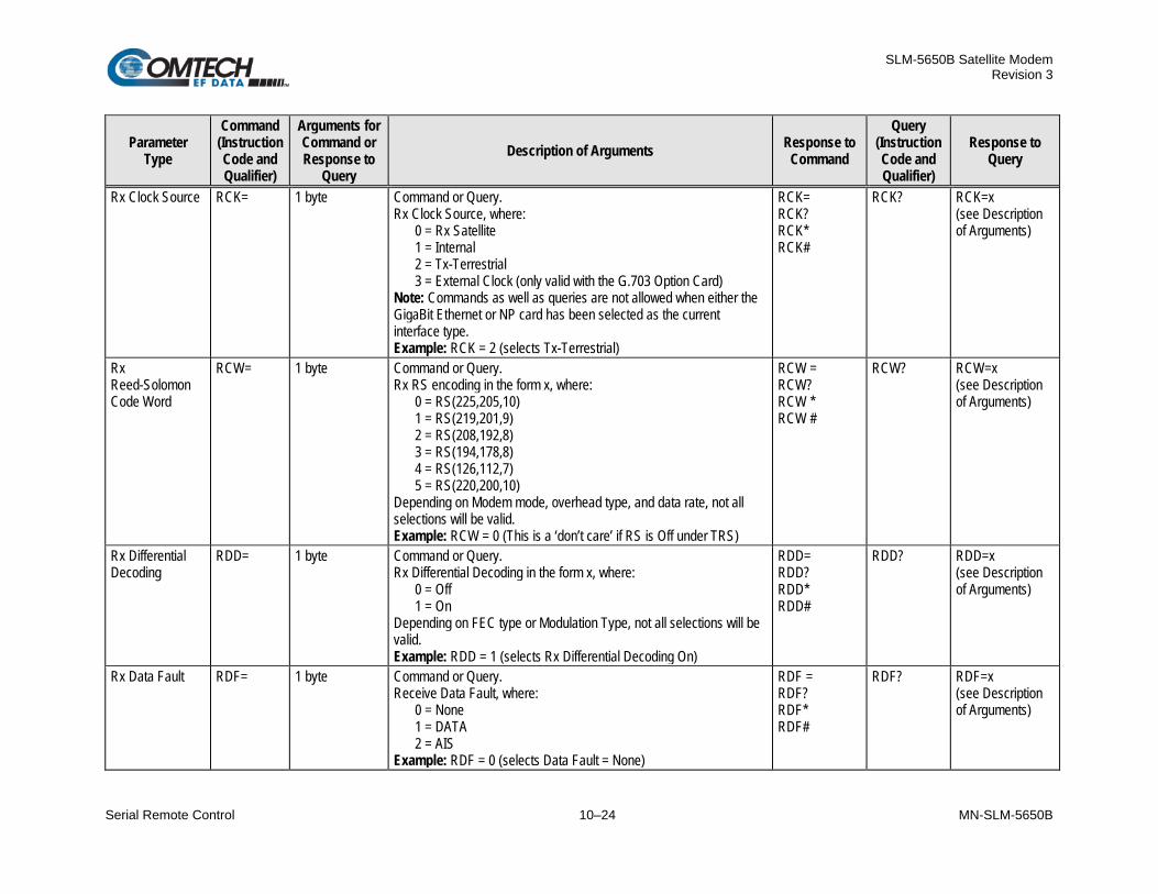
SLM-5650B Satellite Modem Revision 3
Serial Remote Control 10–24 MN-SLM-5650B
Parameter Type
Command (Instruction Code and Qualifier)
Arguments for Command or Response to
Query Description of Arguments Response to
Command
Query (Instruction Code and Qualifier)
Response to Query
Rx Clock Source RCK= 1 byte Command or Query. Rx Clock Source, where:
0 = Rx Satellite 1 = Internal 2 = Tx-Terrestrial 3 = External Clock (only valid with the G.703 Option Card)
Note: Commands as well as queries are not allowed when either the GigaBit Ethernet or NP card has been selected as the current interface type. Example: RCK = 2 (selects Tx-Terrestrial)
RCK= RCK? RCK* RCK#
RCK? RCK=x (see Description of Arguments)
Rx Reed-Solomon Code Word
RCW= 1 byte Command or Query. Rx RS encoding in the form x, where:
0 = RS(225,205,10) 1 = RS(219,201,9) 2 = RS(208,192,8) 3 = RS(194,178,8) 4 = RS(126,112,7) 5 = RS(220,200,10)
Depending on Modem mode, overhead type, and data rate, not all selections will be valid. Example: RCW = 0 (This is a ‘don’t care’ if RS is Off under TRS)
RCW = RCW? RCW * RCW #
RCW? RCW=x (see Description of Arguments)
Rx Differential Decoding
RDD= 1 byte Command or Query. Rx Differential Decoding in the form x, where:
0 = Off 1 = On
Depending on FEC type or Modulation Type, not all selections will be valid. Example: RDD = 1 (selects Rx Differential Decoding On)
RDD= RDD? RDD* RDD#
RDD? RDD=x (see Description of Arguments)
Rx Data Fault RDF= 1 byte Command or Query. Receive Data Fault, where:
0 = None 1 = DATA 2 = AIS
Example: RDF = 0 (selects Data Fault = None)
RDF = RDF? RDF* RDF#
RDF? RDF=x (see Description of Arguments)
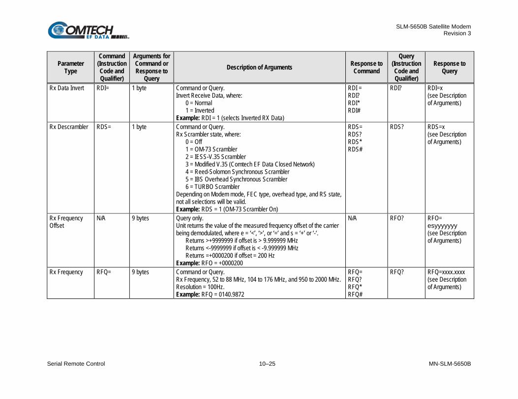
SLM-5650B Satellite Modem Revision 3
Serial Remote Control 10–25 MN-SLM-5650B
Parameter Type
Command (Instruction Code and Qualifier)
Arguments for Command or Response to
Query Description of Arguments Response to
Command
Query (Instruction Code and Qualifier)
Response to Query
Rx Data Invert RDI= 1 byte Command or Query. Invert Receive Data, where:
0 = Normal 1 = Inverted
Example: RDI = 1 (selects Inverted RX Data)
RDI = RDI? RDI* RDI#
RDI? RDI=x (see Description of Arguments)
Rx Descrambler RDS= 1 byte Command or Query. Rx Scrambler state, where:
0 = Off 1 = OM-73 Scrambler 2 = IESS-V.35 Scrambler 3 = Modified V.35 (Comtech EF Data Closed Network) 4 = Reed-Solomon Synchronous Scrambler 5 = IBS Overhead Synchronous Scrambler 6 = TURBO Scrambler
Depending on Modem mode, FEC type, overhead type, and RS state, not all selections will be valid. Example: RDS = 1 (OM-73 Scrambler On)
RDS= RDS? RDS* RDS#
RDS? RDS=x (see Description of Arguments)
Rx Frequency Offset
N/A 9 bytes Query only. Unit returns the value of the measured frequency offset of the carrier being demodulated, where e = ‘<’, ‘>’, or ‘=’ and s = ‘+’ or ‘-‘.
Returns >+9999999 if offset is > 9.999999 MHz Returns <-9999999 if offset is < -9.999999 MHz Returns =+0000200 if offset = 200 Hz
Example: RFO = +0000200
N/A RFO? RFO= esyyyyyyy (see Description of Arguments)
Rx Frequency RFQ= 9 bytes Command or Query. Rx Frequency, 52 to 88 MHz, 104 to 176 MHz, and 950 to 2000 MHz. Resolution = 100Hz. Example: RFQ = 0140.9872
RFQ= RFQ? RFQ* RFQ#
RFQ? RFQ=xxxx.xxxx (see Description of Arguments)

SLM-5650B Satellite Modem Revision 3
Serial Remote Control 10–26 MN-SLM-5650B
Parameter Type
Command (Instruction Code and Qualifier)
Arguments for Command or Response to
Query Description of Arguments Response to
Command
Query (Instruction Code and Qualifier)
Response to Query
Rx Reed-Solomon Interleaver Depth
RRD= 1 byte Command or Query. Rx RS encoding, where:
0 = Interleaver Depth 4 1 = Interleaver Depth 8 2 = Interleaver Depth 16
Depending on Modem mode, overhead type, and data rate, not all selections will be valid. Example: RRD = 0 (This is a ‘don’t care’ if RS is Off under RRS)
RRD = RRD? RRD * RRD #
RRD? RRD =x (see Description of Arguments)
Rx Reed-Solomon Decoding
RRS= 1 byte Command or Query. Rx RS encoding, where:
0 = Off 1 = On
Depending on Modem mode, not all selections will be valid. Example: RRS = 0 (RS encoding is Off)
RRS= RRS? RRS* RRS#
RRS? RRS=x (see Description of Arguments)
Rx Spreading Equation
RSE= 5 bytes Command or Query. Rx Speading Equation, where:
a = Equation 0 or 1: bbbb = GSN 0-9999
Example: RSE = 00000 (Rx Equation 0 GSN 0000)
RSE= RSE? RSE* RSE#
RSE? RSE= abbbb (see Description of Arguments)
Rx Spreading Factor
RSF= 4 bytes Command or Query. Rx Spreading Factor, where xxxx is value from 1 to 512. Values other than 1 are only valid when Modem Type = LDPC. Example: RSF = 0001 (Rx Spreading Off)
RSF= RSF? RSF* RSF#
RSF? RSF=xxxx (see Description of Arguments)
Rx Spectrum Invert
RSI= 1 byte Command or Query. Rx Spectrum Invert, where:
0 = Normal 1 = Rx Spectrum Invert
Example: RSI = 0 (selects Normal)
RSI= RSI? RSI* RSI#
RSI? RSI=x (see Description of Arguments)

SLM-5650B Satellite Modem Revision 3
Serial Remote Control 10–27 MN-SLM-5650B
Parameter Type
Command (Instruction Code and Qualifier)
Arguments for Command or Response to
Query Description of Arguments Response to
Command
Query (Instruction Code and Qualifier)
Response to Query
Rx Signal Level N/A 5 bytes Query only. Unit returns the value of the Rx signal level in the form sxx.x, where: s = + (positive) or – (negative) sign xx.x – Rx signal level value in dBm, between +15.0 and –60.0 dBm Examples:
RSL = +99.9 (RSL > +15.0 dBm) RSL = +15.0 RSL = -60.0 RSL = -99.9 (RSL < -60.0 dBm)
N/A RSL? RSL=sxx.x (see Description of Arguments)
Rx Demod Acquisition Sweep Range
RSW= 8 bytes Command or Query. Rx acquisition sweep range of demodulator, in kHz, ranging from 0 to 60 kHz. Example: RSW = 0060.000 (selects 60 kHz)
RSW= RSW? RSW* RSW#
RSW? RSW=xxxx.xxx (see Description of Arguments)
Live Rx Faults N/A 8 bytes Query only. Live Rx Faults are returned as a 32 bit Hexadecimal value. Bit values are defined as follows:
80000000 = Demodulator IF not locked 40000000 = Demodulator Data Decoder not locked 20000000 = Demodulator RF Synthesizer not locked 10000000 = Demodulator No IQ Activity 08000000 = Interface De-Multiplexers not locked 04000000 = Interface Buffer Fault 02000000 = Interface Buffer about to slip 01000000 = Interface Buffer has overflowed 00800000 = Interface Buffer has underflowed 00400000 = Interface Buffer Clock PLL not locked 00200000 = Interface Buffer Clock Reference Activity 00100000 = Interface Data/AIS 00080000 = Eb/No Threshold exceeded 00040000 = Composite Power > 40 dBc 00020000 = Composite Power > 20 dBm 00010000 = BERT Sync Loss 00008000 = APC Band Mismatch 00004000 = LNB Voltage out of range 00002000 = LNB Current out of range
Example: RXF = 00000000 indicates No Rx Faults
N/A RXF? RXF=xxxxxxxx (see Description of Arguments)

SLM-5650B Satellite Modem Revision 3
Serial Remote Control 10–28 MN-SLM-5650B
10.6.4 Modem, Unit Commands / Queries
Parameter Type
Command (Instruction Code and Qualifier)
Arguments for Command or Response to
Query Description of Arguments Response to
Command
Query (Instruction Code and Qualifier)
Response to Query
CnC-APC Bit Error Rate
N/A 4 bytes Query only. Returns the value of CnC-APC BER in the form xE-c, where:
x = value E-c = Exponent BER is measured in frame UW
Note: Returns 9999 if Modem is not in CnC-APC mode or there is an APC frame sync error. Example: ABE = 8E-5 (indicates CnC-APC BER is 8 x 10⁻⁵)
N/A ABE? ABE=xE-c (see Description of Arguments)
CnC-APC BER Reset
ABR= None Command only. This command takes no arguments. Forces restart of the CnC-APC BER measurement. Example: ABR=
ABR= ABR? ABR* ABR#
N/A N/A
CnC-APC Frame Error Rate
N/A 4 bytes Query only. Returns the value of CnC-APC FER in the form xE-c, where:
x = value E-c = Exponent BER is measured in frame UW
Note: Returns 9999 if Modem is not in CnC-APC mode or there is an APC frame sync error. Example: AFE = 8E-5 (indicates CnC-APC FER is 8 x 10⁻⁵)
N/A AFE? AFE=xE-c (see Description of Arguments)
Advanced FAST Options
N/A 16 bytes Query only. Unit returns information concerning the Advanced FAST Options, and the option field, in the form axxxxxxxxxxxxxxx, where:
a = Reserved1: 0 = Not Installed 1 = Installed
x = spare
N/A AFO? AFO=axxxxxxxxxxxxxxx (see Description of Arguments)
CnC-APC FER Reset
AFR= None Command only. This command takes no arguments. Forces restart of the CnC-APC FER measurement. Example: AFR=
AFR= AFR? AFR* AFR#
N/A N/A

SLM-5650B Satellite Modem Revision 3
Serial Remote Control 10–29 MN-SLM-5650B
Parameter Type
Command (Instruction Code and Qualifier)
Arguments for Command or Response to
Query Description of Arguments Response to
Command
Query (Instruction Code and Qualifier)
Response to Query
CnC-APC Activate/ Suspend
APC= 1 byte Command only. Used to activate or suspend APC operation, in format APC-x, where:
0 = No Action 1 = Activate APC 2 = Suspend APC
Example: APC = 1 (Activate APC)
APC= APC? APC* APC#
N/A N/A
CnC-APC Max Power Level Increase
APL= 3 bytes Command or Query. CnC-APC maximum power level increase in form x.x, range from 0.0 to 9.9 dB, limited by Tx power level. Example: APL = 3.9 (APC max power level increase is 3.9 dB)
APL= APL? APL* APL#
APL? APL=x.x (see Description of Arguments)
CnC-APC State
N/A 2 bytes Query only. Returns the state of APC operation. Return value is in form xx, where:
00 = APC is not active 01 = No Solution 02 = OK – ReBalance Done 03 = OK(Partial) – CnC Ratio approaches limit 04 = OK(Partial) – Local power approaches minimum value (IF) 05 = OK(Partial) – Local power approaches minimum value (L-Band) 06 = OK(Partial) – Local power approaches maximum value 07 = OK(Partial) – Local power approaches limit set by max power level increase 08 = OK(Partial) – Distant power approaches minimum value (IF) 09 = OK(Partial) – Distant power approaches minimum value (L-Band) 10 = OK(Partial) – Distant power approaches maximum value 11 = OK(Partial) – Distant power approaches limit set by max power level increase 12 = OK(Partial) – Incomplete 13 = No APC Frame Sync 14 = CnC Ratio Problem 15 = Local Eb/No too high 16 = Distant Eb/No too high
N/A APS? APS=xx (see Description of Arguments)

SLM-5650B Satellite Modem Revision 3
Serial Remote Control 10–30 MN-SLM-5650B
Parameter Type
Command (Instruction Code and Qualifier)
Arguments for Command or Response to
Query Description of Arguments Response to
Command
Query (Instruction Code and Qualifier)
Response to Query
CnC-APC State (cont)
17 = Distant End ReBalance failed 18 = Distant End No Response 19 = Fail-Calculate Mismatch 20 = CnC Ratio too high 21 = Please run again 22 = APC is active 23 = Local margin too low 24 = Distant margin too low 25 = Rx Data Rate < 64 kbps 26 = Tx Data Rate < 64 kbps 27 = Local RSL too low 28 = Distant RSL too low 29 = Unrecognized Modem
Example: APS = 00 Buffer Fill State N/A 2 bytes Query only.
xx = value of the buffer fill state, between 1 to 99%. Returns 00 if demodulator is unlocked. Example: BFS = 33 (selects 33%)
N/A BFS? BFS=xx (see Description of Arguments)
Clear All Stored Events
CAE= None Command only. Forces the software to clear the software events log. Note: This command takes no arguments Example: CAE=
CAE= CAE? CAE* CAE#
N/A N/A
Clear All Stored Events
CAS= None Command only. Forces the software to clear the software statistics log. Note: This command takes no arguments Example: CAS=
CAS= CAS? CAS* CAS#
N/A N/A
Carrier-in-Carrier (CnC) Frequency Offset Range
CCF= 6 bytes Command or Query. CnC Sweep Frequency range from 0 to 60.000 kHz Example: CCF = 60.000
CCF= CCF? CCF* CCF#
CCF? CCF=xx.xxx (see Description of Arguments)
Carrier-in-Carrier (CnC) Delay Monitor
N/A 6 bytes Query only. When CnC is enabled and locked, the delay of the interferer is readable in microseconds. Example 1: CDM = 229500 (229.5 mSec) Example 2: CDM = 999999 (not locked or CnC not enabled)
N/A CDM? CDM=xxxxxx (see Description of Arguments)

SLM-5650B Satellite Modem Revision 3
Serial Remote Control 10–31 MN-SLM-5650B
Parameter Type
Command (Instruction Code and Qualifier)
Arguments for Command or Response to
Query Description of Arguments Response to
Command
Query (Instruction Code and Qualifier)
Response to Query
Carrier-in-Carrier (CnC) Frequency Offset Monitor
N/A 6 bytes Query only. When CnC is enabled and locked, the estimated frequency offset between the desired signal and the interferer is readable in kHz. Example 1: CFM = +001.0 (1 kHz) Example 2: CFM = 9999.9 (not locked or CnC not enabled)
N/A CFM? CFM=xxxx.x (see Description of Arguments)
Configured FAST Options
N/A 16 bytes Query only. Unit returns information concerning the Configured FAST Options, and the option field, in the form abcdefghxxxxxxxx, where:
a = QOS: 0 = Not Installed 1 = Installed
b = Reserved c = Spectrum Spreading d = Management Security:
0 = Not Installed 1 = Installed
e = Vipersat Compatibility: 0 = Not Installed 1 = Installed
f = Reserved g = Transec Data Rate Option:
0 = Base (5,000 kbps) 1 = 10,000 kbps 2 = 20,000 kbps 3 = 51,840 kbps 4 = 155,520 kbps 5 = 2,500 kbps
h = Vipersat Data Rate Option: 0 = Base (5,000 kbps) 1 = 10,000 kbps 2 = 20,000 kbps 3 = 51,840 kbps 4 = 155,520 kbps 5 = 2,500 kbps
i = Bridged Point to Multipoint: 0 = Not Installed
N/A CFO? CFO= abcdefghijklmnop (see Description of Arguments)

SLM-5650B Satellite Modem Revision 3
Serial Remote Control 10–32 MN-SLM-5650B
Parameter Type
Command (Instruction Code and Qualifier)
Arguments for Command or Response to
Query Description of Arguments Response to
Command
Query (Instruction Code and Qualifier)
Response to Query
Configure FAST Options (cont)
1 = Installed j = Spare k = Reserved l = Reserved m = Spare n = Reserved0
0 = Not Installed 1 = Installed
o = Spare p = Reserved
Circuit ID String CID= 24 bytes Command or Query. Sets or queries the user-defined Circuit ID string, which is a fixed length of 24 characters. Valid characters include: Space ( ) * + – , . / 0 9 and A thru Z
CID= CID? CID* CID#
CID? CID=xxxxxxxxx xxxxxxxxxxxxxx x (see Description of Arguments)
Carrier-in-Carrier (CnC) Mode
CNM= 1 byte Command or Query. CnC Mode of Operation, where:
0 = Off 1 = On
Example: CNM = 0
CNM= CNM? CNM* CNM#
CNM? CNM=x (see Description of Arguments)
Carrier Only Test Modes
COM= 1 byte Command or Query. Test Mode, where:
0 = Normal Mode (no test) 1 = Tx CW 2 = Tx Alternating 1,0 Pattern
Example: COM = 1 (CW Mode)
COM= COM? COM* COM#
COM? COM=x (see Description of Arguments)
CnC Power Ratio Monitor
N/A 6 bytes Query only. When CnC is enabled and locked, the ratio between the interferer and the desired signal power is readable in dB. The precision is 0.1 dB. Example 1: CRM = +02.8 (interferer > desired)(format=sdd.d) Example 2: CRM = LT10.0 (less than -10.0 dB) Example 3: CRM = GT10.0 (greater than +10.0 dB) Example 4: CRM = 9999.9 (not locked or CnC not enabled)
N/A CPR? CPR=xxxxxx (see Description of Arguments)

SLM-5650B Satellite Modem Revision 3
Serial Remote Control 10–33 MN-SLM-5650B
Parameter Type
Command (Instruction Code and Qualifier)
Arguments for Command or Response to
Query Description of Arguments Response to
Command
Query (Instruction Code and Qualifier)
Response to Query
Carrier-in-Carrier (CnC) Re-Acquisition Time
CRA= 3 bytes Command or Query. CnC re-Acquisition time in seconds, from 10 to 999. This is the time wherein CnC will start searching for the delay and frequency offset if a long duration of unlock occurs. Example: CRA = 010
CRA= CRA? CRA* CRA#
CRA? CRA=xxx (see Description of Arguments)
Carrier-in-Carrier (CnC) Ratio Monitor
N/A 4 bytes Query only. When CnC is enabled and locked, the ratio between the interferer and the desired signal power is readable in dB. Example 1: CRM = +02 (interferer > desired) Example 2: CRM = LT10 (less than -10 dB) Example 3: CRM = GT10 (greater than +10 dB) Example 4: CRM = 99.9 (not locked or CnC not enabled)
N/A CRM? CRM=xxxx (see Description of Arguments)
Carrier-in-Carrier (CnC) Min/Max Search Delay
CSD- 6 bytes Command or Query. CnC min/max delay value in milliseconds, from 0 to 300 ms in the form xxxyyy, where:
xxx = min delay yyy = max delay
Example: CSD = 010300
CSD= CSD? CSD* CSD#
CSD? CSD=xxxyyy (see Description of Arguments)
RTC Date DAY= 6 bytes Command or Query. A date in the form ddmmyy, where:
dd = day of the month (01 to 31), mm = month (01 to 12) yy = year (00 to 99)
Example: DAY = 240457 (April 24, 2057)
DAY= DAY? DAY* DAY#
DAY? DAY=ddmmyy (see Description of Arguments)
Eb/No Alarm Point
EBA= 4 bytes Command or Query. Eb/No alarm point in dB, with a range between 0.1 and 20 dB. Resolution = 0.1 dB. Example: EBA = 12.3
EBA= EBA? EBA* EBA#
EBA? EBA=xx.x (see Description of Arguments)
Equipment ID
N/A 17 bytes Query only. Unit returns information concerning the equipment identification, and the option field, in the form aaaabcdefghijklmx where:
aaaa = defines the modem model number (565B = SLM-5650B) b = Advanced FEC:
1 = TPC
N/A EID? EID=aaaabcdef ghijklmx (see Description of Arguments)
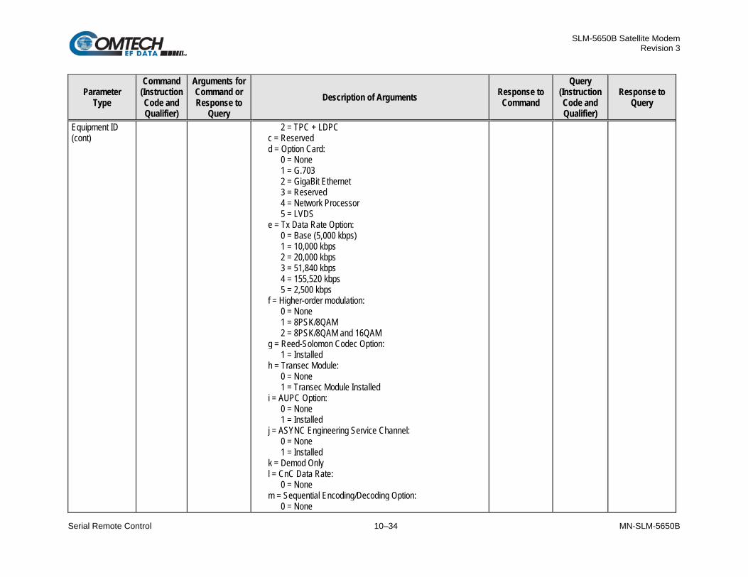
SLM-5650B Satellite Modem Revision 3
Serial Remote Control 10–34 MN-SLM-5650B
Parameter Type
Command (Instruction Code and Qualifier)
Arguments for Command or Response to
Query Description of Arguments Response to
Command
Query (Instruction Code and Qualifier)
Response to Query
Equipment ID (cont)
2 = TPC + LDPC c = Reserved d = Option Card:
0 = None 1 = G.703 2 = GigaBit Ethernet 3 = Reserved 4 = Network Processor 5 = LVDS
e = Tx Data Rate Option: 0 = Base (5,000 kbps) 1 = 10,000 kbps 2 = 20,000 kbps 3 = 51,840 kbps 4 = 155,520 kbps 5 = 2,500 kbps
f = Higher-order modulation: 0 = None 1 = 8PSK/8QAM 2 = 8PSK/8QAM and 16QAM
g = Reed-Solomon Codec Option: 1 = Installed
h = Transec Module: 0 = None 1 = Transec Module Installed
i = AUPC Option: 0 = None 1 = Installed
j = ASYNC Engineering Service Channel: 0 = None 1 = Installed
k = Demod Only l = CnC Data Rate:
0 = None m = Sequential Encoding/Decoding Option:
0 = None
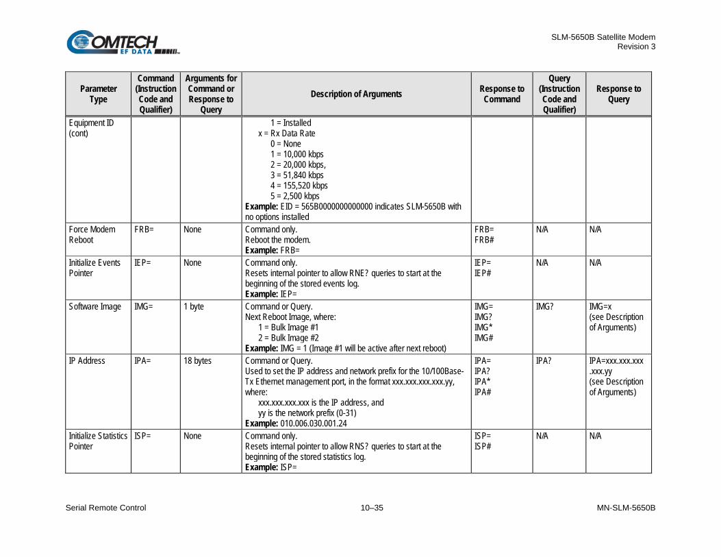
SLM-5650B Satellite Modem Revision 3
Serial Remote Control 10–35 MN-SLM-5650B
Parameter Type
Command (Instruction Code and Qualifier)
Arguments for Command or Response to
Query Description of Arguments Response to
Command
Query (Instruction Code and Qualifier)
Response to Query
Equipment ID (cont)
1 = Installed x = Rx Data Rate
0 = None 1 = 10,000 kbps 2 = 20,000 kbps, 3 = 51,840 kbps 4 = 155,520 kbps 5 = 2,500 kbps
Example: EID = 565B0000000000000 indicates SLM-5650B with no options installed
Force Modem Reboot
FRB= None Command only. Reboot the modem. Example: FRB=
FRB= FRB#
N/A N/A
Initialize Events Pointer
IEP= None Command only. Resets internal pointer to allow RNE? queries to start at the beginning of the stored events log. Example: IEP=
IEP= IEP#
N/A N/A
Software Image IMG= 1 byte Command or Query. Next Reboot Image, where:
1 = Bulk Image #1 2 = Bulk Image #2
Example: IMG = 1 (Image #1 will be active after next reboot)
IMG= IMG? IMG* IMG#
IMG? IMG=x (see Description of Arguments)
IP Address IPA= 18 bytes Command or Query. Used to set the IP address and network prefix for the 10/100Base-Tx Ethernet management port, in the format xxx.xxx.xxx.xxx.yy, where:
xxx.xxx.xxx.xxx is the IP address, and yy is the network prefix (0-31)
Example: 010.006.030.001.24
IPA= IPA? IPA* IPA#
IPA? IPA=xxx.xxx.xxx .xxx.yy (see Description of Arguments)
Initialize Statistics Pointer
ISP= None Command only. Resets internal pointer to allow RNS? queries to start at the beginning of the stored statistics log. Example: ISP=
ISP= ISP#
N/A N/A

SLM-5650B Satellite Modem Revision 3
Serial Remote Control 10–36 MN-SLM-5650B
Parameter Type
Command (Instruction Code and Qualifier)
Arguments for Command or Response to
Query Description of Arguments Response to
Command
Query (Instruction Code and Qualifier)
Response to Query
LoopBack Test Modes
LOP= 1 byte Command or Query. Loopback Test Modes, where:
0 = Normal Mode (no test) 1 = IF Loopback 2 = I/O Loopback #1
Example: LOP = 1 (IF Loopback)
LOP= LOP? LOP* LOP#
LOP? LOP=x (see Description of Arguments)
Local/Remote Status
LRS= 1 byte Command or Query. Local/Remote status, where:
0 = Local 1 = Serial Remote Control 2 = Reserved 3 = Serial + Ethernet Remote Control
Example: LRS = 1 (selects Serial Remote)
LRS= LRS? LRS* LRS#
LRS? LRS=x (see Description of Arguments)
Live Unit Faults N/A 8 bytes Query only. Live Unit Faults are returned as a 32 bit Hexadecimal value. Bit values are defined as follows:
80000000 = Power Supply out of range 40000000 = Reference not locked 20000000 = 250 MHz Clock not locked 10000000 = Ext Reference Activity 08000000 = CPLD #1 not loaded 04000000 = CPLD #2 not loaded 02000000 = Mod FPGA not loaded 01000000 = Demod FPGA not loaded 00800000 = Option Card FPGA not loaded 00400000 = TRANSEC card not ready 00200000 = Modem over temperature 00100000 = Cooling Fan 00080000 = NP Card Mailbox Comm Error 00040000 = TRANSEC Card Mailbox Comm Error
Example: LUF = 00000000 indicates No Unit Faults
N/A LUF? LUF=xxxxxxxx (see Description of Arguments)

SLM-5650B Satellite Modem Revision 3
Serial Remote Control 10–37 MN-SLM-5650B
Parameter Type
Command (Instruction Code and Qualifier)
Arguments for Command or Response to
Query Description of Arguments Response to
Command
Query (Instruction Code and Qualifier)
Response to Query
Modem Reference Clock
MRC= 1 byte Command or Query. Modem Reference Clock (for Frequency Accuracy), where:
0 = Internal 1 = External 1 MHz 2 = External 5 MHz 3 = External 10 MHz
Example: MRC = 0 (Internal)
MRC= MRC? MRC* MRC#
MRC? MRC=x (see Description of Arguments)
Modem Alarm Mask
MSK= 6 bytes Command or Query. Alarm mask conditions, in the form abcdef, where:
a = spare (must be set to 0) b = spare (must be set to 0) c = spare (must be set to 0) d = spare (must be set to 0) e = Demod Faults (0 = unmasked, 1 = masked) f = Eb/No Threshold Alarm (0 = unmasked, 1 = masked)
Example: MSK = 000001
MSK= MSK? MSK* MSK#
MSK? MSK=abcdef (see Description of Arguments)
Number of Unread stored Events
N/A 3 bytes Query only. Unit returns the Number of stored Events that remain Unread in the form xxx. Note: This means unread over the remote control. Example: NUE = 126
N/A NUE? NUE=xxx (see Description of Arguments)
Number of Unread stored Statistics
N/A 3 bytes Query only. Unit returns the Number of stored Statistics, which remain Unread, in the form xxx. Note: This means unread over the remote control. Example: NUS = 126
N/A NUS? NUS=xxx (see Description of Arguments)

SLM-5650B Satellite Modem Revision 3
Serial Remote Control 10–38 MN-SLM-5650B
Parameter Type
Command (Instruction Code and Qualifier)
Arguments for Command or Response to
Query Description of Arguments Response to
Command
Query (Instruction Code and Qualifier)
Response to Query
BERT Pattern PAT= 1 byte Command or Query. BERT Pattern, where:
0 = 2047 1 = Mark 2 = Space 3 = 1:1 4 = 1:2 5 = 2^15-1 6 = 2^20-1 7 = 2^23-1 8 = MIL-188
Example: PAT = 0 (2047 Pattern)
PAT= PAT? PAT* PAT#
PAT? PAT=x (see Description of Arguments)
CnC PSD Ratio N/A 5 bytes Query only. When CnC is enabled and locked, the PSD ratio between the interferer and the desired signal power is readable in dB. The precision is 0.1 dB. Example 1: PSD = +02.8 (interferer > desired)(format=sdd.d) Example 2: PSD = 999.9 (not locked or CnC not enabled)
N/A PSD? PSD=xxxxx (see Description of Arguments)

SLM-5650B Satellite Modem Revision 3
Serial Remote Control 10–39 MN-SLM-5650B
Parameter Type
Command (Instruction Code and Qualifier)
Arguments for Command or Response to
Query Description of Arguments Response to
Command
Query (Instruction Code and Qualifier)
Response to Query
Retrieve next 5 unread Stored Events
N/A 110 bytes Query only. Unit returns the oldest 5 Stored Events which have not yet been read over the remote control. Reply format: CRSub-bodyCRSub-bodyCRSub-bodyCRSub-bodyCRSub-body, where Sub-body= Axxxxxxxxddmmyyhhmmss, A being the fault type where:
1 = Unit 2 = Rx Traffic 3 = Tx Traffic 4 = Info
xxxxxxxx is the Fault Code number, as in LUF?, TXF?, RXF?, or Info Code, which is:
00000000 = Power Off 00000001 = Power On 00000002 = Log Cleared 00000004 = Global Config Change 00000005 = NP Card Watch Dog Timer 00000006 = NP Card Boot Timeout 00000007 = Transec Card Boot Timeout
If there are fewer than five events to be retrieved, the remaining positions are padded with zeros. If there are no new events, the response is RNE*.
N/A RNE? RNE= CRAxxxxxxxx ddmmyyhhmmss CRAxxxxxxxx ddmmyyhhmmss CRAxxxxxxxx ddmmyyhhmmss CRAxxxxxxxx ddmmyyhhmmss CRAxxxxxxxx ddmmyyhhmmss (see Description of Arguments)
Retrieve next 5 unread Stored Statistics
N/A 105 bytes Query only. Unit returns the oldest five Stored Statistics which have not yet been read over the remote control. Reply format: CRSub-bodyCRSub-bodyCRSub-bodyCRSub-bodyCRSub-body, where Sub-body= AA.ABB.Bddmmyyhhmmss, AA.A = Minimum Eb/No during sample period. “Loss” is displayed if carrier was lost during the sample period. BB.B = Average Eb/No during sample period. “Loss” is displayed if carrier was lost during the entire sample period. If there are fewer than five events to be retrieved, the remaining positions are padded with zeros. If there are no new events, the response is RNS*.
N/A RNS? RNS= CRAA.ABB.B ddmmyyhhmmss CRAA.ABB.B ddmmyyhhmmss CRAA.ABB.B ddmmyyhhmmss CRAA.ABB.B ddmmyyhhmmss CRAA.ABB.B ddmmyyhhmmss (see Description for Arguments)

SLM-5650B Satellite Modem Revision 3
Serial Remote Control 10–40 MN-SLM-5650B
Parameter Type
Command (Instruction Code and Qualifier)
Arguments for Command or Response to
Query Description of Arguments Response to
Command
Query (Instruction Code and Qualifier)
Response to Query
Serial Number N/A 9 bytes Query only. Used to query the unit 9-digit serial number. Unit returns its S/N in the form xxxxxxxxx. Example: SNO = 176500143
N/A SNO? SNO=xxxxxxxxx (see Description of Arguments)
Statistics Sample Interval
SSI= 1 byte Command or Query. Used to set the sample interval for the Statistics Logging Function. SSI = x, where x = 0 to 9 in 10 minute steps. Note: Setting this parameter to 0 disables the statistics logging function. Example: SSI = 3 sets the logging inverval to 30 minutes
SSI= SSI? SSI* SSI#
SSI? SSI=x (see Description of Arguments)
Software Revision
N/A 43 bytes Query only. Unit returns the value of the internal software revision installed in the unit, in the form: Boot:xx.yy.zz Bulk1:xx.yy.zz Bulk2:xx.yy.zz Example: SWR = Boot:01.01.01 Bulk1:01.01.01 Bulk2:01.01.01
N/A SWR? SWR= Boot:xx.yy.zz Bulk1:xx.yy.zz Bulk2:xx.yy.zz (see Description of Arguments)
RTC Time TIM= 6 bytes Command or Query. A time in the form hhmmss, indicating the time from midnight, where:
hh = hours (00 to 23) mm = minutes (00 to 59) ss = seconds (00 to 59)
Example: TIM = 231259 (23 hours:12 minutes:59 seconds)
TIM= TIM? TIM* TIM#
TIM? TIM=hhmmss (see Description of Arguments)
Temperature N/A 3 bytes Query only. Unit returns the value of the internal temperature, in the form of xxx (degrees C). Example: TMP = +26
N/A TMP? TMP=xxx (see Description of Arguments)

SLM-5650B Satellite Modem Revision 3
Serial Remote Control 10–41 MN-SLM-5650B
10.6.5 Bulk Configuration Commands / Queries
Parameter Type
Command (Instruction Code and Qualifier)
Arguments for Command or Response to
Query Description of Arguments Response to
Command
Query (Instruction Code and Qualifier)
Response to Query
Configuration Load
CLD= 1 byte Command only. Causes the modem to retrieve a previously stored configuration from Configuration Memory location defined by the one-byte argument (0 to 9). Example: CLD = 4 (retrieve modem configuration from location 4)
CLD= CLD? CLD* CLD#
N/A N/A
Configuration Save
CST= 1 byte Command only. Command causes the modem to store the current configuration in Configuration Memory location defined by the one-byte argument (0 to 9). Example: CST = 4 (store the current configuration in location 4)
CST= CST? CST* CST#
N/A N/A
Global Configuration
MGC= 217 bytes Command or Query. Global Configuration of SLM-5650B, in the form:
a = Modem Operating Mode same as MOM b = Modem RF Band same as RFB c = Modem Interface Type same as ITF d = Modem Reference Clock same as MRC eeeee = Modem Alarm Mask same as MSK f = Carrier Only Test Modes same as COM g = Loopback Test Modes same as LOP h = Tx BERT State same as BTX i = Rx BERT State same as BRX j = BERT Pattern same as PAT k = CnC Mode same as CNM llllll = CnC Mode same as CSD m = expansion byte n = Tx FEC Type same as TFT o = Tx Modulation Type same as TMD p = Tx Code Rate same as TCR qqqqqq.qqq = Tx Data Rate same as TDR rrrr.rrrr = Tx Frequency same as TFQ s = Tx Framing Mode same as TFM t = NP Working Mode same as GBM u = 1st byte of Tx Spread Factor same as TSF
MGC= MGC? MGC* MGC#
MGC? MGC=abcdeeeeeefghijk llllllmnopqqqqqq.qqq rrrr.rrrrstuvwxyzABCCC.C DEFGHIJKLLMM.MMM NOPQQQQQQ.QQQ RRRR.RRRRSTTTUVW XYZabcdeeee.eeefffgh Iiiiiiiijj.jklmnopqrsss.sttt.t uuu.uvv.vw.wxyzABCCD EEuuuFFFFGGGGG HHHHHJKLMMM IIIIIIIIIIIIIIIII

SLM-5650B Satellite Modem Revision 3
Serial Remote Control 10–42 MN-SLM-5650B
Parameter Type
Command (Instruction Code and Qualifier)
Arguments for Command or Response to
Query Description of Arguments Response to
Command
Query (Instruction Code and Qualifier)
Response to Query
Global Configuration (cont)
v = NP Secure Mode same as MIS w = Tx Reed-Solomon state same as TRS x = Tx Reed-Solomon code word same as TCW y = Tx Reed-Solomon interleaver depth same as TRD z = Tx Spectrum Invert same as TSI A = Tx Scrambler same as TSC B = Tx Differential Encoder same as TDE CCC.C = Tx Power Level same as TPL D = Tx Clock Source same as TCK E = Tx SCT Reference same as SCT F = Tx Clock Invert same as TCI G = Tx Data Invert same as TDI H = Tx Data Fault same as TDF I = Tx BPSK Data Ordering same as TBO J = Tx Carrier State same as TXO K = Tx Ternary Code same as TTC LL = expansion bytes MM.MMM = CnC Freq Offset Range same as CCF N = Rx FEC Type same as RFT O = Rx Modulation Type same as RMD P = Rx Code Rate same as RCR QQQQQQ.QQQ = Rx Data Rate same as RDR RRRR.RRRR = Rx Frequency same as RFQ S = Rx Framing Mode same as RFM TTT = CnC Re-acq Time same as CRA U = Rx Reed-Solomon state same as RRS V = Rx Reed-Solomon code word same as RCW W = Rx Reed-Solomon interleaver depth same as RRD X = Rx Spectrum Invert same as RSI Y = Rx Descrambler same as RDS Z = Rx Differential Decoder same as RDD a = Rx Clock Invert same as RCI b = Rx Data Invert same as RDI c = Rx Data Fault same as RDF d = Rx BPSK Data Ordering same as RBO eeee.eee = Rx Demod Acq Sweep Range same as RSW
(see Description of Arguments)

SLM-5650B Satellite Modem Revision 3
Serial Remote Control 10–43 MN-SLM-5650B
Parameter Type
Command (Instruction Code and Qualifier)
Arguments for Command or Response to
Query Description of Arguments Response to
Command
Query (Instruction Code and Qualifier)
Response to Query
Global Configuration (cont)
fff = expansion bytes g = Rx Clock Source same as RCK h = Rx Buffer Programming Mode same as RBM iiiiiiii = Rx Buffer Size same as RBS jj.j = Eb/No Alarm Point same as EBA k = Statistics Sample Interval same as SSI l = Rx Ternary Code same as RTC m = Receive T1 Framing same as T1F n = Receive E1 Framing same as E1F o = Receive T2 Framing same as T2F p = Receive E2 Framing same as E2F q = External Buffer Clock Source same as ERF r = AUPC Local Enable same as LPC sss.s = AUPC Nominal Power Level same as ANP ttt.t = AUPC Maximum Power Level same as AMX uuu.u = AUPC Minimum Power Level same as AMN vv.v = AUPC Eb/No Target Level same as AET w.w = AUPC Max Tracking Rate same as AMT x = AUPC Local Carrier Loss Action same as LCL y = AUPC Remote Carrier Loss Action same as RCL z = AUPC Log Sample Interval same as ASI A = AUPC ESC Type same as ACT B = AUPC ESC Tx Baud Rate same as ATB CC = AUPC ESC Tx Format same as ATF D = AUPC ESC Rx Baud Rate same as ARB EE = AUPC ESC Rx Format same as ARF uuu = last 3 bytes of Tx Spread Factor same as TSF FFFF= Rx Spread Factor same as RSF GGGGG = Rx Spread Poly/GSN same as RSE HHHHH = Tx Spread Poly/GSN same as TSE J = Reserved K = Reserved L = Flow Control same as GFC MMM = WAN Buffer Length same as WBL IIIIIIIIIIIIIIIII = expansion bytes
Fill unused expansion bytes with ‘x’

SLM-5650B Satellite Modem Revision 3
Serial Remote Control 10–44 MN-SLM-5650B
10.6.6 Automatic Uplink Power Control (AUPC) Commands / Queries The instruction codes that follow are valid only when the SLM-5650B Satellite Modem type has been set to AUPC.
Note: Always wait three (3) seconds between consecutive remote modem command/query polls. If Local AUPC is not enabled, queries will return the last known condition. A request for status from the remote modem will then be transmitted, ensuring that the next query will return current status.
Parameter Type
Command (Instruction Code and Qualifier)
Arguments for Command or Response to
Query Description of Arguments Response to
Command
Query (Instruction Code and Qualifier)
Response to Query
ASYNC ESC Type
ACT= 1 byte Command or Query. ASYNC ESC Type, where:
0 = RS-232 1 = RS-485 2-Wire 2 = RS-485 4-Wire
Example: ACT = 0 (sets the ASYNC ESC to RS-232)
ACT= ACT? ACT* ACT#
ACT? ACT=x (see Description of Arguments)
AUPC Eb/N0 Target Set Point
AET= 4 bytes Command or Query. AUPC Eb/N0 Target, where:
xx.x = AUPC Eb/N0 Target, 3.2 to 16.0 dB Example: AET = 13.4
AET= AET? AET* AET#
AET? AET=xx.x (see Description of Arguments)
AUPC Minimum Power Level
AMN= 5 bytes Command or Query. Minimum Tx Output power level, where:
s = sign ( + / – ) xx.x = Tx Output power level, +10.0 and –40.0 dBm
Example: AMN = –13.4
AMN= AMN? AMN* AMN#
AMN? AMN=sxx.x (see Description of Arguments)
AUPC Maximum Tracking Rate
AMT= 3 bytes Command or Query. AUPC Maximum Tracking Rate, where:
x.x = Maximum Tracking Rate, 0.5 to 6.0 dBm/minute in increments of .5.
Example: AMT = 0.5
AMT= AMT? AMT* AMT#
AMT? AMT=x.x (see Description of Arguments)
AUPC Maximum Power Level
AMX= 5 bytes Command or Query. Maximum Tx Output power level, where:
s = sign ( + / - ) xx.x = Tx Output power level, +10.0 and –40.0 dBm
Example: AMX = -13.4
AMX= AMX? AMX* AMX#
AMX? AMX=sxx.x (see Description of Arguments)
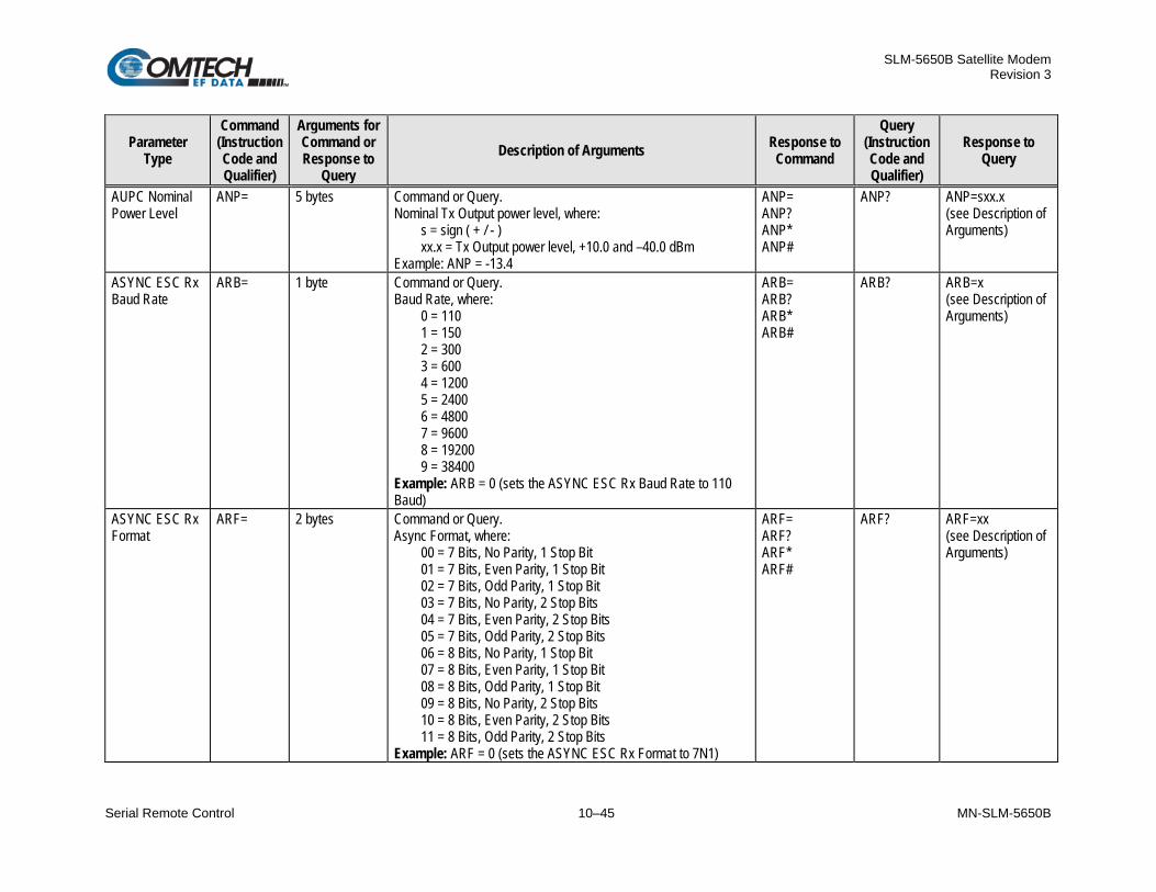
SLM-5650B Satellite Modem Revision 3
Serial Remote Control 10–45 MN-SLM-5650B
Parameter Type
Command (Instruction Code and Qualifier)
Arguments for Command or Response to
Query Description of Arguments Response to
Command
Query (Instruction Code and Qualifier)
Response to Query
AUPC Nominal Power Level
ANP= 5 bytes Command or Query. Nominal Tx Output power level, where:
s = sign ( + / - ) xx.x = Tx Output power level, +10.0 and –40.0 dBm
Example: ANP = -13.4
ANP= ANP? ANP* ANP#
ANP? ANP=sxx.x (see Description of Arguments)
ASYNC ESC Rx Baud Rate
ARB= 1 byte Command or Query. Baud Rate, where:
0 = 110 1 = 150 2 = 300 3 = 600 4 = 1200 5 = 2400 6 = 4800 7 = 9600 8 = 19200 9 = 38400
Example: ARB = 0 (sets the ASYNC ESC Rx Baud Rate to 110 Baud)
ARB= ARB? ARB* ARB#
ARB? ARB=x (see Description of Arguments)
ASYNC ESC Rx Format
ARF= 2 bytes Command or Query. Async Format, where:
00 = 7 Bits, No Parity, 1 Stop Bit 01 = 7 Bits, Even Parity, 1 Stop Bit 02 = 7 Bits, Odd Parity, 1 Stop Bit 03 = 7 Bits, No Parity, 2 Stop Bits 04 = 7 Bits, Even Parity, 2 Stop Bits 05 = 7 Bits, Odd Parity, 2 Stop Bits 06 = 8 Bits, No Parity, 1 Stop Bit 07 = 8 Bits, Even Parity, 1 Stop Bit 08 = 8 Bits, Odd Parity, 1 Stop Bit 09 = 8 Bits, No Parity, 2 Stop Bits 10 = 8 Bits, Even Parity, 2 Stop Bits 11 = 8 Bits, Odd Parity, 2 Stop Bits
Example: ARF = 0 (sets the ASYNC ESC Rx Format to 7N1)
ARF= ARF? ARF* ARF#
ARF? ARF=xx (see Description of Arguments)

SLM-5650B Satellite Modem Revision 3
Serial Remote Control 10–46 MN-SLM-5650B
Parameter Type
Command (Instruction Code and Qualifier)
Arguments for Command or Response to
Query Description of Arguments Response to
Command
Query (Instruction Code and Qualifier)
Response to Query
AUPC Log Sample Interval
ASI= 1 byte Command or Query. Used to set the sample interval for the AUPC Logging Function in the form x, where:
x = 0 to 9 in 10 minute steps. Note: Setting this parameter to 0 disables the logging function. Example: ASI = 3 (sets the logging inverval to 30 minutes)
ASI= ASI? ASI* ASI#
ASI? ASI=x (see Description of Arguments)
ASYNC ESC Tx Baud Rate
ATB= 1 byte Command or Query. Baud Rate, where:
0 = 110 1 = 150 2 = 300 3 = 600 4 = 1200 5 = 2400 6 = 4800 7 = 9600 8 = 19200 9 = 38400
Example: ATB = 0 (sets the ASYNC ESC Tx Baud Rate to 110 Baud)
ATB= ATB? ATB* ATB#
ATB? ATB=x (see Description of Arguments)
ASYNC ESC Tx Format
ATF= 2 bytes Command or Query. Async Format, where:
00 = 7 Bits, No Parity, 1 Stop Bit 01 = 7 Bits, Even Parity, 1 Stop Bit 02 = 7 Bits, Odd Parity, 1 Stop Bit 03 = 7 Bits, No Parity, 2 Stop Bits 04 = 7 Bits, Even Parity, 2 Stop Bits 05 = 7 Bits, Odd Parity, 2 Stop Bits 06 = 8 Bits, No Parity, 1 Stop Bit 07 = 8 Bits, Even Parity, 1 Stop Bit 08 = 8 Bits, Odd Parity, 1 Stop Bit 09 = 8 Bits, No Parity, 2 Stop Bits 10 = 8 Bits, Even Parity, 2 Stop Bits 11 = 8 Bits, Odd Parity, 2 Stop Bits
Example: ATF = 00 (sets the ASYNC ESC Tx Format to 7N1)
ATF= ATF? ATF* ATF#
ATF? ATF=xx (see Description of Arguments)

SLM-5650B Satellite Modem Revision 3
Serial Remote Control 10–47 MN-SLM-5650B
Parameter Type
Command (Instruction Code and Qualifier)
Arguments for Command or Response to
Query Description of Arguments Response to
Command
Query (Instruction Code and Qualifier)
Response to Query
Clear All AUPC Log Entries
CAA= None Command only. Forces the software to clear the software AUPC log. Note: This command takes no arguments. Example: AAS=
CAA= CAA? CAA* CAA#
N/A N/A
Initialize AUPC Log Pointer
IAP= None Command only. Resets internal pointer to allow RNA? queries to start at the beginning of the stored statistics log.
IAP= IAP#
N/A N/A
AUPC Local Carrier Loss Action
LCL= 1 byte Command or Query. Tx Output Power level setting when local carrier is lost, where:
0 = Hold current output power level 1 = Goto Nominal output power level 2 = Goto Maximum output power level
Example: LCL = 0
LCL= LCL? LCL* LCL#
LCL? LCL=x (see Description of Arguments)
AUPC Local Enable
LPC= 1 byte Command or Query. Local AUPC Control, where:
0 = Off 1 = On
Note: When Local AUPC Control is enabled, modulator output power is automatically controlled by the modem. Power output commands via TPL are not allowed during this mode; although, queries will function as normal. Example: LPC = 1 (Turn on Local AUPC Control)
LPC= LPC? LPC* LPC#
LPC? LPC=x (see Description of Arguments)
Number of Unread AUPC Log Entries
N/A 3 bytes Query only. Unit returns the Number of AUPC Log Entries, which remain Unread, in the form xxx. Note: This means unread over the remote control. Example: NUS = 126
N/A NUA? NUA=xxx (see Description of Arguments)

SLM-5650B Satellite Modem Revision 3
Serial Remote Control 10–48 MN-SLM-5650B
Parameter Type
Command (Instruction Code and Qualifier)
Arguments for Command or Response to
Query Description of Arguments Response to
Command
Query (Instruction Code and Qualifier)
Response to Query
Retrieve next 5 unread AUPC Log Entries
N/A 155 bytes Query only. Unit returns the oldest 5 AUPC Log Entries which have not yet been read over the remote control. Reply format: CRSub-bodyCRSub-bodyCRSub-bodyCR Sub-bodyCRSub-body, where Sub-body= AA.ABB.BCCC.CEEE.Eddmmyyhhmmss:
AA.A = Minimum Eb/No during sample period. BB.B = Average Eb/No during sample period. CCC.C = Max Output Power during sample period. EEE.E = Average Output Power during sample period.
If there are less than 5 events to be retrieved, the remaining positions are padded with zeros. If there are no new events, the response is RNA*.
N/A RNA? RNA= CRAA.ABB.BCCC.CEEE.EddmmyyhhmmssCR AA.ABB.BCCC.CEEE.EddmmyyhhmmssCRAA.ABB.BCCC .CEEE.EddmmyyhhmmssCRAA.ABB.BCCC.CEEE.Eddmmyyh hmmssCRAA.ABB.BCCC.CEEE.Eddmmyyhhmmss (see Description of Arguments)
AUPC Remote Carrier Loss Action
RCL= 1 byte Command or Query. Tx Output Power level setting when remote carrier is lost, where:
0 = Hold current output power level 1 = Goto Nominal output power level 2 = Goto Maximum output power level
Example: RCL = 0
RCL= RCL? RCL* RCL#
RCL? RCL=x (see Description of Arguments)
Remote Modem Pattern Substitution
RPB= 1 byte Command or Query. Remote Modem Tx Pattern Substitution, where:
0 = Off 1 = On
Note: For compatibility reasons, only the 2047 Tx pattern can be turned On or Off at the remote modem. Example: RPB = 1 (Turn on remote modem AUPC Control)
RPB= RPB? RPB* RPB#
RPB? RPB=x (see Description of Arguments)
Remote Modem AUPC Enable
RPC= 1 byte Command or Query. Remote Modem AUPC Control, where:
0 = Off 1 = On
Example: RPC = 1 (Turn on remote modem AUPC Control)
RPC= RPC? RPC* RPC#
RPC? RPC=x (see Description of Arguments)

SLM-5650B Satellite Modem Revision 3
Serial Remote Control 10–49 MN-SLM-5650B
Parameter Type
Command (Instruction Code and Qualifier)
Arguments for Command or Response to
Query Description of Arguments Response to
Command
Query (Instruction Code and Qualifier)
Response to Query
Remote Modem BERT BER
N/A 6 bytes Query only. Unit returns the value of the remote modem’s BERT BER in the form a.b x 10-c . First three bytes are the value. Last two bytes are the exponent. Returns 0.0E00 if the BERT is not synchronized to a pattern. Example: RPE = 4.0E06
N/A RPE? RPE=a.bEcc (see Description of Arguments)
Remote Modem I/O Loopback
RPL= 1 byte Command or Query. Remote Modem I/O Loopback Mode, where:
0 = Off 1 = On
Example: RPL = 1 (Turn on remote modem AUPC Control)
RPL= RPL? RPL* RPL#
RPL? RPL=x (see Description of Arguments)

SLM-5650B Satellite Modem Revision 3
Serial Remote Control 10–50 MN-SLM-5650B
10.6.7 G.703 Interface Commands / Queries The instruction codes that follow are valid only when the optional G.703 interface module is installed in the SLM-5650B.
Parameter Type
Command (Instruction Code and Qualifier)
Arguments for Command or Response to
Query Description of Arguments Response to
Command
Query (Instruction Code and Qualifier)
Response to Query
Receive E1 Framing
E1F= 1 byte Command or Query. Receive T1 Framing, where:
0 = None 1 = G.704
Note: Commands as well as queries are not allowed when either the GigaBit Ethernet or NP card has been selected as the current interface type. Example: E1F = 0
E1F= E1F? E1F* E1F#
E1F? E1F=x (see Description of Arguments)
Receive E2 Framing
E2F= 1 byte Command or Query. Receive E2 Framing, where:
0 = None 1 = G.704 2=G.742 3 = Reserved 4 = G.745
Note: Commands as well as queries are not allowed when either the GigaBit Ethernet or NP card has been selected as the current interface type. Example: E2F = 0
E2F= E2F? E2F* E2F#
E2F? E2F=x (see Description of Arguments)
External Buffer Clock Reference
ERF= 1 byte Command or Query. External Buffer Clock Reference, where:
0 = External Clock equals Rx Data Rate 1 = 5 MHz External Clock 2 = 10 MHz External Clock 3 = 20 MHz External Clock
Example: ERF = 0
ERF= ERF? ERF* ERF#
ERF? ERF=x (see Description of Arguments)

SLM-5650B Satellite Modem Revision 3
Serial Remote Control 10–51 MN-SLM-5650B
Parameter Type
Command (Instruction Code and Qualifier)
Arguments for Command or Response to
Query Description of Arguments Response to
Command
Query (Instruction Code and Qualifier)
Response to Query
Rx Ternary Code
RTC= 1 byte Command or Query. Rx Ternary Code, where:
0 = AMI 1 = B8ZS 2 = B6ZS 3 = HDB3
Example: RTC = 3 (Set Rx Ternary Code to HDB3)
RTC= RTC? RTC* RTC#
RTC? RTC=x (see Description of Arguments)
Receive T1 Framing
T1F= 1 byte Command or Query. Receive T1 Framing, where:
0 = None 1 = G.704
Note: Commands as well as queries are not allowed when either the GigaBit Ethernet or NP card has been selected as the current interface type. Example: T1F = 0
T1F= T1F? T1F* T1F#
T1F? T1F=x (see Description of Arguments)
Receive T2 Framing
T2F= 1 byte Command or Query. Receive T2 Framing, where:
0 = None 1 = G.704 2 = Reserved 3 = G.743 4 = Reserved 5 = G.747
Note: Commands as well as queries are not allowed when either the GigaBit Ethernet or NP card has been selected as the current interface type. Example: T2F = 0
T2F= T2F? T2F* T2F#
T2F? T2F=x (see Description of Arguments)
Tx Ternary Code
TTC= 1 byte Command or Query. Tx Ternary Code, where:
0 = AMI 1 = B8ZS 2 = B6ZS 3 = HDB3
Example: TTC = 3 (Set Tx Ternary Code to HDB3)
TTC= TTC? TTC* TTC#
TTC? TTC=x (see Description of Arguments)

SLM-5650B Satellite Modem Revision 3
Serial Remote Control 10–52 MN-SLM-5650B
10.6.8 Gigabit Ethernet Interface Commands / Queries The instruction codes that follow are valid only when the optional 10/100/1000Base-T Gigabit Ethernet Interface Module is installed in the SLM-5650B.
Parameter Type
Command (Instruction Code and Qualifier)
Arguments for Command or Response to
Query Description of Arguments Response to
Command
Query (Instruction Code and Qualifier)
Response to Query
GBEI Flow Control
GFC= 1 byte Command or Query. Used to Enable/Disable Pause Frame flow control on the internal GBEI Interface, where x is:
0 = Disabled 1 = Enabled
Example: GFC = 0
GFC= GFC? GFC* GFC#
GFC? GFC=x (see Description of Arguments)
GBEI WAN Buffer Length
WBL= 3 bytes Command or Query. Used to set the WAN Buffer (transmit) Length, where xxx is in range from 020 mSec to 240 mSec Example: WBL = 020
WBL= WBL? WBL* WBL#
WBL? WBL=xxx (see Description of Arguments)

SLM-5650B Satellite Modem Revision 3
Serial Remote Control 10–53 MN-SLM-5650B
10.6.9 Network Processor (NP) Interface Commands / Queries The instruction codes that follow are valid only when the optional Network Processor (NP) Interface Module is installed in the SLM-5650B.
Parameter Type
Command (Instruction Code and Qualifier)
Arguments for Command or Response to
Query Description of Arguments Response to
Command
Query (Instruction Code and Qualifier)
Response to Query
Router Ethernet Interface Traffic IP Address and Range
BRT= 1 byte Command or Query. Used to set the NP card’s Bridged Point to Multipoint mode, where:
0 = Off 1 = On
Example: BRT = 0
BRT= BRT? BRT* BRT#
BRT? BRT=a (see Description of Arguments)
Router Working Mode
GBM= 1 byte Command or Query. Used to set the NP Card’s Working Mode where:
1 = Vipersat Hub 2 = Vipersat Hub Expansion 3 = Vipersat Remote 4 = Vipersat Remote Expansion 5 = Multipoint Hub 6 = Multipoint Remote 7 = Point to Point 8 = GigaBit Bridge
Example: GBM = 7
GBM= GBM? GBM* GBM#
GBM? GBM=a (see Description of Arguments)
Router Ethernet Interface Management IP Address and Range
MIP= 18 bytes Command or Query. Used to set the IP address and network prefix for the NP Interface Management port, in the form aaa.bbb.ccc.ddd.ee, where:
aaa.bbb.ccc.ddd = IP address ee = network prefix (0-31)
Example: MIP = 010.006.030.001.24
MIP= MIP? MIP* MIP#
MIP? MIP=aaa.bbb.ccc.ddd.ee (see Description of Arguments)
Modem IP Interface Security Mode
MIS= 1 byte Command or Query. Used to set the modem IP Interface security level where:
0 = Normal or Low Level Security 1 = High Level Security
Example: MIS = 0
MIS= MIS? MIS* MIS#
MIS? MIS=a (see Description of Arguments)

SLM-5650B Satellite Modem Revision 3
Serial Remote Control 10–54 MN-SLM-5650B
Parameter Type
Command (Instruction Code and Qualifier)
Arguments for Command or Response to
Query Description of Arguments Response to
Command
Query (Instruction Code and Qualifier)
Response to Query
Router IP Address Mode
RIM= 1 byte Command or Query. Used to set the NP Card’s IP address mode where:
0 = Single IP Address 1 = Dual IP Address
Example: RIM = 0
RIM= RIM? RIM* RIM#
RIM? RIM=a (see Description of Arguments)
Router Ethernet Interface Traffic IP Address and Range
RIP= 18 bytes Command or Query. Used to set the IP address and network prefix for the NP Interface Traffic port, in the form aaa.bbb.ccc.ddd.ee, where:
aaa.bbb.ccc.ddd = IP address ee = network prefix (0-31)
Example: RIP = 010.006.030.001.24
RIP= RIP? RIP* RIP#
RIP? RIP=aaa.bbb.ccc.ddd.ee (see Description of Arguments)

SLM-5650B Satellite Modem Revision 3
Serial Remote Control 10–55 MN-SLM-5650B
10.6.10 TRANSEC Interface Commands / Queries The instruction codes that follow are valid only when the optional TRANSEC Interface Module is installed in the SLM-5650B.
Parameter Type
Command (Instruction Code and Qualifier)
Arguments for Command or Response
to Query Description of Arguments Response to
Command
Query (Instruction Code and Qualifier)
Response to Query
Transec Ethernet Interface Gateway IP Address
SMG= 15 bytes Command or Query. Used to set the Gateway IP address for the Transec Management port in the form aaa.bbb.ccc.ddd, where:
aaa.bbb.ccc.ddd = IP address Example: SMG = 010.006.030.001
N/A SMG? SMG= aaa.bbb.ccc.ddd (see Description of Arguments)
Transec Ethernet Interface Management IP Address and Range
SMI= 18 bytes Command or Query. Used to set the IP address and network prefix for the Transec Management port in the form aaa.bbb.ccc.ddd.ee, where:
aaa.bbb.ccc.ddd = IP address ee = network prefix (0-31)
Example: SMI = 010.006.030.001.24
N/A SMI? SMI=aaa.bbb.ccc .ddd.ee (see Description of Arguments)
Transec Ethernet Interface Management MAC
N/A 12 bytes Query only. Returns the Transec’s Ethernet Management MAC Example: SMM = 0006B003780C
N/A SMM? SMM= xxxxxxxxxxxx (see Description of Arguments)

SLM-5650B Satellite Modem Revision 3
Serial Remote Control 10–56 MN-SLM-5650B
10.6.11 STANAG Only Commands / Queries The instruction codes that follow are valid only when the SLM-5650B is set to the STANAG mode.
Parameter Type
Command (Instruction Code and Qualifier)
Arguments for Command or Response
to Query Description of Arguments Response to
Command
Query (Instruction Code and Qualifier)
Response to Query
STANAG Serial Inerface
SIT= 1 byte Command or Query. STANAG Serial Interface Type, where: 0 = EIA-530 and 1 = HSSI. Example: SIT=1 (HSSI Interface)
SIT= SIT? SIT* SIT#
SIT? SIT=x (see Description of Arguments)
Tx Ethernet Data Rate
TED= 10 bytes Command or Query. Tx Ethernet Data rate, in kbps, in the form xxxxxx.xxx. Resolution=1 bps. Example: TDR=002047.999 (selects 2047.999 kbps)
TED= TED? TED* TED#
TED? TED=xxxxxx.xxx (see Description of Arguments)
Tx Embedded Channel
TEC= 1 byte Command or Query. STANAG Tx Embedded Channel, where: 0 = disabled and 1 = enabled. Example: TEC=0
TEC= TEC? TEC* TEC#
TEC? TEC=x (see Description of Arguments)
Tx Encryption STE= 1 byte Command or Query. STANAG Tx Encryptioin, where: 0 = disabled and 1 = enabled. Example: STE=0
STE= STE? STE* STE#
STE? STE=x (see Description of Arguments)
Tx ITA Mode STI= 1 byte Command or Query. STANAG Tx ITA Mode, where:
0=Disabled 1=Reserved 2=Ethernet Data Only 3=Mixed Serial and Ethernet Data
Example: STI=0
STI= STI? STI* STI#
STI? STI=x (see Description of Arguments)
Tx ITA Waveform Mask
STS= 3 bytes Command or Query. STANAG Tx ITA Waveform Mask, where xx=modcod and y:
0=Disabled 1=Enabled
Example: STS?01 (Query mask for modcod 1, QPSK 1/2)
STS= STS? STS* STS#
STS?xx STS=xxy (see Description of Arguments)

SLM-5650B Satellite Modem Revision 3
Serial Remote Control 10–57 MN-SLM-5650B
Parameter Type
Command (Instruction Code and Qualifier)
Arguments for Command or Response
to Query Description of Arguments Response to
Command
Query (Instruction Code and Qualifier)
Response to Query
Rx Ethernet Data Rate
RDE= 10 bytes Command or Query. Rx Ethernet Data rate, in kbps, in the form xxxxxx.xxx. Resolution=1 bps. Example: TDR=002047.999 (selects 2047.999 kbps)
RDE= RDE? RDE* RDE#
RDE? RDE=xxxxxx.xxx (see Description of Arguments)
Rx Embedded Channel
REC= 1 byte Command or Query. STANAG Rx Embedded Channel, where: 0 = disabled and 1 = enabled. Example: REC=0
REC= REC? REC* REC#
REC? REC=x (see Description of Arguments)
Rx Encryption SRE= 1 byte Command or Query. STANAG Rx Encryptioin, where: 0 = disabled and 1 = enabled. Example: SRE=0
SRE= SRE? SRE* SRE#
SRE? SRE=x (see Description of Arguments)
Rx ITA Mode SRI= 1 byte Command or Query. STANAG Rx ITA Mode, where:
0=Disabled 1=Reserved 2=Ethernet Data Only 3=Mixed Serial and Ethernet Data
Example: SRI=0
SRI= SRI? SRI* SRI#
SRI? SRI=x (see Description of Arguments)
Rx ITA Margin SRM= 3 bytes Command or Query. STANAG Rx ITA Margin, from 0.0 to 2.0 dB Example: SRM=1.0
SRM= SRM? SRM* SRM#
SRM? SRM=x.x (see Description of Arguments)
Rx ITA Hysteresis
SRH= 3 bytes Command or Query. STANAG Rx ITA Hysteresis, from 0.0 to 0.5 dB Example: SRM=1.0
SRH= SRH? SRH* SRH#
SRH? SRH=x.x (see Description of Arguments)
Rx ITA Waveform Mask
SRS= 3 bytes Command or Query. STANAG Rx ITA Waveform Mask, where xx=modcod and y:
0=Disabled 1=Enabled
Example: SRS?01 (Query mask for modcod 1, QPSK 1/2)
SRS= SRS? SRS* SRS#
SRS?xx SRS=xxy (see Description of Arguments)
ITA Tx Current Modcod
N/A 2 bytes Query Only. STANAG ITA Tx current modcod, where xx=modcod Example: ITM=01 (BPSK 1/2)
N/A ITM? ITM=xx (see Description of Arguments)
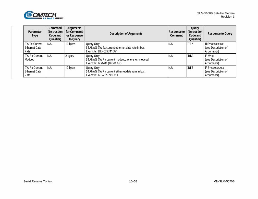
SLM-5650B Satellite Modem Revision 3
Serial Remote Control 10–58 MN-SLM-5650B
Parameter Type
Command (Instruction Code and Qualifier)
Arguments for Command or Response
to Query Description of Arguments Response to
Command
Query (Instruction Code and Qualifier)
Response to Query
ITA Tx Current Ethernet Data Rate
N/A 10 bytes Query Only. STANAG ITA Tx current ethernet data rate in bps. Example: ITE=029741.391
N/A ITE? ITE=xxxxxx.xxx (see Description of Arguments)
ITA Rx Current Modcod
N/A 2 bytes Query Only. STANAG ITA Rx current modcod, where xx=modcod Example: IRM=01 (BPSK 1/2)
N/A IRM? IRM=xx (see Description of Arguments)
ITA Rx Current Ethernet Data Rate
N/A 10 bytes Query Only. STANAG ITA Rx current ethernet data rate in bps. Example: IRE=029741.391
N/A IRE? IRE=xxxxxx.xxx (see Description of Arguments)

SLM-5650B Satellite Modem Revision 3
Appendix A A–1 MN-SLM-5650B
Appendix A. TROUBLESHOOTING
A.1 Overview This appendix provides information pertaining to the SLM-5650B Satellite Modem’s system checkout and fault isolation and identification.
A.2 System Checkout
This equipment contains parts and assemblies' sensitive to damage by ESD. Use ESD precautionary procedures when touching, removing, or inserting Printed Circuit Boards (PCBs).
System checkout entails following the test instructions provided for the modem PCB. The instructions include tables and test points for ensuring that the Eb/No, typical output spectrums, typical eye patterns, and constellations are correct. If a test failure occurs, refer to the fault isolation checkout procedures provided in this appendix.
This section provides instructions for checking the modem setup within the earth station. Due to the complexity of the modem circuitry, the checkout procedure should be used only as a basic guideline. More complicated maintenance tests are beyond the scope of this manual.

SLM-5650B Satellite Modem Revision 3
Appendix A A–2 MN-SLM-5650B
A.2.1 Interface Checkout Use the test setup in Figure A-1 and the procedure that follows to verify the Ethernet interface.
Noise Generator
SpectrumAnalyzer
PacketGenerator
Modem Under Test
TX
Rx
Splitter
SplitterVariable
Attenuator
VariableAttenuator
Figure A-1. Fault Isolation Test Setup
Step Task
1 Ensure the correct IF interface is selected and configured for the proper mode of operation.
2 Connect a packet generator test set to the appropriate Ethernet traffic data connector as shown in Figure A-1.
3 Set up the packet generator for the desired rate, packet size, etc. The modem will run error-free.

SLM-5650B Satellite Modem Revision 3
Appendix A A–3 MN-SLM-5650B
A.2.2 Modulator Checkout Use the following procedure for modulator checkout:
Step Task
1 Set up the equipment as shown in Figure A-1 using the 70/140 MHz IF interface. See Chapter 2. SPECIFICATIONS for the modulator specifications.
2 Set up the modem for IF loopback operation by using TEST: Loopback IF from the front panel menu, or use an external IF loop.
3 Clear all TX faults, Stored Faults, and Alarms using MONITOR: Event-Log Clear-All from the front panel menu.
4 Measure the Eb/No with a receiver that is known to be properly operating:
a. Refer to Table A-1 and Figure A-2 to check for proper Eb/No level. The (S+N)/N is measured by taking the average level of the noise and the average level of the modem spectrum top.
b. Use this measurement for the first column on Table A-1.
c. Read across the page to find the S/N and Eb/No for the specific code rate.
Once the demodulator has locked to the incoming signal, using MONITOR: Rx-Params from the front panel menu displays frequency offset, signal level, BERT data (if enabled), buffer status, Eb/No, and corrected BER.
5 Connect a spectrum analyzer to the modem, as shown in Figure A-1. Ensure the IF output meets the appropriate mask and spurious specifications. Measure the power output at different levels and frequencies.
A typical output spectrum is shown in Figure A-3.
6 Check the frequency and phase modulation accuracy as follows:
a. Set the modem to the continuous wave mode by using TEST: Carrier Tx-CW from the front panel menu. This sets the Carrier modulation in the OFF condition. A pure carrier should now be present at the IF output. This should only be used for frequency measurements. Spurious and power measurements should be taken with the modulation on.
b. Set the modem to the continuous wave Offset mode by using TEST: Carrier Tx-1,0 from the front panel menu. This generates a single upper side band and suppressed carrier signal. Ensure the carrier and side-band suppression are < -30 dBc.
7 Set up the equipment as shown in Figure A-1 using the L-Band IF interface. Repeat steps 2 through 6.

SLM-5650B Satellite Modem Revision 3
Appendix A A–4 MN-SLM-5650B
Table A-1. Conversion to S/N and Eb/No Chart
(dB) (S+N)/N
BPSK 1/3 Eb/No
BPSK 1/2 Eb/No
QPSK 1/2 Eb/No
QPSK 2/3 Eb/No
QPSK 3/4 Eb/No
4.0 6.6 4.8 1.8 0.5 0.0 4.5 7.4 5.6 2.6 1.3 0.8 5.0 8.1 6.4 3.3 2.1 1.6 5.5 8.8 7.1 4.1 2.8 2.3 6.0 9.5 7.8 4.7 3.5 3.0 6.5 10.2 8.4 5.4 4.1 3.6 7.0 10.8 9.0 6.0 4.8 4.3 7.5 11.4 9.7 6.6 5.4 4.9 8.0 12.0 10.3 7.3 6.0 5.5 8.5 12.6 10.8 7.8 6.6 6.1 9.0 13.2 11.4 8.4 7.2 6.7 9.5 13.8 12.0 9.0 7.7 7.2 10.0 14.3 12.6 9.5 8.3 7.8 10.5 14.9 13.1 10.1 8.8 8.3 11.0 15.4 13.7 10.6 9.4 8.9 11.5 16.0 14.2 11.2 9.9 9.4 12.0 16.5 14.7 11.7 10.5 10.0 12.5 17.0 15.3 12.2 11.0 10.5 13.0 17.5 15.8 12.8 11.5 11.0 13.5 18.1 16.3 13.3 12.1 11.5 14.0 18.6 16.8 13.8 12.6 12.1 14.5 19.1 17.4 14.3 13.1 12.6 15.0 19.6 17.9 14.9 13.6 13.1 15.5 20.1 18.4 15.4 14.1 13.6 16.0 20.7 18.9 15.9 14.6 14.1 16.5 21.2 19.4 16.4 15.2 14.6 17.0 21.7 19.9 16.9 15.7 15.2 17.5 22.2 20.4 17.4 16.2 15.7 18.0 22.7 20.9 17.9 16.7 16.2 18.5 23.2 21.4 18.4 17.2 16.7 19.0 23.7 22.0 18.9 17.7 17.2 19.5 24.2 22.5 19.5 18.2 17.7 20.0 24.7 23.0 20.0 18.7 18.2

SLM-5650B Satellite Modem Revision 3
Appendix A A–5 MN-SLM-5650B
Figure A-2. Typical Output Spectrum – with Noise
Figure A-3. Typical Output Spectrum – without Noise
ATTEN 10 dB2.00 dB/DIV
RES BANDWIDTH10.0 kHz
RL -49.00 dBm
CENTER 70.000 MHz*RB 10.0 kHz *VB 10.0 Hz
SPAN 1.000 MHzST 30.00 sec
Modem Rate = 2144 kbit/s, 3/4 Rate Codingwith 7.7 dB Eb/No (S + N)/N = 10 dB
ATTEN 10 dB5.00 dB/DIV
CENTER FREQUENCY140.000 MHz
RL -20.29 dBm
PASS
CENTER 140.000 MHz*RB 30.0 kHz *VB 3.00 Hz
SPAN 5.000 MHzST 166.7 sec

SLM-5650B Satellite Modem Revision 3
Appendix A A–6 MN-SLM-5650B
A.2.3 Demodulator Checkout Use the following procedure for demodulator checkout:
Step Task
1 Set up the equipment as shown in Figure A-1 using the 70/140 MHz IF interface.
2 Set up the modem with an external IF loop and level. Use a properly operating modulator, and ensure that power levels, data rates, code rates, etc. are compatible.
3 Allow the modem to lock up. a. Depending on the data rate and overhead type, lock-up may take several seconds. b. When the GREEN IF and Data Lock LED are ON and any fault has been cleared (where
applicable), the modem will run at the specified error rate. c. Run the Rx power level (input amplitude) over the full range and offset the Tx frequency from
the nominal Rx frequency by up to ±30 kHz. d. Ensure the modem still runs within the specified error rate.
4 Set up the modem to check the constellation by hooking an oscilloscope that is set in the X-Y mode to J9 pins 3 and 8. An alternative method is to use a computer and the IQ Mon program with an Ethernet connection to the modem. Typical constellation patterns are shown with noise (Figure A-4) and without noise (Figure A-5).

SLM-5650B Satellite Modem Revision 3
Appendix A A–7 MN-SLM-5650B
PC Version IQ Monitor with Noise
Oscilloscope with Noise
Figure A-4. Typical Constellation Patterns – with Noise

SLM-5650B Satellite Modem Revision 3
Appendix A A–8 MN-SLM-5650B
PC Version IQ Monitor without Noise
Oscilloscope without Noise
Figure A-5. Typical Constellation Patterns – without Noise

SLM-5650B Satellite Modem Revision 3
Appendix A A–9 MN-SLM-5650B
A.3 Fault Isolation The design of the modem allows for removal and replacement of some faulty components in the field. The optional plug-in interface can be removed from the modem through the rear panel, without requiring special tools. The power supply can be replaced if the top cover is removed.
This equipment contains parts and assemblies' sensitive to damage by ESD. Use ESD precautionary procedures when touching, removing, or inserting PCBs.
The fault monitoring capability of the modem assists the operator in fault isolation. If possible, replace the faulty PCB and return the damaged board to the CEFD Customer Support Department for repair. If not, return the complete modem.
The fault isolation procedure lists the following categories of faults or alarms:
• Modulator • Demodulator • Transmit Interface • Receive Interface • Unit (Common Equipment)
Each fault or alarm category includes possible problems and the appropriate action required to repair the modem.
If any of the troubleshooting procedures mentioned earlier in this appendix do not isolate the problem and CEFD Customer Support assistance is necessary, have the following information available for the representative:
• Modem configuration. Modem configuration includes the modulator, demodulator, interface, or local AUPC sections.
• Faults (active or stored).
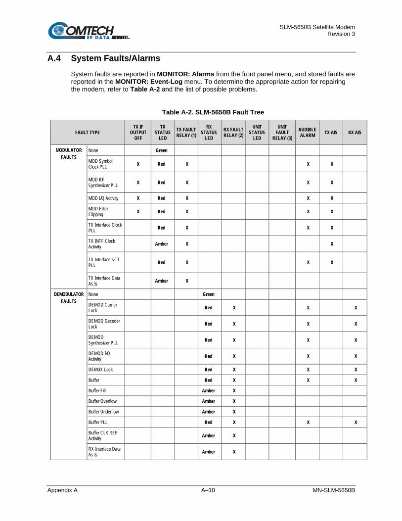
SLM-5650B Satellite Modem Revision 3
Appendix A A–10 MN-SLM-5650B
A.4 System Faults/Alarms System faults are reported in MONITOR: Alarms from the front panel menu, and stored faults are reported in the MONITOR: Event-Log menu. To determine the appropriate action for repairing the modem, refer to Table A-2 and the list of possible problems.
Table A-2. SLM-5650B Fault Tree
FAULT TYPE TX IF
OUTPUT OFF
TX STATUS
LED TX FAULT RELAY (1)
RX STATUS
LED RX FAULT RELAY (2)
UNIT STATUS
LED
UNIT FAULT
RELAY (3) AUDIBLE ALARM TX AIS RX AIS
MODULATOR FAULTS
None Green
MOD Symbol Clock PLL X Red X X X
MOD RF Synthesizer PLL X Red X X X
MOD I/Q Activity X Red X X X
MOD Filter Clipping X Red X X X
TX Interface Clock PLL Red X X X
TX INTF Clock Activity Amber X X
TX Interface SCT PLL Red X X X
TX Interface Data As Is Amber X
DEMODULATOR FAULTS
None Green
DEMOD Carrier Lock Red X X X
DEMOD Decoder Lock Red X X X
DEMOD Synthesizer PLL Red X X X
DEMOD I/Q Activity Red X X X
DEMUX Lock Red X X X
Buffer Red X X X
Buffer Fill Amber X
Buffer Overflow Amber X
Buffer Underflow Amber X
Buffer PLL Red X X X
Buffer CLK REF Activity Amber X
RX Interface Data As Is Amber X

SLM-5650B Satellite Modem Revision 3
Appendix A A–11 MN-SLM-5650B
FAULT TYPE TX IF
OUTPUT OFF
TX STATUS
LED TX FAULT RELAY (1)
RX STATUS
LED RX FAULT RELAY (2)
UNIT STATUS
LED
UNIT FAULT
RELAY (3) AUDIBLE ALARM TX AIS RX AIS
Eb/No Threshold Amber X
BERT SYNC Loss Amber X
UNIT FAULTS None X Green
+5.0V Power X Red X X
+3.3V Power X Red X X
+2.5V Power X Red X X
+1.5V Power X Red X X
+12V Power X Red X X
-12V Power X Red X X
+18V Power X Red X X
Cooling Fan Red X X
External REF Activity Amber X X
192 MHz Clock PLL X Red X X
10 MHz REF PLL X Red X X
M&C FPGA Config X Red X X
MOD FPGA Config X Red X X
DEMOD FPGA Config Red X X
Decoder FPGA Config Red X X
TX INTF FPGA Config X Red X X
RX INTF FPGA Config Red X X
FEC #1 FPGA Config X** Red X X
FEC #2 FPGA Config X** Red X X
Option Card FPGA Config Red X x
FPGA DCM Phase Lock Loop Fault Red X X
NP Mailbox Comm Error Red X X
TRANSEC Mailbox Comm Error Red X X

SLM-5650B Satellite Modem Revision 3
Appendix A A–12 MN-SLM-5650B
Fault Tree Legend
Test Note Fault/Alarm Relay Test Points Connector/Pins 1 TX FAULT J8/Pin 8 (N.O.), 7 (COM), 3 (N.C.) **** 2 RX FAULT J8/Pin 5 (N.O.), 4 (COM), 9 (N.C.) **** 3 UNIT FAULT J8/Pin 2 (N.O.), 1 (COM), 6 (N.C.) ****
** The IF output is only affected if that particular FEC card is currently passing traffic.
**** A connection between the common and N.O. contacts indicate no fault/alarm.
A.5 LED Indicator Faults
Chapter 7. FRONT PANEL OPERATION
There could be any number of reasons for a front panel LED to indicate a fault or an alarm:
• The modem can store up to a total of 255 occurrences of any fault. Use the front panel MONITOR: Event-log menu to review faults as they occur. See Chapter 7. FRONT PANEL OPERATION, Sect 7.1.2 for the LED Indicator descriptions.
• Alarms are considered minor faults. Alarms are shown on the front panel VFD in the MONITOR: Alarms nested Transmit, Receive, and Unit screens. Alarms are graphically represented by a reverse-contrast (white on black) “+”.

SLM-5650B Satellite Modem Revision 3
Appendix B B–1 MN-SLM-5650B
Appendix B. OPERATIONAL REFERENCE
B.1 Overview This appendix provides the end user with reference guides for the DSSS and non-DSSS LDPC modes.
The Data Rates and Symbol Rates shown in the following tables all assume that Transmission Security (TRANSEC) is turned off. To calculate the max data rate with TRANSEC on, the max data rate shown in the table becomes a max aggregate data rate. The real data rate can be calculated by dividing the TRANSEC overhead rate from the aggregate data rate. The TRANSEC overhead rate can be calculated for any TRANSEC Frame Length (N) as follows:
TRANSEC Overhead Rate = (3 + 16 * N) / (16 * N) where N=8

SLM-5650B Satellite Modem Revision 3
Appendix B B–2 MN-SLM-5650B
B.2 Modes
B.2.1 OM-73 Mode
Modulation Type Data Rate (kbps) Symbol Rate (ksps)
Min Max Min Max
BPSK 1/1 64 8472 64 10000
BPSK 1/2 64 15000 128 30000
BPSK 3/4 64 22500 85.333 29999.999
BPSK 7/8 64 26250 73.142 30000
QPSK 1/1 64 20000 32 10000
QPSK 1/2 64 30000 64 30000
QPSK 3/4 64 45000 42.666 30000
QPSK 7/8 64 51840 36.571 29622.857
OQPSK 1/1 64 20000 32 10000
OQPSK 1/2 64 30000 64 30000
OQPSK 3/4 64 45000 42.666 30000
OQPSK 7/8 64 51840 36.571 29622.857
B.2.2 MIL-STD-188-165A Mode
Modulation Type R-S Code Word R-S Depth
Data Rate (kbps) Symbol Rate (ksps)
Min Max Min Max BPSK 1/1 Off N/A 64 8472 64 10000 BPSK 1/2 Off N/A 64 15000 128 30000 BPSK 3/4 Off N/A 64 22500 85.333 29999.999 BPSK 7/8 Off N/A 64 26250 73.142 30000 QPSK 1/1 Off N/A 64 20000 32 10000 QPSK 1/2 Off N/A 64 30000 64 30000 QPSK 3/4 Off N/A 64 45000 42.666 30000 QPSK 7/8 Off N/A 64 51840 36.571 29622.857 OQPSK 1/1 Off N/A 64 20000 32 10000 OQPSK 1/2 Off N/A 64 30000 64 30000 OQPSK 3/4 Off N/A 64 45000 42.666 30000 OQPSK 7/8 Off N/A 64 51840 36.571 29622.857 8-PSK 2/3 Off N/A 256 51840 128 25920 8-PSK 5/6 Off N/A 256 51840 102.4 20736 BPSK 1/2 126,112 4, 8 64 13333.333 144 29999.999
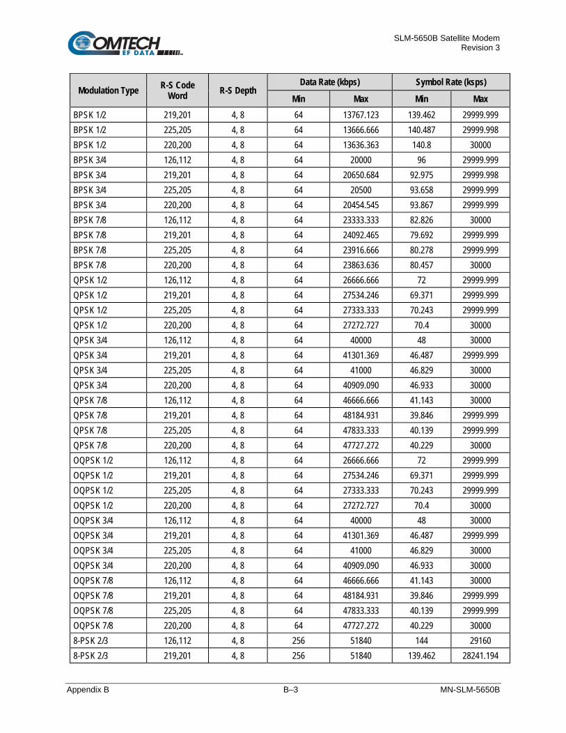
SLM-5650B Satellite Modem Revision 3
Appendix B B–3 MN-SLM-5650B
Modulation Type R-S Code Word R-S Depth
Data Rate (kbps) Symbol Rate (ksps)
Min Max Min Max BPSK 1/2 219,201 4, 8 64 13767.123 139.462 29999.999 BPSK 1/2 225,205 4, 8 64 13666.666 140.487 29999.998 BPSK 1/2 220,200 4, 8 64 13636.363 140.8 30000 BPSK 3/4 126,112 4, 8 64 20000 96 29999.999 BPSK 3/4 219,201 4, 8 64 20650.684 92.975 29999.998 BPSK 3/4 225,205 4, 8 64 20500 93.658 29999.999 BPSK 3/4 220,200 4, 8 64 20454.545 93.867 29999.999 BPSK 7/8 126,112 4, 8 64 23333.333 82.826 30000 BPSK 7/8 219,201 4, 8 64 24092.465 79.692 29999.999 BPSK 7/8 225,205 4, 8 64 23916.666 80.278 29999.999 BPSK 7/8 220,200 4, 8 64 23863.636 80.457 30000 QPSK 1/2 126,112 4, 8 64 26666.666 72 29999.999 QPSK 1/2 219,201 4, 8 64 27534.246 69.371 29999.999 QPSK 1/2 225,205 4, 8 64 27333.333 70.243 29999.999 QPSK 1/2 220,200 4, 8 64 27272.727 70.4 30000 QPSK 3/4 126,112 4, 8 64 40000 48 30000 QPSK 3/4 219,201 4, 8 64 41301.369 46.487 29999.999 QPSK 3/4 225,205 4, 8 64 41000 46.829 30000 QPSK 3/4 220,200 4, 8 64 40909.090 46.933 30000 QPSK 7/8 126,112 4, 8 64 46666.666 41.143 30000 QPSK 7/8 219,201 4, 8 64 48184.931 39.846 29999.999 QPSK 7/8 225,205 4, 8 64 47833.333 40.139 29999.999 QPSK 7/8 220,200 4, 8 64 47727.272 40.229 30000 OQPSK 1/2 126,112 4, 8 64 26666.666 72 29999.999 OQPSK 1/2 219,201 4, 8 64 27534.246 69.371 29999.999 OQPSK 1/2 225,205 4, 8 64 27333.333 70.243 29999.999 OQPSK 1/2 220,200 4, 8 64 27272.727 70.4 30000 OQPSK 3/4 126,112 4, 8 64 40000 48 30000 OQPSK 3/4 219,201 4, 8 64 41301.369 46.487 29999.999 OQPSK 3/4 225,205 4, 8 64 41000 46.829 30000 OQPSK 3/4 220,200 4, 8 64 40909.090 46.933 30000 OQPSK 7/8 126,112 4, 8 64 46666.666 41.143 30000 OQPSK 7/8 219,201 4, 8 64 48184.931 39.846 29999.999 OQPSK 7/8 225,205 4, 8 64 47833.333 40.139 29999.999 OQPSK 7/8 220,200 4, 8 64 47727.272 40.229 30000 8-PSK 2/3 126,112 4, 8 256 51840 144 29160 8-PSK 2/3 219,201 4, 8 256 51840 139.462 28241.194
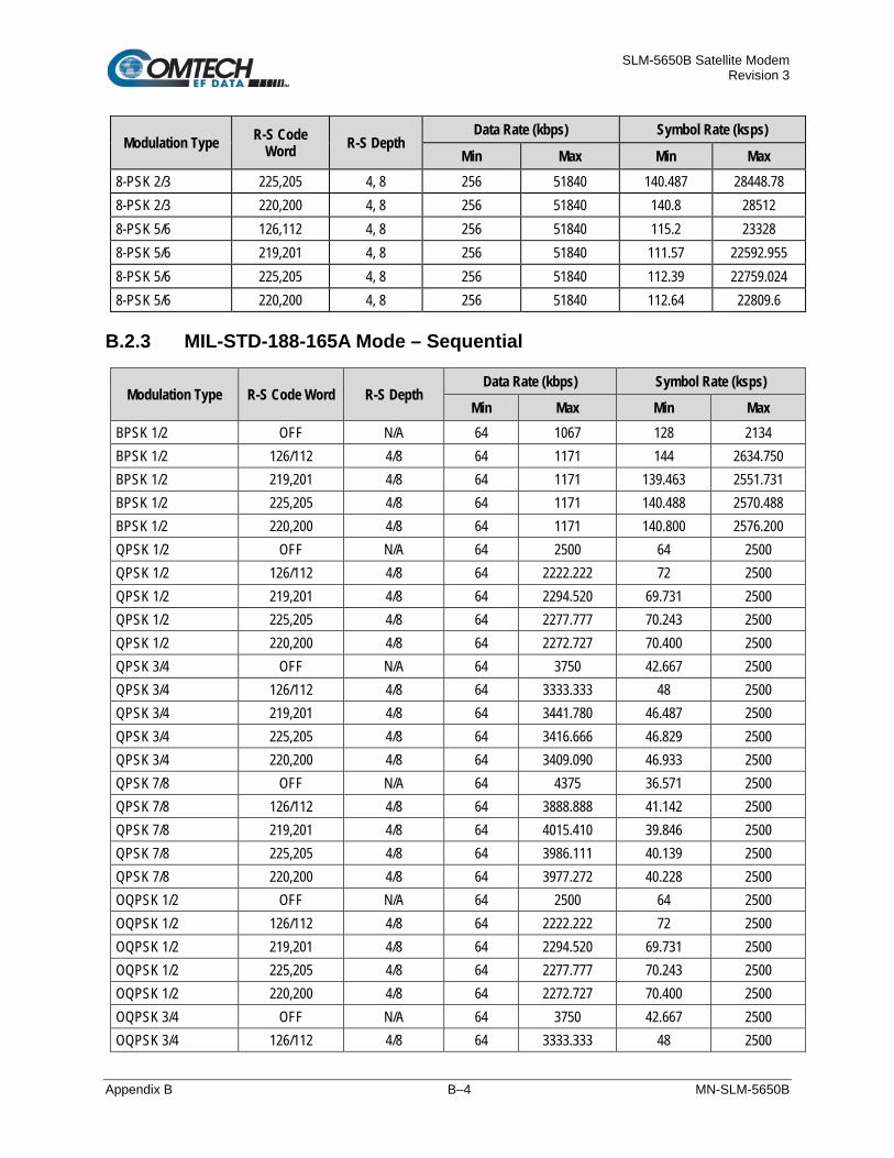
SLM-5650B Satellite Modem Revision 3
Appendix B B–4 MN-SLM-5650B
Modulation Type R-S Code Word R-S Depth
Data Rate (kbps) Symbol Rate (ksps)
Min Max Min Max 8-PSK 2/3 225,205 4, 8 256 51840 140.487 28448.78 8-PSK 2/3 220,200 4, 8 256 51840 140.8 28512 8-PSK 5/6 126,112 4, 8 256 51840 115.2 23328 8-PSK 5/6 219,201 4, 8 256 51840 111.57 22592.955 8-PSK 5/6 225,205 4, 8 256 51840 112.39 22759.024 8-PSK 5/6 220,200 4, 8 256 51840 112.64 22809.6
B.2.3 MIL-STD-188-165A Mode – Sequential
Modulation Type R-S Code Word R-S Depth Data Rate (kbps) Symbol Rate (ksps)
Min Max Min Max BPSK 1/2 OFF N/A 64 1067 128 2134 BPSK 1/2 126/112 4/8 64 1171 144 2634.750 BPSK 1/2 219,201 4/8 64 1171 139.463 2551.731 BPSK 1/2 225,205 4/8 64 1171 140.488 2570.488 BPSK 1/2 220,200 4/8 64 1171 140.800 2576.200 QPSK 1/2 OFF N/A 64 2500 64 2500 QPSK 1/2 126/112 4/8 64 2222.222 72 2500 QPSK 1/2 219,201 4/8 64 2294.520 69.731 2500 QPSK 1/2 225,205 4/8 64 2277.777 70.243 2500 QPSK 1/2 220,200 4/8 64 2272.727 70.400 2500 QPSK 3/4 OFF N/A 64 3750 42.667 2500 QPSK 3/4 126/112 4/8 64 3333.333 48 2500 QPSK 3/4 219,201 4/8 64 3441.780 46.487 2500 QPSK 3/4 225,205 4/8 64 3416.666 46.829 2500 QPSK 3/4 220,200 4/8 64 3409.090 46.933 2500 QPSK 7/8 OFF N/A 64 4375 36.571 2500 QPSK 7/8 126/112 4/8 64 3888.888 41.142 2500 QPSK 7/8 219,201 4/8 64 4015.410 39.846 2500 QPSK 7/8 225,205 4/8 64 3986.111 40.139 2500 QPSK 7/8 220,200 4/8 64 3977.272 40.228 2500 OQPSK 1/2 OFF N/A 64 2500 64 2500 OQPSK 1/2 126/112 4/8 64 2222.222 72 2500 OQPSK 1/2 219,201 4/8 64 2294.520 69.731 2500 OQPSK 1/2 225,205 4/8 64 2277.777 70.243 2500 OQPSK 1/2 220,200 4/8 64 2272.727 70.400 2500 OQPSK 3/4 OFF N/A 64 3750 42.667 2500 OQPSK 3/4 126/112 4/8 64 3333.333 48 2500

SLM-5650B Satellite Modem Revision 3
Appendix B B–5 MN-SLM-5650B
Modulation Type R-S Code Word R-S Depth Data Rate (kbps) Symbol Rate (ksps)
Min Max Min Max OQPSK 3/4 219,201 4/8 64 3441.780 46.487 2500 OQPSK 3/4 225,205 4/8 64 3416.666 46.829 2500 OQPSK 3/4 220,200 4/8 64 3409.090 46.933 2500 OQPSK 7/8 OFF N/A 64 4375 36.571 2500 OQPSK 7/8 126/112 4/8 64 3888.888 41.142 2500 OQPSK 7/8 219,201 4/8 64 4015.410 39.846 2500 OQPSK 7/8 225,205 4/8 64 3986.111 40.139 2500 OQPSK 7/8 220,200 4/8 64 3977.272 40.228 2500
B.2.4 IESS-308 Mode – Standard Higher Rates
Modulation Type Overhead R-S Code Word R-S Depth Data Rate (kbps) Symbol Rate (ksps)
QPSK 1/2 IESS-308 Off N/A 1544 1640 QPSK 1/2 IESS-308 Off N/A 2048 2144 QPSK 1/2 IESS-308 Off N/A 6312 6408 QPSK 1/2 IESS-308 Off N/A 8448 8544 QPSK 1/2 IESS-308 194,178 4, 8, 16 1544 1778.787 QPSK 1/2 IESS-308 194,178 4, 8, 16 2048 2328.09 QPSK 1/2 IESS-308 194,178 4, 8, 16 6312 6975.371 QPSK 1/2 IESS-308 194,178 4, 8, 16 8448 9303.371 QPSK 1/2 IESS-308 219,201 4, 8, 16 1544 1778.269 QPSK 1/2 IESS-308 219,201 4, 8, 16 2048 2327.403 QPSK 1/2 IESS-308 219,201 4, 8, 16 6312 6973.254 QPSK 1/2 IESS-308 219,201 4, 8, 16 8448 9300.537 QPSK 1/2 IESS-308 225,205 4, 8, 16 1544 1790.634 QPSK 1/2 IESS-308 225,205 4, 8, 16 2048 2343.805 QPSK 1/2 IESS-308 225,205 4, 8, 16 6312 7023.805 QPSK 1/2 IESS-308 225,205 4, 8, 16 8448 9368.195 QPSK 1/2 IESS-308 126,112 4, 8, 16 1544 1833 QPSK 1/2 IESS-308 126,112 4, 8, 16 2048 2400 QPSK 1/2 IESS-308 126,112 4, 8, 16 6312 7197 QPSK 1/2 IESS-308 126,112 4, 8, 16 8448 9600 QPSK 1/2 IESS-308 208,192 4, 8, 16 1544 1776.708 QPSK 1/2 IESS-308 208,192 4, 8, 16 2048 2325.333 QPSK 1/2 IESS-308 208,192 4, 8, 16 6312 6966.875 QPSK 1/2 IESS-308 208,192 4, 8, 16 8448 9292 QPSK 3/4 IESS-308 Off N/A 1544 1029.333

SLM-5650B Satellite Modem Revision 3
Appendix B B–6 MN-SLM-5650B
Modulation Type Overhead R-S Code Word R-S Depth Data Rate (kbps) Symbol Rate (ksps)
QPSK 3/4 IESS-308 Off N/A 2048 1365.333 QPSK 3/4 IESS-308 Off N/A 6312 4208 QPSK 3/4 IESS-308 Off N/A 8448 5632 QPSK 3/4 IESS-308 Off N/A 32064 21376 QPSK 3/4 IESS-308 Off N/A 34368 22912 QPSK 3/4 IESS-308 Off N/A 44736 29824 QPSK 3/4 IESS-308 194,178 4, 8, 16 1544 1217.858 QPSK 3/4 IESS-308 194,178 4, 8, 16 2048 1584.06 QPSK 3/4 IESS-308 194,178 4, 8, 16 6312 4682.247 QPSK 3/4 IESS-308 194,178 4, 8, 16 8448 6324.247 QPSK 3/4 IESS-308 194,178 4, 8, 16 32064 23393.438 QPSK 3/4 IESS-308 194,178 4, 8, 16 34368 25067.506 QPSK 3/4 IESS-308 219,201 4, 8, 16 1544 1217.512 QPSK 3/4 IESS-308 219,201 4, 8, 16 2048 1583.602 QPSK 3/4 IESS-308 219,201 4, 8, 16 6312 4680.836 QPSK 3/4 IESS-308 219,201 4, 8, 16 8448 6232.358 QPSK 3/4 IESS-308 219,201 4, 8, 16 32064 23386.269 QPSK 3/4 IESS-308 219,201 4, 8, 16 34368 25059.821 QPSK 3/4 IESS-308 225,205 4, 8, 16 1544 1225.756 QPSK 3/4 IESS-308 225,205 4, 8, 16 2048 1594.537 QPSK 3/4 IESS-308 225,205 4, 8, 16 6312 4714.537 QPSK 3/4 IESS-308 225,205 4, 8, 16 8448 6277.463 QPSK 3/4 IESS-308 225,205 4, 8, 16 32064 23557.463 QPSK 3/4 IESS-308 225,205 4, 8, 16 34368 25243.317 QPSK 3/4 IESS-308 126,112 4, 8, 1 1544 1254 QPSK 3/4 IESS-308 126,112 4, 8, 1 2048 1632 QPSK 3/4 IESS-308 126,112 4, 8, 1 6312 4830 QPSK 3/4 IESS-308 126,112 4, 8, 1 8448 6432 QPSK 3/4 IESS-308 126,112 4, 8, 1 32064 24144 QPSK 3/4 IESS-308 126,112 4, 8, 1 34368 25872 QPSK 3/4 IESS-308 208,192 4, 8, 16 1544 1216.472 QPSK 3/4 IESS-308 208,192 4, 8, 16 2048 1582.222 QPSK 3/4 IESS-308 208,192 4, 8, 16 6312 4676.583 QPSK 3/4 IESS-308 208,192 4, 8, 16 8448 626.667 QPSK 3/4 IESS-308 208,192 4, 8, 16 32064 23364.667 QPSK 3/4 IESS-308 208,192 4, 8, 16 34368 25036.667 QPSK 7/8 IESS-308 Off N/A 1544 882.286

SLM-5650B Satellite Modem Revision 3
Appendix B B–7 MN-SLM-5650B
Modulation Type Overhead R-S Code Word R-S Depth Data Rate (kbps) Symbol Rate (ksps)
QPSK 7/8 IESS-308 Off N/A 2048 1170.286 QPSK 7/8 IESS-308 Off N/A 6312 3606.857 QPSK 7/8 IESS-308 Off N/A 8448 4827.428 QPSK 7/8 IESS-308 Off N/A 32064 20040.571 QPSK 7/8 IESS-308 Off N/A 34368 21473.714 QPSK 7/8 IESS-308 Off N/A 44736 27922.857 QPSK 7/8 IESS-308 194,178 4, 8, 16 1544 1057.592 QPSK 7/8 IESS-308 194,178 4, 8, 16 2048 1371.48 QPSK 7/8 IESS-308 194,178 4, 8, 16 6312 4027.069 QPSK 7/8 IESS-308 194,178 4, 8, 16 8448 5357.355 QPSK 7/8 IESS-308 194,178 4, 8, 16 32064 20065.233 QPSK 7/8 IESS-308 194,178 4, 8, 16 34368 21500.148 QPSK 7/8 IESS-308 194,178 4, 8, 16 44736 27957.265 QPSK 7/8 IESS-308 219,201 4, 8, 16 1544 1057.296 QPSK 7/8 IESS-308 219,201 4, 8, 16 2048 1371.087 QPSK 7/8 IESS-308 219,201 4, 8, 16 6312 4025.859 QPSK 7/8 IESS-308 219,201 4, 8, 16 8448 5355.736 QPSK 7/8 IESS-308 219,201 4, 8, 16 32064 20059.087 QPSK 7/8 IESS-308 219,201 4, 8, 16 34368 21493.561 QPSK 7/8 IESS-308 219,201 4, 8, 16 44736 27948.691 QPSK 7/8 IESS-308 225,205 4, 8, 16 1544 1064.362 QPSK 7/8 IESS-308 225,205 4, 8, 16 2048 1380.46 QPSK 7/8 IESS-308 225,205 4, 8, 16 6312 4054.743 QPSK 7/8 IESS-308 225,205 4, 8, 16 8448 5394.397 QPSK 7/8 IESS-308 225,205 4, 8, 16 32064 20205.826 QPSK 7/8 IESS-308 225,205 4, 8, 16 34368 26150.843 QPSK 7/8 IESS-308 225,205 4, 8, 16 44736 28153.422 QPSK 7/8 IESS-308 126,112 4, 8, 16 1544 1088.571 QPSK 7/8 IESS-308 126,112 4, 8, 16 2048 1412.571 QPSK 7/8 IESS-308 126,112 4, 8, 16 6312 4153.714 QPSK 7/8 IESS-308 126,112 4, 8, 16 8448 5526.857 QPSK 7/8 IESS-308 126,112 4, 8, 16 32064 20708.571 QPSK 7/8 IESS-308 126,112 4, 8, 16 34368 22189.714 QPSK 7/8 IESS-308 126,112 4, 8, 16 44736 28854.857 QPSK 7/8 IESS-308 208,192 4, 8, 16 1544 1056.405 QPSK 7/8 IESS-308 208,192 4, 8, 16 2048 1369.905 QPSK 7/8 IESS-308 208,192 4, 8, 16 6312 4022.214

SLM-5650B Satellite Modem Revision 3
Appendix B B–8 MN-SLM-5650B
Modulation Type Overhead R-S Code Word R-S Depth Data Rate (kbps) Symbol Rate (ksps)
QPSK 7/8 IESS-308 208,192 4, 8, 16 8448 5350.857 QPSK 7/8 IESS-308 208,192 4, 8, 16 32064 20040.571 QPSK 7/8 IESS-308 208,192 4, 8, 16 34368 21473.714 QPSK 7/8 IESS-308 208,192 4, 8, 16 44736 27922.857
B.2.5 IESS-308 Mode – Extended
Modulation Type Overhead R-S Code
Word R-S Depth Data Rate (kbps) Symbol Rate (ksps)
Min Max Min Max QPSK 1/2 None Off N/A 64 30000 64 30000 QPSK 1/2 None 126,112 4, 8, 16 64 26666.666 72 29999.999 QPSK 1/2 None 219,201 4, 8, 16 64 27534.246 69.371 29999.999 QPSK 1/2 None 194,178 4, 8, 16 64 27525.773 69.573 30000 QPSK 1/2 None 225,205 4, 8, 16 64 27333.333 70.243 29999.999 QPSK 1/2 None 208,192 4, 8, 16 64 27559.809 69.667 30000 QPSK 1/2 IESS-309 Off N/A 64 8448 68.267 9011.2 QPSK 1/2 IESS-309 126,112 4, 8, 16 64 8448 76.8 10137.6 QPSK 1/2 IESS-309 194,178 4, 8, 16 64 8448 74.403 9821.196 QPSK 1/2 IESS-309 225,205 4, 8, 16 64 8448 74.927 9890.341 QPSK 1/2 IESS-309 208,192 4, 8, 16 64 8448 74.311 9809.067 QPSK 3/4 None Off N/A 64 45000 42.666 30000 QPSK 3/4 None 126,112 4, 8, 16 64 40000 48 30000 QPSK 3/4 None 219,201 4, 8, 16 64 41301.369 46.487 29999.999 QPSK 3/4 None 194,178 4, 8, 16 64 41288.65 46.502 30000 QPSK 3/4 None 225,205 4, 8, 16 64 41000 46.829 30000 QPSK 3/4 None 208,192 4, 8, 16 64 41339.713 46.444 30000 QPSK 3/4 IESS-309 Off N/A 64 8448 45.511 6007.467 QPSK 3/4 IESS-309 126,112 4, 8, 16 64 8448 51.2 6758.4 QPSK 3/4 IESS-309 219,201 4, 8, 16 64 8448 49.587 6545.449 QPSK 3/4 IESS-309 194,178 4, 8, 16 64 8448 49.602 6547.464 QPSK 3/4 IESS-309 225,205 4, 8, 16 64 8448 49.951 6593.561 QPSK 3/4 IESS-309 208,192 4, 8, 16 64 8448 49.541 6539.378 QPSK 7/8 None Off N/A 64 51840 36.571 29622.857 QPSK 7/8 None 126,112 4, 8, 16 64 46666.666 41.143 30000 QPSK 7/8 None 219,201 4, 8, 16 64 48184.931 39.846 29999.999 QPSK 7/8 None 194,178 4, 8, 16 64 48170.103 38.859 30000 QPSK 7/8 None 225,205 4, 8, 16 64 47833.333 40.139 29999.999

SLM-5650B Satellite Modem Revision 3
Appendix B B–9 MN-SLM-5650B
Modulation Type Overhead R-S Code
Word R-S Depth Data Rate (kbps) Symbol Rate (ksps)
Min Max Min Max QPSK 7/8 None 208,192 4, 8, 16 64 48229.665 39.81 29999.999 QPSK 7/8 IESS-309 Off N/A 64 8448 39.01 4827.428 QPSK 7/8 IESS-309 126,112 4, 8, 16 64 8448 43.886 5792.914 QPSK 7/8 IESS-309 219,201 4, 8, 16 64 8448 42.503 5610.385 QPSK 7/8 IESS-309 194,178 4, 8, 16 64 8448 42.516 5612.112 QPSK 7/8 IESS-309 225,205 4, 8, 16 64 8448 42.818 5561.624 QPSK 7/8 IESS-309 208,192 4, 8, 16 64 8448 42.463 5604.181 OQPSK 1/2 None Off N/A 64 30000 64 30000 OQPSK 1/2 None 126,112 4, 8, 16 64 26666.666 72 29999.999 OQPSK 1/2 None 219,201 4, 8, 16 64 27534.246 69.371 29999.999 OQPSK 1/2 None 194,178 4, 8, 16 64 27525.773 69.573 30000 OQPSK 1/2 None 225,205 4, 8, 16 64 27333.333 70.243 29999.999 OQPSK 1/2 None 208,192 4, 8, 16 64 27559.809 69.667 30000 OQPSK 1/2 IESS-309 Off N/A 64 8448 68.267 901.2 OQPSK 1/2 IESS-309 126,112 4, 8, 16 64 8448 76.8 10137.6 OQPSK 1/2 IESS-309 219,201 4, 8, 16 64 8448 74.38 9818.173 OQPSK 1/2 IESS-309 194,178 4, 8, 16 64 8448 74.403 9821.196 OQPSK 1/2 IESS-309 225,205 4, 8, 16 64 8448 74.927 9890.341 OQPSK 1/2 IESS-309 208,192 4, 8, 16 64 8448 74.311 9809.067 OQPSK 3/4 None Off N/A 64 20000 42.666 30000 OQPSK 3/4 None 126,112 4, 8, 16 64 40000 48 30000 OQPSK 3/4 None 219,201 4, 8, 16 64 41301.369 46.487 29999.999 OQPSK 3/4 None 194,178 4, 8, 16 64 41288.65 46.502 30000 OQPSK 3/4 None 225,205 4, 8, 16 64 41000 46.829 30000 OQPSK 3/4 None 208,192 4, 8, 16 64 41339.713 46.444 30000 OQPSK 3/4 IESS-309 Off N/A 64 8448 45.511 6007.467 OQPSK 3/4 IESS-309 126,112 4, 8, 16 64 8448 51.2 6758.4 OQPSK 3/4 IESS-309 219,201 4, 8, 16 64 8448 49.587 6545.449 OQPSK 3/4 IESS-309 194,178 4, 8, 16 64 8448 49.602 6547.464 OQPSK 3/4 IESS-309 225,205 4, 8, 16 64 8448 49.951 6593.561 OQPSK 3/4 IESS-309 208,192 4, 8, 16 64 8448 49.541 6539.378 OQPSK 7/8 None Off N/A 64 20000 36.571 29622.857 OQPSK 7/8 None 126,112 4, 8, 16 64 46666.666 41.143 30000 OQPSK 7/8 None 219,201 4, 8, 16 64 48184.931 39.846 29999.999 OQPSK 7/8 None 194,178 4, 8, 16 64 48170.103 38.859 30000 OQPSK 7/8 None 225,205 4, 8, 16 64 47833.333 40.139 29999.999 OQPSK 7/8 None 208,192 4, 8, 16 64 48229.665 39.81 29999.999

SLM-5650B Satellite Modem Revision 3
Appendix B B–10 MN-SLM-5650B
Modulation Type Overhead R-S Code
Word R-S Depth Data Rate (kbps) Symbol Rate (ksps)
Min Max Min Max OQPSK 7/8 IESS-309 Off N/A 64 8448 39.01 4827.428 OQPSK 7/8 IESS-309 126,112 4, 8, 16 64 8448 43.886 5792.914 OQPSK 7/8 IESS-309 219,201 4, 8, 16 64 8448 42.503 5610.385 OQPSK 7/8 IESS-309 194,178 4, 8, 16 64 8448 42.516 5612.112 OQPSK 7/8 IESS-309 225,205 4, 8, 16 64 8448 42.818 5561.624 OQPSK 7/8 IESS-309 208,192 4, 8, 16 64 8448 42.463 5604.181
B.2.6 IESS-309 Mode – Extended (Closed Network)
Modulation Type Overhead R-S Code
Word R-S Depth Data Rate (kbps) Symbol Rate (ksps)
Min Max Min Max BPSK 1/2 None Off N/A 64 15000 128 30000 BPSK 1/2 None 219,201 4, 8, 16 64 13767.123 139.462 29999.999 BPSK 1/2 IESS-309 Off N/A 64 8448 136.533 18022.4 BPSK 1/2 IESS-309 219,201 4, 8, 16 64 8448 148.76 19636.346 BPSK 3/4 None Off N/A 64 22500 85.333 29999.999 BPSK 3/4 None 219,201 4, 8, 16 64 20650.684 92.975 29999.999 BPSK 3/4 IESS-309 Off N/A 64 8448 91.022 12014.933 BPSK 3/4 IESS-309 219,201 4, 8, 16 64 8448 99.173 13090.898 QPSK 1/2 None Off N/A 64 30000 64 30000 QPSK 1/2 None 219,201 4, 8, 16 64 27534.246 69.371 29999.999 QPSK 1/2 IESS-309 Off N/A 64 8448 68.267 9011.2 QPSK 1/2 IESS-309 219,201 4, 8, 16 64 8448 74.38 9818.173 QPSK 3/4 None Off N/A 64 20000 42.666 30000 QPSK 3/4 None 219,201 4, 8, 16 64 41301.369 46.487 29999.999 QPSK 3/4 IESS-309 Off N/A 64 8448 45.511 6007.467 QPSK 3/4 IESS-309 219,201 4,8, 16 64 8448 49.587 6545.449 OQPSK 1/2 None Off N/A 64 30000 64 30000 OQPSK 1/2 None 219,201 4, 8, 16 64 27534.246 69.371 29999.999 OQPSK 1/2 IESS-309 Off N/A 64 8448 68.267 9011.2 OQPSK 1/2 IESS-309 219,201 4, 8, 16 64 8448 74.38 9818.173 OQPSK 3/4 None Off N/A 64 20000 42.666 30000 OQPSK 3/4 None 219,201 4, 8, 16 64 41301.369 46.487 29999.999 OQPSK 3/4 IESS-309 Off N/A 64 8448 45.511 6007.467 OQPSK 3/4 IESS-309 219,201 4, 8, 16 64 8448 49.587 6545.449

SLM-5650B Satellite Modem Revision 3
Appendix B B–11 MN-SLM-5650B
B.2.7 IESS-310 Mode – Extended Rates
Modulation Type Overhead R-S Code
Word R-S Depth Data Rate (kbps) Symbol Rate (ksps)
8-PSK 2/3 None 219,201 4, 8, 16 256 139.463 8-PSK 2/3 None 219,201 4, 8, 16 51840 28241.194 8-PSK 2/3 IESS-309 219,201 4, 8, 16 256 148.76 8-PSK 2/3 IESS-309 219,201 4, 8, 16 8448 4909.087 8-PSK 2/3 IESS-309 219,201 4, 8, 16 1544 937.134 8-PSK 2/3 IESS-309 219,201 4, 8, 16 2048 1211.701 8-PSK 2/3 IESS-309 219,201 4, 8, 16 6312 3534.627 8-PSK 2/3 IESS-309 219,201 4, 8, 16 8448 4698.269 8-PSK 2/3 IESS-309 219,201 4, 8, 16 32064 17563.701 8-PSK 2/3 IESS-309 219,201 4, 8, 16 34368 18818.866 8-PSK 2/3 IESS-309 219,201 4, 8, 16 44736 24467.104
B.2.8 Turbo Code Mode
Modulation Type Data Rate (kbps) Symbol Rate (ksps)
Min Max Min Max BPSK 21/44 64 30545.454 134.095 63999.999 BPSK 5/16 64 20000 204.8 64000 QPSK 21/44 64 61090.909 67.047 63999.999 QPSK 3/4 64 96000 42.666 64000 QPSK 7/8 64 112000 36.571 64000 QPSK 17/18 64 120888.888 33.882 63999.999 OQPSK 21/44 64 61090.909 67.047 63999.999 OQPSK 3/4 64 96000 42.666 64000 OQPSK 7/8 64 112000 36.571 64000 OQPSK 17/18 64 120888.888 33.882 63999.999 8-PSK 3/4 256 144000 113.777 64000 8-PSK 7/8 256 155520 97.523 59245.714 8-PSK 17/18 256 155520 90.352 54889.411 8-QAM 3/4 256 144000 113.777 64000 8-QAM 7/8 256 155520 97.523 59245.714 8-QAM 17/18 256 155520 90.352 54889.411 16-QAM 3/4 256 155520 85.333 51840 16-QAM 7/8 256 155520 73.143 44434.285

SLM-5650B Satellite Modem Revision 3
Appendix B B–12 MN-SLM-5650B
B.2.9 16-QAM Mode
Modulation Type R-S Code Word R-S Depth Data Rate (kbps) Symbol Rate (ksps)
Min Max Min Max 16-QAM 3/4 None None 256 51840 85.333 17280 16-QAM 3/4 219,201 4, 8, 16 256 51840 92.975 18827.462 16-QAM 3/4 208,192 4, 8, 16 256 51840 92.889 18810 16-QAM 7/8 None None 256 51840 73.143 14811.428 16-QAM 7/8 219,201 4, 8, 16 256 51840 79.692 16137.825 16-QAM 7/8 208,192 4, 8, 16 256 51840 79.619 16122.857
16-QAM 3/4 requires R-S to be ON to automatically resolve data ambiguities.
B.2.10 AUPC Mode
Modulation Type R-S Code Word R-S Depth Data Rate (kbps) Symbol Rate (ksps)
Min Max Min Max BPSK 1/1 OFF N/A 64 7942.500 68.266 8472 BPSK 1/2 OFF N/A 64 14062.500 136.533 30000 BPSK 3/4 OFF N/A 64 21093.750 91.022 30000 BPSK 7/8 OFF N/A 64 24609.375 78.019 30000 QPSK 1/1 OFF N/A 64 18750 34.133 10000 QPSK 1/2 OFF N/A 64 28125 68.266 30000 QPSK 3/4 OFF N/A 64 42187.500 45.511 30000 QPSK 7/8 OFF N/A 64 49218.750 39.009 30000 OQPSK 1/1 OFF N/A 64 18750 34.133 10000 OQPSK 1/2 OFF N/A 64 28125 68.266 30000 OQPSK 3/4 OFF N/A 64 42187.500 45.511 30000 OQPSK 7/8 OFF N/A 64 49218.750 39.009 30000 8-PSK 2/3 OFF N/A 64 51840 136.533 27648 8-PSK 5/6 OFF N/A 64 51840 109.226 22118.400 16-QAM 3/4 OFF N/A 64 51840 91.022 18432 16-QAM 7/8 OFF N/A 64 51840 78.019 15798.857 BPSK 1/2 225,205 8 256 12812.500 149.853 30000 BPSK 3/4 225,205 8 256 19218.750 99.902 30000 BPSK 7/8 225,205 8 256 22421.875 85.630 30000 QPSK 1/2 225,205 8 256 25625 74.926 30000 QPSK 3/4 225,205 8 256 38437.500 49.951 30000 QPSK 7/8 225,205 8 256 44843.750 42.815 30000

SLM-5650B Satellite Modem Revision 3
Appendix B B–13 MN-SLM-5650B
Modulation Type R-S Code Word R-S Depth Data Rate (kbps) Symbol Rate (ksps)
Min Max Min Max OQPSK 1/2 225,205 8 256 25625 74.926 30000 OQPSK 3/4 225,205 8 256 38437.500 49.951 30000 OQPSK 7/8 225,205 8 256 44843.750 42.815 30000 8-PSK 2/3 225,205 8 256 51250 149.853 30000 8-PSK 5/6 225,205 8 256 51840 119.882 24276.292 16-QAM 3/4 225,205 8 256 51840 99.902 20230.243 16-QAM 7/8 225,205 8 256 51840 85.630 17340.209
B.2.11 AUPC Mode – Sequential
Modulation Type R-S Code Word R-S Depth Data Rate (kbps) Symbol Rate (ksps)
Min Max Min Max
BPSK 1/2 OFF N/A 64 1171 136.533 2498.133
QPSK 1/2 OFF N/A 64 2048 68.266 2184.533
QPSK 3/4 OFF N/A 64 2048 45.511 1456.355
QPSK 7/8 OFF N/A 64 2048 39.009 1248.304
OQPSK 1/2 OFF N/A 64 2048 68.266 2184.533
OQPSK 3/4 OFF N/A 64 2048 45.511 1456.355
OQPSK 7/8 OFF N/A 64 2048 39.009 1248.304
BPSK 1/2 225,205 8 64 1067 149.853 2498.341
QPSK 1/2 225,205 8 64 2048 74.926 2397.658
QPSK 3/4 225,205 8 64 2048 49.951 1598.439
QPSK 7/8 225,205 8 64 2048 42.815 1370.09
OQPSK 1/2 225,205 8 64 2048 74.926 2397.658
OQPSK 3/4 225,205 8 64 2048 49.951 1598.439
OQPSK 7/8 225,205 8 64 2048 42.815 1370.09

SLM-5650B Satellite Modem Revision 3
Appendix B B–14 MN-SLM-5650B
B.2.12 AUPC Mode – Turbo
Modulation Type Data Rate (kbps) Symbol Rate (ksps)
Min Max Min Max
BPSK 5/16 64 8789.062 218.453 29999.998
BPSK 21/44 64 13423.295 143.034 29999.998
QPSK 21/44 64 26846.590 71.517 29999.998
QPSK 3/4 64 42187.500 45.511 30000
QPSK 7/8 64 49218.750 39.009 30000
QPSK 17/18 64 51840 36.141 29274.352
OQPSK 21/44 64 26846.590 71.517 29999.998
OQPSK 3/4 64 42187.500 45.511 30000
OQPSK 7/8 64 49218.750 39.009 30000
OQPSK 17/18 64 51840 36.141 29274.352
8-PSK 3/4 256 51840 121.362 24576
8-PSK 7/8 256 51840 104.025 21065.142
8-PSK 17/18 256 51840 96.376 19516.235
8-QAM 3/4 256 51840 121.362 24576
8-QAM 7/8 256 51840 104.025 21065.142
8-QAM 17/18 256 51840 96.376 19516.235
16-QAM 3/4 256 51840 91.022 18432
16-QAM 7/8 256 51840 78.019 15798.857
B.2.13 NON-SPREAD LDPC Mode – Ultra Low Latency (ULL)
Modulation Type Data Rate (kbps) Symbol Rate (ksps)
DR to SR Multiplier Min Max Min Max
BPSK 1/2 32* 2000 64.868 4054.263 2092/1032
QPSK 1/2 32 2000 32.434 2027.131 2092/2064
QPSK 2/3 41.851 2000 32 1529.239 2092/5448
QPSK 3/4 46.991 2000 32 1361.979 2092/3072

SLM-5650B Satellite Modem Revision 3
Appendix B B–15 MN-SLM-5650B
B.2.14 NON-SPREAD LDPC Mode – Low Latency (LL)
Modulation Type Data Rate (kbps) Symbol Rate (ksps)
DR to SR Multiplier Min Max Min Max
BPSK .378 32.000 5000 84.676 13230.769 4128/1560
BPSK .451 32.000 5000 71.019 11096.774 4128/1860
BPSK .541 32.000 5000 59.182 9247.311 4128/2232
QPSK 1/2 32.000 5000 32.188 5029.411 4104/4080
QPSK 2/3 42.480 5000 32.000 3766.519 4104/5448
QPSK 3/4 47.720 5000 32.000 3352.941 4104/6120
QPSK 7/8 55.767 5000 32.000 2869.127 4104/7152
8-QAM 2/3 256.000 5000 128.313 2506.118 4096/8172
8-QAM 3/4 256.000 5000 114.223 2230.936 4096/9180
8-QAM 7/8 256.000 5000 97.741 1909.023 4096/10728
16-QAM 2/3 256.000 5000 96.140 1877.753 4092/10896
16-QAM 3/4 256.000 5000 85.584 1671.568 4092/12240
16-QAM 7/8 256.000 5000 73.234 1430.369 4092/14304
B.2.15 NON-SPREAD LDPC Mode – High Performance (HP)
Modulation Type Data Rate (kbps) Symbol Rate (ksps)
DR to SR Multiplier Min Max Min Max
BPSK 1/3 32.000 15000 96.000 45000 16416/5472
BPSK 1/2 32.000 22500 64.000 45000 16416/8208
QPSK 1/2 32.000 45000 32.000 45000 8208/8208
QPSK 2/3 42.667 60000 32.000 45000 8208/10944
QPSK 3/4 48.000 67500 32.000 45000 8256/12384
OQPSK 1/2 32.000 45000 32.000 45000 8208/8208
OQPSK 2/3 42.667 60000 32.000 45000 8208/10944
OQPSK 3/4 48.000 67500 32.000 45000 8256/12384
8-QAM 2/3 256.000 60000 128.000 30000 5472/10944
8-QAM 3/4 256.000 67500 113.778 30000 5504/12384
16-QAM 3/4 256.000 69000 85.333 23000 4128/12384
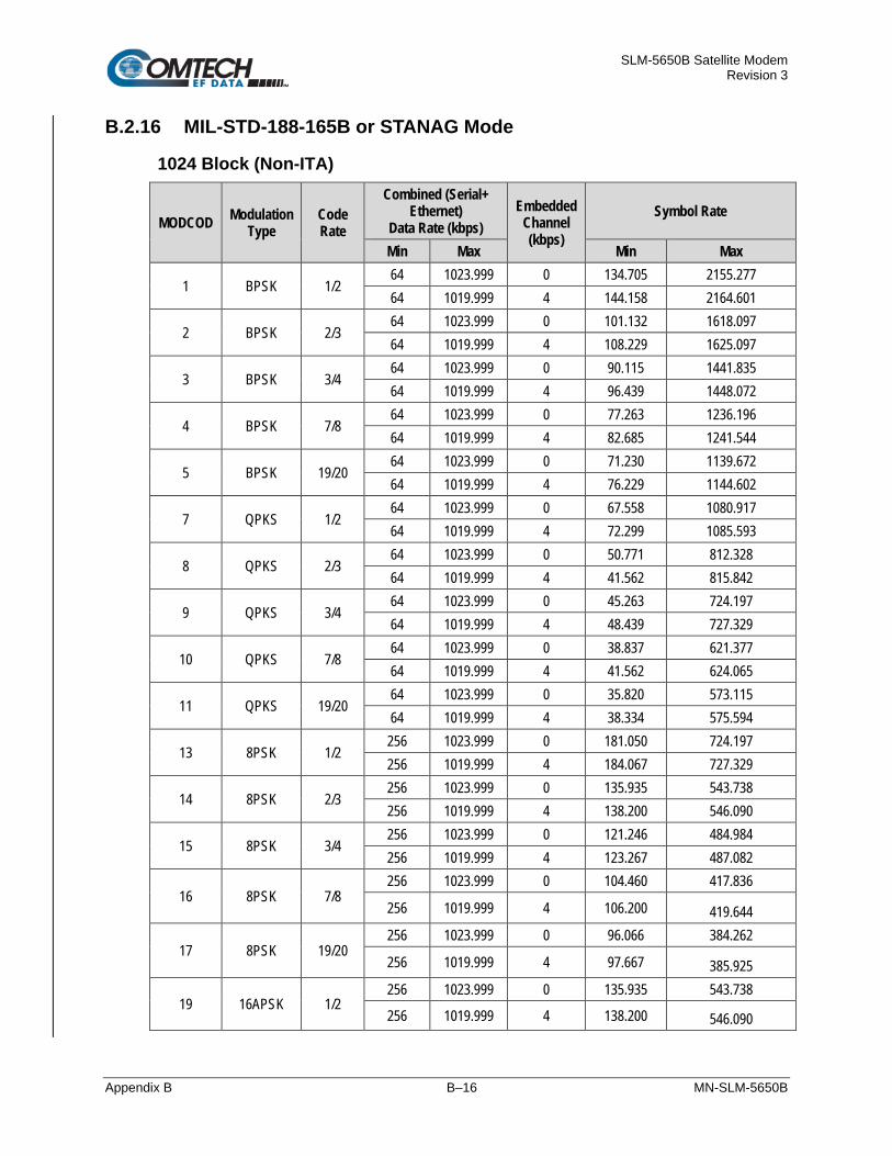
SLM-5650B Satellite Modem Revision 3
Appendix B B–16 MN-SLM-5650B
B.2.16 MIL-STD-188-165B or STANAG Mode
1024 Block (Non-ITA)
MODCOD Modulation Type
Code Rate
Combined (Serial+ Ethernet)
Data Rate (kbps) Embedded
Channel (kbps)
Symbol Rate
Min Max Min Max
1 BPSK 1/2 64 1023.999 0 134.705 2155.277 64 1019.999 4 144.158 2164.601
2 BPSK 2/3 64 1023.999 0 101.132 1618.097 64 1019.999 4 108.229 1625.097
3 BPSK 3/4 64 1023.999 0 90.115 1441.835 64 1019.999 4 96.439 1448.072
4 BPSK 7/8 64 1023.999 0 77.263 1236.196 64 1019.999 4 82.685 1241.544
5 BPSK 19/20 64 1023.999 0 71.230 1139.672 64 1019.999 4 76.229 1144.602
7 QPKS 1/2 64 1023.999 0 67.558 1080.917 64 1019.999 4 72.299 1085.593
8 QPKS 2/3 64 1023.999 0 50.771 812.328 64 1019.999 4 41.562 815.842
9 QPKS 3/4 64 1023.999 0 45.263 724.197 64 1019.999 4 48.439 727.329
10 QPKS 7/8 64 1023.999 0 38.837 621.377 64 1019.999 4 41.562 624.065
11 QPKS 19/20 64 1023.999 0 35.820 573.115 64 1019.999 4 38.334 575.594
13 8PSK 1/2 256 1023.999 0 181.050 724.197 256 1019.999 4 184.067 727.329
14 8PSK 2/3 256 1023.999 0 135.935 543.738 256 1019.999 4 138.200 546.090
15 8PSK 3/4 256 1023.999 0 121.246 484.984 256 1019.999 4 123.267 487.082
16 8PSK 7/8 256 1023.999 0 104.460 417.836
256 1019.999 4 106.200 419.644
17 8PSK 19/20 256 1023.999 0 96.066 384.262
256 1019.999 4 97.667 385.925
19 16APSK 1/2 256 1023.999 0 135.935 543.738
256 1019.999 4 138.200 546.090

SLM-5650B Satellite Modem Revision 3
Appendix B B–17 MN-SLM-5650B
MODCOD Modulation Type
Code Rate
Combined (Serial+ Ethernet)
Data Rate (kbps) Embedded
Channel (kbps)
Symbol Rate
Min Max Min Max
20 16APSK 2/3 256 1023.999 0 102.361 409.443 256 1019.999 4 104.067 411.214
21 16APSK 3/4 256 1023.999 0 91.345 365.377 256 1019.999 4 92.867 366.958
22 16APSK 7/8 256 1023.999 0 78.755 315.017 256 1019.999 4 80.067 316.379
23 16APSK 19/20 256 1023.999 0 72.460 289.836 256 1019.999 4 73.667 291.090
4096 Block (Non-ITA)
MODCOD Modulation Type
Code Rate
Combined (Serial+ Ethernet)
Data Rate (kbps) Embedded
Channel (kbps)
Symbol Rate
Min Max Min Max
1 BPSK 1/2 1024 4095.999 0 2078.609 8314.433 1020 4091.999 4 2078.706 8322.762
2 BPSK 2/3 1024 4095.999 0 1560.538 6242.149 1020 4091.999 4 1560.611 6248.402
3 BPSK 3/4 1024 4095.999 0 1388.522 5554.086 1020 4091.999 4 1388.587 5559.650
4 BPSK 7/8 1024 4095.999 0 1191.210 4764.837 1020 4091.999 4 1191.265 4769.610
5 BPSK 19/20 1024 4095.999 0 1097.107 4388.426 1020 4091.999 4 1097.158 4392.822
7 QPKS 1/2 1024 4095.999 0 1042.467 4169.865 1020 4091.999 4 1042.515 4174.042
8 QPKS 2/3 1024 4095.999 0 783.431 3133.723 1020 4091.999 4 783.468 3136.862
9 QPKS 3/4 1024 4095.999 0 697.423 2789.692 1020 4091.999 4 697.456 2792.486
10 QPKS 7/8 1024 4095.999 0 598.767 2395.067 1020 4091.999 4 598.795 2397.466
11 QPKS 19/20 1024 4095.999 0 551.716 2206.862 1020 4091.999 4 551.742 2209.072
13 8PSK 1/2 1024 4095.999 0 697.423 2789.692 1020 4091.999 4 697.456 2792.486

SLM-5650B Satellite Modem Revision 3
Appendix B B–18 MN-SLM-5650B
MODCOD Modulation Type
Code Rate
Combined (Serial+ Ethernet)
Data Rate (kbps) Embedded
Channel (kbps)
Symbol Rate
Min Max Min Max
14 8PSK 2/3 1024 4095.999 0 524.396 2097.581 1020 4091.999 4 524.420 2099.682
15 8PSK 3/4 1024 4095.999 0 467.226 1868.901 1020 4091.999 4 467.248 1870.773
16 8PSK 7/8 1024 4095.999 0 401.455 1605.818
1020 4091.999 4 401.474 1607.427
17 8PSK 19/20 1024 4095.999 0 370.087 1480.348
1020 4091.999 4 370.105 1481.831
19 16APSK 1/2 1024 4095.999 0 524.396 2097.581
1020 4091.999 4 524.420 2099.682
20 16APSK 2/3 1024 4095.999 0 394.878 1579.510 1020 4091.999 4 394.896 1581.092
21 16APSK 3/4 1024 4095.999 0 351.874 1407.494 1020 4091.999 4 351.890 1408.904
22 16APSK 7/8 1024 4095.999 0 302.799 1211.194 1020 4091.999 4 302.813 1212.407
23 16APSK 19/20 1024 4095.999 0 279.020 1116.079 1020 4091.999 4 279.033 1117.197
16384 Block (Non-ITA)
MODCOD Modulation Type
Code Rate
Combined (Serial+ Ethernet)
Data Rate (kbps) Embedded
Channel (kbps)
Symbol Rate
Min Max Min Max
1 BPSK 1/2 4096 14910.551 0 8241.144 30000 4092 14903.249 4 8241.168 30000
2 BPSK 2/3 4096 19860.593 0 6187.127 30000 4092 19850.867 4 6187.145 30000
3 BPSK 3/4 4096 22329.141 0 5503.123 30000 4092 22318.206 4 5503.139 30000
4 BPSK 7/8 4096 26029.318 0 4720.831 30000
4092 26016.571 4 4720.845 30000
5 BPSK 19/20 4096 28249.942 0 4349.744 30000
4092 28236.107 4 4349.756 30000

SLM-5650B Satellite Modem Revision 3
Appendix B B–19 MN-SLM-5650B
MODCOD Modulation Type
Code Rate
Combined (Serial+ Ethernet)
Data Rate (kbps) Embedded
Channel (kbps)
Symbol Rate
Min Max Min Max
7 QPKS 1/2 4096 29730.647 0 4133.109 30000 4092 29716.088 4 4133.121 30000
8 QPKS 2/3 4096 39560.865 0 3106.100 30000 4092 39541.491 4 3106.109 30000
9 QPKS 3/4 4096 44455.732 0 2764.098 30000 4092 44433.962 4 2764.106 30000
10 QPKS 7/8 4096 51783.600 0 2372.953 30000 4092 51758.241 4 2372.959 30000
11 QPKS 19/20 4096 56176.066 0 2187.409 30000 4092 56148.555 4 2187.415 30000
13 8PSK 1/2 4096 44455.732 0 2764.098 30000 4092 44433.962 4 2764.106 30000
14 8PSK 2/3 4096 59102.749 0 2079.092 30000 4092 59073.806 4 2079.098 30000
15 8PSK 3/4 4096 66388.512 0 1850.923 30000 4092 66356.000 4 1850.928 30000
16 8PSK 7/8 4096 77275.307 0 1590.159 30000
4092 77237.464 4 1590.164 30000
17 8PSK 19/20 4096 83774.358 0 1466.798 30000
4092 83733.333 4 1466.802 30000
19 16APSK 1/2 4096 59102.749 0 2079.092 30000
4092 59073.806 4 2079.098 30000
20 16APSK 2/3 4096 78488.147 0 1565.587 30000 4092 78449.711 4 1565.592 30000
21 16APSK 3/4 4096 88112.189 0 1394.586 30000 4092 88069.039 4 1394.590 30000
22 16APSK 7/8 4096 102484.316 0 1199.013 30000 4092 102434.127 4 1199.017 30000
23 16APSK 19/20 4096 111078.875 0 1106.241 30000 4092 111024.478 4 1106.245 30000

SLM-5650B Satellite Modem Revision 3
Appendix B B–20 MN-SLM-5650B
BLANK PAGE

SLM-5650B Satellite Modem Revision 3
Appendix C C–1 MN-SLM-5650B
Appendix C. MODEM OPTIONS
C.1 Forward Error Correction (FEC) Options
As standard, the SLM-5650B is equipped with three FEC encoders/decoders: Viterbi, Trellis and TURBO (or Turbo Product Codes). The constraint lengths and encoding polynomials are not only Open Network compatible, but are also Closed Network compatible with the vast majority of existing modems from other manufacturers. The modem also provides the capability to disable all FEC, allowing the modem to run uncoded.
C.2 Viterbi
The combination of convolutional coding and Viterbi decoding has become an almost universal standard for satellite communications. The modem complies with the Intelsat IESS 308 and 309 standards for Viterbi decoding with a constraint length of seven. This is a de facto standard, which means inter-operability with other manufacturer’s equipment. It provides very useful levels of coding gain, and its short decoding delay and error-burst characteristics make it particularly suitable for low data rate coded voice applications. It has a short constraint length, fixed at 7, for all code rates. (The constraint length is defined as the number of output symbols from the encoder that are affected by a single input bit.)
By choosing various coding rates (Rate 1/2, 3/4 or 7/8) the user can trade off coding gain for bandwidth expansion. Rate 1/2 coding gives the best improvement in error rate, but doubles the transmitted data rate, and hence doubles the occupied bandwidth of the signal. Rate 7/8 coding, at the other extreme, provides the most modest improvement in performance, but only expands the transmitted bandwidth by 14%. A major advantage of the Viterbi decoding method is that the performance is independent of data rate, and does not display a pronounced threshold effect (i.e., does not fail rapidly below a certain value of Eb/No). Note that in BPSK mode, the modem permits code rates of 1/2, 3/4, and 7/8.
Because the method of convolutional coding used with Viterbi, the encoder does not preserve the original data intact, and is called non-systematic.
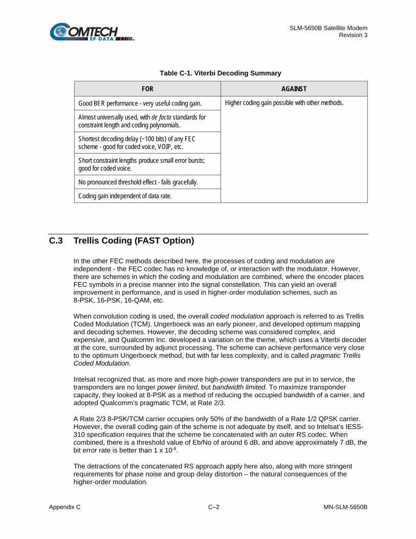
SLM-5650B Satellite Modem Revision 3
Appendix C C–2 MN-SLM-5650B
Table C-1. Viterbi Decoding Summary
FOR AGAINST
Good BER performance - very useful coding gain. Higher coding gain possible with other methods.
Almost universally used, with de facto standards for constraint length and coding polynomials.
Shortest decoding delay (~100 bits) of any FEC scheme - good for coded voice, VOIP, etc.
Short constraint lengths produce small error bursts; good for coded voice.
No pronounced threshold effect - fails gracefully.
Coding gain independent of data rate.
C.3 Trellis Coding (FAST Option)
In the other FEC methods described here, the processes of coding and modulation are independent - the FEC codec has no knowledge of, or interaction with the modulator. However, there are schemes in which the coding and modulation are combined, where the encoder places FEC symbols in a precise manner into the signal constellation. This can yield an overall improvement in performance, and is used in higher-order modulation schemes, such as 8-PSK, 16-PSK, 16-QAM, etc.
When convolution coding is used, the overall coded modulation approach is referred to as Trellis Coded Modulation (TCM). Ungerboeck was an early pioneer, and developed optimum mapping and decoding schemes. However, the decoding scheme was considered complex, and expensive, and Qualcomm Inc. developed a variation on the theme, which uses a Viterbi decoder at the core, surrounded by adjunct processing. The scheme can achieve performance very close to the optimum Ungerboeck method, but with far less complexity, and is called pragmatic Trellis Coded Modulation.
Intelsat recognized that, as more and more high-power transponders are put in to service, the transponders are no longer power limited, but bandwidth limited. To maximize transponder capacity, they looked at 8-PSK as a method of reducing the occupied bandwidth of a carrier, and adopted Qualcomm’s pragmatic TCM, at Rate 2/3.
A Rate 2/3 8-PSK/TCM carrier occupies only 50% of the bandwidth of a Rate 1/2 QPSK carrier. However, the overall coding gain of the scheme is not adequate by itself, and so Intelsat’s IESS-310 specification requires that the scheme be concatenated with an outer RS codec. When combined, there is a threshold value of Eb/No of around 6 dB, and above approximately 7 dB, the bit error rate is better than 1 x 10⁻⁸.
The detractions of the concatenated RS approach apply here also, along with more stringent requirements for phase noise and group delay distortion – the natural consequences of the higher-order modulation.

SLM-5650B Satellite Modem Revision 3
Appendix C C–3 MN-SLM-5650B
The modem fully implements the IESS-310 specification at data rates up to 51.84 Mbps. In accordance with the specification, the R-S outer code cannot be disabled.
Table C-2. 8-PSK/TCM Coding Summary
FOR AGAINST
Exceptionally bandwidth efficient compared to QPSK. Needs concatenated R-S outer codec to give acceptable coding gain performance.
Interoperable with legacy Intelsat networks. Demodulator acquisition threshold much higher than for QPSK.
8-PSK is more sensitive to phase noise and group delay distortion than QPSK.
C.4 Reed-Solomon (R-S) Outer Codec
The concatenation of an outer R-S Codec with a Viterbi decoder first became popular in the early 1990s. It permits significant improvements in error performance without significant bandwidth expansion.
The coding overhead added by the R-S outer Codec is typically around 10%, which translates to a 0.4 dB power penalty for a given link. R-S codes are block codes (as opposed to Viterbi and Sequential, which are convolutional), and to be processed correctly, the data must be framed and de-framed. Additionally, R-S codes are limited in how well they can correct errors that occur in bursts.
This, unfortunately, is the nature of the uncorrected errors from Viterbi decoders, which produce clusters of errors that are multiples of half the constraint length. For this reason, the data must be interleaved following R-S encoding, and is then de-interleaved prior to decoding. This ensures that a single burst of errors leaving the Viterbi decoder is spread out over many interleaving frames, so errors entering the R-S decoder do not exceed its capacity to correct those errors.

SLM-5650B Satellite Modem Revision 3
Appendix C C–4 MN-SLM-5650B
C.5 Closed Network Mode
A 225,205 or 220,200 code is used in closed network mode. For a rate of 225,205 data is put into blocks of 225 bytes, of which 205 bytes are data, and 20 bytes are FEC overhead. The code was chosen because it is compatible with legacy CEFD modems.
For closed network Viterbi R-S, an interleaver depth of 4 or 8 is used. The increase in coding gain is at the expense of delay. The interleaving/de-interleaving delay and the delay through the decoder itself can be as high as 25 kbps. At low data rates, this equates to an appreciable part of a second, when combined with the round trip delay makes it highly unsuitable for voice applications. Additionally, the de-interleaver frame synchronization method can add significantly to the time taken for the demodulator to declare acquisition.
Table C-3. Open Network Modes
Code Rate Mode
225, 205, 219, 201 208, 192, 194, 178 126, 112
IESS-308
219, 201 IESS-309 IBS, VSAT-IBS and Extended
219, 201 IESS-310
A characteristic of concatenated R-S coding is the very pronounced threshold effect. For any given modem design, there will be a threshold value of Eb/No below which the demodulator cannot stay synchronized. This may be due to the carrier-recovery circuits, or the synchronization threshold of the primary FEC device, or both. In the SLM-5650B and Rate 1/2 operation, this threshold is around 4 dB Eb/No. Below this value, operation is not possible, but above this value, the error performance of the concatenated R-S system produces exceptionally low error rates for a very small increase in Eb/No.
Care should be taken not to operate the demodulator near its sync threshold. Small fluctuations in Eb/No may cause total loss of the link, with the subsequent need for the demodulator to re-acquire the signal.
Table C-4. Concatenated R-S Coding Summary
FOR AGAINST
Exceptionally good BER performance - several orders of magnitude improvement in link BER under given link conditions.
Very pronounced threshold effect - does not fail gracefully in poor Eb/No conditions. Additional coding overhead actually degrades sync threshold, and reduces link fade margin.
Very small additional bandwidth expansion. Significant processing delay (~25 kbps) - not good for voice, or IP applications.
Interoperable with legacy Intelsat networks. Adds to demod acquisition time.

SLM-5650B Satellite Modem Revision 3
Appendix C C–5 MN-SLM-5650B
C.6 Turbo Product Codec
Turbo coding is an FEC technique developed within the last few years, which delivers significant performance improvements compared to more traditional techniques. Two general classes of Turbo Codes have been developed, Turbo Convolutional Codes (TCC), and Turbo Product Codes (TPC, a block coding technique). CEFD has chosen to implement an FEC codec based on TPC. A TPC is a 2 or 3-dimensional array of block codes. Encoding is relatively straightforward, but decoding is a very complex process requiring multiple iterations of processing for maximum performance to be achieved.
Unlike the popular method of concatenating an R-S codec with a primary FEC codec, TPC is an entirely stand-alone method. It does not require the complex interleaving/de-interleaving of the R-S approach, and consequently, decoding delays are significantly reduced. Furthermore, the traditional concatenated R-S schemes exhibit a very pronounced threshold effect – a small reduction in Eb/No can result in total loss of demod and decoder synchronization. TPC does not suffer from this problem – the demodulator and decoder remain synchronized down to the point where the output error rate becomes unusable. This is a particularly advantageous characteristic in a fading environment. Typically, in QPSK, 8-PSK and 16-QAM TPC modes the demod and decoder can remain synchronized 2-3 dB below the Viterbi/R-S or TCM cases.
Table C-5. Available TPC Modes
TPC Code Rate/Modulation
Rate 5/16 BPSK
Rate 21/44 BPSK
Rate 21/44 QPSK, OQPSK
Rate 3/4 QPSK, OQPSK
Rate 3/4 8-PSK
Rate 3/4 16-QAM
Rate 7/8 QPSK, OQPSK
Rate 7/8 8-PSK
Rate 7/8 16-QAM
Rate 17/18 QPSK, OQPSK
Rate 17/18 8-PSK

SLM-5650B Satellite Modem Revision 3
Appendix C C–6 MN-SLM-5650B
C.7 Sequential (FAST Option)
Although the method of convolutional coding and Sequential decoding appears to be very similar to the Viterbi method, there are some fundamental differences. To begin with, the convolutional encoder is said to be systematic – it does not alter the input data, and the FEC overhead bits are simply appended to the data. Furthermore, the constraint length, k, is much longer (Rate 1/2, k=36. Rate 3/4, k= 63. Rate 7/8, k=87). This means that when the decoding process fails (i.e., when its capacity to correct errors is exceeded) it produces a burst of errors which is in multiples of half the constraint length.
An error distribution is produced which is markedly different to that of a Viterbi decoder. This gives rise to a pronounced threshold effect. A Sequential decoder does not fail gracefully – a reduction in Eb/No of just a few tenths of a dB can make the difference between acceptable BER and a complete loss of synchronization.
The decoding algorithm itself (called the Fano algorithm) uses significantly more path memory (4 kbps in this case) than the equivalent Viterbi decoder, giving rise to increased latency. Furthermore, a fixed computational clock is used to process input symbols, and to search backwards and forwards in time to determine the correct decoding path. At lower data rates, there are a sufficient number of computational cycles per input symbol to permit the decoding process to perform optimally. However, as the data rate increases, there are fewer cycles available, leading to a reduction in coding gain. For data rates above ~1 Mbps, Viterbi should be considered the better alternative. The practical upper limit at this time is 2.048 Mbps.
Table C-6. Sequential Decoding Summary
FOR AGAINST
Higher coding gain (1-2 dB) at lower data rates, compared to Viterbi.
Pronounced threshold effect - does not fail gracefully in poor Eb/No conditions.
Higher processing delay than Viterbi (~4 k bits) – not good for low-rate coded voice.
Upper data rate limit approximately 2 Mbps.
Coding gain varies with data rate - favors lower data rates.

SLM-5650B Satellite Modem Revision 3
Appendix C C–7 MN-SLM-5650B
C.8 Low Density Parity Check (LDPC) Coding (FAST Option)
C.8.1 Introduction
In the past few years there has been an unprecedented resurgence in interest in FEC technology. The start of this new interest has its origins in the work done by Claude Berrou et al, and the 1993 landmark paper, Near Shannon Limit Error Correcting Coding and Decoding – Turbo Codes. FEC is considered an essential component in all wireless and satellite communications to reduce the power and bandwidth requirements for reliable data transmission.
Claude Shannon, considered by many to be the father of modern communications theory, first established the concept of Channel Capacity in his 1948 paper A Mathematical Theory of Communication. This places an absolute limit on how fast it is possible to transmit error-free data within a channel of a given bandwidth, and with given noise conditions within that channel. He concluded that it would only be possible to approach this limit by using source encoding – what is familiar today as FEC.
Shannon postulated that if it were possible to store every possible message in the receiver, finding the stored message that most closely matched the incoming message would yield an optimum decoding method. However, for all but the shortest bit sequences, the memory required for this, and the time taken to perform the comparisons, makes this approach impractical. For all practical purposes, the memory requirement and the decoding latency become infinite.
For many years, there were few advances in the quest to approach the Shannon Limit. The Viterbi algorithm heralded a major step forward, followed in the early 1990s by the concatenation of a Viterbi decoder with R-S hard-decision block codes. It remained clear, however, that the Shannon Limit was still an elusive target.
Berrou’s work on Turbo Codes showed, by using an ingeniously simple approach (multiple, or iterative decoding passes) that it is possible to achieve performance close to the Shannon Limit. Berrou’s early work dealt exclusively with iteratively-decoded convolutional codes (i.e., TCC), but in time the iterative approach was applied to TPC. TPC exhibits inherently low decoding latency compared with TCC, and so is considered much more desirable for two-way, interactive satellite communications applications.
In August 1999, Comtech became the first company in the world to offer satellite modems that incorporate TPC. Since its inception, Comtech has continued to develop and refine its implementation of TPC in its products, and now offers a comprehensive range of code rates (from Rate 5/16 to Rate 0.95) and modulations (from BPSK to 16QAM). However, in the past few years, as part of the general interest in Turbo coding, a third class of Turbo coding has emerged: Low Density Parity Check (LDPC) Codes.
LDPC is more like TPC than TCC in that it is an iteratively-decoded block code. Gallager first suggested this in 1962 but, at the time, the implementation complexity was considered to be too great; and for decades, it remained of purely academic interest. Further interest in LDPC was stimulated in 2003, when the Digital Video Broadcasting (DVB) committee adopted LDPC codes (proposed by Hughes Network Systems) as the basis for the new DVB-S2 standard. Now, however, with silicon gates being cheap, plentiful and fast, an LDPC decoder can easily be accommodated in a large Field Programmable Gate Array (FPGA) device.

SLM-5650B Satellite Modem Revision 3
Appendix C C–8 MN-SLM-5650B
The LDPC method on its own produces an undesirable ‘flaring’ in the BER vs. Eb/No characteristic, and for this reason it is desirable to concatenate a short BCH code with LDPC. This concatenation produces almost vertical BER vs. Eb/No curves, as can be seen in the performance graphs that are presented later. To take full advantage of the coding gain increase that LDPC provides, it became necessary to find an alternative to 8PSK. CEFD has, therefore, developed an 8QAM approach that permits acquisition and tracking at much lower values of Eb/No than 8PSK. Comtech’s implementation of 8QAM is the subject of a U.S. Patent, granted in 2007.
C.8.2 LDPC versus TPC
Appendix B. OPERATIONAL REFERENCE
Is LDPC better than TPC? The answer must be ‘sometimes, but not always’, and there are issues such as latency that must be taken into consideration. Error free transmission is not possible for values of spectral efficiency (capacity) vs. Eb/No above these limit curves. The horizontal distance to the limit provides a metric of overall performance. Figure D-7 graphs the performance of various TPC and LDPC modes relative to the Shannon Limit – the Channel Capacity is shown for both QPSK and 8PSK. It can be seen from this graph that, for Code Rates above 3/4, Comtech’s TPCs are very close (1-1.5 dB) to the Shannon Limit. However, at 3/4 and below, LDPCs are performing 0.7-1.2 dB better than TPCs. To provide the best possible performance over the range of code rates from 1/2 to 0.95, both an LDPC and a TPC codec need to be offered.
Figure D-7. TPC & LDPC Modes Performance (Relative to Shannon Limit)

SLM-5650B Satellite Modem Revision 3
Appendix C C–9 MN-SLM-5650B
To provide a robust set of LDPC codes with varying degrees of latency, the SLM-5650B has implemented three different block sizes:
• The ULL code provides the lowest latency, but worst performance of the three block sizes. This code is available in the data rate range from 32 kbps to 2 Mbps and is compatible with the CDM-625 ULL code.
• The LL code provides modest latency and performance over the data rate range of 32 kbps to 5 Mbps.
• The HP code provides the best performance but worst latency. This code is available from 32 kbps up to 69 Mbps depending on MODCOD. The HP code is compatible with the CDM-625 LDPC code.
See Appendix B. OPERATIONAL REFERENCE for more details on the data rate and symbol rate ranges supported in each code.

SLM-5650B Satellite Modem Revision 3
Appendix C C–10 MN-SLM-5650B
C.9 Direct Sequence Spread Spectrum (FAST Option)
As On-The-Move systems with very small dishes (e.g., VSATs) become more popular, there is an increased interest in Spectrum Spreading. To meet this need, DSSS is optionally available in the SLM-5650B.
DSSS works by modulating the normal carrier with a pseudo-random PN sequence (chips) at a much higher chip rate. The chip rate is determined by the carrier’s symbol rate and a multiplying (spreading) factor.
The SLM-5650B offers spreading in the following LDPC MODCODs:
• ULL BPSK 1/2 • LL BPSK .378 • LL BPSK .451 • LL BPSK .541 • HP BPSK 1/3 • HP BPSK 1/2
The Spreading Factors currently supported are:
• 1 (Spreading Off) • 2 through 512 up to a maximum chip rate of 64 Mbps.
The user can select between two built-in pseudo-random PN sequences (polynomials) and 10,000 Gold Code Sequences per polynomial so that multiple spread carriers can occupy the same bandwidth in a Code-Division Multiple Access (CDMA) fashion.
When using large spreading factors, the SLM-5650B also exhibits a large tolerance to jamming – up to 24 dB – and a Low Probability of Detection/Interception. With DSSS enabled, the lower data rate limit has been reduced to 8 kbps. The SLM-5650B Base Modem Web Server Interface provides a Web page to facilitate anti-jamming applications. This page allows the user to configure the modem parameters so that a fixed occupied bandwidth can be maintained.
Lastly, there is no loss in performance with spreading enabled.

SLM-5650B Satellite Modem Revision 3
Appendix D D–1 MN-SLM-5650B
Appendix D. OPTIONAL DATA INTERFACE MODULES
D.1 Overview
See Appendix E. OPTIONAL NETWORK PROCESSOR (NP) INTERFACE MODULE for complete information about this specific product.
The SLM-5650B rear panel features one slot that accommodates optional plug-in data interface modules. These modules plug into either the Interface Option slot that is located on the rear panel of the SLM-5650B chassis (Figure D-1).
Figure D-1. SLM-5650B Data Interface Module Slot (Empty)
By convention, a modem is Data Communications Equipment (DCE) where Tx data enters the data interface and Rx data exits. Via the chassis’ internal data interface module connections, theSLM-5650B provides physical and electrical connection between the external terrestrial device and the internal circuitry of the modulator or demodulator.
While the SLM-5650B’s available optional data interface modules are usually ordered with the modem, they are easily field-installed. The available data interface modules and reference to their pertinent section in this appendix are as follows:
CEFD Kit / Assembly Description For Details See Appendix Section
AS/11984 10/100/1000 BaseT (GbE) Interface Module D.2.1
AS/11579 G.703 T1/E1, T2/E2 Interface Module D.2.2
PL/12272-1 Low Voltage Differential (LVDS) Interface Module D.2.3

SLM-5650B Satellite Modem Revision 3
Appendix D D–2 MN-SLM-5650B
D.2 Optional Data Interface Modules
D.2.1 10/100/1000 BaseT (GbE) Interface Module
Figure D-2. 10/100/1000 BaseT (GbE) Interface Module (AS/11985)
The 10/100/1000 BaseT Ethernet – or GbE – Interface Module (Figure D-2), acts as an Ethernet bridge for data traffic. M&C information is not supported on the GbE Interface, but is available through the 10/100 BaseT ‘J5 Ethernet’ port of the Base Modem.
The GbE Interface supports data rates from 64 kbps to 155.52 Mbps. IP traffic entering the interface is encapsulated in HDLC protocol for transmission over the satellite link. HDLC CRS-16 verification is performed on all received (from WAN) HDLC frames. The GbE module user interface is a single IEEE 802.3ab 1000 BaseT copper compliant female RJ-45 connector, wired as per Table D-1.
D.2.1.1 Physical Description The 10/100/1000 Base GbE Interface Module is implemented on a bracket and RJ-45 cable. Connectivity to the SLM-5650B is accomplished with a RJ-45 cable. The functional block diagram is shown in Figure D-3. Figure D-2 shows the rear panel view of the module. The LAN interface consists of an RJ-45 connector with link status and link activity LED indicators.
Figure D-3. GbE Interface Functional Block Diagram

SLM-5650B Satellite Modem Revision 3
Appendix D D–3 MN-SLM-5650B
D.2.1.2 “J12” Connector Pinout The GbE Interface is comprised of one IEEE 802.3ab 1000BaseT copper interface via a single ‘RJ-45’ type female connector (J12). The LAN interface supports 10/100/1000 BaseT operation.
Table D-1. “J12” Connector Pinout
Pin # Description Direction 1 BI_DA+ bidirectional
2 BI_DA- bidirectional
3 BI_DB+ bidirectional
4 BI_DC+ bidirectional
5 BI_DC- bidirectional
6 BI_DB- bidirectional
7 BI_DD+ bidirectional
8 BI_DD- bidirectional

SLM-5650B Satellite Modem Revision 3
Appendix D D–4 MN-SLM-5650B
D.2.1.3 Specifications
D.2.1.3.1 General Specifications • Data Framing: 10/100/1000 BaseT Interface: RFC-894 “Ethernet” • Data Framing Format (WAN): HDLC (Standard Single Channel) • Connector: RJ-45 female, 100Ω • Electrical Properties: Per IEEE 802.3ab • Packet Types: Burst, distributed, or IPV4 • Signal Types: Serial data • Voltage Level: Per IEEE- 802.3ab • Packet Latency: 50 ms maximum • Flow Control: None • Cable Length, Maximum: 100 meters CAT 5 cable, patch cords and connecting
hardware, per ISO/IEC 11801:1995 and ANSI/EIA/TIA-568-A (1995) • Hot Pluggable:
o Cable – YES o Module – NO
• LEDs: Link Status; Link Activity • Ingress Packet Filtration Parameters: MAC, IP Address match value configuration for
media and management packets, User Datagram Protocol (UDP) port for media packets • Egress Packet Parameters: Destination IP address and UDP port for media packets • Packet Filtration Parameters (generic): IP Address match value configuration for
management packets • 1000 BaseT Link Statistics:
o Ingress good octets o Ingress bad octets o Ingress Unicast packets o Ingress broadcast packets o Ingress multicast packets o Ingress pause packets o Ingress undersize packets o Ingress fragments o Ingress oversize packets o Ingress jabber o Ingress Rx errors o Ingress Frame Check Sequence Errors o Egress octets o Egress Unicast packets o Egress broadcast packets o Egress multicast packets

SLM-5650B Satellite Modem Revision 3
Appendix D D–5 MN-SLM-5650B
D.2.1.3.2 Monitor & Control • WAN Port Statistics:
o Ingress good octets o Ingress bad octets o Ingress Unicast packets o Ingress broadcast packets o Ingress multicast packets o Ingress pause packets o Ingress undersize packets o Ingress fragments o Ingress oversize packets o Ingress jabber o Ingress Rx errors o Ingress Frame Check Sequence Errors o Egress octets o Egress Unicast packets o Egress broadcast packets o Egress multicast packets o HDLC link errors o Rx packet count o Tx packet count
• Management Port Statistics: o Ingress good octets o Ingress bad octets o Ingress Unicast packets o Ingress broadcast packets o Ingress multicast packets o Ingress pause packets o Ingress undersize packets o Ingress fragments o Ingress oversize packets o Ingress jabber o Ingress Rx errors o Ingress Frame Check Sequence Errors o Egress octets o Egress Unicast packets o Egress broadcast packets o Egress multicast packets
• Controlled Functions o TX data rate o Rx data rate o Tx enable/disable o Rx enable/disable o Management IP Address and Mask

SLM-5650B Satellite Modem Revision 3
Appendix D D–6 MN-SLM-5650B
D.2.1.3.3 Physical and Environmental • Physical Size – 4.5W x 6.8D x .85H inches (11.43W x 17.27D x 2.16H cm) • Environmental:
o Temperature – 32 to 122°F (0 to 50°C) o Humidity – 0 to 95% non-condensing

SLM-5650B Satellite Modem Revision 3
Appendix D D–7 MN-SLM-5650B
D.2.1.4 10/100/1000 BaseT (GbE) Interface Module Removal and Installation
WARNING! The SLM-5650B Modem is shipped with seals on the top cover. Removing the top cover to remove / install the GbE Interface will break the seals and VOID the CEFD warranty. Contact CEFD Customer Support regarding options to remove / install the GbE Interface.
Figure D-4. GbE Interface Module Removal / Installation
Figure D-5. GbE Interface Module Cable Connections
RJ-45 Cable Connection
4-pin Molex Cable Connection

SLM-5650B Satellite Modem Revision 3
Appendix D D–8 MN-SLM-5650B
D.2.1.4.1 GbE Interface Module Removal Procedure
WARNING! Make sure that the unit is POWERED OFF. Serious injury or damage to the equipment could result if the unit is powered during module removal or installation! You must take care not to damage the module’s components during removal or installation.
Step Task
1 Turn OFF the power to the modem.
2 Open and remove the top cover.
3 Disconnect the RJ-45 cable from the Interface Module.
4 Disconnect the 4-pin Molex cable to the J Module,
5 Loosen the (two) captive screws securing the module to the chassis.
6 Pull the module straight out until it is clear of the chassis slot.
7 Replace the top cover.
8 Turn ON the power to the modem.
D.2.1.4.2 GbE Interface Module Installation Procedure
WARNING! Make sure that the unit is POWERED OFF. Serious injury or damage to the equipment could result if the unit is powered during module removal or installation! You must take care not to damage the module’s components during removal or installation.
Step Task
1 Turn OFF the power to the modem.
2 Open and remove the top cover.
3 Insert the Interface Module straight into the slot, using the chassis’ internal card guides, until it plugs securely into the internal card receptacle.
4 Secure the module to the chassis using the (two) captive screws.
5 Connect the RJ-45 cable to the Interface Module.
6 Connect the 4-pin Molex cable to the J Module.
7 Replace the top cover.
8 Turn ON the power to the modem.

SLM-5650B Satellite Modem Revision 3
Appendix D D–9 MN-SLM-5650B
D.2.2 G.703 T1/E1, T2/E2 Data Interface Module
Figure D-6. G.703 T1/E1, T2/E2 Interface Module (AS/11579 shown)
The G.703 T1/E1, T2/E2 Interface Module (Figure D-5) supports balanced or unbalanced, and differential/ single-ended operation. The plug-in interface has full duplex capability.
D.2.2.1 Physical Description
Figure D-7. G.703T1/E1, T2/E2 Interface Functional Block Diagram
The G.703 T1/E1, T2/E2 Interface Module is implemented on a 4.5W x 6.8D x .85H inches (11.43W x 17.27D x 2.16H cm) PCB. Connectivity to the SLM-5650B is accomplished with a 96-pin DIN receptacle. Figure D-5 shows the rear panel view of the module. Figure D-6 shows the functional block diagram for this interface. The interface provides:
• Two (2) G.703 Interfaces: o Balanced T1/E1 and T2 (J1 BAL. DATA – see Table D-2) o Unbalanced T1/E1, T2/E2 (J2 Tx and J3 Rx – see Table D-3)
• An External Clock Input (J4 Ext. Ref. – see Table D-3)

SLM-5650B Satellite Modem Revision 3
Appendix D D–10 MN-SLM-5650B
D.2.2.1.1 G.703 Balanced “J1 | BAL DATA” Connector (DB-15F) Table D-2. “J1 | BAL. DATA” DB-15F Connector Pinout
Connector Ref Des Pin # G.703 (Non-D&I) Direction
J1
1 SD_A G.703 In
9 SD_B G.703 In
2 Ground –
10
3 RD_A G.703 Out
11 RD_B G.703 Out
4 Ground –
12
5
13
6
14
7
15
8

SLM-5650B Satellite Modem Revision 3
Appendix D D–11 MN-SLM-5650B
D.2.2.1.2 G.703 Unbalanced “J2” through “J4” BNC Connectors Table D-3. G.703 Unbalanced Connectors
Connector Ref Des Description Connector Type Direction
J2 Tx Tx Data G.703 BNC 75Ω Female Input
J3 Rx Rx Data G.703 BNC 75Ω Female Output
J4 Ext. Ref Ext Clock Ref BNC 75Ω Female Input
D.2.2.2 Specifications
D.2.2.2.1 General Specifications
• Interface: Balanced and Unbalanced G.703 ports, T1/E1, T2/E2
Selection of a data rate requires TX and RX having the same data rate.
• External Clock Input: One input • RX Buffer:
G.703 Frame Type Programmable in 0.5 ms increments
Type Bits Bytes T1 G.704 9264 192 E1 G.704 512 64 T2 G.704
G.743 G.747
12624 2352 1680
1578 294 210
E2 G.704 G.745 G.742
2112 2112 1696
264 264 212

SLM-5650B Satellite Modem Revision 3
Appendix D D–12 MN-SLM-5650B
• Minimum Buffer Size for any rate: 0.5 ms • Minimum Buffer Size:
o G.751 – 61 ms o G.752 – 44 ms o G.753 – 61 ms
• Clock Options: o Tx Clock = Tx, Rx (satellite), or External o Rx Clock = Tx, Rx, External, or Internal
• Acquisition Range – Programmed Tx data rate ± 100 ppm • Test:
o Baseband Loopback (at interface) o Interface Loopback (through interface card) o 2047 test pattern generator
D.2.2.2.2 Interfaces
• G.703 Unbalanced: 1 channel supporting T1/E1, T2/E2, and G.703 o Connector Type – BNC female o Signals Supported – ITU-T-G.703 SD, RD o Data Rate –1544, 2048, 6312, and 8448 kbps o Tx and Rx Data Rates – Tx and Rx data rates are programmed the same o Line Coding – HDB3, B8ZS, B6ZS, HDB3, AMI (Common) o Pulse Mask – ITU-T-G.703 o Impedance – 75Ω Unbalanced, 150Ω Balanced Per ITU-T-G.703
• External Clock Input: o Connector – BNC female o Impedance – 75 Ω ± 5% o Return Loss per G.703 – Synchronization XXXXX Interface o Input Amplitude – 0.5 to 5.0 V peak to peak o Input Frequency – 1, 2, 5, 10, 20, 1.544, 2.048, 6.312, and 8.448 MHz o Signal Characteristics – Sine wave or square with duty cycle of 50 ± 10%
• Alarms: o Loss of Signal o All 1’s
D.2.2.2.3 Physical and Environmental
• Physical: 4.5 W x 6.8 D x .85 H inches (11.43 W x 17.27 D x 2.16H cm) • Environmental:
o Temperature – 32° to 122° F (0° to 50° C) o Humidity – 0 to 95% non-condensing

SLM-5650B Satellite Modem Revision 3
Appendix D D–13 MN-SLM-5650B
D.2.2.3 G.703 T1/E1, T2/E2 Interface Module Removal and Installation
WARNING! Make sure that the unit is POWERED OFF. Serious injury or damage to the equipment could result if the unit is powered during module removal or installation! You must take care not to damage the module’s components during removal or installation.
Figure D-8. G.703 Interface Module Removal or Installation
D.2.2.3.1 G.703 Interface Module Removal Procedure
Step Task
1 Turn off the power to the modem.
2 Disconnect all cables (DB-15 and BNC) from the Interface Module.
3 Loosen the (two) captive screws securing the module to the chassis.
4 Pull the module straight out until it is clear of the chassis slot.

SLM-5650B Satellite Modem Revision 3
Appendix D D–14 MN-SLM-5650B
D.2.2.3.2 G.703 Interface Module Installation Procedure
Step Task
1 Insert the Interface Module straight into the slot, using the chassis’ internal card guides, until it plugs securely into the internal card receptacle.
2 Secure the module to the chassis using the (two) captive screws.
3 Connect all cables (DB-15 and BNC) to the Interface Module.
4 Turn on the power to the modem.

SLM-5650B Satellite Modem Revision 3
Appendix D D–15 MN-SLM-5650B
D.2.3 Low Voltage Differential (LVDS) Interface Module
Figure D-9. Low Voltage Differential (LVDS) Interface Module (PL/12272-1)
The LVDS Interface Module (Figure D-8) provides a physical and electrical interface between the SLM-5650B’s modulator or demodulator signal sources operating with LVDS electrical characteristics.
D.2.3.1 Physical Description
Figure D-10. LVDS Interface Functional Block Diagram
The LVDS Interface Module is implemented on a 4.5W x 6.8D x .85H inches (11.43W x 17.27D x 2.16H cm) PCB. Connectivity to the SLM-5650B is accomplished with a 96-pin DIN receptacle. Figure D-8 shows the rear panel view of the module. Figure D-9 shows the functional block diagram for this interface. The ‘J1’ interface is a single Type ‘D’ 25-pin female (DB-25F) connector wired as per Table D-4.
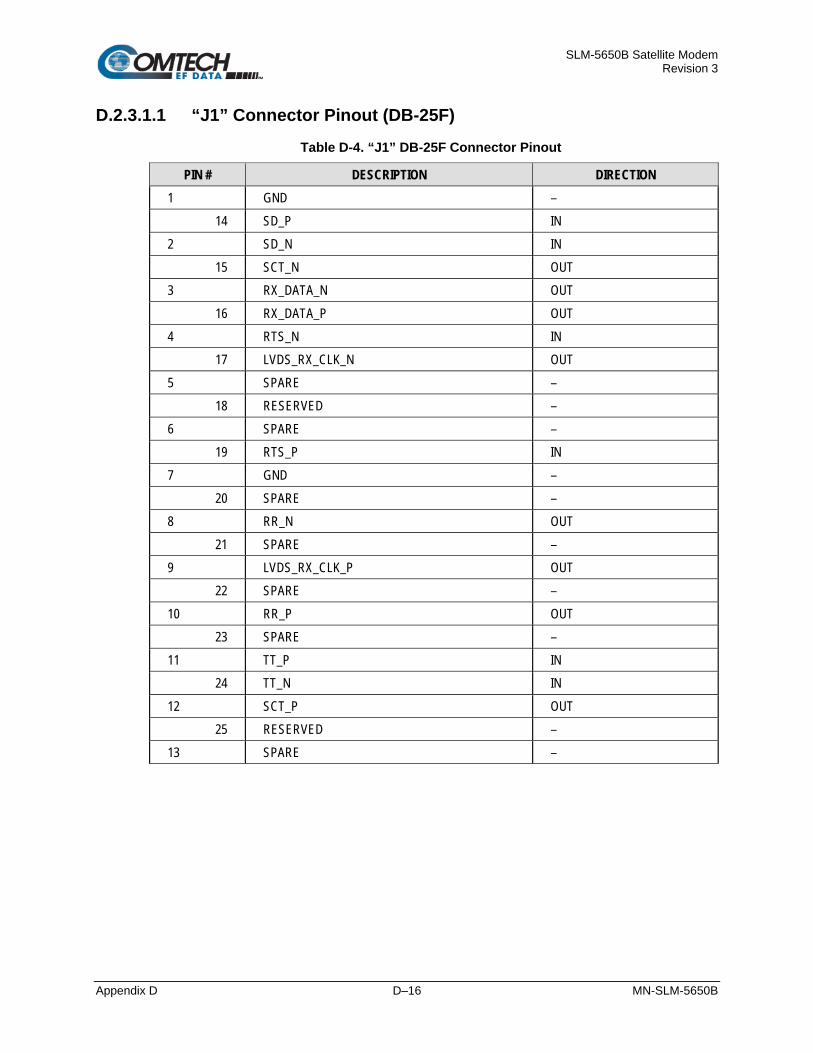
SLM-5650B Satellite Modem Revision 3
Appendix D D–16 MN-SLM-5650B
D.2.3.1.1 “J1” Connector Pinout (DB-25F) Table D-4. “J1” DB-25F Connector Pinout
PIN # DESCRIPTION DIRECTION 1 GND –
14 SD_P IN 2 SD_N IN
15 SCT_N OUT 3 RX_DATA_N OUT
16 RX_DATA_P OUT 4 RTS_N IN
17 LVDS_RX_CLK_N OUT 5 SPARE –
18 RESERVED – 6 SPARE –
19 RTS_P IN 7 GND –
20 SPARE – 8 RR_N OUT
21 SPARE – 9 LVDS_RX_CLK_P OUT
22 SPARE – 10 RR_P OUT
23 SPARE – 11 TT_P IN
24 TT_N IN 12 SCT_P OUT
25 RESERVED – 13 SPARE –

SLM-5650B Satellite Modem Revision 3
Appendix D D–17 MN-SLM-5650B
D.2.3.2 Specifications
D.2.3.2.1 General Specifications
• Digital Data Rate – 64 kbps to 42 Mbps, in 1 bps steps • Tx Clock Source – Rx, INT, Tx Terrestrial, and Data Source Sync • Transmit Clock and Data Inversion – Interface can invert the Tx clock and data
independently of each other. • Buffer Clock Source – INT, Tx Terrestrial, Rx Satellite • Buffer Size –128 to 4,194,304 bits, or 2 to 60 mSec
D.2.3.2.2 Physical & Environmental
• Physical Size – 4.5W x 6.8D x .85H inches (11.43W x 17.27D x 2.16H cm) • Environmental:
o Temperature – 32 to 122°F (0° to 50°C) o Humidity – 0 to 95% non-condensing

SLM-5650B Satellite Modem Revision 3
Appendix D D–18 MN-SLM-5650B
D.2.3.3 LVDS Interface Module Removal and Installation
WARNING! Make sure that the unit is POWERED OFF. Serious injury or damage to the equipment could result if the unit is powered during module removal or installation! You must take care not to damage the module’s components during removal or installation.
Figure D-11. LVDS Interface Module Removal or Installation
D.2.3.3.1 LVDS Interface Module Removal Procedure
Step Task
1 Turn off the power to the modem.
2 Disconnect all cable (DB-25) from the Interface Module.
3 Loosen the (two) captive screws securing the module to the chassis.
4 Pull the module straight out until it is clear of the chassis slot.
D.2.3.3.2 LVDS Interface Module Installation Procedure
Step Task
1 Insert the Interface Module straight into the slot, using the chassis’ internal card guides, until it plugs securely into the internal card receptacle.
2 Secure the module to the chassis using the (two) captive screws.
3 Connect all cable (DB-25) to the Interface Module.
4 Turn on the power to the modem.

SLM-5650B Satellite Modem Revision 3
Appendix E E–1 MN-SLM-5650B
Appendix E. OPTIONAL NETWORK PROCESSOR (NP)
INTERFACE MODULE
E.1 Overview
Figure E-1. Network Processor (NP) Interface Module
The optional SLM-5650B’s Network Processor (NP) Interface Module (also referred to as the “NP Interface” or the “card”), shown in Figure E-1, is CEFD’s third generation IP router and Ethernet bridge device. The NP Interface supports a number of primary operating modes:
• Layer 2 Ethernet Bridge Mode
• Layer 2 and Layer 3 SCPC Ethernet BPM Mode
• Layer 2 and Layer 3 Vipersat BPM Mode
• Layer 3 SCPC IP Router Mode
• Layer 3 Vipersat STDMA Router Mode
The NP Interface is designed to process more than 150,000 packets per second (pps) in Layer 2, Layer 3, or BPM mode of operation. It provides four RJ-45 connectors for user data, wired as described in Table E-1. The NP Interface also has a single RJ-11 console interface that is intended only for factory-use initial interface configuration. The Maximum Ethernet Frame size for the modem is 1518 bytes for all modes.

SLM-5650B Satellite Modem Revision 3
Appendix E E–2 MN-SLM-5650B
To prevent network failure, there should be no more than one Ethernet connection to a single external switch at any time.
User access to management and control of the NP Interface via the built-in HTTP/HTTPS Interface or Telnet server (port 23) is possible using the available RJ-45 connectors (Figure E-2) as follows:
• When in Router Mode, access is possible using any of the NP Interface RJ-45 Ports 1 through 4.
• When in BPM Mode, only the base modem’s J5 Ethernet RJ-45 port can be used for M&C.
E.2 Functional Hardware Description
Figure E-2. NP Interface Block Diagram
The NP Interface employs the very high performance Intel IXP2350 network processor/32-bit microcontroller with four embedded MicroEngines to perform the high-speed Layer 3 routing functions.
A functional block diagram is provided in Figure E-2. The front-end of the NP Interface design incorporates a GBE switch device that provides all Layer 2 management. The back-end of the NP Interface design incorporates an FPGA to provide the WAN framing and deframing, plus the interface into the main modem design.

SLM-5650B Satellite Modem Revision 3
Appendix E E–3 MN-SLM-5650B
E.2.1 Connector Pinout The LAN interface is comprised of four IEEE 802.3ab 10/100/1000Base-T copper interfaces via four female RJ-45 connectors wired, as shown in Table E-1.
Table E-1. LAN Interface Connector Pinout (Typical)
Pin # Description Direction 1 BI_DA+
Bidirectional
2 BI_DA- 3 BI_DB+ 4 BI_DC+ 5 BI_DC- 6 BI_DB- 7 BI_DD+ 8 BI_DD-

SLM-5650B Satellite Modem Revision 3
Appendix E E–4 MN-SLM-5650B
E.3 Interface Specifications
E.3.1 Physical Description
Dimensions 4.5 W x 6.8 D x .85 H inches (11.43 W x 17.27 D x 2.16H cm)
Connectors
Modem connection: (1) 96-pin DIN receptacle Console interface for board bring-up and factory use only: (1) RJ-11 connector
LAN interface: (4) RJ-45 female connectors, 100Ω
Indicators Link Status and Activity LEDs
E.3.2 General Specifications
Data Framing 10/100/1000Base-T Interface: RFC-894 “Ethernet”
Data Framing Format (WAN) CEFD proprietary
Electrical Properties Per IEEE 802.3ab
Max Ethernet Frame 1518 Bytes (all modes)
Packet Types Burst, distributed, or IPV4
Signal Types Serial data
Voltage Level Per IEEE- 802.3ab
Packet Latency 50 ms maximum
Cable Length, Maximum 100 meters CAT 5 cable, patch cords and connecting hardware, per ISO/IEC 11801:1995 and ANSI/EIA/TIA-568-A (1995)
Hot Pluggable Card – No
Cable – Yes

SLM-5650B Satellite Modem Revision 3
Appendix E E–5 MN-SLM-5650B
E.4 NP Interface Module Removal and Installation Ensure that the unit is POWERED OFF. Serious injury or damage to the
equipment could result if the unit is powered during module removal or installation. Care must be taken not to damage the module’s components during removal or installation.
Figure E-3. Network Processor (NP) Removal and Installation
E.4.1 NP Interface Module Removal Procedure
Step Task
1 Turn off the power to the modem.
2 Disconnect the RJ-45 cable(s) from the NP Interface Module.
3 Loosen the (two) captive thumb screws securing the module to the chassis.
4 Remove the module by pulling it straight out until it is clear of the chassis slot.
E.4.2 NP Interface Module Installation Procedure
Step Task
1 Install the NP Interface Module by inserting it straight into the chassis slot, using the chassis’ internal card guides, until it plugs securely into the internal card receptacle.
2 Secure the module to the chassis using the (two) captive thumb screws.
3 Connect the RJ-45 cable(s) to the module.
4 Turn on the power to the modem.

SLM-5650B Satellite Modem Revision 3
Appendix E E–6 MN-SLM-5650B
E.5 Bridge Point-to-Multipoint (BPM) Mode
Appendix I. VIPERSAT NETWORK APPLICATION EXAMPLES for in-depth information about using the BPM FAST Option.
Changing the Bridge Mode will leave QOS On. QOS should be turned Off prior to setting the Bridge Mode.
Networks where modems traditionally act as routers, e.g., Vipersat-based satellite communications systems – and include encryption devices are sometimes incompatible or require difficult and unwieldy configurations. Additionally, the NP Interface limits the number of allowable route tables. This, in turn, can limit the overall size of the network, particularly when Open Shortest Path First (OSPF) dynamic routing protocol is used in the NP Interface.
In order to increase the flexibility and scalability of the satellite network with SLM-5650B, the optional BPM mode is a feature available with NP Interface operation whereby Layer 2 and Layer 3 networks can operate simultaneously. When the BPM mode is selected, users can operate two independent Layer 2 networks and one Layer 3 network simultaneously without interfering with each other. It is recommended to limit the routed traffic to 10% of the modem data rate.

SLM-5650B Satellite Modem Revision 3
Appendix E E–7 MN-SLM-5650B
E.6 Important Operational Considerations
Chapter 8. ETHERNET INTERFACE OPERATION
Before you proceed with using the NP Interface module for secure Ethernet remote product management, make sure the following is true:
• You have read Chapter 8. ETHERNET INTERFACE OPERATION in its entirety and you fully understand the requirements and limitations when using the SLM-5650B Ethernet Interface in non-secure and secure applications.
• The SLM-5650B is operating with the latest version firmware files.
• The User PC is connected to the Base Modem’s RJ-45 ‘J5 Ethernet’ port.
• You have recorded the unit’s Management IP Address and the NP Interface IP Address.
• The User PC is running a compatible web browser for operation of the NP HTTP/HTTPS Interface.
• The User PC is running a terminal emulation program for operation of the Telnet Remote Control features.

SLM-5650B Satellite Modem Revision 3
Appendix E E–8 MN-SLM-5650B
E.7 Network Processor (NP) HTTP/HTTPS Interface
E.7.1 HTTP/HTTPS Interface
E.7.1.1 HTTP/HTTPS Interface Introduction
Chapter 9. BASE MODEM HTTP INTERFACE OPERATION
To make any NP modifications permanent, all changes made on any of the NP HTTP/HTTPS Interface pages must be saved before rebooting the unit.
The NP HTTP/HTTPS Interface functionality not only integrates a good portion of the SLM-5650B Base Modem HTTP Interface non-secure operations (outlined in detail in Chapter 9. BASE MODEM HTTP INTERFACE OPERATION), but also provide operations unique to the NP HTTP/HTTPS Interface.
The pages for the NP HTTP/HTTPS Interface have been designed to work using either Microsoft’s Internet Explorer Version 7.0 or higher, Mozilla Firefox Version 2.0 or higher, or Chrome.
The examples shown in this appendix use Internet Explorer Version 7.0 – most, but not all, pages will display properly with Internet Explorer Version 6.0.

SLM-5650B Satellite Modem Revision 3
Appendix E E–9 MN-SLM-5650B
E.7.1.2 HTTP/HTTPS Interface Availability via Secure Management Interfaces
Chapter 7. FRONT PANEL OPERATION Section 8.2, Ethernet Management Interfaces and Protocols
Non-secure and secure network management operations are controlled by the Interface Security Mode setting provided using the SLM-6560B’s front panel. Refer to Chapter 7. FRONT PANEL OPERATION, Section 7.2.3.11, CONFIG: Remote.
• CONFIG: Remote EthernetConfig Option Card AddrSecurity Its use is dependent on the options installed in the base modem.
When the modem is equipped with the NP Interface only, Management Security is an optional feature.
E.7.1.2.1 Secure Management – NP Interface Only
Make sure to read this section in its entirety!
Changing the Bridge Mode will leave QOS On. QOS should be turned Off prior to setting the Bridge Mode.
When the optional NP Interface is installed in the SLM-5650B without the optional TRANSEC Module Interface, Management Security is optional and the following secure network management operating alternatives apply:
• When Management Security is disabled (i.e., Low Level Security is selected):
o Non-secure serial-based network management is allowed for the Base Modem via Telnet, using the J10 Remote EIA-232/485 Type ‘DB-9F’ serial port and the menu-driven CLI.
o Non-secure Ethernet-based network management is supported over the NP Interface using the HTTP (non-secure) Web browser and SNMPv2.
When the modem is operating in Router Mode, a number of Base Modem M&C parameters are available via the NP HTTP Interface. Similarly, a number of status-only NP parameters are viewable over the Base Modem HTTP Interface.
When the modem is operating in BPM Mode, NP Interface Ethernet ports P1 through P4 transparently bridge data traffic; routed network traffic, and network management traffic is possible using the Base Modem’s J5 Ethernet port. See Section E.7.5.2.1, BPM Port usage. The DPP mode uses all four NP ports.
• When Management Security is enabled (i.e., High Level Security is selected):
o Secure network management is supported by the NP Interface, but not by the Base Modem. The Base Modem’s J5 Ethernet port (external Ethernet connectivity to the Base Modem) is disabled. Reboot the modem after selecting High Level Security under IP Interface Security Mode.
o Secure Ethernet-based network management is supported over HTTPS via SSL; SSH menu-driven CLI; and SNMPv3 are not supported by the NP.
When the modem is operating in Router Mode, a number of Base Modem parameters are available via the NP HTTPS Interface.

SLM-5650B Satellite Modem Revision 3
Appendix E E–10 MN-SLM-5650B
When the modem is operating in BPM Mode, NP Interface Ethernet ports P1 through P4 transparently bridge data traffic; routed network traffic, and network management traffic is possible using the Base Modem’s J5 Ethernet port. See Section E.7.5.2.1, BPM Port usage. The DPP mode uses all four NP ports.
The NP M&C interface is disabled when the NP mode is set to GbE.
When the modem is operating in (Static) Bridge Mode, NP Management Security (i.e., High Level Security) is not allowed. Ethernet communication between the Base Modem and the NP Interface is disabled.
E.7.1.2.2 Secure Management – NP Interface with TRANSEC Module Interface
Make sure to read this section in its entirety!
When the optional NP Interface is installed in the SLM-5650B in tandem with the optional TRANSEC Module Interface and with Management Security enabled, the network management operating restrictions as previously described (i.e., when High Level Security is selected) therefore always apply.
The TRANSEC Module Interface provides a proxy function of HTTPS connections to the Base Modem and the NP Interface; a secure HTTPS connection to the TRANSEC Module, therefore enables user access to all Base Modem and/or all NP M&C parameters securely through this indirect proxy connection. The Secure Management interfaces supported by this configuration are summarized as follows:
Base Modem Network Processor Interface TRANSEC Module
HTTPS Proxy HTTP HTTPS (Proxy via TRANSEC Module) SSH
HTTPS SSH

SLM-5650B Satellite Modem Revision 3
Appendix E E–11 MN-SLM-5650B
E.7.2 User Login
Chapter 7. FRONT PANEL OPERATION
Access to the modem’s NP HTTP/HTTPS Interface depends on the IP Interface Security Mode setting selected for the interface (via the Admin | Security page – see Section E.7.5.2.3 for more information).
From any compatible Web browser, enter the NP Interface IP Address into the browser’s Address area as follows (where “xxx.xxx.xxx.xxx” represents the IP Address of the NP Interface):
Figure E-4. Web Browser Address Line
From any compatible Web browser, enter the NP Interface IP Address into the browser’s Address area as follows (where “xxx.xxx.xxx.xxx” represents the IP Address of the NP Interface).
For a non-secure HTTP session: Use Low Level Security. Refer to Chapter 7. Front Panel Operation, CONFIG: Remote EthernetConfig Option Card AddrSecurity.
http:// xxx.xxx.xxx.xxx;
For a secure HTTPS session: Use High Level Security. Refer to Chapter 7. Front Panel Operation, CONFIG: Remote EthernetConfig Option Card AddrSecurity. https:// xxx.xxx.xxx.xxx.
When prompted, type in a valid User Name and Password, similar to the dialog box shown in Figure E-5.
The default for both is comtech.
Click [OK] to continue.
The NP Interface User Name and Password are each restricted to a minimum of 7 characters and a maximum of 25 characters, excluding < (ASCII Code 60), > (ASCII Code 62), “ (ASCII Code 34), and ~ (ASCII Code 126).
Figure E-5. Password Screen

SLM-5650B Satellite Modem Revision 3
Appendix E E–12 MN-SLM-5650B
Once the valid User Name and Password is accepted, the NP HTTP/HTTPS Interface displays its “splash” page, like the example shown in Figure E-6.
Figure E-6. NP Opening Page
Operation of the NP may be fully monitored and controlled from the NP HTTP/HTTPS Interface. By rolling the cursor over the tabs located at the top of each page, you can select from the available nested hyperlinks (as shown below).
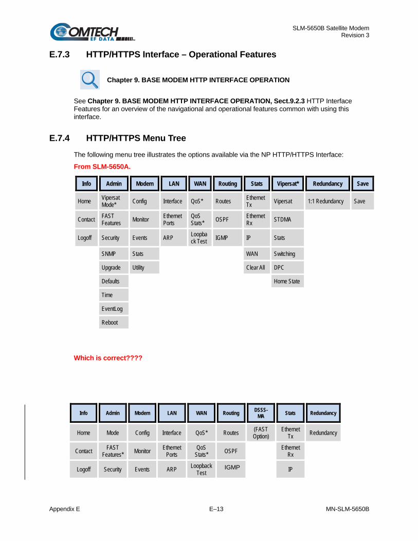
SLM-5650B Satellite Modem Revision 3
Appendix E E–13 MN-SLM-5650B
E.7.3 HTTP/HTTPS Interface – Operational Features
Chapter 9. BASE MODEM HTTP INTERFACE OPERATION
See Chapter 9. BASE MODEM HTTP INTERFACE OPERATION, Sect.9.2.3 HTTP Interface Features for an overview of the navigational and operational features common with using this interface.
E.7.4 HTTP/HTTPS Menu Tree The following menu tree illustrates the options available via the NP HTTP/HTTPS Interface:
From SLM-5650A.
Info Admin Modem LAN WAN Routing Stats Vipersat* Redundancy Save
Home Vipersat Mode* Config Interface QoS* Routes Ethernet
Tx Vipersat 1:1 Redundancy Save
Contact FAST Features Monitor Ethernet
Ports QoS Stats* OSPF Ethernet
Rx STDMA
Logoff Security Events ARP Loopback Test IGMP IP Stats
SNMP Stats WAN Switching
Upgrade Utility Clear All DPC
Defaults Home State
Time
EventLog
Reboot
Which is correct????
Info Admin Modem LAN WAN Routing DSSS-MA Stats Redundancy
Home Mode Config Interface QoS* Routes (FAST Option)
Ethernet Tx Redundancy
Contact FAST Features* Monitor Ethernet
Ports QoS
Stats* OSPF Ethernet Rx
Logoff Security Events ARP Loopback Test
IGMP IP

SLM-5650B Satellite Modem Revision 3
Appendix E E–14 MN-SLM-5650B
SNMP Stats WAN
Upgrade Utility Clear All
Defaults
Time
Event Log
Reboot
This interface provides access to up to nine navigation tabs (shown in blue). The diagram further illustrates each tab’s available nested hyperlinks (shown in grey), which afford more specific functionality.
Note: * indicates a FAST Feature that is available on the interface only after that option has been purchased. Refer to Section E.7.5.2.2 for more information.
Click any tab or hyperlink to continue.

SLM-5650B Satellite Modem Revision 3
Appendix E E–15 MN-SLM-5650B
E.7.5 HTTP/HTTPS Page Descriptions
E.7.5.1 Info (Information) Page Select the Home, Contact, or Logoff hyperlink to continue.
E.7.5.1.1 Info | Home
Figure E-7. Info | Home Page
Use the ‘Info | Home’ page (Figure E-7) to identify pertinent information about the modem NP Interface, including the installed firmware for the Bootrom, Image 1, and Image 2.
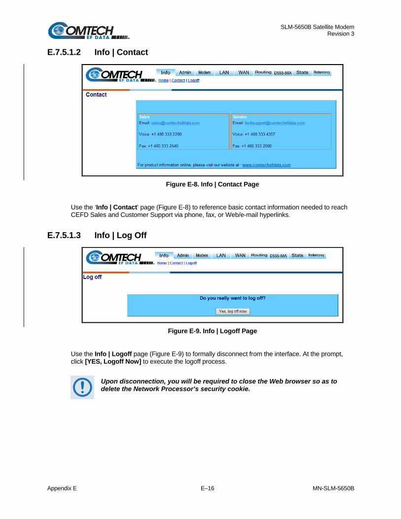
SLM-5650B Satellite Modem Revision 3
Appendix E E–16 MN-SLM-5650B
E.7.5.1.2 Info | Contact
Figure E-8. Info | Contact Page
Use the ‘Info | Contact’ page (Figure E-8) to reference basic contact information needed to reach CEFD Sales and Customer Support via phone, fax, or Web/e-mail hyperlinks.
E.7.5.1.3 Info | Log Off
Figure E-9. Info | Logoff Page
Use the Info | Logoff page (Figure E-9) to formally disconnect from the interface. At the prompt, click [YES, Logoff Now] to execute the logoff process.
Upon disconnection, you will be required to close the Web browser so as to delete the Network Processor’s security cookie.

SLM-5650B Satellite Modem Revision 3
Appendix E E–17 MN-SLM-5650B
E.7.5.2 Admin (Administration) Page On the Admin tab, depending on the enabled features and options, select the Mode, FAST Features, Security, SNMP, Upgrade, Defaults, Time, Event Log, or Reboot hyperlink to continue.
E.7.5.2.1 Admin | Mode (FAST Feature Required)
Figure E-10. Admin | Mode Page
Use the ‘Admin | Mode’ page (Figure E-10) to specify how the modem/NP Interface is to behave in working modes. Once the role of a particular modem in the network is determined, this single point of configuration is intended to simplify deployment.
Multipoint Modes
Item Description
Multipoint Hub Router
When in static SCPC, the option exists for configuring the modems into a hub and spoke network with a shared outbound at the hub. All of the modems at the hub should be put in “Multipoint Hub Router” mode. Note: If a modem at the remote is configured to be a Hub router there will be significant degradation to network performance due to the potential for routing loops.
Multipoint Remote Router Select Multipoint Remote Router for all remote modems in a multipoint network. A Remote router would be classified as a modem which receives the shared outbound and transmits back to the hub on a dedicated SCPC channel
Point-to-Point Mode
Item Description
Point-to-Point Router Select for use in a Point-to-Point SCPC link where there are different IP subnets on either side of the link.

SLM-5650B Satellite Modem Revision 3
Appendix E E–18 MN-SLM-5650B
Routing Mode
Item Description
Gigabit Ethernet Bridge
Select for use in a Point-to-Point SCPC link when you wish to bridge traffic (no IP network routing). Note: System Ethernet traffic will flow end to end when the NP interface is set to Gigabit Bridge for the following conditions:
1. NP interface to NP interface 2. NP interface to SLM-5650A Gigabit Ethernet Bridge circuit card 3. NP interface to SLM-5650B with Gigabit Ethernet face plate.
The NP M&C interface is disabled when the NP mode is set to Gigabit Bridge. Use the base modem WEB page, Admin\Access, or the front panel to select a different mode to access the NP M&C interface.
Router When the modem is operating in Router Mode, a number of Base Modem M&C parameters are available via the NP HTTP Interface.
BPM
When BPM Mode is selected, the NP Interface Ethernet ports P1 and P3 transparently bridge data traffic, and network management is only possible using the Base Modem’s J5 Ethernet port. Port 1 and 2 are a pair. Port 2 can handle bidirectional, bridged Ethernet data. This data is presented to Port 1 LAN traffic. Ports 3 and 4 is also a pair and acts the same way as Port 1 and Port 2.
Note: In BPM Mode, the Gigabit Ethernet Bridge option becomes inaccessible and the appearance of the Routing Mode section changes as follows:
Click [Submit] once the appropriate operating mode is selected on this page.
BPM NP Port Usage End to end Ethernet traffic flows exclusively from NP port 1 to port 1 of the NP card at the distant end. The same applies for port 3 to port 3. Port 2 can be used to deliver Ethernet traffic from another modem set to the local network using NP port 1. The same applies for port 4.

SLM-5650B Satellite Modem Revision 3
Appendix E E–19 MN-SLM-5650B
Figure E-11. BPM NP Port 1 and 2 Diagram
Ports 3 and 4 function identical as Port 1 and 2.
The combined data rate for site 2 and 3 must not exceed the throughput rate for Site 1, modem A, NP port 1.
The data on Port 2 of Modem A does not go over the WAN to site 2.
Site 1 Site 2
5650 5650Network NP interface NP Interface Network
Port 1 WAN WAN Port 1
Port 2
Modem A Modem B
Site 3
5650 5650NP Interface NP Interface NetworkPort 1 WAN WAN Port 1
Modem C Modem D

SLM-5650B Satellite Modem Revision 3
Appendix E E–20 MN-SLM-5650B
E.7.5.2.2 Admin | FAST Features
This section depicts the NP HTTP/HTTPS Interface with Quality of Service (QoS), Management Security, and NP BPM installed on the modem. Note the following: If the modem does not have the FAST options installed, any hyperlinks to that option will not be visible/available to the user.
Figure E-12. Admin | FAST Features Page
The read-only ‘Admin | FAST Features’ page (Figure E-12) displays available FAST Features as Installed or Not Installed.
Network Processor and Modem FAST Features CEFD offers Vipersat, Management Security, NP BPM, Quality of Service (QoS), NP OW Serial Commands, and NP Antenna Handover functionality as optional FAST Features for the NP Interface. The modem’s Demodulator Only FAST feature status is also provided. To install these options, a modem FAST code must be purchased by contacting CEFD Customer Support.
Once the 20-digit modem FAST code is obtained, the purchased FAST Feature(s) is installed via the modem front panel (Utility: FAST Configuration Enter modem code) or the base modem web pages.
See Chapter 5. FRONT PANEL OPERATION for detailed information on installing FAST Features.
Upgrading the FAST features requires a modem reboot in order for FAST features to be activated, and may require reconfiguration of all modem parameters.

SLM-5650B Satellite Modem Revision 3
Appendix E E–21 MN-SLM-5650B
E.7.5.2.3 Admin | Security (Account Information)
Figure E-13. Admin | Security (Management Security) Page
The Admin user, via the ‘Admin | Security’ page (Figure E-13), impacts access to the base modem HTTP and NP Interface HTTP/HTTPS pages. However, the Admin user does not have access to the optional TRANSEC Module parameters; this functionality is only available via the Crypto Officer login provided separately on the TRANSEC Module HTTPS Interface. See Chapter 10. TRANSEC MODULE HTTPS INTERFACE for further information.
Admin Account Info The login process requires a name and password as defined by the systems administrator of the controlling equipment. This name and password is associated to the name and password of an administrator account. Set the desired Admin User Name and Admin Password for the administrator account, and then click [Submit] to apply these settings.
Note: The Admin User Name and Password settings are maintained separately from the IP Interface Security Mode and SSH sections on this page.
IP Interface Security Mode The desired IP Interface Security Mode can be set to either Low Level Security for HTTP/FTP/ SNMP/Telnet access, or High Level Security for HTTPS/SSH (Secure Shell) access only. Click [Submit] to apply this setting. More specifically:
When Management Security is set to Low Level Security, the NP Interface can be managed by non-secure protocols such as HTTP and Telnet.
When Management Security is set to High Level Security, the following restrictions apply:
The NP Interface can ONLY be managed via the secure HTTPS protocol – the the https:// address prefix must be specified in order to connect to the secure NP HTTPS Interface.
Access via Telnet is not permitted – however, while access to the CLI is not permitted via the Telnet interface, the CLI is accessible via the SSH interface.

SLM-5650B Satellite Modem Revision 3
Appendix E E–22 MN-SLM-5650B
Access to the base modem HTTP and FTP server is disabled since non-secure protocols are used.
Management Security can also be changed via the modem front panel:
SELECT: Configuration Remote EthernetConfig Option Card Addr Network Proc Security
See Chapter 5. FRONT PANEL OPERATION for detailed information on using this modem control interface.
SSH (Secure Shell) SSH Host Key: This key signature, or fingerprint, helps to identify the NP when connecting through SSH. SSH clients typically show the host key signature when they connect to a system for the first time. The host key the SSH client shows can then be compared with the host key the NP displays to verify that they are the same.
Click [Generate New Host Key] to generate a new host key that uniquely identifies the NP. After doing this, SSH clients that have connected to the NP before will usually note or warn that the host key has changed when they connect again.

SLM-5650B Satellite Modem Revision 3
Appendix E E–23 MN-SLM-5650B
E.7.5.2.4 Admin | SNMP
Figure E-14. Admin | SNMP Page
The Admin user, via the ‘Admin | SNMP’ page (Figure E-14), may change the parameters associated with Simple Network Management Protocol, an application-layer protocol designed to facilitate the exchange of management information between network devices. The modem SNMP agent supports SNMPv1, SNMP v2c, and SNMP v3.
SNMP SNMP Read Community and SNMP Write Community cannot be changed; the default for Read Community default is public; the Write Community default is private.
Click [Submit] to enable the SNMP configuration changes made to Trap Community, Trap, System Contact, and System Location.
SNMP v3 This section is used to create user accounts under SNMPv3 protocol. SNMPv3 is available only when the IP Interface Security Mode security level setting is set to “High”.
Using the provided text boxes, create an Engine ID (the default is 0000000c000000007f000001), User Name and Password as needed (the default for both is comtech) then, using the available drop-down menu, select the Security Model algorithm as md5 or sha. Note that this setting must match the setting in the SNMP client, or the modem will not allow communications.
Click [Submit] to enable the SNMP v3 configuration changes made in this section.

SLM-5650B Satellite Modem Revision 3
Appendix E E–24 MN-SLM-5650B
E.7.5.2.5 Admin | Upgrade
Figure E-15. Admin | Upgrade Page
Use the ‘Admin | Upgrade’ page (Figure E-15) to review information about and accessibility to the loaded NP Interface and modem firmware (i.e., the Bootrom and image files), and to upgrade the operational firmware for the interface.
Network Processor Firmware Info These fields display the installed NP Interface Firmware (all information is read only):
Item Description
Network Processor Bootrom A single Bootrom that initializes the hardware and loads the full bulk image as selected by the user.
Network Processor Image 1 A full copy of software image stored in slot 1. Network Processor Image 2 A full copy of software image stored in slot 2.
Modem Firmware Info These fields display installed base modem firmware for the Bootrom, Image 1, and Image 2 (all information is read only).

SLM-5650B Satellite Modem Revision 3
Appendix E E–25 MN-SLM-5650B
E.7.5.2.6 Upgrade See Chapter 4. FLASH UPGRADING for complete details on using the NP HTTP/HTTPS Interface for upgrading the base modem, NP Interface and TRANSEC Module firmware.
Item Description
Current Running (read only) – displays current NP Interface Firmware Image as defined on the Admin | Reboot page (e.g., Image1 or Image2).
Upgrade To (read only) – displays the NP Interface Firmware Image that will be overwritten with the new image as defined on the Admin | Reboot page (e.g., Image1 or Image2).
Upgrade Image File Click [Browse] to locate the bulk image on the local computer’s file system, and then click [Upload] to upload the image.
E.7.5.2.7 Admin | Defaults
Figure E-16. Admin | Defaults (Factory Default Configurations) Page
Use the ‘Admin | Defaults’ page (Figure E-16) to restore all previously-configured NP card parameters – with the exception of the Admin User Name and the Admin Password (see Section 8.6.5.2.3) – to their Factory Default Configuration settings.
Click [Restore Now] to begin the restoration process. At the user prompt (shown at right), click OK to execute the process, or Cancel to abort the command.
This reset only affects the NP Card. This reset does not affect the Base Modem or TRANSEC (if installed).

SLM-5650B Satellite Modem Revision 3
Appendix E E–26 MN-SLM-5650B
E.7.5.2.8 Admin | Time (Date and Time)
Figure E-17. Admin | Time (Date & Time) Page
Time Zone Use the drop-down menu to select the modem’s time zone, and then click [Submit] to save the setting.
Internet Time Use the drop-down menu to select automatic time synchronization (using network time protocol) as Enabled or Disabled, and then click [Submit] to save the setting.
Internet Time Servers These fields are editable only when the Internet Time synchronization has been Enabled.
Item Description
Primary Internet Time Server IP Address of primary network time server. Secondary Internet Time Server IP Address of secondary network time server.
Edit each address as needed, and then click [Submit] to save these settings.
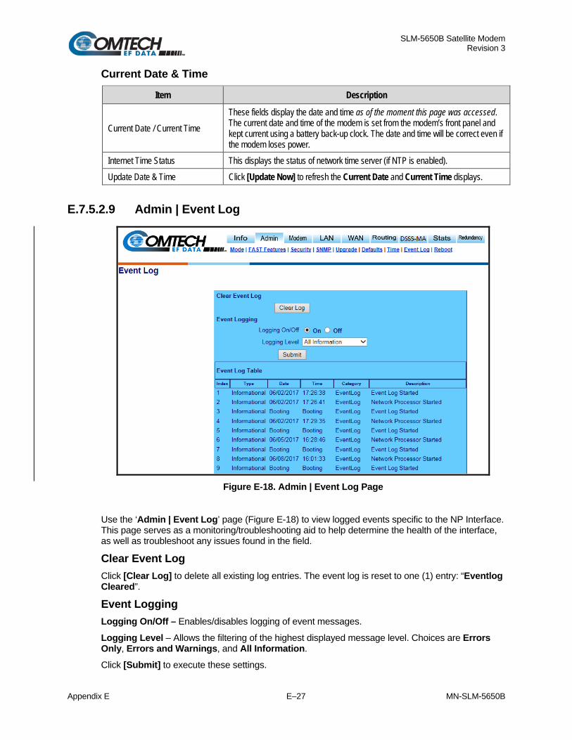
SLM-5650B Satellite Modem Revision 3
Appendix E E–27 MN-SLM-5650B
Current Date & Time
Item Description
Current Date / Current Time These fields display the date and time as of the moment this page was accessed. The current date and time of the modem is set from the modem’s front panel and kept current using a battery back-up clock. The date and time will be correct even if the modem loses power.
Internet Time Status This displays the status of network time server (if NTP is enabled). Update Date & Time Click [Update Now] to refresh the Current Date and Current Time displays.
E.7.5.2.9 Admin | Event Log
Figure E-18. Admin | Event Log Page
Use the ‘Admin | Event Log’ page (Figure E-18) to view logged events specific to the NP Interface. This page serves as a monitoring/troubleshooting aid to help determine the health of the interface, as well as troubleshoot any issues found in the field.
Clear Event Log Click [Clear Log] to delete all existing log entries. The event log is reset to one (1) entry: “Eventlog Cleared”.
Event Logging Logging On/Off – Enables/disables logging of event messages. Logging Level – Allows the filtering of the highest displayed message level. Choices are Errors Only, Errors and Warnings, and All Information. Click [Submit] to execute these settings.

SLM-5650B Satellite Modem Revision 3
Appendix E E–28 MN-SLM-5650B
Event Log Table Column Description
Index Event log entries are numbered in the order they are received. Type Describes the severity of the event.
Date Displays the date that the event was logged. In accordance with European convention, the date is shown in DAY/MONTH/YEAR format.
Time Displays the time of day that the event was logged. Category For use by Customer Support. Description Provides a brief description of the action logged.
E.7.5.2.10 Admin | Reboot
Figure E-19. Admin | Reboot Page
Use the ‘Admin | Reboot’ page (Figure E-19) to display the currently available boot images for both the NP Interface and Modem, or to select from which images the NP Interface and modem will boot.
Once the NP and/or Modem image boot selections are made, [Submit] MUST be clicked for the boot parameter updates to take effect upon the next reboot.
Network Processor Boot From Use the drop-down menu to select the Network Processor image to boot from Image 1, Image 2, or Newest, and then click [Submit] to save the selection.

SLM-5650B Satellite Modem Revision 3
Appendix E E–29 MN-SLM-5650B
Modem Boot From Use the drop-down menu to select the Modem image to boot from Image 1 or Image 2, and then click [Submit] to save the selection.
Reboot
Take care to allow time for the Network Processor Boot From or Modem Boot choices to submit/save to flash memory, and for the ‘Admin | Reboot’ page to refresh, prior to executing a modem reboot.
Click [Reboot Now] to cause the entire modem to reboot; this includes the base modem, Network Processor and TRANSEC Module.

SLM-5650B Satellite Modem Revision 3
Appendix E E–30 MN-SLM-5650B
E.7.5.3 Modem Page Use the Modem pages to configure or view the primary Transmit parameters and primary Receive parameters of the SLM-5650B Satellite Modem.
On the Modem tab, select the Config, Monitor, Events, Stats, or Utility hyperlink to continue.
E.7.5.3.1 Modem | Config (Modem Configuration)
Figure E-20. Modem | Config (Modem Configuration) Page
Modem Mode Modem Type (read-only)
Modem Type Description OM-73 Linkabit OM-73 modem compatibility mode. MIL-165A Functionality defined by MIL-STD-188-165A. IESS-308 Functionality defined by IESS-308, the Intelsat Intermediate Data Rate standard. IESS-309 Functionality defined by IESS-309, the Intelsat Business Services standard. IESS-310 Functionality defined by IESS-310, the Intelsat 8-PSK Intermediate Data Rate standard. TURBO Functionality defined by IESS-315 plus CEFD Turbo mode interoperability. 16-QAM 16-QAM is selected as a modulation type. AUPC Automatic Uplink Power Control is used. TX-BURST The unit is a Vipersat Remote Modem. RX-BURST The unit is a Vipersat STDMA Hub Modem with its Acquisition Mode set to “Standard.” RX-BURST-FA The unit is a Vipersat STDMA Hub Modem with its Acquisition Mode set to “Long”.

SLM-5650B Satellite Modem Revision 3
Appendix E E–31 MN-SLM-5650B
STANAG STANAG is selected as a modulation type. TURBO-FA The unit is a Vipersat Hub Expansion Modem. LDPC Low-density parity-check IESS-308V2 Functionality defined by IESS-308 V2, the Intelsat Intermediate Data Rate standard.
Reference
Selection Description Internal …Internal high stability ovenized 10 MHz oscillator
Ext-1MHz …an external 1 MHz reference, (accepts sine wave or square wave and locks the internal reference to the 1 MHz)
Ext-5MHz …an external 5 MHz reference, (accepts sine wave or square wave and locks the internal reference to the 5 MHz)
Ext-10MHz …an external 10 MHz reference, (accepts sine wave or square wave and locks the internal reference to the 10 MHz)
Click [Submit] to save the desired Reference setting type. Unit Interface Type (read-only)
Unit Interface Type Description Network Processor Identifies current data interface
Frequency Band
Selection Description 70/140 MHz 52 – 88 MHz, 104 – 176 MHz L-Band 950 – 2000 MHz Click [Submit] to save the desired Frequency Band selection.
Transmit
FEC Type
Selection Description
Viterbi (standard) K = 7 convolutional encoder. None (standard) Uncoded. Turbo (optional) Turbo Product Code, which is a block code.
Modulation Type
Selection Description
BPSK Bi Phase Shift Keying QPSK Quadrature Phase Shift Keying. OQPSK Offset Quadrature Phase Shift Keying. 8PSK 8 Phase Shift Keying 8QAM 8 Quadrature Amplitude Modulation 16APSK 16 Amplitude Phase Shift Keying 16QAM (optional) 16 Quadrature Amplitude Modulation.

SLM-5650B Satellite Modem Revision 3
Appendix E E–32 MN-SLM-5650B
FEC Code Rate
Selection Description
Viterbi 1/2, 2/3, 3/4, 5/6, or 7/8 Uncoded 1/1 Turbo 5/16, 21/44, 3/4, 7/8, or 17/18
Data Rate (kbps)
Enter a Transmit Data Rate (in kbps).
Frequency (MHz)
Enter the Frequency: (70/140 MHz) 52-88, 104-176 MHz (in 100 Hz steps) or (L-Band) 950-2000 MHz (in 100 Hz steps)
Spectrum
Selection Description
Normal Used to counteract frequency converters that invert the spectrum
Invert
Scrambler (for energy dispersal)
Selection Description
V.35 ITU standard Modified-V.35 CEFD Closed Network with R-S compatible (modified V.35) IBS Used for IESS-309 and AUPC operation Turbo Synchronous scrambler synchronized to the Turbo block OM73 Linkabit OM-73 modem compatibility mode Synch Synchronous scrambler synchronized to the Reed-Solomon. Off
Tx Power Level (dBm)
Enter a Power Level from –40 dBm to +10 dBm (in 0.1 dB steps).
Carrier
Selection Description
On
RTS Request to Send. RTS is an interface signaling control. If enabled, RTS can be used to control the output state of the modulator. Only available when using either the EIA-530 or HSSI interface.
VSAT VSAT mode ties control of the Transmit Signal to the status of the Receiver. If the receiver is Locked the Transmitter is Enabled. If the receiver is Unlocked the Transmitter will be disabled.
Off

SLM-5650B Satellite Modem Revision 3
Appendix E E–33 MN-SLM-5650B
When changing Modulation Type the data rate must be set to a rate supported by the modulation type or the change to the modulation type will not be allowed. Some choices will only be visible if the modem is set to a compatible mode, or if an option is installed or enabled. When entering the data rate, the following interactions need to be taken into account. If the modulation type selected is 8-PSK or 16-QAM the minimum data rate allowed is 256 kbps. When changing certain parameters like modem type, the data rate will default to 64 kbps or 256 kbps. The calculated symbol rate is displayed for the user. This is helpful for determining the occupied bandwidth required for the selected modulation type, code rate and overhead. When entering an IF frequency, the M&C will check the occupied bandwidth calculated from the data rate, modulation type, code rate and overhead and will not allow an IF frequency to be entered if the occupied bandwidth falls outside of the minimum or maximum IF frequencies.
Click [Transmit Submit] to save the desired configuration settings.
Receive FEC Type
Selection Description Viterbi (standard) K=7 convolutional encoder. None (standard) Uncoded. Turbo (optional) Turbo means Turbo Product Code, which is a block code.
Demodulation Type
Selection Description BPSK Bi Phase Shift Keying QPSK Quadrature Phase Shift Keying. OQPSK Offset Quadrature Phase Shift Keying. 8PSK 8 Phase Shift Keying 16QAM (optional) 16 Quadrature Amplitude Modulation.
FEC Code Rate
Selection Description Viterbi 1/2, 2/3, 3/4, 5/6, or 7/8 Uncoded 1/1 Turbo 5/16, 21/44, 3/4, 7/8, or 17/18
Data Rate (kbps) Enter the Receive Data Rate (in kbps).
Frequency (MHz) Enter a Frequency (70/140 MHz) 52-88, 104-176 MHz (in 100 Hz steps) or (L-Band) 950-2000 MHz (in 100 Hz steps).
Spectrum
Select Description Normal
Used to counteract frequency converters that invert the spectrum Invert

SLM-5650B Satellite Modem Revision 3
Appendix E E–34 MN-SLM-5650B
Descrambler (for energy dispersal)
Select Description V.35 ITU standard Modified-V.35 CEFD Closed Network with R-S compatible (modified V.35) IBS Used for IESS-309 and AUPC operation Turbo Synchronous scrambler synchronized to the Turbo block OM73 Linkabit OM-73 modem compatibility mode Synch Synchronous scrambler synchronized to the Reed-Solomon. Off
When changing Demodulation type the data rate must be set to a rate supported
by the demodulation type or the change to the demodulation type will not be allowed. Some choices will only be visible if the modem is set to a compatible mode, or if an option is installed or enabled. When entering the data rate, the following interactions need to be taken into account. If the modulation type selected is 8-PSK or 16-QAM the minimum data rate allowed is 256 kbps. When changing certain parameters like modem type, the data rate will default to 64 kbps or 256 kbps. The calculated symbol rate is displayed for the user. This is helpful for determining the occupied bandwidth required for the selected modulation type, code rate and overhead. When entering an IF frequency, the M&C will check the occupied bandwidth calculated from the data rate, modulation type, code rate and overhead and will not allow an IF frequency to be entered if the occupied bandwidth falls outside of the minimum or maximum IF frequencies.
Click [Receive Submit] to save the desired configuration settings.

SLM-5650B Satellite Modem Revision 3
Appendix E E–35 MN-SLM-5650B
E.7.5.3.2 Modem | Monitor (Modem Status)
Figure E-21. Modem | Monitor (Modem Status) Page
Use the read-only ‘Modem | Monitor’ page (Figure E-21) to view the currently available modem receive parameters and operating temperature.
Receive Parameters Displays the modem’s currently reported link values as follows:
Item Description BER Displays the estimated BER based on the demodulator’s measurement of the carrier to noise.
Eb/No Displays the estimated Eb/No of the received carrier. The range is threshold to 20 dB Eb/No.
Frequency Offset Displays the received carrier frequency offset in Hz. The range is the same as the acquisition range of the modem, 60 kHz.
Signal Level Displays the signal level of the received carrier in dBm. The range supported is +15 to –60 dBm.
Temperature Reports the temperature of the modem in degrees Celsius.

SLM-5650B Satellite Modem Revision 3
Appendix E E–36 MN-SLM-5650B
E.7.5.3.3 Modem | Events (Modem Events Log)
Figure E-22. Modem |Events (Modem Events Log) Page
Use the read-only ‘Modem | Events’ page (Figure E-22) to view operating events. When a fault condition occurs, it is time-stamped and put into the log. Similarly, when the fault condition clears, this is also recorded.
Clear/Refresh Modem Events Click [Clear] to delete all log entries.
Click [Refresh] to refresh the Event Log to display the most recently recorded events.
Event Log
Column Description
Index Displays the internal table index. Fault Detail Provides a description of the fault or event. Date Date of the log entry (in YY/MM/DD format). Time Time of the log entry (in HH:MM:SS format).

SLM-5650B Satellite Modem Revision 3
Appendix E E–37 MN-SLM-5650B
E.7.5.3.4 Modem | Stats (Modem Statistics Log)
Figure E-23. Modem | Stats (Modem Statistics Log) Page
Clear/Refresh Modem Statistics Click [Clear] to delete all log entries.
Click [Refresh] to refresh the Link Statistics Log to display the most recent entries.
Logging Interval Use the drop-down menu to set the statistics recording interval. Valid settings are from every 10 minutes to every 90 minutes in 10-minute increments, or Disabled.
Click [Submit] to save all changes made to this page.
Link Statistics Log Displays the following modem statistics (all information is read only):
Column Description
Index Displays the internal table index. Min Eb/No Minimum measured Eb/N0 during the configured time interval. Avg Eb/No Average measured Eb/N0 during the configured time interval. Date Date of the log entry (in YY/MM/DD format). Time Time of the log entry (in HH:MM:SS format).

SLM-5650B Satellite Modem Revision 3
Appendix E E–38 MN-SLM-5650B
E.7.5.3.5 Modem | Utility (Modem Utilities)
Figure E-24. Modem | Utility (Modem Utilities) page
Date and Time To set the Date and Time of the modem:
Time (HH: MM: SS) – Set the hours in 24-hour time format
Date (DD/MM/YY) – Set the date in accordance with European convention (DAY/MONTH/YEAR) format.
Click [Submit] to save any changes made to this section.
Circuit ID CID – Enter a name for the communication link in this text field. This name can be any combination of alphanumeric characters up to 24 characters in length.
Additional characters supported are: ( ) * + / period (.) comma (,) and [space].
Click [Submit] to save any changes made to this section.

SLM-5650B Satellite Modem Revision 3
Appendix E E–39 MN-SLM-5650B
E.7.5.4 LAN Page On the LAN tab, select the Interface, Ethernet Ports, or ARP hyperlink to continue.
E.7.5.4.1 LAN | Interface
Figure E-25. LAN | Interface Page
Use the ‘LAN | Interface’ page (Figure E-25) to set LAN operating parameters, to view the MAC Address of the NP Interface, and to set the IP Address and Mask of the NP Interface.
Item Description / Settings
MAC Address (Read-only) The MAC is set at the factory to a guaranteed unique address that cannot be modified by the user.
IP Addressing Mode
Select Single or Dual. Note the following: Single: In this mode, Traffic IP Address should used as M&C as well as NextHop IP Address for adjacent routers. Dual: In this mode, Management IP Address is used as M&C access to the NP Interface, and Traffic IP Address is used as the NextHop IP Address for adjacent Routers.
Traffic IP Address This is the Traffic IP Address of the NP Interface. It is the address that is used for management and control connectivity when the IP addressing Mode is set to Single. It can be used in routing as the Next Hop Address.
Traffic Subnet Mask This is the sunet mask for the traffic IP address. The subnet mask is used to determine the range of valid IP numbers in the subnet.
Management IP Address
This is the IP Address of the NP Interface only. It is the address that should be used for management and control connectivity when IP Addressing Mode was set to Dual.

SLM-5650B Satellite Modem Revision 3
Appendix E E–40 MN-SLM-5650B
Item Description / Settings Management Subnet Mask
This is the sunet mask for the Management IP address. The subnet mask is used to determine the range of valid IP numbers in the subnet.
Click [Submit] to save changes.
VLAN Port Configuration Item / Selection Description / Settings
Single Port VLAN Using the drop-down menu, select Single Port as Enabled or Disabled. When Single Port VLAN is Enabled, the modem’s Ethernet port accepts the VLAN-tagged packets from the NP Interface port specified in the "VLAN Port Select" drop-down.
VLAN Port Select Using the drop-down menu, select Port 1 through Port 4 to designate the Ethernet port on which VLAN-tagged packet are ingress and egress. Only one port may be selected.
VLAN ID Enter an ID value from 2 to 4095. Packets containing specified VLAN only will ingress and egress from the NP Interface port specified in the "VLAN Port Select" drop-down.
Click [Submit] to save the desired Single Port VLAN setting.
Proxy ARP Enable Proxy ARP (Address Resolution Protocol) is a technique by which an NP Interface in Router Mode on a given network answers the ARP queries for a network address that is not on this network, but is reachable via the NP Interface.
With Proxy ARP enabled, the NP Interface (in Router Mode) 'snoops' all ARP_REQs; it will send an ARP_REPLY (one if the ARP_REQ host address is an NP host address that is reachable via one of the routes in the Route Table).
Using the drop-down menu, set Proxy ARP Enable as Enabled or Disabled.
Click [Submit] to save the desired Proxy ARP Enable setting.

SLM-5650B Satellite Modem Revision 3
Appendix E E–41 MN-SLM-5650B
E.7.5.4.2 LAN | Ethernet Ports
Figure E-26. LAN | Ethernet Ports Page
Use the ‘LAN | Ethernet Ports’ page (Figure E-26) to view the current status of the Ethernet ports and to set each port to manual or auto-negotiate configuration.
Note: Only the NP Interface Ethernet ports are represented in this screen. The base modem Ethernet port statistics and port information are set from the modem’s front panel.
Ethernet Link Status This read-only section displays the status for each NP Interface Ethernet port.
Ethernet Speed/Duplex Use the drop-down menus to configure each port to one of the following states:
• Auto • 1000 Full • 100 Full • 10 Full • 100 Half • 10 Half
Click [Submit] once the Ethernet ports have been configured to suit on this page.

SLM-5650B Satellite Modem Revision 3
Appendix E E–42 MN-SLM-5650B
E.7.5.4.3 LAN | ARP (ARP Table)
Figure E-27. LAN | ARP Page
ARP Table (Edit Static ARPs) This table displays all current ARP entries (both Static and Dynamic). The current Static ARPs may be directly edited here:
Column Description
Index Displays the internal table index (read-only, cannot be edited). IP Entry IP Address, format XXX.XXX.XXX.XXX MAC Entry MAC Address, format YY:YY:YY:YY:YY:YY Type Displays the Entry Type as Static or Dynamic (read-only, cannot be edited)
Click [Submit Changes] to save all changes made in this section.
Add Static ARP Use this section to directly add a Static ARP entry, and then click [Add Entry] to add the entry. Note that the index will automatically increment to the next available number.
Delete Static ARP Enter Entry Index to Delete: Type in the Index number, and then click [Delete Entry] to execute removal of the entry.
Flush Dynamic ARPs Click [Flush ARP Table] to execute the command as needed.
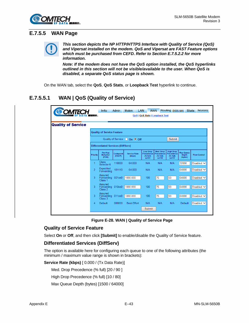
SLM-5650B Satellite Modem Revision 3
Appendix E E–43 MN-SLM-5650B
E.7.5.5 WAN Page
This section depicts the NP HTTP/HTTPS Interface with Quality of Service (QoS) and Vipersat installed on the modem. QoS and Vipersat are FAST Feature options which must be purchased from CEFD. Refer to Section E.7.5.2.2 for more information. Note: If the modem does not have the QoS option installed, the QoS hyperlinks outlined in this section will not be visible/available to the user. When QoS is disabled, a separate QoS status page is shown.
On the WAN tab, select the QoS, QoS Stats, or Loopback Test hyperlink to continue.
E.7.5.5.1 WAN | QoS (Quality of Service)
Figure E-28. WAN | Quality of Service Page
Quality of Service Feature Select On or Off, and then click [Submit] to enable/disable the Quality of Service feature.
Differentiated Services (DiffServ) The option is available here for configuring each queue to one of the following attributes (the minimum / maximum value range is shown in brackets):
Service Rate (kbps) [ 0.000 / (Tx Data Rate)]
Med. Drop Precedence (% full) [20 / 90 ]
High Drop Precedence (% full) [10 / 80]
Max Queue Depth (bytes) [1500 / 64000]

SLM-5650B Satellite Modem Revision 3
Appendix E E–44 MN-SLM-5650B
Refer to the QoS Differentiated Services table, shown in Table E-2.
Flow control can be enabled or disabled. Flow control functionality is between the NP card port and the next directly connected network device. Enable flow control on the directly connected network device when enabling flow control for QOS.
Table E-2. QoS Differentiated Services
TOS / DiffServ DSCP (6 bits) Hex Decimal Hex Decimal Binary
C0 192 30 48 110000 00 Class Selector 6
TOS Hex Decimal
Binary Expedited Forwarding
B8 184 2E 46 101110 00
TOS Hex Decimal
Binary Assured Forwarding Class 1
28 40 A 10 001010 00 Priority traffic, Low drop probability 30 48 C 12 001100 00 Priority traffic, Medium drop probability 38 56 E 14 001110 00 Priority traffic, High drop probability
TOS Hex Decimal
Binary Assured Forwarding Class 2
48 72 12 18 010010 00 Immediate, Low drop probability 50 80 14 20 010100 00 Immediate, Medium drop probability 58 88 16 22 010110 00 Immediate, High drop probability
TOS Hex Decimal
Binary Assured Forwarding Class 3
68 104 1A 26 011010 00 Flash, Low drop probability 70 112 1C 28 011100 00 Flash, Medium drop probability 78 120 1E 30 011110 00 Flash, High drop probability
Click [Submit] after all values have been adjusted to enable settings.

SLM-5650B Satellite Modem Revision 3
Appendix E E–45 MN-SLM-5650B
E.7.5.5.2 WAN | QoS Stats (Quality of Service Statistics)
Figure E-29. WAN | Quality of Service Statistics Page
Clear / Refresh Differentiated Services (DiffServ) Stats Click [Clear] to clear queue statistics.
Click [Refresh] to update queue statistics.

SLM-5650B Satellite Modem Revision 3
Appendix E E–46 MN-SLM-5650B
Differentiated Services (DiffServ) This status table displays the following attributes (all information is read only):
Column Description
Priority Per-Hop Behavior (PHB) Traffic class that determines how packets will be forwarded.
Codepoint (DSCP) Codepoint value in Type of Service (ToS) byte in IP header. The user Ethernet data is marked for all Diff Serve values. There are variables (xx) indicated for Assured Forwarding. For instance: 001 010 would be priority traffic with low drop probability.
Sent Packets Number of packets sent from queue associated with PHB class. Dropped Packets Number of packets dropped in queue associated with PHB class. Queued Packets Number of packets in queue associated with PHB class. Queued Bytes Number of bytes in queue associated with PHB class. Queue Depth (% Full) Percentage (%) full for queue associated with PHB class Bandwidth (kbps) Current data rate for queue associated with PHB class.
E.7.5.5.3 WAN | Loopback Test
Figure E-30. WAN | Loopback Test Page
Use the ‘WAN | Loopback Test’ page (Figure E-30) for testing the operational integrity of the NP Interface M&C, WAN Interface, and IF Interface.
Packet Loopback Test Results This message window displays the results of the completed Loopback Test.
Refresh the web page to view the results.
Packet Loopback Test By clicking [Start Test], the NP Interface sends 50 multicast packets towards the WAN interface, and enables the IF Loopback. All packets returned from the IP Loopback will count by the NP Interface, and are displayed in the Packet Loopback Test Results window.

SLM-5650B Satellite Modem Revision 3
Appendix E E–47 MN-SLM-5650B
E.7.5.6 Routing Page Select the Routes, OSPF, or IGMP hyperlink to continue.
E.7.5.6.1 Routing | Routes
Figure E-31. Routing | Routes Page
Use the ‘Routing | Routes’ page (Figure E-31) to enter static routes into the NP Interface. This facilitates the routing of IP traffic over the satellite or to another device on the local LAN. Route entries can be in any combination of Unicast and Multicast routes.
Multicast static routes are configured on both modems.
Source: 10.10.11.21 Destination 225.0.0.1
Modem 1, index 2 Multicast routed to WAN
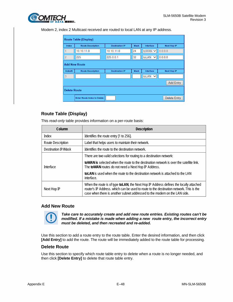
SLM-5650B Satellite Modem Revision 3
Appendix E E–48 MN-SLM-5650B
Modem 2, index 2 Multicast received are routed to local LAN at any IP address.
Route Table (Display) This read-only table provides information on a per-route basis:
Column Description
Index Identifies the route entry [1 to 256]. Route Description Label that helps users to maintain their network. Destination IP/Mask Identifies the route to the destination network.
Interface
There are two valid selections for routing to a destination network: toWAN is selected when the route to the destination network is over the satellite link. The toWAN routes do not need a Next Hop IP Address. toLAN is used when the route to the destination network is attached to the LAN interface.
Next Hop IP When the route is of type toLAN, the Next Hop IP Address defines the locally attached router’s IP Address. which can be used to route to the destination network. This is the case when there is another subnet addressed to the modem on the LAN side.
Add New Route Take care to accurately create and add new route entries. Existing routes can’t be
modified. If a mistake is made when adding a new route entry, the incorrect entry must be deleted, and then recreated and re-added.
Use this section to add a route entry to the route table. Enter the desired information, and then click [Add Entry] to add the route. The route will be immediately added to the route table for processing.
Delete Route Use this section to specify which route table entry to delete when a route is no longer needed, and then click [Delete Entry] to delete that route table entry.

SLM-5650B Satellite Modem Revision 3
Appendix E E–49 MN-SLM-5650B
Examples for routed traffic: Simple Network:
5650B
5650B
Modem 1
Modem 2 Network
Traffic IP
Traffic IP
Network
10.10.1.111
10.10.2.111
PC
Mgmt IP
Mgmt IP
PC
Management
192.168.10.10
192.168.20.10
Management
(dual mode)
(dual mode)
Route Modem 1: Description Destination IP Mask Interface Next Hop IP To Modem 2 10.10.2.0 24 To WAN N/A Route Modem 2: Description Destination IP Mask Interface Next Hop IP To Modem 1 10.10.1.0 24 To WAN N/A Add a Multicast route: Modem 1 to Modem 2 only Route Modem 1: Description Destination IP Mask Interface Next Hop IP MCast 225 225.0.0.1 32 ToWAN N/A Route Modem 2: Description Destination IP Mask Interface Next Hop IP MCast from 1 225.0.0.1 32 ToLAN 0.0.0.0 Note: the NP management IP network can be routed.
Route Modem 1: Description Destination IP Mask Interface Next Hop IP Mgt to Modem 2 192.168.20.0 24 To WAN N/A Route Modem 2: Description Destination IP Mask Interface Next Hop IP Mgt to Modem 1 192.168.10.0 24 To WAN N/A

SLM-5650B Satellite Modem Revision 3
Appendix E E–50 MN-SLM-5650B
Network with Routers, static routes:
Route Modem 1: Description Destination IP Mask Interface Next Hop IP To Modem 2 10.10.2.0 24 To WAN N/A To LAN 1 192.168.1.0 24 To LAN 10.10.1.200* Route Modem 2: Description Destination IP Mask Interface Next Hop IP To Modem 1 10.10.1.0 24 To WAN N/A To LAN 2 192.168.2.0 24 To LAN 10.10.2.200* Router 1: ip route 192.168.2.0/24 10.10.1.111 Router 2: ip route 192.168.1.0/24 10.10.2.111
Note: * The To LAN routes will be automatically added when the NP OSPF option is configured and enabled.
LAN Router 1 Modem 1 Modem 2 Router 2 LANNetwork Gig 0/0 Gig 0/1 Traffic 1 Traffic 1 Gig 0/1 Gig 0/0 Network192.168.1.0/24 192.168.1.200 10.10.1.200 10.10.1.111 WAN 10.10.2.111 10.10.2.200 192.168.2.200 192.168.2.0/24
NP Mgt NP Mgt192.168.10.11 192.168.20.11

SLM-5650B Satellite Modem Revision 3
Appendix E E–51 MN-SLM-5650B
E.7.5.6.2 Routing | OSPF
Figure E-32. Routing | OSPF Page
Use the ‘Routing | OSPF’ page (Figure E-32) to define the operating parameters for Open Shortest Path First routing.
OSPF Parameters
Item Description / Setting
OSPF To control OSPF routing, set the interface as Disabled, Full Enable, or Announcement Only.
Area Network Address Network address of an area. An area is a set of networks and hosts within an Autonomous System (AS) that has been administratively grouped together. As an example, for 10.10.10.0, all NP interface traffic ports must be set to this IP subnet.
Area Subnet Mask Subnet mask of the Area Network.
OSPF Area
The modem NP Interface supports only one OSPF Area at a time. A group of (adjacent) routers which cooperate by exchanging their routing data base for the specified network range; i.e. an OSPF router will only send its database to other routers that advertise that they are in the same area. Valid range is from 0 to 4294967295.
Cost Specify the explicit cost of sending a packet via this interface. Valid range is from 1 to 65535.
Retransmit Interval Specify the number of seconds between link state advertisement retransmissions for adjacencies belonging to an OSPF interface.

SLM-5650B Satellite Modem Revision 3
Appendix E E–52 MN-SLM-5650B
Item Description / Setting
Transmit Delay Parameters used to define the route to the destination network. Valid range is from 1 to 65535 seconds.
Priority Set priority to help determine the OSPF. Valid range is 0 (default, or not designated) to 255.
Hello Interval Specify the length of time, in seconds, between the hello packets that are sent on an OSPF interface. Valid range is from 1 to 65535 seconds.
Dead Interval Set the number of seconds that a device’s ‘Hello’ packets must not have been seen before its neighbors declare the OSPF router down. Valid range is from 1 to 65535 seconds.
Authentication Key Assign a specific password to be used by neighboring OSPF routers on a network segment that is using OSPF’s simple password authentication.
Message Digest Key Enable OSPG MD5 authentication.
OSPF example: Configure the NP interface for Router Point to Point.
0/0 Router 1 0/1 Modem 1 Modem 2 0/1 Router 2 0/0 192.168.1.250 OSPF 10.10.10.1 NP Interface NP Interface 10.10.10.2 OSPF 192.168.2.250
Router 1 • Router OSPF 1 • network 10.10.10.0 0.0.0.255 area 1 • network 192.168.0.0 0.0.255.255 area 1
Modem 1 • OSPF: Full Enable • Area Network Address: 10.10.10.0 • Area Subnet Mask(8-30): 24 • OSPF Area: 1 • Cost: 100 • Retrasmit Interval: 5 • Transmit Delay: 1 • Priority 0 • Hello Interval: 10 • Dead Interval: 40 • Traffic IP: 10.10.10.124 • Management IP: 192.168.11.124 • Addressing mode: Dual

SLM-5650B Satellite Modem Revision 3
Appendix E E–53 MN-SLM-5650B
Modem 2 • Configure the same as Modem 1. • Traffic IP: 10.10.10.134 • Management IP: 192.168.12.134 • Addressing mode: Dual
Router 2 • Router OSPF 1 • network 10.10.10.0 0.0.0.255 area 1 • network 192.168.0.0 0.0.255.255 area 1
Modem1 Routing table:
Index 1: Any IP in subnet 192.168.1.0 is going out the LAN port, next hop is the router WAN interface.
Index 2: Loop back interface.
Index 3: Any IP in subnet 192.169.2.0, direct to the WAN interface to distant end modem traffic IP
Index 4: Loop back interface.
Modem 2 Routing table:
Index 1: Any IP in subnet 192.168.1.0, direct to the WAN to distant end modem traffic IP.
Index 2: Loop back interface.
Index 3. Any IP in 192.168.2.0 subnet send to Lan with next hop to the router WAN interface IP.
Index 4: Loop back interface.

SLM-5650B Satellite Modem Revision 3
Appendix E E–54 MN-SLM-5650B
Router 1 table: show ip route 10.0.0.0/8 is variably subnetted, 2 subnets, 2 masks
C 10.10.10.0/24 is directly connected, GigabitEthernet0/1
L 10.10.10.1/32 is directly connected, GigabitEthernet0/1
192.168.1.0/24 is variably subnetted, 2 subnets, 2 masks
C 192.168.1.0/24 is directly connected, GigabitEthernet0/0
L 192.168.1.250/32 is directly connected, GigabitEthernet0/0
O E2 192.168.2.0/24 [110/20] via 10.10.10.124, 00:54:21, GigabitEthernet0/1
192.168.40.0/24 is variably subnetted, 3 subnets, 2 masks
C 192.168.40.0/24 is directly connected, Loopback0
L 192.168.40.151/32 is directly connected, Loopback0
O E2 192.168.40.152/32
[110/20] via 10.10.10.124, 00:54:21, GigabitEthernet0/1
Router 2 table: 10.0.0.0/8 is variably subnetted, 2 subnets, 2 masks
C 10.10.10.0/24 is directly connected, GigabitEthernet0/1
L 10.10.10.2/32 is directly connected, GigabitEthernet0/1
O E2 192.168.1.0/24 [110/20] via 10.10.10.134, 00:45:02, GigabitEthernet0/1
192.168.2.0/24 is variably subnetted, 2 subnets, 2 masks
C 192.168.2.0/24 is directly connected, GigabitEthernet0/0
L 192.168.2.250/32 is directly connected, GigabitEthernet0/0
192.168.40.0/24 is variably subnetted, 3 subnets, 2 masks
C 192.168.40.0/24 is directly connected, Loopback0
O E2 192.168.40.151/32
[110/20] via 10.10.10.134, 00:45:02, GigabitEthernet0/1
L 192.168.40.152/32 is directly connected, Loopback0

SLM-5650B Satellite Modem Revision 3
Appendix E E–55 MN-SLM-5650B
E.7.5.6.3 Routing | IGMP
Figure E-33. Routing | IGMP Page
Use the ‘Routing | IGMP’ page (Figure E-33) to facilitate use of Internet Group Management Protocol (IGMP) with configured multicast routes.
IGMP, when enabled, responds to IGMP queries for the configured multicast routes on the transmit side and generates IGMP queries on the receive side. If there are no active IGMP receivers on the LAN, it will stop forwarding the multicast traffic (received from the satellite) to the LAN.
Selection Description / Setting
IGMP Select IGMP as Enabled or Disabled.
Query Interval
This is the interval between general queries sent by the modem. By varying the query interval, a modem administrator may tune the number of IGMP messages on the subnet; note that larger numbers cause the IGMP queries to be sent less often. Enter a value, in seconds, from 1 to 60 (default = 1 second).
Response Interval
This is the maximum response time inserted into the periodic general queries. By varying the Response Interval, a modem administrator may tune the “burstiness” of IGMP messages on the subnet; note that larger values make the traffic less “bursty” as host responses are spread out over a large interval. Enter a value, in seconds, from 1 to 25 (default = 10 seconds). Note: The number of seconds assigned to the Response Interval must be less than what is assigned to the Query Interval.
Last Member Query Interval
This is the maximum response time inserted into group-specific queries that are set in response to Leave Group messages, and is also amount of time between group-specific query messages. This value may be tuned to modify the "leave latency" of the network; a reduced value results in reduced time to detect the loss of the last member of a group. Enter a value, in seconds, from 1 to 25 (default = 1 second).

SLM-5650B Satellite Modem Revision 3
Appendix E E–56 MN-SLM-5650B
Selection Description / Setting
Robustness
The Robustness Variable allows tuning for the expected packet loss on a subnet. If a subnet is expected to be lossy, the Robustness Variable may be increased. IGMP is robust to (Robustness Variable-1) packet losses. Enter a value from 2 to 10 (the default value is 2). Note that the Robustness Variable MUST NOT be 0, and SHOULD NOT be 1.
Version Version – Enter 1 for IGMPv1 or 2 for IGMPv2.
Click [Submit] to save the desired IGMP configuration changes on this page.

SLM-5650B Satellite Modem Revision 3
Appendix E E–57 MN-SLM-5650B
E.7.5.7 DSSS-MA Page The DSS-MA is a FAST option. When the FAST option is installed, this page is accessible.
Figure E-34. DSSS-MA Page

SLM-5650B Satellite Modem Revision 3
Appendix E E–58 MN-SLM-5650B
E.7.5.8 Stats (Statistics) Page On the Stats tab, select the Ethernet Tx, Ethernet Rx, IP, WAN, or Clear All hyperlink to continue.
E.7.5.8.1 Stats | Ethernet Tx
Figure E-35. Stats | Ethernet Tx Statistics Page
Clear/Refresh Ethernet Tx Stats Click [Clear] to delete all Ethernet Tx statistics (this will also clear all Ethernet Rx statistics).
Click [Refresh] to update the page with the most recent statistics.
Tx Valid Frames
Column Description
Port The corresponding Ethernet port on the NP Interface and, when in BPM Mode, the base modem’s J5 Ethernet port.
Unicast Number of valid unicast frames transmitted. Broadcast Number of valid broadcast frames transmitted. Multicast Number of valid multicast frames transmitted. Pause Number of PAUSE frames transmitted.

SLM-5650B Satellite Modem Revision 3
Appendix E E–59 MN-SLM-5650B
Tx Collision Frames
The counters provided in this table are applicable in half-duplex only.
Column Description
Port The corresponding Ethernet port on the NP Interface and, when in BPM Mode, the base modem’s J5 Ethernet port.
Collision The number of Collision events seen by the GMAC, not including those controls in a single, Multiple, Excessive or Late.
Late Collision The number of times a collision is detected later than 512 bits-times into the transmission of the frame.
Single Collision The total number of successfully transmitted frames that experienced exactly one collision.
Multiple Collision The total number of successfully transmitted frames that experienced more than one collision.
Maximum Collision The number of frames dropped in the transmit GMAC because the frame experienced 16 consecutive collisions.
Tx Discarded/Filtered
Column Description
Port The corresponding Ethernet port on the NP Interface and, when in BPM Mode, the base modem’s J5 Ethernet port.
Discarded The total number of frames received with either FCS errors or Tx Maximum Collision frames.
Filtered Number of Tx frames filtered. Currently not implemented.

SLM-5650B Satellite Modem Revision 3
Appendix E E–60 MN-SLM-5650B
E.7.5.8.2 Stats | Ethernet Rx
Figure E-36. Stats | Ethernet Rx Statistics Page
Clear/Refresh Ethernet Rx Stats Click [Clear] to delete all Ethernet Rx statistics (this will also clear all Ethernet Tx statistics).
Click [Refresh] to update the page with the most recent statistics.
Rx Valid Frames
Column Description
Port The corresponding Ethernet port on the NP Interface and, when in BPM Mode, the base modem’s J5 Ethernet port.
Unicast Number of valid unicast frames transmitted. Broadcast Number of valid broadcast frames transmitted. Multicast Number of valid multicast frames transmitted. Pause Number of PAUSE frames transmitted.

SLM-5650B Satellite Modem Revision 3
Appendix E E–61 MN-SLM-5650B
Rx Error Frames
Column Description
Port The corresponding Ethernet port on the NP Interface and, when in BPM Mode, the base modem’s J5 Ethernet port.
Invalid FCS Total frames received with CRC error. Alignment Total frames received with either Fragments Error or Jabber Error. Undersized Total frames received with a length of less than 64 bytes but with a valid FCS. Oversized Total frame received with a length of more than 1536 bytes but with a valid FCS.
Rx Discarded/Filtered
Column Description
Port The corresponding Ethernet port on the NP Interface and, when in BPM Mode, the base modem’s J5 Ethernet port.
Discarded Total frames received with Undersized, Fragments, Oversized, Jabber, or invalid FCS errors.
Filtered Number of Rx frames filtered. Currently not implemented.

SLM-5650B Satellite Modem Revision 3
Appendix E E–62 MN-SLM-5650B
E.7.5.8.3 Stats | IP
Figure E-37. Stats | IP Statistics Page
Clear/Refresh IP Statistics Click [Clear] to delete all statistics.
Click [Refresh] to update the page with the most recent statistics.
Router Statistics
Item Description
Received Packets Total packets received by router. Forwarded Packets Total packets forwarded by router. Dropped Packets Total packets dropped by router. End Station Packets Total packets directed to the NP Interface.

SLM-5650B Satellite Modem Revision 3
Appendix E E–63 MN-SLM-5650B
Router Errors
Item Description
Bad Header Packets Counts the packets received with IP header length are less than 20 bytes OR IPV4 version is NOT 4. This only applicable in non-switch mode.
Bad Total Length Packets This Counter will be updated if the ingress packet total length (PACKET_SIZE) less than the Ethernet header size (if present, only from LAN and END station) and total length in IPV4 total length filed. This is only applicable in non-switch mode.
TTL Expired Packets If the IPV4 packet received with TTL zero and need to be forwarded. This is only applicable in non-switch mode.
No Route Packets Counts the packets received with IPV4_DEST_ADDR has no match in Route Table. This is only applicable in non-switch mode.
Length Too Small Packets Counter will be updated if, total length filed in IPV4 header is less than 20 bytes OR PACKET_SIZE is less than 20. This is only applicable in non-switch mode.
Bad Header Protocol Packets If incoming packet has Ethernet type was not IPV4, IPv6, ARP, PPP_SESSION, or PPP_DISCOVERY and non-switch mode. In switch mode it accepts all the Ethernet types.
Bad Header Checksum Packets Counts the packets received with bad IPV4 header checksum. This is only applicable in non-switch mode.
Bad Header Destination Address Packets
The counter will be updated, if the IPV4 destination address is either 255.255.255.255, or 0.X.X.X, or 127.X.X.X, or (224-255).X.X.X. This is only applicable in non-switch mode.
Internal Procesing Error Packets
Non Switch mode: This counter will updated if, the Ingress packet cannot traverse with in the ME components due to resources scarcity. Switch mode: This counter will be update if either the ingresses packet destination MAC address is NP’s MAC, but the IP address is NOT the NP’s IP, or ingress packet cannot traverse within the MEs components due to internal resources scarcity.
End Station Statistics
Item Description
Received Packets Total packets destined to the NP Interface. Forwarded Packets Total packets forwarded by router.
Local Delivery Packets Number of packets delivered to management applications running on the NP Interface.
Created Fragment Packets Number of IP fragments created by the NP Interface because the packet being sent exceeds the maximum transmit unit (MTU).

SLM-5650B Satellite Modem Revision 3
Appendix E E–64 MN-SLM-5650B
End Station Errors
Item Description
Invalid Header Packets Total End Station packets dropped due to incorrect length or IP Header Checksum.
Invalid Address Packets Number of IP packets dropped by the NP Interface because of an invalid destination address.
No Route Packets Number of IP Packets dropped by the NP Interface because no “route destinatioon” matched in the rout table.
Invalid Fragment Packets Number of IP packets dropped by the NP Interface because IP fragments could not be reassembled.
ICMP Statistics Where ICMP is Internet Control Message Protocol:
Item Description Created ICMP Message Packets Total ICMP message packets. Created ICMP Destination Unreachable Packets Total ICMP Destination Unreachable message packets.
Created ICMP Time Exceeded Packets Total ICMP Time Exceeded message packets.
Created ICMP Parameter Problem Packets Total ICMP Parameter Problem message packets.
Created ICMP Redirect Packets Total ICMP Redirect message packets
ICMP Errors ICMP Send Errors Packets – Number of ICMP packets dropped by the NP Interface because of an unknown ICMP error.

SLM-5650B Satellite Modem Revision 3
Appendix E E–65 MN-SLM-5650B
E.7.5.8.4 Stats | WAN
Figure E-38. Stats | WAN Statistics Page
Clear/Refresh WAN Statistics Click [Clear] to delete all statistics.
Click [Refresh] to update the page with the most recent statistics.
WAN Tx Frames
Column Description
Network Layer Total packets sent to data link layer. Data Link Layer Total frames sent to satellite layer. Satellite Layer Total frames sent over satellite.
WAN Tx Errors
Column Description
Network Layer Counter increments if the packets cannot traverse from WAN_DLL_OUT component to ETH_TX-3 component to due to internal resource scarcity.
Data Link Layer Total data link layer Tx errors. Satellite Layer Total satellite layer Tx errors.

SLM-5650B Satellite Modem Revision 3
Appendix E E–66 MN-SLM-5650B
WAN Rx Frames
Column Description
Network Layer Total packets received from data link layer. Data Link Layer Total frames received from satellite layer. Satellite Layer Total frames received over the satellite.
WAN Rx Errors
Column Description
Network Layer Counter updates for every WAN ingress packets with size more than 1700 bytes. Data Link Layer These are the total WAN_FPGA Errors Satellite Layer These are the total WAN_FPGA Errors.
Detailed Satellite Rx Errors
Item Description
WAN Rx Bad Address Errors HDLC Address of the received frame does not match one of the eight configured HDLC addresses.
WAN Rx Undersized Errors For a given CEFD WAN Control byte setting, received frame is too short to be valid.
WAN Rx HDLC Frame Errors Any one of the following HDLC error conditions: Abort, Octet Alignment, or Frame Length shorter than 32-bits.
WAN Rx Overrun Errors HDLC receive FIFO has overflowed. WAN Rx Packet CRC Errors The Packet CRC checksum failed. WAN Rx HDLC CRC Errors The received HDLC frame has failed the HDLC CRC checksum.

SLM-5650B Satellite Modem Revision 3
Appendix E E–67 MN-SLM-5650B
E.7.5.8.5 Stats | Clear All
Figure E-39. Stats | Clear All Statistics Page
Use the ‘Stats | Clear All Statistics’ page (Figure E-39) to simultaneously clear the statistics for the Ethernet Tx, Ethernet Rx, IP, and WAN Stats pages. Click [Clear All Statistics] to execute.

SLM-5650B Satellite Modem Revision 3
Appendix E E–68 MN-SLM-5650B
E.7.5.9 Redundancy Page This feature is optional and not accessible at this time.
Figure E-40. Redundancy | Redundancy Page

SLM-5650B Satellite Modem Revision 3
Appendix E E–69 MN-SLM-5650B
E.8 Telnet Overview
Chapter 8. ETHERNET INTERFACE OPERATION Appendix E. NETWORK PROCESSOR (NP) INTERFACE MODULE
This chapter defines the Command Line Interface (CLI) user menu system provided with the SLM-5650B Satellite Modem’s optional Network Processor (NP) Module Interface.
Access to the CLI depends on the IP Interface Security Mode setting that has been selected for the NP Interface:
The CLI is accessible via Telnet when the IP Interface Security Mode has been set to “Low Level Security”.
SSH (Secure Shell) will not be available for CLI operations at this security level.
The CLI is accessible only via SSH when the IP Interface Security Mode has been set to “High Level Security”.
Telnet will not be available for CLI operations at this security level.
See Chapter 8, Section 8.6.5.2.3 Administration | Security (Account Information) for detailed information about the IP Interface Security Mode features for the NP Interface. For an overview on using Telnet and SSH interfaces with the modem, see Chapter 6. ETHERNET-BASED MANAGEMENT.

SLM-5650B Satellite Modem Revision 3
Appendix E E–70 MN-SLM-5650B
E.8.1 Telnet User Access Telnet operation is permissible only when the IP Interface Security Mode has been set to “Low Level Security”. See Chapter Section 8.6.5.2.3 Administration | Security (Account Information) for instructions on setting the security level to allow for Telnet (non-secure) operation of the CLI.
When connecting via Telnet, the user must have network connectivity to the NP Interface. This connectivity can be via a local LAN, a remote LAN, or via a satellite link from another modem.
Telnet access is available on TCP Port 23. The default user name and password are both comtech.
The user name and password are required to gain access to system through the HTTP/HTTPS and CLI interfaces. For security reasons, the “Restore Factory Defaults” command does NOT reset the user name and password.
E.8.1.1 Telnet Operational Guidelines The CLI allows, at most, seven (7) concurrent logins to the Telnet menu via
multiple Telnet sessions. Note that the CLI user name and password are the same as the NP HTTP/HTTPS Interface user name and password:
E.8.2 SSH (Secure Shell) User Access
• Chapter 9. BASE MODEM HTTP INTERFACE • Appendix E. OPTIONAL NETWORK PROCESSOR (NP)
INTERFACE MODULE • Appendix F. OPTIONAL TRANSEC MODULE OPERATION
SSH access and operation is permissible only when the IP Interface Security Mode has been set to “High Level Security”. See Chapter 8. ETHERNET INTERFACE OPERATION for instructions on setting the security level to allow for SSH (secure) operation of the CLI.
At login, note that the CLI user name and password when starting an SSH CLI session are the same as the NP HTTP/HTTPS Interface user name and password.
See Chapter 8. ETHERNET INTERFACE OPERATION for initial setup and operational examples for using an SSH terminal emulator application for CLI operations.

SLM-5650B Satellite Modem Revision 3
Appendix E E–71 MN-SLM-5650B
E.9 Command Line Interface Pages
• Chapter 5. FRONT PANEL OPERATION • Chapter 8. ETHERNET INTERFACE OPERATION
E.9.1 CLI Menu System – Parallel Functionality The CLI, accessible via Telnet and SSH, allows the user to change operating parameters in a manner similar to the functionality, as provided, for the monitoring, configuration, and control via the SLM-5650B;s front panel menus (Chapter 5. FRONT PANEL OPERATION) and NP Module HTTP/HTTPS Interfaces (Chapter 8. ETHERNET INTERFACE OPERATION).
E.9.2 CLI Menu – Common Information, Navigation, Operation Features Certain operational menu selections are visible/selectable only when that FAST feature has been purchased and enabled for operation. The menu pages that follow show all available options as installed – the configuration in use may or may not provide the level of functionality depicted in this chapter.
With some exceptions, the menu pages depicted in this chapter feature the following common informational or navigational aids:
Menu Options/Fields Entry Description
[Text field example] [RO] Typically found in the body of the page. This designates the field as a read-only status/informational message. There is no user action required for this item.
Save Parameters to Flash S Allows user to save the current configuration of the NP Interface to permanent storage. This configuration will be restored on each successive power cycle.
Logout of CLI Session L Allows user to log out of the CLI session.
Exit Menu X Allows user to exit the current menu and return to the parent menu. Alternately, the user may press the Esc key to perform the same action.
Typically, once any mnemonic is entered, the user is prompted to type in a functional selection, an alphanumeric configuration string, or an operational value. This prompt is provided at the bottom of the active page and takes the form of a selection choice and/or a blank prompt (a solid bar), as shown in the example to the right:
If a parameter is rejected for any reason, an error will appear at the top of the page, along with an explanation that serves to assist the user in the re-entry of information, as per the following example:

SLM-5650B Satellite Modem Revision 3
Appendix E E–72 MN-SLM-5650B
Any changes made via the CLI should be saved to permanent storage prior to terminating the CLI session. Although changes are retained after a CLI session ends (as long as the modem remains running), take note also that changes will be lost if, for example, the modem is rebooted or the NP Interface is reset or loses power.
Modified parameters can be saved by issuing the Save command “S” from any menu. The user is prompted to confirm that all changes should be made permanent:
The user is prompted, when attempting to terminate a CLI session via Logout command “L”, to verify that the CLI session should be ended:

SLM-5650B Satellite Modem Revision 3
Appendix E E–73 MN-SLM-5650B
E.9.3 Main Menu
The Main Menu serves as the CLI’s primary navigation page. All selections made on this page take the user to submenus listed in this table (operation features nested under each of these submenus, in turn, are described in the chapter sections listed):
Submenu Entry Function/Description See…
Administration A The Administration Menu provides a basic set of standard admin functions to the NP Interface. Section E.9.4
Satellite Modem Configuration M
The Satellite Modem Configuration option displays nested menus that allow the user to configure and monitor the satellite base modem.
Section E.9.5
LAN N The LAN menu allows the user to change the IP address and view the ARP (Address Resolution Protocol) table.
Section E.9.6
WAN W The WAN menu allows the user to configure QoS (Quality of Service) and DiffServ (Differentiated Services).
Section E.9.7
Route Table R The Route Table menu allows the user to configure the Unicast/Multicast routing tables. Section E.9.8
OSPF F The OSPF Menu allows the user to configure Open Shortest Path First routing parameters. Section E.9.9
IGMP I The IGMP Menu allows the user to configure Internet Group Management Protocol parameters Section E.9.10
Redundancy Configuration E The Redundancy Configuration Menu allows the user
to view the 1:1 IP redundancy status. Section E.9.11
Operations and Maintenance O
The Operations & Maintenance menu allows the user to configure various options used to control and maintain the system. This menu also provides diagnostic tools for troubleshooting and statistics.
Section E.9.12

SLM-5650B Satellite Modem Revision 3
Appendix E E–74 MN-SLM-5650B
E.9.4 Administration Menu Page (A) When the Administration Menu page is opened from the Main Menu, the following page appears:
The page contains the following options or fields:
Menu Options/Fields Entry Description
Information I See section 9.2.4.1 System Working Mode W See section 9.2.4.2
BPM Mode B Prompts user to select BPM (Bridge Point-to-Multipoint) mode of operation: 0 – Disabled 1 – Enabled
FAST Feature Code F Displays currently installed FAST options.
Security A Allows user to set admin user name and password, and set IP Interface Security Mode.
SNMP P Displays SNMP configuration parameters.
Restore Factory Defaults D Allows user to restore the NP Card to factory default configuration settings.
Set Time T Allows user to configure automatic time synchronization through Network Time Protocol (NTP).
Event Log E Displays summary of faults and events.
Boot Network Processor From [#] N
Prompts user to enter NP boot image: 1 – Image 1 2 – Image 2
3 – Newest
Boot Base Modem From [#] M Prompts user to enter modem boot image: 1 – Image 1 2 – Image 2
Reboot Now R Prompts user to enter Y to reboot, N to exit command without rebooting.

SLM-5650B Satellite Modem Revision 3
Appendix E E–75 MN-SLM-5650B
E.9.4.1 Administration Menu | Information Page (I) The Information Page displays information for NP and Modem Bootrom running status, load images, and current configuration status.
Press ‘X’ to return to the Administration Menu page.
E.9.4.2 Administration Menu | System Working Mode (W) The System Working Mode displays at the bottom of the screen when selected.
Press ‘X’ to return to the Administration Menu page.
E.9.4.3 Administration Menu | BPM Mode (B) The BPM Mode displays at the bottom of the screen when selected.
Press ‘X’ to return to the Administration Menu page.

SLM-5650B Satellite Modem Revision 3
Appendix E E–76 MN-SLM-5650B
E.9.4.4 Administration Menu | FAST Features (F) When the read-only FAST Features page is opened from the Administration Menu, it displays the status (i.e., Installed or Not Installed) of all available FAST options:
Press ‘X’ to return to the Administration Menu page.

SLM-5650B Satellite Modem Revision 3
Appendix E E–77 MN-SLM-5650B
E.9.4.5 Administration Menu | Security (A) The HighLevel Security setting will disable the Telnet menu interface – do not
enable High Level Security if using Telnet or connectivity will be lost! When the High Level Security setting is selected, SSH can be used to interface with the CLI menu system.
When the Security Menu page is opened from the Administration Menu, the following page appears:
The page contains the following options or fields:
Menu Options/Fields Entry Description
Admin User Name A Allows user to set the Admin User Name (excluding < > ” ~, a minimum of 7 / maximum of 25 characters is permitted).
Admin Password P Allows user to set the Admin Password (excluding < > ” ~, a minimum of 7 / maximum of 25 characters is permitted).
IP Interface Security Mode M
Prompts user to select the IP Interface Security Level:
Press For User Accessibility
0 Low Level Security HTTP and Telnet allowed
1 High Level Security Only HTTPS/SSH allowed
SSH Host Key Signature [RO]
This key signature, or fingerprint, helps to identify the NP when connecting through SSH. SSH clients typically show the host key signature when they connect to a system for the first time. The user can then compare the host key the SSH client shows with the host key the NP displays to verify that they are the same
Generate New Host Key G Generates a new host key that uniquely identifies the NP. NOTE: After doing this, SSH clients that have connected to the NP before will usually note or warn that the host key has changed when they connect again.

SLM-5650B Satellite Modem Revision 3
Appendix E E–78 MN-SLM-5650B
E.9.4.6 Administration Menu | SNMP (P) When the SNMP page is opened from the Administration Menu, it allows the user to change the parameters associated with Simple Network Management Protocol, an application-layer protocol designed to facilitate the exchange of management information between network devices.
The modem SNMP agent supports SNMPv1, v2c and, when the IP Interface Security Level has been set to High, SNMPv3.
The page contains the following options or fields:
Menu Options/Fields Entry Description
Read Community [RO]
For complete details on SNMP and using this menu, refer to Chapter 6.4 SNMP Interface.
Write Community [RO]
Trap Community T
Trap I
System Contact C
System Location N
Once all changes have been made using this menu, in order for the configuration to take effect, the user must press ‘S’ to save these SNMP configuration changes, then reboot the modem using the Reboot Now prompt (press ‘R’ using the Administration Menu) as outlined in this chapter in Section E.9.4.10.

SLM-5650B Satellite Modem Revision 3
Appendix E E–79 MN-SLM-5650B
E.9.4.7 Administration Menu | Restore Factory Defaults (D) Select ‘D’ from the Administration Menu to restore all previously-configured modem parameters to their Factory Default Configuration settings. The user is prompted:
Press ‘Y’ to begin the restoration process, or ‘N’ to abort the command and return to the previous menu.
• Using ‘Restore Factory Defaults’ does not change the user name and
password settings. • This reset only affects the NP Card. This reset does not affect the Base
Modem or TRANSEC (if installed).
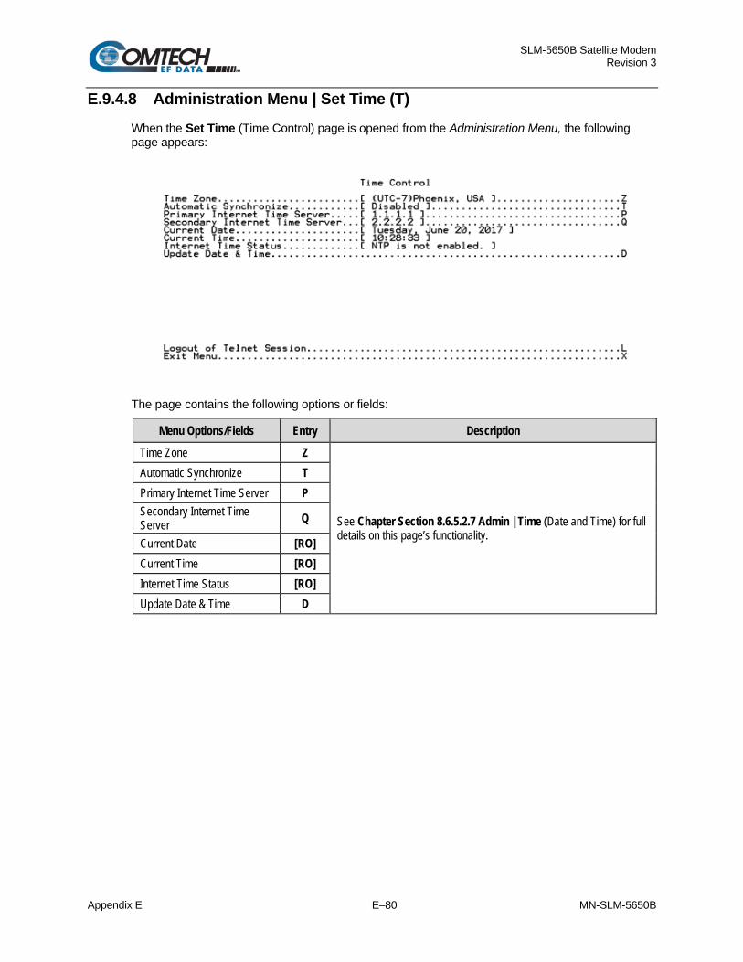
SLM-5650B Satellite Modem Revision 3
Appendix E E–80 MN-SLM-5650B
E.9.4.8 Administration Menu | Set Time (T) When the Set Time (Time Control) page is opened from the Administration Menu, the following page appears:
The page contains the following options or fields:
Menu Options/Fields Entry Description
Time Zone Z
See Chapter Section 8.6.5.2.7 Admin | Time (Date and Time) for full details on this page’s functionality.
Automatic Synchronize T Primary Internet Time Server P Secondary Internet Time Server Q
Current Date [RO] Current Time [RO] Internet Time Status [RO] Update Date & Time D

SLM-5650B Satellite Modem Revision 3
Appendix E E–81 MN-SLM-5650B
E.9.4.9 Administration Menu | Event Log (E) When the Event Log (System Event Log) page is opened from the Administration Menu, the system is polled for summary events and faults, as shown in the following example:
The page contains the following options or fields:
Menu Options/Fields Entry Description
Previous Page P
Allows user to navigate, on a per-page basis, between the start and end of the Event Log.
Next Page N Top T Bottom B Logging On/Off O
See Chapter Section 8.6.5.2.8 Admin | Event Log for full details on this page’s functionality. Logging Level E
Clear Event Log C

SLM-5650B Satellite Modem Revision 3
Appendix E E–82 MN-SLM-5650B
E.9.4.10 Administration Menu | Reboot Now (R)
Before rebooting, the user must remember to SAVE PARAMETERS TO FLASH (Select ‘S’ from the Administration Menu); otherwise, all changes made prior to reboot will be lost.
Select ‘R’ from the Administration Menu to reboot the system. The user is prompted:
Press ‘Y’ to begin the reboot process, or ‘N’ to abort the command and return to the previous menu.
Note: Pressing ‘Y’ causes the entire modem to reboot; this includes the base modem, NP Interface, and TRANSEC Module.

SLM-5650B Satellite Modem Revision 3
Appendix E E–83 MN-SLM-5650B
E.9.5 Satellite Modem Configuration (Modem Menu) (M) When the Satellite Modem Configuration (Modem Menu) page is opened from the Main Menu, the following page appears:
The page contains the following options or fields:
Menu Options/Fields Entry Description
Modem Type [RO] Displays modem type
Interface [RO] Displays installed interface
Reference [RO] Displays active reference (internal / external)
Frequency Band B Prompts user to select:
0 – 70/140 MHz 1 – L-Band
Modulator Settings M Allows user to configure modulator operating parameters
Demodulator Settings D Allows user to configure demodulator operating parameters
Receive Monitor R Read-only – displays active Rx operating parameters
Events E Displays the Modem Event Log and allows user to set or adjust display parameters for logging
Stats T Displays the System Event Log and allows user to set or adjust display parameters for logging
Utility U Allows user to select/set: T - Time (in HH:MM:SS format) D - Date (in DD/MM/YY format), or C - Circuit ID (exactly 24 characters).

SLM-5650B Satellite Modem Revision 3
Appendix E E–84 MN-SLM-5650B
E.9.5.1 Satellite Modem Configuration | Modulator Menu (M) When the Modulator Menu page is opened from the Satellite Modem Configuration (Modem Menu) page, the following page appears:
The page contains the following options or fields:
Menu Options/Fields Entry Description
FEC Type T Prompts the user to select: 0 – None 1 – Viterbi
2 – Turbo 3 – Sequential
Modulation M Prompts the user to select: 0 – BPSK 1 – QPSK
2 – OQPSK 3 – 8-PSK
4 – 16-QAM
FEC Code Rate C
Prompts the user to select: 0 – 1/1 1 – 1/2 2 – 3/4
3 – 7/8 4 – 2/3 5 – 5/6
6 – 21/44 7 – 5/16 8 – 17/18
Data Rate D Allows user to edit Data Rate using arrow keys.
Frequency F Allows user to edit Frequency using arrow keys.
Spectrum I Prompts user to select: 0 – Normal 1 – Inverted
Scrambler R
Prompts the user to select: 0 – Off 1 – OM73 2 – V.35
3 – Modified V.35 4 – SYNC 5 – IBS
6 – TURBO
Power Level P Allows user to edit Power Level using arrow keys.
Carrier A Prompts the user to select 0 – OFF 1 – ON
2 – RTS 3 – VSAT

SLM-5650B Satellite Modem Revision 3
Appendix E E–85 MN-SLM-5650B
E.9.5.2 Satellite Modem Configuration | Demodulator Menu (D) When the Demodulator Menu page is opened from the Satellite Modem Configuration (Modem Menu) page, the following page appears:
The page contains the following options or fields:
Menu Options/Fields Entry Description
FEC Type T Prompts the user to select: 0 – None 1 – Viterbi
2 – Turbo 3 – Sequential
Demodulation M Prompts the user to select: 0 – BPSK 1 – QPSK
2 – OQPSK 3 – 8-PSK
4 – 16-QAM
FEC Code Rate C
Prompts the user to select: 0 – 1/1 1 – 1/2 2 – 3/4
3 – 7/8 4 – 2/3 5 – 5/6
6 – 21/44 7 – 5/16 8 – 17/18
Data Rate D Allows user to edit Data Rate using arrow keys.
Frequency F Allows user to edit Frequency using arrow keys.
Spectrum I Prompts user to select:
0 – Normal 1 – Inverted
Descrambler R
Prompts the user to select: 0 – Off 1 – OM73 2 – V.35
3 – Modified V.35 4 – SYNC 5 – IBS
6 – TURBO

SLM-5650B Satellite Modem Revision 3
Appendix E E–86 MN-SLM-5650B
E.9.5.3 Satellite Modem Configuration | Receive Monitor (R) When the read-only Receive Monitor (Receive Parameters) page is opened from the Satellite Modem Configuration (Modem Menu), the following page appears:
Press ‘X’ to return to the Satellite Modem Configuration (Modem Menu) page.
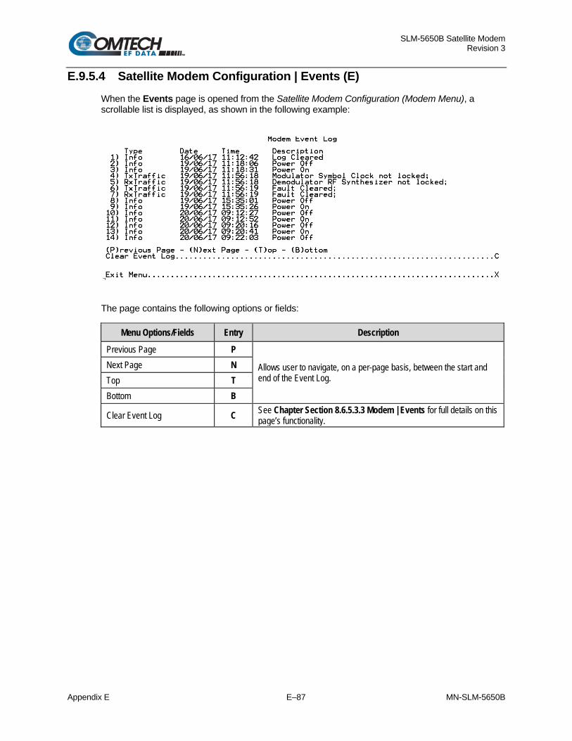
SLM-5650B Satellite Modem Revision 3
Appendix E E–87 MN-SLM-5650B
E.9.5.4 Satellite Modem Configuration | Events (E) When the Events page is opened from the Satellite Modem Configuration (Modem Menu), a scrollable list is displayed, as shown in the following example:
The page contains the following options or fields:
Menu Options/Fields Entry Description
Previous Page P
Allows user to navigate, on a per-page basis, between the start and end of the Event Log.
Next Page N Top T Bottom B
Clear Event Log C See Chapter Section 8.6.5.3.3 Modem | Events for full details on this page’s functionality.
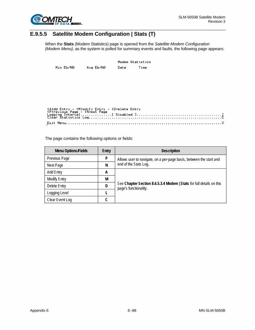
SLM-5650B Satellite Modem Revision 3
Appendix E E–88 MN-SLM-5650B
E.9.5.5 Satellite Modem Configuration | Stats (T) When the Stats (Modem Statistics) page is opened from the Satellite Modem Configuration (Modem Menu), as the system is polled for summary events and faults, the following page appears:
The page contains the following options or fields:
Menu Options/Fields Entry Description
Previous Page P Allows user to navigate, on a per-page basis, between the start and end of the Stats Log. Next Page N
Add Entry A
See Chapter Section 8.6.5.3.4 Modem | Stats for full details on this page’s functionality.
Modify Entry M Delete Entry D Logging Level L Clear Event Log C

SLM-5650B Satellite Modem Revision 3
Appendix E E–89 MN-SLM-5650B
E.9.5.6 Satellite Modem Configuration | Utility (U) When the Utility (Modem Utility Menu) page is opened from the Satellite Modem Configuration(Modem Menu), the following page appears:
The page contains the following options or fields:
Menu Options/Fields Entry Description
Time T Allows user to set the time in HH:MM:SS format. Date D Allows user to set the date in International format (DD/MM/YY).
Circuit ID C Allows the user to define a name for the Circuit ID. Note: This ID must consist of exactly 24 characters in UPPER CASE ONLY. No spaces are permitted in this ID; use a dash [-] instead.

SLM-5650B Satellite Modem Revision 3
Appendix E E–90 MN-SLM-5650B
E.9.6 LAN Menu (N) When the LAN Menu page is opened from the Main Menu, the following page appears:
The page contains the following options or fields:
Menu Options/Fields Entry Description
Interface I The LAN Interface menu allows the user to view the MAC address of the Network Processor and set the IP address and mask of the Network Processor:
Ethernet Ports E The Ethernet Ports menu allows the user to view the current status of the Ethernet ports and set each port to auto-negotiate or for manual configuration.
ARP Menu A The ARP Menu allows the user to view and edit the ARP (Address Resolution Protocol) table.
Proxy ARP P Prompts user to select 0 – Disabled 1 – Enabled
Port VLAN Enable M Prompts user to select 0 – Disabled 1 – Enabled
Port VLAN Select N Prompts user to select 0 – Port 1 1 – Port 2
2 – Port 3 3 – Port 4
Port VLAN Id O Enter an ID value from 2 to 4095. Packets containing specified VLAN only will ingress and egress from the NP Interface port specified via "VLAN Port Select" (Entry “N”).

SLM-5650B Satellite Modem Revision 3
Appendix E E–91 MN-SLM-5650B
E.9.6.1 LAN Menu | Interface (I) When the Interface (LAN Interface Menu) page is opened from the LAN Menu, the following page appears:
The page contains the following options or fields:
Menu Options/Fields Entry Description
MAC Address [RO] The MAC is set at the factory to a guaranteed unique address that cannot be modified by the user.
IP Addressing Mode A Prompts user to select
0 – Single (Traffic IP Address only) 1 – Dual (Traffic and Management IP Addresses)
Traffic IP Address T Allows user to edit the Traffic IP Address using the arrow keys.
Management IP Address M Allows user to edit the Management IP Address using the arrow keys.
Submit Changes C Saves any changes made to the Traffic and Management IP Addresses.

SLM-5650B Satellite Modem Revision 3
Appendix E E–92 MN-SLM-5650B
E.9.6.2 LAN Menu | Ethernet Ports Menu (E) When the Ethernet Ports Menu page is opened from the LAN Menu, a read-only NP Interface Ports 1 through 4 Link Status information is shown, and allows the user to manually change the Ethernet Port Speed/Duplex Configurations for each port by pressing ‘1’ through ‘4’ as needed.
E.9.6.2.1 LAN Menu | Ethernet Ports Menu | Ports 1-4 Speed/Duplex Configuration
When ‘1’, ‘2’, ‘3’ or ‘4’ is pressed on the Ethernet Ports Menu page, the user is then prompted to configure NP Interface Ports 1 through 4, on a per-port basis, with one of the following selections:
0 – Auto 1 – 10 Mbps Half Duplex
2 – 10 Mbps Full Duplex 3 – 100 Mbps Half Duplex 4 – 100 Mbps Full Duplex 5 – 1000 Mbps Full Duplex
Refer to Chapter Section 8.6.5.4.2 LAN | Ethernet Ports for an overview of this functionality.

SLM-5650B Satellite Modem Revision 3
Appendix E E–93 MN-SLM-5650B
E.9.6.3 LAN Menu | ARP Menu (A) When the ARP Menu (ARP Table) page is opened from the LAN Menu, the following page appears:
The page contains the following options or fields:
Menu Options/Fields Entry Description
Add entry A Refer to Chapter Section 8.6.5.4.3 LAN | ARP (ARP Table) for an overview of command functionality. Modify Entry M
Delete Entry D
Previous Page P Allows user to navigate, on a per-page basis, between the start and end of the ARP Table. Next Page N

SLM-5650B Satellite Modem Revision 3
Appendix E E–94 MN-SLM-5650B
E.9.7 WAN Menu (W) When the WAN Menu page is opened from the Main Menu, the following page appears:
The page contains the following options or fields:
Menu Options/Fields Entry Description
QoS Feature Q Prompts user to select: 0 – Disabled 1 – Enabled
Global Config & Statistics G
See Chapter Section 8.6.5.5 WAN Page for an overview of command functionality and/or information presented for these functions.
Global Con Display A
Global Statistics B
Class Selector 6 C
Expedited Forwarding E
Assured Forwarding Class 1 1
Assured Forwarding Class 2 2
Assured Forwarding Class 3 3
Assured Forwarding Class 4 4
Default D Provides user with read-only display of the DiffServ default queue.
Clear (reset) Statistics R Allows user to reset all DiffServ statistics.

SLM-5650B Satellite Modem Revision 3
Appendix E E–95 MN-SLM-5650B
E.9.8 Routing Table (R) When the Routing Table page is opened from the Main Menu, static routes can be entered into the IP Module to route IP traffic over the satellite or to another device on the local LAN. Route entries can be in any combination of Unicast and Multicast routes. The Routing Table page contains the following options or fields:
The page contains the following options or fields:
Menu Options/Fields Entry Description
Add entry A Refer to Chapter Section 8.6.5.6.1 Routing | Routes for an overview of command functionality. Modify Entry M
Delete Entry D
Previous Page P Allows user to navigate, on a per-page basis, between the start and end of the Routing Table. Next Page N

SLM-5650B Satellite Modem Revision 3
Appendix E E–96 MN-SLM-5650B
E.9.9 OSPF Configuration (F) When the OSPF Menu page is opened from the Main Menu, the following page appears:
The page contains the following options or fields:
Menu Options/Fields Entry Description
OSPF E Enables or Disables the Open Shortest Path First operation. Typing ‘E’ prompts user to select: 0 – Disabled 1 – Enabled
Area Network Address N
See Chapter Section 8.6.5.6.2 Routing | OSPF for an overview of command functionality and/or information presented for these functions.
Area Subnet Mask M
OSPF Area A
Cost C
Retransmit Interval R
Transmit Delay T
Priority P
Hello Interval H
Dead Interval D
Authentication Key K
Message Digest Key J
Submit Changes Z Saves any changes made on this page to the OSPF operating parameters.

SLM-5650B Satellite Modem Revision 3
Appendix E E–97 MN-SLM-5650B
E.9.10 IGMP Configuration (I) Whe the IGMP Configuration (IGMP Menu) page is opened from the Main Menu, the following page appears:
The page contains the following options or fields:
Menu Options/Fields Entry Description
IGMP E Enables or Disables the Internet Group Management Protocol operation. Typing ‘E’ prompts user to select: 0 – Disabled 1 – Enabled
Query Interval Q
See Chapter Section 8.6.5.6.3 Routing | IGMP for an overview of command functionality and/or information presented for these functions.
Response Interval R
Last Member Query Interval M
Robustness O
IGMP Version V
Submit Changes Z Saves any changes made on this page to the IGMP operating parameters.

SLM-5650B Satellite Modem Revision 3
Appendix E E–98 MN-SLM-5650B
E.9.11 Redundancy Configuration (E) When the Redundancy Configuration (1:1 Redundancy Menu) page is opened from the Main Menu, it provides the user with read-only status information on the redundant operations configuration.
The SLM-5650B Satellite Modem, when connected to a CEFD CRS-311 1:1 Redundancy Switch, provides fully-automatic protection of IP packet traffic in the case of equipment failure. Refer to the pertinent redundancy switch Installation and Operation Manual for detailed information on the use of the satellite modem in redundant operations.
If the user selects the Redundancy tab without a 1:1 Redundant Configuration, the 1:1 Redundancy status is displayed as Unavailable.

SLM-5650B Satellite Modem Revision 3
Appendix E E–99 MN-SLM-5650B
E.9.12 Operations & Maintenance (O) When the Operations & Maintenance page is opened from the Main Menu, the following page appears:
The page contains the following options or fields:
Menu Options/Fields Entry Description
Statistics T Provides user with read-only access to Ethernet Tx/Rx, LAN, WAN operating statistics; allows user to clear existing statistics.
Ping/TraceRoute Target IP I Allows user to edit target IP address for ping and trace route using the arrow keys.
Ping Above Address P Allows user to ping on IP Address.
Max Trace Route Hops M Allows user to set the maximum number of trace route hops using the arrow keys.
Trace Route Above Address R Allows user to trace route on IP address.
Base Management Port B Allows user to edit the Vipersat base management UDP/TCP port using the arrow keys.
WAN to WAN Internal Mcast Addr W Allows user to edit the WAN-WAN Internal Multicast Address using the arrow keys.
Debug Menu D Password-restricted for factory use only.
Note: Ping and Trace Route are only available through the CLI Operations & Maintenance page. For ping and trace route to work, the user must enter a target IP address. The user can then choose to issue a Ping or Trace Route to the Target IP Address. When doing a Trace Route, the maximum trace route hops can also be specified.

SLM-5650B Satellite Modem Revision 3
Appendix E E–100 MN-SLM-5650B
E.9.12.1 Operations & Maintenance | Statistics (T) When the Statistics page is opened from the Operations & Maintenance menu, a read-only statistics page is shown for varied operating parameters and commands used to clear those statistics.
The page contains the following options or fields:
Menu Options/Fields Entry Description
Ethernet TX T Refer to Chapter Section 8.6.5.7 Stats (Statistics) Page for an overview of the information provided on these read-only pages.
Ethernet RX R IP I WAN W Clear Ethernet Statistics (Tx & Rx) 1
Allows user to clear all statistics. Clear IP Statistics 2 Clear WAN Statistics 3

SLM-5650B Satellite Modem Revision 3
Appendix F F–1 MN-SLM-5650B
Appendix F. OPTIONAL TRANSEC MODULE OPERATION
F.1 Overview
Chapter 9. BASE MODEM HTTP/HTTPS INTERFACE OPERATION
The SLM-5650B is equipped with the optional Federal Information Processing Standards (FIPs) 140 Level 2 certified TRANSEC Module. The TRANSEC Module operates in standalone mode with the Base Modem, or in tandem with the optional NP Interface Module.
The SLM-5650B is fully compatible and interoperable in all specified modes of operation with KIV-19 Provisional and KG-95-1 Provisional TRANSEC equipment currently used by the Government.
EIA-422 data rates higher than 20 Mbps (for complete interoperability with the KG-95-1) are provisional.
For either configuration, the TRANSEC Module provides a proxy function of HTTPS connections to the Base Modem and the NP Interface. A secure HTTPS connection to the TRANSEC Module enables a secure user access to all Base Modem and/or all NP M&C parameters through this indirect proxy connection.
When the TRANSEC Module is installed, Management Security is mandatory, therefore, enabled, provided the proper HTTPS Certificate is installed. Network management M&C limitations are enacted when High Level Security is in effect. If the proper HTTPS Certifiate is not installed, then TRANSEC will function in a non-secure mode. See Chapter 9. BASE MODEM HTTP/HTTPS INTERFACE OPERATION for information related to the HTTPS Certificate. See Section F.3.2.5 for details related HTTPS Certificate installation/replacement for all modes except STANAG and Section F.4.2.4 for STANAG mode.

SLM-5650B Satellite Modem Revision 3
Appendix F F–2 MN-SLM-5650B
F.2 Introduction
You can fully control and monitor operation of the SLM-5650B TRANSEC Module from its HTTPS (Secure HTTP) Interface.
The pages in this section have been designed for optimal performance when using Microsoft’s Internet Explorer Ver. 7.0 or higher, Mozilla Firefox Ver. 2.0 or higher, and Chrome. With TRANSEC Module firmware version 2.2.4 or later, only web browsers with TLS 1.2 or higher are supported.
The examples shown in this appendix use Internet Explorer Version 7.0.
Secure Management – TRANSEC Module Plus NP Interface
Chapter 9. BASE MODEM HTTP/HTTPS INTERFACE OPERATION Appendix E. OPTIONAL NETWORK PROCESSOR (NP) INTERFACE MODULE
Make sure to read this section in its entirety!
The Secure Management interfaces supported by this configuration are summarized as follows:
Base Modem Network Processor (when installed) TRANSEC Module
HTTPS SNMPv3
HTTPS SSH HTTPS (Proxy via TRANSEC Module)
HTTPS SSH
For more information on these available Web interfaces, refer to Chapter 9. BASE MODEM HTTP/HTTPS OPERATION or Appendix E. OPTIONAL NETWORK PROCESSOR (NP) INTERFACE MODULE.
Instructions for Older Browsers
While legacy IE browser versions (e.g., Internet Explorer 6.0), can be used, CEFD Technical Support does not support services for these older browsers. If you have problems connecting to the secure web interface using an older browser, try this troubleshooting tip:
1. From the browser tool bar, go to the Tools | Internet Options | Advanced tab. See Figure F-1.
2. Under the Security heading, use the check boxes to: a. Disable the Secure Sockets Layers (SSL 2.0 and SSL 3.0). b. Enable the Transport Layer Security (TLS 1.0 with TRANSEC firmware version
earlier than 2.2.4, or TLS 1.2 with TRANSEC firmware version 2.2.4 or later). 3. Make sure to enable SSL again, once troubleshooting is finished.
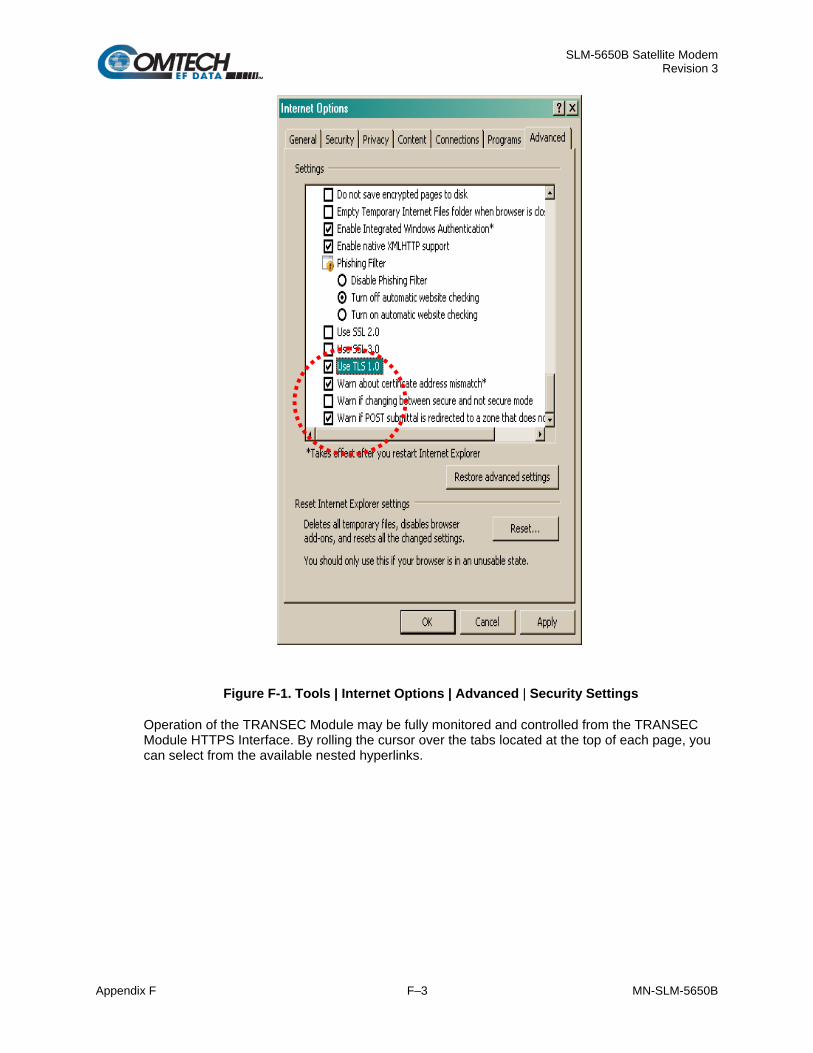
SLM-5650B Satellite Modem Revision 3
Appendix F F–3 MN-SLM-5650B
Figure F-1. Tools | Internet Options | Advanced | Security Settings
Operation of the TRANSEC Module may be fully monitored and controlled from the TRANSEC Module HTTPS Interface. By rolling the cursor over the tabs located at the top of each page, you can select from the available nested hyperlinks.

SLM-5650B Satellite Modem Revision 3
Appendix F F–4 MN-SLM-5650B
Operational Features
Chapter 9. BASE MODEM HTTP/HTTPS INTERFACE OPERATION
See Chapter 9. BASE MODEM HTTP/HTTPS INTERFACE OPERATION for an overview of the navigational and operational features common with using this interface.
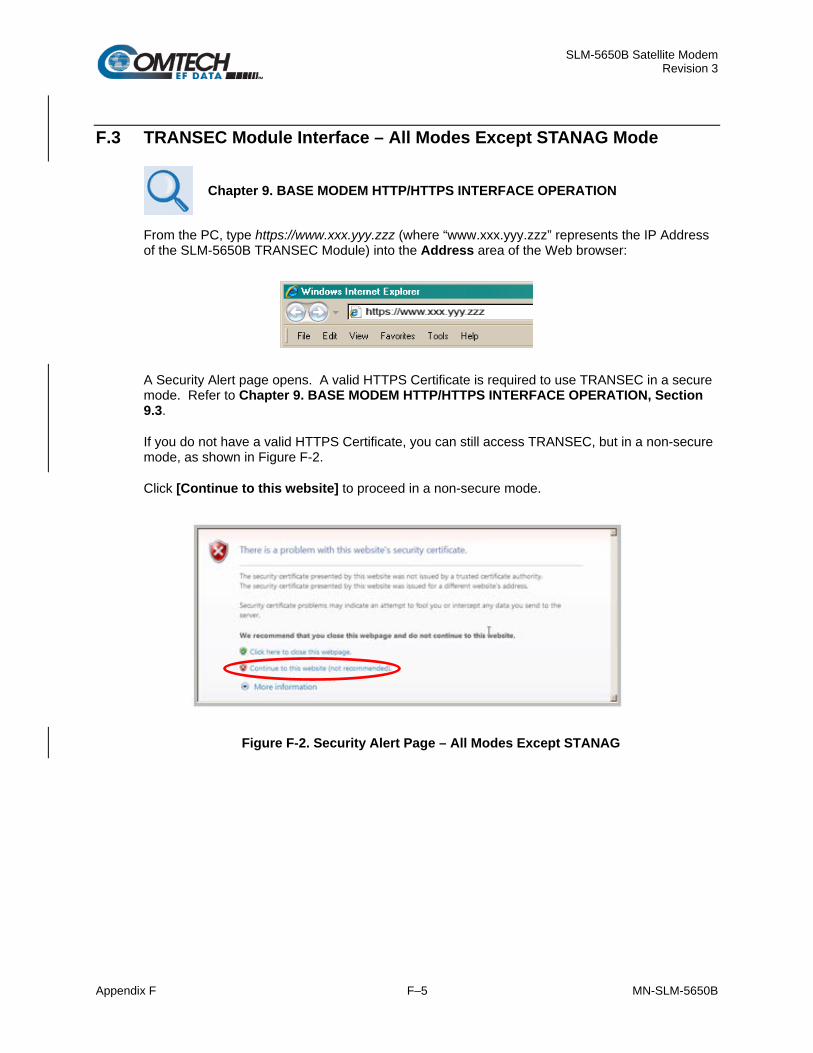
SLM-5650B Satellite Modem Revision 3
Appendix F F–5 MN-SLM-5650B
F.3 TRANSEC Module Interface – All Modes Except STANAG Mode
Chapter 9. BASE MODEM HTTP/HTTPS INTERFACE OPERATION
From the PC, type https://www.xxx.yyy.zzz (where “www.xxx.yyy.zzz” represents the IP Address of the SLM-5650B TRANSEC Module) into the Address area of the Web browser:
A Security Alert page opens. A valid HTTPS Certificate is required to use TRANSEC in a secure mode. Refer to Chapter 9. BASE MODEM HTTP/HTTPS INTERFACE OPERATION, Section 9.3.
If you do not have a valid HTTPS Certificate, you can still access TRANSEC, but in a non-secure mode, as shown in Figure F-2.
Click [Continue to this website] to proceed in a non-secure mode.
Figure F-2. Security Alert Page – All Modes Except STANAG

SLM-5650B Satellite Modem Revision 3
Appendix F F–6 MN-SLM-5650B
From the login page in the TRANSEC Module interface, use the Interface Navigator to select one of three modes of operation.
Figure F-3. TRANSEC Login Page – All Modes Except STANAG
• Crypto Officer: Connects to the secure TRANSEC Module Interface (User Name and Password required).
• Modem Operator: Connects to the Base Modem Interface. See Chapter 9. BASE MODEM HTTP/HTTPS INTERFACE OPERATION for more information.
• Network Operator: Not Available.
Once the login page opens, Crypto Officer appears as the default.
On the Login page, type in a valid Crypto Officer User Name and Crypto Officer Password.
The default for both is comtech. Click Log In.
The TRANSEC Module User Name and Password are each restricted to a minimum of 7 and a maximum of 25 characters, excluding: (ASCII Code 58), < (ASCII Code 60), > (ASCII Code 62), “ (ASCII Code 34), and ~ (ASCII Code 126).
Once the User Name and Password are accepted, the TRANSEC Module Configure page opens.

SLM-5650B Satellite Modem Revision 3
Appendix F F–7 MN-SLM-5650B
Menu Tree
The following menu tree illustrates the options available via the TRANSEC Module HTTPS Interface:
Interface Navigator
Drop-down Menu
Page Navigation Tabs
Configure Monitor Log Firmware Upload
Crypto Officer
Modem Operator
Network Operator
The Interface Navigator Drop-down Menu and its selections (shown in green) allow secure access to one of the SLM-5650B's three, distinct Web interfaces.
Once Crypto Officer (i.e., the TRANSEC Module HTTPS Interface) is selected, the four, available navigation tabs (above, shown in blue) are available.
Click any tab or hyperlink to continue.
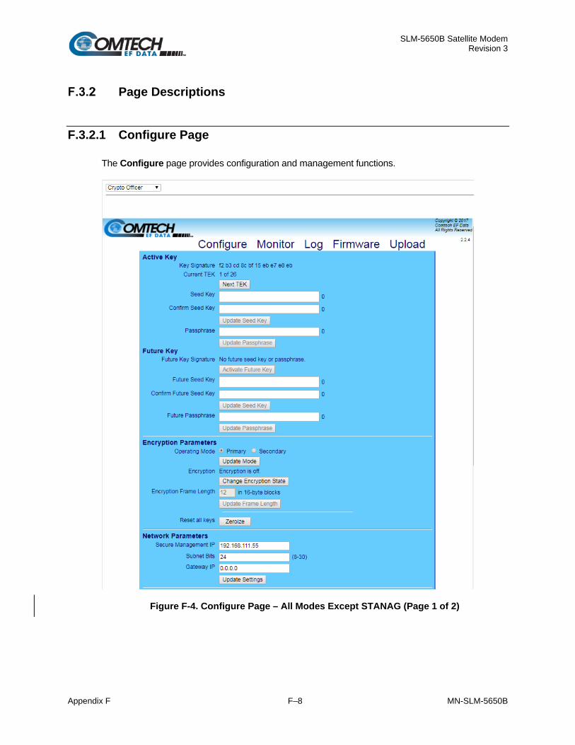
SLM-5650B Satellite Modem Revision 3
Appendix F F–8 MN-SLM-5650B
Page Descriptions
F.3.2.1 Configure Page
The Configure page provides configuration and management functions.
Figure F-4. Configure Page – All Modes Except STANAG (Page 1 of 2)

SLM-5650B Satellite Modem Revision 3
Appendix F F–9 MN-SLM-5650B
Figure F-5. Configure Page – All Modes Except STANAG (Page 2 of 2)
Active Key
Item Description
Key Signature (read-only)
This is a signature, or fingerprint, of the Transmission Encryption Keys (TEKs) generated by the Seed Key and Passphrase. The user can compare signatures on different modems to ensure that each has the same Seed Key and Passphrase. NOTE: The TEKs are updated only when a Passphrase is submitted.
Current TEK (read-only)
The user may generate 26 TEKs from the Seed Key and Passphrase (described below). The active TEK (1 through 26) is displayed here. When it is desired to change the encryption key being used to encrypt traffic, click Next TEK to select the next key in the set of 26 TEKs. Note the following: • The Next TEK button is disabled when the module is in secondary mode, and the
current TEK mirrors the TEK the connected primary modem uses. • The TEK only increments and never decrements; the user cannot re-use a
previous key. The only way to reset the TEK to 1 is by clicking Activate Future Key (described below).
Seed Key (write-only)
Enter a 32-character Seed Key in this text box to generate TEKs when the TRANSEC Module is given a Passphrase (described below).
Confirm Seed Key (write-only)
Re-enter the newly created Seed Key in this text box to ensure its accuracy. Once the Seed Key is entered and confirmed, click Update Seed Key to finalize this change.

SLM-5650B Satellite Modem Revision 3
Appendix F F–10 MN-SLM-5650B
Item Description
Enter Passphrase (write-only)
Accepts a 10- to 32-character Passphrase that is combined with the previously entered Seed Key to generate TEKs. Once the Passphrase is entered, click Update Passphrase to finalize this change.
Future Key
Item Description
Future Key Signature The user can program a second seed key and passphrase to generate a second set of TEKs. These keys will lie dormant until the user activates them by clicking Activate Future Key. At that time, the following happens:
1. The active TEKs are replaced by the ones generated with the Future Seed Key and Future Passphrase.
2. The Current TEK gets reset to 1. 3. Secondary modems connected to this one will also activate their Future Keys.
NOTE: The [Activate Future Key] button is active only when the following conditions are met:
1. The modem is in Primary mode (see Encryption Mode, explained below). 2. The Current TEK is greater than 1.
Future Seed Key (write-only)
Enter a 32-character Future Seed Key in this text box to generate a TEK when the TRANSEC Module is given a Future Passphrase (described below).
Confirm Future Seed Key (write-only)
Re-enter the newly created Future Seed Key in this text box to ensure its accuracy. Once the Future Seed Key is entered and confirmed, click Update Seed Key to finalize this change.
Future Passphrase (write-only)
Accepts a 10- to 32-character Passphrase that is combined with the previously entered Seed Key to generate TEKs. Once the Passphrase is entered, click Update Passphrase to finalize this change.

SLM-5650B Satellite Modem Revision 3
Appendix F F–11 MN-SLM-5650B
Encryption Parameters
Item Description
Operating Mode Set encryption in the TRANSEC Module as Primary or Secondary. Note the following: • If Primary is selected, the TRANSEC Module will allow the user to advance the
TEK and activate the future key independently of any other modems. • If Secondary is selected, the TRANSEC Module's TEK automatically mirrors the
TEK of the primary modem and the module will activate the future key when the primary modem activates its future key.
Click Update Mode when done. Encryption Click Change Encryption State to display the On and Off radio buttons. The “layered”
appearance of this control is intended to prevent the user from accidentally toggling the Encryption State. By selecting the Encryption State as ‘On’, this causes the data traffic to be encrypted by the TRANSEC Module using the current TEK. This encrypted data is then delivered to the base modem for transmission, regardless of the state of the receiving modem. Three user-defined parameters must match in order for encrypted communication to commence between two TRANSEC Module-equipped modems:
1. Seed Key. 2. Passphrase. 3. Encryption Frame Length.
Select the desired operational state, then click Update Encryption to save the selected state and then return this selection to its “protected” mode; the On/Off radio buttons will be hidden once again and the operational state message will update accordingly (i.e., “Encryption is On” or “Encryption is Off”).
Encryption Frame Length
Use this text box to specify the length of the Advanced Encryption Standard (AES) 256 encryption frame. Acceptable range is from 1 (fast acquisition, high overhead ) to 255 (slower acquisition, low overhead). Once the desired Encryption Frame Length has been entered, click Update Frame Length to implement this change.
Reset all keys Click Zeroize to reset all encryption keys in the module’s memory and flash to default values.

SLM-5650B Satellite Modem Revision 3
Appendix F F–12 MN-SLM-5650B
Network Parameters
Item Description
Secure Management IP
Allows users to change the IP address of the TRANSEC Module to suit their own operational environment. NOTE: If this text box changes, it will be necessary to repeat the process in Section 8.3 using the newly-designated IP address, to regain access to the TRANSEC Web Interface.
Subnet Bits Allows users to modify the IP subnet mask of the TRANSEC Module to suit their own operational environment.
Gateway IP
Allows users to modify the default gateway of the TRANSEC Module to suit their own operational environment. NOTE: The IP address entered in the text box must match the subnet of the Secure Management IP. If it does not then the Gateway IP text box will default to 0.0.0.0.
Click Update Settings to apply changes made to any of these parameters.
Crypto Officer Credentials
This section is used to create a TRANSEC Module Crypto Officer Username and Crypto Officer Password. Note that are each restricted to a minimum of 7 and a maximum of 25 characters, excluding: (ASCII Code 58), < (ASCII Code 60), > (ASCII Code 62), “ (ASCII Code 34), and ~ (ASCII Code 126).
The default for both the Crypto Officer Username and Password is transec.
Item Description
Crypto Officer Username
Use this text box to create the desired username.
Password Use this text box to create the desired password for the username being created. Confirm Password Use this text box to re-enter the previously entered password.
Once the Username is entered and the Password is confirmed, click Update Credentials to finalize this update.
Key Generation
This section is only available for TRANSEC firmware version 2.2.4 or later. Prior firmware versions will only be able to operate in the Legacy mode.
Item Description
Key Generation Mode Allows the user to select the Legacy mode, which is compatible with firmware versions prior to 2.2.4, or the FIPS approved mode.

SLM-5650B Satellite Modem Revision 3
Appendix F F–13 MN-SLM-5650B
SSH (Secure Shell) Console
Item Description
Host Key Signature This key signature, or fingerprint, helps to identify the TRANSEC Module when connecting through SSH. SSH clients typically show the host key signature when they connect to a system for the first time. The user can then compare the host key the SSH client shows with the host key the TRANSEC Module displays to verify that they are the same. Click Generate New Host Key to generate a new host key that uniquely identifies the TRANSEC Module. After doing this, SSH clients that have connected to the TRANSEC Module before will usually note or warn that the host key has changed when they connect again.
SSH Console Click On or Off to set administrative access to the console, then click Update SS to implement this setting.
HTTPS
Item Description
Certificate Signature Displays the digital fingerprint of the installed SSL certificate, which helps identify the certificate.
CA File Signature Displays the digital fingerprint of the installed CA File, which helps identify the file. Reset certificate Resets the SSL certificate to the factory default.

SLM-5650B Satellite Modem Revision 3
Appendix F F–14 MN-SLM-5650B
F.3.2.2 Monitor Page
Figure F-6. Monitor Page – All Modes Except STANAG
Encryption Parameters
Item Description AES256 Firmware Version Identifies the version of the AES 256 core.
Encryption Frame Length Displays the currently configured AES 256 frame length.
Board Temp Displays the temperature of the TRANSEC Module TRANSEC Clock Status Displays the DCM locked status for the AES 256 core.
Transmit Status
Item Description TX Frame Count Displays the number of transmitted AES 256 frames. TX Status Describes the value of the Tx Status register. DCM Lock Displays the state of the Tx DCM lock. Bypass Traffic Displays the encryption status (Bypass on means Encryption off).
Crypto Traffic When Detected, the module has sampled outgoing traffic and verifies it has been encrypted. When Not Detected, encryption is off, or the module cannot verify encrypted traffic.

SLM-5650B Satellite Modem Revision 3
Appendix F F–15 MN-SLM-5650B
Receive Status
Item Description RX CRC Errors Displays the count of received CRC errors. RX Frame Count Displays the number of received AES 256 frames. RX Status Displays the value of the Rx Status register. DCM Lock Displays the state of the Rx DCM lock.
Unique Word Lock Indicates that the decryption engine has successfully found the unique word and has been able to lock to it.
Out of Sync Indicates that an out-of-sync condition has been detected by the encryption engine.
Automatic Refresh Status Timer
The page updates itself automatically for the duration of the countdown timer. When the timer reaches 0:00, the page will stop updating to help conserve system resources.
To manually override the timer, click Stop to interrupt or Reset to restart the timer.

SLM-5650B Satellite Modem Revision 3
Appendix F F–16 MN-SLM-5650B
F.3.2.3 Log Page
Figure F-7. Log Page – All Modes Except STANAG
Event Log Control
Item Description
Logging State On/Off Enables/disables logging of event messages.
Logging Level This drop-down menu controls the maximum filtering level of displayed messages. Choices are Errors Only, Errors and Warnings, and All Information. Click Save to save the settings.
Event Log
Column Description
Index The event messages are numbered in the order they are received. Type Describes the severity of the event. Date Displays the date that the event was logged in using MONTH/DAY/YEAR format. Time Displays the time of day that the event was logged in 24-hour format. Description Displays a brief description of the logged event.

SLM-5650B Satellite Modem Revision 3
Appendix F F–17 MN-SLM-5650B
Table F-1. Event Log Message Types
Event Type (By order of severity – from least to worst case)
Event Type Event Description Level of Severity / User Action
Informational Normal operational status change; e.g., successful password or configuration setting change.
Minimum. Event logged is for user reference only.
Warning
Status change that the system might not accept or expect; e.g., setting the future passphrase without first setting the future seed key, entering an invalid remote command, etc.
Moderate. User should consult the pertinent sections of this manual to troubleshoot, and then repeat command or procedure as needed.
Minor
Error condition that the system should be able to recover from without affecting the operation of the system; e.g., encountering software ‘bug’, etc. Such events are not recorded into the Events Log.
Moderate. User should report issues when convenient to CEFD Customer Support.
Major A more severe error that may indicate a degradation of the stability of the system; e.g., out-of-range temperature readings for the TRANSEC Module, etc.
Maximum. User should contact CEFD Customer Support as soon as possible to address issue.
Critical The most severe error level indicating that system failure has occurred or is imminent; e.g., memory allocation failure, OS failure, etc.
Maximum. User should contact CEFD Customer Support immediately to arrange for RMA / in-factory service.
Click Clear Log to clear the event log of all messages. The event log is reset to zero entries.
Figure F-8. Event Log Page Cleared – All Modes Except STANAG

SLM-5650B Satellite Modem Revision 3
Appendix F F–18 MN-SLM-5650B
F.3.2.4 Firmware Page
Chapter 5. FIRMWARE UPDATE
See Chapter 5. FIRMWARE UPDATE for instructions regarding the use of the ‘Admin | Update’ page, and for detailed information on the procedures associated with the TRANSEC Module firmware update process.
Figure F-9. Firmware Unit Info Page – All Modes Except STANAG
Firmware Information
Item Description
Security Module Bootrom Info Boot Loader version information.
Image 1 Info Slot 1 firmware image version information. Image 2 Info Slot 2 firmware image version information. Running Image Indicates the active firmware image.
Upload New Firmware
Item Description
Upload New Firmware Click to navigate to the Upload page

SLM-5650B Satellite Modem Revision 3
Appendix F F–19 MN-SLM-5650B
Active Boot Slot Configuration
Item Description Boot From Select the firmware image to load on the next boot. Click [Submit] to save the selection. [Reboot] Reboot the modem.

SLM-5650B Satellite Modem Revision 3
Appendix F F–20 MN-SLM-5650B
F.3.2.5 Upload Page
Figure F-10. Upload Page – All Modes Except STANAG
Firmware
Use this area to select a file, and then upload updated firmware.
See Section F.3.2.6 for detailed information on the procedures associated with the TRANSEC Module firmware update process.
HTTPS Certificate
Use this area to upload an X509 private key and certificate in PEM format to replace the current HTTPS certificate.

SLM-5650B Satellite Modem Revision 3
Appendix F F–21 MN-SLM-5650B
HTTPS access will be lost if a bad certificate is installed. If this happens, restore the HTTPS access by resetting the SSL certificate through the SSH interface.
Splash Page
Use this area to upload a text file (up to 1 MB in size) to replace the current splash page.

SLM-5650B Satellite Modem Revision 3
Appendix F F–22 MN-SLM-5650B
F.3.2.6 Firmware Update Procedure
Firmware updates for the TRANSEC Module (also referred to in front panel menu screens as the “Option Card”) are not available from the CEFD Web site, but they may be obtained from CEFD on an as-needed basis. To obtain these updates, contact CEFD Customer Support to request access to the modem firmware update files online FTP site. The CEFD Customer Support representative will arrange for full firmware access information and download privileges at that time.
Step Task
1 Contact CEFD Customer Support during normal business hours to request delivery of the TRANSEC Module firmware update files. The Customer Support representative will arrange for full firmware access information and download privileges at that time.
Note: To aid identification, use the TRANSEC Module HTTPS Interface > Firmware Info to see the Bootrom, Bulk1, and Bulk2 firmware loads information.
2 Create a temporary folder (directory) on an external PC (note that the drive letter c: is used in this example; any valid writable drive letter can be used):
• For Windows Explorer: Select File > New > Folder to create a new folder, and then rename it from “New Folder” to "temp" or another convenient, unused name. Assuming "temp" works, a "c:\temp" folder should now be created.
• For Windows Command-line: Click Start on the Windows taskbar, and then click the “Run...” icon (or, depending on Windows OS versions prior to Windows 95, click the “MS-DOS Prompt” icon from the Main Menu). Then, to open a Command-line window…
o For Windows 95 or Windows 98 – Type “command”.
o For any Windows OS versions later than Windows 98 – Type “cmd” or “command”.
Alternately, from Start, select All Programs > Accessories > Command Prompt. At the Command-line prompt (c:\>), type “mkdir temp” or “md temp” (without quotes – mkdir and md stand for make directory). This is the same as creating a new folder from Windows Explorer. There should now be a "c:\temp" subdirectory created.
3 Download the correct firmware file that was obtained from CEFD Customer Support to this temporary folder. The TRANSEC Module firmware is FW-0020567x, where "x" denotes the firmware revision letter.
4 Extract the file in the temporary folder on the PC:
Fw-0020567x.bin, where "x" denotes the revision letter of the module bulk image file.
5 Confirm that the files have been extracted to the specified temporary folder on the PC.
Using Command-line, type “cd c:\temp” to change to the temporary directory created in Step 2, then use the “dir” command to list the files extracted from the downloaded archive file.

SLM-5650B Satellite Modem Revision 3
Appendix F F–23 MN-SLM-5650B
Step Task
6 Connect the PC to the modem’s Ethernet via a hub or a switch, or directly to the PC with a crossover cable.
7 Send a “ping” command to the TRANSEC Module to verify the connection and communication.
First, determine the IP address of the TRANSEC Module from the front panel:
SELECT: Configure Transec Module IP Address menus.
Then, using Command-line to “ping” the modem – at the prompt, type “ping xxx.xxx.xxx.xxx” (where ‘xxx.xxx.xxx.xxx’ is the TRANSEC Module’s IP address). The results should confirm whether or not the module is connected and communicating.
8 Initiate a secure Web session with the TRANSEC Module via its HTTPS Interface. Refer to Section F.2.3.

SLM-5650B Satellite Modem Revision 3
Appendix F F–24 MN-SLM-5650B
Step Task
9 Update the TRANSEC Module bulk firmware: a) Open the Upload page:
b) In the Firmware section of the page, locate the update file downloaded to the PC during Steps 2
through 4 :
• Click Browse. The Choose File dialog box will open.
• Locate the folder created for the file download; double-click on the folder name to open the folder.
c) Select the update file, and then click Open. The filename should appear in the Replace stand-by firmware text box.
d) Click Upload to begin the Firmware Application Process.

SLM-5650B Satellite Modem Revision 3
Appendix F F–25 MN-SLM-5650B
Step Task
10 Wait while the file transfers. After Upload is clicked, the Image Upgrade Process page appears while the TRANSEC Module transfers, and then uploads the update file from the PC.
Allow sufficient time for the file to be uploaded – approximately five minutes is required for the process to be completed. During the upload process, the page displays a transfer progress bar that provides the scrolling percentage of completion. During transfer, the message Please Wait will display.
Any power failure during this process will result in failure of the TRANSEC Module.
In the event that an error occurs during the Image Upgrade Process, then a message stating that an error occurred will appear.
For troubleshooting purposes, three common reasons for disruption of the Firmware Application Process are:
• Power Failure;
• Loss of Ethernet signal (e.g., disconnection of Ethernet cable);
Attempting to load firmware other than the TRANSEC Module bulk firmware (i.e., FW-0020567x.bin).
Upon successful completion of transfer, the progress bar shows 100%.

SLM-5650B Satellite Modem Revision 3
Appendix F F–26 MN-SLM-5650B
Step Task
11 On the Firmware page, verify that the newly-uploaded firmware is reported in the proper Security Module Bulk Info slot. If not, update the Active Boot Slot Configuration by using the drop-down menu to select Newest to force the TRANSEC Module to boot using the firmware with the most recent build date. Click Submit when done.
12 Click Reboot to boot the TRANSEC Module with the new firmware.
The modem will reboot with the new firmware.
It will be necessary to restart the TRANSEC Module HTTPS Interface session once the modem has returned online.
13 To load the second image, repeat Steps 9 through 11.
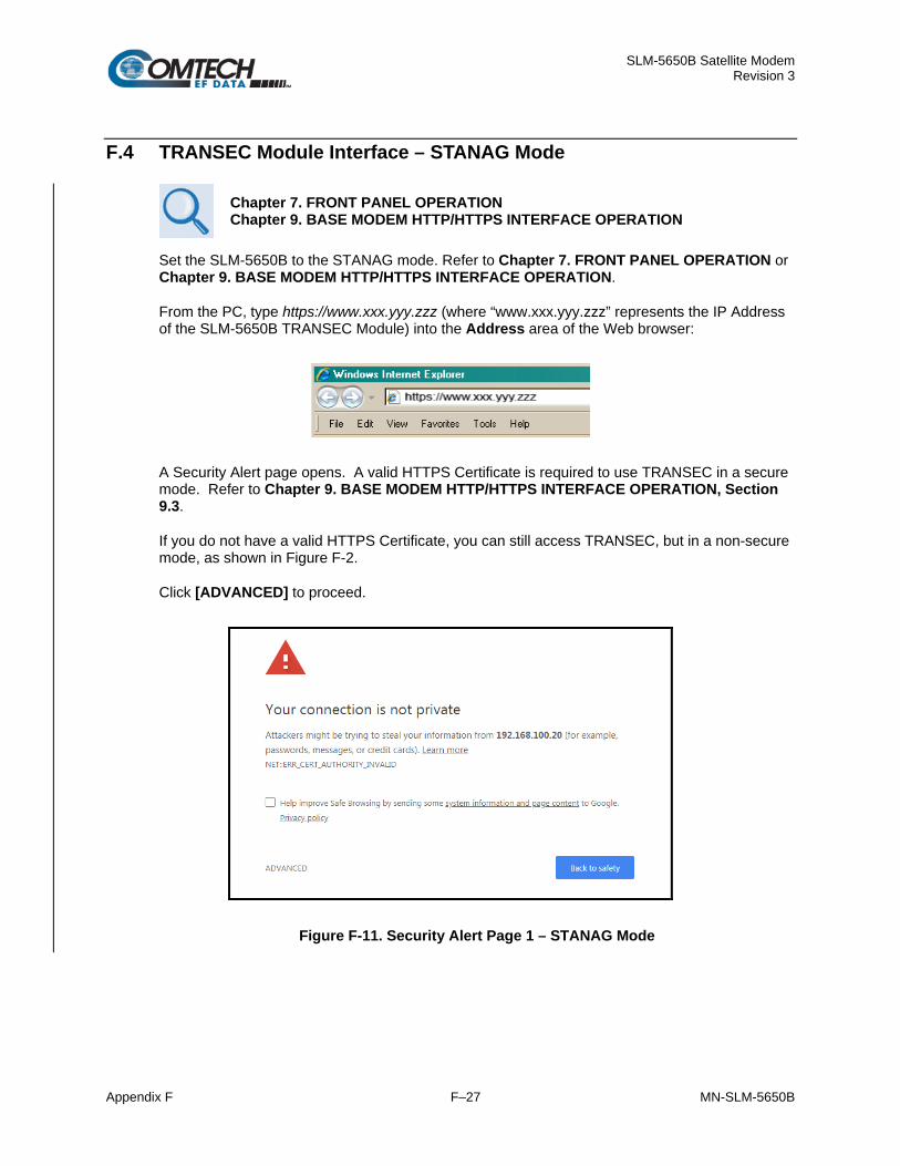
SLM-5650B Satellite Modem Revision 3
Appendix F F–27 MN-SLM-5650B
F.4 TRANSEC Module Interface – STANAG Mode
Chapter 7. FRONT PANEL OPERATION Chapter 9. BASE MODEM HTTP/HTTPS INTERFACE OPERATION
Set the SLM-5650B to the STANAG mode. Refer to Chapter 7. FRONT PANEL OPERATION or Chapter 9. BASE MODEM HTTP/HTTPS INTERFACE OPERATION.
From the PC, type https://www.xxx.yyy.zzz (where “www.xxx.yyy.zzz” represents the IP Address of the SLM-5650B TRANSEC Module) into the Address area of the Web browser:
A Security Alert page opens. A valid HTTPS Certificate is required to use TRANSEC in a secure mode. Refer to Chapter 9. BASE MODEM HTTP/HTTPS INTERFACE OPERATION, Section 9.3.
If you do not have a valid HTTPS Certificate, you can still access TRANSEC, but in a non-secure mode, as shown in Figure F-2.
Click [ADVANCED] to proceed.
Figure F-11. Security Alert Page 1 – STANAG Mode

SLM-5650B Satellite Modem Revision 3
Appendix F F–28 MN-SLM-5650B
The page will open another section:
Figure F-12. Security Alert Page 2 – STANAG Mode
Click [Proceed to xxx.xxx.xx.xx (unsafe] to proceed.
On the Login page, type in a valid Crypto Officer User Name and Crypto Officer Password.
The default for both is comtech. Click Log In.
The TRANSEC Module User Name and Password are each restricted to a minimum of 7 and a maximum of 25 characters, excluding: (ASCII Code 58), < (ASCII Code 60), > (ASCII Code 62), “ (ASCII Code 34), and ~ (ASCII Code 126).
Figure F-13. TRANSEC Login Page – STANAG Mode
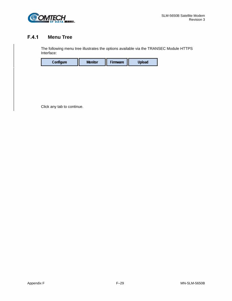
SLM-5650B Satellite Modem Revision 3
Appendix F F–29 MN-SLM-5650B
Menu Tree
The following menu tree illustrates the options available via the TRANSEC Module HTTPS Interface:
Configure Monitor Firmware Upload
Click any tab to continue.

SLM-5650B Satellite Modem Revision 3
Appendix F F–30 MN-SLM-5650B
Page Descriptions
F.4.2.1 Configure Page
Figure F-14. Configure Page – STANAG Mode
Encryption Control
Item Description
SMAT Shared Modem Authentication Token (SMAT) needs to match the other TRANSEC intended to pass secure traffic. The EDC is computed as the SMAT is typed. A SMAT can be 0 through 40 characters, 0-9, A-Z, or spaces. For SMAT to take affect, the modem needs to loose IF lock. Turning the carrier ON/OFF will cause the unit to use the SMAT configured. Click [Save] to enter SMAT.
RNG Seed This field has Auto Seeding when it is blank, otherwise, the RNG must be exactly 78-digits long. The EDC is computed after the RNG is completed and saved. The RNG cannot begin with a 0 and the first half must be different than the second half. The RNG takes affect after a reboot. Click [Save] to enter RNG Seed.

SLM-5650B Satellite Modem Revision 3
Appendix F F–31 MN-SLM-5650B
Item Description
Hours between rekey Enter amount of time required to wait before rekeying. The rekey intervals must be 0, or 8 through 1192. The value of 0 is acceptable for the initial entry. Click [Save] to enter hours.
Crypto Officer Credentials
Item Description
Crypto Officer Username
Enter a Username. The default name is comtech.
Crypto Officer Password
The password can contain any ASCII characters. The password can be 7 through 25 characters long.
Confirm Crypto Officer Password Enter the exact same Crypto Officer Password again.
Click [Update Credentials] to save.
Network
Item Description
MAC Address This is a read-only field that displays the MAC address. The MAC address is programmed at the factory and is unique between modules.
IP Address / Subnet This is the TRANSEC module IP address and gateway. To access this IP address, a secure web browser need to be initiated using https://192.x.x.x.
Default Gateway Enter the default gateway.
Click [Update Network] to save.
HTTPS
Item Description
SSL Certificate Signature
A new private key and certificate can be generated using Open SSL in Linux with the openssl reg\command. A file called cert.pem will hold the key. To load the key, click on the Upload tab in Section F.4.2.4. In the HTTPS Certificate area, browse to select the PEM-format private key/certificate file and upload. Zeroize will restore the default certificate. Certificate installation require a reboot to take effect.
CA File Signature This shows if the CA File Signature is / is not installed. Restore Default Click [Zeroize] to restore default.

SLM-5650B Satellite Modem Revision 3
Appendix F F–32 MN-SLM-5650B
Command Line Interface
Item Description
SSH Host Key Signature
Click [Generate Host Key] and verify that the value for the SSH Host Key Signature changes once it completes.
SSH Console Toggle SSH Console to ON and click [Update SSH]. This allows the SSH client to connect. Toggle SSH Console to OFF and click [Update SSH]. This rejects the SSH client connection.
Zeroize
Item Description
Zeroize All Keying Material Click [Zeroize] to zeroize all keying material.

SLM-5650B Satellite Modem Revision 3
Appendix F F–33 MN-SLM-5650B
F.4.2.2 Monitor Page
Figure F-15. Monitor Page – STANAG Mode
TRANSEC Status
This screen is used to show the status of the TRANSEC Module.
The traffic encryption keys (TEK) are established automatically using the key negotiation algorithm and messages. This is accomplished with the application utilizing an Initiator and Responder role. The Initiator starts with a Key Agreement Message and the Responder responds with a Key Agreement Response Message. This sequence continues until the TEKs are negotiated.

SLM-5650B Satellite Modem Revision 3
Appendix F F–34 MN-SLM-5650B
F.4.2.3 Firmware Page
Chapter 5. FIRMWARE UPDATE
See Chapter 5. FIRMWARE UPDATE for instructions regarding the use of the ‘Admin | Update’ page, and for detailed information on the procedures associated with the TRANSEC Module firmware update process.
Figure F-16. Firmware Page – STANAG Mode

SLM-5650B Satellite Modem Revision 3
Appendix F F–35 MN-SLM-5650B
F.4.2.4 Upload Page
Figure F-17. Upload Page – STANAG Mode
Firmware
Use this area to select a file, and then upload updated firmware.
HTTPS Certificate
Use this area to upload an X509 private key and certificate in PEM format to replace the current HTTPS certificate.
HTTPS access will be lost if a bad certificate is installed. If this happens, restore the HTTPS access by resetting the SSL certificate through the SSH interface.
Splash Page
Use this area to upload a text file (up to 1 MB in size) to replace the current splash page.
A required Government Splash Page, which shows when web browsing, is available for upload by selecting the file: aRequiredGovtSplash.txt. Click the [I Agree] button when it appears.
Click [Upload] to activate the Splash Page.

SLM-5650B Satellite Modem Revision 3
Appendix F F–36 MN-SLM-5650B
F.5 Command Line Interface (CLI)
Chapter 7. FRONT PANEL OPERATION
Overview
This section defines the CLI user menu system provided with the modem’s optional TRANSEC Module via a SSH interface.
The SSH interface allows you to change operating parameters similar to those found on the TRANSEC Module HTTPS Interface, and with the monitoring, configuration, and control operations available via the modem front panel. See Section F.2.3 or Chapter 7. FRONT PANEL OPERATION, respectively, for detailed information about the command functionality outlined in this appendix.

SLM-5650B Satellite Modem Revision 3
Appendix F F–37 MN-SLM-5650B
F.5.1.1 SSH (Secure Shell) User Access
Chapter 8. ETHERNET INTERFACE OPERATION
See Chapter 8. ETHERNET INTERFACE OPERATION, Section 8.4 for initial setup and operational examples for using an SSH terminal emulator application for CLI operations
As explained in Chapter 8. ETHERNET INTERFACE OPERATION, Section 8.4, this appendix section uses PuTTY (Figure F-18), a free and open source terminal emulator application used as a serial console client for SSH, Telnet, rlogin and raw TCP computing protocols. While the TRANSEC Module CLI main and nested screens will be identical across terminal emulator applications, setup may differ slightly – this appendix assumes user familiarity with the preferred SSH interface.
Figure F-18. PuTTY Examples
Once connected to the TRANSEC Module via the SSH interface, you will need to provide a login name and password (the defaults for both are comtech). When the valid login and password are provided, you are taken directly to the CLI Main Menu, as shown in the Figure F-18 examples.

SLM-5650B Satellite Modem Revision 3
Appendix F F–38 MN-SLM-5650B
CLI Menu System – Parallel Functionality
Chapter 7. FRONT PANEL OPERATION
The CLI, accessible via SSH, allows you to change operating parameters in a manner similar to the functionality as provided for the monitoring, configuration, and control via the SLM-5650B Satellite Modem’s front panel menus (Chapter 7. FRONT PANEL OPERATION) and in the TRANSEC Module HTTPS Interface (Section F.2.3).
F.5.2.1 CLI Menu – Common Information, Navigation, and Operation Features
With some exceptions, the menu pages depicted in this chapter feature the following information or navigational aids:
Menu Options/Fields Entry Description [Text field example] [RO] Typically found in the body of the page. This designates the field as
a read-only status/informational message. There is no user action required for this item.
Logout of Administration Session L Found at the bottom of the page. Allows user to log out of the SSH session.
Exit Menu X Found at the bottom of the page. Allows user to exit the current menu and return to the parent menu. Alternately, the user may press the Esc key to perform the same action.
Typically, once any mnemonic is entered, the user is prompted to type in a functional selection, an alphanumeric configuration string, or an operational value. This prompt is provided at the bottom of the active page and takes the form of a selection choice and/or a blank prompt (a solid bar), as shown in the example to the right:
If a parameter is rejected for any reason, an error will appear at the top of the page, along with an explanation that serves to assist the user in the re-entry of information, as per the following examples:

SLM-5650B Satellite Modem Revision 3
Appendix F F–39 MN-SLM-5650B
Save
Any changes made via the CLI should be saved to permanent storage prior to terminating the CLI session. While changes will remain active so long as the modem remains in operation, take note also that changes will be lost if, for example, the modem loses power. Modified parameters can be saved by issuing the Save command “S” from any menu. The user is prompted to confirm that all changes should be made permanent:
Logout
When you attempt to terminate a CLI session via Logout command “L”, the CLI prompts you to confirm that you wish to end your session:

SLM-5650B Satellite Modem Revision 3
Appendix F F–40 MN-SLM-5650B
Command Line Interface Pages
F.5.3.1 Main Menu
The Main Menu serves as the CLI’s primary navigation page. All selections made on this page take the user to submenus listed in this table (operational features nested under each of these submenus, in turn, are outlined in the chapter sections listed):
Submenu Entry Function/Description Section Configuration C Provides configuration access to the TRANSEC
Module encryption features. Error! Reference source not found.
Module Status M This read-only page compiles the TRANSEC Module’s current operating parameters.
Error! Reference source not found.
Event Log E Opens the Event Log page. The user monitors and controls operational faults and alarms here.
Error! Reference source not found.
Firmware F Opens the Unit Info Page which displays the loaded firmware information.
Error! Reference source not found.

SLM-5650B Satellite Modem Revision 3
Appendix F F–41 MN-SLM-5650B
F.5.3.2 Configuration [C]
Figure F-19. Configuration Menu Page
Table F-2. Configuration Menu Options
Menu Options/Fields Entry Description Section
Active Encryption Key A Opens the nested Active Encryption Key Menu page. F.5.3.2.1
Future Encryption Key F Opens the nested Future Encryption Key Menu page. F.5.3.2.2
Encryption Settings E Opens the nested Encryption Menu page. F.5.3.2.3
Network Configuration N Opens the nested Network Menu page. F.5.3.2.4
Crypto Officer Credentials C Opens the nested Credentials Menu page. F.5.3.2.5
Key Generation* K Opens the nested Key Generation Menu page. F.5.3.2.6
SSH Console S Opens the nested SSH Console Menu page. F.5.3.2.7
HTTPS Configuration H Opens the nested HTTPS Menu page. F.5.3.2.8
* This menu option is only available with TRANSEC firmware version 2.2.4 or later. Prior firmware versions will only operate in the Legacy mode.

SLM-5650B Satellite Modem Revision 3
Appendix F F–42 MN-SLM-5650B
F.5.3.2.1 Configuration | Active Encryption Key Menu [A]
Figure F-20. Configuration | Active Encryption Key Menu Page
Table F-3. Active Encryption Key Menu Options
Menu Options/Fields Entry Description/User Prompt Key Signature [RO] Current Active Key Signature is identified here.
Seed Key K Enter a 32-character Active Seed Key to generate a TEK when the TRANSEC Module is given a Passphrase (described below).
Confirm Seed Key C Confirm to the Active Seed Key just entered. Seed Key fields [RO] Displays the status of the Active Seed Key in real time.
Passphrase P Enter a 10- to 32-character Passphrase that is combined with the previously entered Active Seed Key to generate TEKs.
Current TEK [RO] Identifies the Current TEK (1 through 26).

SLM-5650B Satellite Modem Revision 3
Appendix F F–43 MN-SLM-5650B
F.5.3.2.2 Configuration | Future Encryption Key Menu [F]
Figure F-21. Configuration | Future Encryption Key Menu Page
Table F-4. Future Encryption Key Menu Options
Menu Options/Fields Entry Description/User Prompt
Key Signature [RO] Future Key Signature is identified here.
Seed Key K Enter a 32-character Future Seed Key to generate a TEK when the TRANSEC Module is given a Passphrase (described below).
Confirm Seed Key C Confirm to the Future Seed Key just entered.
Seed Key fields [RO] Displays the status of the Future Seed Key in real time.
Passphrase P Enter a 10- to 32-character Passphrase that is combined with the previously entered Future Seed Key to generate TEKs.
Activate Future Key (not shown) I
Activates the future Seed Key and resets the TEK index to 1. Note: This option shows only when all of these are true:
a. the module is in primary mode b. you have entered a future Seed Key and Passphrase c. you have advanced the current TEK so that it is in the range of 2 to 26
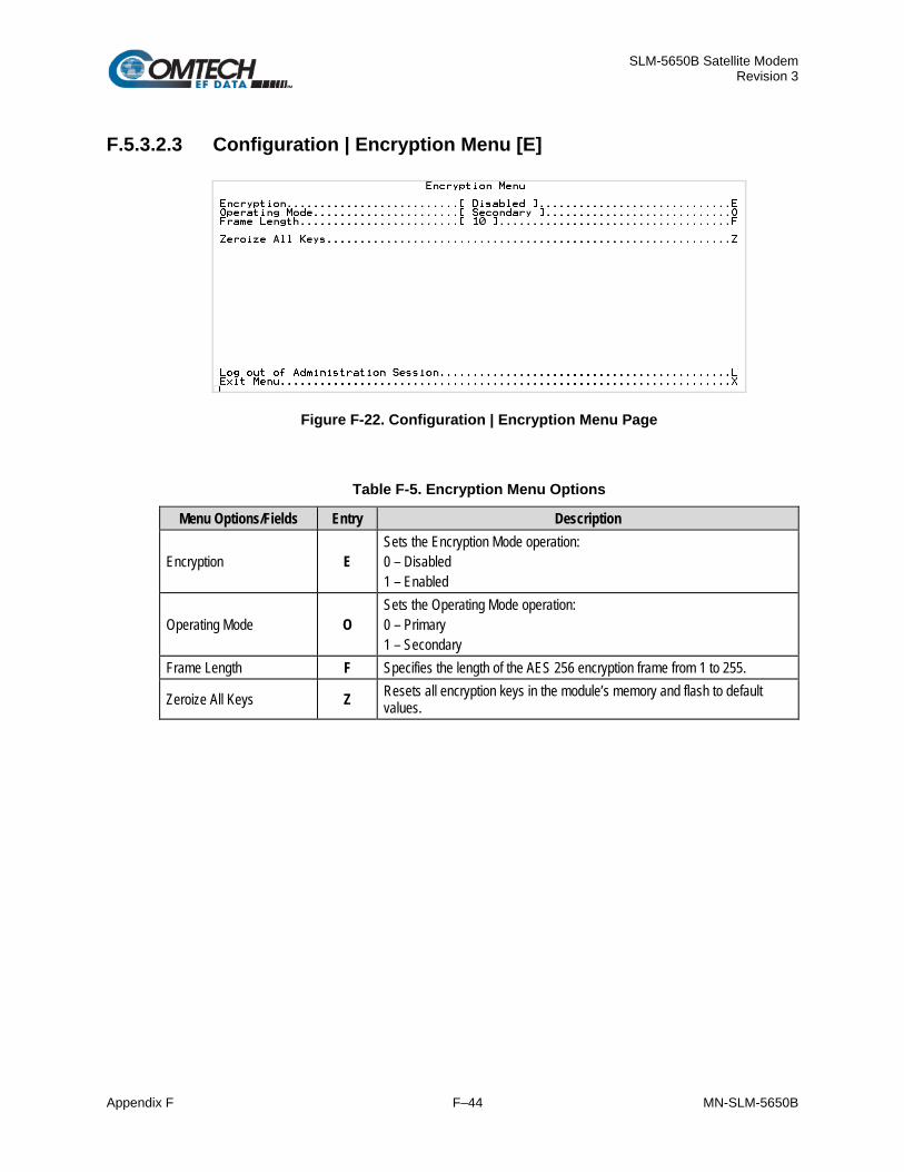
SLM-5650B Satellite Modem Revision 3
Appendix F F–44 MN-SLM-5650B
F.5.3.2.3 Configuration | Encryption Menu [E]
Figure F-22. Configuration | Encryption Menu Page
Table F-5. Encryption Menu Options
Menu Options/Fields Entry Description
Encryption E Sets the Encryption Mode operation: 0 – Disabled 1 – Enabled
Operating Mode O Sets the Operating Mode operation: 0 – Primary 1 – Secondary
Frame Length F Specifies the length of the AES 256 encryption frame from 1 to 255.
Zeroize All Keys Z Resets all encryption keys in the module’s memory and flash to default values.

SLM-5650B Satellite Modem Revision 3
Appendix F F–45 MN-SLM-5650B
F.5.3.2.4 Configuration | Network Menu [N]
Figure F-23. Configuration | Network Menu Page
Table F-6. Network Menu Options
Menu Options/Fields Entry Description
Secure Management IP M
Change the TRANSEC Module IP Address as needed. Note: If this address is changed, it will be necessary to repeat the login process for the SSH interface, as described in Section 8.4, using the newly-designated IP Address, to regain access to the TRANSEC Module SSH CLI.
Subnet Bits B Change the IP subnet mask of the TRANSEC Module as needed.
Gateway IP G
Change the TRANSEC Module IP Gateway Address as needed.
If this address is changed, it must match the subnet of the Secure Management IP. If it does not, then the Gateway IP Address text box will default to 0.0.0.0.

SLM-5650B Satellite Modem Revision 3
Appendix F F–46 MN-SLM-5650B
F.5.3.2.5 Configuration | Credentials Menu [C]
Figure F-24. Configuration | Crypto Officer Credentials Menu Page
Table F-7. Crypto Officer Credentials Menu Options
Menu Options/Fields Entry Description Crypto Officer User Name U Use to create the desired User Name.
Crypto Officer Password P Use to create the desired Password.
Confirm Password C Use to confirm the Password just entered.
Password Fields [RO] Provides the status of the password field in real time.
The Crypto Officer User Name and Password are each restricted to a minimum of 7 and a maximum of 25 characters. Excluded are:
: ASCII Code 58
< ASCII Code 60
> ASCII Code 62
“ ASCII Code 34
~ ASCII Code 126

SLM-5650B Satellite Modem Revision 3
Appendix F F–47 MN-SLM-5650B
F.5.3.2.6 Configuration | Key Generation Method Menu [K]
This menu option is only available with TRANSEC firmware version 2.2.4 or later. Prior firmware versions will only operate in the Legacy mode.
Figure F-25. Key Generation Menu Page
Table F-8. Key Generation Menu Options
Menu Options/Fields Entry Description
Key Generation Method K
Displays a prompt to set the key generation mode to legacy method compatible with firmware version prior to 2.2.4 or the FIPS approved mode. 0 – Legacy 1 – FIPS

SLM-5650B Satellite Modem Revision 3
Appendix F F–48 MN-SLM-5650B
F.5.3.2.7 Configuration | SSH Console Menu [S]
Figure F-26. Configuration | SSH Console Menu Page
Table F-9. SSH Console Menu Options
Menu Options/Fields Entry Description
Host Key Signature [RO] Displays the key signature, or fingerprint, which helps to identify the TRANSEC Module when connecting through SSH.
Generate new host Key G Generate a new host key that uniquely identifies the TRANSEC Module.
SSH S Toggle Secure Shell Console operation: 0 – Off 1 – On
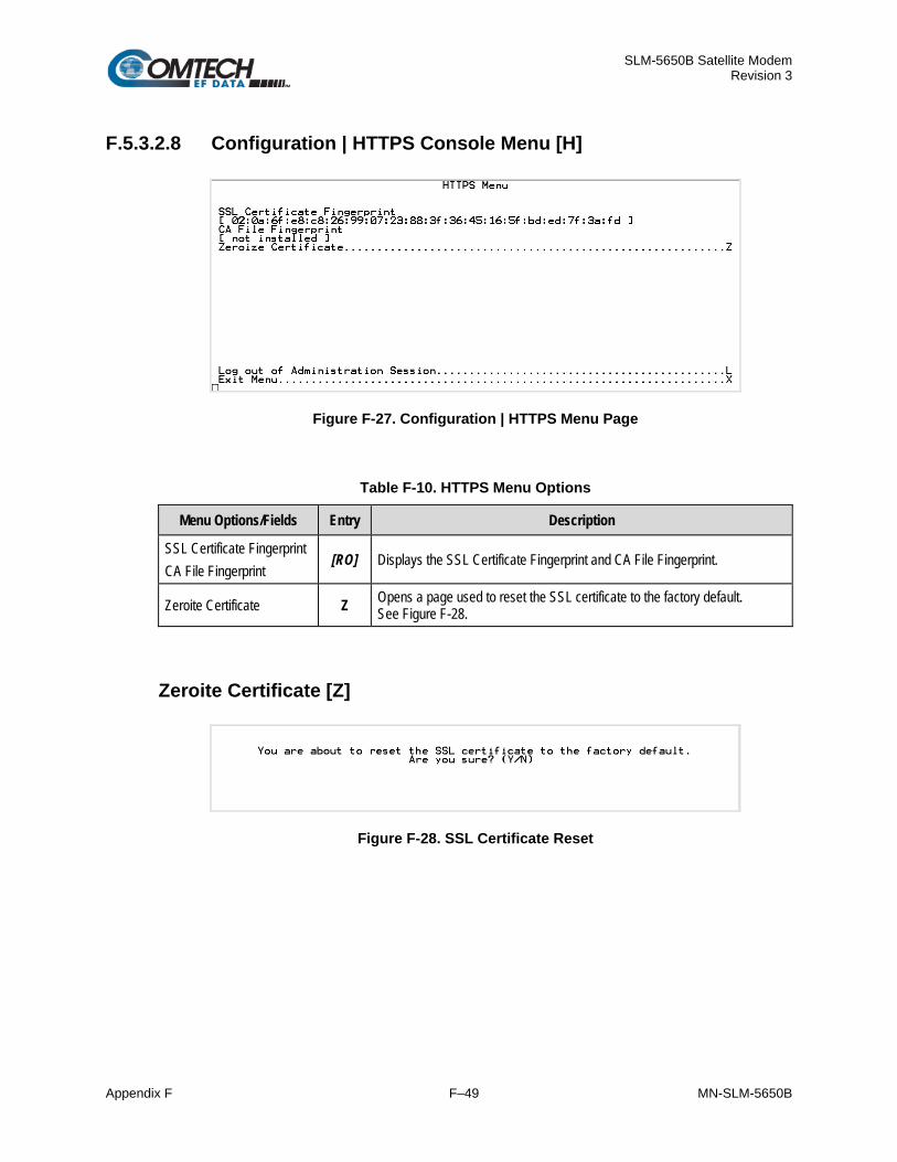
SLM-5650B Satellite Modem Revision 3
Appendix F F–49 MN-SLM-5650B
F.5.3.2.8 Configuration | HTTPS Console Menu [H]
Figure F-27. Configuration | HTTPS Menu Page
Table F-10. HTTPS Menu Options
Menu Options/Fields Entry Description
SSL Certificate Fingerprint CA File Fingerprint
[RO] Displays the SSL Certificate Fingerprint and CA File Fingerprint.
Zeroite Certificate Z Opens a page used to reset the SSL certificate to the factory default. See Figure F-28.
Zeroite Certificate [Z]
Figure F-28. SSL Certificate Reset

SLM-5650B Satellite Modem Revision 3
Appendix F F–50 MN-SLM-5650B
F.5.3.3 Module Status [M]
The read-only Module Status page, opened from the Main Menu, provides the user with the TRANSEC Module Interface’s current operational parameters:
• AES 256 Version; • Encryption Frame Length; • Operating Mode; • Board Temperature; • TRANSEC Clock Status; • Transmit Status; • Receive Status.
Pressing any key will return the user to the Main Menu page.

SLM-5650B Satellite Modem Revision 3
Appendix F F–51 MN-SLM-5650B
F.5.3.4 Event Log [E]
Figure F-29. Event Log Menu Page
Table F-11. Event Log Menu Options
Menu Options/Fields Entry Description
Logging M Sets recording of events and alarms: 0 – Off 1 – On
Logging Level E
Sets the level of information collected for the Events Log: 0 – Errors Only 1 – Errors and Warnings 2 - All Information
View Event Log V Displays the tally of events logged since the last time the Log was cleared.
Clear Event Log C
Clears the event log of all messages. Once selected, you are prompted with the following message: This action will clear the event log. Are you sure? (Y/N)
Enter ‘Y’ or ‘N’. If ‘Y’ is entered, the event log is reset to zero entries, and the following message is displayed: Event log cleared. Press Any Character to Continue.
Press any key to return to the Event Log Menu page.

SLM-5650B Satellite Modem Revision 3
Appendix F F–52 MN-SLM-5650B
F.5.3.5 Firmware [ F ]
Chapter 5. FIRMWARE UPDATE
See Chapter 5. FIRMWARE UPDATE for detailed information on the procedures associated with the TRANSEC Module firmware update process.
Figure F-30. Firmware (Unit Info) Menu Page
Table F-12. Firmware (Unit Info) Menu Options
Menu Options/Fields Entry Description Bootrom Info [RO] Displays the bootrom firmware. Bulk 1 Info [RO] Displays the firmware version loaded into the Slot 1 location. Bulk 2 Info [RO] Displays the firmware version loaded into the Slot 2 location. Boot From B Selects the firmware boot source for modem operations as follows:
0 – Newest (automatically selects the most current version firmware residing in either Slot 1 or Slot 2); 1 – Slot 1 (selects the firmware residing in the Slot 1 location;
2 – Slot 2 (selects the firmware residing in the Slot 2 location.
If the ‘Boot From’ selection is changed, you must reboot the modem in order for that firmware selection to be loaded for operation.

SLM-5650B Satellite Modem Revision 3
Appendix F F–53 MN-SLM-5650B
Menu Options/Fields Entry Description Reboot R Reboots the modem. Once selected, the following message displays:
This action will reboot the TRANSEC module. Are you sure? (Y/N)
Enter ‘Y’ or ‘N’. If ‘Y’ is entered, the reboot process begins by closing the SSH CLI. On the SLM-5650B front panel VFD, three messages will display at minimum (depending on the modem’s installed options): THIS MODEM WILL REBOOT IN FIVE SECONDS! BOOTING MODEM… …PLEASE WAIT INITIALIZING MODEM…
Once the modem reboots, you must initialize a new SSH CLI session to resume use of this interface.

SLM-5650B Satellite Modem Revision 3
Appendix F F–54 MN-SLM-5650B
BLANK PAGE

SLM-5650A Satellite Modem Revision 3
Appendix G G–1 MN-SLM-5650B
Appendix G. OPTIONAL DOUBLETALK
CARRIER-IN-CARRIER (CnC)
BEFORE YOU ATTEMPT TO COMMISSION A SATELLITE LINK USING CARRIER-IN-CARRIER (CnC), YOU MUST ENSURE THAT THE LINK IS ROBUST ENOUGH FOR NORMAL OPERATION. ONLY WHEN YOU HAVE DONE THIS – AND YOU RESOLVE ALL SYSTEM ISSUES (E.G., ANTENNA-POINTING, CABLING, TERRESTRIAL INTERFERENCE, SATELLITE INTERFERENCE, ETC.) – SHOULD YOU ATTEMPT THE USE OF CARRIER-IN-CARRIER.
G.1 Overview Space segment costs are typically the most significant operating expense for any satellite-based service, having a direct impact on the viability and profitability of the service. For a satellite transponder that has finite resources in terms of bandwidth and power, the leasing costs are determined by bandwidth and power used. Therefore, a satellite circuit should be designed for optimal utilization to use a similar share of transponder bandwidth and power.
The traditional approach to balancing a satellite circuit – once the satellite and earth station parameters are fixed – involves trade-off between modulation and coding. A lower order modulation requires less transponder power while using more bandwidth; conversely, higher order modulation reduces required bandwidth, albeit at a significant increase in power.
CEFD’s DoubleTalk Carrier-in-Carrier1 (CnC) option adds a new dimension to satellite communication optimization.
Raytheon Applied Signal Technology patented DoubleTalk®2, which uses a signal processing algorithm that allows both the forward and reverse carriers of a full duplex link to share the same segment of transponder bandwidth, using patented “Adaptive Cancellation.” CEFD refers to it as CnC.
1Carrier-in-Carrier® is a registered trademark of Comtech EF Data. 2 DoubleTalk® is a registered trademark and licensed from Raytheon Applied Signal Technology.

SLM-5650A Satellite Modem Revision 3
Appendix G G–2 MN-SLM-5650B
CnC was first introduced in CEFD products such as the CDM-Qx Satellite Modem, CLO-10 Link Optimizer, and CDM-625 Advanced Satellite Modem. The implementation of CnC in the SLM-5650B has been further refined, and some of the limitations that existed in the prior offerings have been overcome.
Space segment costs are typically the most significant operating expense for any satellite-based service, having a direct impact on the viability and profitability of the service. For a satellite transponder that has finite resources in terms of bandwidth and power, the leasing costs are determined by bandwidth and power used. Therefore, a satellite circuit should be designed for optimal utilization to use a similar share of transponder bandwidth and power.
CnC technology provides a significant improvement in bandwidth and power utilization, beyond what is possible with FEC and modulation alone, allowing users to achieve unprecedented savings. When combined with advanced modulation and FEC, it allows for multi-dimensional optimization:
• Reduced operating expense (OPEX) – e.g., Occupied Bandwidth & Transponder Power;
• Reduced capital expenditure (CAPEX) – e.g., Block Up Converter/High-Power Amplifier (BUC/HPA) size and/or antenna size;
• Increased throughput without using additional transponder resources;
• Increased link availability (margin) without using additional transponder resources;
• A combination of any of the above to meet different objectives.
Conclusion: When using the CnC option, up to 50% savings in transponder utilization is possible when carriers share common bandwidth.

SLM-5650A Satellite Modem Revision 3
Appendix G G–3 MN-SLM-5650B
G.2 Application Requirements These conditions are necessary in order to operate CnC:
• Link must be full duplex:
• A SLM-5650B must be used at the end of the link where the cancellation needs to take place. Normally, this is both ends of the link.
• The transponder is operated as Loopback. That is, each end of the link must be able to see a copy of its own signal in the downlink path from the satellite. The looped back signal is then subtracted, which leaves the signal from the distant end of the link. CnC cannot be used in spot beam systems.
• The transponder needs to be “bent-pipe” – meaning no on-board processing, demodulation, regeneration can be employed. Demodulation/remodulation does not preserve the linear combination of the forward and return signals and the resulting reconstituted waveform prevents recovery of the original constituent signals.
Figure G-1 shows a simplified conceptual block diagram of CnC processing. The two ends of the link are denoted 'A' and 'B' and the uplink and downlink are shown.
This performance is achieved through advanced signal processing algorithms that provide superior cancellation while tracking and compensating for these common link impairments:
• Time varying delay: In addition to the static delays of the electronics and the round-trip delay associated with propagation to the satellite and back, there is a time-varying component due to movement of the satellite. The CnC module tracks and compensates for this variation.
• Frequency offset and drift: Common sources are satellite Doppler shift, up and down converter frequency uncertainties, and other drift associated with the electronics in the SLM-5650B itself. The CnC module tracks and compensates for this frequency offset and drift.
• Atmospheric effects: Fading and scintillation can affect amplitude, phase, and spectral composition of the signal and the degree to which it correlates with the original signal. The CnC module tracks and compensates for these atmospheric related impairments.
• Link Asymmetries: Various asymmetries in the forward and return link can produce differences in the relative power of the two received signal components. These can be both deterministic (static) or random (and time varying). An example of the former would be the differences resulting from antenna size/gain variations between the two ends of the link. An example of the latter would be transient power differences due to different levels of atmospheric fading in the uplinks. CnC compensates for the asymmetries, up to a certain extent.

SLM-5650A Satellite Modem Revision 3
Appendix G G–4 MN-SLM-5650B
Figure G-1. Conceptual Block Diagram
In a number of ways, CnC carriers behave similar to conventional carriers in satellite links. Both are exposed to adjacent carriers, cross-polarization, and rain fade, and exhibit impairments when any of these become too great. CnC additionally operates in an environment where:
• Carriers intentionally occupy the same spectral slot, and
• Performance depends upon desired and co-located interfering carrier. The interfering carrier is canceled, leaving the desired carrier for demodulation.

SLM-5650A Satellite Modem Revision 3
Appendix G G–5 MN-SLM-5650B
G.2.1 Operational Recommendations The rules for CnC operation are summarized as follows:
• Both earth stations share the same footprint so each sees both carriers
• CnC carriers are operated in pairs
• One outbound with multiple return carriers is not allowed
• Asymmetric data rates are allowed (no restrictions)
• The ratio of power spectral density is normally less than 11 dB
• CnC operates with modems – not modulators only or demodulators only.
In addition, to minimize ‘false’ acquisition, observe the following:
• Use of IESS-315 V.35 Scrambler is highly recommended.
• Keep the search delay range as narrow as possible – once the modem has reported the search delay, narrow the search delay range to the nominal reported value ±5 ms – for example, if the modem reported delay is 245 ms, narrow the search range to say 240-250 ms.
• Use external data source (e.g. Fireberd) or internal BER tester when testing CnC performance.
• To prevent self-locking in case the desired carrier is lost, it is recommended that the two carriers have some configuration difference – for example, use different settings for Spectrum Inversion.

SLM-5650A Satellite Modem Revision 3
Appendix G G–6 MN-SLM-5650B
G.3 System Functionality and Operational Considerations Figure G-2 illustrates a conventional, full duplex satellite link where two carriers are placed in non-overlapping channels. Figure G-3 shows the same link using the SLM-5650B equipped with the CnC option. Note that only 50% of the bandwidth is being used, as both carriers are now occupying the same bandwidth.
The transponder downlinks the composite signal containing both carriers on the same band to the SLM-5650B, which then translates the signal to near-baseband where it can be filtered (decimated) and then processed as a complex envelope signal. The SLM-5650B then suppresses the version of the near-end carrier on the downlink side, and then passes the desired carrier to the demodulator for normal processing.
To further illustrate, as shown in Figure G-4, without CnC, the two carriers in a typical full duplex satellite link are adjacent to each other. With CnC, only the composite signal is visible when observed on a spectrum analyzer. Carrier 1 and Carrier 2, shown here for reference only, are overlapping, thus sharing the same spectrum.
Figure G-2. Conventional FDMA Link

SLM-5650A Satellite Modem Revision 3
Appendix G G–7 MN-SLM-5650B
Figure G-3. Same Link Using SLM-5650B and CnC
Figure G-4. Duplex Link Optimization
The CnC module operates on the near-zero signal before the demodulator, and is waveform-agnostic. This means that no prior knowledge of the underlying modulation, FEC, or any other waveform specific parameter is required in order to perform the signal suppression operation. The only caveat to this is that the waveform must be sufficiently random.
Because acquiring the delay and frequency offset of the interfering carrier is fundamentally a correlation operation, anything deterministic in the interfering carrier (within the correlation window of the algorithm) will potentially produce false correlation peaks and result in incorrect delays and/or frequency. Normally, this is not a problem, since energy dispersal techniques are used in the vast majority of commercial and military modems. However, it is something that must be kept in mind when troubleshooting a system that uses the CnC technique for signal suppression.

SLM-5650A Satellite Modem Revision 3
Appendix G G–8 MN-SLM-5650B
One possible way to mitigate false peaks is to narrow the correlation window. For example, if the delay is known to be around 240ms, set the minimum search delay to 230ms and the maximum search delay to 250ms.
As all advances in modem technologies – including advanced modulation and FEC techniques – approach their theoretical limits of power and bandwidth efficiencies, CnC allows satellite users to achieve spectral efficiencies (bps/Hz) that cannot be achieved with modulation and FEC alone. Table shows how CnC, when used with 16-QAM, approaches the bandwidth efficiency of 256-QAM (8bps/Hz).
Table G-1. Spectral Efficiency using CnC
As shown here, CnC allows equivalent spectral efficiency using a lower order modulation and/or FEC Code Rate; CAPEX is therefore reduced by allowing the use of a smaller BUC/HPA and/or antenna. And, as CnC can be used to save transponder bandwidth and/or transponder power, it can be successfully deployed in bandwidth-limited as well as power-limited scenarios.
G.3.1 Cancellation Process The signal processing technology employed via CnC continually estimates and tracks all parametric differences between the local uplink signal and its image within the downlink. Through advanced adaptive filtering and phase locked loop implementations, it dynamically compensates for these differences by appropriately adjusting the delay, frequency, phase and amplitude of the sampled uplink signal, resulting in optimal cancellation performance.
When a full duplex satellite connection is established between two sites, separate satellite channels are allocated for each direction. If both directions transmitted on the same channel, each side would normally find it impossible to extract the desired signal from the aggregate due to interference originating from its local modulator. However, since this interference is produced locally, it is possible to estimate and remove its influence prior to demodulation of the data transmitted from the remote location.

SLM-5650A Satellite Modem Revision 3
Appendix G G–9 MN-SLM-5650B
For the CnC cancellation, it is necessary to provide each demodulator with a copy of its local modulator’s output.
As shown in Figure G-5, Modem 1 and Modem 2 transmit signals S1 and S2 respectively. The satellite receives, translates, and retransmits the composite signal. The downlink signals S1* and S2* received at Modem 1 and Modem 2 differ from the transmit signals primarily in terms of phase, frequency, and delay offsets.
Figure G-5. CnC Signals
For round trip delay estimation (Figure G-6), a search algorithm is used that correlates the received satellite signal to a stored copy of the local modulator’s transmitted signal. The interference cancellation algorithm uses the composite signal and the local copy of S1 to estimate the necessary parameters of scaling (complex gain/phase), delay offset and frequency offset. The algorithm continuously tracks changes in these parameters as they are generally time-varying in a satellite link.
Figure G-6. CnC Signal Processing Block Diagram
The resulting estimate of the unwanted interfering signal is then subtracted from the composite signal. In practical applications, the estimate of the unwanted signal can be extremely accurate. Unwanted interfering signal suppression of 30 dB or more has been achieved in commercial products with minimal degradation of the demodulator performance.

SLM-5650A Satellite Modem Revision 3
Appendix G G–10 MN-SLM-5650B
G.3.2 Margin Requirements Typical interfering signal cancellation is 28 to 35 dB (depending on the product). The residual interfering signal appears as noise causing a slight degradation of the Eb/No. To compensate for the residual noise, a small amount of additional link margin is required to maintain the BER. Margin requirements depend on the product, modulation and power ratios:
For the SLM-5650B, the additional margin requirements are as follows:
Modulation Nominal Margin*
* Equal power and equal symbol rate for the interfering carrier and the desired carrier, i.e., 0 dB PSD ratio. Measured at IF with AWGN, +10 dBc Adjacent Carriers, 1.3 spacing.
BPSK 0.3 dB
QPSK/OQPSK 0.3 dB
8-PSK 0.5 dB
8-QAM 0.4 dB
16-QAM 0.6 dB
G.3.3 Latency CnC has no measurable impact on circuit latency.
G.3.4 Link Design CnC link design involves finding the FEC and modulation combination that provides optimal bandwidth utilization. Just like conventional link design, it is an iterative process that involves trying different FEC and modulation combinations with CnC until an optimal combination is found.
For optimal CnC performance, it is recommended that the two carriers have similar symbol rate and power. This can be achieved by selecting appropriate MODCODs as shown in following sections.

SLM-5650A Satellite Modem Revision 3
Appendix G G–11 MN-SLM-5650B
G.3.4.1 Symmetric Data Rate Link Consider this example:
Satellite & Transponder Galaxy 18 @ 123º W, 13K/13K
Earth Station 1 Phoenix, AZ – 4.6 m Earth Station 2 Phoenix, AZ – 2.4 m Data Rate 512 kbps / 512 kbps
The traditional link was based on QPSK TPC 3/4 and required 0.96 MHz of leased BW. The LST (Intelsat’s Lease Transmission Plan Program) summary for the traditional link is as follows:
CnC link design involved trying different Modulation & FEC Code Rates to find the optimal combination:
• 8-QAM, LDPC 2/3 with CnC
• QPSK, LDPC 3/4 with CnC
• QPSK, LDPC 2/3 with CnC
• QPSK, LDPC 1/2 with CnC

SLM-5650A Satellite Modem Revision 3
Appendix G G–12 MN-SLM-5650B
Link parameters and LST summary for QPSK, LDPC 2/3 with CnC is as follows:
The link budget summary for the different MODCOD combinations is as follows:
Signal No. Modulation & FEC Allocated BW
(MHz) PEB (MHz) Leased BW (MHz)
Savings Compared to Original
PSD Ratio (dB)
1 8-QAM, LDPC 2/3 0.3584 1.1468 1.1468 -20% 2.1
2 QPSK, LDPC 3/4 0.47785 0.6734 0.6734 30% 2.1
3 QPSK, LDPC 2/3 0.53735 0.5777 0.5777 40% 2.1
4 QPSK, LDPC 1/2 0.7168 0.5184 0.7168 25% 2.1
Based on this analysis, QPSK, LDPC 2/3 with CnC provides the maximum savings of 40%.

SLM-5650A Satellite Modem Revision 3
Appendix G G–13 MN-SLM-5650B
In addition to 40% reduction in Leased Bandwidth, using CnC also reduced the required HPA Power by almost 40%:
HPA Power Traditional Link (QPSK, TPC 3/4)
CnC Link (QPSK, LDPC 2/3) HPA Power Reduction
HPA @ 4.6 m 0.7 W 0.5 W 40%
HPA @ 2.4 m 1.5 W 1.1 W 36%
G.3.4.2 Asymmetric Data Rate Link As occupied (or allocated) bandwidth of a CnC circuit is dictated by the larger of the two carriers, it is strongly recommended that the smaller carrier be spread as much as possible using a lower order modulation and/or FEC, while meeting the PSD ratio spec. Spreading the smaller carrier using a lower order modulation has multiple benefits:
• Lower order modulation is always more robust;
• Lower order modulation uses less transponder power – this reduces total transponder, and increases available link margin;
• Lower order modulation uses less transmit power on the ground – this can significantly reduce the BUC/SSPA size by not only reducing the transmit EIRP, but also reducing the BUC/SSPA backoff.
Consider this example:
Satellite & Transponder IS-901 @ 342º W, 22/22 (EH/EH)
Earth Station 1 Africa – 4.5 m
Earth Station 2 Africa – 3.0 m
Data Rate 3000 Mbps / 1000 Mbps

SLM-5650A Satellite Modem Revision 3
Appendix G G–14 MN-SLM-5650B
While the traditional link was based on QPSK, TPC 3/4 and required 3.9 MHz of leased bandwidth, the CnC link was based on QPSK, LDPC 3/4 and QPSK, LDPC 1/2 and required 2.8 MHz of leased bandwidth.
The savings summary is as follows:
Item Original Link With CnC and LDPC
Savings Hub to Remote
Remote to Hub Total Hub to
Remote Remote to
Hub Total
Data Rate (kbps) 3000 1000 3000 1000 Modulation QPSK QPSK QPSK QPSK FEC TPC 3/4 TPC 3/4 LDPC 3/4 LDPC 1/2 Occupied BW (MHZ) 2.8 0.9 3.7 2.8 1.4 2.8 Power Eq. BW (MHz) 3.3 0.6 3.9 2.5 0.3 2.8 Leased BW (MHz) 3.9 2.8 27.5% Hub HPA (W) 26.0 20.3 22% Remote HPA (W) 10.6 6.4 40%
If this link was designed using QPSK, LDPC 3/4 in both directions, it would have required:
• Occupied BW – 2.8 MHz
• Power Eq. BW – 3.0 MHz (a 7.2% increase in Power Eq. BW)
• Leased BW – 3.0 MHz (a 7.2% increase in Leased BW)
• Hub HPA – 20.3 W
• Remote HPA – 8.3 W (a 30% increase in Remote power)

SLM-5650A Satellite Modem Revision 3
Appendix G G–15 MN-SLM-5650B
G.3.4.3 Power Limited Links CnC can provide substantial savings even when the original link is power limited. Spreading the carrier by using a lower modulation and/or FEC along with latest FEC such as VersaFEC can substantially reduce the total power which can then be traded with bandwidth using CnC. The concept is illustrated with the following examples:
The conventional link is using 8-PSK, TPC 3/4:
Switching to VersaFEC and using a lower order modulation – e.g., QPSK, VersaFEC 0.803 increases the total occupied bandwidth, while reducing the total power equivalent bandwidth:
Now using CnC, the second QPSK, VersaFEC 0.803 carrier can be moved over the first carrier – thereby significantly reducing the total occupied bandwidth and total power equivalent bandwidth when compared to the original side-by-side 8PSK, TPC 3/4 carriers:
To continue, consider this example:
Satellite & Transponder IS-901 @ 342º W, 22/22 (EH/EH)
Earth Station 1 Africa – 9.2 m
Earth Station 2 Africa – 4.5 m
Data Rate 2.048 Mbps / 2.048 Mbps

SLM-5650A Satellite Modem Revision 3
Appendix G G–16 MN-SLM-5650B
Whereas the original link used 8-PSK TPC 3/4, the CnC link used QPSK VersaFEC 0.803. The savings summary is as follows:
Item Original Link With CnC and VersaFEC
Savings Hub to Remote
Remote to Hub Total Hub to
Remote Remote to
Hub Total
Data Rate (kbps) 2048 2048 2048 2048 Modulation 8-PSK 8-PSK QPSK QPSK FEC TPC 3/4 TPC 3/4 0.803 0.803 Occupied BW (MHZ) 1.3 1.3 2.6 1.8 1.8 1.8 Power Eq. BW (MHz) 2.2 1.0 3.2 1.1 0.5 1.6 Leased BW (MHz) 3.2 1.8 44% Hub HPA (W) 5.0 2.0 60% Remote HPA (W) 11.6 4.7 60% Note: 1 dB HPA BO for QPSK, 2 dB HPA BO for 8-PSK, 1 dB Feed Loss.
Using CnC and VersaFEC reduced the leased bandwidth by almost 44% and HPA power by 60%.

SLM-5650A Satellite Modem Revision 3
Appendix G G–17 MN-SLM-5650B
G.3.5 Commissioning and Deployment Prior to commissioning a CnC link, it is critical that the link is fully tested in non CnC mode and all system issues including external interference, antenna pointing, cabling, SSPA backoff are resolved. Only after the link is robust, should the user attempt turning on CnC.
The following procedure is recommended for CnC commissioning and deployment.
Step Task
1 Turn ON the carrier at Site ‘A’. Carrier from Site ‘B’ is OFF. CnC function is OFF at both sites. a. Using a spectrum analyzer, measure Co+No/No at the input to the modem at Site ‘A’. b. Using a spectrum analyzer, measure Co+No/No at the input to the modem at Site ‘B’. c. Measure/record Eb/No at Site ‘B’. Make sure there is sufficient margin to account for CnC. d. Measure/record Receive Signal Level (RSL) at Site ‘B’.
2 Turn OFF the carrier at Site ‘A’. Turn ON the carrier at Site ‘B’. CnC function is OFF at both sites. a. Using a spectrum analyzer, measure Co+No/No at the input to the modem at Site ‘A’. b. Using a spectrum analyzer, measure Co+No/No at the input to the modem at Site ‘B’. c. Measure/record Eb/No at Site ‘A’. Make sure there is sufficient margin to account for CnC. d. Measure/record RSL at Site ‘B’.
3 Using Co+No/No readings calculate PSD ratio at Site ‘A’ and Site ‘B’. If it is not within specification, make necessary adjustments to bring it within specification and repeat measurements in Steps 1 and 2. Also verify that the RSL is within spec.
4 Without changing the transmit power levels, turn ON both the carriers (on the same frequency) and turn CnC ON.
a. Measure/record Eb/No at Site ‘A’ and ‘B’ b. Measure/record RSL at Site ‘A’ and ‘B’ c. Compare Eb/No in presence of two over lapping carriers with CnC with Eb/No when only
one carrier was ON. Eb/No variation should be within spec for that modulation, FEC and PSD ratio.
5 Repeat the test for different PSD ratio and Eb/No.

SLM-5650A Satellite Modem Revision 3
Appendix G G–18 MN-SLM-5650B
G.3.6 Validating CnC Performance CnC performance can be easily validated by verifying that Eb/No degradation due to CnC is within published specification for the observed Power Spectral Density Ratio.
The following procedure is recommended for validating CnC performance.
Step Task
1 Setup a conventional side-by-side link of the desired Eb/No. a. CnC should be OFF. b. Record the Eb/No as displayed by the Modems. c. Observe the two carriers on a spectrum analyzer and record the PSD ratio.
Example Link:
• Full duplex 512 kbps, QPSK, LDPC 2/3 circuit between 4.6 m and 2.4 m antennas • Recorded Eb/No = 2.6 dB (at both modems) • PSD Ratio = 1.2 dB (measured at larger Antenna)
2 Relocate one of the carriers on top of the other carrier: a. Enable CnC. b. Record the Eb/No as displayed by the Modems.
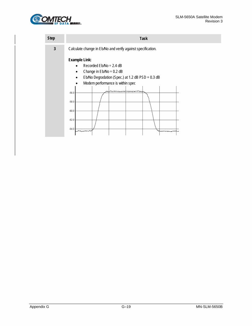
SLM-5650A Satellite Modem Revision 3
Appendix G G–19 MN-SLM-5650B
Step Task
3 Calculate change in Eb/No and verify against specification. Example Link:
• Recorded Eb/No = 2.4 dB • Change in Eb/No = 0.2 dB • Eb/No Degradation (Spec.) at 1.2 dB PSD = 0.3 dB • Modem performance is within spec

SLM-5650A Satellite Modem Revision 3
Appendix G G–20 MN-SLM-5650B
G.4 Operational References
G.4.1 Link Budget Calculation The following procedure is required for calculating the link budget for a CnC Link.
Step Task
1 Calculate the link budget for both carriers in the duplex link, with required CnC margin:
2 Verify that the PDS ration is within spec for the SLM-5650B.
3 Calculate the Allocated Bandwidth (BW) and Power Equivalent Bandwidth (PEB) for the duplex link:
• BWDuplex Link = Greater of (BWCarrier 1, BWCarrier 2)
• PEBDuplex Link = PEBCarrier 1 + PEBCarrier 2
• Leased BWDuplex Link = Greater of (BWDuplex Link, PEBDuplex Link)
4 For an optimal link, the Leased Bandwidth and the Power Equivalent Bandwidth should be equal / nearly equal.
5 Repeat the link budget process by selecting different Modulation and FEC, until the BW and PEB is nearly balanced.

SLM-5650A Satellite Modem Revision 3
Appendix G G–21 MN-SLM-5650B
G.4.2 Estimating PSD Ratio PSD can be estimated from a link budget using Downlink EIRP and Symbol Rate:
PSD = Downlink EIRP – 10 * Log (Symbol Rate)
PSD Ratio Example:
Carrier Downlink EIRP Symbol Rate Power Spectral Density
A to B 27 dBW 500 ksps -29.99 dBW/Hz
B to A 24 dBW 375 ksps -31.74 dBW/Hz
PSD Ratio (@ A) = -29.99 – (-31.74) = 1.75 dB
PSD Ratio (@ B) = -31.74 – (-29.99) = -1.75 dB
G.4.2.1 Estimating PSD Ratio from LST

SLM-5650A Satellite Modem Revision 3
Appendix G G–22 MN-SLM-5650B
G.4.2.2 Estimating PSD Ratio from Satmaster
G.4.2.3 Estimating PSD Ratio Using Spectrum Analyzer PSD Ratio or CnC Ratio can also be estimated using a Spectrum Analyzer capable of integrating the signal power in a given bandwidth.
CnC Ratio (in dB) = PowerC1 (in dBm) – PowerC2 (in dBm)
PSD Ratio (in dB) = (PowerC1 – 10 log BWC1 (in Hz)) – (PowerC2 – 10 log BWC2 (in Hz))
= CnC Ratio – 10 log (BWC1 / BWC2)
If the two carriers have same Symbol Rate / Bandwidth, then the CnC Ratio is same as the PSD Ratio.

SLM-5650A Satellite Modem Revision 3
Appendix G G–23 MN-SLM-5650B
G.5 Specifications Operating Mode: Requires the two links to share a common carrier frequency (Outbound and Inbound symbol rates do not have to be equal)
Power Spectral Density Ratio and CnC Ratio:
• BSPK/QPSK/8-PSK/8-QAM: –7 dB to +11 dB (ratio of power spectral density, outbound interferer to desired inbound)
• 16-QAM: –7 dB to +7 dB (ratio of power spectral density, outbound interferer to desired inbound)
With asymmetric carriers the absolute power ratio (or CnC ratio) would be different, depending on the ratio of the symbol rates.
For Example:
• Outbound interferer = 1 Msymbols/sec
• Desired Inbound = 500 ksymbols/sec
• Ratio of power spectral density = +7 dB
• Absolute power ratio (CnC Ratio) = +7dB + (10 log Outbound/desired symbol rate) = +10 dB
Maximum Symbol Rate Ratio: 3:1 (TX:RX or RX:TX)
Inbound/Outbound frequency uncertainty: Within the normal acquisition range of the demod, as follows:
• Below 64 ksymbols/sec: ±1 to ±(Rs/2) kHz, where Rs = symbol rate in ksymbols/sec
• Between 64 and 389 ksymbols/sec: ± 1up to a maximum of ± 32kHz
• Above 389 ksymbols/sec: ±1 to ± (0.1Rs) kHz, up to a maximum of ± 200 kHz
Delay range: 0-330 ms
Eb/No Degradation (equal Inbound/Outbound power spectral density): BPSK = 0.3dB QPSK = 0.3dB OQPSK = 0.3dB 8-PSK = 0.5dB 8-QAM = 0.4dB 16-QAM = 0.6dB
For +10 dB power spectral density ratio (outbound interferer 10 dB higher than desired inbound) add an additional 0.3 dB
Monitor Functions:
• Delay, in milliseconds
• Frequency offset (between outbound interferer and desired inbound). 100 Hz resolution
• CnC ratio, in dB (ratio of absolute power, outbound interferer to desired inbound)
CnC Monitor Accuracy: ±1.0 dB for symmetric symbol rate
SLM-5650A Satellite Modem Revision 3
Appendix G G–24 MN-SLM-5650B
G.6 Summary CEFD’s CnC can provide significant savings in operational expenses. The following should be considered when evaluating CnC:
• CnC can only be used for full duplex links where the transmitting earth station is able to receive itself.
• CnC can be used in both bandwidth limited and power limited situations.
• The maximum savings is generally achieved when the original link is symmetric in data rate.
G.7 Glossary of Terms
Bandwidth, Allocated or Occupied: Bandwidth or Allocated Bandwidth or Occupied Bandwidth is the frequency space required by a carrier on a transponder.
For example: A Duplex 10 Mbps Circuit with 8PSK Modulation, FEC Rate 3/4 and 1.4 Spacing requires:
• Allocated BW = (DR / SE) * CSF [(Data Rate / Spectral Efficiency) * Carrier Spacing Factor]
• Allocated BW = 6.222 MHz = (10 / 2.25) * 1.4
For a 36 MHz transponder, 6.222 MHz corresponds to 17.3% Bandwidth Utilization.
Bandwidth, Leased (LBW): Almost all satellite operators charge for the Leased Bandwidth (LBW). Leased Bandwidth or Leased Resource is the greater of the Allocated Bandwidth and Power Equivalent Bandwidth.
For example: If a carrier requires 3 MHz of Allocated BW and 4.5 MHz of PEB, the Leased Bandwidth is 4.5 MHz.
Bandwidth, Power Equivalent (PEB): Power Equivalent Bandwidth (PEB) is the transponder power used by a carrier, represented as bandwidth equivalent.
PEB Calculation Example:
• Transponder EIRP = 37 dBW
• Output Backoff (OBO) = 4 dB
• Available EIRP = 37 – 4 = 33 dBW = 103.3 = 1995.26 Watts
• Transponder Bandwidth = 36 MHz
• Power Available / MHz = 1995.26 / 36 = 55.424 W
• If a carrier uses 24 dBW, its PEB = 102.4 / 55.424 = 4.532 MHz
This corresponds to 12.59% of available transponder power.

SLM-5650A Satellite Modem Revision 3
Appendix G G–25 MN-SLM-5650B
CnC Ratio: Ratio of Interfering Carrier Power to Desired Carrier Power (unit in dB).
The Interfering Carrier is the Tx Carrier from local modulator; the Desired Carrier is the carrier from the distant end received by the local demodulator.
At the station transmitting C1: CnC Ratio (in dB) = PowerC1 (in dBm) – PowerC2 (in dBm)
Eb/No: Ratio of Energy per bit (Eb) to Noise density (No) (unit in dB):
• Eb/No = C/No – 10log(DR) [where DR is the Data Rate]
• Eb/No = Es/No – 10log(SE) [where SE is Spectral Efficiency]
Es/No: Ratio of Energy per symbol (Es) to Noise density (No) (unit in dB):
• Es/No = C/No – 10log(SR) [where SR is the Symbol Rate]
• Es/No = Eb/No + 10log(SE) [where SE is Spectral Efficiency]
C/N: Ratio of Carrier Power (C) to Noise (N) (unit in dB):
Equivalent to Es/No when calculated in the Symbol Rate bandwidth.
C/No: Ratio of Carrier Power (C) to Noise Density (No) (unit in dBHz)
Co+No/No: Ratio of Carrier Density (Co) + Noise (No) to Noise Density (No) (unit in dB):
• C/N = C/No – 10log(B) [where B is bandwidth in Hz]
• Eb/No = C/No – 10log(DR)
[where DR is data rate in bits/sec]
= C/N + 10 log (B) – 10 log (DR)
= C/N – 10 log (SE)
[where SE is Spectral Efficiency]
• Eb/No = 10 log (10 ((Co+No/No)/10) – 1) – 10 log (SE)
[where SE is Spectral Efficiency]
Spectral Efficiency is in bps / Hz]
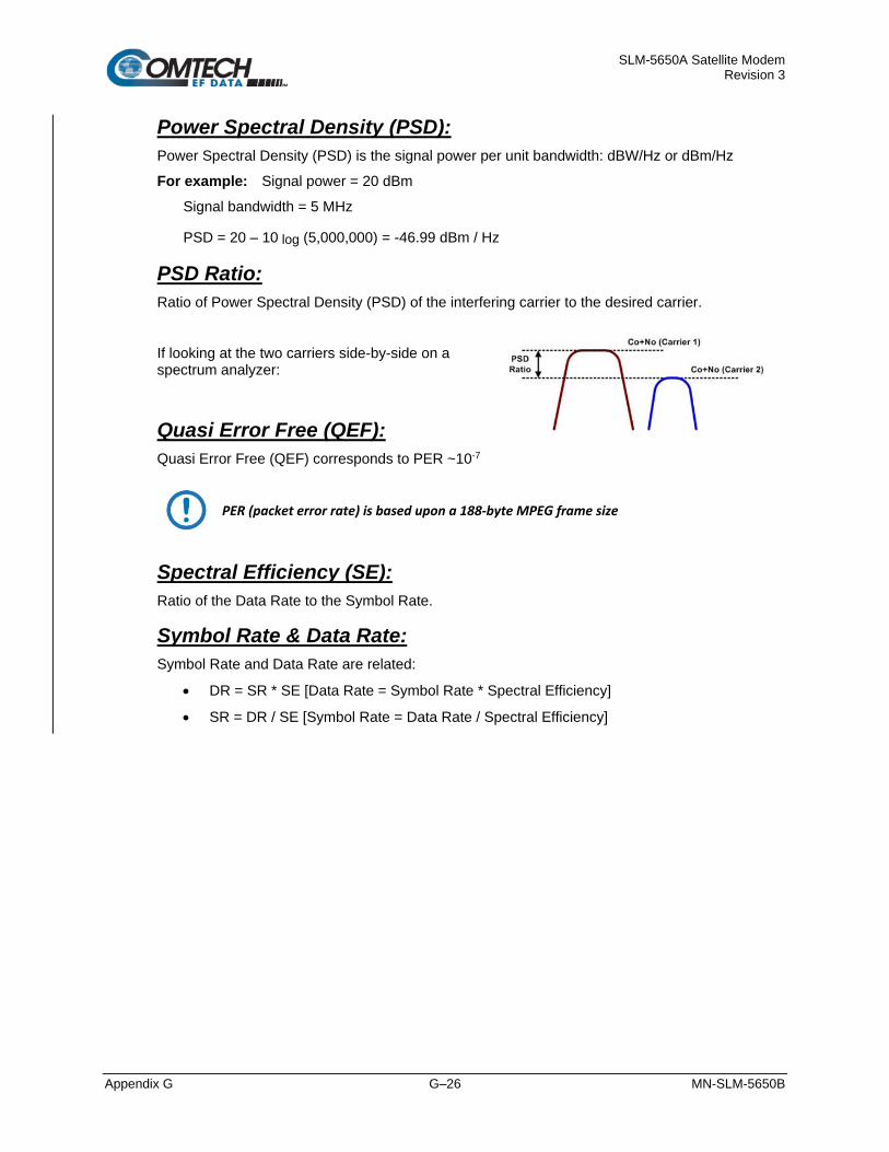
SLM-5650A Satellite Modem Revision 3
Appendix G G–26 MN-SLM-5650B
Power Spectral Density (PSD): Power Spectral Density (PSD) is the signal power per unit bandwidth: dBW/Hz or dBm/Hz
For example: Signal power = 20 dBm
Signal bandwidth = 5 MHz
PSD = 20 – 10 log (5,000,000) = -46.99 dBm / Hz
PSD Ratio: Ratio of Power Spectral Density (PSD) of the interfering carrier to the desired carrier.
If looking at the two carriers side-by-side on a spectrum analyzer:
Quasi Error Free (QEF): Quasi Error Free (QEF) corresponds to PER ~10-7
PER (packet error rate) is based upon a 188-byte MPEG frame size
Spectral Efficiency (SE): Ratio of the Data Rate to the Symbol Rate.
Symbol Rate & Data Rate: Symbol Rate and Data Rate are related:
• DR = SR * SE [Data Rate = Symbol Rate * Spectral Efficiency]
• SR = DR / SE [Symbol Rate = Data Rate / Spectral Efficiency]
SLM-5650A Satellite Modem Revision 3
Appendix H H–1 MN-SLM-5650B
Appendix H. VIPERSAT NETWORK APPLICATION
EXAMPLES
H.1 Overview The SLM-5650B’s optional Network Processor (NP) Interface Module (also referred to as the “NP Interface” or the “card”), when installed and operating in Router Mode OSPFv2 or Bridge Point-to-Multipoint (BPM) Mode, makes point-to-multipoint topologies possible. This appendix provides the following Vipersat Network Application Examples:
• OSPFv2
• BPM Mode

SLM-5650A Satellite Modem Revision 3
Appendix H H–2 MN-SLM-5650B
H.2 OSPF v2 in a Shared Outbound Satellite Network This section examines the challenges and solutions for using the SLM-5650B and Open Shortest Path First (OSPF) in a shared outbound/split path satellite network such as Vipersat.
H.2.1 Shared Outbound Satellite Network Overview
Figure H-1. Satellite Shared Outbound Network
A shared outbound network saves satellite bandwidth and reduces operating expenses by allowing multiple remote terminals to share the same channel from a hub ground station.
Figure H-1 illustrates a satellite shared outbound network. Notably, the outbound interface at the hub is not the same interface at which return traffic received. This is referred to as “split path.”

SLM-5650A Satellite Modem Revision 3
Appendix H H–3 MN-SLM-5650B
H.2.2 OSPF Basics Certain critical features of the OSPF protocol that impact a shared outbound satellite network are as follows:
• OSPF requires that the communication channel between the interfaces that connect any two given OSPF nodes must have ability to pass traffic bidirectionally.
• A router running the OSPF algorithm will send out “Hello” packets on each interface, when the response from a node on the same subnet as the interface is received, OSPF will create a neighbor adjacency with that node. In this way, the subnets and segments of the OSPF network are discovered, mapped and an OSPF database is created. This database is used by all OSPF routers to determine open shortest paths to all remote networks. OSPF nodes that do not follow these rules will not be added to a router's neighbor adjacency database.
H.2.3 OSPF Challenges Use of a split path violates the requirement whereby OSPF messaging is sent and received on the same interface. Therefore, the hub modems will not achieve “neighbor adjacency” with any of the remote routers. This means that running OSPF on the hub routers will not add any value.
In the example diagram, the modem’s NP Router is essentially a two-port router, thereby requiring that another OSPF node must always be in place “downstream” at the remote.
However, if this downstream router is running OSPF, could the high costs associated with a satellite link be managed and reduced by specifically configuring the router interface? Such a configuration would allow the overall OSPF network to control whether traffic should pass to the satellite link, or to a lower-cost link, such a terrestrial fiber, based upon availability. The possibility of such a solution is examined in the following use case.
H.2.4 OSPF Maritime Use Cases The maritime use cases presented here depicts application of OSPFv2 as part of a deployed network of routers that includes the modems NP Interface.
The primary objective of these use cases is to describe the process of automatically re-routing traffic when alternative transmission links are available in a maritime environment. Specifically, the satellite link should be used when at sea, and the high-speed terrestrial link should be used when at shore. This switch should occur automatically.
If other communication links such as ship-to-ship or back-up lower-speed satellite networks are available, then the OSPF routing protocol will select the best path as defined by link cost.

SLM-5650A Satellite Modem Revision 3
Appendix H H–4 MN-SLM-5650B
H.2.4.1 OSPF Use Case: At Shore
Figure H-2. OSPF Support at Shore
When at shore, as depicted in Figure H-2, the shipboard OSPF network automatically re-routes packets destined to non-shipboard networks over the high-speed, low-cost network.

SLM-5650A Satellite Modem Revision 3
Appendix H H–5 MN-SLM-5650B
H.2.4.2 OSPF Use Case: At Sea
Figure H-3. OSPF Support at Sea
When at sea, all traffic is routed to the satellite network. If other communication links such as ship-to-ship or backup lower-speed satellite networks are available, then the OSPF routing protocol selects the best path as defined by link cost.
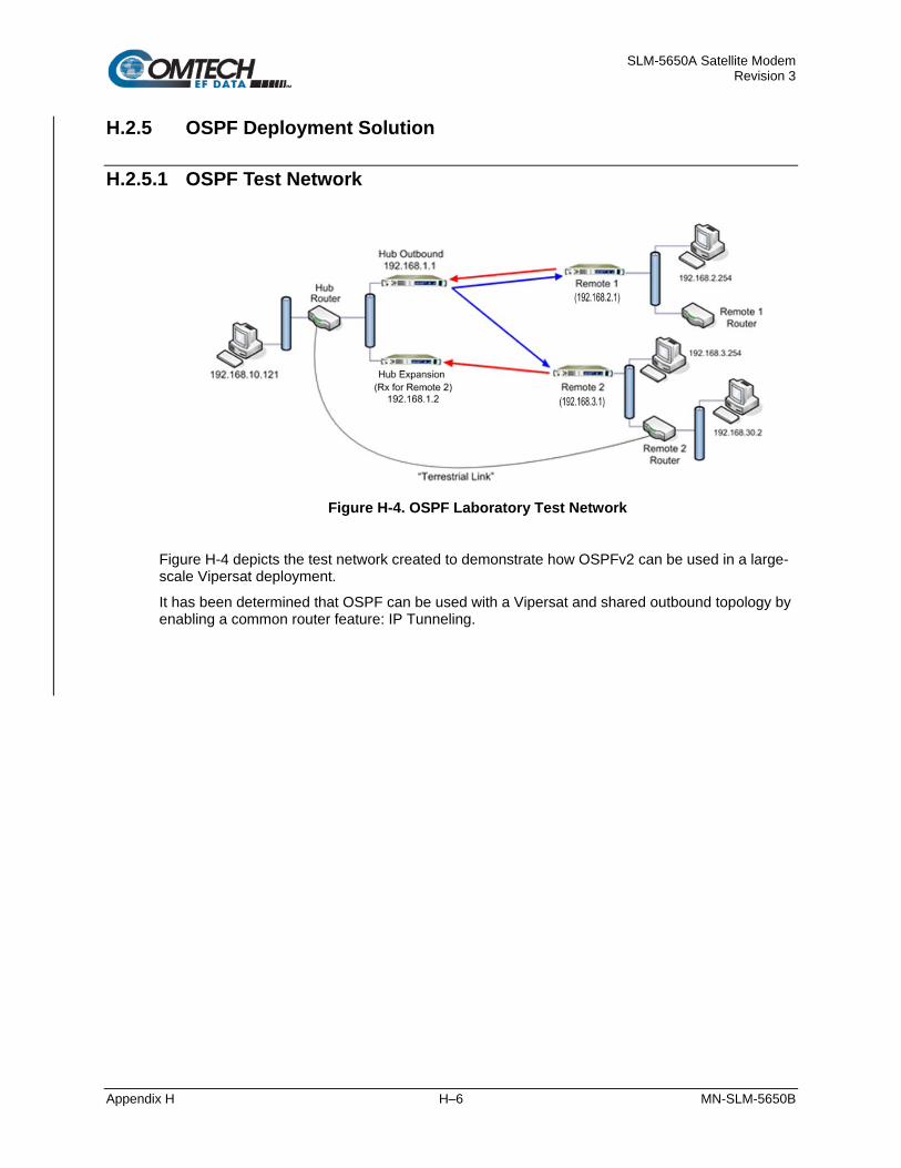
SLM-5650A Satellite Modem Revision 3
Appendix H H–6 MN-SLM-5650B
H.2.5 OSPF Deployment Solution
H.2.5.1 OSPF Test Network
Figure H-4. OSPF Laboratory Test Network
Figure H-4 depicts the test network created to demonstrate how OSPFv2 can be used in a large-scale Vipersat deployment.
It has been determined that OSPF can be used with a Vipersat and shared outbound topology by enabling a common router feature: IP Tunneling.
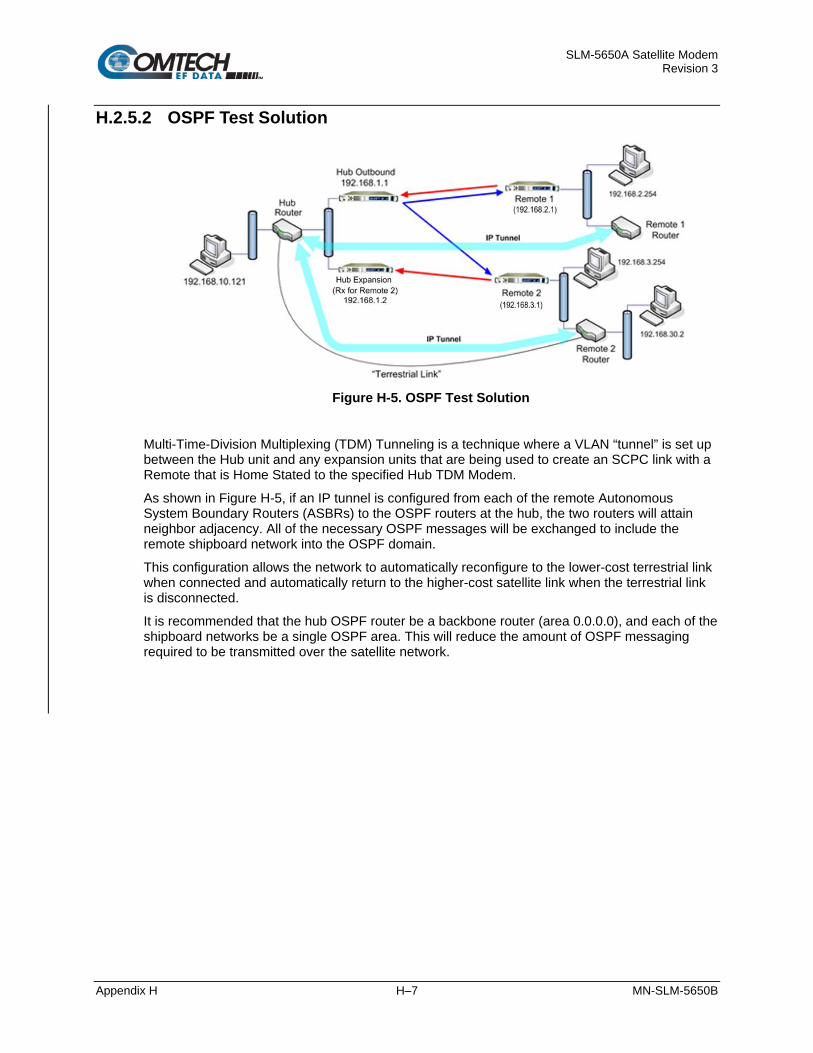
SLM-5650A Satellite Modem Revision 3
Appendix H H–7 MN-SLM-5650B
H.2.5.2 OSPF Test Solution
Figure H-5. OSPF Test Solution
Multi-Time-Division Multiplexing (TDM) Tunneling is a technique where a VLAN “tunnel” is set up between the Hub unit and any expansion units that are being used to create an SCPC link with a Remote that is Home Stated to the specified Hub TDM Modem.
As shown in Figure H-5, if an IP tunnel is configured from each of the remote Autonomous System Boundary Routers (ASBRs) to the OSPF routers at the hub, the two routers will attain neighbor adjacency. All of the necessary OSPF messages will be exchanged to include the remote shipboard network into the OSPF domain.
This configuration allows the network to automatically reconfigure to the lower-cost terrestrial link when connected and automatically return to the higher-cost satellite link when the terrestrial link is disconnected.
It is recommended that the hub OSPF router be a backbone router (area 0.0.0.0), and each of the shipboard networks be a single OSPF area. This will reduce the amount of OSPF messaging required to be transmitted over the satellite network.

SLM-5650A Satellite Modem Revision 3
Appendix H H–8 MN-SLM-5650B
H.2.5.3 OSPFv2 Summary The proposed solution using router-configurable IP tunneling to connect the remotes to the hub OSPF router satisfies the use case with minimal operator configuration.
While the addition of an IP tunnel will add overhead, the overall reduction in satellite bandwidth using the dynamic shared bandwidth functionality of Vipersat will more than offset the added overhead. Load switching, used in conjunction with OSPF, will allow the bandwidth to be automatically returned to the pool once a lower-cost terrestrial link is connected.
Advantages • Allows for automatic path selection via OSPF in a split path configuration with minimal
impact to the network.
• Because each ship is its own area, there will be a reduced amount of OSPF traffic over the satellite.
• If the operator uses Vipersat load switching at the remote (i.e. shipboard modem NP), then once the terrestrial link is connected, traffic will be redirected to fiber link and the load-switching algorithm will free the satellite link and return it to STDMA operation. This will free up significant satellite bandwidth automatically for use by other ships still at sea.
• Satellite link availability will still be available to the participating OSPF routers because periodic LSA and Hello packets will not be received on the router interface in case of satellite outage.
• Reduces the number of OSPF nodes in the network.
• Allows for automatic path selection via OSPF in a split path configuration with minimal impact to the network.
Disadvantages • Because IP tunnels are set up from the remote ASBR to the hub backbone router, an
additional 20-byte IP header will be added to all packets traversing the satellite interface.
• An IP tunnel will have to be configured for each ship to the hub OSPF router.

SLM-5650A Satellite Modem Revision 3
Appendix H H–9 MN-SLM-5650B
H.3 Network Processor (NP) Interface Bridge Point-to-Multipoint (BPM) Mode Networks where modems traditionally act as routers – e.g., Vipersat-based satellite communications systems – and include encryption devices are sometimes incompatible or require difficult and unwieldy configurations. Additionally, the NP Interface is limited to 256 allowable route tables. This, in turn, can limit the overall size of the network, particularly when OSPF dynamic routing protocol is used in the NP Interface.
The BPM Mode, an optional FAST feature, has been included in the NP Interface’s FW-0000051L Ver. 1.9.1 firmware release to increase the flexibility and scalability of the satellite network with SLM-5650Bs.
When BPM Mode is selected, Layer 2 and Layer 3 networks can operate simultaneously – i.e., the users can operate two independent Layer2 networks and one Layer3 network without interfering with each other.
H.3.1 BPM Mode Functional Description
Figure H-6. Ethernet Port Configuration in BPM Mode
The NP Interface features four Ethernet ports: P1 through P4. When BPM Mode is enabled, the SLM-5650B Base Modem ‘J5 Ethernet’ management port effectively becomes the NP Interface’s fifth Ethernet port. All five Ethernet ports are then segregated into three Ethernet switches.
As shown in Figure H-6:
• NP Ethernet ports P1 and P2, with internal Data WAN Port ‘A’ forms the red switch group referred to as Bridge-Group1. This group is reserved for bridged Layer 2 traffic only.
• NP Ethernet ports P3 and P4, with internal Management WAN Port ‘B’ forms the blue switch group referred to as Bridge-Group2. This group is reserved for bridged Layer 2 traffic only.
• The SLM-5650B Base Modem J5 Ethernet port, with internal VS WAN Port ‘C’ forms the green switch group referred to as Router-Group. This set is reserved for routed Layer 3 traffic and management use only.
All three switch groups are isolated such that:
• Traffic from NP Interface Port P1 can only transmit to the Data WAN Port ‘A’ or NP Interface port P2. It will NOT transmit to the NP Interface ports P3 or P4, the Base Modem J5 Ethernet port, Management WAN Port ‘B’, or VS WAN Port ‘C.’

SLM-5650A Satellite Modem Revision 3
Appendix H H–10 MN-SLM-5650B
• The traffic from NP Interface Port P3 can transmit to the Management WAN Port ‘B’ or NP Interface Port P4. It will NOT transmit to the NP Interface ports P1 or P2, the Base Modem J5 Ethernet Port, Data WAN Port ‘A’, or VS WAN Port ‘C.’
• The traffic from the Base Modem J5 Ethernet Port can transmit to VS WAN Port ‘C.’ It will NOT transmit to NP Interface Ports P1 through P4, Data WAN Port ‘A’, or Management Port ‘B.’

SLM-5650A Satellite Modem Revision 3
Appendix H H–11 MN-SLM-5650B
H.3.1.1 Glossary of Terms
Primary Port This is the port that can transmit the traffic those ingresses from any port within its group.
Examples:
• NP Interface Port P1 can transmit the traffic coming from Data WAN Port ‘A’ or NP Interface Port P2.
• NP Interface Port P3 can transmit the traffic coming from Management WAN port ‘B’ or NP Interface Port P4.
• The Base Modem J5 Ethernet port can transmit the traffic coming from VS WAN port ‘C.’
Expansion Port This is the port that can transmit the traffic that ingress from its primary port within that group.
Examples:
• NP Interface Port P2 can transmit the traffic coming from NP Interface Port P1 only.
• NP Interface Port P4 can transmit the traffic coming from NP Interface Port P3 only.
WAN Port This is a logical port that transmits the packet only to the primary ports, but it can receive the packets from either the primary port or the expansion port.
Examples:
• Data WAN port ‘A’ Bridge-Group1.
• Management WAN port ‘B’ in Bridge-Group2.
• VS WAN port ‘C’ in Router-Group.

SLM-5650A Satellite Modem Revision 3
Appendix H H–12 MN-SLM-5650B
H.3.2 BPM Mode Configuration
Chapter 1. INTRODUCTION Chapter 6. FAST ACTIVATION PROCEDURE Capter 7. FRONT PANEL OPERATION Appendix E. OPTIONAL NETWORK PROCESSOR (NP) INTERFACE MODULE
For more information about FAST, see:
• Chapter 1. INTRODUCTION, Section 1.3.1.7 Fully Accessible System Topology (FAST). • Chapter 7. FRONT PANEL OPERATION, Section 7.2.7.10 (UTIL:) FAST, and Section
7.3.3.9 CONFIG: Remote • Appendix E. OPTIONAL NETWORK PROCESSOR (NP) INTERFACE MODULE,
Section E.2.5.2.1 Admin | Vipersat Mode (FAST Option), and Section E.2.5.2.2 Admin | FAST Features
BPM Mode is available on the NP Interface as a FAST Option. Once the FAST Access Code has been purchased during normal business hours from Comtech EF Data Product Support, it is then activated in the NP Interface-equipped modem via the modem front panel. Once activated, BPM Mode must then be enabled for operation.
You may enable BPM Mode operation either from the SLM-5650B front panel menu (CONFIG: Remote EthernetConfig Option Card Addr Network Proc), or from the NP HTTP/HTTPS Interface ‘Admin | Vipersat Modes’ page.

SLM-5650A Satellite Modem Revision 3
Appendix H H–13 MN-SLM-5650B
H.3.3 BPM Mode in Hub Data Traffic Networks
Figure Legend
Equipment Data Type
1 TDM Modem A STDMA Return Link
2 Hub LAN Data Switch B Forward Link
3 Hub router C Network Encryption
4 Other Devices D MAC Learning Disabled (Entire Switch)
5 Hub Demodulator Data Switch E SCPC Return #1
6 Demodulator #1 F SCPC Return #2
7 Demodulator #2 G SCPC Return #N
8 Demodulator #N
Figure H-7. Hub Data Traffic Network

SLM-5650A Satellite Modem Revision 3
Appendix H H–14 MN-SLM-5650B
In a point-to-multipoint system, at the hub a split-path topology is used and traffic in the Forward Link and Return Link directions may be processed by different modems.
Figure H-7 shows a typical Hub Data Traffic Network for one Layer 2 Network (‘P1/P2/A’ shown in red). The other two networks (‘P3/P4/B’ shown in blue and ‘P5/C’ shown in green) can be used in a similar fashion.
Note that the Hub Demodulators used in this configuration are modems configured for operation with the optional ‘Demodulator only’ FAST Feature enabled.
In the Forward Link direction, all traffic is transmitted by the Hub TDM Modem. Packets received from the Hub Data Network are received by the Hub TDM Modem on a Data LAN Port (P1) and forward to the Data WAN.
The packets received by Return Link channels can come into the Hub in one of two ways:
1. They are processed by the Hub TDM Modem for Self-Organizing Time Division Multiple Access (STDMA) channels.
2. Hub Demodulators are used for Single Channel per Carrier (SCPC) channels.
In Figure H-7, the external hub switch supporting data traffic is shown as two separate switches: The Hub LAN Data Switch, and the Hub Demodulator Data Switch. It is important to note that this is a functional concept only – the physical implementation of this switch can be accomplished in one of three ways:
1. Two separate switches, as illustrated in Figure H-7.
2. One physical switch, partitioned into two logical switches using port isolation. Many commercially available managed switches have this capability.
3. A data-path router directly connected to the Hub TDM Modem’s P1 port, with the functionality of the Hub Demodulator Data Switch implemented by means of daisy-chaining the Hub Demodulator units Data LAN ports (i.e., connecting the P1 port of one Hub Demodulator to the P2 port of the next Hub Demodulator). This third method has the advantage of reducing the required Hub equipment. However, it has the disadvantage of adding between 5 µsec and 0.01 ms of delay per Hub Demodulator unit traversed, depending on packet size (64 – 1500 bytes @ 1000 Mbps GigE negotiation between Hub Demodulators and the Hub TDM Modem).
Note also that for return link packets arriving via SCPC channels, you must make sure to avoid potential issues associated with the split path topology inherent in the point-to-multipoint system architecture. In order to forward the packets received from the Hub Demodulator to the Hub expansion port P2, MAC learning on the HUB demodulators switch should be disabled, as indicated by Data Type ‘D’ in Figure H-7.

SLM-5650A Satellite Modem Revision 3
Appendix H H–15 MN-SLM-5650B
H.3.4 Dynamic Hub Demodulators in a Multiple TDM Hubs Configuration
Appendix E. OPTIONAL NETWORK PROCESSOR (NP) INTERFACE MODULE
In BPM Mode, multiple Hub TDM Modem configuration is supported along with dynamic assignment of Hub Demodulators.
In a dynamic Hub Demodulator assignment, the Hub Demodulator can be assigned to any Hub TDM Modem. Packet transmission should therefore be forwarded from the Hub Demodulator to the corresponding Hub TDM Modem. In order to accommodate this, a separate VLAN packet tagging is used.
Packets transmitted from the Hub Demodulator will be tagged with configured VLAN (or double-tagged if the packet already has a VLAN) and then sent to all designated Hub TDM Modems. The corresponding Hub TDM Modem(s) will receive and process these packets, while non-corresponding Hub TDM Modems will ignore them.
Figure H-8. Hub VLAN Configuration HTTP/HTTPS Interface Pages
With this configuration (see Figure H-8), the Hub TDM Modem is set to Vipersat Hub per the ‘Admin | Vipersat Mode’ web page and configured for Multi-TDM Tunneling Mode per the ‘LAN | Interface’ web page (see Appendix E. OPTIONAL NETWORK PROCESSOR (NP) INTERFACE MODULE).
This VLAN communication is configurable as Automatic. When Multi-TDM Tunneling Mode is configured as Manual, then a unique VLAN ID has to be entered.

SLM-5650A Satellite Modem Revision 3
Appendix H H–16 MN-SLM-5650B
H.3.5 Remote Data Traffic Handling
Figure Legend
Equipment Data Type 1 Remote Modem A Tx / Rx Data Link from Hub 2 Remote LAN Data Switches B Network Encryption 3 Remote Router 4 Other Devices
Figure H-9. Remote (Spoke) Data Traffic Network
In BPM Mode, remote operation requires no special configuration – remote role is the same for either point-to-point or point-to-multipoint topologies.
As Figure H-9 shows:
• NP Ethernet ports P1 and P2, with internal Data WAN Port ‘A’, form the red switch group referred to as Bridge-Group1;
• NP Ethernet ports P3 and P4, with internal Management WAN Port ‘B’, form the blue switch group referred to as Bridge-Group2;
• The SLM-5650B Base Modem ‘J5 Ethernet’ port, with internal VS WAN Port ‘C’, forms the green switch group referred to as Router-Group.
• Observe the following rules with this configuration:
• NP Interface ports P1, P3, and Base Modem Ethernet Port J5 are the primary ports.
• NP Interface ports P2 and P4 are the secondary ports.
Note that, while the remote LAN switches shown in Figure H-9 are included to illustrate how third party Layer2 switches can be used, their use is not mandatory.

SLM-5650B Satellite Modem Revision 3
Appendix I I–1 MN-SLM-5650B
Appendix I. OVERHEAD AND SYMBOL RATE CALCULATIONS
I.1 Overview The SLM-5650B has several optional features and functions that can add overhead. This appendix describes:
• The processing flow where overhead can be added;
• The amount of overhead added by each feature when enabled;
• The calculation of modem symbol rate and modem chip rate (when optional spreading is enabled), given the programmed modem bit rate.

SLM-5650B Satellite Modem Revision 3
Appendix I I–2 MN-SLM-5650B
I.2 Processing Flow and Symbol Rate Calculation The SLM-5650B supports both serial and Ethernet interfaces, and provides options for framing, modulation and spreading. Figure I-1 shows the processing flow for these functions when the SLM-5650B ‘J6 EIA530’ rear panel connector and the optional NP Module’s Port ‘1’ are used for the Serial and Ethernet interfaces, respectively.
Figure I-1. SLM-5650B – Feature Block Diagram
The symbol rate SR (Carrier 3dB Bandwidth) is a function of the programmed data bit rate BR with FEC encoding, modulation, and transport overhead factors as shown in the equation “SR=BR/MOCRFRSFTFC” (referred to hereafter as “Equation 1”), containing the following Operands:
• Operand 1 – MO = Modulation Order ‘1’ if BPSK
‘2’ if QPSK
‘3’ if 8PSK
‘4’ if 16QAM
• Operand 2 – CR = Code Rate of the Forward Error Correction (FEC) (e.g., CR = 0.75 if stated FEC code rate = “3/4”)
• Operand 3 – FRS = Reed Solomon Framing Factor, where:
o FRS = (n/k) where (201,219) is default RS for MIL-165A
o FRS = 1 where the RS is disabled.
• Operand 4 – Fc = CnC AUPC Mode or ACPC Control Framing Factor, where:
o FC = 15/16 if AUPC Mode is enabled;
o FC = 32605/32768 if ACPC Mode is enabled;
o FC = 1 if neither feature is enabled.
Only one of these two features (AUPC Mode or ACPC Mode) may be enabled at any given time.

SLM-5650B Satellite Modem Revision 3
Appendix I I–3 MN-SLM-5650B
• Operand 5 – FT = TRANSEC Framing Factor, where:
o FT = N*16/[N*16+3], where ‘N’ is the selected Frame Length in AES blocks per frame, in the range of 1 to 16.
o FT = 1 if the TRANSEC encryption is disabled.
If the Direct Sequence Spread Spectrum (DSSS) feature is enabled, then the simple equation for Chip Rate (SC) equivalent to (Bw) of the spread signal is: “SC=K*SR” where ‘K’ is the programmed spreading factor (e.g. 2, 4, 8, 16, 32, 64, up to 512)

SLM-5650B Satellite Modem Revision 3
Appendix I I–4 MN-SLM-5650B
I.3 Sources of Overhead
I.3.1 Framing Overhead Several modes of operation add framing overhead to the satellite channel.
IBS and IDR framing are also technically supported in the SLM-5650B, in that these framing modes can be enabled. However, the overhead channel information associated with these framing modes is not available external to the modem in either transmit or receive directions. These framing modes therefore are of limited use in the SLM-5650B, and are not included for consideration in this appendix.
I.3.1.1 Reed–Solomon/Outside FEC Codec Framing Factor The overhead factor of this feature is referred to as “Operand 3” in Section I.2:
• R-S can be appended with the Viterbi FEC, but it is only supported in the MIL-165A and IESS modem type configurations. The R-S error correction is user selectable to operate within a set of predefined legacy formats.
I.3.1.2 AUPC/ASYNC (ESC) and ACPC Channel Framing
AUPC/ASYNC overhead channel and the ACPC framing factor are referred to as “Operand 4” in Section I.2:
• The AUPC/ASYNC overhead channel supports an EIA-232 or EIA-422 overhead channel that is asynchronous to the main traffic channel. This legacy communications channel also supports modem-to-modem receiver signal Eb/No status used to automatically adjust the Tx uplink power when (AUPC Power Control) is enabled. If the AUPC framing mode is enabled, 16 framed output bits are created for every 15 input bits of the transport stream regardless if the features are being used. The AUPC/ASYNC overhead factor is a function of the programmed Data Rate.
• The Automatic CnC Power Control (ACPC) overhead frame provides modem-to-modem receiver CnC signal status required to implement the CnC ratio balancing ACPC algorithm. When this feature is enabled, 32769 framed output bits are generated for every 32605 input bits of the transport stream.
ASYNC/AUPC and ACPC communications framing are mutually exclusive features. You may not enable these features simultaneously.

SLM-5650B Satellite Modem Revision 3
Appendix I I–5 MN-SLM-5650B
I.3.1.3 TRANSEC Framing
When the TRANSEC encryption is enabled the transport Frame size is user selectable as (N * AES block). The parameter “N” is programmable from 1 to 16; each AES block is 16 bytes in length; each frame has a 3 byte header. This leads to the FT factor, identified as “Operand 5” in Section I.2. Larger values of “N” create lower overhead, at the expense of slightly longer TRANSEC frame acquisition times.
I.3.2 Total Framing Overhead There may be times where the framing overhead is of interest, expressed as a percentage of framing overhead bits within the framed transport stream. Identified as “Operand 5” in Section H.2, this value can be expressed as:
Framing Overhead[%]=[1-FTFC]*100
As per “Equation 1” (see Section I.2), since the factors FT and FC are less than unity, the Framing Overhead (when framing is present) increases the symbol rate. Framing overhead has no effect on the programmed modem bit rate, which is equivalent to the input bit rate of a serial data stream input to the modem.
I.3.3 IP Traffic Encapsulation Overhead When the Ethernet traffic interface is used, a framed transport overhead is necessary to encapsulate the packets into the transport stream. When the SLM-5650B operates in (Static) Bridge Mode, Ethernet packets received from the interface are encapsulated as-is. When the SLM-5650B operates in Router Modes, the Ethernet MAC header and CRC are removed from the input Ethernet packets, and IP packets are encapsulated into the HDLC frame.
In either (Static) Bridge Mode or Router Mode, a form of the HDLC is used to encapsulate the Ethernet or IP packets. A start flag byte (0x7E) is added to each packet and a 2-byte CRC is appended to the end. In addition, in order to enable the receiver to recognize the start flag within the data stream, a “0” is inserted wherever five “1”s occur in a row in the transport data stream. Assuming random bits, the probability of bit stuffing using this technique is 1/62.
See RFC 4814 “Hash and Stuffing: Overlooked Factors in Network Device Benchmarking” for a derivation of this probability.
Considering both sources of HDLC Overhead means that, for a packet length “L”, the ratio of input bits to encapsulated output bits is expressed as “Equation 2”:
FH=L/[L+3+L/62] = L/[(63/62)L+3]
Unlike framing overhead, HDLC Overhead reduces the effective throughput of packet bits relative to the programmed modem data rate. Packet Throughput, in packet bits/second, is expressed as “Equation 3”:
Packet Throughput=(Programmed Modem Data Rate)*FH

SLM-5650B Satellite Modem Revision 3
Appendix I I–6 MN-SLM-5650B
HDLC Overhead – referred to as “Equation 4” – is expressed as a percent overhead of the modem date rate:
HDLC OH[%]=(1-FH)*100 =([(1/62)L+3]/[(63/62)L+3])*100
The HDLC Overhead ranges from approximately 6% for L=64 to approximately 1.8% for L=1518.
I.4 Product Support For further information about the SLM-5650B’s overhead support of interfaces and framing options, please call CEFD Product Support using the information shown in the Preface.
SLM-5650B Satellite Modem Revision 3
Appendix J J–1 MN-SLM-5650B
Appendix J. OPTIONAL 10/100/1000BASE-T
(GbE) INTERFACE
J.1 Introduction The 10/100/1000BASE-T Ethernet – or Gigabit Ethernet (GbE) – Interface acts as an Ethernet bridge for data traffic. Monitor and Control (M&C) information is not supported on the GbE Interface, but is available through the 10/100/1000BASE-T remote port of the modem.
The GbE Interface supports data rates from 64 kbps to 155.52 Mbps. IP traffic entering the GbE Interface is encapsulated in HDLC protocol for transmission over the satellite link. HDLC CRC-16 verification is performed on all received (from WAN) HDLC frames. The GbE user interface is a single IEEE 802.3ab 1000BASE-T copper compliant female RJ-45 connector, wired as described in Table J-1.
J.2 Physical Description The GbE Interface is implemented on a bracket and RJ-45 cable. Connectivity to the SLM-5650B is accomplished with a 96-pin DIN receptacle. The LAN interface consists of an RJ-45 connector with link status and link activity Light-Emitting Diode (LED) indicators.

SLM-5650B Satellite Modem Revision 3
Appendix J J–2 MN-SLM-5650B
J.2.1 Connector Pinout The GbE Interface is comprised of one IEEE 802.3ab 1000Base-T copper interface via a single ‘RJ-45’ type female connector (J1). The LAN interface supports 10/100/1000BASE-T operation.
Table J-1. Connector Pinout
Pin # Description Direction 1 BI_DA+ bidirectional 2 BI_DA- bidirectional 3 BI_DB+ bidirectional 4 BI_DC+ bidirectional 5 BI_DC- bidirectional 6 BI_DB- bidirectional 7 BI_DD+ bidirectional 8 BI_DD- bidirectional
J.3 General Specifications
General Specifications Data Framing 10/100/1000BASE-T Interface: RFC-894 “Ethernet” Data Framing Format (WAN) HDLC (Standard Single Channel)
Connector RJ-45 female, 100Ω Electrical Properties Per IEEE 802.3ab Packet Types Burst, distributed, or IPV4 Signal Types Serial data Voltage Level Per IEEE- 802.3ab Packet Latency 50 ms maximum Flow Control None
Cable Length, Maximum 100 meters CAT 5 cable, patch cords and connecting hardware, per ISO/IEC 11801:1995 and ANSI/EIA/TIA-568-A (1995)
Hot Pluggable Cable Yes LEDs Link Status, link activity


2114 WEST 7TH STREET TEMPE ARIZONA 85281 USA 480 • 333 • 2200 PHONE
480 • 333 • 2161 FAX
Copyright © 2022 FDOKUMEN