sita200plusV2 - Nova Alarms, Dundee
24
1 sita 200plusV2 INTELLIGENT ADDRESSABLEFIRE DETECTIONSYSTEM User Guide (TO BE RETAINED BY USER) 26-0397 Issue 2
-
Upload
khangminh22 -
Category
Documents
-
view
4 -
download
0
Transcript of sita200plusV2 - Nova Alarms, Dundee
1
sita200plusV2
INTELLIGENT ADDRESSABLE FIRE DETECTION SYSTEM
User Guide (TO BE RETAINED BY USER)
26-0397 Issue 2
Sita 200 plus User Guide
2
Rafiki Protection Limited Rafiki policy is one of continual improvement and the right to change a specification at any time without notice is reserved. Whilst every care has been taken to ensure that the contents of this document are correct at time of publication, Rafiki shall be under no liability whatsoever in
respect of such contents. Due to the complexity and inherent importance of a life risk type system then training on this equipment is essential, and commissioning
should only be carried out by competent persons.

Sita 200 plus User Guide
3
Contents
Introduction . . . . . . . 4
Purpose of the guide . . . . . 4 Definitions . . . . . 4 Understanding the equipment . . . . 4 System configuration . . . . . 5 What to do if!!! . . . . . . 5
Installation Details . . . . . . 6 General Operation . . . . . . 7
Normal . . . . . . 7 Access Levels and Soft Keys. . . . . 7 Fire Alarm . . . . . . 7 Power Supply Unit . . . . . 7 On hearing the alarm . . . . . 7 Accessing the controls . . . . . 8 Silencing the alarms . . . . . 8 Resetting the system . . . . . 8 Sound alarms (evacuate) . . . . . 8 Silence buzzer . . . . . 8 Exit Access Level Two . . . . . 9 Trouble shooting . . . . . . 9
Advanced Operation . . . . . . 10
Additional Functions . . . . . 10 Important Note . . . . . 12
User Responsibilities . . . . . . 13
Introduction . . . . . 13 Routine testing . . . . . . 13
Log Book . . . . . . . 15
Event log . . . . . . 15 Weekly testing . . . . . . 17 Routine maintenance . . . . . 19 Modifications . . . . . . 22 Notes . . . . . . . 23

Sita 200 plus User Guide
4
Introduction Purpose of the Guide
This guide is provided to enable the person responsible for the fire alarm system (see Definitions) to operate the system, undertake their responsibilities with regard to testing and maintenance of the system, and to record events and service/maintenance visits. This is a generic document and therefore refers to the system components in general terms only. The details of the installed system should be recorded in the space provided within this guide, and for further reference, the record drawings (if applicable) should be consulted. The responsible person, and any other staff who may be required to operate the system in an emergency, should read and understand the basic operating instructions before an emergency situation occurs.
Definitions.
Responsible person; The person having control of the premises, whether as an occupier or otherwise, or any person delegated by the person having control of the premises to be responsible for the fire alarm system and the fire procedures.
Competent Person;
A person competent to perform a defined task. Normally a competent person will be an employee of the manufacturer, installer, or servicing contractor, or servicing contractor, or a member of the user’s staff who has received suitable training from the manufacturer or supplier.
Understanding The Equipment.
What is Sita 200 plus? Sita 200 plus is the name of the range of control panels and associated devices which together which together form the fire alarm system installed in the premises, and is derived from the type of system, whereby up to 200 trigger (detectors and call-points) and or alarm (sounders and interfacing) devices may be connected onto the same pair of wires, unlike the majority of systems available. Advantages of the Sita 200 plus system are significantly reduced cabling costs, enhanced flexibility and larger expansion capacity if required. What is Multipoint? This is the name of the automatic detector used in the Sita 200 plus installation. The Multipoint is a unique device, which provides several modes of detection & sensitivity options within a single device, enabling it to be easily configured for the application. One detector can function as a smoke detector or heat detector (or both), and with various levels of sensitivity to suit the environment. The Multipoint detector incorporates an integral sounder for general alarm annunciation or local warning as required, an automatic isolator to maintain maximum cable integrity in the event of cable fault, and the ability to interface a variety of other systems into the Sita 200 plus.
Sita 200 plus User Guide
5
System Configuration
The detectors and call-points are arranged in zones to enable the location of a fire alarm to be identified. The number of zones depends on the size and the layout of the premises, and is limited to 32 zones per control panel (there may be more than one). There should be a chart or drawing provided with the system indicating the area and layout of the zones – ensure that you are familiar with the zone layout so that appropriate action can be taken in the event of a fire alarm. The Control Panel display may also give you a zone number, a device description, a device number and a device type; indicating the exact location of the device which has operated. The system may be interfaced with the building services, e.g., the air conditioning may be shut down when the alarm sounds. Make sure that you know what happens when the fire alarm operates as this can affect routine system testing. The system is powered from the mains supply and incorporates a standby battery which automatically maintains the system in operation for a time of at least 48 hours in the event of a mains supply failure.
What to do if . . .
The fire alarm sounds;
CARRY OUT THE PRESCRIBED FIRE DRILL When it is safe to do so silence the alarms and reset the system, having first established the cause of the alarm (refer to Operation). The buzzer sounds; If the buzzer sounds without the alarm sounders operating it is likely to be a fault or other abnormal condition. Make a note of all illuminated LEDs and displayed messages, record the time that the condition occurred (if known), and other events within the building, eg., power failure, contractors working, etc., (Refer to troubleshooting). Call the service company with as much information as possible.
Sita 200 plus User Guide
6
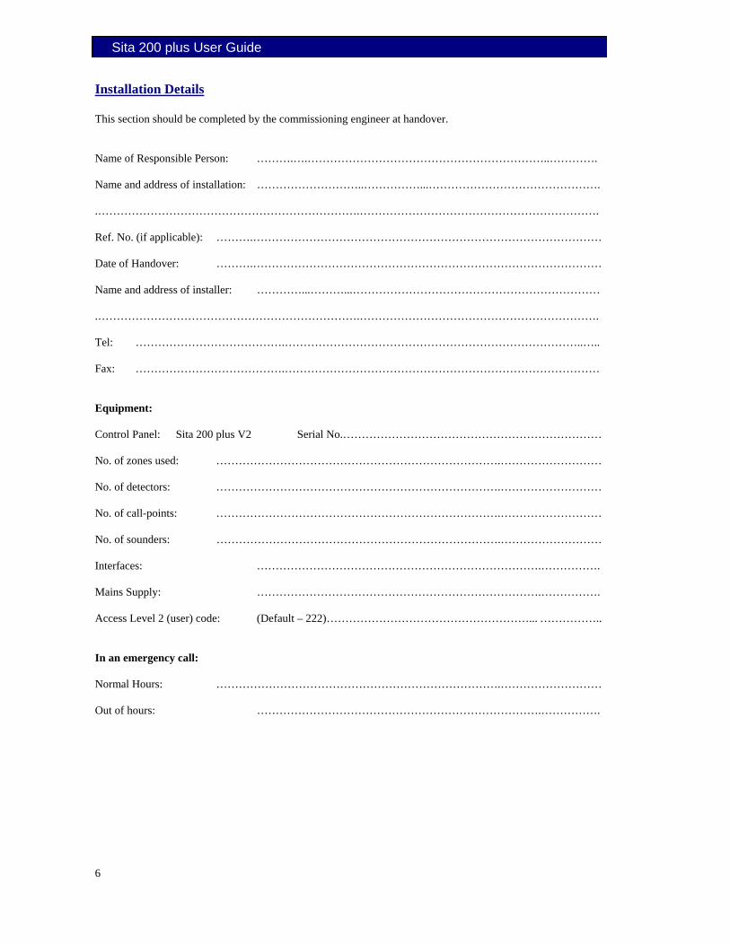
Installation Details This section should be completed by the commissioning engineer at handover. Name of Responsible Person: ……….….………………………………………………………..…………. Name and address of installation: ………………………..……………...………………………………………. .…………………………………………………………….………………………………………………………. Ref. No. (if applicable): ……….………………………………………………………………………………… Date of Handover: ……….………………………………………………………………………………… Name and address of installer: …………...………...………………………………………………………… .…………………………………………………………….……………………………………………………….
Tel: ………………………………….……………………………………………………………………..….. Fax: ………………………………….………………………………………………………………………… Equipment: Control Panel: Sita 200 plus V2 Serial No.…………………………………………………………… No. of zones used: ………………………………………………………………….……………………… No. of detectors: ………………………………………………………………….……………………… No. of call-points: ………………………………………………………………….……………………… No. of sounders: ………………………………………………………………….……………………… Interfaces: ………………………………………………………………….……………. Mains Supply: ………………………………………………………………….……………. Access Level 2 (user) code: (Default – 222)………………………………………………... …………….. In an emergency call: Normal Hours: ………………………………………………………………….……………………… Out of hours: ………………………………………………………………….…………….

Sita 200 plus User Guide
7
General Operation Normal
In the normal operating mode only the green POWER LED is lit. If any other LEDs are lit and/or the buzzer is sounding there is an abnormal condition present.
Access Levels and Soft Keys
In normal operation the panel controls are inoperable, to prevent unauthorised operation. This is classed as ACCESS LEVEL 1 (Normal state). NB/ the ‘SILENCE BUZZER’ button is operational at all times. In order to operate the panel following a fire or fault alarm, or for routine testing, the controls must be enabled by entering ACCESS LEVEL 2 (User level). Soft keys are used to pilot around the menu system. The lower line of the display is arranged in the following format:
[ ] [ ] [ ] [ ] Each section (eg., ‘[AL2 CODE]’) represents the function of the button immediately below on the keypad (follow the raised line in the moulding from the prompt down to the button). The system will therefore prompt you with the relevant options for you to use the system. The default (factory set) ACCESS LEVEL 2 code is ‘222’.
Fire Alarm
When the panel enters the fire state, the alarms will sound, the fire LEDs will illuminate, the buzzer will pulse quickly and the display will show the location and type of alarm.
On Hearing the Alarm
The responsible person should have already prepared written procedures for the action to be taken in the event of a fire alarm. When the alarm sounds these procedures should be implemented.
Sita 200 plus User Guide
8
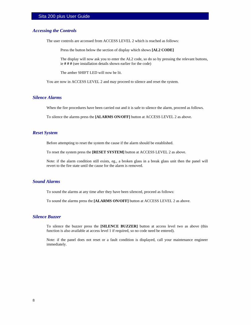
Accessing the Controls
The user controls are accessed from ACCESS LEVEL 2 which is reached as follows:
Press the button below the section of display which shows [AL2 CODE] The display will now ask you to enter the AL2 code, so do so by pressing the relevant buttons, ie # # # (see installation details shown earlier for the code) The amber SHIFT LED will now be lit.
You are now in ACCESS LEVEL 2 and may proceed to silence and reset the system.
Silence Alarms
When the fire procedures have been carried out and it is safe to silence the alarm, proceed as follows. To silence the alarms press the [ALARMS ON/OFF] button at ACCESS LEVEL 2 as above.
Reset System
Before attempting to reset the system the cause if the alarm should be established. To reset the system press the [RESET SYSTEM] button at ACCESS LEVEL 2 as above. Note: if the alarm condition still exists, eg., a broken glass in a break glass unit then the panel will revert to the fire state until the cause for the alarm is removed.
Sound Alarms
To sound the alarms at any time after they have been silenced, proceed as follows: To sound the alarms press the [ALARMS ON/OFF] button at ACCESS LEVEL 2 as above.
Silence Buzzer
To silence the buzzer press the [SILENCE BUZZER] button at access level two as above (this function is also available at access level 1 if required, so no code need be entered). Note: if the panel does not reset or a fault condition is displayed, call your maintenance engineer immediately.

Sita 200 plus User Guide
9
Exit ACCESS LEVEL 2
In order to prevent unauthorised access to the system, return to ACCESS LEVEL 1. If left untouched the display will time out after a short while and return automatically to ACCESS LEVEL 1, but this can be achieved manually if required by pressing the [EXIT AL2] prompt. This will be found at the end of the control menu by pressing the [NEXT menu] prompt until the required prompt is seen. On return to ACCESS LEVEL 1 the SHIFT LED will switch off.
Troubleshooting Problem Possible Cause Remedial Action Unable to silence alarms Panel not set to ACCESS LEVEL 2 Enter ACCESS LEVEL 2 (see section on
operation) Unable to reset system Alarms not silenced Silence alarms before attempting to reset
the system Panel not set to ACCESS LEVEL 2 Enter ACCESS LEVEL 2 (see section on
operation) Alarm condition still present Remove cause of alarm, eg., replace broken
glass in call point Buzzer sounding, FAULT LED lit
Fault or abnormal condition Note all illuminated LEDs and displayed messages. Call engineer
Buzzer sounding, POWER FAULT LED flashing, ‘Mains supply failed’ displayed.
Mains supply failure Wait until mains supply is restored – if panel does not revert to normal operation call engineer.
Buzzer sounding, SYSTEM FAULT LED lit
Control panel fault Call engineer immediately
Any other fault or abnormal behaviour
Various Note all illuminated LEDs and displayed messages. Call engineer

Sita 200 plus User Guide
10
Advanced Operation Additional Functions
Certain additional functions are available for advanced operation of the control panel. The functions summarised below should only be used in consultation with you fire alarm service organisation.
Zone Disable / Enable
This function allows the disablement or enablement of a zone. Thus, all the input devices (Manual Call Points, detectors and inputs) within that zone will be disabled. The control panel will indicate that disablements are present, the device LED will still operate when activated and an event will be recorded to log, but no programmed actions will occur. The sounder within the device will still operate if triggered from elsewhere on the system. More than one zone may be disabled at the same time, and they may be viewed under the ‘<disables’ prompt.
Device Disable / Enable
This function allows the disablement or enablement of an individual device. The control panel will indicate that disablements are present, the device LED will still operate when activated and an event will be recorded to log, but no programmed actions will occur. The sounder within the device will still operate if triggered from elsewhere on the system. More than one device may be disabled at the same time, and they may be viewed under the ‘<disables’ prompt.
Sounder Disable / Enable
This function allows the global disablement or enablement of all the sounders on the system. The control panel will indicate that disablements are present, and they may be viewed under the ‘<disables’ prompt.
Fire Protection Devices (Common Fire Outputs) Disable / Enable
This function allows the global disablement or enablement of all the outputs on the system that are programmed for common or remote fire. The control panel will indicate that disablements are present, and they may be viewed under the ‘<disables’ prompt.
Fire Signal Transmission Outputs Disable / Enable
This function allows the disablement or enablement of the control panel ‘Output relay 1’ (NC1, NC1, NOS1, Nor1, NO1), if it is programmed for Fire Signal Transmission. The control panel will indicate that disablements are present, and they may be viewed under the ‘<disables’ prompt.
Fault Signal Transmission Outputs Disable / Enable
This function allows the disablement or enablement of the control panel ‘Output relay 2’ (nos2, nor2, no2), if it is programmed for Fault Signal Transmission. The control panel will indicate that disablements are present, and they may be viewed under the ‘<disables’ prompt.

Sita 200 plus User Guide
11
Zone Test A
The ‘Zone Test A’ function allows the selection of one or more zones to operate in a ‘silent one-man walk test mode’. On triggering a device the LED in that device operates and the event is recorded into the event log as a test activation, but the sounder does not sound and the control panel does not show an alarm. After approximately 10 seconds the system will reset the device, and another may be tested.
Zone Test B
The ‘Zone Test B’ function allows the selection of one or more zones to operate in a ‘one-man walk test mode with local sound’. On triggering a device the LED in that device operates, the sounder within that device operates and the event is recorded into the event log as a test activation, but the control panel does not show an alarm. After approximately 10 seconds the system will reset the device, and another may be tested.
End Test
The ‘End Test’ function will cancel any test modes that have been selected. Clock Set
The time and date may be set using the ‘CLOCK SET’ function. If these are not set then the panel will not show the time & date, and the event log will not have a time & date stamp. These settings do not remain after the complete removal of power, and will need to be re-programmed if the mains and battery power is allowed to fail.
Minus / Plus One Hour
The time does not automatically adjust for British Summer Time so this feature allows a one hour jump without having to completely reprogram the time & date.
Test Display
The ‘testDISP’ function causes the panel LEDs to pulse and the LCD to blacken in order that their correct operation may be verified.
Warnings
Certain system warnings will be displayed upon the selection of this function. These warnings are of a non-critical nature, such as a low level optical fault. If the condition becomes more serious then it will be displayed as a fault at the control panel.
Disablement Status
The ‘>disables’ function causes the control panel to display any items which are disabled. One point shows at a time and the continued pressing of the ‘>disables’ prompt allows the messages to be scrolled through, one at a time.

Sita 200 plus User Guide
12
Fault Status
The ‘>faults’ function causes the control panel to display any items which are in fault. One point shows at a time and the continued pressing of the ‘>faults’ prompt allows the messages to be scrolled through, one at a time.
Event Log
The event log stores 255 fire and fault events. These are displayed in text format and may be scrolled through by pressing the ‘<Events’ / ‘Events> prompts.
Important Note
These functions above should only be used by authorised responsible persons, and then, only in consultation with your fire alarm service organisation.

Sita 200 plus User Guide
13
User Responsibilities Introduction
The responsible person is required under BS5839 to undertake certain tasks with respect to the testing and maintenance of the fire alarm system. The responsible person should also ensure that written procedures are in place for the actions to be taken by the occupants in a fire condition, and that staff required to operate the system have received adequate training. In a small building the fire procedures can be quite simple, but when larger premises are involved the fire procedures can become more complex and may involve the appointment of fire wardens, reporting procedures, various assembly points, etc. The responsible person is also required to liase with the building maintenance personnel to ensure that their work does not impair or otherwise affect the operation of the fire alarm system, and to ensure that a clear space is maintained in the vicinity of detectors, and call-points remain unobstructed and conspicuous.
Routine Testing
The responsible person should also ensure that the following routine testing is carried out. If there is a link to a remote monitoring center it will be necessary to advise the center prior to a test, or use the control panel facilities to isolate the link. On larger systems it may be necessary to isolate building services interfaces to avoid disruption to the occupants. In any case the panel should provide audible and visual indication that parts of the system are disabled. Daily Check that the panel indicates normal operation and that any fault is recorded. Also check that the recorded faults have been dealt with. Weekly At least one detector or call point should be operated to test the ability of the control equipment to receive a signal and sound the alarm. In practice it is far easier for the user to activate a manual call point, rather than a detector which requires special equipment. A different device should be tested each time if possible, such that each zone on the system is tested at least once in a 13 week period. The results should be recorded in the log book. Quarterly ‘The responsible person should ensure that every three months the following check is carried out by a competent person’ In other words the system should be checked by a fire alarm service organisation. This may be the system installer or an approved maintenance company, and is normally arranged via a maintenance agreement which specifies the number of visits and the level of service. The agreement should also cover non-maintenance visits, eg. call outs to attend faults, etc. The standard specifies a number of maintenance tasks which include a visual inspection of the installation to ensure that there are no alterations or obstructions which could affect the operation of the system, and functional checks to confirm the operation of the system.
Sita 200 plus User Guide
14
Any defects should be recorded in the log book and reported to the responsible person. A certificate of testing should also be completed and given to the responsible person. Annual The requirements of the annual test are similar to the quarterly test except that each device on the system should be tested. Different service organisations may undertake device testing on the same visit, ie. One major service and three minor service visits per year, or they may test a percentage of the devices on each visit so that they are all tested within the 12 month period. Action by the user after a fire Advise the servicing company and arrange for the system to be tested by them. A certificate of testing should be issued to confirm the system operation following the inspection and any remedial work that is necessary. Action by the user after any false alarm The user can assist the servicing company in the identification of false alarms by observing the following:
• Always make a note of all illuminated indicators and messages displayed at the control panel. • Try and identify the activated device, ie. Do not reset the system until the area of the incident
has been inspected. • Record any other incidents occurring at the same time which could affect the system, eg.
power supply failure, building works, etc. The service organisation will be more likely to trace the false alarm if the above information is available. Action by the user following a fault When a fault is reported by the control panel, the user should note all illuminated LEDs and messages displayed, and the circumstances at the time the fault occurred, and report to the servicing company. The service company will be able to advise if the system is still able to respond to a fire alarm or whether extra vigilance should be observed until the fault is rectified. Faults should not be left unreported.
Sita 200 plus User Guide
15
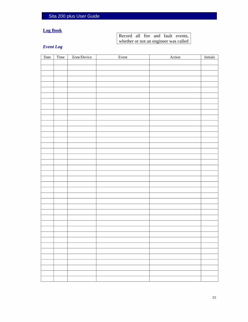
Log Book Record all fire and fault events, whether or not an engineer was called
Event Log Date Time Zone/Device Event Action Initials

Sita 200 plus User Guide
16
Date Time Zone/Device Event Action Initials

Sita 200 plus User Guide
17
Test the alarm each week using a different call point in rotation. All call points should be numbered for identification
Weekly Testing
Date Point No Comment Initials

Sita 200 plus User Guide
18
Date Point No Comment Initials

Sita 200 plus User Guide
19
Record all routine maintenance visits and note parts used/ replaced
Routine Maintenance
Date Comment Initials
Date Comment Initials

Sita 200 plus User Guide
20
Date Comment Initials

Sita 200 plus User Guide
21
Sita 200 plus User Guide
22
Modifications
Date Description of Modification Contractor Complete

Sita 200 plus User Guide
23
Notes

Sita 200 plus User Guide
24