SIR-C - HANNOVER MESSE
14
108 SIR-C Recloser Control & Feeder Protection Relay Primary & Secondary Distribution Protection • The SIR-C is a recloser control and feeder protection relay with current, voltage and frequency functions for primary and secondary distribution with auxiliary power supply of 24-230 Vdc/ac. • 4 current channels and 6 voltage channels. • Voltage measurement through capacitive and resistive sensors (LEAs). • Metallic box with high electromagnetic compatibility level (EMC) and wide range of operating temperature. • Protection of decoupling, load shedding and loss of main (islanding). Loss of Main (islanding) occurs when part of the public utility network loses connection with the rest of the system. If this situation is not detected, then the generator could remain connected, causing a safety hazard within the network. Automatic reconnection of the generator to the network may occur causing damage to the generator and the network. SIR-C relay detects this situation thanks to its voltage and frequency functions focused on the Rate of change of frequency (ROCOF) method. • Signalling/control of the circuit breaker (52 function) and the recloser (79 function). • Zone selection interlocking - ZSI (68 function) is available through configurable inputs and outputs thanks to the programmable logic (PGC). • In case a CB is manually closed, a switch on to an existing fault may occur. This fault condition is critical if the overcurrent protection function does not clear the fault until the adjusted time delay is finished. It is necessary, in those cases, to clear the fault quickly by means of SOTF function. • To allow the communication, relays are provided with a local micro USB front port and with remote communication with different options (ports and protocols) on the rear side: » Rear RS485 Port: IEC60870-5-103, Modbus RTU or DNP3.0 Serial. » Rear RJ45 Port: Modbus TCP/IP, DNP3.0 TCP/IP or IEC60870-5- 104 + Web Server + SNTP Protocol. • Synchronization through IRIG-B optional depending on model. • The SIR-C is provided with 11 configurable inputs and 5 configurable outputs. • The SIR-C is fitted with the demand of power (Load Data Profiling) with the following characteristics: » Number of records: 2160. » Recording mode circular. » Sampling rate (interval): configurable through communications (1- 60 min). • Alarms panel is available. • The SIR-C is provided with non-volatile RAM memory in order to store up to 3072 events and disturbance fault recording (DFR), maintaining date & time thanks to its internal RTC (Real Time Clock). » 5 records in data and COMTRADE format (300 cycles each record): 1 to 8 pre-fault cycles + 292 to 299 postfault cycles. » 25 records in data and COMTRADE format (60 cycles each record): 1 to 8 pre-fault cycles + 52 to 59 postfault cycles. » 50 records in data and COMTRADE format (30 cycles each record): 1 to 8 pre-fault cycles + 22 to 29 postfault cycles. » 100 records in data and COMTRADE format (15 cycles each record): 1 to 8 pre-fault cycles + 7 to 14 postfault cycles.) • The oscillography is downloaded by communications port. The SICom communications program allows the oscillography record to be downloaded and saved in COMTRADE format (IEEE C37.111-1991).
-
Upload
khangminh22 -
Category
Documents
-
view
0 -
download
0
Transcript of SIR-C - HANNOVER MESSE

108
SIR-CRecloser Control & Feeder Protection Relay
Prim
ary & S
econdary Distribution P
rotection
• The SIR-C is a recloser control and feeder protection relay with current,
voltage and frequency functions for primary and secondary distribution
with auxiliary power supply of 24-230 Vdc/ac.
• 4 current channels and 6 voltage channels.
• Voltage measurement through capacitive and resistive sensors (LEAs).
• Metallic box with high electromagnetic compatibility level (EMC) and
wide range of operating temperature.
• Protection of decoupling, load shedding and loss of main (islanding).
Loss of Main (islanding) occurs when part of the public utility network
loses connection with the rest of the system. If this situation is not
detected, then the generator could remain connected, causing a safety
hazard within the network. Automatic reconnection of the generator
to the network may occur causing damage to the generator and the
network. SIR-C relay detects this situation thanks to its voltage and
frequency functions focused on the Rate of change of frequency
(ROCOF) method.
• Signalling/control of the circuit breaker (52 function) and the recloser
(79 function).
• Zone selection interlocking - ZSI (68 function) is available through
configurable inputs and outputs thanks to the programmable logic
(PGC).
• In case a CB is manually closed, a switch on to an existing fault may
occur. This fault condition is critical if the overcurrent protection function
does not clear the fault until the adjusted time delay is finished. It is
necessary, in those cases, to clear the fault quickly by means of SOTF
function.
• To allow the communication, relays are provided with a local micro USB
front port and with remote communication with different options (ports
and protocols) on the rear side:
» Rear RS485 Port: IEC60870-5-103, Modbus RTU or DNP3.0
Serial.
» Rear RJ45 Port: Modbus TCP/IP, DNP3.0 TCP/IP or IEC60870-5-
104 + Web Server + SNTP Protocol.
• Synchronization through IRIG-B optional depending on model.
• The SIR-C is provided with 11 configurable inputs and 5 configurable
outputs.
• The SIR-C is fitted with the demand of power (Load Data Profiling) with
the following characteristics:
» Number of records: 2160.
» Recording mode circular.
» Sampling rate (interval): configurable through communications (1-
60 min).
• Alarms panel is available.
• The SIR-C is provided with non-volatile RAM memory in order to store
up to 3072 events and disturbance fault recording (DFR), maintaining
date & time thanks to its internal RTC (Real Time Clock).
» 5 records in data and COMTRADE format (300 cycles each
record): 1 to 8 pre-fault cycles + 292 to 299 postfault cycles.
» 25 records in data and COMTRADE format (60 cycles each
record): 1 to 8 pre-fault cycles + 52 to 59 postfault cycles.
» 50 records in data and COMTRADE format (30 cycles each
record): 1 to 8 pre-fault cycles + 22 to 29 postfault cycles.
» 100 records in data and COMTRADE format (15 cycles each
record): 1 to 8 pre-fault cycles + 7 to 14 postfault cycles.)
• The oscillography is downloaded by communications port. The SICom
communications program allows the oscillography record to be
downloaded and saved in COMTRADE format (IEEE C37.111-1991).

109
Functions diagram SIR-C
ANSI CODE PROTECTIONS
50 Instantaneous phase overcurrent
67/51 Inverse Time Directional* Phase Overcurrent
50N Instantaneous calculated neutral overcurrent
50G Instantaneous measured neutral overcurrent
67N/51N Inverse Time Directional* Calculated Neutral Overcurrent
67G/51G Inverse Time Directional* Measured Neutral Overcurrent
67NI Directional isolated calculated neutral overcurrent
67GI Directional isolated measured neutral overcurrent
SOTF Switch On To Fault
46 Phase balance current protection
46BC Broken Conductor Detection
64REF Restricted earth fault
49 Thermal overload
49T External Trip
37 Instantaneous phase undercurrent
SHB Second Harmonic Blocking
59 Instantaneous phase overvoltage (Bus bar)
59N Instantaneous Calculated neutral overvoltage (Bus bar)
59-L Instantaneous Line overvoltage (Line)
59N-L Instantaneous Calculated neutral overvoltage (Line)
47 Phase Balance voltage protection (Bus bar)
47-L Phase Balance voltage protection (Line)
27 Instantaneous Phase undervoltage (Bus bar)
27-L Instantaneous phase undervoltage (Line)
27V1 Instantaneous Positive sequence undervoltage (Bus bar)
27V1-L Instantaneous Positive sequence undervoltage (Line)
32 Directional Overpower
81O/U Under/Overfrequency
81R Rate of change of Frequency (ROCOF)
78 Out of Step (Vector Shift)
CLP Cold Load pickup
79 AC Reclosing device
SCM Sequence Coordination Mode
SZM Sectionalizer Mode
HLT Hot Line Tag
52 Breaker wear monitoring
25 Synchro Check
50BF Circuit Breaker Failure
74TCS Trip Circuit Supervision
60CTS Phase CT Supervision
60VTS Phase LPVT Supervision
86 Trip lockout
68 Zone selection interlocking (ZSI)
PGC Programmable logic control
* ANSI 67, ANSI 67G and ANSI 67N can be converted into ANSI 51, ANSI 51G and ANSI 51N respectively by setting the “Directionality” parameter to NO.
ADDITIONAL FUNCTIONS
CNT CountersRTC Real Time ClockALRM Alarm panelPGC Programmable Logic ControlHMI Human Machine InterfaceSER Sequential Event Recording
DFR Disturbance Fault RecordingLDP Load Data ProfilingMET MeteringSTTG Settings GroupsCMMD Commands
LDP MET CMMDSTTG DFR
CNT RTC PGCALRM HMI SER
52
BUS SIR-C
LINE
* Optional
27V127 59 59N 47 81 81R 78
SCM SZM 79 52 74TCS 86 25*
RS485* USBETHERNET
3
3
60CTS
50BF
CLP
67GI
1 67G 50G
49 SHB50N 46 46BC SOTF 3767 50 67N
67NI
32 60VTS
27L 59L 59NL 27V1L 47L1 or 3
tº
49T
IRIG-B*
1 2 1 1
HLT

110
Technical parameters SIR-C
Function 50-1
Function 50-2
Function enable: No/Alarm/Trip/SHB Trip
Current tap: 0.010 to 30.000 xIn (step 0.001xIn)
Time delay: 0.000 to 300.000 s (step 0.001 s)
Activation level: 100%
Deactivation level: 95%
Temporized deactivation
Timing accuracy: ±0.5% or ±35 ms (greater of both)
Function 50N
Function enable: No/Alarm/Trip/SHB Trip
Current tap: 0.050 to 30.000 xIn (step 0.001xIn)
Time delay: 0.000 to 300.000 s (step 0.001 s)
Activation level: 100%
Deactivation level: 95%
Temporized deactivation
Timing accuracy: ±0.5% or ±35 ms (greater of both)
Function 50G
Function enable: No/Alarm/Trip/SHB Trip
Current tap: 0.010 to 30.000 xIn (step 0.001xIn)
Time delay: 0.000 to 300.000 s (step 0.001 s)
Activation level: 100%
Deactivation level: 95%
Temporized deactivation
Timing accuracy: ±0.5% or ±35 ms (greater of both)
Function 67/51-1
Function 67/51-2
Function 67/51-3
Function 67/51-4
Function enable: No/Alarm/Trip/SHB Trip
Curve Type: IEC 60255-151, IEEE, U, SMU and RC curves.
For IEC Definite time curve, time delay: 0.000 to 300.000 s (step 0.001 s)
Time dial (TMS): 0.05 to 25.00 (step 0.01)
If Curve type IEC: 0.05 to 1.00 (step 0.01)
If Curve type IEEE: 0.10 to 25.00 (step 0.01)
If Curve type U: 0.05 to 15.00 (step 0.01)
If Curve type RC: 0.10 to 2.00 (step 0.01)
Current tap: 0.010 to 20.000 xIn (step 0.001xIn)
Directionality: No/Forward/Reverse
Polarization voltage: 0.08 to 2.00 xUn (step 0.01xUn)
Operating angle: 0 to 359º (step 1º)
Halfcone angle: 10 to 170º (step 1º)
Curve, current activation level: 110%
Curve, current deactivation level: 100%
Defined time, current activation level: 100%
Defined time, current deactivation level: 95%
Voltage activation level: 100%
Voltage deactivation level: 95%
Temporized deactivation
Timing accuracy for IEC and IEEE curves selection:
± 30 ms or ± 5% (greater of both)
Timing accuracy for defined time curve selection:
± 35 ms or ± 0.5% (greater of both)
Function 67N/51N-1
Function 67N/51N-2
Function enable: No/Alarm/Trip/SHB Trip
Curve Type: IEC 60255-151, IEEE, U, SMU and RC curves.
For IEC Definite time curve, time delay: 0.000 to 300.000 s (step 0.001 s)
Time dial (TMS): 0.05 to 25.00 (step 0.01)
If Curve type IEC: 0.05 to 1.00 (step 0.01)
If Curve type IEEE: 0.10 to 25.00 (step 0.01)
If Curve type U: 0.05 to 15.00 (step 0.01)
If Curve type RC: 0.10 to 2.00 (step 0.01)
Current tap: 0.050 to 20.000 xIn (step 0.001xIn)
Directionality: No/Forward/Reverse
Polarization voltage: 0.08 to 2.00 xUn (step 0.01xUn)
Operating angle: 0 to 359º (step 1º)
Halfcone angle: 10 to 170º (step 1º)
Curve, current activation level: 110%
Curve, current deactivation level: 100%
Defined time, current activation level: 100%
Defined time, current deactivation level: 95%
Voltage activation level: 100%
Voltage deactivation level: 95%
Temporized deactivation
Timing accuracy for IEC and IEEE curves selection:
± 30 ms or ± 5% (greater of both)
Timing accuracy for defined time curve selection:
± 35 ms or ± 0.5% (greater of both)

111
Technical parameters SIR-C
Function 67G/51G-1
Function 67G/51G-2
Function enable: No/Alarm/Trip/SHB Trip
Curve Type: IEC 60255-151, IEEE, U, SMU and RC curves.
For IEC Definite time curve, time delay: 0.000 to 300.000 s (step 0.001 s)
Time dial (TMS): 0.05 to 25.00 (step 0.01) If Curve type IEC: 0.05 to 1.00 (step 0.01)
If Curve type IEEE: 0.10 to 25.00 (step 0.01)
If Curve type U: 0.05 to 15.00 (step 0.01)
If Curve type RC: 0.10 to 2.00 (step 0.01)
Current tap: 0.010 to 20.000 xIn (step 0.001xIn)
Directionality: No/Forward/Reverse
Polarization voltage: 0.08 to 2.00 xUn (step 0.01xUn)
Operating angle: 0 to 359º (step 1º)
Halfcone angle: 10 to 170º (step 1º)
Curve, current activation level: 110%
Curve, current deactivation level: 100%
Defined time, current activation level: 100%
Defined time, current deactivation level: 95%
Voltage activation level: 100%
Voltage deactivation level: 95%
Temporized deactivation
Timing accuracy for IEC and IEEE curves selection:
± 30 ms or ± 5% (greater of both)
Timing accuracy for defined time curve selection:
± 35 ms or ± 0.5% (greater of both)
Function 67NI
Function enable: No/Alarm/Trip/SHB Trip
Directionality: No/Forward/Reverse
Low Current Tap: 0.010 to 30.000 xIn (step 0.001xIn)
High Current Tap: 0.010 to 30.000 xIn (step 0.001xIn)
Low Voltage Tap: 0.08 to 2.00 xUn (step 0.01xUn)
High Voltage tap: 0.08 to 2.00 xUn (step 0.01xUn)
Time delay: 0.000 to 300.000 s (step 0.001 s)
Operating angle: 0 to 359º (step 1º)
Halfcone angle: 10 to 170º (step 1º)
Curve, current activation level: 110%
Curve, current deactivation level: 100%
Defined time, current activation level: 100%
Defined time, current deactivation level: 95%
Voltage activation level: 100%
Voltage deactivation level: 95%
Temporized deactivation
Timing accuracy for defined time curve selection: ± 35 ms or ± 0.5% (greater of both)
Function 67GI
Function enable: No/Alarm/Trip/SHB Trip
Directionality: No/Forward/Reverse
Low Current Tap: 0.010 to 30.000 xIn (step 0.001xIn)
High Current Tap: 0.010 to 30.000 xIn (step 0.001xIn)
Low Voltage Tap: 0.08 to 2.00 xUn (step 0.01xUn)
High Voltage tap: 0.08 to 2.00 xUn (step 0.01xUn)
Time delay: 0.000 to 300.000 s (step 0.001 s)
Operating angle: 0 to 359º (step 1º)
Halfcone angle: 10 to 170º (step 1º)
Curve, current activation level: 110%
Curve, current deactivation level: 100%
Defined time, current activation level: 100%
Defined time, current deactivation level: 95%
Voltage activation level: 100%
Voltage deactivation level: 95%
Temporized deactivation
Timing accuracy for defined time curve selection: ± 35 ms or ± 0.5% (greater of both)
Function 64REF
Function enable: No/Alarm/Trip/ IN SHB Trip
Current tap: 0.050 to 20.000 xIn (step 0.001xIn)
Time delay: 0.020 to 300.000 s (step 0.001 s)
Neutral SHB Tap: 5 to 50% (step 1%)
Activation level: 100%
Deactivation level: 95%
Temporized deactivation
Timing accuracy: ± 35 ms or ± 0.5% (greater of both)
Function SOTF
Function enable: No/Alarm/Trip/SHB Trip
Current tap: 0.010 to 30.000 xIn (step 0.001xIn)
Time delay: 0.000 to 300.000 s (step 0.001 s)
Safe Time: 0.020 to 300.000 s (step 0.001 s)
Activation level: 100%
Deactivation level: 95%
Temporized deactivation
Timing accuracy: ±0.5% or ±35 ms (greater of both)
Function 49
Function enable: No/Alarm/Trip
Current tap: 0.100 to 2.400 In (step 0.001xIn)
ζ heating: 3 to 600 min (step 1 min)
ζ cooling: 1 to 6 xζ heating (step 1)
Alarm: 20 to 99% (step 1%)
Trip level: 100%
Deactivation level: 95% of alarm level
Timing accuracy: ± 5% respect of theorical value.
Function SHB
Function enable: No/Yes
Current Tap: 5- 50% (step 1%)
Reset Time: 0.000 to 300.000 (step 0.001 s)
Block Threshold: 0.010 to 30.000xIn (step 0.001xIn)
Activation level: 100%
Deactivation level: 95%
Temporized deactivation

112
Technical parameters SIR-C
Function CLP
Function enable: Yes/No
Settings group: 1 to 6 (step 1)
No load time: 0.020 to 300.000 s (step 0.001 s)
Cold load time: 0.020 to 300.000 s (step 0.001 s)
Function 46
Function enable: No/Alarm/Trip/SHB Trip
Curve Type: IEC 60255-151, IEEE, U, SMU and RC curves.
For IEC definite time, Time delay: 0.000 to 300.000 s (step 0.001 s)
Time dial (TMS): 0.05 to 25.00 (step 0.01) If Curve type IEC: 0.05 to 1.00 (step 0.01)
If Curve type IEEE: 0.10 to 25.00 (step 0.01)
If Curve type U: 0.05 to 15.00 (step 0.01)
If Curve type RC: 0.10 to 2.00 (step 0.01)
Current tap: 0.010 to 20.000 xIn (step 0.001xIn)
Curve, current activation level: 110%
Curve, current deactivation level: 100%
Defined time, current activation level: 100%
Defined time, current deactivation level: 95%
Temporized deactivation
Timing accuracy for IEC and IEEE curves selection:
± 30 ms or ± 5% (greater of both)
Timing accuracy for defined time curve selection:
± 35 ms or ± 0.5% (greater of both)
Function 46BC
Function enable: No/Alarm/Trip
Tap: 15 to 100 % (step 1%)
Time delay: 0.030 to 300.000 s (step 0.001 s)
Activation level: 100%
Deactivation level: 95%
Temporized deactivation
Timing accuracy: 0.5% or 30 ms (greater of both)
Function 37
Function enable: No/Alarm/Trip
Current tap: 0.010 to 30.000 xIn (step 0.001xIn)
Minimum level: 0.000 to 1.000 xIn (step 0.001xIn)
Time delay: 0.060 to 300.000 s (step 0.001 s)
Activation level: 100%
Deactivation level: 105%
Temporized deactivation
Timing accuracy: 0.5% or 30 ms (greater of both)
Function 27-1
Function 27-2
Function enable: No/Alarm/Trip
Voltage tap: 0.08 to 2.00 xUn (step 0.01xUn)
Minimum level: 0.00 to 1.00 xUn (step 0.01xUn)
Time delay: 0.060 to 300.000 s (step 0.001 s)
Reset time: 0.020 to 300.000 s (step 0.001 s)
Activation level: 99%
Deactivation level: 101%
Temporized deactivation
Timing accuracy: ±0.5% or ±30 ms (greater of both)
Function 27-L (*)
Function enable: No/Alarm/Trip
Voltage tap: 0.08 to 2.00 xUn (step 0.01xUn)
Minimum level: 0.00 to 1.00 xUn (step 0.01xUn)
Time delay: 0.060 to 300.000 s (step 0.001 s)
Reset time: 0.020 to 300.000 s (step 0.001 s)
Activation level: 99%
Deactivation level: 101%
Temporized deactivation
Timing accuracy: ±0.5% or ±30 ms (greater of both)
Function 27-LB (*)
Function enable: No/Alarm/Trip
Voltage tap: 0.08 to 2.00 xUn (step 0.01xUn)
Minimum level: 0.00 to 1.00 xUn (step 0.01xUn)
Time delay: 0.060 to 300.000 s (step 0.001 s)
Reset time: 0.020 to 300.000 s (step 0.001 s)
Activation level: 99%
Deactivation level: 101%
Temporized deactivation
Timing accuracy: ±0.5% or ±30 ms (greater of both)
Function 27V1
Function enable: No/Alarm/Trip
Voltage tap: 0.15 to 2.00 xUn (step 0.01xUn)
Minimum level: 0.00 to 1.00 xUn (step 0.01xUn)
Time delay: 0.060 to 300.000 s (step 0.001 s)
Reset time: 0.020 to 300.000 s (step 0.001 s)
Activation level: 99%
Deactivation level: 101%
Temporized deactivation
Timing accuracy: ±0.5% or ±30 ms (greater of both)
Function 27V1-L (*)
Function enable: No/Alarm/Trip
Voltage tap: 0.08 to 2.00 xUn (step 0.01xUn)
Minimum level: 0.00 to 1.00 xUn (step 0.01xUn)
Time delay: 0.060 to 300.000 s (step 0.001 s)
Reset time: 0.020 to 300.000 s (step 0.001 s)
Activation level: 99%
Deactivation level: 101%
Temporized deactivation
Timing accuracy: ±0.5% or ±30 ms (greater of both)
Function 59-1
Function 59-2
Function enable: No/Alarm/Trip
Voltage tap: 0.08 to 2.00 xUn (step 0.01xUn)
Time delay: 0.045 to 300.000 s (step 0.001 s)
Reset time: 0.020 to 300.000 s (step 0.001 s)
Activation level: 101%
Deactivation level: 99%
Temporized deactivation
Timing accuracy: ±0.5% or ±30 ms (greater of both)
Function 59-L (*)
Function enable: No/Alarm/Trip
Voltage tap: 0.08 to 2.00 xUn (step 0.01xUn)
Time delay: 0.045 to 300.000 s (step 0.001 s)
Reset time: 0.020 to 300.000 s (step 0.001 s)
Activation level: 101%
Deactivation level: 99%
Temporized deactivation
Timing accuracy: ±0.5% or ±30 ms (greater of both)

113
Technical parameters SIR-C
Function 59-LB (*)
Function enable: No/Alarm/Trip
Voltage tap: 0.08 to 2.00 xUn (step 0.01xUn)
Time delay: 0.045 to 300.000 s (step 0.001 s)
Reset time: 0.020 to 300.000 s (step 0.001 s)
Activation level: 101%
Deactivation level: 99%
Temporized deactivation
Timing accuracy: ±0.5% or ±30 ms (greater of both)
Function 59N-1
Function 59N-2
Function enable: No/Alarm/Trip
Voltage tap: 0.08 to 2.00 xUn (step 0.01xUn)
Time delay: 0.045 to 300.000 s (step 0.001 s)
Reset time: 0.020 to 300.000 s (step 0.001 s)
Activation level: 101%
Deactivation level: 99%
Temporized deactivation
Timing accuracy: ±0.5% or ±30 ms (greater of both)
Function 59N-L (*)
Function enable: No/Alarm/Trip
Voltage tap: 0.08 to 2.00 xUn (step 0.01xUn)
Time delay: 0.045 to 300.000 s (step 0.001 s)
Reset time: 0.020 to 300.000 s (step 0.001 s)
Activation level: 101%
Deactivation level: 99%
Temporized deactivation
Timing accuracy: ±0.5% or ±30 ms (greater of both)
Function 47
Function enable: No/Alarm/Trip
Voltage tap: 0.08 to 2.00 xUn (step 0.01xUn)
Time delay: 0.045 to 300.000 s (step 0.001 s)
Reset time: 0.020 to 300.000 s (step 0.001 s)
Activation level: 101%
Deactivation level: 99%
Temporized deactivation
Timing accuracy: ±0.5% or ±30 ms (greater of both)
Function 47-L (*)
Function enable: No/Alarm/Trip
Voltage tap: 0.08 to 2.00 xUn (step 0.01xUn)
Time delay: 0.045 to 300.000 s (step 0.001 s)
Reset time: 0.020 to 300.000 s (step 0.001 s)
Activation level: 101%
Deactivation level: 99%
Temporized deactivation
Timing accuracy: ±0.5% or ±30 ms (greater of both)
Function 32-1
Function 32-2
Function 32-3
Function 32-4
Function enable: No/Alarm/Trip
Activation level: 0.08 to 2.00 xSn (step 0.01xSn)
Operating angle: 0 to 359º (step 1º)
Time delay: 0.020 to 300.000 s (step 0.001 s)
Activation level: 100%
Deactivation level: 95%
Instantaneous deactivation
Timing accuracy: ±0.5% or ±30 ms (greater of both)
Function 81-1
Function 81-2
Function 81-3
Function 81-4
Function 81-5
Function 81-6
Function enable: No/Alarm/Trip
Type: Underfrequency or overfrequency
Activation level: 45.000 a 65.000 Hz (step 0.001 Hz)
Time delay: 0.020 a 300.000 s (step 0.001 s)
Reset time: 0.020 a 300.000 s (step 0.001 s)
Function blocked if phase B voltage is lower than 6% of the LEA Vrms maximum value (2.8, 5.2, 8 or 16 Vrms depending on model)
Activation level: 100%
Underfrequency reset level: activation level + 50mHz
Overfrequency reset level: activation level - 50 mHz
Temporized deactivation
The frequency measurement is an average value of the frequency measured during 8 cycles. The accuracy of the Time Delay is the adjusted value plus the necessary time to achieve the measurement during 8 cycles.
Function 81R-1
Function 81R-2
Function enable: No/Alarm/Trip
Type: Increase/Decrease
Activation level: 0.100 to 5.000 Hz/s (step 0.001 Hz/s)
Time delay: 0.060 to 40.000 s (step 0.001 s)
Reset time: 0.020 to 300.000 s (step 0.001 s)
Function blocked if phase B voltage is lower than 6% of the LEA Vrms maximum value (2.8, 5.2, 8 or 16 Vrms depending on model)
Activation level: 100%
Temporized deactivation
The frequency measurement is an average value of the frequency measured during 8 cycles. The accuracy of the Time Delay is the adjusted value plus the necessary time to achieve the measurement during 8 cycles.
Function 78
Function enable: No/Alarm/Trip
Activation level: 1 to 25º (step 1º)
Reset time: 0.020 to 300.000 s (step 0.001 s)
Function blocked if phase B voltage is lower than 6% of the LEA Vrms maximum value (2.8, 5.2, 8 or 16 Vrms depending on model)
Temporized deactivation
Measurement accuracy: ±1º or 10% (greater of both)
Function 25 (*)
Dead tap: 0.08 to 2.00 xUn (step 0.01xUn)
Live tap: 0.08 to 2.00 xUn (step 0.01xUn)
Voltage supervision time: 0.060 to 300.000 s (step 0.001 s)
Voltage difference: 0.05 to 2.00 xUn (step 0.01xUn)
Phase difference: 2 to 90 º (step 1º)
Frequency difference: 0.060 to 10.000 Hz (step 0.001 Hz)
Synchro check time: 0.020 to 300.000 s (step 0.001 s)
Function 79
Number of recloses: 0 to 4 (step 1)
Reclosure times 1, 2, 3, 4: 0.020 to 2000.000 s (step 0.001 s)
Hold Enable: No/Yes/No Time
Hold time: 0.000 to 2000.000 s (step 0.001 s)
Safe time: 0.020 to 2000.000 s (step 0.001 s)
Locking possibilities: pulse inputs, level inputs, commands.
114
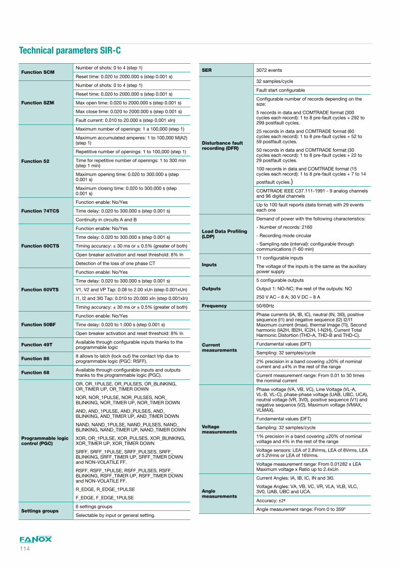
Technical parameters SIR-C
Function SCMNumber of shots: 0 to 4 (step 1)
Reset time: 0.020 to 2000.000 s (step 0.001 s)
Function SZM
Number of shots: 0 to 4 (step 1)
Reset time: 0.020 to 2000.000 s (step 0.001 s)
Max open time: 0.020 to 2000.000 s (step 0.001 s)
Max close time: 0.020 to 2000.000 s (step 0.001 s)
Fault current: 0.010 to 20.000 s (step 0.001 xIn)
Function 52
Maximum number of openings: 1 a 100,000 (step 1)
Maximum accumulated amperes: 1 to 100,000 M(A2) (step 1)
Repetitive number of openings: 1 to 100,000 (step 1)
Time for repetitive number of openings: 1 to 300 min (step 1 min)
Maximum opening time: 0.020 to 300.000 s (step 0.001 s)
Maximum closing time: 0.020 to 300.000 s (step 0.001 s)
Function 74TCS
Function enable: No/Yes
Time delay: 0.020 to 300.000 s (step 0.001 s)
Continuity in circuits A and B
Function 60CTS
Function enable: No/Yes
Time delay: 0.020 to 300.000 s (step 0.001 s)
Timing accuracy: ± 30 ms or ± 0.5% (greater of both)
Open breaker activation and reset threshold: 8% In
Detection of the loss of one phase CT
Function 60VTS
Function enable: No/Yes
Time delay: 0.020 to 300.000 s (step 0.001 s)
V1, V2 and VP Tap: 0.08 to 2.00 xUn (step 0.001xUn)
I1, I2 and 3I0 Tap: 0.010 to 20.000 xIn (step 0.001xIn)
Timing accuracy: ± 30 ms or ± 0.5% (greater of both)
Function 50BF
Function enable: No/Yes
Time delay: 0.020 to 1.000 s (step 0.001 s)
Open breaker activation and reset threshold: 8% In
Function 49T Available through configurable inputs thanks to the programmable logic
Function 86 It allows to latch (lock out) the contact trip due to programmable logic (PGC: RSFF).
Function 68 Available through configurable inputs and outputs thanks to the programmable logic (PGC).
Programmable logic control (PGC)
OR, OR_1PULSE, OR_PULSES, OR_BLINKING, OR_TIMER UP, OR_TIMER DOWN
NOR, NOR_1PULSE, NOR_PULSES, NOR_BLINKING, NOR_TIMER UP, NOR_TIMER DOWN
AND, AND_1PULSE, AND_PULSES, AND_BLINKING, AND_TIMER UP, AND_TIMER DOWN
NAND, NAND_1PULSE, NAND_PULSES, NAND_BLINKING, NAND_TIMER UP, NAND_TIMER DOWN
XOR, OR_1PULSE, XOR_PULSES, XOR_BLINKING, XOR_TIMER UP, XOR_TIMER DOWN
SRFF, SRFF_1PULSE, SRFF_PULSES, SRFF_BLINKING, SRFF_TIMER UP, SRFF_TIMER DOWN and NON-VOLATILE FF.
RSFF, RSFF_1PULSE, RSFF_PULSES, RSFF_BLINKING, RSFF_TIMER UP, RSFF_TIMER DOWN and NON-VOLATILE FF.
R_EDGE, R_EDGE_1PULSE
F_EDGE, F_EDGE_1PULSE
Settings groups6 settings groups
Selectable by input or general setting.
SER 3072 events
Disturbance fault recording (DFR)
32 samples/cycle
Fault start configurable
Configurable number of records depending on the size:
5 records in data and COMTRADE format (300 cycles each record): 1 to 8 pre-fault cycles + 292 to 299 postfault cycles.
25 records in data and COMTRADE format (60 cycles each record): 1 to 8 pre-fault cycles + 52 to 59 postfault cycles.
50 records in data and COMTRADE format (30 cycles each record): 1 to 8 pre-fault cycles + 22 to 29 postfault cycles.
100 records in data and COMTRADE format (15 cycles each record): 1 to 8 pre-fault cycles + 7 to 14
postfault cycles.)COMTRADE IEEE C37.111-1991 - 9 analog channels and 96 digital channels
Up to 100 fault reports (data format) with 29 events each one
Load Data Profiling (LDP)
Demand of power with the following characteristics:
- Number of records: 2160
- Recording mode circular
- Sampling rate (interval): configurable through communications (1-60 min)
Inputs 11 configurable inputs
The voltage of the inputs is the same as the auxiliary power supply
Outputs
5 configurable outputs
Output 1: NO-NC; the rest of the outputs: NO
250 V AC – 8 A; 30 V DC – 8 A
Frequency 50/60Hz
Current measurements
Phase currents (IA, IB, IC), neutral (IN, 3I0), positive sequence (I1) and negative sequence (I2) I2/I1 Maximum current (Imax), thermal Image (TI), Second harmonic (IA2H, IB2H, IC2H, I-N2H), Current Total Harmonic Distortion (THD-A, THD-B and THD-C).
Fundamental values (DFT)
Sampling: 32 samples/cycle
2% precision in a band covering ±20% of nominal current and ±4% in the rest of the range
Current measurement range: From 0.01 to 30 times the nominal current
Voltage measurements
Phase voltage (VA, VB, VC), Line Voltage (VL-A, VL-B, VL-C), phase-phase voltage (UAB, UBC, UCA), neutral voltage (VR, 3V0), positive sequence (V1) and negative sequence (V2), Maximum voltage (VMAX, VLMAX).
Fundamental values (DFT)
Sampling: 32 samples/cycle
1% precision in a band covering ±20% of nominal voltage and 4% in the rest of the range
Voltage sensors: LEA of 2.8Vrms, LEA of 8Vrms, LEA of 5.2Vrms or LEA of 16Vrms.
Voltage measurement range: From 0.01282 x LEA Maximum voltage x Ratio up to 2.4xUn
Angle measurements
Current Angles: IA, IB, IC, IN and 3I0.
Voltage Angles: VA, VB, VC, VR, VLA, VLB, VLC, 3V0, UAB, UBC and UCA.
Accuracy: ±2º
Angle measurement range: From 0 to 359º

115
Technical parameters SIR-C
Power measurements
Total and per phase active power
Total and per phase reactive power
Total and per phase apparent power
Power factor: Cos PHI-A, Cos-PHI-B and Total Cos-PHI
2% accuracy in rated values with power factor between 1 and 0.7 (phase shift from 0 to ±45º).
Energy measurement
Positive and negative active energy
Positive and negative reactive energy
Frequency measurements
Busbar Frequency, Line Frequency, df/dt
Minimum voltage: 5.77% of the LEA Vrms maximum value (2.8, 5.2, 8 or 16 Vrms depending on model)
Accuracy: ±50 mHz
Frequency measurement range: From 45 to 65 Hz
Communications
Local port (micro USB): Modbus RTU
Remote port RS485: Modbus RTU, DNP3.0 or IEC60870-5-103 (*)
Remote port RJ45: DNP3.0 TCP/IP, IEC60870-5-104 or Modbus TCP/IP + Web Server + SNTP Protocol (*)
Power supply 24-230 Vdc / Vac (Tolerance: -20/+10%)
Environmental conditions
Operating temperature: -40 to 70ºC
Storage temperature: -40 to 80ºC
Relative humidity: 95%
Mechanical characteristics
Metallic box
Panel mounted
Vertical assembly: HxWxD: 198x107x145.01 (mm)
Horizontal assembly: HxWxD: 107x198x145.01 (mm)
IP-54
(*) Optional depending on modelNOTE: ANSI 67, ANSI 67G and ANSI 67N can be converted into ANSI 51, ANSI 51G and ANSI 51N respectively by setting the “Directionality” parameter to NO.

116
Dimensions and cutout SIR-C
CUT-OUTPATTERN
Vertical assembly

117
Dimensions and cutout SIR-C
Horizontal assembly
CUT-OUTPATTERN

118
Connections diagram SIR- C
GND SAFETYGROUND
AUX.
POW
ER B1
B2AC/D
C
A1
MEASUREMENT
A B C N
A2 A3 A4 A5 A6 A7 A8
B8
LINEVOLTAGE
B7
B6
B5
B4
B3
A
BC
LINE
A
CBBUS
B14
BUSBARVOLTAGE
B13
B12
B11
B10
B9
Power Supply
52
COM
Va
Vb
Vc
Va
Vb
Vc
3 Resistive Voltage Semsors + 4 Standard Current Transformers
SIRC Feeder Protection
&Recloser Control
INPU
TSO
UTP
UTS
COMMON
COMMON
3 resistive sensors + 4 current transformers
(*) Example of connections diagram

119
Connections diagram SIR-C
GND SAFETYGROUND
AUX.
POW
ER B1
B2AC/D
C
A1
MEASUREMENT
A B C N
A2 A3 A4 A5 A6 A7 A8
B8
LINEVOLTAGE
B7
B6
B5
B4
B3
A
BC
LINE
BUS
B14
BUSBARVOLTAGE
B13
B12
B11
B10
B9
Power Supply
52
COM
Va
Vb
Vc
Va
Vb
Vc
4 Resistive Voltage Semsors + 4 Standard Current Transformers
A
CB
SIRC Feeder Protection
&Recloser Control
INPU
TSO
UTP
UTS
COMMON
COMMON
4 resistive sensors + 4 current transformers
(*) Example of connections diagram

120
Connections diagram SIR- C
GND SAFETYGROUND
AUX.
POW
ER B1
B2AC/D
C
A1
MEASUREMENT
A B C N
A2 A3 A4 A5 A6 A7 A8
B8
LINEVOLTAGE
B7
B6
B5
B4
B3
A
BC
LINE
BUS
B14
BUSBARVOLTAGE
B13
B12
B11
B10
B9
Power Supply
52
COM
Va
Vb
Vc
Va
Vb
Vc
6 Resistive Voltage Semsors + 3 Standard Current Transformers
A
CB
SIRC Feeder Protection
&Recloser Control
INPU
TSO
UTP
UTS
COMMON
COMMON
6 resistive sensors + 3 current transformers
(*) Example of connections diagram

121
Selection & Ordering data SIR-C
SIR-CFeeder & Recloser Control
0PHASE CURRENT MEASUREMENT1 A or 5 A
0NEUTRAL CURRENT MEASUREMENT1 A or 5 A
1234
VOLTAGE MEASUREMENT8 Vrms LEA maximum, 1 MOhm5.2 Vrms LEA maximum, 2 MOhms16 Vrms LEA maximum, 2 MOhms2.8 Vrms LEA maximum, 20 MOhms
CPOWER SUPPLY24-230 Vdc/Vac
02
ADDITIONAL FUNCTIONS-+25 + 27-L + 59-L + 47-L + 27V1-L + 59N-L
A
B
COMMUNICATIONSA: USB (Modbus RTU) + RS485: (Modbus RTU, IEC60870-5-103 or DNP3.0 Serial) B: USB (Modbus RTU) + RS485 (Modbus RTU, IEC60870-5-103 or DNP3.0 Serial) + RJ45 (Modbus TCP, DNP3.0 TCP or IEC60870-5-104) + Web Server + SNTP Protocol + IRIG-B
1INPUTS AND OUTPUTS11 Inputs + 5 Outputs
CDEF
MECHANICAL ASSEMBLYVertical AssemblyHorizontal AssemblyVertical Assembly with anticorrosive treatmentHorizontal Assembly with anticorrosive treatment
AEF
LANGUAGEEnglish, Spanish, German and FrenchEnglish, Spanish, Turkish and RussianEnglish, Spanish, German and Portuguese
BADAPTATIONDefault functions: (2) 50 + SOTF + 50G + 50N + (4) 67/51 + (2) 67G/51G + (2) 67N/51N + 67GI + 67NI + 64REF + 46 + 46BC + 49 + 49T + 37 + (2) 27 + 27V1 + (2) 59 + (2) 59N + 47 + (4) 32 + (6) 81U/O + (2) 81R + 78 + 79 + 74TCS + 60CTS + 60VTS + 50BF + SHB + CLP + 52 + 86 + SCM+ SZM + HLT
Example of ordering code:
0 0 2 C 0 A 0 C A B SIR C 0 0 2 C 0 A 0 C A B
SIR-C
(*) ANSI 67, ANSI 67G and ANSI 67N can be converted into ANSI 51, ANSI 51G and ANSI 51N respectively by setting the “Directionality” parameter to NO.