Single Point Incremental Forming: State-of-the-art and Prospects
45
Single Point Incremental Forming: State-of-the-art and Prospects Joost R. Duflou 1 , Anne-Marie Habraken 2 , Jian Cao 3 , Rajiv Malhotra 4 , Markus Bambach 5 , Dave Adams 6 , Hans Vanhove 1 , Amirahmad Mohammadi 1 , Jack Jeswiet 6 1 Department of Mechanical Engineering, KU Leuven, Belgium 2 Department ArGEnCo, Université de Liège, Belgium 3 Department of Mechanical Engineering, Northwestern University,USA 4 Department of Mechanical Engineering, Oregon State University, USA 5 Chair for Mechanical Design and Manufact., Brandenburg University of Technology, Germany 6 Department of Mechanical and Materials Engineering, Queen’s University, Canada Keywords: Incremental Sheet Forming, Single Point Incremental Forming Abstract. Incremental sheet metal forming in general and Single Point Incremental Forming (SPIF) specifically have gone through a period of intensive development with growing attention from research institutes worldwide. The result of these efforts is significant progress in the understanding of the underlying forming mechanisms and opportunities as well as limitations associated with this category of flexible forming processes. Furthermore, creative process design efforts have enhanced the process capabilities and process planning methods. Also, simulation capabilities have evolved substantially. This review paper aims to provide an overview of the body of knowledge with respect to Single Point Incremental Forming. Without claiming to be exhaustive, each section aims for an up-to-date state-of-the-art review with corresponding conclusions on scientific progress and outlook on expected further developments. 1. Introduction Single Point Incremental Forming (SPIF) has been the subject of intensive research over the past decade, with a growing understanding of the forming mechanisms and process capabilities as a result. The authors of the 2005 CIRP (College International pour la Recherche en Productique) review paper on SPIF (Jeswiet et al. 2005) represented most of the laboratories working on SPIF at the time. From that time onward, there has been a dramatic expansion of the number of research laboratories focussing on SPIF, with a concomitant increase in the number of papers being produced. The SPIF process has also found its way into the manufacturing sector as a rapid manufacturing process and an emerging solution for manufacturing small series of parts (Adams, Jeswiet 2014a). Taking into account the substantial knowledge shift, as reflected by the large number of publications over the past decade and the demonstrated applications, the authors have joined forces to compile an updated overview of the state-of-the-art in the domain of incremental sheet forming. Since the registration of the initial idea as a patent by Leszak (Leszak 1967), numerous variants, such as Double Sided Incremental Forming and Two point Incremental Forming, have been developed and have been extensively described in general reviews like, for instance, Reddy et al. 2015. Specific focus of this review paper is on Single Point Incremental Forming since this is the process variant that has been studied most intensively. Following the description of this process category as specified by Jeswiet et al. in (Jeswiet et al. 2005), this process is characterized by the forming of sheet metal sheets by means of a computer numerically controlled (CNC) generic tool stylus, with the sheets clamped by means of a non-workpiece-specific clamping system and in absence of a partial or full die. In contrast with other incremental forming strategies, in SPIF the back surface of the sheet being deformed is indeed a “free”, unsupported surface. This lack of a partial or full die assures the flexibility of the
-
Upload
khangminh22 -
Category
Documents
-
view
0 -
download
0
Transcript of Single Point Incremental Forming: State-of-the-art and Prospects

Single Point Incremental Forming: State-of-the-art and Prospects
Joost R. Duflou1, Anne-Marie Habraken2, Jian Cao3, Rajiv Malhotra4, Markus Bambach5, Dave Adams6, Hans Vanhove1,
Amirahmad Mohammadi1, Jack Jeswiet6 1Department of Mechanical Engineering, KU Leuven, Belgium
2Department ArGEnCo, Université de Liège, Belgium 3Department of Mechanical Engineering, Northwestern University,USA 4Department of Mechanical Engineering, Oregon State University, USA
5Chair for Mechanical Design and Manufact., Brandenburg University of Technology, Germany 6Department of Mechanical and Materials Engineering, Queen’s University, Canada
Keywords: Incremental Sheet Forming, Single Point Incremental Forming
Abstract.
Incremental sheet metal forming in general and Single Point Incremental Forming (SPIF) specifically have gone through a period of intensive development with growing attention from research institutes worldwide. The result of these efforts is significant progress in the understanding of the underlying forming mechanisms and opportunities as well as limitations associated with this category of flexible forming processes. Furthermore, creative process design efforts have enhanced the process capabilities and process planning methods. Also, simulation capabilities have evolved substantially. This review paper aims to provide an overview of the body of knowledge with respect to Single Point Incremental Forming. Without claiming to be exhaustive, each section aims for an up-to-date state-of-the-art review with corresponding conclusions on scientific progress and outlook on expected further developments.
1. Introduction
Single Point Incremental Forming (SPIF) has been the subject of intensive research over the past decade, with a growing understanding of the forming mechanisms and process capabilities as a result. The authors of the 2005 CIRP (College International pour la Recherche en Productique) review paper on SPIF (Jeswiet et al. 2005) represented most of the laboratories working on SPIF at the time. From that time onward, there has been a dramatic expansion of the number of research laboratories focussing on SPIF, with a concomitant increase in the number of papers being produced. The SPIF process has also found its way into the manufacturing sector as a rapid manufacturing process and an emerging solution for manufacturing small series of parts (Adams, Jeswiet 2014a). Taking into account the substantial knowledge shift, as reflected by the large number of publications over the past decade and the demonstrated applications, the authors have joined forces to compile an updated overview of the state-of-the-art in the domain of incremental sheet forming. Since the registration of the initial idea as a patent by Leszak (Leszak 1967), numerous variants, such as Double Sided Incremental Forming and Two point Incremental Forming, have been developed and have been extensively described in general reviews like, for instance, Reddy et al. 2015. Specific focus of this review paper is on Single Point Incremental Forming since this is the process variant that has been studied most intensively. Following the description of this process category as specified by Jeswiet et al. in (Jeswiet et al. 2005), this process is characterized by the forming of sheet metal sheets by means of a computer numerically controlled (CNC) generic tool stylus, with the sheets clamped by means of a non-workpiece-specific clamping system and in absence of a partial or full die. In contrast with other incremental forming strategies, in SPIF the back surface of the sheet being deformed is indeed a “free”, unsupported surface. This lack of a partial or full die assures the flexibility of the
process with respect to negligible tooling requirements, but also poses a challenge in terms of process control and accuracy assurance. For the scope definition of this review paper, exception is made for the use of a so-called support or backing plate, which is a 2D insert in the clamping system that assures better control of the workpiece edge (see Figure 2.1).
The paper is structured according to the different aspects of the SPIF process that have been the subject of research contributions. Consecutively hardware developments (Section 2), new insights in the process fundamentals (Section 3), methods to increase the process window in terms of geometric forming capabilities and formability (Section 4), process planning support methods and toolpath generation techniques (Section 5) and process simulation capabilities (Section 6) are covered. The review is concluded with a selection of application examples, sorted by different application domains, and an outlook towards expected further trends in the development of the SPIF process.
2. Hardware Requirements and Process Platforms
Single Point Incremental Forming in its most basic form is characterised by continuously superimposing local deformations in a sheet until a final shape is reached. These deformations are induced by a relatively small tool that moves along a predefined path, describing the surface of the desired geometry (Figure 2.1) or any corrected tool path finally yielding to the target shape (see Section 5.2). The localised nature of the deformation zone around the tool, results in low forming forces compared to conventional sheet forming processes. This keeps the strength requirements of the positioning system that drives the tool fairly modest. A first declaration of an apparatus and process for incremental forming was filed as a patent by Leszak (Leszak 1967). The hardware components typically used in SPIF are depicted in Figure 2.1 and will be discussed in detail in the following sections.
Fig 2.1. Schematic overview of the hardware components for conventional SPIF.
2.1. Positioning system
As described, SPIF deforms a sheet through the relative movement between tool and sheet, allowing Incremental Forming to be performed on most multi axes positioning systems. The three orthogonal axes used for most SPIF machines serve as a good base for a wide variety of parts. However, for collision prevention, optimal use of the stiffness of the tool and optimising process parameters, as discussed throughout this paper, a five or more axes system can be required. The addition of two axes allows orientation of the tool into more favourable conditions for forming. The relative movement of the tool compared to the sheet can be accomplished by moving the tool, the sheet or a combination of both.
Besides the choice in number of axes, the strength and stiffness of the positioning system is a key factor. In general, SPIF has fairly limited process forces compared to conventional processes due to the small deformation zone. Aerens et al. (2010) carried out an extensive experimental study and created a factorial model for force prediction. It was concluded that material, tool size, incremental step size between contours (Δz) and wall angle of the part are the main influencing parameters.

Marabuto et al. (2011) provided an overview of forming forces obtained by different research institutes on a variety of materials and thicknesses and concluded that 13kN along the main tool axis and 6.5kN of force perpendicular to the tool axis is sufficient for most industrially relevant parts.
As the SPIF tool executes a contouring operation, tool paths rapidly grow with increased part sizes and make the process time consuming. Ambrogio et al. (2013) and Vanhove et al. (2014) experimented with a high speed variant of SPIF on a lathe for the production of axi-symmetrical parts, showing no negative effect of increasing the strain rate in SPIF. Moreover, for some materials, like the aluminium 5xxx series, an increase in formability was observed at high strain rates. In these studies, forming speeds were increased from the conventional 2m/min up to extremes of 600m/min. This seems to justify the call for highly dynamic machines. However, an increase in the forming speed can adversely affect the formability, as demonstrated in experiments conducted by Peirera Bastos et al. (2015) on 1 mm thick sheets, covering a feed rate from 1.5 to 12m/min. Increasing feed-rate reduced the formability and deteriorated the surface finish for dual-phase steels (DP600, DP780 and DP1000) while Aluminium 1050-H111 appeared to be insensitive to feed rate variations.
For pragmatic reasons many research institutes have chosen to adapt conventional milling machines as a SPIF experimental platform, proving the viability of these alterations and ease of adoption by industry and job shops. Although stiff, these machines are most often not optimised for high dynamic behaviour and high axial forces. Articulated robots are the second most popular used equipment for their versatility and low cost (e.g. Meier et al. 2005). However, low stiffness and absolute accuracy are a great drawback of these platforms (Verbert et al. 2009). The final category involves purpose built machines consisting of either a combinations of linear axes or parallel kinematics (e.g. Alves de Sousa et al. 2014). Mainly parallel kinematics provide a superior stiffness and allow high dynamic behaviour, but are limited in working range (Marabuto et al. 2011).
In a variant closely related to SPIF, a double set of dynamic tools is used. A tool on each side of the sheet can act both as forming tool or supporting tool. This allows the formation of shapes with increased accuracy and complexity. The hardware requirements for these platforms are similar to these of SPIF provided that the system is doubled up and the positioning systems on both sides of the sheet are synchronised. Johnson et al.(2012) filed for a patent using two steward platforms in name of Ford Global Technologies. Meier et al.(2009) introduced the use of two articulated robots enabling the secondary tool to support the part both locally or along its periphery. Paniti (2014) introduced a system using one robot as primary tool and mechanical copying device as a secondary supporting tool.
2.2. Tools and lubrication
Eliminating dedicated tooling makes SPIF a versatile process, and economically feasible for small series of parts. The final shape in SPIF is imposed by local deformations along the tool trajectory in contrast with global deformations imposed by the tool geometry in conventional stamping or deep drawing. This limits the influence of tool geometry on the final accuracy and allows the use of generic tool geometries for a wide variety of parts. A simple hemispherical tipped tool is the tool of choice for the majority of parts. Variations to the tool geometry can only be found to overcome specific challenges in SPIF. Ziran et. al. (2010) employed, for example, a flat end tool to improve the accuracy in shallow sloped parts.
Although parts can be made using a single generic tool, the tool size is an influencing factor in the SPIF process. Aerens et. al. (2010) reported the increased process forces when increasing the tool size. Likewise a decrease in formability has been observed while increasing the tool size (Bhattacharya, Maneesh, et al. 2011). In daily practice, the tool size is limited by high forces and by the smallest detail to be produced and/or the machine limits.
The small contact area between tool and sheet results in high contact pressure and considerable surface friction (Eyckens et. al. 2008). The surface deterioration and reduced formability through friction can best be combatted by using lubrication and a net rolling of the tool over the sheet, rather

than dragging. Jeswiet et.al. (2005) gave a thorough overview considering the optimal axial rotational speed of a driven tool compared to the wall angle of the part, while a spindle free-rotating tool will rotate at optimal speed automatically. Lu et. al. (2014) observed an increased surface quality and formability when using an oblique roller-ball tool, allowing the tool tip to rotate in all directions.
The use of lubrication further reduces the friction between the tool and the sheet. A wide variety of oils, greases and waxes are being used in the incremental forming process. Azevedo et.al. (2015) concluded that, as the hardness of the sheet material increases, the required viscosity of the lubrication decreases. Hussain et. al. (2008) found that all conventional lubrication squeezed out of the tool-sheet contact area for titanium parts resulting in poor surface finish. Satisfactory results could only be obtained through the combination of a micro-arc oxidation coating on the sheet and MoS2 paste as lubricant.
Besides the surface and formability effects on the final part, the significant friction in SPIF also has an effect on tool wear and the choice in tool material. Naturally the tool needs to be hard resulting in using materials such as tool steel (HSS) and carbide tools (Duflou et al. 2007). To further increase hardness these tools are often (surface) hardened and/or coated with conventional coatings as used on cutting tools (TiN, CrN).
2.3. Clamping fixture and support structure
Rigid blank holders are used to clamp the sheet. Often these generic clamping fixtures allow incorporation of different (dedicated) support or backing plates that help to limit undesirable deformation of the blank in an early stage of the forming process (see Fig. 2.1). Rigid support in the immediate vicinity of the forming zone assures a higher accuracy and reduces scrap material associated with extended transition areas between the actual part geometry and clamped workpiece edge. The sheet is typically clamped on the blank holder using bolts and clamping plates along the edge of the sheet. Finite element simulations by Bouffioux et al. (2007) have demonstrated that limited sliding can significantly affect the tool force required to form an indent shape. A sliding effect of 0.08 mm was, for example, found to result in a force reduction on the tool with 16%. In order to obtain reproducible results, the torque applied to each clamping bolt therefore has to be constant and sufficiently high to prevent sliding.
Many metals need to be thermally stress relieved prior to unclamping the part in order to reduce unwanted deformation (Duflou et al. 2007). When this stress relieving is performed using an oven, logistic constraints are typically imposed on the size and weight of the clamping rig, also with respect to handling options.
Vertical mounting of the clamping fixture on the forming setup allows flushing of the sheet with lubricant during production. This flushing allows removal of any possible debris resulting from the tool - sheet interaction during forming and helps to avoid excessive surface damage and tool wear. Furthermore the ease of access to the back of the sheet when in vertical position allows for heating by lasers (see Section 4.1.2) and observation by means of cameras for thermal or dimensional analysis.
3. Process Fundamentals
3.1. Forming mechanism and formability
When Single Point Incremental Forming (SPIF) was initially being developed, most of the studies were directed towards process strategies and parameter variation in an effort to establish fundamental mechanisms (Emmens, Sebastiani et al. 2010). During this time period, it was well noted that the SPIF process significantly enhanced the achievable stretch and formability in sheet metal relative to conventional stamping operations as defined by the forming limit curve (FLC) (Jeswiet, Micari et al. 2005, Filice et al. 2002). While this observation in material formability was widely recognized and

accepted, few publications were available that attempted to explain this behaviour. During this time period, formability/fracture curves for SPIF were being developed and verified, and then often compared to a traditional FLC gathered from stamping processes, despite the significant increase in strain values (see Fig. 3.1). The consensus was that the formability limits in SPIF were much higher than those found in conventional stamping due to the localization of plastic deformation (Emmens and van den Boogaard 2009). However, later studies attempted to further explain the specific material failure mechanisms present in incremental sheet forming, leading to a variety of theories within the field. One school of thought is that formability in SPIF is limited by necking and that a stabilizing effect exists caused by either significant through-the-thickness shear or by serrated strain paths arising from cyclic, local plastic deformation (Jackson and Allwood 2009, Eyckens, He, Van Bael et al. 2011, Silva, Nielsen et al. 2011, Malhotra, Xue et al. 2012). On the other hand, there has been experimental evidence to support the avoidance of necking prior to failure. This was furthered reasoned by noting that the forming limits in SPIF can be approximated in the principal strain space by straight lines with negative slopes of 𝜀1 + 𝜀2 = 𝑞 placed near the fracture forming limit (Jeswiet, Micari et al. 2005, Emmens and van den Boogaard 2009, Silva, Nielsen et al. 2011, Silva, Skjoedt et al. 2009).
Fig 3.1. Illustration of the necking limit (FLC) and the fracture limit(left); Measured FLC in SPIF for 1.21 mm thick AA 1050-O using pyramid parts (adapted from Jeswiet, Micari et al. 2005, Emmens and van den Boogaard 2009) (right).
3.2. Failure mechanism
While it is clear that material failure in SPIF depends significantly on how the stress is imposed on the material, it has proven to be challenging to define both the specific limits of the process as well as the underlying mechanics of the failure mechanisms at play. As previously mentioned, empirical forming limit diagrams, such as those compiled by Filice et al. (Filice et al. 2002), have been developed to approximate the onset of failure. Additional forming limit indicators have been considered as well. Hussain et al. (Hussain, Gao et al. 2009) derived an empirical FLC founded on the reduction in the cross section area of a traditional tensile test. Inspired by the noted through-the-thickness shear present in SPIF, Allwood et al. (Allwood, Shouler et al. 2007) extended an M-K analysis so that all six components of the stress tensor were non-zero. Silva et al. (Silva, Skjoedt et al. 2009) presented a detailed membrane analysis of SPIF which accounted for the influence of major process parameters. This investigation lead to the conclusion that a probable mode of material failure in SPIF is consistent with stretching, rather than solely shearing. On a similar note, Emmens and van den Boogaard (Emmens and van den Boogaard 2009) performed an extensive study on the proposed failure mechanisms in SPIF and remarked that a conventional FLC is only valid if (1) the strain path is straight within the principal strain space, a condition also referred to as radial loading, (2) the deformation is dominantly caused by membrane forces, (3) through-the-thickness shear is negligible, and (4) plane strain exists. While these conditions are often met in traditional stamping processes, all four of these conditions are violated in incremental sheet forming, suggesting that FLC predictions may not be appropriate for SPIF. This raises the
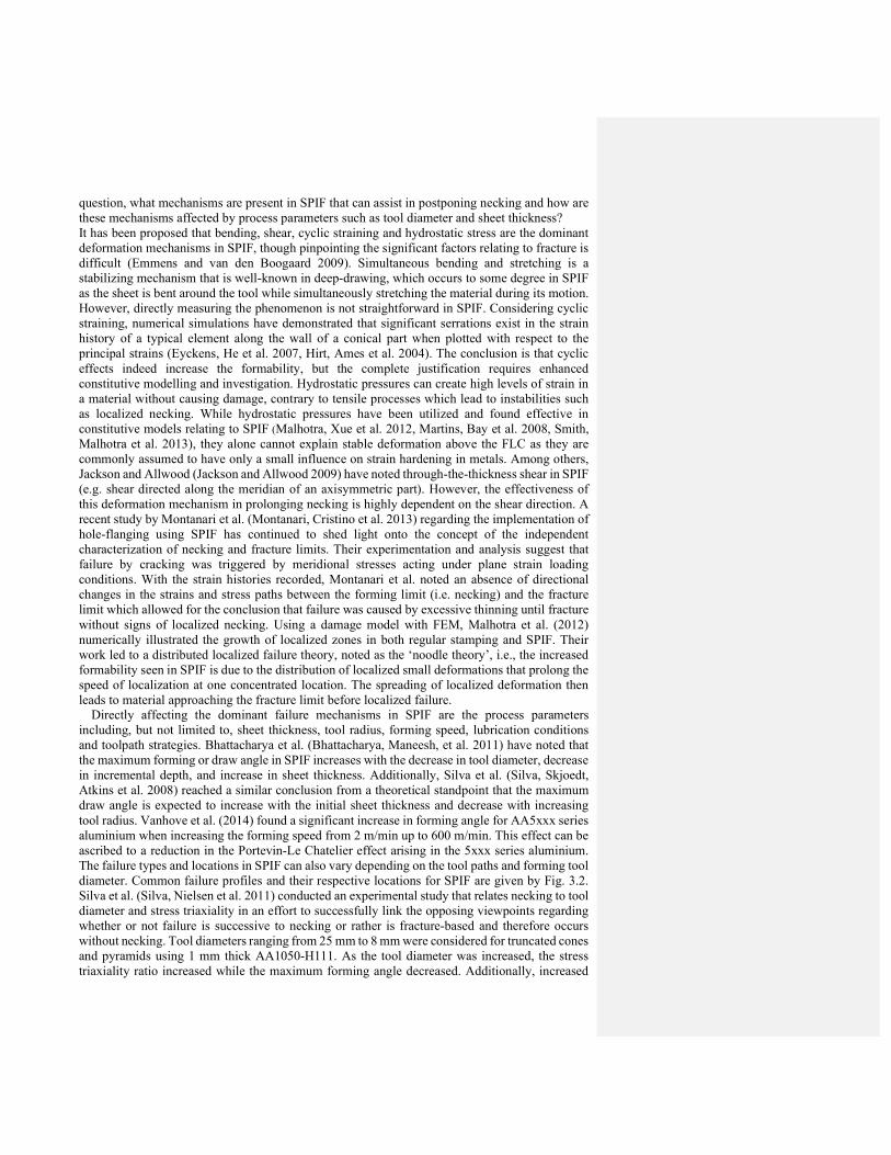
question, what mechanisms are present in SPIF that can assist in postponing necking and how are these mechanisms affected by process parameters such as tool diameter and sheet thickness? It has been proposed that bending, shear, cyclic straining and hydrostatic stress are the dominant deformation mechanisms in SPIF, though pinpointing the significant factors relating to fracture is difficult (Emmens and van den Boogaard 2009). Simultaneous bending and stretching is a stabilizing mechanism that is well-known in deep-drawing, which occurs to some degree in SPIF as the sheet is bent around the tool while simultaneously stretching the material during its motion. However, directly measuring the phenomenon is not straightforward in SPIF. Considering cyclic straining, numerical simulations have demonstrated that significant serrations exist in the strain history of a typical element along the wall of a conical part when plotted with respect to the principal strains (Eyckens, He et al. 2007, Hirt, Ames et al. 2004). The conclusion is that cyclic effects indeed increase the formability, but the complete justification requires enhanced constitutive modelling and investigation. Hydrostatic pressures can create high levels of strain in a material without causing damage, contrary to tensile processes which lead to instabilities such as localized necking. While hydrostatic pressures have been utilized and found effective in constitutive models relating to SPIF (Malhotra, Xue et al. 2012, Martins, Bay et al. 2008, Smith, Malhotra et al. 2013), they alone cannot explain stable deformation above the FLC as they are commonly assumed to have only a small influence on strain hardening in metals. Among others, Jackson and Allwood (Jackson and Allwood 2009) have noted through-the-thickness shear in SPIF (e.g. shear directed along the meridian of an axisymmetric part). However, the effectiveness of this deformation mechanism in prolonging necking is highly dependent on the shear direction. A recent study by Montanari et al. (Montanari, Cristino et al. 2013) regarding the implementation of hole-flanging using SPIF has continued to shed light onto the concept of the independent characterization of necking and fracture limits. Their experimentation and analysis suggest that failure by cracking was triggered by meridional stresses acting under plane strain loading conditions. With the strain histories recorded, Montanari et al. noted an absence of directional changes in the strains and stress paths between the forming limit (i.e. necking) and the fracture limit which allowed for the conclusion that failure was caused by excessive thinning until fracture without signs of localized necking. Using a damage model with FEM, Malhotra et al. (2012) numerically illustrated the growth of localized zones in both regular stamping and SPIF. Their work led to a distributed localized failure theory, noted as the ‘noodle theory’, i.e., the increased formability seen in SPIF is due to the distribution of localized small deformations that prolong the speed of localization at one concentrated location. The spreading of localized deformation then leads to material approaching the fracture limit before localized failure. Directly affecting the dominant failure mechanisms in SPIF are the process parameters including, but not limited to, sheet thickness, tool radius, forming speed, lubrication conditions and toolpath strategies. Bhattacharya et al. (Bhattacharya, Maneesh, et al. 2011) have noted that the maximum forming or draw angle in SPIF increases with the decrease in tool diameter, decrease in incremental depth, and increase in sheet thickness. Additionally, Silva et al. (Silva, Skjoedt, Atkins et al. 2008) reached a similar conclusion from a theoretical standpoint that the maximum draw angle is expected to increase with the initial sheet thickness and decrease with increasing tool radius. Vanhove et al. (2014) found a significant increase in forming angle for AA5xxx series aluminium when increasing the forming speed from 2 m/min up to 600 m/min. This effect can be ascribed to a reduction in the Portevin-Le Chatelier effect arising in the 5xxx series aluminium. The failure types and locations in SPIF can also vary depending on the tool paths and forming tool diameter. Common failure profiles and their respective locations for SPIF are given by Fig. 3.2. Silva et al. (Silva, Nielsen et al. 2011) conducted an experimental study that relates necking to tool diameter and stress triaxiality in an effort to successfully link the opposing viewpoints regarding whether or not failure is successive to necking or rather is fracture-based and therefore occurs without necking. Tool diameters ranging from 25 mm to 8 mm were considered for truncated cones and pyramids using 1 mm thick AA1050-H111. As the tool diameter was increased, the stress triaxiality ratio increased while the maximum forming angle decreased. Additionally, increased
formability was observed when using smaller tool diameters, which also led to failures without evidence of localized necking. However, when the tool radius was increased, the process effectively began to exhibit similar traits to conventional deep drawing and localized necking was clearly present prior to fracture. Thus, this suggests that the effectiveness of various stabilizing effects with respect to localized necking, as well as the prominent deformation mechanisms in SPIF, are highly dependent on the ratio between the initial sheet thickness and the tool diameter.
Fig. 3.2 (a) Circumferential crack in plane strain, rotationally symmetric conditions which can also propagate in a zig-zag fashion; (b) Crack in biaxial stretching, rotationally symmetric conditions; (c) Crack initiation after necking under biaxial stretching, rotationally symmetric conditions due to the use of a large tool (i.e. tool diameter > 20 mm). Adapted from (Silva, Nielsen et al. 2011, Silva, Skjoedt et al. 2008).
In summary, the material fracture limit observed in SPIF is considerably higher than the traditional forming limit curves used on stamping processes. Considering common geometries, most parts fail along the bottom perimeter with some variation of a propagated crack in the circumferential direction. The specific modes of deformation and predicted failure are highly dependent on the material parameters and tooling. Various measures and indicators of formability have been considered in SPIF, however, most failure limits are approximated in principal strain space by a straight line with a negative slope. The proposed reasons for the enhanced formability typically fall into one of two categories: (1) failure is limited by necking, which is prolonged by various stabilizing effects such as in-plane shear or hydrostatic pressure; or (2) that excessive thinning directly leads to fracture without prior localized necking. While both cases have been analytically predicted and experimentally observed, there is a strong case for failure without necking when one considers the typical experimental parameters found in SPIF. To clarify, most applications of SPIF utilize a relatively small tool (Ø ≤ 10 mm) due to the increased formability and precision that can be achieved, which results in the promotion of fracture rather than stabilization effects that ensure localized necking.
3.3 Process instability
Process instability in sheet forming usually refers to localized necking leading to tearing failure, to wrinkling (small wavelength buckles emerging in the presence of normal contact pressure) or to buckling phenomena (occurring in the absence of normal contact from both or either side of the sheet). The focus of this section is on buckling formation since tearing failure has been discussed extensively in Section 3.2 and the absence of a die sets prevents wrinkling from occurring. Buckling is an instability phenomenon due to the presence of excessive in-plane compressive stress. It has not been widely observed in lab-scale SPIF in literature, except for Beltran et al. (Beltran, Malhotra et al. 2013), who reported local buckling in the micro incremental forming of thin cold-rolled 304 stainless steel sheets with thicknesses of 12.5 μm, 25 μm and 37.5 μm, as shown in Fig. 3.3. Note that such buckling occurred after a new clamping system, modified after the design of Sekine et al. (Sekine and Obikawa 2010), was implemented, providing required tension in the ultra-thin sheet to keep it flat. It was also observed that buckling predominantly occurred in the sheet rolling direction, the elongated direction of the grains, indicating possible anisotropy and microstructure effects for the buckling instability in micro-SPIF. The mechanism of failure by buckling essentially involves excessive in-plane forming forces. The scale-up of this buckling investigation has not been studied at the macro-scale.

Fig. 3.3 A sample buckled part in micro-SPIF (Beltran, Malhotra et al. 2013).
4. Process Window Enhancement Strategies
A range of techniques have been explored that allow overcoming the process limitations of single point incremental forming to some extent. Explored strategies cover material formability improvement through heat supported variants of the SPIF process (Section 4.1), the use of electric current (Section 4.2), and toolpath strategies that avoid excessive strains (Section 4.3).
4.1. Heat Supported SPIF
To overcome low geometrical accuracy and limited achievable forming angles, a heat supported process variant of SPIF was introduced by Duflou et al. (Duflou et al. 2007) and various approaches have since been reported on the development of this technology.
4.1.1. Advantages of SPIF at elevated temperatures Warm incremental forming processes are useful for forming materials which show poor overall ductility at room temperature. Among the tested materials, lightweight Mg and Ti alloys are interesting to be used in aerospace, biomedical and automotive applications due to their superior strength to weight ratio. By increasing the forming temperature more slip planes are activated leading to better ductility properties for these alloys (Baker et al. 1999, Donachie et al. 2000). AZ31, Ti grade 2 and Ti grade 5 are among the most widely used materials for warm incremental forming. In addition to Mg and Ti alloys, high strength Al alloys such as AA 5182-O alloy (Duflou et al. 2007) or low carbon steels such as DC04 (Shi et al. 2013) have been formed using heat assisted SPIF processes. Furthermore, forming at elevated temperatures also results in reduced springback and forming forces (Welsch et al. 1993). These effects have also been reported for heat supported SPIF (Duflou et al, 2007) and can help to overcome the forming limitations in single point incremental forming, at least to some extent.
4.1.2. Equipment used for heat assisted SPIF: capabilities and limitations Within the warm incremental forming technology developments, basically two types of heating strategies can be distinguished: localized and global heating. While localized heating brings the advantage of limiting unwanted deformation outside the tool-sheet contact zone, the larger number of variables determining optimum process parameters is far more complex than is the case for global heating.
Localized heating: Kim et al. (2007) investigated the local heating of magnesium by moving several halogen lamps over 0.8 mm thick AZ31 sheets. The complete set-up is schematically illustrated in Fig. 4.1. It has been revealed that increasing the temperature to about 250 °C results in slight improvements in the formability. However, due to the design of the halogen heating source, a large part of the heated area is positioned outside the tool-sheet contact zone and the heating cannot be considered to be thoroughly localized.
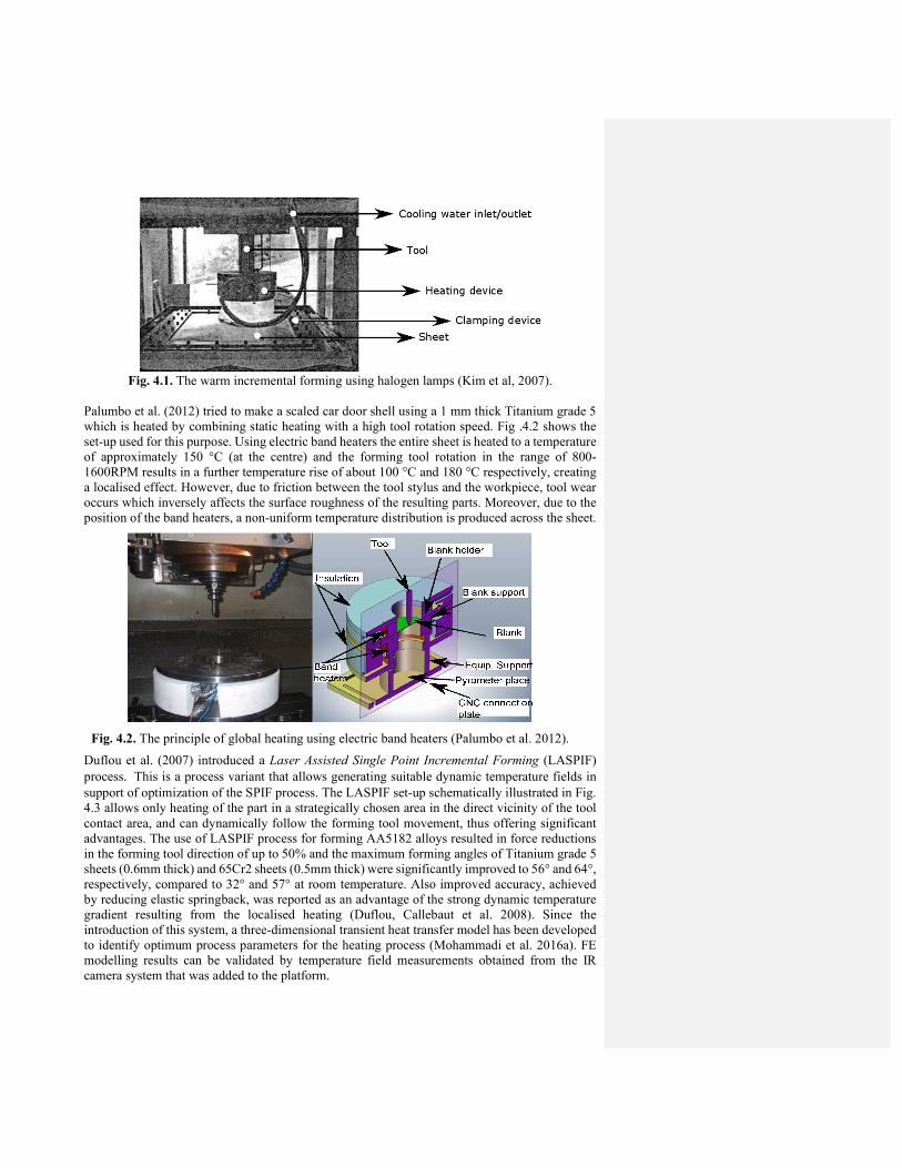
Fig. 4.1. The warm incremental forming using halogen lamps (Kim et al, 2007).
Palumbo et al. (2012) tried to make a scaled car door shell using a 1 mm thick Titanium grade 5 which is heated by combining static heating with a high tool rotation speed. Fig .4.2 shows the set-up used for this purpose. Using electric band heaters the entire sheet is heated to a temperature of approximately 150 °C (at the centre) and the forming tool rotation in the range of 800-1600RPM results in a further temperature rise of about 100 °C and 180 °C respectively, creating a localised effect. However, due to friction between the tool stylus and the workpiece, tool wear occurs which inversely affects the surface roughness of the resulting parts. Moreover, due to the position of the band heaters, a non-uniform temperature distribution is produced across the sheet.
Fig. 4.2. The principle of global heating using electric band heaters (Palumbo et al. 2012).
Duflou et al. (2007) introduced a Laser Assisted Single Point Incremental Forming (LASPIF) process. This is a process variant that allows generating suitable dynamic temperature fields in support of optimization of the SPIF process. The LASPIF set-up schematically illustrated in Fig. 4.3 allows only heating of the part in a strategically chosen area in the direct vicinity of the tool contact area, and can dynamically follow the forming tool movement, thus offering significant advantages. The use of LASPIF process for forming AA5182 alloys resulted in force reductions in the forming tool direction of up to 50% and the maximum forming angles of Titanium grade 5 sheets (0.6mm thick) and 65Cr2 sheets (0.5mm thick) were significantly improved to 56° and 64°, respectively, compared to 32° and 57° at room temperature. Also improved accuracy, achieved by reducing elastic springback, was reported as an advantage of the strong dynamic temperature gradient resulting from the localised heating (Duflou, Callebaut et al. 2008). Since the introduction of this system, a three-dimensional transient heat transfer model has been developed to identify optimum process parameters for the heating process (Mohammadi et al. 2016a). FE modelling results can be validated by temperature field measurements obtained from the IR camera system that was added to the platform.
ToolBlank holder
Blank support
Blank
Equip. Support
Pyrometer place
CNC connectionplate
Insulation
Bandheaters

Furthermore, a number of recently recognized opportunities of the LASPIF platform, such as the use of dynamic, in-process phase transformations to optimize the process have been introduced. Localized in-process phase transformation alters the material properties, the forming mechanisms and intermediate stress state of the sheet. They can be used to influence the sheet behaviour during the forming process (Mohammadi et al. 2016b).
Fig. 4.3. Experimental LASPIF set-up (Duflou et al. 2007). More recently another effort to create localized temperature fields by means of laser support in incremental forming was reported by RWTH Aachen (Göttmann et al. 2011). With this set-up, the laser acts at the same side as the forming tool and the sheet is irradiated at a certain distance from the forming tool (Fig. 4.4). The laser beam is guided around the forming tool by a dedicated laser optic which allows to rotate the laser focus point using mirrors and/or prisms. At present, limited knowledge is available regarding the optimal placement of the heat source. Heating at a distance from the forming tool may be advantageous in applications where the sheet has a high thermal inertia, but may have disadvantages for materials with high thermal conductivity in which no forward offset between the laser spot and the forming tool might be desired. Control of the combined hybrid process setup requires advanced CAM support (see Section 5.3). Lubricants are applied to the surface before forming. Carbon-based lubricants reduce the reflectivity of the surface and hence increase the energy efficiency of the process. Using the laser-assisted ISF system, it has been shown that the formability of titanium grade 5 sheets (1.5mm thick) could be increased by forming the material at temperatures of approximately 400°C, below the temperature range where -case forms.
Fig. 4.4. Experimental setup using laser as a heat source at the tool side (Göttmann et al. 2011).
6-axis robot
Forming tool
Coolant supply
Vertical tablewith clamping system
Glas fiberbeam delivery
SPIF part
3-axis beam positioning system
Laser head
Forming tool
Laser spotForming direction

Electric Hot Incremental Forming (EHIF) offers an alternative approach to the localized heating of the sheet. Based on the resistive heating law, when an electric current passes from the spindle through the sheet, the sheet metal is locally heated up. The schematic representation of the equipment is shown in Fig. 4.5. Fan et al. (2008) studied the effect of different process parameters on the formability enhancement of AZ31 of 1mm thickness and obtained a maximum forming angle of about 64° for this material. Ambrogio et al. (2012) reported that the formability of AA2024-T3 and titanium grade 5 sheets could be enhanced by the EHIF process with maximum achievable forming angles of 40°and 45° respectively, compared to approximately 30° and 20° at room temperature. AZ31B-O could be formed till 60° while forming this alloy without heat support proved to be impossible. Although the EHIF technique seems inexpensive and easy to employ, it has some limitations which should be properly taken into account. Ambrogio et al. (2012) reported that the SPIF part wall angle and tool diameter are inversely proportional to the heat supplied to the sheet. Therefore, applying a small radius forming tool and forming shallow sloped parts might lead to burning out of the sheet because of the localized heat accumulation at the tool-sheet interface. Moreover, heating cannot be localized completely since applying active cooling will affect the electric heating system, and without lubrication the surface finish is affected. This is a major shortcoming of the EHIF process that may need further investigation. For instance, Fan et al. (2010) studied the effect of different lubricants on the surface quality of Ti grade 5 which is formed by the EHIF process and found that a nickel matrix with MoS2 self-lubricating material improves the surface quality of SPIF formed parts and prevents high temperature oxidation of this material. Zhang et al. (2010) also showed that MoS2 powder-coated ceramic coatings have a positive effect on the surface quality of AZ31 formed parts in warm SPIF condition.
Fig. 4.5. The schematic representation of the EHIF process (Fan et al. 2008). Global heating: Ji et al. (2008) studied high temperature formability in incremental forming of 0.5 thick AZ31 sheets by plane-strain stretching and axisymmetric stretching tests. The sheet is globally heated by hot air blowers and a significant increase in formability is achieved above 150°C. Furthermore, by using a combination of multi-stage (see Section 4.3.1) and warm incremental forming approaches, a maximum forming angle of 59° has been achieved at 150 °C. Fig. 4.6 presents an egg shell surface which was formed using this process.
Spindle
Tool
Insulating gasket IIConnection bar
Insulating gasket III
Metal sheetCable
Tool holderInsulating gasket I
Insulating sheath
Working platform
DC power Clamping system
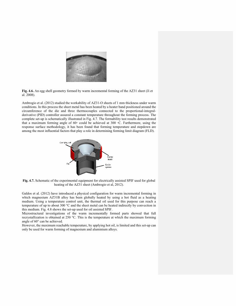
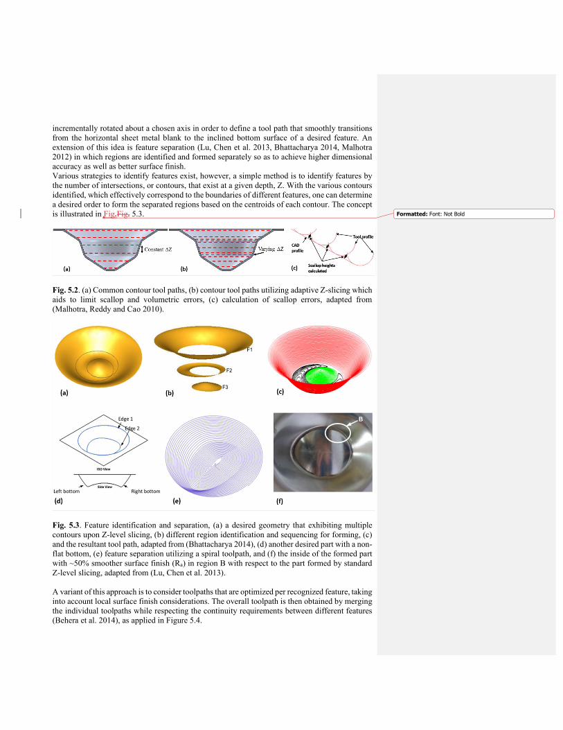
Fig. 4.6. An egg shell geometry formed by warm incremental forming of the AZ31 sheet (Ji et al. 2008). Ambrogio et al. (2012) studied the workability of AZ31-O sheets of 1 mm thickness under warm conditions. In this process the sheet metal has been heated by a heater band positioned around the circumference of the die and three thermocouples connected to the proportional-integral-derivative (PID) controller assured a constant temperature throughout the forming process. The complete set-up is schematically illustrated in Fig. 4.7. The formability test results demonstrated that a maximum forming angle of 60◦ could be achieved at 300 ◦C. Furthermore, using the response surface methodology, it has been found that forming temperature and stepdown are among the most influential factors that play a role in determining forming limit diagram (FLD).
Fig. 4.7. Schematic of the experimental equipment for electrically assisted SPIF used for global heating of the AZ31 sheet (Ambrogio et al, 2012).
Galdos et al. (2012) have introduced a physical configuration for warm incremental forming in which magnesium AZ31B alloy has been globally heated by using a hot fluid as a heating medium. Using a temperature control unit, the thermal oil used for this purpose can reach a temperature of up to about 300 °C and the sheet metal can be heated indirectly by convection in this medium. Fig. 4.8 shows the set-up used for oil assisted SPIF. Microstructural investigations of the warm incrementally formed parts showed that full recrystallization is obtained at 250 °C. This is the temperature at which the maximum forming angle of 60° can be achieved. However, the maximum reachable temperature, by applying hot oil, is limited and this set-up can only be used for warm forming of magnesium and aluminium alloys.
Clamping tool
Die Coolersystem
Heater band

Fig. 4.8. Oil based heat assisted SPIF setup (Galdos et al. 2012). While a number of beneficial effects of warm incremental forming on the process performance have already been described, the different phenomena underlying these effects have not been studied in depth. In order to do this, development of well-optimized FE models, suitable for detailed thermal and stress-strain field analysis, might be helpful. It is worth mentioning that simulation of warm incremental forming is more complex than the room temperature variant, and, depending on the type of the heating source, a sequentially coupled or fully coupled thermal stress FEM analysis is required. This model requires more advanced material models which encounter the effect of anisotropy, strain rate and temperature dependent material parameters. The proper local heating parameters have been identified by developing a thermal model using a transient heat transfer analysis (Mohammadi et al. 2016a), and a thermo-mechanical FE model is developed to simulate the warm incremental forming process (Mohammadi et al. 2017). Furthermore, for reliable and repeatable warm forming results, development of an accurate temperature measurement and control system is crucial. However, because of the movement of the heating source and complexity of installing temperature sensors, most of the above mentioned localized warm forming processes suffer from a lack of accurate temperature measurements. Moreover, non-contact temperature measurement devices require various thermo-physical data of the part and the temperature dependence of the surface emissivity should be taken into account. In addition, using an embedded thermocouple within the forming tool might generate a time delay in temperature recording, which arises from the thermal inertia effect and the tool-sheet contact zone (especially for high wall angle geometries) (Göttmann et al. 2013).
4.2. Electrically assisted SPIF
As shown above in Fig. 4.7, using electrical current has been demonstrated to effectively raise the formability of sheet metal. It is commonly agreed that the majority of the flow stress reduction is due to the Joule heating effect. Whether there exists the so-called electroplastic effect, i.e. extra flow stress reduction or increased formability or springback reduction due to the application of electrical current besides the influence of heat introduced in the workpiece as result of the Joule effect, is still under academic investigation. The supporting statements for electroplasticity are shown in publications such by Salandro et al.(Salandro et al. 2010, Salandro et al. 2015), while more cautious statements with experimental evidences mainly pointing to the Joule heating effect are shown in (Magargee, Morestin et al. 2013) and (Kinsey et al. 2013). Although the debate on this topic is beyond the scope of this review article, one of the common phenomena that is observed is the current threshold density, a critical current density below which Electrically Assisted Forming (EAF) effects are very small. Perkins et al. measured this value for a variety of materials (Perkins, Kronenberger, and Roth 2007) and Margargee et al. (Margargee, Fan et al. 2013) provided theoretical derivations and predictions of the threshold value for various engineering alloys.
In order to model SPIF as an EAF process, it is necessary to model the contact area between the tool and sheet, as this is both the region where forming occurs, and the region of high current
Force sensorForming head
Fluid entrance Fluid exit

density. Further, as the shape of this contact area changes with part geometry and wall angle, better control of the process can be obtained by varying the current to apply the ideal current density at all times. Adams and Jeswiet created an analytical model of the contact region and used it to successfully verify that the current threshold density phenomenon occurs in SPIF of AA 6061-T6 (Adams and Jeswiet 2014b), resulting in a higher maximum wall angle when parts are formed just above the current threshold density. This knowledge may therefore be useful to create systems which vary the applied current during forming with changing contact conditions to prevent overheating of tools and lubricants.
4.3. Material redistribution
In single-step forming by means of SPIF the resulting sheet thinning manifests as a maximum achievable wall angle. This maximum wall angle can be circumvented by using the available material in a more efficient manner. While high wall angles thin out the material in an extreme way, low wall angles result in higher final thicknesses of the part. For conventional single-step SPIF this final thickness can be approximated by the sine law, described by Jeswiet et.al. (2005). In this approach the non-uniform thickness distribution in parts with variable wall angles is inherent to the localised nature of the deformations in incremental forming. Different strategies have been developed to reduce the effect of this maximum wall angle limit and the associated extreme thinning by improved usage of the available material rather than increasing formability. The first strategy enforces a net material flow from thicker regions (low wall angle) to thinner regions (high wall angle) by using intermediate shapes. Alternatively high absolute wall angles of a part can be achieved by rotating the work plane (i.e. the plane in which a single contour of the toolpath lays) effectively lowering the relative wall angle to the work plane.
4.3.1. Multi-stage tool path strategies In order to successfully employ a multi-stage forming strategy, one must develop intermediate models representing all forming stages. Hagan and Jeswiet (2003) used a multi-stage forming method where the part was scaled vertically, increasing depth each time. (Skjoedt, Silva et al. 2010) proposed a multi-stage SPIF strategy consisting of five stages to form a cylindrical cup. The initial stage resembled a cone while the subsequent stages proceeded to bend the wall of the cone into the corner-fillet of the desired cylindrical cup. The maximum depth in the tool paths did not change between stages, and various out-to-in (OI) and in-to-out (IO) approaches were used which correspond to the tool direction during the intermediate profiles (Fig 4.9). For clarification, the authors referenced OI and IO stages as “down” and “up”, respectively, but for consistency the former terminology will be used. Duflou, Verbert et al. (2008) also implemented a five stage strategy to quantify the material flow during multi-stage and form parts with wall angles beyond 90º. By means of digital image correlation techniques they illustrated the displacement paths in the material during consecutive forming steps. More recent multi-stage SPIF studies (Liu, Daniel, Li et al. 2014) have attempted to develop intermediate shapes, that result in drawing in material which would otherwise be left unprocessed, by means of experimental and simplified FE simulations. With respect to multi-pass Two Point Incremental Forming (TPIF), Li et al. (2011) attempted to quantify the rate of thinning between subsequent passes resulting in a prediction for the minimum number of forming stages required to successfully produce a part. The geometric accuracy of the final part is challenging to predict, most prominently due to the accumulation of rigid-body translations (RBT) between subsequent stages. If RBT is not accounted for within a tool path, undesirable stepped-features will be present in the final part (Duflou, Verbert et al. 2008). However, a certain number of stages is required in order to prevent material instability and wrapping in front of the tool, not to mention that the enhanced formability is a result of the number of stages be formed (Li, Hu et al. 2011). Malhotra et al. (Malhotra, Bhattacharya et al. 2011, Xu et al. 2012) developed and calibrated an analytical model that quantitatively predicts the stepped features formed in multi-pass SPIF. The

study reveals that both tool paths starting from the outer edge inwards (OI) and from the inner center outwards (IO) result in some degree of RBT, and that the magnitude of the RBT is reduced if the yield stress or sheet thickness is increased. The concepts were further extended into a tool path consisting of mixed OI and IO stages which compensated for the predicted RBT (Fig. 4.10). A nearly-flat cylindrical cup was thus formed. However, the procedure for predicting the RBT was rather specific to the cylindrical design at hand. Note that Cao et al. (2015) and Lingam et al. (2015) proposed advanced versions of these first analytical models (see Section 2.)
Fig. 4.9 (a) Cross-sections of the multi-pass tool path strategies implemented by Skjoedt et al. (Skjoedt et al. 2008), and (b) the formed part using OI, IO, OI, OI for the intermediate profiles and (c) the result using OI, OI, OI, IO. (d) The measured cross-sections and material flow of the OI multi-pass SPIF strategy implemented by Duflou, Verbert et al. (2008), as well as (e) the corresponding thickness profiles.
Fig. 4.10 (a) Malhotra et al. (Malhotra, Bhattacharya 2011) proposed multi-stage tool path to compensate for rigid body translations through 7 intermediate shapes consisting of OI and IO strategies, and (b) the resulting cross-section of a pure OI toolpath compared to the proposed toolpath of Fig 4.10(a).

4.3.2. Work plane/part orientation Many parts consist of only limited specific regions that exceed the maximum forming angle of the material and thickness of choice. Orienting the work plane allows minimization of the maximum wall angles relative to the work plane, thus allowing for a more uniform thickness distribution throughout the part. Vanhove et al. (2011) and Tanaka et al. (2011) studied this strategy, respectively on a lopsided cone and pyramidal structure, proving the validity of increasing the absolute wall angle to 90° for AA 1050.
Fig. 4.11 Forming strategy for a lob-sided pyramid with a single vertical wall a) non-successful conventional horizontal work plane, b) successful varying work plane approach (Tanaka et al., 2011). Tanaka et al. (2011) also demonstrated an interesting case of combining work plane orientation with multi-stage processing to form a 54mm x 54mm x 25mm box part containing 90° wall angles on all sides.
5. Toolpath Strategies and Process Planning Tools
5.1. Non-compensated contouring
As described in Section 2, incremental forming is characterised by superimposing local deformations along the tool trajectory. This means the trajectory is the main influencing factor, dictating the final geometry. While seemingly simple at first, many variables become critical when designing a successful toolpath. Some of the established process parameters in SPIF are related to the material type and thickness, incremental depth, tool speed, tool diameter, tool path shape, feature compensation, springback compensation, and multi-stage forming (Jeswiet et al. 2005, Silva, Skjoedt and Bay 2009, Azaouzi 2012, Ambrogio, Gagliardi et al. 2013). Choices with respect to the toolpath strategies affect the outcome of SPIF, specifically the geometric accuracy, residual stress, surface finish, distribution of sheet thickness, and material formability. A single-feature part with moderate to small wall-angles is considered in the following, simplest case. Such a part that is convex in nature and does not contain any wall angles greater than the maximum achievable draw angle measured for the material of choice. Parts of this type, specifically the truncated cone, truncated pyramid, and hyperbolic funnel, have been most significantly considered among researchers and therefore used as an informal standard for comparative studies (Jeswiet 2005, Jackson and Allwood 2009, Smith, Malhotra 2013). Assuming the final part is represented in CAD, numerous CAM software suites can be utilized to generate contouring toolpaths. Most used contouring toolpath layouts are z-level- and spiral toolpaths, as conceptually illustrated in Figure 5.1. However, since these software packages are commonly used with conventional CNC milling, the user is often left with the desire for enhanced flexibility and process control. For this reason, many tool path strategies are implemented through in-house codes and/or CAD macros (Malhotra, Reddy et al. 2010, Behera, Verbert et al. 2013).

Fig. 5.1. Dashed lines correspond to a proposed toolpath for a single feature part where (a) is the cross-section view of a cone with wall angle α being formed using a Z-level tool path, and (b) is a cone being formed using a spiral tool path. The ΔZ increment has been exaggerated for clarification. The influence of the toolpath direction on strain distributions is not negligible, as has been documented by Duflou, Vanhove et al. (2010) by means of twist phenomena, demonstrated in truncated pyramid parts, that clearly illustrate non-planar strain conditions. There are a variety of simple parameters that can be altered to enhance the accuracy or practicality of SPIF. Typically spiral tool paths provide a better surface finish than Z-level paths due to the instantaneous downward transition between subsequent contours in the latter. However, spiral tool paths can be difficult to implement on complex geometries. Hamilton and Jeswiet (Hamilton and Jeswiet 2010)] demonstrated that high tool speeds (i.e. greater than 5 m/min) can be used in SPIF without significantly compromising surface finish or structural integrity of the resultant part, thus implying that forming time can be reduced compared to common research applications. Box-Behnken methods have been used for experimental programs carried out by both Bhattacharya et al. (Bhattacharya, Maneesh et al. 2011) and Ham and Jeswiet (Ham and Jeswiet 2007). The obtained results suggest that either a decrease in tool diameter or an increase in sheet thickness will lead to an increase in the maximum achievable forming angle. Depending on the thickness and hardness of the material, there are lower limits to the applicable tool diameter. Additionally, if the incremental depth, ΔZ, is reasonably small (i.e. ~ 1 mm or less), the achievable forming angle is not significantly altered. However, the resultant surface finish is directly related to the incremental depth, which can be clearly seen when one considers that the resultant scallop height along the surface of the formed sheet (see Fig. 5.2c) is related to the tool diameter and incremental depth. Very low stepdown values, as could be used to obtain a semi-polished surface finish, typically lead to cyclic loading of the sheet surface and, depending on the material being processed, can result in early failure due to fatigue phenomena. Numerous studies have been carried out that have attempted to quantify the influences and sensitivities of specific process parameters through means of an empirical and/or analytical Design Of Experiments (DOE), often accompanied by an ANalysis Of VAriance (ANOVA) (Leon et 2013, Desai et al. 2014, Sarraji et al. 2012, Bahloul et al. 2014, Jeswiet, Hagan et al. 2002). While the specific sensitivities appear to be dependent on the experimental setup, general trends have been noted and are consistent with what has already been stated. Typically, the most significant factors towards influencing the formability, geometric accuracy, and surface finish are the tool diameter, incremental depth, and material type/thickness.
5.2. Tool path adaptation for accuracy improvement
A significant effort has been made towards the development of effective tool path strategies and generic techniques for accuracy improvement. For instance, adaptive slicing is a method that varies the incremental depth of the tool path in an effort to lower scallop errors between subsequent contours of the tool (Malhotra, Reddy and Cao 2010). Additionally, the technique estimates and limits the volumetric errors between the desired part and the resultant tool path profile so as to better capture geometric transitions (see Figure 5.2). Another strategy manipulates the inclination of the intersecting plane that defines the contour of a tool path for a given depth. The idea is that, as the depth is increased, the intersection plane is
incrementally rotated about a chosen axis in order to define a tool path that smoothly transitions from the horizontal sheet metal blank to the inclined bottom surface of a desired feature. An extension of this idea is feature separation (Lu, Chen et al. 2013, Bhattacharya 2014, Malhotra 2012) in which regions are identified and formed separately so as to achieve higher dimensional accuracy as well as better surface finish. Various strategies to identify features exist, however, a simple method is to identify features by the number of intersections, or contours, that exist at a given depth, Z. With the various contours identified, which effectively correspond to the boundaries of different features, one can determine a desired order to form the separated regions based on the centroids of each contour. The concept is illustrated in Fig.Fig. 5.3.
Fig. 5.2. (a) Common contour tool paths, (b) contour tool paths utilizing adaptive Z-slicing which aids to limit scallop and volumetric errors, (c) calculation of scallop errors, adapted from (Malhotra, Reddy and Cao 2010).
Fig. 5.3. Feature identification and separation, (a) a desired geometry that exhibiting multiple contours upon Z-level slicing, (b) different region identification and sequencing for forming, (c) and the resultant tool path, adapted from (Bhattacharya 2014), (d) another desired part with a non-flat bottom, (e) feature separation utilizing a spiral toolpath, and (f) the inside of the formed part with ~50% smoother surface finish (Ra) in region B with respect to the part formed by standard Z-level slicing, adapted from (Lu, Chen et al. 2013). A variant of this approach is to consider toolpaths that are optimized per recognized feature, taking into account local surface finish considerations. The overall toolpath is then obtained by merging the individual toolpaths while respecting the continuity requirements between different features (Behera et al. 2014), as applied in Figure 5.4.
Formatted: Font: Not Bold

The most common compensation technique used in correcting both intra and inter feature dimensional errors is simple mirroring. This mirroring compensation translates the vertices of the measured geometry orthogonally to the designed CAD model by a specific factor and was first described by Hirt et al. (Hirt, Bambach et al. 2004). This technique evidently requires the manufacture and dimensional analysis of one or more parts to learn the dimensional error distributions, possibly in an iterative way. For small series production this can imply a significant cost increase. Anticipating dimensional errors based on the feature typology of parts can allow eliminating or reducing the need for experimental error data collection and iterative quality improvement. The use of FE based simulation techniques to quantify the expected geometric deviations is, however, a very time consuming procedure and the state-of-the-art in simulating SPIF does not allow performing such simulations within a reasonable timeframe for complex part geometries (see Section 6). For this reason the anticipation of deviation between the surface approximated by the toolpath and the actually formed part, due to elastic springback or unwanted plastic deformation, has been integrated into a systematic compensation scheme developed by Verbert (Verbert 2010). Multivariate Adaptive Regression Splines (MARS) are used to anticipate deviations between the surfaces corresponding to the toolpaths and the resulting part geometry. The underlying MARS models can be calibrated for a given material and sheet thickness based on a generic test part and allow to predict a wide variety of part configurations containing the covered features (Verbert et al. 2011).
Fig. 5.4. Human face manufactured by SPIF in Al 1050 with sheet thickness of 1.5 mm, (a) various topology types and features were computationally identified and linked to multivariate adaptive regression splines as an error prediction tool: OPGF – Ordinary Positive General Freeform, PGSVE – Positive General Semi-Vertical Edge, and NGSVE – Negative General Semi-Vertical Edge. (b) Typical SPIF process without accuracy compensations versus (c) Case with accuracy compensation methods applied within the identified regions. Adapted from (Behera, Lauwers and Duflou 2014). Closed-loop optimization was suggested by Allwood et al. (Allwood, Music et al. 2009) where feedback was provided by a stereovision camera during the SPIF process. The process model was formed from a set of spatial impulse responses around a pre-planned tool path which made it possible to implement online feedback control. The resultant axisymmetric parts were manufactured within a tolerance of ±0.2 mm of the target geometry. However, the technique suggests prior experimentation and setup for general parts. The approach was tested with a limited range of part geometries only.

5.3. Tool path generation for hybrid processes
The developments in SPIF and incremental sheet forming (ISF) in general have resulted in a number of hybrid process combinations, such as certain heat-assisted ISF variants (see Section 4.1) and stretch-forming (SF) combined with ISF. The development of hybrid processes led to dedicated machine set-ups and solutions for tool path generation. For the two variants mentioned above, a CAD/CAPP/CAM (CAX) environment is needed that provides solutions for tool path planning for the combination of stretch-forming with up to 8 axes and 5-axis ISF as well as for laser-assisted ISF. In order to accommodate these processes, new CAM features have been developed and implemented into a CAX platform (Hirt et al. 2015). Requirements for the development of a CAX environment for ISF in combination with SF are (i) to allow the creation of NC paths both directly in the CAX system and by reading out machine data during manual operation modes of the stretch-forming modules, and (ii) the simulation and collision checking of the forming tool and the stretch forming units. The development of the CAX solution was carried out based on the CAX platform NX by Siemens, which allows for integrating user-defined functions via programming interfaces such as NXopen (C, C ++, Visual Basic), thus allowing the implementation of specific functions for SF+ISF as well as for laser-assisted ISF. Stretch forming does not yield the final part geometry, so that part features need to be formed by ISF or SPIF operations after stretch forming. The detection of the areas to be formed by ISF/SPIF draws upon finite element simulations of the stretch forming process, which are integrated into the CAD/CAM solution. Once these areas are detected, ordinary tool path planning is performed (for areas shown in red in Fig. 5.5).
Fig. 5.5. CAD/CAM chain for hybrid stretch forming and ISF (Hirt et al. 2015).
The hybrid process with 8 stretch-forming axes and 5-axes ISF makes it necessary to perform a machine simulation with collision detection to operate the hybrid machine safely. To this end a full-scale virtual simulation of the combined process is performed (Hirt et al. 2015). In addition to the SF+ISF process, a laser-assisted ISF variant which uses the laser source on the same side as the forming tool has been developed (Göttmann et al, 2011). In the hybrid machine, dedicated laser optics were developed which allow rotating the laser beam around the forming tool (cf. Section 4.1.2). The position of the laser focus is thus defined by a rotation angle about the tool relative to the X-axis (see Fig. 5.6), which is calculated in a dedicated CAM solution during tool path planning.

Fig. 5.6. Integration of laser as rotation axis (left) and integration into the machine via a PLC controller (right) (Hirt et al. 2015).
6. Simulation of the SPIF Process
In this section the substantial efforts that have been dedicated to simulating the SPIF process in off-line procedures are summarized. The ambitions of these contributions range from better understanding of the process mechanisms by detailed simulation, till fast prediction of workpiece shape and thickness distributions for operational support. The boundary conditions in terms of dedicated CPU capacity and acceptable calculation time obviously differ between these ambitions. Therefore the trade-off between precision and response time forms a major point of attention in the following sub-sections.
6.1 FE strategies and material models
The process is characterized by a small, moving plastic zone that is much smaller than the sheet metal blank. The high gradients in this local plastic zone call in Finite Element (FE) simulations for a fine discretization, but meshing the entire part with such a fine mesh yields tremendous CPU time even with massive parallel computations.
As confirmed by the NUMISHEET SPIF benchmark (Elford et al. 2013) dedicated to a 45° cone, no particular trend is observed in terms of the two possible approaches to deal with the (discretized) equilibrium equations: the implicit/explicit schemes. Within the nine participants in this benchmark, five were using the implicit strategy, two the fully explicit one and two performed assessment with explicit approach but unloading step by implicit method. Checking the element choice, six of them used Shell elements, two Solid or Brick elements and one Solid-Shell elements, which is an expected distribution from the literature overview.
In this paper, Section 3 shows that the stress/strain gradients can play an important role both in the deformation mechanism (Jackson and Allwood 2009) and formability (Eyckens et al. 2009). As shell elements prevent accurate prediction of through thickness 3D stress/strain fields, an exhaustive study of SPIF requires the use of 3D solid elements even if the prediction of displacement fields is quite accurate whatever the strategy and element choices are. The finite element family referred as solid-shells (also known as thick-shell) falls between classical shell and brick element. The results from Seong et al., (2014), Sena et al. (2015) and Tuninetti et al. (2016) confirm the interest of a single solid-shell element layer for SPIF simulations.
As widely observed in the literature, the predicted vertical forces are often higher than the experimental measurements and present a large scattering (see for instance Fig. 6.1). Indeed punch force prediction is very sensitive to element stiffness, contact model, boundary conditions such as friction coefficient or blank sliding that should be prevented by the correct tightening of bolts to a specified torque. For instance, the effect of a too low penalty coefficient used in the contact model strongly modifies the prediction (see Fig. 6.1, Lagamine curve with low penalty value for a simulation with Swift hardening law, compared to other curves predicted by the same code).
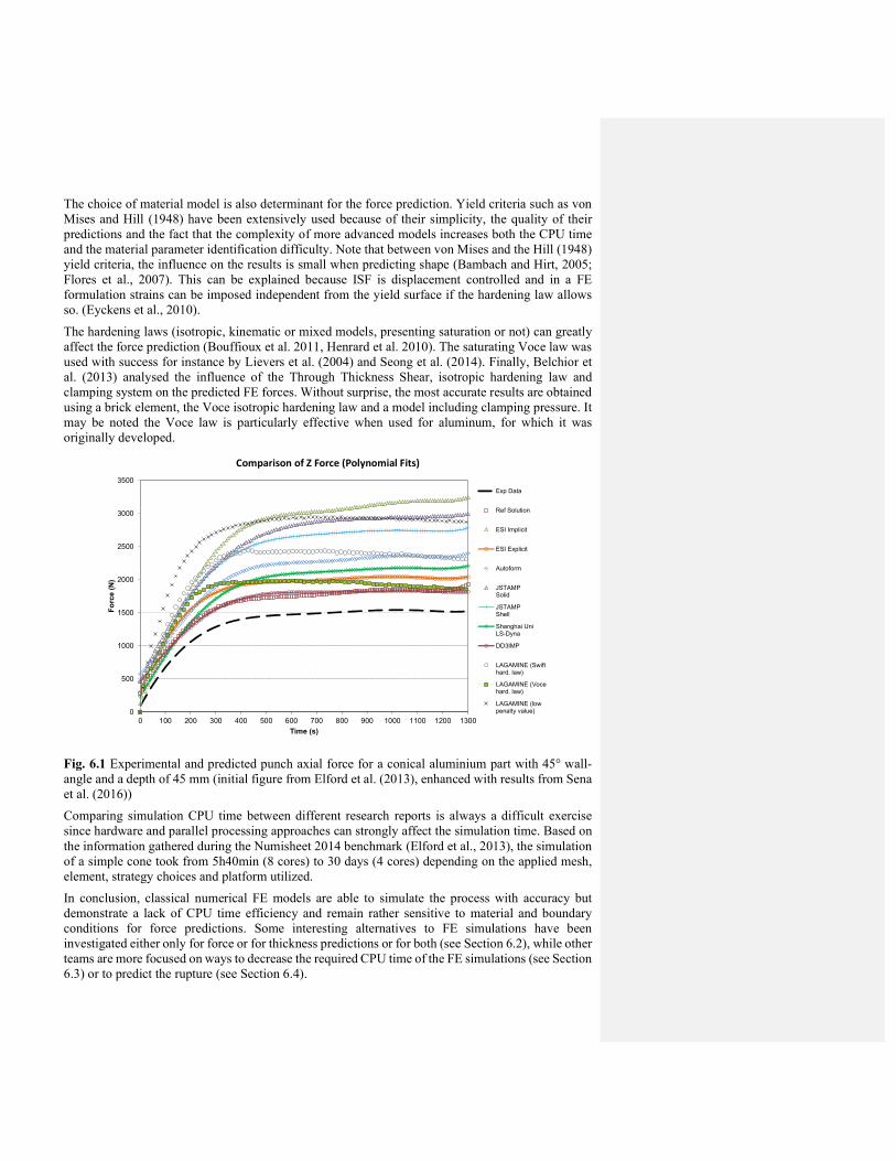
The choice of material model is also determinant for the force prediction. Yield criteria such as von Mises and Hill (1948) have been extensively used because of their simplicity, the quality of their predictions and the fact that the complexity of more advanced models increases both the CPU time and the material parameter identification difficulty. Note that between von Mises and the Hill (1948) yield criteria, the influence on the results is small when predicting shape (Bambach and Hirt, 2005; Flores et al., 2007). This can be explained because ISF is displacement controlled and in a FE formulation strains can be imposed independent from the yield surface if the hardening law allows so. (Eyckens et al., 2010).
The hardening laws (isotropic, kinematic or mixed models, presenting saturation or not) can greatly affect the force prediction (Bouffioux et al. 2011, Henrard et al. 2010). The saturating Voce law was used with success for instance by Lievers et al. (2004) and Seong et al. (2014). Finally, Belchior et al. (2013) analysed the influence of the Through Thickness Shear, isotropic hardening law and clamping system on the predicted FE forces. Without surprise, the most accurate results are obtained using a brick element, the Voce isotropic hardening law and a model including clamping pressure. It may be noted the Voce law is particularly effective when used for aluminum, for which it was originally developed.
Fig. 6.1 Experimental and predicted punch axial force for a conical aluminium part with 45° wall-angle and a depth of 45 mm (initial figure from Elford et al. (2013), enhanced with results from Sena et al. (2016))
Comparing simulation CPU time between different research reports is always a difficult exercise since hardware and parallel processing approaches can strongly affect the simulation time. Based on the information gathered during the Numisheet 2014 benchmark (Elford et al., 2013), the simulation of a simple cone took from 5h40min (8 cores) to 30 days (4 cores) depending on the applied mesh, element, strategy choices and platform utilized.
In conclusion, classical numerical FE models are able to simulate the process with accuracy but demonstrate a lack of CPU time efficiency and remain rather sensitive to material and boundary conditions for force predictions. Some interesting alternatives to FE simulations have been investigated either only for force or for thickness predictions or for both (see Section 6.2), while other teams are more focused on ways to decrease the required CPU time of the FE simulations (see Section 6.3) or to predict the rupture (see Section 6.4).
0
500
1000
1500
2000
2500
3000
3500
0 100 200 300 400 500 600 700 800 900 1000 1100 1200 1300
Fo
rce
(N
)
Time (s)
Comparison of Z Force (Polynomial Fits)
Exp Data
Ref Solution
ESI Implicit
ESI Explicit
Autoform
JSTAMPSolid
JSTAMPShell
Shanghai UniLS-Dyna
DD3IMP
LAGAMINE (Swifthard. law)
LAGAMINE (Vocehard. law)
LAGAMINE (lowpenalty value)

6.2 Force and thickness predictions
6.2.1 Force prediction
For cone shapes, a very quick and convenient force prediction model is provided by Aerens et al. (2010). These authors carried out a parametric study of forces measured during the forming of cones with various slope angles α (see Fig 5.1a) using different materials, sheet thicknesses t, tool diameters dt and incremental depths (scallop height Δh: see Fig 5.2c). They obtained generalized regression equations for peak and steady state forces along the axis of the tool (z direction) as well as radial force. For instance, the axial steady-state force (𝐹 _ ) expressed in Newton is:
𝐹 _ = 0.0716 𝑅 𝑡. 𝑑 . ∆ℎ . 𝛼 cos 𝛼
where Rm is the material tensile strength in N/mm², t, dt and Δh are expressed in mm and α in degree. The scallop height is preferred to depth increment as it characterizes the surface quality. Its link with the depth increment Δz (see Fig 5.1) is:
∆ℎ =∆𝑍
4(𝑠𝑖𝑛𝛼) 𝑑
Mirnia et al. (2012) (for steady-state deformations) and Li et al. (2014) applied the upper bound theorem to provide a preliminary efficient force prediction model for truncated cone shapes. However, empirical coefficients are used to combine different deformation modes which require further quantitative investigation. One step further is provided by Li et al. (2015) who clarified and quantified the deformation mechanisms in any cone formed by the SPIF process involving shearing, stretching and bending through FE simulations. This work focused on an efficient tangential force prediction model and extended the approach to general shapes (see Figure 6.2). The approach shows great potential towards dealing with more complex geometries, although further theoretical justification is essential.
Fig. 6.2 (a) SPIF formed geometry: truncated ellipsoidal cup, (b) associated measured and predicted tangential force by upper bound theorem for a step-down size of 1 mm, from Li et al. 2015 6.2.2 Thickness prediction Considering the thickness prediction, Jackson et al. (2008) gave a comprehensive review of the sine law, which provides approximation of sheet thinning at negligible computational cost. This work confirms that the sine law applies to some situations in which the sheet metal is deformed by pure stretching, pure shear or a combination of both and plane strain deformation. However, the presence of bending and necking deformation, as well as presence of strains parallel to the tool direction reduce

the sheet thickness below the predicted sine law. Bambach (2010) provided a 3D purely geometrical Simplified Modelling Approach (SMA) based on triangular meshes. The main difference with the sine law consists in the fact that no global straight projection or plane strain hypothesis is assumed. It is an improved version of the approach proposed by Hirt and Bambach (2005) in which thin plate spline interpolants were used to model intermediate shapes. Even if SMA predictions are closer to experimental results than sine law ones, the method can only predict the evolution of sheet thickness as long as no necking or failure occurs in the real forming operation. Raithatha and Duncan (2009) applied the Sequential Limit Analysis (SLA), to predict shapes produced by the SPIF process. Within this methodology, the upper-bound theorem of limit analysis can be stated as a minimization or maximization problem depending on whether primal displacement fields or dual variable Lagrange multipliers are used. A few years later, Mirnia et al. (2014) used also this method to investigate the effect of tool diameter and step down size on the thickness. Note that, as in Bambach’s SMA, in SLA the friction is neglected. The computation of SLA strain field is based on classical shell element formulation and power dissipation relies on a simplified rigid-perfectly plastic assumption. The displacement is sequentially achieved by solving a maximization problem for each intermediate configuration. For a 50° truncated cone in aluminium AA1050 sheet of 1.5 mm thickness, with different tool step down, the predicted thickness by the SLA method is closer to the experimental results than the simulation output of Abaqus/explicit FE code applied in nearly similar assumptions (no friction but Swift hardening law). For these cases, SLA provides a computing speed up factor in the range of [1.5; 1.9] compared to FE analysis (Mirnia 2014). Thickness prediction in multi-stage SPIF becomes a major challenge in multi-stage process design. Filice (2006) proposed an analytical model to predict the thickness distribution using the geometry shape parameter of the final formed parts in two-stage incremental forming of a cylindrical cup. Cao et al. (2015) presented an approach validated for two and four forming steps and four different shapes (cones, a non-axisymmetric part and a hemisphere (see Fig.6.3). This model applies plane-strain assumption analysis, constant material volume and neglects bending effects. It deals with 2D cross sections of the part. The intermediate geometric cross-sectional profiles of forming parts between each pass are generated from geometric considerations based on forming parameters, including tool radius and the stepdown value.
Fig 6.3 Comparison of the experimental and predicted thickness of the hemisphere shape shown on the left for: a) the 1st stage; b) the 2nd stage; c) the 3rd stage; d) the 4th stage (from Cao et al. (2015)) Note that Lingam et al. (2015) proposed an analytical prediction of formed geometry in multi-stage single point incremental forming for cone geometries. The computation of tool force components

allows taking into account both the tool and the sheet deflection. The approach to predict the thickness distribution and the generation of geometric profiles for the different passes presents similarities with Cao et al. (Cao et al. 2015). However, in this case, the use of Bezier curves is replaced by stress-strain computations and the contact zone and the contact pressure are identified by both equilibrium and geometrical considerations as well as observations derived from FE simulations.
6.3. Finite Element models with reduced CPU time
SPIF process simulation involves high non-linearities such as continually changing contact conditions and nonlinear material behaviour combined with non-monotonic strain paths (Eyckens et al. 2007). In order to overcome CPU issues related to a refined mesh in the entire blank, adaptive domain decomposition or re-meshing methods have been developed and massive parallel computation has been applied. 6.3.1 Domain decomposition methods Sebastiani et al. (2007) applied a decoupling algorithm consisting of the division of the mesh in an elastic and an elasto-plastic deformation zone. The decoupled simulation involves several subsequent simulations which depend on each other. As a result the solution speed of FE analyses is notably increased, however accuracy remains an issue. Following this idea of mesh sub-division, Hadoush and van den Boogaard (2009) proposed a sub-structuring method in which plastic deformation is restricted to the vicinity of the tool and solved by the modified Newton method, while the remainder of the sheet is considered to deform elastically and a standard Newton method is applied. Later, Hadoush (2010) extended the initial idea to a third region belonging to the elastic deformation zone and computed with larger time steps. 6.3.2 Adaptive mesh refinement strategies Hadoush and van den Boogaard (2008) for triangular shell elements and Lequesne et al. (2008), using quadrilateral ones, presented SPIF simulations in their respective in-house implicit FE packages where the mesh is dynamically refined in the vicinity of the tool. Extended by Sena et al. (2015) for an eight node solid-shell element, the simulations of a single slope cone, or two slope pyramid simulation, show a CPU time reduction of approximately 50%. A very good accuracy was obtained when comparing the numerical results with experimental measurements, even if coarse elements are reactivated when the tool is remote if the geometric distortion is not significant. Giraud-Moreau et al. (2013) used an Abaqus explicit code and Suresh and Regalla (2014) used an explicit LS-DYNA code to perform SPIF simulations with the re-meshing method based on geometry criteria. The latter, using Belytschko-Tsay shell elements, reached a computational time reduction of 50%. The idea of Hadoush (2010) to use subcycling were further developed by Bambach (2016) in parallel SPIF explicit simulation where the number of elements is reduced due to adaptive re-meshing. Additionally, the elements are integrated with different time steps through subcycling. The coarse elements are integrated with a larger time step than the refined elements. For a large multiplicative factor of 10 between time steps, CPU time reduction can reach 75%. However, under these conditions the error in equivalent von Mises stress already reaches 25% (results based on remeshing and subcycling with a factor 10 compared to reference case). 6.3.3 Simplified interaction between tool and sheet Delamézière et al. (2010) and later Ben Ayed et al. (2014) developed a simplified approach in ABAQUS for the contact between the tool and the sheet. In this model, the contact/friction with rigid tools is replaced by imposed nodal displacements and a geometrical assumption for the successive locally deformed shapes. Globally a good agreement of the predicted thickness distribution with the experimental data is reported and the CPU time is significantly reduced.
6.4 Damage and fracture prediction in SPIF In Section 3 some concepts with respect to formability, fracture and mechanics of incremental forming have already been discussed. In the current section the mechanism of degradation/softening, leading to final fracture, is investigated by FE damage simulations. A SPIF literature review shows that the amount of research focused on damage modelling is relatively limited, probably because damage constitutive models require often complex characterization methodologies and increase the CPU time required for SPIF simulations.
Lievers et al. (2004) presented an innovative approach where the void nucleation function of the Gurson law is identified by means of the SPIF process. However, no crack prediction is provided. Hirt et al. (2004) predicted experimental trends with shell simulations and the Gurson-Tvergaard-Needleman (GTN) model (Tvergaard and Needleman 1984) of a truncated pyramid formed by multi-stage forming. Accurate prediction of crack appearance is however difficult to reach with the GTN model for the SPIF process. For instance, Guzman (2016) checked the FE simulation predictions of the limit angle for a DC01 steel cone with a shear extended GTN model and could not reach a correct value (strong underestimation: a critical wall angle of 48° was predicted when the experimentally obtained value is 67°). Different Brick and Solid-Shell elements were tested as well as different mesh densities. The implemented GTN model was validated by numerous comparisons with literature and the identification of the set of material parameters was confirmed by accurate predictions of crack appearance in plane strain tests, notched tensile tests, shear tests as well as tensile tests on samples containing a central hole. Those experimental fracture tests covered different triaxialities and Lode angles and showed accurate predictions (force, strain field, crack event) by the FE simulation results of the extended GTN model. For these SPIF simulations of a DC01 cone, the use of the Thomason criterion (Thomason 1990) coupled with the GTN law (Tuninetti et al. 2016) gave a slight delay for the onset of void coalescence (predicted angle of 51°) and consequently the final failure. Increasing the number of layers of Solid Shell elements, the latter research accurately quantified the damage gradient through the thickness. It demonstrated that the damage is localized on a very thin surface layer where the tensile state is maximum due to bending.
Silva et al. (2008) proposed a theoretical model for cones based on a membrane analysis. The authors observed that the opening mode of cracks in SPIF is similar to conventional stamping (mode I in fracture mechanics): crack opening perpendicular to meridional tensile stress direction. However in SPIF, the stress state is close to a plane strain condition (Filice et al. 2002; Jeswiet and Young 2005; Jeswiet et al. 2005) and with the decrease of the initial sheet thickness (or the increase of the tool radius), a shift of the Mohr circle to the tensile region is observed, thus increasing the hydrostatic stress and the damage. The higher formability of SPIF compared to conventional stamping is explained in terms of the meridional stress. In stamping, the level of hydrostatic stress in biaxial stretching is higher than in plane strain, so damage increases faster. Malhotra et al. (2012) used Xue’s damage model (Xue 2007) to predict the mechanics of fracture in SPIF through FE simulations. The model was validated in terms of thickness, forming forces and fracture depth using a 70° SPIF cone and a more complex cone with varying angle (Hussain et al., 2007) also referred to as funnel. Xue’s damage model is a coupled model which combines plastic strain, hydrostatic pressure and shear strain effects on fracture. One of the main features of this model is that not only damage accumulation and fracture can be predicted, but also the occurrence of diffuse and localized necking (Xue and Belytschko 2010). The simulations are based on a deletion approach within the explicit LS-Dyna code, and a mesh defined by 8 layers of solid 3D elements. The crack happens when all elements through the thickness are removed. The authors present several results concerning the evolution of damage variable, equivalent plastic strain, hydrostatic pressure, through-thickness-shear and reference fracture strain. The main conclusion of Xue and Malhotra’s research is that shear effects solely cannot explain the higher SPIF formability. It confirms that shear is a dominant parameter in SPIF fracture, when comparing SPIF with punch forming which presents no specific shear damage mechanism but predominantly stretching one. Damage triggers localization and the simulation results for a 70˚ cone,

as listed in Table 6.1, clearly show that the SPIF process localizes at a lower depth than punch forming, however SPIF failure is delayed, confirming stable damage evolution. Table 6.1: Predicted localizations and fracture depth for a 70° cone formed using1 mm thick Al5052 sheet using the Xue (2007) model (Malhotra et al., 2012).
Localization type Depth in punch forming [mm] Depth in SPIF forming[mm]
Diffuse 8.0 5.4
Localized 11.0 8.4
Fracture 13.6 14.8
The localized effect of the SPIF process implies that the plastic strain mainly increases stepwise when the tool is close to the studied zone. It is distributed in a different way than in the stamping process. Due to the bending state under the punch, the damage mainly happens in the part of the thickness undergoing high tension, knowing a sounder part in compression through the thickness prevents localization to grow and damage to increase. This stress state explains the inability of conventional FLC (see Section 3.2) to predict failure in SPIF as the rupture finally results from a non-radial load application and non-homogeneous stress state trough the thickness which are classical assumptions in FLC. Ben Hmida et al. (2015) successfully used a Lemaître type model (Lemaitre and Chaboche 1985) to model a micromechanical SPIF process and predict the rupture in cone or pyramid shapes. They could detect the effect of tool path strategies (helical tool path or multiple constant levels) and were quite accurate in their fracture prediction of SPIF components. This overview of damage modelling of SPIF enhances a better behavior of phenomenological constitutive laws (Xue 2007, Lemaitre and Chaboche 1985) than the Gurson type model to detect crack initiation in SPIF. The physical roots of the Gurson model seem to generate difficulties to handle the very high gradient through the thickness requiring an accurate coalescence model and a refined mesh to initiate the crack in the surface layer under tension. The phenomenological models, which predict damage state in a more global way and present also a strong coupling between plasticity and damage seem more robust.
7 Applications
As SPIF is developed further, examples of practical application of the process have been documented. Cases illustrating direct industrial use of SPIF output as functional parts are still rare, but the variety of documented parts and their shape complexity seem to be increasing, indicating that the process is better controlled and gradually approaching the flexible forming technique envisaged in the early research publications.
The demonstrated parts typically are produced in low numbers, ranging from one-of-a-kind tailored product applications to series of tens of parts. Early economic optimization exercises have indicated that, assuming part geometries could be provided by means of different sheet metal working processes, the breakeven point between SPIF and processes requiring die sets is of order of magnitude of a few hundred parts. A recently published study by Cooper et al. (Cooper 2017) documents that with respect to energy intensity the SPIF process offers advantages by avoiding the energy embedded in the manufacture of a dedicated die set, as required for conventional mass production forming techniques. In this comparison the substantially longer processing times and a lower blank utilisation efficiency for SPIF are taken into account. The latter is part dependent and assumes that the SPIF clamping rigs are not specifically tailored to the target parts. The avoidance of the manufacture of a dedicated die set offsets the higher energy input per part produced by SPIF, with a break-even point typically around 100-1000 parts depending on the mass production process under consideration.

The applicability analysis provided by Allwood et al. (Allwood 2005) revealed part accuracy as the major constraint obstructing industrial roll out, with sub-millimetre tolerance expectations dominating the application range. The applications of SPIF parts visible today indeed reflect the relevance of this accuracy constraint, with less demanding applications dominating the field. However, gradually the reported part accuracy seems to improve up to the level that functional parts can be demonstrated in a growing number of application areas, as will be illustrated in the following sections.
7.1 Biomedical applications
SPIF, as a process suitable for one-of-a-kind manufacturing, is well-positioned for forming patient specific medical devices. Ambrogio et al. described how SPIF can be applied to produce a foot orthosis tailored to the patient based on 3D scans, thus providing an early illustration of the contribution SPIF could have to the manufacture of individualized medical artefacts (Ambrogio et al. 2005). Duflou et al. (2005) reported a full SPIF-based procedure for the manufacture of skull implants (Fig 7.1), which was experimentally explored for medical grade titanium as reported in (Duflou et al. 2013).
Fig 7. 1 Steps in the generation of the CAD model of a frontal orbit implant (a) CT scan of the skull with defects (b) clay model of the skull (c) STL file of the implant generated using reverse engineering (d) final CAD model with the implant integrated into the work piece definition (Duflou 2013)
Recent cadaver test implants performed at KU Leuven (Fig 7.2) demonstrated that with appropriate feature compensation a good fit of customized titanium skull implants can be realised eliminating the need for adjustment during surgical procedures.
(a) (b) (c)
Fig 7.2 (a) Cadaver test implant results (source: KU Leuven 2017), (b) test fitting, (c) CT-reconstruction of the test cadaver with implant.
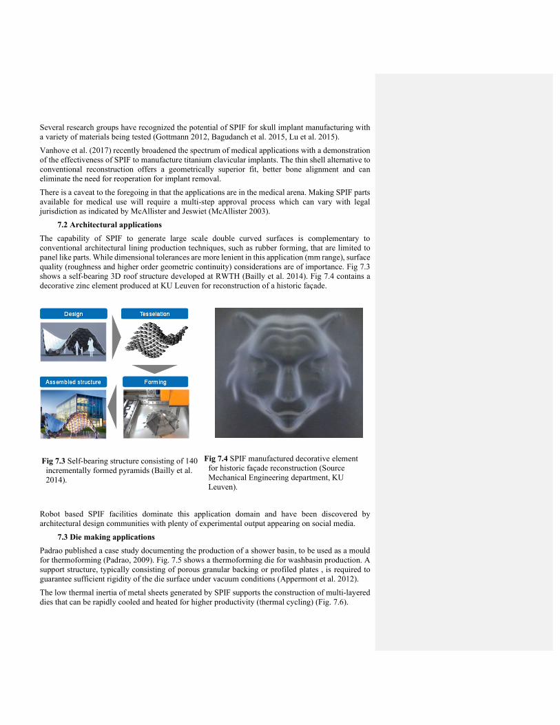
Several research groups have recognized the potential of SPIF for skull implant manufacturing with a variety of materials being tested (Gottmann 2012, Bagudanch et al. 2015, Lu et al. 2015).
Vanhove et al. (2017) recently broadened the spectrum of medical applications with a demonstration of the effectiveness of SPIF to manufacture titanium clavicular implants. The thin shell alternative to conventional reconstruction offers a geometrically superior fit, better bone alignment and can eliminate the need for reoperation for implant removal.
There is a caveat to the foregoing in that the applications are in the medical arena. Making SPIF parts available for medical use will require a multi-step approval process which can vary with legal jurisdiction as indicated by McAllister and Jeswiet (McAllister 2003).
7.2 Architectural applications
The capability of SPIF to generate large scale double curved surfaces is complementary to conventional architectural lining production techniques, such as rubber forming, that are limited to panel like parts. While dimensional tolerances are more lenient in this application (mm range), surface quality (roughness and higher order geometric continuity) considerations are of importance. Fig 7.3 shows a self-bearing 3D roof structure developed at RWTH (Bailly et al. 2014). Fig 7.4 contains a decorative zinc element produced at KU Leuven for reconstruction of a historic façade.
Robot based SPIF facilities dominate this application domain and have been discovered by architectural design communities with plenty of experimental output appearing on social media.
7.3 Die making applications
Padrao published a case study documenting the production of a shower basin, to be used as a mould for thermoforming (Padrao, 2009). Fig. 7.5 shows a thermoforming die for washbasin production. A support structure, typically consisting of porous granular backing or profiled plates , is required to guarantee sufficient rigidity of the die surface under vacuum conditions (Appermont et al. 2012).
The low thermal inertia of metal sheets generated by SPIF supports the construction of multi-layered dies that can be rapidly cooled and heated for higher productivity (thermal cycling) (Fig. 7.6).
Fig Fig 7.3 Self-bearing structure consisting of 140 incrementally formed pyramids (Bailly et al. 2014).
Fig Fig 7.4 SPIF manufactured decorative element for historic façade reconstruction (Source Mechanical Engineering department, KU Leuven).

Fig 7.5 Stainless sheet die for a washbasin based on a perforated SPIF shell and low pressure moulding parts (hand lamination, RTM, thermoforming) (Source Mechanical Engineering department, KU Leuven)
Fig 7.6 a) Cross section of four layered sheet die with integrated heating/cooling chambers for Resin Transfer Moulding (RTM) (1) sealing1, (2) high vacuum chamber, (3) sealing2, (4) RTM cavity, (5) Resin injection nipple, (6) RTM vacuum nipple, (7) water outlet upper die, (8) water outlet lower die, (9) high vacuum nipple, (10) & (11) water inlet lower and upper die. b) & c) Lower and upper die. (Source Mechanical Engineering department, KU Leuven)

7.4 Prototyping applications
Manufacture of a wide variety of components by means of SPIF has been reported in different sources, typically to demonstrate process capabilities, but also as input for prototype development and functional product testing. A limited number of examples are listed here that were found representative for illustrating the maturity of the process capabilities.
Adams and Jeswiet documented the production of, among others, automotive guards, engine intake components, prototypes for research and patient-fitted organic shapes (Adams, Jeswiet 2014a). Other examples of SPIF that have been produced include a solar cooker (Jeswiet et al. 2005) and an engine heat shield (Young and Jeswiet 2004).
Fig. 7.7 Clockwise from top left: Automotive powertrain guards, diffuser cones for a gas turbine diffuser, engine air intake plenums for a race team, a different plenum design (Adams and Jeswiet, 2014b)
Recent unpublished work by Adams and Jeswiet, has included manufacture of prototypes and parts with SPIF for an HVAC industry. A set of prototypes of baffles was made with SPIF for a manufacturer of large, custom HVAC systems (Fig. 7.8). These were used to functionally test a variety of baffle shapes to determine whether the shape could have an effect upon the HVAC efficiency.
Fig. 7.8 Four examples of rapid prototypes for testing in an HVAC system (Source: Department of Mechanical and Materials Engineering, Queen’s University).
An Airfow Management System (AFMS) display, for housing electronic sensor hardware, was designed and manufactured for HVAC systems. This is a unique design and SPIF was found well

suited for manufacturing low quantity, high quality volumes of parts for the manufacturer (see Fig. 7.9).
Fig. 7.9 Initial design concept and final AFMS design. (Source: Department of Mechanical and Materials Engineering, Queen’s University)
The SPIF process has also been used to advantage for the HVAC manufacturer to produce special shroud parts with a specific flow pattern as shown in Fig. 7.10.
Fig. 7.10 HVAC shrouds manufactured by SPIF (Source: Department of Mechanical and Materials Engineering, Queen’s University).
8 Summary and Future Direction
While this review paper only summarizes a selection from a broad range of publications, it is obvious that ISF as flexible forming method in general, and specifically single point incremental forming , have received considerable attention from many research institutes over the last decade. The plethora of papers that have emanated since the initial review paper (Jeswiet et al. 2005) forms testimony thereof.
In an early stage of the development of the SPIF process, accuracy and productivity were identified as major constraints (Allwood et al. 2005). Today, these obstacles remain challenging bottlenecks for the industrial roll out of the process. However, validation results of different toolpath optimization techniques have shown that sub-millimeter tolerances can be respected for convex shapes. Process variants with local heat support or with in-process hardening options, will allow extension of this success to more complex shapes, although robust, generic process planning solutions for this purpose have not been demonstrated yet. Opportunities offered by additional, flexibly controlled contact
points (TPIF) were not extensively covered in this review paper, but are relevant to enhance the applicability of ISF category of processes beyond the shape capabilities of SPIF.
In terms of the productivity aspect, the SPIF process sensitivity to a substantial increase in forming speed seems to be material specific, with the formability of some materials being even positively influenced by higher strain rates. For axisymmetric part geometries, it has been experimental demonstrated that forming parts within seconds can be achieved. Building hardware solutions capable of high processing speeds, while maintaining tool position accuracy under the resulting dynamic loads, forms the main obstacle for further development of high speed process variants with more generic shaping capabilities.
With respect to economic feasibility, the avoidance of a substantial investment in tooling typically compensates for the relatively low productivity, with an economic breakeven point that is, depending on the part complexity, typically in the order of a few hundred parts (Ambrogio et al. 2003). This kind of economic evaluation does not take into account the value of substantial lead time reduction achievable due to the omission of dedicated tooling needs. However, in terms of quick response time, this lack of tooling lead time fits well into strategies as envisaged in a Quick Response Manufacturing (QRM) approach.
Also with respect to environmental impact assessment, a similar lot size consideration can be obtained: for orders of less than a few hundred parts, the absence of dedicated tooling needs provides a strategic advantage for SPIF compared to die-based processes (Cooper et al. 2017).
The improved formability in SPIF, when compared with conventional forming methods, is widely recognized and has created a perceived need for fracture limit curve identification tailored to the process. Efforts to understand the physics underlying this phenomenon have resulted in theories acknowledging significant effects of through-the-thickness shear, serrated strain paths arising from cyclic, local plastic deformation with strong thickness, and sheet plane gradients. However no single factor could explain the higher process formability: different combinations of these factors are active according to the cases studied. The extended, diffuse necking that can be observed in some test samples can be linked to the localized, displacement controlled nature of the process. This prolonged necking can be explained by various stabilizing effects, such as in-plane shear or hydrostatic pressure. However, also cases in which excessive thinning directly leads to fracture have been identified, leaving the compilation of a comprehensive simple model for failure modes in SPIF processing still an open challenge. The key factor depends on target geometry features such as wall angles, the sheet thickness and the tool diameter. With respect to the applicability of SPIF produced parts, predictability of process induced structural damage to the material thus remains a relevant research topic.
While accurate failure prediction has proven to be hard, SPIF simulation capabilities have benefited from progress in FE modelling of the process. The use of single layer solid shell elements was demonstrated to be a valid tradeoff between computational load and physical correctness of the models. Shape and thickness prediction capabilities have reached a mature state, but good approximation of the process forces is sensitive for a number of factors and requires the use of a refined constitutive law, such as the Voce isotropic hardening law and for some materials the kinematic Armstrong Frederick hardening law.
Adaptive mesh refinement techniques and simplified contact models have contributed to significant reductions in CPU times, which obviously contributes to bringing the simulation of more complex part geometries closer to process planning and toolpath verification practice, a trend which is expected to continue in coming years.
Although a large number of application domains have been identified that could benefit from the flexible forming capabilities of ISF in general and SPIF in specific, commercial industrial use of the process has been limited. This can mainly be linked to the lack of systematic process planning and toolpath generation solutions that are capable of making full use of the process window enhancing

techniques and that allow compensating for unwanted deformations. Improved simulation capabilities, advanced feature recognition techniques and adaptive control methods are some of the strategies dominating ongoing research efforts in this respect. For applications in which either the part accuracy is less restrictive, such as architectural lining and decorative element manufacture, or for applications where the limited part topology variability can be translated into well-optimized toolpath strategies, such as medical implants, the process has been used to successfully produce functional parts.
The achieved progress in terms of shape and tolerance control has indeed resulted in demonstration of different medical implant categories by multiple research teams. Judging on recently reported results (Ambrogio et al. 2017, Centeno et al. 2017, Vanhove et al. 2017), it seems likely that in the near future medical procedures will effectively be affected by the emergence of the one-of-a-kind shaping capabilities of SPIF. The high added value of these applications is likely to be instrumental to help pave the way for new developments in more competitive application areas, thus opening perspectives for a broader use of single point incremental forming in industrial practice.
Acknowledgements
J.R. Duflou, A. Mohammadi and H. Vanhove want to acknowledge the support of Research Fund - Flanders (FWO) under project G0B4413N: LASPIF, and the support of KU Leuven through the GOA SUMMA project.
As research director of FNRS AM Habraken acknowledges the support of F.R.S FNRS as well as its PDR Grant on the SPIF process. Belspo (Belgian Science Policy) is also thanked for the PAI P7/21 grant.
For D. Adams and J. Jeswiet, supporting funds were obtained from NSERC (Natural Science and Engineering Research Foundation), both Discovery and Engage grants, and Auto 21.
Compliance with Ethical Standards
The authors declare that they have no conflict of interest.
References
Adams, D., Jeswiet, J., 2014a, Design Rules and Applications of Single-Point Incremental Forming, Proceedings of the Institution of Mechanical Engineers, Part B: Journal of Engineering Manufacture, 229(5) 754–760
Adams, D, Jeswiet, J., 2014b, Single Point Incremental Forming of 6061-T6 Using Electrically Assisted Forming Methods, Proceedings of the Institution of Mechanical Engineers, Part B: Journal of Engineering Manufacture, 228(7) 757-764
Aerens, R, Eyckens, P, Van Bael, A, Duflou, J.R., 2010, Force prediction for single point incremental forming deduced from experimental and FEM observations. International Journal of Advanced Manufacturing Technology 46(9-12) 969–982
Allwood, J. M., Braun, D., Music, O., 2010, The effect of partially cut-out blanks on geometric accuracy in incremental sheet forming, J. Mater. Process. Technol., 210: 1501-1510
Allwood, J.M., King, G.P.F., Duflou J., 2005, A Structured Search for Applications of the Incremental Sheet Forming Process by Product Segmentation, Proc I Mech E, Part B, Journal of Engineering Manufacture, 219(B2) 239-244

Allwood, J. M., Music, O., Raithathna, A., Duncan S. R., 2009, Closed-loop feedback control of product properties in flexible metal forming processes with mobile tools, CIRP Ann. - Manuf. Technol., 58(1) 287–290
Allwood, J., Shouler, D., Tekkaya, A., 2007, The increased forming limits of incremental sheet forming processes., Key Eng. Mater., 344: 621–628
Alves de Sousa, R.J., Ferreira, J.A.F., Sá de Farias, J.B., Torrão, J.N.D., Afonso, D.G. Martins, M.A.B.E, 2014, SPIF-A : On the development of a new concept of incremental forming machine, Structural Engineering and Mechanics, 49(5) 645-660
Ambrogio, G., Costantino, I., De Napoli, L., Filice, L., Fratini, L., Muzzupappa, M., 2004, Influence of some relevant process parameters on the dimensional accuracy in incremental forming: a numerical and experimental investigation, J. Mater. Process. Technol., 153-154: 501-507
Ambrogio, G., Cozza, V., Filice, L., Micari, F., 2007, An analytical model for improving precision in single point incremental forming, J. Mater. Process. Technol., 191(1-3) 92-95
Ambrogio, G., De Napoli, L., Filice, L., Gagliardi, F., Muzzupappa, M., 2005, Application of Incremental Forming Process for High Customised Medical Product Manufacturing, Journal of Materials Processing Technology 162-163: 156–162, doi:10.1016/j.jmatprotec.2005.02.148
Ambrogio, G., Di Lorenzo, R., Micari F., 2003, Analysis of the economical effectiveness of incremental forming processes: An industrial case study, Proceedings VI AITeM Conference, Gaeta, Italy
Ambrogio, G., Filice, L., Gagliardi, F., 2012, Formability of lightweight alloys by hot incremental sheet forming, Materials & Design 34: 501-508
Ambrogio, G., Filice, L., Manco, G.L., 2008, Warm incremental forming of magnesium alloy AZ31, CIRP Annals - Manufacturing Technology, 57(1) 257-260
Ambrogio, G., Gagliardi, F., Filice, L., 2013, On the high-speed Single Point Incremental Forming of titanium alloys, CIRP Annals, 62(1) 243-246
Ambrogio, G., Gagliardi, F.,Bruschi, S. Filice, L., 2013, Robust Design of Incremental Sheet forming by Taguchi’s Method, Procedia CIRP, 12: 270-275
Ambrogio, G., Sgambitterra, E., De Napoli, L, Gagliardi, F., Fragomeni, G, Piccininni, A., Gugleilmi, P., Palumbo, G., Sorgente, D., La Barbera, L., Villa T.M., 2017, Performance analysis of titanium prostheses manufactured by superplastic forming and incremental forming, Procedia Engineering, 183: 168–173
Appermont, R., Van Mieghem, B., Van Bael, A., Bens, J., Ivens, J., Vanhove, H., Behera, A.K., Duflou, J., 2012, Sheet-metal based molds for low-pressure processing of thermoplastics, Proceedings of the 5th Bi-Annual PMI Conference, 5: 383-388
Azaouzi, M., Lebaal, N., 2012, Tool path optimization for single point incremental sheet forming using response surface method, Simulation Modelling Practice and Theory, 24: 49–58
Azevedo, N.G., Farias, J.S., Bastos, R.P., Teixeira, P., Davim, J.P., De Sousa, R.J.A, 2015, Lubrication aspects during Single Point Incremental Forming for steel and aluminum materials. Int. J. Precis. Eng. Manuf. 16: 589. doi:10.1007/s12541-015-0079-0
Bagudanch, I., Lozano-Sánchez, L.M., Puigpinós, L., Sabater, M., Elizalde L.E., Elías-Zúñiga, A., Garcia-Romeu M.L., 2015, Manufacturing of Polymeric Biocompatible Cranial Geometry by Single Point Incremental Forming, Procedia Engineering, 132: 267–273
Bahloul, R., Arfa, H., BelHadjSalah, H., 2014, A study on optimal design of process parameters in single point incremental forming of sheet metal by combining Box–Behnken design of

experiments, response surface methods and genetic algorithms, Int. J. Adv. Manuf. Technol., 74(1-4) 163-185
Avedesian, M.M., Baker, H., 1999, ASM Specialty Handbook: Magnesium and Magnesium Alloys (ASM International)
Bambach, M., 2010, A geometrical model of the kinematics of incremental sheet forming for the prediction of membrane strains and sheet thickness, J. Mater. Process. Technol., 210, 12, 1562–1573
Bambach, M., 2016, Fast simulation of asymmetric incremental sheet metal forming by adaptive remeshing and subcycling, International Journal of Material Forming. 9(3) 353–360
Bambach, M., Ames, J., Azaouzi, M., Campagne, L., Hirt, G., Batoz, J.L., 2005, Initial experimental and numerical investigations into a class of new strategies for single point incremental forming simulations, Proceedings of the 8th ESAFORM Conference on Material Forming, 2005, 671–674
Bambach, M., Cannamela, M., Azaouzi, M., Hirt, G., Batoz, J.L, 2007, Computer-aided tool path optimization for single point incremental sheet forming, In Advanced methods in material forming, 233-250, Springer Berlin Heidelberg
Bambach, M., Grzibovskis, R., 2013, Analysis of optimal metal flow in incremental sheet forming, PAMM, 13(1) 331-332
Bambach, M., Hirt, G., 2005, Performance assessment of element formulations and constitutive laws for the simulation of incremental sheet forming (ISF), Proceedings of the COMPLAS VIII, CIMNE, Barcelona, 1-4
Bambach, M., Taleb Araghi, B., Hirt, G., 2009, Strategies to improve the geometric accuracy in asymmetric single point incremental forming, Prod. Eng., 3(2) 145–156
Behera, A.K., Lauwers, B., Duflou, J., 2013, Tool path generation for single point incremental forming using intelligent sequencing and multi-step mesh morphing techniques, Key Engineering Materials, 554–557: 1408-1418
Behera, A.K., Lauwers, B., Duflou, J.R., 2014, Tool path generation framework for accurate manufacture of complex 3D sheet metal parts using single point incremental forming, Comput. Ind., 65(4) 563–584
Behera, A.K., Verbert, J., Lauwers, B., Duflou, J.R., 2013, Tool path compensation strategies for single point incremental sheet forming using multivariate adaptive regression splines, Comput. Des., 45(3) 575–590
Belchior, J., Guillo, M., Courteille, E., Maurine, P., Leotoing, L., Guines, D., 2013, Off-line compensation of the tool path deviations on robotic machining: Application to incremental sheet forming, Robot. Comput. Integr. Manuf., 29(4) 58-69
Beltran, M., Malhotra, R., Nelson, A.J., Bhattacharya, A., Reddy, N.V., Cao, J., 2013, Experimental study of failure modes and scaling effects in micro-incremental forming, ASME Journal of Micro- and Nano-manufacturing, 3, 031005-1
Ben Ayed, L., Robert, C., Delamézière, A., Nouari, M., Batoz, J.L., 2014, Simplified numerical approach for incremental sheet metal forming process, Engineering Structures, 62-63: 75-86
Ben Hmida, R., Richard, F., Thibaud, S., Malécot, P., 2015, Elastic-plastic damage behavior identification in micro scale length from instrumented micro-single point incremental forming 4M/ICOMM2015 conf., Milan, Italy, Research Publishing

Bens, J., Van Mieghem, B., Appermont, R., Vanhove, H., Van Bael, A., Duflou, J., Ivens, J., 2012, Development of material and energy-efficient metal sheet based tools for composite manufacturing, Proceedings 15th European Conf. on Composite Materials, ECCM, Venice.
Bhattacharya, A., 2014, Studies on Incremental Forming to Enhance Accuracy and Geometric Complexity, PhD Dissertation, IIT Kanpur
Bhattacharya, A., Maneesh, K., Venkata Reddy, N., Cao, J., 2011, Formability and Surface Finish Studies in Single Point Incremental Forming, J. Manuf. Sci. Eng., 133, 6, 061020
Blaga, A., Bologa, O., Oleksik, V. Breaz, R., 2011, Influence of tool path on main strains, thickness reduction and forces in single point incremental forming process, Proceedings in Manufacturing Systems, 6(4) 2-7
Bouffioux, C., Henrard, C., Gu, J., Duflou, J., Habraken, A., 2007, Development of an inverse method for identification of materials parameters in the single point incremental sheet forming process, Proc. of the IDDRG 2007 International Conference
Bouffioux, C., Lequesne, C., Vanhove, H., Duflou, J. R., Pouteau, P., Duchêne, L., Habraken, A.M., 2011, Experimental and numerical study of an AlMgSc sheet formed by an incremental process, J. Mater. Process. Technol., 211(11) 1684-1693
Bouffioux, C., Eyckens, P., Henrard, C., Aerens, R., Van Bael, A., Sol, H., Duflou, J.R., Habraken, A.M., 2008, Identification of material parameters to predict Single Point Incremental Forming forces, Int. J Mater. Form., Suppl 1: 1147-1150, DOI: 10.1007/s12289-008-0183-0
Cao, T., Lu, B., Xu, D., Zhang, H., Chen, J., Long, H., Cao, J., 2015 An efficient method for thickness prediction in multi-pass incremental sheet forming Int J Adv Manuf Technol, 2015, 77(1) 469-483
Centeno, G., Bagudanch, I., Morales-Palma, D., Garcia-Romeu M.L., Gonzalez-Perez-Somarriba B., Martinez-Donaire, A.J., Gonzalez-Perez, L.M., Vallellano, C., 2017, Recent approaches for the manufacturing of polymeric cranial prostheses by incremental sheet forming, Procedia Engineering, 183: 180-187
Conrad, H., 2000, Electroplasticity in Metals and Ceramics, Materials Science and Engineering: A 287 (2) 276–87. doi:10.1016/S0921-5093(00)00786-3
Cooper, D.R., Rossie, K.E., Gutowski, T.G., 2017, The energy requirements and environmental impacts of sheet metal forming: An analysis of five forming processes, Journal of Materials Processing Technology, 244:116–135
De Sousa, R., Ferreira, J.A.F., Sá de Farias, J.B., Torrão, J.N.D., Afonso, D.G., Martins, M.A.B.E., 2014, SPIF-A: on the development of a new concept of incremental forming machine, Structural Engineering and Mechanics, 49(1) 546-660, doi:10.12989/sem.2014.49.5.645
Delamézière, A., Yu, Y., Robert, C., Ayed, L. Ben, Nouari, M., 2010, Numerical Simulation of Incremental Sheet Forming by Simplified Approach, AIP Conference Proceedings 1315: 619–624
Desai, B. V., Desai, K. P., Raval, H. K., 2014, Die-less Rapid Prototyping Process: Parametric Investigations, Procedia Materials Science 6: 666-673
Donachie, M. J., 2000, Titanium: a technical guide, ASM International.
Duchêne, L., Guzmán, C.F., Behera, A.K., Duflou, J.R., Habraken, A.M., 2013, Numerical Simulation of a Pyramid Steel Sheet Formed by Single Point Incremental Forming using Solid-Shell Finite Elements, Key Engineering Materials, 549:180-188

Duflou, J.R., Behera, A.K., Vanhove, H., Bertol, L.S., 2013, Manufacture of Accurate Titanium Cranio-Facial Implants with High Forming Angle Using Single Point Incremental Forming, Key Engineering Materials, 549, 223-230
Duflou, J.R., Callebaut, B., Verbert, J., De Baerdemaeker, H., 2007, Laser Assisted Incremental Forming: Formability and Accuracy Improvement, CIRP Annals - Manufacturing Technology, 56(1) 273-276
Duflou, J., Callebaut, B., Verbert, J., De Baerdemaeker, H., 2008, Improved SPIF performance through dynamic local heating, Int. J. Mach. Tools Manuf., 48(5) 543–549
Duflou, J.R., Lauwers, B., Verbert, J., 2007, Study on the Achievable Accuracy in Single Point Incremental Forming, Advanced Methods in Material Forming, 251-262, doi:10.1007/3-540-69845-0_15
Duflou, J.R., Lauwers, B., Verbert, J., Gelaude, F., Tunckol, Y., 2005, Medical Application of Single Point Incremental Forming: Cranial Plate Manufacturing, Virtual Modeling and Rapid Manufacturing, Proc. 2nd Int. Conf. on Advanced Research in Virtual and Rapid Prototyping, 161-66
Duflou, J.R., Tunçkol, Y., Szekeres, A., Vanherk, P., 2007, Experimental study on force measurements for single point incremental forming, Journal of Materials Processing Technology, 189 (1-3) 65-72
Duflou, J.R., Vanhove H., Verbert J., Gu J., Vasilakos I., Eyckens P., 2010, Twist revisited: Twist phenomena in single point incremental forming, CIRP Annals - Manufacturing Technology 59(1) 307–310
Duflou, J.R., Verbert, J., Belkassem, B., Gu, J., Sol, H., Henrard, C., Habraken, A.M., 2008, Process window enhancement for single point incremental forming through multi-step toolpaths, CIRP Ann. - Manuf. Technol., 57(1) 253–256
Elford, M., Saha, P., Seong, D., Haque, M.Z., Yoon, J.W., 2013, Benchmark 3 - Incremental sheet forming, AIP Conference Proceedings, American Institute of Physics, Melbourne, Australia, 227–261
Emmens, W.C., Sebastiani, G., van den Boogaard, A.H., 2010, The technology of Incremental Sheet Forming - A brief review of the history, J. Mater. Process. Technol., 210(8) 981–997
Emmens, W.C., van den Boogaard, A.H., 2009, An overview of stabilizing deformation mechanisms in incremental sheet forming, J. Mater. Process. Technol., 209(8) 3688–3695
Eyckens, P., Belkassem, B., Henrard, C., Gu, J., Sol, H., Habraken, A.M., Duflou, J.R., Van Bael, A., Van Houtte P., 2010, Strain evolution in the single point incremental forming process: digital image correlation measurement and finite element prediction, Int. J. Material. Forming, 4(1) 55-71
Eyckens, P., He, S., Van Bael, A., Van Houtte, P., Duflou, J., 2007, Forming Limit Predictions for the Serrated Strain Paths in Single Point Incremental Sheet Forming, AIP Conference Proceedings, Aip, 908, 141–146
Eyckens, P., Van Bael, A., Aerens, R., Duflou, J., Van Houtte, P., 2008, Small-scale Finite Element Modelling of the Plastic Deformation Zone in the Incremental Forming Process, Int. J. Mater. Form. 1:1159, doi:10.1007/s12289-008-0186-x
Eyckens, P., Van Bael, A., Van Houtte, P., 2009, Marciniak-Kuczynski type modelling of the effect of Through-Thickness Shear on the forming limits of sheet metal, Int. J. Plast., 25(12) 2249–2268
Fan, G., Gao, L., Hussain, G., Wu, Z., 2008, Electric hot incremental forming: A novel technique, International Journal of Machine Tools and Manufacture, 48: 1688-1692

Fan, G., Sun, F., Meng, X., Gao, L. Tong G., 2010, Electric hot incremental forming of Ti-6Al-4V titanium sheet, The International Journal of Advanced Manufacturing Technology 49(9) 941-947
Filice, L., 2006, A phenomenology-based approach for modeling material thinning and formability in incremental forming of cylindrical parts. Proc IMechE 220:1449–1455
Filice, L., Fratini, L., Micari, F., 2002, Analysis of Material Formability in Incremental Forming, CIRP annals-Manufacturing technology, 51(1) 199–202
Flores, P., Duchêne, L., Bouffioux, C., Lelotte, T., Henrard, C., Pernin, N., Van Bael, A., He, S., Duflou, J.R., Habraken, A.M., 2007. Model identification and FE simulations: Effect of different yield loci and hardening laws in sheet forming, International Journal of Plasticity 23(3) 420–449
Fu, Z., Mo, J., Han, F., Gong, P., 2013, Tool path correction algorithm for single-point incremental forming of sheet metal, Int. J. Adv. Manuf. Technol., 64(9–12) 1239–1248.
Galdos, L., Argandoña, E.S.D., Ulacia, I., Arruebarrena, G., 2012, Warm Incremental Forming of Magnesium Alloys Using Hot Fluid as Heating Media, Key Engineering Materials, 504–506: 815-820
Ghiotti, A., Bruschi, S., 2010, A novel experimental set-up for warm incremental forming of AZ31B magnesium alloy sheets, in Steel Research International, 81: 950-954
Giraud-Moreau, L., Cherouat, A., Zhang, J., Borouchaki, H., 2013, Comparison between an advanced numerical simulations of sheet incremental forming using adaptive remeshing and experimental results, Key Enginneering Materials, 554–557: 1375–1381
Göttmann, A., Bailly D., Bergweiler G., Bambach M., Stollenwerk J., Hirt G., Loosen P., 2013, A novel approach for temperature control in ISF supported by laser and resistance heating, The International Journal of Advanced Manufacturing Technology 67(9-12) 2195-2205
Göttmann, A., Diettrich, J., Bergweiler G., Bambach M., Hirt G., Loosen P., Poprawe R., 2011, Laser-assisted asymmetric incremental sheet forming of titanium sheet metal parts, Prod. Eng. Res. Devel., 5(3): 263-271
Göttmann, A., Korinth, M., 2012, Manufacturing of cranial implants using incremental sheet metal forming, Proceedings 1st Internat. Conf. on Design and Processes for Medical Devices PROMED, 287-290
Guzman, C.F., 2016, Experimental and Numerical Characterization of Damage and Application to Incremental Forming, PhD thesis University of Liège http://hdl.handle.net/2268/192884
Hadoush, A., van den Boogaard, A., 2009, Substructuring in the implicit simulation of single point incremental sheet forming, International Journal of Material Forming 2(3) 181–189
Hadoush, A., van den Boogaard, A.H., 2008, Time reduction in implicit single point incremental sheet forming simulation by refinement - derefinement, International Journal of Material Forming, 1, Suppl. 1, 1167–1170.
Hadoush, A.M.H., 2010, Efficient simulation and process mechanics of incremental sheet forming, PhD thesis University of Twente, Netherland
Hagan, E, Jeswiet, J., 2003, A Review of Conventional and Modern Single-Point Sheet Metal Forming Methods, Proceedings of the Institution of Mechanical Engineers, Part B: Journal of Engineering Manufacture 217 (2) 213–25
Ham, M., Jeswiet, J., 2007, Forming Limit Curves in Single Point Incremental Forming, CIRP Ann. - Manuf. Technol., 56(1) 277–280
Hamilton, K., Jeswiet, J., 2010, Single point incremental forming at high feed rates and rotational speeds: Surface and structural consequences, CIRP Ann. - Manuf. Technol., 59(1) 311–314
Henrard, C., Bouffioux, C., Eyckens, P., Sol, H., Duflou, J.R., Van Houtte, P., Van Bael, A., Duchêne, L., Habraken, A.M., 2010, Forming forces in single point incremental forming: prediction by finite element simulations, validation and sensitivity, Comput. Mech., 47(5) 573–590
Hill 1948 A theory of the yielding and plastic flow of anisotropic metals. Proceedings of the Royal Society London A 193: 281–297
Hirt, G., Ames, J., Bambach, M., Kopp, R., 2004, Forming strategies and Process Modelling for CNC Incremental Sheet Forming, CIRP Ann. - Manuf. Technol., 53(1) 203–206
Hirt, G., Bambach, M., 2005. Modelling incremental sheet forming using a meshless surface representation based on radial basis functions. Advanced Technology of Plasticity, Proceedings of the 8th International Conference on Technology of Plasticity, 261–262
Hirt, G., Bambach, M., Bleck, W., Prahl, U., Stollenwerk, J., 2015, The Development of Incremental Sheet Forming from Flexible Forming to Fully Integrated Production of Sheet Metal Parts, Advances in Production Technology 117-129, Springer International Publishing
Hussain, G., Gao, L., Hayat, N, Cui, Z., Pang, Y.C., Dar, N.U., 2008, Tool and lubrication for negative incremental forming of a commercially pure titanium sheet, J. of Mat. Proc. Tech., 203: 193-201
Hussain, G., Gao, L., Hayat, N., Qijian, L., 2007, The effect of variation in the curvature of part on the formability in incremental forming: An experimental investigation, Int. J. Mach. Tools Manuf., 47(14) 2177–2181
Hussain, G., Gao, L., Hayat, N., Ziran, X., 2009, A new formability indicator in single point incremental forming, J. Mater. Process. Technol., 209(9) 4237–4242
Jackson, K., 2008. The mechanics of incremental sheet forming, PhD thesis, University of Cambridge
Jackson, K., Allwood, J.M., 2009, The mechanics of incremental sheet forming, J. Mater. Process. Technol., 209(3) 1158–1174
Jeswiet, J., 2005, Asymmetric Incremental Sheet Forming, Adv. Mater. Res., 6–8: 35–58
Jeswiet, J., Duflou, J.R., Szekeres, A., Lefebvre, P., 2005, Custom Manufacture of a Solar Cooker – A Case Study, Advanced Materials Research 6-8: 487–92, doi:10.4028/www.scientific.net/AMR.6-8.487
Jeswiet, J., Hagan, E., Szekeres, A., 2002, Forming parameters for incremental forming of aluminium alloy sheet metal, Proceedings of the Institution of Mechanical Engineers, Part B: Journal of Engineering Manufacture, 216: 1367-1371
Jeswiet, J., Micari, F., Hirt, G., Bramley, A., Duflou, J., Allwood, J., 2005, Asymmetric Single Point Incremental Forming of Sheet Metal, CIRP Ann. - Manuf. Technol., 54(2) 88–114
Jeswiet, J., Young D., 2005, Forming limit diagrams for single-point incremental forming of aluminium sheet, Proc. Inst. Mech. Eng. Part B J. Eng. Manuf., 219(4) 359–364
Ji, Y.H., Park J.J., 2008, Formability of magnesium AZ31 sheet in the incremental forming at warm temperature, Journal of Materials Processing Technology 201(1–3) 354-358
Ji, Y.H., Park J.J., 2008, Incremental forming of free surface with magnesium alloy AZ31 sheet at warm temperatures, Transactions of Nonferrous Metals Society of China 18, Supplement 1(0): 165-169
Johnson, C.F., Kiridena, V.S., Ren, F, Xia, Z.C., (2012): System and Method for Incrementally Forming a Workpiece, US Patent US8322176

Kim, S.W., Lee ,Y.S., Kang, S.H., Lee, J.H., 2007, Incremental forming of Mg alloy sheet at elevated temperatures, J Mech Sci Technol, 21: 1518-1522
Kinsey, B., Cullen, G., Jordan, A., Mates, S., 2013, Investigation of electroplastic effect at high deformation rates for 304SS and Ti-6Al-4V, CIRP Annals, 62(1) 279-282.
Kopač, J., Kampus, Z., 2005, Incremental sheet metal forming on CNC milling machine-tool, J. Mater. Process. Technol., 162–163: 622–628.
Kronenberger, T.J., Johnson, D.H., Roth, J.T.. 2009, Coupled Multifield Finite Element Analysis Model of Upsetting Under an Applied Direct Current, Journal of Manufacturing Science and Engineering 131(3) 031003. doi:10.1115/1.3090833.
León, J., Salcedo, D., Ciáurriz, C., Luis, C.J., Fuertes, J.P., Puertas, I., Luri, R., 2013, Analysis of the Influence of Geometrical Parameters on the Mechanical Properties of Incremental Sheet Forming Parts, Procedia Eng., 63: 445–453
Lemaitre, J., Chaboche, J.L., 1985, Mécanique des Matériaux Solides, Dunod
Lequesne, C., Henrard, C., Bouffioux, C., Duflou, J.R., Habraken, A.M., 2008, Adaptive remeshing for incremental forming simulation, Numisheet 2008, Interlaken, Switzerland, 32 : 4–8
Leszak,. E., 1967, Apparatus and process for incremental dieless forming. Patent US3342051A1, published 1967-09-19.
Li, J., Hu, J., Pan, J., Geng, P., 2011, Thickness distribution and design of a multi-stage process for sheet metal incremental forming, Int. J. Adv. Manuf. Technol., 62(9–12) 981–988
Li, Y., Daniel, W.J.T., Liu, Z., Lu, H., Meehan, P.A, 2015, Deformation mechanics and efficient force prediction in single point incremental forming Journal of Materials Processing Technology 221: 100-111
Li, Y., Liu, Z., Lu, H., Daniel, W.J.T., Liu, S., Meehan, P., 2014. Efficient force prediction for incremental sheet forming and experimental validation. Int. J. Adv. Manuf.Technol. 73: 571-587
Lievers, W., Pilkey, A.K., Lloyd, D.J., 2004, Using incremental forming to calibrate a void nucleation model for automotive aluminum sheet alloys, Acta Mater., 52(10) 3001–3007
Lingam, R., Bansal, A., Reddy, N. V., 2015, Analytical prediction of formed geometry in multi-stage single point incremental forming, Int J Mater Form 9 (3) 395-404
Liu, Z., Daniel, W.J.T., Li, Y., Liu, S., Meehan, P.A., 2014, Multi-pass deformation design for incremental sheet forming: Analytical modeling, finite element analysis and experimental validation, J. Mater. Process. Technol., 214(3) 620–634
Liu, Z., Li, Y., Meehan, P.A., 2013, Vertical wall formation and material flow control for incremental sheet forming by revisiting multistage deformation path strategies, Materials and Manufacturing Processes 28 (5), 562–71, doi:10.1080/10426914.2013.763964
Lu, B., Chen, J., Ou, H., Cao, J., 2013, Feature-based tool path generation approach for incremental sheet forming process, J. Mater. Process. Technol., 213(7) 1221–1233
Lu, B., Fang, Y., Xu, D.K., Chen, J., Ou, H., Moser, N.H., Cao, J., 2014, Mechanism investigation of friction-related effects in single point incremental forming using a developed oblique roller-ball tool, Int. J. of Mach. Tools and Manuf., 85: 14-29
Lu, B., Xu, D.K., Liu, R.Z., Ou, H., Long, H., Chen, J., 2015, Cranial Reconstruction using Double Side Incremental Forming, Key Engineering Materials 639: 535-542

Magargee, J., Fan, R., Cao, J., 2013, Analysis and Observations of Current Density Sensitivity and Thermally Activated Mechanical Behavior in Electrically-Assisted Deformation, ASME J. Manufacturing Science and Engineering, 135, 061022, DOI: 10.1115/1.4025882.
Magargee, J., Morestin, F., Cao, J., 2013, Characterization of Flow Stress for Commercially Pure Titanium Subjected to Electrically-Assisted Deformation, ASME Journal of Engineering Materials and Technologies, 135(4), doi:10.1115/1.4024394.
Malhotra, R., 2012, Fundamentals of Process Mechanics and Process Innovation in Incremental Forming, PhD dissertation, Northwestern University
Malhotra, R., Bhattacharya, A., Kumar, A., Reddy, N.V., Cao, J., 2011, A new methodology for multi-pass single point incremental forming with mixed toolpaths, CIRP Ann. - Manuf. Technol., 60(1) 323–326
Malhotra, R., Reddy, N.V., Cao, J., 2010, Automatic 3D Spiral Toolpath Generation for Single Point Incremental Forming, J. Manuf. Sci. Eng., 132(6), 061003
Malhotra, R., Xue, L., Belytschko, T., Cao, J., 2012, Mechanics of fracture in single point incremental forming, J. Mater. Process. Technol., 212(7) 1573–1590
Marabuto ,S.R., Afonso, D., Ferreira, J.A.F., Melo, F.Q., Martins, M.A.B.E., de Sousa, R.J. A., 2011, Finding the Best Machine for SPIF Operations - a Brief Discussion, Key Engineering Materials, 473: 861-868
Martins, P.A.F., Bay, N., Skjoedt, M., Silva, M. B., 2008, Theory of single point incremental forming, CIRP Ann. - Manuf. Technol., 57(1) 247–252
McAllister, P., Jeswiet, J., 2003, Medical device regulation for Manufacturers, J. Engineering in Medicine, 217(H) 459-467
Meier, H., Buff, B., Laurischka,t R., Smukala, V., 2009, Increasing the part accuracy in dieless robot-based incremental sheet metal forming, CIRP Ann. - Manuf. Technol., 58(1) 233–238
Meier, H., Dewald, O., Zhang, J., 2005, Development of a Robot-Based Sheet Metal Forming Process, Steel Research International, 76(2-3) 167–170
Micari, F., Ambrogio, G., Filice, L., 2007, Shape and dimensional accuracy in Single Point Incremental Forming: State of the art and future trends, J. Mater. Process. Technol., 191(1-3) 390–395
Mirnia, M.J., Mollaei Dariani B., 2012, Analysis of incremental sheet metal forming using the upper-bound approach. Proc Inst Mech. Eng. B: J. Eng. Manuf., 226: 1309–1320
Mirnia, M.J., Mollaei Dariani, B., Vanhove, H. Duflou, J.R., 2014, An investigation into thickness distribution in single point incremental forming using sequential limit analysis, Int. J. Material Forming, 7: 469–477
Mohammadi, A., Vanhove, H., Van Bael, A., Duflou, J.R., 2016a, Towards accuracy improvement in single point incremental forming of shallow parts formed under laser assisted conditions, International Journal of Material Forming, 9(3) 339-351, DOI 10.1007/s12289-014-1203-x, ISSN 1960-6206.
Mohammadi, A., Vanhove, H., Van Bael, A., Seefeldt, M., Duflou, J.R., 2016b, Effect of Laser Transformation Hardening on the Accuracy of SPIF Formed Parts. Journal of Manufacturing Science and Engineering (ASME), 139(1):011007-011007-12. doi:10.1115/1.4033926
Mohammadi, A., Vanhove, H., Weise, D., Landgrebe, D., Van Bael, A., Duflou, J.R., 2017, Influence of global forced-air warming on the bulge formation in shallow sloped SPIF parts, Procedia Engineering, 183: 149–154

Montanari, L., Cristino, V.A., Silva, M.B., Martins, P.A.F., 2013, A new approach for deformation history of material elements in hole-flanging produced by single point incremental forming, Int. J. Adv. Manuf. Technol., 69(5–8) 1175–1183
Otsu, M., Matsuo, H., Matsuda, M., Takashima, K., 2011, Development of Friction Stir Incremental Forming, Journal of the Japan Society for Technology of Plasticity, 52: 490-494
Padrao, J.L., 2009, Single Point Incremental Forming, Msc Thesis. Instituto Superior Tecnico Universidade Tecnica de Lisboa.
Paniti, I, A novel, single-robot based two sided incremental sheet forming system, ISR/ROBOTIK, 41st International Symposium on Robotics, Proceedings of VDE
Pereira Bastos, R.N, Alves de Sousa, R.J., Fernandes Ferreira, J.A., 2015, Enhancing time efficiency on single point incremental forming processes, Int J Material Forming, 9(5) 653–662, DOI 10.1007/s12289-015-1251-x
Perkins, T.A., Kronenberger, T.J., Roth, J.T., 2007, Metallic Forging Using Electrical Flow as an Alternative to Warm/Hot Working, Journal of Manufacturing Science and Engineering 129(1) 84-94 , doi:10.1115/1.2386164
Raithatha, A., Duncan S.R., 2009, Rigid plastic model of incremental sheet deformation using second-order cone programming, Int J Numer Methods Eng 78: 955–979
Rauch, M., Hascoet, J.-Y., Hamann, J.-C., Plenel, Y., 2009, Tool path programming optimization for incremental sheet forming applications, Comput. Des., 41(12) 877–885
Reddy, N.V., Lingam, R., Cao, J., 2015, Incremental Metal Forming Process in Manufacturing in Handbook of Manufacturing Engineering and Technology, Springer-Verlag, London.
Riadh, B., Henia, A., Hedi, B., 2013, Application of Response Surface Analysis and Genetic Algorithm for the Optimization of Single Point Incremental Forming Process, Key Engineering Materials 554-557: 1265–1272
Salandro, W., Jones, J., Bunget, C., Mears, L., Roth, J., 2015, Electrically Assisted Forming, Modeling and Control, Springer Series in Advanced Manufacturing
Salandro, W.A., Jones, J.J., McNeal, T.A., Roth, J.T., Hong, S.-T. Smith, M.T., 2010, Formability of Al 5xxx Sheet Metals Using Pulsed Current for Various Heat Treatments, Journal of Manufacturing Science and Engineering 132 (5) 0151016, doi:10.1115/1.4002185
Sarraji, W.K.H., Hussain, J., Ren, W.-X., 2012, Experimental Investigations on Forming Time in Negative Incremental Sheet Metal Forming Process, Mater. Manuf. Process., 27(5) 499–506
Sebastiani, G., Brosius, A., Tekkaya, A.E., Homberg, W. Kleiner, M., 2007, Decoupled simulation method for incremental sheet metal forming, AIP Conference Proceedings, 908: 1501–1506
Sekine, T.,Obikawa, T., 2010, Single Point Micro Incremental Forming of Miniature Shell Structures, Journal of Advanced Mechanical Design, Systems, and Manufacturing, 4(2) 543-557
Sena, J.I.V., Guzmán C.F., Duchêne, L., Habraken, A.M., Behera, A.K., Duflou, J.R., Valente, R.. de Sousa, R.J.A., 2015, Simulation of a two-slope pyramid made by SPIF using an adaptive remeshing method with solid-shell finite element, International Journal of Material Forming. issn: 1960-6206. doi: 10.1007/s12289-014-1213-8
Sena, J., Lequesne, C., Duchene, L., Habraken, A., Valente, R., Alves de Sousa, R., 2016, Single point incremental forming simulation with adaptive remeshing technique using solid-shell elements. Engineering Computations International Journal for Computer- Aided Engineering and Software, 33(5) 1388-1421
Seong, D., Haque, M.Z., Kim, J.B., Stoughton, T.B., Yoon, J.W., 2014, Suppression of necking in incremental sheet forming, Int. J. Solids Struct., 51(15-16) 2840–2849

Silva, M.B., Nielsen, P.S., Bay, N., Martins, P.A.F., 2011, Failure mechanisms in single-point incremental forming of metals, Int. J. Adv. Manuf. Technol., 56(9–12) 893–903
Silva, M.B., Skjoedt, M., Atkins, A.G., Bay, N., Martins, P.A.F., 2008, Single‐point incremental forming and formability-failure diagrams, J. Strain Anal. Eng. Des., 43(1) 15–35
Silva, M.B., Skjoedt, M., Bay, N., Martins, P.A.F., 2009, Revisiting single-point incremental forming and formability/failure diagrams by means of finite elements and experimentation, J. Strain Anal. Eng. Des., 44(4) 221–234
Silva, M.B., Skjoedt, M., Martins, P.A.F., Bay, N., 2008, Revisiting the fundamentals of single point incremental forming by means of membrane analysis, Int. J. Mach. Tools Manuf., 48(1) 73–83
Skjoedt, M, Bay, N., Endelt, B, Ingarao, G., 2008, Multi Stage Strategies for Single Point Incremental Forming of a Cup, Journal of Material Forming 1(1) 1199–1202. doi:10.1007/s12289-008-0
Skjoedt M., Silva, M.B., Martins, P.A.F., Bay, N., 2010, Strategies and limits in multi-stage single-point incremental forming, J. Strain Anal. Eng. Des., 45(1) 33–44
Smith, J., Malhotra, R., Liu, W.K., Cao, J., 2013, Deformation mechanics in single-point and accumulative double-sided incremental forming, Int. J. Adv. Manuf. Technol., 69(5–8) 1185–1201
Suresh, K., Regalla, S.P., 2014, Effect of Mesh Parameters in Finite Element Simulation of Single Point Incremental Sheet Forming Process, Procedia Materials Science, 6: 376–382
Tanaka, S., Hayakawa, K., Nakamura, T., 2011, Incremental Sheet forming with Direction Control of Path Planes. Steel Research Int., Special edition ICTP 2011, 503-507
Thomason, P.E., 1990, Ductile Fracture of Metals, Pergamon Press, Oxford
Tuninetti, V., Yuan, S., Gilles, G., Guzmán, C.F., Habraken, A.M., Duchêne, L., 2016, Modeling the ductile fracture and the plastic anisotropy of DC01 steel at room temperature and low strain rates, J. Phys.: Conf. Ser., 734, 032075
Tvergaard, V., Needleman, A., 1984, Analysis of the Cup-cone Fracture in a Round Tensile Bar, Acta Metall., 32: 157-169
Vanhove, H., Gu, J., Sol, H., Duflou, J.R., 2011, Process Window Extension for Incremental Forming through Optimal Work Plane Rotation, Steel Research Int., Special edition ICTP 2011, 508-512
Vanhove, H., Mohammadi, A., Guo, Y., Duflou, J.R., 2014, High-Speed Single Point Incremental Forming of an automotive aluminium alloy, Key Engineering Materials, 622-623: 433-439
Vanhove, H., Carette, Y., Vancleef, S., Duflou, J.R., 2017, Production of thin shell clavicle implants through Single Point Incremental Forming, Procedia Engineering, 183: 174-179
Verbert J., 2010, Computer Aided Process Planning for Rapid Prototyping with Incremental Sheet Forming Techniques, PhD dissertation Katholieke Universiteit Leuven.
Verbert, J., Aerens, R., Vanhove, H., Aertbeliën, E., Duflou, J., 2009, Obtainable Accuracies and Compensation Strategies for Robot Supported SPIF, Key Engineering Materials, 410–411: 679–687
Verbert, J., Behera, A.K., Lauwers, B., Duflou, J.R., 2011, Multivariate Adaptive Regression Splines as a Tool to Improve the Accuracy of Parts Produced by FSPIF, Key Engineering Materials 473: 841-846

Verbert, J., Belkassem B., Henrard, C., Habraken, A.M., Gu, J., Sol, H., Lauwers, B., Duflou, J.R.., 2008, Multi-Step Toolpath Approach to Overcome Forming Limitations in Single Point Incremental Forming, International Journal of Material Forming 1(1) 1203–6. doi:10.1007/s12289-008-0.
Verbert, J., Duflou, J., Lauwers, B., 2007, Feature Based Approach for Increasing the Accuracy of the SPIF Process, Key Engineering Materials, 344: 527–534
Xu, D., Malhotra, R., Reddy, N.V., Chen, J., Cao, J., 2012, Analytical prediction of stepped feature generation in multi-pass single point incremental forming, J. Manuf. Process., 14(4) 487–494
Xue, L., 2007, Damage accumulation and fracture initiation in uncracked ductile solids subject to triaxial loading, Int. J. Solids Struct., 44(16) 5163–5181
Xue, L., Belytschko, T., 2010, Fast methods for determining instabilities of elastic-plastic damage models through closed-form expressions, Int. J. Numer. Methods Eng., 84(12) 1490–1518
Young, D., Jeswiet J., 2004, Wall Thickness Variations in Single-Point Incremental Forming, Proceedings of the Institution of Mechanical Engineers, Part B: Journal of Engineering Manufacture 218 (11) 1453–59, doi:10.1243/0954405042418400.
Ziran, X., Gao, L., Hussain, G., Cui, Z., 2010, The performance of flat end and hemispherical end tools in single-point incremental forming, Int. J. Adv. Manuf. Technol. 46: 1113. Doi: 10.1007/s00170-009-2179-4