Simulations of optoacoustic wave propagation in light-absorbing media using a finite-difference...
8
Simulations of optoacoustic wave propagation in light-absorbing media using a finite-difference time-domain method Deng-Huei Huang, Chao-Kang Liao, Chen-Wei Wei, and Pai-Chi Li a) Department of Electrical Engineering, National Taiwan University, Taipei, Taiwan ~Received 21 June 2004; revised 12 December 2004; accepted 22 February 2005! Optoacoustic ~OA! imaging is an emerging technology that combines the high optical contrast of tissues with the high spatial resolution of ultrasound. Taking full advantage of OA imaging requires a better understanding of OA wave propagation in light-absorbing media. Current simulation methods are mainly based on simplified conditions such as thermal confinement, negligible viscosity, and homogeneous acoustic properties throughout the image object. In this study a new numerical approach is proposed based on a finite-difference time-domain ~FDTD! method to solve the general OA equations, comprising the continuity, Navier-Stokes, and heat-conduction equations. The FDTD code was validated using a benchmark problem that has an approximate analytical solution. OA experiments were also conducted and data were in good agreement with those predicted by the FDTD method. Characteristics of simulated OA waveforms and OA images were discussed. The simulator was also employed to study wavefront distortion in OA breast imaging. © 2005 Acoustical Society of America. @DOI: 10.1121/1.1893305# PACS numbers: 43.35.Ud, 43.20.El, 43.20.Bi @AJS# Pages: 2795–2801 I. INTRODUCTION Optoacoustic ~OA! effects in biological tissues have re- ceived considerable attention in recent years because of their potential applications in biomedical imaging such as depth- resolved analysis of tissues, 1 detection and localization of breast cancer, 2 and noninvasive brain functional imaging. 3 OA signals can be generated when a light-absorbing object is irradiated by modulated light. The dominant mechanism for the conversion of optical electromagnetic energy into me- chanical energy in biological tissues is thermal expansion. Several algorithms have been proposed for reconstructing the internal light-absorption profile of an object, 4–8 and these algorithms can generally be categorized into three modes ac- cording to the configuration of irradiation and OA signal acquisition: ~1! forward mode, with the radiation source and ultrasound detection on opposite sides of the object; ~2! backward mode, with the radiation source and ultrasound detection on the same side of the object; and ~3! sideward mode, with ultrasound receivers perpendicular to the direc- tion of irradiation to detect the OA signals induced inside the object. Visualization of the OA propagation in these modes, which is currently only possible via simulations, is very im- portant to the development of effective OA imaging meth- ods. Current simulation methods are based on simplified con- ditions such as thermal confinement, negligible viscosity, and homogeneous acoustic properties throughout the object to be imaged. The thermal-confinement condition is satisfied when the duration of the light pulse is much shorter than the ther- mal diffusion time, which is generally the case in soft tissues. The viscosity and the variations in acoustic properties, how- ever, are not negligible for most soft tissues ~e.g., blood is very viscous, and the abdomen and breast are highly inho- mogeneous!. In this study we start from the general OA equations that incorporate the spatial inhomogeneities of thermal and acoustic properties. A numerical approach to solving the OA equations is formulated using a finite- difference time-domain ~FDTD! method. FDTD techniques have been used extensively to simulate the propagation and scattering of electromagnetic waves 9 and acoustic waves. 10 In optoacoustics, however, no similar application has yet been proposed. The approximate analytical solutions ob- tained by Karabutov et al. 11 were then used to validate the FDTD simulator. Experimental backward OA signals from a phantom were also acquired for further validation. The char- acteristics of simulated OA waveforms and OA images are discussed. In addition, the simulator is employed to investi- gate the wavefront distortion in OA breast imaging. In recent years considerable effort has been devoted to the study of OA effects in human breast. 2 The angiogenesis phenomenon associated with cancers makes tumors have ap- preciably higher optical absorption with respect to normal surrounding tissues. When such a tumor is irradiated by short laser pulses, the difference is optical absorption results in differentiable OA signals that can be used to reconstruct the optical absorption distribution. 6,8 Current OA imaging algo- rithms, however, are based on the assumption that acoustic properties of the medium to be imaged are uniform. Unfor- tunately, such an assumption is rarely valid in clinical appli- cations. Effects of acoustic heterogeneities, including acous- tic impedance mismatch and sound velocity infomogeneities, on ultrasound breast imaging have long been studied by many researchers. 12–14 It has been widely recognized that wavefront distortion and the resultant degradation in focus- ing quality is a major cause to prohibit breast ultrasound from obtaining the diffraction-limited resolution. In breast OA tomography, Xu and Wang 15 proposed a ray approach similar to that in geometric optics to account for the OA wavefront distortion. Using acoustic ray tracing under sim- a! Author to whom correspondence should be addressed. Electronic mail: [email protected] 2795 J. Acoust. Soc. Am. 117 (5), May 2005 0001-4966/2005/117(5)/2795/7/$22.50 © 2005 Acoustical Society of America
Transcript of Simulations of optoacoustic wave propagation in light-absorbing media using a finite-difference...
Simulations of optoacoustic wave propagation in light-absorbingmedia using a finite-difference time-domain method
Deng-Huei Huang, Chao-Kang Liao, Chen-Wei Wei, and Pai-Chi Lia)
Department of Electrical Engineering, National Taiwan University, Taipei, Taiwan
~Received 21 June 2004; revised 12 December 2004; accepted 22 February 2005!
Optoacoustic~OA! imaging is an emerging technology that combines the high optical contrast oftissues with the high spatial resolution of ultrasound. Taking full advantage of OA imaging requiresa better understanding of OA wave propagation in light-absorbing media. Current simulationmethods are mainly based on simplified conditions such as thermal confinement, negligibleviscosity, and homogeneous acoustic properties throughout the image object. In this study a newnumerical approach is proposed based on a finite-difference time-domain~FDTD! method to solvethe general OA equations, comprising the continuity, Navier-Stokes, and heat-conduction equations.The FDTD code was validated using a benchmark problem that has an approximate analyticalsolution. OA experiments were also conducted and data were in good agreement with thosepredicted by the FDTD method. Characteristics of simulated OA waveforms and OA images werediscussed. The simulator was also employed to study wavefront distortion in OA breast imaging.© 2005 Acoustical Society of America.@DOI: 10.1121/1.1893305#
PACS numbers: 43.35.Ud, 43.20.El, 43.20.Bi@AJS# Pages: 2795–2801
-thth
f.ctfoe
iot
aald
un
ethes-
tho
anoheeesw
h
Aofto
e-
and
yetob-ea
ar-aresti-
d to
e ap-al
hortin
the
usticor-li-us-
ies,byt
us-ndsthA
m-ma
I. INTRODUCTION
Optoacoustic~OA! effects in biological tissues have received considerable attention in recent years because ofpotential applications in biomedical imaging such as depresolved analysis of tissues,1 detection and localization obreast cancer,2 and noninvasive brain functional imaging3
OA signals can be generated when a light-absorbing objeirradiated by modulated light. The dominant mechanismthe conversion of optical electromagnetic energy into mchanical energy in biological tissues is thermal expansSeveral algorithms have been proposed for reconstructinginternal light-absorption profile of an object,4–8 and thesealgorithms can generally be categorized into three modescording to the configuration of irradiation and OA signacquisition:~1! forward mode, with the radiation source anultrasound detection on opposite sides of the object;~2!backward mode, with the radiation source and ultrasodetection on the same side of the object; and~3! sidewardmode, with ultrasound receivers perpendicular to the dirtion of irradiation to detect the OA signals induced insideobject. Visualization of the OA propagation in these modwhich is currently only possible via simulations, is very important to the development of effective OA imaging meods. Current simulation methods are based on simplified cditions such as thermal confinement, negligible viscosity,homogeneous acoustic properties throughout the object timaged. The thermal-confinement condition is satisfied wthe duration of the light pulse is much shorter than the thmal diffusion time, which is generally the case in soft tissuThe viscosity and the variations in acoustic properties, hoever, are not negligible for most soft tissues~e.g., blood isvery viscous, and the abdomen and breast are highly in
a!Author to whom correspondence should be addressed. [email protected]
J. Acoust. Soc. Am. 117 (5), May 2005 0001-4966/2005/117(5)/2
eir-
isr-
n.he
c-
d
c-e,
-n-dbenr-.-
o-
mogeneous!. In this study we start from the general Oequations that incorporate the spatial inhomogeneitiesthermal and acoustic properties. A numerical approachsolving the OA equations is formulated using a finitdifference time-domain~FDTD! method. FDTD techniqueshave been used extensively to simulate the propagationscattering of electromagnetic waves9 and acoustic waves.10
In optoacoustics, however, no similar application hasbeen proposed. The approximate analytical solutionstained by Karabutovet al.11 were then used to validate thFDTD simulator. Experimental backward OA signals fromphantom were also acquired for further validation. The chacteristics of simulated OA waveforms and OA imagesdiscussed. In addition, the simulator is employed to invegate the wavefront distortion in OA breast imaging.
In recent years considerable effort has been devotethe study of OA effects in human breast.2 The angiogenesisphenomenon associated with cancers makes tumors havpreciably higher optical absorption with respect to normsurrounding tissues. When such a tumor is irradiated by slaser pulses, the difference is optical absorption resultsdifferentiable OA signals that can be used to reconstructoptical absorption distribution.6,8 Current OA imaging algo-rithms, however, are based on the assumption that acoproperties of the medium to be imaged are uniform. Unftunately, such an assumption is rarely valid in clinical appcations. Effects of acoustic heterogeneities, including acotic impedance mismatch and sound velocity infomogeneiton ultrasound breast imaging have long been studiedmany researchers.12–14 It has been widely recognized thawavefront distortion and the resultant degradation in focing quality is a major cause to prohibit breast ultrasoufrom obtaining the diffraction-limited resolution. In breaOA tomography, Xu and Wang15 proposed a ray approacsimilar to that in geometric optics to account for the Owavefront distortion. Using acoustic ray tracing under siil:
2795795/7/$22.50 © 2005 Acoustical Society of America
ongrnio
blehe-mt btmdnsg
uleeth
ii
T
itmd—tiv
a-d
eaeie
lig
a-
therd to-on
s
lceD
rge4-Din-
o-fe-b-on-e
ptedurr
plified geometries, they inferred that amplitude distorticaused by refraction was not serious in breast OA tomophy because OA signals are broadband, in a lower frequerange, and experience only one-way transmission distortHowever,in vitro one-way transmission experiments14 haveshown that waveform distortion was generally not negligifor broadband ultrasound. In addition, full-wave approacsuch as the FDTD method10 showed that waveform distortion was accumulative caused by acoustic impedancematch along all possible propagation paths, which cannofully described with simple ray tracing. An OA wavefroncould potentially undergo less waveform distortion as copared to an ultrasonic wavefront because it suffers lesstortion due to its lower frequency range, but it still remaiunclear if the distortion is negligible in OA breast imaginbecause no counterparts of experiments or full-wave simtions as those in clinical breast ultrasound have yet bseen. Therefore, the simulator that we developed instudy can also be employed to study wavefront distortionOA breast imaging. Numerical examples are also giventhis paper to further demonstrate the usage of this FDsimulator.
II. MATHEMATICAL FORMULATION
The equations of optoacoustics that relate sound exction and the subsequent propagation in liquids to the therfield change caused by light absorption can be formulatewith second-order nonlinear terms and classical dissipaeffects—as follows:16
]r8
]t1r0¹• u⇀52r8¹• u⇀2 u⇀•¹~r81r0!, ~1!
r0
] u⇀]t
1¹p52r8] u⇀]t
2~r01r8!~ u⇀¹!u
11
3m¹~¹• u⇀ !1m¹2 u⇀, ~2!
r0T0
]s
]t5¹•~k¹T8!1W, ~3!
p2c02r85~c0
2/r0!~B/2A!r821c02~rbT/Cp!0s, ~4!
T82~Tb/rCp!0p5~T/Cp!0s, ~5!
wherer8 is the acoustic density deviation,u is the particlevelocity vector,p is the acoustic pressure,s is the acousticentropy deviation, andT8 is the acoustic temperature devition. The constantsc0 , r0 , and T0 are the ambient sounspeed, density, and temperature, respectively, whileb, m, k,Cp , andB/A are the coefficients of thermal expansion, shviscosity, thermal conductivity, specific heat at constant prsure, and ratio of the first two terms of the Taylor serexpansion of the total pressure in terms ofr8. W is thespace- and time-dependent heating function caused byabsorption. The continuity equation~1! and the Navier-Stokes equation~2! are derived from the laws of conservtion of mass and momentum, respectively,~3! is the heat-conduction equation, while ~4! and ~5! define the
2796 J. Acoust. Soc. Am., Vol. 117, No. 5, May 2005
a-cyn.
s
is-e
-is-
a-n
isnnD
a-al
e
rs-s
ht
thermodynamic relations between the OA pressure and ofield variables. The above equations can also be usemodel acoustic propagation~without considering optoacoustic effects! in soft tissues by neglecting the heat conductiand removing the nonlinear terms and dissipative terms.10
Equations~1!–~5! can be rewritten as
]
]t S r8
r0D1¹• u⇀5N1, ~6!
]
]t~r0 u⇀ !1¹p5N21D1, ~7!
]
]t~r0T0s!5D2, ~8!
p2c02r85N31D3, ~9!
T82~Tb/rCp!0p5D4, ~10!
where
N152@ r8¹• u⇀2 u⇀•¹~r81r0!# /r0 , ~11!
N252r8] u⇀]t
2~r01r8!~ u⇀¹! u⇀, ~12!
N35~c02/r0!~B/2A!r82, ~13!
D15 13 m¹~¹• u⇀ !1m¹2 u⇀, ~14!
D25¹•~k¹T8!1W, ~15!
D35c02~rbT/Cp!0s, ~16!
D45~T/Cp!0s. ~17!
In this formulation, N1 –N3 denote the nonlinear termwhile D1 –D4 denote the dissipative terms. In general,~6!–~8! @with ~9! and~10! satisfied# constitute a four-dimensiona~4-D; one dimension in time and three dimensions in spa!problem and can be numerically solved using a FDT
method. Given the initial conditions ofr8, u⇀, ands over thespace domain, these variables~together withp andT8) canbe found at all future times. However, the associated lacomputational and storage requirements make thescheme infeasible. One realistic scheme adopted in OAvestigations is to employ an axisymmetrical cylindrical cordinate system~with the z-axis parallel to the direction oirradiation!, which reduces the computations to thredimensional while remaining 4-D in physical nature. In susequent sections we consider only the axisymmetrical cfiguration in all FDTD computations. More specifically, thtwo-step MacCormack scheme,17 which is fourth-order accu-rate in space and second-order accurate in time, was adoto implement our finite-difference code. The first-order Mabsorbing boundary conditions18 were applied at the outeboundaries:
F] f
]r2
1
c
] f
]t Gr 5r 0
50, F] f
]z7
1
c
] f
]t Gz56z0/2
50, ~18!
Huang et al.: Simulating optoacoustic wave propagation
ee
aer
anT15st
ucinala
anebe
e
ge
theed inastitsbein-
mby
ren-
dyintel at
edive
thebe
ulsethhisastasthear-mmn-ved
ob-tovA
t-la-
,nd
ly
t-
ds
x-
ulaath
where the field parameterf may ber8, u⇀, or s, andr 0 andz0 are the radius and length of the simulated domain, resptively. The simulation procedure is similar to that describby Sparrow and Raspet.19
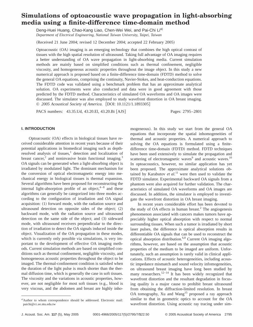
The background acoustic models adopted in all breimaging simulations were constructed according to expmental results for human breast.20,21As shown in Figs. 1~a!and~b!, the cross-sectional model consists of a zone of gldular parenchyma surrounded by subcutaneous fat.sound speed in the parenchyma and the fat were set asand 1459 m/s, respectively. The breast model had a radiu5 cm. The averaged radius of the parenchyma is 4 cm andthickness was varied in such a way that the arrival time fltuations profile for an acoustic wavefront after propagatthrough the parenchyma wall has a root-mean-square vof 66.8 ns and a correlation length of 4.3 mm, which wbased on thein vitro measurements obtained by Hinklemet al.21 Figure 1~a! illustrates one such acoustic speed modAcoustic scattering was also incorporated in our modeladding a normally distributed, zero-mean random componwith a root-mean-square value of 0.1 g/cm3 to the densitymap in which the density of the parenchyma and the fat wset as 0.99 and 0.94 g/cm3, respectively. A typical densitymap is shown in Fig. 1~b!. The acoustic speed and avera
FIG. 1. Background tissue maps for the breast model.~a! Acoustic speedmap. ~b! Density map. Glandular parenchyma is enclosed by the irregwall, subcutaneous fat is bounded by the irregular wall and the circular wOutside the circular wall is the surrounding medium used to coupleultrasound receiver to the subcutaneous fat.
J. Acoust. Soc. Am., Vol. 117, No. 5, May 2005
c-d
sti-
-he23ofhe-gues
l.ynt
re
density in the surrounding medium shown in Fig. 1 weresame as those in subcutaneous fat. The configuration usthis study also had a simulated tumor inside the bremodel. It had a disk with a radius of 1 mm placed atcenter. The absorption coefficient of the disk was set tothree times that of surrounding tissues. The sound speedside the disk was 1550 m/s and the density was 1.12 g/c3.Simulations without heterogeneities were also performedremoving the subcutaneous fat and extending the pachyma outside the tumors to all simulated domains.
In OA simulations, uniform irradiation was assumewith an intensity of 10 mJ/cm2. The laser pulse is temporallGaussian with a full duration at 1/e level of 10 ns. Poultrasound detectors were placed around the breast modan interval of 0.25°~i.e., totally 1440 points!, while the ra-dius of detection is 6 cm. Received OA signals were obtainby summing the OA waveforms received at six consecutpoints ~i.e., totally 240 received OA signals!. In pulse-echoultrasound simulations, a linear array with a focus atbreast center was placed 1 cm above the breast wall toused both as a transmitter and as a receiver. A Gaussian pwith a central frequency of 1.5 MHz and a 6-dB bandwidof 1.5 MHz was employed as the transmitted waveform. Tfrequency range, which was lower than usually used in breultrasonography but was common in breast OA imaging, wchosen to form a fair basis for the comparison betweenOA wavefront and the pulse-echo wavefront. The linearray consists of 1440 points spaced at an interval of 0.043(span56.2 cm). Also acoustic signals coming from six cosecutive points were summed together to form 240 receiacoustic waveforms.
III. RESULTS
The FDTD code was validated using a benchmark prlem that has an analytical solution as proposed by Karabuet al.11 The problem involves calculating the backward Osignal for a single-layer object with a uniform lighabsorption profile and acoustic properties, irradiated by aser pulse that is Gaussian in both space and time:
ptr~q5t/tL ,z,r'50!5C•$A exp~2Aq1A2/4!@1
1erf~q2A/2!#2D exp~2Dq1D2/4!@1
1erf~q2D/2!#%, ~19!
whereC is a scaling factor,A5mac0tL , D52zctrtL /a02, ma
is the light-absorption coefficient,z is the normal distancebetween the acoustic receiver and the irradiated surfacec0
and ctr are the speed of sound in the light-absorbing atransparent media, respectively, andtL and a0 are the timeand radius~i.e., in the time and space domains, respective!for the laser pulse intensity to reduce to 1/e of its originallevel. Figure 2 shows the results for two different lighabsorption coefficients with 2tL59 ns andD550. A gridspacing (Dx) of 30 mm was adopted in our FDTD code, anthe grid was 10003500. A speed of sound of 1523 m/s wachosen for both media. The time stepDt was set to 5 ns inorder to meet the Courant stability condition,22 which re-quires thatc0Dt/Dx should be about 0.25 to obtain the e
rll.e
2797Huang et al.: Simulating optoacoustic wave propagation
wgalnibhe
ckmg-
ity
z
aala
d
honeandb-
inedebe-at-e-
ng-r
t re-ig.thet a
ctor
nt
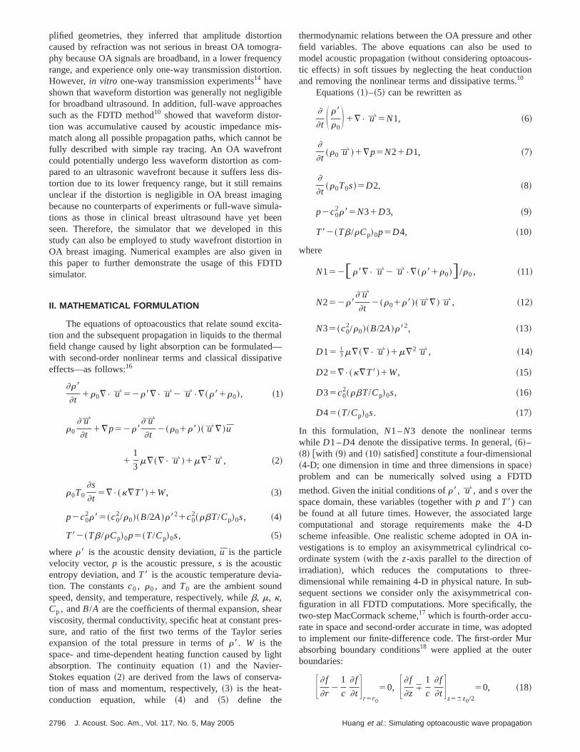
pected accuracy. Figure 2~a! shows the results forma
5160 cm21. The solid curve refers to the OA waveformgenerated by the FDTD method, while the dashed curveobtained using~19!. Figure 2~b! shows the correspondinresults forma5600 cm21. It can be seen that our numericresults were in excellent agreement with those from the alytical solutions; the small discrepancies were mainly attrutable to the errors of the paraxial approximation used wderiving ~19!.23
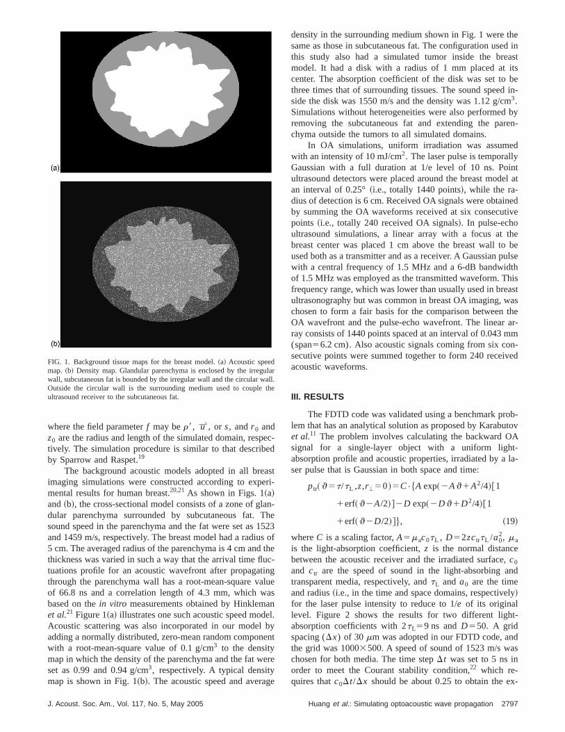
Experimental validation was also performed using baward OA signals induced in a light-absorbing phantom coprising gelatin mixed with commercially available black piments ~OSAMA 42, SIMBALION, ROC!. Pulses from aNd:YAG laser ~LS-2132U, LOTIS TII, Belarus! ~10 ns at532 nm! provided irradiation with an incident energy densof 34 mJ/cm2. A broadband hydrophone~GL-200, ONDA,USA! with 23-dB cutoff frequencies of 0.2 and 20 MHand high sensitivity~28 nV/Pa! was used to record the OAsignals at 1 cm from the irradiated surface. Water wadopted as an optically transparent medium acousticcoupled to the OA phantom. The absorption coefficient wobtained by fitting~19! ~i.e., the analytical solution propose
FIG. 2. Backward OA signals computed by the FDTD method~solid line!and using~19! ~dashed line!: ~a! absorption coefficient5160 cm21 and ~b!absorption coefficient5600 cm21.
2798 J. Acoust. Soc. Am., Vol. 117, No. 5, May 2005
as
a--n
--
slys
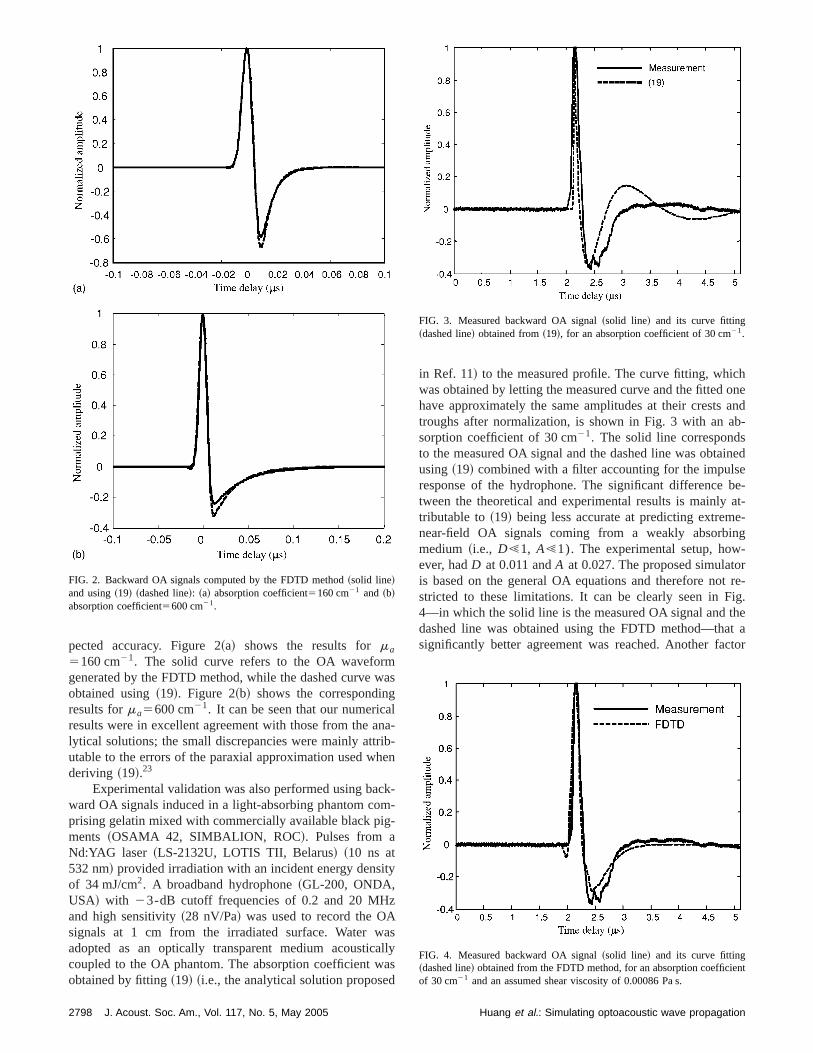
in Ref. 11! to the measured profile. The curve fitting, whicwas obtained by letting the measured curve and the fittedhave approximately the same amplitudes at their creststroughs after normalization, is shown in Fig. 3 with an asorption coefficient of 30 cm21. The solid line correspondsto the measured OA signal and the dashed line was obtausing~19! combined with a filter accounting for the impulsresponse of the hydrophone. The significant differencetween the theoretical and experimental results is mainlytributable to~19! being less accurate at predicting extremnear-field OA signals coming from a weakly absorbimedium ~i.e., D!1, A!1). The experimental setup, however, hadD at 0.011 andA at 0.027. The proposed simulatois based on the general OA equations and therefore nostricted to these limitations. It can be clearly seen in F4—in which the solid line is the measured OA signal anddashed line was obtained using the FDTD method—thasignificantly better agreement was reached. Another fa
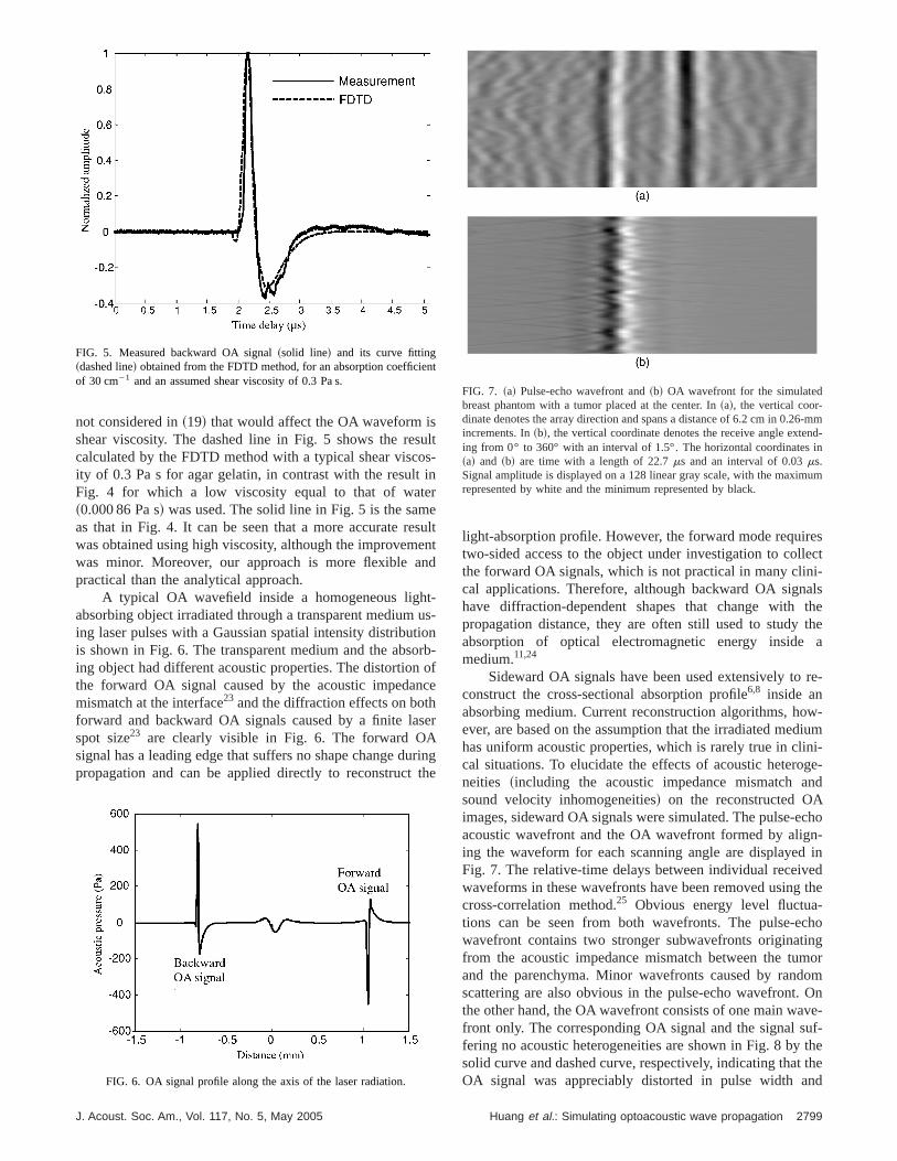
FIG. 3. Measured backward OA signal~solid line! and its curve fitting~dashed line! obtained from~19!, for an absorption coefficient of 30 cm21.
FIG. 4. Measured backward OA signal~solid line! and its curve fitting~dashed line! obtained from the FDTD method, for an absorption coefficieof 30 cm21 and an assumed shear viscosity of 0.00086 Pa s.
Huang et al.: Simulating optoacoustic wave propagation
suosinresen
t-u
tiooro
nchse
urth
eslecti-alsthethea
re-
w-ium
ni-ge-nd
chon-in
edthe
-choingmoromOnve-uf-thethe
nd
n
-mmnd-in
um
not considered in~19! that would affect the OA waveform isshear viscosity. The dashed line in Fig. 5 shows the recalculated by the FDTD method with a typical shear viscity of 0.3 Pa s for agar gelatin, in contrast with the resultFig. 4 for which a low viscosity equal to that of wate~0.000 86 Pa s! was used. The solid line in Fig. 5 is the samas that in Fig. 4. It can be seen that a more accurate rewas obtained using high viscosity, although the improvemwas minor. Moreover, our approach is more flexible apractical than the analytical approach.
A typical OA wavefield inside a homogeneous lighabsorbing object irradiated through a transparent mediuming laser pulses with a Gaussian spatial intensity distribuis shown in Fig. 6. The transparent medium and the absing object had different acoustic properties. The distortionthe forward OA signal caused by the acoustic impedamismatch at the interface23 and the diffraction effects on botforward and backward OA signals caused by a finite laspot size23 are clearly visible in Fig. 6. The forward OAsignal has a leading edge that suffers no shape change dpropagation and can be applied directly to reconstruct
FIG. 5. Measured backward OA signal~solid line! and its curve fitting~dashed line! obtained from the FDTD method, for an absorption coefficieof 30 cm21 and an assumed shear viscosity of 0.3 Pa s.
FIG. 6. OA signal profile along the axis of the laser radiation.
J. Acoust. Soc. Am., Vol. 117, No. 5, May 2005
lt-
ultntd
s-nb-fe
r
inge
light-absorption profile. However, the forward mode requirtwo-sided access to the object under investigation to colthe forward OA signals, which is not practical in many clincal applications. Therefore, although backward OA signhave diffraction-dependent shapes that change withpropagation distance, they are often still used to studyabsorption of optical electromagnetic energy insidemedium.11,24
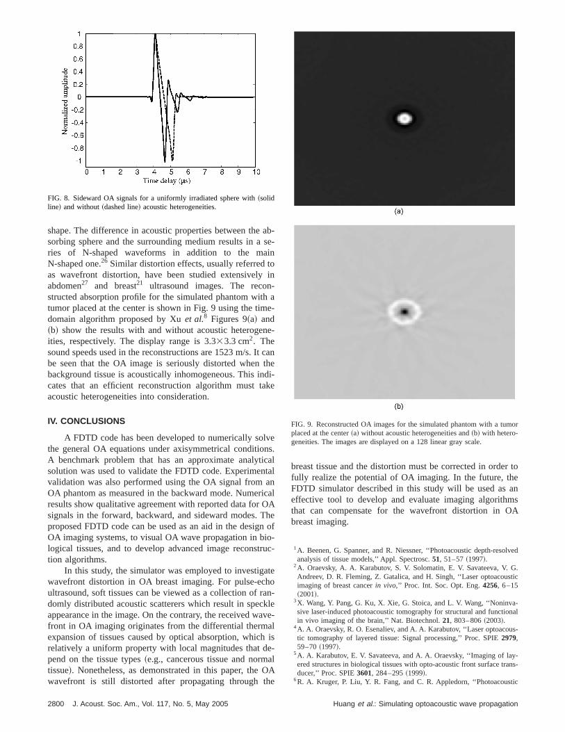
Sideward OA signals have been used extensively toconstruct the cross-sectional absorption profile6,8 inside anabsorbing medium. Current reconstruction algorithms, hoever, are based on the assumption that the irradiated medhas uniform acoustic properties, which is rarely true in clical situations. To elucidate the effects of acoustic heteroneities ~including the acoustic impedance mismatch asound velocity inhomogeneities! on the reconstructed OAimages, sideward OA signals were simulated. The pulse-eacoustic wavefront and the OA wavefront formed by aliging the waveform for each scanning angle are displayedFig. 7. The relative-time delays between individual receivwaveforms in these wavefronts have been removed usingcross-correlation method.25 Obvious energy level fluctuations can be seen from both wavefronts. The pulse-ewavefront contains two stronger subwavefronts originatfrom the acoustic impedance mismatch between the tuand the parenchyma. Minor wavefronts caused by randscattering are also obvious in the pulse-echo wavefront.the other hand, the OA wavefront consists of one main wafront only. The corresponding OA signal and the signal sfering no acoustic heterogeneities are shown in Fig. 8 bysolid curve and dashed curve, respectively, indicating thatOA signal was appreciably distorted in pulse width a
t
FIG. 7. ~a! Pulse-echo wavefront and~b! OA wavefront for the simulatedbreast phantom with a tumor placed at the center. In~a!, the vertical coor-dinate denotes the array direction and spans a distance of 6.2 cm in 0.26increments. In~b!, the vertical coordinate denotes the receive angle exteing from 0° to 360° with an interval of 1.5°. The horizontal coordinates~a! and ~b! are time with a length of 22.7ms and an interval of 0.03ms.Signal amplitude is displayed on a 128 linear gray scale, with the maximrepresented by white and the minimum represented by black.
2799Huang et al.: Simulating optoacoustic wave propagation
asino
-h
e
ne
t cth
ndak
lvnictaricOThniotru
athorakavalheaO
he
r toeanms
A
lved
G.tic
-onal
us-
y-ans-
tic
mor
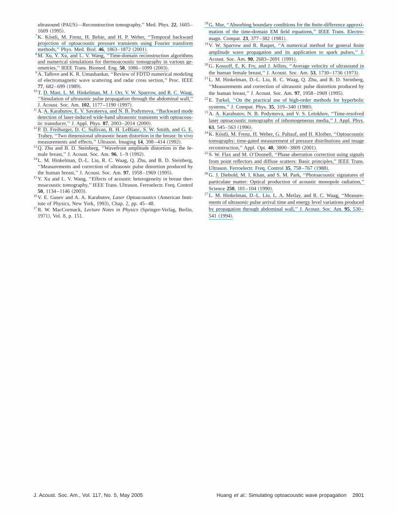
shape. The difference in acoustic properties between thesorbing sphere and the surrounding medium results in aries of N-shaped waveforms in addition to the maN-shaped one.26 Similar distortion effects, usually referred tas wavefront distortion, have been studied extensivelyabdomen27 and breast21 ultrasound images. The reconstructed absorption profile for the simulated phantom wittumor placed at the center is shown in Fig. 9 using the timdomain algorithm proposed by Xuet al.8 Figures 9~a! and~b! show the results with and without acoustic heterogeities, respectively. The display range is 3.333.3 cm2. Thesound speeds used in the reconstructions are 1523 m/s. Ibe seen that the OA image is seriously distorted whenbackground tissue is acoustically inhomogeneous. This icates that an efficient reconstruction algorithm must tacoustic heterogeneities into consideration.
IV. CONCLUSIONS
A FDTD code has been developed to numerically sothe general OA equations under axisymmetrical conditioA benchmark problem that has an approximate analytsolution was used to validate the FDTD code. Experimenvalidation was also performed using the OA signal fromOA phantom as measured in the backward mode. Numeresults show qualitative agreement with reported data forsignals in the forward, backward, and sideward modes.proposed FDTD code can be used as an aid in the desigOA imaging systems, to visual OA wave propagation in blogical tissues, and to develop advanced image reconstion algorithms.
In this study, the simulator was employed to investigwavefront distortion in OA breast imaging. For pulse-ecultrasound, soft tissues can be viewed as a collection ofdomly distributed acoustic scatterers which result in specappearance in the image. On the contrary, the received wfront in OA imaging originates from the differential thermexpansion of tissues caused by optical absorption, whicrelatively a uniform property with local magnitudes that dpend on the tissue types~e.g., cancerous tissue and normtissue!. Nonetheless, as demonstrated in this paper, thewavefront is still distorted after propagating through t
FIG. 8. Sideward OA signals for a uniformly irradiated sphere with~solidline! and without~dashed line! acoustic heterogeneities.
2800 J. Acoust. Soc. Am., Vol. 117, No. 5, May 2005
b-e-
in
a-
-
anei-e
es.alalnalAeof
-c-
e
n-lee-
is-lA
breast tissue and the distortion must be corrected in ordefully realize the potential of OA imaging. In the future, thFDTD simulator described in this study will be used aseffective tool to develop and evaluate imaging algoriththat can compensate for the wavefront distortion in Obreast imaging.
1A. Beenen, G. Spanner, and R. Niessner, ‘‘Photoacoustic depth-resoanalysis of tissue models,’’ Appl. Spectrosc.51, 51–57~1997!.
2A. Oraevsky, A. A. Karabutov, S. V. Solomatin, E. V. Savateeva, V.Andreev, D. R. Fleming, Z. Gatalica, and H. Singh, ‘‘Laser optoacousimaging of breast cancerin vivo,’’ Proc. Int. Soc. Opt. Eng.4256, 6–15~2001!.
3X. Wang, Y. Pang, G. Ku, X. Xie, G. Stoica, and L. V. Wang, ‘‘Noninvasive laser-induced photoacoustic tomography for structural and functiin vivo imaging of the brain,’’ Nat. Biotechnol.21, 803–806~2003!.
4A. A. Oraevsky, R. O. Esenaliev, and A. A. Karabutov, ‘‘Laser optoacotic tomography of layered tissue: Signal processing,’’ Proc. SPIE2979,59–70~1997!.
5A. A. Karabutov, E. V. Savateeva, and A. A. Oraevsky, ‘‘Imaging of laered structures in biological tissues with opto-acoustic front surface trducer,’’ Proc. SPIE3601, 284–295~1999!.
6R. A. Kruger, P. Liu, Y. R. Fang, and C. R. Appledorn, ‘‘Photoacous
FIG. 9. Reconstructed OA images for the simulated phantom with a tuplaced at the center~a! without acoustic heterogeneities and~b! with hetero-geneities. The images are displayed on a 128 linear gray scale.
Huang et al.: Simulating optoacoustic wave propagation
rdfor
sg
ngEE
g,ll,’
dou
Eivo
fe-
g,b
ertro
i-o-
ite’ J.
in
g,by
lic
dhys.
ticage
alsns.
ofn,’’
-ced
ultrasound~PAUS!—Reconstruction tomography,’’ Med. Phys.22, 1605–1609 ~1995!.
7K. Kostli, M. Frenz, H. Bebie, and H. P. Weber, ‘‘Temporal backwaprojection of optoacoustic pressure transients using Fourier transmethods,’’ Phys. Med. Biol.46, 1863–1872~2001!.
8M. Xu, Y. Xu, and L. V. Wang, ‘‘Time-domain reconstruction algorithmand numerical simulations for thermoacoustic tomography in variousometries,’’ IEEE Trans. Biomed. Eng.50, 1086–1099~2003!.
9A. Taflove and K. R. Umashankar, ‘‘Review of FDTD numerical modeliof electromagnetic wave scattering and radar cross section,’’ Proc. I77, 682–699~1989!.
10T. D. Mast, L. M. Hinkelman, M. J. Orr, V. W. Sparrow, and R. C. Waa‘‘Simulation of ultrasonic pulse propagation through the abdominal waJ. Acoust. Soc. Am.102, 1177–1190~1997!.
11A. A. Karabutov, E. V. Savateeva, and N. B. Podymova, ‘‘Backward modetection of laser-induced wide-band ultrasonic transients with optoactic transducer,’’ J. Appl. Phys.87, 2003–2014~2000!.
12P. D. Freiburger, D. C. Sullivan, B. H. LeBlanc, S. W. Smith, and G.Trahey, ‘‘Two dimensional ultrasonic beam distortion in the breast: In vmeasurements and effects,’’ Ultrason. Imaging14, 398–414~1992!.
13Q. Zhu and B. D. Steinberg, ‘‘Wavefront amplitude distortion in themale breast,’’ J. Acoust. Soc. Am.96, 1–9 ~1992!.
14L. M. Hinkelman, D.-L. Liu, R. C. Waag, Q. Zhu, and B. D. Steinber‘‘Measurements and correction of ultrasonic pulse distortion producedthe human breast,’’ J. Acoust. Soc. Am.97, 1958–1969~1995!.
15Y. Xu and L. V. Wang, ‘‘Effects of acoustic heterogeneity in breast thmoacoustic tomography,’’ IEEE Trans. Ultrason. Ferroelectr. Freq. Con50, 1134–1146~2003!.
16V. E. Gusev and A. A. Karabutov,Laser Optoacoustics~American Insti-tute of Physics, New York, 1993!, Chap. 2, pp. 45–48.
17R. W. MacCormack,Lecture Notes in Physics~Springer-Verlag, Berlin,1971!, Vol. 8, p. 151.
J. Acoust. Soc. Am., Vol. 117, No. 5, May 2005
m
e-
E
’
es-
.
y
-l
18G. Mur, ‘‘Absorbing boundary conditions for the finite-difference approxmation of the time-domain EM field equations,’’ IEEE Trans. Electrmagn. Compat.23, 377–382~1981!.
19V. W. Sparrow and R. Raspet, ‘‘A numerical method for general finamplitude wave propagation and its application to spark pulses,’Acoust. Soc. Am.90, 2683–2691~1991!.
20G. Kossoff, E. K. Fry, and J. Jellins, ‘‘Average velocity of ultrasoundthe human female breast,’’ J. Acoust. Soc. Am.53, 1730–1736~1973!.
21L. M. Hinkelman, D.-L. Liu, R. C. Waag, Q. Zhu, and B. D. Steinber‘‘Measurements and correction of ultrasonic pulse distortion producedthe human breast,’’ J. Acoust. Soc. Am.97, 1958–1969~1995!.
22E. Turkel, ‘‘On the practical use of high-order methods for hyperbosystems,’’ J. Comput. Phys.35, 319–340~1980!.
23A. A. Karabutov, N. B. Podymova, and V. S. Letokhov, ‘‘Time-resolvelaser optoacoustic tomography of inhomogeneous media,’’ J. Appl. P63, 545–563~1996!.
24K. Kostli, M. Frenz, H. Weber, G. Paltauf, and H. Kloiber, ‘‘Optoacoustomography: time-gated measurement of pressure distributions and imreconstruction,’’ Appl. Opt.40, 3800–3809~2001!.
25S. W. Flax and M. O’Donnell, ‘‘Phase aberration correction using signfrom point reflectors and diffuse scatters: Basic principles,’’ IEEE TraUltrason. Ferroelectr. Freq. Control35, 758–767~1988!.
26G. J. Diebold, M. I. Khan, and S. M. Park, ‘‘Photoacoustic signaturesparticulate matter: Optical production of acoustic monopole radiatioScience250, 101–104~1990!.
27L. M. Hinkelman, D.-L. Liu, L. A. Metlay, and R. C. Waag, ‘‘Measurements of ultrasonic pulse arrival time and energy level variations produby propagation through abdominal wall,’’ J. Acoust. Soc. Am.95, 530–541 ~1994!.
2801Huang et al.: Simulating optoacoustic wave propagation