Simulation of shot dynamics for ultrasonic shot peening: Effects of process parameters
12
Simulation of shot dynamics for ultrasonic shot peening: Effects of process parameters Jawad Badreddine a , Emmanuelle Rouhaud a,n , Matthieu Micoulaut b , Sebastien Remy a a ICD – LASMIS Université de Technologie de Troyes (UTT), 12 Rue Marie Curie, 10010 Troyes, France b LPTMC, Tour 23-13, Boite Courrier 121, UPMC, 4 Place Jussieu, 75005 Paris, France article info Article history: Received 30 July 2013 Received in revised form 31 January 2014 Accepted 5 March 2014 Keywords: Ultrasonic shot peening Shot dynamics Impact density Impact velocity Impact angle abstract Ultrasonic shot peening is a pre-stressing process that enhances the life span of mechanical parts. The spheres constituting the shot are set in motion with a sonotrode and impact the treated part to generate a compressive residual stress field, hence increasing fatigue life. A model predicting the dynamics of the shot within the ultrasonic shot peening chamber is proposed. The influence of the initial conditions on the shot dynamics is first studied. The model is then used to obtain predictive values for the impact density and the spatial distribution of the velocity of the spheres before the impacts. The influence of the ultrasonic shot peening parameters is also evaluated. The variation of the geometry of the shot peening chamber is further considered with the use of a prismatic geometry. & 2014 Elsevier Ltd. All rights reserved. 1. Introduction Ultrasonic shot peening (USP) is a pre-stressing surface treatment process used to enhance the mechanical strength and life span of high-added value components, such as bladed disks, compressors, gears, and pressure vessels of nuclear power plants. The component to be treated and spherical spheres (the shot) are placed within a treatment chamber. The shot is propelled using a sonotrode that is part of an acoustic system that vibrates at ultrasonic frequencies. The multiple impacts of the spheres induce compressive residual stresses in the material and enhance the surface characteristics and fracture resistance of the mechanical components. The compressive residual stresses after the process has been evaluated and discussed [1,2]. It has been demonstrated to drastically increase the resistance and fatigue life of mechanical parts (see for example [3]). In certain conditions, the ultrasonic shot peening process can also generate nanostructures, which confers greater mechanical properties and fatigue life span [4–9]. Many models have been proposed for the prediction of the residual stress field induced by the process [2,10–16]. These models need to specify the shot dynamics as an input. It is often considered that ultrasonic shot peening produces random shot trajectories during the peening process. The impact density and the compressive residual stresses are supposed to be homogeneous. This implies, in the first place, that the density and velocity of the impacts is homogeneously distributed. The final characteristics of the treated part depend on the process parameters, as well as the position and orientation of the peened part with respect to the sonotrode. However, very little is known about the actual shot dynamics (impact density, impact angles and impact velocities) during an ultrasonic shot peening treatment. In an industrial context, customized peening chambers are usually designed for each type of components. The parts that are shot peened with an ultrasonic process are usually high added value components, like parts of plane engines, with very complex geometries. The measurements of shot velocities are difficult, although it is necessary that it should be well distributed to ensure an adequate residual stress field. The peening chambers are thus designed with trial and error processes to verify the impact density with, for example a coverage analysis. It is thus of interest to construct a predictive model of the shot dynamics for ultrasonic shot peening in any chamber geometry to predict the impact velocities and impact angles, as well as the spatial impact distribution on the surface of the treated part. These parameters are themselves function of the process parameters. The process parameters correspond to the geometry and material properties of the chamber, the characteristics of the shot (diameter, material) and the vibration frequency and amplitude of the sonotrode. We here propose a model for the shot dynamics, which enables to go inside the peening chamber and track the shot motion during the peening process. The objective of the model is even- tually to facilitate the design of shot peening chambers. This model is detailed in the first section of this paper. The model is declined in two versions. One that is geometrically simple enabling a quantitative study of the influence of the parameters on the Contents lists available at ScienceDirect journal homepage: www.elsevier.com/locate/ijmecsci International Journal of Mechanical Sciences http://dx.doi.org/10.1016/j.ijmecsci.2014.03.006 0020-7403/& 2014 Elsevier Ltd. All rights reserved. n Corresponding author. Tel.: þ33 3 25 71 56 56; fax: þ33 3 25 71 80 61. E-mail address: [email protected] (E. Rouhaud). Please cite this article as: Badreddine J, et al. Simulation of shot dynamics for ultrasonic shot peening: Effects of process parameters. Int. J. Mech. Sci. (2014), http://dx.doi.org/10.1016/j.ijmecsci.2014.03.006i International Journal of Mechanical Sciences ∎ (∎∎∎∎) ∎∎∎–∎∎∎
Transcript of Simulation of shot dynamics for ultrasonic shot peening: Effects of process parameters

Simulation of shot dynamics for ultrasonic shot peening:Effects of process parameters
Jawad Badreddine a, Emmanuelle Rouhaud a,n, Matthieu Micoulaut b, Sebastien Remy a
a ICD – LASMIS Université de Technologie de Troyes (UTT), 12 Rue Marie Curie, 10010 Troyes, Franceb LPTMC, Tour 23-13, Boite Courrier 121, UPMC, 4 Place Jussieu, 75005 Paris, France
a r t i c l e i n f o
Article history:Received 30 July 2013Received in revised form31 January 2014Accepted 5 March 2014
Keywords:Ultrasonic shot peeningShot dynamicsImpact densityImpact velocityImpact angle
a b s t r a c t
Ultrasonic shot peening is a pre-stressing process that enhances the life span of mechanical parts.The spheres constituting the shot are set in motion with a sonotrode and impact the treated part togenerate a compressive residual stress field, hence increasing fatigue life. A model predicting the dynamicsof the shot within the ultrasonic shot peening chamber is proposed. The influence of the initial conditionson the shot dynamics is first studied. The model is then used to obtain predictive values for the impactdensity and the spatial distribution of the velocity of the spheres before the impacts. The influence of theultrasonic shot peening parameters is also evaluated. The variation of the geometry of the shot peeningchamber is further considered with the use of a prismatic geometry.
& 2014 Elsevier Ltd. All rights reserved.
1. Introduction
Ultrasonic shot peening (USP) is a pre-stressing surface treatmentprocess used to enhance the mechanical strength and life span ofhigh-added value components, such as bladed disks, compressors,gears, and pressure vessels of nuclear power plants. The componentto be treated and spherical spheres (the shot) are placed within atreatment chamber. The shot is propelled using a sonotrode that ispart of an acoustic system that vibrates at ultrasonic frequencies. Themultiple impacts of the spheres induce compressive residual stressesin the material and enhance the surface characteristics and fractureresistance of the mechanical components. The compressive residualstresses after the process has been evaluated and discussed [1,2]. It hasbeen demonstrated to drastically increase the resistance and fatiguelife of mechanical parts (see for example [3]). In certain conditions, theultrasonic shot peening process can also generate nanostructures,which confers greater mechanical properties and fatigue life span[4–9].
Many models have been proposed for the prediction of theresidual stress field induced by the process [2,10–16]. These modelsneed to specify the shot dynamics as an input. It is often consideredthat ultrasonic shot peening produces random shot trajectoriesduring the peening process. The impact density and the compressiveresidual stresses are supposed to be homogeneous. This implies, inthe first place, that the density and velocity of the impacts is
homogeneously distributed. The final characteristics of the treatedpart depend on the process parameters, as well as the position andorientation of the peened part with respect to the sonotrode.However, very little is known about the actual shot dynamics (impactdensity, impact angles and impact velocities) during an ultrasonicshot peening treatment. In an industrial context, customized peeningchambers are usually designed for each type of components.The parts that are shot peened with an ultrasonic process are usuallyhigh added value components, like parts of plane engines, withvery complex geometries. The measurements of shot velocities aredifficult, although it is necessary that it should be well distributed toensure an adequate residual stress field. The peening chambers arethus designed with trial and error processes to verify the impactdensity with, for example a coverage analysis. It is thus of interest toconstruct a predictive model of the shot dynamics for ultrasonic shotpeening in any chamber geometry to predict the impact velocitiesand impact angles, as well as the spatial impact distribution on thesurface of the treated part. These parameters are themselves functionof the process parameters. The process parameters correspond to thegeometry and material properties of the chamber, the characteristicsof the shot (diameter, material) and the vibration frequency andamplitude of the sonotrode.
We here propose a model for the shot dynamics, which enablesto go inside the peening chamber and track the shot motionduring the peening process. The objective of the model is even-tually to facilitate the design of shot peening chambers. This modelis detailed in the first section of this paper. The model is declinedin two versions. One that is geometrically simple enabling aquantitative study of the influence of the parameters on the
Contents lists available at ScienceDirect
journal homepage: www.elsevier.com/locate/ijmecsci
International Journal of Mechanical Sciences
http://dx.doi.org/10.1016/j.ijmecsci.2014.03.0060020-7403/& 2014 Elsevier Ltd. All rights reserved.
n Corresponding author. Tel.: þ33 3 25 71 56 56; fax: þ33 3 25 71 80 61.E-mail address: [email protected] (E. Rouhaud).
Please cite this article as: Badreddine J, et al. Simulation of shot dynamics for ultrasonic shot peening: Effects of process parameters. Int.J. Mech. Sci. (2014), http://dx.doi.org/10.1016/j.ijmecsci.2014.03.006i
International Journal of Mechanical Sciences ∎ (∎∎∎∎) ∎∎∎–∎∎∎
results. The characteristics of the fields as seen by the mechanicalpart (impact density, velocity and angle of the impacts fields…) asa function of the process parameters are presented. Then, anotherversion of the model corresponding to an industrially realistic casestudy is presented and experimentally validated.
2. A model for the shot dynamics
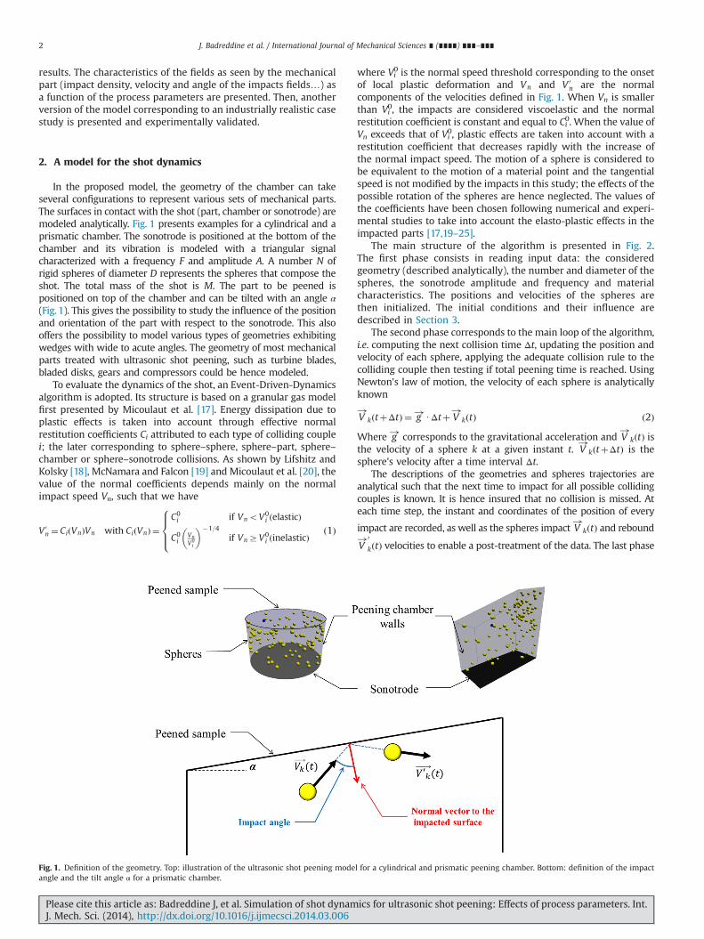
In the proposed model, the geometry of the chamber can takeseveral configurations to represent various sets of mechanical parts.The surfaces in contact with the shot (part, chamber or sonotrode) aremodeled analytically. Fig. 1 presents examples for a cylindrical and aprismatic chamber. The sonotrode is positioned at the bottom of thechamber and its vibration is modeled with a triangular signalcharacterized with a frequency F and amplitude A. A number N ofrigid spheres of diameter D represents the spheres that compose theshot. The total mass of the shot is M. The part to be peened ispositioned on top of the chamber and can be tilted with an angle α(Fig. 1). This gives the possibility to study the influence of the positionand orientation of the part with respect to the sonotrode. This alsooffers the possibility to model various types of geometries exhibitingwedges with wide to acute angles. The geometry of most mechanicalparts treated with ultrasonic shot peening, such as turbine blades,bladed disks, gears and compressors could be hence modeled.
To evaluate the dynamics of the shot, an Event-Driven-Dynamicsalgorithm is adopted. Its structure is based on a granular gas modelfirst presented by Micoulaut et al. [17]. Energy dissipation due toplastic effects is taken into account through effective normalrestitution coefficients Ci attributed to each type of colliding couplei; the later corresponding to sphere–sphere, sphere–part, sphere–chamber or sphere–sonotrode collisions. As shown by Lifshitz andKolsky [18], McNamara and Falcon [19] and Micoulaut et al. [20], thevalue of the normal coefficients depends mainly on the normalimpact speed Vn, such that we have
V 0n ¼ CiðVnÞVn with CiðVnÞ ¼
C0i if VnoV0
i ðelasticÞ
C0i
Vn
V0i
� ��1=4
if VnZV0i ðinelasticÞ
8>><>>:
ð1Þ
where Vi0 is the normal speed threshold corresponding to the onset
of local plastic deformation and Vn and V 0n are the normal
components of the velocities defined in Fig. 1. When Vn is smallerthan Vi
0, the impacts are considered viscoelastic and the normalrestitution coefficient is constant and equal to Ci
0. When the value ofVn exceeds that of Vi
0, plastic effects are taken into account with arestitution coefficient that decreases rapidly with the increase ofthe normal impact speed. The motion of a sphere is considered tobe equivalent to the motion of a material point and the tangentialspeed is not modified by the impacts in this study; the effects of thepossible rotation of the spheres are hence neglected. The values ofthe coefficients have been chosen following numerical and experi-mental studies to take into account the elasto-plastic effects in theimpacted parts [17,19–25].
The main structure of the algorithm is presented in Fig. 2.The first phase consists in reading input data: the consideredgeometry (described analytically), the number and diameter of thespheres, the sonotrode amplitude and frequency and materialcharacteristics. The positions and velocities of the spheres arethen initialized. The initial conditions and their influence aredescribed in Section 3.
The second phase corresponds to the main loop of the algorithm,i.e. computing the next collision time Δt, updating the position andvelocity of each sphere, applying the adequate collision rule to thecolliding couple then testing if total peening time is reached. UsingNewton's law of motion, the velocity of each sphere is analyticallyknown
V!
kðtþΔtÞ ¼ g!UΔtþ V!
kðtÞ ð2Þ
Where g! corresponds to the gravitational acceleration and V!
kðtÞ isthe velocity of a sphere k at a given instant t. V
!kðtþΔtÞ is the
sphere's velocity after a time interval Δt.The descriptions of the geometries and spheres trajectories are
analytical such that the next time to impact for all possible collidingcouples is known. It is hence insured that no collision is missed. Ateach time step, the instant and coordinates of the position of every
impact are recorded, as well as the spheres impact V!
kðtÞ and rebound
V!0
kðtÞ velocities to enable a post-treatment of the data. The last phase
Fig. 1. Definition of the geometry. Top: illustration of the ultrasonic shot peening model for a cylindrical and prismatic peening chamber. Bottom: definition of the impactangle and the tilt angle α for a prismatic chamber.
J. Badreddine et al. / International Journal of Mechanical Sciences ∎ (∎∎∎∎) ∎∎∎–∎∎∎2
Please cite this article as: Badreddine J, et al. Simulation of shot dynamics for ultrasonic shot peening: Effects of process parameters. Int.J. Mech. Sci. (2014), http://dx.doi.org/10.1016/j.ijmecsci.2014.03.006i
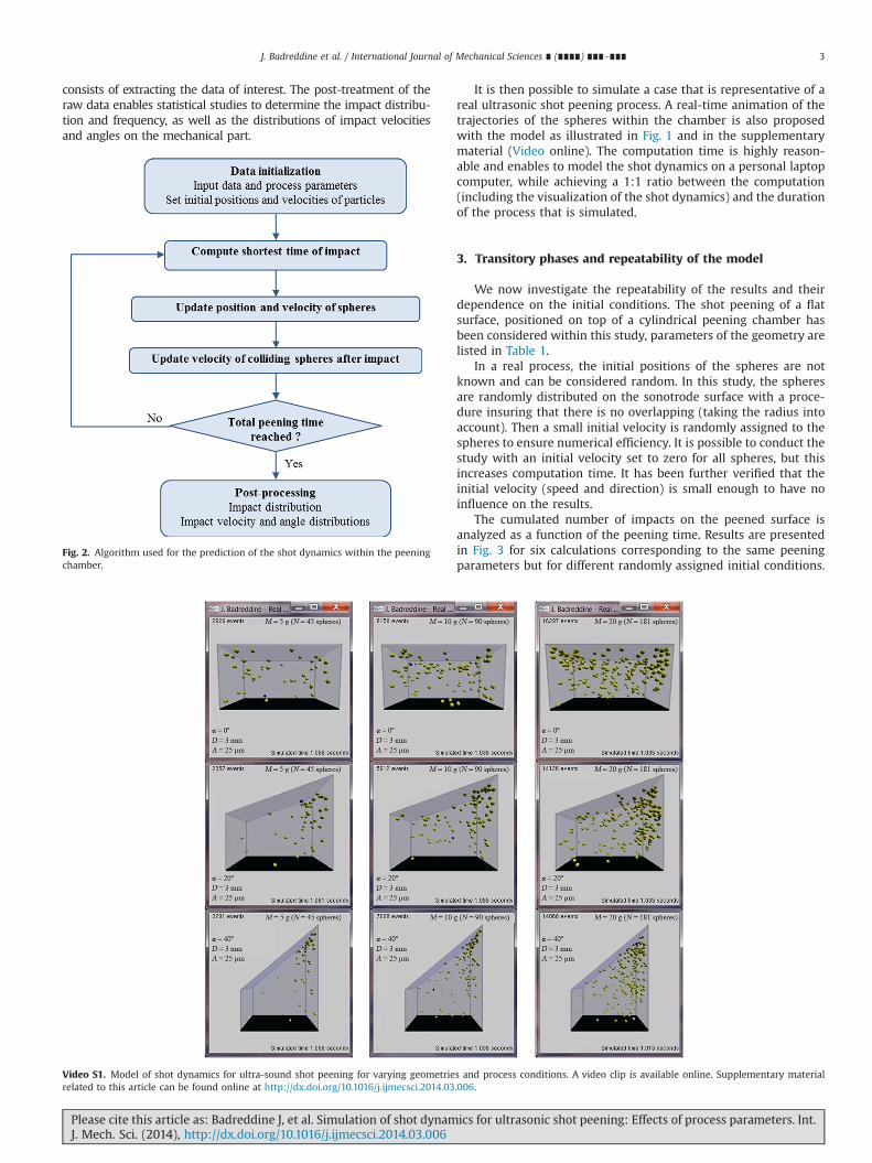
consists of extracting the data of interest. The post-treatment of theraw data enables statistical studies to determine the impact distribu-tion and frequency, as well as the distributions of impact velocitiesand angles on the mechanical part.
It is then possible to simulate a case that is representative of areal ultrasonic shot peening process. A real-time animation of thetrajectories of the spheres within the chamber is also proposedwith the model as illustrated in Fig. 1 and in the supplementarymaterial (Video online). The computation time is highly reason-able and enables to model the shot dynamics on a personal laptopcomputer, while achieving a 1:1 ratio between the computation(including the visualization of the shot dynamics) and the durationof the process that is simulated.
3. Transitory phases and repeatability of the model
We now investigate the repeatability of the results and theirdependence on the initial conditions. The shot peening of a flatsurface, positioned on top of a cylindrical peening chamber hasbeen considered within this study, parameters of the geometry arelisted in Table 1.
In a real process, the initial positions of the spheres are notknown and can be considered random. In this study, the spheresare randomly distributed on the sonotrode surface with a proce-dure insuring that there is no overlapping (taking the radius intoaccount). Then a small initial velocity is randomly assigned to thespheres to ensure numerical efficiency. It is possible to conduct thestudy with an initial velocity set to zero for all spheres, but thisincreases computation time. It has been further verified that theinitial velocity (speed and direction) is small enough to have noinfluence on the results.
The cumulated number of impacts on the peened surface isanalyzed as a function of the peening time. Results are presentedin Fig. 3 for six calculations corresponding to the same peeningparameters but for different randomly assigned initial conditions.
Fig. 2. Algorithm used for the prediction of the shot dynamics within the peeningchamber.
Video S1. Model of shot dynamics for ultra-sound shot peening for varying geometries and process conditions. A video clip is available online. Supplementary materialrelated to this article can be found online at http://dx.doi.org/10.1016/j.ijmecsci.2014.03.006.
J. Badreddine et al. / International Journal of Mechanical Sciences ∎ (∎∎∎∎) ∎∎∎–∎∎∎ 3
Please cite this article as: Badreddine J, et al. Simulation of shot dynamics for ultrasonic shot peening: Effects of process parameters. Int.J. Mech. Sci. (2014), http://dx.doi.org/10.1016/j.ijmecsci.2014.03.006i
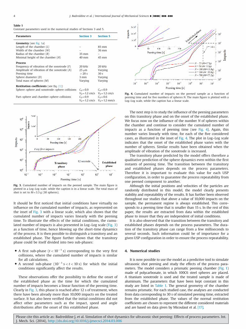
It should be first noticed that initial conditions have virtually noinfluence on the cumulated number of impacts, as represented onthe inset of Fig. 3 with a linear scale, which also shows that thecumulated number of impacts varies linearly with the peeningtime. To illustrate the effects of the initial conditions, the cumu-lated number of impacts is also presented in Log–Log scale (Fig. 3)as a function of time, hence blowing up the short-time dynamicsof the process. It is then possible to distinguish a transitory and anestablished phase. The figure further shows that the transitoryphase could be itself divided into two sub-phases:
� A first sub-phase (to10�1 s) corresponding to the very firstcollisions, where the cumulated number of impacts is similarfor all calculations.
� A second sub-phase (10�1 soto10 s) for which the initialconditions significantly affect the results.
These observations offer the possibility to define the onset ofthe established phase as the time for which the cumulatednumber of impacts becomes a linear function of the peening time.Clearly in Fig. 3, this phase is reached after 12 s of treatment, whenthere have been already more than 10,000 impacts on the treatedsurface. It has also been verified that the initial conditions did notaffect other parameters such as the impact, speed and angledistributions after the onset of this established phase.
The next step is to study the influence of the peening parameterson this transitory phase and on the onset of the established phase.We focus now on the influence of the number N of spheres withinthe chamber and continue to consider the cumulated number ofimpacts as a function of peening time (see Fig. 4). Again, thisnumber varies linearly with time, for each of the five consideredcases, as illustrated in the inset of Fig. 4. The plot in Log–Log scaleindicates that the onset of the established phase varies with thenumber of spheres. Similar results have been obtained when theamplitude of vibration of the sonotrode is increased.
The transitory phase predicted by the model offers therefore aqualitative prediction of the sphere dynamics even within the firstinstants of peening time. The transition between the transitoryand established phases depends on the process parameters.Therefore it is important to evaluate this value for each USPconfiguration, in order to guarantee the process repeatability fromone peened component to another.
Although the initial positions and velocities of the particles arerandomly distributed in this model, the model clearly presentsstability and repeatability of the results. It has further been observedthroughout our studies that above a value of 10,000 impacts on thesample, the permanent regime is always established. This corre-sponds to a peening time that is smaller than 15 s. In the rest of thispaper, the results are extracted from data within the establishedphase to insure that they are independent of initial conditions.
It is also observed that the transition between the transitory andestablished phases depends on the process parameters. The dura-tion of the transitory phase can range from a few milliseconds toseveral seconds. Such information could be of importance for agiven USP configuration in order to ensure the process repeatability.
4. Numerical studies
It is now possible to use the model as a predictive tool to simulateultrasonic shot peening and study the effects of the process para-meters. The model considers a prismatic peening chamber (Fig. 1)made of polycarbonate, in which 100C6 steel spheres are placed.A titanium sonotrode is used and the treated sample is made ofaluminum. The parameters that have been kept constant in thisstudy are listed in Table 1. The general geometry of the chamberremains prismatic. For each studied case, the analyses are conductedfrom data corresponding to 30 s of simulated peening time, extractedfrom the established phase. The values of the normal restitutioncoefficients are chosen to represent the different considered materialsand are based on data given by Micoulaut et al. [17].
Table 1Constant parameters used in the numerical studies of Sections 3 and 5.
Parameters Section 3 Section 5
Geometry (see Fig. 1a)Length of the chamber (L) – 85 mmWidth of the chamber (W) – 36 mmRadius of the chamber (R) 35 mm –
Minimal height of the chamber (H) 40 mm 45 mm
ProcessFrequency of vibration of the sonotrode (F) 20 kHz 20 kHzAmplitude of vibration of the sonotrode (A) 25 mm VaryingPeening time 420 s 30 sSphere diameter (D) 3 mm VaryingTotal mass of spheres (M) Varying Varying
Restitution coefficients (see Eq. (1))Sphere–sphere and sonotrode–sphere collisions C0¼0.9 C0¼0.9
V0¼1.2 cm/s V0¼1.2 cm/sPart–sphere and chamber–sphere collisions C0¼0.9 C0¼0.6
V0¼1.2 cm/s V0¼1.2 mm/s
Fig. 3. Cumulated number of impacts on the peened sample. The main figure isplotted in a Log–Log scale, while the caption is in a linear scale. The total mass ofshot is set to M¼3.3 g (30 spheres).
Fig. 4. Cumulated number of impacts on the peened sample as a function ofpeening time and for five numbers of spheres N. The main figure is plotted with aLog–Log scale, while the caption has a linear scale.
J. Badreddine et al. / International Journal of Mechanical Sciences ∎ (∎∎∎∎) ∎∎∎–∎∎∎4
Please cite this article as: Badreddine J, et al. Simulation of shot dynamics for ultrasonic shot peening: Effects of process parameters. Int.J. Mech. Sci. (2014), http://dx.doi.org/10.1016/j.ijmecsci.2014.03.006i

The process parameters whose effects are evaluated are thevibration amplitude A of the sonotrode (half the peak-to-peakvibration amplitude), the diameter of the spheres D, the total massM of shot within the chamber (corresponding to a number N ofspheres) and the tilt angle α of the peened surface. They have beenchosen to better qualify the process because they are of industrialinterest. The numerical values of these parameters have beenchosen among values that are classically encountered in an industrialcontext. Table 2 presents the values and symbols attributed to thesefour parameters.
The results of the simulation presented in the followingsections are the density and the distribution of the velocity ofthe impacts (speed and direction). These parameters are expectedto directly influence the compressive residual stresses obtained inthe treated part and possibly the surface microstructure.
5. Impact density
The coverage is of industrial interest and is used within thespecifications for quality control of the ultrasonic shot peeningprocess, as specified in the SAE Standard J2277 [26]. It corresponds
to the percentage of the exposed surface that has effectively beenimpacted. The model gives access to the impact density with thecoordinates of each impact making it possible to extract a distribu-tion. A global analysis of the results is presented in Fig. 5. It is theneventually possible to relate this value to the coverage itself, with arelation between the size of the impact dent and the velocity [27].The same result is presented in percentage in the table of Fig. 5.Clearly there is an important influence of the parameters and thechamber geometry on the total number of impacts, which seems todepend mostly on the total number of spheres present in thechamber. The sphere diameter has a noticeable effect. For allstudied cases, the impacts that took place on the chamber wallsand between spheres correspond around 60% of all collisions, evenexceeding 80% in some cases. Impacts on the sonotrode representthe lowest percentage of all impacts, and seem to increase when thenumber of spheres decreases. This could be explained by anincrease of sphere–sphere interactions within the chamber. As forimpacts on the non-tilted peened sample, the amplitude of vibra-tion seems to have little influence on their overall percentage.When the sample is tilted, the evolution of the percentage ofimpacts on its surface exhibits a complex behavior, with a notice-able smaller value for a tilt angle equal to 201.
To further analyze the data, the surface impact density ispresented for three tilt angles (Fig. 6). It is computed by dividingthe sample surface into 1.5�2 mm2 cells. The cumulated number ofimpacts on each cell is then divided by the area of the cell. Thesample covers entirely the top of the peening chamber: this explainsthe change in length when the tilt angle is modified. The surface ofthe sample that cannot be hit by the shot, due to the geometricalconfiguration, has not been taken into account in the analysis and isnot presented on the different figures below (this concerns inparticular the external part of the sample forming a corner withthe wall that cannot be hit due to the radius of the shot). Theillustrations, located on the right side of Fig. 6, represent a typical
Table 2Values of the studied process parameters and their attributed visualization option.
Vibration amplitude A(mm)
Sphere diameterD (mm)
Total mass ofspheres M (g)
Tilt angle of thepart α (deg.)
10 3 No symbol 5 — 0
25 4 10 20
50 5 20 40
Fig. 5. The number of impacts that took place on the sample (blue), on the sonotrode (red), on the chamber walls (green) and between spheres (violet), for a simulatedpeening period of 30 s for each studied case. (For interpretation of the references to color in this figure caption, the reader is referred to the web version of this paper.)
J. Badreddine et al. / International Journal of Mechanical Sciences ∎ (∎∎∎∎) ∎∎∎–∎∎∎ 5
Please cite this article as: Badreddine J, et al. Simulation of shot dynamics for ultrasonic shot peening: Effects of process parameters. Int.J. Mech. Sci. (2014), http://dx.doi.org/10.1016/j.ijmecsci.2014.03.006i

shot distribution within the chamber for each respective case.The density of impacts seems well distributed on average and theimpact density stays constant in the central region of the sample.There is clearly a concentration of impacts close to the edges of thechamber. When the sample is tilted, an increased concentration ofimpacts can be observed at the acute angle, formed by the sampleand the chamber walls. The spheres get trapped within this area, asillustrated by the shot distributions, and do not participate to thepeening of the sample. This is very distinguishable for the sampletilted with a 401 angle (see also the Video online) which actuallyincreases the homogeneity of the peening up to the very border.
The influence of the process parameters on the surface impactdensity is now detailed for the cases corresponding to non-tiltedsamples (Fig. 7). This density is evaluated within a 15 mm widesurface that is centered on the sample (the transparent gray zoneon Fig. 6). This area is divided into 1 mm cells to evaluate the localdensity. The surface impact density is then plotted as a function ofthe longitudinal direction (sample length). Fig. 7 presents theresults obtained for various combinations of the amplitude, thequantity and the diameter of the shot. Because there is animportant ratio between the density close to the edges and theone found in the middle of the sample, a logarithmic scale hasbeen used. It is confirmed that the impact density is much higherclose to the edges of the chamber, for all considered cases. Awayfrom this area (about 1.5 times the shot diameter) the impactdensity falls to a more or less constant level, even though a smalldecrease is observed toward the center of the sample. It appearsthat the main factor that influences the impact density is thediameter of the spheres, followed by the total mass (or number) ofspheres. As for the sonotrode amplitude, although it is the leastinfluential parameter, its effect is not negligible.
To conclude this section, angles within the geometry can lead toimportant heterogeneities in impact densities with an increase ofimpacts in the vicinity of an acute angle. Acute angles influence theshot dynamics and spatial distribution within the chamber by“trapping” some of the spheres. This leads to the emergence of a“dead shot mass”, i.e. a quantity of spheres that is no longer activelypeening the sample. However, regions of the sample that are farfrom edges exhibit homogeneous impact densities; the latter beinghighly sensitive to the spheres diameter and total mass.
Fig. 6. Spatial impact density on the peened sample, obtained with three tilt angles α¼{01;201;401}. The constant process parameters are the total mass of spheres M¼20 g,spheres diameter D¼3 mm and sonotrode amplitude A¼25 mm. The typical shot distribution within the chamber is displayed next to each impact distribution.
Fig. 7. Impact density on the sample surface along the length of the peenedsample, obtained for different combinations of the diameter D, total mass ofspheres M and sonotrode amplitude A. The tilt angle of the sample is α¼01 forall cases.
J. Badreddine et al. / International Journal of Mechanical Sciences ∎ (∎∎∎∎) ∎∎∎–∎∎∎6
Please cite this article as: Badreddine J, et al. Simulation of shot dynamics for ultrasonic shot peening: Effects of process parameters. Int.J. Mech. Sci. (2014), http://dx.doi.org/10.1016/j.ijmecsci.2014.03.006i
6. Impact velocities
The model gives access to the spheres velocity just before eachcollision on the sample. This is a key factor for the prediction ofresidual stresses and the possible evolution of the microstructuredue to ultrasonic shot peening. It is thus now proposed to draw aquantitative profile of the impact velocity distributions on thetreated sample for the various process parameters listed in Table 2.
6.1. Statistical distributions of impact velocities
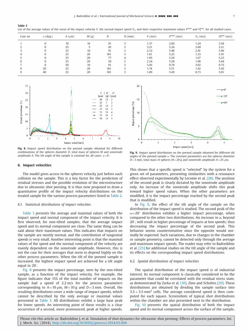
Table 3 presents the average and maximal values of both theimpact speed and normal component of the impact velocity. It isfirst observed, for non-tilted samples, that the average impactspeed and its normal component are close. The same thing can besaid about their maximum values. This indicates that impacts onthe sample are mostly normal, and the contribution of tangentialspeeds is very small. Another interesting point is that the maximalvalues of the speed and the normal component of the velocity aremainly dependent on the sonotrode amplitude. However, this isnot the case for their averages that seem to depend highly on theother process parameters. When the tilt of the peened sample isincreased, the highest impact speed are achieved for a tilt angleequal to 201.
Fig. 8 presents the impact percentage, seen by the non-tiltedsample, as a function of the impact velocity. For example, thefigure indicates that 15% of the total number of impacts on thesample had a speed of 2.2 m/s for the process parameterscorresponding to A¼10 μm, M¼10 g and D¼3 mm. Overall, theresulting distributions cover a wide range of impact speeds, whichcannot be described by the only average or maximal valuespresented in Table 3. All distributions exhibit a large base peakfor lower speeds. An interesting point of these results is a clearoccurrence of a second, more pronounced, peak at higher speeds.
This shows that a specific speed is “selected” by the system for agiven set of parameters, presenting similarities with a resonanceeffect observed experimentally by Leconte et al. [28]. The positionof the second peak is clearly dictated by the sonotrode amplitudeonly. An increase of the sonotrode amplitude shifts this peaktoward higher speed values. When the other parameters aremodified, it is the impact percentage reached by the second peakthat is modified.
In Fig. 9, the effect of the tilt angle of the sample on thedistribution of the impact speed is studied. The second peak of theα¼201 distribution exhibits a higher impact percentage, whencompared to the other two distributions. An increase in α, beyond201, will result in higher percentage of impacts at low speeds; thusdecreasing the impact percentage of the second peak. Thisbehavior seems counterintuitive since the opposite would nor-mally be expected. Such variations, due to changes in the chamberor sample geometry, cannot be detected only through the averageand maximum impact speeds. The reader may refer to Badreddineet al. [25] for additional studies on the tilt angle of the sample andits effects on the corresponding impact speed distributions.
6.2. Spatial distributions of impact velocities
The spatial distribution of the impact speed is of industrialinterest. Its normal component is classically considered to be theparameter that could be correlated with the residual stress state,as demonstrated by Zarka et al. [10], Zinn and Scholtes [29]. Thesedistributions are obtained by dividing the sample surface into3.5�3.5 mm2 cells. The average considered speed is then com-puted for each square. Screenshots of typical shot distributionswithin the chamber are also presented next to the distribution.
Fig. 10 presents the spatial distribution of both the impactspeed and its normal component across the surface of the sample,
Table 3List of the average values of the norm of the impact velocity V, the normal impact speed Vn, and their respective maximum values Vmax and Vn
max, for all studied cases.
Case no α (deg.) A (mm) M (g) N D (mm) V (m/s) Vmax (m/s) Vn (m/s) Vnmax (m/s)
1 0 10 10 91 3 1.37 2.60 1.24 2.582 0 25 5 45 3 3.21 5.24 3.00 5.213 0 25 10 91 3 2.33 5.48 2.10 5.464 0 25 20 181 3 1.61 5.25 1.33 5.195 0 25 20 77 4 1.95 5.26 1.67 5.256 0 25 20 39 5 2.24 5.58 1.98 5.447 0 50 10 91 3 3.45 9.79 3.02 9.758 20 25 20 181 3 1.74 5.51 1.42 5.429 40 25 20 181 3 1.09 5.49 0.73 5.01
Fig. 8. Impact speed distribution on the peened sample obtained for differentcombinations of the spheres diameter D, total mass of spheres M and sonotrodeamplitude A. The tilt angle of the sample is constant for all cases: α¼01.
Fig. 9. Impact speed distribution on the peened sample obtained for different tiltangles of the peened sample α. The constant parameters are the spheres diameterD¼3 mm, total mass of spheres M¼20 g and sonotrode amplitude A¼25 mm.
J. Badreddine et al. / International Journal of Mechanical Sciences ∎ (∎∎∎∎) ∎∎∎–∎∎∎ 7
Please cite this article as: Badreddine J, et al. Simulation of shot dynamics for ultrasonic shot peening: Effects of process parameters. Int.J. Mech. Sci. (2014), http://dx.doi.org/10.1016/j.ijmecsci.2014.03.006i

for three combinations of process parameters. Concerning thenormal speed, the spatial distribution is not constant and its valueis reduced close to the edges of the chamber. The normal speed ishigher than the threshold velocity chosen for the transition toplastic impacts (see Table 1 and Eq. (1)) on most of the surface ofthe sample, but may not be reached close to the edges and theacute angle when the sample is tilted. In these regions, the normalimpact speeds have values under 0.5 m/s. For a non-tilted sample,the highest values are reached in the center of the sample. For a
tilted sample, the highest normal impact speeds are located at theopposite of the acute angle, reaching 3.5 m/s. The fact that thevelocity is reduced close to a corner can be explained by the factthat the shot is trapped within this corner, as observed in the shotdistributions. This tends to increase the sphere–sphere andsphere–chamber collisions, as shown in Fig. 5, thus decreasingthe number of spheres that reach the sample with a high normalspeed. The more acute is the angle, the higher is the amount ofshot trapped within the corner. Similar spatial distributions and
Fig. 10. Normal impact speed and impact speed distributions on the peened sample obtained for different values of the sample tilt angle α and total mass of shot M. Theconstant parameters are the spheres diameter D¼3 mm and sonotrode amplitude A¼25 mm.
J. Badreddine et al. / International Journal of Mechanical Sciences ∎ (∎∎∎∎) ∎∎∎–∎∎∎8
Please cite this article as: Badreddine J, et al. Simulation of shot dynamics for ultrasonic shot peening: Effects of process parameters. Int.J. Mech. Sci. (2014), http://dx.doi.org/10.1016/j.ijmecsci.2014.03.006i

speed levels are obtained for the impact speed, on non-tiltedsamples. This confirms that the contribution of tangentialspeeds is negligible. However, for α¼401, the observed differencebetween the distribution of the impact speed and its normalcomponent becomes important. In this case, the contribution oftangential speeds can no longer be neglected.
Fig. 11 presents the spatial distributions of the maximal valuesreached by the impact speed and its normal component, for thetilted case also presented in Fig. 10. It is interesting to look at thedistribution of the maximal values only, because the resultingresidual stress is mainly due to the impact with the higher speed,as demonstrated by Rouhaud et al. [12]. When the sample is nottilted (cases 2 and 3 of Fig. 10) the maximal impact speed and itsnormal is homogeneously distributed and its value is between4.5 and 5 m/s. Such a constant distribution across the sampleshould result in a homogeneous compressive residual stress field
distribution. When the sample is tilted, the distribution becomesheterogeneous along the length of the sample, the maximalnormal impact speed in then close to 4 m/s.
7. Angles of impact
This Section focuses on the distribution of the incident angle ofthe impacts with respect to the treated sample: an impact angleequal to 01 corresponds to a normal impact, whereas 901 corre-sponds to a tangential impact, as defined in Fig. 1.
Table 4 presents the statistical distribution of the angles ofimpact for angles close to normal (angles corresponding to a normalspeed of at least 90% of the total speed), angles close to tangentialand the average angle. The process parameters strongly influencethe impact angles percentage of normal and quasi-normal impacts.
Fig. 11. Maximum values of the normal impact speed and impact speed distributions on the peened sample obtained for a tilt angle of 401 and total mass of shot of 20 g. Theconstant parameters are the spheres diameter D¼3 mm and sonotrode amplitude A¼25 mm.
Table 4Impact angles as a function of the parameters.
Case no α (deg.) A (mm) M (g) N D(mm) Impact angles
o261 4451 (%) Average (deg.)
1 0 10 10 91 3 58.75 20.43 25.42 0 25 5 45 3 69.11 12.91 18.63 0 25 10 91 3 50.94 25.52 29.34 0 25 20 181 3 36.69 37.57 37.45 0 25 20 77 4 43.78 31.39 33.46 0 25 20 39 5 50.53 25.71 29.77 0 50 10 91 3 42.16 32.54 33.38 20 25 20 181 3 40.33 35.53 39.39 40 25 20 181 3 10.87 58.95 54.6
Fig. 12. Spatial distribution of impact angles on the peened sample, obtained for a tilt angle of 401 and total mass of shot of 20 g. The constant parameters are the spheresdiameter D¼3 mm and sonotrode amplitude A¼25 mm.
J. Badreddine et al. / International Journal of Mechanical Sciences ∎ (∎∎∎∎) ∎∎∎–∎∎∎ 9
Please cite this article as: Badreddine J, et al. Simulation of shot dynamics for ultrasonic shot peening: Effects of process parameters. Int.J. Mech. Sci. (2014), http://dx.doi.org/10.1016/j.ijmecsci.2014.03.006i
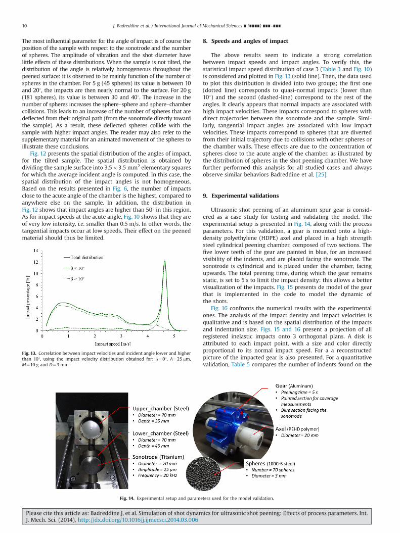
Themost influential parameter for the angle of impact is of course theposition of the sample with respect to the sonotrode and the numberof spheres. The amplitude of vibration and the shot diameter havelittle effects of these distributions. When the sample is not tilted, thedistribution of the angle is relatively homogeneous throughout thepeened surface: it is observed to be mainly function of the number ofspheres in the chamber. For 5 g (45 spheres) its value is between 10and 201, the impacts are then nearly normal to the surface. For 20 g(181 spheres), its value is between 30 and 401. The increase in thenumber of spheres increases the sphere–sphere and sphere–chambercollisions. This leads to an increase of the number of spheres that aredeflected from their original path (from the sonotrode directly towardthe sample). As a result, these deflected spheres collide with thesample with higher impact angles. The reader may also refer to thesupplementary material for an animated movement of the spheres toillustrate these conclusions.
Fig. 12 presents the spatial distribution of the angles of impact,for the tilted sample. The spatial distribution is obtained bydividing the sample surface into 3.5�3.5 mm2 elementary squaresfor which the average incident angle is computed. In this case, thespatial distribution of the impact angles is not homogeneous.Based on the results presented in Fig. 6, the number of impactsclose to the acute angle of the chamber is the highest, compared toanywhere else on the sample. In addition, the distribution inFig. 12 shows that impact angles are higher than 501 in this region.As for impact speeds at the acute angle, Fig. 10 shows that they areof very low intensity, i.e. smaller than 0.5 m/s. In other words, thetangential impacts occur at low speeds. Their effect on the peenedmaterial should thus be limited.
8. Speeds and angles of impact
The above results seem to indicate a strong correlationbetween impact speeds and impact angles. To verify this, thestatistical impact speed distribution of case 3 (Table 3 and Fig. 10)is considered and plotted in Fig. 13 (solid line). Then, the data usedto plot this distribution is divided into two groups; the first one(dotted line) corresponds to quasi-normal impacts (lower than101) and the second (dashed-line) correspond to the rest of theangles. It clearly appears that normal impacts are associated withhigh impact velocities. These impacts correspond to spheres withdirect trajectories between the sonotrode and the sample. Simi-larly, tangential impact angles are associated with low impactvelocities. These impacts correspond to spheres that are divertedfrom their initial trajectory due to collisions with other spheres orthe chamber walls. These effects are due to the concentration ofspheres close to the acute angle of the chamber, as illustrated bythe distribution of spheres in the shot peening chamber. We havefurther performed this analysis for all studied cases and alwaysobserve similar behaviors Badreddine et al. [25].
9. Experimental validations
Ultrasonic shot peening of an aluminum spur gear is consid-ered as a case study for testing and validating the model. Theexperimental setup is presented in Fig. 14, along with the processparameters. For this validation, a gear is mounted onto a high-density polyethylene (HDPE) axel and placed in a high strengthsteel cylindrical peening chamber, composed of two sections. Thefive lower teeth of the gear are painted in blue, for an increasedvisibility of the indents, and are placed facing the sonotrode. Thesonotrode is cylindrical and is placed under the chamber, facingupwards. The total peening time, during which the gear remainsstatic, is set to 5 s to limit the impact density: this allows a bettervisualization of the impacts. Fig. 15 presents de model of the gearthat is implemented in the code to model the dynamic ofthe shots.
Fig. 16 confronts the numerical results with the experimentalones. The analysis of the impact density and impact velocities isqualitative and is based on the spatial distribution of the impactsand indentation size. Figs. 15 and 16 present a projection of allregistered inelastic impacts onto 3 orthogonal plans. A disk isattributed to each impact point, with a size and color directlyproportional to its normal impact speed. For a a reconstructedpicture of the impacted gear is also presented. For a quantitativevalidation, Table 5 compares the number of indents found on the
Fig. 13. Correlation between impact velocities and incident angle lower and higherthan 101, using the impact velocity distribution obtained for: α¼01, A¼25 mm,M¼10 g and D¼3 mm.
Fig. 14. Experimental setup and parameters used for the model validation.
J. Badreddine et al. / International Journal of Mechanical Sciences ∎ (∎∎∎∎) ∎∎∎–∎∎∎10
Please cite this article as: Badreddine J, et al. Simulation of shot dynamics for ultrasonic shot peening: Effects of process parameters. Int.J. Mech. Sci. (2014), http://dx.doi.org/10.1016/j.ijmecsci.2014.03.006i
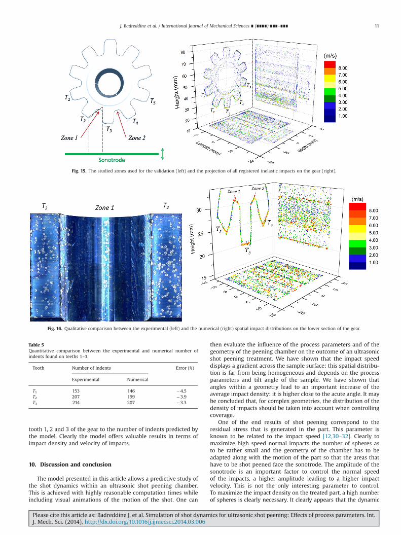
tooth 1, 2 and 3 of the gear to the number of indents predicted bythe model. Clearly the model offers valuable results in terms ofimpact density and velocity of impacts.
10. Discussion and conclusion
The model presented in this article allows a predictive study ofthe shot dynamics within an ultrasonic shot peening chamber.This is achieved with highly reasonable computation times whileincluding visual animations of the motion of the shot. One can
then evaluate the influence of the process parameters and of thegeometry of the peening chamber on the outcome of an ultrasonicshot peening treatment. We have shown that the impact speeddisplays a gradient across the sample surface: this spatial distribu-tion is far from being homogeneous and depends on the processparameters and tilt angle of the sample. We have shown thatangles within a geometry lead to an important increase of theaverage impact density: it is higher close to the acute angle. It maybe concluded that, for complex geometries, the distribution of thedensity of impacts should be taken into account when controllingcoverage.
One of the end results of shot peening correspond to theresidual stress that is generated in the part. This parameter isknown to be related to the impact speed [12,30–32]. Clearly tomaximize high speed normal impacts the number of spheres asto be rather small and the geometry of the chamber has to beadapted along with the motion of the part so that the areas thathave to be shot peened face the sonotrode. The amplitude of thesonotrode is an important factor to control the normal speedof the impacts, a higher amplitude leading to a higher impactvelocity. This is not the only interesting parameter to control.To maximize the impact density on the treated part, a high numberof spheres is clearly necessary. It clearly appears that the dynamic
Fig. 15. The studied zones used for the validation (left) and the projection of all registered inelastic impacts on the gear (right).
Fig. 16. Qualitative comparison between the experimental (left) and the numerical (right) spatial impact distributions on the lower section of the gear.
Table 5Quantitative comparison between the experimental and numerical number ofindents found on teeths 1–3.
Tooth Number of indents Error (%)
Experimental Numerical
T1 153 146 �4.5T2 207 199 �3.9T3 214 207 �3.3
J. Badreddine et al. / International Journal of Mechanical Sciences ∎ (∎∎∎∎) ∎∎∎–∎∎∎ 11
Please cite this article as: Badreddine J, et al. Simulation of shot dynamics for ultrasonic shot peening: Effects of process parameters. Int.J. Mech. Sci. (2014), http://dx.doi.org/10.1016/j.ijmecsci.2014.03.006i
of the shot for the ultra-sound shot peening of a part is complex andseveral parameters of the process jointly influence the results.The proposed model offers comprehensive and predictive solutions,to specify the initial and boundary conditions for a shot peeningmodel in order to predict the residual stress fields.
Acknowledgments
It is a pleasure to acknowledge ongoing discussions withSONATS (Europe Technologies group) and D. Le Saunier, G. Doubre,M. Prioul, J. Talbot and P. Viot. SNECMA (Groupe SAFRAN) isgratefully acknowledged for its financial support.
References
[1] Lu J, editor. Mechanical surface treatment. In: Handbook on residual stress,vol. 1, 2nd ed. Society of Experimental Mechanics (SEM); 2005. p. 137–77.
[2] Zimmermann M, Klemenz M, Schulze V. Literature review on shot peeningsimulation. Int J Comput Mater Sci Surf Eng 2010;3(4):289–310.
[3] Benrabah A, Langlade C, Vannes AB. Residual stresses and fretting fatigue.Wear Feb. 1999;224(2):267–73.
[4] Retraint D, Garnier C, Guelorget B, Lu J. Improvement of the fatigue behaviourof an automotive part using a new mechanical treatment. Mater Sci Forum2002;404:463–8.
[5] Roland T, Retraint D, Lu K, Lu J. Generation of nanostructures on 316 L stainlesssteel and its effect on mechanical behavior. Mater Sci Forum 2005;490:625–630.
[6] Chan HL, Lu J, Schoberth A. Study of the mechanical properties of nanos-tructured aluminum obtained by smat. In: ASME international mechanicalengineering congress and exposition; 2008. p. 39–3.
[7] Waltz L, Retraint D, Roos A, Olier P, Lu J. High strength nanocrystallizedmultilayered structure obtained by SMAT and co-rolling. Mater Sci Forum2009;614:249–54.
[8] Chemkhi M, Retraint D, Montay G, Garnier C, Belahcene F. Effect of SMATparameters on microstructural features using DOE technique. In: 11th inter-national conference on shot peening; 2011. p. 87–2.
[9] Jelliti S, Richard C, Retraint D, Roland T, Chemkhi M, Demangel C. Effect ofsurface nanocrystallization on the corrosion behavior of Ti–6Al–4V titaniumalloy. Surf Coatings Technol 2013;224(March):82–7.
[10] Zarka J, Frelat J, Kasmai-Navidi P. A new approach in inelastic analysis ofstructures, 1st ed. CadLM; 1990.
[11] Pilé C, François M, Retraint D, Rouhaud E, Jian L. Modelling of ultrasonic shotpeening process. Mater Sci Forum 2005;490–491:67–72.
[12] Rouhaud E, Deslaef D, Lu J, Chaboche JL. Modeling of shot peening. In: Lu J,editor. Handbook on residual stress, vol. 2, 2nd ed. Society of ExperimentalMechanics; 2005. p. 116–48.
[13] Franchim AS, De Campos VS, Travessa DN, Neto CD M, Moura C De. Analyticalmodelling for residual stresses produced by shot peening. Mater Des May2009;30(5):1556–60.
[14] Miao HY Y, Larose S, Perron C, Lévesque M. On the potential applications of a3D random finite element model for the simulation of shot peening. Adv EngSoftware 2009;40(October (10)):1023–38.
[15] Chaise T, Li J, Nélias D, Kubler R, Taheri S, Douchet G, Robin V, Gilles P.Modelling of multiple impacts for the prediction of distortions and residualstresses induced by ultrasonic shot peening (USP). J Mater Process TechnolOct. 2012;212(10):2080–90.
[16] Bhuvaraghan B, Srinivasan SM, Maffeo B. Numerical simulation of Almen stripresponse due to random impacts with strain-rate effects. Int J Mech Sci2011;53(June (6)):417–24.
[17] Micoulaut M, Mechkov S, Retraint D, Viot P, François M. Granular gases inmechanical engineering: on the origin of heterogeneous ultrasonic shotpeening. Granul Matter 2007;9(August):25–33.
[18] Lifshitz JM, Kolsky H. Some experiments on anelastic rebound. J Mech PhysSolids 1964;12(February (1)):35–43.
[19] McNamara S, Falcon E. Simulations of vibrated granular medium with impact-velocity-dependent restitution coefficient. Phys Rev E 2005;71(March(3)):031302-1–6.
[20] Micoulaut M, Retraint D, Viot P, François M. Heterogeneous ultrasonic shotpeening: experiment and simulation. In: 9th international conference on shotpeening (ICSP9); 2005. p. 119–24.
[21] Brach RM. Impact dynamics with application to solid particle erosion. Int JImpact Eng 1988;7(1):37–53.
[22] Goldsmith W. The theory and physical behavior of colliding solids. London:Dover; 1990.
[23] Sondergaard R, Chaney K, Brennen CE. Measurements of solid spheresbouncing off flat plates. J Appl Mech 1990;112(90):7.
[24] Micoulaut M, Retraint D, Viot P, François M. Grenaillage ultrasonore hétéro-gène. In: 17eme Congres Francais de Mécanique; 2005. p. 1–6.
[25] Badreddine J, Micoulaut M, Rouhaud E, Remy S, Retraint D, Manuel F. Effect ofthe confinement on the properties of ultrasonic vibrated granular gases.Granul Matter 2013;15(3):367–76.
[26] SAE Standard J2277. Surface enhancment division—shot peening coveragedetermination; 2009.
[27] Bagherifard S, Ghelichi R, Guagliano M. On the shot peening surface coverageand its assessment by means of finite element simulation: a critical reviewand some original developments. Appl Surf Sci 2012;259(October):186–94.
[28] Leconte M, Garrabos Y, Palencia F, Lecoutre C, Evesque P, Beysens D. Inelasticball-plane impact: an accurate way to measure the normal restitutioncoefficient. Appl Phys Lett 2006;89(24):243518–1–3.
[29] Zinn W, Scholtes B. Influence of shot velocity and shot size on Almen intensityand residual stress depth distributions. In: 9th international conference onshot peening (ICSP9), vol. 20; 2000. p. 379–84.
[30] Benedetti M, Fontanari V, Ho B. Influence of shot peening on bending toothfatigue limit of case hardened gears. Int. J. Fatigue 2002;24:1127–36.
[31] Olmi G, Comandini M, Freddi A. Fatigue on shot-peened gears: experimenta-tion, simulation and sensitivity analyses. Strain 2010;46(March (4)):382–95.
[32] Olmi G, Freddi A. A new method for modelling the support effect underrotating bending fatigue: application to Ti–6Al–4V alloy, with and withoutshot peening. Fatigue Fract Eng Mater Struct 2013;36(October (10)):981–93.
J. Badreddine et al. / International Journal of Mechanical Sciences ∎ (∎∎∎∎) ∎∎∎–∎∎∎12
Please cite this article as: Badreddine J, et al. Simulation of shot dynamics for ultrasonic shot peening: Effects of process parameters. Int.J. Mech. Sci. (2014), http://dx.doi.org/10.1016/j.ijmecsci.2014.03.006i