Simulating pursuit with machine experiments with robots and artificial vision
18
IEEE TRANSACTIONS ON ROBOTICS AND AUTOMATION, VOL. 14, NO. 1, FEBRUARY 1998 1 Simulating Pursuit with Machine Experiments with Robots and Artificial Vision Jorge Dias, Carlos Paredes, In´ acio Fonseca, Helder Ara´ ujo, Jorge Batista, and Anibal T. Almeida Abstract— This article is concerned with the simulation of pursuit. The article describes one solution for the problem of pursuit of objects moving on a plane by using a mobile robot and an active vision system. The solution deals with the interaction of different control systems using visual feedback and it is accom- plished by the implementation of a visual gaze holding process interacting cooperatively with the control of the trajectory of a mobile robot. These two systems are integrated to follow a moving object at constant distance and orientation with respect to the mobile robot. The orientation and the position of the active vision system running a gaze holding process give the feedback signals to the control used to pursuit the target in real-time. The paper addresses the problems of visual fixation, visual smooth pursuit, navigation using visual feedback and compensation for system’s movements. The algorithms for visual processing and control are described in the article. The mechanisms of cooperation between the different control and visual algorithms are also described. The final solution is a system able to operate at approximately human walking rates as the experimental results show at the end of the article. Index Terms— Active vision, artificial vision, pursuit, naviga- tion. I. INTRODUCTION T HE PURSUIT of moving objects with machines such as a mobile robot equipped with an active vision system deals with the problem of integration and cooperation between different systems. This integration has two distinct aspects: the interaction and cooperation between different control systems and the use of a common feedback information provided by the vision system. In this article a global solution is proposed based on the visual gaze holding process to establish a pursuit mechanism for targets moving in front of the mobile robot. The system is controlled to keep constant the distance and the orientation of the robot and the vision system. The solution for this problem deals with the interaction of different control systems using visual feedback. It also addresses the real-time tracking of objects by using a vision system. This problem has been addressed in different fields such as surveillance, automated guidance systems, and robotics in general. Several works addressed the problems of visual servoing but they Manuscript received March 9, 1995; revised July 18, 1996. This paper was recommended for publication by Associate Editor R. Chatila and Editor S. Salcudean upon evaluation of the reviewers’ comments. The authors are with the I.S.R.-Instituto de Sistemas e Rob´ otica-Coimbra site, Departamento de Eugeuharia Electrot´ ecnica, Polo II da Universidade de Coimbre, 3030 Coimbra, Portugal. Publisher Item Identifier S 1042-296X(98)01546-8. are mainly concerned with object tracking by using vision and manipulators [1], [8], [9], [11] and only some address problems related with ours [13]–[15]. Coombs studied the real- time implementation of a gaze holding process using binocular vision [8]. The system used a binocular system mounted on a manipulator and Coombs studied different control schemes for visual gaze holding using the information of two images. These studies included predictive control schemes to avoid delays, [4], [8]. Papanikolopoulos also proposed a tracking process by using a camera mounted on a manipulator for tracking objects with a trajectory parallel to the image plane [11]. The information supplied by the vision system is processed by an optical flow based algorithm that is accurate enough for tracking the objects in real-time. The efficient use of windows in the image improves the performance of the method. A control process is also reported by Allen for tracking moving objects in three-dimensions (3-D) [1]. The system can be used for grasping the objects by using a manipulator. The vision system uses two cameras and the distance from the manipulator’s tool to the object is computed in real-time by using stereo images. Once the tracking scheme is stable, the system controls the manipulator to intercept the moving object and pick it up. These studies have connection with the solution for pursuit proposed in this article, since they deal with the tracking problem by using visual information. However in our system we explore the concept of visual fixation to develop the application. The computational solution for visual fixation uses motion detection to initiate the fixation process and to define a pattern that will be tracked. During pursuit the system uses image correlation to continuously track the target in the images. The solution is a refinement of the Burt technique [6]. Burt reports a real-time feature detection algorithm using hierarchical scaling images for surveillance and robotics. More recently several laboratories have been engaged in a large European project (the Vision as Process project) for the development of systems, based on active vision principles. During the project, studies have been made to integrate camera control, ocular reflexes, real-time image processing, image tracking, perceptual grouping, active 3-D modeling, and object recognition. Some of the systems described above have similarities with ours but in our system we control the system to keep the distance and orientation of the mobile robot with respect to a target. The solution described in this article includes the control of the gaze of the active vision system. Furthermore, 1042–296X/98$10.00 1998 IEEE
Transcript of Simulating pursuit with machine experiments with robots and artificial vision

IEEE TRANSACTIONS ON ROBOTICS AND AUTOMATION, VOL. 14, NO. 1, FEBRUARY 1998 1
SimulatingPursuit with MachineExperiments with Robots
and Artificial VisionJorge Dias, Carlos Paredes, In´acio Fonseca, Helder Ara´ujo, Jorge Batista, and Anibal T. Almeida
Abstract—This article is concerned with the simulation ofpursuit. The article describes one solution for the problem ofpursuit of objects moving on a plane by using a mobile robot andan active vision system. The solution deals with the interaction ofdifferent control systems using visual feedback and it is accom-plished by the implementation of a visualgaze holdingprocessinteracting cooperatively with the control of the trajectory of amobile robot. These two systems are integrated to follow a movingobject at constant distance and orientation with respect to themobile robot. The orientation and the position of the active visionsystem running a gaze holdingprocess give the feedback signalsto the control used to pursuit the target in real-time. The paperaddresses the problems ofvisual fixation, visual smooth pursuit,navigation using visual feedbackand compensationfor system’smovements. The algorithms for visual processing and control aredescribed in the article. The mechanisms of cooperation betweenthe different control and visual algorithms are also described.The final solution is a system able to operate at approximatelyhuman walking rates as the experimental results show at the endof the article.
Index Terms—Active vision, artificial vision, pursuit, naviga-tion.
I. INTRODUCTION
T HE PURSUIT of moving objects with machines such asa mobile robot equipped with an active vision system
deals with the problem of integration and cooperation betweendifferent systems. This integration has two distinct aspects: theinteraction and cooperation between different control systemsand the use of a common feedback information provided bythe vision system. In this article a global solution is proposedbased on the visualgaze holdingprocess to establish a pursuitmechanism fortargets moving in front of the mobile robot.The system is controlled to keep constant the distance and theorientation of the robot and the vision system. The solutionfor this problem deals with the interaction of different controlsystems using visual feedback. It also addresses the real-timetracking of objects by using a vision system. This problemhas been addressed in different fields such as surveillance,automated guidance systems, and robotics in general. Severalworks addressed the problems of visual servoing but they
Manuscript received March 9, 1995; revised July 18, 1996. This paper wasrecommended for publication by Associate Editor R. Chatila and Editor S.Salcudean upon evaluation of the reviewers’ comments.
The authors are with the I.S.R.-Instituto de Sistemas e Robotica-Coimbrasite, Departamento de Eugeuharia Electrotecnica, Polo II da Universidade deCoimbre, 3030 Coimbra, Portugal.
Publisher Item Identifier S 1042-296X(98)01546-8.
are mainly concerned with object tracking by using visionand manipulators [1], [8], [9], [11] and only some addressproblems related with ours [13]–[15]. Coombs studied the real-time implementation of agaze holdingprocess using binocularvision [8]. The system used a binocular system mounted on amanipulator and Coombs studied different control schemes forvisualgaze holdingusing the information of two images. Thesestudies included predictive control schemes to avoid delays,[4], [8]. Papanikolopoulos also proposed a tracking processby using a camera mounted on a manipulator for trackingobjects with a trajectory parallel to the image plane [11]. Theinformation supplied by the vision system is processed byan optical flow based algorithm that is accurate enough fortracking the objects in real-time. The efficient use of windowsin the image improves the performance of the method. Acontrol process is also reported by Allen for tracking movingobjects in three-dimensions (3-D) [1]. The system can beused for grasping the objects by using a manipulator. Thevision system uses two cameras and the distance from themanipulator’s tool to the object is computed in real-time byusing stereo images. Once the tracking scheme is stable, thesystem controls the manipulator to intercept the moving objectand pick it up. These studies have connection with the solutionfor pursuit proposed in this article, since they deal with thetracking problem by using visual information. However in oursystem we explore the concept of visual fixation to developthe application. The computational solution for visual fixationuses motion detection to initiate thefixation processand todefine a pattern that will be tracked. Duringpursuit the systemuses image correlation to continuously track the target in theimages. The solution is a refinement of the Burt technique[6]. Burt reports a real-time feature detection algorithm usinghierarchical scaling images for surveillance and robotics.
More recently several laboratories have been engaged ina large European project (theVision as Processproject) forthe development of systems, based on active vision principles.During the project, studies have been made to integrate cameracontrol, ocular reflexes, real-time image processing, imagetracking, perceptual grouping, active 3-D modeling, and objectrecognition.
Some of the systems described above have similarities withours but in our system we control the system to keep thedistance and orientation of the mobile robot with respect toa target. The solution described in this article includes thecontrol of thegazeof the active vision system. Furthermore,
1042–296X/98$10.00 1998 IEEE
2 IEEE TRANSACTIONS ON ROBOTICS AND AUTOMATION, VOL. 14, NO. 1, FEBRUARY 1998
our hierarchical control scheme establishes a pursuit processusing different degrees of freedom on the active vision systemand the movement of the mobile robot. To simplify the solutionseveral assumptions were made. These assumptions are basedon the type of movements and targets that we designed thesystem to cope with, and system’s physical constraints suchas: maximum robot velocity, possibility of adjustment ofthe optical parameters for focusing, maximum computationalpower for image processing and, the nonholonomic structureof the mobile robot. We assume that:
1) target and the robot move on a plane (horizontal plane);2) the difference between the velocities of the target and of
the robot does not exceed 1.2 m/s;3) the distance between the target and the mobile robot will
be in the interval of [2.5 m, 5 m] and the focal lengthof both lenses is set to 12.5 mm;
4) the target is detected only when it appears inside thecameras’ field of view.
5) the system is initialized by setting the vision systemaligned with the vehicle (the cameras are oriented to seethe vehicle’s front).
These assumptions bound the problem and only two vari-ables are used to control the system. One is the angle in thehorizontal plane defined by the target position relative to themobile robot referential. The other is the distance between therobot and the target.
In the next Section, an outline of the pursuit process andits solution is given. In Section III, the system architectureand all geometric relations used in the solution are described.Section IV describes the image processing methods used toobtain information about the target. Section V describes thecontrol of the system and explains the integration of differentcontrol modules. Section VI describes and illustrates somesystem’s parameters when the system is performing pursuitand the last Section summarizes and comments the solutionproposed.
II. PURSUIT OF MOVING OBJECTS
The problem of pursuing a moving object is essentiallya motion matching problem. The machine, the robot in ourcase, must be controlled to reach the same motion as thetarget. In practice this is equivalent to keep constant thedistance and orientation from the robot to thetarget. However,the solution for this problem has some particular aspectsthat must be emphasized. If the target is a person walking,its trajectory can be suddenly modified and consequentlyits velocity. Any solution proposed must cope with thesesituations and perform the control of the system inreal-time. Since the machines have physical limitations in theirvelocity and maneuvering capabilities, it is essential to classifythe different sub-systems used according to their velocitycharacteristics. In our experiments we use a mobile robot andan active vision system, and these two systems have differentmovement characteristics. The active vision system presentsgreater velocity than the mobile robot and also has less mass.However, it is the mobile robot (the body of the system) thatmust follow thetarget—see Fig. 1.
Fig. 1. The information provided by theactive vision systemis used tocontrol the mobile robot topursuit a person inreal-time.
To perform the pursuit of a movingtarget we use twobasic control schemes: a visualfixation control of the activevision system and the trajectory control of the robot. Thevisualfixationcontrol guarantees that thetargetis continuouslytracked by the vision system, and gives information aboutits position to the robot control. The robot control usesthat information as a feedback to maintain the distance andorientation to thetarget.
The visualfixation control must be one visual process thatruns in the active vision system and has capabilities to definea target, to concentrate the vision system on thetarget andfollow it. A process with these characteristics has similaritieswith the visual gaze-shifting mechanism in the humans [7].The gaze-shifting mechanism generates movements in thevision system to put a new object of interest in the centerof the image and hold it there. The movement used to putthe object in the center is calledsaccade, it is fast and itis performed by the two eyes simultaneously. If thetarget ofinterest is moving relative to the world, the vision system mustperform movements to hold thetarget in the image center.These movements are composed by two types of motionscalled smooth pursuitand vergence. These motions are theconsequence of the control performed by the process that wedesignate asfixation.
Thefixationprocess centers and holds the orientation of thevision system on a point in the environment. The principle isdescribed graphically in Fig. 1 where the mobile robot withan active vision system is concentrated on a person.Fixationgives a useful mechanism to maintain the relative orientationand translation between the referential in the vehicle and thetarget that is followed. This results from the advantages ofthe fixation process, where the selectedtarget is always in theimage center (foveal region in the mammals). This avoids thesegmentation of all the image to select thetargetand allows the

DIAS et al: SIMULATING PURSUITWITH MACHINES EXPERIMENTS WITH ROBOTS AND ARTIFICIAL VISION 3
Fig. 2. State diagram of thepursuit process.
use of relative coordinate systems which simplifies the spatialdescription of thetarget (relationship between the observerreference system and the object reference system).
The pursuit process can be described graphically by thestate diagram in Fig. 2. The process has three states:Rest,Vergence Stabilization, andPursuit. The pursuit process mustbe initialized before starting. During this initialization, atargetis chosen and several movements are performed by the activevision system: the gaze is shifted by asaccademovementand the vergence stabilized. In our system thetarget is chosenbased on the visual motion stimulus. The selection correspondsto a region in the images that generates a large visual motionin the two images.
If a target is selected, asaccademovement is performed toput thetarget in the image center, and the system changes fromthe stateRest to Vergence Stabilization. During the saccademovement no visual information is used to feedback the move-ment. In theVergence Stabilizationstate the system adjustsits fixation in the target. This is equivalent to establishing thecorrect correspondence between the centers of the two images,and defining afixation point in thetarget. When the vergenceis stabilized, the system is maintained in thePursuit state.
III. B UILDING A SYSTEM TO SIMULATE PURSUIT
A. System Architecture
The main hardware components of the system are the mobilerobot and the active vision system. These two basic units areinterconnected by a computer designatedMaster ProcessingUnit. This unit controls the movements of the active vision sys-tem, communicates with the robot’s on-board computer and isconnected to two other computers designatedSlave ProcessingUnits. These units are responsible for processing the imagesprovided by the active vision system. The connections betweendifferent processing units are represented in the diagram shownin Fig. 3 and a photograph of the system is presented in Fig. 4.
TheRightand theLeft Slave Processing Unitsare computerswith i486DX2 CPU’s running at 66 MHz. Each contains aDT-IRIS (50 Hz) frame grabber connected to each one ofthe cameras. TheSlave Processing Unitsprocess the imagesand communicate their results to theMaster Processing Unit(another computer with a i486DX2 CPU running at 66MHz).These communications use a 10 MBits connection providedby Ethernet boards (one board on each computer). The active
Fig. 3. System architecture.
Fig. 4. The active vision system and the mobile robot.
vision system has two CDD monochromatic video cameraswith motorized lenses (allowing for the control of the iris,focus and zoom) and five step motors that confer an equalnumber of degrees of freedom to the system (vergence ofeach camera, baseline shifting, head tilt and neck pan). TheMaster Processing Unitis responsible for the control of thedegrees of freedom of the active vision system (using stepmotor controllers) and for the communication with the mobileplatform (using a serial link).
The actual control of the mobile platform is done by amultiprocessor system based on a 68 020 CPU, installed on theplatform. The management and the interface with the systemis done by a computer, connected to theMaster ProcessingUnit using the serial link and a wireless modem.

4 IEEE TRANSACTIONS ON ROBOTICS AND AUTOMATION, VOL. 14, NO. 1, FEBRUARY 1998
(a) (b)
(c) (d)
Fig. 5. Location of all the system’s referentials: (a)CYCLOP and EYESreferentials; (b) and (c)NECK referentials; (d)BODY referential.
B. System Geometry
There are six referentials associated with the system’smechanical structure, as illustrated in Fig. 5. The mechanicalstructure is divided into four groups:BODY, NECK, CYCLOPand EYES. The last three groups contain the referentialsassociated with the part of the structure referred to as head.
The upper part of the head structure is formed by theEYESand theCYCLOPgroups [represented in Fig. 5(a)]. TheEYESgroup contains two referentials designated andThey are associated with the mechanical support for the twocameras, and each referential can be rotated around its-axis,allowing for the cameras’ vergence control. The cameras aresupported by theCYCLOPmechanical part and between themis located the referential This referential is located overthe same vertical line as the referentials in theNECK group[described in Fig. 5(b) and (c)]. The distance between thereferentials and ] is known as the andcan be changed. For calibration purposes, both cameras canbe adjusted along the-axis. The appendix-A describes theparameters of the mobile robot and the vision system in detail[16], [18].
Located in the lower part of the head structure are the tworeferentials of theNECKgroup: and (representedin Fig. 5(b) and (c), respectively). Each can be rotated arounda different axis (the index of each name indicates the rotationaxis), allowing the upper part of the structure to be movedwith two degrees of freedom (head tilt and neck pan).
The referential his located directly above thereferential and they have coincident-axis.
Finally theBODYgroup, that contains the referentialand is located in the mobile platform at the middle of thedriving axle (i.e. the rear axle) and is represented in Fig. 5(d).The platform’s driving wheels are independent, allowing theplatform to rotate around the-axis of the referentialand to move its origin.
Fig. 6. Geometric model of each camera.
The head structure is placed on the mobile robot in sucha way that the -planes of the referentials in theCYCLOP,NECK, and BODY groups are coincident.
C. Camera Model
To find the relation between a two-dimensional (2-D) pointin one image obtained by either camera with its corresponding3-D point in that camera’s referential we use theperspective model.
The projection of the 3-D point in plane is a pointthat results from the intersection of the projective
line of with the plane The perpendicular projection of thepoint in the plane is defined as the center of the image,with coordinates ( ). The distance between the pointand its projection is called the focal length.
If ( ) are the 3-D coordinates of the point in thereferential, the 2-D coordinates of the projection
( ) of it on a continuous image plane is given by theperspective relationships
(1)
Since the image for processing is a sampled version of thecontinuous image, the relation between the units (millimeters)used in the referential and the image points ( )are related with by
(2)
That relation is obtained with a calibration process that givesthe scale factors for both the and the -axis ( and ,respectively) [17]. The image center ( ), the focal length
and the scale factors and are called the intrinsicparameters of the camera.
Three-dimensional point given in the referentialtransforms into the 2-D image coordinates of that point’sprojection. To obtain this transformation in the andreferentials we must take into consideration the orientationand location of in those referentials. As can be seenin Fig. 6, the referential is rotated with respect to
DIAS et al: SIMULATING PURSUITWITH MACHINES EXPERIMENTS WITH ROBOTS AND ARTIFICIAL VISION 5
and and their origins are probably not coincident.However the camera’s position can be adjusted, thereforepermitting the vector to become approximately equal tothe null vector, making the origins almost coincident. Thisadjustment is realized during the cameras calibration phase.If the translation is null, the transformation of thereferential into the or referentials can be donewith a simple transformation.
D. System Models and Geometric Relations
The information of thetarget’sposition in the images is usedto control the position and orientation of the vision systemand of the mobile robot in order to maintain the relativedistance and orientation to thetarget. Essentially the systemmust control the position of each actuator to maintain this goal.This implies to control the actuators of the vision system andalso of the mobile robot. In our system these actuators havetheir ownunits that control their position with accuracy. Theseunits are designated low-levelcontrol units.
In the case of the vision system the actuators used arestep motors. These motors are controlled by dedicated unitssupervised by theMaster Processing Unit. These motors rotatea specific number of degrees for each pulse sent to their powerdriver unit. The pulses are generated by the dedicated controlunits. These units generate different profiles for the pulse ratecurve which must be adjusted for each motor. This adjustmentis equivalent to a step motoridentification procedure. Thisprocedure was performed for each motor used in the activevision system. With this procedure the correct curve profilewas adapted for a precise position control.
The mobile robot has also its own on-board computer thatcontrols the motors used to move it. The onboard computer isresponsible for the correct execution of the movements, andit accepts commands for movements that can be modifiedduring their execution. This possibility is explored in oursystem to correct the path during the movement execution. Thecommands sent to the mobile robot reflect the position that therobot must reach to maintain the distance to thetarget. If thecommands sent do not exceed the possibilities of the system,the command will be sent to the robot to be executed withaccuracy. This detail is verified before sending a commandto the mobile robot. Appendix A gives some details aboutthese mobile robot parameters. These low-level control unitsfacilitate the global control of the system and its adjustment.
Since thetargetchanges its position in space, in most of thetime its image position will also change. The goal is to controlthe system in such a way that the object’s image projectsinto the center of both images, maintaining at the same timethe distance to the object. The control can be performed bycontrolling the robot position, the neck orientation and thevergence of both cameras. The control implies the use of thesedegrees of freedom to reach the goal ofpursuinga target. Itis possible to obtain expressions between the several degreesof freedom, useful for their control, based on the geometricrelationships.
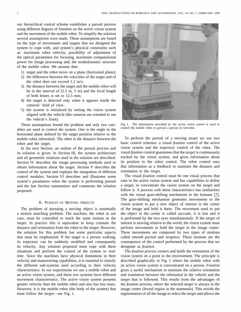
The goal is to change the cameras’ anglesand bythe amount necessary to keep the projection of thetarget in
(a)
(b)
Fig. 7. Cameras’ vergence angle control.
the center of the image (see Fig. 7). Since we assume that thetarget moves on the same plane as the mobile robot we willconsider only the horizontal disparity
Let be the coordinate in pixels of the reference point alongthe -axis of either frame. The angle that each camera mustturn is given by
(3)
This relation is easily derived from the (2) and from therepresentation in Fig. 7. To provide the system with the abilityto react to the movements of the object’s and with the abilityto keep the distance and attitude between the two bodies, it isnecessary to evaluate the distance of the object with respectto the robot. The position of the object to track is defined interms of its distance and the angle with respect to the
referential, and using thefixationpoint as reference (bothparameters are represented in Fig. 8).
To obtain the equations that give the values ofandwe start by defining the following relations, taken directlyfrom Fig. 9 (equivalent to Fig. 8, but with some auxiliaryparameters)
(4)
The distance and the angle of the fixation point withrespect to the referential can be obtained by the followingequations (recall that the angle is positive clockwise—seeFig. 9):
(5)
6 IEEE TRANSACTIONS ON ROBOTICS AND AUTOMATION, VOL. 14, NO. 1, FEBRUARY 1998
(a)
(b)
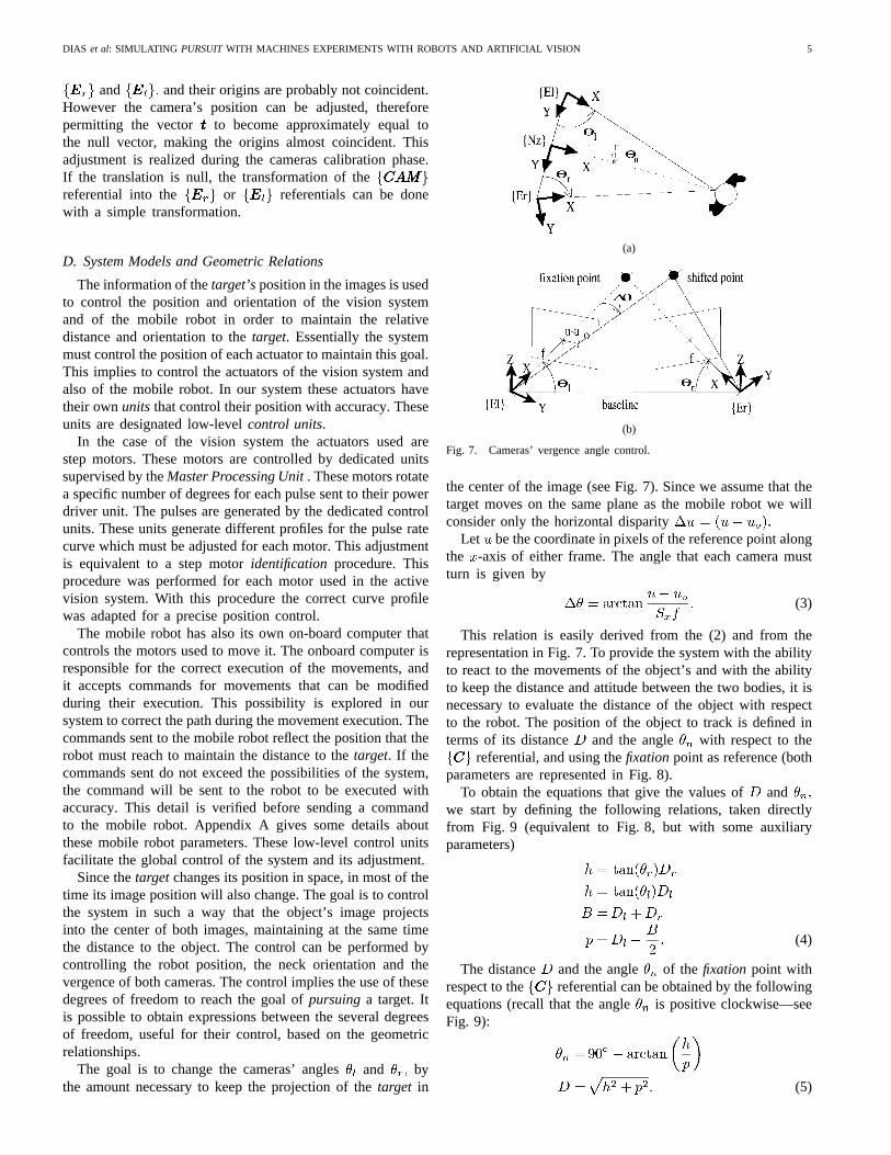
Fig. 8. Distance and angle to the object defined in the plane parallel to thexy-plane of thefCCCg referential.
Fig. 9. Auxiliary parameters.
Note that, when equals the above relations are notvalid. In that case, the angle is zero, and the distanceis equal to
As described above, the motion and feature detection al-gorithms generate the position in both images of the objectto follow. From that position, only the value along the-axis will be used, since we assume that the objectmoves inthe horizontal plane, and thereforewithout significant verticalshifts.
The trajectories of the moving platform are planned by theMaster Processing Unitbased on the values of and givenby (5). The values and define a 2-D point in thereferential. These values can be related to the referentialsince all the relationships between referentials are known. Theresult is a point with coordinates and as shown inFig. 10.
Fig. 10. Robot trajectory planning.
This figure is useful to establish the conditions for a mobilerobot’s trajectory when we want that the mobile robot reachesa point To clarify the situation we suppose that theobject appeared in vehicle’s front with an initial orientation
(the solution is be similar for an angle Weknow that several trajectories are possible to reach a specificpoint but, the trajectories’ parameters are chosen according tothe following.
1) The point is assumed to be in front of the vehicle andthe angle is always greater than zero as show Fig. 10.This is a condition derived from the system initializationand the correct execution of thepursuit process (seeSection I). Additionally, that condition helps to deal withthe nonholonomic structure of the mobile robot.
2) The platform must stop at a given distance from theobject. This condition is represented in Fig. 10 by thecircle around the point (the center of the platform’sdriving axle, point must stop somewhere over thiscircle).
3) The platform must be facing the object at the end ofthe trajectory. In other words, the object must be on the
-axis at a distance from the origin of when theplatform stops.
The trajectory that results from the application of thoseconditions is a combination of translational and rotationalmovements that achieve the desired position. Notice that thistype of mobile platform is subject to nonholonomic constraintsand those constraints restricts the mobile platform motion.However since the position of the point that we wantto control is not on the motor wheels, is possible to establishfeedback control laws with exponential convergence around agiven configuration [19], [20]. That is our case since the point
in the end of the trajectory, must be at a distancefrom thecenter of the platform’s driving axle, the point Note if thedistance the system is no more controllable, since themobile platform can not move in the direction of wheels axis.
Two parameters are needed to define the trajectory, as shownin Fig. 10: the radius and the angle The analysis of Fig. 10
DIAS et al: SIMULATING PURSUITWITH MACHINES EXPERIMENTS WITH ROBOTS AND ARTIFICIAL VISION 7
allows the derivation of the following relations:
(6)
After simplification we get
(7)
The equations (7) are not defined when thecoordinateis equal to zero. In that case, the trajectory is linear, and thedistance that the mobile platform must cover is given by
(8)
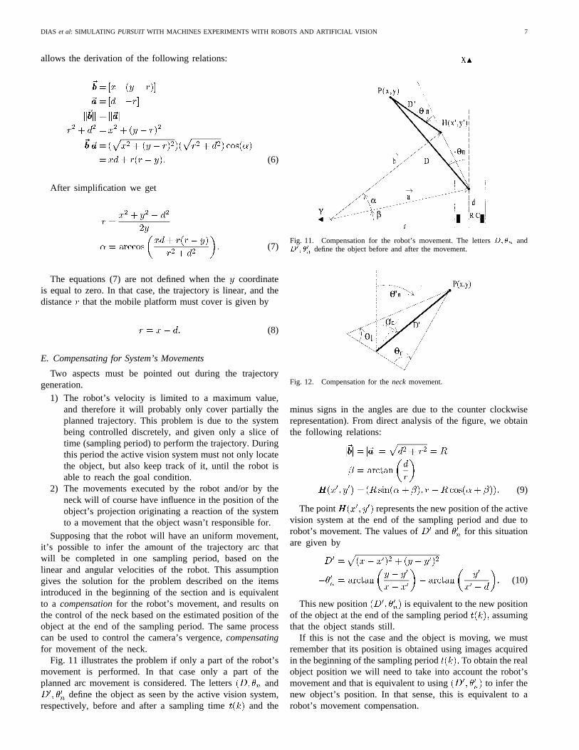
E. Compensating for System’s Movements
Two aspects must be pointed out during the trajectorygeneration.
1) The robot’s velocity is limited to a maximum value,and therefore it will probably only cover partially theplanned trajectory. This problem is due to the systembeing controlled discretely, and given only a slice oftime (sampling period) to perform the trajectory. Duringthis period the active vision system must not only locatethe object, but also keep track of it, until the robot isable to reach the goal condition.
2) The movements executed by the robot and/or by theneck will of course have influence in the position of theobject’s projection originating a reaction of the systemto a movement that the object wasn’t responsible for.
Supposing that the robot will have an uniform movement,it’s possible to infer the amount of the trajectory arc thatwill be completed in one sampling period, based on thelinear and angular velocities of the robot. This assumptiongives the solution for the problem described on the itemsintroduced in the beginning of the section and is equivalentto a compensationfor the robot’s movement, and results onthe control of the neck based on the estimated position of theobject at the end of the sampling period. The same processcan be used to control the camera’s vergence,compensatingfor movement of the neck.
Fig. 11 illustrates the problem if only a part of the robot’smovement is performed. In that case only a part of theplanned arc movement is considered. The letters and
define the object as seen by the active vision system,respectively, before and after a sampling time and the
Fig. 11. Compensation for the robot’s movement. The lettersD; �n andD0; �0
ndefine the object before and after the movement.
Fig. 12. Compensation for theneckmovement.
minus signs in the angles are due to the counter clockwiserepresentation). From direct analysis of the figure, we obtainthe following relations:
(9)
The point represents the new position of the activevision system at the end of the sampling period and due torobot’s movement. The values of and for this situationare given by
(10)
This new position is equivalent to the new positionof the object at the end of the sampling period assumingthat the object stands still.
If this is not the case and the object is moving, we mustremember that its position is obtained using images acquiredin the beginning of the sampling period To obtain the realobject position we will need to take into account the robot’smovement and that is equivalent to using to infer thenew object’s position. In that sense, this is equivalent to arobot’s movement compensation.
8 IEEE TRANSACTIONS ON ROBOTICS AND AUTOMATION, VOL. 14, NO. 1, FEBRUARY 1998
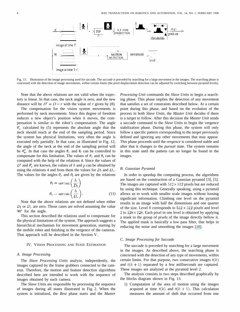
Fig. 13. Illustration of the image processing used for saccade. Thesaccadeis preceded by searching for a large movement in the images. The searching phase isconcerned with the detection of image movements, within certain limits (the pixel displacement detection can be adjusted by switching between pyramid levels).
Note that the above relations are not valid when the trajec-tory is linear. In that case, the neck angle is zero, and the newdistance will be with the value of given by (8).
The compensation for the vision system movements isperformed by neck movements. Since this degree of freedominduces a new object’s position when it moves, the com-pensation is similar to the robot’s compensation. The angle
calculated by (5) represents the absolute angle that theneck should reach at the end of the sampling period. Sincethe system has physical limitations, very often the angle isexecuted only partially. In that case, as illustrated in Fig. 12,the angle of the neck at the end of the sampling period willbe In that case the angles and can be controlled tocompensate for this limitation. The values ofand can becomputed with the help of the relations 4. Since the values of
and are known, the values of and can be obtained byusing the relations 4 and from them the values forandThe values for the angles and are given by the relations
(11)
Note that the above relations are not defined when eitheror are zero. Those cases are solved assuming the valuefor the angle.
This section described the relations used to compensate forthe physical limitations of the system. The approach suggests ahierarchical mechanism for movement generation, starting bythe mobile robot and finishing in the vergence of the cameras.That approach will be described in the Section V.
IV. V ISION PROCESSING ANDSTATE ESTIMATION
A. Image Processing
The Slave Processing Unitsanalyze, independently, theimages captured by the frame grabbers connected to the cam-eras. Therefore, the motion and feature detection algorithmsdescribed here are intended to work with the sequence ofimages obtained by each camera.
The Slave Unitsare responsible by processing the sequenceof images during all states illustrated in Fig. 2. When thesystem is initialized, theRest phase starts and theMaster
Processing Unitcommands theSlave Unitsto begin a search-ing phase. This phase implies the detection of any movementthat satisfies a set of constraints described below. At a certainpoint during this phase, and based on the evolution of theprocess in bothSlave Units, the Master Unit decides if thereis a target to follow. After this decision theMaster Unitsendsa saccadecommand to theSlave Unitsto begin the vergencestabilization phase. During this phase, the system will onlyfollow a specific pattern corresponding to thetargetpreviouslydefined and ignoring any other movements that may appear.This phase proceeds until thevergenceis considered stable andafter that it changes to thepursuit state. The system remainsin this state until the pattern can no longer be found in theimages.
B. Gaussian Pyramid
In order to speedup the computing process, the algorithmsare based on the construction of a Gaussian pyramid [3], [5].The images are captured with pixels but are reducedby using this technique. Generally speaking, using a pyramidallows us to work with smaller scale images without loosingsignificant information. Climbing one level on the pyramidresults in an image with half the dimensions and one quarterof the size. Level 0 corresponds to pixels and level2 to Each pixel in one level is obtained by applyinga mask to the group of pixels of the image directly bellow it.The applied mask is basically a low pass filter, that helps inreducing the noise and smoothing the images [10].
C. Image Processing for Saccade
Thesaccadeis preceded by searching for a large movementin the images. As described above, the searching phase isconcerned with the detection of any type of movements, withincertain limits. For that purpose, two consecutive imagesand separated by a few milliseconds are captured.These images are analyzed at the pyramid level 2.
The analysis consists in two steps described graphically bythe blocks diagram shown in Fig. 13.
1) Computation of the area of motion using the imagesacquired at time and This calculationmeasures the amount of shift that occurred from one
DIAS et al: SIMULATING PURSUITWITH MACHINES EXPERIMENTS WITH ROBOTS AND ARTIFICIAL VISION 9
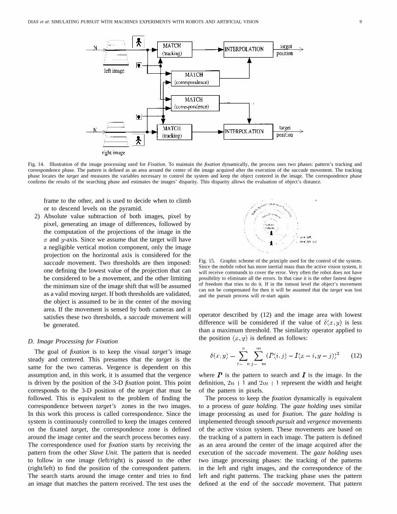
Fig. 14. Illustration of the image processing used forFixation. To maintain thefixation dynamically, the process uses two phases: pattern’s tracking andcorrespondence phase. The pattern is defined as an area around the center of the image acquired after the execution of thesaccademovement. The trackingphase locates thetarget and measures the variables necessary to control the system and keep the object centered in the image. The correspondence phaseconfirms the results of the searching phase and estimates the images’ disparity. This disparity allows the evaluation of object’s distance.
frame to the other, and is used to decide when to climbor to descend levels on the pyramid.
2) Absolute value subtraction of both images, pixel bypixel, generating an image of differences, followed bythe computation of the projections of the image in the
and -axis. Since we assume that the target will havea negligible vertical motion component, only the imageprojection on the horizontal axis is considered for thesaccademovement. Two thresholds are then imposed:one defining the lowest value of the projection that canbe considered to be a movement, and the other limitingthe minimum size of the image shift that will be assumedas a valid movingtarget. If both thresholds are validated,the object is assumed to be in the center of the movingarea. If the movement is sensed by both cameras and itsatisfies these two thresholds, asaccademovement willbe generated.
D. Image Processing for Fixation
The goal offixation is to keep the visualtarget’s imagesteady and centered. This presumes that thetarget is thesame for the two cameras. Vergence is dependent on thisassumption and, in this work, it is assumed that the vergenceis driven by the position of the 3-Dfixation point. This pointcorresponds to the 3-D position of thetarget that must befollowed. This is equivalent to the problem of finding thecorrespondence betweentarget’s zones in the two images.In this work this process is called correspondence. Since thesystem is continuously controlled to keep the images centeredon the fixatedtarget, the correspondence zone is definedaround the image center and the search process becomes easy.The correspondence used forfixation starts by receiving thepattern from the otherSlave Unit. The pattern that is neededto follow in one image (left/right) is passed to the other(right/left) to find the position of the correspondent pattern.The search starts around the image center and tries to findan image that matches the pattern received. The test uses the
Fig. 15. Graphic scheme of the principle used for the control of the system.Since the mobile robot has more inertial mass than the active vision system, itwill receive commands to cover the error. Very often the robot does not havepossibility to eliminate all the errors. In that case it is the other fastest degreeof freedom that tries to do it. If in the inmost level the object’s movementcan not be compensated for then it will be assumed that thetarget was lostand the pursuit process will re-start again.
operator described by (12) and the image area with lowestdifference will be considered if the value of is lessthan a maximum threshold. The similarity operator applied tothe position is defined as follows:
(12)
where is the pattern to search andis the image. In thedefinition, and represent the width and heightof the pattern in pixels.
The process to keep thefixation dynamically is equivalentto a process ofgaze holding. The gaze holdinguses similarimage processing as used forfixation. The gaze holdingisimplemented throughsmooth pursuitandvergencemovementsof the active vision system. These movements are based onthe tracking of a pattern in each image. The pattern is definedas an area around the center of the image acquired after theexecution of thesaccademovement. Thegaze holdingusestwo image processing phases: the tracking of the patternsin the left and right images, and the correspondence of theleft and right patterns. The tracking phase uses the patterndefined at the end of thesaccademovement. That pattern
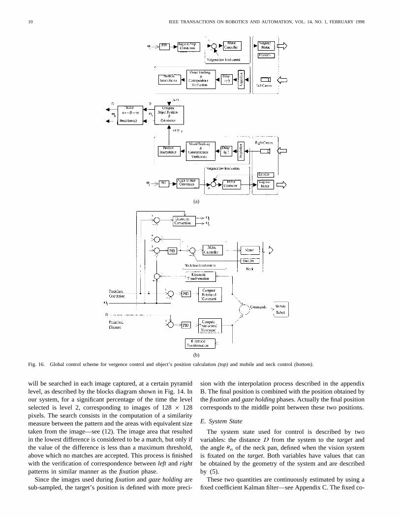
10 IEEE TRANSACTIONS ON ROBOTICS AND AUTOMATION, VOL. 14, NO. 1, FEBRUARY 1998
(a)
(b)
Fig. 16. Global control scheme for vergence control and object’s position calculation(top) and mobile and neck control(bottom).
will be searched in each image captured, at a certain pyramidlevel, as described by the blocks diagram shown in Fig. 14. Inour system, for a significant percentage of the time the levelselected is level 2, corresponding to images of 128128pixels. The search consists in the computation of a similaritymeasure between the pattern and the areas with equivalent sizetaken from the image—see (12). The image area that resultedin the lowest difference is considered to be a match, but only ifthe value of the difference is less than a maximum threshold,above which no matches are accepted. This process is finishedwith the verification of correspondence betweenleft andrightpatterns in similar manner as thefixation phase.
Since the images used duringfixation andgaze holdingaresub-sampled, the target’s position is defined with more preci-
sion with the interpolation process described in the appendixB. The final position is combined with the position obtained bythefixationandgaze holdingphases. Actually the final positioncorresponds to the middle point between these two positions.
E. System State
The system state used for control is described by twovariables: the distance from the system to thetarget andthe angle of the neck pan, defined when the vision systemis fixated on thetarget. Both variables have values that canbe obtained by the geometry of the system and are describedby (5).
These two quantities are continuously estimated by using afixed coefficient Kalman filter—see Appendix C. The fixed co-
DIAS et al: SIMULATING PURSUITWITH MACHINES EXPERIMENTS WITH ROBOTS AND ARTIFICIAL VISION 11
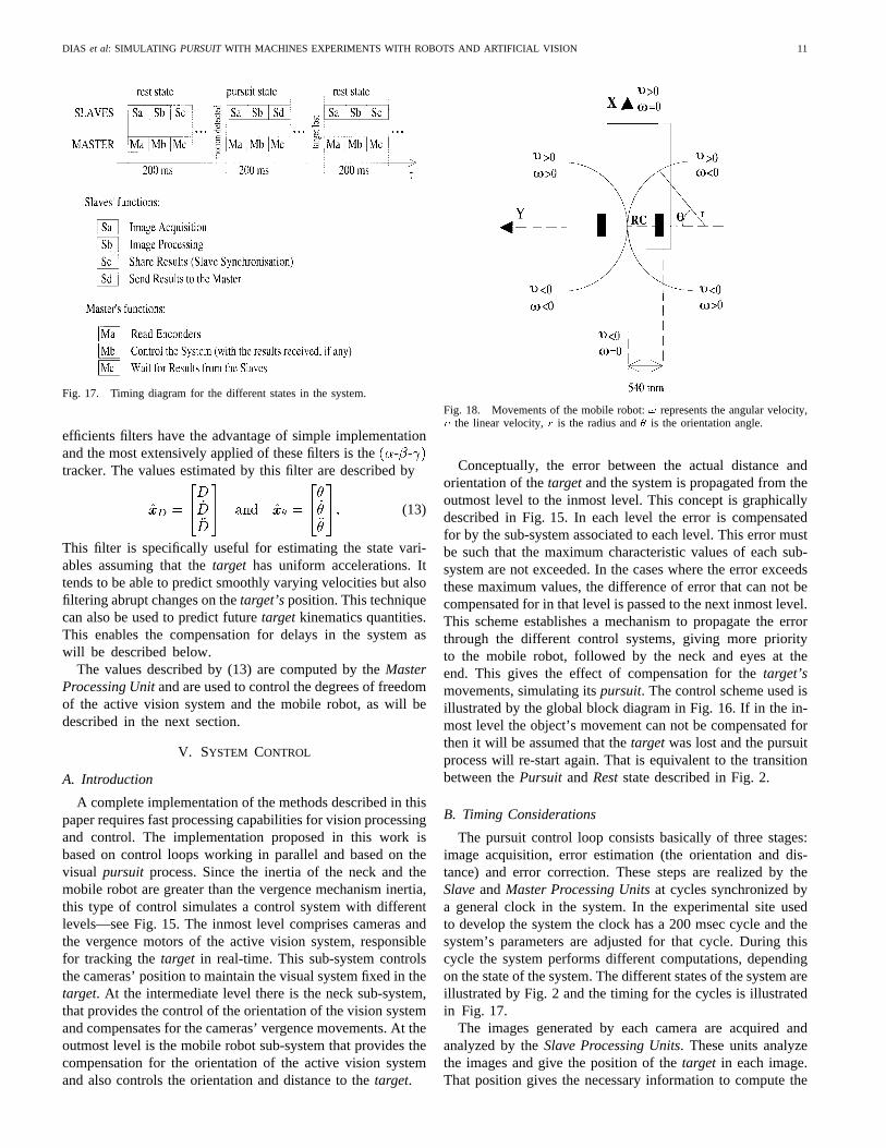
Fig. 17. Timing diagram for the different states in the system.
efficients filters have the advantage of simple implementationand the most extensively applied of these filters is the- -tracker. The values estimated by this filter are described by
(13)
This filter is specifically useful for estimating the state vari-ables assuming that thetarget has uniform accelerations. Ittends to be able to predict smoothly varying velocities but alsofiltering abrupt changes on thetarget’sposition. This techniquecan also be used to predict futuretarget kinematics quantities.This enables the compensation for delays in the system aswill be described below.
The values described by (13) are computed by theMasterProcessing Unitand are used to control the degrees of freedomof the active vision system and the mobile robot, as will bedescribed in the next section.
V. SYSTEM CONTROL
A. Introduction
A complete implementation of the methods described in thispaper requires fast processing capabilities for vision processingand control. The implementation proposed in this work isbased on control loops working in parallel and based on thevisual pursuit process. Since the inertia of the neck and themobile robot are greater than the vergence mechanism inertia,this type of control simulates a control system with differentlevels—see Fig. 15. The inmost level comprises cameras andthe vergence motors of the active vision system, responsiblefor tracking thetarget in real-time. This sub-system controlsthe cameras’ position to maintain the visual system fixed in thetarget. At the intermediate level there is the neck sub-system,that provides the control of the orientation of the vision systemand compensates for the cameras’ vergence movements. At theoutmost level is the mobile robot sub-system that provides thecompensation for the orientation of the active vision systemand also controls the orientation and distance to thetarget.
Fig. 18. Movements of the mobile robot:! represents the angular velocity,� the linear velocity,r is the radius and� is the orientation angle.
Conceptually, the error between the actual distance andorientation of thetargetand the system is propagated from theoutmost level to the inmost level. This concept is graphicallydescribed in Fig. 15. In each level the error is compensatedfor by the sub-system associated to each level. This error mustbe such that the maximum characteristic values of each sub-system are not exceeded. In the cases where the error exceedsthese maximum values, the difference of error that can not becompensated for in that level is passed to the next inmost level.This scheme establishes a mechanism to propagate the errorthrough the different control systems, giving more priorityto the mobile robot, followed by the neck and eyes at theend. This gives the effect of compensation for thetarget’smovements, simulating itspursuit. The control scheme used isillustrated by the global block diagram in Fig. 16. If in the in-most level the object’s movement can not be compensated forthen it will be assumed that thetargetwas lost and the pursuitprocess will re-start again. That is equivalent to the transitionbetween thePursuit and Reststate described in Fig. 2.
B. Timing Considerations
The pursuit control loop consists basically of three stages:image acquisition, error estimation (the orientation and dis-tance) and error correction. These steps are realized by theSlaveandMaster Processing Unitsat cycles synchronized bya general clock in the system. In the experimental site usedto develop the system the clock has a 200 msec cycle and thesystem’s parameters are adjusted for that cycle. During thiscycle the system performs different computations, dependingon the state of the system. The different states of the system areillustrated by Fig. 2 and the timing for the cycles is illustratedin Fig. 17.
The images generated by each camera are acquired andanalyzed by theSlave Processing Units. These units analyzethe images and give the position of thetarget in each image.That position gives the necessary information to compute the

12 IEEE TRANSACTIONS ON ROBOTICS AND AUTOMATION, VOL. 14, NO. 1, FEBRUARY 1998
Fig. 19. Evolution of the searching algorithm when a target is moving.This image searching algorithm is responsible by the trigger of the saccademovement.
system state and This state is passed to the - -tracker. The information provided by theSlave Unitsis delayedby one cycle of 200 msec. To avoid the lateral effects of thisdelay we use the prediction capabilities of the- - filterto estimate a value for the system state (see Appendix C) (25).
TheMaster Processing Unitrepeatedly performs the controlalgorithm by using the error between the predicted system stateand the desired system state. This error is passed to the differ-ent sub-systems according to the illustration in Fig. 16. Thiserror is passed to the different PID discrete time algorithmsimplemented in each subsystem. The results will be changesin the positions of the step motors associated with the visionsystem and the commands for the mobile robot to maintainthe desired system state and
The movements executed by the mobile platform are basedon two motors associated with each of the driving wheels (rearaxle) and are essential to make the compensation for the errorin the distance The movements permitted with this typeof configuration are represented in Fig. 18. Pure rotations arearound the center of the driving axle represented in Fig. 18by
The values of the velocities are dependent on the type ofmovement and the duration time. In our experiments the period
Fig. 20. Evolution of the tracking algorithm. This image tracking algorithmis used for keep the visual systemfixatedon the person that is moving.
of time is a multiple integer of the system cycle (200 msec).For movements composed by linear and angular velocities,the radius of the trajectory and the trajectory arc can beobtained by the relations (14) and (15) presented in Section Bof Appendix A.
VI. EXPERIMENTAL RESULTS
This section gives examples of the system performances.The first example is related with the evolution of the searchingalgorithm used for saccade movement. Fig. 19 represents tencycles of the process with the entire system stopped. Fromtop to bottom we can see the image taken at time theimage taken at time the differences image and itsprojection on the -axis. The analysis of the sequence allowsus to conclude that we can detect the motion by efficientlythresholding the differences obtained due to the noise. It alsoshows that the values above the threshold, although unstable,appear in the area where the movement occurred. Noticethat the images are pre-filtered and smoothed as explainedin Section V.
The second example concerns the evolution of the algorithmused during pursuit. Fig. 20 shows a sequence of pairs ofimages (right image on top of the left image) obtained withthe system running and thetarget moving. As it can be seen, apart from some minor deviations, the selected area ofthe target is matched correctly. Also important is the obvioustendency to keep thetarget in the middle of the images, asshould be expected from the type of control implemented.
It is interesting to know the system response to a input signallike the the step signal. The step-response reveals the generalform of the system model. The response of the neck’s angleto a simulation of the step signal is shown in Fig. 21. The

DIAS et al: SIMULATING PURSUITWITH MACHINES EXPERIMENTS WITH ROBOTS AND ARTIFICIAL VISION 13
Fig. 21. The response of the neck’s angle to a simulation of the step signalwhen the filter prediction is used. The vertical axis represents�n (degrees)for diferent time clocks(k) represented on the horizontal axis.
signal used is equivalent to the signal resulting from a personstanding in front of the system, and then quickly taking a stepaside. The distance is constant and equal to 2 meters. The useof the filter prediction, described in appendix C by (25), resultsin the signal shown in Fig. 21.
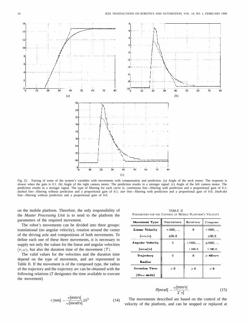
The next three graphics (Fig. 22) show the angle shifts ofthe neck motor, right camera motor and left camera motorrespectively, when filtering and prediction are used. The curvesshows traces for the proportional, integrative and differentialgains (PID) of 0.6 and 0.1.
The same experiment was repeated with a proportional gainof 0.1 for the neck motor and the results are depicted inFig. 23. Note that, since the system is now slower, the useof compensation and prediction methods assumes a greaterimportance.
The final examples (Figs. 24 and 25) show the importance offiltering the distance and the angle The - - filteringis used mostly to predict the position of thetarget one cyclein advance. This will compensate for the delay between theacquisition of the images and the reaction of the system (dueto the computational burden).
VII. CONCLUSION
This article reports the integration of an active vision systemin a mobile platform. It describes a control scheme used forreal-time pursuit of objects moving in front of the vehicle.The pursuit process controls the system to maintain the initialorientation and distance to the object. The control is based onmultiple independent processes, controlling different degreesof freedom of the vision system and the mobile robot’s positionand orientation. The system is able to operate at approximatelyhuman walking rates, and experimental results were presentedwith the robot following a person. The system has limitationsand some of them were already discussed and established asassumptions in Section I.
Future developments will address the problem of differentobjects moving in front of the mobile robot. These extensionsalso include the use of more elaborated control schemes
TABLE IPARAMETERS OF THESTEP MOTORS USED IN THEACTIVE VISION SYSTEM
and the improvement of the image processing hardware androutines.
APPENDIX A
VISION SYSTEM AND ROBOT PARAMETERS
A. Active Vision System
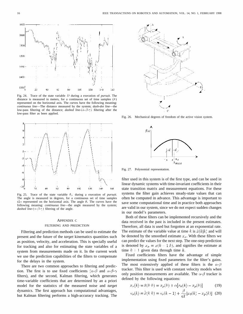
The vision system can be divided into three major areas:the platform that supports the cameras, the mechanical systemthat permits the orientation of that platform and the motorizedlenses. The platform allows for the cameras to execute themovementA shown in Fig. 26 (the vergence) and also the con-trol of the distance between them (the baseline shifting). Themechanical system that supports the platform is responsiblefor the execution of the movementsB andC shown in Fig. 26(the head tilt and the neck pan respectively). The cameras’lenses are motorized, using direct current motors to controlthe degrees of freedom corresponding to the iris, focus andzoom. The lenses used can have a focal length between 12.5and 75 mm, focusing between 1.3 m and thedepending onthe focal length.
The offsets permitted to the various degrees of freedomassociated with the active vision system are listed in Table I,resulting from the limits imposed to the system by the electri-cal and mechanical limits, and due to the mechanical structureof the system itself.
The velocities reached by the step motors depend on thevalues of the parameters measured experimentally. The valuesobtained do not permit movements from one end-positionto the other in acceptable periods of time (once a movingcommand is issued to the controllers, the motors cannotbe interrupted until they stop). Therefore, any movementrequested must be divided into smaller movements that canbe completed by the motors during one control period.
Typically, the control period for the vergence motors is 0.2 swith a maximum of 40 steps, and for the neck pan motor is 0.2s with a maximum of 100 steps. The choice for these periodsresulted from a compromise between the reaction speed of thesystem and the amplitude of the movements executed.
B. Mobile Robot System
The movements executed by the mobile robot are based ontwo direct current motors associated with each of the drivingwheels (rear axle). The control of the motors is done by amulti-processing system based on the 68 020 CPU, installed
14 IEEE TRANSACTIONS ON ROBOTICS AND AUTOMATION, VOL. 14, NO. 1, FEBRUARY 1998
(a) (b)
(c)
Fig. 22. Tracing of some of the system’s variables with movements with compensation and prediction. (a) Angle of the neck motor. The response isslower when the gain is 0.1. (b) Angle of the right camera motor. The prediction results in a stronger signal. (c) Angle of the left camera motor. Theprediction results in a stronger signal. The type of filtering for each curve is:continuous line—filtering with prediction and a proportional gain of 0.1;dashed line—filtering without prediction and a proportional gain of 0.1;star line—filtering with prediction and a proportional gain of 0.6;Dash-dotline—filtering without prediction and a proportional gain of 0.6.
on the mobile platform. Therefore, the only responsibility ofthe Master Processing Unitis to send to the platform theparameters of the required movement.
The robot’s movements can be divided into three groups:translational (no angular velocity), rotation around the centerof the driving axle and compositions of both movements. Todefine each one of these three movements, it is necessary tosupply not only the values for the linear and angular velocities
but also the duration time of the movementThe valid values for the velocities and the duration time
depend on the type of movement, and are represented inTable II. If the movement is of the composed type, the radiusof the trajectory and the trajectory arc can be obtained with thefollowing relations (T designates the time available to executethe movement)
mmmm/smrad/s
(14)
TABLE IIPARAMETERS FOR THECONTROL OF MOBILE PLATFORM’ S VELOCITY
mradmm/s
s(15)
The movements described are based on the control of thevelocity of the platform, and can be stopped or replaced at

DIAS et al: SIMULATING PURSUITWITH MACHINES EXPERIMENTS WITH ROBOTS AND ARTIFICIAL VISION 15
(a) (b)
(c)
Fig. 23. Movements with compensation and prediction with smaller proportional gains (0.1). (a) Angle of the neck motor. The vertical axis represents�n
(degrees) for diferent time clocks(k) represented on the horizontal axis. (b) Angle of the right camera motor. The vertical axis represents�r (degrees) fordiferent time clocks(k) represented on the horizontal axis. (c) Angle of the left camera motor. The vertical axis represents�
l(degrees) for diferent time
clocks (k) represented on the horizontal axis.Continuous line—filtering without prediction or compensation;dashed line—filtering without prediction and withcompensation;star line—filtering with prediction and compensation;dash-dot line—filtering with prediction and without compensation.
any time by another movement with other parameters. Thetransition between movements is controlled by the multi-processing system, assuring the smoothness of the globalmovement of the robot.
The following lines are examples of commands that can beissued to the platform to launch velocity controlled movementsissuing a:
1) composed movement: “MOTV LA V 100 W 100T 50”;
2) pure rotation movement: “MOTV LA V 0 W 100T 50”;
3) a linear movement: “MOTV LA V 100 T 50”.
APPENDIX B
QUADRATIC SUB PIXEL INTERPOLATION
The objective of this appendix is to explain the mechanismused to find the maximum of a function of which only discretesamples are known. Since we are using images, the samples are
discrete values of the function and we use interpolation to findthe function’s maximum with sub pixel precision (Fig. 27).
Suppose that the function is parameterized by the polyno-mial
(16)
with the extreme point at If the discretepoints are at and with the distancebetween samples, their values for the function are givenby
(17)
Combining these equations we obtain the position isgiven by
(18)
16 IEEE TRANSACTIONS ON ROBOTICS AND AUTOMATION, VOL. 14, NO. 1, FEBRUARY 1998
Fig. 24. Trace of the state variableD during a execution ofpursuit. Thedistance is measured in meters, for a continuous set of time samples(k)represented on the horizontal axis. The curves have the following meaning:continuous line—The distance measured by the system;dash-dot line—thelow-pass filtering of the distance;dashed line-(�-�- ) filtering after thelow-pass filter as been applied.
Fig. 25. Trace of the state variable�n during a execution ofpursuit.The angle is measured in degrees, for a continuous set of time samples(k) represented on the horizontal axis. The angle�: The curves have thefollowing meaning: continuous line—the angle measured by the system;dashed line-(�-�- ) filtering of the angle.
APPENDIX C
FILTERING AND PREDICTION
Filtering and prediction methods can be used to estimate thepresent and the future of thetarget kinematics quantities suchas position, velocity, and acceleration. This is specially usefulfor tracking and also for estimating the state variables of asystem from measurements made on it. In the current workwe use the prediction capabilities of the filters to compensatefor the delays in the system.
There are two common approaches to filtering and predic-tion. The first is to use fixed coefficients - and - -filters), and the second, Kalman filtering, which generatestime-variable coefficients that are determined by an a priorimodel for the statistics of the measured noise andtargetdynamics. The first approach has computational advantages,but Kalman filtering performs a high-accuracy tracking. The
Fig. 26. Mechanical degrees of freedom of the active vision system.
Fig. 27. Polynomial representation.
filter used in this system is of the first type, and can be used inlinear dynamic systems with time-invariant coefficients in theirstate transition matrix and measurement equations. For thesesystems the filter gain achieves steady-state values that canoften be computed in advance. This advantage is important tosave some computational time and in practice both approachesare valid in our system, since we do not expect sudden changesin our model’s parameters.
Both of these filters can be implemented recursively and thedata received in the past is included in the present estimates.Therefore, all data is used but forgotten at an exponential rate.The estimate of the variable value at timeis and willbe denoted by the smoothed estimateWith these filters wecan predict the values for the next step. The one-step predictionis denoted by and signifies the estimate attime given data through time
Fixed coefficients filters have the advantage of simpleimplementation using fixed parameters for the filter’s gains.The most extensively applied of these filters is the-tracker. This filter is used with constant velocity models whenonly position measurements are available. The- tracker isdefined by the following equations:
(19)
(20)

DIAS et al: SIMULATING PURSUITWITH MACHINES EXPERIMENTS WITH ROBOTS AND ARTIFICIAL VISION 17
(21)
The variable is the sampling interval, is themeasurement at time and the and are the fixed filtergain coefficients. The quantity is normally defined as one,but in the case where missing observations occur its value maybe taken as the number of scan steps (interactions) since thelast measurement. The initialization process can be defined by
The (19) is used directly when an observation is receivedat time The optimal values for and are derived in [2]and depend only on the ratio of the process noise standarddeviation and the measurement noise standard deviation.
The logical extension of the - filter is the - - filter,which includes an estimate for the acceleration and can be usedwith the assumption of uniform acceleration. This filter makesa quadratic prediction instead of a linear one, and tends tobe more sensitive to noise but better able to predict smoothlyvarying velocities. The equations for this filter are defined as
(22)
(23)
(24)
(25)
The usual initialization is
The optimal values for and are defined as [2] and theoptimal value for is given by
(26)
ACKNOWLEDGMENT
The authors would like to thank the Associate Editor and theanonymous referees for their careful review and constructivecomments on the earlier versions of this article.
REFERENCES
[1] P. Allen, A. Timcenko, B. Yoshimi, and P. Michelman, “Automatedtracking and grasping of a moving object with a robotic hand-eyesystem,”IEEE Trans. Robot. Automat.,vol. 9, Apr. 1993.
[2] S. Blackman, Multiple-Target Tracking with Radar Applications.Boston, MA: Artech House, 1986, pp. 19–25.
[3] J. Bergen, P. Burt, R. Hingorani, and S. Peleg, “Computing two motionsfrom three frames,” David Sarnoff Research Center, Subsidiary of SRIInt., Princeton, NJ 08543-5300, Apr. 1990.
[4] C. Brown, “Gaze controls with interaction and delays,”IEEE Trans.Syst., Man., Cybern.,vol. 20, pp. 518–527, May, 1990.
[5] P. Burt, C. Anderson, J. Sinniger, and G. van der Wal, “A pipelinedpyramid machine,” RCA David Sarnoff Research Center, NATO ASISeries, vol. F25, 1986.
[6] P. Burt, J. Bergen, R. Hingorani, R. Kolczynski, W. Lee, A. Leung, J.Lubin, and H. Shvaytser, “Object tracking with a moving camera,” inProc. IEEE Workshop Visual Motion,Irvine, CA, 1989.
[7] H. Carpenter,Movements of the Eyes. London, U.K.: Pion Ltd., 2nd ed.[8] D. Coombs, “Real-time gaze holding in binocular robot vision,” Ph.D.
dissertation, Univ. of Rochester, Rochester, NY, June 1992.[9] E. Grosso and D. Ballard, “Head-Centered Orientation Strategies in
Animate Vaision,” Tech. Rep. 442, Comput. Sci. Dept., Univ. ofRochester, Rochester, NY, Oct. 1992.
[10] P. Meer, E. Baugher, and A. Rosenfeld, “Frequency domain analysis andsynthesis of image pyramid generating kernels,”IEEE Trans. PatternAnal. Machine Intell.,vol. PAMI-9, pp. 512–522, July 1987.
[11] N. Papanikopoulos, P. Khosla, and T. Kanade, “Visual tracking of amovingtargetby a camera mounted on a robot: a combination of controland vision,”IEEE Trans. Robot. Automat.,vol. 9, pp. 14–34, Feb. 1993.
[12] R. Paul,Robot Manipulators: Mathematics, Programming, and Control.Cambridge, MA: MIT Press, 1981, pp. 9–11.
[13] C. M. Brown and D. Terzopoulos, Eds.,Real-time Computer Vision.Cambridge, MA: Cambridge Univ. Press, 1994.
[14] J. L. Crowley and H. I. Christensen, Eds.,Vision as Process. NewYork: Springer-Verlag, 1995.
[15] A. Blake and A. Yuille, Eds.,Active Vision. Cambridge, MA: MITPress, 1992.
[16] J. Dias, H. de Araujo, J. Batista, A. de Almeida, and C. Simplıcio,s“Implementation of an active vision system,” inProc. Int. WorkshopMechatron. Comput. Syst. Perception Action,June 1–3, 1993, HalmstadUniversity, Sweden.
[17] J. Batista, J. Dias, H. de Ara´ujo, and A. de Almeida, “Monoplanar cam-era calibration-iteractive multi-step approach,” inProc. British MachineVision Conf. BMVA’93, Surrey, U.K., July 1993.
[18] H. Araujo, J. Dias, J. Batista, and P. Peixoto, “Autonomous robots andactive vision systems: Issues on architectures and integration,” inProc.Workshop Appl. Artif. Intell. Robot. Vision,Funchal, Portugal, 1995.
[19] C. Samson and K. Ait-Abderrahim, “Mobile-robot control. Part 1:Feedback control of a nonholonomic wheeled cart in Cartesian space,”Rapport de Recherche 1288, INRIA, Sophia Antipolis, France, Oct.1990; Active Vision, A. Blake and A. Yuille, Eds. Cambridge, MA:MIT Press, 1992.
[20] Theory of Robot Control, C. Canudas de Wit, B. Siciliano, and G. Bastin,Eds. New York: Springer-Verlag, 1996.
Jorge Diaswas born in Coimbra, Portugal, in 1960.He received the B.S. and Ph.D. degrees in electricalengineering from the University of Coimbra, Portu-gal, in 1984.
He is an Assistant Professor in the Departmentof Electrical Engineering, University of Coimbraand is a Researcher at the Institute of Systemsand Robotics, Coimbra Pole. His primary researchinterest is in the area of computer vision, with anemphasis on the active vision and vision basednavigation.
18 IEEE TRANSACTIONS ON ROBOTICS AND AUTOMATION, VOL. 14, NO. 1, FEBRUARY 1998
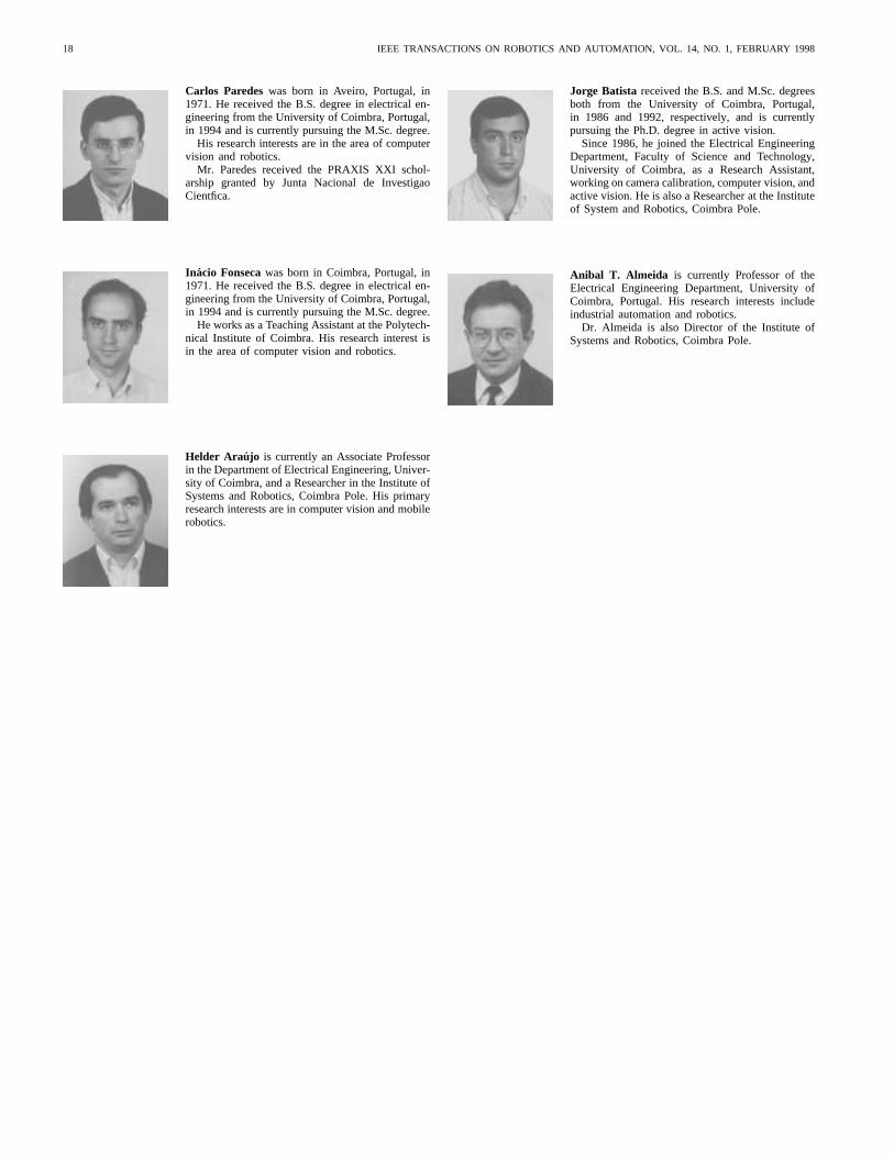
Carlos Paredeswas born in Aveiro, Portugal, in1971. He received the B.S. degree in electrical en-gineering from the University of Coimbra, Portugal,in 1994 and is currently pursuing the M.Sc. degree.
His research interests are in the area of computervision and robotics.
Mr. Paredes received the PRAXIS XXI schol-arship granted by Junta Nacional de InvestigaoCientfica.
In acio Fonsecawas born in Coimbra, Portugal, in1971. He received the B.S. degree in electrical en-gineering from the University of Coimbra, Portugal,in 1994 and is currently pursuing the M.Sc. degree.
He works as a Teaching Assistant at the Polytech-nical Institute of Coimbra. His research interest isin the area of computer vision and robotics.
Helder Araujo is currently an Associate Professorin the Department of Electrical Engineering, Univer-sity of Coimbra, and a Researcher in the Institute ofSystems and Robotics, Coimbra Pole. His primaryresearch interests are in computer vision and mobilerobotics.
Jorge Batista received the B.S. and M.Sc. degreesboth from the University of Coimbra, Portugal,in 1986 and 1992, respectively, and is currentlypursuing the Ph.D. degree in active vision.
Since 1986, he joined the Electrical EngineeringDepartment, Faculty of Science and Technology,University of Coimbra, as a Research Assistant,working on camera calibration, computer vision, andactive vision. He is also a Researcher at the Instituteof System and Robotics, Coimbra Pole.
Anibal T. Almeida is currently Professor of theElectrical Engineering Department, University ofCoimbra, Portugal. His research interests includeindustrial automation and robotics.
Dr. Almeida is also Director of the Institute ofSystems and Robotics, Coimbra Pole.