Simulating Energy Efficient Control of Multiple ...
13
Simulating Energy Efficient Control of Multiple-Compressor Compressed Air Systems Sean Murphy Kelly Kissock Energy Engineer Professor and Department Chair EnerNOC University of Dayton Los Angeles, CA Dayton, OH ABSTRACT In many industrial facilities it is common for more than one air compressor to be operating simultaneously to meet the compressed air demand. The individual compressor set-points and how these compressors interact and respond to the facility demand have a significant impact on the compressed air system total power consumption and efficiency. In the past, compressors were staged by cascading the pressure band of each compressor in the system. Modern automatic sequencers now allow more intelligent and efficient staging of air compressors. AirSim, a compressed air simulation tool, is now able to simulate multiple-compressor systems with pressure band and automatic sequencer controls. AirSim can simulate a current compressed air system and a proposed system with changes to the equipment and/or controls. Thus, quickly and accurately, users can calculate the energy and cost savings expected from many proposed compressed air system upgrades. INTRODUCTION Nearly every industrial plant contain compressed air systems. In many industrial facilities air compressors use more electricity than any other single type of equipment. Commonly referred to as the “fourth utility”, compressed air systems can typically be optimized to decrease the energy use of the system by 20% to 50%. In addition to energy and cost savings, an energy efficient compressed air system can reduce maintenance, extend the useful life of the system components, and improve system reliability [6]. Compressed air controls match the compressed air supply with the facility demand and can be one of the most important determinants in overall system energy efficiency. Compressed air systems are sized for the maximum expected plant air demand, thus these systems typically operate only partially loaded. Compressed air system controls coordinate how individual compressors operate and how multiple compressors interact to deliver the required pressure and volume of air to the facility in the most reliable and efficient manner. Systems with multiple compressors contain greater opportunity for controls optimization. The three main types of multiple- compressor control strategies which will be discussed in this paper are: pressure band control, network sequencer control, and automatic sequencer control (also referred to as system master control) [13]. Compressor air component manufactures are acutely aware of the potential for energy savings from multiple-compressor controls. Atlas Copco, Kaeser, and Quincy all market compressed air system central controllers to optimize system efficiency [1] [10] [12]. Furthermore, the 2013 California Building Energy Efficiency Standard, which became law July 1, 2014, requires a central controller for multiple- compressor compressed air systems with total rated power over 100-hp. This standard also requires a variable speed drive (VSD) trim compressor [8]. As will be discussed later, these two requirements cannot be met with pressure band control or network sequencer control. Only automatic sequencer control allows a trim compressor to always meet the part- load marginal system demand. This paper begins by reviewing the basics of simulating individual air compressors, fundamental to the compressed air simulation tool AirSim. Next, the basic principles and control algorithms are detailed for pressure band control, network sequencer control, and automatic sequencer control strategies for multiple-compressor compressed air systems. Finally, a case study is presented demonstrating the use of the improved compressed air simulation tool, AirSim [9], to quickly and accurately model multiple-compressor compressed air systems. SIMULATING SINGLE AIR COMPRESSOR PERFORMANCE Individual air compressors can be controlled in several ways. Schmidt and Kissock describe these control methods as generalized linear relationships between fraction full-load power (FP) and fraction rated capacity (FC) [3]. Using linear generalizations and assigning FP 0 as the fraction of full-load power consumed when the compressor is producing no compressed air, the relationship between FP and FC can be modeled as: FP = FP 0 + (1 – FP 0 ) × FC (1)
-
Upload
khangminh22 -
Category
Documents
-
view
0 -
download
0
Transcript of Simulating Energy Efficient Control of Multiple ...

Simulating Energy Efficient Control of Multiple-Compressor Compressed Air Systems
Sean Murphy Kelly Kissock
Energy Engineer Professor and Department Chair
EnerNOC University of Dayton
Los Angeles, CA Dayton, OH
ABSTRACT
In many industrial facilities it is common for
more than one air compressor to be operating
simultaneously to meet the compressed air demand.
The individual compressor set-points and how these
compressors interact and respond to the facility
demand have a significant impact on the compressed
air system total power consumption and efficiency. In
the past, compressors were staged by cascading the
pressure band of each compressor in the system.
Modern automatic sequencers now allow more
intelligent and efficient staging of air compressors.
AirSim, a compressed air simulation tool, is now able
to simulate multiple-compressor systems with
pressure band and automatic sequencer controls.
AirSim can simulate a current compressed air system
and a proposed system with changes to the equipment
and/or controls. Thus, quickly and accurately, users
can calculate the energy and cost savings expected
from many proposed compressed air system
upgrades.
INTRODUCTION
Nearly every industrial plant contain compressed
air systems. In many industrial facilities air
compressors use more electricity than any other
single type of equipment. Commonly referred to as
the “fourth utility”, compressed air systems can
typically be optimized to decrease the energy use of
the system by 20% to 50%. In addition to energy and
cost savings, an energy efficient compressed air
system can reduce maintenance, extend the useful life
of the system components, and improve system
reliability [6].
Compressed air controls match the compressed
air supply with the facility demand and can be one of
the most important determinants in overall system
energy efficiency. Compressed air systems are sized
for the maximum expected plant air demand, thus
these systems typically operate only partially loaded.
Compressed air system controls coordinate how
individual compressors operate and how multiple
compressors interact to deliver the required pressure
and volume of air to the facility in the most reliable
and efficient manner. Systems with multiple
compressors contain greater opportunity for controls
optimization. The three main types of multiple-
compressor control strategies which will be discussed
in this paper are: pressure band control, network
sequencer control, and automatic sequencer control
(also referred to as system master control) [13].
Compressor air component manufactures are
acutely aware of the potential for energy savings
from multiple-compressor controls. Atlas Copco,
Kaeser, and Quincy all market compressed air system
central controllers to optimize system efficiency [1]
[10] [12]. Furthermore, the 2013 California Building
Energy Efficiency Standard, which became law July
1, 2014, requires a central controller for multiple-
compressor compressed air systems with total rated
power over 100-hp. This standard also requires a
variable speed drive (VSD) trim compressor [8]. As
will be discussed later, these two requirements
cannot be met with pressure band control or network
sequencer control. Only automatic sequencer control
allows a trim compressor to always meet the part-
load marginal system demand.
This paper begins by reviewing the basics of
simulating individual air compressors, fundamental
to the compressed air simulation tool AirSim. Next,
the basic principles and control algorithms are
detailed for pressure band control, network sequencer
control, and automatic sequencer control strategies
for multiple-compressor compressed air systems.
Finally, a case study is presented demonstrating the
use of the improved compressed air simulation tool,
AirSim [9], to quickly and accurately model
multiple-compressor compressed air systems.
SIMULATING SINGLE AIR COMPRESSOR
PERFORMANCE
Individual air compressors can be controlled in
several ways. Schmidt and Kissock describe these
control methods as generalized linear relationships
between fraction full-load power (FP) and fraction
rated capacity (FC) [3]. Using linear generalizations
and assigning FP0 as the fraction of full-load power
consumed when the compressor is producing no
compressed air, the relationship between FP and FC
can be modeled as:
FP = FP0 + (1 – FP0) × FC (1)

The normalized power and capacity coefficients in
Equation 1 are the actual power and capacity divided
by the maximum power and capacity:
FP = P / FLP (2)
FC = C / FLC (3)
FP0 = P0 / FLP (4)
P is the actual compressor power, FLP is the full-load
compressor power, C is the actual compressed air
output, FLC is the full-load compressor output
capacity, and P0 is the compressor power when
producing no compressed air.
Schmidt and Kissock originally graphed the
linear relationships between FP and FC for different
control methods [3]. Figure 1 shows these FP and FC
relationships for several common compressor control
methods with added insight. While Equation 1 can be
used to model the part-load efficiencies of these
different control types, it is important to notice the
variations which occur for load/unload, variable
speed, and on/off control. Load/unload and on/off
only operate at full-load, 100% capacity and 100%
power, or no-load, 0% capacity and FP0. Variable
speed control can operate on the continuum between
full-load and about 25% FC. Blow off and
modulation control operate continuously between
full-load and no-load.
Figure 1. FP vs FC for Common Compressor Control
Types
Other control methods not shown in the FP-FC
graph in Figure 1 include dual, auto-dual, and
variable displacement control. Dual and auto-dual
control operate in load/unload control down to a
certain capacity, below which they operate in on/off
control. Variable displacement typically employs a
turn-, spiral-, poppet-, or slide-valve to vary the
effective length of the screw compressor [7].
Air compressors supply compressed air to the
distribution system, which deliver it to end-uses. The
system pressure depends on the volume of air
supplied by the compressors, the volume of air
demanded by the plant, and the fixed volume (storage
and distribution) of the compressed air system. A
first order model of this relationship, originally
developed by Schmidt and Kissock, is revisited
below, which leads to the underlying relationships
AirSim uses to model air compressors. The model
excludes the effect of pressure drop due to friction
through the dryer and distribution system [3].
From the ideal gas law, the mass of air, m,
enclosed in a volume, V, at a given air pressure, P,
and temperature, T, where R is the gas constant for
air can be written as:
m = (P × V) / (R × T) (5)
The volume flow rates of air from the compressor
and to the plant are defined as Vc and Vp,
respectively. Similarly, the mass flow rates of air
from the compressor and to the plant are defined as
mc and mp, respectively. The volume of compressed
air storage is defined as Vs. A mass balance on the
compressed air distribution system, where t is time,
is:
mc – mp = δm / δt =
δ[ (P × V) / (R × T) ] / δt (6)
Assuming the compressed air system is
isothermal and the changes happen over a finite time
interval, Δt, Equation 6 can be simplified to:
(V × ρ)c – ( V × ρ)p =
(P+ – P) × Vs / (R × T × Δt) (7)
where ρ is the density of air and P and P+ are the
pressures at the beginning and end of the time
interval, respectively. When the volume flow rates
are measured in terms of standard conditions (i.e.
scfm), the air density is also taken at standard
atmospheric conditions. Thus, the pressure at the end
of a time interval, P+, with varying volume flow rates
from the compressor and to the plant, can be written
as:
P+ = P + (Vc – Vp) × ρ × Δt × R × T / Vs (8)
Equation 8 is the fundamental equation AirSim
uses for simulating air compressor performance,
since air compressor output, Vc, is typically
controlled based on the system pressure, P. Thus, a
control algorithm for on/off and load/unload control

modes can be written such that the compressor
generates the full rated capacity of compressed air
output to raise the pressure from the lower to the
upper activation pressures. The compressor would
generate no compressed air output as the system
pressure falls back to the lower activation pressure.
Similarly, an algorithm for modulation and
variable speed control modes can be written to
maintain system pressure between the lower and
upper activation pressures, Pl and Ph, respectively,
using a variant of proportional control. AirSim does
this by relating the compressed air output and the
system pressure, P, such that the compressed air
output is the product of the full rated capacity and
FC, where FC is defined as:
FC = 1 – (P – Pl) / (Ph – Pl) (9)
The primary differences between AirSim and the
popular AirMaster+ software [17] is the time interval
for the simulation and the automatic sequencer
control logic. AirSim allows the user to define a time
interval appropriate for the system being considered,
where AirMaster+ operates on a fixed time interval
of one hour. Thus, in AirSim the time interval can be
defined short enough to model actual load/unload,
blowdown, or modulation events, which typically
occur on the order of seconds or minutes. This
feature makes calibration easy, allows the user to
develop a better understanding of the dynamic
behavior of the system, and allows AirSim to
consider savings opportunities, such as automatic
shut off, which cannot be modeled using AirMaster+.
Additionally, AirSim allows the user to simulate
a compressed air system with multiple compressors
using automatic sequencer control. AirSim uses basic
control logic, to be discussed in the next section, to
automatically determine which compressors operate
based on the variable plant air demand. AirMaster+
requires the user to specify the staging order of
compressors for each hour of plant air demand.
SIMULATING MULTIPLE AIR COMPRESSOR
PERFORMANCE
Multiple-compressor system controls coordinate
how individual compressors operate and how
multiple compressors interact to deliver the required
pressure and volume of air to the facility in the most
reliable and efficient manner. The three main types of
multiple-compressor control strategies are: pressure
band control, network sequencer control, and
automatic sequencer control (also referred to as
system master control). In the past, compressors were
typically staged by cascading the pressure bands of
the compressors in the system, the most basic type of
pressure band control. The next advancement was
network sequencer controls, which tied multiple
compressors together to operate as a strategic unit,
rather than independently. Modern automatic
sequencers now enable much more intelligent and
efficient staging of air compressors by fully utilizing
VSD trim compressors [13].
Pressure Band Control
The lease sophisticated multiple-compressor
control strategy is pressure band control. Pressure
band control is a strategy for operating individual
compressors without communication between
compressors. Each compressor continues to operate
with a distinct control type (i.e. modulation,
load/unload, variable speed) and makes control
decisions based solely on the pressure at the outlet of
the compressor. Traditionally, pressure band control
has been used to stage load/unload compressors in
cascading pressure band, as shown in the Figure 2.
Pressure bands for load/unload compressors typically
span 10 psig with individual compressors
overlapping every 5 psig.
Figure 2. Cascading Pressure Band Control Strategy
For the set-points shown in Figure 2, if plant
demand is low, only the lead compressor will operate
between 105-115 psig. When the plant air demand
increases, the lead compressor will become fully
loaded. If the lead compressor cannot keep up with
demand, the system pressure will drop and eventually
hit 100 psig. At this point the first lag compressor
will sense the plant air pressure at its activation
pressure, 100 psig, and it will load.
Now if the plant air demand remains fairly
constant the system will stabilize with the lead
compressor running fully loaded and the first lag
compressor operating at part-load between load and
unload. The plant pressure will be in the 100-110
psig band. Since the pressure never reaches 115, the
lead compressor will not unload.
Finally, if the plant air demand increases further
beyond the capacity of both the lead and first lag

compressor combined, the system pressure will drop
below the lower band of the first lag compressor to
the activation pressure of the second lag compressor,
95 psig. At this higher plant air demand both the lead
and first lag compressors will operate fully loaded,
while the second lag compressor loads and unloads
between 95-105 psig. If additional plant air demand
were to occur beyond the capacity of these three
compressors an additional lag compressor would
need to be cascaded at a lower pressure band. When
plant air demand decreases and the system pressure
increases, the compressor operating partially loaded
will unload and typically automatically shut off after
a certain time period. Once the system pressure
reaches the unload pressure of the previously
cascaded compressor, this compressor will
unload/load and become the partially loaded
compressor.
This control strategy allows only one compressor
to operate at part-load at a time, thus limiting the
quick cycling of load/unload compressors. However,
since the lower band of the last cascaded compressor
must still provide high enough pressure to meet plant
demand, the lead and lag #1 compressors operate
inefficiently at excessively high pressures. This
control strategy also results in very high pressure
fluctuations throughout the compressed air system as
the system cascades between pressure bands.
Furthermore, depending on plant demand, any one of
the three compressors could be operating at part-load
with a cascading pressure band control strategy.
Figure 3 shows a simple compressed air demand
profile over time. The operation of lead and lag
compressors with varying demand is shown for
cascading pressure band control and network
sequencer control (discussed in the next section). As
described previously, the lead compressor always
meets the first amount of compressed air demand,
followed by each of the lag compressors based on
their cascading pressure set-points.
Figure 3. Cascading Pressure Band and Network
Sequencer Control Demand Profile
More complicated control strategies can be
achieved if a modulating or variable speed
compressor is included in a pressure band controlled
system. Figure 4 shows one such pressure band
strategy with a VSD compressor staged in such a way
as to maximize the operation of the VSD compressor
at part-load rather than the load/unload compressors.
This strategy achieves energy savings due to VSD
compressors operating at higher part-load
efficiencies and an overall reduction is the system
pressure band compared to the cascading pressure
band strategy shown in Figure 2.
Figure 4. VSD Pressure Band Control Strategy
The VSD pressure band strategy shown in
Figure 4 would operate in the following way as plant
air demand changes. Initially assume that the plant
air demand is low enough to be met by the VSD
compressor alone. The compressor speeds up and
slows down within the pressure band of 99-102 psig
with a control algorithm similar to Equation 9. If the
plant air demand increases beyond the capacity of the
VSD compressor, the system pressure will drop
below 99 psig to the activation pressure of the first
load/unload compressor. This constant speed drive
(CSD) compressor will load at 97 psig and cause the
system pressure to increase. As the system pressure
increases back within the VSD compressor’s pressure
band, the VSD compressor slows down until the
system pressure stabilizes. Since the system pressure
did not increase to the first load/unload compressor’s
unload pressure, this compressor will remain fully
loaded while the VSD compressor will operate at
part-load.
If the plant air demand increases further, the
pressure will drop causing the VSD compressor to
fully load and the first load/unload compressor will
remain fully loaded. The pressure will drop to the
second load/unload compressor’s activation pressure,
95 psig, causing it to load. As the system pressure
increases back within the VSD compressor’s pressure
band, the VSD compressor slows down until the
system pressure stabilizes. Now the two load/unload

compressor are operating fully loaded and the VSD
compressor is operating at part-load.
If the plant air demand decreases from this point,
the system pressure will increase through the VSD
compressor pressure band causing it to eventually
shut off. The pressure may continue to rise to the
second load/unload compressor’s unload pressure
set-point, 105 psig, causing this compressor to
unload. With the second load/unload compressor
unloaded, the system pressure will decrease back into
the VSD pressure band. If the system demand
stabilizes, the first load/unload compressor remains
fully loaded and the VSD compressor operates at
part-load.
A potential issue when operating a VSD
compressor in such a manner as shown in Figure 4 is
having a system control gap. Control gaps can be
avoided by properly sizing the capacity range of the
VSD compressor to be greater than the full-load
capacity of the largest base compressor. Control gaps
will be discussed further in the automatic sequencer
section.
The VSD pressure band control strategy is much
more efficient than the cascading pressure band
control strategy with all load/unload compressors.
However, the main disadvantages of both include:
large pressure swings throughout the plant, decreased
compression efficiency due to excessively high
pressure bands, and limited compressor response
time. This last issue, compressor response time, often
results in some “ideal” pressure band control
strategies being unrealistic due to significant
response times of individual compressors not tied to
a central controller. If the individual compressor’s
pressure bands are too small or if compressors’
unload or load set-points are too near each other,
compressors could short-cycle, excessive pressure
swings could occur, and the system will likely not
operate as intended [16]. Thus, communication
between individual compressors is key to reduce
large pressure swings and operate the system most
efficiently.
AirSim allows for the staging of multiple
compressors of various individual controls with
pressure band system control [9]. This control
strategy idealizes systems to have immediate
response times and exactly the same system pressure
sensed at each compressor. Thus, simulating pressure
band control in AirSim should be done with caution.
Network Sequencer Control
Network sequencer control adds a level of
sophistication by allowing individual compressor to
communicate with one another. This typically occurs
by linking the compressors’ microprocessors
together, with one compressor designated as the lead
compressor and all other compressors subordinate,
lag compressors. Network sequencer control allows
the lead compressor to decide which compressors
operate based on which compressors are currently
operating and a single reading of system pressure.
This single pressure reading reduces the variance
which often occurs in pressure band control where
different compressors sense different system pressure
depending on where they are located throughout the
system [16].
Although the system still makes decisions based
primarily on the system pressure, the additional data
points of which compressors are operating allows for
tighter overall system pressure control. An example
of a network sequencer control strategy is shown in
Figure 5.
Figure 5. Network Sequencer Control Strategy
In this network sequencer control strategy, three
load/unload compressors are operating within a
common pressure band. This is possible by
classifying their sequence of operation based on their
lead/lag position. The lead compressor will operate
first within the 95-105 psig range. If the system
demand exceeds the lead compressor’s capacity, the
network sequencer will sense the system pressure
dropping below the lower pressure set-point,
determine which compressors are currently
operating, and turn on the next appropriate
compressor (lag compressor #1). Now the first lag
compressor will operate at part-load while the lead
compressor will remain fully loaded. If plant demand
continues to increase and system pressure drops
below the lower pressure set-point, the second lag
compressor will operate at part-load with the first
two compressors fully loaded. Conversely, if the
plant air demand decreased and the pressure rises
above the upper pressure set-point, the network
sequencer will know which compressors are
operating and determine which compressor to shut-
off (lag compressor #2) and which compressor to run
at part-load (lag compressor #1).
Is compressor (i – 1) operating?
Is compressor (i + 1) operating?
No
Yes
Yes
No
Turn off compressor i
While i <= n (number of
compressors)i = i + 1
Operate compressor i
Start network sequencer logic
Compressor Index: i = 1
Set compressor 0 operating to True
Is Psystem > Pmax? Yes
No
Is Psystem < Pmin? Yes
No
Is compressor i at minimum capacity?
Turn off compressor i
Unload or modulate down
compressor i
Operate compressors i
and (i + 1)
Load or modulate up compressor i
Is compressor i at maximum capacity?
Yes
Yes
No
No
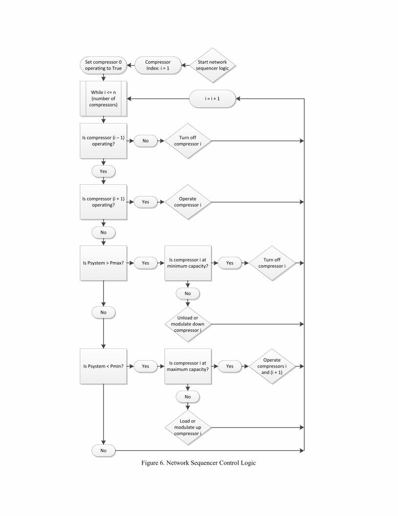
Figure 6. Network Sequencer Control Logic

This multiple-compressor control strategy is
currently not explicitly available in AirSim, however,
the pressure band control strategy can be used to
simulate network sequencer control. Rather than a 5
psig span between cascading compressors, to
simulate network sequencer control enter a 1 psig or
even a 0.1 psig gap between sequenced compressors.
As always, AirSim models should be carefully
calibrated with each use.
Figure 6 details the control logic which could be
expected for network sequencer control. In
application, compressors contain timers to prevent
them from short-cycling on/off too frequently. Thus,
the compressors will typically idle for 5-10 minutes
before automatically turning off.
While network sequencer control achieves a
tighter system pressure band resulting in increased
compression efficiency, it still is not an ideal control
strategy. As shown in Figure 3, any of the
compressors could operate partially loaded,
regardless of their individual part-load efficiency.
Ideally, only one compressor in a multiple-
compressor system should operate at part-load, with
all other compressors either fully loaded or off.
Automatic sequencer control achieves this objective
and is, therefore, the most efficient multiple-
compressor control strategy.
Automatic Sequencer (System Master) Control
Automatic sequencer control (also referred to as
system master control) ties compressors together at a
central controller which operates the system at the
highest efficiency at any plant air demand. This is the
most sophisticated multiple-compressor control
strategy and also the most efficient. In addition to
measuring system pressure, central controllers
typically monitor the rate of change of system
pressure, plant air demand, and individual
compressor’s output and power draw. Rather than
being responsive to system pressure changes, an
automatic sequenced system proactively makes
adjustments based on all of these incoming data.
Furthermore, more holistic central controllers could
measure drier performance, pressure drop across
filters, and include the ability to trend historic data.
These additional data provide added value for
preventative maintenance programs on compressed
air system components [13].
The main disadvantage of both pressure band
and network sequencer control is that any of the
compressors in the system could be operating at part-
load depending on the plant air demand. Automatic
sequencer control eliminates this problem by
designating one compressor the “trim” compressor,
which is the only compressor in the system to operate
at part-load. Thus, the trim compressor should have a
very high part-load efficiency and fast response time
to changing air demand. Trim compressors are
typically VSD compressors.
Similar to network sequencer control, automatic
sequencer control operates compressors within a
common pressure band. However, the sequencer
order is not predefined, as it is in network sequencer
control. The automatic sequencer determines the
combination of compressors at any given plant air
demand which will produce the require amount of air
within the required pressure band at the highest
system efficiency. Typically this results in base
compressors either fully loaded or automatically
shut-off, with a trim VSD compressor meeting the
part-load air demand. The same sample demand
profile from Figure 3 is shown in Figure 7 with
automatic sequencer control.
Figure 7. Automatic Sequencer Control Demand
Profile
The trim compressor is vital to the successful
operation of an automatically sequenced system. If
the trim compressor is incorrectly sized, control gaps
can occur at various plant air demands. A control gap
occurs when the plant air demand cannot be met by
some combination of fully-loaded base compressors
and a partially-loaded trim compressor. This results
in a base compressor cycling between loaded and
unloaded or modulating at an inefficient part-load.
To avoid control gaps, the trim compressor should be
at least the same size as the base compressors [11].
Control gaps can also occur on pressure band
controlled systems with VSD compressors, such as
the one described in Figure 4. Similar precautions
should be taken when sizing VSD compressors in
these systems [14].
Additional consideration should be given if the
trim compressor is a variable speed compressor
controlled with a variable frequency drive (VFD),
which is often the case. VFDs can typically only
reduce electrical frequency down to about 15 Hz,
corresponding to motor speeds of about 25%. Thus,
the effective capacity range of most VSD

Is the trim compressor operating?
Can trim compressor meet the marginal plant air demand?
Yes
No
Yes
Start automatic sequencer logic
No
Trim = FalseCompressor Index: i = 1
Operate compressor i
Operate compressor
(i – 1)
While i <= n (number of
compressors)i = i + 1
Operate compressor n
Trim = True
Marginal plant air demand = plant air
demand
Marginal plant air demand = marginal plant
air demand – current compressor full capacity
Is marginal plant air demand > 0?
Yes
NoIs the trim
compressor operating?
Yes
No
Turn off compressor i
Turn off compressor
(i – 1)
Figure 8. AirSim Automatic Sequencer Control Logic
Compressors is only about 75% of their full-load
capacity. This is the motivation behind the 2013
California Building Energy Efficiency Standard
requiring VFD compressors to be at least 1.25
greater than the next largest compressor [8].
Compressors controlled with VSDs operate more
efficiently at part-load than full-load. Another
advantage of automatic sequencers is determining the
specific part-load efficiency relationships for all
compressors in the system and making sequencing
adjustments accordingly. The linear FP vs FC
relationships shown in Figure 1 are simplifications
which depend on many factors from system storage
to operating pressure.
AirSim allows users to specify a trim compressor
and the sequence order of the base compressors for
automatically controlled systems [9]. The automatic
sequencer control logic built into AirSim operates the
base compressors at full-load or no-load and operates
the trim compressor to meet any part-load demand.

This is the main advantage of AirSim over
AirMaster+, as AirMaster+ does not have the
capability to automatically sequence air compressors
[17]. Users must manually choose the percent load of
each compressor for each hour of operation based on
the plant air demand profile. While it is feasible to
simulate automatically sequenced system in this
manner [4], it is a very time intensive process
requiring in-depth knowledge about compressed air
systems.
The AirSim automatic sequencer control strategy
is controlled by the following logic. The automatic
sequencer allows for only one trim compressor. If
more than one trim compressor is present in a system,
consider modeling the multiple trim compressors as
one larger trim compressor. All other compressors
are designated as base-load compressors. The highest
numbered compressor (i.e. ‘4’ in a 4-compressor
system) is designated as the trim compressor, and all
other compressors are designated as base-load
compressors. Base-load compressors are staged in an
ascending order following their defined sequence
position (i.e. compressor ‘1’ loads first before
compressor ‘2’ loads). The automatic sequencer
determines which compressors operate based on the
plant air demand and the capacity of the available
compressors with the logic diagram shown in Figure
8.
CASE STUDY
The following case study uses AirSim to
simulate a multiple-compressor compressed air
system and calculate the energy use from various
system controls. Additional and updated examples of
energy saving opportunities modelled with AirSim
are available in the University of Dayton Industrial
Assessment Center (UD-IAC) Energy Efficiency
Guidebook [15]. The Energy Efficiency Guidebook
is available for download free of charge on the UD-
IAC website: http://www.udayton.edu/engineering/
industrial_assessment/.
During an UD-IAC energy assessment, the
following compressed air system was investigated.
Two 100-hp, air-cooled, oil-injected, rotary-screw,
CSD compressors were operating in load/unload
control. One 125-hp, air-cooled, oil-injected, rotary-
screw, VSD compressor was operating in VSD
control. The compressed air system contained 1,860
gallons of primary compressed air storage and was
controlled with an automatic sequencer between 110-
115 psig. The VSD compressor operated as the trim
compressor, and the two CSD compressors operated
as base compressors. Trend power, output, and
pressure data was provided for each compressor and
the system, as seen in Figures 9 and 10.
Using these power and load profiles and the air
compressor datasheets from the Compressed Air &
Gas Institute (CAGI), AirSim was used to model the
current system [5]. AirSim was calibrated against the
logged system data to accurately simulate the actual
compressed air system. Figures 11 and 12 show the
inputs and outputs for the base case automatically
sequenced compressed air system.
Figure 9. Stacked Individual Compressor Input Power for 24-hours

Figure 10. Stacked Individual Compressor Air Output and System Pressure for 24-hours
Figure 11. AirSim Inputs for Base Case Automatically Sequenced System
Figure 12. AirSim Outputs for Base Case Automatically Sequenced System

As described in previous papers by Schmidt and
Kissock and Abels and Kissock, AirSim can be used
to simulate a variety of compressed air system
changes including: reduced pressure set-points,
increased storage, decreased plant air demand, and
various control and compressor changes [3] [2].
AirSim now has the capability to simulate multiple-
compressor compressed air systems and investigate
total system power from changing system control
parameters.
Maintaining the same demand profile with the
same compressors used to establish the base case in
Figures 11 and 12 above, various pressure band and
network sequencer system controls were simulated in
AirSim. A summary of these control strategies and
resulting system power are shown in Table 1.
The current automatically sequenced system is
the most energy efficient, when compared to
cascading pressure band, VSD trim pressure band,
and network sequencer controls. Cascading pressure
band control is the least efficient alternative, while
pressure band control with the VSD compressor
staged as the trim compressor is the most efficient
alternative. It is important to keep in mind that
AirSim allows for instantaneous compressor response
with all compressors sensing the exact same system
pressure. This is not true in most facilities and piping
arrangements, thus the tight and overlapping pressure
bands in some of the alternative cases are likely not
practical without a central controller.
Further analysis was done with the same demand
profile and three CSD compressors, rather than two
CSD and one VSD compressor. Automatic
sequencer, cascading pressure band, and network
sequencer controls were simulated for this system
with the inputs and output power shown in Table 2.
Without a VSD compressor, the total system
power draw is significantly increased. In all three
cases, the average power increased by at least 10%,
in addition to increased system pressure swings
without a VSD compressor. These energy savings for
systems with and without a central controller and a
VSD trim compressor are comparable to those
calculated by the California Utilities Statewide Codes
and Standards Team [4].
CONCLUSIONS AND FUTURE WORK
Multiple compressor systems without a VSD
compressor or an automatic sequencer can benefit
from both. Energy savings on the order of 10% could
be realized for systems without VSD compressors.
While energy savings between 2-7% could be
realized for systems with VSD compressors but
without automatic sequencer control. Compressed air
systems are very complicated and detailed analysis
should be conducted before upgrading system
components or controls. However, AirSim allows
individuals to quickly and accurately simulate current
and proposed compressed air systems. By making
modifications to the base case, the proposed systems
can estimate the energy savings and pressure swing
reductions expected from hardware and/or software
controls upgrades.
Furthermore, the ability of AirSim to simulate
pressure band control and automatic sequencer
control allows individual system operators and policy
makers to simulate energy efficient compressed air
systems. As more states begin to follow California’s
leading role in energy efficiency, VSD trim
compressors and automatic sequencers will become
the norm, not the exception, in compressed air
systems. AirSim allows users to quickly and
accurately model automatically sequenced systems,
where AirMaster+ lacks this capability.
Despite the many improvements made to
AirSim, additional advancements are always
Table 1. Various Control Strategies with a VSD Compressor Simulated with AirSim
Control Strategy with VSD 100-hp CSD #1 100-hp CSD #2 125-hp VSD #3Avg. Power
hp (kW)
Percent Difference
from Base Case
Automatic Sequencer - Base Case Base #1 Base #2 Trim 225.3 (168.0) 0.0%
Pressure Band (Cascading) 115-125 psig 110-120 psig 120-130 psig 240.2 (179.1) 6.6%
Pressure Band (Cascading) 120-130 psig 115-125 psig 110-120 psig 235.2 (175.4) 4.4%
Pressure Band (VSD trim) 112-122 psig 110-120 psig 114-117 psig 230.1 (171.6) 2.1%
Pressure Band (VSD trim) 111-116 psig 110-115 psig 112-114 psig 227.4 (169.6) 1.0%
Network Sequencer Lag #1 Lag #2 Lead 232.7 (173.5) 3.3%
Network Sequencer Lead Lag #1 Lag #2 230.4 (171.8) 2.3%
Table 2. Various Control Strategies without a VSD Compressor Simulated with AirSim
Control Strategy without VSD 100-hp CSD #1 100-hp CSD #2 100-hp CSD #3Avg. Power
hp (kW)
Percent Difference
from Base Case
Automatic Sequencer Base #1 Base #2 Trim 252.4 (188.2) 12.0%
Pressure Band (Cascading) 120-130 psig 115-125 psig 110-120 psig 249.6 (186.1) 10.8%
Network Sequencer Lead Lag #1 Lag #2 248.0 (184.9) 10.1%

available. With the capability to simulate multiple
compressors, better output visualization is needed to
differentiate individual compressors in a system.
Output load profile plots, similar to those in Figures
3 and 7, would increase the understanding of how
compressors are interacting and help identify
potential system inefficiencies.
Future work should also add additional
individual compressor control options, such as auto-
dual control, and refine current control options. For
example, the relationship between power and
capacity becomes non-linear for VSD compressors
operating at very low loads, and most VSD
compressors can only reduce to about 25% fraction
capacity. Furthermore, AirSim is currently based on
linear generalizations for individual compressor
control; future work should allow for custom
development of the performance function based on
measured data or manufacturer data. Manufacturer
automatic sequencer control algorithms consider
these non-linear part-load efficiencies with added
complexity to multiple-compressor control logic.
Additional areas for improvement within AirSim
include the ability to model the influence on
compressed air storage volume on dampening system
pressure swings. Also, secondary effects such as
pressure drop from friction through dryers and the
compressed air distribution system could be
incorporated into AirSim in the future. Finally,
increased demand profile resolution would increase
the accuracy of AirSim, especially when simulating
different multiple-compressor compressed air system.
Despite these limitations, AirSim is an effective
tool to quickly and accurately simulate compressed
air systems. It allows users to easily calibrate a
simulation to the current system and simulate
proposed changes to the system. The pressure band
and automatic sequencer control logic built into
AirSim can simulate multiple-compressor control
strategies with VSD compressors, which are certain
to become more prominent in future compressed air
systems.
ACKNOWLEDGEMENTS
The work described in this paper builds on
previous work by the University of Dayton Industrial
Assessment Center (UD-IAC); we all stand on the
shoulders of giants. The authors are grateful for
support for this work from the U.S. Department of
Energy through the Industrial Assessment Center
(IAC) program. Furthermore, the authors would like
to thank the Compressed Air Challenge for the
scholarship to participate in a Fundamentals of
Compressed Air Systems training, which helped get
this research off the ground.
REFERENCES
[1] Atlas Copco, "ES: Central Control Solution,"
2014. [Online]. Available:
http://www.atlascopco.com/geus/products/produ
ct.aspx?id=1547517.
[2] B. Ables and K. Kissock, "Optimizing
Compressed Air Storage for Energy Efficiency,"
SAE International, 2011.
[3] C. Schmidt and K. Kissock, "Modeling and
Simulation of Air Compressor Energy Use," in
ACEEE Summer Study on Energy in Industry,
West Point, NY, 2005.
[4] California Utilities Statewide Codes and
Standards, "Codes and Standards Enhancement
Initiative (CASE) Compressed Air Systems,"
California Public Utilities Commission, 2011.
[5] Compressed Air and Gas Institute, "Data Sheets -
Performance Verification - CAGI," 2014.
[Online]. Available:
http://www.cagi.org/performance-
verification/data-sheets.aspx.
[6] Compressed Air Challenge, "Improving
Compressed Air System Performance: a
sourcebook for industy," Lawrence Berkeley
National Laboratory, Washington, DC, 2003.
[7] Compressed Air Challenge, Fundamentals of
Compressed Air Systems, 2013.
[8] J. Laird, "2013 Building Energy Efficiency
Standards, for residential and nonresidential
buildings," California Energy Commission,
2012.
[9] K. Kissock and S. Murphy, AirSim, Dayton, OH:
UD-IAC, 2014.
[10] Kaeser, "Compressed Air Engineering," 2014.
[Online]. Available:
http://us.kaeser.com/Products_and_Solutions/Co
ntrollers/default.asp.
[11] N. A. Mehltretter, "Applying Variable Speed
Compressors in Multiple Compressor
Applications - Application Success Stories and
Improvement Stories," Energy Engineering, vol.
111, no. 2, pp. 25-42, 2014.
[12] Quincy, "Net$ync II Conductor System," 2014.
[Online]. Available:
http://www.quincycompressor.com/products/clea
n-a-efficient/21-featured-news/413-net-ync-
ii.html.
[13] R. Marshall and B. Scales, "Compressed Air
Best Practices: Compressed Air Controls,"
December 2010. [Online]. Available:
https://www.compressedairchallenge.org/library/
.
[14] R. Marshall, "Compressed Air Best Practices:
VSD Compressor Control," March 2011.

[Online]. Available:
https://www.compressedairchallenge.org/library/
.
[15] UD-IAC, "University of Dayton Industrial
Assessment Center," 2014. [Online]. Available:
http://www.udayton.edu/engineering/industrial_a
ssessment/.
[16] W. Scales and D. M. McCulloch, Best Practices
for Compressed Air Systems, Compressed Air
Challenge, 2013.
[17] Washington State University, AIRMaster+,
Olympia, WA: U.S. Department of Energy,
2000.