Optimizing Statistical Machine Translation for Text Simplification
Upload
khangminh22Category
view
0download
0
Al-Neelain University
Graduate College
Simplification of Solar Control System for
a Water Pump in Irrigation System
A Thesis submitted in partial fulfillment for the degree of M.Sc. in
Control Engineering
Prepared By:
Khadega Mohammed Osman Ebrahim
Supervisor:
Dr. Abdelrahim Ate
April 2018

Al-Neelain University
Graduate College
Simplification of Solar Control System for
a Water Pump in Irrigation System
A Thesis submitted in partial fulfillment for the degree of M.Sc. in
Control Engineering
Prepared By:
Khadega Mohammed Osman Ebrahim
Supervisor:
Dr. Abdelrahim Ate
April 2018


I
اآلية
بسم هللا الرحمن الرحيم
يرفع هللا الذين آمنوا منكم والذين أوتوا العلم قال تعالى: }
{درجات
صدق هللا العظيم
[ 11اآلية سورة المجادلة: ]

II
Dedication
I dedicate my dissertation work to my great parents for their endless love, support and
encouragement and their unconditional love that motivates me to set higher targets.
To all my family, the symbol of love and giving, my friends who encourage and support me,
To All the people in my life who touch my heart, I dedicate this research.

III
Acknowledgement
First of all, we are grateful to Allah, the Almighty, the Merciful without whose blessing this
project would not been successfully completed. He gave us zeal, power of determination and
courage and vanquished all the stumbling hardness that we faced on the way.
I have to thank my parents for their love and support throughout my life, thank you both for
giving me strength to reach for the stars and chase my dreams. My little sisters and brother you
deserve my whole hearted thanks as well.
I would like to sincerely thank my supervisor Dr. Abd Alrahim Ate, for his guidance and
support throughout this study and his countless hours of reflecting, reading and encouraging.

IV
Abstract
The basic idea for this project is to create a simplified solar control system that would be used
on irrigation systems in Sudan. This solar system will pump water from the land which means
underground water. This system would be Arduino based and quite useful in areas where there
is plenty of sunshine but insufficient water to carry out farming activities, which requires
frequent watering. The system is powered by solar system as a renewable energy which uses
solar panel module to convert Sunlight into electricity. In addition, the system is powered by
an intelligent solar system in which solar panel targets the radiation from the Sun. Other than
that, the solar system has reduced energy cost as well as pollution. The system is equipped with
five input sensors; four LDRs sensors, one level detection sensors. LDR sensor measures the
light intensity falling on solar panel, whereas the level detection sensors detect the level of
water in the tank. The output sides consist of two servomotors, which are controlled
respectively by four LDRs sensors to the direction of sun light.

V
المستخلص
.الفكرة األساسية لهذا المشروع في إنشاء نظام مبسط للتحكم في الطاقة الشمسية يمكن استخدامه في أنظمة الري في السودان تتمثل
ومفيد للغاية في Arduino سيكون هذا النظام على أساس.األرض التي تعني المياه الجوفيةسيضخ هذا النظام الشمسي المياه من
يعمل النظام .ري متكرر التي تتطلبالمناطق التي يوجد فيها الكثير من أشعة الشمس ولكن المياه غير كافية للقيام بأنشطة الزراعة
باإلضافة إلى ذلك ، يتم تشغيل النظام .الشمسية لتحويل ضوء الشمس إلى كهرباءبالطاقة الشمسية كطاقة متجددة بإستخدام وحدة األلواح
بخالف ذلك ، خفض النظام الشمسي تكلفة الطاقة .بواسطة نظام شمسي ذكي حيث تستهدف األلواح الشمسية اإلشعاع من الشمس
جهاز استشعار واحد للكشف عن مستوى ، و LDRs تم تجهيز النظام بخمسة حساسات إدخال ؛ أربعة أجهزة استشعار .والتلوث
ستوى معن مستشعر كشف المستوى يتحسسشدة الضوء الساقط على األلواح الشمسية ، بينما يقيسLDR مستشعر . الماء في الخزان
وذلك LDRs الخرج من محركين سيرفو ، يتم التحكم بهما على التوالي بواسطة أجهزة استشعار تتكون جانب.الماء في الخزان
.لتحريك األلواح بإتجاه أشعة الشمس

VI
List of figures
Figure No ( 2.1) Solar Energy System. ..................................................................................... .8
Figure No ( 2.2) Solar Photovoltaic (SPV) Cell. .................................................................... .10
Figure No ( 2.3) Solar Panel configuration. ............................................................................ .10
Figure No ( 2.4) Arduino Uno Board...................................................................................... .11
Figure No ( 2.5) An Arduino pin diagram Based on ATMega-328 Microcontroller .............. 12
Figure No ( 2.6) Photo Resistor .............................................................................................. .15
Figure No ( 2.7) Characteristic curve. ................................................................................... .15
Figure No ( 2.8) Construction of photocell ............................................................................. .16
Figure No ( 2.9)Servo motor inside features. ......................................................................... .17
Figure No ( 2.10)Variable pulse width control servo position ............................................... .18
Figure No ( 2.11) Working of ultra-sonic sensor. ................................................................... .20
Figure No (3.1) The Block Diagram of the system. ............................................................... .22
Figure No (3.2) The Flow Chart of the system. ....................................................................... 25
Figure No (3.3) Overview of Proteus ...................................................................................... 25
Figure No (3.4) An Arduino board in Protoeus8. .................................................................... 26
Figure No (3.5) The 4 LDRs connection. ................................................................................ 27
Figure No(3.6)Connection of Horizontal and Vertical servo motors when it ON and OFF....27
Figure No(3.7) Ultrasonic sensor connection in proteus. ........................................................ 28
Figure No(3.8) LED which indicate pump. ............................................................................. 28
Figure No(3.9) The LDR module. ........................................................................................... 29
Figure No (3.10) Servo motor. ................................................................................................. 29
Figure No (3.11) Solar panel. .................................................................................................. 30
Figure No (3.12) An Arduino board. ....................................................................................... 30
Figure No (3.13) An Ultrasonic Ranging Module HC-SR04 Sensor. ..................................... 31
Figure No (4.1) The design of circuit in Proteus. .................................................................... 33
Figure No (4.2)Case 1 when A has higher light intensity........................................................ 34
Figure No (4.3) Case 2 when B has much light intensity. ....................................................... 35
Figure No (4.4) Case 3 when C has much light intensity. ....................................................... 36
Figure No (4.5) The design of circuit in hardware. ................................................................. 37
Figure No (4.6) Case 1 when the light intensity in A bigger than B andC…………………..37
Figure No (4.7) Case 2 when the light intensity in B bigger than A and C.. .......................... .38
Figure No (4.8) Case 3 when the light intensity in C is higher than A and B. ...................... ..38

VII
List of Abbreviations
DC……………………………… Direct current
AC……………………………… Alternate current
LDR……………………………. Light Dependent Resistor
LED……………………………. Light emitting diode
PV……………………………… Photovoltaic
SPV……………………………. Solar Photovoltaic
OPamp…….………………….... Operation amplifier
Mc……………………………… Microcontroller
P-type silicon………………….. Positive charge of the hole
N-type silicon…………………. Negative charge of the hole
SRAM………………………..... Static random-access memory
EEPROM… …………………... Electrically erasable programmable read-only
memory
PWM………………………….. Pulse width modulated
USB…………………………… Universal Serial Bus
GND…………………………... Ground
RX………….………………… Receiver in Serial communication
TX …………………….…...… Transmitter in Serial communication
ARef………………………….. Reference voltage used for analog input
IORef…………………………. Voltage corresponding to the input/output of that board
RPM…………………………... Rotation per minute
VSM………………………….. Virtual System Modelling
LCD…………………………... Liquid-crystal display

VIII
List of Tables
1 Table of equipment cost………………………………………………….e

IX
Table of Contents:
I ...................................................................................................................................اآلية
Dedication…….............................................................................................................II
Acknowledgement…..................................................................................................III
Abstract……...............................................................................................................IV
V.................................................................................................................……المستخلص
List of Figures….........................................................................................................VI
List of Abbreviations................................................................................................VII
List of Tables ……..................................................................................................VIII
Chapter One: Introduction .......................................................................................... 6
1.2. Background .......................................................................................................... 6
1.3. Problems statement .............................................................................................. 9
1.4 Objectives .............................................................................................................. 9
1.5. Thesis Layout ....................................................................................................... 9
Chapter Two: Theory and Literature Review ......................................................... 11
2.1. Literature Review ............................................................................................... 11
2.2. Development of Solar energy............................................................................. 11
2.3. Solar energy definition ....................................................................................... 12
2.4. Solar Energy System .......................................................................................... 12
2.5. Solar Photovoltaic (SPV) Cell ........................................................................... 13
2.6. Solar Panel ......................................................................................................... 14
2.6.1. Working Principle of Solar Panel ................................................................... 15
2.7. Arduino .............................................................................................................. 15
2.7.1. Arduino Architecture ...................................................................................... 16
2.7.2. Arduino Pin Diagram ...................................................................................... 16
2.7.3. Programming an Arduino ................................................................................ 17
2.8. Light Dependent Resistor (LDR) ....................................................................... 18
2.8.1. Types of light Dependent Resistors ................................................................ 18
2.8.2. Working Principle of LDR .............................................................................. 19
2.8.3. Characteristics of LDR .................................................................................... 19
2.8.4. Construction of a Photocell ............................................................................. 20

X
2.8.5. Applications of LDR ....................................................................................... 20
2.9 Servo motor ......................................................................................................... 21
2.9.1 Components of the servo motor ....................................................................... 21
2.9.2 Controlling the servo ........................................................................................ 22
2.10. Pumps ............................................................................................................... 23
2.11. Storage Tank .................................................................................................... 24
2.12. Ultrasonic Sensor ............................................................................................. 24
Chapter Three: Component in Proteus and Hardware .......................................... 26
3.1. Block diagram .................................................................................................... 26
3.2. Explanation the Flow Chart ............................................................................... 26
3.3. Flow Chart .......................................................................................................... 27
3.4. Algorithm ........................................................................................................... 27
3.5. Proteus 8 software .............................................................................................. 28
3.6. Explanations of the tools are used in research ................................................... 29
3.6.1 Component of circuit in Software (Proteus) .................................................... 29
3.6.1.1 Arduino-UNO based ATmega-328P. ............................................................ 29
3.6.1.2 Light dependent Resistor: ............................................................................. 30
3.6.1.3 Servo motor ................................................................................................... 31
3.6.1.4 Ultrasonic sensor ........................................................................................... 32
3.6.1.5 LED and DC motor ....................................................................................... 32
3.6.2 Component of circuit in Hardware ................................................................... 33
3.6.2.1 Light Dependent Resistor (LDR module) ..................................................... 33
3.6.2.2 Servo motor (micro servo 9g) ....................................................................... 33
3.6.2.3 Solar panel ..................................................................................................... 34
3.6.2.4 Arduino UNO ................................................................................................ 34
3.6.2.5 Ultrasonic sensor (HC-SR04) ....................................................................... 35
Chapter Four: Result in Proteus and Hardware ..................................................... 37
4.1. The design of circuit in Proteus ......................................................................... 37
4.2 Results of Proteus ................................................................................................ 37
4.2.1 Case 1 in Proteus: ............................................................................................. 37
4.2.2 Case 2 in Proteus: ............................................................................................. 38

XI
4.2.3 Case 3 in proteus: ............................................................................................. 39
4.3 The design of circuit in Hardware: ..................................................................... 41
4.4 Results of hardware ............................................................................................. 41
4.4.1 Case 1 in hardware: .......................................................................................... 41
4.4.2 Case 2 in hardware ........................................................................................... 42
4.4.3 Case 3 in hardware ........................................................................................... 42
Chapter Five: Conclusion and Recommendation .................................................... 43
Conclusion ................................................................................................................. 43
Recommendation ....................................................................................................... 43
References .................................................................................................................... 44
APPENDIX(A) code of project..............................................................................a
APPENDIX(B) equipment cost……………………..……………………………e

6
Chapter One
Introduction
1.1. Introduction
Renewable energy is energy generated from natural resources such as sunlight, wind, rain,
tides and geothermal heat which are renewable (naturally replenished). Renewable energy
technologies range from solar power, wind power, hydroelectricity/micro hydro, biomass and
biofuels for transportation.
Renewable energy is energy that is generated from natural processes that are continuously
replenished. This includes sunlight, geothermal heat, wind, tides, water, and various forms of
biomass. This energy cannot be exhausted and is constantly renewed.
The sun is a powerful source of renewable energy for our planet. This solar energy can be
harnessed through Photovoltaic (PV) systems to produce electricity for subsequent uses. The
energy harnessed from the sun is known as solar energy and is considered as the most reliable
resource among the available renewable energy sources.
Solar energy can be used to pump water and these solar-powered pumping systems are
particularly ideal for remote locations. [1]
1.2. Background
Shreyasi Chakrabory, Nilanjana Mukherjee, Rashmi Biswas, Tanushree Saha, Astika
Mohinta, Neha Kumari Modi and Dip Prakash Samajdar they have discussed about the
solar tracking system that they have designed using some LDR’s (light dependent
resistances), micro-controller (AT89S52), comparator using OPAMP’s, a crystal
oscillator, stepper motor and stepper motor driver.[2]
The basic idea behind this work is that the intensity of light will be sensed by the LDR’s
separated by a certain angular distance, the comparators will compare the incident
light intensity with the intensity of perpendicular incidence. The micro-controller will
rotate the stepper motor by the desired angle depending on the output of the comparators via
a stepper motor driver circuit to maximize the efficiency. [2]
7
In the result The designed prototype is tested in the laboratory using a torch light as
the light source. The comparator output connected with the east most LDR becomes
high when the light is incident on the LDR and the prototype orients itself in the east most
direction from its reset position.[2]
This system can work properly irrespective of weather conditions and location.
however, the designed prototype of the solar tracker is a miniature of the main system
and so there are a number of limitations. They recommended that the number of LDRs
should be increased for the practical case. Moreover, we have considered one-
dimensional rotation of the tracker. So we aim to increase the degrees of freedom of this
tracker in future course of work. [2]
B. Eker has discuss about agricultural technology and how its change rapidly and how PV
solution becomes the best solution for remote area. He make comparison between using fuel
and using solar panel to drive motor and pumping water. He mentioned some significant
drawbacks of using diesel [3].
He proved that for many agricultural needs, the alternative is solar energy. Because it is
Modern, well-designed, simple-to-maintain solar systems can provide the energy that is
needed where it is needed, and when it is needed [3]
He discussed about basic types of solar-powered water pumping systems, battery-coupled and
direct-coupled [3].
Battery-coupled water pumping systems consist of photovoltaic (PV) panels, charge control
regulator, batteries, pump controller, pressure switch and tank and DC water pump. The
electric current produced by PV panels during daylight hours charges the batteries, and the
batteries in turn supply power to the pump anytime water is needed. [3]
In direct-coupled pumping systems, electricity from the PV modules is sent directly to the
pump, which in turn pumps water through a pipe to where it is needed. This system is
designed to pump water only during the day. The amount of water pumped is totally
dependent on the amount of sunlight hitting the PV panels and the type of pump. [3]
Arnab Samanta ,RachitVarma , Shrikant Bhatt , they designed system with a view to track
the position of the sun by the solar panel so that rays of the sun always fall
perpendicular on the panel. As only perpendicular rays can produce maximum intensity

8
of solar energy. In this way concentrated solar rays can be made available throughout
the day [4]. PIC18252 micro-controller is set of a predefined value, so that it will be active
only for a certain period of time. This is done with the help of in-built Timer1 present in the
Mc. For this much period of time motor will be active and rotate the solar panel. [4]
The project recommended a futuristic fission in harvesting of solar energy in a more
efficient and suitable way. The project has developed a small prototype which can
open the doors of advancing the utilization of solar energy in near future at affordable
prices. The solar tracker will help in future to make bigger systems which can
be chronologically operated and helped in efficient tracking the position of the sun. [4]
The energy harvested can be used in number of home application, driving engines which
use electricity or diesel, or even in driving cars and micro-light aircraft.
Implementation of this model on large scale will ensure that bigger models can be
implemented using better and bigger motors.[4]
Bugała, G. Frydrychowicz-Jastrzębska, they have determined a receiver positioning in the
east west axis allows to follow the daily movement of the Sun across the sky. The
mechanical system uses a turntable with a DC motor to change the position of the
photovoltaic module in the range of 0 -170°.[5] The angle of incidence of the solar radiation
can be adjusted by changing the spatial orientation of the PV receiver.
The measurements conducted in real conditions were carried out from June 2013 to July
2014. Based on the obtained values of current, voltage and DC power, the current – voltage
and power – voltage characteristics were determined for different weather conditions like
clear sky, medium cloud cover and heavy clouds.[5]
P.Ramya1,R.Ananth M.E,(Ph.D.)2,“the implementation of solar tracker using Arduino with
servomotor” they have discussed about consuming the maximum solar energy through solar
panel , Power output from a solar cell will be maximum when it is facing the sun, The
components they used for its construction are servo motor, Arduino and LDR. The active
sensors continuously monitor the sunlight and alternate the panel towards the direction where
the intensity of sunlight is maximum. [26]
In this project, it’s divided by two categories; hardware and software. In hardware part, 2
light dependent resistors (LDR) have been used to trace the synchronize of sunlight by

9
detecting brightness level of sunlight. For rotation part, one standard servo motor has been
selected. In software part, the code is constructed in C programming language and inserted in
Arduino. This project is designed for low power and portable application.[26]
Result of this project was, when light falls on the LDR, its resistance varies and a potential
divider circuit is used to obtain corresponding voltage value (5v) from the resistance of LDR.
The voltage signal is sent to the Arduino microcontroller. Established on the voltage signal, a
corresponding PWM signal is sent to the servo motor which causes it to rotate and to end
with attains a position where intensity of light falls on the solar panel is maximum.[26]
1.3. Problems statement
The main problem people are facing in the region is the lack of water because of low and
inconsistent rainfall. Gradually decreasing energy sources and increasing demand for energy
in recent years, makes more efficient and positive use of current water resources together
with global warming and drought. [6]Energy of pumps used for the agricultural irrigation is
generally provided from electrical energy or fossil fuels. Since fossil fuels commence to
annihilate besides its increasing of prices and hazards to environment alternative energy
seeking efforts has become inevitable also in agricultural sector. Since the sources utilized for
the purpose of producing electricity are limited and their prices gradually increase researches
for new alternatives for irrigation systems become more important. [6]
1.4 Objectives
To overcome the above problem and to improve water availability in the rural area, there is a
need to design a simple solar powered system for water abstraction. Solar system will address
their problems through the use of solar tracking system and submersible solar water pump.
The solar powered system for water abstraction uses the readily available renewable energy
i.e. solar energy. Therefore, the stakeholders will not incur the daily cost for diesel engine
pump. The cost incurred through human labour will also be minimised.
1.5. Thesis Layout
This project divided to five chapters as following:
Chapter one contains the Problem statement, General objective of research, and the
Methodology.

10
Chapter two discussed History of solar energy ,Solar energy definition, Solar energy system,
Solar photovoltaic cell , Solar panel ,Arduino ,Light dependent resistor ,Servo motor, Pumps ,
Storage tank , Ultrasonic sensor.
Chapter three contains Component of circuit in proteus and in hardware.
Chapter four contains Circuit design in proteus and hardware and Results.
Finally chapter five contains the Conclusion and Recommendations.

11
Chapter Two
Theory and Literature Review
2.1. Literature Review
Renewable energy is energy which originates from natural source such as sunlight, tides,
wind rain, wave and etc. Solar Energy is the energy consequent from the sun through the
form of solar radiation. Solar energy is a very large, inexhaustible source of energy. Today
solar energy is the major eco-friendly & pollution less method of producing the electricity.
The power from the sun interrupted by the earth is approximately 1.8*1011MW, which is
many thousands of times larger than the current consumption rate on the earth of all
commercial energy sources.
At the present time, clean renewable energy sources attract a great attention as an essential
mean for solving the energy crisis around the globe. Solar energy is frequently offered free of
charge all over the world although it is not a continuous energy source. One of the most
promising renewable energy sources characterized by a huge potential of conversion into
electrical power is the solar energy.
This project include solar control system using Arduino based solar tracker. This solar tracker
system uses the Arduino board, Four LDR and motor to rotate the solar panel towards the sun
or a source of light. In this project LDR was selected since it has no polarity, and easy to
interface with circuit, cheap, reliable and is described by high spectral sensitivity.
2.2. Development of Solar energy
The history of solar energy is as old as human kind. In the last two centuries, we started using
Sun's energy directly to make electricity.
In 1839, 19-year old French physicist Alexandre Edmond Becquerel discovered that certain
materials would produce small amounts of electric current when exposed to light. This basic
physical process of using light to generate an electric current is known as the photovoltaic
effect. [7]
However, it would be more than 100 years before engineers would develop a photovoltaic
cell capable of converting enough solar energy into electricity to run electrical equipment. [7]

12
The breakthrough came in 1954 when physicists at Bell Labs discovered that a Silicon
semiconductor was able to convert light into electricity with 4to6% efficiency. Compared to
earlier materials which were less than 1% efficient, this was a major accomplishment. [7]
2.3. Solar energy definition
Solar energy is any type of energy generated by the sun. Solar energy is created by nuclear
fusion that takes place in the sun. Fusion occurs when protons of hydrogen atoms violently
collide in the sun’s core and fuse to create a helium atom. [8]
The energy that Earth receives from the sun, primarily as visible light and other forms of
electromagnetic radiation. The term solar energy often refers to processes that use this energy
to generate heat or electricity for human use.
2.4. Solar Energy System
Solar energy is the cleanest and most available renewable energy source. The Modern
technology can harness this energy for a variety of uses, including producing electricity,
providing light and heating water for domestic, commercial or industrial application.
Solar energy can also be used to meet our electricity requirements. Through solar
photovoltaic (SPV) cells, solar radiation gets converted into DC electricity directly. This
electricity can either be used as it is or can be stored in the battery. [7][8]

13
Figure No (2.1) Solar Energy System.
2.5. Solar Photovoltaic (SPV) Cell
A solar photovoltaic or solar cell is a device that converts light into electric current using the
photoelectric effect. SPVs are used in many applications such as railway signals, street
lighting, domestic lighting and powering of remote telecommunication systems.
It has a p-type of silicon layer placed in contact with an n-type silicon layer and the diffusion
of electrons occurs from the n-type material to the p-type material. In the p-type material,
there are holes for accepting the electrons. The n-type material is rich in electrons, so by the
influence of the solar energy, the electrons move from the n- type material and in the p-n
junction, the combine with holes. This creates a charge on either side of the p-n junction to
create an electric field. [7]
So in dark, the solar cell behaves like a reverse biased diode. When light falls on it, like diode
the solar cell forward biases and current flows in one direction from anode to cathode like a
diode. Usually the open circuit (without connecting the battery) voltage of a solar panel is

14
higher than its rated voltage. For example a 12 volt panel gives around 20 volts in bright sun
light. But when the battery is connected to it, the voltage drops to 14to15 volts. Solar
photovoltaic (SPV) cells are made of extraordinary materials called semiconductors for
example silicon, which is presently the most generally used. Essentially, when light strikes
the cell, a certain bit of it is absorbed within the semiconductor material. This means that the
energy of the absorbed light is transferred to the semiconductor. [9]
Solar PV cells also all have one or more electric fields that act to force electrons freed by
light absorption to flow in a certain direction. This flow of electrons is a current and by
placing metal contacts on the top and bottom of the SPV cell, we can draw that current off to
utilize remotely. The cells voltage defines the power that the solar cell can produce. The
process of converting light into electricity is called the solar photovoltaic (SPV) effect.
Figure No (2.2) Solar Photovoltaic (SPV) Cell.
2.6. Solar Panel
A solar panel is a collection of solar cells. The solar panel converts the solar energy into
electrical energy. Solar panels are the main components used for driving the solar pump.
Several solar panels connected together in arrays produce DC electricity, interconnections are
made using series or parallel combinations to achieve desired voltage and power for the
pump. [10]

15
Figure No (2.3) Solar Panel configuration.
2.6.1. Working Principle of Solar Panel
Simply put, a solar panel works by allowing photons, or particles of light, to knock electrons
free from atoms, generating a flow of electricity. Solar panels actually comprise many,
smaller units called photovoltaic cells. (Photovoltaic simply means they convert sunlight into
electricity)
Photovoltaic (PV) (or solar electricity) is the process that converts sunlight into electricity.
PV modules (some may know them to be solar panels) are comprised of small photovoltaic
cells that are all wired together and sealed underneath a tempered glass cover. [10]
2.7. Arduino
An Arduino board is a one type of microcontroller based kit. The first Arduino technology
was developed in the year 2005 by David Cuartielles and Massimo Banzi. The designers
thought to provide easy and low cost board for students, hobbyists and professionals to build
devices. Arduino technology is used in many operating devices like communication or
controlling. [11]

16
Figure No (2.4) Arduino Uno Board.
2.7.1. Arduino Architecture
Arduino’s processor basically uses the Harvard architecture where the program code and
program data have separate memory. It consists of two memories- Program memory and the
data memory.
The code is stored in the flash program memory, whereas the data is stored in the data
memory. The Atmega328 has 32 KB of flash memory for storing code (of which 0.5 KB is
used for the boot loader), 2 KB of SRAM and 1 KB of EEPROM and operates with a clock
speed of 16MHz.[11]
2.7.2. Arduino Pin Diagram
A typical example of Arduino board is Arduino Uno. It includes an ATmega328
microcontroller and it has 28-pins as it shown below.
The pin configuration of the Arduino Uno board is shown in the above. It consists of 14-
digital I/O pins. Wherein 6 pins are used as pulse width modulation o/ps and 6 analog i/ps, a
USB connection, a power jack, a 16MHz crystal oscillator, a reset button, and an ICSP
header. Arduino board can be powered either from the personal computer through a USB or
external source like a battery or an adaptor. This board can operate with an external supply of
7to12V by giving voltage reference through the IORef pin or through the pin Vin. [11]

17
Figure No (2.5) An Arduino pin diagram based on ATMega-328 Microcontroller.
Digital I/Ps
It comprises of 14-digital I/O pins, each pin take up and provides 40mA current. Some of the
pins have special functions like pins 0 & 1, which acts as a transmitter and receiver
respectively. For serial communication, pins-2 & 3 are external interrupts, 3,5,6,9,10,11
pins delivers PWM o/p and pin-13 is used to connect LED.
Analog I/Ps: It has 6-analog I/O pins, each pin provide a 10 bits resolution.
Aref: This pin gives a reference to the analog i/ps.
Reset: When the pin is low, then it resets the microcontroller.
2.7.3. Programming an Arduino
The most important advantage with Arduino is the programs can be directly loaded to the
device without requiring any hardware programmer to burn the program. This is done
because of the presence of the 0.5KB of Boot loader which allows the program to be burned

18
into the circuit. All we have to do is to download the Arduino software and writing the code.
[11]
2.8. Light Dependent Resistor (LDR)
A Light Dependent Resistor (LDR) or a photo resistor is a device whose resistivity is a
function of the incident electromagnetic radiation. Hence, they are light sensitive devices.
They are also called as photo conductors, photo conductive cells or simply photocells. They
are made up of semiconductor materials having high resistance. There are many different
symbols used to indicate a LDR. One of the most commonly used symbol is shown in the
figure below. The arrow indicates light falling on it. [12]
Figure No (2.6) Photo Resistor
2.8.1. Types of light Dependent Resistors
Based on the materials used they are classified as:
Intrinsic photo resistors (Un doped semiconductor): These are made of pure
semiconductor materials such as silicon or germanium. Electrons get excited from valance
band to conduction band when photons of enough energy fall on it and number charge
carriers is increased.
Extrinsic photo resistors: These are semiconductor materials doped with impurities which
are called as dopants. Theses dopants create new energy bands above the valence band which
are filled with electrons. Hence this reduces the band gap and less energy is required in
exciting them. Extrinsic photo resistors are generally used for long wavelengths. [12]

19
2.8.2. Working Principle of LDR
A light dependent resistor works on the principle of photo conductivity. Photo conductivity is
an optical phenomenon in which the materials conductivity is increased when light is
absorbed by the material. When light falls i.e. when the photons fall on the device, the
electrons in the valence band of the semiconductor material are excited to the conduction
band.
These photons in the incident light should have energy greater than the band gap of the
semiconductor material to make the electrons jump from the valence band to the conduction
band.
Hence when light having enough energy strikes on the device, more and more electrons are
excited to the conduction band which results in large number of charge carriers.
The result of this process is more and more current starts flowing through the device when
the circuit is closed and hence it is said that the resistance of the device has been decreased.
This is the most common working principle of LDR. [12]
2.8.3. Characteristics of LDR
LDR’s are light dependent devices whose resistance is decreased when light falls on them
and that is increased in the dark. When a light dependent resistor is kept in dark, its resistance
is very high.
This resistance is called as dark resistance. It can be as high as 10^12 Ω and if the device is
allowed to absorb light its resistance will be decreased drastically. If a constant voltage is
applied to it and intensity of light is increased the current starts increasing.
Figure below shows resistance vs. illumination curve for a particular LDR. [12]
Figure No (2.7) Characteristic curve.

20
Photocells or LDR‟s are nonlinear devices. There sensitivity varies with the wavelength of
light incident on them. Some photocells might not at all response to a certain range of
wavelengths. Based on the material used different cells have different spectral response
curves. [12]
2.8.4. Construction of a Photocell
The structure of a light dependent resistor consists of a light sensitive material which is
deposited on an insulating substrate such as ceramic. The material is deposited in zigzag
pattern in order to obtain the desired resistance and power rating. This zigzag area separates
the metal deposited areas into two regions. Then the ohmic contacts are made on the either
sides of the area. The resistances of these contacts should be as less as possible to make sure
that the resistance mainly changes due to the effect of light only. Materials normally used are
cadmium sulphide, cadmium selenide, indium antimonide and cadmium sulphonide. The use
of lead and cadmium is avoided as they are harmful to the environment.[12]
Figure No (2.8) Construction of photocell.
2.8.5. Applications of LDR
LDR’s have low cost and simple structure. They are often used as light sensors. They are
used when there is a need to detect absences or presences of light like in a camera light meter.
Used in street lamps, alarm clock, burglar alarm circuits, light intensity meters, for counting
the packages moving on a conveyor belt, etc. [12]

21
2.9 Servo motor
A servo motor is an electrical device which can push or rotate an object with great precision.
If you want to rotate and object at some specific angles or distance, then you use servo motor.
It is just made up of simple motor which run through servo mechanism. If motor is used is
DC powered then it is called DC servo motor, and if it is AC powered motor then it is called
AC servo motor. [14]
Servo motors are used for various applications. They are normally small in size and have
good energy efficiency. The servo circuitry is built inside the motor unit and comes with a
positionable shaft that is fitted with a gear. The motor is controlled with an electric signal that
determines the amount of shaft movement. [13]
Figure No (2.9) Servo motor inside features.
2.9.1 Components of the servo motor
Inside the servo there are three main components; a small DC motor, a potentiometer and a
control circuit. Gears are used to attach the motor to the control wheel. As the motor rotates,
the resistance of the potentiometer changes so the control circuit can precisely regulate the
amount of movement there is and the required direction.
When the shaft of the motor is at the desired position, power supply to the motor is stopped.
If the shaft is not at the right position, the motor is turned in the right direction.
The desired position is sent through electrical pulses via the signal wire. The speed of the
motor is proportional to the difference between the actual position and the position that is
desired.
Therefore, if the motor is close to the desired position, it turns slowly. Otherwise, it turns fast.
This is known as proportional control. [13]

22
2.9.2 Controlling the servo
Servos are sent through sending electrical pulses of variable width, or pulse width modulation
(PWM), through the control wire. There is a minimum pulse, maximum pulse and a repetition
rate. Servos can usually turn only 90 degrees in either direction for a total of 180 degrees
movement. The neutral position of the motor is defined as that where the servo has the same
amount of potential rotation in both the clockwise and counter-clockwise direction. The
PWM sent to the motor determines the position of the shaft, and based on the duration of the
pulse sent through the control wire the rotor will turn to the position that is desired.
The servo motor expects to see a pulse after every 20 milliseconds and the length of the pulse
will determine how far the motor will turn. For instance, a 1.5ms pulse makes the motor to
turn in the 90 degrees position. If the pulse was shorter than 1.5ms, it will move to 0 degrees
and a longer pulse moves it to 180 degrees. This is shown below. [13] [14]
Figure No (2.10) Variable pulse width control servo position.
For applications where there is requirement of high torque, servos are preferable. They will
also maintain the torque at high speeds, up to 90% of the rated torque is available from servos
at high speeds. Their efficiencies are between 80 to 90%.
A servo is able to supply approximately twice their rated torque for short periods of time
offering enough capacity to draw from when needed. In addition, they are quiet, are available
in AC and DC, and do not suffer from vibrations. [13] [14]

23
2.9.3. Advantages and disadvantages of servo motors
For applications where high speed and high torque are required, servo motors are the better
option. While stepper motors peak at around 2000 RPM, servos are available at much faster
speeds. Servo motors also maintain torque at high speed, up to 90% of the rated torque is
available from servos at high speeds. They have an efficiency of about 80-90% and supply
roughly twice their rated torque for short periods. Furthermore, they do not vibrate or suffer
from resonance issues.
Servo motors are more expensive than other types of motors. Servos require gear boxes,
especially for lower operation speeds. The requirement for a gear box and position encoder
makes the designs more mechanically complex. Maintenance requirements will also increase.
[13]
2.10. Pumps
Solar water pumping systems in its simplest way, have the solar panels connected
directly to the small DC motor that drives the water pump.
Solar water pumps are designed to use the direct current (DC) provided by a PV array.
DC water pumps in general use one-third to one half the energy of conventional AC
(alternating current) pumps. Solar pumps are available in several capacities depending upon
the requirement of water.
There are two types of DC pumps namely surface pumps and submersible pumps. All Surface
pumps are centrifugal, while submersible pumps can be both centrifugal and helical rotor
pumps.
Surface pumps are more accessible for maintenance and less expensive than submersible
pumps, but they are not well suited for suction and can only draw water from about 20
vertical feet. Surface pumps are excellent for pushing water long distances.
Most submersible pumps have high lift capability, but they are sensitive to dirt/sand in the
water and should not be run if the water level drops below the pump.

24
Brief definition of each type of pump:
Surface pumps, located at near the water surface, are used primarily for moving water
through a pipeline. Some surface pumps can develop high heads and are suitable for moving
water long distances or to high elevations.
Submersible pumps, placed down a well or sump, are highly reliable because they are not
exposed to freezing temperatures, do not need special protection from the elements, and do
not require priming.
Centrifugal pumps use a spinning impeller that adds energy to the water and pushes into the
system, similar to a water wheel.
Helical rotor pumps is a positive displacement pump, the rotor has an eccentric movement
which when rotating inside the stator effectively squeezes water through the pump on every
rotation.
This positive displacement action means that water is pumped when the pump is running at
very low speeds and that high pressure can be created making it able to pump water at high
lifts. [15]
2.11. Storage Tank
Solar water systems most likely use tanks to store water. The size should be able to keep
roughly 3 days of water or 2 to 3 days depending on the variation in the sun. Too much water
should not be kept too long because of diminishing quality due to growth in algae.
2.12. Ultrasonic Sensor
An Ultrasonic sensor is a device that can measure the distance to an object by using sound
waves. It measures distance by sending out a sound wave at a specific frequency and listening
for that sound wave to bounce back. [16] By recording the elapsed time between the sound
wave being generated and the sound wave bouncing back, it is possible to calculate the
distance between the sonar sensor and the object. [17]

25
Figure No (2.11) Working of ultrasonic sensor.

26
Chapter Three
Component in Proteus and Hardware
3.1. Block diagram
The following block diagram explain solar tracking system that is done by Light Dependant
Resistor (LDR). In addition an ultrasonic sensor is used to sense water level inside tank. The
inputs are from values of LDR and ultrasonic sensor, Arduino as the controller and the DC
motor will be the output. The DC motor will move the solar panel to the position of the high
intensity LDR that was in the programming.
Figure No (3.1) The Block Diagram of the system.
3.2. Explanation the Flow Chart
The principle of the solar tracking system is done by Light Dependant Resistor (LDR). Four
LDR’s are connected to Arduino in analog pins from A1 to A4 that acts as the input for the
system. The built-in Analog-to-Digital Converter will convert the analog value of LDR and
convert it into digital. The inputs are from analog value of LDR, Arduino as the controller
and the DC motor will be the output. (LDR1, LDR2), (LDR3, LDR4) and (LDR2, LDR3) are
taken as pair there labels in code are A, B and C respectively. If one of the LDRs pair gets
more light intensity than the other, it will send to the respective Arduino to take necessary
action. The servo motor will move the solar panel to the position of the high intensity LDR
that was in the programming. Furthermore an automatic water indicator of tank level will
work by using an ultrasonic sensor. The ultrasonic sensor is placed at the top of water tank
for demonstration. This sensor module will read the distance between sensor module and

27
water surface. It means we are here measuring empty distance or volume for water instead of
full water level.
When empty water level reaches at distance about 15 cm then Arduino turn ON the water
pump, any value of distance less than 15 cm Arduino turns pump OFF.
3.3. Flow Chart
Figure No (3.2) The Flow Chart of the system.
3.4. Algorithm
Step1: Start the program.
Step2: Initialize all the values.
Step3: Calculate the summation of LDRs pair.
Step4: If (LDR1+LDR2)>> (LDR3+LDR4)>> (LDR2+LDR3) Vertical servo motor go
down..

28
Step5: If (LDR3 +LDR4) >> (LDR1+LDR2)>> (LDR2+LDR3) Vertical servo motor go up.
Step6: If (LDR2+LDR3)>> (LDR1+LDR2)>> (LDR3+LDR4) Horizontal servo motor go
right.
Step7: Ultrasonic send pulses and check its echo.
Step8: Fill the Tank depending on ultrasonic sensor read and Arduino program.
Step9: End the program.
3.5. Proteus 8 software
Proteus 8 is a Virtual System Modelling (VSM) that combines circuit simulation, animated
components and microprocessor models to co-simulate the complete Arduino microcontroller
based designs. [18]
This is the perfect tool for engineers to test their micro controller designs before constructing
a physical model in real time. This program allows users to interact with the design using on-
screen indicators, LED and LCD displays and switches.
In summary, Proteus 8 is the program to use when you want to simulate the interaction
between software running on a micro controller and any analog or digital electronic device
connected to it.
In this research has been use a number of components, each of them has a specific target to
obtain a successful design. [18]

29
Figure No (3.3) Overview of Proteus
The components from library are
Arduino “UNO”, LDR, Ultrasonic sensor “HC SR-04”, LED and Servo motor.
3.6. Explanations of the tools are used in research
3.6.1 Component of circuit in Software (Proteus)
3.6.1.1 Arduino-UNO based ATmega-328P.
In our research the software design was done using Arduino ONO which was used for the
programming. The program was written using the C language in Arduino IDE software. The
Proteus circuit editing software was used for drawing the circuit.
Our board was connected four LDRs in analog pins from A1 to A4 respectively also
connected two servo motors (horizontal and vertical) in digital pins 5 ,6 respectively ,
ultrasonic sensor was connected their pins trig and echo to pin 9 and 10 respectively.
Last thing is LED which connected to pin 13 as indicator to pump working.

30
Figure No (3.4) An Arduino board in Protoeus8.
3.6.1.2 Light dependent Resistor:
LDR alight dependent resistor, otherwise known as photo-resistor, photoconductor, or
photocell, is a variable resistor whose value decreases with increasing incident light intensity.
An LDR is made of a high-resistance semiconductor. If light falling on the device is of high
enough frequency, photons absorbed by the semiconductor give bound electrons adequate
energy to jump into the conduction band. The resulting free electrons conduct electricity,
thereby lowering resistance.
In our project four LRDs is used to measure the light intensity during day time and rotate the
solar to follow bigger amount of lights. Four LDRs was connected in analog pins from A1 to
A4 respectively. [25]

31
Figure No (3.5) The 4 LDRs connection.
3.6.1.3 Servo motor
In this research two servo motors have been used first one is vertical motor is move solar in
vertical movement by limited angle, the second is horizontal servo is move the solar in
horizontal movement. Their connection to Arduino are in pins 9, 10.
Figure No (3.6) Connection of Horizontal and Vertical servo motors when it ON and OFF.
32
3.6.1.4 Ultrasonic sensor
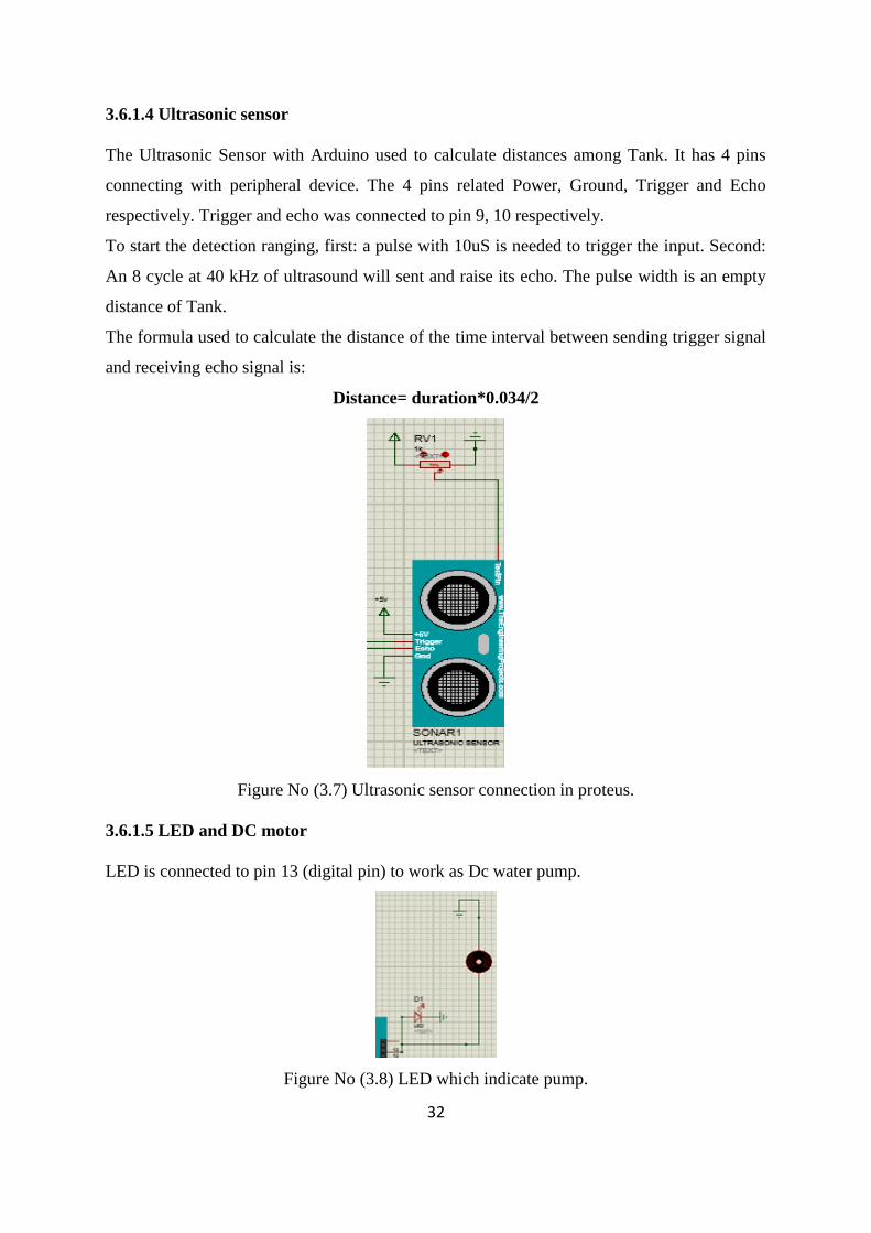
The Ultrasonic Sensor with Arduino used to calculate distances among Tank. It has 4 pins
connecting with peripheral device. The 4 pins related Power, Ground, Trigger and Echo
respectively. Trigger and echo was connected to pin 9, 10 respectively.
To start the detection ranging, first: a pulse with 10uS is needed to trigger the input. Second:
An 8 cycle at 40 kHz of ultrasound will sent and raise its echo. The pulse width is an empty
distance of Tank.
The formula used to calculate the distance of the time interval between sending trigger signal
and receiving echo signal is:
Distance= duration*0.034/2
Figure No (3.7) Ultrasonic sensor connection in proteus.
3.6.1.5 LED and DC motor
LED is connected to pin 13 (digital pin) to work as Dc water pump.
Figure No (3.8) LED which indicate pump.

33
3.6.2 Component of circuit in Hardware
3.6.2.1 Light Dependent Resistor (LDR module)
LDR are also named as photo conductors (or) photo resistors. Which works on the principal
of photo conductivity. LDR resistance decrease with increase in light intensity and vice versa.
LDR s are mainly used for sensing purpose in order to catch the solar energy and provide
analog input to Arduino. [19] [20]
Figure No (3.9) The LDR module.
3.6.2.2 Servo motor (micro servo 9g)
Servo motor is three wired dc motor which works on the principal of servo mechanism. Servo
motor can rotate up to maximum angle of 180degrees. In our proposed project 5v motor is
used. Since it is dual axis system two servo motors are used vertical and horizontal
respectively. Servo motors are powered by PWM output received from the Arduino. [21]
Figure No (3.10) Servo motor

34
.
3.6.2.3 Solar panel
Solar energy is the photovoltaic cell which convert light energy received from sun into
electrical energy. The name behind “solar” panel is they grab high powerful energy emitted
from the sun. The solar panel finds its applications in street lights, domestic and industrial
areas.
Figure No (3.11) Solar panel.
3.6.2.4 Arduino UNO
Arduino is the type of microcontroller. The purpose of microcontroller is to control the
position of motor. So Atmega 328p microcontroller is used. Arduino consist of 6 analog
inputs and 14 digital I/O ports out of them 6 acts as PWM signals. In addition to this it
consist of 16 MHZ crystal oscillator, a USB cable through which program is dumped. And
Arduino get powered by the power jack. Advantages of Arduino is low cost, robust
construction and platform independent. [22][23]

35
Figure No (3.12) An Arduino board.
3.6.2.5 Ultrasonic sensor (HC-SR04)
The ultrasonic sensor module works on the natural phenomenon of ECHO of sound. A pulse
is sent for about 10us to trigger the module. After which the module automatically sends 8
cycles of 40 KHz ultrasound signal and checks its echo. The signal after striking with an
obstacle returns back and is captured by the receiver. Thus the distance of the obstacle from
the sensor is simply calculated by the formula given as:
Distance= (time x speed) / 2
Here the product of speed and time was divided by 2 because the time is the total time it took
to reach the obstacle and return back. Thus the time to reach obstacle is just half the total time
taken.
The Ultrasonic Sensor with Arduino used to calculate distances among objects. It has 4 pins
Connecting with peripheral device. The 4 pins related Power, Ground, Trigger and Echo
respectively.
Ultrasonic sensors use sound vibrations to estimate the distance between a source (sensor)
and a given target. The echo of the emission is used to calculate the desired distance.
For the proposed system, the sound reflection in the water mirror is considered for the
calculus. [24]

36
Figure No (3.13) An Ultrasonic Ranging Module HC-SR04 Sensor.

37
Chapter Four
Result in Proteus and Hardware
4.1. The design of circuit in Proteus
Shown in figure 4.1, the complete circuit of the model connected (LDRs to analog inputs, Ultrasonic
sensor, Servo motors and pump LED to digital inputs), then linked all together to virtual serial port
through transmit and receive pins.
Figure No (4.1) The design of circuit in Proteus.
4.2 Results of Proteus
4.2.1 Case 1 in Proteus:
In the first case it was assumed that the summation of (LDR1 +LDR2) has the higher light
intensity by concentrating torch light on them. They indicate that it is summer season and sun
starts rising from east in the beginning of the day. The virtual terminal represented LDRs
readings and explains the direction of solar panel. In this case the summation of (LDR1
+LDR2) has the higher intensity of light.

38
Notice that A= LDR1+LDR2.
Figure No (4.2) Case 1 when A has higher light intensity.
4.2.2 Case 2 in Proteus:
In the second case it was assumed that the summation of (LDR3 +LDR4) has a higher light
intensity by concentrating bulb light on them. They indicate the time of sunset. Therefore
solar panel directly rotates to west direction as to follow the sun movement.

39
The virtual terminal represented LDRs readings and the direction of solar panel. In this case
the summation of (LDR3 +LDR4) has the higher intensity of light.
Notice that B=LDR3 + LDR4
Figure No (4.3) Case 2 when B has much light intensity.
4.2.3 Case 3 in proteus:
In the third case it was assumed that the summation of LDR2, LDR3 has a higher light
intensity by concentrating torch light on them. They indicate winter season when the sun

40
tends from the first axes (in summer) to be moved on the south. Solar panel directly moves to
south direction. As to follow the sun movement.
The virtual terminal represented LDRs reading and the direction of solar panel .in this case
the summation of (LDR2 +LDR3) has the higher intensity of light.
Notice that C=LDR2+LDR3
Figure No (4.4) Case 3 when C has much light intensity.

41
4.3 The design of circuit in Hardware:
Figure No (4.5) The design of circuit in hardware.
4.4 Results of hardware
4.4.1 Case 1 in hardware:
In the first case it was assumed that the summation of (LDR1 +LDR2) has the higher light
intensity by concentrating torch light on them. They indicate that it is summer season and the
sun starts rising from east in the beginning of the day.
Figure No (4.6) Case 1 when the light intensity in A bigger than B and C.

42
4.4.2 Case 2 in hardware:
In the second case it was assumed that the summation of (LDR3 +LDR4) has a higher light
intensity by concentrating bulb light on them. They indicate the time of sunset. Therefore
solar panel directly rotates to west direction as to follow the sun movement.
Figure No (4.7) Case 2 when the light intensity in B bigger than A and C.
4.4.3 Case 3 in hardware:
In the third case it was assumed that the summation of LDR2, LDR3 has a higher light
intensity by concentrating torch light on them. They indicate winter season when the sun
tends from the first axes (in summer) to be moved on the south. Solar panel directly moves to
south direction. As to follow the sun movement.
Figure No (4.8) Case 3 when the light intensity in C is higher than A and B.

43
Chapter Five
Conclusion and Recommendation
Conclusion
An Arduino solar control system was designed and constructed in the current work. And it
works successfully as expected. LDR sensors were used to sense the intensity of the solar
light occurrence on the photo-voltaic cells panel. Also an ultrasonic sensor were used to sense
the tank level to automatically fill the tank depending on ultrasonic sensor output.
Conclusions of this project is summarized as, the existing tracking system had successfully
sketched the light source even it was a small torch light, in a dark room, or it is the sun light
rays. The Arduino solar tracker with servo motor and tank level control is employed by
means of Arduino ATmega328p microcontroller. The essential software is developed via
Arduino Uno and verified in Proteus. The cost and reliability of this solar tracker creates it
suitable for the rural usage. The purpose of renewable energy from this project offered new
and advanced idea to help the people.
Recommendation
For future work, one may consider the use of more efficient sensors, but which are cost
effective and consume little power. For more efficient control of irrigation system it is
suggested to add soil moisture sensor. This would further enhance efficiency. For more
protection it is suggested to use AC solar pump (submersible pump) with inverter to take
advantages of the pump protection system located in inverter. Battery can also be used to
increase the power backup time and in lighting. If there is the possibility of further reducing
the cost of this project, it would help a great deal.

44
References
1) Abdelkerim, A.I., Eusuf, M.S., Salami, M.J.E., Aibinu, A. and Eusuf, M.A., 2013.
Development of solar powered irrigation system. In IOP Conference Series: Materials
Science and Engineering (Vol. 53, No. 1, p. 012005). IOP Publishing.
2) Chakrabory, S., Mukherjee, N., Biswas, R., Saha, T., Mohinta, A., Modi, N.K. and
Samajdar, D.P., 2015. Microcontroller based Solar Tracker system using LDRs and
Stepper Motor. Int J Comput Appl, pp.38-41.
3) Eker, B., 2005. Solar powered water pumping systems. Trakia Journal of Sciences, 3(7),
pp.7-11.
4) Samantha, A., Varma, R. and Bhatt, S., 2013. Chronological Single Axis Solar
Tracker. International Journal of Engineering Trends and Technology (IJETT), 21.
5) Bugała, A. and Frydrychowicz-Jastrzębska, G., 2015. Single–axis sun tracking unit with
sensor control. Computer Applications in Electrical Engineering, 13, pp.414-422.
6) Dursun, M. and Ozden, S., 2012. Application of solar powered automatic water pumping
in Turkey. International Journal of Computer and Electrical Engineering, 4(2), p.161.
7) Michael. ”Solar Energy At Home”, 2016. [Online].
Available: https://www.solar-energy-at-home.com/photovoltaic-solar-power.html.
[Accessed: 10-feb-2018].
8) “Solarenergy”, 2018. [Online].
Available: https://www.nationalgeographic.org/encyclopedia/solar-energy/
[Accessed: 10-feb-2018].
9) “Photovoltaic (Solar Electric) “, 2017.
[Online]. Available: https://www.seia.org/initiatives/photovoltaic-solar-electric.
[Accessed: 15-feb-2018]
10) Energy Saving Trust. “Solar Panels Electricity.” (2018). [online].
Available at: http://www.energysavingtrust.org.uk/renewable-energy/electricity/solar-
panels /
[Accessed 15- Feb-2018].
11) Tarun Agarwal. “Arduino Technology Architecture and Its Advantages “, 2018. [Online].
Available:http://www.edgefxkits.com/blog/arduino-technology-architecture-and-
applications/.
[Accessed: 24-feb-2018].

45
12) “Light Dependent Resistor | LDR and Working Principle of LDR”, 2011. [Online].
Available:https://www.electrical4u.com/light-dependent-resistor-ldr-working-
principle-of-ldr /.
[Accessed: 9-feb-2018].
13) Frances Reed.” How Do Servo Motors Work”, 2002. [Online].
Available:https://www.jameco.com/jameco/workshop/howitworks/how-servo-motors-
work.html.
[Accessed: 23-feb-2018].
14) Apoorve . “Servo Motor: Basics, Theory & Working Principle”, 2018. [Online].
Available: https://circuitdigest.com/article/servo-motor-basics.
[Accessed: 23-feb-2018].
15) ” Helical rotor pumps “2016. [Online].
Available: https://www.lorentz.de/products-and-technology/technology/helical-rotor-
pumps.
[Accessed: 27-feb-2018].
16) kunalgokhe . “Ultrasonic Sensor Range Finder “, 2018. [Online].
Available: http://www.instructables.com/id/Ultrasonic-Sensor-Range-Finder/.
[Accessed: 1-march-2018].
17) Richard .” Uses And Applications of Ultrasonic Level Sensors “, [online].
Available: http://www.connectioncafe.com/uses-and-applications-of-ultrasonic-level-
sensors/.
[Accessed: 1-march-2018]
18) Genius Devils .” What is Proteus Software? “, 2013. [Online].
Available: http://geniusdevils.com/2013/03/what-is-proteus-software/.
[Accessed: 12-march-2018].
19) Potentiallabs,” LDR Sensor Module “.Copyright © 2013 – 2018. [Online].
Available: https://potentiallabs.com/cart/buy-photo-resistor-ldr-%20light-sensor-
module.
[Accessed 20 -Mar- 2018].
20) Technology Instructables, “LDR Sensor Module Interface With Arduino”. (2016).[online]
Available:http://www.instructables.com/id/LDR-Sensor-Module-Users-Manual-V10/.
[Accessed 20- Mar.-2018].

46
21) Technology Instructables,” Arduino Servo Motors”, (2015). [Online].
Available: http://w ww.instructables.com/id/Arduino-Servo-Motors/.
[Accessed 18 -MAR-2018].
22) ARDUINO,” What is Arduino? ”, (2018). [On line].
Available: https://www.arduino.cc/en/Guide/Introduction#/.
[Accessed: 24-feb-2018].
23) ARDUINO. “Arduino Uno Rev3”. (2018). [online]
Available at: https://store.arduino.cc/usa/arduino-uno-rev3
[Accessed 21 - Feb- 2018].
24) Dejan Nedelkovski , “Ultrasonic Sensor HC-SR04 and Arduino Tutorial”, 2018. [On
Line].
Available:https://howtomechatronics.com/tutorials/arduino/ultrasonic-sensor-hc-sr04/.
[Accessed: 20 -Mar-2018].
25) Syed Zain Nasir. “How to use LDR Sensor in Proteus“, 2015 [online].
Available:https://www.theengineeringprojects.com/2015/03/use-ldr-sensor-
proteus.html
[Accessed: 3-march-2018].
26) Ramya, P. And Me, R.A., 2016. The Implementation of Solar Tracker Using Arduino
with Servomotor.

a
Appendix (A)
Code of project
int val1;
int val2;
int val3;
int val4;
int A,B,C;// direction of the soler cell
#include<Servo.h>
Servo horizontalservo;
Servo verticalservo;
int ldr1=A1;
int ldr2=A2;
int ldr3=A3;
int ldr4=A4;
int trigPin = 9;
int echoPin = 10;
int led = 13;
long duration;
int distance;
void setup()
{
horizontalservo.attach(5);
verticalservo.attach(6);
pinMode (led, OUTPUT);
pinMode(trigPin, OUTPUT);
pinMode(echoPin, INPUT);

b
Serial.begin(9600);
}
void loop() {
digitalWrite(trigPin, LOW);
delayMicroseconds(2);
digitalWrite(trigPin, HIGH);
delayMicroseconds(10); // Sets the trigPin on HIGH state for 10 micro seconds
digitalWrite(trigPin, LOW);
duration = pulseIn(echoPin, HIGH); // Reads echoPin, returns the wave travel time
distance= duration*0.034/2;
Serial.print("Distance: ");
Serial.println(distance);
Serial.println( );
// if condition for pumping water
digitalWrite(led,LOW);
if (distance>15)
{
digitalWrite(led,HIGH);
Serial.println("ledhigh");
delay(1000);
}

c
int val1=analogRead(ldr1);
int val2= analogRead(ldr2);
int val3=analogRead(ldr3);
int val4= analogRead(ldr4);
A = val1+val2 ;
B= val3+val4 ;
C = val2+val3;
if(A<B && A<C)
{
verticalservo.write(45);
delay(1000);
horizontalservo.write(0);
Serial.println("A");
}
//delay(1000);
else if(B<A && B<C){
verticalservo.write(135);
delay(1000);
horizontalservo.write(0);
Serial.println("B");
}
//delay(1000);
else if(C<B && C<A){
verticalservo.write(45);
delay(1000);

d
horizontalservo.write(90);
Serial.println("C");
}
//delay(1000);
Serial.println(val1);
Serial.println(val2);
Serial.println(val3);
Serial.println(val4);
}

e
Appendix (B)
Equipment Cost
Equipment Cost SDG USD
Breadboard 60 SDG 1.76 USD
Jumper Wires 120 SDG 3.53 USD
LDR Sensor Module 200 SDG 5.88 USD
Servo Motor 300 SDG 8.8 USD
Ultrasonic Sensor 180 SDG 5.3 USD
LED 4 SDG 0.12 USD
Table 1: Table of equipment cost.
Copyright © 2022 FDOKUMEN