Honda Presentation - Attracting & Retaining Associates final
Upload
khangminh22Category
view
0download
0
SIGNIFICANCE OF SOLAR RADIATION ON
CONCRETE WATER RETAINING STRUCTURES
Annesley Erwin Barthelot
(09/8905)
Degree of Master of Engineering
Department of Civil Engineering
University of Moratuwa
Sri Lanka
January 2015

SIGNIFICANCE OF SOLAR RADIATION ON
CONCRETE WATER RETAINING STRUCTURES
Annesley Erwin Barthelot
(09/8905)
Thesis Submitted in Partial Fulfillment of the Requirements for the Degree
Master of Engineering
Department of Civil Engineering
University of Moratuwa
Sri Lanka
January 2015

i
Declaration
I declare that this is my own work and this thesis does not incorporate without
acknowledgement any material previously submitted for a Degree or Diploma in any
other University or institute of higher learning to the best of my knowledge and
believe it does not contain any material previously published or written by another
person except where the acknowledgement is made in the text.
Also, I hereby grant University of Moratuwa the non-exclusive right to reproduce
and distribute my thesis, in whole or in part in print, electronic or other medium. I
retain the right to use this content in whole or part in future works (such as articles or
books).
Signature: Date:
The above candidate has carried out research for the Masters’ thesis under my
supervision.
Signature of the supervisor: Date:

ii
Abstract
According to the codes of practice for design of concrete structures, the effect of solar
radiation has to be given due consideration. However, it is not specifically incorporated in
the structural design. Often providing expansion or sliding joints is the common practice to
accommodate the effect of solar radiation. The need to provide reinforcement bars at tensile
stress regions where thermal stresses may develop within the design life of the structure is
currently an undocumented fact.
Therefore the main aim of this research was to investigate the significance of solar
radiation effect on concrete water retaining structures and to highlight the occurrence of high
stress zones that need attention. The investigation was performed using a finite element
model with gathered solar radiation data. The model was simulated with probable thermal
properties of concrete and environmental conditions including solar heat flux, to identify the
governing parameters.
In order to process large amounts of data and for economic reasons, a finite element
method of analysis using ANSYS software was considered. This provided the robustness and
contributed to focus on the sensitivity of the parameters under investigation. Further, several
simplified models were verified with numerical calculations and compared with the finite
element model. Characteristic points on stress response curve from the finite element
analysis were compared with the numerical results. Comparisons were made with respect to
the accuracy and reliability of using the finite element model for the analysis.
Based on the verified modeling approach, a typical underground water tank was
investigated for sliding and fixed roof slab to wall connectivity. The temperature variation
and corresponding stress variations were obtained.
It was found that significantly high tensile stresses are developed at the soffit level of
the roof slab near the column heads, where normally only compressive stresses are expected.
This occurs for both fixed and sliding roof slab-to-wall connections. Also at the mid spans,
as the top surface of the roof slab was being compressed due to thermal expansion, the
bottom surface was not being compressed due to the comparatively low temperature than the
top surface (i.e. the temperature gradient). Therefore the bottom fibers developed tensile
stresses, which was significantly more than the tensile stress due to selfweight only.
It is conclusive that the solar radiation is significant on concrete water retaining
structures and the use of sliding or fixity conditions between the roof slab and wall is not
effective in minimizing the tensile stresses due to solar heat gain;
Keywords: solar radiation, stresses in concrete, transient thermal analysis, element overlay,
ANSYS

iii
Acknowledgments
This research was performed under the supervision of Prof. S.M.A. Nanayakkara. I
am extremely grateful for the guidance provided; knowledge given; understanding;
motivation and numerous hours spent helping me to complete this research.
My extended thanks also go to Mr. Aruna Karunaratna and Prof. Nanayakkara for
providing me with the solar radiation and the ambient temperature variation data that
was used for this research.
Appreciation is also extended to the research coordinator, Dr. Baskaran for
organizing review presentations from which it helped me to get a feedback on my
research. Appreciation extends to the lab staff for their support too.
Finally, I am grateful to my family for their understanding and encouragement
extended to me during this period.

iv
Contents
Declaration .................................................................................................................... i
Abstract ........................................................................................................................ ii
Acknowledgments ....................................................................................................... iii
List of Figures ........................................................................................................... viii
List of Tables............................................................................................................... xi
List of Abbreviations (Nomenclature) ....................................................................... xii
1 Chapter 1 - Introduction ........................................................................................ 1
1.1 General .......................................................................................................... 1
1.2 Research Objectives ...................................................................................... 2
1.3 Organization of the Thesis ............................................................................ 2
2 Chapter 2- Literature Review ............................................................................... 4
2.1 Introduction ................................................................................................... 4
2.2 Recommendations for Effect of Solar Radiation Given in Codes of .. ......... 5
2.3 Effect of Thermal Loads in Concrete Structures ........................................... 7
2.4 Temperature Rise due to Solar Radiation ...................................................... 9
2.5 Modes of Heat Transfer ............................................................................... 10
2.5.1 Heat Conduction................................................................................... 10
2.5.2 Convection ........................................................................................... 11
2.5.3 Thermal Radiation ................................................................................ 12
2.6 Numerical Equations for Heat Transfer ...................................................... 13
2.7 Numerical Equations for Thermal Stresses ................................................. 14
2.8 Thermal Properties of Concrete................................................................... 16
2.8.1 Specific Heat Capacity ......................................................................... 16
2.8.2 Conductivity of Concrete ..................................................................... 17
2.9 Uncoupled Thermal and Mechanical Analysis............................................ 18
2.10 Initial Temperature of the Structure ............................................................ 18
2.11 Use of ANSYS for Finite Element Analysis and Element Selection .......... 19
2.12 Solar Radiation ............................................................................................ 20
2.12.1 Radiation Spectrum .............................................................................. 20
2.12.2 Time and Orientation for Maximum Solar Radiation .......................... 21

v
2.12.3 Ground Measurements of Solar Radiation ........................................... 24
2.12.4 Generalized Solar Energy Studies for Sri Lanka ................................. 26
2.13 Solar Radiation Absorption in Concrete ..................................................... 28
2.14 Studies on Ambient Temperature ................................................................ 30
2.15 Summary of Literature Review ................................................................... 32
3 Chapter 3 – Finite Element Analysis .................................................................. 34
3.1 Introduction ................................................................................................. 34
3.2 Modeling ..................................................................................................... 34
3.3 Selection of Element Type .......................................................................... 34
3.4 Degrees of Freedom .................................................................................... 37
3.5 Material Setup ............................................................................................. 37
3.6 Real Constants ............................................................................................. 38
3.7 Surface overlaying ....................................................................................... 38
3.8 Numbering Controls .................................................................................... 39
3.9 Physical Environments ................................................................................ 39
3.10 Use of Arrays to Store Data ........................................................................ 40
3.11 Load Assignment ......................................................................................... 41
3.11.1 Solar Radiation as Heat Flux................................................................ 41
3.11.2 Heat Convection ................................................................................... 42
3.12 Temperature Offset ...................................................................................... 42
3.13 Boundary Conditions ................................................................................... 42
3.14 Analysis Setup ............................................................................................. 43
3.15 Solution Controls ......................................................................................... 43
3.15.1 Time Control ........................................................................................ 43
3.15.2 Time at End of Time Step .................................................................... 43
3.15.3 Transient Solution Controls ................................................................. 44
3.15.4 Solution Options .................................................................................. 45
3.15.5 Nonlinear Options ................................................................................ 46
3.15.6 Convergence Criteria ........................................................................... 46
3.15.7 Advanced NL ....................................................................................... 47
3.16 Reference Temperature ............................................................................... 47

vi
4 Chapter 4 – Model Verification .......................................................................... 48
4.1 Introduction ................................................................................................. 48
4.2 Model Verification Methodology ................................................................ 48
4.3 Heat Transfer by Conduction ...................................................................... 48
4.3.1 Numerical Idealization ......................................................................... 48
4.3.2 Numerical Solution .............................................................................. 49
4.3.3 ANSYS Solution .................................................................................. 50
4.3.4 Comparison Between Numerical and ANSYS Solution ...................... 51
4.4 Heat Transfer by Convection and Conduction ............................................ 53
4.4.1 Numerical Solution .............................................................................. 53
4.4.2 ANSYS Solution for Heat Transfer by Convection and Conduction .. 55
4.4.3 Comparison with FE model ................................................................. 56
4.5 Thermal Stresses .......................................................................................... 57
4.5.1 Specimen calculation for stress calculation ......................................... 58
5 Chapter 5 – Sensitivity Analysis ......................................................................... 62
5.1 Default Parameters ...................................................................................... 62
5.2 Analysis and Results ................................................................................... 64
5.2.1 Solar Heat Flux .................................................................................... 64
5.2.2 Sensitivity to Ambient Temperature .................................................... 66
5.2.3 Effect of Initial Temperature ................................................................ 68
5.2.4 Effect of Convection–Radiation Coefficient ........................................ 70
5.2.5 Effect of Specific Heat Capacity .......................................................... 72
5.2.6 Effect of Thermal Conductivity ........................................................... 73
5.2.7 Member Thickness ............................................................................... 74
5.2.8 Sensitivity of Parameters...................................................................... 77
6 Chapter 6 – Case Study ....................................................................................... 79
6.1 Model Description ....................................................................................... 79
6.2 Idealization of the Tank for Analysis .......................................................... 80
6.3 Boundary Conditions ................................................................................... 81
6.4 Inputs for Analytical Model ........................................................................ 82
6.5 Thermal Boundary Conditions for the Model ............................................. 83

vii
6.6 Results ......................................................................................................... 84
6.6.1 Slab Monolithically Cast With Walls and Column Heads (Case 1) .... 84
6.6.2 Sliding on Walls and Monolithic at Column Heads (Case 2) .............. 85
7 Chapter 6 – Conclusions and Recommendations ............................................... 87
8 Bibliography ....................................................................................................... 88
APPENDIX A ............................................................................................................ 91
APPENDIX B ........................................................................................................... 98
APPENDIX C ......................................................................................................... 104

viii
List of Figures
Figure 2.1: Representation of temperature profile ....................................................... 6
Figure 2.2: Test model with thermal load used by Vecchio and Sato.......................... 7
Figure 2.3: Transient condition after application of thermal load [3] .......................... 8
Figure 2.4: Diurnal variation of roof panel temperature [4] ........................................ 9
Figure 2.5: Cross-section of a member subjected to a rise of temperature ................ 15
Figure 2.6: Solar radiation spectrum .......................................................................... 20
Figure 2.7: Average solar insolation for Colombo, Sri Lanka ................................... 21
Figure 2.8: Solar declination angle ............................................................................ 22
Figure 2.9: Variation of declination angle ................................................................. 23
Figure 2.10: Solar irradiance on Horizontal Plane [24] ............................................. 23
Figure 2.11: Solar irradiance on Vertical Plane [24] ................................................. 24
Figure 2.12: Generic spectrum for a silicon PV cell [27] .......................................... 25
Figure 2.13: Total and IR radiation variation during the day [19] ............................. 26
Figure 2.14: Albedo values of Concrete [36] ............................................................. 29
Figure 2.15 : Ambient Temperature Variation during a day ...................................... 31
Figure 3.1: 3D Couple Field Solid – SOLID5 ........................................................... 35
Figure 3.2: Thermal Shell Element - SHELL57 ........................................................ 35
Figure 3.3: 3-D 4-Node CONTA173 ......................................................................... 36
Figure 3.4: 3-D Target Element – TARGE170 .......................................................... 36
Figure 3.5: Solid element overlaid with Surface element (conceptual) ..................... 39
Figure 3.6: Flow Chart - Thermal and Structural Analysis ........................................ 40
Figure 3.7: Heat Flux stored in an Array ................................................................... 41
Figure 3.8: Solution Control – Basic.......................................................................... 44
Figure 3.9: Solution Control - Transient .................................................................... 45
Figure 3.10: Solution Control – Solution Options ..................................................... 45
Figure 3.11: Solution Control – Nonlinear ................................................................ 46
Figure 3.12: Solution Control – Convergence Criteria .............................................. 46
Figure 3.13: Solution Control – Advanced NL .......................................................... 47
Figure 4.1: Comparison of surface temperature – Convection and Conduction ........ 57
Figure 4.1: Comparison Stress –Analytical methods and ANSYS FEA solution ..... 61

ix
Figure 5.1: Normalized Heat Flux variation Indented on Horizontal Plane .............. 63
Figure 5.2: Normalized ambient temperature variation ............................................. 63
Figure 5.3: Top surface temperature variation due to factored heat flux ................... 64
Figure 5.4: surface temperature variation vs. factored heat flux................................ 64
Figure 5.5: Temperature difference with varying heat flux ....................................... 65
Figure 5.6: Surface temperature vs. solar radiation absorption factor ...................... 65
Figure 5.7: Derived factored ambient temperature variations ................................... 66
Figure 5.8: Top surface temperature variation due to factored ambient temp. .......... 67
Figure 5.9: Surface temperature vs. factorized norm. ambient temp. ........................ 67
Figure 5.10: Temperature difference due to factorized ambient temperature ............ 68
Figure 5.11: Top surface temperature due to initial temperature .............................. 69
Figure 5.12: Top surface temperature vs. factored initial temperature ...................... 69
Figure 5.13: Temperature difference due to factored initial temperature .................. 70
Figure 5.14: Surface temp. variation due to coefficient of convection-radiation ...... 71
Figure 5.15: Temp. difference due to coefficient of convection-radiation ................ 71
Figure 5.16: Peak temperature vs. convection-radiation coefficient .......................... 72
Figure 5.17: Top surface temperature due to specific heat capacity .......................... 72
Figure 5.18: Effect of specific heat capacity on surface temperature ........................ 73
Figure 5.19: Temperature difference vs. Specific heat capacity .............................. 73
Figure 5.20: Effect of Conductivity on Top Surface Temperature ............................ 74
Figure 5.21: Effect of conductivity on temperature difference .................................. 74
Figure 5.22: Temperature vs. Depth for different member thicknesses ..................... 75
Figure 5.23: Maximum surface temperature vs. Member thickness .......................... 75
Figure 5.24: Temperature difference vs. Member thickness ...................................... 76
Figure 5.25: Temperature difference vs. ratio of depth/thickness ............................. 76
Figure 5.26: Sensitivity graph for top surface temperature ....................................... 77
Figure 5.27: Sensitivity graph for temperature difference ......................................... 78
Figure 6.1: Underground Reservoir - Plan ................................................................. 79
Figure 6.2: Underground Reservoir – Section on grid 2-2......................................... 79
Figure 6.3: Underground Reservoir – Section on grid C-C ....................................... 80
Figure 6.4: Idealized strip .......................................................................................... 80
Figure 6.5: Finite element model (perspective view) ................................................ 81

x
Figure 6.6: (Continuous) monolithically cast on column heads and walls ................ 81
Figure 6.7: (Sliding) monolithically cast over columns but sliding on walls ............ 82
Figure 6.8: Region of Convective Surface ................................................................ 83
Figure 6.9: Convective surfaces indicated (Perspective view) .................................. 83
Figure 6.10: Stresses due to Selfweight + Soil pressure (Case 1) .............................. 85
Figure 6.11: Stresses due to Selfweight + Soil pressure + Thermal Load (Case 1)... 85
Figure 6.12: Stresses due to Selfweight + Soil pressure (Case 2) .............................. 86
Figure 6.13: Stresses due to Selfweight + Soil pressure + Thermal Load (Case 2)... 86

xi
List of Tables
Table 2.1: Extract of Table 5.2 of Eurocode1- Part 5 .................................................. 7
Table 2.2: Typical specific heat capacity of concrete ................................................ 16
Table 2.3: Conductivity of concrete ........................................................................... 17
Table 2.4: Effect of aggregate type and dry density on conductivity ........................ 17
Table 2.5: Effect of moist density on conductivity .................................................... 18
Table 2.6: Solar Radiation at Coconut Research Institute, Sri Lanka ........................ 27
Table 2.7: Comparison between reported solar energy data ...................................... 27
Table 2.8: Ambient temperature variation for each zone ........................................... 30
Table 2.9: Average and maximum temperature for 50 year return period................. 31
Table 3.10: Material Properties .................................................................................. 37
Table 4.1: Input Parameters ....................................................................................... 49
Table 4.2: Numerical solution for heat transfer by conduction ................................. 50
Table 4.3: ANSYS solution for heat transfer by conduction ..................................... 51
Table 4.4: Comparison of temp. due to heat transfer by conduction at 3600s ........... 52
Table 4.5: Comparison of temp. due to heat transfer by conduction at 12000s ......... 52
Table 4.6: Numerical solution for convection and conduction .................................. 55
Table 4.7 ANSYS solution due to Convection and Conduction ................................ 56
Table 4.8 Comparison of Results on Convection and Conduction ............................ 56
Table 4.9 Temperature along slab depth .................................................................... 58
Table 4.10 Thermal stresses using analytical methods ............................................. 60
Table 4.11 Thermal Stresses from ANSYS solution ................................................. 61
Table 5.1: Material and thermal Property .................................................................. 62
Table 5.2: FEM Arrangement .................................................................................... 62
Table 5.3: Paired cases for convection-radiation coefficients ................................... 70
Table 6.1: Input parameters ....................................................................................... 82
Table 6.2: Stress at end of column head - Continuously Cast Slab (Case 1) ............. 84
Table 6.3: Stress at first mid span .............................................................................. 84
Table 6.4: Stress near column head ........................................................................... 85
Table 6.5: Stress at first mid span .............................................................................. 86
xii
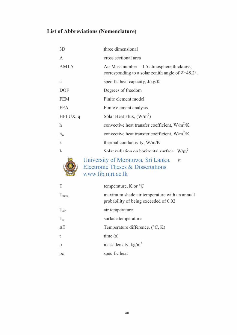
List of Abbreviations (Nomenclature)
3D three dimensional
A cross sectional area
AM1.5 Air Mass number = 1.5 atmosphere thickness,
corresponding to a solar zenith angle of =48.2°.
c specific heat capacity, J/kg/K
DOF Degrees of freedom
FEM Finite element model
FEA Finite element analysis
HFLUX, q Solar Heat Flux, (W/m2)
h convective heat transfer coefficient, W/m2/K
hw convective heat transfer coefficient, W/m2/K
k thermal conductivity, W/m/K
Ih Solar radiation on horizontal surface , W/m2
L Length, heat flow path length of interest
Q rate of heat transfer (W)
q Surface flux (power per unit area)
T temperature, K or °C
Tmax maximum shade air temperature with an annual
probability of being exceeded of 0.02
Tair air temperature
Ts surface temperature
ΔT Temperature difference, (°C, K)
t time (s)
ρ mass density, kg/m3
ρc specific heat
Copyright © 2022 FDOKUMEN