Signal Processing for Future Multicarrier Systems - Archive ...
228
HAL Id: tel-02430685 https://hal.archives-ouvertes.fr/tel-02430685 Submitted on 7 Jan 2020 HAL is a multi-disciplinary open access archive for the deposit and dissemination of sci- entific research documents, whether they are pub- lished or not. The documents may come from teaching and research institutions in France or abroad, or from public or private research centers. L’archive ouverte pluridisciplinaire HAL, est destinée au dépôt et à la diffusion de documents scientifiques de niveau recherche, publiés ou non, émanant des établissements d’enseignement et de recherche français ou étrangers, des laboratoires publics ou privés. Signal Processing for Future Multicarrier Systems Faouzi Bader To cite this version: Faouzi Bader. Signal Processing for Future Multicarrier Systems. Signal and Image processing. Université Rennes 1, 2016. tel-02430685
-
Upload
khangminh22 -
Category
Documents
-
view
1 -
download
0
Transcript of Signal Processing for Future Multicarrier Systems - Archive ...

HAL Id: tel-02430685https://hal.archives-ouvertes.fr/tel-02430685
Submitted on 7 Jan 2020
HAL is a multi-disciplinary open accessarchive for the deposit and dissemination of sci-entific research documents, whether they are pub-lished or not. The documents may come fromteaching and research institutions in France orabroad, or from public or private research centers.
L’archive ouverte pluridisciplinaire HAL, estdestinée au dépôt et à la diffusion de documentsscientifiques de niveau recherche, publiés ou non,émanant des établissements d’enseignement et derecherche français ou étrangers, des laboratoirespublics ou privés.
Signal Processing for Future Multicarrier SystemsFaouzi Bader
To cite this version:Faouzi Bader. Signal Processing for Future Multicarrier Systems. Signal and Image processing.Université Rennes 1, 2016. tel-02430685

Higher Degree by Research/
Habilitation à Diriger des Recherches-HDR
Presented by
Faouzi BADERDoctor in Telecommunication from
Universidad Politécnica de Madrid-UPM, SPAINAssociate Professor/ Enseignant Chercheur, CentraleSupélec, Rennes-FRANCE
Signal Processing for Future Multicarrier Systems
A dissertation submitted in partial fulfillmentof the Higher Degree by Research (HDR)
at University of Rennes 1, Rennes- Brittany, FRANCE
September 2016
The Jury Members
Prof. Luc Vandendorpe Université Catholique de Louvain, Belgium (Examinateur)Prof. Eric Pottier Université de Rennes 1, France (Membre invité)Prof. Bernard Uguen Université de Rennes 1, France (Examinateur)Prof. Jacques Palicot CentraleSupélec, France (Examinateur)Prof. Michel Terré Conservatoire National des Arts et Métier, France (Rapporteur)Prof. Ana Pérez Neira Universitat Politècnica de Catalunya, Spain (Rapportrice)Prof. Linda Doyle Trinity College of Dublin, Ireland (Rapportrice)

Notice: To introduce the reader, in France, HDR (habilitation à diriger les recherches) is a degree(diploma) which accredits to supervise alone PhD students and allows to run for positions of full professor inuniversities."Habilitation" 1(from Latin habilis "fit, proper, skillful") is the highest academic qualification a scholar can achieveby his or her own pursuit in many countries in Europe, Central Asia, Egypt and the Caucasus. Earned usually afterobtaining a research doctorate, such as a PhD, "habilitation" requires that the candidate write a professorial thesis(also "habilitation" thesis or inaugural dissertation) based on independent scholarship, reviewed by and defendedbefore an academic committee in a process similar to that of the doctoral dissertation. However, the level ofscholarship has to be considerably higher than that required for a research doctoral (PhD) thesis in terms of qualityand quantity, and must be accomplished independently, in contrast with a PhD dissertation typically directed orguided by a faculty supervisor. In the sciences, publication of numerous (frequently ten or more) research articlesis required during the "habilitation" period of about four to ten years. In the humanities, a major book publicationmay be a prerequisite for defense. The teaching ability of the "habilitation" candidate may also be evaluated 2.
Whereas a PhD is sufficient qualification for a full university faculty position in many other countries, where inuse, only the HDR qualifies the holder to independently supervise doctoral candidates.This clarification on academic credentials is very specific to France (and above cited countries or regions). Tothe best of my knowledge, there is no equivalence in the US higher education system or any other Anglo Saxoncountries. If you have a PhD and you are hired as an assistant professor, you will supervise doctoral students ifyour university issues doctoral degrees. There is no separate degree or accreditation legally required for doing so.
1Wikipedia definition citation2end of the definition
1

AcknowledgementsI would like to express my deep acknowledgment to my advisor Prof. Santiago Zazo Bello fromUniversidad Politécnica de Madrid (UPM)-Spain for having instilled in me the love of the sci-entific research, to Prof. Miguel Ángel Lagunas Hernandez, professor at Universitat Politècnicade Catalunya (UPC)- Barcelona, and director of the Centre Tecnològic de Telecomunicacions deCatalunya (CTTC)- Barcelona, Spain, for always trusting me and giving me the opportunity towork in an environment of excellence such as the CTTC for more than ten years, and to Prof.Jacques Palicot from CentraleSupélec, campus of Rennes (France), for his long and fruitful techni-cal discussions and advices, and for learning me everyday to not be afraid to shake and underminea lot of principles taken for granted in the scientific community. I would like also to thank a lotthe SCEE research team of CentraleSupélec for having adopted me in a so short time, for theirprofessionalism, humanism, and for the so nice working environment they are creating at every day.
I would like also to confess my deep gratitude to all my PhD students, postdocs, researchers, Ihad, or I have, the privilege to advise and/or to collaborate with them. Without all these brilliantpersons and their hard motivation, I would never be able to write one word of this document. Thankyou guys for making me enjoying with you the exiting word of research.
There is not enough words in this world to express my gratefulness to my lovely family, for theircontinuous support, patience, and love, "Habbkoum Mucho !".
Faouzi Bader

Contents
Acknowledgements 2
1 Extended Curriculum Vitae 101.1 About my PhD thesis . . . . . . . . . . . . . . . . . . . . . . . . . . . . . . . . . . . . . . . . . . . . 141.2 Teaching activities . . . . . . . . . . . . . . . . . . . . . . . . . . . . . . . . . . . . . . . . . . . . . . 15
1.2.1 @ CentraleSupélec, France . . . . . . . . . . . . . . . . . . . . . . . . . . . . . . . . . . . . . . 151.2.2 @ University of Jyväskylä-JUY, Finland . . . . . . . . . . . . . . . . . . . . . . . . . . . . . . 151.2.3 Tutorials . . . . . . . . . . . . . . . . . . . . . . . . . . . . . . . . . . . . . . . . . . . . . . . 151.2.4 Organization of schools . . . . . . . . . . . . . . . . . . . . . . . . . . . . . . . . . . . . . . . 16
1.3 Research Activities . . . . . . . . . . . . . . . . . . . . . . . . . . . . . . . . . . . . . . . . . . . . . . 161.3.1 Short Terms Scientific Cooperation . . . . . . . . . . . . . . . . . . . . . . . . . . . . . . . . . 161.3.2 Postdocs . . . . . . . . . . . . . . . . . . . . . . . . . . . . . . . . . . . . . . . . . . . . . . . . 171.3.3 PhD Supervisions . . . . . . . . . . . . . . . . . . . . . . . . . . . . . . . . . . . . . . . . . . 171.3.4 Masters (M2) . . . . . . . . . . . . . . . . . . . . . . . . . . . . . . . . . . . . . . . . . . . . . 20
1.4 PhD Examination and Committee Member . . . . . . . . . . . . . . . . . . . . . . . . . . . . . . . . 211.5 R&D Projects participation . . . . . . . . . . . . . . . . . . . . . . . . . . . . . . . . . . . . . . . . . 22
1.5.1 Project(s) starting soon . . . . . . . . . . . . . . . . . . . . . . . . . . . . . . . . . . . . . . . 221.5.2 Ongoing R&D projects . . . . . . . . . . . . . . . . . . . . . . . . . . . . . . . . . . . . . . . . 221.5.3 Completed R&D projects . . . . . . . . . . . . . . . . . . . . . . . . . . . . . . . . . . . . . . 23
1.6 Services . . . . . . . . . . . . . . . . . . . . . . . . . . . . . . . . . . . . . . . . . . . . . . . . . . . . 261.6.1 Chairing Events . . . . . . . . . . . . . . . . . . . . . . . . . . . . . . . . . . . . . . . . . . . 261.6.2 Organization of Special Sessions . . . . . . . . . . . . . . . . . . . . . . . . . . . . . . . . . . 281.6.3 Editor . . . . . . . . . . . . . . . . . . . . . . . . . . . . . . . . . . . . . . . . . . . . . . . . . 281.6.4 Panels and Invited keynotes . . . . . . . . . . . . . . . . . . . . . . . . . . . . . . . . . . . . . 281.6.5 Technical Program Committee (TPC) Member . . . . . . . . . . . . . . . . . . . . . . . . . . 29
2 Scientific Production 302.1 Publications . . . . . . . . . . . . . . . . . . . . . . . . . . . . . . . . . . . . . . . . . . . . . . . . . . 30
2.1.1 In Journals . . . . . . . . . . . . . . . . . . . . . . . . . . . . . . . . . . . . . . . . . . . . . . 302.1.2 Books Edited . . . . . . . . . . . . . . . . . . . . . . . . . . . . . . . . . . . . . . . . . . . . . 322.1.3 Book Chapters . . . . . . . . . . . . . . . . . . . . . . . . . . . . . . . . . . . . . . . . . . . . 332.1.4 In Conferences . . . . . . . . . . . . . . . . . . . . . . . . . . . . . . . . . . . . . . . . . . . . 342.1.5 Others . . . . . . . . . . . . . . . . . . . . . . . . . . . . . . . . . . . . . . . . . . . . . . . . . 42
3 Research Synthesis 433.1 Resource allocation in cognitive radio . . . . . . . . . . . . . . . . . . . . . . . . . . . . . . . . . . . 43
3.1.1 Resource allocation in CR without relaying communications . . . . . . . . . . . . . . . . . . . 433.1.2 Resource allocation in CR using relay communication . . . . . . . . . . . . . . . . . . . . . . 83
3.2 Coexistence capabilities . . . . . . . . . . . . . . . . . . . . . . . . . . . . . . . . . . . . . . . . . . . 1043.2.1 In Professional mobile communication context . . . . . . . . . . . . . . . . . . . . . . . . . . 1043.2.2 In Device-to-Device communications context . . . . . . . . . . . . . . . . . . . . . . . . . . . 125
3.3 Signal processing for OFDM and beyond OFDM . . . . . . . . . . . . . . . . . . . . . . . . . . . . . 152
4 Future perspectives 207
3

Bibliography 211
4

List of Figures
3.1 Cognitive Radio Network . . . . . . . . . . . . . . . . . . . . . . . . . . . . . . . . . . . . . . . . . . 443.2 Frequency distribution of the primary and cognitive bands . . . . . . . . . . . . . . . . . . . . . . . . 453.3 An Example of the SU’s allocated power using PI-Algorithm . . . . . . . . . . . . . . . . . . . . . . 483.4 Mean throughput vs. interference constraints for OFDM based CR. . . . . . . . . . . . . . . . . . . 493.5 Mean throughput vs. interference constraints for FBMC based CR. . . . . . . . . . . . . . . . . . . . 503.6 Frequency distribution with two active PU bands. . . . . . . . . . . . . . . . . . . . . . . . . . . . . 513.7 Achieved capacity vs. allowed interference threshold for OFDM and FBMC based CR systems - Two
active PU bands. . . . . . . . . . . . . . . . . . . . . . . . . . . . . . . . . . . . . . . . . . . . . . . . 513.8 Achieved CR vs allowed interference threshold (low) for OFDM and FBMC based CR systems - Two
active bands. . . . . . . . . . . . . . . . . . . . . . . . . . . . . . . . . . . . . . . . . . . . . . . . . . 523.9 Uplink Cognitive Radio Network. . . . . . . . . . . . . . . . . . . . . . . . . . . . . . . . . . . . . . . 533.10 Frequency distribution of active and non-active primary bands. . . . . . . . . . . . . . . . . . . . . . 533.11 Achieved capacity vs No. of SUs when N = 128 subcarriers, Pm = 1mWatt, B1 = B2 = 10 MHz,
and Rmin = 20 Mbits/sec. . . . . . . . . . . . . . . . . . . . . . . . . . . . . . . . . . . . . . . . . . . 563.12 Achieved capacity vs per-user power Pm when N = 128 subcarriers, M = 8 SUs, B1 = B2 = 10
MHz, and Rmin = 20 Mbits/sec. . . . . . . . . . . . . . . . . . . . . . . . . . . . . . . . . . . . . . . 563.13 Relayed cognitive radio network. . . . . . . . . . . . . . . . . . . . . . . . . . . . . . . . . . . . . . . 833.14 Achieved capacity vs available power budget with PS = PR, when Ith = -30 dBm. OFDM based
system is plotted by the solid lines while the dashed ones represent the FBMC based systems. . . . . 853.15 Achieved capacity vs the interference threshold with Ps = PR = 0 dBm. OFDM based system is
plotted by the solid lines while the dashed ones represent the FBMC based systems. . . . . . . . . . 863.16 System model of the cooperative two way relaying cognitive radio system. . . . . . . . . . . . . . . . 863.17 Effective interference powers [in dBc] of 1.4 MHz band of different multi-c waveforms versus 25KHz
TEDS reception mask. . . . . . . . . . . . . . . . . . . . . . . . . . . . . . . . . . . . . . . . . . . . . 1053.18 Mean Interference Table on OFDM receiver [C97]. . . . . . . . . . . . . . . . . . . . . . . . . . . . . 1263.19 Maximum Interference Table on OFDM receiver [C97]. . . . . . . . . . . . . . . . . . . . . . . . . . . 1273.20 Graphical summary of the undertaken study: two users U1 and U2 transmit on adjacent bands L1 and
L2 and interfere with each other. Channel is assumed perfect and no Gaussian noise is considered.U2 uses CP-OFDM in Hom scenario and OFDM/OQAM in Het scenario. . . . . . . . . . . . . . . . 128
3.21 Modeling of injected interference with the PSD-based model for CP-OFDM (top) and OFDM/OQAMwith PHYDYAS filter (bottom). The values of interference injected by subcarrier 0 on a subcarrierat a spectral distance of l = 1 correspond to the integration of the PSD from 0.5 ∆F to 1.5 ∆F . . . 128
3.22 Comparison between interference values obtained with (a) OFDM/OQAM onto CP-OFDM withPSD-based model, (b) OFDM/OQAM onto CP-OFDM through numerical simulation, and (c) CP-OFDM onto CP-OFDM with mean interference tables [1]. . . . . . . . . . . . . . . . . . . . . . . . . 129
3.23 Mean Normalized EVM of users U1 and U2 in the scenarios Het and Hom . . . . . . . . . . . . . . . 1293.24 Proposed blind equalizer using CNA, adapted to OFDM/OQAM system in [J24]. . . . . . . . . . . . 1543.25 Time domain signals comparison. In the Upper figure the two signals xev and xodd are drawn. In
the bottom Figure the summation xev + xodd is drawn and compared with the original signal x. . . . 1843.26 Illustration of the cost function in TR-GP method. . . . . . . . . . . . . . . . . . . . . . . . . . . . . 1863.27 Illustration of the clipping partial noise J1(.) and J2(.). . . . . . . . . . . . . . . . . . . . . . . . . . 1863.28 Illustration of the clipping partial noise J1,1(.), J1,2(.), J2,1(.) and J2,2(.). . . . . . . . . . . . . . . . 186
5

3.29 Taxonomy of multi-carrier waveforms regarding the PAPR performance, condition (2) here corre-spond to (3.29) in this manuscript, and (27) is the Lebesgue measure expression of the interval A+
defined in [J25]. . . . . . . . . . . . . . . . . . . . . . . . . . . . . . . . . . . . . . . . . . . . . . . . . 189
6

List of Acronyms
AF Amplify and Forward
ASER Average Symbol Error Rate
AWGN additive white Gaussian noise
BER Bit Error Rate
B3G Beyond 3rd Generation
B5G Beyond 5th Generation
CBS Cognitive Base Station
CCDF Complementary Cumulative Distribution Function
CDF Cumulative Distribution Function
CMA Constant Modulus Algorithm
C-MTC Critical Machine Type Communications
CNA Constant Norm Algorithm
CP Cyclic Prefix
CR Cognitive Radio
CSI Channel State Information
CLT Central Limit Theorem
D2D Device-To-Device
EC European Community
ES Exhaustive Search
EVM Error Vector Magnitude
FBMC Filter Bank Multiple Carriers
FCC Federal Communications Commission
FFT Fast Fourier Transform
F-OFDM Filtered Orthogonal Frequency Division Multiplexing
GA Genetic Algorithm
GFDM Generalized Frequency Division Multiplexing
5G 5th Generation
7

3GPP The 3rd Generation Partnership Project
HPA High Power Amplifier
ICI Inter-Carrier Interference
ICT Information and Communication Technologies
IEEE Institute of Electrical and Electronics Engineers
IMT International Mobile Telecommunications
IoT Internet of Things
IOTA Isotropic Orthogonal Transform Algorithm
LTE long Term Evolution
LPWA Low Power Wide Area
MAC Multiple Access Control layer
MC-CDMA Multi-Carrier Code Division Multiple Access
MGF Moment Generating Function
MIMO Multiple Input Multiple Output
MMA Multi-Modulus Algorithm
MMSE Minimum Mean Square Error
MRC Maximal Ratio Combining
MT-CDMA Multi-Tone Code Division Multiple Access
MTR Modified Tone Reservation
MUD Multi-User Detection
OFDMA Orthogonal Frequency Division Multiple Access
OOB Out-Of-Band
OQAM Offset Quadrature Amplitude Modulation
PA Power Allocation
PAP Phase Adaptation Procedure
PAPR Peak to Average Power Ratio
PDF Probability Distribution Function
PHY Physical layer
PI Power Interference algorithm
PMR Professional Mobile Radio
PN Primary Network
PPDR Public Protection Disaster Relief
PSACE Pilot Aided Channel Estimation
PSD Power Spectrum Density
8

PU Primary User
QCQP Quadratic Constrained Quadratic Program
QoS Quality of Service
RA Resource Allocation
RB Resource block
RF Radio Frequency
RRA radio Resource Allocation
RRM radio resource Management
SC Selection Combining
SC-FDMA Single carrier Frequency Division Multiple Access
SN Secondary Network
SNR Signal to Noise Ratio
SOCP Second Order Cone Program
SS Spread Spectrum
SS-MC-MA Spread Spectrum Multi-Carrier Multiple-Access
STREP Specific Targeted Research Projects
SU Secondary User
TAS Transmit Antenna Selection
TEQ Time-domain EQualizer
TR Tone Reservation
TTI Transmission Time Interval
UFMC Universal-Filtered Multi-Carrier
UTRA UMTS Terrestrial Radio Access
WAN Wide Area Network
WLAN Wireless Local Area Network
9


Chapter 1
Extended Curriculum Vitae
Brief and preliminary informationStatus:Name: BADERSurname: FaouziActual position: Associate Professor/ECActual institution: CentraleSupélec, Campus of Rennes-France.Address: Avenue de la Boulaie CS 47601. F-35576. Cesson-Sévigné CedexE-mails: [email protected]/[email protected]: +33 (0) 299844536, fax: +33 (0)299844599,Home page: http://www.faouzibader.com
Academia:• 1998-2002: PhD degree in Signal Processing and Telecommunication (with "cum laude" honor) at ETSIT–Universidad Politécnica de Madrid (UPM), Madrid, Spain.
Dissertation titled: "New Signal Processing Techniques Applied to MC-CDMA System in the Reverse Link"(document in Spanish). 6th November 2002.Adviser: Prof. Santiago Zazo, Universidad Politécnica de Madrid-UPM, Madrid-Spain.Examination committee:Prof. José Manuel Paez Borrallo, Universidad Politécnica de Madrid (UPM), (President), Prof. FranciscoJavier Casajús Quirós, Universidad Politécnica de Madrid (UPM), Prof. Luis Castedo Ribas, UniversidadA Coruña, A Coruña (UDC), Prof. Miguel Ángel Lagunas Hernandez, Universitat Politècnica de Catalunya(UPC), Barcelona, Prof. Javier Rodriguez Fonollosa, Universitat Politècnica de Catalunya (UPC), Barcelona.
• 1991-1996: Electronic Engineering Degree, with honor at Institute of Electronics, Faculty of EngineeringSciences of University Mentouri of Constantine (UMC), Constantine-Algeria.
Professional experience:• Since June 2013- present: Associate Professor/ Enseignant Chercheur at Signal, Communication & EmbeddedElectronics (SCEE) research group of CentraleSupelec, Campus of Rennes-France.
• From February 2012-May 2012: Visiting researcher at Department of Electronics and Communications Engi-neering, of Tampere University of Technology-TUT at Tampere, Finland.
• From 2006- June 2013: Senior Research Associate at Catalonia’s Telecommunications and Technology Centre-CTTC (http://www.cttc.es), Barcelona-Spain.
10

• From 2002-2005: Research Associate and Coordinator of Access Technologies research area at Telecommuni-cations Technological Center of Catolonia-CTTC, Barcelona, Spain.
• From 2000- 2001: Development Engineer at Massana Technologies SL. company (Ireland). In 2002 the com-pany has been bought by Ageere System (USA), and in 2007 merged with LSI Corporation http://www.lsi.com/(USA).
• From 1997-2002: Research member of the “Systems and Signal Processing” research group (GAPS) of depart-ment of Systems and Radio Communications (SSR) at the High School of Engineers of Telecommunications(ETSIT) of Universidad Politécnica de Madrid (UPM), Spain.
Scientific and Professional Society Membership- Project reviewer at the «French National Research Agency» (ANR)-France, since 2014.- Project reviewer at the "Fonds de la Recherche Scientifique" of Belgium (FNRS), since 2013.- Chair of the working group "WG1" on High Capacity PHY for future radio access of the European CommissionRadio Access and Spectrum (RAS) Cluster (2012-2014).- Project reviewer at Natural Sciences and Engineering Research Council of Canada (NSERC)-Canada, since 2014.- IEEE Standards Association Member- IEEE Senior Member since 2007.- Member of IEEE Communication Society (ComSoc IEEE).- Member of Cognitive Communications (CogCom) of WorldWide Universities Network Initiative (WUN-CogCOM),since 2009.
Main research activities:- Advanced Multi-carrier Waveforms for future communication Systems (5G),- Cooperative, relay and multi-(two-way) scenarios,- Professional Mobile Radio PMR/PPDR for public safety and beyond,- Cross layer System design,- Cognitive Radio and Spectrum sharing,- Radio Resource Management.
Publications:- In journals: 23 including 3 editorials, see all the list in Subsection 2.1.1, page 30.- Book chapters: 15, see the details in Subsection 2.1.3, page 33.- In international Conferences: 100 with peer review process see detailed list of conference papers in Subsection2.1.4, page 34.- In National Conferences: 5 with peer review process.- Edited books: 3, see all the edited books in Subsection 2.1.2, page 32.- Standardization: 9, all the details are in Subsection 2.1.5, page 42.
Advised young researchers- Postdocs: 2.- PhD Students under supervision: 3.- Supervised PhDs: 4.- Masters (MS2): 6.
International collaborations with academia and research centersBelow you have the list of my collaborations to the date. I mean by collaboration any action with joint technicaloutput(s) representing a joint project collaboration(s), publication(s), or research mobility. My main research rela-tionships are among others with:
11
Asia: Dr. Sumit Darak from Indraprastha Institute of Information Technology Delhi -IIID (India).Australia: Prof. Eryk Dutkiewicz and Prof. Michael Heimlich from Macquarie University of Sydney-MQ, Dr.Beeshanga Abewardana Jayawickrama from University of technology Sidney-UTS, prof. Kandeepan Sithampara-nathan from Royal Melbourne Institute of Technology-RMIT.Europe: Prof. Maurice Bellanger, Prof. Didier Le Ruyet, Prof. Daniel Roviras, Dr. Yahia Medjahdi from Con-servatoire National des Arts et Métiers (CNAM), Dr. Dominique Noguet, Dr. Vincent Berg, Dr. J. B. Dorefrom CEA-Leti-Grenoble, Prof. Hakima Chaouchi from Université Paris-Sud (France), Université Catholique deLouvain-(UCL) (Belgium), Prof. Nikos Passas from University of Athens, Prof. Panagiotis Demestichas and Dr.Lefteris Kofidis from University of Piraeus (Greece), Dr. Oliver Holland, Dr. Vassilis Friderikos from King’s Collegeof London, Prof. Klaus Moessner from University of Surrey (UK), Prof. Martin O’Droma, and Dr. Ivan Ganchevfrom University of Limerik, Prof. Luiz DaSilva, and Dr. Arman Farhang from Trinity College of Dublin, Dr.Hamed Ahmadi from University College of Dublin (Ireland), Prof. Markku Renfors from Tampere University ofTechnology and Prof. T. Ristaniemi from University of Jyväskylä, Dmitry Petrov from Magister (Finland), Dr.Jonathan Rodriguez and Shahid Mumtaz from Instituto de Telecomunicações-IT Lisbon and Aveiro (Portugal),Prof. Santiago Zazo Bello from Universidad Politécnica de Madrid, Prof. Luis Muñoz, Dr. Ramon Agüero fromUniversidad de Cantabria, Dr. Ivan A. Perez-Alvarez from Universidad de Las Palmas de Gran Canaria, Prof. A.Perez Neira, Dr. Christian Ibars, Dr. Stephan Pfletschinger from CTTC, Prof. Oriol Sallent from UniversitatPolitècnica de Catalunya-UPC (Spain), Dr. Simon Plass from German Aerospace Center-DLR, Prof. ThomasKaiser from Duisburg-Essen University, Prof. Eduard Jorswieck from Dresden University of Technology, RWTHAachen University (Germany), Prof. S. Ben-Slimane from Royal Institute of Technology-KTH (Sweden), Prof.Hanna Bogucka and Dr. Adrian Kliks from Poznan University of Technology-PUT (Poland), Ringset Vidar fromSINTEF research centre (Norway), Prof. M. Gabriella Di Benedetto, Dr. Luca De Nardis from University of RomeLa Sapienza, Dr. Gianmarco Baldini from European Research Center, Andrea Giorgetti from University of Bologna(Italy), Dr. Andrea Fabio Cattoni from Aalborg University (Denmark).Middle East: Dr. Youssef Nasser from American University of Beirut-AUB, Prof. Oussama Baazi from LebaneseUniversity of Beirut (Lebanon), Prof. Mohammad Banat from Jordan University of Science and Technology-JUST(Jordan), Prof. Mohamed-Slim Alouini from King Abdullah University of Science and Technology-KAUST (SaudiArabia), Dr. Nizar Zorba from Qatar University (Qatar).North America: Prof. B. Farhang-Boroujeny from University of Utah (USA), Prof. Sofiene Affés from InstitutNational de la Recherche Scientifique-INRS of Quebec, Prof. Mohamed Ibnkahla from Queen’s University, Dr.Kareem Emile Baddour from Communications Research Centre-CRC (Canada).
Involved research projects- EU Funded projects: 10 projects (7 STREPs, 1 COST Action, and 2 CELTICs).- National projects: 7 projects, from which 3 funded by the Spanish Ministry of Industry, Tourism and Commerce(MITYC), and 4 from the French National Research Agency (ANR).- Industrial projects: 3 projects.- Grants: 1 PHC (ULYSSES with Ireland).More details on my involvement in projects can be found in Subsection 1.5, page 22.
Awards & Recognitions2012: Assumed the role of General Coordinator and Manager of FP7 STREP Project titled: Enhanced Multi-carrier Techniques for Professional Ad-hoc and Cell Based Communications [ICT-EMPhAtiC], with contract code:ICT-318362.- 2010: BEST CONFERENCE PAPER AWARD of the Sixth International Conference on Wireless and Mobile Com-munications (ICWMC’2010) on the paper “Pilot Pattern Adaptation and Channel Estimation in MIMO WiMAX-like FBMC System” Sept 2010.- 2007: Member of "Bridge Technologies" team, finalist at the 7th Competition of Business Ideas, organized by theSpanish Ministry of Innovation, Universities and Enterprise of the local Government of Catalonia (CIDEM). 2007edition.- 2007: Nominated IEEE Senior Member.
12

- 2003: Certificate of Appreciation for contributions to The IEE European Personal Mobile Communications Con-ference (IEE EPMCC), Glasgow, UK. April 2003.- 2002: PhD degree titled: "New Signal Processing Techniques Applied on the MC-CDMA System in the ReverseLink" (In Spanish) obtained with Honours (CUM LAUDE) from the High School of Engineers of Telecommunica-tions (ETSIT) at Universidad Politécnica de Madrid (UPM), Madrid-Spain. November 2002.- 2000: Certificate of Appreciation for contributions to The IEEE Boston Fall Vehicular Technologies Conference.Boston -USA. September 2000.- 1999: BEST CONFERENCE PAPER AWARD -Arthec House Publishers Award on the paper “Optimum PilotPattern for Multi-carrier CDMA Systems”, presented at WPMC’99/IEEE VTC-Fall’99.
13
1.1 About my PhD thesisAt early of the nineteenths, several research works focusing on the combination of the OFDM and the CDMA havebeen developed and proposed as the MC-CDMA by N. Yee et al, in [2], the MC-DS-CDMA by K. Fazel in [3], andthe MT-CDMA by L. Vandendorpe in [4]. In all these schemes, the users share the same time-frequency dimension,and can be separated in the code domain.
The general focus of my dissertation (1998-2002) is on wireless communication systems, more precisely on thedevelopment of new signal processing techniques for multi-carrier code division multiple access (MC-CDMA) systemfor the uplink communication mode. My dissertation is about 231 pages and six chapters including the furtherresearch lines. Main technical contributions are presented in chapter 3 on: "Channel Estimation", Chapter 4 on:"Synchronization in MC-CDMA in Uplink communication mode", and Chapter 5 on: "Multi-User Detection in Up-link Mode". In Chapter 3, a hexagonal pilot pattern design has been designed and developed to be compatible withthe MC-CDMA systems for the uplink communications mode. At that time no such pilot pattern scheme was eithercontemplated nor developed for MC-CDMA. Only conventional patterns as; diagonal, rectangular or square wereavailable in the scientific literature. The performances of proposed scheme have been analysed and published in(see in Subsection 2.1.4 and Subsection 2.1.3) [C1, C2, C3],and [CB1, CB2].
The second main technical contribution (Chapter 4) is related with the uplink acquisition of synchronization pa-rameters in MC-CDMA. The uplink communication case of the MC-CDMA sygnal is a critical communicationmode that may degrade severely the system performance and the data demodulation, where the signal detectionis much more difficult to treat in an asynchronous (as uplink) mode than the synchronous one. When the basestation intends to detect the signal of a specific user, the first step for the demodulation process at the receiver isthe frame synchronization. Note that each MC-CDMA mobile system has its own spreading code, which is sharedwith the base station. When a mobile station transmits only the spreading code with no data, the base station canknow the time domain of the spreading signal. The good detection process is related in big part with the periodiccross-correlation characteristics of the used spreading code during the transmission process. According with theobservation in [5, 6], the repetition of the spread code in frequency domain has bad cross-correlation characteristicsin the time domain. One solution is the use of a concatenate distribution of the later. This mode can improvesignificantly the cross-correlation characteristics between the spreading used sequences in the time domain.To design proposed scheme, we consider K (K is the total number of active users ) orthogonal Gold sequences,the first user concatenate the codes from 1 to P code (P is an integer factor that can be equal or lower that themaximum active users depending on the total available carriers, and indicating the number of the code words usedin one OFDM-symbol) in a specific order. The second assigned user code is and L (L correspond to the length ofone orthogonal code spread sequence ) shifts displacement of the first generated code, and the rest of users adoptthe same technique up to last active user. At the end, all the symbols in the same frequency band are spread bydifferent orthogonal Gold codes, such that the different frequency bands may be spread by the same Gold code.The combination of the T. M. Schmild and D. Cox frequency offsets correction algorithm in [7], [8] and the useof spreading sequences and the reservation of PSACE positions allowed a design of a combined scheme to get theessential acquisition parameters which are: the detection of the user’s time arrivals frames, the correction of thetime-frequency offsets misalignment, and a rough estimation of the CSI of every transmitting user in the uplinkmode. Note that The use of the proposed spreading code allows the exploitation of the correlation properties in timedomain by permitting a good detection of the starting time of the user’s signal at the base station. The supportof the offset correction sequence in the initial channel estimation jointly with the inserted pilots is very benefitpermitting a higher channel estimation accuracy. More details on achieved performances with proposed acquisitionscheme in terms of bit error rate (BER), initial channel estimation minimum mean square error (MSE), and MSEvalues of the offset correction, are available in (see in Subsection 2.1.4) [C4] and [CB4] publications.
Two multi-user detection (MUD) schemes have been developed in Chapter 5, proposed have been adapted tothe transmission block developed by Z. Wang and B. Giannakis in [9] to the MC-CDMA scheme for the uplinkcommunications mode.In addition, their combination with preliminary studies undertaken by S. Verdu allowed toencompass different detection schemes (synchronous, quasi-synchronous, and asynchronous) under a unique math-ematical formulation [10], and the development of different MUD (decorrelators, and MMSE detector) all adaptedto the uplink communication mode. The developed detection models allowed us to address the MC-CDMA wirelesscommunications for uplink mode with a higher grade of delay than those usually used in small cells environments
14

where only quasi-synchronous detections are possible. More details on proposed decorrelators for MC-CDMA com-bined with SIC and PIC cancellation schemes and achieved performances can be found at (see in Subsection 2.1.4and Subsection 2.1.3) [C4, C5, C6] and in [CB3, CB3] references.
Here are the main publications1 directly related with my PhD thesis:• Linked with Chapter 3 on: "Pilot pattern design", [C2, C3] and [CB2].• Linked with Chapter 4 on: "Uplink acquisition of synchronization parameters in MC-CDMA", [C4, C7].• Linked with Chapter 5 on: "Multi-User detection in reverse mode", [C2, C3, C5, C8], [CB3], and [J1].
1.2 Teaching activities1.2.1 @ CentraleSupélec, FranceMy teaching activities formally started at my coming to CentraleSupélec in 2013 (June). Below are listed the maincourses:
• Since 2014: Teaching fellow, lecture on: "Random Processes and Probabilities" for undergraduate students(first year), 18 hours. Period: first semester.
• Since 2014: Teaching Assistant-ship, tutorials/integrated2 courses on: "Random Processes and Probabilities",for undergraduate students (first year), 4 classes of 1h:30min each. Period: first semester.
• Since 2013: Teaching Assistant-ship, tutorials/integrated courses on: “Statistical Representation and Analysisof Signals", for undergraduate students (second year), 4 classes of 1h:30min. Period: first semester.
• Since 2013: Teaching Assistant-ship, tutorials/integrated courses on: “Signals and Systems I“, for undergrad-uate students (second year), 4 classes of 1h:30min each. Period: first semester.
• Since 2013: Teaching Assistant-ship3, laboratory work related with course "Statistical Representation andAnalysis of Signals", for undergraduate students (second year), 8 sessions of 5h:30min each. Period: firstsemester.
1.2.2 @ University of Jyväskylä-JUY, FinlandBellow are the lectures I gave during two years (2014 and 2015) at JUY.
• Lecture on: “Potential Multi-carrier Techniques and Waveforms for Future 5G Communication Networks“ (40hours), at faculty of information and technology of University of Jyväskylä, Finland. Period: August 2015.The number of students registered in this course is: 26 students.
• Lecture on: “Beyond OFDM Radio Interfaces Facilitating Spectrum Coexistence and Secondary Access”, (40hours), at faculty of information and technology of University of Jyväskylä, Finland. Period: August 2014.The number of students registered in this course is: 20 students.
1.2.3 Tutorials• Candidate Multi-carrier Waveforms for Future 5G Communication Systems, by F. Bader (CentralSupélec-France) and Dmitry Petrov (Magister Solutions Ltd., Jyväskylä, Finland), at the 8th International Congresson Ultra Modern Telecommunications & Control Systems (ICUMT’2016). Lisbon-Portugal. October 2016.
• Beyond OFDM Radio Interfaces Facilitating Spectrum Coexistence and Secondary Access: New UnsuspectedApplications, by F. Bader (Supélec-France) and A. Kliks (Poznan University of Technology-Poland). Fivehours tutorial taught for postgraduate class of 40 students at King’s College of London (KCL). July 2013.London-UK.
1 indexes: [JX], [CBX], [CX], and [OX] refer to published: journal, chapter book, conference, and other publication respectively.The "X" is referring to the publication number
2the equivalent of "Travaux Dirigés-TD" in French Universities.3the equivalent of "Travaux de Laboratoire-TL" in French Universities.
15

• OFDM vs. FBMC System Performances in Non-Relay and Relay Cognitive Radio Scenarios, by F. Baderand Musbah Shaat. (4) hours tutorial taught for postgraduate class at CTTC, 2012.
• Technologies Evolution and Regulation in Communication Systems, (at Telefónica I+D). Postgraduate classof 14 students, Telefónica (Spain). Years 2007 and 2008.
• Technology Bases for Spectrum Management Evolution, by F. Bader, four (4) hours tutorial taught atMosharaka International Conference on Signal, Image and Speech Processing (M-SISP2007), Amman, Jordan.June 2007.
• WiMAX a New Broadband Access Solution, three (3) hours tutorial taught for postgraduate class of 16students at the 1st IEEE Mobile Computing and Wireless Conference (IEEE MCWC’2006). 16th September2006, Amman-Jordan.
• Enabling Technologies and Key Issues for QoS Enabled Reconfigurable Mobile/Wireless Networks, by F. Bader,M. Navarro, S. Pfletschinger, C. Pinart. Three (3) hours tutorial taught for postgraduate class of 24 studentsat the 1st IST-ANWIRE Summer School on Wireless Internet: Network Architectures, Quality of Service andApplications, 21-25 July 2003, IT-Lisbon, Portugal.
1.2.4 Organization of schools• Network of Excellence in Wireless Communications-(Newcom#) Spring School on "Flexible Multi-carrierWaveforms for Future Communications Wireless Networks", at Supélec, campus of Rennes- France, 21-23 May2014.
• Spring School Tutorials days on "Advances on Signal Waveforms, Decision Making and Implementationin CR Radio", supported by the COST Action IC 0902 "Cognitive Radio and Networking for CooperativeCoexistence of Heterogeneous Wireless Networks”. Location: CTTC, Castelldefels-Barcelona-Spain. 11-13February 2013.
• European Network of Excellence "Advanced Coexistence Technologies for Radio Optimization in Licensed andUnlicensed Spectrum"-ACROPOLIS Winter School 2013. Location: CTTC, Castelldefels-Barcelona-Spain.14-15 February 2013.
1.3 Research Activities1.3.1 Short Terms Scientific Cooperation2014
• Laura Beatriz Melián Gutiérrez, PhD student from Universidad de Las Palmas de Gran Canaria - ULPGC(Spain). Supervisor: Dr. Iván A. Pérez Álvarez IDeTIC-ULPGC-Spain, and Dr. Santiago Zazo Bello,UPM- Madrid, Spain. Research collaboration topic on: “HF Spectrum Activity Prediction Model Based onLearning Techniques for Cognitive Radio Applications." Period: September-December 2014 at SUPELEC,Rennes-France.
2013
• Sener Dikmese PhD student of Tampere University of Technology (TUT), Tampere-Finland. Supervisor:Prof. Markku Renfors (TUT). Research cooperative topic: “Spectrum Sensing and Spectrum Allocation for802.11g based WLAN & Filter Bank Multi-carrier based cognitive radios using compressed sensing technique”.Period: November-December 2013 at SUPELEC, Rennes-France.
2012
• Prof. Eryk Dutkiewicz from Macquarie University of Sydney-MQUS (Australia). Research collaboration topicon: "Dynamic Spectrum Access in Cognitive Radio Networks. Period: July to September 2012 at CTTC,Barcelona-Spain.
16

• Jing Lv PhD student of Dresden University of Technology (TUD), Dresden-Germany. Supervisor: Prof.Eduard Jorswieck (TUD). Research collaboration topic on: “Advanced Coexistence Technologies for RadioResource Usage Optimization”. Period: September-October 2012 at CTTC, Barcelona-Spain.
• Dr Yahia Medjahdi from Conservatoire National des Arts et Métiers (CNAM), Paris-France. Research col-laboration topic on: Interference Modeling of Asynchronous FBMC Based System for primary Narrow-bandCoexistence. Period: October 2012 at CTTC, Barcelona-Spain.
• Sener Dikmese PhD student of Tampere University of Technology (TUT), Tampere-Finland. Supervisor:Prof. Markku Renfors (TUT). Research collaboration topic on: “Spectrum Sensing and Spectrum Allocationfor IEEE 802.11g based WLAN & FBMC based Cognitive radios”. Period. November-December 2012 atCTTC, Barcelona-Spain.
• Jin Lai PhD student from Macquarie University of Sydney-MQUS (Australia). Supervisor: Prof. ErykDutkiewicz (MQUS). Research collaboration topic on: “Radio Resource Management in Broadband WirelessNetworks: Maximizing Resource Utilization in LTE and CR Networks”. Period: November-December 2012 atCTTC, Barcelona-Spain.
• Dr. Djamel Slimani from University Ferhat Abbas (UFA) of Sétif in Algeria. Research cooperative topic:“IMT advanced Multi-carrier Communication Systems for Cellular Networks”. Period: December 2012, atCTTC Barcelona-Spain.
2011
• Dr. Mohammad M. Banat from Jordan University of Science and Technology (JUST), Amman-Jordan.Research collaboration topic on: “Three Dimensional Pilot Aided Channel Estimation for Filter Bank Multi-carrier MIMO Systems with Spatial Channel Correlation”. Period: January –July 2011, at CTTC, Barcelona-Spain.
• Dr. Adrian Kliks from Poznan University of Technology-PUT (Poznan-Poland). Research collaboration topicon: Advanced AMC techniques for throughput enhancement and interference mitigation in cognitive systems.Period: August-September 2011 at CTTC, Barcelona-Spain.
1.3.2 Postdocs• Vincent SAVAUX (CentraleSupélec), on research topic: "Blind detection strategies for OQAM-OFDM Sys-tems". Under the French National Research Agency project PROFIL: ANR-13-INFR-0007-03. Period: 2013-2015. Related publications: [J24, J23, J20, J18], and [C104, C101, C99, C94, C92, C91, C87].
• Malek NAOUS (CentraleSupélec), on research topic: “FBMC Equalization- HW Implementation“. Under theFrench National Research Agency project PROFIL: ANR-13-INFR-0007-03. Period: 2014-June 2016. Relatedpublications: [C104, C92], and [O1].
1.3.3 PhD Supervisions1.3.3.1 In progress
• Hussein CHOUR, PhD. title: "Cognitive Radio in Device-to-Device (D2D) Future Communication Systems",Joint doctoral supervision with the Lebanese University in Beirut (Lebanon), and CentraleSupélec (France).Advisors: Prof. Yves Louët and Dr. Faouzi Bader (France), and Prof. Oussama Bazzi with Dr. YoussefNasser (Lebanon).Period: Oct. 2016 end 2019.
• Antonio Cristo SUAREZ RODRIGUEZ, PhD. titled: "Device-to-Device Communication in 5G Cellular Net-works". Joint doctoral supervision with Macquarie University of Sydney (Australia) and CentraleSupélec(France).Advisors: Prof. Jacques Palicot and Dr. Faouzi Bader (France), and Prof. Eryk Dutkiewicz and Prof. MichaelHeimlich (Australia).Period: April 2016- end 2019.
17
• Quentin BODINIER, PhD. titled (provisional): "GFDM Multi-User Detection Scheme in Asynchronous Co-ordinated Multi-point Scenario". Advisors: Prof. Jacques Palicot (30%), and Dr. Faouzi Bader (70%).Period: Oct. 2014-end Oct. 2017. Related papers to the date: [C96, C97, C100, C103, C105, C106] (page34).
1.3.3.2 Finished
• Marwa CHAFII, PhD. title: "Study of a New Multi-Carrier Waveform with Reduced PAPR" (original inFrench), at SCEE Research group, SUPELEC-Rennes-France.Advisors: 50% Prof. Jacques Palicot (Supélec, France), 30% Prof. Rémi Gribonval (INRIA-Rennes, France),and 20% Dr. Faouzi Bader (Supélec, France).Period: Sept. 2013- end Oct. 2016.
Related publications (see Section 2.1), were I’m directly involved journal(s): [J25] (page 30); and confer-ences: [C102, C98] (page 34). Other publications in this thesis are: in journals: [11], in conferences:[12, C98, 13, 14, 15, 16, 17].
Examination Committee:- Prof. Laurent Jacques, University Catholic of Louvain, Belgium.- Prof. Michel Terré, CNAM, Paris-France.- Prof. Cyrille Siclet, Université Gronole Alpes-UGA, Grenoble, France.- Prof. Geneviève Baudoin, ESSIEE, Noisy le Grand, France.- Dr. Matthieu Gautier, University Rennes 1-UR1, Rennes, France.
Short description: OFDM is a multi-carrier modulation system widely used in wireline and wireless applica-tions such as DVB-T/T2,Wifi, and 4G, due to its resilience against frequency selective channels compared withthe single carrier modulation systems. However, the OFDM signal suffers from large amplitude variations.The fluctuations of the OFDM envelope generate non-linear distortions when we introduce the signal into anon-linear device like the power amplifier. Reducing the variations of the signal improves the power amplifierefficiency, reduces the energy consumption and decreases CO2 emissions. The peak-to-average power ratio(PAPR) has been introduced as a random variable that measures the power variations of the signal. Thereexist several multi-carrier modulation systems based on different modulation basis and shaping filters. Wefirst prove in this work that the PAPR depends on this modulation structure. Moreover, the behavior of thePAPR regarding to the modulation waveforms is analyzed and the PAPR reduction problem is formulatedas an optimization problem. Furthermore, a necessary condition for designing waveforms with better PAPRthan OFDM is developed. This necessary condition is particularly satisfied by wavelet basis. Finally, a newadaptive wavelet packet waveform is proposed, allowing significant gain in terms of PAPR, while keeping theadvantages of multi-carrier modulations.Keywords: PAPR, OFDM, wavelet modulation, adaptive modulation.
• Lamarana DIALLO, PhD. title: "Contributions to Techniques for Crest Factor Reduction in OFDM Signals"(original in French), at SCEE Research group of Supélec-Rennes. Advisors: Prof. Jacques Palicot (70%), andDr. Faouzi Bader (30%) both from Supélec-Rennes. Period: Nov 2012- March 2016.Related publications (see Section 2.1): Journal(s): [J22] (page 30); Conferences: [C89, C93, C95, C98, C102](page 34).
Examination Committee:- Prof. Marie Laure Boucheret, INP-ENSEEIHT-Toulouse-France. - Prof. Geneviene Baudouin, ESSIEE,Noisy le Grand, France.- Prof. Daniel Roviras, CNAM, Paris-France.- Dr. Mohamad Mroué, Université Libanaise, Beirut, Lebanon
Short description: The Orthogonal Frequency Division Multiplexing (OFDM) is the most commonly usedmulti-carriers modulation scheme in the telecommunication systems. It is used in most communication stan-dards such as DVB-T2, Wireless Local Area Networks (WLAN), WiMAX and the LTE (Long Term Evolution)
18

standard. The success of the OFDM comes from its robustness in presence of multi-paths and frequency se-lective fading channels, and the simplicity of the implementation of its transmitter and receiver. One of themain drawbacks of the OFDM modulation scheme is its high Peak-To-Average Power variation (PAPR) whichcan induce poor power efficiency at the transmitter amplifier. The digital base band pre-distortion for thelinearization of the power amplifier (PA) and the PAPR mitigation are the most commonly used solutions inorder to deal with efficiency and the linearisation at the high power amplifier. This thesis is focused on thislast solution, and particularly on the addition of signal based techniques to mitigate the PA effects. Developedsolutions in this thesis are about improving the Tone Reservation method which is the most popular addingsignal based technique for PAPR mitigation, and also the classical clipping method which is nowadays themost simple method (in terms of computational complexity).
Keywords: OFDM, PAPR, high power amplifier, tone reservation, clipping;
• Musbah SHAAT, PhD. title: "Resource Management in Multi-carrier Based Cognitive Radio Systems", attheory of signal and communications department, Polytechnic University of Catalonia-UPC, Spain.Advisors: Dr. Faouzi Bader (70%), and Prof. Miguel Angel Lagunas (30%) from Polytechnic University ofCatalonia-UPC, Barcelona, Spain.Duration: March 2008-2012 (4 years)
Examination Committee:- Prof. Ana Isabel Perez Neira, Universitat Polit‘ecnica de Catalunya (UPC), Barcelona-Spain- Prof. Didier Le Ruyet, Conservatoire National des Arts et Métiers (CNAM), Paris-France- Prof. Santiago Zazo Bello, Universidad Politécnica de Madrid (UPM), Madrid-Spain- Prof. Mohamed-Slim Alouini King Abdullah University of Science and Technology (KAUST), Thuwal-SaudiArabia- Dr. Jocelyn Fiorina, Supélec, Paris-France
Related publications (see Section 2.1): Journal(s): [J11, J10, J9, J5] (page 30); Chapters in books: [CB14,CB11] (page 33); Conferences: [C44, C48, C51, C52, C56, C57, C58, C59, C65, C67, C68, C69, C70, C71, C76](page 34).
Short description: In this dissertation, the resource management problem in multi-carrier based CR sys-tems is considered. The dissertation focuses on three main issues: 1) design of efficient resource allocationalgorithms to allocate subcarriers and powers between SUs such that no harmful interference is introduced toPUs, 2) compare the spectral efficiency of using different multi-carrier schemes in the CR physical layer, specif-ically, orthogonal frequency division multiplexing (OFDM) and filter bank multi-carrier (FBMC) schemes, 3)investigate the impact of the different constraints values on the overall performance of the CR system. Threedifferent scenarios are considered in this dissertation, namely downlink transmission, uplink transmission, andrelayed transmission. For every scenario, the optimal solution is examined and efficient sub-optimal algorithmsare proposed to reduce the computational burden of obtaining the optimal solution. The suboptimal algo-rithms are developed by separate the subcarrier and power allocation into two steps in downlink and uplinkscenarios. In the relayed scenario, dual decomposition technique is used to obtain an asymptotically optimalsolution, and a joint heuristic algorithm is proposed to find the suboptimal solution. Numerical simulationsshow that the proposed suboptimal algorithms achieve a near optimal performance and perform better thanthe existing algorithms designed for cognitive and non-cognitive systems. Eventually, the ability of FBMCto overcome the OFDM drawbacks and achieve more spectral efficiency is verified which recommends theconsideration of FBMC in the future CR systems.
Keywords: Power allocation, relay, multi-relays, cognitive radio, multi-carrier.
• Ismael GUTIERREZ GONZALEZ, PhD. title on: “Adaptive Communications for Next Generation Broad-band Wireless Access Systems”.Advisors: Faouzi Bader (70%)-CTTC, and Dr. Joan Luis Pijoan (30%) from Ramon Llull University-URL,Barcelona-Spain.Duration: 2005-2009 (4 years)
19

Examination Committee:- Prof. Santiago Zazo Bello, Universidad Politécnica de Madrid (UPM), Madrid-Spain- Dr. Alain Mourad, Samsung research center, London UK.- Dr. Jaume Anguera, Universitat Ramon Llull (URL), Barcelona-Spain.- Dr. Joan Ramon Regue, Universitat Ramon Llull (URL), Barcelona-Spain.
Related publications (see Section 2.1): Journal(s): [J4] (page 30); Chapters in books: [CB13, CB12, CB10,CB8, CB7] (page 33); Conferences: [C60, C55, C53, C50, C47, C43, C42, C41, C40, C39, C36, C34, C32, C31,C28, C27] (page 34).
Short description: In this Ph.D. thesis, different adaptive techniques for B3G multi-carrier wireless systemsare developed and proposed focusing on the SS-MC-MA and the OFDM(A) (IEEE 802.16a/e/m standards)communication schemes. The research lines emphasize into the adaptation of the transmission having (Partial)knowledge of the Channel State Information for both; single antenna and multiple antenna links. For singleantenna links, the implementation of a joint resource allocation and scheduling strategies by including adap-tive modulation and coding is investigated. A low complexity resource allocation and scheduling algorithm isproposed with the objective to cope with real- and/or non-real- time requirements and constraints. A specialattention is also devoted in reducing the required signaling both in the downlink and the uplink. Moreover,for multiple antenna links, the performance of a proposed adaptive transmit antenna selection scheme jointlywith space-time block coding selection is investigated and compared with conventional structures. In thisresearch line, mainly two optimizations criteria are proposed for spatial link adaptation, one based on theminimum error rate for fixed throughput, and the second focused on the maximization of the rate for fixederror rate. Finally, some indications are given on how to include the spatial adaptation into the investigatedand proposed resource allocation and scheduling process developed for single antenna transmission.
Keywords: RRM, adaptive modulation, WiMAX, multi-carrier, spatial link adaptation.
1.3.4 Masters (M2)• Quentin Bodinier from Supélec. Master degree topic on: “Contributions to PHY and MAC layers for GFDMin the Context of Cognitive Radio”, in collaboration with Trinity College in Dublin (Ireland). Supervisors:Dr. Christophe Moy and Faouzi Bader (Supélec), Dr. Hamed Ahmadi and Prof. Luiz DaSilva (Trinity CollegeDublin, Ireland). Period: March 2013-Aug 2014.
• Ahmad-Sharoa, from Electrical Engineering (EE) department of King Abdullah University of Science andTechnology-KAUST (Saudi Arabia). Supervisor: Prof. Mohamed Slim-Alouini (KAUST). Master degreetopic on: “Resource Allocation in Two-way Relaying and the Adaptive Relaying in Cognitive Radio”. Period:May-August 2012, at CTTC Barcelona-Spain.
• Zahed F. Kilani, from Electrical Engineering (EE) department of King Abdullah University of Science andTechnology-KAUST (Saudi Arabia). Co-Supervision with: Prof. Mohamed Slim-Alouini (KAUST). Mas-ter degree topic on: “Incremental Power Allocation to Maximize per Energy Capacity in Macro-Femtocellenvironment”. Period: May-August 2012, at CTTC Barcelona-Spain.
• Hamza Souri, from Electrical Engineering (EE) department of King Abdullah University of Science andTechnology-KAUST (Saudi Arabia). Co-Supervision with: Prof. Mohamed Slim-Alouini (KAUST). Masterdegree topic on: “Optimal Power Allocation Algorithm for Adaptive Relay Networks in Cognitive Systems”.Period: May-July 2011, at CTTC Barcelona-Spain.
• Jaime Peña, from Electrical Engineering (EE) department of King Abdullah University of Science andTechnology-KAUST (Saudi Arabia). Co-Supervision with: Prof. Mohamed Slim-Alouini (KAUST). Masterdegree topic on: “Energy Efficiency Resource Allocation in (Two-tier) Cellular Network”. Period: May-July2011, at CTTC Barcelona-Spain.
• Mahmoud Roumieh from Lebanese University–(UL) of Doctoral School of Science and Technology, Beirut-Lebanon. Co-Supervision with: Dr. Oussama Baazzi. Master degree topic on: “Spectral Sensing for Filter
20

Bank Multicarrier System and OFDM in Cognitive Radio”. Period: January-July 2010, at CTTC Barcelona-Spain.
1.4 PhD Examination and Committee Member• Juwendo Denis, PhD title: "Resource allocation Frameworks for Multi-Carrier-based Cognitive Radio Net-works with full and Statistical CSI", in English. Conservatoire National des Arts et Métiers- CNAM, Paris-France. June 2016.Advisor(s): Prof. Didier le Ruyet (CNAM, Paris-France) and Mylène Pischella (CNAM, Paris-France).Role: committee member.
• Valentin Rakovic, PhD title: "Spatial Diversity Aspects un Medium Access Control for Cognitive RadioAccess", Ss Cyril and Methodius University of Skopje, Faculty of Electrical Engineering and Informationtechnologies, Institute of Telecommunications. May 2016.Advisor(s): Prof. Liljana Gavrilovska (University in Skopje), and Prof. Petri Mähönen (RWTH AachenUniversity, Germany).Role: examiner.
• Candidate: Marwa CHAMI. PhD title: "Resource Allocation in Cognitive Radio Systems." in English. Con-servatoire National des Arts et Métiers- CNAM, Paris-France. April 2016.Advisor(s): Prof. Didier le Ruyet (CNAM, Paris-France) and Mylène Pischella (CNAM, Paris-France).Role: committee member.
• Candidate: Laura Beatriz Melián Gutiérrez. PhD title: "Cognitive Radio in HF Communications: SelectiveTransmission and Broadband Acquisition", in English. Universidad Las Palmas de Gran Canarias, Spain.April 2016.Advisor(s): Dr. Ivan Alejandro Pérez Alvarez (Universidad De las Palmas de Gran Canaria, Spain) and Prof.Santiago Zazo (Universidad Politécnica de Madrid-Spain).Role: examiner.
• Candidate: Beeshanga Abewardana Jayawickrama. PhD title: “On the Usage of Geolocation Aware SpectrumMeasurements in Spectrum Sharing“, in English. Macquarie University of Sydney, Australia. October 2015.Advisor(s): Prof. Eryk Dutkiewicz (Macquarie University of Sydney, Australia), Dr. Markus Dominik Mueck(Intel Mobile Communications, Germany), and Dr. Ian Oppermann (CSIRO, Australia).Role: examiner.
• Candidate: Alberto Padilla Diaz, PhD title: “Synthesis and Design of Dissipative Filters with Improvedperformances “, In English. Universitat Politècnica de Catalunya-UPC, Barcelona-Spain. End September2015.Advisor(s): Prof. Jordi Mateu Mateu ( Universitat Politècnica de Catalunya-UPC, Spain).Role: examiner & committee member.
• Candidate: Arman Farhang, PhD title: “Multiuser Communications For Next generation Wireless Networks“,in English. Trinity College of Dublin, University of Dublin- Ireland. July 2015.Advisor(s): Prof. L. Doyle (Trinity College of Dublin, Ireland) and Dr. N. Marchetti (Trinity College ofDublin, Ireland).Role: examiner & committee member.
• Candidate: M.G.S. Sriyananda, PhD title: “Analysis and Performance of FBMC Techniques with Applicationto Relay Networks“, in English. University of Jyväskylä, Finland. July 2014.Advisor(s): Prof. R. M. A. P. Rajatheva (University of Oulu Finland), and Prof. T. Hämäläinen and Prof.T. Ristaniemi (both from University of Jyväskylä, Finland).Role: examiner.
• Candidate: Lai Jin, PhD title: “Optimizing Channel Sensing and Allocation In Opportunistic SpectrumAccess Networks” in English. Macquarie University of Sydney, Australia. July 2013.Advisor(s): Prof. Eryk Dutkiewicz (Macquarie University of Sydney, Australia).Role: examiner.
21

• Candidate: Yu Yiwei, PhD title: “Resource Allocation for Next Generation Wireless Networks Subject toInter Cell Interference” in English. Macquarie University of Sydney, Australia. April 2013.Advisor(s): Prof. Eryk Dutkiewicz (Macquarie University of Sydney, Australia).Role: examiner.
• Candidate: Ziad Khalaf, PhD title: “Contributions à l’étude de détection des bandes libres dans le contextede la radio intelligente” in French. Supélec, Rennes-France, February 2013.Advisor(s): Dr. Jacques Palicot and Dr. M. Amor Nafkha (both, Supélec, Rennes-France).Role: committee member.
• Candidate: Yahia Medjahdi, PhD title: ‘’Interference Modeling and Performance Analysis of AsynchronousOFDM and FBMCWireless Communication Systems” in English. Conservatoire National des Arts et Métiers-CNAM, Paris-France. May 2012.Advisor(s): Dr. Michel Terré, Dr. Didier Le Ruyet, Dr. Daniel Roviras, all from CNAM (Paris-France).Role: committee member.
1.5 R&D Projects participation1.5.1 Project(s) starting soon• Project titled: Enhanced PHY for Cellular Low power communication IoT-EPHYL. Project type: FrenchNational Research Agency (ANR).Duration: Oct 2016- end 2019.Role: Main coordinator and researcher at CentraleSupélec.Main focus: EPHYL proposes to evaluate and experiment improvements to the new cellular networks thathave been emerging in the context of the internet of things (IoT). The project will be based on the extremelyactive standardization in the field of Cellular IoT that will be closely followed by the industrial partner of theconsortium. Then, the research entities will evaluate and propose improvements to these emerging standardsconsidering the physical layer and the radio resource management levels. Coverage aspects, data link qualityand energy consumption will be used for comparison as performance criteria. Some of the most promisingtechnologies will be implemented on a prototype and tested within mutual research facility of the French FIT-CorteXlab. The impact of the project will principally be found in innovations where patents,contributions tostandardization are to be expected.
1.5.2 Ongoing R&D projects• Project title : Waveforms MOdels for Machine Type CommuNication inteGrating 5G Networks-WONG5.Project type: French National Research Agency (ANR) with grant agreement code: ANR -15-CE25-0005-03.Duration: Jan 2016- end 2019.Role : Researcher CentraleSupelec.Main focus: project will focus on waveforms (WF) well adapted to the context of Critical Machine TypeCommunications (C-MTC). For C-MTC, important data rates are necessary together with robust and reliablecommunications with low latency. Constrains related to consumption and asynchronism are also to be takeninto account. Targeted application are Intelligent Transport Systems and Industry 4.0 with autonomousmachines (robots, drones, ..). The WF under study are multi-carrier 5G WF (FBMC-OQAM, FMT, GFDM,MC-FTN). MTCWF5 objectives are to study and determine the best WF for C-MTC. Several criteria will bestudied on commons C-MTC scenarios. Aspects like adaptation to asynchronism, spectral efficiency, latency,energy efficiency, MIMO techniques and coexistence between C-MTC and other 5G services will be studied.
• Project title: Advanced Waveforms, MAC Design and Dynamic Radio Resource Allocation for D2D in 5GWireless Networks-ACCENT5. Project type The French National Research Agency (ANR) with grant agree-ment code: ANR- 14-CE28-0026-02. Duration: 4 years, Dec. 2014 end 2018. Role: Main coordinator andresearcher at CentraleSupélec.Main focus: Main focus: The project proposes innovative technological approaches for a smooth integra-tion of D2D communication in future (5G) wireless networks. The proposed solutions allow increased data
22

throughput and dynamic resource allocation in D2D communications in a relaxed and completely omitted syn-chronization manner in order to satisfy the emerging new data service needs in cohabitation with the existingcellular communications in the same frequency bands. The project will study advanced waveforms to provideadditional enhancements to FBMC and OFDM based physical layer performance for D2D. It will define anew MAC layer to include the possibility of D2D communications and considering the characteristics of thewaveform defined for D2D transmissions. It will study D2D-related green aspects for 5G systems, includinginterference reduction and HPA efficiency optimization. Active participation to standardization bodies (i.e.,3GPP) and publications will guarantee a strong dissemination.
• Project title: Broadband Professional Mobile Radio Based on Filter Band Multi-carrier modulation-PROFIL.Project type: The French National Research Agency (ANR-13-INFR-0007-03), France. Duration: 3 years.Starting date: January 2014. Role: Main coordinator and researcher at CentraleSupelec.Main focus: aims at contributing to PMR (Professional Mobile Radio) networks evolutions. These networks,which transmit low data bit rate services for public safety and mission critical applications (usually voice),are asked to meet new requirements for larger bit rate transmission (video). Nevertheless these future PMRBroadband services are required (at first) to share channel bandwidths with current (narrow band) PMRservices and to access free spaces between these PMR narrow bands. As a consequence a deep study has tobe done in order to keep quality of service (especially of currently deployed PMR services) and to meet newrequirements.
1.5.3 Completed R&D projects• PHC (Hubert Curien Partnerships) ULYSSES, French-Irish research mobility program titled: GeneralizedFrequency Division Multiplexing (GFDM) for the Next Generation Wireless Systems. Partners: IETR-Institutd’Electronique et de Telcommunications de Rennes (SCEE) France, and CTVR Trinity College University ofDublin, Ireland. Code Project: 34151SA. Duration: year 2015.
• FP7 Call 8 EC funded project titled: Network of Excellence in Wireless Communications NEWCOM#, withcontract code: FP7-ICT-318306. Project duration: Nov. 2012 to Oct. 2015. Role: SUPELEC researcher.
• FP7 Call 8 EC funded project titled: Enhanced Multi-carrier Techniques for Professional Ad-hoc and CellBased Communications-EMPhAtiC, with contract code: ICT-318362. Project duration: 2012-2015. Role:General project coordinator and manager. I left the project by end of November 2013.Main focus: is to develop, evaluate and demonstrate the capability of enhanced multi-carrier techniques tomake better use of the existing radio frequency bands in providing broadband data services in coexistence withnarrow band legacy services. The project will address the Professional Mobile Radio (PMR) application, andin particular the evolution of the Public Protection & Disaster Relief (PPDR) service currently using TETRAor other legacy systems for voice and low-speed data services. The core idea is to develop a multi-mode radioplatform, based on variable filter-bank processing, which is able to perform modulation/detection functionssimultaneously for different signal formats with adjustable centre frequencies, bandwidths and subchannelspacings. SC-FDMA waveforms are included in the study in order to relax the transmitter power amplifierrequirements of mobile terminals. Enhanced OFDM solutions are also considered as alternatives aiming atminimal modifications to the 3GPP LTE standard, which serves as the reference system in the studies. Inaddition to physical layer functionality, the project also develops MIMO and MAC-layer techniques, as wellas relay networking solutions which are compatible and maximize the benefits of the waveform level solutions.
• FP7- EC funded Project: Advanced coexistence Technologies for Radio Optimization in Licensed and unli-censed Spectrum-ACROPILIS-NoE (ICT project with code: ICT-2009.1.1) with duration: 2009-2013. Role:project coordinator and main researcher at the CTTC.Main focus: The purpose of ACROPOLIS is to link experts from around Europe working on coexistence tech-nologies such as spectrum sharing and cognitive radio, to obtain a rounded complement of European researchand to investigate and bolster relevant research areas that are under-represented in the current Europeanresearch repertoire. Such coexistence technologies within ACROPOLIS are aimed towards the optimizationof radio spectrum usage. The main emphasis is to reduce fragmentation in European research in this field,and to translate cognitive communications and other coexistence paradigms into economic benefits.
23

• Project tiled: Self-Organised FemtoCells for Broadband Services-SOFOCLES. National project funded bySpanish Ministry of Industry, Tourism and Commerce-MITYC, duration: 2011-2013. Main role: main re-searcher at the CTTC.Main focus: project aims to research and develop evolved femtocell technologies that accelerate the cost-effective provision of ubiquitous broadband services by convergence between fixed and wireless broadband.The approach adopted is pragmatic. On the one hand, this project aims at solving the main open issuesand concerns related with the expected mid-term massive deployment of femtocells. In this context, non-cooperative femtocells will be considered and issues related with interference management and coexistencewith cellular macro system and with other femtocells, admission control, handoff, self-organization for lowoperational costs, QoS provided by the backhaul, low power consumption, low cost, business model, etc., willbe addressed and performance results will be analyzed through system level simulations. On the other hand,it expands the market opportunities for femtocells and facilitates the entrance of new services, by proposingnew deployment scenarios like cooperative, networked femtocells, to provide service to big areas like malls,airports, etc., where unprecedented spectrum efficiency will be achieved by means of a novel joint accessand wireless backhaul network design. Particular attention will be paid to self-organization of femtocells,supported by machine learning schemes, which is expected to significantly decrease the operational costs andfacilitate the scalability of the operator’s management of the femto network
• FP7 EC Project titled: Beyond Next Generation Mobile Broadband-BunGee, STREP. (ICT project, EUpublic funding, duration: 2010-2012). Role: researcher.Main focus: BuNGee’s goal is to dramatically improve the overall infrastructure capacity density of themobile network by an order of magnitude (10x) to an ambitious goal of 1Gbps/Km2 anywhere in the cell –thereby removing the barrier to beyond next-generation networks deployment. To achieve this objective, theproject will target the following breakthroughs:
1. unprecedented joint design of access and backhaul over licensed and license exempt spectrum,2. unconventional below-rooftop backbone solutions exploiting natural radio isolation,3. beyond next-generation networked and distributed MIMO & interference techniques,4. protocol suite facilitating autonomous ultra-high capacity deployment.
To evaluate the effectiveness of these approaches, a high capacity radio cell prototype will be built targetingover 1Gbps/Km2. It shall serve as proof-of-concept in real life scenarios and demonstrate the superiority ofBuNGee’s architecture for mobile networks.
• EC funded project from FP7 frame work titled: Physical Layer for Dynamic Spectrum Access and CognitiveRadio-ICT-PHYDYAS STREP. Project duration: 2008-2010.Main focus: a Physical layer best suited to the new concepts of dynamic access spectrum managementand cognitive radio is needed for future efficient wireless and mobile radio networks. The requirements ofhigh data rates and flexible spectrum allocation are met by multicarrier techniques which can approachthe theoretical capacity limits in communications. The scheme used so far, Orthogonal Frequency DivisionMultiplexing (OFDM), is a block processing technique, which lacks flexibility and has poor spectral resolution.In contrast, a filter bank-based multi-carrier (FBMC) technique offers high spectrum resolution and canprovide independent sub-channels, while maintaining or enhancing the high data rate capability. In theproject, a short term objective is to develop and demonstrate algorithms for single and multiantenna terminals,scalability and adaptability, and multiple access. In the longer term, the impact on cognitive radio will beinvestigated. FBMC has the potential to fulfill the requirements of the new concepts, but a major researcheffort is necessary for full exploitation and optimization in all aspects of the radio context. The physical layeris the basis on which the networks are built and, with the numerous scenarios and environments, a complexand coherent set of techniques and algorithms has to be worked out. Therefore, the effort is carried out atthe European level, in order to benefit from the vast amount of knowledge and experience available and makethe time scale compatible with the on-going or planned standardization actions.
• European COST Action IC0902: Cognitive Radio and Networking for Cooperative Coexistence of Hetero-geneous Wireless Networks (EU public funding, duration: 2009-2013). Role: project coordinator at CTTC,Management committee member (MCM) representing Spain, and working group WG1 leader of the COSTAction.
24

Main focus: The main objective of the COST Action IC0902 is to integrate the cognitive concept across alllayers of communication systems, resulting in the definition of a European platform for cognitive radio andnetworks. The Action proposes coordinated research in the field of cognitive radio and networks. The cog-nitive concept applies to coexistence between heterogeneous wireless networks that share the electromagneticspectrum for maximum efficiency in resource management. Several efforts are currently in place in Europeanresearch centers and consortia to introduce cognitive mechanisms at different layers of the communicationsprotocol stack. This Action goes beyond the above trend by integrating the cognitive concept across all layersof system architecture, in view of joint optimization of link adaptation based on spectrum sensing, resource al-location, and selection between multiple networks, including underlay technologies. The cross-layer approachwill provide a new perspective in the design of cognitive systems, based on a global optimization process thatintegrates existing cognitive radio projects, thanks to the merge of a wide-range of expertise, from hardwareto applications, provided by over 30 academic and industrial partners.
• Project titled: Mobility Concepts for IMT-Advances- MOBILIA. Project type: EUREKA /CELTIC projectfunded by Spanish Ministry of Industry, Tourism and Commerce-MITYC. Duration: 2008-2010.Role: project coordinator at CTTC, main researcher, and work package leader.Main focus: MOBILIA project targets ITU IMT-advanced requirements for future wireless systems, i.e.peak data rates of 100 Mbps for mobile applications and 1 Gbps for low mobility. The IMT-advanced visionof future network as being formed of inter-working access systems will also be considered. A derived target isto obtain an increased aggregate throughput/ user satisfaction vs. existing systems.
• Project titled: WiMAX Base for General Audio & Visual Applications-(Wi4GOAL). Industrial funded project.Duration: 2007-2008. Project coordinator and main researcher at CTTC.
• Project tiled: Cooperative and Cross layer Techniques for Wireless Sensor Networks-(PERSEO). Nationalproject funded by Spanish Ministry of Industry, Tourism and Commerce-MITYC, duration: 2007-2009.Role: researcher at the CTTC.Main focus: The PERSEO aims to contribute to technical innovation by exploiting the potential of cooper-ative transmission and cross-layer techniques for wireless sensor networks. The main objectives of the projectare:
1. Definition of a network stack architecture able to accommodate a rich variety of sensor devices andapplications.
2. Analysis of possible Cross-Layer techniques that can be used in order to enhance the efficiency of wirelesssensor networks.
3. In-depth study of the potential benefits that can be obtained from using these techniques in differentenvironments.
4. Study of energy saving techniques based on cooperative diversity.5. Study of virtual MIMO (multiple input – multiple output) channels using individual SISO antennas of
the sensor devices.6. Development of advanced, decentralized, self-organized MAC protocols that guarantee certain QoS for
different scenarios.7. A demonstrator with standard wireless sensor devices will be implemented to assess the proposed algo-
rithms in a real scenario.
• Project titled: Wireless System Providing High Quality of Service- (WISQUAS). Project type: EUREKA/CELTIC/National project funded by Spanish Ministry of Industry, Tourism and Commerce-MITYC.Role: project coordinator at CTTC, and main researcher.Duration: 2005-2007.Main focus: The WISQUAS project aims at enabling multimedia services in future wireless networks. Onthe one hand, wireless bandwidth is a scarce resource. On the other hand, users want terminals to be lightand consume minimal power. Within these constraints, a wide variety of multimedia services are desired.Thereto, current wireless systems need to be upgraded to offer:
– Higher data rates, More flexibility, and Quality of Service (QoS) provisions
25

These goals can only be achieved by focusing the research on new solutions at the physical layer and at thesame time meet the QoS requisites of higher layers. To fulfil the above needs, innovative research needs to beperformed and demonstrated on the following topics:
– System specification and innovative design flow to allow cross-layer optimization,
Advanced physical-layer air interfaces, featuring flexibility, scalability, adaptivity, high capacity and band-width efficiency, Advanced protocols and architectures for QoS at higher layers, and System integration andvalidation.WISQUAS aims at playing a key role in providing the enabling technologies for the future wireless multimediacommunications, by conceiving excellent fast physical layers, and appropriate higher layers that can bring the
• Project title: Intelligent radio Resource Management for High-Speed Ad-hoc Networks Through the Develop-ment of Technique of Fuzzy Logic, Signal processing and Media Access Control Protocols- (GIRAFA). Projecttype: Public funding, from Spanish Minister of Science and Technologies-CYCIT. Project code: TIC 2002-04594-C02-02.Duration: 2002-2005.Main role: project coordinator at CTTC.Main focus: This project deals with the interference problem in WLAN networks in a novel way, i.e. theintelligent radio resource management. Intelligent management involves: on one hand, (i) not only usingtraditional signal processing techniques or classical medium access protocols, but also the deployment of fuzzylogic techniques. On the other hand, (ii) the development of adaptive/reconfigurable algorithms depending onthe scenario, which may adapt the requirements on Quality of Service (QoS) without losing the communicationand finally (iii) the joint resource optimization between physical and link layers.
• EC funded project FP5 titled: Academic Network for Wireless Internet Research in Europe (IST-ANWIRE).Project type: NoE.Duration: 2002-2004.Role: Researcher at CTTC.Main focus: ANWIRE is a thematic network established by academic and research institutions from variouscountries of the EU acting in two main overlapping research tracks: Wireless Internet and Reconfigurability.ANWIRE aims at organizing and coordinating parallel actions in key research areas of Wireless Internet andReconfigurability, in order to encompass research activities towards the design of a fully integrated system;and at promoting and disseminating Wireless Internet and Reconfigurability solutions, in order to make themavailable to the research and industrial community. -
• FP4 European Project: MC-CDMA Transmission Techniques for Integrated Broadband Cellular Systems-(IST-MATRICE). Project type: STREP. Public funding, duration: 2001-2003 (I left the project by end of2002).Role: researcher at Polytechnic University of Madrid-UPM, Spain.Main focus: aims at defining a methodology for the performance evaluation of a Beyond 3G radio interfacesbased on MC-CDMA.
• Project title: Analysis of Transmission and Radio Propagation Conditions for UTRA, Industrial contract withAlcatel, Spain.Duration: 1999-2000.Role: researcher at Universidad Politécnica de Madrid-UPM, Madrid-Spain.
1.6 Services1.6.1 Chairing Events• General Track Chair of "Cognitive Radio and Spectrum Management," at the IEEE Vehicular Technology
Conference [VTC’2017-Spring], Sydney, Australia. June 2017.
• General Co-Chair of Workshop on, Cognitive Radio and Innovative Spectrum Sharing Paradigms for FutureNetworks [CRAFT2016], at 27th Annual IEEE International Symposium on Personal, Indoor and Mobile radioCommunications [PIMRC’2016]. Valencia, Spain. September 2016.
26
• TPC Co-Chair of the fourth International Workshop on Next Generation Green Wireless Networks [Next-GWING’2016], Dublin, Ireland. September 2016.
• General Co-Chair of Twelfth International Symposium on Wireless Communications Systems [ISWCS’2015]conference, Brussels, Belgium. 26-29 August 2015.
• General Chair of Eleventh International Symposium on Wireless Communications Systems [ISWCS’2014]conference, Barcelona, Spain. 26-29 August 2014.
• General co-Chair of the Workshop on “Advanced Multi-carrier Waveforms and Mechanisms for FutureAd-Hoc and Cell-Based Systems”, jointly organized with the 10th International Symposium on WirelessCommunication Systems Conference, [IEEE ISWCS’2013], Ilmenau, Germany, August, 2013.
• Special Sessions co-Chair at 20th International Conference on Telecommunications [IEEE ICT 2013] 6-8May 2013 Casablanca Morocco.
• General Co-Chair of the 2nd International Workshop of the COST Action IC0902 on: “Cognitive Radioand Networking for Cooperative Coexistence of Heterogeneous Wireless Networks”. Castelldefels-Barcelona,Spain. 5-7 October 2011.
• Session Chair of "Innovations in Cognitive Technologies” session at the Cognitive Radio and InnovativeSpectrum Sharing Paradigms for Future Networks (CRAFT’2016), Valencia, Spain. September 2016.
• Session Chair: R9 on; “Spectrum Sensing for Cognitive Radio”, at the 9th International Symposium onWireless Communication Systems [IEEE ISWCS’2012], Paris, France, 28-31 August 2012.
• Special Session Chair: on "Advances on Cognitive Radio and Learning Mechanisms", at the 9th Interna-tional Symposium on Wireless Communication Systems [IEEE ISWCS’2012] , Paris, France, 28-31 August2012.
• Session Chair: on "Cognitive Radio Systems" Session -CRSM9, at the IEEE 22nd International Symposiumon Personal, Indoor and Mobile Radio Communications [IEEE PIMRC’2011]. Toronto, Canada. September2011.
• Special Session Chair on: Technical Enablers and Platforms for Cognitive Radio Session, at the 19thEuropean Signal Processing Conference [EUSIPCO’2011] in Barcelona, Spain. September 2011.
• Special Session Chair on: Wireless Communications Track 3 Session, at the 17th IEEE InternationalConference on Telecommunications [IEEE ICT’2010]. Doha-Qatar. April 2010.
• Special Session Chair on: Cognitive Radio Network I Session, at the IEEE Wireless Communications andNetworking Conference [IEEE WCNC’2010], Sydney, Australia. April 2010.
• Session Chair on: MAC-LTE, at the IEEE Wireless Communications and Networking Conference [IEEEWCNC’09], Budapest, Hungary. April 2009.
• TCP General Chair, at 1st IEEE International Workshop on Broadband Wireless Network CommunicationsPerformance [BWNCP’09], Phoenix, Arizona, USA. December 2009.
• Session Chair: 2D: OFDM II session, at the IEEE Vehicular Technology Conference [IEEE VTC-Spring’09],Barcelona, Spain. April 2009.
• Sponsorships Chair at IEEE Create-Net Conference on Testbeds and Research Infrastructures for theDevelopment of Networks and Communities, (TridentCom’2006), Barcelona. Spain
27
1.6.2 Organization of Special Sessions• Special session on: "Using Cognitive Radio to Achieve Green Radio Networks", at the IEEE InternationalWorkshop on Cognitive Cellular Systems [CCS’2014]. Rhine River, Germany | September 2-4, 2014.
• Special session on: “Advances on Cognitive Radio and Learning Mechanisms”, at the 9th International Sym-posium on Wireless Communication Systems [ISWCS’2012], Paris, France, 28-31 August 2012.
• Special session on: “Cognition in Green Next Generation Networks”, at the Eighth International Symposiumon Wireless Communication Systems [ISWCS’2011]. Aachen, Germany, 6th - 9th November, 2011.
• Special session on: Technical Enablers and Platforms for Cognitive Radio, at the 19th European SignalProcessing Conference [EUSIPCO’2011] in Barcelona, Spain. September 2011.
• Special session on: “Mobility Concepts and IMT-advanced-MOBILIA” at the 6th International Mobile Mul-timedia Communications Conference |MobiMedia]. Aveiro, Portugal. September 2010.
• Special session on: “Filter Bank Multi-Carrier PHY versus OFDM for Unsynchronized Cognitive RadioNetworks” at the 5th International Conference on Cognitive Radio Oriented Wireless Networks and Commu-nications [CrownCom’2010], Canne, France. June 2010.
• Special session on: “Mobility Concepts and IMT-advanced-MOBILIA” at the 2nd International Conferenceon Mobile Lightweight Wireless Systems (MOBILIGHT’2010). Barcelona, Spain. May 2010.
1.6.3 Editor• Editorial Board Member of Transactions on Emerging Telecommunications Technologies (ETT) Wiley&SonsJournal (since 2013).
• Lead guest editor of special issue on: "Future Evolution of Public Safety Communications in the 5G Era,"in Transactions on Emerging Telecommunications Technologies - ETT Wiley Journal (formerly known asEuropean Transactions on Telecommunications Journal), December 2015.
• Guest editor of special issue on: "Advances in Flexible Multi-carrier Waveforms for Future Wireless Commu-nications", in EURASIP Journal on Advances on Signal Processing (ASP), November 2013.
• Lead guest editor of special issue on: "Cognitive Radio in Emerging Communications Systems - Small Cells,Machine-to-Machine Communications, TV White Spaces, and Green Radios", in Wiley Journal Transactionson Emerging Telecommunications Technologies - ETT (formerly known as European Transactions on Telecom-munications Journal), December 2012. Published Nov 2013 at:http://onlinelibrary.wiley.com/doi/10.1002/ett.v24.7-8/issuetoc
• Guest editor of Special issue on: "Filter Banks for Next Generation Multi-carrier Wireless Communications"in EURASIP Journal on Advances on Signal Processing (JASP), May 2009.
• Lead Guest editor of Special issue on: "Simulators and Experimental Testbeds Design and Development forWireless Networks", in EURASIP Journal on Wireless Communications and Networking (JWCN), June 2009.
1.6.4 Panels and Invited keynotes• Invited talk on: "Candidate Multi-carrier Waveforms for Future 5G Communication System-WhyDo we Look for Beyond OFDM Systems?", at Centre de Developement des Technologies Avancées -CDTA, Algiers- Algeria, April 2016.
• Invited Keynotes on: " Current PMR Status, Migration, and Flexible Waveform for an Evolutionto Broadband LTE-like Scheme for Public Safety Communications”, at the IoE2 Lab UniversityCollege Dublin (UCD), Dublin-Ireland, 16 Oct 2015.
• Invited keynotes on: "Why Looking for Beyond OFDM in 5G Wireless Network Systems?", atCTVR Lab, Trinity College, University of Dublin, July 2015.
28

• Keynote on "Why Looking for Beyond OFDM in 5GWireless Network Systems ?", at The 8th Inter-national Wireless Internet Conference-Symposium on Wireless and Vehicular Communications- WICON’2014.November 13–14, 2014. Lisbon, Portugal.
• Invited Panelist on: "Transition from Static Frequency Management to a Dynamic FrequencyManagement (DFM) in the Military Context", at the Cognitive Radio Workshop of the "MilitaryCommunications and Information Systems Conference" (MCC’2013), Saint Malo-France. 7th-9th October2013.
• Invited talk on: "Tecnología y Regulación en Sistemas de Comunicación" (in Spanish), at the 10thAnniversary of Barcelona Digital Global Congress, 20th-22nd of May 2008. Barcelona, Spain.
• Invited talk on: "Key notes on: New Opportunities for Spectrum Sharing and Cognitive Radio",at Joint public workshop on Cognitive Radio and Spectrum Sharing Strategies for Wireless Broadband, COST095 -TERRA at Thessaloniki, Greece. 17th-19th April 2013.
• Chair and Panel organizer on:"Cognitive Radio Networks: Operators Perspective," at 2nd Inter-national Workshop of the COST Action IC 0902 on: "Cognitive Radio and Networking for CooperativeCoexistence of Heterogeneous Wireless Networks". Castelldefels-Barcelona, Spain. 5th-7th October 2011.
• Invited Panelist on: "Practical Scenarios and Opportunities for Future Cognitive Radio Systems",in Workshop on “Cognitive Radio and Networking: Challenges and Solutions Ahead” at IEEE PIMRC-WS-CRN, Toronto, Canada 2011.
1.6.5 Technical Program Committee (TPC) Member- 2016: at, IEEE WCNC, CROWNCOM, IEEE ISWCS, IEEE VTC-Spring, IEEE PIMRC, IEEE GLOBECOM.- 2015: at,IEEE ICC, IEEE VTC’fall, IEEE VTC-Spring, IEEE PIMRC, IEEE ICUWB.- 2014: at,IEEE ICC, IEEE ITS, IEEE CSS, IEEE WCNC, IEEE GLOBECOM, IEEE MELECON ICT, ICUWB,EUCNC, IEEE VTC-Fall.- 2013: at,IEEE WCNC, IEEE ICC, IEEE ICUWB, FuNMS, IEEE VTC-Spring, IEEE ICCIT, IEEE ISWCS,IEEE ICT, IEEE VTC-Fall, IEEE PIMRC, IEEE GlobalSIP.- 2012: at,IEEE ISCIT, IEEE PIMRC, CIP, IEEE ISWCS, IEEE WCNC, IEEE IWCRN, IEEE CAMAD.- 2011: at,IEEE PIMRC, EUSIPCO, ACC, MOBIMEDIA, ICWMC, MONAMI, MOBILITY, IEEE ICC.- 2010: at,MONAMI’2010.- 2009: at,IEEE BWNCP, MWNS, IEEE VTC-Spring.- 2008: at,IEEE WiMob, MIC-CSC.- 2007: at,M-SISP, IEEE VTC-Spring, IEEE ICSPC.- 2006: at,IEEE MWC.
29

Chapter 2
Scientific Production
2.1 PublicationsIn this chapter you have all my scientific production to the date in terms of journals, magazines, papers in nationalor international conferences, in workshops, and in standardization working groups. The hereafter indexes: [JX],[CBX], [CX], and [OX] refer to: journal, chapter book, conference, and other publication respectively. The "X" isreferring to the publication number. The list does not include technical reports or deliverable related with the R&Dprojects listed in Subsection 1.5, page 22. The publications are sorted from the most recent to less recent paper.
2.1.1 In JournalsIn this Subsection are listed my publications in different transactions and magazines.
[J26] - Faouzi Bader, Laurent Martinod, Gianmarco Baldini, Fred Frantz, Sithamparanathan Kandeepan, and OriolSallent, "Future Evolution of Public Safety Communications in the 5G Era", (editorial) at the Transactions onEmerging Telecommunications Technologies-ETT Journal, doi: 10.1002/ett.3101. year 2016.
[J25] - Marwa Chafii, Jacques Palicot, Rémi Gribonval, and Faouzi Bader, "A Necessary Condition for Waveformswith Better PAPR than OFDM", IEEE Transactions on Communications, vol. 64, issue: 8, pp. 3395-3405, doi10.1109/TCOMM.2016.2584068, August 2016.
[J24] - Vincent Savaux, Faouzi Bader, and Jacques Palicot, "OFDM/OQAM Blind Equalization Using CNA Ap-proach", IEEE Transactions on Signal Processing, vol. 64, issue 9, pp.2324-2333, doi: 10.1109/TSP.2016.2519000,May 2016.
[J23] - Vincent Savaux, Faouzi Bader, and Jacques Palicot, "Correcting CNA Phase Mismatch Phenomena inFrequency Blind Equalization for OFDM Systems", Elsevier Signal Processing Journal, vol. 127, pp. 227–238,doi: 10.1016/j.sigpro.2016.02.024, October 2016.
[J22] - Lamarana Mamadou Diallo, Jacques Palicot, and Faouzi Bader, "A Step Forward on Adaptive IterativeClipping Approach for PAPR Reduction in OFDM System," IARIA International Journal on Advances inTelecommunications, vol 9, no 1&2, 2016.
[J21] Laura Melian-Gutierrez, Navikkumar Modi, Christophe Moy, Faouzi Bader, Ivan Pérez-Alvarez, and SantiagoZazo "Hybrid UCB-HMM: A Machine Learning Strategy for Cognitive Radio in HF Band", IEEE Transactionson Cognitive Communications and Networking, vol. 1, issue: 3, pp. 347-358, doi: 10.1109/TCCN.2016.2527021,September 2015.
[J20] - Vincent Savaux, Faouzi Bader and Yves Louët, "A Joint MMSE Channel and Noise Variance Estimationfor OFDM/OQAM Modulation", IEEE Transactions on Communications, vol. 63, issue:11, pp. 4254-4266, doi10.1109/TCOMM.2015.2476798. November 2015.
[J19] -Mohammed El-Absi, Musbah Shaat, Faouzi Bader, and Thomas. Kaiser, "Interference Alignment withFrequency-Clustering for Efficient Resource Allocation in Cognitive Radio Networks". IEEE Transactions onWireless Communications, vol. 14, issue: 12, pp. 7070-7082, doi: 10.1109/TWC.2015.2464371. December 2015.
30

[J18] - Vinsant Savaux, and Faouzi Bader, "Mean Square Error Analysis and LMMSE Application for Preamble-Based Channel Estimation in OFDM/OQAM Systems", IET Communications Journal, vol. 9, issue: 14, pp.1763-1773, doi: 10.1049/iet-com.2014.1181, September 2015.
[J17] - Sener Dikmese, Sudharsan Srinivasan, Musbah Shaat, Faouzi Bader, and Markku Renfors, "Spectrum Sens-ing and Resource Allocation for Multicarrier Cognitive Radio Systems under Interference and Power Con-straints". EURASIP Journal on Advances on Signal Processing, doi: 10.1186/1687-6180-2014-68. May 2014.
[J16] - Hamza Soury, Faouzi Bader, Musbah Shaat, and Mohamed-Slim Alouini, "Joint Subcarrier Pairing andResource Allocation for Cognitive Networks with Adaptive Relaying", EURASIP Journal on Wireless Commu-nications and Networking. Doi: 10.1186/1687-1499-2013-259. November 2013.
[J15] Faouzi Bader, Panagiotis Demestricas, Luiz DaSilva, and Hiroshi Harada, "Cognitive Radio in Emerging Com-munications Systems - Small Cells, Machine-to-Machine Communications, TV White Spaces, and Green Radios"(editorial), at Transactions on Emerging Telecommunications Technologies - (ETT), Wiley&Sons Journal, doi:10.1002/ett.2732, October 2013.
[J14] - Ahmad Alsharoa, Faouzi Bader, and Mohamed-Slim Alouini, "Relay Selection and Resource Allocation forTwo Way DF-AF Cognitive Radio Network". IEEE Wireless Communications Letters (WCL), vol. 2, issue: 4,pp. 427-430, doi: 10.1109/WCL.2013.13.130211. August 2013.
[J13] - Jaime Peña Leon, Faouzi Bader, and Mohamed Slim Alouini, “Analysis of Handoff Strategies in Macro-Femto Cells Environment Based on Per-Energy Capacity”. IET Communications Journal, vol. 6, issue 14, pp.2218-2227, doi: 10.1049/iet-com.2011.0810. year 2012.
[J12] - V. Stavroulaki, A. Bantouna, Y. Kritikou, K. Tsagkaris, P. Demestichas, P. Blasco, Faouzi Bader, M. Dohler,D. Denkovski, V. Atanasovski, L. Gavrilovska, and K. Moessner, "Learning and Knowledge Management Toolboxfor Cognitive Radio Network Applications, at special issue on: Applications of Cognitive Radio Networks", IEEEVehicular Technology Magazine, vol. 7, issue 2, pp. 91-99, doi: 10.1109/MVT.2012.2190196. June 2012.
[J11] - Musbah Shaat and Faouzi Bader, "Asymptotically Optimal Resource Allocation in OFDM-Based Cogni-tive Networks with Multiple Relays", IEEE Transactions on Wireless Communications, vol.11, issue 3, doi10.1109/TWC.2012.011012.110880. March 2012.
[J10] - Musbah Shaat and Faouzi Bader, "Efficient Resource Allocation Algorithm for Uplink in Multicarrier BasedCR Networks with Fairness Consideration", IET Communications Journal, vol. 5, issue 16. pp. 2328-2338, doi:10.1049/iet-com.2010.1062. November 2011.
[J9] - Faouzi Bader, Musbah Shaat, "Pilot Pattern Design for PUSC MIMO WiMAX-like Filter Banks Multi-carrierSystem", at IARIA International Journal On Advances in Telecommunications 2011, vol 4, no. 1 and 2. Januaryto June 2011.
[J8] - Nizar Zorba and Faouzi Bader, "Spatial Diversity Scheme to Efficiently Cancel ISI and ICI in OFDM-OQAM Systems", EURASIP Journal of Computer Systems, Networks, and Communications, vol. 2010,doi:10.1155/2010/57624. October 2010.
[J7] -Markku Renfors, Pierre Siohan,Behrouz Farhang-Boroujeny, Faouzi Bader, "Filter Bank for Next GenerationMulti-carrier Wireless System", EURASIP Journal on Advances on Signal Processing (ASP)-(editorial). Vol.2010, doi: 10.1155/2010/314193. May 2010.
[J6] - Faouzi Bader, Guillame Chelius, Christian Ibars, Mohamed Ibnkahla, Nikos Passas,and Arnd-RagnarRhiemeier, "Simulators and Experimental Testbeds Design and Development for Wireless Networks", EURASIPJournal on Wireless Communications and Networking, Vol. 2010, Article ID 603970, doi:10.1155/2010/603970(editorial). May 2010.
[J5] - M. Shaat, Faouzi Bader, "Computationally Efficient Power Allocation Algorithm in Multi-carrier BasedCognitive Radio Networks: OFDM and FBMC Systems", EURASIP Journal on Advanced Signal Processing(ASP). Vol. 2010, Article ID 528378, 13 pages, doi:10.1155/2010/528378. March 2010.
31

[J4] - I. Gutiérrez, Faouzi Bader, R. Aquilué, and J. L. Pijoan, "Contiguous Frequency-Time Resource Allocation andScheduling for Wireless OFDMA Systems with QoS Support", EURASIP Journal on Wireless Communicationsand Networking, Vol. 2009, Article ID 134579, doi:10.1155/2009/134579, June 2009.
[J3] - M. S. O’ Droma, I. Ganchez, M. Siebert, Faouzi Bader, H. Chaouchi, I. Armuelles, I. Demeure, F. McEvoy, "A4G ANWIRE Generic System and Service Integration Architecture". Mobile Computing and CommunicationsReview -MC2R. Vol 10, no1, pp. 13-30. January 2006.
[J2] - Nikos Passas, Sarantis Paskalis, Alexandros Kaloxylos, Faouzi Bader, Renato Narcisi, Evangelos Tsontsis,and Adil S. Jahan, "Enabling Techologies of Always Best Connected Concept". Wiley&Sons, Wireless Commu-nications & Mobile Computing Journal. No 5, Issue 2, pp. 175-191, doi: 10.1002/wcm.207. August 2004.
[J1] - S. Zazo, Faouzi Bader, J. M. Páez Borrallo, "Spread Spectrum OFDM Modem for HF Voice BandLink over Fading Channels”. The European Transaction on Telecommunications-ETT. Vol. 11, issue 6, doi:10.1002/ett.4460110610. pp. 593–598, November/December 2000.
2.1.2 Books EditedI was involved from 2012 to 2014 in the edition of three books. The focus of the below referred book [B1], wason the exhibition of part of my research works on "Scheduling and Resource Allocation," and those of my closecollaborations with the chapters’ co-authors of this book. The book [B2] and book [B3], are the result of severalyears of close collaboration with different partners of the European COST Action IC0902 research project in thefield of cognitive radio and cooperative networks, and spectrum access (see details in subsection 1.5.3).
[B1] Book title: Advances on Processing for Multiple Carrier Schemes: OFDM & OFDMA. Editors: F. Baderand N. Zorba (CTTC, Barcelona-Spain).Editorial: Series: Computer Science, Technology and Applications. Nova Science Publishers, c©2012. ISBN: 978-1-61470-634-2.Content Level: Research.Table of contents:Introduction to Wireless Multi-Carrier Schemes, Peak-to-Average Power Ratio Issues for Pulse-Shaped Multi-carrierModulations, Synchronization in OFDM Based Systems, Channel Estimation, Channel Coding and Equalization,Adaptive Modulation and Predistortion Techniques Over Nonlinear Fading Channels, Scheduling and ResourceAllocation, MIMO-OFDM Applications for Satellite Communications, Medium Access Control Layer, PerformanceEvaluation of Mobile WiMAX System, 3GPP-Lte Cellular System.
[B2] Book title: Cognitive Communication and Cooperative HetNet Coexistence-Selected Advances on SpectrumSensing, Learning, and Security Approaches (book I). Editors: Maria Gabriella Di Benedetto (Sapienza Universityof Rome-Italy) and Faouzi Bader (Supélec-France).Editorial: Signals and Communication Technology Series of Springer International Publishing (SIP), Copyrightc©2014. Book doi: 10.1007/978-3-319-01402-9, ISBN 978-3-319-01402-9. January 2014 (with peer reviewed processper chapter).Content Level: Research.Number of Pages: 365.Table of contents:Recent Advances on Wide-band Spectrum Sensing for Cognitive Radio.- Complexity of Spectrum Activity and its ef-fect on Opportunistic Access.- Analysis and Optimization of Energy Detection for Non-Flat Spectral Characteristics.-Spectrum Sensing Algorithms for Cognitive White-Space Systems.- New Blind Free Bands Detectors ExploitingCyclic Autocorrelation Function Sparsity.- Intersystem Coexistence and Cooperation Through Cognitive ControlChannels.- Cooperative Spectrum Sensing with Censoring of Cognitive Radios in Rayleigh Fading Under MajorityLogic Fusion.- Medium Access Control in Cognitive Impulse Radio UWB networks.- Integration of HeterogeneousSpectrum Sensing Devices Towards Accurate REM Construction.- Cellular Coverage Optimization: A Radio En-vironment Map for Minimization of Drive Tests.- Use of Learning, Game Theory and Optimization as BiomimeticApproaches for Self-Organization in Macro-Femtocell Coexistence - Detection of Primary user Emulation (PUE)Attacks Based on Cooperative Localization.- Cognition as a tool for Green Next generation Networks.- Testbeds
32

and Implementation Issues.
[B3] Book title: Cognitive Communication and Cooperative HetNet Coexistence-Recent Advances and Visionsfor the Future (book II). Editors: Maria Gabriella Di Benedetto, Andrea Fabio Cattoni, Jocelyn Fiorina, FaouziBader, Luca De Nardis.Editorial: Signals and Communication Technology Series of Springer International Publishing (SIP), Copyrightc©2014. (with peer reviewed process per chapter). ISBN 978-3-319-01718-1.Content Level: Research.Number of Pages: 450.Table of contents:New Types of Air Interface based on Filter Banks for Spectrum Sharing and Coexistence.- Cognitive InterferenceAlignment for Spectral Coexistence.- Cooperative Spectrum Sensing.- Medium Access Control Protocols in Cog-nitive Radio Networks.- Dynamic Channel Selection for Cognitive Femtocells.- Towards Cognitive Internet: anEvolutionary Vision.- Automatic best wireless network selection based on Key Performance Indicators.- Localiza-tion in Cognitive Radio Networks.- Challenges Towards a Cloud-RAN Realization.- A Regulatory Perspective onCognitive Radio and Spectrum Sharing.-Simulation of Cognitive Radio Networks in OMNeT++.- Designing a CRTest bed - Practical Issues.- Low-cost testbed development and its applications in cognitive radio prototyping.
[B4] Book title: Orthogonal Waveforms and Filter Banks for Future Communication Systems. Editors: MarkkuRenfors, Xavier Mestre, Eleftherios Kofidis, and Faouzi Bader.Editorial: ELSEVIER INC (with peer reviewed process per chapter).Expected publication: June 2017.Content Level: Research.Number of Pages: 450.Table of contents:Part 1: Application driversNew Waveforms for New Services in 5G, TVWS as an Emerging Application of Cognitive Radio, BroadbandPMR/PPDR, Optical Communications.Part 2: FBMC basicsMultirate Signal Processing and Filter Banks, Filter Banks for Software Defined Radio, Orthogonal CommunicationWaveforms, FBMC Design and Implementation.Part 3: FBMC Signal ProcessingFBMC Over Frequency Selective Channels, FBMC Synchronization Techniques, FBMC Channel Estimation Tech-niques, FBMC Channel Equalization Techniques.Part 4: Multiantenna and multiuser techniquesMIMOFBMC Precoding and Beamforming, MIMOFBMC Receivers, SpaceTime Coding for FBMC, Distributedand Cooperative FBMC Systems, FBMC Multiple Access.Part 5: ImplementationHigh Power Amplifier Effects and Peak to Average Power Ratio Mitigation, FBMC Implementation of a TVWSSystem, The EMPhAtiC Demonstrator of an FBMCbased PMR System: Design, Implementation and Results.
2.1.3 Book Chapters
[CB14] - Musbah Shaat and Faouzi Bader, Channel Assignment and Power Allocation Algorithms in Multi-carrierBased Cognitive Radio Environment. Book: Cognitive Communications: Distributed Artificial Intelligence(DAI), Regulatory Policy & Economics, Implementation. Eds. David Grace and Honggang Zhang. c©Wiley.ISBN: 978-11-199-5150-6.
[CB13] - Ismael Gutierrez, Faouzi Bader, Chapter on: Space-Time Adaptation and MIMO Standardization Status.Book: Advanced Transmission Techniques in WiMAX, edited by: Roberto C. Hincapie, Javier E. Sierra, andRoberto Hincapie, c©INTECH Publisher January 2012, ISBN 978-953-307-965-3.
33

[CB12] - Ismael Gutierrez, Faouzi Bader, Chapter: Scheduling and Resource Allocation . Book title: Advances onProcessing for Multiple Carrier Schemes: OFDM & OFDMA, edited by: Faouzi Bader and Nizar Zorba, NOVAPublisher 2011, ISBN: 978-1-61470-634-2.
[CB11] - M. Shaat, F. Bader, Power Allocation with Interference Constraint in Multi-carrier Based Cognitive RadioSystems. Book Title: Multi-Carrier Systems and Solutions. Chapter 4: Adaptive Transmission .Eds. Plass, S.;Dammann, A.; Kaiser, S.; Fazel, K. Springer c©2009. ISBN: 978-90-481-2529-6 (HB). Netherlands.
[CB10] - I. Gutierrez, F. Bader, A. Mourad, J. L. Pijoan, Transmit Antenna and Space-Time Code Selection forDownlink MIMO System. Book title: Multi-Carrier Systems and Solutions. Chapter 2: Multiple-Input andMultiple-Output (MIMO).Eds. Plass, S. Dammann, A. Kaiser, S. Fazel, K. Springer c©2009. ISBN: 978-90-481-2529-6 (HB). Netherlands.
[CB9] - N. Zorba, S. Pfletschinger, F. Bader, Increasing the Performance of OFDM-OQAM Communication Systemsthrough Smart Antennas Processing. Editors: Fabrizio Granelli, Charalabos Skianis, Periklis Chatzimisios, YangXiao, Simone Redana. Book title: Mobile Lightweight Wireless Systems, pp.315-324. Springer c©2009 ISBN-13978-3-642-03818-1.
[CB8] - I. Gutierrez, F. Bader, J. Pijoan, Cross-Layer Design for Resource Allocation under QoS Requirementsfor Multiuser SS-MC-MA Systems, Editors: Thomas Magedanz, Markus Muek, et al. Book title: MiddlewareTechnologies for Enabling Next Generation Network Services and Applications. Chapter: NGN Networking andSecurity, pp123-136. ISBN-13 978-3-930736-12-6. Edition Multicon Verlag, c©copyright 2008.
[CB7] - I. Gutierrez, F. Bader, J. L. Pijoan, Radio Resource Allocation in MC-CDMA Under QoS Requirements.Book title: Multi-Carrier Spread Spectrum 2007. Chapter 5: Adaptive Transmission, pp. 207-216. Ed.: S. Plass,A. Dammann, S. Kaiser and K. Fazel, Springer c©2007. ISBN: 978-1-4020-6128-8. Netherlands.
[CB6] - S. Pfletchinger, F. Bader, OFDMA with Subcarrier Sharing. Book title: Multi-Carrier Spread Spec-trum.Chapter 5: MIMO and Adaptivity, pp. 319-326. Ed. Springer c©copyright 2006, ISBN: 10 1-4020-4435-6(HB). Netherlands.
[CB5] - F. Bader, Pilot Time-Frequency Location Adjustment in OFDM Systems Based on Channel VariabilityParameters. Chapter 4: Channel Estimation, pp. 257-264. Book tile: Multi-Carrier Spread Spectrum. Ed.Springer c©copyright 2006, ISBN:101-4020-4435-6(HB) [8]. Netherlands.
[CB4] - F. Bader, S. Zazo, Synchronism Loss Effect on the Signal Detection at the Base Station Using an OFDM-CDMA Systems. Book: Multi-Carrier Spread Spectrum. Editor(s): Khaled Fazel and Stephan Kaiser. Chaper05: Multiplexing, Detection & Interference Cancellation .pp. 421-428. Ed. Kluwer Academic Publisher- KAPc©2004. ISBN-1-4020-1837-1.
[CB3] - F. Bader, S. Zazo, P. Borrallo, Decorrelation MUD for MC-CDMA in an Uplink Transmission Mode.Book: Multi-Carrier Spread Spectrum & Related Topics. Editor(s): Khaled Fazel and Stefan Kaiser. Ed KluwerAcademic Publishers -KAP c© 2002. ISBN-0-7923-7653-6.
[CB2] - F. Bader, S. Zazo, P. Borrallo, MUD Improvement by Using Hexagonal Pilot Distributions for Multi-channelAcquisition and Tracking in MC- CDMA. Book: Multi-Carrier Spread Spectrum & Related Topics. Editor(s):Khaled Fazel and Stefan Kaiser. Ed. Kluwer Academic Publishers -KAP c©2000. ISBN-0-7923-7740-0.
[CB1] - S. Zazo, F. Bader, P. Borrallo, On the Improvement of HF Multi-Carrier Modem Behaviour by UsingSpread Spectrum. Book: Multi-Carrier Spread Spectrum & Related Topics. Editor(s): Khaled Fazel and StefanKaiser. Ed. Kluwer Academic Publishers -KAP c©2000. ISBN-0-7923-7740-0.
2.1.4 In Conferences
Following are listed all my publications in national and international conference with peer review process.
[C106] - Conor Sexton, Quentin Bodinier, Arman Farhang, Nicola Marchetti, Faouzi Bader, and Luiz DaSilva,"Coexistence of OFDM and FBMC for Underlay D2D Communication in 5G Networks", in Proc. of the IEEEGlobal Communications Conference (Globecom’2016). Washington DC, USA, December 2016.
34

[C105] -Quentin Bodinier, Faouzi Bader, and Jacques Palicot, "Coexistence in 5G: Analysis of Cross-Interferencebetween OFDM/OQAM and Legacy Users", in Proc. of the IEEE Global Communications Conference (Globe-com’2016). Washington DC, USA, December 2016.
[C104] - Vincent Savaux, Faouzi Bader, and Malek Naoues, "Blind Equalization using Constant Modulus AlgorithmAdapted to OFDM/OQAM Modulation", at the IEEE International Symposium on Wireless CommunicationSystems (ISWCS’2016), Poznan, Poland, Sept 2016.
[C103] - Quentin Bodinier, Faouzi Bader, and Jacques Palicot, "Coexistence of Filter Banks and CP-OFDM: Whatare the Real Gains?", (invited paper) in Proc. of the IEEE International Symposium on Wireless CommunicationSystems (ISWCS’2016), Poznan, Poland, Sept 2016.
[C102] - Mamadou Lamarana Diallo, Marwa Chafii, Jacques Palicot, and Faouzi Bader,"Modified Tone Reserva-tion for PAPR Reduction in OFDM Systems", in Proc. of th European Signal Processing Conference (EU-SIPCO’2016), Budapest, Hungary. September 2016.
[C101] - Vincent Savaux, Yves Louet, and Faouzi Bader, "Low-Complexity Approximations for LMMSE ChannelEstimation in OFDM/OQAM", in Proc. of the International Conference on Telecommunications (ICT’2016),Thessaloniki-Greece. May 2016.
[C100] - Quentin Bodinier, Faouzi Bader, and Jacques Palicot, "Modeling Interference Between OFDM/OQAMand CP-OFDM: Limitations of the PSD-Based Model", in Proc. of the International Conference on Telecom-munications (ICT’2016), Thessaloniki-Greece. May 2016.
[C99] - Vincent Savaux, Faouzi Bader, and Jacques Palicot, "CMA-Based Blind Equalization and Phase Recov-ery in OFDM/OQAM Systems", in Proc. of the International Conference on Telecommunications (ICT’2016),Thessaloniki-Greece. May 2016.
[C98] - Marwa Chafii, M. Lamarana Diallo, Jacques Palicot, Faouzi Bader, Rémi Gribonval, "Adaptive Tone Reser-vation for Better BER Performance in Frequency Selective Fading Channel", in Proc. of the IEEE 83rd VehicularTechnology Conference (VTC’2016-Spring), 15–18 May 2016. Nanjing, China.
[C97] - Quentin Bodinier, Arman Farhang, Faouzi Bader, Hamed Ahmadi, Jacques Palicot, and Luiz A. DaSilva,"5G Waveforms for Overlay D2D Communications: Effects of Time-Frequency Misalignment", in Proc. of theIEEE International Communications Conference (IEEE ICC ’2016). Kuala Lumpur, Malaysia. May 2016.
[C96] - Marius Caus, Ana I. Perez-Neira, Adrian Kliks, Quentin Bodinier, Faouzi Bader, "Capacity Analysis ofWCC-FBMC/OQAM Systems", in Proc. of the IEEE International Conference on Acoustics, Speech and SignalProcessing (IEEE ICASSP ’2016) Shanghai, China. March 2016.
[C95] - Diallo Mamadou Lamarana, Palicot Jacques and Faouzi Bader, "Carrier Parity distribution influence onPAPR mitigation Using Tones Reservation Method", in Proc. of the IEEE International Congress on UltraModern Telecommunications and Control Systems (IEEE ICUMT’2015), Brno, Cezch Republic, October 2015.
[C94] - V. Savaux, Y. Louët, F. Bader, "Estimation de Canal MMSE pour la Modulation OFDM/OQAM", (inFrench) Seminar (GRETSI’15), Lyon-France. September 2015.
[C93] - Lamarana Mamadou Diallo, Jacques Palicot, Faouzi Bader, "Diminution du Facteur de Crête d’un SignalMultiporteuse par Décomposition Selon Deux Signaux, Symétrique et Antisymétrique", (in French) Seminar(GRETSI’15), Lyon-France. September 2015.
[C92] - Vincent Savaux, Malek Naoues, Faouzi Bader and Jacques Palicot, "Ultra-Fast Blind Equalization forOFDM: Principle and Steps Towards Implementation", in Proc. of the 12th International Symposium onWirelessCommunication Systems (ISWCS’2015). Brussels, Belgium. August 2015.
[C91] - Vincent Savaux and Faouzi Bader, "Sub-Optimal Initialization for Blind Equalization with Fast Convergencein OFDM/OQAM Modulation", at European Conference on Networks and Communications, (EuCNC’2015)Paris, France, June 29/July 2, 2015.
35

[C90] - Laura Melian-Gutierrez, Navikkumar Modi, Christophe Moy, Ivan Pérez-Alvarez, Faouzi Bader, and San-tiago Zazo, "Upper Confidence Bound Learning Approach for Real HF Measurements", in Proc. of the IEEEInternational Conference on Communications (IEEE ICC 2015) - International Workshop on Advances in Soft-ware Defined and Context Aware Cognitive Networks 2015, London, UK, June 2015.
[C89] - Lamarana Mamadou Diallo, Jacques Palicot, Faouzi Bader, "Achieving a Desired Deterministic UpperBounded PAPR Value Using a Fast Adaptive Clipping Algorithm", The Eleventh Advanced International Con-ference on Telecommunications. (AICT’2015) Brussels, Belgium. June 21 - 26, 2015.
[C88] - Laura Melian-Gutierrez, Navikkumar Modi, Christophe Moy, Ivan Pérez-Alvarez, Faouzi Bader, and Santi-ago Zazo, "DSAWith Reinforcement Learning in the HF band", The 1st URSI Atlantic Radio Science Conference(URSI AT-RASC), Gran Canaria, Spain. May 2015.
[C87] - Vincent Savaux and Faouzi Bader, "Pilot Adaptation for Broadband LTE-Like FBMC System in PMRBand", in Proc. of the IEEE Vehicular Technology Conference (IEEE VTC’2015 Spring), Glasgow, Scotland.May 2015.
[C86] - Mohammed El-Absi, Musbah Shaat, Faouzi Bader, and Thomas Kaiser, "Spectral Efficiency Comparison ofOFDM/FBMC for Interference Alignment Based Power Loading in MIMO Cognitive Radio Systems". In Proc.of the 11th International Symposium on Wireless Communication Systems (ISWCS’2014). Barcelona, Spain.August 2014.
[C85] - Mohammed El-Absi , Musbah Shaat, Faouzi Bader, and Thomas Kaiser, "Interference Alignment withFrequency-Clustering for Efficient Resource Allocation in Cognitive Radio Networks", at the Proc. of the IEEEGlobal Communications Conference (Globecom’2014), Austin, TX USA. 8-12 December 2014.
[C84] - Ahmed Jendeya, Musbah Shaat, Ammar Abu Hdrouss, and Faouzi Bader, "Joint Allocation in Multi-carrierBased Cognitive Networks with Two-Way Relaying", at the Proc. of the IEEE Workshop on Cognitive CellularSystems (IEEE CCS’2014). Rhine River, Germany, September 2-4, 2014.
[C83] - Yahia Medjahdi, Didier le Ruyet, Faouzi Bader, and Laurent Martinod, "Integrating LTE BroadbandSystem in PMR Band: OFDM vs. FBMC Coexistence Capabilities and Performances", in the Proc. of the 11thInternational Symposium on Wireless Communication Systems (ISWCS’2014). Barcelona, Spain. August 2014.
[C82] - Mohammed El-Absi, Musbah Shaat, Faouzi Bader, and Thomas Kaiser, "Interference Alignment BasedResource Management in MIMO Cognitive Radio Systems", at the 20th European Wireless (EW) Conference,Barcelona-Spain. May 2014.
[C81] - Alexandra Oborina, Christian Ibars, Lorenza Giupponi, Faouzi Bader, "Link Performance Model for SystemLevel Simulations of Filter Bank Multicarrier-Based Systems in PMR Networks", at workshop on AdvancedMulticarrier Waveforms and Mechanisms for Future Ad-Hoc and Cell-Based Systems at the Tenth InternationalSymposim on Wireless Communication Systems (IEEE ISWCS’2013), Ilmenau, Germany. August 2013.
[C80] - Faouzi Bader, Musbah Shaat, and Yahia Medjahdi, "New Opportunities for Spectrum Coexistence UsingAdvanced Multicarrier Scheme", at workshop on Cognitive Radio at Military Communications and InformationSystems Conference MCC’2013 (Invited paper). Saint Malo, France, October 2013.
[C79] - Mohamad Kalil, Mohammad M. Banat, and Faouzi Bader, "Three Dimensional Pilot Aided Channel Esti-mation for Filter Bank Multicarrier MIMO Systems with Spatial Channel Correlation", at the 8th JordanianInternational Electrical and Electronic Engineering Conference (JIEEEC’2013), April 2013. Aman, Jordan.
[C78] - Adrian Kliks, Faouzi Bader, "Bit and Power loading for FBMC systems: an analysis with Mercury-fillingApproach, Submitted to the SS on: Cognitive Radio for Energy Efficient Next Generation Networks", in Proc. ofthe 20th IEEE International Conference on Telecommunications (IEEE ICT 2013) May 6-8, 2013 in Casablanca,Morocco.
[C77] - Markku Renfors, Faouzi Bader, Leonardo Baltar, Didier Le Ruyet, Daniel Roviras, Philippe Mege, MartinHaardt, "On the Use of Filter Bank Based Multicarrier Modulation for Professional Mobile Radio", at the IEEEVehicular Technology Conference (VTC-Spring’2013), 2-5 June 2013. Dresden, Germany.
36

[C76] - M. Shaat and F. Bader, "Comparison of OFDM and FBMC Performance in Multi-Relay Cognitive Ra-dio Network", in Proc. of the Ninth IEEE International Symposium in Wireless Communication Systems(ISWCS’2012), on 29 August 2012, at Paris, France.
[C75] - A. Kliks and F. Bader, "Application of the mercury-filling principle in FBMC/GMC systems", in Proc. ofthe ICT-ACROPOLIS Workshop, on 28 June, in Brussels. 2012.
[C74] - Hamza Soury, F. Bader, M. Shaat, and M. Slim Alouini, "Near Optimal Power Allocation Algorithm forOFDM-Based Cognitive Using Adaptive Relaying Strategy", in Proc. of the 7th International Conference onCognitive Radio Oriented Wireless Networks (CrownCom’2012), June 18–20, 2012 Stockholm, Sweden.
[C73] - Jaime Peña Leon, F. Bader, M. Slim Alouini, "Energy Scope of Handoff Strategies in Macro-FemtocellEnvironments", in Proc. of the IEEE International Conference on Communications (IEEE ICC’2012). Ottawa,Canada. June 2012.
[C72] - Jaime Peña Leon, F. Bader, M. Slim Alouini, "Per-energy Capacity and Handoff Strategies in Macro-Femto Cells Environment", in Proc. of the IEEE Wireless Communications and Networking Conference, (IEEEWCNC’2012),(Future Green Communications Workshop). Paris, France. April 2012.
[C71] - M. Shaat and F. Bader, "Joint Resource Optimization in Decode and Forward Multi-Relay CognitiveNetwork With Direct Link", in Proc. of the IEEE Wireless Communications and Networking Conference (IEEEWCNC’2012). Paris, France. April 2012.
[C70] - M. Shaat and F. Bader, "Asymptotically Optimal Subcarrier Matching and Power Allocation for Cogni-tive Relays With Power and Interference Constraints", in Proc. of the IEEE Wireless Communications andNetworking Conference (IEEE WCNC’2012). Paris, France. April 2012.
[C69] - M. Shaat and F. Bader, "Joint Subcarrier Pairing and Power Allocation for DF-Relayed OFDM CognitiveSystems", in Proc. of the IEEE Global Communications Conference (IEEE GLOBECOM’2011), Houston, Texas,USA. December 2011.
[C68] - M. Shaat and F. Bader, "Optimal and Suboptimal Resource Allocation For Two-Hop OFDM-Based Multi-Relay Cognitive Networks", in Proc. of the 22nd IEEE International Symposium on Personal, Indoor and MobileRadio Communications (IEEE PIMRC’2011). Toronto, Canada, 11-14 September, 2011.
[C67] - M. Shaat and F. Bader, "Optimal Resource Allocation in Multi-Relay Cognitive Networks Using DualDecomposition", in the 22nd Annual IEEE International Symposium on Personal, Indoor and Mobile RadioCommunications (IEEE PIMRC’2011). Toronto, Canada, 11-14 September, 2011.
[C66] - F. Bader and M. Banat, "Radio Resource Unit Allocation and Rate Adaptation in Filter Banks Multi-carrier System", the seventh International Conference on Wireless and Mobile Communications and MobileCommunications (ICWMC’2011) conference in Luxembourg, 19-24 June 2011.
[C65] - M. Shaat, F. Bader," Optimal Power Allocation Algorithm for OFDM-Based Decode-and-Forward Dual-Hop Cognitive Systems", in Proc. of the IEEE 73rd Vehicular Technology Conference (IEEE VTC’2011-Spring)15-18 May 2011, Budapest, Hungary.
[C64] - Adrian Kliks, Ivan Stupia, Vincenzo Lottici, Filippo Giannetti, F. Bader, "Generalized Multi-Carrier: an Ef-ficient Platform for Cognitive Wireless Applications", in Proc. of the 8th International Workshop on MulticarrierSystems & Solutions (MC-SS’2011), Herrsching, Germany. May 2011.
[C63] - D. Pubill, M. Miozzo, L. Giupponi, F. Bader, "Hybrid Simulator for Heterogeneous Networks– WiMaxModule"s, (in Spanish) in Proc. of the 20th Telecom I+D Conference (Telecom I+D’2010), Valladolid, Spain.September 2010.
[C62] - J. Bastos, V. Monteiro, J. Rodriguez, R. Aguero, D. Gomez, Y. Fernández, M. Peña, F. Bader, C. Verik-oukis, J. Herrero, B. Cendón, M. Raspopoulos, S. Stavrou, M. Cabañas, J. Sainz and M. R. Santos, "MobilityConcepts for IMT-Advanced", in ICST 6th International Mobile Multimedia Communications Conference (MO-BIMEDIA’2010), Lisbon, Portugal. September 2010.
37
[C61] - M. Miozzo, F. Bader, "Accurate Modelling of OFDMA Transmission Technique using IEEE 802.16m Rec-ommendations for WiMAX Network Simulator Design", in Proc. 2nd International ICST Conference on MobileNetworks and Management (MONAMI’2010), Santander, Spain. September 2010.
[C60] - I. Gutierrez, F. Bader, "Linear Dispersion Codes Selection Using WiMAX over Uncorrelated MIMO RayleighChannel", in Proc. of ICST 6th International Mobile Multimedia Communications Conference (MOBIME-DIA’2010), Lisbon, Portugal. September 2010.
[C59] -M. Shaat, F. Bader, "Efficient Uplink Subcarrier and Power Allocation Algorithm in Cognitive Radio Net-works", in Proc. of the IEEE Seventh International Symposium on Wireless Communication Systems (IEEEISWCS’2010). York, United Kingdom, 19th-22nd September, 2010
[C58] - F. Bader, M. Shaat," Pilot Pattern Adaptation and Channel Estimation in MIMO WIMAX-Like FBMCSystem", in Proc. of Sixth International Conference on Wireless and Mobile Communications (ICWMC’2010).September 20-25, 2010 - Valencia, Spain. BEST CONFERENCE PAPER AWARD.
[C57] - M. Shaat, F. Bader, "Fair and Efficient Resource Allocation Algorithm for Uplink Multicarrier BasedCognitive Networks", in Proc. of the 21st IEEE Personal, Indoor and Mobile Radio Communications Symposium(IEEE PIMRC 2010). Istambul, Turkey. September 2010.
[C56] - M. Shaat, F. Bader, "An Uplink Resource Allocation Algorithm for OFDM and FBMC Based CognitiveRadio Systems" , in Proc. of the 5th International Conference on Cognitive Radio Oriented Wireless Networksand Communications (IEEE CrownCom’2010). Canne, France. June 2010.
[C55] - I. Gutierrez, F. Bader, "Spectral Efficiency using Combinations of Transmit Antenna Selection with LinearDispersion Code Selection", in Proc. of the ICST 2nd International Conference on Mobile Lightweight WirelessSystems (MOBILIGHT’2010). Barcelona, Spain. May 2010.
[C54] - Ismahene Ikhlef, Abdellatif Said, Faouzi Soltani and Faouzi Bader, "Performance of MC-DS-CDMA Systemin Rayleigh Fading Channel with Non-Coherent Combining Schemes and MAI Interference", in Proc. of theICST 2nd International Conference on Mobile Lightweight Wireless Systems (MOBILIGHT’2010). Barcelona,Spain. May 2010.
[C53] - I. Gutierrez, F. Bader, A. Mourad, "Spectral Efficiency Under Transmit Antenna and STC Selection withThroughput Maximization Using WiMAX", in Proc. of the IEEE 17th International Conference on Telecommu-nications (IEEE ICT’2010), Doha-Qatar. April 2010.
[C52] - M. Shaat and F. Bader, "A Two-Step Resource Allocation Algorithm in Multicarrier Based Cognitive RadioSystems", in Proc. of the IEEE Wireless Communications and Networking Conference (IEEE WCNC’2010).Sydney, Australia. April 2010.
[C51] - M. Shaat and F. Bader, "Downlink Resource Allocation Algorithm in OFDM/FBMC Cognitive RadioNetworks". The third Mosharaka International Conference on Communications, Signals and Coding (MIC-CSC2009). Amman, Jordan. November 2009.
[C50] - I. Gutiérrez, F. Bader, J.L. Pijoan, "Combining resource Allocation and Packet Scheduling with New Proi-rization Function in SISOWiMAX System". The third Mosharaka International Conference on Communications,Signals and Coding (MIC-CSC2009). Amman, Jordan. November 2009.
[C49] - G. Ruiz, D. Pubill, F. Bader, J. A. Ortega, "Video Streaming in Uplink mode Using WiMAX System– Experimental Results", in Proc. of The 20th IEEE Personal, Indoor and Mobile Radio CommunicationsSymposium 2009 (IEEE PIMRC’09). Tokyo, Japan. 13th-16th September 2009.
[C48] - M. Shaat, F. Bader, "Low Complexity Power Loading Scheme in Cognitive Radio Networks: FBMC Capa-bility", in Proc. of The 20th IEEE Personal, Indoor and Mobile Radio Communications Symposium 2009 (IEEEPIMRC’09). Tokyo, Japan. 13th-16th September 2009.
[C47] - I. Gutierrez, F. Bader, A. Mourad, "Joint Transmit Antenna and Space-Time Coding Selection for WiMAXMIMO System", in Proc. of The 20th IEEE Personal, Indoor and Mobile Radio Communications Symposium2009 (IEEE PIMRC’09). Tokyo, Japan. 13th-16th September 2009.
38

[C46] - N. Zorba, S. Pfletschinger, F. Bader, "Increasing the Performance of OFDM-OQAMCommunication Systemsthrough Smart Antennas Processing", in Proc. of the 1st ICST International Conference on Mobile LightweightWireless Systems (Mobilight’09). Athens, Greece. May 2009.
[C45] - F. Bader, M. Shaat, "Power Loading Scheme in Cognitive Radio Networks: FBMC Capability", in Proc.of the 10th IEEE International Workshop on Signal Processing Advances in Wireless Communications (IEESPAWC 2009) jointly with the PHYDYAS (Physical Layer For Dynamic Spectrum Access And Cognitive Radio)workshop, 21-24 June 2009, Perugia (Italy).
[C44] - M. Shaat, F. Bader, "Power Allocation and Throughput Comparison in OFDM and FBMC Based CognitiveRadio", the 22nd Meeting of the Wireless World Research Forum (WWRF’2009), Paris, France. May 2009.
[C43] - I. Gutierrez, F. Bader, J. L.Pijoan, "Mixed TUSC and Band AMC Permutation Zone in OFDMA Systemswith Limited Feedback", in the proc. of the 69th IEEE Vehicular Technology Conference (IEEE VTC-Spring’09). Barcelona, Spain. April 2009.
[C42] - I. Gutierrez, F. Bader, J. L. Pijoan, "New Prioritization function for User Scheduling in OFDMA Systems",IEEE Radio Wireless Symposium (IEEE RWS’2009), San Diego, California, USA. Jan 2009.
[C41] - I. Gutierrez, F.Bader, J.Pijoan, "Cross-Layer Design for Resource Allocation under QoS Requirements forMultiuser SS-MC-MA Systems", 4th International Week on Management of Networks and Services Manweek2008, Samos Island, Greece. September 2008.
[C40] - I. Gutierrez, F. Bader, J. L.Pijoan, "Prioritization Function for Packet Data Scheduling in WiMAX Systems",The Fourth International Wireless Internet Conference (WiCON 2008), Maui, Hawai, USA. Nov 2008.
[C39] - I. Gutierrez, F. Bader, J. L.Pijoan, "Subchannel Power Allocation and Rate Adaptation for a MC-CDMASatisfying Mixed QoS Requirements", Mosharaka International Conference on Communications, Signals andCoding (MIC-CSC’2008), Amman, Jordan. 17th-19th October 2008.
[C38] - F. Bader, "Tecnología y Regulación en Sistemas de Comunicación", 10th Anniversary of Barcelona DigitalGlobal Congress, 20-22 of May 2008. Barcelona, Spain.
[C37] - F. Bader, The Technology Basis for Spectrum Management Evolution, 3 hours Tutorial taught at theMusharaka Multi-Conference on Communications, Signals and Control (MM-CSC-2007). 7-9 June, Amman-Jordan, 2007.
[C36] - I. Gutierrez, F. Bader, J. L. Pijoan, S. Ben Slimane, "Adaptive Resource Management for a MC-CDMASystem with Mixed QoS Classes Using a Cross Layer Strategy". The IEEE 65th Vehicular Technology Conference(IEEE VTC-Spring 2007). 22nd-25th April, Dublin-Ireland 2007.
[C35] - F. Bader, N. Labed, I. Gutierrez, "Intercell Interference Investigation in a MC-CDMA System with Iter-ative Demaping". In the proceedings of the Semi Annual 64th IEEE Vehicular Technology Conference (IEEEVTC’2006 Spring). 25th-28th of September. Montréal, Québec-Canada 2006.
[C34] - N. Labed, F. Bader, I. Gutierrez, "Supported Active Users in a MC-CDMA System Under Intercell In-terference". The Proc. of the 1st IEEE Mobile Computing and Wireless Conference (MCWC’2006). 16th-20thSeptember, Amman-Jordan, 2006.
[C33] - F. Bader, "WiMAX a New Broadband Access Solution". 3 hours Tutorial taught at the 1st IEEE MobileComputing and Wireless Conference (MCWC’2006). 16 September, Amman-Jordan, 2006.
[C32] - I. Gutierrez, F. Bader, J. Pijoan, "Adaptive Bit Loading with Multi-User Diversity in MC-CDMA". Inproceedings of the 12th European Wireless Conference (EWC’2006), 2-5 April, Athens-Greece 2006.
[C31] - I. Gutierrez, J. Pijoan, F. Bader, R. Aquilué, "New Channel Interpolation Method for OFDM Systems byNearest Pilot Padding", in Proc. of the 12th European Wireless Conference (EWC’2006), 2-5 April, Athens-Greece, 2006.
39

[C30] - F. Bader, "Pilot Time-Frequency Location Adjustment in OFDM Systems Based on the Channel Vari-ability Parameters". The 5th International Workshop on Multi-Carrier Spread Spectrum (MC-SS’2005), 14-16September, Oberpfaffenhofen, Munich-Germany, 2005.
[C29] - S. Pfletschinger, F. Bader, "Adaptive Assignment of Subcarriers and Spreading Codes for Throughput Max-imization in a Multi-User MC-SS System". The 5th International Workshop on Multi-Carrier Spread Spectrum(MC-SS’2005),14-16 September, Oberpfaffenhofen, Munich-Germany, 2005.
[C28] - I. Gutierrez, F. Bader, J. Pijoan, M. Deumal, "Performance of a New Adaptive Grouping and ModulationProcedure For Multiuser Group Orthogonal MC-CDMA". In the proceedings of the 4th IASTED InternationalConference on Communications Systems and Networks (CSN 2005). September 12-14, Benidorm-Spain, 2005.
[C27] - I. Gutierrez, F. Bader, J. Pijoan, M. Deumal, "Agrupación de Usuarios con Modulación Adaptativa en Sis-temas GO-MC-CDMA" (original title in Spanish). El XX Simposio Nacional de la Unión Científica Internacionalde Radio U.R.S.I.2005). Sept. 2005, Gandía-Spain, 2005.
[C26] - F. Bader, R. Gonzalez, "Analysis of the Design of the Optimum Pilot Pattern Using Different Bi-dimensionalInterpolation Filters". The Proc. of the 16th IEEE International Symposium on Personal Indoor Mobile RadioCommunications (IEEE PIMRC’2005). Sept 11-14, International Congress Center ICC) Berlin-Germany, 2005.
[C25] - F. Bader, R. Gonzalez, "Seeking the Time-Frequency Location of Pilot Symbol based on The Channel Vari-ability Parameters". The Proc. of the 7th IFIP International Conference on Mobile and Wireless CommunicationNetworks MWCN 2005), Marrakech, Morocco, 19-21-September 2005.
[C24] - Hakima Chaouchi, F. Bader, Josep Mangues, Nino Kubinidze, Ivan Ganchev, Mairtin O’Droma, IvanArmuelles, "On the Mobility Support in Multi-Access Wireless Networks". The 1st International Workshop onConvergence of Heterogeneous Wireless Networks. Budapest, Hungary In Conjunction with (WICON 2005),July 10, 2005.
[C23] - R. Gonzalez, F. Bader, "Time-Frequency Spacing Desing for PACE on OFDM System", in Proc. of the ISTMobile & Communication Summit 2005 (IST 2005). 19-23 of June 2005, Dresden-Germany.
[C22] - R. Gonzalez, F. Bader, M. A. Lagunas, "Analysis of the Behaviour of Different 2D Inetrpolation TechniquesUsing an Adaptive Pilot Symbol Aided OFDM Wireless Systems". The Proc. of the IEEE Symposium on Trendsin Communications (IEEE SympoTIC’04). Bratislava, Slovakia.24th-26th October 2004.
[C20] - Ivan Armuelles, Tomas Robles, F. Bader, C. Pinart, H Chaouchi, M. O’Droma, I. Ganchev, M. Siebert,"Modelos de Integración de Sistemas para el Desarrollo de Redes de Communicaciones Móviles de 4ta Generación"(in Spanish). The XIV Jornadas Telecom. I+D. Madrid, Spain. 18th-20th November 2004.
[C19] - F. Bader, "Multiple Access Technologies For Future Wireless Communication Systems". 2 hours Tutorialtaught at the 9a Setmana de la Ciència. 8 October, Barcelona, Spain, 2004.
[C18] - R. Gonzalez, F. Bader, M. A. Lagunas, Adaptive Distribution of Pilot Symbols Aided Channel Estimationin an OFDM System. The 1st International Workshop on End-to End Reconfigurable Mobile Systems andNetworks Beyond 3G (E2R’04). Barcelona, Spain. 5th September 2004.
[C17] - Hakima Chaouchi, Guy Pujolle, Ivan Armuelles, Matthias Siebert, Faouzi Bader, Ivan Ganchev, MairtinO’ Droma, Nikos Passas, "Policy Based Networking in the Integration Effort of 4G Networks and Services".The Proc. of the IEEE Vehicular Technology Conference (IEEE VTC’2004 Spring). Milan, Italy, 17th-19th May2004.
[C16] - N. Alonistioti, N. Passas, A. Kaloxylos, H. Chaouchi, M. Sibert, M. O’Droma, I. Ganchev, F. Bader,"Buisness Model and Generci Architecture for Integrated Systems and Services- The ANWIRE Approach".Wireless World Research Forum meeting (WWRF8 Bis). Beijing, China. 26th-27th February 2004.
[C15] - I. Armuelles Voinov, C. Bader, T. Robles Valladares, "System Integration Towards a 4G Mobile Commu-nications Architecture" (Original title in Spanish). The XIII Jornadas Telecom. I+D. Madrid, Spain. 18th-20thNovember 2003.
40
[C14] - F. Bader, C. Pinart, C. Christophi, I. Ganchev, E. Tsiakkouri, C. Bohoris, V. Friderikos, L. Correia, "User-Centric Analysis of Perceived QoS in 4G IPMobile/Wireless Networks". The Proc. of the 14th IEEE InternationalSymposium on Personal, Indoor and Mobile Radio Communications (IEEE PIMRC’2003). Beijing, China. 7-10of September, 2003.
[C13] - F. Bader, M. Navarro, S. Pfletschinger, C. Pinart, Enabling Technologies and Key Issues for QoS EnabledReconfigurable Mobile/Wireless Networks. 3 hours Tutorial taught at the 1st ANWIRE Summer School onWireless Internet: Network Architectures, Quality of Service, Services and Applications, 21-25 July, Lisbon,Portugal, 2003.
[C12] - M. O’Droma, I. Ganchev, G. Morabito, R. Narcisi, N. Passas, S. Paskalis, V. Friderikos, A. S. Jahan, E.Tsontsis, C. F. Bader, J. Rotrou, H. Chaouchi, "Always Best Connected" Enabled 4G Wireless World". TheProc. of the IST Mobile and Wireless Communications Summit 2003. Aveiro, Portugal, June 15th-18th 2003.
[C11] - F. Bader, C. Pinart, "Physical Layer Strategies and Issues for ABC Vision", First ANWIRE InternationalWorkshop on Wireless, Mobile & Always Best Connected. Glasgow (Scotland, UK). 22th April 2003.
[C10] - F. Bader, S. Zazo, "MC-CDMA System Evaluation Using the MMSE Decorrelator and PIC in the Re-verse Link Over an Asynchronous Channel Environment". The Proc. of the IEE 5th European Personal MobileCommunications Conference (IEE EPMCC 2003). Glasgow (Scotland, UK). April 22th-24th 2003.
[C9] - I. Raos, S. Zazo, F. Bader, "Prolate Sheroidal Functions: A General Framework for MC-CDMA Wave FormsWithout Time Redundancy". The Proc. of the 13th IEEE International Symposium on Personal Indoor andMobile Radio Communications (IEEE PIMRC’2002), Lisboa, Portugal. September 2002.
[C8] - F. Bader, S. Zazo, I. Raos," Improvement on the Multi-User Detection Decorrelator of a MC-CDMA Usedin the Reverse Link". The 13th IEEE International Symposium on Personal Indoor and Mobile Radio Commu-nications (IEEE PIMRC’2002). Lisboa, Portugal. September 2002.
[C7] - F. Bader, S. Zazo, J. M. Páez Borrallo, "Pre-Rake and Multi-User Detection Techniques in UTRA-TDDSystem". The IEEE Vehicular Technology Conference (IEEE VTC2000-spring). Tokyo-Japan, May 2000.
[C6] - S. Zazo, F. Bader. J. M. Páez Borrallo, "A Multiple Access s/ Self Interference Canceller Receiver forDS-CDMA Multi-User Detection Over Channels". The IEEE Vehicular Technology Conference (IEEE VTCFall-2000), Boston-Massachusetts-USA. September 2000.
[C5] - F. Bader, S. Zazo, J. M. Páez Borrallo, "Decorrelation MUD for MC-CDMA in an Uplink TransmissionMode", The Third International Workshop in Multi-Carrier Spread Spectrum (MCSS’2001). Oberfafenhoffen-Munich- Germany. September 2001.
[C4] - F. Bader, S. Zazo, J. M. Páez Borrallo, "Uplink Acquisition of Synchronization Parameters in MC-CDMASystems". The IEEE Vehicular Technology Conference (IEEE VTC Fall-2000) , Boston-Massachusetts, USA,September 2000.
[C3] - F. Bader, S. Zazo, J. M. Páez Borrallo, "Optimum Pilot Pattern for the Uplink Multi-carrier CDMA System".The First International Symposium on Wireless Personal Multimedia Conference (WPMC’99), Amsterdam-Netherlands, September 1999. BEST CONFERENCE PAPER AWARD.
[C2] - F. Bader, S. Zazo, J. M. Páez Borrallo, "MUD Improvement by Using Hexagonal Pilot Distributions forMulti-channel Acquisition and Tracking in MC- CDMA". The Second International Workshop in Multi-CarrierSpread Spectrum (MCSS’99), Oberfafenhoffen -Munich-Germany, Sept 1999.
[C1] - F. Bader, S. Zazo, J. M. Páez Borrallo, "On the Improvement of HF Multi-Carrier Modem Behaviour byUsing Spread Spectrum". The Second International Workshop in Multi-Carrier Spread Spectrum (MCSS’99),Oberfafenhoffen -Munich- Germany. September 99.
41

2.1.5 Others
[O1] - Jean-Baptiste Doré, Malek Naous, Vincent Savaux, F. Bader, Laurent Martinod, and Olivier Rousset, "NewMulticarrier Waveforms for Broadband Professional Mobile Radio: Make it Real!", testbed demonstration, atthe 11th EAI International Conference on Cognitive Radio Oriented Wireless Networks (Crowncom’2016). May30–June 1, 2016. Grenoble, France.
[O2] - Adrian Kliks, Hanna Bogucka, Faouzi Bader, Musbah Shaat, Oliver Holland, "FBMC and GMC capabilitiesfor TV White Space and Cognitive Radio", IEEE 1900.7 Working Group Meeting, Osaka, Japan, 26-29 March2012.
[O3] - Paweł Kryszkiewicz, Hanna Bogucka, Adrian Kliks, Oliver Holland, Faouzi Bader, "Spectrum Shaping Al-gorithms for Cognitive Radio", IEEE 1900.7 Working Group Meeting, Osaka, Japan, 26-29 March 2012.
[O4] - Adrian Kliks, Hanna Bogucka, Faouzi Bader, Musbah Shaat, Oliver Holland, "Signal Adaptation and Dy-namic Spectrum Masks Used for Cognitive Radio", IEEE 1900.7 Working Group Meeting, Osaka, Japan, 26-29March 2012.
[O5] - Hanna Bogucka, Adrian Kliks, Oliver Holland, Faouzi Bader, "Femto-Cell Use-Case", IEEE 1900.7 WorkingGroup Meeting, Osaka, Japan, 26-29 March 2012.
[O6] - A. Kliks and F. Bader, "Application of the Mercury-Filling Principle in FBMC/GMC Systems", at the ECfunded project ICT-ACROPOLIS NoE Workshop, on 28th June, in Brussels, Belgium. 2012
[O7] - M. Shaat and F. Bader, "Subcarrier Selection and Power Loading for Multicarrier Based Cognitive NetworksUnder Interference and Fairness Constraints", at the EC-funded COST Action IC0902/WG1-Cognitive Radioand Networking for Cooperative Coexistence of Heterogeneous Wireless Networks, Sept. 2011.
[O8] - F. Bader, C. Pinart, "Physical Layer Strategies and Issues for ABC Vision". The first ICT-ANWIRE In-ternational Workshop on Wireless, Mobile & Always Best Connected. Glasgow (Scotland), UK. 22th April2003
[O9] - F. Bader, "Tecnología y Regulación en Sistemas de Comunicación", (in Spanish). The 10th Anniversary ofBarcelona Digital Global Congress, 20th-22nd of May 2008. Barcelona, Spain (invited talk).
[O10] - M. A. Lagunas, F. Bader, "Open Spectrum Technology and Regulation". Amena (Orange, Spain) MobileOperator pavilion, at the 3rd GSM World Congress, 13-16 February 2006. Barcelona, Spain.
42
Chapter 3
Research SynthesisIn this Chapter are described my main and different research lines. Despite my involvement in different types ofresearch projects (2002-2016), my undertaken researches during all these years essentially focused on multi-carriercommunication systems and can be categorized into three major research fields/lines. The first field is centered on"Resource allocation in cognitive radio" (details of this research field are in Subsection 3.1) that involves essentiallytwo scenarios: i) that without any relay communication in page 44, and ii) that with relays in page 83. Thesecond research field encompass different aspects of the coexistence between communication systems using differenttypes of physical layers with distinct multi-carrier waveforms (see the details in Subsection 3.2). In this field thecoexistence issues are considered for two main communication contexts which are: i) the professional mobile radiosystem (PMR) in page 104, and ii) the Device-to-Device (D2D) communication environment in page 125. The thirdpresented field of my researches includes aspects of signal processing for OFDM and beyond OFDM schemes inpage 152. In the hereafter, starts the description of the above mentioned research lines.Note: All the cited references in this Chapter with the following indication: [JX], [CBX], [CX], or/and [OX], andwith "X" the number of this publication, is referring to my publications listed in the Chapter 2, pp. 30-42.
3.1 Resource allocation in cognitive radioMy research activities in this field started during my involvement in the EC funded project ICT-PHYDYAS (2007-2009) (see more details on this project in Subsection 1.5.3, page 24) being at the CTTC research center. The targetof this project was to design suited concepts for dynamic access spectrum management and cognitive radio (CR)context. The originality of this project was that it brings new challenges at the PHY layer by proposing new signalprocessing advances using the filter bank-based multi-carrier (FBMC) scheme that offers high spectrum resolutionthan the OFDM, and can provide independent sub-channels, while maintaining or enhancing the high data ratecapability. The use of the FBMC (also named OFDM/OQAM) modulation at that time and in such context wasconsidered by the EC as one the most interesting ICT funded projects. My research line on resource allocation(RA) in the CR context, can be divided in two parts. One dedicated to the non relaying context, and the secondpart by considering the relaying scenario.The obtained CTTC’s fellowship by Mr. Musbah Shaat for a PhD career, allowed me to supervise him and tocarry through research the main technical challenges raised in the project PHYDYAS. My researches in this fieldwere not only conducted in PHYDYAS project but also in the COST Action IC0902 project on "Cognitive Radioand Networking for Cooperative Coexistence of Heterogeneous Wireless Networks" (see page 24 for more details),and the EC network of excellence (NoE) project ACROPOLIS on "Advanced Coexistence Technologies for RadioOptimization in Licensed and Unlicensed Spectrum" (see more details on this project in Subsection 1.5.3, page 23).
3.1.1 Resource allocation in CR without relaying communicationsCognitive Radio (CR) was first introduced by Mitola in [18] as a radio that can change its parameters based oninteraction with the environment in which it operates. According to Federal Communications Commission (FCC)[19], temporal and geographical variation in the utilization of the assigned spectrum range from 15% to 85% whichmeans that assigning frequency bands to specific users or service providers exclusively does not guarantee thatthe bands are being used efficiently all the time. The CR technology aims to increase the spectrum utilization byallowing a group of unlicensed users [referred to as secondary users (SU’s)] to use the licensed frequency channels
43
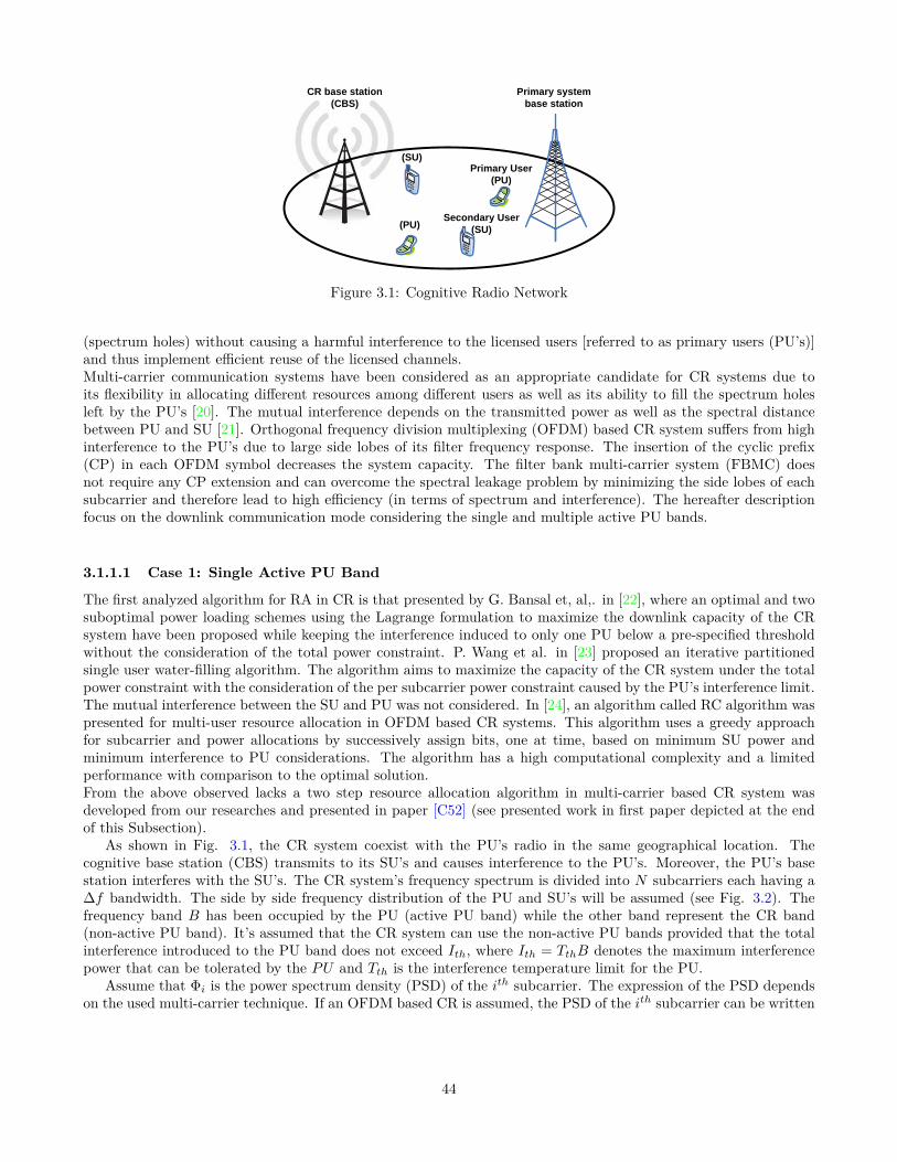
CR base station(CBS)
Primary system base station
Secondary User(SU)
(SU)Primary User
(PU)
(PU)
Figure 3.1: Cognitive Radio Network
(spectrum holes) without causing a harmful interference to the licensed users [referred to as primary users (PU’s)]and thus implement efficient reuse of the licensed channels.Multi-carrier communication systems have been considered as an appropriate candidate for CR systems due toits flexibility in allocating different resources among different users as well as its ability to fill the spectrum holesleft by the PU’s [20]. The mutual interference depends on the transmitted power as well as the spectral distancebetween PU and SU [21]. Orthogonal frequency division multiplexing (OFDM) based CR system suffers from highinterference to the PU’s due to large side lobes of its filter frequency response. The insertion of the cyclic prefix(CP) in each OFDM symbol decreases the system capacity. The filter bank multi-carrier system (FBMC) doesnot require any CP extension and can overcome the spectral leakage problem by minimizing the side lobes of eachsubcarrier and therefore lead to high efficiency (in terms of spectrum and interference). The hereafter descriptionfocus on the downlink communication mode considering the single and multiple active PU bands.
3.1.1.1 Case 1: Single Active PU Band
The first analyzed algorithm for RA in CR is that presented by G. Bansal et, al,. in [22], where an optimal and twosuboptimal power loading schemes using the Lagrange formulation to maximize the downlink capacity of the CRsystem have been proposed while keeping the interference induced to only one PU below a pre-specified thresholdwithout the consideration of the total power constraint. P. Wang et al. in [23] proposed an iterative partitionedsingle user water-filling algorithm. The algorithm aims to maximize the capacity of the CR system under the totalpower constraint with the consideration of the per subcarrier power constraint caused by the PU’s interference limit.The mutual interference between the SU and PU was not considered. In [24], an algorithm called RC algorithm waspresented for multi-user resource allocation in OFDM based CR systems. This algorithm uses a greedy approachfor subcarrier and power allocations by successively assign bits, one at time, based on minimum SU power andminimum interference to PU considerations. The algorithm has a high computational complexity and a limitedperformance with comparison to the optimal solution.From the above observed lacks a two step resource allocation algorithm in multi-carrier based CR system wasdeveloped from our researches and presented in paper [C52] (see presented work in first paper depicted at the endof this Subsection).
As shown in Fig. 3.1, the CR system coexist with the PU’s radio in the same geographical location. Thecognitive base station (CBS) transmits to its SU’s and causes interference to the PU’s. Moreover, the PU’s basestation interferes with the SU’s. The CR system’s frequency spectrum is divided into N subcarriers each having a∆f bandwidth. The side by side frequency distribution of the PU and SU’s will be assumed (see Fig. 3.2). Thefrequency band B has been occupied by the PU (active PU band) while the other band represent the CR band(non-active PU band). It’s assumed that the CR system can use the non-active PU bands provided that the totalinterference introduced to the PU band does not exceed Ith, where Ith = TthB denotes the maximum interferencepower that can be tolerated by the PU and Tth is the interference temperature limit for the PU.
Assume that Φi is the power spectrum density (PSD) of the ith subcarrier. The expression of the PSD dependson the used multi-carrier technique. If an OFDM based CR is assumed, the PSD of the ith subcarrier can be written
44

1 2 ………. N Frerquency
PUband
B
f
CRband
Figure 3.2: Frequency distribution of the primary and cognitive bands
as [21]
Φi (f) = PiTs
(sin πfTsπfTs
)2(3.1)
where Pi is the total transmit power emitted by the ith subcarrier and Ts is the symbol duration. If FBMC basedCR system is assumed, the PSD of the ith subcarrier can be written as
Φi (f) = Pi |Hi (f)|2 (3.2)
where |Hi (f)| is the frequency response of the prototype filter with coefficients h [n] with n = 0, · · · ,W − 1, where W = KN and K is the length of each polyphase components (overlapping factor). Assuming that theprototype coefficients have even symmetry around the
(KN
2)th coefficient, and the first coefficient is zero [25], we
get
|Hi (f)| = h [W/2] + 2
W2 −1∑n=1
h [(W/2)− n] cos(2πn
(f − i/N
))(3.3)
The interference introduced by the ith subcarrier to PU band, Ii (di, Pi) , is the integration of the PSD of the ithsubcarrier across the PU band, B , and can be expressed as [21]
Ii (di, Pi) =di+Bl/2ˆ
di−Bl/2
|gi|2 Φi (f) df = Pi Ωi (3.4)
where di is the spectral distance between the ith subcarrier and the PU band. Ωi denotes the interference factor ofthe ith subcarrier.
The interference power introduced by the PU signal into the band of the ith subcarrier is [21]
Ji (di, PPU ) =di+∆f/2ˆ
di−∆f/2
|yi|2 ψl(ejω)dω (3.5)
where ψ(ejω)is the power spectrum density of the PU signal and yi is the channel gain between the ith subcarrier
and PU signal.It will be assumed that all the instantaneous fading gains are perfectly known at the CBS and there is no inter-
carrier interference (ICI). Let vi,m to be a subcarrier allocation indicator, i.e. vi,m = 1 if and only if the subcarrieris allocated to mth user. It is assumed that each subcarrier can be used for transmission to at most one user atany given time. Our objective is to maximize the total capacity of the CR system subject to the instantaneousinterference introduced to the PU’s and total transmit power constraint. Therefore, the optimization problem can
45
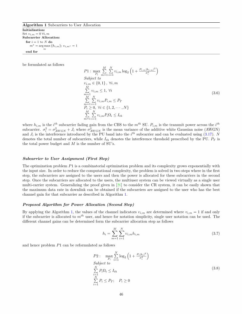
Algorithm 1 Subcarriers to User AllocationInitialization:Set υi,m = 0 ∀i,mSubcarrier Allocation:
for i = 1 to N dom∗ = arg max
m
hi,m; υi,m∗ = 1
end for
be formulated as followsP1 : max
Pi
M∑m=1
N∑i=1
υi,m log2
(1 + Pi,m|hi,m|2
σ2i
)Subject toυi,m ∈ 0, 1 , ∀i,mM∑m=1
υi,m ≤ 1, ∀iM∑m=1
N∑i=1
υi,mPi,m ≤ PTPi ≥ 0, ∀i ∈ 1, 2, · · · , NM∑m=1
N∑i=1
υi,mPiΩi ≤ Ith
(3.6)
where hi,m is the ith subcarrier fading gain from the CBS to the mth SU. Pi,m is the transmit power across the ithsubcarrier. σ2
i = σ2AWGN + Ji where σ2
AWGN is the mean variance of the additive white Gaussian noise (AWGN)and Ji is the interference introduced by the PU band into the ith subcarrier and can be evaluated using (3.17). Ndenotes the total number of subcarriers, while Ith denotes the interference threshold prescribed by the PU. PT isthe total power budget and M is the number of SU’s.
Subcarrier to User Assignment (First Step)
The optimization problem P1 is a combinatorial optimization problem and its complexity grows exponentially withthe input size. In order to reduce the computational complexity, the problem is solved in two steps where in the firststep, the subcarriers are assigned to the users and then the power is allocated for these subcarriers in the secondstep. Once the subcarriers are allocated to the users, the multiuser system can be viewed virtually as a single usermulti-carrier system. Generalizing the proof given in [26] to consider the CR system, it can be easily shown thatthe maximum data rate in downlink can be obtained if the subcarriers are assigned to the user who has the bestchannel gain for that subcarrier as described in Algorithm 1.
Proposed Algorithm for Power Allocation (Second Step)
By applying the Algorithm 1, the values of the channel indicators υi,m are determined where vi,m = 1 if and onlyif the subcarrier is allocated to mth user, and hence for notation simplicity, single user notation can be used. Thedifferent channel gains can be determined form the subcarrier allocation step as follows
hi =M∑m=1
N∑i=1
υi,mhi,m (3.7)
and hence problem P1 can be reformulated as follows
P2 : maxPi
N∑i=1
log2
(1 + Pi|hi|2
σ2i
)Subject toN∑i=1
PiΩi ≤ IthN∑i=1
Pi ≤ PT ; Pi ≥ 0
(3.8)
46

The problem P2 is a convex optimization problem. The Lagrangian can be written as
G = −N∑i=1
log2
(1 + P∗i |hi|
2
σ2i
)+ α
(N∑i=1
P ∗i Ωi − Ith)
+β(N∑i=1
P ∗i − PT)−
N∑i=1
P ∗i µi
(3.9)
where α, µi, i ∈ 1, 2, . . . , N, and β are the Lagrange multipliers. The Karush-Kuhn-Tucker (KKT) conditions canbe written as follows
P ∗i ≥ 0; α ≥ 0; β ≥ 0; µi ≥ 0; µiP∗i = 0
α
(N∑i=1
P ∗i Ωi − Ith)
= 0
β
(N∑i=1
P ∗i − PT)
= 0∂G∂P∗
i= −1
σ2
|hi|2+P∗
i
+ αΩi + β − µi = 0
(3.10)
and also the solution should satisfy the total power and interference constraints. Rearranging the last condition in(3.10) we get
P ∗i = 1αΩi + β − µi
− σ2
|hi|2(3.11)
Since P ∗i ≥ 0, we get σ2
|hi|2≤ 1
αΩi+β−µi . Ifσ2
|hi|2< 1
αΩi+β , then µi = 0 and hence P ∗i = 1αΩi+β −
σ2
|hi|2. Moreover, if
σ2
|hi|2> 1
αΩi+β , from (3.11) we get 1αΩi+β−µi ≥
σ2
|hi|2> 1
αΩi+β and since µiP ∗i = 0 and µi ≥ 0, we get that P ∗i = 0.Therefore, the optimal solution can be written as follows
P ∗i =[
1αΩi + β
− σ2
|hi|2
]+
(3.12)
where [x]+ = max (0, x). Solving for the more than one Lagrangian multiplier is computational complex. Thesemultipliers can be found numerically using ellipsoid or interior point method with a polynomial time complexityO(N3) [27]. The high computational complexity makes the optimal solution unsuitable for practical application
and hence a low complexity algorithm will be proposed.If the interference constraints are ignored in P2, the solution of the problem will follow the well known water-
filling interpretation. On the other side, if the total power constraint is ignored, the Lagrangian of the problem canbe written as
G′ = −∑i∈Nl
log2
(1 + P ′i |hi|
2
σ2i
)+α′
( ∑i∈Nl
P ′iΩi − Ith
) (3.13)
where α′ is the Lagrange multiplier. Equating ∂G′∂P ′
ito zero, we get
P ′i =[
1α′Ωi
− σ2
|hi|2
]+
(3.14)
The value of α′ can be calculated by substituting (3.14) into∑i∈N
P ′iΩi = Ith to get
α′ = |N |Ith +
∑i∈N
Ωiσ2i
|hi|2(3.15)
It is obvious that if the summation of the allocated power under only the interference constraints is lower than
or equal the available total power budget, i.e.N∑i=1
P ′i ≤ PT , then (3.14)-(3.15) will be the optimal solution for the
47

Pmax
Updated Pmax
Set A
Initial PiUpdated Pi
Subcarriers
Power
PUBand
(CR allocates zero power in these
subcarriers)
Figure 3.3: An Example of the SU’s allocated power using PI-Algorithm
optimization problem P2. In most of the cases, the total power budget is quite lower than this summation andhence the Power Interference (PI) constrained algorithm, referred to as PI-Algorithm, is proposed to allocate thepower under both the total power and interference constraints.In order to solve the optimization problem P2, we can start by assuming that the maximum power that can beallocated for a given subcarrier PMax
i is determined according to the interference constraints only by using (3.14)-(3.15) for every subcarriers i ∈ N . By such an assumption, we can guarantee that the interference introducedto the PU band will be under the pre-specified threshold. Once the maximum power PMax
i is determined, thetotal power constraint is tested. If the total power constraint is satisfied, then the solution has been found andequal to the maximum power that can be allocated to each subcarrier, i.e. P ∗i = PMax
i . Otherwise, the availablepower budget should be distributed among the subcarriers giving that the power allocated to each subcarrier islower than or equal to the maximum power PMax
i . This can be done optimally by applying successive conventionalwater-fillings on the subcarriers. Given the initial water-filling solution, the channels that violate the maximumpower PMax
i are determined and upper bounded with PMaxi . The total power budget is reduced by subtracting
the power assigned so far. At the next step, the algorithm proceeds to successive water-filling over the subcarriersthat not violated the maximum power PMax
i in the last step. This procedures is repeated until the allocated powerPW.Fi doesn’t violate the maximum power PMax
i in any of the subcarriers in the new iteration. Once the powerallocated to each subcarriers is determined, the total interference induced to the PU is evaluated. According tothe left interference, the maximum power that can be allocated to each subcarrier is relaxed and the successivewater-fillings are performed again to get the final solution. The final power allocation vector P ∗i is satisfyingapproximately the interference constraint with equality as well as guaranteeing that the total power used is equalto PT . A graphical description of this algorithm can be found in Fig. 3.3 while the algorithm steps are describedin Algorithm 2.
The computational complexity of Step 1 in the proposed Algorithm (Algorithm 2) is O (N logN). Steps 2 and4 of the algorithm execute the successive water-fillings which has a complexity of O (N logN + ηN) where η ≤ Nis the number of the iterations. Step 3 has a complexity of O (1). Hence, The overall complexity of the algorithm islower than O (N logN + ηN) +O (1). The value of η is estimated via simulation with an average value η = 2.953and never exceeds five, i.e. η ∈ [0, 5]. Comparing to the computational complexity of the optimal solution , O
(N3),
the proposed algorithm has much lower computational complexity specially when the number of the subcarriers Nincreased.The achievable capacities versus the interference constraint of the OFDM based CR system using the optimal,two-step and RC algorithm are plotted in Fig. 3.4 with PT = 1 and PT = 2 watts. It can be noted that the capacityachieved using two-step algorithm is very close to that achieved using the optimal algorithm with a good reductionin the computational complexity. Moreover, the proposed algorithm outperform the RC algorithm. As the allowedinterference increase, the total throughput increase.
It can be noticed that the throughput increased as the total power increased. When the total power exceedsa certain value, the throughput become constant regardless of the increase in total power. This is because withsuch a given interference constraint, the system reach to the maximum total power that can be used to keep theinterference to the primary user below the prescribed threshold.The filter bank multi-carrier system (FBMC) can overcome the spectral leakage problem by minimizing the sidelobes
48

Algorithm 2 Power Allocation Algorithm
• Let N = 1, 2, · · · , N to be the set of all the CR available subcarriers and P ∗i to be the solution of theoptimization problem.
• Step 1
1. Find the power allocation vector P ′i according to interference constraint only using equations (3.14)-(3.15)and make it to be the maximum power that can be allocated to each subcarrier PMax
i = P ′i .
2. IfN∑i=1
PMaxi ≤ PT , then the solution is found and hence P ∗i = PMax
i , else continue.
• Step 2 Find the power allocation vector PW.Fi using the iterative water-filling under the constraints of totalpower, PT , and the maximum power that can be allocated to each subcarrier, PMax
i .
• Step 3 Find the set of subcarriers A ⊂ N (See Fig. 3.3) in which PW.Fi = PMaxi and evaluate the left
available interference ILeft = Ith −∑i∈N
PW.Fi Ωi.
• Step 4 Update PMaxi by applying equations (3.14)-(3.15) on the subcarriers in the set A only under the
interference constraint I ′th = ILeft +∑i∈A
PW.Fi Ωi and execute the iterative water-filling again under the PT
and updated PMaxi constraints.
0 0.2 0.4 0.6 0.8 1 1.2
x 10−5
10
11
12
13
14
15
16
Interference Threshold (Watt)
Me
an
Th
rou
gp
ut (b
it/s
/Hz)
Optimal Pt=1WRC Pt=1WTwo Step Pt=1WOptimal Pt=2WRC Pt=2WTwo Step Pt=2W
Figure 3.4: Mean throughput vs. interference constraints for OFDM based CR.
49

0 0.2 0.4 0.6 0.8 1 1.2
x 10−5
11
11.5
12
12.5
13
13.5
14
14.5
15
15.5
16
Interference Threshold (Watt)
Me
an
Th
rou
gp
ut (b
it/s
/Hz)
Optimal Pt=1WRC Pt=1WTwo Step Pt=1WOptimal Pt=2WRC Pt=2WTwo Step Pt=2W
Figure 3.5: Mean throughput vs. interference constraints for FBMC based CR.
of each subcarrier. Fig. 3.5 plot the average throughput for FBMC based CR system using different algorithmsversus different interference constraint with PT = 1 and PT = 2 watts and different total power constraints withIth = 5µ and Ith = 10µ watts.
The proposed two-step algorithm approaches the optimal solution and outperform the RC algorithm. Compar-ing with the OFDM based CR system in Fig. 3.4, the throughput of FBMC system is higher than that of OFDMbecause the side lobes in FBMC PSD is smaller than that in OFDM and also the inserted CP in OFDM basedCR systems reduces the total throughput of the system. It can be noticed also that the interference conditionintroduce a small restriction on the overall average throughput in FBMC based CR systems which is not the casein OFDM based CR systems. These results are contributing to recommend the using of the FBMC as a candidatefor a physical layer in the future communication environments with heterogeneous systems.
As a general conclusion, we can say that proposed two-step algorithm solves the problem efficiently and achievesapproximately the same optimal capacity with a good reduction in the computational complexity. The proposedalgorithm outperformed the RC algorithm that uses a greedy approach for the subcarrier and power allocation.Simulation results prove that the FBMC based CR systems have more capacity than OFDM based ones.
3.1.1.2 Case 2: Two Active PU Bands
In this case, two interference constraints belonging to two active PU bands, i.e. L = 2, are assumed as depicted inFig. 3.6. Each active PU band is assumed to have six subcarriers (|N1| = |N2| = 16). The achieved capacity usingoptimal, PI defined in [J5] (PI algorithm is detailed in page 9 of first journal paper depicted at the end Subsection3.1), and Zhang algorithm is defined in [28], for different interference constraints where I1
th = I2th is plotted in
Fig. 3.7. It can be noted that the proposed PI-algorithm approaches the optimal solution and outperforms Zhangalgorithm.
The effect of assuming that every subcarrier belongs to the closest PU band and introducing interference to itonly on the net interference introduced to the active PU bands is studied in Fig. 8 and Fig. 9 in [J5]1 for PU1 andPU2 respectively.
It can be observed that the net interference induced using the PI-algorithm approximately satisfies the pre-1See page 10 in EURASIP journal paper depicted at the end Subsection 3.1
50

3.5. Simulation Results
1 2 ……….
Non-Active
band
N
Non-Active
band
Non-Active
band
B1 B2
Active
PU2 bandActive
PU1 band
N2N1
f
Frequency
Figure 3.6: Frequency distribution with two active PU bands.
(|N1| = |N2| = 16). The achieved capacity usingoptimal, PI and Zhangalgorithms for
different interference constraints whereI1th = I2
th is plotted in Fig. 3.7. It can be noted that the
proposedPI-algorithmapproaches the optimal solution and outperformsZhangalgorithm.
The effect of assuming that every subcarrier belongs to the closest PU band and introduc-
ing interference to it only on the net interference introduced to the active PU bands is studied
in Fig.3.8 and Fig. 3.9 forPU1 andPU2 respectively.
0.002 0.004 0.006 0.008 0.01 0.012 0.014 0.016 0.018 0.0213
13.5
14
14.5
15
15.5
16
16.5
17
Ith−Watt
Cap
acity
(B
it/H
z/se
c)
Optimal−OFDMPI−OFDMZhang−OFDMOptimal−FBMCPI−FBMCZhang−FBMC
Figure 3.7: Achieved capacity vs allowed interference threshold for OFDM and FBMC based
CR systems - Two active PU bands.
87
Figure 3.6: Frequency distribution with two active PU bands.
3.5. Simulation Results
1 2 ……….
Non-Active
band
N
Non-Active
band
Non-Active
band
B1 B2
Active
PU2 bandActive
PU1 band
N2N1
f
Frequency
Figure 3.6: Frequency distribution with two active PU bands.
(|N1| = |N2| = 16). The achieved capacity usingoptimal, PI and Zhangalgorithms for
different interference constraints whereI1th = I2
th is plotted in Fig. 3.7. It can be noted that the
proposedPI-algorithmapproaches the optimal solution and outperformsZhangalgorithm.
The effect of assuming that every subcarrier belongs to the closest PU band and introduc-
ing interference to it only on the net interference introduced to the active PU bands is studied
in Fig.3.8 and Fig. 3.9 forPU1 andPU2 respectively.
0.002 0.004 0.006 0.008 0.01 0.012 0.014 0.016 0.018 0.0213
13.5
14
14.5
15
15.5
16
16.5
17
Ith−Watt
Cap
acity
(B
it/H
z/se
c)
Optimal−OFDMPI−OFDMZhang−OFDMOptimal−FBMCPI−FBMCZhang−FBMC
Figure 3.7: Achieved capacity vs allowed interference threshold for OFDM and FBMC based
CR systems - Two active PU bands.
87
Figure 3.7: Achieved capacity vs. allowed interference threshold for OFDM and FBMC based CR systems - Twoactive PU bands.
51

3.5. Simulation Results
It can be observed that the net interference induced using thePI-algorithmapproximately
satisfies the pre-specified interference constraints whichmakes the assumption reasonable. Un-
like the OFDM based CR system, the interference induced by the FBMC based system does
not reach the pre-specified thresholds. This is because the FBMC based CR system reaches
the maximum interference that can be introduced to the PU using the given power budget.
Moreover, the interference induced by the proposed algorithm is less than that usingZhang
algorithm. Returning to Fig.3.7, one can notice that the interference constraints aboveI lth = 10
mWatt start to have no effect on the achieved capacity of the FBMC system. This indicates
also that the FBMC system reaches the maximum interference for the given power budget.
The small difference between the net interference values aboveI lth = 10 mWatt is due to the
averaging over different channel realizations.
The achieved capacity of the different algorithms is plotted in Fig. 3.10 with lower values
of the interference constraints. It can be noticed thatZhangalgorithm has a limited perfor-
mance with low interference constraints because the algorithm turns off the subcarriers that
have a noise level which is higher than the initial waterfilling level and never uses these subcar-
riers again even if the new waterfilling level exceeds its noise level. Moreover, the algorithm
0.2 0.4 0.6 0.8 1 1.2 1.4 1.6 1.8 2
x 10−5
0
2
4
6
8
10
12
14
Ith−Watt
Cap
acity
(B
it/H
z/se
c)
Optimal−OFDMPI−OFDMZhang−OFDMOptimal−FBMCPI−FBMCZhang−FBMC
Figure 3.10: Achieved CR vs allowed interference threshold (low) for OFDM and FBMC
based CR systems - Two active bands.
89
Figure 3.8: Achieved CR vs allowed interference threshold (low) for OFDM and FBMC based CR systems - Twoactive bands.
specified interference constraints which makes the assumption reasonable. Unlike the OFDM based CR system, theinterference induced by the FBMC based system does not reach the pre-specified thresholds. This is because theFBMC based CR system reaches the maximum interference that can be introduced to the PU using the given powerbudget. Moreover, the interference induced by the proposed algorithm is less than that using Zhang algorithm.Returning to Fig.3.7, one can notice that the interference constraints above I lth = 10 mWatt start to have no effecton the achieved capacity of the FBMC system. This indicates also that the FBMC system reaches the maximuminterference for the given power budget. The small difference between the net interference values above I lth = 10mWatt is due to the averaging over different channel realizations.
The achieved capacity of the different algorithms is plotted in Fig. 3.8 with lower values of the interferenceconstraints. It can be noticed that Zhang algorithm has a limited performance with low interference constraintsbecause the algorithm turns off the subcarriers that have a noise level which is higher than the initial water-fillinglevel (see the cap-limited water-filling algorithm [29] adapted for multi-active PU bands in page 8 of EURASIPjournal paper depicted at the end of this Subsection 3.1) and never uses these subcarriers again even if the newwater-filling level exceeds its noise level. Moreover, the algorithm deactivates some subcarriers, i.e. transmit zeropower, in order to ensure that the interference introduced to PU bands is below the pre-specified thresholds. Thelower the interference constraints, the higher the number of deactivated subcarriers is, which justifies the limitedperformance of this algorithm in case of low interference constraints.
To show the efficiency of transmitting over the active PU bands as well as the non-active bands, Fig. 11 andFig. 12 in [J5]2 show the achieved capacity using the PI algorithm with and without allowing the SUs to transmitover the PU active bands. The capacity of the CR system transmitting on both the active and non-active bandsis higher than that of the system in which the transmission takes place on the non-active bands only. Since thecognitive transmission in the active PU band introduces more interference to the PUs than the other subcarriers,low power levels can be used in these bands with low interference constraints. This justifies why the differencebetween the two systems decreases when the interference constraints decrease.
For all the presented results, the capacity of FBMC based CR system is higher than that of the one based onOFDM because the side lobes in FBMC’s PSD are smaller than those in OFDM, which introduces less interferenceto the PUs. Moreover, the inserted CP in OFDM based CR systems reduces the total capacity of the system. Itcan be noticed also that the interference condition introduces a small restriction on the capacity of FBMC basedCR systems which is not the case in OFDM based CR systems.
In what follows, an efficient resource allocation algorithm in uplink OFDM-based CR systems is proposed. The2See page 11 in EURASIP journal paper depicted at the end of this Subsection 3.1
52

CR base station(CBS)
Secondary User(SU1)
(SU2)
(SU3)
Transmission
Interference
Primary User(PU1)
(PU2)
Figure 3.9: Uplink Cognitive Radio Network.
4.2. System Model and Problem Formulation
CR base station
(CBS)
Secondary User
(SU1)
(SU2)
(SU3)
Transmission
Interference
Primary User
(PU1)
(PU2)
Figure 4.1: Uplink Cognitive Radio Network.
tems. The interference induced to thelth PU band should not exceed the predefined interference
temperature limitI lth.
Assume thatΦi (f) is the power spectral density (PSD) of theith subcarrier. The expres-
sion of the PSD depends on the used multicarrier technique. If an OFDM based CR is assumed,
the PSD of theith subcarrier can be written as
Φi (f) = |Gi (f)|2 (4.1)
where|Gi (f)|2 is the Fourier transform of the used pulse shapegT . Assuming a rectangular
pulse with lengthTs = N + C whereN is the number of subcarriers (IDFT size) andC is the
length of the CP,|Gi (f)|2 can be expressed as follows
|Gi (f)|2 = Ts + 2
Ts−1∑
r=1
(Ts − r) cos (2πfr) (4.2)
If FBMC based CR system is assumed, the PSD of theith subcarrier can be written as
Φi (f) = |Hi (f)|2 (4.3)
Active
PU1 bandActive
PU2 bandActive
PUL band
1 2 ………. N
Frequency
Non-
Active
band
B1 B2 BL
f
Figure 4.2: Frequency distribution of active and non-active primary bands.
107
Figure 3.10: Frequency distribution of active and non-active primary bands.
scenario in which the SUs are transmitting on the unused PU bands and causing interference to the active onesis considered. This scenario has been investigated within the project COST Action IC0902, and the network ofexcellence (NoE) ICT project ACROPOLIS.
The main objective of this research is to maximize the capacity while respecting the per-user power constraintsand guaranteeing that no excessive interference is induced to the PUs. The research work carried out in [J10]3summarizes the main contribution which are the following points:
• As the resource allocation algorithm is a mixed-integer optimization problem, we proposed an efficient algo-rithm that reduces the computational complexity by separating the subcarrier and power allocation processesinto two different steps. The proposed algorithm is shown to have a near-optimal performance and outper-forms the algorithms presented in [30, 31, 32, 33]. Additionally, the performance of the algorithm used innon-cognitive multi-carrier systems is discussed.
• Different from the algorithms developed in [30, 31, 32, 33], the fairness among users is considered withinthe subcarrier allocation by reducing the probability of having users whose instantaneous rate is below theminimum required value.
• The efficiency of the proposed algorithm is investigated for OFDM and FBMC based systems to show thecapability of using FBMC in the cognitive networks.
In the carried researches for the uplink transmission mode, the PUs and SUs are co-existing in the samegeographical location as described in Fig.3.9, and it is assumed that SUs are opportunistically accessing the unusedPU bands and transmitting to their cognitive base station (CBS) without causing harmful interference to PUs. Asshown in Fig.3.10, the frequency bands B1, B2,· · · ,BL represent the L active PU bands while the non-active bandsrepresent the bands that can be used by CR system (CR band). The CR band is divided into N subcarriers eachhaving a ∆f bandwidth. There is no synchronization between the primary and secondary systems. The interferenceinduced to the lth PU band should not exceed the predefined interference temperature limit I lth.
The objective is to maximize the total CR data rate while limiting the interference introduced to the PUs.Fairness among users is considered within the subcarrier allocation by reducing the probability of having users
3See IET Communication journal paper depicted at the end of this Subsection 3.1
53

whose instantaneous rate is below a given value. The proposed resource allocation is divided into two phases. Theassignment of subcarriers to users is performed first and then the power is allocated to the different subcarriers.The scheme for subcarrier to user assignment proposed in [34] for non-cognitive systems is adopted in order to besuitable for cognitive ones. Subcarriers are allocated based on the channel quality, amount of interference imposedto PUs, instantaneous rate achieved by every user and the increment in the total data rate. For the power allocationphase, an efficient power allocation algorithm is proposed to distribute the powers among the subcarriers under theper-user total power and interference constraints. The system model used in [22] is considered where the PUs andSUs are co-existing in the same geographical location. The interference introduced by the transmission of the ithsubcarrier of the CR system to the lth PU band, I li
(dli, Pi
), is the integration of the power spectrum density (PSD)
of the ith subcarrier across the lth PU band, Bl. If an ideal Nyquist pulse is assumed, the mutual interference canbe expressed as [21]
I li(dli, Pi
)= PiΩli ; Ωli =
dli+Bl/2ˆ
dli−Bl/2
∣∣gli∣∣2 Ts( sin πfTsπfTs
)2df (3.16)
where dli is the spectral distance between the ith subcarrier and the lth PU band. gli denotes the channel gain (caninclude path loss and shadowing part) between the ith subcarrier and the lth PU band while Pi is the total transmitpower emitted by the ith subcarrier. Ts = 1/∆f is the symbol duration and Ωli denotes the interference factor ofthe ith subcarrier to the lth PU band. By the same way, the interference power introduced by the lth PU signalinto the band of the ith subcarrier is [21]
J li =dli+∆f/2ˆ
dli−∆f/2
∣∣yli∣∣2 ψl (ejω) dω (3.17)
where ψl(ejω)is the power spectrum density of the lth PU signal and yli is the channel gain between the ith
subcarrier and lth PU signal. Several parameters should be considered to built a reliable CR system such that theappearance of the PU during CR transmission which can be taken into account by applying a risk-return model likein [30], the effect of spectrum sensing error like false alarm and misdetection probability as in [35], and the channelestimation errors in the transmission and interfering links as in [36]. Dealing with such a general model is out ofthe range of the target of developed research work.
The transmission rate for the ith subcarrier, Ri can be evaluated as
Ri (Pi,m, hi,m) = ∆f log2
(1 + Pi,m |hi,m|2
σ2i
)(3.18)
where Pi,m is the transmission power and hi,m is the ith subcarrier fading gain from the mth SU to the CBS.
Additionally, σ2i = σ2
AWGN +L∑l=1
J li where σ2AWGN is the variance of the additive white Gaussian noise (AWGN)
and J li is the interference introduced by the lth PU band into the ith subcarrier which is evaluated using (3.17)and can be modeled as AWGN as described in [22]. Throughout this analysis, all the instantaneous fading gainsare assumed to be perfectly known at the CBS. The channel gains between SUs and the CBS can be obtainedpractically by classical channel estimation techniques while the channel gains between SUs and PUs can be obtainedby estimating the received signal power from each primary terminal when it transmits, under the assumptions ofpre-knowledge on the primary transmit power levels and the channel reciprocity [37, 38]. Based on the channelgains, the CBS assigns the subcarriers and powers to each SU through a reliable low-rate signaling channel. Letai,m be the subcarrier allocation indicator, i.e. ai,m = 1 if and only if the ith subcarrier is allocated to the mth user.It is assumed that each subcarrier can be used for transmission to at most one user at any given time. Fairnessamong SUs is guaranteed by assuming that every SU has a minimum instantaneous rate Rmin. Our objective is tomaximize the total data rate of the CR system subject to the constraints on the interference introduced to the PUs,the per-user transmit power constraints and the per-user minimum rate constraints. Therefore, the optimizationproblem can be formulated as follows
54

P1 : maxPi,m,ai,m
M∑m=1
N∑i=1
ai,mRi (Pi,m, hi,m)
s.t.M∑m=1
N∑i=1
ai,mPi,mΩli,m ≤ I lth ∀l ∈ 1, · · · , LN∑i=1
ai,mPi,m ≤ Pm, ∀m
Pi,m ≥ 0, ∀i,mai,m ∈ 0, 1 , ∀i,mM∑m=1
ai,m ≤ 1, ∀iN∑i=1
ai,mRi (Pi,m, hi,m) ≥ Rmin, ∀m
(3.19)
where N denotes the total number of subcarriers whileM denotes the number of SUs. L is the number of active PUbands and I lth is the interference threshold prescribed by the lth PU. Pm is the mth SU total power budget. Withoutloss of generality, the minimum instantaneous rate Rmin is assumed constant for all the users. The solution can beeasily extended to consider different minimum instantaneous rates for the different SUs. The CBS will perform thesubcarrier and power allocation and then diffuse the result to the different SUs.
The optimization problem P1 is a mixed optimization problem in which achieving the optimal solution needshigh computational complexity. Additionally, the minimum rate constraints increase the complexity of the prob-lem. In order to solve the problem, we propose an algorithm to perform the resource allocation in two phases. In thefirst phase, a heuristic sub-optimal algorithm is used to allocate the subcarriers to the different users. Afterward,the optimal power allocation is evaluated in the second phase. The optimal power allocation algorithm requireshigh computational complexity and hence a low complexity power algorithm is proposed to perform the powerallocation phase. Depending on the values of I lth, Pm and the channel gains, the CR system may not be able tosatisfy the minimum rate Rmin for all the users. Therefore, the last constraint in the optimization problem P1is relaxed by trying to reduce the probability of having users whose rates are below the minimum rate [34]. Theoutage probability can be defined as
Poutage = PrMlow ≥ 1 (3.20)
where Mlow is the number of SUs whose instantaneous rate are below Rmin.
First the optimal downlink subcarriers to users allocation scheme in multi-carrier systems is achieved by allo-cating each subcarrier to the user with the maximum SNR [15–18 dB]. This scheme of subcarrier allocation is notefficient in uplink case because of the per-user power constraints. Moreover, the interference introduced to theprimary system by each SU should be considered in the CR context, which makes the schemes used in classicalmulti-carrier systems not efficient. An heuristic subcarrier and power allocation algorithm is presented. Proposedalgorithm was first evaluated for one PU band with a single interference constraint and fairness considerations, andthen generalized for the multiple PU case in Section 3 and Section 4 respectively of depicted IET journal paper atthe end of this Subsection.
For performance comparison, the following algorithms are considered:
1. Optimal: the subcarriers are allocated by exhaustive enumeration while the power is allocated using (3.12).The optimal capacity is found without considering the minimum rate requirements.
2. Wang: the method proposed in[39] is used. The interference constraint is converted into per-subcarrier powerconstraints.
3. Fadel: the method proposed in [32] is used. The per SU maximum power constraint is generated by convertingthe interference constraint into per-subcarrier power.
4. Classical+Pr: the subcarriers are allocated according to the scheme used in non-cognitive OFDM systems[40], while the power is allocated using (3.12).
55

23
−40 −35 −30 −25 −20 −15 −10 −5 010−5
10−4
10−3
10−2
10−1
100
Interference threshold Ith1=Ith2 (dBm)
Out
age
Pro
babi
lity
Proposed without FairnessProposed with FairnessWangClassical+PrFadel
Fig. 8. Outage probability vs allowed interference thresholds when N = 128 subcarriers, M = 8 SUs, Pm = 1mWatt, B1 = B2 = 10 MHz, and
Rmin = 20 Mbits/sec.
2 4 6 8 10 12 14 163
4
5
6
7
8
9
No. of secondary users
Cap
acity
(Bit/
Hz/
sec)
Proposed without FairnessProposed with FairnessWangClassical+PrFadel
Ith=− 20dBm
Ith=−30dBm
Fig. 9. Achieved capacity vs No. of SUs when N = 128 subcarriers, Pm = 1mWatt, B1 = B2 = 10 MHz, and Rmin = 20 Mbits/sec.
Figure 3.11: Achieved capacity vs No. of SUs when N = 128 subcarriers, Pm = 1mWatt, B1 = B2 = 10 MHz, andRmin = 20 Mbits/sec.
24
−20 −15 −10 −5 0 5 102
3
4
5
6
7
8
9
Per−user power budget (dBm)
Cap
acity
(Bit/
Hz/
sec)
Proposed without FairnessProposed with FairnessWangClassical+PrFadel
Ith=−30dBm
Ith=−20dBm
Fig. 10. Achieved capacity vs per-user power Pm when N = 128 subcarriers, M = 8 SUs, B1 = B2 = 10 MHz, and Rmin = 20 Mbits/sec.
0 10 20 30 40 50 60 70 80 90 1000
20
40
60
80
100
120
140
160
180
200
Sample index
Inst
anta
neou
s R
ate
(bits
/sym
bol)
Propsed without FairnessProposed with Fairness
Fig. 11. Instantaneous rates over time when N = 128 subcarriers, M = 8 SUs, Pm = 1mWatt, B1 = B2 = 10 MHz, I1th = I2
th = −20 dBm and
Rmin = 20 Mbits/sec (80 bits per OFDM symbol).
Figure 3.12: Achieved capacity vs per-user power Pm when N = 128 subcarriers, M = 8 SUs, B1 = B2 = 10 MHz,and Rmin = 20 Mbits/sec.
Hereafter, you have an overview of main obtained results by the proposed algorithm for the uplink mode withFairness considerations in a CR scenario. Fig.3.11 shows the average capacity against the number of SUs whenthe interference thresholds are 220 and 230 dBm. The capacity increases with the number of users because of themultiuser diversity. The lower the number of SUs, the smaller the difference between the proposed and Classical+Pr algorithm. This is because the number of subcarriers that will be allocated to each user will increase, whichreduces the amount of power that will be allocated to each subcarrier and consequently the amount of interferenceimposed to the primary system. This makes the CR system to act relatively as a non-cognitive system. The gapbetween the different algorithms decreases with the interference thresholds as the CR system becomes closer to theclassical (non-cognitive) system.
Fig.3.12 shows the average capacity against per-user power constraint, Pm, when the interference thresholds are 220
56

and 230 dBm. The proposed algorithm outperforms the reference algorithms and the capacity of the CR systemincreases as the per-user power budget increases up to certain total power value. After this value, the capacityremains constant regardless of the increase of the per-user power because the system reaches the maximum powerthat can be used with the given interference threshold. Remark that when the available SUs power is too lowand unable to cause the pre-defined interference constraint, the CR system acts as a non-cognitive one where theproposed algorithm performs very close to the Classical+ Pr algorithm. More extended results can be found at theIET communication journal depicted at end of this Subsection 3.1.1.1.
To resume, all the publications (See Subsection 2.1.1, pp. 30-42) related with this research orientation are:Journals: [J5, J10, J17], Conferences: [C45, C48, C51, C52, C65, C67, C69, C70, C76, C86], Chapter book: [CB14],and the PhD thesis of Mr. Musbah Shaat (2008-2012).Efforts have been made to disseminate obtained results on FBMC vs. OFDM resource allocation capabilities in CRscenario over the DysPAN-IEEE 1900.7 White Space Radio Working Group. See publications from [O2] to [O6] inSubsection 2.1.5, page 42.
57

Following are the corresponding depicted papers:1. [J5] - M. Shaat, Faouzi Bader, "Computationally Efficient Power Allocation Algorithm in Multi-carrier Based
Cognitive Radio Networks: OFDM and FBMC Systems", EURASIP Journal on Advanced Signal Processing(ASP). Vol. 2010, Article ID 528378, 13 pages, doi:10.1155/2010/528378. March 2010.
2. [J10] - Musbah Shaat and Faouzi Bader, "Efficient Resource Allocation Algorithm for Uplink in MulticarrierBased CR Networks with Fairness Consideration", IET Communications Journal, vol. 5, issue 16. pp. 2328-2338, doi:10.1049/iet-com.2010.1062. November 2011.
58
Hindawi Publishing CorporationEURASIP Journal on Advances in Signal ProcessingVolume 2010, Article ID 528378, 13 pagesdoi:10.1155/2010/528378
Research Article
Computationally Efficient Power AllocationAlgorithm in Multicarrier-Based Cognitive Radio Networks:OFDM and FBMC Systems
Musbah Shaat and Faouzi Bader
Centre Tecnologic de Telecomunicacions de Catalunya (CTTC), Parc Mediterrani de la Tecnologıa (PMT),Avenida Carl Friedrich Gauss 7, Castelldefels, 08860 Barcelona, Spain
Correspondence should be addressed to Musbah Shaat, [email protected]
Received 4 June 2009; Revised 19 October 2009; Accepted 23 December 2009
Academic Editor: Behrouz Farhang-Boroujeny
Copyright © 2010 M. Shaat and F. Bader. This is an open access article distributed under the Creative Commons AttributionLicense, which permits unrestricted use, distribution, and reproduction in any medium, provided the original work is properlycited.
Cognitive Radio (CR) systems have been proposed to increase the spectrum utilization by opportunistically access the unusedspectrum. Multicarrier communication systems are promising candidates for CR systems. Due to its high spectral efficiency,filter bank multicarrier (FBMC) can be considered as an alternative to conventional orthogonal frequency division multiplexing(OFDM) for transmission over the CR networks. This paper addresses the problem of resource allocation in multicarrier-based CRnetworks. The objective is to maximize the downlink capacity of the network under both total power and interference introducedto the primary users (PUs) constraints. The optimal solution has high computational complexity which makes it unsuitable forpractical applications and hence a low complexity suboptimal solution is proposed. The proposed algorithm utilizes the spectrumholes in PUs bands as well as active PU bands. The performance of the proposed algorithm is investigated for OFDM and FBMCbased CR systems. Simulation results illustrate that the proposed resource allocation algorithm with low computational complexityachieves near optimal performance and proves the efficiency of using FBMC in CR context.
1. Introduction
Federal Communications Commission (FCC) has reportedthat many licensed frequency bands are severely under-utilized in both time and spatial domain [1]. Assigningfrequency bands to specific users or service providersexclusively does not guarantee that the bands are being usedefficiently all the time. Cognitive radio (CR) [2–4], whichis an intelligent wireless communication system capable oflearning from its radio environment and dynamically adjust-ing its transmission characteristics accordingly, is consideredto be one of the possible solutions to solve the spectrumefficiency problem. By CR, a group of unlicensed users(referred to as secondary users (SUs)) can use the licensedfrequency channels (spectrum holes) without causing aharmful interference to the licensed users (referred to asprimary users (PUs)) and thus implement efficient reuse ofthe licensed channels.
Multicarrier communication systems have been sug-gested as a candidate for CR systems due to its flexibilityto allocate resources between the different SUs. As the SUand PU bands may exist side by side and their accesstechnologies may be different, the mutual interferencebetween the two systems is considered as a limiting factoraffects the performance of both networks. In [5], the mutualinterference between PU and SU was studied. The mutualinterference depends on the transmitted power as wellas the spectral distance between PU and SU. Orthogonalfrequency division multiplexing- (OFDM-) based CR systemsuffers from high interference to the PUs due to largesidelobes of its filter frequency response. The insertion ofthe cyclic prefix (CP) in each OFDM symbol decreases thesystem capacity. The leakage among the frequency subbandshas a serious impact on the performance of FFT-basedspectrum sensing, and in order to combat the leakageproblem of OFDM, a very tight and hard synchronization
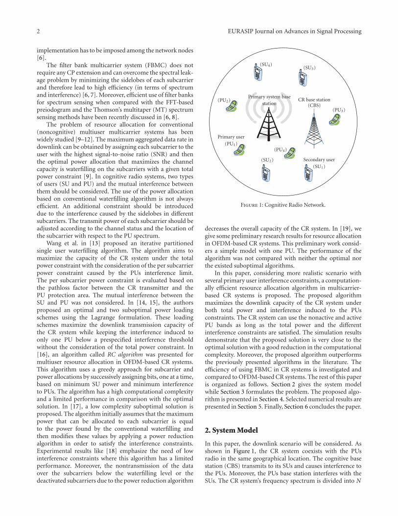
2 EURASIP Journal on Advances in Signal Processing
implementation has to be imposed among the network nodes[6].
The filter bank multicarrier system (FBMC) does notrequire any CP extension and can overcome the spectral leak-age problem by minimizing the sidelobes of each subcarrierand therefore lead to high efficiency (in terms of spectrumand interference) [6, 7]. Moreover, efficient use of filter banksfor spectrum sensing when compared with the FFT-basedpreiodogram and the Thomson’s multitaper (MT) spectrumsensing methods have been recently discussed in [6, 8].
The problem of resource allocation for conventional(noncognitive) multiuser multicarrier systems has beenwidely studied [9–12]. The maximum aggregated data rate indownlink can be obtained by assigning each subcarrier to theuser with the highest signal-to-noise ratio (SNR) and thenthe optimal power allocation that maximizes the channelcapacity is waterfilling on the subcarriers with a given totalpower constraint [9]. In cognitive radio systems, two typesof users (SU and PU) and the mutual interference betweenthem should be considered. The use of the power allocationbased on conventional waterfilling algorithm is not alwaysefficient. An additional constraint should be introduceddue to the interference caused by the sidelobes in differentsubcarriers. The transmit power of each subcarrier should beadjusted according to the channel status and the location ofthe subcarrier with respect to the PU spectrum.
Wang et al. in [13] proposed an iterative partitionedsingle user waterfilling algorithm. The algorithm aims tomaximize the capacity of the CR system under the totalpower constraint with the consideration of the per subcarrierpower constraint caused by the PUs interference limit.The per subcarrier power constraint is evaluated based onthe pathloss factor between the CR transmitter and thePU protection area. The mutual interference between theSU and PU was not considered. In [14, 15], the authorsproposed an optimal and two suboptimal power loadingschemes using the Lagrange formulation. These loadingschemes maximize the downlink transmission capacity ofthe CR system while keeping the interference induced toonly one PU below a prespecified interference thresholdwithout the consideration of the total power constraint. In[16], an algorithm called RC algorithm was presented formultiuser resource allocation in OFDM-based CR systems.This algorithm uses a greedy approach for subcarrier andpower allocations by successively assigning bits, one at a time,based on minimum SU power and minimum interferenceto PUs. The algorithm has a high computational complexityand a limited performance in comparison with the optimalsolution. In [17], a low complexity suboptimal solution isproposed. The algorithm initially assumes that the maximumpower that can be allocated to each subcarrier is equalto the power found by the conventional waterfilling andthen modifies these values by applying a power reductionalgorithm in order to satisfy the interference constraints.Experimental results like [18] emphasize the need of lowinterference constraints where this algorithm has a limitedperformance. Moreover, the nontransmission of the dataover the subcarriers below the waterfilling level or thedeactivated subcarriers due to the power reduction algorithm
Secondary user(SU1)
(SU2)
(SU3)(SU4)
Primary user(PU1)
(PU2)
(PU3)
(PU4)
Primary system basestation
CR base station(CBS)
Figure 1: Cognitive Radio Network.
decreases the overall capacity of the CR system. In [19], wegive some preliminary research results for resource allocationin OFDM-based CR systems. This preliminary work consid-ers a simple model with one PU. The performance of thealgorithm was not compared with neither the optimal northe existed suboptimal algorithms.
In this paper, considering more realistic scenario withseveral primary user interference constraints, a computation-ally efficient resource allocation algorithm in multicarrier-based CR systems is proposed. The proposed algorithmmaximizes the downlink capacity of the CR system underboth total power and interference induced to the PUsconstraints. The CR system can use the nonactive and activePU bands as long as the total power and the differentinterference constraints are satisfied. The simulation resultsdemonstrate that the proposed solution is very close to theoptimal solution with a good reduction in the computationalcomplexity. Moreover, the proposed algorithm outperformsthe previously presented algorithms in the literature. Theefficiency of using FBMC in CR systems is investigated andcompared to OFDM-based CR systems. The rest of this paperis organized as follows. Section 2 gives the system modelwhile Section 3 formulates the problem. The proposed algo-rithm is presented in Section 4. Selected numerical results arepresented in Section 5. Finally, Section 6 concludes the paper.
2. System Model
In this paper, the downlink scenario will be considered. Asshown in Figure 1, the CR system coexists with the PUsradio in the same geographical location. The cognitive basestation (CBS) transmits to its SUs and causes interference tothe PUs. Moreover, the PUs base station interferes with theSUs. The CR system’s frequency spectrum is divided into N

EURASIP Journal on Advances in Signal Processing 3
B1 B2 BL
ActivePU1 band
Non-activeband
ActivePU2 band
ActivePUL band
Frequency
1 2 Δ f N· · ·
. . .
. . .
Figure 2: Frequency distribution of the active and nonactive primary bands.
subcarriers each having a Δ f bandwidth. The side by sidefrequency distribution of the PUs and SUs will be assumed(see Figure 2). The frequency bands B1,B2,. . .,BL have beenoccupied by the PUs (active PU bands) while the other bandsrepresent the nonactive PU bands. Its assumed that the CRsystem can use the nonactive and active PU bands providedthat the total interference introduced to the lth PU band doesnot exceed Ilth where Ilth = Tl
thBl denotes that the maximuminterference power that can be tolerated by the PUl and Tl
this the interference temperature limit for PUl.
The interference introduced by the ith subcarrier to lth
PU, Ili (di,Pi), is the integration of the power spectrumdensity (PSD),Φi, of the ith subcarrier across the lth PU band,Bl, and can be expressed as [5]
Ili (di,Pi) =∫ di+Bl/2di−Bl/2
∣∣∣gli∣∣∣2Φi(f)df = PiΩ
li, (1)
where Pi is the total transmit power emitted by the ith
subcarrier and di is the spectral distance between the ith
subcarrier and the lth PU band. gli denotes the channel gainbetween the ith subcarrier and the lth PU. Ωl
i denotes theinterference factor of the ith subcarrier.
The interference power introduced by the lth PU signalinto the band of the ith subcarrier is [5]
J li(di,PPUl
) =∫ di+Δ f /2di−Δ f /2
∣∣∣yli∣∣∣2ψl(e jω)dω, (2)
where ψl(e jω) is the power spectrum density of the PUl signaland yli is the channel gain between the ith subcarrier andlth PU signal. The PSD expression, Φi, depends on the usedmulticarrier technique. The OFDM and FBMC PSDs aredescribed in the following subsections.
2.1. OFDM System and Its PSD. The OFDM symbol isformed by taking the inverse discrete Fourier transform(IDFT) to a set of complex input symbols Xk and adding acyclic prefix. This can be written mathematically as
x(n) =∑k
∑w∈Z
Xk,wgT(n−wT)e j2π(n−wT−C)k/N , (3)
where k is the set of data subcarrier indices and is a subsetof the set 0, 1, . . . ,N − 1, N is the IDFT size, C is the lengthof the cyclic prefix in number of samples, and T = C + Nis the length of the OFDM symbol in number of samples.
gT denotes the pulse shape, while w denotes the wth OFDMsymbol.
Following the derivation of the PSD for general basebandsignal given in [20], it can be shown that the OFDM PSD is
ΦOFDM(f) = σ2
x
T
∑k
∣∣∣∣GT
(f − k
N
)∣∣∣∣2
, (4)
where GT( f ) is the Fourier transform of gT(n), and σ2x is
the variance of the zero mean (symmetrical constellation)and uncorrelated input symbols. The assumption of theuncorrelated input symbols can be justified because ofcoding and interleaving in practical symbols [21].
gT(n) can be chosen as
gT(n) =⎧⎨⎩
1, n = 0, 1, . . . ,T − 1,
0, otherwise,(5)
and hence its Fourier transform is
∣∣GT(f)∣∣2 = T + 2
T−1∑r=1
(T − r) cos(2π f r
). (6)
2.2. FBMC System and Its PSD. Each subcarrier in FBMCsystem is modulated with a staggered QAM (offset QAM)[22]. The basic idea is to transmit real-valued symbolsinstead of transmitting complex-valued ones. Due to thistime staggering of the in-phase and quadrature componentsof the symbols, orthogonality is achieved between adjacentsubcarriers. The modulator and the demodulator are imple-mented using the synthesis and analysis filter banks. Thefilters in the synthesis and analysis filter bank are obtained byfrequency shifts of a single prototype filter. Figure 3 depictsthe structure of the synthesis and analysis filter bank atthe transmitter and receiver in FBMC-based multicarriersystems.
The FBMC, also called OQAM/OFDM, signal can bewritten mathematically as [23]
x(n) =∑k
∑w∈Z
ak,wh(n−wτo)e j2π(k/N)ne jφk,w , (7)
where k is the set of subcarrier indices, h is the pulseshape, φk,w is an additional phase term, and τo is FBMCsymbol duration. ak,w are the real symbols obtained fromthe complex QAM symbols having a zero mean and variance

4 EURASIP Journal on Advances in Signal Processing
Inputsymbols Channel
Re
jIm
jIm
Re
2
2
2
2
2
2
jIm
Re
Z−1
Z−1
Z−1
OQAM modulation
IFFT
H0
H1
HN−1
Z−1
Z−(N−1)
P/SS/P
Polyphasefiltering
···
···
··· ··
·
···
(a)
ChannelS/P
H0
H1
HN−1
Z−1
Z−(N−1)
FFT
2
2
Z−1
2
2
Re Z−1
Z−1 jIm
jIm Z−1
Z−1 2 Re
jIm Z−1
2 Re
P/SOutput
Polyphasefiltering OQAM modulation
···
···
···
···
···
(b)
Figure 3: FBMC system’s transmitter and receiver.
σ2x . Hence, the FBMC symbols have a zero mean and finite
variance σ2r = σ2
x /2. The PSD of the FBMC can be expressedby [23]
ΦFBMC = σ2r
τ
∑k
∣∣∣∣H(f − k
N
)∣∣∣∣2
, (8)
where H( f ) is the frequency response of the prototypefilter with coefficients h[n] with n = 0, . . . ,W − 1,where W = KN and K is the length of each polyphasecomponents (overlapping factor) while N is the numberof the subcarriers. Assuming that the prototype coefficients
have even symmetry around the (KN/2)th coefficient, and thefirst coefficient is zero [21], we get
∣∣H( f )∣∣ = h[W
2
]+ 2
W/2−1∑r=1
h[(
W
2
)− r
]cos
(2π f r
). (9)
To make a parallel between OFDM and FBMC, we placeourselves in the situation where both systems transmit thesame quantity of information. This is the case if they havethe same number of subcarriers N together with duration ofτo samples for FBMC real data and T = 2τo for the complexQAM ones [21, 23].
From the relations above we can notice that the PSDsof OFDM and FBMC are the summation of the spectra of

EURASIP Journal on Advances in Signal Processing 5
−0.2
0
0.2
0.4
0.6
0.8
1
1.2
4 5 6 7 8 9 10 11 12
Am
plit
ude
Filter bank
OFDM
Sub-channel
Figure 4: Single subcarrier PSDs of the OFDM and FBMC systems.
the individual subcarriers. Using the PHYDYAS prototypefilter [24], Figure 4 plots a single subcarrier power spectraldensities of the OFDM and FBMC systems. It can benoted that the FBMC system has very small side lobesin comparison with that of the OFDM system. Note thatin order to solve the large sidelobes problem in OFDMsystem, many methods have already been employed, suchas the insertion of guard subcarriers [25] or cancelationsubcarriers [26], windowing (in time domain) [27, 28], andfiltering before transmitting [29]. It is known that the guardsubcarriers decrease the spectral efficiency, while windowingreduces the delay spread tolerance and filtering is morecomplex and introduces distortion in the desired signals [30].
3. Problem Formulation
The transmission rate of the ith subcarrier, Ri, with thetransmit power Pi can be evaluated using the Shannoncapacity formula and is given by
Ri(Pi,hi) = Δ f log2
(1 +
Pi|hi|2σ2i
), (10)
where hi is the subcarrier fading gain from the CBS to theuser. σ2
i = σ2AWGN +
∑Ll=1 J
li where σ2
AWGN is the mean varianceof the additive white Gaussian noise (AWGN) and J li is theinterference introduced by the lth PUs band into the ith
subcarrier. The interference from PUs to the ith subcarrieris assumed to be the superposition of large number ofindependent components, that is,
∑Ll=1 J
li . Hence, we can
model the interference as AWGN. This assumption may notbe valid for low number of PU bands but can be consideredas a good approximation for large number of PU bands.The same model can be found in [6, 15, 17]. Remark thatthe nature of the PUs interference on SUs band is the sameon both OFDM and FBMC systems. The difference is onlyin the SUs interference to the PU bands, which is in thatcase FBMC has significantly lower interference, because ofits significantly smaller sidelobes as compared to those ofOFDM.
Assuming that each subcarrier band is narrow, subcar-riers can be approximated as channel with flat fading gains
[31, 32]. It will be assumed that the channel changes slowly sothat the channel gains will be constant during transmission.The total achievable rate for OFDM and FBMC systemsis evaluated by summing the transmission rate across thedifferent subcarriers [7, 33]. All the instantaneous fadinggains are assumed perfectly known at the CR system andthere is no intercarrier interference (ICI). Let vi,m to be asubcarrier allocation indicator, that is, vi,m = 1 if and onlyif the subcarrier is allocated to the mth user. It is assumedthat each subcarrier can be used for transmission to at mostone user at any given time. Our objective is to maximize thetotal capacity of the CR system subject to the instantaneousinterference introduced to the PUs and total transmit powerconstraints. Therefore, the optimization problem can beformulated as follows:
P1 : maxPi,m
M∑m=1
N∑i=1
υi,mRi,m(Pi,m,hi,m
)(11)
subject to
υi,m ∈ 0, 1, ∀i,m, (12)
M∑m=1
υi,m ≤ 1, ∀i, (13)
M∑m=1
N∑i=1
υi,mPi,m ≤ PT , (14)
Pi,m ≥ 0, ∀i ∈ 1, 2, . . . ,N, (15)
M∑m=1
N∑i=1
υi,mPi,mΩli ≤ Ilth, ∀l ∈ 1, 2, . . . ,L, (16)
where N denotes the total number of subcarriers, M isthe number of users, Ilth denotes the interference thresholdprescribed by the lth PU, and PT is the total SUs powerbudget. L is the number of the active PU bands. Inequality(13) ensures that any given subcarrier can be allocated to atmost one user.
The optimization problem P1 is a combinatorial opti-mization problem and its complexity grows exponentiallywith the input size. In order to reduce the computationalcomplexity, the problem is solved in two steps by manyof the suboptimal algorithms [9–12]. In the first step, thesubcarriers are assigned to the users and then the power isallocated for these subcarriers in the second step. Once thesubcarriers are allocated to the users, the multiuser systemcan be viewed virtually as a single user multicarrier system.As proved in [9], the maximum data rate in downlink canbe obtained if the subcarriers are assigned to the user whohas the best channel gain for that subcarrier as described inAlgorithm 1.
By applying Algorithm 1, the values of the channel indi-cators υi,m are determined and hence for notation simplicity,single user notation can be used. The different channel gains

6 EURASIP Journal on Advances in Signal Processing
can be determined from the subcarrier allocation step asfollows:
hi =M∑m=1
υi,mhi,m. (17)
Therefore, problem P1 in (11) can be reformulated asfollows:
P2 : maxPi
N∑i=1
log2
(1 +
Pi|hi|2σ2i
)(18)
subject to
N∑i=1
PiΩli ≤ Ilth ∀l ∈ 1, 2, . . . ,L, (19)
N∑i=1
Pi ≤ PT , (20)
Pi ≥ 0 ∀i ∈ 1, 2, . . . ,N. (21)
The problem P2 is a convex optimization problem. TheLagrangian can be written as [17]
G = −N∑i=1
log2
(1 +
P∗i |hi|2σ2i
)+
L∑l=1
αl
⎛⎝ N∑i=1
P∗i Ωli − Ilth
⎞⎠
+ β
⎛⎝ N∑i=1
P∗i − PT⎞⎠−
N∑i=1
P∗i μi,
(22)
where αl, l ∈ 1, 2, . . . ,L, μi, i ∈ 1, 2, . . . ,N, and β arethe Lagrange multipliers. The Karush-Kuhn-Tucker (KKT)conditions can be written as follows:
P∗i ≥ 0, ∀i ∈ 1, 2, . . . ,N,αl ≥ 0, ∀l ∈ 1, 2, . . . ,L,
β ≥ 0,
μi ≥ 0, ∀i ∈ 1, 2, . . . ,N,
αl
⎛⎝ N∑i=1
P∗i Ωli − Ilth
⎞⎠ = 0, ∀l ∈ 1, 2, . . . ,L,
β
⎛⎝ N∑i=1
P∗i − PT⎞⎠ = 0,
μiP∗i = 0, ∀i ∈ 1, 2, . . . ,N,
∂G
∂P∗i= −1
σ2i /|hi|2 + P∗i
+L∑l=1
αlΩli + β − μi = 0,
(23)
and also the solution should satisfy the total power andinterference constraints given by (20) and (19). Rearrangingthe last condition in (23) we get
P∗i =1∑L
l=1 αlΩli + β − μi
− σ2i
|hi|2. (24)
Initialization:Set υi,m = 0 ∀i,mSubcarrier Allocation:
for i = 1 to N dom∗ = argmax
mhi,m; υi,m∗ = 1
end for
Algorithm 1: Subcarriers to user allocation.
Since P∗i ≥ 0, we get
σ2i
|hi|2≤ 1∑L
l=1 αlΩli + β − μi
. (25)
If σ2i /|hi|2 < 1/(
∑Ll=1 αlΩi + β), then μi = 0 and hence
P∗i =1∑L
l=1 αlΩli + β
− σ2i
|hi|2. (26)
Moreover, if σ2i /|hi|2 > 1/(
∑Ll=1 αlΩ
li + β), from (24) we get
1∑Ll=1 αlΩ
li + β − μi
≥ σ2i
|hi|2≥ 1∑L
l=1 αlΩli + β
, (27)
and since μiP∗i = 0 and μi ≥ 0, we get that P∗i = 0.Therefore, the optimal solution can be written as follows:
P∗i =
⎧⎪⎪⎪⎪⎨⎪⎪⎪⎪⎩
1∑Ll=1 αlΩ
li + β
− σ2i
|hi|2if
σ2i
|hi|2<
1∑Ll=1 αlΩ
li + β
,
0 ifσ2i
|hi|2≥ 1∑L
l=1 αlΩli + β
,
(28)
or more simply, (28) can be written as the follows:
P∗i =[
1∑Ll=1 αlΩ
li + β
− σ2i
|hi|2]+
, (29)
where [x]+ = max(0, x). Solving for L + 1 Lagrangianmultipliers is computational complex. These multiplierscan be found numerically using ellipsoid or interior pointmethod with a complexity O(N3) [17, 34]. In what followswe will propose a low complexity algorithm that achievesnear optimal performance.
4. Proposed Algorithm
The optimal solution for the optimization problem has ahigh computational complexity which makes it unsuitablefor the practical applications. A low complexity algorithm isproposed in [17]. The subcarriers nulling and deactivatingthroughout this algorithm degrade the system capacity andcausing the algorithm to have a limited performance in lowinterference constraints. To overcome the drawbacks of thisalgorithm, a low complexity power allocation algorithm willbe presented.

EURASIP Journal on Advances in Signal Processing 7
As described in [5, 17], most of the interferenceintroduced to the PU bands is induced by the cognitivetransmission in the subcarriers where the PU is active as wellas the subcarriers that are directly adjacent to the PU bands.Considering this fact, it can be assumed that each subcarrieris belonging to the closest PU band and only introducinginterference to it, then the optimization problem P2 can bereformulated as follows:
P3 : maxP′i
N∑i=1
log2
(1 +
P′i |hi|2σ2i
)(30)
subject to∑i∈Nl
P′iΩli ≤ Ilth ∀l ∈ 1, 2, . . . ,L,
N∑i=1
P′i ≤ PT ,
P′i ≥ 0 ∀i ∈ 1, 2, . . . ,N,
(31)
where Nl denotes the set of the subcarriers belong to the lth
PU band. Using the same derivation leading to (29), we get
P′i =[
1
α′lΩli + β′
− σ2i
|hi|2]+
, (32)
where α′l and β′ are the non-negative dual variablescorresponding to the interference and power constraintsrespectively. The solution of the problem still has highcomputational complexity which encourages us to find afaster and efficient power allocation algorithm.
If the interference constraints are ignored in P3, the solu-tion of the problem will follow the well-known waterfillinginterpretation [35]
P′(PT )i =
[λ− σ2
i
|hi|2]+
, (33)
where λ is the waterfilling level. On the other side, if the totalpower constraint is ignored, the Lagrangian of the problemcan be written as [15]
G(Int) = −∑i∈Nl
log2
(1 +
P′(Int)i |hi|2σ2i
)
+ α′(Int)l
⎛⎝∑i∈Nl
P′(Int)i Ωl
i − Ilth
⎞⎠,
(34)
where α′l is the Lagrange multiplier. Equating ∂G(Int)/∂P′(Int)i
to zero, we get
P′(Int)i =
⎡⎣ 1
α′(Int)l Ωl
i
− σ2i
|hi|2
⎤⎦
+
, (35)
where the value of α′l can be calculated by substituting (35)
into∑
i∈NlP′(Int)i Ωi = Ilth to get
α′(Int)l = |Nl|
Ilth +∑
i∈Nl
(Ωliσ
2i /|hi|2
) . (36)
It is obvious that if the summation of the allocatedpower under only the interference constraints is lowerthan or equal the available total power budget, that is,∑N
i=1 P′(Int)i ≤ PT , for all i ∈ 1, 2, . . . ,N, then (35)-(36)
will be the optimal solution for the optimization problem P3.In most of the cases, the total power budget is quite lowerthan this summation, and hence the Power Interference(PI) constrained algorithm, referred to as PI-Algorithm, isproposed to allocate the power under both total power andinterference constraints.
In order to solve the optimization problem P3, we canstart by assuming that the maximum power that can beallocated for a given subcarrier PMax
i is determined accordingto the interference constraints only by using (35)-(36) forevery set of subcarriers Nl, for all l ∈ 1, 2, . . . ,L. Bysuch an assumption, we can guarantee that the interferenceintroduced to PU bands will be under the prespecifiedthresholds. Once the maximum power PMax
i is determined,the total power constraint is tested. If the total powerconstraint is satisfied, then the solution has been found andis equal to the maximum power that can be allocated to eachsubcarrier, that is, P′i = PMax
i . Otherwise, the available powerbudget should be distributed among the subcarriers givingthat the power allocated to each subcarrier is lower than orequal to the maximum power that can be allocated to eachsubcarrier PMax
i , and hence the following problem should besolved:
P4 : maxPW.Fi
N∑i=1
log2
(1 +
PW.Fi |hi|2σ2i
)(37)
subject to
N∑i=1
PW.Fi ≤ PT ,
0 ≤ PW.Fi ≤ PMax
i .
(38)
The problem P4 is called “cap-limited” waterfilling [36].The problem can be solved efficiently using the concept ofthe conventional waterfilling. Given the initial waterfillingsolution, the channels that violate the maximum power PMax
i
are determined and upper bounded with PMaxi . The total
power budget is reduced by subtracting the power assignedso far. At the next step, the algorithm proceeds to successivewaterfilling over the subcarriers that did not violate themaximum power PMax
i in the last step. This procedure isrepeated until the allocated power PW.F
i does not violatethe maximum power PMax
i in any of the subcarriers inthe new iteration. The “cap-limited” waterfilling algorithmimplementation is described in Algorithm 2.
The solution PW.Fi of the problem P4 is satisfying the
total power constraint of the problem P3 with equalitywhich is not the case for the different interference constraintsIlth. Since it is assumed that PW.F
i ≤ PMaxi , some of the
powers allocated to subcarriers will not reach the maximumallowable values. This will make the interference introducedto the PU bands below the thresholds Ilth. In order to takeadvantage of all the allowable interference, the values of the
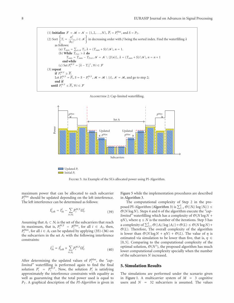
8 EURASIP Journal on Advances in Signal Processing
(1) Initialize F =M = N = 1, 2, . . . ,N, Pi = PMaxi , and S = PT .
(2) Sort
Ti = σ2
i
|hi|2, i ∈ N
in decreasing order with J being the sorted index. Find the waterfilling λ
as follows:(a) Tsum =
∑i∈N Ti, λ = (Tsum + S)/|N |, n = 1.
(b) While TJ(n) > λ doTsum = Tsum − TJ(n), N = N \ J(n), λ = (Tsum + S)/|N |, n = n + 1
end while(c) Set PW.F
i = [λ− Ti]+,∀i ∈ F(3) repeat
if PW.Fi ≥ Pi
Let PW.Fi = Pi, S = S− PW.F
i , M =M \ i, N =M, and go to step 2;end if
until PW.Fi ≤ Pi,∀i ∈ F
Algorithm 2: Cap-limited waterfilling.
Initial Pi
Updated Pi
Pow
er
Subcarriers
PMax
Set A
PMax
Updated
PMax
Updated
PMax
Figure 5: An Example of the SUs allocated power using PI-Algorithm.
maximum power that can be allocated to each subcarrierPMaxi should be updated depending on the left interference.
The left interference can be determined as follows:
IlLeft = Ilth −∑i∈Nl
PW.Fi Ωl
i. (39)
Assuming that Al ⊂ Nl is the set of the subcarriers that reachits maximum, that is, PW.F
i = PMaxi , for all i ∈ Al, then,
PMaxi , for all i ∈ Al can be updated by applying (35)-(36) on
the subcarriers in the set Al with the following interferenceconstraints:
I′lth = IlLeft +
∑i∈Al
PW.Fi Ωl
i. (40)
After determining the updated values of PMaxi , the “cap-
limited” waterfilling is performed again to find the finalsolution P′i = PW.F
i . Now, the solution P′i is satisfyingapproximately the interference constraints with equality aswell as guaranteing that the total power used is equal toPT . A graphical description of the PI-Algorithm is given in
Figure 5 while the implementation procedures are describedin Algorithm 3.
The computational complexity of Step 2 in the pro-posed PI-Algorithm (Algorithm 3) is
∑Ll=1 O(|Nl| log |Nl|) ≤
O(N logN). Steps 4 and 6 of the algorithm execute the “cap-limited” waterfilling which has a complexity of O(N logN +ηN), where η ≤ N is the number of the iterations. Step 5 hasa complexity of
∑Ll=1 O(|Al| log |Al|) +O(L) ≤ O(N logN) +
O(L). Therefore, The overall complexity of the algorithmis lower than O(N logN + ηN) + O(L). The value of η isestimated via simulation to be lower than five, that is, η ∈[0, 5]. Comparing to the computational complexity of theoptimal solution, O(N3), the proposed algorithm has muchlower computational complexity specially when the numberof the subcarriers N increased.
5. Simulation Results
The simulations are performed under the scenario givenin Figure 1. A multicarrier system of M = 3 cognitiveusers and N = 32 subcarriers is assumed. The values

EURASIP Journal on Advances in Signal Processing 9
(1) Initialize N = 1, 2, · · · ,N, Nl = Nl , I lLeft = 0, S = PT and Al = ∅.
(2)∀l ∈ 1, 2, · · · ,L, sort
Hi = σ2
i
|hi|2Ωli, i ∈ Nl
in decreasing order with k being the sorted index.
Find the PMaxi as follows:
(a) Hsum =∑
i∈NlHi, α
′(Int)l = |Nl|/(I lth +Hsum), n = 1.
(b) while α′(Int)l > H−1
k(n) do
Hsum = Hsum −Hk(n), Nl = Nl \ k(n), α′(Int)l = |Nl|/(I lth +Hsum), n = n + 1
end while
(c) Set PMaxi =
[1
α′(Int)l Ωl
i
− σ2i
|hi|2]+
(3) if∑
i∈N PMaxi ≤ PT
Let P′i = PMaxi and stop the algorithm.
end if(4) Execute the “cap-limited” waterfilling (Algorithm 2) and find the set Al ⊂ Nl where PW.F
i = PMaxi .
(5) Evaluate I lLeft = I lth −∑
i∈Nl PW.Fi Ωl
i and set Nl =Al, I lth = I lLeft +∑
i∈AlPW.Fi Ωl
i and applyagain only step 2 to update PMax
i .(6) Execute the “cap-limited” waterfilling (Algorithm 2) and set P′i = PW.F
i .
Algorithm 3: PI-Algorithm.
of Δ f and PT are assumed to be 0.3125 MHz and 1 watt,respectively. AWGN of variance 10−6 is assumed. Withoutloss of generality, the interference induced by PUs to theSUs band is assumed to be negligible. The channel gains hand g are outcomes of independent, identically distributed(i.i.d) Rayleigh distributed random variables (rv’s) withmean equal to “1” and assumed to be perfectly known at the(CBS). OFDM and FBMC-based cognitive radio systems areevaluated. The OFDM system is assumed to have a 6.67% ofits symbol time as cyclic prefix (CP). For FBMC system, theprototype coefficients are assumed to be equal to PHYDYAScoefficients with overlapping factor K = 4 and are defined by[24, 37]
h[n] = 1− 1.94392 cos(
2πn128
)+√
2 cos(
4πn128
)
− 0.470294 cos(
6πn128
), 0 ≤ n ≤ 127,
(41)
The optimal solution is implemented using the interior pointmethod. We refer to the method proposed in [17] by Zhangalgorithm. All the results have been averaged over 1000iterations.
Two interference constraints belonging to two active PUbands, that is, L = 2, is assumed as given in Figure 6. Eachactive PU band is assumed to have six subcarriers where|N1| = |N2| = 16. The achieved capacity using optimal, PIand Zhang algorithms for different interference constraintswhere I1
th = I2th is plotted in Figure 7. It can be noted that
the proposed PI-algorithm approaches the optimal solutionand outperforms Zhang algorithm. The effect of assumingthat every subcarrier is belonging to the closest PU band andintroducing interference to it only on the net interferenceintroduced to the active PU bands is studied in Figures 8and 9 for PU1 and PU2, respectively. It can be observedthat the net interference induced using the PI-algorithm
is approximately satisfying the prespecified interferenceconstraints which makes the assumption reasonable. Unlikethe OFDM-based CR system, the interference induced bythe FBMC-based system does not reach the pre-specifiedthresholds. This is because the FBMC-based CR systemreaches to the maximum interference that can be introducedto the PU using the given power budget. Moreover, theinterference induced by the proposed algorithm is less thanthat using Zhang algorithm. Returning to Figure 7, one cannotice that the interference constraints after Ilth = 10mWattstart to have no effect on the achieved capacity of the FBMCsystem. This indicates also that the FBMC system reaches themaximum interference for the given power budget. The smalldifference between the net interference values after Ilth = 10mWatt is due to averaging over different channel realizations.The achieved capacity of the different algorithms is plotted inFigure 10 with lower values of the interference constraints.It can be noticed that Zhang algorithm has a limitedperformance with low interference constraints because thealgorithm turns off the subcarriers that have a noise levelmore than the initial waterfilling level and never uses thesesubcarriers again even if the new waterfilling level exceedsits noise level. Moreover, the algorithm deactivates somesubcarriers, that is, transmit zero power, in order to ensurethat the interference introduced to PU bands is below theprespecified thresholds. The lower the interference con-straints, the more the deactivated subcarriers which justifiesthe limited performance of this algorithm in low interferenceconstraints.
To show the efficiency of transmitting over the activePU bands as well as the nonactive bands, Figures 11 and12 plot the achieved capacity using the PI algorithm withand without allowing the SUs to transmit over the PUactive bands. The capacity of the CR system transmittingon both the active and nonactive bands is more than thatone transmitting only on the nonactive band. Since thecognitive transmission in the active PU band introduces
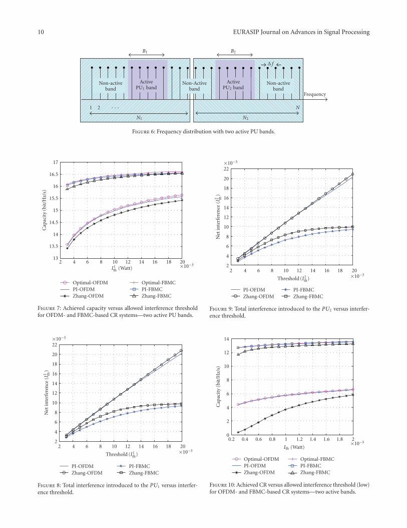
10 EURASIP Journal on Advances in Signal Processing
Non-activeband
ActivePU1 band
Non-Activeband
ActivePU2 band
Non-activeband
B1 B2
N1 N2
N1 2
Frequency
· · ·
Δ f
Figure 6: Frequency distribution with two active PU bands.
13
13.5
14
14.5
15
15.5
16
16.5
17
Optimal-OFDMPI-OFDMZhang-OFDM
Optimal-FBMCPI-FBMCZhang-FBMC
I1th (Watt)
Cap
acit
y(b
it/H
z/s)
2 4 6 8 10 12 14 16 18 20×10−3
Figure 7: Achieved capacity versus allowed interference thresholdfor OFDM- and FBMC-based CR systems—two active PU bands.
2 4 6 8 10 12 14 16 18 20×10−3
2
4
6
8
10
12
14
16
18
20
22×10−3
Net
inte
rfer
ence
(I1 th
)
Threshold (I1th)
PI-OFDMZhang-OFDM
PI-FBMCZhang-FBMC
Figure 8: Total interference introduced to the PU1 versus interfer-ence threshold.
2 4 6 8 10 12 14 16 18 20×10−3
2
4
6
8
10
12
14
16
18
20
22×10−3
Net
inte
rfer
ence
(I2 th
)
Threshold (I2th)
PI-OFDMZhang-OFDM
PI-FBMCZhang-FBMC
Figure 9: Total interference introduced to the PU2 versus interfer-ence threshold.
0.2 0.4 0.6 0.8 1 1.2 1.4 1.6 1.8 2×10⁻⁵
0
2
4
6
8
10
12
14
Cap
acit
y(b
it/H
z/s)
Ith (Watt)
Optimal-OFDMPI-OFDMZhang-OFDM
Optimal-FBMCPI-FBMCZhang-FBMC
Figure 10: Achieved CR versus allowed interference threshold (low)for OFDM- and FBMC-based CR systems—two active bands.

EURASIP Journal on Advances in Signal Processing 11
10
11
12
13
14
15
16
17
2 4 6 8 10 12 14 16 18 20×10−3
Ith (Watt)
Cap
acit
y(b
it/H
z/s)
PI-OFDM PI-OFDM without PU bandPI-FBMC PI-FBMC without PU band
Figure 11: Achieved capacity versus allowed interference thresholdwith and without transmitting over active bands—two active PUbands.
0.2 0.4 0.6 0.8 1 1.2 1.4 1.6 1.8 2×10⁻⁵
4
5
6
7
8
9
10
11
12
13
14
Cap
acit
y(b
it/H
z/s)
Ith (Watt)
PI-OFDM PI-OFDM without PU bandPI-FBMC PI-FBMC without PU band
Figure 12: Achieved capacity versus allowed interference threshold(low) with and without transmitting over active bands—two activePU bands.
more interference to the PUs than the other subcarriers,low power levels can be used in these bands with lowinterferences constraints. This justifies why the differencebetween the two systems decreases when the interferenceconstraints decrease.
RC algorithm can be used if there is only one activePU band, that is, L = 1. The RC algorithm allocatesthe subcarriers and bits considering the relative importancebetween the power needed to transmit and the interferenceinduced to the PU band. In order to compare the proposedPI-algorithm with RC algorithm, One active PU band with“12” subcarriers will be assumed as given in Figure 13. For
Non-activeband
Active PUband
Non-activeband
B
1 2 Δ f N
Frequency
· · ·
Figure 13: Frequency distribution with one active PU band.
11.5
12
12.5
13
13.5
14
14.5
15
15.5
16
16.5
2 4 6 8 10 12 14 16 18 20×10−3
Ith (Watt)
Cap
acit
y(b
it/H
z/s)
Optimal-OFDMPI-OFDMZhang-OFDMRC-OFDM
Optimal-FBMCPI-FBMCZhang-FBMCRC-FBMC
Figure 14: Achieved capacity versus allowed interference thresholdfor OFDM- and FBMC-based CR systems—one active PU band.
fair comparison, the same bit mapping used in [16] isconsidered as follows:
bi =⌊
log2
(1 +
P′i |hi|2σ2i
)⌋, (42)
where bi denotes the maximum number of bits in the symboltransmitted in the ith subcarrier and · denotes the floorfunction. Figures 14 and 15 show that the proposed algo-rithm performs better than the RC and Zhang algorithms. Inlow interference constraints, RC algorithm performs betterthan Zhang algorithm because of the limited performance ofZhang algorithm with low interference constraints.
For all the so far presented results, the capacity of FBMC-based CR system is higher than that of OFDM-based onebecause the sidelobes in FBMC’s PSD is smaller than thatin OFDM which introduces less interference to the PUs.Moreover, the inserted CP in OFDM-based CR systemsreduces the total capacity of the system. It can be noticed alsothat the interference condition introduces a small restrictionon the capacity of FBMC-based CR systems which is not thecase in OFDM-based CR systems. The significant increase inthe capacity of FBMC-based CR systems over the OFDM-based ones recommends the FBMC as a candidate for the CRnetwork applications.

12 EURASIP Journal on Advances in Signal Processing
0.2 0.4 0.6 0.8 1 1.2 1.4 1.6 1.8 2×10⁻⁵
0
2
4
6
8
10
12
14C
apac
ity
(bit
/Hz/
s)
Ith (Watt)
Optimal-OFDMPI-OFDMZhang-OFDMRC-OFDM
Optimal-FBMCPI-FBMCZhang-FBMCRC-FBMC
Figure 15: Achieved capacity versus allowed interference threshold(low) for OFDM- and FBMC-based CR systems—one active PUband.
6. Conclusion
In this paper, a low complexity suboptimal resource allo-cation algorithm for multicarrier-based CR networks ispresented. Our objective was to maximize the total downlinkcapacity of the CR network while respecting the availablepower budget and guaranteeing that no excessive interferenceis caused to the PUs. With a significant reduction in thecomputational complexity from O(N3) to O(N logN+ηN)+O(L),η ∈ [0, 5], It is shown that the proposed PI-algorithmachieves a near optimal performance and outperforms thesuboptimal algorithms proposed so far. It is found thatthe net total interference introduced to the PUs band isrelatively not affected by assuming that each subcarrier isbelonging to the closest PU band and only introducinginterference to it. Its demonstrated also that capacity ofthe CR system uses the nonactive as well as the activebands is more than that only uses the nonactive bands.Simulation results prove that the FBMC-based CR systemshave more capacity than OFDM-based ones. FBMC offersmore spectral efficiency and introduces small interference tothe PUs. The obtained results contribute in recommendingthe use of FBMC physical layer in the future cognitiveradio systems. Developing a resource allocation algorithmthat considers the fairness among different users as wellas their quality of service (QoS) will be the guideline ofour future research work towards better radio resourcemanagement.
Acknowledgment
This work was partially supported by the European ICT-2008-211887 project PHYDYAS.
References
[1] Federal Communication Commission, “Spectrum Policy TaskForce,” Report of ET Docket 02-135, November 2002.
[2] J. Mitola III, “Cognitive radio for flexible mobile multimediacommunications,” in Proceedings of IEEE International Work-shop on Mobile Multimedia Communications (MoMuC ’99),pp. 3–10, San Diego, Calif, USA, November 1999.
[3] T. A. Weiss and F. K. Jondral, “Spectrum pooling: an innova-tive strategy for the enhancement of spectrum efficiency,” IEEECommunications Magazine, vol. 42, no. 3, pp. S8–S14, 2004.
[4] S. Haykin, “Cognitive radio: brain-empowered wireless com-munications,” IEEE Journal on Selected Areas in Communica-tions, vol. 23, no. 2, pp. 201–220, 2005.
[5] T. Weiss, J. Hillenbrand, A. Krohn, and F. K. Jondral, “Mutualinterference in OFDM-based spectrum pooling systems,” inProceedings of the 59th IEEE Vehicular Technology Conference(VTC ’04), vol. 59, Milan, Italy, May 2004.
[6] B. Farhang-Boroujeny and R. Kempter, “Multicarrier commu-nication techniques for spectrum sensing and communicationin cognitive radios,” IEEE Communications Magazine, vol. 46,no. 4, pp. 80–85, 2008.
[7] H. Zhang, D. L. Ruyet, and M. Terre, “On spectral effi-ciency analysis between OFDM/OQAM and OFDM based CRnetworks,” in Proceedings of the IEEE Vehicular TechnologyConference (VTC ’09), Barcelona, Spain, 2009.
[8] B. Farhang-Boroujeny, “Filter bank spectrum sensing forcognitive radios,” IEEE Transactions on Signal Processing, vol.56, no. 5, pp. 1801–1811, 2008.
[9] J. Jang and K. B. Lee, “Transmit power adaptation formultiuser OFDM systems,” IEEE Journal on Selected Areas inCommunications, vol. 21, no. 2, pp. 171–178, 2003.
[10] D. Kivanc, G. Li, and H. Liu, “Computationally efficientbandwidth allocation and power control for OFDMA,” IEEETransactions on Wireless Communications, vol. 2, no. 6, pp.1150–1158, 2003.
[11] Z. Shen, J. G. Andrews, and B. L. Evans, “Optimal powerallocation in multiuser OFDM systems,” in Proceedings of IEEEGlobal Telecommunications Conference (GLOBECOM ’03), vol.1, pp. 337–341, San Francisco, Calif, USA, December 2003.
[12] C. Y. Wong, R. S. Cheng, K. B. Letaief, and R. D. Murch,“Multiuser OFDM with adaptive subcarrier, bit, and powerallocation,” IEEE Journal on Selected Areas in Communications,vol. 17, no. 10, pp. 1747–1758, 1999.
[13] P. Wang, M. Zhao, L. Xiao, S. Zhou, and J. Wang, “Powerallocation in OFDM-Based cognitive radio systems,” inProceedings of IEEE Global Telecommunications Conference(GLOBECOM ’07), pp. 4061–4065, 2007.
[14] G. Bansal, M. J. Hossain, and V. K. Bhargava, “Adaptive powerloading for OFDM-based cognitive radio systems,” in Pro-ceedings of IEEE International Conference on Communications(ICC ’07), pp. 5137–5142, Glasgow, UK, 2007.
[15] G. Bansal, M. J. Hossain, and V. K. Bhargava, “Optimaland suboptimal power allocation schemes for OFDM-basedcognitive radio systems,” IEEE Transactions on Wireless Com-munications, vol. 7, no. 11, pp. 4710–4718, 2008.
[16] T. Qin and C. Leung, “Fair adaptive resource allocation formultiuser OFDM cognitive radio systems,” in Proceedingsof the 2nd International Conference on Communications andNetworking in China (ChinaCom ’07), August 2007.
[17] Y. Zhang, Resource allocation for OFDM-based cognitive radiosystems, Ph.D. dissertation, University of British Columbia,Vancouver, Canada, December 2008.

EURASIP Journal on Advances in Signal Processing 13
[18] G. Stuber, S. Almalfouh, and D. Sale, “Interference analysis ofTV-band whitespace,” Proceedings of the IEEE, vol. 97, no. 4,pp. 741–754, 2009.
[19] M. Shaat and F. Bader, “Power allocation with interferenceconstraint in multicarrier based cognitive radio systems,” inProceedings of the 7th International Workshop on Multi-CarrierSystems and Solutions (MCSS ’09), Herrsching, Germany, May2009.
[20] J. G. Proakis and M. Salehi, Communication Systems Engineer-ing, Prentice-Hall, Upper Saddle River, NJ, USA, 2nd edition,2002.
[21] L. G. Baltar, D. S. Waldhauser, and J. Nossek, “Out-of-band radiation in multicarrier systems: a comparison,” inProceedings of the International Workshop on Multi-CarrierSystems & Solutions (MC-SS ’07), pp. 107–116, Springer, May2007.
[22] B. Hirosaki, “An orthogonally multiplexed QAM systemusing the discrete fourier transform,” IEEE Transactions onCommunications Technology, vol. 29, no. 7, pp. 982–989, 1981.
[23] A. Skrzypczak, P. Siohan, and J.-P. Javaudin, “Power spectraldensity and cubic metric for the OFDM/OQAM modulation,”in Proceedings of the 6th IEEE International Symposium onSignal Processing and Information Technology (ISSPIT ’06),Vancouver, Canada, August 2006.
[24] “PHYDYAS-Physical layer for dynamic spectrum access andcognitive radio,” http://www.ict-phydyas.org/.
[25] A. Jayalath and C. Tellambura, “Reducing the out-of-bandradiation of OFDM using an extended guard interval,”in Proceedings of the 53rd Vehicular Technology Conference(VTC ’01), vol. 2, pp. 829–833, Rhodes, Greece, May 2001.
[26] S. Brandes, I. Cosovic, and M. Schnell, “Reduction of out-of-band radiation in OFDM systems by insertion of cancellationcarriers,” IEEE Communications Letters, vol. 10, no. 6, pp. 420–422, 2006.
[27] Y.-P. Lin and S.-M. Phoong, “Window designs for DFT-basedmulticarrier systems,” IEEE Transactions on Signal Processing,vol. 53, no. 3, pp. 1015–1024, 2005.
[28] H. A. Mahmoud and H. Arslan, “Sidelobe suppressionin OFDM-based spectrum sharing systems using adaptivesymbol transition,” IEEE Communications Letters, vol. 12, no.2, pp. 133–134, 2008.
[29] A. Vahlin and N. Holte, “Optimal finite duration pulses forOFDM,” IEEE Transactions on Communications, vol. 44, no. 1,pp. 10–14, 1996.
[30] R. Xu and M. Chen, “Spectral leakage suppression of DFT-based OFDM via adjacent subcarriers correlative coding,”in Proccedings of IEEE Global Telecommunications Conference(GLOBECOM ’08), pp. 3029–3033, December 2008.
[31] A. Amini, R. Kempter, L. Lin, and B. Farhang-Boroujeny, “Fil-ter bank multitone: a candidate for physical layer of cognitiveradio,” in Proceedings of the Software Defined Radio TechnicalConference and Product Exhibition (SDR ’05), Orange County,Calif, USA, November 2005.
[32] A. Amini, R. Kempter, and B. Farhang-Boroujeny, “A compar-ison of alternative filterbank multicarrier methods in cognitiveradios,” in Proceedings of the Software Defined Radio TechnicalConference and Product Exhibition (SDR ’06), Orlando, Fla,USA, November 2006.
[33] H. Zhang, D. Le Ruyet, and M. Terre, “Spectral efficiencycomparison between OFDM/OQAM- and OFDM-based CRnetworks,” Wireless Communications and Mobile Computing,vol. 9, no. 11, pp. 1487–1501, 2009.
[34] S. Boyd and L. Vandenberghe, Convex Optimization, Cam-bridge University Press, Cambridge, UK, 2004.
[35] A. Leke and J. Cioffi, “A maximum rate loading algorithmfor discrete multitone modulation systems,” in Proceedingsof the IEEE Global Telecommunications Conference (GLOBE-COM ’97), vol. 3, pp. 1514–1518, 1997.
[36] N. Papandreou and T. Antonakopoulos, “Bit and powerallocation in constrained multicarrier systems: the single-usercase,” EURASIP Journal on Advances in Signal Processing, vol.2008, Article ID 643081, 14 pages, 2008.
[37] M. Bellanger, “Filter banks and OFDM-OQAM for highthroughput wireless LAN,” in Proceedings of the 3rd Inter-national Symposium on Communications, Control, and SignalProcessing (ISCCSP ’08), pp. 758–761, St Julians, Malta, March2008.

Published in IET CommunicationsReceived on 2nd December 2010Revised on 23rd June 2011doi: 10.1049/iet-com.2010.1062
ISSN 1751-8628
Efficient resource allocation algorithm for uplinkin multicarrier-based cognitive radio networkswith fairness considerationM. Shaat F. BaderCentre Tecnologic de Telecomunicacions de Catalunya (CTTC), Parc Mediterrani de la Tecnologıa, Av. Canal Olimpia s/n.08860, Castelldefels-Barcelona, SpainE-mail: [email protected]
Abstract: An efficient fairness-aware uplink resource allocation algorithm in orthogonal frequency-division multiplexing-basedcognitive radio systems is presented. The proposed resource allocation algorithm is divided into two steps. The subcarriers to userassignment is first performed, and then the power is allocated to the different subcarriers. The objective is to maximise the totaldata rate while guaranteeing that the interference introduced to the primary system is under the prescribed interference temperaturelimit. The fairness among users is considered within the subcarrier allocation by reducing the probability of having users whoseinstantaneous rates are below a given minimum rate. Many factors will be considered during the resource allocation process likethe channel quality, potential interference caused to the primary bands, instantaneous rate achieved by every user and theincrement in the total data rate. Simulation results confirm the efficiency of the proposed algorithm.
1 Introduction
The available spectrum is divided into several frequencybands that are allocated traditionally to a specific user orservice provider exclusively in order to be protected fromany interference. Since most of the current frequency bandshave been already allocated [1], it will be very hard tofind vacant bands for the emerging wireless systems orservices. Moreover, recent measurements by the FederalCommunications Commission show that the spectrumutilisation in the 0–6 GHz band varies from 15 to 85%depending on time, frequency and geographical location[2, 3]. These observations motivate the development ofcognitive radio (CR) communications [4, 5] whereby thesecondary users (SUs), also called unlicensed users, areallowed to access the radio spectrum originally allocated tothe primary users (PUs), also called licensed user. In this way,CR will greatly improve the spectrum utilisation withoutmajor changes to the existing primary systems. By using oneof the spectrum sensing techniques [6, 7], SUs need toperiodically monitor the radio spectrum in order to detect intime and frequency the PUs transmission. The interferenceintroduced to the PUs because of CR transmission should bebelow a predefined value called the interference temperaturelimit [3, 5]. In order to maximise the CR system throughputwithout causing harmful interference to the PUs, the availableradio resources (powers, rates and bandwidth) should bedistributed carefully and efficiently. To that end, the problemof resource allocation in CR networks has been widely studiedrecently. For a single channel (carrier) CR systems, theoptimal resource allocation schemes in uplink and downlink
have been presented for both single and multiuserenvironments (see e.g. [8–12]).
By virtue of its flexibility in the allocation of differentresources among different users as well as its ability to fill thespectrum holes left by PUs, multicarrier communicationsystems have been considered as an appropriate candidate forCR systems [13, 14]. Uncounted research work has been doneto find optimal/efficient resource allocation techniques inconventional (non-cognitive) multicarrier systems. For non-cognitive downlink scenario (see e.g. [15–18] and referencestherein), the maximum throughput can be achieved byallocating each subcarrier to the user with the maximumsignal-to-noise ratio (SNR) and then allocate the poweraccording to waterfilling solution. Many algorithms to solveresource allocation problem in uplink non-cognitive systemshave been proposed (see e.g. [19–22] and references therein).In [21], the authors proposed a greedy subcarrier allocationalgorithm based on marginal rate function and iterativewaterfilling power allocation algorithm. This algorithm isdeveloped in [22] to consider fairness among the differentusers. The algorithms used in non-cognitive multicarriersystems are not efficient in CR ones because of the existenceof the interference temperature constraints. Although thedownlink multicarrier-based CR system has been addressedwell recently (see e.g. [14, 23–27]), there is a few existedresearch on subcarrier and power allocation in uplinkmulticarrier-based CR systems [28–30].
In [28], the author proposed an algorithm for jointlyallocating channels and powers among different users underindividual user’s power constraints. The problem is relaxedto obtain a convex version and then the solution is quantised
2328 IET Commun., 2011, Vol. 5, Iss. 16, pp. 2328–2338
& The Institution of Engineering and Technology 2011 doi: 10.1049/iet-com.2010.1062
www.ietdl.org

to yield a binary channel allocation. Afterwards, the solution ismodified to consider the constraints on the in-band interferenceto the licensed system. Wang et al. proposed in [29] analgorithm to allocate resources in uplink orthogonalfrequency-division multiplexing access (OFDMA)-based CRsystems under per subcarrier power constraints (in-bandinterference constraints). Subcarriers are allocated initially tothe users with the best channel quality and then adjustedaccording to different user’s waterfilling levels. Thealgorithm has high computational complexity and limitedperformance. In [30], the authors proposed a resourceallocation algorithm in which subcarrier assignment andpower allocation are carried out sequentially under mutualinterference and per user power constraints. The proposedscheme requires pre-knowledge about the number ofsubcarriers that should be allocated to each user as well asthe capacity that can be achieved by each subcarrier. Thepower allocation was performed using gradient projectionalgorithm. Instantaneous fairness among users was not takeninto consideration in the algorithms proposed in [28–30].
In this paper, we propose an efficient resource allocationalgorithm in uplink OFDM-based CR systems. The objectiveis to maximise the total CR data rate while limiting theinterference introduced to the PUs. Fairness among users isconsidered within the subcarrier allocation by reducing theprobability of having users whose instantaneous rate isbelow a given value. The proposed resource allocation isdivided into two phases. The assignment of subcarriers tousers is performed first and then the power is allocated to thedifferent subcarriers. The scheme for subcarrier to userassignment proposed in [22] for non-cognitive systems isadopted in order to be suitable for cognitive ones.Subcarriers are allocated based on the channel quality,amount of interference imposed to PUs, instantaneous rateachieved by every user and the increment in the total datarate. For the power allocation phase, an efficient powerallocation algorithm is proposed to distribute the powersamong the subcarriers under the per-user total power andinterference constraints.
The rest of this paper is organised as follows: Section 2introduces the system model and formulates the problem.The proposed algorithm is presented for single PU in Section3 and then generalised for multiple PUs in Section 4. Thecomputational complexity of the algorithm is discussed andselected numerical results are presented in Section 5. Finally,Section 6 concludes the paper.
2 System model and problem formulation
There are several models that can be used to model andformulate the multicarrier-based CR systems depending on thespectrum access technique. Using underlay spectrum access,CR system can use both active and non-active PU bands. Inthis access technique, CR system should have a maximumtransmitting power limit in order to avoid inducinginterference to the PU operating in the same frequency asgiven in [8–10, 23, 29]. In overlay spectrum access-based CRsystems, CR system can transmit only on non-active PUbands. Although there is no in-band interference to PUs, theCR transmission will cause interference to the PU bandslocated adjacent to the CR band because of side-lobes of itsfilter frequency response [14, 25–27, 30]. Fig. 1. describesunderlay and overlay access schemes for multicarrier-basedCR system.
In this paper, the system model used in [14] is consideredwhere the PUs and SUs are co-existing in the same
geographical location as described in Fig. 2. For the CRsystem, uplink transmission will be assumed in which SUsare opportunistically accessing the unused PU bands totransmit to their cognitive base station (CBS) withoutcausing harmful interference to PUs. As shown in Fig. 3,the frequency bands B1, B2, . . . , BL represent the L activePU bands, whereas the non-active bands represent the bandsthat can be used by CR system (CR band). The CR bandis divided into N subcarriers each having a Df bandwidth.There is no synchronisation between the primary and CRsystems. The interference induced to the lth PU bandshould not exceed the predefined interference temperaturelimit I l
th.The interference introduced by the transmission of the ith
subcarrier of the CR system to the lth PU band, I li (dl
i , Pi), isthe integration of the power spectrum density (PSD) of theith subcarrier across the lth PU band, Bl. If an ideal Nyquistpulse is assumed, the mutual interference can be expressedas [31]
I li (d
li , Pi) = PiV
li; V
li =
∫dli+Bl/2
dli−Bl/2
|gli |2Ts
sinpfTs
pfTs
( )2
df (1)
where dli is the spectral distance between the ith subcarrier and
the lth PU band. gli denotes the channel gain (can include path
loss and shadowing part) between the ith subcarrier and thelth PU band whereas Pi is the total transmit power emittedby the ith subcarrier. Ts ¼ 1/Df is the symbol duration and
Fig. 1 Underlay and overlay spectrum access techniques
Fig. 2 Uplink CR network
IET Commun., 2011, Vol. 5, Iss. 16, pp. 2328–2338 2329doi: 10.1049/iet-com.2010.1062 & The Institution of Engineering and Technology 2011
www.ietdl.org
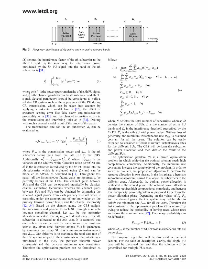
Vli denotes the interference factor of the ith subcarrier to the
lth PU band. By the same way, the interference powerintroduced by the lth PU signal into the band of the ithsubcarrier is [31]
J li =
∫dli+Df /2
dli−Df /2
|yli|2cl(e
jv) dv (2)
whereci(ejv) is the power spectrum density of the lth PU signal
and yli is the channel gain between the ith subcarrier and lth PU
signal. Several parameters should be considered to built areliable CR system such as the appearance of the PU duringCR transmission, which can be taken into account byapplying a risk-return model like in [26], the effect ofspectrum sensing error like false alarm and misdetectionprobability as in [32], and the channel estimation errors inthe transmission and interfering links as in [33]. Dealingwith such a general model is out of the range of this paper.
The transmission rate for the ith subcarrier, Ri can beevaluated as
Ri(Pi,m, hi,m) = Df log2 1 +Pi,m|hi,m|2
s2i
( )(3)
where Pi,m is the transmission power and hi,m is the ithsubcarrier fading gain from the mth SU to the CBS.
Additionally, s2i = s2
AWGN + SLl=1J l
i where s2AWGN is the
variance of the additive white Gaussian noise (AWGN) andJ l
i is the interference introduced by the lth PU band into theith subcarrier which is evaluated using (2) and can bemodelled as AWGN as described in [14]. Throughout thispaper, all the instantaneous fading gains are assumed to beperfectly known at the CBS. The channel gains betweenSUs and the CBS can be obtained practically by classicalchannel estimation techniques whereas the channel gainsbetween SUs and PUs can be obtained by estimating thereceived signal power from each primary terminal when ittransmits, under the assumptions of pre-knowledge on theprimary transmit power levels and the channel reciprocity[12, 34]. Based on the channel gains, the CBS assignsthe subcarriers and powers to each SU through a reliablelow-rate signalling channel. Let ai,m be the subcarrierallocation indicator, that is, ai,m ¼ 1 if and only if the ithsubcarrier is allocated to the mth user. It is assumed thateach subcarrier can be used for transmission to at most oneuser at any given time. Fairness among SUs is guaranteedby assuming that every SU has a minimum instantaneousrate Rmin. Our objective is to maximise the total data rate ofthe CR system subject to the constraints on the interferenceintroduced to the PUs, the per-user transmit powerconstraints and the per-user minimum rate constraints.Therefore the optimisation problem can be formulated as
follows
P1: maxPi,m ,ai,m
∑Mm=1
∑Ni=1
ai,mRi(Pi,m, hi,m)
s.t.∑M
m=1
∑Ni=1
ai,mPi,mVli,m ≤ I l
th, ∀l [ 1, . . . , L
∑Ni=1
ai,mPi,m ≤ Pm, ∀m
Pi,m ≥ 0, ∀i, m
ai,m [ 0, 1, ∀i, m∑Mm=1
ai,m ≤ 1, ∀i
∑Ni=1
ai,mRi(Pi,m, hi,m) ≥ Rmin, ∀m
(4)
where N denotes the total number of subcarriers whereas Mdenotes the number of SUs. L is the number of active PUbands and I l
th is the interference threshold prescribed by thelth PU. Pm is the mth SU total power budget. Without loss ofgenerality, the minimum instantaneous rate Rmin is assumedconstant for all the users. The solution can be easilyextended to consider different minimum instantaneous ratesfor the different SUs. The CBS will perform the subcarrierand power allocation and then diffuse the result to thedifferent SUs.
The optimisation problem P1 is a mixed optimisationproblem in which achieving the optimal solution needs highcomputational complexity. Additionally, the minimum rateconstraints increase the complexity of the problem. In order tosolve the problem, we propose an algorithm to perform theresource allocation in two phases. In the first phase, a heuristicsub-optimal algorithm is used to allocate the subcarriers to thedifferent users. Afterwards, the optimal power allocation isevaluated in the second phase. The optimal power allocationalgorithm requires high computational complexity and hence alow complexity power algorithm is proposed to perform thepower allocation phase. Depending on the values of I l
th, Pmand the channel gains, the CR system may not be able tosatisfy the minimum rate Rmin for all the users. Therefore thelast constraint in the optimisation problem P1 is relaxed bytrying to reduce the probability of having users whose ratesare below the minimum rate [22]. The outage probability canbe defined as
Poutage = PrMlow ≥ 1 (5)
where Mlow is the number of SUs whose instantaneous rate arebelow Rmin.
The proposed algorithm will be discussed in the nextsection. For the sake of description clarity, the single PUcase will be discussed first and then the solution will begeneralised for multiple PUs case.
Fig. 3 Frequency distribution of the active and non-active primary bands
2330 IET Commun., 2011, Vol. 5, Iss. 16, pp. 2328–2338
& The Institution of Engineering and Technology 2011 doi: 10.1049/iet-com.2010.1062
www.ietdl.org

3 Proposed algorithm (single PU case)
The optimal downlink subcarriers to users allocation scheme inmulticarrier systems is achieved by allocating each subcarrierto the user with the maximum SNR [15–18]. This scheme ofsubcarrier allocation is not efficient in uplink case because ofthe per-user power constraints. Moreover, the interferenceintroduced to the primary system by each SU should beconsidered in the CR context, which makes the schemesused in classical multicarrier systems not efficient. In thissection, a heuristic subcarrier and power allocation algorithmis presented. To better describe the proposed algorithm, onlyone PU band, that is, single interference constraint, will beconsidered in this section. The solution will be generalised inthe next section to consider multiple interference constraints.We will refer to the single interference constraint by I l∗
th , andhence the first constraint in the optimisation problem P1 canbe rewritten as follows
∑Mm=1
∑N
i=1
ai,mPi,mVl∗i,m ≤ I l∗
th (6)
where Vl∗i,m denotes the interference factor of the ith subcarrier
to the PU band (l∗) when the ith subcarrier is allocated to mthSU. In the sequel, the proposed subcarrier to user assignmentscheme with low outage probability is introduced and thenan efficient power allocation algorithm is presented.
3.1 Proposed subcarrier allocation algorithm withfairness consideration
To achieve an efficient subcarrier allocation, the proposedalgorithm should assign the subcarriers to the different SUsconsidering not only their channel quality and per-user powerconstraints but also the interference that will be induced to thePU band. Moreover, the probability of having users withinstantaneous rates below the minimum rate should be reduced.
The scheme assumes that the interference introduced to theprimary system, that is, I l∗
th , is divided uniformly among thedifferent subcarriers [14]. Accordingly, the maximumamount of interference, I l∗
Uniform, that can be introduced byany subcarrier is
I l∗Uniform = I l∗
th
N(7)
By using (1), the maximum power, PUnii,m , that can be allocated
to the ith subcarrier when it is allocated to the mth SU is
PUnii,m = I l∗
Uniform
Vl∗i,m
(8)
Let us define the following sets:
† C: the set of unassigned subcarriers.† U: the set that contains the indices of the users whose ratesare below Rmin.† Am: the set that includes the subcarriers already allocatedto the mth user with powers equal to the maximum powerPUni
i,m .† Bm: the set that includes the subcarriers already allocated tothe mth user with powers equal to the average power. Theaverage power means here that the remaining power for themth user after allocating the powers to the subcarriers in Am
is divided equally among the subcarriers in the set Bm, i.e.
Pavgm =
Pm − Sx[AmPUni
x,m
|Bm|
where |Bm| means the cardinality of the set Bm.According to the previous definition, the instantaneous rate
of the mth user, R(m, Am, Bm), is the summation of the ratesof the subcarriers in the sets Am and Bm and is given by
R(m, Am, Bm) =∑
i[Am
Ri(PUnim , hi,m) +
∑i[Bm
Ri(Pavgm , hi,m) (9)
where Ri(Pi,m, hi,m) is evaluated using (3). Note that theallocated powers according to either the maximum oraverage power are only used to simplify the calculation ofthe increment in the data rate. The optimal power allocationwill be derived later based on the subcarrier allocationinformation.
The algorithm begins by allocating the subcarriers that arelocated next to the PU band, that is, subcarriers that havemore interference to the PU, and moving towards the distantones. The subcarriers are allocated sequentially to the usersuntil all the subcarriers are assigned. In order to reduce theprobability of having users whose rates are below theminimum, the allocation of the subcarriers will be confinedwithin the users in the set U. Initially the set U is assumed tocontain all SUs. Throughout the allocation of the differentsubcarriers, if the rate of the mth user become more than theminimum required rate Rmin, the user will be removed fromthe set U. If the minimum rate constraints are satisfied for allthe users, that is, U is empty, the subcarrier can be allocatedto any one of the SUs. If the optimisation problem isassumed to be solved without any minimum rate constraints,the set U will assumed always empty and accordingly thesubcarrier can be allocated to any one of the SUs. Remarkthat the subcarriers with high interference gains will have alow transmitting power even that they have a good channelquality. Therefore the limitation that will be introduced toany subcarrier assignment due the interference constraintsshould be considered and the subcarriers should be classifiedaccording to their interference gains. To allocate a givensubcarrier, the algorithm initially assigns the subcarrier tothe set Bm and evaluates the new average power, PTest. Ifthe average power exceeds the maximum power, that is,PTest ≥ PUni
i,m , then the subcarrier should be moved to theset Am. Afterwards, the increments of the individual datarates because of the allocation of a particular subcarrierto different SUs are evaluated and the subcarrier is allocatedto the SU with maximum data rate increment. The schemeis repeated until the allocation of all subcarriers. Notethat the final set of allocated subcarriers to mth SU isN m = Am < Bm. By assuming initially that U =1, . . . , M, and both sets Am and Bm are empty sets, theassigning procedures of a particular subcarrier i∗ [ C are asfollows
1. ∀m [ U.
Evaluate PTest =Pm − Sr[Am
PUnir,m
|Bm| + 1if PTest ≥ PUni
i∗,mlet A∗
m = Am < i∗ and B∗m = Bm
IET Commun., 2011, Vol. 5, Iss. 16, pp. 2328–2338 2331doi: 10.1049/iet-com.2010.1062 & The Institution of Engineering and Technology 2011
www.ietdl.org
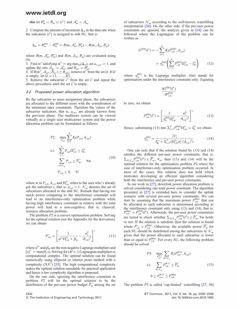
else let B∗m = Bm < i∗ and A∗
m = Am.
2. Compute the amount of increment Dm in the data rate whenthe subcarrier i∗ is assigned to mth SU, that is
Dm = Rnewm − Rold
m = R(m, A∗m, B∗
m) − R(m, Am, Bm)
where R(m, A∗m, B∗
m) and R(m, Am, Bm) are evaluated using(9).3. Find m∗ satisfying m∗ ¼ arg maxm(Dm), set ai∗,m∗ = 1, andupdate the sets Am∗ = A∗
m∗ and Bm∗ = B∗m∗ .
4. If R(m∗, Am∗ , Bm∗ ) ≥ Rmin, remove m∗ from the set U. If Uis empty, let U = 1, . . . , M.5. Remove the subcarrier i∗ from the set C and repeat theabove procedures until the set C is empty.
3.2 Proposed power allocation algorithm
By the subcarrier to users assignment phase, the subcarriersare allocated to the different users with the consideration ofthe minimum rates constraints. Therefore the values of thesubcarrier indicators, that is, ai,m, are already known fromthe previous phase. The multiuser system can be viewedvirtually as a single user multicarrier system and the powerallocation problem can be formulated as follows
P2: maxPi,m
∑N
i=1
Ri(Pi,m, hi,m)
s.t.∑N
i=1
Pi,mVl∗i,m ≤ I l∗
th
∑i[Nm
Pi,m ≤ Pm, ∀m
Pi,m ≥ 0, ∀i
(10)
where m in Pi,m, hi,m and Vl∗i,m refers to the user who’s already
got the subcarrier i, that is, ai,m ¼ 1. N m denotes the set ofsubcarriers allocated to the mth SU. Remark that having toomuch power comparing to the interference constraint willlead to an interference-only optimisation problem whilehaving high interference constraint in relative with the totalpower will lead to a non-cognitive, that is, classical,resource allocation problem.
The problem P2 is a convex optimisation problem. Solvingfor the optimal solution (see the Appendix for the derivation),we can obtain
P∗i,m = 1
al∗Vl∗i,m + bm
− s2i
|hi,m|2
[ ]+
(11)
whereal∗ andbm are the non-negative Lagrange multipliers and[x]+ ¼ max(0, x). Solving for (M + 1) Lagrangian multipliers iscomputational complex. The optimal solution can be foundnumerically using ellipsoid or interior point method with acomplexity O(N 3) [35]. The high computational complexitymakes the optimal solution unsuitable for practical applicationand hence a low complexity algorithm is proposed.
On the one side, ignoring the interference constraint inproblem P2 will let the optimal solution to be thedistribution of the per-user power budget Pm among the set
of subcarriers N m according to the well-known waterfillinginterpretation [36]. On the other side, if the per-user powerconstraints are ignored, the analysis given in [14] can befollowed where the Lagrangian of the problem can bewritten as
G(Int)(l∗) = −∑N
i=1
Ri(P(Int)i,m , hi,m)
+ g(Int)l∗
∑N
i=1
P(Int)i,m V
l∗i,m − I l∗
th
( )(12)
where g(Int)l∗ is the Lagrange multiplier. (Int) stands for
optimisation under the interference constraint only. Equating
∂G(Int)(l∗)
∂P(Int)i,m
to zero, we obtain
P(Int)i,m (l∗) = 1
g(Int)l∗ Vl∗
i,m
− s2i
|hi,m|2
[ ]+
(13)
Hence, substituting (13) into SNi=1P(Int)
i,m Vl∗i,m = I l∗
th we obtain
g(Int)l∗ = |N |
I l∗th + S
Ni=1(Vl∗
i,ms2i /|hi,m|2)
(14)
One can note that if the solution found by (13) and (14)satisfies the different per-user power constraints, that is,
Si[NmP(Int)
i,m (l∗) ≤ Pm, ∀m, then (13) and (14) will be theoptimal solution for the optimisation problem P2 where thecase of interference-only optimisation problem occurred. Inmost of the cases, this relation does not hold whichmotivates developing an efficient algorithm consideringboth the interference and per-user power constraints.
In our work in [27], downlink power allocation problem issolved considering one total power constraint. The algorithmpresented in [27] is extended here to consider the uplinkscenario with several per-user power constraints. We canstart by assuming that the maximum power PMax
i,m that canbe allocated to each subcarrier is determined according tothe interference constraint only using (13) and (14), that is,PMax
i,m = P(Int)i,m (l∗). Afterwards, the per-user power constraints
are tested to check whether Si[NmP(Int)
i,m (l∗) ≤ Pm, ∀m holdsor not. If the relation is satisfied, then the solution is foundwhere P∗
i,m = PMaxi,m . Otherwise, the available power Pm for
each SU should be distributed among the subcarriers in N mgiven that the power allocated to each subcarrier is lowerthan or equal to PMax
i,m . For every SU, the following problemshould be solved
P3: maxPW.F
i,m
∑i[Nm
Ri(PW.Fi,m , hi,m)
s.t.∑
i[Nm
PW.Fi,m ≤ Pm
0 ≤ PW.Fi,m ≤ PMax
i,m
(15)
The problem P3 is called ‘cap-limited’ waterfilling [37, 38]
2332 IET Commun., 2011, Vol. 5, Iss. 16, pp. 2328–2338
& The Institution of Engineering and Technology 2011 doi: 10.1049/iet-com.2010.1062
www.ietdl.org

where PW.Fi,m is cap-limited waterfilling allocated power. The
problem is solved efficiently using the concept of theconventional waterfilling and can be explained as follows:given the initial waterfilling solution, the channels thatviolate the maximum power PMax
i,m are determined and upper
bounded with PMaxi,m . The total power budget of the user is
reduced by subtracting the power assigned so far. At thenext step, the algorithm proceeds to successive waterfillingover the subcarriers that did not violate the maximumpower PMax
i,m in the last step. This procedures is repeated
until the allocated power PW.Fi,m does not violate the
maximum power PMaxi,m in any of the subcarriers in the new
iteration. Low computational complexity implementation ofthe ‘cap-limited’ waterfilling can be found in [38]. Since itis assumed that PW.F
i,m ≤ PMaxi,m , some of the powers allocated
to subcarriers will not reach the maximum allowable valueswhich will make the interference introduced to the primarysystem below the threshold I l∗
th . In order to take theadvantage of the allowable interference, some power can betaken from one subcarrier and given to another hoping toincrease the total system capacity. Therefore the values ofthe maximum power that can be allocated to each subcarrierPMax
i,m should be updated depending on the remaininginterference. The residual interference can be determined asfollows
I l∗Residual = I l∗
th −∑N
i=1
PW.Fi,m Vl∗
i,m (16)
Assuming that Sm , N m is the set of the subcarriers thatreach its maximum, that is, PW.F
i,m = PMaxi,m , ∀i [ Sm, then
PMaxi,m , ∀i [ Sm can be updated by applying (13) and (14) on
the subcarriers in the set S = S1 < S2 · · · < Sm with the
following interference constraint
I l∗updated = I l∗
Residual +∑i[S
PW.Fi,m Vl∗
i,m (17)
After determining the updated values of PMaxi,m , the ‘cap-
limited’ waterfilling is performed again for every SU to findthe final solution P∗
i,m = PW.Fi,m . A graphical description of the
proposed power allocation algorithm is given in Fig. 4.
4 Generalisation of the proposed algorithm(multiple PU case)
In this section, the algorithm presented in the previous sectionto solve the optimisation problem P1 considering only oneinterference constraint will be generalised to consider Linterference constraints, that is, multiple PU bands.
For the subcarrier allocation phase, considering the sameassumption in which every subcarrier is able to introducethe same amount of interference to the the different PUbands, the value of the maximum power that can beallocated to each subcarrier, that is, PUni
i,m , is determined bychoosing the minimum among the different maximumpowers evaluated according to the different interferenceconstraints. Therefore (8) can be generalised as follows
PUnii,m = min
I1Uniform
V1i,m
,I2Uniform
V2i,m
, . . . ,ILUniform
VLi,m
(18)
Once the maximum power PUnii,m is determined, the same
subcarrier assigning procedures presented previously can beused for the multiple PU bands case.
In the power allocation phase, if multiple interferenceconstraints are considered in the optimisation problem P2,
Fig. 4 Example of the SUs allocated power using the proposed power allocation algorithm
IET Commun., 2011, Vol. 5, Iss. 16, pp. 2328–2338 2333doi: 10.1049/iet-com.2010.1062 & The Institution of Engineering and Technology 2011
www.ietdl.org

the solution given in (11) can be generalised as follows
P∗i,m = 1
SLl=1a
lVli,m + bm
− s2i
|hi,m|2
[ ]+
(19)
where al and bm are the non-negative Lagrange multipliers.Therefore the problem become more computationallycomplex where (M + L) Lagrangian multipliers should bedetermined. To find a suboptimal solution for the multiplePUs case, the values of the allocated power P(Int)
i,m (l) underevery interference constraint I l
th are determined using (13)and (14). Then, the maximum power PMax
i,m that can beallocated to each subcarrier is determined according to thefollowing formula
PMaxi,m = minP(Int)
i,m (1), P(Int)i,m (s), . . . , P(Int)
i,m (L) (20)
Afterwards, the per-user power constraints are tested and the‘cap-limited’ waterfilling is applied for every user m. Using(16) and (17), the updated values of the interferencethresholds can be found and then (13) and (14) are appliedto find the values of P(Int)
i,m (l) ∀i [ S. Accordingly, the newvalues of PMax
i,m can be determined using (20). The ‘cap-limited’ waterfilling is performed again for every SUconsidering the updated maximum values to find the finalsolution. The implementation procedures of the powerallocation algorithm with multiple interference constraintsare described in Fig. 5. Step 1 in Fig. 5 initialises thevariables values whereas Step 2 finds the optimal powerallocation under the interference only constraint for everyPU where the powers are evaluated using a waterfilling-likesolution. Afterwards, the maximum power that can beallocated to every subcarrier is determined in Step 3. Step 4
checks whether the user power constraints are violated ornot. If they are violated, the ‘cap-limited’ waterfilling isperformed in Step 5 to distribute the user power among thesubcarriers that were allocated to this user in the subcarriersallocation phase, that is, N m. The subcarriers whichreached the maximum allowable power are determined forevery user and the maximum power that can be allocated tothese subcarriers are updated in Step 6. The last stepperforms the ‘cap-limited’ waterfilling over the subcarriersunder the updated maximum power constraints to find thefinal power allocation vector.
5 Complexity analysis and simulations
Theexhaustiveenumerationschemeneedsto iterateMN times toexhaust all the cases, and its complexity of O(N3MN ) is veryhard to afford. The algorithm proposed in [28] has acomplexity of O(NM ) with the assumption of sorted channelgains matrices. Therefore including the sorting complexityof the different matrices as well as the iterative natureof the algorithm, the complexity will be more thanO(N log N ) +O(NM ). Moreover, the algorithm proposed byWang et al. in [29] has a complexity larger than O(N2M ) andlower than O(N 3M ). Note that the algorithms presented in[28, 29] are not considering fairness among users and aredealing with interference temperature constraint as severalper-subcarrier maximum power constraints.
Recall that our proposed algorithm to solve problem P1 isdivided into two phases: the subcarriers to users allocationphase and the power allocation phase. Each subcarrier inthe first phase requires no more than M function evaluationsto be assigned to one user depending on the size of the setU. Hence, the computational complexity of the proposedsubcarrier to user allocation algorithm is lower than orequal O(NM ). In the power allocation algorithm, Step 2 in
Fig. 5 Power allocation algorithm
2334 IET Commun., 2011, Vol. 5, Iss. 16, pp. 2328–2338
& The Institution of Engineering and Technology 2011 doi: 10.1049/iet-com.2010.1062
www.ietdl.org

Fig. 5 has a computational complexity of O(N log N ) whereasSteps 5 and 7 of the algorithm execute the ‘cap-limited’waterfilling for every SU with a complexity ofS
Mm=1O(N m) ≤ O(N ) ≤ O(N log N ) [38]. Step 6 has a
complexity of O(|S| log |S|) ≤ O(N log N ). Hence, thecomplexity of the power allocation algorithm is lower thanO(N log N ). Thus, the overall asymptotic complexity of theproposed uplink resource allocation algorithm is lower thanO(N log N ) +O(NM ). Table 1 summarises the complexityof the different algorithms.
The simulations are performed under the scenario givenin Fig. 2. The values of Ts, Df and s2
i are assumed to be4 ms, 0.3125 MHz and 1026, respectively. For simplicity, thechannel gains h and g are outcomes of independent Rayleighdistributed random variables with mean equal to 1. Twointerference constraints belonging to two active PU bands,that is, L ¼ 2, are assumed with B1 ¼ B2 and I1
th = I2th (see
Fig. 3). Perfect synchronisation is assumed between SUs. Allthe results have been averaged over 1000 iterations. For thepurpose of performance comparison, the followingalgorithms are considered:
1. Optimal: The subcarriers are allocated by exhaustiveenumeration whereas the power is allocated using (11). Theoptimal capacity is found without considering the minimumrate requirements.2. Wang: The method proposed in [29] is used. Theinterference constraint is converted into per-subcarrierpower constraints using (18).3. Fadel: The method proposed in [28] is used. The per SUmaximum power constraint is generated by converting theinterference constraint into per-subcarrier power constraintsusing (18).4. Classical + Pr: The subcarriers are allocated according tothe scheme used in non-cognitive OFDM systems [21],whereas the power is allocated using (11).
Fig. 6 plots the average capacity of a CR system with M ¼ 3SUs against the interference thresholds when the number ofsubcarriers is N ¼ 8, the per-user power budget Pm = 1m Wand B1 ¼ B2 ¼ 1.25 MHz. The proposed algorithm withoutfairness achieves a good performance in comparison withoptimal and outperforms the other algorithms. When theminimum user’s rate constraint of 4 Mbits/s is applied, thatis, Rmin ¼ 16 bits per OFDM symbol, the proposedalgorithm with fairness still performs well where the outageprobability of having users below Rmin is reduced asdescribed in Fig. 7. For the rest of the results, the CR systemis assumed to have M ¼ 10 SUs and N ¼ 128 subcarriers.The per-user power budget is set to be Pm = 1m W. Theactive PU bands bandwidths are assumed to beB1 ¼ B2 ¼ 10 MHz. The minimum rate for each user is setto be 20 Mbits/s, that is, Rmin ¼ 80 bits per OFDM symbol.To that end, the optimal solution will not be simulated
because of its extremely high computational complexitywhen the numbers of subcarriers and users are increased.
Fig. 8 plots the average capacity against the interferencethresholds with I1
th = I2th. It can be observed that as the
interference thresholds increase, the average sum rateincreases since each SU is allowed to have more flexibilityin allocating more power on its subcarriers. Remark thatthe algorithms Wang, Fadel and Classical + Pr are notconsidering any fairness among users. The performance ofthe proposed algorithm without considering the fairnessamong the users outperforms the reference algorithms.Moreover, it is worth noting that the performance of theproposed algorithm without fairness is considered as anupper bound for the case when fairness is taken into account.From this fact, numerical results reveal that the proposedalgorithm with fairness consideration achieves a very goodperformance. Fig. 9 plots the outage probability of thedifferent algorithms. The outage probability of the proposed
Table 1 Complexity comparison
Algorithm Complexity
Optimal O(N3MN )
Wang [29] [ [O(N2M), O(N3M)]
Fadel [28] O(N log N) +O(NM)
Proposed O(N log N) +O(NM)
Classical + Pr O(N log N) +O(NM)
Fig. 6 Three SUs achieved capacity against interference thresholdwhen N ¼ 8 subcarriers, Pm = 1 mW , B1 ¼ B2 ¼ 1.25 MHz andRmin ¼ 4 Mbits/s
Fig. 7 Outage probability against allowed interference thresholdswhen N ¼ 8 subcarriers, Pm = 1 mW , B1 ¼ B2 ¼ 1.25 MHz andRmin ¼ 4 Mbits/s
IET Commun., 2011, Vol. 5, Iss. 16, pp. 2328–2338 2335doi: 10.1049/iet-com.2010.1062 & The Institution of Engineering and Technology 2011
www.ietdl.org

algorithm with fairness is much lower than that of the referencealgorithms. Moreover, the outage probability decreases withthe increase of the interference constraints because thedifferent algorithms become more able to fulfill theminimum instantaneous rate for the different users.
Fig. 10 shows the average capacity against the number of SUswhen the interference thresholds are 220 and 230 dBm. Thecapacity increases with the number of users because of themultiuser diversity. The lower the number of SUs, the smallerthe difference between the proposed and Classical + Pralgorithm. This is because the number of subcarriers that willbe allocated to each user will increase, which reduces theamount of power that will be allocated to each subcarrier andconsequently the amount of interference imposed to theprimary system. This makes the CR system to act relatively asa non-cognitive system. The gap between the differentalgorithms decreases with the interference thresholds as theCR system becomes closer to the classical (non-cognitive)
system. Fig. 11 shows the average capacity against per-userpower constraint, Pm, when the interference thresholds are220 and 230d Bm. The proposed algorithm outperformsthe reference algorithms and the capacity of the CR systemincreases as the per-user power budget increases up to certaintotal power value. After this value, the capacity remainsconstant regardless of the increase of the per-user powerbecause the system reaches the maximum power that can beused with the given interference threshold. Remark that whenthe available SUs power is too low and unable to cause thepre-defined interference constraint, the CR system acts as anon-cognitive one where the proposed algorithm performsvery close to the Classical + Pr algorithm. Fig. 12 plots anexample of the instantaneous data rate for a given user overtime for the proposed algorithm with and without fairnessconsideration when I1
th = I2th = −20 dBm. It can be noted that
the proposed algorithm with fairness keeps the instantaneousrate above Rmin ¼ 80 bits/symbol.
Fig. 8 Achieved capacity against allowed interference thresholdswhen N ¼ 128 subcarriers, M ¼ 8 SUs, Pm = 1 mW ,B1 ¼ B2 ¼ 10 MHz and Rmin ¼ 20 Mbits/s
Fig. 9 Outage probability against allowed interference thresholdswhen N ¼ 128 subcarriers, M ¼ 8 SUs, Pm = 1 mW ,B1 ¼ B2 ¼ 10 MHz and Rmin ¼ 20 Mbits/s
Fig. 10 Achieved capacity against no. of SUs when N ¼ 128subcarriers, Pm = 1 mW , B1 ¼ B2 ¼ 10 MHz andRmin ¼ 20 Mbits/s
Fig. 11 Achieved capacity against per-user power Pm = 1 mWwhen N ¼ 128 subcarriers, M ¼ 8 SUs, B1 ¼ B2 ¼ 10 MHz andRmin ¼ 20 Mbits/s
2336 IET Commun., 2011, Vol. 5, Iss. 16, pp. 2328–2338
& The Institution of Engineering and Technology 2011 doi: 10.1049/iet-com.2010.1062
www.ietdl.org

6 Conclusion
In this paper, we propose an efficient resource allocationalgorithm for uplink in multicarrier-based CR networks withfairness consideration. The allocation process is separated intotwo phases. In the first phase, the subcarriers are allocatedto the users according to their channel quality as well as theinterference that they may introduce to the primary system. Inthe second phase, the per-user power budget is distributedamong the subcarriers so that the total system capacity ismaximised without causing excessive interference to theprimary system. The fairness among users is consideredwithin the subcarrier allocation by reducing the probability ofhaving users whose instantaneous rates are below a givenminimum rate. Without applying the fairness constraints, theproposed algorithm can achieve lower computationalcomplexity along with better performance relative to thereference algorithms in which the fairness among users are notconsidered. The proposed algorithm achieves superior outageperformance when the fairness among users is considered.Developing a distributed resource allocation algorithm will bethe guideline of our future research.
7 Acknowledgment
This work was partially supported by the European ICT-2009.1.1 project ACROPOLIS, COST Action IC0902 andNational project Sofocles with code TEC 2010-21100. Part ofthis work was presented in the 5th International Conferenceon Cognitive Radio Oriented Wireless Networks andCommunications (CrownCom 2010).
8 References
1 National Telecommunications and Information Administration (NTIA):‘FCC frequency allocation chart’. Available at www.ntia.doc.gov/osmhome/allochrt.pdf, 2003
2 Federal Communication Commission: ‘Spectrum policy task force’.Report of ET Docket 02-135, November 2002
3 Akyildiz, I., Won-Yeol, L., Vuran, M., Mohanty, S.: ‘NeXt generation/dynamic spectrum access/cognitive radio wireless networks: a survey’,Comput. Netw., 2006, 50, (13), pp. 2127–2159
4 Mitola, J.: ‘Cognitive radio for flexible mobile multimediacommunications’. IEEE Int. Workshop on Mobile MultimediaCommunications, MoMuC’99, November 1999, pp. 3–10
5 Haykin, S.: ‘Cognitive radio: brain-empowered wireless communications’,IEEE J. Sel. Areas Commun., 2005, 23, (2), pp. 201–220
6 Yucek, T., Arslan, H.: ‘A survey of spectrum sensing algorithms forcognitive radio applications’, IEEE Commun. Surv. Tutor., 2009, 11,(1), pp. 116–130 (first quarter 2009)
7 Zeng, Y., Liang, Y.-C., Hoang, A.T., Zhang, R.: ‘A review on spectrumsensing for cognitive radio: Challenges and solutions’, EURASIP J. Adv.Signal Process., 2010, 2010, 15pp, article id 381465
8 Musavian, L., Aissa, S.: ‘Capacity and power allocation for spectrum-sharing communications in fading channels’, IEEE Trans. Wirel.Commun., 2009, 8, (1), pp. 148–156
9 Kang, X., Liang, Y.-C., Nallanathan, A., Garg, H., Zhang, R.: ‘Optimalpower allocation for fading channels in cognitive radio networks:ergodic capacity and outage capacity’, IEEE Trans. Wirel. Commun.,2009, 8, (2), pp. 940–950
10 Zhang, R.: ‘On peak versus average interference power constraints forprotecting primary users in cognitive radio networks’, IEEE Trans.Wirel. Commun., 2009, 8, (4), pp. 2112–2120
11 Zhang, R., Liang, Y.-C.: ‘Exploiting multi-antennas for opportunisticspectrum sharing in cognitive radio networks’, IEEE J. Sel. TopicsSignal Process., 2008, 2, (1), pp. 88–102
12 Zhang, R., Cui, S., Liang, Y.-C.: ‘On ergodic sum capacity of fadingcognitive multiple-access and broadcast channels’, IEEE Trans.Inform. Theory, 2009, 55, (11), pp. 5161–5178
13 Weiss, T., Jondral, F.K.: ‘Spectrum pooling: an innovative strategy forthe enhancement of spectrum efficiency’, IEEE Commun. Mag., 2004,42, pp. S8–S14
14 Bansal, G., Hossain, M.J., Bhargava, V.K.: ‘Optimal and suboptimalpower allocation schemes for OFDM-based cognitive radio systems’,IEEE Trans. Wirel. Commun., 2008, 7, (11), pp. 4710–4718
15 Jang, J., Lee, K.: ‘Transmit power adaptation for multiuser OFDMsystems’, IEEE J. Sel. Areas Commun., 2003, 21, (2), pp. 171–178
16 Kivanc, D., Li, G., Liu, H.: ‘Computationally efficient bandwidthallocation and power control for OFDMA’, IEEE Trans. Wirel.Commun., 2003, 2, (6), pp. 1150–1158
17 Shen, Z., Andrews, J., Evans, B.: ‘Optimal power allocation in multiuserOFDM systems’. IEEE Global Telecommunications Conf.,(GLOBECOM’03), 2003, vol. 1
18 Wong, C., Cheng, R., Lataief, K., Murch, R.: ‘Multiuser OFDM withadaptive subcarrier, bit, and power allocation’, IEEE J. Sel. AreasCommun., 1999, 17, (10), pp. 1747–1758
19 Yu, W., Rhee, W., Boyd, S., Cioffi, J.: ‘Iterative water-filling forgaussian vector multiple-access channels’, IEEE Trans. Inf. Theory,2004, 50, (1), pp. 145–152
20 Munz, G., Pfletschinger, S., Speidel, J.: ‘An efficient waterfilling algorithmfor multiple access OFDM’. IEEE Global Telecommunications Conf.,(GLOBECOM’02), November 2002, vol. 1, pp. 681–685
21 Kim, K., Han, Y., Kim, S.-L.: ‘Joint subcarrier and power allocation inuplink OFDMA systems’, IEEE Commun. Lett., 2005, 9, (6),pp. 526–528
22 Gao, L., Cui, S.: ‘Efficient subcarrier, power, and rate allocation withfairness consideration for OFDMA uplink’, IEEE Trans. Wirel.Commun., 2008, 7, (5), pp. 1507–1511
23 Wang, P., Zhao, M., Xiao, L., Zhou, S., Wang, J.: ‘Power allocation inOFDM-Based cognitive radio systems’. IEEE Global Tele-communications Conf., (GLOBECOM’07), 2007, pp. 4061–4065
24 Bansal, G., Hossain, M.J., Bhargava, V.K.: ‘Adaptive power loading forOFDM-Based cognitive radio systems’. IEEE Int. Conf. onCommunication, (ICC’07), 2007, pp. 5137–5142
25 Zhang, Y., Leung, C.: ‘Resource allocation in an OFDM-based cognitiveradio system’, IEEE Trans. Commun., 2009, 57, (7), pp. 1928–1931
26 Hasan, Z., Bansal, G., Hossain, E., Bhargava, V.: ‘Energy-efficientpower allocation in OFDM-based cognitive radio systems: a risk-return model’, IEEE Trans. Wirel. Commun., 2009, 8, (12),pp. 6078–6088
27 Shaat, M., Bader, F.: ‘Computationally efficient power allocationalgorithm in multicarrier-based cognitive radio networks: OFDM andFBMC systems’, EURASIP J. Adv. Signal Process., 2010, 2010,13pp, article id 528378
28 Digham, F.: ‘Joint power and channel allocation for cognitive radios’.IEEE Wireless Communications and Networking Conf., WCNC’08,April 2008, pp. 882–887
29 Wang, W., Wang, W., Lu, Q., Peng, T.: ‘An uplink resource allocationscheme for OFDMA-based cognitive radio networks’, Int. J. Commun.Syst., 2009, 22, (5), pp. 603–623
30 Zhang, H., Ruyet, D.L., Roviras, D., Medjahdi, Y., Sun, H.: ‘Spectralefficiency comparison of OFDM/FBMC for uplink cognitive radionetworks’, EURASIP J. Adv. Signal Process., 2010, 2010, 14pp,article id 621808
Fig. 12 Instantaneous rates over time when N ¼ 128 subcarriers,M ¼ 8 SUs, Pm = 1 mW , B1 ¼ B2 ¼ 10 MHz, Ith
1 ¼ Ith2 ¼ 220 dBm
and Rmin ¼ 20 Mbits/s (80 bits per OFDM symbol)
IET Commun., 2011, Vol. 5, Iss. 16, pp. 2328–2338 2337doi: 10.1049/iet-com.2010.1062 & The Institution of Engineering and Technology 2011
www.ietdl.org

31 Weiss, T., Hillenbrand, J.: ‘Mutual interference in OFDM-basedspectrum pooling systems’. Vehicular Technology Conf., (VTC’04-Spring), May 2004, vol. 4
32 Almalfouh, S.M., Stuber, G.L.: ‘Interference-aware power allocation incognitive radio networks with imperfect spectrum sensing’. IEEE Int.Conf. on Communications (ICC), May 2010, pp. 1–6
33 Tao Qin, C.M., Leung, C., Shen, Z.: ‘Resource allocation in a cognitiveradio system with imperfect channel state estimation’, J. Electr. Comput.Eng., 2010, 2010, 5pp, article id 419430
34 Zhang, R.: ‘Optimal power control over fading cognitive radio channelby exploiting primary user CSI’. IEEE Global TelecommunicationsConf., (IEEE GLOBECOM’08), Dec. 2008, pp. 1–5
35 Boyd, S., Vandenberghe, L.: ‘Convex optimization’ (CambridgeUniversity Press, Cambridge, UK, 2004)
36 Leke, A., Cioffi, J.: ‘A maximum rate loading algorithm for discretemultitone modulation systems’. IEEE Global TelecommunicationsConf., (GLOBECOM’97), 1997, vol. 3, pp. 1514–1518
37 Papandreou, N., Antonakopoulos, T.: ‘Bit and power allocation inconstrained multicarrier systems: the single-user case’, EURASIPJ. Adv. Signal Process., 2008, 2008, 4pp, article id 643081
38 Zhao, C., Kwak, K.: ‘Power/bit loading in OFDM-based cognitivenetworks with comprehensive interference considerations: the single-SU case’, IEEE Trans. Veh. Technol., 2010, 59, (4), pp. 1910–1922
9 Appendix
9.1 Derivation of the optimal power allocationgiven by (11) and (19)
We want to find the optimal solution for the followingoptimisation problem
maxPi,m
∑N
i=1
log2 1 +Pi,m|hi,m|2
s2i
( )(21)
s.t.∑N
i=1
Pi,mVli,m ≤ I l
th, ∀l [ 1, . . . , L (22)
∑i[Nm
Pi,m ≤ Pm, ∀m (23)
Pi,m ≥ 0, ∀i (24)
The problem above is a convex optimisation problem.Introducing the lagrange multipliers al, mi and bm for theinequality constraints in (22), (23) and (24), respectively,the Lagrangian can be written as
G = −∑N
i=1
Ri(Pi,m, hi,m) +∑L
l=1
al∑N
i=1
Pi,mVli,m − I l
th
( )
+∑Mm=1
bm
∑i[Nm
Pi,m − Pm
⎛⎝
⎞⎠−
∑N
i=1
Pi,mmi (25)
The Karush–Kuhn–Tucker conditions can be written asfollows
al ≥ 0, ∀l [ 1, 2, . . . , L; bm ≥ 0, ∀m [ 1, 2, . . . , M
mi ≥ 0 ∀i [ 1, 2, . . . , N; P∗i,m ≥ 0
al∑N
i=1
P∗i,mV
li,m − I l
th
( )= 0
bm
∑i[Nm
P∗i,m −Pm
⎛⎝
⎞⎠= 0, ∀m [ 1, 2, . . . , M
miP∗i = 0, ∀i [ 1, 2, . . . , N
∑N
i=1
Pi,mVli,m − I l
th ≤ 0
∑i[Nm
Pi,m −Pm ≤ 0, ∀m [ 1, 2, . . . , M
∂G
∂P∗i,m
= −1
(s2i /|hi,m|2)+P∗
i,m
+∑L
l=1
alVli,m +bm −mi = 0
(26)
Rearranging the last condition in (26) we obtain
P∗i,m = 1
SLl=1a
lVli,m +bm −mi
− s2i
|hi,m|2(27)
Since P∗i,m ≥ 0, we obtain
s2i
|hi,m|2≤ 1
SLl=1a
lVli,m +bm −mi
(28)
If
s2i
|hi,m|2,
1
SLl=1a
lVli,m +bm
then mi ¼ 0 and hence
P∗i,m = 1
SLl=1a
lVli,m +bm
− s2i
|hi,m|2(29)
Moreover, if
s2i
|hi,m|2.
1
SLl=1a
lVli,m +bm
from (27) we obtain
1
SLl=1a
lVli,m +bm −mi
≥ s2i
|hi,m|2.
1
SLl=1a
lVli,m +bm
(30)
and since miP∗i,m = 0 mi ≥ 0, we obtain that P∗
i,m = 0.Therefore the optimal solution can be written as follows
P∗i,m = 1
SLl=1a
lVli,m + bm
− s2i
|hi,m|2
[ ]+
(31)
where [x]+ ¼ max(0, x). If only one PU is assumed withinterference constraint I l∗
th , (31) is reduced to
P∗i,m = 1
al∗Vl∗i,m + bm
− s2i
|hi,m|2
[ ]+
(32)
2338 IET Commun., 2011, Vol. 5, Iss. 16, pp. 2328–2338
& The Institution of Engineering and Technology 2011 doi: 10.1049/iet-com.2010.1062
www.ietdl.org


3.1.2 Resource allocation in CR using relay communicationAs a continuation to the above research and cited works in CR environment, the relying mode was introduced toanalyze the behavior and achieved performance of the previously developed algorithms.
Combining cognitive radio (CR) with cooperative communications can further improve the spectrum utilizationand enhance the network performance. Different relays in the network can collaborate in the spectrum sensing andassist the network transmission [41]. An overview of the cooperative communication in cognitive scenario has beenpresented in [42, 43]. The relay assisted transmission can be categorized into two basic strategies; amplify andforward (AF) and decode and forward (DF). In the AF strategy, the relay amplifies the received signal and thenforwards it to the destination. On the other hand, in DF scheme, the relay decodes the received massage before theretransmission. In multi-carrier based relay networks, in addition to the power and subcarrier allocation requiredin non-cooperative networks, proper relay selection and subcarrier coupling in the different hops are required toimprove the system performance.As it’s well known, the communications in CR environment should not disturb the operation of the primary systemor negatively altering its performance and hence, the different resources should be distributed adequately so thatthe interference introduced to the primary system is not harmful (see Fig.3.13).
Joint Resource Optimization in Decode and ForwardMulti-Relay Cognitive Network With Direct Link
Musbah Shaat and Faouzi BaderCentre Tecnologic de Telecomunicacions de Catalunya (CTTC), Castelldefels-Barcelona, Spain
Email:musbah.shaat,[email protected]
Abstract—An OFDM based cognitive radio (CR) network isconsidered in this paper. The goal is to maximize the totalsum rate of the CR system while ensuring that no excessiveinterference is induced to the primary system.The optimal schemeadopts the dual decomposition technique and in order to reducethe computational complexity of the optimal scheme, a greedysuboptimal algorithm is proposed. Selected numerical resultsis discussed to reveal the near-optimal performance of thesuboptimal scheme and the superiority of the proposed algorithmover the random and the signal-to-noise ratio (SNR) basedschemes.Index Terms- Cooperative cognitive radio system; Decode-and-
Forward; Joint resource allocation; OFDM; Resource manage-ment; Throughput.
I. INTRODUCTION
The continuous increase in the growth of the wirelesssystems reveals the importance of the effective usage of theradio resources. Recent measurements showed that the existingspectrum policies have lead to the spectrum underutilizationproblem. Accordingly, cognitive radio (CR) has been proposedto increase the spectrum utilization by allowing a group ofsecondary users (SUs) to access and share the radio spectrumwith the licensed primary users (PUs). To further improve thespectrum usage and enhance the CR performance, cooperativecommunications could be used so that the different relayscollaborate to detect the open spectrum and assist the networktransmission. Multicarrier communications has been suggestedas a candidate for the CR systems.The operation of the CR networks should not negatively
affect the performance of the primary system. Therefore,careful design of the resource allocation algorithm is requiredto deal with the interference control and to guarantee efficientshare of the radio spectrum. Jia et al. proposed in [1] acentralized heuristic algorithm to select the most profitable pairof nodes and to allocate the different channels based on theavailability of the spectrum. The interference to the primarysystem was not considered. In [2], the primary system isprotected by adjusting the maximum transmission power of therelay in the CR network to a limit by which the CR does notinduce harmful interference to the licensed system. In [3], theauthors proposed an algorithm to select the best transmit waybetween the network nodes based on the spectrum availabilityand maximum power levels that limit the transmission. Threedifferent transmission forms between the network nodes areconsidered : direct, dual or diversity transmission.
CRDestination
1R
2R
MR
CRSource
1st time-slot 2nd time-slot
Licensed Primary System
TransmissionInterference
CR Relay
Group of subcarriers selected for direct
transmission
Fig. 1. Relayed cognitive radio network.
This paper tackles the resource allocation problem inOFDM-based CR systems with multiple relays. The targetis to jointly optimize the different radio resources in orderto achieve the maximum CR sum rate under the per-relaypower and per-time slot interference constraints. The optimalsolution is derived by using the dual decomposition techniquewith the limit of having sufficient number of subcarriers. Todecrease the computational complexity of the optimal scheme,an efficient suboptimal algorithm is proposed. The suboptimalalgorithm has a near-optimal performance with a significantreduction in the computational complexity.The rest of this paper is organized as follows. Section II
describes the system model. The problem is formulated andthe optimal solution is presented in Section III. The suboptimalscheme is proposed in Section IV. Selected numerical resultsare discussed in Section V. Finally, Section VI summarizesthe paper.
II. SYSTEM MODELIn this paper, an OFDM-based cooperative CR system is
considered. As shown in Fig. 1, the coexistence between theCR system and the primary system in the same transmissionarea is assumed. The source can transmit to the destinationthrough the direct link. If the direct link is blocked due tothe existence of an obstacle in some frequencies or if thedirect channel has a poor quality, the source will communicatewith the destination through M relays. The CR frequency
2012 IEEE Wireless Communications and Networking Conference: MAC and Cross-Layer Design
978-1-4673-0437-5/12/$31.00 ©2012 IEEE 1398
Figure 3.13: Relayed cognitive radio network.
My main analyzed work is that of Jia et al. that proposed in [44] a centralized heuristic algorithm to selectthe most profitable pair of nodes and to allocate the different channels based on the availability of the spectrum.However, the interference to the primary system was not considered. In [45], a power allocation algorithm in asingle relay DF orthogonal frequency division multiplexing (OFDM) based CR system has been proposed. Underthe assumption of prior perfect subcarrier matching in the two hops, the authors treated the optimization problemin the source and the relay individually. The algorithm performance degrades significantly if the relay has to for-ward the receiving message on the same subcarrier, i.e. there is no subcarrier pairing. Same can be found in theresearches developed in [46] to deal with the bit loading problem in relay.Liying et al. presented in [47] a joint relay selection and power allocation algorithm where the cognitive relaysystem is prevented from inducing severe interference to the primary system by limiting its maximum transmissionpower. In [48], the authors proposed an algorithm to select the best transmit way between the network nodes. Thealgorithm can select direct, dual or diversity transmission based on the available spectrum as well as the maximumallowable transmission powers. The systems in [47] and [48] are considering single carrier channels. The resourceallocation with the consideration of the interference constraint in OFDM based multi-relay CR has not been inves-tigated in the previously cited works.
83

Thus, the resource allocation problem in a dual-hop multi-relay DF multi-carrier based CR system has beenconsidered in my conducted researches. The different system resources, i.e. powers, subcarriers and relays, areoptimized jointly in order to maximize the system capacity. The resource allocation process is performed under theper-node power constraint as well as the interference to the primary system constraint. These research works havebeen realized in Musbah Shaat PhD. thesis, and under the framework of the EC funded projects the COST ActionIC0902, the network of excellence (NoE) ICT project ACROPOLIS, and the Spanish national project SOFOCLES(more details in Subsection 1.5.3, page 24). An extension to the conducted works with M. Shaat is that developedin close collaboration with KAUST institution on relay resource allocation in two-way DF-AF in CR networks in[J14] (listed in Subsection 2.1.1), and that of optimal power allocation algorithm for adaptive relay networks incognitive systems (see details in Subsection 1.3.4) in [C74] and [J16]. My main contributions can be summarizedto the following:
• The resource allocation problem has been formulated as a mixed-integer programming problem. Thanksto the fulfillment of the time sharing condition, the dual decomposition technique is used to find jointlythe optimal subcarrier pairs, selected relays and allocated powers. The group of subcarriers used for thedirect transmission (without relaying) is determined as well. Related works can be found in: [CB14], and in[C52, C65, C67, C69, C70].
• Due to the high computational complexity of the optimal algorithm, an heuristic suboptimal algorithm hasbeen also proposed. The suboptimal algorithm allocates jointly the different resources taking into consid-eration the channel qualities, interference to the primary system, individual power budgets and the lim-itation introduced from applying the DF relaying strategy. Related papers with this research part are:[C56, C67, C68, C71, C74].
• The performance of the OFDM and FBMC based CR systems have been compared. Moreover, the impact ofthe different constraints values on the system performance is investigated. Extended details on this work canbe found in the second paper depicted the end of this Subsection 3.1.2, and at [C45, C48, C51, C76].
• A new formulation on relay selection in two-way relaying CR system that selects between the AF and DFprotocols based on the higher sum rate (SR) achieved by the secondary network (SN) without affecting theQoS of the primary network has been also developed in [J14], and [C84] (see Subsections 2.1.1 and 2.1.4respectively).
In the simulations, the following algorithms are considered for performance comparison purpose:
• Optimal with direct: apply the solution based on the dual decomposition technique presented in Section IIIof [J11], the first paper depicted at the end of Subsection 3.1.2.
• Optimal without direct: apply the solution based on the dual decomposition technique when the relayedtransmission is allowed only while the direct link is always blocked, i.e. the direct/relayed transmissionindicator αj4 is assumed to be αj = 1, ∀j.
• Suboptimal: apply the proposed suboptimal algorithm described in Algorithm 1, Section IV of [J11], thefirst paper depicted at the end of Subsection 3.1.2.
• SNR: the subcarriers are paired and assigned to the relays based on their SNR. The powers are evaluated5 with the known values of αj , tj,k (tj,k ∈ 0, 1 is the subcarrier pairing indicator, i.e. tj,k = 1 if thejth subcarrier in the source is paired with the kth in the destination, and zero otherwise) and πmj,k (is therelay assignment indicator which equals to one when the pair (j, k) 6 is assigned to the mth relay and zerootherwise).
• Random: the subcarriers are paired and assigned to the relays randomly. The powers are evaluated bysolving equation (6) in Section III of [C76] with the known values of αj , tj,k πmj,k.
4j∀0, 1 is the subcarrier transmission mode indicator which has a value of one when the subcarrier is used for relayed transmission
while equals zero if the subcarrier is used for the direct transmission.5by solving equation (6) in Section III in [C76] the second depicted paper at the end of this Subsection 3.1.2.6The jth subcarrier in the source should be paired with only one subcarrier k in the destination which may not be the same as j to
form the (j, k) pair that should be assigned to only one relay m.
84

3.5,--------,-----,---------,.-----,----------,
,1',." /t:<" 2.5 L . /
3 ..!;Q!:- --- g/ / 1. . - -+- -+- + -+--t- +
f:=-j-t 'I
// .... -Y .... 5 '" - FBMC ITr/---- . 1.5 . ·f· -a- Optimal with Direct
g- I -- Optimal without Direct o
1 ·
0.5
-100
Suboptimal
SNR
--+-- Random
-80 -60 -40 Interference threshold I
th (dBm)
-20 o
Fig. I. Achieved capacity vs the interference threshold with Ps = PR", = O. dBm. OFDM based system is plotted by the solid lines while the dashed ones represent the FBMC based systems.
physical layers. For the OFDM case, It can be noticed that the capacity is increased by considering the relayed transmission with ability of using the direct link in some subcarriers. Additionally, as the interference threshold increases, the achieved capacity of the CR is also increases. This is can be justified by the increase of the CR system ability to use higher transmission powers on the subcarriers. In addition to that, one can notice the close performance of the suboptimal algorithm to that of the optimal algorithm and the superiority of the proposed schemes over the SNR and random algorithms. Furthermore, the gap between the optimal algorithm and the SNR algorithm is decreased as the interference threshold increases. This is because of the non-cognitive like behavior of the CR system in this region. Regarding the performance of OFDM and FBMC systems, two different performance regions can be identified as follows: (i) when Ith ::; -30 dBm: the capacity of the FBMC based CR systems is more that of the OFDM based ones. This is because of the small sidelobes of the FBMC systems in adition to the loss of the spectrum efficiency in OFDM due to the use of the CPo Therefore, the interference constraint generally has small effect on the performance of the FBMC based systems which is not the case in OFDM ones, (ii) when Ith > -30 dBm: both of the system has almost the same performance when operating with high interference thresholds or low power budgets. This is can be justified by noting that the systems in this region operate in noncognitive-like environment. Similarly, in Fig. 2, the region when Ps = PR", ::; -5 dBm represents the noncognitive-like environment; where the available power budget is not able to introduce high interference. When the power constraints increase more than this value, FBMC system has significantly improves the CR capacity since FBMC based systems can use more transmission power which increase the total system capacity.
VI. CONCLUSIONS
In this paper, we have considered the resource allocation problem in multiple relay DF OFDM and FBMC based CR system. To maximize the achieved capacity while maintain
z'u '"
7
6
g-3-o
2
-30
.;. 1/ .. ": r/' *1/ /",./ -e- Optimal with Direct
__ Optimal without Direct
Suboptimal
SNR
-+-Random
•• ' : (/ '.
-, / FBMC . . .. . . . .. . . . . , . . . . . " . . ; . / . . . . . . ; . . . . . .
/ . s " . ..... ... . . /".f ...
-20 -10 0 10 20 Source and relays power budget PS;PRm (dBm)
30
Fig. 2. Achieved capacity vs available power budget with Ps = PR", when Ith = -30 dBm. OFDM based system is plotted by the solid lines while the dashed ones represent the FBMC based systems.
the interference introduced to the primary system below a pre-specified threshold, the network resources are optimized jointly using the dual decomposition technique. A greedy suboptimal algorithm is presented to reduce the computational complexity of the dual decomposition scheme. The suboptimal algorithm achieves a near optimal performance with much less complexity. Moreover, the proposed scheme outperforms the SNR and Random based algorithms. Additionally, the capacities achieved by OFDM and FBMC based systems is compared to prove the efficiency of using FBMC in the CR systems. The multiple hops scenario and the consideration of several interference constraints are possible future developments of this work.
ACKNOWLEDGMENTS This work was partially supported by COST Action IC0902
the European project ACROPOLIS-NoE (ICT-2009.1.1) and the National project Sofocles with code TEC 2010-21100.
REFERENCES
[I] J. Jia, J. Zhang, and Q. Zhang, "Cooperative relay for cognitive radio networks," in IEEE INFOCOM 2009, apr. 2009, pp. 2304 -2312.
[2] L. Li, X. Zhou, H. Xu, G. Li, D. Wang, and A. Soong, "Simplified relay selection and power allocation in cooperative cognitive radio systems," IEEE Transactions on Wireless Communications, vol. 10, no. I, pp. 33 -36,2011.
[3] G. Zhao, C. Yang, G. Li, D. Li, and A. Soong, "Power and channel allocation for cooperative relay in cognitive radio networks," IEEE Journal of Selected Topics in Signal Processing, vol. 5, no. I, pp. 151 -159, 2011.
(4) T. Weiss and J. Hillenbrand, "Mutual interference in OFDM-based spectrum pooling systems," in Vi!hicular Technology Coriference (VTC '04-Spring), vol. 4, May 2004.
[5] A. Skrzypczak, P. Siohan, and J. Javaudin, "Power spectral density and cubic metric for the OFDM/OQAM modulation," in IEEE ISSPIT, Vancouver-Canada, August 2006.
[6] G. Bansal, M. J. Hossain, and V. K. Bhargava, "Optimal and suboptimal power allocation schemes for OFDM-based cognitive radio systems," IEEE Transactions on Wireless Communications, vol. 7, no. II, pp. 4710-4718, November 2008.
[7] W. Yu and R. Lui, "Dual methods for nonconvex spectrum optimization of multi carrier systems," IEEE Transactions on Communications, vol. 54, no. 7, pp. 1310 -1322, 2006.
[8] H. W. Kuhn, "The hungarian method for the assignment problem," in 50 Years of Integer Programming 1958-2008. Springer Berlin Heidelberg, 2010, pp. 29-47.
[9] S. Boyd and L. Vandenberghe, Convex optimization. Cambridge, U.K.: Cambridge Univ. Press, 2004.
760
Figure 3.14: Achieved capacity vs available power budget with PS = PR, when Ith = -30 dBm. OFDM basedsystem is plotted by the solid lines while the dashed ones represent the FBMC based systems.
As main results, to compare the performance of OFDM and FBMC based system in cooperative relay networks,Fig. 3.15 and Fig. 3.14 plot the achieved capacity of the algorithms against different interference thresholds anddifferent power constraints, respectively. In Fig. 3.14 , two different performance regions can be identified as follows
1. When Ith 30 dBm: the capacity of the FBMC based CR systems is more that that of the OFDM basedones. This is because of the small side lobes of the FBMC systems as well as because of loss of the spectrumefficiency in OFDM due to the use of the CP. Therefore, the interference constraint generally has small effecton the performance of the FBMC based systems which is not the case in OFDM ones.
2. When Ith > 30 dBm: both of the system has almost the same performance when operating with highinterference thresholds or low power budgets. This is can be justified by noting that the systems in this regionoperate in non-cognitive-like environment.
Similarly, in Fig. 3.14, the region when PS = PRm ≤ 5 dBm represents the non-cognitive like environment;where the available power budget is not able to introduce high interference. When the power constraints increasemore than this value, FBMC system has significantly improves the CR capacity since FBMC based systems canuse more transmission power which increase the total system capacity.
The transmission process in the two-way relaying technique takes place in two time slots. In the first slot, theterminals transmit their signals simultaneously to the relay. Subsequently, in the second slot, the relay broadcastsits signal to the terminals. The works in [49, 50, 51] brought some solutions providing a useful framework to solvethe relay selection and the optimum power allocation in cooperative way and two-way relaying CR (see the systemmodel depicted in Fig. 3.16).
The main research contributions and achievements in the two-way relay context can be summarized as follow:
1. Formulate a new relay selection scheme in two-way relaying CR system which selects between the AF and DFprotocols depending on the higher Sum Rate (SR) achieved by a Secondary Network (SN) without affectingthe Quality of Service (QoS) of a Primary Network (PN). For that reason, additional interference constraintsare considered in the optimization problem for both time slots.
2. Derivation of the optimal terminals power and relay power that maximize the cognitive SR of the system
85

3.5,--------,-----,---------,.-----,----------,
,1',." /t:<" 2.5 L . /
3 ..!;Q!:- --- g/ / 1. . - -+- -+- + -+--t- +
f:=-j-t 'I
// .... -Y .... 5 '" - FBMC ITr/---- . 1.5 . ·f· -a- Optimal with Direct
g- I -- Optimal without Direct o
1 ·
0.5
-100
Suboptimal
SNR
--+-- Random
-80 -60 -40 Interference threshold I
th (dBm)
-20 o
Fig. I. Achieved capacity vs the interference threshold with Ps = PR", = O. dBm. OFDM based system is plotted by the solid lines while the dashed ones represent the FBMC based systems.
physical layers. For the OFDM case, It can be noticed that the capacity is increased by considering the relayed transmission with ability of using the direct link in some subcarriers. Additionally, as the interference threshold increases, the achieved capacity of the CR is also increases. This is can be justified by the increase of the CR system ability to use higher transmission powers on the subcarriers. In addition to that, one can notice the close performance of the suboptimal algorithm to that of the optimal algorithm and the superiority of the proposed schemes over the SNR and random algorithms. Furthermore, the gap between the optimal algorithm and the SNR algorithm is decreased as the interference threshold increases. This is because of the non-cognitive like behavior of the CR system in this region. Regarding the performance of OFDM and FBMC systems, two different performance regions can be identified as follows: (i) when Ith ::; -30 dBm: the capacity of the FBMC based CR systems is more that of the OFDM based ones. This is because of the small sidelobes of the FBMC systems in adition to the loss of the spectrum efficiency in OFDM due to the use of the CPo Therefore, the interference constraint generally has small effect on the performance of the FBMC based systems which is not the case in OFDM ones, (ii) when Ith > -30 dBm: both of the system has almost the same performance when operating with high interference thresholds or low power budgets. This is can be justified by noting that the systems in this region operate in noncognitive-like environment. Similarly, in Fig. 2, the region when Ps = PR", ::; -5 dBm represents the noncognitive-like environment; where the available power budget is not able to introduce high interference. When the power constraints increase more than this value, FBMC system has significantly improves the CR capacity since FBMC based systems can use more transmission power which increase the total system capacity.
VI. CONCLUSIONS
In this paper, we have considered the resource allocation problem in multiple relay DF OFDM and FBMC based CR system. To maximize the achieved capacity while maintain
z'u '"
7
6
g-3-o
2
-30
.;. 1/ .. ": r/' *1/ /",./ -e- Optimal with Direct
__ Optimal without Direct
Suboptimal
SNR
-+-Random
•• ' : (/ '.
-, / FBMC . . .. . . . .. . . . . , . . . . . " . . ; . / . . . . . . ; . . . . . .
/ . s " . ..... ... . . /".f ...
-20 -10 0 10 20 Source and relays power budget PS;PRm (dBm)
30
Fig. 2. Achieved capacity vs available power budget with Ps = PR", when Ith = -30 dBm. OFDM based system is plotted by the solid lines while the dashed ones represent the FBMC based systems.
the interference introduced to the primary system below a pre-specified threshold, the network resources are optimized jointly using the dual decomposition technique. A greedy suboptimal algorithm is presented to reduce the computational complexity of the dual decomposition scheme. The suboptimal algorithm achieves a near optimal performance with much less complexity. Moreover, the proposed scheme outperforms the SNR and Random based algorithms. Additionally, the capacities achieved by OFDM and FBMC based systems is compared to prove the efficiency of using FBMC in the CR systems. The multiple hops scenario and the consideration of several interference constraints are possible future developments of this work.
ACKNOWLEDGMENTS This work was partially supported by COST Action IC0902
the European project ACROPOLIS-NoE (ICT-2009.1.1) and the National project Sofocles with code TEC 2010-21100.
REFERENCES
[I] J. Jia, J. Zhang, and Q. Zhang, "Cooperative relay for cognitive radio networks," in IEEE INFOCOM 2009, apr. 2009, pp. 2304 -2312.
[2] L. Li, X. Zhou, H. Xu, G. Li, D. Wang, and A. Soong, "Simplified relay selection and power allocation in cooperative cognitive radio systems," IEEE Transactions on Wireless Communications, vol. 10, no. I, pp. 33 -36,2011.
[3] G. Zhao, C. Yang, G. Li, D. Li, and A. Soong, "Power and channel allocation for cooperative relay in cognitive radio networks," IEEE Journal of Selected Topics in Signal Processing, vol. 5, no. I, pp. 151 -159, 2011.
(4) T. Weiss and J. Hillenbrand, "Mutual interference in OFDM-based spectrum pooling systems," in Vi!hicular Technology Coriference (VTC '04-Spring), vol. 4, May 2004.
[5] A. Skrzypczak, P. Siohan, and J. Javaudin, "Power spectral density and cubic metric for the OFDM/OQAM modulation," in IEEE ISSPIT, Vancouver-Canada, August 2006.
[6] G. Bansal, M. J. Hossain, and V. K. Bhargava, "Optimal and suboptimal power allocation schemes for OFDM-based cognitive radio systems," IEEE Transactions on Wireless Communications, vol. 7, no. II, pp. 4710-4718, November 2008.
[7] W. Yu and R. Lui, "Dual methods for nonconvex spectrum optimization of multi carrier systems," IEEE Transactions on Communications, vol. 54, no. 7, pp. 1310 -1322, 2006.
[8] H. W. Kuhn, "The hungarian method for the assignment problem," in 50 Years of Integer Programming 1958-2008. Springer Berlin Heidelberg, 2010, pp. 29-47.
[9] S. Boyd and L. Vandenberghe, Convex optimization. Cambridge, U.K.: Cambridge Univ. Press, 2004.
760
Figure 3.15: Achieved capacity vs the interference threshold with Ps = PR = 0 dBm. OFDM based system isplotted by the solid lines while the dashed ones represent the FBMC based systems.
R1
RM
Rm
PUh(S-P)
h1
(S-R)
h(CB-P)
hm
(R-P)
S CB
hm
(S-R)
hM
(S-R)
h1
(CB-R)
hm
(CB-R)
hM
(CB-R)
Multiple Access Channel phase (MAC)Broadcast Channel phase (BC)
Interference in PU for MAC phase
Interference in PU for BC phase
Fig. 1. System model of the cooperative two way relaying cognitive radio system.
We assume that all the channel gains are perfectly known at the communication nodes. All
channel gains for the network can be adopted by assuming channel reciprocity and classical
channel estimation approaches [8]. The interference between the PN and SN is studied in
Section III. Also, we assume that the PN and SN access the spectrum at the same time. Without
loss of generality, all the noise variances are assumed to beequal toσ2n. Finally, selection strategy
between the AF and the DF protocols is applied in order to achieve the maximum SR of the
SN without affecting the QoS of the PU measured byIth.
III. PROBLEM FORMULATION
Let us defineRDF and RAF as the achievable secondary SR for the DF protocol, and the
achievable secondary SR for the AF protocol, respectively.
The Optimization Problem1 (OP1) for a single relay selection can be formulated as1
(OP1): m∗ = argmaxm∈1:M
maxR
ρRDF + (1 − ρ)RAF , (1)
s.t 0 ≤ PS ≤ PS, (2)
0 ≤ PCB ≤ PCB, (3)
1For simplicity and uniformity we use the mathematical notations depicted in Table I.
Figure 3.16: System model of the cooperative two way relaying cognitive radio system.
86

3. Using dual decomposition and sub-gradient methods for both AF and DF protocols in order to solve the SRmaximization problem and select the best relay with the best protocol
4. Design a practical low complexity suboptimal approach based on Genetic Algorithm (GA) to solve the for-mulated optimization problem [52], and compare it with the optimal and Exhaustive Search (ES) solutions.Some of the details are given in a comparison technical report available online [53].
Developed algorithms related with the above numbered achievements are depicted in [J14], the last paper depictedat the end of this Subsection 3.1.2.
To resume, all the publications (See Subsection 2.1.1, pp. 30-41) related with this research orientation are: Journals:[J11, J14, J16], Conferences: [C56, C67, C68, C71, C74, C84], the PhD thesis of Mr. Musbah Shaat (2008-2012),and the following masters:
• Ahmad-Sharoa, from Electrical Engineering (EE) department of King Abdullah University of Science andTechnology-KAUST (Saudi Arabia). Supervisor: Prof. Mohamed Slim-Alouini (KAUST). Master degreetopic on: “Resource Allocation in Two-way Relaying and the Adaptive Relaying in Cognitive Radio”. Period:May-August 2012, at CTTC Barcelona-Spain.
• Hamza Souri, from Electrical Engineering (EE) department of King Abdullah University of Science andTechnology-KAUST (Saudi Arabia). Co-Supervision with: Prof. Mohamed Slim-Alouini (KAUST). Masterdegree topic on: “Optimal Power Allocation Algorithm for Adaptive Relay Networks in Cognitive Systems”.Period: May-July 2011, at CTTC Barcelona-Spain.
87

Following are the corresponding depicted papers:1. [J11]- Musbah Shaat and Faouzi Bader, "Asymptotically Optimal Resource Allocation in OFDM-Based Cog-
nitive Networks with Multiple Relays", IEEE Transactions on Wireless Communications, vol.11, issue 3, doi10.1109/TWC.2012.011012.110880. March 2012.
2. [C76]- M. Shaat and F. Bader, "Comparison of OFDM and FBMC Performance in Multi-Relay CognitiveRadio Network", in Proc. of the Ninth IEEE International Symposium in Wireless Communication Systems(ISWCS’2012), on 29 August 2012, at Paris, France.
3. [J14] - Ahmad Alsharoa, Faouzi Bader, and Mohamed-Slim Alouini, "Relay Selection and Resource Allocationfor Two Way DF-AF Cognitive Radio Network". IEEE Wireless Communications Letters (WCL), vol. 2,issue: 4, pp. 427-430, doi: 10.1109/WCL.2013.13.130211. August 2013.
88

892 IEEE TRANSACTIONS ON WIRELESS COMMUNICATIONS, VOL. 11, NO. 3, MARCH 2012
Asymptotically Optimal Resource Allocation inOFDM-Based Cognitive Networks with Multiple Relays
Musbah Shaat, Student Member, IEEE, and Faouzi Bader, Senior Member, IEEE
Abstract—In this letter, the problem of resources allocation indecode-and-forward (DF) relayed OFDM based cognitive systemis considered. The dual decomposition technique is adoptedto obtain an asymptotically optimal subcarrier pairing, relayselection, and power allocation. The resources are optimizedunder the individual power constraints in source and relays sothat the sum rate is maximized while the interference inducedto the primary system is kept below a pre-specified interferencetemperature limit. Moreover, a sub-optimal scheme is presentedto avoid the high computational complexity of the optimalscheme. The sub-optimal algorithm allocates jointly the differentresources taking into account the channel qualities, the DF-relaying strategy, the interference induced to the primary system,and the individual power budgets. The performance of thedifferent schemes and the impact of the constraints values arediscussed through the numerical simulation results.
Index Terms—Cooperative cognitive radio system, decode-and-forward, joint resource allocation, OFDM, resource management,throughput.
I. INTRODUCTION
COGNITIVE radio (CR) has been proposed to solvethe spectrum under-utilization problem by allowing a
group of secondary users (SU) to access the unused radiospectrum originally allocated to the primary user (PU). TheCR performance and the spectrum utilization can be furtherimproved by using the cooperative communications in whichseveral relays are used to assist the source to destinationtransmission. An overview of cooperative communications incognitive scenario can be found in [1].
A lot of work has been already done on the resourcesallocation in non-cognitive relay systems (see e.g. [2], [3] andreferences therein). In [2] and [3], the dual approach has beenused to allocate the different system resources where [2] dealswith multiple amplify-and-forward (AF) relays system whileHsu et al. considered decode-and-forward (DF) single relaysystem in [3]. In cognitive systems, the different resources(i.e. power and frequency) should be distributed such thatthe interference induced to the primary system is minimized.Liying et al. presented in [4] a joint relay selection andpower allocation algorithm where the cognitive relay systemis prevented from inducing severe interference to the primarysystem by limiting its maximum transmission power. In [5],the authors proposed an algorithm to select the best transmitway between the network nodes. The algorithm can select
Manuscript received May 10, 2011; revised October 13, 2011; acceptedNovember 27, 2011. The associate editor coordinating the review of this letterand approving it for publication was J. R. Luo.
This work was partially supported by the European (ICT-2009.1.1) project(ACROPOLIS-NoE), COST Action IC0902, and the Spanish Research Coun-cil under SOFOCLES grant (TEC2010-21100).
The authors are with the Centre Tecnologic de Telecomunica-cions de Catalunya (CTTC), Barcelona, Spain (e-mail: musbah.shaat,[email protected]).
Digital Object Identifier 10.1109/TWC.2012.011012.110880
direct, dual or diversity transmission based on the availablespectrum as well as the maximum allowable transmissionpowers. The systems in [4] and [5] are considering singlecarrier channels.
In this letter, a dual-hop multiple relays DF-orthogonal fre-quency division multiplexing (OFDM) based cognitive systemis considered. The different system resources, i.e. powers,subcarriers and relay selection, are optimized jointly in orderto maximize the total system capacity. The resource allocationprocess is performed under the per node power constraint aswell as the interference to the primary system constraint. Tothe best of our knowledge, the resource allocation with theconsideration of the interference constraint in OFDM basedmulti-relay CR has not been investigated before. The maincontributions of the paper are as follows: 1) The resourceallocation problem is formulated as a mixed integer program-ming problem taking into account that the different relays areapplying DF-protocol. Thanks to the fulfillment of the timesharing condition described in [6], the dual decompositiontechnique is used to find jointly the asymptotically optimalsubcarrier pairs, selected relays and allocated powers; 2)Due to the high computational complexity of the optimalalgorithm, a sub-optimal algorithm is proposed. The sub-optimal algorithm allocates jointly the different resourcestaking into consideration the channel qualities, interferenceto the primary system, individual power budgets and thelimitations introduced from applying the DF relaying strategy.The sub-optimal algorithm performs close to optimal with lesscomputational complexity.
The rest of this letter is organized as follows. SectionII gives the system model while the problem is formulatedand the optimal algorithm is presented in Section III. Thesub-optimal scheme is presented in Section IV. Section Vdemonstrates selected numerical results and concludes thepaper.
II. SYSTEM MODEL
In this letter, an OFDM-based cooperative CR system isconsidered. As shown in Fig. 1, the CR system coexists withthe primary system in the same geographical location. Dueto the existence of an obstacle or a large distance, there isno direct link between the source and the destination so thatthe source tries to communicate with destination through Mrelays. The CR system’s frequency spectrum is divided intoN subcarriers each having a Δf bandwidth. It is assumed thatthe CR system can use the inactive PU bands provided thatthe total interference introduced to the PU band, Ith, does notexceed the maximum interference power that can be toleratedby PU. The relays are assumed to operate in half-duplexmode with DF-protocol, thus receiving and transmitting in twodifferent time slots. In the first time slot, the source transmits
1536-1276/12$31.00 c© 2012 IEEE

SHAAT and BADER: ASYMPTOTICALLY OPTIMAL RESOURCE ALLOCATION IN OFDM-BASED COGNITIVE NETWORKS WITH MULTIPLE RELAYS 893
Cognitive Destination
1R
2R
MR
CognitiveSource
1st time slot 2nd time slot
Primary System
TransmissionInterference
Cognitive Relay
Fig. 1. Cooperative relay cognitive radio network.
to the different relays while in the second time slot the relaysdecode the message, re-encode it and then forward it to thedestination. The jth subcarrier in the source should be pairedwith only one subcarrier k in the destination which may notbe the same as j to form the (j, k) pair that should be assignedto only one relay m. The maximum total transmission powersthat can be used in the source and the different relays are PS
and PRm respectively.In OFDM systems, the mutual interference introduced by
the ith subcarrier to PU, Ii (di, Pi), can be expressed as [7]
Ii (di, Pi) =
di+B/2∫
di−B/2
GiPiTs
(sin πfTs
πfTs
)2
df Pi Ωi (1)
where di is the spectral distance between the ith subcarrierand the PU band. Gi denotes the square of the channel gainbetween the ith subcarrier and the PU band. Pi is the totaltransmit power emitted by the ith subcarrier and Ts is thesymbol duration. Ωi denotes the interference factor of the ith
subcarrier to the PU band. Similarly, the interference powerintroduced by PU signal with power spectrum density Υ
(ejω)
into the band of the ith subcarrier is [7]
Ji =
di+Δf/2∫
di−Δf/2
YiΥ(ejω)
dω (2)
where Yi is the square of the channel gain between the ith
subcarrier and the PU signal.
III. PROBLEM FORMULATION AND OPTIMAL SOLUTION
The transmission rate of the jth subcarrier in the sourcecoupled with the kth subcarrier in the destination and assignedto the mth relay, Rate(j,k,m), can be evaluated as follows
Rate(j,k,m) =1
2min
⎧⎪⎪⎨⎪⎪⎩
log2
(1 +
P jSRm
HjSRm
σ2j,m
)
log2
(1 +
P kRmDHk
RmD
σ2k,m
) (3)
where P jSRm
(P kRmD) is the power transmitted over the
jth(kth) subcarrier in the Source to Rm(Rm to Destination)
link. Rm means the mth relay. Moreover, HjSRm
(HkRmD)
is the square of the jth(kth) subcarrier fading gainover Source to Rm(Rm to Destination) link. σ2
j,m(k,m) =
σ2AWGNj,m(k,m)
+ Jj(k) where σ2AWGNj,m(k,m)
is the vari-ance of the additive white Gaussian noise (AWGN) on theSource to Rm(Rm to Destination) link and Jj(k) is the in-terference introduced by the PU signal into the jth(kth)subcarrier which is evaluated using (2) and can be modeled asAWGN by applying the law of large number as described in[8] or by assuming that the primary and cognitive systems areusing an independent and random Gaussian codewords [9].
Our objective is to maximize the CR system throughputby optimizing the subcarrier pairing, relays assignment, anddistributing the available power budgets among the assignedsubcarrier pairs so that the instantaneous interference intro-duced to the primary system is kept below the maximumlimit. Therefore, the optimization problem can be formulatedas follows
maxπ(j,k,m),tj,k
P jSRm
≥0,P kRmD≥0
M∑m=1
N∑j=1
N∑k=1
π(j,k,m)tj,kRatem(j,k)
s.t.- (C1: Source power constraint):M∑
m=1
N∑j=1
P jSRm
≤ PS
- (C2: Relays individual power constraints):N∑
k=1
P kRmD ≤ PRm , ∀m
- (C3: Interference at the first time slot):M∑
m=1
N∑j=1
P jSRm
Ωj ≤ Ith
- (C4: Interference at the second time slot):M∑
m=1
N∑k=1
P kRmDΩk,m ≤ Ith
- (C5: Subcarrier pairing constraint):N∑
k=1
tj,k ≤ 1, ∀j;N∑
j=1
tj,k ≤ 1, ∀k
- (C6: Relay Assignment constraint):M∑
m=1π(j,k,m) = 1, ∀j, k
(4)where N denotes the total number of subcarriers while Ith
is the interference threshold prescribed by PU. PS and PRm
are the available power budget in the source and the mth
relay respectively. Ωj and Ωk,m are the jth(kth) subcarrierinterference factor to the PU band from the source and themth relay respectively. Note that the interference factor inthe first time slot depends only on the source subcarrier indexregardless of the assigned relay like the downlink case in non-cooperative multicarrier based CR system [10]. In contrast,the interference factor in the second time slot depends onthe destination subcarrier index as well as the assigned relaylike the uplink case in non-cooperative multicarrier basedCR system [11]. The subcarrier pairing constraint ensuresthat each subcarrier in the source is paired with only onesubcarrier in the destination; where tj,k ∈ 0, 1 is thesubcarrier pairing indicator, i.e. tj,k = 1 if the jth subcarrierin the source is paired with the kth in the destination, and

894 IEEE TRANSACTIONS ON WIRELESS COMMUNICATIONS, VOL. 11, NO. 3, MARCH 2012
zero otherwise. Additionally, π(j,k,m) is the relay assignmentindicator which equals to one when the pair (j, k) is assignedto the mth relay and zero otherwise. The source performs theresources allocation where all the instantaneous fading gainsare assumed to be perfectly known. The assumption of perfectknowledge of all the channels is a typical assumption forresearchers in this area [8], [12], [13]. The result of the idealcase can serve as an upper-bound for the work include anotherassumption or relaxation. The work in [14], [15] discusses thecapacity loss due to the imperfect estimation and the resourceallocation under the imperfect channel estimation respectively.Remark that the channel gains between the CR system nodescan be obtained practically by the classical channel estimationtechniques while the channel gains between the CR systemand PU can be obtained by estimating the received signalpower from the primary terminal when it transmits, under theassumptions of pre-knowledge on the primary transmit powerlevels and the channel reciprocity [16].
To make the mathematical analysis more clear and withoutloss of generality, the noise variance is assumed to be constantfor all the subcarriers and users, i.e. σ2
j,m = σ2k,m = σ2.
From (3), the maximum capacity over the (j, k) subcarrierpair which allocated to the mth relay can be achieved whenP j
SRmHj
SRm= P k
RmDHkRmD. Therefore, the power allocated
at Rm can be expressed as function of the power at the source
as P kRmD =
P jSRm
HjSRm
HkRmD
. Hence, the optimization problem in
(4) can be re-written as follows
maxπ(j,k,m),tj,k
P jSRm
≥0
M∑m=1
N∑j=1
N∑k=1
12π(j,k,m)tj,k
· log
(1 +
P jSRm
HjSRm
σ2
)
s.t. (C1), (C3), (C5), (C6)N∑
j=1
N∑k=1
π(j,k,m)tj,kP j
SRHjSR
HkRD
≤ PRm ; ∀m
M∑m=1
N∑j=1
N∑k=1
π(j,k,m)tj,kP j
SRHjSR
HkRD
Ωk,m ≤ Ith
(5)Finding the optimization variables P j
SRm, tj,k and π(j,k,m) in
(5) is a mixed binary integer programming problem. Thereare (MN × N !) subcarrier matching and relay assignmentpossibilities and hence, the complexity is prohibitive for largenumber of subcarriers. The problem in (5) is satisfying thetime sharing condition described in [6]. Therefore, the dualitygap of the problem is negligible as the number of subcarrieris sufficiently large, i.e. N > 8, regardless of the convexityof the problem. The solution obtained by the dual method isasymptotically optimal [6].
The dual problem associated with the primal problem (5)can be written as
minβ≥0;γm≥0;λ≥0;μ≥0
g (β, γm, λ, μ) (6)
where β and γm are the dual variables associated withthe power constraint at the source and the different relaysrespectively. Moreover, the dual variables λ and μ are relatedto the interference constraints at the first and second time slotsrespectively. The dual function g (β, γm, λ, μ) is defined as
follows
g (β, γm, λ, μ) maxP j
SRm>0,tj,k,π(j,k,m)
L
s.t. (C5), (C6)(7)
where the Lagrangian L is given in (8) at the top of the nextpage.
The dual function in (7) can be rewritten as follows
g (β, γm, λ, μ) = maxπ(j,k,m),tj,k
P jSRm
≥0
[M∑
m=1
N∑j=1
N∑k=1
π(j,k,m)tj,k
·D(P j
SRm, k)
+ βPS +M∑
m=1γmPRm + Ith (λ + μ)
]
s.t. (C5), (C6)(9)
where
D(P j
SRm, k)
= 12 log
(1 +
P jSRm
HjSRm
σ2
)− βP j
SRm
−γmP j
SRmHj
SRm
HkRmD
− λP jSRm
Ωj − μP j
SRmHj
SRm
HkRmD
Ωk,m
(10)Hence, to get the solution, we can commence by assuming
any initial values for the different dual variables and alsoassuming that (j, k) is a valid subcarrier pair; that is alreadymatched and allocated to the mth relay. Hence, (9) is decom-posed into N2M independent power allocation sub-problems.The optimal power allocation can be determined by solvingthe following subproblem for every (j, k, m) pair
maxP j
SRm
D(P j
SRm, k)
s.t. P jSRm
≥ 0(11)
Solving (11) for the optimal power, we can find
P ∗jSRm
=
⎡⎢⎣ 1
β + γmHj
SRm
HkRmD
+ λΩj + μHj
SRm
HkRmD
Ωk,m
− σ2
HjSRm
⎤⎥⎦
+
(12)where [x]+ = max (0, x).
The optimal power allocation found by (12) can be substi-tuted in (9) to eliminate the power variable. Accordingly, thefollowing problem should be solved for every (j, k) pair
maxπ(j,k,m)
[M∑
m=1
N∑j=1
N∑k=1
π(j,k,m)tj,k D(P ∗j
SRm, k)
+ βPS
+M∑
m=1γmPRm + Ith (λ + μ)
]
s.t. (C6)(13)
Therefore, the optimal relay assignment strategy is achievedby allocating the (j, k) pair to the relay which maximizes
the function D(P ∗j
SRm, k)
, i.e. π∗(j,k,m) = 1 if m =
arg maxm
D(P ∗j
SRm, k)
and zero otherwise. By performing this
allocation, the best relay is determined for every possiblesubcarrier pair .

SHAAT and BADER: ASYMPTOTICALLY OPTIMAL RESOURCE ALLOCATION IN OFDM-BASED COGNITIVE NETWORKS WITH MULTIPLE RELAYS 895
L =M∑
m=1
N∑j=1
N∑k=1
12 π(j,k,m)tj,k log
(1 +
P jSRm
HjSRm
σ2
)+ β
(PS −
M∑m=1
N∑j=1
P jSRm
)+ λ
(Ith −
M∑m=1
N∑j=1
P jSRm
Ωj
)
+M∑
m=1γm
(PRm −
N∑j=1
N∑k=1
π(j,k,m)tj,kP j
SRmHj
SRm
HkRmD
)+ μ
(Ith −
M∑m=1
N∑j=1
N∑k=1
π(j,k,m)tj,kP j
SRmHj
SRm
HkRmD
Ωk,m
) (8)
Once the power and relay allocation are determined forevery subcarrier pair, the following dual function is obtained
maxtj,k
[N∑
j=1
N∑k=1
tj,kD(P ∗j
SR, k)
+ βPS
+M∑
m=1γmPRm + Ith (λ + μ)
]
s.t. (C5)(14)
The problem in (14) is a linear assignment problem that canbe solved efficiently by using the Hungarian method with acomplexity of O
(N3)
[17].The subgradient method can be used to solve the dual prob-
lem with guaranteed convergence. After finding the optimalsolution, i.e. P ∗j
SR, π∗(j,k,m) and t∗j,k, of the dual function at a
given dual points β, γm, λ and μ, the dual variables at the(i + 1)
th iteration are updated as
β(i+1) = β(i) − δ(i)
(PS −
M∑m=1
N∑j=1
P ∗jSRm
)
γ(i+1)m = γ
(i)m − δ(i)
(PRm −
N∑k=1
N∑j=1
t∗j,kP ∗j
SRmHj
SRm
HkRmD
); ∀m
λ(i+1) = λ(i) − δ(i)
(Ith −
M∑m=1
N∑j=1
P ∗jSmRΩj
)
μ(i+1) = μ(i) − δ(i)
·(
Ith −M∑
m=1
N∑k=1
N∑j=1
π(j,k,m)t∗j,k
P ∗jSRm
HjSRm
HkRmD
Ωk,m
)
(15)where δ(i) is the step size that can be updated accordingto the nonsummable diminishing step size policy [18]. Withthe updated values of the dual variables, the optimal powerallocation and subcarrier matching are evaluated again. Theiterations are repeated until convergence.
IV. SUB-OPTIMAL ALGORITHM
In order to solve the problem efficiently, we propose in thissection a sub-optimal algorithm by which the different sys-tem resources are allocated jointly with lower computationalcomplexity than that of the optimal solution. The sub-optimalalgorithm takes into consideration the interference introducedto the primary system, the different channel qualities, theavailable power budgets and the limitation introduced by usingDF-protocol.
We commence the description of the sub-optimal schemeby defining the sets A and B to include all the non-assignedsubcarriers in the source and the destination sides respectively.Moreover, define the set M to contain all the relays inthe network. In the source side, assume that the availablesource power is distributed uniformly over the subcarriers, i.e.Puni
j = PS
N , and also assume that the interference introduced
to the primary system by every subcarrier is equal; andhence from (1), the maximum allowable power that can beallocated to the jth subcarrier is Pmax
j = Ith
NΩj. Therefore,
the allocated power to the jth subcarrier in the source sideis P j
SRm= min(Puni
j , Pmaxj ). The assigning procedures of a
particular subcarrier j ∈ A are as follows
1) For every relay m ∈ M, evaluate the rate RSourcej,m =
12 log2
(1 +
P jSRm
HjSRm
σ2
)achieved by allocating the
subcarrier j to the mth relay.2) For every relay m ∈ M and subcarrier k ∈ B, compute
the required power to achieve a rate in the relay todestination link equal to that in the source to relay link,
i.e. P ratej,k,m = (2
(2∗RSourcej,m )−1)σ2
HkRmD
.
3) For every relay m ∈ M and subcarrier k ∈ B, evaluatePuni
k,m =PRm
|B| and Pmaxk,m = Ith
NΩk,mwhere |B| means the
cardinality of the set B. Afterwards, set Powerj,k,m =min(P rate
j,k,m, Punik,m, Pmax
k,m ).4) Find k∗ and m∗ satisfying (k∗, m∗) =
arg maxk,m
(Powerj,k,mHkRmD). Set tj,k∗ = 1,
πm∗(j,k∗) = 1 and P kRmD = Powerj,k∗ ,m∗
and update the m∗th
relay power budget asPR∗
m= PR∗
m− Powerj,k∗,m∗ .
5) Remove the subcarriers j and k∗ from the sets A andB respectively and repeat the procedures until the set Ais empty.
The first step in the proposed algorithm determines theachieved capacity by allocating a given subcarrier j in thesource side to a specific relay. From (3), the rate achievedon the relay to destination link should be equal to that inthe source to relay link in order to maximize the capacity.Therefore, the amount of power required to achieve thisequality is evaluated in the second step. The limitation of thepower and interference constraints are considered by the thirdstep. The subcarrier pairing and relay selection indicators aswell as the remaining relays power are updated in the last step.
For the optimal solution derived in the previous section,(M + 3) dual variables are updated in every iteration. Usingthese values, MN2 function evaluations are performed tofind the power allocation. Afterwards, M function evaluationsare performed for every possible subcarrier pair where thereare N2 different subcarrier pairs. By including the compu-tational complexity of the Hungarian method, the optimalsolution derived in the previous section has a complexityof O
(T (MN2) + N3
)where T is the number of iterations
required to converge which is usually high [6]. In the proposedscheme, every subcarrier in the source side requires no morethan (M + MN) function evaluations to be paired and as-signed to the relay. Therefore, the complexity of the proposedalgorithm is O(MN2).

896 IEEE TRANSACTIONS ON WIRELESS COMMUNICATIONS, VOL. 11, NO. 3, MARCH 2012
V. SIMULATION RESULTS AND CONCLUSIONS
The simulations are performed under the scenario givenin Fig.1. An OFDM system of N = 64 subcarriers isassumed with M = 5 relays. The values of Ts, Δf , andσ2 are assumed to be 4μ seconds, 0.3125 MHz and 10−6
respectively. The channel gains are outcomes of independentRayleigh distributed random variables with mean equal to1. All the results have been averaged over 1000 iterations.In the simulations, Optimal and Sub-optimal algorithms ap-ply the dual decomposition technique presented in Sec. IIIand the proposed method presented in Sec. IV respectively.Additionally, SNR algorithm refers to the method by whichthe subcarriers and users are selected according to the signalto noise ratio values; while in Random, the subcarriers arematched and assigned randomly. For both SNR and Random,the powers are evaluated by solving (5) with the known tj,kand π(j,k,m).
Fig. 2 depicts the achieved capacity of the optimal andsub-optimal schemes vs. the interference constraint. The solidlines plots the case when PS = PRm = 0 dBm while thedashed ones when PS = PRm = 20 dBm. The achievedcapacity is compared with that when only one of the in-terference or power constraint is applied. The interference(power) only performance forms an upper bound for that withboth constraints. To that end, the performance of the optimalsolution under both constraints has three different regions.Considering the case of PS = PRm = 0 dBm, the three regioncould be explained as follows: 1) if Ith ≤ −35 dBm, theperformance is equal to that of the interference only case. Thelimited effect of the power constraints comes from the smallvalue of the allowed interference since only a small quantityof the available power can induce the maximum allowedinterference. 2) if Ith ≥ −20 dBm, the performance is equal tothat of the power only case. The system in this region performslike a non-cognitive one since the available power budgetscannot induce the maximum allowed interference threshold.3) if −35 < Ith ≤ −20 dBm, in this region both power andinterference constraints are affecting the optimization problem.Optimal solution performs close to the upper bound formed bythe interference and power only curves. The same observationscan be applied on the case of PS = PRm = 20 dBm but withdifferent ranges of the regions.
To more clarify the different regions, Fig. 3 plots theoptimal achieved capacity for different interference and powerconstraints. By fixing one of the constraints, one can see thatthe achieved capacity increases with the other up to certainpoint. After this point, the change of the constraint value doesnot affect the achieved capacity. This is can be justified -asdescribed above- by working in the non-cognitive regions orin the regions in which the interference limit can be reachedby only a small part of the available power budgets.
Fig. 4 shows the achieved capacity of the different algo-rithms vs. the interference threshold. One can notes that theCR system capacity increases with the interference thresholdas the CR system become able to use more power on thedifferent subcarriers. Additionally, the throughput increases -as expected- with the increase of the available power budgets.However, the increment in the throughput by changing the
−60 −50 −40 −30 −20 −10 0
1
2
3
4
5
6
7
8
9
Interference threshold Ith
(dBm)
Cap
acity
(B
it/H
z/se
c)
Optimal with interference and power constraints
Suboptimal with interference and power constraints
Optimal with power constraint only
Optimal with interference constraint only
Ps=P
Rm
=20 dBm
Ps=P
Rm
=0 dBm
Fig. 2. Achieved capacity vs allowed interference threshold. The solid lineswhen PS = PR = 0 dBm while the dashed ones when PS = PR = 20dBm.
−60−40
−200
20
−40
−20
0
20
400
2
4
6
8
Ith
(dBm)PS=P
Rm
(dBm)
Cap
acity
(B
it/H
z/se
c)
Fig. 3. Achieved capacity vs allowed interference thresholds and powerbudget constraints.
available power from 0 dBm to 20 dBm is very small in thelow interference region since both systems use approximatelythe same amount of power to induce the maximum allowedinterference to the PU. In the low interference thresholdsregion, the SNR-based matching criteria applied in the non-cognitive system has limited performance in comparison withoptimal because it does not take the interference to theprimary system into account. Furthermore, the gap betweenthe optimal algorithm and the SNR algorithm is decreased withthe interference threshold as the system behaves closer to thenon-cognitive one. The same interpretation can be applied onFig. 5 in which the achieved capacities are plotted vs. theavailable power budgets in the source and the relays. In thisfigure, the non-cognitive behavior lies on the low power regionwhere the available power budgets are not able to induce thepre-specified interference threshold.
Its worth mentioning that the performance loss of the sub-optimal algorithm relative to the optimal one is caused bydifferent factors. In the sub-optimal algorithm, the availablepower budgets in the source and the destination are dis-

SHAAT and BADER: ASYMPTOTICALLY OPTIMAL RESOURCE ALLOCATION IN OFDM-BASED COGNITIVE NETWORKS WITH MULTIPLE RELAYS 897
−60 −50 −40 −30 −20 −10 0 100
1
2
3
4
5
6
7
Interference threshold Ith
(dBm)
Cap
acity
(B
it/H
z/se
c)
OptimalSuboptimalSNRRandom
PS=P
Rm
=0 dbm
PS=P
Rm
=20 dbm
Fig. 4. Achieved capacity vs allowed interference threshold. The solid lineswhen PS = PR = 0 dBm while the dashed ones when PS = PR = 20dBm.
−30 −20 −10 0 10 20 300
1
2
3
4
5
6
Source and relays power budget PS=P
Rm
(dBm)
Cap
acity
(B
it/H
z/se
c)
OptimalSuboptimalSNRRandom
Ith
=−10 dbm
Ith=−30 dbm
Fig. 5. Achieved capacity vs available power budget with PS = PR. Thesolid lines when Ith = −30 dBm while the dashed ones when Ith = −10dBm.
tributed equally between the subcarrier which is not alwaysoptimal depending on whether the system is operating onhigh or low SNR. Moreover, the step ladder power allocationin which every subcarrier is assumed to induce the sameamount of interference to the PU is shown to create someperformance degradation as presented in [8]. Additionally,the sub-optimal algorithm performs the subcarrier pairing andthe power allocation in sequential way starting by the firstsubcarrier up to the last one. When a given subcarrier in thesource side is paired with another one in destination side,the latter cannot be used anymore for the next steps. Hence,the order of the subcarrier assignment process may slightlydegrades the performance of the sub-optimal scheme. Despiteof the performance loss generated by these factors, the sub-optimal algorithm with low computational complexity has anear optimal performance and outperforms SNR and randomalgorithms.
Summarizing, we have considered the resource allocation
problem in multiple relay DF-OFDM based CR system. Tomaximize the achieved capacity while maintain the interfer-ence introduced to the primary system below a pre-specifiedthreshold, the subcarrier pairing, relay assignment and powerallocation are performed jointly using the dual decompositiontechnique. Due to the high computational complexity of theoptimal scheme, a sub-optimal algorithm is presented. Thesub-optimal algorithm allocates the different resources jointlyand achieve a near optimal performance with much lesscomplexity. Moreover, the proposed scheme outperforms theSNR and Random based methods. We are currently workingon extension of the proposed scheme by considering moreinterference constraints as well as channel estimation errorsin the cognitive and primary links.
REFERENCES
[1] J. Jia, J. Zhang, and Q. Zhang, “Cooperative relay for cognitive radionetworks,” in Proc. 2009 IEEE INFOCOM, pp. 2304–2312.
[2] W. Dang, M. Tao, H. Mu, and J. Huang, “Subcarrier-pair based resourceallocation for cooperative multi-relay OFDM systems,” IEEE Trans.Wireless Commun., vol. 9, no. 5, pp. 1640–1649, May 2010.
[3] C.-N. Hsu, H.-J. Su, and P.-H. Lin, “Joint subcarrier pairing and powerallocation for OFDM transmission with decode-and-forward relaying,”IEEE Trans. Signal Process., vol. 59, no. 1, pp. 399–414, Jan. 2011.
[4] L. Li, X. Zhou, H. Xu, G. Li, D. Wang, and A. Soong, “Simplified relayselection and power allocation in cooperative cognitive radio systems,”IEEE Trans. Wireless Commun., vol. 10, no. 1, pp. 33–36, Jan. 2011.
[5] G. Zhao, C. Yang, G. Li, D. Li, and A. Soong, “Power and channelallocation for cooperative relay in cognitive radio networks,” IEEE J.Sel. Topics Signal Process., vol. 5, no. 1, pp. 151–159, Feb. 2011.
[6] W. Yu and R. Lui, “Dual methods for nonconvex spectrum optimizationof multicarrier systems,” IEEE Trans. Commun., vol. 54, no. 7, pp.1310–1322, July 2006.
[7] T. Weiss and J. Hillenbrand, “Mutual interference in OFDM-based spec-trum pooling systems,” in 2004 IEEE Vehicular Technology Conference– Spring, vol. 4.
[8] G. Bansal, M. J. Hossain, and V. K. Bhargava, “Optimal and suboptimalpower allocation schemes for OFDM-based cognitive radio systems,”IEEE Trans. Wireless Commun., vol. 7, no. 11, pp. 4710–4718, Nov.2008.
[9] T. M. Cover and J. A. Thomas, Elements of Information Theory,2nd edition. John Wiley and Sons, 2006.
[10] M. Shaat and F. Bader, “Computationally efficient power allocationalgorithm in multicarrier-based cognitive radio networks: OFDM andFBMC systems,” EURASIP J. Advances in Signal Process., vol. 2010,article ID 528378, 13 pages.
[11] ——, “Fair and efficient resource allocation algorithm for uplink mul-ticarrier based cognitive networks,” in Proc. 2010 IEEE InternationalSymposium on Personal Indoor and Mobile Radio Communications, pp.1212–1217.
[12] C.-X. Wang, H.-H. Chen, X. Hong, and M. Guizani, “Cognitive radionetwork management,” IEEE Veh. Technol. Mag., vol. 3, no. 1, pp. 28–35, Mar. 2008.
[13] P. Gong, P. Xue, D. Park, and D. K. Kim, “Optimum power allocationin a nonorthogonal amplify-and-forward relay-assisted network,” IEEETrans. Veh. Technol., vol. 60, no. 3, pp. 890–900, Mar. 2011.
[14] H. Suraweera, P. Smith, M. Shafi, and M. Faulkner, “Channel capacitylimits of cognitive radio with imperfect channel knowledge,” in Proc.2009 IEEE Global Telecommunications Conference, pp. 1–6.
[15] C. M. Tao Qin, C. Leung, and Z. Shen, “Resource allocation in acognitive radio system with imperfect channel state estimation,” J.Electrical and Computer Engineering, vol. 2010, article ID 419430,5 pages.
[16] R. Zhang, S. Cui, and Y.-C. Liang, “On ergodic sum capacity of fadingcognitive multiple-access and broadcast channels,” IEEE Trans. Inf.Theory, vol. 55, no. 11, pp. 5161–5178, Nov. 2009.
[17] H. W. Kuhn, “The Hungarian method for the assignment problem,” in 50Years of Integer Programming 1958-2008. Springer Berlin Heidelberg,2010, pp. 29–47.
[18] S. Boyd and A. Mutapcic, “Subgradient methods,” notes for EE364,Standford University, Winter. 2006-07.
Comparison of OFDM and FBMC Performance in Multi-Relay Cognitive Radio Network
Musbah Shaat and Faouzi Bader Centre Tecnologic de Telecomunicacions de Catalunya (CTTC), Castelldefels-Barcelona, Spain
Email: [email protected]
Abstract-A multicarrier based cognitive radio (CR) network is considered in this paper. The goal is to maximize the total sum rate of the CR system while ensuring that no excessive interference is induced to the primary system. The optimal scheme adopts the dual decomposition technique and in order to reduce the computational complexity of the optimal scheme, a greedy suboptimal algorithm is proposed. Selected numerical results is discussed to reveal the near-optimal performance of the suboptimal scheme and the superiority of the proposed algorithm over the random and the signal-to-noise ratio (SNR) based schemes. This paper highlights the advantages of using filter bank multicarrier (FBMC) instead of OFDM in the physical layer of the future CR systems.
I. INTRODUCTION The dynamic spectrum access (DSA) scheme has been
proposed to replace the current inadequate spectrum licensing scheme and make a balance between the spectrum scarcity and the spectrum underutilization. Cognitive radio (CR) has been received a significant attention as the enabling technology for DSA by provide the wireless system with the required capability to adapt its parameters intelligently according to the surrounding environment and users requirements to achieve a highly reliable communication.
Orthogonal frequency division multiplexing (OFDM) is the most common multicarrier technique that is considered by several communication standards including IEEE 802.22 TV based cognitive system that develops an unlicensed wireless regional area network (WRAN) to exploit the unused TV bands. In spite of this, there are several factors that limit the achieved capacity in OFDM systems. The large frequency domain sidelobes of the OFDM signal produces high mutual interference to the adjacent licensed system due to the lack of the synchronization. Moreover, OFDM utilize the transmission of the cyclic prefix (CP) to compact the effect of the multiple path propagation which reduces the overall spectral efficiency. To overcome the limitations of the OFDM, the light is shed recently on the filter bank multicarrier (FBMC) system which was developed before the OFDM. FBMC systems have received limited attention in comparison with OFDM due to the simple concept and low complexity of OFDM. In FBMC systems, the sidelobes of each subcarrier frequency response is reduced by using signals with high spectral containment. Additionally, FBMC doesn't require any CP extension and offers more robustness to the time and frequency offset that OFDM.
The operation of the CR networks should not negatively affect the performance of the primary system. Therefore,
careful design of the resource allocation algorithm is required to deal with the interference control and to guarantee efficient share of the radio spectrum. Jia et al. proposed in [I] a centralized heuristic algorithm to select the most profitable pair of nodes and to allocate the different channels based on the availability of the spectrum. The interference to the primary system was not considered. In [2], the protection of the primary system from the secondary systems transmission is achieved by limiting the maximum power that can be transmitted by every relay in the CR network. In [3], the authors proposed an algorithm to select the best transmit way between the network nodes based on the spectrum availability and maximum power levels that limit the transmission. Three different transmission forms between the network nodes are considered : direct, dual or diversity transmission.
This paper tackles the resource allocation problem in OFDM and FBMC based CR systems with multiple relays. The target is to jointly optimize the different radio resources in order to achieve the maximum CR sum rate under the per-relay power and per-time slot interference constraints and compare the performance of using OFDM and FBMC physical layers. The optimal solution is derived by using the dual decomposition technique with the limit of having sufficient number of subcarriers. To decrease the computational complexity of the optimal scheme, an efficient suboptimal algorithm is proposed. The suboptimal algorithm has a near-optimal performance with a significant reduction in the computational complexity.
II. SYSTEM MODEL In this paper, an multicarrier based cooperative CR system
is considered. The source can transmit to the destination through the direct link. If the direct link is blocked due to the existence of an obstacle in some frequencies or if the direct channel has a poor quality, the source will communicate with the destination through M relays. The CR frequency spectrum is accommodates N subcarriers each of them has a tl.f bandwidth. The CR can use the vacant primary bands under the condition of not inducing interference to the primary bands higher than the maximum interference limit, I tho Each of the source subcarriers can either be used for relayed or direct transmission. The relays are assumed to operate in halfduplex mode with decode-and-forward (DF)-protocol. The lh subcarrier in the source which is selected for relayed transmission should be paired with only one subcarrier k in the destination which may not be the same as j to form the (j, k) pair that should be assigned to only one relay m. The
978-1-4673-0762-8/12/$31.00 ©2012 IEEE 756

maximum total transmission powers that can be used in the source and the different relays are P s and PRt/i respectively.
The mutual interference introduced by the i t subcarrier to the PU band, 11 (di, Pi), can be expressed as [4]
dHB/2 Ii (di, Pi) = / 19i12 Pi<.I>i (I) df Pi (!i (1)
di-B/2
where <Pi is the power spectrum density (PSD) of the ith subcarrier and Pi is the total transmit power emitted by the ith subcarrier. Additionally, di is the spectral distance between the ith subcarrier and the PU band. The channel gain between the ith subcarrier and the PU is denoted by gi. ni refers to the interference factor of the ith subcarrier to the PU band.
The expression of <P i depends on the used transmission technique. In OFDM system with rectangular pulse of length Ts = N +0 where N is the number of subcarriers (IDFT size) and 0 is the length of the CP, <P i can be written as follows
Ts-1 <.I>i = T. + 2 L (T. - r) cos (27rfr) (2)
r=1 In FBMC systems, if the prototype filter with coefficients
h[n] with n = 0,···, W -1 is used, where W = KN and K is the length of each polyphase components (overlapping factor) and under the assumption of that the prototype coefficients have even symmetry around the (K2N ) th coefficient, and the first coefficient is zero, the FBMC PSD can be expressed as <.I>i (I) = IHi (I) 12 where IHi (f) I is the frequency response of the prototype filter and can be written as 1 H i (I) 1 =
If -1 h [W /2] + 2 L: h [(W /2) - r] cos (27rfr) [5].
r-1 III. PROBLEM FORMULATION AND OPTIMAL SOLUTION
The relayed transmission rate of the j th subcarrier in the source coupled with the kth subcarrier in the destination and assigned to the mth relay, RRelayed(j, k, m), can be evaluated as follows log2 (1 + P:'Rrn )
RRelayed(j, k, m) = min ( Pk j;;k ) (3) log 1 + RrnD RrnD 2 (7,'ffl
where P is the power transmitted over the ph subcarrier while in PrnD is the power transmitted over the kth in the Rm to Destination link. Rm means the m th relay. Moreover, HRrn (HrnD) is the square of the Ph(kth) subcarrier fading gain over Source to Rm(Rm to destination) link. a;'m(k,m) =
aWGN' + Jj(k) , where aWGN' is the variance of the aIiditivi white Gaussian noise (AWGN) on the source to Rm(Rm to destination) link, and Jj(k) is the interference introduced by the PU signal into the jth(kth) subcarrier which can be modeled as AWGN as described in [6]. If the source transmits to the destination over the direct link, the transmission rate of the jth subcarrier is given by
(. 1 ( PHD ) RDirect J) = "2 log2 1 + O,D (4)
where HD is the square of the jth subcarrier fading gain over source to destination link. a;,D is the the direct link
noise variance. The factor ! in (3) and (4) accounts for the two time slots in each transmission frame. To make the mathematical analysis more clear and without loss of generality, the following variables substitutions are considered: H R = __ .__ ____ ___ rn Hh k H D j Hj . . , HR D = , and HSD = . Our objective (jj'ln m. Uk m. CFj D is to maximize the CR system throughput by determining the subcarriers best transmission way (direct/relayed) and optimize the subcarrier pairing and relays assignment for the subcarriers used for relayed transmission. The instantaneous interference introduced to the primary system by the CR network nodes should be below the maximum limit. Therefore, the optimization problem can be formulated as follows
max n P o,PmDo,O:j ,7r7:k,tj,k s.t. - (Cl: Source power constraint):
N . I: P S Ps j=1
- (C2: Relays individual power constraints): N I: P D S PRrn, "1m k=1 rn
- (C3: Interference at the first time slot): N . I: POj S Ith 1 W
- (C4: Interference at the second time slot): M N I: I: PrnDOk,m S Ith m=1k=1
- (C5: RelayedlDirect transmission constraint): Ck.j E a, I, Vj - (C6: Subcarrier pairing constraint):
N N I: Ck.jtj,k S 1, Vj; I: Ck.jtj,k S 1, Vk k=l j=l
- (C7: Relay Assignment constraint): M I: Ck.j7rj\ = 1, Vj, k
m=l M N N
with R [L: L: L: O!j7rm(j,k)tj,kRRelayed(j, k, m) + m=lj=l k=l N
L: (1 - O!j) RDirect(j)]; where N denotes the total number j=l of subcarriers while Ith is the interference threshold prescribed by Pu. Ps and PRrn are the available power budgets in the source and the mth relay respectively. nj and nk,m are the lh (kth) subcarrier interference factor to the PU band from the source and the m th relay respectively. O! j E O, I is the subcarrier transmission mode indicator which has a value of one when the subcarrier is used for relayed transmission while equals zero if the subcarrier is used for the direct transmission. The subcarrier pairing constraint ensures that each relayed transmission subcarrier in the source is paired with only one subcarrier in the destination where tj,k E O, I is the subcarrier pairing indicator, i.e. t ',k = 1 if the lh subcarrier in the source is paired with the kth in the destination, and zero otherwise. Additionally, 7rhk is the relay assignment indicator which has a binary value. 7r hk = 1 when the subcarriers pair (j, k) is assigned to relay m while 7rjk = ° otherwise.
Assume that the subcarrier j is used for the relayed transmission, i.e. O!j = 1, and paired with the kth subcarrier in the destination side. From (3), the maximum capaci over the (j, k) subcarrier pair which is allocated to the m t relay
757

can be achieved when pJHR = P DH D' Therefore, the power allocated at Rm caD be expressed as function of
pjHj the power at the source as P D = k SRm. Hence, the m R D optimization problem in (5) can be re-written as follows
- (:2:
- (:4:
(6) [ M N N where R
mljE kr:l O!j7r;':ktj,k log2 (1 + PHRTJ +
j
l (1 - O!j) log2 (1 + PHD )] ' Finding the optimization
variables pJ, O!j, tj,k and 7r"!:k in (6) is a mixed binary integer programming problem where the complexity is prohibitive for large number of subcarriers. The time sharing condition is satisfied by (6) in the limit of having large number of subcarriers, i.e. N > 8, as described in [7]. Accordingly, although that the problem in (6) is not convex, zero-duality gap solution can be obtained by applying the dual decomposition technique.
The dual problem associated with the primal problem (6) can be written as
(7)
where (3 and 'Ym are the dual variables associated with the power constraints at the source and at the different relays respectively. Moreover, the dual variables A and J..L are related to the interference constraints at the first and second time slots respectively. The dual function 9 ((3, 'Ym, A, J..L) is defined as follows
9 (3, 'Ym, A, J..L) . max £ P>O,aj ,tj,k,1ff:k
s.t. (C5), (C6), (C7) (8)
where the Lagrangian C is given in (9) at the top of the next page.The dual furiction in (8) can be rewritten as follows
M N N . g«(3,'Ym,A,P,) = max[ Cij1r;':ktj,kVrelay(P§, k, m) m=lj=lk=l
N M + (1- Cij) Vdirect(i) + (3Ps + 'YmPRm + lth (A + p,)] j=l m=l
s.t. (C5), (C6), (C7) (10)
j 1 ( j j ) j where Vrelay(Ps, k, m) log2 1+ PSHSRm - 3Ps -j P§Hhm P§Hhm d ( .) >.PSnj - 'Ym Hk - J..L H
k nk,man Vdirect J RmD RmD
log2 (1 + PHD ) - 3P - >.pnj. Therefore, We can commence by initializing the different
dual variables and assume that the value of the variable O!j is already known. Accordingly, (10) is decomposed into N (N M + 1) independent power allocation subproblems. Depending on the value of the variable 0: j, we have the following two cases:
A. Case 1: If O:j = 1, (j, k) will be assumed as a valid subcarrier pair and is already matched and allocated to the m th
relay. Hence, by solving the following subproblem for every m (j, k) pair, the optimal power allocation can be evaluated
max Vrelay(p, k, m) p3 S
s.t.
Solving (11) for the optimal power we can get
(11)
where [x]+ = max (0, x). As the value of the variable O:j is assumed to be one in thIS case, the optimal power allocation found by (12) can be substituted in the first part of (10) to eliminate the power variable and hence the following problem should be solved for every (j, k) pair
M N N . 9 (3, 'Ym, >., J..L) = m[ l: l: l: 7r;':ktj,kVrelay(p;J, k, m) 7rj,k m=l j=l k=l
M +3Ps + l: 'YmPRm + Ith (>. + J..L)] s.t. (C7)
m=l (13) Therefore, the optimal relay assignment strategy is achieved by allocating the (j, k) pair to the relay which maximizes the function 'Drela'!'(p;J, k, m) , i.e. 7r"!:; = 1 if m =
arg max 'DrelaY (P;J , k, m) and zero otherwise. By performing m this allocation, the best relay is assigned for every possible subcarrier pair .
B. Case 2: If O:j = 0, the following subproblem should be solved for every subcarrier j
max Vdirect(j) p3 S
s.t.
Solving (14) for the optimal power we can find
p*j _ 1 __ u_ [ 2 ] + S - (3+Anj Hb
(14)
(15)
Using the previous analysis, and for given dual variables values, we can find the optimal power levels and relay assignment of the pair (j, k) when the subcarrier is used for relayed transmission, and we can evaluate the optimal power allocation when it is used for direct transmission. The last remaining step is to determine the optimal subcarrier pairs and to decide whether the j th subcarrier should be used for direct transmission or for relayed one. Therefore, the following problem should be solved
9 (3, 'Ym, >., J..L) = ak [jl kl O!jtj,kVrelay (p;j, k, m*) +
jl (1 - O!j) Vdirect (j) + 3Ps +
ml 'YmPRm + Ith (>. + J..L)]
s.t. (C5), (C6) (16)
where m* in 'Drelay (p;j, k, m*) denotes the best relay
selected for the (j, k) pair as described previously. The maximum value between 'Ddirect (j) and'Drelay (p;
j, k, m*)
decides whether the subcarrier j should be used for direct
758

transmission or for relayed transmission based on to the assignment (j, k, m*). Therefore, (16) can rewritten as follows
9 ((3, 7m, .x, p,) [j
l k
l tj,kVmax(p;j, k, m* ) + (3Ps+
ml 7mPRm + Ith (.x + p,)] s.t. (C6) (17)
where
Vmax(p;j, k, m* ) = maxVrelay (p, k, m* ) , Vdirect (j)
(18) The problem in (17) is a linear assignment problem that can be solved efficiently by the Hungarian method with a complexity of 0 (N3) [8]. Note that the set of subcarriers used for direct transmission can be determined from the optimal solution t j,k when the profit value associated with the optimal pair (j, k) with tj,k = 1 is Vmax(p;j, k, m*) = Vdirect (j).
With a guaranteed convergence, the subgradient method can be used to solve the dual problem [9].
IV. SUBOPTIMAL ALGORITHM Using the dual decomposition technique, (M + 3) dual
variables are updated in every iteration. Using these values, N (M + 1) function evaluations are performed to find the power allocation. Then, M function evaluations are performed for every possible subcarrier pair considering that there are N! subcarrier matching possibilities. By including the computational complexity of the Hungarian method and the N functions evaluations required to classify the subcarrier into the direct or relayed transmission, the optimal solution derived in the previous section has a complexity of o (T(M N) + M(N!) + 2N + N3) where T is the number of iterations required to converge which is usually high [7]. To reduce the computational complexity, a suboptimal algorithm is proposed in this section to jointly optimize the different system resources.
The suboptimal algorithm commences by defining the sets A and 8; where A contains all the un-assigned subcarriers in the source side while 8 contains the un-assigned ones in the destination side. Additionally, define M to be the set that includes the different relays in the network. The source power Ps is assumed to be uniformly distributed among the subcarriers in the source side, i.e. Plni
= Iff. Additionally, every subcarrier in the source side is assumed to induce the same amount of interference to the primary system, i.e. the interference is uniformly distributed among the subcarriers and by using (1), the maximum power that can be used by the lh subcarrier is prax = n . . From these assumption, the power for every subcarrier in the source side is evaluated by P = min(Plni, prax). Based on this, the assigning steps of a particular subcarrier j E A are detailed in Algorithm 1.
Algorithm 1 Sub-optimal Algorithm 1) For every relay m E M, evaluate the rate Rfc;:rce =
! log2 (1 + PHRm) achieved by allocating the subcarrier j to the mth relay.
2) For every relay m E M and subcarrier k E 8, compute the required power to achieve a rate in the relay to destination link equal to that in the source to relay (2(2R1::,rceLl) link · prate - - - Th 1 , I.e. j k m - Hk • en, eva uate
p " RmD puni = Rm and pmax = where 181 means the k,m IBI k,m Nflk m
cardinality of the set 8. Afterwards, set Power j,k,m = . (prate puni pmax) mIn j,k,m' k,m' k,m .
3) Find k* and m* satisfying (k*, m*) argmaxk,m (Powerj,k,mHmD). If PHD > Powerj,k*,m*Hm*D' the direct link is selected. Otherwise, set tj,k* = 1, 7r(J,*) and PmD =
th POWerj,k*,m* and update the m* relay power budget as PRi" = PRi" - POWerj,k* ,m·.
4) Remove the subcarriers j and k* (in case of relayed transmission) from the sets A and 8 respectively and repeat the procedures until the set A is empty.
In the proposed scheme, every subcarrier in the source side requires no more than (M + M N) function evaluations to be paired and assigned to the relay or selected for the direct transmission. Therefore, the complexity of the proposed algorithm is O(M N2).
V. SIMULATION RESULTS The simulations are performed under the assumption of
having a multicarrier system of N = 64 subcarriers with M = 5 relays. The values ofTs, t1j, and (72 are assumed to be 4J.L seconds, 0.3125 MHz and 10-6 respectively. The channel gains are outcomes of independent Rayleigh distributed random variables with mean equal to 1. All the results have been averaged over 1000 iterations. In the simulations, optimal with direct and suboptimal algorithms apply the dual decomposition technique presented in Sec. III and the proposed method presented in Sec. IV respectively. We will refer to the case when the direct/relayed transmission indicator a j is assumed to be aj = 1, V j by optimal without direct. Additionally, in SNR, the subcarriers and users are selected according to their SNR values while in random, the subcarriers are matched and assigned randomly. For both SNR and random, the powers are evaluated by solving (6) with the known aj, tj,k and 7r"!:k.
Fig. 1 shows the achieved capacity of the different algorithms vs. the interference threshold using OFDM and FBMe
759

3.5,--------,-----,---------,.-----,----------,
,1',." /t:<" 2.5 L . /
3 ..!;Q!:- --- g/ / 1. . - -+- -+- + -+--t- +
f:=-j-t 'I
// .... -Y .... 5 '" - FBMC ITr/---- . 1.5 . ·f· -a- Optimal with Direct
g- I -- Optimal without Direct o
1 ·
0.5
-100
Suboptimal
SNR
--+-- Random
-80 -60 -40 Interference threshold I
th (dBm)
-20 o
Fig. I. Achieved capacity vs the interference threshold with Ps = PR", = O. dBm. OFDM based system is plotted by the solid lines while the dashed ones represent the FBMC based systems.
physical layers. For the OFDM case, It can be noticed that the capacity is increased by considering the relayed transmission with ability of using the direct link in some subcarriers. Additionally, as the interference threshold increases, the achieved capacity of the CR is also increases. This is can be justified by the increase of the CR system ability to use higher transmission powers on the subcarriers. In addition to that, one can notice the close performance of the suboptimal algorithm to that of the optimal algorithm and the superiority of the proposed schemes over the SNR and random algorithms. Furthermore, the gap between the optimal algorithm and the SNR algorithm is decreased as the interference threshold increases. This is because of the non-cognitive like behavior of the CR system in this region. Regarding the performance of OFDM and FBMC systems, two different performance regions can be identified as follows: (i) when Ith ::; -30 dBm: the capacity of the FBMC based CR systems is more that of the OFDM based ones. This is because of the small sidelobes of the FBMC systems in adition to the loss of the spectrum efficiency in OFDM due to the use of the CPo Therefore, the interference constraint generally has small effect on the performance of the FBMC based systems which is not the case in OFDM ones, (ii) when Ith > -30 dBm: both of the system has almost the same performance when operating with high interference thresholds or low power budgets. This is can be justified by noting that the systems in this region operate in noncognitive-like environment. Similarly, in Fig. 2, the region when Ps = PR", ::; -5 dBm represents the noncognitive-like environment; where the available power budget is not able to introduce high interference. When the power constraints increase more than this value, FBMC system has significantly improves the CR capacity since FBMC based systems can use more transmission power which increase the total system capacity.
VI. CONCLUSIONS
In this paper, we have considered the resource allocation problem in multiple relay DF OFDM and FBMC based CR system. To maximize the achieved capacity while maintain
z'u '"
7
6
g-3-o
2
-30
.;. 1/ .. ": r/' *1/ /",./ -e- Optimal with Direct
__ Optimal without Direct
Suboptimal
SNR
-+-Random
•• ' : (/ '.
-, / FBMC . . .. . . . .. . . . . , . . . . . " . . ; . / . . . . . . ; . . . . . .
/ . s " . ..... ... . . /".f ...
-20 -10 0 10 20 Source and relays power budget PS;PRm (dBm)
30
Fig. 2. Achieved capacity vs available power budget with Ps = PR", when Ith = -30 dBm. OFDM based system is plotted by the solid lines while the dashed ones represent the FBMC based systems.
the interference introduced to the primary system below a pre-specified threshold, the network resources are optimized jointly using the dual decomposition technique. A greedy suboptimal algorithm is presented to reduce the computational complexity of the dual decomposition scheme. The suboptimal algorithm achieves a near optimal performance with much less complexity. Moreover, the proposed scheme outperforms the SNR and Random based algorithms. Additionally, the capacities achieved by OFDM and FBMC based systems is compared to prove the efficiency of using FBMC in the CR systems. The multiple hops scenario and the consideration of several interference constraints are possible future developments of this work.
ACKNOWLEDGMENTS This work was partially supported by COST Action IC0902
the European project ACROPOLIS-NoE (ICT-2009.1.1) and the National project Sofocles with code TEC 2010-21100.
REFERENCES
[I] J. Jia, J. Zhang, and Q. Zhang, "Cooperative relay for cognitive radio networks," in IEEE INFOCOM 2009, apr. 2009, pp. 2304 -2312.
[2] L. Li, X. Zhou, H. Xu, G. Li, D. Wang, and A. Soong, "Simplified relay selection and power allocation in cooperative cognitive radio systems," IEEE Transactions on Wireless Communications, vol. 10, no. I, pp. 33 -36,2011.
[3] G. Zhao, C. Yang, G. Li, D. Li, and A. Soong, "Power and channel allocation for cooperative relay in cognitive radio networks," IEEE Journal of Selected Topics in Signal Processing, vol. 5, no. I, pp. 151 -159, 2011.
(4) T. Weiss and J. Hillenbrand, "Mutual interference in OFDM-based spectrum pooling systems," in Vi!hicular Technology Coriference (VTC '04-Spring), vol. 4, May 2004.
[5] A. Skrzypczak, P. Siohan, and J. Javaudin, "Power spectral density and cubic metric for the OFDM/OQAM modulation," in IEEE ISSPIT, Vancouver-Canada, August 2006.
[6] G. Bansal, M. J. Hossain, and V. K. Bhargava, "Optimal and suboptimal power allocation schemes for OFDM-based cognitive radio systems," IEEE Transactions on Wireless Communications, vol. 7, no. II, pp. 4710-4718, November 2008.
[7] W. Yu and R. Lui, "Dual methods for nonconvex spectrum optimization of multi carrier systems," IEEE Transactions on Communications, vol. 54, no. 7, pp. 1310 -1322, 2006.
[8] H. W. Kuhn, "The hungarian method for the assignment problem," in 50 Years of Integer Programming 1958-2008. Springer Berlin Heidelberg, 2010, pp. 29-47.
[9] S. Boyd and L. Vandenberghe, Convex optimization. Cambridge, U.K.: Cambridge Univ. Press, 2004.
760

IEEE WIRELESS COMMUNICATIONS LETTERS, VOL. 2, NO. 4, AUGUST 2013 427
Relay Selection and Resource Allocation forTwo-Way DF-AF Cognitive Radio Networks
Ahmad Alsharoa, Member, IEEE, Faouzi Bader, Senior Member, IEEE, and Mohamed-Slim Alouini, Fellow, IEEE
Abstract—In this letter, the problem of relay selection andoptimal resource allocation for two-way relaying cognitive radionetworks using half duplex amplify-and-forward and decode-and-forward protocols is investigated. The primary and sec-ondary users are assumed to access the spectrum simultaneously,in a way that the interference introduced to the primary usersshould be below a certain tolerated limit. Dual decompositionand subgradient methods are used to find the optimal powerallocation. A suboptimal approach based on a genetic algorithmis also presented. Simulation results show that the proposedsuboptimal algorithm offers a performance close to the optimalperformance with a considerable complexity saving.
Index Terms—Cognitive radio networks, two-way relaying,genetic algorithm.
I. INTRODUCTION
COGNITIVE Radio (CR) has recently attracted enormousattention by researchers in wireless communication [1]. It
is considered as a promising solution towards a more efficientusage of the radio spectrum. The idea of CR spectrum sharingis to allow unlicensed users known also as Secondary Users(SUs) to utilize the spectrum band allocated to licensed usersknown also as Primary Users (PUs) at the same time. In orderto protect the PUs, the interference due to the SUs should bekept under a certain interference level.
Exchanging different signals between two terminals inone-way relaying requires four time slot to accomplish thetransmission. In order to improve the spectral efficiency, therehas been recently a great deal of interest in two-way relay-ing transmission. The transmission process in this relayingtechnique takes place in two time slots. In the first slot, theterminals transmit their signals simultaneously to the relay.Subsequently, in the second slot, the relay broadcasts its signalto the terminals [2]. For instance, the authors in [3] proposeda useful framework to solve the optimal power allocationproblem for a two-way relaying network. Their work showsthat two-way relaying provides an improvement of spectralefficiency compared with one-way relaying transmission. Fur-thermore, the relay selection and power allocation problemsfor Amplify-and-Forward (AF) protocol in cooperative one-way and two-way relaying CR have been investigated in [4]and [5], respectively. However, to the best knowledge of the
Manuscript received March 19, 2013. The associate editor coordinating thereview of this letter and approving it for publication was I.-M. Kim.
A. Alsharoa and M.-S. Alouini are with the Computer, Electrical, and Math-ematical Science of Engineering (CEMSE) Division, King Abdullah Univer-sity of Science and Technology (KAUST), Thuwal, Makkah Province, King-dom of Saudi Arabia (e-mail: ahmad.sharoa, [email protected]).
F. Bader is with the Centre Tecnologic de Telecommunication de Catalunya(CTTC), Parc Mediterrani de la Tecnologia, Av. Carl Friedrich Gauss 7,08860, Castelldefels-Barcelona, Spain (e-mail: [email protected]).
Digital Object Identifier 10.1109/WCL.2013.051513.130211
authors and contrary to the case of the AF protocol, the relayselection problem in two-way relaying CR networks usingDecode-and-Forward (DF) protocol has not been discussedso far. In this letter, a best relay selection scheme for two-way half duplex relaying CR assuming channel reciprocityis considered. In the AF protocol, the relay broadcasts theamplified copy of the received signal to the terminals, i.e.,the noise gets amplified too. On the other hand, in the DFprotocol, the relay regenerates clean signals from the receivedsignal and transmits the re-encoded message to the terminals.More specifically, the main contributions for our new proposedscheme can be summarized as follows: 1- Formulate a newrelay selection scheme in two-way relaying CR system whichselects between the AF and DF protocols depending on thehigher Sum Rate (SR) achieved by a Secondary Network(SN) without affecting the Quality of Service (QoS) of aPrimary Network (PN). For that reason, additional interferenceconstraints are considered in the optimization problem for bothtime slots. 2- Derivation of the optimal terminals power andrelay power that maximize the cognitive SR of the system. 3-Using dual decomposition and subgradient methods for bothAF and DF protocols in order to solve the SR maximizationproblem and select the best relay with the best protocol.4- Design a practical low complexity suboptimal approachbased on Genetic Algorithm (GA) to solve the formulatedoptimization problem [6], and compare it with the optimaland Exhaustive Search (ES) solutions. Due to space limitationssome of the details are given in a comparison technical reportavailable online [7].
The results provided in Section V show that in our two-wayrelaying scheme and at high Signal-to-Noise-Ratio (SNR), theDF protocol becomes a bottleneck in the first phase, so higherSR can be achieved using the AF protocol. On the other hand,for low SNR, the relay with the DF protocol achieves higherSR.
II. SYSTEM MODEL
In this section, the best relay selection scheme for CRtwo-way relaying is investigated. The SN is constituted of acognitive Mobile User (MU), a Cognitive Base station (CB),and M Relay Stations (RSs). It is assumed that there is nodirect link between the cognitive terminals and the singlerelay principle is applied to select the best relay. During thefirst time slot, the CB transmits its signal to RSs with powerdenoted PCB . Concurrently, the secondary MU transmits itssignal to RSs with power denoted PS . This causes twointerferences to the PU. In the second time slot, the selectedRS broadcast its signal. This phase also causes interference tothe PU from the active RS.
2162-2337/13$31.00 c© 2013 IEEE

428 IEEE WIRELESS COMMUNICATIONS LETTERS, VOL. 2, NO. 4, AUGUST 2013
We assume that all the channel gains are perfectly known atthe communication nodes. All channel gains for the networkcan be adopted by assuming channel reciprocity and classicalchannel estimation approaches [8]. The interference betweenthe PN and SN is studied in Section III. Also, we assumethat the PN and SN access the spectrum at the same time.Furthermore, the selection strategy between the AF and theDF protocols is applied in order to achieve the maximum SRof the SN without affecting the QoS of the PU measured byIth. Finally, without loss of generality, all the noise variancesare assumed to be equal to σ2
n.
III. PROBLEM FORMULATION
RAF and RDF denote the achievable secondary SR for theAF protocol, and the achievable secondary SR for the DFprotocol, respectively. Let us define f1 = |h(CB−R)
m |2, f2 =
|h(S−R)m |2, f3 = |h(S−P )|2, f4 = |h(CB−P )|2, and f5 = |h(R−P )
m |2as the complex channel gain between the CB and RS m, MUand RS m, MU and PU, CB and PU, and RS m and PU,respectively.
The Optimization Problem1 (OP1) for a single relay selec-tion can be formulated as
(OP1): m∗ = argmaxm∈1:M
maxR
ρRDF + (1 − ρ)RAF , (1)
s.t 0 ≤ PS ≤ PS , (2)
0 ≤ PCB ≤ PCB, (3)
0 ≤ PR,m ≤ PR, ∀m = 1, ..., M, (4)
- interference constraint in the first time slot[f3PS + f4PCB
]≤ Ith, (5)
- interference constraint in the second time slot
f5PR,m ≤ Ith, ∀m = 1, ..., M, (6)
where PS , PCB , and PR, are the peak transmit power of thesecondary MU, CB, and m-th RS, respectively. In (1), ρ is aconstant equal to either zero for the AF protocol or one forthe DF protocol. Let x1 and x2 are the symbols transmittedby the MU and CB respectively. It is assumed that E(|x1|2) =E(|x2|2) = 1, where E(·) denotes the expectation operator. Inthe first time slot, the received signal at the m-th relay is givenby
rm =√
PSh(S−R)m x1 +
√PCBh(CB−R)
m x2 + zm, (7)
where zm is the additive Gaussian noise at the m-th relay.In order to simplify the formulated OP1, we solve it time
slot per time slot. During the second phase, the power alloca-tion at the m-th relay depends essentially on two constraints:the peak power constraint (4) and the interference constraint(6). For this reason, the optimal relay power can be expressedas
P ∗R,m = min
(PR,
Ith
f5
), ∀m = 1, ..., M. (8)
The optimization problem during the first phase is thereforegiven by
(OP2): m∗ = argmaxm∈1:M
maxR
ρRDF + (1 − ρ)RAF , (9)
s.t (2), (3), (5) (10)
We can decompose the OP2 outlined above into parallelsubproblems using single relay principle, i.e., each inde-pendently solvable for a different relay and can be solvedby applying the dual decomposition method [9]. Then, weselect the relay that offers maximum SR. Therefore, the dualsubproblem associated with OP2 can be written as
minλ≥0
g(λ), (11)
where λ is a Lagrangian vector contains all Lagrangianmultipliers. The dual function g(λ) is defined as follows
g(λ) = maxPS≥0,PCB≥0
L(λ, PS , PCB). (12)
A. Amplify-and-Forward Protocol
In this protocol, the relay amplifies the received signal bywm and broadcasts it to the terminals. The relay power of them-th relay node can be expressed as
PR,m = E(|wmrm|2) = (PSf2 + PCBf1 + σ2n)|wm|2. (13)
By using the perfect knowledge of the channel gains and chan-nel reciprocity, the terminals can remove the self interferenceby eliminating their own signals. Thus, the SNR at MU andCB are given by (for details see [7])
γm,S =PCBP ∗
R,mf2f1
σ2n(P ∗
R,mf1 + PSf2 + PCBf1 + σ2n)
,
γm,CB =PSP ∗
R,mf2f1
σ2n(P ∗
R,mf2 + PSf2 + PCBf1 + σ2n)
·(14)
The achieved SR for AF protocol can be written as
RAF =1
2log2(1 + γm,S) +
1
2log2(1 + γm,CB). (15)
Due to the non-convexity of the formula (15) for the AFprotocol, a convex approximation when the system operatesat high SNR region is presented as [5]
RAF =1
2log2(γm,S · γm,CB). (16)
When ρ = 0 and due the fact that the logarithmic functionis a monotonically increasing function of its arguments, theLagrangian of OP2 can be written as
LAF =γm,S .γm,CB − λS(PS − PS) − λCB(PCB − PCB)
− λ1(f3PS + f4PCB − Ith),(17)
where λS , λCB , and λ1 represent the Lagrangian multipliersrelated to the peak power at the MU, peak power at the CB,and interference constraint in the first time slot, respectively.By applying the Karush-Kuhn-Tucker (KKT) optimality con-ditions [9], direct calculation yields [7]
P ∗S =
√(σ4
nA
σ4nf2
2 +(λS + λ1f3
)PCBP ∗2
R,mf21 f2
2
)+
, (18)
P ∗CB =
√(σ4
nB
σ4nf2
1 +(λCB + λ1f4
)PSP ∗2
R,mf21 f2
2
)+
, (19)
where A = P ∗2
R,mf2f1 + P ∗R,m(f2σ
2n + f1σ
2n) + P 2
CBf21 +
PCB(2f1σ2n) + P ∗
R,mPCB(f2f1 + f21 ) + σ4
n, B = P ∗2
R,mf2f1 +
P ∗R,m(f2σ
2n+f1σ
2n)+P 2
Sf22 +PS(2f2σ
2n)+P ∗
R,mPS(f2f1+f22 )+σ4
n,and (x)+ denotes the maximum between x and zero.

ALSHAROA et al.: RELAY SELECTION AND RESOURCE ALLOCATION FOR TWO-WAY DF-AF COGNITIVE RADIO NETWORKS 429
B. Decode-and-Forward Protocol
Prior works in the literature have studied the sum rate fortwo-way relaying with the DF protocol [3], [10]. The max SRof the DF protocol can be expressed as
RDF =1
2min
[minR1, R3 + minR2, R4, R5
], (20)
where R1 = log2
(1+ PSf2
σ2n
)and R2 = log2
(1+ PCBf1
σ2n
)denote
the rate from the MU and the CB to the relay in the firsttime slot, respectively. While R3 = log2
(1 + PRf1
σ2n
)and R4 =
log2
(1 + PRf2
σ2n
)denote the rate from the relay to the MU and
to the CB in the second time slot, respectively. In (20), R5 =
log2
(1 + PCBf1+PSf2
σ2n
)denotes the max SR can be achieved
in both time slots.It is assumed that the relay node decodes the high SNR
signal (Down-Link (DL) signal) first, then decodes the othersignal (Up-Link (UL) signal) after subtracting the decodedsignal. For this reason additional Lagrangian multipliers areconsidered for UL and DL. When ρ = 1, the Lagrangianof OP2 can be written as (21) at the top of the next page.where λu and λd are the dual variables associated with theUL and DL rate constraints, respectively. Letting α = 2. ln 2and applying the KKT optimality conditions, we obtain aftersimplification [7]
P ∗CB =
((1 − λd)
α(λ1f4 + λCB)− PSf2 + σ2
n
f1
)+
, (22)
P ∗S =
( (λd−λu)f2f1(1−λd)α(λ1f4+λCB) − σ2
n(1−λd)(λ1f3+λS)f1
λ1f4+λCB− f2
(1−λd)f2f1(λ1f3+λS)(λ1f4+λCB) + (λd − λu)f2
2 − (1 − λu)f2
)+
.
(23)
C. Dual Problem Solution
The dual problem of OP2 can be solved by using thesubgradient method [11]. Therefore, to obtain the solution, wecan start with any initial values for the different Lagrangianmultipliers and evaluate the optimal powers. We then updatethe Lagrangian multipliers at the next iteration as
λt+1S = λt
S − δ(t)[PS − P ∗
S
], (24)
λt+1CB = λt
CB − δ(t)[PCB − P ∗
CB
], (25)
λt+11 = λt
1 − δ(t)[Ith −
(f3P
∗S + f4P
∗CB
)], (26)
λt+1u = λt
u − δ(t)[1
2log2
(1 +
P ∗R,mf1
σ2n
)− 1
2log2
(1 +
P ∗Sf2
σ2n
)],
(27)
λt+1d =λt
d − δ(t)[1
2log2
(1 +
P ∗R,mf2
σ2n
)+
1
2log2
(1 +
P ∗Sf2
σ2n
)
− 1
2log2
(1 +
P ∗Sf2 + P ∗
CBf1
σ2n
)],
(28)
where δ(t) is the step size updated according to the non-summable diminishing step lengths policy [11]. Using thesubgradient method, the updated values of the optimal powersand the Lagrangian multipliers are repeated until convergence.The implementation procedures to solve the OP2 is describedin details in the comparison technical report [7, Algorithm 1].
IV. SUBOPTIMAL ALGORITHM
The optimal solution for our non linear OP2 sometimesis difficult to solve due to its high computational complexity.Therefore, in order to solve the problem efficiently, we proposea low complexity suboptimal approach in discrete domain tofind a suboptimal solution. In the first phase, we need to findthe optimal power allocation over the terminals (i.e., PS andPCB) in order to maximize the SR of SN without interferingwith the PU. In this section, we propose a heuristic GAwith discrete number of power levels from zero to the peakpower budget. In fact, each terminal can transmit its signalsusing one of the power levels between 0 and peak powerbudget, i.e.,
(PS ∈
0, PS
N−1 , 2PS
N−1 , ..., (N−2)PS
N−1 , PS
), and(
PCB ∈
0, PCB
N−1 , 2PCB
N−1 , ..., (N−2)PCB
N−1 , PCB
)where N is
the number of quantization levels. In this way, the transmittershave more flexibility to allocate their powers in the case wherecontinuous power distribution is not available. The GA tries tofind the optimal binary string that maximizes the SR expressedin (9). At the beginning, we generate randomly N binarystrings each concatenating two binary words correspondingto PS and PCB to produce an initial population set S of Nelements and each with 2K bits, where K = log2(N) wherex denotes the smallest integer not less than x. The first Kbits represent the equivalent binary string for PS and the lastK bits represent the equivalent binary string for PCB . Initially,the GA computes the SR of all elements in S using (9). Then,it maintains the best β strings ∈ S to the next populationthat verifies the interference constraint (5), and from themgenerates N −β new strings by applying crossovers techniqueto form a new population S. This procedure is repeated untilreaching convergence (i.e., SR remains constant for severaliterations) or until reaching the maximum generation numberI . Details of the proposed GA are given in [7, Algorithm 2].
The formulated OP2 can be, of course, solved via anES algorithm by investigating all possible combinations ofthe transmitters power and select the best combinations thatsatisfied the interference constraint. This algorithm requires
M2∑
i=0
(2i
)(N −1)i = O(MN2) operations [12]. However, our
proposed GA requires MNI operations to reach a suboptimalsolution. The last step in our proposed algorithm is selectingbetween the AF and DF protocols depending on the higherachieved SR. Hence, our proposed algorithm is able to reacha suboptimal solution with a considerable complexity saving.In addition to that, selected simulation results in Section Vshow that by increasing N , our proposed GA achieves almostthe same performance as the optimal solution.
V. SIMULATION RESULTS AND CONCLUDED REMARKS
In this section, some selected simulation results are per-formed to show the benefits of our system. We assume a singlecell subject to a small scale Rayleigh fading, consisting of onePU and a SN constituted by one CB, one secondary MU, andM = 4 relays. The variance σ2
n is assumed to be equal to10−4. We also assume that the transmit peak power constraintof MU, CB, and each RS are equal to Pbar. The crossoverpoint is chosen randomly between 1 and 2K for each binarystring with β = 0.5N and we run the GA at most 10 times.

430 IEEE WIRELESS COMMUNICATIONS LETTERS, VOL. 2, NO. 4, AUGUST 2013
LDF = (1 − λu − 1 + λd)12
log2(1 + PSf2
σ2n
)(1 − λd)12
log2(1 + PCBf1+PSf2
σ2n
) − λS(PS − PS) − λCB(PCB − PCB)
−λ1(f3PS + f4PCB − Ith).(21)
−10 −5 0 5 10 15 20 25 300
1
2
3
4
5
6
7
8
9
10
Peak Power Constraint Pbar
[dBm]
Sum
Rat
e (B
its/H
z/s)
Optimal AFOptimal DF
Ith
= 5 dBm
Ith
= 20 dBm
Fig. 1. . Achieved SR for the AF and DF protocols versus Pbar .
−10 0 10 20 300
1
2
3
4
5
6
Peak Power Constraint Pbar
dBm
(a)
Sum
Rat
e (B
its/s
/Hz)
DF Ith
=20 dBm
−10 0 10 20 300
2
4
6
8
10
Peak Power Constraint Pbar
dBm
(b)
Sum
Rat
e (B
its/s
/Hz)
AF Ith
=20 dBm
−10 0 10 20 300
0.5
1
1.5
2
2.5
3
3.5
4
Peak Power Constraint Pbar
dBm
(c)
Sum
Rat
e (B
its/s
/Hz)
DF Ith
=5 dBm
−10 0 10 20 300
1
2
3
4
5
Peak Power Constraint Pbar
dBm
(d)
Sum
Rat
e (B
its/s
/Hz)
AF Ith
=5 dBm
OptimalExhaustive Search with N=256Suboptimal with N=256Suboptimal with N=128Suboptimal with N=64Suboptimal with N=16
Fig. 2. . The achieved SR of the GA, the ES, and the optimal solutions withdifferent Ith versus Pbar , for (a,c) DF protocol, (b,d) AF protocol.
The advantage of relay selection is depicted in Fig.1. Theselection strategy can switch between the AF and DF protocolsaccording to the better performance. In general, the resultssuggest the usage of the AF protocol for high SNR regionand suggest the usage of the DF protocol for low SNR region.This can be justified by noticing that the SR value of the DFprotocol becomes a bottleneck for the first phase in the highSNR regime. Furthermore, additional comparison betweenthe performance of the one-way and two-way relaying CRnetworks is illustrated in the comparison technical report [7,Fig.3].
Fig.2 shows a comparison between the performance of theproposed GA with the optimal and ES solutions. We plot
the achieved secondary SR versus Pbar for different valuesof Ith = 20, 5 dBm and different relaying protocols. We
can notice that, in the low Pbar region, the proposed GA,the optimal solution, and the ES have almost the same SR,while in the high Pbar region, a gap between these methodsis observed. This gap is increasing with higher Pbar values.This is justified by the fact that starting from a certain valueof Pbar the GA can not supply the selected relay with thefull power budget. In fact, with high values of Pbar, theconstraint (5) can be affected. For this reason, we introduce thediscretization set to get more degrees of freedom by increasingN and as such enhance the SR. Indeed, thanks to the GArandom evolution process, it provides more chance to find aclose combination to ES combination. For instance, Fig.2(a)and Fig.2(b) plot the secondary SR for Ith = 20 dBm forDF protocol and AF protocol, respectively. It is shown thatthe GA achieves almost the same SR reached by the optimalsolution. While when Ith is reduced, we notice a degradationof the GA performance at large values of Pbar as shown inFig.2(c) and Fig.2(d). However, it can be shown that whenN → ∞, the proposed GA achieves the performance of theoptimal solution. The same interpretation is applied wherethe achieved secondary SR is plotted versus the interferencethreshold for both relaying protocols [7, Fig.5].
REFERENCES
[1] S. Haykin, “Cognitive radio: brain-empowered wireless communica-tions,” IEEE J. Sel. Areas Commun., vol. 23, no. 2, pp. 201–220, Feb.2005.
[2] B. Rankov and A. Wittneben, “Spectral efficient protocols for half-duplex fading relay channels,” IEEE J. Sel. Areas Commun., vol. 25,no. 2, pp. 379–389, 2007.
[3] K. Jitvanichphaibool, R. Zhang, and Y.-C. Liang, “Optimal resourceallocation for two-way relay-assisted OFDMA,” IEEE Trans. Veh. Tech-nol., vol. 58, no. 7, pp. 3311–3321, Sep. 2009.
[4] L. Li, X. Zhou, H. Xu, G. Li, D. Wang, and A. Soong, “Simplified relayselection and power allocation in cooperative cognitive radio systems,”IEEE Trans. Wireless Commun., vol. 10, no. 1, pp. 33–36, Jan. 2011.
[5] P. Ubaidulla and S. Aissa, “Optimal relay selection and power allocationfor cognitive two-way relaying networks,” IEEE Wireless Commun.Lett., vol. 1, no.3, pp. 225–228, Jun. 2012.
[6] R. L. Haupt and S. E. Haupt, Practical Genetic Algorithms, 2nd ed.John Wiley and Sons, Inc., 2004.
[7] A. Alsharoa, F. Bader, and M.-S. Alouini, “Relay selection and resourceallocation for two way DF-AF cognitive radio networks,” tech. rep.,King Abdullah Univeristy of Science and Technology (KAUST), Mar.2013. Available: http://arxiv.org/abs/1303.3489.
[8] R. Zhang, S. Cui, and Y.-C. Liang, “On ergodic sum capacity of fadingcognitive multiple-access channel,” in Proc. 2008 Allerton Conferenceon Communication, Control, and Computing.
[9] S. Boyd and L. Vandenberghe, Convex Optimization. Cambridge Uni-versity Press, 2004.
[10] S. J. Kim, P. Mitran, and V. Tarokh, “Performance bounds for bidirec-tional coded cooperation protocols,” IEEE Trans. Inf. Theory, vol. 54,pp. 5235–5241, Nov. 2008.
[11] S. Boyd and A. Mutapcic, “Stochastic subgradient methods,” notes forEE364, Stanford University, Winter 2006-07.
[12] K. H. Rosen, Discrete Mathematics and its Applications, 6th ed.McGraw-Hill, 2007.


3.2 Coexistence capabilitiesThe growing economic and social impact of mobile telecommunication devices, together with the evolution of proto-cols and interoperability requirements among different standards for voice and data, have driving worldwide researchtowards the development of new waveforms with better coexistence capabilities in heterogeneous communicationnetworks, and the implementation of fully-integrated multi-standards future (5G) transceivers. In this context Iparticipated in the development and the coordination of the European project EMPhATIC7 project, and also in theFrench National project PROFIL8 where I conducted complementary researches to the EMPhAtiC project for thedevelopment of PMR communication systems. Both projects focuses on heterogeneous networks in general, and onsystems coexistence in particular. The most important focus is the prospective evolution of PMR/PPDR system toprovide a high data-rate service by utilizing fragments of a PMR frequency band partly occupied by narrow bandlegacy PMR signals with 10, 12.5, 25, 50, and/or 100 kHz channelization primary waveforms.Part of my researches in these projects focused into the analysis of the use of flexible multi-carrier structures en-abling coexistence and migration to future generation broadband professional radio communication. Main achievedcoexistence capabilities and performance by using different waveforms in the PMR context are presented in thehereafter Subsection 3.2.1.
Extended analysis have been also conducted during my actual involvement in the ACCENT59 National frenchproject, and over the PhD supervision of Mr. Quentin BODINIER (see details in Subsection 1.3.3.1, page 17). TheACCENT5 project targets innovative technological approaches for a smooth integration of Device-to-Device (D2D)communications in future (5G) wireless networks. Details on my main achieved results on the time-frequency mis-alignment effects of the D2D pair on the incumbent network, and the modeling of the interference in heterogeneousenvironment are presented in Subsection 3.2.2.
3.2.1 In Professional mobile communication contextNowadays, Professional Mobile Radio (PMR) and Public Protection and Disaster Relief services (PPDR) are fun-damentally used for low-rate data transmission like voice communications. This is due to the limited throughputresulting from the small frequency bands used by these systems. Recently, there is a trend to upgrade the PMRsystems to support high-rate applications and broadband services. As described in [54], the possible deploymentand introduction of broadband systems in PMR bands (within the current frequency allocation) is facing importantchallenges as several technical constraints must be overtaken, mainly those related to coexistence with the actuallyexisting narrow band PMR commercial devices (primary systems). The primary goal is to examine the coexistencebetween PMR narrow-band systems with new broadband services. As a first step, different waveform strategieshave been studied. These waveforms are multi-carrier waveforms. Multi-carrier transmission is the predominanttechnique used in current wireless communication systems (e.g. WLAN, WiMAX, DVB-T, LTE, etc.) and con-sists in splitting up a wide band signal at a high symbol rate into several lower rate signals, each one occupyinga narrower band. Because of the various trade-off between time and frequency localization, each waveform has aparticular interest for a given scenario. The aim of the conducted analysis is to give a synthesis view for the choiceof the waveform adapted to the broadband PMR scenario.
The poor spectral containment of the CP-OFDM waveform, if applied in the considered coexistence scenario,imposes generous guard bands towards legacy channels due to very high adjacent sub-channel power rejection level.This is directly related to the intrinsic high spectrum side-lobes of the used CP-OFDM scheme, which createsinterference to neighboring frequencies. Furthermore, the future broadband system has to support non-contiguousspectrum allocations, as reminded in the introduction. That is the reason to study and design new waveformshaving in mind this particular coexistence constraints and thus very high spectral containment criterion. Fordetailed description of the methodology, please refer to [55] and [56]. A quite large part of the interference analysisfor different waveforms (FBMC, GFDM and FMT schemes) and the respective performances have already beenperformed and presented in [56], and [C83, C80, C77] all depicted at the end of this Subsection 3.2.1. Manymulti-carrier physical layers waveforms (PHY) are considered and analyzed for the coexistence analysis:
7Enhanced Multi-carrier Techniques for Professional Ad-hoc and Cell Based Communications- EMPhATIC, with code: ICT-318362(see more details in Subsection 1.5.3, page 23).
8Broadband Professional Mobile Radio Based on Filter Band Multi-carrier Modulation project, funded by the French NationalResearch Agency with code: ANR-13-INFR-0007-03 (see more details in Subsection 1.5.2, page 23).
9Advanced Waveforms, MAC Design and Dynamic Radio Resource Allocation for D2D in 5G Wireless Networks funded by theFrench National Research Agency with code: ANR- 14-CE28-0026-02 (see more details in Subsection 1.5.2, page 22).
104

Figure 3.17: Effective interference powers [in dBc] of 1.4 MHz band of different multi-c waveforms versus 25KHzTEDS reception mask.
• CP-OFDM,
• GFDM: using different filter for the modulation (i.e. RRC filter, Gauss filter and Xia filter) [57],
• FBMC: PHYDYAS’s project prototype filter with an overlapping factor K=4 [58, 59],
• FMT waveform as defined in [56].
Considering the adjacent sub-channel power rejection level criterion, it is obvious that only one candidate suc-cessfully achieves the required level of rejection. FBMC waveform is the only one that is able to reach the desiredlevels of spectral rejections close to the useful bandwidth. As a result, FBMC waveform will allow reduced frequencyguard band between narrow band and broadband systems in the coexistence scenario. This seems to be the bestcandidate at least from a theoretical point of view.Nevertheless, those results are digitally computed performances with ideal tools. One should take care that thereal broadband radio communication system will of course use analog components and more specifically HPA (HighPower Amplifier). Thus, achieving such rejections will be mitigated by RF non linearities. As a consequence, thegains and theoretical performances shown within the FBMC scheme will be less important and the difference withFMT will be reduced.As far as GFDM waveforms are concerned, their own performances seem to be far from the desired ones, but FMTperformances are finally relatively close to the requirements. One could imagine on one hand to improve a bit morethe FMT pulse shaping filtering template by replacing ideal RRC filter by one more optimized, and on the otherhand relaxing a bit the arbitrary constraint of the limited temporal support, or replacing FIR implementation byIIR implementation to decrease latency constraints. This would help reaching some supplementary dBc of rejectionin order to be closer to the desired requirements.To conclude, GFDM, FMT, FBMC waveforms have been studied in order to investigate our problematic. Each ofthose waveforms has its own advantages, benefits or drawbacks. Optimizations and improvements are still possiblefor each solution, but the general tendency is given in the comparison figure here over about rejection criterion.More extended and deep results can be found in the technical deliverable [56], where OFDM (using time windowing,and carriers cancellation) and GFDM ( with different filters as: Xia with order K=1,4 and roll-off=0.25,0.8 andGaussian filter, and carriers cancellation techniques) waveforms have been compared using bandwidths 1.4 MHz, 2MHz, and 5MHz.
105

Through the investigation of the impact of the time synchronization errors on the performance of the downlinkof OFDM and FBMC based multi-cellular networks, it is shown that the timing errors between BSs in the OFDMcase cause a severe degradation in system performance. This result is explained by the of orthogonality between allsystem subcarriers. In contrast to the OFDM system, the FBMC waveform is demonstrated to be less sensitive totiming errors between the different cells, due to the better frequency localization of the prototype filter [C80] (thefirst paper depicted in this Subsection 3.2).
The primary approach chosen in the European project EMPhAtiC is to reach the needed spectral agility isto utilize highly flexible, variable filter bank based waveform generation and detection methods. The idea is todevelop a platform able to process simultaneously alternative filter bank based waveforms, with highly adjustablecharacteristics, and also able to do the channelization for the legacy signals following the SDR (software definedradio) model, e.g., in case of a multimode base station. One strong candidate is the fast convolution based variablefilter bank processing approach of [60, 61] , the structure of which is illustrated in Figs. 2. and 3 in [C77] (the lastpaper depicted in this Subsection 3.2), depict an example of the subchannel frequency responses for a multimodefilter bank which is able to accommodate simultaneously single carrier, FBMC/OQAM, and FMT waveforms. Suchvariable filter bank structures provide also additional flexibility in adapting to the transmission channel’s time- andfrequency-selectivity features, as it is possible to use different subchannel bandwidths or prototype filters for eachindividual user’s signal. The proposed filter bank processing approach is particularly important for the base stationtransmitters and receivers, in which case there is a need to process simultaneously different FB-MC waveforms andlegacy signals. Such scheme has proven its potential and capabilities for coexisting in heterogeneous communicationenvironments (5G context evolution).
As a conclusion, from Fig. 3.17 and results depicted in [C83], and in [56], FMT scheme has several benefits interms of implementation: the classical CP-OFDM digital processing chain is conserved, only adding the FMT filter-ing block after IFFT computation (Tx side), or before FFT computation (Rx side), with limited added complexity.As a consequence, the 3GPP LTE upper layer (MAC) could be kept identical: same number of resources (RE)and same pilot ratio (RS), more generally speaking, 3GPP LTE physical fields remain unchanged. This constitutesthe main advantage of the FMT scheme: relatively good spectral performances in combination with 3GPP LTEupper layer compatibility. On the other hand, we are not able to benefit from enhanced data throughput due toCP removal for example. This is why FMT scheme could be considered as a first step towards broadband for PMRintroduction.From a spectral performances point of view (rejection performances close to the useful bandwidth), is it clear thatFBMC waveform is the best choice (compared to FMT scheme). The spectral containment of FBMC scheme overperforms the FMT one. Moreover, data throughput is significantly increased due to CP removal. Those greatadvantages are unfortunately balanced by the fact that the PHY layer frame structure has to be redefined in avery different manner compared to classical CP-OFDM (especially regarding RS structure). FBMC scheme, morepromising, could be seen as a second step towards broadband for PMR introduction, implying more standardizationefforts, and consequently, increasing the time-to-market.
To resume, all the publications (See Subsection 2.1.1, pp. 30-41) related with this research orientation are:Journals: [J18, J20, J26], Conferences: [C77, C80, C83, C87, C94].
106

Following are the corresponding depicted papers:1. [C80]- Faouzi Bader, Musbah Shaat, and Yahia Medjahdi, "New Opportunities for Spectrum Coexistence
Using Advanced Multi-carrier Scheme", at workshop on Cognitive Radio at Military Communications andInformation Systems Conference MCC’2013 (Invited paper). Saint Malo, France, October 2013.
2. [C83]- Yahia Medjahdi, Didier le Ruyet, Faouzi Bader, and Laurent Martinod, "Integrating LTE BroadbandSystem in PMR Band: OFDM vs. FBMC Coexistence Capabilities and Performances", in the Proc. of the11th International Symposium on Wireless Communication Systems (ISWCS’2014). Barcelona, Spain. Au-gust 2014.
3. [C77]- Markku Renfors, Faouzi Bader, Leonardo Baltar, Didier Le Ruyet, Daniel Roviras, Philippe Mege,Martin Haardt, "On the Use of Filter Bank Based Multi-carrier Modulation for Professional Mobile Radio",at the IEEE Vehicular Technology Conference (VTC-Spring’2013), 2-5 June 2013. Dresden, Germany.
107

New Opportunities for Spectrum Coexistence UsingAdvanced Multicarrier Scheme
Faouzi Bader∗, Musbah Shaat and Yahia Medjahdi∗∗
∗SUPELEC, Rennes-FranceAvenue de la Boulaie CS 47601. F-35576 Cesson-Sevigne Cedex. Rennes-France.
Emails: [email protected] , and [email protected]∗∗Conservatoire National des Arts et Metiers-CNAM, Paris, 75003, France.
Email: [email protected](Invited paper)
Abstract— This paper presents an analysis of capabilities ofadvanced filter bank based multicarrier schemes such as theFBMC (named also OFDM/OQAM), or the IOTA scheme in thecontext of spectrum sharing (Cognitive Radio). The throughputof orthogonal frequency division multiplexing (OFDM) and thefilter bank multicarrier schemes are compared to reveal theefficiency of using FBMC in the cognitive radio systems. Differentproblems have been analysed; the spectrum and power allocationproblem, the resource allocation in decode and forward multi-relay cognitive network, and finally the impact of the timesynchronization errors on the performance of the downlink ofOFDM and FBMC based multi-cellular networks. Simulationresults contribute in recommending the use of advanced mul-ticarrier filter bank (FBMC) physical layer in future cognitiveradio systems.
I. INTRODUCTION
Orthogonal frequency division multiplexing (OFDM) is themost common multicarrier (MC) technique and the most pre-dominant technique used in nowadays wireless communicationsystems (e.g. WLAN, WiMAX, DVB-T, LTE, etc.). It isalso considered by the IEEE 802.22 standard [1] TV basedcognitive system that develops an unlicensed wireless regionalarea network (WRAN) to exploit the unused TV bands.
Using OFDM scheme, consists in splitting up a wide bandsignal at a high symbol rate into several lower rate signals,each one occupying a narrower band. Consequently, the systemperformance improves as subcarriers experience flat fadingchannels. The interference between subcarriers is reduced bymaintaining the orthogonality between the different subcarri-ers. In spite of this, there are several factors that limit achievedcapacity in OFDM systems. OFDM utilizes the transmission ofthe cyclic prefix (CP) to compact the effect of the multiple pathpropagation which reduces the overall spectral efficiency. Inaddition to the CP insertion, the large sidelobes of the OFDMfrequency response cause high interference to the adjacentunsynchronized sub-carriers, this drawback is considered asthe major shortcoming of the OFDM system specially in thespectrum sharing (Cognitive Radio-CR) context where thelarge sidelobes means more interference to the primary system.
Many techniques have been developed to solve the largesidelobes problem [2] [3]. Instead of using a rectangular pulse
to shape the OFDM symbol, a window with soft transitionamong successive symbols can be used. The raised cosine(RC) windowing is one of the well known techniques toreduce the OFDM sidelobes [2]. One of the drawback ofthis technique is that it introduces a small reduction onsidelobes close to the mainlobe. It is shown in [2] that thehigh sidelobe suppression using RC windowing requires aprohibitive length of the cosine tail (overhead). The windowingat the receiver side is another type of techniques that canbe used and it requires a suffix samples in addition to theCP which further reduces the bandwidth efficiency. Remarkthat windowing reduces delay spread tolerance too [2]. Theseproblems are addressed with advanced MC waveforms basedon filter bank (FBMC) approach by using a well designedshaping filters which produces a well localized subchannel inboth time and frequency domain. Accordingly, FBMC (alsonamed Offset-QAM/OFDM) scheme [9] [10] based on therecent successfully completed EC-funded ICT-PHYDYAS 1
project, made significant progresses in establishing filter bankbased MC as a mature technology for spectrum sharing and CRconsideration for the development of future wireless commu-nication systems. FBMC has more spectral containment andprovide more efficient use of the radio resources where no CPis needed [5] [6]. The spectra of OFDM and FBMC subcarriersare plotted in Fig 1. The OFDM signal has larger sidelobesthan the FBMC one. The first sidelobe in OFDM is 13 dBbelow the mainlobe. In FBMC, the first sidelobe is 40 dBbelow the mainlobe and the filter attenuation exceeds 60 dBfor the frequency range above two subchannel spacings.
This paper focuses on the potential use of advanced MCfilter bank based (main emphasis is on PHYDYAS’s filterbank prototype presented in [10]) systems for spectrum co-existence and cognitive radio for future generation of wirelesscommunications. A comparative performance analysis withconventional OFDM scheme is presented. The paper addressesboth the non-relayed and Decode and Forward (DF)-relayedtransmission scenarios. Additionally, the problem of timing
1PHYDYAS-Physical Layer for Dynamic Spectrum Access and CognitiveRadio [4].
108

0 0.5 1 1.5 2 2.5 3 3.5 4−100
−90
−80
−70
−60
−50
−40
−30
−20
−10
0
Frequency (subcarrier spacing)
Magnitude (
dB
)
FBMC
OFDM
Fig. 1. Frequency response of OFDM and FBMC filters
Active
PU1 bandActive
PU2 bandActive
PUL band
1 2 . N
Frerquency
Non-
Active
band
B1 B2 BL
f∆
Fig. 2. Frequency distribution of the active and non-active primary bands.
misalignment between neighboring cells is addressed.The rest of this paper is organized as follows: Section II
describes the different scenarios that are considered in thispaper. Additionally, the performance of the CR system usingboth the OFDM and the FBMC schemes is compared underthe different scenarios. Section III, concludes the papers.
II. OFDM VERSUS FBMC PERFORMANCE ANALYSIS INDIFFERENT SCENARIOS
In the sequel, a description of the different analyzed scenar-ios is provided including the main definitions related to eachcontext/scenario.
A. Spectrum and power allocation in spectrum sharing sce-nario
Here, the downlink scenario is considered. The system shar-ing spectrum coexists with the primary users (PUs) radio in thesame geographical location. The cognitive base station (CBS)transmits to its secondary users (SUs) and causes interferenceto the PUs. Moreover, the PUs base station interferes with theSUs. The CR system’s frequency spectrum is divided into Nsubcarriers each having a ∆f bandwidth. The side by sidefrequency distribution of the PUs and SUs is assumed asshown in Fig. 2. The frequency bands B1, B2,· · · ,BL havebeen occupied by the PUs (active PU bands) while the otherbands represent the non-active PU bands. It is assumed thatthe CR system can use the non-active and active PU bandsprovided that the total interference introduced to the lth PUband does not exceed the value I l
th which is the maximuminterference power that can be tolerated by PUl.
The interference introduced by the ith subcarrier to lth PU,I li (di, Pi), is the integration of the power spectral density
(PSD), Φi (f), of the ith subcarrier across the lth PU band,Bl, and can be expressed as [7]
Ili (di, Pi) =
di+Bl/2∫
di−Bl/2
∣∣∣gli
∣∣∣2
PiΦi (f) df , Pi Ωli (1)
where Pi is the total transmit power emitted by the ith
subcarrier and di is the spectral distance between the ith
subcarrier and the lth PU band. gli denotes the channel gain
between the CBS and the lth PU on the subcarrier i. Ωli
denotes the interference factor of the ith subcarrier to the lth
PU band.The interference power introduced by the lth PU signal into
the band of the ith subcarrier is [2]
J li (di, PPUl) =
di+∆f/2∫
di−∆f/2
∣∣∣yli
∣∣∣2
ψl
(ejω)dω (2)
where ψl
(ejω
)is the power spectral density (PSD) of the PUl
signal and yli is the channel gain between the ith subcarrier
and lth PU signal. The PSD expression, Φi (f), depends onthe used MC technique.
The OFDM PSD is expressed as follows
ΦOFDM (f) =σ2
x
T
∑
k
∣∣∣∣GT
(f − k
N
)∣∣∣∣2
(3)
where GT (f) is the Fourier transform of the pulse shapegT (n), T = C + N is the length of the OFDM symbol innumber of samples where C is the length of CP in numberof samples and N is the IDFT size, σ2
x is the variance of thezero mean (symmetrical constellation) and uncorrelated inputsymbols and k is the set of subcarrier indices. The pulseshape gT (n) can be chosen as
gT (n) =
1 n = 0, 1, · · · , T − 10 otherwise
(4)
and hence its Fourier transform is
|GT (f)|2 = T + 2
T−1∑
r=1
(T − r) cos (2πfr) (5)
Additionally, the PSD of the FBMC can be expressed by [10]
ΦFBMC =σ2
r
τ
∑
k
∣∣∣∣H(f − k
N
)∣∣∣∣2
(6)
where H (f) is the frequency response of the prototype filterwith coefficients h [n] with n = 0, · · · ,W − 1 , where W =KN , and K is the length of each polyphase components(overlapping factor) while N is the number of the subcarriers.Additionally, k is the set of subcarrier indices, σ2
r =σ2
x
2 isthe FBMC symbol variance, and τo is FBMC symbol duration.Assuming that the prototype coefficients have even symmetryaround the
(KN2
)thcoefficient, and the first coefficient is zero
we get
|H (f)| = h [W/2] + 2
W2 −1∑
r=1
h [(W/2) − r] cos (2πfr) . (7)
109
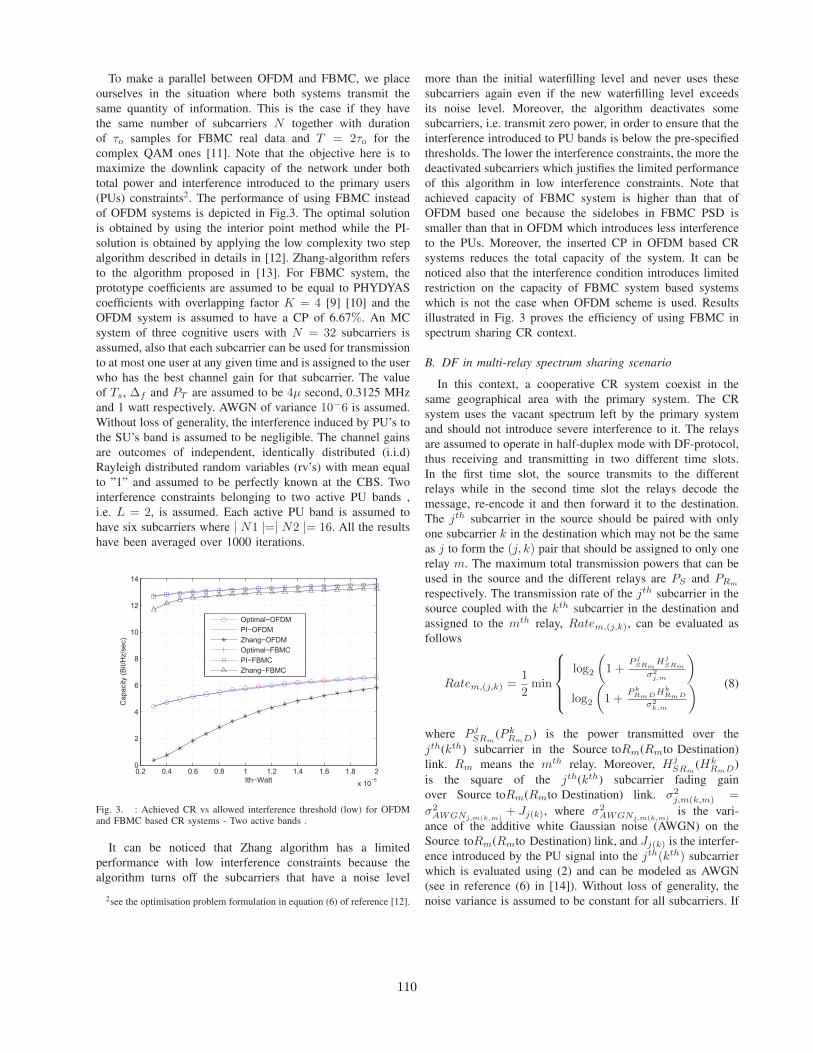
To make a parallel between OFDM and FBMC, we placeourselves in the situation where both systems transmit thesame quantity of information. This is the case if they havethe same number of subcarriers N together with durationof τo samples for FBMC real data and T = 2τo for thecomplex QAM ones [11]. Note that the objective here is tomaximize the downlink capacity of the network under bothtotal power and interference introduced to the primary users(PUs) constraints2. The performance of using FBMC insteadof OFDM systems is depicted in Fig.3. The optimal solutionis obtained by using the interior point method while the PI-solution is obtained by applying the low complexity two stepalgorithm described in details in [12]. Zhang-algorithm refersto the algorithm proposed in [13]. For FBMC system, theprototype coefficients are assumed to be equal to PHYDYAScoefficients with overlapping factor K = 4 [9] [10] and theOFDM system is assumed to have a CP of 6.67%. An MCsystem of three cognitive users with N = 32 subcarriers isassumed, also that each subcarrier can be used for transmissionto at most one user at any given time and is assigned to the userwho has the best channel gain for that subcarrier. The valueof Ts, ∆f and PT are assumed to be 4µ second, 0.3125 MHzand 1 watt respectively. AWGN of variance 10−6 is assumed.Without loss of generality, the interference induced by PU’s tothe SU’s band is assumed to be negligible. The channel gainsare outcomes of independent, identically distributed (i.i.d)Rayleigh distributed random variables (rv’s) with mean equalto ”1” and assumed to be perfectly known at the CBS. Twointerference constraints belonging to two active PU bands ,i.e. L = 2, is assumed. Each active PU band is assumed tohave six subcarriers where | N1 |=| N2 |= 16. All the resultshave been averaged over 1000 iterations.
0.2 0.4 0.6 0.8 1 1.2 1.4 1.6 1.8 2
x 10−5
0
2
4
6
8
10
12
14
Ith−Watt
Ca
pa
city (
Bit/H
z/s
ec)
Optimal−OFDM
PI−OFDM
Zhang−OFDM
Optimal−FBMC
PI−FBMC
Zhang−FBMC
Fig. 3. : Achieved CR vs allowed interference threshold (low) for OFDMand FBMC based CR systems - Two active bands .
It can be noticed that Zhang algorithm has a limitedperformance with low interference constraints because thealgorithm turns off the subcarriers that have a noise level
2see the optimisation problem formulation in equation (6) of reference [12].
more than the initial waterfilling level and never uses thesesubcarriers again even if the new waterfilling level exceedsits noise level. Moreover, the algorithm deactivates somesubcarriers, i.e. transmit zero power, in order to ensure that theinterference introduced to PU bands is below the pre-specifiedthresholds. The lower the interference constraints, the more thedeactivated subcarriers which justifies the limited performanceof this algorithm in low interference constraints. Note thatachieved capacity of FBMC system is higher than that ofOFDM based one because the sidelobes in FBMC PSD issmaller than that in OFDM which introduces less interferenceto the PUs. Moreover, the inserted CP in OFDM based CRsystems reduces the total capacity of the system. It can benoticed also that the interference condition introduces limitedrestriction on the capacity of FBMC system based systemswhich is not the case when OFDM scheme is used. Resultsillustrated in Fig. 3 proves the efficiency of using FBMC inspectrum sharing CR context.
B. DF in multi-relay spectrum sharing scenario
In this context, a cooperative CR system coexist in thesame geographical area with the primary system. The CRsystem uses the vacant spectrum left by the primary systemand should not introduce severe interference to it. The relaysare assumed to operate in half-duplex mode with DF-protocol,thus receiving and transmitting in two different time slots.In the first time slot, the source transmits to the differentrelays while in the second time slot the relays decode themessage, re-encode it and then forward it to the destination.The jth subcarrier in the source should be paired with onlyone subcarrier k in the destination which may not be the sameas j to form the (j, k) pair that should be assigned to only onerelay m. The maximum total transmission powers that can beused in the source and the different relays are PS and PRm
respectively. The transmission rate of the jth subcarrier in thesource coupled with the kth subcarrier in the destination andassigned to the mth relay, Ratem,(j,k), can be evaluated asfollows
Ratem,(j,k) =1
2min
log2
(1 +
P jSRm
HjSRm
σ2j,m
)
log2
(1 +
P kRmDHk
RmD
σ2k,m
) (8)
where P jSRm
(P kRmD) is the power transmitted over the
jth(kth) subcarrier in the Source toRm(Rmto Destination)link. Rm means the mth relay. Moreover, Hj
SRm(Hk
RmD)is the square of the jth(kth) subcarrier fading gainover Source toRm(Rmto Destination) link. σ2
j,m(k,m) =
σ2AWGNj,m(k,m)
+ Jj(k), where σ2AWGNj,m(k,m)
is the vari-ance of the additive white Gaussian noise (AWGN) on theSource toRm(Rmto Destination) link, and Jj(k) is the interfer-ence introduced by the PU signal into the jth(kth) subcarrierwhich is evaluated using (2) and can be modeled as AWGN(see in reference (6) in [14]). Without loss of generality, thenoise variance is assumed to be constant for all subcarriers. If
110
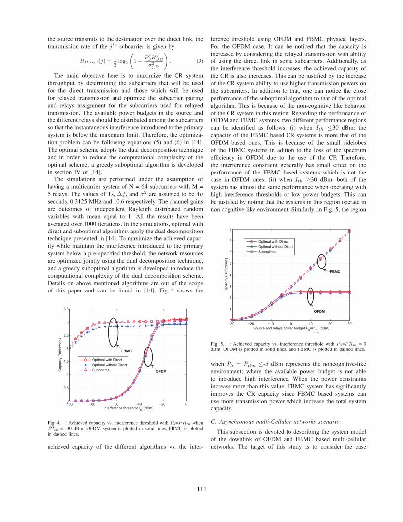
the source transmits to the destination over the direct link, thetransmission rate of the jth subcarrier is given by
RDirect(j) =1
2log2
(1 +
P jSH
jSD
σ2j,D
). (9)
The main objective here is to maximize the CR systemthroughput by determining the subcarriers that will be usedfor the direct transmission and those which will be usedfor relayed transmission and optimize the subcarrier pairingand relays assignment for the subcarriers used for relayedtransmission. The available power budgets in the source andthe different relays should be distributed among the subcarriersso that the instantaneous interference introduced to the primarysystem is below the maximum limit. Therefore, the optimiza-tion problem can be following equations (5) and (6) in [14].The optimal scheme adopts the dual decomposition techniqueand in order to reduce the computational complexity of theoptimal scheme, a greedy suboptimal algorithm is developedin section IV of [14].
The simulations are performed under the assumption ofhaving a multicarrier system of N = 64 subcarriers with M =5 relays. The values of Ts, ∆f , and σ2 are assumed to be 4µseconds, 0.3125 MHz and 10.6 respectively. The channel gainsare outcomes of independent Rayleigh distributed randomvariables with mean equal to 1. All the results have beenaveraged over 1000 iterations. In the simulations, optimal withdirect and suboptimal algorithms apply the dual decompositiontechnique presented in [14]. To maximize the achieved capac-ity while maintain the interference introduced to the primarysystem below a pre-specified threshold, the network resourcesare optimized jointly using the dual decomposition technique,and a greedy suboptimal algorithm is developed to reduce thecomputational complexity of the dual decomposition scheme.Details on above mentioned algorithms are out of the scopeof this paper and can be found in [14]. Fig 4 shows the
−100 −80 −60 −40 −20 00
0.5
1
1.5
2
2.5
3
3.5
Interference threshold Ith
(dBm)
Capacity (
Bit/H
z/s
ec)
Optimal with Direct
Optimal without Direct
SuboptimalOFDM
FBMC
Fig. 4. : Achieved capacity vs. interference threshold with Ps=PRm whenPIth = -30 dBm. OFDM system is plotted in solid lines, FBMC is plottedin dashed lines.
achieved capacity of the different algorithms vs. the inter-
ference threshold using OFDM and FBMC physical layers.For the OFDM case, It can be noticed that the capacity isincreased by considering the relayed transmission with abilityof using the direct link in some subcarriers. Additionally, asthe interference threshold increases, the achieved capacity ofthe CR is also increases. This can be justified by the increaseof the CR system ability to use higher transmission powers onthe subcarriers. In addition to that, one can notice the closeperformance of the suboptimal algorithm to that of the optimalalgorithm. This is because of the non-cognitive like behaviorof the CR system in this region. Regarding the performance ofOFDM and FBMC systems, two different performance regionscan be identified as follows: (i) when Ith ≤30 dBm: thecapacity of the FBMC based CR systems is more that of theOFDM based ones. This is because of the small sidelobesof the FBMC systems in adition to the loss of the spectrumefficiency in OFDM due to the use of the CP. Therefore,the interference constraint generally has small effect on theperformance of the FBMC based systems which is not thecase in OFDM ones, (ii) when Ith ≥30 dBm: both of thesystem has almost the same performance when operating withhigh interference thresholds or low power budgets. This canbe justified by noting that the systems in this region operate innon cognitive-like environment. Similarly, in Fig. 5, the region
−30 −20 −10 0 10 20 300
1
2
3
4
5
6
7
8
Source and relays power budget PS=P
Rm
(dBm)
Ca
pa
city (
Bit/H
z/s
ec)
Optimal with Direct
Optimal without Direct
Suboptimal
OFDM
FBMC
Fig. 5. : Achieved capacity vs. interference threshold with Ps=PRm = 0dBm. OFDM is plotted in solid lines, and FBMC is plotted in dashed lines.
when PS = PRm ≤-5 dBm represents the noncognitive-likeenvironment; where the available power budget is not ableto introduce high interference. When the power constraintsincrease more than this value, FBMC system has significantlyimproves the CR capacity since FBMC based systems canuse more transmission power which increase the total systemcapacity.
C. Asynchronous multi-Cellular networks scenario
This subsection is devoted to describing the system modelof the downlink of OFDM and FBMC based multi-cellularnetworks. The target of this study is to consider the case
111
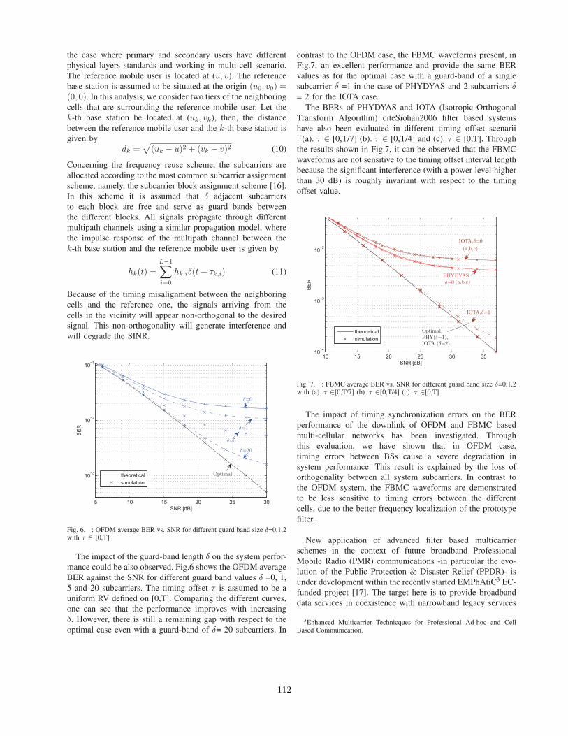
the case where primary and secondary users have differentphysical layers standards and working in multi-cell scenario.The reference mobile user is located at (u, v). The referencebase station is assumed to be situated at the origin (u0, v0) =(0, 0). In this analysis, we consider two tiers of the neighboringcells that are surrounding the reference mobile user. Let thek-th base station be located at (uk, vk), then, the distancebetween the reference mobile user and the k-th base station isgiven by
dk =√
(uk − u)2 + (vk − v)2 (10)
Concerning the frequency reuse scheme, the subcarriers areallocated according to the most common subcarrier assignmentscheme, namely, the subcarrier block assignment scheme [16].In this scheme it is assumed that δ adjacent subcarriersto each block are free and serve as guard bands betweenthe different blocks. All signals propagate through differentmultipath channels using a similar propagation model, wherethe impulse response of the multipath channel between thek-th base station and the reference mobile user is given by
hk(t) =
L−1∑
i=0
hk,iδ(t− τk,i) (11)
Because of the timing misalignment between the neighboringcells and the reference one, the signals arriving from thecells in the vicinity will appear non-orthogonal to the desiredsignal. This non-orthogonality will generate interference andwill degrade the SINR.
5 10 15 20 25 30
10−3
10−2
10−1
SNR [dB]
BE
R
theoretical
simulation
Optimal
δ=20
δ=5
δ=1
δ=0
Fig. 6. : OFDM average BER vs. SNR for different guard band size δ=0,1,2with τ ∈ [0,T]
The impact of the guard-band length δ on the system perfor-mance could be also observed. Fig.6 shows the OFDM averageBER against the SNR for different guard band values δ =0, 1,5 and 20 subcarriers. The timing offset τ is assumed to be auniform RV defined on [0,T]. Comparing the different curves,one can see that the performance improves with increasingδ. However, there is still a remaining gap with respect to theoptimal case even with a guard-band of δ= 20 subcarriers. In
contrast to the OFDM case, the FBMC waveforms present, inFig.7, an excellent performance and provide the same BERvalues as for the optimal case with a guard-band of a singlesubcarrier δ =1 in the case of PHYDYAS and 2 subcarriers δ= 2 for the IOTA case.
The BERs of PHYDYAS and IOTA (Isotropic OrthogonalTransform Algorithm) citeSiohan2006 filter based systemshave also been evaluated in different timing offset scenarii: (a). τ ∈ [0,T/7] (b). τ ∈ [0,T/4] and (c). τ ∈ [0,T]. Throughthe results shown in Fig.7, it can be observed that the FBMCwaveforms are not sensitive to the timing offset interval lengthbecause the significant interference (with a power level higherthan 30 dB) is roughly invariant with respect to the timingoffset value.
10 15 20 25 30 3510
−4
10−3
10−2
SNR [dB]
BE
R
theoretical
simulation
Optimal,PHY(δ=1),IOTA (δ=2)
PHYDYAS(a,b,c)δ=0
IOTA,δ=0
(a,b,c)
IOTA,δ=1
Fig. 7. : FBMC average BER vs. SNR for different guard band size δ=0,1,2with (a). τ ∈[0,T/7] (b). τ ∈[0,T/4] (c). τ ∈[0,T]
The impact of timing synchronization errors on the BERperformance of the downlink of OFDM and FBMC basedmulti-cellular networks has been investigated. Throughthis evaluation, we have shown that in OFDM case,timing errors between BSs cause a severe degradation insystem performance. This result is explained by the loss oforthogonality between all system subcarriers. In contrast tothe OFDM system, the FBMC waveforms are demonstratedto be less sensitive to timing errors between the differentcells, due to the better frequency localization of the prototypefilter.
New application of advanced filter based multicarrierschemes in the context of future broadband ProfessionalMobile Radio (PMR) communications -in particular the evo-lution of the Public Protection & Disaster Relief (PPDR)- isunder development within the recently started EMPhAtiC3 EC-funded project [17]. The target here is to provide broadbanddata services in coexistence with narrowband legacy services
3Enhanced Multicarrier Technicques for Professional Ad-hoc and CellBased Communication.
112

of the TETRA family. The core idea is a multi-mode radioplatform, based on variable filter-bank processing, which isable to perform modulation/detection functions simultaneouslyfor different signal formats with adjustable center frequencies,bandwidths and subchannel spacings [18].
III. CONCLUSIONS
In this paper, we provided some performance comparisonsbetween the usage of OFDM and filter based MC schemes asthe IOTA and the developed within the PHYDYAS project(FBMC). Different spectrum sharing scenarios have beenconsidered and analysed. In the context of spectrum and powerallocation, obtained results prove that the FBMC based CRsystems have more capacity than OFDM based ones, mainlyunder very low interference conditions which introduces lim-ited restriction on the capacity of FBMC system based systemswhich is not the case when OFDM scheme is used. In thecontext of resource allocation problem in multiple relay DFwith direct link, FBMC system has significantly improve theCR capacity since it can use more transmission power whichincreases the total system capacity.
To maximize the achieved capacity while maintaining thecapacities achieved, FBMC scheme proved its high capacityin such scenarios compared with the OFDM. Through theinvestigation of the impact of the time synchronization errorson the performance of the downlink of OFDM and FBMCbased multi-cellular networks, it is shown that the timing errorsbetween BSs in the OFDM case cause a severe degradationin system performance. This result is explained by the lossof orthogonality between all system subcarriers. In contrast tothe OFDM system, the FBMC waveform is demonstrated tobe less sensitive to timing errors between the different cells,due to the better frequency localization of the prototype filter.As a general output from this paper, obtained results in thespectrum sharing (CR) context contribute in recommendingthe use of advanced multicarrier filter bank (FBMC) physicallayer in future cognitive radio systems.
REFERENCES
[1] Stevenson, C. Chouinard, G.; Zhongding Lei; Wendong Hu; Shellham-mer, S.J.; Caldwell, W. ”IEEE 802.22: The first Cognitive Radio Wire-less Regional Area network standard,” IEEE Communications Magazine,Volume: 47 , Issue: 1, pp. 130 - 138. January 2009
[2] T. Weiss, J. Hillenbrand, A. Krohn, and F.K. Jondral,”Mutual Interfer-ence in OFDM-based Spectrum Pooling Systems,” in 59th VehicularTechnology Conference, (VTC’2004), May 2004, vol. 4, pp. 1873 to1877.
[3] R. Xu and M. Chen, ”A Precoding Scheme for DFT-based OFDM toSuppress Sidelobes,” IEEE Communications Letters, vol. 13, no. 10,pp.776 to 778, 2009.
[4] FP7-ICT PHYDYAS - Physical Layer for Dynamic Spectrum Accessand Cognitive Radio. http://www.ict-phydyas.org
[5] H. Zhang, D. Le Ruyet, and M. Terre, “Spectral Efficiency Comparisonbetween OFDM/OQAM and OFDM Based CR Networks,” WirelessCommun. and Mobile Computing Wiley, vol. 9, pp. 1487 to 1501, Nov.2009.
[6] B. Farhang-Boroujeny, ”OFDM Versus Filter Bank Multicarrier,” inIEEE Signal Processing Magazine, pp.92 to 112, May 2011.
[7] T. Weiss, J. Hill enbrand, A. Krohn, and F. K. Jondral, ”Mutual Interfer-ence in OFDM-based Spectrum Pooling Systems,” in Proceedings of the59th IEEE Vehicular Technology Conference (VTC’04), vol. 59, Milan,Italy, May 2004.
[8] B. Farhang-Boroujeny, ”Filter Bank Spectrum Sensing for CognitiveRadios,” in IEEE Transactions on Signal Processing, vol. 56, no. 5,pp. 1801 to 1811, 2008.
[9] M. G. Bellanger, ”Specification and Design of a Prototype Filter forFilter Bank Based Multicarrier Transmission,” in Proc. IEEE Int. Conf.Acoustics, Speech, and Signal Processing, pp. 2417 to 2420, Salt LakeCity, USA, May 2001.
[10] M. G. Bellanger, ”Phydyas : Analytical Expressions for the ReferencePrototype filter,” Tech. report, pp. 1-4, Feb. 2009, CNAM, Paris.
[11] Skrzypczak, A and Siohan, P and Javaudin, J.P, ”Power Spectral Densityand Cubic Metric for the OFDM/OQAM Modulation,” in Proc. of theIEEE Symposium on Signal Processing and Information Technology(ISSPIT’2006). Vancouver-Canada. August 2006.
[12] M. Shaat and F. Bader, ”A Two-Step Resource Allocation Algorithmin Multicarrier Based Cognitive Radio Systems,” in Proc. IEEE Wire-less Communications and Networking Conference (IEEE WCNC’2010).pp.1-6. Sydney, Australia. April 2010.
[13] Y. Zhang, ”Resource allocation for OFDM-based cognitive radio sys-tems”, Ph.D. dissertation, University of British Columbia, Vancouver,Canada, December 2008.
[14] M. Shaat and F. Bader, ”Joint Resource Optimization in Decode andForward Multi-Relay Cognitive Network With Direct Link,” in the Proc.the IEEE Wireless Communications and Networking Conference (IEEEWCNC’2012). Paris, France. April 2012.
[15] G. Stuber, S. Almalfouh and D. Sale, ”Iterference analysis of TV-bandwhitespace,” in the Proc. the Proceedings of the IEEE, vol. 97, no4,pp.741-754. April 2009.
[16] Y. Medjahdi, M. Terre, D. Le Ruyet, and D. Roviras, and A. Dziri,”Performance Analysis in the Downlink of Asynchronous OFDM/FBMCBased Multi-Cellular Networks,” IEEE Transactions on Wireless Com-munications, Vol. 10, No. 8, August 2011.
[17] European Funded research project on ”Enhanced Multicarrier Technic-ques for Professional Ad-hoc and Cell Based Communication” ICT-EMPhAtiC wih code:318362),http : //www.ict − emphatic.eu(visited 25 June 2013)
[18] M. Renfors, F. Bader, L. Baltar, D. Le Ruyet, D. Roviras, P. Mege, M.Haardt, ”On the Use of Filter Bank Based Multicarrier Modulation forProfessional Mobile Radio,” at Proc. of the IEEE Vehicular TechnologyConference (VTC-Spring’2013), Dresden, Germany. June 2013.
113

Integrating LTE Broadband System in PMR Band:OFDM vs. FBMC Coexistence Capabilities and
PerformancesYahia Medjahdi1, Didier le Ruyet2, Faouzi Bader3, and Laurent Martinod4
1ICTEAM, Universite Catholique de Louvain. Place du Levant, 2, 1348 Louvain-la-Neuve, BelgiumEmail: [email protected]
2CNAM, Paris, France. Email: didier.le [email protected], Rennes, France. Email: [email protected]
4CASSIDIAN Systems, Elancourt, France. Email: [email protected]
Abstract—This paper focuses on the use of Long Term Evo-lution (LTE) broadband system in coexistence with currentlydeployed Professional Mobile Radio (PMR) communication sys-tems. The coexistence capabilities are analyzed using of an LTElike based system with Orthogonal Frequency Division Multi-plexing (OFDM) and Filter Bank MultiCarrier (FBMC) physicallayers. Obtained results show that, in order to achieve the LTE-PMR coexistence, we need to filter the synthesized OFDM signal.This filtering is made to protect the PMR (TETRA, TETRAPOL,TETRA TEDS standards, etc.) systems by reducing the sidelobeslevels due the use of modulated OFDM scheme. On the otherhand, the FBMC signal fits perfectly the LTE-TEDS harmfulinterference protection requirements starting from the minimumfrequency offset allowed by the TEDS standard mask. This canbe explained by the fact that a good frequency localization isachieved by the prototype filter used in the FBMC scheme.
I. INTRODUCTION
Nowadays, PMR and Public Protection and Disaster Reliefservices (PPDR) are fundamentally used for low-rate datatransmission like voice communications. This is due to thelimited throughput resulting from the small bandwidths usedby these systems [1]. Recently, there is a trend to upgrade thePMR systems to support high-rate applications and broadbandservices. To upgrade the PMR/PPDR networks (TETRA11,TETRAPOL, TETRA Enhanced Data Services-TEDS, etc.)[1][2] towards supporting broadband data communicationsservices, new capacity is required and can be achieved withtwo complementary ways; i) by obtaining new bandwidths forPMR/PPDR data services, and ii) by fitting a novel broadbanddata service within the scarcity (which is the European case)of available spectrum devoted to PMR systems (depending oncustomers, reserved bands are located in: 380-400 MHz, 410-430 MHz, or 450-470 MHz). To satisfy the growing demands,both directions actually have to be followed. One of the majorissues is being able to introduce new broadband data serviceswithin the current frequency allocation, in coexistence and co-habitation with the currently deployed and active PMR/PPDRsystems. Having in mind the widely expected dominance of3GPP LTE systems, it is natural to consider the LTE system
1TETRA: Terrestrial Trunked Radio
as a reference basis in the PMR/PPDR system developmentdue to its high data rate, modularity, and adoption by worldwide mobile companies. Broadband systems such as LTE riseas one of the most attractive candidates that can achieve veryhigh data rates.
Multicarrier transmission is the predominant technique usedin nowadays wireless communication systems (e.g. WLAN,WiMAX, DVB-T, LTE, etc.) where a wide band signal at ahigh symbol rate is split into several lower rate signals, eachone occupying a narrower band. Consequently, the systemperformance improves as subcarriers experience flat fadingchannels and are by construction orthogonal to one anotherthus minimizing the threat of interference.
However, the possible deployment of broadband systemsin PMR bands is still facing important challenges as severaltechnical constraints must be overtaken, mainly those relatedto coexistence with the currently existing narrowband PMRcommercial devices (primary systems). The primary objectiveof this paper is to examine the coexistence between PMRnarrowband systems with LTE-based Broadband system. Atthe waveform level, the main issue is the poor spectral con-tainment of the OFDM subcarriers, leading to high side-lobesof the modulated OFDM spectrum. These high side-lobescreate interference to adjacent systems frequencies and arethus problematic in the coexistence scenario to be addressed.However, the filter bank multicarrier system (FBMC) does notrequire any CP extension and can overcome the spectral leak-age problem by minimizing the sidelobes of each subcarrierand therefore lead to high efficiency [4], [5], [6]. Additionally,a high flexibility is needed to utilize effectively the variablespectral gaps between different narrowband PMR users.
In this paper, we analyze the interference effect caused bya deployed multicarrier broadband (LTE-like) system in thePMR channel. Two different multicarrier techniques are used:OFDM and FBMC schemes, and their direct impact and effecton the system coexistence performances are analyzed.
In the following, first in Section II we describe the coex-istence scenario and PMR system requirement defined in theETSI TETRA standard. In Section III, some key parameters
978-1-4799-5863-4/14/$31.00 c⃝2014 IEEE114

related with the LTE system and used for the context analysisare defined. Section IV, encompass the interference perfor-mance analysis in PMR channel using a 1.4MHz,3MHz, and5MHz LTE bands. The analysis includes achieved coexistenceusing OFDM and FBMC schemes.
II. COEXISTENCE SCENARIO AND PMR SYSTEMREQUIREMENTS
We analyze in this paper the possibility to deploy an LTEbroadband system in a 5MHz PMR channel (located in the400MHz band). As stated in the introduction, the broadbandsystem should respect the constraints imposed by the alreadyexisting and operational PMR communication devices. ThePMR system considered for the analysis is an ETSI TEDSstandard [1] which is currently widely used by public safetyorganisms both privates and governmental, and by aroundtwo millions of business users over the world. Figure 1,illustrates the considered coexistence scenario in a 5MHz PMRband, where an LTE-like system is used. Note that differentPMR equipments using TETRA1 and TETRA2 standards arecurrently deployed in the 5MHz bandwidth. Depicted systemsin Figure 1 are two TEDS of 25kHz bandwidth each. Themain goal (as it can be shown in Figure 1) is to deployan LTE-like broadband system in the spectrum holes of thePMR bands by strictly accomplishing the PMR standardsinterference blocking recommendations. This can be achievedby respecting the reception masks of the currently activePMR systems. Here, ∆f1 and ∆f2 refer to the frequencydistances between the nearest adjacent interferer channels andthe nominal carrier frequencies of the existing active users inthe band.
−200 −150 −100 −50 0 50 100 150 200 250 300−20
−15
−10
−5
0
5
10
25kHz−TEDS
LTE
5MHz
25kHz−TEDS
NominalCarrier
Frequency1
∆f2∆f
1
Nearestadjacentinterfererchannels
NominalCarrier
Frequency2
Fig. 1. LTE broadband in coexistence with narrowband PMR systems
In order to ensure the PMR/LTE cohabitation, the out-of-band radiation of the deployed LTE system should not exceedthe levels defined by the reception mask of the TEDS standard.The TEDS reception mask can be computed based on theblocking levels presenting the interfering signal powers as
function of frequency offsets between the nominal carrierfrequency of the TEDS system and the nearest adjacentinterfering channel. In this work, we focus on the 25 kHz-TEDS case, however, the extension to other PMR standards isstraightforward.Based on the blocking levels given in Table I, we can computethe TEDS reception mask corresponding to 4, 16, and 64 QAMconstellations. A slight difference can be observed betweenthe obtained masks. Accordingly, only the 4-QAM case willbe considered in the sequel of this paper.
TABLE IBLOCKING LEVELS OF THE 25 KHZ-TEDS RECEIVER DEFINED IN [1]
offset from nominal Rx freq. level of interfering signal50 kHz to 100 kHz -40 dBm100 kHz to 200 kHz -35 dBm200 kHz to 500 kHz -30 dBm
> 500 kHz -25 dBm
TABLE II25 KHZ-TEDS RECEPTION MASK
offset from nominal Rx freq. 4-QAM 16-QAM 64-QAM50 kHz to 100 kHz -81.4 dBm -81.4 dBm -82.6 dBm
100 kHz to 200 kHz -86.4 dBm -86.4 dBm -87.6 dBm200 kHz to 500 kHz -91.4 dBm -91.4 dBm -92.6 dBm
> 500 kHz -96.4 dBm -96.4 dBm -97.6 dBm
III. LTE-BASED BROADBAND SYSTEMS
In this paper, we consider the LTE system with differenttransmission bandwidths where main parameters summarizedin Table III [12],
TABLE IIILTE PHY LAYER MAIN PARAMETERS [3]
Transmission bandwidth 1.4 MHz 3 MHz 5 MHzSubcarrier spacing 15 kHz 15 kHz 15 kHz
FFT size 128 256 512Useful subcarriers(with DC) 73 181 301
Effective bandwidth 1.08 MHz 2.7 MHz 4.5 MHz
Furthermore, two multicarrier physical layers (PHY) areconsidered and analyzed for the coexistence analysis: i) thecyclic prefixed orthogonal frequency division multiplexing(CP-OFDM) using the rectangular pulse shape, ii) and thefilterbank multicarrier technique (FBMC) using the prototypefilter proposed in the European funded project ”Physical Layerfor Dynamic Access and Cognitive Radio-PHYDYAS” [7].
The interference analysis is based on the power spectraldensity (PSD) model which is commonly used in the scientificliterature [9], [10]. This evaluation is based on the PSDmethod, and it is measured based on the spectral distancecalculation of the out-of band radiation value between adesigned carrier and its spectral distance from the primary
115

band. According to [10], the resulting interference power in agiven bandwidth [f1, f2] is defined by,
I =
f2∫
f1
Φ(f)df (1)
where Φ(f) is the PSD which depends on the consideredmulticarrier technique. In case of CP-OFDM PHY systems,the normalized PSD has been computed as in [10] and is givenby
ΦOFDM(f) = TOFDM
(sin(πfTOFDM)
πfTOFDM
)2
(2)
where TOFDM = T + ∆, with T the useful symbol duration,and ∆ the CP duration.Concerning the FBMC system, the PSD of the PHYDYAS’sproject waveform is expressed as follows [11],
ΦPHYDYAS(f) = (G(f))2 (3)
Here, G(f) is the square root of the PHYDYAS filter fre-quency response which is given by,
G(f) =
k=(K−1)∑
k=−(K−1)
Gk
sin(π
(f − k
NK
)NK
)
NK sin(π
(f − k
NK
)) (4)
where, K is the overlapping factor of the prototype filter andthe coefficients Gk depend on the overlapping factor K. Forexample, when K = 4, we have G1 = 0.971960, G2 =
√2/2,
and G3 = 0.235147 [11]. Figure 2 depicts the PSDs of
−4 −3 −2 −1 0 1 2 3 4−100
−90
−80
−70
−60
−50
−40
−30
−20
−10
0
Fre
quen
cy R
espo
nse
[dB
]
Normalized Frequency
RectangularPhydyas
Fig. 2. OFDM (refereed as ”rectangular”) and FBMC (refereed as ”Phydyas”)Power Spectral Densities
single modulated subcarrier of both systems: the CP-OFDM(refereed as rectangular) and the FBMC (refereed as Phydyas).Comparing the two PSDs, it can be seen that the PHYDYASscheme offers better frequency localization compared to theOFDM scheme using the rectangular pulse shape in the timedomain. It is clear that the high frequency localization of thePHYDYAS filter prototype offers a much higher spectrum
contention allowing higher capabilities for spectrum sharingand coexistence.
IV. INTERFERENCE ANALYSIS
In what follows, the effective interference power caused byLTE systems is computed in a bandwidth of 25 kHz withrespect to the different frequency offsets ∆f given in TableII. It is worth noticing that the LTE transmit power, in thethree cases, is fixed at 0 dBm. Furthermore, both the PMRbase station and the LTE one are assumed to be adjacentlysituated (i.e. the PMR transmitter and the LTE one are at equaldistances from the PMR-receiver).
−250 −200 −150 −100 −50 0−40
−35
−30
−25
−20
−15
−10
−5
0
frequency [kHz]
PS
D [d
B]
OFDM
I(200kHz)
I(100kHz)
I(50kHz)25kHz
Fig. 3. : Effective interference levels of 1.4 MHz-LTE (73 active subcarriers)in 25 kHz-TEDS band, OFDM case
−250 −200 −150 −100 −50 0−200
−180
−160
−140
−120
−100
−80
−60
−40
−20
0
frequency [kHz]
PS
D [d
B]
FBMC
25kHz
I(100kHz)
I(200kHz)
I(50kHz)
Fig. 4. : Effective interference levels of 1.4 MHz-LTE (73 active subcarriers)in 25 kHz-TEDS band, FBMC case
Figure 3 and 4 show an example of this interference whenwe have a 1.4 MHz-LTE system using OFDM and FBMCtechniques, respectively. The gray-colored areas correspond
116
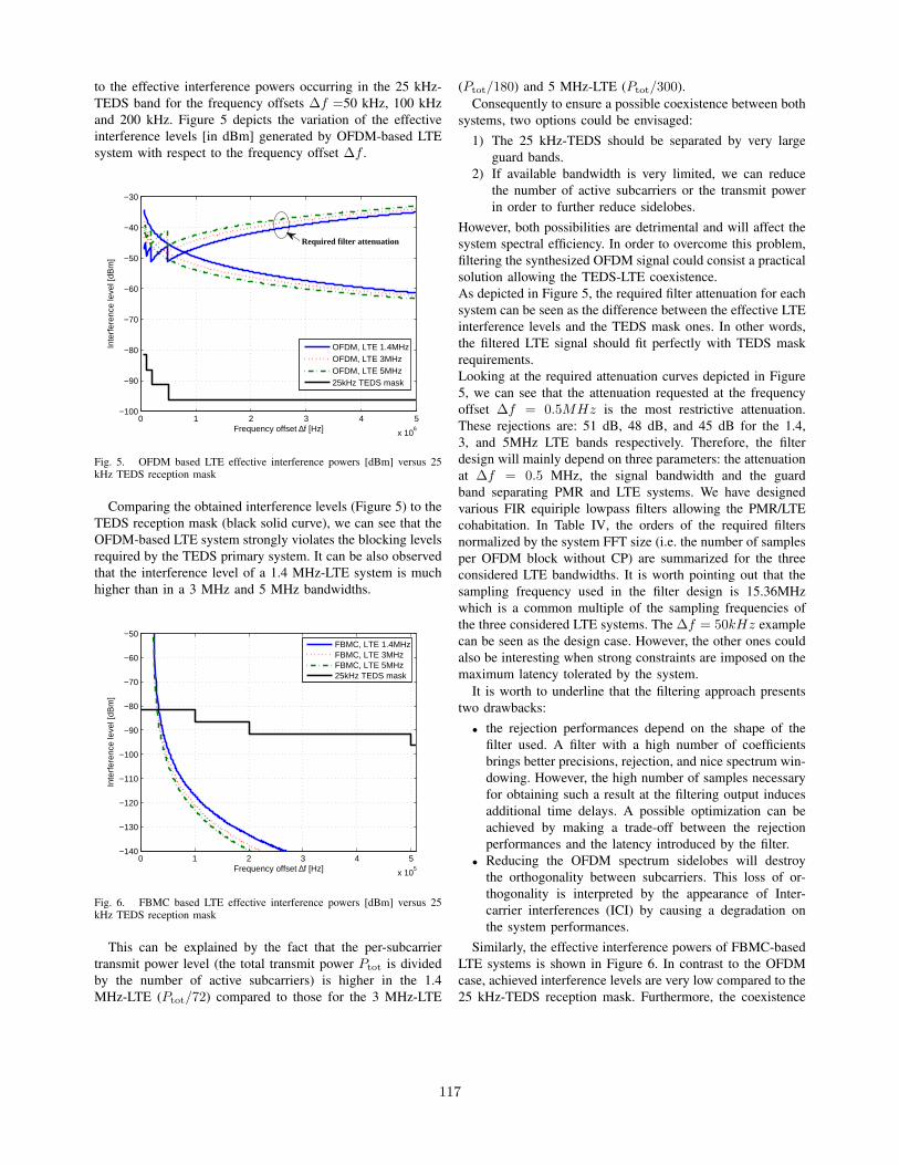
to the effective interference powers occurring in the 25 kHz-TEDS band for the frequency offsets ∆f =50 kHz, 100 kHzand 200 kHz. Figure 5 depicts the variation of the effectiveinterference levels [in dBm] generated by OFDM-based LTEsystem with respect to the frequency offset ∆f .
0 1 2 3 4 5
x 106
−100
−90
−80
−70
−60
−50
−40
−30
Frequency offset ∆f [Hz]
Inte
rfer
ence
leve
l [dB
m]
OFDM, LTE 1.4MHzOFDM, LTE 3MHzOFDM, LTE 5MHz25kHz TEDS mask
Required filter attenuation
Fig. 5. OFDM based LTE effective interference powers [dBm] versus 25kHz TEDS reception mask
Comparing the obtained interference levels (Figure 5) to theTEDS reception mask (black solid curve), we can see that theOFDM-based LTE system strongly violates the blocking levelsrequired by the TEDS primary system. It can be also observedthat the interference level of a 1.4 MHz-LTE system is muchhigher than in a 3 MHz and 5 MHz bandwidths.
0 1 2 3 4 5
x 105
−140
−130
−120
−110
−100
−90
−80
−70
−60
−50
Frequency offset ∆f [Hz]
Inte
rfer
ence
leve
l [dB
m]
FBMC, LTE 1.4MHzFBMC, LTE 3MHzFBMC, LTE 5MHz25kHz TEDS mask
Fig. 6. FBMC based LTE effective interference powers [dBm] versus 25kHz TEDS reception mask
This can be explained by the fact that the per-subcarriertransmit power level (the total transmit power Ptot is dividedby the number of active subcarriers) is higher in the 1.4MHz-LTE (Ptot/72) compared to those for the 3 MHz-LTE
(Ptot/180) and 5 MHz-LTE (Ptot/300).Consequently to ensure a possible coexistence between both
systems, two options could be envisaged:1) The 25 kHz-TEDS should be separated by very large
guard bands.2) If available bandwidth is very limited, we can reduce
the number of active subcarriers or the transmit powerin order to further reduce sidelobes.
However, both possibilities are detrimental and will affect thesystem spectral efficiency. In order to overcome this problem,filtering the synthesized OFDM signal could consist a practicalsolution allowing the TEDS-LTE coexistence.As depicted in Figure 5, the required filter attenuation for eachsystem can be seen as the difference between the effective LTEinterference levels and the TEDS mask ones. In other words,the filtered LTE signal should fit perfectly with TEDS maskrequirements.Looking at the required attenuation curves depicted in Figure5, we can see that the attenuation requested at the frequencyoffset ∆f = 0.5MHz is the most restrictive attenuation.These rejections are: 51 dB, 48 dB, and 45 dB for the 1.4,3, and 5MHz LTE bands respectively. Therefore, the filterdesign will mainly depend on three parameters: the attenuationat ∆f = 0.5 MHz, the signal bandwidth and the guardband separating PMR and LTE systems. We have designedvarious FIR equiriple lowpass filters allowing the PMR/LTEcohabitation. In Table IV, the orders of the required filtersnormalized by the system FFT size (i.e. the number of samplesper OFDM block without CP) are summarized for the threeconsidered LTE bandwidths. It is worth pointing out that thesampling frequency used in the filter design is 15.36MHzwhich is a common multiple of the sampling frequencies ofthe three considered LTE systems. The ∆f = 50kHz examplecan be seen as the design case. However, the other ones couldalso be interesting when strong constraints are imposed on themaximum latency tolerated by the system.
It is worth to underline that the filtering approach presentstwo drawbacks:
• the rejection performances depend on the shape of thefilter used. A filter with a high number of coefficientsbrings better precisions, rejection, and nice spectrum win-dowing. However, the high number of samples necessaryfor obtaining such a result at the filtering output inducesadditional time delays. A possible optimization can beachieved by making a trade-off between the rejectionperformances and the latency introduced by the filter.
• Reducing the OFDM spectrum sidelobes will destroythe orthogonality between subcarriers. This loss of or-thogonality is interpreted by the appearance of Inter-carrier interferences (ICI) by causing a degradation onthe system performances.
Similarly, the effective interference powers of FBMC-basedLTE systems is shown in Figure 6. In contrast to the OFDMcase, achieved interference levels are very low compared to the25 kHz-TEDS reception mask. Furthermore, the coexistence
117

TABLE IVFILTER ORDER/SYSTEM FFT SIZE
∆f 1.4MHz LTE 3MHz LTE 5MHz LTE50 kHz 0.8623 0.8301 0.7979100 kHz 0.3965 0.3818 0.3672200 kHz 0.1904 0.1836 0.1768500 kHz 0.0742 0.0713 0.0693
LTE system TEDS system
,
,
Δ
,=+,+,
2+ ∆
LTE systemTEDS system
TEDS system
Fig. 7. Two coexistence configurations c.1 and c.2
of FBMC-LTE with a 25 kHz-TEDS is possible starting fromthe minimum frequency offset allowed by the TEDS receptionmask (i.e at ∆f=50 kHz). Therefore, increasing the numberof FBMC-LTE active subcarriers can be considered whichprovides a higher spectral efficiency.
V. COEXISTENCE ANALYSIS IN SOME SPECIFICCONFIGURATIONS
We examine in this section the feasibility of the coexistencebetween the 25 kHz-TEDS and the LTE-based broadbandsystems in 5 MHz PMR bandwidth. Two configurations aredepicted in Figure 7.
The minimum bandwidth required in configurations (c.1)and (c.2) can be computed respectively by
Breq,min1 =BTEDS + Beffective,LTE + Btotal,LTE
2+ ∆fmin
(5)
Breq,min2 = BTEDS + Beffective,LTE + 2∆fmin (6)
where, BTEDS is the TEDS bandwidth which is in our case25 kHz, Beffective,LTE is the sum of the bandwidth of theuseful subcarriers used by the LTE system (see Table III), and
Btotal,LTE is the total bandwidth of the LTE system (see TableIII). ∆fmin means the minimum spectral distance that shouldseparate the TEDS nominal frequency from the nearest LTEactive subcarrier.
Looking at the OFDM results shown in Figure 8, we can seethat the OFDM-5MHz-LTE and the 25 kHz TEDS coexistenceis not possible (i.e the minimum required bandwidth exceedsthe 5 MHz available for PMR) in the case of minimum latency(when ∆f = 0.5MHz). It is worth noticing that the caseof OFDM with maximum latency (when ∆f = 50kHz) isequivalent to FBMC one. As expected, the FBMC-LTE is ableto cohabit with the 25 KHz-TEDS starting from the minimumspectral distance allowed by this latter that is 50 kHz. Sincethe required bandwidth Breq,min is always below the 5 MHzavailable for PMR, it can be observed that the FBMC-TEDScoexistence is possible for figure 7 cases. Furthermore, sinceBreq,min does not exceed 1.5 MHz, we can consider theinsertion of additional FBMC-LTE systems (2× 1.4 MHz-LTE).
Fig. 8. Minimum required bandwidth (configurations c.1 and c.2) for OFDMcase with maximum and minimum latency ∆f = 0.05, 0.5 MHz
VI. CONCLUSION
In this paper, the coexistence between PMR narrowbandsystems with LTE-like broadband using different bandwidthhas been examined. Based on the PSDs waveforms of OFDMand FBMC, we analyzed the interference effect caused by thedeployed multicarrier broadband system in the PMR channelactive systems. Obtained results show that, in order to makethe LTE-TEDS coexistence possible, we need to filter thesynthesized OFDM signal. This filtering is made to protectthe TEDS systems by reducing the sidelobes levels of themodulated OFDM spectrum. We have also shown that bet-ter rejection performances require filters with long impulseresponses, thus inducing additional delays. On the other hand,the FBMC signal fits perfectly the PMR-TEDS harmful inter-ference protection requirements. Moreover, this cohabitation is
118

possible starting from the minimum frequency offset allowedby the TEDS reception mask. This can be explained by the factthat a good frequency localization is achieved by the prototypefilter used by the FBMC (PHYDYAS scheme). Therefore,FBMC-broadband (LTE-like) system could be considered as apotential candidate to be deployed in the PMR band offeringvery high data rates to the next generation of PMR/PPDRsystems. Future works will focus on optimization of the filterlength giving the best rejection performances. Furthermore,the performance of LTE systems will be investigated sincedegradations are expected due to the loss of orthogonalitybetween subcarriers induced by the sidelobes reduction.
VII. ACKNOWLEDGEMENTS
The authors acknowledge the financial support by theEuropean Union FP7-ICT project EMPhAtiC under grantagreement no.318362, and the French ANR project PROFILwith grant agreement code: ANR-13-INFR-0007-03.
REFERENCES
[1] ETSI TS 100 392-2, Terrestrial Trunked Radio (TETRA); Voice plusData (V+D); Part 2: Air Interface (AI), Oct. 2011
[2] ETSI TR 102 580 V1.1.1 Terrestrial Trunked Radio (TETRA);Release 2;Designer’s Guide; TETRA High-Speed Data (HSD); TETRA EnhancedData Service (TEDS) (2007-10).
[3] 3GPP TR 25.814, Physical layer aspects for evolved Universal Terres-trial Radio Access (UTRA)
[4] B. Farhang-Boroujeny, ”Filter Bank Spectrum Sensing for CognitiveRadios,” in IEEE Transactions on Signal Processing, vol. 56, no. 5,pp. 1801-1811, 2008.
[5] Y. Medjahdi, M. Terre, D. Le Ruyet, and D. Roviras, “Interferencetables: a useful model for interference analysis in asynchronous multicar-rier transmission,” EURASIP Journal on Advances in Signal Processing,vol. 2014.
[6] Y. Medjahdi, M. Terre, D. Le Ruyet, D. Roviras, and A. Dziri, “Per-formance analysis in the downlink of asynchronous ofdm/fbmc basedmulti-cellular networks,” IEEE Trans. on Wireless Commun., vol. 10,no. 8, pp. 2630–2639, Aug. 2011.
[7] M. G. Bellanger, ”Specification and design of a prototype filter forfilter bank based multicarrier transmission,” in Proc. IEEE Int. Conf.Acoustics, Speech, and Signal Processing, pp. 2417-2420, Salt LakeCity, USA, May 2001.
[8] H-P. A. Ketterling, Introduction to Digital Professional Mobile Radio,Artech House, Boston, 2004.
[9] H. Zhang, D. Le Ruyet, and M. Terre, “Spectral Efficiency Comparisonbetween OFDM/OQAM and OFDM based CR Networks,” WirelessCommun. and Mobile Computing Wiley, vol. 9, pp. 1487–1501, Nov.2009.
[10] T. Weiss, J. Hillenbrand, A. Krohn, and F.K. Jondral, “Mutual In-terference in OFDM-based Spectrum Pooling Systems,” in VehicularTechnology Conference, IEEE 59th, May 2004, vol. 4, pp. 1873–1877.
[11] M. G. Bellanger, ”Phydyas : Analytical expressions for the referenceprototype filter,” Tech. report, pp. 1-4, Feb. 2009, CNAM, Paris.
[12] Evolved Universal Terrestrial Radio Access (E-UTRA), LTE physicallayer: General description,
119

On the Use of Filter Bank Based MulticarrierModulation for Professional Mobile Radio
Markku Renfors1, Faouzi Bader2, Leonardo Baltar3, Didier Le Ruyet4,Daniel Roviras4, Philippe Mege5, Martin Haardt6, Tobias Hidalgo Stitz7
1Dept. of Electronics and Communications Engineering, Tampere University of Technology, Finland, [email protected], Castelldefels-Barcelona, Spain
3Circuit Theory and Signal Processing, Technische Universitat Munchen, Germany4Electronics and Communications Laboratory, CNAM, Paris, France
5Cassidian, Elancourt, France6Communications Research Laboratory, Ilmenau University of Technology, Ilmenau, Germany
7Magister Solutions Ltd, Tampere, Finland
Abstract—Our main emphasis is on the use of enhancedOFDM and filter bank based multicarrier (FB-MC) waveformsfor utilizing effectively the available fragmented spectrum inheterogeneous radio environments. Special attention is on thebroadband-narrowband coexistence scenario of the ProfessionalMobile Radio (PMR) evolution. The target here is to providebroadband data services in coexistence with narrowband legacyservices of the TETRA family. The core idea is a multi-moderadio platform, based on variable filter bank processing, whichis able to perform modulation/detection functions simultaneouslyfor different signal formats with adjustable center frequencies,bandwidths and subchannel spacings.
I. INTRODUCTION
Public Safety organizations are using radio communicationsystems for the day to day operational needs, for exceptionalevents, and for disaster recovery conditions. These usagesare collectively called PPDR (Public Protection and DisasterRelief), which corresponds to the Professional Mobile Radio(PMR) services for Public Safety organizations [1] [2]. Todaythey use dedicated radio communications systems (APCO25in North America; TETRA, TETRAPOL and TEDS in Europeand in a large part of the world) primarily for voice communi-cations and also for low-rate data transmissions. This is due tothe technological limitations of currently deployed PMR/PPDRsystems, which only use a small radio channel bandwidth andhave thus limited throughput.
There are various important services that need essentiallyhigher data throughput and cannot be supported by the currentnetworks. The new required capacity can be achieved in twocomplementary ways: by obtaining new frequency bands forPPDR data services and by fitting a novel broadband dataservice within the scarcely available spectrum devoted to PMRsystems. To satisfy the growing demands, actually both direc-tions have to be followed. The EU FP7 ICT project EMPhAtiC(http://www.ict-emphatic.eu) will focus on the latter approach,which can be seen as the technically more challenging path.One of the major issues is being able to introduce newbroadband data services within the current frequency allocationat the 450 MHz frequency band, in coexistence/cohabitationwith the current PMR/PPDR systems.
It is natural to consider the highly spectrally efficient 3GPP
LTE system as a reference basis in the PMR/PPDR systemdevelopment due to its modularity and wide adoption in thecivil world. However, there is a clear need to go beyond LTE,especially improving the spectral characteristics and strivingto maximize the spectral efficiency, while maintaining most ofthe functionalities intact, especially at the higher layers.
The considered coexistence scenario, aiming at the de-ployment of a broadband data service in a band alreadyoccupied by narrowband PMR channels, is illustrated in Fig. 1.Here high flexibility and spectral agility, in combination withefficient fragmented spectrum use are necessary requirementsfor the broadband system. To reach good spectral efficiencyand minimize interferences between the different services,well-contained spectrum, providing improved adjacent channelprotection, is critical. This is a general issue when consideringchallenging spectrum access scenarios, like cognitive radio andopportunistic dynamic spectrum use.
Various enhancements to the CP-OFDM multicarrierscheme have been proposed in the literature and are underactive investigations. In particular, we are witnessing an ex-pansion of technical publications that encourage and supportthe use of the filter bank modulation schemes as a solution forthe drawbacks and limitations of the conventional CP-OFDMscheme, which are critical for the chosen PMR/PPDR concept[3] [4]. The main limitation is the poor spectral containmentof the OFDM signal, which would necessitate relatively wideguard bands around the active groups of subcarriers to isolatethe new broadband service and legacy narrowband servicesfrom each other. Using filter bank schemes, it is also possibleto reduce the overhead in data transmission rate due to thecyclic prefix (CP).
Multicarrier signals present a high peak-to-average powerratio (PAPR) which, combined with the nonlinearity of trans-mitter power amplifiers, produce undesired signal distortionand spectral regrowth. PAPR reduction and mitigation of thenonlinearity effects are important aspects in all multicarriersystems, but since the focus of this paper is on spectralcontainment, we concentrate here on the reduction of OFDMspectrum sidelobes.
In the following, first in Section II we discuss techniquesfor sidelobe suppression in OFDM, introduce the filter bank
978-1-4673-6337-2/13/$31.00 ©2013 IEEE
120

Fig. 1. Proposed future PMR broadband service in cohabitation with currentsystems.
multicarrier schemes and a fast convolution based flexiblemultimode filter bank structure. Section II also includes acomparison of the spectral characteristics of an enhancedOFDM scheme and FBMC/OQAM in a non-contiguous LTElike scenario. In Section III channel equalization and syn-chronization aspects in FBMC/OQAM are briefly discussed,together with important higher-layer aspects. Conclusions aredrawn in Section IV.
II. MULTICARRIER WAVEFORMS FOR FRAGMENTEDSPECTRUM USE
At the waveform level, the European project EMPhAtiC[5] focuses on heterogeneous networks in general. The mostimportant example is the prospective evolution of PMR/PPDRto provide a high data-rate service by utilizing fragmentsof a PMR frequency band partly occupied by narrowbandlegacy PMR signals with 10, 12.5, 25, 50, and/or 100 kHzchannelization. Here it is crucial to exploit the availablefrequency gaps efficiently while keeping the interferences inboth directions at acceptable levels. Similar radio environmentsare encountered also in cognitive radio applications, however,with much higher variability of the primary waveforms. Incell-based PMR networks, all mobile stations are under thecontrol of a base station. The PMR ad-hoc scenario resemblesthe cognitive radio case in the sense that different stations arenot necessarily well-synchronized and the interferences in theenvironment are more difficult to handle.
OFDM solves the fundamental channel equalization prob-lem in wideband wireless communications in an elegant androbust way, and it provides efficient means for channel awarescheduling of the transmission resources to different users inan optimal way. Due to the flat-fading channel characteristics,CP-OFDM is also an excellent basis for different multi-antenna(MIMO) techniques which are able to enhance the performanceat link and system levels [6]. However, as mentioned above,OFDM has also a number of limitations, which have motivatedresearch on various enhancements as well as on alternativewaveforms.
A. Sidelobe Suppression in CP-OFDM
A very flexible way of approaching for facilitatingthe broadband narrowband coexistence can be named non-contiguous multicarrier modulation, as a generalization ofnon-contiguous OFDM scheme [7]. Here the idea is thatthe spectrum of the transmitted waveform can be controlled
by activating only those subcarriers which are available andhave been allocated for transmission, and modulating zero-symbols on the others. The approach is the same as thebasic idea of OFDMA, but now the target is to be ableto tolerate asynchronous waveforms in the unused frequencyslots. Using basic OFDM in this way, the spectrum leakagewould necessitate considerable guardbands between the activesubcarriers and occupied frequency channels, and would thuslead to low spectrum efficiency.
OFDM systems maintain orthogonality between spectralcomponents which are synchronized in time and frequency tosatisfy the quasi-stationarity conditions. However, the spectralcontainment of the OFDM waveform is far from ideal, and theattenuation of a basic OFDM receiver for non-synchronizedspectral components (interferences, adjacent channels) is lim-ited. A straightforward approach to solve these issues isbaseband filtering of the generated waveform on the transmitterside and digital channelization filtering before the FFT onthe receiver side [8]. However, sharp filtering, with narrowtransition band, increases the computational complexity sig-nificantly. More importantly, there is an increasing demandfor spectrum agile waveform processing, in which case thepost-/pre-filtering solutions would have high structural andcomputational complexity.
In addition to post- or pre-filtering, a number of techniqueshave been presented in the literature for reducing the spectralleakage in CP-OFDM based systems. One possibility is touse a tapered time-domain window for OFDM symbols [9],instead of rectangular windowing. Especially, the raised cosinewindow in combination with extended CP has been widelyconsidered. For effective spectrum leakage suppression, the CPhas to be significantly extended to accommodate a higher roll-off of the RC-window, leading to reduced spectrum efficiency.Raised-cosine windowing can be used also on the receiver sidefor better rejection of interference leakage from the unusedspectral slots, with similar trade offs. In [10], it is proposed touse the windowing in edge subcarriers only to improve spec-trum efficiency. Other approaches include subcarrier weighting[11], cancellation carrier method [7] [12], and precoding [13].
B. Filter Bank Multicarrier
Another approach for spectrally agile waveforms and signalprocessing is filter bank based multicarrier modulation (FB-MC) [4] [14] [15] [16]. Here the idea is to use spectrally well-contained synthesis and analysis filter banks in the transmulti-plexer configuration, instead of the IFFT and FFT, respectively.The most common approach is to use modulated uniformpolyphase filter banks based on a prototype filter design,which determines the spectral containment characteristics ofthe system. FB-MC is able to reduce the sidelobes to a levelwhich depends in practice only on the spectral leakage (spec-tral regrowth) resulting from the transmitter power amplifiernonlinearities.
The two basic alternatives are filtered multitone modulation(FMT) [17] [18] and FBMC/OQAM (or OFDM/OQAM) [3][4]. In FMT, the adjacent subchannels are isolated by designingthem to have non-overlapping transition bands, and for eachsubcarrier basic subcarrier modulation, like QAM with Nyquistpulse shaping, can be used. The principle of FMT is just
121
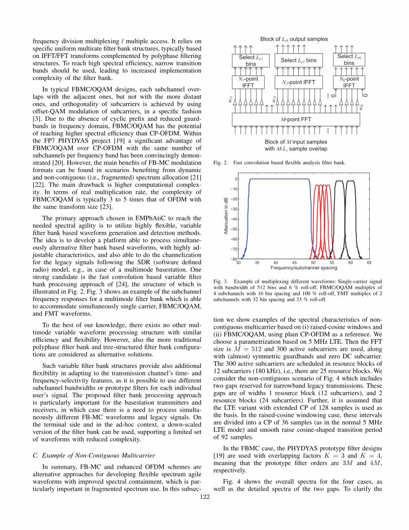
frequency division multiplexing / multiple access. It relies onspecific uniform multirate filter bank structures, typically basedon IFFT/FFT transforms complemented by polyphase filteringstructures. To reach high spectral efficiency, narrow transitionbands should be used, leading to increased implementationcomplexity of the filter bank.
In typical FBMC/OQAM designs, each subchannel over-laps with the adjacent ones, but not with the more distantones, and orthogonality of subcarriers is achieved by usingoffset-QAM modulation of subcarriers, in a specific fashion[3]. Due to the absence of cyclic prefix and reduced guard-bands in frequency domain, FBMC/OQAM has the potentialof reaching higher spectral efficiency than CP-OFDM. Withinthe FP7 PHYDYAS project [19] a significant advantage ofFBMC/OQAM over CP-OFDM with the same number ofsubchannels per frequency band has been convincingly demon-strated [20]. However, the main benefits of FB-MC modulationformats can be found in scenarios benefiting from dynamicand non-contiguous (i.e., fragmented) spectrum allocation [21][22]. The main drawback is higher computational complex-ity. In terms of real multiplication rate, the complexity ofFBMC/OQAM is typically 3 to 5 times that of OFDM withthe same transform size [23].
The primary approach chosen in EMPhAtiC to reach theneeded spectral agility is to utilize highly flexible, variablefilter bank based waveform generation and detection methods.The idea is to develop a platform able to process simultane-ously alternative filter bank based waveforms, with highly ad-justable characteristics, and also able to do the channelizationfor the legacy signals following the SDR (software definedradio) model, e.g., in case of a multimode basestation. Onestrong candidate is the fast convolution based variable filterbank processing approach of [24], the structure of which isillustrated in Fig. 2. Fig. 3 shows an example of the subchannelfrequency responses for a multimode filter bank which is ableto accommodate simultaneously single carrier, FBMC/OQAM,and FMT waveforms.
To the best of our knowledge, there exists no other mul-timode variable waveform processing structure with similarefficiency and flexibility. However, also the more traditionalpolyphase filter bank and tree-structured filter bank configura-tions are considered as alternative solutions.
Such variable filter bank structures provide also additionalflexibility in adapting to the transmission channel’s time- andfrequency-selectivity features, as it is possible to use differentsubchannel bandwidths or prototype filters for each individualuser’s signal. The proposed filter bank processing approachis particularly important for the basestation transmitters andreceivers, in which case there is a need to process simulta-neously different FB-MC waveforms and legacy signals. Onthe terminal side and in the ad-hoc context, a down-scaledversion of the filter bank can be used, supporting a limited setof waveforms with reduced complexity.
C. Example of Non-Contiguous Multicarrier
In summary, FB-MC and enhanced OFDM schemes arealternative approaches for developing flexible spectrum agilewaveforms with improved spectral containment, which is par-ticularly important in fragmented spectrum use. In this subsec-
Fig. 2. Fast convolution based flexible analysis filter bank.
30 35 40 45 50 55 60 65−80
−70
−60
−50
−40
−30
−20
−10
0
Frequency/subchannel spacing
Atte
nuat
ion
in d
B
Fig. 3. Example of multiplexing different waveforms: Single-carrier signalwith bandwidth of 512 bins and 6 % roll-off, FBMC/OQAM multiplex of4 subchannels with 16 bin spacing and 100 % roll-off, FMT multiplex of 2subchannels with 32 bin spacing and 33 % roll-off.
tion we show examples of the spectral characteristics of non-contiguous multicarrier based on (i) raised-cosine windows and(ii) FBMC/OQAM, using plain CP-OFDM as a reference. Wechoose a parametrization based on 5 MHz LTE. Then the FFTsize is M = 512 and 300 active subcarriers are used, alongwith (almost) symmetric guardbands and zero DC subcarrier.The 300 active subcarriers are scheduled in resource blocks of12 subcarriers (180 kHz), i.e., there are 25 resource blocks. Weconsider the non-contiguous scenario of Fig. 4 which includestwo gaps reserved for narrowband legacy transmissions. Thesegaps are of widths 1 resource block (12 subcarriers), and 2resource blocks (24 subcarriers). Further, it is assumed thatthe LTE variant with extended CP of 128 samples is used asthe basis. In the raised-cosine windowing case, these intervalsare divided into a CP of 36 samples (as in the normal 5 MHzLTE mode) and smooth raise cosine-shaped transition periodof 92 samples.
In the FBMC case, the PHYDYAS prototype filter designs[19] are used with overlapping factors K = 3 and K = 4,meaning that the prototype filter orders are 3M and 4M ,respectively.
Fig. 4 shows the overall spectra for the four cases, aswell as the detailed spectra of the two gaps. To clarify the
122

figure, here just the envelope of the power spectrum is visible,not the stopband ripples. It can be seen that FBMC resultsin much lower spectrum leakage to the spectral gaps in thisnon-contiguous multicarrier case than plain CP-OFDM orOFDM with raised-cosine windowing. With the used param-eters, raised-cosine windowing results in about 31 dB or 50dB attenuation, with respect to the passband level, for 1 or2 resource block gaps, respectively, when considering a 30kHz (2 subcarriers) bandwidth in the center of the gap. Thecorresponding values with plain OFDM are 15 dB and 18 dB,respectively.
III. MULTICARRIER SYSTEM DEVELOPMENT FOR PMR
A. Channel equalization and Synchronization Aspects
Both FMT and FBMC/OQAM systems can be designedto have similar number of subcarriers as an OFDM system,in which case the channel can usually be considered as flat-fading at subcarrier level, and one-tap complex subcarrier-wiseequalizers are sufficient. However, there is also the possibilityof increase the subcarrier spacing, e.g., in order to relax the ICIeffects with high mobility, in which case multi-tap equalizersare needed [16]. A convenient approach for realizing multitapsubcarrier equalizers is based on frequency sampling [25]. Thismethod can be adapted to the multi-mode receiver architecturein an effective way by modifying the weights in Figure 2.
The special OQAM-type signal structure has to be takeninto account when designing the pilot structures for channelestimation and synchronization [26], and it introduces alsodifficulties in adapting certain multiantenna schemes to theFBMC/OQAM context.
The broadband PMR system should be able to support awide range of link distances and thus relatively long channeldelay spreads. This requirement is also emphasized by thepropagation characteristics at the used relatively low frequencyband. Also relaxed synchronization and power control re-quirements for mobile terminals are important targets. Theseaspects are in favor of using FB-MC waveforms which is ableto support frequency division multiplexing of asynchronoustransmissions with high spectral efficiency.
Regarding asynchronous FDMA channelization, includingcell-based uplink and ad-hoc scenarios, the baseline approachis to use a narrow guard band (usually one subchannel)between different non-synchronized frequency channels. Thenthe filter bank based transmission modes allow fully asyn-chronous operation regarding timing offsets between transmis-sions and relatively coarse mutual frequency synchronizationis sufficient. This allows the transmission of short data packetswithout initial synchronization, and maintaining the synchro-nization of idle stations is not critical. Also the latency due toinitial synchronization can be minimized. The required timingand frequency offset compensation algorithms will be inte-grated with the variable filter bank structure. However, in caseof continuous transmission in cell-based systems, there aregood reasons for establishing synchronism between the uplinksignals. These reasons include reduced signal processing com-plexity and minimization of the overheads in TDD and TDMAoperation modes due to time-domain guard intervals betweentransmission bursts, which have to be able to absorb thetiming uncertainties. The overall synchronization process for
−200 −100 0 100 200
−100
−80
−60
−40
−20
0
Subcarriers
Pow
er d
B
CP−OFDMRC−windowingFMBC K=3FMBC K=4
−104 −102 −100 −98 −96 −94 −92
−100
−80
−60
−40
−20
0
Subcarriers
Pow
er d
B
5 10 15 20 25 30
−100
−80
−60
−40
−20
0
Subcarriers
Pow
er d
B
Fig. 4. Examples of the power spectra of non-contiguous multicarrierwaveforms. (a) Overall spectra. (b) The gap of 12 subcarriers, (c) The gap of24 subcarriers. Only the envelope of the spectra are shown, not the stopbandripples.
123

continuous transmission will be developed utilizing feedbackinformation about synchronization offsets from basestations tomobiles.
B. Higher Layers and Demonstrator Development
In addition to the waveform and basic signal processingaspects of the physical layer, EMPhAtiC will also developeffective multi-antenna techniques for the FB-MC transmis-sion schemes, and address relay and ad-hoc networking, ra-dio resource management and cross-layer aspects as well asspectrum sensing methods utilizing the flexible multichannelarchitecture. The developed broadband PMR scheme and itscoexistence with narrowband PMR services is planned to behighlighted through a demonstrator development.
IV. CONCLUDING REMARKS
We have discussed non-contiguous multicarrier schemesfor heterogeneous radio environments aimed at effective useof fragmented spectrum for broadband data communications.The Professional Mobile Radio evolution, along with generalcognitive radio development are important applications forthese techniques. We have seen that while sidelobe suppressiontechniques for CP-OFDM are able to significantly reduce thespectrum leakage to the frequency slots of non-active subcar-riers, the FBMC/OQAM approach has superior characteristicsin this respect.
The main challenge, and the main topic for future studies isto include the effects of the power amplifier nonlinearity intoconsideration. In this context, methods for reducing the peak-to-average power ratio (PAPR) of the modulated waveform andpower amplifier linearization techniques are central issues.
The multimode filter bank structure of Fig. 2 gives theopportunity to use single-carrier waveforms with the samespectral characteristics and reduced PAPR. This is especiallythe case on the terminal transmitter side. Unfortunately, it is noteasy use fragmented spectrum by a single-carrier waveform.However, in the uplink case the user data rates are often lowerthan in the cellular downlink, and there are less demands fornon-contiguous transmission by a mobile station.
ACKNOWLEDGMENT
The authors acknowledge the financial support by theEuropean Union FP7-ICT project EMPhAtiC (http://www.ict-emphatic.eu) under grant agreement no. 318362.
REFERENCES
[1] K. Balachandran, K. Budka, T. Chu, T. Doumi, and J. Kang, “Mobileresponder communication networks for public safety,” IEEE Communi-cations Magazine, vol. 44, pp. 56–64, Jan. 2006.
[2] “Mobile broadband in a mission critical environment - as seen from aTETRA perspective,” Feb. 2011, White Paper, Tetra Association.
[3] P. Siohan, C. Siclet, and N. Lacaille, “Analysis and design of OFDM-OQAM systems based on filterbank theory,” IEEE Trans. Signal Pro-cessing, vol. 50, no. 5, pp. 1170–1183, May 2002.
[4] B. Farhang-Boroujeny and R. Kempter, “Multicarrier communicationtechniques for spectrum sensing and communication in cognitive ra-dios,” IEEE Communications Magazine, Special Issue on CognitiveRadios for Dynamic Spectrum Access, vol. 46, no. 4, pp. 80–85, April2008.
[5] FP7-ICT Project EMPhAtiC - Enhanced Multicarrier Techniques forProfessional Ad-Hoc and Cell-Based Communications. http://www.ict-emphatic.eu.
[6] E. Dahlman, S. Parkvall, and J. Skold, 4G LTE / LTE-Advanced forMobile Broadband. Academic Press, 2011.
[7] Z. Yuan and A. Wyglinski, “On sidelobe suppression for multicarrier-based transmission in dynamic spectrum access networks,” IEEE Trans.Veh. Technol., vol. 59, no. 4, pp. 1998 – 2006, apr 2010.
[8] M. Faulkner, “The effect of filtering on the performance of OFDMsystems,” IEEE Trans. Veh. Technol., vol. 49, no. 9, pp. 1877–1884,sep 2000.
[9] T. A. Weiss, J. Hillenbrand, A. Krohn, and F. K. Jondral, “Mutualinterference in OFDM-based spectrum pooling systems,” in Proc. IEEEVeh. Technol. Conf. Spring, Dallas, TX, USA, may 2004, pp. 1872–1877.
[10] A. Sahin and H. Arslan, “Edge windowing for OFDM based systems,”IEEE Commun. Lett., vol. 15, no. 11, pp. 1208–1211, nov 2011.
[11] I. Cosovic, S. Brandes, and M. Schnell, “Subcarrier weighting: a methodfor sidelobe suppression in OFDM systems,” IEEE Commun. Lett.,vol. 10, no. 6, pp. 444–446, jun 2006.
[12] S. Brandes, I. Cosovic, and M. Schnell, “Sidelobe suppression in OFDMsystems by insertion of cancellation carriers,” in Proc. IEEE Veh.Technol. Conf. Fall, Los Angeles, CA, USA, sep 2005, pp. 152–156.
[13] H.-M. Chen, W.-C. Chen, and C.-D. Chung, “Spectrally precodedOFDM and OFDMA with cyclic prefix and unconstrained guard ratios,”IEEE Trans. Wireless Commun., vol. 10, no. 5, pp. 1416 – 1427, may2011.
[14] R. Chang, “High-speed multichannel data transmission with bandlimitedorthogonal signals,” Bell Sys. Tech. J., vol. 45, pp. 1775–1796, Dec.1966.
[15] B. Saltzberg, “Performance of an efficient parallel data transmissionsystem,” IEEE Trans. Commun. Technol., vol. 15, no. 6, pp. 805–811,dec 1967.
[16] B. Hirosaki, “An orthogonally multiplexed qam system using thediscrete fourier transform,” IEEE Transactions on Communications,vol. 29, no. 7, pp. pp. 982 – 989, Jul 1981.
[17] R. Vallet and K. H. Taieb, “Fraction spaced multi-carrier modulation,”Wireless Pers. Commun., Kluwer, vol. 2, pp. 97–103, 1995.
[18] G. Cherubini, E. Eleftheriou, and S. Olcer, “Filtered multitone modula-tion for vdsl,” Proc. of IEEE Global Telecommunications Conference,pp. 1139–1144, 1999.
[19] FP7-ICT Project PHYDYAS - Physical Layer for Dynamic SpectrumAccess and Cognitive Radio. http://www.ict-phydyas.org.
[20] V. Ringset, H. Rustad, F. Schaich, J. Vandermot, and M. Najar,“Performance of a filterbank multicarrier (FBMC) physical layer inthe WiMAX context,” Proc. Future Network and Mobile Summit 2010,Florence, Italy, June 2010.
[21] M. Shaat and F. Bader, “Computationally efficient power allocationalgorithm in multicarrier-based cognitive radio networks: OFDM andFBMC systems,” EURASIP J. Advances Signal Processing, vol. 2010,pp. 1–13, 2010.
[22] H. Zhang, D. LeRuyet, D. Roviras, Y. Medjahdi, and H. Sun, “Spectralefficiency comparison of OFDM/FBMC for uplink cognitive radionetworks,” EURASIP J. Advances Signal Processing, vol. 2010, pp.1–14, 2010.
[23] L. Baltar, F. Schaich, M. Renfors, and J. A. Nossek, “Computationalcomplexity analysis of advanced physical layers based on multicar-rier modulation,” in Proc. Future Network and Mobile Summit (Fu-tureNetw), Warsaw, Poland, Jun. 15–17 2011, pp. 1–8.
[24] M. Renfors and f. harris, “Highly adjustable multirate digital filtersbased on fast convolution,” Proc. European Conference on CircuitTheory and Design, ECCTD 2011, Linkoping, Sweden, Aug. 2011.
[25] T. Ihalainen, A. Ikhlef, J. Louveaux, and M. Renfors, “Channel equal-ization for multi-antenna FBMC/OQAM receivers,” IEEE Trans. Veh.Technol., vol. 60, no. 5, pp. 2070–2085, May 2011.
[26] C. Lele, J.-P. Javaudin, R. Legouable, A. Skrzypczak, , and P. Siohan,“Channel estimation methods for preamble-based ofdm/oqam modula-tion,” European Transactions on Telecommunications, vol. 19, pp. 741–750, Sept. 2008.
124


3.2.2 In Device-to-Device communications contextAs extension to previous works on systems coexistence in the PMR communication band, I focused my interestsin the D2D communications scenario. The result of this interest is the preparation and the acceptance by theFrench National research agency (ANR) of the project ACCENT5, and the PHC ULYSSES10 project betweenCentraleSupélec (France) and Trinity College of Dublin (Ireland) accepted by the "Campus France"11 and the IrishResearch Council 12 agencies respectively. Also the supervision of the PhD thesis (in progress) of Mr. QuentinBODINIER, and obtained results have been determinant for the development of coexistence issues in the D2Dcommunication environment.
The target here is to demonstrate the feasibility and compare the efficiency of enhanced OFDM and differentfilter bank based multi-carrier waveforms in the D2D IMT advanced evolution (5G) context. Therefore, for coexis-tence purposes, the conducted studies focused on advanced filter based multi-carrier (FBMC) waveforms for D2Dcommunications allowing a much higher relaxation (above the cyclic prefix time duration) on the synchronizationconstraint at the eNB (evolved Node B). Note that the context scenario is the use of D2D communications in alegacy band controlled by an operator that already deployed an LTE network in the same band.
Studies on interference caused by time-frequency misalignment are restricted to the case where the misaligneduser has the same waveform as the other systems in the network [62], and very limited works addressed the inter-ference caused by a given waveform13 onto OFDM. On the other hand, power-loading studies rely on interferencemodels which do not take time-frequency misalignment into account [63, 64, 65]. Therefore, it is crucial to analyzethe effects of time-frequency misalignment on the interference caused by D2D pairs onto cellular users.
As it’s well known, numerous new waveforms with intrinsic filtering properties have emerged for the 5G context.Almost of these waveforms are relied on filter bank based modulation. Four recently proposed FBMC based wave-forms, namely Filtered Multi-Tone [66], OFDM/OQAM [67], Lapped FBMC [68], and GFDM [57] have been usedto analyze, in the coexistence context, the time-frequency misalignment effects of the D2D pair on the incumbentnetwork. The interference injected by the D2D pair has been analyzed on the incumbent network for each waveformseparately. This is allowing us to build interference tables to be used as inputs to the power loading solution andanalyze the maximum rate achievable through each waveform. Different resource sizes in time and frequency hasbeen used and the resulting rate calculated.For the interference analysis, to assign the power to be distributed on the D2D pairs, it’s important to know howmuch power leaks to the adjacent band depending on which waveform is utilized by the D2D users. The classicalway to compute the leakage is to integrate the Power Spectral Density (PSD) of the interfering signal on the bandthat suffers from the interference. However, this model does not take into account the time window of the incum-bent. This is of paramount importance as the incumbent only considers a time window with a specific width basedon its own parameters. Besides, it has been shown in [1], that the PSD is not a suitable practice to evaluate theinter system interference for the scenario of interest. We therefore employed the instantaneous interference modelproposed in [1] to compute the interference I lm injected to the l− th subcarrier of the incumbent by the D2D signalxm where only subcarrier m is utilized.
For our analysis, we consider an incumbent system following similar parameters to 3GPP LTE standard. TheOFDM cellular user occupies 180 subcarriers, which corresponds to 15 LTE resource blocks (RB) along the fre-quency axis. Besides, it uses a number of CP samples NCP = 12 samples. The length of the transmission windowin time varies from Nf = 1 to 100 OFDM symbols. In the center of the incumbent band, a free band Bf dividedinto Mf subcarriers of 15 kHz is unused. This band is utilized by the D2D pair. No guard band is considered inthis study.Fig. 4 in [C97] ([C97] is the first paper depicted at the end of this Subsection 3.2.2) shows the interference thatis injected by an active subcarrier with unitary power on 20 neighboring OFDM subcarriers as a function of δt fordifferent waveforms. Interference caused by the Lapped FBMC and the OFDM/OQAM is weakly affected by thetiming offset. GFDM and FMT show slight variations with respect to δt. On the contrary, the figure for OFDMshows high variations along the δt axis.
10for more details on this project see Subsection 1.5.3, page 23.11http://www.campusfrance.org/en12http://www.research.ie/13different from OFDM scheme.
125

Subcarrier Distance-10 -8 -6 -4 -2 0 2 4 6 8 10
Mea
n in
ject
ed in
terf
eren
ce in
dB
-35
-30
-25
-20
-15
-10
-5
0OFDMFMTOFDM/OQAMLapped FBMCGFDM
Figure 3.18: Mean Interference Table on OFDM receiver [C97].
Main observations are threefold:
1. It appears that OFDM is the only waveform that shows a significant difference between its mean and maximuminjected interference on the OFDM based incumbent. Other waveforms show a difference of approximatelyabout 0 to 1dB.
2. If mean interference is considered, GFDM causes the highest interference. However, if the maximum interfer-ence is considered, OFDM based D2D pair has the worst performance.
3. It’s important to point out that values of interference injected by 5G waveforms are surprisingly high. ForOFDM/OQAM for example, the PSD based model predicts an attenuation of 60 dB at subcarrier distance of2 [1], whereas our interference tables show that the interference power seen by an OFDM receiver at subcarrierdistance of 2 is 18.5 dB. This is due to the fact that the OFDM demodulator performs Fast Fourier Transform(FFT) on a time window that may be much shorter than the length of the symbol of the other waveform.Therefore the signal suffers from discontinuities that produce projections on the whole incumbent spectrum.
Obtained results bring insight into which waveform performs best for different time window lengths and inter-ference constraint. It seems that for transmission windows shorter than 10 symbols, OFDM is the best choice, asit does not suffer from any transmission delay. Therefore, linearly pulse shaped waveforms can compete only whenthe transmission window starts getting wider than 10 OFDM symbols. It can be noticed that Lapped FBMC showsa promising performance. This is due to the fact that it has a very short delay about only one symbol, and injectsinterference comparable to that of OFDM/OQAM and FMT. FMT suffers from a large delay during transmissionand seems not to be an appropriate candidate for low latency applications. However, OFDM/OQAM performancestays very close to the Lapped FBMC. Interestingly, the performance of OFDM starts to degrade for time windowsof width larger than Nf = 15 regardless of the interference constraint. This is the result of the OFDM spectralefficiency loss due to the presence of a CP. Note that, even though GFDM seems to be a potential competitor toOFDM/OQAM and Lapped FBMC when the interference constraint is very relaxed, it cannot efficiently cope withstringent interference constraints. This is the consequence of its high interference leakage as it is shown in Figs.3.18 and 3.19.Through numerical results, we have shown that it is not worth synchronizing the D2D pair in time domain withrespect to the incumbent network. Interference tables derived in this paper allowed us to analyze the maximumrate achievable by the D2D pair under different interference constraints. We also demonstrated that the communi-cation window size has a direct impact on the efficacy of the waveform utilized by the D2D pair. For short D2D
126

Subcarrier Distance-10 -8 -6 -4 -2 0 2 4 6 8 10
Max
imum
inje
cted
inte
rfer
ence
in d
B
-35
-30
-25
-20
-15
-10
-5
0OFDMFMTOFDM/OQAMLapped FBMCGFDM
Figure 3.19: Maximum Interference Table on OFDM receiver [C97].
transmission windows, OFDM, GFDM and Lapped FBMC seem to be appropriate candidates. We also showedthat under stringent interference constraints and wide transmission windows, OFDM/OQAM and Lapped FBMCare strong candidates.More detailed and extended results on transmitted bits as a function of available OFDM time symbols in the trans-mission window, and also on transmitted bits by different waveforms over 12 subcarriers (1 RB) during one TTI infunction of the interference threshold are presented in [C97] (this reference is the first publication depicted by theend of this Subsection 3.2.2).
From obtained results and observations in [C97], the main raised question is "What are the Real Gains fromFilter Banks and CP-OFDM systems coexistence?". Researches undertaken in [C100, C103], and [C105] focused onmodeling the interference between OFDM/OQAM and CP-OFDM to give some answers to the previous question.The followed approach is the study of inter-user interference in scenarios where CP-OFDM and OFDM/OQAMusers interfere with each other. It is shown in [C100] (this reference is the second publication depicted at the endof this Subsection 3.2.2) that the PSD based approach consists in modeling the interference at the input antennaof the interfered receiver, and totally omits the demodulation operations that are performed by the latter. Theinterference seen at the output of the demodulator of the interfered receiver is much higher than expected usingthe PSD based model. Moreover, the interference between the incumbent and secondary systems is symmetrical,which contradicts the results obtained with the PSD-based model.
We focused on rating the inter-user interference caused by the fact that different users transmit in an asyn-chronous manner with different waveforms. Therefore, we consider a simple scenario where an incumbent systemU1 coexists with a secondary user U2 in the same band. Both systems use multi-carrier waveforms with the samesubcarrier spacing ∆F , and each of them is assigned a set of subcarriers Li (i ∈ 1, 2). The incumbent U1 utilizesCP-OFDM, whereas two alternatives are studied for U2. The latter uses CP-OFDM in the case of a homogeneousscenario (referred to as Hom) and OFDM/OQAM in the case of a heterogeneous scenario (referred to as Het). Theconfigurations studied in this context are summarized in Figs. 3.20 and 3.2114.
First, the amount of interference suffered by U1 and U2 on each of their subcarriers is calculated using Monte-Carlo simulations for heterogeneous environment (See Section IV in [C100]). Second, we calculated the PSD-basedmodel that consists in computing the leakage caused by users onto each other by integrating the PSD of the inter-fering signal on the band that suffers from the interference.
14where in Fig. 3.21, ΦCP-OFDM (resp. ΦPHYDYAS ) is the PSD of the CP-OFDM signal (resp. of OFDM/OQAM with PHYDYASfilter in [58]).
127
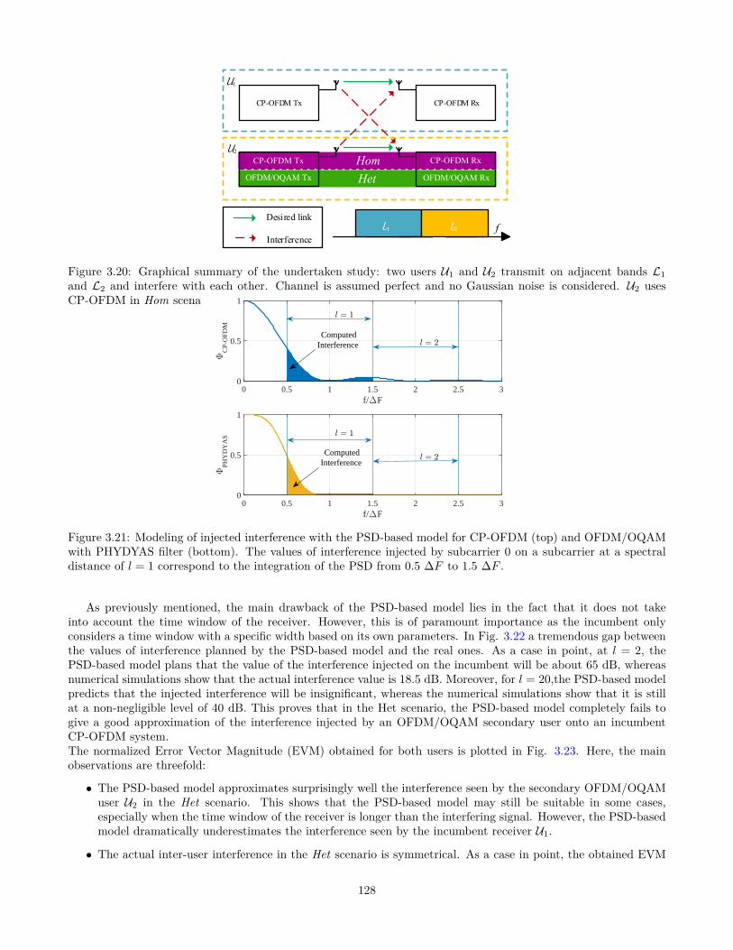
CP-OFDM Tx CP-OFDM Rx
U1
U2
L1 L2
Desired link
Interference
f
HetOFDM/OQAM Tx OFDM/OQAM Rx
CP-OFDM Tx Hom CP-OFDM Rx
Figure 3.20: Graphical summary of the undertaken study: two users U1 and U2 transmit on adjacent bands L1and L2 and interfere with each other. Channel is assumed perfect and no Gaussian noise is considered. U2 usesCP-OFDM in Hom scenario and OFDM/OQAM in Het scenario.
f/∆F0 0.5 1 1.5 2 2.5 3
ΦC
P-O
FDM
0
0.5
1
l = 1
l = 2
Computed Interference
f/∆F0 0.5 1 1.5 2 2.5 3
ΦPH
YD
YA
S
0
0.5
1
Computed Interference
l = 1
l = 2
Figure 3.21: Modeling of injected interference with the PSD-based model for CP-OFDM (top) and OFDM/OQAMwith PHYDYAS filter (bottom). The values of interference injected by subcarrier 0 on a subcarrier at a spectraldistance of l = 1 correspond to the integration of the PSD from 0.5 ∆F to 1.5 ∆F .
As previously mentioned, the main drawback of the PSD-based model lies in the fact that it does not takeinto account the time window of the receiver. However, this is of paramount importance as the incumbent onlyconsiders a time window with a specific width based on its own parameters. In Fig. 3.22 a tremendous gap betweenthe values of interference planned by the PSD-based model and the real ones. As a case in point, at l = 2, thePSD-based model plans that the value of the interference injected on the incumbent will be about 65 dB, whereasnumerical simulations show that the actual interference value is 18.5 dB. Moreover, for l = 20,the PSD-based modelpredicts that the injected interference will be insignificant, whereas the numerical simulations show that it is stillat a non-negligible level of 40 dB. This proves that in the Het scenario, the PSD-based model completely fails togive a good approximation of the interference injected by an OFDM/OQAM secondary user onto an incumbentCP-OFDM system.The normalized Error Vector Magnitude (EVM) obtained for both users is plotted in Fig. 3.23. Here, the mainobservations are threefold:
• The PSD-based model approximates surprisingly well the interference seen by the secondary OFDM/OQAMuser U2 in the Het scenario. This shows that the PSD-based model may still be suitable in some cases,especially when the time window of the receiver is longer than the interfering signal. However, the PSD-basedmodel dramatically underestimates the interference seen by the incumbent receiver U1.
• The actual inter-user interference in the Het scenario is symmetrical. As a case in point, the obtained EVM
128
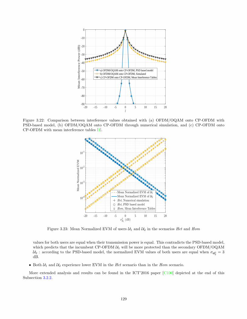
l
-20 -15 -10 -5 0 5 10 15 20
Mea
n I
nte
rfer
ence
Po
wer
(d
B)
-90
-80
-70
-60
-50
-40
-30
-20
-10
0
a) OFDM/OQAM onto CP-OFDM, PSD based modelb) OFDM/OQAM onto CP-OFDM, Simulatedc) CP-OFDM onto CP-OFDM, Mean Interference Tables
Figure 3.22: Comparison between interference values obtained with (a) OFDM/OQAM onto CP-OFDM withPSD-based model, (b) OFDM/OQAM onto CP-OFDM through numerical simulation, and (c) CP-OFDM ontoCP-OFDM with mean interference tables [1].
σ2d2
(dB)-20 -15 -10 -5 0 5 10 15 20
Mea
n N
orm
aliz
ed E
VM
10-4
10-3
10-2
10-1
Mean Normalized EVM of U1
Mean Normalized EVM of U2
Het, Numerical simulation
Het, PSD based model
Hom, Mean Interference Tables
Figure 3.23: Mean Normalized EVM of users U1 and U2 in the scenarios Het and Hom
values for both users are equal when their transmission power is equal. This contradicts the PSD-based model,which predicts that the incumbent CP-OFDM U1 will be more protected than the secondary OFDM/OQAMU2 : according to the PSD-based model, the normalized EVM values of both users are equal when σd2
2= 3
dB.
• Both U1 and U2 experience lower EVM in the Het scenario than in the Hom scenario.
More extended analysis and results can be found in the ICT’2016 paper [C100] depicted at the end of thisSubsection 3.2.2.
129

As a general conclusion, it has been shown that the widely used PSD-based model is highly flawed and failsto give a good approximation of the interference seen by each user in heterogeneous scenarios. Indeed, presentednumerical results showed that when the secondary system utilizes OFDM/OQAM, the actual values of interferenceare higher than those planned by the PSD based model by more than 50 dB. Furthermore, contrary to the widelyspread idea that CP-OFDM interferes more onto OFDM/OQAM users than the opposite, we revealed that hetero-geneous interference is symmetrical and that users interfere equally onto each other. Though it was shown thatboth users experience a slight improvement when the secondary user uses OFDM/OQAM modulation, the gain wasshown to be much more limited than what was expected with the PSD-based model.
Results with exact mathematical close forms of the cross-interference between OFDM/OQAM and CP-OFDMsystems due to their coexistence are provided in [C103, C105], where a copy of this last is depicted at the end ofthis Subsection 3.2.2. A Journal paper that gathers a deep analysis on the cross-interference with both numericaland the mathematical (theoretical) close form using generalized multi-Carrier waveform model based on linear andcircular filter banks has been submitted to the IEEE Transactions on Communications Journal.
To resume, all the publications (See Subsection 2.1.1, pp. 30-41) related with the cited researches in thisSubsection 3.2.2 are: Journals: one IEEE Transactions on Communications Journal submitted, Conferences:[C96, C97, C100, C103, C105, C106], the PhD thesis of Mr. Quentin BODINIER in progress, and the Master:
• Quentin Bodinier from Supélec. Master degree topic on: “Contributions to PHY and MAC layers for GFDMin the Context of Cognitive Radio”, in collaboration with Trinity College in Dublin (Ireland). Supervisors:Dr. Christophe Moy and Faouzi Bader (Supélec), Dr. Hamed Ahmadi and Prof. Luiz DaSilva (Trinity CollegeDublin, Ireland). Period: March 2013-Aug 2014.
130

Following are the corresponding depicted papers:1. [C97]- Quentin Bodinier, Arman Farhang, Faouzi Bader, Hamed Ahmadi, Jacques Palicot, and Luiz A.
DaSilva,"5G Waveforms for Overlay D2D Communications: Effects of Time-Frequency Misalignment", inProc. of the IEEE International Communications Conference (IEEE ICC ’2016). Kuala Lumpur, Malaysia.May 2016.
2. [C100]- Quentin Bodinier, Faouzi Bader, and Jacques Palicot, "Modeling Interference Between OFDM/OQAMand CP-OFDM: Limitations of the PSD-Based Model", in Proc. of the International Conference on Telecom-munications (ICT’2016), Thessaloniki-Greece. May 2016.
3. [C105]- Quentin Bodinier, Faouzi Bader, and Jacques Palicot, "Coexistence in 5G: Analysis of Cross-Interferencebetween OFDM/OQAM and Legacy Users", in Proc. of the IEEE Global Communications Conference (Globe-com’2016). Washington DC, USA, December 2016.
131

5G Waveforms for Overlay D2D Communications:Effects of Time-Frequency Misalignment
Quentin Bodinier∗, Arman Farhang†, Faouzi Bader∗, Hamed Ahmadi‡, Jacques Palicot∗, and Luiz A. DaSilva†∗SCEE/IETR - CentraleSupelec, Rennes, France,†CONNECT - Trinity College Dublin, Ireland,
‡University College Dublin, Ireland.Email : [email protected]
Abstract—This paper analyses a scenario where a Device-To-Device (D2D) pair coexists with an Orthogonal FrequencyDivision Multiplexing (OFDM) based incumbent network. D2Dtransmitter communicates in parts of spectrum left free bycellular users, while respecting a given spectral mask. TheD2Dpair is misaligned in time and frequency with the cellular users.Furthermore, the D2D pair utilizes alternative waveforms toOFDM proposed for 5G. In this study, we show that it isnot worth synchronising the D2D pair in time with respectto the cellular users. Indeed, the interference injected into theincumbent network has small variations with respect to timemisalignment. We provide interference tables that encompassboth time and frequency misalignment. We use them to analysethe maximum rate achievable by the D2D pair when it usesdifferent waveforms. Then, we present numerical results showingwhat waveform should be utilized by the D2D pair according tothe time-frequency resources that are not used by the incumbentnetwork. Our results show that the delay induced by linearlyconvolved waveforms make them hardly applicable to short timewindows, but that they dominate OFDM for long transmissions,mainly in the case where cellular users are very sensitive tointerference.
I. I NTRODUCTION
The advent of Device-To-Device (D2D) communication asa new application in5th Generation wireless networks (5G)raises a number of challenges. In particular, coexistence ofD2D pairs with cellular users may affect the performanceobserved by the latter. To avoid that, a first standard for D2Dcommunication has been proposed [1], requiring consequentinteraction between the base station and the D2D pairs.
With increasing number of D2D links, perfect synchro-nization between those and the native cellular subscribersis infeasible. Therefore, it is important to consider schemeswhere D2D users are not perfectly synchronized both intime and frequency with respect to the cellular users. In thatcase, it is well known that Orthogonal Frequency DivisionMultiplexing (OFDM) suffers from very high multiple userinterference when timing and frequency offsets go beyondcertain values [2], [3]. As a consequence, the overall quality oftransmission seen by cellular users may decrease dramatically.
To cope with that challenge, a number of solutions based onboth power loading and waveform design have been proposed[4]–[14]. On one hand, to the best of our knowledge, studiesof interference caused by time-frequency misalignment arerestricted to the case where the misaligned user has the same
waveform as the others [3], [15], and there is no work address-ing the interference caused by a given waveform onto OFDM.On the other hand, power-loading studies rely on interferencemodels which do not take time-frequency misalignment intoaccount [4]–[7]. However, accurately estimating the causedinterference is of high importance, as D2D users aim tomaximise their data rate subject to constraints of total powerand maximum injected interference.
Therefore, it is crucial to analyse the effects of time-frequency misaligment on the interference caused by D2Dpairs onto cellular users. In this paper, we derive interferencetables that can be used to find the optimal solution of thepower loading problem for D2D users following the model of[6]. These results allow us to analyse the performance of aD2D pair as a function of the waveform they utilise.
As a matter of fact, the rate achievable by D2D users ishighly dependent on their air interface. Indeed, utilizationof appropriate waveforms can limit Out Of Band (OOB)emissions of D2D users and therefore allows them to allocatehigher power to their active subcarriers. It is well known thatOFDM suffers from large sidelobes in frequency due to itsrectangular window in time [11], [16], [17]. To overcomethis problem, numerous new waveforms with intrinsic filteringproperties have emerged [7]–[14]. These waveforms all relyonFilter Bank Multi Carrier (FBMC) modulation. In this work,we focus on four recently proposed FBMC based waveforms,namely Filtered Multi-Tone (FMT), Offset Quadrature Ampli-tude Modulated-Orthogonal Frequency Division Multiplexing(OFDM/OQAM), Lapped FBMC and GFDM.
In FMT modulation [8], [9], the assumption is that there isno overlapping between adjacent subcariers. Therefore, FMTsuffers from some bandwidth efficiency loss. To increase spec-tral efficiency, OFDM/OQAM [10], [11] allows for adjacentsubcarriers to overlap. Differently from FMT, real symbolshaving Pulse Amplitude Modulation (PAM) are transmittedon each subcarrier. Aπ
2 phase difference is applied to ad-jacent subcarriers, which provides real-domain orthogonality.However, OFDM/OQAM requires doubling the symbol rate.To avoid that, Lapped FBMC modulation has been recentlyproposed by Bellanger et al. in [12]. In this scheme, thenumber of subcarriers is doubled instead of the number oftime symbols.
A drawback common to all the aforementioned modulations
132

Simulations
Optimal Power Loading [6]
Interference Tables
Optimal Rate
Transmission WindowSize Consideration
Best Waveform selection
D2DTX
OFDMRX
δt,δf
Fig. 1: Paper Synopsis
is the transient imposed by their transmit and receive filters.Generalized Frequency Division Multiplexing (GFDM) tacklesthis problem by application of cyclic pulse shaping [13].However, this comes at the expense of higher OOB emissions,which is due do the discontinuities induced in the signal bytruncation in time with a rectangular window [14].
In this paper, we analyse time-frequency misalignmenteffects of the D2D pair on the incumbent network. We evaluatethe interference injected by the D2D pair on the incumbentnetwork for each waveform separately. This allows us to buildinterference tables to be used as inputs to the power loadingsolution and analyse the maximum rate achievable througheach waveform. We consider different resource sizes in timeand frequency and calculate the resulting data rate. This analy-sis reveals the strength and weaknesses of different waveformsto be used by the D2D pair as a function of available time-frequency resources. Our approach is summarized in Fig. 1.
The remainder of this paper is organized as follows. Insection II, the system model and the analysed waveforms arepresented. Section III is dedicated to the interference analysis,whereas section IV presents the rate optimization problemand its solution. Section V presents simulation results. Finally,section VI concludes this paper.
II. CONSIDEREDSCENARIO AND STUDIED WAVEFORMS
A. Considered scenario
In this study, we consider an OFDM based incumbentnetwork with subcarrier spacing∆F where a certain groupof subcarriers is free and can be utilized by a D2D pair.It is assumed that the base station broadcasts informationabout its unused time-frequency resources. This informationincludes the number of free subcarriersMf and the numberof OFDM symbols during which the band will be freeNf.We defineBi as the band ocuppied by the cellular users,Bf the free band used by the D2D pair, andIth as theinterference threshold forBi . It is assumed that the D2D paircan misalign its transmission frequency with respect toBf.Besides, we assume that, even though the D2D transmission is
Fig. 2: Time-Frequency layout of the situation with time-frequency misplacement representation.
contained in the duration of the opportunity, time synchronismbetween D2D and cellular users at the symbol level maynot be achieved. We denoteδt and δf as the offsets in timeand frequency. The scenario is presented in figure 2, wherethe grey grid represents the time-frequency resources of theincumbent network. These resources follow the 3GPP LongTerm Evolution (LTE) standard.
B. Waveforms under consideration
To pave the way for the analysis conducted in SectionIII, we briefly explain the mathematical representation of thewaveforms under study to be used by the D2D pair.
1) FMT: In this scheme, complex Quadrature AmplitudeModulation (QAM) symbols are linearly pulse shaped usingthe prototype filterg = [g[0] . . . g[KP − 1]]T, whereK is theoverlapping factor andP is the number of samples per timesymbol. M is the number of subcarriers,N the number ofsymbols in time, anddm = [dm[0] . . . dm[N − 1]]T the vectorof modulated symbols on themth subcarrier. Finally, the FMTsignal can be obtained as [9]
xFMT[k] =
N−1∑
n=0
M−1∑
m=0
dm[n]g[k − nP ]ej2π mM k, (1)
∀k = 0 . . . (N + K − 1)P − 1.
2) OFDM/OQAM: In this modulation format, the signalcan be derived in a similar way to FMT, whereP = M ,dm symbols are drawn from a PAM constellation, and aphase factorθm[n] = ej π
2 ⌊ n+m2 ⌋ is introduced wheren andm
the time-frequency indexes respectively. Besides, subsequentsymbols are separated byM2 samples in time, which impliesdoubling the symbol rate. Therefore, the transmit signal canbe expressed as [18]
xOQAM[k] =
N−1∑
n=0
M−1∑
m=0
(dm[n]θm[n]g[k − n
M
2] (2)
×ej2π mM (k− KM−1
2 )
),
∀k = 0 . . . (P + K − 1
2)M − 1.
3) Lapped FBMC: This scheme is in essence similar toOFDM/OQAM systems. However, for this modulation thesymbol rate is not doubled. As defined in [12], the emittedsignal can be written as
xLapped[k] =
N−1∑
n=0
M−1∑
m=0
dm[n]g[k − nM ]ej(k− 12+ M
2 )(m− 12 ) π
M ,
∀k = 0 . . . (P + 1)M − 1. (3)
133
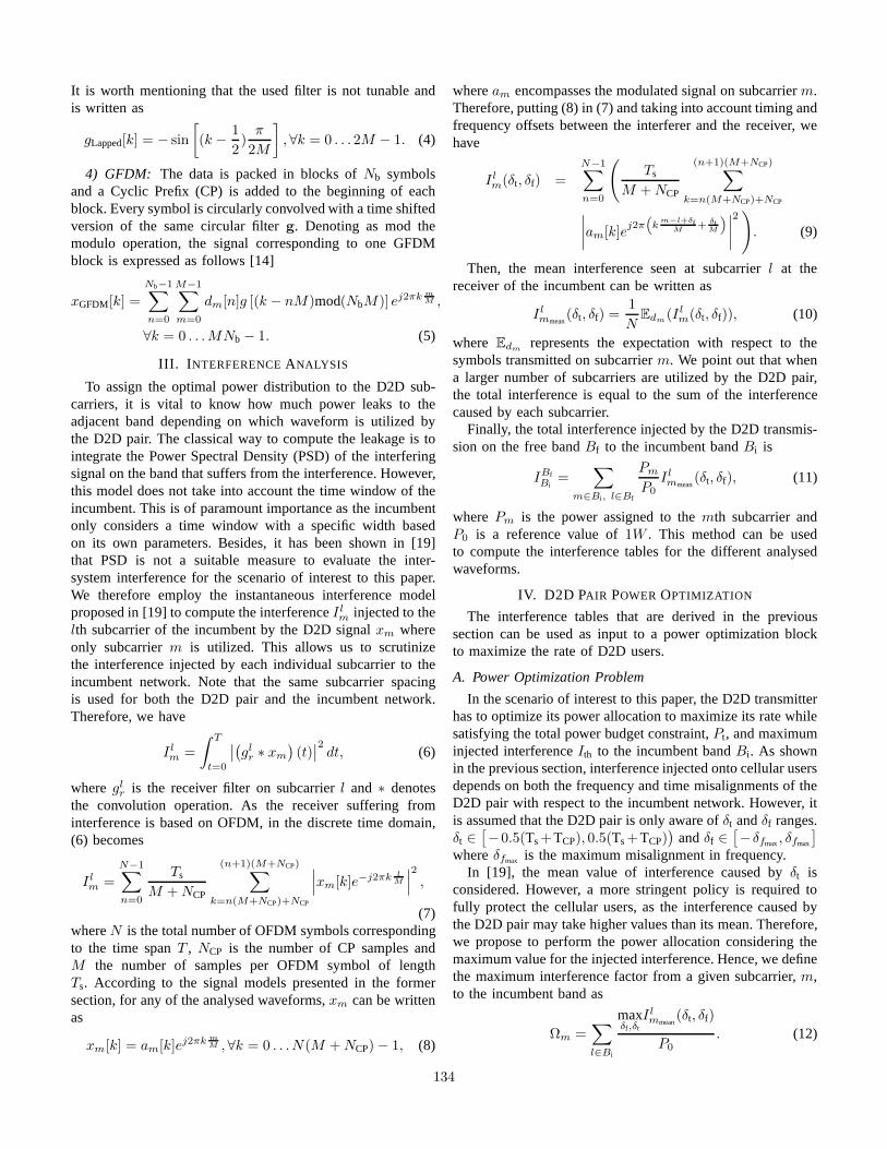
It is worth mentioning that the used filter is not tunable andis written as
gLapped[k] = − sin
[(k − 1
2)
π
2M
], ∀k = 0 . . . 2M − 1. (4)
4) GFDM: The data is packed in blocks ofNb symbolsand a Cyclic Prefix (CP) is added to the beginning of eachblock. Every symbol is circularly convolved with a time shiftedversion of the same circular filterg. Denoting as mod themodulo operation, the signal corresponding to one GFDMblock is expressed as follows [14]
xGFDM[k] =
Nb−1∑
n=0
M−1∑
m=0
dm[n]g [(k − nM)mod(NbM)] ej2πk mM ,
∀k = 0 . . .MNb − 1. (5)
III. I NTERFERENCEANALYSIS
To assign the optimal power distribution to the D2D sub-carriers, it is vital to know how much power leaks to theadjacent band depending on which waveform is utilized bythe D2D pair. The classical way to compute the leakage is tointegrate the Power Spectral Density (PSD) of the interferingsignal on the band that suffers from the interference. However,this model does not take into account the time window of theincumbent. This is of paramount importance as the incumbentonly considers a time window with a specific width basedon its own parameters. Besides, it has been shown in [19]that PSD is not a suitable measure to evaluate the inter-system interference for the scenario of interest to this paper.We therefore employ the instantaneous interference modelproposed in [19] to compute the interferenceI l
m injected to thelth subcarrier of the incumbent by the D2D signalxm whereonly subcarrierm is utilized. This allows us to scrutinizethe interference injected by each individual subcarrier totheincumbent network. Note that the same subcarrier spacingis used for both the D2D pair and the incumbent network.Therefore, we have
I lm =
∫ T
t=0
∣∣(glr ∗ xm
)(t)∣∣2 dt, (6)
whereglr is the receiver filter on subcarrierl and ∗ denotes
the convolution operation. As the receiver suffering frominterference is based on OFDM, in the discrete time domain,(6) becomes
I lm =
N−1∑
n=0
Ts
M + NCP
(n+1)(M+NCP)∑
k=n(M+NCP)+NCP
∣∣∣xm[k]e−j2πk lM
∣∣∣2
,
(7)whereN is the total number of OFDM symbols correspondingto the time spanT , NCP is the number of CP samples andM the number of samples per OFDM symbol of lengthTs. According to the signal models presented in the formersection, for any of the analysed waveforms,xm can be writtenas
xm[k] = am[k]ej2πk mM , ∀k = 0 . . .N(M + NCP) − 1, (8)
wheream encompasses the modulated signal on subcarrierm.Therefore, putting (8) in (7) and taking into account timingandfrequency offsets between the interferer and the receiver,wehave
I lm(δt, δf) =
N−1∑
n=0
(Ts
M + NCP
(n+1)(M+NCP)∑
k=n(M+NCP)+NCP
∣∣∣∣am[k]ej2π
(k
m−l+δfM + δt
M
)∣∣∣∣2)
. (9)
Then, the mean interference seen at subcarrierl at thereceiver of the incumbent can be written as
I lmmean
(δt, δf) =1
NEdm(I l
m(δt, δf)), (10)
where Edm represents the expectation with respect to thesymbols transmitted on subcarrierm. We point out that whena larger number of subcarriers are utilized by the D2D pair,the total interference is equal to the sum of the interferencecaused by each subcarrier.
Finally, the total interference injected by the D2D transmis-sion on the free bandBf to the incumbent bandBi is
IBfBi
=∑
m∈Bi, l∈Bf
Pm
P0I lmmean
(δt, δf), (11)
where Pm is the power assigned to themth subcarrier andP0 is a reference value of1W . This method can be usedto compute the interference tables for the different analysedwaveforms.
IV. D2D PAIR POWER OPTIMIZATION
The interference tables that are derived in the previoussection can be used as input to a power optimization blockto maximize the rate of D2D users.
A. Power Optimization Problem
In the scenario of interest to this paper, the D2D transmitterhas to optimize its power allocation to maximize its rate whilesatisfying the total power budget constraint,Pt, and maximuminjected interferenceIth to the incumbent bandBi . As shownin the previous section, interference injected onto cellular usersdepends on both the frequency and time misalignments of theD2D pair with respect to the incumbent network. However, itis assumed that the D2D pair is only aware ofδt andδf ranges.δt ∈
[−0.5(Ts+TCP), 0.5(Ts+TCP)
)andδf ∈
[−δfmax, δfmax
]
whereδfmax is the maximum misalignment in frequency.In [19], the mean value of interference caused byδt is
considered. However, a more stringent policy is required tofully protect the cellular users, as the interference caused bythe D2D pair may take higher values than its mean. Therefore,we propose to perform the power allocation considering themaximum value for the injected interference. Hence, we definethe maximum interference factor from a given subcarrier,m,to the incumbent band as
Ωm =∑
l∈Bi
maxδf ,δt
I lmmean
(δt, δf)
P0. (12)
134

TABLE I: Number of data symbols useful to D2D pairs
Waveform Useful D2D Symbols
OFDM Nf
FMT Nf − K + 1
OFDM/OQAM ⌊NfM+NCP
M− K + 1
2⌋
Lapped FBMC ⌊NfM+NCP
M− 1⌋
GFDM Nb⌊ NfNb
Nb(M+NCP)NbM+NCP
⌋
On this basis, we define the following optimization problemfor D2D pairs.
P1 : maxPm
Mf−1∑
m=0
log2(1 +P 2
m
σ2N+I
),
s.t. ∑
m∈Bf
PmΩm, ≤ Ith,
Mf−1∑
m=0
Pm ≤ Pt,
Pm ≥ 0, ∀m ∈ 1 . . .Mf.
(13)
whereσ2N+I is the term accounting for both white noise and
interference coming from cellular users.After deriving the Karush-Kuhn-Tucker (KKT) conditions
for the optimization in (13), the optical power allocation onsubcarrier m is given by [6] as
P ∗m = max
(0,
1
αΩm + β− σ2
N+I
), (14)
α andβ being the Lagrangian coefficients relative to (13).
B. Considering Transmission Window Duration
As a static interference constraint is assumed during thewhole D2D transmission, we can simply compute the totalnumber of bits transmitted as
b = Tuseful∗Mf−1∑
m=0
log2(1 +P ∗
m
σ2N+I
), (15)
where Tuseful is the duration in which useful symbols cantransmitted. This value depends on the utilized waveform.Indeed, for filter banks with linear pulse shaping like FMT andLapped FBMC, the overlapping factorK introduces a delayof K − 1 symbols in the time domain. For OFDM/OQAM,the delay imposed by the transmit and receive filters isK − 1
2
symbols in time as symbols are separated byTs
2 . In contrast,OFDM and GFDM do not suffer from any delay. In fact,the block structure of GFDM brings some limitations, asthe length of the whole block is fixed for any number ofactive symbols. Thus, the transmission window can only befully utilized in time if its duration is a multiple of theGFDM block length. Table I presents the number of usablesymbols for each waveform as a function of both D2D andincumbent parameters during a transmission window of lengthNf symbols.
TABLE II: Proposed D2D Waveform Parameters
Waveform Samplespersymbol
CPsamples
Filter Overlappingfactor.
OFDM M NCP Irrelevant IrrelevantFMT M + NCP 0 RRC,
rolloff 0.26
OFDM/OQAM
M 0 Phydias[18]
4
LappedFBMC
M 0 Sine [12] 2
GFDM M NCP RRC,rolloff 0.2
5
V. NUMERICAL RESULTS
In this section, we present a broad set of numerical resultsanalyzing the effects of time-frequency misalignment of theD2D pair and performance of the optimal power allocationscheme discussed in Section IV for different waveforms.
A. System Setup
We consider an incumbent system following similar param-eters to 3GPP LTE standard. The OFDM cellular user occupies180 subcarriers, which corresponds to 15 LTE resource blocksalong the frequency axis. Besides, it usesM = 180 samplesper symbol andNCP = 12 samples. The length of thetransmission window in time varies fromNf = 1 to 100OFDM symbols. In the center of the incumbent band, a freebandBf divided intoMf subcarriers of15 kHz is unused. Thisband is utilized by the D2D pair. No guard band is consideredin this study. The parameters of each waveform under studyfor utilization by the D2D pair are listed in Table II. RRCrefers to the Root Raised Cosine filter.
B. Computation of Interference Tables
In this subsection, we compute the interference caused bythe D2D transmission according to (10). Fig. 3 illustrates theinterference injected by one active subcarrier on the incumbentband as a function ofδt whenδf = 0. We notice that OFDMbased D2D transmission does not interfere at all if the timingoffset is contained within the CP. However, whenδt fallsoutside the CP, there is a big increase in the amount ofinterference to the incumbent band. On the other hand, theinterference caused by other waveforms does not have a highvariation with respect toδt. This result reveals that it may notbe worth synchronising D2D transmission in time with thecellular users when different waveforms are utilised by theD2D pair.
Fig. 4 shows the interference that is injected by an activesubcarrier with unitary power on 20 neighboring OFDMsubcarriers as a function ofδt for different waveforms. In-terference caused by Lapped FBMC and OFDM/OQAM isweakly affected by the timing offset. GFDM and FMT showslight variations with respect toδt. On the contrary, the figurefor OFDM shows high variations along theδt axis.
In addition, we evaluate the interference that is causedby the different waveforms. We present the mean and max-imum interference with respect toδt in Figs. 5a and 5b.
135

δt
-0.5 0 0.5
Tot
al in
terf
eren
ce in
ject
ed o
n P
U b
and
in W
0
0.1
0.2
0.3
0.4
0.5
0.6
OFDMFMTOFDM/OQAMLapped FBMCGFDM
Fig. 3: Total injected interference on the incumbent band asa function ofδt. Timing offset has limited impact on injectedinterference except in the case where D2D transmitters useOFDM.
Our observations are threefold: First, it appears that OFDMis the only waveform that shows a significant differencebetween its mean and maximum injected interference on theOFDM based incumbent. Other waveforms show a differenceof approximately 0 to 1dB. Second, if mean interference isconsidered, GFDM causes the highest interference. However,if the maximum interference is considered, OFDM based D2Dpair has the worst performance. Third, we point out that valuesof interference injected by 5G waveforms are surprisinglyhigh. For OFDM/OQAM for example, the PSD based modelpredicts an attenuation of−60 dB at subcarrier distance of 2[19], whereas our interference tables show that the interferencepower seen by an OFDM receiver at subcarrier distance of 2 is−18.5 dB. This is due to the fact that the OFDM demodulatorperforms Fast Fourier Transform (FFT) on a time window thatmay be much shorter than the length of the symbol of the otherwaveform. Therefore the signal suffers from discontinuitiesthat produce projections on the whole incumbent spectrum.
Finally, we point out that interference tables are presentedfor δf = 0. However, asδf only acts as a frequency shiftin (10), when δf 6= 0, the interference can be directly takenfrom interference tables by taking the corresponding subcarrierdistance into account. As a case in point, if the subcarrierdistance is−2 and δf = 1, interference value correspondingto an actual subcarrier distance of−1 should be read from thetable.
C. Transmission Performance
In this subsection, we consider the total amount of data thatcan be transmitted by the D2D pair during the transmissionwindow as a measure to evaluate the performance of differentwaveforms. We use the interference tables derived in theprevious subsection to calculate the total amount of data thatcan be transmitted during the transmission window based onthe waveform that is utilised. We consider a transmissionband consistingMf = 12 free subcarriers, an interferenceconstraintIth of either1 W or 1 mW, and variable number of
δt
-0.5 0 0.5
Sub
carr
ier
inde
x 0
5
10
15
20 -40
-30
-20
-10
0
(a) OFDM
δt
-0.5 0 0.5
Sub
carr
ier
inde
x 0
5
10
15
20 -40
-30
-20
-10
0
(b) FMT
δt
-0.5 0 0.5
Sub
carr
ier
inde
x 0
5
10
15
20 -40
-30
-20
-10
0
(c) OFDM/OQAM
δt
-0.5 0 0.5
Sub
carr
ier
inde
x 0
5
10
15
20 -40
-30
-20
-10
0
(d) Lapped FBMC
δt
-0.5 0 0.5
Sub
carr
ier
inde
x 0
5
10
15
20 -40
-30
-20
-10
0
(e) GFDM
Fig. 4: Interference in dB caused by an active D2D atsubcarrier 0 on 20 neighboring OFDM subcarriers of theincumbent in function ofδt for different waveforms. OnlyOFDM shows a figure significantly varying along theδt axis.For the other studied waveforms, perfect time synchroizationdoes not significantly reduce injected interference.
136

Subcarrier Distance-10 -8 -6 -4 -2 0 2 4 6 8 10
Mea
n in
ject
ed in
terf
eren
ce in
dB
-35
-30
-25
-20
-15
-10
-5
0OFDMFMTOFDM/OQAMLapped FBMCGFDM
(a) Mean Interference Table on OFDM receiver
Subcarrier Distance-10 -8 -6 -4 -2 0 2 4 6 8 10
Max
imum
inje
cted
inte
rfer
ence
in d
B
-35
-30
-25
-20
-15
-10
-5
0OFDMFMTOFDM/OQAMLapped FBMCGFDM
(b) Maximum Interference Table on OFDM receiver
Fig. 5: Maximum and Mean interference seen by a subcarrierof OFDM receiver as a function of its distance to an active5G waveform subcarrier.
time symbolsNf ∈ [1, 100]. Besides, the maximum frequencymisalignment is one subcarrier spacing (i.e.δfmax = 1). Notethat, σ2
N+I is assigned a low value of10−6 to keep this paperfocused on the interference injected by D2D pairs onto cellularusers. The amount of data transmitted by the D2D pair as afunction of Nf is obtained for two values ofIth in Fig. 6.
The presented results bring insight into which waveformperforms best for different time window lengths and interfer-ence constraint. It seems that for transmission windows shorterthan 10 symbols, OFDM is the best choice, as it does notsuffer from any transmission delay. Therefore, linearly pulseshaped waveforms can compete only when the transmissionwindow starts getting wider than 10 OFDM symbols. It can benoticed that Lapped FBMC shows a promising performance.This is due to the fact that it has a very short delay aboutonly one symbol, and injects interference comparable to that ofOFDM/OQAM and FMT. FMT suffers from a large delay dur-ing transmission and seems not to be an appropriate candidatefor low latency applications. However, OFDM/OQAM perfor-
Nf
10 20 30 40 50 60 70 80 90 100
Tra
nmitt
ed b
its d
urin
g tr
ansm
issi
on w
indo
w
×104
0
0.2
0.4
0.6
0.8
1
1.2
1.4
1.6
1.8
2
5 10 15 200
2000
4000
OFDM
FMT
OFDM/OQAM
Lapped FBMC
GFDM
(a) Ith = 1W
Nf
10 20 30 40 50 60 70 80 90 100
Tra
nmitt
ed b
its d
urin
g tr
ansm
issi
on w
indo
w
0
0.2
0.4
0.6
0.8
1
1.2
5 10 15 200
1000
2000
OFDMFMTOFDM/OQAMLapped FBMCGFDM
× 104
(b) Ith = 1mW
Fig. 6: Bits transmitted as a function of available OFDM timesymbols in the transmission window
mance stays very close to the Lapped FBMC. Interestingly,the performance of OFDM starts to degrade for time windowsof width larger thanNf = 15 regardless of the interferenceconstraint. This is the result of its spectral efficiency loss dueto the presence of a CP. Note that, even though GFDM seemsto be a potential competitor to OFDM/OQAM and LappedFBMC when the interference constraint is very relaxed, itcannot efficiently cope with stringent interference constraints.This is the consequence of its high interference leakage asshown in Fig. 5.
Finally, we present results corresponding to a scenariowhere the time-frequency window is equal to 1 LTE TimeTransmission Interval (TTI) and 12 subcarriers in frequency.This transmission window is indeed very short and hencewaveforms with linear pulse shaping may suffer from the delayimposed by the transient of their transmit and receive filters.Fig. 7 depicts the performance of different waveforms as afunction of the interference constraint. All the waveformsshowa similar behaviour in which the number of transmitted bitssaturate after a certain value ofIth. This corresponds to the
137

Ith
(dB)-30 -25 -20 -15 -10 -5 0
Num
ber
of tr
ansm
itted
bits
in th
e tr
ansm
issi
on w
indo
w
1
1.2
1.4
1.6
1.8
2.0
2.2
2.4
2.6OFDMFMTOFDM/OQAMLapped FBMCGFDM
× 103
Fig. 7: Bits transmitted by different waveforms in 12 subcar-riers during one TTI in function of the interference threshold.
point where the total power budget becomes the dominatingfactor to consider in (13). Furthermore, it can be seen onceagain that Lapped FBMC achieves the best performance asit offers a good trade-off between latency and interference.However, for Ith ≥ −10 dB, OFDM achieves the bestperformance as the interference constraint is not restrictiveanymore. It is worth mentioning that a specific number ofsymbols can be transmitted during a TTI corresponding to eachwaveform (see table I). In particular, GFDM performance islimited because it can only fit 10 symbols in the transmissionwindow.
VI. CONCLUSION
In this study, we investigated a scenario where a D2D paircoexists with an OFDM based incumbent network. The D2Dpair adopts an alternative 5G waveform to OFDM. Time-frequency misalignment of the D2D was taken into accountto generate the interference tables from different waveformsto an OFDM receiver. This is in contrast to the usual anal-ysis available in the literature, where the same waveformis considered for the source and the victim of interference.Through numerical results, we have shown that it is not worthsynchronizing the D2D pair in time domain with respect to theincumbent network. Interference tables derived in this paperallowed us to analyse the maximum rate achievable by theD2D pair under different interference constraints. We haveshown that the communication window size has a direct impacton the efficacy of the waveform utilized by the D2D pair.For short D2D transmission windows, OFDM, GFDM andLapped FBMC seem to be appropriate candidates. We alsoshowed that under stringent interference constraints and widetransmission windows, OFDM/OQAM and Lapped FBMC arestrong candidates.
ACKNOWLEDGMENT
This work is an outcome of the mobility programm PHC UlyssesN34151SA funded by the French Ministry of Foreign Affairs andthe Irish Research Council, and was partially funded through FrenchNational Research Agency (ANR) project ACCENT5 with grantagreement code: ANR-14-CE28-0026-02.
REFERENCES
[1] 3GPP TR36.843, “Study on LTE device to device proximity services;Radio aspects (Release 12),” Tech. Rep., 2014.
[2] M. Morelli, C.-C. J. Kuo, and M.-O. Pun, “Synchronization Techniquesfor Orthogonal Frequency Division Multiple Access (OFDMA): ATutorial Review,” Proceedings of the IEEE, vol. 95, no. 7, pp. 1394–1427, Jul. 2007.
[3] B. Aziz, I. Fijalkow, and M. Ariaudo, “Intercarrier interference inuplink OFDMA systems with carrier frequency offset,”21st AnnualIEEE International Symposium on Personal, Indoor and Mobile RadioCommunications, pp. 746–751, Sep. 2010.
[4] M. El-absi, M. Shaatet al., “Power Loading and Spectral EfficiencyComparison of MIMO OFDM / FBMC for Interference AlignmentBased Cognitive Radio Systems,” inISWCS, 2014, pp. 480–485.
[5] Y. Ma, Y. Xu, and D. Zhang, “Power allocation for orthogonal frequencydivision multiplexing-based cognitive radio systems withand withoutintegral bit rate consideration,”IET Communications, vol. 5, no. 5, p.575, 2011.
[6] M. Shaat and F. Bader, “Low complexity power loading scheme incognitive radio networks: FBMC capability,” inIEEE InternationalSymposium on Personal, Indoor and Mobile Radio Communications,2009, pp. 2597–2602.
[7] G. Bansal, J. Hossain, and V. K. Bhargava, “Adaptive Power Loadingfor OFDM-Based Cognitive Radio Systems,” inIEEE InternationalConference on Communications, 2007, pp. 5137–5142.
[8] A. M. Tonello, “Performance limits for filtered multitone modulationin fading channels,”IEEE Transactions on Wireless Communications,vol. 4, no. 5, pp. 2121–2135, 2005.
[9] M. Renfors, J. Yli-Kaakinenet al., “ICT-Emphatic, D2.1 : FB-MC andEnhanced OFDM Schemes,” 2013.
[10] P. Siohan, C. Siclet, and N. Lacaille, “Analysis and design ofOFDM/OQAM systems based on filterbank theory,”IEEE Transactionson Signal Processing, vol. 50, no. 5, pp. 1170–1183, 2002.
[11] B. Farhang-Boroujeny, “OFDM versus filter bank multicarrier,” SignalProcessing Magazine, IEEE, no. MAY 2011, pp. 92–112, 2011.
[12] M. Bellanger, D. Mattera, and M. Tanda, “A Filter Bank MulticarrierScheme Running at Symbol Rate for FutureWireless Systems,”inWireless Telecommunications Symposium, no. April, 2015.
[13] G. Fettweis, M. Krondorf, and S. Bittner, “GFDM-generalized frequencydivision multiplexing,” inIEEE Vehicular Technology Conference Sping,2009, pp. 1–4.
[14] N. Michailow, M. Matthe et al., “Generalized Frequency DivisionMultiplexing for 5th Generation Cellular Networks,”IEEE Transactionson Communications, vol. 62, no. 9, pp. 3045–3061, 2014.
[15] A. Aminjavaheri, A. Farhang et al., “Impact of Timing andFrequency Offsets on Multicarrier Waveform Candidates for5G,” 2015.http://arxiv.org/abs/1505.00800
[16] L. G. Baltar, D. S. Waldhauser, and J. A. Nossek, “Out-Of-BandRadiation in Multicarrier Systems: A Comparison,” inMulti-CarrierSpread Spectrum 2007. Springer Netherlands, 2007, vol. 1, pp. 107–116.
[17] H. Mahmoud, T. Yucek, and H. Arslan, “OFDM for cognitiveradio:merits and challenges,”IEEE Wireless Communications, vol. 16, no.April, pp. 6–15, 2009.
[18] A. Viholainen, M. Bellanger, and M. Huchard, “Prototype Filter andStructure Optimization,” Phydias Project Consortium, Tech. Rep., 2009.
[19] Y. Medjahdi, M. Terreet al., “Performance analysis in the downlinkof asynchronous OFDM/FBMC based multi-cellular networks,” IEEETransactions on Wireless Communications, vol. 10, no. 8, pp. 2630–2639, 2011.
138
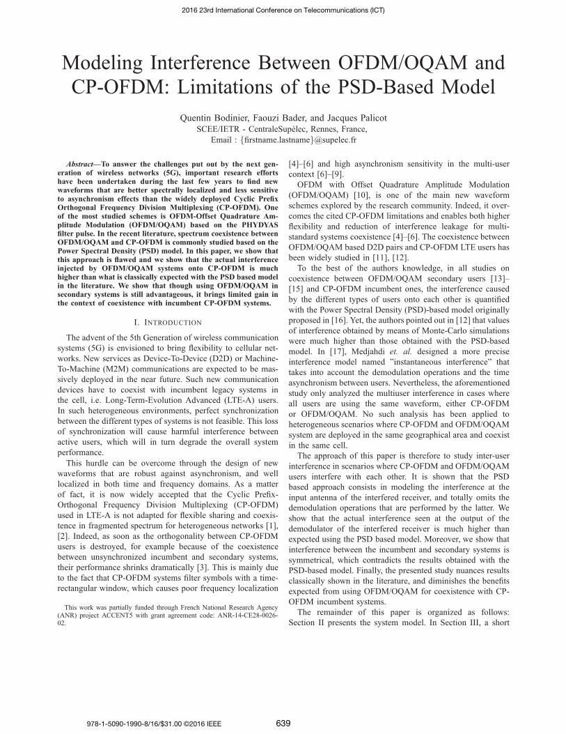
Modeling Interference Between OFDM/OQAM and
CP-OFDM: Limitations of the PSD-Based Model
Quentin Bodinier, Faouzi Bader, and Jacques Palicot
SCEE/IETR - CentraleSupelec, Rennes, France,
Email : [email protected]
Abstract—To answer the challenges put out by the next gen-eration of wireless networks (5G), important research effortshave been undertaken during the last few years to find newwaveforms that are better spectrally localized and less sensitiveto asynchronism effects than the widely deployed Cyclic PrefixOrthogonal Frequency Division Multiplexing (CP-OFDM). Oneof the most studied schemes is OFDM-Offset Quadrature Am-plitude Modulation (OFDM/OQAM) based on the PHYDYASfilter pulse. In the recent literature, spectrum coexistence betweenOFDM/OQAM and CP-OFDM is commonly studied based on thePower Spectral Density (PSD) model. In this paper, we show thatthis approach is flawed and we show that the actual interferenceinjected by OFDM/OQAM systems onto CP-OFDM is muchhigher than what is classically expected with the PSD based modelin the literature. We show that though using OFDM/OQAM insecondary systems is still advantageous, it brings limited gain inthe context of coexistence with incumbent CP-OFDM systems.
I. INTRODUCTION
The advent of the 5th Generation of wireless communication
systems (5G) is envisioned to bring flexibility to cellular net-
works. New services as Device-To-Device (D2D) or Machine-
To-Machine (M2M) communications are expected to be mas-
sively deployed in the near future. Such new communication
devices have to coexist with incumbent legacy systems in
the cell, i.e. Long-Term-Evolution Advanced (LTE-A) users.
In such heterogeneous environments, perfect synchronization
between the different types of systems is not feasible. This loss
of synchronization will cause harmful interference between
active users, which will in turn degrade the overall system
performance.
This hurdle can be overcome through the design of new
waveforms that are robust against asynchronism, and well
localized in both time and frequency domains. As a matter
of fact, it is now widely accepted that the Cyclic Prefix-
Orthogonal Frequency Division Multiplexing (CP-OFDM)
used in LTE-A is not adapted for flexible sharing and coexis-
tence in fragmented spectrum for heterogeneous networks [1],
[2]. Indeed, as soon as the orthogonality between CP-OFDM
users is destroyed, for example because of the coexistence
between unsynchronized incumbent and secondary systems,
their performance shrinks dramatically [3]. This is mainly due
to the fact that CP-OFDM systems filter symbols with a time-
rectangular window, which causes poor frequency localization
This work was partially funded through French National Research Agency(ANR) project ACCENT5 with grant agreement code: ANR-14-CE28-0026-02.
[4]–[6] and high asynchronism sensitivity in the multi-user
context [6]–[9].
OFDM with Offset Quadrature Amplitude Modulation
(OFDM/OQAM) [10], is one of the main new waveform
schemes explored by the research community. Indeed, it over-
comes the cited CP-OFDM limitations and enables both higher
flexibility and reduction of interference leakage for multi-
standard systems coexistence [4]–[6]. The coexistence between
OFDM/OQAM based D2D pairs and CP-OFDM LTE users has
been widely studied in [11], [12].
To the best of the authors knowledge, in all studies on
coexistence between OFDM/OQAM secondary users [13]–
[15] and CP-OFDM incumbent ones, the interference caused
by the different types of users onto each other is quantified
with the Power Spectral Density (PSD)-based model originally
proposed in [16]. Yet, the authors pointed out in [12] that values
of interference obtained by means of Monte-Carlo simulations
were much higher than those obtained with the PSD-based
model. In [17], Medjahdi et. al. designed a more precise
interference model named ”instantaneous interference” that
takes into account the demodulation operations and the time
asynchronism between users. Nevertheless, the aforementioned
study only analyzed the multiuser interference in cases where
all users are using the same waveform, either CP-OFDM
or OFDM/OQAM. No such analysis has been applied to
heterogeneous scenarios where CP-OFDM and OFDM/OQAM
system are deployed in the same geographical area and coexist
in the same cell.
The approach of this paper is therefore to study inter-user
interference in scenarios where CP-OFDM and OFDM/OQAM
users interfere with each other. It is shown that the PSD
based approach consists in modeling the interference at the
input antenna of the interfered receiver, and totally omits the
demodulation operations that are performed by the latter. We
show that the actual interference seen at the output of the
demodulator of the interfered receiver is much higher than
expected using the PSD based model. Moreover, we show that
interference between the incumbent and secondary systems is
symmetrical, which contradicts the results obtained with the
PSD-based model. Finally, the presented study nuances results
classically shown in the literature, and diminishes the benefits
expected from using OFDM/OQAM for coexistence with CP-
OFDM incumbent systems.
The remainder of this paper is organized as follows:
Section II presents the system model. In Section III, a short
2016 23rd International Conference on Telecommunications (ICT)
978-1-5090-1990-8/16/$31.00 ©2016 IEEE 639
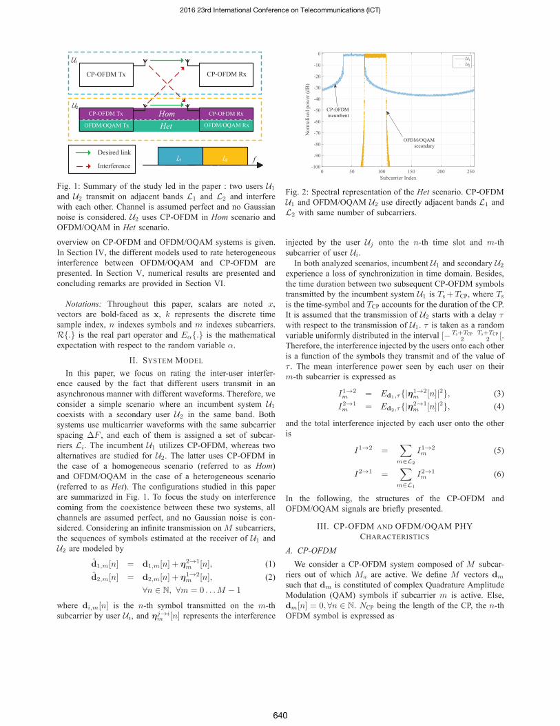
CP-OFDM Tx CP-OFDM Rx
U1
U2
L1 L2
Desired link
Interferencef
Het
Hom CP-OFDM Rx
OFDM/OQAM Rx
CP-OFDM Tx
OFDM/OQAM Tx
Fig. 1: Summary of the study led in the paper : two users U1
and U2 transmit on adjacent bands L1 and L2 and interfere
with each other. Channel is assumed perfect and no Gaussian
noise is considered. U2 uses CP-OFDM in Hom scenario and
OFDM/OQAM in Het scenario.
overview on CP-OFDM and OFDM/OQAM systems is given.
In Section IV, the different models used to rate heterogeneous
interference between OFDM/OQAM and CP-OFDM are
presented. In Section V, numerical results are presented and
concluding remarks are provided in Section VI.
Notations: Throughout this paper, scalars are noted x,
vectors are bold-faced as x, k represents the discrete time
sample index, n indexes symbols and m indexes subcarriers.
R. is the real part operator and Eα. is the mathematical
expectation with respect to the random variable α.
II. SYSTEM MODEL
In this paper, we focus on rating the inter-user interfer-
ence caused by the fact that different users transmit in an
asynchronous manner with different waveforms. Therefore, we
consider a simple scenario where an incumbent system U1
coexists with a secondary user U2 in the same band. Both
systems use multicarrier waveforms with the same subcarrier
spacing ∆F , and each of them is assigned a set of subcar-
riers Li. The incumbent U1 utilizes CP-OFDM, whereas two
alternatives are studied for U2. The latter uses CP-OFDM in
the case of a homogeneous scenario (referred to as Hom)
and OFDM/OQAM in the case of a heterogeneous scenario
(referred to as Het). The configurations studied in this paper
are summarized in Fig. 1. To focus the study on interference
coming from the coexistence between these two systems, all
channels are assumed perfect, and no Gaussian noise is con-
sidered. Considering an infinite transmission on M subcarriers,
the sequences of symbols estimated at the receiver of U1 and
U2 are modeled by
d1,m[n] = d1,m[n] + η2→1m [n], (1)
d2,m[n] = d2,m[n] + η1→2m [n], (2)
∀n ∈ N, ∀m = 0 . . .M − 1
where di,m[n] is the n-th symbol transmitted on the m-th
subcarrier by user Ui, and ηj→im [n] represents the interference
Subcarrier Index
0 50 100 150 200 250
No
rmal
ised
po
wer
(d
B)
-100
-90
-80
-70
-60
-50
-40
-30
-20
-10
0U1
U2
OFDM/OQAM
secondary
CP-OFDM
incumbent
Fig. 2: Spectral representation of the Het scenario. CP-OFDM
U1 and OFDM/OQAM U2 use directly adjacent bands L1 and
L2 with same number of subcarriers.
injected by the user Uj onto the n-th time slot and m-th
subcarrier of user Ui.
In both analyzed scenarios, incumbent U1 and secondary U2
experience a loss of synchronization in time domain. Besides,
the time duration between two subsequent CP-OFDM symbols
transmitted by the incumbent system U1 is Ts + TCP, where Ts
is the time-symbol and TCP accounts for the duration of the CP.
It is assumed that the transmission of U2 starts with a delay τwith respect to the transmission of U1. τ is taken as a random
variable uniformly distributed in the interval [−Ts+TCP
2Ts+TCP
2 [.Therefore, the interference injected by the users onto each other
is a function of the symbols they transmit and of the value of
τ . The mean interference power seen by each user on their
m-th subcarrier is expressed as
I1→2m = Ed1,τ|η1→2
m [n]|2, (3)
I2→1m = Ed2,τ|η2→1
m [n]|2, (4)
and the total interference injected by each user onto the other
is
I1→2 =∑
m∈L2
I1→2m (5)
I2→1 =∑
m∈L1
I2→1m (6)
In the following, the structures of the CP-OFDM and
OFDM/OQAM signals are briefly presented.
III. CP-OFDM AND OFDM/OQAM PHY
CHARACTERISTICS
A. CP-OFDM
We consider a CP-OFDM system composed of M subcar-
riers out of which Ma are active. We define M vectors dm
such that dm is constituted of complex Quadrature Amplitude
Modulation (QAM) symbols if subcarrier m is active. Else,
dm[n] = 0, ∀n ∈ N. NCP being the length of the CP, the n-th
OFDM symbol is expressed as
2016 23rd International Conference on Telecommunications (ICT)
640

xn[k] =
M−1∑
m=0
dm[n]ej2π mM
k, (7)
n(M + NCP ) − NCP ≤ k ≤ n(M + NCP ) + M − 1,
and the total signal is expressed as x[k] =∑
n xn[k].To highlight the effects of inter-user interference only, we
consider that the channel is perfect and that the CP-OFDM
signal is polluted by an additive interfering signal y. In that
case, the n-th CP-OFDM estimated symbol is
dm[n] = dm[n] +
n(M+NCP )+M−1∑
k=n(M+NCP )
y[k]ej2π kM m
︸ ︷︷ ︸ηm[n]
, (8)
0 ≤ m ≤ M − 1
where ηm[n] represent the total amount of interference that
affects the estimated signal dm[n] as defined in (1) or (2).
B. OFDM/OQAM
The OFDM/OQAM system is composed of M subcarriers
out of which Ma are active, where M vectors dm contain
real Pulse Amplitude Modulation (PAM) symbols if subcarrier
m is active and dm[n] = 0, ∀n ∈ N otherwise. A phase
factor θn[m] = ej π2 ⌊ n+m
2 ⌋ is further added to the symbols
dm[n]. OFDM/OQAM is a based on a uniform polyphase filter
bank structure with a prototype filter g of length Lg = KM ,
where K is called the overlapping factor, which is shifted to
cover the whole of the system bandwidth. Subsequent symbols
are separated by M2 samples and are filtered through time-
frequency shifted versions of g. Therefore, each subcarrier is
filtered by a filter fm defined as :
fm[k] = g[k]ej2π mM (k− KM−1
2 ), 0 ≤ k ≤ KM − 1 (9)
and the n-th modulated OFDM/OQAM symbol is written as
xn[k] =
M−1∑
m=0
dn[m]θn[m]g[k − nM
2] × ej2π m
M (k− KM−12 ),
(n − K)M
2≤ k ≤ (n + K)
M
2− 1 (10)
In this study, g is taken as the PHYDYAS filter with
overlapping factor K = 4 [18]. The frequency response of
g is expressed as
G(f) =
K−1∑
k=−(K−1)
G|k|sin(π(f − k
KM )KM)
KMπ(f − kKM )
, (11)
where G0 = 1, G1 = 0.971960, G2 = 1/√
2, and G3 =0.235147 (see [18] for more details on OFDM/OQAM modu-
lation).
At the receiver, each subcarrier is filtered through the
matched filter fm and the real part of the signal is taken to
remove purely imaginary intrinsic interference [4] generated
by the prototype filter g. Therefore, the estimated signal at the
m-th subcarrier of the n-th symbol can be expressed as (13).
Based on the signal models defined in this section, we will
hereafter discuss the modeling of the interference that the
primary and secondary systems U1 and U2 inject onto each
other.
IV. MODELING HETEROGENEOUS INTERFERENCE
A. Mean Interference
The amount of interference suffered by U1 and U2 on each
of their subcarriers can be estimated from (3),(4). In the Hom
scenario, both η1→2 and η2→1 are obtained by replacing y in
(8) with xn[k] expression of (7). Then, I1→2 and I2→1 are
obtained by substituting (8) in (5) and (6) respectively. These
derivations lead to the following expressions of the interference
caused by U1 (resp. U2) onto U2 (resp. U1):
I1→2Hom = σd2
1
∑
m∈L2,q∈L1
I1→2Hom (q − m), (13)
I2→1Hom = σd2
2
∑
m∈L1,q∈L2
I2→1Hom (q − m), (14)
where σd2i
is the variance of di. Besides, ∀l, I1→2Hom (l) (resp.
I2→1Hom (l)) represents the interference injected by the signal on
the q-th subcarrier of U1 (resp. U2) onto the m-th subcarrier mof (resp. U1) where l = q − m is called the spectral distance.
In Hom scenario, ∀l, I1→2Hom (l) = I2→1
Hom (l), and Mejdahdi et. al.
have derived in [17] a closed-form of the interference I1→2Hom (l)
and tabulated its values in so-called ”Mean Interference Ta-
bles”.
In Het scenario, the expression of η1→2 (resp. η2→1) is
obtained by replacing y in (8) (resp. (13)) with the expression
of xn[k] in (10) (resp. (7)). Then, values of I1→2 (resp. I2→1)
are finally rated by substituting the resulting expression in (5)
(resp. (6)). After several derivation steps, we get, as in the Hom
scenario,I1→2Het = σd2
1
∑
m∈L2,q∈L1
I1→2Het (q − m), (15)
I2→1Het = σd2
2
∑
m∈L1,q∈L2
I2→1Het (q − m). (16)
Getting mathematical closed-forms of I1→2Het (l) and I2→1
Het (l) is
challenging, which is why, for sake of simplicity, most studies
of mutual interference in heterogeneous scenarios are based on
the PSD-based model [13]–[16].
B. PSD-based Interference Modeling
The PSD-based model consists in computing the leakage
caused by users onto each other by integrating the PSD of the
interfering signal on the band that suffers from the interference.
Therefore, in the Het scenario, according to the PSD-based
model, (15) and (16) are obtained by computing
I1→2Het (l) =
l+1/2∆F∫
l−1/2∆F
ΦCP-OFDM(f)df, (17)
I2→1Het (l) =
l+1/2∆F∫
l−1/2∆F
ΦPHYDIAS(f)df, (18)
2016 23rd International Conference on Telecommunications (ICT)
641

dn[m] = dn[m] + R
(n+K) M2∑
k=(n−K) M2
y[k]
2K−1∑
ν=−2K+1
(−1)m(ν−n) × e−j2π mM (k− KM−1
2 )g
[k + (ν − n)
M
2
]
︸ ︷︷ ︸ηm[n]
(12)
f/∆F
0 0.5 1 1.5 2 2.5 3
ΦC
P-O
FD
M
0
0.5
1
l = 1
l = 2Computed
Interference
f/∆F
0 0.5 1 1.5 2 2.5 3
ΦP
HY
DY
AS
0
0.5
1
Computed
Interference
l = 1
l = 2
Fig. 3: Modeling of injected interference with the PSD-based
model for CP-OFDM (top) and OFDM/OQAM with PHY-
DYAS filter (bottom). The values of interference injected by
subcarrier 0 on a subcarrier at a spectral distance of l = 1correspond to the integration of the PSD from 0.5 ∆F to
1.5 ∆F .
where ΦCP-OFDM (resp. ΦPHYDIAS ) is the PSD of the CP-
OFDM signal (resp. of OFDM/OQAM with PHYDIAS filter).
A graphical view of (17) and (18) is presented in Fig. 3. It
can be seen than values of interference rated with the PSD-
based model are not symmetrical. As a matter of fact, because
the side-lobes of ΦCP-OFDM are much higher than those of
ΦPHYDIAS, the PSD-based model will give I1→2Het ≫ I2→1
Het .
Therefore, according to the PSD-based model, the CP-OFDM
incumbent U1 interferes more onto the OFDM/OQAM sec-
ondary U2 than the opposite.
Besides, because the PSD-based model only rates the power
of injected interference, it is challenging to map the obtained
values of interference to higher level metrics, e.g. Bit Error
Rate (BER). The only possibility offered by the PSD-based
model is to approximate the statistics of heterogeneous inter-
ference as a white Gaussian noise the variance of which is
given by (18), i.e
η2→1m ∼ N (0,
∑
q∈L∞
I2→1Het (q − m)). (19)
Then, classical expressions of transmission performance under
white Gaussian noise in [19] can be applied.
C. Discussing the suitability of the PSD-based model
The main pitfall of the PSD-based model lies in the fact that
it does not take into account the time window of the receiver.
t
t
FFT FFTCP
rem.
CP
rem.FFTFFT
CP
rem.
Fig. 4: Demodulation operations at the CP-OFDM receiver
with an interfering OFDM/OQAM signal. The well-shaped
PHYDYAS filter is cut in small non-contiguous parts on which
FFT operations are performed.
However, this is of paramount importance as the incumbent
only considers a time window with a specific width based
on its own parameters. To illustrate this, Fig. 4 shows the
demodulation operations that are performed by the CP-OFDM
incumbent with an interfering secondary OFDM/OQAM sig-
nal. Though the PHYDYAS filter is well spectrally localized, it
has a length of LPHYDYAS = KM samples. However, the CP-
OFDM receiver window is of length LCP-OFDM = M samples.
Therefore, as plotted in Fig. 4, the CP-OFDM incumbent
demodulator performs Fast Fourier Transform (FFT) on a
time window which is much shorter than the length of the
prototype filter of OFDM/OQAM. In turn, the signal suffers
from discontinuities that produce projections on the whole
incumbent spectrum.
Moreover, Fig. 3 shows that the PSD based model consists
in multiplying the interfering signal by a rectangular window
in the frequency domain. In the time domain, this corresponds
to filtering the interfering signal through an infinite sinc filter.
Therefore, the PSD-based model does not reflect the actual
demodulation operations that are processed at the CP-OFDM
receiver that suffers from interference.
Besides, Fig. 4 shows that the prototype filter of
OFDM/OQAM spans multiple time windows of the CP-OFDM
incumbent receiver. Then, one OFDM/OQAM symbol inter-
feres on several subsequent CP-OFDM symbols. This shows
that the elements of η2→1 cannot be considered independent.
Therefore, though Gaussian, the heterogeneous interference
between the two users in Het scenario is not white, but colored.
V. NUMERICAL RESULTS
In this section, we present several numerical results com-
paring values obtained with the PSD-based model and by
2016 23rd International Conference on Telecommunications (ICT)
642

numerical simulations. Besides, both scenarios Het and Hom
are studied to rate the advantages of using OFDM/OQAM in
the secondary system.
A. System Setup
We consider an incumbent system U1 with 3GPP LTE
standard parameters with Ma = 36 active subcarriers, which
corresponds to 3 LTE resource blocks along the frequency axis,
M = 256 samples per symbol and NCP = 18 CP samples. The
secondary user U2 also uses 3 LTE resource blocks along the
frequency axis. No guard band is considered between the two
users, and they are directly adjacent in the spectrum. More
specifically, the sets of subcarriers occupied by the two users
are defined as L1 = [37 . . .72] and L2 = [73 . . . 108]. Both
users use the same subcarrier spacing ∆F = 15 kHz. In
Hom scenario, CP-OFDM based U2 uses the same parameters
as U1. In the Het scenario, OFDM/OQAM based U2 uses
M = 256 samples per symbol and the PHYDIAS filter with
overlapping factor K = 4. In Het scenario, the performance
of users is evaluated though empirical estimation of (5) and
(6) based on Monte-Carlo simulation and compared with the
values expected with the PSD-based model. CP-OFDM sys-
tems transmit complex symbols drawn from a 64-Quadrature
Amplitude Modulation (QAM) constellation. To ensure fair-
ness, OFDM/OQAM systems transmit twice as much real
symbols drawn from a 8-Pulse Amplitude Modulation (PAM),
which corresponds to a 64 QAM after reconstruction of a
complex constellation. Moreover, U2 starts transmitting with
a delay τ ∈ [−M+NCP
2M+NCP
2 [. Finally, numerical simulations
are led on 105 symbols, each carrying 6 bits. Therefore, the
BER curves drawn from numerical simulation are based on a
transmission of 6 × Ma × 105 = 1.92 × 107 bits.
B. Interference Analysis
First, we aim to rate the interference caused by U2 on the
incumbent U1. Fig. 5 presents the values of I2→1(l) in dB for
spectral distance l ∈ [−20 20]. For the Het scenario, i.e. when
U2 uses OFDM/OQAM, we present values obtained with both
the PSD-based model and through numerical simulations. We
can observe in Fig. 5 a tremendous gap between the values
of interference planned by the PSD-based model and the real
ones. As a case in point, at l = 2, the PSD-based model plans
that the value of the interference injected on the incumbent will
be about −65 dB, whereas numerical simulations show that the
actual interference value is −18.5 dB. Moreover, for l = 20,
the PSD-based model predicts that the injected interference will
be insignificant, whereas the numerical simulations show that
it is still at a non-negligible level of −40 dB. This proves that
in the Het scenario, the PSD-based model completely fails to
give a good approximation of the interference injected by an
OFDM/OQAM secondary user onto an incumbent CP-OFDM
system.
Besides, the mean interference tables from [17] are plotted
to rate the interference injected by U2 onto U1 for the Hom
scenario, when both systems are using CP-OFDM. It shows
l
-20 -15 -10 -5 0 5 10 15 20
Mea
n I
nte
rfer
ence
Pow
er (
dB
)
-90
-80
-70
-60
-50
-40
-30
-20
-10
0
a) OFDM/OQAM onto CP-OFDM, PSD based model
b) OFDM/OQAM onto CP-OFDM, Simulated
c) CP-OFDM onto CP-OFDM, Mean Interference Tables
Fig. 5: Comparison between interference values obtained with
(a) OFDM/OQAM onto CP-OFDM with PSD-based model, (b)
OFDM/OQAM onto CP-OFDM through numerical simulation,
and (c) CP-OFDM onto CP-OFDM with mean interference
tables [17].
that the interference injected onto U1 can be reduced by
approximately 5 dB if U2 uses OFDM/OQAM. Though much
less than what was expected with the PSD-based model, this
gain is still high enough to be noticed.
Having rated the power of injected interference, we focus
now on the statistics of the latter in the Het scenario. To do so,
we scrutinize the distribution of η2→172 , which corresponds to
the interference injected by the OFDM/OQAM based U2 onto
the closest subcarrier of U1. We show the Probability Distri-
bution Function (PDF) of this interference signal in Fig. 6a.
We can notice that it is well approximated by a Gaussian
function of variance I2→172,Het. However, the covariance matrix of
the studied interference, plotted in Fig. 6b is band-diagonal.
This reveals a dependency between subsequent samples of
the interference signal η2→172 . These two figures therefore
corroborate the remarks we highlighted in Section IV-C and
confirm the fact that heterogeneous interference is colored.
C. Transmission Performance
We now focus on the transmission performance of both
users. To do so, we set the power of the symbols transmitted
by the incumbent system U1 as σ2d1
= 0 dB and we sweep σ2d2
from −20 dB to 20 dB. Here, we focus on the effects of inter-
user interference caused by the adjacent transmissions of the
two users. Therefore, no channel and no noise is considered.
The normalized Error Vector Magnitude (EVM) obtained for
both users is plotted in Fig. 7. Here, our observations are three-
fold: first, the PSD-based model approximates surprisingly well
the interference seen by the secondary OFDM/OQAM user U2
in the Het scenario. This shows that the PSD-based model
may still be suitable in some cases, especially when the time
window of the receiver is longer than the interfering signal.
However, the PSD-based model dramatically underestimates
2016 23rd International Conference on Telecommunications (ICT)
643

x
-1.5 -1 -0.5 0 0.5 1 1.5
PD
F
0
0.2
0.4
0.6
0.8
1
1.2
1.4
1.6
1.8
Studied interference signal
Theoretical Gaussian
Simulated Gaussian
(a) Probability Distribution Function
Sample index
1 2 3 4 5 6 7 8 9 10
Sam
ple
index
1
2
3
4
5
6
7
8
9
10
(b) Covariance matrix
Fig. 6: Statistics of interference signal caused by
OFDM/OQAM onto CP-OFDM subcarrier 72. The different
results show that it can be modeled by a colored Gaussian
noise.
the interference seen by the incumbent receiver U1. Second,
we point out that the actual inter-user interference in the Het
scenario is symmetrical. As a case in point, the obtained EVM
values for both users are equal when their transmission power
is equal. This contradicts the PSD-based model, which predicts
that the incumbent CP-OFDM U1 will be more protected than
the secondary OFDM/OQAM U2 : according to the PSD-based
model, the normalized EVM values of both users are equal
when σd22
= 3 dB. Third, both U1 and U2 experience lower
EVM in the Het scenario than in the Hom scenario.
Based on the above results, we analyze the BER for both
users in Fig. 8. As said in Section IV-C, the interfering signal
is approximated to a white Gaussian noise to compute the
BER from the EVM for both the PSD-based model in the
Het scenario and the instantaneous interference tables in the
Hom scenario. This allows to compute BER thanks to the
classical expressions of the BER of M-ary QAM constellations
σ2d2
(dB)-20 -15 -10 -5 0 5 10 15 20
Mea
n N
orm
aliz
ed E
VM
10-4
10-3
10-2
10-1
Mean Normalized EVM of U1
Mean Normalized EVM of U2
Het, Numerical simulation
Het, PSD based model
Hom, Mean Interference Tables
Fig. 7: Mean Normalized EVM of users U1 and U2 in the
scenarios Het and Hom
[19]. As expected, the obtained BER performance confirms the
EVM behaviour presented in Fig.7, and again, the PSD-based
model is totally wrong for modeling the interference seen by
the incumbent U1 in the Het scenario. Nevertheless, it gives a
satisfying approximation of the BER of OFDM/OQAM based
U2, especially for values of BER higher than 10−3. However,
when the BER of OFDM/OQAM based U2 becomes low (for
σ2d2
> 10 dB), the PSD-based model understimates it. This
is due to the fact that the interference was approximated as a
white gaussian signal whereas it has been shown that it is col-
ored in Fig. 6b. Finally, Fig. 8 shows that the benefits of using
OFDM/OQAM are not as high as what was expected with the
PSD-based model. Yet, it shows that using OFDM/OQAM for
the secondary U2 does still bring some advantage. For example,
when both users have the same transmission power, the BER
of each user in the Het scenario is equal to half what they
experience in the Hom scenario.
Presented results show that, in scenarios where an incumbent
CP-OFDM system coexists with an asynchronous user U2, it is
still advantageous to both users that U2 uses OFDM/OQAM,
though benefits are much less important than those planned
with the PSD-based model in [14], [15]. To conclude this
study, we focus on the BER of the incumbent U1 in both
Het and Hom scenarios with a deterministic value of τ . Fig.9
highlights three different and interesting results: first, in the
Het scenario, τ has no impact. This is mainly due to the
fact that OFDM/OQAM and CP-OFDM systems are inherently
asynchronous, as they do not have the same time spacing
between subsequent symbols (see Fig.4). Second, in the Hom
scenario, if the timing offset can be contained in the CP
duration, the performance of incumbent U1 is not degraded
at all. This is a well known result concerning Multi-User
Interference in CP-OFDM systems. Third, as soon as τ grows
higher than the CP duration, it is worth using OFDM/OQAM
instead of CP-OFDM at the secondary system U2 to protect
U1.
2016 23rd International Conference on Telecommunications (ICT)
644
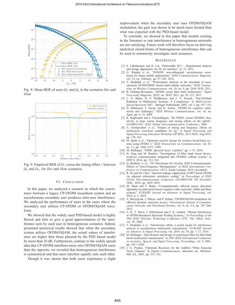
σ2d2
(dB)-20 -15 -10 -5 0 5 10 15 20
Mea
n B
ER
10-6
10-5
10-4
10-3
10-2
10-1
Mean BER of U1
Mean BER of U2
Het, Numerical simulationHet, PSD based modelHom, Mean Interference Tables
Fig. 8: Mean BER of users U1 and U2 in the scenarios Het and
Hom
Relative time offset τ
-0.4 -0.3 -0.2 -0.1 0 0.1 0.2 0.3 0.4
BER
ofincu
mbentU1
10-4
10-3
10-2
Hom scenarioHet scenario
Fig. 9: Empirical BER of U1 versus the timing offset τ between
U2 and U1, for Het and Hom scenarios.
VI. CONCLUSION
In this paper, we analyzed a scenario in which the coexis-
tence between a legacy CP-OFDM incumbent system and an
asynchronous secondary user produces inter-user interference.
We analyzed the performance of users in the cases where the
secondary user utilizes CP-OFDM or OFDM/OQAM wave-
form.
We showed that the widely used PSD-based model is highly
flawed and fails to give a good approximation of the inter-
ference seen by each user in heterogeneous scenarios. Indeed,
presented numerical results showed that when the secondary
system utilizes OFDM/OQAM, the actual values of interfer-
ence are higher than those planned by the PSD based model
by more than 50 dB. Furthermore, contrary to the widely spread
idea that CP-OFDM interferes more onto OFDM/OQAM users
than the opposite, we revealed that heterogeneous interference
is symmetrical and that users interfere equally onto each other.
Though it was shown that both users experience a slight
improvement when the secondary user uses OFDM/OQAM
modulation, the gain was shown to be much more limited than
what was expected with the PSD-based model.
To conclude, we showed in this paper that models existing
in the literature to rate interference in heterogeneous networks
are not satisfying. Future work will therefore focus on deriving
analytical closed-forms of heterogeneous interference that can
be used to extensively investigate such scenarios.
REFERENCES
[1] E. Lahetkangas and H. Lin, “Deliverable D2.1 - Requirement analysisand design approaches for 5G air interface,” p. 72, 2013.
[2] G. Wunder et al., “5GNOW: non-orthogonal, asynchronous wave-forms for future mobile applications,” IEEE Communications Magazine,vol. 52, no. February, pp. 97–105, 2014.
[3] Y. Medjahdi et al., “Performance analysis in the downlink of asyn-chronous OFDM/FBMC based multi-cellular networks,” IEEE Transac-tions on Wireless Communications, vol. 10, no. 8, pp. 2630–2639, 2011.
[4] B. Farhang-Boroujeny, “OFDM versus filter bank multicarrier,” SignalProcessing Magazine, IEEE, no. MAY 2011, pp. 92–112, 2011.
[5] L. G. Baltar, D. S. Waldhauser, and J. A. Nossek, “Out-Of-BandRadiation in Multicarrier Systems: A Comparison,” in Multi-CarrierSpread Spectrum 2007. Springer Netherlands, 2007, vol. 1, pp. 107–116.
[6] H. Mahmoud, T. Yucek, and H. Arslan, “OFDM for cognitive radio:merits and challenges,” IEEE Wireless Communications, vol. 16, no.April, pp. 6–15, 2009.
[7] K. Raghunath and a. Chockalingam, “SC-FDMA versus OFDMA: Sen-sitivity to large carrier frequency and timing offsets on the uplink,”GLOBECOM - IEEE Global Telecommunications Conference, 2009.
[8] A. Aminjavaheri et al., “Impact of timing and frequency offsets onmulticarrier waveform candidates for 5g,” in Signal Processing andSignal Processing Education Workshop (SP/SPE), 2015 IEEE, Aug 2015,pp. 178–183.
[9] M. Speth et al., “Optimum receiver design for wireless broad-band sys-tems using OFDM. I,” IEEE Transactions on Communications, vol. 47,no. 11, pp. 1668–1677, 1999.
[10] M. Bellanger, “FBMC physical layer: a primer,” pp. 1–31, 2010.[11] H. Xing and M. Renfors, “Investigation of filter bank based device-
to-device communication integrated into OFDMA cellular system,” inISWCS, 2014, pp. 513–518.
[12] Q. Bodinier et al., “5G Waveforms for Overlay D2D Communications:Effects of Time-Frequency Misalignment,” in IEEE International Con-ference on Communications (ICC), Kuala Lumpur, 2016 (Accepted).
[13] R. Xu and M. Chen, “Spectral leakage suppression of DFT based OFDMvia adjacent subcarriers correlative coding,” in Proccedings of IEEEGlobal Telecommunications Conference (GLOBECOM ’08) December2008., 2018, pp. 3029–3033.
[14] M. Shaat and F. Bader, “Computationally efficient power allocationalgorithm in multicarrier-based cognitive radio networks: Ofdm and fbmcsystems,” EURASIP Journal on Advances in Signal Processing, vol.2010, p. 5, 2010.
[15] A. Skrzypczak, J. Palicot, and P. Siohan, “OFDM/OQAM modulation forefficient dynamic spectrum access,” International Journal of Communi-cation Networks and Distributed Systems, vol. 8, no. 3-4, pp. 247–266,2012.
[16] A. K. T. Weiss, J. Hillenbrand and F. K. Jondral, “Mutual Interferencein OFDM-Basedased Spectrum Pooling Systems,,” in Proceedings of the59th IEEE Vehicular Technology Conference (VTC ’04). Milan, Italy.,vol. 59, 2004.
[17] Y. Medjahdi et al., “Interference tables: a useful model for interferenceanalysis in asynchronous multicarrier transmission,” EURASIP Journalon Advances in Signal Processing, vol. 2014, no. 54, pp. 1–17, 2014.
[18] M. Bellanger, “Specification and design of a prototype filter for filter bankbased multicarrier transmission,” in 2001 IEEE International Conferenceon Acoustics, Speech, and Signal Processing. Proceedings, vol. 4, 2001,pp. 2417–2420.
[19] J. G. Proakis, “Optimum Receivers for the Additive White GaussianNoise Channel,” in Digital Communications, internatio ed., McGraw-Hill, Ed., 2001, pp. 231–332.
2016 23rd International Conference on Telecommunications (ICT)
645

Coexistence in 5G: Analysis of Cross-Interferencebetween OFDM/OQAM and Legacy Users
Quentin Bodinier, Faouzi Bader, and Jacques PalicotSCEE/IETR - CentraleSupelec, Rennes, France,
Email : [email protected]
Abstract—To optimize the use of the spectrum, it is expectedthat the next generation of wireless networks (5G) will enablecoexistence of newly introduced services with legacy cellular net-works. These new services, like Device-To-Device (D2D) commu-nication, should require limited synchronization with the legacycell to limit the amount of signaling overhead in the network.However, it is known that Cyclic Prefix-Orthogonal FrequencyDivision Multiplexing (CP-OFDM) used in Long Term Evolutio n-Advanced (LTE-A) is not fit for asynchronous environments. Thishas motivated the search for a new waveform, able to enhancecoexistence with CP-OFDM. Namely, it has been widely suggestedthat new devices could use OFDM/Offset-Quadrature AmplitudeModulation (OFDM/OQAM) to reduce the interference they inj ectto legacy cellular users. However, values of interference areusually measured at the input antenna of the receiver, basedon thePSD of the interfering signal. We showed in previous works thatthis measurement is not representative of the actual interferencethat is seen after the demodulation operations. Building onthisfinding, we provide in this paper the first exact closed forms ofcross-interference between OFDM/OQAM and CP-OFDM users.Our results prove that using OFDM/OQAM only marginallyreduces interference to legacy users, in contradiction with manyresults in the literature.
I. I NTRODUCTION
The advent of the 5th Generation of wireless communicationsystems (5G) is envisioned to bring flexibility to cellular net-works. New services as Device-To-Device (D2D) or Machine-To-Machine (M2M) communications are expected to be mas-sively deployed in the near future. Such new communicationdevices have to coexist with incumbent legacy systems inthe cell, i.e. Long-Term-Evolution Advanced (LTE-A) users.In such heterogeneous environments, perfect synchronizationbetween the different types of systems is not feasible. Thislossof synchronization will cause harmful interference betweenactive users, which will in turn degrade the overall systemperformance. This hurdle can be overcome through the designof new waveforms that are robust against asynchronism, andwell localized in frequency. As a matter of fact, as soonas the orthogonality between CP-OFDM users is destroyed,for example because of the coexistence of unsynchronizedincumbent and secondary systems, their performance shrinksdramatically [1]. This is mainly due to the fact that CP-OFDM systems filter symbols with a time-rectangular window,which causes poor frequency localization [2]–[4] and highasynchronism sensitivity in the multi-user context [4]–[6].
OFDM with Offset Quadrature Amplitude Modulation(OFDM/OQAM) [2], [7], is one of the main new wave-
form schemes explored by the research community. Indeed, itovercomes the cited CP-OFDM limitations and enables bothhigher flexibility and reduction of interference leakage formultistandard systems coexistence [2], [7]. The main sellingpoint of OFDM/OQAM lies in its improved spectral contain-ment that is obtained through the filtering of each subcarrierwith a highly selective prototype filter. In this paper, we willstudy the case of OFDM/OQAM systems using the PHYDYASfilter [7]. Thanks to the enhanced spectral localization of thelatter, OFDM/OQAM boasts hardly measurable out-of-band(OOB) emissions, as its Power Spectral Density (PSD) rapidlydecreases below the ambient noise level.
Building on this, a number of papers, for example [8]–[10],have suggested to use OFDM/OQAM to coexist efficientlywith CP-OFDM based networks. All the studies on that matteruse the PSD-based model, originally proposed in [11], to ratethe cross-interference between the OFDM/OQAM and CP-OFDM systems. This model consists in integrating the PSDof the interfering signal on each subcarrier of the user thatsuffers from interference. Because of the advantageous PSDproperties of OFDM/OQAM, studies using the PSD-basedmodel predicted that using this waveform instead of CP-OFDMfor coexistence with LTE-A users would be highly beneficial.
However, the expected gains were not confirmed throughsimulations [12], [13]. Moreover, in [13], we explained ina qualitative manner why the PSD-based model was notfit to properly estimate the cross-interference that is seenafter the demodulation operations at both the receivers ofOFDM/OQAM and CP-OFDM systems. Furthermore, weshowed through numerical simulations that the gains expectedby following the PSD-based model were highly overesti-mated. However, a thorough mathematical analysis of the post-demodulation cross-interference arising between coexistingOFDM/OQAM and CP-OFDM systems is still lacking. Thispaper aims at resolving this issue by providing mathematicalclosed forms of cross-interference injected by OFDM/OQAMonto CP-OFDM and vice-versa. The provided closed-formsprove that OFDM/OQAM fails to protect incumbent legacyCP-OFDM users.
The remainder of this paper is organized as follows: SectionII presents the system model and a short overview on CP-OFDM and OFDM/OQAM waveforms. In Section III, theanalysis of cross-interference is led. In Section IV, the validityof the derived closed forms is asserted by comparison with
146

QAMEncoding
OFDMModulation
OFDMDemodulation
. . . 101 . . . di yi(t)si(t)
si(t)
wi(t)di
OQAMEncoding
OFDM/OQAMModulation
OFDM/OQAMDemodulation
. . . 101 . . . ds
ys(t)ss(t)ws(t)
ss(t)
ds
Incumbent
Secondary
Fig. 1: Considered system model. Interference signals are marked with dashed arrows.
numerical simulations, and conclusions are given in Section V.Notations: scalars are notedx,vectors are bold-faced asx,
and ensembles are represented by a calligraphy letterX . nis the discrete symbol index,m indexes subcarriers andt isthe continuous time.∗ is the convolution operation,x∗ is thecomplex conjugate ofx, Eα is the mathematical expectationwith regards to the random variableα and Rx is the realpart of x.
II. BACKGROUND AND SYSTEM MODEL
A. Analyzed Coexistence Scenario
We consider a coexistence scenario where an incumbent CP-OFDM based system and an OFDM/OQAM secondary systemshare the same spectral band. The incumbent is assigned aset of active subcarriersMi and the secondary a setMs.We assume that both systems use the same subcarrier spacing∆F and time-symbolT = 1
∆F. To focus on cross-interferencebetween users, we consider a transmission on an additive whitegaussian noise (AWGN) channel and do not take into accountany pathloss or shadowing effect. The corresponding systemmodel is represented in Fig. 1 and an example of subcarriersdistribution is given in Fig. 2.
Note that, strictly speaking, each interfering signal arrivesat the receiver it interferes on with a certain delay. Forexample, namingδt,s the propagation delay between the sec-ondary transmitter and the incumbent receiver, the interferingsignal received at the incumbent is notss(t) but ss(t − δt,s).However, we showed through simulation in [12] that thispropagation delay has only little impact on the interferencebetween OFDM/OQAM and CP-OFDM users. Without loss ofgenerality, we will therefore neglect the propagation delays inour analysis.
Now that the system model is laid out, we present inthe following Section a short background on CP-OFDM andOFDM/OQAM signal models.
B. CP-OFDM Incumbent System
We consider a CP-OFDM incumbent system withM subcar-riers, time-symbolT and a CP duration ofTCP. As previouslymentioned, it has a set of active subcarriersMi . The CP-OFDM time-domain signal transmitted on each active subcar-rier mi ∈ Mi is expressed as
smi (t) =∑
ni∈Zdmi [ni ]fT,i (t − ni(T + TCP)) ej2πmi
t−ni TCPT ,
(1)
with dmi the data vector of quadrature amplitude modulated(QAM) symbols transmitted on subcarriermi andfT,i the CP-OFDM transmit filter defined as:
fT,i(t) =
1√T
, t ∈ [−TCP, T ]
0, elsewhere.(2)
The total transmitted signal is expressed as
si(t) =∑
mi∈Mi
smi (t), ∀t ∈ R. (3)
In this study, we consider an AWGN interference channel.Therefore, the signal at the input antenna of the CP-OFDMincumbent receiver is expressed as
yi(t) = si(t) + ss(t) + wi(t), ∀t ∈ R (4)
wheress(t) is the interfering OFDM/OQAM secondary signalwhose expression will be detailed in the next section andwi(t)is the AWGN seen at the incumbent receiver.
Assuming perfect synchronization between the CP-OFDMtransmitter and receiver, theni-th demodulated symbol on themi-th subcarrier of the CP-OFDM receiver is expressed,∀ni ∈Z, as
dmi [ni ] = dmi [ni ] +∑
ms∈Ms
ηms→mi [ni ] + wi [ni ], (5)
where wi is the filtered white gaussian noise componentexpressed as
wi [ni ] =
∞∫
−∞
fR,i(t−ni(T+TCP))e−j2πmi
t−niTCPT wi(t)dt, ∀ni ∈ Z
(6)andηms→mi is the interference injected by thems-th subcarrierof the secondary onto themi-th subcarrier of the incumbent,which is expressed∀ni ∈ Z as
ηms→mi [ni ] =
∞∫
−∞
fR,i(t−ni(T +TCP))e−j2πmi
t−ni TCPT sms(t)dt.
(7)In (6) and (7),fR,i is the receive filter of the incumbent and isexpressed as
fR,i(t) =
1√T
, t ∈ [0, T ]
0, elsewhere.(8)
147

f∆F
M2 − 1−M
20
Mi Ms
Fig. 2: Spectral representation of the considered scenario. Theincumbent and secondary systems coexist in the same spectralband, and each one is assigned a different subset of subcarriers.
C. Secondary OFDM/OQAM System
We consider an OFDM/OQAM secondary system withMsubcarriers and time-symbolT , and nameMs its set of activesubcarriers. The time-domain signal transmitted on each activesubcarrierms ∈ Ms of the secondary OFDM/OQAM systemis expressed as [14]
sms(t) =∑
ns∈Z(−1)msnsdms[ns]θms[ns]fT,s
(t − ns
T
2
)ej2πms
tT
(9)where dms is the data vector of pulse amplitude modulated(PAM) real symbols andθms[ns] is a phase factor added to thesymbols and defined as [14]
θms[ns] = ej π2 ⌊ ns+ms
2 ⌋. (10)
Besides,fT,s is the transmit filter of the secondary systemexpressed as
fT,s(t) =
g(t) t ∈ [−KT
2 , KT2 ]
0, elsewhere(11)
whereK is called the overlapping factor, andg is the usedprototype filter. In the remainder of this study, we takeg asthe PHYDYAS prototype filter with overlapping factorK = 4,[15], defined as
g(t) =
K−1∑
k=−K+1
G|k|K
ej2π ktKT , t ∈ [−KT
2,KT
2], (12)
with G0 = 1, G1 = 0.971960, G2 = 1√2, G3 = 0.235147.
Note thatg is a real and symmetric filter, such thatg∗(−t) =g(t), ∀t ∈ R.
The signal received at the input antenna of theOFDM/OQAM receiver is expressed in a similar manner asin (4) and is given by
ys(t) = ss(t) + si(t) + ws(t), ∀t ∈ R (13)
At the OFDM/OQAM receiver, the received signal is passedthrough the receive filterfR,i expressed as
fR,s(t) =
g∗(−t) = g(t) t ∈ [−KT
2 , KT2 ]
0, elsewhere.(14)
t0
ni = −1ni = −2 ni = 0 ni = 1
TCP T
ns = 0
ns = −7
KT
T2
Fig. 3: Time axis view of the interference caused by theOFDM/OQAM transmission on CP-OFDM receiving windowsni = 0 andni = 1. Both CP-OFDM symbols suffer the sameamount of cross-interference.
Then, the real part of the filtered signal is taken to removepurely imaginary intrinsic interference [14]. Therefore,thens-th demodulated symbol on thems-th subcarrier of theOFDM/OQAM secondary receiver is expressed as
dms[ns] = dms[ns] +∑
mi∈Mi
ηmi→ms[ns] + ws[ns], (15)
with
ws[ns] =
∞∫
−∞
RfR,s(t − nsT
2)e−j2πms
tT (−1)msnsws(t)dt
(16)
ηmi→ms[ns] =
∞∫
−∞
RfR,s(t − nsT
2)
× e−j2πmstT (−1)msnssmi (t)dt. (17)
III. C ROSS-INTERFERENCEANALYSIS
A. Cross-Interference at the Incumbent CP-OFDM Receiver
Here, we derive the closed-form of interference seen at theincumbent CP-OFDM receiver as expressed in (7). Substitutingthe expression offT,s given by (11) in (9), and then puttingboth the resulting form of (9) and the expression of theincumbent receive filterfR,i given by (8) in (7), we obtainthe expression (18) ofηms→mi [ni ]. In the following, we focuson the mean interference power caused by subcarrierms of theOFDM/OQAM secondary onto subcarriermi of the CP-OFDMincumbent, which we define as
Ims→mi [ni ] = Eds|ηms→mi [ni ]|2 (19)
=σ2ds
T
∑
ns∈Z
∣∣∣∣∣
ni(T+TCP)+T∫
ni(T+TCP)
g
(t − ns
T
2
)
× ej2π(ms−mi)tT dt
∣∣∣∣∣
2
, (20)
ηms→mi [ni ] =1√T
∑
ns∈Z(−1)msnsdms[ns]θms[ns]
ni(T+TCP)+T∫
ni(T+TCP)
g
(t − ns
T
2
)ej2π(ms−mi)
tT dt, ∀ni ∈ Z. (18)
148

with σ2ds
the variance of the symbols modulated by the sec-ondary OFDM/OQAM system. Note that this last expressionis obtained by considering that the symbolsds are independentand identically distributed (i.i.d.). Besides, note that the sum in(20) can be reduced to the values ofns such thatg(t−ns
T2 ) is
not null everywhere on the reception window corresponding totheni-th symbol of the receiver. This is shown in Fig. 3, wherewe also point out that the value ofni does not affect the meaninterference power seen at the receiver. Note also that onlythedifferencems − mi plays a role in (20). Namingl = ms − mi
the spectral distance in terms of subcarriers, we thereforehaveIms→mi [ni ] = Is→i(l), ∀ni ∈ Z.
After operating the change of variablet 7→ t − ni(T + TCP)in (20), we obtain,∀ni ∈ Z,
Ims→mi [ni ] =
Is→i(l)︷ ︸︸ ︷σ2ds
T
T2∑
τ=−KT+T2
∣∣∣∣∣∣
T∫
0
g(t − τ)ej2π ltT dt
∣∣∣∣∣∣
2
︸ ︷︷ ︸Is→i(l,τ)
(21)
By including in (21) the expression ofg given in (12), weobtain,∀l ∈ Z,
Is→i(l, τ) =1
K2
∣∣∣∣∣∣
K−1∑
k=−K+1
G|k|
T∫
0
ej2π( k(t+τ)KT + lt
T )dt
∣∣∣∣∣∣
2
(22)
=T
K2
∣∣∣∣∣K−1∑
k=−K+1
G|k|ejπ k
K τsinc(π(k
K+ l))
∣∣∣∣∣
2
,
(23)
and the interference power injected by an OFDM/OQAMsubcarrier to a CP-OFDM subcarrier at spectral distancel isfinally given by
Is→i(l) =σ2ds
K2
T2∑
τ=−KT+T2
∣∣∣∣∣K−1∑
k=−K+1
G|k|ejπ k
K τ
× sinc(π(k
K+ l))
∣∣∣∣∣
2
(24)
B. Cross-Interference at the Secondary OFDM/OQAMReceiver
We now focus on the cross-interference that is injected bythe CP-OFDM incumbent transmitter onto the OFDM/OQAMreceiver, as expressed in (17). Substituting the expression of theCP-OFDM transmit filter (2) into (1), and then the resultingform of (1) and the expression offR,s given by (14) into (17),we obtain the expression of (25), which is very close to (18),
the only differences being the real part operator and some phasefactors due to the OFDM/OQAM demodulation. In a similarway as (19), we define the mean interference power injectedby subcarriermi of the incumbent onto thems-th subcarrierof the secondary as
Imi→ms[ns] = Edi |ηmi→ms[ns]|2 (26)
=σ2di
2T
∑
ni∈Z
∣∣∣∣∣
ni(T+TCP)+T∫
ni(T+TCP)−TCP
g
(t − ns
T
2
)
× ej2π(mi−ms)tT dt
∣∣∣∣∣
2
, (27)
with σ2di
the variance of the symbolsdi . Note that the factor12comes from the fact that only the real part of the signal is takenat the OFDM/OQAM receiver. The obtained expression is sim-ilar to (19) and the different observations made in the previoussection still hold true here. Therefore, following developmentssimilar to (19)-(24), the power of interference injected bya CP-OFDM subcarrier to an OFDM/OQAM subcarrier at spectraldistancel is expressed as (28).
Note that, if both systems transmit with the same energy per
symbol Es,σ2di
2 = σ2ds
= Es
2 because each OQAM symboltransmits half the energy of a QAM symbol. Therefore, in thecase whereTCP = 0, which corresponds to a situation where theincumbent system does not use any CP,Ii→s(l) = Is→i(l), ∀l ∈Z and the incumbent and secondary systems interfere equallyonto each other.
From both (28) and (24), it can be noticed that the rect-angular time window of the CP-OFDM system incurs a sumof sine-cardinal in frequency, which slowly decrease and willtherefore cause high interference to both systems, despitethewell shaped prototype filter used by the OFDM/OQAM system.
C. Taking into Account Frequency Misalignments
The closed-forms we derived in the previous section wereobtained in the case where the secondary and the incumbentsystems agree on the exact same frequency basis. Therefore,the spectral distancel between each subcarrier of the secondaryand each subcarrier of the incumbent is an integer, i.e.l ∈ Z.This is correct if the local oscillators (LO) of all users areperfectly synchronized. However, in a real setup, this is not thecase. Indeed, LOs of mobile terminals have a typical accuracyof ±1 ppm with respect to their nominal frequency [16]. Ata carrier frequency of2 GHz, this can yield a misalignmentbetween users of around104 Hz, which can become significantas it is close to the LTE subcarrier width of15 kHz.
Here, we consider that the transmitter and receiver in eachsystem achieve perfect frequency synchronization. However,
ηmi→ms[ns] =1√T
∑
ni∈ZR
dmi [ni ]e
−j2πmini TCP
T (−1)msns
ni(T+TCP)+TCP∫
ni(T+TCP)−TCP
g
(t − ns
T
2
)ej2π(mi−ms)
tT dt
, ∀ns ∈ Z (25)
Ii→s(l) =σ2di
2K2(1 +
TCP
T)
T2∑
τ=−KT+T2
∣∣∣∣∣K−1∑
k=−K+1
G|k|ejπ k
K τ(1+TCPT )sinc
(π
(1 +
TCP
T
) (k
K+ l
))∣∣∣∣∣
2
(28)
149
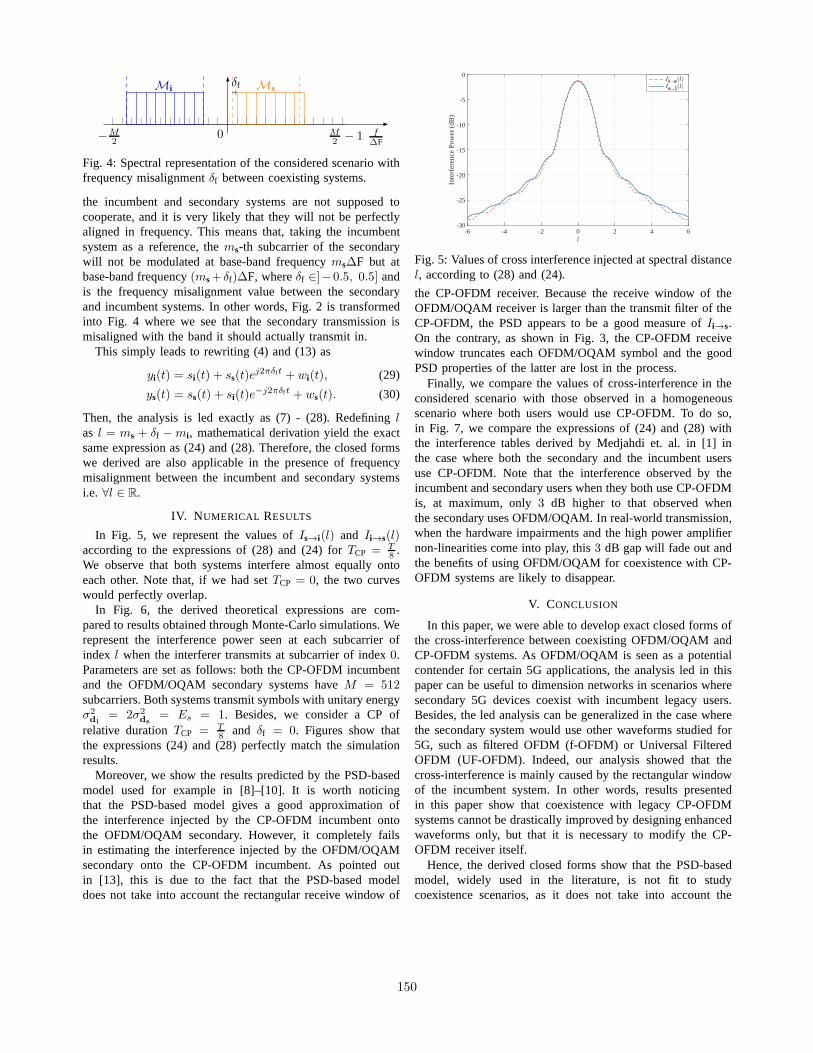
f∆F
M2 − 1−M
20
Mi Msδf
Fig. 4: Spectral representation of the considered scenariowithfrequency misalignmentδf between coexisting systems.
the incumbent and secondary systems are not supposed tocooperate, and it is very likely that they will not be perfectlyaligned in frequency. This means that, taking the incumbentsystem as a reference, thems-th subcarrier of the secondarywill not be modulated at base-band frequencyms∆F but atbase-band frequency(ms+ δf)∆F, whereδf ∈]−0.5, 0.5] andis the frequency misalignment value between the secondaryand incumbent systems. In other words, Fig. 2 is transformedinto Fig. 4 where we see that the secondary transmission ismisaligned with the band it should actually transmit in.
This simply leads to rewriting (4) and (13) as
yi(t) = si(t) + ss(t)ej2πδft + wi(t), (29)
ys(t) = ss(t) + si(t)e−j2πδft + ws(t). (30)
Then, the analysis is led exactly as (7) - (28). Redefininglas l = ms + δf − mi , mathematical derivation yield the exactsame expression as (24) and (28). Therefore, the closed formswe derived are also applicable in the presence of frequencymisalignment between the incumbent and secondary systemsi.e. ∀l ∈ R.
IV. N UMERICAL RESULTS
In Fig. 5, we represent the values ofIs→i(l) and Ii→s(l)according to the expressions of (28) and (24) forTCP = T
8 .We observe that both systems interfere almost equally ontoeach other. Note that, if we had setTCP = 0, the two curveswould perfectly overlap.
In Fig. 6, the derived theoretical expressions are com-pared to results obtained through Monte-Carlo simulations. Werepresent the interference power seen at each subcarrier ofindex l when the interferer transmits at subcarrier of index0.Parameters are set as follows: both the CP-OFDM incumbentand the OFDM/OQAM secondary systems haveM = 512subcarriers. Both systems transmit symbols with unitary energyσ2di
= 2σ2ds
= Es = 1. Besides, we consider a CP ofrelative durationTCP = T
8 and δf = 0. Figures show thatthe expressions (24) and (28) perfectly match the simulationresults.
Moreover, we show the results predicted by the PSD-basedmodel used for example in [8]–[10]. It is worth noticingthat the PSD-based model gives a good approximation ofthe interference injected by the CP-OFDM incumbent ontothe OFDM/OQAM secondary. However, it completely failsin estimating the interference injected by the OFDM/OQAMsecondary onto the CP-OFDM incumbent. As pointed outin [13], this is due to the fact that the PSD-based modeldoes not take into account the rectangular receive window of
l
-6 -4 -2 0 2 4 6
Inte
rfer
ence
Pow
er (
dB)
-30
-25
-20
-15
-10
-5
0Ii→s
(l)Is→i
(l)
Fig. 5: Values of cross interference injected at spectral distancel, according to (28) and (24).
the CP-OFDM receiver. Because the receive window of theOFDM/OQAM receiver is larger than the transmit filter of theCP-OFDM, the PSD appears to be a good measure ofIi→s.On the contrary, as shown in Fig. 3, the CP-OFDM receivewindow truncates each OFDM/OQAM symbol and the goodPSD properties of the latter are lost in the process.
Finally, we compare the values of cross-interference in theconsidered scenario with those observed in a homogeneousscenario where both users would use CP-OFDM. To do so,in Fig. 7, we compare the expressions of (24) and (28) withthe interference tables derived by Medjahdi et. al. in [1] inthe case where both the secondary and the incumbent usersuse CP-OFDM. Note that the interference observed by theincumbent and secondary users when they both use CP-OFDMis, at maximum, only3 dB higher to that observed whenthe secondary uses OFDM/OQAM. In real-world transmission,when the hardware impairments and the high power amplifiernon-linearities come into play, this3 dB gap will fade out andthe benefits of using OFDM/OQAM for coexistence with CP-OFDM systems are likely to disappear.
V. CONCLUSION
In this paper, we were able to develop exact closed forms ofthe cross-interference between coexisting OFDM/OQAM andCP-OFDM systems. As OFDM/OQAM is seen as a potentialcontender for certain 5G applications, the analysis led in thispaper can be useful to dimension networks in scenarios wheresecondary 5G devices coexist with incumbent legacy users.Besides, the led analysis can be generalized in the case wherethe secondary system would use other waveforms studied for5G, such as filtered OFDM (f-OFDM) or Universal FilteredOFDM (UF-OFDM). Indeed, our analysis showed that thecross-interference is mainly caused by the rectangular windowof the incumbent system. In other words, results presentedin this paper show that coexistence with legacy CP-OFDMsystems cannot be drastically improved by designing enhancedwaveforms only, but that it is necessary to modify the CP-OFDM receiver itself.
Hence, the derived closed forms show that the PSD-basedmodel, widely used in the literature, is not fit to studycoexistence scenarios, as it does not take into account the
150

Subcarrier index l
-30 -20 -10 0 10 20 30
Is→i(l)(dB)
-45
-40
-35
-30
-25
-20
-15
-10
-5
0Theoretical (24)Monte-Carlo SimulationsPSD Based Model
(a) Cross-interference seen at the Incumbent CP-OFDM receiver
Subcarrier index l
-30 -20 -10 0 10 20 30
Ii→
s(l)(dB)
-45
-40
-35
-30
-25
-20
-15
-10
-5
0Theoretical (28)Monte-Carlo SimulationsPSD Based Model
(b) Cross-interference seen at the Secondary OFDM/OQAM receiver
Fig. 6: Cross-interference values forδf = 0.
Subcarrier Index l
-30 -20 -10 0 10 20 30
Interferen
cePow
er(dB)
-45
-40
-35
-30
-25
-20
-15
-10
-5
0CP-OFDM onto OFDM/OQAM (28)OFDM/OQAM onto CP-OFDM (24)CP-OFDM onto CP-OFDM [1]
Fig. 7: Comparison of cross-interference values in the casewhere the secondary uses CP-OFDM or OFDM/OQAM.
receive operations of the terminal that suffers from interference.This observation has a wide array of consequences: indeed, itshows that all the studies which rely on OOB emissions orPSD to rate cross-interference between users are inherentlyflawed, especially in the context of coexistence between twosystems with different waveforms. However, a large numberof studies recently released on that matter rely on these twomeasurements to rate the performance of various waveforms.
Moreover, standards like LTE-A usually define spectralmasks that systems should respect to coexist smoothly. How-ever, as these masks are based on PSD measurements as well,our results show that they are not adapted to the managementand dimensioning of 5G systems. Therefore, the results wederived in a particular scenario in this paper have broaderapplications and consequences. Especially, it is utterly impor-tant to rethink the models used to ensure coexistence betweendifferent physical layers. Future work will therefore focus onthis particular aspect.
ACKNOWLEDGEMENT
This work was partially funded through French National ResearchAgency (ANR) project ACCENT5 with grant agreement code: ANR-14-CE28-0026-02.
REFERENCES
[1] Y. Medjahdi et al., “Performance analysis in the downlink of asyn-chronous OFDM/FBMC based multi-cellular networks,”IEEE Trans.Wireless Commun., vol. 10, no. 8, pp. 2630–2639, 2011.
[2] B. Farhang-Boroujeny, “OFDM versus filter bank multicarrier,” IEEESignal Process. Mag., no. May 2011, pp. 92–112, 2011.
[3] L. G. Baltar et al., “Out-Of-Band Radiation in Multicarrier Systems:A Comparison,” in Multi-Carrier Spread Spectrum 2007. SpringerNetherlands, 2007, vol. 1, pp. 107–116.
[4] H. Mahmoudet al., “OFDM for cognitive radio: merits and challenges,”IEEE Wireless Commun. Mag., vol. 16, no. April, pp. 6–15, 2009.
[5] K. Raghunath and a. Chockalingam, “SC-FDMA versus OFDMA: Sen-sitivity to large carrier frequency and timing offsets on the uplink,” inGLOBECOM - IEEE Global Telecommunications Conference, 2009.
[6] A. Aminjavaheri et al., “Impact of timing and frequency offsets onmulticarrier waveform candidates for 5G,” inIEEE Signal Processingand Signal Processing Education Workshop (SP/SPE), Aug 2015, pp.178–183.
[7] M. Bellanger, “FBMC physical layer: a primer,” Project PHYDYAS,Tech. Rep., January 2010.
[8] M. Shaat and F. Bader, “Computationally efficient power allocationalgorithm in multicarrier-based cognitive radio networks: OFDM andFBMC systems,”EURASIP Journal on Advances in Signal Processing,vol. 2010, p. 5, 2010.
[9] A. Skrzypczaket al., “OFDM/OQAM modulation for efficient dynamicspectrum access,”International Journal of Communication Networks andDistributed Systems, vol. 8, no. 3-4, pp. 247–266, 2012.
[10] T. Ihalainen et al., “On spectrally efficient multiplexing in cognitiveradio systems,” inWireless Pervasive Computing, 2008. ISWPC 2008.3rd International Symposium on, May 2008, pp. 675–679.
[11] A. K. T. Weiss, J. Hillenbrand and F. K. Jondral, “MutualInterferencein OFDM-Basedased Spectrum Pooling Systems,,” inProceedings of the59th IEEE Vehicular Technology Conference (VTC ’04). Milan, Italy.,vol. 59, 2004.
[12] Q. Bodinier et al., “5G Waveforms for Overlay D2D Communications:Effects of Time-Frequency Misalignment,” inIEEE International Con-ference on Communications (ICC), Kuala Lumpur, 2016.
[13] ——, “Modeling Interference Between OFDM / OQAM and CP-OFDM: Limitations of the PSD-Based Model,” inInternational Conference onTelecommunications (ICT), Thessaloniki, 2016.
[14] M. Causet al., “Capacity Analysis of WCC-FBMC/OQAM Systems,” inICASSP, IEEE International Conference on Acoustics, Speech and SignalProcessing - Proceedings, Shanghai, 2016.
[15] M. Bellanger, “Specification and design of a prototype filter for filter bankbased multicarrier transmission,” in2001 IEEE International Conferenceon Acoustics, Speech, and Signal Processing. Proceedings, vol. 4, 2001,pp. 2417–2420.
[16] D. R. I. Brown and A. G. Kelin, “Synchronization Concepts,” inCoordinated Multi-Point in Mobile Communications: From Theory toPractice, P. Marsch and G. P. Fettweis, Eds. Cambridge UniveristyPress, 2011, ch. 8.1, pp. 161–170.
151


3.3 Signal processing for OFDM and beyond OFDMThis Subsection includes research lines carried out on the OFDM scheme, on advanced multi-carrier schemes(named beyond OFDM) in general, and on OFDM/OQAM (FBMC) in particular. From one hand, my preliminaryresearch works using OFDM scheme started from my PhD studies period at UPM (1998-2002) where although theinvestigated scheme was the MC-CDMA (SS-OFDM), the OFDM scheme was always indirectly there in all myresearch analysis (See references cited in Subsection 1.1, in page 15). Works strictly dealing with signal processingfor OFDM have been undertaken since my advice (2005-2009) of Mr. Ismael Gutierrez Gonzalez PhD thesis on"Adaptive Communications for Next Generation Broadband Wireless Access Systems" (see related publications anddetails in page 19).
From an other hand, although my researches related with OFDM/OQAM (FBMC) signal started during myinvolvement in the European funded PHYDYAS project in 2008, where my main focuses were on: pilot patterndesign for channel estimation in SISO and MIMO cases (see references [C58, J9, 69, 70]), and on interferencealignment with MIMO in CR environment (see references [C82, C85, C86, C87], and [J19]), my involvement in theANR French project PROFIL allowed me to undertake from 2014 a research focus on signal processing using blindequalization techniques on OQAM/OFDM signal. In fact the blind equalization use in OFDM/OQAM is one ofthe interesting research aspects not addressed neither in the PHYDYAS project nor in the project EMPhATIC.One can do the simple exercise of typing at the IEEE Xplore15 digital library the key words "OFDM blind", anddo the same for "OFDM/OQAM blind". The result is overwhelming16 (see the result at footnote16) and in favor ofOFDM scheme. This is saying a lot on the available research potential for combining blind equalization and channelestimation techniques with OFDM/OQAM scheme. My researches undertaken in this field were in collaborationwith Dr. Vincent Savaux, and Dr. Malek Naoues, postdocs (see Subsection 1.3.2 in page 17 for more details) underthe ANR French project PROFIL.
First work in this context dealt with an adaptation of the constant norm algorithm (CNA) class for frequency blindequalization in OFDM modulation as a first step toward its extension to the OFDM/OQAM scheme. Overviewsand comparative studies of data-aided channel estimation methods for OFDM systems are provided in [71, 72, 73].Once estimated, the channel can be directly inverted with a one-tap per carrier equalization. However, the use ofthe CP and pilot symbols may drastically reduce the useful data rate. Therefore, the pilot density reduction orthe CP length shortening is recommended for higher data rate transmissions. Such capabilities can be reached, inparticular by means of blind equalization.
First works dealing with blind equalization have been undertaken by Sato [74] in 1975, but one of the most usedalgorithms is the constant modulus algorithm (CMA) proposed by Godard [75] in 1980, a nice overview on blindequalization using CMA is presented by Johnson et al. in [76]. The CMA converges independently of the phase,but this feature leads to a misadjustment in the detected symbols, which needs to be corrected.The multi-modulus algorithm (MMA) presented in [77] (originally called modified CMA) has been proposed to solvethe phase ambiguity issue by employing the CMA on both the real and imaginary parts of the received symbols.More recently, MMA-based methods have been derived in order to improve the performance of CMA for high-orderconstellations [78, 79]. In particular, the β-MMA method such as proposed in [80] has proven to outperform bothCMA and MMA.In CP-OFDM systems, the blind equalization is generally carried out for two purposes; i) performing a channelshortening, when the delay spread is longer than the CP duration. In that case, a deconvolution filter is used astime-domain equalizer (TEQ). The equalizer coefficients can then be updated by using some features of the OFDMsignal. A solution consists of minimizing the difference between the last samples of the OFDM symbol and thecorresponding samples in the CP, as presented in [81], ii) performing a simple frequency per-carrier equalization.In [82], the simple decision directed algorithm is used, in which the considered cost function compares the receivedsignal and the detected data after a decoding stage. The authors in [83] have proposed an algorithm based onthe maximum likelihood (ML) criterion. Although this blind equalizer shows good performance, it is particularlycomplex, especially if numerous subcarriers and high order constellations are considered.
The CNA for frequency blind equalization was originally designed in single-carrier systems [84, 85], the conver-gence analysis of CNA during our investigations has been carried out for an adaptation to OFDM. It results that
15http://ieeexplore.ieee.org/Xplore/home.jsp16Displaying result is: 1361 for OFDM, 18 for OFDM/OQAM, and 7 for FBMC. [Accessed]: 20/08/2016.
152

a phase adaptation of the equalizer coefficient has to be undertaken to ensure a convergence toward the expectedvalue, leading to the proposed phase adaptation procedure (PAP). Furthermore, a sub-optimal initialization strat-egy (see Section 5 in [J23] on "Correcting CNA Phase Mismatch Phenomena in Frequency Blind Equalization forOFDM Systems", depicted at the end of this Subsection 3.3) has been also proposed, which allows to improve theconvergence speed of the algorithm. Simulations show that the proposed CNA with PAP outperforms the constantmodulus algorithm (CMA) for both the convergence speed and the steady-state performance. Furthermore, a gainin number of iterations of up to 50% is achieved when the proposed sub-optimal initialization is used comparedwith a fixed initialization value.Note that from achieved results the adapted CNA family has proved to be very relevant when a square constellationas 16-QAM is used, but has only been implemented in single carrier systems [84, 85]. It has been shown from ourobtained results that the CNA with p =∞ (p− norm) the constant square algorithm (CQA) is not able to recoverthe phase. Due to the features of CQA, this phase mismatch induces a convergence of the equalizer coefficientsFm,n (see footnote17) toward erroneous values, which limits the performance of this algorithm in OFDM. In orderto overcome this problem, a procedure for the phase adaptation of the coefficients Fm,n called (PAP) has beenproposed and it has been shown that CNA-6 and CQA with PAP outperform the CMA as well as the β-MMA. Infact, it has been demonstrated that CNA has a higher convergence speed and achieves a lower MSE than CMA fora 16-QAM constellation. Furthermore, the capability of CNA with proposed PAP to track the channel variationshas been also demonstrated. Finally, thanks to the proposed initialization strategy, an increase of the convergencespeed is achieved. All the details of this work is available in [J23] depicted at the end of this Subsection 3.3.
An extension of the work on correcting the CNA phase mismatch in frequency blind equalization for OFDMto OFDM/OQAM has been undertaken in [C91, C92, C99, C104] and partially in [J24], where different aspectshas been investigated. In our work in [C91], a suboptimal initialization strategy allowing to drastically reduce thetransient state of the blind iterative process is presented for OFDM/OQAM scheme. The issue of initialization forblind equalizer in FBMC has been dealt with in [86], where the authors presented a thorough convergence study,and proposed to set the initialized coefficients to a weak value. However, such an initialization is not optimal withregard to the convergence speed toward the steady-state. As a matter of fact, it is possible to take advantage ofthe OFDM/OQAM feature to assess a sub-optimal initialization coefficient for each subcarrier as presented in ourwork in [C91]. The main drawback of the one-tap blind equalizer for FBMC is the possible convergence of theupdate algorithm toward local minima, which induces a delay in the convergence process. In order to avoid it,the authors in [86] proposed to set the initialized coefficient Fm,017 to a value near to zero. However, this solutiondoes not ensure a fast convergence toward the steady state of the update algorithm. It has been proved thatoptimal solutions cannot be achieved in the complex field, but sub-optimal real values can be derived, and such asub-optimal initialization strategy allows to improve the convergence speed of the equalizer. Numerical results haveshown that thousands of iterations are gained by using the proposed initialization strategy in [C91] compared withthe initialized coefficient Fm,0 1.
As a continuity to our works in [C91] and in [C99, C104], an OFDM/OQAM blind equalization technique usingCNA approach is presented in [J24]18 (see the reference in Subsection 2.1.1, page 30). In [J24], the CNA is de-signed to fit the complex square constellations with high order. As a consequence, the received signal is reshapedin order to change the real OQAM symbols into complex ones. Although it increases the intrinsic interferences ofthe OFDM/OQAM signal, it is proved by analysis and through simulations that the CNA with proposed reshapedsignal achieves better mean square error (MSE) performance than CMA applied to the received OFDM/OQAMsignal. Performance analysis of CNA-6 Adapted to OFDM/OQAM has been developed, and the reshape of complexsymbols as described in Fig. 3.24 has opened new perspectives for blind equalization in filter bank-based modula-tions, as specific cost functions (not limited to the real field) can now be used and investigated.The CNA, which can be seen as a generalized CMA, has been developed. To be effective, the CNA requires a signalusing a complex constellation. Therefore, it has been proposed to reshape the “real” received OQAM symbols toobtain “complex” 16-QAM symbols. The performance of the proposed method has been analyzed, and it has beenproved that, despite the increase of the interference level due to the reshape, the CNA applied to the new signalachieves better performance than the CMA applied to the OFDM/OQAM signal.
Furthermore, the principle of changing the shape of the received signal opens new perspectives for the blind17Fm,n is the initialized coefficient, where m,n indexes means frequency and time directions respectively18a copy of this paper is available at the end of this Subsection
153

ym,n
z-1
j
+
+1/(1+<g>m,n+1)
m,n
Fm,n
z-1
Re am,nym,n~
z-1
j+ +zm,n
Figure 3.24: Proposed blind equalizer using CNA, adapted to OFDM/OQAM system in [J24].
equalization in the FBMC-based modulations, as specific cost functions (not limited to the real field) can nowbe investigated. In addition, a sub-optimal initialization strategy, in the sense of the mean square error, has beenpresented. Numerical results revealed that the CNA and the proposed initialization method allows to reduce by2000 the number of iterations of the blind equalizer. Moreover, the performances of CMA and CNA-6 have beenstudied in conditions where the receiver is not well-synchronized with the transmitter and the channel is time-varying. Results have shown that this degrades the performance.In order to overcome these deterioration, a relevant solution consists of using preamble, from which the synchro-nization and accurate initialization can be obtained.
All the publications (See Subsection 2.1.1, pp. 30-42) related with the above mentioned research work on sig-nal processing for blind equalization in CP-OFDM and OFDM/OQAM are: Journals: [J24, J23, J20], Conferences[C104, C101, C99, C92, C91], Other: [O1].
154

Following are the corresponding depicted papers:1. [J23]- Vincent Savaux, Faouzi Bader, and Jacques Palicot, "Correcting CNA Phase Mismatch Phenomena in
Frequency Blind Equalization for OFDM Systems", Elsevier Signal Processing Journal, vol. 127, pp. 227–238,doi: 10.1016/j.sigpro.2016.02.024, October 2016.
2. [C101]- Vincent Savaux, Yves Louet, and Faouzi Bader, "Low-Complexity Approximations for LMMSEChannel Estimation in OFDM/OQAM", in Proc. of the International Conference on Telecommunications(ICT’2016), Thessaloniki-Greece. May 2016.
3. [J24]- Vincent Savaux, Faouzi Bader, and Jacques Palicot, "OFDM/OQAM Blind Equalization Using CNAApproach", IEEE Transactions on Signal Processing, vol. 64, issue 9, pp.2324-2333, doi: 10.1109/TSP.2016.2519000,May 2016.
155

Correcting CNA phase mismatch phenomena in frequency blindequalization for OFDM systems
Vincent Savaux a,n, Faouzi Bader a, Jacques Palicot a
a SCEE team/IETR, CentraleSupélec, Rennes, France
a r t i c l e i n f o
Article history:Received 23 July 2015Received in revised form17 February 2016Accepted 26 February 2016Available online 15 March 2016
Keywords:Blind equalizationConstant norm algorithmOFDM
a b s t r a c t
This paper presents an adaptation of the constant norm algorithm (CNA) class for frequency blindequalization in orthogonal frequency division multiplexing (OFDM) modulation. Originally designed insingle-carrier systems, the convergence analysis of CNA is investigated in OFDM. It results that a phaseadaptation of the equalizer coefficient has to be undertaken to ensure a convergence toward the ex-pected value, leading to the proposed phase adaptation procedure (PAP). Furthermore, a sub-optimalinitialization strategy is proposed, which allows to improve the convergence speed of the algorithm.Simulations show that the proposed CNA with PAP outperforms the constant modulus algorithm (CMA)for both the convergence speed and the steady-state performance. Furthermore, a gain in number ofiterations of up to 50% is achieved when the proposed sub-optimal initialization is used compared with afixed initialization value.
& 2016 Elsevier B.V. All rights reserved.
1. Introduction
The robustness of orthogonal frequency division multiplexingwith cyclic prefix (CP-OFDM) against multipath channels has madeit a very popular modulation scheme that has been adopted in alarge number of communication standards. The use of a CP longerthan the delay spread of the channel allows us to suppress theinter-symbols interference and recover the orthogonality betweensubcarriers at the receiver. Furthermore, the remaining channeldistortions can be easily estimated by using pilot symbols that aremultiplexed in the data stream. Overviews and comparative stu-dies of data-aided channel estimation methods for OFDM systemsare provided in [1–3]. Once estimated, the channel can be directlyinverted with a one-tap per carrier equalization. However, the useof the CP and pilot symbols may drastically reduce the useful datarate. Therefore, the pilot density reduction or the CP lengthshortening is recommended for higher data rate transmissions.Such capabilities can be reached, in particular by means of blindequalization.
First works dealing with blind equalization have been under-taken by Sato [4] in 1975, but one of the most used algorithms isthe constant modulus algorithm (CMA) proposed by Godard [5] in1980 (and independently in [6] in 1983), and an overview on blindequalization using CMA is presented by Johnson et al. [7]. The CMA
converges independently of the phase, but this feature leads to amisadjustment in the detected symbols, which needs to be cor-rected. The multimodulus algorithm (MMA) presented in [8](originally called modified CMA [9,10]) has been proposed to solvethe phase ambiguity issue by employing the CMA on both the realand imaginary parts of the received symbols. More recently, MMA-based methods have been derived in order to improve the per-formance of CMA for high-order constellations [11,12]. In parti-cular, the β-MMA method such as proposed in [13,14] has provento outperform both CMA and MMA.
In CP-OFDM systems, the blind equalization is generally carriedout for two purposes:
(i) Performing a channel shortening, when the delay spread islonger than the CP duration. In that case, a deconvolution filteris used as time-domain equalizer (TEQ). The equalizer coeffi-cients can then be updated by using some features of theOFDM signal. A solution consists of minimizing the differencebetween the last samples of the OFDM symbol and the cor-responding samples in the CP, as presented in [15]. In [16], theauthors propose to use a mean square criterion on the“artificial” null symbols between subcarriers. Another methodin [17] aims to maximize the signal to interference plus noiseratio (SINR).
(ii) Performing a simple frequency per-carrier equalization. In[18], the simple decision directed algorithm is used, in whichthe considered cost function compares the received signal andthe detected data after a decoding stage. The authors in [19]have proposed an algorithm based on the maximum
Contents lists available at ScienceDirect
journal homepage: www.elsevier.com/locate/sigpro
Signal Processing
http://dx.doi.org/10.1016/j.sigpro.2016.02.0240165-1684/& 2016 Elsevier B.V. All rights reserved.
n Corresponding author.E-mail addresses: [email protected] (V. Savaux),
[email protected] (F. Bader), [email protected] (J. Palicot).
Signal Processing 127 (2016) 227–238

likelihood (ML) criterion. Although this blind equalizer showsgood performance, it is particularly complex, especially ifnumerous subcarriers and high order constellations areconsidered.
Alternatively, both channel shortening and frequency equal-ization can be performed by the per-tone equalization methodwhich has been originally proposed in [20], and transposed toblind receivers in [21,22]. In this paper, we rather focus on per-carrier frequency equalization. This task is performed by using theconstant norm algorithm (CNA) proposed in [23,24]. This methodcan be seen as a generalization of the CMA, in which the modulusis substituted by a norm on the complex plane. In this way, aspecific norm fits a particular constellation which allows us toreduce the noise of the algorithm. The CNA has been presented forsingle-carriers systems in [24], and to the best of the authors'knowledge, it has not been used in multicarrier systems. It isworth noting that the special case of the infinity norm has beenindependently proposed in [24–27], and has been originally calledsquare contour algorithm (SQA). One of the main goals of this paperis to extend the CNA to the OFDM context by including specificadaptations. As a matter of fact, the phase mismatch between thechannel and the equalizer coefficient has to be taken into accountto ensure that the update algorithm converges toward the ex-pected value. Thus, we propose to add a phase adaptation proce-dure (PAP) to the CNA in order to cancel the phase mismatchphenomenon. Furthermore, a quasi-optimal initialization strategyfor each of the equalizer's coefficients is proposed.
The remaining of the paper is organized as follows: Section 2presents the system model and the used equalization algorithms.The convergence behavior of CNA is analyzed in Section 3, and theproposed phase adaptation procedure is presented in Section 4.Then, a sub-optimal initialization value is provided in Section 5.Simulations will show achieved performances of the CNA with itsadaptations to OFDM in Section 6, and we draw our conclusions inSection 7.
2. Background
2.1. System model
The transmission of OFDM symbols over a multipath channel isconsidered with a perfect time and frequency synchronization. It isassumed that the cyclic prefix (CP) duration is longer than themaximum delay spread of the channel. Therefore, after the fastFourier transform (FFT) of size M and the CP removal, the nthreceived OFDM signal is expressed as
= + ( )Y H X W , 1n n n n
where Xn and Yn are the ×M 1 vectors containing the transmittedand received complex symbols Ym n, and Xm n, respectively, and them subscript is pointing out the subcarrier index. The vector Wn iscomposed of M independent zero-mean Gaussian noise sampleswhose variance is s2, and Hn is the ×M M diagonal matrix of thechannel with entries
∑= =( )
πτ
=
−−H H h e ,
2m n m
l
L
lj
mM,
0
12 l
on the diagonal. The removal of the subscript n in (2) means thatthe channel is assumed to be static throughout the paper. Theconstant L in (2) is the number of paths of the channel, hl is thepath gain, and τl is the corresponding delay. More details related tothe derivation of (1) and (2) are provided in Chapter 1 of [28].
2.2. Blind equalization: problem formulation
The equalization aims at recovering the transmitted data Xnfrom the received signal Yn. The equalization in OFDM systems canbe undertaken on each subcarrier independently of each other bythe following expression:
= = ( + ) ( )Z F Y F H X W , 3m n m n m n m n m n m n m n, , , , , , ,
where Fm n, is the equalizer coefficient on the mth subcarrier. In thispaper, the coefficients Fm n, are blindly adapted by solving the fol-lowing optimization problem:
= ( ( ))( )
F E J Zmin ,4m
opt
Fm
m
where ·E is the mathematical expectation, and J is a given costfunction that will be determined afterward. The minimizationproblem in (4) can be carried out by employing the classical sto-chastic gradient algorithm as
μ= −∂ ( )
∂ ( )+F F
J Z
Z,
5m n m n
m n
m n, 1 ,
,
,
where μ is the appropriate step-size parameter. Since the costfunction J may be phase-blind, the demodulation stage in (1) andthe convergence process in (5) may lead to a phase error ϕm n, . As aconsequence, a phase recovery and tracking algorithm must beadded to the equalizer in order to track both the phase and themodulus of the transmitted symbols [5,29,10], such as depicted inFig. 1, and expressed as
ϕ ϕ μ= − ( ˜ ) ( )ϕ+ f Z , 6m n m n m n, 1 , ,
where μϕ is the step size parameter for the phase tracking algo-rithm, and f is a given function. The simple decision directed hasbeen used in [5] for the phase tracking, but this method is limitedwhen the variation speed of the phase is to high. Some more re-cent techniques have been proposed in the literature in order toovercome this problem, such as in [30,31]. However, it has beenaforementioned that the symbols Ym n, are received with perfectsynchronization, and the channel is supposed to be static. There-fore, the phase tracking is out of the scope of this paper, and wefocus on the way to perform (5) in the following.
2.3. Constant norm algorithm
As a general rule, the cost function J in (5) compares the outputof the equalizer Zm n, with a constant value. One of the most fre-quently used cost function is the CMA presented by Godard [5].CMA is particularly adapted for constant modulus constellations asphase shift keying (PSK), but also works for square constellation asQAM. A generalization of this function called CNA has been pro-posed in [24]. The authors have shown that CNA fits better QAMconstellations than CMA, as a particular norm can be adapted foreach modulation. As presented in [24], the cost function of CNAcan be written as
( ) = ∥| ∥ − | ( )J Zab
Z R1
, 7m ma b
Fig. 1. Blind equalization and phase recovering process on each subcarrier m at theOFDM receiver.
V. Savaux et al. / Signal Processing 127 (2016) 227–238228

where ∥·∥ is a norm defined on , R is a real positive constant thatdepends on the constellation type, and a and b are two parametersthat give two degrees of freedom to the algorithm. However, themost frequently used values are = =a b 21 and will be consideredthroughout the present paper. It has been demonstrated in [5,24]that the optimal value α = | | =F H 1m m m should be reached if
=∥ ∥ ∥ ∥ ( )
RE XE X
.8
ma
ma
2
We can consider (8) as the most general expression of R, which isvalid for any norm, and whose derivation is provided by (9)–(14) in[24]. In the rest of the paper, we consider the p-norm family,which is expressed for any complex z on the plane as
∥ ∥ = | | + | | ( )z z zRe Im . 9pp pp
The CMA is obtained by considering p¼2, i.e. the “usual norm”. Inthat case, the update algorithm in (5) can be rewritten as follows:
μ= − (| | − ) ( )+⁎F F Z R Z Y . 10m n m n m n m n m n, 1 , ,
2, ,
Thus, CMA is a particular case of the more general CNA family. In[24], the cases p¼6 and = ∞p have also been studied as they arerelevant for QAM constellations (especially 16-QAM). Since wefocus our developed analysis on the square 16-QAM constellation,we will consider these two norms in the rest of the paper.2 Notethat the update algorithms related to CNA-6 and −∞CNA are
μ= − (∥ ∥ − ) × +
∥ ∥ ( )+
⁎F F Z RZ j Z
ZY
Re Im,
11m n m n m n
m n m n
m nm n, 1 , , 6
2 ,5
,5
, 64 ,
and
μ= − (∥ ∥ − ) ( ) ( )+ ∞⁎F F Z R f Z Y , 12m n m n m n m n m n, 1 , ,
2, ,
where the infinite norm is ∥ ∥ = (| | | |)∞Z Z Zmax Re , Imm n m n m n, , ,and f is a function defined as
( ) = | | > | |
( )⎪
⎪⎧⎨⎩
f ZZ Z Z
j Z
Re , if Re Im
Im , otherwise.
13m n
m n m n m n
m n,
, , ,
,
As it was highlighted in [23,24], the infinite norm does not belongto the p-norm family, and the derivation of (12) requires specificdevelopments. Besides, the unit ball of the infinite norm is asquare of side 2, therefore the authors of [23,24] named the updatealgorithm in (12) Constant sQuare Algorithm (CQA). It is worthnoting that the output of the equalizer is constrained by the unitball of the utilized norm. For instance, the equalized symbols Zm n,are on a circle when CNA-2 (CMA) is used, whereas they are on asquare if CQA is chosen.3 Fig. 2 depicts the unit balls of the mod-ulus and the infinite norms compared with the symbols of a 16-QAM. Since the steady-state performance of the algorithm de-pends on the mean distance E l between the constellation sym-bols and the unit ball (see Section 2 in [23] for more details), it canbe easily shown that < ∞E l E l2 . In fact, if it is supposed that thecircle in Fig. 2 has a radius of 1, then we obtain:
= × + × =
= × + × + × =
∞E l
E l
4 1 12 016
0.25
8 0.0541 4 0.5286 4 0.414216
0.2627,2
where 0.0541, 0.5286, and 0.4142 correspond to the distancesbetween the points ± ± ± ± j j, 11
313
, ± ± j13
13
, and ± ± j1respectively, and the unit circle. Thus, the performance of the
−∞CNA should be better than that of CMA using a 16-QAM con-stellation. This will be further explained and shown through si-mulations in Section 6.
As previously mentioned, the CNA has been proposed for singlecarrier systems where the blind equalization is a blind deconvo-lution [24]. To the best of the authors' knowledge, this concept hasnot been adapted and used in OFDM systems, which is the mainpurpose of this paper.
3. Convergence analysis of CNA in OFDM
One of the advantages of the CMA is its phase-independencenature as demonstrated in [5,7]. This can be straightforwardlyshown by substituting =Z F Ym n m n m n, , , into (10), which yields thefollowing expression:
μ= ( − (| | − )| | ) ( )+F F Z R Y1 . 14m n m n m n m n, 1 , ,2
,2
It can be noticed that μ( − (| | − )| | )Z R Y1 m n m n,2
,2 (14) is real. It results
that the phase of Fm n, is that used at the initialization =Fm n, 0.Geometrically, the CMA can be interpreted as a projection of thereceived symbols Ym n, on a given circle as shown in Fig. 2. As aconsequence, the direction of Fm n, is not a limiting parameter forthe convergence of CMA.
It has been stated in [23,24] that the CNA is able to recover thephase in single carrier systems. However, this is obtained to thecost of an additive delay in the convergence process comparedwith CMA. Such a result is valid for a blind deconvolution in singlecarrier systems but might be reconsidered in the present OFDMcontext where the equalization is performed by a single coefficientper carrier as in (11) and (12). In particular, it can be noticed forCQA that
( ) = ( ) = ( ) ( )+ =E F E F E Farg arg arg . 15m n m n m n, 1 , , 0
The difference between the result in (14) and (15) is that CMAconverges in the same direction as =Fm n, 0 in a deterministic way (itis a projection), whereas CQA converges “in average” in the di-rection of =Fm n, 0. The equality in (15) is proved in Appendix A. Theunit ball of CMA is a circle, so the phase of Fm n, does affect itsmodulus when the steady-state is reached. On the other hand theunit ball of CQA is a square, therefore the convergence of Fm n, in thedirection of the side or the corner of the square shall not lead tothe same results, reflecting that the convergence of CQA dependson the phase of =Fm n, 0 as shown in (15).
Besides the previous geometrical considerations, it is possibleto mathematically show that the result α| | = =F H 1m
optm m , which is
verified for any Fm,0 value using CMA, is not ensured anymore forCQA. To achieve this, the optimization problem in (4) is solved by
Fig. 2. Distance between the unit balls corresponding to CMA (circle) and −∞CNA(square), and the symbols of the 16-QAM constellation.
1 It has been stated in [5] that it is very difficult to ensure the convergence ofthe algorithm for a and b values higher than 2.
2 More generally, it has been shown by the authors of [24] that for any con-stellation corresponds a specific norm.
3 The equalities ∥ ∥ − =Z R 0m n,2 and ∥ ∥ − =∞Z R 0m n,
2 are achieved in (10) and(12) if the steady state is reached, and correspond to the equations of the circle andthe square on the complex plane, respectively.
V. Savaux et al. / Signal Processing 127 (2016) 227–238 229

assuming (i) a noiseless transmission, (ii) the optimal value Fmopt is
reached with a phase mismatch ϕm with the channel such asα= ϕF H em
optm m
opt j m (i.e. ϕm is the angle between Fm and Hm) and (iii)R is defined as in (8). For sake of simplicity, further developmentsare carried out considering that = =a b 2. The optimal value αm
opt isobtained by solving the following expression:
α∂ ( )
∂=
( )α α=
E J Z0.
16
m
mm m
opt
The optimization problem is rewritten by substituting (7) into (16)leading to
αα
α α
∂ ∥| ∥ − |
∂= ⇔ ∥ ∥
= ∥ ∥ ⇔
=· ∥ ∥ ∥ ∥ ( )
α α
ϕ
ϕ
ϕ
ϕ
=
⎧⎨⎩⎫⎬⎭
⎛⎝⎜⎜
⎞⎠⎟⎟
E Z RE e X
E R e X
R E e X
E e X
14 0
.17
m
mm
jm
mj
m m
jm
jm
2 2
3 2
2
4
12
m mopt
m
m
m
m
Fig. 3 depicts achieved αm versus ϕm from − π2to π
2for p¼2,
p¼6, and = ∞p . The used constellation is a 4-QAM. Fig. 3 confirmsthat CMA (i.e. CNA with p¼2) converges to the optimal valueα = 1m whatever the phase ϕm is. However, it can be observed thatthe phase mismatch (ϕ ≠ 0m ) for p¼6 and = ∞p will conduct to anon-optimal value α ≠ 1m . In particular, it can be observed for
= ∞p that at ϕ = ± πm 4
we have α = 1/ 2m , which corresponds tothe length of half the diagonal of a square of side 2. The phasemismatch ϕm n, has no incidence if p¼2 since the unit ball is a
circle, but induces an increase of α1/ m if >p 2. Fig. 4 illustrates thisphenomenon for CQA (for which the unit ball is a square) using
( ) ==Farg 0m n, 0 , and ϕ < 0m . Thus, | |Fm n, converges to α| |H
m
m n,with
α ≤ 1m .
It has been proved in (15) that CQA converges in the samedirection as =Fm n, 0, whereas the phase mismatch between Fm n,
and Hm n, leads to an erroneous Fm n, value. Therefore, the con-vergence of Fm n, to non-optimal values such as α ≤ 1m seems tobe an inherent property of CQA in OFDM, whereas as afore-mentioned, the sole effect of the phase mismatch in singlecarrier systems as in [24] seems to be a delay in the convergenceprocess, in comparison with CMA. In order to overcome thisproblem, the coefficients Fm n, should be chosen with a phasemismatch ϕ = 0m . A solution allowing to achieve this result isproposed in Section 4.
−1.5 −1 −0.5 0 0.5 1 1.50.7
0.75
0.8
0.85
0.9
0.95
1
1.05
φm
(rad)
αm
p=6
p=2
p=∞
Fig. 3. Achieved αm in (17) versus phase mismatch ϕm for p¼2, p¼6, and = ∞p .
Fig. 4. Geometrical interpretation of the effect of the phase rotation ϕm on αm,using = ∞p .
V. Savaux et al. / Signal Processing 127 (2016) 227–238230

4. CNA in OFDM with phase adaptation procedure
4.1. Basic principle of the phase adaptation procedure
In this section, we propose a procedure for the phase adapta-tion of the coefficients Fm n, allowing to obtain ϕ = 0m , and there-fore α = 1m . Although the problem of convergence due to the phasemismatch has been shown for the particular case = ∞p , theproposed algorithm remains valid whatever the degree p of CNA is.In fact, simulation results in Section 6 show that CNA-6 is able tocancel the phase mismatch in OFDM (with an increase of theconvergence delay), whereas the phase mismatch is persistent forCQA. As a consequence, a method that adapts the phase of Fm n,according to that of Hm n, should be mandatory for CQA, while itshall reduce the convergence time of CNA when ≠ ∞p . Since thephase adaptation can be used for any p value, we adopt the generalformulation “CNA” throughout the section.
The basic idea behind the proposed phase adaptation proce-dure (PAP)4 is to re-inject, at a given iteration, the result of thephase recovery ϕm n, in the equalizer coefficient value Fm n, instead ofthe equalized symbol Zm n, . This can be viewed as a reset of the
equalizer coefficient by replacing Fm n, by ϕF em nj
,m n, . It must be
emphasized that this phase adaptation is relevant only when ϕm n,has converged. This issue is discussed afterward. The steps of theproposed PAP are summarized as follows, and illustrated in Fig. 5.
If ϕm n, has converged, then(a) ← ϕF F em n m n
j, ,
m n, ;(b) ϕ ← 0m n, ; else, the iterative blind equalization continues as usual.
4.2. Decision rule for performing the PAP
We propose three decision rules for the implementation of thePAP:
1. Decision rule 1 (DR1): An iteration number nPAP is a priori fixedsuch as if =n nPAP , then the PAP is performed. This rule is verysimple to implement, but either the PAP is carried out too earlyand the convergence of ϕm n, is not certainly achieved, or thephase is adapted too late which could affect the convergencespeed of the blind equalizer. In order to ensure an optimal valueof nPAP, the convergence behavior of ϕm n, should be a prioriknown, but this is not available in practice. However, this so-lution can be used as a point of comparison for other methods.
2. Decision rule 2 (DR2): This rule consists of comparing athreshold γϕ with the mean square error (MSE) defined by
∑ ϕ ϕ= | − |( )=
−
−MSEM1
.18
phi nm
M
m n m n,0
1
, , 12
The decision rule using MSEphi n, is defined as follows: thethreshold γ >ϕ 0 is set such as if γ< ϕMSEphi n, , then the PAP isperformed.
3. Decision rule 3 (DR3): Instead of using the MSE in (18), thedecision is made independently on each subcarrier
∈ ‥ − m M0, 1, , 1 by using a “local” error
Δ ϕ ϕ= | − | ( )− . 19m nphi
m n m n, , , 12
Therefore, the PAP is carried out on the mth subcarrier ifΔ γ< ϕm n
phi, . It must be noticed that the threshold γϕ is the same
for DR2 and DR3 as DR2 is only the averaged version of DR3.
Compared with DR2, DR3 takes into account the differentconvergence speeds of the phases ϕm n, , but the variance of the
processes Δm nphi
, is also larger than that of MSEphi n, , which couldinduce erroneous decisions.
The choice of a convenient value of γϕ is discussed hereafter.
The optimal value γϕopt can be expressed when the phase ϕm n, has
converged by the following expression:
γ ϕ ϕ μ= | − | = ˜ ( ˜ − ) ( )ϕ ϕ−⁎E E Z Z aIm . 20
optm n m n m n m n m n, , 1
2 2, , ,
2
As previously mentioned, the optimal value γϕopt remains the same
for both DR2 and DR3, since the average in (18) is only an ap-proximation of the expectation in (20). Due to the convergencebehavior of CQA described in Fig. 4, it would be very difficult toobtain an exact expression of γϕ
opt in (20). However, thanks to someapproximations, a minimum value of γϕ can be derived. To achieve
this, we rewrite ˜ = ϕ−Z Z em n m nj
, ,m n, and we obtain the following
expression:
˜ = +
= + ϵ +
( )
ϕ ϕ−
+ϵ
−
˜
Z F e H X F e W
a F W ,
21
m n m nj
m n m n
a
m nj
m n
m n m n m n m n
W
, , , , , ,
, , , ,
m n
m n m n
m n
m n
,
, ,
,
,
where ϵm n, is the error between the equalized symbol and theclosest constellation element, and Wm n, is equivalent to a noise
sample with zero-mean and with variance σ2. Due to the presenceof ϵm n, and Fm n, in the expression of σ2, it can be assumed that
σ σ˜ ≥2 2. Therefore, a straightforward development by substituting(21) into (20) yields (more details are in A.1)
γ μ μ σ= ˜ ˜ ≥ + ( )ϕ ϕ ϕ⁎
E Z W E a aIm Re Im , 22m n m n m n m n2
, ,2 2 2
,2
,2
where + =E a aRe Im 2m n m n,2
,2 in the case of a 4-QAM, and
equal to 10 if a 16-QAM is used. Thus, (22) shows that the chosenvalue of γϕ depends on the noise level and the constellation size.
5. Sub-optimal initialization strategy
When the blind equalization is carried out with a deconvolu-tion filter in time domain for single carrier systems as in [24], theinitialized equalizer consists of a vector composed of zeros exceptfor a unique coefficient that is set to one. In the same ways forOFDM modulations, the initialization strategy consists of setting aunique value =Fm n, 0 for all ≤ ≤ −m M0 1, e.g. ==F 1m n, 0 . However,such an initialization is not optimal with regard to the con-vergence speed toward the steady-state.
Actually, it is possible to take advantage of the OFDM feature toassess a (sub-)optimal initialization coefficient =Fm n
opt, 0 for each
subcarrier. For sake of clarity, it is assumed that n¼0 in the
Fig. 5. Receiver structure with blind equalization, phase recovering, and phaseadaptation procedure (PAP).
4 Note that we have called the proposed method “phase adaptation procedure”in order to avoid any confusion with the phase tracking algorithm given in (6).
V. Savaux et al. / Signal Processing 127 (2016) 227–238 231

hereafter expressions. The optimal initialization value in the senseof the mean square error criterion can be calculated by minimizingthe following cost function:
= | − | ( )J E F Y X . 23mini
m m m,0 ,0 ,02
After some straightforward mathematical developments, solving
=∂∂ 0
J
Fmini
m,0(i.e. finding the MMSE) leads to
=| |
| | ( )
⁎
FH E X
E Y.
24mopt m m
m,0
,0 ,02
,02
One should notice that the equality | | = | | | | E Y H E Xm m m,02
,02
,02
holds in noise-free conditions, and hence (24) reduces to=Fm
optH,0
1
m,0. However, it must be emphasized that the value of Hm,0
is unknown, and the evaluation of | | E Ym,02 in (24) requires the
prior knowledge of the noise variance, when this is not supposedto be null. Therefore, the optimal initialization coefficient in (24)cannot be assessed in practice. However, a sub-optimal value −Fm
s opt,0
can be derived from (24) by constraining ∝−| |Fm
s optH,0
1
m,0instead of
=Fmopt
H,01
m,0when the noise level tends to zero. This feature can be
achieved by defining
κ=
| | | | + ( )
−FE X
Y,
25ms opt m
m,0
,02
,02
where κ is a real-valued positive constant that avoids the diver-gence of −Fm
s opt,0 when Ym,0 is very close to zero. In practice, it is
chosen such that κ⪡1. The sub-optimal nature of −Fms opt
,0 is provedhereafter. The mean error between the square moduli of the invertof −Fm
s opt,0 and Hm,0 is defined as
ϵ =| |
− | |( )
−⎪ ⎪
⎪ ⎪⎧⎨⎩
⎫⎬⎭
EF
H1
.26
Fms opt m
,02 ,0
2
It must be reminded that the noise samples Wm,0 are zero-mean,
have a variance σ = | | E Wm2
,02 , and are uncorrelated with Hm,0 and
Xm,0 samples. Therefore, the ϵF value in (26) can be simplified as
κ
κ σ κ
ϵ =| | +
| | − | |
=| | + | | + ( )
| |
+( ) +
| | − | | = +
| | ( )
⁎
⁎
⎪ ⎪
⎪
⎪
⎪ ⎪
⎪
⎪
⎧⎨⎩
⎫⎬⎭
⎧⎨⎩
⎫⎬⎭
EY
E XH
EH X W H X W
E X
H X W
E XH
E X.
27
Fm
mm
m m m m m m
m
m m m
mm
m
,02
,02 ,0
2
,0 ,02
,02
,0 ,0 ,0
,02
,0 ,0 ,0
,02 ,0
22
,02
It can be noticed in (27) that we asymptotically obtain
κϵ =| |
⪡( )E X
128
Fm,0
2
when s2 tends to 0 (i.e. when the signal-to-noise ratio tends toinfinity). Therefore, the initialization strategy proposed in (25) issub-optimal, which should improve the convergence speed com-pared with ==F 1m,0 0 . This behavior will be numerically verified inthe hereafter Section 6.
6. Simulations results
6.1. Simulations setup
The numerical results presented in this section use the fol-lowing parameters. The OFDM signal is composed of M¼128
subcarriers and CP duration is 10% of the OFDM symbol timelength. Whatever the chosen algorithm is, the equalizer coeffi-cients are initialized at =F 1m n, , and the step-size parameter for thephase is set to μ =ϕ 0.1. Simulations are carried out with a 16-QAMmodulation since the used CQA is especially designed to fit thismodulation. Furthermore, a SNR of 30 dB is considered in order tocompare the limit of the methods, independently of the addednoise distortions. The Proakis' channel [32] (refereed as “Proakis1”) whose path coefficients are given by the vector[ − − − ]0.04, 0.05, 0.07, 0.21, 0.5, 0.72, 0.36, 0, 0.21, 0.03, 0.07 isused for simulations. The length of the channel is 86% that of theCP, which guarantees a transmission without intersymbolinterference.
The blind equalization algorithms have been compared withthe data-aided least square (LS) channel estimation method. Inthat case, the channel is estimated thanks to a preamble composedof M pilot tones. The power of the preamble has been set equal tothe signal. The LS channel estimate is given by
= = +( )
HY
XH
W
X,
29m nLS m n
m nm n
m n
m n,
,
,,
,
,
where Xm n, in (29) is a pilot, whose value is known from the re-ceiver. The channel is then inverted by using the zero forcingequalizer (ZF), whose coefficients are =Fm n H,
1
m nLS
,. More details re-
lative to channel estimation is provided in [28]. Furthermore, CMAand CNA are compared with the blind β-MMA equalizer, the up-date algorithm of which is detailed in (17) in [13].
The analyzed methods (CMA, CNA, β-MMA, and LS) are com-pared by using the following MSE:
∑= (| ˜ | − | |)( )=
−
MSEM
Z X1
.30m
M
m n m n0
1
, ,2
This measure allows us to compare performed algorithms in terms oftheir converge speeds as well as their steady-state performances. Ithas been stated in [5] that the optimal step-size parameter should bechosen as μ = ( | | )−E X30 m n,
2 1. However, three blind algorithms (CMA,CNA-6, and CQA) are compared in this paper, and each of them has adifferent behavior (in terms of convergence speed and/or of steadystate performance) for a given μ value. As a consequence, it should bemore relevant to adjust the step-size parameter of each of themethods in order to obtain same convergence speed (and thencompare the steady state MSE values), or on the other hand, tocompare the convergence speed given the same steady-state per-formance. In the following, all the plotted results have been obtainedafter an average over 100 realizations.
6.2. Numerical results
Fig. 6 compares the steady-state performance of CMA, CNA-6and CQAwhen carried out without PAP, and β-MMA. To be fair, thecompared algorithms start with the same convergence speed,therefore the step-size parameter μ has been specifically set foreach of them. It can be seen that the CQA achieves an MSE steady-state performance equal to 9.5 dB whereas the CMA reaches17.5 dB. This result is consistent with the analysis undertaken inSection 3. Furthermore, algorithm behaviors in Fig. 6 show thatCMA converges faster than CNA-6, but the latter has a lowersteady-state than CMA (and has a weaker MSE for ≥n 4000iterations). This proves that CNA-6, unlike CQA, does not requireany phase adaptation to converge toward the optimum, but thephase recovering delays the convergence. Furthermore, it can beobserved that the β-MMA achieves the lowest steady-state MSE,but to the cost of a longer delay of convergence. This result isconsistent with those that are shown in [13].
V. Savaux et al. / Signal Processing 127 (2016) 227–238232

The same parameters as in Fig. 6 are used to compare the MSEperformance of CMA, β-MMA, CNA-6 and CQA with proposed PAPusing DR1 with =n 1000PAP (this value has been a posteriori setusing results from Fig. 9) in Fig. 7. Furthermore, the achieved MSEof LS estimation in (29) with ZF equalization is plotted as well. Itcan be observed that CNA-6 and CQA have the same steady-stateperformance at 19.5 dB, and CQA has a slightly higher con-vergence speed than CNA-6. Furthermore, Fig. 7 shows that CNA-6and CQA achieve higher convergence rate and lower MSE thanCMA. It proves that the PAP proposed in Section 4 allows the CQAto be adapted in OFDM systems to achieve similar performances asthose observed for single carrier systems in [24,23]. Moreover,although CNA-6 has the same steady-state performance with orwithout phase adaptation, we draw from Fig. 7 that the PAP
increases the convergence speed of the algorithm. The comparisonwith the pilot-aided LSþZF method reveals that several hundredsof iterations are required by the blind algorithm to reach the sameMSE as LSþZF, since the latter achieves its steady-state from thefirst OFDM symbol. However, this drawback is compensated by thefact that a MSE gain of 2.5 is achieved by CNA-6 and CQA incomparison with the data-aided method. Furthermore, the gain ofβ-MMA is about 0.5 dB compared with the CNA methods, but itrequires 2000 more iteration than CNA to converge. Thus, theperformance gain is low in comparison to the additional delay. Inaddition to the above, the blind methods allows to maximize thespectral efficiency of the signal, since no pilots are used.
Unlike previous figures, Fig. 8 shows the convergence speed ofCMA, β-MMA, CNA-6 and CQA with PAP using DR1 ( = )n 1000PAP
0 2000 4000 6000 8000 10000 12000 14000 16000 18000−20
−18
−16
−14
−12
−10
−8
−6
−4
−2
OFDM symbols
MS
E (d
B)
p=2 (CMA)
p=∞ (CQA)
β−MMA
p=6
Fig. 6. CMA, CNA-6, β-MMA, and CQA performances versus OFDM symbols numbers on Proakis 1 channel, without PAP.
0 2000 4000 6000 8000 10000 12000 14000 16000 18000−20
−18
−16
−14
−12
−10
−8
−6
−4
−2
OFDM symbols
MS
E (d
B)
p=∞ (CQA)
p=6
β−MMA
p=2 (CMA)
LS+ZF
Fig. 7. CMA, CNA-6, β-MMA, and CQA performances versus OFDM symbol numbers on Proakis 1 channel, with PAP using DR1. Comparison with data-aided LSþZFequalization.
V. Savaux et al. / Signal Processing 127 (2016) 227–238 233

for the same steady state MSE set to ≈ − 19.5 dB. Therefore, thestep-size parameters μ of CMA and β-MMA have been chosen toobtain this steady-state performance. It can be seen that β-MMA,CNA-6 and CQA converges faster than CMA (e.g. CQA reaches itssteady-state at n¼2000 whereas that of CMA is reached atn¼7000). We conclude from Figs. 7 and 8 that, for a fixed con-vergence rate, CNA with PAP achieves a lower MSE than CMA, andfor a fixed steady-state performance, CNA with PAP convergesfaster than CMA. It is worth noting that these results are consistentwith those observed in [24,23] and prove that CNA-6 and CQA aremore efficient than CMAwhen a 16-QAM is used. Furthermore, we
conclude from Fig. 8 that, for a desired steady-state performance,β-MMA, CNA-6 and CQA are equivalent methods. As a con-sequence, CNA-6 and CQA are potential alternatives to β-MMA.
Fig. 9 shows the performance comparison of CQA using the PAPwith DR1 for =n 250PAP , 1000, and 4000. The CMA is plotted asreference. It can be observed that DR1 with nPAP¼1000 and 4000have the same steady-state performance, but as expected,nPAP¼1000 converges faster than nPAP¼4000. Furthermore, Fig. 9shows that the case DR1 with nPAP¼250 converges faster than DR1with nPAP¼1000 but achieves higher MSE than the latter. This isdue to the fact that the phase updating algorithm in (6) has
0 2000 4000 6000 8000 10000 12000−20
−18
−16
−14
−12
−10
−8
−6
−4
−2
OFDM symbols
MS
E (d
B)
p=∞ (CQA)
p=2 (CMA)
p=6
β−MMA
Fig. 8. Convergence speed of CMA, CNA-6, β-MMA, and CQA with PAP using DR1 for a given steady-state performance.
0 2000 4000 6000 8000 10000 12000 14000 16000 18000−20
−18
−16
−14
−12
−10
−8
−6
−4
−2
OFDM symbols
MS
E (d
B)
p=∞ (CQA)
p=2 (CMA)
nPAP
=1000n
PAP=4000
nPAP
=250
Fig. 9. MSE performance comparison of CQA with PAP using DR1 for =n 250PAP , 1000, and 4000.
V. Savaux et al. / Signal Processing 127 (2016) 227–238234
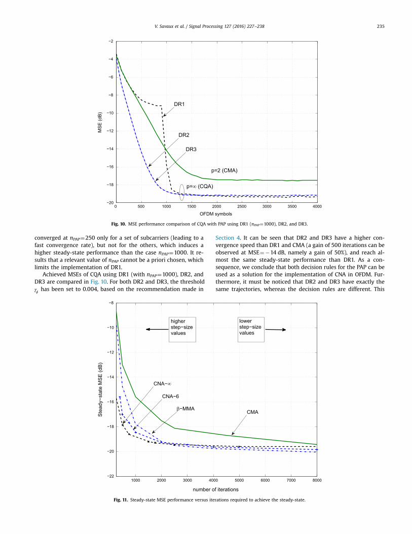
converged at nPAP¼250 only for a set of subcarriers (leading to afast convergence rate), but not for the others, which induces ahigher steady-state performance than the case nPAP¼1000. It re-sults that a relevant value of nPAP cannot be a priori chosen, whichlimits the implementation of DR1.
Achieved MSEs of CQA using DR1 (with nPAP¼1000), DR2, andDR3 are compared in Fig. 10. For both DR2 and DR3, the thresholdγϕ has been set to 0.004, based on the recommendation made in
Section 4. It can be seen that DR2 and DR3 have a higher con-vergence speed than DR1 and CMA (a gain of 500 iterations can beobserved at MSE¼14 dB, namely a gain of 50%), and reach al-most the same steady-state performance than DR1. As a con-sequence, we conclude that both decision rules for the PAP can beused as a solution for the implementation of CNA in OFDM. Fur-thermore, it must be noticed that DR2 and DR3 have exactly thesame trajectories, whereas the decision rules are different. This
0 500 1000 1500 2000 2500 3000 3500 4000−20
−18
−16
−14
−12
−10
−8
−6
−4
−2
OFDM symbols
MS
E (d
B)
p=2 (CMA)
p=∞ (CQA)
DR1
DR2
DR3
Fig. 10. MSE performance comparison of CQA with PAP using DR1 (nPAP¼1000), DR2, and DR3.
1000 2000 3000 4000 5000 6000 7000 8000−22
−20
−18
−16
−14
−12
−10
−8
number of iterations
Ste
ady−
stat
e M
SE
(dB
)
CMA
CNA−∞
β−MMA
CNA−6
higherstep−sizevalues
lowerstep−sizevalues
Fig. 11. Steady-state MSE performance versus iterations required to achieve the steady-state.
V. Savaux et al. / Signal Processing 127 (2016) 227–238 235

result is quite surprising, but can be explained by the fact that theMSE in (30) is averaged over 100 realizations, and for M¼128.Therefore, it could be highlighted from Fig. 10 that DR2 and DR3have the same performance “in average”.
In order to provide a fair comparison of the performance of thedifferent algorithms, Fig. 11 depicts the steady-state MSE perfor-mance versus iterations required to achieve the steady-state. Thecurves in Fig. 11 have been obtained from a set of traces corre-sponding to different step-size parameters values. Thus, theachieved performances in the left side of the plot correspond tohigh μ values (i.e. high convergence speed but low precision),whereas those on the right side of Fig. 11 correspond to lower μvalues (i.e. low convergence speed but high precision). Note thatboth CNA-6 and −∞CNA are performed with PAP using DR2. It canbe observed that in the “higher convergence speed” range (i.e. inthe left side of the figure), both CNA-6 and −∞CNA outperforms β-MMA in terms of steady-state MSE. It is worth mentioning that again of up to 6 dB is achieved by −∞CNA compared with β-MMAwhere 250 iterations are required to reach the steady-state. On theother hand, β-MMA achieves a gain less than 1 dB in the “lowerconvergence speed” range compared with CNA-6 and −∞CNA .These results reveal that −∞CNA using PAP allows us to obtain ablind equalizer combining a good convergence speed with lowsteady-state MSE performance.
Other simulations have been performed to analyze the beha-vior of CNA with PAP using DR2 when the channel changes. To bedone, the same parameters as before are considered, but thecoefficients of the channel are multiplied by a coefficient equal to
πe0.9 j
4 at the 4000th OFDM symbol, which changes both modulusand phase. Fig. 12 shows achieved MSE performance using theCMA, CNA-6 and CQA. A peak appears in the trajectories of CNA forp¼2, p¼6, and = ∞p at the 4000th OFDM symbol, and about 800iterations are required by the algorithms to converge again. It canbe seen that the achieved steady-state performance after thechannel variation is the same as before the 4000th iteration. Thisresult shows the capability of CNA with PAP to track the channelvariations in terms of both phase and modulus.
The convergence speed of CMA and CNA-6 using the proposedsub-optimal initialization value −Fm n
s opt, given in (25) is compared
with the case ==F 1m n, 0 in Fig. 13. It can be observed that CMA with−Fm n
s opt, experiences a gain of 1000 iterations (or equivalently 1000
OFDM symbols) to reach its steady-state. Moreover, at= −MSE 16 dB, a gain of 500 iterations is achieved by CNA-6 with
−Fm ns opt
, compared with ==F 1m n, 0 . This result validates the use of theproposed sub-optimal initialization strategy proposed Section 5 toimprove the convergence speed of the CNA in OFDM systems.
6.3. Discussion
The previous results showed that the proposed correction ofthe phase mismatch allows us to adapt the CNA-6 and CQA tech-niques in OFDM. Moreover, these methods are able to achievebetter performance in terms of MSE and convergence speed thanthe β-MMA [13] for high step-size parameter values. Another ad-vantage of the CNA lies in the fact that it can be adapted to squareand non-square constellations since norms can be specificallydesigned for all kinds of constellations. On the contrary, β-MMA isa simple method which shows good performance in the case ofsquare constellations. Other series of simulations revealed that ablind equalizer achieves at least as good performance as pilot-ai-ded methods. However, simulations have been undertaken in astatic propagation channel. As a consequence, these blind re-ceivers could be relevant in a broadcast context, where thechannels are usually assumed to be static or quasi-static. In thatscenario, a short preamble in comparison with the data sequencemay not reduce that much the spectral efficiency of the data aidedsignal. However, the use of a preamble could increase the PAPR ofthe transmitted signal, whereas the PAPR of the signal using ablind receiver is that of the OFDM, i.e. about 12 dB.
7. Conclusion
In this paper, we have proposed an adaptation of the CNA forfrequency blind equalization in OFDM. The CNA family has provedto be very relevant when a square constellation as 16-QAM is used,but has only been implemented in single carrier systems [23,24]. It
0 1000 2000 3000 4000 5000 6000 7000 8000−20
−18
−16
−14
−12
−10
−8
−6
−4
−2
OFDM symbols
MS
E (d
B)
p=2 (CMA)
p=6
p=∞ (CQA)
Fig. 12. Tracking performance of CMA, CNA-6, and CQA with PAP using DR2.
V. Savaux et al. / Signal Processing 127 (2016) 227–238236

has been shown in (15) that the CNA with = ∞p (CQA) is not ableto recover the phase. Due to the features of CQA, this phase mis-match induces a convergence of the equalizer coefficients Fm n,
toward erroneous values, which limits the performance of thisalgorithm in OFDM. In order to overcome this problem, a proce-dure for the phase adaptation of the coefficients Fm n, called (PAP)has been proposed in Section 4. Simulations have shown that CNA-6 and CQA with PAP outperforms the CMA, and achieves as well asβ-MMA. In fact, it has been demonstrated that CNA has a higherconvergence speed and achieves a lower MSE than CMA for a 16-QAM constellation. Furthermore, the capability of CNA with pro-posed PAP to track the channel variations has been highlighted.Finally, thanks to the proposed initialization strategy, an increaseof the convergence speed is achieved.
Acknowledgment
This work is supported by the project PROFIL (Evolution of thewideband PROfessional Mobile Radio based on the FILter BankMultiCarrier modulation) funded by the French National ResearchAgency with grant agreement code ANR-13-INFR-0007-03 and ICTEC-funded project Newcom# with code FP7-IC-318306.
Appendix A. Proof of (15)
In this appendix, we prove that the equalizer coefficients +Fm n, 1 ofCQA in (15) converge in average in the same direction as =Fm n, 0. Forsake of simplicity, a 4-QAM is considered hereafter. For any ∈ n werewrite ( )+E Farg m n, 1 in (A.1) by substituting (12) into (15). It is as-
sumed that (| | > | |) = (| | > | |) =P Z Z P Z ZRe Im Im Rem n m n m n m n, , , ,12.
Then, we can express ( )E Aarg R as in (A.2). Since
( = ± ± ) =⁎P Y j1m n,14, we obtain (A.3):
( )
μ
μ
( ) = (| | > | |)
× ( − (| | − ) )
+ (| | > | |)
× ( − (| | − ) )
+
⁎
⁎
⎧⎨⎪⎪
⎩⎪⎪
⎫⎬⎪⎪
⎭⎪⎪
⎧⎨⎪⎪
⎩⎪⎪
⎫⎬⎪⎪
⎭⎪⎪
A.1
E F P Z Z
E F Z R Z Y
P Z Z
E F Z R Z Y
arg Re Im
arg Re Re
Im Re
arg Im Im .
m n m n m n
m n m n m n m n
AR
m n m n
m n m n m n m n
AI
, 1 , ,
, ,2
, ,
, ,
, ,2
, ,
( )
( )
()
()
μ
μ
μ
μ
( )
= ( = + )
− (| | − ) ( + )
+ ( = − )
− (| | − ) ( − )
+ ( = − + )
− (| | − )
( − + ) + ( = − − )
− (| | − )
( − − ) ( )
⁎
⁎
⁎
⁎
E A
P Y j
E F Z R Z H j
P Y j
E F Z R Z H j
P Y j
E F Z R Z
H j P Y j
E F Z R Z
H j
arg
1
arg Re Re 1
1
arg Re Re 1
1
arg Re Re
1 1
arg Re Re
1 . A.2
R
m n
m n m n m n m n
m n
m n m n m n m n
m n
m n m n m n
m n m n
m n m n m n
m n
,
, ,2
, ,
,
, ,2
, ,
,
, ,2
,
, ,
, ,2
,
,
( )( )( )( )
μ
μ
μ
μ
( )
= − (| | − ) ( + )
+ − (| | − ) ( − )
+ − (| | − ) ( − + )
+ − (| | − ) ( − − ) ( )
E A
E F Z R Z H j
F Z R Z H j
F Z R Z H j
F Z R Z H j
arg
arg Re Re 1
arg Re Re 1
arg Re Re 1
arg Re Re 1 A.3
R
m n m n m n m n
m n m n m n m n
m n m n m n m n
m n m n m n m n
14 , ,
2, ,
, ,2
, ,
, ,2
, ,
, ,2
, ,
0 1000 2000 3000 4000 5000 6000 7000 8000−20
−18
−16
−14
−12
−10
−8
−6
−4
−2
OFDM symbols
MS
E (d
B)
p=2 (CMA)
Fm,ns−opt
Fm,n
=1
p=6
Fig. 13. MSE performance of CMA and CNA-6 with sub-optimal initialization strategy.
V. Savaux et al. / Signal Processing 127 (2016) 227–238 237

It is straightforward to show that for any ( ) ∈ z z,1 22, we have
( ) ( )+ + + + +
+ + = ( )( )
π π π
π
−
−
⎜ ⎟
⎜ ⎟
⎛⎝
⎞⎠
⎛⎝
⎞⎠
z z e z z e z z e
z z e z
arg arg arg
arg 4 arg .A.4
j j j
j
1 2 4 1 234 1 2 4
1 234 1
Then, by substituting the result in (A.4) into (A.3), we obtain that ( ) = ( )E A Farg argR m n, . The same development can be carried out
with ( )E Aarg I leading to the equality ( ) = ( )+E F E Farg argm n m n, 1 ,in (A.1). As this result is valid for any ∈ n , a simple mathematicalinduction yields
( ) = ( ) ( )+ =E F E Farg arg . A.5m n m n, 1 , 0
A.1. Proof of (22)
The substitution of (21) into (20) yields
( )γ μ μ
μ
= ˜ ˜ = ˜ + | ˜ |
= ˜ + ˜ ( )
ϕ ϕ ϕ
ϕ
⁎ ⁎
⁎ ⁎
E Z W E a W W
E a W a W
Im Im
Im Re Re Im .A.6
m n m n m n m n m n
m n m n m n m n
2, ,
2 2, , ,
2 2
2, , , ,
2
The expectation of the cross-factors obtained from the develop-ment of the third line in (A.6) are equal to zero since both am n, and
Wm n, are variables with zero mean. Hence, using σ σ˜ ≥2 2 leads tothe following:
γ μ
μ σ
μ σ
= ˜ + ˜
≥ ˜ +
≥ + ( )
ϕ ϕ
ϕ
ϕ
⁎ ⁎E a W a W
E a a
E a a
Im Re Re Im
Re Im
Re Im . A.7
m n m n m n m n
m n m n
m n m n
2,
2,
2,
2,
2
2 2,
2,
2
2 2,
2,
2
Note that the covariance of aIm m n,2 and ˜
⁎WRe m n,
2 has beenomitted in the second line of (A.7), which justify the use of theinequality.
References
[1] M. Morelli, U. Mengali, A comparison of pilot-aided channel estimationmethods for OFDM systems, IEEE Trans. Signal Process. 49 (12) (2001)3065–3073.
[2] M.K. Ozdemir, H. Arslan, Channel estimation for wireless OFDM systems, IEEECommun. Surv. Tutor. 9 (2) (2007) 18–48.
[3] Y. Liu, Z. Tan, H. Hu, L.J. Cimini, G.Y. Li, Channel estimation for OFDM, IEEECommun. Surv. Tutor. 16 (4) (2014) 1891–1908.
[4] Y. Sato, A method of self-recovering equalization for multilevel amplitude-modulation systems, IEEE Trans. Commun. 23 (6) (1975) 679–682.
[5] D.N. Godard, Self-recovering equalization and carrier tracking in two-dimen-sional data communication systems, IEEE Trans. Commun. 28 (11) (1980)1867–1875.
[6] J. Treichler, B. Agee, A new approach to multipath correction of constantmodulus signals, IEEE Trans. Acoust. Speech Signal Process. 31 (2) (1983)459–472.
[7] R. Johnson, Jr., P. Schniter, T. Endres, J. Behm, D. Brown, R. Casas, Blindequalization using the constant modulus criterion: a review, Proc. IEEE 86 (10)(1998) 1927–1950.
[8] J. Yang, J.-J. Werner, Dumont, G.A. The multimodulus blind equalization and itsgeneralized algorithms, IEEE Trans. Sel. Areas Commun. 20 (5) (2002) 997–1015.
[9] K. Wesolowski, Analysis and properties of the modified constant modulusalgorithm for blind equalization, Eur. Trans. Telecommun. 3 (1992) 225–230.
[10] K.N. Oh, Y.O. Chin, Modified constant modulus algorithm: blind equalizationand carrier phase recovery algorithm, in: ICC'95, vol. 1, Seattle, WA, 1995, pp.498–502.
[11] S. Abrar, A.K. Nandi, Blind equalization of square-QAM signals: a multi-modulus approach, IEEE Trans. Commun. 58 (6) (2010) 1674–1685.
[12] J. Mendes Filho, M.D. Miranda, M.T.M. Silva, A regional multimodulus algo-rithm for blind equalization of QAM signals: introduction and steady-stateanalysis, Signal Process. 92 (11) (2012) 2643–2656.
[13] S. Abrar, A.K. Nandi, Adaptive solution for blind equalization and carrier-phaserecovery of square-QAM, IEEE Signal Process. Lett. 17 (9) (2010) 791–794.
[14] A.W. Azim, S. Abrar, A. Zerguine, A.K. Nandi, Steady-state performance ofmultimodulus blind equalizers, Signal Process. 108 (2015) (2015) 509–520.
[15] T.C. Hewavithana, D.M. Brookes, Blind adaptive channel equalization for OFDMusing the cyclic prefix data, in: GLOBECOM'04, vol. 4, 2004, pp. 2376–2380.
[16] M. de Courville, P. Duhamel, P. Madec, J. Palicot, Blind equalization of OFDMsystems based on the minimization of a quadratic criterion, in: ICC'96, vol. 3,Dallas, TX, 1996, pp. 1318–1322.
[17] H. Zamiri-Jafarian, H. Khoshbin, S. Pasupathy, Time-domain equalizer forOFDM systems based on SINR maximization, IEEE Trans. Commun. 53 (6)(2005) 924–929.
[18] M. Luise, R. Reggiannini, G. Vitetta, Blind equalization/detection for OFDMsignals over frequency-selective channels, IEEE Trans. Sel. Areas Commun. 16(8) (1998) 1568–1578.
[19] T. Al-Naffouri, A. Dahman, M. Sohail, W. Xu, B. Hassibi, Low-complexity blindequalization for OFDM systems with general constellations, IEEE Trans. SignalProcess. 60 (12) (2012) 6395–6407.
[20] K. Van Acker, G. Leus, M. Moonen, O. Van de Viel, T. Pollet, Per tone equal-ization for DMT-based systems, IEEE Trans. Commun. 49 (1) (2001) 109–119.
[21] R.K. Martin, Blind, adaptive equalization for multicarrier receivers (Ph.D.thesis), Cornell University, Ithaca, NY, 2004.
[22] B.H.B. Naeeni, H. Amindavar, H. Bakhshi, Blind per tone equalization of mul-tilevel signals using support vector machines for OFDM in wireless commu-nication, Int. J. Electron. Commun. 64 (2) (2010) 186–190.
[23] A. Goupil, J. Palicot, Constant norm algorithms class, in: Proceedings of EU-SIPCO'02, Toulouse, France, 2002.
[24] A. Goupil, J. Palicot, New algorithms for blind equalization: the constant normalgorithm family, IEEE Trans. Signal Process. 55 (4) (2007) 1436–1444.
[25] T. Thaiupathump, New algorithms for blind equalization and blind sourceseparation/phase recovery (Ph.D. thesis), University of Pennsylvania, Phila-delphia, PA, January 2002.
[26] T. Thaiupathump, L. He, S.A. Kassam, Square contour algorithm for blindequalization of QAM signals, Signal Process. 86 (11) (2006) 3357–3370.
[27] N. Benvenuto, G. Cherubini, Algorithms for Communications Systems andtheir Applications, Wiley, Chichester, England, 2002.
[28] V. Savaux, Contribution to multipath channel estimation in OFDM context (Ph.D. thesis), Supélec, Rennes, France, November 2013.
[29] G. Picchi, G. Prati, blind equalization and carrier recovery using a “stop-and-go” decision-directed algorithm, IEEE Trans. Commun. 35 (9) (1987) 877–887.
[30] A. Belouchrani, W. Ren, Blind carrier phase tracking with guaranteed globalconvergence, IEEE Trans. Signal Process. 45 (7) (1997) 1889–1894.
[31] Y. Ha, W. Chung, Non-data-aided phase noise suppression scheme for CO-OFDM systems, IEEE Photon. Technol. Lett. 25 (17) (2013) 1703–1706.
[32] J.G. Proakis, Communication through band-limited channels, in: DigitalCommunications, Mc Graw-Hill, New York, 1995, pp. 583–635 (Chapter 10).
V. Savaux et al. / Signal Processing 127 (2016) 227–238238

CMA-Based Blind Equalization and Phase Recovery
in OFDM/OQAM Systems
*Vincent Savaux, **Faouzi Bader, and **Jacques Palicot**SCEE/IETR - CentraleSupelec, Rennes.
Avenue de la Boulaie, 35576 Cesson - Sevigne Cedex, France.
Emails: [email protected], and [email protected]
Abstract—This paper deals with a constant modulus algorithm-(CMA) based blind equalization method for orthogonal frequencydivision multiplexing/offset quadrature amplitude modulation(OFDM/OQAM) scheme. The authors propose to combine theCMA with a low-pass filter in order to increase the convergencespeed of the equalizer, and to avoid the detection of the receivedsymbols with phase mismatch. Simulations results show that theconvergence speed is largely increased, and the proposed methodachieves bit error rate (BER) performance very close to that ofthe perfect channel estimation and equalization.
Index Terms—Blind equalization, OFDM/OQAM, CMA, Im-pulse Noise Cancellation.
I. INTRODUCTION
The blind equalization is an interesting solution for the
channel inversion (or deconvolution) since it guarantees the
signal a maximum spectral efficiency. Indeed, these techniques
do not use pilots, the blind equalizer only takes advantage of a
few signal features to perform the channel inversion. In [1], B.
Farhang-Boroujeny has adapted the blind equalization using the
constant modulus algorithm (CMA) proposed by D. N. Godard
in [2] to the cosine modulated filter bank (CMFB) modulation.
In [3] the authors proposed to use the second order moment
of the received signal, while the CMA is used in [1].
In filter bank multicarrier (FBMC), and in particular in
orthgonal frequency division multiplexing/offset quadrature
amplitude modulation (OFDM/OQAM), only few papers deals
with blind equalization. Due the convergence delay of the blind
methods and the uncertainty on the phase of the recovered
symbols, the blind channel equalization remains a pending
challenge not much studied by the scientific community, in
particular in FBMC.
In this paper we propose a constant modulus algorithm-
based (CMA) blind equalizer for OFDM/OQAM systems. As
in [1], we consider a one-tap per carrier equalization, since it is
particularly adapted to the multicarrier systems. As mentioned
in [4], this type of technique may lead to local solutions and
implies that the symbols are detected with a phase shift of 0or π. The proposed method consists of filtering the equalizer
*CentraleSupelec is the former institution of Vincent Savaux, actually withb<>com research institute. E-mail: [email protected]. This work issupported by the project PROFIL (Evolution of the wideband PROfessionalMobile Radio based on the FILter Bank MultiCarrier modulation) funded bythe French national research agency (ANR) with grant agreement code: ANR-13-INFR-0007-03.
response in order to smooth the channel frequency response.
The principle of the proposed technique is simple, since it
is similar to a low-pass filter as used in channel estimation
[5]. The addition of a differential phase coding allows to
suppress any uncertainty on the phase of the recovered sym-
bols. Furthermore, the proposed techniques largely increases
the convergence speed of the CMA. The idea behind CMA
applied in OFDM/OQAM is to iteratively update the algorithm
by comparing the real part of the output of the equalizer with
a given real constant that depends on the constellation size.
However, it is worth noting that CMA is equivalent to Sato’s
algorithm [6], and the constant norm algorithm (CNA) [7], due
to the use of real transmitted OQAM symbols. Therefore, this
limits the choice of the cost function to those that are adapted
to real constellation, whereas numerous cost functions adapted
to different complex constellations have been proposed in the
scientific literature [7]–[9].
The rest of the paper is organized as follows: Section II
presents the system model and the CMA, and we propose
our equalizer with IN cancellation in Section III. Simulations
shows the performance of the method in terms of mean square
error (MSE) and BER in Section IV, and we draw conclusions
in Section V.
II. SYSTEM MODEL
We consider the transmission of OFDM/OQAM symbols
over a frequency selective channel, with perfect time and fre-
quency synchronization. At the frequency-time position (m, n),the output of the analysis filter bank (AFB) is written as
ym,n = Hm,nxm,n + j∑
(p,q)∈Ω
Hp,qxp,q < g >m,np,q
︸ ︷︷ ︸Im,n
+wm,n,
(1)
where xm,n is the real symbol transmitted at frequency-
time position (m, n), Hm,n is the complex channel frequency
response (CFR). A detailed description of the synthesis filter
bank (SFB) and the AFB is available in [10]. wm,n and
Im,n are the complex additive white Gaussian noise (AWGN)
and the interference terms whose variances are σ2 and σ2I
respectively. The term j < g >m,np,q is called the intrinsic
2016 23rd International Conference on Telecommunications (ICT)
978-1-5090-1990-8/16/$31.00 ©2016 IEEE
168

interference due to the prototype filter gm,n(t) that is given
by
gm,n[i] = g(i− nM
2)e
2jπmM (i− Lf−1
2 )ejφm,n , (2)
where the phase term is φm,n = (π/2)(m + n) + mnπ as
defined in [10]. It should be noted that the real symbols xm,n
are transmitted with a period M2 twice shorter than that of
OFDM signal where symbols are complex. The used filter
has a length Lf = KM , where K is the overlapping factor
and M is the total number of carriers. Thus, even in absence
of the multipath channel, there will be some intercarrier and
intersymbol purely imaginary interferences. In fact, gm,n is
orthogonal in the real field, which allows to perfectly recover
the real OQAM symbols. However, it can be seen in (1) that the
CFR Hp,q induces some distortions from the time-frequency
positions (p, q) that belongs to the set Ω1 and have to be
estimated and corrected.
In this paper, the signal is blindly equalized, by using the
simple one-tap per-carrier CMA equalizer. To summarize, the
aim of the CMA is to tends toward the optimal equalizer
coefficient F optm,n thanks to the update algorithm, which can
be written asFm,n+1 = Fm,n − μy∗
m,nsign(am,n)(|am,n| − γ). (3)
where Fm,n is the equalizer coefficient, and am,n =Re(Fm,nym,n), μ is the step-size parameter, and γ is a real-
valued constant which is defined as γ = E|x|4E|x|2 (see [2] for
more details). The CMA has a low complexity, but it suffers
from two drawbacks: i) it requires a long convergence time, and
ii) it is phase blind, i.e. the real equalized symbols am,n can
be detected with a phase equal to 0 or π. In the following, we
propose a simple method that reduces the delay of convergence
of CMA, and avoids the phase incertainty.
III. CMA BLIND EQUALIZATION WITH IMPULSE NOISE
CANCELLATION
It has been shown in [1], [4] that the CMA applied to the
real OQAM symbols converges toward the optimal coefficient
value |F optm,n| with a phase shift equal to 0 or π. The solution
that consists of using a differential phase coding as in [1] do not
ensure a low bit error rate (BER) value when a large number
of received symbols are detected with an opposite phase. In
this section, we propose to consider the issue of convergence
toward F optm,n or −F opt
m,n from an original point of view, which
is described just below.
A. Equalization with Impulsive Noise Cancellation
Fig. 1 shows the real part of a frequency response of
the invert of the equalizer coefficients 1/F optm,n (using CMA)
compared with the exact channel frequency response Hm,n,
knowing that |F optm,nHm,n| = 1. It can be seen that the fre-
quency positions m=11, 29, and 92 correspond to the opposite
minima −F optm,n.
1Ω is the set of positions p, q that surround the position m, n
20 40 60 80 100 120−1
−0.5
0
0.5
1
1.5
2
Subcarriers m
H
H
1/F
Opposite channel values
Fig. 1: Real part of H and 1/F showing opposite equalizer
coefficient values.
Fig. 2: Proposed equalizer structure with impulse noise can-
cellation.
The optimal solutions with opposite phase depicted in Fig. 1
can be seen as an impulsive noise (IN) in the channel frequency
response, which can be filtered in a simple way as described in
[11]. The IN cancellation can be seen as a low-pass filtering,
but performed in the time domain. This technique is also
usually used in channel estimation techniques in order to filter
the noise or to perform an interpolation [5]. In the considered
blind equalization context, the IN cancellation should be seen
as a smoothing stage applied to the equalizer coefficients Fm,n,
and allows full blind equalization as it does not require any
pilot for the phase estimation. The proposed equalizer regularly
switch to the IN cancellation block as depicted in Fig. 2.
The steps into the ”IN cancellation” block in Fig. 2 are
described as follows:
1) ∀m ∈ 0, M − 1, the channel frequency response (CFR)
samples are obtained by Hm,n = 1/Fm,n, and stored in
the vector Hn of size M × 1.
2) The estimated channel impulse response (CIR) is
achieved by applying an IFFT: hn = IFFT (Hn).3) The CIR is multiplied by a rectangular window Π defined
by
Πm =
1, if m ≤ LΠ
0, else, (4)
2016 23rd International Conference on Telecommunications (ICT)
169

such as hn = hnΠ, where the length of Π denoted by
LΠ must be at least equal to channel length L.
4) The filtered CFR is obtained by the FFT as Hn =FFT (hn) and then the equalizer coefficients by Fm,n =1/Hm,n.
Note that in practice, the L value is unknown, so LΠ is
chosen in order to overestimate the length of the channel.
The advantages of the IN cancellation process are multiple:
in addition to suppress the opposite solutions that are seen
as an impulsive noise, it also avoids the possible convergence
of the coefficients toward local minima2. Therefore, it offers
the possibility of initialization strategies different from the one
proposed in [1]. Moreover, as observed in [5] for the channel
estimation, the IN cancellation mitigates the noise and the
interferences level. In an OFDM/OQAM context in which the
interference term may be not negligible, this smoothing stage
may appear to be very convenient.
Also, it is worth highlighting that the proposed IN cancella-
tion process using scheme in Fig. 2 may lead to two solutions:
i) all the M coefficients Fm,n converge toward their optimal
solutions without phase shift F optm,n, ii) all the coefficients Fm,n
are equal to the opposite expected solutions −F optm,n.
That is the main difference with the CMA in (3) where
each coefficient Fm,n may converge to the optimal value
or its opposite. In our solution, if all the coefficients Fm,n
converge to their opposite optimal solution, the differential
phase decoding stage leads to a single error3 which could
be easily suppressed by means of a channel code. If no IN
cancellation is performed as in [1], a large number of phases
may be erroneous because they are detected with a difference
equal to π. In the latter case, the differential phase encoding
becomes inefficient and therefore the channel coding as well.
In the hereafter section, we will focus on the way of applying
the proposed IN cancellation stage in Fig. 2.
B. How to apply the IN Cancellation?There are three possible ways to perform the IN cancellation
stage, which are hereafter explained:
• The IN cancellation is used only one time during the
convergence process. It could be a convenient solution if
only few Fm,n coefficients are detected with an opposite
phase (see the example in Fig. 1). However, if a large
number of phases are detected with a shift equal to π, a
single IN cancellation stage is not sufficient to suppress
the appearance of the impulse noise and this solution is
similar to the CMA approach. Furthermore, this option
raises the issue of the choice of the appropriate starting
point to proceed the smoothing stage.
• The IN cancellation is employed at each iteration. Here,
the update algorithm (3) does not have any sense since it
is fed by a coefficient Fm,n that is not the one obtained
2In fact, local minima can also be seen as peaks in the estimated CFR3If all the phases are detected with an error equal to π, the difference of
phase between to consecutive symbols is the same as if the phase error is 0,excepted for the first symbol.
at the previous iteration. In other words, this solution
is not anymore a blind equalization, and should lead to
unsuitable coefficients Fm,n.
• The operation is performed with a reasonable regular-
ity regarding to the convergence speed of the update
algorithm (3). Thus, the process either performs the IN
cancellation as long as optimal solutions with opposite
phases remain, or performs a noise cancellation due to
the nature of the filter. This solution seems to be the way
to carry out the proposed CMA with IN cancellation in
Fig. 2.
In order to formalize these three solutions, we define Ni the
time delay between two consecutive smoothing operations.
Thus, the first solution corresponds to Ni = +∞, the second
one to Ni = 1 and the third one to a value of Ni conveniently
chosen. It is worth noticing that simulations revealed that
the first two solutions lead to unsatisfactory results. As a
consequence, we only focus on the third solution in the next
section.
IV. SIMULATIONS RESULTS
In this section, we present simulations results which show
the performance of the proposed blind equalizer. Since we
are comparing obtained results with the CMA in (3), we will
use the same parameters as described in [1] where the CMA
is used in FBMC. We consider a constant multipath channel
whose CIR is h = [1,−0.2, 0.3, 0.2, 0.1, 0.2, 0.35,−0.2]. The
real part of the corresponding CFR is displayed in Fig. 1. The
results are presented for a 4-QAM constellation, i.e. for binary
OQAM symbols. As a consequence, note that γ = 1. Each
OFDM/OQAM symbol is composed of M = 128 carriers. Two
initialisation values are tested: a constant initialization Fm,0 =0.01 for any m = 0, 1, ..,M−1 such as proposed in [1], and the
sub-optimal initialization strategy F s−optm,0 =
√Exm,02
|ym,0|2 such
as proposed in [12]. In both cases, the step-size parameters is
set at μ = 0.015. In the following, the performance of the data-
aided interference approximation method (IAM) is also plotted
for reference. A detailed description of the IAM is provided
in [10]. The performance of the different blind equalizers is
assessed by using the mean square error MSE defined as
MSE = E(|am,n| − |xm,n|)2. (5)
In Fig. 3, the CMA is compared with the proposed CMA
using IN cancellation (denoted by INC in the figures) for Ni =1 and Ni = +∞, where it is performed at the 200th and at the
2000th iterations. The results are obtained for SNR=30 dB,
and Fm,0 = 0.01. Moreover, achieved MSE values with IAM
pilot aided pattern is plotted as a reference.
It can be observed that CMA achieves better performance
than CMA with IN cancellation when it is performed with
Ni = 1 and has a similar MSE than CMA using IN cancellation
where Ni = +∞. Having Ni = 1, the MSE has a ”chaotic”
behavior, but has a lower bound around -14 dB, whereas the
CMA achieves a MSE lower than -17 dB. These observations
2016 23rd International Conference on Telecommunications (ICT)
170

0 1000 2000 3000 4000 5000 6000 7000 8000−25
−20
−15
−10
−5
0
5
OFDM/OQAM symbols
MS
E (
dB
)
CMA+INC, Ni=∞
CMA+INC, Ni=∞
CMA+INC, Ni=1
pilot aided (IAM)
CMA
200−th iteration2000−th iteration
Fig. 3: MSE of CMA and CMA with impulse noise cancel-
lation (INC) versus OFDM/OQAM symbols for Ni = 1 and
Ni = +∞, SNR=30 dB.
confirm that the gradient update in (3) does not make sense
in the case Ni = 1. For Ni = +∞, one can observe that
once the smoothing stage has been performed (at the 200th or
2000th iteration), the trajectories of CMA using IN cancellation
are the same as those with CMA. The peaks that appear at
iterations 200 and 2000 can be interpreted as a reset of the
equalizer coefficient due to the IN cancellation stage, and this
indicates that the option Ni = 1 is not suitable when too
much coefficients Fm,n converge to their opposite solutions.
More generally, results presented in Fig. 3 show that the IN
cancellation with Ni = 1 and Ni = +∞ does not improve
CMA as proposed in [1]. These results are consistent with the
a priori remarks we made in Section III-B. Note that none
of the presented methods is able to reach the performance
of the pilot-aided estimation using IAM. This is mainly due
to the facts that: i) IAM is an accurate channel estimation
method, and ii) CMA is known to be a simple method, but
achieves weak performance. In Fig. 4 we compare the MSE
performance of the proposed CMA in Fig. 2 for a regular
IN mitigation stage performed every Ni = 500 iterations.
Furthermore, the initialization F s−optm,0 is compared with the
constant Fm,0 = 0.01 value.
It can be observed that CMA with sub-optimal initialization
achieves a gain of 2000 iteration at MSE=-15 dB compared
with the ”classical” CMA such as proposed in [1]. Fig. 4 also
highlights that the CMA using IN cancellation with Ni = 500reaches its lower bound equal to MSE=-22 dB at the 3500-th
iteration, and when F s−optm,n is used, this MSE floor is reached
at the 1000-th iteration. These results show the capability of
the proposed CMA-based equalizer with convenient Ni value
to have a high convergence speed compared with CMA. Fur-
thermore, it must be noticed that this advantage is accompanied
with a good performance, as a MSE gain of 6 dB is achieved
by the proposed method compared to the CMA at the 4000-th
iteration. Also, it can be seen that CMA with IN cancellation
0 1000 2000 3000 4000 5000 6000 7000 8000−25
−20
−15
−10
−5
0
OFDM/OQAM symbols
MS
E (
dB
)
CMA+INC, Ni = 500
CMA+INC, Ni = 500 + F
0
s−opt
CMA+F0
s−optCMA
pilot aided (IAM)
Fig. 4: MSE of the CMA using IN cancellation versus iterations
compared with CMA, Ni = 500, SNR=30 dB.
achieves a gain of 2 dB of MSE compared with the pilot-aided
method.
For proposed CMA approach with IN cancellation, one can
notice that peaks appear at the iterations corresponding to
the application of IN cancellation stages. This is due to the
fact that the IN cancellations gradually suppress the peaks
in the equalizer coefficients. Although the proposed equalizer
in Fig. 2 with the initialization in F s−optm,0 has a remarkable
convergence speed, it can be observed that the initialization
F s−optm,0 alone with the CMA allows to get a satisfactory fast
convergence as well, such as shown in [12]. However, the MSE
defined in (5) does not take into account the phase shift of 0 or
π. In fact it does not affect the absolute values of the expected
equalizer coefficients |Fm,opt| but plays a key role in the BER
performance, as it is shown afterward. Fig. 5 depicts the MSE-
floor values of CMA, and CMA using IN cancellation with
sub-optimal initialization value, and IAM, when the steady-
state is reached, versus SNRs. Once again, it can be concluded
from Fig. 5 that the blind equalizers achieve better performance
than the data aided method (at least for the same channel as in
[1]) for SNR values <24 dB using CMA and <40 dB using
CMA with IN cancellation (Ni = 500). Furthermore, the latter
has lower MSE values than the ”usual” CMA for SNR>10 dB.
This result reflects the fact that the IN cancellation stage is also
able to smooth the noise of the channel frequency response
(step 3) in the algorithm presented in Section III.
Fig. 6 shows the BER performance of the proposed blind
equalizer versus the SNR, and also that of CMA approach
using both the constant initialization and F s−optm,0 . The BER
is obtained by using a differential phase coding and a con-
volutional coding with code rate 1/2 and a Viterbi decoder.
The BER is calculated at the 4000th iteration, by averaging
the results on 107 random transmitted bits. The data aided
estimation and equalization using IAM is also depicted, and
the equalizer using perfect CSI is plotted as a reference.
It can be clearly observed that the proposed technique
2016 23rd International Conference on Telecommunications (ICT)
171

0 5 10 15 20 25 30 35 40−25
−20
−15
−10
−5
0
5
10
SNR (dB)
MS
E (
dB
)
CMA+INC
CMA
pilot aided (IAM)
Fig. 5: MSE performance versus SNR. Comparison between
CMA, CMA using IN cancellation (ICN) with sub-optimal
initialization value, and pilot-aided method (IAM).
0 5 10 15 20 2510
−5
10−4
10−3
10−2
10−1
100
SNR (dB)
BE
R
CMA
CMA+proposed init.
CMA+INC
CMA+INC+proposed init.
pilot aided (IAM)
perfect CSI
Fig. 6: BER versus SNR of the proposed equalizer compared
to [1].
outperforms the blind equalizer using CMA proposed in [1].
This reflects the fact that a large number of coefficients Fm,n
converge toward their opposite optimal values. Consequently,
when CMA is used alone, a large number of symbols are
detected with a phase shift equal to π. In that case, the
differential phase decoder and the Viterbi decoder are unable
to recover the expected correct binary symbols. With the
proposed blind equalizer, this problem is solved since all the
symbols are detected with the correct phase thanks to both
the differential and Viterbi decoders. Moreover, it should be
noticed that a SNR gain of 3 dB is achieved by the CMA
with IN cancellation compared with the pilot aided estimation
and equalization, which is consistent with the MSE result.
Furthermore, the CMA with IN cancellation losses less than
0.2 dB compared with the equalizer with perfect CSI. This is
an important result since it shows that blind equalization (once
the steady-state is reached) is able in our context to outperform
data-aided techniques, in terms of both BER performance
and spectral efficiency. Fig. 6 also reveals that the use of
the sub-optimal initialization has almost no influence on the
BER performance. However, it has been shown that largely
improves the convergence speed of the equalizer. From the
performance analyzed in both Figs. 4 and 6, we conclude that
the combination of the proposed method with the initialization
F s−optm,0 leads to i) a fast equalizer, ii) a low MSE floor value,
and iii) a high BER performance, compared with CMA alone,
and with IAM. Furthermore, the proposed with IN cancellation
allows to achieve a full blind equalizer and phase recovery,
since no pilot is used.
V. CONCLUSION
In this paper, we presented a simple blind equalization
technique for OFDM/OQAM systems. The principle is to
combine the CMA and a low-pass filtering in order to increase
the convergence speed of the blind equalizer, and to avoid the
convergence of the coefficients toward wrong phase values.
Simulations revealed that the proposed method achieves perfor-
mance close to the perfect channel estimation and equalization.
Further work will deal with the extension of proposed method
to larger constellation sizes.
REFERENCES
[1] B. Farhang-Boroujeny, “Multicarrier Modulation With Blind DetectionCapability Using Cosine Modulated Filter Banks,” IEEE Transactionson Communications, vol. 51, no. 12, pp. 2057 – 2070, December 2003.
[2] D. N. Godard, “Self-Recovering Equalization and Carrier Tracking inTwo-Dimensional Data Communication Systems,” IEEE Transactions onCommunications, vol. com-28, no. 11, pp. 1867 – 1875, November 1980.
[3] H. Bolcskei, P. Duhamel, and R. Hleiss, “A Subspace-Based Approach toBlind Channel Identification in Pulse Shaping OFDM/OQAM Systems,”IEEE Transactions on Signal Processing, vol. 49, no. 7, pp. 1594 – 1598,July 2001.
[4] L. Lin and B. Farhang-Boroujeny, “Convergence analysis of blind equal-izer in a cosine modulated filter bank-based multicarrier communicationsystem,” in proc. of SPAWC’03, Roma, Italy, June 2003, pp. 368 – 372.
[5] J. Schoukens, R. Pintelon, and H. V. Hamme, “The Interpolated FastFourier Transform: A Comparative Study,” IEEE Transactions on In-strumentation and Measurement, vol. 41, no. 2, pp. 226 – 232, April1992.
[6] Y. Sato, “A Method of Self-Recovering Equalization for MultilevelAmplitude-Modulation Systems,” IEEE Transactions on Communica-tions, vol. 23, no. 6, pp. 679 – 682, June 1975.
[7] A. Goupil and J. Palicot, “New Algorithms for Blind Equalization:The Constant Norm Algorithm Family,” IEEE Transactions on SignalProcessing, vol. 55, no. 4, pp. 1436 – 1444, April 2007.
[8] K. N. Oh and Y. O. Chin, “Modified constant modulus algorithm: blindequalization and carrier phase recovery algorithm,” in proc. of ICC’95,vol. 1, Seattle, WA, June 1995, pp. 498 – 502.
[9] S. Barbarossa, “Blind Equalization Using Cost Function Matched to theSignal Constellation,” in proc. of ACSSC’97, vol. 1, Pacific Grove, CA,USA, November 1997, pp. 550 – 554.
[10] E. Kofidis, D. Katselis, A.Rontogiannis, and S. Theodoridis, “Preamble-based channel estimation in OFDM/OQAM systems: A review,” SignalProcessing, Elsevier, vol. 93, pp. 2038 – 2054, January 2013.
[11] S. V. Vaseghi, Advanced Digital Signal Processing and Noise Reduction.John Wiley & Sons, 2000, ch. 12, pp. 355 – 377.
[12] V. Savaux and F. Bader, “Sub-Optimal Initialization for Blind Equaliza-tion with Fast Convergence in OFDM/OQAM Modulation,” in proc. ofEuCNC’15, Paris, France, June - July 2015.
2016 23rd International Conference on Telecommunications (ICT)
172
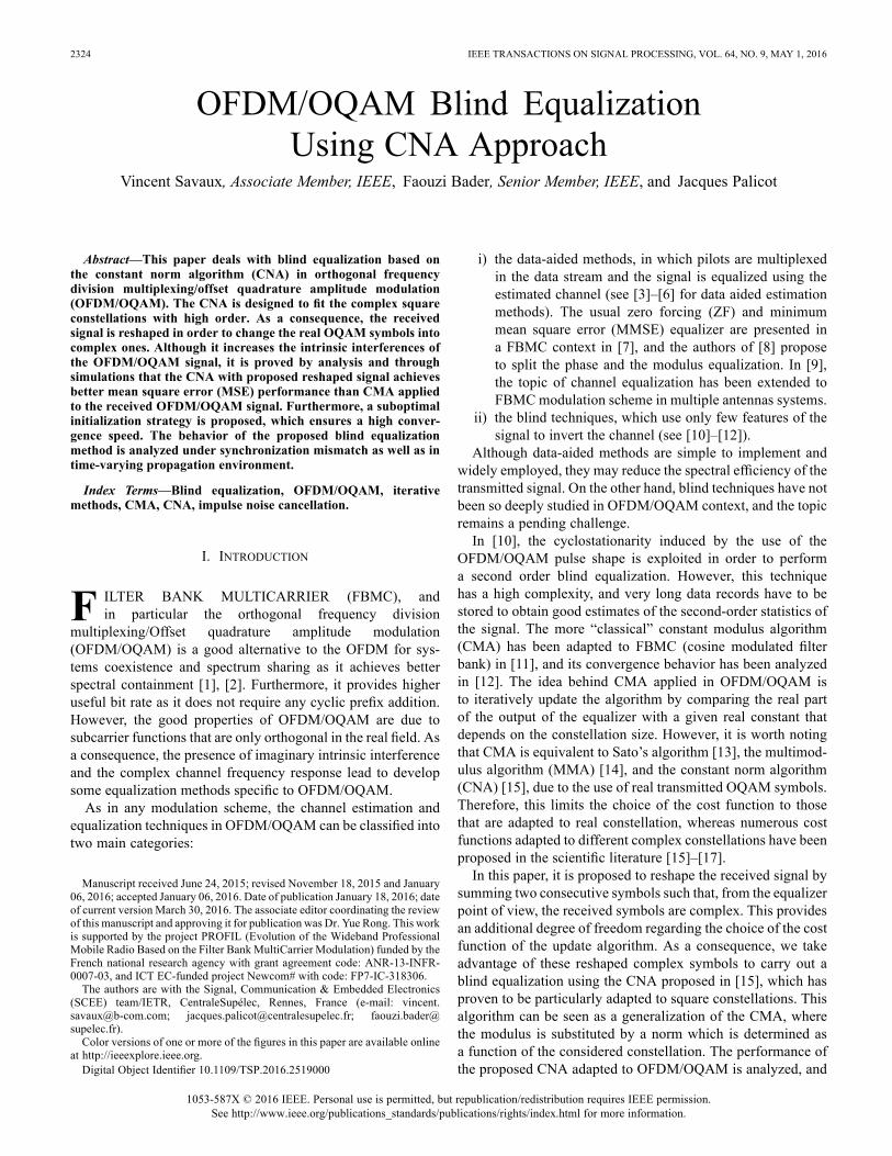
2324 IEEE TRANSACTIONS ON SIGNAL PROCESSING, VOL. 64, NO. 9, MAY 1, 2016
OFDM/OQAM Blind EqualizationUsing CNA Approach
Vincent Savaux, Associate Member, IEEE, Faouzi Bader, Senior Member, IEEE, and Jacques Palicot
Abstract—This paper deals with blind equalization based onthe constant norm algorithm (CNA) in orthogonal frequencydivision multiplexing/offset quadrature amplitude modulation(OFDM/OQAM). The CNA is designed to fit the complex squareconstellations with high order. As a consequence, the receivedsignal is reshaped in order to change the real OQAM symbols intocomplex ones. Although it increases the intrinsic interferences ofthe OFDM/OQAM signal, it is proved by analysis and throughsimulations that the CNA with proposed reshaped signal achievesbetter mean square error (MSE) performance than CMA appliedto the received OFDM/OQAM signal. Furthermore, a suboptimalinitialization strategy is proposed, which ensures a high conver-gence speed. The behavior of the proposed blind equalizationmethod is analyzed under synchronization mismatch as well as intime-varying propagation environment.
Index Terms—Blind equalization, OFDM/OQAM, iterativemethods, CMA, CNA, impulse noise cancellation.
I. INTRODUCTION
F ILTER BANK MULTICARRIER (FBMC), andin particular the orthogonal frequency division
multiplexing/Offset quadrature amplitude modulation(OFDM/OQAM) is a good alternative to the OFDM for sys-tems coexistence and spectrum sharing as it achieves betterspectral containment [1], [2]. Furthermore, it provides higheruseful bit rate as it does not require any cyclic prefix addition.However, the good properties of OFDM/OQAM are due tosubcarrier functions that are only orthogonal in the real field. Asa consequence, the presence of imaginary intrinsic interferenceand the complex channel frequency response lead to developsome equalization methods specific to OFDM/OQAM.As in any modulation scheme, the channel estimation and
equalization techniques in OFDM/OQAM can be classified intotwo main categories:
Manuscript received June 24, 2015; revised November 18, 2015 and January06, 2016; accepted January 06, 2016. Date of publication January 18, 2016; dateof current version March 30, 2016. The associate editor coordinating the reviewof this manuscript and approving it for publication was Dr. Yue Rong. This workis supported by the project PROFIL (Evolution of the Wideband ProfessionalMobile Radio Based on the Filter BankMultiCarrier Modulation) funded by theFrench national research agency with grant agreement code: ANR-13-INFR-0007-03, and ICT EC-funded project Newcom# with code: FP7-IC-318306.The authors are with the Signal, Communication & Embedded Electronics
(SCEE) team/IETR, CentraleSupélec, Rennes, France (e-mail: [email protected]; [email protected]; [email protected]).Color versions of one or more of the figures in this paper are available online
at http://ieeexplore.ieee.org.Digital Object Identifier 10.1109/TSP.2016.2519000
i) the data-aided methods, in which pilots are multiplexedin the data stream and the signal is equalized using theestimated channel (see [3]–[6] for data aided estimationmethods). The usual zero forcing (ZF) and minimummean square error (MMSE) equalizer are presented ina FBMC context in [7], and the authors of [8] proposeto split the phase and the modulus equalization. In [9],the topic of channel equalization has been extended toFBMC modulation scheme in multiple antennas systems.
ii) the blind techniques, which use only few features of thesignal to invert the channel (see [10]–[12]).
Although data-aided methods are simple to implement andwidely employed, they may reduce the spectral efficiency of thetransmitted signal. On the other hand, blind techniques have notbeen so deeply studied in OFDM/OQAM context, and the topicremains a pending challenge.In [10], the cyclostationarity induced by the use of the
OFDM/OQAM pulse shape is exploited in order to performa second order blind equalization. However, this techniquehas a high complexity, and very long data records have to bestored to obtain good estimates of the second-order statistics ofthe signal. The more “classical” constant modulus algorithm(CMA) has been adapted to FBMC (cosine modulated filterbank) in [11], and its convergence behavior has been analyzedin [12]. The idea behind CMA applied in OFDM/OQAM isto iteratively update the algorithm by comparing the real partof the output of the equalizer with a given real constant thatdepends on the constellation size. However, it is worth notingthat CMA is equivalent to Sato’s algorithm [13], the multimod-ulus algorithm (MMA) [14], and the constant norm algorithm(CNA) [15], due to the use of real transmitted OQAM symbols.Therefore, this limits the choice of the cost function to thosethat are adapted to real constellation, whereas numerous costfunctions adapted to different complex constellations have beenproposed in the scientific literature [15]–[17].In this paper, it is proposed to reshape the received signal by
summing two consecutive symbols such that, from the equalizerpoint of view, the received symbols are complex. This providesan additional degree of freedom regarding the choice of the costfunction of the update algorithm. As a consequence, we takeadvantage of these reshaped complex symbols to carry out ablind equalization using the CNA proposed in [15], which hasproven to be particularly adapted to square constellations. Thisalgorithm can be seen as a generalization of the CMA, wherethe modulus is substituted by a norm which is determined asa function of the considered constellation. The performance ofthe proposed CNA adapted to OFDM/OQAM is analyzed, and
1053-587X © 2016 IEEE. Personal use is permitted, but republication/redistribution requires IEEE permission.See http://www.ieee.org/publications_standards/publications/rights/index.html for more information.

SAVAUX et al.: OFDM/OQAM BLIND EQUALIZATION USING CNA APPROACH 2325
Fig. 1. Blind OFDM/OQAM receiver structure with (a) AFB, and (b) blindequalizer.
it is proved that the CNA achieves better performance than theCMA.The rest of the paper is organized as follows: the blind
OFDM/OQAM receiver structure is presented in Section II.The proposed CNA using a reshaped received signal is devel-oped in Section III. Section IV provides simulations resultsthat show the performance of the proposed blind equalizationtechniques. Finally, we draw our conclusions in Section V.
II. BLIND OFDM/OQAM RECEIVERThe blind OFDM/OQAM receiver is presented in Fig. 1. The
demodulator consists of a serial to parallel converter (denotedby S/P), and an analysis filter bank (AFB). The latter is com-posed of i) the polyphase network (PPN) that contains a set ofdigital filters, and ii) the fast Fourier transform (FFT) of size(M is also the number of subcarriers).In the following expression, the receiver is considered to be
perfectly synchronized with the transmitter in both time and fre-quency domains, and the channel delay is assumed to be shortcompared to the length of the used prototype filter, in such a waythat the output of the AFB described in Fig. 1-(a) can be writtenas
(1)
where the subscripts “ ” denote the frequency-time position.is the channel frequency response (CFR), is the
complex Gaussian noise sample with circular covariance ma-trix . Note that for convenience, this matrix is commonlyapproximated by , where is the noise level, and is theidentity matrix. is the real OQAM symbol that is carriedby the prototype filter which is given by
(2)
where the phase term is as de-fined in [18]. It should be noted that the real symbols aretransmitted with a period twice shorter than that of OFDMsignal where symbols are complex. Therefore, the data rate inOFDM/OQAM is the same as in OFDM. The specificity of theOFDM/OQAM modulation scheme lies in the presence of in-terferences denoted by in (1), which is due to the usedprototype filter . The term in (1) is called “intrinsicinterference” (according to the definition in [6]), and is definedas the scalar product
(3)
In this paper, the Bellanger’s filter is employed, but other filterswith self interference effect could be used. This filter is alsoknown as “PHYDYAS filter”, and its frequency response canbe expressed as (see [19] for details)
(4)
where , andaccording to [19], and . is the length
of the filter defined as , where is called overlap-ping factor. As mentioned in [6]-(13), the weights of anywell-chosen prototype filter have a symmetrical property as
(5)
where the weight 1 corresponds to the position , andwhere , and values depend on and . Note that, dueto (5), the noise component cannot be white. However,the assumption of “whiteness” of the noise in OFDM/OQAMhas proven to be accurate, such as in [20].The pulse shape allows the OFDM/OQAM signal to have a
good spectral containment, but it is orthogonal only in the realfield. Thus, the interference term is purely imaginary if
, and therefore the real OQAM symbols can be re-covered by . However, the presence of thechannel gain induces complex interferences from allthe symbols at positions , where is the set of fre-quency-time positions that surround . As a consequence,the distortion due to the channel must be canceled in order to re-cover the real orthogonality between subcarriers and symbols.It is worth noting that in practice, the received signal in
(1) is also distorted by some residual channel frequency offset(CFO) and time synchronization mismatch [21]–[23]. In thispaper, it is assumed that the misalignment between the carrierfrequencies generated at the transmitter and the receiver canbe neglected in comparison with the subcarrier distance. How-ever, the time synchronization mismatch induces a phase rota-tion after the demodulation stage, in such a way that the receivedsignal should be rewritten where is the timeshift.In this paper, the signal is blindly equalized, which maximize
its spectral efficiency since no pilot is used. Some techniques
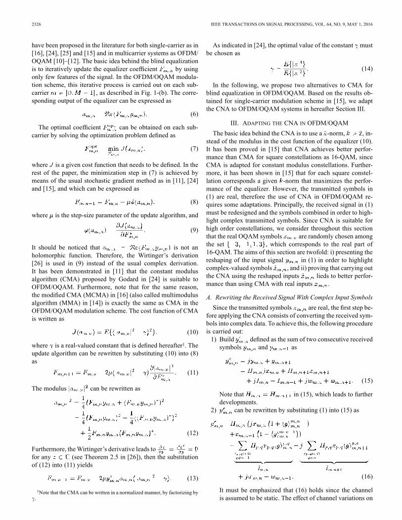
2326 IEEE TRANSACTIONS ON SIGNAL PROCESSING, VOL. 64, NO. 9, MAY 1, 2016
have been proposed in the literature for both single-carrier as in[16], [24], [25] and [15] and in multicarrier systems as OFDM/OQAM [10]–[12]. The basic idea behind the blind equalizationis to iteratively update the equalizer coefficient by usingonly few features of the signal. In the OFDM/OQAM modula-tion scheme, this iterative process is carried out on each sub-carrier , as described in Fig. 1-(b). The corre-sponding output of the equalizer can be expressed as
(6)
The optimal coefficient can be obtained on each sub-carrier by solving the optimization problem defined as
(7)
where is a given cost function that needs to be defined. In therest of the paper, the minimization step in (7) is achieved bymeans of the usual stochastic gradient method as in [11], [24]and [15], and which can be expressed as
(8)
where is the step-size parameter of the update algorithm, and
(9)
It should be noticed that is not anholomorphic function. Therefore, the Wirtinger’s derivation[26] is used in (9) instead of the usual complex derivation.It has been demonstrated in [11] that the constant modulusalgorithm (CMA) proposed by Godard in [24] is suitable toOFDM/OQAM. Furthermore, note that for the same reason,the modified CMA (MCMA) in [16] (also called multimodulusalgorithm (MMA) in [14]) is exactly the same as CMA in theOFDM/OQAMmodulation scheme. The cost function of CMAis written as
(10)
where is a real-valued constant that is defined hereafter1. Theupdate algorithm can be rewritten by substituting (10) into (8)as
(11)
The modulus can be rewritten as
(12)
Furthermore, theWirtinger’s derivative leads tofor any (see Theorem 2.5 in [26]), then the substitutionof (12) into (11) yields
(13)
1Note that the CMA can be written in a normalized manner, by factorizing by.
As indicated in [24], the optimal value of the constant mustbe chosen as
(14)
In the following, we propose two alternatives to CMA forblind equalization in OFDM/OQAM. Based on the results ob-tained for single-carrier modulation scheme in [15], we adaptthe CNA to OFDM/OQAM systems in hereafter Section III.
III. ADAPTING THE CNA IN OFDM/OQAMThe basic idea behind the CNA is to use a -norm, , in-
stead of the modulus in the cost function of the equalizer (10).It has been proved in [15] that CNA achieves better perfor-mance than CMA for square constellations as 16-QAM, sinceCMA is adapted for constant modulus constellations. Further-more, it has been shown in [15] that for each square constel-lation corresponds a given -norm that maximizes the perfor-mance of the equalizer. However, the transmitted symbols in(1) are real, therefore the use of CNA in OFDM/OQAM re-quires some adaptations. Principally, the received signal in (1)must be redesigned and the symbols combined in order to high-light complex transmitted symbols. Since CNA is suitable forhigh order constellations, we consider throughout this sectionthat the real OQAM symbols are randomly chosen amongthe set , which corresponds to the real part of16-QAM. The aims of this section are twofold: i) presenting thereshaping of the input signal in (1) in order to highlightcomplex-valued symbols , and ii) proving that carrying outthe CNA using the reshaped inputs lieds to better perfor-mance than using CMA with real inputs .
A. Rewriting the Received Signal With Complex Input SymbolsSince the transmitted symbols are real, the first step be-
fore applying the CNA consists of converting the received sym-bols into complex data. To achieve this, the following procedureis carried out:1) Build defined as the sum of two consecutive received
symbols and as
(15)
Note that in (15), which leads to furtherdevelopments.
2) can be rewritten by substituting (1) into (15) as
(16)
It must be emphasized that (16) holds since the channelis assumed to be static. The effect of channel variations on

SAVAUX et al.: OFDM/OQAM BLIND EQUALIZATION USING CNA APPROACH 2327
Fig. 2. Proposed blind equalizer using CNA, adapted to OFDM/OQAMsystem.
the accuracy of (16) will be investigated in Section IV. Thesymmetry property of weights given in (5) yields
, and therefore we can definefrom in (16) as
(17)
where is a 16-QAM symbol.It is worth noticing that the redesigned received signal in (17)
is exactly equivalent to the transmission of complex 16-QAMsymbols over the channel , with additive interfer-ence and non-white Gaussian noise . Therefore, theCNA can now be employed as blind equalizer whose inputis defined as
(18)
where and are the outputs of the equalizer givenby (6). The specific update algorithm for is described inthe hereafter Section III.B. The overall principle of the blindequalizer using CNA adapted to OFDM/OQAM is depicted inFig. 2.
B. Deriving CNA in OFDM/OQAM
The cost function of the CNA can be formulated in a generalexpression as
(19)
Fig. 3. Balls of (a) CNA-2 (CMA) in (10) compared with , and(b) CNA-6 in (22) compared 16-QAM.
where is a norm defined on , and and are two param-eters that give two degrees of freedom to the algorithm. In thefollowing, it will be assumed that2 . Since istaken from a 16-QAM constellation, the real positive constantshould be rewritten as
(20)
The -norm family considered in this paper can be formu-lated for any complex on the plane as
(21)
Note that the CNA reduces to the CMA when . It has beendemonstrated in [15] that the case (denoted by CNA-6)is very suitable for 16-QAM constellation. According to thisresult, we hereafter employ the CNA-6 whose update algorithmcan be adapted to OFDM/OQAM using (17) as
(22)
The steady-state performance of any constant norm-basedequalizers can be characterized by the average distancebetween the constellation symbols and the ball defined in (10)and (19) (see details [27]). Fig. 3 shows the balls of the mod-ulus and the 6-norm compared with the 16-QAM in 3-(b), andwith the corresponding real OQAM symbols in3-(a). It can be deduced from Fig. 3 that
. The developments leading to this results are pro-vided in Appendix A. As a consequence, the performance ofthe CNA-6 using the proposed reshaped symbols in (17)should be lower than that of CMA using in (1). However,the distance does not take into account the interferences,and therefore a deeper analysis must be undertaken in order toshow the influence of the interferences on the performance ofthe CMA and CNA-6.
2This choice is motivated, once again, by the difficulty of setting a properstep-size value when and increase.
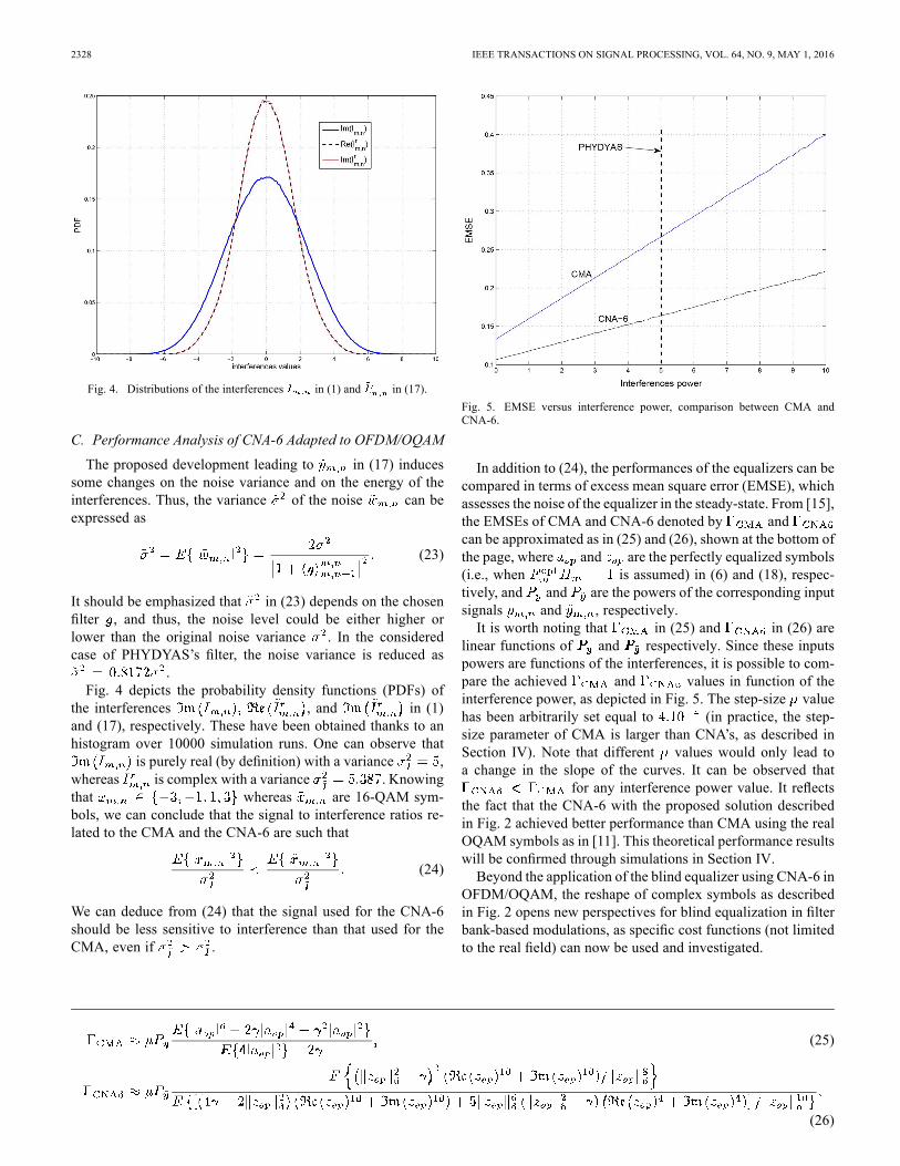
2328 IEEE TRANSACTIONS ON SIGNAL PROCESSING, VOL. 64, NO. 9, MAY 1, 2016
Fig. 4. Distributions of the interferences in (1) and in (17).
C. Performance Analysis of CNA-6 Adapted to OFDM/OQAM
The proposed development leading to in (17) inducessome changes on the noise variance and on the energy of theinterferences. Thus, the variance of the noise can beexpressed as
(23)
It should be emphasized that in (23) depends on the chosenfilter , and thus, the noise level could be either higher orlower than the original noise variance . In the consideredcase of PHYDYAS’s filter, the noise variance is reduced as
.Fig. 4 depicts the probability density functions (PDFs) of
the interferences , and in (1)and (17), respectively. These have been obtained thanks to anhistogram over 10000 simulation runs. One can observe that
is purely real (by definition) with a variance ,whereas is complex with a variance . Knowingthat whereas are 16-QAM sym-bols, we can conclude that the signal to interference ratios re-lated to the CMA and the CNA-6 are such that
(24)
We can deduce from (24) that the signal used for the CNA-6should be less sensitive to interference than that used for theCMA, even if .
Fig. 5. EMSE versus interference power, comparison between CMA andCNA-6.
In addition to (24), the performances of the equalizers can becompared in terms of excess mean square error (EMSE), whichassesses the noise of the equalizer in the steady-state. From [15],the EMSEs of CMA and CNA-6 denoted by andcan be approximated as in (25) and (26), shown at the bottom ofthe page, where and are the perfectly equalized symbols(i.e., when is assumed) in (6) and (18), respec-tively, and and are the powers of the corresponding inputsignals and , respectively.It is worth noting that in (25) and in (26) are
linear functions of and respectively. Since these inputspowers are functions of the interferences, it is possible to com-pare the achieved and values in function of theinterference power, as depicted in Fig. 5. The step-size valuehas been arbitrarily set equal to (in practice, the step-size parameter of CMA is larger than CNA’s, as described inSection IV). Note that different values would only lead toa change in the slope of the curves. It can be observed that
for any interference power value. It reflectsthe fact that the CNA-6 with the proposed solution describedin Fig. 2 achieved better performance than CMA using the realOQAM symbols as in [11]. This theoretical performance resultswill be confirmed through simulations in Section IV.Beyond the application of the blind equalizer using CNA-6 in
OFDM/OQAM, the reshape of complex symbols as describedin Fig. 2 opens new perspectives for blind equalization in filterbank-based modulations, as specific cost functions (not limitedto the real field) can now be used and investigated.
(25)
(26)
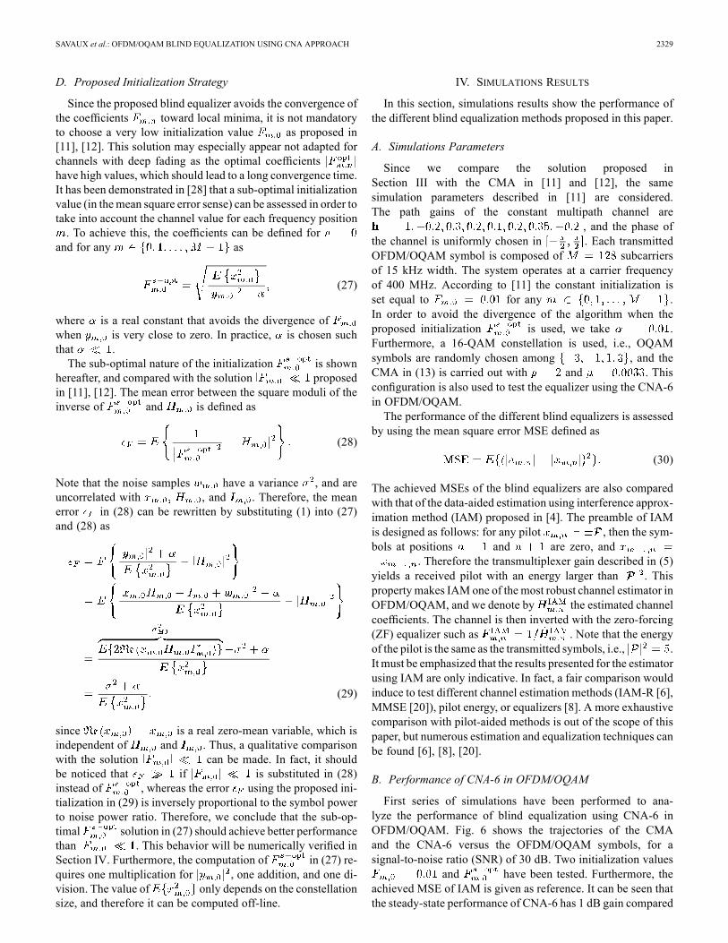
SAVAUX et al.: OFDM/OQAM BLIND EQUALIZATION USING CNA APPROACH 2329
D. Proposed Initialization Strategy
Since the proposed blind equalizer avoids the convergence ofthe coefficients toward local minima, it is not mandatoryto choose a very low initialization value as proposed in[11], [12]. This solution may especially appear not adapted forchannels with deep fading as the optimal coefficientshave high values, which should lead to a long convergence time.It has been demonstrated in [28] that a sub-optimal initializationvalue (in themean square error sense) can be assessed in order totake into account the channel value for each frequency position. To achieve this, the coefficients can be defined for
and for any as
(27)
where is a real constant that avoids the divergence ofwhen is very close to zero. In practice, is chosen suchthat .The sub-optimal nature of the initialization is shown
hereafter, and compared with the solution proposedin [11], [12]. The mean error between the square moduli of theinverse of and is defined as
(28)
Note that the noise samples have a variance , and areuncorrelated with , and . Therefore, the meanerror in (28) can be rewritten by substituting (1) into (27)and (28) as
(29)
since is a real zero-mean variable, which isindependent of and . Thus, a qualitative comparisonwith the solution can be made. In fact, it shouldbe noticed that if is substituted in (28)instead of , whereas the error using the proposed ini-tialization in (29) is inversely proportional to the symbol powerto noise power ratio. Therefore, we conclude that the sub-op-timal solution in (27) should achieve better performancethan . This behavior will be numerically verified inSection IV. Furthermore, the computation of in (27) re-quires one multiplication for , one addition, and one di-vision. The value of only depends on the constellationsize, and therefore it can be computed off-line.
IV. SIMULATIONS RESULTS
In this section, simulations results show the performance ofthe different blind equalization methods proposed in this paper.
A. Simulations Parameters
Since we compare the solution proposed inSection III with the CMA in [11] and [12], the samesimulation parameters described in [11] are considered.The path gains of the constant multipath channel are
, and the phase ofthe channel is uniformly chosen in . Each transmittedOFDM/OQAM symbol is composed of subcarriersof 15 kHz width. The system operates at a carrier frequencyof 400 MHz. According to [11] the constant initialization isset equal to for any .In order to avoid the divergence of the algorithm when theproposed initialization is used, we take .Furthermore, a 16-QAM constellation is used, i.e., OQAMsymbols are randomly chosen among , and theCMA in (13) is carried out with and . Thisconfiguration is also used to test the equalizer using the CNA-6in OFDM/OQAM.The performance of the different blind equalizers is assessed
by using the mean square error MSE defined as
(30)
The achieved MSEs of the blind equalizers are also comparedwith that of the data-aided estimation using interference approx-imation method (IAM) proposed in [4]. The preamble of IAMis designed as follows: for any pilot , then the sym-bols at positions and are zero, and
. Therefore the transmultiplexer gain described in (5)yields a received pilot with an energy larger than . Thisproperty makes IAM one of the most robust channel estimator inOFDM/OQAM, and we denote by the estimated channelcoefficients. The channel is then inverted with the zero-forcing(ZF) equalizer such as . Note that the energyof the pilot is the same as the transmitted symbols, i.e., .It must be emphasized that the results presented for the estimatorusing IAM are only indicative. In fact, a fair comparison wouldinduce to test different channel estimation methods (IAM-R [6],MMSE [20]), pilot energy, or equalizers [8]. A more exhaustivecomparison with pilot-aided methods is out of the scope of thispaper, but numerous estimation and equalization techniques canbe found [6], [8], [20].
B. Performance of CNA-6 in OFDM/OQAM
First series of simulations have been performed to ana-lyze the performance of blind equalization using CNA-6 inOFDM/OQAM. Fig. 6 shows the trajectories of the CMAand the CNA-6 versus the OFDM/OQAM symbols, for asignal-to-noise ratio (SNR) of 30 dB. Two initialization values
and have been tested. Furthermore, theachieved MSE of IAM is given as reference. It can be seen thatthe steady-state performance of CNA-6 has 1 dB gain compared

2330 IEEE TRANSACTIONS ON SIGNAL PROCESSING, VOL. 64, NO. 9, MAY 1, 2016
Fig. 6. MSE performance versus OFDM/OQAM symbols. Comparison be-tween CNA-6, CNA-2 (CMA) using and , and pilot-aidedmethod (IAM).
with the MSE floor using CMA. This result is consistent withthe analysis undertaken in Section III.C. However, the CNA-6using requires at least 1000 OFDM/OQAMsymbols more than CMA to achieve a given MSE value. Thisloss is reduced by half when the algorithms are initialized with
. This delay in the convergence is due to the intrinsicphase adjustment when using CNA-6. The basic idea behindthis phenomenon can be described by using the balls of theequalizers in Fig. 3. In fact, it can be observed in Fig. 3-(a) thatCMA is phase-independent since the balls of CMA is a circle.However, the optimal equalizer coefficient value depends on thephase of (see Fig. 3-(b)), therefore the phase adjustmentslows down the convergence of CNA-6. This phenomenon hasbeen described in detail in [15]. It is also worth noticing thatthe use of the sub-optimal value allows the algorithmto gain 2000 iterations compared with for bothCMA and CNA-6. Finally, Fig. 6 highlights that a gain of 1dB and 2 dB is achieved by CMA and CNA-6 respectivelycompared with IAM. This shows the capability of the blindequalization to outperform data-aided techniques.Fig. 7 depicts the MSE-floor values of CMA, CNA-6, and
IAM when the steady-state is reached (at the 3000-th itera-tion) versus SNR. It can be observed that the blind equalizersachieved an MSE gain (up to 12 dB at dB) comparedwith IAM for SNR values dB. This reflects the fact thatthe updated coefficients in (13) or (22) are less disturbedin noisy conditions than the ZF coefficient using IAM.However, it is worth noticing that these results are obtainedafter 3000 iterations, whereas no convergence delay is requiredfor data-aided methods (see Fig. 6 for instance). Furthermore,the MSE value of the IAM also depends on the pilot energy
. Otherwise, it can be also observed that CNA-6 achievesbetter performance than CMA for dB.Fig. 8 presents the results of simulations undertaken to com-
pare the convergence speed of CMA and CNA-6 for a givensteady-state performance. Thus, the values have been tuned
Fig. 7. MSE performance versus SNR. Comparison between CNA-6, CNA-2(CMA) at the 3000-th iteration, and pilot-aided method.
Fig. 8. MSE performance versus OFDM/OQAM symbols. Comparison be-tween CNA-6, CNA-2 (CMA), and pilot-aided method.
so that the MSE floor values of both equalizers reach the samevalue at dB. It can be observed that CNA-6 convergesfaster than CMA, e.g., a gain of 1200 iterations is achieved usingCNA-6 at dB (which corresponds to the MSEof estimation using IAM) compared with CMA. We concludefrom Figs. 6 and 8 that, for a given convergence rate (i.e., forthe same value) the CNA-6 achieves lower MSE than CMA,and for a given steady-state the CNA-6 converges faster thanCMA.As indicated in Section II, the blind receiver may suffer from
synchronization mismatch. The effect of such a time synchro-nization mismatch on the performance of CMA and CNA-6 isdepicted in Fig. 9. The time shift between the transmitter andthe receiver is given as a percentage of the prototype filter length
. The performance of the system using IAM is shown as well,but it is only indicative. It can be observed that time synchro-nization mismatches of 1%, 3%, and 5% induce MSE losses

SAVAUX et al.: OFDM/OQAM BLIND EQUALIZATION USING CNA APPROACH 2331
Fig. 9. MSE performance of CNA-6, CNA-2 (CMA), and pilot-aidedmethod versus OFDM/OQAM symbols in presence of time synchroniza-tion mismatch. The synchronization mismatch is given as a percentage of
% % % .
of 11, 13, and 16.5 dB, respectively, compared with the resultsgiven in Fig. 6. Such a MSE loss is due to the interferencesinduced by the synchronization mismatch. Furthermore, addi-tional simulations revealed that a time shift larger than 5% leadsto instability, i.e., the blind equalizer diverges. These resultsshow that both CMA and CNA-6 require a very accurate syn-chronization process in order to work at their best performance.Fig. 10 shows the MSE performance of CNA-6, CNA-2
(CMA) versus OFDM/OQAM symbols for three receiverspeeds: (a) 1 km/h, (b) 3 km/h, and (c) 10 km/h. Two differentinitialization strategies have been considered: i) using ,and ii) using a preamble such that (referred to“pilot init.” on the figures). It can be observed that the equalizersperformances tend to the MSE level whatever the initializationis (for 1 km/h, this limit is outside the OFDM/OQAM symbolsrange). However, the MSE starts at 4 dB where isused, whereas it starts at dB when isused. Thus, it can be noted that the CMA and CNA-6 equalizerusing outperforms those using from0 to 5000 iterations and from 0 to 2500 iteration for 3 km/hand 10 km/h respectively. Furthermore, it can be also noted in(a) and (b) that CMA achieves 0.5 MSE gain compared withCNA-6 where the steady state is reached the steady-state. Thisis mainly due to the approximation in (16), which does not holdanymore when time selectivity of the channel increases.
C. DiscussionThe practical use of blind equalizers such as CMA and
CNA-6 is discussed in this section. We deduce from Figs. 6 and8 that, even if the use of and CNA-6 reduces the con-vergence delay, blind equalizers still require more than 1000OFDM/OQAM symbols to converge. As a consequence, theuse of these methods requires is limited by the length of thesignal packets. Thus, broadcast applications could be a possiblecontext to operate blind receivers. Note that the reuse of the
Fig. 10. MSE performance of CNA-6, CNA-2 (CMA) versus OFDM/OQAMsymbols using the initialization compared with the initialization usinga preamble, for three receiver speeds: (a) 1 km/h, (b) 3 km/h, and (c) 10 km/h.
received symbols as input of the equalizers seems to be a goodsolution to further reduce the convergence delay [29].
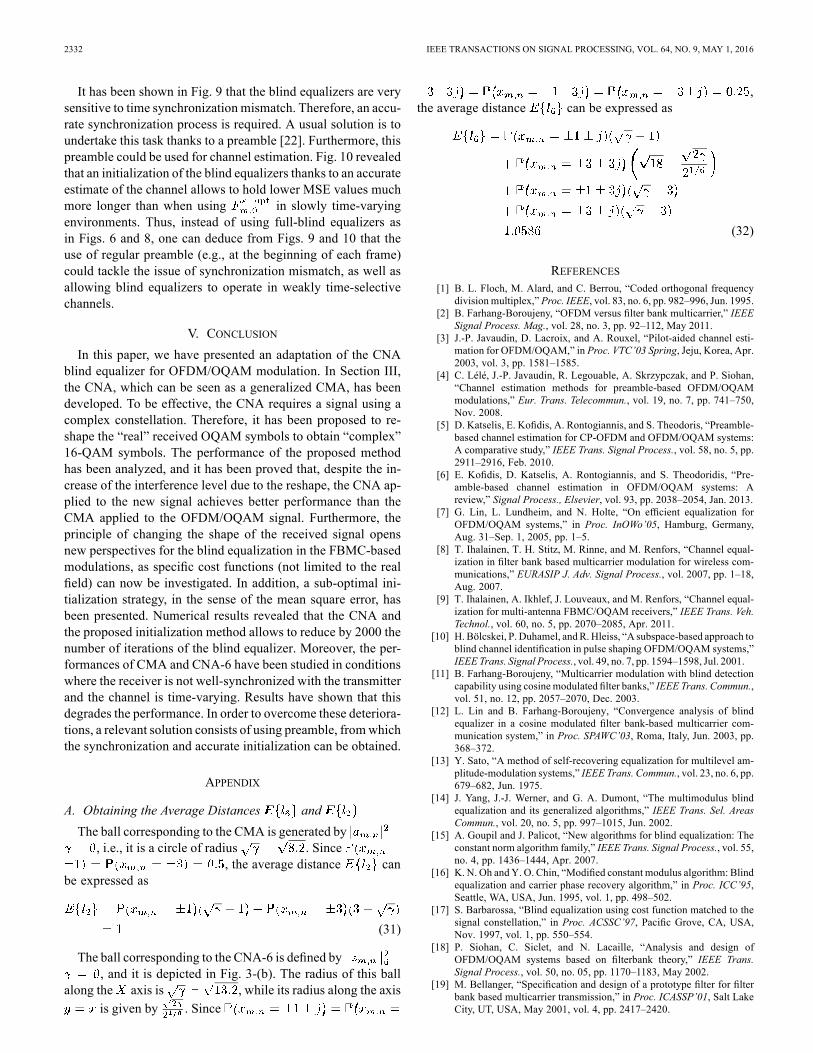
2332 IEEE TRANSACTIONS ON SIGNAL PROCESSING, VOL. 64, NO. 9, MAY 1, 2016
It has been shown in Fig. 9 that the blind equalizers are verysensitive to time synchronization mismatch. Therefore, an accu-rate synchronization process is required. A usual solution is toundertake this task thanks to a preamble [22]. Furthermore, thispreamble could be used for channel estimation. Fig. 10 revealedthat an initialization of the blind equalizers thanks to an accurateestimate of the channel allows to hold lower MSE values muchmore longer than when using in slowly time-varyingenvironments. Thus, instead of using full-blind equalizers asin Figs. 6 and 8, one can deduce from Figs. 9 and 10 that theuse of regular preamble (e.g., at the beginning of each frame)could tackle the issue of synchronization mismatch, as well asallowing blind equalizers to operate in weakly time-selectivechannels.
V. CONCLUSIONIn this paper, we have presented an adaptation of the CNA
blind equalizer for OFDM/OQAM modulation. In Section III,the CNA, which can be seen as a generalized CMA, has beendeveloped. To be effective, the CNA requires a signal using acomplex constellation. Therefore, it has been proposed to re-shape the “real” received OQAM symbols to obtain “complex”16-QAM symbols. The performance of the proposed methodhas been analyzed, and it has been proved that, despite the in-crease of the interference level due to the reshape, the CNA ap-plied to the new signal achieves better performance than theCMA applied to the OFDM/OQAM signal. Furthermore, theprinciple of changing the shape of the received signal opensnew perspectives for the blind equalization in the FBMC-basedmodulations, as specific cost functions (not limited to the realfield) can now be investigated. In addition, a sub-optimal ini-tialization strategy, in the sense of the mean square error, hasbeen presented. Numerical results revealed that the CNA andthe proposed initialization method allows to reduce by 2000 thenumber of iterations of the blind equalizer. Moreover, the per-formances of CMA and CNA-6 have been studied in conditionswhere the receiver is not well-synchronized with the transmitterand the channel is time-varying. Results have shown that thisdegrades the performance. In order to overcome these deteriora-tions, a relevant solution consists of using preamble, fromwhichthe synchronization and accurate initialization can be obtained.
APPENDIX
A. Obtaining the Average Distances andThe ball corresponding to the CMA is generated by
, i.e., it is a circle of radius . Since, the average distance can
be expressed as
(31)
The ball corresponding to the CNA-6 is defined by, and it is depicted in Fig. 3-(b). The radius of this ball
along the axis is , while its radius along the axisis given by . Since
,the average distance can be expressed as
(32)
REFERENCES[1] B. L. Floch, M. Alard, and C. Berrou, “Coded orthogonal frequency
division multiplex,” Proc. IEEE, vol. 83, no. 6, pp. 982–996, Jun. 1995.[2] B. Farhang-Boroujeny, “OFDM versus filter bank multicarrier,” IEEE
Signal Process. Mag., vol. 28, no. 3, pp. 92–112, May 2011.[3] J.-P. Javaudin, D. Lacroix, and A. Rouxel, “Pilot-aided channel esti-
mation for OFDM/OQAM,” in Proc. VTC’03 Spring, Jeju, Korea, Apr.2003, vol. 3, pp. 1581–1585.
[4] C. Lélé, J.-P. Javaudin, R. Legouable, A. Skrzypczak, and P. Siohan,“Channel estimation methods for preamble-based OFDM/OQAMmodulations,” Eur. Trans. Telecommun., vol. 19, no. 7, pp. 741–750,Nov. 2008.
[5] D. Katselis, E. Kofidis, A. Rontogiannis, and S. Theodoris, “Preamble-based channel estimation for CP-OFDM and OFDM/OQAM systems:A comparative study,” IEEE Trans. Signal Process., vol. 58, no. 5, pp.2911–2916, Feb. 2010.
[6] E. Kofidis, D. Katselis, A. Rontogiannis, and S. Theodoridis, “Pre-amble-based channel estimation in OFDM/OQAM systems: Areview,” Signal Process., Elsevier, vol. 93, pp. 2038–2054, Jan. 2013.
[7] G. Lin, L. Lundheim, and N. Holte, “On efficient equalization forOFDM/OQAM systems,” in Proc. InOWo’05, Hamburg, Germany,Aug. 31–Sep. 1, 2005, pp. 1–5.
[8] T. Ihalainen, T. H. Stitz, M. Rinne, and M. Renfors, “Channel equal-ization in filter bank based multicarrier modulation for wireless com-munications,” EURASIP J. Adv. Signal Process., vol. 2007, pp. 1–18,Aug. 2007.
[9] T. Ihalainen, A. Ikhlef, J. Louveaux, and M. Renfors, “Channel equal-ization for multi-antenna FBMC/OQAM receivers,” IEEE Trans. Veh.Technol., vol. 60, no. 5, pp. 2070–2085, Apr. 2011.
[10] H. Bölcskei, P. Duhamel, andR.Hleiss, “A subspace-based approach toblind channel identification in pulse shaping OFDM/OQAM systems,”IEEE Trans. Signal Process., vol. 49, no. 7, pp. 1594–1598, Jul. 2001.
[11] B. Farhang-Boroujeny, “Multicarrier modulation with blind detectioncapability using cosine modulated filter banks,” IEEE Trans. Commun.,vol. 51, no. 12, pp. 2057–2070, Dec. 2003.
[12] L. Lin and B. Farhang-Boroujeny, “Convergence analysis of blindequalizer in a cosine modulated filter bank-based multicarrier com-munication system,” in Proc. SPAWC’03, Roma, Italy, Jun. 2003, pp.368–372.
[13] Y. Sato, “A method of self-recovering equalization for multilevel am-plitude-modulation systems,” IEEE Trans. Commun., vol. 23, no. 6, pp.679–682, Jun. 1975.
[14] J. Yang, J.-J. Werner, and G. A. Dumont, “The multimodulus blindequalization and its generalized algorithms,” IEEE Trans. Sel. AreasCommun., vol. 20, no. 5, pp. 997–1015, Jun. 2002.
[15] A. Goupil and J. Palicot, “New algorithms for blind equalization: Theconstant norm algorithm family,” IEEE Trans. Signal Process., vol. 55,no. 4, pp. 1436–1444, Apr. 2007.
[16] K. N. Oh andY. O. Chin, “Modified constant modulus algorithm: Blindequalization and carrier phase recovery algorithm,” in Proc. ICC’95,Seattle, WA, USA, Jun. 1995, vol. 1, pp. 498–502.
[17] S. Barbarossa, “Blind equalization using cost function matched to thesignal constellation,” in Proc. ACSSC’97, Pacific Grove, CA, USA,Nov. 1997, vol. 1, pp. 550–554.
[18] P. Siohan, C. Siclet, and N. Lacaille, “Analysis and design ofOFDM/OQAM systems based on filterbank theory,” IEEE Trans.Signal Process., vol. 50, no. 05, pp. 1170–1183, May 2002.
[19] M. Bellanger, “Specification and design of a prototype filter for filterbank based multicarrier transmission,” in Proc. ICASSP’01, Salt LakeCity, UT, USA, May 2001, vol. 4, pp. 2417–2420.

SAVAUX et al.: OFDM/OQAM BLIND EQUALIZATION USING CNA APPROACH 2333
[20] V. Savaux, F. Bader, and Y. Louët, “A joint MMSE channel and noisevariance estimation for OFDM/OQAM modulation,” IEEE Trans.Commun., vol. 63, no. 11, pp. 4254–4266, Nov. 2015.
[21] Y. Medjahdi, M. Terre, D. Le Ruyet, D. Roviras, and A. Dziri, “Theimpact of timing synchronization errors on the performance of OFDM/FBMC systems,” in Proc. ICC’11, Kyoto, Japan, Jun. 2011, pp. 1–5.
[22] N. Cassiau, D. Kténas, and J.-B. Doré, “Time and frequency synchro-nization for CoMP with FBMC,” in Proc. ISWCS’13, Ilmenau, Ger-many, Aug. 2013, pp. 1–5.
[23] Y. Zeng and M. W. Chia, “Joint time-frequency synchronization andchannel estimation for FBMC,” in Proc. PIMRC’14, Washington, DC,USA, Sep. 2014, pp. 1–5.
[24] D. N. Godard, “Self-recovering equalization and carrier trackingin two-dimensional data communication systems,” IEEE Trans.Commun., vol. Com-28, no. 11, pp. 1867–1875, Nov. 1980.
[25] R. Johnson, Jr, P. Schniter, T. Endres, J. Behm,D. Brown, and R. Casas,“Blind equalization using the constant modulus criterion: A review,”Proc. IEEE, vol. 86, no. 10, pp. 1927–1950, Oct. 1998.
[26] P. Bouboulis, “Wirtinger’s calculus in general Hilbert spaces,” May2010, pp. 1–27, arXiv:1005.5170v1.
[27] A. Goupil and J. Palicot, “Constant norm algorithms class,” presentedat the EUSIPCO, Toulouse, France, Sep. 2002.
[28] V. Savaux and F. Bader, “Sub-optimal initialization for blind equaliza-tion with fast convergence in OFDM/OQAM modulation,” presentedat the EuCNC’15, Paris, France, Jun.–Jul. 2015.
[29] V. Savaux, M. Naoues, F. Bader, and J. Palicot, “Ultra-fast blind equal-ization for OFDM: Principle and steps towards implementation,” inProc. ISWCS’15, Brussels, Belgium, Aug. 2015, pp. 1–5.
Vincent Savaux (AM’15) received the engineer degree from the High Schoolof Engineering, ECAM Rennes, the M.Sc. degree from the University ofRennes 1, France, in 2010, and the Ph.D. degree in telecommunications fromÉcole Supérieure d’Electricité Supélec, in 2013. Since January 2014, he hasbeen a Postdoctoral Researcher with the Signal, Communication, and Em-bedded Electronics (SCEE) Research Group at CentraleSupélec, Campus deRennes, France. His research activities include channel estimation, equalizationfor multicarrier modulations as OFDM and OFDM/OQAM, spectrum sensing.He received the Exemplary Reviewer 2014 appreciation from IEEE WIRELESSCOMMUNICATIONS LETTERS and IEEE COMMUNICATIONS LETTERS.
Faouzi Bader (SM’07) received the Ph.D. degree (with Honours) in telecom-munications from Universidad Politécnica de Madrid (UPM), Madrid, Spain,in 2002. He joined the Centre Technologic de Telecomunicacions de Catalunya(CTTC), Barcelona, Spain, as Associate Researcher, in 2002, and was nomi-nated in 2006 as a Senior Research Associate at same institution. Since June2013, he has worked as an Associate Professor at École Supérieur d’Electricité-SUPELEC in Rennes, France. His research activities mainly focus on IMT-Ad-vanced systems, system design, advanced multicarrier waveforms (OFDM(A),(non-)uniform multimode filter based multicarrier schemes), and frequency al-location techniques in relay cognitive environment. He has been involved inseveral European projects from the 5th–7th EC research frameworks, and from2012 to 2013 he was nominated the General Coordinator andManager of the ECfunded research project ICT EMPhAtiC project, Enhanced Multicarrier Tech-niques for Professional Ad-Hoc and Cell-Based Communications. He has pub-lished over 120 papers in peer-reviewed journals and international conferences,more than 13 book chapters, and 3 books. He served as Technical ProgramCom-mittee member in major IEEE ComSoc and VTS conferences, and as the Gen-eral Chair of the 11th edition of the ISWCS’2014 conference, and the Cochairof the ISWCS 2015 edition.
Jacques Palicot received, in 1983, his Ph.D. degree in signal processing fromthe University of Rennes. Since 1988, he has been involved in studies aboutequalization techniques applied to digital transmissions and analog TV systems.Since 1991 he has been involved mainly in studies concerning the digital com-munications area and automatic measurements techniques. He has taken an ac-tive part in various international bodies EBU, CCIR, URSI, and within RACE,ACTS and IST European projects. He has published various scientific articlesnotably on equalization techniques, echo cancellation, hierarchical modulationsand Software Radio techniques. He is author or co-author of more than 300 pub-lications with more than 50 in prestigious journals, two books and 22 patents.He is currently involved in adaptive Signal Processing, digital communications,Software Radio, Cognitive radio and Green Radio. From November 2001 toSeptember 2003 he had a temporary position with INRIA/IRISA in Rennes. Heserves as Associate Editor for EURASIP JASP since 2008. He also served aslead guest editor for several Special Issues on Software Radio, Cognitive Radioand Green Radio. He was Co General Chairman of ISCIT 2011, Co GeneralChairman of Next-GWiN 2014, Technical Program Chairman of CROWNCOM2009, Technical Program Chairman of GREENCOM 2013 and Technical Pro-gramChairman of CRN Symposium of ICC 2014. Since October 2003 he is withCentraleSupélec in Rennes where he leads the Signal Communications and Em-bedded Electronics (SCEE) research team.

Others research aspects related with signal processing for OFDM and OFDM/OQAM signal is that relatedwith the development of techniques for peak to average power ratio (PAPR) reduction. These works have beenundertaken through the advice of the PhD thesis of Mr. Lamarana DIALLO (2012-2016), and that of Ms. MarwaCHAFII19 (2013-2016).One of the aspects investigated is that related with the the tones reservation (TR), that is one of the most popularapproach that allows to carry the addition of a signal for PAPR reduction with neither degradation of the biterror rate (BER), nor an increase of the out-of-band (OOB) pollution [87]. As TR approach uses reserved tones,there is no need for additional processing at the receiver to process the data information. This last is what makesthe tone reservation a widely used and implemented approach already used in commercial standards such as thedigital video broadcasting-terrestrial (DVBT2) system. Note that a large number of research works exist with aspecific focus on how to compute the adding signal by using the TR principle. In [87, 88], the authors proposed touse a quadratic constrained quadratic program (QCQP) and a second order cone program (SOCP) respectively toset the appropriate values on the reserved tones (carriers) for the PAPR mitigation. However, the computationalcomplexity of these approaches is very high and not affordable for real time systems. To reduce the computationcomplexity, various methods have been proposed as: the active-set method in [89], the selective mapping of partialtones reservation approach (SMOPT) in [90], and a modified version of the clipping method in [91, 92], all withthe purpose of peak cancellation using TR principle. It is worth to mention that the best technique that providesthe most appropriate compromise between PAPR reduction and computational complexity is the TR method thatuses the gradient project (GP) algorithm to compute the adding signal by maximizing the signal to clipping ratio,in other words this is equivalent to minimize the clipping noise as indicated in [93].Based on developed work in Lamarana’s DIALLO dissertation, a new TR method using the gradient project (TR-GP) algorithm has been proposed. The main idea behind this approach is to modify the classical TR structure byexploiting the decomposition of the useful OFDM symbol as the combinations of two multi-carrier symbols, whereeach one contains a number of subcarriers two times less than the original OFDM symbol. This proposed approachis named, modified tones reservation (MTR), and consists in minimizing the partials clipping noise effect withrespect to the different resulted signals of the useful OFDM symbol after the decomposition process. Therefore,the proposed MTR technique allows us to relax some constraints relative to the classical TR approach withoutdegrading the orthogonality between reserved tones, the BER, and the OOB that can harmful the possible adjacentsystems in the band.Proposed MTR approach consists in modifying the classical TR structure by exploiting the decomposition of theuseful OFDM symbol as a mixture of two times shorter multi-carrier symbols by containing each two times lesscarriers. Thus, by decomposing jointly the J[xn](.) as a sum of a partial clipping noise signals with respect to thedecomposed parts of the useful OFDM symbol, the MTR proposed approach consists in jointly minimizing thepartial clipping noise over the decomposed structures of the OFDM signal by using the gradient project algorithm(MTR-GP) subject to the predefined TR positions.The OFDM symbol x(t) of duration Tu can be expressed as follows by
x(t) =√
1M
M−1∑m=0
Xmej2πmFt , 0 ≤ t ≤ Tu (3.21)
where M is the total number of carriers, F = 1Tu
is the inter-carrier spacing and Xm the symbol carried out by them− th carrier at instant Tu. After oversampling the signal by a factor L, xl with l = 0, . . . , LM − 1 will denotethe discrete time samples at the instant lTe of x(t) where Te = Tu
LM is the time sampling. We denote the vectorcontaining the time samples of x(t) after the oversampling operation by x = [x0, . . . , xLM−1]. This vector can beefficiently computed by using an inverse discrete Fourier transform (IDFT)20 and can be expressed by the followingmatrix
x = FMLX, (3.22)
where FLM is the LM ×LM normalized IDFT square matrix scaled by√L with the k-th vector column expressed
19See more details on L. DIALLO’s and M. CHAFII’s PhDs in Subsection 1.3.3.2, page 1820In this paper, we use the zero-inserting scheme to calculate x, i.e., the IFFT operation is applied to the extended vector X =
[X0, . . . , XM2 −1, 0, . . . , 0︸ ︷︷ ︸
(L−1)M Zeros
, XM2, . . . , XM−1]
183
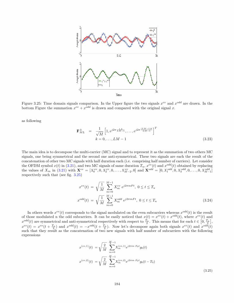
Figure 3.25: Time domain signals comparison. In the Upper figure the two signals xev and xodd are drawn. In thebottom Figure the summation xev + xodd is drawn and compared with the original signal x.
as following
F kML = 1√
M
[1, ej2π
1.kLM−1 , . . . , ej2π
(LM−1)kLM−1
]Tk = 0, . . . , LM − 1 (3.23)
The main idea is to decompose the multi-carrier (MC) signal and to represent it as the summation of two others MCsignals, one being symmetrical and the second one anti-symmetrical. These two signals are each the result of theconcatenation of other two MC signals with half duration each (i.e. comprising half number of carriers). Let considerthe OFDM symbol x(t) in (3.21), and two MC signals of same duration Tu, xev(t) and xodd(t) obtained by replacingthe values of Xm in (3.21) with Xev = [X ev
0 , 0,X ev2 , 0, . . . ,X ev
M−2, 0] and Xodd = [0,X odd1 , 0,X odd
3 , 0, . . . , 0,X oddM−1]
respectively such that (see fig. 3.25)
xev(t) =√
1M
M−1∑m=0
Xevm ej2πmFt, 0 ≤ t ≤ Tu
xodd(t) =√
1M
M−1∑m=0
Xoddm ej2πmFt, 0 ≤ t ≤ Tu (3.24)
In others words xev(t) corresponds to the signal modulated on the even subcarriers whereas xodd(t) is the resultof those modulated n the odd subcarriers. It can be easily noticed that x(t) = xev(t) + xodd(t), where xev(t) andxodd(t) are symmetrical and anti-symmetrical respectively with respect to Tu
2 . This means that for each t ∈[0, Tu2
],
xev(t) = xev(t + Tu2 ) and xodd(t) = −xodd(t + Tu
2 ). Now let’s decompose again both signals xev(t) and xodd(t)such that they result as the concatenation of two new signals with half number of subcarriers with the followingexpressions
x(ev,1)(t) =√
2M
M2 −1∑m=0
X(ev,1)m ej2πm F0tg0(t)
x(ev,2)(t) =√
2M
M2 −1∑m=0
X(ev,2)m ej2πm F0tg0(t− T0)
(3.25)
184

x(odd,1)(t) =√
2M
M2 −1∑m=0
X(odd,1)m ej2π(m F0+F )tg0(t)
x(odd,2)(t) =√
2M
M2 −1∑m=0
X(odd,2)m ej2π(m F0+F )tg0(t− T0)
(3.26)
where T0 = Tu2 , F0 = 1
T0= 2F , and g0 a rectangular window of duration T0. Note that in (3.25), X(ev,1)
m = X(ev,2)m =
Xev2m√2 , however, in (3.26), X(odd,1)
m = X(odd,2)m = Xodd2m+1√
2 . Thus, from (3.25) and (3.26) the time discrete signal x in(3.22) can be reconstructed as the following
x =
x(ev,1)︷ ︸︸ ︷
x(ev,1)0 , . . . , x
(ev,1)M2 −1 ,
x(ev,2)(=x(ev,1))︷ ︸︸ ︷x
(ev,2)0 , . . . , x
(ev,2)M2 −1
+
x(odd,1)0 , . . . , x
(odd,1)M2 −1︸ ︷︷ ︸
x(odd,1)
, x(odd,2)0 , . . . , x
(odd,2)M2 −1︸ ︷︷ ︸
x(odd,2)(=−x(odd,1))
(3.27)
Using an MTR approach based on the first decomposition (1-MTR-GP) according to the useful OFDM symboldecomposition, the clipping noise J(.) (cost function in TR-GP method) is also decomposed as a sum of the partialclipping noise J1(.) and J2(.).
Going more deeply into the decomposition approach of the OFDM signal, a second decomposition on the x(t)symbol has been proceeded. For this purpose, the symbols derived from the first decomposition are decomposedsimilarly as in Annexe A in [C102]21. Through this double decomposition, the x of e.g., of M=64 subcarriers, canbe expressed as a mixture of 16 multi-carrier symbols each with a duration of Tu4 and M2 = M
2 carriers (useful andreserved). Conjointly to this double decomposition, the cost function J(.) is also decomposed as a sum of 4 partialclipping noise J1,1(.), J1,2(.), J2,1(.), and J2,2(.). Fig. 3.28 gives an illustration of the partial clipping noise derivedfrom the decomposition of the clipping noise depicted in Fig. 3.26. Details using the MTR approach based on thedouble decomposition (2-MTR-GP) are presented in Subsections A and B in [C102].
Simulations performed with a 16-QAM modulated OFDM system that has M = 256 carriers wherein MR = 12carriers are reserved for PAPR reduction. The signal is oversampled by a factor of four (L = 4). The set of reservedtones is R = [123, 124, . . . , 133, 134]. Obtained CCDF before and after the PAPR reduction using the TR-GPmethod, the 1-MTR-GP and 2-MTRGP methods after Nmax = 10 (number of performed iterations by the GPalgorithm ) featuring different normalized thresholds of ρ = 5dB and 6dB, show that the proposed approachesoutperform the classical TR-GP method in terms of PAPR reduction. In fact, with ρ = 6 dB ( ρ = 5 dB respect.)and Nmax = 10, the achieved PAPR at a clip rate 104 of the CCDF for the TR-GP, 1-MTR-GP, and 2-MTR-GPare 10.9 dB, 10.4 dB, and 9.9 dB (10.9 dB, 10.45 dB, and 10.12 dB respect.) respectively. Thus, the MTR solutionsallow us to improve the PAPR reduction about approximately 1dB. Besides, it can be also noticed that the deeperis the decomposition process of the OFDM signal x(t), better is the PAPR reduction performance achieved of theMTR-GP method.Given the good results obtained thanks to this operated modification on the classical TR method on the symbolof interest [C93], the method was extended iteratively to new orders of decomposition to define news structures ofinsertion for the PAPR correcting signal. There was thus obtained the 2-MTR-GP, and extended it to 3-MTR-GP,4-MTR-GP, and finally 5-MTR-GP (a journal paper including a synthesis analysis from 1-MTR-GP to 5-MTR-GPis under preparation for its submission to the IEEE Transactions on Communications). Concerning the 2-MTR-GP
21A copy of this paper titled: "Modified Tone Reservation for PAPR Reduction in OFDM Systems", by Marwa Chaffi, MamadouLamarana Diallo, Jacques Palicot, and Faouzi Bader, is depicted at the end of this Subsection.
185

(IFFT)1, and it can be expressed as follows
x = FMX. (2)
Where FM is the normalized IFFT matrix scaled by√
L.Let R = [m1, . . . , mMR
] ⊂ [0, . . . , M − 1] be a set ofMR reserved tones. Then,FM,R denotes a sub-matrix ofFM
indexed by the column vectors that belong toR. The matrixFM,R hasLM rows andMR columns and is used in [3] forthe computation of the suitable frequencies data carried bythereserved tones for PAPR reduction.
Hereafter,FK represents, more generally, the normalizedIFFT matrix of sizeLK scaled by
√L andFK,X a sub-matrix
of FK containing only the column that belong toK.
B. Overview of TR based approaches for PAPR mitigationThe main idea of the TR approach is to use a set ofMR
reserved tones (namedR) to design the peak cancelling signal.TR approach prevents then BER degradation and out-of-bandemissions [3]. In fact, letc be the peak cancelling addressedto reduce the PAPR of the useful symbolx. Therefore, underthe TR constraintx + c satisfies the following equation
1
L(FCol
M,m)H(x + c) = Xm + Cm =
Xm if m /∈ RCm if m ∈ R , (3)
whereFColM,m is them-th column of the matrixF. The scaling
by 1L is due to(FM )HFM = LI with I is the identity matrix.
From the (3), it can be remarked thatc = FM,RC. Thenthe TR method rely on finding the suitable frequency vectorC. For this purpose, several studies have been proposed inthe literature, in order to find the effective peak cancellingsignal c for PAPR reduction [3], [3], [5], [4], [7]. All theseapproaches are focused on the way of the effectivec can becomputed. For instance, in [3] the authors have formulated thecomputation ofc as a Quadratically Constrained QuadraticProgram (QCQP). This approach allows to achieve a goodperformance in terms of PAPR reduction. Nevertheless, thisapproach requires high numerical complexity. For real timesystems, the best technique that provides the best compromisebetween PAPR reduction and computational complexity is theTR-Gradient Project (TR-GP) [3] which consists in minimiz-ing the clipping noise by adding a peak cancelling signalsubject to TR constraint [3]. This algorithm has been alsonormalized and included in the DVB-T2 standard [1].
Let x + c be the transmitted symbol after PAPR reduction.The clipping noise of this symbol is defined in [3], [3] asfollows:
J(.) = ‖x + c − f(x + c, A)‖22. (4)
WhereA is a clipping magnitude andf(., .) a hard clippingfunction. Fig. 1 gives an illustration ofJ(.) that we want tominimize by adding a peak cancelling signal.
The TR-GP method, proposed in [3], relies on finding thepeak cancelling signalc by minimizing J(c) via the gradientproject algorithm [8] subject to TR constraint, i.e,
minc
(‖x + FM,RC− f(x + FM,RC)‖2
2
)(5)
1In this paper, we use the zero-inserting scheme to calculatex, i.e., the IFFT operation is applied to the extended vectorX = [X0, . . . , X M
2−1
, 0, . . . , 0︸ ︷︷ ︸(L−1)M Zeros
, X M2
, . . . , XM−1]. More generally,
if Y is a vector, thenY is its extension thanks to zeros-padding operation
Am
plitu
de
0 Tu
A
J(.)
Fig. 1. Illustration of the cost function in TR-GP method.
Starting with the initial condition ofx(0) = x, it has beenshown in [3] that the TR-GP method reduce iteratively thePAPR as follows,
x(i+1) = x(i) − µ∑
|x(i)l
|>A
α(i)l Pl, (6)
where Pl is the l-th line of matrix P = FR (FR)H and
α(i)l = (x
(i)l − Aej arg(x
(i)l )). Note that the matrixP can be
precalculated and stored, the numerical complexity of the TR-GP is thenO (ML).
III. M ODIFIED TONE RESERVATION PRINCIPLE AND
PROBLEM FORMULATION
The MTR approach consists in modifying the classical TRstructure by using the decomposition of the useful OFDMsymbol as a mixture of 4 multi-carriers (after first decom-position) signal or 16 multi-carriers signal (after the doubledecomposition), see Annexe III-A and Subsection III-B. Thus,by decomposing conjointlyJ(.) as a sum of a partial clippingnoise with respect to the decomposed parts of the usefulOFDM symbol, the MTR proposed approach propose tominimize conjointly these partial clipping noise by using thegradient project algorithm (MTR-GP) subject to prevent BERfrom degrading.
A. The MTR approach based on the first decompositionLet x1, x2, x1 andx2 be the multi-carriers symbols derived
from the decomposition ofx. Assuming thatx satisfies the TRconstraint, i.e, all reserved tones are set to zero, it can beeasilyverified that (use (20) and (23))
1
L(FCol
M1,m)Hx1 = X1m =
X1
m Si m /∈ K(0)
0 if m ∈ K(0)
1
L(FCol
M1,m)Hx3 = X3m =
X3
m Si m /∈ K(0)
0 if m ∈ K(0)
1
L(FCol
M1,m)H(DM1)Hx2 = X2
m =
X2
m Si m /∈ K(1)
0 if m ∈ K(1)
1
L(FCol
M1,m)H(DM1)Hx4 = X4
m =
X4
m Si m /∈ K(1)
0 if m ∈ K(1) (7)
whereK(0) = R(0)
2 , K(1) = R(1)−12 and FCol
M1,m is the m-throw of the matrixFM1
which is a normalized IFFT matrixof size M1L. The construction of such a matrix is given inSection II-A.
According to the useful OFDM symbol decomposition, theclipping noiseJ(.) (cost function in TR-GP method) can be
Figure 3.26: Illustration of the cost function in TR-GP method.
also decomposed as a sum of the partial clipping noiseJ1(.)andJ2(.).
J1(.) = ‖(x1 + x2) − f(x1 + x2, A
)‖22
J2(.) = ‖(x3 + x4) − f(x3 + x4, A
)‖22 (8)
Fig. 2 gives an illustration of the partial clipping noise derivedfrom the decomposition of the clipping noise represented inthe Fig. 1.
Am
plitu
de
0 Tu/2 T
u
A
J1(.)
J2(.)
Fig. 2. Illustration of the clipping partial noiseJ1(.) andJ2(.).
By using the reserved tones of the symbols derived fromthe decomposition of the useful symbolx, see (7), the MTRapproach consists in finding the signalc1 andc2 (c3 andc4
respect.) by minimizingJ1(c1 + c2) (J2(c
3 + c4) respect.).The objective is to construct the peak cancelling signal forPAPR reductionc using c1, c2, c3 and c4 derived from itsdecomposition, i.e
c = [(c1 + c2).(c3 + c4)]. (9)
Where. stands for the concatenation operator.In other words, the MTR-GP method consists in solving the
following optimization problems
minC1,C2
(‖x1 + x2 + FM1,K(0)C1 + FM1,K(1)C2
−f(x1 + x2 + FM1,K(0)C1
︸ ︷︷ ︸c1
+ FM1,K(1)C2
︸ ︷︷ ︸c4
, A)‖22), (10)
and,
minC3,C4
(‖x1 + x2 + FM1,K(0)C3 + FM1,K(1)C4
−f(x1 + x2 + FM1,K(0)C3
︸ ︷︷ ︸c3
+ FM1,K(1)C4
︸ ︷︷ ︸c4
, A)‖22). (11)
Let A be a matrix of dimension(LM, 2MR) defined by(12) andC =
[C1.C2.C3.C4
].
A =
[FM1,K(0) 0LM1,K0
F1M1,K(1) 0LM1,K1
0LM1,K0FM1,K(0) 0LM1,K1
F2M1,K(1)
](12)
where0t,z represents a null matrix of size(t, z), K0 andK1
denote the number of even and odd tones inR respectively.The optimization problems (10) and (11) can be conjointly
formulated as follows, thanks to the matrixA
minC
(‖x + AC− f(x + AC)‖2
2
)(13)
It may be noticed thatx1, x2, x3 andx4 are not used in thecomputation of the peak cancelling signalc = AC, see (13).The decomposition of the OFDM symbol presented in theAnnex allows us only to modify the classical TR structure.
It is important to highlight thatC1 6= C3 andC2 6= −C4
(the cost functionsJ1(.) and J2(.) are a priori different).Therefore, the peak cancelling signalc will interfere with theuseful carriers of the symbolx. To prevent BER degradation,digital frequencies, described in Fig. 3 are proposed.
Fig. 3. Digital Frequency Domain scheme.
Let cev = [c1.c3] andcodd = [c2.c4], from Fig. 3, it can beshown thatCev
m = FColM,m(cev) andCod
m = FColM,m(cod) satisfy
(14) and (15) respectively.
Cevm =
FHM1,pDH
M1FM1,K(0)
L√
2(C1 −C3)
︸ ︷︷ ︸P ev
m 6=0
if m ∈ R(1)
C1m2
+ C3m2
if m ∈ R(0)(m2
∈ K(0))
0 if m /∈ R(14)
Codm =
FHM1,pDH
M1FM1,K(1)
L√
2(C2 −C4)
︸ ︷︷ ︸P ev
m 6=0
if m ∈ R(0)
C2m−1
2
+ C4m−1
2
if m ∈ R(1)(m−12
∈ K(1))
0 if m /∈ R(15)
From (14) and (15), it can be observed thatc1 6= c3 andc2 6= c4 despite the filtering stage. This property represents thenew degree of freedom in the optimization problem that willallows us to outperform the classical TR-GP method in termsof PAPR reduction. In fact, subject toc1 = c3 andc2 = c4,i.e,C1 = C3 andC2 = C4, it can be shown through a changeof variable that (13) can be formulated as the classical TR-GPmethod defined by (5).
Due to the digital frequency domain filtering stage whichrequires an FFT and IFFT operation, the MTR-GP methodis more complex than the classical TR-GP method. Then, toreduce the computational complexity of the MTR-GP method,we propose to include the frequency domain filtering processdirectly in the optimization problem. In fact, from the proposeddigital frequency domain filtering (see Fig. 3) the signalp canbe computed as follows
p =1
L
(FM,Rc (FM,Rc )HA
)C. (16)
WhereRc is the complementary ofR including the carriersdue to the zero padding operation.
Therefore, to prevent BER degradation, the optimizationproblem (13) and the filtering stage can be simultaneouslyformulated through the following optimization problem
minC
(‖x + AC− f(x + AC)‖2
2
), (17)
whereA = A − 1L
(FM,RcFH
M,RcA).
As in [3], (17) can be solved thanks to (6) by replacingPby AAH . These two methods have the same computationalcomplexity becauseAAH can be pre-calculated, and stored.This method will be called as 1-MTR-GP and in following
Figure 3.27: Illustration of the clipping partial noise J1(.) and J2(.).
subsection we will briefly extend the MTR principle byiterating the OFDM symbol decomposition.
B. MTR based on the double decomposition: 2-MTR-GP
Going more deeply into the decomposition approach of theOFDM signal, we proceed, similarly as Annexe A, a seconddecomposition on thex(t) symbol. For this purpose, thesymbols derived from the first decomposition are decomposedsimilarly as in Annexe A. Through this double decomposition,x can be expressed as a mixture of 16 multi-carrier symbolswith a duration of Tu
4 and M2 = M2 carriers (useful and
reserved). Conjointly to this double decomposition, the costfunction J(.) is also decomposed as a sum of 4 partialclipping noiseJ1,1(.), J1,2(.), J2,1(.) andJ2,2(.). Fig. 4 givesan illustration of the partial clipping noise derived from thedecomposition of the clipping noise depicted in Fig. 1.
Am
plitu
de
0 Tu/4 T
u/2 T
u/4 T
u
A
J1,1
(.) J1,2
(.)J2,1
(.)J2,2
(.)
Fig. 4. Illustration of the clipping partial noiseJ1,1(.), J1,2(.), J2,1(.) andJ2,2(.).
As in Section III-A, the 2-MT-GP method consists in findingthe substructures of the peak cancelling signal thanks tothe reserved tones of the symbols derived from the doubledecomposition, by minimizingJ1,1(.), J1,2(.), J2,1(.) andJ2,2(.). Thus, similarly as in Section III-A, it can be shownthat the 2-MTR-GP consists in finding the peak cancelling bysolving the following optimisation problem
minCn
(‖x + BCn − f(x + BCn)‖2
2
), (18)
where C is a frequency vector constructed similarly as in(13), andB is a matrix of dimensionLM × 4MR definedin Appendix B.
To avoid BER degradation, a similar process as in (III-A)can be undertaken. In other words, this is equivalent to solvethe following problem
minC
(‖x + BC− f(x + BC)‖2
2
), (19)
where B = B − 1L
(FM,RcFH
M,RcB). This problem can
iteratively solved thanks to gradient project algorithm aspreviously.
IV. SIMULATION RESULTS
Simulations are performed with a 16-QAM modulatedOFDM system that hasM = 256 carriers whereinMR = 12carriers are reserved for PAPR reduction. The signal is over-sampled by a factor of four (L = 4). The set of reserved tonesis R = [123, 124, . . . , 133, 134].
Fig. 6 and 5, depict the CCDF before and after PAPRreduction using the TR-GP method , 1-MTR-GP and 2-MTR-GP methods afterNmax = 10 (number of performed iterationsby the GP algorithm ) featuring different normalized thresholdsρ = 5dB and6dB. The simulation results depicted in Fig. 6
6 7 8 9 10 11 1210
−4
10−3
10−2
10−1
100
Φ in dB
CCDF
(Φ) =
Pro
b[PA
PR≥Φ
]
CCDF Orig
TR−GP with ρ = 5dB
1−MTR−GP with ρ = 5dB
2−MTR−GP with ρ = 5dB
Fig. 5. Performance in term of PAPR reduction withρ = 5dB.
6 7 8 9 9.5 10 10.5 11 1210
−4
10−3
10−2
10−1
100
Φ in dB
CCDF
(Φ) =
Pro
b[PA
PR≥Φ
]
CCDF Orig
TR−GP with ρ = 6dB
1−MTR−GP with ρ = 6dB
2−MTR−GP with ρ = 6dB
Fig. 6. Performance in term of PAPR reduction withρ = 6dB.
show that the proposed approaches outperform the classicalTR-GP method in terms of PAPR reduction. In fact, withρ = 6 dB ( ρ = 5 dB respect.) andNmax = 10, the achievedPAPR at a clip rate10−4 of the CCDF for the TR-GP, 1-MTR-GP, and 2-MTR-GP are10.9 dB, 10.4 dB, and9.9 dB(10.9dB, 10.45dB, and10.12dB respect.) respectively. Thus,the MTR solutions allow us to improve the PAPR reductionof approximately1dB. Besides, it can be also noticed thatthe deeper is the decomposition process of the signalx(t),the better is the PAPR reduction performance achieved of theMTR-GP method. Fig. (7) evaluates the BER versusEb/N0
curves in AWGN channels, whereEb denotes the average bitenergy andN0 is the one-sided power spectral density of thenoise component.
From Fig. 7, it is worth noting that both proposed MTR-GP methods and the classical TR approach prevent the BERdegradation as it is noticed in Subsection III-A and III-B.
V. CONCLUSION
In this paper, a new approach of designing the addingsignal for PAPR mitigation by modifying the classical TRscheme is proposed. Using the gradient algorithm for thecomputation of the peak cancelling for PAPR mitigation, wehave shown theoretically that it can be expected that ourproposed solution outperforms the classical TR-GP method
Figure 3.28: Illustration of the clipping partial noise J1,1(.), J1,2(.), J2,1(.) and J2,2(.).
186
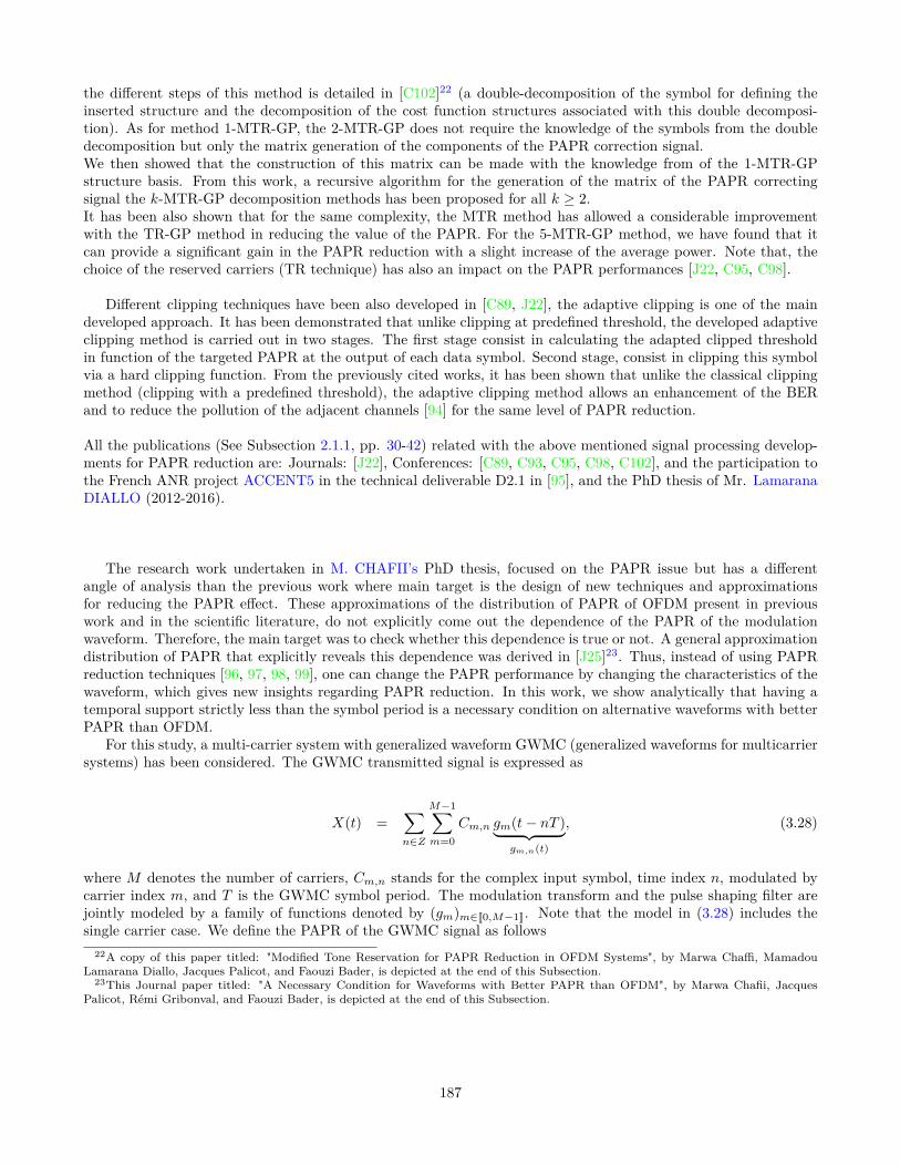
the different steps of this method is detailed in [C102]22 (a double-decomposition of the symbol for defining theinserted structure and the decomposition of the cost function structures associated with this double decomposi-tion). As for method 1-MTR-GP, the 2-MTR-GP does not require the knowledge of the symbols from the doubledecomposition but only the matrix generation of the components of the PAPR correction signal.We then showed that the construction of this matrix can be made with the knowledge from of the 1-MTR-GPstructure basis. From this work, a recursive algorithm for the generation of the matrix of the PAPR correctingsignal the k-MTR-GP decomposition methods has been proposed for all k ≥ 2.It has been also shown that for the same complexity, the MTR method has allowed a considerable improvementwith the TR-GP method in reducing the value of the PAPR. For the 5-MTR-GP method, we have found that itcan provide a significant gain in the PAPR reduction with a slight increase of the average power. Note that, thechoice of the reserved carriers (TR technique) has also an impact on the PAPR performances [J22, C95, C98].
Different clipping techniques have been also developed in [C89, J22], the adaptive clipping is one of the maindeveloped approach. It has been demonstrated that unlike clipping at predefined threshold, the developed adaptiveclipping method is carried out in two stages. The first stage consist in calculating the adapted clipped thresholdin function of the targeted PAPR at the output of each data symbol. Second stage, consist in clipping this symbolvia a hard clipping function. From the previously cited works, it has been shown that unlike the classical clippingmethod (clipping with a predefined threshold), the adaptive clipping method allows an enhancement of the BERand to reduce the pollution of the adjacent channels [94] for the same level of PAPR reduction.
All the publications (See Subsection 2.1.1, pp. 30-42) related with the above mentioned signal processing develop-ments for PAPR reduction are: Journals: [J22], Conferences: [C89, C93, C95, C98, C102], and the participation tothe French ANR project ACCENT5 in the technical deliverable D2.1 in [95], and the PhD thesis of Mr. LamaranaDIALLO (2012-2016).
The research work undertaken in M. CHAFII’s PhD thesis, focused on the PAPR issue but has a differentangle of analysis than the previous work where main target is the design of new techniques and approximationsfor reducing the PAPR effect. These approximations of the distribution of PAPR of OFDM present in previouswork and in the scientific literature, do not explicitly come out the dependence of the PAPR of the modulationwaveform. Therefore, the main target was to check whether this dependence is true or not. A general approximationdistribution of PAPR that explicitly reveals this dependence was derived in [J25]23. Thus, instead of using PAPRreduction techniques [96, 97, 98, 99], one can change the PAPR performance by changing the characteristics of thewaveform, which gives new insights regarding PAPR reduction. In this work, we show analytically that having atemporal support strictly less than the symbol period is a necessary condition on alternative waveforms with betterPAPR than OFDM.
For this study, a multi-carrier system with generalized waveform GWMC (generalized waveforms for multicarriersystems) has been considered. The GWMC transmitted signal is expressed as
X(t) =∑n∈Z
M−1∑m=0
Cm,n gm(t− nT )︸ ︷︷ ︸gm,n(t)
, (3.28)
where M denotes the number of carriers, Cm,n stands for the complex input symbol, time index n, modulated bycarrier index m, and T is the GWMC symbol period. The modulation transform and the pulse shaping filter arejointly modeled by a family of functions denoted by (gm)m∈[[0,M−1]]. Note that the model in (3.28) includes thesingle carrier case. We define the PAPR of the GWMC signal as follows
22A copy of this paper titled: "Modified Tone Reservation for PAPR Reduction in OFDM Systems", by Marwa Chaffi, MamadouLamarana Diallo, Jacques Palicot, and Faouzi Bader, is depicted at the end of this Subsection.
23This Journal paper titled: "A Necessary Condition for Waveforms with Better PAPR than OFDM", by Marwa Chafii, JacquesPalicot, Rémi Gribonval, and Faouzi Bader, is depicted at the end of this Subsection.
187

PAPR =maxt∈[0,T ] |X(t)|2
Pmean,
Pmean = limt0→+∞
12t0
ˆ t0
−t0E(|X(t)|2) dt.
E(.) is the expectation operator. The mean power Pmean is defined over an infinite integration time, because ourscenario assumes an infinite transmission time, but the observation is limited to a single GWMC symbol. Note thatthe PAPR reduction problem can be formulated as the following constrained optimization problem.
maximize(gm)m∈[[0,M−1]]
ˆ T
0ln(1− e
−γ∑M−1
m=0‖gm‖2
T∑
n∈Z
∑M−1m=0
|gm,n(t)|2 ) dt,
subject to A := minm,t
∑n∈Z|gm,n(t)|2 > 0. (3.29)
The quantity that we want to maximize in the PAPR optimization problem is equivalent to minimizing the ap-proximation of the complementary cumulative distribution function (CCDF) of the PAPR, subject to the constraintexpressed in (3.29). The CCDF is the probability that the PAPR exceeds a defined value γ, i.e. Pr(PAPR ≥ γ).
The condition (3.29), roughly means that the translated versions of every carrier gm are overlapping in time,and the waveform gm does not vanish within the symbol period T . If there exists at least an index m0 ∈ [[0,M − 1]]such that gm0 vanishes in a time interval in the symbol period T and its support is of length at most T , then thefamily of functions (gm)m∈[[0,M−1]] does not satisfy the constraint (3.29). In this case, we can also say that gm0 hasa temporal support strictly smaller than the symbol period T .
A particular consequence is that gm0 is likely to have a larger frequency support and then a worse frequencylocalization. This is due to the fact that time frequency localization measure is limited by the Heisenberg uncertaintyprinciple 24.
In order to formulate the PAPR optimization problem, we have first derived in [11] an approximation of theCCDF of the PAPR for the GWMC systems. Based on the Lyapunov central limit theorem (CLT), we showedthat the distribution of the signal is approximately Gaussian, and then we derived the approximate distributionof the PAPR by considering a simplifying assumption related to the independence of the samples. To apply theLyapunov CLT, Lyapunov conditions should be verified. For this purpose, we assumed that the modulation functionssatisfy the conditions in (3.29) and B := maxm,t
∑n∈Z |gm(t− nT )| < +∞, where the second condition is always
satisfied for all the functions belonging to L∞I space. In practice, all the waveforms should be bounded and havea finite support, therefore they necessarily belong to L∞I , that is why this condition does not appear in the PAPRoptimization problem.
It is important to highlight that the assumption of independence of the samples is not always verified in practice,which makes the derived distribution only an approximation. Simulation results showed that for a large number ofcarriers, the curve based on the theoretical approximation fits the empirical one. For more details about why weneed (3.29) to satisfy Lyapunov conditions and how we derive the CCDF approximation based on Lyapunov CLT,the reader can refer to the the work in [11].
An extended theoretical analysis of the PAPR optimization problem can be found in Section III and main obtainedresults by simulations in Section IV of [J25]. Several families of modulation functions (the modulation transformand the pulse shaping filter) that does not vanish in the symbol period have been investigated and a compari-son in terms of PAPR performance between each considered multi-carrier system and the conventional OFDM ispresented. Among the analyzed waveforms we have the Walsh-Hadamard-MC (WH-MC) scheme, the weightedcyclic prefix-OFDM (WCP-OFDM) as a variant of the OFDM scheme which gives a weighted version of the cyclicprefix-OFDM by using non-rectangular pulse shapes. The prototype filter out-of-band energy (OBE) defined in
24Or sometimes the Heisenberg-Gabor theorem, it states that a function cannot be both time-limited and band-limited (a functionand its Fourier transform cannot both have bounded domain). Then, one cannot simultaneously sharply localize a signal in both thetime domain and the frequency domain. More details can be found in [100]
188

0090-6778 (c) 2016 IEEE. Personal use is permitted, but republication/redistribution requires IEEE permission. See http://www.ieee.org/publications_standards/publications/rights/index.html for more information.
This article has been accepted for publication in a future issue of this journal, but has not been fully edited. Content may change prior to final publication. Citation information: DOI 10.1109/TCOMM.2016.2584068, IEEETransactions on Communications
SUBMITTED PAPER 9
• According to the necessary condition theorem, we un-derstand now why FBMC systems based on IOTA orSRRC filters for example as well as the universal-filteredmulticarrier (UFMC) systems [37] do not have betterPAPR than OFDM, since they do not satisfy the necessarycondition stated in the theorem.
Fig. 9 summarizes the conclusions of this study. The rect-angle represents the set of all GWMC waveforms∈ L∞
I .The optimization problem analysed in this work is for thewaveforms belonging to the setA, which means satisfying(2). Systems inA ∩B (including OFDM, WH-MC) have thebest possible PAPR performanceamong all systems inA. Anysystem with better PAPR performance than OFDM must be inC. There are indeed systems (Daubechies6, Symlet3, Coiflet2) in C with better PAPR performance than OFDM. Some areeven inB (Haar wavelets), but not inA.
Figure 9: Taxonomy of multicarrier waveforms regarding thePAPR performance.
V. CONCLUSION
In this paper, we have investigated the GWMC systembased on the family of modulation functions (the modulationtransform and the pulse shaping filter) which does not vanishin the symbol period, and we have proved analytically thatthe PAPR, which depends on the modulation waveform, isoptimal only if the sum of these waveforms over the number ofcarriers and the number of symbols is constant over time. Wehave concluded that there exists an infinite number of GWMCsystems that are optimal in terms of PAPR performance,and conventional OFDM based on the Fourier transform andthe rectangular filter belongs to this family. In addition, wehave deduced that the PAPR performance of GWMC systemscannot be better than OFDM system without reducing thetemporal support of the modulation functions compared to thesymbol period. It is worth mentioning that, by limiting thesupport of the individual carriers, we are moving more andmore from a multicarrier system to a single carrier system.
We have provided some examples to illustrate our theoreti-cal results: WH-MC has a PAPR performance equal to thatof OFDM, which is optimal among systems which satisfycondition (2), the WCP-OFDM’s waveform is not constantover time and thus it is worse than conventional OFDM interms of PAPR performance. By not satisfying constraint (2),it is possible to achieve a better PAPR performance, as hasbeen shown for the Haar wavelets. Moreover, our work alsoprovides a theoretical explanation about why several advanced
Table III: Study of the positivity of the functions.
H
s′′(H)
s′(H)
s(H)
0 +∞
+
−2
0
1
−1
H0
0
multicarrier systems such as NOFDM, FBMC, UFMC, do notachieve a better PAPR than OFDM.
Our future work will focus on designing a new waveformwith low PAPR than OFDM, by acting on the number ofintervals that vanish over time, and taking into considerationother constraints such as the bit error rate, the complexityand the spectral efficiency. If we would like to design a newwaveform as a candidate for the next generation of mobilecommunication systems, it should not be selected from theexcluded regionA, because in this case, it will not improvethe PAPR performance. Waveforms with reduced PAPR canbe found in particular in the regionB (as depicted in Fig. 9).
APPENDIX
We study the variations of the functions(H) = 1 − 2H + 2He
−1H , we have
s′(H) = −2 + 2e−1H +
2
He
−1H , (33)
s′′(H) =2
H2e
−1H + 2(− 1
H2e
−1H +
1
H
1
H2e
−1H ),
=2
H3e
−1H ≥ 0. (34)
As we can see in Table III, the functions is positive when0 < H ≤ H0. A numerical approximation givesH0 ≈ 0.63.
REFERENCES
[1] H. Ochiai and H. Imai, “On the Distribution of the Peak-to-Average
Power Ratio in OFDM Signals,”Communications, IEEE Transactions
on, vol. 49, no. 2, pp. 282–289, 2001.
[2] T. Jiang, M. Guizani, H.-H. Chen, W. Xiang, and Y. Wu, “Derivation
of PAPR Distribution for OFDM Wireless Systems Based on Extreme
Value Theory,”Wireless Communications, IEEE Transactions on, vol. 7,
no. 4, pp. 1298–1305, 2008.
[3] G. Auer, O. Blume, V. Giannini, I. Godor, M. Imran, Y. Jading, E. Ka-
tranaras, M. Olsson, D. Sabella, P. Skillermarket al., “D2. 3: Energy
Efficiency Analysis of the Reference Systems, Areas of Improvements
and Target Breakdown,”EARTH, 2010.
Figure 3.29: Taxonomy of multi-carrier waveforms regarding the PAPR performance, condition (2) here correspondto (3.29) in this manuscript, and (27) is the Lebesgue measure expression of the interval A+ defined in [J25].
[101] is used in WCP-OFDM, this waveform is also known as orthogonal wavelet division multiplexing (OWDM)[102]. Several wavelets can be used to modulate the input symbols, such as Daubechies, Coiflets, and Symlets. Inthis work we were interested on the Haar wavelet, which belongs to the family of Daubechies wavelets. The PAPRof other examples of multi-carrier systems from the literature have been also be discussed as the NOFDM, theFBMC, the IOTA FBMC systems based on IOTA, or SRRC filters for example, as well as the universal-filteredmulti-carrier (UFMC) systems [103] that have a worse PAPR than the OFDM signal since they do not satisfy thenecessary condition stated in (3.29).
Fig. 3.29 summarizes the conclusions of this study. The rectangle represents the set of all GWMC waveforms∈ L∞I . The optimization problem analyzed in this work is for the waveforms belonging to the set A, which meanssatisfying (3.29). Systems in A∩B (including OFDM, WH-MC) have the best possible PAPR performance amongall systems in A. Any system with better PAPR performance than OFDM must be in C. There are indeed systems(Daubechies 6, Symlet 3, Coiflet 2) in C with better PAPR performance than OFDM. Some are even in B (Haarwavelets), but not in A.To summarize, It can be concluded that it exists an infinite number of GWMC systems that are optimal in termsof PAPR performance, and conventional OFDM based on the Fourier transform and the rectangular filter belongsto this family. In addition, we have deduced that the PAPR performance of GWMC systems cannot be betterthan OFDM system without reducing the temporal support of the modulation functions compared to the symbolperiod. It is worth mentioning that, by limiting the support of the individual carriers, we are moving more andmore from a multi-carrier system to a single carrier system. Some examples to illustrate our theoretical resultshave been provided: WH-MC has a PAPR performance equal to that of OFDM, which is optimal among systemswhich satisfy condition (3.29), the WCP-OFDM’s waveform is not constant over time and thus it is worse thanconventional OFDM in terms of PAPR performance. By not satisfying constraint (3.29), it is possible to achieve abetter PAPR performance, as it has been shown for the Haar wavelets. Moreover, the work in [J25] also providesa theoretical explanation about why several advanced multi-carrier systems such as NOFDM, FBMC, UFMC, donot achieve a better PAPR than OFDM.All the publications related with the above mentioned research on the dependence of the PAPR of the modulationwaveform are: Journals: [J25, 11], Conferences: [C102, 12, C98, 13, 16, 17], and the PhD thesis of Ms. MarwaCHAFII (2013-2016).
189

Following are the corresponding depicted papers:1. [C102]- Mamadou Lamarana Diallo, Marwa Chafii, Jacques Palicot, and Faouzi Bader,"Modified Tone Reser-
vation for PAPR Reduction in OFDM Systems", in Proc. of th European Signal Processing Conference(EUSIPCO’2016), Budapest, Hungary. September 2016.
2. [J25]- Marwa Chafii, Jacques Palicot, Rémi Gribonval, and Faouzi Bader, "A Necessary Condition for Wave-forms with Better PAPR than OFDM", IEEE Transactions on Communications, vol. 64, issue: 8, pp. 3395-3405, doi 10.1109/TCOMM.2016.2584068, August 2016.
190

Modified Tone Reservation for PAPR Reduction in
OFDM Systems
Mamadou Lamarana Diallo, Marwa Chafii, Jacques Palicot and Faouzi Bader
CentraleSupelec/IETR/SCEE
Avenue de la boulaie-CS 47601-35576 Cesson Sevigne, Rennes, France
Email: mamadou-lamarana.diallo,marwa.chafii,jacques.palicot,[email protected]
Abstract—One of the main drawbacks of orthogonal frequency
division multiplex modulation is its high peak-to-average power
ratio (PAPR) which can induce poor power efficiency at high
power amplifier. Tone reservation (TR) is the most popular PAPR
mitigation technique that uses a set of reserved tones to design
peak cancelling signal for PAPR reduction. Finding an effective
peak cancelling for PAPR reduction in the time domain by using
only a small number of reserved tones, is not straightforward.
Therefore, we are led to a trade-off between computational
complexity and PAPR reduction. The TR method based on the
gradient projection algorithm gives the best compromise. In this
paper, we propose to modify the classical TR structure. The
new proposed method achieves an improvement up to 1.2 dB in
terms of PAPR performance without increasing the complexity.
The effectiveness of this solution is confirmed through theoretical
analysis and simulation results.
Index Terms—OFDM, PAPR, Tone Reservation, CCDF
I. INTRODUCTION
Orthogonal frequency division multiplex (OFDM) modula-
tion, although being used in standards such as IEEE 802.16,
IEEE 802.11a/g., HIPERLAN/2, and digital video broadcast-
ing terrestrial (DVB-T2) [1], suffers from high peak-to-average
power ratio (PAPR). A signal with high PAPR requires a
linear high power amplifier (HPA), which is inefficient in
terms of power consumption. To overcome this downside,
a larger number of PAPR mitigation techniques have been
proposed in the scientific community [2]. Tone reservation
(TR) [3] is the most popular adding signal technique for PAPR
reduction without bit error rate (BER) distortion and out-of-
Band pollution. In fact, the TR approach consists in using a
set of reserved tones in order to design the peak cancelling
signal. As TR works on reserved tones, no additional signal
processing is required at the receiver to extract the data
information. Due to these reasons, TR is quite popular for
practical implementations and therefore, it was adopted for
commercial standards such as (DVB-T2).
There are several studies in the literature about finding the
suitable peak cancelling subject to TR constraint [3], [4],
[5], [6], [7]. In [3] and [4] the authors propose to use a
quadratic constrained quadratic program (QCQP) and a second
order cone program (SOCP) respectively, to set the appropriate
values on the reserved tones for PAPR mitigation. However,
these approaches increase drastically the mean power of the
signal and their complexity is very high, which make them
not adequate for real time systems. To lower the computation
complexity, various methods have been proposed to design
the peak cancelling signal subject to TR principle, such as the
active-set method [5], one tone-one peak (OPTOP) method
[6], and transformation of clipping method as TR method [8].
Actually, the best technique that provides the best compromise
between PAPR reduction and computational complexity is the
TR method that uses the gradient project algorithm to compute
the adding signal by maximizing the signal to clipping ratio,
which is equivalent to minimizing the clipping noise [7].
In this paper, a new TR method using the gradient project
algorithm is proposed. The main idea of this approach is to
modify the classical TR structure by exploiting the decompo-
sition of the useful OFDM symbol as a mixture of two times
shorter multicarrier symbols, each containing two times less
carriers. Thus, by decomposing conjointly the clipping noise
with respect to the decomposition of the useful OFDM symbol,
this new approach named modified tone reservation (MTR)
consists in minimizing these partial clipping noise subject to
the TR constraint with respect to the different components of
the useful OFDM symbol after the decomposition.
The remainder of this paper is organized as follows: Section
II, briefly reviews the TR principle. Section III describes the
MTR principle. The simulation results are presented in Section
IV, while in Section V a conclusion is drawn.
II. OVERVIEW OF TR TECHNIQUES
A. Notations and Definitions
Throughout this paper, an OFDM symbol x(t) of durationTu is used and expressed as follows
x(t) =
√1
M
M−1∑
m=0
Xmej2πmFt , 0 ≤ t ≤ Tu. (1)
Where M is the total number of carriers, F = 1Tu
is the inter-
carrier spacing and Xm the symbol carried out by the m − th
carrier during Tu. After oversampling the signal by a factor L,
xl, l = 0, . . . , LM −1 are the discrete time domain samples
at the instant lTe where Te = Tu
LM .
We denote x = [x0, . . . , xLM−1] the vector of the samples
of x(t) after the oversampling operation. This vector can be
efficiently computed by using an inverse fast Fourier transform
(IFFT), and it can be expressed as follows
x = FMX. (2)
191

Where FM is the normalized IFFT matrix scaled by√
L and
X is the vector obtained by zero-padding on X. Let R =[m1, . . . , mMR
] ⊂ [0, . . . , M − 1] be a set of MR reserved
tones. Then, FM,R denotes a sub-matrix of FM indexed by the
column vectors that belong to R. The matrix FM,R has LMrows and MR columns and is used in [7] for the computation
of the suitable frequencies data carried by the reserved tones
for PAPR reduction.
Hereafter, FK represents, more generally, the normalized
IFFT matrix of size LK scaled by√
L and FK,X a sub-matrix
of FK containing only the column that belong to X .
B. Overview of TR based approaches for PAPR mitigation
The main idea of the TR approach is to use a set of MRreserved tones (named R) to design the peak cancelling signal.TR approach prevents then BER degradation and out-of-bandemissions [7]. In fact, let c be the peak cancelling addressedto reduce the PAPR of the useful symbol x. Therefore, underthe TR constraint x + c satisfies the following equation
1
L(FCol
M,m)H(x + c) = Xm + Cm =
Xm if m /∈ RCm if m ∈ R , (3)
where FColM,m is the m-th column of the matrix F. The scaling
by 1L is due to (FM )HFM = LI with I is the identity matrix.
From the (3), it can be remarked that c = FM,RC. Then
the TR method rely on finding the suitable frequency vector
C. For this purpose, several studies have been proposed in
the literature, in order to find the effective peak cancelling
signal c for PAPR reduction [3], [4], [5], [7], [8]. All these
approaches are focused on the way of the effective c can be
computed. For instance, in [7] the authors have formulated the
computation of c as a Quadratically Constrained Quadratic
Program (QCQP). This approach allows to achieve a good
performance in terms of PAPR reduction. Nevertheless, this
approach requires high numerical complexity. For real time
systems, the best technique that provides the best compro-
mise between PAPR reduction and computational complexity
is the TR-Gradient Project (TR-GP) [7] which consists in
minimizing the clipping noise by adding a peak cancelling
signal subject to TR constraint [3]. This algorithm has been
suggested for PAPR reduction in the DVB-T2 standard [1].Let x + c be the transmitted symbol after PAPR reduction.
The clipping noise of this symbol is defined in [7] as follows:
J(.) = ‖x + c − f(x + c, A)‖22. (4)
Where A is a clipping magnitude and f(., .) a hard clipping
function. Fig. 1 gives an illustration of J(.) that we want to
minimize by adding a peak cancelling signal.The TR-GP method, proposed in [7], relies on finding the
peak cancelling signal c by minimizing J(c) via the gradientproject algorithm [9] subject to TR constraint, i.e,
minC
(‖x + FM,RC− f(x + FM,RC)‖2
2
)(5)
Starting with the initial condition of x(0) = x, it has beenshown in [7] that the TR-GP method reduce iteratively thePAPR as follows,
x(i+1) = x(i) − µ∑
|x(i)l
|>A
α(i)l Pl, (6)
Am
plit
ude
0 Tu
A
J(.)
Fig. 1. Illustration of the cost function in TR-GP method.
where Pl is the l-th line of matrix P = FR (FR)H
and
α(i)l = (x
(i)l −Aej arg(x
(i)l )). Note that the matrix P can be pre-
calculated and stored, the numerical complexity of the TR-GP
is then O (ML).
III. MODIFIED TONE RESERVATION PRINCIPLE AND
PROBLEM FORMULATION
The MTR approach consists in modifying the classical TR
structure by using the decomposition of the useful OFDM
symbol as a mixture of 4 multi-carriers (after first decom-
position) signal or 16 multi-carriers signal (after the double
decomposition), see Annexe III-A and Subsection III-B. Thus,
by decomposing conjointly J(.) as a sum of a partial clipping
noise with respect to the decomposed parts of the useful
OFDM symbol, the MTR approach propose to minimize
conjointly these partial clipping noise by using the gradient
project algorithm (MTR-GP) subject to prevent BER from
degrading.
A. The MTR approach based on the first decomposition
Let x1, x2, x3 and x4 be the multi-carriers symbols derivedfrom the decomposition of x, see Appendix A. Assuming thatx satisfies the TR constraint, i.e, all reserved tones are set tozero, it can be easily verified that (use (21) and (24))
1
L(FCol
M1,m)Hx1 = X1m =
X1
m Si m /∈ K(0)
0 if m ∈ K(0)
1
L(FCol
M1,m)Hx3 = X3m =
X3
m Si m /∈ K(0)
0 if m ∈ K(0)
1
L(FCol
M1,m)H(DM1)Hx2 = X2
m =
X2
m Si m /∈ K(1)
0 if m ∈ K(1)
1
L(FCol
M1,m)H(DM1)Hx4 = X4
m =
X4
m Si m /∈ K(1)
0 if m ∈ K(1) , (7)
where K(0) = R(0)
2 , K(1) = R(1)−12 and FCol
M1,m is the m-th
row of the matrix FM1which is a normalized IFFT matrix
of size M1L. The construction of such a matrix is given in
Section II-A.According to the useful OFDM symbol decomposition, the
clipping noise J(.) (cost function in TR-GP method) is alsodecomposed as a sum of the partial clipping noise J1(.) andJ2(.).
J1(.) = ‖(x1 + x2) − f(x1 + x2, A
)‖22
J2(.) = ‖(x3 + x4) − f(x3 + x4, A
)‖22 (8)
192

Fig. 2 gives an illustration of the partial clipping noise derived
from the decomposition of the clipping noise represented in
the Fig. 1.
Am
plit
ude
0 Tu/2 T
u
A
J1(.)
J2(.)
Fig. 2. Illustration of the clipping partial noise J1(.) and J2(.).
By using the reserved tones of the symbols derived fromthe decomposition of the useful symbol x, see (7), the MTRapproach consists in finding the signal c1 and c2 (c3 and c4
respect.) by minimizing J1(c1 + c2) (J2(c
3 + c4) respect.).The objective is to construct the peak cancelling signal forPAPR reduction c using c1, c2, c3 and c4 derived from itsdecomposition, i.e
c = [c1.c3] + [c2.c4]. (9)
Where . stands for the vectors concatenation operator.In other words, the MTR-GP method consists in solving the
following optimization problems
minC1,C2
(‖x1 + x2 + FM1,K(0)C1 + FM1,K(1)C2
−f(x1 + x2 + FM1,K(0)C1
︸ ︷︷ ︸c1
+ FM1,K(1)C2
︸ ︷︷ ︸c4
, A)‖22), (10)
and,
minC3,C4
(‖x1 + x2 + FM1,K(0)C3 + FM1,K(1)C4
−f(x1 + x2 + FM1,K(0)C3
︸ ︷︷ ︸c3
+ FM1,K(1)C4
︸ ︷︷ ︸c4
, A)‖22). (11)
Let A be a matrix of dimension (LM, 2MR) defined by(12) and C =
[C1.C2.C3.C4
].
A =
[FM1,K(0) 0LM1,K0
F1M1,K(1) 0LM1,K1
0LM1,K0FM1,K(0) 0LM1,K1
F2M1,K(1)
](12)
where 0t,z represents a null matrix of size (t, z), K0 and K1
denote the number of even and odd tones in R respectively.The optimization problems (10) and (11) can be conjointly
formulated as follows, thanks to the matrix A
minC
(‖x + AC− f(x + AC)‖2
2
)(13)
It may be noticed that x1, x2, x3 and x4 are not used in the
computation of the peak cancelling signal c = AC, see (13).
The decomposition of the OFDM symbol presented in the
Annex allows us only to modify the classical TR structure.
It is important to highlight that C1 6= C3 and C2 6= −C4
(the cost functions J1(.) and J2(.) are a priori different).
Therefore, the peak cancelling signal c will interfere with the
useful carriers of the symbol x. To prevent BER degradation,
Fig. 3. Digital Frequency Domain Filtering scheme.
a digital frequency domain filtering described in Fig. 3 are
proposed.Let cev = [c1.c3] and codd = [c2.c4], from Fig. 3, it can be
shown that Cevm = FCol
M,m(cev) and Codm = FCol
M,m(cod) satisfy(14) and (15) respectively.
Cevm =
FHM1,pDH
M1FM1,K(0)
L√
2(C1 −C3)
︸ ︷︷ ︸6=0
if m ∈ R(1)
C1m2
+ C3m2
if m ∈ R(0)(m2
∈ K(0))
0 if m /∈ R(14)
Codm =
FHM1,pDH
M1FM1,K(1)
L√
2(C2 −C4)
︸ ︷︷ ︸6=0
if m ∈ R(0)
C2m−1
2
+ C4m−1
2
if m ∈ R(1)(m−12
∈ K(1))
0 if m /∈ R(15)
From (14) and (15), it can be observed that c1 6= c3 andc2 6= c4 despite the filtering stage. This property represents thenew degree of freedom in the optimization problem that willallows us to outperform the classical TR-GP method in termsof PAPR reduction. In fact, subject to c1 = c3 and c2 = c4,i.e, C1 = C3 and C2 = C4, it can be shown through a changeof variable that (13) can be formulated as the classical TR-GPmethod defined by (5). Due to the digital frequency domainfiltering stage which requires an FFT and IFFT operation,the MTR-GP method is more complex than the classical TR-GP method. Then, to reduce the computational complexity ofthe MTR-GP method, we propose to include the frequencydomain filtering process directly in the optimization problem.In fact, from the proposed digital frequency domain filtering(see Fig. 3) the signal p can be computed as follows
p =1
L
(FM,Rc (FM,Rc )HA
)C. (16)
Where Rc is the complementary of R including the carriersdue to the zero padding operation. Therefore, to prevent BERdegradation, the optimization problem (13) and the filteringstage can be simultaneously formulated through the followingoptimization problem
minC
(‖x + AC− f(x + AC)‖2
2
), (17)
where A = A − 1L
(FM,RcFH
M,RcA).
As in [7], (17) can be solved thanks to (6) by replacing Pby AAH . These two methods have the same computational
complexity because AAH can be pre-calculated, and stored.
This method will be called as 1-MTR-GP and in following
subsection we will briefly extend the MTR principle by
iterating the OFDM symbol decomposition.
B. MTR based on the double decomposition: 2-MTR-GP
Going more deeply into the decomposition of the OFDM
signal, we proceed, similarly as Appendix A, a second de-
composition of the symbol x(t). For this purpose, the symbols
193

derived from the first decomposition are decomposed similarly
as in Annexe A. Through this double decomposition, x can
be expressed as a mixture of 16 multi-carrier symbols with a
duration of Tu
4 and M2 = M4 carriers (useful and reserved).
Conjointly to this double decomposition, the cost function J(.)is also decomposed as a sum of 4 partial clipping noise J1,1(.),J1,2(.), J2,1(.) and J2,2(.). Fig. 4 gives an illustration of the
partial clipping noise derived from the decomposition of the
clipping noise depicted in Fig. 1.
Am
plit
ude
0 Tu/4 T
u/2 T
u/4 T
u
A
J1,1
(.) J1,2
(.)
J2,1
(.)J2,2
(.)
Fig. 4. Illustration of the double decomposition of J[x](.)
As in Section III-A, the 2-MT-GP method consists in findingthe substructures of the peak cancelling signal thanks tothe reserved tones of the symbols derived from the doubledecomposition, by minimizing J1,1(.), J1,2(.), J2,1(.) andJ2,2(.). Thus, similarly as in Section III-A, it can be shownthat the 2-MTR-GP consists in finding the peak cancelling bysolving the following optimisation problem
minCn
(‖x + BCn − f(x + BCn)‖2
2
), (18)
where C is a frequency vector constructed similarly as in (13),and B is a matrix of dimension LM ×4MR defined as follows
B =
[B1 0M1L,K0
DM1LB2 0M1L,K1
0M1L,K0B1 0M1L,K1
−DM1LB2
]. (19)
The matrix B1 and B2 are defined in Appendix B.To avoid BER degradation, a similar process as in (III-A)
can be undertaken. In other words, this is equivalent to solvethe following problem
minC
(‖x + BC− f(x + BC)‖2
2
), (20)
where B = B− 1L
(FM,RcFH
M,RcB)
. This problem can iteratively
solved thanks to the gradient project algorithm as previously.
IV. SIMULATION RESULTS
Simulations are performed with a 16-QAM modulated
OFDM system that has M = 256 carriers wherein MR = 12carriers are reserved for PAPR reduction. The signal is over-
sampled by a factor of four (L = 4). The set of reserved tones
is R = [123, 124, . . . , 133, 134].Fig. 6 and 5, depict the CCDF before and after PAPR
reduction using the TR-GP method , 1-MTR-GP and 2-MTR-
GP methods after Nmax = 10 (number of performed iterations
by the GP algorithm ) featuring different normalized thresholds
ρ = 5dB and 6dB. The simulation results depicted in Fig. 6
show that the proposed approaches outperform the classical
TR-GP method in terms of PAPR reduction. In fact, with
6 7 8 9 10 11 1210
−4
10−3
10−2
10−1
100
Φ in dB
CC
DF(
Φ) =
Pro
b[PA
PR≥Φ
]
CCDF Orig
TR−GP with ρ = 5dB
1−MTR−GP with ρ = 5dB
2−MTR−GP with ρ = 5dB
Fig. 5. Performance in term of PAPR reduction with ρ = 5dB.
6 7 8 9 9.5 10 10.5 11 1210
−4
10−3
10−2
10−1
100
Φ in dBC
CD
F(Φ)
= P
rob[
PAPR
≥Φ]
CCDF Orig
TR−GP with ρ = 6dB
1−MTR−GP with ρ = 6dB
2−MTR−GP with ρ = 6dB
Fig. 6. Performance in term of PAPR reduction with ρ = 6dB.
ρ = 6 dB ( ρ = 5 dB respect.) and Nmax = 10, the achieved
PAPR at a clip rate 10−4 of the CCDF for the TR-GP, 1-
MTR-GP, and 2-MTR-GP are 10.9 dB, 10.4 dB, and 9.9 dB(10.9dB, 10.45dB, and 10.12dB respect.) respectively. Thus,
the MTR scheme allow us to improve the PAPR reduction
of approximately 1dB. Besides, it can be also noticed that
the deeper is the decomposition process of the signal x(t),the better is the PAPR reduction performance achieved of the
MTR-GP method.
Fig. (7) evaluates the BER versus Eb/N0 curves in AWGN
channels, where Eb denotes the average bit energy and N0 is
the one-sided power spectral density of the noise component.
From these simulation results, it is worth noting that both
proposed MTR-GP methods and the classical TR approach
prevent the BER degradation as it is noticed in Subsec-
tion III-A and III-B.
0 2 4 6 8 10 12 1410
−4
10−3
10−2
10−1
100
Eb/N
0 in dB
Bit
Err
or R
ate
BER Theo 16−QAM
BER OFDM orig
TR−GP after 10 iterations
1−MTR−GP after 10 iterations
2−MTR−GP after 10 iterations
Fig. 7. BER performance of the signal before and after PAPR reduction.
194

V. CONCLUSION
In this paper, a new approach of designing the adding
signal for PAPR mitigation by modifying the classical TR
scheme is proposed. Using the gradient algorithm for the
computation of the peak cancelling for PAPR mitigation, we
have shown theoretically that it can be expected that our
proposed solution outperforms the classical TR-GP method
with the same computational complexity. Simulation results
approved these theoretical analyses. Moreover, we have shown
that going deeply in the decomposition process of the useful
OFDM signal achieves better performance for the MTR-GP
method. In our future works, the MTR will be analysed for
higher decomposition levels.
APPENDIX A
OFDM SYMBOL DECOMPOSITION
In this section, we show that an OFDM symbol x(t) can be
seen as a mixture of 4 multi-carriers symbols.Let X1, X2, X3 and X4 be the data vectors in frequency
domain, of size M2 defined as follows:
X1p = X3
p = X2p and X2p = X4
p = X2p+1. (21)
Note that X1 and X3 (X2 and X4 respect.) contain the dataof X indexed by the even tones (odd tone respect.). Now,let x1(t), x2(t), x3(t) and x4(t) be the multi-carriers signalsdefined as
x1(t) =
√1
M1
M1−1∑
m=0
X1mej2πmF1t, 0 ≤ t ≤ T1,
x3(t) =
√1
M1
M1−1∑
m=0
X3mej2πmF1t, T1 ≤ t ≤ 2T1,
x2(t) =
√1
M1
M1−1∑
m=0
X2mej2π(mF1+F )t, 0 ≤ t ≤ T1,
x4(t) =
√1
M1
M1−1∑
m=0
X4mej2π(mF1+F )t, T1 ≤ t ≤ 2T1. (22)
with T1 = Tu
2 , M1 = M2 and F1 = 1/T1.
From 21 and 22 we have
x(t) =
x1(t) + x2(t), if t ∈]0, Tu
2
]
x3(t) + x4(t), if t ∈[
Tu2
, Tu
[ . (23)
After oversampling using the same oversample rate, let x1,x2, x3 and x4 be the vectors of the samples of the symbolsx1(t), x2(t), x3(t) and x4(t) respectively. Therefore, aftersome derivations, we obtain:
x1 = FM1X1, and x3 = FM1
X3,
x2 = FM1X2, and x4 = −FM1
X4. (24)
where FM1is the normalized IFFT matrix of size (M1L),
FM1= DM1
FM1, and DM1
is a diagonal matrix whose the
diagonal is the vector d = [1, ej2π 1M1L , . . . , ej2π
M1L−1M1L ]. For
i = 1, .., 4, the vector X(i) is a vector obtained thanks to the
zero-padding operation.Therefore, using (23) x can be expressed versus x1, x2, x3
and x4 as follows:
x = [x1.x3] + [x2.x4]. (25)
where . denotes the concatenation operation.
APPENDIX B
CONSTRUCTION OF THE MTR MATRIX
Let K(0),ev and K(0),od (K(1),ev and K(1),od respect.) bethe subsets of K(0) (K(1) respect.) containing its even andodd tones (indices) respectively. From these subsets, let P(0),P(1), Q(0), Q(1) be the following subsets
P(0) =K(0),ev
2, and P(1) = K(0),od
2,
Q(0) =K(1),ev − 1
2, and Q(1) = K(1),od−1
2. (26)
The matrix B1 and B2 are then defined as follows
B1 =
[FM2,P(0) 0M2L,P0
F1M2,P(1) 0M2L,P1
0M2L,P0FM2,P(0) 0M2L,P1
F2M2,P(1)
]. (27)
where M2 = M4 , P0 is the cardinal of P(0) (i.e number of the
even tones in K(0)) and P1 is the cardinal of P(1) (i.e numberof the odd tones in K(0)).
B2 =
[FM2,Q(0) 0M2L,Q0
F1M2,Q(1) 0M2L,Q1
0M2L,Q0FM2,Q(0) 0M2L,Q1
F2M2,Q(1)
]. (28)
where Q0 is the cardinal of Q(0) (i.e number of the even tones
in K(1)) and Q1 is the cardinal of Q(1) (i.e number of the odd
tones in Q(1)).
ACKNOWLEDGMENT
Part of this work is supported by the project ACCENT5
(Advanced Waveforms, MAC Design and Dynamic Radio Re-
source Allocation for D2D in 5G Wireless Networks) funded
by the French national research agency with grant agreement
code: ANR-14-CE28-0026-02.
REFERENCES
[1] DVB: Frame Structure Channel Coding and Modulation for a ScecondGeneration Digital Terrestrial Television Broadcasting System DVB-T2,TR, TR Std., Juin 2008.
[2] H. B. G. Wunder, R. Fischer and S. Litsyn, “The PAPR Problem in OFDMTransmission: New directions for a long-lasting problem,” IEEE SignalProcessing Magazine, pp. 130–140, October 2013.
[3] J. Tellado-Mourelo, “Peak to Average Power Reduction for MulticarrierModulation,” Ph.D. dissertation, Standford University, 1999.
[4] S. Zabre, J. Palicot, Y. Louet, and C. Lereau, “SOCP Approach for OFDMPeak-to-Average Power Ratio Reduction in the Signal Adding Context,” inSignal Processing and Information Technology, 2006 IEEE InternationalSymposium on, 2006, pp. 834–839.
[5] B. S. Krongold and D. Jones, “A new tone reservation method forcomplex-baseband par reduction in ofdm systems,” in Acoustics, Speech,and Signal Processing (ICASSP), 2002 IEEE International Conferenceon, vol. 3, May 2002, pp. III–2321–III–2324.
[6] E. Bouquet, S. Haese, M. Drissi, C. Moullec, and K. Sayegrih, “Aninnovative and low complexity papr reduction technique for multicarriersystems,” in Wireless Technology, 2006. The 9th European Conferenceon, Sept 2006, pp. 162–165.
[7] J. Tellado and J. Cioffi, “Efficient algorithms for reducing par in multi-carrier systems,” in Information Theory, 1998. Proceedings. 1998 IEEEInternational Symposium on, Aug 1998, pp. 191–.
[8] L. Wang and C. Tellambura, “Analysis of Clipping Noise and Tone-Reservation Algorithms for Peak Reduction in OFDM Systems,” Vehic-ular Technology, IEEE Transactions on, vol. 57, no. 3, pp. 1675–1694,2008.
[9] A. Hjorungnes and D. Gesbert, “Complex-valued matrix differentiation:Techniques and key results,” Signal Processing, IEEE Transactions on,vol. 55, no. 6, pp. 2740–2746, June 2007.
195

0090-6778 (c) 2016 IEEE. Personal use is permitted, but republication/redistribution requires IEEE permission. See http://www.ieee.org/publications_standards/publications/rights/index.html for more information.
This article has been accepted for publication in a future issue of this journal, but has not been fully edited. Content may change prior to final publication. Citation information: DOI 10.1109/TCOMM.2016.2584068, IEEETransactions on Communications
IEEE TRANSACTIONS ON COMMUNICATIONS 1
A Necessary Condition for Waveforms with BetterPAPR than OFDM
Marwa Chafii,Member, IEEE,Jacques Palicot,Member, IEEE,Rémi Gribonval,Fellow, IEEE,and Faouzi Bader,Senior, IEEE
Abstract—This paper establishes a necessary condition thatmust be satisfied by the modulation waveforms of any generalizedwaveforms for multicarrier (GWMC) system with better peak-to-average power ratio (PAPR) than conventional orthogonalfrequency division multiplexing (OFDM). GWMC systems in-clude in particular all classical multicarrier modulation systems.As a consequence, we show that OFDM has the best PAPRperformance over all GWMC systems that do not satisfy thisnecessary condition. We also identify an infinite family of GWMCsystems with the same PAPR performance as OFDM. To illustrateour results, we present simulations of the PAPR behaviour fordifferent GWMC systems, including some with better PAPRperformance than OFDM.
Index Terms—Peak-to-Average Power Ratio (PAPR), Orthog-onal Frequency Division Multiplexing (OFDM), GeneralizedWaveforms for Multi-Carrier (GWMC), Fourier Transforms.
I. I NTRODUCTION
T He peak-to-average power ratio (PAPR) [1], [2] is arandom variable that measures the power variations of
the multicarrier modulation signals. The fluctuations of amulticarrier signal envelope generate non-linear distortionswhen we introduce the signal into the high power amplifier(HPA), due to the non-linearity of the HPA response. Toavoid these distortions, an input back-off is needed in order toamplify the signal in the linear area of the HPA. The larger thePAPR, the larger the input back-off introduced, and the smallerthe HPA efficiency. The energy consumption of the poweramplifier represents60% of the total energy consumption ina base station [3]. Therefore, the signal amplitude variationsshould be reduced in order to reach a better HPA efficiencyand minimize the power consumption.
As presented later in the state of the art, several multicar-rier modulation systems based on different waveforms havebeen proposed in the literature as alternatives to conventionalorthogonal frequency division multiplexing (OFDM) [4]. Inaddition to the PAPR, there are several relevant criteria forselecting or designing new waveforms for future multicarriersystems, which include, among others:
• Bit error rate to evaluate reliability of the transmission.
M. Chafii, J. Palicot and Faouzi Bader are with theCentraleSupélec/IETR, 35576 Cesson-Sévigné, France (e-mail:marwa.chafii, jacques.palicot,[email protected]).
R. Gribonval is with Inria Rennes-Bretagne Atlantique, 35042 RennesCedex, France (e-mail:[email protected].
This work has received a French state support granted to the CominLabsexcellence laboratory and managed by the National Research Agency in the"Investing for the Future" program under reference Nb. ANR-10-LABX-07-01. The authors would also like to thank the Region Bretagne, France, for itssupport of this work.
• Complexity to ensure feasibility of the system.• Bandwidth efficiency to ensure a high transmission rate
using the available resources.• Latency to reduce the delay of the transmission.• Data rate to meet the needs of high-speed applications.
In this paper, we focus on the PAPR criterion, and weinvestigate the behaviour of the PAPR regarding to the modu-lation waveforms. It has been proved that the PAPR dependson the waveform used in the modulation [5], [6]. Thus,instead of using PAPR reduction techniques [7]–[11], one canchange the PAPR performance by changing the characteristicsof the waveform, which gives new insights regarding PAPRreduction. In this work, we show analytically thathaving atemporal support1 strictly less than the symbol period isa necessary condition on alternative waveforms with betterPAPR than OFDM2.
In fact, we prove that, if the previous necessary conditionis not satisfied, i.e if the waveforms have a temporal supportlarger than or equal to the symbol period, then their PAPR per-formance cannot be better than that of conventional OFDM. Inaddition, we identify several multicarrier modulation systemswith the same PAPR performance as OFDM. Fig. 9 providesan insight into the conclusions of this work.
A. Paper outline
Our main contributions are to prove that:
1) Among systems which waveforms have a temporal sup-port larger than or equal to the symbol period:
– The (distribution of the) PAPR is optimal only ifthe sum of the squared modulus of the individual(multicarrier) waveforms is constant over time. (See(4)).
– An infinite number of GWMC systems are optimal interms of PAPR performance.
– OFDM is among this class of GWMC systems.– No better PAPR compared to OFDM is possible, with-
out reducing the temporal support of the waveforms.
2) Signal sets may have better PAPR than OFDM, when thetemporal support is limited (e.g. Haar wavelet).
1The support of a function means here the interval outside which thefunction is equal to zero.
2The study here considers OFDM without guard interval, but the analysisis the same for OFDM with cyclic prefix, since the addition of a cyclic prefixdoes not give any additional information about the peak power.

0090-6778 (c) 2016 IEEE. Personal use is permitted, but republication/redistribution requires IEEE permission. See http://www.ieee.org/publications_standards/publications/rights/index.html for more information.
This article has been accepted for publication in a future issue of this journal, but has not been fully edited. Content may change prior to final publication. Citation information: DOI 10.1109/TCOMM.2016.2584068, IEEETransactions on Communications
2 IEEE TRANSACTIONS ON COMMUNICATIONS
B. State of the art
Several classes of multicarrier modulation systems can bedefined [12], [13], based on several characteristics, includingwhether the modulation is based on the discrete Fourier trans-form or other transforms, and orthogonal or non-orthogonalschemes. A first distinction can be made:
• Modulations based on the Fourier transform: the mod-ulation scheme can be based on the inverse fast Fouriertransform (IFFT) at the transmitter side and the fast Fouriertransform (FFT) at the receiver side. After the IFFT block,the signal is filtered with pulse shaping filters. Depending onthe selected filter, the resulting signal is orthogonal or non-orthogonal. Hereafter, we provide some examples of suchwaveforms:
– OFDM is a well known orthogonal scheme based on theFourier transform and the rectangular filter.
– NOFDM: non-orthogonal frequency division multiplexing[14] is a multicarrier modulation system that does nothave any restriction about the distance between pulsesin the time-frequency plane, and the design of the pulseshape, which leads to a better bandwidth efficiency, whilethe time frequency location and the shape of the pulsesfor conventional OFDM are strictly defined.
– OFDM/OQAM:(offset quadrature amplitude modulation)[15]–[17] is a filter bank multicarrier (FBMC) [18] systemthat allows a flexible selection of the pulse shaping filters,such as the isotropic orthogonal transform algorithm(IOTA) [19], the extended Gaussian functions (EGF), thePHYDYAS filter 3, and the Hermite filters, in order toreduce side lobes without using guard bands in contrastto conventional OFDM. OFDM/OQAM does not use acyclic prefix.
– GFDM: generalized frequency division multiplexing [20],[21] is a non-orthogonal scheme which allows the useof well-localized filters to avoid out-of-band emissions.The modulation is performed block by block, where eachGFDM data block consists of a certain number of carriersand symbols. A cyclic prefix can be added in the GFDMdata block, along with tail biting in the pulse shape.
For more details, a taxonomy of multicarrier modulationsystems is proposed in [12]. For the different pulse shapingfilters, the reader can refer to [13] that defines and gives theanalytical expression and characteristics of the most popularprototype filters in the literature.
• Modulations based on other transforms: instead of per-forming the modulation based on the Fourier transform,other transforms can be used. These are examples reportedin the literature:
– The Wavelet Transformis widely used in wireless com-munication applications. These multicarrier modulationsystems can be based on the discrete wavelet transform(DWT) [22] or the wavelet packet transform (WPT) [23].
– The Walsh-Hadamard Transformcan be used as amodulation basis for multicarrier modulation systems.
3Physical Layer For Dynamic Spectrum Access And Cognitive Radio, moredetails on http://www.ict-phydyas.org/
In [24], the author introduces the Walsh-Hadamardtransform for multicarrier modulation applications, andcompares it with the Fourier transform in conventionalOFDM. It has been also showed that multicarriermodulation systems based on the Walsh-Hadamardtransform are more suitable for optical communicationsthan OFDM at short distance transmission, in terms ofcomputational complexity [25].
– The Discrete Cosine Transform (DCT)has been proposedin the literature [26], [27] as a modulation basis formulticarrier systems. In [28], the multicarrier modulationscheme based on the DCT has been proved better thanOFDM in terms of BER under certain channel conditions.
The remainder of this paper is structured as follows. InSection II, we define the generalized waveforms for multi-carrier (GWMC) system considered in our derivations, andwe formulate the PAPR reduction problem as an optimizationproblem. The solution of this problem is given in SectionIII with the whole proof behind. To support the theoreticalresults, we illustrate some examples of multicarrier modulationsystems in Section IV. Finally, Section V concludes the paperand opens new perspectives of the work.
II. PROBLEM FORMULATION
A. Notation: the GWMC modelThe GWMC system is a generalization of classical multi-
carrier modulation systems based on a larger choice of mod-ulation schemes. The GWMC transmitted signal is expressedas
X(t) =∑
n∈
M−1∑
m=0
Cm,n gm(t− nT )︸ ︷︷ ︸gm,n(t)
, (1)
whereM denotes the number of carriers,Cm,n stands forthe complex input symbol, time indexn, modulated by carrierindexm, andT is the GWMC symbol period. The modulationtransform and the pulse shaping filter are jointly modeled bya family of functions denoted by(gm)m∈[[0,M−1]]. Note thatthe model in (1) includes the single carrier case.
We define the PAPR of the GWMC signal as follows
PAPR =maxt∈[0,T ] |X(t)|2
Pmean,
Pmean = limt0→+∞
1
2t0
∫ t0
−t0
E(|X(t)|2) dt.
E(.) is the expectation operator. The mean powerPmean isdefined over an infinite integration time, because our scenarioassumes an infinite transmission time, but the observation islimited to a single GWMC symbol.
B. Main assumptionsThe number of carriers is supposed to beM ≥ 8. This is an
assumption made for the validity of the central limit theorem.We assume that(Cm,n)(m∈[[0,M−1]], n∈Z) are independent andidentically distributed, with zero mean and unit varianceσ2
C . Let (gm)m∈[[0,M−1]] ∈ L∞I , whereL∞
I is the space ofessentially bounded functions which vanish outside a finiteinterval I. Then we have
∀m ∈ [[0,M − 1]] ∀t /∈ I gm(t) = 0.

0090-6778 (c) 2016 IEEE. Personal use is permitted, but republication/redistribution requires IEEE permission. See http://www.ieee.org/publications_standards/publications/rights/index.html for more information.
This article has been accepted for publication in a future issue of this journal, but has not been fully edited. Content may change prior to final publication. Citation information: DOI 10.1109/TCOMM.2016.2584068, IEEETransactions on Communications
SUBMITTED PAPER 3
C. Optimization problem associated to PAPR reduction
As we will soon recall in Section II-E, the PAPR reduc-tion problem can be formulated as the following constrainedoptimization problem.
The PAPR Optimization Problem.
maximize(gm)m∈[[0,M−1]]
∫ T
0
ln(1 − e
−γ∑M−1
m=0 ‖gm‖2
T∑
n∈Z∑M−1
m=0 |gm,n(t)|2 ) dt,
subject to A := minm,t
∑
n∈Z
|gm,n(t)|2 > 0. (2)
The quantity that we want to maximize in the PAPRoptimization problem is equivalent to minimizing the approxi-mation of the complementary cumulative distribution function(CCDF) of the PAPR, subject to the constraint expressed in(2). The CCDF is the probability that the PAPR exceeds adefined valueγ, i.e. Pr(PAPR≥ γ).
D. The meaning of condition(2)
Roughly speaking, (2) means that the translated versions ofevery carriergm are overlapping in time, and the waveformgm does not vanish within the symbol periodT .
If there exists at least an indexm0 ∈ [[0,M − 1]] such thatgm0
vanishes in a time interval in the symbol periodT and itssupport is of length at mostT , then the family of functions(gm)m∈[[0,M−1]] does not satisfy (2). In this case, we can alsosay thatgm0
has a temporal support strictly smaller than thesymbol periodT .
A particular consequence is thatgm0is likely to have a
larger frequency support and then a worse frequency localiza-tion. This is due to the fact that time frequency localizationmeasure is limited by the Heisenberg uncertainty principle4.
E. Origins of the optimization problem formulation
In order to formulate the PAPR optimization problem, wehave first derived in [6] an approximation of the CCDF ofthe PAPR for the GWMC systems. Based on the Lyapunovcentral limit theorem (CLT), we showed that the distributionof the signal is approximately Gaussian, and then we derivedthe approximate distribution of the PAPR by consideringa simplifying assumption related to the independence ofthe samples. To apply the Lyapunov CLT, Lyapunov condi-tions should be verified. For this purpose, we assumed thatthe modulation functions satisfy the conditions in (2) andB := maxm,t
∑n∈Z |gm(t− nT )| < +∞, where the second
condition is always satisfied for all the functions belonging toL∞
I space. In practice, all the waveforms should be boundedand have a finite support, therefore they necessarily belong toL∞
I , that is why this condition does not appear in the PAPRoptimization problem.
It is important to highlight that the assumption of inde-pendence of the samples is not always verified in practice,
4Or sometimes the Heisenberg-Gabor theorem, it states that a function can-not be both time-limited and band-limited (a function and its Fourier transformcannot both have bounded domain). Then, one cannot simultaneously sharplylocalize a signal in both the time domain and the frequency domain. Moredetails can be found in [29].
which makes the derived distribution only an approximation.Simulation results showed that for a large number of carriers,the curve based on the theoretical approximation fits theempirical one. For more details about why we need (2) tosatisfy Lyapunov conditions and how we derive the CCDFapproximation based on Lyapunov CLT, the reader can referto the authors work in [6].
III. M AIN THEORETICAL RESULTS
In this section, the solution of the PAPR optimizationproblem is presented. The PAPR optimality of conventionalOFDM is also proved and discussed. The early work in thiscontext goes back to the study undertaken by A. Skrzypczaket al. for OFDM/OQAM and oversampled OFDM [30], whereit has been shown analytically that the PAPR performancefor the latest two multicarrier modulation systems based ondifferent pulse shapes is not better than that of conventionalOFDM with the rectangular pulse shape.
Based on simulation results, A. Kliks [31] has furthernoticed that, when simulating the CCDF of the PAPR forthe generalized multicarrier (GMC) signal for different pulses,the lowest values are obtained for the rectangular pulse. Inthe analysis conducted in this paper, we consider the GWMCsystem, which is a generalization of classical multicarrier mod-ulation systems and based on a larger choice of modulationschemes.
A. Overview of the main resultsLet H0 ≈ 0.63 be the unique solution to the equation
1 − 2H0 + 2H0e−1H0 = 0 (see Appendix). For a given GWMC
systemgm, we define the “critical” value ofγ for thissystem as
γcrit(gm) := supt∈[0,T ]
T∑M−1
m=0
∑n∈ |gm,n(t)|2
H0
∑M−1m=0 ‖gm‖2
. (3)
Our main technical result is the following proposition, wherethe proof will be provided in Section III-C.
Property 1. (Sufficient condition for optimality)Assume thatγ ≥ 1/H0 and consider any GWMC systemg∗
msatisfying(2) and
M−1∑
m=0
∑
n∈|g∗
m,n(t)|2 is constant over time. (4)
For this systemγcrit(g∗m) = 1/H0 has the minimum possible
value.At levelγ, the CCDF of the PAPR of the systemg∗
m is lower(corresponding to a better PAPR) than that of any other systemgm satisfying(2) such thatγ ≥ γcrit(gm).
In other words, the GWMC systemg∗m has globally
optimal PAPR performance at levelγ among all GWMCsystems satisfying(2) and γ ≥ γcrit(gm).
The condition in (4) means that the statistical mean of theinstantaneous power of the transmitted signalE(|x(t)|2) isconstant over time.
Corollary 1. (Optimality of conventional OFDM)Considergm a GWMC system satisfying(2). For any γ ≥

0090-6778 (c) 2016 IEEE. Personal use is permitted, but republication/redistribution requires IEEE permission. See http://www.ieee.org/publications_standards/publications/rights/index.html for more information.
This article has been accepted for publication in a future issue of this journal, but has not been fully edited. Content may change prior to final publication. Citation information: DOI 10.1109/TCOMM.2016.2584068, IEEETransactions on Communications
4 IEEE TRANSACTIONS ON COMMUNICATIONS
γcrit(gm), this system has PAPR performance at levelγ nobetter than that of OFDM, the Walsh-Hadamard system, andof any other GWMC system satisfying(4).
These results will be illustrated in Sections IV-A and IV-B.Hence, the logical contraposition of Corollary 1 gives the
following Theorem.
Theorem. (Necessary condition for improving PAPR perfor-mance)Consider a GWMC systemgm and γ ≥ γcrit(gm). If thisGWMC system has better PAPR performance at levelγ thanOFDM, thengm necessarily violates condition(2).
As explained in Section II-D, the fact that GWMC violatescondition (2) means that the temporal support of at least onemodulation function must be strictly smaller than the symbolperiod. Thus, we are led to a trade-off between frequencylocalization of multicarrier waveforms and PAPR performance.This phenomenon will be illustrated in Section IV-C.
B. Discussion
The conditionγ ≥ γcrit(gm) satisfied by a GWMC systemmeans that our results are valid for the values ofγ greater thana threshold valueγcrit(gm).
For any GWMC system satisfying (2) such that OFDMor Walsh-Hadamard multicarrier system, we haveγcrit ≈ 2dB.For the weighted cyclic prefix-OFDM system discussed inSection IV-B, we haveγcrit ≈ 1.2
H0= 2.7dB.
Our analysis does not cover the values ofγ smaller thanγcrit. In practice, the PAPR of multicarrier modulation systemsis greater thanγcrit. Thus, this interval does not represent aninterval of interest.
C. Proof
Replacing the PAPR Optimization Problem with aSimpler Problem. In order to characterize the optima ofthe PAPR optimization problem, we first show that it canbe rewritten in a simpler form. We start by noticing that thefunctions(gm)m∈[[0,M−1]] perform the same role and only thesum
∑n∈Z
∑M−1m=0 |gm,n(t)|2 is involved in the maximized
quantity, the maximization can thus be performed over onlyone non-negative functionG(t), such that
G(t) =
M−1∑
m=0
∑
n∈Z
|gm,n(t)|2. (5)
Note that (2) implies thata := inftG(t) > 0. Similarly,G ∈ L∞([0, T ]), L∞ is the space of essentially boundedfunctions. Moreover,
∫ T
0
G(τ)dτ =
∫ T
0
M−1∑
m=0
∑
n∈|gm,n(t)|2 dt
=
M−1∑
m=0
∑
n∈
∫ nT+T
nT
|gm(t)|2 dt
=
M−1∑
m=0
∫ +∞
−∞|gm(t)|2 dt
=
M−1∑
m=0
‖gm‖2. (6)
The optimization problem can thus be expressed as
maximizeG∈L∞([0,T ])
β(G) =
∫ T
0
ln(1 − e−γ
∫ T0 G(τ)dτ
T G(t) ) dt. (7)
subject to ∃ a such that
G(t) ≥ a > 0.
Finally, the conditionγ ≥ γcrit(gm) is equivalent to
supt∈[0,T ]
G(t) ≤ γH0
∫ T
0
G(τ)dτ.
Remark 1. DenotingH(t) := G(Tt), we have
β(G) = T
∫ 1
0
ln(1 − e−γ
∫ 10 H(τ)dτ
H(t) ) dt (8)
=: T β(H), (9)
and H ≥ a > 0. (10)
Maximizingβ with respect toG ∈ L∞([0, T ]) is then equiv-alent to maximizingβ with respect toH ∈ L∞([0, 1]).
Moreover the expression ofβ(H) does not change if wemultiply the functionH(t) by a scalar: for allλ ∈ R∗+, wehave
β(λH) = β(H). (11)
It follows that if the problem in(7) has an optimal solution,then there exists an infinite set of optimal solutions obtainedby scaling the first solution.
From Remark 1, we can search the maximizer ofβ underthe additional normalization constraint
γ
∫ 1
0
H(τ)dτ = 1. (12)
If G is an optimum of problem (7), thenH(t) := TG(tT )
γ∫ T0
G(τ)dτ
is an optimum of the following optimization problem
maximizeH∈L∞([0,1])
β(H) :=
∫ 1
0
ln(1 − e−1
H(t) ) dt. (13)
subject to H satisfies (12) and∃ a such that
H(t) ≥ a > 0.
Vice-versa, ifH is an optimum of the above problem thenG(t) = H(t/T ) is an optimum of problem (7). The rest ofthe study therefore focuses on characterizing the optima ofproblem (13).
Note that the conditionγ ≥ γcrit(gm) now read simply
supt∈[0,T ]
H(t) ≤ H0.
Theoretical Analysis. We define the following convexsubsets ofL∞:
• F :=H : [0, 1] → R∗+ such that
∫ 1
0H(τ)dτ = 1
γ
,
• Fa := F ∩ H : [0, 1] → R∗+ such thatH ≥ a,• F+ := ∪
a>0Fa.
We consider here the optimization problem in (13). To charac-terize its optima, we first recall the definition of its stationarypoints.
Definition 1. We say that a functionH∗ ∈ Fa is a stationarypoint ofβ defined in(13) if and only if: for anyϕ ∈ L∞([0, 1])such that
∫ 1
0
ϕ(t) dt = 0, (14)
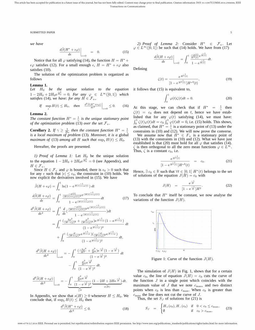
0090-6778 (c) 2016 IEEE. Personal use is permitted, but republication/redistribution requires IEEE permission. See http://www.ieee.org/publications_standards/publications/rights/index.html for more information.
This article has been accepted for publication in a future issue of this journal, but has not been fully edited. Content may change prior to final publication. Citation information: DOI 10.1109/TCOMM.2016.2584068, IEEETransactions on Communications
SUBMITTED PAPER 5
we have
dβ(H∗ + ǫϕ)
dǫ
∣∣∣∣ǫ=0
= 0. (15)
Notice that for allϕ satisfying (14), the functionH = H∗+ǫϕ satisfies (12). For a small enoughǫ, H = H∗ + ǫϕ alsosatisfies (10).
The solution of the optimization problem is organized asfollows
Lemma 1.Let H0 be the unique solution to the equation1 − 2H0 + 2H0e
−1H0 = 0. For any ϕ ∈ L∞([0, 1]) which
satisfies(14), we have: for anyH ∈ F+,
If suptH(t) ≤ H0, then d2β(H∗+ǫϕ)
dǫ2
∣∣∣ǫ=0
≤ 0. (16)
Lemma 2.The constant functionH∗ = 1
γ is the unique stationary pointof the optimization problem(13) over the setF+.
Corollary 2. If γ ≥ 1H0
then the constant functionH∗ = 1γ
is a local maximum of problem(13). Moreover, it is aglobalmaximum of(13) among allH such thatsuptH(t) ≤ H0.
Hereafter, the proofs are presented.
1) Proof of Lemma 1:Let H0 be the unique solutionto the equation1 − 2H0 + 2H0e
−1H0 = 0 (see Appendix), and
H ∈ F+.SinceH ∈ F+ andϕ is bounded, there isǫ0 > 0 such that
for any ǫ such that|ǫ| ≤ ǫ0, the constraint in (10) holds. Wenow explicit the derivatives involved in (15). We have
β(H + ǫϕ) =
∫ 1
0
ln(1 − e−1
H(t)+ǫϕ(t) ) dt
dβ(H + ǫϕ)
dǫ=
∫ 1
0
−ϕ(t)
(H(t)+ǫϕ(t))2e
−1(H(t)+ǫϕ(t))
1 − e−1
(H(t)+ǫϕ(t))
dt (17)
d2β(H + ǫϕ)
dǫ2=
∫ 1
0
d
dǫ(
−ϕ(t)
(H(t)+ǫϕ(t))2e
−1(H(t)+ǫϕ(t))
1 − e−1
(H(t)+ǫϕ(t))
)dt
=
∫ 1
0
( 2ϕ2
(H−ǫϕ)3+ ϕ2
(H+ǫϕ)4)e
−1H+ǫϕ (1 − e
−1H+ǫϕ )
(1 − e−1
H+ǫϕ )2dt
+
∫ 1
0
( ϕ(H+ǫϕ)2
e−1
H+ǫϕ )( −ϕ(H+ǫϕ)2
e−1
H+ǫϕ )
(1 − e−1
H+ǫϕ )2dt,
d2β(H + ǫϕ)
dǫ2
∣∣∣∣ǫ=0
= −∫ 1
0
(−2ϕ2
H3 + ϕ2
H4 )e−1H (1 − e
−1H )
(1 − e−1H )2
dt
−∫ 1
0
ϕ2
H4 e−2H
(1 − e−1H )2
dt.
d2β(H + ǫϕ)
dǫ2
∣∣∣∣ǫ=0
= −∫ 1
0
ϕ2
H4 e−1H
(1 − e−1H )2︸ ︷︷ ︸
≥0
(1 − 2H + 2He−1H )︸ ︷︷ ︸
s(H)
dt.
In Appendix, we show thats(H) ≥ 0 wheneverH ≤ H0. Weconclude that, ifsuptH(t) ≤ H0 then
d2β(H∗ + ǫϕ)
dǫ2≤ 0. (18)
2) Proof of Lemma 2: Consider H∗ ∈ F+. Letϕ ∈ L∞([0, 1]) be such that (14) holds. We have from (17)
dβ(H + ǫϕ)
dǫ
∣∣∣∣ǫ=0
=
∫ 1
0
−ϕ(t)
H2(t)e
−1H(t)
1 − e−1
H(t)
dt.
Defining
ζ(t) =e
−1H∗(t)
[1 − e−1
H∗(t) ]H∗2(t), (19)
it follows that (15) is equivalent to,∫ 1
0
ϕ(t)ζ(t)dt = 0. (20)
At this stage, we can check that ifH∗ = 1γ then
ζ(t) = c0 does not depend ont, hence we have estab-lished that for anyϕ(t) satisfying (14), we must have:∫ 1
0ζ(t)ϕ(t)dt = c0
∫ 1
0ϕ(t)dt = 0, i.e. (15) holds. This shows,
as claimed, thatH∗ = 1γ is a stationary point of (13) under the
constraints in (10) and (12). We will now prove the converse.We assume now thatH∗ ∈ F+ is a stationary point of
(13) with the constraints in (10) and (12). What we have justestablished is that (20) must hold for allϕ that satisfies (14).ζ is then orthogonal to all the zero mean functionsϕ ∈ L∞.Thus,ζ is a constantc0, i.e.
e−1
H∗(t)
[1 − e−1
H∗(t) ]H∗2(t)= c0. (21)
Hence,∃ c0 ∈ R such that∀t ∈ [0, 1] H∗(t) belongs to the setof solutions of the equationJ(H) = c0 with
J(H) =e
−1H
[1 − e−1H ]H2
. (22)
To conclude thatH∗ itself be constant, we now analyse thevariations of the functionJ(H).
H
J(H
)
cmax
c0
H−(c
0) H
+(c
0)
Figure 1: Curve of the functionJ(H).
The simulation ofJ(H) in Fig. 1, shows that for a certainvalue c0, the line of equationJ(H) = c0 cuts the curve ofthe function J in a single point which coincides with themaximum value ofJ that we notecmax, and two distinctpoints whenc0 is less thancmax. When c0 is greater thancmax the line does not cut the curve ofJ .
Thus, the setSJ of solutions for (21) is
SJ =
H+(c0), H−(c0) if 0 < c0 ≤ cmax,
∅ if c0 > cmax.(23)

0090-6778 (c) 2016 IEEE. Personal use is permitted, but republication/redistribution requires IEEE permission. See http://www.ieee.org/publications_standards/publications/rights/index.html for more information.
This article has been accepted for publication in a future issue of this journal, but has not been fully edited. Content may change prior to final publication. Citation information: DOI 10.1109/TCOMM.2016.2584068, IEEETransactions on Communications
6 IEEE TRANSACTIONS ON COMMUNICATIONS
Table I: Solutions of (21) for different values ofc0.
c0 H−(c0) H+(c0)0.64 0.720 00.720.62 0.510 00.830.60 0.450 00.900.50 0.360 01.340.40 0.300 01.900.30 0.250 02.760.20 0.210 04.460.10 0.170 09.480.05 0.145 19.500.02 0.091 49.490.01 0.085 99.49
Note that whenc0 = cmax, we haveH+(c0) = H−(c0).H+(c0) is the greatest solution, andH−(c0) is the smallestone (H−(c0) ≤ H+(c0)).
The following property summarizes what we have estab-lished so far
Property 2. Let H∗ ∈ F+ be a stationary point ofβ,under the constraints in(10) and (12). There exists a constantc0 ∈ [0, cmax], a setA+ and a setA− = [0, 1] \ A+ such that
H|A+= H+(c0), and H|A− = H−(c0). (24)
H|A+(H|A− respectively) is the restriction of the function
H over the setA+ ⊂ [0, 1] (A− ⊂ [0, 1] respectively).
Corollary 3. The Lebesgue measure of the intervalA+ canbe expressed as
LA+(c0) =
1γ
−H−(c0)
H+(c0) −H−(c0)∈ [0, 1]. (25)
In fact, from (12) and Property 1, we have
LA+(c0)H+(c0) + (1 − LA+)H−(c0) =1
γ, (26)
LA+(c0)(H+(c0) −H−(c0)) =1
γ−H−(c0). (27)
Property 3. Let H∗ ∈ F+ be a stationary point ofβ, underthe constraints in(10) and (12). Then, the value ofc0 solvesthe following optimization problem
maximizec0
β(c0) = LA+(c0) ln(1 − e− 1
H+(c0) )
+(1 − LA+(c0)) ln(1 − e− 1
H−(c0) ),
subject to LA+(c0) ∈ [0, 1].
Numerical Results:Table I shows for each value ofc0 theset of solutionsSJ of (21). As we can see,H−(c0) is anincreasing function ofc0 andH+(c0) is a decreasing functionof c0, we can resume these conclusions in Table II.
Now, we should study the variations ofβ(c0), whichdepend on the monotonicity ofLA+ . We have 1
γ ≥ H−since LA+ is positive, so we cannot decide directly onthe monotonicity of LA+ , because it is the product of apositive decreasing functionc0 7→ 1
γ −H−(c0) and a positiveincreasing function c0 7→ 1
H+(c0)−H−(c0). Therefore, we
simulate the variations ofLA+ and β(c0) as depicted inFig. 2 and Fig. 3.To maximizeβ we should minimizeLA+ under the constraint
Table II: Variations ofH+, H− and 1H+−H−
as a function ofc0.
c0
H+
H−
1H+−H−
0 cmax
+∞+∞HmaxHmax
00
HmaxHmax
00
+∞+∞
of 0 ≤ LA+ ≤ 1. For LA+ = 0, we haveH− = 1γ and
β∗ = ln(1 − e−γ). Thus,H∗ takes a single valueH− andH∗ = 1
γ . To conclude, forH∗ ∈ F+ a stationary point ofβunder the constraint in (12), we haveH∗ = 1
γ . This concludesthe proof of Lemma 2.
3) Proof of Corollary 2: The setF+ ∩ H : suptH(t) ≤H0 is convex. We deduce from Lemma 1 thatβ is a concavefunction on this convex set. Therefore, its local maximumis a global maximum over this set [32]. From Lemma 2,H∗ = 1
γ is the unique stationary point ofβ overF+, hence it
is the global maximum ofβ overF+∩H : suptH(t) ≤ H0.
4) Proof of the main result: Property 1:Property 1 followsfrom Corollary 2 using two simple observations that wehighlight:
• The Property (4) is equivalent to the conditionH(t) = H∗(t) = P
γT ;• The propertyγ ≥ γcrit(gm) is equivalent to the condi-
tion suptH(t) ≤ H0.
IV. A NALYSIS BY SIMULATIONS
In order to illustrate our theoretical results, we considerthree different multicarrier modulation systems, which arebased on different families of modulation functions, and weanalysed the CCDF of their PAPR. A comparison in termsof PAPR performance, between each considered multicarriersystem and the conventional OFDM is presented.
A. Walsh-Hadamard-MC (WH-MC)Instead of using the IFFT for the modulation, we can use
the inverse Walsh-Hadamard transform (IWHT). The familyof the modulation functions is expressed as:
gm[k] = Wq[k],
whereWq represent the Walsh functions (see Fig. 4) and arecolumns of Hadamard matrix of dimensionM = 2Q, whichis defined by the following recursive formula:
Hw(21) =
(1 11 −1
), (28)
and for2 ≤ q ≤ Q:
Hw(2q) =
(Hw(2q−1) Hw(2q−1)Hw(2q−1) −Hw(2q−1)
)= Hw(2) ⊗Hw(2q−1),
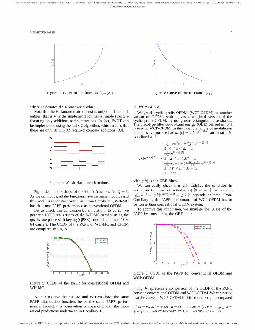
0090-6778 (c) 2016 IEEE. Personal use is permitted, but republication/redistribution requires IEEE permission. See http://www.ieee.org/publications_standards/publications/rights/index.html for more information.
This article has been accepted for publication in a future issue of this journal, but has not been fully edited. Content may change prior to final publication. Citation information: DOI 10.1109/TCOMM.2016.2584068, IEEETransactions on Communications
SUBMITTED PAPER 7
LA
+(c
0)
c0
Figure 2: Curve of the functionLA+(c0).
c0
β(c
0)
Figure 3: Curve of the functionβ(c0).
where⊗ denotes the Kronecker product.Note that the Hadamard matrix consists only of+1 and−1
entries, that is why the implementation has a simple structurefeaturing only additions and subtractions. In fact, IWHT canbe implemented using the radix-2 algorithm, which means thatthere are onlyM log2M required complex additions [33].
Figure 4: Walsh-Hadamard functions.
Fig. 4 depicts the shape of the Walsh functions forQ = 3.As we can notice, all the functions have the same modulus andthis modulus is constant over time. From Corollary 1, WH-MChas the same PAPR performance as conventional OFDM.
Let us check this conclusion by simulation. To do so, wegenerate10000 realizations of the WH-MC symbol using thequadrature phase-shift keying (QPSK) constellation, andM =64 carriers. The CCDF of the PAPR of WH-MC and OFDMare compared in Fig. 5.
3 4 5 6 7 8 9 10 11 1210
−2
10−1
100
γ in dB
CC
DF
(γ)
= P
rob[
PA
PR
≥γ])
OFDMWH−MC
Figure 5: CCDF of the PAPR for conventional OFDM andWH-MC.
We can observe that OFDM and WH-MC have the samePAPR distribution function, hence the same PAPR perfor-mance. Indeed, this observation is consistent with the theo-retical predictions undertaken in Corollary 1 .
B. WCP-OFDM
Weighted cyclic prefix-OFDM (WCP-OFDM) is anothervariant of OFDM, which gives a weighted version of thecyclic prefix-OFDM, by using non-rectangular pulse shapes.The prototype filter out-of-band energy (OBE) defined in [34]is used in WCP-OFDM. In this case, the family of modulationfunctions is expressed asgm[k] = g[k]ej2π m
M k such thatg[k]is defined as5
g[k]ej2π mM
k =
1√M′ cos(a+ b 2k+1
2∆)ej2π m
M[k]
if 0 ≤ k ≤ ∆ − 1,1√M′ e
j2π mM
[k]
if ∆ ≤ k ≤ M ′ − 1,1√M′ cos(a+ b 2(M−k)+1
2∆)ej2π m
M[k]
if M ′ ≤ k ≤ M − 1,
0, else.
with g[k] is the OBE filter.We can easily check thatg[k] satisfies the condition in
(2). In addition, we notice that∀m ∈ [[0,M − 1]] the modulus|gm[k]|2 = |g[k]ej2π m
M k|2 = |g[k]|2 depends on time. FromCorollary 1, the PAPR performance of WCP-OFDM has tobe worse than conventional OFDM system.
To approve this conclusion, we simulate the CCDF of thePAPR by considering the OBE filter.
3 4 5 6 7 8 9 10 11 1210
−2
10−1
100
γ in db
CC
DF
(γ)
= P
rob[
PA
PR
≥γ])
OFDMWCP−OFDM
Figure 6: CCDF of the PAPR for conventional OFDM andWCP-OFDM.
Fig. 6 represents a comparison of the CCDF of the PAPRbetween conventional OFDM and WCP-OFDM. We can noticethat the curve of WCP-OFDM is shifted to the right, compared
5M = 80, M ′ = 4/5M , ∆ = M ′ − M , M0 = M∆
, b = 1α+βM0
, a =π4− 1
2b, α = −0.1714430594740783, β = −0.5852184808129936.

0090-6778 (c) 2016 IEEE. Personal use is permitted, but republication/redistribution requires IEEE permission. See http://www.ieee.org/publications_standards/publications/rights/index.html for more information.
This article has been accepted for publication in a future issue of this journal, but has not been fully edited. Content may change prior to final publication. Citation information: DOI 10.1109/TCOMM.2016.2584068, IEEETransactions on Communications
8 IEEE TRANSACTIONS ON COMMUNICATIONS
to OFDM. Thus, OFDM has a better PAPR performance thanWCP-OFDM, which matches our theoretical results.
C. Wavelet-OFDMWavelet-OFDM, or also known as orthogonal wavelet di-
vision multiplexing (OWDM) [35], is a multicarrier systembased on the wavelet transform. The principle of the wavelettransform is to decompose the signal in terms of small wavescomponents called wavelets. The Wavelet-OFDM transmittedsignal can be defined as:
X(t) =∑
n
J−1∑
j=J0
2j−1∑
k=0
wj,kψj,k(t− nT )
+∑
n
2J0−1∑
q=0
aJ0,qφJ0,q(t− nT ).
• J − 1: last scale considered, withM = 2J ;• J0: first scale considered (J0 ≤ j ≤ J − 1);• wj,k: wavelet coefficients located atk-th position from
scalej;• aJ0,q: approximation coefficients located atq-th position
from the first scaleJ0;• ψj,k = 2
j/2ψ(2jt− kT ): the wavelet orthonormal family,ψ is the mother wavelet function;
• φJ0,q = 2J02 φ(2J0t−qT ): the scaling orthonormal family
at the scaleJ0, φ is the mother scaling function.Note that the wavelet functions and the scaling functions haveidentical energy. For more details about the wavelet theory,the reader can refer to [36].
Several wavelets can be used to modulate the input symbols,such as Daubechies, Coiflets, and Symlets. We are inter-ested here to the Haar wavelet, which belongs to the familyof Daubechies wavelets. The Haar mother wavelet functionψhaar(t) is expressed as:
with ψhaar(t) =
1√T
if 0 ≤ t ≤ T2,
− 1√T, if T
2≤ t ≤ T,
0, else.
(29)
The scaling functionφhaar(t) can be described as:
and φhaar(t) =
1√T
if 0 ≤ t ≤ T,
0, else.(30)
Fig. 7 describes Haar wavelet functionsψhaarj,k for J0 = 0
Figure 7: Haar wavelet function for different scales.
and M = 8. As we can notice, the temporal support ofthe contracted versions of the mother wavelet functionψhaar
are smaller than the symbol periodT , therefore this family
of functions does not satisfy the constraint in (2). FromProperty III-A, we can reach a better PAPR performance thanusing the Fourier transform. To check this claim by simulation,we consider the Haar wavelet transform, and we extract thedetail and approximation coefficients at the maximal level 6(J0 = 0) for a number of carriersM = 64.
3 4 5 6 7 8 9 10 11 1210
−2
10−1
100
γ in dB
CC
DF
(γ)
= P
rob[
PA
PR
≥γ])
OFDMHaar Wavelet OFDM
Figure 8: CCDF of the PAPR for conventional OFDM andHaar Wavelet based OFDM.
We can observe in Fig. 8 that the curve of the Haar Wavele-OFDM is shifted to the left, compared to OFDM. Thus, theHaar Wavelet-OFDM has a better PAPR performance thanconventional OFDM.
Note here that, by changing the modulation waveform, thePAPR is reduced. As explained previously, without using theclassical PAPR reduction methods, the PAPR can be reducedby selecting the appropriate waveform.
Complexity of implementation of Wavelet-OFDM: ac-cording to the Mallat Algorithm in [36], the wavelet modula-tion can be implemented based on the inverse discrete wavelettransform (IDWT). The IDWT consists of up-sampling by afactor of two and filtering the approximation coefficientsaj,k(scaling coefficients) and the detail coefficientswj,k (waveletcoefficients) respectively by a low-pass filterg and a high-passfilter h associated to the wavelet used. LetL be the length ofthe filtersh and g (L = 2 in the case of the Haar wavelet).Let M = 2J be the number of carriers which is equal to thenumber of the input coefficients. The wavelet modulation iscalculated with a number of operations bounded by
J∑
j=J0+1
2jL ≤J∑
j=1
2jL (31)
= 2ML. (32)
The complexity order in terms of the number of additionsand multiplications is thereforeO(ML). Knowing that thecomplexity order of the FFT or the IFFT isO(Mlog2(M)),the complexity increase order is aboutO( L
log2(M) ), which isaffordable sinceL is bounded, and the number of carriersMis usually large.
Other examples of multicarrier systems from the literaturecan also be discussed:
• The PAPR of NOFDM is evaluated by simulation forHanning and Kaiser windows in [12]. The PAPR perfor-mance of NOFDM is shown experimentally to be worsethan OFDM. Corollary 1 gives a theoretical explanationto these simulation results.

0090-6778 (c) 2016 IEEE. Personal use is permitted, but republication/redistribution requires IEEE permission. See http://www.ieee.org/publications_standards/publications/rights/index.html for more information.
This article has been accepted for publication in a future issue of this journal, but has not been fully edited. Content may change prior to final publication. Citation information: DOI 10.1109/TCOMM.2016.2584068, IEEETransactions on Communications
SUBMITTED PAPER 9
• According to the necessary condition theorem, we un-derstand now why FBMC systems based on IOTA orSRRC filters for example as well as the universal-filteredmulticarrier (UFMC) systems [37] do not have betterPAPR than OFDM, since they do not satisfy the necessarycondition stated in the theorem.
Fig. 9 summarizes the conclusions of this study. The rect-angle represents the set of all GWMC waveforms∈ L∞
I .The optimization problem analysed in this work is for thewaveforms belonging to the setA, which means satisfying(2). Systems inA ∩B (including OFDM, WH-MC) have thebest possible PAPR performanceamong all systems inA. Anysystem with better PAPR performance than OFDM must be inC. There are indeed systems (Daubechies6, Symlet3, Coiflet2) in C with better PAPR performance than OFDM. Some areeven inB (Haar wavelets), but not inA.
Figure 9: Taxonomy of multicarrier waveforms regarding thePAPR performance.
V. CONCLUSION
In this paper, we have investigated the GWMC systembased on the family of modulation functions (the modulationtransform and the pulse shaping filter) which does not vanishin the symbol period, and we have proved analytically thatthe PAPR, which depends on the modulation waveform, isoptimal only if the sum of these waveforms over the number ofcarriers and the number of symbols is constant over time. Wehave concluded that there exists an infinite number of GWMCsystems that are optimal in terms of PAPR performance,and conventional OFDM based on the Fourier transform andthe rectangular filter belongs to this family. In addition, wehave deduced that the PAPR performance of GWMC systemscannot be better than OFDM system without reducing thetemporal support of the modulation functions compared to thesymbol period. It is worth mentioning that, by limiting thesupport of the individual carriers, we are moving more andmore from a multicarrier system to a single carrier system.
We have provided some examples to illustrate our theoreti-cal results: WH-MC has a PAPR performance equal to thatof OFDM, which is optimal among systems which satisfycondition (2), the WCP-OFDM’s waveform is not constantover time and thus it is worse than conventional OFDM interms of PAPR performance. By not satisfying constraint (2),it is possible to achieve a better PAPR performance, as hasbeen shown for the Haar wavelets. Moreover, our work alsoprovides a theoretical explanation about why several advanced
Table III: Study of the positivity of the functions.
H
s′′(H)
s′(H)
s(H)
0 +∞
+
−2
0
1
−1
H0
0
multicarrier systems such as NOFDM, FBMC, UFMC, do notachieve a better PAPR than OFDM.
Our future work will focus on designing a new waveformwith low PAPR than OFDM, by acting on the number ofintervals that vanish over time, and taking into considerationother constraints such as the bit error rate, the complexityand the spectral efficiency. If we would like to design a newwaveform as a candidate for the next generation of mobilecommunication systems, it should not be selected from theexcluded regionA, because in this case, it will not improvethe PAPR performance. Waveforms with reduced PAPR canbe found in particular in the regionB (as depicted in Fig. 9).
APPENDIX
We study the variations of the functions(H) = 1 − 2H + 2He
−1H , we have
s′(H) = −2 + 2e−1H +
2
He
−1H , (33)
s′′(H) =2
H2e
−1H + 2(− 1
H2e
−1H +
1
H
1
H2e
−1H ),
=2
H3e
−1H ≥ 0. (34)
As we can see in Table III, the functions is positive when0 < H ≤ H0. A numerical approximation givesH0 ≈ 0.63.
REFERENCES
[1] H. Ochiai and H. Imai, “On the Distribution of the Peak-to-Average
Power Ratio in OFDM Signals,”Communications, IEEE Transactions
on, vol. 49, no. 2, pp. 282–289, 2001.
[2] T. Jiang, M. Guizani, H.-H. Chen, W. Xiang, and Y. Wu, “Derivation
of PAPR Distribution for OFDM Wireless Systems Based on Extreme
Value Theory,”Wireless Communications, IEEE Transactions on, vol. 7,
no. 4, pp. 1298–1305, 2008.
[3] G. Auer, O. Blume, V. Giannini, I. Godor, M. Imran, Y. Jading, E. Ka-
tranaras, M. Olsson, D. Sabella, P. Skillermarket al., “D2. 3: Energy
Efficiency Analysis of the Reference Systems, Areas of Improvements
and Target Breakdown,”EARTH, 2010.

0090-6778 (c) 2016 IEEE. Personal use is permitted, but republication/redistribution requires IEEE permission. See http://www.ieee.org/publications_standards/publications/rights/index.html for more information.
This article has been accepted for publication in a future issue of this journal, but has not been fully edited. Content may change prior to final publication. Citation information: DOI 10.1109/TCOMM.2016.2584068, IEEETransactions on Communications
10 IEEE TRANSACTIONS ON COMMUNICATIONS
[4] R. V. Nee and R. Prasad,OFDM for Wireless Multimedia Communica-
tions. Inc.: Artech House, 2000.
[5] A. Skrzypczak, P. Siohan, and J.-P. Javaudin, “Analysis of the Peak-
to-Average Power Ratio for OFDM/OQAM,” inSignal Processing
Advances in Wireless Communications, 2006. SPAWC’06. IEEE 7th
Workshop on. IEEE, 2006, pp. 1–5.
[6] M. Chafii, J. Palicot, and R. Gribonval, “Closed-form Approximations
of the Peak-to-Average Power Ratio Distribution for Multi-Carrier
Modulation and their Applications,”EURASIP Journal on Advances in
Signal Processing, vol. 2014, no. 1, pp. 1–13, 2014.
[7] T. Jiang and G. Zhu, “Complement block coding for reduction in peak-
to-average power ratio of ofdm signals,”Communications Magazine,
IEEE, vol. 43, no. 9, pp. S17–S22, 2005.
[8] M. Deumal, A. Behravan, and J. L. Pijoan, “On Cubic Metric Reduc-
tion in OFDM Systems by Tone Reservation,”Communications, IEEE
Transactions on, vol. 59, no. 6, pp. 1612–1620, 2011.
[9] C. Li, T. Jiang, Y. Zhou, and H. Li, “A Novel Constellation Reshaping
Method for PAPR Reduction of OFDM Signals,”Signal Processing,
IEEE Transactions on, vol. 59, no. 6, pp. 2710–2719, 2011.
[10] T. Jiang and C. Li, “Simple Alternative Multisequences for PAPR
Reduction without Side Information in SFBC MIMO-OFDM Systems,”
Vehicular Technology, IEEE Transactions on, vol. 61, no. 7, pp. 3311–
3315, 2012.
[11] S. Y. Le Goff, B. K. Khoo, C. C. Tsimenidis, and B. S. Sharif, “A Novel
Selected Mapping Technique for PAPR Reduction in OFDM Systems,”
Communications, IEEE Transactions on, vol. 56, no. 11, pp. 1775–1779,
2008.
[12] H. Bogucka, A. M. Wyglinski, S. Pagadarai, and A. Kliks, “Spectrally
Agile Multicarrier Waveforms for Opportunistic Wireless Access,”Com-
munications Magazine, IEEE, vol. 49, no. 6, pp. 108–115, 2011.
[13] A. Sahin, I. Guvenc, and H. Arslan, “A Survey on Multicarrier Com-
munications: Prototype Filters, Lattice Structures, and Implementation
Aspects,”Communications Surveys & Tutorials, IEEE, vol. 16, no. 3,
pp. 1312–1338, 2012.
[14] W. Kozek and A. F. Molisch, “Nonorthogonal Pulseshapes for Multicar-
rier Communications in Doubly Dispersive Channels,”Selected Areas in
Communications, IEEE Journal on, vol. 16, no. 8, pp. 1579–1589, 1998.
[15] P. Siohan, C. Siclet, and N. Lacaille, “Analysis and Design of
OFDM/OQAM Systems based on Filterbank Theory,”Signal Processing,
IEEE Transactions on, vol. 50, no. 5, pp. 1170–1183, 2002.
[16] L. Vangelista and N. Laurenti, “Efficient Implementations and Alterna-
tive Architectures for OFDM-OQAM Systems,”Communications, IEEE
Transactions on, vol. 49, no. 4, pp. 664–675, 2001.
[17] T. Jiang, C. Ni, D. Qu, and C. Wang, “Energy-efficient NC-
OFDM/OQAM-based Cognitive Radio Networks,”Communications
Magazine, IEEE, vol. 52, no. 7, pp. 54–60, 2014.
[18] B. Farhang-Boroujeny, “OFDM versus Filter Bank Multicarrier,”Signal
Processing Magazine, IEEE, vol. 28, no. 3, pp. 92–112, 2011.
[19] B. Le Floch, M. Alard, and C. Berrou, “Coded Orthogonal Frequency
Division Multiplex,” Proceedings of the IEEE, vol. 83, no. 6, pp. 24–
182, 1995.
[20] G. Fettweis, M. Krondorf, and S. Bittner, “Gfdm-generalized frequency
division multiplexing,” inVehicular Technology Conference, 2009. VTC
Spring 2009. IEEE 69th. IEEE, 2009, pp. 1–4.
[21] N. Michailow, I. Gaspar, S. Krone, M. Lentmaier, and G. Fettweis,
“Generalized frequency division multiplexing: Analysis of an alternative
multi-carrier technique for next generation cellular systems,” inWireless
Communication Systems (ISWCS), 2012 International Symposium on.
IEEE, 2012, pp. 171–175.
[22] R. Kanti and M. Rai, “Comparative Analysis of Different Wavelets in
OWDM with OFDM for DVB-T,” International Journal of Advance-
ments in Research & Technology, vol. 2, no. 3, 2013.
[23] K. M. Wong, J. Wu, T. N. Davidson, Q. Jin, and P.-C. Ching, “Per-
formance of Wavelet Packet-Division Multiplexing in Impulsive and
Gaussian Noise,”Communications, IEEE Transactions on, vol. 48, no. 7,
pp. 1083–1086, 2000.
[24] A. Aboltins, “Comparison of Orthogonal Transforms for OFDM Com-
munication System,”Electronics and Electrical Engineering Journal,
vol. 111, no. 5, pp. 77–80, 2011.
[25] M. Bernhard and J. Speidel, “Multicarrier Transmission using Hadamard
Transform for Optical Communications,”ITG-Fachbericht-Photonische
Netze, 2013.
[26] P. Tan and N. C. Beaulieu, “A Comparison of DCT-based OFDM
and DFT-based OFDM in Frequency Offset and Fading Channels,”
Communications, IEEE Transactions on, vol. 54, no. 11, pp. 2113–2125,
2006.
[27] G. D. Mandyam, “On the Discrete Cosine Transform and OFDM
Systems,” in Acoustics, Speech, and Signal Processing, 2003. Pro-
ceedings.(ICASSP’03). 2003 IEEE International Conference on, vol. 4.
IEEE, 2003, pp. IV–544.
[28] A. Deshmukh and S. Bodhe, “Performance of DCT Based OFDM Com-
munication System Working in 60 GHz Band,”International Journal of
Engineering Science & Technology, vol. 4, no. 1, 2012.
[29] N. De Bruijn, “Uncertainty Principles in Fourier Analysis,”Inequalities,
vol. 2, pp. 57–71, 1967.
[30] A. Skrzypczak, P. Siohan, and J.-P. Javaudin, “Peak-to-Average Power
Ratio Issues for Pulse-Shaped Multicarrier Modulations,” inAdvances on
Processing for Multiple Carrier Schemes: OFDM & OFDMA, F. Bader
and N. Zorba, Eds. Nova Science Publishers, Inc., 2011, pp. 43–90.
[31] A. Kliks, “New Transmission and Reception Techniques of the Gen-
eralized Multicarrier Signals,” Ph.D. dissertation, Poznan University of
Technology, 2011.
[32] S. Boyd and L. Vandenberghe,Convex Optimization. Cambridge
University Press, 2004.
[33] B. Evanset al., “Hardware Structure for Walsh-Hadamard Transforms,”
Electronics Letters, vol. 34, no. 21, pp. 2005–2006, 1998.
[34] D. Roque, “Modulations Multiporteuses WCP-OFDM: évaluation des
performances en environnement radiomobile,” Ph.D. dissertation, Greno-
ble University, 2012.
[35] S. L. Linfoot, M. K. Ibrahim, and M. M. Al-Akaidi, “Orthogonal
Wavelet Division Multiplex: An Alternative to OFDM,”Consumer
Electronics, IEEE Transactions on, vol. 53, no. 2, pp. 278–284, 2007.
[36] S. Mallat,A Wavelet Tour of Signal Processing. Academic press, 1999.
[37] F. Schaich and T. Wild, “Waveform Contenders for 5G-OFDM vs.
FBMC vs. UFMC,” in Communications, Control and Signal Processing
(ISCCSP), 2014 6th International Symposium on. IEEE, 2014, pp.
457–460.

0090-6778 (c) 2016 IEEE. Personal use is permitted, but republication/redistribution requires IEEE permission. See http://www.ieee.org/publications_standards/publications/rights/index.html for more information.
This article has been accepted for publication in a future issue of this journal, but has not been fully edited. Content may change prior to final publication. Citation information: DOI 10.1109/TCOMM.2016.2584068, IEEETransactions on Communications
SUBMITTED PAPER 11
Marwa Chafii (M’13) is currently doing her PhDat the Communication and Electronic EmbeddedSystems (SCEE) research team of CentraleSupélec,Campus of Rennes-France. Her research interestsinclude advanced waveforms for multi-carrier sys-tems and the peak-to-average power ratio (PAPR)reduction problem. She received in 2013, her re-search master’s degree in the field of advancedwireless communication systems (SAR) from Cen-traleSupélec at Paris-France, and her engineeringdiploma in telecommunications from Institut Na-
tional des Postes et Télécommunications (INPT) in Morocco. Between 2014and 2015, she has been visiting, for short scientific research missions, PoznanUniversity of Technology (Poland), University of York (UK), and YokohamaNational University (Japan).
Jacques Palicotreceived, in 1983, his PhD degreein Signal Processing from the University of Rennes.Since 1988, he has been involved in studies aboutequalization techniques applied to digital transmis-sions and analog TV systems. Since 1991 he hasbeen involved mainly in studies concerning the dig-ital communications area and automatic measure-ments techniques. He has taken an active part invarious international bodies EBU, CCIR, URSI, andwithin RACE, ACTS and IST European projects.He has published various scientific articles notably
on equalization techniques, echo cancellation, hierarchical modulations andSoftware Radio techniques. He is author or co-author of more than 300publications with more than 50 in journals, two books and 22 patents. Heis currently involved in adaptive Signal Processing, digital communications,Software Radio, Cognitive radio and Green Radio. From November 2001 toSeptember 2003 he had a temporary position with INRIA/IRISA in Rennes.He serves as Associate Editor for EURASIP JASP since 2008. He also servedas lead guest editor for several Special Issues on Software Radio, CognitiveRadio and Green Radio. He was Co General Chairman of ISCIT 2011,Co General Chairman of Next-GWiN 2014, Technical Program Chairmanof CROWNCOM 2009, Technical Program Chairman of GREENCOM 2013and Technical Program Chairman of CRN Symposium of ICC 2014. SinceOctober 2003 he is with CentraleSupélec in Rennes where he leads theSignal Communications and Embedded Electronics (SCEE) research team.
Rémi Gribonval (M’02,SM’08,FM’14) is a SeniorResearcher with Inria (Rennes, France), and thescientific leader of the PANAMA research group onsparse audio processing. A former student at ÉcoleNormale Supérieure (Paris, France), he received thePh. D. degree in applied mathematics from Univer-sité de Paris-IX Dauphine (Paris, France) in 1999,and his Habilitation à Diriger des Recherches inapplied mathematics from Université de Rennes I(Rennes, France) in 2007. His research focuses onmathematical signal processing, machine learning,
approximation theory and statistics, with an emphasis on sparse approxima-tion, audio source separation and compressed sensing. He founded the seriesof international workshops SPARS on Signal Processing with Adaptive/SparseRepresentations. In 2011, he was awarded the Blaise Pascal Award in AppliedMathematics and Scientific Engineering from the SMAI by the FrenchNational Academy of Sciences, and a starting investigator grant from theEuropean Research Council.
Faouzi Bader (SM’07) received his PhD degree(with Honours) in Telecommunications in 2002 fromUniversidad Politécnica de Madrid (UPM), Madrid-Spain. He joined the Centre Technologic de Tele-comunicacions de Catalunya (CTTC) in Barcelona-Spain as Associate researcher in 2002, and nomi-nated in 2006 Senior Research Associate at sameinstitution. Since June 2013, he is as AssociateProfessor at CentraleSupélec in Rennes- France. Hisresearch activities mainly focus on advanced multi-carrier waveforms (OFDM(A), (non-) uniform mul-
timode filter based multicarrier schemes) and frequency allocation techniquesin relay cognitive environment. He has been involved in several Europeanprojects from the 5th-7th EC research frameworks, and from 2012-2013 hewas nominated general coordinator and manager of the EC funded researchproject ICT "EMPhAtiC" focusing on "Enhanced Multicarrier Techniques forProfessional Ad-Hoc and Cell-Based Communications". He has publishedover 120 papers in peer-reviewed journals and international conferences, morethan 13 book chapters, and published 3 books. He served as Technical ProgramCommittee member in major IEEE ComSoc and VTS conferences, and as thegeneral chair of the eleventh edition of the ISWCS’2014 conference, and theco-chair of the ISWCS 2015 edition. He is IEEE Senior Member from 2007.


Chapter 4
Future perspectivesFrom my point of view, the future perspectives should pass through two aspects, one purely academic, and a secondfocusing on the advance and the development of many of the research lines mentioned in Chapter 3. These twoaspects are of course directly correlated and they are mutually influenced.From my short research career between 2002 to nowadays (2016) the interest of the scientific community to futuremulti-carrier systems has tremendously increased. This can be just observed over the increased number of thescientific publications, research labs, and the European funded projects1 where tremendous advances have beenachieved in this field (e.g., FMT, FBMC, GFDM, UFMC, and F-OFDM, among many others variants) from 2007the year of the starting funding of the EU PHYDYAS project. The actual 5G and IoT context has even boosted theinvolvement and the R&D dedication of the telecommunication operators and worldwide manufacturers like Alcatel-Lucent, Huawei, Ericsson, and many others, into the design of future flexible radio access technologies (RATs) usingadvanced multi-carrier schemes. Saying this, style big efforts have to be made to transfer to academia, and therefore,to undergraduate and postgraduate students the critical knowledge and background to be able to better understandthese new communication schemes and to participate in a more active manner to their development. It’s nowadayseasy to found a plethora of detailed information in lectures and tutorials, free access software and platforms, basedon the OFDM communication scheme and its basic standards. However, information or open testing platforms foracademic purposes or research are very limited to not saying rares for the above mentioned multi-carrier schemes.Several factors are behind this lack of information, among them the natural cycle that has to undertake any in-dustrial product from its successful development to its wide adoption by the mass consumers, for thus being afterwidely learned in the universities at undergraduate or postgraduate levels. Same experience has been observed inthe past for the GSM, UMTS, WiFi, DVB-T and many other "standardized" communication systems. Anotheraspect no less important is related with the development of more didactic and simplistic ways of teaching many ofthe signal processing, filtering concepts required for the generation of these multi-carrier schemes not necessarilyeasy to assimilate by the students as those used for OFDM scheme.The book of M. Bellanger in [104], and more recent ones as that of F. L. Luo and C. J. Zhang in [105], that of A.Osseiran et al., in [106], or that under edition in [B4], although their way of writing is more oriented to postgrad-uate and senior researchers or experts than undergraduate students, are a big support that foster and encouragethe dissemination of advanced results and uses of the above flexible waveforms in different future communicationenvironments. To what I’m concerned with this aspect my future efforts will be on the elaboration of undergraduateand/or Master courses focusing on two parts; one on the theoretical design, implementation, and concept of thepreviously mentioned waveforms and their possible applications, and the second part on more practical aspects asthe development of software/hardware platform that serves for both teaching and the development of more advancedresearch aspects. To this last, some steps have been already undertaken under the French ANR PROFIL project.
Regarding the second aspect that concerns the main future research aspects from the actually listed in Chapter 3,I would name the following:
• Obtained results from cited researches in Subsections 3.2.1 and 3.2.2 have demonstrated the importance ofthe choice of the multi-carrier waveforms on the overall coexistence capabilities of different systems usingdifferent physical layers and communicating side by side in the same band. It has been also demonstratedthat the PSD based approach consists in modeling the interference at the input antenna of the interfered
1from the FP7 European Union’s Research and Innovation funding programme for 2007-2013, and the current Horizon 2020 pro-gramme.
207

receiver, and totally omits the demodulation operations that are performed by the latter. Thus, this modeldoes not take into account the time window size of the incumbent system. Therefore, the interference seenat the output of the demodulator of the interfered receiver is much higher than expected using the PSDbased model. Moreover, the interference between the incumbent and secondary systems is symmetrical, whichcontradicts the results obtained with the PSD-based model. Our analysis in [C103, C105] showed that thecross-interference is mainly caused by the rectangular window of the incumbent system. In other words,presented results show that coexistence with legacy CP-OFDM systems cannot be drastically improved bydesigning enhanced waveforms only, but that it is necessary to modify the CP-OFDM receiver itself. Thisresults is a key result that may change the perception of the scientific community on the way of measuring thecross-interference between systems with different waveforms in heterogeneous communication environments.More deep signal processing researches have to be undertaken at the LTE and future LTE-Advanced receiversto enhance the coexistence capability, and therefore the interference with future deployed systems using adifferent waveform and coexisting in the same band.
• Besides researches on coexistence in D2D scenario, in the collaborations within the PHC ULYSSES project[C106], we considered a scenario whereby asynchronous D2D communication underlays an OFDMA macro-cellin the uplink. Motivated by the superior performance of new waveforms with increased spectral localizationin the presence of frequency and time misalignment, we compared the system-level performance of a set-upfor when D2D pairs use either OFDM or FBMC/OQAM. We first demonstrated that inter-D2D interference,resulting from misaligned communications, plays a significant role in clustered D2D topologies. We thendemonstrated that the resource allocation procedure can be simplified when D2D pairs use FBMC/OQAM,since the high spectral localization of FBMC/OQAM results in negligible inter-D2D interference. Specifically,we identified that FBMC/OQAM is best suited to scenarios consisting of small, densely populated D2D clusterslocated near the encompassing cell’s edge. Given recent developments in self-interference cancellation, in bandfull duplex (FD) [107, 108, 109] is attracting much interest for 5G due to promises of potentially doubledspectral efficiency. We are interested in investigating the system level implications of using FD. We canidentify two main tracks for future researches incorporating FD into our current collaborative works:
1. FD and new waveforms: is FD waveform dependent?2. FD and D2D: resource management and adaptive switching for FD capable D2D pairs. How the measured
cross-interference generated for different 5G candidates waveforms can play a role in this context?
• Always on the continuity of researches on RA/RM, coexistence (PMR, D2D), and spectrum sharing, andfollowing the actual evolution and the development of the 5G context, the IoT is also a fundamental aspectfor future researchers. In relation with "barrier in terms of fragmented spectrum and massive IoT deployment",The expected massive increase of LPWA traffic applications and its densification may raise questions on thespectrum availability license/exempt needed for the IoT service reliability. Actually, licensed spectrum maybecome overloaded with traffic of higher ARPU (average Revenue per User) and IoT traffic may be movedto less costly spectrum for the operator: unlicensed spectrum. However, QoS is not guaranteed on suchspectrum and it may be required to develop techniques to aggregate multiple unlicensed bands to mitigatepossible saturation issues on a given band. Despite this theoretical limitation, many IoT devices are servedby radio technologies that operate on unlicensed spectrum and that are designed for short-range connectivitywith limited QoS and security requirements typically applicable for a home or indoor environment. Currently,there are two alternative connectivity tracks for the many IoT applications that depend on wide-area coverage:
1. Cellular technologies: 3GPP technologies like GSM, WCDMA, LTE and future 5G. These WANs operateon licensed spectrum and historically have primarily targeted high-quality mobile voice and data services.Now, however, they are being rapidly evolved with new functionality and the new radio access technologynarrow band IoT (NB-IoT) specifically tailored to form an attractive solution for emerging low powerwide area (LPWA) applications.
2. Unlicensed LPWA: new proprietary radio technologies, provided by, for example, Sigfox and LoRa, havebeen developed and designed solely for machine-type communication (MTC) applications addressing theultra-low-end sensor segment, with very limited demands on throughput, reliability or QoS
My future researchers will focus on driving the IoT with carrier aggregation (CA) which is a key concept inLTE-Advanced enabling the operators to allocate a higher bandwidth than the LTE to supply even higher
208
bandwidth than LTE, to support such connected devices. As its name suggests, carrier aggregation combinestwo or more carriers in order to offer a greater throughput. Capacity is essential for IoT, as hundreds ofdevices are in constant communication with the LTE-A network. One of the focuses will be to investigate thepossible use of carrier aggregation for IoT, providing on one hand the possibility to combine low frequencycarriers with high frequency ones, but at the cost of more complex and power consuming Hardware (HW).Another challenge is to provide tools for flexible waveforms, and spectrum use with optimized resource. Evenwhen existing 3GPP end-to-end connectivity is not feasible, cellular technology can still provide key benefitswhen used as a bridging option, i.e. as an aggregation and routing solution. This capillary network approachallows end devices to utilize varying access solutions from either the short range or LPWA domain and accessthe cellular networks via a gateway device. Capillary networks enable the reuse of cellular functions andassets such as security, device management, billing and QoS without requiring each end device to be cellularenabled.
• The developed fast convergence method based on the sub-optimal initialization strategy value, in the sense ofthe mean square error, for OFDM/OQAM blind equalization with CNA opens new perspectives for the blindequalization in the FBMC-based modulations and its possible implementation in static or semi-static channelenvironments. The extension of the undertaken research work to the MIMO case using the OFDM/OQAMseems a natural evolution. Similar to the SISO blind equalization signal processing context, there is limitedresearches carried out for the MIMO OFDM/OQAM compared to OFDM signal . This extension would bethe basis of the pilot decontamination in OFDM/OQAM based massive MIMO networks. Multiple researchgroups in recent years have studied a variety of implementation issues related to massive MIMO systems theonly limiting factor of the network capacity in the single-cell scenario is the coherence time of the channelwhich needs to be much larger than the number of mobile users (MU) in order to facilitate accurate channelestimation and allow for data transmission. However, multi-cellular time-division duplex (TDD) networkssuffer from a pilot contamination, this problem which was first reported by Jose et al., in [110]. Thus, thechannel estimates at each BS will contain the channel information of the MUs positioned in the other cellsas well as its own users. As a result, when the BS combines the received signal in order to decode thetransmitted symbols of its MUs, it also combines the data symbols of the users of other cells which results ininter-cell interference. Recent solutions have been developed to mitigate the effect of the pilot contaminationin [111, 112] using OFDM signal. The authors in [113] have proposed the blind equalization capability usingcosine modulated multitone (CMT), and its extension to massive MIMO. The work in [C91] achieved blindequalization with fast convergence than that in [113] using OFDM/OQAM modulation. Thus the extensionof its capability to massive MIMO context could bring interesting results for its implementation.
• While 5G networks has an established road-map towards technology validation, specifications and tests byindustry, outstanding new scientific opportunities are blooming in the field of networking research, with theobjective of bringing little explored technologies and system concepts closer to exploitation. Future inno-vative research actions are going (among others) towards novel use of the spectrum potential, de-riskingtechnological building blocks at frequencies above 90 Ghz up to THz communications [114] backed by inno-vative usage scenarios [115], to develop radically new approaches for spectrum efficiency, and to reach Tbpsin wireless communications. The beyond 90 GHz frequency bands provide unused, large bandwidths withspecific characteristics (some of them similar and some others different to the ones below 90 GHz) such ashigh path loss (leading to short-range transmissions), high-data rates (multiple Gb/s), distance-dependentbandwidth (requiring advanced distance-aware signal processing algorithms) and higher spatial resolutiondue to the possibility of very large antenna arrays of limited size. Moreover, mostly LOS conditions (anddirectional antennas) are expected although NLOS transmissions in distances from 100 m to 200 m have beenreported [116]. Additionally, synchronization is challenging both at the receiver and among transmitters whencooperating, due to very short symbol periods. Applications for both indoor and outdoor environments areenvisioned such as in small cells and heterogeneous networks, kiosk downloading, terabits WLANs and cellularback-hauling [115]. From more than two decades, the MC scheme is the undisputed pattern (with OFDM asthe leader) scheme in frequency bands up to 6 GHz. However, the special characteristics in above 90 GHzband and associated channels make single-carrier (SC) modulation schemes, as opposed to the popular MCMones, potentially more appropriate for communication systems operating in such bands. This last opens newand serious questions regarding the automatic jumping to establish MC schemes as key modulation schemefor such communication environment.
209

• From all the above cited future research orientations, there is a key issue that should be not forgotten which isthe "green aspect". Energy efficiency to optimize the capacity/efficiency of IoT networks by trading betweenperfect scheduled and fully decentralized systems by tuning and optimizing the feedback needs is one of theessential objectives. In the D2D context, since the energy is usually limited in mobile system, main focus willbe on increasing power efficiency of D2D users and satisfying service rate requirements. Main target here isalso to propose an energy-efficient scheduling scheme for D2D users, that jointly optimizes resource allocationand power control with interference limitations and required transmission rate constraints. The signalingschemes to cope with high numbers of D2D candidate is also one of the less developed aspect to be analyzed.The introduction of FD in the D2D context in particular and in Hetnet in general, will allow some advanceson energy efficiency [117].
210


Bibliography
[1] Y. Medjahdi, M. Terre, D. L. Ruyet, D. Roviras, and A. Dziri, “Performance Analysis in the Downlink of Asyn-chronous OFDM/FBMC Based Multi-Cellular Networks,” IEEE Transactions on Wireless Communications,vol. 10, pp. 2630 – 2639, August 2011.
[2] N. Yee, J. P. M. G. Linnartz, and G. Fetteweis, “Multi-Carrier CDMA in Indoor Wireless Radio Networks,”in in the Proc. of the IEEE Personal, Indoor and Mobile Radio Communications (PIMRC 93), pp. 109-113.Yokohama, Japan, Sept 1993.
[3] K. Fazel, “Performance of CDMA/OFDM for Mobile Communication System,” in Proc. of the IEEE Personal,Indoor and Mobile Radio Communications (PIMRC 93), pp. 468-472, Yokohama, Japan, Sept 1993.
[4] L. Vandendorpe, “Multitone Spread Spectrum Multiple Access Communications Systems in Multipath RicianFading Channel,” in Proc. of the IEEE First Symposium of Communication and Vehicular Technology. pp4.1-1-4.1.8, Benelux, Delf, the Netehrlands, Oct 1993.
[5] S. H. Kim, K. Ha, and C. W. Lee, “A frame Synchronization Scheme for Uplink MC-CDMA Systems,” inProc. of the IEEE Vehicular Technology Conference- (VTC99), September 1999.
[6] J. S. Lee and L. E. L. Miller, “CDMA Systems Engineering Hand Book,” in Artech House Publishers ed.,1998.
[7] T. M. Schmidl and D. C. Cox, “Low-Overhead, Low Complexity [Burst] Synchronization for OFDM,” in theIEEE International Conference on Communications (ICC’96), vol. 3, pp. 1301–1306, June 1996.
[8] T. M. Schmidl and D. C. Cox, “Robust Frequency and Timing Synchronisation for OFDM,” IEEE Transac-tions on Communications, vol. 45, pp. 1613–1621, December 1997.
[9] Z. Wang and G. B. Giannakis, “Wireless MMulticarrier Communications Where Fourier Meets Shannon,”IEEE Signal Processing Magazine, pp. .29–48, May 2000.
[10] S. Verdu, Multiuser Detection. Cambridge University Press, ISBN: 0-521-59373-5, 1998.
[11] M. Chafii, J. Palicot, and R. Gribonval, “Closed-form Approximations of the Peak-to-Average Power RatioDistribution for Multi-Carrier Modulation and their Applications,” EURASIP Journal on Advances in SignalProcessing, vol. 2014, no. 1, pp. 1–13, 2014.
[12] M. Chafii, a. J. Palicot, R. Gribonval, and A. Burr, “Power Spectral Density Limitations of the Wavelet-OFDMSystem,” in in the Proc. of the European Signal Processing Conference (Eusipco’16), 2016.
[13] M. Chafii, Y. Harbi, A. Burr, and J. Palicot, “Wavelet-OFDM vs. OFDM : Performance Comparison,” in inProc of the IEEE International Conference on Telecommunications (ICT’16), 2016.
[14] M. Chafii, J. Palicot, and R. Gribonval, “La modulation en ondelettes : une modulation alternative ibleconsommation d’energie,” in International Union of Radio Science (URSI’16), Rennes, France, 2016.
[15] M. Chafii, J. Palicot, and R. Gribonval, “L’optimalit l’OFDM en termes de performance en PAPR,” inGRETSI’ 2015, 2015.
[16] M. Chafii, J. Palicot, and R. Gribonval, “Closed-Form Approximations of the PAPR Distribution for Multi-Carrier Modulation Systems,” in in Proc. of the European Signal Processing Conference (Eusipco’14), 2014.
211

[17] M. Chafii, J. Palicot, and R. Gribonval, “A PAPR upper bound of Generalized Waveforms for Multi-Carriermodulation systems,” in in Proc. of the 6th International Symposium on Communications, Control and SignalProcessing (ISCCSP’14), 2014.
[18] J. Mitola, “Cognitive radio for flexible mobile multimedia communications,” in the Proc. of the IEEE Inter-national Workshop on Mobile Multimedia Communications, MoMuC’99., November 1999.
[19] “Spectrum Policy Task Force,” tech. rep., Federal Communication Commission, November 2002.
[20] T. Weiss and F. K. Jondral, “Spectrum Pooling: An Innovative Strategy for the Enhancement of SpectrumEfficiency,” IEEE Communications Magazine, vol. 42, pp. 8–14, March 2004.
[21] T. Weiss and J. Hillenbrand, “Mutual Interferencein OFDM-Based Sprectrum Pooling Systems,” in the Proc.of the IEEE Vehicular Technology Conference (IEEE VTC’04-Spring), vol. 4, May 2004.
[22] G. Bansal, M. J. Hossain, and V. K. Bhargava, “Optimal and Suboptimal Power Allocation Scheme for OFDM-Based Cognitive Radio Systems,” IEEE Transactions on Wireless Communications, vol. 7, pp. 4710–4718,November 2008.
[23] P.Wang, M. Zhao, L. Xiao, S. Zhou, and J. Wang, “Power Allocation in OFDM-Based Cognitive RadioSystems,” in the Proc. of the IEEE Global Telecommunication Conference (GLOBECOM’07), pp. 4061 –4065, November 2007.
[24] T. Qin and C. Leung, “Fair Adaptive Resource Allocation for Multiuser OFDM Cognitive Radio Systems,”in the Proc. of the Second International Conference on Communications and Networking in China (CHINA-COM’07), August 2007.
[25] B. Farhang-Borounjeny and R. Kempter, “Multicarrier Communication Techniques for Spectrum Sensing andCommunication in Cognitive Radios,” IEEE Communications Magazine (Special Issue on Cognititve Radiosfor Dynamic Spectrum Access), vol. 48, pp. 80–85, April 2008.
[26] J. Jang and K. Lee, “Transmit Power Adaptation for Multiuser OFDM Systems,” IEEE Journal on SelectedAreas in Communications, vol. 21, pp. 171–178, February 2003.
[27] S. Boy and L. Vandenberghe, Convex Optimization. Cambridge University Press, 2004.
[28] Y. Zhang and C. Leung, “An Efficient Power-Loading Scheme for OFDM-Based Cognitive Radio systems,”IEEE Transactions on Vehicular Technology, vol. 59, pp. 1858 – 1864, May 2010.
[29] N. Papandreou and T. Antonakopoulos, “Bit and Power Allocation in Constrained Multicarrier Systems:Single-User Case,” EURASIP Journal on Advanced Signal Processing, vol. 2008, p. 14 pages, 2008.
[30] Z. Hasan, G. Bansal, E. Hossain, and V. Bhargava, “Energy-Efficient Power Allocation in OFDM-BasedasedCognitive Radio Systems: A Risk-Return Model,” IEEE Transactions on Wireless Communications, vol. 8,pp. 6078–6088, December 2008.
[31] M. Shaat and F. Bader, “Computationally Efficient Power Allocation Algorithm in Multicarrier Based Cog-nitive Radio Networks: OFDM and FBMC Systems,” EURASIP Journal on Advanced Signal Processing,vol. 2010, no. ID 528378, 2010.
[32] F. Digham, “Joint Power and Channel Allocation for Cognitive Radios,” in Proc. of the IEEE WirelessCommunications and Networking Conference, (WCNC08), pp. 882–887, April 2008.
[33] A. Attar, M. Nakhai, and A. Aghvami, “Cognitive Radio Game for secondary Spectrum Access Problem,”IEEE Transactions on Wireless Communications, vol. 8, pp. 2121–2131, April 2009.
[34] L. Gao and S. Cui, “Efficient Subcarrier, Power, and Rate Allocation with Fairness Consideration for OFDMAUplink,” IEEE Transactions in Wireless Commununications, vol. 7, no. 5, pp. 1507–1511, 2008.
[35] S. M. Almalfouh and G. L. Stuber, “Interference-Aware Power Allocation in Cognitive Radio Networks withImperfect Spectrum Sensing,” in Proc. of the IEEE International Conference on Communications (ICC’2010),pp. 1–6, May 2010.
212
[36] C. T. Qin, C. Leung, and Z. Shen:, “Resource Allocation in a Cognitive Radio System with Imperfect ChannelState Estimation,” IEEE Journal of Electrical and Computer Engineering, 2010.
[37] R. Zhang, “Optimal Power Control over Fading cognitive Radio Channel by Exploiting Primary User CSI,”in Proc. of the IEEE Global Telecommunications Conference, (IEEE GLOBECOM08), pp. 1– 5, December2008.
[38] R. Zhang, S. Cui, and Y.-C. Liang, “On Ergodic Sum Capacity of Fading Cognitive Multiple-access andBroadcast Channels,” IEEE Transactions on Information Theory, vol. 11, no. 55, p. 5161 5178, 2009.
[39] W. Wang, Q. Lu, and T. Peng, “An Uplink Resource Allocation Scheme for OFDMA-based Cognitive RadioNetworks,” Int.ernational Journal on Communication Systems, vol. 5, no. 22, pp. 603–623, 2009.
[40] K. Kim, Y. Han, and S.-L. Kim, “Joint Subcarrier and Power allocation in Uplink OFDMA Systems,” IEEECommunications Letters, vol. 9, no. 6, pp. 526–528, 2005.
[41] O. Simeone, Y. Bar-Ness, and U. Spagnolini, “Stable Throughput of Cognitive Radios with and WithoutRelaying Capability,” IEEE Transactions on Communications, vol. 55, no. 12, p. 2351 2360, 2007.
[42] S. Golrezaei-Khuzani and M. Nasiri-Kenari, “Orthogonal Frequency Division Multiple Access-based CognitiveRadio Networks with Relaying Capability,” IET Communications, vol. 4, p. 395 409, March 2010.
[43] T. Luo, F. Lin, T. Jiang, M. Guizani, and W. Chen, “Multicarrier Modulation and Cooperative communica-tion in Multihop Cognitive Radio Networks,” Transactions on Wireless Communications, vol. 18, pp. 38–45,February 2011.
[44] J. Jia, J. Zhang, and Q. Zhang, “Cooperative Relay for Cognitive Radio Networks,” in IEEE INFOCOM,pp. 2304–2312, April 2009.
[45] U. D. T. Nadkar, V. Thumar and S. Merchant, “Judicious Power Loading for a Cognitive Relay Scenario,”in International Symposium on Intelligent Signal Processing and Communication Systems (ISPACS2009),pp. 327–330, January 2009.
[46] T. Nadkar, V. Thumar, U. Desai, and S. Merchant, “Optimum Bit Loading for Cognitive Relaying,” in IEEEWireless Communications and Networking Conference (WCNC10), pp. 1–6, April 2010.
[47] L. Li, X. Zhou, H. Xu, G. Y. Li, D. Wang, and A. Soong, “Simplified Relay Selection and Power Allocationin Cooperative Cognitive Radio Systems,” IEEE Transactions on Wireless Communications, vol. 10, no. 1,pp. 33–36, 2011.
[48] G. Zhao, C. Yang, G. Li, D. Li, and A. Soong, “Power and Channel Allocation for Cooperative Relay inCognitive Radio Networks,” IEEE Journal of Selected Topics in Signal Processing, vol. 5, no. 1, pp. 151–159,2011.
[49] K. Jitvanichphaibool, R. Zhang, and Y.-C. Liang, “Optimal Resource Allocation for Two-Way Relay-AssistedOFDMA,” IEEE Transactions on Vehicular Technology, vol. 58, no. 7, pp. 3311 –3321, 2009.
[50] L. Li, X. Zhou, H. Xu, G. Li, D. Wang, and A. Soong, “Simplified Relay Selection and Power Allocation inCooperative Cognitive Radio Systems,” IEEE Transactions in Wireless Commununications, vol. 10, pp. 33–36, Jan 2011.
[51] P. Ubaidulla and S. Aissa, “Optimal Relay Selection and Power Allocation for Cognitive Two-Wayay RelayingNetworks,” IEEE Wireless Communications Letters, vol. 1, pp. 225 – 228, June 2012.
[52] R. L. Haupt and S. E. Haupt, eds., Practical Genetic Algorithms. 2nd ed. John Wiley and Sons, 2004.
[53] A. Alsharoa, F. Bader, and M.-S. Alouini, “Relay Selection and Resource Allocation for Two Way DF-AF Cognitive radio Networks,” tech. rep., King Abdullah Univeristy of Science and Technology (KAUST).Available: http://arxiv.org/abs/1303.3489, March 2013.
213

[54] L. Martinod, J.-B. Dore, F. Bader, and V. Savaux, “ L0.1: Broadband Professional Mobile Radio Based onFilter Bank Multicarrier modulation-Context and Typical Scenario. Available: http://www.anr-profil.com.[Accessed: 14- August- 2016],” tech. rep., 2014.
[55] L. Martinod and J.-B. Dore, “ L1.1: Broadband Professional Mobile Radio Based on Filter Bank Multicarriermodulation-Coexistence studies specifications and metrics. Available: http://www.anr-profil.com. [Accessed:14- August- 2016],” tech. rep., 2014.
[56] F. Bader, V. Savaux, A. Amri, J.-B. Dore, V. Berg, and L. Martinod, “ L2.1: Broadband Profes-sional Mobile Radio Based on Filter Bank Multicarrier modulation-Physical Layer Specifications. Available:http://www.anr-profil.com. [Accessed: 14- August- 2016],” tech. rep., 2014.
[57] N. Michailow, M. Matth. S. Gaspar, A. N. Caldevilla, L. L. Mendes, A. Festag, and G. Fettweis, “GeneralizedFrequency Division Multiplexing for 5th Generation Cellular Networks,” IEEE Transactions on Communica-tions, vol. 62, no. 9, pp. 3045 – 3061, 2014.
[58] M. G. Bellanger, “Specification and Design of a Prototype Filter for Filter Bank Based Multicarrier Trans-mission,” in in Proc. IEEE Int. Conf. Acoustics, Speech, and Signal Processing (ICASSP’2001), pp. 2417 –2420, May 2001.
[59] “FP7-ICT Project PHYDYAS - Physical Layer for Dynamic Spectrum Access and Cognitive Radio. [Online]http://www.ict-phydyas.org.,”
[60] M. Renfors and F. Harris, “Highly Adjustable Multirate Digital filters Based on Fast Convolution,” in theProc. European Conference on Circuit Theory and Design, ECCTD 2011, August 2011.
[61] M. Renfors, J. Yli-Kaakinen, and F. J. Harris, “Analysis and Design of Efficient and Flexible Fast-ConvolutionBased Multirate Filter Banks,” Transactions on Signal Processing, vol. 62, pp. 3768 – 3783, August 2014.
[62] A. Aminjavaheri, A. Farhang, A.-R. Reyhani, and B. Farhang-Boroujeny, “Impact of Timing and FrequencyOffsets on Multicarrier Waveform Candidates for 5G,” in arXiv:1505.00800, September 2015.
[63] G. Bansal, J. Hossain, and V. K. Bhargava, “Adaptive Power Loading for OFDM-Based Cognitive RadioSystems,” in Proc. of the IEEE International Conference on Communications (ICC’07). Glasgow, Scotland,pp. 5137–5142, 2007.
[64] M. Shaat and F. Bader, “Low Complexity Power Loading scheme in Cognitive Radio Networks: FBMC Capa-bility,” in Proc. of the IEEE International Symposium on Personal, Indoor and Mobile Radio Communications(PIMRC’09), Tokyo, Japan, pp. 2597–2602, 2009.
[65] Y. Ma, Y. Xu, and D. Zhang, “Power Allocation for Orthogonal Frequency Division Multiplexing-BasedCognitive Radio Systems with and without Integral Bit Rate Consideration,” IET Communications, vol. 5,pp. 575 – 586, March 2011.
[66] A. M. Tonello, “Performance Limits for Filtered Multitone Modulation in Fading Channels,” IEEE Transac-tions on Wireless Communications, vol. 4, pp. 2121–2135, September 2005.
[67] B. Farhang-Boroujeny, “OFDM versus Filter Bank Multicarrier,” IEEE Signal Processing Magazine, vol. 28,pp. 92 –112, May 2011.
[68] M. Bellanger, D. Mattera, and M. Tanda, “A Filter Bank Multicarrier Scheme Running at Symbol Rate forFuture Wireless Systems,” in Wireless Telecommunications Symposium (WTS’15), April 2015.
[69] J. Louveaux, L. Baltar, D. Waldhauser, M. Renfors, M. Tanda, F. Bader, and E. Kofidis, “DeliverableD3.1: PHYDYAS-Equalization and demodulation in the receiver (single antenna), [Online]: http://www.ict-phydyas.org/. [Accessed: 20/08/2016] ,” tech. rep., 2008.
[70] M. Najar, F. Bader, F. Rubio, E. Kofidis, M. Tanda, J. Louveaux, M. Renfors, and D. L. Ruyet, “Deliv-erable D4.1: PHYDYAS- MIMO Transmit and Receive Processing, [Online]: http://www.ict-phydyas.org/.[Accessed: 20/08/2016] ,” tech. rep., 2008.
214

[71] M. Morelli and U. Mengali, “A Comparisaon of Pilot-Aided Channel Estimation Methods for OFDM Systems,”IEEE Transactions on Signal Processing, vol. 49, pp. 3065–3073, December 2001.
[72] M. K. Ozdemir and H. Arslan, “Channel Estimation for Wireless OFDM Systems,” IEEE CommunicationsSurveys and Tutorials, vol. 9, pp. 18 – 48, Second Quarter 2007.
[73] Y. Liu, Z. Tan, H. Hu, L. J. Cimini, and G. Y. Li, “Channel Estimation for OFDM,” IEEE CommunicationSurveys and Tutorials, vol. 16, pp. 1891–1908, Fourthquarter 2014.
[74] Y. Sato, “A Method of Self-Recovering Equalization for Multilevel Amplitude-Modulation Systems,” IEEETransactions on Communications, vol. 23, pp. 679– 682, June 1975.
[75] D. N. Godard, “Self-Recovering Equalization and Carrier Tracking in Two-Dimensional Data CommunicationSystems,” IEEE Transactions on Communications, vol. 28, pp. 1867 – 1875, November 1980.
[76] R. Johnson, J. P. Schniter, T. Endres, J. Behm, D. Brown, and R. Casas, “Blind Equalization Using theConstant Modulus Criterion: A Review,” Proceedings of the IEEE, vol. 86, pp. 1927 –1950, October 1998.
[77] J. Yang, J. J. Werner, and G. A. Dumont, “The Multimodulus Blind Equalization and its Generalized Algo-rithms,” IEEE Journal on Selected Areas in Communications, vol. 20, pp. 997 –1015, June 2002.
[78] S. Abrar and A. K. Nandi, “Blind Equalization of Square-QAM Signals: A Multimodulus Approach,” IEEETransactions in Wireless Commununications, vol. 58, pp. 1674 – 1685, June 2010.
[79] J. M. Filho, M. D. Miranda., and M. T. M. Silva, “A Regional Multimodulus Algorithm for Blind Equaliza-tion of QAM Signals: Introduction and Steady-State Analysis,” Elsevier, Signal Processing, vol. 92, no. 11,pp. 2643– 2656, 2012.
[80] A. W. Azim, S. Abrar, A. Zerguine, and A. K. Nandi, “Steady-State Performance of Multimodulus BlindEqualizers,” , Elsevier, Signal Processing, vol. 108, no. 2015, pp. 509 –520, 2014.
[81] T. C. Hewavithana and D. M. Brookes, “Blind Adaptive Channel Equalization for OFDM Using the CyclicPrefix Data,” in in Proc. of the IEEE Global Telecommunications Conference (GLOBECOM04). Dallas,Texas, USA, pp. 2376 –2380., December 2004.
[82] M. Luise, R. Reggiannini, and G. Vitetta, “Blind Equalization/Detection for OFDM Signals over Frequency-Selective Channels,” IEEE Transactions on Selected Areas in Communications, vol. 16, pp. 1568 –1578,October 1998.
[83] T. Al-Naffouri, A. Dahman, M. Sohail, W. Xu, and B. Hassibi, “Low-Complexity Blind Equalization forOFDM Systems With General Constellations,” IEEE Transactions on Signal Processing, vol. 60, pp. 6395 –6407, December 2012.
[84] A. Goupil and J. Palicot, “Constant Norm Algorithms Class,” in in Proc. of the 11th European Signal Pro-cessing Conference (EUSIPCO’02), Toulouse, France, September 2002.
[85] A. Goupil and J. Palicot, “New Algorithms for Blind Equalization: The Constant Norm Algorithm Family,”IEEE Transactions on Signal Processing, vol. 55, pp. 1436 –1444, April 2007.
[86] L. Lin and B. Farhang-Boroujeny, “Convergence Analysis of Blind Equalizer in a Cosine Modulated FilterBank-Based Multi-carrier Communication System,” in in the proc. of the IEEE International workshop onSignal Processing advances in Wireless Communications (SPAWC’03). Rome, Italy, pp. 368 –372, June 2003.
[87] J. Tellado-Mourelo, Peak to Average Power Reduction for Multicarrier Modulation. PhD thesis, StandfordUniversity, 1999.
[88] S. Zabre, J. Palicot, Y. Louet, and C. Lereau, “SOCP Approach for OFDM Peak-to-Average Power RatioReduction in the Signal Adding Context,” in in Proc. of the International Symposium on Signal Processingand Information Technology,, pp. 834–839, 2006.
215

[89] B. S. Krongold and D. Jones, “A New Tone Reservation Method for Complex-Baseband par Reduction inOFDM Systems,” in in Proc. of the International Conference in Acoustics, Speech, and Signal Processing(ICASSP’02), vol. 3, pp. 2321–2324, May 2002.
[90] S. Yoo, S. Yoon, S. Y. Kim, and I. Song, “A Novel PAPR Reduction Scheme for OFDM Systems: SelectiveMapping of Partial tones (SMPT),” IEEE Transactions on Consumer Electronics, vol. 52, no. 1, pp. 40–43,2006.
[91] D. Guel and J. Palicot, “FFT/IFFT Pair Based Digital Filtering for the Transformation of Adding SignalPAPR Reduction Techniques in Tone Reservation Techniques,” in in the Proc. of the IEEE 5th Conferenceon Wireless and Mobile Communications ( ICWMC 09), pp. 200–204, 2009.
[92] L. Wang and C. Tellambura, “Analysis of Clipping Noise and Tone-Reservation Algorithms for Peak Reductionin OFDM Systems,” IEEE Transactions on Vehicular Communications, vol. 57, no. 3, pp. 1675–1694, 2008.
[93] J. Tellado and J. Cioffi, “Efficient Algorithms for Reducing PAPR in Multicarrier Systems,” in in Proc. ofthe IEEE International Symposium on Information Theory, 1998.
[94] X. Li and L. J. Cimini., “Effects of Clipping and Filtering on the Performance of OFDM,” IEEE Communi-cation Letter, vol. 2, pp. 131–133, May 1998.
[95] “ACCENT5. Dliverable D2.1: Energy-Efficient Power Controls and Interference Mitigation (first issue). [On-line]: http://accent5.fr. [Accessed: 20/08/2016],” tech. rep., 2016.
[96] T. Jiang and G. Zhu, “Complement Block Coding for Reduction in Peak-to-Average Power Ratio of OFDMSignals,” IEEE Communications Magazine, vol. 43, pp. S17–S22, September 2005.
[97] M. Deumal, A. Behravan, and J. L. Pijoan, “On Cubic Metric Reduction in OFDM Systems by Tone Reser-vation,” IEEE Transactions on Communications, vol. 59, pp. 1612–1620, April 2011.
[98] T. Jiang and C. Li, “Simple Alternative Multisequences for PAPR Reduction without Side Information inSFBC MIMO-OFDM Systems,” IEEE Transactions on Vehicular Communications, vol. 61, pp. 3311–3315,June 2012.
[99] S. Y. L. Goff, B. K. Khoo, C. C. Tsimenidis, and B. S. Sharif, “A Novel Selected Mapping Technique for PAPRReduction in OFDM Systems,” IEEE Transactions on Communications, vol. 56, pp. 1775–1779, November2008.
[100] N. D. Bruijn, Uncertainty Principles in Fourier Analysis. Technological University, Eindhoven, Netherlands,1967. 57-71.
[101] D. Roque, Modulations Multiporteuses WCP-OFDM: Evaluation des Performances en Environnement Ra-diomobile. PhD thesis, Grenoble University, France, 2012.
[102] S. L. Linfoot, M. K. Ibrahim, and M. M. Al-Akaidi, “Orthogonal Wavelet Division Multiplex: An Alternativeto OFDM,” IEEE Transactions on Consumer Electronics, vol. 53, pp. 278–284, July 2007.
[103] F. Schaich and T. Wild, “Waveform Contenders for 5G-OFDM vs. FBMC vs. UFMC,” in in the Proc. ofthe IEEE 6th International Symposium on Communications, Control and Signal Processing (ISCCSP’14),pp. 457–460, 2014.
[104] M. Bellanger, Digital Processing of Signals: Theory and Practice, 3rd edition. Wiley, 2000.
[105] F.-L. Luo and C. J. Zhang, eds., Signal Processing for 5G: Algorithms and Implementations. Wiley-IEEEPress, October 2016.
[106] A. Osseiran, J. F. Monserrat, P. Marsch, M. Dohler, and T. Nakamura, eds., 5G Mobile and Wireless Com-munications Technology, 1st Edition. Cambridge University Press, June 2016.
[107] S. Ali, A. Ghazanfari, N. Rajatheva, and M. Latva-aho, “Effect of Residual of Self-Interference in Performanceof Full-Duplex D2D Communication,” in The 1st International Conference on 5G for Ubiquitous Connectivity(5GU’2014), November 2014.
216

[108] G. Zhang, K. Yang, P. Liu, and J. Wei, “Power Allocation for Full-Duplex Relaying-Based D2D Communi-cation Underlaying Cellular Networks,” IEEE Transactions on Vehicular Technology, vol. 64, pp. 4911–4916,October 2015.
[109] A. C. Cirik, K. Rikkinen, and M. Latva-aho, “Joint Subcarrier and Power Allocation for Sum-Rate Maxi-mization in OFDM Full-Duplex Systems,” in in the Proc. of the IEEE 81st Vehicular Technology Conference(VTC Spring’15), pp. 1–5, May 2015.
[110] J. Jose, A. Ashikhmin, T. Marzetta, and S. Vishwanath, “Pilot Contamination Problem in Multi-cell TDDSystems,” in in the Proc. of the IEEE International Symposium on Information Theory, (ISIT’09), pp. 2184–2188, June 2009.
[111] H. Q. Ngo and E. Larsson, “EVD-based Channel Estimation in Multicell Multiuser MIMO Systems with VeryLarge Antenna Arrays,” in in the Proc. of the IEEE International Conference on Acoustics, Speech and SignalProcessing (ICASSP’12), pp. 3249–3252, March 2012.
[112] H. Yin, D. Gesbert, M. Filippou, and Y. Liu, “A Coordinated Approach to Channel Estimation in Large-Scale Multiple-Antenna Systems,” IEEE Journal on Selected Areas in Communications, vol. 31, pp. 264–273,February 2013.
[113] B. Farhang-Boroujeny, “Multicarrier Modulation with Blind Detection Capability Using Cosine ModulatedFilter Banks,” IEEE Transactions on Communications, vol. 51, no. 2, pp. 2057–2070, 2003.
[114] A. Moldovan, M. A. Ruder, I. F. Akyildiz, and W. H. Gerstacker, “LOS and NLOS Channel Modeling forTerahertz Wireless Communication with Scattered Rays,” in in the Proc. of the IEEE Global CommunicationsConference (Globecom 2014), Workshop - Mobile Communications in Higher Frequency Bands, pp. 388–392,2014.
[115] G. Fettweis, F. Guderian, and S. Krone, “Entering the Path Towards Terabit/s Wireless Links,” in in Proc.of the IEEE Design, Automation & Test in Europe Conference & Exhibition (DATE’11), May 2011.
[116] P. Wang, Y. Li, L. Song, and B. Vucetic, “Multi-Gigabit Millimeter Wave Wireless Communications for 5G:from Fixed Access to Cellular Networks,” IEEE Communications Magazine, vol. 53, pp. 168–178, January2015.
[117] T. Chen, G. Liu, Z. Ma, and P. Fan, “Energy-Efficient Resource Allocation in HetNets with Full Duplexand D2D Communications,” in in the Proc. of the 25th Wireless and Optical Communication Conference(WOCC’16), 2016.
217