SIDEWINDER OWNER'S & OPERA T OR'S MANUAL
35
SAFFETY NOTICE WARRANTY SECTION 1 - INTRODUCTION Introduction..................................................................................................1 Hoist' Description.........................................................................................1 SECTION 2 - SAFETY PRECAUTIONS, DECALS, AND MESSAGES Safety Precautions......................................................................................2 Hoist Capacity .............................................................................................2 Caution Decal Index....................................................................................3 Safety Messages.........................................................................................8 SECTION 3 - OPERATIONS INSTRUCTIONS Power Take-Off Operation With Manual Transmission.................................................................................13 Power Take-Off Operation With Allison Transmission..................................................................................13 Hoist Operation..........................................................................................15 Traveling Instructions.................................................................................16 SECTION 4 - MAINTENANCE INSTRUCTIONS General......................................................................................................17 Maintenance Safety ...................................................................................17 Preventive Maintenance Instructions.........................................................19 Daily Maintenance.....................................................................................19 Weekly, Maintenance - Lubrication............................................................20 Monthly Maintenance Checks....................................................................21 6-Months Maintenance Hydraulic Oil Change.................................................................................22 Corrective Maintenance (Troubleshooting).......................................................................................22 Trouble Chart.............................................................................................23 Cylinder Repair ..........................................................................................26 Pump Repair ..............................................................................................26 Control Valve Repair ..................................................................................26 DBG-74404- 593 TABLE OF CONTENTS SIDEWINDER OWNER’S & OPERATOR’S MANUAL
-
Upload
khangminh22 -
Category
Documents
-
view
5 -
download
0
Transcript of SIDEWINDER OWNER'S & OPERA T OR'S MANUAL

SAFFETY NOTICEWARRANTY
SECTION 1 - INTRODUCTION
Introduction..................................................................................................1Hoist' Description.........................................................................................1
SECTION 2 - SAFETY PRECAUTIONS, DECALS, AND MESSAGES
Safety Precautions......................................................................................2Hoist Capacity.............................................................................................2 Caution Decal Index....................................................................................3 Safety Messages.........................................................................................8
SECTION 3 - OPERATIONS INSTRUCTIONS
Power Take-Off Operation WithManual Transmission.................................................................................13Power Take-Off Operation WithAllison Transmission..................................................................................13Hoist Operation..........................................................................................15Traveling Instructions.................................................................................16
SECTION 4 - MAINTENANCE INSTRUCTIONS
General......................................................................................................17Maintenance Safety...................................................................................17Preventive Maintenance Instructions.........................................................19Daily Maintenance.....................................................................................19Weekly, Maintenance - Lubrication............................................................20Monthly Maintenance Checks....................................................................216-Months Maintenance Hydraulic Oil Change.................................................................................22Corrective Maintenance(Troubleshooting).......................................................................................22Trouble Chart.............................................................................................23Cylinder Repair..........................................................................................26Pump Repair..............................................................................................26Control Valve Repair..................................................................................26
DBG-74404- 593
TABLE OF CONTENTS
SID
EW
IND
ER
OW
NE
R’S
& O
PE
RAT
OR
’S M
AN
UA
L

WARNING
IF INCORRECTLY USED, THIS EQUIPMENT CAN CAUSE SEVERE INJURY. THOSE WHO USE AND MAINTAIN THE EQUIPMENT SHOULD BE TRAINED IN ITS PROPER USE, WARNED OF ITS DANGERS, AND SHOULD READ AND FULLY UNDERSTAND THE INSTALLATION INSTRUC-TIONS, THE OPERATOR'S MANUAL, AND ANY OTHER IN-FORMATION PROVIDED WITH THE VEHICLE, BEFORE ATTEMPTING TO SET UP, OPERATE, ADJUST OR SER-VICE THE EQUIPMENT. KEEP THIS MANUAL FOR FUTUREREFERENCE.
The information and specifications included in this pub-lication were in effect at the time of approval for printing. DuraClass,Tishomingo, MS. reserves the right, however, to discontinue or change specifications or design at any time without notice and without incurring any obligation whatso-ever.

WARRANTY CLAIMS AND INQUIRES
The DuraClass Equipment Warranty is included in this manual. Should a warranty failure occur on Truck Equipment equipment purchased from a DuraClass Distributor, contactthe distributor for warranty repair. All warranty repairs are to be done by the distributor.
For all parts, claims or inquiries refer to model and serial number of the unit. This information is found on the identifica-tion plate (see figure below). This plate is located on the left side of the unit, below the access door.
DIRECTIONAL REFERENCE
Sides of the SIDEWINDER are determined by facing in the direction o travel. The right side is the "Curbside", the left side is the "Streetside".
Unit Serial Number: ____________________
DURACLASS TISHOMINGO,MS,USA
SERIAL NO. MODEL
PART NO.
212A959

IMPORTANT
IF INCORRECTLY USED, THIS EQUIPMENT CAN CAUSE SEVERE INJURY. THOSE WHO USE AND MAINTAIN THE EQUIPMENT SHOULD BE TRAINED IN ITS PROPER USE. WARNED OF ITS DANGERS, AND SHOULD READ ENTIRE MANUAL BEFORE AT-TEMPTING TO SET UP, OPERATE, ADJUST OR SERVICE THE EQUIPMENT. KEET THIS MANUAL FOR FUTURE REFERANCE.
Before starting the engine, study this Operator's Manual. Read all safety messages and decals on the unit.
Clear the area of other persons.
Learn and practice safe use of controls before operating. It is your responsibility to understand and followmanufacturer's instructions on equipment operation and to observe pertinent laws and regulations.
DANGER !

1
SECTION 1
INTRODUCTION
INTRODUCTION
This instruction manual has operation and maintenance informa-tion for DuraClass Sidewinder body and hoist.Its been prepared to acquaint you with the design features of the unit, and to instruct you in its proper operation and maintenance.
Read this manual carefully before you operate or service the body and hoist. Remember that you're working with heavy equipment that can injure you or someone else. You can lessen the chance of injury by following the procedures in this manual, carefully.
All Operator/Service people should review it carefully and become familiar with the contents. This manual and the Instal-lation Manual are to be retained in the glove box of the vehicle equipped with this unit for future reference for Operator and Maintenance Personnel. IF ANYONE ELSE BESIDES YOUR-SELF OPERATES OR SERVICES THIS EQUIPMENT, MAKE SURE THEY READ THIS MANUAL AND ARE INSTRUCTED WITH ALL THE SAFETY PROCEDURES. RELATED TO THIS EQUIPMENT.
For truck operation and maintenance instructions, see Truck Owners Manual.
HOIST DESCRIPTION
DuraClass Sidewinder Hoist is a single cylinder front mount invert telescopic hoist. It was made to fit a single axle chassis.
The hoist and body combination can be used as a dump body and a salt/sand spreader.

2
SECTION 2SAFETY PRECAUTIONS, DECALS, AND MESSAGES
SAFETY PRECAUTIONS
Before you start operating the hoist, familiarize yourself with the following safety precautions.
HOIST CAPACITY
CAUTION ! Do not exceed hoist capacities shown. Excessive loads will result in dangerous operating conditions, and could result in failure of the equipment, personal injury, including death.
HOIST MODEL
BODYLENGTH
ft. m
OVER-HANG
in. mm
CAPACITY BODY AND PAYLOAD
tons-U.S. tons-metric
42-98TMSIDEWINDER 10 3.048 12 305 36 32.7
ABOVE CAPACITIES ARE BASED ON LEVEL LOADING, WITH CENTER OF GRAVITY AT MIDPOINT OF BODY.
Figure 1. Typical Sidewinder 42-98TM hoist

3
CAUTION DECAL INDEX
The following illustration shows the location of DuraClass caution and warning decals. Following the illustration you will find a listing of the cautions contained on the decals. Familiarize yourself with all of the operating cautions before you operate the hoist.
All decals must be kept clean and complete. Replace any decals which are unreadable. Decals may be procured from authorized DuraClass Distributor or directly from DuraClass.
Figure 2. Caution and Warning Decal Location

4
THIS SAFETY ALERT SYMBOL INDICATES IMPORTANT SAFETY MESSAGES IN THIS MANUAL. WHEN YOU SEE THIS SYMBOL, CAREFULLY READ THE MESSAGE THAT FOLLOWS AND BE ALERT TO THE POSSI-BILITY OF PERSONAL INJURY OR DEATH.
WARNING
! DO NOT OPERATE OR SERVICE THIS MACHINE UNTIL YOU HAVE READ AND UNDERSTOOD THIS MANUAL SUPPLIED WITH THIS EQUIPMENT. WHEN OPERATING, BE CERTAIN THAT ALL INDIVIDUALS ARE CLEAR AND BE READY TO STOP AND/OR REVERSE THE OPERATION.
THIS VEHICLE MUST BE EQUIPPED WITH HOIST OPERAT-ING LEVER LOCKOUT. HOIST CONTROL LEVER MUST BE ENGAGED IN NEUTRAL POSITION WITH LEVER LOCK-OUT ENGAGED IN LOCK POSITION WHENEVER HOIST IN NOT BEING OPERATED. FAILURE TO DO SO MAY RESULT IN INJURY OR DEATH.
Whenever the body is in an elevated or raised position, posi-tion, including but not limited to when any repairs or adjust-ments are made, the body must have its props securely set or blocked securely, on level solid ground, so that the body cannot fall on anyone. In addition, the body must be fully unloaded prior to using the body props and the hoist control lever must be in neutral with lever lockout engaged in the "lock" position, the PTO disengaged, and the unit in LOCKOUT. FAILURE TO DO SO MAY RESULT IN INJURY OR DEATH.
! 1
DANGER ! 2
DANGER ! 43

5
When TWO props are installed on the vehicle BOTH MUST BE USED>TO USE:1. RAISE BODY TO A HEIGHT WHERE PROPS CAN BE
SWUNG INTO POSITION.2. BE SURE HOIST CONTROL VALVE IS IN THE NEUTRAL
POSITION WITH THE LEVER LOCKOUT ENGAGED IN THE LOCK POSITION.
3. REMOVE TRANSIT POSITION BODY PROP RETAINERS AND SWING BODY PROPS INTO SUPPORT POSITION.
4. LOWER BODY ONTO THE BODY PROPS AND VISUALLY INSPECT TO SEE THAT BOTH ARE SECURE BEFORE PERFORMING ANY WORK. IF HOIST IS DOUBLE ACT-ING, DO NOT POWER DOWN ON PROPS (GRAVITY LOWER ONLY). BE SURE HOIST CONTROL VALVE IS IN THE NEUTRAL POSITION WITH THE LEVER LOCKOUT ENGAGED IN THE LOCK POSITION.
TO STORE:5. RAISE BODY SLIGHTLY. BE SURE HOIST CONTROL
VALVE IS IN THE NEUTRAL POSITION WITH THE LE-VER LOCKOUT ENGAGED IN THE "LOCK" POSITION.
6. RETURN PROPS TO TRANSIT POSITION AND INSTALL RETAINERS.
CAUTION ! 5

6
CAUTION !
For detailed PTO and HOIST operating and maintenance instruc-tions, see manual. Whenever vehicle is in motion the HOIST control must be in the neutral position with lever lockout engaged in the "lock" position and the PTO control in the OUT sosition.
CAUTION ! 1. DO NOT operate this equipment until you have fully read
and understand the "Operations Manual" and have been properly trained in its operation.
2. When vehicle is in transit, the hoist control valve MUST BE kept in neutral and the P.T.O. disengaged.
3. Tailgate controls MUST BE locked when vehicle is in transit.
4. The vehicle MUST BE on level ground before dumping.5. DO NOT dump on ground that has been recently exca-
vated or filled without being properly compacted.6. Operator MUST REMAIN at the controls during the
dumping cycle.7. Tailgate controls MUST BE released before the front
body is 2 feet (0.6 m) above the chassis frame.8. When operating, DO NOT allow anyone to stand in or
move through the area where the hoist operates, or into an area where an upset load might fall.
9. When the truck is stored or not in use, the body MUST BE in the full lowered position, and resting on the chas-sis or hoist frame. Ignition key SHOULD BE removed to prevent tampering by unauthorized personnel.
10. Whenever the body is in any elevated or raised position for any repairs or adjustments. it MUST BE securely propped or blocked on level solid ground so it can not fall on anyone.
6
7

7
TO AVOID POSSIBLE INJURY, STAND CLEAR OF SPINNER AND FLYING MATERIAL AT ALL TIMES. USE SAFETY EYE PROTECTION AT ALL TIMES.
MOVING CHAIN. TO AVOID POSSIBLE INJURY, DO NOT STAND IN BODY.
THIS VEHICLE IS EQUIPPED WITH A BACK-UP ALARM AND BODY RAISED WARNING LIGHT. BE-FORE USING VEHICLE, CHECK TO ENSURE THEY ARE OPERATING PROPERLY.
PINCH POINT! STAND CLEAR WHILE BODY IS IN MOTION.
11
10
9
8 DANGER !
DANGER !
DANGER !
DANGER !

8
SAFETY MESSAGES
CAUTION ! Disengage PTO when hoist is not in use or when traveling on the highway. Do not move truck (loaded or unloaded) un-less the body is lowered and resting on truck frame.
CAUTION ! Whenever traveling on the highway, the HOIST control in cab must be in the neutral position with the lever lockout engaged in the "lock" position and the PTO disengaged. Be-fore traveling, be sure "body raised" indicator light is not on.
CAUTION ! In all cases, when truck is stored or not in use, the body must be in the fully lowered position and resting on the truck chassis or hoist frame. The key should be removed from the ignition and the cab locked to prevent tampering by unau-thorized people.
CAUTION ! Disengage PTO, or "Pump Switch when Unit is not in use, being repaired or worked upon or when traveling for longer than 2 minutes.
CAUTION ! Wear the proper safety equipment. Obtain additional safety equipment when your safety is in doubt. Hard hats, safety shoes, protective eye wear, reflective clothing and gloves may be required. Inquire from the owner/operator any ad-ditional safety equipment.
CAUTION ! Check that all lights are functioning properly at all times.

9
CAUTION ! At all times, clean and replace all safety decals if they are missing or cannot be read. Decals should be obtained from your DuraClass Distributor or DuraClass.
CAUTION ! Carry and maintain a fire extinguisher and first aid kit at all times. Know how to use them both.
CAUTION ! Whenever you are working on ar about hydraulic lines or components, wear proper eye protection and avoid contact with oil if possible. Never check for oil leaks with your hands.
Never operate this unit unless you are fully knowledgeable of all control functions and all persons are sufficiently clear of the unit so as to avoid injury or death.
Be sure rear of truck is clear of all individuals or obstruc-tions. Failure to do so may result in property damage, injury or death.
WARNING
! Do not operate or service this machine until you have been fully trained and have read and understood the the entire operation and maintenance manual supplied with this equipment. Manuals may be obtained from a DuraClass distributor.
Operating this unit under the influence of alcohol or drugs could result in personal injury or death!
DANGER !
DANGER !
DANGER !

10
DO NOT enter under the chassis, or body, orperform any maintenance operation, unless the body is in LOCK-OUT. To place the body in LOCK-OUT, stop the engine, set the brakes and make sure the brakes are hold-ing and working properly, chock all wheels, remove the keys from the cab and insert a LOCK-OUT tag on the steering wheel.
Visually check the machine and run it through several cycles to find leaks, broken, missisg or malfunctioning parts. If such deficient condition exists, immediately stop work on the ma-chine and advise the appropriate person. A part failure during operating can cause damage to the unit, injury or death.
LOOK UP AND LIVE. Make sure there is enough clearance between a raised body and overhead power lines. It is not necessary for the body to be in contact with the electric cable for the electricity to go through the body. If body does come in contact with a power line, stay in the cab and KEEP AWAY FROM METAL PARTS OF THE UNIT.
Voltage of Electric Cables
Minimum Amount of Clearance from the Electric CablesWhen the Unit is Work-ing.
Minimum Amount of Clearance from the Electric CablesWhen You Drive the Unit Between Jobs
50,000 volts or less 10 feet (3 m) 4 feet (1.2 m)
Over 50,000 volts 10 feet (3 m) plus 1/2 inch (10 mm)for every 1,000 volts over 50,000 volts
10 feet (3 m)
345,000-750,000 volts 16 feet (5 m)
NOTE: If local rules and laws require more clearances, you must follow them.
DANGER !
DANGER !
DANGER !

11
Never enter between a raised body and chassis frame as it may descend and cause injury or death. Read and understand the Instructions on page 17 before proceeding.
Know the clearance of all overhead obstructions, viaducts, bridges, etc., as the unit is approximately 15'-6" in height with the body in 'the raised position. See decal in chassis cab for this units overall height. NEVER drive unit under any overhead obstruction with the body in the "up" positionas unit may be too high! Any chassis suspension modifica-tion may alter the height. Check height after any such work has been performed. Failure to do so may result in unit damage or personal injury.
To prevent possible injury, death or property damage, do not use this vehicle to tow other equipment. It is not intended, designed or equipped for towing.
ALWAYS PROPERLYOPERATE AND
MAINTAIN YOUR
SIDEWINDER
DANGER !
DANGER !
DANGER !

12
SECTION 3OPERATING INSTRUCTIONS

13
OPERATING INSTRUCTIONS
POWER TAKE-OFF OPERATION WITH MANUAL TRANSMISSION
CAUTION ! Disengage PTO when hoist is not in use or when traveling on the highway.
To Engage Power Take-Off (PTO)1. Place transmission shift lever in NEUTRAL.2. Set parking brake.3. Depress clutch pedal.4. Shift PTO into gear.5. Release clutch pedal.Equipment is now ready to operate.
To Disengage PTO1. Depress clutch pedal.2, Shift PTO out of gear.3. Release clutch pedal.4. Release parking brake.Truck is now ready to move.
POWER TAKE-OFF OPERATION WITH ALLISON TRANSMISSION
CAUTION ! Disengage PTO when hoist is not in use or when traveling on highway.
To engage Power Take-Off (PTO)1. Stop the truck and set the hand brake.2, With the Allison transmission in a gear position to provide a PTO output at 45 to 60% of engine speed, engage PTO. NOTE: Do not exceed RPM on the pump. NOTE: If gears do not mesh, it may be necessary to let the truck creep slightly in gear while putting slight pull on the PTO control.3. After PTO is engaged, move transmission shift lever to NEUTRAL.Equipment is now ready to operate.

14
To disengage PTO1. Move transmission shift lever into any gear position and shift PTO out of gear.2. Move transmission shift lever to NEUTRAL.Truck is now ready to move.

15
Figure 8. Optional Console Controls
HOIST OPERATION
CAUTION ! Whenever traveling on the highway, the HOIST control in cab must be in the neutral position with the lever lockout engaged in the "lock" position and the PTO disengaged.
To Raise Body — With PTO engaged and truck engine running at a speed slightly faster than idle, release lever lock and move valve control in cab to RAISE position (rearward).
To Hold Body — To hold in any position, move valve control in cab to HOLD position. If body will be held in position any length of time, shift PTO out of gear, and re-engage lever lock.
To Lower Body — If lever lock is engaged, release and move valve control in cab to LOWER position (forward). When body is firmly resting on chassis frame, disengage PTO and re-en-gage hoist control lever lock.

16
TRAVELING INSTRUCTIONS
Observe the following cautions when traveling with your truck.
CAUTION ! Disengage PTO when hoist is not in use or when traveling on the highway. Do not move truck (loaded or unloaded) unless the body is lowered and resting on truck frame.
CAUTION !
Whenever traveling on the highway, the HOIST control in cab must be in the neutral position with the lever lockout engaged in the "lock" position and the PTO disengaged. Before travel-ing, be sure "body raised" indicator light is not on.

17
SECTION 4
MAINTENANCE INSTRUCTIONS
GENERAL
Maintenance people whose job is to service this equipment should have a basic understanding of the equipment and normal sequence of operation. Refer to the previous Sections of this manual.
Maintenance in this section is divided into two parts - Preventive Maintenance and Corrective Maintenance (Troubleshooting).
Preventive maintenance routines keep the equipment in proper working condition. Preventive maintenance is not only desirable, but is necessary, since scheduled inspection ensures continued trouble-free operation of the equipment. It also prevents or at least detects at an early stage, mechanical or hydraulic troubles that might otherwise develop into equipment malfunction.
Corrective Maintenance (Troubleshooting) is the examination and repair or replacement of the part or parts of the equipment that resulted in equipment malfunction.
MAINTENANCE SAFETY
WHENEVER THE BODY IS IN AN ELEVATED OR RAISED POSITION, INCLUDING BUT NOT LIMITED TO WHEN ANY REPAIRS OR ADJUSTMENTS ARE MADE, THE BODY MUST HAVE ITS PROPS SECURELY SET OR BLOCKED SECURELY, ON LEVEL SOLID GROUND, SO THAT THE BODY CANNOT FALL ON ANYONE. IN ADDITION, THE BODY MUST BE FULLY UNLOADED PRIOR TO USING THE BODY PROPS AND THE HOIST CONTROL LEVER MUST BE IN NEUTRAL WITH LEVERLOCKOUT ENGAGED IN THE “LOCK” POSITION, THE PTO DISENGAGED, AND THE UNIT IN LOCKOUT. FAILURE TO DO SO MAY RESULT IN INJURY OR DEATH
The following illustrations show how to correctly block the body when it is in a raised position.
DANGER ! !

18
Figure 9. Blocking the Body with Factory Installed Props
WHENEVER THE BODY IS IN AN ELEVATED OR RAISED POSITION, INCLUDING BUT NOT LIMITED TO WHEN ANY REPAIRS OR ADJUSTMENTS ARE MADE, THE BODY MUST HAVE ITS PROPS SECURELY SET OR BLOCKED SECURELY, ON LEVEL SOLID GROUND, SO THAT THE BODY CANNOT FALL ON ANYONE. IN ADDITION, THE BODY MUST BE FULLY UNLOADED PRIOR TO USING THE BODY PROPS AND THE HOIST CONTROL LEVER MUST BE IN NEUTRAL WITH LEVERLOCKOUT ENGAGED IN THE “LOCK” POSITION, THE PTO DISENGAGED, AND THE UNIT IN LOCKOUT. FAILURE TO DO SO MAY RESULT IN INJURY OR DEATH
The illustration above shows how to block the body using the props supplied with the hoist. Alternate methods for blocking are shown in following illustrations.
Railroad tie or wood piece of ap-proximate size 6" x 6" x 5 ft (14 x 14 x 150 cm) to extend approxi-mately 1 ft (30 cm) each side of frame.
Place two 4" x 4"'s (9 x 9 cm) approximately 5 ft (150 cm) long between tandem tires and block securely against body understruc-ture.
Figure 10. Alternate Blocking Methods
DANGER ! !

19
PREVENTIVE MAINTENANCE INSTRUCTIONS
WHENEVER THE BODY IS IN AN ELEVATED OR RAISED POSITION, INCLUDING BUT NOT LIMITED TO WHEN ANY REPAIRS OR ADJUSTMENTS ARE MADE, THE BODY MUST HAVE ITS PROPS SECURELY SET OR BLOCKED SECURELY, ON LEVEL SOLID GROUND, SO THAT THE BODY CANNOT FALL ON ANYONE. IN ADDITION, THE BODY MUST BE FULLY UNLOADED PRIOR TO USING THE BODY PROPS AND THE HOIST CONTROL LEVER MUST BE IN NEUTRAL WITH LEVERLOCKOUT ENGAGED IN THE “LOCK” POSITION, THE PTO DISENGAGED, AND THE UNIT IN LOCKOUT. FAILURE TO DO SO MAY RESULT IN INJURY OR DEATH
DAILY MAINTENANCE
Inspect the truck at the beginning of each shift to make sure all caution and warning decals are legible. If decals are not legible, clean them. If cleaning the decals does not make them legible, install new decals.
Refer to the illustration below for location and part numbers if replacement is necessary. Decals can be procured through your authorized DuraClass Distributor or directly from DuraClass.
ITEM PART NUMBER DESCRIPTION QTY. •1 212-2055 RED DECAL 1-1/2 X 4-1/4 1 •2 212-2057 YELLOW DECAL 1-7/8 X 4-3/4 1 •3 212-2058 YELLOW DECAL 1-7/8 X 4-3/4 1 •4 212-2059 YELLOW DECAL 3-1/2 X 9 3 •5 212-1171 YELLOW DECAL 8-1/4 X 6-1/4 2 •6 212-1166 YELLOW DECAL 3-3/4 X 5-1/4 1 •7 212-2060 YELLOW DECAL 5-1/4 X 6 1 •8 212-2061 YELLOW DECAL 3-1/2 X 9 1 •9 212-2062 YELLOW DECAL 3-1/2 X 9 1 •10 212-2056 YELLOW DECAL 1-7/8 X 4-3/4 1 •11 212-2063 YELLOW DECAL 3-1/2 X 9 1
Figure 11. Decal and Serial Number Plate Location
DANGER ! !

20
WEEKLY MAINTENANCE - LUBRICATION
WHENEVER THE BODY IS IN AN ELEVATED OR RAISED POSITION, INCLUDING BUT NOT LIMITED TO WHEN ANY REPAIRS OR ADJUSTMENTS ARE MADE, THE BODY MUST HAVE ITS PROPS SECURELY SET OR BLOCKED SECURELY, ON LEVEL SOLID GROUND, SO THAT THE BODY CANNOT FALL ON ANYONE. IN ADDITION, THE BODY MUST BE FULLY UNLOADED PRIOR TO USING THE BODY PROPS AND THE HOIST CONTROL LEVER MUST BE IN NEUTRAL WITH LEVERLOCKOUT ENGAGED IN THE “LOCK” POSITION, THE PTO DISENGAGED, AND THE UNIT IN LOCKOUT. FAILURE TO DO SO MAY RESULT IN INJURY OR DEATH
1. The hoist should be lubricated at least once a week. See figure 10. Use the same grease as recommended for the chassis. Use oil on control rod ends, cable levers, and link ends.
2. Check hydraulic oil level in reservoir for proper level as fol-
lows: Extend cylinder to full stroke, block body securely and check oil level in tank by removing oil level plug (1/4 NPT) from L.H. side of tank. Oil should be level with plug opening. Add oil in necessary, see page 16 for recommended oil type. Replace pipe plug and lower body.
The hoist has a total of five grease fittings.
2 - One on each upper trunnion pin 1 - On lower trunnion pin 2 - One on each body hinge
The body has a total of twenty-one grease fittings.
2 - On tailgate operating device 4 - One on each conveyor bearing 4 - One on each end of side cylinders 11 - One on each hinge tube
DANGER ! !

21
MONTHLY MAINTENANCE CHECKS
WHENEVER THE BODY IS IN AN ELEVATED OR RAISED POSITION, INCLUDING BUT NOT LIMITED TO WHEN ANY REPAIRS OR ADJUSTMENTS ARE MADE, THE BODY MUST HAVE ITS PROPS SECURELY SET OR BLOCKED SECURELY, ON LEVEL SOLID GROUND, SO THAT THE BODY CANNOT FALL ON ANYONE. IN ADDITION, THE BODY MUST BE FULLY UNLOADED PRIOR TO USING THE BODY PROPS AND THE HOIST CONTROL LEVER MUST BE IN NEUTRAL WITH LEVERLOCKOUT ENGAGED IN THE “LOCK” POSITION, THE PTO DISENGAGED, AND THE UNIT IN LOCKOUT. FAILURE TO DO SO MAY RESULT IN INJURY OR DEATH
1. Check bolt tightness at tie downs, valve, PTO, tank, pump brackets, pump, cab controls, and body guides. Tighten as necessary. Self- locking nuts are used throughout unit, and any time a replacement is needed, it must be replaced with an equal part.
2. Check structural welds at rear hinge, lift brackets and hoist frame for cracks due to fatigue or overload.
3. Inspect drive line for possible wear and check set screws for tightness and lock wire in position.
4. Check and replace cotter pins in shaft ends if necessary
5. Purge hydraulic system of entrapped air. With vent valve on cylinder closed and top doghouse cover removed, raise body slowly until
body is approximately 12 inches (300 mm) above chassis at the front. Put the operating valve in neutral. With another man in the body, open the vent valve at the top of the cylinder until all air is purged. Then close the vent valve. Extend cylinder to full stroke, block body securely and check oil level in tank by removing oil level plug (1/4 NPT) from L.H. side of tank.Oil should be level with plug opening. Add oil if necessary. Replace pipe plug, lower body. It may be necessary to repeat the purging procedure until all air is removed from the system. Reinstall top doghouse cover.
6. Check color of oil for possible contamination. If oil appears thick or dirty, drain system and replace. See "Hydraulic Oil Change" for proper type oil.
7. Check for oil leaks in all hydraulic fittings and hoses. Retighten fittings or replace hoses as necessary.
8. Inspect valve pull out cable for proper operation
9. When equipped with oil filter, element must be changed after first month of operation (approximately 50 hours). Thereafter, see six month mainte-nance section.
DANGER ! !

22
6-MONTHS MAINTENANCE — HYDRAULIC OIL CHANGE
WHENEVER THE BODY IS IN AN ELEVATED OR RAISED POSITION, INCLUDING BUT NOT LIMITED TO WHEN ANY REPAIRS OR ADJUSTMENTS ARE MADE, THE BODY MUST HAVE ITS PROPS SECURELY SET OR BLOCKED SECURELY, ON LEVEL SOLID GROUND, SO THAT THE BODY CANNOT FALL ON ANYONE. IN ADDITION, THE BODY MUST BE FULLY UNLOADED PRIOR TO USING THE BODY PROPS AND THE HOIST CONTROL LEVER MUST BE IN NEUTRAL WITH LEVERLOCKOUT ENGAGED IN THE “LOCK” POSITION, THE PTO DISENGAGED, AND THE UNIT IN LOCKOUT. FAILURE TO DO SO MAY RESULT IN INJURY OR DEATH
1. We recommend that the oil in the system be changed at least twice a year.
When adding or replacing oil, use a hydraulic oil with an SAE viscosity rating of 10W that contains antifoamant, rust and oxidation inhibitors, and an antiwear additive. If a hydraulic oil is not available use an API engine oil, designation SE, with an SAE viscosity rating of 10W.
DO NOT USE low viscosity naphtha base motor oil, hydraulic brake fluid, or aircraft hydraulic fluid, HY-TRAN or other transmission fluid.2. Oil filter to be changed routinely at each half year interval (approximately 500 hours).
CORRECTIVE MAINTENANCE (TROUBLESHOOTING)The operation of any mechanical or hydraulic system depends on the life span of the various parts. Some parts should last indefinately, others may not. This section is a general guide to the cause of possible equipment malfunction.SafetyRespect the potential danger of the equipment. Observe all “Safety Precau-tions” while working on the equipment.
WHENEVER THE BODY IS IN AN ELEVATED OR RAISED POSITION, INCLUDING BUT NOT LIMITED TO WHEN ANY REPAIRS OR ADJUSTMENTS ARE MADE, THE BODY MUST HAVE ITS PROPS SECURELY SET OR BLOCKED SECURELY, ON LEVEL SOLID GROUND, SO THAT THE BODY CANNOT FALL ON ANYONE. IN ADDITION, THE BODY MUST BE FULLY UNLOADED PRIOR TO USING THE BODY PROPS AND THE HOIST CONTROL LEVER MUST BE IN NEUTRAL WITH LEVERLOCKOUT ENGAGED IN THE “LOCK” POSITION, THE PTO DISENGAGED, AND THE UNIT IN LOCKOUT. FAILURE TO DO SO MAY RESULT IN INJURY OR DEATH
Test Equipment
Use high quality test equipment. Any gages or instrumentation used in checking hydraulic systems in these hoists must be capable of withstanding 3000 psi (20 684 kPa) minimum pressure.
Trouble Chart
To aid maintenance people in finding and correcting a problem, a trouble chart has been included.
DANGER ! !
DANGER ! !

23
TROUBLE CHARTTrouble Cause Remedy
1) Faiiure to raise load.
1a) Insufficient oil in tank.
1a) With body fully raised oil should flow out of oil level plug. (This leaves 4” (101.6 mm) of oil in tank.) Add oil as required. See page 16 for rec-ommended
oil type.1b) Air in system. 1b) Purge air from
system.
1c) Pinched hydrau- lic hose.
1c) Locate and relieve pinching. Relo-cate or replace hoses as re-quired.
1d) Control linkage parts worn or missing.
1d) Check linkage for proper connec-tions and move-ment. Replace worn or missing parts.
1e) Pump not running. 1e) Check U-joints at PTO and pump for tightness.
1f) Control valve not operating.
1f) Check valve spool for full stroke.
1g) Relief valve set- ting incorrect.
1g) (See following)
WHENEVER THE BODY IS IN AN ELEVATED OR RAISED POSITION, INCLUDING BUT NOT LIMITED TO WHEN ANY REPAIRS OR ADJUSTMENTS ARE MADE, THE BODY MUST HAVE ITS PROPS SECURELY SET OR BLOCKED SECURELY, ON LEVEL SOLID GROUND, SO THAT THE BODY CANNOT FALL ON ANYONE. IN ADDITION, THE BODY MUST BE FULLY UNLOADED PRIOR TO USING THE BODY PROPS AND THE HOIST CONTROL LEVER MUST BE IN NEUTRAL WITH LEVERLOCKOUT ENGAGED IN THE “LOCK” POSITION, THE PTO DISENGAGED, AND THE UNIT IN LOCKOUT. FAILURE TO DO SO MAY RESULT IN INJURY OR DEATH
DANGER ! !
24
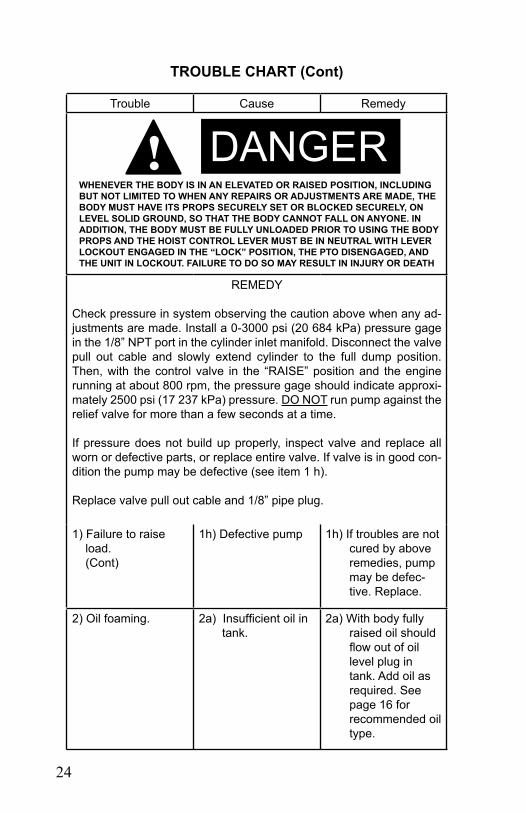
TROUBLE CHART (Cont)
Trouble Cause Remedy
REMEDY
Check pressure in system observing the caution above when any ad-justments are made. Install a 0-3000 psi (20 684 kPa) pressure gage in the 1/8” NPT port in the cylinder inlet manifold. Disconnect the valve pull out cable and slowly extend cylinder to the full dump position. Then, with the control valve in the “RAISE” position and the engine running at about 800 rpm, the pressure gage should indicate approxi-mately 2500 psi (17 237 kPa) pressure. DO NOT run pump against the relief valve for more than a few seconds at a time.
If pressure does not build up properly, inspect valve and replace all worn or defective parts, or replace entire valve. If valve is in good con-dition the pump may be defective (see item 1 h).
Replace valve pull out cable and 1/8” pipe plug.
1) Failure to raise load. (Cont)
1h) Defective pump 1h) If troubles are not cured by above remedies, pump may be defec-tive. Replace.
2) Oil foaming. 2a) Insufficient oil in tank.
2a) With body fully raised oil should flow out of oil level plug in tank. Add oil as required. See page 16 for recommended oil type.
WHENEVER THE BODY IS IN AN ELEVATED OR RAISED POSITION, INCLUDING BUT NOT LIMITED TO WHEN ANY REPAIRS OR ADJUSTMENTS ARE MADE, THE BODY MUST HAVE ITS PROPS SECURELY SET OR BLOCKED SECURELY, ON LEVEL SOLID GROUND, SO THAT THE BODY CANNOT FALL ON ANYONE. IN ADDITION, THE BODY MUST BE FULLY UNLOADED PRIOR TO USING THE BODY PROPS AND THE HOIST CONTROL LEVER MUST BE IN NEUTRAL WITH LEVERLOCKOUT ENGAGED IN THE “LOCK” POSITION, THE PTO DISENGAGED, AND THE UNIT IN LOCKOUT. FAILURE TO DO SO MAY RESULT IN INJURY OR DEATH
DANGER ! !

25
Trouble Cause Remedy2b) Suction line hose
fittings loose, al-lowing air to enter system.
2b) Tighten hose clamps and fittings; vent air from system.
2c) Oil too heavy. 2c) Install proper oil for expected temperature.
2d) Pump operated at high speed in cold weather.
2d) Operate pump at slower speed
3) Body raises un steadily, jerks or vibrates.
3a) Air in system. 3a) Check suction hoses and fittings for leaks; retight-en loose fittings. Vent cylinder.
4) Body lowers errati-cally by misstag-ing of cylinder sleeves.
4a) Cylinder packing too tight.
4a) (See Below)
REMEDY
Disconnect valve pull out cable and slowly extend cylinder to full stroke. Observe WARNING (Safety Precautions) rules in Section 1.2. Loosen set screw in each packing gland and unscrew gland one full turn. Place valve in the RAISE position and run pump against relief valve for a few seconds to loosen packing. Hand tighten packing gland and tighten set screw. Lower body and reconnect cable pull out.
5) Body will not stay up.
5a) Control valve not shifting completely, valve spool or housing scored. Cylinder scored and leaking exter-nally.
5a) Adjust linkage for complete stroke replace or repair valve; return cylinder to Dura-Class Distribu-tor if cylinder is scored or replace packing if leaking.

26
CYLINDER REPAIR
CAUTION ! When any work is to be done on body or hoist and body is fully or partly raised, body must have both props securely set or be blocked securely so it cannot fall. In addition, the HOIST control lever must be in neutral with the lever lockout engaged in the "lock" position and the PTO disengaged.
For any major repair the cylinder should be returned to the DuraClass Distributor.
Repairs in the field should be limited to the replacement of packing which can be done without removing the cylinder from the truck. Raise body, observing CAUTION above, loosen lock screws in packing gland, unscrew gland and slide out wiper ring, upper guide ring, and packing.
Cut replacement packing rings on a diagonal (slant) and install so cuts are 90° apart on adjacent rings. Dip packing in oil before assembly. Replace guide ring and packing gland. Be sure wiper is held in place by packing gland. Replace nylon, plugs and lock screws in gland and tighten lock screws.
CAUTION ! Packing glands should be snug — but not tight. There should always be a light film of oil on the sleeves during operation. Tight packing will cause scoring of sleeves, and mistaging of the sleeves as an empty body is lowered.
Keep dirt out of system.
PUMP REPAIR
Replacement parts for pump are available, although pump should be returned to your local DuraClass Distributor for any repairs beyond the replacement of seals and O-rings.
CONTROL VALVE REPAIR
Replacement parts for valve are available, although valve should be re-turned to your local DuraClass Distributor for repairs beyond the replace-ment of seals and O-rings.

PROTECT YOUR PRODUCT AND WARRANTY--
USE GENUINE DURACLASSREPLACEMENT PARTS
Contact your DuraClass Distributoror call
1-800-243-DURACLASS
DURACLASS


MODEL AND SERIAL NUMBER DATA
For your records fill in data below at the time warranty card is filled in.
Owner _______________________________________________
Date Unit Put in Operation ________________________________
Address ______________________________________________
City ____________________________State__________________
Body Model __________________Body P/N__________________
Body Serial No._____________ Hoist Model__________________
Hoist P/N _______________Hoist Serial No.__________________
Truck Make _______________ Truck Model __________________ Truck Serial No. ________________________________________
Dealer Purchased From __________________________________
City __________________________________________________
"DURACLASS as manufacturer of the equipment that is covered by this manual, is providing a product to the user who has acknowledged to have superior knowledge of the conditions of the use to which the product will be put. DURACLASS relies upon the user's superior knowledge in specifying any changes or modifications including, but not limited to, the inclusion or non-inclusion of options that are required by the user and the DURACLASS product, and for the particular application of the user relative to the DURA-CLASS product."

DURACLASS
TRUCK EQUIPMENT DIVISIONTISHOMINGO, MS

SID
EW
IND
ER
OW
NE
R’S
& O
PE
RAT
OR
’S M
AN
UA
L