
sherman & reilly, inc. - HDD Broker
60
SHERMAN & REILLY, INC. P.O. Box 11267 • 400 West 33rd Street Chattanooga, TN 37401 USA Phone 423 • 756 • 5300 Fax No. 423 • 756 • 2948 Toll-Free 800 • 251 • 7780 Web Site www.sherman-reilly.com © Copyright February 26, 2005 Sherman & Reilly, Inc. • Operation • Service • Parts
-
Upload
khangminh22 -
Category
Documents
-
view
0 -
download
0
Transcript of sherman & reilly, inc. - HDD Broker
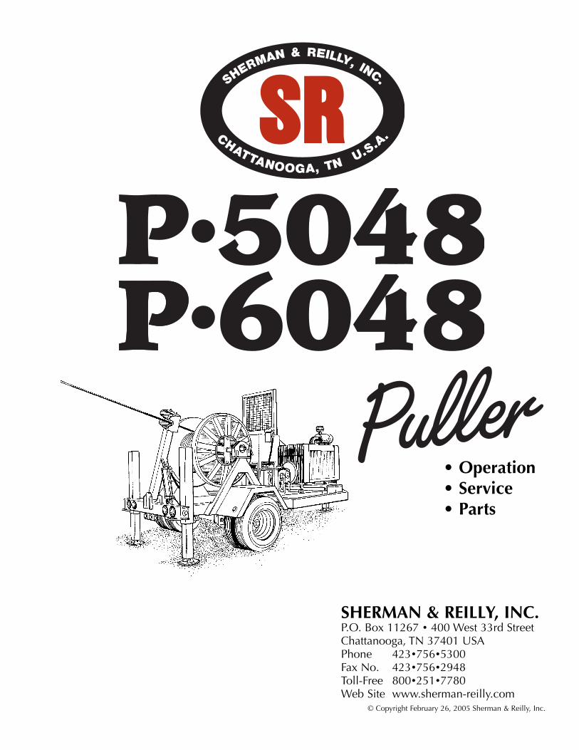
SHERMAN & REILLY, INC.P.O. Box 11267 • 400 West 33rd StreetChattanooga, TN 37401 USAPhone 423•756•5300Fax No. 423•756•2948Toll-Free 800•251•7780Web Site www.sherman-reilly.com
© Copyright February 26, 2005 Sherman & Reilly, Inc.
• Operation• Service• Parts


February 26, 2005 I
TABLE OF CONTENTS
Section 1 • INTRODUCTIONImportant Information . . . . . . . . . . . . . . . 1.1General Specifications. . . . . . . . . . . . . . . 1.2Trailer Specifications . . . . . . . . . . . . . . . . 1.2
Section 2 • SAFETYWarning Terms . . . . . . . . . . . . . . . . . . . . 2.1Operator Safety Precautions . . . . . . . . . . 2.1Employer Safety Requirements . . . . . . . . 2.3
Section 3 • OPERATIONDescription of Operating Controls . . . . . 3.2Terms You Need To Know. . . . . . . . . . . . 3.4Pre-Operation Inspection . . . . . . . . . . . . 3.6Towing . . . . . . . . . . . . . . . . . . . . . . . . . . 3.8Set-up for Pulling . . . . . . . . . . . . . . . . . 3.10Paying Out the Pulling Line. . . . . . . . . . 3.11Pulling. . . . . . . . . . . . . . . . . . . . . . . . . . 3.13Levelwind . . . . . . . . . . . . . . . . . . . . . . . 3.15Installing Pulling Grip . . . . . . . . . . . . . . 3.16
Section 4 • SERVICEGeneral Service. . . . . . . . . . . . . . . . . . . . 4.1Important Information . . . . . . . . . . . . . . . 4.1Safety Precautions . . . . . . . . . . . . . . . . . . 4.2Hydraulic System . . . . . . . . . . . . . . . . . . 4.3
Section 5 • PARTSPintle Eye . . . . . . . . . . . . . . . . . . . . . . . . 5.1Control Panel . . . . . . . . . . . . . . . . . . . . . 5.2Control Valves & Levers . . . . . . . . . . . . . 5.4Hydraulic Pump Assembly . . . . . . . . . . . 5.5Pump Control Valves . . . . . . . . . . . . . . . . 5.6Hydraulic Fluid Reservoir . . . . . . . . . . . . 5.7Ratchet Pawl . . . . . . . . . . . . . . . . . . . . . . 5.8Ratchet Wheel. . . . . . . . . . . . . . . . . . . . . 5.9Drum Shaft & Drive Bar Assembly . . . . 5.10Manual Brake Assembly . . . . . . . . . . . . 5.11Optional Hydraulic Brake Assembly . . . 5.12Drive Shaft Assembly . . . . . . . . . . . . . . 5.14Hydraulic Drive Motor Assembly . . . . . 5.15Levelwind Head Assembly . . . . . . . . . . 5.16Levelwind Arm Assembly . . . . . . . . . . . 5.17Jack Assembly . . . . . . . . . . . . . . . . . . . . 5.18Jack Valve Assembly . . . . . . . . . . . . . . . 5.20Trailer Lighting . . . . . . . . . . . . . . . . . . . 5.21Axle, Wheel & Brake Assembly. . . . . . . 5.22Fuel Tank. . . . . . . . . . . . . . . . . . . . . . . . 5.24Optional Diesel Fuel Tank Assembly . . . 5.25Oil Cooler & Exhaust . . . . . . . . . . . . . . 5.26

II
TABLE OF CONTENTS
1.1
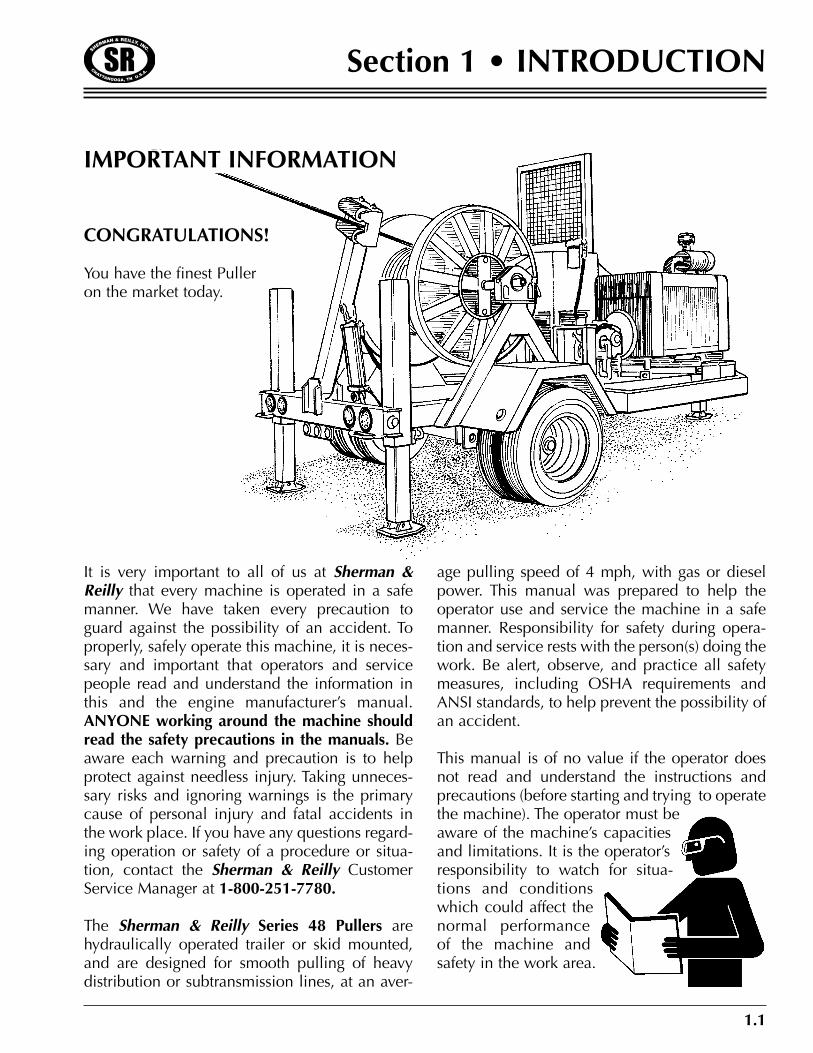
Section 1 • INTRODUCTION
CONGRATULATIONS!
You have the finest Pulleron the market today.
IMPORTANT INFORMATION
It is very important to all of us at Sherman &Reilly that every machine is operated in a safemanner. We have taken every precaution toguard against the possibility of an accident. Toproperly, safely operate this machine, it is neces-sary and important that operators and servicepeople read and understand the information inthis and the engine manufacturer’s manual.ANYONE working around the machine shouldread the safety precautions in the manuals. Beaware each warning and precaution is to helpprotect against needless injury. Taking unneces-sary risks and ignoring warnings is the primarycause of personal injury and fatal accidents inthe work place. If you have any questions regard-ing operation or safety of a procedure or situa-tion, contact the Sherman & Reilly CustomerService Manager at 1-800-251-7780.
The Sherman & Reilly Series 48 Pullers arehydraulically operated trailer or skid mounted,and are designed for smooth pulling of heavydistribution or subtransmission lines, at an aver-
age pulling speed of 4 mph, with gas or dieselpower. This manual was prepared to help theoperator use and service the machine in a safemanner. Responsibility for safety during opera-tion and service rests with the person(s) doing thework. Be alert, observe, and practice all safetymeasures, including OSHA requirements andANSI standards, to help prevent the possibility ofan accident.
This manual is of no value if the operator doesnot read and understand the instructions andprecautions (before starting and trying to operatethe machine). The operator must beaware of the machine’s capacitiesand limitations. It is the operator’sresponsibility to watch for situa-tions and conditionswhich could affect thenormal performanceof the machine andsafety in the work area.
1.2
Section 1 • INTRODUCTION
GENERAL SPECIFICATIONS*Maximum Pulling Capacity P5048 . . . . . . . . . 120,000 in. lbs. of torque (5,000 lbs. on top of drum)Maximum Pulling Capacity P6048 . . . . . . . . . 144,000 in. lbs. of torque (6,000 lbs. on top of drum)Maximum Line Speed. . . . . . . . . . . . . . . . . . . . . . . . . . . . . . . . . . . . . . . 4 mph (Average to fill drum)Pulling Drum:Size . . . . . . . . . . . . . . . . . . . . . . . . . . . . . . . . . . . . 48 in. O.D. x 20 in. I.D. x 38 in. T x 48 in. WRope Capacity . . . . . . . . . . . . . . . . . . . . . . . . . . . . . . . . . . . . . . . . . . . . . . . 8,500 ft. of 3⁄4 in. dia.
6,200 ft. of 7⁄8 in. dia.12,000 ft. of 5⁄8 in. dia.
Maximum Reel Size . . . . . . . . . . . . . . . . . . . . . . . . . . . . . . . . . . . . . . . . . . . . 72 in. dia. x 441⁄2 in. WMaximum Reel Weight . . . . . . . . . . . . . . . . . . . . . . . . . . . . . . . . . . . . . . . . . . . . . . . . . . . . 5,800 lbs.Engine . . . . . . . . . . . . . . . . . . . . . . . . . . . . . . . . . . . . . . . . . . . . . . . . . . . . . . . . . . 300 CID (gasoline)Drive System . . . . . . . . . . . . . . . . . . . . . . . . . . . . . . . . . . . Hydraulic (final stage chain and sprocket)Hydraulic System Oil . . . . . . . . . . . . . . . . . . . . . . . . . . . . . . . . . . Dexron Quality Transmission FluidEmergency/Parking Brake . . . . . . . . . . . . . . . . . . . . . . . . . . . . . . . Ratchet/PAWL (Pulling Mode only)Payout (Overspin) Brake. . . . . . . . . . . . . . . . . . . . . . . . . . . . . . . . . . . . . . . . . . . . . . . . . . Caliper/DiskLevelwind . . . . . . . . . . . . . . . . . . . . . . . . . . . . . . . . . . . . . . . . . . . . . . . . . . . . . . . . . . . . . . Hydraulic
TRAILER SPECIFICATIONSAxle. . . . . . . . . . . . . . . . . . . . . . . . . . . . . . . . . . . . . . . . . . . . . . . . . . . . . . . . . . . . . . . . . . . . . . SingleSuspension . . . . . . . . . . . . . . . . . . . . . . . . . . . . . . . . . . . . . . . . . . . . . . . . . . . . . . . . . . . . Leaf SpringsBrakes . . . . . . . . . . . . . . . . . . . . . . . . . . . . . . . . . . . . . . . . . . . . . . . . . . . . . . Electric 121⁄4 in. x 33⁄8 in.Tires . . . . . . . . . . . . . . . . . . . . . . . . . . . . . . . . . . . . . . . . . . . . . . . . . . . . . . . . . . . . . 7:50 x 16, 10 PlyFront Jack. . . . . . . . . . . . . . . . . . . . . . . . . . . . . . . . . . . . . . . . . . . . . . . . . . . . . . . . . . . . . . . HydraulicAdjustable Rear Jack . . . . . . . . . . . . . . . . . . . . . . . . . . . . . . . . . . . . . . . . . . . Drop Leg & Pin Type (2)Safety Chain & Hooks . . . . . . . . . . . . . . . . . . . . . . . . . . . . . . . . . . . . . . . . . . . . . . . . . . . . . . . Two (2)Towing . . . . . . . . . . . . . . . . . . . . . . . . . . . . . . . . . . . . . . . . . . . . . . . . . . . . . . . . Adjustable Pintle EyeTrailer Lights . . . . . . . . . . . . . . . . . . . . . . . . . . . . . . . . . . . . . . . . . . . . . . . . . . . . . . . . . . . . . StandardLength . . . . . . . . . . . . . . . . . . . . . . . . . . . . . . . . . . . . . . . . . . . . . . . . . . . . Approximately 17 ft. 3 in.Width . . . . . . . . . . . . . . . . . . . . . . . . . . . . . . . . . . . . . . . . . . . . . . . . . . . . . . . . . . Approximately 8 ft.Height. . . . . . . . . . . . . . . . . . . . . . . . . . . . . . . . . . . . . . . . . . . . . . . . . . . . . . . . . . Approximately 9 ft.Weight . . . . . . . . . . . . . . . . . . . . . . . . . . . . . . . . . . . . . . . . . . . . . . . . . . . . Approximately 5,500 lbs.Note: Pulling drum, reconductoring reel and some other options on PT-2766-BV and PT-3366 will fitthe P-6048 Puller. Diesel engine also available.* Dimensions, weights, capacities are approximate. Manufacturer’s specifications subject to change without notice.
Publication of this manual and the safety pre-cautions in it does not in any way represent anall inclusive list. It is the operator’s responsibilityto make sure the machine is operated in accor-dance with all state and local safety require-ments and codes, including all applicable OSHA(Occupational Safety and Health Act) and ANSI(American National Standards Institute) regulations.
Should a problem or unsafe condition arise,shut the machine down using the normal shut-
down procedure. In the event of an emergency,use the emergency stop procedure. Turn igni-tion key off, then apply emergency/parkingbrake. Notify the proper authority or follow youremployer’s prescribed procedure for an emer-gency situation.
Sherman & Reilly strongly recommends that onlypersons literate and understanding the Englishlanguage be considered as operators or servicepersonnel for this machine.
2.1
Section 2 • SAFETY
WARNING TERMS
Signal words in this manual call the operator’sattention to safety concerns.
The word DANGER indicates the informationrelates to a specific immediate hazard which, ifdisregarded, will result in severe personal injuryor death.
The word WARNING indicates the informationrelates to a specific immediate hazard or unsafepractice which, if disregarded, could result inpersonal injury or death.
The word CAUTION indicates the informationpertains to a potential hazard or unsafe practicewhich, if disregarded, may result in minor per-sonal injury or equipment damage.
The word NOTE indicates the information isimportant to the correct operation or mainte-nance of the machine.
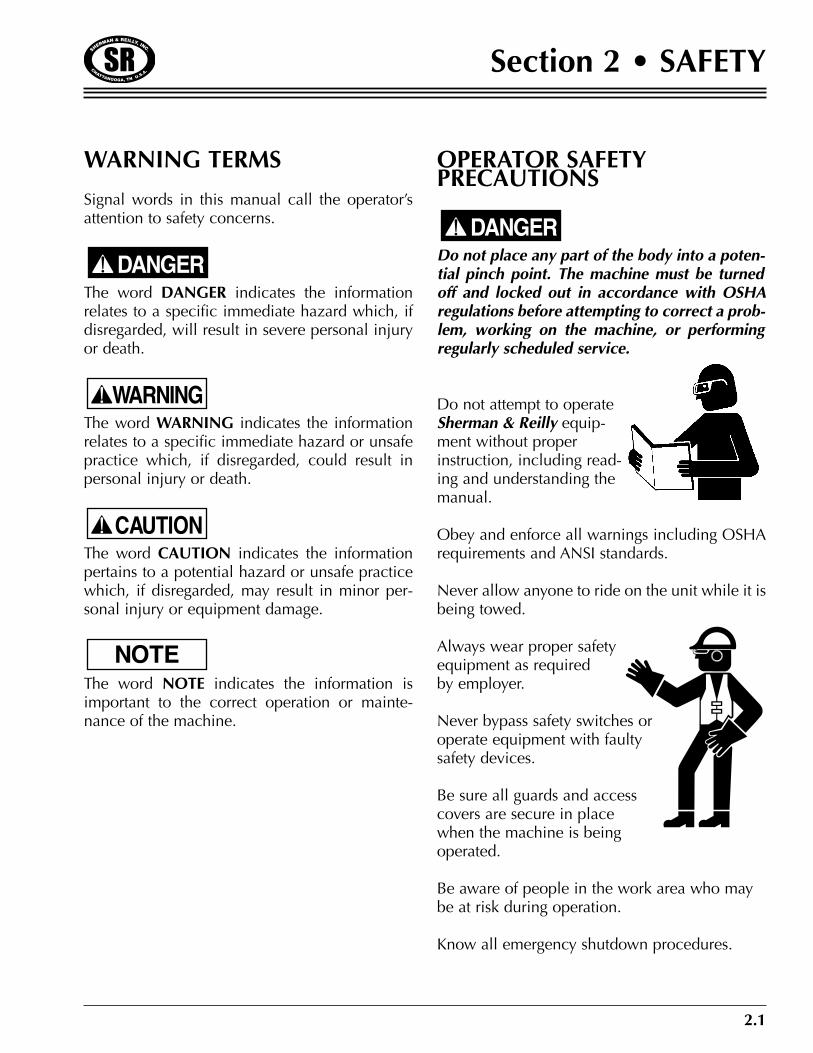
OPERATOR SAFETYPRECAUTIONS
Do not place any part of the body into a poten-tial pinch point. The machine must be turnedoff and locked out in accordance with OSHAregulations before attempting to correct a prob-lem, working on the machine, or performingregularly scheduled service.
Do not attempt to operateSherman & Reilly equip-ment without properinstruction, including read-ing and understanding themanual.
Obey and enforce all warnings including OSHArequirements and ANSI standards.
Never allow anyone to ride on the unit while it isbeing towed.
Always wear proper safetyequipment as requiredby employer.
Never bypass safety switches oroperate equipment with faultysafety devices.
Be sure all guards and accesscovers are secure in placewhen the machine is beingoperated.
Be aware of people in the work area who maybe at risk during operation.
Know all emergency shutdown procedures.
DANGER
NOTE
CAUTION
WARNING
DANGER
2.2
Section 2 • SAFETY
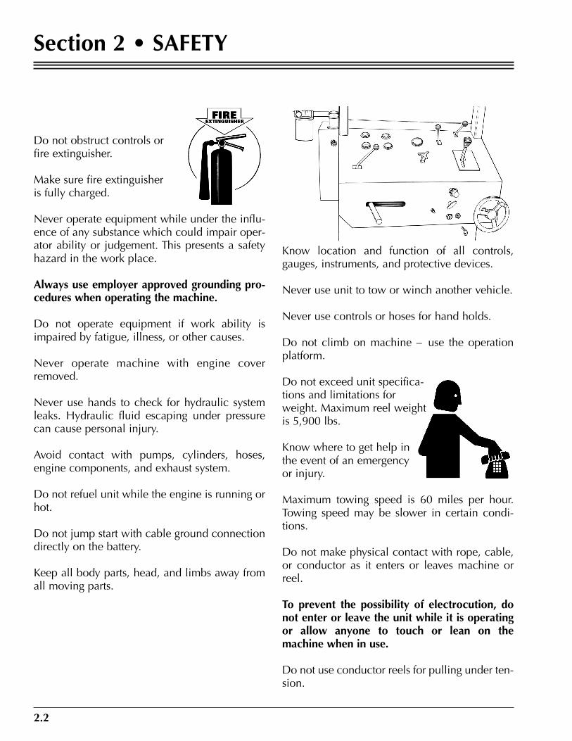
Do not obstruct controls orfire extinguisher.
Make sure fire extinguisheris fully charged.
Never operate equipment while under the influ-ence of any substance which could impair oper-ator ability or judgement. This presents a safetyhazard in the work place.
Always use employer approved grounding pro-cedures when operating the machine.
Do not operate equipment if work ability isimpaired by fatigue, illness, or other causes.
Never operate machine with engine coverremoved.
Never use hands to check for hydraulic systemleaks. Hydraulic fluid escaping under pressurecan cause personal injury.
Avoid contact with pumps, cylinders, hoses,engine components, and exhaust system.
Do not refuel unit while the engine is running orhot.
Do not jump start with cable ground connectiondirectly on the battery.
Keep all body parts, head, and limbs away fromall moving parts.
Know location and function of all controls,gauges, instruments, and protective devices.
Never use unit to tow or winch another vehicle.
Never use controls or hoses for hand holds.
Do not climb on machine – use the operationplatform.
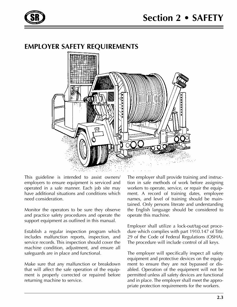
Do not exceed unit specifica-tions and limitations forweight. Maximum reel weightis 5,900 lbs.
Know where to get help inthe event of an emergencyor injury.
Maximum towing speed is 60 miles per hour.Towing speed may be slower in certain condi-tions.
Do not make physical contact with rope, cable,or conductor as it enters or leaves machine orreel.
To prevent the possibility of electrocution, donot enter or leave the unit while it is operatingor allow anyone to touch or lean on themachine when in use.
Do not use conductor reels for pulling under ten-sion.
2.3
Section 2 • SAFETY
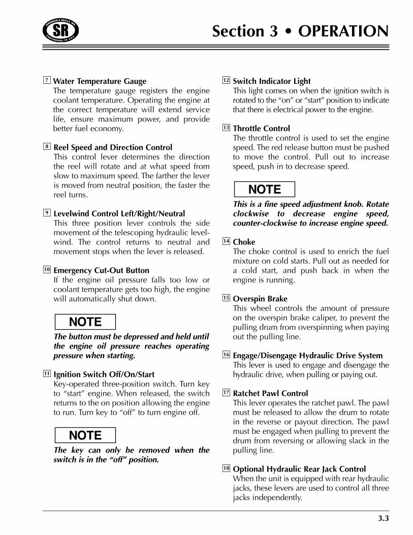
This guideline is intended to assist owners/employers to ensure equipment is serviced andoperated in a safe manner. Each job site mayhave additional situations and conditions whichneed consideration.
Monitor the operators to be sure they observeand practice safety procedures and operate thesupport equipment as outlined in this manual.
Establish a regular inspection program whichincludes malfunction reports, inspection, andservice records. This inspection should cover themachine condition, adjustment, and ensure allsafeguards are in place and functional.
Make sure that any malfunction or breakdownthat will affect the safe operation of the equip-ment is properly corrected or repaired beforereturning machine to service.
The employer shall provide training and instruc-tion in safe methods of work before assigningworkers to operate, service, or repair the equip-ment. A record of training dates, employeenames, and level of training should be main-tained. Only persons literate and understandingthe English language should be considered tooperate this machine.
Employer shall utilize a lock-out/tag-out proce-dure which complies with part 1910.147 of Title29 of the Code of Federal Regulations (OSHA).The procedure will include control of all keys.
The employer will specifically inspect all safetyequipment and protective devices on the equip-ment to ensure they are not bypassed or dis-abled. Operation of the equipment will not bepermitted unless all safety devices are functionaland in place. The employer shall meet the appro-priate protection requirements for the workers.
EMPLOYER SAFETY REQUIREMENTS

2.4
Section 2 • SAFETY

3.1
Section 3 • OPERATION
Puller

3.2
Section 3 • OPERATION
Front Jack Up/DownThis three-position lever is used to operate thefront jack. The lock must be pulled beforerotating the lever to raise “up” and lower“down” the front of the machine. The lockprevents accidental movement of the control.
The engine must be running for this controlto function.
System Pressure GaugeThis gauge indicates the hydraulic systempressure has available control from 0 to 3150PSI. The gauge indicates the existing systempressure setting.
Line Tension Control (Decrease/Increase)This variable-position control increases anddecreases the hydraulic motor torque. Thiscontrol determines how much pull or tensionis on the line or conductor. Clockwise rota-tion increases hydraulic pressure (pull or ten-sion) Counter-clockwise rotation decreasespressure (pull or tension).
Hour MeterThis gauge registers the number of hours theengine runs and is useful in keeping accurateservice records.
Oil Pressure GaugeThis gauge displays the engine oil lubricatingsystem pressure in pounds per square inch(PSI). It should be checked frequently toensure the system is functioning and there isadequate oil in the engine for lubrication.Should the pressure fluctuate or drop, stopthe engine, determine the cause, and makethe necessary repairs. Do not operate theengine with lower than normal oil pressure.Doing so could result in engine damage.
VoltmeterThe voltmeter measures the battery chargingvoltage with the engine running. If the meterindicates less than 13 volts or more than 15volts, have the engine’s electrical systemchecked.
6
5
4
3
2
NOTE
1
DESCRIPTION OF OPERATING CONTROLS
18
4 6 1
(OPTION)
58
793
2
17
15
13
1410
1116 12
Water Temperature GaugeThe temperature gauge registers the enginecoolant temperature. Operating the engine atthe correct temperature will extend servicelife, ensure maximum power, and providebetter fuel economy.
Reel Speed and Direction ControlThis control lever determines the directionthe reel will rotate and at what speed fromslow to maximum speed. The farther the leveris moved from neutral position, the faster thereel turns.
Levelwind Control Left/Right/NeutralThis three position lever controls the sidemovement of the telescoping hydraulic level-wind. The control returns to neutral andmovement stops when the lever is released.
Emergency Cut-Out ButtonIf the engine oil pressure falls too low orcoolant temperature gets too high, the enginewill automatically shut down.
The button must be depressed and held untilthe engine oil pressure reaches operatingpressure when starting.
Ignition Switch Off/On/StartKey-operated three-position switch. Turn keyto “start” engine. When released, the switchreturns to the on position allowing the engineto run. Turn key to “off” to turn engine off.
The key can only be removed when theswitch is in the “off” position.
Switch Indicator LightThis light comes on when the ignition switch isrotated to the “on” or “start” position to indicatethat there is electrical power to the engine.
Throttle ControlThe throttle control is used to set the enginespeed. The red release button must be pushedto move the control. Pull out to increasespeed, push in to decrease speed.
This is a fine speed adjustment knob. Rotateclockwise to decrease engine speed,counter-clockwise to increase engine speed.
ChokeThe choke control is used to enrich the fuelmixture on cold starts. Pull out as needed fora cold start, and push back in when theengine is running.
Overspin BrakeThis wheel controls the amount of pressureon the overspin brake caliper, to prevent thepulling drum from overspinning when payingout the pulling line.
Engage/Disengage Hydraulic Drive SystemThis lever is used to engage and disengage thehydraulic drive, when pulling or paying out.
Ratchet Pawl ControlThis lever operates the ratchet pawl. The pawlmust be released to allow the drum to rotatein the reverse or payout direction. The pawlmust be engaged when pulling to prevent thedrum from reversing or allowing slack in thepulling line.
Optional Hydraulic Rear Jack ControlWhen the unit is equipped with rear hydraulicjacks, these levers are used to control all threejacks independently.
18
17
16
15
14
NOTE
13
127
NOTE
11
NOTE
10
9
8
3.3
Section 3 • OPERATION
3.4
Section 3 • OPERATION
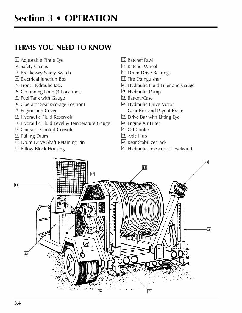
TERMS YOU NEED TO KNOW
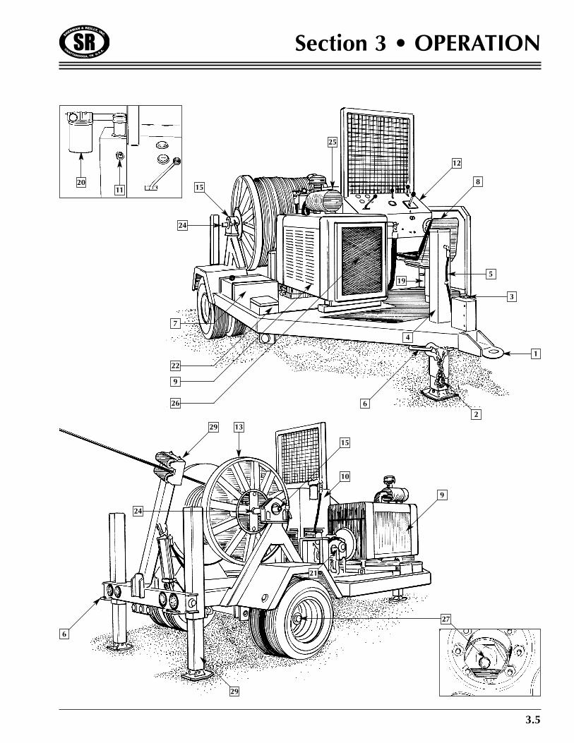
Adjustable Pintle EyeSafety ChainsBreakaway Safety SwitchElectrical Junction BoxFront Hydraulic JackGrounding Loop (4 Locations)Fuel Tank with GaugeOperator Seat (Storage Position)Engine and CoverHydraulic Fluid ReservoirHydraulic Fluid Level & Temperature GaugeOperator Control ConsolePulling DrumDrum Drive Shaft Retaining PinPillow Block Housing
Ratchet PawlRatchet WheelDrum Drive BearingsFire ExtinguisherHydraulic Fluid Filter and GaugeHydraulic PumpBattery/CaseHydraulic Drive MotorGear Box and Payout BrakeDrive Bar with Lifting EyeEngine Air FilterOil CoolerAxle HubRear Stabilizer JackHydraulic Telescopic Levelwind29
28
27
26
25
24
23
22
21
20
19
18
17
16
15
14
13
12
11
10
9
8
7
6
5
4
3
2
1
17
14
23
18
16 6
28
29
13
3.5
Section 3 • OPERATION
2011 15
24
7
22
9
26 62
1
4
5
3
19
8
12
25
6
29
27
29 13
24
15
10
9
21
3.6
Section 3 • OPERATION
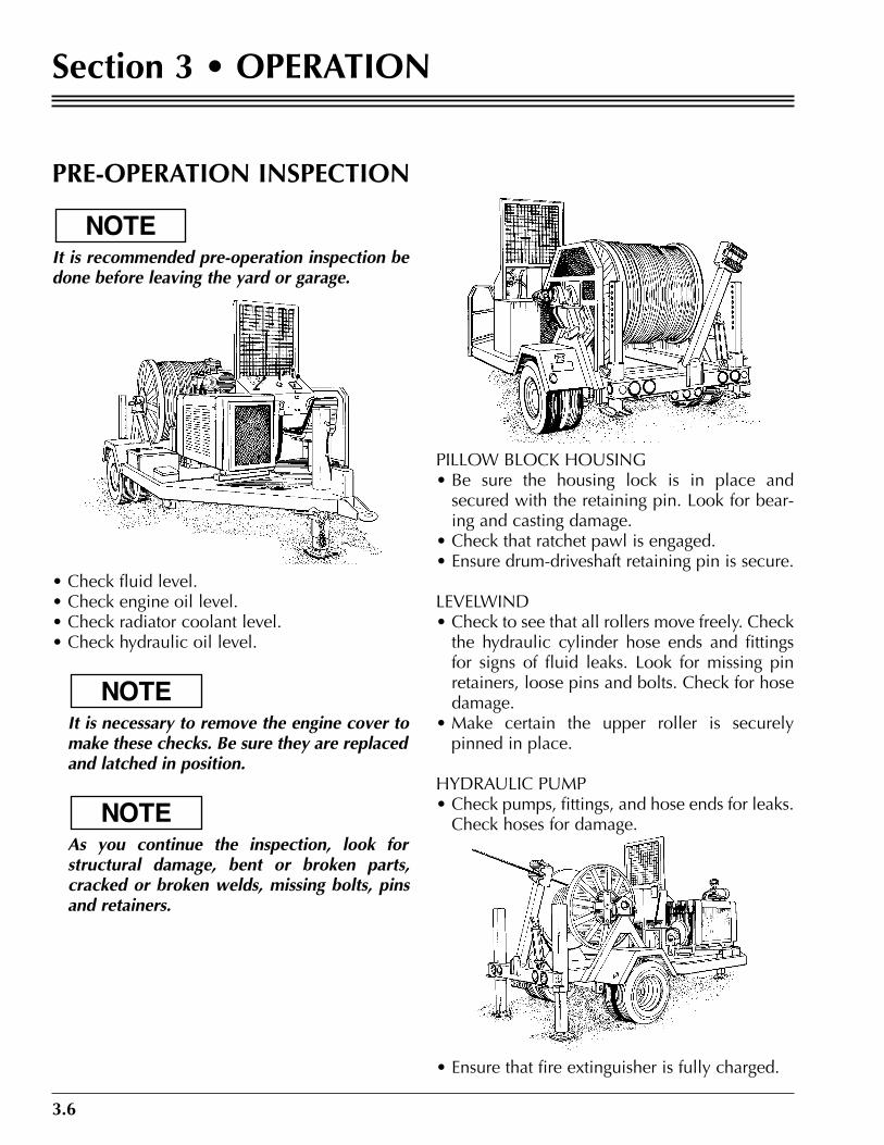
PRE-OPERATION INSPECTION
It is recommended pre-operation inspection bedone before leaving the yard or garage.
• Check fluid level.• Check engine oil level.• Check radiator coolant level.• Check hydraulic oil level.
•• It is necessary to remove the engine cover tomake these checks. Be sure they are replacedand latched in position.
•• As you continue the inspection, look forstructural damage, bent or broken parts,cracked or broken welds, missing bolts, pinsand retainers.
PILLOW BLOCK HOUSING• Be sure the housing lock is in place andsecured with the retaining pin. Look for bear-ing and casting damage.
• Check that ratchet pawl is engaged.• Ensure drum-driveshaft retaining pin is secure.
LEVELWIND• Check to see that all rollers move freely. Checkthe hydraulic cylinder hose ends and fittingsfor signs of fluid leaks. Look for missing pinretainers, loose pins and bolts. Check for hosedamage.
• Make certain the upper roller is securelypinned in place.
HYDRAULIC PUMP• Check pumps, fittings, and hose ends for leaks.Check hoses for damage.
• Ensure that fire extinguisher is fully charged.
NOTE
NOTE
NOTE

3.7
Section 3 • OPERATION
• Start the Engine• Start-Up Procedure• a. Make sure all controls are in neutral and
parking brake is on.• b. Check to be sure the throttle is in the idle or
closed position.• c. Choke if necessary.• d. Push in emergency cut-out button and hold.• e. Insert key and turn ignition switch to start.
•• Refer to the engine manufacturer’s manual for
proper engine starting procedures.
•• Never add ETHER to fuel to start cold engine.Ether WILL damage small diesel engines.
•• Hold the cut-out button in until the enginebuilds oil pressure before releasing.
• f. Check oil pressure and voltmeter to be sureeverything is working properly.
• Check the hydraulic fluid filter indicator to besure the filter is in serviceable condition.
• After starting engine, moveeach control to make sure thelever moves easily and thefunction operates correctly.
• Shut the engine down. Referto the engine manufacturer’smanual for proper shutdownprocedures.
NOTE
CAUTION
NOTE
3.8
Section 3 • OPERATION
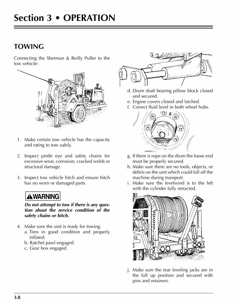
TOWING
Connecting the Sherman & Reilly Puller to thetow vehicle:
1. Make certain tow vehicle has the capacityand rating to tow safely.
2. Inspect pintle eye and safety chains forexcessive wear, corrosion, cracked welds orstructural damage.
3. Inspect tow vehicle hitch and ensure hitchhas no worn or damaged parts.
Do not attempt to tow if there is any ques-tion about the service condition of thesafety chains or hitch.
4. Make sure the unit is ready for towing.a. Tires in good condition and properlyinflated.
b. Ratchet pawl engaged.c. Gear box engaged.
d. Drum shaft bearing pillow block closedand secured.
e. Engine covers closed and latched.f. Correct fluid level in both wheel hubs.
g. If there is rope on the drum the loose endmust be properly secured.
h. Make sure there are no tools, objects, ordebris on the unit which could fall off themachine during transport.
i. Make sure the levelwind is to the leftwith the cylinder fully retracted.
j. Make sure the rear leveling jacks are inthe full up position and secured withpins and retainers.
WARNING
3.9
Section 3 • OPERATION
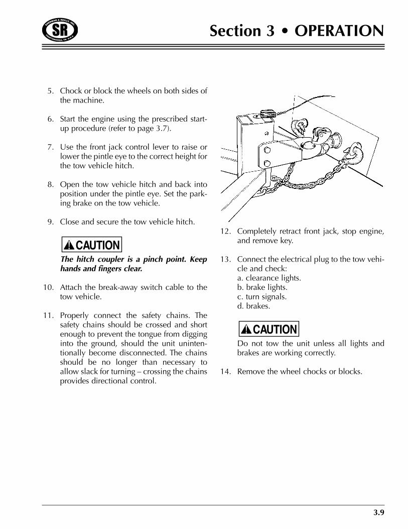
5. Chock or block the wheels on both sides ofthe machine.
6. Start the engine using the prescribed start-up procedure (refer to page 3.7).
7. Use the front jack control lever to raise orlower the pintle eye to the correct height forthe tow vehicle hitch.
8. Open the tow vehicle hitch and back intoposition under the pintle eye. Set the park-ing brake on the tow vehicle.
9. Close and secure the tow vehicle hitch.
The hitch coupler is a pinch point. Keephands and fingers clear.
10. Attach the break-away switch cable to thetow vehicle.
11. Properly connect the safety chains. Thesafety chains should be crossed and shortenough to prevent the tongue from digginginto the ground, should the unit uninten-tionally become disconnected. The chainsshould be no longer than necessary toallow slack for turning – crossing the chainsprovides directional control.
12. Completely retract front jack, stop engine,and remove key.
13. Connect the electrical plug to the tow vehi-cle and check:a. clearance lights.b. brake lights.c. turn signals.d. brakes.
Do not tow the unit unless all lights andbrakes are working correctly.
14. Remove the wheel chocks or blocks.
CAUTION
CAUTION
3.10
Section 3 • OPERATION
SET-UP FOR PULLING
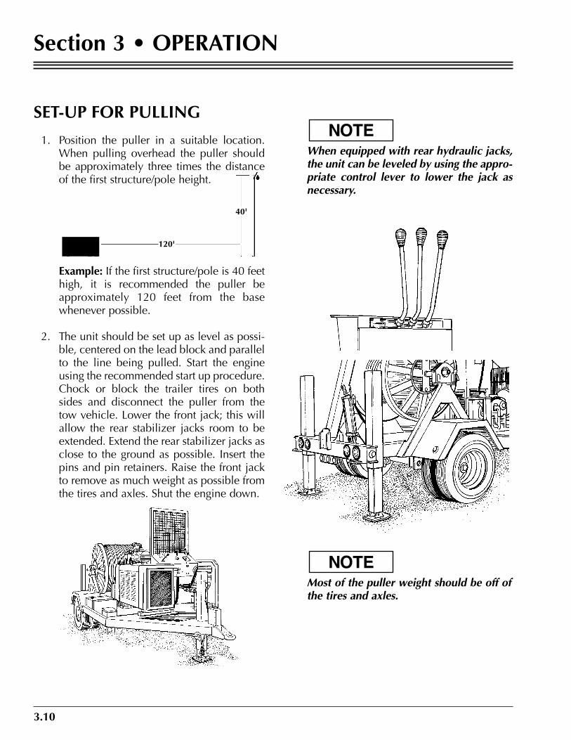
1. Position the puller in a suitable location.When pulling overhead the puller shouldbe approximately three times the distanceof the first structure/pole height.
Example: If the first structure/pole is 40 feethigh, it is recommended the puller beapproximately 120 feet from the basewhenever possible.
2. The unit should be set up as level as possi-ble, centered on the lead block and parallelto the line being pulled. Start the engineusing the recommended start up procedure.Chock or block the trailer tires on bothsides and disconnect the puller from thetow vehicle. Lower the front jack; this willallow the rear stabilizer jacks room to beextended. Extend the rear stabilizer jacks asclose to the ground as possible. Insert thepins and pin retainers. Raise the front jackto remove as much weight as possible fromthe tires and axles. Shut the engine down.
When equipped with rear hydraulic jacks,the unit can be leveled by using the appro-priate control lever to lower the jack asnecessary.
Most of the puller weight should be off ofthe tires and axles.
NOTE
NOTE
120'
40'

3.11
Section 3 • OPERATION
1. The pulling line may be paid out by twomethods. The line can be pulled off usingthe payout brake to prevent overspin or themachine may be driven in the reversedirection.
2. Before paying out the pulling line, the anti-reversing “ratchet pawl” must be lockedout.
The ratchet wheel is bolted to the largesprocket, and the pawl assembly is weldedto the rear leg of the drum support (“A”frame).
The pawl assembly includes a control armwith a friction pad attached to its end. Thefriction pad contacts the ratchet wheel;thereby, the rotation of the ratchet wheelcontrols the position of the pawl.
The control arm holds the pawl away fromthe ratchet wheel during normal pullingoperations. This prevents the “machinegun” like noise caused by the teeth strikingthe pawl. If the ratchet wheel reversesdirection the control arm moves, allowingthe pawl to engage the ratchet wheel.
There is a small, stainless cable attached tothe counterweight end of the pawl. Thiscable leads to a lever on the control panel.By holding the lever down and rotating theratchet wheel several revolutions in the“payout” direction, you can lock out thepawl. This allows you to drive the drum inthe reverse direction or pull out the pullingrope.
When the ratchet wheel is rotated severalrevolutions in the “pull in” direction, thepawl assembly will return to its normalfunction as described above.
The only time the selector is placed in the“freewheel” position is when the line is tobe pulled off the drum by hand or withanother machine.
CAUTION
PAYING OUT THE PULLING LINE
RATCHET PAWL
RATCHET PAWLRELEASE LEVER

3.12
Section 3 • OPERATION
3. The drum may be driven in reverse after thepawl is locked out. Move the“speed/direction” control lever to payout todrive the drum in the reverse “payout”direction.
4. To pull the rope from the machine, eitherby hand or with another machine, first lockout the pawl, then turn off the gasolineengine. Set the selector valve to the “free-wheel” position, and adjust the payoutbrake to provide the desired line tensionand to prevent the drum from over-spinningwhen the pull is stopped.
When pulling the rope from the machine,it is not necessary to run the engine on thepuller.
5. The pulling line should be removed fromthe levelwind when paying out for ease ofoperation.
NOTE
3.13
Section 3 • OPERATION
PULLING
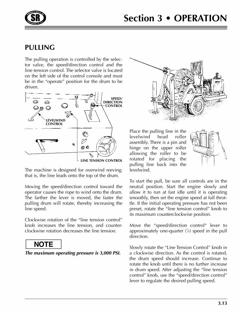
The pulling operation is controlled by the selec-tor valve, the speed/direction control and theline tension control. The selector valve is locatedon the left side of the control console and mustbe in the “operate” position for the drum to bedriven.
The machine is designed for overwind reeving;that is, the line leads onto the top of the drum.
Moving the speed/direction control toward theoperator causes the rope to wind onto the drum.The farther the lever is moved, the faster thepulling drum will rotate, thereby increasing theline speed.
Clockwise rotation of the “line tension control”knob increases the line tension, and counter-clockwise rotation decreases the line tension.
The maximum operating pressure is 3,000 PSI.
Place the pulling line in thelevelwind head rollerassembly. There is a pin andhinge on the upper rollerallowing the roller to berotated for placing thepulling line back into thelevelwind.
To start the pull, be sure all controls are in theneutral position. Start the engine slowly andallow it to run at fast idle until it is operatingsmoothly, then set the engine speed at full throt-tle. If the initial operating pressure has not beenpreset, rotate the “line tension control” knob toits maximum counterclockwise position.
Move the “speed/direction control“ lever toapproximately one-quarter (1⁄4) speed in the pulldirection.
Slowly rotate the “Line Tension Control” knob ina clockwise direction. As the control is rotated,the drum speed should increase. Continue torotate the knob until there is no further increasein drum speed. After adjusting the “line tensioncontrol” knob, use the “speed/direction control”lever to regulate the desired pulling speed.
NOTE
LEVELWINDCONTROL
SPEED/DIRECTIONCONTROL
LINE TENSION CONTROL
3.14
Section 3 • OPERATION
Do not leave the line tension control adjustedto full system pressure. The system pressuregauge indicating the pressure used to pull theconductor is actual pressure being used. If thecontrol is adjusted above that setting, or if thepulling line or conductor can foul or hang up,pressure will spike or build rapidly, jerking thepulling line, and may create a safety hazard orcause damage to the pulling line, conductor orstringing block, etc.
The operator should monitor and adjust thepulling speed and system pressure as required topull the drum, slowing the speed as pulling gripsand swivels enter angles, or dead ends.
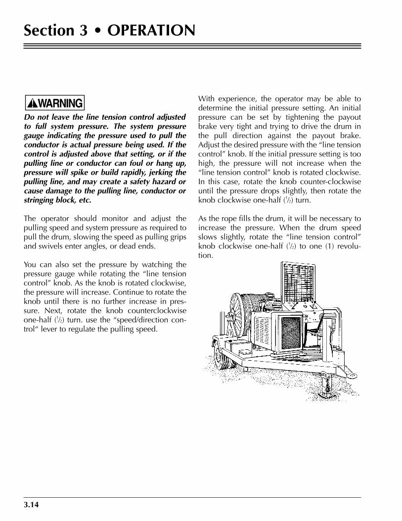
You can also set the pressure by watching thepressure gauge while rotating the “line tensioncontrol” knob. As the knob is rotated clockwise,the pressure will increase. Continue to rotate theknob until there is no further increase in pres-sure. Next, rotate the knob counterclockwiseone-half (1⁄2) turn. use the “speed/direction con-trol“ lever to regulate the pulling speed.
With experience, the operator may be able todetermine the initial pressure setting. An initialpressure can be set by tightening the payoutbrake very tight and trying to drive the drum inthe pull direction against the payout brake.Adjust the desired pressure with the “line tensioncontrol” knob. If the initial pressure setting is toohigh, the pressure will not increase when the“line tension control” knob is rotated clockwise.In this case, rotate the knob counter-clockwiseuntil the pressure drops slightly, then rotate theknob clockwise one-half (1⁄2) turn.
As the rope fills the drum, it will be necessary toincrease the pressure. When the drum speedslows slightly, rotate the “line tension control”knob clockwise one-half (1⁄2) to one (1) revolu-tion.
WARNING
3.15
Section 3 • OPERATION
LEVELWIND
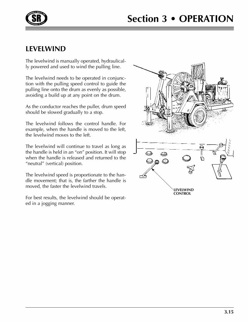
The levelwind is manually operated, hydraulical-ly powered and used to wind the pulling line.
The levelwind needs to be operated in conjunc-tion with the pulling speed control to guide thepulling line onto the drum as evenly as possible,avoiding a build up at any point on the drum.
As the conductor reaches the puller, drum speedshould be slowed gradually to a stop.
The levelwind follows the control handle. Forexample, when the handle is moved to the left,the levelwind moves to the left.
The levelwind will continue to travel as long asthe handle is held in an “on” position. It will stopwhen the handle is released and returned to the“neutral” (vertical) position.
The levelwind speed is proportionate to the han-dle movement; that is, the farther the handle ismoved, the faster the levelwind travels.
For best results, the levelwind should be operat-ed in a jogging manner.
LEVELWINDCONTROL
3.16
Section 3 • OPERATION
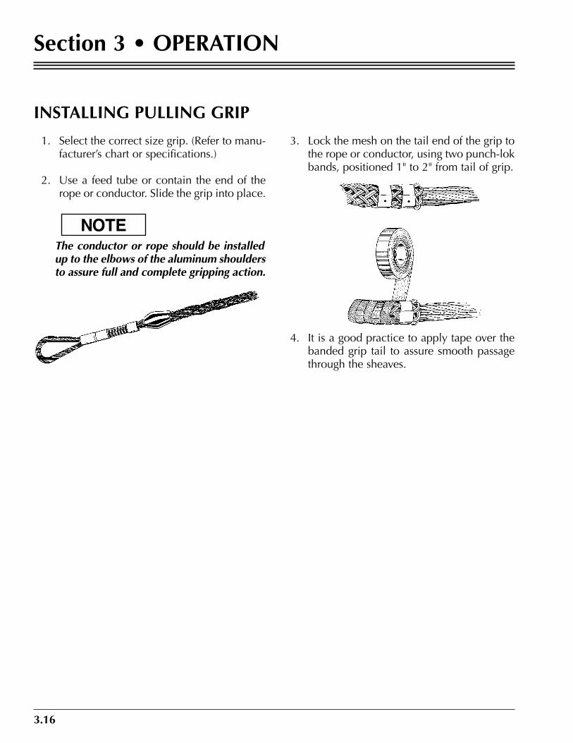
INSTALLING PULLING GRIP
1. Select the correct size grip. (Refer to manu-facturer’s chart or specifications.)
2. Use a feed tube or contain the end of therope or conductor. Slide the grip into place.
The conductor or rope should be installedup to the elbows of the aluminum shouldersto assure full and complete gripping action.
3. Lock the mesh on the tail end of the grip tothe rope or conductor, using two punch-lokbands, positioned 1" to 2" from tail of grip.
4. It is a good practice to apply tape over thebanded grip tail to assure smooth passagethrough the sheaves.
NOTE
4.1
Section 4 • SERVICE
IMPORTANT INFORMATION
The service guidelines outlined in this manualare effective methods. These guidelines are notall inclusive. Anyone who performs service orrepair on a Sherman & Reilly machine must becompletely satisfied that no one’s safety will bejeopardized and take responsibility for theseactions.
If there are any questions about safety, procedureor precautions, contact Sherman & Reilly at800-251-7780 before attempting to do the work.
Service should be scheduled to allow adequatetime so the procedure can be completed correct-ly. It must be done byskilled, trained servicepersonnel with a goodbasic knowledge ofequipment, procedures,and safety practices.
Accurate records shouldbe kept of all service andrepairs.
WARNING
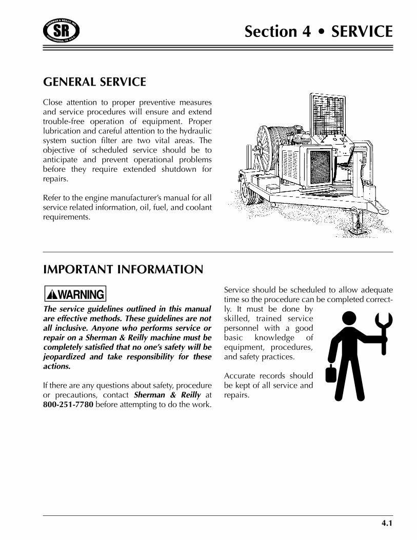
GENERAL SERVICE
Close attention to proper preventive measuresand service procedures will ensure and extendtrouble-free operation of equipment. Properlubrication and careful attention to the hydraulicsystem suction filter are two vital areas. Theobjective of scheduled service should be toanticipate and prevent operational problemsbefore they require extended shutdown forrepairs.
Refer to the engine manufacturer’s manual for allservice related information, oil, fuel, and coolantrequirements.
4.2
Section 4 • SERVICE
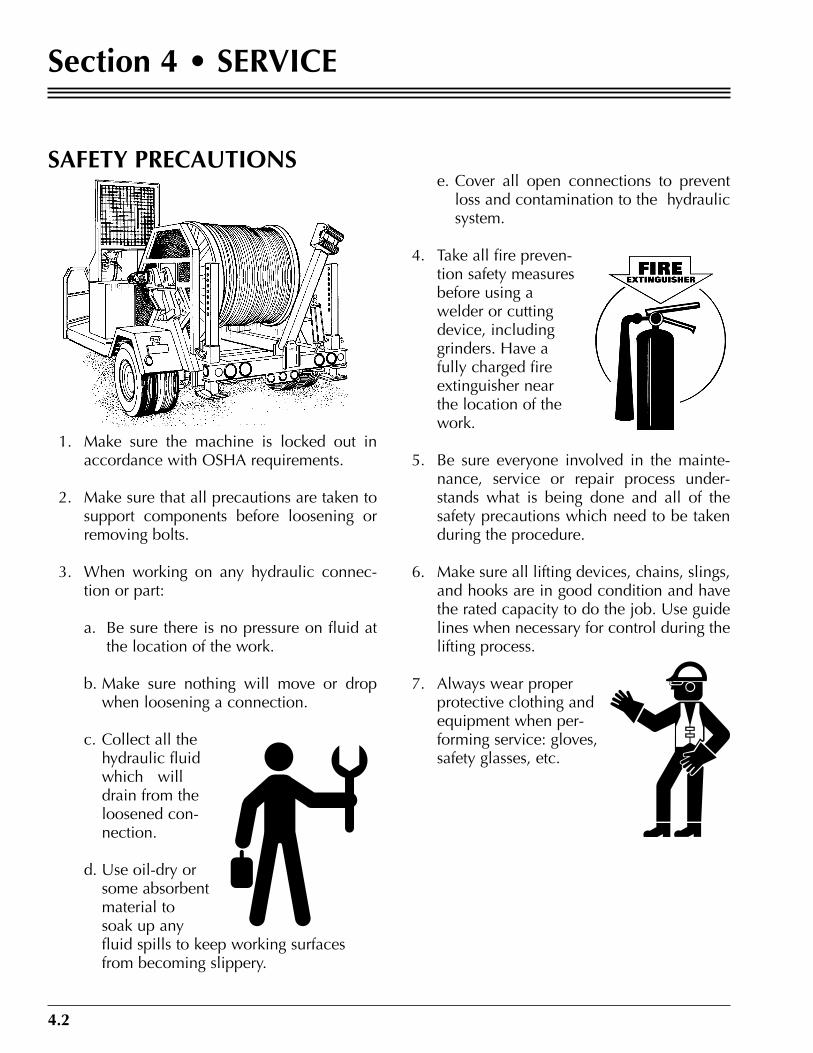
SAFETY PRECAUTIONS
1. Make sure the machine is locked out inaccordance with OSHA requirements.
2. Make sure that all precautions are taken tosupport components before loosening orremoving bolts.
3. When working on any hydraulic connec-tion or part:
a. Be sure there is no pressure on fluid atthe location of the work.
b. Make sure nothing will move or dropwhen loosening a connection.
c. Collect all thehydraulic fluidwhich willdrain from theloosened con-nection.
d. Use oil-dry orsome absorbentmaterial tosoak up anyfluid spills to keep working surfacesfrom becoming slippery.
e. Cover all open connections to preventloss and contamination to the hydraulicsystem.
4. Take all fire preven-tion safety measuresbefore using awelder or cuttingdevice, includinggrinders. Have afully charged fireextinguisher nearthe location of thework.
5. Be sure everyone involved in the mainte-nance, service or repair process under-stands what is being done and all of thesafety precautions which need to be takenduring the procedure.
6. Make sure all lifting devices, chains, slings,and hooks are in good condition and havethe rated capacity to do the job. Use guidelines when necessary for control during thelifting process.
7. Always wear properprotective clothing andequipment when per-forming service: gloves,safety glasses, etc.
4.3
Section 4 • SERVICE
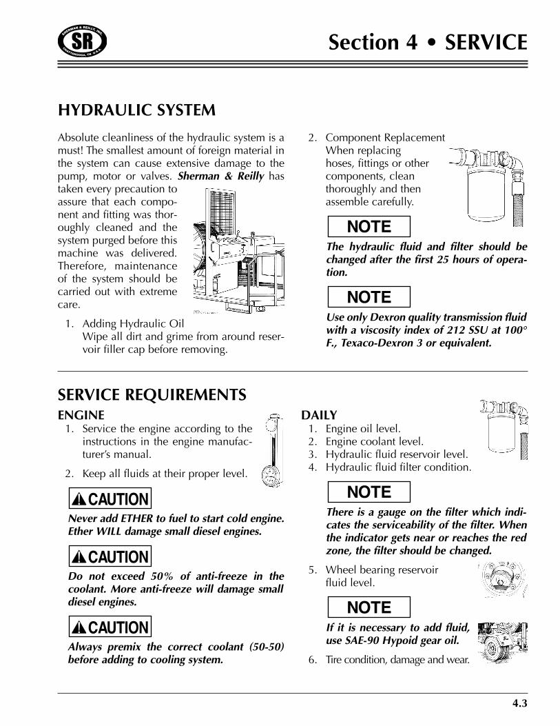
HYDRAULIC SYSTEM
Absolute cleanliness of the hydraulic system is amust! The smallest amount of foreign material inthe system can cause extensive damage to thepump, motor or valves. Sherman & Reilly hastaken every precaution toassure that each compo-nent and fitting was thor-oughly cleaned and thesystem purged before thismachine was delivered.Therefore, maintenanceof the system should becarried out with extremecare.
1. Adding Hydraulic OilWipe all dirt and grime from around reser-voir filler cap before removing.
2. Component ReplacementWhen replacinghoses, fittings or othercomponents, cleanthoroughly and thenassemble carefully.
The hydraulic fluid and filter should bechanged after the first 25 hours of opera-tion.
Use only Dexron quality transmission fluidwith a viscosity index of 212 SSU at 100°F., Texaco-Dexron 3 or equivalent.
NOTE
NOTE
SERVICE REQUIREMENTSENGINE1. Service the engine according to the
instructions in the engine manufac-turer’s manual.
2. Keep all fluids at their proper level.
•• Never add ETHER to fuel to start cold engine.Ether WILL damage small diesel engines.
•• Do not exceed 50% of anti-freeze in thecoolant. More anti-freeze will damage smalldiesel engines.
•• Always premix the correct coolant (50-50)before adding to cooling system.
DAILY1. Engine oil level.2. Engine coolant level.3. Hydraulic fluid reservoir level.4. Hydraulic fluid filter condition.
There is a gauge on the filter which indi-cates the serviceability of the filter. Whenthe indicator gets near or reaches the redzone, the filter should be changed.
5. Wheel bearing reservoirfluid level.
If it is necessary to add fluid,use SAE-90 Hypoid gear oil.
6. Tire condition, damage and wear.
NOTE
NOTE
CAUTION
CAUTION
CAUTION

4.4
Section 4 • SERVICE
SERVICE REQUIREMENTSWEEKLY
1. Perform daily inspection requirements.
2. Check gearbox oil level.
There is a removable plug on the side ofthe gear box. Remove the plug. Gear oilshould be level with the bottom edge ofthe opening.
3. Inspect payoutbrake pads.
The pads shouldbe replacedbefore the rivetsmake contactwith the disc.
4. Inspect axle assembly and springs for align-ment, broken or damaged spring leaves.
5. Check battery electrolyte level. Replenishas required.
NOTE
NOTE
CHECKFLUIDLEVELHERE
SEMI-ANNUAL OR EVERY 100 HOURSOF SERVICE
1. Replace the hydraulic fluid in the hydraulicsystem.
2. Replace the oil filter.
3. Inspect trailer brake linings for wear andreplace as necessary.
4. In extremely dirty or dusty conditions, filterand fluid should be changed every 50hours of service.
4.5
Section 4 • SERVICE
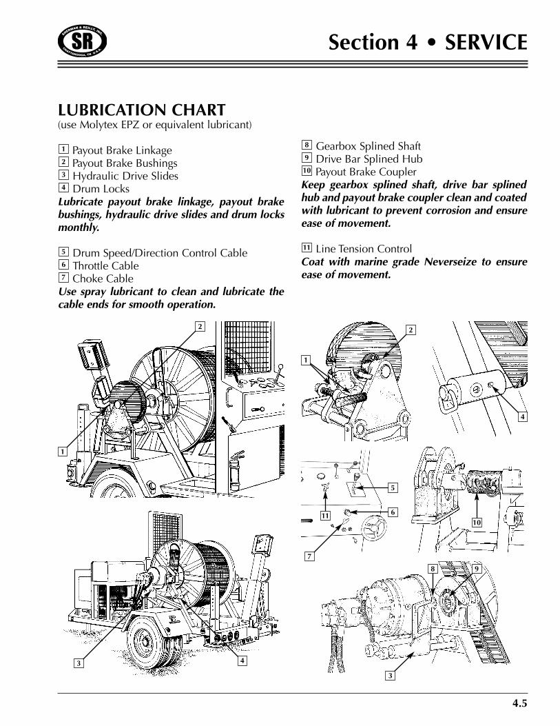
LUBRICATION CHART(use Molytex EPZ or equivalent lubricant)
Payout Brake LinkagePayout Brake BushingsHydraulic Drive SlidesDrum Locks
Lubricate payout brake linkage, payout brakebushings, hydraulic drive slides and drum locksmonthly.
Drum Speed/Direction Control CableThrottle CableChoke Cable
Use spray lubricant to clean and lubricate thecable ends for smooth operation.
Gearbox Splined ShaftDrive Bar Splined HubPayout Brake Coupler
Keep gearbox splined shaft, drive bar splinedhub and payout brake coupler clean and coatedwith lubricant to prevent corrosion and ensureease of movement.
Line Tension ControlCoat with marine grade Neverseize to ensureease of movement.
11
10
9
8
7
6
5
4
3
2
1
1
2
3
4
8 9
10
43
2
1
6
7
11
5

4.6
Section 4 • SERVICE
SERVICE REQUIREMENTS
SEMI-ANNUAL OR EVERY 100 HOURSOF SERVICE
1. Replace the hydraulic fluid in the hydraulicsystem.
2. Replace the oil filter.
3. Inspect trailer brake linings for wear andreplace as necessary.
4. In extremely dirty or dusty conditions, filterand fluid should be changed every 50hours of service.
5.1
Section 5 • PARTS
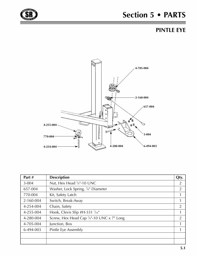
PINTLE EYE
Part # Description Qty.
3-004 Nut, Hex Head 3⁄4"-10 UNC 2
657-004 Washer, Lock Spring, 3⁄4" Diameter 2
770-004 Kit, Safety Latch 1
2-160-004 Switch, Break-Away 1
4-254-004 Chain, Safety 2
4-255-004 Hook, Clevis Slip #H-331 7⁄16" 1
4-280-004 Screw, Hex Head Cap 3⁄4"-10 UNC x 7" Long 2
4-705-004 Junction, Box 1
6-494-003 Pintle Eye Assembly 1
770-004
4-254-004
4-255-004
4-280-004
4-705-004
2-160-004
657-004
3-004
6-494-003
5.2
Section 5 • PARTS
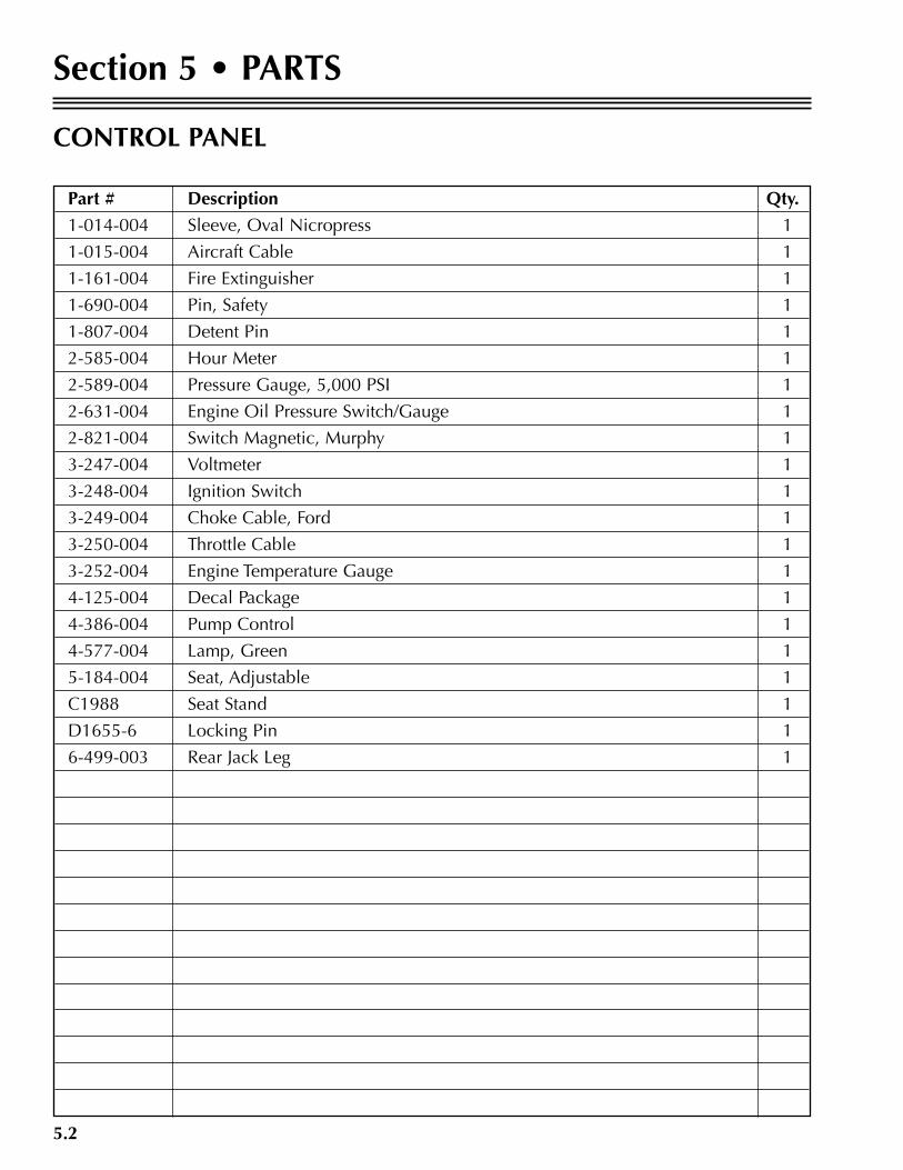
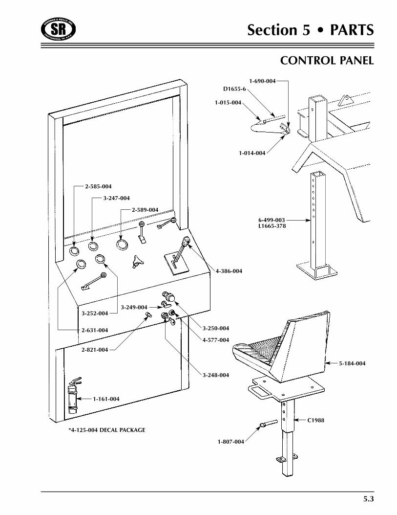
CONTROL PANEL
Part # Description Qty.
1-014-004 Sleeve, Oval Nicropress 1
1-015-004 Aircraft Cable 1
1-161-004 Fire Extinguisher 1
1-690-004 Pin, Safety 1
1-807-004 Detent Pin 1
2-585-004 Hour Meter 1
2-589-004 Pressure Gauge, 5,000 PSI 1
2-631-004 Engine Oil Pressure Switch/Gauge 1
2-821-004 Switch Magnetic, Murphy 1
3-247-004 Voltmeter 1
3-248-004 Ignition Switch 1
3-249-004 Choke Cable, Ford 1
3-250-004 Throttle Cable 1
3-252-004 Engine Temperature Gauge 1
4-125-004 Decal Package 1
4-386-004 Pump Control 1
4-577-004 Lamp, Green 1
5-184-004 Seat, Adjustable 1
C1988 Seat Stand 1
D1655-6 Locking Pin 1
6-499-003 Rear Jack Leg 1
5.3
Section 5 • PARTS
CONTROL PANEL
2-585-004
3-247-004
2-589-004
5-184-004
3-252-004
2-631-004
2-821-004
*4-125-004 DECAL PACKAGE
4-386-004
4-577-004
3-250-004
3-248-004
3-249-004
C1988
1-807-004
1-015-004
D1655-61-690-004
1-014-004
6-499-003L1665-378
1-161-004
2-053-004
3-277-004
2-589-004
1-020-002
4-848-004
887-315
3-131-003882-315
4-386-004
4-248-004
5.4
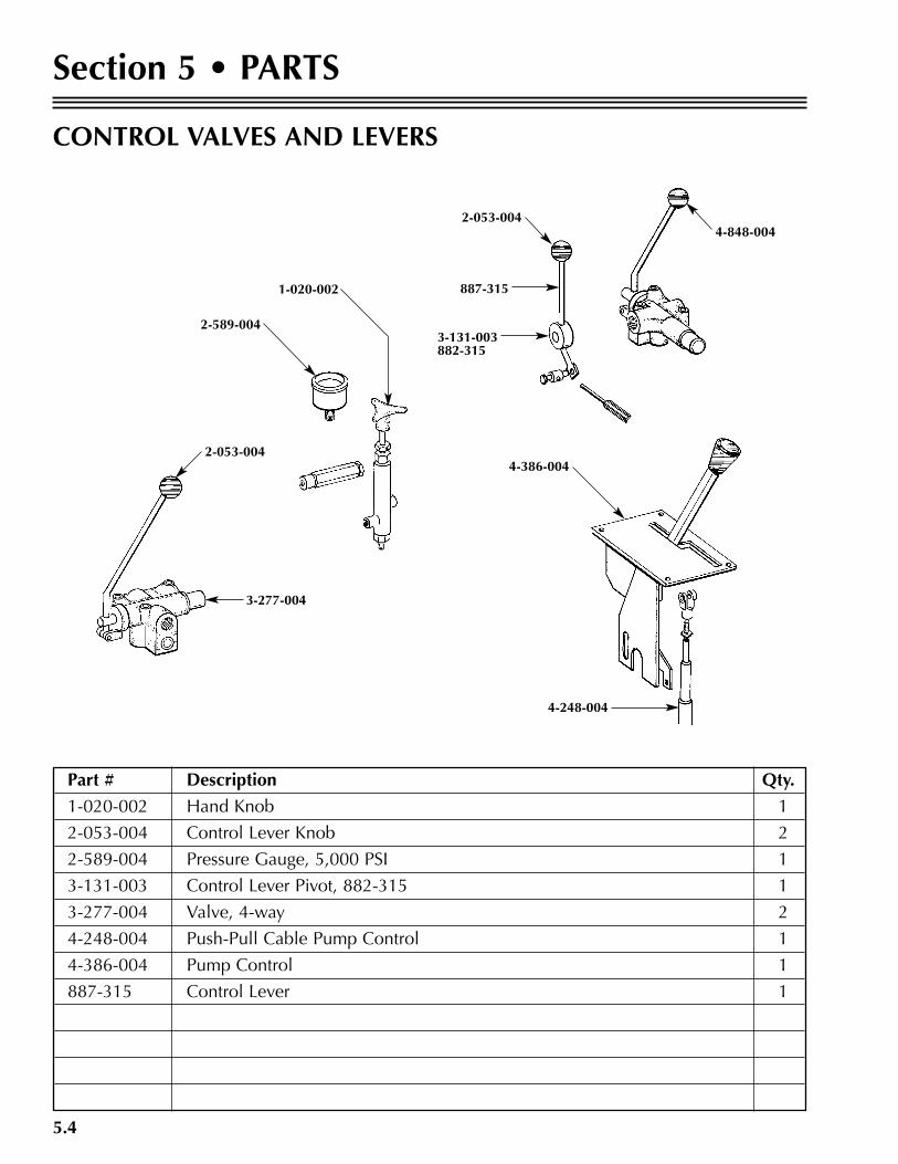
Section 5 • PARTS
Part # Description Qty.
1-020-002 Hand Knob 1
2-053-004 Control Lever Knob 2
2-589-004 Pressure Gauge, 5,000 PSI 1
3-131-003 Control Lever Pivot, 882-315 1
3-277-004 Valve, 4-way 2
4-248-004 Push-Pull Cable Pump Control 1
4-386-004 Pump Control 1
887-315 Control Lever 1
CONTROL VALVES AND LEVERS
2-053-004

5.5
Section 5 • PARTS
HYDRAULIC PUMP ASSEMBLY
Part # Description Qty.
4-248-004 Push-Pull Cable Pump Control 1
4-249-004 Control Module 1
4-255-004 Clevis 1
4-374-004 Engine, Ford Gas 1
4-388-004 Pump, Clockwise Rotation 1
4-633-004 Clevis Pin 1
5-597-004 Engine, John Deere Diesel 1
4-633-004
4-255-004
4-249-004
4-248-004
4-388-004*4-374-004 FORD ENGINE GAS*5-597-004 DIESEL ENGINE
5.6
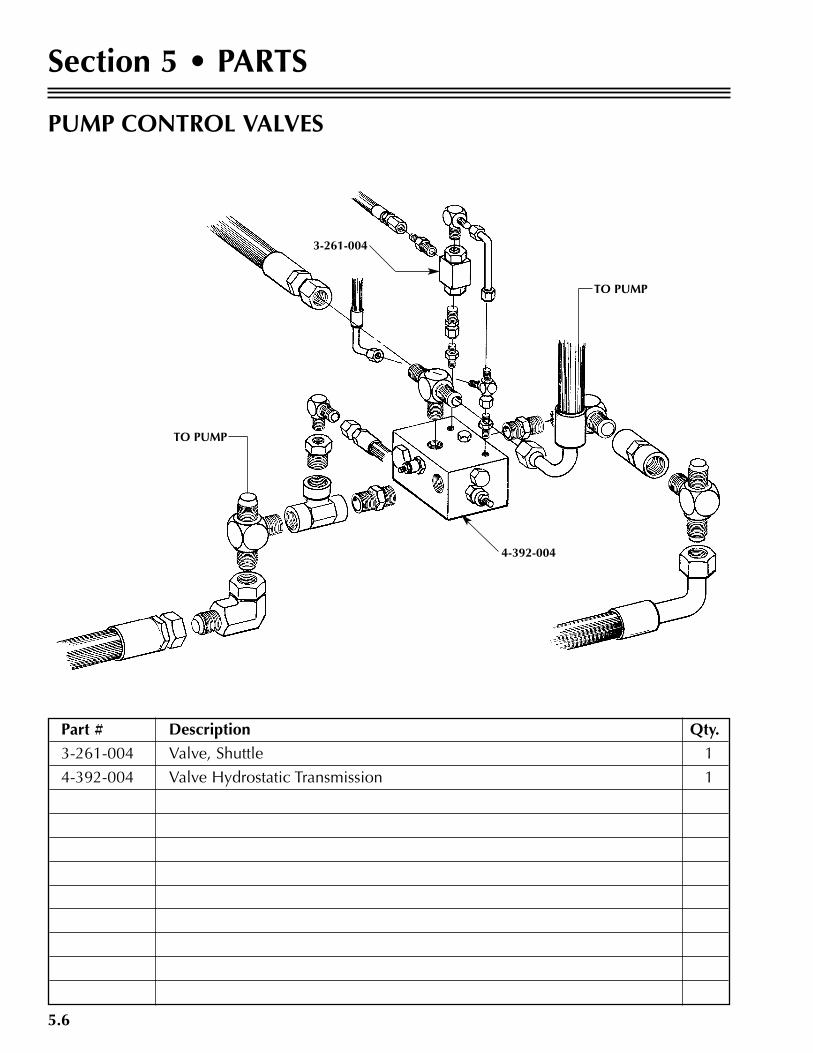
Section 5 • PARTS
PUMP CONTROL VALVES
Part # Description Qty.
3-261-004 Valve, Shuttle 1
4-392-004 Valve Hydrostatic Transmission 1
TO PUMP
4-392-004
TO PUMP
3-261-004
5.7
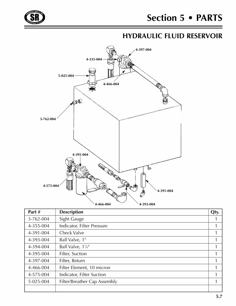
Section 5 • PARTS
HYDRAULIC FLUID RESERVOIR
Part # Description Qty.
3-762-004 Sight Gauge 1
4-355-004 Indicator, Filter Pressure 1
4-391-004 Check Valve 1
4-393-004 Ball Valve, 1" 1
4-394-004 Ball Valve, 11⁄4" 1
4-395-004 Filter, Suction 1
4-397-004 Filter, Return 1
4-466-004 Filter Element, 10 micron 1
4-575-004 Indicator, Filter Suction 1
5-025-004 Filter/Breather Cap Assembly 1
4-391-004
4-393-0044-466-004
4-395-004
4-575-004
3-762-004
5-025-004
4-335-004
4-397-004
4-466-004

5.8
Section 5 • PARTS
RATCHET PAWL
Part # Description Qty.
6-548-003 Pawl (1688-378) 1
6-549-003 Linkage Mounting Weldment 1
6-550-003 Drag Arm Linkage 1
6-551-003 Control Arm 1
6-552-003 Friction Pad Arm 1
6-553-003 Friction Pad (1688-378) 2
6-555-003 Bronze Bushing (4-264-004) 1
6-556-003 Bronze Washer 2
6-558-003 Linkage Pin 1
6-551-003
6-558-003
6-556-003
6-555-003
6-549-003
6-548-003
6-552-0031688-3786-553-003
6-550-003
5.9
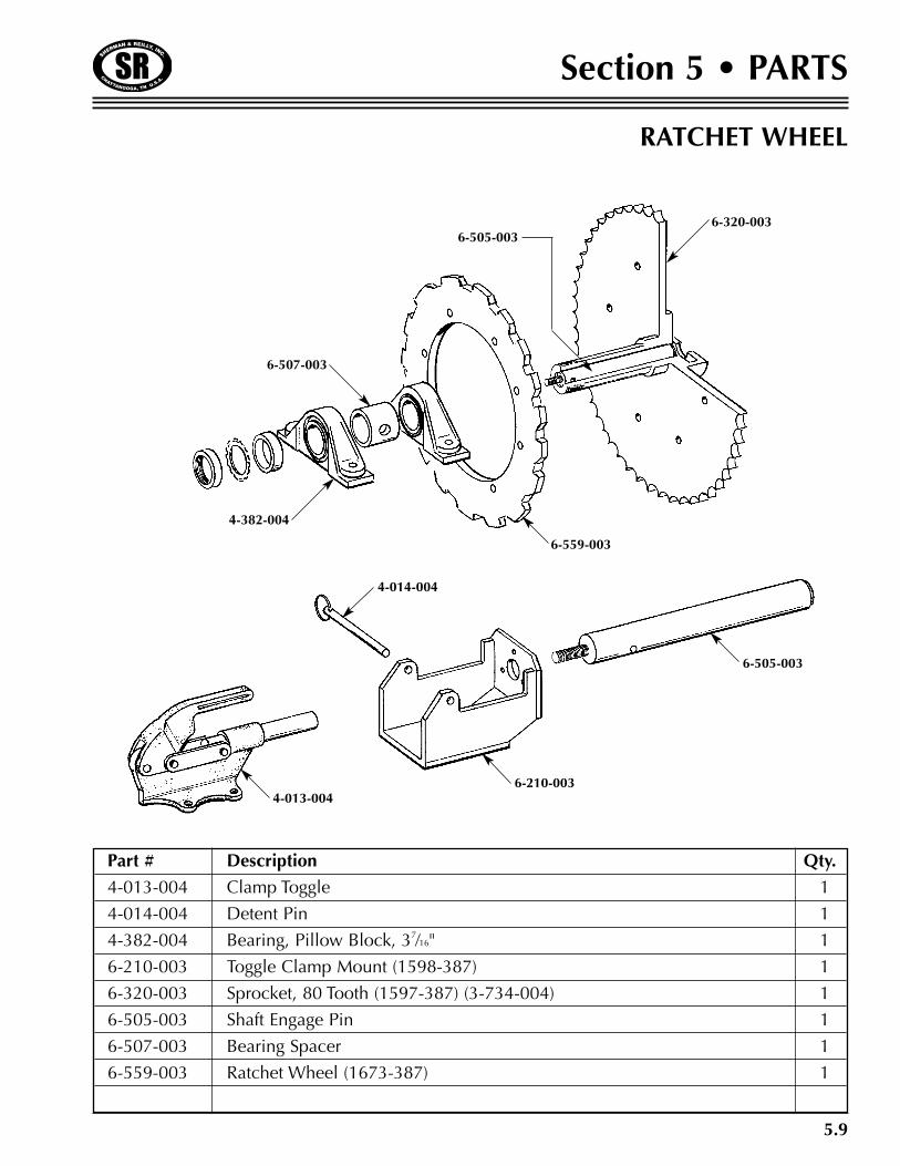
Section 5 • PARTS
RATCHET WHEEL
Part # Description Qty.
4-013-004 Clamp Toggle 1
4-014-004 Detent Pin 1
4-382-004 Bearing, Pillow Block, 37⁄16" 1
6-210-003 Toggle Clamp Mount (1598-387) 1
6-320-003 Sprocket, 80 Tooth (1597-387) (3-734-004) 1
6-505-003 Shaft Engage Pin 1
6-507-003 Bearing Spacer 1
6-559-003 Ratchet Wheel (1673-387) 1
6-320-003
6-559-003
4-382-004
6-507-003
6-505-003
4-014-004
6-210-0034-013-004
6-505-003
5.10
Section 5 • PARTS
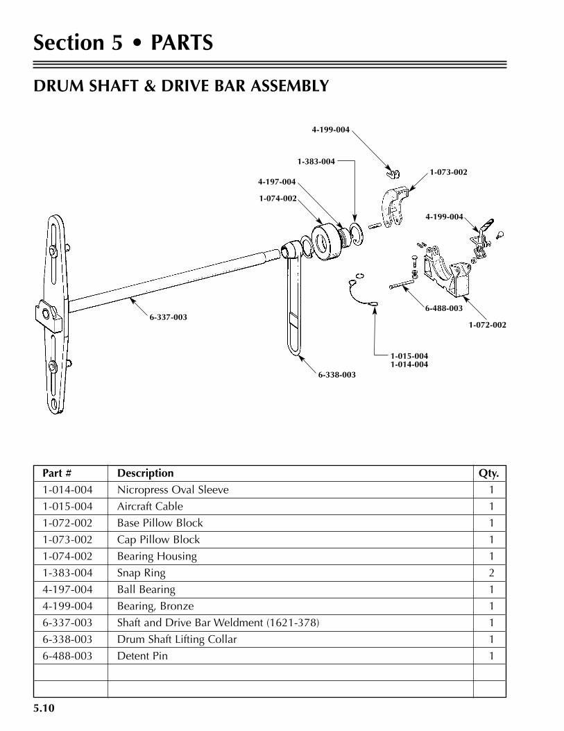
DRUM SHAFT & DRIVE BAR ASSEMBLY
Part # Description Qty.
1-014-004 Nicropress Oval Sleeve 1
1-015-004 Aircraft Cable 1
1-072-002 Base Pillow Block 1
1-073-002 Cap Pillow Block 1
1-074-002 Bearing Housing 1
1-383-004 Snap Ring 2
4-197-004 Ball Bearing 1
4-199-004 Bearing, Bronze 1
6-337-003 Shaft and Drive Bar Weldment (1621-378) 1
6-338-003 Drum Shaft Lifting Collar 1
6-488-003 Detent Pin 1
6-337-003
6-338-003
1-074-002
4-197-004
1-383-004
4-199-004
1-073-002
4-199-004
1-072-002
6-488-003
1-015-0041-014-004
5.11
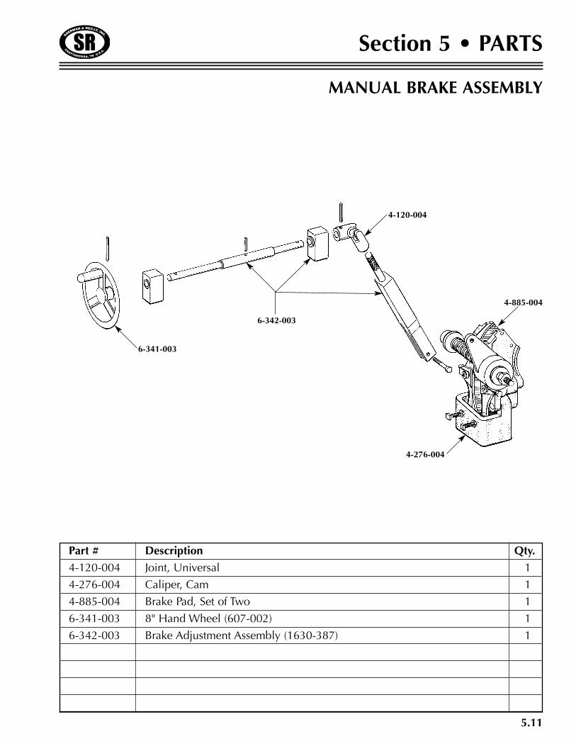
Section 5 • PARTS
MANUAL BRAKE ASSEMBLY
Part # Description Qty.
4-120-004 Joint, Universal 1
4-276-004 Caliper, Cam 1
4-885-004 Brake Pad, Set of Two 1
6-341-003 8" Hand Wheel (607-002) 1
6-342-003 Brake Adjustment Assembly (1630-387) 1
6-341-003
6-342-003
4-120-004
4-885-004
4-276-004
5.12
Section 5 • PARTS
Part # Description Qty.
A1747 “T” Handle Assembly 1
B1769 Master Cylinder Mount 1
B1778 Cylinder Mounting Rod 1
860-004 Roll Pin 2
1-829-004 Hex Head Screw 1
1-830-004 Nut 5
2-979-004 Washer 1
3-038-004 Hex Head Screw 4
4-276-004 Brake Caliper 1
4-885-004 Brake Pads (Set of Two) 1
5-192-004 Brake Master Cylinder 1
5-193-004 Hydraulic Fluid Reservoir 1
5-651-004 Pressure Gauge 1
5-830-004 Hydraulic Cylinder 1
5-867-004 Hex Head Screw 4
5-868-004 Fitting 1
5-869-004 Fitting, Tee 1
5-870-004 Fitting, Elbow 2
5-871-004 Fitting, Reducer 1
5-872-004 Brake Line Tubing 2
5-873-004 Fitting 4
5-874-004 Fitting Sleeve 4
5-875-004 Brake Line Hose 1
6-229-004 Seal Kit 1
OPTIONAL HYDRAULIC BRAKE ASSEMBLY
5.13
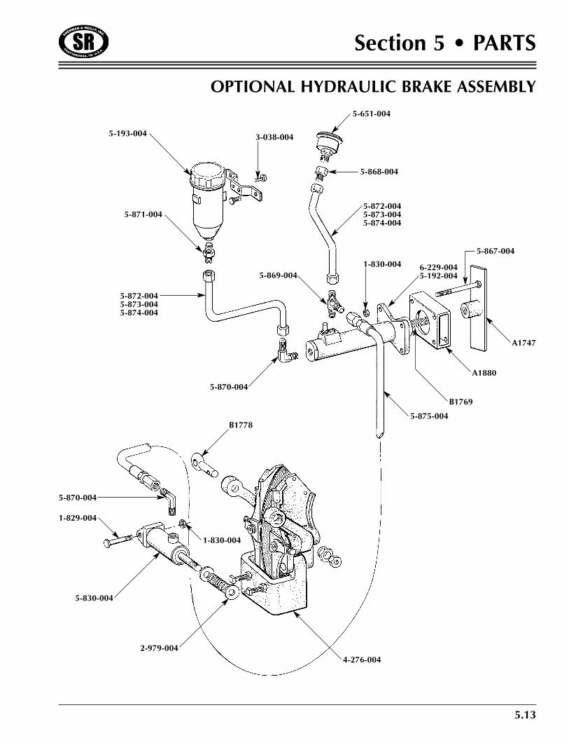
Section 5 • PARTS
OPTIONAL HYDRAULIC BRAKE ASSEMBLY
5-193-004
5-871-004
3-038-004
5-651-004
1-830-004
5-872-0045-873-0045-874-004
5-870-004
2-979-0044-276-004
B1778
A1880
5-869-004
A1747
5-868-004
5-872-0045-873-0045-874-004
6-229-0045-192-004
1-830-004
5-867-004
B1769
5-875-004
5-830-004
1-829-004
5-870-004
5.14
Section 5 • PARTS
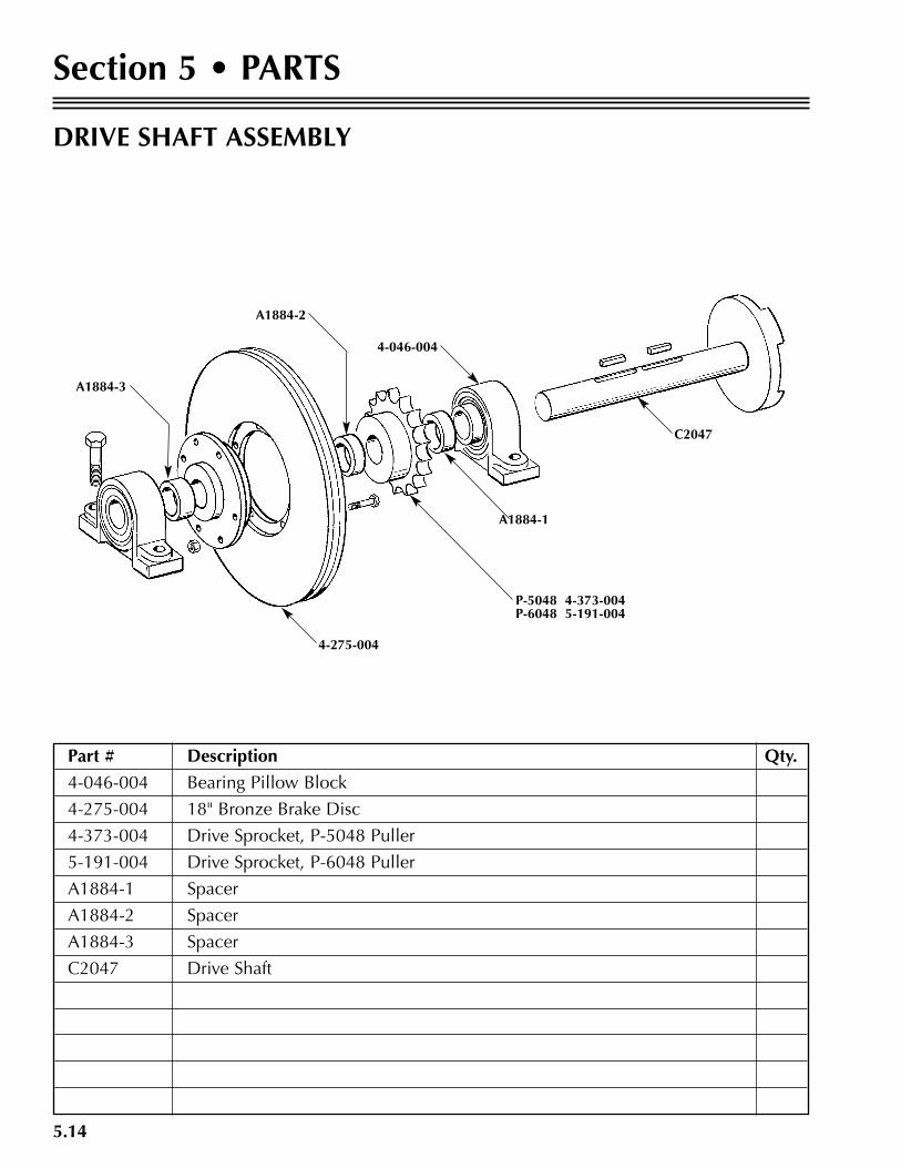
DRIVE SHAFT ASSEMBLY
Part # Description Qty.
4-046-004 Bearing Pillow Block
4-275-004 18" Bronze Brake Disc
4-373-004 Drive Sprocket, P-5048 Puller
5-191-004 Drive Sprocket, P-6048 Puller
A1884-1 Spacer
A1884-2 Spacer
A1884-3 Spacer
C2047 Drive Shaft
C2047
P-5048 4-373-004P-6048 5-191-004
4-275-004
A1884-3
4-046-004
A1884-2
A1884-1
5.15
Section 5 • PARTS
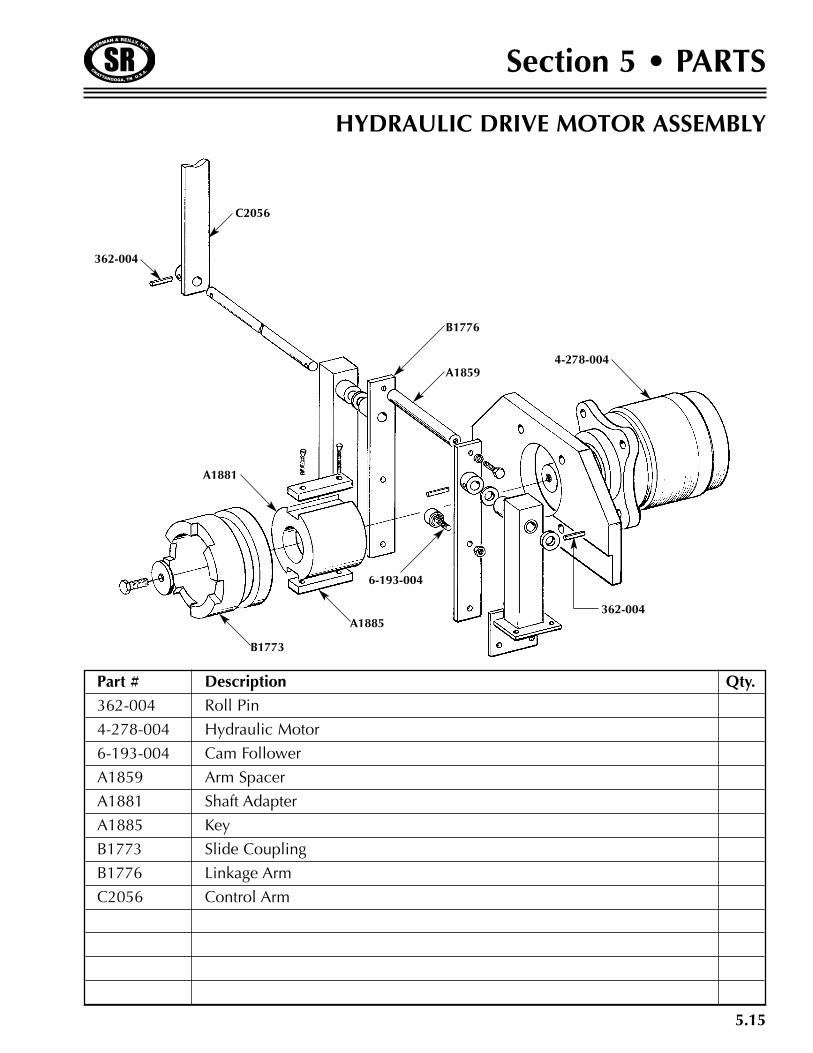
HYDRAULIC DRIVE MOTOR ASSEMBLY
Part # Description Qty.
362-004 Roll Pin
4-278-004 Hydraulic Motor
6-193-004 Cam Follower
A1859 Arm Spacer
A1881 Shaft Adapter
A1885 Key
B1773 Slide Coupling
B1776 Linkage Arm
C2056 Control Arm
C2056
362-004
A1859
B1776
A1885
A1881
B1773
6-193-004
362-004
4-278-004
5.16
Section 5 • PARTS
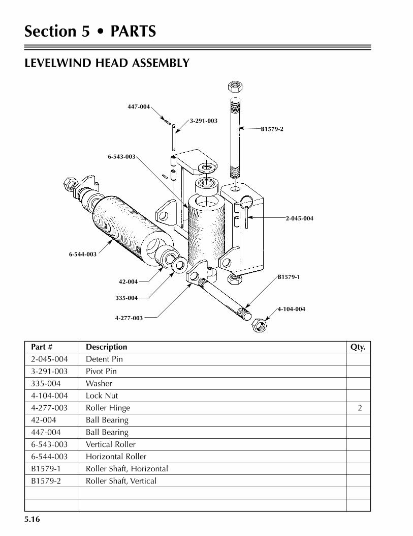
LEVELWIND HEAD ASSEMBLY
Part # Description Qty.
2-045-004 Detent Pin
3-291-003 Pivot Pin
335-004 Washer
4-104-004 Lock Nut
4-277-003 Roller Hinge 2
42-004 Ball Bearing
447-004 Ball Bearing
6-543-003 Vertical Roller
6-544-003 Horizontal Roller
B1579-1 Roller Shaft, Horizontal
B1579-2 Roller Shaft, Vertical
B1579-2
2-045-004
4-104-004
B1579-1
4-277-003
42-004
335-004
6-544-003
6-543-003
447-004
3-291-003
5.17
Section 5 • PARTS
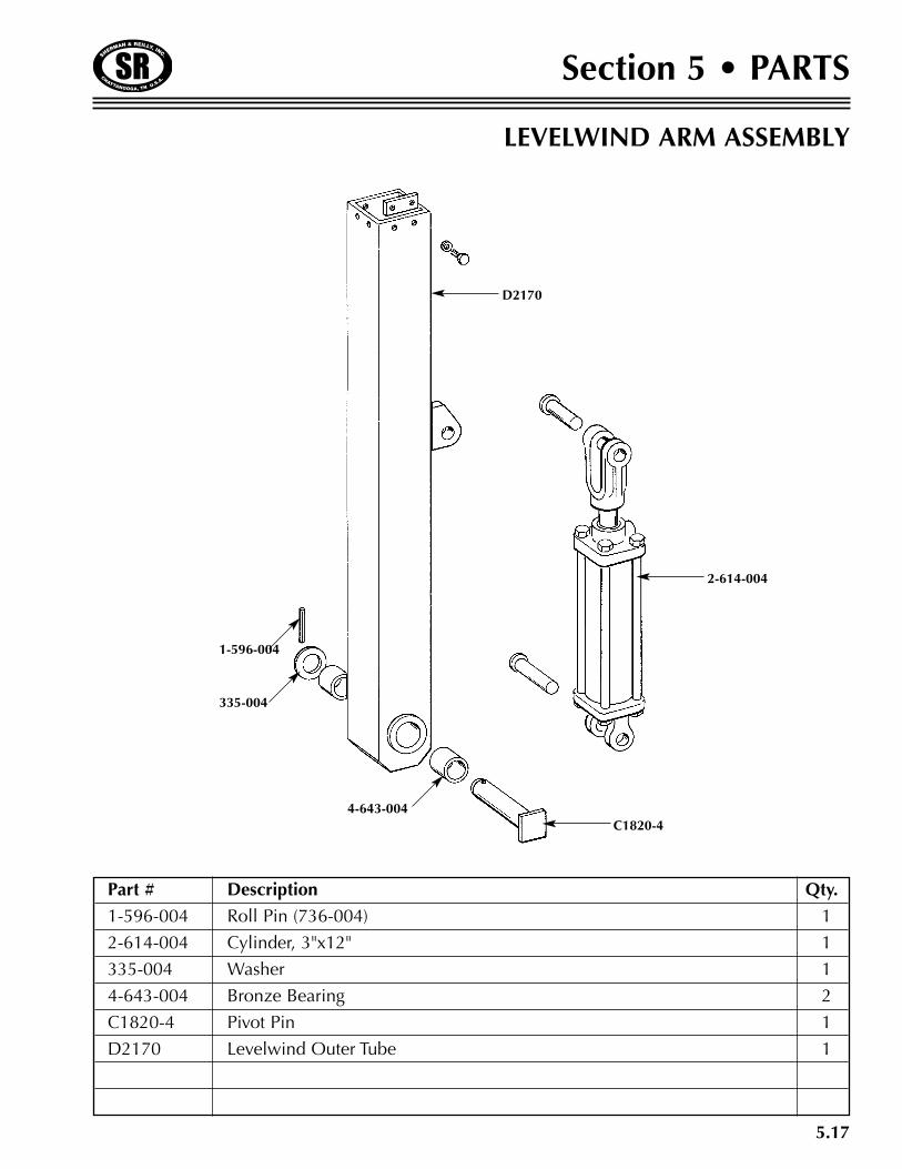
LEVELWIND ARM ASSEMBLY
Part # Description Qty.
1-596-004 Roll Pin (736-004) 1
2-614-004 Cylinder, 3"x12" 1
335-004 Washer 1
4-643-004 Bronze Bearing 2
C1820-4 Pivot Pin 1
D2170 Levelwind Outer Tube 1
4-643-004
335-004
1-596-004
C1820-4
2-614-004
D2170
5.18
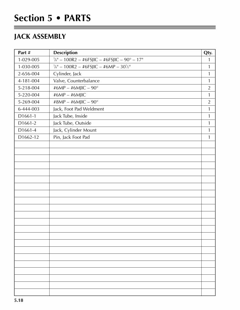
Section 5 • PARTS
JACK ASSEMBLY
Part # Description Qty.
1-029-005 3⁄8" – 100R2 – #6FSJIC – #6FSJIC – 90° – 17" 1
1-030-005 3⁄8" – 100R2 – #6FSJIC – #6MP – 301⁄2" 1
2-656-004 Cylinder, Jack 1
4-181-004 Valve, Counterbalance 1
5-218-004 #6MP – #6MJIC – 90° 2
5-220-004 #6MP – #6MJIC 1
5-269-004 #8MP – #6MJIC – 90° 2
6-444-003 Jack, Foot Pad Weldment 1
D1661-1 Jack Tube, Inside 1
D1661-2 Jack Tube, Outside 1
D1661-4 Jack, Cylinder Mount 1
D1662-12 Pin, Jack Foot Pad 1

5.19
Section 5 • PARTS
JACK ASSEMBLY
D1661-4
2-656-004
D1661-2
D1661-1
D1662-12
6-444-003
5-218-004
5-220-0044-181-004
5-218-004
1-029-005
1-030-005
5-269-004
5.20
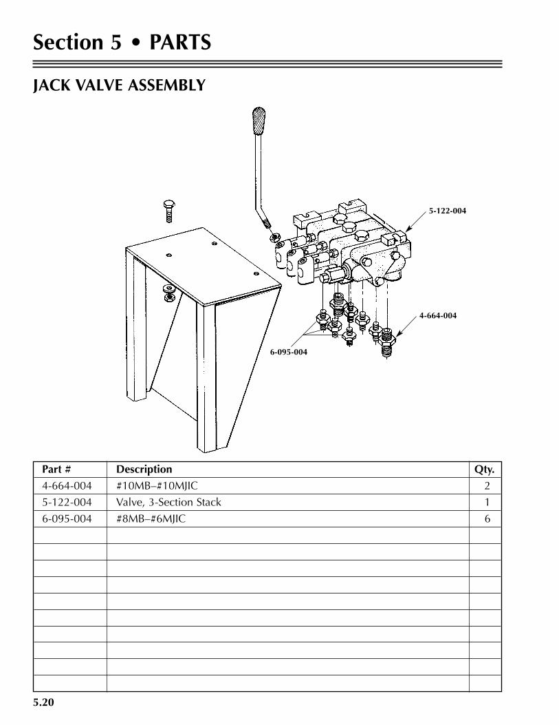
Section 5 • PARTS
JACK VALVE ASSEMBLY
Part # Description Qty.
4-664-004 #10MB–#10MJIC 2
5-122-004 Valve, 3-Section Stack 683.25 1
6-095-004 #8MB–#6MJIC 6
6-095-004
4-664-004
5-122-004
5.21
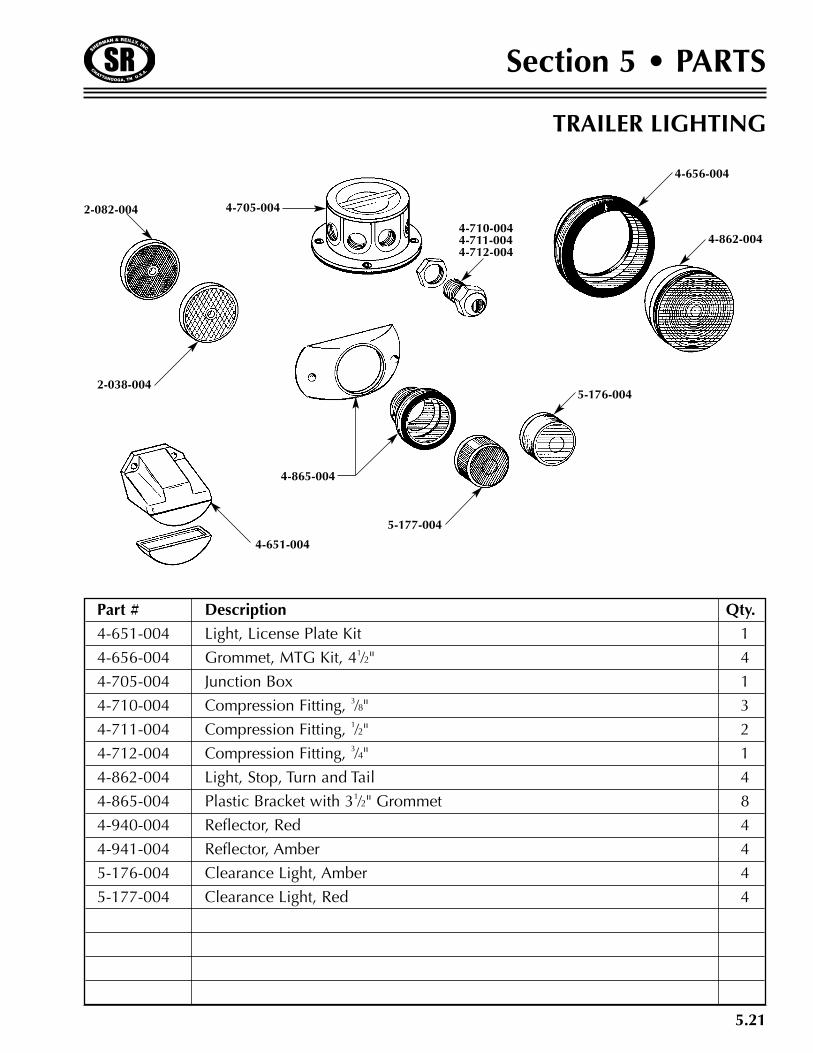
Section 5 • PARTS
Part # Description Qty.
4-651-004 Light, License Plate Kit 1
4-656-004 Grommet, MTG Kit, 41⁄2" 4
4-705-004 Junction Box 1
4-710-004 Compression Fitting, 3⁄8" 3
4-711-004 Compression Fitting, 1⁄2" 2
4-712-004 Compression Fitting, 3⁄4" 1
4-862-004 Light, Stop, Turn and Tail 4
4-865-004 Plastic Bracket with 31⁄2" Grommet 8
4-940-004 Reflector, Red 4
4-941-004 Reflector, Amber 4
5-176-004 Clearance Light, Amber 4
5-177-004 Clearance Light, Red 4
TRAILER LIGHTING
2-082-004
2-038-004
4-705-004
4-710-0044-711-0044-712-004
4-862-004
5-176-004
5-177-004
4-865-004
4-651-004
4-656-004

5.22
Section 5 • PARTS
Part # Description Qty.
3-243-004 Wheel Assembly, Complete 2
3-244-004 Tire, Tubeless Type, 7.50-16LT, 10 Ply 4
3-245-004 Wheels, 16 x 6 Dual 4
5-542-004 Axle, 10,000 Lb. Single 1
6-109 5/8" Cone Wheel Nut 1
7-101 Drum Mounting Bolt 1
7-115 Drive-in Stud, 5⁄8" Diameter 1
8-228-3UC1 Hub Assembly, Complete (does not include brake drum or mtg bolts) 1
8-288-3 Hub Only 1
9-44-1 Brake Drum Only
10-50 O-Ring Gasket for Oil Cap 1
10-51 Unitized Oil Seal, (3.88" O.D., 2.875" I.D.) 1
21-36 Oil Cap Only, 4.00" O.D., Screw-in, Plastic 1
33-52-1 Wheel Retaining Ring 1
46-32 Oil Cap Plug 1
46-52 Oil Hub Plug 1
382A Inner Race 1
387A Inner Bearing 1
25580 Outer Bearing 1
25520 Outer Race 1
BP01-301 Magnet Kit, 9 & 10K GD (yellow wire) 1
BP02-315 Actuating Arm, Left Hand 1
BP02-325 Actuating Arm, Right Hand 1
BP04-240 Shoe and Lining (One Wheel), Left Hand 1
BP04-250 Shoe and Lining (One Wheel), Right Hand 1
BP06-240 Shoe Hold Down Kit (One Wheel) 1
BP06-280 Actuating Arm Retainer, Left Hand 1
BP06-290 Actuating Arm Retainer, Right Hand 1
BP07-225 Shoe Return Spring Set (One Each, Green and Black) 1
BP08-150 Adjuster Spring 1
BP10-135 Adjuster, Lever and Spring, Left Hand 1
BP10-145 Adjuster, Lever and Spring, Right Hand 1
BP13-020 Adjuster Cable 1
BP15-085 Brake Dust Shield Metal (1-Piece) 7 Bolt 1
AXLE, WHEEL & BRAKE ASSEMBLY

5.23
Section 5 • PARTS
3-243-004
3-245-004
3-244-004
BRAKE ASSEMBLY
WHEEL ASSEMBLY
AXLE, WHEEL & BRAKE ASSEMBLY
5.24
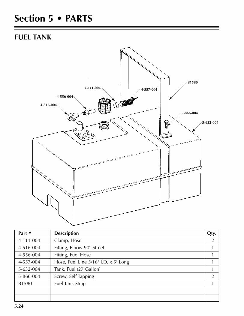
Section 5 • PARTS
FUEL TANK
Part # Description Qty.
4-111-004 Clamp, Hose 2
4-516-004 Fitting, Elbow 90° Street 1
4-556-004 Fitting, Fuel Hose 1
4-557-004 Hose, Fuel Line 5/16" I.D. x 5' Long 1
5-632-004 Tank, Fuel (27 Gallon) 1
5-866-004 Screw, Self Tapping 2
B1580 Fuel Tank Strap 1
5-632-004
B1580
4-557-004
4-516-004
4-556-004
4-111-004
5-866-004
5.25
Section 5 • PARTS
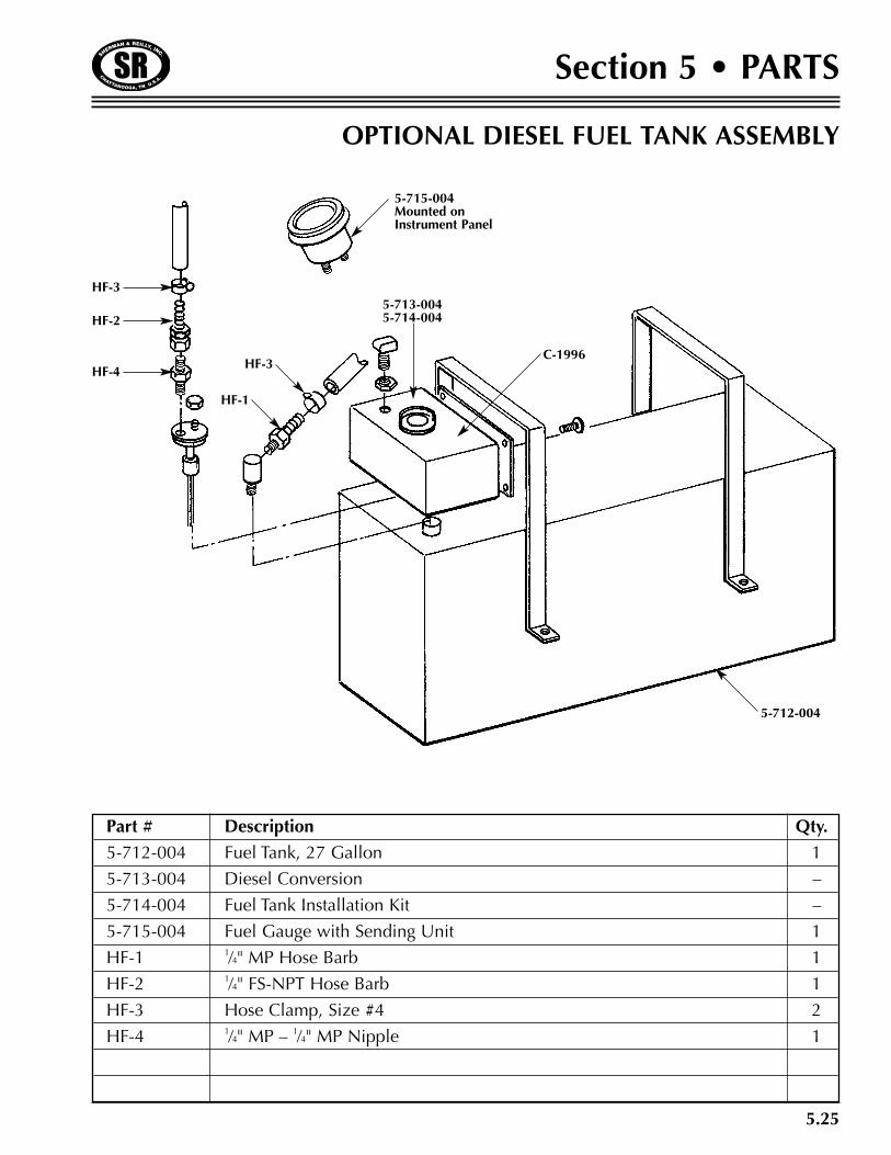
Part # Description Qty.
5-712-004 Fuel Tank, 27 Gallon 1
5-713-004 Diesel Conversion –
5-714-004 Fuel Tank Installation Kit –
5-715-004 Fuel Gauge with Sending Unit 1
HF-1 1⁄4" MP Hose Barb 1
HF-2 1⁄4" FS-NPT Hose Barb 1
HF-3 Hose Clamp, Size #4 2
HF-4 1⁄4" MP – 1⁄4" MP Nipple 1
OPTIONAL DIESEL FUEL TANK ASSEMBLY
HF-4
HF-2
HF-3
5-712-004
C-1996
5-713-0045-714-004
5-715-004Mounted onInstrument Panel
HF-3
HF-1
5.26
Section 5 • PARTS
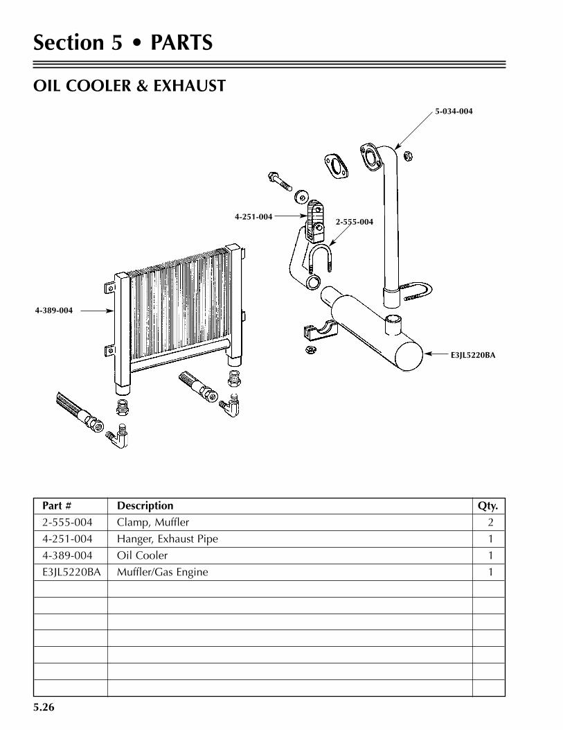
OIL COOLER & EXHAUST
Part # Description Qty.
2-555-004 Clamp, Muffler 2
4-251-004 Hanger, Exhaust Pipe 1
4-389-004 Oil Cooler 1
E3JL5220BA Muffler/Gas Engine 1
5-034-004
2-555-004
E3JL5220BA
4-389-004
4-251-004

SHERMAN & REILLY, INC.P.O. Box 11267 • 400 West 33rd StreetChattanooga, TN 37401 USAPhone 423•756•5300Fax No. 423•756•2948Toll-Free 800•251•7780Web Site www.sherman-reilly.com
Manual No. P5048/P6048 Printed in the U.S.A.