Assessment: Interviews, Tests, Techniques - Perfectionism ...

EARTHQUAKE ENGINEERING AND STRUCTURAL DYNAMICSEarthquake Engng Struct. Dyn. 2003; 32:1353–1372 (DOI: 10.1002/eqe.277)
Shake table tests on a mass eccentric modelwith base isolation
Bijan Samali∗;†, Yi Min Wu and Jianchun Li
Faculty of Engineering; University of Technology; Sydney; P.O. Box 123; Broadway, NSW 2007; Australia
SUMMARY
A mass eccentric structure is usually more seismically vulnerable than its concentric counterpart becauseof the coupled torsional–translational response of such structures. In this work, dynamic characteristicsand response of a �ve-storey benchmark model with moderate mass eccentricity were investigated usinga shake table, simulating four di�erent ground motions. The e�ectiveness of laminated rubber bearings(LRB) and lead-core rubber bearings (LCRB) in protecting eccentric structures was examined andevaluated in relation to translational and torsional responses of the benchmark model. It was observedthat both translational and torsional responses were signi�cantly reduced with the addition of either aLRB or LCRB isolated system regardless of the nature of ground motion input. The LRB were identi�edto be more e�ective than LCRB in reducing model relative displacements, the relative torsional angle aswell as accelerations, and therefore provided a better protection of the superstructure and its contents.On the other hand, LCRB rendered a smaller torsional angle and absolute displacement of the baseisolation system, hence a more stable structural system. Copyright ? 2003 John Wiley & Sons, Ltd.
KEY WORDS: eccentric model; base isolation; laminated rubber bearing; lead core rubber bearing;earthquakes; torsion
1. INTRODUCTION
Extensive research has been undertaken during the past two decades to investigate the seismicbehaviour of base isolated structures [1–3]. The basic idea of seismic base isolation is toprovide a �exible interface between a structure and the ground in order to minimize thelateral load on a superstructure during strong earthquake ground motions [4]. This is achievedby shifting the fundamental period of the structure to a range outside the periods of earthquakeground motion containing large seismic energy, and by providing supplemental damping inorder to dissipate energy. The e�ectiveness of various types of base isolation systems inlimiting the earthquake forces acting on buildings has been demonstrated both experimentally
∗ Correspondence to: Bijan Samali, Faculty of Engineering, University of Technology, Sydney, P.O. Box 123,Broadway, NSW 2007, Australia.
† E-mail: [email protected]
Received 17 May 2002Copyright ? 2003 John Wiley & Sons, Ltd. Accepted 23 October 2002

1354 B. SAMALI, Y. M. WU AND J. LI
[5] and analytically [6–8]. An excellent review of the earlier works and recent investigationson base isolation is provided in the literature [9; 10].Most of the studies have been limited to symmetric structures where the centre of mass
(CM) is also that of sti�ness (CS). However, real world structures are usually eccentric,meaning their centre of sti�ness does not coincide with their centre of mass. Some structuresare inherently eccentric, due to an asymmetric �oor plan (probably dictated by the needsof the building), or asymmetric layout of the structural members, including the location ofstair-wells and lift-shafts, etc. When a translational mode is coupled with a rotational mode,there is dynamic ampli�cation of the torsional component of seismic response. Some studies[1; 2; 11] have shown that if the uncoupled torsional and translational fundamental periodsof a structure are close then signi�cant torsional responses can occur, even if the CM–CSeccentricity is small. This e�ect has also been observed experimentally [12] during forced vi-bration tests of a multi-storey building. The seismic vulnerability of asymmetric structures hasbeen repeatedly demonstrated in strong earthquakes. Surveys and analyses conducted follow-ing the 1985 Mexico earthquake [13; 14], 1994 Northridge earthquake [15], 1985 Michanocanearthquake [16] and 1989 Loma Prieta earthquake [17], concluded that approximately 50% ofthe failures were either directly or indirectly attributable to asymmetry of structures in termsof sti�ness/strength or mass distributions. The excessive displacement and ductility demandwhich may be generated in some of the elements in post-elastic behaviour of such buildingsunder a large earthquake were not adequately accounted for in the design provisions.An interaction between lateral and torsional motions could also happen in base-isolated
structures subjected to lateral ground motions, when an eccentricity exists either in the super-structure [18–20], or in the isolation system itself [3; 21–23].Several early investigations have addressed torsional coupling in base-isolated structures
with elastomeric isolation systems. Pan and Kelly [22] pointed out that the e�ect of torsionalcoupling on the seismic response of base-isolated structures with small eccentricities is in-signi�cant, due to the combined e�ect of the time lag between the maximum lateral andtorsional response and the in�uence of the high damping in the isolation system. They stud-ied a rigid-superstructure model equipped with linear isolators possessing equivalent isolationdamping of 8–10%. Lee [3] investigated seismic response of single-storey structures, havingfour corner columns and elastomeric isolators, with masses concentrated at the same corners,and concluded that the dynamic torque ampli�cation (i.e. ratio of dynamic torque to statictorque induced in the superstructure) is small or negligible, and that the additional cornerdisplacements from the base rotation remain small (within 30% of the lateral displacement atthe centre of the base), provided the eccentricity of the isolation system is small (60:2L)—even if the superstructure eccentricity is large (60:4L). Here, L is de�ned as the width ofthe building. Eisenberger and Rutenberg [21] stated that when the eccentricity in the isola-tion system is small or zero, the torsional response is virtually eliminated, even for moderatesuperstructure eccentricities (0:16L). Experimental work from shake table tests [24; 25] seemto support conclusions drawn from the analytical studies mentioned above. Zayas [24] foundthat the torsional response is negligible in sliding isolated structures even in the presence oflarge mass and sti�ness eccentricities. Nakamura [25] reached a similar conclusion in elas-tomeric base-isolated structures that ampli�cation of torsional motions is small or negligible,for moderate superstructure and isolation system eccentricities (0:1L).However, theoretical work by Nagarajaiah [26; 27] concluded that, although the total su-
perstructure response is reduced signi�cantly due to the e�ects of elastomeric base isolation,
Copyright ? 2003 John Wiley & Sons, Ltd. Earthquake Engng Struct. Dyn. 2003; 32:1353–1372

MASS ECCENTRIC MODEL WITH BASE ISOLATION 1355
torsional ampli�cation can be signi�cant in both sliding and elastomeric base-isolated struc-tures, depending on the isolation and superstructure eccentricity and the torsional coupling ofsliding-isolated structures, and that dynamic torque ampli�cation could be as high as 4.0 forsuperstructure eccentricities of about 0:1L. The torsional behaviour and response of FoothillCommunities Law and Justice Center (FCLJC) in California, the �rst base-isolated buildingbuilt in the U.S., was studied by Tarics [28] using 3D non-linear dynamic analysis. The su-perstructure eccentricity in the structure is moderate at 0:07L [29], and the uncoupled torsionalfrequency is nearly equal to the uncoupled lateral frequency. The results of the analysis [28]indicated that in some cases the additional corner displacement at the base due to rotation isalmost equal to the lateral displacement at the centre of the base, i.e. corner displacement wasnearly twice that at the centre of the base. The preceding results contradict the conclusionsof all the previous studies. Furthermore, Papageorgiou and Lin [29] con�rmed through theobserved response of FCLJC during an earthquake that torsional coupling is a true feature ofthe structure.In the preceding review, the di�erences in results indicate that the conclusions of afore-
mentioned studies are not generally applicable and may only be applicable to the particularsystem considered and the underlying modelling assumptions. Experimental data from shaketable testing are essential for veri�cation of the validity and accuracy of certain simpli�cationsand assumptions used in the analytical studies. The problem of torsional coupling is, in gen-eral, not well understood in the context of base-isolated systems. Hence, more comprehensiveand systematic experimental studies are necessary, especially considering that only a few ref-erences [24; 25], presenting the results of shake table tests on eccentric superstructures witha base isolation system, are available in the literature. Moreover, most studies to date havedealt with sti�ness eccentric systems. However, it is likely that a mass eccentric system anda sti�ness eccentric system may exhibit di�erent inelastic responses and the design guidelinesfor these two eccentric systems could be somewhat di�erent [30; 31].This paper summarizes the results of a comprehensive experimental study that examined
dynamic response of a �ve-storey steel frame structure with a moderate mass eccentricityof 0:125L. The mass eccentric superstructure was isolated by either a set of lead-core rub-ber bearings (LCRB) or laminated rubber bearings (LRB). The tests were performed on ashake table simulating four lateral ground motions identi�ed by the International Associationfor Structural Control (IASC) as benchmark earthquakes. The aim of this study is to deter-mine whether a base isolation system is capable of reducing the torsional ampli�cation ofmass eccentric superstructure subjected to translational earthquake excitations, and, if so, todetermine the extent to which a base isolation system can be e�ective in reducing coupledlateral-torsional response. The e�ect of rubber bearing dynamic properties on the seismicallycoupled lateral-torsional response of eccentric superstructures is also explored.
2. EXPERIMENTAL STUDIES
2.1. Test model
The experimental benchmark building model, having dimensions of 1:5 m× 1:0 m× 3 m,designed by Samali [32], o�ers the �exibility needed to model and test various building con-�gurations. The original structural model, called ‘bare frame’ is a balanced concentric steel
Copyright ? 2003 John Wiley & Sons, Ltd. Earthquake Engng Struct. Dyn. 2003; 32:1353–1372

1356 B. SAMALI, Y. M. WU AND J. LI
Figure 1. (a) Concentric bare frame, (b) eccentric base-isolated frame.
frame weighing 1200 kg, as shown in Figure 1(a), and consists of �ve identical rectangularstoreys of equal �oor height. The superstructure is composed of two moment-resisting framesin the longitudinal (X ) direction and three frames in the Y direction, and was subjected toseismic ground motion along the X direction.
Copyright ? 2003 John Wiley & Sons, Ltd. Earthquake Engng Struct. Dyn. 2003; 32:1353–1372

MASS ECCENTRIC MODEL WITH BASE ISOLATION 1357
A mass eccentric model, as shown in Figure 1(b), was created by adding a total mass of350kg to one side of the above-mentioned bare frame. This extra 350kg mass was made up of140 circular steel disks, equally distributed on the front side of each �oor. This produces aneccentricity of 0:125L, where L is the width of the �oor. This level of eccentricity is regardedas moderate eccentricity. Using disks will allow the increase of mass without any unwantedincrease in frame lateral sti�ness.A base isolation system was produced by placing a pair of connected rubber bearings on
each corner of the model. The rubber bearings were secured to a steel plate which, then, wasconnected to the bare frame above and the shake table below, as shown in Figure 1(b). Twomodels isolated with laminated rubber bearings and lead-core rubber bearings are labelledLRB isolated model and LCRB isolated model, respectively.
2.2. Characteristics of rubber bearings
Laminated rubber bearings (LRB) used in this study consist of 25 thin rubber sheets with asheet thickness of 2:2mm and 25 thin-layered steel plates with a thickness of 1:8mm, respec-tively. The rubber sheets are vulcanized and bonded to the thin steel plates under pressureand heat. The inner thin steel plates prevent lateral bulging of the rubber layers, and producea large vertical sti�ness of about 500 times larger than lateral sti�ness of 220 kN=m, andtherefore provide a large vertical load carrying capacity. Horizontal �exibility is provided bythe shear deformability of the rubber sheets. The overall dimensions of the laminated bearingis 120mm× 120mm× 100mm. Two thick mounting steel plates (200mm× 200mm× 20mm)are then attached to the bottom and top surfaces of the laminated bearings to allow theisolators to be �rmly connected to the shake table and the superstructure, as shown inFigure 2(a).Con�guration and dimensions of lead-core rubber bearings (LCRB) are the same as LRB
but a lead plug with a diameter of 30 mm was inserted into a machined hole at the centreof the bearings (Figure 2(b)). In addition to LRB characteristics, a further energy dissipationmechanism can be achieved, via the plastic deformation of the lead plug. A lead rubberbearing also provides initial rigidity under lateral service loads, such as wind loads, due tothe presence of the lead plug and its high sti�ness prior to yielding. In such cases, the energydissipation mechanism is activated only once the lead plug has yielded. Furthermore, lead-corerubber bearings provide a greater restoring e�ect, which is necessary to re-centre the isolatorsto their original positions after the earthquake.
2.3. Shake table tests
Shake table tests were carried out using the unidirectional shake table facility at the Universityof Technology, Sydney. The shake table has dimensions of 3 m× 3 m and a 10 tonne loadcapacity. The shake table can move horizontally by a hydraulic actuator with a maximumacceleration of ±2:5 g (bare table), and ±0:9 g (with 10 tonne specimens), and a maximumstroke and piston velocity of ±100mm and 550mm=s, respectively. The frequency of the inputwaveform can range from 0.1 to 50 Hz.The shake table was driven in the longitudinal direction of the �ve-storey model. As the
input excitation to the table, four earthquake records: El Centre (1994), Hachinohe (1968),and 50% intensity for both Kobe (1995) and Northridge (1994) motions were used. These
Copyright ? 2003 John Wiley & Sons, Ltd. Earthquake Engng Struct. Dyn. 2003; 32:1353–1372

1358 B. SAMALI, Y. M. WU AND J. LI
Figure 2. Schematic of (a) a laminated rubber bearing LRB, and (b) a lead core rubber bearing LCRB.
earthquakes are benchmark ground motions speci�ed by the International Association forStructural Control. Measured maximum accelerations on the shake table were 0:42 g, 0:23 g,0:41g and 0:45g for the above four earthquakes, respectively. To maintain dynamic similitude,each record was compressed in time by a factor of 3 to keep the �rst mode frequency ofthe model consistent with dominant frequency of the earthquake records. In other words, thedominant frequencies of the earthquakes were increased by a factor of 3.The shake table tests were conducted on the bare frame, LRB isolated and LCRB isolated
models. Absolute �oor accelerations of the three models and the shake table were measuredusing Model 356A08 piezoelectric tri-axial accelerometers, which are speci�cally designed formodal analysis and structural testing applications. They are lightweight and high resolution.Their voltage sensitivity, frequency range, amplitude range and resolution are 100 mV=g, 0.5
Copyright ? 2003 John Wiley & Sons, Ltd. Earthquake Engng Struct. Dyn. 2003; 32:1353–1372

MASS ECCENTRIC MODEL WITH BASE ISOLATION 1359
Figure 3. Locations of installed accelerometers and LVTDs on the �oor plan.
to 5000 Hz, ±50 g and 0:001 g, respectively. Absolute �oor and shake table displacementswere measured using dynamic displacement Transducers (LVDT), Hewlett-Packard Model7/24DCDT. Its full-scale output, full-scale displacement range, scale factor and frequencyresponse range are 5:0 VDC, ±76:20 mm, 1:4 V=in and 0 to 100 Hz, respectively.As shown in Figure 3, two accelerometers and two LVDTs were installed at four di�erent
locations in plan. Two accelerometers and two LVDTs each were located at the rubber bearinglevel, the second and the �fth �oors, respectively. Additionally, another accelerometer and aLVDT were installed on the shake table to measure the table response. Test data were thenrecorded using three Yokogawa AR1200 Analyzing Recorders.
3. RESULTS OF DYNAMIC TESTS
3.1. Hysteretic characteristics of the LRB and LCRB
Cyclic loading tests are most common standard tests for determining mechanical propertiesof rubber bearings. These are usually done to evaluate lateral sti�ness and equivalent damp-ing ratios of the isolators. In this experiment, two rubber bearings are tested simultaneously,as shown in Figure 4. The test was performed by varying the pre-load, frequency and thedisplacement to simulate the in-service condition of the rubber bearings. Similar hystereticcharacteristics were observed for the entire set of either LRB or LCRB. Figure 5 showstypical hysteresis loops for LRB and LCRB under the preload of 388 kg, which is approx-imately the same as the vertical load on a rubber isolator in the isolated model. It can beseen that the lateral sti�ness of LRB is approximately constant under the current test con-ditions, but is non-linear for LCRB. The lateral sti�ness was measured from the slope ofthe shear force-displacement curve. Furthermore, LCRB demonstrated a much greater energydissipation capacity than LRB due to yielding of lead core. Additionally, it was observed thatthe characteristic strength Qd, e�ective sti�ness Ke� , and energy dissipation capacity EDC ofLCRB are dependent on the preload, frequency, and displacement which are consistent withthat reported by Tyler and Robinson [33].
3.2. Dynamic properties of the structural systems
The natural frequencies and damping ratios of unisolated and isolated models were mea-sured through impulse-hammer tests. Impulse-hammer tests were performed by impacting the
Copyright ? 2003 John Wiley & Sons, Ltd. Earthquake Engng Struct. Dyn. 2003; 32:1353–1372

1360 B. SAMALI, Y. M. WU AND J. LI
Figure 4. Experimental set-up for shear testing of rubber bearings.
�ve-storey steel frame either at the middle of the short beam of the third �oor for the transla-tional response or at the corner for the torsional response. Four accelerometers were placed atthe four corners of each �oor to pick up the translational and torsional responses. Frequencies,damping ratios and mode shapes of the �ve-storey steel frame were obtained through exper-imental modal analysis using LMS CADA-X software. The natural frequencies of the testmodels were also measured on the shake table through a sweep sine wave excitation (0.1 to50Hz), which con�rmed the results obtained by impulse-hammer tests. The results of the testsare summarized in Table I. As expected, both translational and torsional frequencies of themodel were reduced after a base isolation system was installed. However, the natural frequen-cies of the LRB-isolated model were smaller than those of the LCRB-isolated model becauseof the added lateral sti�ness provided by the lead core. Furthermore, it can be seen that tor-sional frequencies are higher than translational counterparts for each of the three test models.
3.3. Earthquake response
The e�ectiveness of the base isolation systems was evaluated by comparing the translationaland torsional responses of the models. The variation of front maximum relative displacementwith �oor height, de�ned as the �oor displacement relative to the shake table for the bareframe or relative to the base of column pads for the base-isolated model in the direction ofshake table movement, is displayed in Figure 6(a). Experimental data for maximum relativedisplacements are presented in Table II. It can be seen that relative displacements increasewith the �oor height, as expected. Clearly, both LRB and LCRB isolators are e�ective inreducing the relative movements of the model. However, the LRB isolator is better than theLCRB isolator. A smaller improvement on the earthquake responses of the LCRB-isolated
Copyright ? 2003 John Wiley & Sons, Ltd. Earthquake Engng Struct. Dyn. 2003; 32:1353–1372

MASS ECCENTRIC MODEL WITH BASE ISOLATION 1361
Figure 5. Typing hysteresis loops of (a) LRB, and (b) LCRB.
Table I. Translational and torsional frequencies of the tested eccentric models.
Natural 1st 2nd 3rd 4th 5th 6thfrequencies (Hz) Mode Mode Mode Mode Mode Mode
Bare frame (translation) 6.82 20.28 32.49 43.18 50.09Bare frame (torsion) 8.63 25.68 41.57 55.00 63.87LRB (translation) 2.51 12.15 22.20 33.98 42.55 49.90LRB (torsion) 3.36 14.92 25.82 40.98 53.64 63.31LCRB(translation) 4.15 13.55 24.64 33.65 42.67 50.00LCRB (torsion) 5.87 18.01 30.33 42.08 54.21 63.60
Copyright ? 2003 John Wiley & Sons, Ltd. Earthquake Engng Struct. Dyn. 2003; 32:1353–1372

1362 B. SAMALI, Y. M. WU AND J. LI
Figure 6. (a) Variation of maximum relative displacement with �oor height; (b) variation of maximumrelative torsional angle with �oor height.
Copyright ? 2003 John Wiley & Sons, Ltd. Earthquake Engng Struct. Dyn. 2003; 32:1353–1372

MASS ECCENTRIC MODEL WITH BASE ISOLATION 1363
Table II. Maximum relative displacements (mm).
2nd Floor 5th Floor
Front Back Front Back
El Centro earthquakeBare frame 5.33 3.07 9.94 6.80LRB 2.63 2.18 4.48 4.23LCRB 4.10 3.08 6.72 5.54
Hachinohe earthquakeBare frame 2.901 2.582 5.67 5.23LRB 2.21 1.98 3.61 4.03LCRB 2.72 2.14 5.47 4.66
50% Kobe earthquakeBare frame 6.064 5.560 11.48 10.78LRB 3.97 3.40 8.04 7.12LCRB 6.20 5.26 10.91 9.83
50% Northridge earthquakeBare frame 5.225 4.159 9.68 8.42LRB 3.56 2.56 7.14 6.43LCRB 4.57 3.19 8.30 6.28
model, compared with that of the LRB-isolated model, is attributed to its high initial sti�nessand its sudden change at certain base displacements. It is also observed that the e�ectivenessof base isolation systems is earthquake dependent. Time histories of relative displacement ofthe 5th �oor on the front side due to the El Centre earthquake is shown in Figure 7. Twointense vibration regions of the bare frame were clearly identi�ed, the maximum displacementof which occurs at 5.2 and 12:5 s, respectively. The maximum displacements in these tworegions were reduced after LRB and LCRB were mounted to the bare frame. Frequency shiftsdue to installation of LRB and LCRB systems are clearly seen in Figure 7. A comparisonof maximum relative displacements between front side and back side of the models revealslarger values for the front side than the back side (Table II), attributed to a denser massdistribution on the front side.Torsional angle was used to characterize the torsional behaviour of the model. It is simply
de�ned as the rotation of the rigid �oor diaphragm of the model. Model relative torsionalangle, termed model torsional angle, is de�ned as the di�erence in torsional angle betweenthe �fth �oor and the rubber base, which characterizes the torsional deformation of the buildingmodel. Variation of maximum model relative torsional angle with �oor height is presentedin Figure 6(b). It is very clear that a signi�cant reduction in model torsional angle can beobtained when LCRB and LRB isolators are installed under the model to form a rubber base.The isolated models behave closer to a rigid body than the bare frame. In this case, rubberbearings absorb most of the total torsional component, resulting in only a small torsionalcomponent transmitting into the building. Moreover, the e�ectiveness of LCRB in controllingtorsional deformation is almost as good as that of LRB. Capability of isolators in reducingtorsional response stems from a shift of the fundamental frequency of isolated models to avalue far lower than the dominant frequencies of earthquakes, compared to that of the bare
Copyright ? 2003 John Wiley & Sons, Ltd. Earthquake Engng Struct. Dyn. 2003; 32:1353–1372

1364 B. SAMALI, Y. M. WU AND J. LI
Figure 7. Time histories of relative displacement of the top �oor under El Centro earthquake.
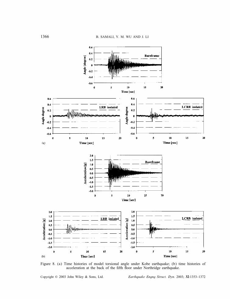
frame. This shift of frequency prevents resonance conditions. Experimental data pertaining tomaximum model torsional angles are summarized in Table III.Time histories of the model torsional angle for the �fth �oor under the 50% intensity Kobe
earthquake are depicted in Figure 8(a). Maximum torsional angle of bare frame reaches a value
Copyright ? 2003 John Wiley & Sons, Ltd. Earthquake Engng Struct. Dyn. 2003; 32:1353–1372
MASS ECCENTRIC MODEL WITH BASE ISOLATION 1365
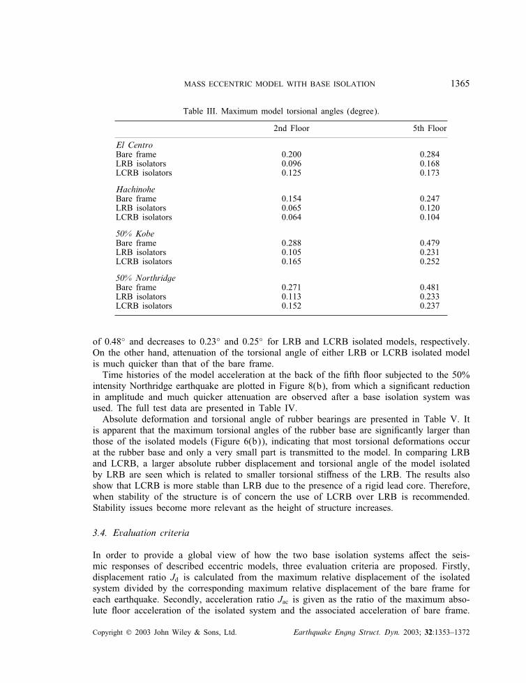
Table III. Maximum model torsional angles (degree).
2nd Floor 5th Floor
El CentroBare frame 0.200 0.284LRB isolators 0.096 0.168LCRB isolators 0.125 0.173
HachinoheBare frame 0.154 0.247LRB isolators 0.065 0.120LCRB isolators 0.064 0.104
50% KobeBare frame 0.288 0.479LRB isolators 0.105 0.231LCRB isolators 0.165 0.252
50% NorthridgeBare frame 0.271 0.481LRB isolators 0.113 0.233LCRB isolators 0.152 0.237
of 0:48◦ and decreases to 0:23◦ and 0:25◦ for LRB and LCRB isolated models, respectively.On the other hand, attenuation of the torsional angle of either LRB or LCRB isolated modelis much quicker than that of the bare frame.Time histories of the model acceleration at the back of the �fth �oor subjected to the 50%
intensity Northridge earthquake are plotted in Figure 8(b), from which a signi�cant reductionin amplitude and much quicker attenuation are observed after a base isolation system wasused. The full test data are presented in Table IV.Absolute deformation and torsional angle of rubber bearings are presented in Table V. It
is apparent that the maximum torsional angles of the rubber base are signi�cantly larger thanthose of the isolated models (Figure 6(b)), indicating that most torsional deformations occurat the rubber base and only a very small part is transmitted to the model. In comparing LRBand LCRB, a larger absolute rubber displacement and torsional angle of the model isolatedby LRB are seen which is related to smaller torsional sti�ness of the LRB. The results alsoshow that LCRB is more stable than LRB due to the presence of a rigid lead core. Therefore,when stability of the structure is of concern the use of LCRB over LRB is recommended.Stability issues become more relevant as the height of structure increases.
3.4. Evaluation criteria
In order to provide a global view of how the two base isolation systems a�ect the seis-mic responses of described eccentric models, three evaluation criteria are proposed. Firstly,displacement ratio Jd is calculated from the maximum relative displacement of the isolatedsystem divided by the corresponding maximum relative displacement of the bare frame foreach earthquake. Secondly, acceleration ratio Jac is given as the ratio of the maximum abso-lute �oor acceleration of the isolated system and the associated acceleration of bare frame.
Copyright ? 2003 John Wiley & Sons, Ltd. Earthquake Engng Struct. Dyn. 2003; 32:1353–1372
1366 B. SAMALI, Y. M. WU AND J. LI
Figure 8. (a) Time histories of model torsional angle under Kobe earthquake; (b) time histories ofacceleration at the back of the �fth �oor under Northridge earthquake.
Copyright ? 2003 John Wiley & Sons, Ltd. Earthquake Engng Struct. Dyn. 2003; 32:1353–1372

MASS ECCENTRIC MODEL WITH BASE ISOLATION 1367
Table IV. Maximum �oor accelerations (g).
Bare frame LRB LCRB
El Centro earthquakeBase Front 0.52 0.77
Back 0.46 0.612nd �oor Front 1.21 0.53 0.82
Back 0.77 0.49 0.655th �oor Front 2.07 0.60 1.35
Back 1.15 0.54 0.83
Hachinohe earthquakeBase Front 0.31 0.71
Back 0.30 0.502nd �oor Front 0.63 0.34 0.60
Back 0.61 0.33 0.395th �oor Front 1.04 0.40 1.04
Back 1.08 0.40 0.76
50% Kobe earthquakeBase Front 0.64 1.30
Back 0.60 1.132nd �oor Front 1.38 0.68 1.40
Back 1.42 0.66 1.015th �oor Front 2.26 0.91 2.21
Back 2.43 0.82 1.72
50% Northridge earthquakeBase Front 0.70 0.88
Back 0.51 0.652nd �oor Front 1.24 0.70 1.15
Back 1.00 0.54 0.785th �oor Front 1.87 0.79 1.77
Back 1.99 0.66 1.00
Table V. Absolute deformation (mm) and torsional angle (degree) of rubber bearings.
Earthquake Base Absolute deformation of Absolute torsional angleisolator rubber bearing (mm) of rubber bearing
Front side Back side (deg)
El Centro LRB 17.54 18.61 0.374LCRB 13.33 12.89 0.109
Hachinohe LRB 18.06 16.62 0.254LCRB 14.02 13.77 0.078
50% Kobe LRB 26.26 23.27 0.468LCRB 17.16 16.15 0.118
50% Northridge LRB 35.26 34.38 0.402LCRB 23.60 22.71 0.085
Copyright ? 2003 John Wiley & Sons, Ltd. Earthquake Engng Struct. Dyn. 2003; 32:1353–1372

1368 B. SAMALI, Y. M. WU AND J. LI
Figure 9. The 5th �oor acceleration ratios versus earthquake type.
Figure 10. Acceleration response spectrum for El Centro earthquake.
Lastly, torsional angle ratio Jan is calculated from the ratio of the maximum model torsionalangle with and without base isolation.Figure 9 shows the 5th �oor acceleration ratios of LRB and LCRB isolated models and
their sensitivity to the type of earthquake. It can be seen that LCRB is less e�ective than LRBin controlling accelerations. Also LRB is less sensitive to earthquake type with the exceptionof the El Centro earthquake. The relative e�ectiveness of these isolators by shifting vibrationfrequencies can be seen in Figure 10 in terms of acceleration response spectrum (e.g. for ElCentro in this case) where the spectral values reduce from 1:3g for the bare frame possessinga natural frequency of 6:82 Hz to 0:75 g for the LCRB system with a natural frequency of4:15Hz and to 0:45g for the LRB system with a natural frequency of 2:51Hz. The evaluationcriteria, namely acceleration, displacement and torsional angle ratios, for the 2nd and 5th �oors
Copyright ? 2003 John Wiley & Sons, Ltd. Earthquake Engng Struct. Dyn. 2003; 32:1353–1372

MASS ECCENTRIC MODEL WITH BASE ISOLATION 1369
Table VI. Acceleration, relative displacement, and torsional angle evaluation criteria.
Evaluation Earthquake Laminated rubber Lead core rubber bearingcriteria bearing LRB LCRB
5th Floor 5th Floor
Front Back Front Back
Acceleration El Centro 0.439 0.628 0.678 0.838ratio Hachinohe 0.543 0.547 0.949 0.643
Kobe 0.492 0.468 1.011 0.711Northridge 0.568 0.559 0.928 0.807
Displacement El Centro 0.451 0.622 0.676 0.814ratio Hachinohe 0.636 0.770 0.964 0.891
Kobe 0.700 0.659 0.950 0.911Northridge 0.738 0.763 0.858 0.745
2nd �oor 5th �oor 2nd �oor 5th �oorTorsional angle El Centro 0.480 0.592 0.625 0.608ratio Hachinohe 0.424 0.486 0.417 0.420
Kobe 0.364 0.483 0.572 0.526Northridge 0.416 0.483 0.561 0.493
and for both LRB and LCRB systems, subject to four benchmark earthquakes, are presentedin Table VI. This table con�rms overall e�ectiveness of both isolation systems, with the LRBsystem showing better response reductions. Dependence of response reduction on earthquaketype is also evident. The LRB system o�ers better response reduction for acceleration responsecompared with displacement response, where the reverse is true for the LCRB system.
3.5. Comparison with analytical studies
In order to compare the experimental results with analytical predictions, the �ve-storey modelwas modelled using ANSYS Finite Element software. In modelling the LCRB and LRBsystems, the measured sti�ness and damping properties for each type of isolator were used.The FE model assumes �xed connections for all joints, however, in reality the joints arenot fully �xed and this can introduce some errors when comparing the results with thoseobtained experimentally. Figures 11–13 show time histories of front relative displacement atlevel 5 due to the Kobe earthquake for the bare frame, LRB and LCRB systems, respectively.These �gures compare the experimental results with those predicted using �nite element (FE)modelling. As can be seen from these �gures, there is general agreement between the twosets of results. The experimental and analytical results are initially in phase but graduallydrift apart slightly, indicating that the sti�ness of the FE model is slightly di�erent than theactual model. This is the main reason for the di�erences seen in the bare frame (Figure 11).Figure 12 clearly indicates that the actual damping displayed by the LRB system during thefree vibration phase (after about 7 s) on the shake table is higher than those used in the �niteelement analysis. Di�erences seen in Figure 13 are also due to the inability of the FE modelto fully represent the actual model. It should be emphasized that by re�ning the FE model abetter agreement between the analytical and experimental results is anticipated but developingsuch a re�ned FE model was beyond the scope of this study.
Copyright ? 2003 John Wiley & Sons, Ltd. Earthquake Engng Struct. Dyn. 2003; 32:1353–1372

1370 B. SAMALI, Y. M. WU AND J. LI
Figure 11. Bare frame displacements on the front side of the 5th �oor (LVDT1)—analytical vsexperimental results (Kobe earthquake).
Figure 12. Displacements for LRB isolated model on the front side of the 5th �oor (LVDT1)—analyticalvs experimental results (Kobe earthquake).
It must also be emphasized that these di�erences were not due to the inability of theshake table to produce the desired input excitation. The UTS shake table compensates forshake table dynamics. As part of the process to prepare test drive signals, the FrequencyResponse Function (FRF) of the system (including shake table, hydraulic actuator, bearingsand a dummy specimen, etc.) were measured and inverted to calculate the initial drive signal.This signal was then used to drive the shake table and in the meantime the response ofthe shake table was measured. The information obtained from the comparison of measuredresponse from the shake table and the desired signal (e.g. the El Centro earthquake) wasused to modify the drive signal. The iteration procedure continued until the error between the
Copyright ? 2003 John Wiley & Sons, Ltd. Earthquake Engng Struct. Dyn. 2003; 32:1353–1372

MASS ECCENTRIC MODEL WITH BASE ISOLATION 1371
Figure 13. Displacements for LCRB isolated model on the front side of the 5th �oor(LVDT1)—analytical vs experimental results (Kobe earthquake).
response and desired signals was down to an acceptable level. In other words, in the end, thedesired signal was reproduced on the shake table, accurately.
4. CONCLUSIONS
In this study, the coupling e�ect of lateral and torsional responses were evaluated on a �ve-storey steel frame with eccentricity of 0:125L. A series of shake table tests were conductedon the unisolated model, the LRB-isolated and the LCRB-isolated eccentric models to in-vestigate the earthquake-resistant performance of LRB and LCRB isolators against torsionaldamage under strong ground motions. It was found, experimentally, that both LRB and LCRBsystems have great potential in reducing torsional deformation, model relative displacement,and acceleration. However, a proportion of torsional responses of the base-isolated modelsstill remains and cannot be neglected. Notable di�erences in performance between the twoisolators were also observed. The LRB was found to be similar to LCRB in protecting tor-sional deformation of the model but was more e�ective than LCRB in reducing model relativedisplacement and acceleration. The experimental results were compared favourably with thoseobtained from �nite element analysis of the �ve-storey model equipped with LRB and LCRBsystems. The two base isolation systems proved e�ective against most earthquakes but theirdependence on earthquake type needs to be addressed in future studies.
REFERENCES
1. Kan CL, Chopra AK. Linear and non-linear earthquake responses of simple torsionally coupled systems. Rep.No. UCB/E.E.R.C. 79/03, University of California at Berkeley, 1979.
2. Skinner RI, Skilton DWC, Laws DA, Unbalanced buildings and buildings with light towers under earthquakeforces. Proceedings of the 3rd World Conference on Earthquake Engineering, Auckland and Wellington,New Zealand, 1965; vol. 2:586–602.
3. Lee DM. Base Isolation for torsion reduction in asymmetric structures under earthquake loading. EarthquakeEngineering and Structural Dynamics 1980; 8:349–359.
Copyright ? 2003 John Wiley & Sons, Ltd. Earthquake Engng Struct. Dyn. 2003; 32:1353–1372

1372 B. SAMALI, Y. M. WU AND J. LI
4. Chopra AK. Dynamics of Structures, Theory and Applications to Earthquake Engineering. Prentice-Hall:Upper Saddle River, New Jersey, 1995.
5. Kelly JM, Hodder SB. Experimental study of the lead and elastomeric dampers for base isolation system inlaminated neoprene bearings. Bulletin of the New Zealand National Society for Earthquake Engineering 1982;15:53–67.
6. Constantinou MC, Tadjbakhsh IG. Hysteretic dampers in base isolation: random approach. Journal of StructuralEngineering, ASCE 1985; 111:705–721.
7. Fan F, Ahmadi G. Floor response spectra for base-isolated multi-storey structures. Earthquake Engineering andStructural Dynamics 1990; 19:377–388.
8. Lin BC, Tadjbakhsh IG, Papageorgiou AS, Ahmadi G. Performance of earthquake isolation system. Journal ofEngineering Mechanics, ASCE 1990; 116:446–461.
9. Buckle IG, Mayes RL. Seismic isolation: history, application and performance—a world overview. EarthquakeSpectra 1990; 6(2):161–202.
10. Kelly JM. A seismic base isolation: a review and bibliography. Soil Dynamics and Earthquake Engineering1986; 5(3):202–216.
11. Shepherd R, Donakl RAH. Seismic response of torsionally unbalanced buildings. Journal of Sound andVibration 1967; 6:20–37.
12. Jennings PC, Matthiesen RB, Hoener JB. Forced vibration of a tall steel frame building. Earthquake Engineeringand Structure Dynamics 1972; 1:107–132.
13. Rosenblueth E, Meli R. The 1985 earthquake: causes and e�ects in Mexico city. Concrete International 1986;8:23–34.
14. Chandler AM. Building damage in Mexico city earthquake. Nature 1986; 320(6062):497–501.15. CSMIP strong-motion record from the Northridge, California earthquake of January 17, 1994. California
Department of Conservation, Division of Mines and Geology, Sacramento, California 1994.16. Esteva L. Earthquake engineering research and practice in Mexico after the 1985 Earthquake. Bulletin of the
New Zealand National Society for Earthquake Engineering 1987; 20(3):159–200.17. Mitchell D. Damage to buildings due to the 1989 Loma Prieta earthquake—a Canadian code perspective.
Canadian Journal of Civil Engineering 1990; 17(15):813–834.18. Hart GC, DiJulio RM, Lew M. Torsional response of high-rise buildings. Journal of the Structural Division,
ASCE 1975; 101(2):397–416.19. Kan CL, Chopra AK. Torsional coupling and earthquake response of simple elastic and inelastic systems. Journal
of the Structural Division, ASCE 1981; 107:1569–1588.20. Ryan KL, Chopra AK. Approximate analysis methods for asymmetric plan base-isolated buildings. Earthquake
Engineering and Structural Dynamics 2002; 31:33–54.21. Eisenberger M, Rutenberg A. Seismic base isolation of asymmetric shear buildings. Engineering Structures
1986; 8(1):2–8.22. Pan TC, Kelly JM. Seismic response of torsionally coupled base isolated structures. Earthquake Engineering
and Structural Dynamics 1983; 11(6):749–770.23. Hwang JS, Hsu TY. Experimental study of isolated building under triaxial ground excitations. Journal of
Structural Engineering 2000; 126(8):879–886.24. Zayas VA, Low SS, Mahin SA. The FPS earthquake resisting system: Experimental report. Rep. No. 87/01,
Earthquake Engrg. Res. Ctr., University of California, Berkeley, Berkeley, Calif. 1987.25. Nakamura T, Suzuki T, Okada H, Takeda T. Study of base isolation for torsional response reduction in
asymmetric structures under earthquake motion. Proceedings of the 9th World Conference on EarthquakeEngineering, International Association for Earthquake Engineering 1988; 5:675–680.
26. Nagarajaiah S, Reinhorn AM, Constantinou MC. Torsional coupling in sliding isolated structures. Journal ofthe Structural Division, ASCE 1993; 119(1):130–149.
27. Nagarajaiah S, Reinhom AM, Constantinou MC. Torsion in Base-isolated structures with elastomeric isolationsystems. Journal of Structural Engineering 1993; 119(10):2932–2951.
28. Tarics AG, Way D, Kelly JM. The implementation of base isolation for the foothill communities law and justicecenter. Report to the National Science Foundation 1984.
29. Papageorgiou AS, Lin BC. Study of the earthquake response of the base-isolated law and justice center inRancho Cucamonga. Earthquake Engineering and Structural Dynamics 1989; 18(4):1189–1200.
30. Tso WK, Ying H. Additional seismic inelastic deformation caused by structural asymmetry. EarthquakeEngineering and Structural Dynamics 1990; 19:243–258.
31. Tso WK, Zhu TJ. Design of torsionally unbalanced structural systems based on code provisions I: Ductilitydemand. Earthquake Engineering and Structural Dynamics 1992; 21:609–627.
32. Samali B, Li J, Mayol E, Wu YM. System identi�cation of a �ve storey benchmark model using modal analysis.Proceedings of the International Conference on Applications of Modal Analysis, Gold Coast, Queensland,Australia, paper 12, 1999.
33. Tyler RG, Robinson WH. High-strain tests on lead rubber bearings for earthquake loading. Bulletin of the NewZealand National Society for Earthquake Engineering 1984; 17(2):90–105.
Copyright ? 2003 John Wiley & Sons, Ltd. Earthquake Engng Struct. Dyn. 2003; 32:1353–1372
Copyright © 2022 FDOKUMEN