SFP-5UD & SFP-10UD Series - Manual
136
Fire Alarm Control Panels SFP-5UD & SFP-10UD Series Manual Document 52879 Rev: C6 6/12/2018 ECN: 18-253
-
Upload
khangminh22 -
Category
Documents
-
view
1 -
download
0
Transcript of SFP-5UD & SFP-10UD Series - Manual

Fire Alarm Control Panels
SFP-5UD & SFP-10UD SeriesManual
Document 52879 Rev: C66/12/2018 ECN: 18-253
2 SFP-5UD & SFP-10UD Series Manual— P/N 52879:C6 6/12/2018
Fire Alarm & Emergency Communication System LimitationsWhile a life safety system may lower insurance rates, it is not a substitute for life and property insurance!
An automatic fire alarm system—typically made up of smoke detectors, heat detectors, manual pull stations, audible warning devices, and a fire alarm control panel (FACP) with remote notifica-tion capability—can provide early warning of a developing fire. Such a system, however, does not assure protection against property damage or loss of life resulting from a fire.
An emergency communication system—typically made up of an automatic fire alarm system (as described above) and a life safety communication system that may include an autonomous control unit (ACU), local operating console (LOC), voice communication, and other various interoperable communication methods—can broadcast a mass notification message. Such a system, however, does not assure protection against property damage or loss of life resulting from a fire or life safety event.
The Manufacturer recommends that smoke and/or heat detectors be located throughout a protected premises following the recommendations of the current edition of the National Fire Protection Association Standard 72 (NFPA 72), manufacturer's recommendations, State and local codes, and the recommendations contained in the Guide for Proper Use of System Smoke Detectors, which is made available at no charge to all installing dealers. This document can be found at http://www.systemsensor.com/appguides/. A study by the Federal Emergency Management Agency (an agency of the United States government) indicated that smoke detectors may not go off in as many as 35% of all fires. While fire alarm systems are designed to provide early warning against fire, they do not guarantee warning or protection against fire. A fire alarm system may not provide timely or adequate warning, or simply may not function, for a variety of reasons:
Smoke detectors may not sense fire where smoke cannot reach the detectors such as in chimneys, in or behind walls, on roofs, or on the other side of closed doors. Smoke detectors also may not sense a fire on another level or floor of a building. A second-floor detector, for example, may not sense a first-floor or basement fire.
Particles of combustion or “smoke” from a developing fire may not reach the sensing chambers of smoke detectors because:
• Barriers such as closed or partially closed doors, walls, chim-neys, even wet or humid areas may inhibit particle or smoke flow.
• Smoke particles may become “cold,” stratify, and not reach the ceiling or upper walls where detectors are located.
• Smoke particles may be blown away from detectors by air out-lets, such as air conditioning vents.
• Smoke particles may be drawn into air returns before reaching the detector.
The amount of “smoke” present may be insufficient to alarm smoke detectors. Smoke detectors are designed to alarm at various levels of smoke density. If such density levels are not created by a devel-oping fire at the location of detectors, the detectors will not go into alarm.
Smoke detectors, even when working properly, have sensing limita-tions. Detectors that have photoelectronic sensing chambers tend to detect smoldering fires better than flaming fires, which have little visible smoke. Detectors that have ionizing-type sensing chambers tend to detect fast-flaming fires better than smoldering fires. Because fires develop in different ways and are often unpredictable in their growth, neither type of detector is necessarily best and a given type of detector may not provide adequate warning of a fire.
Smoke detectors cannot be expected to provide adequate warning of fires caused by arson, children playing with matches (especially in bedrooms), smoking in bed, and violent explosions (caused by escaping gas, improper storage of flammable materials, etc.).
Heat detectors do not sense particles of combustion and alarm only when heat on their sensors increases at a predetermined rate or reaches a predetermined level. Rate-of-rise heat detectors may be subject to reduced sensitivity over time. For this reason, the rate-of-rise feature of each detector should be tested at least once per year by a qualified fire protection specialist. Heat detectors are designed to protect property, not life.
IMPORTANT! Smoke detectors must be installed in the same room as the control panel and in rooms used by the system for the connection of alarm transmission wiring, communications, signal-ing, and/or power. If detectors are not so located, a developing fire may damage the alarm system, compromising its ability to report a fire.
Audible warning devices such as bells, horns, strobes, speak-ers and displays may not alert people if these devices are located on the other side of closed or partly open doors or are located on another floor of a building. Any warning device may fail to alert peo-ple with a disability or those who have recently consumed drugs, alcohol, or medication. Please note that:
• An emergency communication system may take priority over a fire alarm system in the event of a life safety emergency.
• Voice messaging systems must be designed to meet intelligibility requirements as defined by NFPA, local codes, and Authorities Having Jurisdiction (AHJ).
• Language and instructional requirements must be clearly dis-seminated on any local displays.
• Strobes can, under certain circumstances, cause seizures in people with conditions such as epilepsy.
• Studies have shown that certain people, even when they hear a fire alarm signal, do not respond to or comprehend the meaning of the signal. Audible devices, such as horns and bells, can have different tonal patterns and frequencies. It is the property owner's responsibility to conduct fire drills and other training exercises to make people aware of fire alarm signals and instruct them on the proper reaction to alarm signals.
• In rare instances, the sounding of a warning device can cause temporary or permanent hearing loss.
A life safety system will not operate without any electrical power. If AC power fails, the system will operate from standby batteries only for a specified time and only if the batteries have been properly maintained and replaced regularly.
Equipment used in the system may not be technically compatible with the control panel. It is essential to use only equipment listed for service with your control panel.
Telephone lines needed to transmit alarm signals from a premises to a central monitoring station may be out of service or temporarily disabled. For added protection against telephone line failure, backup radio transmission systems are recommended.
The most common cause of life safety system malfunction is inad-equate maintenance. To keep the entire life safety system in excel-lent working order, ongoing maintenance is required per the manufacturer's recommendations, and UL and NFPA standards. At a minimum, the requirements of NFPA 72 shall be followed. Envi-ronments with large amounts of dust, dirt, or high air velocity require more frequent maintenance. A maintenance agreement should be arranged through the local manufacturer's representative. Mainte-nance should be scheduled as required by National and/or local fire codes and should be performed by authorized professional life safety system installers only. Adequate written records of all inspec-tions should be kept.
Limit-D2-2016
SFP-5UD & SFP-10UD Series Manual— P/N 52879:C6 6/12/2018 3
Installation PrecautionsAdherence to the following will aid in problem-free installation with long-term reliability:WARNING - Several different sources of power can be con-nected to the fire alarm control panel. Disconnect all sources of power before servicing. Control unit and associated equipment may be damaged by removing and/or inserting cards, modules, or interconnecting cables while the unit is energized. Do not attempt to install, service, or operate this unit until manuals are read and understood.
CAUTION - System Re-acceptance Test after Software Changes: To ensure proper system operation, this product must be tested in accordance with NFPA 72 after any programming opera-tion or change in site-specific software. Re-acceptance testing is required after any change, addition or deletion of system compo-nents, or after any modification, repair or adjustment to system hardware or wiring. All components, circuits, system operations, or software functions known to be affected by a change must be 100% tested. In addition, to ensure that other operations are not inadver-tently affected, at least 10% of initiating devices that are not directly affected by the change, up to a maximum of 50 devices, must also be tested and proper system operation verified.
This system meets NFPA requirements for operation at 0-49º C/32-120º F and at a relative humidity . However, the useful life of the system's standby batteries and the electronic components may be adversely affected by extreme temperature ranges and humidity. Therefore, it is recommended that this system and its peripherals be installed in an environment with a normal room temperature of 15-27º C/60-80º F.
Verify that wire sizes are adequate for all initiating and indicating device loops. Most devices cannot tolerate more than a 10% I.R. drop from the specified device voltage.
Like all solid state electronic devices, this system may operate erratically or can be damaged when subjected to lightning induced transients. Although no system is completely immune from light-ning transients and interference, proper grounding will reduce sus-ceptibility. Overhead or outside aerial wiring is not recommended, due to an increased susceptibility to nearby lightning strikes. Con-sult with the Technical Services Department if any problems are anticipated or encountered.
Disconnect AC power and batteries prior to removing or inserting circuit boards. Failure to do so can damage circuits.
Remove all electronic assemblies prior to any drilling, filing, reaming, or punching of the enclosure. When possible, make all cable entries from the sides or rear. Before making modifications, verify that they will not interfere with battery, transformer, or printed circuit board location.
Do not tighten screw terminals more than 9 in-lbs. Over-tighten-ing may damage threads, resulting in reduced terminal contact pressure and difficulty with screw terminal removal.
This system contains static-sensitive components. Always ground yourself with a proper wrist strap before handling any cir-cuits so that static charges are removed from the body. Use static suppressive packaging to protect electronic assemblies removed from the unit.
Follow the instructions in the installation, operating, and pro-gramming manuals. These instructions must be followed to avoid damage to the control panel and associated equipment. FACP operation and reliability depend upon proper installation.
Precau-D1-9-2005
FCC WarningWARNING: This equipment generates, uses, and can radi-ate radio frequency energy and if not installed and used in accordance with the instruction manual may cause interfer-ence to radio communications. It has been tested and found to comply with the limits for class A computing devices pur-suant to Subpart B of Part 15 of FCC Rules, which is designed to provide reasonable protection against such interference when devices are operated in a commercial environment. Operation of this equipment in a residential area is likely to cause interference, in which case the user will be required to correct the interference at his or her own expense.
Canadian Requirements
This digital apparatus does not exceed the Class A limits for radiation noise emissions from digital apparatus set out in the Radio Interference Regulations of the Canadian Depart-ment of Communications.
Le present appareil numerique n'emet pas de bruits radio-electriques depassant les limites applicables aux appareils numeriques de la classe A prescrites dans le Reglement sur le brouillage radioelectrique edicte par le ministere des Communications du Canada.
HARSH™, NIS™, and NOTI•FIRE•NET™ are all trademarks; and Acclimate® Plus™, eVance®, FlashScan®, FAAST Fire Alarm Aspiration Sensing Technology®,Honeywell®, Intelligent FAAST®, NOTIFIER®, ONYX®, ONYXWorks®, SWIFT®, VeriFire®, and VIEW® are all registered trademarks of Honeywell International Inc.Microsoft® and Windows® are registered trademarks of the Microsoft Corporation. Chrome™ and Google™ are trademarks of Google Inc. Firefox® is a registeredtrademark of The Mozilla Foundation.
©2018 by Honeywell International Inc. All rights reserved. Unauthorized use of this document is strictly prohibited.
4 SFP-5UD & SFP-10UD Series Manual— P/N 52879:C6 6/12/2018
Software DownloadsIn order to supply the latest features and functionality in fire alarm and life safety technology to our customers, we make frequent upgrades to the embedded software in our products. To ensure that you are installing and programming the latest features, we strongly recommend that you download the most current version of software for each product prior to commissioning any system. Contact Technical Support with any questions about software and the appropriate version for a specific application.
Documentation FeedbackYour feedback helps us keep our documentation up-to-date and accurate. If you have any comments or suggestions about our online Help or printed manuals, you can email us.
Please include the following information:
• Product name and version number (if applicable)
• Printed manual or online Help
• Topic Title (for online Help)
• Page number (for printed manual)
• Brief description of content you think should be improved or corrected
• Your suggestion for how to correct/improve documentation
Send email messages to:
Please note this email address is for documentation feedback only. If you have any technical issues, please contact Technical Services.
Table of Contents
Section 1: Product Description ...................................................................................................................................... 121.1: Product Features ..............................................................................................................................................................................................121.2: Specifications...................................................................................................................................................................................................131.3: Controls and Indicators....................................................................................................................................................................................171.4: Digital Alarm Communicator/Transmitter.......................................................................................................................................................171.5: Components .....................................................................................................................................................................................................181.6: Optional Modules and Accessories..................................................................................................................................................................181.7: Telephone Requirements and Warnings...........................................................................................................................................................19
1.7.1: Telephone Circuitry ..............................................................................................................................................................................191.7.2: Digital Communicator ..........................................................................................................................................................................191.7.3: Telephone Company Rights and Warnings ..........................................................................................................................................191.7.4: For Canadian Applications ...................................................................................................................................................................20
Section 2: Installation ..................................................................................................................................................... 212.1: Backbox Mounting ..........................................................................................................................................................................................212.2: Operating Power ..............................................................................................................................................................................................232.3: Input Circuits ...................................................................................................................................................................................................242.4: Output Circuits.................................................................................................................................................................................................26
2.4.1: Notification Appliance Circuits ............................................................................................................................................................262.4.2: Special Application DC Power Output Connections............................................................................................................................272.4.3: Relays - Programmable.........................................................................................................................................................................282.4.4: Remote Synchronization Output...........................................................................................................................................................28
2.5: Power-limited Wiring Requirements ...............................................................................................................................................................292.6: Digital Communicator .....................................................................................................................................................................................302.7: Installation of Optional Modules .....................................................................................................................................................................31
2.7.1: N-CAC-5X Class A Converter Module................................................................................................................................................31Installation ..............................................................................................................................................................................................31Wiring NACs and IDCs for Class A.......................................................................................................................................................31
2.7.2: 4XTM Option Module..........................................................................................................................................................................324XTM Transmitter Module Installation .................................................................................................................................................33
2.7.3: ANN-SEC Option Card ........................................................................................................................................................................342.8: ANN-BUS Devices ..........................................................................................................................................................................................35
Guidelines ...............................................................................................................................................................................................352.8.1: ANN-BUS Wiring ................................................................................................................................................................................35
Calculating Wiring Distance for ANN-BUS Modules ...........................................................................................................................35Wiring Configuration..............................................................................................................................................................................37Powering ANN-BUS Devices from Auxiliary Power Supply................................................................................................................38
2.8.2: ANN-BUS Device Addressing .............................................................................................................................................................382.8.3: N-ANN-80(C) Remote Fire Annunciator/Indicator .............................................................................................................................38
Specifications..........................................................................................................................................................................................39Installation ..............................................................................................................................................................................................39Opening/Closing Annunciator ................................................................................................................................................................39Mounting.................................................................................................................................................................................................39Wiring N-ANN-80 to FACP...................................................................................................................................................................40
2.8.4: N-ANN-S/PG Serial/Parallel Printer Interface Installation..................................................................................................................41Specifications..........................................................................................................................................................................................41PRN-7 Printer Installation ......................................................................................................................................................................41PRN-6 Printer Installation ......................................................................................................................................................................42
2.8.5: N-ANN-I/O LED Driver Module .........................................................................................................................................................43N-ANN-I/O Board Layout......................................................................................................................................................................43Specifications..........................................................................................................................................................................................43N-ANN-I/O Connection to FACP ..........................................................................................................................................................44N-ANN-I/O Module LED Wiring ..........................................................................................................................................................44
2.8.6: N-ANN-LED Annunciator Module ......................................................................................................................................................45Specifications..........................................................................................................................................................................................45Mounting/Installation..............................................................................................................................................................................45N-ANN-LED Board Layout and Connection to FACP ..........................................................................................................................46
2.8.7: N-ANN-RLY Relay Module ................................................................................................................................................................46Specifications..........................................................................................................................................................................................46Mounting/Installation..............................................................................................................................................................................47N-ANN-RLY Board Layout and Connection to FACP..........................................................................................................................48
SFP-5UD & SFP-10UD Series Manual— P/N 52879:C6 6/12/2018 5
Table of Contents
2.9: ANN-BUS Audio Panel ...................................................................................................................................................................................48
Section 3: Programming ................................................................................................................................................. 503.1: User Programming...........................................................................................................................................................................................503.2: Initial Power-up ...............................................................................................................................................................................................523.3: Programming Screens Description ..................................................................................................................................................................523.4: Programming and Passwords...........................................................................................................................................................................523.5: Master Programming Level .............................................................................................................................................................................53
3.5.1: Input Zones ...........................................................................................................................................................................................533.5.2: NAC (Notification Appliance Circuit) .................................................................................................................................................64
Enabled ...................................................................................................................................................................................................64NAC Coding ...........................................................................................................................................................................................64Silence.....................................................................................................................................................................................................66Auto Silence............................................................................................................................................................................................66Silence Inhibited .....................................................................................................................................................................................66
3.5.3: Relays ...................................................................................................................................................................................................673.5.4: System Setup ........................................................................................................................................................................................67
Timers .....................................................................................................................................................................................................67Banner.....................................................................................................................................................................................................69Time-Date ...............................................................................................................................................................................................69Trouble Reminder ...................................................................................................................................................................................70Canadian Option .....................................................................................................................................................................................70Charger Disable ......................................................................................................................................................................................71
3.5.5: Option Modules ....................................................................................................................................................................................71ANN-BUS...............................................................................................................................................................................................71ANN-RLY Options Screen.....................................................................................................................................................................74ANN-AUDIO Options Screen ................................................................................................................................................................74ANN-SEC Enable ...................................................................................................................................................................................74Onboard DACT.......................................................................................................................................................................................75
3.5.6: History ..................................................................................................................................................................................................91View Events ............................................................................................................................................................................................91Erase History...........................................................................................................................................................................................92
3.5.7: Walktest ................................................................................................................................................................................................923.5.8: Clear Program.......................................................................................................................................................................................92
Printer/PC................................................................................................................................................................................................933.5.9: Password Change..................................................................................................................................................................................93
3.6: Maintenance Programming Level....................................................................................................................................................................943.6.1: Input Zones - Enable/Disable ...............................................................................................................................................................943.6.2: History ..................................................................................................................................................................................................943.6.3: Walktest ................................................................................................................................................................................................953.6.4: Time-Date .............................................................................................................................................................................................95
Section 4: Operating Instructions.................................................................................................................................. 964.1: Panel Control Buttons......................................................................................................................................................................................96
4.1.1: Acknowledge/Step................................................................................................................................................................................964.1.2: Alarm Silenced .....................................................................................................................................................................................964.1.3: Drill/Hold 2 Sec....................................................................................................................................................................................964.1.4: Reset .....................................................................................................................................................................................................96
4.2: LED Indicators.................................................................................................................................................................................................964.3: Normal Operation ............................................................................................................................................................................................964.4: Trouble Operation............................................................................................................................................................................................974.5: Alarm Operation ..............................................................................................................................................................................................974.6: Supervisory Operation .....................................................................................................................................................................................984.7: Process Monitor Operation ..............................................................................................................................................................................984.8: Hazard/Tornado Condition Operation .............................................................................................................................................................994.9: Medical Alert Condition Operation .................................................................................................................................................................994.10: Disable/Enable Operation..............................................................................................................................................................................994.11: Waterflow Circuits Operation ........................................................................................................................................................................994.12: Detector Functions.........................................................................................................................................................................................994.13: Time Functions: Real-Time Clock...............................................................................................................................................................1004.14: Coded Operation..........................................................................................................................................................................................1004.15: Presignal ......................................................................................................................................................................................................1004.16: Positive Alarm Sequence .............................................................................................................................................................................100
6 SFP-5UD & SFP-10UD Series Manual— P/N 52879:C6 6/12/2018
Table of Contents
4.17: Special System Timers.................................................................................................................................................................................1004.17.1: Silence Inhibit Timer ........................................................................................................................................................................1004.17.2: Autosilence Timer ............................................................................................................................................................................1014.17.3: Trouble Reminder .............................................................................................................................................................................1014.17.4: Waterflow Retard Timer...................................................................................................................................................................1014.17.5: Alarm Verification (None or One Minute) .......................................................................................................................................101
4.18: Walktest........................................................................................................................................................................................................1014.19: Read Status ..................................................................................................................................................................................................102
4.19.1: Input Zones .......................................................................................................................................................................................1024.19.2: NAC..................................................................................................................................................................................................1024.19.3: Relays ...............................................................................................................................................................................................1034.19.4: System Settings.................................................................................................................................................................................1034.19.5: Timers ...............................................................................................................................................................................................1034.19.6: Daylight Savings...............................................................................................................................................................................1034.19.7: History ..............................................................................................................................................................................................1034.19.8: Print...................................................................................................................................................................................................1034.19.9: ANN-BUS.........................................................................................................................................................................................1044.19.10: Central Station ................................................................................................................................................................................1044.19.11: Phone Line ......................................................................................................................................................................................1044.19.12: Service Terminal.............................................................................................................................................................................105
Section 5: Central Station Communications............................................................................................................... 1065.1: Transmittal Priorities .....................................................................................................................................................................................106
Section 6: Local/Remote Site Upload/Download........................................................................................................ 1086.1: Remote Download .........................................................................................................................................................................................1086.2: Transferring a Program ..................................................................................................................................................................................108
6.2.1: Security Features ................................................................................................................................................................................109
Section 7: Power Supply Calculations ........................................................................................................................ 1107.1: Overview........................................................................................................................................................................................................1107.2: Calculating the AC Branch Circuit ................................................................................................................................................................1107.3: Calculating the System Current Draw ...........................................................................................................................................................110
7.3.1: Overview.............................................................................................................................................................................................1107.3.2: How to Use Table 7.3 on page 111 to Calculate System Current Draw ............................................................................................110
7.4: Calculating the Battery Size ..........................................................................................................................................................................1127.4.1: NFPA Battery Requirements ..............................................................................................................................................................1127.4.2: Selecting and Locating Batteries ........................................................................................................................................................112
Appendix A: Ademco Contact ID Format Event Code Descriptions ........................................................................ 113A.1: Transmission Format Between DACT and Receiver....................................................................................................................................113A.2: Ademco Contact ID Typical Printout............................................................................................................................................................113
Appendix B: NFPA Standard-Specific Requirements ................................................................................................ 118B.1: Central Station/Remote Station Transmitter: Connection to FACP Dry Contacts........................................................................................123
Appendix C: FACP with Keltron................................................................................................................................... 124
Appendix D: Wire Requirements.................................................................................................................................. 125D.1: SFP-5UD(E) NAC Wiring ............................................................................................................................................................................125D.2: SFP-5UDC & SFP-10UD(C/E) NAC Wiring...............................................................................................................................................126
Appendix E: Default Programming .............................................................................................................................. 127
Appendix F: Canadian Applications ............................................................................................................................ 128F.1: N-ANN-LED Annunciator Installation for Canadian Applications...............................................................................................................128
Index ............................................................................................................................................................................... 130
SFP-5UD, SFP-5UDE, SFP-5UDC, SFP-10UD, SFP-10UDE, SFP-10UDCFire Alarm Control PanelOperating Instructions .................................................................................................................................................. 133
SFP-5UD & SFP-10UD Series Manual— P/N 52879:C6 6/12/2018 7
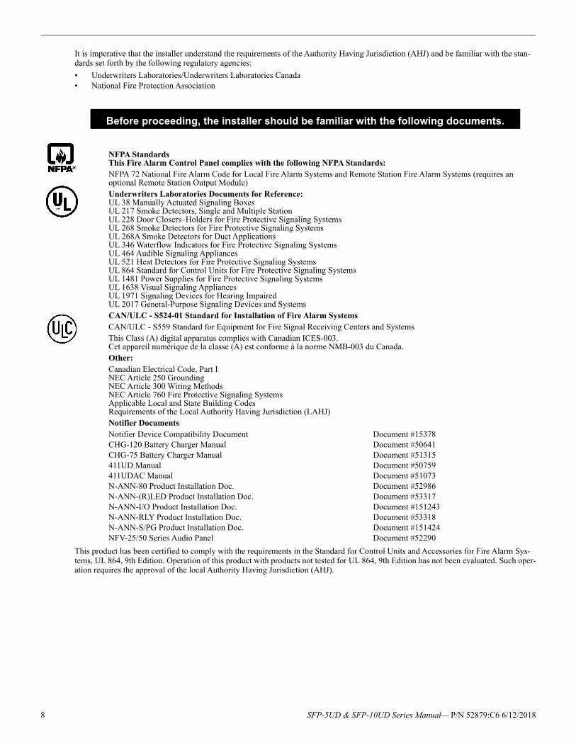
It is imperative that the installer understand the requirements of the Authority Having Jurisdiction (AHJ) and be familiar with the stan-dards set forth by the following regulatory agencies:
• Underwriters Laboratories/Underwriters Laboratories Canada• National Fire Protection Association
NFPA StandardsThis Fire Alarm Control Panel complies with the following NFPA Standards:NFPA 72 National Fire Alarm Code for Local Fire Alarm Systems and Remote Station Fire Alarm Systems (requires an optional Remote Station Output Module)Underwriters Laboratories Documents for Reference:UL 38 Manually Actuated Signaling BoxesUL 217 Smoke Detectors, Single and Multiple StationUL 228 Door Closers–Holders for Fire Protective Signaling SystemsUL 268 Smoke Detectors for Fire Protective Signaling SystemsUL 268A Smoke Detectors for Duct ApplicationsUL 346 Waterflow Indicators for Fire Protective Signaling SystemsUL 464 Audible Signaling AppliancesUL 521 Heat Detectors for Fire Protective Signaling SystemsUL 864 Standard for Control Units for Fire Protective Signaling SystemsUL 1481 Power Supplies for Fire Protective Signaling SystemsUL 1638 Visual Signaling AppliancesUL 1971 Signaling Devices for Hearing ImpairedUL 2017 General-Purpose Signaling Devices and SystemsCAN/ULC - S524-01 Standard for Installation of Fire Alarm SystemsCAN/ULC - S559 Standard for Equipment for Fire Signal Receiving Centers and SystemsThis Class (A) digital apparatus complies with Canadian ICES-003.Cet appareil numérique de la classe (A) est conforme à la norme NMB-003 du Canada.Other:Canadian Electrical Code, Part INEC Article 250 GroundingNEC Article 300 Wiring MethodsNEC Article 760 Fire Protective Signaling SystemsApplicable Local and State Building CodesRequirements of the Local Authority Having Jurisdiction (LAHJ)Notifier DocumentsNotifier Device Compatibility Document Document #15378CHG-120 Battery Charger Manual Document #50641CHG-75 Battery Charger Manual Document #51315411UD Manual Document #50759411UDAC Manual Document #51073N-ANN-80 Product Installation Doc. Document #52986N-ANN-(R)LED Product Installation Doc. Document #53317N-ANN-I/O Product Installation Doc. Document #151243N-ANN-RLY Product Installation Doc. Document #53318N-ANN-S/PG Product Installation Doc. Document #151424NFV-25/50 Series Audio Panel Document #52290
This product has been certified to comply with the requirements in the Standard for Control Units and Accessories for Fire Alarm Sys-tems, UL 864, 9th Edition. Operation of this product with products not tested for UL 864, 9th Edition has not been evaluated. Such oper-ation requires the approval of the local Authority Having Jurisdiction (AHJ).
Before proceeding, the installer should be familiar with the following documents.
8 SFP-5UD & SFP-10UD Series Manual— P/N 52879:C6 6/12/2018
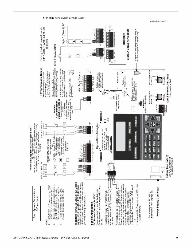
SFP-5UD Series Main Circuit Board
SW
1
Dum
my
load
all
unu
sed
circ
uits
w
ith 4
.7K
Ω, ½
wa
tt E
nd-o
f-Li
ne
resi
sto
rs
Sty
le Z
(C
lass
A)
NA
C
Sty
le D
(C
lass
A)
IDC
Cla
ss A
Co
nve
rter
Mo
du
le
3 P
rog
ram
ma
ble
Rel
ays
No
nsu
per
vise
d r
elay
con
tact
sC
onta
ct R
atin
gs2
.0 a
mps
@ 3
0 V
DC
(re
sist
ive
)0
.5 a
mp
@ 3
0 V
AC
(re
sist
ive)
Co
nta
cts
show
n b
elo
w in
no
rma
l co
nditi
on
(AC
po
wer
with
no
ala
rm,
tro
uble
, or
sup
erv
iso
ry a
ctiv
ity)
A F
ail S
afe
Tro
uble
rel
ay
switc
hes
to t
he
NC
pos
itio
n d
urin
g tr
oub
le
cond
itio
ns a
nd
un
der
loss
of a
ll p
owe
r.
(*F
acto
ry d
efau
lt re
lay
pro
gra
mm
ing
)
Ala
rT
rou
Sup
ervi
Rem
ote
S
ynch
ron
izat
ion
O
utp
ut
(see
no
te 2
)S
pec
ial A
pplic
atio
n
Pow
er
24 V
DC
filte
red
, su
perv
ise
d, a
nd p
ow
er-
limite
d.
0.0
40 a
mp
m
axim
um. R
equi
res
4.7
K
oh
m E
LR
.
Not
es:
1.S
FP
-5U
D/E
= 2
.5 a
mps
max
. per
NA
CS
FP
-5U
DC
= 3
am
ps m
ax. p
er N
AC
2.R
emot
e S
ync
Out
put i
s re
quir
ed o
nly
for
the
SFP
-5U
D/E
: Ref
er to
“R
emot
e S
ynch
roni
zati
on O
utpu
t” o
n pa
ge28
.3.
18 A
mp
Hou
r m
ax. f
or S
FP
-5U
D/E
26 A
mp
Hou
r m
ax. f
or S
FP
-5U
DC
Cla
ss A
Co
nve
rte
r M
od
ule
Rem
ove
jum
pe
r JP
43
to
dis
abl
e G
rou
nd
Fa
ult
Det
ect
ion
circ
uit (
on
ly w
ith
ap
pro
val o
f A
HJ)
Cut
this
jum
per
to s
upe
rvis
e
the
4X
TM
mod
ule
wh
en
inst
alle
d (s
ee J
4 &
J5)
Cut
this
jum
per
to
ena
ble
Sup
ervi
sory
R
ela
y w
he
n 4
XT
M
mo
dule
is in
sta
lled
Au
xilia
ry
Tro
uble
In
put
Kis
s-of
f LE
D
Se
con
dar
y P
hon
e
Act
ive
LED
Pri
mar
y P
hon
e A
ctiv
e L
ED
Prim
ary
Se
con
dary
AN
N-S
EC
optio
n ca
rd c
onn
ecto
r
US
B p
ort
for
loca
l pro
gram
min
g u
sin
g a
p
erso
nal
co
mp
ute
r an
d P
K-5
X U
tility
DA
CT
Ph
on
e L
ine
Jack
sN
on
pow
er-
Lim
ited
Bat
tery
(se
e n
ote
3)
24
VD
C,
sup
ervi
sed
, n
onp
ow
er-
limite
d
Bas
ic S
yste
m C
onne
ctio
ns5-
Zon
e P
anel
Po
wer
Su
pp
ly C
on
nec
tor
Fo
r m
ore
sp
eci
fic U
L w
irin
g
info
rmat
ion
, re
fer
to p
ag
e2
9.
Imp
ort
ant!
Re
mo
vin
g G
rou
nd
Fa
ult
Dis
ab
le
Jum
per
JP43
voi
ds U
L/N
FP
A S
tyle
/Cla
ss
ind
en
tific
atio
ns
for
circ
uits
. Re
mo
ve ju
mpe
r JP
43 o
nly
with
the
ap
pro
val o
f th
e lo
cal A
HJ
(Au
tho
rity
Hav
ing
Jur
isd
ictio
n).
Sp
ecia
l A
pp
licat
ion
DC
Po
wer
Ou
tpu
ts 2
4 V
DC
)N
ons
upe
rvis
ed
, po
we
r-lim
ited
cir
cuits
Sup
erv
ise
with
a p
ow
er
sup
erv
isio
n re
lay
EO
LR
-1
Re
setta
ble
Pow
er -
24
VD
C f
ilte
red,
p
owe
r-lim
ited
(0.5
am
p m
axim
um)
to
smo
ke d
ete
ctor
s (I
DC
). S
up
erv
isio
n
req
uir
ed.
No
nre
sett
abl
e o
r R
ese
tta
ble
Po
we
r Ju
mpe
r se
lect
able
by
JP31
, 24
VD
C
filte
red,
po
we
r-lim
ited
(0
.5 a
mp
ma
xim
um
).
Sup
erv
isio
n re
qu
ired
. No
nre
setta
ble
Po
we
r su
itab
le f
or
pow
erin
g sm
oke
de
tect
ors.
Co
nfig
ure
TB
9,
Ter
min
als
1 &
2 a
s R
ese
ttab
le o
r N
on
rese
tta
ble
Po
we
r.•
Res
etta
ble
Po
we
r -
jum
per
JP
31 p
ins
2
& 3
•N
onre
setta
ble
Po
we
r - ju
mp
er J
P31
pin
s 1
& 2
(as
sh
ow
n)
4 3 2 1
{ {
No
tifi
ca
tio
n A
pp
lia
nc
e C
ircu
its
(se
e n
ote
1)
Sp
eci
al A
ppl
ica
tion
Pow
er
NA
C #
1, #
2, #
3, &
#4
, Sty
le Y
(C
lass
B)
(Su
perv
ise
d, P
ower
-L
imite
d) (
See
Sty
le Z
illu
stra
ted
ne
ar r
ight
ed
ge o
f bo
ard
.)4
.7K
ohm
, ½
wa
tt E
nd-o
f-Li
ne
Re
sist
or
PN
71
252
NA
C #
1N
AC
#2
NA
C #
3N
AC
#4
Sp
ecia
l App
lica
tion
P
owe
rID
Cs
1 th
rou
gh 5
, Sty
le B
(C
lass
B)
(Su
perv
ise
d,
Pow
er-
Lim
ited
) (S
ee
Sty
le D
illu
stra
ted
nea
r ri
ght
ed
ge o
f bo
ard
.)4.
7K
ohm
, ½ w
att
En
d-of
-Li
ne R
esis
tor
PN
71
252
Initi
atin
g D
evi
ce C
ircu
its
Pus
h sw
itch
dow
n to
up
gra
de
so
ftwar
e
ms-5udlayout.wmf
SFP-5UD & SFP-10UD Series Manual— P/N 52879:C6 6/12/2018 9
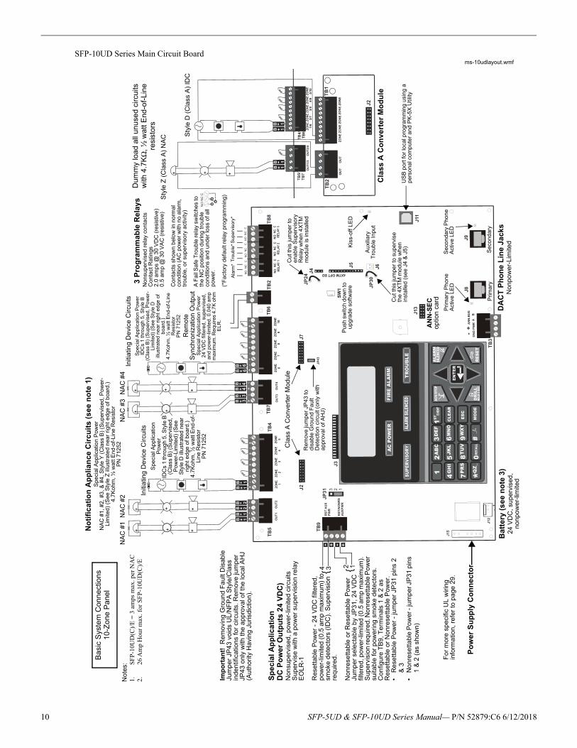
SFP-10UD Series Main Circuit Board
46
64
TB
6
ZO
NE
6Z
ON
E7
ZO
NE
8Z
ON
E9
ZO
NE
10
SW
1
TB
4/T
B6
1/6
2/7
3/8
5/1
04
/9
Not
es:
1.S
FP
-10U
D(C
)/E
= 3
am
ps m
ax. p
er N
AC
2.26
Am
p H
our
max
. for
SF
P-1
0UD
(C)/
E
Du
mm
y lo
ad a
ll un
use
d ci
rcui
ts
with
4.7
KΩ
, ½ w
att E
nd-o
f-Li
ne
resi
stor
s
Sty
le Z
(C
lass
A)
NA
C Sty
le D
(C
lass
A)
IDC
Cla
ss A
Co
nve
rter
Mo
du
le
3 P
rog
ram
mab
le R
elay
sN
ons
up
ervi
sed
rel
ay c
onta
cts
Con
tact
Rat
ings
2.0
am
ps @
30
VD
C (
resi
stiv
e)
0.5
am
p @
30
VA
C (
resi
stiv
e)
Co
nta
cts
show
n b
elo
w in
no
rma
l co
nditi
on
(AC
po
we
r w
ith n
o a
larm
, tr
oub
le, o
r su
pe
rvis
ory
act
ivity
)
A F
ail S
afe
Tro
ubl
e re
lay
switc
hes
to
the
NC
pos
itio
n d
urin
g t
rou
ble
co
nditi
ons
an
d u
nde
r lo
ss o
f all
pow
er.
(*F
act
ory
defa
ult
rela
y p
rogr
amm
ing
)
Ala
rm*
Tro
uble
*S
upe
rvis
ory*
Re
mo
te
Syn
chro
niza
tion
Ou
tpu
tS
peci
al A
ppl
ica
tion
Pow
er24
VD
C f
ilter
ed,
su
perv
ised
, an
d po
wer
-lim
ited
. 0.0
40 a
mp
max
imum
. Re
quire
s 4
.7K
oh
m
EL
R.
Cla
ss A
Co
nve
rter
Mod
ule
Rem
ove
jum
per
JP4
3 to
di
sabl
e G
roun
d F
aul
t D
ete
ctio
n c
ircu
it (o
nly
with
ap
prov
al o
f A
HJ)
Cut
this
jum
per
to s
upe
rvis
e th
e 4
XT
M m
odul
e w
hen
in
stal
led
(see
J4
& J
5)
Cut
this
jum
per
to
ena
ble
Sup
ervi
sory
R
ela
y w
hen
4X
TM
m
od
ule
is in
sta
lled
Au
xilia
ry
Tro
uble
Inpu
t
Kis
s-of
f LE
D
Se
con
dary
Pho
ne
Act
ive
LED
Pri
ma
ry P
hon
e
Act
ive
LED
Prim
ary
Se
cond
ary
AN
N-S
EC
optio
n c
ard
US
B p
ort
for
loca
l pro
gram
min
g u
sing
a
pe
rson
al c
omp
ute
r an
d P
K-5
X U
tility
DA
CT
Ph
on
e L
ine
Jack
sN
onp
ow
er-
Lim
ited
Bat
tery
(s
ee n
ote
3)
24
VD
C,
sup
ervi
sed
, n
onp
ow
er-
limite
d
Bas
ic S
yste
m C
onn
ectio
ns10
-Zon
e P
ane
l
Po
wer
Su
pp
ly C
on
nec
tor
Fo
r m
ore
sp
ecifi
c U
L w
irin
g
info
rma
tion
, re
fer
to p
age
29
.
Imp
ort
an
t!
Rem
ovin
g G
rou
nd
Fa
ult
Dis
able
Ju
mpe
r JP
43 v
oid
s U
L/N
FP
A S
tyle
/Cla
ss
inde
ntif
icat
ion
s fo
r ci
rcu
its. R
em
ove
jum
per
JP
43
onl
y w
ith t
he a
pp
rova
l of
the
loca
l AH
J (A
uth
ori
ty H
avi
ng
Juris
dict
ion
).
Sp
ecia
l Ap
plic
ati
on
DC
Po
wer
Ou
tpu
ts 2
4 V
DC
)N
onsu
pe
rvis
ed,
po
wer
-lim
ited
cir
cuits
Su
per
vise
with
a p
ow
er
sup
ervi
sio
n r
ela
y E
OL
R-1
Res
etta
ble
Po
we
r -
24
VD
C f
ilte
red
, p
ow
er-
limite
d (
0.5
am
p m
axi
mu
m)
to
smok
e d
ete
cto
rs (
IDC
). S
upe
rvis
ion
re
qu
ired
.
Non
rese
ttab
le o
r R
ese
ttab
le P
ower
Ju
mp
er
sele
cta
ble
by
JP3
1,
24 V
DC
fil
tere
d, p
ow
er-
limite
d (
0.5
am
p m
axi
mu
m).
S
up
ervi
sio
n re
quir
ed.
No
nre
sett
abl
e P
ow
er
suita
ble
for
po
we
ring
sm
oke
det
ect
ors
.C
onfig
ure
TB
9, T
erm
inal
s 1
& 2
as
Res
etta
ble
or
Non
rese
ttab
le P
ower
.•
Re
sett
able
Po
we
r -
jum
per
JP3
1 p
ins
2
& 3
•N
on
rese
tta
ble
Po
we
r - ju
mp
er J
P3
1 p
ins
1 &
2 (
as
show
n)
4 3 2 1
{ {
No
tifi
cat
ion
Ap
plia
nce
Cir
cuit
s (s
ee n
ote
1)
Spe
cia
l Ap
plic
atio
n P
ower
NA
C #
1, #
2, #
3, &
#4
, S
tyle
Y (
Cla
ss B
) (S
uper
vise
d, P
ower
-Li
mite
d)
(See
Sty
le Z
illu
stra
ted
nea
r rig
ht e
dge
of b
oard
.)4
.7K
ohm
, ½
wa
tt E
nd-o
f-Li
ne R
esis
tor
PN
712
52N
AC
#1
NA
C #
2N
AC
#3
NA
C #
4
Spe
cia
l Ap
plic
atio
n P
ow
er
IDC
s 1
thro
ugh
5, S
tyle
B
(Cla
ss B
) (S
upe
rvis
ed,
P
owe
r-L
imite
d)
(See
S
tyle
D il
lust
rate
d n
ear
righ
t ed
ge o
f bo
ard.
)4.
7Ko
hm, ½
wa
tt E
nd-
of-
Lin
e R
esis
tor
PN
71
252
Initi
atin
g D
evi
ce C
ircu
its
Pus
h sw
itch
dow
n to
u
pgra
de s
oftw
are
Spe
cia
l App
lica
tion
Pow
erID
Cs
1 th
roug
h 5,
Sty
le B
(C
lass
B)
(Sup
ervi
sed,
Po
we
r-L
imite
d)
(See
Sty
le D
ill
ustr
ate
d n
ear
rig
ht e
dge
of
boa
rd.)
4.7K
ohm
, ½
wa
tt E
nd-
of-
Lin
e
Res
isto
rP
N 7
1252
Initi
atin
g D
evi
ce C
ircui
ts
ms-10udlayout.wmf
10 SFP-5UD & SFP-10UD Series Manual— P/N 52879:C6 6/12/2018
- +- +
JP1
JP3
SW1
JP4
TB3 TB4
TB2
ENABLE AC DELAY
16 HRDELAY
TENS
ONES
CUT FOR240VAC
GND FLTDISABLE
AM-1 ENABLE
ADDRESS
ON OFF
AM-1JP5
JP2
F1 F2
J4
J1 J2 J3
F3TB1H
OT
OU
T +
BA
T +
OU
T -
BA
T -
EA
RT
HN
EU
T
1515
A- B- A+ B+ NC NO C
0
4 39 261
5 78
1213
15
1410
11
0
4 392
61
5 78
1213
15
1410
11
TB
1
TB
L
J1 J2
7 6 5 1 POWER LIMITED
Sw
1
P1 P2 P3 P4
1 10 11 20 21 30 31 40
1
2
3
4 5
ALARM
TROUBLE
FIRE ALARM ANNUNCIATOR
ACK
ST E P
TB1
J1
SW
1
JP2
ANN-BUS
1 2 3 4 5 6 7 8
TB6
TB3
TB5
TB4
TB2
AlarmSilenced
EarthFaultZONE 1
ALM
TBL
SUP 1ZONE 6
ALM
TBL
SUP 6
NAC 1Fault
BatteryFaultZONE 2
ALM
TBL
SUP 2ZONE 7
ALM
TBL
SUP 7
NAC2Fault
ChargerFaultZONE 3
ALM
TBL
SUP 3ZONE 8
ALM
TBL
SUP 8FIRE ALARM ANNUNCIATOR
NAC 4Fault
ZONE 5ALM
TBL
SUP 5ALM
TBL
SUP
NAC 3Fault
Disabled
ZONE 4ALM
TBL
SUP 4ZONE 9
ALM
TBL
SUP 9
FR
OM
AP
PH
ON
E
PS
TN
T
O A
P
OU
T N
C
O
UT
NO
IN
PU
T
T
AM
PE
R
GN
D
+12
/24V
P4
CN
2
P5
P6
P7
P8
P9
P1
0P
11P
12
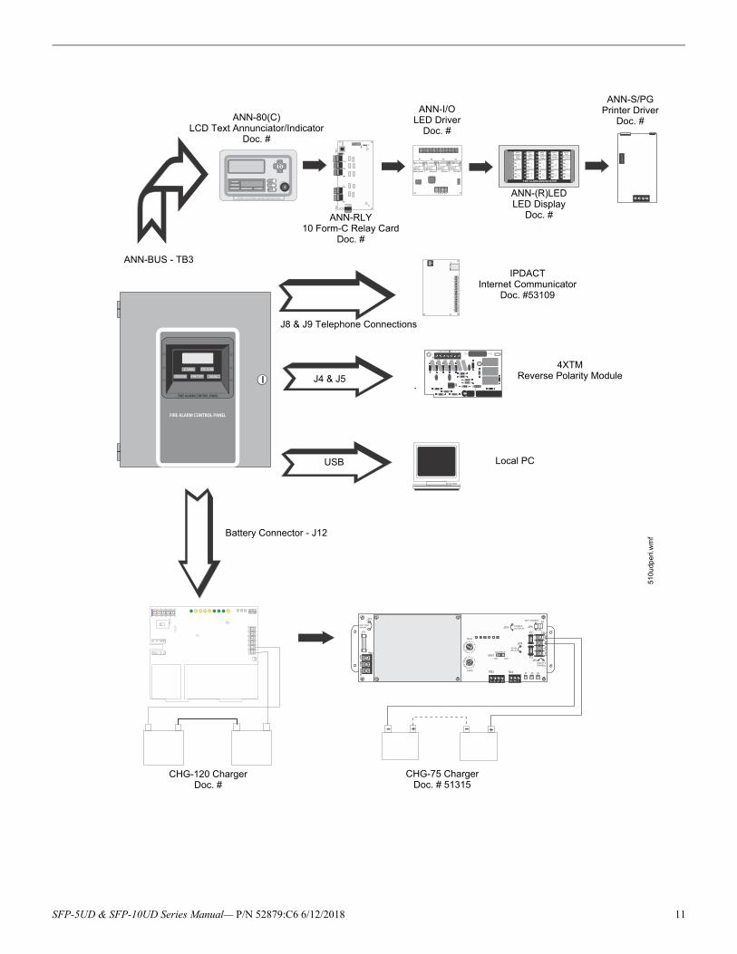
CHG-120 Charger Doc. #
ANN-BUS - TB3
Battery Connector - J12
510u
dpe
ri.w
mf
ANN-80(C)LCD Text Annunciator/Indicator
Doc. #
ANN-I/OLED Driver
Doc. #
ANN-S/PGPrinter Driver
Doc. #
CHG-75 Charger Doc. # 51315
ANN-(R)LEDLED Display
Doc. #ANN-RLY10 Form-C Relay Card
Doc. #
4XTMReverse Polarity ModuleJ4 & J5
IPDACTInternet Communicator
Doc. #53109
J8 & J9 Telephone Connections
USB Local PC
SFP-5UD & SFP-10UD Series Manual— P/N 52879:C6 6/12/2018 11
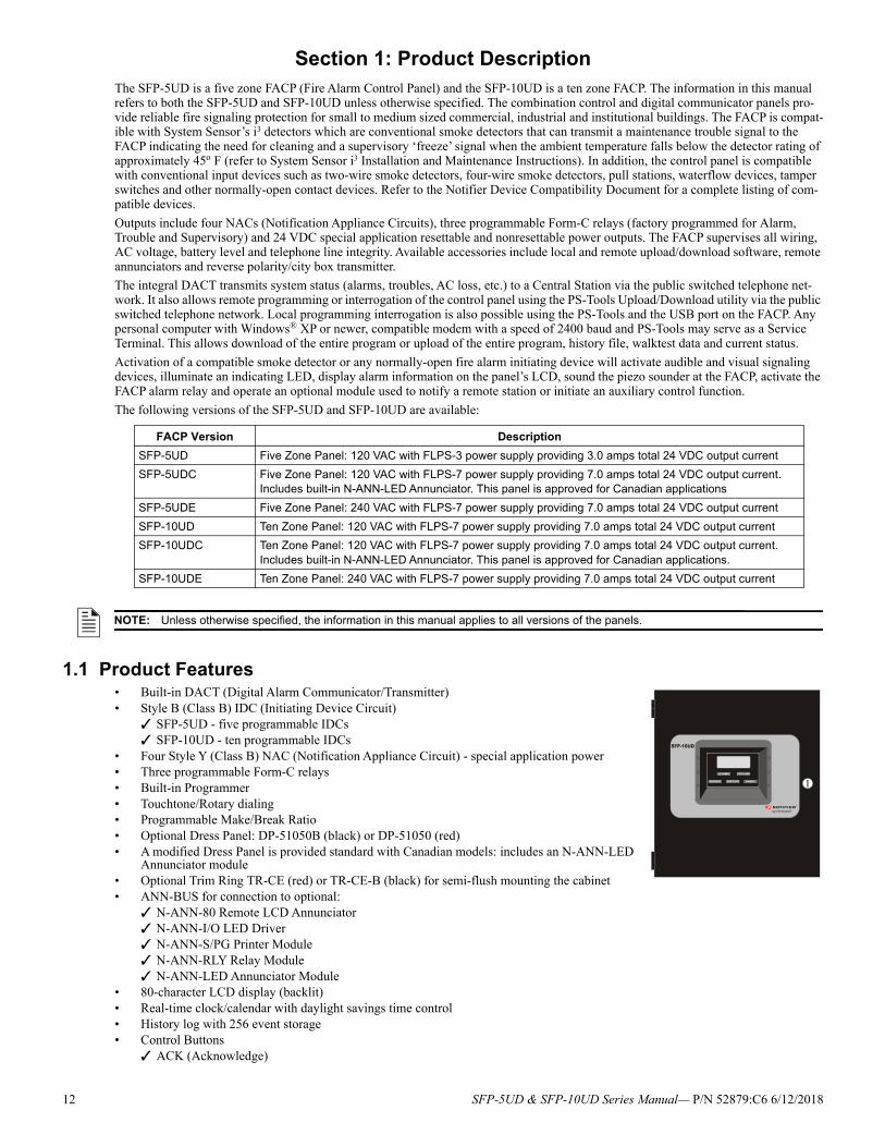
Section 1: Product DescriptionThe SFP-5UD is a five zone FACP (Fire Alarm Control Panel) and the SFP-10UD is a ten zone FACP. The information in this manual refers to both the SFP-5UD and SFP-10UD unless otherwise specified. The combination control and digital communicator panels pro-vide reliable fire signaling protection for small to medium sized commercial, industrial and institutional buildings. The FACP is compat-ible with System Sensor’s i3 detectors which are conventional smoke detectors that can transmit a maintenance trouble signal to the FACP indicating the need for cleaning and a supervisory ‘freeze’ signal when the ambient temperature falls below the detector rating of approximately 45o F (refer to System Sensor i3 Installation and Maintenance Instructions). In addition, the control panel is compatible with conventional input devices such as two-wire smoke detectors, four-wire smoke detectors, pull stations, waterflow devices, tamper switches and other normally-open contact devices. Refer to the Notifier Device Compatibility Document for a complete listing of com-patible devices.
Outputs include four NACs (Notification Appliance Circuits), three programmable Form-C relays (factory programmed for Alarm, Trouble and Supervisory) and 24 VDC special application resettable and nonresettable power outputs. The FACP supervises all wiring, AC voltage, battery level and telephone line integrity. Available accessories include local and remote upload/download software, remote annunciators and reverse polarity/city box transmitter.
The integral DACT transmits system status (alarms, troubles, AC loss, etc.) to a Central Station via the public switched telephone net-work. It also allows remote programming or interrogation of the control panel using the PS-Tools Upload/Download utility via the public switched telephone network. Local programming interrogation is also possible using the PS-Tools and the USB port on the FACP. Any personal computer with Windows® XP or newer, compatible modem with a speed of 2400 baud and PS-Tools may serve as a Service Terminal. This allows download of the entire program or upload of the entire program, history file, walktest data and current status.
Activation of a compatible smoke detector or any normally-open fire alarm initiating device will activate audible and visual signaling devices, illuminate an indicating LED, display alarm information on the panel’s LCD, sound the piezo sounder at the FACP, activate the FACP alarm relay and operate an optional module used to notify a remote station or initiate an auxiliary control function.
The following versions of the SFP-5UD and SFP-10UD are available:
1.1 Product Features• Built-in DACT (Digital Alarm Communicator/Transmitter) • Style B (Class B) IDC (Initiating Device Circuit)
SFP-5UD - five programmable IDCs SFP-10UD - ten programmable IDCs
• Four Style Y (Class B) NAC (Notification Appliance Circuit) - special application power• Three programmable Form-C relays• Built-in Programmer• Touchtone/Rotary dialing• Programmable Make/Break Ratio• Optional Dress Panel: DP-51050B (black) or DP-51050 (red)• A modified Dress Panel is provided standard with Canadian models: includes an N-ANN-LED
Annunciator module• Optional Trim Ring TR-CE (red) or TR-CE-B (black) for semi-flush mounting the cabinet• ANN-BUS for connection to optional:
N-ANN-80 Remote LCD Annunciator N-ANN-I/O LED Driver N-ANN-S/PG Printer Module N-ANN-RLY Relay Module N-ANN-LED Annunciator Module
• 80-character LCD display (backlit)• Real-time clock/calendar with daylight savings time control• History log with 256 event storage• Control Buttons
ACK (Acknowledge)
FACP Version Description
SFP-5UD Five Zone Panel: 120 VAC with FLPS-3 power supply providing 3.0 amps total 24 VDC output current
SFP-5UDC Five Zone Panel: 120 VAC with FLPS-7 power supply providing 7.0 amps total 24 VDC output current. Includes built-in N-ANN-LED Annunciator. This panel is approved for Canadian applications
SFP-5UDE Five Zone Panel: 240 VAC with FLPS-7 power supply providing 7.0 amps total 24 VDC output current
SFP-10UD Ten Zone Panel: 120 VAC with FLPS-7 power supply providing 7.0 amps total 24 VDC output current
SFP-10UDC Ten Zone Panel: 120 VAC with FLPS-7 power supply providing 7.0 amps total 24 VDC output current. Includes built-in N-ANN-LED Annunciator. This panel is approved for Canadian applications.
SFP-10UDE Ten Zone Panel: 240 VAC with FLPS-7 power supply providing 7.0 amps total 24 VDC output current
NOTE: Unless otherwise specified, the information in this manual applies to all versions of the panels.
12 SFP-5UD & SFP-10UD Series Manual— P/N 52879:C6 6/12/2018
Specifications Product Description
Alarm Silence System Reset/Lamp Test Drill
• LED Indicators Fire Alarm Supervisory Trouble AC Power Alarm Silence Primary and Secondary Phone Line Active LEDs
• Piezo sounder for alarm, trouble and supervisory• 24 volt operation• Low AC voltage sense• Alarm Verification• NACs Programmable for:
Silence Inhibit Auto-Silence Strobe Synchronization (System Sensor, Wheelock, Gentex, Faraday, Amseco) Selective Silence (horn-strobe mute) Temporal or Steady Signal Silenceable or Nonsilenceable
• Automatic battery charger with charger supervision• Silent or audible walktest capabilities• Optional PS-Tools utilityfor local or remote Upload/Download of program and data• Optional N-CAC-5X Class A Converter Module for NACs and IDCs• Optional 4XTM Transmitter Module• Optional ANN-SEC card for a secondary ANN-BUS
1.2 Specifications
AC Power
SFP-5UD (FLPS-3 Power Supply): 120 VAC, 60 HZ, 1.00 ampsSFP-5UDC (FLPS-7 Power Supply): 120 VAC, 60 HZ, 3.90 ampsSFP-10UD(C) (FLPS-7 Power Supply): 120 VAC, 60 HZ, 3.90 ampsSFP-5UDE (FLPS-3 Power Supply): 240 VAC, 50 HZ, 0.54 ampsSFP-10UDE (FLPS-7 Power Supply): 240 VAC, 50 HZ, 2.20 ampsWire size: minimum #14 AWG (2.0 mm2) with 600V insulationSupervised, nonpower-limited
Battery (sealed lead acid only) - J12
Maximum Charging Circuit - Normal Flat Charge: 27.6 VDC @ 1.4 ampSupervised, nonpower-limitedMaximum Charger Capacity: 18 Amp Hour battery for SFP-5UD, and 26 Amp Hour battery for SFP-5UDC and SFP-10UD(C)/E [two 18 Amp Hour batteries can be housed in FACP cabinet. Larger batteries require a separate battery box such as the NFS-LBB or BB-26 and the CHG-75 or CHG-120 Battery Charger.]Minimum Battery Size: 7 Amp Hour (12 Amp Hour for SFP-5UD-7C & SFP-10UD-7C)
Initiating Device Circuits - TB4 (and TB6 on SFP-10UD only)
Alarm Zones 1 - 5 on TB 4 (SFP-5UD and SFP-10UD)Alarm Zones 6 - 10 on TB6 (SFP-10UD only)Supervised and power-limited circuitryOperation: All zones Style B (Class B)Normal Operating Voltage: Nominal 20 VDC Alarm Current: 15 mA minimumShort Circuit Current: 40 mA max.Maximum Loop Resistance: 100 ohms (700 ohms per zone for linear heat detection - See Section 2.3, “Input Circuits” for more informa-tion.)End-of-Line Resistor: 4.7KΩ, 1/2 watt (Part #71252)Standby Current: 2 mARefer to the Notifier Device Compatibility Document for listed compatible devices
NOTE: For wiring specifications, refer to“Wire Requirements” on page 125.
SFP-5UD & SFP-10UD Series Manual— P/N 52879:C6 6/12/2018 13
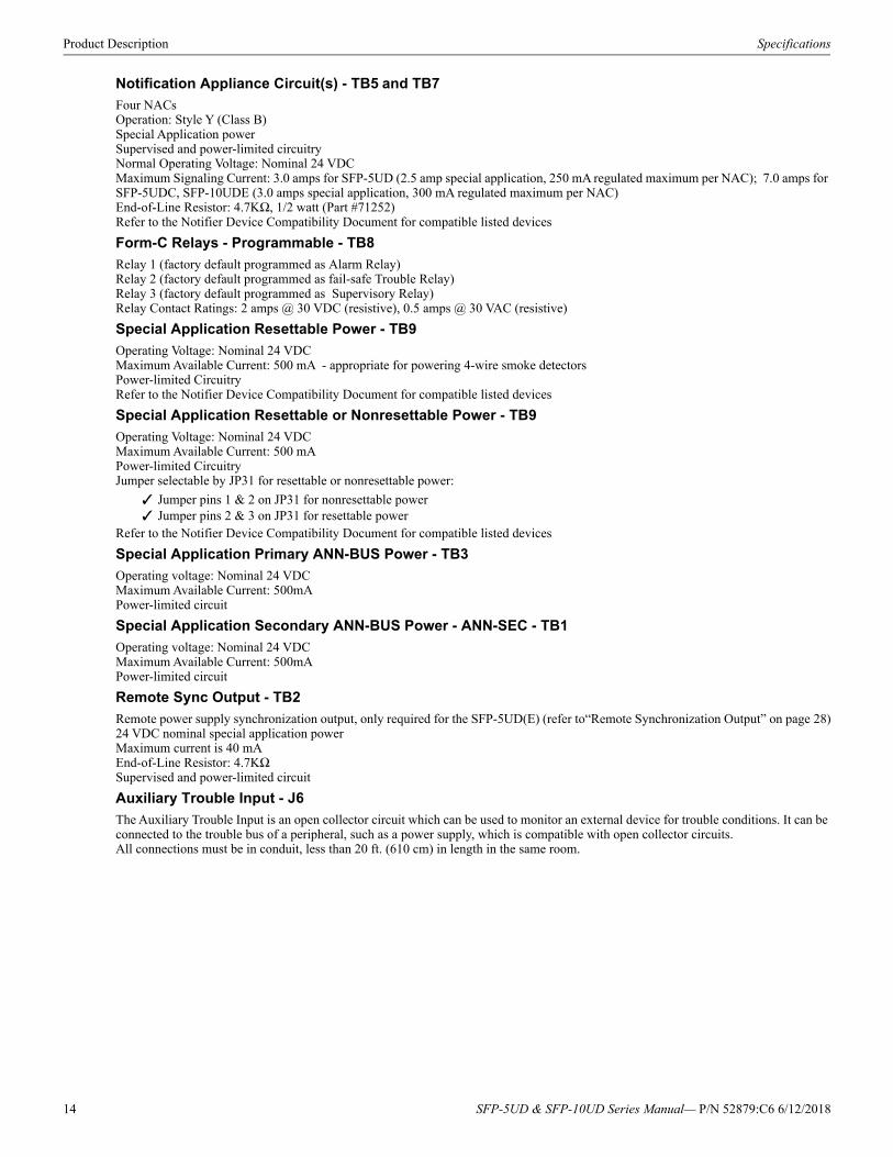
Product Description Specifications
Notification Appliance Circuit(s) - TB5 and TB7
Four NACsOperation: Style Y (Class B)Special Application powerSupervised and power-limited circuitryNormal Operating Voltage: Nominal 24 VDCMaximum Signaling Current: 3.0 amps for SFP-5UD (2.5 amp special application, 250 mA regulated maximum per NAC); 7.0 amps for SFP-5UDC, SFP-10UDE (3.0 amps special application, 300 mA regulated maximum per NAC)End-of-Line Resistor: 4.7KΩ, 1/2 watt (Part #71252)Refer to the Notifier Device Compatibility Document for compatible listed devices
Form-C Relays - Programmable - TB8
Relay 1 (factory default programmed as Alarm Relay)Relay 2 (factory default programmed as fail-safe Trouble Relay)Relay 3 (factory default programmed as Supervisory Relay) Relay Contact Ratings: 2 amps @ 30 VDC (resistive), 0.5 amps @ 30 VAC (resistive)
Special Application Resettable Power - TB9
Operating Voltage: Nominal 24 VDC Maximum Available Current: 500 mA - appropriate for powering 4-wire smoke detectors Power-limited CircuitryRefer to the Notifier Device Compatibility Document for compatible listed devices
Special Application Resettable or Nonresettable Power - TB9
Operating Voltage: Nominal 24 VDCMaximum Available Current: 500 mA Power-limited CircuitryJumper selectable by JP31 for resettable or nonresettable power:
Jumper pins 1 & 2 on JP31 for nonresettable power Jumper pins 2 & 3 on JP31 for resettable power
Refer to the Notifier Device Compatibility Document for compatible listed devices
Special Application Primary ANN-BUS Power - TB3
Operating voltage: Nominal 24 VDCMaximum Available Current: 500mAPower-limited circuit
Special Application Secondary ANN-BUS Power - ANN-SEC - TB1
Operating voltage: Nominal 24 VDCMaximum Available Current: 500mAPower-limited circuit
Remote Sync Output - TB2
Remote power supply synchronization output, only required for the SFP-5UD(E) (refer to“Remote Synchronization Output” on page 28)24 VDC nominal special application powerMaximum current is 40 mAEnd-of-Line Resistor: 4.7KΩSupervised and power-limited circuit
Auxiliary Trouble Input - J6
The Auxiliary Trouble Input is an open collector circuit which can be used to monitor an external device for trouble conditions. It can be connected to the trouble bus of a peripheral, such as a power supply, which is compatible with open collector circuits.All connections must be in conduit, less than 20 ft. (610 cm) in length in the same room.
14 SFP-5UD & SFP-10UD Series Manual— P/N 52879:C6 6/12/2018
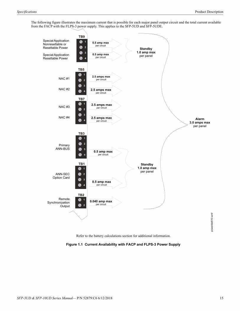
Specifications Product Description
The following figure illustrates the maximum current that is possible for each major panel output circuit and the total current available from the FACP with the FLPS-3 power supply. This applies to the SFP-5UD and SFP-5UDE.
TB9
TB5
TB7
TB3
TB2
TB1
Figure 1.1 Current Availability with FACP and FLPS-3 Power Supply
pow
erd
ist5
10.
wm
f
Refer to the battery calculations section for additional information.
Standby1.0 amp max
per panel
Special Application Nonresettable or Resettable Power
Special Application Resettable Power
NAC #1
NAC #2
NAC #3
NAC #4
0.5 amp maxper circuit
0.5 amp maxper circuit
2.5 amps maxper circuit
2.5 amps maxper circuit
2.5 amps maxper circuit
2.5 amps maxper circuit
Alarm3.0 amps max
per panel
PrimaryANN-BUS
Standby1.0 amp max
per panel
0.5 amp maxper circuit
RemoteSynchronization
Output
0.040 amp maxper circuit
ANN-SECOption Card
0.5 amp maxper circuit
SFP-5UD & SFP-10UD Series Manual— P/N 52879:C6 6/12/2018 15
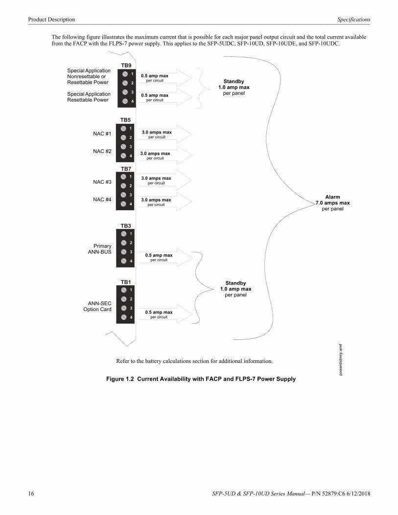
Product Description Specifications
The following figure illustrates the maximum current that is possible for each major panel output circuit and the total current available from the FACP with the FLPS-7 power supply. This applies to the SFP-5UDC, SFP-10UD, SFP-10UDE, and SFP-10UDC.
TB9
TB5
TB7
TB3
TB1
Figure 1.2 Current Availability with FACP and FLPS-7 Power Supply
po
wer
dist
mrp
.wm
f
Refer to the battery calculations section for additional information.
Standby1.0 amp max
per panel
Special Application Nonresettable or Resettable Power
Special Application Resettable Power
NAC #1
NAC #2
NAC #3
NAC #4
0.5 amp maxper circuit
0.5 amp maxper circuit
3.0 amps maxper circuit
3.0 amps maxper circuit
3.0 amps maxper circuit
3.0 amps maxper circuit
Alarm7.0 amps max
per panel
PrimaryANN-BUS
Standby1.0 amp max
per panel
0.5 amp maxper circuit
0.5 amp maxper circuit
ANN-SECOption Card
16 SFP-5UD & SFP-10UD Series Manual— P/N 52879:C6 6/12/2018
Controls and Indicators Product Description
1.3 Controls and IndicatorsLCD Display
The FACP uses an 80-character (4 lines X 20 characters) high viewing angle LCD display. The display includes a long life LED backlight that remains illuminated. If AC power is lost and the system is not in alarm, the LED backlight will turn off to conserve batteries.
Key Panel
Mounted on the main circuit board, the key panel includes a window for the LCD display and LED indicators as listed above. The key panel, which is visible with the cabinet door closed, has 25 keys, including a 16 key alpha-numeric pad similar to a telephone keypad.
Function keys:• Acknowledge/Step• Alarm Silence• Drill• System Reset (lamp test)
Service/program keys:• Keys labeled 1 to 9• * key• # key• 0 (recall) key• 1st Event key• Clear key• Escape key• Mode key• Four cursor keys (up, down, left and right)• Enter key
LED Indicators
LEDs are provided to annunciate the following conditions:
• Fire Alarm - red LED• Supervisory - yellow LED• AC Power - green LED• System Trouble - yellow LED• Alarm Silence - yellow LED• Primary Phone Line Active (on circuit board) - red LED• Secondary Phone Line Active (on circuit board) - red LED• Kiss-off (on circuit board) - green LED
Local Piezo Sounder
A piezo sounder provides separate and distinct sounds for alarm, trouble, maintenance, process monitor and supervisory conditions as follows:
• Alarm - on steady• Trouble - pulse 1 second on and 1 second off• Maintenance - pulse 1 second on and 1 second off• Supervisory - pulse ½ second on and ½ second off• Process Monitor - pulse ¼ second on and ¼ second off
1.4 Digital Alarm Communicator/TransmitterTwo modular phone jacks allow easy connection to telephone lines. Modular jacks are labeled PH1 for Primary Phone Line and PH2 for Secondary Phone Line. Two telephone line active red LEDs are provided as well as a green Kissoff LED. The integral digital communi-cator provides the following functions:
• Line Seizure: takes control of the phone lines disconnecting any premises phones• Off/On Hook: performs on and off-hook status to the phone lines• Listen for dial tone: 440 Hz tone typical in most networks• Dialing the Central Station(s) number: default is Touch-Tone®, programmable to rotary• For tone burst or touchtone type formats: discern proper Ack and Kissoff tone(s). The frequency and time duration of the tone(s)
varies with the transmission format. The control panel will adjust accordingly.• Communicate in the following formats:
Ademco Contact ID SIA-DCS-8 SIA-DCS-20
SYSTEM ALL NORMAL
10:00A 012118
Figure 1.3 Membrane/Display Panel
90
50ud
kypd
.cdr
SFP-5UD & SFP-10UD Series Manual— P/N 52879:C6 6/12/2018 17
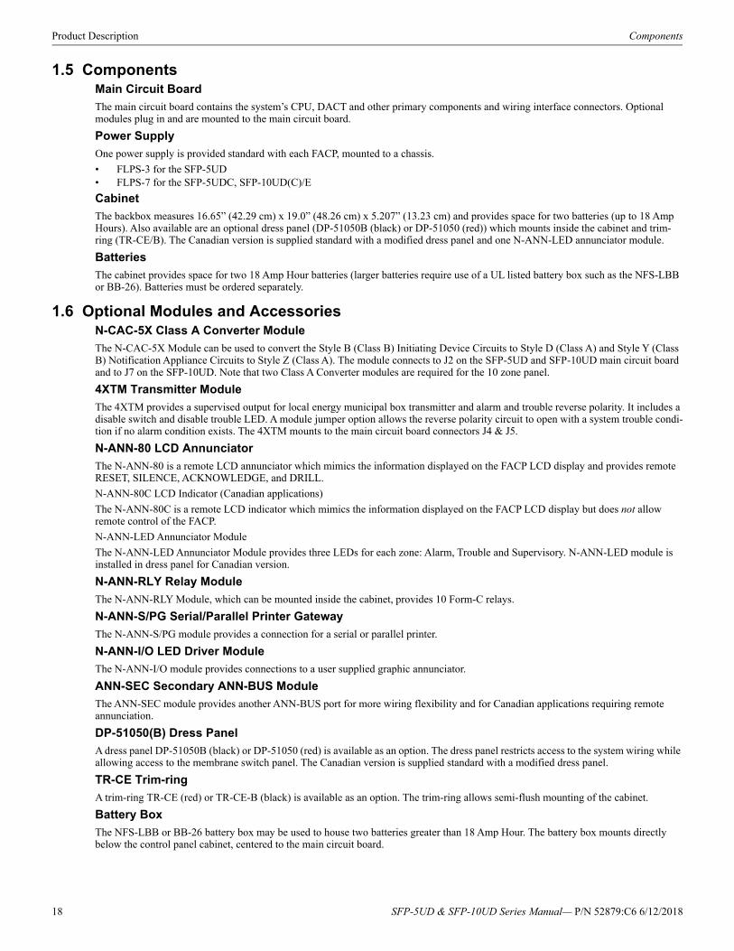
Product Description Components
1.5 ComponentsMain Circuit Board
The main circuit board contains the system’s CPU, DACT and other primary components and wiring interface connectors. Optional modules plug in and are mounted to the main circuit board.
Power Supply
One power supply is provided standard with each FACP, mounted to a chassis.
• FLPS-3 for the SFP-5UD• FLPS-7 for the SFP-5UDC, SFP-10UD(C)/E
Cabinet
The backbox measures 16.65” (42.29 cm) x 19.0” (48.26 cm) x 5.207” (13.23 cm) and provides space for two batteries (up to 18 Amp Hours). Also available are an optional dress panel (DP-51050B (black) or DP-51050 (red)) which mounts inside the cabinet and trim-ring (TR-CE/B). The Canadian version is supplied standard with a modified dress panel and one N-ANN-LED annunciator module.
Batteries
The cabinet provides space for two 18 Amp Hour batteries (larger batteries require use of a UL listed battery box such as the NFS-LBB or BB-26). Batteries must be ordered separately.
1.6 Optional Modules and AccessoriesN-CAC-5X Class A Converter Module
The N-CAC-5X Module can be used to convert the Style B (Class B) Initiating Device Circuits to Style D (Class A) and Style Y (Class B) Notification Appliance Circuits to Style Z (Class A). The module connects to J2 on the SFP-5UD and SFP-10UD main circuit board and to J7 on the SFP-10UD. Note that two Class A Converter modules are required for the 10 zone panel.
4XTM Transmitter Module
The 4XTM provides a supervised output for local energy municipal box transmitter and alarm and trouble reverse polarity. It includes a disable switch and disable trouble LED. A module jumper option allows the reverse polarity circuit to open with a system trouble condi-tion if no alarm condition exists. The 4XTM mounts to the main circuit board connectors J4 & J5.
N-ANN-80 LCD Annunciator
The N-ANN-80 is a remote LCD annunciator which mimics the information displayed on the FACP LCD display and provides remote RESET, SILENCE, ACKNOWLEDGE, and DRILL.
N-ANN-80C LCD Indicator (Canadian applications)
The N-ANN-80C is a remote LCD indicator which mimics the information displayed on the FACP LCD display but does not allow remote control of the FACP.
N-ANN-LED Annunciator Module
The N-ANN-LED Annunciator Module provides three LEDs for each zone: Alarm, Trouble and Supervisory. N-ANN-LED module is installed in dress panel for Canadian version.
N-ANN-RLY Relay Module
The N-ANN-RLY Module, which can be mounted inside the cabinet, provides 10 Form-C relays.
N-ANN-S/PG Serial/Parallel Printer Gateway
The N-ANN-S/PG module provides a connection for a serial or parallel printer.
N-ANN-I/O LED Driver Module
The N-ANN-I/O module provides connections to a user supplied graphic annunciator.
ANN-SEC Secondary ANN-BUS Module
The ANN-SEC module provides another ANN-BUS port for more wiring flexibility and for Canadian applications requiring remote annunciation.
DP-51050(B) Dress Panel
A dress panel DP-51050B (black) or DP-51050 (red) is available as an option. The dress panel restricts access to the system wiring while allowing access to the membrane switch panel. The Canadian version is supplied standard with a modified dress panel.
TR-CE Trim-ring
A trim-ring TR-CE (red) or TR-CE-B (black) is available as an option. The trim-ring allows semi-flush mounting of the cabinet.
Battery Box
The NFS-LBB or BB-26 battery box may be used to house two batteries greater than 18 Amp Hour. The battery box mounts directly below the control panel cabinet, centered to the main circuit board.
18 SFP-5UD & SFP-10UD Series Manual— P/N 52879:C6 6/12/2018

Telephone Requirements and Warnings Product Description
Battery Charger
CHG-75 Battery Charger
The CHG-75 is capable of charging up to 75 AH lead-acid batteries with the FACP. The FACP battery charger must be disabled, through software programming, when using the CHG-75. The charger and up to 26 AH batteries can be housed in the BB-26 battery box. Larger batteries and the charger can be housed in the NFS-LBB battery box which can be mounted up to 20 feet away from the control panel. Refer to the CHG-75 Manual for additional information.
CHG-120 Battery Charger
The CHG-120 is capable of charging up to 120 AH lead-acid batteries with the FACP. The FACP battery charger must be disabled, through software programming, when using the CHG-120. The batteries and charger can be housed in the NFS-LBB battery box which can be mounted up to 20 feet away from the control panel. Note that when using an NFS-LBB for housing the charger and batteries greater than 26AH, multiple NFS-LBBs are required. Refer to the CHG-120 Manual for additional information.
PS-Tools Programming Utility
The PS-Tools Programming Utility can be used to locally or remotely program the FACP directly from most IBM compatible personal computers (PC), running Windows® XP (or newer). FACP program files can also be created and stored on the PC and then downloaded later to the control panel. The Windows-based Programming Utility, PS-Tools, and its on-line help file are available for download from www.magni-fire.com. A standard USB cable with male-A to male-B connectors, which must be purchased separately, is required for local connection of the PC to the USB port J11 on the FACP main circuit board. Remote programming requires that the PC have a 2400 baud (or faster) modem.
Important: Remote modification of FACP programming requires that the panel be enabled for remote download (refer to “Remote Download” on page 108). Remote interrogation of panel programming, history logs, detector status, etc., is possible without enabling the remote download option.
1.7 Telephone Requirements and Warnings
1.7.1 Telephone CircuitryRinger Equivalence Number (REN) = 0.0BAC Impedance: 10.0 Mega OhmComplies with FCC Part 68Mates with RJ31X Male ConnectorSupervision Threshold: loss of phone line voltage for 2 minutes
The REN is used to determine the quantity of devices which may be connected to the telephone line. Excessive RENs on the telephone line may result in the devices not ringing in response to an incoming call. In most, but not all areas, the sum of the RENs should not exceed five (5.0). To be certain of the number of devices that may be connected to the line as determined by the total RENs, contact the telephone company to determine the maximum REN for the calling area.
1.7.2 Digital CommunicatorBefore connecting the control panel to the public switched telephone network, the installation of two RJ31X jacks is necessary. If trouble is experienced with this equipment, for repair or warranty information, please contact:
Manufacturer: Notifier12 Clintonville RoadNorthford, CT 06472(203) 484-7161
Product Model Number: SFP-5UD/SFP-10UDFCC Registration Number: 1W6AL00B10UDRinger Equivalence: 0.0B
Important! The DACT must not be used to dial a phone number that is call-forwarded.
This equipment complies with Part 68 of the FCC rules and the requirements adopted by the ACTA. On the inside of the FACP door is a label that contains, among other information, a product identifier in the format US:AAAEQ##TXXXX. If requested, this number must be provided to the telephone company.
Alarm dialing equipment must be able to seize the telephone line and place a call in an emergency situation. It must be able to do this even if other equipment (telephone, answering system, computer modem, etc.) already has the telephone line in use. To do so, alarm dial-ing equipment must be connected to a properly installed RJ31X jack that is electrically in series with and ahead of all other equipment attached to the same telephone line. If there are any questions concerning these instructions, consult the telephone company or a quali-fied installer about installing the RJ31X jack and alarm dialing equipment. Refer to “Digital Communicator” on page 30 for an illustra-tion of the proper installation of this equipment.
1.7.3 Telephone Company Rights and WarningsThe telephone company, under certain circumstances, may temporarily discontinue services and/or make changes in its facilities, ser-vices, equipment or procedures which may affect the operation of this control panel. However, the telephone company is required to give advance notice of such changes or interruptions.
SFP-5UD & SFP-10UD Series Manual— P/N 52879:C6 6/12/2018 19
Product Description Telephone Requirements and Warnings
If the control panel causes harm to the telephone network, the telephone company reserves the right to temporarily discontinue service. Advance notification will be provided except in cases when advance notice is not practical. In such cases, notification will be provided as soon as possible. The opportunity will be given to correct any problems and to file a complaint with the FCC if you believe it is nec-essary.
DO NOT CONNECT THIS PRODUCT TO COIN TELEPHONE, GROUND START, OR PARTY LINE SERVICES.
When the control panel activates, premise phones will be disconnected.
Two separate phone lines are required. Do not connect both telephone interfaces to the same telephone line.
The control panel must be connected to the public switched telephone network upstream (as first device) of any private telephone system at the protected premises.
A plug and jack used to connect this equipment to the premises wiring and telephone network must comply with the applicable FCC Part 68 rules and requirements adopted by ACTA. This equipment is designed to be connected to the telephone network or premises wiring using a compliant RJ31X male modular plug and compatible modular jack that is also compliant.
1.7.4 For Canadian ApplicationsThe following is excerpted from CP-01 Issue 5:
NOTICE: The Industry Canada (IC) label identifies certified equipment. This certification means that the equipment meets certain tele-communications network protective, operational and safety requirements as prescribed in the appropriate Terminal Equipment Technical Requirements document(s). The Department does not guarantee the equipment will operate to the users’s satisfaction.
Before installing this equipment, users should ensure that it is permissible to be connected to the facilities of the local telecommunica-tions company. The equipment must also be installed using an acceptable method of connection. The customer should be aware that compliance with the above conditions may not prevent degradation of service in some situations.
Repairs to certified equipment should be made by an authorized Canadian maintenance facility designated by the supplier. Any repairs or alterations made by the user to this equipment, or equipment malfunctions, may give the telecommunications company cause to request the user to disconnect the equipment.
Users should ensure, for their own protection, that the electrical ground connections of the power utility, telephone lines and internal metallic water pipe system, if present, are connected together. This precaution may be particularly important in rural areas.
CAUTION
Users should not attempt to make such connections themselves, but should contact the appropriate electric inspections authority, or elec-trician.
“The Ringer Equivalence Number (REN) assigned to each terminal device provides an indication of the maximum number of terminals allowed to be connected to a telephone interface. the termination of an interface may consist of any combination of devices subject only to the requirement that the sum of the REN of all devices does not exceed 5.”
DOC Compliance - “This digital apparatus does not exceed the Class A limits for radio noise emissions from digital apparatus set out in the Radio Interference Regulations of the Canadian Department of Communications.”
Representative: NOTIFIER/FIRE•LITE, CANADA10 Whitmore RoadWoodbridge, Ontario L4L7Z4Phone: (905) 856-8733FAX: (905) 856-9687
IC Certificate Number: 2132A-10UDRinger Equivalence Number (REN): 0.0BLoad Number: 2
20 SFP-5UD & SFP-10UD Series Manual— P/N 52879:C6 6/12/2018
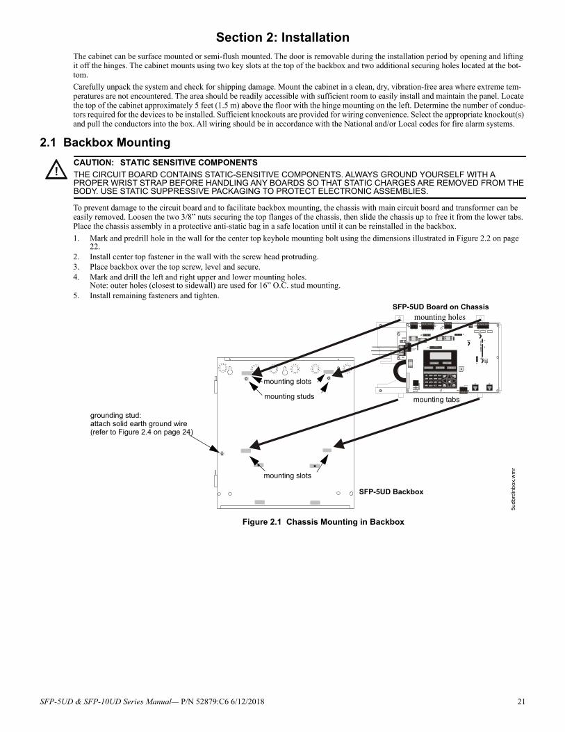
Section 2: InstallationThe cabinet can be surface mounted or semi-flush mounted. The door is removable during the installation period by opening and lifting it off the hinges. The cabinet mounts using two key slots at the top of the backbox and two additional securing holes located at the bot-tom.
Carefully unpack the system and check for shipping damage. Mount the cabinet in a clean, dry, vibration-free area where extreme tem-peratures are not encountered. The area should be readily accessible with sufficient room to easily install and maintain the panel. Locate the top of the cabinet approximately 5 feet (1.5 m) above the floor with the hinge mounting on the left. Determine the number of conduc-tors required for the devices to be installed. Sufficient knockouts are provided for wiring convenience. Select the appropriate knockout(s) and pull the conductors into the box. All wiring should be in accordance with the National and/or Local codes for fire alarm systems.
2.1 Backbox Mounting
To prevent damage to the circuit board and to facilitate backbox mounting, the chassis with main circuit board and transformer can be easily removed. Loosen the two 3/8” nuts securing the top flanges of the chassis, then slide the chassis up to free it from the lower tabs. Place the chassis assembly in a protective anti-static bag in a safe location until it can be reinstalled in the backbox.
1. Mark and predrill hole in the wall for the center top keyhole mounting bolt using the dimensions illustrated in Figure 2.2 on page 22.
2. Install center top fastener in the wall with the screw head protruding.3. Place backbox over the top screw, level and secure.4. Mark and drill the left and right upper and lower mounting holes.
Note: outer holes (closest to sidewall) are used for 16” O.C. stud mounting.5. Install remaining fasteners and tighten.
!CAUTION: STATIC SENSITIVE COMPONENTS
THE CIRCUIT BOARD CONTAINS STATIC-SENSITIVE COMPONENTS. ALWAYS GROUND YOURSELF WITH A PROPER WRIST STRAP BEFORE HANDLING ANY BOARDS SO THAT STATIC CHARGES ARE REMOVED FROM THE BODY. USE STATIC SUPPRESSIVE PACKAGING TO PROTECT ELECTRONIC ASSEMBLIES.
mounting studs
mounting slots
mounting tabs
mounting holes
grounding stud:attach solid earth ground wire (refer to Figure 2.4 on page 24)
SFP-5UD Board on Chassis
SFP-5UD Backbox
Figure 2.1 Chassis Mounting in Backbox5u
dbrd
inb
ox.
wm
r
mounting slots
SFP-5UD & SFP-10UD Series Manual— P/N 52879:C6 6/12/2018 21
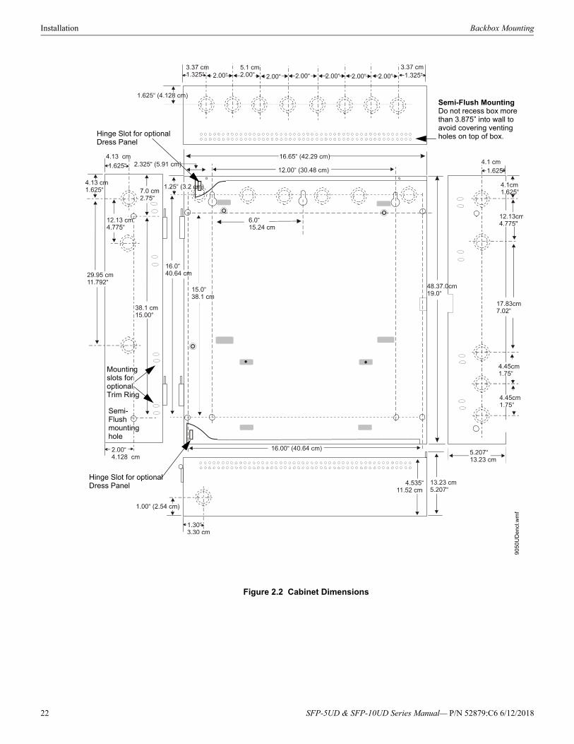
Installation Backbox Mounting
9050
UD
enc
l.wm
f
Figure 2.2 Cabinet Dimensions
Hinge Slot for optional Dress Panel
Semi-Flushmounting hole
Mountingslots foroptionalTrim Ring
Hinge Slot for optional Dress Panel
Semi-Flush MountingDo not recess box more than 3.875” into wall to avoid covering venting holes on top of box.
22 SFP-5UD & SFP-10UD Series Manual— P/N 52879:C6 6/12/2018
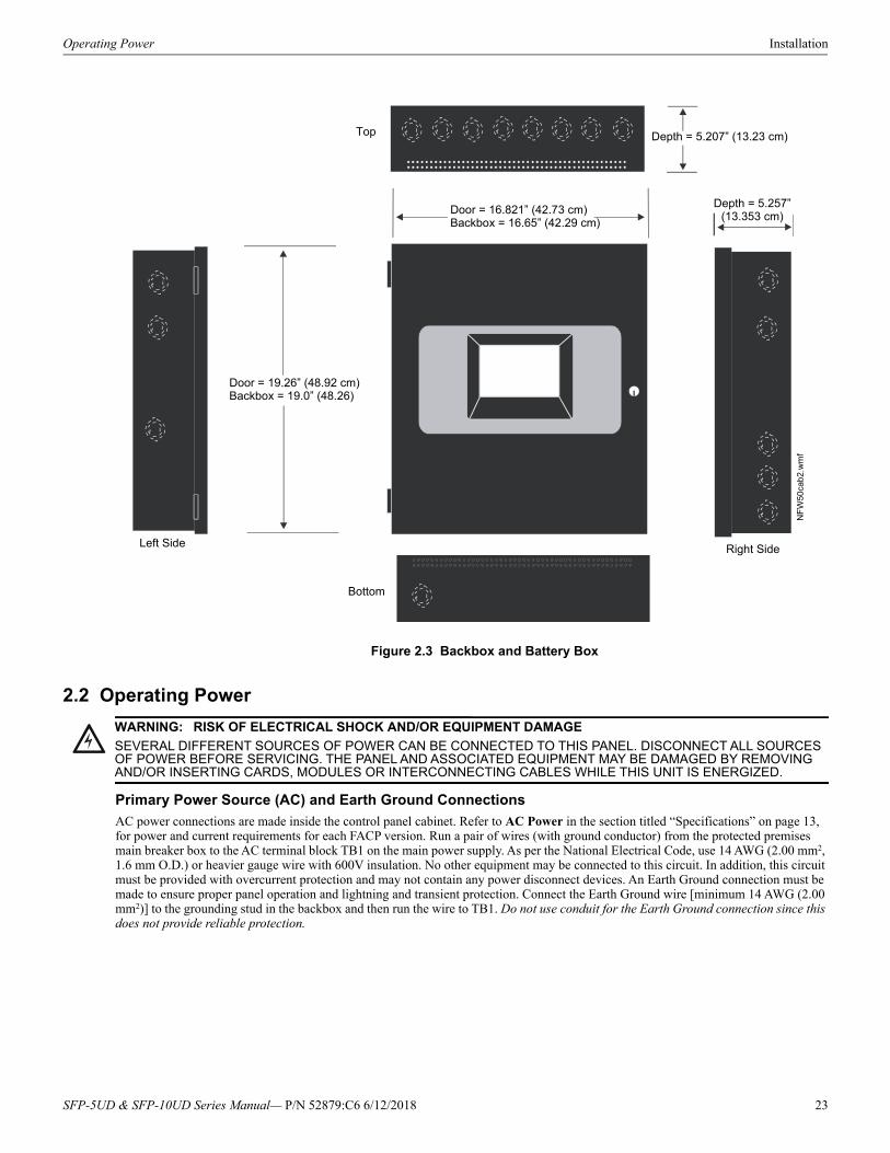
Operating Power Installation
2.2 Operating Power
Primary Power Source (AC) and Earth Ground Connections
AC power connections are made inside the control panel cabinet. Refer to AC Power in the section titled “Specifications” on page 13, for power and current requirements for each FACP version. Run a pair of wires (with ground conductor) from the protected premises main breaker box to the AC terminal block TB1 on the main power supply. As per the National Electrical Code, use 14 AWG (2.00 mm2, 1.6 mm O.D.) or heavier gauge wire with 600V insulation. No other equipment may be connected to this circuit. In addition, this circuit must be provided with overcurrent protection and may not contain any power disconnect devices. An Earth Ground connection must be made to ensure proper panel operation and lightning and transient protection. Connect the Earth Ground wire [minimum 14 AWG (2.00 mm2)] to the grounding stud in the backbox and then run the wire to TB1. Do not use conduit for the Earth Ground connection since this does not provide reliable protection.
Figure 2.3 Backbox and Battery Box
NF
W50
cab
2.w
mf
Door = 19.26” (48.92 cm)Backbox = 19.0” (48.26)
Door = 16.821” (42.73 cm)Backbox = 16.65” (42.29 cm)
Depth = 5.207” (13.23 cm)
Depth = 5.257”(13.353 cm)
Top
Left Side Right Side
Bottom
!WARNING: RISK OF ELECTRICAL SHOCK AND/OR EQUIPMENT DAMAGE
SEVERAL DIFFERENT SOURCES OF POWER CAN BE CONNECTED TO THIS PANEL. DISCONNECT ALL SOURCES OF POWER BEFORE SERVICING. THE PANEL AND ASSOCIATED EQUIPMENT MAY BE DAMAGED BY REMOVING AND/OR INSERTING CARDS, MODULES OR INTERCONNECTING CABLES WHILE THIS UNIT IS ENERGIZED.
SFP-5UD & SFP-10UD Series Manual— P/N 52879:C6 6/12/2018 23
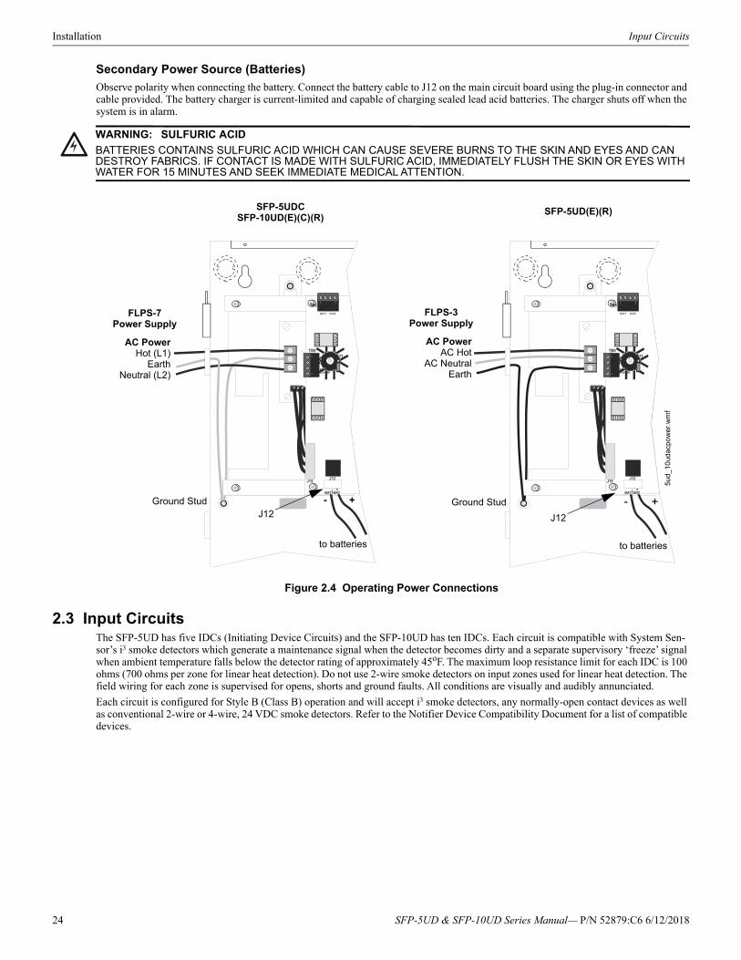
Installation Input Circuits
Secondary Power Source (Batteries)
Observe polarity when connecting the battery. Connect the battery cable to J12 on the main circuit board using the plug-in connector and cable provided. The battery charger is current-limited and capable of charging sealed lead acid batteries. The charger shuts off when the system is in alarm.
2.3 Input CircuitsThe SFP-5UD has five IDCs (Initiating Device Circuits) and the SFP-10UD has ten IDCs. Each circuit is compatible with System Sen-sor’s i3 smoke detectors which generate a maintenance signal when the detector becomes dirty and a separate supervisory ‘freeze’ signal when ambient temperature falls below the detector rating of approximately 45oF. The maximum loop resistance limit for each IDC is 100 ohms (700 ohms per zone for linear heat detection). Do not use 2-wire smoke detectors on input zones used for linear heat detection. The field wiring for each zone is supervised for opens, shorts and ground faults. All conditions are visually and audibly annunciated.
Each circuit is configured for Style B (Class B) operation and will accept i3 smoke detectors, any normally-open contact devices as well as conventional 2-wire or 4-wire, 24 VDC smoke detectors. Refer to the Notifier Device Compatibility Document for a list of compatible devices.
!WARNING: SULFURIC ACID
BATTERIES CONTAINS SULFURIC ACID WHICH CAN CAUSE SEVERE BURNS TO THE SKIN AND EYES AND CAN DESTROY FABRICS. IF CONTACT IS MADE WITH SULFURIC ACID, IMMEDIATELY FLUSH THE SKIN OR EYES WITH WATER FOR 15 MINUTES AND SEEK IMMEDIATE MEDICAL ATTENTION.
Figure 2.4 Operating Power Connections
AC PowerHot (L1)
EarthNeutral (L2)
Ground StudJ12
to batteries
5ud_
10u
dacp
ow
er.w
mf
+- Ground Stud
J12
to batteries
+-
FLPS-7 Power Supply
FLPS-3 Power Supply
AC PowerAC Hot
AC NeutralEarth
SFP-5UDCSFP-10UD(E)(C)(R)
SFP-5UD(E)(R)
24 SFP-5UD & SFP-10UD Series Manual— P/N 52879:C6 6/12/2018
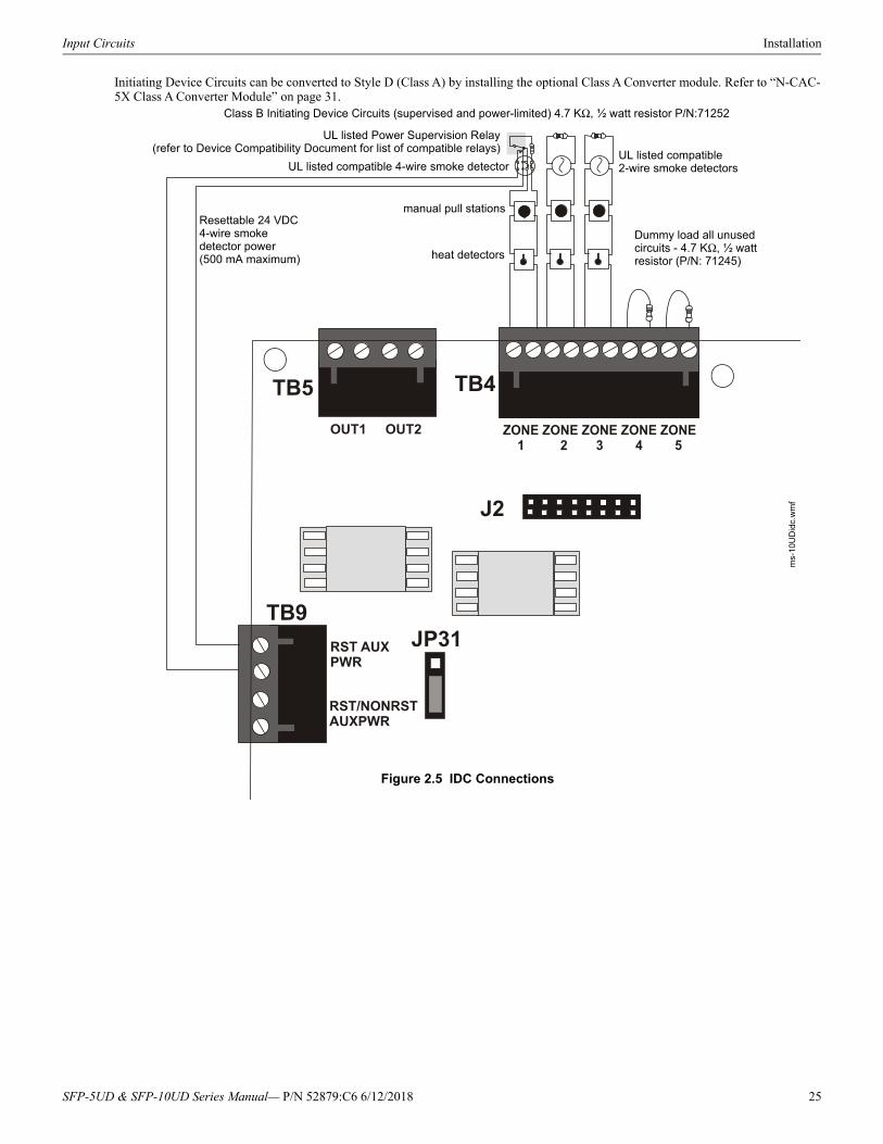
Input Circuits Installation
Initiating Device Circuits can be converted to Style D (Class A) by installing the optional Class A Converter module. Refer to “N-CAC-5X Class A Converter Module” on page 31.
Figure 2.5 IDC Connections
Class B Initiating Device Circuits (supervised and power-limited) 4.7 KΩ, ½ watt resistor P/N:71252
UL listed compatible 2-wire smoke detectors
manual pull stations
heat detectors
Dummy load all unused circuits - 4.7 KΩ, ½ watt resistor (P/N: 71245)
ms-
10U
Did
c.w
mf
UL listed Power Supervision Relay(refer to Device Compatibility Document for list of compatible relays)
Resettable 24 VDC 4-wire smoke detector power (500 mA maximum)
UL listed compatible 4-wire smoke detector
SFP-5UD & SFP-10UD Series Manual— P/N 52879:C6 6/12/2018 25
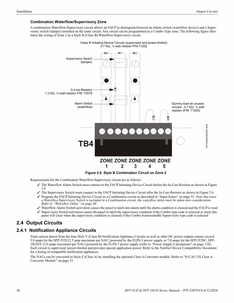
Installation Output Circuits
Combination Waterflow/Supervisory Zone
A combination Waterflow/Supervisory circuit allows an FACP to distinguish between an Alarm switch (waterflow device) and a Super-visory switch (tamper) installed on the same circuit. Any circuit can be programmed as a Combo Type zone. The following figure illus-trates the wiring of Zone 2 as a Style B (Class B) Waterflow/Supervisory circuit.
Requirements for the Combination Waterflow/Supervisory circuit are as follows:
The Waterflow Alarm Switch must connect to the FACP Initiating Device Circuit before the In-Line Resistor as shown in Figure 2.6
The Supervisory Switch must connect to the FACP Initiating Device Circuit after the In-Line Resistor as shown in Figure 2.6 Program the FACP Initiating Device Circuit as a Combination circuit as described in “Input Zones” on page 53. Note that since
a Waterflow Supervisory Switch is included in a Combination circuit, the waterflow delay must be taken into consideration. Refer to “Waterflow Delay” on page 68.
Waterflow Alarm Switch activation causes the panel to latch into alarm until the alarm condition is cleared and the FACP is reset Supervisory Switch activation causes the panel to latch the supervisory condition if the Combo type code is selected or track (the
panel will clear when the supervisory condition is cleared) if the Combo Autoresettable Supervisory type code is selected
2.4 Output Circuits
2.4.1 Notification Appliance CircuitsTotal current drawn from the four Style Y (Class B) Notification Appliance Circuits as well as other DC power outputs cannot exceed 3.0 amps for the SFP-5UD [2.5 amp maximum per NAC] powered by the FLPS-3 power supply or 7.0 amps for the SFP-5UDC, SFP-10UD/E [3.0 amps maximum per NAC] powered by the FLPS-7 power supply (refer to “Power Supply Calculations” on page 110). Each circuit is supervised, power-limited and provides special application power. Refer to the Notifier Device Compatibility Document for a listing of compatible notification appliances.
The NACs can be converted to Style Z (Class A) by installing the optional Class A Converter module. Refer to “N-CAC-5X Class A Converter Module” on page 31.
Class B Initiating Device Circuits (supervised and power-limited)4.7 KΩ, ½ watt resistor P/N:71252
In-Line-Resistor1.2 KΩ, ½ watt resistor P/N: 75579
Alarm Switch(waterflow)
Dummy load all unused circuits - 4.7 KΩ, ½ watt resistor (P/N: 71245)
Figure 2.6 Style B Combination Circuit on Zone 2
Supervisory Switch(tamper)
ms1
0ud
com
boID
C.w
mf
26 SFP-5UD & SFP-10UD Series Manual— P/N 52879:C6 6/12/2018
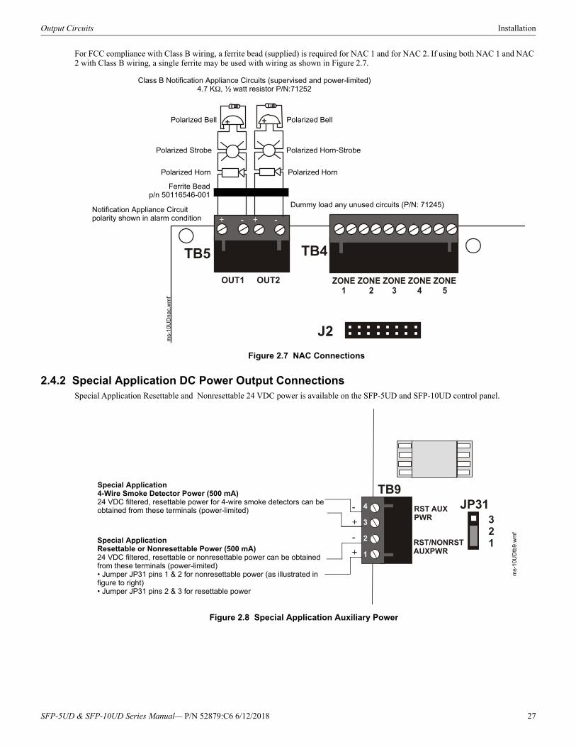
Output Circuits Installation
For FCC compliance with Class B wiring, a ferrite bead (supplied) is required for NAC 1 and for NAC 2. If using both NAC 1 and NAC 2 with Class B wiring, a single ferrite may be used with wiring as shown in Figure 2.7.
2.4.2 Special Application DC Power Output ConnectionsSpecial Application Resettable and Nonresettable 24 VDC power is available on the SFP-5UD and SFP-10UD control panel.
Figure 2.7 NAC Connections
Class B Notification Appliance Circuits (supervised and power-limited)4.7 KΩ, ½ watt resistor P/N:71252
Dummy load any unused circuits (P/N: 71245)
Polarized Bell
Polarized Strobe
Polarized Horn Polarized Horn
Polarized Horn-Strobe
Polarized Bell
Notification Appliance Circuit polarity shown in alarm condition
ms-
10U
Dn
ac.w
mf
+ - + -
Ferrite Beadp/n 50116546-001
Figure 2.8 Special Application Auxiliary Power
Special Application4-Wire Smoke Detector Power (500 mA)24 VDC filtered, resettable power for 4-wire smoke detectors can be obtained from these terminals (power-limited)
Special ApplicationResettable or Nonresettable Power (500 mA)24 VDC filtered, resettable or nonresettable power can be obtained from these terminals (power-limited)• Jumper JP31 pins 1 & 2 for nonresettable power (as illustrated in figure to right)• Jumper JP31 pins 2 & 3 for resettable power
-
+
-
+
ms-
10U
Dtb
9.w
mf
4
3
2
1
SFP-5UD & SFP-10UD Series Manual— P/N 52879:C6 6/12/2018 27
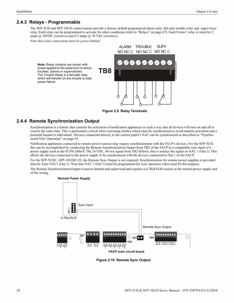
Installation Output Circuits
2.4.3 Relays - ProgrammableThe SFP-5UD and SFP-10UD control panels provide a factory default programmed alarm relay, fail-safe trouble relay and supervisory relay. Each relay can be programmed to activate for other conditions (refer to “Relays” on page 67). Each Form-C relay is rated for 2 amps @ 30VDC (resistive) and 0.5 amps @ 30 VAC (resistive).
Note that relay connections must be power-limited.
2.4.4 Remote Synchronization OutputSynchronization is a feature that controls the activation of notification appliances in such a way that all devices will turn on and off at exactly the same time. This is particularly critical when activating strobes which must be synchronized to avoid random activation and a potential hazard to individuals. Devices connected directly to the control panel’s NAC can be synchronized as described in “Synchro-nized NAC Operation” on page 65.
Notification appliances connected to remote power sources may require synchronization with the FACP’s devices. For the SFP-5UD, this can be accomplished by connecting the Remote Synchronization Output from TB2 of the FACP to a compatible sync input of a power supply such as the FCPS-24S6/8. The 24 VDC, 40 mA signal from TB2 follows, that is mimics the signal on NAC 1 (Out 1). This allows the devices connected to the power supply to be synchronized with the devices connected to Out 1 on the FACP.
For the SFP-5UDC, SFP-10UD(C)/E, the Remote Sync Output is not required. Synchronization for remote power supplies is provided directly from NAC1 (Out 1). Note that NAC 1 (Out 1) must be programmed for sync operation when used for this purpose.
The Remote Synchronization Output is power-limited and supervised and requires a 4.7KΩ ELR resistor at the remote power supply end of the wiring.
Figure 2.9 Relay Terminals
Note: Relay contacts are shown with power applied to the panel and no active troubles, alarms or supervisories.The Trouble Relay is a fail-safe relay which will transfer on any trouble or total power failure.
ms1
0udr
ela
y.w
mf
Remote Power Supply
FACP main circuit board
4.7KΩ ELR
Sync Input
Remote Sync Output
Figure 2.10 Remote Sync Output
28 SFP-5UD & SFP-10UD Series Manual— P/N 52879:C6 6/12/2018
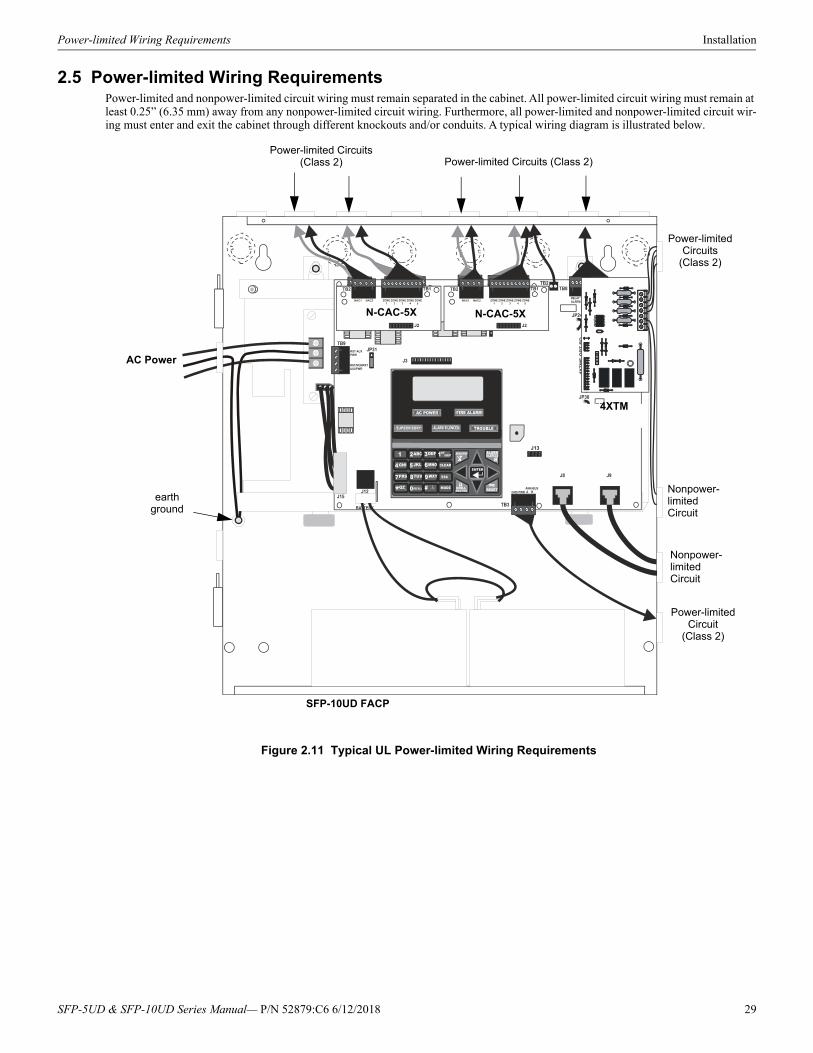
Power-limited Wiring Requirements Installation
2.5 Power-limited Wiring RequirementsPower-limited and nonpower-limited circuit wiring must remain separated in the cabinet. All power-limited circuit wiring must remain at least 0.25” (6.35 mm) away from any nonpower-limited circuit wiring. Furthermore, all power-limited and nonpower-limited circuit wir-ing must enter and exit the cabinet through different knockouts and/or conduits. A typical wiring diagram is illustrated below.
J13
Figure 2.11 Typical UL Power-limited Wiring Requirements
Power-limited Circuits(Class 2)
Power-limited Circuits
(Class 2)
Nonpower-limited Circuit
AC Power
N-CAC-5X
4XTM
N-CAC-5X
earthground
Nonpower-limited Circuit
Power-limited Circuit
(Class 2)
SFP-10UD FACP
Power-limited Circuits (Class 2)
SFP-5UD & SFP-10UD Series Manual— P/N 52879:C6 6/12/2018 29
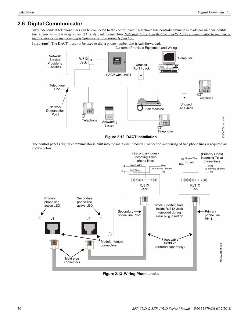
Installation Digital Communicator
2.6 Digital CommunicatorTwo independent telephone lines can be connected to the control panel. Telephone line control/command is made possible via double line seizure as well as usage of an RJ31X style interconnection. Note that it is critical that the panel's digital communicator be located as the first device on the incoming telephone circuit to properly function.
Important! The DACT must not be used to dial a phone number that is call-forwarded.
The control panel's digital communicator is built into the main circuit board. Connection and wiring of two phone lines is required as shown below.
Figure 2.12 DACT Installation
Customer Premises Equipment and Wiring
Telephone Line
FACP with DACT
Network Service
Provider’s Facilities
Network Demarcation
Point
RJ31XJack
UnusedRJ-11 Jack
UnusedJ-11 Jack
Telephone
Telephone
Telephone Answering System
Fax Machine
Computer
905
0AC
TA
dact
.wm
f
1 2 3 4 5 6 77 81 2 3 4 5 6 8
J8 J9
Figure 2.13 Wiring Phone Jacks
10U
DJA
CK
2.w
mf
RJ31XJack
RJ31XJack
(Secondary Lines)Incoming Telco
phone lines
(Primary Lines)Incoming Telco
phone lines
Ring
Ring RingTip
Tip Tip
Green Wire
Red Wireto premise phones
Ring
Tip Green Wire
Red Wire
to premise phones
Note: Shorting bars inside RJ31X Jack
removed during male plug insertion
7 foot cableMCBL-7
(ordered separately)
Primary phone line PH-1
Secondary phone line PH-2
Modular female connectors
Male plug connectors
Primary phone line active LED
Secondary phone line active LED
30 SFP-5UD & SFP-10UD Series Manual— P/N 52879:C6 6/12/2018
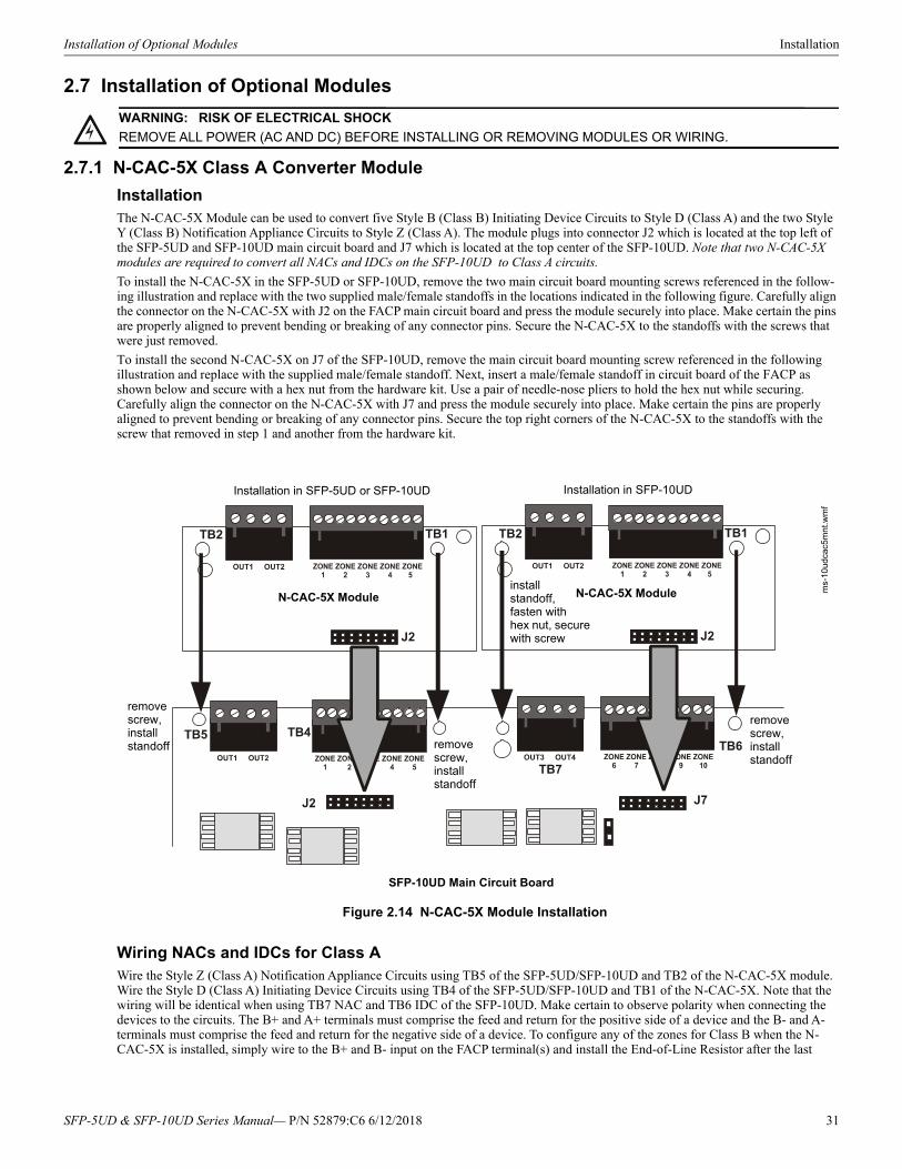
Installation of Optional Modules Installation
2.7 Installation of Optional Modules
2.7.1 N-CAC-5X Class A Converter Module
InstallationThe N-CAC-5X Module can be used to convert five Style B (Class B) Initiating Device Circuits to Style D (Class A) and the two Style Y (Class B) Notification Appliance Circuits to Style Z (Class A). The module plugs into connector J2 which is located at the top left of the SFP-5UD and SFP-10UD main circuit board and J7 which is located at the top center of the SFP-10UD. Note that two N-CAC-5X modules are required to convert all NACs and IDCs on the SFP-10UD to Class A circuits.
To install the N-CAC-5X in the SFP-5UD or SFP-10UD, remove the two main circuit board mounting screws referenced in the follow-ing illustration and replace with the two supplied male/female standoffs in the locations indicated in the following figure. Carefully align the connector on the N-CAC-5X with J2 on the FACP main circuit board and press the module securely into place. Make certain the pins are properly aligned to prevent bending or breaking of any connector pins. Secure the N-CAC-5X to the standoffs with the screws that were just removed.
To install the second N-CAC-5X on J7 of the SFP-10UD, remove the main circuit board mounting screw referenced in the following illustration and replace with the supplied male/female standoff. Next, insert a male/female standoff in circuit board of the FACP as shown below and secure with a hex nut from the hardware kit. Use a pair of needle-nose pliers to hold the hex nut while securing. Carefully align the connector on the N-CAC-5X with J7 and press the module securely into place. Make certain the pins are properly aligned to prevent bending or breaking of any connector pins. Secure the top right corners of the N-CAC-5X to the standoffs with the screw that removed in step 1 and another from the hardware kit.
!WARNING: RISK OF ELECTRICAL SHOCK
REMOVE ALL POWER (AC AND DC) BEFORE INSTALLING OR REMOVING MODULES OR WIRING.
Figure 2.14 N-CAC-5X Module Installation
Wiring NACs and IDCs for Class AWire the Style Z (Class A) Notification Appliance Circuits using TB5 of the SFP-5UD/SFP-10UD and TB2 of the N-CAC-5X module. Wire the Style D (Class A) Initiating Device Circuits using TB4 of the SFP-5UD/SFP-10UD and TB1 of the N-CAC-5X. Note that the wiring will be identical when using TB7 NAC and TB6 IDC of the SFP-10UD. Make certain to observe polarity when connecting the devices to the circuits. The B+ and A+ terminals must comprise the feed and return for the positive side of a device and the B- and A- terminals must comprise the feed and return for the negative side of a device. To configure any of the zones for Class B when the N-CAC-5X is installed, simply wire to the B+ and B- input on the FACP terminal(s) and install the End-of-Line Resistor after the last
SFP-10UD Main Circuit Board
N-CAC-5X Module
ms-
10ud
cac5
mn
t.wm
f
N-CAC-5X Module
Installation in SFP-5UD or SFP-10UD Installation in SFP-10UD
remove screw, install standoff
remove screw, install standoff
remove screw, install standoff
install standoff, fasten with hex nut, secure with screw
SFP-5UD & SFP-10UD Series Manual— P/N 52879:C6 6/12/2018 31
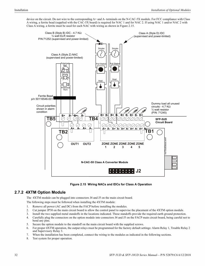
Installation Installation of Optional Modules
device on the circuit. Do not wire to the corresponding A+ and A- terminals on the N-CAC-5X module. For FCC compliance with Class A wiring, a ferrite bead (supplied with the CAC-5X board) is required for NAC 1 and for NAC 2. If using NAC 1 and/or NAC 2 with Class A wiring, a ferrite must be used for each NAC with wiring as shown in Figure 2.15.
2.7.2 4XTM Option ModuleThe 4XTM module can be plugged into connectors J4 and J5 on the main circuit board.
The following steps must be followed when installing the 4XTM module:
1. Remove all power (AC and DC) from the FACP before installing the modules.2. Cut jumper JP30 on the main circuit board to allow the control panel to supervise the placement of the 4XTM option module.3. Install the two supplied metal standoffs in the locations indicated. These standoffs provide the required earth ground protection.4. Carefully plug the connectors on the option module into connectors J4 and J5 on the FACP main circuit board, being careful not to
bend any pins.5. Secure the option module to the standoff on the main circuit board with the supplied screws.6. For proper 4XTM operation, the output relays must be programmed for the factory default settings: Alarm Relay 1, Trouble Relay 2
and Supervisory Relay 3.7. When the installation has been completed, connect the wiring to the modules as indicated in the following sections.8. Test system for proper operation.
Figure 2.15 Wiring NACs and IDCs for Class A Operation
N-CAC-5X Class A Converter Module
SFP-5UDCircuit Board
Class B (Style B) IDC - 4.7 KΩ½ watt ELR resistor
P/N:71252 (supervised and power-limited)
Dummy load all unused circuits - 4.7 KΩ½ watt resistor (P/N: 71245)
PolarizedBell
Circuit polarities shown in alarm condition
Class A (Style Z) NAC (supervised and power-limited)
Class A (Style D) IDC (supervised and power-limited)
Polarized Strobe
Polarized Horn
SmokeSmoke
Pull Station Pull Station
HeatHeat
ms1
0udc
lass
a.w
mf
B+ B- B+ B-
A+ A- A+ A- A+ A- A+ A- A+ A- A+ A- A+ A-
B+ B- B+ B- B+ B- B+ B- B+
Ferrite Beadp/n 50116546-001
32 SFP-5UD & SFP-10UD Series Manual— P/N 52879:C6 6/12/2018
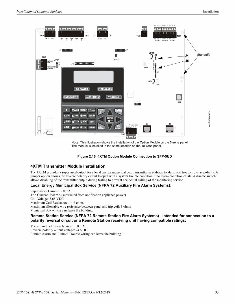
Installation of Optional Modules Installation
4XTM Transmitter Module InstallationThe 4XTM provides a supervised output for a local energy municipal box transmitter in addition to alarm and trouble reverse polarity. A jumper option allows the reverse polarity circuit to open with a system trouble condition if no alarm condition exists. A disable switch allows disabling of the transmitter output during testing to prevent accidental calling of the monitoring service.
Local Energy Municipal Box Service (NFPA 72 Auxiliary Fire Alarm Systems):
Supervisory Current: 5.0 mATrip Current: 350 mA (subtracted from notification appliance power)Coil Voltage: 3.65 VDCMaximum Coil Resistance: 14.6 ohmsMaximum allowable wire resistance between panel and trip coil: 3 ohmsMunicipal Box wiring can leave the building
Remote Station Service (NFPA 72 Remote Station Fire Alarm Systems) - Intended for connection to a polarity reversal circuit or a Remote Station receiving unit having compatible ratings:
Maximum load for each circuit: 10 mAReverse polarity output voltage: 24 VDCRemote Alarm and Remote Trouble wiring can leave the building
SW1
Figure 2.16 4XTM Option Module Connection to SFP-5UD
J4
J5
Standoffs
ms-
5bo
ard.
wm
f
Note: This illustration shows the installation of the Option Module on the 5-zone panel. The module is installed in the same location on the 10-zone panel.
SFP-5UD & SFP-10UD Series Manual— P/N 52879:C6 6/12/2018 33
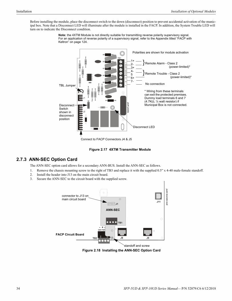
Installation Installation of Optional Modules
Before installing the module, place the disconnect switch to the down (disconnect) position to prevent accidental activation of the munic-ipal box. Note that a Disconnect LED will illuminate after the module is installed in the FACP. In addition, the System Trouble LED will turn on to indicate the Disconnect condition.
2.7.3 ANN-SEC Option CardThe ANN-SEC option card allows for a secondary ANN-BUS. Install the ANN-SEC as follows.
1. Remove the chassis mounting screw to the right of TB3 and replace it with the supplied 0.5” x 4-40 male-female standoff.2. Install the header into J13 on the main circuit board.3. Secure the ANN-SEC to the circuit board with the supplied screw.
Figure 2.17 4XTM Transmitter Module
Connect to FACP Connectors J4 & J5
Disconnect Switch shown in disconnect position
TBL Jumper
}Remote Alarm - Class 2 (power-limited)*
}Remote Trouble - Class 2 (power-limited)*
No connection
1+2-3+4-56+7-
Polarities are shown for module activation
Note: the 4XTM Module is not directly suitable for transmitting reverse polarity supervisory signal. For an application of reverse polarity of a supervisory signal, refer to the Appendix titled “FACP with Keltron” on page 124.
* Wiring from these terminals can exit the protected premises. Dummy load terminals 6 and 7 (4.7KΩ, ¼ watt resistor) if Municipal Box is not connected.
Disconnect LED4x
tmf.w
mf
TB1
J1
ANN-SEC
FACP Circuit Board
connector to J13 on main circuit board
standoff and screw
Figure 2.18 Installing the ANN-SEC Option Card
ann-
seci
nst.w
mf
34 SFP-5UD & SFP-10UD Series Manual— P/N 52879:C6 6/12/2018
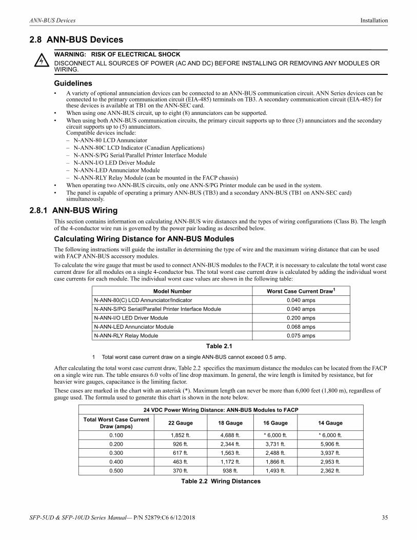
ANN-BUS Devices Installation
2.8 ANN-BUS Devices
Guidelines• A variety of optional annunciation devices can be connected to an ANN-BUS communication circuit. ANN Series devices can be
connected to the primary communication circuit (EIA-485) terminals on TB3. A secondary communication circuit (EIA-485) for these devices is available at TB1 on the ANN-SEC card.
• When using one ANN-BUS circuit, up to eight (8) annunciators can be supported.• When using both ANN-BUS communication circuits, the primary circuit supports up to three (3) annunciators and the secondary
circuit supports up to (5) annunciators.Compatible devices include:– N-ANN-80 LCD Annunciator– N-ANN-80C LCD Indicator (Canadian Applications)– N-ANN-S/PG Serial/Parallel Printer Interface Module– N-ANN-I/O LED Driver Module– N-ANN-LED Annunciator Module– N-ANN-RLY Relay Module (can be mounted in the FACP chassis)
• When operating two ANN-BUS circuits, only one ANN-S/PG Printer module can be used in the system.• The panel is capable of operating a primary ANN-BUS (TB3) and a secondary ANN-BUS (TB1 on ANN-SEC card)
simultaneously.
2.8.1 ANN-BUS WiringThis section contains information on calculating ANN-BUS wire distances and the types of wiring configurations (Class B). The length of the 4-conductor wire run is governed by the power pair loading as described below.
Calculating Wiring Distance for ANN-BUS ModulesThe following instructions will guide the installer in determining the type of wire and the maximum wiring distance that can be used with FACP ANN-BUS accessory modules.
To calculate the wire gauge that must be used to connect ANN-BUS modules to the FACP, it is necessary to calculate the total worst case current draw for all modules on a single 4-conductor bus. The total worst case current draw is calculated by adding the individual worst case currents for each module. The individual worst case values are shown in the following table:
After calculating the total worst case current draw, Table 2.2 specifies the maximum distance the modules can be located from the FACP on a single wire run. The table ensures 6.0 volts of line drop maximum. In general, the wire length is limited by resistance, but for heavier wire gauges, capacitance is the limiting factor.
These cases are marked in the chart with an asterisk (*). Maximum length can never be more than 6,000 feet (1,800 m), regardless of gauge used. The formula used to generate this chart is shown in the note below.
!WARNING: RISK OF ELECTRICAL SHOCK
DISCONNECT ALL SOURCES OF POWER (AC AND DC) BEFORE INSTALLING OR REMOVING ANY MODULES OR WIRING.
Model Number Worst Case Current Draw1
1 Total worst case current draw on a single ANN-BUS cannot exceed 0.5 amp.
N-ANN-80(C) LCD Annunciator/Indicator 0.040 amps
N-ANN-S/PG Serial/Parallel Printer Interface Module 0.040 amps
N-ANN-I/O LED Driver Module 0.200 amps
N-ANN-LED Annunciator Module 0.068 amps
N-ANN-RLY Relay Module 0.075 amps
Table 2.1
24 VDC Power Wiring Distance: ANN-BUS Modules to FACP
Total Worst Case Current Draw (amps)
22 Gauge 18 Gauge 16 Gauge 14 Gauge
0.100 1,852 ft. 4,688 ft. * 6,000 ft. * 6,000 ft.
0.200 926 ft. 2,344 ft. 3,731 ft. 5,906 ft.
0.300 617 ft. 1,563 ft. 2,488 ft. 3,937 ft.
0.400 463 ft. 1,172 ft. 1,866 ft. 2,953 ft.
0.500 370 ft. 938 ft. 1,493 ft. 2,362 ft.
Table 2.2 Wiring Distances
SFP-5UD & SFP-10UD Series Manual— P/N 52879:C6 6/12/2018 35
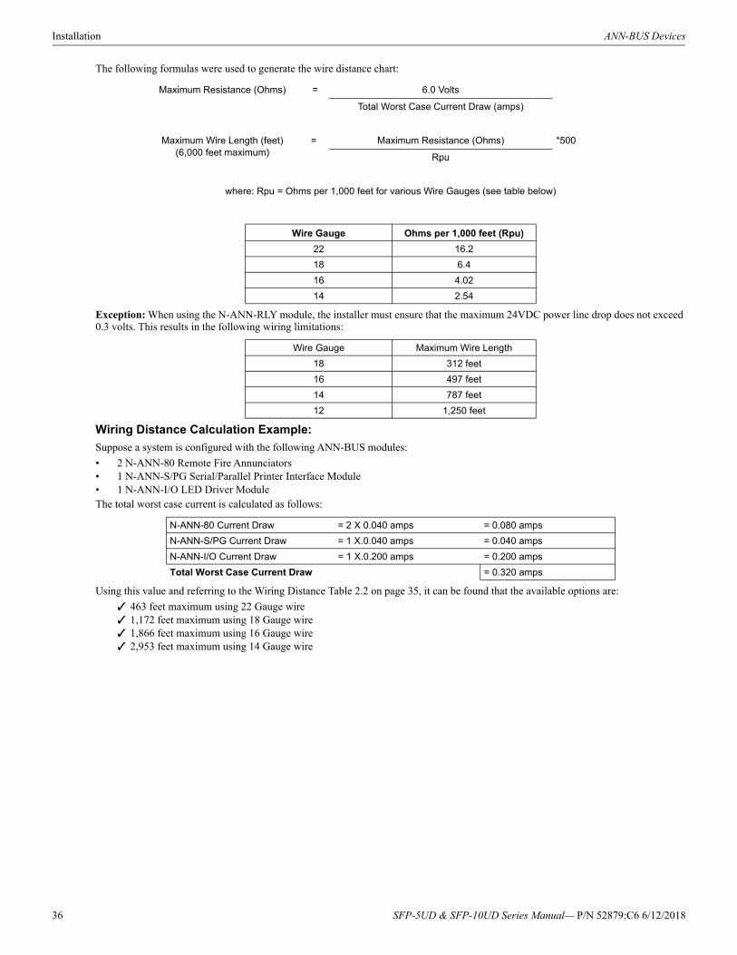
Installation ANN-BUS Devices
The following formulas were used to generate the wire distance chart:
Exception: When using the N-ANN-RLY module, the installer must ensure that the maximum 24VDC power line drop does not exceed 0.3 volts. This results in the following wiring limitations:
Wiring Distance Calculation Example:
Suppose a system is configured with the following ANN-BUS modules:
• 2 N-ANN-80 Remote Fire Annunciators• 1 N-ANN-S/PG Serial/Parallel Printer Interface Module• 1 N-ANN-I/O LED Driver ModuleThe total worst case current is calculated as follows:
Using this value and referring to the Wiring Distance Table 2.2 on page 35, it can be found that the available options are:
463 feet maximum using 22 Gauge wire 1,172 feet maximum using 18 Gauge wire 1,866 feet maximum using 16 Gauge wire 2,953 feet maximum using 14 Gauge wire
Maximum Resistance (Ohms) = 6.0 Volts
Total Worst Case Current Draw (amps)
Maximum Wire Length (feet)(6,000 feet maximum)
= Maximum Resistance (Ohms) *500
Rpu
where: Rpu = Ohms per 1,000 feet for various Wire Gauges (see table below)
Wire Gauge Ohms per 1,000 feet (Rpu)
22 16.2
18 6.4
16 4.02
14 2.54
Wire Gauge Maximum Wire Length
18 312 feet
16 497 feet
14 787 feet
12 1,250 feet
N-ANN-80 Current Draw = 2 X 0.040 amps = 0.080 amps
N-ANN-S/PG Current Draw = 1 X.0.040 amps = 0.040 amps
N-ANN-I/O Current Draw = 1 X.0.200 amps = 0.200 amps
Total Worst Case Current Draw = 0.320 amps
36 SFP-5UD & SFP-10UD Series Manual— P/N 52879:C6 6/12/2018
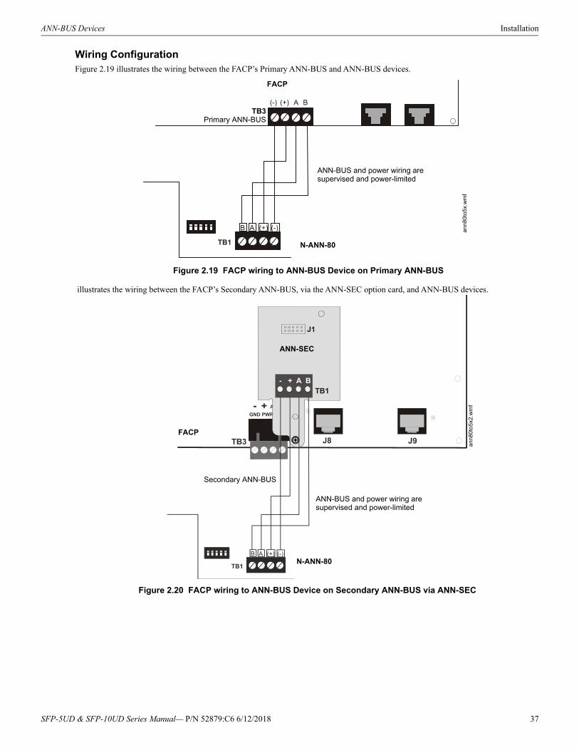
ANN-BUS Devices Installation
Wiring ConfigurationFigure 2.19 illustrates the wiring between the FACP’s Primary ANN-BUS and ANN-BUS devices.
illustrates the wiring between the FACP’s Secondary ANN-BUS, via the ANN-SEC option card, and ANN-BUS devices.
Figure 2.19 FACP wiring to ANN-BUS Device on Primary ANN-BUS
FACP
N-ANN-80
ANN-BUS and power wiring are supervised and power-limited
TB3Primary ANN-BUS
an
n80t
o5x
.wm
f
TB1
J1
- + A B
ANN-SEC
Figure 2.20 FACP wiring to ANN-BUS Device on Secondary ANN-BUS via ANN-SEC
FACP
N-ANN-80
ANN-BUS and power wiring are supervised and power-limited
Secondary ANN-BUSa
nn80
to5
x2.w
mf
SFP-5UD & SFP-10UD Series Manual— P/N 52879:C6 6/12/2018 37
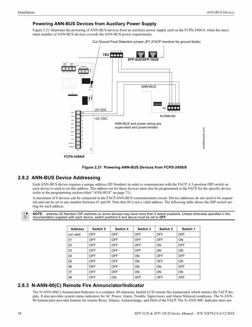
Installation ANN-BUS Devices
Powering ANN-BUS Devices from Auxiliary Power SupplyFigure 2.21 illustrates the powering of ANN-BUS devices from an auxiliary power supply such as the FCPS-24S6/8, when the maxi-mum number of ANN-BUS devices exceeds the ANN-BUS power requirements.
2.8.2 ANN-BUS Device AddressingEach ANN-BUS device requires a unique address (ID Number) in order to communicate with the FACP. A 5-position DIP switch on each device is used to set this address. The address set for these devices must also be programmed at the FACP for the specific device (refer to the programming section titled “ANN-BUS” on page 71).
A maximum of 8 devices can be connected to the FACP ANN-BUS communication circuit. Device addresses do not need to be sequen-tial and can be set to any number between 01 and 08. Note that 00 is not a valid address. The following table shows the DIP switch set-ting for each address.
2.8.3 N-ANN-80(C) Remote Fire Annunciator/IndicatorThe N-ANN-80(C) Annunciator/Indicator is a compact, 80 character, backlit LCD remote fire annunciator which mimics the FACP dis-play. It also provides system status indicators for AC Power, Alarm, Trouble, Supervisory and Alarm Silenced conditions. The N-ANN-80 Annunciator provides buttons for remote Reset, Silence, Acknowledge, and Drill of the FACP. The N-ANN-80C Indicator does not
Figure 2.21 Powering ANN-BUS Devices from FCPS-24S6/8
N-ANN-80
SFP-5UD/SFP-10UD
FCPS-24S6/8
+24 VDC
-24 VDC
ANN-BUS
Cut Ground Fault Detection jumper JP1 (FACP monitors for ground faults)
ANN-BUS and power wiring are supervised and power-limited
TB3
ann8
0to
fcp
s5x.
wm
f
NOTE: address (ID Number) DIP switches on some devices may have more than 5 switch positions. Unless otherwise specified in the documentation supplied with each device, switch positions 6 and above must be set to OFF.
Address Switch 5 Switch 4 Switch 3 Switch 2 Switch 1
not valid OFF OFF OFF OFF OFF
01 OFF OFF OFF OFF ON
02 OFF OFF OFF ON OFF
03 OFF OFF OFF ON ON
04 OFF OFF ON OFF OFF
05 OFF OFF ON OFF ON
06 OFF OFF ON ON OFF
07 OFF OFF ON ON ON
08 OFF ON OFF OFF OFF
38 SFP-5UD & SFP-10UD Series Manual— P/N 52879:C6 6/12/2018
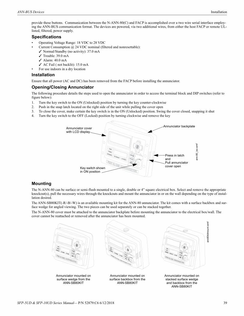
ANN-BUS Devices Installation
provide these buttons. Communication between the N-ANN-80(C) and FACP is accomplished over a two wire serial interface employ-ing the ANN-BUS communication format. The devices are powered, via two additional wires, from either the host FACP or remote UL-listed, filtered, power supply.
Specifications• Operating Voltage Range: 18 VDC to 28 VDC• Current Consumption @ 24 VDC nominal (filtered and nonresettable):
Normal/Standby (no activity): 37.0 mA Trouble: 39.0 mA Alarm: 40.0 mA AC Fail ( not backlit): 15.0 mA
• For use indoors in a dry location
InstallationEnsure that all power (AC and DC) has been removed from the FACP before installing the annunciator.
Opening/Closing AnnunciatorThe following procedure details the steps used to open the annunciator in order to access the terminal block and DIP switches (refer to figure below):
1. Turn the key switch to the ON (Unlocked) position by turning the key counter-clockwise2. Push in the snap latch located on the right side of the unit while pulling the cover open3. To close the cover, make certain the key switch is in the ON (Unlocked) position. Swing the cover closed, snapping it shut4. Turn the key switch to the OFF (Locked) position by turning clockwise and remove the key
MountingThe N-ANN-80 can be surface or semi-flush mounted to a single, double or 4” square electrical box. Select and remove the appropriate knockout(s), pull the necessary wires through the knockouts and mount the annunciator in or on the wall depending on the type of instal-lation desired.
The ANN-SB80KIT(-R/-B/-W) is an available mounting kit for the ANN-80 annunciator. The kit comes with a surface backbox and sur-face wedge for angled viewing. The two pieces can be used separately or can be stacked together.
The N-ANN-80 cover must be attached to the annunciator backplate before mounting the annunciator to the electrical box/wall. The cover cannot be reattached or removed after the annunciator has been mounted.
Key switch shown in ON position
Press in latch and Pull annunciator cover open
Annunciator cover with LCD display
Annunciator backplate
ann-
80_i
so.w
mf
Annunciator mounted on surface wedge from the
ANN-SB80KIT
Annunciator mounted on surface backbox from the
ANN-SB80KIT
Annunciator mounted on stacked surface wedge and backbox from the
ANN-SB80KIT
ann
80ki
tmo
unt.w
mf
SFP-5UD & SFP-10UD Series Manual— P/N 52879:C6 6/12/2018 39
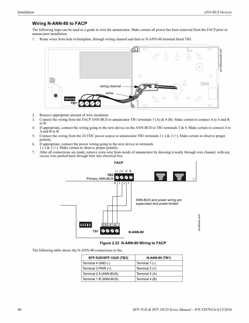
Installation ANN-BUS Devices
Wiring N-ANN-80 to FACPThe following steps can be used as a guide to wire the annunciator. Make certain all power has been removed from the FACP prior to annunciator installation.
1. Route wires from hole in backplate, through wiring channel and then to N-ANN-80 terminal block TB1.
2. Remove appropriate amount of wire insulation.3. Connect the wiring from the FACP ANN-BUS to annunciator TB1 terminals 3 (A) & 4 (B). Make certain to connect A to A and B
to B.4. If appropriate, connect the wiring going to the next device on the ANN-BUS to TB1 terminals 3 & 4. Make certain to connect A to
A and B to B. 5. Connect the wiring from the 24 VDC power source to annunciator TB1 terminals 1 (-) & 2 (+). Make certain to observe proper
polarity.6. If appropriate, connect the power wiring going to the next device to terminals
1 (-) & 2 (+). Make certain to observe proper polarity.7. After all connections are made, remove extra wire from inside of annunciator by dressing it neatly through wire channel, with any
excess wire pushed back through hole into electrical box.
The following table shows the N-ANN-80 connections to the .
SFP-5UD/SFP-10UD (TB3) N-ANN-80 (TB1)
Terminal 4 GND (-) Terminal 1 (-)
Terminal 3 PWR (+) Terminal 2 (+)
Terminal 2 A (ANN-BUS) Terminal 3 (A)
Terminal 1 B (ANN-BUS) Terminal 4 (B)
wiring channel
wires
TB1
ann-
80bo
xin
sid
e.w
mf
Figure 2.22 N-ANN-80 Wiring to FACP
FACP
N-ANN-80
ANN-BUS and power wiring are supervised and power-limited
4 3 2 1
TB3Primary ANN-BUS
ann
80to
5x.
wm
f
40 SFP-5UD & SFP-10UD Series Manual— P/N 52879:C6 6/12/2018
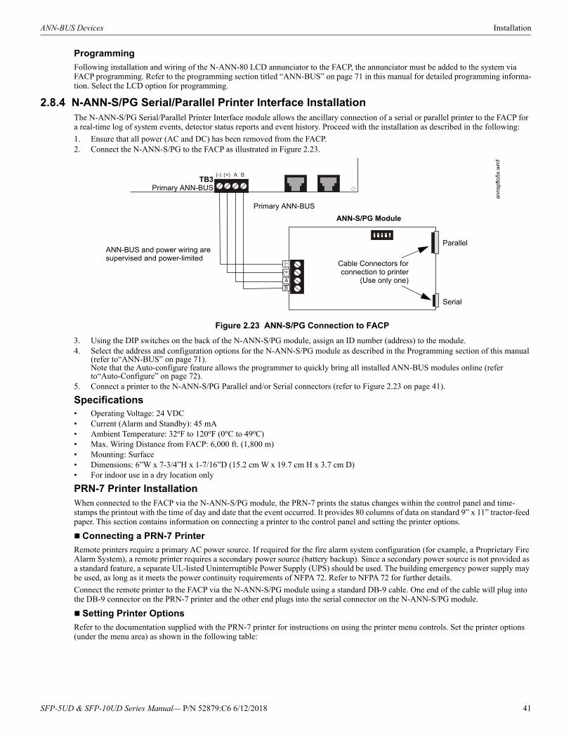
ANN-BUS Devices Installation
Programming
Following installation and wiring of the N-ANN-80 LCD annunciator to the FACP, the annunciator must be added to the system via FACP programming. Refer to the programming section titled “ANN-BUS” on page 71 in this manual for detailed programming informa-tion. Select the LCD option for programming.
2.8.4 N-ANN-S/PG Serial/Parallel Printer Interface InstallationThe N-ANN-S/PG Serial/Parallel Printer Interface module allows the ancillary connection of a serial or parallel printer to the FACP for a real-time log of system events, detector status reports and event history. Proceed with the installation as described in the following:
1. Ensure that all power (AC and DC) has been removed from the FACP.2. Connect the N-ANN-S/PG to the FACP as illustrated in Figure 2.23.
3. Using the DIP switches on the back of the N-ANN-S/PG module, assign an ID number (address) to the module.4. Select the address and configuration options for the N-ANN-S/PG module as described in the Programming section of this manual
(refer to“ANN-BUS” on page 71).Note that the Auto-configure feature allows the programmer to quickly bring all installed ANN-BUS modules online (refer to“Auto-Configure” on page 72).
5. Connect a printer to the N-ANN-S/PG Parallel and/or Serial connectors (refer to Figure 2.23 on page 41).
Specifications• Operating Voltage: 24 VDC• Current (Alarm and Standby): 45 mA• Ambient Temperature: 32oF to 120oF (0oC to 49oC)• Max. Wiring Distance from FACP: 6,000 ft. (1,800 m)• Mounting: Surface• Dimensions: 6”W x 7-3/4”H x 1-7/16”D (15.2 cm W x 19.7 cm H x 3.7 cm D)• For indoor use in a dry location only
PRN-7 Printer InstallationWhen connected to the FACP via the N-ANN-S/PG module, the PRN-7 prints the status changes within the control panel and time-stamps the printout with the time of day and date that the event occurred. It provides 80 columns of data on standard 9” x 11” tractor-feed paper. This section contains information on connecting a printer to the control panel and setting the printer options.
Connecting a PRN-7 Printer
Remote printers require a primary AC power source. If required for the fire alarm system configuration (for example, a Proprietary Fire Alarm System), a remote printer requires a secondary power source (battery backup). Since a secondary power source is not provided as a standard feature, a separate UL-listed Uninterruptible Power Supply (UPS) should be used. The building emergency power supply may be used, as long as it meets the power continuity requirements of NFPA 72. Refer to NFPA 72 for further details.
Connect the remote printer to the FACP via the N-ANN-S/PG module using a standard DB-9 cable. One end of the cable will plug into the DB-9 connector on the PRN-7 printer and the other end plugs into the serial connector on the N-ANN-S/PG module.
Setting Printer Options
Refer to the documentation supplied with the PRN-7 printer for instructions on using the printer menu controls. Set the printer options (under the menu area) as shown in the following table:
Figure 2.23 ANN-S/PG Connection to FACP
ANN-S/PG Module
Parallel
Serial
ANN-BUS and power wiring are supervised and power-limited
TB3Primary ANN-BUS
Primary ANN-BUS
anns
pfto
5x.w
mf
Cable Connectors forconnection to printer
(Use only one)
SFP-5UD & SFP-10UD Series Manual— P/N 52879:C6 6/12/2018 41
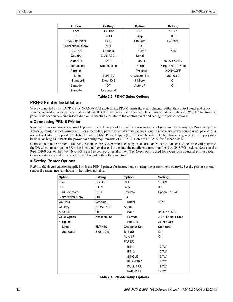
Installation ANN-BUS Devices
PRN-6 Printer InstallationWhen connected to the FACP via the N-ANN-S/PG module, the PRN-6 prints the status changes within the control panel and time-stamps the printout with the time of day and date that the event occurred. It provides 80 columns of data on standard 9” x 11” tractor-feed paper. This section contains information on connecting a printer to the control panel and setting the printer options.
Connecting PRN-6 Printer
Remote printers require a primary AC power source. If required for the fire alarm system configuration (for example, a Proprietary Fire Alarm System), a remote printer requires a secondary power source (battery backup). Since a secondary power source is not provided as a standard feature, a separate UL-listed Uninterruptible Power Supply (UPS) should be used. The building emergency power supply may be used, as long as it meets the power continuity requirements of NFPA 72. Refer to NFPA 72 for further details.
Connect the remote printer to the FACP via the N-ANN-S/PG module using a standard DB-25 cable. One end of the cable will plug into the DB-25 connector on the PRN-6 printer and the other end plugs into the parallel connector on the N-ANN-S/PG module. Note that the 9-pin DB-9 port on the N-ANN-S/PG is used to connect a serial printer. The 25-pin port is used for a Centronics parallel printer cable. Connect either a serial or parallel printer, but not both at the same time.
Setting Printer Options
Refer to the documentation supplied with the PRN-6 printer for instructions on using the printer menu controls. Set the printer options (under the menu area) as shown in the following table:
Option Setting Option Setting
Font HS Draft CPI 10CPI
LPI 6 LPI Skip 0.5
ESC Character ESC Emulate LQ-2550
Bidirectional Copy ON I/O
CG-TAB Graphic Buffer 64K
Country E-US ASCII Serial
Auto CR OFF Baud 9600 or 2400
Color Option Not Installed Format 7 Bit, Even, 1 Stop
Formien Protocol XON/XOFF
Lines 6LPI=60 Character Set Standard
Standard Exec 10.5 SI.Zero On
Barcode Off Auto LF On
Barcode Unsecured
Table 2.3 PRN-7 Setup Options
Option Setting Option Setting
Font HS Draft CPI 10CPI
LPI 6 LPI Skip 0.5
ESC Character ESC Emulate Epson FX-850
Bidirectional Copy ON I/O
CG-TAB Graphic Buffer 40K
Country E-US ASCII Serial
Auto CR OFF Baud 9600 or 2400
Color Option Not Installed Format 7 Bit, Even, 1 Stop
Formien Protocol XON/XOFF
Lines 6LPI=60 Character Set Standard
Standard Exec 10.5 SI.Zero On
Auto LF On
PAPER
BIN 1 12/72”
BIN 2 12/72”
SINGLE 12/72”
PUSH TRA 12/72”
PULL TRA 12/72”
PAP ROLL 12/72”
Table 2.4 PRN-6 Setup Options
42 SFP-5UD & SFP-10UD Series Manual— P/N 52879:C6 6/12/2018
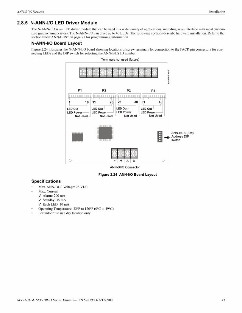
ANN-BUS Devices Installation
2.8.5 N-ANN-I/O LED Driver ModuleThe N-ANN-I/O is an LED driver module that can be used in a wide variety of applications, including as an interface with most custom-ized graphic annunciators. The N-ANN-I/O can drive up to 40 LEDs. The following sections describe hardware installation. Refer to the section titled“ANN-BUS” on page 71 for programming information.
N-ANN-I/O Board LayoutFigure 2.24 illustrates the N-ANN-I/O board showing locations of screw terminals for connection to the FACP, pin connectors for con-necting LEDs and the DIP switch for selecting the ANN-BUS ID number.
Specifications• Max. ANN-BUS Voltage: 28 VDC• Max. Current:
Alarm: 200 mA Standby: 35 mA Each LED: 10 mA
• Operating Temperature: 32oF to 120oF (0oC to 49oC)• For indoor use in a dry location only
Figure 2.24 ANN-I/O Board Layout
ANN-BUS (ID#) Address DIP switch
ANN-BUS Connector
Terminals not used (future)
an
nio
brd.
wm
f
SFP-5UD & SFP-10UD Series Manual— P/N 52879:C6 6/12/2018 43
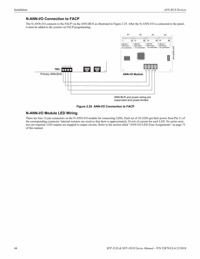
Installation ANN-BUS Devices
N-ANN-I/O Connection to FACPThe N-ANN-I/O connects to the FACP via the ANN-BUS as illustrated in Figure 2.25. After the N-ANN-I/O is connected to the panel, it must be added to the system via FACP programming.
N-ANN-I/O Module LED WiringThere are four 12-pin connectors on the N-ANN-I/O module for connecting LEDs. Each set of 10 LEDs get their power from Pin 11 of the corresponding connector. Internal resistors are sized so that there is approximately 10 mA of current for each LED. No series resis-tors are required. LED outputs are mapped to output circuits. Refer to the section titled “ANN-I/O LED Zone Assignments” on page 72 of this manual.
Figure 2.25 ANN-I/O Connection to FACP
ANN-I/O Module
ANN-BUS and power wiring are supervised and power-limited
TB3
Primary ANN-BUS
an
n-io
to5x
.wm
f
44 SFP-5UD & SFP-10UD Series Manual— P/N 52879:C6 6/12/2018
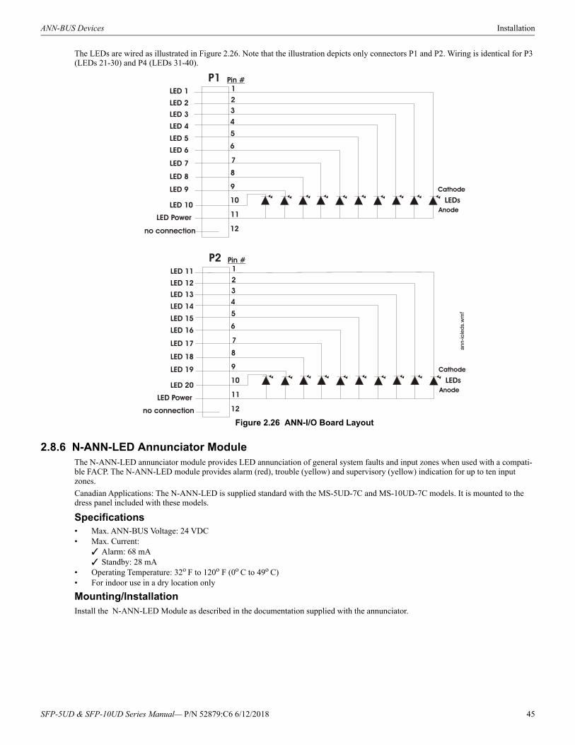
ANN-BUS Devices Installation
The LEDs are wired as illustrated in Figure 2.26. Note that the illustration depicts only connectors P1 and P2. Wiring is identical for P3 (LEDs 21-30) and P4 (LEDs 31-40).
2.8.6 N-ANN-LED Annunciator ModuleThe N-ANN-LED annunciator module provides LED annunciation of general system faults and input zones when used with a compati-ble FACP. The N-ANN-LED module provides alarm (red), trouble (yellow) and supervisory (yellow) indication for up to ten input zones.
Canadian Applications: The N-ANN-LED is supplied standard with the MS-5UD-7C and MS-10UD-7C models. It is mounted to the dress panel included with these models.
Specifications• Max. ANN-BUS Voltage: 24 VDC• Max. Current:
Alarm: 68 mA Standby: 28 mA
• Operating Temperature: 32o F to 120o F (0o C to 49o C)• For indoor use in a dry location only
Mounting/InstallationInstall the N-ANN-LED Module as described in the documentation supplied with the annunciator.
Figure 2.26 ANN-I/O Board Layout
an
n-io
leds
.wm
f
SFP-5UD & SFP-10UD Series Manual— P/N 52879:C6 6/12/2018 45
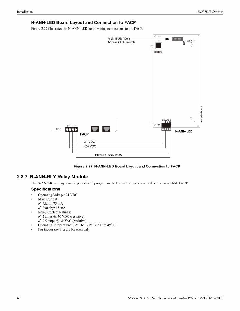
Installation ANN-BUS Devices
N-ANN-LED Board Layout and Connection to FACPFigure 2.27 illustrates the N-ANN-LED board wiring connections to the FACP.
2.8.7 N-ANN-RLY Relay ModuleThe N-ANN-RLY relay module provides 10 programmable Form-C relays when used with a compatible FACP.
Specifications• Operating Voltage: 24 VDC• Max. Current:
Alarm: 75 mA Standby: 15 mA
• Relay Contact Ratings: 2 amps @ 30 VDC (resistive) 0.5 amps @ 30 VAC (resistive)
• Operating Temperature: 32o F to 120o F (0o C to 49o C)• For indoor use in a dry location only
Figure 2.27 N-ANN-LED Board Layout and Connection to FACP
FACPN-ANN-LED
Primary ANN-BUS
+24 VDC
-24 VDC
ANN-BUS (ID#)Address DIP switch
TB3
an
nle
dto
5x.w
mf
46 SFP-5UD & SFP-10UD Series Manual— P/N 52879:C6 6/12/2018
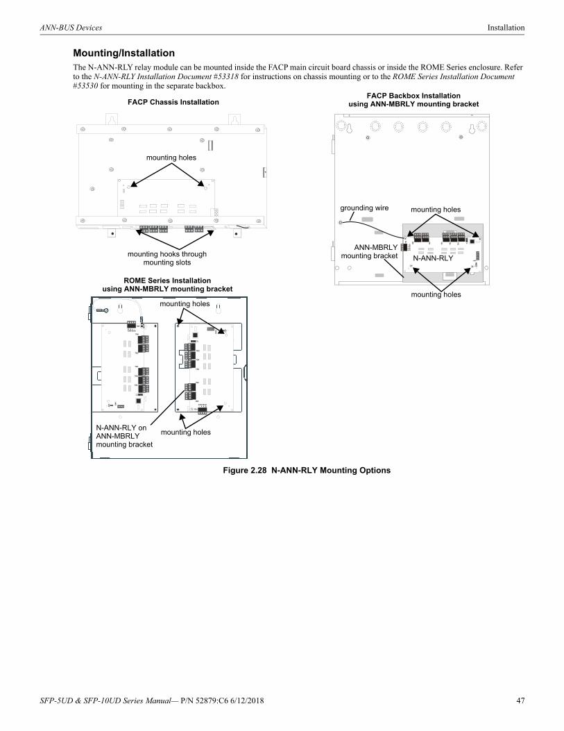
ANN-BUS Devices Installation
Mounting/InstallationThe N-ANN-RLY relay module can be mounted inside the FACP main circuit board chassis or inside the ROME Series enclosure. Refer to the N-ANN-RLY Installation Document #53318 for instructions on chassis mounting or to the ROME Series Installation Document #53530 for mounting in the separate backbox.
mounting holes
mounting hooks through mounting slots
grounding wire
N-ANN-RLY
ANN-MBRLYmounting bracket
mounting holes
mounting holes
FACP Backbox Installationusing ANN-MBRLY mounting bracketFACP Chassis Installation
mounting holes
mounting holesN-ANN-RLY on ANN-MBRLY mounting bracket
ROME Series Installationusing ANN-MBRLY mounting bracket
Figure 2.28 N-ANN-RLY Mounting Options
SFP-5UD & SFP-10UD Series Manual— P/N 52879:C6 6/12/2018 47
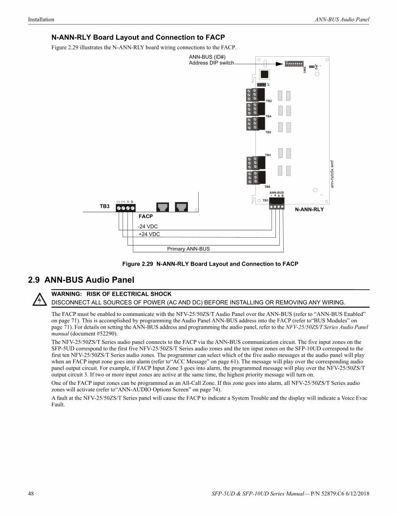
Installation ANN-BUS Audio Panel
N-ANN-RLY Board Layout and Connection to FACPFigure 2.29 illustrates the N-ANN-RLY board wiring connections to the FACP.
2.9 ANN-BUS Audio Panel
The FACP must be enabled to communicate with the NFV-25/50ZS/T Audio Panel over the ANN-BUS (refer to “ANN-BUS Enabled” on page 71). This is accomplished by programming the Audio Panel ANN-BUS address into the FACP (refer to“BUS Modules” on page 71). For details on setting the ANN-BUS address and programming the audio panel, refer to the NFV-25/50ZS/T Series Audio Panel manual (document #52290).
The NFV-25/50ZS/T Series audio panel connects to the FACP via the ANN-BUS communication circuit. The five input zones on the SFP-5UD correspond to the first five NFV-25/50ZS/T Series audio zones and the ten input zones on the SFP-10UD correspond to the first ten NFV-25/50ZS/T Series audio zones. The programmer can select which of the five audio messages at the audio panel will play when an FACP input zone goes into alarm (refer to“ACC Message” on page 61). The message will play over the corresponding audio panel output circuit. For example, if FACP Input Zone 3 goes into alarm, the programmed message will play over the NFV-25/50ZS/T output circuit 3. If two or more input zones are active at the same time, the highest priority message will turn on.
One of the FACP input zones can be programmed as an All-Call Zone. If this zone goes into alarm, all NFV-25/50ZS/T Series audio zones will activate (refer to“ANN-AUDIO Options Screen” on page 74).
A fault at the NFV-25/50ZS/T Series panel will cause the FACP to indicate a System Trouble and the display will indicate a Voice Evac Fault.
Figure 2.29 N-ANN-RLY Board Layout and Connection to FACP
FACPN-ANN-RLY
Primary ANN-BUS
+24 VDC
-24 VDC
ANN-BUS (ID#) Address DIP switch
TB3
an
n-rl
yto5
x.w
mf
!WARNING: RISK OF ELECTRICAL SHOCK
DISCONNECT ALL SOURCES OF POWER (AC AND DC) BEFORE INSTALLING OR REMOVING ANY WIRING.
48 SFP-5UD & SFP-10UD Series Manual— P/N 52879:C6 6/12/2018
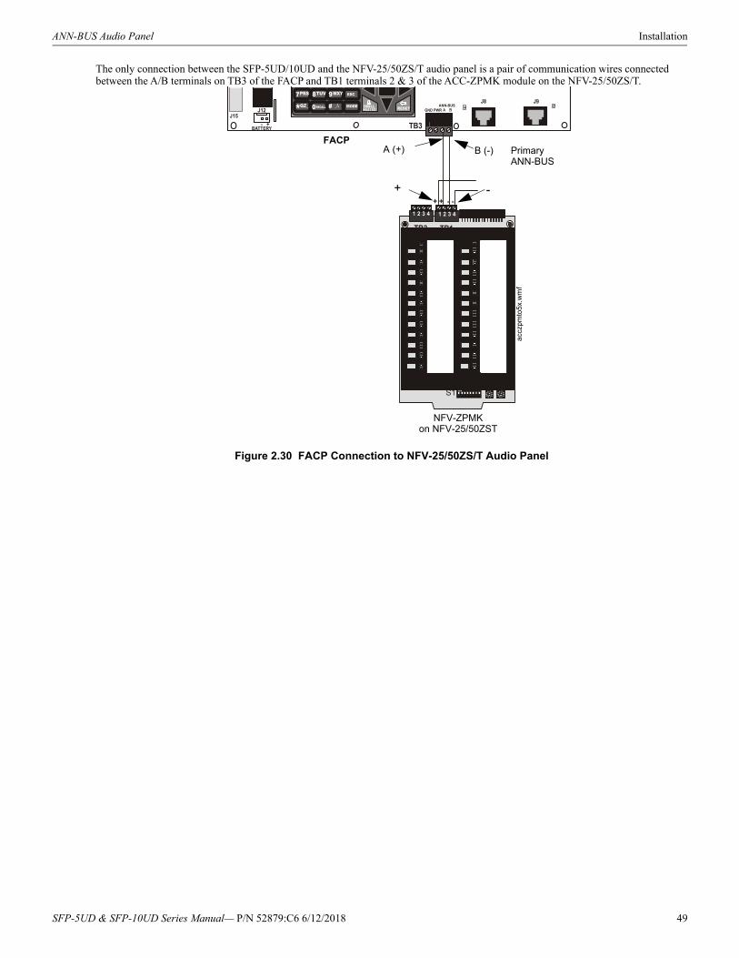
ANN-BUS Audio Panel Installation
The only connection between the SFP-5UD/10UD and the NFV-25/50ZS/T audio panel is a pair of communication wires connected between the A/B terminals on TB3 of the FACP and TB1 terminals 2 & 3 of the ACC-ZPMK module on the NFV-25/50ZS/T.
A (+) B (-)FACP
NFV-ZPMKon NFV-25/50ZST
-+
Figure 2.30 FACP Connection to NFV-25/50ZS/T Audio Panel
PrimaryANN-BUS
accz
pmto
5x.w
mf
SFP-5UD & SFP-10UD Series Manual— P/N 52879:C6 6/12/2018 49
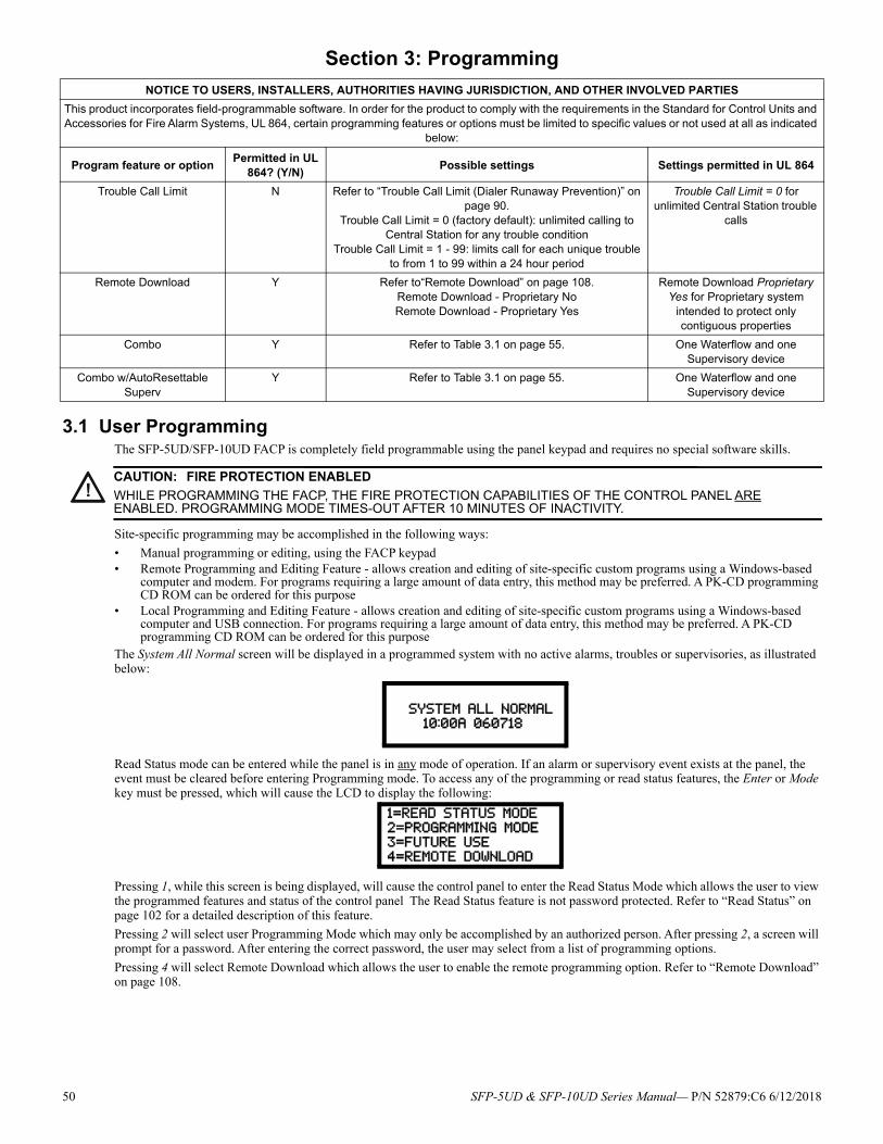
Section 3: Programming
3.1 User ProgrammingThe SFP-5UD/SFP-10UD FACP is completely field programmable using the panel keypad and requires no special software skills.
Site-specific programming may be accomplished in the following ways:
• Manual programming or editing, using the FACP keypad• Remote Programming and Editing Feature - allows creation and editing of site-specific custom programs using a Windows-based
computer and modem. For programs requiring a large amount of data entry, this method may be preferred. A PK-CD programming CD ROM can be ordered for this purpose
• Local Programming and Editing Feature - allows creation and editing of site-specific custom programs using a Windows-based computer and USB connection. For programs requiring a large amount of data entry, this method may be preferred. A PK-CD programming CD ROM can be ordered for this purpose
The System All Normal screen will be displayed in a programmed system with no active alarms, troubles or supervisories, as illustrated below:
Read Status mode can be entered while the panel is in any mode of operation. If an alarm or supervisory event exists at the panel, the event must be cleared before entering Programming mode. To access any of the programming or read status features, the Enter or Mode key must be pressed, which will cause the LCD to display the following:
Pressing 1, while this screen is being displayed, will cause the control panel to enter the Read Status Mode which allows the user to view the programmed features and status of the control panel The Read Status feature is not password protected. Refer to “Read Status” on page 102 for a detailed description of this feature.
Pressing 2 will select user Programming Mode which may only be accomplished by an authorized person. After pressing 2, a screen will prompt for a password. After entering the correct password, the user may select from a list of programming options.
Pressing 4 will select Remote Download which allows the user to enable the remote programming option. Refer to “Remote Download” on page 108.
NOTICE TO USERS, INSTALLERS, AUTHORITIES HAVING JURISDICTION, AND OTHER INVOLVED PARTIES
This product incorporates field-programmable software. In order for the product to comply with the requirements in the Standard for Control Units and Accessories for Fire Alarm Systems, UL 864, certain programming features or options must be limited to specific values or not used at all as indicated
below:
Program feature or optionPermitted in UL
864? (Y/N)Possible settings Settings permitted in UL 864
Trouble Call Limit N Refer to “Trouble Call Limit (Dialer Runaway Prevention)” on page 90.
Trouble Call Limit = 0 (factory default): unlimited calling to Central Station for any trouble condition
Trouble Call Limit = 1 - 99: limits call for each unique trouble to from 1 to 99 within a 24 hour period
Trouble Call Limit = 0 for unlimited Central Station trouble
calls
Remote Download Y Refer to“Remote Download” on page 108.Remote Download - Proprietary NoRemote Download - Proprietary Yes
Remote Download Proprietary Yes for Proprietary system
intended to protect only contiguous properties
Combo Y Refer to Table 3.1 on page 55. One Waterflow and one Supervisory device
Combo w/AutoResettable Superv
Y Refer to Table 3.1 on page 55. One Waterflow and one Supervisory device
!CAUTION: FIRE PROTECTION ENABLED
WHILE PROGRAMMING THE FACP, THE FIRE PROTECTION CAPABILITIES OF THE CONTROL PANEL ARE ENABLED. PROGRAMMING MODE TIMES-OUT AFTER 10 MINUTES OF INACTIVITY.
SYSTEM ALL NORMAL
10:00A 060718
1=READ STATUS MODE
2=PROGRAMMING MODE3=FUTURE USE
4=REMOTE DOWNLOAD
50 SFP-5UD & SFP-10UD Series Manual— P/N 52879:C6 6/12/2018

User Programming Programming
Exit Programming and Read Status Mode
The programmer can exit any mode by repeatedly pressing the keypad ESC (Escape) key until the display reads System All Normal. Ten minutes of inactivity will also cause the panel to exit Programming Mode Note that the data which is entered during Programming mode is not saved until the programmer exits this mode by repeatedly pressing the ‘ESC’ key. If the Reset key is pressed or power is lost before exiting Programming mode, all data just entered will be lost.
SFP-5UD & SFP-10UD Series Manual— P/N 52879:C6 6/12/2018 51
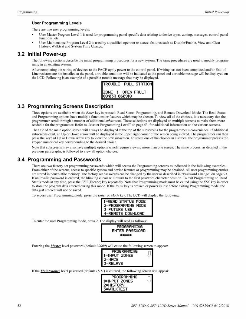
Programming Initial Power-up
User Programming Levels
There are two user programming levels:
• User Master Program Level 1 is used for programming panel specific data relating to device types, zoning, messages, control panel functions, etc.
• User Maintenance Program Level 2 is used by a qualified operator to access features such as Disable/Enable, View and Clear History, Walktest and System Time Change.
3.2 Initial Power-upThe following sections describe the initial programming procedures for a new system. The same procedures are used to modify program-ming in an existing system.
After completing the wiring of devices to the FACP, apply power to the control panel. If wiring has not been completed and/or End-of-Line resistors are not installed at the panel, a trouble condition will be indicated at the panel and a trouble message will be displayed on the LCD. Following is an example of a possible trouble message that may be displayed.
3.3 Programming Screens DescriptionThree options are available when the Enter key is pressed: Read Status, Programming, and Remote Download Mode. The Read Status and Programming options have multiple functions or features which may be chosen. To view all of the choices, it is necessary that the programmer scroll through a number of additional subscreens. These selections are displayed on multiple screens to make them more readable for the programmer. Refer to “Master Programming Level” on page 53, for additional information on the various screens.
The title of the main option screen will always be displayed at the top of the subscreens for the programmer’s convenience. If additional subscreens exist, an Up or Down arrow will be displayed in the upper right corner of the screen being viewed. The programmer can then press the keypad Up or Down arrow key to view the new subscreen. To select one of the choices in a screen, the programmer presses the keypad numerical key corresponding to the desired choice.
Note that subscreens may also have multiple options which require viewing more than one screen. The same process, as detailed in the previous paragraphs, is followed to view all option choices.
3.4 Programming and PasswordsThere are two factory set programming passwords which will access the Programming screens as indicated in the following examples. From either of the screens, access to specific system and device features or programming may be obtained. All user programming entries are stored in nonvolatile memory. The factory set passwords can be changed by the user as described in “Password Change” on page 93. If an invalid password is entered, the blinking cursor will return to the first password character position. To exit Programming or Read Status mode at any time, press the ESC (Escape) key repeatedly. Note that Programming mode must be exited using the ESC key in order to store the program data entered during this mode. If the Reset key is pressed or power is lost before exiting Programming mode, the data just entered will not be saved.
To access user Programming mode, press the Enter or Mode key. The LCD will display the following:
To enter the user Programming mode, press 2. The display will read as follows:
Entering the Master level password (default 00000) will cause the following screen to appear:
If the Maintenance level password (default 11111) is entered, the following screen will appear:
TROUBLE PULL STATION
ZONE 1 OPEN FAULT
09:03A 060918
1=READ STATUS MODE
2=PROGRAMMING MODE
3=FUTURE USE4=REMOTE DOWNLOAD
PROGRAMMING
ENTER PASSWORD
PROGRAMMING1=INPUT ZONES
2=NACS
3=RELAYS
PROGRAMMING
1=INPUT ZONES
2=HISTORY3=WALKTEST
52 SFP-5UD & SFP-10UD Series Manual— P/N 52879:C6 6/12/2018
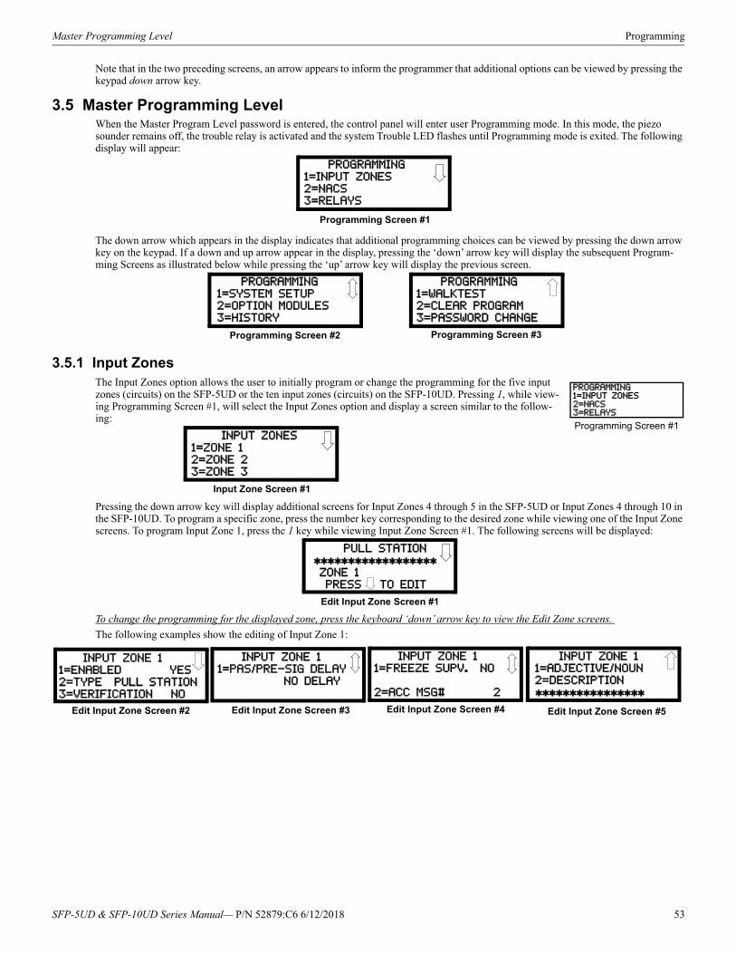
Master Programming Level Programming
Note that in the two preceding screens, an arrow appears to inform the programmer that additional options can be viewed by pressing the keypad down arrow key.
3.5 Master Programming LevelWhen the Master Program Level password is entered, the control panel will enter user Programming mode. In this mode, the piezo sounder remains off, the trouble relay is activated and the system Trouble LED flashes until Programming mode is exited. The following display will appear:
The down arrow which appears in the display indicates that additional programming choices can be viewed by pressing the down arrow key on the keypad. If a down and up arrow appear in the display, pressing the ‘down’ arrow key will display the subsequent Program-ming Screens as illustrated below while pressing the ‘up’ arrow key will display the previous screen.
3.5.1 Input ZonesThe Input Zones option allows the user to initially program or change the programming for the five input zones (circuits) on the SFP-5UD or the ten input zones (circuits) on the SFP-10UD. Pressing 1, while view-ing Programming Screen #1, will select the Input Zones option and display a screen similar to the follow-ing:
Pressing the down arrow key will display additional screens for Input Zones 4 through 5 in the SFP-5UD or Input Zones 4 through 10 in the SFP-10UD. To program a specific zone, press the number key corresponding to the desired zone while viewing one of the Input Zone screens. To program Input Zone 1, press the 1 key while viewing Input Zone Screen #1. The following screens will be displayed:
To change the programming for the displayed zone, press the keyboard ‘down’ arrow key to view the Edit Zone screens.
The following examples show the editing of Input Zone 1:
PROGRAMMING
1=INPUT ZONES2=NACS
3=RELAYS
Programming Screen #1
PROGRAMMING
1=SYSTEM SETUP
2=OPTION MODULES3=HISTORY
PROGRAMMING
1=WALKTEST
2=CLEAR PROGRAM3=PASSWORD CHANGE
Programming Screen #2 Programming Screen #3
PROGRAMMING1=INPUT ZONES2=NACS3=RELAYS
Programming Screen #1 INPUT ZONES
1=ZONE 12=ZONE 2
3=ZONE 3
Input Zone Screen #1
PULL STATION
ZONE 1 PRESS TO EDIT
Edit Input Zone Screen #1
INPUT ZONE 1
1=ENABLED YES2=TYPE PULL STATION
3=VERIFICATION NO
Edit Input Zone Screen #2
INPUT ZONE 1
1=PAS/PRE-SIG DELAY
NO DELAY
Edit Input Zone Screen #3 Edit Input Zone Screen #5
INPUT ZONE 1
1=ADJECTIVE/NOUN2=DESCRIPTION
INPUT ZONE 1
1=FREEZE SUPV. NO
2=ACC MSG# 2
Edit Input Zone Screen #4
SFP-5UD & SFP-10UD Series Manual— P/N 52879:C6 6/12/2018 53

Programming Master Programming Level
Enable/Disable Zone
To Enable or Disable the zone, press the 1 key while viewing the Edit Input Zone Screen #2. Each press of the key will toggle the screen between Enabled Yes and Enabled No. If Enabled No is selected, the zone will be disabled by the control panel, preventing the circuit from reporting alarms and troubles to the panel. The control panel LCD will display the zone which has been disabled and FACP will turn on the Trouble LED.
INPUT ZONE1=ENABLED2=TYPE3=VERIFICATION
Edit Input Zone Screen #2
54 SFP-5UD & SFP-10UD Series Manual— P/N 52879:C6 6/12/2018
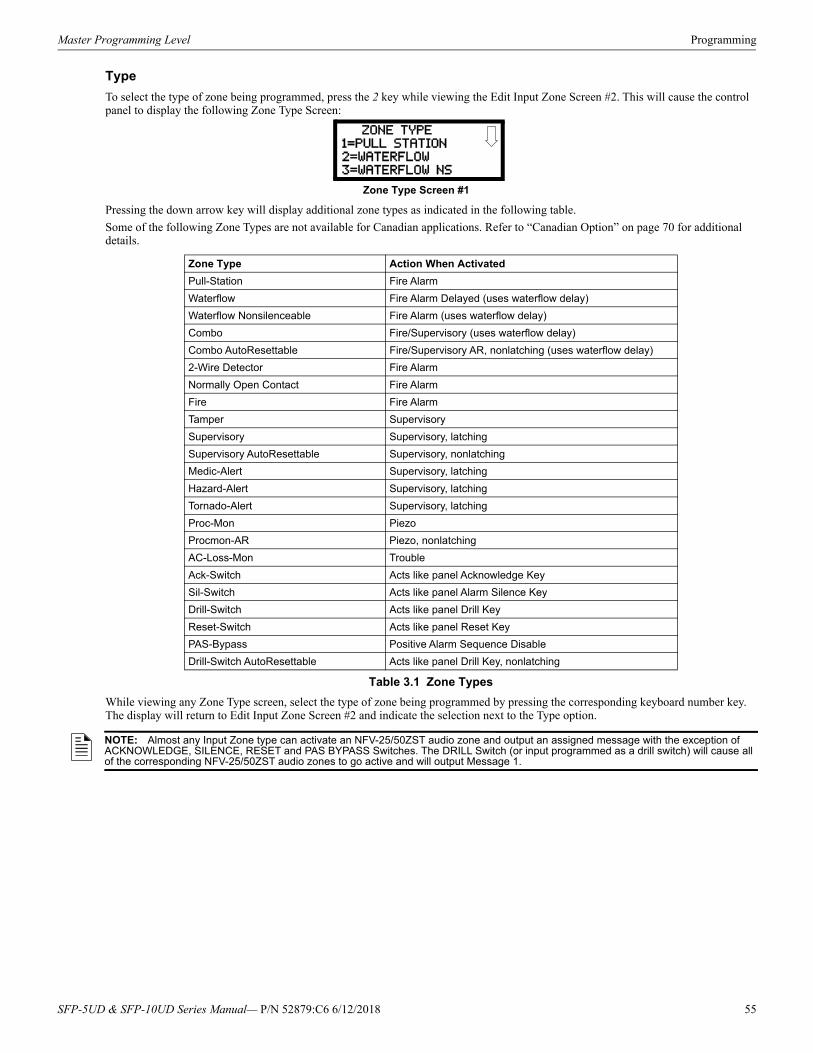
Master Programming Level Programming
Type
To select the type of zone being programmed, press the 2 key while viewing the Edit Input Zone Screen #2. This will cause the control panel to display the following Zone Type Screen:
Pressing the down arrow key will display additional zone types as indicated in the following table.
Some of the following Zone Types are not available for Canadian applications. Refer to “Canadian Option” on page 70 for additional details.
While viewing any Zone Type screen, select the type of zone being programmed by pressing the corresponding keyboard number key. The display will return to Edit Input Zone Screen #2 and indicate the selection next to the Type option.
Zone Type Action When Activated
Pull-Station Fire Alarm
Waterflow Fire Alarm Delayed (uses waterflow delay)
Waterflow Nonsilenceable Fire Alarm (uses waterflow delay)
Combo Fire/Supervisory (uses waterflow delay)
Combo AutoResettable Fire/Supervisory AR, nonlatching (uses waterflow delay)
2-Wire Detector Fire Alarm
Normally Open Contact Fire Alarm
Fire Fire Alarm
Tamper Supervisory
Supervisory Supervisory, latching
Supervisory AutoResettable Supervisory, nonlatching
Medic-Alert Supervisory, latching
Hazard-Alert Supervisory, latching
Tornado-Alert Supervisory, latching
Proc-Mon Piezo
Procmon-AR Piezo, nonlatching
AC-Loss-Mon Trouble
Ack-Switch Acts like panel Acknowledge Key
Sil-Switch Acts like panel Alarm Silence Key
Drill-Switch Acts like panel Drill Key
Reset-Switch Acts like panel Reset Key
PAS-Bypass Positive Alarm Sequence Disable
Drill-Switch AutoResettable Acts like panel Drill Key, nonlatching
Table 3.1 Zone Types
ZONE TYPE
1=PULL STATION
2=WATERFLOW3=WATERFLOW NS
Zone Type Screen #1
NOTE: Almost any Input Zone type can activate an NFV-25/50ZST audio zone and output an assigned message with the exception of ACKNOWLEDGE, SILENCE, RESET and PAS BYPASS Switches. The DRILL Switch (or input programmed as a drill switch) will cause all of the corresponding NFV-25/50ZST audio zones to go active and will output Message 1.
SFP-5UD & SFP-10UD Series Manual— P/N 52879:C6 6/12/2018 55

Programming Master Programming Level
Verification
Alarm verification is used to confirm that a smoke detector activation is a true alarm condition and not a false alarm. This feature is selected by pressing 3 while viewing the Edit Zone Screen #2 so that the display reads Verification On. Each time the 3 key is pressed, the display will toggle between Verification On and Verification Off. For a detailed description, refer to “Alarm Verification (None or One Minute)” on page 101.
Note that verification can only be enabled for a zone that is programmed as a smoke detector type. Zones programmed for any other type will not allow the Verification feature to be enabled. Do not use the verification feature if a mix of smoke detectors and normally open contact devices are connected to the same zone.
INPUT ZONE1=ENABLED2=TYPE3=VERIFICATION
Edit Input Zone Screen #2
56 SFP-5UD & SFP-10UD Series Manual— P/N 52879:C6 6/12/2018

Master Programming Level Programming
PAS/Pre-Signal Delay
Pressing 1 while viewing Edit Input Zone Screen #3 will display the following screen: INPUT ZONE #1=PAS/PRE-SIG DELAY NO DELAY
Edit Input Zone Screen #3
PAS/PRE-SIG DELAY
1=NO DELAY
2=PRE-SIGNAL DELAY3=PAS DELAY
PAS/Pre-Signal Delay Screen
SFP-5UD & SFP-10UD Series Manual— P/N 52879:C6 6/12/2018 57

Programming Master Programming Level
Pre-signal
The Pre-signal option programs the zone to delay panel activation for a preprogrammed time delay of up to three minutes while allowing for visual verification by a person. Note that the alarm relay and communicator will respond to the initial alarm immediately. To enable the Pre-signal feature, press 2 while viewing PAS/Pre-Signal Screen. Refer to “Presignal” on page 100.
58 SFP-5UD & SFP-10UD Series Manual— P/N 52879:C6 6/12/2018

Master Programming Level Programming
PAS
The PAS (Positive Alarm Sequence) option will program the zone to delay panel activation (including alarm relay and communicator) for a period of 15 seconds plus a programmable time of up to 3 minutes. To enable the PAS feature, press 3 while viewing the PAS/Pre-Signal Screen. This option is available only for circuits programmed as smoke detector circuits. Refer to “Positive Alarm Sequence” on page 100.
SFP-5UD & SFP-10UD Series Manual— P/N 52879:C6 6/12/2018 59

Programming Master Programming Level
Freeze Supervision
Pressing 1 for Freeze Supv. while viewing Edit Input Zone Screen #4 programs the FACP to supervise the devices connected to the selected zone for freeze conditions. Each press of the 1 key will toggle the display between Freeze Supv. Yes and No. The factory default setting is No Freeze Supervision.
INPUT ZONE #1=FREEZE SUPV. NO2=ACC MSG #
Edit Input Zone Screen #4
60 SFP-5UD & SFP-10UD Series Manual— P/N 52879:C6 6/12/2018
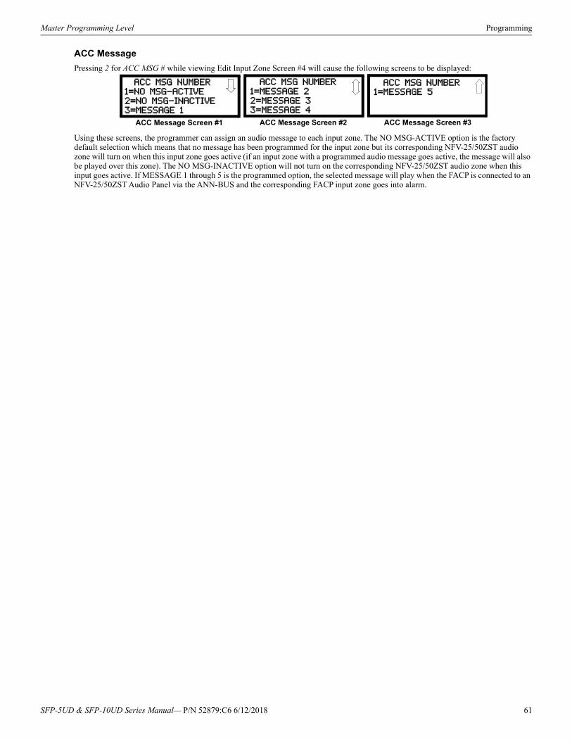
Master Programming Level Programming
ACC Message
Pressing 2 for ACC MSG # while viewing Edit Input Zone Screen #4 will cause the following screens to be displayed:
Using these screens, the programmer can assign an audio message to each input zone. The NO MSG-ACTIVE option is the factory default selection which means that no message has been programmed for the input zone but its corresponding NFV-25/50ZST audio zone will turn on when this input zone goes active (if an input zone with a programmed audio message goes active, the message will also be played over this zone). The NO MSG-INACTIVE option will not turn on the corresponding NFV-25/50ZST audio zone when this input goes active. If MESSAGE 1 through 5 is the programmed option, the selected message will play when the FACP is connected to an NFV-25/50ZST Audio Panel via the ANN-BUS and the corresponding FACP input zone goes into alarm.
ACC MSG NUMBER
1=NO MSG-ACTIVE
2=NO MSG-INACTIVE3=MESSAGE 1
ACC Message Screen #1
ACC MSG NUMBER
1=MESSAGE 22=MESSAGE 3
3=MESSAGE 4
ACC Message Screen #2
ACC MSG NUMBER1=MESSAGE 5
ACC Message Screen #3
SFP-5UD & SFP-10UD Series Manual— P/N 52879:C6 6/12/2018 61
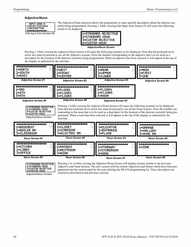
Programming Master Programming Level
Adjective/Noun
The Adjective/Noun selection allows the programmer to enter specific descriptors about the detector cur-rently being programmed. Pressing 1 while viewing Edit Input Zone Screen #4 will cause the following screen to be displayed:
Pressing 1 while viewing the Adjective/Noun Screen will cause the following screen(s) to be displayed. Note that the keyboard down arrow key must be pressed to see all the Adjective screens. Press the number corresponding to the adjective that is to be used as a descriptor for the location of the detector currently being programmed. When an adjective has been selected, it will appear at the top of the display as indicated by the asterisks.
Pressing 2 while viewing the Adjective/Noun Screen will cause the following screen(s) to be displayed. Note that the keyboard down arrow key must be pressed to see all the Noun screens. Press the number cor-responding to the noun that is to be used as a descriptor for the location of the detector currently being pro-grammed. When a noun has been selected, it will appear at the top of the display as indicated by the asterisks.
Pressing 3 or 4 while viewing the Adjective/Noun Screen will display screens similar to the previous Adjective and Noun Screens. The new screens will list custom Adjectives and Nouns which have been pro-grammed into the control panel by the user utilizing the PK-CD programming kit. These descriptors are selected as described in the previous sections.
INPUT ZONE #1=ADJECTIVE/NOUN2=DESCRIPTION
Edit Input Zone Screen #5 1=STANDARD ADJECTIVE
2=STANDARD NOUN3=CUSTOM ADJECTIVE
4=CUSTOM NOUN
Adjective/Noun Screen
1=NORTH
2=SOUTH
3=EAST
Adjective Screen #1
1=WEST
2=FRONT
3=CENTER
Adjective Screen #3
1=REAR
2=UPPER3=LOWER
Adjective Screen #5
1=MAIN2=FIRST
3=2ND
Adjective Screen #7
1=3RD
2=4TH3=5TH
Adjective Screen #2
1=FLOOR4
2=FLOOR5
3=ROOM
Adjective Screen #6
1=FLOOR1
2=FLOOR23=FLOOR3
Adjective Screen #4
1=STANDARD ADJECTIVE2=STANDARD NOUN3=CUSTOM ADJECTIVE4=CUSTOM NOUN
Adjective/Noun Screen
1=BASEMENT2=BOILER RM
3=CLASSROOM
Noun Screen #1
1=CLOSET
2=CORRIDOR3=ELECTRIC RM
Noun Screen #3
1=ELEVATOR
2=ENTRANCE
3=FLOOR
Noun Screen #5
1=GARAGE2=HALLWAY
3=HVAC RM
Noun Screen #7
1=KITCHEN
2=LOBBY3=OFFICE
Noun Screen #2
1=STAIRWAY2=STOREROOM
3=WING
Noun Screen #6
1=PATIENT2=RESTROOM
3=ROOM
Noun Screen #4
1=ZONE
Noun Screen #8
1=STANDARD ADJECTIVE2=STANDARD NOUN3=CUSTOM ADJECTIVE4=CUSTOM NOUN
Adjective/Noun Screen
62 SFP-5UD & SFP-10UD Series Manual— P/N 52879:C6 6/12/2018
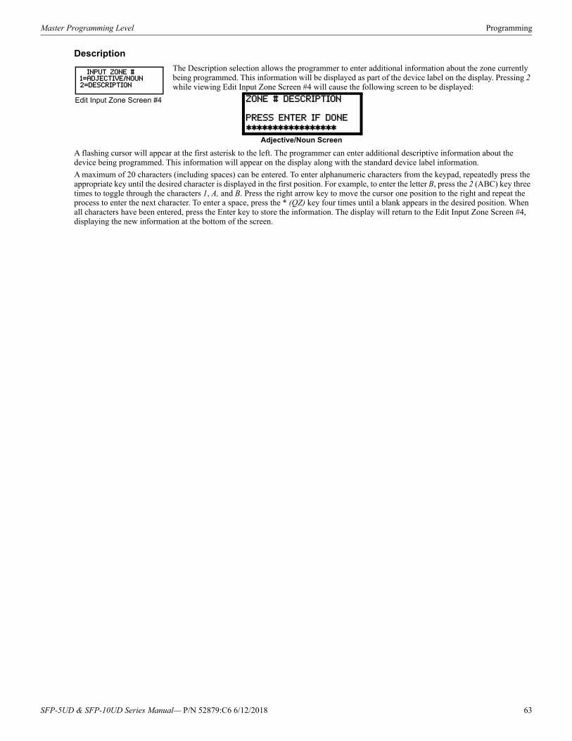
Master Programming Level Programming
Description
The Description selection allows the programmer to enter additional information about the zone currently being programmed. This information will be displayed as part of the device label on the display. Pressing 2 while viewing Edit Input Zone Screen #4 will cause the following screen to be displayed:
A flashing cursor will appear at the first asterisk to the left. The programmer can enter additional descriptive information about the device being programmed. This information will appear on the display along with the standard device label information.
A maximum of 20 characters (including spaces) can be entered. To enter alphanumeric characters from the keypad, repeatedly press the appropriate key until the desired character is displayed in the first position. For example, to enter the letter B, press the 2 (ABC) key three times to toggle through the characters 1, A, and B. Press the right arrow key to move the cursor one position to the right and repeat the process to enter the next character. To enter a space, press the * (QZ) key four times until a blank appears in the desired position. When all characters have been entered, press the Enter key to store the information. The display will return to the Edit Input Zone Screen #4, displaying the new information at the bottom of the screen.
INPUT ZONE #1=ADJECTIVE/NOUN2=DESCRIPTION
Edit Input Zone Screen #4 ZONE # DESCRIPTION
PRESS ENTER IF DONE
Adjective/Noun Screen
SFP-5UD & SFP-10UD Series Manual— P/N 52879:C6 6/12/2018 63
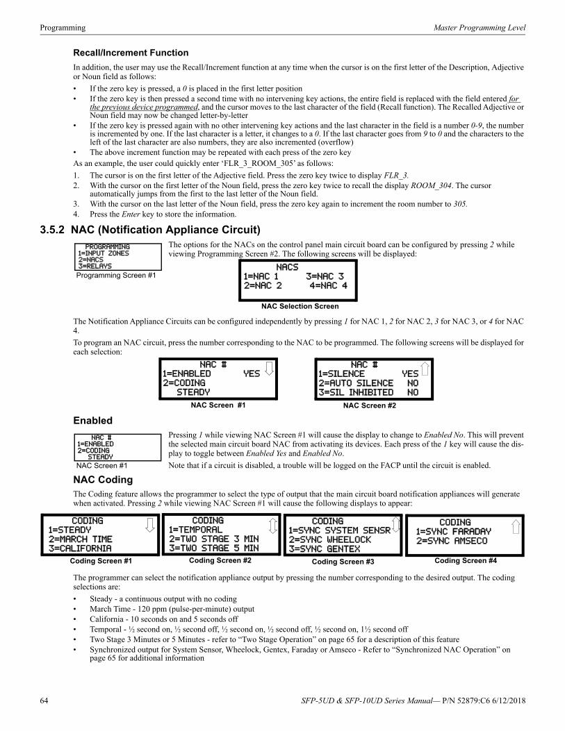
Programming Master Programming Level
Recall/Increment Function
In addition, the user may use the Recall/Increment function at any time when the cursor is on the first letter of the Description, Adjective or Noun field as follows:
• If the zero key is pressed, a 0 is placed in the first letter position• If the zero key is then pressed a second time with no intervening key actions, the entire field is replaced with the field entered for
the previous device programmed, and the cursor moves to the last character of the field (Recall function). The Recalled Adjective or Noun field may now be changed letter-by-letter
• If the zero key is pressed again with no other intervening key actions and the last character in the field is a number 0-9, the number is incremented by one. If the last character is a letter, it changes to a 0. If the last character goes from 9 to 0 and the characters to the left of the last character are also numbers, they are also incremented (overflow)
• The above increment function may be repeated with each press of the zero keyAs an example, the user could quickly enter ‘FLR_3_ROOM_305’ as follows:
1. The cursor is on the first letter of the Adjective field. Press the zero key twice to display FLR_3.2. With the cursor on the first letter of the Noun field, press the zero key twice to recall the display ROOM_304. The cursor
automatically jumps from the first to the last letter of the Noun field.3. With the cursor on the last letter of the Noun field, press the zero key again to increment the room number to 305.4. Press the Enter key to store the information.
3.5.2 NAC (Notification Appliance Circuit)The options for the NACs on the control panel main circuit board can be configured by pressing 2 while viewing Programming Screen #2. The following screens will be displayed:
The Notification Appliance Circuits can be configured independently by pressing 1 for NAC 1, 2 for NAC 2, 3 for NAC 3, or 4 for NAC 4.
To program an NAC circuit, press the number corresponding to the NAC to be programmed. The following screens will be displayed for each selection:
EnabledPressing 1 while viewing NAC Screen #1 will cause the display to change to Enabled No. This will prevent the selected main circuit board NAC from activating its devices. Each press of the 1 key will cause the dis-play to toggle between Enabled Yes and Enabled No.
Note that if a circuit is disabled, a trouble will be logged on the FACP until the circuit is enabled.
NAC CodingThe Coding feature allows the programmer to select the type of output that the main circuit board notification appliances will generate when activated. Pressing 2 while viewing NAC Screen #1 will cause the following displays to appear:
The programmer can select the notification appliance output by pressing the number corresponding to the desired output. The coding selections are:
• Steady - a continuous output with no coding• March Time - 120 ppm (pulse-per-minute) output• California - 10 seconds on and 5 seconds off• Temporal - ½ second on, ½ second off, ½ second on, ½ second off, ½ second on, 1½ second off• Two Stage 3 Minutes or 5 Minutes - refer to “Two Stage Operation” on page 65 for a description of this feature• Synchronized output for System Sensor, Wheelock, Gentex, Faraday or Amseco - Refer to “Synchronized NAC Operation” on
page 65 for additional information
PROGRAMMING1=INPUT ZONES2=NACS3=RELAYS
Programming Screen #1 NACS1=NAC 1 3=NAC 3
2=NAC 2 4=NAC 4
NAC Selection Screen
NAC #
1=ENABLED YES
2=CODING STEADY
NAC Screen #1 NAC Screen #2
NAC #1=SILENCE YES
2=AUTO SILENCE NO
3=SIL INHIBITED NO
NAC #1=ENABLED2=CODING STEADY
NAC Screen #1
CODING
1=STEADY
2=MARCH TIME3=CALIFORNIA
Coding Screen #1
CODING
1=TEMPORAL
2=TWO STAGE 3 MIN3=TWO STAGE 5 MIN
Coding Screen #2
CODING1=SYNC SYSTEM SENSR
2=SYNC WHEELOCK
3=SYNC GENTEX
Coding Screen #3
CODING
1=SYNC FARADAY
2=SYNC AMSECO
Coding Screen #4
64 SFP-5UD & SFP-10UD Series Manual— P/N 52879:C6 6/12/2018
Master Programming Level Programming
Selection of one of the above options will cause the control panel to store the information in memory and return the display to NAC Screen #1, which will display the new coding choice.
Two Stage Operation
Two Stage operation consists of the following:
• 1st stage output - 20 ppm (pulse-per-minute) coding• 2nd stage output - Temporal coding as described above• Acknowledge button functions as the automatic alarm signal cancel buttonIf Two Stage operation is programmed as the Coding option, the following sequence of events will occur during an alarm.
1. The on-board NACs will activate with a 1st stage output upon activation of any alarm.2. If, after the programmed time of 3 or 5 minutes, the Acknowledge switch has not been pressed, all NACs presently in 1st stage
activation will go to 2nd stage activation.3. If an Acknowledge switch has been pressed, the Alarm LED will turn from flashing to steady. Any NACs currently in 1st stage
activation will remain in 1st stage. Pressing the Acknowledge switch does not affect NACs already in 2nd stage activation.4. If another alarm point is activated and the countdown timer is counting, the alarm point will have no effect on the NACs.5. If another alarm point is activated and the countdown timer has stopped counting due to the Acknowledge switch being pressed, the
countdown timer will restart and the NACs will respond as outlined in step 1. NACs already in 2nd stage activation will not be affected.
Synchronized NAC Operation
Synchronization is a panel feature that controls the activation of notification appliances in such a way that all devices will turn on and off at exactly the same time. This is particularly critical when activating strobes which must be synchronized to avoid random activation and a potential hazard or confusion. The FACP can be programmed to operate with a variety of manufacturer’s devices.
SFP-5UD & SFP-10UD Series Manual— P/N 52879:C6 6/12/2018 65
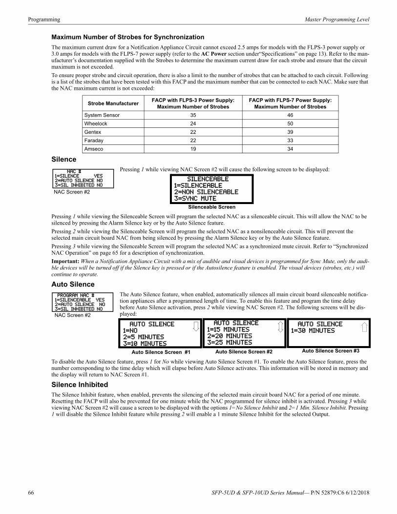
Programming Master Programming Level
Maximum Number of Strobes for Synchronization
The maximum current draw for a Notification Appliance Circuit cannot exceed 2.5 amps for models with the FLPS-3 power supply or 3.0 amps for models with the FLPS-7 power supply (refer to the AC Power section under“Specifications” on page 13). Refer to the man-ufacturer’s documentation supplied with the Strobes to determine the maximum current draw for each strobe and ensure that the circuit maximum is not exceeded.
To ensure proper strobe and circuit operation, there is also a limit to the number of strobes that can be attached to each circuit. Following is a list of the strobes that have been tested with this FACP and the maximum number that can be connected to each NAC. Make sure that the NAC maximum current is not exceeded:
SilencePressing 1 while viewing NAC Screen #2 will cause the following screen to be displayed:
Pressing 1 while viewing the Silenceable Screen will program the selected NAC as a silenceable circuit. This will allow the NAC to be silenced by pressing the Alarm Silence key or by the Auto Silence feature.
Pressing 2 while viewing the Silenceable Screen will program the selected NAC as a nonsilenceable circuit. This will prevent the selected main circuit board NAC from being silenced by pressing the Alarm Silence key or by the Auto Silence feature.
Pressing 3 while viewing the Silenceable Screen will program the selected NAC as a synchronized mute circuit. Refer to “Synchronized NAC Operation” on page 65 for a description of synchronization.
Important: When a Notification Appliance Circuit with a mix of audible and visual devices is programmed for Sync Mute, only the audi-ble devices will be turned off if the Silence key is pressed or if the Autosilence feature is enabled. The visual devices (strobes, etc.) will continue to operate.
Auto SilenceThe Auto Silence feature, when enabled, automatically silences all main circuit board silenceable notifica-tion appliances after a programmed length of time. To enable this feature and program the time delay before Auto Silence activation, press 2 while viewing NAC Screen #2. The following screens will be dis-played:
To disable the Auto Silence feature, press 1 for No while viewing Auto Silence Screen #1. To enable the Auto Silence feature, press the number corresponding to the time delay which will elapse before Auto Silence activates. This information will be stored in memory and the display will return to NAC Screen #1.
Silence InhibitedThe Silence Inhibit feature, when enabled, prevents the silencing of the selected main circuit board NAC for a period of one minute. Resetting the FACP will also be prevented for one minute while the NAC programmed for silence inhibit is activated. Pressing 3 while viewing NAC Screen #2 will cause a screen to be displayed with the options 1=No Silence Inhibit and 2=1 Min. Silence Inhibit. Pressing 1 will disable the Silence Inhibit feature while pressing 2 will enable a 1 minute Silence Inhibit for the selected Output.
Strobe ManufacturerFACP with FLPS-3 Power Supply:
Maximum Number of StrobesFACP with FLPS-7 Power Supply:
Maximum Number of Strobes
System Sensor 35 46
Wheelock 24 50
Gentex 22 39
Faraday 22 33
Amseco 19 34
NAC #1=SILENCE YES2=AUTO SILENCE NO3=SIL INHIBITED NO
NAC Screen #2
SILENCEABLE1=SILENCEABLE
2=NON SILENCEABLE
3=SYNC MUTE
Silenceable Screen
PROGRAM NAC #1=SILENCEABLE YES2=AUTO SILENCE NO3=SIL INHIBITED NO
NAC Screen #2
AUTO SILENCE
1=NO2=5 MINUTES
3=10 MINUTES
Auto Silence Screen #1
AUTO SILENCE
1=30 MINUTES
Auto Silence Screen #2
AUTO SILENCE
1=15 MINUTES2=20 MINUTES
3=25 MINUTES
Auto Silence Screen #3
66 SFP-5UD & SFP-10UD Series Manual— P/N 52879:C6 6/12/2018
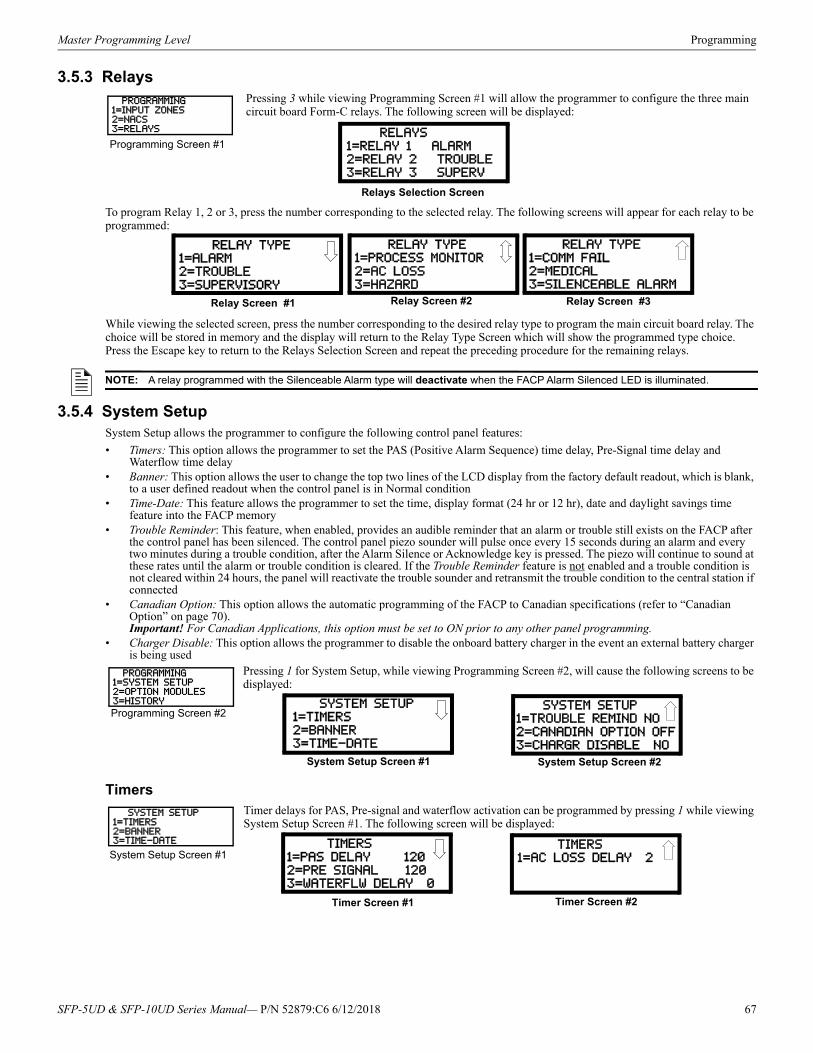
Master Programming Level Programming
3.5.3 RelaysPressing 3 while viewing Programming Screen #1 will allow the programmer to configure the three main circuit board Form-C relays. The following screen will be displayed:
To program Relay 1, 2 or 3, press the number corresponding to the selected relay. The following screens will appear for each relay to be programmed:
While viewing the selected screen, press the number corresponding to the desired relay type to program the main circuit board relay. The choice will be stored in memory and the display will return to the Relay Type Screen which will show the programmed type choice. Press the Escape key to return to the Relays Selection Screen and repeat the preceding procedure for the remaining relays.
3.5.4 System SetupSystem Setup allows the programmer to configure the following control panel features:
• Timers: This option allows the programmer to set the PAS (Positive Alarm Sequence) time delay, Pre-Signal time delay and Waterflow time delay
• Banner: This option allows the user to change the top two lines of the LCD display from the factory default readout, which is blank, to a user defined readout when the control panel is in Normal condition
• Time-Date: This feature allows the programmer to set the time, display format (24 hr or 12 hr), date and daylight savings time feature into the FACP memory
• Trouble Reminder: This feature, when enabled, provides an audible reminder that an alarm or trouble still exists on the FACP after the control panel has been silenced. The control panel piezo sounder will pulse once every 15 seconds during an alarm and every two minutes during a trouble condition, after the Alarm Silence or Acknowledge key is pressed. The piezo will continue to sound at these rates until the alarm or trouble condition is cleared. If the Trouble Reminder feature is not enabled and a trouble condition is not cleared within 24 hours, the panel will reactivate the trouble sounder and retransmit the trouble condition to the central station if connected
• Canadian Option: This option allows the automatic programming of the FACP to Canadian specifications (refer to “Canadian Option” on page 70).Important! For Canadian Applications, this option must be set to ON prior to any other panel programming.
• Charger Disable: This option allows the programmer to disable the onboard battery charger in the event an external battery charger is being used
Pressing 1 for System Setup, while viewing Programming Screen #2, will cause the following screens to be displayed:
TimersTimer delays for PAS, Pre-signal and waterflow activation can be programmed by pressing 1 while viewing System Setup Screen #1. The following screen will be displayed:
PROGRAMMING1=INPUT ZONES2=NACS3=RELAYS
Programming Screen #1 RELAYS
1=RELAY 1 ALARM2=RELAY 2 TROUBLE
3=RELAY 3 SUPERV
Relays Selection Screen
RELAY TYPE1=ALARM
2=TROUBLE
3=SUPERVISORY
Relay Screen #1
RELAY TYPE1=PROCESS MONITOR
2=AC LOSS
3=HAZARD
Relay Screen #3
RELAY TYPE
1=COMM FAIL
2=MEDICAL3=SILENCEABLE ALARM
Relay Screen #2
NOTE: A relay programmed with the Silenceable Alarm type will deactivate when the FACP Alarm Silenced LED is illuminated.
PROGRAMMING1=SYSTEM SETUP2=OPTION MODULES3=HISTORY
Programming Screen #2 SYSTEM SETUP1=TIMERS
2=BANNER
3=TIME-DATE
System Setup Screen #1
SYSTEM SETUP
1=TROUBLE REMIND NO
2=CANADIAN OPTION OFF3=CHARGR DISABLE NO
System Setup Screen #2
SYSTEM SETUP1=TIMERS2=BANNER3=TIME-DATE
System Setup Screen #1 TIMERS
1=PAS DELAY 120
2=PRE SIGNAL 1203=WATERFLW DELAY 0
Timer Screen #1
TIMERS
1=AC LOSS DELAY 2
Timer Screen #2
SFP-5UD & SFP-10UD Series Manual— P/N 52879:C6 6/12/2018 67
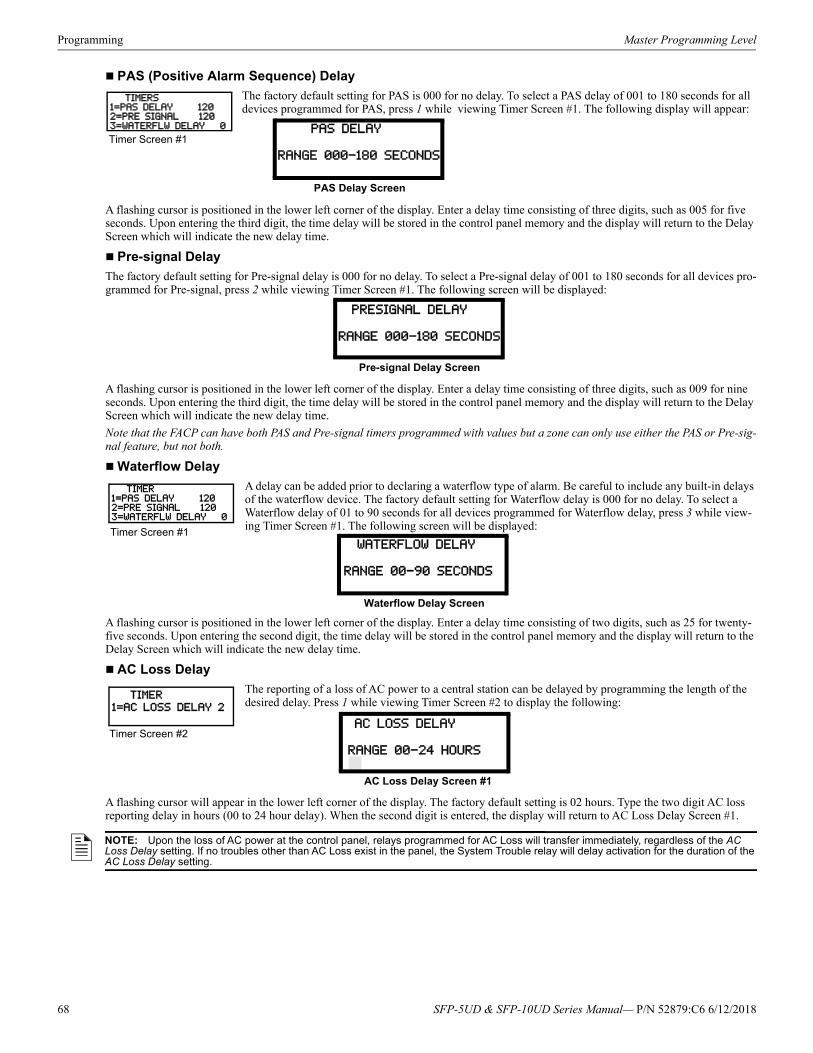
Programming Master Programming Level
PAS (Positive Alarm Sequence) Delay
The factory default setting for PAS is 000 for no delay. To select a PAS delay of 001 to 180 seconds for all devices programmed for PAS, press 1 while viewing Timer Screen #1. The following display will appear:
A flashing cursor is positioned in the lower left corner of the display. Enter a delay time consisting of three digits, such as 005 for five seconds. Upon entering the third digit, the time delay will be stored in the control panel memory and the display will return to the Delay Screen which will indicate the new delay time.
Pre-signal Delay
The factory default setting for Pre-signal delay is 000 for no delay. To select a Pre-signal delay of 001 to 180 seconds for all devices pro-grammed for Pre-signal, press 2 while viewing Timer Screen #1. The following screen will be displayed:
A flashing cursor is positioned in the lower left corner of the display. Enter a delay time consisting of three digits, such as 009 for nine seconds. Upon entering the third digit, the time delay will be stored in the control panel memory and the display will return to the Delay Screen which will indicate the new delay time.
Note that the FACP can have both PAS and Pre-signal timers programmed with values but a zone can only use either the PAS or Pre-sig-nal feature, but not both.
Waterflow Delay
A delay can be added prior to declaring a waterflow type of alarm. Be careful to include any built-in delays of the waterflow device. The factory default setting for Waterflow delay is 000 for no delay. To select a Waterflow delay of 01 to 90 seconds for all devices programmed for Waterflow delay, press 3 while view-ing Timer Screen #1. The following screen will be displayed:
A flashing cursor is positioned in the lower left corner of the display. Enter a delay time consisting of two digits, such as 25 for twenty-five seconds. Upon entering the second digit, the time delay will be stored in the control panel memory and the display will return to the Delay Screen which will indicate the new delay time.
AC Loss Delay
The reporting of a loss of AC power to a central station can be delayed by programming the length of the desired delay. Press 1 while viewing Timer Screen #2 to display the following:
A flashing cursor will appear in the lower left corner of the display. The factory default setting is 02 hours. Type the two digit AC loss reporting delay in hours (00 to 24 hour delay). When the second digit is entered, the display will return to AC Loss Delay Screen #1.
TIMERS1=PAS DELAY 1202=PRE SIGNAL 1203=WATERFLW DELAY 0
Timer Screen #1 PAS DELAY
RANGE 000-180 SECONDS
PAS Delay Screen
PRESIGNAL DELAY
RANGE 000-180 SECONDS
Pre-signal Delay Screen
TIMER1=PAS DELAY 1202=PRE SIGNAL 1203=WATERFLW DELAY 0
Timer Screen #1 WATERFLOW DELAY
RANGE 00-90 SECONDS
Waterflow Delay Screen
TIMER1=AC LOSS DELAY 2
Timer Screen #2 AC LOSS DELAY
RANGE 00-24 HOURS
AC Loss Delay Screen #1
NOTE: Upon the loss of AC power at the control panel, relays programmed for AC Loss will transfer immediately, regardless of the AC Loss Delay setting. If no troubles other than AC Loss exist in the panel, the System Trouble relay will delay activation for the duration of the AC Loss Delay setting.
68 SFP-5UD & SFP-10UD Series Manual— P/N 52879:C6 6/12/2018
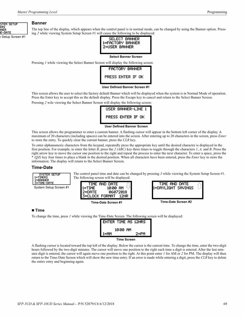
Master Programming Level Programming
STEM SETERSNNERME-DATE
m Setup Sc
BannerThe top line of the display, which appears when the control panel is in normal mode, can be changed by using the Banner option. Press-ing 2 while viewing System Setup Screen #1 will cause the following to be displayed:
Pressing 1 while viewing the Select Banner Screen will display the following screen:
This screen allows the user to select the factory default Banner which will be displayed when the system is in Normal Mode of operation. Press the Enter key to accept this as the default display. Press the Escape key to cancel and return to the Select Banner Screen.
Pressing 2 wile viewing the Select Banner Screen will display the following screen:
This screen allows the programmer to enter a custom banner. A flashing cursor will appear in the bottom left corner of the display. A maximum of 20 characters (including spaces) can be entered into the screen. After entering up to 20 characters in the screen, press Enter to store the entry. To quickly clear the current banner, press the CLR key.
To enter alphanumeric characters from the keypad, repeatedly press the appropriate key until the desired character is displayed in the first position. For example, to enter the letter B, press the 2 (ABC) key three times to toggle through the characters 1, A, and B. Press the right arrow key to move the cursor one position to the right and repeat the process to enter the next character. To enter a space, press the * (QZ) key four times to place a blank in the desired position. When all characters have been entered, press the Enter key to store the information. The display will return to the Select Banner Screen.
Time-DateThe control panel time and date can be changed by pressing 3 while viewing the System Setup Screen #1. The following screen will be displayed:
Time
To change the time, press 1 while viewing the Time-Date Screen. The following screen will be displayed:
A flashing cursor is located toward the top left of the display. Below the cursor is the current time. To change the time, enter the two-digit hours followed by the two-digit minutes. The cursor will move one position to the right each time a digit is entered. After the last min-utes digit is entered, the cursor will again move one position to the right. At this point enter 1 for AM or 2 for PM. The display will then return to the Time-Date Screen which will show the new time entry. If an error is made while entering a digit, press the CLR key to delete the entire entry and beginning again.
UP
reen #1 SELECT BANNER
1=FACTORY BANNER2=USER BANNER
Select Banner Screen
FACTORY BANNER
PRESS ENTER IF OK
User Defined Banner Screen #1
USER BANNER-LINE 1
PRESS ENTER IF OK
User Defined Banner Screen
SYSTEM SETUP1=TIMERS2=BANNER3=TIME-DATE
System Setup Screen #1 TIME AND DATE1=TIME 10:00 AM
2=DATE 06072018
3=CLOCK FORMAT 12HR
Time-Date Screen #1
TIME AND DATE
1=DAYLIGHT SAVINGS
Time-Date Screen #2
ENTER TIME AS 12HRS
10:00 AM
1=AM 2=PM
Time Screen
SFP-5UD & SFP-10UD Series Manual— P/N 52879:C6 6/12/2018 69
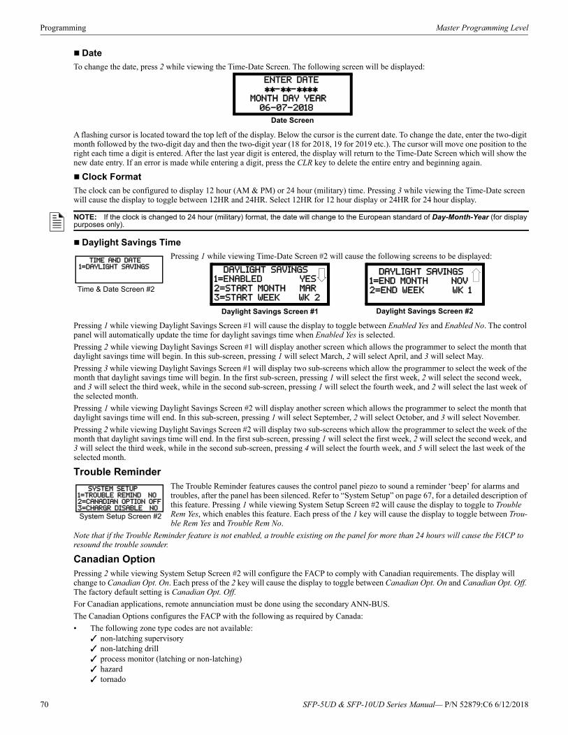
Programming Master Programming Level
Date
To change the date, press 2 while viewing the Time-Date Screen. The following screen will be displayed:
A flashing cursor is located toward the top left of the display. Below the cursor is the current date. To change the date, enter the two-digit month followed by the two-digit day and then the two-digit year (18 for 2018, 19 for 2019 etc.). The cursor will move one position to the right each time a digit is entered. After the last year digit is entered, the display will return to the Time-Date Screen which will show the new date entry. If an error is made while entering a digit, press the CLR key to delete the entire entry and beginning again.
Clock Format
The clock can be configured to display 12 hour (AM & PM) or 24 hour (military) time. Pressing 3 while viewing the Time-Date screen will cause the display to toggle between 12HR and 24HR. Select 12HR for 12 hour display or 24HR for 24 hour display.
Daylight Savings Time
Pressing 1 while viewing Time-Date Screen #2 will cause the following screens to be displayed:
Pressing 1 while viewing Daylight Savings Screen #1 will cause the display to toggle between Enabled Yes and Enabled No. The control panel will automatically update the time for daylight savings time when Enabled Yes is selected.
Pressing 2 while viewing Daylight Savings Screen #1 will display another screen which allows the programmer to select the month that daylight savings time will begin. In this sub-screen, pressing 1 will select March, 2 will select April, and 3 will select May.
Pressing 3 while viewing Daylight Savings Screen #1 will display two sub-screens which allow the programmer to select the week of the month that daylight savings time will begin. In the first sub-screen, pressing 1 will select the first week, 2 will select the second week, and 3 will select the third week, while in the second sub-screen, pressing 1 will select the fourth week, and 2 will select the last week of the selected month.
Pressing 1 while viewing Daylight Savings Screen #2 will display another screen which allows the programmer to select the month that daylight savings time will end. In this sub-screen, pressing 1 will select September, 2 will select October, and 3 will select November.
Pressing 2 while viewing Daylight Savings Screen #2 will display two sub-screens which allow the programmer to select the week of the month that daylight savings time will end. In the first sub-screen, pressing 1 will select the first week, 2 will select the second week, and 3 will select the third week, while in the second sub-screen, pressing 4 will select the fourth week, and 5 will select the last week of the selected month.
Trouble ReminderThe Trouble Reminder features causes the control panel piezo to sound a reminder ‘beep’ for alarms and troubles, after the panel has been silenced. Refer to “System Setup” on page 67, for a detailed description of this feature. Pressing 1 while viewing System Setup Screen #2 will cause the display to toggle to Trouble Rem Yes, which enables this feature. Each press of the 1 key will cause the display to toggle between Trou-ble Rem Yes and Trouble Rem No.
Note that if the Trouble Reminder feature is not enabled, a trouble existing on the panel for more than 24 hours will cause the FACP to resound the trouble sounder.
Canadian OptionPressing 2 while viewing System Setup Screen #2 will configure the FACP to comply with Canadian requirements. The display will change to Canadian Opt. On. Each press of the 2 key will cause the display to toggle between Canadian Opt. On and Canadian Opt. Off. The factory default setting is Canadian Opt. Off.
For Canadian applications, remote annunciation must be done using the secondary ANN-BUS.
The Canadian Options configures the FACP with the following as required by Canada:
• The following zone type codes are not available: non-latching supervisory non-latching drill process monitor (latching or non-latching) hazard tornado
ENTER DATE
-- MONTH DAY YEAR
06-07-2018
Date Screen
NOTE: If the clock is changed to 24 hour (military) format, the date will change to the European standard of Day-Month-Year (for display purposes only).
TIME AND DATE1=DAYLIGHT SAVINGS
Time & Date Screen #2
DAYLIGHT SAVINGS1=ENABLED YES
2=START MONTH MAR
3=START WEEK WK 2
Daylight Savings Screen #1 Daylight Savings Screen #2
DAYLIGHT SAVINGS1=END MONTH NOV
2=END WEEK WK 1
SYSTEM SETUP1=TROUBLE REMIND NO2=CANADIAN OPTION OFF3=CHARGR DISABLE NO
System Setup Screen #2
70 SFP-5UD & SFP-10UD Series Manual— P/N 52879:C6 6/12/2018
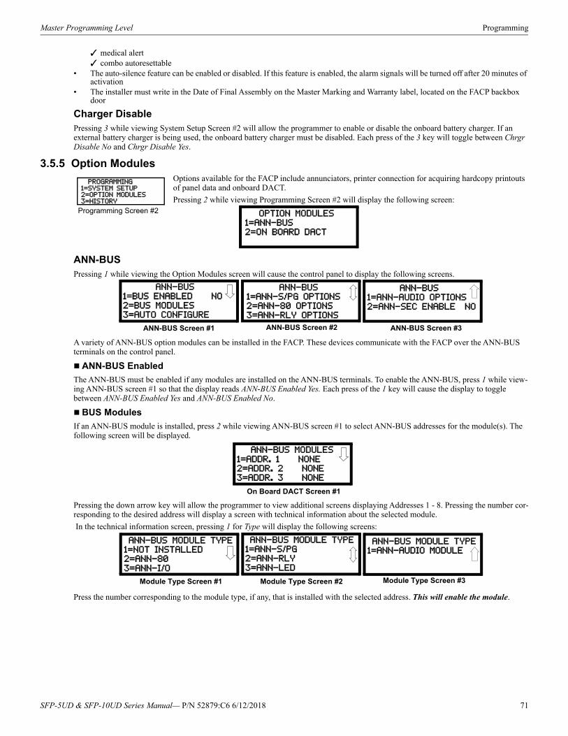
Master Programming Level Programming
medical alert combo autoresettable
• The auto-silence feature can be enabled or disabled. If this feature is enabled, the alarm signals will be turned off after 20 minutes of activation
• The installer must write in the Date of Final Assembly on the Master Marking and Warranty label, located on the FACP backbox door
Charger DisablePressing 3 while viewing System Setup Screen #2 will allow the programmer to enable or disable the onboard battery charger. If an external battery charger is being used, the onboard battery charger must be disabled. Each press of the 3 key will toggle between Chrgr Disable No and Chrgr Disable Yes.
3.5.5 Option ModulesOptions available for the FACP include annunciators, printer connection for acquiring hardcopy printouts of panel data and onboard DACT.
Pressing 2 while viewing Programming Screen #2 will display the following screen:
ANN-BUSPressing 1 while viewing the Option Modules screen will cause the control panel to display the following screens.
A variety of ANN-BUS option modules can be installed in the FACP. These devices communicate with the FACP over the ANN-BUS terminals on the control panel.
ANN-BUS Enabled
The ANN-BUS must be enabled if any modules are installed on the ANN-BUS terminals. To enable the ANN-BUS, press 1 while view-ing ANN-BUS screen #1 so that the display reads ANN-BUS Enabled Yes. Each press of the 1 key will cause the display to toggle between ANN-BUS Enabled Yes and ANN-BUS Enabled No.
BUS Modules
If an ANN-BUS module is installed, press 2 while viewing ANN-BUS screen #1 to select ANN-BUS addresses for the module(s). The following screen will be displayed.
Pressing the down arrow key will allow the programmer to view additional screens displaying Addresses 1 - 8. Pressing the number cor-responding to the desired address will display a screen with technical information about the selected module.
In the technical information screen, pressing 1 for Type will display the following screens:
Press the number corresponding to the module type, if any, that is installed with the selected address. This will enable the module.
PROGRAMMING1=SYSTEM SETUP2=OPTION MODULES3=HISTORY
Programming Screen #2 OPTION MODULES
1=ANN-BUS2=ON BOARD DACT
ANN-BUS
1=BUS ENABLED NO2=BUS MODULES
3=AUTO CONFIGURE
ANN-BUS Screen #1
ANN-BUS
1=ANN-S/PG OPTIONS2=ANN-80 OPTIONS
3=ANN-RLY OPTIONS
ANN-BUS Screen #2
ANN-BUS
1=ANN-AUDIO OPTIONS
2=ANN-SEC ENABLE NO
ANN-BUS Screen #3
ANN-BUS MODULES
1=ADDR. 1 NONE2=ADDR. 2 NONE
3=ADDR. 3 NONE
On Board DACT Screen #1
ANN-BUS MODULE TYPE
1=NOT INSTALLED2=ANN-80
3=ANN-I/O
Module Type Screen #1
ANN-BUS MODULE TYPE1=ANN-S/PG
2=ANN-RLY
3=ANN-LED
Module Type Screen #2
ANN-BUS MODULE TYPE1=ANN-AUDIO MODULE
Module Type Screen #3
SFP-5UD & SFP-10UD Series Manual— P/N 52879:C6 6/12/2018 71
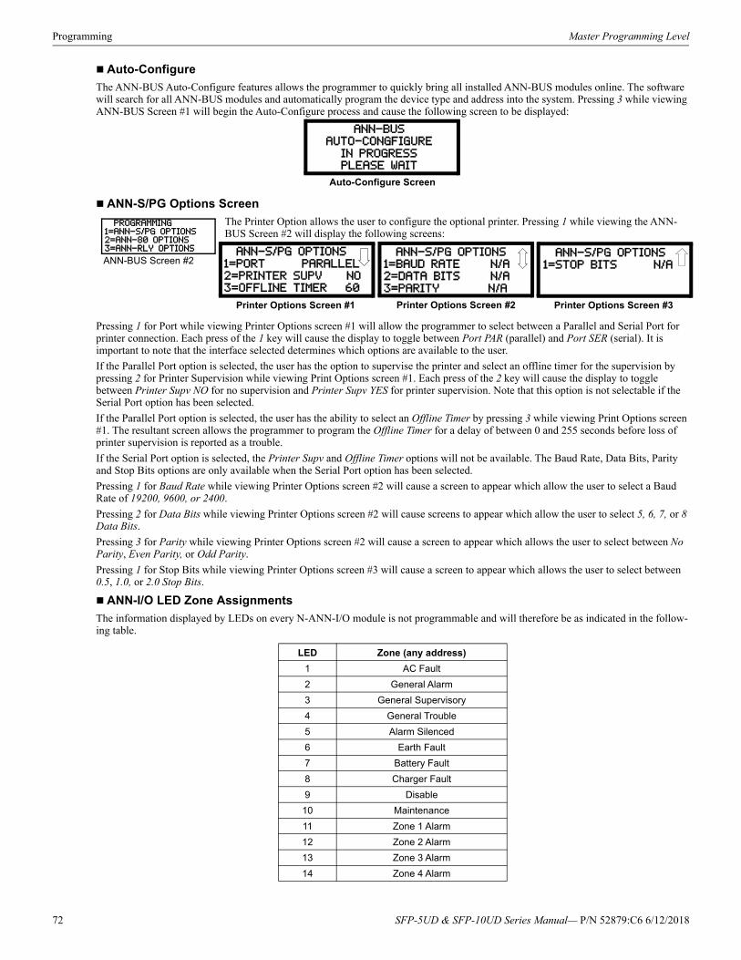
Programming Master Programming Level
Auto-Configure
The ANN-BUS Auto-Configure features allows the programmer to quickly bring all installed ANN-BUS modules online. The software will search for all ANN-BUS modules and automatically program the device type and address into the system. Pressing 3 while viewing ANN-BUS Screen #1 will begin the Auto-Configure process and cause the following screen to be displayed:
ANN-S/PG Options Screen
The Printer Option allows the user to configure the optional printer. Pressing 1 while viewing the ANN-BUS Screen #2 will display the following screens:
Pressing 1 for Port while viewing Printer Options screen #1 will allow the programmer to select between a Parallel and Serial Port for printer connection. Each press of the 1 key will cause the display to toggle between Port PAR (parallel) and Port SER (serial). It is important to note that the interface selected determines which options are available to the user.
If the Parallel Port option is selected, the user has the option to supervise the printer and select an offline timer for the supervision by pressing 2 for Printer Supervision while viewing Print Options screen #1. Each press of the 2 key will cause the display to toggle between Printer Supv NO for no supervision and Printer Supv YES for printer supervision. Note that this option is not selectable if the Serial Port option has been selected.
If the Parallel Port option is selected, the user has the ability to select an Offline Timer by pressing 3 while viewing Print Options screen #1. The resultant screen allows the programmer to program the Offline Timer for a delay of between 0 and 255 seconds before loss of printer supervision is reported as a trouble.
If the Serial Port option is selected, the Printer Supv and Offline Timer options will not be available. The Baud Rate, Data Bits, Parity and Stop Bits options are only available when the Serial Port option has been selected.
Pressing 1 for Baud Rate while viewing Printer Options screen #2 will cause a screen to appear which allow the user to select a Baud Rate of 19200, 9600, or 2400.
Pressing 2 for Data Bits while viewing Printer Options screen #2 will cause screens to appear which allow the user to select 5, 6, 7, or 8 Data Bits.
Pressing 3 for Parity while viewing Printer Options screen #2 will cause a screen to appear which allows the user to select between No Parity, Even Parity, or Odd Parity.
Pressing 1 for Stop Bits while viewing Printer Options screen #3 will cause a screen to appear which allows the user to select between 0.5, 1.0, or 2.0 Stop Bits.
ANN-I/O LED Zone Assignments
The information displayed by LEDs on every N-ANN-I/O module is not programmable and will therefore be as indicated in the follow-ing table.
LED Zone (any address)
1 AC Fault
2 General Alarm
3 General Supervisory
4 General Trouble
5 Alarm Silenced
6 Earth Fault
7 Battery Fault
8 Charger Fault
9 Disable
10 Maintenance
11 Zone 1 Alarm
12 Zone 2 Alarm
13 Zone 3 Alarm
14 Zone 4 Alarm
ANN-BUSAUTO-CONGFIGURE
IN PROGRESS
PLEASE WAIT
Auto-Configure Screen
PROGRAMMING1=ANN-S/PG OPTIONS2=ANN-80 OPTIONS3=ANN-RLY OPTIONS
ANN-BUS Screen #2 ANN-S/PG OPTIONS
1=PORT PARALLEL
2=PRINTER SUPV NO3=OFFLINE TIMER 60
Printer Options Screen #1
ANN-S/PG OPTIONS
1=BAUD RATE N/A2=DATA BITS N/A
3=PARITY N/A
Printer Options Screen #2
ANN-S/PG OPTIONS
1=STOP BITS N/A
Printer Options Screen #3
72 SFP-5UD & SFP-10UD Series Manual— P/N 52879:C6 6/12/2018
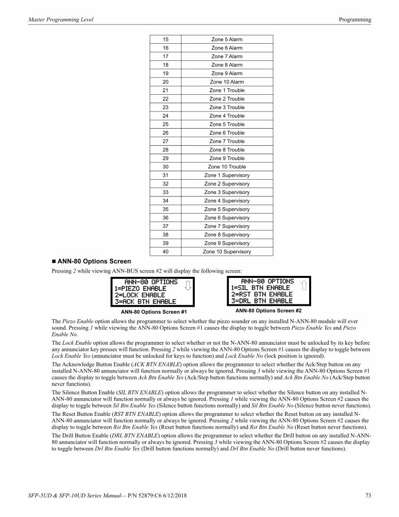
Master Programming Level Programming
ANN-80 Options Screen
Pressing 2 while viewing ANN-BUS screen #2 will display the following screen:
The Piezo Enable option allows the programmer to select whether the piezo sounder on any installed N-ANN-80 module will ever sound. Pressing 1 while viewing the ANN-80 Options Screen #1 causes the display to toggle between Piezo Enable Yes and Piezo Enable No.
The Lock Enable option allows the programmer to select whether or not the N-ANN-80 annunciator must be unlocked by its key before any annunciator key presses will function. Pressing 2 while viewing the ANN-80 Options Screen #1 causes the display to toggle between Lock Enable Yes (annunciator must be unlocked for keys to function) and Lock Enable No (lock position is ignored).
The Acknowledge Button Enable (ACK BTN ENABLE) option allows the programmer to select whether the Ack/Step button on any installed N-ANN-80 annunciator will function normally or always be ignored. Pressing 3 while viewing the ANN-80 Options Screen #1 causes the display to toggle between Ack Btn Enable Yes (Ack/Step button functions normally) and Ack Btn Enable No (Ack/Step button never functions).
The Silence Button Enable (SIL BTN ENABLE) option allows the programmer to select whether the Silence button on any installed N-ANN-80 annunciator will function normally or always be ignored. Pressing 1 while viewing the ANN-80 Options Screen #2 causes the display to toggle between Sil Btn Enable Yes (Silence button functions normally) and Sil Btn Enable No (Silence button never functions).
The Reset Button Enable (RST BTN ENABLE) option allows the programmer to select whether the Reset button on any installed N-ANN-80 annunciator will function normally or always be ignored. Pressing 2 while viewing the ANN-80 Options Screen #2 causes the display to toggle between Rst Btn Enable Yes (Reset button functions normally) and Rst Btn Enable No (Reset button never functions).
The Drill Button Enable (DRL BTN ENABLE) option allows the programmer to select whether the Drill button on any installed N-ANN-80 annunciator will function normally or always be ignored. Pressing 3 while viewing the ANN-80 Options Screen #2 causes the display to toggle between Drl Btn Enable Yes (Drill button functions normally) and Drl Btn Enable No (Drill button never functions).
15 Zone 5 Alarm
16 Zone 6 Alarm
17 Zone 7 Alarm
18 Zone 8 Alarm
19 Zone 9 Alarm
20 Zone 10 Alarm
21 Zone 1 Trouble
22 Zone 2 Trouble
23 Zone 3 Trouble
24 Zone 4 Trouble
25 Zone 5 Trouble
26 Zone 6 Trouble
27 Zone 7 Trouble
28 Zone 8 Trouble
29 Zone 9 Trouble
30 Zone 10 Trouble
31 Zone 1 Supervisory
32 Zone 2 Supervisory
33 Zone 3 Supervisory
34 Zone 4 Supervisory
35 Zone 5 Supervisory
36 Zone 6 Supervisory
37 Zone 7 Supervisory
38 Zone 8 Supervisory
39 Zone 9 Supervisory
40 Zone 10 Supervisory
ANN-80 OPTIONS
1=PIEZO ENABLE2=LOCK ENABLE
3=ACK BTN ENABLE
ANN-80 Options Screen #1
ANN-80 OPTIONS1=SIL BTN ENABLE
2=RST BTN ENABLE
3=DRL BTN ENABLE
ANN-80 Options Screen #2
SFP-5UD & SFP-10UD Series Manual— P/N 52879:C6 6/12/2018 73
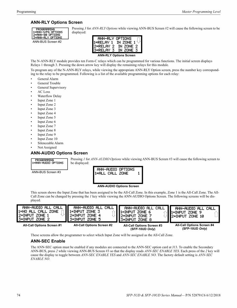
Programming Master Programming Level
ANN-RLY Options ScreenPressing 3 for ANN-RLY Options while viewing ANN-BUS Screen #2 will cause the following screen to be displayed:
The N-ANN-RLY module provides ten Form-C relays which can be programmed for various functions. The initial screen displays Relays 1 through 3. Pressing the down arrow key will display the remaining relays for this module.
To program any of the N-ANN-RLY relays, while viewing the appropriate ANN-RLY Option screen, press the number key correspond-ing to the relay to be programmed. Following is a list of the available programming options for each relay:
• General Alarm• General Trouble• General Supervisory• AC Loss• Waterflow Delay• Input Zone 1• Input Zone 2• Input Zone 3• Input Zone 4• Input Zone 5• Input Zone 6• Input Zone 7• Input Zone 8• Input Zone 9• Input Zone 10• Silenceable Alarm• Not Assigned
ANN-AUDIO Options ScreenPressing 1 for ANN-AUDIO Options while viewing ANN-BUS Screen #3 will cause the following screen to be displayed:
This screen shows the Input Zone that has been assigned to be the All-Call Zone. In this example, Zone 1 is the All-Call Zone. The All-Call Zone can be changed by pressing the 1 key while viewing the ANN-AUDIO Options Screen. The following screens will be dis-played.
These screens allow the programmer to select which Input Zone will be assigned as the All-Call Zone.
ANN-SEC EnableThe ANN-SEC option must be enabled if any modules are connected to the ANN-SEC option card at J13. To enable the Secondary ANN-BUS, press 2 while viewing ANN-BUS Screen #3 so that the display reads ANN-SEC ENABLE YES. Each press of the 2 key will cause the display to toggle between ANN-SEC ENABLE YES and ANN-SEC ENABLE NO. The factory default setting is ANN-SEC ENABLE NO.
PROGRAMMING1=ANN-S/PG OPTIONS2=ANN-80 OPTIONS3=ANN-RLY OPTIONS
ANN-BUS Screen #2 ANN-RLY OPTIONS
1=RELAY 1 IN ZONE 12=RELAY 2 IN ZONE 2
3=RELAY 3 IN ZONE 3
ANN-RLY Options Screen
PROGRAMMING1=ANN-AUDIO OPTIONS
ANN-BUS Screen #3 ANN-AUDIO OPTIONS
1=ALL CALL ZONE 1
ANN-AUDIO Options Screen
ANN-AUDIO ALL CALL
1=NO ALL CALL ZONE2=INPUT ZONE 1
3=INPUT ZONE 2
All-Call Options Screen #1
ANN-AUDIO ALL CALL1=INPUT ZONE 3
2=INPUT ZONE 4
3=INPUT ZONE 5
All-Call Options Screen #2
ANN-AUDIO ALL CALL1=INPUT ZONE 9
2=INPUT ZONE 10
All-Call Options Screen #4(SFP-10UD Only)
ANN-AUDIO ALL CALL
1=INPUT ZONE 6
2=INPUT ZONE 73=INPUT ZONE 8
All-Call Options Screen #3(SFP-10UD Only)
74 SFP-5UD & SFP-10UD Series Manual— P/N 52879:C6 6/12/2018
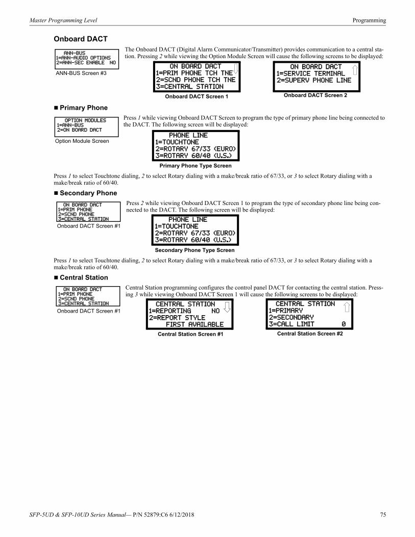
Master Programming Level Programming
Onboard DACT The Onboard DACT (Digital Alarm Communicator/Transmitter) provides communication to a central sta-tion. Pressing 2 while viewing the Option Module Screen will cause the following screens to be displayed:
Primary Phone
Press 1 while viewing Onboard DACT Screen to program the type of primary phone line being connected to the DACT. The following screen will be displayed:
Press 1 to select Touchtone dialing, 2 to select Rotary dialing with a make/break ratio of 67/33, or 3 to select Rotary dialing with a make/break ratio of 60/40.
Secondary Phone
Press 2 while viewing Onboard DACT Screen 1 to program the type of secondary phone line being con-nected to the DACT. The following screen will be displayed:
Press 1 to select Touchtone dialing, 2 to select Rotary dialing with a make/break ratio of 67/33, or 3 to select Rotary dialing with a make/break ratio of 60/40.
Central Station
Central Station programming configures the control panel DACT for contacting the central station. Press-ing 3 while viewing Onboard DACT Screen 1 will cause the following screens to be displayed:
ANN-BUS1=ANN-AUDIO OPTIONS2=ANN-SEC ENABLE NO
ANN-BUS Screen #3 ON BOARD DACT1=PRIM PHONE TCH TNE
2=SCND PHONE TCH TNE
3=CENTRAL STATION
ON BOARD DACT
1=SERVICE TERMINAL2=SUPERV PHONE LINE
Onboard DACT Screen 1 Onboard DACT Screen 2
OPTION MODULES1=ANN-BUS2=ON BOARD DACT
Option Module Screen PHONE LINE
1=TOUCHTONE2=ROTARY 67/33 (EURO)
3=ROTARY 60/40 (U.S.)
Primary Phone Type Screen
ON BOARD DACT1=PRIM PHONE 2=SCND PHONE3=CENTRAL STATION
Onboard DACT Screen #1 PHONE LINE
1=TOUCHTONE2=ROTARY 67/33 (EURO)
3=ROTARY 60/40 (U.S.)
Secondary Phone Type Screen
ON BOARD DACT1=PRIM PHONE 2=SCND PHONE3=CENTRAL STATION
Onboard DACT Screen #1 CENTRAL STATION
1=REPORTING NO
2=REPORT STYLE FIRST AVAILABLE
Central Station Screen #1
CENTRAL STATION
1=PRIMARY
2=SECONDARY3=CALL LIMIT 0
Central Station Screen #2
SFP-5UD & SFP-10UD Series Manual— P/N 52879:C6 6/12/2018 75

Programming Master Programming Level
Reporting
To enable the DACT for reporting FACP activity to the central station, press 1 while viewing Central Station Screen #1 so the display reads Reporting Yes. Each press of the 1 key will toggle the display between Reporting Yes and Reporting No.
76 SFP-5UD & SFP-10UD Series Manual— P/N 52879:C6 6/12/2018

Master Programming Level Programming
Report Style
The DACT can be programmed to transmit reports to primary and/or secondary central station phone numbers as a backup. Press 2 while viewing Central Station Screen #1 to display the following screen:
Press 1 to have all reports transmitted to the central station secondary phone number as a backup only if the primary phone line fails, 2 to transmit all reports to both the primary and secondary phone numbers all of the time, or 3 to send reports to the first available phone number.
REPORT STYLE
1=BACKUP ONLY
2=BOTH
3=FIRST AVAILABLE
Backup Reporting Screen
SFP-5UD & SFP-10UD Series Manual— P/N 52879:C6 6/12/2018 77
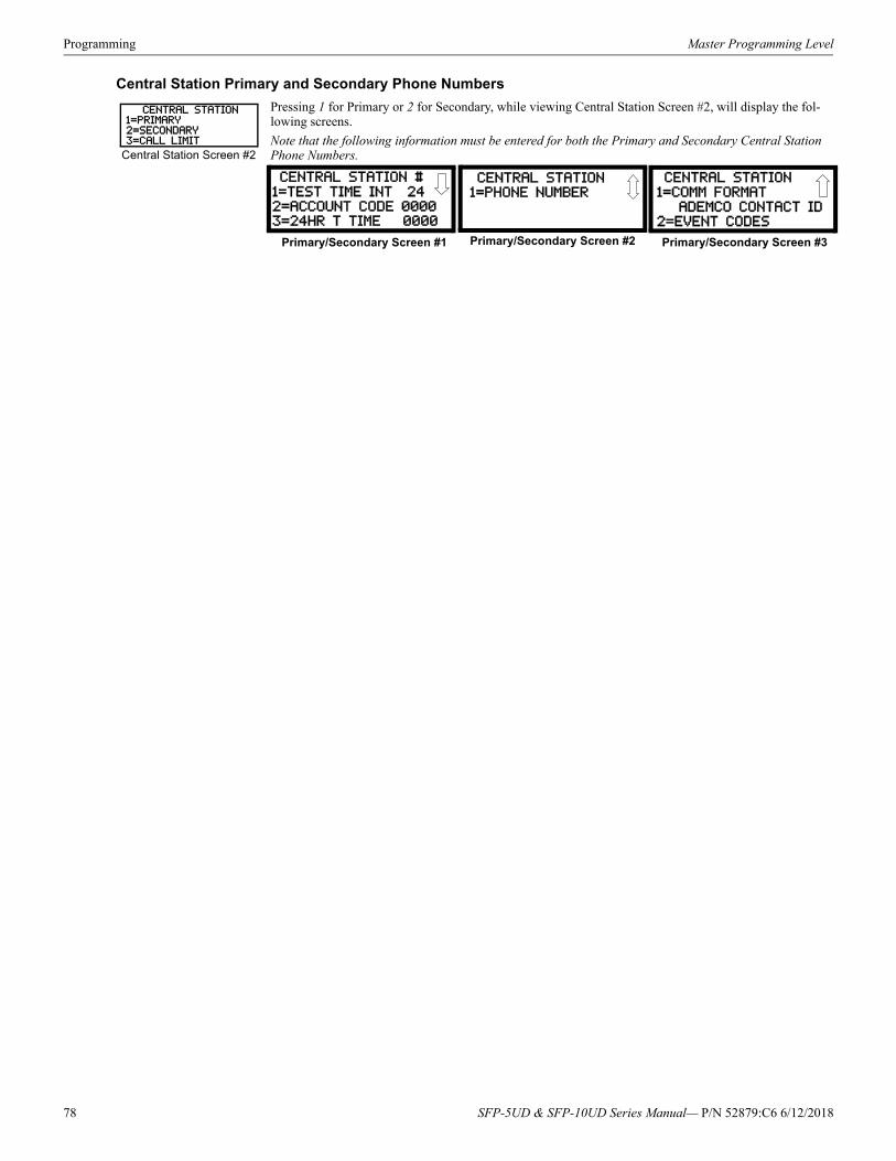
Programming Master Programming Level
Central Station Primary and Secondary Phone Numbers
Pressing 1 for Primary or 2 for Secondary, while viewing Central Station Screen #2, will display the fol-lowing screens.
Note that the following information must be entered for both the Primary and Secondary Central Station Phone Numbers.
CENTRAL STATION1=PRIMARY2=SECONDARY3=CALL LIMIT
Central Station Screen #2
CENTRAL STATION #
1=TEST TIME INT 242=ACCOUNT CODE 0000
3=24HR T TIME 0000
Primary/Secondary Screen #1
CENTRAL STATION1=PHONE NUMBER
Primary/Secondary Screen #2
CENTRAL STATION
1=COMM FORMAT
ADEMCO CONTACT ID2=EVENT CODES
Primary/Secondary Screen #3
78 SFP-5UD & SFP-10UD Series Manual— P/N 52879:C6 6/12/2018

Master Programming Level Programming
Test Time Interval
Pressing 1 while viewing Primary/Secondary Screen #1 will cause the following screens to be displayed:
The test report sent to the Central Station phone number may be sent once every 6, 8, 12 or 24 hours. Select the desired Test Time Inter-val by pressing the corresponding digit in the screens shown above.
CENTRAL STATION1=TEST TIME INT2=ACCOUNT CODE3=24HR TST TIME
Primary/Secondary Screen #1
TEST TIME INTERVAL1=24 HOURS
2=12 HOURS
3=8 HOURS
Test Time Interval Screen #1
TEST TIME INTERVAL
1=6 HOURS
Test Time Interval Screen #2
SFP-5UD & SFP-10UD Series Manual— P/N 52879:C6 6/12/2018 79

Programming Master Programming Level
Account Code
Pressing 2 while viewing Primary/Secondary Screen #1 will cause the following screen to be displayed:
The Account Code, which is assigned by a Central Station, depends on the communication format being used. The Account Code screen will have a flashing cursor in the lower left corner. Program the supplied 4-digit account code using 0 - 9 and A - F keys. Enter the first digit, then press the right arrow key to move the cursor to the right, one position. Repeat the process until all digits are entered.
ACCOUNT CODE
RANGE 0000-FFFF
Account Codes Screen
80 SFP-5UD & SFP-10UD Series Manual— P/N 52879:C6 6/12/2018

Master Programming Level Programming
24 Hour Test Time
Pressing 3 while viewing Primary/Secondary Screen #1 will cause the following screen to be displayed:
Use the 24 Hour Test Time screen to program the time that the DACT will transmit the 24 Hour Test to the Central Station. A flashing cursor will appear in the lower left corner of the screen. Enter a four digit number representing the test time using military time (0000 = midnight and 2359 = 11:59PM).
CENTRAL STATION1=TEST TIME INT2=ACCOUNT CODE3=24HR T TIME
Primary/Secondary Screen #1
24 HOUR TEST TIME
ENTR USING 24HR TIME
RANGE 0000-2359
24 Hour Test Time Screen
SFP-5UD & SFP-10UD Series Manual— P/N 52879:C6 6/12/2018 81
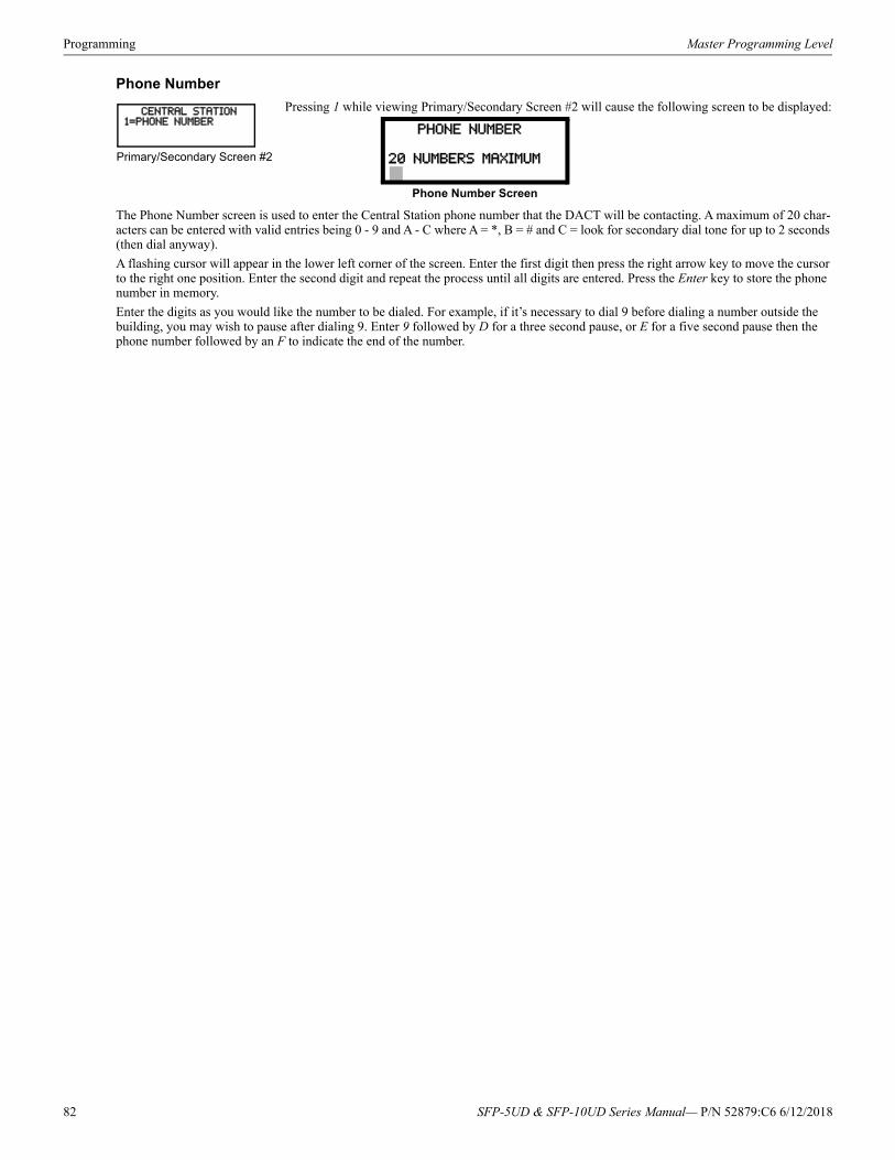
Programming Master Programming Level
Phone Number
Pressing 1 while viewing Primary/Secondary Screen #2 will cause the following screen to be displayed:
The Phone Number screen is used to enter the Central Station phone number that the DACT will be contacting. A maximum of 20 char-acters can be entered with valid entries being 0 - 9 and A - C where A = *, B = # and C = look for secondary dial tone for up to 2 seconds (then dial anyway).
A flashing cursor will appear in the lower left corner of the screen. Enter the first digit then press the right arrow key to move the cursor to the right one position. Enter the second digit and repeat the process until all digits are entered. Press the Enter key to store the phone number in memory.
Enter the digits as you would like the number to be dialed. For example, if it’s necessary to dial 9 before dialing a number outside the building, you may wish to pause after dialing 9. Enter 9 followed by D for a three second pause, or E for a five second pause then the phone number followed by an F to indicate the end of the number.
CENTRAL STATION1=PHONE NUMBER
Primary/Secondary Screen #2
PHONE NUMBER
20 NUMBERS MAXIMUM
Phone Number Screen
82 SFP-5UD & SFP-10UD Series Manual— P/N 52879:C6 6/12/2018
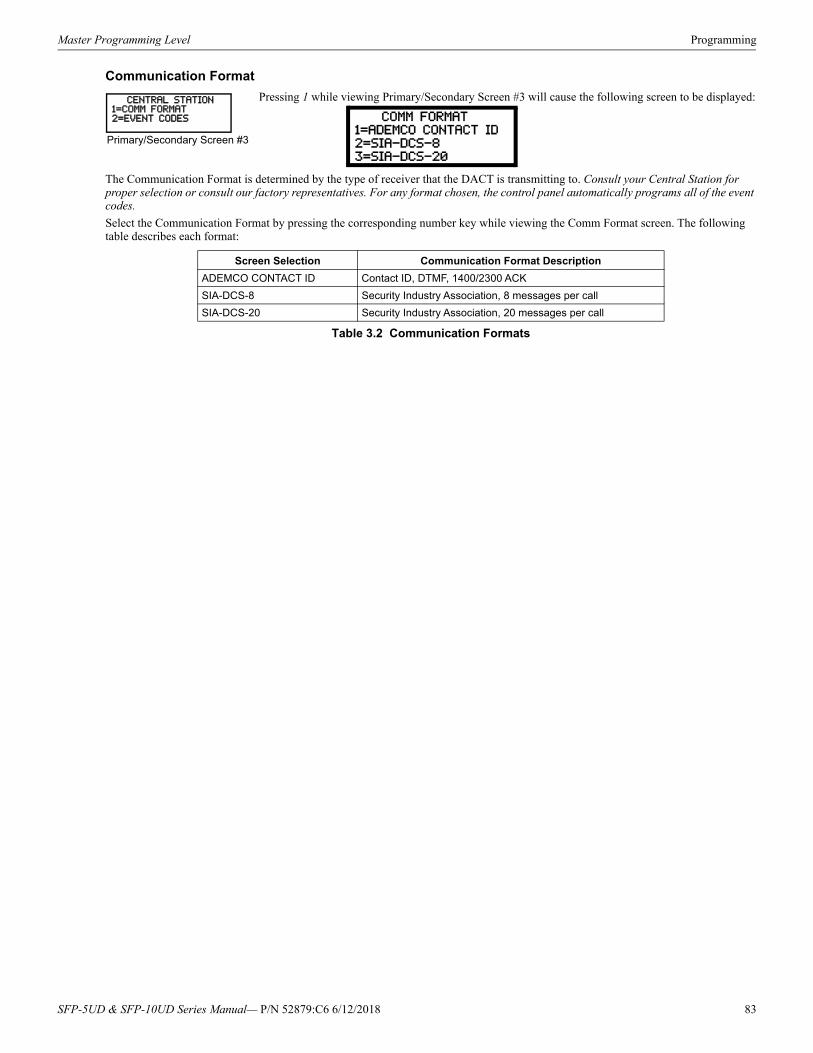
Master Programming Level Programming
Communication Format
Pressing 1 while viewing Primary/Secondary Screen #3 will cause the following screen to be displayed:
The Communication Format is determined by the type of receiver that the DACT is transmitting to. Consult your Central Station for proper selection or consult our factory representatives. For any format chosen, the control panel automatically programs all of the event codes.
Select the Communication Format by pressing the corresponding number key while viewing the Comm Format screen. The following table describes each format:
Screen Selection Communication Format Description
ADEMCO CONTACT ID Contact ID, DTMF, 1400/2300 ACK
SIA-DCS-8 Security Industry Association, 8 messages per call
SIA-DCS-20 Security Industry Association, 20 messages per call
Table 3.2 Communication Formats
CENTRAL STATION1=COMM FORMAT2=EVENT CODES
Primary/Secondary Screen #3
COMM FORMAT1=ADEMCO CONTACT ID
2=SIA-DCS-8
3=SIA-DCS-20
SFP-5UD & SFP-10UD Series Manual— P/N 52879:C6 6/12/2018 83
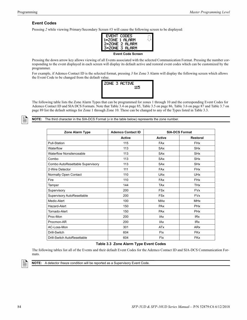
Programming Master Programming Level
Event Codes
Pressing 2 while viewing Primary/Secondary Screen #3 will cause the following screen to be displayed:
Pressing the down arrow key allows viewing of all Events associated with the selected Communication Format. Pressing the number cor-responding to the event displayed in each screen will display its default active and restoral event codes which can be customized by the programmer.
For example, if Ademco Contact ID is the selected format, pressing 3 for Zone 3 Alarm will display the following screen which allows the Event Code to be changed from the default value.
The following table lists the Zone Alarm Types that can be programmed for zones 1 through 10 and the corresponding Event Codes for Ademco Contact ID and SIA DCS Formats. Note that Table 3.4 on page 85, Table 3.5 on page 86, Table 3.6 on page 87 and Table 3.7 on page 89 list the default settings for Zone 1 through Zone 10. These can be changed to any of the Types listed in Table 3.3.
The following tables list all of the Events and their default Event Codes for the Ademco Contact ID and SIA-DCS Communication For-mats.
EVENT CODES
1=ZONE 1 ALARM2=ZONE 2 ALARM
3=ZONE 3 ALARM
Event Code Screen
ZONE 3 ACTIVE
115
NOTE: The third character in the SIA-DCS Format (x in the table below) represents the zone number.
Zone Alarm Type Ademco Contact ID SIA-DCS Format
Active Active Restoral
Pull-Station 115 FAx FHx
Waterflow 113 SAx SHx
Waterflow Nonsilenceable 113 SAx SHx
Combo 113 SAx SHx
Combo AutoResettable Supervisory 113 SAx SHx
2-Wire Detector 111 FAx FHx
Normally Open Contact 110 UAx UHx
Fire 110 FAx FHx
Tamper 144 TAx THx
Supervisory 200 FSx FVx
Supervisory AutoResettable 200 FSx FVx
Medic-Alert 100 MAx MHx
Hazard-Alert 150 PAx PHx
Tornado-Alert 150 PAx PHx
Proc-Mon 200 IAx IRx
Procmon-AR 200 IAx IRx
AC-Loss-Mon 301 ATx ARx
Drill-Switch 604 FIx FKx
Drill-Switch AutoResettable 604 FIx FKx
Table 3.3 Zone Alarm Type Event Codes
NOTE: A detector freeze condition will be reported as a Supervisory Event Code.
84 SFP-5UD & SFP-10UD Series Manual— P/N 52879:C6 6/12/2018
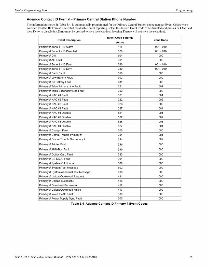
Master Programming Level Programming
Ademco Contact ID Format - Primary Central Station Phone Number
The information shown in Table 3.4 is automatically programmed for the Primary Central Station phone number Event Codes when Ademco Contact ID Format is selected. To disable event reporting, select the desired Event Code to be disabled and press 0 or Clear and then Enter to disable it. (Enter must be pressed to save the selection. Pressing Escape will not save the selection).
Event DescriptionEvent Code Settings
Zone CodeActive
Primary # Zone 1 - 10 Alarm 115 001 - 010
Primary # Zone 1 - 10 Disabled 570 001 - 010
Primary # Drill 604 000
Primary # AC Fault 301 000
Primary # Zone 1 - 10 Fault 380 001 - 010
Primary # Zone 1 - 10 Dirty 380 001 - 010
Primary # Earth Fault 310 000
Primary # Low Battery Fault 302 000
Primary # No Battery Fault 311 000
Primary # Telco Primary Line Fault 351 001
Primary # Telco Secondary Line Fault 352 002
Primary # NAC #1 Fault 321 001
Primary # NAC #2 Fault 322 002
Primary # NAC #3 Fault 326 003
Primary # NAC #4 Fault 327 004
Primary # NAC #1 Disable 521 001
Primary # NAC #2 Disable 522 002
Primary # NAC #3 Disable 526 003
Primary # NAC #4 Disable 527 004
Primary # Charger Fault 300 000
Primary # Comm Trouble Primary # 354 001
Primary # Comm Trouble Secondary # 354 002
Primary # Printer Fault 336 000
Primary # ANN-Bus Fault 330 000
Primary # Option Card Fault 333 000
Primary # CS CALC Fault 304 000
Primary # System Off Normal 308 000
Primary # System Test Message 602 000
Primary # System Abnormal Test Message 608 000
Primary # Upload/Download Request 411 000
Primary # Upload Successful 416 000
Primary # Download Successful 412 000
Primary # Upload/Download Failed 413 000
Primary # Voice EVAC Fault 330 000
Primary # Power Supply Sync Fault 300 000
Table 3.4 Ademco Contact ID Primary # Event Codes
SFP-5UD & SFP-10UD Series Manual— P/N 52879:C6 6/12/2018 85
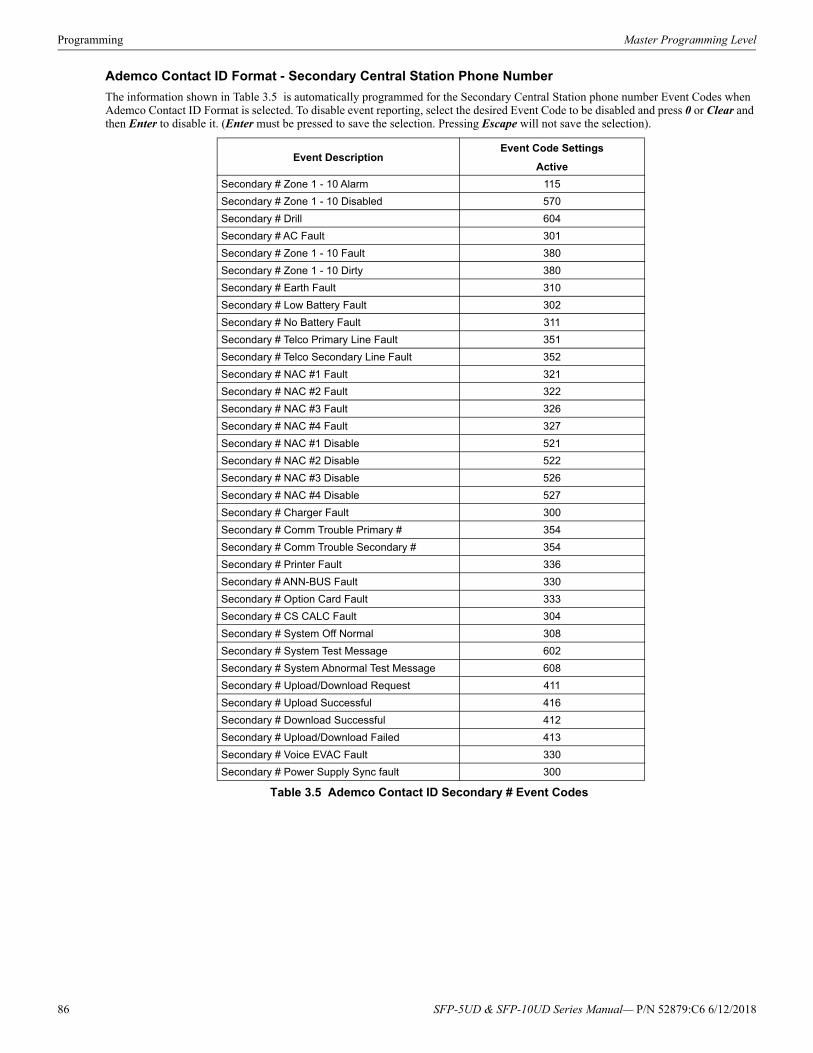
Programming Master Programming Level
Ademco Contact ID Format - Secondary Central Station Phone Number
The information shown in Table 3.5 is automatically programmed for the Secondary Central Station phone number Event Codes when Ademco Contact ID Format is selected. To disable event reporting, select the desired Event Code to be disabled and press 0 or Clear and then Enter to disable it. (Enter must be pressed to save the selection. Pressing Escape will not save the selection).
Event DescriptionEvent Code Settings
Active
Secondary # Zone 1 - 10 Alarm 115
Secondary # Zone 1 - 10 Disabled 570
Secondary # Drill 604
Secondary # AC Fault 301
Secondary # Zone 1 - 10 Fault 380
Secondary # Zone 1 - 10 Dirty 380
Secondary # Earth Fault 310
Secondary # Low Battery Fault 302
Secondary # No Battery Fault 311
Secondary # Telco Primary Line Fault 351
Secondary # Telco Secondary Line Fault 352
Secondary # NAC #1 Fault 321
Secondary # NAC #2 Fault 322
Secondary # NAC #3 Fault 326
Secondary # NAC #4 Fault 327
Secondary # NAC #1 Disable 521
Secondary # NAC #2 Disable 522
Secondary # NAC #3 Disable 526
Secondary # NAC #4 Disable 527
Secondary # Charger Fault 300
Secondary # Comm Trouble Primary # 354
Secondary # Comm Trouble Secondary # 354
Secondary # Printer Fault 336
Secondary # ANN-BUS Fault 330
Secondary # Option Card Fault 333
Secondary # CS CALC Fault 304
Secondary # System Off Normal 308
Secondary # System Test Message 602
Secondary # System Abnormal Test Message 608
Secondary # Upload/Download Request 411
Secondary # Upload Successful 416
Secondary # Download Successful 412
Secondary # Upload/Download Failed 413
Secondary # Voice EVAC Fault 330
Secondary # Power Supply Sync fault 300
Table 3.5 Ademco Contact ID Secondary # Event Codes
86 SFP-5UD & SFP-10UD Series Manual— P/N 52879:C6 6/12/2018
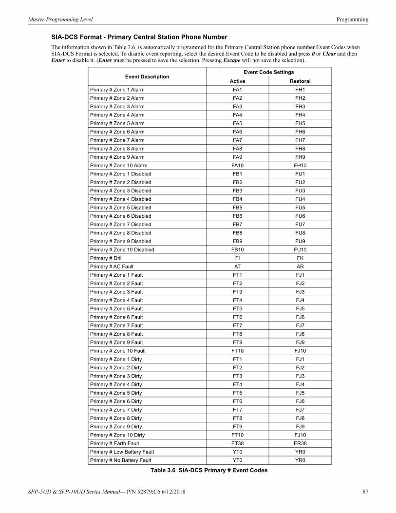
Master Programming Level Programming
SIA-DCS Format - Primary Central Station Phone Number
The information shown in Table 3.6 is automatically programmed for the Primary Central Station phone number Event Codes when SIA-DCS Format is selected. To disable event reporting, select the desired Event Code to be disabled and press 0 or Clear and then Enter to disable it. (Enter must be pressed to save the selection. Pressing Escape will not save the selection).
Event DescriptionEvent Code Settings
Active Restoral
Primary # Zone 1 Alarm FA1 FH1
Primary # Zone 2 Alarm FA2 FH2
Primary # Zone 3 Alarm FA3 FH3
Primary # Zone 4 Alarm FA4 FH4
Primary # Zone 5 Alarm FA5 FH5
Primary # Zone 6 Alarm FA6 FH6
Primary # Zone 7 Alarm FA7 FH7
Primary # Zone 8 Alarm FA8 FH8
Primary # Zone 9 Alarm FA9 FH9
Primary # Zone 10 Alarm FA10 FH10
Primary # Zone 1 Disabled FB1 FU1
Primary # Zone 2 Disabled FB2 FU2
Primary # Zone 3 Disabled FB3 FU3
Primary # Zone 4 Disabled FB4 FU4
Primary # Zone 5 Disabled FB5 FU5
Primary # Zone 6 Disabled FB6 FU6
Primary # Zone 7 Disabled FB7 FU7
Primary # Zone 8 Disabled FB8 FU8
Primary # Zone 9 Disabled FB9 FU9
Primary # Zone 10 Disabled FB10 FU10
Primary # Drill FI FK
Primary # AC Fault AT AR
Primary # Zone 1 Fault FT1 FJ1
Primary # Zone 2 Fault FT2 FJ2
Primary # Zone 3 Fault FT3 FJ3
Primary # Zone 4 Fault FT4 FJ4
Primary # Zone 5 Fault FT5 FJ5
Primary # Zone 6 Fault FT6 FJ6
Primary # Zone 7 Fault FT7 FJ7
Primary # Zone 8 Fault FT8 FJ8
Primary # Zone 9 Fault FT9 FJ9
Primary # Zone 10 Fault FT10 FJ10
Primary # Zone 1 Dirty FT1 FJ1
Primary # Zone 2 Dirty FT2 FJ2
Primary # Zone 3 Dirty FT3 FJ3
Primary # Zone 4 Dirty FT4 FJ4
Primary # Zone 5 Dirty FT5 FJ5
Primary # Zone 6 Dirty FT6 FJ6
Primary # Zone 7 Dirty FT7 FJ7
Primary # Zone 8 Dirty FT8 FJ8
Primary # Zone 9 Dirty FT9 FJ9
Primary # Zone 10 Dirty FT10 FJ10
Primary # Earth Fault ET38 ER38
Primary # Low Battery Fault YT0 YR0
Primary # No Battery Fault YT0 YR0
Table 3.6 SIA-DCS Primary # Event Codes
SFP-5UD & SFP-10UD Series Manual— P/N 52879:C6 6/12/2018 87
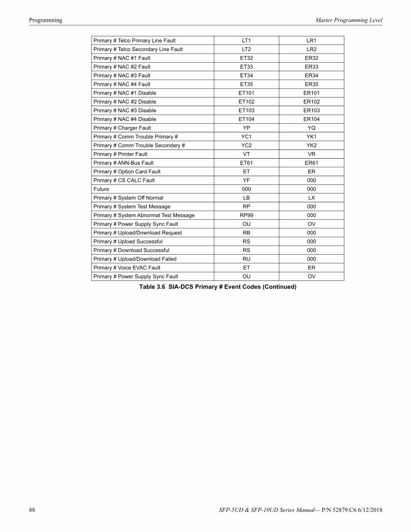
Programming Master Programming Level
Primary # Telco Primary Line Fault LT1 LR1
Primary # Telco Secondary Line Fault LT2 LR2
Primary # NAC #1 Fault ET32 ER32
Primary # NAC #2 Fault ET33 ER33
Primary # NAC #3 Fault ET34 ER34
Primary # NAC #4 Fault ET35 ER35
Primary # NAC #1 Disable ET101 ER101
Primary # NAC #2 Disable ET102 ER102
Primary # NAC #3 Disable ET103 ER103
Primary # NAC #4 Disable ET104 ER104
Primary # Charger Fault YP YQ
Primary # Comm Trouble Primary # YC1 YK1
Primary # Comm Trouble Secondary # YC2 YK2
Primary # Printer Fault VT VR
Primary # ANN-Bus Fault ET61 ER61
Primary # Option Card Fault ET ER
Primary # CS CALC Fault YF 000
Future 000 000
Primary # System Off Normal LB LX
Primary # System Test Message RP 000
Primary # System Abnormal Test Message RP99 000
Primary # Power Supply Sync Fault OU OV
Primary # Upload/Download Request RB 000
Primary # Upload Successful RS 000
Primary # Download Successful RS 000
Primary # Upload/Download Failed RU 000
Primary # Voice EVAC Fault ET ER
Primary # Power Supply Sync Fault OU OV
Table 3.6 SIA-DCS Primary # Event Codes (Continued)
88 SFP-5UD & SFP-10UD Series Manual— P/N 52879:C6 6/12/2018
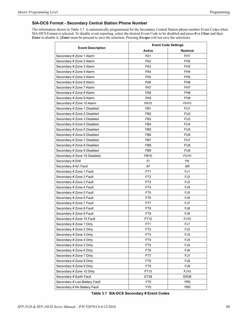
Master Programming Level Programming
SIA-DCS Format - Secondary Central Station Phone Number
The information shown in Table 3.7 is automatically programmed for the Secondary Central Station phone number Event Codes when SIA-DCS Format is selected. To disable event reporting, select the desired Event Code to be disabled and press 0 or Clear and then Enter to disable it. (Enter must be pressed to save the selection. Pressing Escape will not save the selection).
Event DescriptionEvent Code Settings
Active Restoral
Secondary # Zone 1 Alarm FA1 FH1
Secondary # Zone 2 Alarm FA2 FH2
Secondary # Zone 3 Alarm FA3 FH3
Secondary # Zone 4 Alarm FA4 FH4
Secondary # Zone 5 Alarm FA5 FH5
Secondary # Zone 6 Alarm FA6 FH6
Secondary # Zone 7 Alarm FA7 FH7
Secondary # Zone 8 Alarm FA8 FH8
Secondary # Zone 9 Alarm FA9 FH9
Secondary # Zone 10 Alarm FA10 FH10
Secondary # Zone 1 Disabled FB1 FU1
Secondary # Zone 2 Disabled FB2 FU2
Secondary # Zone 3 Disabled FB3 FU3
Secondary # Zone 4 Disabled FB4 FU4
Secondary # Zone 5 Disabled FB5 FU5
Secondary # Zone 6 Disabled FB6 FU6
Secondary # Zone 7 Disabled FB7 FU7
Secondary # Zone 8 Disabled FB8 FU8
Secondary # Zone 9 Disabled FB9 FU9
Secondary # Zone 10 Disabled FB10 FU10
Secondary # Drill FI FK
Secondary # AC Fault AT AR
Secondary # Zone 1 Fault FT1 FJ1
Secondary # Zone 2 Fault FT2 FJ2
Secondary # Zone 3 Fault FT3 FJ3
Secondary # Zone 4 Fault FT4 FJ4
Secondary # Zone 5 Fault FT5 FJ5
Secondary # Zone 6 Fault FT6 FJ6
Secondary # Zone 7 Fault FT7 FJ7
Secondary # Zone 8 Fault FT8 FJ8
Secondary # Zone 9 Fault FT9 FJ9
Secondary # Zone 10 Fault FT10 FJ10
Secondary # Zone 1 Dirty FT1 FJ1
Secondary # Zone 2 Dirty FT2 FJ2
Secondary # Zone 3 Dirty FT3 FJ3
Secondary # Zone 4 Dirty FT4 FJ4
Secondary # Zone 5 Dirty FT5 FJ5
Secondary # Zone 6 Dirty FT6 FJ6
Secondary # Zone 7 Dirty FT7 FJ7
Secondary # Zone 8 Dirty FT8 FJ8
Secondary # Zone 9 Dirty FT9 FJ9
Secondary # Zone 10 Dirty FT10 FJ10
Secondary # Earth Fault ET38 ER38
Secondary # Low Battery Fault YT0 YR0
Secondary # No Battery Fault YT0 YR0
Table 3.7 SIA-DCS Secondary # Event Codes
SFP-5UD & SFP-10UD Series Manual— P/N 52879:C6 6/12/2018 89
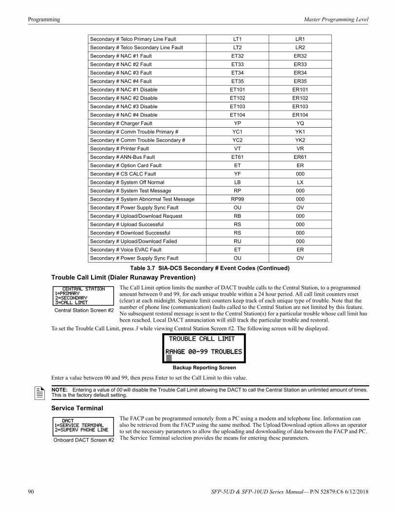
Programming Master Programming Level
Trouble Call Limit (Dialer Runaway Prevention)
The Call Limit option limits the number of DACT trouble calls to the Central Station, to a programmed amount between 0 and 99, for each unique trouble within a 24 hour period. All call limit counters reset (clear) at each midnight. Separate limit counters keep track of each unique type of trouble. Note that the number of phone line (communication) faults called to the Central Station are not limited by this feature. No subsequent restoral message is sent to the Central Station(s) for a particular trouble whose call limit has been reached. Local DACT annunciation will still track the particular trouble and restoral.
To set the Trouble Call Limit, press 3 while viewing Central Station Screen #2. The following screen will be displayed.
Enter a value between 00 and 99, then press Enter to set the Call Limit to this value.
Service Terminal
The FACP can be programmed remotely from a PC using a modem and telephone line. Information can also be retrieved from the FACP using the same method. The Upload/Download option allows an operator to set the necessary parameters to allow the uploading and downloading of data between the FACP and PC. The Service Terminal selection provides the means for entering these parameters.
Secondary # Telco Primary Line Fault LT1 LR1
Secondary # Telco Secondary Line Fault LT2 LR2
Secondary # NAC #1 Fault ET32 ER32
Secondary # NAC #2 Fault ET33 ER33
Secondary # NAC #3 Fault ET34 ER34
Secondary # NAC #4 Fault ET35 ER35
Secondary # NAC #1 Disable ET101 ER101
Secondary # NAC #2 Disable ET102 ER102
Secondary # NAC #3 Disable ET103 ER103
Secondary # NAC #4 Disable ET104 ER104
Secondary # Charger Fault YP YQ
Secondary # Comm Trouble Primary # YC1 YK1
Secondary # Comm Trouble Secondary # YC2 YK2
Secondary # Printer Fault VT VR
Secondary # ANN-Bus Fault ET61 ER61
Secondary # Option Card Fault ET ER
Secondary # CS CALC Fault YF 000
Secondary # System Off Normal LB LX
Secondary # System Test Message RP 000
Secondary # System Abnormal Test Message RP99 000
Secondary # Power Supply Sync Fault OU OV
Secondary # Upload/Download Request RB 000
Secondary # Upload Successful RS 000
Secondary # Download Successful RS 000
Secondary # Upload/Download Failed RU 000
Secondary # Voice EVAC Fault ET ER
Secondary # Power Supply Sync Fault OU OV
Table 3.7 SIA-DCS Secondary # Event Codes (Continued)
CENTRAL STATION1=PRIMARY2=SECONDARY3=CALL LIMIT
Central Station Screen #2
TROUBLE CALL LIMIT
RANGE 00-99 TROUBLES
Backup Reporting Screen
NOTE: Entering a value of 00 will disable the Trouble Call Limit allowing the DACT to call the Central Station an unlimited amount of times. This is the factory default setting.
DACT1=SERVICE TERMINAL2=SUPERV PHONE LINE
Onboard DACT Screen #2
90 SFP-5UD & SFP-10UD Series Manual— P/N 52879:C6 6/12/2018
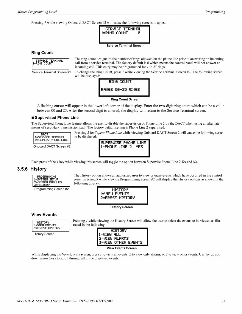
Master Programming Level Programming
Pressing 1 while viewing Onboard DACT Screen #2 will cause the following screens to appear:
Ring Count
The ring count designates the number of rings allowed on the phone line prior to answering an incoming call from a service terminal. The factory default is 0 which means the control panel will not answer an incoming call. This entry may be programmed for 1 to 25 rings.
To change the Ring Count, press 1 while viewing the Service Terminal Screen #2. The following screen will be displayed:
A flashing cursor will appear in the lower left corner of the display. Enter the two-digit ring count which can be a value between 00 and 25. After the second digit is entered, the display will return to the Service Terminal screen.
Supervised Phone Line
The Supervised Phone Line feature allows the user to disable the supervision of Phone Line 2 by the DACT when using an alternate means of secondary transmission path. The factory default setting is Phone Line 2 supervised.
Pressing 2 for Superv Phone Line while viewing Onboard DACT Screen 2 will cause the following screen to be displayed:
Each press of the 1 key while viewing this screen will toggle the option between Supervise Phone Line 2 Yes and No.
3.5.6 HistoryThe History option allows an authorized user to view or erase events which have occurred in the control panel. Pressing 3 while viewing Programming Screen #2 will display the History options as shown in the following display:
View EventsPressing 1 while viewing the History Screen will allow the user to select the events to be viewed as illus-trated in the following:
While displaying the View Events screen, press 1 to view all events, 2 to view only alarms, or 3 to view other events. Use the up and down arrow keys to scroll through all of the displayed events.
SERVICE TERMINAL1=RING COUNT 0
Service Terminal Screen
SERVICE TERMINAL1=RING COUNT
Service Terminal Screen #2
RING COUNT
RANGE 00-25 RINGS
Ring Count Screen
DACT1=SERVICE TERMINAL2=SUPERV PHONE LINE
Onboard DACT Screen #2SUPERVISE PHONE LINE
1=PHONE LINE 2 YES
PROGRAMMING1=SYSTEM SETUP2=OPTION MODULES3=HISTORY
Programming Screen #2 HISTORY
1=VIEW EVENTS2=ERASE HISTORY
History Screen
HISTORY1=VIEW EVENTS2=ERASE HISTORY
History Screen HISTORY1=VIEW ALL
2=VIEW ALARMS
3=VIEW OTHER EVENTS
View Events Screen
SFP-5UD & SFP-10UD Series Manual— P/N 52879:C6 6/12/2018 91
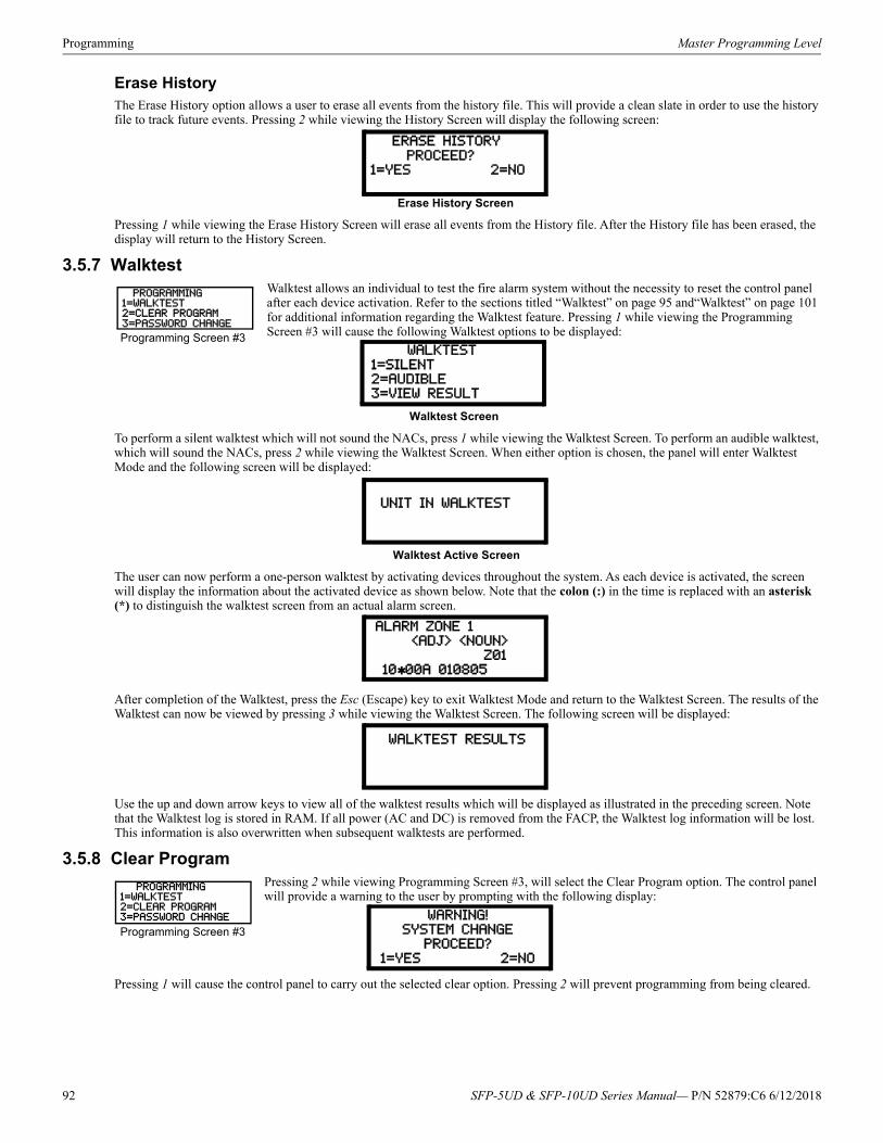
Programming Master Programming Level
Erase HistoryThe Erase History option allows a user to erase all events from the history file. This will provide a clean slate in order to use the history file to track future events. Pressing 2 while viewing the History Screen will display the following screen:
Pressing 1 while viewing the Erase History Screen will erase all events from the History file. After the History file has been erased, the display will return to the History Screen.
3.5.7 WalktestWalktest allows an individual to test the fire alarm system without the necessity to reset the control panel after each device activation. Refer to the sections titled “Walktest” on page 95 and“Walktest” on page 101 for additional information regarding the Walktest feature. Pressing 1 while viewing the Programming Screen #3 will cause the following Walktest options to be displayed:
To perform a silent walktest which will not sound the NACs, press 1 while viewing the Walktest Screen. To perform an audible walktest, which will sound the NACs, press 2 while viewing the Walktest Screen. When either option is chosen, the panel will enter Walktest Mode and the following screen will be displayed:
The user can now perform a one-person walktest by activating devices throughout the system. As each device is activated, the screen will display the information about the activated device as shown below. Note that the colon (:) in the time is replaced with an asterisk (*) to distinguish the walktest screen from an actual alarm screen.
After completion of the Walktest, press the Esc (Escape) key to exit Walktest Mode and return to the Walktest Screen. The results of the Walktest can now be viewed by pressing 3 while viewing the Walktest Screen. The following screen will be displayed:
Use the up and down arrow keys to view all of the walktest results which will be displayed as illustrated in the preceding screen. Note that the Walktest log is stored in RAM. If all power (AC and DC) is removed from the FACP, the Walktest log information will be lost. This information is also overwritten when subsequent walktests are performed.
3.5.8 Clear ProgramPressing 2 while viewing Programming Screen #3, will select the Clear Program option. The control panel will provide a warning to the user by prompting with the following display:
Pressing 1 will cause the control panel to carry out the selected clear option. Pressing 2 will prevent programming from being cleared.
ERASE HISTORY
PROCEED?1=YES 2=NO
Erase History Screen
PROGRAMMING1=WALKTEST2=CLEAR PROGRAM3=PASSWORD CHANGE
Programming Screen #3 WALKTEST
1=SILENT
2=AUDIBLE3=VIEW RESULT
Walktest Screen
UNIT IN WALKTEST
Walktest Active Screen
ALARM ZONE 1
<ADJ> <NOUN>
Z01 1000A 010805
WALKTEST RESULTS
PROGRAMMING1=WALKTEST2=CLEAR PROGRAM3=PASSWORD CHANGE
Programming Screen #3WARNING!
SYSTEM CHANGE
PROCEED?
1=YES 2=NO
92 SFP-5UD & SFP-10UD Series Manual— P/N 52879:C6 6/12/2018
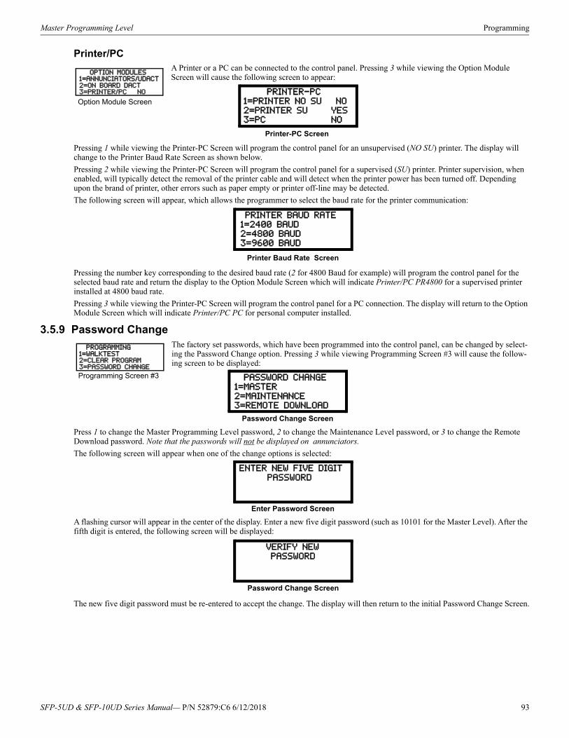
Master Programming Level Programming
Printer/PCA Printer or a PC can be connected to the control panel. Pressing 3 while viewing the Option Module Screen will cause the following screen to appear:
Pressing 1 while viewing the Printer-PC Screen will program the control panel for an unsupervised (NO SU) printer. The display will change to the Printer Baud Rate Screen as shown below.
Pressing 2 while viewing the Printer-PC Screen will program the control panel for a supervised (SU) printer. Printer supervision, when enabled, will typically detect the removal of the printer cable and will detect when the printer power has been turned off. Depending upon the brand of printer, other errors such as paper empty or printer off-line may be detected.
The following screen will appear, which allows the programmer to select the baud rate for the printer communication:
Pressing the number key corresponding to the desired baud rate (2 for 4800 Baud for example) will program the control panel for the selected baud rate and return the display to the Option Module Screen which will indicate Printer/PC PR4800 for a supervised printer installed at 4800 baud rate.
Pressing 3 while viewing the Printer-PC Screen will program the control panel for a PC connection. The display will return to the Option Module Screen which will indicate Printer/PC PC for personal computer installed.
3.5.9 Password Change The factory set passwords, which have been programmed into the control panel, can be changed by select-ing the Password Change option. Pressing 3 while viewing Programming Screen #3 will cause the follow-ing screen to be displayed:
Press 1 to change the Master Programming Level password, 2 to change the Maintenance Level password, or 3 to change the Remote Download password. Note that the passwords will not be displayed on annunciators.
The following screen will appear when one of the change options is selected:
A flashing cursor will appear in the center of the display. Enter a new five digit password (such as 10101 for the Master Level). After the fifth digit is entered, the following screen will be displayed:
The new five digit password must be re-entered to accept the change. The display will then return to the initial Password Change Screen.
OPTION MODULES1=ANNUNCIATORS/UDACT2=ON BOARD DACT3=PRINTER/PC NO
Option Module Screen PRINTER-PC
1=PRINTER NO SU NO
2=PRINTER SU YES3=PC NO
Printer-PC Screen
PRINTER BAUD RATE
1=2400 BAUD
2=4800 BAUD3=9600 BAUD
Printer Baud Rate Screen
PROGRAMMING1=WALKTEST2=CLEAR PROGRAM3=PASSWORD CHANGE
Programming Screen #3 PASSWORD CHANGE
1=MASTER
2=MAINTENANCE3=REMOTE DOWNLOAD
Password Change Screen
ENTER NEW FIVE DIGIT
PASSWORD
Enter Password Screen
VERIFY NEW
PASSWORD
Password Change Screen
SFP-5UD & SFP-10UD Series Manual— P/N 52879:C6 6/12/2018 93
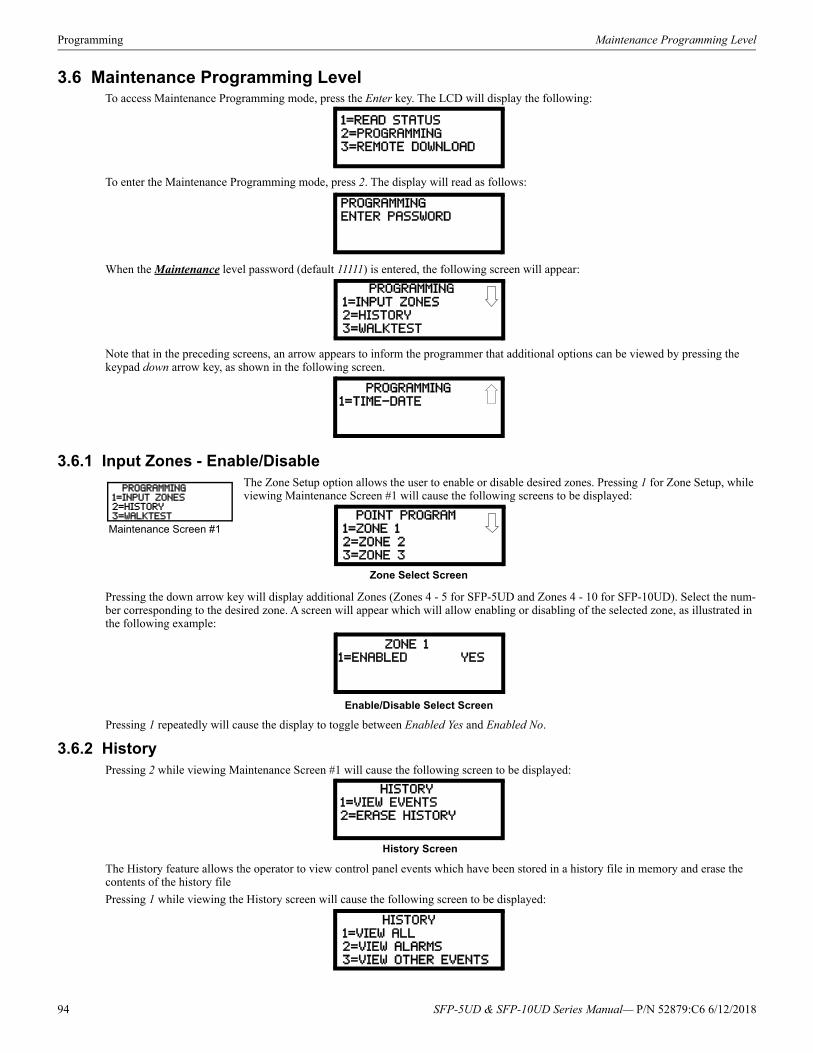
Programming Maintenance Programming Level
3.6 Maintenance Programming LevelTo access Maintenance Programming mode, press the Enter key. The LCD will display the following:
To enter the Maintenance Programming mode, press 2. The display will read as follows:
When the Maintenance level password (default 11111) is entered, the following screen will appear:
Note that in the preceding screens, an arrow appears to inform the programmer that additional options can be viewed by pressing the keypad down arrow key, as shown in the following screen.
3.6.1 Input Zones - Enable/DisableThe Zone Setup option allows the user to enable or disable desired zones. Pressing 1 for Zone Setup, while viewing Maintenance Screen #1 will cause the following screens to be displayed:
Pressing the down arrow key will display additional Zones (Zones 4 - 5 for SFP-5UD and Zones 4 - 10 for SFP-10UD). Select the num-ber corresponding to the desired zone. A screen will appear which will allow enabling or disabling of the selected zone, as illustrated in the following example:
Pressing 1 repeatedly will cause the display to toggle between Enabled Yes and Enabled No.
3.6.2 HistoryPressing 2 while viewing Maintenance Screen #1 will cause the following screen to be displayed:
The History feature allows the operator to view control panel events which have been stored in a history file in memory and erase the contents of the history file
Pressing 1 while viewing the History screen will cause the following screen to be displayed:
1=READ STATUS
2=PROGRAMMING3=REMOTE DOWNLOAD
PROGRAMMINGENTER PASSWORD
PROGRAMMING
1=INPUT ZONES
2=HISTORY
3=WALKTEST
PROGRAMMING
1=TIME-DATE
PROGRAMMING1=INPUT ZONES2=HISTORY3=WALKTEST
Maintenance Screen #1 POINT PROGRAM
1=ZONE 12=ZONE 2
3=ZONE 3
Zone Select Screen
ZONE 11=ENABLED YES
Enable/Disable Select Screen
HISTORY
1=VIEW EVENTS2=ERASE HISTORY
History Screen
HISTORY
1=VIEW ALL
2=VIEW ALARMS3=VIEW OTHER EVENTS
94 SFP-5UD & SFP-10UD Series Manual— P/N 52879:C6 6/12/2018
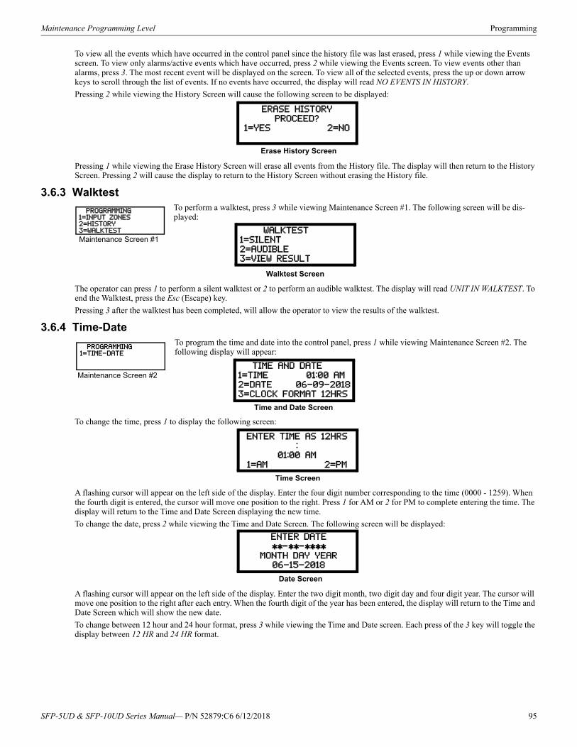
Maintenance Programming Level Programming
To view all the events which have occurred in the control panel since the history file was last erased, press 1 while viewing the Events screen. To view only alarms/active events which have occurred, press 2 while viewing the Events screen. To view events other than alarms, press 3. The most recent event will be displayed on the screen. To view all of the selected events, press the up or down arrow keys to scroll through the list of events. If no events have occurred, the display will read NO EVENTS IN HISTORY.
Pressing 2 while viewing the History Screen will cause the following screen to be displayed:
Pressing 1 while viewing the Erase History Screen will erase all events from the History file. The display will then return to the History Screen. Pressing 2 will cause the display to return to the History Screen without erasing the History file.
3.6.3 Walktest To perform a walktest, press 3 while viewing Maintenance Screen #1. The following screen will be dis-played:
The operator can press 1 to perform a silent walktest or 2 to perform an audible walktest. The display will read UNIT IN WALKTEST. To end the Walktest, press the Esc (Escape) key.
Pressing 3 after the walktest has been completed, will allow the operator to view the results of the walktest.
3.6.4 Time-DateTo program the time and date into the control panel, press 1 while viewing Maintenance Screen #2. The following display will appear:
To change the time, press 1 to display the following screen:
A flashing cursor will appear on the left side of the display. Enter the four digit number corresponding to the time (0000 - 1259). When the fourth digit is entered, the cursor will move one position to the right. Press 1 for AM or 2 for PM to complete entering the time. The display will return to the Time and Date Screen displaying the new time.
To change the date, press 2 while viewing the Time and Date Screen. The following screen will be displayed:
A flashing cursor will appear on the left side of the display. Enter the two digit month, two digit day and four digit year. The cursor will move one position to the right after each entry. When the fourth digit of the year has been entered, the display will return to the Time and Date Screen which will show the new date.
To change between 12 hour and 24 hour format, press 3 while viewing the Time and Date screen. Each press of the 3 key will toggle the display between 12 HR and 24 HR format.
ERASE HISTORY
PROCEED?1=YES 2=NO
Erase History Screen
PROGRAMMING1=INPUT ZONES2=HISTORY3=WALKTEST
Maintenance Screen #1 WALKTEST
1=SILENT
2=AUDIBLE3=VIEW RESULT
Walktest Screen
PROGRAMMING1=TIME-DATE
Maintenance Screen #2 TIME AND DATE1=TIME 01:00 AM
2=DATE 06-09-2018
3=CLOCK FORMAT 12HRS
Time and Date Screen
ENTER TIME AS 12HRS
:01:00 AM
1=AM 2=PM
Time Screen
ENTER DATE
--MONTH DAY YEAR
06-15-2018
Date Screen
SFP-5UD & SFP-10UD Series Manual— P/N 52879:C6 6/12/2018 95
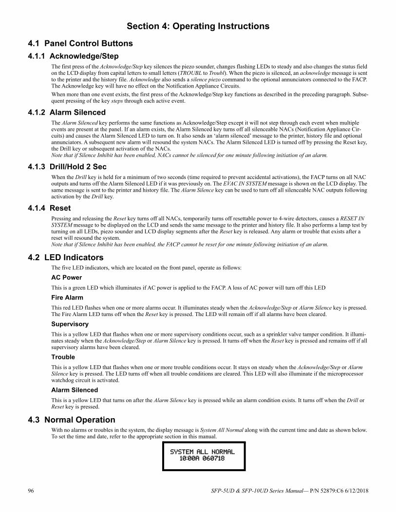
Section 4: Operating Instructions
4.1 Panel Control Buttons
4.1.1 Acknowledge/StepThe first press of the Acknowledge/Step key silences the piezo sounder, changes flashing LEDs to steady and also changes the status field on the LCD display from capital letters to small letters (TROUBL to Troubl). When the piezo is silenced, an acknowledge message is sent to the printer and the history file. Acknowledge also sends a silence piezo command to the optional annunciators connected to the FACP. The Acknowledge key will have no effect on the Notification Appliance Circuits.
When more than one event exists, the first press of the Acknowledge/Step key functions as described in the preceding paragraph. Subse-quent pressing of the key steps through each active event.
4.1.2 Alarm SilencedThe Alarm Silenced key performs the same functions as Acknowledge/Step except it will not step through each event when multiple events are present at the panel. If an alarm exists, the Alarm Silenced key turns off all silenceable NACs (Notification Appliance Cir-cuits) and causes the Alarm Silenced LED to turn on. It also sends an ‘alarm silenced’ message to the printer, history file and optional annunciators. A subsequent new alarm will resound the system NACs. The Alarm Silenced LED is turned off by pressing the Reset key, the Drill key or subsequent activation of the NACs. Note that if Silence Inhibit has been enabled, NACs cannot be silenced for one minute following initiation of an alarm.
4.1.3 Drill/Hold 2 SecWhen the Drill key is held for a minimum of two seconds (time required to prevent accidental activations), the FACP turns on all NAC outputs and turns off the Alarm Silenced LED if it was previously on. The EVAC IN SYSTEM message is shown on the LCD display. The same message is sent to the printer and history file. The Alarm Silence key can be used to turn off all silenceable NAC outputs following activation by the Drill key.
4.1.4 ResetPressing and releasing the Reset key turns off all NACs, temporarily turns off resettable power to 4-wire detectors, causes a RESET IN SYSTEM message to be displayed on the LCD and sends the same message to the printer and history file. It also performs a lamp test by turning on all LEDs, piezo sounder and LCD display segments after the Reset key is released. Any alarm or trouble that exists after a reset will resound the system.Note that if Silence Inhibit has been enabled, the FACP cannot be reset for one minute following initiation of an alarm.
4.2 LED IndicatorsThe five LED indicators, which are located on the front panel, operate as follows:
AC Power
This is a green LED which illuminates if AC power is applied to the FACP. A loss of AC power will turn off this LED
Fire Alarm
This red LED flashes when one or more alarms occur. It illuminates steady when the Acknowledge/Step or Alarm Silence key is pressed. The Fire Alarm LED turns off when the Reset key is pressed. The LED will remain off if all alarms have been cleared.
Supervisory
This is a yellow LED that flashes when one or more supervisory conditions occur, such as a sprinkler valve tamper condition. It illumi-nates steady when the Acknowledge/Step or Alarm Silence key is pressed. It turns off when the Reset key is pressed and remains off if all supervisory alarms have been cleared.
Trouble
This is a yellow LED that flashes when one or more trouble conditions occur. It stays on steady when the Acknowledge/Step or Alarm Silence key is pressed. The LED turns off when all trouble conditions are cleared. This LED will also illuminate if the microprocessor watchdog circuit is activated.
Alarm Silenced
This is a yellow LED that turns on after the Alarm Silence key is pressed while an alarm condition exists. It turns off when the Drill or Reset key is pressed.
4.3 Normal OperationWith no alarms or troubles in the system, the display message is System All Normal along with the current time and date as shown below. To set the time and date, refer to the appropriate section in this manual.
SYSTEM ALL NORMAL 10:00A 060718
96 SFP-5UD & SFP-10UD Series Manual— P/N 52879:C6 6/12/2018
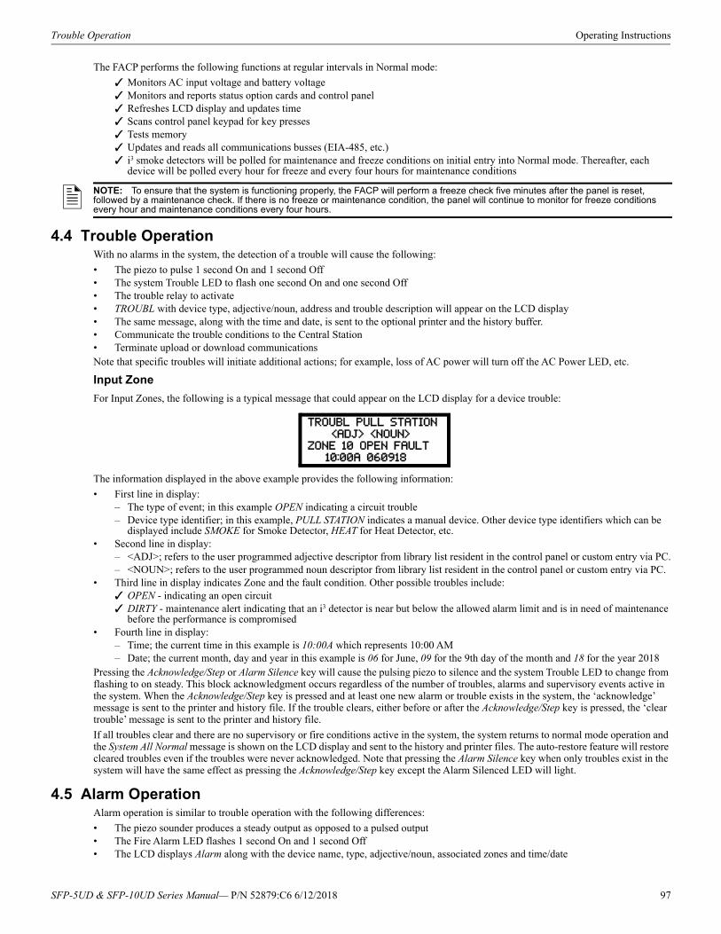
Trouble Operation Operating Instructions
The FACP performs the following functions at regular intervals in Normal mode:
Monitors AC input voltage and battery voltage Monitors and reports status option cards and control panel Refreshes LCD display and updates time Scans control panel keypad for key presses Tests memory Updates and reads all communications busses (EIA-485, etc.) i3 smoke detectors will be polled for maintenance and freeze conditions on initial entry into Normal mode. Thereafter, each
device will be polled every hour for freeze and every four hours for maintenance conditions
4.4 Trouble OperationWith no alarms in the system, the detection of a trouble will cause the following:
• The piezo to pulse 1 second On and 1 second Off• The system Trouble LED to flash one second On and one second Off• The trouble relay to activate• TROUBL with device type, adjective/noun, address and trouble description will appear on the LCD display• The same message, along with the time and date, is sent to the optional printer and the history buffer. • Communicate the trouble conditions to the Central Station• Terminate upload or download communicationsNote that specific troubles will initiate additional actions; for example, loss of AC power will turn off the AC Power LED, etc.
Input Zone
For Input Zones, the following is a typical message that could appear on the LCD display for a device trouble:
The information displayed in the above example provides the following information:
• First line in display:– The type of event; in this example OPEN indicating a circuit trouble– Device type identifier; in this example, PULL STATION indicates a manual device. Other device type identifiers which can be
displayed include SMOKE for Smoke Detector, HEAT for Heat Detector, etc. • Second line in display:
– <ADJ>; refers to the user programmed adjective descriptor from library list resident in the control panel or custom entry via PC.– <NOUN>; refers to the user programmed noun descriptor from library list resident in the control panel or custom entry via PC.
• Third line in display indicates Zone and the fault condition. Other possible troubles include: OPEN - indicating an open circuit DIRTY - maintenance alert indicating that an i3 detector is near but below the allowed alarm limit and is in need of maintenance
before the performance is compromised• Fourth line in display:
– Time; the current time in this example is 10:00A which represents 10:00 AM– Date; the current month, day and year in this example is 06 for June, 09 for the 9th day of the month and 18 for the year 2018
Pressing the Acknowledge/Step or Alarm Silence key will cause the pulsing piezo to silence and the system Trouble LED to change from flashing to on steady. This block acknowledgment occurs regardless of the number of troubles, alarms and supervisory events active in the system. When the Acknowledge/Step key is pressed and at least one new alarm or trouble exists in the system, the ‘acknowledge’ message is sent to the printer and history file. If the trouble clears, either before or after the Acknowledge/Step key is pressed, the ‘clear trouble’ message is sent to the printer and history file.
If all troubles clear and there are no supervisory or fire conditions active in the system, the system returns to normal mode operation and the System All Normal message is shown on the LCD display and sent to the history and printer files. The auto-restore feature will restore cleared troubles even if the troubles were never acknowledged. Note that pressing the Alarm Silence key when only troubles exist in the system will have the same effect as pressing the Acknowledge/Step key except the Alarm Silenced LED will light.
4.5 Alarm OperationAlarm operation is similar to trouble operation with the following differences:
• The piezo sounder produces a steady output as opposed to a pulsed output• The Fire Alarm LED flashes 1 second On and 1 second Off• The LCD displays Alarm along with the device name, type, adjective/noun, associated zones and time/date
NOTE: To ensure that the system is functioning properly, the FACP will perform a freeze check five minutes after the panel is reset, followed by a maintenance check. If there is no freeze or maintenance condition, the panel will continue to monitor for freeze conditions every hour and maintenance conditions every four hours.
TROUBL PULL STATION
<ADJ> <NOUN>ZONE 10 OPEN FAULT
10:00A 060918
SFP-5UD & SFP-10UD Series Manual— P/N 52879:C6 6/12/2018 97
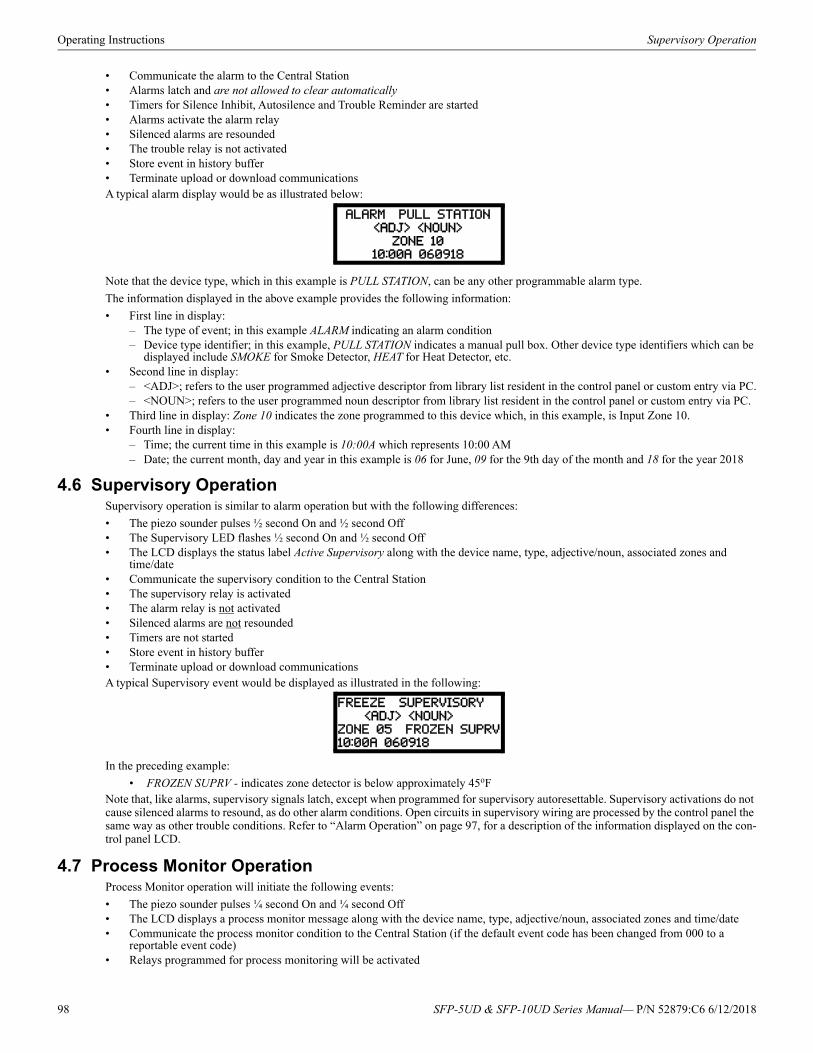
Operating Instructions Supervisory Operation
• Communicate the alarm to the Central Station• Alarms latch and are not allowed to clear automatically• Timers for Silence Inhibit, Autosilence and Trouble Reminder are started• Alarms activate the alarm relay• Silenced alarms are resounded• The trouble relay is not activated• Store event in history buffer• Terminate upload or download communicationsA typical alarm display would be as illustrated below:
Note that the device type, which in this example is PULL STATION, can be any other programmable alarm type.
The information displayed in the above example provides the following information:
• First line in display:– The type of event; in this example ALARM indicating an alarm condition– Device type identifier; in this example, PULL STATION indicates a manual pull box. Other device type identifiers which can be
displayed include SMOKE for Smoke Detector, HEAT for Heat Detector, etc. • Second line in display:
– <ADJ>; refers to the user programmed adjective descriptor from library list resident in the control panel or custom entry via PC.– <NOUN>; refers to the user programmed noun descriptor from library list resident in the control panel or custom entry via PC.
• Third line in display: Zone 10 indicates the zone programmed to this device which, in this example, is Input Zone 10. • Fourth line in display:
– Time; the current time in this example is 10:00A which represents 10:00 AM– Date; the current month, day and year in this example is 06 for June, 09 for the 9th day of the month and 18 for the year 2018
4.6 Supervisory OperationSupervisory operation is similar to alarm operation but with the following differences:
• The piezo sounder pulses ½ second On and ½ second Off• The Supervisory LED flashes ½ second On and ½ second Off• The LCD displays the status label Active Supervisory along with the device name, type, adjective/noun, associated zones and
time/date• Communicate the supervisory condition to the Central Station• The supervisory relay is activated• The alarm relay is not activated• Silenced alarms are not resounded• Timers are not started• Store event in history buffer• Terminate upload or download communicationsA typical Supervisory event would be displayed as illustrated in the following:
In the preceding example:
• FROZEN SUPRV - indicates zone detector is below approximately 45oFNote that, like alarms, supervisory signals latch, except when programmed for supervisory autoresettable. Supervisory activations do not cause silenced alarms to resound, as do other alarm conditions. Open circuits in supervisory wiring are processed by the control panel the same way as other trouble conditions. Refer to “Alarm Operation” on page 97, for a description of the information displayed on the con-trol panel LCD.
4.7 Process Monitor OperationProcess Monitor operation will initiate the following events:
• The piezo sounder pulses ¼ second On and ¼ second Off• The LCD displays a process monitor message along with the device name, type, adjective/noun, associated zones and time/date• Communicate the process monitor condition to the Central Station (if the default event code has been changed from 000 to a
reportable event code)• Relays programmed for process monitoring will be activated
ALARM PULL STATION
<ADJ> <NOUN>ZONE 10
10:00A 060918
FREEZE SUPERVISORY
<ADJ> <NOUN>
ZONE 05 FROZEN SUPRV
10:00A 060918
98 SFP-5UD & SFP-10UD Series Manual— P/N 52879:C6 6/12/2018
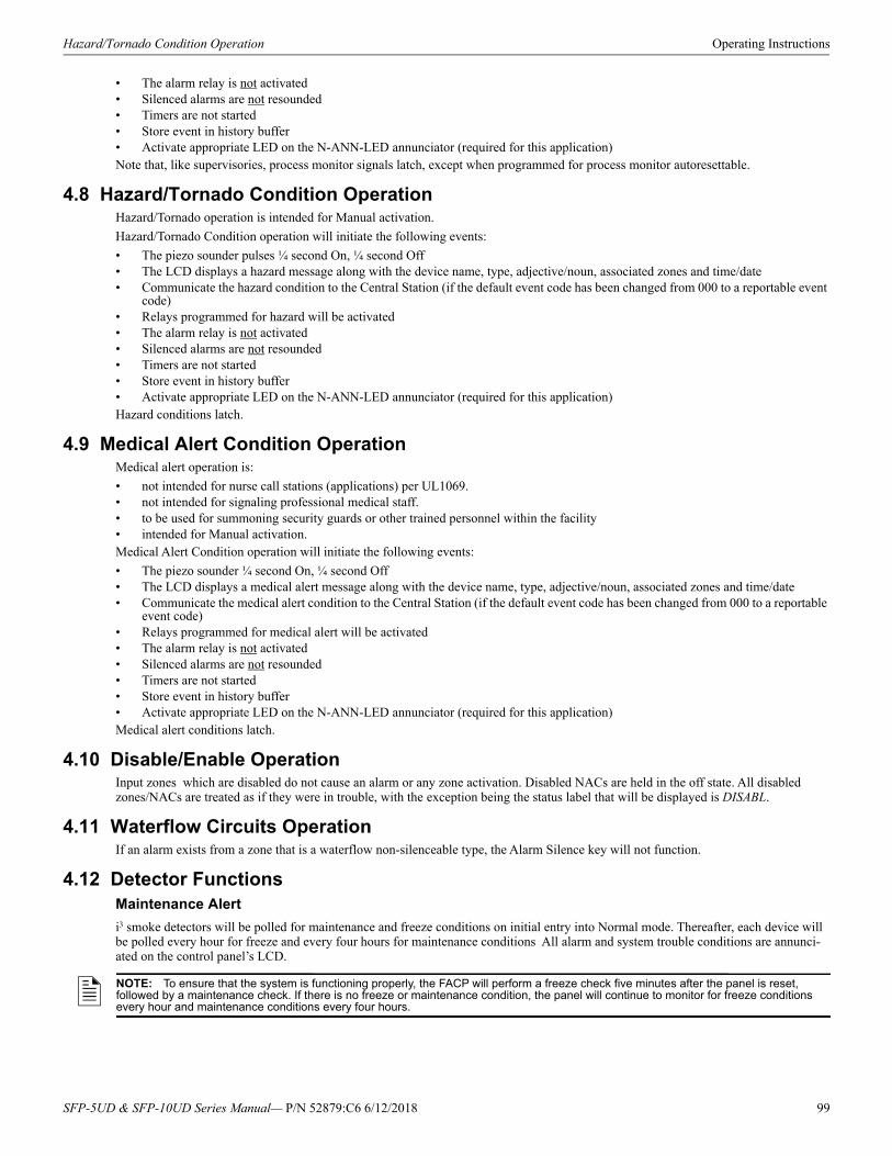
Hazard/Tornado Condition Operation Operating Instructions
• The alarm relay is not activated• Silenced alarms are not resounded• Timers are not started• Store event in history buffer• Activate appropriate LED on the N-ANN-LED annunciator (required for this application)Note that, like supervisories, process monitor signals latch, except when programmed for process monitor autoresettable.
4.8 Hazard/Tornado Condition OperationHazard/Tornado operation is intended for Manual activation.
Hazard/Tornado Condition operation will initiate the following events:
• The piezo sounder pulses ¼ second On, ¼ second Off• The LCD displays a hazard message along with the device name, type, adjective/noun, associated zones and time/date• Communicate the hazard condition to the Central Station (if the default event code has been changed from 000 to a reportable event
code)• Relays programmed for hazard will be activated• The alarm relay is not activated• Silenced alarms are not resounded• Timers are not started• Store event in history buffer• Activate appropriate LED on the N-ANN-LED annunciator (required for this application)Hazard conditions latch.
4.9 Medical Alert Condition OperationMedical alert operation is:
• not intended for nurse call stations (applications) per UL1069. • not intended for signaling professional medical staff. • to be used for summoning security guards or other trained personnel within the facility • intended for Manual activation.Medical Alert Condition operation will initiate the following events:
• The piezo sounder ¼ second On, ¼ second Off• The LCD displays a medical alert message along with the device name, type, adjective/noun, associated zones and time/date• Communicate the medical alert condition to the Central Station (if the default event code has been changed from 000 to a reportable
event code)• Relays programmed for medical alert will be activated• The alarm relay is not activated• Silenced alarms are not resounded• Timers are not started• Store event in history buffer• Activate appropriate LED on the N-ANN-LED annunciator (required for this application)Medical alert conditions latch.
4.10 Disable/Enable OperationInput zones which are disabled do not cause an alarm or any zone activation. Disabled NACs are held in the off state. All disabled zones/NACs are treated as if they were in trouble, with the exception being the status label that will be displayed is DISABL.
4.11 Waterflow Circuits OperationIf an alarm exists from a zone that is a waterflow non-silenceable type, the Alarm Silence key will not function.
4.12 Detector FunctionsMaintenance Alert
i3 smoke detectors will be polled for maintenance and freeze conditions on initial entry into Normal mode. Thereafter, each device will be polled every hour for freeze and every four hours for maintenance conditions All alarm and system trouble conditions are annunci-ated on the control panel’s LCD.
NOTE: To ensure that the system is functioning properly, the FACP will perform a freeze check five minutes after the panel is reset, followed by a maintenance check. If there is no freeze or maintenance condition, the panel will continue to monitor for freeze conditions every hour and maintenance conditions every four hours.
SFP-5UD & SFP-10UD Series Manual— P/N 52879:C6 6/12/2018 99
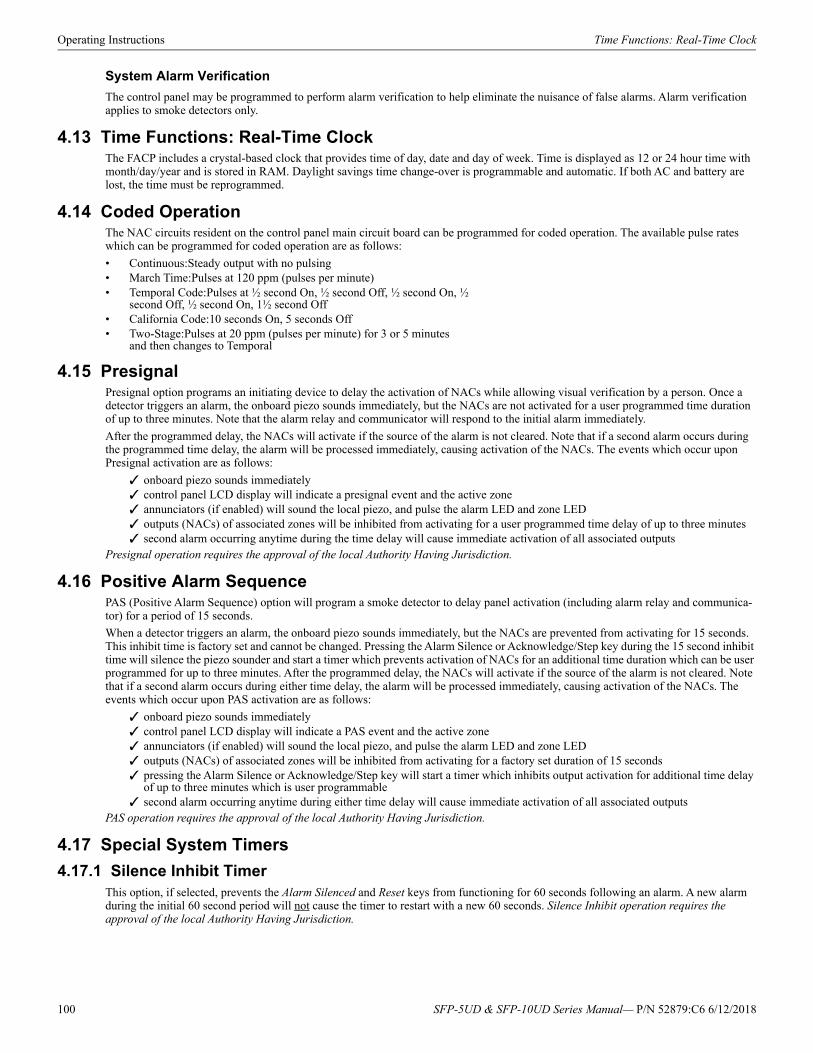
Operating Instructions Time Functions: Real-Time Clock
System Alarm Verification
The control panel may be programmed to perform alarm verification to help eliminate the nuisance of false alarms. Alarm verification applies to smoke detectors only.
4.13 Time Functions: Real-Time ClockThe FACP includes a crystal-based clock that provides time of day, date and day of week. Time is displayed as 12 or 24 hour time with month/day/year and is stored in RAM. Daylight savings time change-over is programmable and automatic. If both AC and battery are lost, the time must be reprogrammed.
4.14 Coded OperationThe NAC circuits resident on the control panel main circuit board can be programmed for coded operation. The available pulse rates which can be programmed for coded operation are as follows:
• Continuous:Steady output with no pulsing• March Time:Pulses at 120 ppm (pulses per minute)• Temporal Code:Pulses at ½ second On, ½ second Off, ½ second On, ½
second Off, ½ second On, 1½ second Off• California Code:10 seconds On, 5 seconds Off• Two-Stage:Pulses at 20 ppm (pulses per minute) for 3 or 5 minutes
and then changes to Temporal
4.15 PresignalPresignal option programs an initiating device to delay the activation of NACs while allowing visual verification by a person. Once a detector triggers an alarm, the onboard piezo sounds immediately, but the NACs are not activated for a user programmed time duration of up to three minutes. Note that the alarm relay and communicator will respond to the initial alarm immediately.
After the programmed delay, the NACs will activate if the source of the alarm is not cleared. Note that if a second alarm occurs during the programmed time delay, the alarm will be processed immediately, causing activation of the NACs. The events which occur upon Presignal activation are as follows:
onboard piezo sounds immediately control panel LCD display will indicate a presignal event and the active zone annunciators (if enabled) will sound the local piezo, and pulse the alarm LED and zone LED outputs (NACs) of associated zones will be inhibited from activating for a user programmed time delay of up to three minutes second alarm occurring anytime during the time delay will cause immediate activation of all associated outputs
Presignal operation requires the approval of the local Authority Having Jurisdiction.
4.16 Positive Alarm SequencePAS (Positive Alarm Sequence) option will program a smoke detector to delay panel activation (including alarm relay and communica-tor) for a period of 15 seconds.
When a detector triggers an alarm, the onboard piezo sounds immediately, but the NACs are prevented from activating for 15 seconds. This inhibit time is factory set and cannot be changed. Pressing the Alarm Silence or Acknowledge/Step key during the 15 second inhibit time will silence the piezo sounder and start a timer which prevents activation of NACs for an additional time duration which can be user programmed for up to three minutes. After the programmed delay, the NACs will activate if the source of the alarm is not cleared. Note that if a second alarm occurs during either time delay, the alarm will be processed immediately, causing activation of the NACs. The events which occur upon PAS activation are as follows:
onboard piezo sounds immediately control panel LCD display will indicate a PAS event and the active zone annunciators (if enabled) will sound the local piezo, and pulse the alarm LED and zone LED outputs (NACs) of associated zones will be inhibited from activating for a factory set duration of 15 seconds pressing the Alarm Silence or Acknowledge/Step key will start a timer which inhibits output activation for additional time delay
of up to three minutes which is user programmable second alarm occurring anytime during either time delay will cause immediate activation of all associated outputs
PAS operation requires the approval of the local Authority Having Jurisdiction.
4.17 Special System Timers
4.17.1 Silence Inhibit TimerThis option, if selected, prevents the Alarm Silenced and Reset keys from functioning for 60 seconds following an alarm. A new alarm during the initial 60 second period will not cause the timer to restart with a new 60 seconds. Silence Inhibit operation requires the approval of the local Authority Having Jurisdiction.
100 SFP-5UD & SFP-10UD Series Manual— P/N 52879:C6 6/12/2018
Walktest Operating Instructions
4.17.2 Autosilence TimerIf Autosilence is selected, the notification appliances, programmed as silenceable, will automatically be silenced after a programmable duration of from 5 to 30 minutes. Pressing the Drill key will restart the timer. Autosilence operation requires the approval of the local Authority Having Jurisdiction.
4.17.3 Trouble ReminderIf selected, this feature causes a reminding ‘beep’ every 15 seconds during an alarm (after the Alarm Silence key is pressed) and every two minutes during a trouble condition (after the Acknowledge/Step or Alarm Silence key is pressed). The ‘beeps’ from the onboard piezo sounder will occur until the alarm or fault is cleared.
Note that if Trouble Reminder feature is not selected and the trouble is not cleared within 24 hours, the piezo will resound, indicating that the trouble condition still exists.
4.17.4 Waterflow Retard TimerIf selected, this option will delay the activation of a waterflow type alarm for a programmable time duration from 1 to 90 seconds. This delay is in addition to any time delay inherent in the waterflow device. This feature requires the approval of the local Authority Having Jurisdiction.
4.17.5 Alarm Verification (None or One Minute)If alarm verification is selected, a smoke detector activation will cause the FACP to reset the detector by removing power for 6 seconds. Power is reapplied and a 17 second retard period begins which allows all detectors to stabilize. If no other detectors alarm, there will be no alarm indication at the FACP during the 23 second Reset/Retard period. A Confirmation period of 60 seconds follows, during which a subsequent alarm from the same detector will cause the panel to immediately activate the appropriate outputs and indicate the alarm condition at the FACP. If a different detector zone alarms any time during the first detector's Retard & Confirmation period, the panel will immediately activate all appropriate outputs and indicate the alarm condition at the FACP. If no additional detector alarms occur within 83 seconds of the first alarm (23 second Reset/Retard plus 60 second Confirmation), the timer resets and the panel is ready to ver-ify any new detector alarms which may occur.
4.18 WalktestWalktest is a feature which allows one person to test the fire alarm system. An audible walktest will momentarily sound the Notification Appliance Circuits in the building and store the walktest information in a file at the panel. A silent walktest will not sound the NACs but will store the walktest information in a file which can be viewed at the panel. Disabled NAC devices will not activate during walktest. In addition, i3 smoke detectors will enter their own test mode causing their LEDs to flash twice every five seconds (refer to i3 specification document).
Alarm/Shorted Condition
When in audible Walktest, the panel responds to each new alarm and activates the NACs for four seconds. It also stores each alarm in the walktest history file which can be sent to an optional printer. The stored display will be the same as if the device actually activated except the colon (:) in the time stamp is replaced with an asterisk (*).
Open Condition
IDCs and all main circuit board NACs are monitored for fault conditions during Walktest mode. When an open condition occurs on an IDC, the FACP will activate all enabled NACs during an audible Walktest and remain activated until the open condition is cleared.
83 sec.6 sec.0 sec.
CONFIRMATION (60 seconds)RESET
Alarm Ignored Control Panel Processes Alarm if Same Detector is Still in Alarm
Control Panel Immediately Processes Alarm
Detector Alarm Verification (Reset/Retard + Confirmation)
Detector Goes Into Alarm
Different Detector Alarms During First Detector's Verification Period
23 sec.
RETARD
NOTE: Alarm Verification is available only for smoke detectors.
SFP-5UD & SFP-10UD Series Manual— P/N 52879:C6 6/12/2018 101
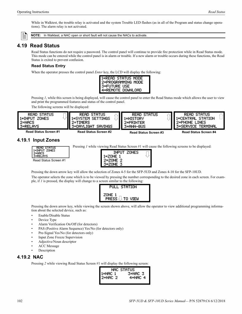
Operating Instructions Read Status
While in Walktest, the trouble relay is activated and the system Trouble LED flashes (as in all of the Program and status change opera-tions). The alarm relay is not activated.
4.19 Read StatusRead Status functions do not require a password. The control panel will continue to provide fire protection while in Read Status mode. This mode can be entered while the control panel is in alarm or trouble. If a new alarm or trouble occurs during these functions, the Read Status is exited to prevent confusion.
Read Status Entry
When the operator presses the control panel Enter key, the LCD will display the following:
Pressing 1, while this screen is being displayed, will cause the control panel to enter the Read Status mode which allows the user to view and print the programmed features and status of the control panel.
The following screens will be displayed:
4.19.1 Input ZonesPressing 1 while viewing Read Status Screen #1 will cause the following screens to be displayed:
Pressing the down arrow key will allow the selection of Zones 4-5 for the SFP-5UD and Zones 4-10 for the SFP-10UD.
The operator selects the zone which is to be viewed by pressing the number corresponding to the desired zone in each screen. For exam-ple, if 1 is pressed, the display will change to a screen similar to the following:
Pressing the down arrow key, while viewing the screen shown above, will allow the operator to view additional programming informa-tion about the selected device, such as:
• Enable/Disable Status• Device Type• Alarm Verification On/Off (for detectors)• PAS (Positive Alarm Sequence) Yes/No (for detectors only)• Pre-Signal Yes/No (for detectors only)• Input Zone Freeze Supervision• Adjective/Noun descriptor• ACC Message• Description
4.19.2 NACPressing 2 while viewing Read Status Screen #1 will display the following screen:
NOTE: In Walktest, a NAC open or short fault will not cause the NACs to activate.
1=READ STATUS MODE
2=PROGRAMMING MODE
3=FUTURE USE4=REMOTE DOWNLOAD
READ STATUS
1=INPUT ZONES
2=NACS3=RELAYS
READ STATUS
1=SYSTEM SETTINGS
2=TIMERS3=DAYLIGHT SAVINGS
Read Status Screen #1 Read Status Screen #3
READ STATUS
1=HISTORY
2=PRINTER3=ANN-BUS
Read Status Screen #2
READ STATUS1=CENTRAL STATION
2=PHONE LINES
3=SERVICE TERMINAL
Read Status Screen #4
READ STATUS1=INPUT ZONES2=NACS3=RELAYS
Read Status Screen #1
INPUT ZONES
1=ZONE 1
2=ZONE 23=ZONE 3
PULL STATION
ZONE 1
PRESS TO VIEW
NAC STATUS1=NAC 1 3=NAC 3
2=NAC 2 4=NAC 4
102 SFP-5UD & SFP-10UD Series Manual— P/N 52879:C6 6/12/2018
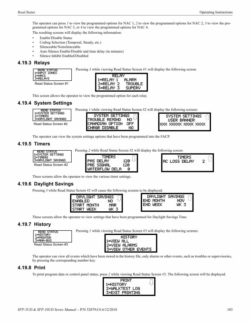
Read Status Operating Instructions
The operator can press 1 to view the programmed options for NAC 1, 2 to view the programmed options for NAC 2, 3 to view the pro-grammed options for NAC 3, or 4 to view the programmed options for NAC 4.
The resulting screens will display the following information:
• Enable/Disable Status• Coding Selection (Temporal, Steady, etc.)• Silenceable/Nonsilenceable• Auto Silence Enable/Disable and time delay (in minutes)• Silence Inhibit Enabled/Disabled
4.19.3 RelaysPressing 3 while viewing Read Status Screen #1 will display the following screen:
This screen allows the operator to view the programmed option for each relay.
4.19.4 System SettingsPressing 1 while viewing Read Status Screen #2 will display the following screens:
The operator can view the system settings options that have been programmed into the FACP.
4.19.5 TimersPressing 2 while Read Status Screen #2 will display the following screen:
These screens allow the operator to view the various timer settings.
4.19.6 Daylight SavingsPressing 3 while Read Status Screen #2 will cause the following screens to be displayed:
These screens allow the operator to view settings that have been programmed for Daylight Savings Time.
4.19.7 HistoryPressing 1 while viewing Read Status Screen #3 will display the following screens:
The operator can view all events which have been stored in the history file, only alarms or other events, such as troubles or supervisories, by pressing the corresponding number key.
4.19.8 PrintTo print program data or control panel status, press 2 while viewing Read Status Screen #3. The following screen will be displayed:
READ STATUS1=INPUT ZONES2=NACS3=RELAYS
Read Status Screen #1
RELAY
1=RELAY 1 ALARM
2=RELAY 2 TROUBLE3=RELAY 3 SUPERV
READ STATUS1=SYSTEM SETTINGS2=TIMERS3=DAYLIGHT SAVINGS
Read Status Screen #2
SYSTEM SETTINGSTROUBLE REMIND NO
CANADIAN OPTION OFF
CHRGR DISABLE NO
SYSTEM SETTINGS
USER BANNER:XXX XXXXX XXXX XXXX
READ STATUS1=SYSTEM SETTINGS2=TIMERS3=DAYLIGHT SAVINGS
Read Status Screen #2
TIMERS
PAS DELAY 120
PRE SIGNAL 120WATERFLOW DELA 0
TIMERS
AC LOSS DELAY 2
DAYLIGHT SAVINGS
ENABLED NOSTART MONTH MAR
START WEEK WK 3
DAYLIGHT SAVINGSEND MONTH NOV
END WEEK WK 3
READ STATUS1=HISTORY2=PRINTER3=ANN-BUS
Read Status Screen #3
HISTORY
1=VIEW ALL
2=VIEW ALARMS3=VIEW OTHER EVENTS
1=HISTORY
2=WALKTEST LOG3=EXIT PRINTING
SFP-5UD & SFP-10UD Series Manual— P/N 52879:C6 6/12/2018 103

Operating Instructions Read Status
Pressing 1 while viewing the Print Screen allows the user to print the History file which will detail all of the system activities since the file was last cleared from memory.
Pressing 2 while viewing the Print Screen allows the user to print the Walktest log which will detail all of the system activations during walktest since the log was last cleared. Refer to “Walktest” on page 92 for additional information on the display.
Pressing 3 while viewing the Print Screen will exit the Print operation.
4.19.9 ANN-BUSPressing 3 while viewing Read Status Screen #3 will display the settings for the ANN-BUS options as shown in the following screens:
ANN-BUS Screen #1 indicates whether the ANN-BUS is enabled (Yes/No).
Pressing 1 while viewing ANN-BUS Screen #1 will display BUS Module addresses 1-8 and the devices, if any, located at those addresses.
Pressing 2 while viewing ANN-BUS Screen #1 will display the printer settings for the printer connected to the FACP. This information includes:
• Serial or Parallel printer• Printer Supervision (Yes or No)• Off-line Timer setting• Baud Rate• Data Bits• Parity• Stop BitsPressing 1 while viewing ANN-BUS Screen #2 will display the programmed options for the N-ANN-80 devices connected to the ANN-BUS. These include Piezo enable/disable, Lock enable/disable and which buttons/keys on the annunciator are enabled/disabled.
Pressing 2 while viewing ANN-BUS Screen #2 will display the zone programming for each N-ANN-RLY relay.
Pressing 3 while viewing ANN-BUS Screen #2 will display the zone, if any, that has been assigned as the All-Call Zone.
4.19.10 Central Station Pressing 1 while viewing Read Status Screen #4 will display the following screens:
Central Station Screen #1 indicates whether the Central Station Reporting is enabled or disabled and if the Reports will be sent to one or both the Primary and Secondary Central Station phone numbers. Central Station Screen #2 provides information on the Primary and Sec-ondary Central Station programming which includes:
• Test Time Interval• Account Code• 24 Hour Test Time• Phone Number• Communication Format• Event CodesThis screen also displays the Call Limit for each unique DACT trouble call within a 24 hour period
4.19.11 Phone LinePressing 1 while viewing Read Status Screen #4 will display the following screen:
The second and third lines of this screen indicate that both the Primary and Secondary phone lines have been configured for touchtone dialing operation.
READ STATUS1=HISTORY2=PRINTER3=ANN-BUS
Read Status Screen #3 ANN-BUS
BUS ENABLED NO1=BUS MODULES
2=ANN-S/PG OPTIONS
ANN-BUS1=ANN-80 OPTIONS
2=ANN-RLY OPTION
3=ANN-AUDIO OPTIONS
ANN-BUS Screen #1 ANN-BUS Screen #2
READ STATUS1=CENTRAL STATION2=PHONE LINES3=SERVICE TERMINAL
Read Status Screen #4
CENTRAL STATIONREPORTING YES
REPORT STYLE BOTH
Central Station Screen #1
CENTRAL STATION
1=PRIMARY
2=SECONDARY3=CALL LIMIT 0
Central Station Screen #2
PHONE LINES
PRIMARY TCH TNE
SECONDARY TCH TNE3=SUPERV PHONE LINE
104 SFP-5UD & SFP-10UD Series Manual— P/N 52879:C6 6/12/2018
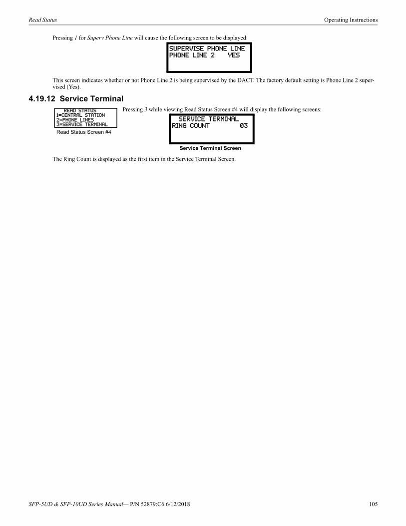
Read Status Operating Instructions
Pressing 1 for Superv Phone Line will cause the following screen to be displayed:
This screen indicates whether or not Phone Line 2 is being supervised by the DACT. The factory default setting is Phone Line 2 super-vised (Yes).
4.19.12 Service TerminalPressing 3 while viewing Read Status Screen #4 will display the following screens:
The Ring Count is displayed as the first item in the Service Terminal Screen.
SUPERVISE PHONE LINE
PHONE LINE 2 YES
READ STATUS1=CENTRAL STATION2=PHONE LINES3=SERVICE TERMINAL
Read Status Screen #4
SERVICE TERMINALRING COUNT 03
Service Terminal Screen
SFP-5UD & SFP-10UD Series Manual— P/N 52879:C6 6/12/2018 105
Section 5: Central Station CommunicationsThe control panel transmits zone and system status reports to Central Stations via the public switched telephone network. Two super-vised telephone line connections are made to interface the control panel to the telephone lines. Two optional 7 foot telephone cords are available for this purpose and can be purchased separately.
The control panel supervises both telephone lines for proper voltage. A delay of two minutes will occur before a fault in either phone line connection is reported as a trouble. When a fault is detected, an audible trouble signal will sound, the LCD display will indicate the phone line trouble and the trouble condition will be reported to the Central Station over the remaining operational phone line.
The control panel comes with line seizure capability provided for both the primary and secondary telephone line interfaces. Any time that the control panel needs to make a call to a Central Station, line seizure will disconnect any local premises phones sharing the same telephone line.
All transmissions to the Central Stations will be sent over the primary phone line. In the event of noisy phone lines, transmissions will be sent over the backup secondary phone line.
Two phone numbers must be programmed, the primary Central Station phone number and the secondary Central Station phone number. All system reports will be transmitted to the primary Central Station phone number. Reports will automatically be sent to the secondary Central Station phone number if attempts to transmits to the primary Central Station phone number are unsuccessful. If 10 total attempts to communicate are unsuccessful, a Communicator Failure report will be displayed. Note that as an option, all reports may also be sent to the secondary Central Station phone number.
The FACP meets NFPA 72 National Fire Code reporting requirements for: (a) the type of signal, (b) condition and (c) location of the reporting premises. The general priority reporting structure is:
1. Zone Alarms and Restores2. Zone Troubles and Restores3. System Troubles and Restores4. 24-hour Test
5.1 Transmittal PrioritiesThe integral communicator transmits highest priority events first. Events, in terms of priority, are listed below in descending order:
1. Alarms (highest priority level) Pull stations Waterflow Smoke detector Other alarm types
2. Supervisory Zone3. System Troubles
Zone disabled Fire drill AC fail (after delay) Zonal faults Earth fault Low battery Telephone line fault Notification Appliance Circuits fault Communication trouble Annunciator trouble System off normal
4. Restoral Reports Zone alarm Supervisory Zone(s) enabled Fire drill AC Zone fault Earth Battery Telephone line Notification Appliance Circuits Communication Annunciator trouble System off normal
5. 24 Hour Test (lowest priority)
106 SFP-5UD & SFP-10UD Series Manual— P/N 52879:C6 6/12/2018
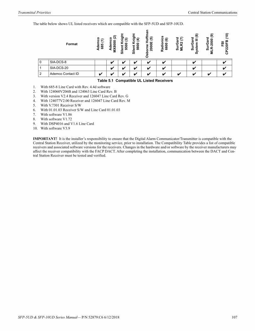
Transmittal Priorities Central Station Communications
The table below shows UL listed receivers which are compatible with the SFP-5UD and SFP-10UD.
1. With 685-8 Line Card with Rev. 4.4d software2. With 124060V206B and 124063 Line Card Rev. B3. With version V2.4 Receiver and 126047 Line Card Rev. G4. With 124077V2.00 Receiver and 126047 Line Card Rev. M5. With V.7301 Receiver S/W6. With 01.01.03 Receiver S/W and Line Card 01.01.037. With software V1.868. With software V1.729. With DSP4016 and V1.6 Line Card10. With software V3.9
IMPORTANT! It is the installer’s responsibility to ensure that the Digital Alarm Communicator/Transmitter is compatible with the Central Station Receiver, utilized by the monitoring service, prior to installation. The Compatibility Table provides a list of compatible receivers and associated software versions for the receivers. Changes in the hardware and/or software by the receiver manufacturers may affect the receiver compatibility with the FACP DACT. After completing the installation, communication between the DACT and Cen-tral Station Receiver must be tested and verified.
Format
Ad
emco
685
(1)
Ad
emco
MX
8000
(2)
Sile
nt
Kn
igh
t95
00 (
3)
Sile
nt
Kn
igh
t98
00 (
4)
Os
bo
rne
Ho
ffm
an20
00E
(5)
Rad
ion
ics
6600
(6)
Su
rGa
rd
ML
R2
(7)
Su
rGa
rd
Sys
tem
III (
8)
Su
rGa
rd
ML
R-2
000
(9)
FB
I C
P22
0FB
(10
)
0 SIA-DCS-8
1 SIA-DCS-20
2 Ademco Contact ID
Table 5.1 Compatible UL Listed Receivers
SFP-5UD & SFP-10UD Series Manual— P/N 52879:C6 6/12/2018 107
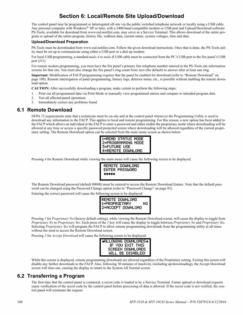
Section 6: Local/Remote Site Upload/DownloadThe control panel may be programmed or interrogated off-site via the public switched telephone network or locally using a USB cable. Any personal computer with Windows® XP or later, with a 2400 baud compatible modem or USB port and Upload/Download software PS-Tools, available for download from www.esd.notifier.com, may serve as a Service Terminal. This allows download of the entire pro-gram or upload of the entire program, history file, walktest data, current status, system voltages, time and date.
Upload/Download Preparation
PS-Tools must be downloaded from www.esd.notifier.com. Follow the given download instructions. Once that is done, the PS-Tools util-ity must be set up to communicate using either a USB port or a dial-up modem.
For local USB programming, a standard male-A to male-B USB cable must be connected from the PC’s USB port to the fire panel’s USB port (J11).
For remote modem programming, you must have the fire panel’s primary line telephone number entered in the PS-Tools site information screens for that site. You must also change the fire panel’s ring count from zero (the default) to answer after at least one ring.
Important: Modification of FACP programming requires that the panel be enabled for download (refer to “Remote Download” on page 108). Remote interrogation of panel programming, history logs, detector status, etc., is possible without enabling the remote down-load option.
CAUTION: After successfully downloading a program, make certain to perform the following steps:
1. Print out all programmed data via Print Mode or manually view programmed entries and compare to intended program data2. Test all affected panel operations3. Immediately correct any problems found
6.1 Remote DownloadNFPA 72 requirements state that a technician must be on-site and at the control panel whenever the Programming Utility is used to download any information to the FACP. This applies to local and remote programming. For this reason, a new option has been added to the FACP which allows an individual at the FACP to enter a password and either enable the proprietary mode where downloading will be allowed at any time or access a specific password protected screen where downloading will be allowed regardless of the current propri-etary setting. The Remote Download option can be selected from the main menu screen as shown below:
Pressing 4 for Remote Download while viewing the main menu will cause the following screen to be displayed:
The Remote Download password (default 00000) must be entered to access the Remote Download feature. Note that the default pass-word can be changed using the Password Change option (refer to “Password Change” on page 93).
Entering the correct password will cause the following screen to be displayed:
Pressing 1 for Proprietary No (factory default setting), while viewing the Remote Download screen, will cause the display to toggle from Proprietary No to Proprietary Yes. Each press of the 1 key will cause the display to toggle between Proprietary No and Proprietary Yes. Selecting Proprietary Yes will program the FACP to allow remote programming downloads from the programming utility at all times without the need to access the Remote Download screen.
Pressing 2 for Accept Download will cause the following screen to be displayed:
While this screen is displayed, remote programming downloads are allowed regardless of the Proprietary setting. Exiting this screen will disable any further downloads to the FACP. Also, following 30 minutes of inactivity (including up/downloading), the Accept Download screen will time-out, causing the display to return to the System All Normal screen.
6.2 Transferring a ProgramThe first time that the control panel is contacted, a secret code is loaded in by a Service Terminal. Future upload or download requests cause verification of the secret code by the control panel before processing of data is allowed. If the secret code is not verified, the con-trol panel will terminate the request.
1=READ STATUS MODE
2=PROGRAMMING MODE3=FUTURE USE
4=REMOTE DOWNLOAD
REMOTE DOWNLOAD
ENTER PASSWORD
REMOTE DOWNLOAD1=PROPRIETARY NO
2=ACCEPT DOWNLOAD
ALLOWING DOWNLOADS IF YOU EXIT THIS
SCREEN DOWNLOADS
WILL BE DISABLED!
108 SFP-5UD & SFP-10UD Series Manual— P/N 52879:C6 6/12/2018
Transferring a Program Local/Remote Site Upload/Download
While the control panel is communicating with the remote Service Terminal, one of the DACT’s red phone line active LEDs and the green Kissoff LED will remain on steady.
In order to download the panel (whether initiated at the jobsite or remotely), the following must be true:
The control panel must be in the Normal Mode of operation. Downloading is not possible if the panel is in any other mode There cannot be any active communications ongoing with a Central Station receiver All active events must be successfully 'kissed-off' by the Central Station(s). The communicator must be in a standby state with
no new information waiting to be transmitted to a Central Station
6.2.1 Security FeaturesUpload and download with the control panel have been carefully designed to include key security features to ensure proper functionality. Any time a transfer is initiated, the control panel and the Service Terminal will communicate and transfer data before contacting a Cen-tral Station. When the data transfers are completed and the control panel disconnects from the Service Terminal, the control panel will call the Central Station and report one of the following conditions:
• Upload/download request received• Upload and/or download request successful• Upload/download failedThe key features are listed and explained in the following sections.
Secret Code Verification
A secret code is stored in the control panel by a Service Terminal to prevent unauthorized access. The secret code is created at the Ser-vice Terminal by the master user and cannot be viewed or changed by anyone other than a master user. Viewing of the secret code is pro-hibited at the control panel. Prior to allowing an upload or download of data, the control panel will verify the secret code transmitted by the Service Terminal.
Time-out at Control Panel
Upon answering an incoming (modem) call on the primary Central Station phone line, the control panel will listen for a modem connec-tion signal. If this signal is not received within 50 seconds, the control panel will disconnect the call. Upon successful connection (secret code verified), if no communication occurs within 30 minutes, the panel will disconnect the call. Upon time-out, transfer activity will be reported to the Central Station (if enabled) and the connection will be terminated.
Error Checking
As each block of data is received by the control panel, it is checked for accuracy. If an error is detected, the block is retransmitted until correct, up to a maximum of four times. If the Secret Code is not verified and four errors occur, the call is disconnected and the report that the upload/download was not successful is called to the Central Station(s).
Central Station Data Protection
The primary and secondary Central Station phone numbers, communications format, account code, test time and programmable event codes are vital Central Station information. These blocks of data are protected from partial programming due to faulty phone connec-tions, line noise and other errors. This prevents the panel from being confused due to a wrong phone number, account code, test time and most critical formatting errors.
SFP-5UD & SFP-10UD Series Manual— P/N 52879:C6 6/12/2018 109
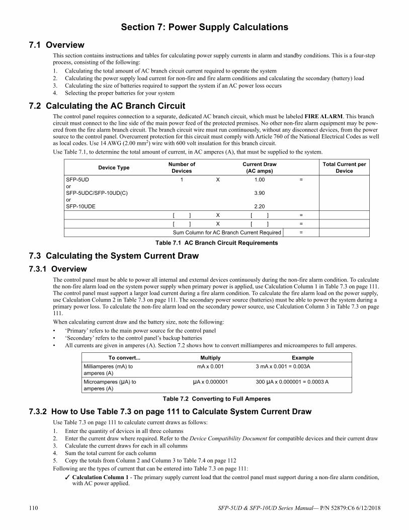
Section 7: Power Supply Calculations
7.1 OverviewThis section contains instructions and tables for calculating power supply currents in alarm and standby conditions. This is a four-step process, consisting of the following:
1. Calculating the total amount of AC branch circuit current required to operate the system2. Calculating the power supply load current for non-fire and fire alarm conditions and calculating the secondary (battery) load3. Calculating the size of batteries required to support the system if an AC power loss occurs4. Selecting the proper batteries for your system
7.2 Calculating the AC Branch CircuitThe control panel requires connection to a separate, dedicated AC branch circuit, which must be labeled FIRE ALARM. This branch circuit must connect to the line side of the main power feed of the protected premises. No other non-fire alarm equipment may be pow-ered from the fire alarm branch circuit. The branch circuit wire must run continuously, without any disconnect devices, from the power source to the control panel. Overcurrent protection for this circuit must comply with Article 760 of the National Electrical Codes as well as local codes. Use 14 AWG (2.00 mm2) wire with 600 volt insulation for this branch circuit.
Use Table 7.1, to determine the total amount of current, in AC amperes (A), that must be supplied to the system.
7.3 Calculating the System Current Draw
7.3.1 OverviewThe control panel must be able to power all internal and external devices continuously during the non-fire alarm condition. To calculate the non-fire alarm load on the system power supply when primary power is applied, use Calculation Column 1 in Table 7.3 on page 111. The control panel must support a larger load current during a fire alarm condition. To calculate the fire alarm load on the power supply, use Calculation Column 2 in Table 7.3 on page 111. The secondary power source (batteries) must be able to power the system during a primary power loss. To calculate the non-fire alarm load on the secondary power source, use Calculation Column 3 in Table 7.3 on page 111.
When calculating current draw and the battery size, note the following:
• ‘Primary’ refers to the main power source for the control panel• ‘Secondary’ refers to the control panel’s backup batteries• All currents are given in amperes (A). Section 7.2 shows how to convert milliamperes and microamperes to full amperes.
7.3.2 How to Use Table 7.3 on page 111 to Calculate System Current DrawUse Table 7.3 on page 111 to calculate current draws as follows:
1. Enter the quantity of devices in all three columns2. Enter the current draw where required. Refer to the Device Compatibility Document for compatible devices and their current draw3. Calculate the current draws for each in all columns4. Sum the total current for each column5. Copy the totals from Column 2 and Column 3 to Table 7.4 on page 112Following are the types of current that can be entered into Table 7.3 on page 111:
Calculation Column 1 - The primary supply current load that the control panel must support during a non-fire alarm condition, with AC power applied.
Device TypeNumber of
DevicesCurrent Draw
(AC amps)Total Current per
Device
SFP-5UDorSFP-5UDC/SFP-10UD(C)orSFP-10UDE
1 X 1.00
3.90
2.20
=
[ ] X [ ] =
[ ] X [ ] =
Sum Column for AC Branch Current Required =
Table 7.1 AC Branch Circuit Requirements
To convert... Multiply Example
Milliamperes (mA) toamperes (A)
mA x 0.001 3 mA x 0.001 = 0.003A
Microamperes (µA) toamperes (A)
µA x 0.000001 300 µA x 0.000001 = 0.0003 A
Table 7.2 Converting to Full Amperes
110 SFP-5UD & SFP-10UD Series Manual— P/N 52879:C6 6/12/2018
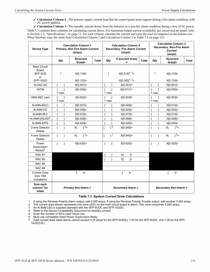
Calculating the System Current Draw Power Supply Calculations
Calculation Column 2 - The primary supply current load that the control panel must support during a fire alarm condition, with AC power applied.
Calculation Column 3 - The standby current drawn from the batteries in a non-fire alarm condition during a loss of AC power.Table 7.3 contains three columns for calculating current draws. For maximum output current availability per circuit and per panel, refer to Section 1.2, “Specifications”, on page 13. For each column, calculate the current and enter the total (in amperes) in the bottom row. When finished, copy the totals from Calculation Column 2 and Calculation Column 3 to Table 7.4 on page 112.
Device TypeCalculation Column 1
Primary, Non-Fire Alarm Current(amps)
Calculation Column 2Secondary, Fire Alarm Current
(amps)
Calculation Column 3Secondary, Non-Fire Alarm
Current (amps)
QtyX[current
draw]=Total Qty
X [current draw] =
Total QtyX[current
draw]=Total
Main Circuit Board
SFP-5UDor
SFP-10UD
1 X[0.110]=
X[0.133]=
1 X[0.214]1, 2=
X[0.282]1, 2=
1 If using the Reverse Polarity Alarm output, add 0.005 amps; if using the Reverse Polarity Trouble output, add another 0.005 amps.2 The current draw shown represents one zone (IDC) on the main circuit board in alarm. One zone consumes 0.040 amps.
1 X[0.110]=
X[0.133]=
N-CAC-5X [ ] X[0.001]= [ ] X[0.001]= [ ] X[0.001]=
4XTM [ ] 1 max.
X[0.005]= [ ]1 max.
X[0.011]1= [ ]1 max.
X[0.005]=
ANN-SEC card [ ] 1 max.
X[0.003]= [ ] 1 max.
X[0.003]= [ ] 1 max.
X[0.003]=
N-ANN-80(C) [ ] X[0.037]= [ ] X[0.040]= [ ] X[0.015]=
N-ANN-I/O [ ] X[0.035]= [ ] X[0.200]= [ ] X[0.035]=
N-ANN-RLY [ ] X[0.015]= [ ] X[0.075]= [ ] X[0.015]=
N-ANN-(R)LED3
3 An N-ANN-LED is supplied standard with the SFP-5UDC and SFP-10UDC.
[ ] X[0.028]= [ ] X[0.068]= [ ] X[0.028]=
N-ANN-S/PG [ ] X[0.045]= [ ] X[0.045]= [ ] X[0.045]=
2-wire Detector Heads
[ ] X[ ] 4=
4 Refer to the Device Compatibility Document for standby current.
[ ] 5
5 Enter the number of IDCs used minus one.
X[0.040]= [ ] X[ ] 4=
4-wire Detector Heads
[ ] X[ ] 4= [ ] 5 X[0.040]= [ ] X[ ] 4=
Power Supervision
Relays6
6 Must use compatible listed Power Supervision Relay.
[ ] X[0.025]= [ ] X[0.025]= [ ] X[0.025]=
NAC #1 [ ] X[ ]=
NAC #2 [ ] X[ ]=
NAC #3
NAC #4
Current Draw from TB9
(nonalarm)
[ ]= [ ]= [ ]=
Sum each column7 for
totals
7 Total current draw listed above cannot exceed 3.25 amps for the SFP-5UD(E), 7.25 for the SFP-5UDC, and 7.28 for the SFP-10UD(C/E).
Primary Non-Alarm = Secondary Alarm = Secondary Non-Alarm =
Table 7.3 System Current Draw Calculations
SFP-5UD & SFP-10UD Series Manual— P/N 52879:C6 6/12/2018 111
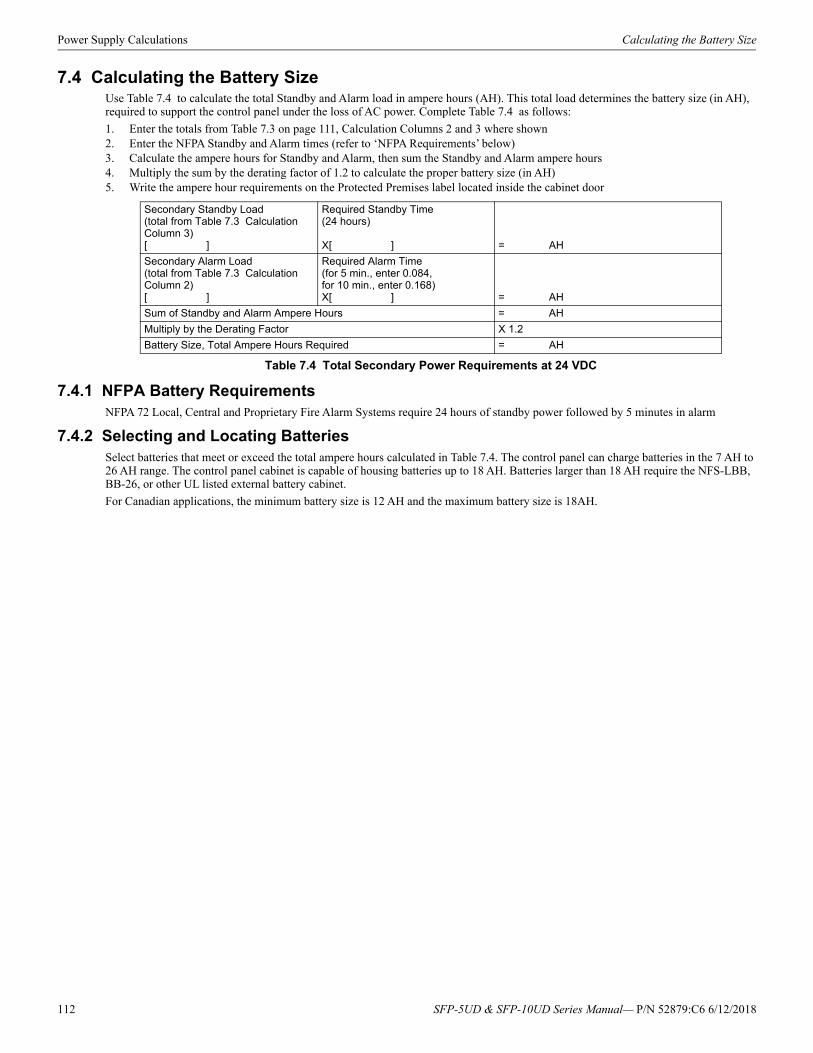
Power Supply Calculations Calculating the Battery Size
7.4 Calculating the Battery SizeUse Table 7.4 to calculate the total Standby and Alarm load in ampere hours (AH). This total load determines the battery size (in AH), required to support the control panel under the loss of AC power. Complete Table 7.4 as follows:
1. Enter the totals from Table 7.3 on page 111, Calculation Columns 2 and 3 where shown2. Enter the NFPA Standby and Alarm times (refer to ‘NFPA Requirements’ below)3. Calculate the ampere hours for Standby and Alarm, then sum the Standby and Alarm ampere hours4. Multiply the sum by the derating factor of 1.2 to calculate the proper battery size (in AH)5. Write the ampere hour requirements on the Protected Premises label located inside the cabinet door
7.4.1 NFPA Battery RequirementsNFPA 72 Local, Central and Proprietary Fire Alarm Systems require 24 hours of standby power followed by 5 minutes in alarm
7.4.2 Selecting and Locating BatteriesSelect batteries that meet or exceed the total ampere hours calculated in Table 7.4. The control panel can charge batteries in the 7 AH to 26 AH range. The control panel cabinet is capable of housing batteries up to 18 AH. Batteries larger than 18 AH require the NFS-LBB, BB-26, or other UL listed external battery cabinet.
For Canadian applications, the minimum battery size is 12 AH and the maximum battery size is 18AH.
Secondary Standby Load(total from Table 7.3 Calculation Column 3)[ ]
Required Standby Time(24 hours)
X[ ] = AH
Secondary Alarm Load(total from Table 7.3 Calculation Column 2)[ ]
Required Alarm Time(for 5 min., enter 0.084,for 10 min., enter 0.168)X[ ] = AH
Sum of Standby and Alarm Ampere Hours = AH
Multiply by the Derating Factor X 1.2
Battery Size, Total Ampere Hours Required = AH
Table 7.4 Total Secondary Power Requirements at 24 VDC
112 SFP-5UD & SFP-10UD Series Manual— P/N 52879:C6 6/12/2018
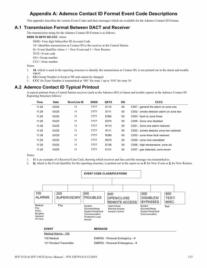
Appendix A: Ademco Contact ID Format Event Code DescriptionsThis appendix describes the various Event Codes and their messages which are available for the Ademco Contact ID Format.
A.1 Transmission Format Between DACT and ReceiverThe transmission string for the Ademco Contact ID Format is as follows:SSSS 18 QXYZ GG CCC where
SSSS= Four digit Subscriber ID Account Code18= Identifies transmission as Contact ID to the receiver at the Central StationQ= Event Qualifier where 1 = New Event and 3 = New RestoreXYZ= Event codeGG= Group numberCCC= Zone number
Notes:
1. 18, which is used in the reporting structure to identify the transmission as Contact ID, is not printed out in the alarm and trouble report.
2. GG Group Number is fixed at '00' and cannot be changed.3. CCC for Zone Number is transmitted as ‘001’ for zone 1 up to ‘010’ for zone 10
A.2 Ademco Contact ID Typical PrintoutA typical printout from a Central Station receiver (such as the Ademco 685) of alarm and trouble reports in the Ademco Contact ID Reporting Structure follows:
Notes:
1. 11 is an example of a Receiver/Line Card, showing which receiver and line card the message was transmitted to.2. Q, which is the Event Qualifier for the reporting structure, is printed out in the report as an E for New Event or R for New Restore.
Time Date Rcvr/Line ID SSSS QXYZ GG CCCC
11:28 03/25 11 7777 E110 00 C001 - general fire alarm on zone one
11:28 03/25 11 7777 E111 00 C002 - smoke detector alarm on zone two
11:28 03/25 11 7777 E380 00 C003 - fault on zone three
11:28 03/25 11 7777 E570 00 C009 - Zone nine disabled
11:28 03/25 11 7777 R110 00 C001 - Zone one alarm restored
11:28 03/25 11 7777 R111 00 C002 - smoke detector zone two restored
11:28 03/25 11 7777 R380 00 C003 - zone three fault restored
11:28 03/25 11 7777 R570 00 C009 - zone nine reenabled
11:28 03/25 11 7777 E158 00 C006 - high temperature, zone six
11:28 03/25 11 7777 E151 00 C007 - gas detected, zone seven
EVENT MESSAGE
Medical Alarms - 100
100 Medical EMERG - Personal Emergency - #
101 Pendant Transmitter EMERG - Personal Embergency - #
EVENT CODE CLASSIFICATIONS
100 ALARMS
200 SUPERVISORY
300 TROUBLES
400 OPEN/CLOSE REMOTE ACCESS
500 DISABLES/BYPASSES
600 TEST/MISC.
Medical Fire Panic Burglary General 24 Hour
Fire System Sounder/Relay System Peripheral Communication Protective Loop Sensor
Open/Close Remote Access Access Control
System Sounder/Relay System Peripheral Communication
Test
SFP-5UD & SFP-10UD Series Manual— P/N 52879:C6 6/12/2018 113
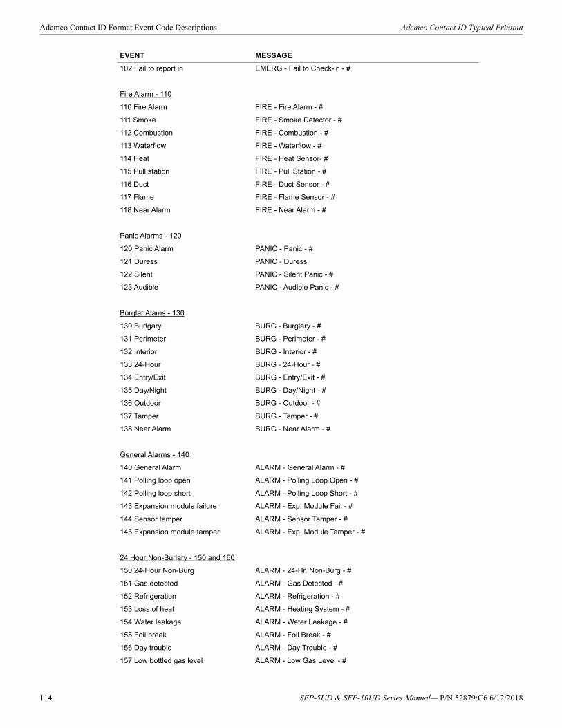
Ademco Contact ID Format Event Code Descriptions Ademco Contact ID Typical Printout
102 Fail to report in EMERG - Fail to Check-in - #
Fire Alarm - 110
110 Fire Alarm FIRE - Fire Alarm - #
111 Smoke FIRE - Smoke Detector - #
112 Combustion FIRE - Combustion - #
113 Waterflow FIRE - Waterflow - #
114 Heat FIRE - Heat Sensor- #
115 Pull station FIRE - Pull Station - #
116 Duct FIRE - Duct Sensor - #
117 Flame FIRE - Flame Sensor - #
118 Near Alarm FIRE - Near Alarm - #
Panic Alarms - 120
120 Panic Alarm PANIC - Panic - #
121 Duress PANIC - Duress
122 Silent PANIC - Silent Panic - #
123 Audible PANIC - Audible Panic - #
Burglar Alams - 130
130 Burlgary BURG - Burglary - #
131 Perimeter BURG - Perimeter - #
132 Interior BURG - Interior - #
133 24-Hour BURG - 24-Hour - #
134 Entry/Exit BURG - Entry/Exit - #
135 Day/Night BURG - Day/Night - #
136 Outdoor BURG - Outdoor - #
137 Tamper BURG - Tamper - #
138 Near Alarm BURG - Near Alarm - #
General Alarms - 140
140 General Alarm ALARM - General Alarm - #
141 Polling loop open ALARM - Polling Loop Open - #
142 Polling loop short ALARM - Polling Loop Short - #
143 Expansion module failure ALARM - Exp. Module Fail - #
144 Sensor tamper ALARM - Sensor Tamper - #
145 Expansion module tamper ALARM - Exp. Module Tamper - #
24 Hour Non-Burlary - 150 and 160
150 24-Hour Non-Burg ALARM - 24-Hr. Non-Burg - #
151 Gas detected ALARM - Gas Detected - #
152 Refrigeration ALARM - Refrigeration - #
153 Loss of heat ALARM - Heating System - #
154 Water leakage ALARM - Water Leakage - #
155 Foil break ALARM - Foil Break - #
156 Day trouble ALARM - Day Trouble - #
157 Low bottled gas level ALARM - Low Gas Level - #
EVENT MESSAGE
114 SFP-5UD & SFP-10UD Series Manual— P/N 52879:C6 6/12/2018
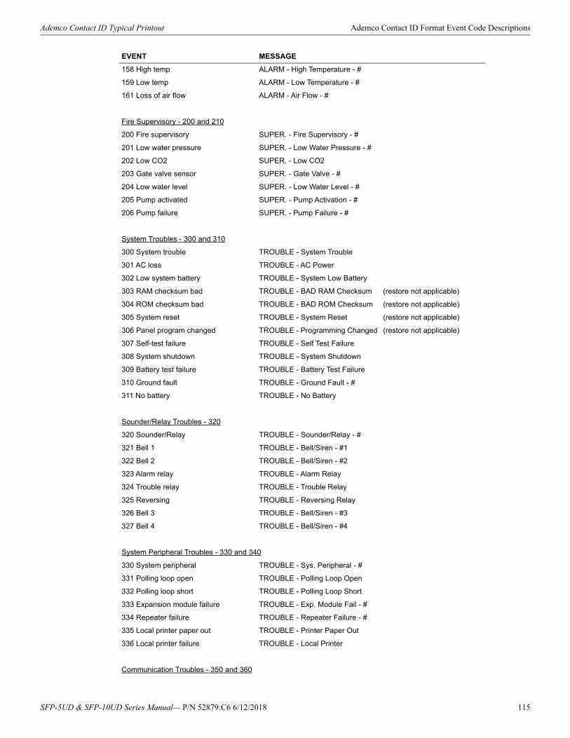
Ademco Contact ID Typical Printout Ademco Contact ID Format Event Code Descriptions
158 High temp ALARM - High Temperature - #
159 Low temp ALARM - Low Temperature - #
161 Loss of air flow ALARM - Air Flow - #
Fire Supervisory - 200 and 210
200 Fire supervisory SUPER. - Fire Supervisory - #
201 Low water pressure SUPER. - Low Water Pressure - #
202 Low CO2 SUPER. - Low CO2
203 Gate valve sensor SUPER. - Gate Valve - #
204 Low water level SUPER. - Low Water Level - #
205 Pump activated SUPER. - Pump Activation - #
206 Pump failure SUPER. - Pump Failure - #
System Troubles - 300 and 310
300 System trouble TROUBLE - System Trouble
301 AC loss TROUBLE - AC Power
302 Low system battery TROUBLE - System Low Battery
303 RAM checksum bad TROUBLE - BAD RAM Checksum (restore not applicable)
304 ROM checksum bad TROUBLE - BAD ROM Checksum (restore not applicable)
305 System reset TROUBLE - System Reset (restore not applicable)
306 Panel program changed TROUBLE - Programming Changed (restore not applicable)
307 Self-test failure TROUBLE - Self Test Failure
308 System shutdown TROUBLE - System Shutdown
309 Battery test failure TROUBLE - Battery Test Failure
310 Ground fault TROUBLE - Ground Fault - #
311 No battery TROUBLE - No Battery
Sounder/Relay Troubles - 320
320 Sounder/Relay TROUBLE - Sounder/Relay - #
321 Bell 1 TROUBLE - Bell/Siren - #1
322 Bell 2 TROUBLE - Bell/Siren - #2
323 Alarm relay TROUBLE - Alarm Relay
324 Trouble relay TROUBLE - Trouble Relay
325 Reversing TROUBLE - Reversing Relay
326 Bell 3 TROUBLE - Bell/Siren - #3
327 Bell 4 TROUBLE - Bell/Siren - #4
System Peripheral Troubles - 330 and 340
330 System peripheral TROUBLE - Sys. Peripheral - #
331 Polling loop open TROUBLE - Polling Loop Open
332 Polling loop short TROUBLE - Polling Loop Short
333 Expansion module failure TROUBLE - Exp. Module Fail - #
334 Repeater failure TROUBLE - Repeater Failure - #
335 Local printer paper out TROUBLE - Printer Paper Out
336 Local printer failure TROUBLE - Local Printer
Communication Troubles - 350 and 360
EVENT MESSAGE
SFP-5UD & SFP-10UD Series Manual— P/N 52879:C6 6/12/2018 115
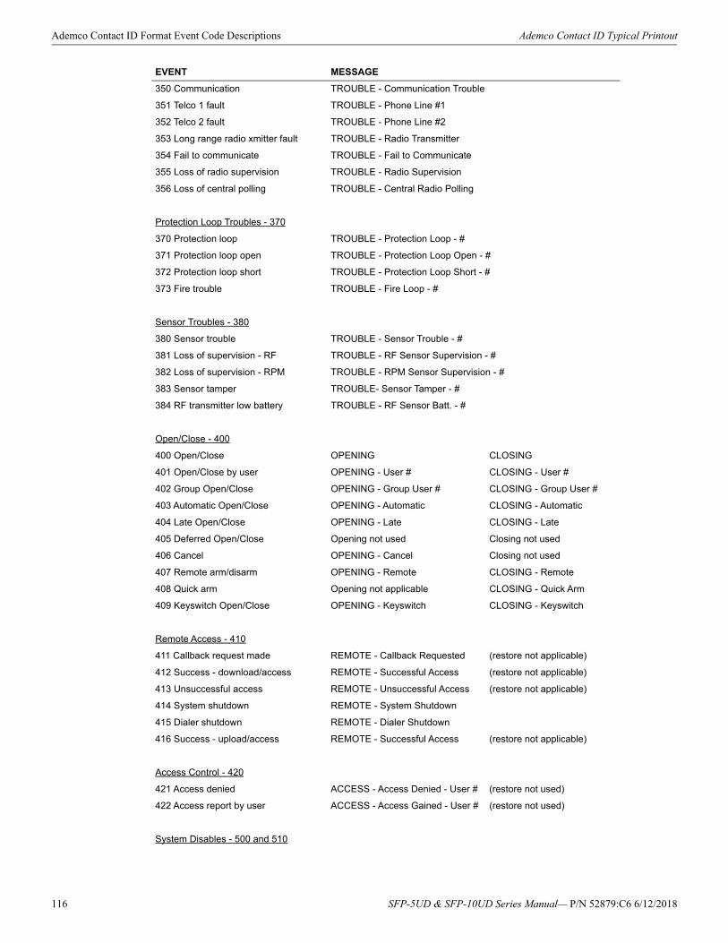
Ademco Contact ID Format Event Code Descriptions Ademco Contact ID Typical Printout
350 Communication TROUBLE - Communication Trouble
351 Telco 1 fault TROUBLE - Phone Line #1
352 Telco 2 fault TROUBLE - Phone Line #2
353 Long range radio xmitter fault TROUBLE - Radio Transmitter
354 Fail to communicate TROUBLE - Fail to Communicate
355 Loss of radio supervision TROUBLE - Radio Supervision
356 Loss of central polling TROUBLE - Central Radio Polling
Protection Loop Troubles - 370
370 Protection loop TROUBLE - Protection Loop - #
371 Protection loop open TROUBLE - Protection Loop Open - #
372 Protection loop short TROUBLE - Protection Loop Short - #
373 Fire trouble TROUBLE - Fire Loop - #
Sensor Troubles - 380
380 Sensor trouble TROUBLE - Sensor Trouble - #
381 Loss of supervision - RF TROUBLE - RF Sensor Supervision - #
382 Loss of supervision - RPM TROUBLE - RPM Sensor Supervision - #
383 Sensor tamper TROUBLE- Sensor Tamper - #
384 RF transmitter low battery TROUBLE - RF Sensor Batt. - #
Open/Close - 400
400 Open/Close OPENING CLOSING
401 Open/Close by user OPENING - User # CLOSING - User #
402 Group Open/Close OPENING - Group User # CLOSING - Group User #
403 Automatic Open/Close OPENING - Automatic CLOSING - Automatic
404 Late Open/Close OPENING - Late CLOSING - Late
405 Deferred Open/Close Opening not used Closing not used
406 Cancel OPENING - Cancel Closing not used
407 Remote arm/disarm OPENING - Remote CLOSING - Remote
408 Quick arm Opening not applicable CLOSING - Quick Arm
409 Keyswitch Open/Close OPENING - Keyswitch CLOSING - Keyswitch
Remote Access - 410
411 Callback request made REMOTE - Callback Requested (restore not applicable)
412 Success - download/access REMOTE - Successful Access (restore not applicable)
413 Unsuccessful access REMOTE - Unsuccessful Access (restore not applicable)
414 System shutdown REMOTE - System Shutdown
415 Dialer shutdown REMOTE - Dialer Shutdown
416 Success - upload/access REMOTE - Successful Access (restore not applicable)
Access Control - 420
421 Access denied ACCESS - Access Denied - User # (restore not used)
422 Access report by user ACCESS - Access Gained - User # (restore not used)
System Disables - 500 and 510
EVENT MESSAGE
116 SFP-5UD & SFP-10UD Series Manual— P/N 52879:C6 6/12/2018
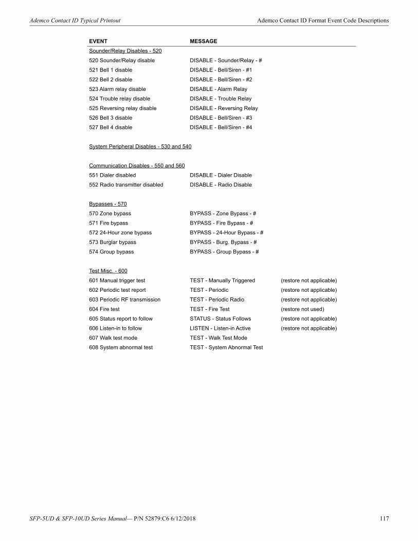
Ademco Contact ID Typical Printout Ademco Contact ID Format Event Code Descriptions
Sounder/Relay Disables - 520
520 Sounder/Relay disable DISABLE - Sounder/Relay - #
521 Bell 1 disable DISABLE - Bell/Siren - #1
522 Bell 2 disable DISABLE - Bell/Siren - #2
523 Alarm relay disable DISABLE - Alarm Relay
524 Trouble relay disable DISABLE - Trouble Relay
525 Reversing relay disable DISABLE - Reversing Relay
526 Bell 3 disable DISABLE - Bell/Siren - #3
527 Bell 4 disable DISABLE - Bell/Siren - #4
System Peripheral Disables - 530 and 540
Communication Disables - 550 and 560
551 Dialer disabled DISABLE - Dialer Disable
552 Radio transmitter disabled DISABLE - Radio Disable
Bypasses - 570
570 Zone bypass BYPASS - Zone Bypass - #
571 Fire bypass BYPASS - Fire Bypass - #
572 24-Hour zone bypass BYPASS - 24-Hour Bypass - #
573 Burglar bypass BYPASS - Burg. Bypass - #
574 Group bypass BYPASS - Group Bypass - #
Test Misc. - 600
601 Manual trigger test TEST - Manually Triggered (restore not applicable)
602 Periodic test report TEST - Periodic (restore not applicable)
603 Periodic RF transmission TEST - Periodic Radio (restore not applicable)
604 Fire test TEST - Fire Test (restore not used)
605 Status report to follow STATUS - Status Follows (restore not applicable)
606 Listen-in to follow LISTEN - Listen-in Active (restore not applicable)
607 Walk test mode TEST - Walk Test Mode
608 System abnormal test TEST - System Abnormal Test
EVENT MESSAGE
SFP-5UD & SFP-10UD Series Manual— P/N 52879:C6 6/12/2018 117
Appendix B: NFPA Standard-Specific RequirementsThe SFP-5UD/SFP-10UD has been designed for use in commercial, industrial and institutional applications and meets the requirements for service under the National Fire Protection Association (NFPA) Standards outlined in this Appendix. The minimum system compo-nents required for compliance with the appropriate NFPA standard are listed below:
SFP-5UD/SFP-10UD Control Panel
Contains the main control board, cabinet (backbox and door), main power supply and transformer.
Batteries
Refer to “Power Supply Calculations” on page 110, for Standby Power Requirements.
Initiating Devices
Connected to one of the control panel's Initiating Device Circuits.
Notification Appliances
Connected to the control panel's Notification Appliance Circuits via a control module.
The following additional equipment is needed for compliance with the NFPA 72 standards listed below:
NFPA 72 NATIONAL FIRE ALARM STANDARDS FOR:
NFPA 72 Central Station Service (Protected Premises Unit) or Remote Station Service
Onboard Digital Alarm Communicator Transmitter for connection to a compatible listed Central Station DACR or Protected Premises Receiving Unit. This unit must be installed as outlined in “Digital Alarm Communicator/Transmitter” on page 17.OR411UD may be installed as illustrated in Figure B.1, “SFP-5UD/SFP-10UD FACP Connection to 411UD,” on page 119.OR4XTM Transmitter Module for connection to the RS82 Remote Station Receiver. See Figure B.3, “Remote Station Connection Using 4XTM Module,” on page 121, for installation instructions for this unit.
NFPA 72 Auxiliary Fire Alarm System
4XTM Transmitter Module for connection to a compatible listed Local Energy Municipal Box. This unit must be installed as illustrated in the section titled “4XTM Transmitter Module Installation” on page 33 and as outlined in Figure B.2, “Municipal Box Connected to 4XTM Transmitter Module,” on page 120.
NFPA 72 Proprietary Fire Alarm System
SFP-5UD/SFP-10UD Alarm, Trouble and Supervisory contacts connected to Transmitter(s). See Figure B.4, “Proprietary Protective Sig-naling System,” on page 122, for installation instructions for this unit.
118 SFP-5UD & SFP-10UD Series Manual— P/N 52879:C6 6/12/2018
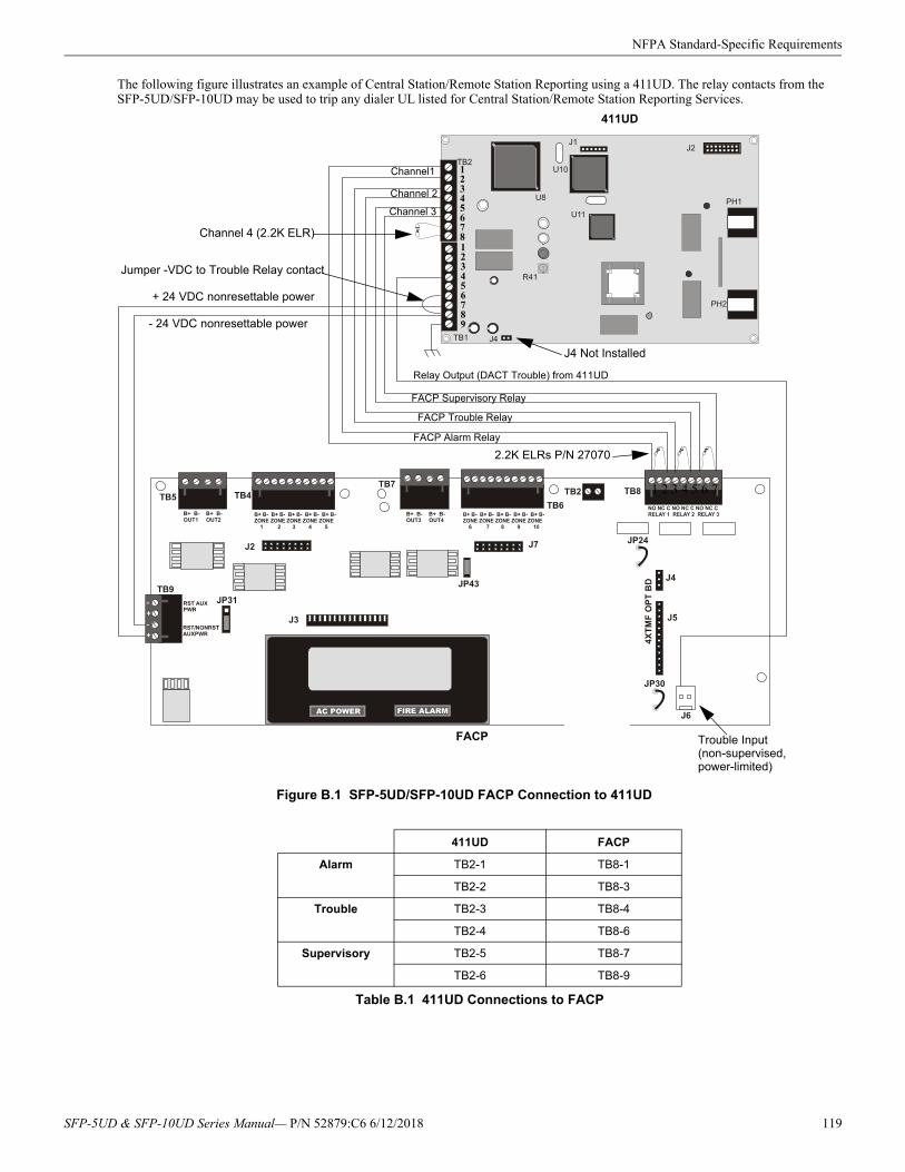
NFPA Standard-Specific Requirements
The following figure illustrates an example of Central Station/Remote Station Reporting using a 411UD. The relay contacts from the SFP-5UD/SFP-10UD may be used to trip any dialer UL listed for Central Station/Remote Station Reporting Services.
411UD FACP
Alarm TB2-1 TB8-1
TB2-2 TB8-3
Trouble TB2-3 TB8-4
TB2-4 TB8-6
Supervisory TB2-5 TB8-7
TB2-6 TB8-9
Table B.1 411UD Connections to FACP
Figure B.1 SFP-5UD/SFP-10UD FACP Connection to 411UD
Channel1
Channel 2
Channel 3
Channel 4 (2.2K ELR)
Relay Output (DACT Trouble) from 411UD
FACP Supervisory Relay
FACP Alarm Relay
FACP Trouble Relay
J4 Not Installed
411UD
12345678
+ 24 VDC nonresettable power
- 24 VDC nonresettable power
2.2K ELRs P/N 27070
123456789
1 2 3 4 5 6 7
FACP
Jumper -VDC to Trouble Relay contact
Trouble Input(non-supervised, power-limited)
SFP-5UD & SFP-10UD Series Manual— P/N 52879:C6 6/12/2018 119
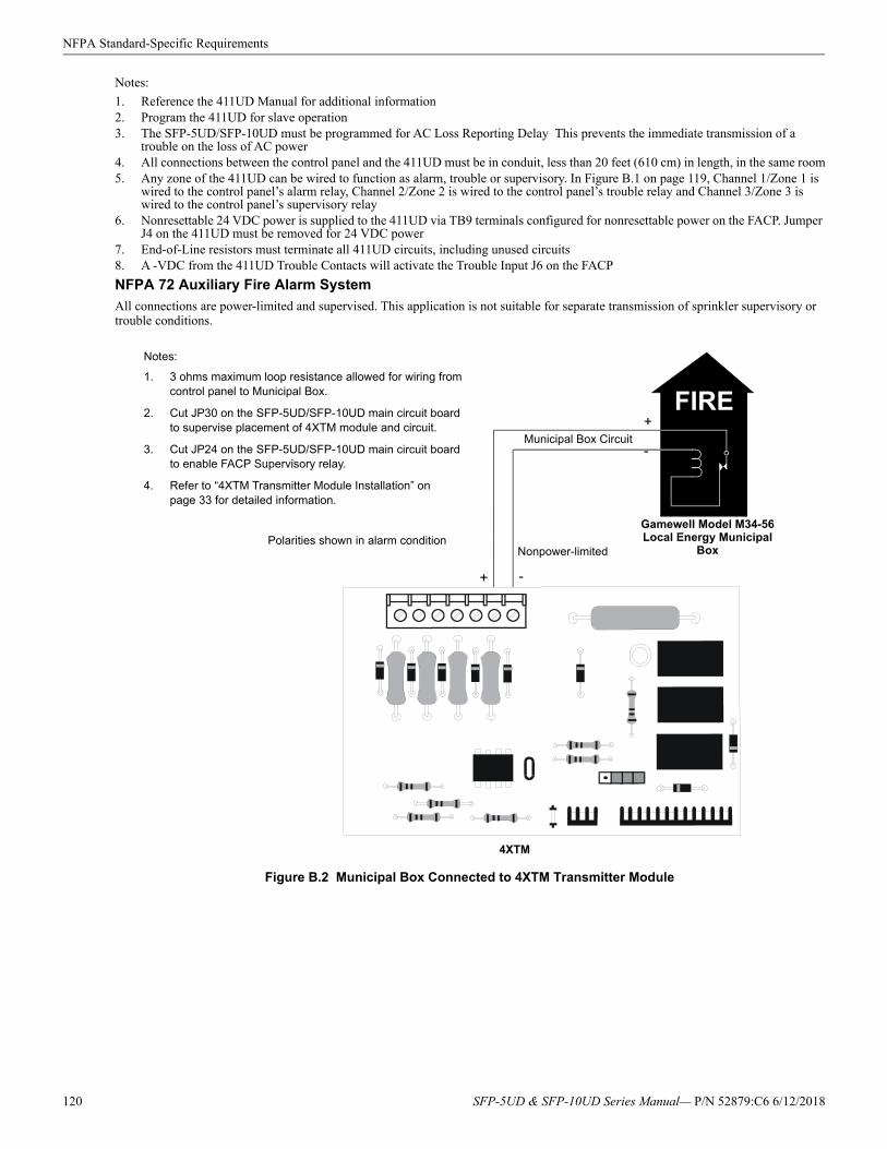
NFPA Standard-Specific Requirements
Notes:
1. Reference the 411UD Manual for additional information2. Program the 411UD for slave operation3. The SFP-5UD/SFP-10UD must be programmed for AC Loss Reporting Delay This prevents the immediate transmission of a
trouble on the loss of AC power4. All connections between the control panel and the 411UD must be in conduit, less than 20 feet (610 cm) in length, in the same room5. Any zone of the 411UD can be wired to function as alarm, trouble or supervisory. In Figure B.1 on page 119, Channel 1/Zone 1 is
wired to the control panel’s alarm relay, Channel 2/Zone 2 is wired to the control panel’s trouble relay and Channel 3/Zone 3 is wired to the control panel’s supervisory relay
6. Nonresettable 24 VDC power is supplied to the 411UD via TB9 terminals configured for nonresettable power on the FACP. Jumper J4 on the 411UD must be removed for 24 VDC power
7. End-of-Line resistors must terminate all 411UD circuits, including unused circuits8. A -VDC from the 411UD Trouble Contacts will activate the Trouble Input J6 on the FACP
NFPA 72 Auxiliary Fire Alarm System
All connections are power-limited and supervised. This application is not suitable for separate transmission of sprinkler supervisory or trouble conditions.
FIRE
Gamewell Model M34-56 Local Energy Municipal
BoxPolarities shown in alarm condition
+
Nonpower-limited
Municipal Box Circuit
+
-
-
4XTM
Figure B.2 Municipal Box Connected to 4XTM Transmitter Module
Notes:
1. 3 ohms maximum loop resistance allowed for wiring from control panel to Municipal Box.
2. Cut JP30 on the SFP-5UD/SFP-10UD main circuit board to supervise placement of 4XTM module and circuit.
3. Cut JP24 on the SFP-5UD/SFP-10UD main circuit board to enable FACP Supervisory relay.
4. Refer to “4XTM Transmitter Module Installation” on page 33 for detailed information.
120 SFP-5UD & SFP-10UD Series Manual— P/N 52879:C6 6/12/2018
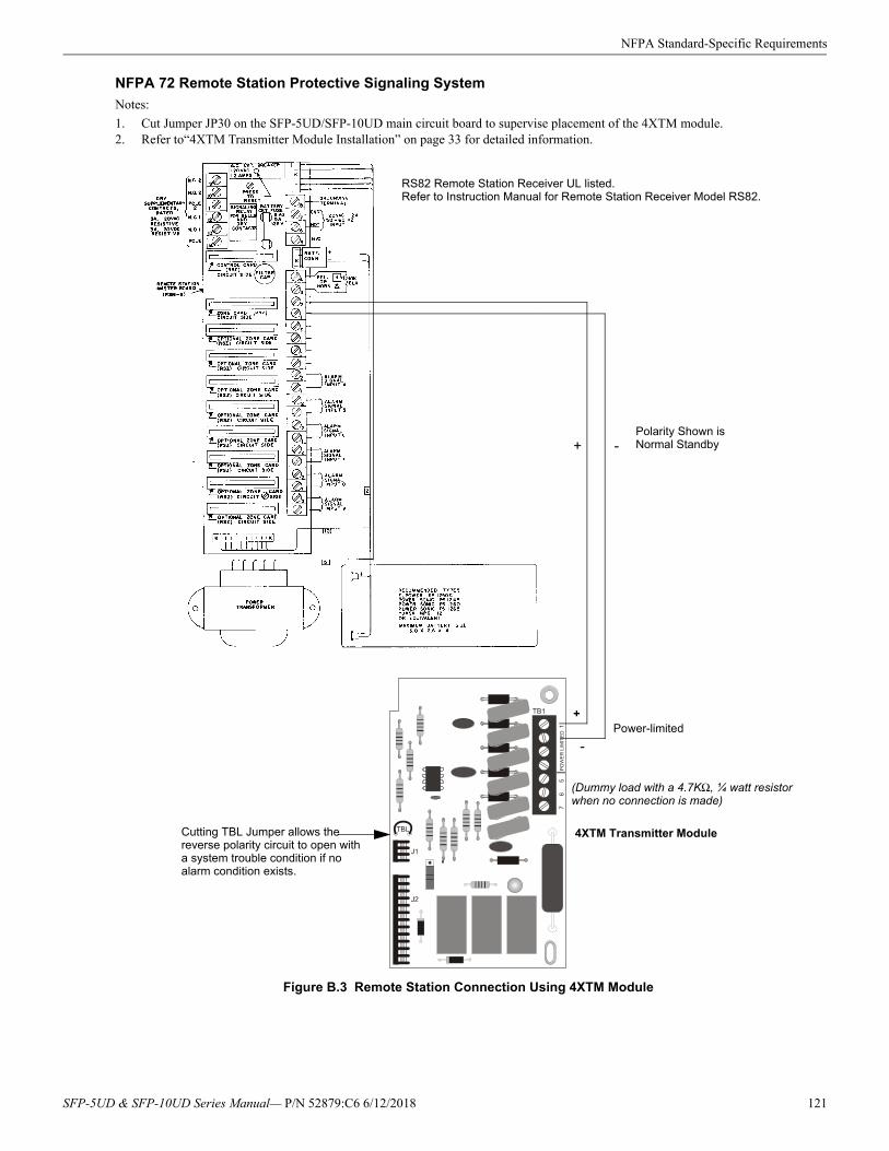
NFPA Standard-Specific Requirements
NFPA 72 Remote Station Protective Signaling System
Notes:
1. Cut Jumper JP30 on the SFP-5UD/SFP-10UD main circuit board to supervise placement of the 4XTM module.2. Refer to“4XTM Transmitter Module Installation” on page 33 for detailed information.
RS82 Remote Station Receiver UL listed.Refer to Instruction Manual for Remote Station Receiver Model RS82.
+ -Polarity Shown is Normal Standby
4XTM Transmitter ModuleCutting TBL Jumper allows the reverse polarity circuit to open with a system trouble condition if no alarm condition exists.
Power-limited
Figure B.3 Remote Station Connection Using 4XTM Module
+
-
(Dummy load with a 4.7KΩ, ¼ watt resistor when no connection is made)
SFP-5UD & SFP-10UD Series Manual— P/N 52879:C6 6/12/2018 121
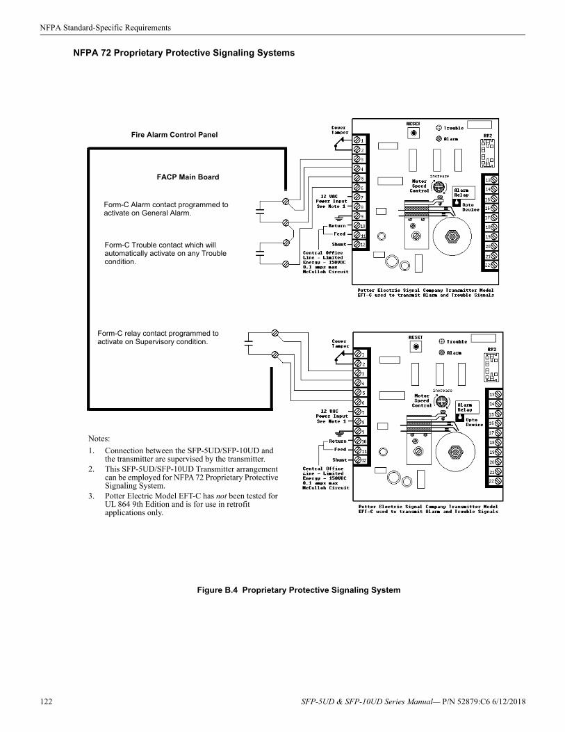
NFPA Standard-Specific Requirements
NFPA 72 Proprietary Protective Signaling Systems
Figure B.4 Proprietary Protective Signaling System
Form-C relay contact programmed to activate on Supervisory condition.
Form-C Trouble contact which will automatically activate on any Trouble condition.
Form-C Alarm contact programmed to activate on General Alarm.
FACP Main Board
Fire Alarm Control Panel
Notes:
1. Connection between the SFP-5UD/SFP-10UD and the transmitter are supervised by the transmitter.
2. This SFP-5UD/SFP-10UD Transmitter arrangement can be employed for NFPA 72 Proprietary Protective Signaling System.
3. Potter Electric Model EFT-C has not been tested for UL 864 9th Edition and is for use in retrofit applications only.
122 SFP-5UD & SFP-10UD Series Manual— P/N 52879:C6 6/12/2018
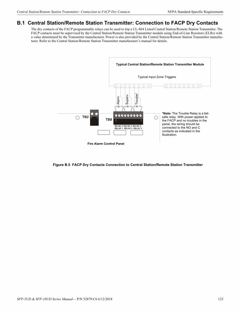
Central Station/Remote Station Transmitter: Connection to FACP Dry Contacts NFPA Standard-Specific Requirements
B.1 Central Station/Remote Station Transmitter: Connection to FACP Dry ContactsThe dry contacts of the FACP programmable relays can be used to trip a UL-864 Listed Central Station/Remote Station Transmitter. The FACP contacts must be supervised by the Central Station/Remote Station Transmitter module using End-of-Line Resistors (ELRs) with a value determined by the Transmitter manufacturer. Power is also provided by the Central Station/Remote Station Transmitter manufac-turer. Refer to the Central Station/Remote Station Transmitter manufacturer’s manual for details.
Figure B.5 FACP Dry Contacts Connection to Central Station/Remote Station Transmitter
Typical Central Station/Remote Station Transmitter Module
Typical Input Zone Triggers
Fire Alarm Control Panel
Ala
rm
Sup
erv.
Tro
uble
*
*Note: The Trouble Relay is a fail-safe relay. With power applied to the FACP and no troubles in the panel, the wiring should be connected to the NO and C contacts as indicated in the illustration.
SFP-5UD & SFP-10UD Series Manual— P/N 52879:C6 6/12/2018 123
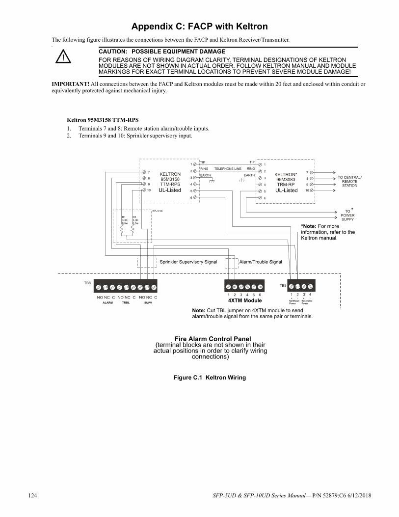
124 SFP-5UD & SFP-10UD Series Manual— P/N 52879:C6 6/12/2018
Appendix C: FACP with KeltronThe following figure illustrates the connections between the FACP and Keltron Receiver/Transmitter.
IMPORTANT! All connections between the FACP and Keltron modules must be made within 20 feet and enclosed within conduit or equivalently protected against mechanical injury.
!
P
CAUTION: POSSIBLE EQUIPMENT DAMAGE
FOR REASONS OF WIRING DIAGRAM CLARITY, TERMINAL DESIGNATIONS OF KELTRON MODULES ARE NOT SHOWN IN ACTUAL ORDER. FOLLOW KELTRON MANUAL AND MODULE MARKINGS FOR EXACT TERMINAL LOCATIONS TO PREVENT SEVERE MODULE DAMAGE!
Fire Alarm Control Panel(terminal blocks are not shown in their
actual positions in order to clarify wiring connections)
Keltron 95M3158 TTM-RPS
1. Terminals 7 and 8: Remote station alarm/trouble inputs.2. Terminals 9 and 10: Sprinkler supervisory input.
Note: Cut TBL jumper on 4XTM module to send alarm/trouble signal from the same pair or terminals.
Alarm/Trouble SignalSprinkler Supervisory Signal
*Note: For more information, refer to the Keltron manual.
4XTM Module
Figure C.1 Keltron Wiring
UL-ListedUL-Listed
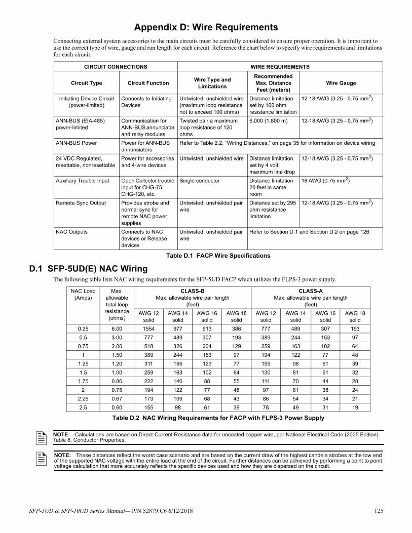
Appendix D: Wire RequirementsConnecting external system accessories to the main circuits must be carefully considered to ensure proper operation. It is important to use the correct type of wire, gauge and run length for each circuit. Reference the chart below to specify wire requirements and limitations for each circuit.
D.1 SFP-5UD(E) NAC WiringThe following table lists NAC wiring requirements for the SFP-5UD FACP which utilizes the FLPS-3 power supply.
CIRCUIT CONNECTIONS WIRE REQUIREMENTS
Circuit Type Circuit FunctionWire Type and
Limitations
Recommended Max. DistanceFeet (meters)
Wire Gauge
Initiating Device Circuit(power-limited)
Connects to Initiating Devices
Untwisted, unshielded wire (maximum loop resistance not to exceed 100 ohms)
Distance limitation set by 100 ohm resistance limitation
12-18 AWG (3.25 - 0.75 mm2)
ANN-BUS (EIA-485)power-limited
Communication for ANN-BUS annunciator and relay modules
Twisted pair a maximum loop resistance of 120 ohms
6,000 (1,800 m) 12-18 AWG (3.25 - 0.75 mm2)
ANN-BUS Power Power for ANN-BUS annunciators
Refer to Table 2.2, “Wiring Distances,” on page 35 for information on device wiring
24 VDC Regulated, resettable, nonresettable
Power for accessories and 4-wire devices
Untwisted, unshielded wire Distance limitation set by 4 volt maximum line drop
12-18 AWG (3.25 - 0.75 mm2)
Auxiliary Trouble Input Open Collector trouble input for CHG-75, CHG-120, etc.
Single conductor Distance limitation 20 feet in same room
18 AWG (0.75 mm2)
Remote Sync Output Provides strobe and normal sync for remote NAC power supplies
Untwisted, unshielded pair wire
Distance set by 295 ohm resistance limitation
12-18 AWG (3.25 - 0.75 mm2)
NAC Outputs Connects to NAC devices or Release devices
Untwisted, unshielded pair wire
Refer to Section D.1 and Section D.2 on page 126.
Table D.1 FACP Wire Specifications
NAC Load (Amps)
Max. allowable total loop resistance
(ohms)
CLASS-BMax. allowable wire pair length
(feet)
CLASS-AMax. allowable wire pair length
(feet)
AWG 12solid
AWG 14solid
AWG 16solid
AWG 18solid
AWG 12solid
AWG 14solid
AWG 16solid
AWG 18solid
0.25 6.00 1554 977 613 386 777 489 307 193
0.5 3.00 777 489 307 193 389 244 153 97
0.75 2.00 518 326 204 129 259 163 102 64
1 1.50 389 244 153 97 194 122 77 48
1.25 1.20 311 195 123 77 155 98 61 39
1.5 1.00 259 163 102 64 130 81 51 32
1.75 0.86 222 140 88 55 111 70 44 28
2 0.75 194 122 77 48 97 61 38 24
2.25 0.67 173 109 68 43 86 54 34 21
2.5 0.60 155 98 61 39 78 49 31 19
Table D.2 NAC Wiring Requirements for FACP with FLPS-3 Power Supply
NOTE: Calculations are based on Direct-Current Resistance data for uncoated copper wire, per National Electrical Code (2005 Edition) Table 8, Conductor Properties.
NOTE: These distances reflect the worst case scenario and are based on the current draw of the highest candela strobes at the low end of the supported NAC voltage with the entire load at the end of the circuit. Further distances can be achieved by performing a point to point voltage calculation that more accurately reflects the specific devices used and how they are dispersed on the circuit.
SFP-5UD & SFP-10UD Series Manual— P/N 52879:C6 6/12/2018 125
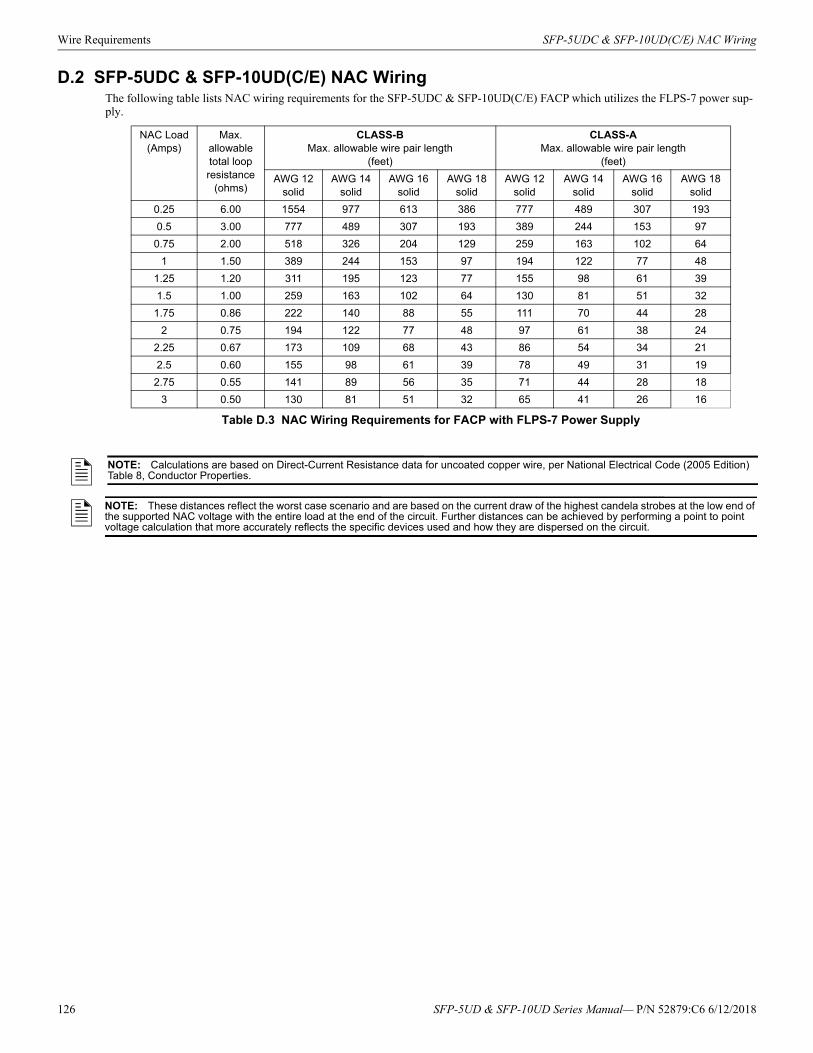
Wire Requirements SFP-5UDC & SFP-10UD(C/E) NAC Wiring
D.2 SFP-5UDC & SFP-10UD(C/E) NAC WiringThe following table lists NAC wiring requirements for the SFP-5UDC & SFP-10UD(C/E) FACP which utilizes the FLPS-7 power sup-ply.
NAC Load (Amps)
Max. allowable total loop resistance
(ohms)
CLASS-BMax. allowable wire pair length
(feet)
CLASS-AMax. allowable wire pair length
(feet)
AWG 12solid
AWG 14solid
AWG 16solid
AWG 18solid
AWG 12solid
AWG 14solid
AWG 16solid
AWG 18solid
0.25 6.00 1554 977 613 386 777 489 307 193
0.5 3.00 777 489 307 193 389 244 153 97
0.75 2.00 518 326 204 129 259 163 102 64
1 1.50 389 244 153 97 194 122 77 48
1.25 1.20 311 195 123 77 155 98 61 39
1.5 1.00 259 163 102 64 130 81 51 32
1.75 0.86 222 140 88 55 111 70 44 28
2 0.75 194 122 77 48 97 61 38 24
2.25 0.67 173 109 68 43 86 54 34 21
2.5 0.60 155 98 61 39 78 49 31 19
2.75 0.55 141 89 56 35 71 44 28 18
3 0.50 130 81 51 32 65 41 26 16
Table D.3 NAC Wiring Requirements for FACP with FLPS-7 Power Supply
NOTE: Calculations are based on Direct-Current Resistance data for uncoated copper wire, per National Electrical Code (2005 Edition) Table 8, Conductor Properties.
NOTE: These distances reflect the worst case scenario and are based on the current draw of the highest candela strobes at the low end of the supported NAC voltage with the entire load at the end of the circuit. Further distances can be achieved by performing a point to point voltage calculation that more accurately reflects the specific devices used and how they are dispersed on the circuit.
126 SFP-5UD & SFP-10UD Series Manual— P/N 52879:C6 6/12/2018

SFP-5UD & SFP-10UD Series Manual— P/N 52879:C6 6/12/2018 127
Appendix E: Default ProgrammingThe following table provides a list of the programming options and their factory default settings.
Program Option Factory Default Program Option Factory Default
Zone #1-10 Enabled Yes ANN-80 Lock Enabled Yes
Zone #1-10 Type Pull Station ANN-80 Acknowledge Button Enabled Yes
Zone #1-10 PAS Pre-Signal Enabled No Delay ANN-80 Silence Button Enabled Yes
Zone #1-10 Verify Enabled No ANN-80 Reset Button Enabled Yes
Zone #1-10 ACC Message No Message Active ANN-80 Drill Button Enabled Yes
Zone #1-10 Freeze Enabled Yes ACC All-Call Zone None
Adjective None ANN-BUS Device 1 None
Noun None ANN-BUS Device 2 None
NAC #1-4 Enabled Yes ANN-BUS Device 3 None
NAC #1-4 Coding Steady ANN-BUS Device 4 None
NAC #1-4 Auto Silence No ANN-BUS Device 5 None
NAC #1-4 Silence Inhibit No ANN-BUS Device 6 None
NAC #1-4 Silenceable Silenceable ANN-BUS Device 7 None
Banner ANN-BUS Device 8 None
Relay 1 Alarm ANN-BUS Relay 1 type Zone 1
Relay 2 Trouble ANN-BUS Relay 2 type Zone 2
Relay 3 Supervisory ANN-BUS Relay 3 type Zone 3
Trouble Reminder No ANN-BUS Relay 4 type Zone 4
Canadian Option No ANN-BUS Relay 5 type Zone 5
Charger Disable No ANN-BUS Relay 6 type Zone 6
Factory Banner Factory Banner ANN-BUS Relay 7 type Zone 7
PAS Timer 120 ANN-BUS Relay 8 type Zone 8
Pre-Signal Timer 120 ANN-BUS Relay 9 type Zone 9
AC Loss Timer 2 ANN-BUS Relay 10 type Zone 10
Waterflow Delay Timer 0 Phone Line 2 Supervision Yes
Time Format 12 Hour Primary Phone Type Touchtone
Daylight Savings Enabled Yes Secondary Phone Type Touchtone
Daylight Savings Start Week Week 2 Central Station Reporting Enabled No
Daylight Savings Start Month March Central Station Report Type First Available
Daylight Savings End Week Week 1 Central Station Call Limit 0
Daylight Savings End Month November Central Station Primary Test Time Interval 24 Hr
Printer Port Type Parallel Port Central Station Primary Communication Format Ademco Contact ID
Printer Supervision No Central Station Primary Phone Number
Printer Baud Rate N/A Central Station Primary Test Time 1:00
Printer Parity N/A Central Station Primary Account Code 0000
Printer Data Bits N/A Central Station Secondary Test Time Interval 24 Hr
Printer Stop Bits N/A Central Station Secondary Communication Format Ademco Contact ID
Printer Offline Timer 60 Central Station Secondary Phone Number
ANN-BUS Enabled No Central Station Secondary Test Time 2:00
ANN-LED Piezo Enabled Yes Central Station Seocndary Account Code 0000
ANN-80 Piezo Enabled Yes Service Terminal Ring Count 0
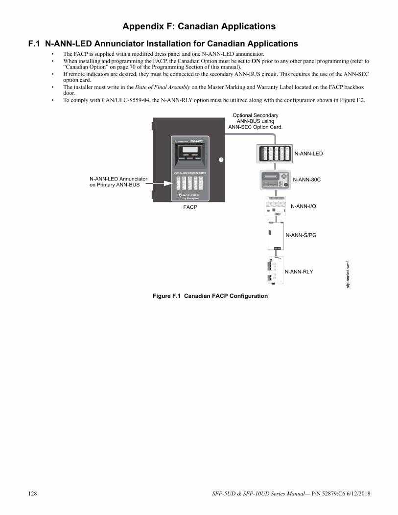
Appendix F: Canadian Applications
F.1 N-ANN-LED Annunciator Installation for Canadian Applications• The FACP is supplied with a modified dress panel and one N-ANN-LED annunciator.• When installing and programming the FACP, the Canadian Option must be set to ON prior to any other panel programming (refer to
“Canadian Option” on page 70 of the Programming Section of this manual).• If remote indicators are desired, they must be connected to the secondary ANN-BUS circuit. This requires the use of the ANN-SEC
option card.• The installer must write in the Date of Final Assembly on the Master Marking and Warranty Label located on the FACP backbox
door.• To comply with CAN/ULC-S559-04, the N-ANN-RLY option must be utilized along with the configuration shown in Figure F.2.
Figure F.1 Canadian FACP Configuration
FACP
N-ANN-LED Annunciatoron Primary ANN-BUS
sfp
-ann
led.
wm
f
N-ANN-LED
N-ANN-80C
N-ANN-I/O
N-ANN-S/PG
N-ANN-RLY
Optional Secondary ANN-BUS using
ANN-SEC Option Card.
128 SFP-5UD & SFP-10UD Series Manual— P/N 52879:C6 6/12/2018
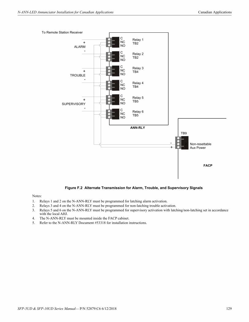
N-ANN-LED Annunciator Installation for Canadian Applications Canadian Applications
Notes:
1. Relays 1 and 2 on the N-ANN-RLY must be programmed for latching alarm activation.2. Relays 3 and 4 on the N-ANN-RLY must be programmed for non-latching trouble activation.3. Relays 5 and 6 on the N-ANN-RLY must be programmed for supervisory activation with latching/non-latching set in accordance
with the local AHJ.4. The N-ANN-RLY must be mounted inside the FACP cabinet.5. Refer to the N-ANN-RLY Document #53318 for installation instructions.
Figure F.2 Alternate Transmission for Alarm, Trouble, and Supervisory Signals
FACP
ANN-RLY
+ALARM
-
+TROUBLE
-
+SUPERVISORY
-
CNCNO
CNCNO
CNCNO
CNCNO
CNCNO
CNCNO
Relay 1TB2
Relay 2TB2
Relay 4TB4
Relay 6TB5
Relay 3TB4
Relay 5TB5
To Remote Station Receiver
TB9
Non-resettable Aux Power
21
-+
SFP-5UD & SFP-10UD Series Manual— P/N 52879:C6 6/12/2018 129

Index
Numerics10 Zone Main Circuit Board 1024 Hour Test Time 814XTM 121
installation 33see also Transmitter Module 18, 33
4XTM installation 325 Zone Main Circuit Board 9
AAC Loss Delay 68AC power 23AC power rating 13AC power requirements 110ACC audio message 55, 61accessories 18Account Code 80ACK
see also Acknowledge 12Acknowledge 12Acknowledge/Step 17, 96Ademco
contact ID format 113Adjective
list 62multiple entries 64
Adjective/Noun 62alarm 97
piezo pulse rate 17alarm relay 12, 28
contact rating 14Alarm Silence 13, 17, 96alarm verification 56, 100, 101ANN-BUS
guidelines 35ANN-I/O
LED zone assignments 72ANN-LED 45, 46, 48ANN-SEC option card 34applications 12Autosilence 101
NAC 66auxiliary power 27Auxiliary Trouble Input 14
Bbackbox
dimensions 18mounting 21
Backup Reporting 77Banner 67
setting 69battery 18, 24
precautions 24rating 13
battery box 18mounting 22, 23
battery calculations 112baud rate 93buttons
see also control buttons 12
Ccabinet
mounting 21CAC-5X 25
installation 31call limit 50, 90Canadian Applications 20Canadian Option 67, 70Central Station 75, 109
account code 80communications 106phone number 82Phone Numbers 78
Central Station/Remote Station Reporting 119charger capacity 13Charger Disable 67circuits 12Class A 18, 25, 31Class A Converter Module 18
installation 31Class B 12, 13, 24Clock Format 70Coded Operation 100coding
NAC 64two stage operation 65
combination circuit 26combination waterflow/supervisory 26
requirements 26wiring 26
communications format 83compatibility
see also device compatibility 12contact ID 113control buttons 12, 96controls 17current
nonresettable power 27resettable power 27total output 26
current requirements for system 110, 111
DDACT
onboard 75Date setting 70Daylight Savings Time 70Default Programming 127description 12
detector label 63Detector
adding description 62enable/disable 54
device compatibility 12dialer runaway 50, 90Digital Communicator 19dimensions
backbox 18
Downloading 108, 109dress panel 12, 18Drill 13, 17, 96
Eearth ground 23edit
detector screens 53Enable/Disable
zone 54End-of-Line resistor
IDC 13, 25, 26NAC 14, 27
Enter key 52Erase History 92Error Checking 109event code classification 113event codes 84exiting
programming 51, 52Read Status 51, 52
Ffail-safe
trouble relay 28features 12Form-C
see also relay 12freeze 24freeze signal
see also smoke detector monitoring 12
Gguidelines 35
HHazard Condition 99History 91
erase 92Maintenance Level 94view events 91
II3 detectors 24IDC 12, 13, 24
alarm current 13compatibility 24End-of_Line resistor 26End-of-Line resistor 13, 25maximum loop resistance 13, 24short circuit current 13standby current 13wiring 25
indicators 17see also LED 13
Initiating Device Circuit 12, 13, 24Class A 31
In-Line resistorIDC combination circuit 26
130 SFP-5UD & SFP-10UD Series Manual— P/N 52879:C6 6/12/2018
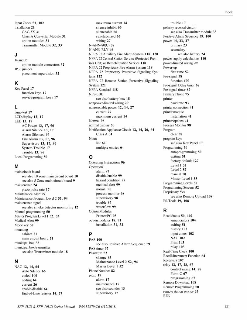
Index
Input Zones 53, 102installation 21
CAC-5X 31Class A Converter Module 31option modules 31Transmitter Module 32, 33
JJ4 and J5
option module connectors 32JP30 jumper
placement supervision 32
KKey Panel 17
function keys 17service/program keys 17
Llamp test 17LCD display 12, 17LED 13, 17
AC Power 13, 17, 96Alarm Silence 13, 17Alarm Silenced 96Fire Alarm 13, 17, 96Supervisory 13, 17, 96System Trouble 17Trouble 13, 96
Local Programming 50
Mmain circuit board
see also 10 zone main circuit board 10see also 5 Zone main circuit board 9
maintenance 24piezo pulse rate 17
Maintenance Alert 99Maintenance Program Level 2 52, 94maintenance signal
see also smoke detector monitoring 12Manual programming 50Master Program Level 1 52, 53Medical Alert 99Mode key 52mounting
cabinet 21main circuit board 21
municipal box 33municipal box transmitter
see also Transmitter module 18
NNAC 12, 14, 64
Auto Silence 66coded 100coding 64current 26enable/disable 64End-of-Line resistor 14, 27
maximum current 14silence inhibit 66silenceable 66synchronized 65wiring 27
N-ANN-80(C) 38N-ANN-RLY 46NFPA 72 Auxiliary Fire Alarm System 118, 120NFPA 72 Central Station Service (Protected Prem-ises Unit) or Remote Station Service 118NFPA 72 Proprietary Fire Alarm System 118NFPA 72 Proprietary Protective Signaling Sys-tems 122NFPA 72 Remote Station Protective SignalingSystem 121NFPA Standard 118NFS-LBB
see also battery box 18nonpower-limited wiring 29nonresettable power 12, 14, 27
current 27maximum current 14
Normal 96normal display 50Notification Appliance Circuit 12, 14, 26, 64
Class A 31Noun
list 62multiple entries 64
OOperating Instructions 96Operation
alarm 97disable/enable 99hazard condition 99medical alert 99normal 96process monitor 98supervisory 98trouble 97waterflow 99
Option ModulesPrinter/PC 93
option modules 18, 71installation 31, 32
PPAS 100
see also Positive Alarm Sequence 59PAS timer 67Password 52
change 93Maintenance Level 2 52, 94Master Level 1 52
Phone Number 82piezo 17
alarm 17maintenance 17see also sounder 13supervisory 17
trouble 17polarity reversal circuit
see also Transmitter module 33Positive Alarm Sequence 59, 100power 14, 23, 27
primary 23secondary
see also battery 24power supply calculations 110power-limited wiring 29Power-up
first time 52Pre-signal 58
function 100Pre-signal Delay timer 68Pre-signal timer 67Primary Phone 75printer
baud rate 93printer connection 41printer module
installation 41printer options 41Process Monitor 98Program
clear 92program keys
see also Key Panel 17Programming 50
autoprogramming 50exiting 51factory default 127Level 1 52Level 2 52manual 50Master Level 1 53
Programming Levels 52Programming Screens 52Proprietary Yes
see also Remote Upload 108PS-Tools 19, 108
RRead Status 50, 102
annunciators 104exiting 51history 103input zones 102NAC 102Print 103relay 103
Real-Time Clock 100Recall/Increment Function 64Receivers 107relay 12, 17, 28, 67
contact rating 14, 28Form-C 67programming 67
Remote Download 108Remote Programming 50remote station service 33REN
SFP-5UD & SFP-10UD Series Manual— P/N 52879:C6 6/12/2018 131
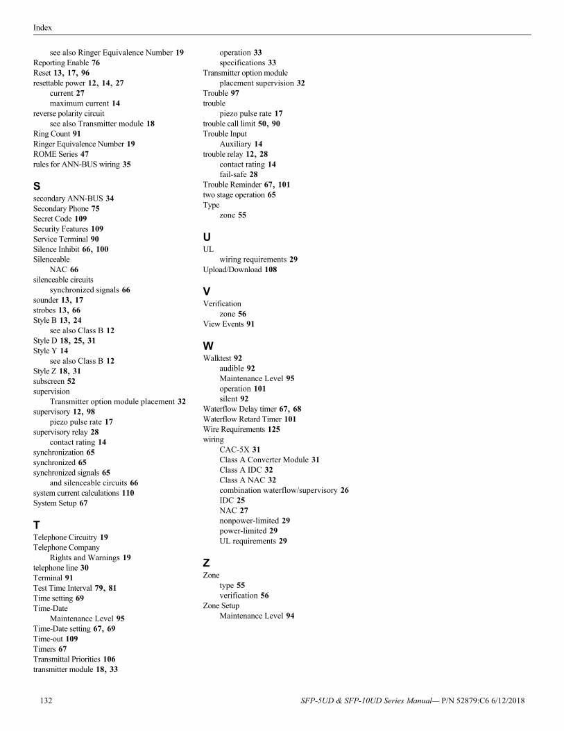
Index
see also Ringer Equivalence Number 19Reporting Enable 76Reset 13, 17, 96resettable power 12, 14, 27
current 27maximum current 14
reverse polarity circuitsee also Transmitter module 18
Ring Count 91Ringer Equivalence Number 19ROME Series 47rules for ANN-BUS wiring 35
Ssecondary ANN-BUS 34Secondary Phone 75Secret Code 109Security Features 109Service Terminal 90Silence Inhibit 66, 100Silenceable
NAC 66silenceable circuits
synchronized signals 66sounder 13, 17strobes 13, 66Style B 13, 24
see also Class B 12Style D 18, 25, 31Style Y 14
see also Class B 12Style Z 18, 31subscreen 52supervision
Transmitter option module placement 32supervisory 12, 98
piezo pulse rate 17supervisory relay 28
contact rating 14synchronization 65synchronized 65synchronized signals 65
and silenceable circuits 66system current calculations 110System Setup 67
TTelephone Circuitry 19Telephone Company
Rights and Warnings 19telephone line 30Terminal 91Test Time Interval 79, 81Time setting 69Time-Date
Maintenance Level 95Time-Date setting 67, 69Time-out 109Timers 67Transmittal Priorities 106transmitter module 18, 33
operation 33specifications 33
Transmitter option moduleplacement supervision 32
Trouble 97trouble
piezo pulse rate 17trouble call limit 50, 90Trouble Input
Auxiliary 14trouble relay 12, 28
contact rating 14fail-safe 28
Trouble Reminder 67, 101two stage operation 65Type
zone 55
UUL
wiring requirements 29Upload/Download 108
VVerification
zone 56View Events 91
WWalktest 92
audible 92Maintenance Level 95operation 101silent 92
Waterflow Delay timer 67, 68Waterflow Retard Timer 101Wire Requirements 125wiring
CAC-5X 31Class A Converter Module 31Class A IDC 32Class A NAC 32combination waterflow/supervisory 26IDC 25NAC 27nonpower-limited 29power-limited 29UL requirements 29
ZZone
type 55verification 56
Zone SetupMaintenance Level 94
132 SFP-5UD & SFP-10UD Series Manual— P/N 52879:C6 6/12/2018
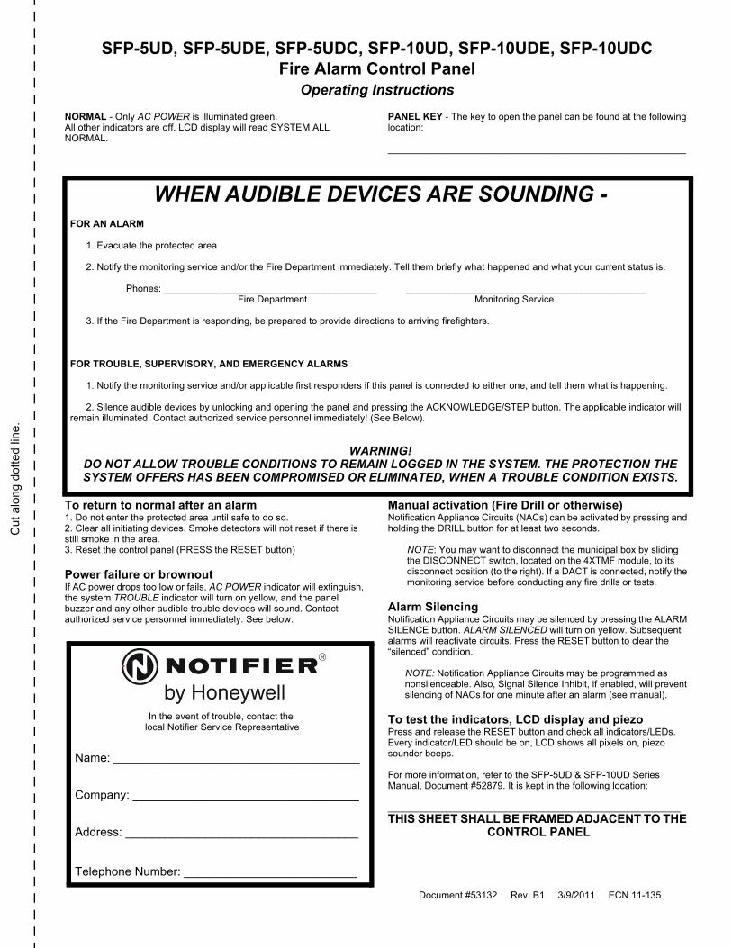
Cu
t alo
ng
dot
ted
lin
e.
SFP-5UD, SFP-5UDE, SFP-5UDC, SFP-10UD, SFP-10UDE, SFP-10UDCFire Alarm Control Panel
Operating Instructions
NORMAL - Only AC POWER is illuminated green. All other indicators are off. LCD display will read SYSTEM ALL NORMAL.
PANEL KEY - The key to open the panel can be found at the following location:
________________________________________________________
To return to normal after an alarm 1. Do not enter the protected area until safe to do so.2. Clear all initiating devices. Smoke detectors will not reset if there isstill smoke in the area.3. Reset the control panel (PRESS the RESET button)
Power failure or brownout If AC power drops too low or fails, AC POWER indicator will extinguish, the system TROUBLE indicator will turn on yellow, and the panel buzzer and any other audible trouble devices will sound. Contact authorized service personnel immediately. See below.
Manual activation (Fire Drill or otherwise)Notification Appliance Circuits (NACs) can be activated by pressing and holding the DRILL button for at least two seconds.
NOTE: You may want to disconnect the municipal box by sliding the DISCONNECT switch, located on the 4XTMF module, to its disconnect position (to the right). If a DACT is connected, notify the monitoring service before conducting any fire drills or tests.
Alarm Silencing Notification Appliance Circuits may be silenced by pressing the ALARM SILENCE button. ALARM SILENCED will turn on yellow. Subsequent alarms will reactivate circuits. Press the RESET button to clear the “silenced” condition.
NOTE: Notification Appliance Circuits may be programmed as nonsilenceable. Also, Signal Silence Inhibit, if enabled, will prevent silencing of NACs for one minute after an alarm (see manual).
To test the indicators, LCD display and piezoPress and release the RESET button and check all indicators/LEDs. Every indicator/LED should be on, LCD shows all pixels on, piezo sounder beeps.
For more information, refer to the SFP-5UD & SFP-10UD Series Manual, Document #52879. It is kept in the following location:
_______________________________________________________THIS SHEET SHALL BE FRAMED ADJACENT TO THE
CONTROL PANEL
WHEN AUDIBLE DEVICES ARE SOUNDING -FOR AN ALARM
1. Evacuate the protected area
2. Notify the monitoring service and/or the Fire Department immediately. Tell them briefly what happened and what your current status is.
Phones: ________________________________________ _____________________________________________ Fire Department Monitoring Service
3. If the Fire Department is responding, be prepared to provide directions to arriving firefighters.
FOR TROUBLE, SUPERVISORY, AND EMERGENCY ALARMS
1. Notify the monitoring service and/or applicable first responders if this panel is connected to either one, and tell them what is happening.
2. Silence audible devices by unlocking and opening the panel and pressing the ACKNOWLEDGE/STEP button. The applicable indicator willremain illuminated. Contact authorized service personnel immediately! (See Below).
WARNING!DO NOT ALLOW TROUBLE CONDITIONS TO REMAIN LOGGED IN THE SYSTEM. THE PROTECTION THE SYSTEM OFFERS HAS BEEN COMPROMISED OR ELIMINATED, WHEN A TROUBLE CONDITION EXISTS.
In the event of trouble, contact the local Notifier Service Representative
Name: _____________________________________
Company: __________________________________
Address: ___________________________________
Telephone Number: __________________________
Document #53132 Rev. B1 3/9/2011 ECN 11-135

Cut a
long do
tted lin
e.

Manufacturer Warranties and Limitation of LiabilityManufacturer Warranties. Subject to the limitations set forth herein, Manufacturerwarrants that the Products manufactured by it in its Northford, Connecticut facilityand sold by it to its authorized Distributors shall be free, under normal use andservice, from defects in material and workmanship for a period of thirty six months(36) months from the date of manufacture (effective Jan. 1, 2009). The Productsmanufactured and sold by Manufacturer are date stamped at the time of production.Manufacturer does not warrant Products that are not manufactured by it in itsNorthford, Connecticut facility but assigns to its Distributor, to the extent possible,any warranty offered by the manufacturer of such product. This warranty shall bevoid if a Product is altered, serviced or repaired by anyone other than Manufactureror its authorized Distributors. This warranty shall also be void if there is a failure tomaintain the Products and the systems in which they operate in proper workingconditions.
MANUFACTURER MAKES NO FURTHER WARRANTIES, AND DISCLAIMS ANYAND ALL OTHER WARRANTIES, EITHER EXPRESSED OR IMPLIED, WITHRESPECT TO THE PRODUCTS, TRADEMARKS, PROGRAMS AND SERVICESRENDERED BY MANUFACTURER INCLUDING WITHOUT LIMITATION,INFRINGEMENT, TITLE, MERCHANTABILITY, OR FITNESS FOR ANYPARTICULAR PURPOSE. MANUFACTURER SHALL NOT BE LIABLE FOR ANYPERSONAL INJURY OR DEATH WHICH MAY ARISE IN THE COURSE OF, OR ASA RESULT OF, PERSONAL, COMMERCIAL OR INDUSTRIAL USES OF ITSPRODUCTS.
This document constitutes the only warranty made by Manufacturer with respect toits products and replaces all previous warranties and is the only warranty made byManufacturer. No increase or alteration, written or verbal, of the obligation of thiswarranty is authorized. Manufacturer does not represent that its products willprevent any loss by fire or otherwise.
Warranty Claims. Manufacturer shall replace or repair, at Manufacturer's discretion,each part returned by its authorized Distributor and acknowledged by Manufacturerto be defective, provided that such part shall have been returned to Manufacturerwith all charges prepaid and the authorized Distributor has completed Manufacturer'sReturn Material Authorization form. The replacement part shall come fromManufacturer's stock and may be new or refurbished. THE FOREGOING ISDISTRIBUTOR'S SOLE AND EXCLUSIVE REMEDY IN THE EVENT OF AWARRANTY CLAIM.
Warn-HL-08-2009.fm
SFP-5UD & SFP-10UD Series Manual— P/N 52879:C6 6/12/2018 135

NOTIF12 ClinNorthf203-48www.n
IERtonville Road
ord, CT 06472-1610 USA4-7161otifier.com