GOT1000 Series Connection Manual (Microcomputer ...
348
MICROCOMPUTER CONNECTION MICROCOMPUTER CONNECTION MODBUS/RTU CONNECTION MODBUS/RTU CONNECTION MODBUS/TCP CONNECTION MODBUS/TCP CONNECTION CONNECTION TO SOUND OUTPUT UNIT CONNECTION TO SOUND OUTPUT UNIT CONNECTION TO EXTERNAL I/O DEVICE CONNECTION TO EXTERNAL I/O DEVICE FINGERPRINT AUTHENTICATION DEVICE CONNECTION FINGERPRINT AUTHENTICATION DEVICE CONNECTION BAR CODE READER CONNECTION BAR CODE READER CONNECTION REMOTE PERSONAL COMPUTER OPERATION CONNECTION REMOTE PERSONAL COMPUTER OPERATION CONNECTION VNC(R) SERVER CONNECTION VNC(R) SERVER CONNECTION VIDEO/RGB CONNECTION VIDEO/RGB CONNECTION PRINTER CONNECTION PRINTER CONNECTION MULTIMEDIA CONNECTION MULTIMEDIA CONNECTION RFID CONNECTION RFID CONNECTION MICROCOMPUTER CONNECTION MODBUS/RTU CONNECTION MODBUS/TCP CONNECTION CONNECTION TO SOUND OUTPUT UNIT CONNECTION TO EXTERNAL I/O DEVICE FINGERPRINT AUTHENTICATION DEVICE CONNECTION BAR CODE READER CONNECTION REMOTE PERSONAL COMPUTER OPERATION CONNECTION VNC(R) SERVER CONNECTION VIDEO/RGB CONNECTION PRINTER CONNECTION MULTIMEDIA CONNECTION RFID CONNECTION Series (Microcomputer, MODBUS Products, Peripherals) Connection Manual for GT Works3
-
Upload
khangminh22 -
Category
Documents
-
view
0 -
download
0
Transcript of GOT1000 Series Connection Manual (Microcomputer ...

MICROCOMPUTER CONNECTIONMICROCOMPUTER CONNECTION
MODBUS/RTU CONNECTIONMODBUS/RTU CONNECTION
MODBUS/TCP CONNECTIONMODBUS/TCP CONNECTION
CONNECTION TO SOUND OUTPUT UNITCONNECTION TO SOUND OUTPUT UNIT
CONNECTION TO EXTERNAL I/O DEVICECONNECTION TO EXTERNAL I/O DEVICE
FINGERPRINT AUTHENTICATION DEVICE CONNECTIONFINGERPRINT AUTHENTICATION DEVICE CONNECTION
BAR CODE READER CONNECTIONBAR CODE READER CONNECTION
REMOTE PERSONAL COMPUTER OPERATION CONNECTIONREMOTE PERSONAL COMPUTER OPERATION CONNECTION
VNC(R) SERVER CONNECTIONVNC(R) SERVER CONNECTION
VIDEO/RGB CONNECTIONVIDEO/RGB CONNECTION
PRINTER CONNECTIONPRINTER CONNECTION
MULTIMEDIA CONNECTIONMULTIMEDIA CONNECTION
RFID CONNECTIONRFID CONNECTION
MICROCOMPUTER CONNECTION
MODBUS/RTU CONNECTION
MODBUS/TCP CONNECTION
CONNECTION TO SOUND OUTPUT UNIT
CONNECTION TO EXTERNAL I/O DEVICE
FINGERPRINT AUTHENTICATION DEVICE CONNECTION
BAR CODE READER CONNECTION
REMOTE PERSONAL COMPUTER OPERATION CONNECTION
VNC(R) SERVER CONNECTION
VIDEO/RGB CONNECTION
PRINTER CONNECTION
MULTIMEDIA CONNECTION
RFID CONNECTION
Series
(Microcomputer, MODBUS Products, Peripherals)
Connection Manualfor GT Works3


SAFETY PRECAUTIONS(Always read these precautions before using this equipment.)
Before using this product, please read this manual and the relevant manuals introduced in this manual
carefully and pay full attention to safety to handle the product correctly.
The precautions given in this manual are concerned with this product.
In this manual, the safety precautions are ranked as "WARNING" and "CAUTION".
Note that the caution level may lead to a serious accident according to the circumstances.
Always follow the instructions of both levels because they are important to personal safety.
Please save this manual to make it accessible when required and always forward it to the end user.
[DESIGN PRECAUTIONS]
WARNING
● Some failures of the GOT, communication unit or cable may keep the outputs on or off.
An external monitoring circuit should be provided to check for output signals which may lead to a
serious accident.
Not doing so can cause an accident due to false output or malfunction.
● If a communication fault (including cable disconnection) occurs during monitoring on the GOT,
communication between the GOT and PLC CPU is suspended and the GOT becomes inoperative.
For bus connection : The CPU becomes faulty and the GOT becomes inoperative.
For other than bus connection : The GOT becomes inoperative.
A system where the GOT is used should be configured to perform any significant operation to the
system by using the switches of a device other than the GOT on the assumption that a GOT
communication fault will occur.
Not doing so can cause an accident due to false output or malfunction.
● Do not use the GOT as the warning device that may cause a serious accident.
An independent and redundant hardware or mechanical interlock is required to configure the device
that displays and outputs serious warning.
Failure to observe this instruction may result in an accident due to incorrect output or malfunction.
WARNING Indicates that incorrect handling may cause hazardous conditions, resulting in death or severe injury.
CAUTION Indicates that incorrect handling may cause hazardous conditions, resulting in medium or slight personal injury or physical damage.
A - 1

[DESIGN PRECAUTIONS]
WARNING
● Incorrect operation of the touch switch(s) may lead to a serious accident if the GOT backlight is goneout.When the GOT backlight goes out, the display section dims, while the input of the touch switch(s)remains active.This may confuse an operator in thinking that the GOT is in "screensaver" mode, who then tries torelease the GOT from this mode by touching the display section, which may cause a touch switch tooperate.Note that the following occurs on the GOT when the backlight goes out.<When using the GT1655-V, Handy GOT, GT15, GT14, GT12, GT11, or GT105 >
The POWER LED blinks (green/orange) and the monitor screen appears blank.<When using the GT1695, GT1685, GT1675, GT1672, GT1665, or GT1662>
The POWER LED blinks (green/orange) and the monitor screen appears dimmed.<When using the GT104 >
The monitor screen appears blank.<When using the GT103 or GT102 >
The monitor screen appears dimmed.
● The display section of the GT16, GT1595-X, GT14, GT12 or GT1020 are an analog-resistive type
touch panel.
If you touch the display section simultaneously in 2 points or more, the switch that is located around
the center of the touched point, if any, may operate.
Do not touch the display section in 2 points or more simultaneously.
Doing so may cause an accident due to incorrect output or malfunction.
● When programs or parameters of the controller (such as a PLC) that is monitored by the GOT are
changed, be sure to reset the GOT or shut off the power of the GOT at the same time.
Not doing so can cause an accident due to false output or malfunction.
A - 2

CAUTION
● Do not bundle the control and communication cables with main-circuit, power or other wiring.
Run the above cables separately from such wiring and keep them a minimum of 100mm apart.
Not doing so noise can cause a malfunction.
● Do not press the GOT display section with a pointed material as a pen or driver.
Doing so can result in a damage or failure of the display section.
● When the GOT is connected to the Ethernet network, the available IP address is restricted according
to the system configuration.
• When multiple GOTs are connected to the Ethernet network:
Do not set the IP address (192.168.0.18) for the GOTs and the controllers in the network.
• When a single GOT is connected to the Ethernet network:
Do not set the IP address (192.168.0.18) for the controllers except the GOT in the network.
Doing so can cause the IP address duplication. The duplication can negatively affect the
communication of the device with the IP address (192.168.0.18).
The operation at the IP address duplication depends on the devices and the system.
● Turn on the controllers and the network devices to be ready for communication before they
communicate with the GOT.
Failure to do so can cause a communication error on the GOT.
A - 3

[MOUNTING PRECAUTIONS]
WARNING
● Be sure to shut off all phases of the external power supply used by the system before mounting or
removing the GOT to/from the panel.
Not switching the power off in all phases can cause a unit failure or malfunction.
● Be sure to shut off all phases of the external power supply used by the system before mounting or
removing the communication unit, option function board or multi-color display board onto/from the
GOT.
Not doing so can cause the unit to fail or malfunction.
● Before mounting an optional function board or Multi-color display board, wear a static discharge wrist
strap to prevent the board from being damaged by static electricity.
CAUTION
● Use the GOT in the environment that satisfies the general specifications described in the User'sManual.Not doing so can cause an electric shock, fire, malfunction or product damage or deterioration.
● When mounting the GOT to the control panel, tighten the mounting screws in the specified torquerange.Undertightening can cause the GOT to drop, short circuit or malfunction.Overtightening can cause a drop, short circuit or malfunction due to the damage of the screws or theGOT.
● When loading the communication unit or option unit to the GOT (GT16, GT15), fit it to the extensioninterface of the GOT and tighten the mounting screws in the specified torque range.Undertightening can cause the GOT to drop, short circuit or malfunction.Overtightening can cause a drop, failure or malfunction due to the damage of the screws or unit.
● When mounting the multi-color display board onto the GOT (GT15), connect it to the correspondingconnector securely and tighten the mounting screws within the specified torque range.Loose tightening may cause the unit and/or GOT to malfunction due to poor contact.Overtightening may damage the screws, unit and/or GOT; they might malfunction.
● When mounting the option function board onto the GOT (GT16), connect it to the correspondingconnector securely and tighten the mounting screws within the specified torque range.
● When mounting an optional function board onto the GOT(GT15), fully connect it to the connectoruntil you hear a click.
● When mounting an optional function board onto the GOT(GT11), fully connect it to the connector.
● When inserting a CF card into the GOT(GT16, GT15, GT11), push it into the CF card interface ofGOT until the CF card eject button will pop out.Failure to do so may cause a malfunction due to poor contact.
● When inserting/removing a SD card into/from the GOT(GT14), turn the SD card access switch off inadvance. Failure to do so may corrupt data within the SD card.
A - 4

[MOUNTING PRECAUTIONS]
[WIRING PRECAUTIONS]
CAUTION
● When inserting/removing a CF card into/from the GOT(GT16, GT15, GT11), turn the CF card accessswitch off in advance.Failure to do so may corrupt data within the CF card.
● When removing a SD card from the GOT(GT14), make sure to support the SD card by hand, as it maypop out.Failure to do so may cause the SD card to drop from the GOT and break.
● When removing a CF card from the GOT, make sure to support the CF card by hand, as it may pop out.Failure to do so may cause the CF card to drop from the GOT and break.
● When installing a USB memory to the GOT(GT16, GT14), make sure to install the USB memory tothe USB interface firmly.Failure to do so may cause a malfunction due to poor contact.
● Before removing the USB memory from the GOT(GT16, GT14), operate the utility screen for removal.After the successful completion dialog box is displayed, remove the memory by hand carefully.Failure to do so may cause the USB memory to drop, resulting in a damage or failure of the memory.
● For closing the USB environmental protection cover, fix the cover by pushing the mark on the latchfirmly to comply with the protective structure.
● Remove the protective film of the GOT.
When the user continues using the GOT with the protective film, the film may not be removed.
● Operate and store the GOT in environments without direct sunlight, high temperature, dust, humidity,
and vibrations.
● When using the GOT in the environment of oil or chemicals, use the protective cover for oil.Failure to do so may cause failure or malfunction due to the oil or chemical entering into the GOT.
WARNING
● Be sure to shut off all phases of the external power supply used by the system before wiring.Failure to do so may result in an electric shock, product damage or malfunctions.
A - 5

[WIRING PRECAUTIONS]
CAUTION
● Please make sure to ground FG terminal and LG terminal and protective ground terminal of the GOTpower supply section by applying Class D Grounding (Class 3 Grounding Method) or higher which isused exclusively for the GOT.Not doing so may cause an electric shock or malfunction.
● Be sure to tighten any unused terminal screws with a torque of 0.5 to 0.8N•m.Failure to do so may cause a short circuit due to contact with a solderless terminal.
● Use applicable solderless terminals and tighten them with the specified torque.If any solderless spade terminal is used, it may be disconnected when the terminal screw comesloose, resulting in failure.
CAUTION
● Correctly wire the GOT power supply section after confirming the rated voltage and terminal
arrangement of the product.
Not doing so can cause a fire or failure.
● Tighten the terminal screws of the GOT power supply section in the specified torque range.
Undertightening can cause a short circuit or malfunction.
Overtightening can cause a short circuit or malfunction due to the damage of the screws or the GOT.
● Exercise care to avoid foreign matter such as chips and wire offcuts entering the GOT.
Not doing so can cause a fire, failure or malfunction.
● The module has an ingress prevention label on its top to prevent foreign matter, such as wire offcuts,
from entering the module during wiring.
Do not peel this label during wiring.
Before starting system operation, be sure to peel this label because of heat dissipation.
● Plug the bus connection cable by inserting it into the connector of the connected unit until it "clicks".
After plugging, check that it has been inserted snugly.
Not doing so can cause a malfunction due to a contact fault.
● Plug the communication cable into the connector of the connected unit and tighten the mounting and
terminal screws in the specified torque range.
Undertightening can cause a short circuit or malfunction.
Overtightening can cause a short circuit or malfunction due to the damage of the screws or unit.
● Plug the QnA/ACPU/Motion controller (A series) bus connection cable by inserting it into the
connector of the connected unit until it "clicks".
After plugging, check that it has been inserted snugly.
Not doing so can cause a malfunction due to a contact fault.
A - 6

[TEST OPERATION PRECAUTIONS]
[STARTUP/MAINTENANCE PRECAUTIONS]
WARNING
● Before performing the test operations of the user creation monitor screen (such as turning ON or
OFF bit device, changing the word device current value, changing the settings or current values of
the timer or counter, and changing the buffer memory current value), read through the manual
carefully and make yourself familiar with the operation method.
During test operation, never change the data of the devices which are used to perform significant
operation for the system.
False output or malfunction can cause an accident.
WARNING
● When power is on, do not touch the terminals.
Doing so can cause an electric shock or malfunction.
● Correctly connect the battery connector.
Do not charge, disassemble, heat, short-circuit, solder, or throw the battery into the fire.
Doing so will cause the battery to produce heat, explode, or ignite, resulting in injury and fire.
● Before starting cleaning or terminal screw retightening, always switch off the power externally in all
phases.
Not switching the power off in all phases can cause a unit failure or malfunction.
Undertightening can cause a short circuit or malfunction.
Overtightening can cause a short circuit or malfunction due to the damage of the screws or unit.
A - 7

[TOUCH PANEL PRECAUTIONS]
CAUTION
● Do not disassemble or modify the unit.Doing so can cause a failure, malfunction, injury or fire.
● Do not touch the conductive and electronic parts of the unit directly.Doing so can cause a unit malfunction or failure.
● The cables connected to the unit must be run in ducts or clamped.Not doing so can cause the unit or cable to be damaged due to the dangling, motion or accidentalpulling of the cables or can cause a malfunction due to a cable connection fault.
● When unplugging the cable connected to the unit, do not hold and pull the cable portion.Doing so can cause the unit or cable to be damaged or can cause a malfunction due to a cableconnection fault.
● Do not drop or apply strong impact to the unit.Doing so may damage the unit.
● Do not drop or give an impact to the battery mounted to the unit.Doing so may damage the battery, causing the battery fluid to leak inside the battery.If the battery is dropped or given an impact, dispose of it without using.
● Before touching the unit, always touch grounded metal, etc. to discharge static electricity fromhuman body, etc.Not doing so can cause the unit to fail or malfunction.
● Replace battery with GT15-BAT(GT16, GT15) or GT11-50BAT(GT14, GT12, GT11, GT10) byMitsubishi electric Co. only.Use of another battery may present a risk of fire or explosion.
● Dispose of used battery promptly. Keep away from children. Do not disassemble and do not dispose of in fire.
CAUTION
● For the analog-resistive film type touch panels, normally the adjustment is not required. However,the difference between a touched position and the object position may occur as the period of useelapses. When any difference between a touched position and the object position occurs, executethe touch panel calibration.
● When any difference between a touched position and the object position occurs, other object may beactivated. This may cause an unexpected operation due to incorrect output or malfunction.
A - 8

[BACKLIGHT REPLACEMENT PRECAUTIONS]
[DISPOSAL PRECAUTIONS]
[TRANSPORTATION PRECAUTIONS]
WARNING
● Be sure to shut off all phases of the external power supply of the GOT (and the PLC CPU in the case
of a bus topology) and remove the GOT from the control panel before replacing the backlight (when
using the GOT with the backlight replaceable by the user).
Not doing so can cause an electric shock.
Replacing a backlight without removing the GOT from the control panel can cause the backlight or
control panel to drop, resulting in an injury.
CAUTION
● Wear gloves for the backlight replacement when using the GOT with the backlight replaceable by theuser.Not doing so can cause an injury.
● Before replacing a backlight, allow 5 minutes or more after turning off the GOT when using the GOTwith the backlight replaceable by the user.Not doing so can cause a burn from heat of the backlight.
CAUTION
● When disposing of the product, handle it as industrial waste.
● When disposing of this product, treat it as industrial waste. When disposing of batteries, separate
them from other wastes according to the local regulations.
(For details of the battery directive in EU member states, refer to the User's Manual of the GOT to be
used.)
CAUTION
● When transporting lithium batteries, make sure to treat them based on the transport regulations.
(For details on models subject to restrictions, refer to the User's Manual for the GOT you are using.)
● Make sure to transport the GOT main unit and/or relevant unit(s) in the manner they will not be
exposed to the impact exceeding the impact resistance described in the general specifications of the
User's Manual, as they are precision devices.
Failure to do so may cause the unit to fail.
Check if the unit operates correctly after transportation.
A - 9

SAFETY PRECAUTIONS .........................................................................................................................A - 1
INTRODUCTION ....................................................................................................................................A - 10
CONTENTS ............................................................................................................................................A - 10
MANUALS...............................................................................................................................................A - 16
QUICK REFERENCE .............................................................................................................................A - 18
ABBREVIATIONS AND GENERIC TERMS ...........................................................................................A - 20
HOW TO READ THIS MANUAL .............................................................................................................A - 25
1.PREPARATORY PROCEDURES FOR MONITORING
1.1 Setting the Communication Interface............................................................................................... 1 - 3
1.1.1 Setting connected equipment (Channel setting)................................................................... 1 - 3
1.1.2 I/F communication setting................................................................................................... 1 - 10
1.1.3 Precautions......................................................................................................................... 1 - 12
1.2 Writing the Project Data and OS onto the GOT............................................................................. 1 - 13
1.2.1 Writing the project data and OS onto the GOT................................................................... 1 - 13
1.2.2 Checking the project data and OS writing on GOT............................................................. 1 - 14
1.3 Option Devices for the Respective Connection ............................................................................. 1 - 15
1.3.1 Communication module ...................................................................................................... 1 - 15
1.3.2 Option unit .......................................................................................................................... 1 - 16
1.3.3 Conversion cable ................................................................................................................ 1 - 16
1.3.4 Connector conversion adapter............................................................................................ 1 - 16
1.3.5 Serial Multi-Drop Connection Unit ...................................................................................... 1 - 16
1.3.6 RS-232/485 signal conversion adapter............................................................................... 1 - 16
1.3.7 Installing a unit on another unit (Checking the unit installation position) ............................ 1 - 17
1.4 Connection Cables for the Respective Connection ....................................................................... 1 - 24
1.4.1 GOT connector specifications............................................................................................. 1 - 24
1.4.2 Coaxial cable connector connection method ...................................................................... 1 - 27
1.4.3 Terminating resistors of GOT ............................................................................................. 1 - 28
1.4.4 Setting the RS-232/485 signal conversion adaptor ............................................................ 1 - 31
1.5 Verifying GOT Recognizes Connected Equipment........................................................................ 1 - 32
1.6 Checking for Normal Monitoring .................................................................................................... 1 - 36
1.6.1 Check on the GOT.............................................................................................................. 1 - 36
1.6.2 Confirming the communication state on the GOT side (For Ethernet connection) ............. 1 - 38
1.6.3 Confirming the communication state with each station (station monitoring function) ......... 1 - 40
1.6.4 Check on the PLC.............................................................................................................. 1 - 43
INTRODUCTION
Thank you for choosing Mitsubishi Graphic Operation Terminal (Mitsubishi GOT).
Read this manual and make sure you understand the functions and performance of the GOT thoroughly
in advance to ensure correct use.
CONTENTS
A - 10

MICROCOMPUTER CONNECTION
2.MICROCOMPUTER CONNECTION (SERIAL)
2.1 Microcomputer Connection (Serial) ................................................................................................. 2 - 2
2.2 System Configuration ...................................................................................................................... 2 - 4
2.2.1 For the microcomputer connection (serial) ........................................................................... 2 - 4
2.3 Connection Diagram........................................................................................................................ 2 - 6
2.3.1 RS-232 cable........................................................................................................................ 2 - 6
2.3.2 RS-422 cable........................................................................................................................ 2 - 8
2.4 Device Data Area........................................................................................................................... 2 - 10
2.4.1 D devices............................................................................................................................ 2 - 11
2.4.2 R devices............................................................................................................................ 2 - 15
2.4.3 L devices ............................................................................................................................ 2 - 16
2.4.4 M devices ........................................................................................................................... 2 - 17
2.4.5 SD devices ......................................................................................................................... 2 - 18
2.4.6 SM devices ......................................................................................................................... 2 - 21
2.5 Message Formats .......................................................................................................................... 2 - 23
2.5.1 Data format type and application........................................................................................ 2 - 23
2.5.2 List of commands ............................................................................................................... 2 - 25
2.5.3 Formats 1, 2 (GOT-A900 Series microcomputer connection) ............................................ 2 - 28
2.5.4 Formats 3 to 6 (A compatible 1C frame) ............................................................................ 2 - 41
2.5.5 Formats 7 to 10 (QnA compatible 3C/4C frame) ................................................................ 2 - 46
2.5.6 Formats 11 to 13 (Digital Electronics Corporation's memory link method)......................... 2 - 54
2.5.7 Formats 14, 15 (GOT-F900 Series microcomputer connection)......................................... 2 - 63
2.6 GOT Side Settings......................................................................................................................... 2 - 77
2.6.1 Setting communication interface (Communication settings)............................................... 2 - 77
2.6.2 Communication detail settings............................................................................................ 2 - 78
2.7 System Configuration Examples.................................................................................................... 2 - 79
2.8 Device Range that Can Be Set...................................................................................................... 2 - 82
2.9 Precautions.................................................................................................................................... 2 - 83
3.MICROCOMPUTER CONNECTION (ETHERNET)
3.1 Microcomputer connection (Ethernet).............................................................................................. 3 - 2
3.2 System Configuration ...................................................................................................................... 3 - 2
3.2.1 For the microcomputer connection (Ethernet) ...................................................................... 3 - 2
3.3 Device Data Area............................................................................................................................. 3 - 3
3.3.1 D devices.............................................................................................................................. 3 - 4
3.3.2 R devices.............................................................................................................................. 3 - 8
3.3.3 L devices .............................................................................................................................. 3 - 9
3.3.4 M devices ........................................................................................................................... 3 - 10
3.3.5 SD devices ......................................................................................................................... 3 - 11
3.3.6 SM devices ......................................................................................................................... 3 - 14
3.4 Message Formats .......................................................................................................................... 3 - 16
3.4.1 Data format type and application........................................................................................ 3 - 16
3.4.2 List of commands ............................................................................................................... 3 - 17
3.4.3 Formats 1, 2 (GOT-A900 Series microcomputer connection) ............................................ 3 - 19
3.4.4 Formats 3, 4 (GOT-F900 series microcomputer connection) ............................................. 3 - 31
3.4.5 Formats 5(Digital Electronics Corporation's memory link method)..................................... 3 - 45
A - 11

3.4.6 Formats 6, 7 (4E frame)...................................................................................................... 3 - 50
3.4.7 Formats 8, 9 (QnA compatible 3E frame) ........................................................................... 3 - 60
3.5 GOT Side Settings......................................................................................................................... 3 - 69
3.5.1 Setting communication interface (Communication settings)............................................... 3 - 69
3.5.2 Communication detail settings............................................................................................ 3 - 69
3.6 System Configuration Examples.................................................................................................... 3 - 72
3.7 Device Range that Can Be Set ...................................................................................................... 3 - 73
3.8 Precautions.................................................................................................................................... 3 - 74
MODBUS CONNECTIONS
4.MODBUS(R)/RTU CONNECTION
4.1 Connectable Model List ................................................................................................................... 4 - 2
4.2 System Configuration ...................................................................................................................... 4 - 3
4.2.1 Connecting to MODBUS(R)/RTU equipment........................................................................ 4 - 3
4.3 Connection Diagram ........................................................................................................................ 4 - 4
4.3.1 RS-232 cable ........................................................................................................................ 4 - 4
4.3.2 RS-422/485 cable ................................................................................................................. 4 - 5
4.4 GOT Side Settings......................................................................................................................... 4 - 12
4.4.1 Setting communication interface (Communication settings)............................................... 4 - 12
4.4.2 Communication detail settings............................................................................................ 4 - 12
4.5 MODBUS(R)/RTU Equipment Side Setting ................................................................................... 4 - 14
4.5.1 Communication settings ..................................................................................................... 4 - 14
4.5.2 Station number setting........................................................................................................ 4 - 17
4.6 Precautions.................................................................................................................................... 4 - 17
5.MODBUS(R)/TCP CONNECTION
5.1 Connectable Model List ................................................................................................................... 5 - 2
5.2 System Configuration ...................................................................................................................... 5 - 2
5.2.1 Connecting to MODBUS(R)/TCP equipment........................................................................ 5 - 2
5.3 GOT Side Settings........................................................................................................................... 5 - 3
5.3.1 Setting communication interface (Communication settings)................................................. 5 - 3
5.3.2 Communication detail settings.............................................................................................. 5 - 3
5.3.3 Ethernet setting..................................................................................................................... 5 - 5
5.4 MODBUS(R)/TCP Equipment Setting ............................................................................................. 5 - 6
5.5 Device Range that Can Be Set ........................................................................................................ 5 - 6
5.6 Example of Connection.................................................................................................................. 5 - 10
5.6.1 Connecting to SCHNEIDER PLC
(Modicon Premium series and Modicon Quantum series).................................................. 5 - 10
5.6.2 Connecting to YOKOGAWA PLC (STARDOM).................................................................. 5 - 12
5.7 Precautions.................................................................................................................................... 5 - 15
CONNECTIONS TO PERIPHERAL EQUIPMENT
6.CONNECTION TO SOUND OUTPUT UNIT
6.1 Connectable Model List ................................................................................................................... 6 - 2
6.2 System Configuration ...................................................................................................................... 6 - 2
A - 12
6.2.1 Connecting to sound output unit ........................................................................................... 6 - 2
6.3 GOT Side Settings........................................................................................................................... 6 - 3
6.3.1 Setting communication interface .......................................................................................... 6 - 3
6.4 Precautions...................................................................................................................................... 6 - 4
7.CONNECTION TO EXTERNAL I/O DEVICE
7.1 Connectable Model List ................................................................................................................... 7 - 2
7.2 System Configuration ...................................................................................................................... 7 - 2
7.2.1 Connecting to the external I/O device .................................................................................. 7 - 2
7.3 Connection Diagram........................................................................................................................ 7 - 4
7.3.1 Connection cable between external I/O unit and operation panel ........................................ 7 - 4
7.3.2 Connection cable between external I/O unit
and connector/terminal block converter module ................................................................... 7 - 6
7.3.3 Connection diagram between connector/terminal block converter module
and user-created original operation panel ............................................................................ 7 - 8
7.4 GOT Side Settings......................................................................................................................... 7 - 12
7.4.1 Setting communication interface ........................................................................................ 7 - 12
7.5 Precautions.................................................................................................................................... 7 - 13
8.FINGERPRINT AUTHENTICATION DEVICE CONNECTION
8.1 Connectable Model List ................................................................................................................... 8 - 2
8.2 System Configuration ...................................................................................................................... 8 - 2
8.2.1 Connecting to fingerprint authentication device.................................................................... 8 - 2
8.3 GOT Side Settings........................................................................................................................... 8 - 3
8.3.1 Setting communication interface .......................................................................................... 8 - 3
8.4 Precautions...................................................................................................................................... 8 - 4
9.BAR CODE READER CONNECTION
9.1 Connectable Model List ................................................................................................................... 9 - 2
9.2 System Configuration ...................................................................................................................... 9 - 2
9.2.1 Connecting to bar code reader ............................................................................................. 9 - 2
9.3 GOT Side Settings........................................................................................................................... 9 - 3
9.3.1 Setting communication interface .......................................................................................... 9 - 3
9.3.2 Communication detail settings.............................................................................................. 9 - 4
9.4 System Configuration Examples...................................................................................................... 9 - 5
9.5 Precautions...................................................................................................................................... 9 - 7
10.PC REMOTE CONNECTION
10.1 Connectable Model List ................................................................................................................. 10 - 2
10.2 Serial Connection .......................................................................................................................... 10 - 2
10.2.1 System Configuration ......................................................................................................... 10 - 2
10.2.2 Connection Diagram........................................................................................................... 10 - 3
10.2.3 GOT Side Settings.............................................................................................................. 10 - 4
10.2.4 Communication detail settings............................................................................................ 10 - 5
10.2.5 Installing and setting up computer remote operation driver................................................ 10 - 6
10.2.6 Precautions......................................................................................................................... 10 - 6
A - 13
10.3 Ethernet Connection ...................................................................................................................... 10 - 7
10.3.1 System Configuration ......................................................................................................... 10 - 7
10.3.2 GOT Side Settings.............................................................................................................. 10 - 8
10.3.3 Install and setting the required software ............................................................................. 10 - 8
10.3.4 Precautions......................................................................................................................... 10 - 8
11.VNC(R) SERVER CONNECTION
11.1 Connectable Model List ................................................................................................................. 11 - 2
11.2 System Configuration .................................................................................................................... 11 - 2
11.3 GOT Side Settings......................................................................................................................... 11 - 3
11.3.1 VNC(R) server function setting ........................................................................................... 11 - 3
11.3.2 Setting communication interface (Communication settings)............................................... 11 - 3
11.4 Setting in Personal Computer ........................................................................................................ 11 - 4
12.VIDEO/RGB CONNECTION
12.1 Connectable Model List ................................................................................................................. 12 - 2
12.2 System Configuration .................................................................................................................... 12 - 2
12.2.1 Displaying video image on GOT ......................................................................................... 12 - 2
12.2.2 Displaying GOT screen on external monitor....................................................................... 12 - 3
12.3 Connection Diagram ...................................................................................................................... 12 - 4
12.3.1 Coaxial cable ...................................................................................................................... 12 - 4
12.3.2 Analog RGB cable .............................................................................................................. 12 - 4
12.4 GOT Side Settings......................................................................................................................... 12 - 6
12.4.1 Setting communication interface......................................................................................... 12 - 6
12.4.2 Communication detail settings............................................................................................ 12 - 7
12.4.3 Setting the video/RGB function........................................................................................... 12 - 7
12.5 Precautions.................................................................................................................................... 12 - 7
13.PRINTER CONNECTION
13.1 Connectable Model List ................................................................................................................. 13 - 2
13.2 System Configuration .................................................................................................................... 13 - 2
13.2.1 Connecting to PictBridge compatible printer....................................................................... 13 - 2
13.2.2 Connecting to serial printer................................................................................................. 13 - 3
13.3 GOT Side Settings......................................................................................................................... 13 - 4
13.3.1 Setting communication interface......................................................................................... 13 - 4
13.3.2 Communication detail settings............................................................................................ 13 - 5
13.4 Precautions.................................................................................................................................... 13 - 6
14.MULTIMEDIA CONNECTION
14.1 Connectable Model List ................................................................................................................. 14 - 2
14.2 System Configuration .................................................................................................................... 14 - 2
14.2.1 Saving video image and displaying it on GOT.................................................................... 14 - 2
14.2.2 Sending video image to personal computer ....................................................................... 14 - 3
14.3 Connection Diagram ...................................................................................................................... 14 - 4
14.3.1 Coaxial cable ...................................................................................................................... 14 - 4
14.4 GOT Side Settings......................................................................................................................... 14 - 5
14.4.1 Setting communication interface......................................................................................... 14 - 5
14.4.2 Communication detail settings............................................................................................ 14 - 6
A - 14

14.4.3 Installing and setting multimedia interaction tool onto personal computer ......................... 14 - 6
14.4.4 Setting the multimedia function .......................................................................................... 14 - 6
14.4.5 Set the gateway function .................................................................................................... 14 - 6
14.5 Precautions.................................................................................................................................... 14 - 7
15.RFID CONNECTION
15.1 Connectable Model List ................................................................................................................. 15 - 2
15.2 System Configuration .................................................................................................................... 15 - 2
15.2.1 Connecting to RFID ............................................................................................................ 15 - 2
15.3 GOT Side Settings......................................................................................................................... 15 - 3
15.3.1 Setting communication interface ........................................................................................ 15 - 3
15.3.2 Communication detail settings............................................................................................ 15 - 4
15.4 Precautions.................................................................................................................................... 15 - 5
INDEX
REVISIONS
A - 15

MANUALS
The following table lists the manual relevant to this product.Refer to each manual for any purpose.
Screen creation software manuals
Connection manuals
Extended and option function manuals
GT SoftGOT1000 manuals
Manual Name PackagingManual Number
(Model code)
GT Works3 Version1 Installation Procedure Manual Enclosed in product -
GT Designer3 Version1 Screen Design Manual (Fundamentals) 1/2, 2/2 Stored in CD-ROMSH-080866ENG
(1D7MB9)
GT Designer3 Version1 Screen Design Manual (Functions) 1/2, 2/2 Stored in CD-ROMSH-080867ENG
(1D7MC1)
GT Simulator3 Version1 Operating Manual for GT Works3 Stored in CD-ROMSH-080861ENG
(1D7MB1)
GT Converter2 Version3 Operating Manual for GT Works3 Stored in CD-ROMSH-080862ENG
(1D7MB2)
Manual Name PackagingManual Number
(Model code)
GOT1000 Series Connection Manual (Mitsubishi Products) for GT Works3 Stored in CD-ROMSH-080868ENG
(1D7MC2)
GOT1000 Series Connection Manual (Non-Mitsubishi Products 1) for GT Works3 Stored in CD-ROMSH-080869ENG
(1D7MC3)
GOT1000 Series Connection Manual (Non-Mitsubishi Products 2) for GT Works3 Stored in CD-ROMSH-080870ENG
(1D7MC4)
GOT1000 Series Connection Manual (Microcomputer, MODBUS Products, Peripherals) for GT
Works3Stored in CD-ROM
SH-080871ENG
(1D7MC5)
Manual Name PackagingManual Number
(Model code)
GOT1000 Series Gateway Functions Manual for GT Works3 Stored in CD-ROMSH-080858ENG
(1D7MA7)
GOT1000 Series MES Interface Function Manual for GT Works3 Stored in CD-ROMSH-080859ENG
(1D7MA8)
GOT1000 Series User's Manual (Extended Functions, Option Functions) for GT Works3 Stored in CD-ROMSH-080863ENG
(1D7MB3)
Manual Name PackagingManual Number
(Model code)
GT SoftGOT1000 Version3 Operating Manual for GT Works3 Stored in CD-ROMSH-080860ENG
(1D7MA9)
A - 16

GT16 manuals
GT15 manuals
GT14 manuals
GT12 manuals
GT11 manuals
GT10 manuals
Manual Name PackagingManual Number
(Model code)
GT16 User's Manual (Hardware) Stored in CD-ROMSH-080928ENG
(1D7MD3)
GT16 User's Manual (Basic Utility) Stored in CD-ROMSH-080929ENG
(1D7MD4)
GT16 Handy GOT User's Manual Stored in CD-ROM
JY997D41201
JY997D41202
(09R821)
Manual Name PackagingManual Number
(Model code)
GT15 User's Manual Stored in CD-ROMSH-080528ENG
(1D7M23)
Manual Name PackagingManual Number
(Model code)
GT14 User's Manual Stored in CD-ROMJY997D44801
(09R823)
Manual Name PackagingManual Number
(Model code)
GT12 User's Manual Stored in CD-ROMSH-080977ENG
(1D7ME1)
Manual Name PackagingManual Number
(Model code)
GT11 User's Manual Stored in CD-ROMJY997D17501
(09R815)
GT11 Handy GOT User's Manual Stored in CD-ROM
JY997D20101
JY997D20102
(09R817)
Manual Name PackagingManual Number
(Model code)
GT10 User's Manual Stored in CD-ROMJY997D24701
(09R819)
A - 17
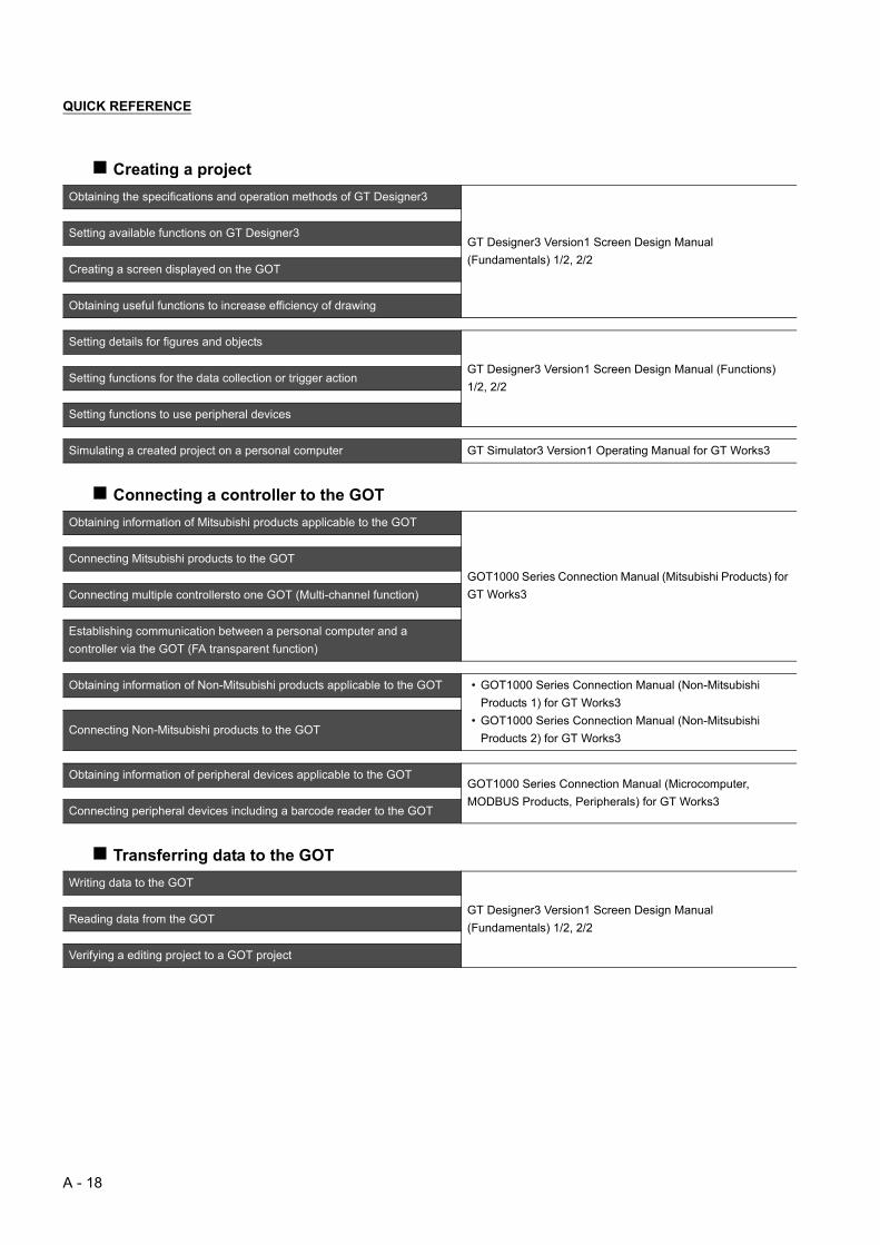
QUICK REFERENCE
Creating a project
Connecting a controller to the GOT
Transferring data to the GOT
Obtaining the specifications and operation methods of GT Designer3
GT Designer3 Version1 Screen Design Manual
(Fundamentals) 1/2, 2/2
Setting available functions on GT Designer3
Creating a screen displayed on the GOT
Obtaining useful functions to increase efficiency of drawing
Setting details for figures and objects
GT Designer3 Version1 Screen Design Manual (Functions)
1/2, 2/2Setting functions for the data collection or trigger action
Setting functions to use peripheral devices
Simulating a created project on a personal computer GT Simulator3 Version1 Operating Manual for GT Works3
Obtaining information of Mitsubishi products applicable to the GOT
GOT1000 Series Connection Manual (Mitsubishi Products) for
GT Works3
Connecting Mitsubishi products to the GOT
Connecting multiple controllersto one GOT (Multi-channel function)
Establishing communication between a personal computer and a
controller via the GOT (FA transparent function)
Obtaining information of Non-Mitsubishi products applicable to the GOT • GOT1000 Series Connection Manual (Non-Mitsubishi
Products 1) for GT Works3
• GOT1000 Series Connection Manual (Non-Mitsubishi
Products 2) for GT Works3Connecting Non-Mitsubishi products to the GOT
Obtaining information of peripheral devices applicable to the GOTGOT1000 Series Connection Manual (Microcomputer,
MODBUS Products, Peripherals) for GT Works3Connecting peripheral devices including a barcode reader to the GOT
Writing data to the GOT
GT Designer3 Version1 Screen Design Manual
(Fundamentals) 1/2, 2/2Reading data from the GOT
Verifying a editing project to a GOT project
A - 18
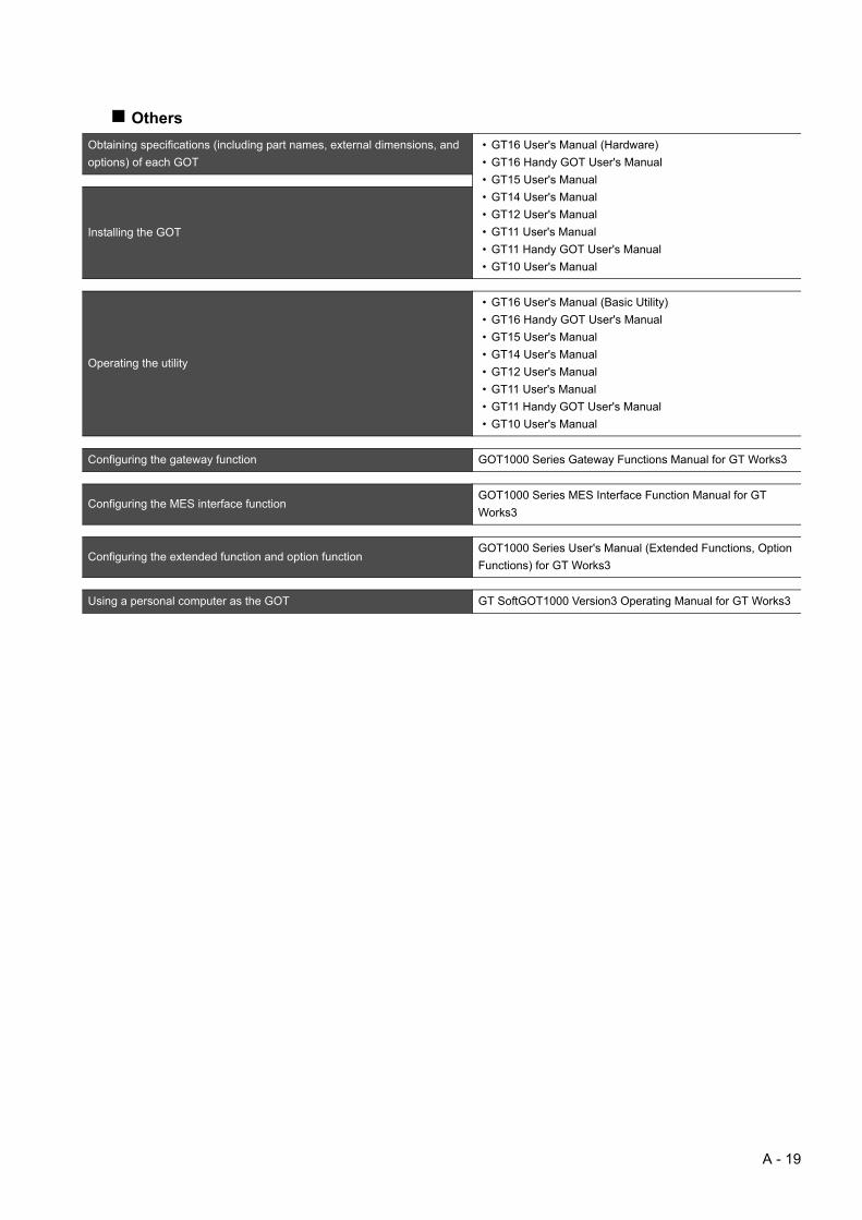
Others
Obtaining specifications (including part names, external dimensions, and
options) of each GOT
• GT16 User's Manual (Hardware)
• GT16 Handy GOT User's Manual
• GT15 User's Manual
• GT14 User's Manual
• GT12 User's Manual
• GT11 User's Manual
• GT11 Handy GOT User's Manual
• GT10 User's Manual
Installing the GOT
Operating the utility
• GT16 User's Manual (Basic Utility)
• GT16 Handy GOT User's Manual
• GT15 User's Manual
• GT14 User's Manual
• GT12 User's Manual
• GT11 User's Manual
• GT11 Handy GOT User's Manual
• GT10 User's Manual
Configuring the gateway function GOT1000 Series Gateway Functions Manual for GT Works3
Configuring the MES interface functionGOT1000 Series MES Interface Function Manual for GT
Works3
Configuring the extended function and option functionGOT1000 Series User's Manual (Extended Functions, Option
Functions) for GT Works3
Using a personal computer as the GOT GT SoftGOT1000 Version3 Operating Manual for GT Works3
A - 19

ABBREVIATIONS AND GENERIC TERMS
GOT
Abbreviations and generic terms Description
GOT1000
Series
GT1695 GT1695M-X Abbreviation of GT1695M-XTBA, GT1695M-XTBD
GT1685 GT1685M-S Abbreviation of GT1685M-STBA, GT1685M-STBD
GT1675
GT1675M-S Abbreviation of GT1675M-STBA, GT1675M-STBD
GT1675M-V Abbreviation of GT1675M-VTBA, GT1675M-VTBD
GT1675-VN Abbreviation of GT1675-VNBA, GT1675-VNBD
GT1672 GT1672-VN Abbreviation of GT1672-VNBA, GT1672-VNBD
GT1665GT1665M-S Abbreviation of GT1665M-STBA, GT1665M-STBD
GT1665M-V Abbreviation of GT1665M-VTBA, GT1665M-VTBD
GT1662 GT1662-VN Abbreviation of GT1662-VNBA, GT1662-VNBD
GT1655 GT1655-V Abbreviation of GT1655-VTBD
GT16 Abbreviation of GT1695, GT1685, GT1675, GT1672, GT1665, GT1662, GT1655, GT16 Handy GOT
GT1595 GT1595-X Abbreviation of GT1595-XTBA, GT1595-XTBD
GT1585GT1585V-S Abbreviation of GT1585V-STBA, GT1585V-STBD
GT1585-S Abbreviation of GT1585-STBA, GT1585-STBD
GT157
GT1575V-S Abbreviation of GT1575V-STBA, GT1575V-STBD
GT1575-S Abbreviation of GT1575-STBA, GT1575-STBD
GT1575-V Abbreviation of GT1575-VTBA, GT1575-VTBD
GT1575-VN Abbreviation of GT1575-VNBA, GT1575-VNBD
GT1572-VN Abbreviation of GT1572-VNBA, GT1572-VNBD
GT156GT1565-V Abbreviation of GT1565-VTBA, GT1565-VTBD
GT1562-VN Abbreviation of GT1562-VNBA, GT1562-VNBD
GT155
GT1555-V Abbreviation of GT1555-VTBD
GT1555-Q Abbreviation of GT1555-QTBD, GT1555-QSBD
GT1550-Q Abbreviation of GT1550-QLBD
GT15 Abbreviation of GT1595, GT1585, GT157 , GT156 , GT155
GT145GT1455-Q Abbreviation of GT1455-QTBDE, GT1455-QTBD
GT1450-Q Abbreviation of GT1450-QLBDE, GT1450-QLBD
GT14 Abbreviation of GT1455-Q, GT1450-Q
GT1275 GT1275-V Abbreviation of GT1275-VNBA, GT1275-VNBD
GT1265 GT1265-V Abbreviation of GT1265-VNBA, GT1265-VNBD
GT12 Abbreviation of GT1275, GT1265
GT115GT1155-Q
Abbreviation of GT1155-QTBDQ, GT1155-QSBDQ, GT1155-QTBDA, GT1155-QSBDA,
GT1155-QTBD, GT1155-QSBD
GT1150-Q Abbreviation of GT1150-QLBDQ, GT1150-QLBDA, GT1150-QLBD
GT11 Abbreviation of GT115 , GT11 Handy GOT,
GT105GT1055-Q Abbreviation of GT1055-QSBD
GT1050-Q Abbreviation of GT1050-QBBD
GT104GT1045-Q Abbreviation of GT1045-QSBD
GT1040-Q Abbreviation of GT1040-QBBD
GT1030
Abbreviation of GT1030-LBD, GT1030-LBD2, GT1030-LBL, GT1030-LBDW, GT1030-LBDW2,
GT1030-LBLW, GT1030-LWD, GT1030-LWD2, GT1030-LWL, GT1030-LWDW, GT1030-LWDW2,
GT1030-LWLW, GT1030-HBD, GT1030-HBD2, GT1030-HBL, GT1030-HBDW, GT1030-HBDW2,
GT1030-HBLW, GT1030-HWD, GT1030-HWD2, GT1030-HWL, GT1030-HWDW, GT1030-HWDW2,
GT1030-HWLW
GT1020
Abbreviation of GT1020-LBD, GT1020-LBD2, GT1020-LBL, GT1020-LBDW, GT1020-LBDW2,
GT1020-LBLW, GT1020-LWD, GT1020LWD2, GT1020-LWL, GT1020-LWDW, GT1020-LWDW2,
GT1020-LWLW
GT10 Abbreviation of GT105 , GT104 , GT1030, GT1020
A - 20

Communication unit
*1 A9GT-QJ71LP23 + GT15-75IF900 set
*2 A9GT-QJ71BR13 + GT15-75IF900 set
*3 A8GT-J61BT13 + GT15-75IF900 set
Option unit
*1 GT15-CFEX + GT15-CFEXIF + GT15-C08CF set.
GOT1000
Series
Handy
GOT
GT16
Handy
GOT
GT1665HS-V Abbreviation of GT1665HS-VTBD
GT11
Handy
GOT
GT1155HS-Q Abbreviation of GT1155HS-QSBD
GT1150HS-Q Abbreviation of GT1150HS-QLBD
GT SoftGOT1000 Abbreviation of GT SoftGOT1000
GOT900 Series Abbreviation of GOT-A900 series, GOT-F900 series
GOT800 Series Abbreviation of GOT-800 series
Abbreviations and generic terms Description
Bus connection unitGT15-QBUS, GT15-QBUS2, GT15-ABUS, GT15-ABUS2, GT15-75QBUSL, GT15-75QBUS2L,
GT15-75ABUSL, GT15-75ABUS2L
Serial communication unit GT15-RS2-9P, GT15-RS4-9S, GT15-RS4-TE
RS-422 conversion unit GT15-RS2T4-9P, GT15-RS2T4-25P
Ethernet communication unit GT15-J71E71-100
MELSECNET/H communication unit GT15-J71LP23-25, GT15-J71BR13
MELSECNET/10 communication unit GT15-75J71LP23-Z*1, GT15-75J71BR13-Z*2
CC-Link IE Controller Network communication
unitGT15-J71GP23-SX
CC-Link IE Field Network Communication Unit GT15-J71GF13-T2
CC-Link communication unit GT15-J61BT13, GT15-75J61BT13-Z*3
Interface converter unit GT15-75IF900
Serial multi-drop connection unit GT01-RS4-M
Connection Conversion Adapter GT10-9PT5S
RS-232/485 signal conversion adapter GT14-RS2T4-9P
Abbreviations and generic terms Description
Printer unit GT15-PRN
Video/RGB unit
Video input unit GT16M-V4, GT15V-75V4
RGB input unit GT16M-R2, GT15V-75R1
Video/RGB input unit GT16M-V4R1, GT15V-75V4R1
RGB output unit GT16M-ROUT, GT15V-75ROUT
Multimedia unit GT16M-MMR
CF card unit GT15-CFCD
CF card extension unit*1 GT15-CFEX-C08SET
External I/O unit GT15-DIO, GT15-DIOR
Sound output unit GT15-SOUT
Abbreviations and generic terms Description
A - 21
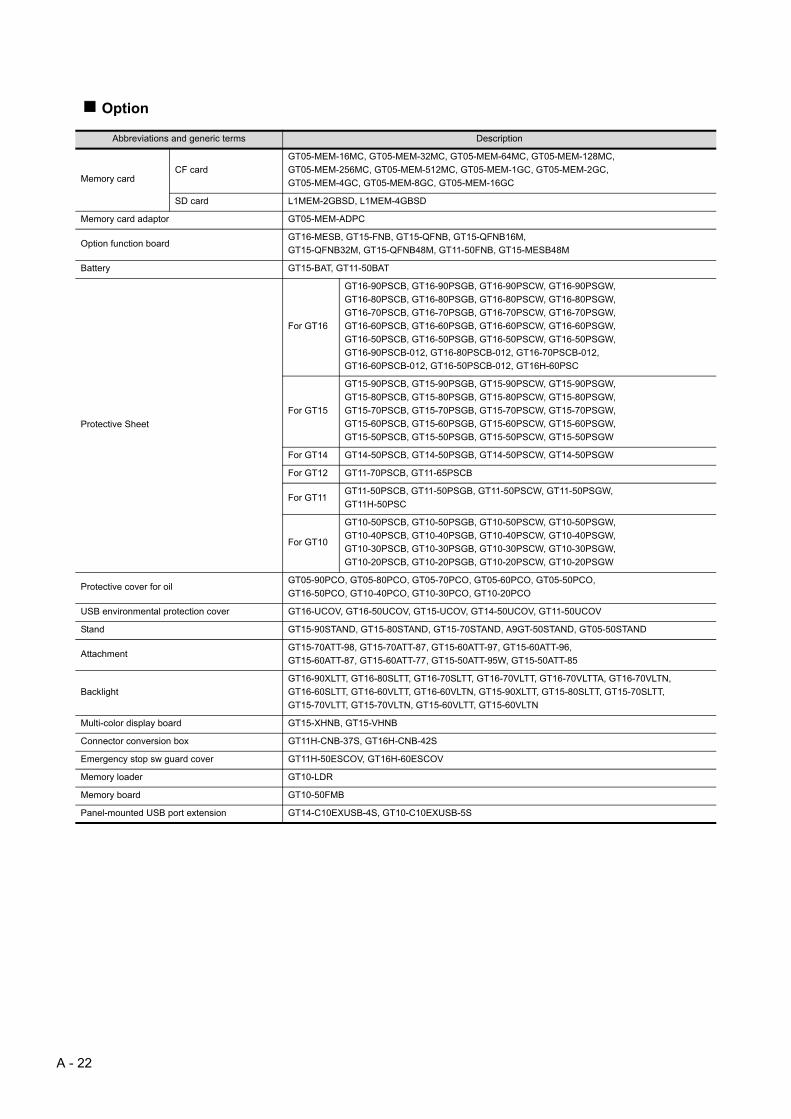
Option
Abbreviations and generic terms Description
Memory cardCF card
GT05-MEM-16MC, GT05-MEM-32MC, GT05-MEM-64MC, GT05-MEM-128MC,
GT05-MEM-256MC, GT05-MEM-512MC, GT05-MEM-1GC, GT05-MEM-2GC,
GT05-MEM-4GC, GT05-MEM-8GC, GT05-MEM-16GC
SD card L1MEM-2GBSD, L1MEM-4GBSD
Memory card adaptor GT05-MEM-ADPC
Option function boardGT16-MESB, GT15-FNB, GT15-QFNB, GT15-QFNB16M,
GT15-QFNB32M, GT15-QFNB48M, GT11-50FNB, GT15-MESB48M
Battery GT15-BAT, GT11-50BAT
Protective Sheet
For GT16
GT16-90PSCB, GT16-90PSGB, GT16-90PSCW, GT16-90PSGW,
GT16-80PSCB, GT16-80PSGB, GT16-80PSCW, GT16-80PSGW,
GT16-70PSCB, GT16-70PSGB, GT16-70PSCW, GT16-70PSGW,
GT16-60PSCB, GT16-60PSGB, GT16-60PSCW, GT16-60PSGW,
GT16-50PSCB, GT16-50PSGB, GT16-50PSCW, GT16-50PSGW,
GT16-90PSCB-012, GT16-80PSCB-012, GT16-70PSCB-012,
GT16-60PSCB-012, GT16-50PSCB-012, GT16H-60PSC
For GT15
GT15-90PSCB, GT15-90PSGB, GT15-90PSCW, GT15-90PSGW,
GT15-80PSCB, GT15-80PSGB, GT15-80PSCW, GT15-80PSGW,
GT15-70PSCB, GT15-70PSGB, GT15-70PSCW, GT15-70PSGW,
GT15-60PSCB, GT15-60PSGB, GT15-60PSCW, GT15-60PSGW,
GT15-50PSCB, GT15-50PSGB, GT15-50PSCW, GT15-50PSGW
For GT14 GT14-50PSCB, GT14-50PSGB, GT14-50PSCW, GT14-50PSGW
For GT12 GT11-70PSCB, GT11-65PSCB
For GT11GT11-50PSCB, GT11-50PSGB, GT11-50PSCW, GT11-50PSGW,
GT11H-50PSC
For GT10
GT10-50PSCB, GT10-50PSGB, GT10-50PSCW, GT10-50PSGW,
GT10-40PSCB, GT10-40PSGB, GT10-40PSCW, GT10-40PSGW,
GT10-30PSCB, GT10-30PSGB, GT10-30PSCW, GT10-30PSGW,
GT10-20PSCB, GT10-20PSGB, GT10-20PSCW, GT10-20PSGW
Protective cover for oilGT05-90PCO, GT05-80PCO, GT05-70PCO, GT05-60PCO, GT05-50PCO,
GT16-50PCO, GT10-40PCO, GT10-30PCO, GT10-20PCO
USB environmental protection cover GT16-UCOV, GT16-50UCOV, GT15-UCOV, GT14-50UCOV, GT11-50UCOV
Stand GT15-90STAND, GT15-80STAND, GT15-70STAND, A9GT-50STAND, GT05-50STAND
AttachmentGT15-70ATT-98, GT15-70ATT-87, GT15-60ATT-97, GT15-60ATT-96,
GT15-60ATT-87, GT15-60ATT-77, GT15-50ATT-95W, GT15-50ATT-85
Backlight
GT16-90XLTT, GT16-80SLTT, GT16-70SLTT, GT16-70VLTT, GT16-70VLTTA, GT16-70VLTN,
GT16-60SLTT, GT16-60VLTT, GT16-60VLTN, GT15-90XLTT, GT15-80SLTT, GT15-70SLTT,
GT15-70VLTT, GT15-70VLTN, GT15-60VLTT, GT15-60VLTN
Multi-color display board GT15-XHNB, GT15-VHNB
Connector conversion box GT11H-CNB-37S, GT16H-CNB-42S
Emergency stop sw guard cover GT11H-50ESCOV, GT16H-60ESCOV
Memory loader GT10-LDR
Memory board GT10-50FMB
Panel-mounted USB port extension GT14-C10EXUSB-4S, GT10-C10EXUSB-5S
A - 22

Software
License key (for GT SoftGOT1000)
Abbreviations and generic terms Description
GT Works3 Abbreviation of the SW DNC-GTWK3-E and SW DNC-GTWK3-EA
GT Designer3 Abbreviation of screen drawing software GT Designer3 for GOT1000 series
GT Simulator3 Abbreviation of screen simulator GT Simulator3 for GOT1000/GOT900 series
GT SoftGOT1000 Abbreviation of monitoring software GT SoftGOT1000
GT Converter2 Abbreviation of data conversion software GT Converter2 for GOT1000/GOT900 series
GT Designer2 Classic Abbreviation of screen drawing software GT Designer2 Classic for GOT900 series
GT Designer2 Abbreviation of screen drawing software GT Designer2 for GOT1000/GOT900 series
iQ Works Abbreviation of iQ Platform compatible engineering environment MELSOFT iQ Works
MELSOFT NavigatorGeneric term for integrated development environment software included in the SW DNC-IQWK (iQ
Platform compatible engineering environment MELSOFT iQ Works)
GX Works2Abbreviation of SW DNC-GXW2-E and SW DNC-GXW2-EA type programmable controller
engineering software
GX Simulator2 Abbreviation of GX Works2 with the simulation function
GX SimulatorAbbreviation of SW D5C-LLT-E(-EV) type ladder logic test tool function software packages
(SW5D5C-LLT (-EV) or later versions)
GX Developer Abbreviation of SW D5C-GPPW-E(-EV)/SW D5F-GPPW-E type software package
GX LogViewer Abbreviation of SW DNN-VIEWER-E type software package
PX Developer Abbreviation of SW D5C-FBDQ-E type FBD software package for process control
MT Works2Abbreviation of motion controller engineering environment MELSOFT MT Works2
(SW DNC-MTW2-E)
MT Developer Abbreviation of SW RNC-GSV type integrated start-up support software for motion controller Q series
MR Configurator2 Abbreviation of SW DNC-MRC2-E type Servo Configuration Software
MR Configurator Abbreviation of MRZJW -SETUP E type Servo Configuration Software
FR Configurator Abbreviation of Inverter Setup Software (FR-SW -SETUP-WE)
NC Configurator Abbreviation of CNC parameter setting support tool NC Configurator
FX Configurator-FPAbbreviation of parameter setting, monitoring, and testing software packages for FX3U-20SSC-H
(SW D5C-FXSSC-E)
FX3U-ENET-L Configuration tool Abbreviation of FX3U-ENET-L type Ethernet module setting software (SW1D5-FXENETL-E)
RT ToolBox2 Abbreviation of robot program creation software (3D-11C-WINE)
MX Component Abbreviation of MX Component Version (SW D5C-ACT-E, SW D5C-ACT-EA)
MX Sheet Abbreviation of MX Sheet Version (SW D5C-SHEET-E, SW D5C-SHEET-EA)
LCPU Logging Configuration Tool Abbreviation of LCPU Logging Configuration Tool (SW1DNN-LLUTL-E)
Abbreviations and generic terms Description
License GT15-SGTKEY-U, GT15-SGTKEY-P
A - 23
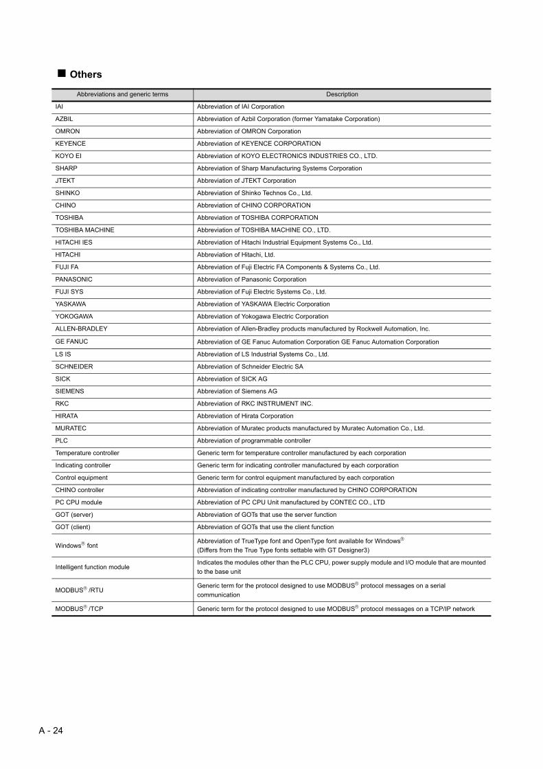
Others
Abbreviations and generic terms Description
IAI Abbreviation of IAI Corporation
AZBIL Abbreviation of Azbil Corporation (former Yamatake Corporation)
OMRON Abbreviation of OMRON Corporation
KEYENCE Abbreviation of KEYENCE CORPORATION
KOYO EI Abbreviation of KOYO ELECTRONICS INDUSTRIES CO., LTD.
SHARP Abbreviation of Sharp Manufacturing Systems Corporation
JTEKT Abbreviation of JTEKT Corporation
SHINKO Abbreviation of Shinko Technos Co., Ltd.
CHINO Abbreviation of CHINO CORPORATION
TOSHIBA Abbreviation of TOSHIBA CORPORATION
TOSHIBA MACHINE Abbreviation of TOSHIBA MACHINE CO., LTD.
HITACHI IES Abbreviation of Hitachi Industrial Equipment Systems Co., Ltd.
HITACHI Abbreviation of Hitachi, Ltd.
FUJI FA Abbreviation of Fuji Electric FA Components & Systems Co., Ltd.
PANASONIC Abbreviation of Panasonic Corporation
FUJI SYS Abbreviation of Fuji Electric Systems Co., Ltd.
YASKAWA Abbreviation of YASKAWA Electric Corporation
YOKOGAWA Abbreviation of Yokogawa Electric Corporation
ALLEN-BRADLEY Abbreviation of Allen-Bradley products manufactured by Rockwell Automation, Inc.
GE FANUC Abbreviation of GE Fanuc Automation Corporation GE Fanuc Automation Corporation
LS IS Abbreviation of LS Industrial Systems Co., Ltd.
SCHNEIDER Abbreviation of Schneider Electric SA
SICK Abbreviation of SICK AG
SIEMENS Abbreviation of Siemens AG
RKC Abbreviation of RKC INSTRUMENT INC.
HIRATA Abbreviation of Hirata Corporation
MURATEC Abbreviation of Muratec products manufactured by Muratec Automation Co., Ltd.
PLC Abbreviation of programmable controller
Temperature controller Generic term for temperature controller manufactured by each corporation
Indicating controller Generic term for indicating controller manufactured by each corporation
Control equipment Generic term for control equipment manufactured by each corporation
CHINO controller Abbreviation of indicating controller manufactured by CHINO CORPORATION
PC CPU module Abbreviation of PC CPU Unit manufactured by CONTEC CO., LTD
GOT (server) Abbreviation of GOTs that use the server function
GOT (client) Abbreviation of GOTs that use the client function
Windows fontAbbreviation of TrueType font and OpenType font available for Windows
(Differs from the True Type fonts settable with GT Designer3)
Intelligent function moduleIndicates the modules other than the PLC CPU, power supply module and I/O module that are mounted
to the base unit
MODBUS/RTUGeneric term for the protocol designed to use MODBUS protocol messages on a serial
communication
MODBUS/TCP Generic term for the protocol designed to use MODBUS protocol messages on a TCP/IP network
A - 24

HOW TO READ THIS MANUAL
SymbolsFollowing symbols are used in this manual.
Since the above page was created for explanation purpose, it differs from the actual page.
Not connectable model name
Connectable model nameBUS CONNECTION
5.1 Connectable Model List 5 - 2
Indicates the location of related content.
Indicates the operation steps.
[ ]: Indicates the setting items displayed on the software and GOT screen.
1. 2. 3. …
Applicable model name
Shows GT16.
Shows GT15.
Shows GT12.
Shows GT14.
Shows GT11.
Shows GT11 (BUS).
Shows GT10.
Shows GT11 (SERIAL).
Shows GT1020,GT1030 (input power supply : 24V).
Shows GT1020,GT1030 (input power supply : 5V).
Refers to the information required.
Refers to information usefulfor operation.
2.
3.
4.
Click!
Shows GT105 ,GT104 .
A - 25
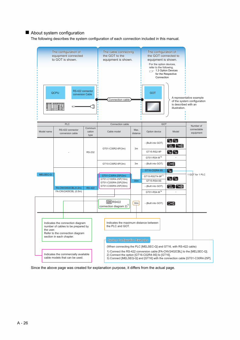
About system configurationThe following describes the system configuration of each connection included in this manual.
Since the above page was created for explanation purpose, it differs from the actual page.
The configuration of The configuration of equipment connected equipment connected to GOT is shown.to GOT is shown.
The cable connecting The cable connecting the GOT to the the GOT to the equipment is shown.equipment is shown.
The configuration of The configuration of the GOT connected to the GOT connected to equipment is shown.equipment is shown.
RS-422 connector conversion CableQCPU GOT
Connection cableA representative example of the system configuration is described with an illustration.
Indicates the connection diagram number of cables to be prepared by the user.Refer to the connection diagram section in each chapter.
Indicates the commercially available cable models that can be used.
Indicates the maximum distance between the PLC and GOT.
1) Connect the RS-422 conversion cable [FA-CNV2402CBL] to the [MELSEC-Q].2) Connect the option [GT16-C02R4-9S] to [GT16].3) Connect [MELSEQ-Q] and [GT16] with the connection cable [GT01-C30R4-25P].
System Configuration ExamplesSystem Configuration Examples
(When connecting the PLC [MELSEC-Q] and GT16, with RS-422 cable)
System Configuration Examples
The configuration of equipment connected to GOT is shown.
The cable connecting the GOT to the equipment is shown.
The configuration of the GOT connected to equipment is shown.
For the option devices, refer to the following.
1.3 Option Devices for the Respective Connection
A - 26

1 1
PR
EP
AR
AT
OR
Y
PR
OC
ED
UR
ES
FO
R
MO
NIT
OR
ING
2
MIC
RO
CO
MP
UT
ER
C
ON
NE
CT
ION
(S
ER
IAL
)
3
MIC
RO
CO
MP
UT
ER
C
ON
NE
CT
ION
(E
TH
ER
NE
T)
4
MO
DB
US
(R)/
RT
U
CO
NN
EC
TIO
N
5
MO
DB
US
(R)/
TC
P
CO
NN
EC
TIO
N
6
CO
NN
EC
TIO
N T
O
SO
UN
D O
UT
PU
T
UN
IT
7
CO
NN
EC
TIO
N T
O
EX
TE
RN
AL
I/O
D
EV
ICE
8
ING
ER
PR
INT
UTH
EN
TIC
ATIO
N
EV
ICE
CO
NN
EC
TIO
N
1.PREPARATORY PROCEDURESFOR MONITORING
1.1 Setting the Communication Interface . . . . . . . . . . . . . . . . . . 1 - 3
1.2 Writing the Project Data and OS onto the GOT . . . . . . . . . 1 - 13
1.3 Option Devices for the Respective Connection . . . . . . . . . 1 - 15
1.4 Connection Cables for the Respective Connection . . . . . . 1 - 24
1.5 Verifying GOT Recognizes Connected Equipment . . . . . . 1 - 32
1.6 Checking for Normal Monitoring. . . . . . . . . . . . . . . . . . . . . 1 - 36
F A D
1 - 1

1 - 2 1. PREPARATORY PROCEDURES FOR MON
1. PREPARATORY PROCEDURES FOR MONITORING
The following shows the procedures to be taken before monitoring and corresponding reference sections.
Setting the communication interfaceDetermine the connection type and channel No. to be used, and
perform the communication setting.
1.1 Setting the Communication Interface
Each chapter GOT Side Settings
Writing the project data and OSWrite the standard monitor OS, communication driver, option
OS, project data and communication settings onto the GOT.
1.2.1 Writing the project data and OS onto the GOT
Verifying the project data and OSVerify the standard monitor OS, communication driver, option
OS, project data and communication settings are properly
written onto the GOT.
1.2.2 Checking the project data and OS writing on GOT
Attaching the communication unit and
connecting the cableMount the optional equipment and prepare/connect the
connection cable according to the connection type.
1.3 Option Devices for the Respective Connection
1.4 Connection Cables for the Respective Connection
Each chapter System Configuration
Each chapter Connection Diagram
Verifying GOT recognizes connected
equipmentVerify the GOT recognizes controllers on [Communication
Settings] of the Utility.
1.5 Verifying GOT Recognizes Connected Equipment
Verifying the GOT is monitoring normallyVerify the GOT is monitoring normally using Utility, Developer,
etc.
1.6 Checking for Normal Monitoring
ITORING
1
1. PREPARAT
PR
EP
AR
AT
OR
Y
PR
OC
ED
UR
ES
FO
R
MO
NIT
OR
ING
2
CR
OC
OM
PU
TE
R
NN
EC
TIO
N
RIA
L)
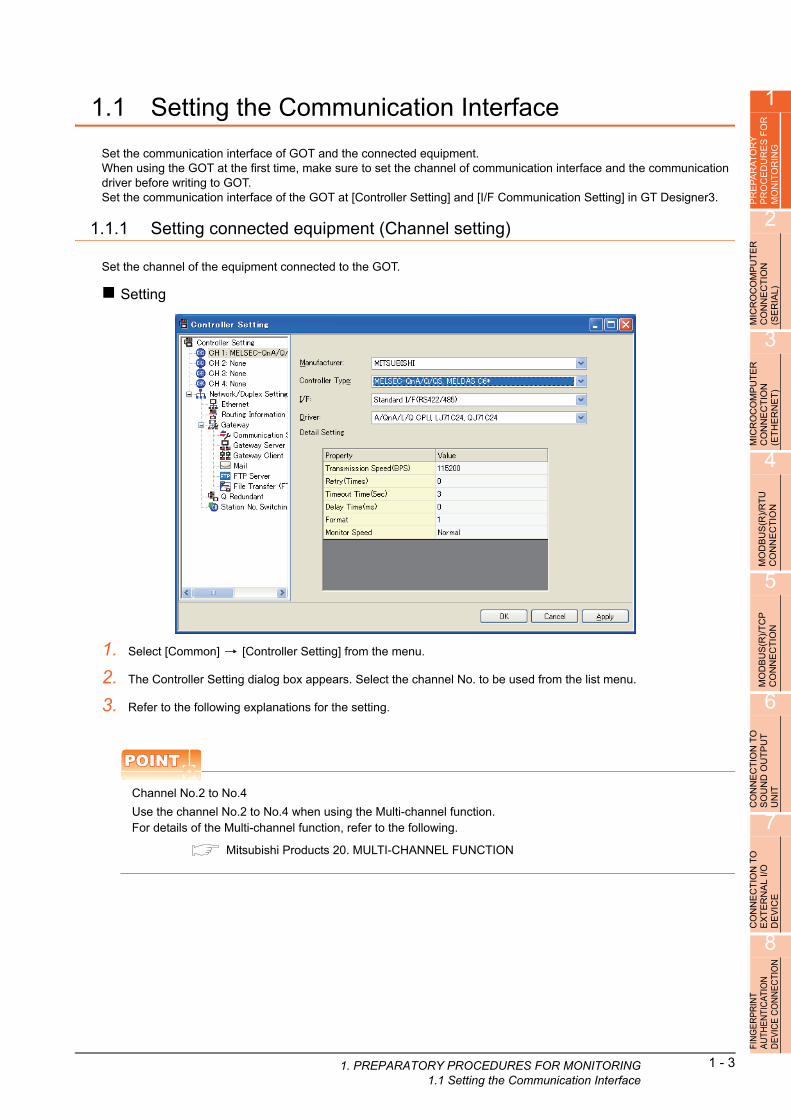
1.1 Setting the Communication Interface
Set the communication interface of GOT and the connected equipment.When using the GOT at the first time, make sure to set the channel of communication interface and the communication driver before writing to GOT.Set the communication interface of the GOT at [Controller Setting] and [I/F Communication Setting] in GT Designer3.
1.1.1 Setting connected equipment (Channel setting)
Set the channel of the equipment connected to the GOT.
Setting
I O SE
M C (
3
MIC
RO
CO
MP
UT
ER
C
ON
NE
CT
ION
(E
TH
ER
NE
T)
4
MO
DB
US
(R)/
RT
U
CO
NN
EC
TIO
N
5
MO
DB
US
(R)/
TC
P
CO
NN
EC
TIO
N
6
CO
NN
EC
TIO
N T
O
SO
UN
D O
UT
PU
T
UN
IT
7
CO
NN
EC
TIO
N T
O
EX
TE
RN
AL
I/O
D
EV
ICE
8
FIN
GE
RP
RIN
T A
UTH
EN
TIC
ATIO
N
DE
VIC
E C
ON
NE
CTI
ON
1. Select [Common] [Controller Setting] from the menu.
2. The Controller Setting dialog box appears. Select the channel No. to be used from the list menu.
3. Refer to the following explanations for the setting.
POINTPOINTPOINT
Channel No.2 to No.4
Use the channel No.2 to No.4 when using the Multi-channel function.For details of the Multi-channel function, refer to the following.
Mitsubishi Products 20. MULTI-CHANNEL FUNCTION
ORY PROCEDURES FOR MONITORING1.1 Setting the Communication Interface
1 - 3

1 - 4 1. PREPARATORY PROCEDURES FOR MON1.1 Setting the Communication Interface
Setting itemThis section describes the setting items of the Manufacturer, Controller Type, Driver and I/F.When using the channel No.2 to No.4, put a check mark at [Use CH*].
Item Description
Use CH* Select this item when setting the channel No.2 to No.4.
Manufacturer Select the manufacturer of the equipment to be connected to the GOT.
TypeSelect the type of the equipment to be connected to the GOT. For the settings, refer to the following.
(2)Setting [Controller Type]
I/FSelect the interface of the GOT to which the equipment is connected.For the settings, refer to the following.
(3)Setting [I/F]
DriverSelect the communication driver to be written to the GOT.For the settings, refer to the following.
(1)Setting [Driver]
Detail SettingMake settings for the transmission speed and data length of the communication driver.
Refer to each chapter of the equipment to be connected to the GOT.
(1) Setting [Driver]The displayed items for a driver differ according to the settings [Manufacturer], [Controller Type] and [I/F].When the driver to be set is not displayed, confirm if [Manufacturer], [Controller Type] and [I/F] are correct.For the settings, refer to the following.
[Setting the communication interface] section in each chapter
ITORING

1
1. PREPARAT
PR
EP
AR
AT
OR
Y
PR
OC
ED
UR
ES
FO
R
MO
NIT
OR
ING
2
MIC
RO
CO
MP
UT
ER
C
ON
NE
CT
ION
(S
ER
IAL
)
3
MIC
RO
CO
MP
UT
ER
C
ON
NE
CT
ION
(E
TH
ER
NE
T)
4
MO
DB
US
(R)/
RT
U
CO
NN
EC
TIO
N
5
MO
DB
US
(R)/
TC
P
CO
NN
EC
TIO
N
6
CO
NN
EC
TIO
N T
O
SO
UN
D O
UT
PU
T
UN
IT
7
CO
NN
EC
TIO
N T
O
EX
TE
RN
AL
I/O
D
EV
ICE
8
FIN
GE
RP
RIN
T A
UTH
EN
TIC
ATIO
N
DE
VIC
E C
ON
NE
CTI
ON
(2) Setting [Controller Type]The types for the selection differs depending on the PLC to be used.For the settings, refer to the following.
Type Model name Manufacturer
MODBUS
NFCP100YOKOGAWA
NFJT100
TSX P57 203M
Schneider Electric
TSX P57 253M
TSX P57 303M
TSX P57 353M
TSX P57 453M
140 CPU 311 10
140 CPU 434 12U
140 CPU 534 14U
140 CPU 651 50
140 CPU 651 60
140 CPU 671 60
140 CPU 113 02
140 CPU 113 03
140 CPU 434 12A
140 CPU 534 14A
Microcomputer connection Microcomputer -
ORY PROCEDURES FOR MONITORING1.1 Setting the Communication Interface
1 - 5

1 - 6 1. PREPARATORY PROCEDURES FOR MON1.1 Setting the Communication Interface
(3) Setting [I/F]The interface differs depending on the GOT to be used.Set the I/F according to the connection and the position of communication unit to be mounted onto the GOT.
(a) GT16
(b) GT15
3rd stage
Extension interface 1
Extension interface 2
Standard interface 1(RS-232 interface built in the GOT)
2nd stage
1st stage
Standard interface 2(USB interface built in the GOT)
(Example: In the case of the GT1685)
Standard interface 3(RS-422/485 interface built in the GOT)
Standard interface 4(Ethernet interface built in the GOT)
3rd stage
Extension interface 1
Extension interface 2
Standard interface 1(RS-232 interface built in the GOT)
2nd stage
1st stage
Standard interface 2(USB interface built in the GOT)
(Example: In the case of the GT1575)
ITORING

1
1. PREPARAT
PR
EP
AR
AT
OR
Y
PR
OC
ED
UR
ES
FO
R
MO
NIT
OR
ING
2
MIC
RO
CO
MP
UT
ER
C
ON
NE
CT
ION
(S
ER
IAL
)
3
MIC
RO
CO
MP
UT
ER
C
ON
NE
CT
ION
(E
TH
ER
NE
T)
4
MO
DB
US
(R)/
RT
U
CO
NN
EC
TIO
N
5
MO
DB
US
(R)/
TC
P
CO
NN
EC
TIO
N
6
CO
NN
EC
TIO
N T
O
SO
UN
D O
UT
PU
T
UN
IT
7
CO
NN
EC
TIO
N T
O
EX
TE
RN
AL
I/O
D
EV
ICE
8
FIN
GE
RP
RIN
T A
UTH
EN
TIC
ATIO
N
DE
VIC
E C
ON
NE
CTI
ON
(c) GT14
(d) GT12
Standard interface 4(GOT built-in Ethernet interface)
Standard interface 3(GOT built-in USB interface)
[Front view]] [Rear view]
[Under view]
Standard interface 1(GOT built-in RS-422 interface)
Standard interface 2(GOT built-in RS-232 interface)
Standard interface 1(GOT built-in RS-422 interface)
Standard interface 2(GOT built-in RS-232 interface)
Standard interface 4(GOT built-in Ethernet interface)
[Front view] [Rear view]
ORY PROCEDURES FOR MONITORING1.1 Setting the Communication Interface
1 - 7
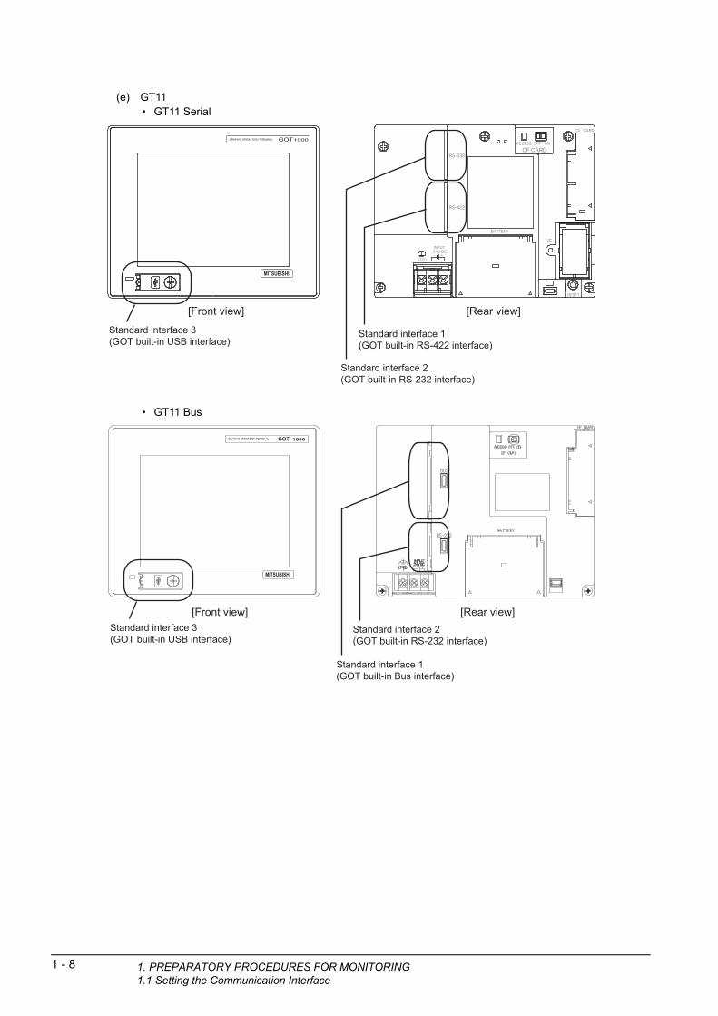
1 - 8 1. PREPARATORY PROCEDURES FOR MON1.1 Setting the Communication Interface
(e) GT11• GT11 Serial
• GT11 Bus
Standard interface 3(GOT built-in USB interface)
[Front view] [Rear view]
Standard interface 1(GOT built-in RS-422 interface)
Standard interface 2(GOT built-in RS-232 interface)
Standard interface 3(GOT built-in USB interface)
Standard interface 2(GOT built-in RS-232 interface)
Standard interface 1(GOT built-in Bus interface)
[Front view] [Rear view]
ITORING
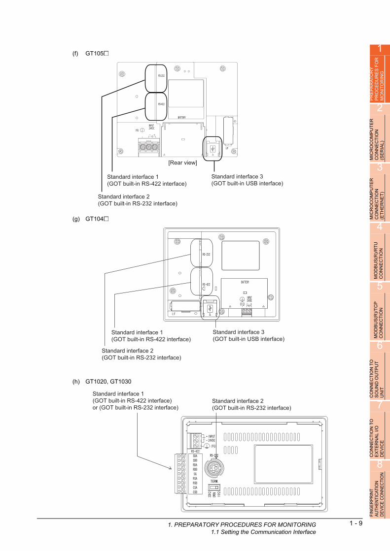
1
1. PREPARAT
PR
EP
AR
AT
OR
Y
PR
OC
ED
UR
ES
FO
R
MO
NIT
OR
ING
2
MIC
RO
CO
MP
UT
ER
C
ON
NE
CT
ION
(S
ER
IAL
)
3
RO
CO
MP
UT
ER
N
NE
CT
ION
H
ER
NE
T)
(f) GT105
Standard interface 1(GOT built-in RS-422 interface)
Standard interface 2(GOT built-in RS-232 interface)
Standard interface 3(GOT built-in USB interface)
[Rear view]
IC O ET
M C (
4
MO
DB
US
(R)/
RT
U
CO
NN
EC
TIO
N
5
MO
DB
US
(R)/
TC
P
CO
NN
EC
TIO
N
6
ION
TO
U
TP
UT
(g) GT104
Standard interface 3(GOT built-in USB interface)
Standard interface 1(GOT built-in RS-422 interface)
Standard interface 2(GOT built-in RS-232 interface)
CT
O
CON
NE
SO
UN
DU
NIT
7
CO
NN
EC
TIO
N T
O
EX
TE
RN
AL
I/O
D
EV
ICE
8
FIN
GE
RP
RIN
T A
UTH
EN
TIC
ATIO
N
DE
VIC
E C
ON
NE
CTI
ON
(h) GT1020, GT1030
Standard interface 1(GOT built-in RS-422 interface)or (GOT built-in RS-232 interface)
Standard interface 2(GOT built-in RS-232 interface)
ORY PROCEDURES FOR MONITORING1.1 Setting the Communication Interface
1 - 9
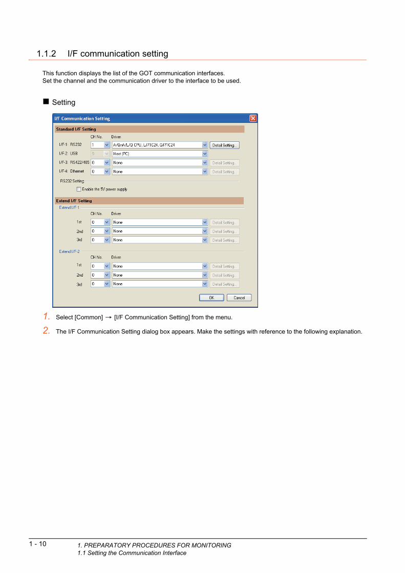
1 - 10 1. PREPARATORY PROCEDURES FOR MON1.1 Setting the Communication Interface
1.1.2 I/F communication setting
This function displays the list of the GOT communication interfaces.Set the channel and the communication driver to the interface to be used.
Setting
1. Select [Common] [I/F Communication Setting] from the menu.
2. The I/F Communication Setting dialog box appears. Make the settings with reference to the following explanation.
ITORING

1
1. PREPARAT
RY
E
S F
OR
G
Setting itemThe following describes the setting items for the standard I/F setting and extension I/F setting.
TO R IN
PR
EP
AR
AP
RO
CE
DU
MO
NIT
OR
2
MIC
RO
CO
MP
UT
ER
C
ON
NE
CT
ION
(S
ER
IAL
)
3
MIC
RO
CO
MP
UT
ER
C
ON
NE
CT
ION
(E
TH
ER
NE
T)
4
MO
DB
US
(R)/
RT
U
CO
NN
EC
TIO
N
5
MO
DB
US
(R)/
TC
P
CO
NN
EC
TIO
N
6
CO
NN
EC
TIO
N T
O
SO
UN
D O
UT
PU
T
UN
IT
7
CO
NN
EC
TIO
N T
O
EX
TE
RN
AL
I/O
D
EV
ICE
8
FIN
GE
RP
RIN
T A
UTH
EN
TIC
ATIO
N
DE
VIC
E C
ON
NE
CTI
ON
Item Description
Standard I/F Setting
Set channel No. and drivers to the GOT standard interfaces.
GT16, GT14, GT12: Standard I/F-1, Standard I/F-2, Standard I/F-3, Standard I/F-4
GT15, GT1030, GT1020: Standard I/F-1, Standard I/F-2
GT11, GT105 , GT104 : Standard I/F-1, Standard I/F-2, Standard I/F-3
CH No.
Set the CH No. according to the intended purpose.
The number of channels differs depending on the GOT to be used.
0: Not used
1 to 4: Used for connecting a controller of channel No. 1 to 4 set in Setting connected equipment (Channel
setting)
8: Used for barcode reader connection, RFID connection, PC remote operation connection (serial) fingerprint
authentication device connection, or printer (serial) GOT (extended computer)
9: Used for connecting Host (PC) or Host (modem)
*: Used for gateway function, MES interface function, and Ethernet download
Multi: Used for Ethernet multiple connection
I/F The communication type of the GOT standard interface is displayed.
DriverSet the driver for the device to be connected.
None Host (PC) Each communication driver for connected devices
Detail SettingMake settings for the transmission speed and data length of the communication driver.
Refer to each chapter of the equipment to be connected to the GOT.
RS232 Setting
To validate the 5V power supply function in RS232, mark the [Enable the 5V power supply] checkbox.
The RS232 setting is invalid in the following cases.
• CH No. of [I/F-1: RS232] is [9] in GT15 and 16.
• CH No. of [I/F-1: RS232] is [9] or [8] in GT14.
• For GT12, GT11 and GT10
ORY PROCEDURES FOR MONITORING1.1 Setting the Communication Interface
1 - 11

Extend I/F Setting Set the communication unit attached to the extension interface of the GOT.
CH No.
Set the CH No. according to the intended purpose.
The number of channels differs depending on the GOT to be used.
0: Not used
1 to 4: Used for connecting a controller of channel No. 1 to 4 set in Setting connected equipment (Channel
setting)
5 to 7: Used for barcode reader connection, RFID connection, and PC remote operation connection
* : For the gateway function, MES interface function, Ethernet download, report function,
hard copy (For printer output), video/RGB input, RGB output, multimedia function,
CF card unit, CF card extension unit, sound output, and external I/O or operation panel
DriverSet the driver for the device to be connected.
None Each driver for connected devices
Detail SettingMake settings for the transmission speed and data length of the communication driver.
Refer to each chapter of the equipment to be connected to the GOT.
Item Description
1 - 12 1. PREPARATORY PROCEDURES FOR MON1.1 Setting the Communication Interface
POINTPOINTPOINT
Channel No., drivers, [RS232 Setting]
(1) Channel No.2 to No.4Use the channel No.2 to No.4 when using the Multi-channel function.For details of the Multi-channel function, refer to the following.
Mitsubishi Products 20. MULTI-CHANNEL FUNCTION
(2) DriversThe displayed items for a driver differ according to the settings [Manufacturer], [Controller Type] and [I/F].When the driver to be set is not displayed, confirm if [Manufacturer], [Controller Type] and [I/F] are correct.
[Setting the communication] section in each chapter
(3) [RS232 Setting] of GT14Do not use [RS232 Setting] of GT14 for other than the 5V power feeding to the RS-232/485 signal conversion adaptor.For details, refer to the following manual.
GT14 User's Manual 7.11 RS-232/485 Signal Conversion Adaptor
1.1.3 Precautions
(1) Precautions for changing model
(a) When devices that cannot be converted are included.When setting of [Manufacturer] or [Controller Type] is changed, GT Designer3 displays the device that cannot be converted (no corresponding device type, or excessive setting ranges) as [??]. In this case, set the device again.
(b) When the changed Manufacturer or Controller Type does not correspond to the network.The network will be set to the host station.
(c) When the Manufacturer or Controller Type is changed to [None]The GT Designer3 displays the device of the changed channel No. as [??]. In this case, set the device again.Since the channel No. is retained, the objects can be reused in other channel No. in a batch by using the [Device Bach Edit], [CH No. Batch Edit] or [Device List].
ITORING

1
1. PREPARAT1.2 Wri
PR
EP
AR
AT
OR
Y
PR
OC
ED
UR
ES
FO
R
MO
NIT
OR
ING
1.2 Writing the Project Data and OS onto the GOT
Write the standard monitor OS, communication driver, option OS, project data and communication settings onto the GOT.For details on writing to GOT, refer to the following manual.
GT Designer3 Version1 Screen Design Manual
2
MIC
RO
CO
MP
UT
ER
C
ON
NE
CT
ION
(S
ER
IAL
)
3
MIC
RO
CO
MP
UT
ER
C
ON
NE
CT
ION
(E
TH
ER
NE
T)
4
MO
DB
US
(R)/
RT
U
CO
NN
EC
TIO
N
5
MO
DB
US
(R)/
TC
P
CO
NN
EC
TIO
N
6
CO
NN
EC
TIO
N T
O
SO
UN
D O
UT
PU
T
UN
IT
7
NE
CT
ION
TO
R
NA
L I
/O
ICE
1.2.1 Writing the project data and OS onto the GOT
1. Select [Communication] [Write to GOT…] from the menu.
2. The [Communication configuration] dialog box appears.Set the communication setting between the GOT and the personal computer.Click the [OK] button when settings are completed.
3. The [GOT Write] tab appears on the [Communicate with GOT] dialog box.Select the [Project data, OS] radio button of the Write Data.
4. Check-mark a desired standard monitor OS, communication driver, option OS, extended function OS, and Communication Settings and click the [GOT Write] button.
POINTPOINTPOINT
Writing communication driver onto GT10
When writing a communication driver onto the GT10 in which a Boot OS Ver. under F or a standard monitor OS Ver. under 01.08.00 is written, turn on the GOT in the OS transfer mode.Also, even when the communication port to be used for transferring is assigned to Ch9, turn on the GOT in the OS transfer mode.For details, refer to the following manual.
GT10 User's Manual
N TE
V
(Operating of transmission mode)CO
EX
DE
8
FIN
GE
RP
RIN
T A
UTH
EN
TIC
ATIO
N
DE
VIC
E C
ON
NE
CTI
ON
Turn on the GOT while the bottom right corner is touched.
ORY PROCEDURES FOR MONITORINGting the Project Data and OS onto the GOT
1 - 13

1 - 14 1. PREPARATORY PROCEDURES FOR MON1.2 Writing the Project Data and OS onto the G
1.2.2 Checking the project data and OS writing on GOT
Confirm if the standard monitor OS, communication driver, option OS, project data and communication settings are properly written onto the GOT by reading from GOT using GT Designer3.For reading from the GOT, refer to the following manual.
GT Designer3 Version1 Screen Design Manual
1. Select [Communication] [Read from GOT…] from the menu.
2. The [Communication configuration] dialog box appears.Set the communication setting between the GOT and the personal computer.Click the [OK] button when settings are completed.
3. The [GOT Read] tab appears on the [Communicate with GOT] dialog box.Select the [Drive information] radio button of the Read Data.
4. Click the [Info Reception] button.
5. Confirm that the project data and OS are written correctly onto the GOT.
ITORINGOT
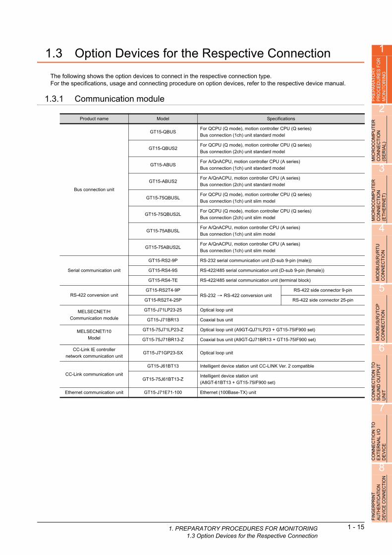
1
1. PREPARAT1.3 Op
PR
EP
AR
AT
OR
Y
PR
OC
ED
UR
ES
FO
R
MO
NIT
OR
ING
2
MIC
RO
CO
MP
UT
ER
C
ON
NE
CT
ION
(S
ER
IAL
)
3
MIC
RO
CO
MP
UT
ER
C
ON
NE
CT
ION
(E
TH
ER
NE
T)
4
MO
DB
US
(R)/
RT
U
CO
NN
EC
TIO
N
5
MO
DB
US
(R)/
TC
P
CO
NN
EC
TIO
N
6
CO
NN
EC
TIO
N T
O
SO
UN
D O
UT
PU
T
UN
IT
7
CO
NN
EC
TIO
N T
O
EX
TE
RN
AL
I/O
D
EV
ICE
8
FIN
GE
RP
RIN
T A
UTH
EN
TIC
ATIO
N
DE
VIC
E C
ON
NE
CTI
ON
1.3 Option Devices for the Respective Connection
The following shows the option devices to connect in the respective connection type.For the specifications, usage and connecting procedure on option devices, refer to the respective device manual.
1.3.1 Communication module
Product name Model Specifications
Bus connection unit
GT15-QBUSFor QCPU (Q mode), motion controller CPU (Q series)
Bus connection (1ch) unit standard model
GT15-QBUS2For QCPU (Q mode), motion controller CPU (Q series)
Bus connection (2ch) unit standard model
GT15-ABUSFor A/QnACPU, motion controller CPU (A series)
Bus connection (1ch) unit standard model
GT15-ABUS2For A/QnACPU, motion controller CPU (A series)
Bus connection (2ch) unit standard model
GT15-75QBUSLFor QCPU (Q mode), motion controller CPU (Q series)
Bus connection (1ch) unit slim model
GT15-75QBUS2LFor QCPU (Q mode), motion controller CPU (Q series)
Bus connection (2ch) unit slim model
GT15-75ABUSLFor A/QnACPU, motion controller CPU (A series)
Bus connection (1ch) unit slim model
GT15-75ABUS2LFor A/QnACPU, motion controller CPU (A series)
Bus connection (1ch) unit slim model
Serial communication unit
GT15-RS2-9P RS-232 serial communication unit (D-sub 9-pin (male))
GT15-RS4-9S RS-422/485 serial communication unit (D-sub 9-pin (female))
GT15-RS4-TE RS-422/485 serial communication unit (terminal block)
RS-422 conversion unitGT15-RS2T4-9P
RS-232 RS-422 conversion unitRS-422 side connector 9-pin
GT15-RS2T4-25P RS-422 side connector 25-pin
MELSECNET/H
Communication module
GT15-J71LP23-25 Optical loop unit
GT15-J71BR13 Coaxial bus unit
MELSECNET/10
Model
GT15-75J71LP23-Z Optical loop unit (A9GT-QJ71LP23 + GT15-75IF900 set)
GT15-75J71BR13-Z Coaxial bus unit (A9GT-QJ71BR13 + GT15-75IF900 set)
CC-Link IE controller
network communication unitGT15-J71GP23-SX Optical loop unit
CC-Link communication unit
GT15-J61BT13 Intelligent device station unit CC-LINK Ver. 2 compatible
GT15-75J61BT13-ZIntelligent device station unit
(A8GT-61BT13 + GT15-75IF900 set)
Ethernet communication unit GT15-J71E71-100 Ethernet (100Base-TX) unit
ORY PROCEDURES FOR MONITORINGtion Devices for the Respective Connection
1 - 15

1 - 16 1. PREPARATORY PROCEDURES FOR MON1.3 Option Devices for the Respective Connec
1.3.2 Option unit
1.3.3 Conversion cable
1.3.4 Connector conversion adapter
1.3.5 Serial Multi-Drop Connection Unit
1.3.6 RS-232/485 signal conversion adapter
Product name Model Specifications
Printer unit GT15-PRN USB slave (PictBridge) for connecting printer 1 ch
Multimedia unit GT16M-MMR For video input signal (NTSC/PAL) 1 ch, playing movie
Video input unitGT16M-V4
For video input signal (NTSC/PAL) 4 chGT15V-75V4
RGB input unitGT16M-R2
For analog RGB input signal 2 chGT15V-75R1
Video/RGB input unitGT16M-V4R1
For video input signal (NTSC/PAL) 4 ch, for analog RGB mixed input signal 1 chGT15V-75V4R1
RGB output unitGT16M-ROUT
For analog RGB output signal 1 chGT15V-75ROUT
CF card unit GT15-CFCD For CF card installation (B drive) For GOT back face CF card eject
CF card extension unit GT15-CFEX-C08SET For CF card installation (B drive) For control panel front face CF card eject
Sound output unit GT15-SOUT For sound output
External I/O unit
GT15-DIORFor the connection to external I/O device or operation panel (Negative Common
Input/Source Type Output)
GT15-DIOFor the connection to external I/O device or operation panel (Positive Common
Input/Sink Type Output)
Product name Model Specifications
RS-422 connector conversion
cableGT16-C02R4-9S RS-422/485 (Connector) RS-422 conversion cable (D-sub 9-pin)
RS-485 terminal block
conversion modules
FA-LTBGTR4CBL05
RS-422/485 (Connector) RS-485 (Terminal block)
Supplied connection cable dedicated for the conversion unitFA-LTBGTR4CBL10
FA-LTBGTR4CBL20
Product name Model Specifications
Connector conversion adapter GT10-9PT5S RS-422/485 (D-Sub 9-pin connector) RS-422/485 (Terminal block)
Product name Model Specifications
Serial multi-drop
connection unitGT01-RS4-M
GOT multi-drop connection module
Mitsubishi Products 18. GOT MULTI-DROP CONNECTION
Product name Model Specifications
RS-232/485 signal
conversion adapterGT14-RS2 4-9P RS-232 signal (D-Sub 9-pin connector) RS-485 signal (Terminal block)
ITORINGtion

1
1. PREPARAT1.3 Op
PR
EP
AR
AT
OR
Y
PR
OC
ED
UR
ES
FO
R
MO
NIT
OR
ING
2
MIC
RO
CO
MP
UT
ER
C
ON
NE
CT
ION
(S
ER
IAL
)
1.3.7 Installing a unit on another unit (Checking the unit installation position)
This section describes the precautions for installing units on another unit.For the installation method of each unit, refer to the following manual.
GT16 User’s Manual (Hardware)
GT15 User's Manual
Calculating consumed currentFor using multiple extension units, a bar code reader, or a RFID controller, the total current for the extension units, bar code reader, or RFID controller must be within the current that the GOT can supply.For the current that the GOT can supply and the current for the extension units, bar code reader, or RFID controller, refer to the following tables. Make sure that the total of consumed current is within the capacity of the GOT.
(1) Current supply capacity of the GOT
3
MIC
RO
CO
MP
UT
ER
C
ON
NE
CT
ION
(E
TH
ER
NE
T)
4
MO
DB
US
(R)/
RT
U
CO
NN
EC
TIO
N
GOT type
Current supply
capacity
(A)
GOT type
Current supply
capacity
(A)
GT1695M-X 2.4 GT1595-X 2.13
GT1685M-S 2.4 GT1585V-S 1.74
GT1675M-S 2.4 GT1585-S 1.74
GT1675M-V 2.4 GT1575V-S 2.2
GT1675-VN, GT1672-VN 2.4 GT1575-S 2.2
GT1665M-S 2.4 GT1575-V, GT1572-VN 2.2
GT1665M-V 2.4 GT1565-V, GT1562-VN 2.2
GT1662-VN 2.4 GT1555-V 1.3
GT1655-V 1.3 GT1555-Q, GT1550-Q 1.3
5
(2) Current consumed by an extension unit/barcode reader/RFID controllerMO
DB
US
(R)/
TC
P
CO
NN
EC
TIO
N
6
CO
NN
EC
TIO
N T
O
SO
UN
D O
UT
PU
T
UN
IT
7
CO
NN
EC
TIO
N T
O
EX
TE
RN
AL
I/O
D
EV
ICE
8
FIN
GE
RP
RIN
T A
UTH
EN
TIC
ATIO
N
DE
VIC
E C
ON
NE
CTI
ON
*1 Value used for calculating the current consumption of the multi-channel function.
For the specifications of the unit, refer to the manual included with the unit.*2 When the GOT supplies power to a barcode reader or a RFID controller from the standard interface, add their consumed
current.(Maximum value is less than 0.3 A.)
Module type
Consumed
current
(A)
Module type
Consumed
current
(A)
GT15-QBUS, GT15-QBUS2,
GT15-75QBUSL, GT15-75QBUS2L0.275*1 GT16M-R2 0*1
GT15-ABUS, GT15-ABUS2,
GT15-75ABUSL, GT15-75ABUS2L0.12 GT15V-75R1 0.2*1
GT15-RS2-9P 0.29 GT16M-V4R1 0.12*1
GT15-RS4-9S 0.33 GT15V-75V4R1 0.2*1
GT15-RS4-TE 0.3 GT16M-ROUT 0.11*1
GT15-RS2T4-9P 0.098 GT15V-75ROUT 0.11
GT15-J71E71-100 0.224 GT16M-MMR 0.27*1
GT15-J71GP23-SX 1.07 GT15-CFCD 0.07
GT15-J71LP23-25 0.56 GT15-CFEX-C08SET 0.15
GT15-J71BR13 0.77 GT15-SOUT 0.08
GT15-J61BT13 0.56 GT15-DIO 0.1
Bar code reader *2 GT15-DIOR 0.1
GT15-PRN 0.09 RFID controller *2
GT16M-V4 0.12*1 GT15-80FPA 0.22
GT15V-75V4 0.2*1
ORY PROCEDURES FOR MONITORINGtion Devices for the Respective Connection
1 - 17

1 - 18 1. PREPARATORY PROCEDURES FOR MON1.3 Option Devices for the Respective Connec
(3) Calculation example
(a) When connecting the GT15-J71BR13, GT15-RS4-9S (3 units), GT15-J71E71-100 (for the gateway function) and a bar code reader (0.12 A) to the GT1575-V
Since the calculated value is within the capacity of the GOT, they can be connected to the GOT.
Current supply capacity of GOT (A) Total consumed current (A)
2.2 0.77+0.33+0.33+0.33+0.224+0.12=2.104
(b) When connecting the GT15-J71BR13, GT15-RS4-9S (2 units), GT15-J71E71-100 (for the gateway function) and a bar code reader (0.12 A) to the GT1585-S
Since the calculated value exceeds the capacity of the GOT, such configuration is not allowed.
Current supply capacity of GOT (A) Total consumed current (A)
1.74 0.77+0.33+0.33+0.224+0.12=1.774
When using a bus connection unitThe installation position varies depending on the bus connection unit to be used.
(1) Wide bus units (GT15-75QBUS(2)L, GT15-75ABUS(2)L, GT15-QBUS2,GT15-ABUS2)Install a bus connection unit in the 1st stage of the extension interface.If a bus connection unit is installed in the 2nd stage or above, the unit cannot be used.
Example: Installing a bus connection unit and se
l communication units riaSerial communication unit
Bus connection unit
Bus connection unit
Serial communication unit
ITORINGtion

1
1. PREPARAT1.3 Op
PR
EP
AR
AT
OR
Y
PR
OC
ED
UR
ES
FO
R
MO
NIT
OR
ING
2
MIC
RO
CO
MP
UT
ER
C
ON
NE
CT
ION
(S
ER
IAL
)
3
MIC
RO
CO
MP
UT
ER
C
ON
NE
CT
ION
(E
TH
ER
NE
T)
4
MO
DB
US
(R)/
RT
U
CO
NN
EC
TIO
N
5
POINTPOINTPOINT
Cautions for using GT15-QBUS2 and GT15-ABUS2
The stage number of communication units installed on the next stage of GT15-QBUS2 or GT15-ABUS2 are recognized by the GOT differently depending on the extension interface position.For communication units installed in the extension interface 2 side, even if the communication unit is physically installed in the 2nd stage position, the GOT recognizes the position as the 1st stage.
(2) Standard size bus connection unit (GT15-QBUS and GT15-ABUS)A bus connection unit can be installed in any position (1st to 3rd stage) of the extension interface.
Recognized as the 3rd stage of extend interface 1
Recognized as the 2nd stage of extend interface 2
Recognized as the 1st stage of extend interface 2
Recognized as the 2nd stage of extend interface 1
Recognized as the 1st stage of extend interface 1
GT15-QBUS2, GT15-ABUS2
Relay connector
Example: Installing a bus connection unit and se l communication unitsMO
DB
US
(R)/
TC
PC
ON
NE
CT
ION
6
CO
NN
EC
TIO
N T
O
SO
UN
D O
UT
PU
T
UN
IT
7
CO
NN
EC
TIO
N T
O
EX
TE
RN
AL
I/O
D
EV
ICE
8
FIN
GE
RP
RIN
T A
UTH
EN
TIC
ATIO
N
DE
VIC
E C
ON
NE
CTI
ON
ria
Serial communication unit
Bus connection unit
Bus connection unit
Serial communication unit
ORY PROCEDURES FOR MONITORINGtion Devices for the Respective Connection
1 - 19
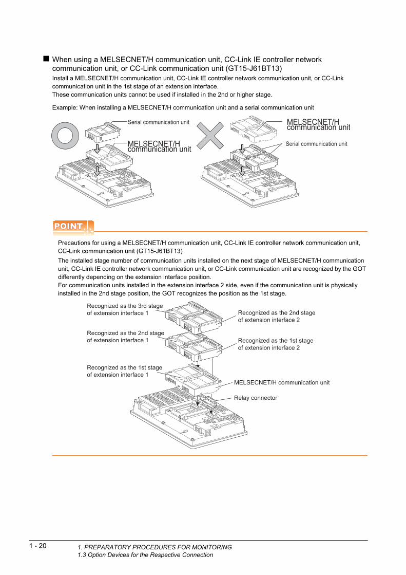
1 - 20 1. PREPARATORY PROCEDURES FOR MON1.3 Option Devices for the Respective Connec
When using a MELSECNET/H communication unit, CC-Link IE controller network communication unit, or CC-Link communication unit (GT15-J61BT13)Install a MELSECNET/H communication unit, CC-Link IE controller network communication unit, or CC-Link communication unit in the 1st stage of an extension interface.These communication units cannot be used if installed in the 2nd or higher stage.
Example: When installing a MELSECNET/H commun
tion unit and a serial communication unit icaPOINTPOINTPOINT
Precautions for using a MELSECNET/H communication unit, CC-Link IE controller network communication unit, CC-Link communication unit (GT15-J61BT13)
The installed stage number of communication units installed on the next stage of MELSECNET/H communication unit, CC-Link IE controller network communication unit, or CC-Link communication unit are recognized by the GOT differently depending on the extension interface position.For communication units installed in the extension interface 2 side, even if the communication unit is physically installed in the 2nd stage position, the GOT recognizes the position as the 1st stage.
Serial communication unit
MELSECNET/H communication unit
MELSECNET/H communication unit
Serial communication unit
Recognized as the 3rd stage of extension interface 1 Recognized as the 2nd stage
of extension interface 2
Recognized as the 1st stage of extension interface 2
Recognized as the 2nd stage of extension interface 1
Recognized as the 1st stage of extension interface 1
MELSECNET/H communication unit
Relay connector
ITORINGtion

1
1. PREPARAT1.3 Op
PR
EP
AR
AT
OR
Y
PR
OC
ED
UR
ES
FO
R
MO
NIT
OR
ING
2
When using a MELSECNET/10 communication unit (GT15-75J71LP23-Z, GT15- 75J71BR13-Z) or CC-Link communication unit (GT15-75J61BT13-Z)Install a MELSECNET/10 communication unit (GT15-75J71LP23-Z, GT15-75J71BR13-Z) or CC-Link communication unit (GT15-75J61BT13-Z) at the 1st stage of the extension interface.These communication units cannot be used if installed in the 2nd or higher stage.
For GT16 and the GT155 , the MELSECNET/10 communication unit (GT15-75J71LP23-Z, GT15- 75J71BR13-Z) and the CC-Link communication unit (GT15-75J61BT13-Z) are not applicable.
R
Example: When installing a MELSECNET/10 commu ation unit and a serial communication unitMIC
RO
CO
MP
UT
EC
ON
NE
CT
ION
(S
ER
IAL
)
3
MIC
RO
CO
MP
UT
ER
C
ON
NE
CT
ION
(E
TH
ER
NE
T)
4
(R)/
RT
U
TIO
N
nic
When using an Ethernet communication unitAn Ethernet communication unit can be installed in any position (1st to 3rd stage) of the extension interface.For GT16, the Ethernet communication unit is not applicable.Use the Ethernet interface built in the GOT.
Serial communication unit
MELSECNET/10 communication unit
US
EC
Example: When installing an Ethernet communication
nit and a serial communication unitMO
DB
CO
NN
5
MO
DB
US
(R)/
TC
P
CO
NN
EC
TIO
N
6
CO
NN
EC
TIO
N T
O
SO
UN
D O
UT
PU
T
UN
IT
7
CO
NN
EC
TIO
N T
O
EX
TE
RN
AL
I/O
D
EV
ICE
8
FIN
GE
RP
RIN
T A
UTH
EN
TIC
ATIO
N
DE
VIC
E C
ON
NE
CTI
ON
u
When using a serial communication unitA serial communication unit can be installed in any position (1st to 3rd stage) of the extension interface.
Serial communication unit
Ethernet communication unit
Ethernet communication unitSerial communication unit
Serial communication unit
Serial communication unit
ORY PROCEDURES FOR MONITORINGtion Devices for the Respective Connection
1 - 21

1 - 22 1. PREPARATORY PROCEDURES FOR MON1.3 Option Devices for the Respective Connec
When using the printer unit, sound output unit, or external I/O unitThe printer unit, sound output unit, or external I/O unit can be installed in any position (1st to 3rd stage) of the extension interface.
Example: When installing a printer unit
When using the video input unit, RGB input unit, video/RGB input unit, RGB output unit, or multimedia unitInstall the video input unit, RGB input unit, video/RGB input unit, RGB output unit, or multimedia unit at the 1st stage of the extension interface.If any of these units is installed in the 2nd stage or above, the unit cannot be used.When any of these units is used, the communication units indicated below must be installed in the 2nd stage of the extension interface.
Communication unit Model
Bus connection unit GT15-QBUS2, GT15-ABUS2
MELSECNET/H communication
unitGT15-J71LP23-25, GT15-J71BR13
CC-Link IE controller
network communication unitGT15-J71GP23-SX
CC-Link communication unit GT15-J61BT13
Printer unit
Communication unit
Printer unit
Communication unit
Example: When installing a video input unit and a ME
ECNET/H communication unit LSMELSECNET/H communication unit
Video/RGB input unit
Video/RGB input unitMELSECNET/H communication unit
ITORINGtion
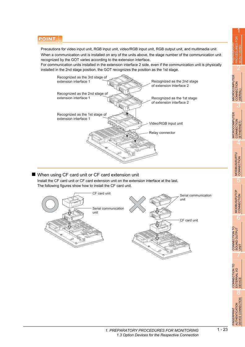
1
1. PREPARAT1.3 Op
PR
EP
AR
AT
OR
Y
PR
OC
ED
UR
ES
FO
R
MO
NIT
OR
ING
2
MIC
RO
CO
MP
UT
ER
C
ON
NE
CT
ION
(S
ER
IAL
)
3
MIC
RO
CO
MP
UT
ER
C
ON
NE
CT
ION
(E
TH
ER
NE
T)
4
MO
DB
US
(R)/
RT
U
CO
NN
EC
TIO
N
5
MO
DB
US
(R)/
TC
P
CO
NN
EC
TIO
N
6
CO
NN
EC
TIO
N T
O
SO
UN
D O
UT
PU
T
UN
IT
7
CO
NN
EC
TIO
N T
O
EX
TE
RN
AL
I/O
D
EV
ICE
8
FIN
GE
RP
RIN
T A
UTH
EN
TIC
ATIO
N
DE
VIC
E C
ON
NE
CTI
ON
POINTPOINTPOINT
Precautions for video input unit, RGB input unit, video/RGB input unit, RGB output unit, and multimedia unit
When a communication unit is installed on any of the units above, the stage number of the communication unit recognized by the GOT varies according to the extension interface.For communication units installed in the extension interface 2 side, even if the communication unit is physically installed in the 2nd stage position, the GOT recognizes the position as the 1st stage.
When using CF card unit or CF card extension unitInstall the CF card unit or CF card extension unit on the extension interface at the last.The following figures show how to install the CF card unit.
Recognized as the 3rd stage of extension interface 1 Recognized as the 2nd stage
of extension interface 2
Recognized as the 1st stage of extension interface 2
Recognized as the 2nd stage of extension interface 1
Recognized as the 1st stage of extension interface 1
Video/RGB input unit
Relay connector
Serial communication unit
CF card unit
CF card unit
Serial communication unit
ORY PROCEDURES FOR MONITORINGtion Devices for the Respective Connection
1 - 23

1 - 24 1. PREPARATORY PROCEDURES FOR MON1.4 Connection Cables for the Respective Con
1.4 Connection Cables for the Respective Connection
To connect the GOT to a device in the respective connection type, connection cables between the GOT and a device are necessary.For cables needed for each connection, refer to each chapter for connection.
1.4.1 GOT connector specifications
The following shows the connector specifications on the GOT side.Refer to the following table when preparing connection cables by the user.
RS-232 interfaceUse the following as the RS-232 interface and RS-232 communication unit connector on the GOT. For the GOT side connection cable, use a connector and connector cover applicable to the GOT connector.
(1) Connector specifications
*1 For the procedure to check the GT15 hardware version, refer to the GT15 User's Manual.
*2 The terminal block (MC1.5/9-ST-3.5 or corresponding product) of the cable side is packed together with the GT1030 and
GT1020.
(2) Connector pin arrangement
GOTHardware
version*1Connector type Connector model Manufacturer
GT16 ―
9-pin D-sub (male)
inch screw fixed type
17LE-23090-27(D4C )
DDK Ltd.GT1595-X ―17LE-23090-27(D4CK)
GT1585V-S ―
GT1585-STBAB or later GM-C9RMDU11 Honda Tsushin Kogyo Co., Ltd.
C
17LE-23090-27(D4CK) DDK Ltd.GT1585-STBD ―
GT1575V-S ―
GT1575-STBAB or later GM-C9RMDU11 Honda Tsushin Kogyo Co., Ltd.
C17LE-23090-27(D4CK) DDK Ltd.
GT1575-STBD ―
GT1575-VTBAD or later GM-C9RMDU11 Honda Tsushin Kogyo Co., Ltd.
E
17LE-23090-27(D4CK)
DDK Ltd.
GT1575-VTBD ―
GT1575-VN ―
GT1572-VN ―
GT1565-V ―
GT1562-VN ―
GT12 ―
GT155 ―
GT14 ―
17LE-23090-27(D3CC)GT115 -Q ―
GT105 -Q ―
GT104 -Q ―
GT1030, GT1020 ― 9-pin terminal block*2 MC1.5/9-G-3.5BK PHOENIX CONTACT Inc.
GT15-RS2-9P ― 9-pin D-sub (male)
inch screw fixed type17LE-23090-27(D3CC) DDK Ltd.
GT01-RS4-M ―
GT16, GT15, GT14, GT12, GT11, GT105 , GT104 , GT01-RS4-M GT1030, GT1020
9-pin D-sub (male)
GOT main part connectorsee from the front
1 5
6 9
See from the back of aGOT main part
9-pin terminal block
SD
RD
ER
DR
SG
CS
RS
NC
NC
ITORINGnection
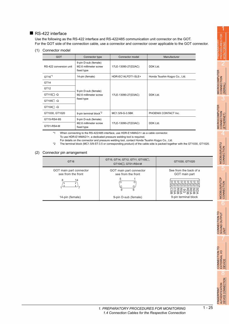
1
1. PREPARAT1.4 Connec
PR
EP
AR
AT
OR
Y
PR
OC
ED
UR
ES
FO
R
MO
NIT
OR
ING
2
MIC
RO
CO
MP
UT
ER
C
ON
NE
CT
ION
(S
ER
IAL
)
3
MIC
RO
CO
MP
UT
ER
C
ON
NE
CT
ION
(E
TH
ER
NE
T)
4
/RT
U
N
RS-422 interfaceUse the following as the RS-422 interface and RS-422/485 communication unit connector on the GOT.For the GOT side of the connection cable, use a connector and connector cover applicable to the GOT connector.
(1) Connector model
*1 When connecting to the RS-422/485 interface, use HDR-E14MAG1+ as a cable connector.
To use HDR-E14MAG1+, a dedicated pressure welding tool is required.For details on the connector and pressure welding tool, contact Honda Tsushin Kogyo Co., Ltd.
*2 The terminal block (MC1.5/9-ST-3.5 or corresponding product) of the cable side is packed together with the GT1030, GT1020.
GOT Connector type Connector model Manufacturer
RS-422 conversion unit
9-pin D-sub (female)
M2.6 millimeter screw
fixed type
17LE-13090-27(D2AC) DDK Ltd.
GT16*1 14-pin (female) HDR-EC14LFDT1-SLE+ Honda Tsushin Kogyo Co., Ltd.
GT14
9-pin D-sub (female)
M2.6 millimeter screw
fixed type
17LE-13090-27(D3AC) DDK Ltd.
GT12
GT115 -Q
GT105 -Q
GT104 -Q
GT1030, GT1020 9-pin terminal block*2 MC1.5/9-G-3.5BK PHOENIX CONTACT Inc.
GT15-RS4-9S 9-pin D-sub (female)
M2.6 millimeter screw
fixed type
17LE-13090-27(D3AC) DDK Ltd.GT01-RS4-M
(R) IO
MO
DB
US
CO
NN
EC
T
5
MO
DB
US
(R)/
TC
P
CO
NN
EC
TIO
N
6
CO
NN
EC
TIO
N T
O
SO
UN
D O
UT
PU
T
UN
IT
7
CO
NN
EC
TIO
N T
O
EX
TE
RN
AL
I/O
D
EV
ICE
8
FIN
GE
RP
RIN
T A
UTH
EN
TIC
ATIO
N
DE
VIC
E C
ON
NE
CTI
ON
(2) Connector pin arrangement
GT16GT15, GT14, GT12, GT11, GT105 ,
GT104 , GT01-RS4-MGT1030, GT1020
14-pin (female)
GOT main part connectorsee from the front
8 14
1 7
9-pin D-sub (female)
GOT main part connectorsee from the front
5 1
9 6
See from the back of aGOT main part
9-pin terminal block
SD
AS
DB
RD
AR
DB
SG
RS
BR
SA
CS
AC
SB
ORY PROCEDURES FOR MONITORINGtion Cables for the Respective Connection
1 - 25

1 - 26 1. PREPARATORY PROCEDURES FOR MON1.4 Connection Cables for the Respective Con
RS-485 interfaceUse the following as the RS-485 interface and RS-422/485 communication unit connector on the GOT.For the GOT side of the connection cable, use a connector and connector cover applicable to the GOT connector.
(1) Connector model
*1 For the checking procedure of the hardware version, refer to the User's Manual.
*2 When connecting to the RS-422/485 interface, use HDR-E14MAG1+ as a cable connector.
To use HDR-E14MAG1+, a dedicated pressure welding tool is required.For details on the connector and pressure welding tool, contact Honda Tsushin Kogyo Co., Ltd..
*3 The terminal block (MC1.5/9-ST-3.5 or corresponding product) of the cable side is packed together with the GT1030, GT1020.
GOT Hardware version*1 Connector type Connector model Manufacturer
GT16*2 ― 14-pin (female) HDR-EC14LFDT1-SLE+ Honda Tsushin Kogyo Co., Ltd.
GT14 ―
9-pin D-sub (female)
M2.6 millimeter screw
fixed type
17LE-13090-27(D3AC) DDK Ltd.
GT12 ―
GT1155-QTBD C or later
GT1155-QSBDF or later
GT1150-QLBD
GT105 -Q C or later
GT104 -Q A or later
GT1030 B or later9-pin terminal block*3 MC1.5/9-G-3.5BK PHOENIX CONTACT Inc
GT1020 E or later
GT15-RS4-9S ―
9-pin D-sub (female)
M2.6 millimeter screw
fixed type
17LE-13090-27(D3AC) DDK Ltd.
GT15-RS4-TE ― ― SL-SMT3.5/10/90F BOX Weidmuller interconnections inc
(2) Connector pin arrangement
GT16GT15, GT14, GT12, GT11,
GT105 , GT104GT1030, GT1020
14-pin (female)
GOT main part connectorsee from the front
8 14
1 7
9-pin D-sub (female)
GOT main part connectorsee from the front
5 1
9 6
See from the back of aGOT main part
9-pin terminal block
SD
AS
DB
RD
AR
DB
SG
RS
BR
SA
CS
AC
SB
ITORINGnection

1
1. PREPARAT1.4 Connec
TO
RY
R
ES
FO
R
ING
1.4.2 Coaxial cable connector connection method
The following describes the method for connecting the BNC connector (connector plug for coaxial cable) and the cable.
A U R
PR
EP
AR
PR
OC
ED
MO
NIT
O
2
CAUTION Solder the coaxial cable connectors properly.
Insufficient soldering may result in malfunctions.
R
MICR
OC
OM
PU
TE
CO
NN
EC
TIO
N
(SE
RIA
L)
3
MP
UT
ER
IO
N
T)
Nut Washer Gasket
Clamp Contact
Components of the BNC connector
Plug shell
Outer sheathExternal conductor
Insulating material
Internal conductor
Structure of the coaxial cable
O TN
E
MIC
RO
CC
ON
NE
C(E
TH
ER
4
MO
DB
US
(R)/
RT
U
CO
NN
EC
TIO
N
5
MO
DB
US
(R)/
TC
P
CO
NN
EC
TIO
N
6
CO
NN
EC
TIO
N T
O
SO
UN
D O
UT
PU
T
UN
IT
7
CO
NN
EC
TIO
N T
O
EX
TE
RN
AL
I/O
D
EV
ICE
8
FIN
GE
RP
RIN
T A
UTH
EN
TIC
ATIO
N
DE
VIC
E C
ON
NE
CTI
ON
Precautions for solderingNote the following precautions when soldering the internal conductor and contact.• Make sure that the solder does not bead up at the soldered section.• Make sure there are no gaps between the connector and cable insulator or they do not cut into each other.• Perform soldering quickly so the insulation material does not become deformed.
1. Remove the external sheath of the coaxial cable with dimensions as shown below.
2. Pass the nut, washer, gasket, and clamp through the coaxial cable as shown on the left and loosen the external conductor.
3. Cut the external conductor, insulting material, and internal conductor with the dimensions as shown below.Note that the external conductor should be cut to the same dimension as the tapered section of the clamp and smoothed down to the clamp.
4. Solder the contact to the internal conductor.
5. Insert the connector assembly shown in into the plug shell and screw the nut into the plug shell.
A
Cut this portion of the outer sheath
Cable in use A
3C-2V 15mm
5C-2V, 5C-2V-CCY 10mm
Clamp
GasketWasher
Nut
Internal conductorInsulating material
CB Clamp and external
conductor Cable in use B C
3C-2V 6mm 3mm
5C-2V, 5C-2V-CCY 7mm 5mm
Solder here
Oti
RY PROCEDURES FOR MONITORINGon Cables for the Respective Connection
1 - 27
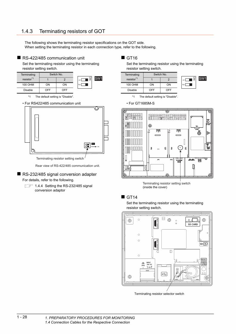
1 - 28 1. PREPARATORY PROCEDURES FOR MON1.4 Connection Cables for the Respective Con
1.4.3 Terminating resistors of GOT
The following shows the terminating resistor specifications on the GOT side.When setting the terminating resistor in each connection type, refer to the following.
RS-422/485 communication unitSet the terminating resistor using the terminating resistor setting switch.
*1 The default setting is "Disable".
• For RS422/485 communication unit
RS-232/485 signal conversion adapterFor details, refer to the following.
1.4.4 Setting the RS-232/485 signal conversion adaptor
Terminating
resistor*1Switch No.
1 2
100 OHM ON ON
Disable OFF OFF
SW1
ON1
2
ON SW1
ON
12
Rear view of RS-422/485 communication unit.
Terminating resistor setting switch
GT16Set the terminating resistor using the terminating resistor setting switch.
*1 The default setting is "Disable".
• For GT1685M-S
GT14Set the terminating resistor using the terminating resistor setting switch.
Terminating
resistor*1Switch No.
1 2
100 OHM ON ON
Disable OFF OFF
SW1
ON1
2
Terminating resistor setting switch(inside the cover)
Terminating resistor selector switch
ITORINGnection
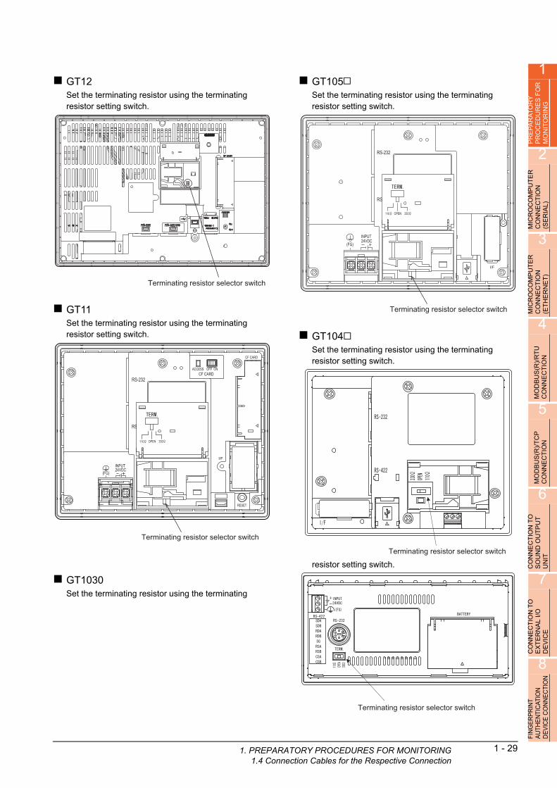
1
PR
EP
AR
AT
OR
Y
PR
OC
ED
UR
ES
FO
R
MO
NIT
OR
ING
2
MIC
RO
CO
MP
UT
ER
C
ON
NE
CT
ION
(S
ER
IAL
)
3
MIC
RO
CO
MP
UT
ER
C
ON
NE
CT
ION
(E
TH
ER
NE
T)
4
MO
DB
US
(R)/
RT
U
CO
NN
EC
TIO
N
5
MO
DB
US
(R)/
TC
P
CO
NN
EC
TIO
N
6
ON
NE
CT
ION
TO
O
UN
D O
UT
PU
T
NIT
GT12Set the terminating resistor using the terminating resistor setting switch.
GT11Set the terminating resistor using the terminating resistor setting switch.
Terminating resistor selector switch
Terminating resistor selector switch
1. PREPARAT1.4 Connec
GT105Set the terminating resistor using the terminating resistor setting switch.
GT104Set the terminating resistor using the terminating resistor setting switch.
resistor setting switch.
Terminating resistor selector switch
Terminating resistor selector switch
C S U
7
CO
NN
EC
TIO
N T
O
EX
TE
RN
AL
I/O
D
EV
ICE
8
FIN
GE
RP
RIN
T A
UTH
EN
TIC
ATIO
N
DE
VIC
E C
ON
NE
CTI
ON
GT1030Set the terminating resistor using the terminating
Terminating resistor selector switch
ORY PROCEDURES FOR MONITORINGtion Cables for the Respective Connection
1 - 29

GT1020Set the terminating resistor using the terminating resistor setting switch.
Terminating resistor selector switch
1 - 30 1. PREPARATORY PROCEDURES FOR MON1.4 Connection Cables for the Respective Con
ITORINGnection

1
1. PREPARAT1.4 Connec
PR
EP
AR
AT
OR
Y
PR
OC
ED
UR
ES
FO
R
MO
NIT
OR
ING
2
MIC
RO
CO
MP
UT
ER
C
ON
NE
CT
ION
(S
ER
IAL
)
3
MIC
RO
CO
MP
UT
ER
C
ON
NE
CT
ION
(E
TH
ER
NE
T)
4
MO
DB
US
(R)/
RT
U
CO
NN
EC
TIO
N
5
(R)/
TC
P
TIO
N
1.4.4 Setting the RS-232/485 signal conversion adaptor
Set the 2-wire/4-wire terminating resistor setting switch according to the connection type.
POINTPOINTPOINT
Enable the 5V power supplyMake sure to validate "Enable the 5V power supply" in the [RS232 Setting] to operate the RS-232/485 signalconversion adaptor.
1.2.2 Checking the project data and OS writing on GOT
When validating the function using the utility function of the GOT main unit, refer to the following manual.
GT14 User's Manual 8.2 Utility Function List
Setting the 2-wire/4-wire terminating resistor setting switch
2-wire/4-wire terminating resistor setting switch
1O
2N
3 4 5 6
US
EC
MO
DB
CO
NN
6
CO
NN
EC
TIO
N T
O
SO
UN
D O
UT
PU
T
UN
IT
7
CO
NN
EC
TIO
N T
O
EX
TE
RN
AL
I/O
D
EV
ICE
POINTPOINTPOINT
RS-232/485 signal conversion adapter
For details on the RS-232/485 signal conversion adapter, refer to the following manual.
GT14-RS2T4-9P RS-232/485 Signal Conversion Adapter User's Manual
Setting item Set valueSwitch No.
1 2 3 4 5 6
2-wire/4-wire2-wire (1Pair) ON ON - - - OFF
4-wire (2Pair) OFF OFF - - - OFF
Terminating resistor
110 - - ON OFF OFF OFF
OPEN - - OFF OFF OFF OFF
330 - - OFF ON ON OFF
8
FIN
GE
RP
RIN
T A
UTH
EN
TIC
ATIO
N
DE
VIC
E C
ON
NE
CTI
ON
ORY PROCEDURES FOR MONITORINGtion Cables for the Respective Connection
1 - 31

1 - 32 1. PREPARATORY PROCEDURES FOR MON1.5 Verifying GOT Recognizes Connected Equ
1.5 Verifying GOT Recognizes Connected Equipment
Verify the GOT recognizes controllers on [Communication Settings] of the Utility.• Channel number of communication interface, communication drivers allocation status• Communication unit installation status
For details on the Utility, refer to the following manual.
User's Manual of GOT used.
When using GT16, GT12(For GT16)
1. After powering up the GOT, touch [Main menu] [Communication setting] from the Utility.
2. Touch [Communication setting].
1.
2.
ITORINGipment

1
PR
EP
AR
AT
OR
Y
PR
OC
ED
UR
ES
FO
R
MO
NIT
OR
ING
2
MIC
RO
CO
MP
UT
ER
C
ON
NE
CT
ION
(S
ER
IAL
)
3
MIC
RO
CO
MP
UT
ER
C
ON
NE
CT
ION
(E
TH
ER
NE
T)
4
MO
DB
US
(R)/
RT
U
CO
NN
EC
TIO
N
5
MO
DB
US
(R)/
TC
P
CO
NN
EC
TIO
N
6
CO
NN
EC
TIO
N T
O
SO
UN
D O
UT
PU
T
UN
IT
7
CO
NN
EC
TIO
N T
O
EX
TE
RN
AL
I/O
D
EV
ICE
8
FIN
GE
RP
RIN
T A
UTH
EN
TIC
ATIO
N
DE
VIC
E C
ON
NE
CTI
ON
For GT15, GT14 or GT11
3. The [Communication Settings] appears.
4. Verify that the communication driver name to be used is displayed in the communication interface box to be used.
5. When the communication driver name is not displayed normally, carry out the following procedure again.
1.1Setting the Communication Interface
1. After powering up the GOT, touch [Main menu] [Communication setting] from the Utility.
2. Touch [Communication setting].(The screen on the left is not displayed on GT11.)
3. 4.
1.
2.
1. PREPARATORY PROCEDURES FOR MONITORING1.5 Verifying GOT Recognizes Connected Equipment
1 - 33

For GT10
3. The [Communication Settings] appears.
4. Verify that the communication driver name to be used is displayed in the box for the communication interface to be used.
5. When the communication driver name is not displayed normally, carry out the following procedure again.
1.1Setting the Communication Interface
1. After powering up the GOT, touch [Main menu] [Communication setting] from the Utility.
2. Touch [Standard I/F] on [Comm. Setting].
3. The [Standard I/F] appears.
4. Verify that the communication driver name to be used is displayed in the box for the communication interface to be used.
5. When the communication driver name is not displayed normally, carry out the following procedure again.
1.1Setting the Communication Interface
3. 4.
1.
2.
3. 4.
1 - 34 1. PREPARATORY PROCEDURES FOR MONITORING1.5 Verifying GOT Recognizes Connected Equipment

1
1. PREPARAT1.5 Verifyin
PR
EP
AR
AT
OR
Y
PR
OC
ED
UR
ES
FO
R
MO
NIT
OR
ING
2
MIC
RO
CO
MP
UT
ER
C
ON
NE
CT
ION
(S
ER
IAL
)
3
MIC
RO
CO
MP
UT
ER
C
ON
NE
CT
ION
(E
TH
ER
NE
T)
4
MO
DB
US
(R)/
RT
U
CO
NN
EC
TIO
N
5
MO
DB
US
(R)/
TC
P
CO
NN
EC
TIO
N
6
CO
NN
EC
TIO
N T
O
SO
UN
D O
UT
PU
T
UN
IT
7
CO
NN
EC
TIO
N T
O
EX
TE
RN
AL
I/O
D
EV
ICE
8
FIN
GE
RP
RIN
T A
UTH
EN
TIC
ATIO
N
DE
VIC
E C
ON
NE
CTI
ON
POINTPOINTPOINT
Utility
(1) How to display Utility (at default)
(2) Utility callWhen setting [Pressing time] to other than 0 second on the setting screen of the utility call key, press and hold the utility call key until the buzzer sounds.For the setting of the utility call key, refer to the following.
User's Manual of GOT used.
(3) Communication interface setting by the UtilityThe communication interface setting can be changed on the Utility's [Communication setting] after writing [Communication Settings] of project data.For details on the Utility, refer to the following manual.
User's Manual of GOT used.
(4) Precedence in communication settingsWhen settings are made by GT Designer3 or the Utility, the latest setting is effective.
When using GT16, GT1595, GT14, GT12 or GT1020Utility call key1-point press on GOT screen upper-left corner
Utility call keySimultaneous 2-point press
(When using GT15)(When using GT16,GT12)Utility display
When using GT1585, GT157 ,GT156 , GT155 , GT11, GT105 , GT104 or GT1030
(When using GT14, GT11)
(When using GT1030,GT1020)
(When using GT105 ,GT104 )
ORY PROCEDURES FOR MONITORINGg GOT Recognizes Connected Equipment
1 - 35
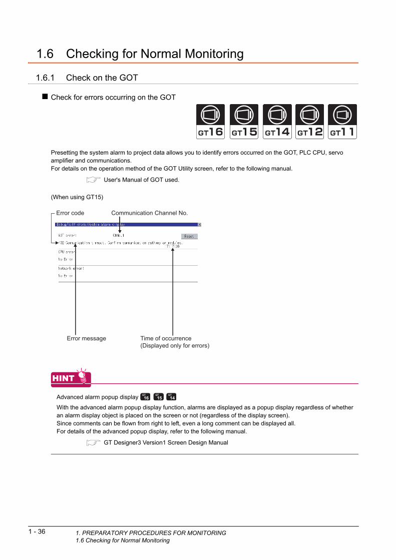
1 - 36 1. PREPARATORY PROCEDURES FOR MON1.6 Checking for Normal Monitoring
1.6 Checking for Normal Monitoring
1.6.1 Check on the GOT
Check for errors occurring on the GOT
Presetting the system alarm to project data allows you to identify errors occurred on the GOT, PLC CPU, servo amplifier and communications.For details on the operation method of the GOT Utility screen, refer to the following manual.
User's Manual of GOT used.
(When using GT15)
HINTHINTHINT
Advanced alarm popup display
With the advanced alarm popup display function, alarms are displayed as a popup display regardless of whether an alarm display object is placed on the screen or not (regardless of the display screen).Since comments can be flown from right to left, even a long comment can be displayed all.For details of the advanced popup display, refer to the following manual.
GT Designer3 Version1 Screen Design Manual
Error code Communication Channel No.
Error message Time of occurrence(Displayed only for errors)
ITORING
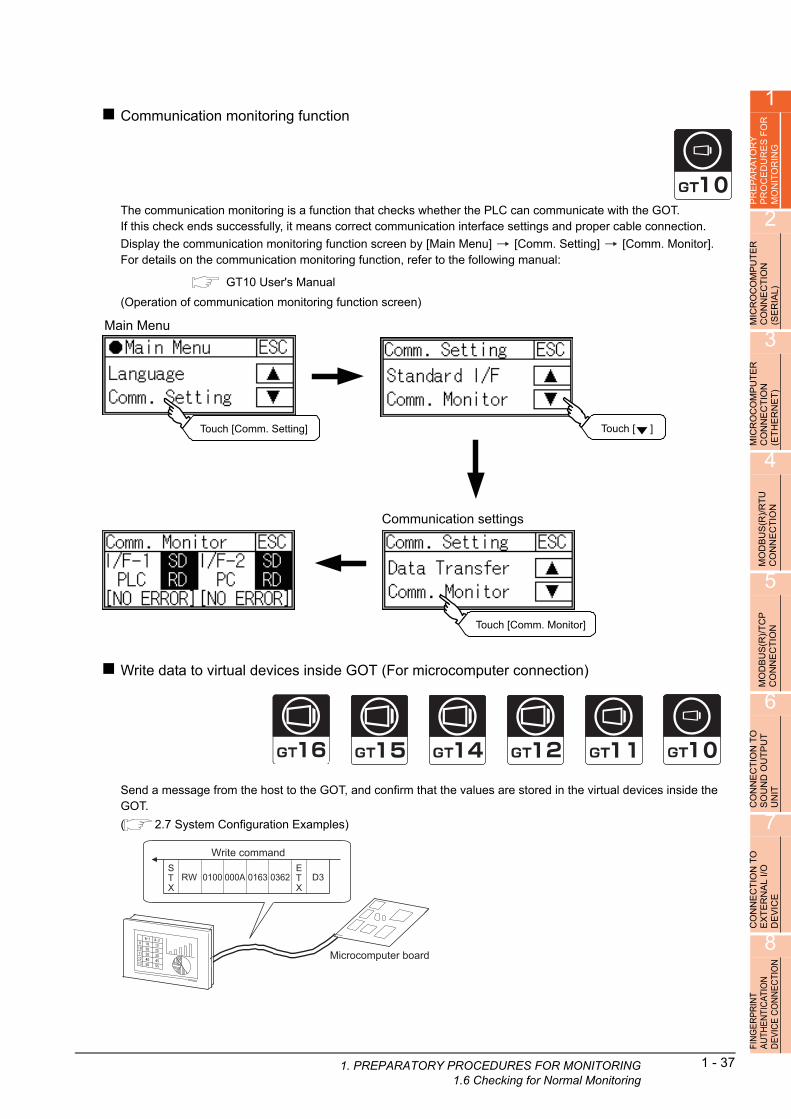
1
1. PREPARAT
PR
EP
AR
AT
OR
Y
PR
OC
ED
UR
ES
FO
R
MO
NIT
OR
ING
2
MIC
RO
CO
MP
UT
ER
C
ON
NE
CT
ION
(S
ER
IAL
)
3
MIC
RO
CO
MP
UT
ER
C
ON
NE
CT
ION
(E
TH
ER
NE
T)
4
MO
DB
US
(R)/
RT
U
CO
NN
EC
TIO
N
5
MO
DB
US
(R)/
TC
P
CO
NN
EC
TIO
N
6
CO
NN
EC
TIO
N T
O
SO
UN
D O
UT
PU
T
UN
IT
7
CO
NN
EC
TIO
N T
O
EX
TE
RN
AL
I/O
D
EV
ICE
8
FIN
GE
RP
RIN
T A
UTH
EN
TIC
ATIO
N
DE
VIC
E C
ON
NE
CTI
ON
Communication monitoring function
The communication monitoring is a function that checks whether the PLC can communicate with the GOT.If this check ends successfully, it means correct communication interface settings and proper cable connection.
Display the communication monitoring function screen by [Main Menu] [Comm. Setting] [Comm. Monitor].For details on the communication monitoring function, refer to the following manual:
GT10 User's Manual
(Operation of communication monitoring function screen)
Write data to virtual devices inside GOT (For microcomputer connection)
Send a message from the host to the GOT, and confirm that the values are stored in the virtual devices inside the GOT.
( 2.7 System Configuration Examples)
Main Menu
Touch [Comm. Setting] Touch [ ]
Communication settings
Touch [Comm. Monitor]
Microcomputer board
Write commandSTX
RW 0163000A0100 0362ETX
D3
ORY PROCEDURES FOR MONITORING1.6 Checking for Normal Monitoring
1 - 37

1 - 38 1. PREPARATORY PROCEDURES FOR MON1.6 Checking for Normal Monitoring
1.6.2 Confirming the communication state on the GOT side (For Ethernet connection)
Confirming the communication state in Windows®, GT Designer3
(1) When using the Command Prompt of Windows®
Execute a Ping command at the Command Prompt of Windows®.
(a) When normal communicationC:\>Ping 192.168.0.18Reply from 192.168.0.18: bytes=32 time<1ms TTL=64
(b) When abnormal communicationC:\>Ping 192.168.0.18Request timed out.
(2) When using the [PING Test] of GT Designer3Select [Communication] [Communication configuration] [Ethernet] and [Connection Test] to display [PING Test].
(3) When abnormal communicationAt abnormal communication, check the followings and execute the Ping command again.• Mounting condition of Ethernet communication unit• Cable connecting condition• Confirmation of [Communication Settings]• IP address of GOT specified by Ping command
1. Specify the [GOT IP Address] of the [PING Test] and click the [PING Test] button.
2. The [Test Result] is displayed after the [PING Test] is finished.
2.
1.Click!
ITORING

1
1. PREPARAT
PR
EP
AR
AT
OR
Y
PR
OC
ED
UR
ES
FO
R
MO
NIT
OR
ING
2
MIC
RO
CO
MP
UT
ER
C
ON
NE
CT
ION
(S
ER
IAL
)
3
MIC
RO
CO
MP
UT
ER
C
ON
NE
CT
ION
(E
TH
ER
NE
T)
4
MO
DB
US
(R)/
RT
U
CO
NN
EC
TIO
N
5
MO
DB
US
(R)/
TC
P
CO
NN
EC
TIO
N
6
CO
NN
EC
TIO
N T
O
SO
UN
D O
UT
PU
T
UN
IT
7
CO
NN
EC
TIO
N T
O
EX
TE
RN
AL
I/O
D
EV
ICE
8
FIN
GE
RP
RIN
T A
UTH
EN
TIC
ATIO
N
DE
VIC
E C
ON
NE
CTI
ON
Confirming the communication state in the GOT module (For GT16, GT14)The Ping test can be confirmed by the Utility screen of the GOT.For the operation method of GOT Utility, refer to the following.
GT16 User's Manual (Basic Utility)GT14 User's Manual
ORY PROCEDURES FOR MONITORING1.6 Checking for Normal Monitoring
1 - 39

1 - 40 1. PREPARATORY PROCEDURES FOR MON1.6 Checking for Normal Monitoring
1.6.3 Confirming the communication state with each station (station monitoring function)
The station monitoring function detects the faults (com
unication timeout) of the stations monitored by the GOT. mWhen detecting the abnormal state, it is assigning the information of the faulty station to the GOT special register (GS).(1) No. of faulty stations
(a) For the Ethernet connection (except for the Ethernet multiple connection)The total No. of the faulty CPUs is stored.
(b) For the Ethernet multiple connectionThe total No. of the faulty devices is stored.
POINTPOINTPOINT
When monitoring GS230 on Numerical Display
When monitoring GS230 on Numerical Display, check [mask processing] with data operation tab as the following.For the data operation, refer to the following manual.
GT Designer3 Version1 Screen Design Manual
Device b15 to b8 b7 to b0
GS230 (00Hfixed) No. of faulty stations
Channel Device b15 to b8 b7 to b0
Ch1 GS280 (00Hfixed) No. of faulty stations
Ch2 GS300 (00Hfixed) No. of faulty stations
Ch3 GS320 (00Hfixed) No. of faulty stations
Ch4 GS340 (00Hfixed) No. of faulty stations
Numerical Display (Data Operation tab)
Set [mask processing] to the upper eight bits (b8to b15) of GS230 on Numerical Display.
ITORING
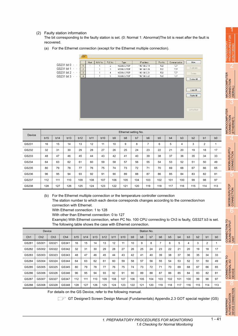
1
1. PREPARAT
PR
EP
AR
AT
OR
Y
PR
OC
ED
UR
ES
FO
R
MO
NIT
OR
ING
2
MIC
RO
CO
MP
UT
ER
C
ON
NE
CT
ION
(S
ER
IAL
)
3
MIC
RO
CO
MP
UT
ER
C
ON
NE
CT
ION
(E
TH
ER
NE
T)
4
MO
DB
US
(R)/
RT
U
CO
NN
EC
TIO
N
5
)/T
CP
IO
N
(2) Faulty station informationThe bit corresponding to the faulty station is set. (0: Normal 1: Abnormal)The bit is reset after the fault is recovered.
(a) For the Ethernet connection (except for the Ethernet multiple connection).
DeviceEthernet setting No.
b15 b14 b13 b12 b11 b10 b9 b8 b7 b6 b5 b4 b3 b2 b1 b0
GS231 16 15 14 13 12 11 10 9 8 7 6 5 4 3 2 1
GS232 32 31 30 29 28 27 26 25 24 23 22 21 20 19 18 17
GS233 48 47 46 45 44 43 42 41 40 39 38 37 36 35 34 33
GS234 64 63 62 61 60 59 58 57 56 55 54 53 52 51 50 49
GS235 80 79 78 77 76 75 74 73 72 71 70 69 68 67 66 65
GS236 96 95 94 93 92 91 90 89 88 87 86 85 84 83 82 81
GS237 112 111 110 109 108 107 106 105 104 103 102 101 100 99 98 97
GS238 128 127 126 125 124 123 122 121 120 119 118 117 116 115 114 113
GS231 bit 0GS231 bit 1GS231 bit 2GS231 bit 3
(R T
MOD
BU
SC
ON
NE
C
6
CO
NN
EC
TIO
N T
O
SO
UN
D O
UT
PU
T
UN
IT
7
CO
NN
EC
TIO
N T
O
EX
TE
RN
AL
I/O
D
EV
ICE
8
FIN
GE
RP
RIN
T A
UTH
EN
TIC
ATIO
N
DE
VIC
E C
ON
NE
CTI
ON
(b) For the Ethernet multiple connection or the temperature controller connectionThe station number to which each device corresponds changes according to the connection/non connection with Ethernet.With Ethernet connection: 1 to 128With other than Ethernet connection: 0 to 127Example) With Ethernet connection, when PC No. 100 CPU connecting to Ch3 is faulty, GS327.b3 is set.The following table shows the case with Ethernet connection.
For details on the GS Device, refer to the following manual.
GT Designer3 Screen Design Manual (Fundamentals) Appendix.2.3 GOT special register (GS)
Device Station No.
Ch1 Ch2 Ch3 Ch4 b15 b14 b13 b12 b11 b10 b9 b8 b7 b6 b5 b4 b3 b2 b1 b0
GS281 GS301 GS321 GS341 16 15 14 13 12 11 10 9 8 7 6 5 4 3 2 1
GS282 GS302 GS322 GS342 32 31 30 29 28 27 26 25 24 23 22 21 20 19 18 17
GS283 GS303 GS323 GS343 48 47 46 45 44 43 42 41 40 39 38 37 36 35 34 33
GS284 GS304 GS324 GS344 64 63 62 61 60 59 58 57 56 55 54 53 52 51 50 49
GS285 GS305 GS325 GS345 80 79 78 77 76 75 74 73 72 71 70 69 68 67 66 65
GS286 GS306 GS326 GS346 96 95 94 93 92 91 90 89 88 87 86 85 84 83 82 81
GS287 GS307 GS327 GS347 112 111 110 109 108 107 106 105 104 103 102 101 100 99 98 97
GS288 GS308 GS328 GS348 128 127 126 125 124 123 122 121 120 119 118 117 116 115 114 113
ORY PROCEDURES FOR MONITORING1.6 Checking for Normal Monitoring
1 - 41

1 - 42 1. PREPARATORY PROCEDURES FOR MON1.6 Checking for Normal Monitoring
(3) Network No., station No. notificationThe network No. and station No. of the GOT in Ethernet connection are stored at GOT startup.If connected by other than Ethernet, 0 is stored.
DeviceDescription
CH1 CH2 CH3 CH4
GS376 GS378 GS380 GS382 Network No. (1 to 239)
GS377 GS379 GS381 GS383 Station No. (1 to 64)
ITORING

1
1. PREPARAT
PR
EP
AR
AT
OR
Y
PR
OC
ED
UR
ES
FO
R
MO
NIT
OR
ING
2
MIC
RO
CO
MP
UT
ER
C
ON
NE
CT
ION
(S
ER
IAL
)
3
MIC
RO
CO
MP
UT
ER
C
ON
NE
CT
ION
(E
TH
ER
NE
T)
4
MO
DB
US
(R)/
RT
U
CO
NN
EC
TIO
N
5
MO
DB
US
(R)/
TC
P
CO
NN
EC
TIO
N
6
CO
NN
EC
TIO
N T
O
SO
UN
D O
UT
PU
T
UN
IT
7
CO
NN
EC
TIO
N T
O
EX
TE
RN
AL
I/O
D
EV
ICE
8
FIN
GE
RP
RIN
T A
UTH
EN
TIC
ATIO
N
DE
VIC
E C
ON
NE
CTI
ON
1.6.4 Check on the PLC
Read IC tag (For RFID connection)
Read IC tag with a RFID reader/writer and check that the read data are written into the PLC CPU.Detailed settings including sequence programs, device settings and other settings required for monitoring, refer to the following manual.
GT Designer3 Version1 Screen Design Manual (Functions)
ORY PROCEDURES FOR MONITORING1.6 Checking for Normal Monitoring
1 - 43

1 - 44 1. PREPARATORY PROCEDURES FOR MONITORING1.6 Checking for Normal Monitoring

MICROCOMPUTERCONNECTION
2. MICROCOMPUTER CONNECTION (SERIAL) . . . . . . . . . . 2 - 1
3. MICROCOMPUTER CONNECTION (ETHERNET). . . . . . . 3 - 1


21
PR
EP
AR
AT
OR
Y
PR
OC
ED
UR
ES
FO
R
MO
NIT
OR
ING
2
MIC
RO
CO
MP
UT
ER
C
ON
NE
CT
ION
(S
ER
IAL
)
3
MIC
RO
CO
MP
UT
ER
C
ON
NE
CT
ION
(E
TH
ER
NE
T)
4
MO
DB
US
(R)/
RT
U
CO
NN
EC
TIO
N
5
MO
DB
US
(R)/
TC
P
CO
NN
EC
TIO
N
6
CO
NN
EC
TIO
N T
O
SO
UN
D O
UT
PU
T
UN
IT
7
CO
NN
EC
TIO
N T
O
EX
TE
RN
AL
I/O
D
EV
ICE
8
ING
ER
PR
INT
UTH
EN
TIC
ATIO
N
EV
ICE
CO
NN
EC
TIO
N
2.MICROCOMPUTERCONNECTION (SERIAL)
2.1 Microcomputer Connection (Serial) . . . . . . . . . . . . . . . . . . . 2 - 2
2.2 System Configuration. . . . . . . . . . . . . . . . . . . . . . . . . . . . . . 2 - 4
2.3 Connection Diagram . . . . . . . . . . . . . . . . . . . . . . . . . . . . . . 2 - 6
2.4 Device Data Area . . . . . . . . . . . . . . . . . . . . . . . . . . . . . . . . 2 - 10
2.5 Message Formats. . . . . . . . . . . . . . . . . . . . . . . . . . . . . . . . 2 - 23
2.6 GOT Side Settings . . . . . . . . . . . . . . . . . . . . . . . . . . . . . . . 2 - 77
2.7 System Configuration Examples . . . . . . . . . . . . . . . . . . . . 2 - 79
2.8 Device Range that Can Be Set . . . . . . . . . . . . . . . . . . . . . 2 - 82
2.9 Precautions . . . . . . . . . . . . . . . . . . . . . . . . . . . . . . . . . . . . 2 - 83
F A D
2 - 1

2 - 2 2. MICROCOMPUTER CONNECTION (SERIA2.1 Microcomputer Connection (Serial)
2. MICROCOMPUTER CONNECTION (SERIAL)
2.1 Microcomputer Connection (Serial)
The "microcomputer connection (Serial)" is a function by which data can be written or read from a PC, microcomputer board, PLC, etc. (hereinafter referred to as "host") to virtual devices of the GOT.
Interrupt output is also available from the GOT to the host.
POINTPOINTPOINT
Virtual devices inside the GOT
The devices inside the GOT are used in the microcomputer connection.(PLC devices are not used)
2.4 Device Data Area
D0
D100
D4095
D163
000A
0362D0
to 4
095
Virtual devices inside GOT
Interrupt output
Microcomputer board
Write,Read CommandSTX
RW 0100 000A 0163 0362ETX
D3
Flow of data processing
(1) When reading or writing data
1. The host sends a request message (the read/write command) to the GOT.
2. The GOT performs a read/write processing to its virtual devices according to the request from the host.
3. Upon completion of the processing, the GOT sends a response message (processing result) to the host.
4. Creating the following objects on the screen allows you to use the data read/written to the virtual devices:• Numerical Display that displays data written by the
write command• Numerical Input that is used to input data to be
upload to the host
Host
Display(D4 to 9)
Input(D20)
GOT
2.4.
3. 1.
Screen data
04/06/01 18:46:49
1254
Screen displayDevice data area(Virtual devices)*2
Responsemessage*1
Requestmessage*1
L)

1
PR
EP
AR
AT
OR
Y
PR
OC
ED
UR
ES
FO
R
MO
NIT
OR
ING
2
MIC
RO
CO
MP
UT
ER
C
ON
NE
CT
ION
(S
ER
IAL
)
3
MIC
RO
CO
MP
UT
ER
C
ON
NE
CT
ION
(E
TH
ER
NE
T)
4
MO
DB
US
(R)/
RT
U
CO
NN
EC
TIO
N
5
MO
DB
US
(R)/
TC
P
CO
NN
EC
TIO
N
6
CO
NN
EC
TIO
N T
O
SO
UN
D O
UT
PU
T
UN
IT
7
CO
NN
EC
TIO
N T
O
EX
TE
RN
AL
I/O
D
EV
ICE
8
FIN
GE
RP
RIN
T A
UTH
EN
TIC
ATIO
N
DE
VIC
E C
ON
NE
CTI
ON
(2) When outputting interrupts
1. Data are written to the virtual devices for interrupt output from the touch switches on the GOT.
2. The GOT sends the written data (interrupt output) to the host.
*1 2.5 Message Formats
*2 2.4 Device Data Area
2.
1.
Host
GOT
Screen data
Interrupt output*1
Screen displayDevice data area(virtual devices)*2
Interrupt(D13) D13 3139H
31H
output value1 output value2
39H
(When the number of interrupt data bytes is 2)
2. MIC
ROCOMPUTER CONNECTION (SERIAL)2.1 Microcomputer Connection (Serial)2 - 3

2 - 4 2. MICROCOMPUTER CONNECTION (SERIA2.2 System Configuration
2.2 System Configuration
2.2.1 For the microcomputer connection (serial)
When connecting one GOT
Computer
Communication driver
Host GOT
Connection cable
*1 Connect it to the RS-232 interface (built into GOT). It cannot be mounted on GT1655 and GT155 .
Host Connection cable GOT Number of
connectable
equipmentCommunication
Type
Max.
distanceConnection diagram number Option device Model
RS-232
Differs
according to
host side
specifications
RS-232 connection diagram 1)
- (Built into GOT)
1 GOT for 1 host
GT15-RS2-9P
RS-232 connection diagram 2) - (Built into GOT)
RS-422
Differs
according to
host side
specifications
RS-422 connection diagram 1) - (Built into GOT)
RS-422 connection diagram 2)
GT16-C02R4-9S(0.2m)
GT15-RS2T4-9P*1
GT15-RS4-9S
- (Built into GOT)
RS-422 connection diagram 3) - (Built into GOT)
L)

1
2. MIC
PR
EP
AR
AT
OR
Y
PR
OC
ED
UR
ES
FO
R
MO
NIT
OR
ING
2
MIC
RO
CO
MP
UT
ER
C
ON
NE
CT
ION
(S
ER
IAL
)
3
When connecting multiple GOTs
Computer
Communication driver
Host GOT(n-th)
GOT (n+1th)
Varies according tothe connection type.
Connection cable
R
MICR
OC
OM
PU
TE
CO
NN
EC
TIO
N
(ET
HE
RN
ET
)
4
MO
DB
US
(R)/
RT
U
CO
NN
EC
TIO
N
5
MO
DB
US
(R)/
TC
P
CO
NN
EC
TIO
N
6
CO
NN
EC
TIO
N T
O
SO
UN
D O
UT
PU
T
UN
IT
7
CO
NN
EC
TIO
N T
O
EX
TE
RN
AL
I/O
D
EV
ICE
8
FIN
GE
RP
RIN
T A
UTH
EN
TIC
ATIO
N
DE
VIC
E C
ON
NE
CTI
ON
*1 This is the connection type (for n-th and n+1th from the host) of GOT, which is connected to the host.
*2 For the connection to GOT, refer to the connection diagram. ( RS-232 connection diagram 3))
*3 The n+1th GOT must be a RS-232 built-in product.
*4 The n+1th GOT must be a RS-422 built-in product (input power supply: 24V).
Host GOT (n-th) *1 Connection cable GOT (n+1th) *1Number of
connectable
equipmentConnection type
Commun
ication
Type
Option device Model
Commun
ication
Type
Cable model
Max.
dis-
tance
Option
deviceModel
For the system configuration
between the GOT and host,
refer to the following.
When connecting one
GOT
RS-232
RS-422
- (Built into
GOT)RS-232
GT10-C30R2-6P(3m)*2 3m
- (Built into
GOT) *3
4 GOT for 1
host
GT10-C02H-6PT9P(0.2m)
+
RS-232 connection
diagram 6)
15m
GT01-C30R2-6P(3m) 3m
- (Built into
GOT)
GT10-C02H-6PT9P(0.2m)
+
RS-232 connection
diagram 7)
15m
RS-232- (Built into
GOT)RS-422
RS-422 connection
diagram 4)30m
- (Built into
GOT) *4
RS-422 connection
diagram 5)30m
- (Built into
GOT)
RS-422- (Built into
GOT)RS-232
RS-232 connection
diagram 4)15m
- (Built into
GOT) *3
RS-232 connection
diagram 5)15m
- (Built into
GOT)
ROCOMPUTER CONNECTION (SERIAL)2.2 System Configuration
2 - 5

2 - 6 2. MICROCOMPUTER CONNECTION (SERIA2.3 Connection Diagram
2.3 Connection Diagram
The following diagram shows the connection between the GOT and the microcomputer.
2.3.1 RS-232 cable
Connection diagramRS-232 connection diagram 1)
(For GT16, GT15, GT14, GT12, GT11, GT105 , GT104 )
Example of the case where the DTR/DSR signal is not used
*1 GT16: CD, GT15: CD, GT14: NC, GT12: NC, GT11: NC, GT105 : NC, GT104 : NC
Example of the case where the DTR/DSR signal is used
*1 GT16: CD, GT15: CD, GT14: NC, GT12: NC, GT11: NC, GT105 : NC, GT104 : NC
GOT side Host side
CD/NC*1
RD(RXD)
SD(TXD)
ER(DTR)
SG
DR(DSR)
RS(RTS)
CS(CTS)
-
1
2
3
4
5
6
7
8
9
FG
SD(TXD)
RD(RXD)
RS(RTS)
SG
CS(CTS)
-
-
ER(DTR)
GOT side Host side
FG
SD(TXD)
RD(RXD)
DR(DSR)
SG
ER(DTR)
RS(RTS)
CS(CTS)
5V
CD/NC*1
RD(RXD)
SD(TXD)
ER(DTR)
SG
DR(DSR)
RS(RTS)
CS(CTS)
-
1
2
3
4
5
6
7
8
9
RS-232 connection diagram 2)
(For GT1030, GT1020)
Example of the case where the DTR/DSR signal is not used
Example of the case where the DTR/DSR signal is used
RS-232 connection diagram 3)
(For GT1030, GT1020)Connection diagram for connecting GT10-C30R2-6P to GT1030 or GT1020
GOT side(terminal block) Host side
SD
RD
ER
DR
SG
RS
CS
NC
NC
RD(RXD)
SD(TXD)
RS(RTS)
CS(CTS)
SG
-
-
ER(DTR)
FG
GOT side(terminal block) Host side
SD
RD
ER
DR
SG
RS
CS
NC
NC
RD(RXD)
SD(TXD)
DR(DSR)
ER(DTR)
SG
RS(RTS)
CS(CTS)
5V
FG
n+1th GOT side(terminal block)
Brown
Red
Blue
Yellow
Green
Purple
Unfastened cable color of GT10-C30R2-6P
SD
RD
ER
DR
SG
RS
CS
NC
NC
L)
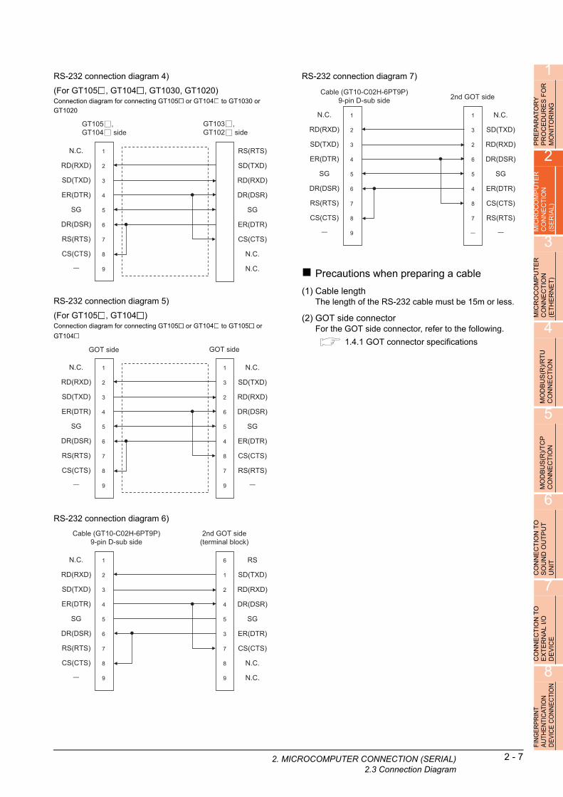
1
PR
EP
AR
AT
OR
Y
PR
OC
ED
UR
ES
FO
R
MO
NIT
OR
ING
2
MIC
RO
CO
MP
UT
ER
C
ON
NE
CT
ION
(S
ER
IAL
)
3
MIC
RO
CO
MP
UT
ER
C
ON
NE
CT
ION
(E
TH
ER
NE
T)
4
MO
DB
US
(R)/
RT
U
CO
NN
EC
TIO
N
5
MO
DB
US
(R)/
TC
P
CO
NN
EC
TIO
N
6
CO
NN
EC
TIO
N T
O
SO
UN
D O
UT
PU
T
UN
IT
7
CO
NN
EC
TIO
N T
O
EX
TE
RN
AL
I/O
D
EV
ICE
8
FIN
GE
RP
RIN
T A
UTH
EN
TIC
ATIO
N
DE
VIC
E C
ON
NE
CTI
ON
RS-232 connection diagram 4)
(For GT105 , GT104 , GT1030, GT1020)Connection diagram for connecting GT105 or GT104 to GT1030 or
GT1020
RS-232 connection diagram 5)
(For GT105 , GT104 )Connection diagram for connecting GT105 or GT104 to GT105 or
GT104
RS-232 connection diagram 6)
N.C.
RD(RXD)
SD(TXD)
ER(DTR)
SG
DR(DSR)
RS(RTS)
CS(CTS)
1
2
3
4
5
6
7
8
9
RS(RTS)
SD(TXD)
RD(RXD)
DR(DSR)
SG
ER(DTR)
CS(CTS)
N.C.
N.C.
GT105 , GT104 side
GT103 , GT102 side
GOT side GOT side
N.C.
RD(RXD)
SD(TXD)
ER(DTR)
SG
DR(DSR)
RS(RTS)
CS(CTS)
1
2
3
4
5
6
7
8
9
1
3
2
6
5
4
8
7
9
N.C.
SD(TXD)
RD(RXD)
DR(DSR)
SG
ER(DTR)
CS(CTS)
RS(RTS)
2nd GOT side(terminal block)
Cable (GT10-C02H-6PT9P)9-pin D-sub side
N.C.
RD(RXD)
SD(TXD)
ER(DTR)
SG
DR(DSR)
RS(RTS)
CS(CTS)
1
2
3
4
5
6
7
8
9
6
1
2
4
5
3
7
8
9
RS
SD(TXD)
RD(RXD)
DR(DSR)
SG
ER(DTR)
CS(CTS)
N.C.
N.C.
2. MIC
RS-232 connection diagram 7)
Precautions when preparing a cable
(1) Cable lengthThe length of the RS-232 cable must be 15m or less.
(2) GOT side connectorFor the GOT side connector, refer to the following.
1.4.1 GOT connector specifications
Cable (GT10-C02H-6PT9P)9-pin D-sub side 2nd GOT side
N.C.
RD(RXD)
SD(TXD)
ER(DTR)
SG
DR(DSR)
RS(RTS)
CS(CTS)
1
2
3
4
5
6
7
8
9
1
3
2
6
5
4
8
7
N.C.
SD(TXD)
RD(RXD)
DR(DSR)
SG
ER(DTR)
CS(CTS)
RS(RTS)
ROCOMPUTER CONNECTION (SERIAL)2.3 Connection Diagram
2 - 7

2.3.2 RS-422 cable
Connection diagramRS-422 connection diagram 1)
(For GT16)
RS-422 connection diagram 2)
(For GT16, GT15, GT14, GT12, GT11, GT105 , GT104 )
SDA1(TXD1+)
SDB1(TXD1-)
RDA1(RXD1+)
RDB1(RXD1-)
SDA2(TXD2+)
SDB2(TXD2-)
RDA2(RXD2+)
RDB2(RXD2-)
RSA(RTS+)
RSB(RTS-)
CSA(CTS+)
CSB(CTS-)
SG
NC
RDA
RDB
SDA
SDB
-
-
-
-
-
-
-
-
SG
1
2
3
4
5
6
7
8
9
10
11
12
13
14
Shell
Host sideGOT side
GOT side Host side
SDA
SDB
RDA
RDB
-
-
-
-
SHELL
RDA
RDB
SDA
SDB
RSA
RSB
CSA
CSB
SG
2
7
1
6
3
8
4
9
5
2 - 8 2. MICROCOMPUTER CONNECTION (SERIA2.3 Connection Diagram
RS-422 connection diagram 3)
(For GT1030, GT1020)
RS-422 connection diagram 4)
(For GT105 , GT104 , GT1030, GT1020)Connection diagram for connecting GT105 or GT104 to GT1030 or
GT1020
RS-422 connection diagram 5)
(For GT105 , GT104 )Connection diagram for connecting GT105 or GT104 to GT105 or
GT104
GOT side Host side
SDA
SDB
RDA
RDB
-
-
-
-
SHELL
RDA
RDB
SDA
SDB
RSA
RSB
CSA
CSB
SG
RXD+(RDA)
RXD-(RDB)
TXD+(SDA)
TXD-(SDB)
SG
CTS+(CSA)
CTS-(CSB)
RTS+(RSA)
RTS-(RSB)
2
7
1
6
5
4
9
3
8
TXD+(SDA)
TXD-(SDB)
RXD+(RDA)
RXD-(RDB)
SG
RTS+(RSA)
RTS-(RSB)
CTS+(CSA)
CTS-(CSB)
GT105 , GT104 side
GT103 , GT102 side (terminal block)
GOT side
TXD+(SDA)
RXD+(RDA)
RTS+(RSA)
CTS+(CSA)
SG
TXD-(SDB)
RXD-(RDB)
RTS-(RSB)
CTS-(CSB)
2
1
4
3
5
7
6
9
8
1
2
3
4
5
6
7
8
9
GOT side
RXD+(RDA)
TXD+(SDA)
CTS+(CSA)
RTS+(RSA)
SG
RXD-(RDB)
TXD-(SDB)
CTS-(CSB)
RTS-(RSB)
L)

1
PR
EP
AR
AT
OR
Y
PR
OC
ED
UR
ES
FO
R
MO
NIT
OR
ING
2
MIC
RO
CO
MP
UT
ER
C
ON
NE
CT
ION
(S
ER
IAL
)
3
MIC
RO
CO
MP
UT
ER
C
ON
NE
CT
ION
(E
TH
ER
NE
T)
4
MO
DB
US
(R)/
RT
U
CO
NN
EC
TIO
N
5
MO
DB
US
(R)/
TC
P
CO
NN
EC
TIO
N
6
CO
NN
EC
TIO
N T
O
SO
UN
D O
UT
PU
T
UN
IT
7
CO
NN
EC
TIO
N T
O
EX
TE
RN
AL
I/O
D
EV
ICE
8
FIN
GE
RP
RIN
T A
UTH
EN
TIC
ATIO
N
DE
VIC
E C
ON
NE
CTI
ON
POINTPOINTPOINT
The polarity A and B in signal names may be reverseddepending on the microcomputer to be used.Prepare a cable according to the microcomputer to beused.
Precautions when preparing a cable
(1) Cable lengthThe distance between the GOT and the PLC of connection diagram 1), 2) and 3) must be 1200 m or less.The length of the RS-422 connection diagram 4) or RS-422 connection diagram 5) must be 30m or less.
(2) GOT side connectorFor the GOT side connector, refer to the following.
1.4.1 GOT connector specifications
Connecting terminating resistors
(1) GOT sideWhen connecting a microcomputer to the GOT, a terminating resistor must be connected to the GOT.
(a) For GT16, GT15, GT12Set the terminating resistor setting switch of the GOT main unit to "Disable".
(b) For GT14, GT11, GT10Set the terminating resistor selector to "330 ".
For the procedure to set the terminating resistor, refer to the following.
1.4.3 Terminating resistors of GOT
2. MIC
ROCOMPUTER CONNECTION (SERIAL)2.3 Connection Diagram2 - 9

2 - 10 2. MICROCOMPUTER CONNECTION (SERIA2.4 Device Data Area
2.4 Device Data Area
The following shows a list of virtual devices inside the GOT available in the microcomputer connection (serial), and the address specification values for each data format.
The address specification of the virtual devices differs depending on the data format.*1
*1 For the address specification method for each data format, refer to the following.
2.5 Message Formats
*2 When reusing GOT900 Series project data
• GOT-A900 Series virtual devices (D0 to 2047)Can be used as they are without changing the assignments.
• GOT-F900 Series virtual devicesSince some of the assigned virtual device values differ as indicated below, change the assignment using device batch edit of GT Designer3.Refer to the following manual for device batch edit of GT Designer3.
GT Designer3 Version1 Screen Design Manual
Model
Virtual device*2 Address specification value
Refer toName
Device
range
(decimal)
Device
type
Format
1, 2
Format
3 to 6
Format
7 to 10
Format
11 to 13
Format
14, 15
D 0 to 4095 Word 0 to 4095 D0 to 4095 D0 to 4095 0000 to 0FFFH 8000 to 9FFFH 2.4.1
R 0 to 4095 Word 4096 to 8191 R0 to 4095 R0 to 4095 1000 to 1FFFH 0000 to 1FFFH 2.4.2
L 0 to 2047 Bit 8192 to 8319 L0 to 2047 L0 to 2047 2000 to 207FH A000 to A0FFH 2.4.3
M 0 to 2047 Bit 8320 to 8447 M0 to 2047 M0 to 2047 2080 to 20FFH 2000 to 20FFH 2.4.4
SD 0 to 15 Word 8448 to 8463D9000 to
9015SD0 to 15 2100 to 210FH
2100 to 211FH
(3000 to 300DH)*3 2.4.5
SM 0 to 63 Bit 8464 to 8467M9000 to
9063SM0 to 63 2110 to 2113H 2200 to 2207H 2.4.6
D 0 to 511 Word 0 to 511 - 8000 to 83FFH 2.4.1
R 0 to 4095 Word 4096 to 8191 - 0000 to 1FFFH 2.4.2
L 0 to 2047 Bit 8192 to 8319 - A000 to A0FFH 2.4.3
M 0 to 2047 Bit 8320 to 8447 - 2000 to 20FFH 2.4.4
SD 0 to 15 Word 8448 to 8463 -2100 to 211FH
(3000 to 300DH)*3 2.4.5
SM 0 to 63 Bit 8464 to 8467 - 2200 to 2207H 2.4.6
• Formats 1, 2 : GOT-A900 Series microcomputer connection
• Formats 3 to 6 : A compatible 1C frame
• Formats 7 to 10 : QnA compatible 3C/4C frame
• Formats 11 to 13 : Digital Electronics Corporation's memory link method
• Formats 14, 15 : GOT-F900 Series microcomputer connection
GOT1000 Series virtual devices GOT-F900 Series virtual devices
D0 to 2047 ―
D2048 to 4095 ―
R0 to 4095 D0 to 4095
L0 to 2047 ―
M0 to 2047 M0 to 2047
SD0 to 15D8000 to 8015
GD0 to 6
SM0 to 63 M8000 to 8063
*3 Access to SD3 to 9 can also be made by the sp
ication of the addresses (3000 to 300DH) of GD0 to 6 on the GOT-F900 Series. ecifPOINTPOINTPOINT
Values of virtual devices inside the GOTWhen the GOT is turned OFF or reset, values are cleared to their defaults(bit devices: OFF, word devices: 0).Values are held in the memory when project data are written to the GOT.
L)
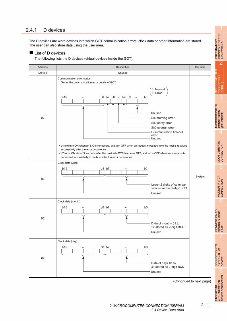
1
2. MIC
PR
EP
AR
AT
OR
Y
PR
OC
ED
UR
ES
FO
R
MO
NIT
OR
ING
2.4.1 D devices
The D devices are word devices into which GOT communication errors, clock data or other information are stored.The user can also store data using the user area.
List of D devicesThe following lists the D devices (virtual devices inside the GOT).
2
MIC
RO
CO
MP
UT
ER
C
ON
NE
CT
ION
(S
ER
IAL
)
3
MIC
RO
CO
MP
UT
ER
C
ON
NE
CT
ION
(E
TH
ER
NE
T)
4
MO
DB
US
(R)/
RT
U
CO
NN
EC
TIO
N
5
MO
DB
US
(R)/
TC
P
CO
NN
EC
TIO
N
6
CO
NN
EC
TIO
N T
O
SO
UN
D O
UT
PU
T
UN
IT
7
CO
NN
EC
TIO
N T
O
EX
TE
RN
AL
I/O
D
EV
ICE
8
ION
Address Description Set side
D0 to 2 Unused ―
D3
Communication error status
Stores the communication error details of GOT.
• b4 to 6 turn ON when an SIO error occurs, and turn OFF when an request message from the host is received
successfully after the error occurrence.
• b7 turns ON about 3 seconds after the host side DTR becomes OFF, and turns OFF when transmission is
performed successfully to the host after the error occurrence.
SystemD4
Clock data (year)
D5
Clock data (month)
D6
Clock data (day)
b15 b0– b3
Unused
–b4
SIO framing error
b5
SIO parity errorSIO overrun error
b6b7
Communication timeout errorUnused
b8
0: Normal1: Error
b15 b0–
Lower 2 digits of calendar year stored as 2-digit BCD
–b7
Unused
b8
b15 b0–
Data of months 01 to 12 stored as 2-digit BCD
–b7
Unused
b8
b15 b0–
Data of days 01 to 31 stored as 2-digit BCD
–b7
Unused
b8
N CT
(Continued to next page)FIN
GE
RP
RIN
T A
UTH
EN
TIC
ATIO
DE
VIC
E C
ON
NE
ROCOMPUTER CONNECTION (SERIAL)2.4 Device Data Area
2 - 11

2 - 12 2. MICROCOMPUTER CONNECTION (SERIA2.4 Device Data Area
(From previous page)
Address Description Set side
D7
Clock data (hour)
System
D8
Clock data (minute)
D9
Clock data (second)
D10
Clock data (day of week)*1
D11, D12 Unused ―
b15 b0–
Data of hours 00 to 23 stored as 2-digit BCD
–b7
Unused
b8
b15 b0–
Data of minutes 00 to 59 stored as 2-digit BCD
–b7
Unused
b8
b15 b0–
Data of seconds 00 to 59 stored as 2-digit BCD
–b7
Unused
b8
b15 b0–
Day-of-week data stored as 2-digit BCD
–b7
Unused
b8
00: Sunday 01: Monday02: Tuesday 03: Wednesday04: Thursday 05: Friday06: Saturday
(Continued to next page)
*1 If a wrong day of the week is set by the clock d
setting commands, the clock data will differ from the time displayed on the atautility.
Example: When June 1, 2004 (Thursday) is set by the clock data setting command (the actual day of the week is Tuesday),"04" is stored to D10 although Tuesday (TUE) will be displayed on the utility time display.
L)

1
2. MIC
(From previous page)
OR
PRE
PA
RA
TO
RY
P
RO
CE
DU
RE
S F
MO
NIT
OR
ING
2
MIC
RO
CO
MP
UT
ER
C
ON
NE
CT
ION
(S
ER
IAL
)
3
MIC
RO
CO
MP
UT
ER
C
ON
NE
CT
ION
(E
TH
ER
NE
T)
4
MO
DB
US
(R)/
RT
U
CO
NN
EC
TIO
N
5
MO
DB
US
(R)/
TC
P
CO
NN
EC
TIO
N
6
CO
NN
EC
TIO
N T
O
SO
UN
D O
UT
PU
T
UN
IT
7
CO
NN
EC
TIO
N T
O
EX
TE
RN
AL
I/O
D
EV
ICE
8
FIN
GE
RP
RIN
T A
UTH
EN
TIC
ATIO
N
DE
VIC
E C
ON
NE
CTI
ON
*1 After writing data, the interrupt data is output within a period of 1 to 10ms.*2 When data are written to D13 and D14 from the host side, interrupt output is not performed.
Address Description Set side
D13
Interrupt output
When data are written to D13 and D14 from a GOT touch switch, for example, the data of D13
and D14 are transmitted (interrupt output) to the host side.*1*2
The data amount (number of bytes) to be interrupt-output is set at "Interrupt Data Byte" in
"Communication Detail Settings".( 2.6.1 Setting communication interface (Communication
settings))
• Output value when 1 is set to "Interrupt Data Byte" in "Communication Detail Settings"
User
D14
• Output value when 2 is set to "Interrupt Data Byte" in "Communication Detail Settings"
• Output value when 4 is set to "Interrupt Data Byte" in "Communication Detail Settings
"(1) When setting the LH order to [32bit Storage] for the communication detail settings
(2) When setting the HL order to [32bit Storage] for the communication detail settings
D15 to 19 Unused ―
D20 to 2031 User area User
D2032 to 2034 Unused ―
D2035
1-second binary counter
The counter is incremented at 1-second intervals after the GOT is turned ON.
(The time elapsed after GOT is turned ON is stored in 1-second units.)
Data are stored in binary format.
System
D2036 to 4095 User area User
D20 to 511 User area User
D13
Lower 8 bits
1 byte
D13
Upper 8 bits Lower 8 bits
2 bytes
Upper 8 bits
D14 D13
Upper 8 bitsLower 8 bits Lower 8 bits
4 bytes
Upper 8 bits
D13 D14
Upper 8 bitsLower 8 bits Lower 8 bits
4 bytes
ROCOMPUTER CONNECTION (SERIAL)2.4 Device Data Area
2 - 13

2 - 14 2. MICROCOMPUTER CONNECTION (SERIA2.4 Device Data Area
POINTPOINTPOINT
(1) The side where virtual devices are setSystem : Set on the system side.User : Set on the user side (by sending request messages from host or using the touch switches, etc.
on the GOT).
(2) Interrupt output (D13, D14)
• To disable the interrupt output, turn ON SM52 (interrupt code output disable flag). ( 2.4.6 SM devices)• To enable the interrupt output, set 8 bits to the data length at "Communication Detail Settings".
( 2.6.1 Setting communication interface (Communication settings))
• When "7 bits" is set, the MSB (8th bit) is ignored. (Example: FFH 7FH)
Differences in address specifications by data format
The address specification of devices varies depending on the data format.*1
The following shows the address specification values for each data format.
*1 For the address specification method for each data format, refer to the following.
2.5 Message Formats
Model Address
Address specification value
Format
1, 2
Format
3 to 6
Format
7 to 10
Format
11 to 13
Format
14, 15
D0 0 D0 D0 0000H
8000H
8001H
D1 1 D1 D1 0001H
8002H
8003H
: : : : : :
D4095 4095 D4095 D4095 0FFFH
9FFEH
9FFFH
D0 0 -
8000H
8001H
D1 1 -
8002H
8003H
: : - :
D511 511 -
83FEH
83FFH
• Formats 1, 2 : GOT-A900 Series microcomputer connection
• Formats 3 to 6 : A compatible 1C frame
• Formats 7 to 10 : QnA compatible 3C/4C frame
• Formats 11 to 13 : Digital Electronics Corporation's memory link method
• Formats 14, 15 : GOT-F900 Series microcomputer connection
Upper 8 bits
8000H
Lower 8 bits
8001H
Upper 8 bits
8002H
Lower 8 bits
8003H
Upper 8 bits
9FFEH
Lower 8 bits
9FFFH
Upper 8 bits
8000H
Lower 8 bits
8001H
Upper 8 bits
8002H
Lower 8 bits
8003H
Upper 8 bits
83FEH
Lower 8 bits
83FFH
L)

1
2. MIC
PR
EP
AR
AT
OR
Y
PR
OC
ED
UR
ES
FO
R
MO
NIT
OR
ING
2
2.4.2 R devices
The R devices are word devices into which user data are stored.All of these devices can be used as a user area.
List of R devices and differences in address specification by data formatThe following shows the R devices (virtual devices inside the GOT).
The address specification values different depending on the data format are also given below.*1
R
MICR
OC
OM
PU
TE
CO
NN
EC
TIO
N
(SE
RIA
L)
3
MIC
RO
CO
MP
UT
ER
C
ON
NE
CT
ION
(E
TH
ER
NE
T)
4
MO
DB
US
(R)/
RT
U
CO
NN
EC
TIO
N
5
MO
DB
US
(R)/
TC
P
CO
NN
EC
TIO
N
6
CO
NN
EC
TIO
N T
O
SO
UN
D O
UT
PU
T
UN
IT
7
CO
NN
EC
TIO
N T
O
EX
TE
RN
AL
I/O
D
EV
ICE
8
FIN
GE
RP
RIN
T A
UTH
EN
TIC
ATIO
N
DE
VIC
E C
ON
NE
CTI
ON
*1 For the address specification method for each data format, refer to the following.
2.5 Message Formats
Model Address
Address specification value
Format
1, 2
Format
3 to 6
Format
7 to 10
Format
11 to 13
Format
14, 15
R0 4096 R0 R0 1000H
0000H
0001H
R1 4097 R1 R1 1001H
0002H
0003H
: : : : : :
R4095 8191 R4095 R4095 1FFFH
1FFEH
1FFFH
R0 4096 -
0000H
0001H
R1 4097 -
0002H
0003H
: : - :
R4095 8191 -
1FFEH
1FFFH
• Formats 1, 2 : GOT-A900 Series microcomputer connection
• Formats 3 to 6 : A compatible 1C frame
• Formats 7 to 10 : QnA compatible 3C/4C frame
• Formats 11 to 13 : Digital Electronics Corporation's memory link method
• Formats 14, 15 : GOT-F900 Series microcomputer connection
Upper 8 bits
0000H
Lower 8 bits
0001H
Upper 8 bits
0002H
Lower 8 bits
0003H
Upper 8 bits
1FFEH
Lower 8 bits
1FFFH
Upper 8 bits
0000H
Lower 8 bits
0001H
Upper 8 bits
0002H
Lower 8 bits
0003H
Upper 8 bits
1FFEH
Lower 8 bits
1FFFH
ROCOMPUTER CONNECTION (SERIAL)2.4 Device Data Area
2 - 15

2 - 16 2. MICROCOMPUTER CONNECTION (SERIA2.4 Device Data Area
2.4.3 L devices
The L devices are bit devices into which user data are stored.All of these devices can be used as a user area.
List of L devices and differences in address specification by data formatThe following shows the L devices (virtual devices inside the GOT).
The address specification values different depending on the data format are also given below.*1
*1 For the address specification method for each data format, refer to the following.
2.5 Message Formats
*2 For reading or writing data in word units, specify the addresses in 16-point units. (Example: L0, L16, L32, etc.)
Model
Address Address specification value
b7 b6 b5 b4 b3 b2 b1 b0Format
1, 2
Format
3 to 6
Format
7 to 10
Format
11 to 13
Format
14, 15
L7 L6 L5 L4 L3 L2 L1 L08192
Same as address
column on left*2
2000H
A000H
L15 L14 L13 L12 L11 L10 L9 L8 A001H
L23 L22 L21 L20 L19 L18 L17 L168193 2001H
A002H
L31 L30 L29 L28 L27 L26 L25 L24 A003H
: : : :
L2039 L2038 L2037 L2036 L2035 L2034 L2033 L20328319 207FH
A0FEH
L2047 L2046 L2045 L2044 L2043 L2042 L2041 L2040 A0FFH
L7 L6 L5 L4 L3 L2 L1 L08192
- A000H
L15 L14 L13 L12 L11 L10 L9 L8 - A001H
L23 L22 L21 L20 L19 L18 L17 L168193
- A002H
L31 L30 L29 L28 L27 L26 L25 L24 - A003H
: : - :
L2039 L2038 L2037 L2036 L2035 L2034 L2033 L20328319
- A0FEH
L2047 L2046 L2045 L2044 L2043 L2042 L2041 L2040 - A0FFH
• Formats 1, 2 : GOT-A900 Series microcomputer connection
• Formats 3 to 6 : A compatible 1C frame
• Formats 7 to 10 : QnA compatible 3C/4C frame
• Formats 11 to 13 : Digital Electronics Corporation's memory link method
• Formats 14, 15 : GOT-F900 Series microcomputer connection
L)

1
2. MIC
PR
EP
AR
AT
OR
Y
PR
OC
ED
UR
ES
FO
R
MO
NIT
OR
ING
2
2.4.4 M devices
The M devices are bit devices into which user data are stored.All of these devices can be used as a user area.
List of M devices and differences in address specification by data formatThe following shows the M devices (virtual devices inside the GOT).
The address specification values different depending on the data format are also given below.*1
R
MICR
OC
OM
PU
TE
CO
NN
EC
TIO
N
(SE
RIA
L)
3
MIC
RO
CO
MP
UT
ER
C
ON
NE
CT
ION
(E
TH
ER
NE
T)
4
MO
DB
US
(R)/
RT
U
CO
NN
EC
TIO
N
5
MO
DB
US
(R)/
TC
P
CO
NN
EC
TIO
N
6
CO
NN
EC
TIO
N T
O
SO
UN
D O
UT
PU
T
UN
IT
7
CO
NN
EC
TIO
N T
O
EX
TE
RN
AL
I/O
D
EV
ICE
8
FIN
GE
RP
RIN
T A
UTH
EN
TIC
ATIO
N
DE
VIC
E C
ON
NE
CTI
ON
*1 For the address specification method for each data format, refer to the following.
2.5 Message Formats
*2 For reading or writing data in word units, specify the addresses in 16-point units.(Example: M0, M16, M32, and others)
Model
Address Address specification value
b7 b6 b5 b4 b3 b2 b1 b0Format
1, 2
Format
3 to 6
Format
7 to 10
Format
11 to 13
Format
14, 15
M7 M6 M5 M4 M3 M2 M1 M08320
Same as address
column on left*2
2080H
2000H
M15 M14 M13 M12 M11 M10 M9 M8 2H001H
M23 M22 M21 M20 M19 M18 M17 M168321 2081H
2002H
M31 M30 M29 M28 M27 M26 M25 M24 2003H
: : : :
M2039 M2038 M2037 M2036 M2035 M2034 M2033 M20328447 20FFH
20FEH
M2047 M2046 M2045 M2044 M2043 M2042 M2041 M2040 20FFH
M7 M6 M5 M4 M3 M2 M1 M08320
- 2000H
M15 M14 M13 M12 M11 M10 M9 M8 - 2001H
M23 M22 M21 M20 M19 M18 M17 M168321
- 2002H
M31 M30 M29 M28 M27 M26 M25 M24 - 2003H
: : - :
M2039 M2038 M2037 M2036 M2035 M2034 M2033 M20328447
- 20FEH
M2047 M2046 M2045 M2044 M2043 M2042 M2041 M2040 - 20FFH
• Formats 1, 2 : GOT-A900 Series microcomputer connection
• Formats 3 to 6 : A compatible 1C frame
• Formats 7 to 10 : QnA compatible 3C/4C frame
• Formats 11 to 13 : Digital Electronics Corporation's memory link method
• Formats 14, 15 : GOT-F900 Series microcomputer connection
ROCOMPUTER CONNECTION (SERIAL)2.4 Device Data Area
2 - 17
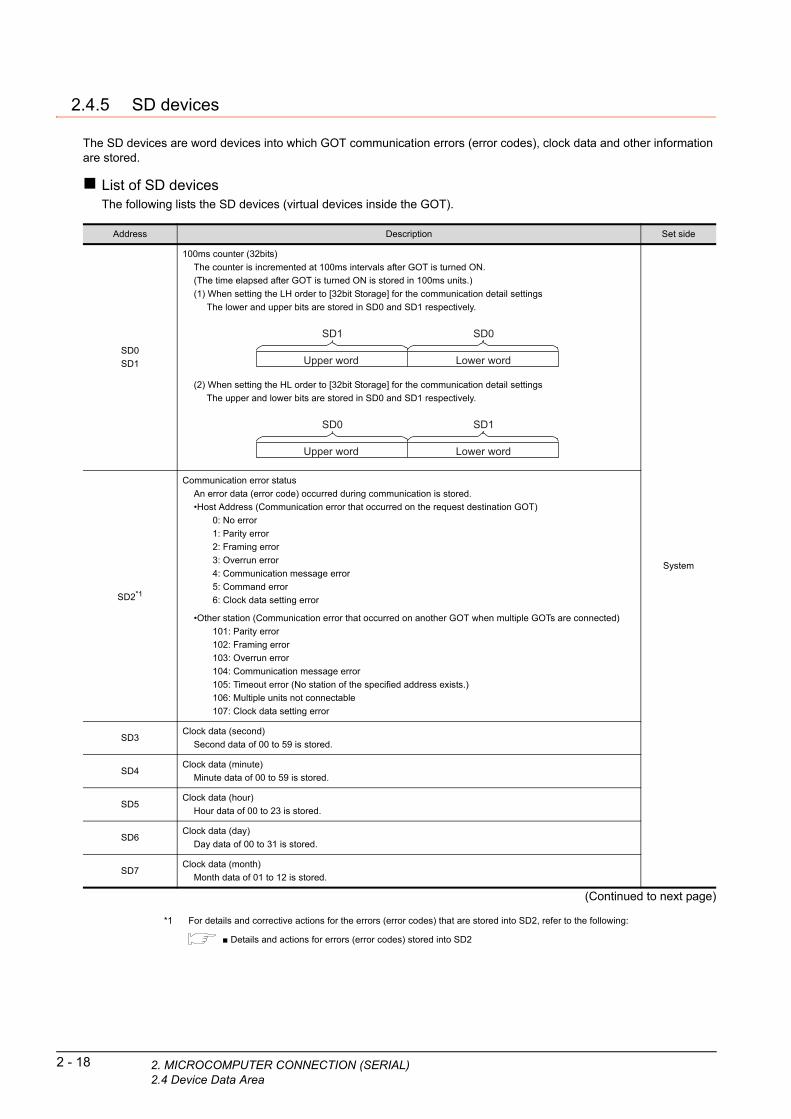
2 - 18 2. MICROCOMPUTER CONNECTION (SERIA2.4 Device Data Area
2.4.5 SD devices
The SD devices are word devices into which GOT communication errors (error codes), clock data and other information are stored.
List of SD devicesThe following lists the SD devices (virtual devices inside the GOT).
(Continued to next page)
Address Description Set side
SD0
SD1
100ms counter (32bits)
The counter is incremented at 100ms intervals after GOT is turned ON.
(The time elapsed after GOT is turned ON is stored in 100ms units.)
(1) When setting the LH order to [32bit Storage] for the communication detail settings
The lower and upper bits are stored in SD0 and SD1 respectively.
(2) When setting the HL order to [32bit Storage] for the communication detail settings
The upper and lower bits are stored in SD0 and SD1 respectively.
System
SD2*1
Communication error status
An error data (error code) occurred during communication is stored.
•Host Address (Communication error that occurred on the request destination GOT)
0: No error
1: Parity error
2: Framing error
3: Overrun error
4: Communication message error
5: Command error
6: Clock data setting error
•Other station (Communication error that occurred on another GOT when multiple GOTs are connected)
101: Parity error
102: Framing error
103: Overrun error
104: Communication message error
105: Timeout error (No station of the specified address exists.)
106: Multiple units not connectable
107: Clock data setting error
SD3Clock data (second)
Second data of 00 to 59 is stored.
SD4Clock data (minute)
Minute data of 00 to 59 is stored.
SD5Clock data (hour)
Hour data of 00 to 23 is stored.
SD6Clock data (day)
Day data of 00 to 31 is stored.
SD7Clock data (month)
Month data of 01 to 12 is stored.
SD0SD1
Lower wordUpper word
SD1SD0
Lower wordUpper word
*1 For details and corrective actions for the errors
ror codes) that are stored into SD2, refer to the following: (er■ Details and actions for errors (error codes) stored into SD2
L)

1
2. MIC
(From previous page)
OR
PRE
PA
RA
TO
RY
P
RO
CE
DU
RE
S F
MO
NIT
OR
ING
2
MIC
RO
CO
MP
UT
ER
C
ON
NE
CT
ION
(S
ER
IAL
)
3
MIC
RO
CO
MP
UT
ER
C
ON
NE
CT
ION
(E
TH
ER
NE
T)
*1 If a wrong day of the week is set by the clock data setting commands, the clock data will differ from the time displayed on the
utility.
Example: When June 1, 2004 (Thursday) is set by the clock data setting command (the actual day of the week is Tuesday),"4" is stored to SD9 although Tuesday (TUE) will be displayed on the utility time display.
POINTPOINTPOINT
The side where virtual devices are set
System : Set on the system side.User : Set on the user side (by sending request messages from host or using the touch switches, etc.
on the GOT).
Address Description Set side
SD8Clock data (year)
4-digit year data is stored.
System
SD9
Clock data (day of week)*1
Day-of-the-week data is stored.
0: Sunday 1: Monday 2: Tuesday 3: Wednesday
4: Thursday 5: Friday 6: Saturday
SD10 to 15 Unused ―
4
Details and actions for errors (error codes) stored into SD2
TU
MO
DB
US
(R)/
RC
ON
NE
CT
ION
5
MO
DB
US
(R)/
TC
P
CO
NN
EC
TIO
N
6
CO
NN
EC
TIO
N T
O
SO
UN
D O
UT
PU
T
UN
IT
7
CO
NN
EC
TIO
N T
O
EX
TE
RN
AL
I/O
D
EV
ICE
8
FIN
GE
RP
RIN
T A
UTH
EN
TIC
ATIO
N
DE
VIC
E C
ON
NE
CTI
ON
Error code Description Action
0 No error ―
1, 101Parity error
The parity bit does not match.• Check the communication cable and communication module
attachment.
• Check the settings of "Communication Detail Settings".
• Match the GOT and host transmission settings.2, 102Framing error
The data bit and/or stop bit are not correct.
3, 103
Overrun error
The next data was transmitted from the host before GOT
completes the processing of the data received.
• Check the settings of "Communication Detail Settings".
• Decrease the transmission speed.
4, 104
Communication message error
EXT/CR could not be found before the upper limit of the
receive buffer was exceeded.
• Check the communication cable and communication module
attachment.
• Check the settings of "Communication Detail Settings".
• Review the contents of the message to transmit.
5Command error
An unsupported command was used.
• Review the contents of the message to transmit.
• Check the commands in the message.
( 2.5.2 List of commands)
105
Timeout error
There is no response from the GOT, or the station of the
specified address does not exist.
• Check the communication cable and communication module
attachment.
• Check the settings of "Communication Detail Settings".
• Review the contents of the message to transmit.
106Multiple units not connectable
The RS-232 port is occupied.
• Check the communication cable and communication module
attachment.
• Check the settings of "Communication Detail Settings".
• Check to see if the RS-232 port is occupied.
6, 107Clock data setting error
The setting value of the clock data has error.
• Review the contents of the message to transmit.
• Check whether the non-existent data is set (e.g. setting "07"
at the day of the week) as clock data.
ROCOMPUTER CONNECTION (SERIAL)2.4 Device Data Area
2 - 19

2 - 20 2. MICROCOMPUTER CONNECTION (SERIA2.4 Device Data Area
Differences in address specifications by data format
The address specification of devices varies depending on the data format.*1
The following shows the address specification values for each data format.
*1 For the address specification method for each data format, refer to the following.
2.5 Message Formats
*2 SD3 to 9 correspond to GD0 to 6 on the GOT-F900 Series.
Access to SD3 to 9 can be also made by the specification of the addresses (3000 to 300DH) of GD0 to 6 on the GOT-F900 Series.
AddressAddress specification value
Formats 1, 2 Formats 3 to 6 Formats 7 to 10 Formats 11 to 13 Formats 14, 15*2
SD0 8448 D9000 SD0 2100H
2100H
2101H
SD1 8449 D9001 SD1 2101H
2102H
2103H
SD2 8450 D9002 SD2 2102H
2104H
2105H
SD3 8451 D9003 SD3 2103H
2106H
(3000H)
2107H
(3001H)
SD4 8452 D9004 SD4 2104H
2108H
(3002H)
2109H
(3003H)
SD5 8453 D9005 SD5 2105H
210AH
(3004H)
210BH
(3005H)
SD6 8454 D9006 SD6 2106H
210CH
(3006H)
210DH
(3007H)
SD7 8455 D9007 SD7 2107H
210EH
(3008H)
210FH
(3009H)
SD8 8456 D9008 SD8 2108H
2110H
(300AH)
2111H
(300BH)
SD9 8457 D9009 SD9 2109H
2112H
(300CH)
2113H
(300DH)
• Formats 1, 2 : GOT-A900 Series microcomputer connection
• Formats 3 to 6 : A compatible 1C frame
• Formats 7 to 10 : QnA compatible 3C/4C frame
• Formats 11 to 13 : Digital Electronics Corporation's memory link method
• Formats 14, 15 : GOT-F900 Series microcomputer connection
Upper 8 bits
2100H
Lower 8 bits
2101H
Upper 8 bits
2102H
Lower 8 bits
2103H
Upper 8 bits
2104H
Lower 8 bits
2105H
Upper 8 bits
2106H(3000H)
Lower 8 bits
2107H(3001H)
Upper 8 bits
2108H(3002H)
Lower 8 bits
2109H(3003H)
Upper 8 bits
210AH(3004H)
Lower 8 bits
210BH(3005H)
Upper 8 bits
210CH(3006H)
Lower 8 bits
210DH(3007H)
Upper 8 bits
210EH(3008H)
Lower 8 bits
210FH(3009H)
Upper 8 bits
2110H(300AH)
Lower 8 bits
2111H(300BH)
Upper 8 bits
2112H(300CH)
Lower 8 bits
2113H(300DH)
L)

1
2. MIC
PR
EP
AR
AT
OR
Y
PR
OC
ED
UR
ES
FO
R
MO
NIT
OR
ING
2.4.6 SM devices
The SM devices are bit devices into which interrupt outputs and clock data that turn ON/OFF at 1-second cycles.
List of SM devicesThe following shows the SM devices (virtual devices inside the GOT).
2
MIC
RO
CO
MP
UT
ER
C
ON
NE
CT
ION
(S
ER
IAL
)
3
MIC
RO
CO
MP
UT
ER
C
ON
NE
CT
ION
(E
TH
ER
NE
T)
4
MO
DB
US
(R)/
RT
U
CO
NN
EC
TIO
N
5
MO
DB
US
(R)/
TC
P
CO
NN
EC
TIO
N
6
CO
NN
EC
TIO
N T
O
SO
UN
D O
UT
PU
T
UN
IT
7
CO
NN
EC
TIO
N T
O
EX
TE
RN
AL
I/O
D
EV
ICE
8
FIN
GE
RP
RIN
T A
UTH
EN
TIC
ATIO
N
DE
VIC
E C
ON
NE
CTI
ON
*1 After the ON/OFF state is changed, the interrupt data is output within a period of 1 to 10 ms.
*2 When the ON/OFF state of SM0 to 49 is changed from the host side, interrupt output is not performed.
POINTPOINTPOINT
(1) The side where virtual devices are setSystem : Set on the system side.User : Set on the user side (by sending request messages from host or using the touch switches, etc.
on the GOT).
(2) Interrupt outputs (SM0 to 49)
• To disable the interrupt output, turn ON SM52 (interrupt code output disable flag).( 2.4.6 SM devices)• To enable the interrupt output, set 8 bits to the data length at "Communication Detail Settings".
( 2.6.1 Setting communication interface (Communication settings))
• When "7 bits" is set, the MSB (8th bit) is ignored. (Example: FFH 7FH)
Address Description Set side
SM0 to 49
Interrupt output
When the ON/OFF state of SM0 to 49 is changed by a touch switch on the GOT, for example, the interrupt
codes shown below are transmitted (interrupt output) to the host side.*1*2
The data amount (number of bytes) to be interrupt-output is set at "Interrupt Data Byte" in "Communication
Detail Settings". ( 2.6.1 Setting communication interface (Communication settings))
User
SM50
1-second cycle clock
Turns ON/OFF at a 1-second cycle.
System
SM51
2-second cycle clock
Turns ON/OFF at a 2-second cycle.
SM52
Interrupt code output disable flag
Enables or disables the output of the interrupt code.
OFF : Interrupt code output enabled ON : Interrupt code output disabled
When set to disable the interrupt code output, no interrupt data are output to the host.
(Relevant devices: D13, D14, SM0 to 49)
User
SM53 to 63 Unused ―
Address Event type
SM0Changed from OFF to ON
Changed from ON to OFF
Changed from OFF to ON
Changed from ON to OFF
Changed from OFF to ON
Changed from ON to OFF
Changed from OFF to ON
Changed from ON to OFF
Changed from OFF to ON
Changed from ON to OFF
Interrupt code
SM1
SM2
50H
51H
52H
53H
54H
55H
SM48B0H
B1H
SM49B2H
B3H
0.5 0.5
1 1
ROCOMPUTER CONNECTION (SERIAL)2.4 Device Data Area
2 - 21
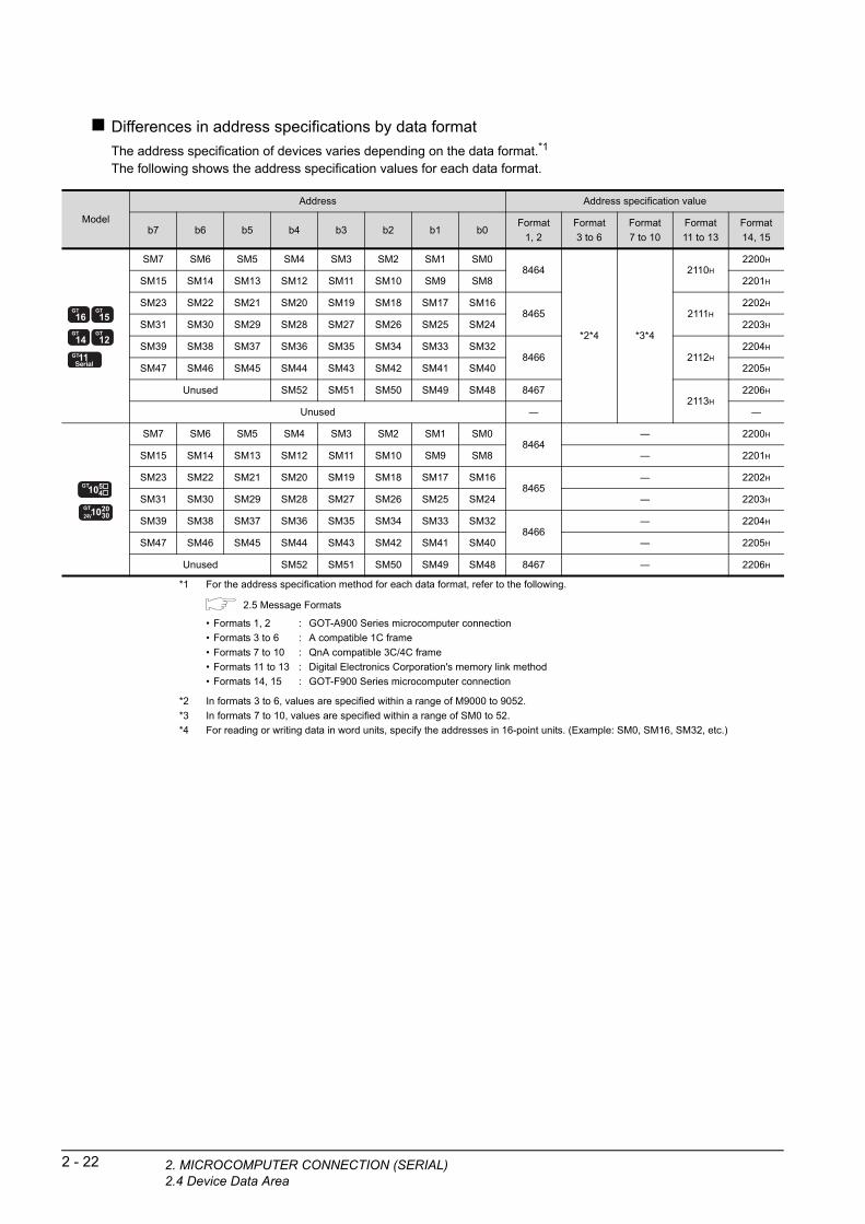
2 - 22 2. MICROCOMPUTER CONNECTION (SERIA2.4 Device Data Area
Differences in address specifications by data format
The address specification of devices varies depending on the data format.*1
The following shows the address specification values for each data format.
*1 For the address specification method for each data format, refer to the following.
2.5 Message Formats
*2 In formats 3 to 6, values are specified within a range of M9000 to 9052.
*3 In formats 7 to 10, values are specified within a range of SM0 to 52.
*4 For reading or writing data in word units, specify the addresses in 16-point units. (Example: SM0, SM16, SM32, etc.)
Model
Address Address specification value
b7 b6 b5 b4 b3 b2 b1 b0Format
1, 2
Format
3 to 6
Format
7 to 10
Format
11 to 13
Format
14, 15
SM7 SM6 SM5 SM4 SM3 SM2 SM1 SM08464
*2*4 *3*4
2110H
2200H
SM15 SM14 SM13 SM12 SM11 SM10 SM9 SM8 2201H
SM23 SM22 SM21 SM20 SM19 SM18 SM17 SM168465 2111H
2202H
SM31 SM30 SM29 SM28 SM27 SM26 SM25 SM24 2203H
SM39 SM38 SM37 SM36 SM35 SM34 SM33 SM328466 2112H
2204H
SM47 SM46 SM45 SM44 SM43 SM42 SM41 SM40 2205H
Unused SM52 SM51 SM50 SM49 SM48 84672113H
2206H
Unused ― ―
SM7 SM6 SM5 SM4 SM3 SM2 SM1 SM08464
― 2200H
SM15 SM14 SM13 SM12 SM11 SM10 SM9 SM8 ― 2201H
SM23 SM22 SM21 SM20 SM19 SM18 SM17 SM168465
― 2202H
SM31 SM30 SM29 SM28 SM27 SM26 SM25 SM24 ― 2203H
SM39 SM38 SM37 SM36 SM35 SM34 SM33 SM328466
― 2204H
SM47 SM46 SM45 SM44 SM43 SM42 SM41 SM40 ― 2205H
Unused SM52 SM51 SM50 SM49 SM48 8467 ― 2206H
• Formats 1, 2 : GOT-A900 Series microcomputer connection
• Formats 3 to 6 : A compatible 1C frame
• Formats 7 to 10 : QnA compatible 3C/4C frame
• Formats 11 to 13 : Digital Electronics Corporation's memory link method
• Formats 14, 15 : GOT-F900 Series microcomputer connection
L)

1
2. MIC
PR
EP
AR
AT
OR
Y
PR
OC
ED
UR
ES
FO
R
MO
NIT
OR
ING
2
PU
TE
R
ION
2.5 Message Formats
This section describes the format of messages that can be used in the microcomputer connection (serial).
2.5.1 Data format type and application
Data format type and applicationCommunication is possible using any of the data formats shown below.
OM T )
MIC
RO
CC
ON
NE
C(S
ER
IAL
(1) Formats 1, 2 (GOT-A900 Series microcomputer connection)This is the same message format as when a microcomputer connection is established with the GOT-A900 series.
3
ICR
OC
OM
PU
TE
R
ON
NE
CT
ION
T
HE
RN
ET
)
Type Name Description Refer to
Format 1GOT-A900 Series microcomputer connection
(format 1)
This format is used when the GOT is connected to the host in a 1:1
connection. 2.5.3
Format 2GOT-A900 Series microcomputer connection
(format 2)
This is the appended format with error code at the error response of the
GOT-A900 Series microcomputer connection (format 1).
M C (E
4
TU
(2) Formats 3 to 6 (A compatible 1C frame)This is the same message format as when communication is performed using the dedicated protocol of the A series computer link module.
R N
MOD
BU
S(R
)/C
ON
NE
CT
IO
5
S(R
)/T
CP
C
TIO
N
Type Name Description Refer to
Format 3 A compatible 1C frame (format 1) This is the basic format of the dedicated protocols.
2.5.4
Format 4 A compatible 1C frame (format 2)This is the appended format of the A compatible 1C frame (format 1) with a
block No.
Format 5 A compatible 1C frame (format 3)This is the enclosed format of the A compatible 1C frame (format 1) with
STX and ETX.
Format 6 A compatible 1C frame (format 4)This is the appended format of the A compatible 1C frame (format 1) with
CR and LF.
BU
NE
MO
DC
ON
6
(3) Formats 7 to 10 (QnA compatible 3C/4C frame)This is the same message format as when a communication is performed using the MC protocol of Q/QnA Series serial communication module.
CO
NN
EC
TIO
N T
O
SO
UN
D O
UT
PU
T
UN
IT
7
CO
NN
EC
TIO
N T
O
EX
TE
RN
AL
I/O
D
EV
ICE
8
FIN
GE
RP
RIN
T A
UTH
EN
TIC
ATIO
N
DE
VIC
E C
ON
NE
CTI
ON
Type Name Description Refer to
Format 7 QnA compatible 3C/4C frame (format 1) This is the basic format of the MC protocols.
2.5.5
Format 8 QnA compatible 3C/4C frame (format 2)This is the appended format of the QnA compatible 3C/4C frame (format 1)
with block No.
Format 9 QnA compatible 3C/4C frame (format 3)This is the enclosed format of the QnA compatible 3C/4C frame (format 1)
with STX and ETX.
Format 10 QnA compatible 3C/4C frame (format 4)This is the appended format of the QnA compatible 3C/4C frame (format 1)
with CR and LF.
ROCOMPUTER CONNECTION (SERIAL)2.5 Message Formats
2 - 23

2 - 24 2. MICROCOMPUTER CONNECTION (SERIA2.5 Message Formats
(4) Formats 11 to 13 (Digital Electronics Corporation's memory link method)This is the same format as the protocol of the Digital Electronics Corporation's memory link method.
Type Name Description Refer to
Format 11
Digital Electronics Corporation's memory link
method
(compatible mode)
This is the basic format of the Digital Electronics Corporation's memory link
method.
2.5.6Format 12
Digital Electronics Corporation's memory link
method
(extended mode, ASCII code 1:1)
This is the appended format of the Digital Electronics Corporation's memory
link method (compatible mode) with sum check, CR and LF.
Format 13
Digital Electronics Corporation's memory link
method
(extended mode, ASCII code 1:n)
This is the appended format of the Digital Electronics Corporation's memory
link method (extended mode, ASCII code 1:1) with a station No.
(5) Formats 14, 15 (GOT-F900 Series microcomputer connection)This is the same message format as when a microcomputer connection is established with the GOT-F900 Series.
Type Name Description Refer to
Format 14GOT-F900 Series microcomputer connection
(format 1)
Use this format when establishing a 1:1 or m:n connection between the
GOT and the host.
The end code is CR. 2.5.7
Format 15GOT-F900 Series microcomputer connection
(format 2)
Use this format when establishing a 1:1 or m:n connection between the
GOT and the host.
The end code is ETX or sum check.
How to set data formatSet the data format at [Detail setting] in GT Designer3.For details of the data format setting method, refer to the following.
2.6.1 Setting communication interface (Communication settings)
L)

1
2. MIC
EP
AR
AT
OR
Y
OC
ED
UR
ES
FO
R
NIT
OR
ING
2.5.2 List of commands
The following shows the list of commands available in each data format.
List of commands for formats 1, 2 (GOT-A900 Series microcomputer connection)
R R O
P P M
2
MIC
RO
CO
MP
UT
ER
C
ON
NE
CT
ION
(S
ER
IAL
)
3
MIC
RO
CO
MP
UT
ER
C
ON
NE
CT
ION
(E
TH
ER
NE
T)
4
*1 Mixed specification of bit devices and word devices is also possible.Command
Command name DescriptionMax. number of points
processedSymbolASCII
code
RD 52H 44HBatch read
in word units
Reads bit devices in 16-point units. 64 words (1024 points)
Reads word devices in 1-point units. 64 points
WD 57H 44HBatch write
in word units
Writes to bit devices in 16-point units. 64 words (1024 points)
Writes to word devices in 1-point units. 64 points
RR 52H 52HRandom read
in word units*1
Reads multiple different bit devices in 16-point units. 64 words (1024 points)
Reads multiple different word devices in 1-point units. 64 points
RW 52H 57HRandom write
in word units*1
Writes to multiple different word devices in 16-point units. 64 words (1024 points)
Writes to multiple different word devices in 1-point units. 64 points
TR 54H 52H Read clock data Reads the clock data of the GOT. ―
TS 54H 53H Set clock data Sets the clock data of the GOT. ―
RT
U
N
List of commands for formats 3 to 6 (A compatible 1C frame)
)/ O
MOD
BU
S(R
CO
NN
EC
TI
5
MO
DB
US
(R)/
TC
P
CO
NN
EC
TIO
N
6
CO
NN
EC
TIO
N T
O
SO
UN
D O
UT
PU
T
UN
IT
7
CO
NN
EC
TIO
N T
O
EX
TE
RN
AL
I/O
D
EV
ICE
8
FIN
GE
RP
RIN
T A
UTH
EN
TIC
ATIO
N
DE
VIC
E C
ON
NE
CTI
ON
*2 This is a dedicated command of GOT for the microcomputer connection.
*3 Specifies the address of bit devices in 16-point units. (Example: M0, M16, M32, and others)
Command
Command name DescriptionMax. number of points
processedSymbolASCII
code
BR
JR
42H 52H
4AH 52H
Batch read
in bit unitsReads bit devices in 1-point units. 64 points
WR
QR
57H 52H
51H 52H
Batch read
in word units
Reads bit devices in 16-point units.*3 64 words (1024 points)
Reads word devices in 1-point units. 64 points
BW
JW
42H 57H
4AH 57H
Batch write
in bit unitsWrites to bit devices in 1-point units. 64 points
WW
QW
57H 57H
51H 57H
Batch write
in word units
Writes to bit devices in 16-point units.*3 64 words (1024 points)
Writes to word devices in 1-point units. 64 points
BT
JT
42H 54H
4AH 54H
Test in bit units
(random write)Writes to multiple different bit devices in 1-point units. 64 points
WT
QT
57H 54H
51H 54H
Test in word units
(random write)
Writes to multiple different bit devices in 16-point units.*3 64 words (1024 points)
Writes to multiple different word devices in 1-point units. 64 points
TR*2 54H 52H Read clock data Reads the clock data of the GOT. ―
TS*2 54H 53H Set clock data Sets the clock data of the GOT. ―
ROCOMPUTER CONNECTION (SERIAL)2.5 Message Formats
2 - 25

2 - 26 2. MICROCOMPUTER CONNECTION (SERIA2.5 Message Formats
Command lists for formats 7 to 10 (QnA compatible 3C/4C frame)
*1 Mixed specification of bit devices and word devices is also possible.
*2 This is a dedicated command of GOT for the microcomputer connection.
*3 Specifies the address of bit devices in 16-point units. (Example: M0, M16, M32, and others)
CommandSub-
commandCommand name Description
Max. number of points
processed
0401 0001Batch read
in bit unitsReads bit devices in 1-point units. 64 points
0401 0000Batch read
in word units
Reads bit devices in 16-point units.*3 64 words (1024 points)
Reads word devices in 1-point units. 64 points
1401 0001Batch write
in bit unitsWrites to bit devices in 1-point units. 64 points
1401 0000Batch write
in word units
Writes to bit devices in 16-point units.*3 64 words (1024 points)
Writes to word devices in 1-point units. 64 points
0403 0000Random read
in word units*1
Reads multiple different bit devices in 16-point and 32-point units.*3 64 words (1024 points)
Reads multiple different word devices in 1-point and 2-point units. 64 points
1402 0001Random write
in bit unitsWrites to multiple different bit devices in 1-point units. 64 points
1402 0000Random write
in word units*1
Writes to multiple different bit devices in 16-point and 32-point units.*3 64 words (1024 points)
Writes to multiple different word devices in 1-point and 2-point units. 64 points
0406 0000Multiple block
batch read
Reads multiple blocks. A bit device (16 bits for 1 point) or a word device
(1 word for 1 point) is regarded as one block.*364 points
1406 0000Multiple block
batch write
Writes multiple blocks. A bit device (16 bits for 1 point) or a word device
(1 word for 1 point) is regarded as one block.*364 points
1901*2 0000 Read clock data Reads the clock data of the GOT. ―
0901*2 0000 Set clock data Sets the clock data of the GOT. ―
List of commands for formats 11 to 13 (Digital Electronics Corporation's memory link method)
*4 This is a dedicated command of GOT for the microcomputer connection.
Command
Command name DescriptionMax. number of points
processedSymbolASCII
code
R 52HBatch read
in word units
Reads bit devices in 16-point units. 64 words (1024 points)
Reads word devices in 1-point units. 64 points
W 57HBatch write
in word units
Writes to bit devices in 16-point units. 64 words (1024 points)
Writes to word devices in 1-point units. 64 points
I 49H Interrupt inquiry Issues an interrupt inquiry.(format 13 only) ―
N*4 4DH Read clock data Reads the clock data of the GOT. ―
M*4 4EH Set clock data Sets the clock data of the GOT. ―
L)
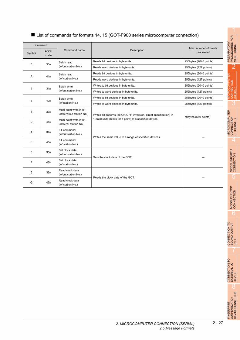
1
2. MIC
FO
R
List of commands for formats 14, 15 (GOT-F900 series microcomputer connection)Y S
PR
EP
AR
AT
OR
PR
OC
ED
UR
EM
ON
ITO
RIN
G
2
MIC
RO
CO
MP
UT
ER
C
ON
NE
CT
ION
(S
ER
IAL
)
3
MIC
RO
CO
MP
UT
ER
C
ON
NE
CT
ION
(E
TH
ER
NE
T)
4
MO
DB
US
(R)/
RT
U
CO
NN
EC
TIO
N
5
MO
DB
US
(R)/
TC
P
CO
NN
EC
TIO
N
6
CO
NN
EC
TIO
N T
O
SO
UN
D O
UT
PU
T
UN
IT
7
CO
NN
EC
TIO
N T
O
EX
TE
RN
AL
I/O
D
EV
ICE
8
FIN
GE
RP
RIN
T A
UTH
EN
TIC
ATIO
N
DE
VIC
E C
ON
NE
CTI
ON
Command
Command name DescriptionMax. number of points
processedSymbolASCII
code
0 30HBatch read
(w/out station No.)
Reads bit devices in byte units. 255bytes (2040 points)
Reads word devices in byte units. 255bytes (127 points)
A 41HBatch read
(w/ station No.)
Reads bit devices in byte units. 255bytes (2040 points)
Reads word devices in byte units. 255bytes (127 points)
1 31HBatch write
(w/out station No.)
Writes to bit devices in byte units. 255bytes (2040 points)
Writes to word devices in byte units. 255bytes (127 points)
B 42HBatch write
(w/ station No.)
Writes to bit devices in byte units. 255bytes (2040 points)
Writes to word devices in byte units. 255bytes (127 points)
3 33HMulti-point write in bit
units (w/out station No.) Writes bit patterns (bit ON/OFF, inversion, direct specification) in
1-point units (8 bits for 1 point) to a specified device.70bytes (560 points)
D 44HMulti-point write in bit
units (w/ station No.)
4 34HFill command
(w/out station No.)Writes the same value to a range of specified devices. ―
E 45HFill command
(w/ station No.)
5 35HSet clock data
(w/out station No.)Sets the clock data of the GOT. ―
F 46HSet clock data
(w/ station No.)
6 36HRead clock data
(w/out station No.)Reads the clock data of the GOT. ―
G 47HRead clock data
(w/ station No.)
ROCOMPUTER CONNECTION (SERIAL)2.5 Message Formats
2 - 27
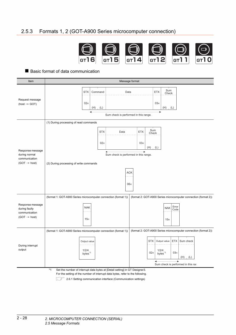
2 - 28 2. MICROCOMPUTER CONNECTION (SERIA2.5 Message Formats
2.5.3 Formats 1, 2 (GOT-A900 Series microcomputer connection)
Basic format of data communication
*1 Set the number of interrupt data bytes at [Detail setting] in GT Designer3.
For the setting of the number of interrupt data bytes, refer to the following.
2.6.1 Setting communication interface (Communication settings)
Item Message format
Request message
(host GOT)
Response message
during normal
communication
(GOT host)
(1) During processing of read commands
(2) During processing of write commands
Response message
during faulty
communication
(GOT host)
(format 1: GOT-A900 Series microcomputer connection (format 1)) (format 2: GOT-A900 Series microcomputer connection (format 2))
During interrupt
output
(format 1: GOT-A900 Series microcomputer connection (format 1)) (format 2: GOT-A900 Series microcomputer connection (format 2))
Sum check is performed in this range.
(H) (L)
Command Data
02H
STX
03H
ETX
(H) (L)
SumCheck
Sum check is performed in this range.
Data
02H
STX
03H
ETX
(H) (L)
SumCheck
06H
ACK
15H
NAK
15H
NAK ErrorCode
Output value
1/2/4bytes*1
Sum check is performed in this ran
02H
STX
03H
ETX
(H) (L)
Sum checkOutput value
1/2/4bytes*1
L)

1
2. MIC
PR
EP
AR
AT
OR
Y
PR
OC
ED
UR
ES
FO
R
MO
NIT
OR
ING
2
Details of data items in message format
POINTPOINTPOINT
Data code during communication
Communication is performed in ASCII code. (excluding interrupt output)
R
PUT
EN
(1) Control codesIO
MICR
OC
OM
CO
NN
EC
T(S
ER
IAL
)
3
MIC
RO
CO
MP
UT
ER
C
ON
NE
CT
ION
(E
TH
ER
NE
T)
Symbol ASCII code Description
STX 02H Start of Text (start marker of message frame)
ETX 03H End of Text (end marker of message frame)
EOT 04H End of Transmission
ENQ 05H Enquiry (start of enquiry)
NAK 15H Negative ACK (error response)
ACK 06H Acknowledge (write completion response)
LF 0AH Line Feed
CL 0CH Clear
CR 0DH Carriage Return
4
OD
BU
S(R
)/R
TU
N
NE
CT
ION
(2) CommandSpecifies the contents to access from the host to GOT.The command is converted to a 2-digit ASCII code (Hex) and transmitted from the upper digit.For details of the commands that can be used, refer to the following.
2.5.2 List of commands
M CO
5
US
(R)/
TC
P
EC
TIO
N
(3) AddressSpecifies the head No. of the device data to be read/written.The address notated in decimal is converted to a 4-digit ASCII code (Hex) and transmitted from the upper digit.For details of the device range that can be accessed, refer to the following.
2.4 Device Data Area
OD
BN
N
M CO
6
(4) Number of pointsSpecifies the number of device data to be read/written. (Setting range: 1 to 64)The address notated in decimal is converted to a 2-digit ASCII code (Hex) and transmitted from the upper digit.
O T
CO
NN
EC
TIO
N T
SO
UN
D O
UT
PU
UN
IT
7
(5) Year, month, day, hour, minute, second and day of the week dataSpecifies year, month, day, hour, minute, second, and day of the week to be read/set to the GOT clock data.The address notated in decimal is converted to a 2-digit ASCII code (Hex) and transmitted from the upper digit.
■ Message format (5) Read clock data (TR) command
■ Message format (6) Set clock data (TS) command
ONN
EC
TIO
N T
OX
TE
RN
AL
I/O
E
VIC
E
(6) DataSpecifies the data to read from/write to the specified device data.(word unit)The address notated in hexadecimal is converted to a 4-digit ASCII code (Hex) and transmitted from the upper digit.
C E D
8
FIN
GE
RP
RIN
T A
UTH
EN
TIC
ATIO
N
DE
VIC
E C
ON
NE
CTI
ON
(7) Error codeThis is the response message at faulty communication appended with error contents.Error code is transmitted in 1 byte.For details of the error codes generated in format 2 (GOT-A900 Series microcomputer connection (format 2)), refer to the following:
■ Error code list
ROCOMPUTER CONNECTION (SERIAL)2.5 Message Formats
2 - 29
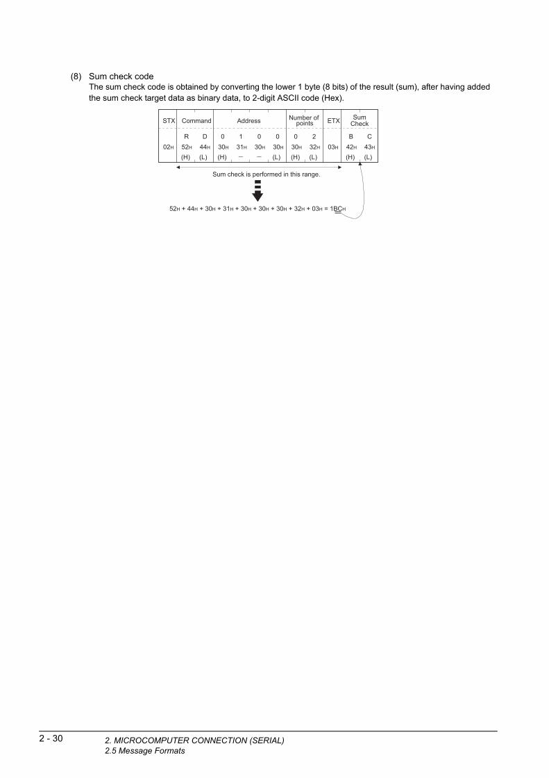
2 - 30 2. MICROCOMPUTER CONNECTION (SERIA2.5 Message Formats
(8) Sum check codeThe sum check code is obtained by converting the lower 1 byte (8 bits) of the result (sum), after having added the sum check target data as binary data, to 2-digit ASCII code (Hex).
Sum check is performed in this range.
02H
STX
03H
ETX
(H) (L)
B C42H 43H
SumCheck
(H) (L)
Command
R D52H 44H
(H) (L)
Address
0 130H 31H
030H
030H
(H) (L)
Number of points
0 230H 32H
52H + 44H + 30H + 31H + 30H + 30H + 30H + 32H + 03H = 1BCH
L)

1
2. MIC
PR
EP
AR
AT
OR
Y
PR
OC
ED
UR
ES
FO
R
MO
NIT
OR
ING
Message Formats
(1) Batch read in word units (RD) command
(a) When reading a word deviceThe following shows an example of reading the two points of the virtual devices D100 and D101.(Assuming D100=0102H, D101=0304H are stored.)
2
ICR
OC
OM
PU
TE
R
ON
NE
CT
ION
E
RIA
L)
D100
D101
0102H
0304H
S
M C (3
MIC
RO
CO
MP
UT
ER
C
ON
NE
CT
ION
(E
TH
ER
NE
T)
4
MO
DB
US
(R)/
RT
U
CO
NN
EC
TIO
N
5
MO
DB
US
(R)/
TC
P
CO
NN
EC
TIO
N
6
CO
NN
EC
TIO
N T
O
SO
UN
D O
UT
PU
T
UN
IT
7
CO
NN
EC
TIO
N T
O
EX
TE
RN
AL
I/O
D
EV
ICE
8
FIN
GE
RP
RIN
T A
UTH
EN
TIC
ATIO
N
DE
VIC
E C
ON
NE
CTI
ON
Item Message format
Request message
(host GOT)
Response message
during normal
communication
(GOT host)
Response message
during faulty
communication
(GOT host)
(format 1: GOT-A900 Series microcomputer connection (format 1))
(format 2: GOT-A900 Series microcomputer connection (format 2))
Sum check is performed in this range.
02H
STX
03H
ETX
(H) (L)
B C42H 43H
SumCheck
(H) (L)
Command
R D52H 44H
(H) (L)
Address
0 130H 31H
030H
030H
(H) (L)
Number of points
0 230H 32H
Sum check is performed in this range.
02H
STX
03H
ETX
(H) (L)
8 D38H 44H
SumCheck
(H) (L)
0 130H 31H
030H
232H
(H) (L)
0 330H 33H
030H
434H
Data 1 (D100) Data 2 (D101)
15H
NAK
The above is a case where the sum check error (06H) has occurred.
15H
NAK
06H
Error code
ROCOMPUTER CONNECTION (SERIAL)2.5 Message Formats
2 - 31
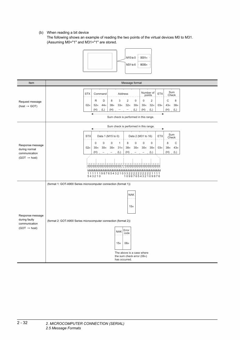
2 - 32 2. MICROCOMPUTER CONNECTION (SERIA2.5 Message Formats
(b) When reading a bit deviceThe following shows an example of reading the two points of the virtual devices M0 to M31.(Assuming M0="1" and M31="1" are stored.
M15 to 0
M31 to 6
0001H
8000H
Item Message format
Request message
(host GOT)
Response message
during normal
communication
(GOT host)
Response message
during faulty
communication
(GOT host)
(format 1: GOT-A900 Series microcomputer connection (format 1))
(format 2: GOT-A900 Series microcomputer connection (format 2))
Sum check is performed in this range.
02H
STX
03H
ETX
(H) (L)
8C38H43H
SumCheck
(H) (L)
Command
R D52H 44H
(H) (L)
Address
8 338H 33H
232H
030H
(H) (L)
Number of points
0 230H 32H
Sum check is performed in this range.
02H
STX
03H
ETX
(H) (L)
8 C38H 43H
SumCheck
(H) (L)
Data 1 (M15 to 0)
030H
030H
131H
030H
(H) (L)
838H
030H
030H
030H
M16
M17
M18
M19
M20
M21
M22
M23
M24
M25
M26
M27
M28
M29
M30
M31
00000000M0
M1
M2
M3
M4
M5
M6
M7
M8
M9
M10
M12
M13
M14
M15
M11
10000000 00000001 00000000
Data 2 (M31 to 16)
15H
NAK
The above is a case where the sum check error (06H) has occurred.
15H
NAK
06H
Error code
L)

1
2. MIC
TO
RY
U
RE
S F
OR
IN
G
(2) Batch write in word units (WD) command
(a) When writing to a word deviceThe following shows as example of writing "0064H"and "0065H"to virtual devices D100 and D101.
A D R
PR
EP
AR
PR
OC
EM
ON
ITO
2
UT
ER
N
D100
D101
0000H
0000H
D100
D101
0064H
0065H
Before execution After execution
P
MICR
OC
OM
CO
NN
EC
TIO
(SE
RIA
L)
3
MIC
RO
CO
MP
UT
ER
C
ON
NE
CT
ION
(E
TH
ER
NE
T)
4
MO
DB
US
(R)/
RT
U
CO
NN
EC
TIO
N
5
MO
DB
US
(R)/
TC
P
CO
NN
EC
TIO
N
6
CO
NN
EC
TIO
N T
O
SO
UN
D O
UT
PU
T
UN
IT
7
CO
NN
EC
TIO
N T
O
EX
TE
RN
AL
I/O
D
EV
ICE
8
FIN
GE
RP
RIN
T A
UTH
EN
TIC
ATIO
N
DE
VIC
E C
ON
NE
CTI
ON
Item Message format
Request message
(host GOT)
Response message
during normal
communication
(GOT host)
Response message
during faulty
communication
(GOT host)
(format 1: GOT-A900 Series microcomputer connection (format 1))
(format 2: GOT-A900 Series microcomputer connection (format 2))
Sum check is performed in this range.
02H
STX
03H
ETX
(H) (L)
5 635H 36H
SumCheck
(H) (L)
Command
W D57H 44H
(H) (L)
Address
0 130H 31H
030H
030H
(H) (L)
Number of points
0 230H 32H
(H) (L)
Data 1(D100)
0 030H 30H
636H
434H
(H) (L)
Data 2 (D101)
0 030H 30H
636H
535H
06H
ACK
15H
NAK
The above is a case where the sum check error (06H) has occurred.
15H
NAK
06H
Error code
ROCOMPUTER CONNECTION (SERIAL)2.5 Message Formats
2 - 33

2 - 34 2. MICROCOMPUTER CONNECTION (SERIA2.5 Message Formats
(b) When writing to a bit deviceThe following shows an example of writing "1"s to virtual devices M0 and M31.
M15 to 0 0000H
0000H
0001H
8000H
Before execution After execution
M31 to 16
M15 to 0
M31 to 16
Item Message format
Request message
(host GOT)
Response message
during normal
communication
(GOT host)
Response message
during faulty
communication
(GOT host)
(format 1: GOT-A900 Series microcomputer connection (format 1))
(format 2: GOT-A900 Series microcomputer connection (format 2))
Sum check is performed in this range.
02H
STX
03H
ETX
(H) (L)
5 635H 36H
SumCheck
(H) (L)
Data 1 (M15 to 0)
030H
––
030H
131H
030H
(H) (L)
Data 2 (M31 to 16)
838H
––
030H
030H
030H
M16
M17
M18
M19
M20
M21
M22
M23
M24
M25
M26
M27
M28
M29
M30
M31
00000000M0
M1
M2
M3
M4
M5
M6
M7
M8
M9
M10
M12
M13
M14
M15
M11
10000000 00000001 00000000
(H) (L)
W D57H 44H
Command
(H) (L)
Address
838H
––
030H
232H
333H
(H) (L)
0 230H 32H
Number of points
06H
ACK
15H
NAK
The above is a case where the sum check error (06H) has occurred.
15H
NAK
06H
Error code
L)
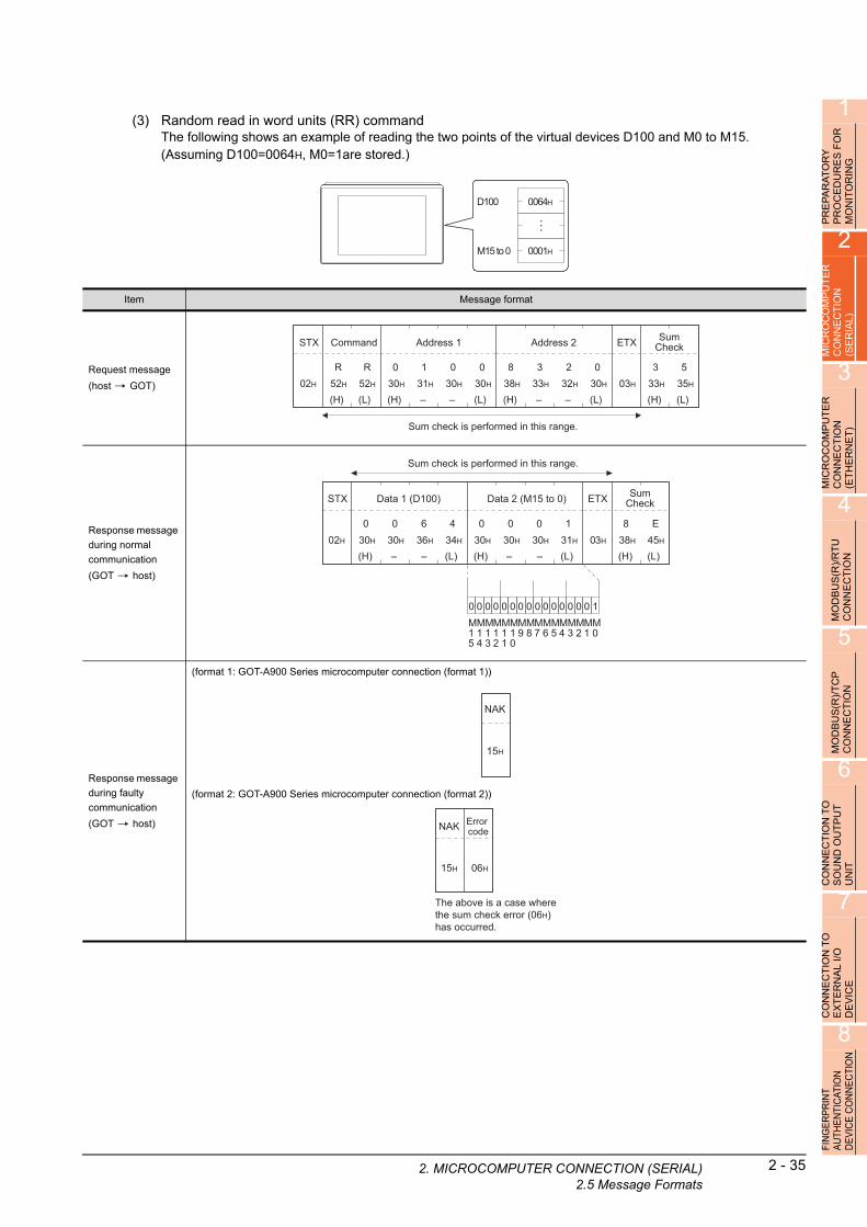
1
2. MIC
OR
Y
RE
S F
OR
IN
G
(3) Random read in word units (RR) commandThe following shows an example of reading the two points of the virtual devices D100 and M0 to M15.(Assuming D100=0064H, M0=1are stored.)
AT U R
PR
EP
AR
PR
OC
ED
MO
NIT
O
2
UT
ER
D100 0064H
0001HM15 to 0
N
MICR
OC
OM
PC
ON
NE
CT
IO(S
ER
IAL
)
3
MIC
RO
CO
MP
UT
ER
C
ON
NE
CT
ION
(E
TH
ER
NE
T)
4
MO
DB
US
(R)/
RT
U
CO
NN
EC
TIO
N
5
MO
DB
US
(R)/
TC
P
CO
NN
EC
TIO
N
6
CO
NN
EC
TIO
N T
O
SO
UN
D O
UT
PU
T
UN
IT
7
CO
NN
EC
TIO
N T
O
EX
TE
RN
AL
I/O
D
EV
ICE
8
FIN
GE
RP
RIN
T A
UTH
EN
TIC
ATIO
N
DE
VIC
E C
ON
NE
CTI
ON
Item Message format
Request message
(host GOT)
Response message
during normal
communication
(GOT host)
Response message
during faulty
communication
(GOT host)
(format 1: GOT-A900 Series microcomputer connection (format 1))
(format 2: GOT-A900 Series microcomputer connection (format 2))
Sum check is performed in this range.
02H
STX
03H
ETX
(H) (L)
3 5
33H 35H
SumCheck
(H) (L)
Command
R R
52H 52H
(H) (L)
Address 1
0 1
30H 31H
––
0
30H
0
30H
(H) (L)
Address 2
8 3
38H 33H
––
2
32H
0
30H
Sum check is performed in this range.
02H
STX
03H
ETX
(H) (L)
8 E38H 45H
SumCheck
(H) (L)
Data 1 (D100)
030H
––
636H
434H
030H
00000000M0
M1
M2
M3
M4
M5
M6
M7
M8
M9
M10
M12
M13
M14
M15
M11
10000000
(H) (L)
Data 2 (M15 to 0)
030H
––
030H
131H
030H
15H
NAK
The above is a case where the sum check error (06H) has occurred.
15H
NAK
06H
Error code
ROCOMPUTER CONNECTION (SERIAL)2.5 Message Formats
2 - 35

2 - 36 2. MICROCOMPUTER CONNECTION (SERIA2.5 Message Formats
(4) Random write in word units (RW) commandThe following shows an example of writing "0064H" and "1" to virtual devices D100 and M0, respectively.
M15 to 0
0000H
Before execution After execution
D100
0000H M15 to 0
0064HD100
0001H
Item Message format
Request message
(host GOT)
Response message
during normal
communication
(GOT host)
Response message
during faulty
communication
(GOT host)
(format 1: GOT-A900 Series microcomputer connection (format 1))
(format 2: GOT-A900 Series microcomputer connection (format 2))
Sum check is performed in this range.
02H
STX
03H
ETX
(H) (L)
C 543H 35H
SumCheck
(H) (L)
Address 2
838H
––
232H
030H
333H
00000000M0
M1
M2
M3
M4
M5
M6
M7
M8
M9
M10
M12
M13
M14
M15
M11
10000000
(H) (L)
Data 2 (M15 to 0)
030H
––
030H
131H
030H
(H) (L)
R W52H 57H
Command
(H) (L)
Address 1
030H
––
131H
030H
030H
(H) (L)
Data 1 (D100)
030H
––
636H
434H
030H
*1
Following*1
06H
ACK
15H
NAK
The above is a case where the sum check error (06H) has occurred.
15H
NAK
06H
Error code
L)

1
2. MIC
OR
Y
RE
S F
OR
IN
G
(5) Read clock data (TR) commandThe following shows an example of reading the clock data of GOT.(Assuming that the clock data of GOT has been set to "2004, June 1, 18:46:49, Tuesday".)
AT U R
PR
EP
AR
PR
OC
ED
MO
NIT
O
2
ER
Time display
2004/06/01 18:46:49 TUE
T
MICR
OC
OM
PU
CO
NN
EC
TIO
N
(SE
RIA
L)
3
MIC
RO
CO
MP
UT
ER
C
ON
NE
CT
ION
(E
TH
ER
NE
T)
4
MO
DB
US
(R)/
RT
U
CO
NN
EC
TIO
N
5
MO
DB
US
(R)/
TC
P
CO
NN
EC
TIO
N
6
CO
NN
EC
TIO
N T
O
SO
UN
D O
UT
PU
T
UN
IT
7
CO
NN
EC
TIO
N T
O
EX
TE
RN
AL
I/O
D
EV
ICE
8
FIN
GE
RP
RIN
T A
UTH
EN
TIC
ATIO
N
DE
VIC
E C
ON
NE
CTI
ON
Item Message format
Request message
(host GOT)
Response message
during normal
communication
(GOT host)
Response message
during faulty
communication
(GOT host)
(format 1: GOT-A900 Series microcomputer connection (format 1))
(format 2: GOT-A900 Series microcomputer connection (format 2))
Sum check is performed in this range.
02H
STX
03H
ETX
(H) (L)
A 941H 39H
SumCheck
(H) (L)
Command
T R54H 52H
Sum check is performed in this range.
02H
STX
03H
ETX
(H) (L)
D 044H 30H
SumCheck
(H) (L)
Year data
0 430H 34H
(H) (L)
Month data
0 630H 36H
(H) (L)
Day data
0 130H 31H
(H) (L)
Hour data
1 831H 38H
(H) (L)
Minute data
4 634H 36H
(H) (L)
Second data
4 934H 39H
(H) (L)
Day-of-week data
0 230H 32H
15H
NAK
The above is a case where the sum check error (06H) has occurred.
15H
NAK
06H
Error code
ROCOMPUTER CONNECTION (SERIAL)2.5 Message Formats
2 - 37

2 - 38 2. MICROCOMPUTER CONNECTION (SERIA2.5 Message Formats
(6) Set clock data (TS) commandThe following shows an example of setting the clock data of GOT.(Assuming the clock data of GOT is to be set to "2004, June 1, 18:46:49 Tuesday".)
Time display
2004/06/01 18:46:49 TUE
After execution
Item Message format
Request message
(host GOT)
Response message
during normal
communication
(GOT host)
Response message
during faulty
communication
(GOT host)
(format 1: GOT-A900 Series microcomputer connection (format 1))
(format 2: GOT-A900 Series microcomputer connection (format 2))
Sum check is performed in this range.
02H
STX
03H
ETX
(H) (L)
737H
SumCheck
737H
(H) (L)
Year data
0 430H 34H
(H) (L)
Month data
0 630H 36H
(H) (L)
Day data
0 130H 31H
(H) (L)
Hour data
1 831H 38H
(H) (L)
Minute data
4 634H 36H
(H) (L)
Second data
4 934H 39H
(H) (L)
Day-of-week data
0 230H 32H
(H) (L)
Command
T S54H 53H
06H
ACK
15H
NAK
The above is a case where the sum check error (06H) has occurred.
15H
NAK
06H
Error code
POINTPOINTPOINT
When a wrong day of the week has been set by the clock data setting command
If a wrong day of the week is set by the clock data setting commands, the clock data will differ from the time displayed on the utility.Example: When June 1, 2004 (Thursday) is set by the clock data setting command (the actual day of week is
Tuesday), Tuesday (TUE) will be displayed on the utility time display.
L)

1
2. MIC
RA
TO
RY
D
UR
ES
FO
R
OR
ING
(7) In the case of interrupt outputsThe following shows an example of an interrupt output when data are written to the interrupt output devices (D13 and D14).(Assuming that "3139H" is written to D13 and "AA55H" to D14.)
A E IT
Example: When the number of interrup ata bytes is 2PR
EP
PR
OC
MO
N
2
MIC
RO
CO
MP
UT
ER
C
ON
NE
CT
ION
(S
ER
IAL
)
3
MP
UT
ER
IO
N
ET
)
Interrupt
Interrupt output
t d
31H
Output value 1
3139HD13
39H
Output value 2
O T
MICR
OC
CO
NN
EC
(ET
HE
RN
4
MO
DB
US
(R)/
RT
U
CO
NN
EC
TIO
N
5
MO
DB
US
(R)/
TC
P
CO
NN
EC
TIO
N
6
CO
NN
EC
TIO
N T
O
SO
UN
D O
UT
PU
T
UN
IT
7
CO
NN
EC
TIO
N T
O
EX
TE
RN
AL
I/O
D
EV
ICE
8
FIN
GE
RP
RIN
T A
UTH
EN
TIC
ATIO
N
DE
VIC
E C
ON
NE
CTI
ON
Item Message format
Interrupt output
(GOT host)
(1) When [Interrupt Data Byte] in "Communication Detail Settings" is set to "1 byte"
(2) When [Interrupt Data Byte] in "Communication Detail Settings" is set to "2 byte"
(3) When [Interrupt Data Byte] in "Communication Detail Settings" is set to "4 byte"
Sum check is performed in this range.
02H
STX
03H
ETX
(H) (L)
333H
Sum check
C43H39H
Output value 1
39H
Output value 1
(format 1: in the case of GOT-A900 Series microcomputer connection (format 1))
(format 2: in the case of GOT-A900 Series microcomputer connection (format 2))
Sum check is performed in this range.
02H
STX
03H
ETX
(H) (L)
636H
Sum check
D44H31H 39H 31H 39H
Output value 1
Output value 2
Output value 1
Output value 2
(format 1: in the case of GOT-A900 Series microcomputer connection (format 1))
(format 2: in the case of GOT-A900 Series microcomputer connection (format 2))
Sum check is performed in this range.
02H
STX
03H
ETX
(H) (L)
636H
Sum Check
C43HAAH
Output value1
55H
Output value2
31H
Output value3
39H
Output value4
AAH
Output value1
55H
Output value2
31H
Output value3
39H
Output value4
(format 1: in the case of GOT-A900 Series microcomputer connection (format 1))
(format 2: in the case of GOT-A900 Series microcomputer connection (format 2))
ROCOMPUTER CONNECTION (SERIAL)2.5 Message Formats
2 - 39

2 - 40 2. MICROCOMPUTER CONNECTION (SERIA2.5 Message Formats
POINTPOINTPOINT
Interrupt output
• To disable the interrupt output, turn ON SM52 (interrupt code output disable flag). ( 2.4.6 SM devices)• To enable the interrupt output, set 8 bits to the data length at "Communication Detail Settings".
( 2.6.1 Setting communication interface (Communication settings))
• When "7 bits" is set, the MSB (8th bit) is ignored. (Example: FFH 7FH)
Error code listIn the case of format 2 (GOT-A900 series microcomputer connection (format 2)), the error contents (error code) are appended to the response message during faulty communication.The following shows error code, error contents, cause, and measures.
Precautions
(1) Batch reading/writing crossing over different devicesWhen using the batch read (RD) or batch write (WD) command, do not batch read/write crossing over the different devices.This will cause an error response.
(2) Storage order for 32-bit dataTo use the program of GOT-A900 series with [32bit Order] setting to GOT1000 series, set [HL Order] to [32bit Order] for [Communication Detail Settings] when 32-bit data is set for GOT-A900 series.With setting [LH Order], the order of upper bits and lower bits are reversed when the GOT displays and writes 32-bit data.
Error code Description Action
06H
Sum check error
The sum check code created from received data differs
from the sum check code in the receive data.
• Review the contents of the message to transmit.
10HCommand error
An unsupported command was used.
• Review the contents of the message to transmit.
• Check the commands in the message.
( 2.5.2 List of commands)
11H
Message length error
The upper limit of the data length that can be received by
the GOT has been exceeded.
• Review the contents of the message to transmit.
• Check the data length of the message.(data length of the data section,
etc.)
12H
Communication message error
EXT was not found within the upper limit of the receive
buffer.
• Check the communication cable and communication module attachment.
• Check the settings of "Communication Detail Settings".
• Review the contents of the message to transmit.
15HClock data setting error
The setting value of the clock data has error.
• Review the contents of the message to transmit.
• Check whether the non-existent data is set (e.g. setting "07" at the day of
the week) as clock data.
7AHAddress error
The start address of the read/write device is out of range.• Review the contents of the message to transmit.
• Check the devices that can be used and the device ranges.
( 2.4 Device Data Area)7BHExceeded number of points error
The read/write range exceeded the device range.
L)
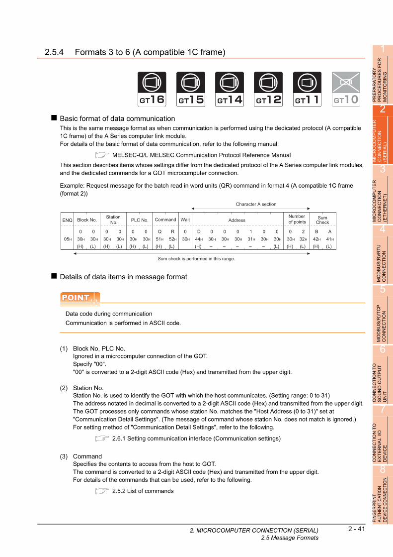
1
2. MIC
R
2.5.4 Formats 3 to 6 (A compatible 1C frame)
RY
E
S F
OG
PR
EP
AR
AT
OP
RO
CE
DU
RM
ON
ITO
RIN
2
MIC
RO
CO
MP
UT
ER
C
ON
NE
CT
ION
(S
ER
IAL
)
3
Basic format of data communicationThis is the same message format as when communication is performed using the dedicated protocol (A compatible 1C frame) of the A Series computer link module.For details of the basic format of data communication, refer to the following manual:
MELSEC-Q/L MELSEC Communication Protocol Reference Manual
This section describes items whose settings differ from the dedicated protocol of the A Series computer link modules, and the dedicated commands for a GOT microcomputer connection.
ER
Example: Request message for the batch read in wor
nits (QR) command in format 4 (A compatible 1C frameOM
PU
TT
ION
E
T)
d u(format 2))
C C N
Character A sectionMIC
RO
CO
NN
E(E
TH
ER
4
US
(R)/
RT
U
CT
ION
Sum check is performed in this range.
05H
ENQ
(H) (L)
B A42H 41H
SumCheck
(H) (L)
Command
R52H
Q51H
(H)
Address
D 144H 31H
––
030H
030H
(H) (L)
Number of points
0 230H 32H
(H) (L)
Block No.
030H
030H
(H) (L)
Station No.
030H
030H
(H) (L)
PLC No.
030H
030H 30H
Wait
0
–
030H
(L)
030H
030H
– –
B NE
MO
DC
ON
5
MO
DB
US
(R)/
TC
P
CO
NN
EC
TIO
N
6
TIO
N T
O
UT
PU
T
Details of data items in message format
POINTPOINTPOINT
Data code during communication
Communication is performed in ASCII code.
(1) Block No, PLC No.Ignored in a microcomputer connection of the GOT.Specify "00"."00" is converted to a 2-digit ASCII code (Hex) and transmitted from the upper digit.
C O
CON
NE
SO
UN
DU
NIT
7
CT
ION
TO
N
AL
I/O
E
(2) Station No.Station No. is used to identify the GOT with which the host communicates. (Setting range: 0 to 31)The address notated in decimal is converted to a 2-digit ASCII code (Hex) and transmitted from the upper digit.The GOT processes only commands whose station No. matches the "Host Address (0 to 31)" set at "Communication Detail Settings". (The message of command whose station No. does not match is ignored.)For setting method of "Communication Detail Settings", refer to the following.
2.6.1 Setting communication interface (Communication settings)
NN
EE
RIC
CO
EX
TD
EV
8
FIN
GE
RP
RIN
T A
UTH
EN
TIC
ATIO
N
DE
VIC
E C
ON
NE
CTI
ON
(3) CommandSpecifies the contents to access from the host to GOT.The command is converted to a 2-digit ASCII code (Hex) and transmitted from the upper digit.For details of the commands that can be used, refer to the following.
2.5.2 List of commands
ROCOMPUTER CONNECTION (SERIAL)2.5 Message Formats
2 - 41

2 - 42 2. MICROCOMPUTER CONNECTION (SERIA2.5 Message Formats
(4) AddressSpecifies the head No. of the device data to be read/written.The data annotated in decimal is converted to a 5- or 7-digit ASCII code (Hex) and transmitted from the upper digit.For details of the device range that can be accessed, refer to the following.
2.4 Device Data Area
(5) Number of pointsSpecifies the number of device data to be read/written. (Setting range: 1 to 40H)The address notated in hexadecimal is converted to a 2-digit ASCII code (Hex) and transmitted from the upper digit.
(6) Year, month, day, hour, minute, second and day of the week dataSpecifies year, month, day, hour, minute, second, and day of the week to be read/set to the GOT clock data.The address notated in decimal is converted to a 2-digit ASCII code (Hex) and transmitted from the upper digit.
■ (1) Read clock data (TR) command
■ (2) Set clock data (TS) command
(7) Error codeThis is the response message at faulty communication appended with error contents.The address notated in hexadecimal is converted to a 2-digit ASCII code (Hex) and transmitted from the upper digit.For details of error codes generated in formats 3 to 6 (A compatible 1C frame), refer to the following:
■ Error code list
POINTPOINTPOINT
When connecting a microcomputer, etc. that uses the dedicated protocol of the A series computer link module with the GOT
When connecting a microcomputer, etc. that uses the dedicated protocol of the A series computer link module with the GOT, correct the commands to use and the device range according to the specifications of GOT.
L)

1
2. MIC
PR
EP
AR
AT
OR
Y
PR
OC
ED
UR
ES
FO
R
MO
NIT
OR
ING
Message formatThe following shows the message format of the dedicated commands for a microcomputer connection of GOT.
(1) Read clock data (TR) commandThe following shows an example of reading the clock data of GOT.(Assuming that the clock data of GOT has been set to "2004, June 1, 18:46:49, Tuesday".)
2
OC
OM
PU
TE
R
NE
CT
ION
IA
L)
Time display
2004/06/01 18:46:49 TUE
R R
MIC
CO
N(S
E
3
MIC
RO
CO
MP
UT
ER
C
ON
NE
CT
ION
(E
TH
ER
NE
T)
4
MO
DB
US
(R)/
RT
U
CO
NN
EC
TIO
N
5
MO
DB
US
(R)/
TC
P
CO
NN
EC
TIO
N
6
CO
NN
EC
TIO
N T
O
SO
UN
D O
UT
PU
T
UN
IT
7
CO
NN
EC
TIO
N T
O
EX
TE
RN
AL
I/O
D
EV
ICE
8
FIN
GE
RP
RIN
T A
UTH
EN
TIC
ATIO
N
DE
VIC
E C
ON
NE
CTI
ON
Item Message format
Request message
(host GOT)
Example: Format 3 (A compatible 1C frame (format 1))
Response message
during normal
communication
(GOT host)
Example: Format 3 (A compatible 1C frame (format 1))
Response message
during faulty
communication
(GOT host)
Example: Format 3 (A compatible 1C frame (format 1))
Sum check is performed in this range.
05H
ENQ
(H) (L)
9 639H 36H
SumCheck
(H) (L)
Command
R52H
T54H
(H) (L)
Station No.
030H
030H
(H) (L)
PLC No.
030H
030H 30H
Wait
0
Sum check is performed in this range.
02H
STX
03H
ETX
(H) (L)
9 039H 30H
SumCheck
(H) (L)
Year data
0 430H 34H
(H) (L)
Month data
0 630H 36H
(H) (L)
Day data
0 130H 31H
(H) (L)
Hour data
1 831H 38H
(H) (L)
Minute data
4 634H 36H
(H) (L)
Second data
4 934H 39H
(H) (L)
Day-of-week data
0 230H 32H
*1
(H) (L)
Station No.
030H
030H
Following*1
Character B section
(H) (L)
PLC No.
030H
030H
The above is the case where an overrun error (05H) has occurred.
15H
NAK
(H) (L)30H 35H
Error code
(H) (L)30H
Station No.
030H
0
(H) (L)30H
PLC No.
030H
0 0 5
ROCOMPUTER CONNECTION (SERIAL)2.5 Message Formats
2 - 43

2 - 44 2. MICROCOMPUTER CONNECTION (SERIA2.5 Message Formats
(2) Set clock data (TS) commandThe following shows an example of setting the clock data of GOT.(Assuming the clock data of GOT is to be set to "2004, June 1, 18:46:49 Tuesday".)
Time display
2004/06/01 18:46:49 TUE
After execution
POINTPOINTPOINT
When a wrong day of the week has been set by the clock data setting command
If a wrong day of the week is set by the clock data setting commands, the clock data will differ from the time displayed on the utility.Example: When June 1, 2004 (Thursday) is set by the clock data setting command (the actual day of week is
Tuesday), Tuesday (TUE) will be displayed on the utility time display.
Item Message format
Request message
(host GOT)
Example: Format 3 (A compatible 1C frame (format 1))
Response message
during normal
communication
(GOT host)
Example: Format 3 (A compatible 1C frame (format 1))
Response message
during faulty
communication
(GOT host)
Example: Format 3 (A compatible 1C frame (format 1))
Sum check is performed in this range.
05H
ENQ
(H) (L)
6 436H 34H
SumCheck
(H) (L)
Year data
0 430H 34H
(H) (L)
Month data
0 630H 36H
(H) (L)
Day data
0 130H 31H
(H) (L)
Hour data
1 831H 38H
(H) (L)
Minute data
4 634H 36H
(H) (L)
Second data
4 934H 39H
(H) (L)
Day-of-week data
0 230H 32H
*1
(H) (L)
Station No.
030H
030H
Following*1
Character C section
(H) (L)
PLC No.
030H
030H
(H) (L)
Command
T54H
S53H 30H
Wait
0
06H
ACK
(H) (L)30H
Station No.
030H
0
(H) (L)30H
PLC No.
030H
0
The above is the case where an overrun error (05H) has occurred.
15H
NAK
(H) (L)30H 35H
Error code
(H) (L)30H
Station No.
030H
0
(H) (L)30H
PLC No.
030H
0 0 5
L)

1
2. MIC
RY
E
S F
OR
G
Error code listThe following shows error code, error contents, cause, and measures.
TO R IN
PR
EP
AR
AP
RO
CE
DU
MO
NIT
OR
2
MIC
RO
CO
MP
UT
ER
C
ON
NE
CT
ION
(S
ER
IAL
)
3
MIC
RO
CO
MP
UT
ER
C
ON
NE
CT
ION
(E
TH
ER
NE
T)
4
MO
DB
US
(R)/
RT
U
CO
NN
EC
TIO
N
5
MO
DB
US
(R)/
TC
P
CO
NN
EC
TIO
N
6
CO
NN
EC
TIO
N T
O
SO
UN
D O
UT
PU
T
UN
IT
7
CO
NN
EC
TIO
N T
O
EX
TE
RN
AL
I/O
D
EV
ICE
8
FIN
GE
RP
RIN
T A
UTH
EN
TIC
ATIO
N
DE
VIC
E C
ON
NE
CTI
ON
Error code Description Action
01HParity error
The parity bit does not match.
• Check the communication cable and communication module attachment.
• Check the settings of "Communication Detail Settings".
• Match the GOT and host transmission settings.
02H
Sum check error
The sum check code created from received data differs
from the sum check code in the receive data.
• Review the contents of the message to transmit.
03H
Protocol error
Received a message that does not follow the control
procedure of the format set at "Communication Detail
Settings".
• Check the settings of "Communication Detail Settings".
• Review the contents of the message to transmit.
05H
Overrun error
The next data was transmitted from the host before GOT
completes the processing of the data received.
• Check the settings of "Communication Detail Settings".
• Decrease the transmission speed.
06H
Character section error
The character section specification error.
•The method of specifying the character section is wrong.
•The specified command has error.
•The number of points of the processing requests exceeds
the allowable range.
•A non-existent device has been specified.
•The setting value of the clock data has error.
• Review the contents of the message to transmit.
• Check the commands in the message.
( 2.5.2 List of commands)
• Check the devices that can be used and the device ranges.
( 2.4 Device Data Area)
• Check whether the non-existent data is set (e.g. setting "07" at the day of
the week) as clock data.
07H
Character error
A character other than "A to Z", "0 to 9", space, and control
codes has been received.
• Review the contents of the message to transmit.
ROCOMPUTER CONNECTION (SERIAL)2.5 Message Formats
2 - 45

2 - 46 2. MICROCOMPUTER CONNECTION (SERIA2.5 Message Formats
2.5.5 Formats 7 to 10 (QnA compatible 3C/4C frame)
Basic format of data communicationThis is the same message format as when communication is performed using the MC protocol (QnA compatible 3C/4C frame) of the Q/QnA Series serial communication module.For details of the basic format of data communication, refer to the following manual:
MELSEC-Q/L MELSEC Communication Protocol Reference Manual
This section describes items whose settings differ from the MC protocol of the Q/QnA Series serial communication module, and the dedicated commands for a GOT microcomputer connection.
Example: Request message for the batch read in wor
nits (0401) command in format 8 (QnA compatible 4C frame d u(format 2))Sum check is performed in this range.
05H
ENQ
(H) (L)
B A42H 41H
Sum check
(H) (L)
Device code
*2AH
D44H
(H) (L)
Block No.
030H
030H
(H) (L)
Frame ID No.
F46H
838H
(H) (L)
PLC No.
030H
030H
(H)
Head Device
131H
––
030H
–
030H
(L)
030H
–
030H
030H
Character A section
(H) (L)
Station No.
030H
030H
(H) (L)
Network No.
030H
030H
(H) –
Request destination module I/O No.
030H
030H
– (L)
030H
030H
(H) (L)
Request destination module station No.
030H
030H
(H) (L)
Host Address No.
030H
030H
(H) –
Command
030H
434H
– (L)
030H
131H
(H) –
Sub-command
030H
030H
(L)
030H
030H
– (H) –
Device points
030H
030H
– (L)
030H
232H
Following*1
*1
POINTPOINTPOINT
QnA compatible 4C frame (format 5)
GOT cannot use the QnA compatible 4C frame (format 5).
L)
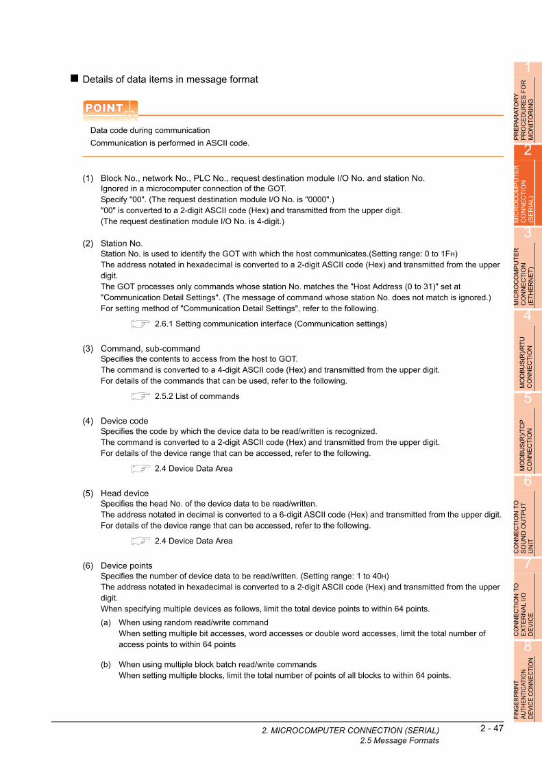
1
2. MIC
PR
EP
AR
AT
OR
Y
PR
OC
ED
UR
ES
FO
R
MO
NIT
OR
ING
2
MIC
RO
CO
MP
UT
ER
C
ON
NE
CT
ION
(S
ER
IAL
)
Details of data items in message format
POINTPOINTPOINT
Data code during communication
Communication is performed in ASCII code.
(1) Block No., network No., PLC No., request destination module I/O No. and station No.Ignored in a microcomputer connection of the GOT.Specify "00". (The request destination module I/O No. is "0000".)"00" is converted to a 2-digit ASCII code (Hex) and transmitted from the upper digit.(The request destination module I/O No. is 4-digit.)
3
MIC
RO
CO
MP
UT
ER
C
ON
NE
CT
ION
(E
TH
ER
NE
T)
4
(2) Station No.Station No. is used to identify the GOT with which the host communicates.(Setting range: 0 to 1FH)The address notated in hexadecimal is converted to a 2-digit ASCII code (Hex) and transmitted from the upper digit.The GOT processes only commands whose station No. matches the "Host Address (0 to 31)" set at "Communication Detail Settings". (The message of command whose station No. does not match is ignored.)For setting method of "Communication Detail Settings", refer to the following.
2.6.1 Setting communication interface (Communication settings)
TU
MO
DB
US
(R)/
RC
ON
NE
CT
ION
5
(3) Command, sub-commandSpecifies the contents to access from the host to GOT.The command is converted to a 4-digit ASCII code (Hex) and transmitted from the upper digit.For details of the commands that can be used, refer to the following.
2.5.2 List of commands
MO
DB
US
(R)/
TC
P
CO
NN
EC
TIO
N
(4) Device codeSpecifies the code by which the device data to be read/written is recognized.The command is converted to a 2-digit ASCII code (Hex) and transmitted from the upper digit.For details of the device range that can be accessed, refer to the following.
2.4 Device Data Area
6
CO
NN
EC
TIO
N T
O
SO
UN
D O
UT
PU
T
UN
IT
(5) Head deviceSpecifies the head No. of the device data to be read/written.The address notated in decimal is converted to a 6-digit ASCII code (Hex) and transmitted from the upper digit.For details of the device range that can be accessed, refer to the following.
2.4 Device Data Area
7
CO
NN
EC
TIO
N T
O
EX
TE
RN
AL
I/O
D
EV
ICE
8
(6) Device pointsSpecifies the number of device data to be read/written. (Setting range: 1 to 40H)The address notated in hexadecimal is converted to a 2-digit ASCII code (Hex) and transmitted from the upper digit.When specifying multiple devices as follows, limit the total device points to within 64 points.
(a) When using random read/write commandWhen setting multiple bit accesses, word accesses or double word accesses, limit the total number of access points to within 64 points
N
FIN
GE
RP
RIN
T A
UTH
EN
TIC
ATIO
N
DE
VIC
E C
ON
NE
CTI
O
(b) When using multiple block batch read/write commandsWhen setting multiple blocks, limit the total number of points of all blocks to within 64 points.ROCOMPUTER CONNECTION (SERIAL)2.5 Message Formats
2 - 47

2 - 48 2. MICROCOMPUTER CONNECTION (SERIA2.5 Message Formats
(7) Year, month, day, hour, minute, second and day of the week dataSpecifies year, month, day, hour, minute, second, and day of the week to be read/set to the GOT clock data.The address notated in decimal is converted to a 2-digit ASCII code (Hex) and transmitted from the upper digit.
■ Message format (1) Read clock data (1901) command
■ Message format (2) Set clock data (0901) command
(8) Error codeThis is the response message at faulty communication appended with error contents.The address notated in hexadecimal is converted to a 4-digit ASCII code (Hex) and transmitted from the upper digit.For details of error codes that are generated in formats 7 to 10 (QnA compatible 3C/4C frame), refer to the following:
■ Error code list
POINTPOINTPOINT
When connecting a microcomputer, etc. that uses the MC protocol of the Q/QnA series serial communication module with the GOT
When connecting a microcomputer, etc. that uses the MC protocol of the Q/QnA series serial communication module with the GOT, correct the commands to be used and the device ranges to match the GOT specifications.
L)
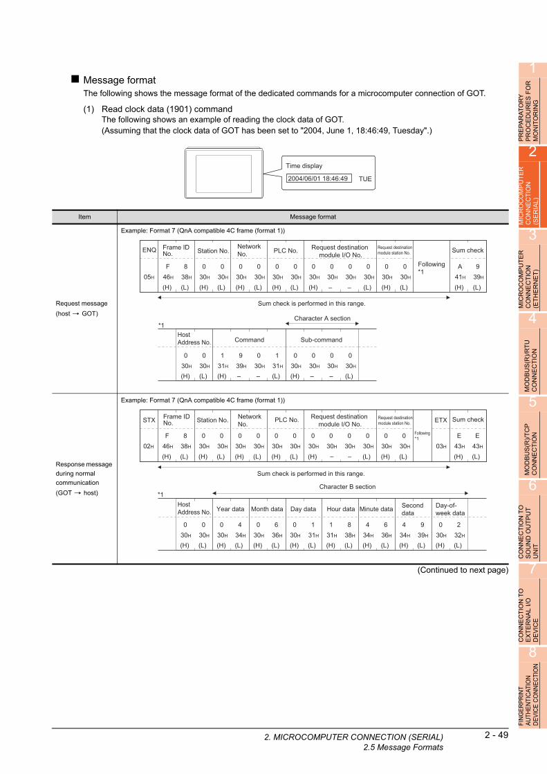
1
2. MIC
PR
EP
AR
AT
OR
Y
PR
OC
ED
UR
ES
FO
R
MO
NIT
OR
ING
Message formatThe following shows the message format of the dedicated commands for a microcomputer connection of GOT.
(1) Read clock data (1901) commandThe following shows an example of reading the clock data of GOT.(Assuming that the clock data of GOT has been set to "2004, June 1, 18:46:49, Tuesday".)
2
OC
OM
PU
TE
R
NE
CT
ION
IA
L)
Time display
2004/06/01 18:46:49 TUE
R R
MIC
CO
N(S
E
3
MIC
RO
CO
MP
UT
ER
C
ON
NE
CT
ION
(E
TH
ER
NE
T)
4
MO
DB
US
(R)/
RT
U
CO
NN
EC
TIO
N
5
MO
DB
US
(R)/
TC
P
CO
NN
EC
TIO
N
6
CO
NN
EC
TIO
N T
O
SO
UN
D O
UT
PU
T
UN
IT
7
CO
NN
EC
TIO
N T
O
EX
TE
RN
AL
I/O
D
EV
ICE
8
FIN
GE
RP
RIN
T A
UTH
EN
TIC
ATIO
N
DE
VIC
E C
ON
NE
CTI
ON
(Continued to next page)
Item Message format
Request message
(host GOT)
Example: Format 7 (QnA compatible 4C frame (format 1))
Response message
during normal
communication
(GOT host)
Example: Format 7 (QnA compatible 4C frame (format 1))
Sum check is performed in this range.
05H
ENQ
(H) (L)
939H
Sum check
A41H
(H) (L)
Frame ID No.
F46H
838H
(H) (L)
PLC No.
030H
030H
Character A section
(H) (L)
Station No.
030H
030H
(H) (L)
Network No.
030H
030H
(H) –
Request destination module I/O No.
030H
030H
– (L)
030H
030H
(H) (L)
Request destination module station No.
030H
030H
(H) (L)
Host Address No.
030H
030H
(H) –
Command
939H
– (L)
030H
131H
131H
(H) –
Sub-command
030H
030H
(L)
030H
030H
–
Following*1
*1
Sum check is performed in this range.
02H
STX
(H) (L)
Sum check
E43H
E43H
(H) (L)
Frame ID No.
F46H
838H
(H) (L)
PLC No.
030H
030H
Character B section
(H) (L)
Station No.
030H
030H
(H) (L)
Network No.
030H
030H
(H)
Request destination module I/O No.
030H
030H
– (L)
030H
030H
(H) (L)
Request destination module station No.
030H
030H
(H) (L)
Host Address No.
030H
030H
Following*1
*1
03H
ETX
(H) (L)
Year data
0 430H 34H
(H) (L)
Month data
0 630H 36H
(H) (L)
Day data
0 130H 31H
(H) (L)
Hour data
1 831H 38H
(H) (L)
Minute data
4 634H 36H
(H) (L)
Second data
4 934H 39H
(H) (L)
Day-of-week data
0 230H 32H
–
ROCOMPUTER CONNECTION (SERIAL)2.5 Message Formats
2 - 49

2 - 50 2. MICROCOMPUTER CONNECTION (SERIA2.5 Message Formats
(From previous page)
Item Message format
Response message
during faulty
communication
(GOT host)
Example: Format 7 (QnA compatible 4C frame (format 1))
NAK
15H
(H) (L)
Frame ID No.
F46H
838H
(H) (L)
PLC No.
030H
030H
(H) (L)
Station No.
030H
030H
(H) (L)
Network No.
030H
030H
(H) –
Request destination module I/O No.
030H
030H
– (L)
030H
030H
(H) (L)
Request destination module station No.
030H
030H
(H) (L)
Host Address No.
030H
030H
*1
Following*1
(H) –
Error code
737H
F46H
– (L)
636H
939H
The above is the case where a parity error (7F69H) has occurred.
L)
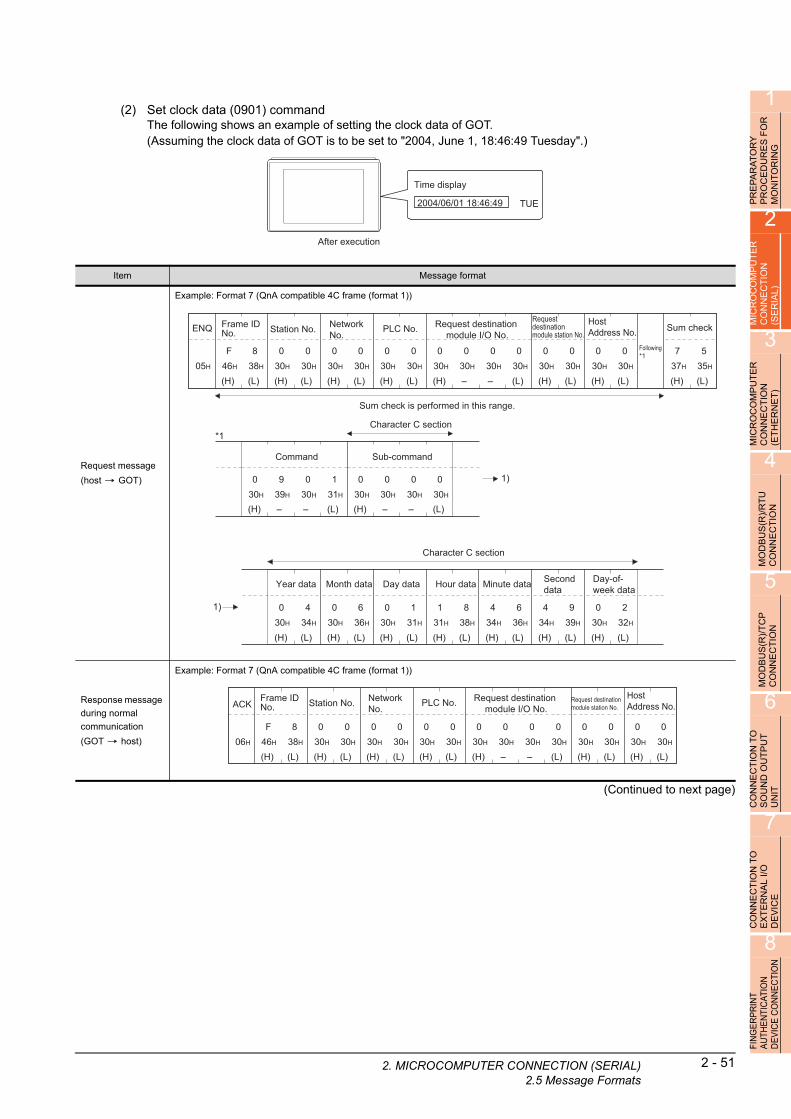
1
2. MIC
OR
Y
RE
S F
OR
IN
G
(2) Set clock data (0901) commandThe following shows an example of setting the clock data of GOT.(Assuming the clock data of GOT is to be set to "2004, June 1, 18:46:49 Tuesday".)
AT U R
PR
EP
AR
PR
OC
ED
MO
NIT
O
2
UT
ER
Time display
2004/06/01 18:46:49 TUE
After execution
P N
MICR
OC
OM
CO
NN
EC
TIO
(SE
RIA
L)
3
MIC
RO
CO
MP
UT
ER
C
ON
NE
CT
ION
(E
TH
ER
NE
T)
4
MO
DB
US
(R)/
RT
U
CO
NN
EC
TIO
N
5
MO
DB
US
(R)/
TC
P
CO
NN
EC
TIO
N
6
CO
NN
EC
TIO
N T
O
SO
UN
D O
UT
PU
T
UN
IT
7
CO
NN
EC
TIO
N T
O
EX
TE
RN
AL
I/O
D
EV
ICE
8
FIN
GE
RP
RIN
T A
UTH
EN
TIC
ATIO
N
DE
VIC
E C
ON
NE
CTI
ON
(Continued to next page)
Item Message format
Request message
(host GOT)
Example: Format 7 (QnA compatible 4C frame (format 1))
Response message
during normal
communication
(GOT host)
Example: Format 7 (QnA compatible 4C frame (format 1))
Sum check is performed in this range.
05H
ENQ
(H) (L)
737H
535H
(H) (L)
F46H
838H
(H) (L)
030H
030H
Character C section
(H) (L)
030H
030H
(H) (L)
030H
030H
(H) –
030H
030H
– (L)
030H
030H
(H) (L)
030H
030H
(H) (L)
030H
030H
*1
(H) (L)
0 430H 34H
(H) (L)
0 630H 36H
(H) (L)
0 130H 31H
(H) (L)
1 831H 38H
(H) (L)
4 634H 36H
(H) (L)
4 934H 39H
(H) (L)
0 230H 32H
(H) –
Command
030H
939H
– (L)
030H
131H
(H) –
Sub-command
030H
030H
– (L)
030H
030H
Character C section
1)
Sum checkFrame ID No. PLC No.Station No. Network
No.Request destination
module I/O No.
Request destination module station No.
Host Address No.
Following*1
Year data Month data Day data Hour data Minute data Second data
Day-of-week data
1)
06H
ACK
(H) (L)
F46H
838H
(H) (L)
030H
030H
(H) (L)
030H
030H
(H) (L)
030H
030H
(H) –
030H
030H
– (L)
030H
030H
(H) (L)
030H
030H
(H) (L)
030H
030H
Frame ID No. PLC No.Station No. Network
No.Request destination
module I/O No.Request destination module station No.
Host Address No.
ROCOMPUTER CONNECTION (SERIAL)2.5 Message Formats
2 - 51

2 - 52 2. MICROCOMPUTER CONNECTION (SERIA2.5 Message Formats
(From previous page)
POINTPOINTPOINT
When a wrong day of the week has been set by the clock data setting command
If a wrong day of the week is set by the clock data setting commands, the clock data will differ from the time displayed on the utility.Example: When June 1, 2004 (Thursday) is set by the clock data setting command (the actual day of week is
Tuesday), Tuesday (TUE) will be displayed on the utility time display.
Item Message format
Response message
during faulty
communication
(GOT host)
Example: Format 7 (QnA compatible 4C frame (format 1))
NAK
15H
(H) (L)
F46H
838H
(H) (L)
030H
030H
(H) (L)
030H
030H
(H) (L)
030H
030H
(H) –
030H
030H
– (L)
030H
030H
(H) (L)
030H
030H
(H) (L)
030H
030H
*1
(H) –
Error code
737H
F46H
– (L)
636H
939H
The above is the case where a parity error (7F69H) has occurred.
Frame ID No. PLC No.Station No. Network
No.Request destination
module I/O No.Request destination module station No.
Host Address No.
Following*1
L)

1
2. MIC
RY
E
S F
OR
G
Error code listThe following shows error code, error contents, cause, and measures.
TO R IN
PR
EP
AR
AP
RO
CE
DU
MO
NIT
OR
2
MIC
RO
CO
MP
UT
ER
C
ON
NE
CT
ION
(S
ER
IAL
)
3
MIC
RO
CO
MP
UT
ER
C
ON
NE
CT
ION
(E
TH
ER
NE
T)
4
MO
DB
US
(R)/
RT
U
CO
NN
EC
TIO
N
5
MO
DB
US
(R)/
TC
P
CO
NN
EC
TIO
N
6
CO
NN
EC
TIO
N T
O
SO
UN
D O
UT
PU
T
UN
IT
7
CO
NN
EC
TIO
N T
O
EX
TE
RN
AL
I/O
D
EV
ICE
8
FIN
GE
RP
RIN
T A
UTH
EN
TIC
ATIO
N
DE
VIC
E C
ON
NE
CTI
ON
Error code Description Action
7E40HCommand error
An unsupported command or sub-command was used.
• Review the contents of the message to transmit.
• Check the commands in the message.
( 2.5.2 List of commands)
7E41H
Data length error
Specified points exceeding the number of points that can
be communicated during random read/write.• Review the contents of the message to transmit.
• Check the devices that can be used and the device ranges.
( 2.4 Device Data Area)7E42H
Number of data error
The number of requests exceeds the command range.
7E43HDevice error
A non-existent device has been specified.
• Review the contents of the message to transmit.
• Check the devices that can be used and the device ranges.
( 2.4 Device Data Area)
7E46HClock data setting error
The setting value of the clock data has error.
• Review the contents of the message to transmit.
• Check whether the non-existent data is set (e.g. setting "07" at the day of
the week) as clock data.
7E4FHExceeded number of points error
The read/write range exceeded the device range.
• Review the contents of the message to transmit.
• Check the devices that can be used and the device ranges.
( 2.4 Device Data Area)
7F20H
Character error
A character other than "A to Z", "0 to 9", space, and control
codes has been received.
• Review the contents of the message to transmit.
7F23H
Communication message error
EXT/CR+LF was not found within the upper limit of the
receive buffer.
• Check the communication cable and communication module attachment.
• Check the settings of "Communication Detail Settings".
• Review the contents of the message to transmit.
7F24H
Sum check error
The sum check code created from received data differs
from the sum check code in the receive data.
• Review the contents of the message to transmit.
7F67H
Overrun error
The next data was transmitted from the host before GOT
completes the processing of the data received.
• Check the settings of "Communication Detail Settings".
• Decrease the transmission speed.
7F68HFraming error
The data bit and/or stop bit are not correct. • Check the communication cable and communication module attachment.
• Check the settings of "Communication Detail Settings".
• Match the GOT and host transmission settings.7F69HParity error
The parity bit does not match.
7F6AHBuffer full error
The receive buffer overflowed.
• Check the communication cable and communication module attachment.
• Check the settings of "Communication Detail Settings".
• Review the contents of the message to transmit.
ROCOMPUTER CONNECTION (SERIAL)2.5 Message Formats
2 - 53

2 - 54 2. MICROCOMPUTER CONNECTION (SERIA2.5 Message Formats
2.5.6 Formats 11 to 13 (Digital Electronics Corporation's memory link method)
Basic format of data communicationThis is the same format as the protocol of the Digital Electronics Corporation's memory link method.For details of the basic format of data communication, refer to the following manual:
The connection manual of the device manufactured by Digital Electronics Corporation
This section describes items whose settings differ from the protocols of the Digital Electronics Corporation's memory link method and dedicated commands for a microcomputer connection of GOT.
Example:Request message for the batch read in wor
nits (R) command in format 13 (Digital Electronics d uCorporation's memory link method (extended mode, ASCII code 1:n))POINTPOINTPOINT
Compatibility with the Digital Electronics Corporation's memory link method
In the case of formats 12 and 13 (Digital Electronics Corporation's memory link method (extended mode)), a communication error may occur since some communication packets are not compatible with the Digital Electronics Corporation's memory link method in the communication.To give the compatibility, turn on the digital compatible signals (GS580 to GS583) of the GOT internal device and communicate in the fully compatible message format.
For the GOT internal device, refer to the following manual.
GT Designer3 Version1 Screen Design Manual (Fundamentals)
Device Function Bit Bit position Settings
GS580Microcomputer connection (serial) extended
setting (CH1)
Digital compatible
signal
b00: Partly compatible (Default)
1: Fully compatible
b1 to b15 Unused
GS581Microcomputer connection (serial) extended
setting (CH2)
Digital compatible
signal
b00: Partly compatible (Default)
1: Fully compatible
b1 to b15 Unused
GS582Microcomputer connection (serial) extended
setting (CH3)
Digital compatible
signal
b00: Partly compatible (Default)
1: Fully compatible
b1 to b15 Unused
GS583Microcomputer connection (serial) extended
setting (CH4)
Digital compatible
signal
b00: Partly compatible (Default)
1: Fully compatible
b1 to b15 Unused
Sum check is performed in this range.
05H
ENQ
(H) (L)
5 E35H 45H
SumCheck
(H) (L)
Station No.
030H
030H
(H) –
Address
030H
434H
– (L)
030H
636H
(H) –
Number of points
030H
030H
– (L)
030H
232H1BH
ESC
52H
R0DH
CR
0AH
LFCom-mand
L)

1
2. MIC
PR
EP
AR
AT
OR
Y
PR
OC
ED
UR
ES
FO
R
MO
NIT
OR
ING
2
Details of data items in message format
POINTPOINTPOINT
Data code during communication
Communication is performed in ASCII code.
R
MICR
OC
OM
PU
TE
CO
NN
EC
TIO
N
(SE
RIA
L)
3
MIC
RO
CO
MP
UT
ER
C
ON
NE
CT
ION
(E
TH
ER
NE
T)
4
MO
DB
US
(R)/
RT
U
CO
NN
EC
TIO
N
5
MO
DB
US
(R)/
TC
P
CO
NN
EC
TIO
N
6
CO
NN
EC
TIO
N T
O
SO
UN
D O
UT
PU
T
UN
IT
7
CO
NN
EC
TIO
N T
O
EX
TE
RN
AL
I/O
D
EV
ICE
8
FIN
GE
RP
RIN
T A
UTH
EN
TIC
ATIO
N
DE
VIC
E C
ON
NE
CTI
ON
(1) CommandSpecifies the contents to access from the host to GOT.The command is converted to a 1-digit ASCII code (Hex) and transmitted.For details of the commands that can be used, refer to the following.
2.5.2 List of commands
(2) Station No.Station No. is used to identify the GOT with which the host communicates. (Setting range: 0 to 1FH)The address notated in hexadecimal is converted to a 2-digit ASCII code (Hex) and transmitted from the upper digit.The GOT processes only commands whose station No. matches the "Host Address (0 to 31)" set at "Communication Detail Settings". (The message of command whose station No. does not match is ignored.)For setting method of "Communication Detail Settings", refer to the following.
2.6.2 Communication detail settings
(3) AddressSpecifies the head No. of the device data to be read/written.The address notated in hexadecimal is converted to a 4-digit ASCII code (Hex) and transmitted from the upper digit.For details of the device range that can be accessed, refer to the following.
2.4 Device Data Area
(4) Number of pointsSpecifies the number of device data to be read/written. (Setting range: 1 to 40H)The address notated in hexadecimal is converted to a 4-digit ASCII code (Hex) and transmitted from the upper digit.
(5) Year, month, day, hour, minute, second and day of the week dataSpecifies year, month, day, hour, minute, second, and day of the week to be read/set to the GOT clock data.The address notated in decimal is converted to a 2-digit ASCII code (Hex) and transmitted from the upper digit.
■ Message format (1) Read clock data (N) command
■ Message format (2) Set clock data (M) command
(6) Error codeThis is the response message at faulty communication appended with error contents.The address notated in hexadecimal is converted to a 2-digit ASCII code (Hex) and transmitted from the upper digit.For details of error codes generated in formats 12 and 13 (Digital Electronics Corporation's memory link method (extended mode)), refer to the following:
■ Error code list
POINTPOINTPOINT
When connecting a microcomputer, etc. that uses the protocol of the Digital Electronics Corporation's memory link method with the GOT
When connecting a microcomputer, etc. that uses the protocol of the Digital Electronics Corporation's memory link method with the GOT, correct the commands to be used and the device ranges to match the specifications of the GOT.
ROCOMPUTER CONNECTION (SERIAL)2.5 Message Formats
2 - 55

2 - 56 2. MICROCOMPUTER CONNECTION (SERIA2.5 Message Formats
Message formatThe following shows the message format of the dedicated commands for a microcomputer connection of GOT.
(1) Read clock data (N) commandThe following shows an example of reading the clock data of GOT.(Assuming that the clock data of GOT has been set to "2004, June 1, 18:46:49, Tuesday".)
Time display
2004/06/01 18:46:49 TUE
(Continued to next page)
Item Message format
Request message
(host GOT)
Example: Format 13 (Digital Electronics Corporation's memory link method (extended mode, ASCII code 1:n))
• Digital compatible signal (GS580 to GS583): OFF (Partly compatible)
• Digital compatible signal (GS580 to GS583): ON (Fully compatible)
This range Sum check
05H
ENQ
(H) (L)
C E43H 45H
SumCheck
(H) (L)
Station No.
030H
030H 1BH
ESC
4EH
N0DH
CR
0AH
LFCom-mand
This range Sum check
05H
ENQ
(H) (L)
C 943H 39H
SumCheck
(H) (L)
Station No.
030H
030H 1BH
ESC
4EH
N0DH
CR
0AH
LFCom-mand
L)

1
2. MIC
(From previous page)
OR
PRE
PA
RA
TO
RY
P
RO
CE
DU
RE
S F
MO
NIT
OR
ING
2
MIC
RO
CO
MP
UT
ER
C
ON
NE
CT
ION
(S
ER
IAL
)
3
MIC
RO
CO
MP
UT
ER
C
ON
NE
CT
ION
(E
TH
ER
NE
T)
4
MO
DB
US
(R)/
RT
U
CO
NN
EC
TIO
N
5
MO
DB
US
(R)/
TC
P
CO
NN
EC
TIO
N
6
CO
NN
EC
TIO
N T
O
SO
UN
D O
UT
PU
T
UN
IT
7
CO
NN
EC
TIO
N T
O
EX
TE
RN
AL
I/O
D
EV
ICE
8
FIN
GE
RP
RIN
T A
UTH
EN
TIC
ATIO
N
DE
VIC
E C
ON
NE
CTI
ON
Item Message format
Response message
during normal
communication
(GOT host)
Example: Format 13 (Digital Electronics Corporation's memory link method (extended mode, ASCII code 1:n))
• Digital compatible signal (GS580 to GS583): OFF (Partly compatible)
• Digital compatible signal (GS580 to GS583): ON (Fully compatible)
Response message
during faulty
communication
(GOT host)
Example: Format 13 (Digital Electronics Corporation's memory link method (extended mode, ASCII code 1:n))
This range Sum check
02H
STX
(H) (L)
8 E38H 45H
SumCheck
(H) (L)
Station No.
030H
030H 1BH
ESC
41H
A0DH
CR
0AH
LF
(H) (L)
Year data
0 430H 34H
(H) (L)
Month data
0 630H 36H
(H) (L)
Day data
0 130H 31H
(H) (L)
Hour data
1 831H 38H
(H) (L)
Minute data
4 634H 36H
(H) (L)
Second data4 9
34H 39H
(H) (L)
Day-of-week data0 2
30H 32H
*1
Following*1
03H
ETXCom-mand
This range Sum check
02H
STX
(H) (L)
8 C38H 43H
SumCheck
(H) (L)
Station No.
030H
030H 1BH
ESC
41H
A0DH
CR
0AH
LF
(H) (L)
Year data
0 430H 34H
(H) (L)
Month data
0 630H 36H
(H) (L)
Day data
0 130H 31H
(H) (L)
Hour data
1 831H 38H
(H) (L)
Minute data
4 634H 36H
(H) (L)
Second data4 9
34H 39H
(H) (L)
Day-of-week data0 2
30H 32H
*1
Following*1
03H
ETXCom-mand
The above is a case where the sum check error (06H) has occurred.
15H
NAK
(H) (L)30H 36H
Error code
(H) (L)30H
Station No.
030H
0 0 60DH
CR
0AH
LF
ROCOMPUTER CONNECTION (SERIAL)2.5 Message Formats
2 - 57
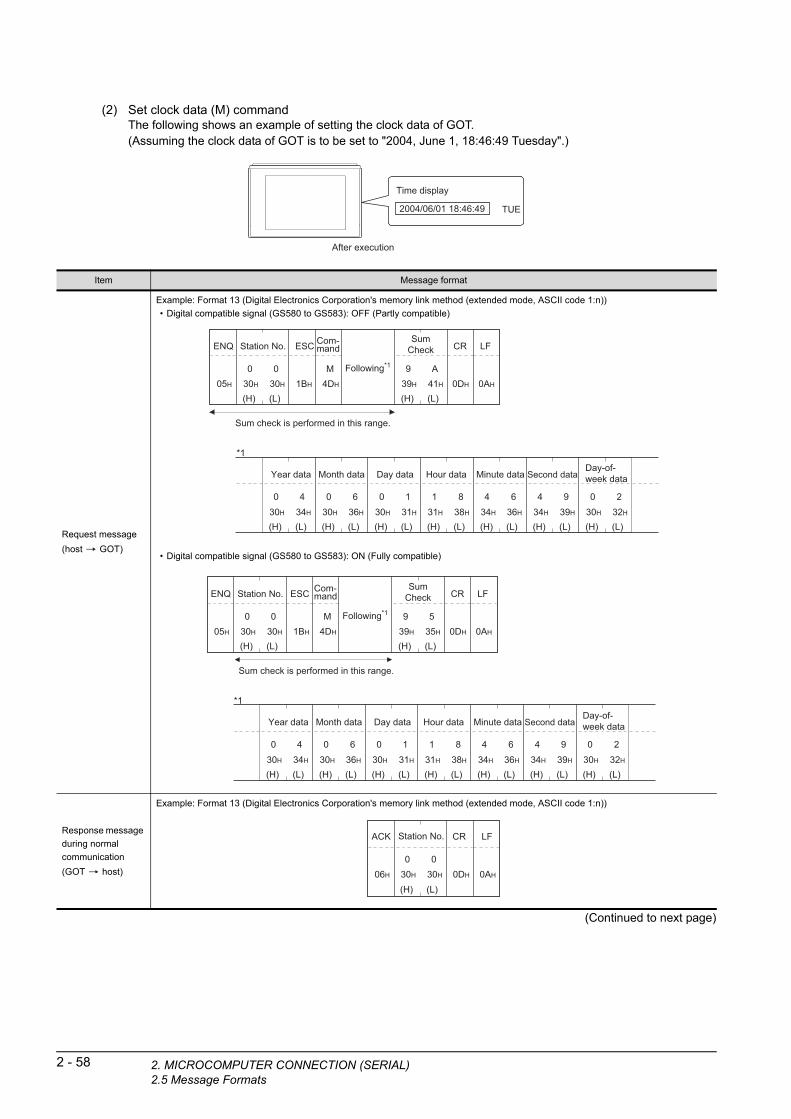
2 - 58 2. MICROCOMPUTER CONNECTION (SERIA2.5 Message Formats
(2) Set clock data (M) commandThe following shows an example of setting the clock data of GOT.(Assuming the clock data of GOT is to be set to "2004, June 1, 18:46:49 Tuesday".)
Time display
2004/06/01 18:46:49 TUE
After execution
(Continued to next page)
Item Message format
Request message
(host GOT)
Example: Format 13 (Digital Electronics Corporation's memory link method (extended mode, ASCII code 1:n))
• Digital compatible signal (GS580 to GS583): OFF (Partly compatible)
• Digital compatible signal (GS580 to GS583): ON (Fully compatible)
Response message
during normal
communication
(GOT host)
Example: Format 13 (Digital Electronics Corporation's memory link method (extended mode, ASCII code 1:n))
Sum check is performed in this range.
05H
ENQ
(H) (L)
9 A39H 41H
SumCheck
(H) (L)
Station No.
030H
030H 1BH
ESC
4DH
M0DH
CR
0AH
LF
(H) (L)
Year data
0 430H 34H
(H) (L)
Month data
0 630H 36H
(H) (L)
Day data
0 130H 31H
(H) (L)
Hour data
1 831H 38H
(H) (L)
Minute data
4 634H 36H
(H) (L)
Second data
4 934H 39H
(H) (L)
Day-of-week data
0 230H 32H
*1
Following*1
Com-mand
Sum check is performed in this range.
05H
ENQ
(H) (L)
9 539H 35H
SumCheck
(H) (L)
Station No.
030H
030H 1BH
ESC
4DH
M0DH
CR
0AH
LF
(H) (L)
Year data
0 430H 34H
(H) (L)
Month data
0 630H 36H
(H) (L)
Day data
0 130H 31H
(H) (L)
Hour data
1 831H 38H
(H) (L)
Minute data
4 634H 36H
(H) (L)
Second data
4 934H 39H
(H) (L)
Day-of-week data
0 230H 32H
*1
Following*1
Com-mand
06H
ACK
(H) (L)30H
Station No.
030H
00DH
CR
0AH
LF
L)
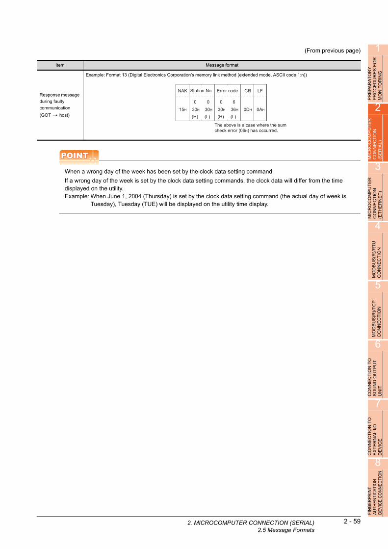
1
2. MIC
(From previous page)
OR
PRE
PA
RA
TO
RY
P
RO
CE
DU
RE
S F
MO
NIT
OR
ING
2
MIC
RO
CO
MP
UT
ER
C
ON
NE
CT
ION
(S
ER
IAL
)
3
MIC
RO
CO
MP
UT
ER
C
ON
NE
CT
ION
(E
TH
ER
NE
T)
4
MO
DB
US
(R)/
RT
U
CO
NN
EC
TIO
N
5
MO
DB
US
(R)/
TC
P
CO
NN
EC
TIO
N
6
CO
NN
EC
TIO
N T
O
SO
UN
D O
UT
PU
T
UN
IT
7
CO
NN
EC
TIO
N T
O
EX
TE
RN
AL
I/O
D
EV
ICE
8
FIN
GE
RP
RIN
T A
UTH
EN
TIC
ATIO
N
DE
VIC
E C
ON
NE
CTI
ON
POINTPOINTPOINT
When a wrong day of the week has been set by the clock data setting command
If a wrong day of the week is set by the clock data setting commands, the clock data will differ from the time displayed on the utility.Example: When June 1, 2004 (Thursday) is set by the clock data setting command (the actual day of week is
Tuesday), Tuesday (TUE) will be displayed on the utility time display.
Item Message format
Response message
during faulty
communication
(GOT host)
Example: Format 13 (Digital Electronics Corporation's memory link method (extended mode, ASCII code 1:n))
The above is a case where the sum check error (06H) has occurred.
15H
NAK
(H) (L)30H 36H
Error code
(H) (L)30H
Station No.
030H
0 0 60DH
CR
0AH
LF
ROCOMPUTER CONNECTION (SERIAL)2.5 Message Formats
2 - 59

2 - 60 2. MICROCOMPUTER CONNECTION (SERIA2.5 Message Formats
(3) In the case of interrupt inquiryThe following shows an example of an interrupt inquiry when data are written to the interrupt output devices (D13 and D14).(Assuming that "3139H" is written to D13 and "AA55H" to D14.)
Interrupt output
Example: When the number of interrupt data bytes is 2 in format 11
31H
Output value 1
3139HD13
39H
Output value 2
Interrupt
(Continued to next page)
Item Message format
Request message
(host GOT)
Example: Format 13 (Digital Electronics Corporation's memory link method (extended mode, ASCII code 1:n))
• Digital compatible signal (GS580 to GS583): OFF (Partly compatible)
• Digital compatible signal (GS580 to GS583): ON (Fully compatible)
This range Sum check
05H
ENQ
(H) (L)
C 943H 39H
SumCheck
(H) (L)
Station No.
030H
030H 1BH
ESC
49H
I0DH
CR
0AH
LFCom-mand
This range Sum check
05H
ENQ
(H) (L)
C 443H 34H
SumCheck
(H) (L)
Station No.
030H
030H 1BH
ESC
49H
I0DH
CR
0AH
LFCom-mand
L)
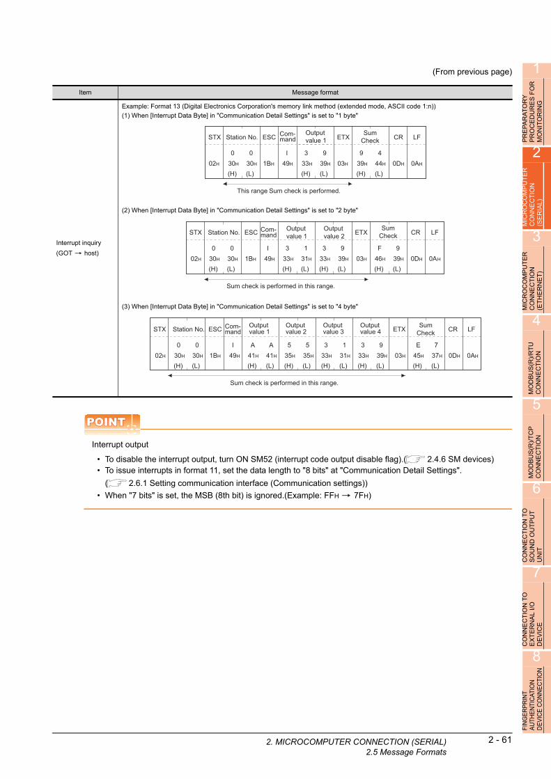
1
2. MIC
(From previous page)
OR
PRE
PA
RA
TO
RY
P
RO
CE
DU
RE
S F
MO
NIT
OR
ING
2
MIC
RO
CO
MP
UT
ER
C
ON
NE
CT
ION
(S
ER
IAL
)
3
MIC
RO
CO
MP
UT
ER
C
ON
NE
CT
ION
(E
TH
ER
NE
T)
4
MO
DB
US
(R)/
RT
U
CO
NN
EC
TIO
N
Item Message format
Interrupt inquiry
(GOT host)
Example: Format 13 (Digital Electronics Corporation's memory link method (extended mode, ASCII code 1:n))
(1) When [Interrupt Data Byte] in "Communication Detail Settings" is set to "1 byte"
(2) When [Interrupt Data Byte] in "Communication Detail Settings" is set to "2 byte"
(3) When [Interrupt Data Byte] in "Communication Detail Settings" is set to "4 byte"
This range Sum check is performed.
02H
STX
(H) (L)
Station No.
030H
030H 1BH
ESC
49H
I0DH
CR
0AH
LF
(H) (L)
9 439H 44H
SumCheck
(H) (L)
3 933H 39H
Output value 1
03H
ETXCom-mand
Sum check is performed in this range.
02H
STX
(H) (L)
939H
SumCheck
F46H
(H) (L)
Station No.
030H
030H 1BH
ESC
49H
I0DH
CR
0AH
LF
(H) (L)
3 133H 31H
Output value 1
03H
ETX
(H) (L)
3 933H 39H
Output value 2
Com-mand
Sum check is performed in this range.
02H
STX
(H) (L)
737H
SumCheck
E45H
(H) (L)
Station No.
030H
030H 1BH
ESC
49H
I0DH
CR
0AH
LF
(H) (L)
A41H
Output value 1
A41H 03H
ETX
(H) (L)
535H
Output value 2
535H
(H) (L)
3 133H 31H
Output value 3
(H) (L)
3 933H 39H
Output value 4
Com-mand
5
MO
DB
US
(R)/
TC
P
CO
NN
EC
TIO
N
6
CO
NN
EC
TIO
N T
O
SO
UN
D O
UT
PU
T
UN
IT
7
CO
NN
EC
TIO
N T
O
EX
TE
RN
AL
I/O
D
EV
ICE
8
FIN
GE
RP
RIN
T A
UTH
EN
TIC
ATIO
N
DE
VIC
E C
ON
NE
CTI
ON
POINTPOINTPOINT
Interrupt output
• To disable the interrupt output, turn ON SM52 (interrupt code output disable flag).( 2.4.6 SM devices)• To issue interrupts in format 11, set the data length to "8 bits" at "Communication Detail Settings".
( 2.6.1 Setting communication interface (Communication settings))
• When "7 bits" is set, the MSB (8th bit) is ignored.(Example: FFH 7FH)
ROCOMPUTER CONNECTION (SERIAL)2.5 Message Formats
2 - 61

2 - 62 2. MICROCOMPUTER CONNECTION (SERIA2.5 Message Formats
Error code listIn the case of formats 12 and 13 (Digital Electronics Corporation's memory link method (extended mode)), the details (error code) of the error are appended to the response message during faulty communication.The following shows error code, error contents, cause, and measures.
Precautions
(1) Batch reading/writing crossing over different devicesWhen using the batch read (R) or batch write (W) command, do not batch read/write crossing over the different devices.This will cause an error response.
(2) Storage order for 32-bit dataTo use the program of Digital Electronics Corporation's memory link method with [32bit Order] setting to GOT1000 series, set [HL Order] to [32bit Order] for [Communication Detail Settings] when 32-bit data is set for GOT-A900 series.With setting [LH Order], the order of upper bits and lower bits are reversed when the GOT displays and writes 32-bit data.
Error code Description Action
06H
Sum check error
The sum check code created from received data differs
from the sum check code in the receive data.
• Review the contents of the message to transmit.
10HCommand error
An unsupported command was used. • Review the contents of the message to transmit.
• Check the commands in the message.
( 2.5.2 List of commands)12H
Message length error
The upper limit of the data length that can be received by
the GOT has been exceeded.
16HClock data setting error
The setting value of the clock data has error.
• Review the contents of the message to transmit.
• Check the data length of the message.(data length of the data section,
etc.)
FAHAddress error
The start address of the read/write device is out of range.
• Review the contents of the message to transmit.
• Check whether the non-existent data is set (e.g. setting "07" at the day of
the week) as clock data.
FBHExceeded number of points error
The read/write range exceeded the device range.
• Review the contents of the message to transmit.
• Check the devices that can be used and the device ranges.
( 2.4 Device Data Area)
FCHMessage format error
The format of the received message has error.
• Check the settings of "Communication Detail Settings".
• Review the contents of the message to transmit.
FFH
Timeout error
There is no response from the GOT, or the station of the
specified address does not exist.
• Check the communication cable and communication module attachment.
• Check the settings of "Communication Detail Settings".
• Review the contents of the message to transmit.
L)

1
2. MIC
R
2.5.7 Formats 14, 15 (GOT-F900 Series microcomputer connection)
RY
E
S F
OG
PR
EP
AR
AT
OP
RO
CE
DU
RM
ON
ITO
RIN
2
UT
ER
Basic format of data communication
P ON
MIC
RO
CO
MC
ON
NE
CT
I(S
ER
IAL
)
3
MIC
RO
CO
MP
UT
ER
C
ON
NE
CT
ION
(E
TH
ER
NE
T)
4
MO
DB
US
(R)/
RT
U
CO
NN
EC
TIO
N
5
MO
DB
US
(R)/
TC
P
CO
NN
EC
TIO
N
6
CO
NN
EC
TIO
N T
O
SO
UN
D O
UT
PU
T
UN
IT
7
CO
NN
EC
TIO
N T
O
EX
TE
RN
AL
I/O
D
EV
ICE
8
FIN
GE
RP
RIN
T A
UTH
EN
TIC
ATIO
N
DE
VIC
E C
ON
NE
CTI
ON
*1 Set the number of interrupt data bytes at [Detail setting] in GT Designer3.
For the setting of the number of interrupt data bytes, refer to the following.
2.6.1 Setting communication interface (Communication settings)
Item Message format
Request message
(host GOT)
(format 14: GOT-F900 Series microcomputer connection (format
1))
(1) w/out station No.
(format 15: GOT-F900 Series microcomputer connection (format
2))
(1) w/out station No.
(2) w/station No. (2) w/station No.
Response message
during normal
communication
(GOT host)
(1) During processing of read commands
(format 14: GOT-F900 Series microcomputer connection (format 1)) (format 15: GOT-F900 Series microcomputer connection (format 2))
(2) During processing of write commands
Response message
during faulty
communication
(GOT host)
During interrupt
output
02H
STX
0DH
CRDataCom-mand
Sum check is performed in this range.
02H
STX
03H
ETX
(H) (L)
SumCheckDataCom-
mand
02H
STX
0DH
CRData
(H) (L)
Station No.Com-mand
Sum check is performed in this range.
02H
STX
03H
ETX
(H) (L)
SumCheckData
(H) (L)
Station No.Com-mand
02H
STX
0DH
CRData
Sum check is performed in this range.
02H
STX
03H
ETX
(H) (L)
SumCheckData
06H
ACK
15H
NAK
Output value
1/2/4 bytes*1
ROCOMPUTER CONNECTION (SERIAL)2.5 Message Formats
2 - 63
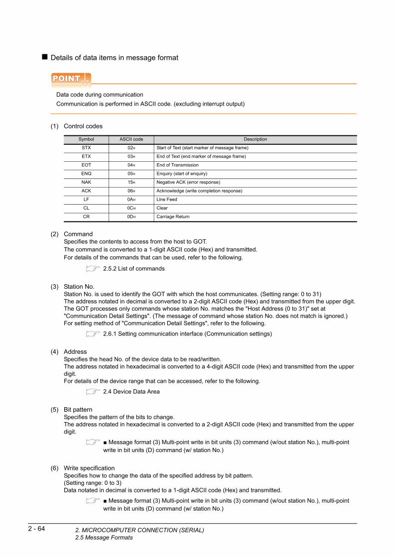
2 - 64 2. MICROCOMPUTER CONNECTION (SERIA2.5 Message Formats
Details of data items in message format
POINTPOINTPOINT
Data code during communication
Communication is performed in ASCII code. (excluding interrupt output)
(1) Control codes
Symbol ASCII code Description
STX 02H Start of Text (start marker of message frame)
ETX 03H End of Text (end marker of message frame)
EOT 04H End of Transmission
ENQ 05H Enquiry (start of enquiry)
NAK 15H Negative ACK (error response)
ACK 06H Acknowledge (write completion response)
LF 0AH Line Feed
CL 0CH Clear
CR 0DH Carriage Return
(2) CommandSpecifies the contents to access from the host to GOT.The command is converted to a 1-digit ASCII code (Hex) and transmitted.For details of the commands that can be used, refer to the following.
2.5.2 List of commands
(3) Station No.Station No. is used to identify the GOT with which the host communicates. (Setting range: 0 to 31)The address notated in decimal is converted to a 2-digit ASCII code (Hex) and transmitted from the upper digit.The GOT processes only commands whose station No. matches the "Host Address (0 to 31)" set at "Communication Detail Settings". (The message of command whose station No. does not match is ignored.)For setting method of "Communication Detail Settings", refer to the following.
2.6.1 Setting communication interface (Communication settings)
(4) AddressSpecifies the head No. of the device data to be read/written.The address notated in hexadecimal is converted to a 4-digit ASCII code (Hex) and transmitted from the upper digit.For details of the device range that can be accessed, refer to the following.
2.4 Device Data Area
(5) Bit patternSpecifies the pattern of the bits to change.The address notated in hexadecimal is converted to a 2-digit ASCII code (Hex) and transmitted from the upper digit.
■ Message format (3) Multi-point write in bit units (3) command (w/out station No.), multi-point write in bit units (D) command (w/ station No.)
(6) Write specificationSpecifies how to change the data of the specified address by bit pattern.(Setting range: 0 to 3)Data notated in decimal is converted to a 1-digit ASCII code (Hex) and transmitted.
■ Message format (3) Multi-point write in bit units (3) command (w/out station No.), multi-point write in bit units (D) command (w/ station No.)
L)

1
2. MIC
RA
TO
RY
D
UR
ES
FO
R
OR
ING
(7) Number of bytesSpecifies the number of bytes of the device data to be batch read/written.(Setting range: 0 to FFH)The address notated in hexadecimal is converted to a 2-digit ASCII code (Hex) and transmitted from the upper digit.
PA CE IT
PR
EP
RO
MO
N
2
(8) Number of pointsSpecifies the number of device data to be written to multiple points in bit units.(Setting range: 0 to 70)The address notated in decimal is converted to a 2-digit ASCII code (Hex) and transmitted from the upper digit.
R
MIC
RO
CO
MP
UT
EC
ON
NE
CT
ION
(S
ER
IAL
)
3
(9) Year, month, day, hour, minute, second and day of the week dataSpecifies year, month, day, hour, minute, second, and day of the week to be read/set to the GOT clock data.The address notated in decimal is converted to a 2-digit ASCII code (Hex) and transmitted from the upper digit.
■ (5) Read clock data (6) command (w/out station No.), read clock data (G) command (w/station No.)
■ (6) Set clock data (5) command (w/out station No.), set clock data (F) command (w/station No.)
ER
MIC
RO
CO
MP
UT
CO
NN
EC
TIO
N
(ET
HE
RN
ET
)
(10) DataSpecifies the data to read from/write to the specified device data.(word unit)The address notated in hexadecimal is converted to a 4-digit ASCII code (Hex) and transmitted from the upper digit.
4
(R)/
RT
U
ION
(11) Write dataSpecifies the data to write to the specified device data.The address notated in hexadecimal is converted to a 2-digit ASCII code (Hex) and transmitted from the upper digit.
S CT
MO
DB
UC
ON
NE
5
(12) Sum check code (for format 15: GOT-F900 series microcomputer connection (format 2) only)The sum check code is obtained by converting the lower 1 byte (8 bits) of the result (sum), after having added the sum check target data as binary data, to 2-digit ASCII code (Hex).
MO
DB
US
(R)/
TC
P
CO
NN
EC
TIO
N
6
CO
NN
EC
TIO
N T
O
SO
UN
D O
UT
PU
T
UN
IT
7
CO
NN
EC
TIO
N T
O
EX
TE
RN
AL
I/O
D
EV
ICE
8
FIN
GE
RP
RIN
T A
UTH
EN
TIC
ATIO
N
DE
VIC
E C
ON
NE
CTI
ON
Sum check is performed in this range.
02H
STX
03H
ETX
(H) (L)
B C42H 43H
SumCheck
(H) (L)
Command
R D52H 44H
(H) (L)
Address
0 130H 31H
––
030H
030H
(H) (L)
Number of points
0 230H 32H
52H + 44H + 30H + 31H + 30H + 30H + 30H + 32H + 03H = 1BCH
ROCOMPUTER CONNECTION (SERIAL)2.5 Message Formats
2 - 65

2 - 66 2. MICROCOMPUTER CONNECTION (SERIA2.5 Message Formats
Message format
(1) Batch read (0) command (w/out station No.), batch read (A) command (w/station No.)
(a) When reading a word deviceThe following shows an example of reading four bytes of virtual devices R100 to R101 from the GOT at station No.15.(Assuming R100=3D21H, R101=3604H are stored.)
R100
R101
3D21H
3604H
Item Message format
Request message
(host GOT)
(format 14: GOT-F900 Series microcomputer connection (format 1))
(format 15: GOT-F900 Series microcomputer connection (format 2))
Response message
during normal
communication
(GOT host)
(format 14: GOT-F900 Series microcomputer connection (format 1))
(format 15: GOT-F900 Series microcomputer connection (format 2))
Response message
during faulty
communication
(GOT host)
02H
STX
0DH
CR
(H) (L)
Station No.
1 531H 35H
(H) (L)
Address
030H
––
030H
838H
(H) (L)
Number of bytes
0 430H 34H
A41H
C43H
Com-mand
Sum check is performed in this range.
02H
STX
03H
ETX
(H) (L)
E 945H 39H
SumCheck
(H) (L)
Station No.
1 531H 35H
(H) (L)
Address
030H
––
030H
838H
(H) (L)
Number of bytes
0 430H 34H
A41H
C43H
Com-mand
02H
STX
0DH
CR
(H)
Data 1(R100 upper)
333H
(L)
D44H
(H)
Data 2(R100 lower)
232H
(L)
131H
(H)
Data 3(R101 upper)
333H
(L)
636H
(H)
Data 4(R101 lower)
030H
(L)
434H
02H
STX
03H
ETX
(H) (L)
A41H
A41H
(H)
Data 1(R100 upper)
Data 3(R101 upper)
333H
(L)
D44H
(H)
Data 2(R100 lower)
Data 4(R101 lower)
232H
(L)
131H
(H)
333H
(L)
636H
(H)
030H
(L)
434H
Sum check is performed in this range.
SumCheck
15H
NAK
L)

1
2. MIC
PR
EP
AR
AT
OR
Y
PR
OC
ED
UR
ES
FO
R
MO
NIT
OR
ING
2
ER
(b) When reading a bit deviceThe following shows an example of reading four bytes of the virtual devices M0 to M31.(Assuming M0="1" and M31="1" are stored.
M15 to 0
M31 to 16
0001H
8000H
UT
N
MIC
RO
CO
MP
CO
NN
EC
TIO
(SE
RIA
L)
3
MIC
RO
CO
MP
UT
ER
C
ON
NE
CT
ION
(E
TH
ER
NE
T)
4
MO
DB
US
(R)/
RT
U
CO
NN
EC
TIO
N
5
MO
DB
US
(R)/
TC
P
CO
NN
EC
TIO
N
6
CO
NN
EC
TIO
N T
O
SO
UN
D O
UT
PU
T
UN
IT
7
CO
NN
EC
TIO
N T
O
EX
TE
RN
AL
I/O
D
EV
ICE
8
FIN
GE
RP
RIN
T A
UTH
EN
TIC
ATIO
N
DE
VIC
E C
ON
NE
CTI
ON
Item Message format
Request message
(host GOT)
(format 14: GOT-F900 Series microcomputer connection (format 1))
(format 15: GOT-F900 Series microcomputer connection (format 2))
Response message
during normal
communication
(GOT host)
(format 14: GOT-F900 Series microcomputer connection (format 1))
(format 15: GOT-F900 Series microcomputer connection (format 2))
Response message
during faulty
communication
(GOT host)
02H
STX
0DH
CR
(H) (L)
Station No.
1 531H 35H
(H) (L)
Address
232H
––
030H
(H) (L)
Number of bytes
0 430H 34H
A41H
030H
030H
Com-mand
Sum check is performed in this range.
02H
STX
03H
ETX
(H) (L)
D 044H 30H
SumCheck
(H) (L)
Station No.
1 531H 35H
(H) (L)
Address
232H
––
030H
(H) (L)
Number of bytes
0 430H 34H
A41H
030H
030H
Com-mand
02H
STX
0DH
CR
M16
M17
M18
M19
M20
M21
M22
M23
M24
M25
M26
M27
M28
M29
M30
M31
00000000M8
M9
M10
M12
M13
M14
M15
M11
00000M0
M1
M2
M3
M4
M5
M6
M7
10000000 00100000000
(H) (L)
Data 1(M7 to 0)
030H
131H
(H) (L)
Data 2(M15 to 8)
030H
030H
(H) (L)
Data 3(M23 to 16)
030H
030H
(H) (L)
Data 4(M31 to 24)
838H
030H
Sum check is performed in this range.
02H
STX
03H
ETX
(H) (L)
8 C38H 43H
SumCheck
M16
M17
M18
M19
M20
M21
M22
M23
M24
M25
M26
M27
M28
M29
M30
M31
00000000M8
M9
M10
M12
M13
M14
M15
M11
00000M0
M1
M2
M3
M4
M5
M6
M7
10000000 00100000000
(H) (L)
Data 1(M7 to 0)
030H
131H
(H) (L)
Data 2(M15 to 8)
030H
030H
(H) (L)
Data 3(M23 to 16)
030H
030H
(H) (L)
Data 4(M31 to 24)
838H
030H
15H
NAK
ROCOMPUTER CONNECTION (SERIAL)2.5 Message Formats
2 - 67

2 - 68 2. MICROCOMPUTER CONNECTION (SERIA2.5 Message Formats
(2) Batch write (1) command (w/out station No.), batch write (B) command (w/station No.)
(a) When writing to a word deviceThe following shows an example of writing "0064H" and "0065H" to virtual devices R100 and R101 on the GOT at station No.15.
R100
R101
0000H
0000H
R100
R101
0064H
0065H
Before execution After execution
Item Message format
Request message
(host GOT)
(format 14: GOT-F900 Series microcomputer connection (format 1))
(format 15: GOT-F900 Series microcomputer connection (format 2))
Response message
during normal
communication
(GOT host)
Response message
during faulty
communication
(GOT host)
02H
STX
0DH
CR
(H) (L)
Station No.
1 531H 35H
(H) (L)
Address
030H
030H
838H
(H) (L)
Number of bytes
0 430H 34H
B42H
C43H
Following*1
Com-mand
Sum check is performed in this range.
02H
STX
03H
ETX
(H) (L)
131H
SumCheck
939H
(H) (L)
Station No.
1 531H 35H
(H) (L)
Address
030H
––
030H
838H
(H) (L)
Number of bytes
0 430H 34H
B42H
C43H
(H) (L)
Data 1(R100 upper)
0 030H 30H
(H) (L)
Data 2(R100 lower)
6 436H 34H
(H) (L)
Data 3(R101 upper)
0 030H 30H
(H) (L)
Data 4(R101 lower)
6 536H 35H
Following*1
*1
Com-mand
06H
ACK
15H
NAK
L)

1
2. MIC
Y F
OR
(b) When writing to a bit deviceThe following shows an example of writing "1"s to virtual devices M0 and M31 on the GOT at station No.15.
R S
PRE
PA
RA
TO
PR
OC
ED
UR
EM
ON
ITO
RIN
G
2
R
M15 to 0 0000H
0000H
Before execution After execution
M31 to 16
M15 to 0 0001H
8000HM31 to 16
E
MICR
OC
OM
PU
TC
ON
NE
CT
ION
(S
ER
IAL
)
3
MIC
RO
CO
MP
UT
ER
C
ON
NE
CT
ION
(E
TH
ER
NE
T)
4
MO
DB
US
(R)/
RT
U
CO
NN
EC
TIO
N
5
MO
DB
US
(R)/
TC
P
CO
NN
EC
TIO
N
6
CO
NN
EC
TIO
N T
O
SO
UN
D O
UT
PU
T
UN
IT
7
CO
NN
EC
TIO
N T
O
EX
TE
RN
AL
I/O
D
EV
ICE
8
FIN
GE
RP
RIN
T A
UTH
EN
TIC
ATIO
N
DE
VIC
E C
ON
NE
CTI
ON
Item Message format
Request message
(host GOT)
(format 14: GOT-F900 Series microcomputer connection (format 1))
(format 15: GOT-F900 Series microcomputer connection (format 2))
Response message
during normal
communication
(GOT host)
Response message
during faulty
communication
(GOT host)
02H
STX
0DH
CR
42H
B
(H) (L)
Station No.
535H
131H
(H) –
Address
030H
232H
– (L)
030H
030H
(H) (L)
Number of bytes
434H
030H
Following*1
Com-mand
Sum check is performed in this range.
02H
STX
03H
ETX
(H) (L)
5 A35H 41H
SumCheck
M16
M17
M18
M19
M20
M21
M22
M23
M24
M25
M26
M27
M28
M29
M30
M31
00000000M8
M9
M10
M12
M1
M14
M15
M11
00000M0
M1
M2
M3
M4
M5
M6
M7
10000000 00100000000
(H) (L)
Data 1(M7 to 0)
030H
131H
(H) (L)
Data 2(M15 to 8)
030H
030H
(H) (L)
Data 3(M23 to 16)
030H
030H
(H) (L)
Data 4(M31 to 24)
838H
030H
42H
B
(H) (L)
Station No.
535H
131H
(H) –
Address
030H
232H
– (L)
030H
030H
(H) (L)
Byte Number
434H
030H
Following*1
*1
3
Com-mand
06H
ACK
15H
NAK
ROCOMPUTER CONNECTION (SERIAL)2.5 Message Formats
2 - 69

2 - 70 2. MICROCOMPUTER CONNECTION (SERIA2.5 Message Formats
(3) Multi-point write in bit units (3) command (w/out station No.), multi-point write in bit units (D) command (w/ station No.)The following shows an example of turning OFF the virtual device M31 and turning ON the virtual device M2038 on the GOT at station No.31.
Item Message format
Request message
(host GOT)
(format 14: GOT-F900 Series microcomputer connection (format 1))
(format 15: GOT-F900 Series microcomputer connection (format 2))
Response message
during normal
communication
(GOT host)
Response message
during faulty
communication
(GOT host)
02H
STX
0DH
CR
(H) (L)
Station No.
333H
131H
D44H
Following*1
(H) (L)
Number of points
030H
232H
Com-mand
Sum check is performed in this range.
02H
STX
03H
ETX
(H) (L)
C43H
Sum check
E45H
(H) (L)
Station No.
333H
131H
(H) (L)
Address1 Address2
232H
––
030H
(H) (L)
Bit pattern1
838H
030H
D44H
Following *1
*1
(H) (L)
Number of points
030H
232H
Write specification1
131H
030H
333H
(H) (L)
232H
––
030H
(H) (L)
Bit pattern2
434H
030H
Write specification2
030H
F46
E45H
*2 *2
M24
M25
M26
M27
M28
M29
M30
M31
01010101Source data bit pattern 00000001
01010100Result
(write specification1=1)
M2032
M2033
M2034
M2035
M2036
M2037
M2038
M2039
01010101Source data bit pattern 00000010
01010111Result
(write specification2=0)
Com-mand
06H
ACK
15H
NAK
L)
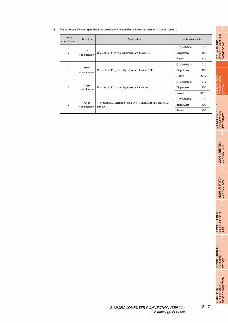
1
*2 The write specification specifies how the data o2. MIC
e specified address is changed in the bit pattern.
f th
R
PRE
PA
RA
TO
RY
P
RO
CE
DU
RE
S F
OM
ON
ITO
RIN
G
2
MIC
RO
CO
MP
UT
ER
C
ON
NE
CT
ION
(S
ER
IAL
)
3
MIC
RO
CO
MP
UT
ER
C
ON
NE
CT
ION
(E
TH
ER
NE
T)
4
MO
DB
US
(R)/
RT
U
CO
NN
EC
TIO
N
5
MO
DB
US
(R)/
TC
P
CO
NN
EC
TIO
N
6
CO
NN
EC
TIO
N T
O
SO
UN
D O
UT
PU
T
UN
IT
7
CO
NN
EC
TIO
N T
O
EX
TE
RN
AL
I/O
D
EV
ICE
8
FIN
GE
RP
RIN
T A
UTH
EN
TIC
ATIO
N
DE
VIC
E C
ON
NE
CTI
ON
Write
specificationFunction Description Action example
0ON
specificationBits set to "1" by the bit pattern are turned ON.
Original data 1010
Bit pattern 1100
Result 1110
1OFF
specificationBits set to "1" by the bit pattern are turned OFF.
Original data 1010
Bit pattern 1100
Result 0010
2Invert
specificationBits set to "1" by the bit pattern are inverted.
Original data 1010
Bit pattern 1100
Result 0110
3Write
specification
The numerical values to write by the bit pattern are specified
directly.
Original data 1010
Bit pattern 1100
Result 1100
ROCOMPUTER CONNECTION (SERIAL)2.5 Message Formats
2 - 71

2 - 72 2. MICROCOMPUTER CONNECTION (SERIA2.5 Message Formats
(4) Fill command (4) (w/out station No.), fill command (E) (w/station No.)The following shows an example of writing "16"s to virtual devices R50 to R100 on the GOT at station No.27.
R100
0000H
Before execution After execution
R50
0000H
0000H
R100
1616HR50
1616H
1616H
POINTPOINTPOINT
(1) Start address/end address specification conditionsSpecify addresses so that the start address is the same or less than the end address.Error response occurs in the following cases:• The address to specify has the start address greater than the end address.• Either of the start address or end address exceeds the device range that can be specified.
Item Message format
Request message
(host GOT)
(format 14: GOT-F900 Series microcomputer connection (format 1))
(format 15: GOT-F900 Series microcomputer connection (format 2))
Response message
during normal
communication
(GOT host)
Response message
during faulty
communication
(GOT host)
02H
STX
0DH
CR
(H) (L)
Station No.
2 732H 37H
(H) (L)
WriteData
1 631H 36H
E45H
(H) (L)
Start address
030H
––
030H
434H
636H
(H) (L)
End address
030H
––
030H
939H
C43H
Com-mand
Sum check is performed in this range.
02H
STX
03H
ETX
(H) (L)
B42H
SumCheck
E45H
(H) (L)
Station No.
2 732H 37H
(H) (L)
WriteData
1 631H 36H
E45H
(H) (L)
Start address
030H
––
030H
434H
636H
(H) (L)
End address
030H
––
030H
939H
C43H
Com-mand
06H
ACK
15H
NAK
(2) Address specifying crossing over different devicesThe start address and end address can be specified crossing over different devices.
L)
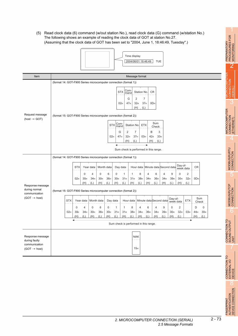
1
2. MIC
OR
Y
RE
S F
OR
IN
G
(5) Read clock data (6) command (w/out station No.), read clock data (G) command (w/station No.)The following shows an example of reading the clock data of GOT at station No.27.(Assuming that the clock data of GOT has been set to "2004, June 1, 18:46:49, Tuesday".)
AT U R
PR
EP
AR
PR
OC
ED
MO
NIT
O
2
Time display
2004/06/01 18:46:49 TUE
R
MICR
OC
OM
PU
TE
CO
NN
EC
TIO
N
(SE
RIA
L)
3
MIC
RO
CO
MP
UT
ER
C
ON
NE
CT
ION
(E
TH
ER
NE
T)
4
MO
DB
US
(R)/
RT
U
CO
NN
EC
TIO
N
5
MO
DB
US
(R)/
TC
P
CO
NN
EC
TIO
N
6
CO
NN
EC
TIO
N T
O
SO
UN
D O
UT
PU
T
UN
IT
7
CO
NN
EC
TIO
N T
O
EX
TE
RN
AL
I/O
D
EV
ICE
8
FIN
GE
RP
RIN
T A
UTH
EN
TIC
ATIO
N
DE
VIC
E C
ON
NE
CTI
ON
Item Message format
Request message
(host GOT)
(format 14: GOT-F900 Series microcomputer connection (format 1))
(format 15: GOT-F900 Series microcomputer connection (format 2))
Response message
during normal
communication
(GOT host)
(format 14: GOT-F900 Series microcomputer connection (format 1))
(format 15: GOT-F900 Series microcomputer connection (format 2))
Response message
during faulty
communication
(GOT host)
02H
STX
0DH
CR
(H) (L)
Station No.
2 732H 37H
G47H
Com-mand
Sum check is performed in this range.
02H
STX
03H
ETX
(H) (L)
B42H
SumCheck
333H
(H) (L)
Station No.
2 732H 37H
G47H
Com-mand
02H
STX
0DH
CR
(H) (L)
Month data
0 630H 36H
(H) (L)
Day data
0 130H 31H
(H) (L)
Hour data
1 831H 38H
(H) (L)
Minute data
4 634H 36H
(H) (L)
Second data
4 934H 39H
(H) (L)
Day-of-week data
0 230H 32H
(H) (L)
Year data
0 430H 34H
Sum check is performed in this range.
02H
STX
03H
ETX
(H) (L)
D 044H 30H
SumCheck
(H) (L)
Month data
0 630H 36H
(H) (L)
Day data
0 130H 31H
(H) (L)
Hour data
1 831H 38H
(H) (L)
Minute data
4 634H 36H
(H) (L)
Second data
4 934H 39H
(H) (L)
Day-of-week data
0 230H 32H
(H) (L)
Year data
0 430H 34H
15H
NAK
ROCOMPUTER CONNECTION (SERIAL)2.5 Message Formats
2 - 73

2 - 74 2. MICROCOMPUTER CONNECTION (SERIA2.5 Message Formats
(6) Set clock data (5) command (w/out station No.), set clock data (F) command (w/station No.)The following shows an example of setting clock data of GOT at station No.27.(Assuming the clock data of GOT is to be set to "2004, June 1, 18:46:49 Tuesday".)
Time display
2004/06/01 18:46:49 TUE
After execution
POINTPOINTPOINT
When a wrong day of the week has been set by the clock data setting command
If a wrong day of the week is set by the clock data setting commands, the clock data will differ from the time displayed on the utility.Example: When June 1, 2004 (Thursday) is set by the clock data setting command(the actual day of week is
Tuesday), Tuesday (TUE) will be displayed on the utility time display.
Item Message format
Request message
(host GOT)
(format 14: GOT-F900 Series microcomputer connection (format 1))
(format 15: GOT-F900 Series microcomputer connection (format 2))
Response message
during normal
communication
(GOT host)
Response message
during faulty
communication
(GOT host)
46H
F0DH
CR
(H) (L)
Station No.
2 732H 37H
(H) (L)
Month data
0 630H 36H
(H) (L)
Day Data
0 130H 31H
(H) (L)
Hour data
1 831H 38H
(H) (L)
Minute data
4 634H 36H
(H) (L)
Second data
4 934H 39H
(H) (L)
Day-of-week data
0 230H 32H
(H) (L)
Year data
0 430H 34H02H
STX Com-mand
Sum check is performed in this range.
02H
STX
03H
ETX
(H) (L)
7 F37H 46H
SumCheck
(H) (L)
Station No.
2 732H 37H
(H) (L)
Month data
0 630H 36H
(H) (L)
Day data
0 130H 31H
(H) (L)
Hour data
1 831H 38H
(H) (L)
Minute data
4 634H 36H
(H) (L)
Second data
4 934H 39H
(H) (L)
Day-of-week data
0 230H 32H
(H) (L)
Year data
0 430H 34H
46H
F Following*1
*1
Com-mand
06H
ACK
15H
NAK
L)
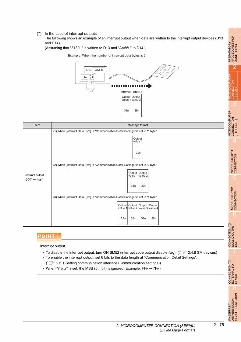
1
2. MIC
RA
TO
RY
D
UR
ES
FO
R
OR
ING
(7) In the case of interrupt outputsThe following shows an example of an interrupt output when data are written to the interrupt output devices (D13 and D14).(Assuming that "3139H" is written to D13 and "AA55H" to D14.)
A E IT
PR
EP
PR
OC
MO
N
2
MIC
RO
CO
MP
UT
ER
C
ON
NE
CT
ION
(S
ER
IAL
)
3
MP
UT
ER
IO
N
T)
Interrupt
Interrupt output
Example: When the number of interrupt data bytes is 2
31H
Output value 1
3139HD13
39H
Output value 2
T E
MIC
RO
CO
CO
NN
EC
(ET
HE
RN
4
MO
DB
US
(R)/
RT
U
CO
NN
EC
TIO
N
5
MO
DB
US
(R)/
TC
P
CO
NN
EC
TIO
N
6
CO
NN
EC
TIO
N T
O
SO
UN
D O
UT
PU
T
UN
IT
7
CO
NN
EC
TIO
N T
O
EX
TE
RN
AL
I/O
D
EV
ICE
8
FIN
GE
RP
RIN
T A
UTH
EN
TIC
ATIO
N
DE
VIC
E C
ON
NE
CTI
ON
POINTPOINTPOINT
Interrupt output
• To disable the interrupt output, turn ON SM52 (interrupt code output disable flag). ( 2.4.6 SM devices)• To enable the interrupt output, set 8 bits to the data length at "Communication Detail Settings".
( 2.6.1 Setting communication interface (Communication settings))
• When "7 bits" is set, the MSB (8th bit) is ignored.(Example: FFH 7FH)
Item Message format
Interrupt output
(GOT host)
(1) When [Interrupt Data Byte] in "Communication Detail Settings" is set to "1 byte"
(2) When [Interrupt Data Byte] in "Communication Detail Settings" is set to "2 byte"
(3) When [Interrupt Data Byte] in "Communication Detail Settings" is set to "4 byte"
39H
Output value 1
31H
Output value 1
39H
Output value 2
AAH
Output value 1
55H
Output value 2
31H
Output value 3
39H
Output value 4
ROCOMPUTER CONNECTION (SERIAL)2.5 Message Formats
2 - 75

2 - 76 2. MICROCOMPUTER CONNECTION (SERIA2.5 Message Formats
Error code listWhen faulty, the error code is stored in SD2.For details of error code stored in SD2, the error contents, cause and measures, refer to the following:
2.4.5 ■ Details and actions for errors (error codes) stored into SD2
When an error other than those to be stored in SD2 occurs, at faulty, only the NAK response is executed.
Precautions
(1) Batch reading/writing crossing over different devicesWhen using the batch read (0, A) or batch write (1, B) command, do not batch read/write crossing over different devices.This will cause an error response.
L)
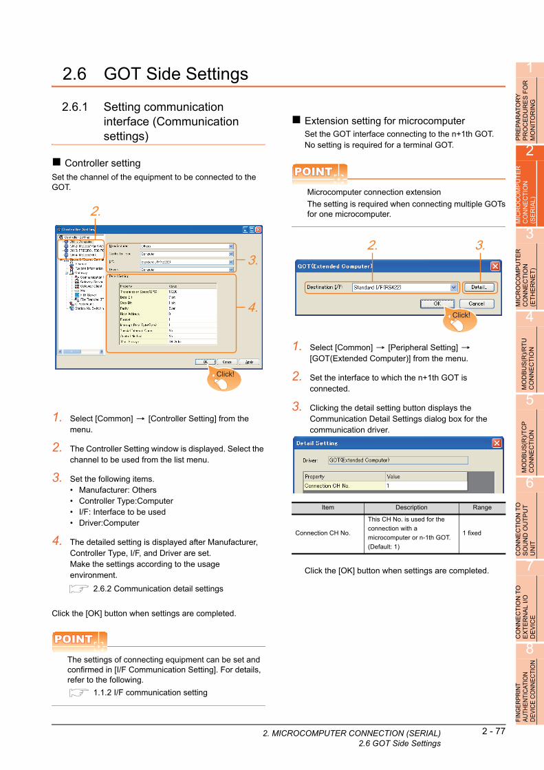
1
2. MIC
FO
R
2.6 GOT Side SettingsPR
EP
AR
AT
OR
YP
RO
CE
DU
RE
S
MO
NIT
OR
ING
2
MIC
RO
CO
MP
UT
ER
C
ON
NE
CT
ION
(S
ER
IAL
)
3
MIC
RO
CO
MP
UT
ER
C
ON
NE
CT
ION
(E
TH
ER
NE
T)
4
MO
DB
US
(R)/
RT
U
CO
NN
EC
TIO
N
5
MO
DB
US
(R)/
TC
P
CO
NN
EC
TIO
N
6
CO
NN
EC
TIO
N T
O
SO
UN
D O
UT
PU
T
UN
IT
7
CO
NN
EC
TIO
N T
O
EX
TE
RN
AL
I/O
D
EV
ICE
8
FIN
GE
RP
RIN
T A
UTH
EN
TIC
ATIO
N
DE
VIC
E C
ON
NE
CTI
ON
2.6.1 Setting communication interface (Communication settings)
Controller settingSet the channel of the equipment to be connected to the GOT.
1. Select [Common] [Controller Setting] from the menu.
2. The Controller Setting window is displayed. Select the channel to be used from the list menu.
3. Set the following items.• Manufacturer: Others• Controller Type:Computer• I/F: Interface to be used• Driver:Computer
4. The detailed setting is displayed after Manufacturer, Controller Type, I/F, and Driver are set.Make the settings according to the usage environment.
2.6.2 Communication detail settings
Click the [OK] button when settings are completed.
POINTPOINTPOINT
The settings of connecting equipment can be set and confirmed in [I/F Communication Setting]. For details, refer to the following.
1.1.2 I/F communication setting
2.
3.
4.
Click!
Extension setting for microcomputerSet the GOT interface connecting to the n+1th GOT.No setting is required for a terminal GOT.
POINTPOINTPOINT
Microcomputer connection extension
The setting is required when connecting multiple GOTsfor one microcomputer.
1. Select [Common] [Peripheral Setting] [GOT(Extended Computer)] from the menu.
2. Set the interface to which the n+1th GOT is connected.
3. Clicking the detail setting button displays the Communication Detail Settings dialog box for the communication driver.
Click the [OK] button when settings are completed.
Item Description Range
Connection CH No.
This CH No. is used for the
connection with a
microcomputer or n-1th GOT.
(Default: 1)
1 fixed
2. 3.
Click!
ROCOMPUTER CONNECTION (SERIAL)2.6 GOT Side Settings
2 - 77

2.6.2 Communication detail settings
Make the settings according to the usage environment.
Item Description Range
Transmission Speed
Set this item when change the transmission speed used for communication with the connected equipment.(Default: 19200bps)
4800bps, 9600bps, 19200bps, 38400bps, 57600bps, 115200bps
Data Bit
Set this item when change the data length used for communication with the connected equipment.(Default: 7bits)
7bits/8bits
Stop BitSpecify the stop bit length for communications.(Default: 1bit)
1bit/2bits
Parity
Specify whether or not to perform a parity check, and how it is performed during communication.(Default: Even)
NoneEvenOdd
Host Address
Specify the host address (station No. of the PLC to which the GOT is connected) in the network of the GOT.(Default: 0)
0 to 31
Format
Select the communication format.(Default: 1)
1 to 15
Select the communication format.(Default: 14)
1, 2, 14, 15
Interrupt Data ByteSpecify the number of bytes of interrupt data.(Default: 1byte)
1byte, 2byte, 4byte
Special Interrupt Code
Set whether or not to output the special interrupt code.(Default: No)
Yes or No
Control Method
Set this item when selecting the XON/XOFF control for the control method.(Default: No)
XON/XOFF, No
32bit StorageSelect the steps to store two words (32-bit data).(Default: LH Order)
LH Order/HL Order
2 - 78 2. MICROCOMPUTER CONNECTION (SERIA2.6 GOT Side Settings
POINTPOINTPOINT
(1) Special Interrupt CodeThe following shows the compatibility between the special interrupt codes and the event types.
(2) Communication detail setting when connecting multiple GOTsFor the following items, set the same settings to the n+1th GOT interface as the CH No.1 of n-th GOT.• Transmission Speed• Data Bit• Stop Bit• ParitySet each [Host Address] for the GOT.
(3) Communication interface setting by the UtilityThe communication interface setting can be changed on the Utility's [Communication setting] after writing [Communication Settings] of project data.For details on the Utility, refer to the following manual.
User's Manual of GOT used.
(4) Precedence in communication settingsWhen settings are made by GT Designer3 or the Utility, the latest setting is effective.
Special
Interrupt Code
(Hex)
Event type
20H
Base Screen*1 and Overlap Window*1
Output when the screens are switched according to the
change in the switching device values assigned to 1/2.
*1: Base Screen or Overlap Window 1/2 switches
independently without being interlocked.
(Example of output)
When all the switching device values assigned to
the Base Screen and Overlap Window1/2 are
changed, 3 special interrupt codes are output.
21H Output when Numerical/ASCII Input is completed.
22HOutput when Recipe data transfer (read-out, write-in) is
completed.
23HOutput when Bar code, RFID data has been imported
into GOT
L)

1
2. MIC
FO
R
2.7 System Configuration ExamplesPR
EP
AR
AT
OR
YP
RO
CE
DU
RE
S
MO
NIT
OR
ING
2
MIC
RO
CO
MP
UT
ER
C
ON
NE
CT
ION
(S
ER
IAL
)
3
MIC
RO
CO
MP
UT
ER
C
ON
NE
CT
ION
(E
TH
ER
NE
T)
4
MO
DB
US
(R)/
RT
U
CO
NN
EC
TIO
N
5
MO
DB
US
(R)/
TC
P
CO
NN
EC
TIO
N
6
CO
NN
EC
TIO
N T
O
SO
UN
D O
UT
PU
T
UN
IT
7
CO
NN
EC
TIO
N T
O
EX
TE
RN
AL
I/O
D
EV
ICE
8
FIN
GE
RP
RIN
T A
UTH
EN
TIC
ATIO
N
DE
VIC
E C
ON
NE
CTI
ON
The following shows a system configuration example in the case of the microcomputer connection (serial).
System configurationThe system configuration example illustrated below is explained in this section.
Communication settings on GOT side and monitor screen settings
(1) Transmission settingsSet the transmission settings of the GOT.The transmission settings in the microcomputer connection (serial) are made at [Detail Setting] on GT Designer3.
2.6.2 Communication detail settings
Setting item Setting details
Baud rate 38400bps
Data bit 8bits
Stop bit 1bit
Parity Even
Interrupt Data Byte 1 byte
Host address (0 to 31) 0
Format 1
Special Interrupt Code None
Control Method None
32bit Storage LH Order
IBM-PC/AT-compatible PC(Microsoft® Visual C++® Ver.6.0)
(2) Monitor screen settingsThe following shows the monitor screen settings in this system configuration example.
(a) Common settingsSet D20 to the screen switching device (base screen).
1. Select [Common] [GOT Environmental Setting] [Screen Switching/Window] to display [Environment Setup] on GT Designer3.
2. Set D20 to the screen switching device (base screen).
ROCOMPUTER CONNECTION (SERIAL)2.7 System Configuration Examples
2 - 79

(b) Monitor screen imageCreate the following screens by GT Designer3.
Base screen 1
1. Numerical displayBy setting this with the numerical display, the device value of D21 can be monitored.The device value is incremented only while [Sample Screen 1] is displayed.
2. Switch 1This is the screen switching switch to [Sample Screen 2].Touching this changes the base screen to [Sample Screen 2].
Base screen 2
3. Bit lampThe device status of D22.b0 is displayed as a lamp.
4. Switch 2This is an alternate switch for changing the state of D22.b0.
5. Switch 3This is the screen switching switch to [Sample Screen 1]. Touching this changes the base screen to [Sample Screen 1].
Sample Screen 1
123
Screen 2
Sample Screen 2
Screen 1
2 - 80 2. MICROCOMPUTER CONNECTION (SERIA2.7 System Configuration Examples
Numerical display
Touch switch
Bit lamp
No.
Basic Settings
Device/Style
Device Data Type Format Number Size Digits
D21 Unsigned BIN16 Signed Decimal Arbitrary 4
No.
Basic Settings
Action
Action Next Screen DeviceData
TypeSetting
Value
Action
Type
Screen Switching
Base
Fixed
Screen No.2― ― ― ―
Word ― D13Signed
BIN16
Constant
1―
BIt ― D22.b0 ― ― Alternate
Screen Switching
Base
Fixed
Screen No.1― ― ― ―
Word ― D13Signed
BIN16
Constant
255―
No.
Basic Settings
Device/Style
Lamp Type Device Shape Shape Attribute
BIt D22.b0 Arbitrary Arbitrary
L)
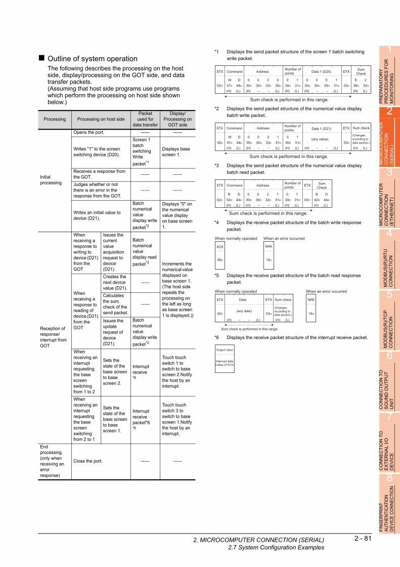
1
PR
EP
AR
AT
OR
Y
PR
OC
ED
UR
ES
FO
R
MO
NIT
OR
ING
2
MIC
RO
CO
MP
UT
ER
C
ON
NE
CT
ION
(S
ER
IAL
)
3
MIC
RO
CO
MP
UT
ER
C
ON
NE
CT
ION
(E
TH
ER
NE
T)
4
MO
DB
US
(R)/
RT
U
CO
NN
EC
TIO
N
5
MO
DB
US
(R)/
TC
P
CO
NN
EC
TIO
N
6
CO
NN
EC
TIO
N T
O
SO
UN
D O
UT
PU
T
UN
IT
7
CO
NN
EC
TIO
N T
O
EX
TE
RN
AL
I/O
D
EV
ICE
8
FIN
GE
RP
RIN
T A
UTH
EN
TIC
ATIO
N
DE
VIC
E C
ON
NE
CTI
ON
Outline of system operationThe following describes the processing on the host side, display/processing on the GOT side, and data transfer packets.(Assuming that host side programs use programs which perform the processing on host side shown below.)
Processing Processing on host sidePacket
used for data transfer
Display/Processing on
GOT side
Initial processing
Opens the port. ―― ――
Writes "1" to the screen switching device (D20).
Screen 1 batch switchingWrite
packet*1
Displays base screen 1.
Receives a response from the GOT.
―― ――
Judges whether or not there is an error in the response from the GOT.
―― ――
Writes an initial value to device (D21).
Batch numerical value display write
packet*2
Displays "0" on the numerical value display on base screen 1.
Reception of response/interrupt from GOT
When receiving a response to writing to device (D21) from the GOT
Issues the current value acquisition request to device (D21).
Batch numerical value display read
packet*3 Increments the numerical value displayed on base screen 1.(The host side repeats the processing on the left as long as base screen 1 is displayed.))
When receiving a response to reading of device (D21) from the GOT
Creates the next device value (D21).
――
Calculates the sum check of the send packet.
――
Issues the update request of device (D21).
Batch numerical value display write
packet*2
When receiving an interrupt requesting the base screen switching from 1 to 2
Sets the state of the base screen to base screen 2.
Interrupt receive*6
Touch touch switch 1 to switch to base screen 2.Notify the host by an interrupt.
When receiving an interrupt requesting the base screen switching from 2 to 1
Sets the state of the base screen to base screen 1.
Interrupt receivepacket*6*6
Touch touch switch 3 to switch to base screen 1.Notify the host by an interrupt.
End processing(only when receiving an error response)
Close the port. ―― ――
2. MIC
*1 Displays the send packet structure of the screen 1 batch switching
write packet.
*2 Displays the send packet structure of the numerical value display
batch write packet.
*3 Displays the send packet structure of the numerical value display
batch read packet.
*4 Displays the receive packet structure of the batch write response
packet.
*5 Displays the receive packet structure of the batch read response
packet.
*6 Displays the receive packet structure of the interrupt receive packet.
Sum check is performed in this range.
02H
STX
03H
ETX
(H) (L)
8 238H 32H
SumCheck
(H) (L)
Command
W D57H 44H
(H) (L)
Address
0 230H 32H
––
030H
030H
(H) (L)
Number of points
0 130H 31H
(H) (L)
Data 1 (D20)
0 030H 30H
––
131H
030H
Sum check is performed in this range.
02H
STX
03H
ETX
(H) (L)
Sum check
(Changes according to data section.)
(H) (L)
Command
W D57H 44H
(H) (L)
Address
0 230H 32H
––
131H
030H
(H) (L)
Number of points
0 130H 31H
(H) (L)
Data 1 (D21)
––
(any value)
Sum check is performed in this range.
02H
STX
03H
ETX
(H) (L)
B D42H 44H
SumCheck
(H) (L)
Command
R D52H 44H
(H) (L)
Address
0 130H 31H
––
232H
(H) (L)
Number of points
0 130H 31H
030H
15H
NAK
When an error occurred
06H
ACK
When normally operated
Sum check is performed in this range.
02H
STX
03H
ETX
(H) (L)
Sum check
(Changes according to data section.)
(H) (L)––
Data
(any data)
When normally operated
15H
NAK
When an error occurred
Output value
Interrupt data(value of D13)
ROCOMPUTER CONNECTION (SERIAL)2.7 System Configuration Examples
2 - 81
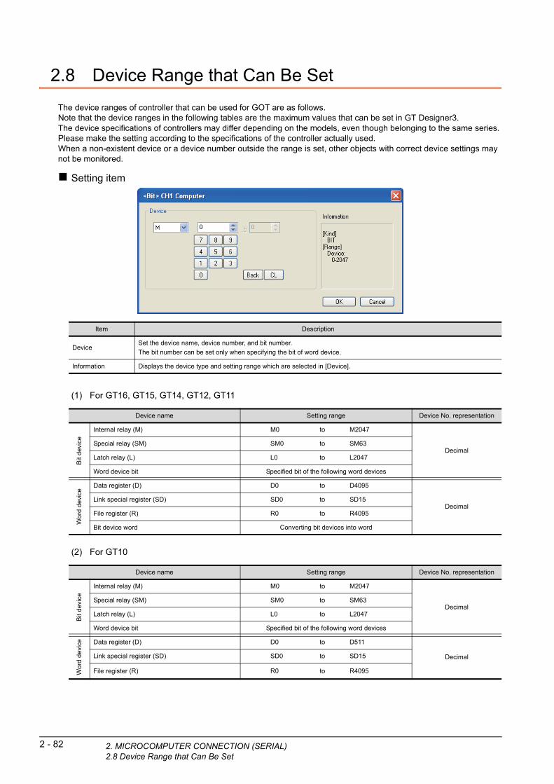
2 - 82 2. MICROCOMPUTER CONNECTION (SERIA2.8 Device Range that Can Be Set
2.8 Device Range that Can Be Set
The device ranges of controller that can be used for GOT are as follows.Note that the device ranges in the following tables are the maximum values that can be set in GT Designer3.The device specifications of controllers may differ depending on the models, even though belonging to the same series.Please make the setting according to the specifications of the controller actually used.When a non-existent device or a device number outside the range is set, other objects with correct device settings may not be monitored.
Setting item
(1) For GT16, GT15, GT14, GT12, GT11
Item Description
DeviceSet the device name, device number, and bit number.
The bit number can be set only when specifying the bit of word device.
Information Displays the device type and setting range which are selected in [Device].
Device name Setting range Device No. representation
Bit
de
vice
Internal relay (M) M0 to M2047
DecimalSpecial relay (SM) SM0 to SM63
Latch relay (L) L0 to L2047
Word device bit Specified bit of the following word devices
Wor
d d
evi
ce
Data register (D) D0 to D4095
DecimalLink special register (SD) SD0 to SD15
File register (R) R0 to R4095
Bit device word Converting bit devices into word
(2) For GT10
Device name Setting range Device No. representation
Bit
de
vice
Internal relay (M) M0 to M2047
DecimalSpecial relay (SM) SM0 to SM63
Latch relay (L) L0 to L2047
Word device bit Specified bit of the following word devices
Wo
rd d
evic
e Data register (D) D0 to D511
DecimalLink special register (SD) SD0 to SD15
File register (R) R0 to R4095
L)
1
2. MIC
FO
R
2.9 PrecautionsPR
EP
AR
AT
OR
YP
RO
CE
DU
RE
S
MO
NIT
OR
ING
2
MIC
RO
CO
MP
UT
ER
C
ON
NE
CT
ION
(S
ER
IAL
)
3
MIC
RO
CO
MP
UT
ER
C
ON
NE
CT
ION
(E
TH
ER
NE
T)
4
MO
DB
US
(R)/
RT
U
CO
NN
EC
TIO
N
5
MO
DB
US
(R)/
TC
P
CO
NN
EC
TIO
N
6
CO
NN
EC
TIO
N T
O
SO
UN
D O
UT
PU
T
UN
IT
7
CO
NN
EC
TIO
N T
O
EX
TE
RN
AL
I/O
D
EV
ICE
8
FIN
GE
RP
RIN
T A
UTH
EN
TIC
ATIO
N
DE
VIC
E C
ON
NE
CTI
ON
GOT clock controlThe settings of "time adjusting" or "time broadcast" made on the GOT will be disabled on the PLC. Use the dedicated commands to set or read out the clock data of microcomputer.
ROCOMPUTER CONNECTION (SERIAL)2.9 Precautions
2 - 83

2 - 84 2. MICROCOMPUTER CONNECTION (SERIAL)2.9 Precautions
31
PR
EP
AR
AT
OR
Y
PR
OC
ED
UR
ES
FO
R
MO
NIT
OR
ING
2
MIC
RO
CO
MP
UT
ER
C
ON
NE
CT
ION
(S
ER
IAL
)
3
MIC
RO
CO
MP
UT
ER
C
ON
NE
CT
ION
(E
TH
ER
NE
T)
4
MO
DB
US
(R)/
RT
U
CO
NN
EC
TIO
N
5
MO
DB
US
(R)/
TC
P
CO
NN
EC
TIO
N
6
CO
NN
EC
TIO
N T
O
SO
UN
D O
UT
PU
T
UN
IT
7
CO
NN
EC
TIO
N T
O
EX
TE
RN
AL
I/O
D
EV
ICE
8
ING
ER
PR
INT
UTH
EN
TIC
ATIO
N
EV
ICE
CO
NN
EC
TIO
N
3.MICROCOMPUTERCONNECTION (ETHERNET)
3.1 Microcomputer connection (Ethernet) . . . . . . . . . . . . . . . . . 3 - 2
3.2 System Configuration. . . . . . . . . . . . . . . . . . . . . . . . . . . . . . 3 - 2
3.3 Device Data Area . . . . . . . . . . . . . . . . . . . . . . . . . . . . . . . . . 3 - 3
3.4 Message Formats. . . . . . . . . . . . . . . . . . . . . . . . . . . . . . . . 3 - 16
3.5 GOT Side Settings . . . . . . . . . . . . . . . . . . . . . . . . . . . . . . . 3 - 69
3.6 System Configuration Examples . . . . . . . . . . . . . . . . . . . . 3 - 72
3.7 Device Range that Can Be Set . . . . . . . . . . . . . . . . . . . . . 3 - 73
3.8 Precautions . . . . . . . . . . . . . . . . . . . . . . . . . . . . . . . . . . . . 3 - 74
F A D
3 - 1

3 - 2 3. MICROCOMPUTER CONNECTION (ETHE3.1 Microcomputer connection (Ethernet)
3. MICROCOMPUTER CONNECTION (ETHERNET)
3.1 Microcomputer connection (Ethernet)
The "microcomputer connection (Ethernet)" is a function by which data can be written or read from a PC, microcomputer board, PLC, etc. (hereinafter referred to as "host") to virtual devices of the GOT after connecting the host to the GOT with the Ethernet.Interrupt output is also available from the GOT to the host.
For the flow of the data processing, such as reading or writing data and interrupt output, refer to the following.
2.1 Microcomputer Connection (Serial)
3.2 System Configuration
3.2.1 For the microcomputer connection (Ethernet)
Ethernet (microcomputer)
Communication driver
Host GOT
Connection cable
*1 The destination connected with the twisted pair cable varies with the configuration of the applicable Ethernet network system.
Connect to the Ethernet module, hub, transceiver or other system equipment corresponding to the applicable Ethernet network system.Use cables, connectors, and hubs that meet the IEEE802.3 10BASE-T/100BASE-TX standard.
*2 A length between a hub and a node.
The maximum distance differs depending on the Ethernet device to be used.The following shows the number of the connectable nodes when a repeater hub is used.• 10BASE-T: Max. 4 nodes for a cascade connection (500m)• 100BASE-TX: Max. 2 nodes for a cascade connection (205m)When switching hubs are used, the cascade connection between the switching hubs has no logical limit for the number of cascades.For the limit, contact the switching hub manufacturer.
*3 When connecting GT16 of the function version A to an equipment that meets the 10BASE (-T/2/5) standard, use the switching
hub and operate in a 10Mbps/100Mbps mixed environment.
For how to check the function version, refer to the following.
GT16 User’s Manual (Hardware)*4 GT14 models compatible with Ethernet connection are only GT1455-QTBDE and GT1450-QLBDE.
Host Connection cable GOTNumber of
connectable
equipmentCommunication
TypeCable model
Maximum
segment
length*2
Option device Model*3
Ethernet
Twisted pair cable*1
• 10BASE-T
Shielded twisted pair cable (STP) or
unshielded twisted pair cable (UTP):
Category 3, 4, and 5
• 100BASE-TX
Shielded twisted pair cable (STP):
Category 5 and 5e
100m
- (Built into GOT) *4
Unlimited number
of GOTs for 1 hostGT15-J71E71-100
RNET)

1
3. MICRO
PR
EP
AR
AT
OR
Y
PR
OC
ED
UR
ES
FO
R
MO
NIT
OR
ING
3.3 Device Data Area
The following shows a list of virtual devices inside the GOT available in the microcomputer connection (Ethernet), and the address specification values for each data format.
The address specification of the virtual devices differs depending on the data format.*1
2
MIC
RO
CO
MP
UT
ER
C
ON
NE
CT
ION
(S
ER
IAL
)
3
MIC
RO
CO
MP
UT
ER
C
ON
NE
CT
ION
(E
TH
ER
NE
T)
4
MO
DB
US
(R)/
RT
U
CO
NN
EC
TIO
N
5
*1 For the address specification method for each data format, refer to the following.
3.4 Message Formats
*2 When reusing GOT900 Series project data
• GOT-A900 Series virtual devices (D0 to 2047)Can be used as they are without changing the assignments.
• GOT-F900 Series virtual devicesSince some of the assigned virtual device values differ as indicated below, change the assignment using device batch edit of GT Designer3.Refer to the following manual for device batch edit of GT Designer3.
GT Designer3 Version1 Screen Design Manual
Virtual device*2 Address specification value
Refer toName
Device
range
(decimal)
Device typeFormat
1, 2
Format
3, 4
Format
5
Format
6 to 9
D 0 to 4095 Word 0 to 4095 8000 to 9FFFH 0000 to 0FFFH D0 to 4095 3.3.1
R 0 to 4095 Word 4096 to 8191 0000 to 1FFFH 1000 to 1FFFH R0 to 4095 3.3.2
L 0 to 2047 Bit 8192 to 8319 A000 to A0FFH 2000 to 207FH L0 to 2047 3.3.3
M 0 to 2047 Bit 8320 to 8447 2000 to 20FFH 2080 to 20FFH M0 to 2047 3.3.4
SD 0 to 15 Word 8448 to 84632100 to 211FH
(3000 to 300DH)*32100 to 210FH SD0 to 15 3.3.5
SM 0 to 63 Bit 8464 to 8467 2200 to 2207H 2110 to 2113H SM0 to 63 3.3.6
• Formats 1, 2 : GOT-A900 Series microcomputer connection
• Formats 3, 4 : GOT-F900 series microcomputer connection
• Formats 5 : Digital Electronics Corporation's memory link method
• Formats 6, 7 : 4E frame
• Formats 8, 9 : QnA compatible 3E frame
P
MOD
BU
S(R
)/T
CC
ON
NE
CT
ION
6
ION
TO
U
TP
UT
GOT1000 Series virtual devices GOT-F900 Series virtual devices
D0 to 2047 ―
D2048 to 4095 ―
R0 to 4095 D0 to 4095
L0 to 2047 ―
M0 to 2047 M0 to 2047
SD0 to 15D8000 to 8015
GD0 to 6
SM0 to 63 M8000 to 8063
CT O
*3 Access to SD3 to 9 can also be made by the sp ication of the addresses (3000 to 300DH) of GD0 to 6 on the GOT-F900 Series.E D
ecifN N T
CO
NS
OU
UN
I
7
CO
NN
EC
TIO
N T
O
EX
TE
RN
AL
I/O
D
EV
ICE
8
FIN
GE
RP
RIN
T A
UTH
EN
TIC
ATIO
N
DE
VIC
E C
ON
NE
CTI
ON
POINTPOINTPOINT
Values of virtual devices inside the GOTWhen the GOT is turned OFF or reset, values are cleared to their defaults(bit devices: OFF, word devices: 0).Values are held in the memory when project data are written to the GOT.
COMPUTER CONNECTION (ETHERNET)3.3 Device Data Area
3 - 3

3 - 4 3. MICROCOMPUTER CONNECTION (ETHE3.3 Device Data Area
3.3.1 D devices
The D devices are word devices into which GOT communication errors, clock data or other information are stored.The user can also store data using the user area.
List of D devicesThe following lists the D devices (virtual devices inside the GOT).
Address Description Set side
D0 to 2 Unused ―
D3
Communication error status
Stores the communication error details of GOT.
• b4 to 6 turn ON when an SIO error occurs, and turn OFF when an request message from the host is received
successfully after the error occurrence.
• b7 turns ON about 3 seconds after the host side DTR becomes OFF, and turns OFF when transmission is
performed successfully to the host after the error occurrence.
SystemD4
Clock data (year)
D5
Clock data (month)
D6
Clock data (day)
b15 b0– b3
Unused
–b4
SIO framing error
b5
SIO parity errorSIO overrun error
b6b7
Communication timeout errorUnused
b8
0: Normal1: Error
b15 b0–
Lower 2 digits of calendar year stored as 2-digit BCD
–b7
Unused
b8
b15 b0–
Data of months 01 to 12 stored as 2-digit BCD
–b7
Unused
b8
b15 b0–
Data of days 01 to 31 stored as 2-digit BCD
–b7
Unused
b8
(Continued to next page)
RNET)
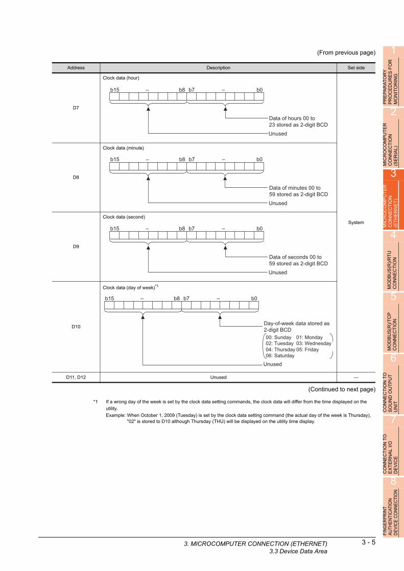
1
3. MICRO
(From previous page)
OR
PRE
PA
RA
TO
RY
P
RO
CE
DU
RE
S F
MO
NIT
OR
ING
2
MIC
RO
CO
MP
UT
ER
C
ON
NE
CT
ION
(S
ER
IAL
)
3
MIC
RO
CO
MP
UT
ER
C
ON
NE
CT
ION
(E
TH
ER
NE
T)
4
MO
DB
US
(R)/
RT
U
CO
NN
EC
TIO
N
5
MO
DB
US
(R)/
TC
P
CO
NN
EC
TIO
N
6
ON
TO
T
PU
T
Address Description Set side
D7
Clock data (hour)
System
D8
Clock data (minute)
D9
Clock data (second)
D10
Clock data (day of week)*1
D11, D12 Unused ―
b15 b0–
Data of hours 00 to 23 stored as 2-digit BCD
–b7
Unused
b8
b15 b0–
Data of minutes 00 to 59 stored as 2-digit BCD
–b7
Unused
b8
b15 b0–
Data of seconds 00 to 59 stored as 2-digit BCD
–b7
Unused
b8
b15 b0–
Day-of-week data stored as 2-digit BCD
–b7
Unused
b8
00: Sunday 01: Monday02: Tuesday 03: Wednesday04: Thursday 05: Friday06: Saturday
TI U
(Continued to next page)EC
D O
N N T
*1 If a wrong day of the week is set by the clock d setting commands, the clock data will differ from the time displayed on theCO
NS
OU
UN
I
7
CO
NN
EC
TIO
N T
O
EX
TE
RN
AL
I/O
D
EV
ICE
8
FIN
GE
RP
RIN
T A
UTH
EN
TIC
ATIO
N
DE
VIC
E C
ON
NE
CTI
ON
ata
utility.
Example: When October 1, 2009 (Tuesday) is set by the clock data setting command (the actual day of the week is Thursday),"02" is stored to D10 although Thursday (THU) will be displayed on the utility time display.
COMPUTER CONNECTION (ETHERNET)3.3 Device Data Area
3 - 5

3 - 6 3. MICROCOMPUTER CONNECTION (ETHE3.3 Device Data Area
(From previous page)
*1 After writing data, the interrupt data is output within a period of 1 to 10ms.*2 When data are written to D13 and D14 from the host side, interrupt output is not performed.
POINTPOINTPOINT
(1) The side where virtual devices are setSystem : Set on the system side.User : Set on the user side (by sending request messages from host or using the touch switches, etc.
on the GOT).
(2) Interrupt output (D13, D14)
• To disable the interrupt output, turn ON SM52 (interrupt code output disable flag). ( 3.3.6 SM devices)• To enable the interrupt output, set 8 bits to the data length at "Communication Detail Settings".
( 3.5.1 Setting communication interface (Communication settings))
• When "7 bits" is set, the MSB (8th bit) is ignored. (Example: FFH 7FH)
Address Description Set side
D13
Interrupt output
When data are written to D13 and D14 from a GOT touch switch, for example, the data of D13 and D14 are
transmitted (interrupt output) to the host side.*1*2
The data amount (number of bytes) to be interrupt-output is set at "Interrupt Data Byte" in "Communication Detail
Settings".
( 3.5.1 Setting communication interface (Communication settings))
• Output value when 1 is set to "Interrupt Data Byte" in "Communication Detail Settings"
User
D14
• Output value when 2 is set to "Interrupt Data Byte" in "Communication Detail Settings"
• Output value when 4 is set to "Interrupt Data Byte" in "Communication Detail Settings
(1) When setting the LH order to [32bit Storage] for the communication detail settings
(2) When setting the HL order to [32bit Storage] for the communication detail settings
D15 to 19 Unused ―
D20 to 2031 User area User
D2032 to 2034 Unused ―
D2035
1-second binary counter
The counter is incremented at 1-second intervals after the GOT is turned ON.
(The time elapsed after GOT is turned ON is stored in 1-second units.)
Data are stored in binary format.
System
D2036 to 4095 User area User
D13
Lower 8 bits
1 byte
D13
Upper 8 bits Lower 8 bits
2 bytes
Upper 8 bits
D14 D13
Upper 8 bitsLower 8 bits Lower 8 bits
4 bytes
Upper 8 bits
D13 D14
Upper 8 bitsLower 8 bits Lower 8 bits
4 bytes
RNET)
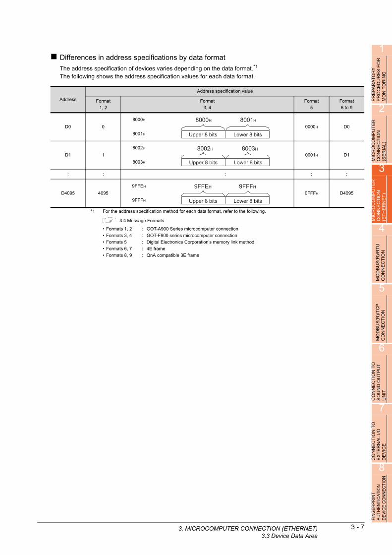
1
3. MICRO
AT
OR
Y
DU
RE
S F
OR
R
ING
Differences in address specifications by data format
The address specification of devices varies depending on the data format.*1
The following shows the address specification values for each data format.
AR E TO
PR
EP
PR
OC
MO
NI
2
MIC
RO
CO
MP
UT
ER
C
ON
NE
CT
ION
(S
ER
IAL
)
3
MIC
RO
CO
MP
UT
ER
C
ON
NE
CT
ION
(E
TH
ER
NE
T)
4
MO
DB
US
(R)/
RT
U
CO
NN
EC
TIO
N
5
MO
DB
US
(R)/
TC
P
CO
NN
EC
TIO
N
6
CO
NN
EC
TIO
N T
O
SO
UN
D O
UT
PU
T
UN
IT
7
CO
NN
EC
TIO
N T
O
EX
TE
RN
AL
I/O
D
EV
ICE
8
FIN
GE
RP
RIN
T A
UTH
EN
TIC
ATIO
N
DE
VIC
E C
ON
NE
CTI
ON
*1 For the address specification method for each data format, refer to the following.
3.4 Message Formats
Address
Address specification value
Format
1, 2
Format
3, 4
Format
5
Format
6 to 9
D0 0
8000H
0000H D0
8001H
D1 1
8002H
0001H D1
8003H
: : : : :
D4095 4095
9FFEH
0FFFH D4095
9FFFH
• Formats 1, 2 : GOT-A900 Series microcomputer connection
• Formats 3, 4 : GOT-F900 series microcomputer connection
• Formats 5 : Digital Electronics Corporation's memory link method
• Formats 6, 7 : 4E frame
• Formats 8, 9 : QnA compatible 3E frame
Upper 8 bits
8000H
Lower 8 bits
8001H
Upper 8 bits
8002H
Lower 8 bits
8003H
Upper 8 bits
9FFEH
Lower 8 bits
9FFFH
COMPUTER CONNECTION (ETHERNET)3.3 Device Data Area
3 - 7
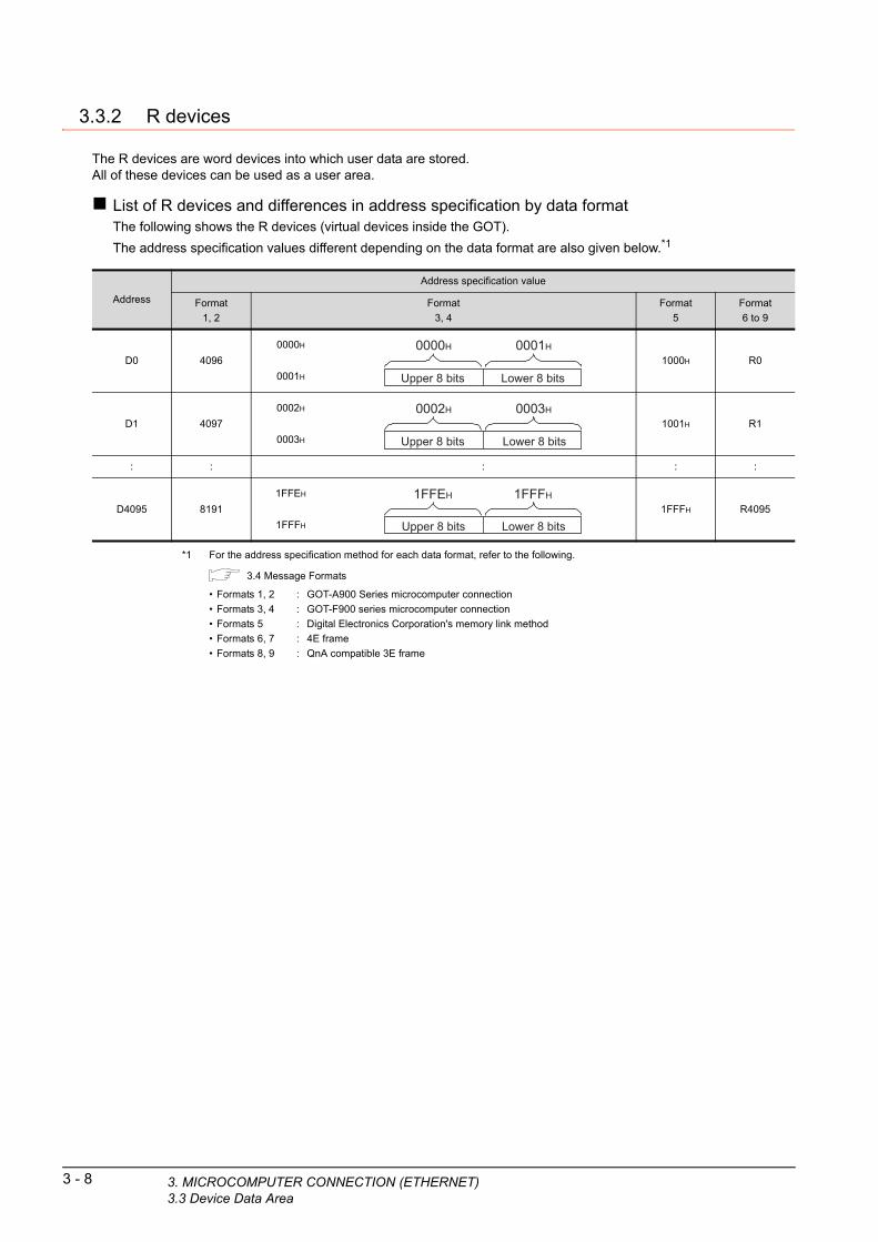
3 - 8 3. MICROCOMPUTER CONNECTION (ETHE3.3 Device Data Area
3.3.2 R devices
The R devices are word devices into which user data are stored.All of these devices can be used as a user area.
List of R devices and differences in address specification by data formatThe following shows the R devices (virtual devices inside the GOT).
The address specification values different depending on the data format are also given below.*1
Address
Address specification value
Format
1, 2
Format
3, 4
Format
5
Format
6 to 9
D0 4096
0000H
1000H R0
0001H
D1 4097
0002H
1001H R1
0003H
: : : : :
D4095 8191
1FFEH
1FFFH R4095
1FFFH
Upper 8 bits
0000H
Lower 8 bits
0001H
Upper 8 bits
0002H
Lower 8 bits
0003H
Upper 8 bits
1FFEH
Lower 8 bits
1FFFH
*1 For the address specification method for each
format, refer to the following. data3.4 Message Formats
• Formats 1, 2 : GOT-A900 Series microcomputer connection
• Formats 3, 4 : GOT-F900 series microcomputer connection
• Formats 5 : Digital Electronics Corporation's memory link method
• Formats 6, 7 : 4E frame
• Formats 8, 9 : QnA compatible 3E frame
RNET)

1
3. MICRO
PR
EP
AR
AT
OR
Y
PR
OC
ED
UR
ES
FO
R
MO
NIT
OR
ING
2
3.3.3 L devices
The L devices are bit devices into which user data are stored.All of these devices can be used as a user area.
List of L devices and differences in address specification by data formatThe following shows the L devices (virtual devices inside the GOT).
The address specification values different depending on the data format are also given below.*1
R
MICR
OC
OM
PU
TE
CO
NN
EC
TIO
N
(SE
RIA
L)
3
MIC
RO
CO
MP
UT
ER
C
ON
NE
CT
ION
(E
TH
ER
NE
T)
4
MO
DB
US
(R)/
RT
U
CO
NN
EC
TIO
N
5
MO
DB
US
(R)/
TC
P
CO
NN
EC
TIO
N
6
CO
NN
EC
TIO
N T
O
SO
UN
D O
UT
PU
T
UN
IT
7
CO
NN
EC
TIO
N T
O
EX
TE
RN
AL
I/O
D
EV
ICE
8
FIN
GE
RP
RIN
T A
UTH
EN
TIC
ATIO
N
DE
VIC
E C
ON
NE
CTI
ON
*1 For the address specification method for each data format, refer to the following.
3.4 Message Formats
*2 For reading or writing data in word units, specify the addresses in 16-point units. (Example: L0, L16, L32, etc.)
Address Address specification value
b7 b6 b5 b4 b3 b2 b1 b0Format
1, 2
Format
3, 4
Format
5
Format
6 to 9
L7 L6 L5 L4 L3 L2 L1 L08192
A000H
2000H
Same as
address
column on
left*2
L15 L14 L13 L12 L11 L10 L9 L8 A001H
L23 L22 L21 L20 L19 L18 L17 L168193
A002H
2001H
L31 L30 L29 L28 L27 L26 L25 L24 A003H
: : : :
L2039 L2038 L2037 L2036 L2035 L2034 L2033 L20328319
A0FEH
207FH
L2047 L2046 L2045 L2044 L2043 L2042 L2041 L2040 A0FFH
• Formats 1, 2 : GOT-A900 Series microcomputer connection
• Formats 3, 4 : GOT-F900 series microcomputer connection
• Formats 5 : Digital Electronics Corporation's memory link method
• Formats 6, 7 : 4E frame
• Formats 8, 9 : QnA compatible 3E frame
COMPUTER CONNECTION (ETHERNET)3.3 Device Data Area
3 - 9

3 - 10 3. MICROCOMPUTER CONNECTION (ETHE3.3 Device Data Area
3.3.4 M devices
The M devices are bit devices into which user data are stored.All of these devices can be used as a user area.
List of M devices and differences in address specification by data formatThe following shows the M devices (virtual devices inside the GOT).
The address specification values different depending on the data format are also given below.*1
*1 For the address specification method for each data format, refer to the following.
3.4 Message Formats
*2 For reading or writing data in word units, specify the addresses in 16-point units.(Example: M0, M16, M32, and others)
Address Address specification value
b7 b6 b5 b4 b3 b2 b1 b0Format
1, 2
Format
3, 4
Format
5
Format
6 to 9
M7 M6 M5 M4 M3 M2 M1 M08320
2000H
2080H
Same as
address
column on
left*2
M15 M14 M13 M12 M11 M10 M9 M8 2001H
M23 M22 M21 M20 M19 M18 M17 M168321
2002H
2081H
M31 M30 M29 M28 M27 M26 M25 M24 2003H
: : : :
M2039 M2038 M2037 M2036 M2035 M2034 M2033 M20328447
20FEH
20FFH
M2047 M2046 M2045 M2044 M2043 M2042 M2041 M2040 20FFH
• Formats 1, 2 : GOT-A900 Series microcomputer connection
• Formats 3, 4 : GOT-F900 series microcomputer connection
• Formats 5 : Digital Electronics Corporation's memory link method
• Formats 6, 7 : 4E frame
• Formats 8, 9 : QnA compatible 3E frame
RNET)

1
3. MICRO
PR
EP
AR
AT
OR
Y
PR
OC
ED
UR
ES
FO
R
MO
NIT
OR
ING
3.3.5 SD devices
The SD devices are word devices into which GOT communication errors (error codes), clock data and other information are stored.
List of SD devicesThe following lists the SD devices (virtual devices inside the GOT).
2
MIC
RO
CO
MP
UT
ER
C
ON
NE
CT
ION
(S
ER
IAL
)
3
MIC
RO
CO
MP
UT
ER
C
ON
NE
CT
ION
(E
TH
ER
NE
T)
4
MO
DB
US
(R)/
RT
U
CO
NN
EC
TIO
N
5
MO
DB
US
(R)/
TC
P
CO
NN
EC
TIO
N
6
CO
NN
EC
TIO
N T
O
SO
UN
D O
UT
PU
T
UN
IT
7
NN
EC
TIO
N T
O
TE
RN
AL
I/O
V
ICE
(Continued to next page)Address Description Set side
SD0
SD1
100ms counter (32bits)
The counter is incremented at 100ms intervals after GOT is turned ON.
(The time elapsed after GOT is turned ON is stored in 100ms units.)
(1) When setting the LH order to [32bit Storage] for the communication detail settings
The lower and upper bits are stored in SD0 and SD1 respectively.
(2) When setting the HL order to [32bit Storage] for the communication detail settings
The upper and lower bits are stored in SD0 and SD1 respectively.
System
SD2*1
Communication error status
An error data (error code) occurred during communication is stored.
•Host Address (Communication error that occurred on the request destination GOT)
0: No error
1: Parity error
2: Framing error
3: Overrun error
4: Communication message error
5: Command error
6: Clock data setting error
•Other station (Communication error that occurred on another GOT when multiple GOTs are connected)
101: Parity error
102: Framing error
103: Overrun error
104: Communication message error
105: Timeout error (No station of the specified address exists.)
106: Multiple units not connectable
107: Clock data setting error
SD3Clock data (second)
Second data of 00 to 59 is stored.
SD4Clock data (minute)
Minute data of 00 to 59 is stored.
SD5Clock data (hour)
Hour data of 00 to 23 is stored.
SD6Clock data (day)
Day data of 00 to 31 is stored.
SD7Clock data (month)
Month data of 01 to 12 is stored.
SD0SD1
Lower wordUpper word
SD1SD0
Lower wordUpper word
O X E
*1 For details and corrective actions for the errors ror codes) that are stored into SD2, refer to the following: C E D8
FIN
GE
RP
RIN
T A
UTH
EN
TIC
ATIO
N
DE
VIC
E C
ON
NE
CTI
ON
(er
■ Details and actions for errors (error codes) stored into SD2
COMPUTER CONNECTION (ETHERNET)3.3 Device Data Area
3 - 11

3 - 12 3. MICROCOMPUTER CONNECTION (ETHE3.3 Device Data Area
(From previous page)
*1 If a wrong day of the week is set by the clock data setting commands, the clock data will differ from the time displayed on the
utility.
Example: When October 1, 2009 (Tuesday) is set by the clock data setting command (the actual day of the week is Thursday),"2" is stored to SD9 although Thursday (THU) will be displayed on the utility time display.
POINTPOINTPOINT
The side where virtual devices are set
System : Set on the system side.User : Set on the user side (by sending request messages from host or using the touch switches, etc.
on the GOT).
Address Description Set side
SD8Clock data (year)
4-digit year data is stored.
System
SD9
Clock data (day of week)*1
Day-of-the-week data is stored.
0: Sunday 1: Monday 2: Tuesday 3: Wednesday
4: Thursday 5: Friday 6: Saturday
SD10 to 15 Unused ―
Details and actions for errors (error codes) stored into SD2
Error code Description Action
0 No error ―
1, 101Parity error
The parity bit does not match.• Check the communication cable and communication module
attachment.
• Check the settings of "Communication Detail Settings".
• Match the GOT and host transmission settings.2, 102Framing error
The data bit and/or stop bit are not correct.
3, 103
Overrun error
The next data was transmitted from the host before GOT
completes the processing of the data received.
• Check the settings of "Communication Detail Settings".
• Decrease the transmission speed.
4, 104
Communication message error
EXT/CR could not be found before the upper limit of the
receive buffer was exceeded.
• Check the communication cable and communication module
attachment.
• Check the settings of "Communication Detail Settings".
• Review the contents of the message to transmit.
5Command error
An unsupported command was used.
• Review the contents of the message to transmit.
• Check the commands in the message.
( 3.4.2 List of commands)
105
Timeout error
There is no response from the GOT, or the station of the
specified address does not exist.
• Check the communication cable and communication module
attachment.
• Check the settings of "Communication Detail Settings".
• Review the contents of the message to transmit.
106Multiple units not connectable
The RS-232 port is occupied.
• Check the communication cable and communication module
attachment.
• Check the settings of "Communication Detail Settings".
• Check to see if the RS-232 port is occupied.
6, 107Clock data setting error
The setting value of the clock data has error.
• Review the contents of the message to transmit.
• Check whether the non-existent data is set (e.g. setting "07"
at the day of the week) as clock data.
RNET)

1
3. MICRO
AT
OR
Y
DU
RE
S F
OR
R
ING
Differences in address specifications by data format
The address specification of devices varies depending on the data format.*1
The following shows the address specification values for each data format.
AR E TO
PR
EP
PR
OC
MO
NI
2
MIC
RO
CO
MP
UT
ER
C
ON
NE
CT
ION
(S
ER
IAL
)
3
MIC
RO
CO
MP
UT
ER
C
ON
NE
CT
ION
(E
TH
ER
NE
T)
4
MO
DB
US
(R)/
RT
U
CO
NN
EC
TIO
N
5
MO
DB
US
(R)/
TC
P
CO
NN
EC
TIO
N
6
CO
NN
EC
TIO
N T
O
SO
UN
D O
UT
PU
T
UN
IT
7
CO
NN
EC
TIO
N T
O
EX
TE
RN
AL
I/O
D
EV
ICE
8
FIN
GE
RP
RIN
T A
UTH
EN
TIC
ATIO
N
DE
VIC
E C
ON
NE
CTI
ON
*1 For the address specification method for each data format, refer to the following.
3.4 Message Formats
*2 SD3 to 9 correspond to GD0 to 6 on the GOT-F900 Series.
Access to SD3 to 9 can be also made by the specification of the addresses (3000 to 300DH) of GD0 to 6 on the GOT-F900 Series.
AddressAddress specification value
Formats 1, 2 Formats 3, 4*2 Formats 5 Formats 6 to 9
SD0 8448
2100H
2100H SD0
2101H
SD1 8449
2102H
2101H SD1
2103H
SD2 8450
2104H
2102H SD2
2105H
SD3 8451
2106H
(3000H)2103H SD3
2107H
(3001H)
SD4 8452
2108H
(3002H)2104H SD4
2109H
(3003H)
SD5 8453
210AH
(3004H)2105H SD5
210BH
(3005H)
SD6 8454
210CH
(3006H)2106H SD6
210DH
(3007H)
SD7 8455
210EH
(3008H)2107H SD7
210FH
(3009H)
SD8 8456
2110H
(300AH)2108H SD8
2111H
(300BH)
SD9 8457
2112H
(300CH)2109H SD9
2113H
(300DH)
• Formats 1, 2 : GOT-A900 Series microcomputer connection
• Formats 3, 4 : GOT-F900 series microcomputer connection
• Formats 5 : Digital Electronics Corporation's memory link method
• Formats 6, 7 : 4E frame
• Formats 8, 9 : QnA compatible 3E frame
Upper 8 bits
2100H
Lower 8 bits
2101H
Upper 8 bits
2102H
Lower 8 bits
2103H
Upper 8 bits
2104H
Lower 8 bits
2105H
Upper 8 bits
2106H(3000H)
Lower 8 bits
2107H(3001H)
Upper 8 bits
2108H(3002H)
Lower 8 bits
2109H(3003H)
Upper 8 bits
210AH(3004H)
Lower 8 bits
210BH(3005H)
Upper 8 bits
210CH(3006H)
Lower 8 bits
210DH(3007H)
Upper 8 bits
210EH(3008H)
Lower 8 bits
210FH(3009H)
Upper 8 bits
2110H(300AH)
Lower 8 bits
2111H(300BH)
Upper 8 bits
2112H(300CH)
Lower 8 bits
2113H(300DH)
COMPUTER CONNECTION (ETHERNET)3.3 Device Data Area
3 - 13

3 - 14 3. MICROCOMPUTER CONNECTION (ETHE3.3 Device Data Area
3.3.6 SM devices
The SM devices are bit devices into which interrupt outputs and clock data that turn ON/OFF at 1-second cycles.
List of SM devicesThe following shows the SM devices (virtual devices inside the GOT).
*1 After the ON/OFF state is changed, the interrupt data is output within a period of 1 to 10 ms.
*2 When the ON/OFF state of SM0 to 49 is changed from the host side, interrupt output is not performed.
POINTPOINTPOINT
(1) The side where virtual devices are setSystem : Set on the system side.User : Set on the user side (by sending request messages from host or using the touch switches, etc.
on the GOT).
(2) Interrupt outputs (SM0 to 49)
• To disable the interrupt output, turn ON SM52 (interrupt code output disable flag). ( 3.3.6 SM devices)• To enable the interrupt output, set 8 bits to the data length at "Communication Detail Settings".
( 3.5.1 Setting communication interface (Communication settings))
• When "7 bits" is set, the MSB (8th bit) is ignored. (Example: FFH 7FH)
Address Description Set side
SM0 to 49
Interrupt output
When the ON/OFF state of SM0 to 49 is changed by a touch switch on the GOT, for example, the interrupt
codes shown below are transmitted (interrupt output) to the host side.*1*2
The data amount (number of bytes) to be interrupt-output is set at "Interrupt Data Byte" in "Communication
Detail Settings". ( 3.5.1 Setting communication interface (Communication settings))
User
SM50
1-second cycle clock
Turns ON/OFF at a 1-second cycle.
System
SM51
2-second cycle clock
Turns ON/OFF at a 2-second cycle.
SM52
Interrupt code output disable flag
Enables or disables the output of the interrupt code.
OFF : Interrupt code output enabled ON : Interrupt code output disabled
When set to disable the interrupt code output, no interrupt data are output to the host.
(Relevant devices: D13, D14, SM0 to 49)
User
SM53 to 63 Unused ―
Address Event type
SM0Changed from OFF to ON
Changed from ON to OFF
Changed from OFF to ON
Changed from ON to OFF
Changed from OFF to ON
Changed from ON to OFF
Changed from OFF to ON
Changed from ON to OFF
Changed from OFF to ON
Changed from ON to OFF
Interrupt code
SM1
SM2
50H
51H
52H
53H
54H
55H
SM48B0H
B1H
SM49B2H
B3H
0.5 0.5
1 1
RNET)

1
3. MICRO
AT
OR
Y
DU
RE
S F
OR
R
ING
Differences in address specifications by data format
The address specification of devices varies depending on the data format.*1
The following shows the address specification values for each data format.
AR E TO
PR
EP
PR
OC
MO
NI
2
MIC
RO
CO
MP
UT
ER
C
ON
NE
CT
ION
(S
ER
IAL
)
3
MIC
RO
CO
MP
UT
ER
C
ON
NE
CT
ION
(E
TH
ER
NE
T)
4
MO
DB
US
(R)/
RT
U
CO
NN
EC
TIO
N
5
MO
DB
US
(R)/
TC
P
CO
NN
EC
TIO
N
6
CO
NN
EC
TIO
N T
O
SO
UN
D O
UT
PU
T
UN
IT
7
CO
NN
EC
TIO
N T
O
EX
TE
RN
AL
I/O
D
EV
ICE
8
FIN
GE
RP
RIN
T A
UTH
EN
TIC
ATIO
N
DE
VIC
E C
ON
NE
CTI
ON
*1 For the address specification method for each data format, refer to the following.
3.4 Message Formats
*2 In formats 6, 7, values are specified within a range of SM0 to 52.
*3 For reading or writing data in word units, specify the addresses in 16-point units. (Example: SM0, SM16, SM32, etc.)
Address Address specification value
b7 b6 b5 b4 b3 b2 b1 b0Format
1, 2
Format
3, 4
Format
5
Format
6 to 9
SM7 SM6 SM5 SM4 SM3 SM2 SM1 SM08464
2200H
2110H
*2*3
SM15 SM14 SM13 SM12 SM11 SM10 SM9 SM8 2201H
SM23 SM22 SM21 SM20 SM19 SM18 SM17 SM168465
2202H
2111H
SM31 SM30 SM29 SM28 SM27 SM26 SM25 SM24 2203H
SM39 SM38 SM37 SM36 SM35 SM34 SM33 SM328466
2204H
2112H
SM47 SM46 SM45 SM44 SM43 SM42 SM41 SM40 2205H
Unused SM52 SM51 SM50 SM49 SM48 8467 2206H
2113H
Unused ― ―
• Formats 1, 2 : GOT-A900 Series microcomputer connection
• Formats 3, 4 : GOT-F900 series microcomputer connection
• Formats 5 : Digital Electronics Corporation's memory link method
• Formats 6, 7 : 4E frame
• Formats 8, 9 : QnA compatible 3E frame
COMPUTER CONNECTION (ETHERNET)3.3 Device Data Area
3 - 15

3 - 16 3. MICROCOMPUTER CONNECTION (ETHE3.4 Message Formats
3.4 Message Formats
This section describes the format of messages that can be used in the microcomputer connection (Ethernet).
3.4.1 Data format type and application
Data format type and applicationCommunication is possible using any of the data formats shown below.
(1) Formats 1, 2 (GOT-A900 Series microcomputer connection)This is the same message format as when a microcomputer connection is established with the GOT-A900 series.
Type Name Description Refer to
Format 1GOT-A900 series microcomputer connection
(ASCII)
This format is used when the GOT is connected to the host in a 1:1
connection. The data format is ASCII. 3.4.3
Format 2GOT-A900 series microcomputer connection
(Binary)
This format is used when the GOT is connected to the host in a 1:1
connection. The data format is Binary.
(2) Formats 3, 4 (GOT-F900 series microcomputer connection)This is the compatible message format with when a microcomputer connection is established with the GOT-F900 Series.
Type Name Description Refer to
Format 3GOT-F900 series microcomputer connection
(ASCII)
This format is used when the GOT is connected to the host in a 1:1
connection. The data format is ASCII. 3.4.4
Format 4GOT-F900 series microcomputer connection
(Binary)
This format is used when the GOT is connected to the host in a 1:1
connection. The data format is Binary.
(3) Format 5 (Digital Electronics Corporation's memory link method)This is the compatible message format with the protocol of the Digital Electronics Corporation's memory link method.
Type Name Description Refer to
Format 5Digital Electronics Corporation's memory link
method
This is the basic format of the Digital Electronics Corporation's memory link
method. 3.4.5
(4) Formats 6, 7 (4E frame)This is the compatible message format with when a communication is performed using the MC protocol of Q/QnA Series serial communication module.
Type Name Description Refer to
Format 6 4E frame (ASCII) This is the basic format of the MC protocols. The data format is ASCII. 3.4.6
Format 7 4E frame (Binary) This is the basic format of the MC protocols. The data format is Binary.
(5) Formats 8, 9 (QnA compatible 3E frame)This is the compatible message format with when a communication is performed using the MC protocol of Q/QnA Series serial communication module.
Type Name Description Refer to
Format 8 QnA compatible 3E frame (ASCII) This is the basic format of the MC protocols. The data format is ASCII. 3.4.7
Format 9 QnA compatible 3E frame (Binary) This is the basic format of the MC protocols. The data format is Binary.
How to set data formatSet the data format at [Detail setting] in GT Designer3.For details of the data format setting method, refer to the following.
3.5.1 Setting communication interface (Communication settings)
RNET)
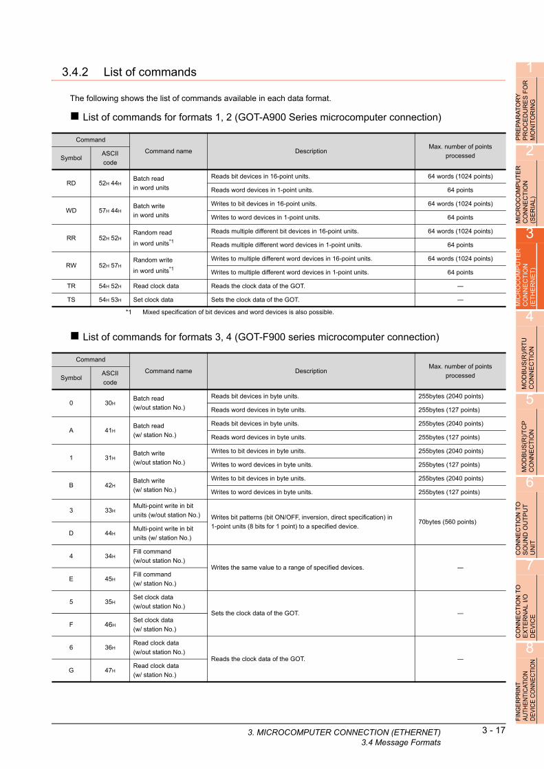
1
3. MICRO
EP
AR
AT
OR
Y
OC
ED
UR
ES
FO
R
NIT
OR
ING
3.4.2 List of commands
The following shows the list of commands available in each data format.
List of commands for formats 1, 2 (GOT-A900 Series microcomputer connection)
R R O
P P M
2
MIC
RO
CO
MP
UT
ER
C
ON
NE
CT
ION
(S
ER
IAL
)
3
MIC
RO
CO
MP
UT
ER
C
ON
NE
CT
ION
(E
TH
ER
NE
T)
4
*1 Mixed specification of bit devices and word devices is also possible.Command
Command name DescriptionMax. number of points
processedSymbolASCII
code
RD 52H 44HBatch read
in word units
Reads bit devices in 16-point units. 64 words (1024 points)
Reads word devices in 1-point units. 64 points
WD 57H 44HBatch write
in word units
Writes to bit devices in 16-point units. 64 words (1024 points)
Writes to word devices in 1-point units. 64 points
RR 52H 52HRandom read
in word units*1
Reads multiple different bit devices in 16-point units. 64 words (1024 points)
Reads multiple different word devices in 1-point units. 64 points
RW 52H 57HRandom write
in word units*1
Writes to multiple different word devices in 16-point units. 64 words (1024 points)
Writes to multiple different word devices in 1-point units. 64 points
TR 54H 52H Read clock data Reads the clock data of the GOT. ―
TS 54H 53H Set clock data Sets the clock data of the GOT. ―
RT
U
N
List of commands for formats 3, 4 (GOT-F900 series microcomputer connection)
)/ O
MOD
BU
S(R
CO
NN
EC
TI
5
MO
DB
US
(R)/
TC
P
CO
NN
EC
TIO
N
6
CO
NN
EC
TIO
N T
O
SO
UN
D O
UT
PU
T
UN
IT
7
CO
NN
EC
TIO
N T
O
EX
TE
RN
AL
I/O
D
EV
ICE
8
FIN
GE
RP
RIN
T A
UTH
EN
TIC
ATIO
N
DE
VIC
E C
ON
NE
CTI
ON
Command
Command name DescriptionMax. number of points
processedSymbolASCII
code
0 30HBatch read
(w/out station No.)
Reads bit devices in byte units. 255bytes (2040 points)
Reads word devices in byte units. 255bytes (127 points)
A 41HBatch read
(w/ station No.)
Reads bit devices in byte units. 255bytes (2040 points)
Reads word devices in byte units. 255bytes (127 points)
1 31HBatch write
(w/out station No.)
Writes to bit devices in byte units. 255bytes (2040 points)
Writes to word devices in byte units. 255bytes (127 points)
B 42HBatch write
(w/ station No.)
Writes to bit devices in byte units. 255bytes (2040 points)
Writes to word devices in byte units. 255bytes (127 points)
3 33HMulti-point write in bit
units (w/out station No.) Writes bit patterns (bit ON/OFF, inversion, direct specification) in
1-point units (8 bits for 1 point) to a specified device.70bytes (560 points)
D 44HMulti-point write in bit
units (w/ station No.)
4 34HFill command
(w/out station No.)Writes the same value to a range of specified devices. ―
E 45HFill command
(w/ station No.)
5 35HSet clock data
(w/out station No.)Sets the clock data of the GOT. ―
F 46HSet clock data
(w/ station No.)
6 36HRead clock data
(w/out station No.)Reads the clock data of the GOT. ―
G 47HRead clock data
(w/ station No.)
COMPUTER CONNECTION (ETHERNET)3.4 Message Formats
3 - 17

3 - 18 3. MICROCOMPUTER CONNECTION (ETHE3.4 Message Formats
List of commands for formats 5 (Digital Electronics Corporation's memory link method)
Command
Command name DescriptionMax. number of points
processedSymbolASCII
code
R 52HBatch read
in word units
Reads bit devices in 16-point units. 64 words (1024 points)
Reads word devices in 1-point units. 64 points
W 57HBatch write
in word units
Writes to bit devices in 16-point units. 64 words (1024 points)
Writes to word devices in 1-point units. 64 points
I 49H Interrupt inquiry Issues an interrupt inquiry. ―
List of commands for formats 6, 7 (4E frame), formats 8, 9 (QnA compatible 3E frame)
*1 Mixed specification of bit devices and word devices is also possible.
*2 This is a dedicated command of GOT for the microcomputer connection.
*3 Specifies the address of bit devices in 16-point units. (Example: M0, M16, M32, and others)
CommandSub-
commandCommand name Description
Max. number of points
processed
0401 0001Batch read
in bit unitsReads bit devices in 1-point units. 64 points
0401 0000Batch read
in word units
Reads bit devices in 16-point units.*3 64 words (1024 points)
Reads word devices in 1-point units. 64 points
1401 0001Batch write
in bit unitsWrites to bit devices in 1-point units. 64 points
1401 0000Batch write
in word units
Writes to bit devices in 16-point units.*3 64 words (1024 points)
Writes to word devices in 1-point units. 64 points
0403 0000Random read
in word units*1
Reads multiple different bit devices in 16-point and 32-point units.*3 64 words (1024 points)
Reads multiple different word devices in 1-point and 2-point units. 64 points
1402 0001Random write
in bit unitsWrites to multiple different bit devices in 1-point units. 64 points
1402 0000Random write
in word units*1
Writes to multiple different bit devices in 16-point and 32-point units.*3 64 words (1024 points)
Writes to multiple different word devices in 1-point and 2-point units. 64 points
0406 0000Multiple block
batch read
Reads multiple blocks. A bit device (16 bits for 1 point) or a word device
(1 word for 1 point) is regarded as one block.*364 points
1406 0000Multiple block
batch write
Writes multiple blocks. A bit device (16 bits for 1 point) or a word device
(1 word for 1 point) is regarded as one block.*364 points
1901*2 0000 Read clock data Reads the clock data of the GOT. ―
0901*2 0000 Set clock data Sets the clock data of the GOT. ―
RNET)

1
3. MICRO
R
3.4.3 Formats 1, 2 (GOT-A900 Series microcomputer connection)
RY
E
S F
OG
PR
EP
AR
AT
OP
RO
CE
DU
RM
ON
ITO
RIN
2
TE
R
Basic format of data communicationU
MICR
OC
OM
PC
ON
NE
CT
ION
(SE
RIA
L)
3
MIC
RO
CO
MP
UT
ER
C
ON
NE
CT
ION
(E
TH
ER
NE
T)
4
MO
DB
US
(R)/
RT
U
CO
NN
EC
TIO
N
5
MO
DB
US
(R)/
TC
P
CO
NN
EC
TIO
N
6
CO
NN
EC
TIO
N T
O
SO
UN
D O
UT
PU
T
UN
IT
7
CO
NN
EC
TIO
N T
O
EX
TE
RN
AL
I/O
D
EV
ICE
8
FIN
GE
RP
RIN
T A
UTH
EN
TIC
ATIO
N
DE
VIC
E C
ON
NE
CTI
ON
*1 Set the number of interrupt data bytes at [Detail setting] in GT Designer3.
For the setting of the number of interrupt data bytes, refer to the following.
3.5.1 Setting communication interface (Communication settings)
Item Message format
Request message
(host GOT)
Response message
during normal
communication
(GOT host)
(1) During processing of read commands
(2) During processing of write commands
Response message
during faulty
communication
(GOT host)
During interrupt
output
(H) (L)
Command Data
Data
06H
ACK
15H
NAK ErrorCode
Output value
1/2/4bytes*1
COMPUTER CONNECTION (ETHERNET)3.4 Message Formats
3 - 19

3 - 20 3. MICROCOMPUTER CONNECTION (ETHE3.4 Message Formats
Details of data items in message format
POINTPOINTPOINT
Data code during communication
Communication of the format 1 is performed in ASCII code. (excluding interrupt output)Communication of the format 2 is performed in Binary code.
(1) Control codes
(2) CommandSpecifies the contents to access from the host to GOT.The command is converted to a 2-digit ASCII code (Hex) and transmitted from the upper digit.For details of the commands that can be used, refer to the following.
3.4.2 List of commands
Symbol ASCII code Description
EOT 04H End of Transmission
ENQ 05H Enquiry (start of enquiry)
NAK 15H Negative ACK (error response)
ACK 06H Acknowledge (write completion response)
LF 0AH Line Feed
CL 0CH Clear
CR 0DH Carriage Return
(3) AddressSpecifies the head No. of the device data to be read/written.In the format 1, the address notated in decimal is converted to a 4-digit ASCII code (Hex) and transmitted from the upper digit.In the format 2, the address notated in decimal is converted to a 2-digit Binary code (binary) and transmitted from the upper digit.For details of the device range that can be accessed, refer to the following.
3.3 Device Data Area
(4) Number of pointsSpecifies the number of device data to be read/written. (Setting range: 1 to 64)In the format 1, the address notated in decimal is converted to a 2-digit ASCII code (Hex) and transmitted from the upper digit.In the format 2, the address notated in decimal is converted to a 1-digit Binary code (binary) and transmitted.
(5) Year, month, day, hour, minute, second and day of the week dataSpecifies year, month, day, hour, minute, second, and day of the week to be read/set to the GOT clock data.In the format 1, the address notated in decimal is converted to a 2-digit ASCII code (Hex) and transmitted from the upper digit.In the format 2, the address notated in decimal is converted to a 1-digit Binary code (binary) and transmitted.
■ Message format (5) Read clock data (TR) command
■ Message format (6) Set clock data (TS) command
(6) Data
Specifies the data to read from/write to the specified device data.(word unit)In the format 1, the address notated in hexadecimal is converted to a 4-digit ASCII code (Hex) and transmitted from the upper digit.In the format 2, the address notated in hexadecimal is converted to a 2-digit Binary code (binary) and transmitted from the upper digit.(7) Error codeThis is the response message at faulty communication appended with error contents. Error code is transmitted in 1 byte.For the error codes, refer to the following.
■ Error code list
RNET)
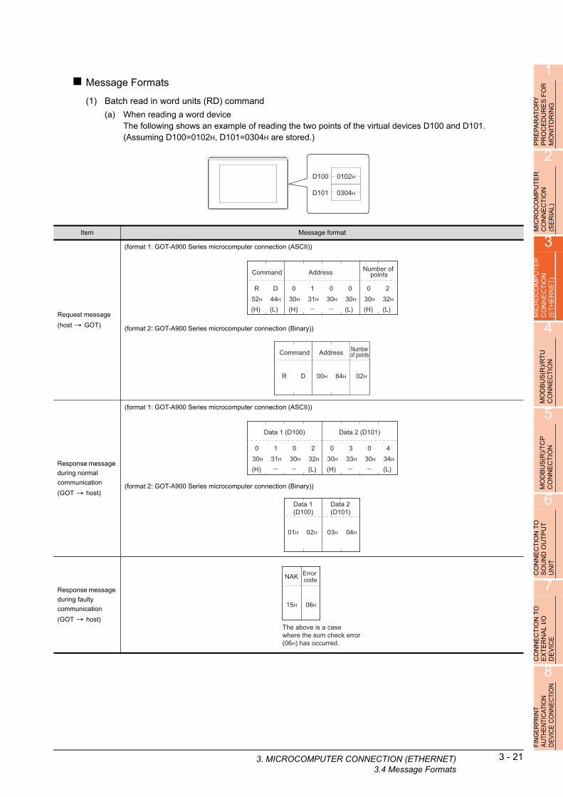
1
3. MICRO
PR
EP
AR
AT
OR
Y
PR
OC
ED
UR
ES
FO
R
MO
NIT
OR
ING
Message Formats
(1) Batch read in word units (RD) command
(a) When reading a word deviceThe following shows an example of reading the two points of the virtual devices D100 and D101.(Assuming D100=0102H, D101=0304H are stored.)
2
ICR
OC
OM
PU
TE
R
ON
NE
CT
ION
E
RIA
L)
D100
D101
0102H
0304H
S
M C (3
MIC
RO
CO
MP
UT
ER
C
ON
NE
CT
ION
(E
TH
ER
NE
T)
4
MO
DB
US
(R)/
RT
U
CO
NN
EC
TIO
N
5
MO
DB
US
(R)/
TC
P
CO
NN
EC
TIO
N
6
CO
NN
EC
TIO
N T
O
SO
UN
D O
UT
PU
T
UN
IT
7
CO
NN
EC
TIO
N T
O
EX
TE
RN
AL
I/O
D
EV
ICE
8
FIN
GE
RP
RIN
T A
UTH
EN
TIC
ATIO
N
DE
VIC
E C
ON
NE
CTI
ON
Item Message format
Request message
(host GOT)
(format 1: GOT-A900 Series microcomputer connection (ASCII))
(format 2: GOT-A900 Series microcomputer connection (Binary))
Response message
during normal
communication
(GOT host)
(format 1: GOT-A900 Series microcomputer connection (ASCII))
(format 2: GOT-A900 Series microcomputer connection (Binary))
Response message
during faulty
communication
(GOT host)
(H) (L)
Command
R D52H 44H
(H) (L)
Address
0 130H 31H
030H
030H
(H) (L)
Number of points
0 230H 32H
Command
R D
Address
00H 64H
Numberof points
02H
(H) (L)
0 130H 31H
030H
232H
(H) (L)
0 330H 33H
030H
434H
Data 1 (D100) Data 2 (D101)
01H 02H 03H 04H
Data 1(D100)
Data 2(D101)
The above is a case where the sum check error (06H) has occurred.
15H
NAK
06H
Error code
COMPUTER CONNECTION (ETHERNET)3.4 Message Formats
3 - 21

3 - 22 3. MICROCOMPUTER CONNECTION (ETHE3.4 Message Formats
(b) When reading a bit deviceThe following shows an example of reading the two points of the virtual devices M0 to M31.(Assuming M0="1" and M31="1" are stored.)
M15 to 0
M31 to 6
0001H
8000H
Item Message format
Request message
(host GOT)
(format 1: GOT-A900 Series microcomputer connection (ASCII))
(format 2: GOT-A900 Series microcomputer connection (Binary))
Response message
during normal
communication
(GOT host)
(format 1: GOT-A900 Series microcomputer connection (ASCII))
(format 2: GOT-A900 Series microcomputer connection (Binary))
Response message
during faulty
communication
(GOT host)
(H) (L)
Command
R D52H 44H
(H) (L)
Address
8 338H 33H
232H
030H
(H) (L)
Number of points
0 230H 32H
Command
R D
Address
83H 20H
Numberof points
02H
(H) (L)
Data 1 (M15 to 0)
030H
030H
131H
030H
(H) (L)
838H
030H
030H
030H
M16
M17
M18
M19
M20
M21
M22
M23
M24
M25
M26
M27
M28
M29
M30
M31
00000000M0
M1
M2
M3
M4
M5
M6
M7
M8
M9
M10
M12
M13
M14
M15
M11
10000000 00000001 00000000
Data 2 (M31 to 16)
M16
M17
M18
M19
M20
M21
M22
M23
M24
M25
M26
M27
M28
M29
M30
M31
00000000M0
M1
M2
M3
M4
M5
M6
M7
M8
M9
M10
M12
M13
M14
M15
M11
10000000 00000001 00000000
00H 01H 80H 00H
Data 1(M15 to 0)
Data 2(M31 to 16)
The above is a case where the sum check error (06H) has occurred.
15H
NAK
06H
Error code
RNET)
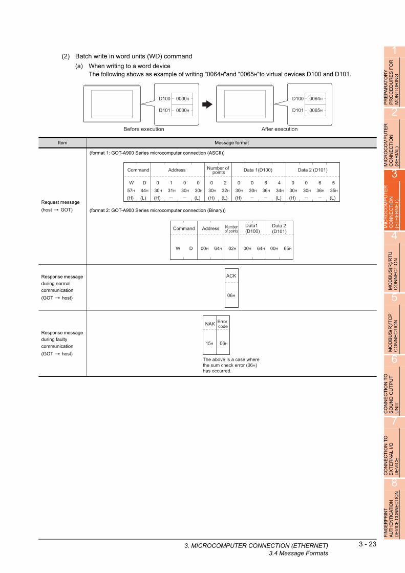
1
3. MICRO
TO
RY
U
RE
S F
OR
IN
G
(2) Batch write in word units (WD) command
(a) When writing to a word deviceThe following shows as example of writing "0064H"and "0065H"to virtual devices D100 and D101.
A D R
PR
EP
AR
PR
OC
EM
ON
ITO
2
UT
ER
N
D100
D101
0000H
0000H
D100
D101
0064H
0065H
Before execution After execution
P
MICR
OC
OM
CO
NN
EC
TIO
(SE
RIA
L)
3
MIC
RO
CO
MP
UT
ER
C
ON
NE
CT
ION
(E
TH
ER
NE
T)
4
MO
DB
US
(R)/
RT
U
CO
NN
EC
TIO
N
5
MO
DB
US
(R)/
TC
P
CO
NN
EC
TIO
N
6
CO
NN
EC
TIO
N T
O
SO
UN
D O
UT
PU
T
UN
IT
7
CO
NN
EC
TIO
N T
O
EX
TE
RN
AL
I/O
D
EV
ICE
8
FIN
GE
RP
RIN
T A
UTH
EN
TIC
ATIO
N
DE
VIC
E C
ON
NE
CTI
ON
Item Message format
Request message
(host GOT)
(format 1: GOT-A900 Series microcomputer connection (ASCII))
(format 2: GOT-A900 Series microcomputer connection (Binary))
Response message
during normal
communication
(GOT host)
Response message
during faulty
communication
(GOT host)
(H) (L)
Command
W D57H 44H
(H) (L)
Address
0 130H 31H
030H
030H
(H) (L)
Number of points
0 230H 32H
(H) (L)
Data 1(D100)
0 030H 30H
636H
434H
(H) (L)
Data 2 (D101)
0 030H 30H
636H
535H
Command
W D
Address
00H 64H
Numberof points
02H
Data1(D100)
00H 64H
Data 2(D101)
00H 65H
06H
ACK
The above is a case where the sum check error (06H) has occurred.
15H
NAK
06H
Error code
COMPUTER CONNECTION (ETHERNET)3.4 Message Formats
3 - 23

3 - 24 3. MICROCOMPUTER CONNECTION (ETHE3.4 Message Formats
(b) When writing to a bit deviceThe following shows an example of writing "1"s to virtual devices M0 and M31.
M15 to 0 0000H
0000H
0001H
8000H
Before execution After execution
M31 to 16
M15 to 0
M31 to 16
Item Message format
Request message
(host GOT)
(format 1: GOT-A900 Series microcomputer connection (ASCII))
(format 2: GOT-A900 Series microcomputer connection (Binary))
Response message
during normal
communication
(GOT host)
Response message
during faulty
communication
(GOT host)
(H) (L)
Data 1 (M15 to 0)
030H
––
030H
131H
030H
(H) (L)
Data 2 (M31 to 16)
838H
––
030H
030H
030H
M16
M17
M18
M19
M20
M21
M22
M23
M24
M25
M26
M27
M28
M29
M30
M31
00000000M0
M1
M2
M3
M4
M5
M6
M7
M8
M9
M10
M12
M13
M14
M15
M11
10000000 00000001 00000000
(H) (L)
W D57H 44H
Command
(H) (L)
Address
838H
––
030H
232H
333H
(H) (L)
0 230H 32H
Number of points
M16
M17
M18
M19
M20
M21
M22
M23
M24
M25
M26
M27
M28
M29
M30
M31
00000000M0
M1
M2
M3
M4
M5
M6
M7
M8
M9
M10
M12
M13
M14
M15
M11
10000000 00000001 00000000
Command
W D
Address
20H 80H
Numberof points
02H
Data 1(M15 to 0)
00H 01H
Data 2(M31 to 16)
80H 00H
06H
ACK
The above is a case where the sum check error (06H) has occurred.
15H
NAK
06H
Error code
RNET)

1
3. MICRO
OR
Y
RE
S F
OR
IN
G
(3) Random read in word units (RR) commandThe following shows an example of reading the two points of the virtual devices D100 and M0 to M15.(Assuming D100=0064H, M0=1are stored.)
AT U R
PR
EP
AR
PR
OC
ED
MO
NIT
O
2
UT
ER
D100 0064H
0001HM15 to 0
N
MICR
OC
OM
PC
ON
NE
CT
IO(S
ER
IAL
)
3
MIC
RO
CO
MP
UT
ER
C
ON
NE
CT
ION
(E
TH
ER
NE
T)
4
MO
DB
US
(R)/
RT
U
CO
NN
EC
TIO
N
5
MO
DB
US
(R)/
TC
P
CO
NN
EC
TIO
N
6
CO
NN
EC
TIO
N T
O
SO
UN
D O
UT
PU
T
UN
IT
7
CO
NN
EC
TIO
N T
O
EX
TE
RN
AL
I/O
D
EV
ICE
8
FIN
GE
RP
RIN
T A
UTH
EN
TIC
ATIO
N
DE
VIC
E C
ON
NE
CTI
ON
Item Message format
Request message
(host GOT)
(format 1: GOT-A900 Series microcomputer connection (ASCII))
(format 2: GOT-A900 Series microcomputer connection (Binary))
Response message
during normal
communication
(GOT host)
(format 1: GOT-A900 Series microcomputer connection (ASCII))
(format 2: GOT-A900 Series microcomputer connection (Binary))
Response message
during faulty
communication
(GOT host)
(H) (L)
Command
R R52H 52H
(H) (L)
Address 1
0 130H 31H
––
030H
030H
(H) (L)
Address 2
8 338H 33H
––
232H
030H
Command
R R
Address 1
00H 64H
Address 2
20H 80H
(H) (L)
Data 1 (D100)
030H
––
636H
434H
030H
00000000M0
M1
M2
M3
M4
M5
M6
M7
M8
M9
M10
M12
M13
M14
M15
M11
10000000
(H) (L)
Data 2 (M15 to 0)
030H
––
030H
131H
030H
Data 1(D100)
00H 64H
00000000M0
M1
M2
M3
M4
M5
M6
M7
M8
M9
M10
M12
M13
M14
M15
M11
10000000
Data 2(M15 to 0)
00H 01H
The above is a case where the sum check error (06H) has occurred.
15H
NAK
06H
Error code
COMPUTER CONNECTION (ETHERNET)3.4 Message Formats
3 - 25

3 - 26 3. MICROCOMPUTER CONNECTION (ETHE3.4 Message Formats
(4) Random write in word units (RW) commandThe following shows an example of writing "0064H" and "1" to virtual devices D100 and M0, respectively.
M15 to 0
0000H
Before execution After execution
D100
0000H M15 to 0
0064HD100
0001H
Item Message format
Request message
(host GOT)
(format 1: GOT-A900 Series microcomputer connection (ASCII))
(format 2: GOT-A900 Series microcomputer connection (Binary))
Response message
during normal
communication
(GOT host)
Response message
during faulty
communication
(GOT host)
(H) (L)
Address 2
838H
––
232H
030H
333H
00000000M0
M1
M2
M3
M4
M5
M6
M7
M8
M9
M10
M12
M13
M14
M15
M11
10000000
(H) (L)
Data 2 (M15 to 0)
030H
––
030H
131H
030H
(H) (L)
R W52H 57H
Command
(H) (L)
Address 1
030H
––
131H
030H
030H
(H) (L)
Data 1 (D100)
030H
––
636H
434H
030H
Address 2
20H 80H
00000000M0
M1
M2
M3
M4
M5
M6
M7
M8
M9
M10
M12
M13
M14
M15
M11
10000000
Data 2(M15 to 0)
00H 01HR W
Command Address 1
00H 64H
Data 1(D100)
00H 00H
06H
ACK
The above is a case where the sum check error (06H) has occurred.
15H
NAK
06H
Error code
RNET)
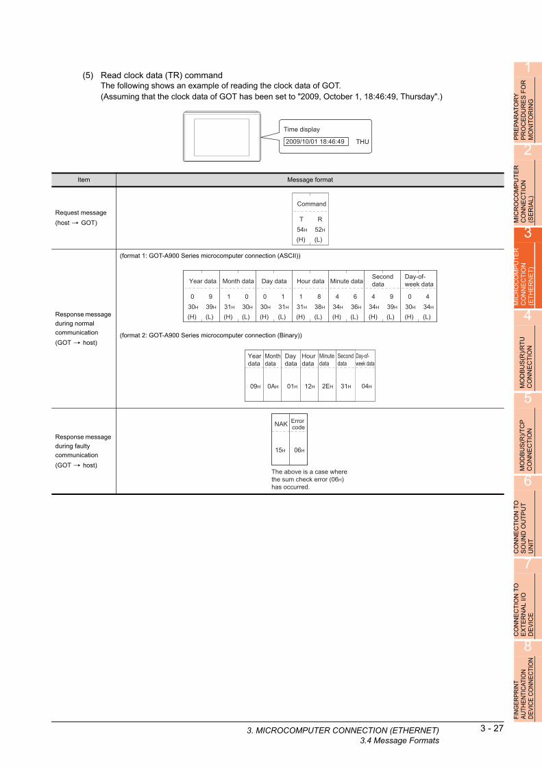
1
3. MICRO
OR
Y
RE
S F
OR
IN
G
(5) Read clock data (TR) commandThe following shows an example of reading the clock data of GOT.(Assuming that the clock data of GOT has been set to "2009, October 1, 18:46:49, Thursday".)
AT U R
PR
EP
AR
PR
OC
ED
MO
NIT
O
2
ER
Time display
2009/10/01 18:46:49 THU
T
MICR
OC
OM
PU
CO
NN
EC
TIO
N
(SE
RIA
L)
3
MIC
RO
CO
MP
UT
ER
C
ON
NE
CT
ION
(E
TH
ER
NE
T)
4
MO
DB
US
(R)/
RT
U
CO
NN
EC
TIO
N
5
MO
DB
US
(R)/
TC
P
CO
NN
EC
TIO
N
6
CO
NN
EC
TIO
N T
O
SO
UN
D O
UT
PU
T
UN
IT
7
CO
NN
EC
TIO
N T
O
EX
TE
RN
AL
I/O
D
EV
ICE
8
FIN
GE
RP
RIN
T A
UTH
EN
TIC
ATIO
N
DE
VIC
E C
ON
NE
CTI
ON
Item Message format
Request message
(host GOT)
Response message
during normal
communication
(GOT host)
(format 1: GOT-A900 Series microcomputer connection (ASCII))
(format 2: GOT-A900 Series microcomputer connection (Binary))
Response message
during faulty
communication
(GOT host)
(H) (L)
Command
T R54H 52H
(H) (L)
Year data
0 930H 39H
(H) (L)
Month data
1 031H 30H
(H) (L)
Day data
0 130H 31H
(H) (L)
Hour data
1 831H 38H
(H) (L)
Minute data
4 634H 36H
(H) (L)
Second data
4 934H 39H
(H) (L)
Day-of-week data
0 430H 34H
Yeardata
09H
Monthdata
0AH
Daydata
01H
Hourdata
12H
Minutedata
2EH
Second data
31H
Day-of-week data
04H
The above is a case where the sum check error (06H) has occurred.
15H
NAK
06H
Error code
COMPUTER CONNECTION (ETHERNET)3.4 Message Formats
3 - 27
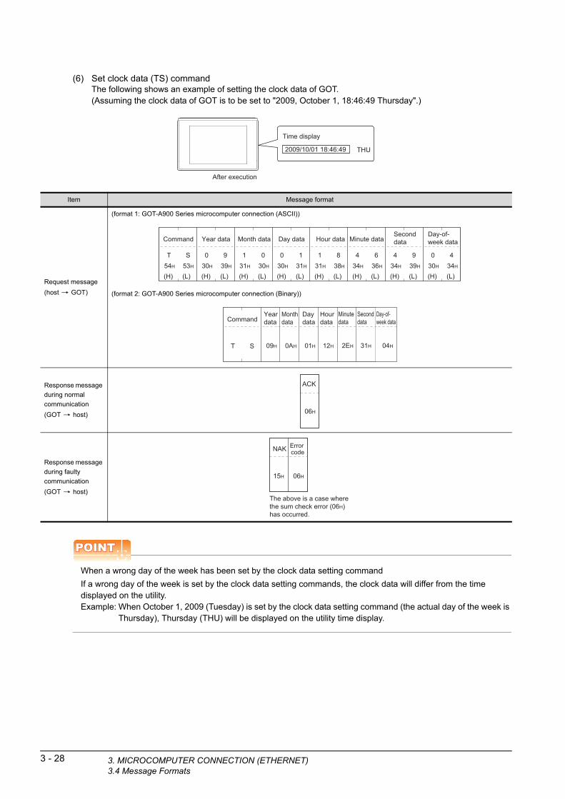
3 - 28 3. MICROCOMPUTER CONNECTION (ETHE3.4 Message Formats
(6) Set clock data (TS) commandThe following shows an example of setting the clock data of GOT.(Assuming the clock data of GOT is to be set to "2009, October 1, 18:46:49 Thursday".)
Time display
2009/10/01 18:46:49 THU
After execution
Item Message format
Request message
(host GOT)
(format 1: GOT-A900 Series microcomputer connection (ASCII))
(format 2: GOT-A900 Series microcomputer connection (Binary))
Response message
during normal
communication
(GOT host)
Response message
during faulty
communication
(GOT host)
(H) (L)
Year data
0 930H 39H
(H) (L)
Month data
1 031H 30H
(H) (L)
Day data
0 130H 31H
(H) (L)
Hour data
1 831H 38H
(H) (L)
Minute data
4 634H 36H
(H) (L)
Second data
4 934H 39H
(H) (L)
Day-of-week data
0 430H 34H
(H) (L)
Command
T S54H 53H
Command
T S
Yeardata
09H
Monthdata
0AH
Daydata
01H
Hourdata
12H
Minutedata
2EH
Second data
31H
Day-of-week data
04H
06H
ACK
The above is a case where the sum check error (06H) has occurred.
15H
NAK
06H
Error code
POINTPOINTPOINT
When a wrong day of the week has been set by the clock data setting command
If a wrong day of the week is set by the clock data setting commands, the clock data will differ from the time displayed on the utility.Example: When October 1, 2009 (Tuesday) is set by the clock data setting command (the actual day of the week is
Thursday), Thursday (THU) will be displayed on the utility time display.
RNET)

1
3. MICRO
RA
TO
RY
D
UR
ES
FO
R
OR
ING
(7) In the case of interrupt outputsThe following shows an example of an interrupt output when data are written to the interrupt output devices (D13 and D14).(Assuming that "3139H" is written to D13 and "AA55H" to D14.)
A E IT
PR
EP
PR
OC
MO
N
2
MIC
RO
CO
MP
UT
ER
C
ON
NE
CT
ION
(S
ER
IAL
)
3
MP
UT
ER
IO
N
ET
)
Interrupt
Interrupt output
Example: When the number of interrupt data bytes is 2
31H
Output value 1
3139HD13
39H
Output value 2
O T
MICR
OC
CO
NN
EC
(ET
HE
RN
4
MO
DB
US
(R)/
RT
U
CO
NN
EC
TIO
N
5
MO
DB
US
(R)/
TC
P
CO
NN
EC
TIO
N
6
CO
NN
EC
TIO
N T
O
SO
UN
D O
UT
PU
T
UN
IT
7
CO
NN
EC
TIO
N T
O
EX
TE
RN
AL
I/O
D
EV
ICE
8
FIN
GE
RP
RIN
T A
UTH
EN
TIC
ATIO
N
DE
VIC
E C
ON
NE
CTI
ON
POINTPOINTPOINT
Interrupt output
To disable the interrupt output, turn ON SM52 (interrupt code output disable flag).
( 3.3.6 SM devices)
Item Message format
Interrupt output
(GOT host)
(1) When [Interrupt Data Byte] in "Communication Detail Settings" is set to "1 byte"
(2) When [Interrupt Data Byte] in "Communication Detail Settings" is set to "2 byte"
(3) When [Interrupt Data Byte] in "Communication Detail Settings" is set to "4 byte"
39H
Output value 1
31H 39H
Output value 1
Output value 2
AAH
Output value1
55H
Output value2
31H
Output value3
39H
Output value4
COMPUTER CONNECTION (ETHERNET)3.4 Message Formats
3 - 29

3 - 30 3. MICROCOMPUTER CONNECTION (ETHE3.4 Message Formats
Error code listThe error contents (error code) are appended to the response message during faulty communication.The following shows error code, error contents, cause, and measures.
Precautions
(1) Batch reading/writing crossing over different devicesWhen using the batch read (RD) or batch write (WD) command, do not batch read/write crossing over the different devices.This will cause an error response.
(2) Storage order for 32-bit dataTo use the program of GOT-A900 series with [32bit Order] setting to GOT1000 series, set [HL Order] to [32bit Order] for [Communication Detail Settings] when 32-bit data is set for GOT-A900 series.With setting [LH Order], the order of upper bits and lower bits are reversed when the GOT displays and writes 32-bit data.
Error code Description Action
10HCommand error
An unsupported command was used.
• Review the contents of the message to transmit.
• Check the commands in the message.
( 3.4.2 List of commands)
11H
Message length error
The upper limit of the data length that can be received by
the GOT has been exceeded.
• Review the contents of the message to transmit.
• Check the data length of the message. (data length of the data section,
etc.)
15HClock data setting error
The setting value of the clock data has error.
• Review the contents of the message to transmit.
• Check whether the non-existent data is set (e.g. setting "07" at the day of
the week) as clock data.
7AHAddress error
The start address of the read/write device is out of range.• Review the contents of the message to transmit.
• Check the devices that can be used and the device ranges.
( 3.3 Device Data Area)7BHExceeded number of points error
The read/write range exceeded the device range.
RNET)
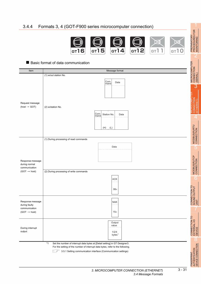
1
3. MICRO
R
3.4.4 Formats 3, 4 (GOT-F900 series microcomputer connection)
RY
E
S F
OG
PR
EP
AR
AT
OP
RO
CE
DU
RM
ON
ITO
RIN
2
UT
ER
Basic format of data communication
P ON
MIC
RO
CO
MC
ON
NE
CT
I(S
ER
IAL
)
3
MIC
RO
CO
MP
UT
ER
C
ON
NE
CT
ION
(E
TH
ER
NE
T)
4
MO
DB
US
(R)/
RT
U
CO
NN
EC
TIO
N
5
MO
DB
US
(R)/
TC
P
CO
NN
EC
TIO
N
6
CO
NN
EC
TIO
N T
O
SO
UN
D O
UT
PU
T
UN
IT
7
CO
NN
EC
TIO
N T
O
EX
TE
RN
AL
I/O
D
EV
ICE
8
FIN
GE
RP
RIN
T A
UTH
EN
TIC
ATIO
N
DE
VIC
E C
ON
NE
CTI
ON
*1 Set the number of interrupt data bytes at [Detail setting] in GT Designer3.For the setting of the number of interrupt data bytes, refer to the following.
3.5.1 Setting communication interface (Communication settings)
Item Message format
Request message
(host GOT)
(1) w/out station No.
(2) w/station No.
Response message
during normal
communication
(GOT host)
(1) During processing of read commands
(2) During processing of write commands
Response message
during faulty
communication
(GOT host)
During interrupt
output
DataCom-mand
Data
(H) (L)
Station No.Com-mand
Data
06H
ACK
15H
NAK
Output value
1/2/4 bytes*1
COMPUTER CONNECTION (ETHERNET)3.4 Message Formats
3 - 31
3 - 32 3. MICROCOMPUTER CONNECTION (ETHE3.4 Message Formats
Details of data items in message format
POINTPOINTPOINT
Data code during communication
Communication of the format 3 is performed in ASCII code. (excluding interrupt output)Communication of the format 4 is performed in Binary code.
(1) Control codes
Symbol ASCII code Description
EOT 04H End of Transmission
ENQ 05H Enquiry (start of enquiry)
NAK 15H Negative ACK (error response)
ACK 06H Acknowledge (write completion response)
LF 0AH Line Feed
CL 0CH Clear
CR 0DH Carriage Return
(2) CommandSpecifies the contents to access from the host to GOT.The command is converted to a 1-digit ASCII code (Hex) and transmitted.For details of the commands that can be used, refer to the following.
3.4.2 List of commands
(3) Station No.Station No. is used to identify the GOT with which the host communicates. (Setting range: 0 to 31)In the format 3, the address notated in decimal is converted to a 2-digit ASCII code (Hex) and transmitted from the upper digit.In the format 4, the address notated in decimal is converted to a 1-digit Binary code (binary) and transmitted.The GOT processes only commands whose station No. matches the "Host Address (0 to 31)" set at "Communication Detail Settings". (The message of command whose station No. does not match is ignored.)For setting method of "Communication Detail Settings", refer to the following.
3.5.1 Setting communication interface (Communication settings)
(4) AddressSpecifies the head No. of the device data to be read/written.In the format 3, the address notated in hexadecimal is converted to a 4-digit ASCII code (Hex) and transmitted from the upper digit.In the format 4, the address notated in hexadecimal is converted to a 2-digit Binary code (binary) and transmitted from the upper digit.For details of the device range that can be accessed, refer to the following.
3.3 Device Data Area
(5) Bit patternSpecifies the pattern of the bits to change.In the format 3, the address notated in hexadecimal is converted to a 2-digit ASCII code (Hex) and transmitted from the upper digit.In the format 4, the address notated in hexadecimal is converted to a 1-digit Binary code (binary) and transmitted.
■ Message format (3) Multi-point write in bit units (3) command (w/out station No.), multi-point write in bit units (D) command (w/ station No.)
RNET)

1
3. MICRO
PR
EP
AR
AT
OR
Y
PR
OC
ED
UR
ES
FO
R
MO
NIT
OR
ING
(6) Write specificationSpecifies how to change the data of the specified address by bit pattern.(Setting range: 0 to 3)Data notated in decimal is converted to a 1-digit ASCII code (Hex) and transmitted.
■ Message format (3) Multi-point write in bit units (3) command (w/out station No.), multi-point write in bit units (D) command (w/ station No.)
2
MIC
RO
CO
MP
UT
ER
C
ON
NE
CT
ION
(S
ER
IAL
)
(7) Number of bytesSpecifies the number of bytes of the device data to be batch read/written. (Setting range: 0 to FFH)In the format 3, the address notated in hexadecimal is converted to a 2-digit ASCII code (Hex) and transmitted from the upper digit.In the format 4, the address notated in hexadecimal is converted to a 1-digit Binary code (binary) and transmitted.
3
CO
MP
UT
ER
E
CT
ION
R
NE
T)
(8) Number of pointsSpecifies the number of device data to be written to multiple points in bit units. (Setting range: 0 to 70)In the format 3, the address notated in decimal is converted to a 2-digit ASCII code (Hex) and transmitted from the upper digit.In the format 4, the address notated in decimal is converted to a 1-digit Binary code (binary) and transmitted.
RO N
HE
MIC
CO
N(E
T
4
MO
DB
US
(R)/
RT
U
CO
NN
EC
TIO
N
(9) Year, month, day, hour, minute, second and day of the week dataSpecifies year, month, day, hour, minute, second, and day of the week to be read/set to the GOT clock data.In the format 3, the address notated in decimal is converted to a 2-digit ASCII code (Hex) and transmitted from the upper digit.In the format 4, the address notated in decimal is converted to a 1-digit Binary code (binary) and transmitted.
■ (5) Read clock data (6) command (w/out station No.), read clock data (G) command (w/station No.)
■ (6) Set clock data (5) command (w/out station No.), set clock data (F) command (w/station No.)
5
MO
DB
US
(R)/
TC
P
CO
NN
EC
TIO
N
(10) DataSpecifies the data to read from/write to the specified device data. (word unit)In the format 3, the address notated in hexadecimal is converted to a 4-digit ASCII code (Hex) and transmitted from the upper digit.In the format 4, the address notated in hexadecimal is converted to a 2-digit Binary code (binary) and transmitted from the upper digit.
6
TIO
N T
O
OU
TP
UT
(11) Write dataSpecifies the data to write to the specified device data.The address notated in hexadecimal is converted to a 2-digit ASCII code (Hex) and transmitted from the upper digit.
CO
NN
EC
SO
UN
D
UN
IT
7
CO
NN
EC
TIO
N T
O
EX
TE
RN
AL
I/O
D
EV
ICE
8
FIN
GE
RP
RIN
T A
UTH
EN
TIC
ATIO
N
DE
VIC
E C
ON
NE
CTI
ON
COMPUTER CONNECTION (ETHERNET)3.4 Message Formats
3 - 33

3 - 34 3. MICROCOMPUTER CONNECTION (ETHE3.4 Message Formats
Message format
(1) Batch read (0) command (w/out station No.), batch read (A) command (w/station No.)
(a) When reading a word deviceThe following shows an example of reading four bytes of virtual devices R100 to R101 from the GOT at station No.15.(Assuming R100=3D21H, R101=3604H are stored.)
R100
R101
3D21H
3604H
Item Message format
Request message
(host GOT)
(format 3: GOT-F900 Series microcomputer connection (ASCII))
(format 4: GOT-F900 Series microcomputer connection (Binary))
Response message
during normal
communication
(GOT host)
(format 3: GOT-F900 Series microcomputer connection (ASCII))
(format 4: GOT-F900 Series microcomputer connection (Binary))
Response message
during faulty
communication
(GOT host)
(H) (L)
Station No.
1 531H 35H
(H) (L)
Address
030H
––
030H
838H
(H) (L)
Number of bytes
0 430H 34H
A41H
C43H
Com-mand
StationNo.
0FH
Address
C8H
Number of bytes
04HA 00H
Com-mand
(H)
Data 1(R100 upper)
333H
(L)
D44H
(H)
Data 2(R100 lower)
232H
(L)
131H
(H)
Data 3(R101 upper)
333H
(L)
636H
(H)
Data 4(R101 lower)
030H
(L)
434H
Data 1(R100 upper)
3DH
Data 2(R100 lower)
21H
Data 3(R101 upper)
36H
Data 4(R101 lower)
04H
15H
NAK
RNET)

1
3. MICRO
PR
EP
AR
AT
OR
Y
PR
OC
ED
UR
ES
FO
R
MO
NIT
OR
ING
2
ER
(b) When reading a bit deviceThe following shows an example of reading four bytes of the virtual devices M0 to M31.(Assuming M0="1" and M31="1" are stored.)
M15 to 0
M31 to 16
0001H
8000H
UT
N
MIC
RO
CO
MP
CO
NN
EC
TIO
(SE
RIA
L)
3
MIC
RO
CO
MP
UT
ER
C
ON
NE
CT
ION
(E
TH
ER
NE
T)
4
MO
DB
US
(R)/
RT
U
CO
NN
EC
TIO
N
5
MO
DB
US
(R)/
TC
P
CO
NN
EC
TIO
N
6
CO
NN
EC
TIO
N T
O
SO
UN
D O
UT
PU
T
UN
IT
7
CO
NN
EC
TIO
N T
O
EX
TE
RN
AL
I/O
D
EV
ICE
8
FIN
GE
RP
RIN
T A
UTH
EN
TIC
ATIO
N
DE
VIC
E C
ON
NE
CTI
ON
Item Message format
Request message
(host GOT)
(format 3: GOT-F900 Series microcomputer connection (ASCII))
(format 4: GOT-F900 Series microcomputer connection (Binary))
Response message
during normal
communication
(GOT host)
(format 3: GOT-F900 Series microcomputer connection (ASCII))
(format 4: GOT-F900 Series microcomputer connection (Binary))
Response message
during faulty
communication
(GOT host)
(H) (L)
Station No.
1 531H 35H
(H) (L)
Address
232H
––
030H
(H) (L)
Number of bytes
0 430H 34H
A41H
030H
030H
Com-mand
StationNo.
0FH
AddressNumberof bytes
04HA 20H 00H
Com-mand
M16
M17
M18
M19
M20
M21
M22
M23
M24
M25
M26
M27
M28
M29
M30
M31
00000000M8
M9
M10
M12
M13
M14
M15
M11
00000M0
M1
M2
M3
M4
M5
M6
M7
10000000 00100000000
(H) (L)
Data 1(M7 to 0)
030H
131H
(H) (L)
Data 2(M15 to 8)
030H
030H
(H) (L)
Data 3(M23 to 16)
030H
030H
(H) (L)
Data 4(M31 to 24)
838H
030H
M16
M17
M18
M19
M20
M21
M22
M23
M24
M25
M26
M27
M28
M29
M30
M31
00000000M8
M9
M10
M12
M13
M14
M15
M11
00000M0
M1
M2
M3
M4
M5
M6
M7
10000000 00100000000
Data 1(M7 to 0)
01H
Data 2(M15 to 8)
00H
Data 3(M23 to 16)
00H
Data 4(M31 to 24)
80H
15H
NAK
COMPUTER CONNECTION (ETHERNET)3.4 Message Formats
3 - 35

3 - 36 3. MICROCOMPUTER CONNECTION (ETHE3.4 Message Formats
(2) Batch write (1) command (w/out station No.), batch write (B) command (w/station No.)
(a) When writing to a word deviceThe following shows an example of writing "3D21H" and "3604H" to virtual devices R100 and R101 on the GOT at station No.15.
R100
R101
0000H
0000H
R100
R101
0064H
0065H
Before execution After execution
Item Message format
Request message
(host GOT)
(format 3: GOT-F900 Series microcomputer connection (ASCII))
(format 4: GOT-F900 Series microcomputer connection (Binary))
Response message
during normal
communication
(GOT host)
Response message
during faulty
communication
(GOT host)
(H) (L)
Data 1(R100 upper)
3 D33H 44H
(H) (L)
Data 2(R100 lower)
2 132H 31H
(H) (L)
Data 3(R101 upper)
3 633H 36H
(H) (L)
Data 4(R101 lower)
0 430H 34H
*1
(H) (L)
Station No.
1 531H 35H
(H) (L)
Address
030H
––
030H
838H
(H) (L)
Number of bytes
0 430H 34H
B42H
C43H
Following*1
Com-mand
Data 1(R100 upper)
3DH 21H
Data 2(R100 lower)
Data 3(R101 upper)
36H 04H
Data 4(R101 lower)
*2
StationNo.
0FH
Address
C8H
Number of bytes
04HB 00H
Following*2
Com-mand
06H
ACK
15H
NAK
RNET)

1
3. MICRO
Y F
OR
(b) When writing to a bit deviceThe following shows an example of writing "1"s to virtual devices M0 and M31 on the GOT at station No.15.
R S
PRE
PA
RA
TO
PR
OC
ED
UR
EM
ON
ITO
RIN
G
2
R
M15 to 0 0000H
0000H
Before execution After execution
M31 to 16
M15 to 0 0001H
8000HM31 to 16
E
MICR
OC
OM
PU
TC
ON
NE
CT
ION
(S
ER
IAL
)
3
MIC
RO
CO
MP
UT
ER
C
ON
NE
CT
ION
(E
TH
ER
NE
T)
4
MO
DB
US
(R)/
RT
U
CO
NN
EC
TIO
N
5
MO
DB
US
(R)/
TC
P
CO
NN
EC
TIO
N
6
CO
NN
EC
TIO
N T
O
SO
UN
D O
UT
PU
T
UN
IT
7
CO
NN
EC
TIO
N T
O
EX
TE
RN
AL
I/O
D
EV
ICE
8
FIN
GE
RP
RIN
T A
UTH
EN
TIC
ATIO
N
DE
VIC
E C
ON
NE
CTI
ON
Item Message format
Request message
(host GOT)
(format 3: GOT-F900 Series microcomputer connection (ASCII))
(format 4: GOT-F900 Series microcomputer connection (Binary))
Response message
during normal
communication
(GOT host)
Response message
during faulty
communication
(GOT host)
(H) (L)
Data 1(M7 to 0)
0 130H 31H
(H) (L)
Data 2(M15 to 8)
0 030H 30H
(H) (L)
Data 3(M23 to 16)
0 030H 30H
(H) (L)
Data 4(M31 to 24)
8 038H 30H
*1
(H) (L)
Station No.
1 531H 35H
(H) (L)
Address
232H
––
030H
030H
(H) (L)
Number of bytes
0 430H 34H
B42H
030H
Following*1
Com-mand
M16
M17
M18
M19
M20
M21
M22
M23
M24
M25
M26
M27
M28
M29
M30
M31
00000000M8
M9
M10
M12
M1
M14
M15
M11
00000M0
M1
M2
M3
M4
M5
M6
M7
10000000 00100000000
3
Data 1(M7 to 0)
01H 00H
Data 2(M15 to 8)
Data 3(M23 to 16)
00H 80H
Data 4(M31 to 24)
*2
StationNo.
0FH
Address
00H
Number of bytes
04HB 20H
Following*2
Com-mand
M16
M17
M18
M19
M20
M21
M22
M23
M24
M25
M26
M27
M28
M29
M30
M31
00000000
M8
M9
M10
M12
M1
M14
M15
M11
00000
M0
M1
M2
M3
M4
M5
M6
M7
10000000 00100000000
3
06H
ACK
15H
NAK
COMPUTER CONNECTION (ETHERNET)3.4 Message Formats
3 - 37
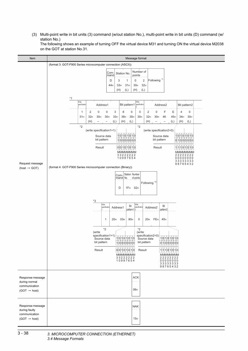
3 - 38 3. MICROCOMPUTER CONNECTION (ETHE3.4 Message Formats
(3) Multi-point write in bit units (3) command (w/out station No.), multi-point write in bit units (D) command (w/ station No.)The following shows an example of turning OFF the virtual device M31 and turning ON the virtual device M2038 on the GOT at station No.31.
Item Message format
Request message
(host GOT)
(format 3: GOT-F900 Series microcomputer connection (ASCII))
(format 4: GOT-F900 Series microcomputer connection (Binary))
Response message
during normal
communication
(GOT host)
Response message
during faulty
communication
(GOT host)
(H) (L)
Address1 Address2
232H
––
030H
(H) (L)
Bit pattern1
838H
030H
*1Write specification1
131H
030H
333H
(H) (L)
232H
––
030H
(H) (L)
Bit pattern2
434H
030H
Write specification2
030H
F46
E45H
*2 *2
M24
M25
M26
M27
M28
M29
M30
M31
01010101Source data bit pattern 00000001
01010100Result
(write specification1=1)
M2032
M2033
M2034
M2035
M2036
M2037
M2038
M2039
01010101Source data bit pattern 00000010
01010111Result
(write specification2=0)
(H) (L)
Station No.
333H
131H
D44H
Following *1
(H) (L)
Number of points
030H
232H
Com-mand
StationNo.
1FH 02HD
Following *3
Numberof points
Com-mand
Address1 Address2
20H 03H
Bitpattern1
80H
*3Write specification1
1 20H FEH
Bitpattern2
40H
Write specification2
0
*2 *2
M24
M25
M26
M27
M28
M29
M30
M31
01010101Source data bit pattern 00000001
01010100Result
(writespecification1=1)
M2032
M2033
M2034
M2035
M2036
M2037
M2038
M2039
01010101Source data bit pattern 00000010
01010111Result
(writespecification2=0)
06H
ACK
15H
NAK
RNET)

1
*2 The write specification specifies how the data o3. MICRO
e specified address is changed in the bit pattern.
f th
R
PRE
PA
RA
TO
RY
P
RO
CE
DU
RE
S F
OM
ON
ITO
RIN
G
2
MIC
RO
CO
MP
UT
ER
C
ON
NE
CT
ION
(S
ER
IAL
)
3
MIC
RO
CO
MP
UT
ER
C
ON
NE
CT
ION
(E
TH
ER
NE
T)
4
MO
DB
US
(R)/
RT
U
CO
NN
EC
TIO
N
5
MO
DB
US
(R)/
TC
P
CO
NN
EC
TIO
N
6
CO
NN
EC
TIO
N T
O
SO
UN
D O
UT
PU
T
UN
IT
7
CO
NN
EC
TIO
N T
O
EX
TE
RN
AL
I/O
D
EV
ICE
8
FIN
GE
RP
RIN
T A
UTH
EN
TIC
ATIO
N
DE
VIC
E C
ON
NE
CTI
ON
Write
specificationFunction Description Action example
0ON
specificationBits set to "1" by the bit pattern are turned ON.
Original data 1010
Bit pattern 1100
Result 1110
1OFF
specificationBits set to "1" by the bit pattern are turned OFF.
Original data 1010
Bit pattern 1100
Result 0010
2Invert
specificationBits set to "1" by the bit pattern are inverted.
Original data 1010
Bit pattern 1100
Result 0110
3Write
specification
The numerical values to write by the bit pattern are specified
directly.
Original data 1010
Bit pattern 1100
Result 1100
COMPUTER CONNECTION (ETHERNET)3.4 Message Formats
3 - 39

3 - 40 3. MICROCOMPUTER CONNECTION (ETHE3.4 Message Formats
(4) Fill command (4) (w/out station No.), fill command (E) (w/station No.)The following shows an example of writing "16"s to virtual devices R50 to R100 on the GOT at station No.27.
R100
0000H
Before execution After execution
R50
0000H
0000H
R100
1616HR50
1616H
1616H
POINTPOINTPOINT
(1) Start address/end address specification conditionsSpecify addresses so that the start address is the same or less than the end address.Error response occurs in the following cases:• The address to specify has the start address greater than the end address.• Either of the start address or end address exceeds the device range that can be specified.
Item Message format
Request message
(host GOT)
(format 3: GOT-F900 Series microcomputer connection (ASCII))
(format 4: GOT-F900 Series microcomputer connection (Binary))
Response message
during normal
communication
(GOT host)
Response message
during faulty
communication
(GOT host)
(H) (L)
Station No.
2 732H 37H
(H) (L)
WriteData
1 631H 36H
E45H
(H) (L)
Start address
030H
––
030H
434H
636H
(H) (L)
End address
030H
––
030H
939H
C43H
Com-mand
StationNo.
1BH
WriteData
16HE
Startaddress
64H00H
Endaddress
C9H00H
Com-mand
06H
ACK
15H
NAK
(2) Address specifying crossing over different devicesThe start address and end address can be specified crossing over different devices.
RNET)
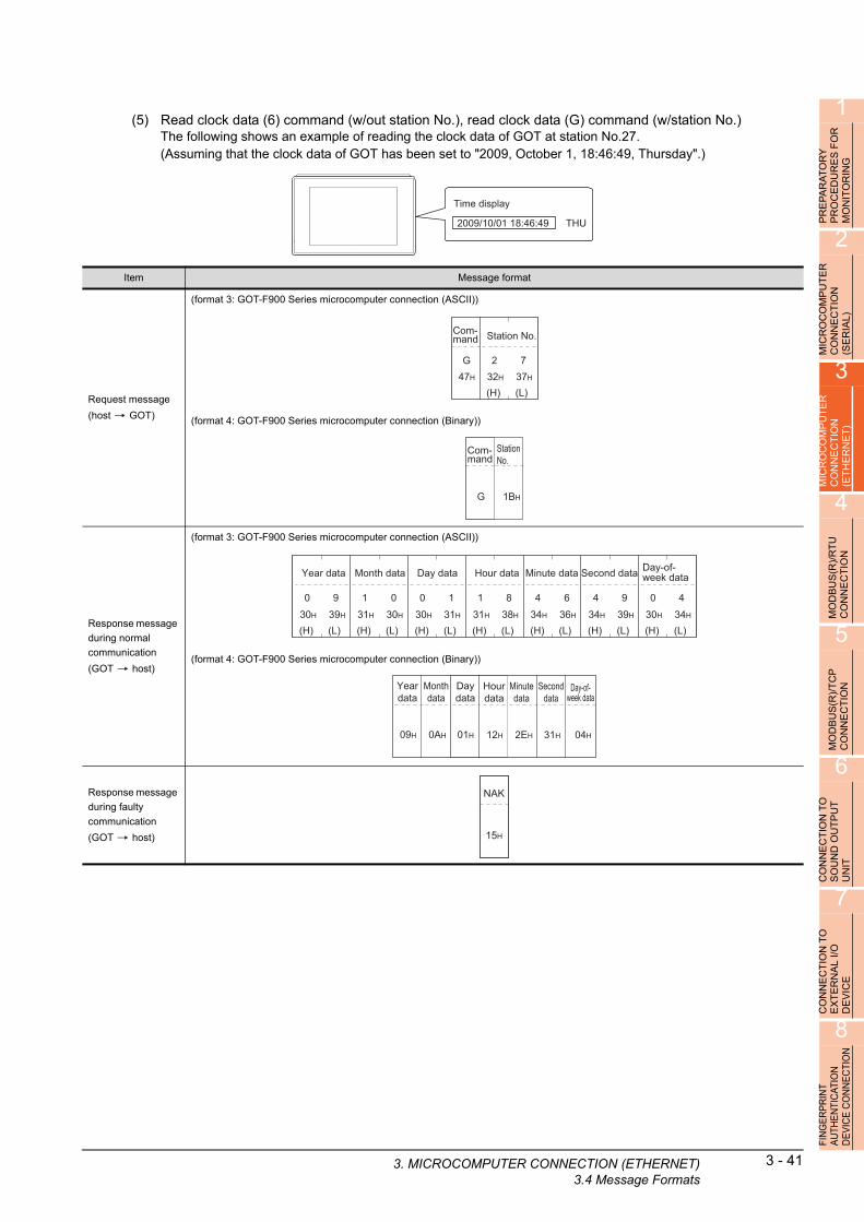
1
3. MICRO
OR
Y
RE
S F
OR
IN
G
(5) Read clock data (6) command (w/out station No.), read clock data (G) command (w/station No.)The following shows an example of reading the clock data of GOT at station No.27.(Assuming that the clock data of GOT has been set to "2009, October 1, 18:46:49, Thursday".)
AT U R
PR
EP
AR
PR
OC
ED
MO
NIT
O
2
Time display
2009/10/01 18:46:49 THU
R
MICR
OC
OM
PU
TE
CO
NN
EC
TIO
N
(SE
RIA
L)
3
MIC
RO
CO
MP
UT
ER
C
ON
NE
CT
ION
(E
TH
ER
NE
T)
4
MO
DB
US
(R)/
RT
U
CO
NN
EC
TIO
N
5
MO
DB
US
(R)/
TC
P
CO
NN
EC
TIO
N
6
CO
NN
EC
TIO
N T
O
SO
UN
D O
UT
PU
T
UN
IT
7
CO
NN
EC
TIO
N T
O
EX
TE
RN
AL
I/O
D
EV
ICE
8
FIN
GE
RP
RIN
T A
UTH
EN
TIC
ATIO
N
DE
VIC
E C
ON
NE
CTI
ON
Item Message format
Request message
(host GOT)
(format 3: GOT-F900 Series microcomputer connection (ASCII))
(format 4: GOT-F900 Series microcomputer connection (Binary))
Response message
during normal
communication
(GOT host)
(format 3: GOT-F900 Series microcomputer connection (ASCII))
(format 4: GOT-F900 Series microcomputer connection (Binary))
Response message
during faulty
communication
(GOT host)
(H) (L)
Station No.
2 732H 37H
G47H
Com-mand
StationNo.
1BHG
Com-mand
(H) (L)
Month data
1 031H 30H
(H) (L)
Day data
0 130H 31H
(H) (L)
Hour data
1 831H 38H
(H) (L)
Minute data
4 634H 36H
(H) (L)
Second data
4 934H 39H
(H) (L)
Day-of-week data
0 430H 34H
(H) (L)
Year data
0 930H 39H
Monthdata
0AH
Daydata
01H
Hourdata
12H
Minutedata
2EH
Seconddata
31H
Day-of-week data
04H
Yeardata
09H
15H
NAK
COMPUTER CONNECTION (ETHERNET)3.4 Message Formats
3 - 41

3 - 42 3. MICROCOMPUTER CONNECTION (ETHE3.4 Message Formats
(6) Set clock data (5) command (w/out station No.), set clock data (F) command (w/station No.)The following shows an example of setting clock data of GOT at station No.27.(Assuming the clock data of GOT is to be set to "2009, October 1, 18:46:49 Thursday".)
Time display
2009/10/01 18:46:49 THU
After execution
POINTPOINTPOINT
When a wrong day of the week has been set by the clock data setting command
If a wrong day of the week is set by the clock data setting commands, the clock data will differ from the time displayed on the utility.Example: When October 1, 2009 (Tuesday) is set by the clock data setting command (the actual day of the week is
Thursday), Thursday (THU) will be displayed on the utility time display.
Item Message format
Request message
(host GOT)
(format 3: GOT-F900 Series microcomputer connection (ASCII))
(format 4: GOT-F900 Series microcomputer connection (Binary))
Response message
during normal
communication
(GOT host)
Response message
during faulty
communication
(GOT host)
46H
F
(H) (L)
Station No.
2 732H 37H
(H) (L)
Month data
1 031H 30H
(H) (L)
Day Data
0 130H 31H
(H) (L)
Hour data
1 831H 38H
(H) (L)
Minute data
4 634H 36H
(H) (L)
Second data
4 934H 39H
(H) (L)
Day-of-week data
0 430H 34H
(H) (L)
Year data
0 930H 39H
Com-mand
F
StationNo.
1BH
Monthdata
0AH
Daydata
01H
Hourdata
12H
Minutedata
2EH
Second data
31H
Day-of-week data
04H
Yeardata
09H
Com-mand
06H
ACK
15H
NAK
RNET)

1
3. MICRO
RA
TO
RY
D
UR
ES
FO
R
OR
ING
(7) In the case of interrupt outputsThe following shows an example of an interrupt output when data are written to the interrupt output devices (D13 and D14).(Assuming that "3139H" is written to D13 and "AA55H" to D14.)
A E IT
PR
EP
PR
OC
MO
N
2
MIC
RO
CO
MP
UT
ER
C
ON
NE
CT
ION
(S
ER
IAL
)
3
MP
UT
ER
IO
N
T)
Interrupt
Interrupt output
Example: When the number of interrupt data bytes is 2
31H
Output value 1
3139HD13
39H
Output value 2
T E
MIC
RO
CO
CO
NN
EC
(ET
HE
RN
4
MO
DB
US
(R)/
RT
U
CO
NN
EC
TIO
N
5
MO
DB
US
(R)/
TC
P
CO
NN
EC
TIO
N
6
CO
NN
EC
TIO
N T
O
SO
UN
D O
UT
PU
T
UN
IT
7
CO
NN
EC
TIO
N T
O
EX
TE
RN
AL
I/O
D
EV
ICE
8
FIN
GE
RP
RIN
T A
UTH
EN
TIC
ATIO
N
DE
VIC
E C
ON
NE
CTI
ON
POINTPOINTPOINT
Interrupt output
• To disable the interrupt output, turn ON SM52 (interrupt code output disable flag). ( 3.3.6 SM devices)• To enable the interrupt output, set 8 bits to the data length at "Communication Detail Settings".
( 3.5.1 Setting communication interface (Communication settings))
• When "7 bits" is set, the MSB (8th bit) is ignored.(Example: FFH 7FH)
Item Message format
Interrupt output
(GOT host)
(1) When [Interrupt Data Byte] in "Communication Detail Settings" is set to "1 byte"
(2) When [Interrupt Data Byte] in "Communication Detail Settings" is set to "2 byte"
(3) When [Interrupt Data Byte] in "Communication Detail Settings" is set to "4 byte"
39H
Output value 1
31H
Output value 1
39H
Output value 2
AAH
Output value 1
55H
Output value 2
31H
Output value 3
39H
Output value 4
COMPUTER CONNECTION (ETHERNET)3.4 Message Formats
3 - 43

3 - 44 3. MICROCOMPUTER CONNECTION (ETHE3.4 Message Formats
Error code listWhen faulty, the error code is stored in SD2.For details of error code stored in SD2, the error contents, cause and measures, refer to the following:
3.3.5 ■ Details and actions for errors (error codes) stored into SD2
When an error other than those to be stored in SD2 occurs, at faulty, only the NAK response is executed.
Precautions
(1) Batch reading/writing crossing over different devicesWhen using the batch read (0, A) or batch write (1, B) command, do not batch read/write crossing over different devices.This will cause an error response.
RNET)

1
3. MICRO
R
3.4.5 Formats 5(Digital Electronics Corporation's memory link method)
RY
E
S F
OG
PR
EP
AR
AT
OP
RO
CE
DU
RM
ON
ITO
RIN
2
MIC
RO
CO
MP
UT
ER
C
ON
NE
CT
ION
(S
ER
IAL
)
3
Basic format of data communicationThis is the same format as the protocol of the Digital Electronics Corporation's memory link method.For details of the basic format of data communication, refer to the following manual:
The connection manual of the device manufactured by Digital Electronics Corporation
This section describes items whose settings differ from the protocols of the Digital Electronics Corporation's memory link method and dedicated commands for a microcomputer connection of GOT.
R
Example:Request message for the batch read in word
nits (R) command in format 5MP
UT
EIO
N
T)
u (Digital Electronics Corporation's memory link method)
O T E
MIC
RO
CC
ON
NE
C(E
TH
ER
N
4
Data length
00H 06H
Address
64H00H
Numberof points
00H 02H1BH
ESC
52H
R
Com-mand
00H 00H 00H 00H42H 00H
B
U
MOD
BU
S(R
)/R
TC
ON
NE
CT
ION
5
MO
DB
US
(R)/
TC
P
CO
NN
EC
TIO
N
6
TO
T
Details of data items in message format
POINTPOINTPOINT
Data code during communication
Communication is performed in ASCII code.
(1) CommandSpecifies the contents to access from the host to GOT.The command is converted to a 1-digit ASCII code (Hex) and transmitted.For details of the commands that can be used, refer to the following.
3.4.2 List of commands
N
PU
CO
NN
EC
TIO
SO
UN
D O
UT
UN
IT
7
ON
NE
CT
ION
TO
X
TE
RN
AL
I/O
E
VIC
E
(2) AddressSpecifies the head No. of the device data to be read/written.The address notated in hexadecimal is converted to a 4-digit ASCII code (Hex) and transmitted from the upper digit.For details of the device range that can be accessed, refer to the following.
3.3 Device Data Area
(3) Number of pointsSpecifies the number of device data to be read/written. (Setting range: 1 to 40H)The address notated in hexadecimal is converted to a 4-digit ASCII code (Hex) and transmitted from the upper digit.
C E D
8
FIN
GE
RP
RIN
T A
UTH
EN
TIC
ATIO
N
DE
VIC
E C
ON
NE
CTI
ON
(4) Error codeThis is the response message at faulty communication appended with error contents.The address notated in hexadecimal is converted to a 2-digit ASCII code (Hex) and transmitted from the upper digit.For details of error codes generated in format 5 (Digital Electronics Corporation's memory link method), refer to the following:
■ Error code list
COMPUTER CONNECTION (ETHERNET)3.4 Message Formats
3 - 45

3 - 46 3. MICROCOMPUTER CONNECTION (ETHE3.4 Message Formats
POINTPOINTPOINT
When connecting a microcomputer, etc. that uses the protocol of the Digital Electronics Corporation's memory link method with the GOT
When connecting a microcomputer, etc. that uses the protocol of the Digital Electronics Corporation's memory link method with the GOT, correct the commands to be used and the device ranges to match the specifications of the GOT.
RNET)

1
3. MICRO
PR
EP
AR
AT
OR
Y
PR
OC
ED
UR
ES
FO
R
MO
NIT
OR
ING
Message FormatsThe following shows the message format of the dedicated commands for a microcomputer connection of GOT.
(1) Batch read in word units (R) commandThe following shows an example of reading the two points of the virtual devices D100 and D101.(Assuming D100=0102H, D101=0304H are stored.)
2
CR
OC
OM
PU
TE
R
NN
EC
TIO
N
RIA
L)
D100
D101
0102H
0304H
I O E
M C (S
3
MIC
RO
CO
MP
UT
ER
C
ON
NE
CT
ION
(E
TH
ER
NE
T)
4
MO
DB
US
(R)/
RT
U
CO
NN
EC
TIO
N
Item Message format
Request message
(host GOT)
Response message
during normal
communication
(GOT host)
Data length
00H 06H
Address
64H00H
Numberof points
00H 02H1BH
ESC
52H
R
Com-mand
00H 00H 00H 00H42H 00H
B
Data length
00H 06H
Address
02H01H
Numberof points
03H 04H1BH
ESC
41H
A
Com-mand
00H 00H 00H 00H42H 00H
b
5
)/T
CP
N
(2) Batch write in word units (WD) command
(a) When writing to a word deviceThe following shows as example of writing "0064H"and "0065H"to virtual devices D100 and D101.
R IO
MOD
BU
S(
CO
NN
EC
T
6
TO
T
D100
D101
0000H
0000H
D100
D101
0064H
0065H
Before execution After execution
U
CON
NE
CT
ION
SO
UN
D O
UT
PU
NIT
7
CO
NN
EC
TIO
N T
O
EX
TE
RN
AL
I/O
D
EV
ICE
8
N TIO
N
Item Message format
Request message
(host GOT)
Response message
during normal
communication
(GOT host)
Data length
00H 0AH
Address
64H00H
Numberof points
00H 02H1BH
ESC
57H
W
Com-mand
00H 00H 00H 00H42H 00H
B
Data 1
64H00H
Data 2
00H 65H
Data length
00H 06H 06H
ACK
00H 00H 00H 00H42H 00H
b
FIN
GE
RP
RIN
T A
UTH
EN
TIC
ATIO
DE
VIC
E C
ON
NE
C
COMPUTER CONNECTION (ETHERNET)3.4 Message Formats
3 - 47

3 - 48 3. MICROCOMPUTER CONNECTION (ETHE3.4 Message Formats
(3) In the case of interrupt outputsThe following shows an example of an interrupt output when data are written to the interrupt output devices (D13).(Assuming that "31H" is written to D13.)
Interrupt
Interrupt output
Example: When the number of interrupt data bytes is 1
31H
Output value 1
31HD13
POINTPOINTPOINT
Interrupt output
• To disable the interrupt output, turn ON SM52 (interrupt code output disable flag).
( 3.3.6 SM devices)• To enable the interrupt output, set 8 bits to the data length at "Communication Detail Settings".
( 3.5.1 Setting communication interface (Communication settings))
• When "7 bits" is set, the MSB (8th bit) is ignored. (Example: FFH 7FH)
Item Message format
Interrupt output
(GOT host)
When [Interrupt Data Byte] in "Communication Detail Settings" is set to "1 byte"
31H
Output value 1
RNET)
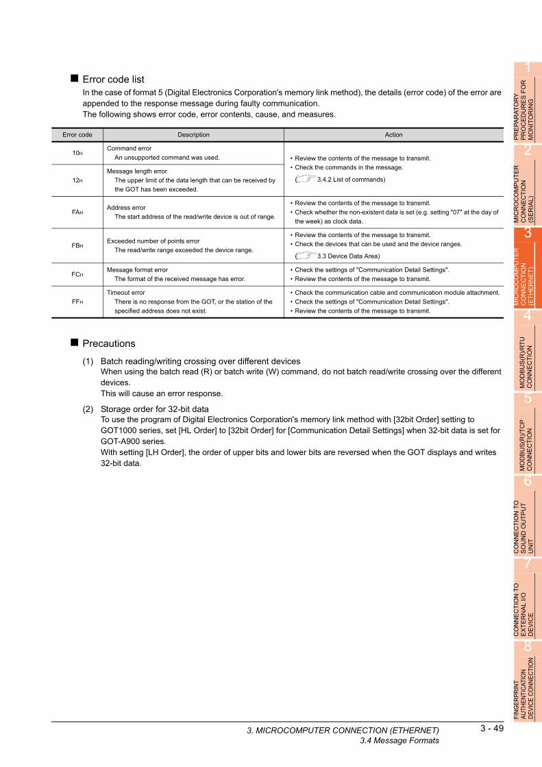
1
3. MICRO
PA
RA
TO
RY
C
ED
UR
ES
FO
R
ITO
RIN
G
Error code listIn the case of format 5 (Digital Electronics Corporation's memory link method), the details (error code) of the error are appended to the response message during faulty communication.The following shows error code, error contents, cause, and measures.
E O N
PR
PR
MO
2
MIC
RO
CO
MP
UT
ER
C
ON
NE
CT
ION
(S
ER
IAL
)
3
MIC
RO
CO
MP
UT
ER
C
ON
NE
CT
ION
(E
TH
ER
NE
T)
4
MO
DB
US
(R)/
RT
U
CO
NN
EC
TIO
N
5
MO
DB
US
(R)/
TC
P
CO
NN
EC
TIO
N
6
CO
NN
EC
TIO
N T
O
SO
UN
D O
UT
PU
T
UN
IT
7
CO
NN
EC
TIO
N T
O
EX
TE
RN
AL
I/O
D
EV
ICE
8
FIN
GE
RP
RIN
T A
UTH
EN
TIC
ATIO
N
DE
VIC
E C
ON
NE
CTI
ON
Precautions
(1) Batch reading/writing crossing over different devicesWhen using the batch read (R) or batch write (W) command, do not batch read/write crossing over the different devices.This will cause an error response.
(2) Storage order for 32-bit dataTo use the program of Digital Electronics Corporation's memory link method with [32bit Order] setting to GOT1000 series, set [HL Order] to [32bit Order] for [Communication Detail Settings] when 32-bit data is set for GOT-A900 series.With setting [LH Order], the order of upper bits and lower bits are reversed when the GOT displays and writes 32-bit data.
Error code Description Action
10HCommand error
An unsupported command was used. • Review the contents of the message to transmit.
• Check the commands in the message.
( 3.4.2 List of commands)12H
Message length error
The upper limit of the data length that can be received by
the GOT has been exceeded.
FAHAddress error
The start address of the read/write device is out of range.
• Review the contents of the message to transmit.
• Check whether the non-existent data is set (e.g. setting "07" at the day of
the week) as clock data.
FBHExceeded number of points error
The read/write range exceeded the device range.
• Review the contents of the message to transmit.
• Check the devices that can be used and the device ranges.
( 3.3 Device Data Area)
FCHMessage format error
The format of the received message has error.
• Check the settings of "Communication Detail Settings".
• Review the contents of the message to transmit.
FFH
Timeout error
There is no response from the GOT, or the station of the
specified address does not exist.
• Check the communication cable and communication module attachment.
• Check the settings of "Communication Detail Settings".
• Review the contents of the message to transmit.
COMPUTER CONNECTION (ETHERNET)3.4 Message Formats
3 - 49

3 - 50 3. MICROCOMPUTER CONNECTION (ETHE3.4 Message Formats
3.4.6 Formats 6, 7 (4E frame)
Basic format of data communicationThis is the same message format as when communication is performed using the MC protocol (4E frame) of the Q/QnA Series serial communication module.For details of the basic format of data communication, refer to the following manual:
MELSEC-Q/L MELSEC Communication Protocol Reference Manual
This section describes items whose settings differ from the MC protocol of the Q/QnA Series serial communication module, and the dedicated commands for a GOT microcomputer connection.
Example: Request message for the batch read (0401
ommand in word units ) cDevice name : DHead device : 100Device points : 2Communication setting of GOT side : Network No.=1, PLC No.=1(Format 6 (4E frame (ASCII))
(H) –
Fixed value
030H
030H
(H) (L)
PLC No.
030H
131H
(H) (L)
Network No.
030H
131H
(H) –
Request destination module I/O No.
030H
030H
– (L)
030H
030H
(H) (L)
Request destination module station No.
030H
030H
Following*10 0
30H 30H
(H) (L)(H) (L)
Serial No.
030H
030H
0 030H 30H
(H) (L)(H) (L)
Request type
030H
030H
5 435H 34H
(H) (L)
*1
(format 7:4E frame (Binary))
Details of data items in message format
POINTPOINTPOINT
Data code during communicationCommunication of format 6 is performed in ASCII code.Communication of the format 7 is performed in Binary code.
(H) (L)
Device code
*2AH
D44H
(H)
Head Device
131H
––
030H
–
030H
(L)
030H
–
030H
030H
Character A section
(H) –
Sub-command
030H
030H
(L)
030H
030H
– (H) –
Device points
030H
030H
– (L)
030H
232H
(H) (L)
Request data length
030H
030H
(H) (L)
131H
838H
(H) (L)
CPU monitoring timer
030H
030H
(L)
030H
030H
(H) (H) –
Command
030H
434H
– (L)
030H
131H
1)
1)
Data length target range
Data length target range
00H 00H 00H 00H0CH54H 00H
Request type
Fixed value
00H 00H 00H 00H00H 00H
Serial No.
01H 01H
Data length target range
00H 00H64H 00H02HA8H01H 04H 00H 00H
PLC No.
Network No.
Request destination
module I/O No.
Request destination module
station No.
Device codeHead DeviceSub-
command Device pointsRequest data length
CPU monitoring
timerCommand
RNET)

1
The following table shows the contents of the data items.3. MICRO
PR
EP
AR
AT
OR
Y
PR
OC
ED
UR
ES
FO
R
MO
NIT
OR
ING
2
MIC
RO
CO
MP
UT
ER
C
ON
NE
CT
ION
(S
ER
IAL
)
3
MIC
RO
CO
MP
UT
ER
C
ON
NE
CT
ION
(E
TH
ER
NE
T)
4
MO
DB
US
(R)/
RT
U
CO
NN
EC
TIO
N
5
MO
DB
US
(R)/
TC
P
CO
NN
EC
TIO
N
6
CO
NN
EC
TIO
N T
O
SO
UN
D O
UT
PU
T
UN
IT
7
CO
NN
EC
TIO
N T
O
EX
TE
RN
AL
I/O
D
EV
ICE
8
FIN
GE
RP
RIN
T A
UTH
EN
TIC
ATIO
N
DE
VIC
E C
ON
NE
CTI
ON
(Continued to next page)
Data item nameContents
Format 6 Format 7
Request type
(Microcomputer
side)
Indicates it is a command message.
Command message: ASCII "5400" (Fixed value) Command message: 54H (Upper digit) (Fixed value)
Response type
(GOT side)
Indicates it is a response message.
Response message: ASCII "D400" (Fixed value) Response message: D4H (Upper digit) (Fixed value)
Serial No.Arbitrary number for recognition of the message appended at the microcomputer side. GOT sends the response message appending
this Serial No.
Fixed value Should be ASCII "0000". Should be "0000H".
Network No.
Set the same number as the network No. set in the GOT.
For setting method of "Communication Detail Settings", refer to the following.
3.5.1 Setting communication interface (Communication settings)
Transmit the data converted to a 2-digit ASCII code from the upper
digit.Transmit the data converted to a 2-digit binary code.
PLC No.
Set the same number as the PLC No. set in the GOT.
For setting method of "Communication Detail Settings", refer to the following.
3.5.1 Setting communication interface (Communication settings)
Transmit the data converted to a 2-digit ASCII code from the upper
digit.Transmit the data converted to a 2-digit binary code.
Request destination
module I/O No.Ignore GOT.
Request destination
module station No.Ignore GOT.
Request data length
Number of bytes from the start of CPU monitoring timer to the last request data.
Transmit the data converted to a 4-digit ASCII code from the upper
digit.
Transmit the data converted to a 4-digit binary code from the lower
two digits.
Response data
length
Appended to the response message from the microcomputer side.
Number of bytes from the start of end code to the last request data.
Transmit the data converted to a 4-digit ASCII code from the upper
digit.
Transmit the data converted to a 4-digit binary code from the lower
two digits.
CPU monitoring
timerIgnore GOT.
Command,
Sub-command
Specifies the access contents from the microcomputer side to GOT. For details of the commands that can be used, refer to the following.
3.4.2 List of commands
Transmit the command and sub-command converted to a 4-digit
ASCII code, from the upper digit.
Transmit the data converted to a 4-digit binary code from the lower
two digits.
Device code
Specifies the code by which the device data to be read/written is recognized.
For details of the device range that can be accessed, refer to the following.
3.3 Device Data Area
Transmit the 2-digit ASCII code corresponding to the following
device codes.
Transmit the 2-digit binary code corresponding to the following
device codes.
Device name Device code
M M*
SM SM
L L*
D D*
SD SD
R R*
Device name Device code
M 90H
SM 91H
L 92H
D A8H
SD A9H
R AFH
COMP
UTER CONNECTION (ETHERNET)3.4 Message Formats3 - 51

3 - 52 3. MICROCOMPUTER CONNECTION (ETHE3.4 Message Formats
(From previous page)
POINTPOINTPOINT
When connecting a microcomputer, etc. that uses the MC protocol of the Q/QnA series serial communication module with the GOT
When connecting a microcomputer, etc. that uses the MC protocol of the Q/QnA series serial communication module with the GOT, correct the commands to be used and the device ranges to match the GOT specifications.
Data item nameContents
Format 6 Format 7
Head device
Specifies the head No. of the device data to be read/written.
For details of the device range that can be accessed, refer to the following.
3.3 Device Data Area
Transmit the data notated in decimal converted to a 6-digit
ASCII code, from the upper digit.
Transmit the data converted to a 6-digit binary code from the lower
two digits.
Device points
Specifies the number of device data to be read/written. (Setting range: 1 to 40H)
<When using random read/write command>
When setting multiple bit accesses, word accesses or double word accesses, limit the total number of access points to within 64 points.
<When using multiple block batch read/write commands>
When setting multiple blocks, limit the total number of points of all blocks to within 64 points.
Transmit the data notated in decimal converted to a 4-digit
ASCII code, from the upper digit.
Transmit the data converted to a 4-digit binary code from the lower
two digits.
Year, month, day,
hour,
minute, second and
day
of the week data
Specifies year, month, day, hour, minute, second, and day of the week to be read/set to the GOT clock data.
■ Message format (1) Read clock data (1901) command
■ Message format (2) Set clock data (0901) command
Transmit the data notated in decimal converted to a 2-digit
ASCII code, from the upper digit.Transmit the data converted to a 2-digit binary code.
End code
(Microcomputer
side)
Appended to the response message from the microcomputer side. If an error occurs at the microcomputer side, the error code is
displayed.
■ Error code list
Transmit the data notated in hexadecimal converted to a 4-digit
ASCII code, from the upper digit.
Transmit the data converted to a 4-digit binary code from the lower
two digits.
RNET)
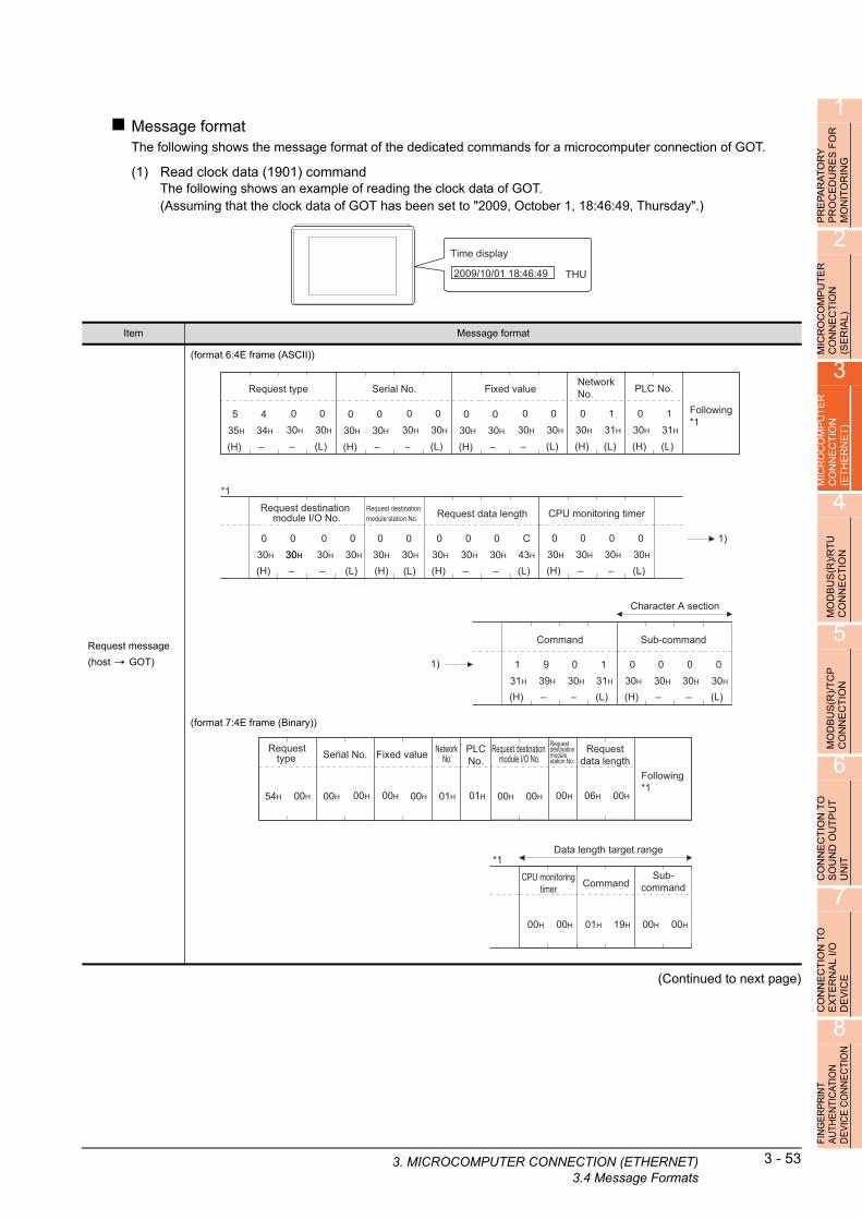
1
3. MICRO
PR
EP
AR
AT
OR
Y
PR
OC
ED
UR
ES
FO
R
MO
NIT
OR
ING
Message formatThe following shows the message format of the dedicated commands for a microcomputer connection of GOT.
(1) Read clock data (1901) commandThe following shows an example of reading the clock data of GOT.(Assuming that the clock data of GOT has been set to "2009, October 1, 18:46:49, Thursday".)
2
CO
MP
UT
ER
E
CT
ION
L
)
Time display
2009/10/01 18:46:49 THU
O IA
MIC
RC
ON
N(S
ER
3
MIC
RO
CO
MP
UT
ER
C
ON
NE
CT
ION
(E
TH
ER
NE
T)
4
MO
DB
US
(R)/
RT
U
CO
NN
EC
TIO
N
5
MO
DB
US
(R)/
TC
P
CO
NN
EC
TIO
N
6
CO
NN
EC
TIO
N T
O
SO
UN
D O
UT
PU
T
UN
IT
7
CT
ION
TO
A
L I
/O
Item Message format
Request message
(host GOT)
(format 6:4E frame (ASCII))
(format 7:4E frame (Binary))
– (L)
Fixed value
030H
030H
(H) (L)
PLC No.
030H
131H
(H) (L)
Network No.
030H
131H
(H)
030H
030H
(H) –
Request data length
030H
– (L)
030H
C43H
030H
(H) –
CPU monitoring timer
030H
030H
(L)
030H
030H
–
Following*1
*1
(H) –
030H
030H
– (L)
Serial No.
030H
030H
(H) –
030H
030H
– (L)
Request type
030H
030H
(H) –
535H
434H
Character A section
(H) –
Command
939H
– (L)
030H
131H
131H
(H) –
Sub-command
030H
030H
(L)
030H
030H
–
– (L)–
030H
030H30H
(H) (L)
030H
030H
1)
1)
Request destination module I/O No.
Request destination module station No.
Fixed value
00H
PLCNo.
Network No.
06H 00H
Requestdata length
Following*1
*1
00H 00H
Serial No.
01H00H 01H00H 00H54H 00H
Data length target range
Command
00H 01H 19H00H
Sub-command
00H 00H
Request destination module I/O No.
Requestdestinationmodulestation No.
CPU monitoringtimer
Request type
00H
E RN E
(Continued to next page)CO
NN
EX
TE
DE
VIC
8
FIN
GE
RP
RIN
T A
UTH
EN
TIC
ATIO
N
DE
VIC
E C
ON
NE
CTI
ON
COMPUTER CONNECTION (ETHERNET)3.4 Message Formats
3 - 53

3 - 54 3. MICROCOMPUTER CONNECTION (ETHE3.4 Message Formats
(From previous page)
(Continued to next page)
Item Message format
Response message
during normal
communication
(GOT host)
(format 6:4E frame (ASCII))
(format 7:4E frame (Binary))
– (L)
Fixed value
030H
030H
(H) (L)
PLC No.
030H
131H
(H) (L)
Network No.
030H
131H
(H)
030H
030H
(H) –
Response data length
030H
– (L)
131H
232H
030H
(H) –
End code
030H
030H
(L)
030H
030H
–
Following*1
*1
(H) –
030H
030H
– (L)
Serial No.
030H
030H
(H) –
030H
030H
– (L)
Response type
030H
030H
(H) –
D44H
434H
Character B section
(H) (L)
939H
(H) (L)
131H
030H
030H
(H) (L)
030H
131H
(L)
131H
838H
(H)
– (L)–
030H
030H30H
(H) (L)
030H
030H
1)
1)
Request destination module I/O No.
Request destination module station No.
(H) (L)
636H
(H) (L)
434H
939H
434H
(H) (L)
030H
434H
Year data Month data Day data Hour data Minute data Second data
Day-of-week data
Data length target range
End code
00H 00H
*1Yeardata
09H 0AH
Monthdata
01H 12H
Daydata
2EH 31H
Hourdata
04H
Minutedata
Second data
Day-of-week data
Fixed value
00H
PLCNo.
Network No.
09H 00H
Responsedata length
Following*100H 00H
Serial No.
01H 01H00H
Requesttype
00H 00HD4H 00H
Request destination module I/O No.
00H
Requestdestinationmodulestation No.
RNET)

1
3. MICRO
(From previous page)
OR
PRE
PA
RA
TO
RY
P
RO
CE
DU
RE
S F
MO
NIT
OR
ING
2
MIC
RO
CO
MP
UT
ER
C
ON
NE
CT
ION
(S
ER
IAL
)
3
MIC
RO
CO
MP
UT
ER
C
ON
NE
CT
ION
(E
TH
ER
NE
T)
4
MO
DB
US
(R)/
RT
U
CO
NN
EC
TIO
N
5
MO
DB
US
(R)/
TC
P
CO
NN
EC
TIO
N
6
CO
NN
EC
TIO
N T
O
SO
UN
D O
UT
PU
T
UN
IT
7
CO
NN
EC
TIO
N T
O
EX
TE
RN
AL
I/O
D
EV
ICE
8
FIN
GE
RP
RIN
T A
UTH
EN
TIC
ATIO
N
DE
VIC
E C
ON
NE
CTI
ON
Item Message format
Response message
during faulty
communication
(GOT host)
(format 6:4E frame (ASCII))
(format 7:4E frame (Binary))
– (L)
Fixed value
030H
030H
(H) (L)
PLC No.
030H
131H
(H) (L)
Network No.
030H
131H
(H)
030H
030H
(H) –
Response data length
030H
– (L)
131H
636H
030H
(H) –
End code
030H
030H
(L)
535H
636H
–
Following*1
*1
(H) –
030H
030H
– (L)
Serial No.
030H
030H
(H) –
030H
030H
– (L)
Response type
030H
030H
(H) –
D44H
434H
– (L)–
030H
030H30H
(H) (L)
030H
030H
1)
1)
Request destination module I/O No.
Request destination module station No.
(H) (L)
PLC No.
030H
030H
(H) (L)
Network No.
030H
030H
(H)
030H
030H
– (L)–
030H
030H30H
(H) (L)
030H
030H
Request destination module I/O No.
Request destination module station No.
– (L)
Sub-command
030H
030H
(H) –
030H
030H
– (L)
Command
030H
131H
(H) –
131H
939H
Data length target range
End code
56H 00H
*1
Fixed value
00H
PLCNo.
0BH 00H
Responsedata length
Following*1
00H 00H
Serial No.
01H 01H00H
Requesttype
00H 00HD4H 00H
Request destination module I/O No.
Command
01H 19H
Sub-command
00H 00H00H
PLCNo.
00H 00H00H 00H
Request destination module I/O No.
Network No.
Requestdestinationmodulestation No.
00H
Network No.
Requestdestinationmodulestation No.
COMPUTER CONNECTION (ETHERNET)3.4 Message Formats
3 - 55
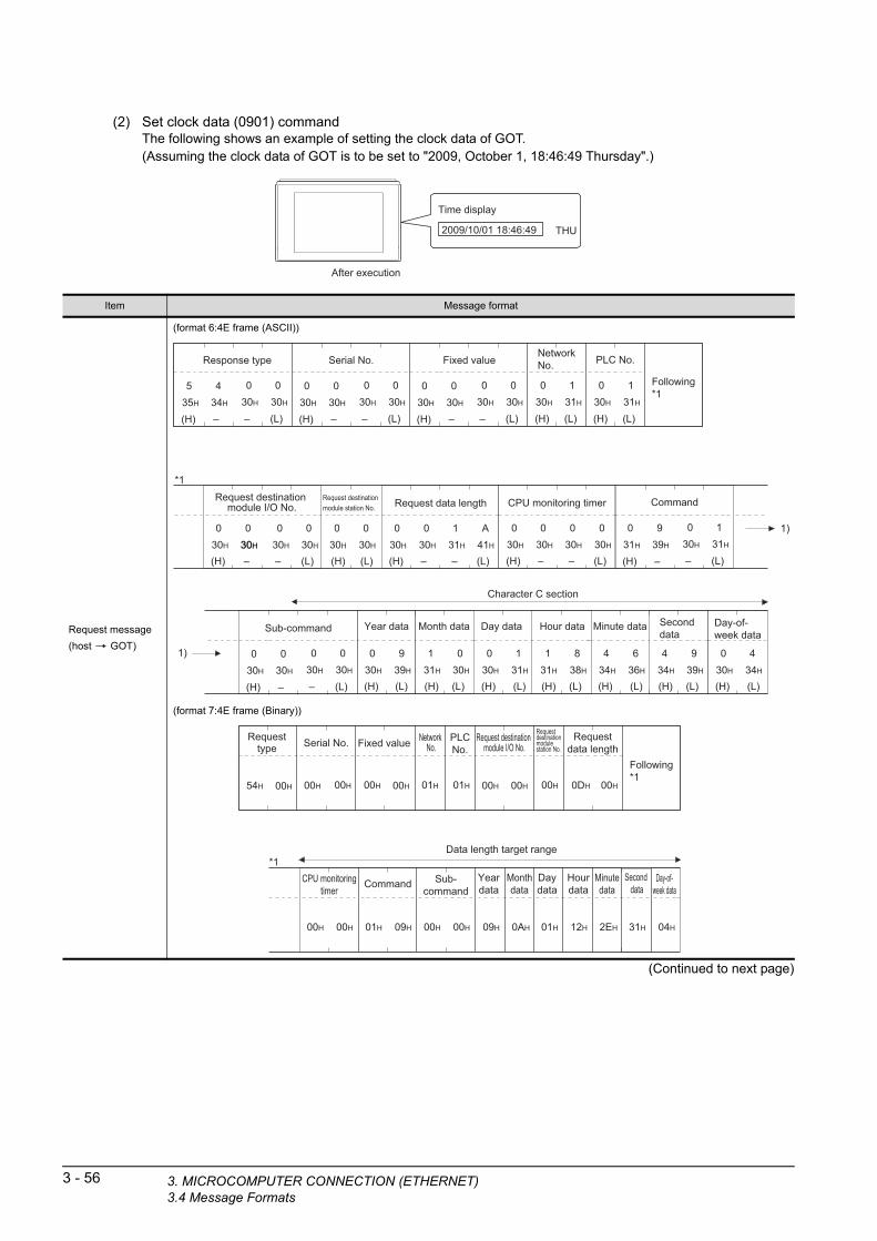
3 - 56 3. MICROCOMPUTER CONNECTION (ETHE3.4 Message Formats
(2) Set clock data (0901) commandThe following shows an example of setting the clock data of GOT.(Assuming the clock data of GOT is to be set to "2009, October 1, 18:46:49 Thursday".)
Time display
2009/10/01 18:46:49 THU
After execution
(Continued to next page)
Item Message format
Request message
(host GOT)
(format 6:4E frame (ASCII))
(format 7:4E frame (Binary))
– (L)
Fixed value
030H
030H
(H) (L)
PLC No.
030H
131H
(H) (L)
Network No.
030H
131H
(H)
030H
030H
(H) –
Request data length
030H
– (L)
131H
A41H
030H
(H) –
CPU monitoring timer
030H
030H
(L)
030H
030H
–
Following*1
*1
(H) –
030H
030H
– (L)
Serial No.
030H
030H
(H) –
030H
030H
– (L)
Response type
030H
030H
(H) –
535H
434H
– (L)–
030H
030H30H
(H) (L)
030H
030H
1)
Request destination module I/O No.
Request destination module station No.
Character C section
(H) (L)
939H
(H) (L)
131H
030H
030H
(H) (L)
030H
131H
(L)
131H
838H
(H)
1)
(H) (L)
636H
(H) (L)
434H
939H
434H
(H) (L)
030H
434H
Year data Month data Day data Hour data Minute data Second data
Day-of-week data
– (L)
Command
030H
131H
(H) –
031H
939H
– (L)
Sub-command
030H
030H
(H) –
030H
030H
Data length target range
CPU monitoringtimer
00H 00H
*1Yeardata
09H 0AH
Monthdata
01H 12H
Daydata
2EH 31H
Hourdata
04H
Minutedata
Second data
Day-of-week data
Fixed value
00H
PLCNo.
Network No.
0DH 00H
Requestdata length
Following*1
00H 00H
Serial No.
01H 01H00H
Requesttype
00H 00H54H 00H
Request destination module I/O No.
01H 09H 00H 00H
Command Sub-command
00H
Requestdestinationmodulestation No.
RNET)

1
3. MICRO
(From previous page)
OR
PRE
PA
RA
TO
RY
P
RO
CE
DU
RE
S F
MO
NIT
OR
ING
2
MIC
RO
CO
MP
UT
ER
C
ON
NE
CT
ION
(S
ER
IAL
)
3
MIC
RO
CO
MP
UT
ER
C
ON
NE
CT
ION
(E
TH
ER
NE
T)
4
MO
DB
US
(R)/
RT
U
CO
NN
EC
TIO
N
5
MO
DB
US
(R)/
TC
P
CO
NN
EC
TIO
N
6
CO
NN
EC
TIO
N T
O
SO
UN
D O
UT
PU
T
UN
IT
7
CO
NN
EC
TIO
N T
O
EX
TE
RN
AL
I/O
D
EV
ICE
8
FIN
GE
RP
RIN
T A
UTH
EN
TIC
ATIO
N
DE
VIC
E C
ON
NE
CTI
ON
(Continued to next page)
Item Message format
Response message
during normal
communication
(GOT host)
(format 6:4E frame (ASCII))
(format 7:4E frame (Binary))
– (L)
Fixed value
030H
030H
(H) (L)
PLC No.
030H
131H
(H) (L)
Network No.
030H
131H
(H)
030H
030H
(H) –
Response data length
030H
– (L)
030H
434H
030H
(H) –
End code
030H
030H
(L)
030H
030H
–
Following*1
*1
(H) –
030H
030H
– (L)
Serial No.
030H
030H
(H) –
030H
030H
– (L)
Response type
030H
030H
(H) –
D44H
434H
– (L)–
030H
030H30H
(H) (L)
030H
030H
Request destination module I/O No.
Request destination module station No.
Data lengthtarget range
00H 00H
Fixed value
00H
PLCNo.
Network No.
02H 00H
Responsedata length
00H 00H
Serial No.
01H 01H00H00H
Requesttype
00H 00HD4H 00H
Request destination module I/O No. End code
Requestdestinationmodulestation No.
COMPUTER CONNECTION (ETHERNET)3.4 Message Formats
3 - 57

3 - 58 3. MICROCOMPUTER CONNECTION (ETHE3.4 Message Formats
(From previous page)
POINTPOINTPOINT
When a wrong day of the week has been set by the clock data setting command
If a wrong day of the week is set by the clock data setting commands, the clock data will differ from the time displayed on the utility.Example: When October 1, 2009 (Tuesday) is set by the clock data setting command (the actual day of the week is
Thursday), Thursday (THU) will be displayed on the utility time display.
Item Message format
Response message
during faulty
communication
(GOT host)
(format 6:4E frame (ASCII))
(format 7:4E frame (Binary))
– (L)
Fixed value
030H
030H
(H) (L)
PLC No.
030H
131H
(H) (L)
Network No.
030H
131H
(H)
030H
030H
(H) –
Response data length
030H
– (L)
131H
636H
030H
(H) –
End code
030H
030H
(L)
535H
636H
–
Following*1
*1
(H) –
030H
030H
– (L)
Serial No.
030H
030H
(H) –
030H
030H
– (L)
Response type
030H
030H
(H) –
D44H
434H
– (L)–
030H
030H30H
(H) (L)
030H
030H
1)
1)
Request destination module I/O No.
Request destination module station No.
(H) (L)
PLC No.
030H
030H
(H) (L)
Network No.
030H
030H
(H)
030H
030H
– (L)–
030H
030H30H
(H) (L)
030H
030H
Request destination module I/O No.
Request destination module station No.
– (L)
Sub-command
030H
030H
(H) –
030H
030H
– (L)
Command
030H
131H
(H) –
030H
939H
D4H 00H 00H 01H 00H00H 00H00H 01H 00H 00H 0BH 0H
*1
56H 00H 00H 00H 00H 00H 01H 09H 00H 00H00H
Serial No. Fixed value Request type
Request destination module I/O No.
Response data length
Request destination module I/O No.
Following*1
PLC No.
End code PLC No.
Sub-commandCommand
Data length target range
Network No.
Requestdestinationmodulestation No.
Network No.
Requestdestinationmodulestation No.
RNET)

1
3. MICRO
RY
E
S F
OR
G
Error code listThe following shows error code, error contents, cause, and measures.
TO R IN
PR
EP
AR
AP
RO
CE
DU
MO
NIT
OR
2
MIC
RO
CO
MP
UT
ER
C
ON
NE
CT
ION
(S
ER
IAL
)
3
MIC
RO
CO
MP
UT
ER
C
ON
NE
CT
ION
(E
TH
ER
NE
T)
4
MO
DB
US
(R)/
RT
U
CO
NN
EC
TIO
N
5
MO
DB
US
(R)/
TC
P
CO
NN
EC
TIO
N
6
CO
NN
EC
TIO
N T
O
SO
UN
D O
UT
PU
T
UN
IT
7
CO
NN
EC
TIO
N T
O
EX
TE
RN
AL
I/O
D
EV
ICE
8
FIN
GE
RP
RIN
T A
UTH
EN
TIC
ATIO
N
DE
VIC
E C
ON
NE
CTI
ON
Error code Description Action
0002HDevice point error
The specification of device range to read/write has error.
• Check the specified head device and number of points, and correct it.
( 3.3 Device Data Area)
0050H
Request (command)/Response (response) type code error
Code other than the specified value is set for command/
response type.
• Check the command/response type set in the microcomputer and correct
it.
0056HDevice error
A non-existent device has been specified.
• Check the devices that can be used and the device ranges.
( 3.3 Device Data Area)
0057H
Device point error
• The command number of points specification from the
microcomputer exceeds the maximum number of points
processed at each process (number of points processed in
one communication).
• The start address (head device number) to specified
number of points exceeds the maximum address (device
number, step number) for each process.
• Correct the specified number of points, or the start address (device
number).
( 3.3 Device Data Area)
When reading data which the command bit length is longer
than the specification, the set number of write data points
differs from the specified number of points value.
• Check the command data length and set the data again.
0058H
• The command start address (head device number, start
step number) specification from the microcomputer
exceeds the range that can be specified.
• Value outside the GOT parameter setting range is specified
in the microcomputer program and file register (R) reading/
writing.
• Correct the values to values that can be specified in each process.
• Word device is specified in the command for bit device.
• In the command for word device, a bit device start number
is specified in other than hexadecimal.
• Correct the command or the specified device.
00A1HRequest content cannot be analyzed because the text length
or request data length is too short.• Review the text length or the head request data length.
00A2H Request cannot be processed. • Correct the request content and command.
C0D6H The specification of network No. and station No. have error. • Review the network No., station No. specification method.
COMPUTER CONNECTION (ETHERNET)3.4 Message Formats
3 - 59
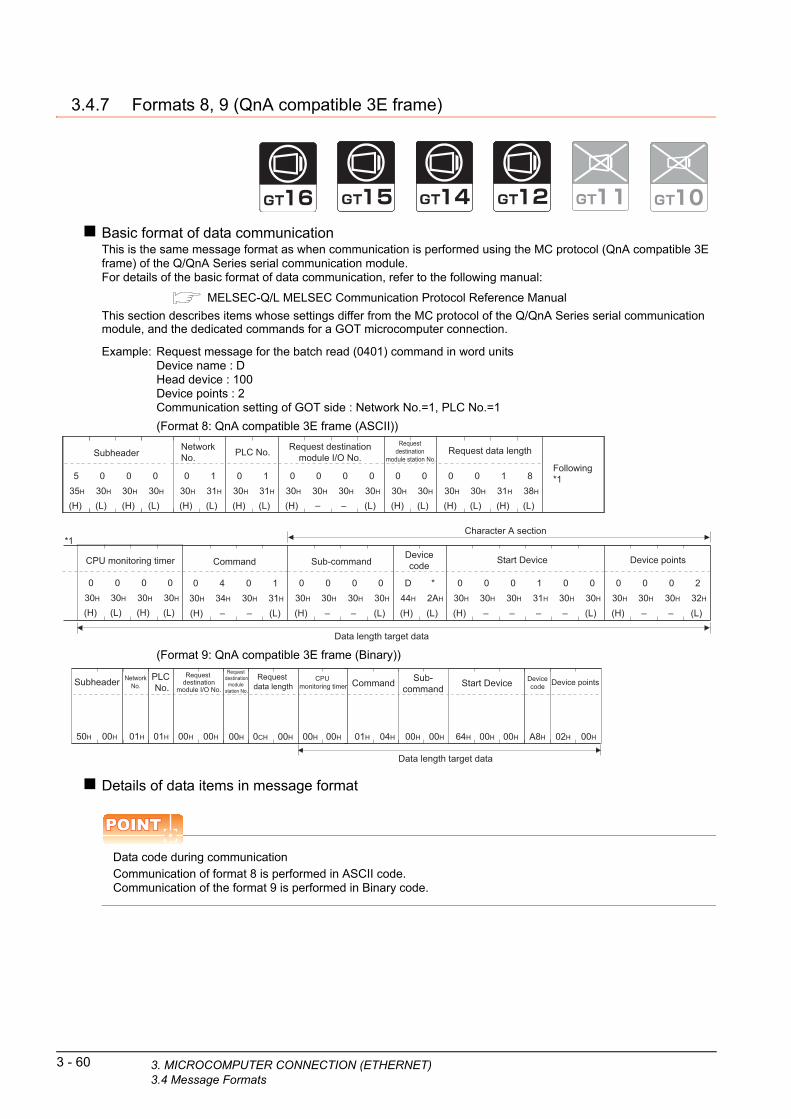
3 - 60 3. MICROCOMPUTER CONNECTION (ETHE3.4 Message Formats
3.4.7 Formats 8, 9 (QnA compatible 3E frame)
Basic format of data communicationThis is the same message format as when communication is performed using the MC protocol (QnA compatible 3E frame) of the Q/QnA Series serial communication module.For details of the basic format of data communication, refer to the following manual:
MELSEC-Q/L MELSEC Communication Protocol Reference Manual
This section describes items whose settings differ from the MC protocol of the Q/QnA Series serial communication module, and the dedicated commands for a GOT microcomputer connection.
Example: Request message for the batch read (0401
ommand in word units ) cDevice name : DHead device : 100Device points : 2Communication setting of GOT side : Network No.=1, PLC No.=1(Format 8: QnA compatible 3E frame (ASC
) II)(H) (L)
PLC No.
030H
(H) (L)
NetworkNo.
030H
(H)
Request destinationmodule I/O No.
030H
030H
– (L)
030H
030H
(H) (L)
Request destination
module station No.
030H
030H
Following*1
(H) –
Command
030H
434H
– (L)
030H
131H
*1
(H) (L)
Devicecode
*2AH
D44H
(H)
Start Device
131H
––
030H
–
030H
(L)
030H
–
030H
030H
Character A section
(H) –
Sub-command
030H
030H
(L)
030H
030H
– (H) –
Device points
030H
030H
– (L)
030H
232H
(H) (L)
535H
030H
(H) (L)
Subheader
030H
030H
1 131H31H
(H) (L)
030H
030H
(H) (L)
Request data length
131H
838H
(H) (L)
030H
030H
(H) (L)
CPU monitoring timer
030H
030H
Data length target data
–
(Format 9: QnA compatible 3E frame (Bina
) ry)Details of data items in message format
POINTPOINTPOINT
Data code during communicationCommunication of format 8 is performed in ASCII code.Communication of the format 9 is performed in Binary code.
00H 00H 00H 00H0CH50H 00H
Subheader PLC No.
NetworkNo.
Request destination
module I/O No.
Request data length
CPU monitoring timer
Request destination
module station No.
00H 00H01H 01H
Sub-command
00H 00H64H
Start Device Devicecode Device points
00H02HA8H
Command
01H 04H 00H 00H
Data length target data
RNET)
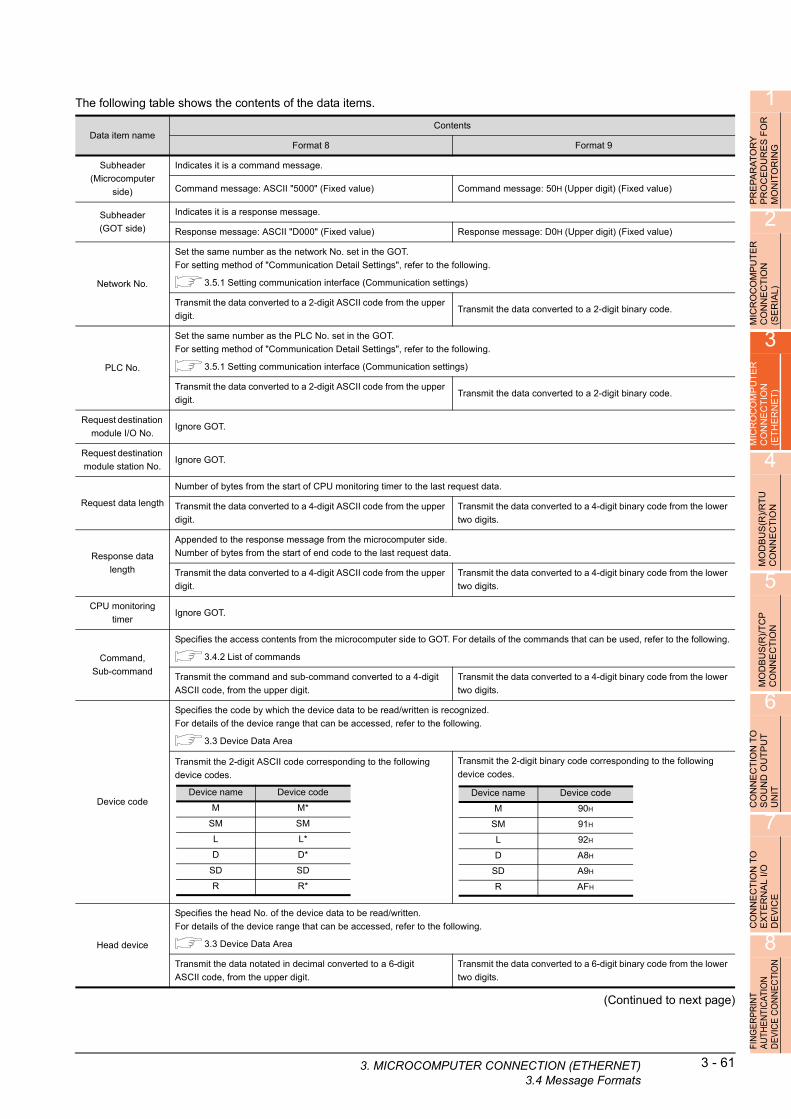
1
The following table shows the contents of the data items.3. MICRO
PR
EP
AR
AT
OR
Y
PR
OC
ED
UR
ES
FO
R
MO
NIT
OR
ING
2
MIC
RO
CO
MP
UT
ER
C
ON
NE
CT
ION
(S
ER
IAL
)
3
MIC
RO
CO
MP
UT
ER
C
ON
NE
CT
ION
(E
TH
ER
NE
T)
4
MO
DB
US
(R)/
RT
U
CO
NN
EC
TIO
N
5
MO
DB
US
(R)/
TC
P
CO
NN
EC
TIO
N
6
CO
NN
EC
TIO
N T
O
SO
UN
D O
UT
PU
T
UN
IT
7
CO
NN
EC
TIO
N T
O
EX
TE
RN
AL
I/O
D
EV
ICE
8
FIN
GE
RP
RIN
T A
UTH
EN
TIC
ATIO
N
DE
VIC
E C
ON
NE
CTI
ON
(Continued to next page)
Data item nameContents
Format 8 Format 9
Subheader
(Microcomputer
side)
Indicates it is a command message.
Command message: ASCII "5000" (Fixed value) Command message: 50H (Upper digit) (Fixed value)
Subheader
(GOT side)
Indicates it is a response message.
Response message: ASCII "D000" (Fixed value) Response message: D0H (Upper digit) (Fixed value)
Network No.
Set the same number as the network No. set in the GOT.
For setting method of "Communication Detail Settings", refer to the following.
3.5.1 Setting communication interface (Communication settings)
Transmit the data converted to a 2-digit ASCII code from the upper
digit.Transmit the data converted to a 2-digit binary code.
PLC No.
Set the same number as the PLC No. set in the GOT.
For setting method of "Communication Detail Settings", refer to the following.
3.5.1 Setting communication interface (Communication settings)
Transmit the data converted to a 2-digit ASCII code from the upper
digit.Transmit the data converted to a 2-digit binary code.
Request destination
module I/O No.Ignore GOT.
Request destination
module station No.Ignore GOT.
Request data length
Number of bytes from the start of CPU monitoring timer to the last request data.
Transmit the data converted to a 4-digit ASCII code from the upper
digit.
Transmit the data converted to a 4-digit binary code from the lower
two digits.
Response data
length
Appended to the response message from the microcomputer side.
Number of bytes from the start of end code to the last request data.
Transmit the data converted to a 4-digit ASCII code from the upper
digit.
Transmit the data converted to a 4-digit binary code from the lower
two digits.
CPU monitoring
timerIgnore GOT.
Command,
Sub-command
Specifies the access contents from the microcomputer side to GOT. For details of the commands that can be used, refer to the following.
3.4.2 List of commands
Transmit the command and sub-command converted to a 4-digit
ASCII code, from the upper digit.
Transmit the data converted to a 4-digit binary code from the lower
two digits.
Device code
Specifies the code by which the device data to be read/written is recognized.
For details of the device range that can be accessed, refer to the following.
3.3 Device Data Area
Transmit the 2-digit ASCII code corresponding to the following
device codes.
Transmit the 2-digit binary code corresponding to the following
device codes.
Head device
Specifies the head No. of the device data to be read/written.
For details of the device range that can be accessed, refer to the following.
3.3 Device Data Area
Transmit the data notated in decimal converted to a 6-digit
ASCII code, from the upper digit.
Transmit the data converted to a 6-digit binary code from the lower
two digits.
Device name Device code
M M*
SM SM
L L*
D D*
SD SD
R R*
Device name Device code
M 90H
SM 91H
L 92H
D A8H
SD A9H
R AFH
COMP
UTER CONNECTION (ETHERNET)3.4 Message Formats3 - 61

3 - 62 3. MICROCOMPUTER CONNECTION (ETHE3.4 Message Formats
(From previous page)
POINTPOINTPOINT
When connecting a microcomputer, etc. that uses the MC protocol of the Q/QnA series serial communication module with the GOT
When connecting a microcomputer, etc. that uses the MC protocol of the Q/QnA series serial communication module with the GOT, correct the commands to be used and the device ranges to match the GOT specifications.
Data item nameContents
Format 8 Format 9
Device points
Specifies the number of device data to be read/written. (Setting range: 1 to 40H)
<When using random read/write command>
When setting multiple bit accesses, word accesses or double word accesses, limit the total number of access points to within 64 points.
<When using multiple block batch read/write commands>
When setting multiple blocks, limit the total number of points of all blocks to within 64 points.
Transmit the data notated in decimal converted to a 4-digit
ASCII code, from the upper digit.
Transmit the data converted to a 4-digit binary code from the lower
two digits.
Year, month, day,
hour,
minute, second and
day
of the week data
Specifies year, month, day, hour, minute, second, and day of the week to be read/set to the GOT clock data.
■ Message format (1) Read clock data (1901) command
■ Message format (2) Set clock data (0901) command
Transmit the data notated in decimal converted to a 2-digit
ASCII code, from the upper digit.Transmit the data converted to a 2-digit binary code.
End code
(Microcomputer
side)
Appended to the response message from the microcomputer side. If an error occurs at the microcomputer side, the error code is
displayed.
■ Error code list
Transmit the data notated in hexadecimal converted to a 4-digit
ASCII code, from the upper digit.
Transmit the data converted to a 4-digit binary code from the lower
two digits.
RNET)

1
3. MICRO
PR
EP
AR
AT
OR
Y
PR
OC
ED
UR
ES
FO
R
MO
NIT
OR
ING
Message formatThe following shows the message format of the dedicated commands for a microcomputer connection of GOT.
(1) Read clock data (1901) commandThe following shows an example of reading the clock data of GOT.(Assuming that the clock data of GOT has been set to "2009, October 1, 18:46:49, Thursday".)
2
CO
MP
UT
ER
E
CT
ION
L
)
Time display
2009/10/01 18:46:49 THU
O IA
MIC
RC
ON
N(S
ER
3
MIC
RO
CO
MP
UT
ER
C
ON
NE
CT
ION
(E
TH
ER
NE
T)
4
MO
DB
US
(R)/
RT
U
CO
NN
EC
TIO
N
5
MO
DB
US
(R)/
TC
P
CO
NN
EC
TIO
N
Item Message format
Request message
(host GOT)
(format 8:QnA compatible 3E frame (ASCII))
(format 9:QnA compatible 3E frame (Binary))
(H) (L)
PLC No.
030H
(H) (L)
NetworkNo.
030H
(H) –
Request destinationmodule I/O No.
030H
030H
–
– – – –
(L)
030H
030H
(H) (L)
Request destination module station No.
030H
030H
Following*1
*1
(H)
030H
030H
(L)
Request data length
030H
C43H
(H)
030H
030H
(L)
CPU monitoring timer
030H
030H
(H)
535H
030H
(L)
Subheader
030H
030H
– –
(H) –
Command
131H
939H
– (L)
030H
131H
Character A section
(H) –
Sub-command
030H
030H
(L)
030H
030H
–
1 131H31H
Data length target data
Command
00H 00H
Data length target data
01H 19H 00H 00H
Sub-command
CPU monitoring timer
00H
NetworkNo.
PLC No.
00H50H
Subheader
00H 00H 00H
Request destination
module I/O No.
Requestdestinationmodule station No.
Request data length
01H01H 06H
(Continued to next page)
6CO
NN
EC
TIO
N T
O
SO
UN
D O
UT
PU
T
UN
IT
7
CO
NN
EC
TIO
N T
O
EX
TE
RN
AL
I/O
D
EV
ICE
8
FIN
GE
RP
RIN
T A
UTH
EN
TIC
ATIO
N
DE
VIC
E C
ON
NE
CTI
ON
COMPUTER CONNECTION (ETHERNET)3.4 Message Formats
3 - 63
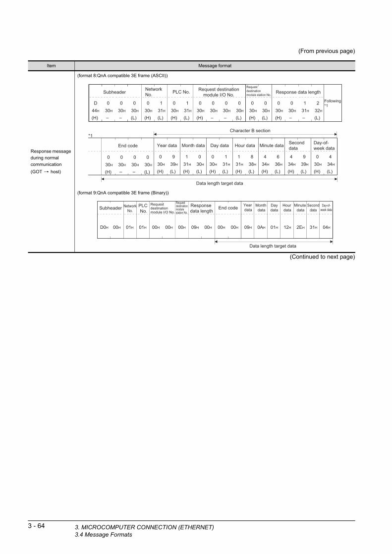
3 - 64 3. MICROCOMPUTER CONNECTION (ETHE3.4 Message Formats
(From previous page)
(Continued to next page)
Item Message format
Response message
during normal
communication
(GOT host)
(format 8:QnA compatible 3E frame (ASCII))
(format 9:QnA compatible 3E frame (Binary))
Character B section
(H) (L)
Year data
0 930H 39H
(H) (L)
Month data
1 031H 30H
(H) (L)
Day data
0 130H 31H
(H) (L)
Hour data
1 831H 38H
(H) (L)
Minute data
4 634H 36H
(H) (L)
Seconddata
4 934H 39H
(H) (L)
Day-of-week data
0 430H 34H
(H) (L)
PLC No.
030H
(H) (L)
NetworkNo.
030H
Following*1
(H)
D44H
030H
(L)
Subheader
030H
030H
– – (H) –
Request destinationmodule I/O No.
030H
030H
– (L)
030H
030H
(H) (L)
Request destinationmodule station No.
030H
030H
*1
(H)
030H
030H
(L)
Response data length
131H
232H
(H)
030H
030H
(L)
End code
030H
030H
– –
– –
1131H31H
Data length target data
00H
NetworkNo.
PLC No.
00HD0H
Subheader
00H 00H 00H
Request destinationmodule I/O No.
Request destinationmodule station No.
Response data length
00H 00H
End code Year data
Month data
Daydata
Hour data
09H
Minute data
0AH 01H
Seconddata
12H 2EH
Day-of-week data
31H 04H01H01H 09H
Data length target data
RNET)

1
3. MICRO
(From previous page)
OR
PRE
PA
RA
TO
RY
P
RO
CE
DU
RE
S F
MO
NIT
OR
ING
2
MIC
RO
CO
MP
UT
ER
C
ON
NE
CT
ION
(S
ER
IAL
)
3
MIC
RO
CO
MP
UT
ER
C
ON
NE
CT
ION
(E
TH
ER
NE
T)
4
MO
DB
US
(R)/
RT
U
CO
NN
EC
TIO
N
5
MO
DB
US
(R)/
TC
P
CO
NN
EC
TIO
N
6
CO
NN
EC
TIO
N T
O
SO
UN
D O
UT
PU
T
UN
IT
7
CO
NN
EC
TIO
N T
O
EX
TE
RN
AL
I/O
D
EV
ICE
8
FIN
GE
RP
RIN
T A
UTH
EN
TIC
ATIO
N
DE
VIC
E C
ON
NE
CTI
ON
Item Message format
Response message
during faulty
communication
(GOT host)
(format 8:QnA compatible 3E frame (ASCII))
(format 9:QnA compatible 3E frame (Binary))
(H) (L)
PLC No.
030H
(H) (L)
NetworkNo.
030H
(H) –
Request destinationmodule I/O No.
030H
030H
– – –
– –
(L)
030H
030H
(H) (L)
Request destinationmodule station No.
030H
030H
Following*1
*1
(H)
030H
030H
(L)
Response data length
131H
636H
(H)
030H
030H
(L)
End code
535H
636H
(H)
D44H
030H
(L)
Subheader
030H
030H
– –
(H) –
Request destinationmodule I/O No.
030H
030H
– (L)
030H
030H
(H) (L)
Request destinationmodule station No.
030H
030H
(H) (L)
PLC No.
030H
030H
(H) (L)
NetworkNo.
030H
030H
1131H 31H
1)
1)
(H) –
Command
131H
939H
– (L)
030H
131H
(H) –
Sub-command
030H
030H
(L)
030H
030H
–
Data length target data
Data length target data
01H
*1
Command
01H 19H 00H 00H
Sub-commandEnd code
NetworkNo.
00H01H
PLC No.
00HD0H
Subheader
00H 00H 00H
Following*1
Request destination
module I/O No.
Request destinationmodule station No.
Response data length
NetworkNo.
PLC No.
00H
01H
00H 00H56H 00H 00H 00H
Request destinationmodule station No.
0BH
Data length target data
Request destination
module I/O No.
COMPUTER CONNECTION (ETHERNET)3.4 Message Formats
3 - 65
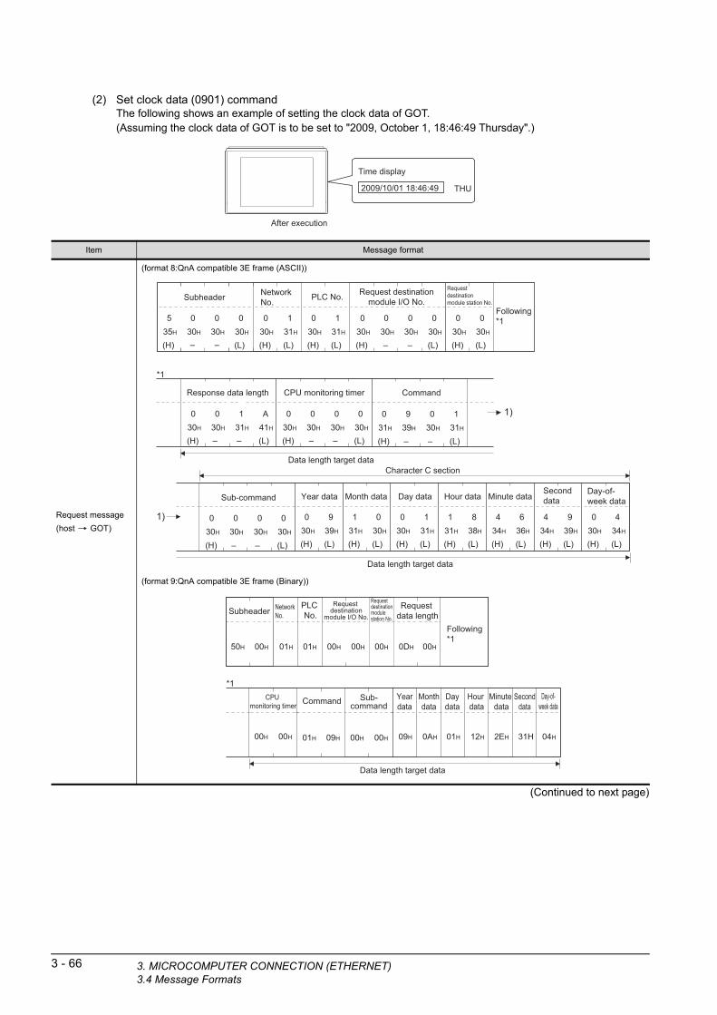
3 - 66 3. MICROCOMPUTER CONNECTION (ETHE3.4 Message Formats
(2) Set clock data (0901) commandThe following shows an example of setting the clock data of GOT.(Assuming the clock data of GOT is to be set to "2009, October 1, 18:46:49 Thursday".)
Time display
2009/10/01 18:46:49 THU
After execution
(Continued to next page)
Item Message format
Request message
(host GOT)
(format 8:QnA compatible 3E frame (ASCII))
(format 9:QnA compatible 3E frame (Binary))
Character C section
(H) (L)
Year data
0 930H 39H
(H) (L)
Month data
1 031H 30H
(H) (L)
Day data
0 130H 31H
(H) (L)
Hour data
1 831H 38H
(H) (L)
Minute data
4 634H 36H
(H) (L)
Seconddata
4 934H 39H
(H) (L)
Day-of-week data
0 430H 34H
1)
(H) (L)
PLC No.
030H
(H) (L)
NetworkNo.
030H
Following*1
(H)
535H
030H
(L)
Subheader
030H
030H
– – (H) –
Request destinationmodule I/O No.
030H
030H
– (L)
030H
030H
(H) (L)
Request destinationmodule station No.
030H
030H
*1
(H)
030H
030H
(L)
Response data length
131H
A41H
(H)
030H
030H
(L)
CPU monitoring timer
030H
030H
1)
– – – –
11
(H) –
Command
031H
939H
– (L)
030H
131H
(H) –
Sub-command
030H
030H
(L)
030H
030H
–
31H31H
Data length target data
Data length target data
00H
NetworkNo.
00H 0DH50H
Subheader
00H 00H 00H
Following*1
Request destination
module I/O No.
Request destinationmodulestation No.
Request data length
00H 00H
CPU monitoring timer
*1Yeardata
Monthdata
Daydata
Hour data
09H
Minute data
0AH 01H
Seconddata
12H 2EH
Day-of-week data
31H 04H
01H 01H
PLC No.
Command
01H 09H 00H 00H
Sub-command
Data length target data
RNET)

1
3. MICRO
(From previous page)
OR
PRE
PA
RA
TO
RY
P
RO
CE
DU
RE
S F
MO
NIT
OR
ING
2
MIC
RO
CO
MP
UT
ER
C
ON
NE
CT
ION
(S
ER
IAL
)
3
MIC
RO
CO
MP
UT
ER
C
ON
NE
CT
ION
(E
TH
ER
NE
T)
4
MO
DB
US
(R)/
RT
U
CO
NN
EC
TIO
N
5
MO
DB
US
(R)/
TC
P
CO
NN
EC
TIO
N
6
CO
NN
EC
TIO
N T
O
SO
UN
D O
UT
PU
T
UN
IT
7
CO
NN
EC
TIO
N T
O
EX
TE
RN
AL
I/O
D
EV
ICE
8
FIN
GE
RP
RIN
T A
UTH
EN
TIC
ATIO
N
DE
VIC
E C
ON
NE
CTI
ON
(Continued to next page)
Item Message format
Response message
during normal
communication
(GOT host)
(format 8:QnA compatible 3E frame (ASCII))
(format 9:QnA compatible 3E frame (Binary))
(H) (L)
PLC No.
030H
(H) (L)
NetworkNo.
030H
(H) –
Request destinationmodule I/O No.
030H
030H
–
– – – –
(L)
030H
030H
(H) (L)
Request destinationmodule station No.
030H
030H
Following*1
*1
(H)
030H
030H
(L)
Response data length
030H
434H
(H)
030H
030H
(L)
End code
030H
030H
(H)
D44H
030H
(L)
Subheader
030H
030H
– –31H 31H
1 1
Data length target data
00H 00H
End code
00H
NetworkNo.
PLCNo.
00H 02HD0H
Subheader
00H 01H 01H 00H 00H
Request destination
module I/O No.
Request destinationmodule station No.
Responsedata length
Data lengthtarget data
COMPUTER CONNECTION (ETHERNET)3.4 Message Formats
3 - 67
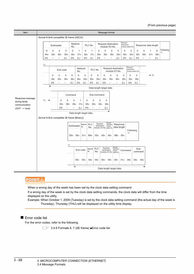
3 - 68 3. MICROCOMPUTER CONNECTION (ETHE3.4 Message Formats
(From previous page)
POINTPOINTPOINT
When a wrong day of the week has been set by the clock data setting command
If a wrong day of the week is set by the clock data setting commands, the clock data will differ from the time displayed on the utility.Example: When October 1, 2009 (Tuesday) is set by the clock data setting command (the actual day of the week is
Thursday), Thursday (THU) will be displayed on the utility time display.
Error code listFor the error codes, refer to the following.
3.4.6 Formats 6, 7 (4E frame) ■Error code list
Item Message format
Response message
during faulty
communication
(GOT host)
(format 8:QnA compatible 3E frame (ASCII))
(format 9:QnA compatible 3E frame (Binary))
(H) (L)
PLC No.
030H
(H) (L)
NetworkNo.
030H
(H) –
Request destinationmodule I/O No.
030H
030H
– – –
– –
(L)
030H
030H
(H) (L)
Request destinationmodule station No.
030H
030H
Following*1
*1
(H)
030H
030H
(L)
Response data length
131H
636H
(H)
030H
030H
(L)
End code
535H
636H
(H)
D44H
030H
(L)
Subheader
030H
030H
– –
(H) –
Request destinationmodule I/O No.
030H
030H
– (L)
030H
030H
(H) (L)
Request destinationmodule station No.
030H
030H
(H) (L)
PLC No.
030H
030H
(H) (L)
NetworkNo.
030H
030H
1131H 31H
1)
1)
(H) –
Command
030H
939H
– (L)
030H
131H
(H) –
Sub-command
030H
030H
(L)
030H
030H
–
Data length target data
Data length target data
01H
*1
Command
01H 09H 00H 00H
Sub-command
End code
NetworkNo.
00H01H
PLCNo.
00HD0H
Subheader
00H 00H 00H
Following*1
Request destination
module I/O No.
Request destinationmodule station No.
Responsedata length
NetworkNo.
PLCNo.
00H
01H
00H 00H56H 00H 00H 00H
Request destination
module I/O No.
Request destinationmodule station No.
0BH
Data length target data
RNET)

1
3. MICRO
FO
R
3.5 GOT Side SettingsPR
EP
AR
AT
OR
YP
RO
CE
DU
RE
S
MO
NIT
OR
ING
2
MIC
RO
CO
MP
UT
ER
C
ON
NE
CT
ION
(S
ER
IAL
)
3
MIC
RO
CO
MP
UT
ER
C
ON
NE
CT
ION
(E
TH
ER
NE
T)
4
MO
DB
US
(R)/
RT
U
CO
NN
EC
TIO
N
5
MO
DB
US
(R)/
TC
P
CO
NN
EC
TIO
N
6
CO
NN
EC
TIO
N T
O
SO
UN
D O
UT
PU
T
UN
IT
7
CO
NN
EC
TIO
N T
O
EX
TE
RN
AL
I/O
D
EV
ICE
8
FIN
GE
RP
RIN
T A
UTH
EN
TIC
ATIO
N
DE
VIC
E C
ON
NE
CTI
ON
3.5.1 Setting communication interface (Communication settings)
Set the channel of the equipment to be connected to the GOT.
1. Select [Common] [Controller Setting] from the menu.
2. The Controller Setting window is displayed. Select the channel to be used from the list menu.
3. Set the following items.• Manufacturer: Others• Controller Type: Computer• I/F: Interface to be used• Driver: Ethernet (MICROCOMPUTER)
4. The detailed setting is displayed after Manufacturer, Controller Type, I/F, and Driver are set.Make the settings according to the usage environment.
3.5.2 Communication detail settings
Click the [OK] button when settings are completed.
POINTPOINTPOINT
The settings of connecting equipment can be set and confirmed in [I/F Communication Setting]. For details, refer to the following.
1.1.2 I/F communication setting
2.
3.
4.
Click!
3.5.2 Communication detail settings
Make the settings according to the usage environment.
GT16, GT14
Item Description Range
GOT IP Address*1 Set the IP address of the GOT.(Default: 192.168.3.18)
0.0.0.0 to 255.255.255.255
Subnet Mask*1
Set the subnet mask for the sub network. (Only for connection via router)If the sub network is not used, the default value is set.(Default: 255.255.255.0)
0.0.0.0 to 255.255.255.255
Default Gateway*1
Set the router address of the default gateway where the GOT is connected. (Only for connection via router)(Default: 0.0.0.0)
0.0.0.0 to 255.255.255.255
Ethernet Download Port No.
Set the GOT port No. for Ethernet download.(Default: 5014)
1024 to 5010.5014 to 65534(Except for 5011, 5012, 5013 and 49153)
GOT Communication Port No.
Set the GOT port No. for the connection with the Ethernet module.(Default: 5021)
1024 to 5010.5014 to 65534(Except for 5011, 5012, 5013 and 49153)
Startup Time
Specify the time period from the GOT startup until GOT starts the communication with the PLC CPU.(Default: 3sec)
3 to 255sec
Delay Time
Set the delay time for reducing the load of the network/destination PLC.(Default: 0ms)
0 to 10000
( 10ms)
COMPUTER CONNECTION (ETHERNET)3.5 GOT Side Settings
3 - 69

*1 Click the [Setting] button and perform the setting in the [GOT IP Address Setting] screen.
*2 For the interrupt output, select [TCP/IP].*3 Select [Yes] only when [Protocol] is [TCP/IP].*4 The setting value can be changed when the [Living
Confirmation] is [Yes].
GT15, GT12
Item Description Range
32bit StorageSelect the steps to store two words (32-bit data).(Default: LH Order)
LH Order/HL Order
Protocol*2Select the communication protocol(Default: UDP/IP)
TCP/IPUDP/IP
FormatSelect the communication format.(Default: 1)
1 to 9
Interrupt Data LengthSpecify the number of bytes of interrupt data.(Default: 1)
1 / 2 / 4
Special Interrupt Output
Set whether or not to output the special interrupt code.(Default: none)
Yes or No
Living Confirmation*3Set whether or not to perform a living confirmation.(Default: No)
Yes/No
Living Confirmation
Cycle*4
Set the sampling to perform a living confirmation.(Default: 20s)
10 to 100s
Item Description Range
GOT IP AddressSet the IP address of the GOT.(Default: 192.168.0.18)
0.0.0.0 to 255.255.255.255
3 - 70 3. MICROCOMPUTER CONNECTION (ETHE3.5 GOT Side Settings
*1 For the interrupt output, select [TCP/IP].*2 Select [Yes] only when [Protocol] is [TCP/IP].*3 The setting value can be changed when the [Living
Confirmation] is [Yes].
Item Description Range
Subnet Mask
Set the subnet mask for the sub network. (Only for connection via router)If the sub network is not used, the default value is set.(Default: 255.255.255.0)
0.0.0.0 to 255.255.255.255
Default Gateway
Set the router address of the default gateway where the GOT is connected. (Only for connection via router)(Default: 0.0.0.0)
0.0.0.0 to 255.255.255.255
Ethernet Download Port No.
Set the GOT port No. for Ethernet download.(Default: 5014)
1024 to 5010.5014 to 65534(Except for 5011, 5012, 5013 and 49153)
GOT Communication Port No.
Set the GOT port No. for the connection with the Ethernet module.(Default: 5021)
1024 to 5010.5014 to 65534(Except for 5011, 5012, 5013 and 49153)
Startup Time
Specify the time period from the GOT startup until GOT starts the communication with the PLC CPU.(Default: 3sec)
3 to 255sec
Delay Time
Set the delay time for reducing the load of the network/destination PLC.(Default: 0ms)
0 to 10000
( 10ms)
32bit StorageSelect the steps to store two words (32-bit data).(Default: LH Order)
LH Order/HL Order
Protocol*1Select the communication protocol(Default: UDP/IP)
TCP/IPUDP/IP
FormatSelect the communication format.(Default: 1)
1 to 9
Interrupt Data ByteSpecify the number of bytes of interrupt data.(Default: 1)
1 / 2 / 4
Special Interrupt CodeSet whether or not to output the special interrupt code.(Default: none)
Yes or No
Living Confirmation*2Set whether or not to perform a living confirmation.(Default: No)
Yes/No
Living Confirmation
Cycle*3
Set the sampling to perform a living confirmation.(Default: 20s)
10 to 100s
RNET)
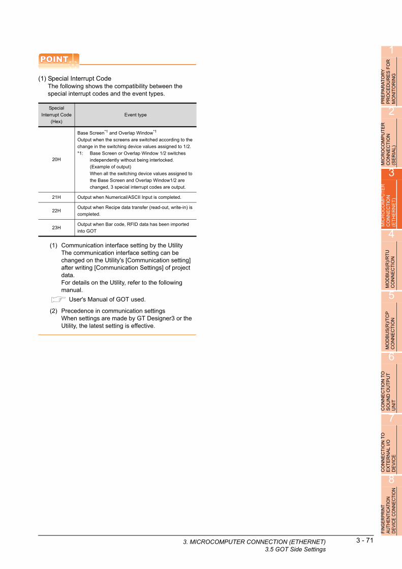
1
PR
EP
AR
AT
OR
Y
PR
OC
ED
UR
ES
FO
R
MO
NIT
OR
ING
2
MIC
RO
CO
MP
UT
ER
C
ON
NE
CT
ION
(S
ER
IAL
)
3
MIC
RO
CO
MP
UT
ER
C
ON
NE
CT
ION
(E
TH
ER
NE
T)
4
MO
DB
US
(R)/
RT
U
CO
NN
EC
TIO
N
5
MO
DB
US
(R)/
TC
P
CO
NN
EC
TIO
N
6
CO
NN
EC
TIO
N T
O
SO
UN
D O
UT
PU
T
UN
IT
7
CO
NN
EC
TIO
N T
O
EX
TE
RN
AL
I/O
D
EV
ICE
8
FIN
GE
RP
RIN
T A
UTH
EN
TIC
ATIO
N
DE
VIC
E C
ON
NE
CTI
ON
POINTPOINTPOINT
(1) Special Interrupt CodeThe following shows the compatibility between the special interrupt codes and the event types.
(1) Communication interface setting by the UtilityThe communication interface setting can be changed on the Utility's [Communication setting] after writing [Communication Settings] of project data.For details on the Utility, refer to the following manual.
User's Manual of GOT used.
(2) Precedence in communication settingsWhen settings are made by GT Designer3 or the Utility, the latest setting is effective.
Special
Interrupt Code
(Hex)
Event type
20H
Base Screen*1 and Overlap Window*1
Output when the screens are switched according to the
change in the switching device values assigned to 1/2.
*1: Base Screen or Overlap Window 1/2 switches
independently without being interlocked.
(Example of output)
When all the switching device values assigned to
the Base Screen and Overlap Window1/2 are
changed, 3 special interrupt codes are output.
21H Output when Numerical/ASCII Input is completed.
22HOutput when Recipe data transfer (read-out, write-in) is
completed.
23HOutput when Bar code, RFID data has been imported
into GOT
3. MICRO
COMPUTER CONNECTION (ETHERNET)3.5 GOT Side Settings3 - 71

3 - 72 3. MICROCOMPUTER CONNECTION (ETHE3.6 System Configuration Examples
3.6 System Configuration Examples
The following shows a system configuration example in the case of the microcomputer connection (Ethernet).
System configurationThe system configuration example illustrated below is explained in this section.
IBM-PC/AT-compatible PC(Microsoft® Visual C++® Ver.6.0)
Communication settings on GOT side and monitor screen settings
(1) Transmission settingsSet the transmission settings of the GOT.The transmission settings in the microcomputer connection (Ethernet) are made at [Detail Setting] on GT Designer3.
3.5.2 Communication detail settings
(2) Monitor screen settingsFor the monitor screen settings in this system configuration example, refer to the example of the system configuration of the microcomputer connection (serial).
2.7 System Configuration Examples
RNET)
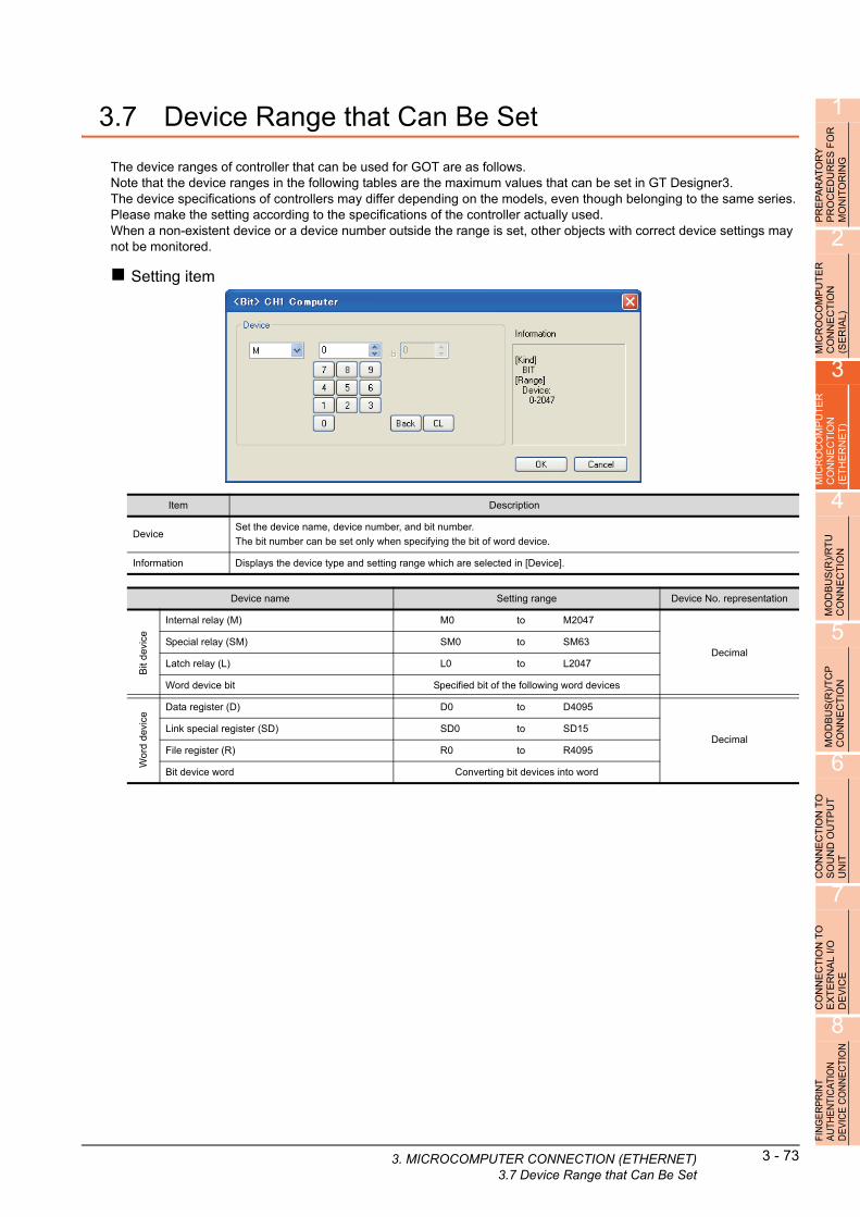
1
3. MICRO
PR
EP
AR
AT
OR
Y
PR
OC
ED
UR
ES
FO
R
MO
NIT
OR
ING
2
MIC
RO
CO
MP
UT
ER
C
ON
NE
CT
ION
(S
ER
IAL
)
3
MIC
RO
CO
MP
UT
ER
C
ON
NE
CT
ION
(E
TH
ER
NE
T)
3.7 Device Range that Can Be Set
The device ranges of controller that can be used for GOT are as follows.Note that the device ranges in the following tables are the maximum values that can be set in GT Designer3.The device specifications of controllers may differ depending on the models, even though belonging to the same series.Please make the setting according to the specifications of the controller actually used.When a non-existent device or a device number outside the range is set, other objects with correct device settings may not be monitored.
Setting item
4
US
(R)/
RT
U
EC
TIO
N
Item Description
DeviceSet the device name, device number, and bit number.
The bit number can be set only when specifying the bit of word device.
Information Displays the device type and setting range which are selected in [Device].
B N
MOD
CO
N
5
MO
DB
US
(R)/
TC
P
CO
NN
EC
TIO
N
6
Device name Setting range Device No. representation
Bit
dev
ice
Internal relay (M) M0 to M2047
DecimalSpecial relay (SM) SM0 to SM63
Latch relay (L) L0 to L2047
Word device bit Specified bit of the following word devices
Wo
rd d
evic
e
Data register (D) D0 to D4095
DecimalLink special register (SD) SD0 to SD15
File register (R) R0 to R4095
Bit device word Converting bit devices into word
O T
CO
NN
EC
TIO
N T
SO
UN
D O
UT
PU
UN
IT
7
CO
NN
EC
TIO
N T
O
EX
TE
RN
AL
I/O
D
EV
ICE
8
FIN
GE
RP
RIN
T A
UTH
EN
TIC
ATIO
N
DE
VIC
E C
ON
NE
CTI
ON
COMPUTER CONNECTION (ETHERNET)3.7 Device Range that Can Be Set
3 - 73

3 - 74 3. MICROCOMPUTER CONNECTION (ETHE3.8 Precautions
3.8 Precautions
GOT clock controlThe settings of "time adjusting" or "time broadcast" made on the GOT will be disabled on the PLC. Use the dedicated commands to set or read out the clock data of microcomputer.
UDP/IP connectionWhen the commands are sent from multiple controllers simultaneously, the GOT may not receive all the commands.Retry sending the commands on the controller, to receive them on the GOT again.
Station monitoring functionThe microcomputer connection (Ethernet) does not support the station monitoring function.
Interrupt outputThe interrupt output is effective only at TCP/IP connection.At UDP/IP connection, the interrupt output is not enabled.
RNET)

MODBUS CONNECTIONS
4. MODBUS(R)/RTU CONNECTION. . . . . . . . . . . . . . . . . . . . 4 - 1
5. MODBUS(R)/TCP CONNECTION . . . . . . . . . . . . . . . . . . . . 5 - 1


41
PR
EP
AR
AT
OR
Y
PR
OC
ED
UR
ES
FO
R
MO
NIT
OR
ING
2
MIC
RO
CO
MP
UT
ER
C
ON
NE
CT
ION
(S
ER
IAL
)
3
MIC
RO
CO
MP
UT
ER
C
ON
NE
CT
ION
(E
TH
ER
NE
T)
4
MO
DB
US
(R)/
RT
U
CO
NN
EC
TIO
N
5
MO
DB
US
(R)/
TC
P
CO
NN
EC
TIO
N
6
CO
NN
EC
TIO
N T
O
SO
UN
D O
UT
PU
T
UN
IT
7
CO
NN
EC
TIO
N T
O
EX
TE
RN
AL
I/O
D
EV
ICE
8
ING
ER
PR
INT
UTH
EN
TIC
ATIO
N
EV
ICE
CO
NN
EC
TIO
N
4.MODBUS(R)/RTU CONNECTION
4.1 Connectable Model List . . . . . . . . . . . . . . . . . . . . . . . . . . . . 4 - 2
4.2 System Configuration. . . . . . . . . . . . . . . . . . . . . . . . . . . . . . 4 - 3
4.3 Connection Diagram . . . . . . . . . . . . . . . . . . . . . . . . . . . . . . 4 - 4
4.4 GOT Side Settings . . . . . . . . . . . . . . . . . . . . . . . . . . . . . . . 4 - 12
4.5 MODBUS(R)/RTU Equipment Side Setting . . . . . . . . . . . . 4 - 14
4.6 Precautions . . . . . . . . . . . . . . . . . . . . . . . . . . . . . . . . . . . . 4 - 17
F A D
4 - 1
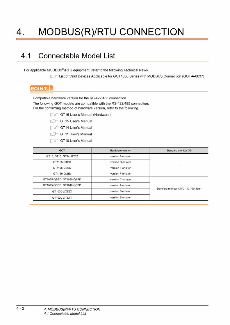
4 - 2 4. MODBUS(R)/RTU CONNECTION4.1 Connectable Model List
4. MODBUS(R)/RTU CONNECTION
4.1 Connectable Model List
For applicable MODBUS®/RTU equipment, refer to the following Technical News.
List of Valid Devices Applicable for GOT1000 Series with MODBUS Connection (GOT-A-0037)
POINTPOINTPOINT
Compatible hardware version for the RS-422/485 connection
The following GOT models are compatible with the RS-422/485 connection.For the confirming method of hardware version, refer to the following.
GT16 User’s Manual (Hardware)
GT15 User's Manual
GT14 User's Manual
GT11 User's Manual
GT10 User's Manual
GOT Hardware version Standard monitor OS
GT16, GT15, GT14, GT12 version A or later
-GT1155-QTBD version C or later
GT1155-QSBD version F or later
GT1150-QLBD version F or later
GT1055-QSBD, GT1050-QBBD version C or later
Standard monitor OS[01.12.**]or laterGT1045-QSBD, GT1040-QBBD version A or later
GT1030-L D version B or later
GT1020-L D version E or later

1
PR
EP
AR
AT
OR
Y
PR
OC
ED
UR
ES
FO
R
MO
NIT
OR
ING
2
ICR
OC
OM
PU
TE
R
ON
NE
CT
ION
E
RIA
L)
4.2 System Configuration
4.2.1 Connecting to MODBUS(R)/RTU equipment
MODBUS/RTU
Communication driver
MODBUS®/RTUequipment GOT
Connection cable
M C (S
3
MIC
RO
CO
MP
UT
ER
C
ON
NE
CT
ION
(E
TH
ER
NE
T)
4
MO
DB
US
(R)/
RT
U
CO
NN
EC
TIO
N
5
MO
DB
US
(R)/
TC
P
CO
NN
EC
TIO
N
6
CO
NN
EC
TIO
N T
O
SO
UN
D O
UT
PU
T
UN
IT
7
CO
NN
EC
TIO
N T
O
EX
TE
RN
AL
I/O
D
EV
ICE
8
FIN
GE
RP
RIN
T A
UTH
EN
TIC
ATIO
N
DE
VIC
E C
ON
NE
CTI
ON
*1 The shortest specification on the MODBUS®/RTU equipment side is prioritized.
*2 Product manufactured by MITSUBISHI ELECTRIC ENGINEERING COMPANY LIMITED.
For details of the product, contact MITSUBISHI ELECTRIC ENGINEERING COMPANY LIMITED.
*3 When it is less than 31 units, the number of the maximum connectable units on the MODBUS®/RTU equipment side will apply.
*4 Connect it to the RS-232 interface (built into GOT). It cannot be mounted on GT1655, GT155 .
*5 Connect it to the RS-422 interface (built into GOT).
*6 Connect it to the RS-232 interface (built into GOT).
ControllerCommunic
ation Type
Connection cable GOT Number of
connectable
equipmentCable model
Connection diagram number
Max.
distanceOption device Model
MODBUS®/RTU
equipment
RS-232
RS232 connection diagram
1)15m*1
- (Built into GOT)
1 MODBUS
equipment for 1
GOTGT15-RS2-9P
RS232 connection diagram
2)15m*1 - (Built into GOT)
RS-422/
485
RS422/485 connection
diagram 1)1200m*1
FA-LTBGTR4CBL05(0.5m)*2
FA-LTBGTR4CBL10(1m)*2
FA-LTBGTR4CBL20(2m)*2
Up to 31 MODBUS
equipment for 1
GOT*3
RS422/485 connection
diagram 2)1200m*1 - (Built into GOT)
RS422/485 connection
diagram 3)1200m*1
GT16-C02R4-9S(0.2m)
GT15-RS4-9S
GT15-RS2T4-9P*4
RS422/485 connection
diagram 4)1200m*1 - (Built into GOT)
RS422/485 connection
diagram 5)1200m*1 GT10-9PT5S*5
RS422/485 connection
diagram 6)1200m*1 - (Built into GOT)
RS422/485 connection
diagram 7)1200m*1 GT15-RS4-TE
RS422/485 connection
diagram 8)1200m*1 GT14-RS2T4-9P*6
4. MODBUS(R)/RTU CONNECTION4.2 System Configuration
4 - 3

4 - 4 4. MODBUS(R)/RTU CONNECTION4.3 Connection Diagram
4.3 Connection Diagram
The following diagram shows the connection between the GOT and the PLC.
4.3.1 RS-232 cable
Connection diagramRS232 connection diagram 1)
*1 GT16: CD, GT15: CD, GT14: NC, GT12: NC,GT11: NC,GT105 : NC, GT104 : NC
*2 Some MODBUS®/RTU equipment require the control line (CS, RS, etc.) to be controlled.Make sure to connect the cables and wires as described in
the MODBUS®/RTU equipment manual.
RS232 connection diagram 2)
*1 Some MODBUS®/RTU equipment require the control line (CS, RS, etc.) to be controlled.Make sure to connect the cables and wires as described in
the MODBUS®/RTU equipment manual.
GOT side
*1
*2MODBUS equipment side
-
TxD
RxD
-
SG
-
-
-
-
CD/NC
RD(RXD)
SD(TXD)
ER(DTR)
SG
DR(DSR)
RS(RTS)
CS(CTS)
NC
1
2
3
4
5
6
7
8
9
GOT side *1MODBUS equipment side
RxD
TxD
-
-
SG
-
-
SD
RD
ER
DR
SG
RS
CS
Precautions when preparing a cable
(1) Cable lengthThe length of the RS-232 cable must be 15m or less.
(2) GOT side connectorFor the GOT side connector, refer to the following.
1.4.1 GOT connector specifications
(3) MODBUS equipment side connector
Use the connector compatible with the MODBUS®/RTU equipment side module.
For details, refer to the MODBUS®/RTU equipment user's manual.

1
OR
Y
RE
S F
OR
IN
G
4.3.2 RS-422/485 cableThe following shows the connection diagrams and connector specifications of the RS-422/485 cable used for connecting the GOT to a PLC.
T U
RS-422/485 cable 1) (2 pair wiring)PR
EP
AR
AP
RO
CE
DM
ON
ITO
R
2
MIC
RO
CO
MP
UT
ER
C
ON
NE
CT
ION
(S
ER
IAL
)
3
MIC
RO
CO
MP
UT
ER
C
ON
NE
CT
ION
(E
TH
ER
NE
T)
4
MO
DB
US
(R)/
RT
U
CO
NN
EC
TIO
N
5
MO
DB
US
(R)/
TC
P
CO
NN
EC
TIO
N
6
CO
NN
EC
TIO
N T
O
SO
UN
D O
UT
PU
T
UN
IT
7
CO
NN
EC
TIO
N T
O
EX
TE
RN
AL
I/O
D
EV
ICE
8
FIN
GE
RP
RIN
T A
UTH
EN
TIC
ATIO
N
DE
VIC
E C
ON
NE
CTI
ON
*1 Some MODBUS®/RTU equipment doesn't have SG.In this case, the wiring between GOT and SG is unnecessary.
*2 Some MODBUS®/RTU equipment require the control line (CS, RS, etc.) to be controlled. Make sure to connect the cables and
wires as described in the MODBUS®/RTU equipment manual.*3 A terminating resistor is required. Set the terminating resistor selector of the main unit to "Disable" and connect a 110
terminating resistor. ( 1.4.3 Terminating resistors of GOT)
*4 For the terminating resistor of MODBUS®/RTU equipment, refer to the manual of MODBUS®/RTU equipment to be used.*5 Use the twisted pair cable for SDA1/SDB1 and RDA1/RDB1.
RS-422/485 cable 1) (1 pair wiring)
*1 The actual terminal layout on the MODBUS®/RTU equipment may differ from the example shown above. SDA/B(+/-) and RDA/
B(+/-) terminals can be separated from each other. Make sure to connect the cables and wires as described in the MODBUS®/RTU equipment manual.
*2 Some MODBUS®/RTU equipment doesn't have SG. In this case, the wiring between GOT and SG is unnecessary.*3 A terminating resistor is required. Set the terminating resistor selector of the main unit to "Disable" and connect a 110
terminating resistor. ( 1.4.3 Terminating resistors of GOT)
*4 For the terminating resistor of MODBUS®/RTU equipment, refer to the manual of MODBUS®/RTU equipment to be used.*5 Use the twisted pair cable for SDA1/SDB1.
CON side(20 pin)*3
SGNCNCNC
SDA2(TXD2+)SDB2(TXD2-)
RDA2(RXD2+)RDB2(RXD2-)
NCRSA(RTS+)
NCRSB(RTS-)
NCCSA(CTS+)
NCCSB(CTS-)
SDA1(TXD1+) *5
SDB1(TXD1-) *5
RDA1(RXD1+) *5
RDB1(RXD1-) *5
6
8
10
12
2
1
3
4
5
7
9
11
13
14
15
16
17
18
19
20
MODBUS®/RTU equipment side*1*2*4
RDA(+)
RDB(-)
SDA(+)
SDB(-)
SG
MODBUS®/RTU equipment side*1*2*4
RDA(+)
RDB(-)
SDA(+)
SDB(-)
SG
*3R
*3R
CON side(20 pin)*3
SGNCNCNC
SDA2(TXD2+)SDB2(TXD2-)
RDA2(RXD2+)RDB2(RXD2-)
NCRSA(RTS+)
NCRSB(RTS-)
NCCSA(CTS+)
NCCSB(CTS-)
SDA1(TXD1+)*5
SDB1(TXD1-)*5
RDA1(RXD1+)
RDB1(RXD1-)
6
8
10
12
2
1
3
4
5
7
9
11
13
14
15
16
17
18
19
20
MODBUS®/RTU equipment side*1*2*4
(+)
(-)
SG
MODBUS®/RTU equipment side*1*2*4
(+)
(-)
SG*3R
4. MODBUS(R)/RTU CONNECTION4.3 Connection Diagram
4 - 5
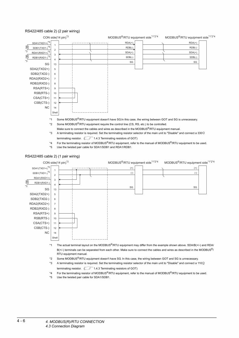
RS422/485 cable 2) (2 pair wiring)
4 - 6 4. MODBUS(R)/RTU CONNECTION4.3 Connection Diagram
*1 Some MODBUS®/RTU equipment doesn't have SG.In this case, the wiring between GOT and SG is unnecessary.
*2 Some MODBUS®/RTU equipment require the control line (CS, RS, etc.) to be controlled.
Make sure to connect the cables and wires as described in the MODBUS®/RTU equipment manual.
*3 A terminating resistor is required. Set the terminating resistor selector of the main unit to "Disable" and connect a 330
terminating resistor. ( 1.4.3 Terminating resistors of GOT)
*4 For the terminating resistor of MODBUS®/RTU equipment, refer to the manual of MODBUS®/RTU equipment to be used.
*5 Use the twisted pair cable for SDA1/SDB1 and RDA1/RDB1.
RS422/485 cable 2) (1 pair wiring)
*1 The actual terminal layout on the MODBUS®/RTU equipment may differ from the example shown above. SDA/B(+/-) and RDA/
B(+/-) terminals can be separated from each other. Make sure to connect the cables and wires as described in the MODBUS®/
RTU equipment manual.
*2 Some MODBUS®/RTU equipment doesn't have SG. In this case, the wiring between GOT and SG is unnecessary.
*3 A terminating resistor is required. Set the terminating resistor selector of the main unit to "Disable" and connect a 110
terminating resistor. ( 1.4.3 Terminating resistors of GOT)
*4 For the terminating resistor of MODBUS®/RTU equipment, refer to the manual of MODBUS®/RTU equipment to be used.
*5 Use the twisted pair cable for SDA1/SDB1.
CON side(14 pin)*3
SGSDA2(TXD2+)SDB2(TXD2-)
RDA2(RXD2+)RDB2(RXD2-)
RSA(RTS+)RSB(RTS-)CSA(CTS+)CSB(CTS-)
NC
SDA1(TXD1+)*5
SDB1(TXD1-)*5
RDA1(RXD1+)*5
RDB1(RXD1-)*5
1
2
3
4
13
5
6
7
8
9
10
11
12
14
Shell
MODBUS®/RTU equipment side*1*2*4
RDA(+)
RDB(-)
SDA(+)
SDB(-)
SG
MODBUS®/RTU equipment side*1*2*4
RDA(+)
RDB(-)
SDA(+)
SDB(-)
SG
*3
*3
R
R
CON side(14 pin)*3
SGSDA2(TXD2+)SDB2(TXD2-)
RDA2(RXD2+)RDB2(RXD2-)
RSA(RTS+)RSB(RTS-)CSA(CTS+)CSB(CTS-)
NC
SDA1(TXD1+)*5
SDB1(TXD1-)*5
RDA1(RXD1+)
RDB1(RXD1-)
1
2
3
4
13
5
6
7
8
9
10
11
12
14
Shell
MODBUS®/RTU equipment side*1*2*4
(+)
(-)
SG
MODBUS®/RTU equipment side*1*2*4
(+)
(-)
SG*3R

1
RS422/485 cable 3) (2 pair wiring)PR
EP
AR
AT
OR
Y
PR
OC
ED
UR
ES
FO
R
MO
NIT
OR
ING
2
MIC
RO
CO
MP
UT
ER
C
ON
NE
CT
ION
(S
ER
IAL
)
3
PU
TE
R
ON
T
)
*1 Some MODBUS®/RTU equipment doesn't have SG. In this case, the wiring between GOT and SG is unnecessary.
*2 Some MODBUS®/RTU equipment require the control line (CS, RS, etc.) to be controlled.
Make sure to connect the cables and wires as described in the MODBUS®/RTU equipment manual.*3 A terminating resistor is required. For GT16, set the terminating resistor selector of the main unit to "Disable" and connect a
330 terminating resistor. For GT15, connect a 330 terminating resistor. ( 1.4.3 Terminating resistors of GOT)
*4 For the terminating resistor of MODBUS®/RTU equipment, refer to the manual of MODBUS®/RTU equipment to be used.
SGRSARSBCSACSB
SDA
SDB
RDA
RDB
1
6
2
7
5
3
8
4
9
RDA(+)
RDB(-)
SDA(+)
SDB(-)
SG
RDA(+)
RDB(-)
SDA(+)
SDB(-)
SG*3
*3R
R
GOT side (D-Sub 9-pin)*3MODBUS®/RTU equipment side*1*2*4
(1st)MODBUS®/RTU equipment side*1*2*4
(2nd)
OM TI E
RS422/485 cable 4) (2 pair wiring)MIC
RO
CC
ON
NE
C(E
TH
ER
N
4
MO
DB
US
(R)/
RT
U
CO
NN
EC
TIO
N
5
MO
DB
US
(R)/
TC
P
CO
NN
EC
TIO
N
6
*1 Some MODBUS®/RTU equipment doesn't have SG. In this case, the wiring between GOT and SG is unnecessary.
*2 Some MODBUS®/RTU equipment require the control line (CS, RS, etc.) to be controlled.
Make sure to connect the cables and wires as described in the MODBUS®/RTU equipment manual.
*3 When placing the GOT to the terminal in the system configuration, set the terminating resistor to "330 ".
When placing the GOT to the position other than the terminal, set the terminating resistor of the GOT to "OPEN".
1.4.3 Terminating resistors of GOT
*4 For the terminating resistor of MODBUS®/RTU equipment, refer to the manual of MODBUS®/RTU equipment to be used.
SDASDBRDARDB
SGRSARSBCSACSB
1
6
2
7
5
3
8
4
9
RDA(+)
RDB(-)
SDA(+)
SDB(-)
SG
RDA(+)
RDB(-)
SDA(+)
SDB(-)
SG
GOT side (D-Sub 9-pin)*3MODBUS®/RTU equipment side*1*2*4
(1st)MODBUS®/RTU equipment side*1*2*4
(2nd)
RS422/485 cable 4) (1 pair wiring)
CO
NN
EC
TIO
N T
O
SO
UN
D O
UT
PU
T
UN
IT
7
CO
NN
EC
TIO
N T
O
EX
TE
RN
AL
I/O
D
EV
ICE
8
FIN
GE
RP
RIN
T A
UTH
EN
TIC
ATIO
N
DE
VIC
E C
ON
NE
CTI
ON
*1 The actual terminal layout on the MODBUS®/RTU equipment may differ from the example shown above. SDA/B(+/-) and RDA/
B(+/-) terminals can be separated from each other. Make sure to connect the cables and wires as described in the MODBUS®/
RTU equipment manual.
*2 Some MODBUS®/RTU equipment doesn't have SG. In this case, the wiring between GOT and SG is unnecessary.
*3 When placing the GOT to the terminal in the system configuration, set the terminating resistor to "110 ".
When placing the GOT to the position other than the terminal, set the terminating resistor of the GOT to "OPEN".
1.4.3 Terminating resistors of GOT
*4 For the terminating resistor of MODBUS®/RTU equipment, refer to the manual of MODBUS®/RTU equipment to be used.
SDASDBRDARDB
SGRSARSBCSACSB
1
6
2
7
5
3
8
4
9
(+)
(-)
SG
(+)
(-)
SG
GOT side (D-Sub 9-pin)*3MODBUS®/RTU equipment side*1*2*4
(1st)MODBUS®/RTU equipment side*1*2*4
(2nd)
4. MODBUS(R)/RTU CONNECTION4.3 Connection Diagram
4 - 7

RS422/485 cable 5) (2 pair wiring)
4 - 8 4. MODBUS(R)/RTU CONNECTION4.3 Connection Diagram
*1 Some MODBUS®/RTU equipment doesn't have SG. In this case, the wiring between GOT and SG is unnecessary.
*2 Some MODBUS®/RTU equipment require the control line (CS, RS, etc.) to be controlled.
Make sure to connect the cables and wires as described in the MODBUS®/RTU equipment manual.
*3 When placing the GOT to the terminal in the system configuration, set the terminating resistor to "330 ".When placing the GOT to the position other than the terminal, set the terminating resistor of the GOT to "OPEN".
1.4.3 Terminating resistors of GOTSet the 1pair/2pair signal selection switch to "1pair" when using the connection conversion adapter.
Connection Conversion Adapter User’s manual
*4 For the terminating resistor of MODBUS®/RTU equipment, refer to the manual of MODBUS®/RTU equipment.
SDA
SDB
RDA
RDB
SG
RDA(+)
RDB(-)
SDA(+)
SDB(-)
SG
RDA(+)
RDB(-)
SDA(+)
SDB(-)
SG
GOT side (terminal block)*3MODBUS®/RTU equipment side*1*2*4
(1st)MODBUS®/RTU equipment side*1*2*4
(2nd)
RS422/485 cable 5) (1 pair wiring)
*1 The actual terminal layout on the MODBUS®/RTU equipment may differ from the example shown above. SDA/B(+/-) and RDA/
B(+/-) terminals can be separated from each other. Make sure to connect the cables and wires as described in the MODBUS®/RTU equipment manual.
*2 Some MODBUS®/RTU equipment doesn't have SG. In this case, the wiring between GOT and SG is unnecessary.
*3 When placing the GOT to the terminal in the system configuration, set the terminating resistor to "110 ".When placing the GOT to the position other than the terminal, set the terminating resistor of the GOT to "OPEN".
1.4.3 Terminating resistors of GOTSet the 1pair/2pair signal selection switch to "1pair" when using the connection conversion adapter.
Connection Conversion Adapter User’s manual
*4 For the terminating resistor of MODBUS®/RTU equipment, refer to the manual of MODBUS®/RTU equipment.
SDA
SDB
RDA
RDB
SG
(+)
(-)
SG
(+)
(-)
SG
GOT side (terminal block)*3MODBUS®/RTU equipment side*1*2*4
(1st)MODBUS®/RTU equipment side*1*2*4
(2nd)
RS422/485 cable 6) (2 pair wiring)
*1 Some MODBUS®/RTU equipment doesn't have SG. In this case, the wiring between GOT and SG is unnecessary.
*2 Some MODBUS®/RTU equipment require the control line (CS, RS, etc.) to be controlled.
Make sure to connect the cables and wires as described in the MODBUS®/RTU equipment manual.
*3 When placing the GOT to the terminal in the system configuration, set the terminating resistor to "330 ".When placing the GOT to the position other than the terminal, set the terminating resistor of the GOT to "OPEN".
1.4.3 Terminating resistors of GOT
*4 For the terminating resistor of MODBUS®/RTU equipment, refer to the manual of MODBUS®/RTU equipment.
SDA
SDB
RDA
RDB
SG
RSA
RSB
CSA
CSB
RDA(+)
RDB(-)
SDA(+)
SDB(-)
SG
RDA(+)
RDB(-)
SDA(+)
SDB(-)
SG
GOT side (terminal block)*3MODBUS®/RTU equipment side*1*2*4
(1st)MODBUS®/RTU equipment side*1*2*4
(2nd)

1
RS422/485 cable 6) (1 pair wiring)PR
EP
AR
AT
OR
Y
PR
OC
ED
UR
ES
FO
R
MO
NIT
OR
ING
2
MIC
RO
CO
MP
UT
ER
C
ON
NE
CT
ION
(S
ER
IAL
)
3
MIC
RO
CO
MP
UT
ER
C
ON
NE
CT
ION
(E
TH
ER
NE
T)
4
MO
DB
US
(R)/
RT
U
CO
NN
EC
TIO
N
5
MO
DB
US
(R)/
TC
P
CO
NN
EC
TIO
N
6
CO
NN
EC
TIO
N T
O
SO
UN
D O
UT
PU
T
UN
IT
7
CO
NN
EC
TIO
N T
O
EX
TE
RN
AL
I/O
D
EV
ICE
8
FIN
GE
RP
RIN
T A
UTH
EN
TIC
ATIO
N
DE
VIC
E C
ON
NE
CTI
ON
*1 The actual terminal layout on the MODBUS®/RTU equipment may differ from the example shown above. SDA/B(+/-) and RDA/
B(+/-) terminals can be separated from each other. Make sure to connect the cables and wires as described in the MODBUS®/
RTU equipment manual.
*2 Some MODBUS®/RTU equipment doesn't have SG.
In this case, the wiring between GOT and SG is unnecessary.
*3 When placing the GOT to the terminal in the system configuration, set the terminating resistor to "110 ".
When placing the GOT to the position other than the terminal, set the terminating resistor of the GOT to "OPEN".
1.4.3 Terminating resistors of GOT
*4 For the terminating resistor of MODBUS®/RTU equipment, refer to the manual of MODBUS®/RTU equipment.
RS422/485 connection diagram 7)
*1 The actual terminal layout on the MODBUS®/RTU equipment may differ from the example shown above. SDA/B(+/-) and RDA/
B(+/-) terminals can be separated from each other. Make sure to connect the cables and wires as described in the MODBUS®/
RTU equipment manual.
*2 Some MODBUS®/RTU equipment doesn't have SG. In this case, the wiring between GOT and SG is unnecessary.
*3 When placing the GOT to the terminal in the system configuration, set the terminating resistor to "100 OHM".
When placing the GOT to the position other than the terminal, set the terminating resistor of the GOT to "No".
1.4.3 Terminating resistors of GOT
*4 For the terminating resistor of MODBUS®/RTU equipment, refer to the manual of MODBUS®/RTU equipment.
SDA
SDB
RDA
RDB
SG
RSA
RSB
CSA
CSB
1
6
2
7
5
3
8
4
9
(+)
(-)
SG
(+)
(-)
SG
GOT side (D-Sub 9-pin)*3MODBUS®/RTU equipment side*1*2*4
(1st)MODBUS®/RTU equipment side*1*2*4
(2nd)
SDA1
SDB1
RDA1
RDB1
SDA2
SDB2
RDA2
RDB2
SG
FG
1
2
3
4
5
6
7
8
9
10
(+)
(-)
SG
(+)
(-)
SG
GOT side (terminal block)*3MODBUS®/RTU equipment side*1*2*4
(1st)MODBUS®/RTU equipment side*1*2*4
(2nd)
4. MODBUS(R)/RTU CONNECTION4.3 Connection Diagram
4 - 9

RS422/485 cable 8) (2 pair wiring)
4 - 10 4. MODBUS(R)/RTU CONNECTION4.3 Connection Diagram
*1 The actual terminal layout on the MODBUS®/RTU equipment may differ from the example shown above. SDA/B(+/-) and RDA/
B(+/-) terminals can be separated from each other. Make sure to connect the cables and wires as described in the MODBUS®/
RTU equipment manual.
*2 Some MODBUS®/RTU equipment doesn't have SG.
In this case, the wiring between GOT and SG is unnecessary.
*3 For the terminating resistor of MODBUS®/RTU equipment, refer to the manual of MODBUS®/RTU equipment to be used.
*4 Set the 2-wire/4-wire terminating resistor setting switch of the RS-232/485 signal conversion adaptor as follows.
2-wire type/4-wire type: 4-wire type (2Pair)<When placing GOT to the terminal>
Set the same terminating resistor value as that of MODBUS®/RTU equipment. However, only "110 "/"330 " can be set as the terminating resistor of GOT.
If the terminating resistor value of MODBUS®/RTU equipment is other than "110 "/"330 ", set the terminating resistor of GOT
side to "OPEN" and install the terminating resistor set according to the terminating resistor value of MODBUS®/RTU equipment to the RS-232/485 signal conversion adaptor externally.<When placing GOT to other than the terminal>Set the terminating resistor of the GOT to "OPEN".
1.4.4 Setting the RS-232/485 signal conversion adaptor
*5 Some MODBUS®/RTU equipment require the control line (CS, RS) to be controlled. In this case, the connection using the RS-
232/485 signal conversion adaptor is unavailable.
RS422/485 cable 8) (1 pair wiring)
*1 The actual terminal layout on the MODBUS®/RTU equipment may differ from the example shown above. SDA/B(+/-) and RDA/
B(+/-) terminals can be separated from each other. Make sure to connect the cables and wires as described in the MODBUS®/
RTU equipment manual.
*2 Some MODBUS®/RTU equipment doesn't have SG.
In this case, the wiring between GOT and SG is unnecessary.
*3 For the terminating resistor of MODBUS®/RTU equipment, refer to the manual of MODBUS®/RTU equipment to be used.
*4 Set the 2-wire/4-wire terminating resistor setting switch of the RS-232/485 signal conversion adaptor as follows.
2-wire type/4-wire type: 2-wire type (1Pair)<When placing GOT to the terminal>
Set the same terminating resistor value as that of MODBUS®/RTU equipment. However, only "110 "/"330 " can be set as the terminating resistor of GOT.
If the terminating resistor value of MODBUS®/RTU equipment is other than "110 "/"330 ", set the terminating resistor of GOT
side to "OPEN" and install the terminating resistor set according to the terminating resistor value of MODBUS®/RTU equipment to the RS-232/485 signal conversion adaptor externally.<When placing GOT to other than the terminal>Set the terminating resistor of the GOT to "OPEN".
1.4.4 Setting the RS-232/485 signal conversion adaptor
*5 Some MODBUS®/RTU equipment require the control line (CS, RS) to be controlled. In this case, the connection using the RS-
232/485 signal conversion adaptor is unavailable.
GOT side (terminal block)*)*4*5
SDA
SDB
RDA
RDB
SG
MODBUS®/RTU equipment side*1*2*3
(1st)MODBUS®/RTU equipment side*1*2*3
(2nd)
RDA(+)
RDB(-)
SDA(+)
SDB(-)
SG
RDA(+)
RDB(-)
SDA(+)
SDB(-)
SG
GOT side(terminal block)*4*5
SDA
SDB
RDA
RDB
SG
MODBUS®/RTU equipment side*1*2*3
(1st)MODBUS®/RTU equipment side*1*2*3
(2nd)
(+)
(-)
SG
(+)
(-)
SG

1
PR
EP
AR
AT
OR
Y
PR
OC
ED
UR
ES
FO
R
MO
NIT
OR
ING
2
MIC
RO
CO
MP
UT
ER
C
ON
NE
CT
ION
(S
ER
IAL
)
3
MIC
RO
CO
MP
UT
ER
C
ON
NE
CT
ION
(E
TH
ER
NE
T)
4
MO
DB
US
(R)/
RT
U
CO
NN
EC
TIO
N
5
MO
DB
US
(R)/
TC
P
CO
NN
EC
TIO
N
6
CO
NN
EC
TIO
N T
O
SO
UN
D O
UT
PU
T
UN
IT
7
CO
NN
EC
TIO
N T
O
EX
TE
RN
AL
I/O
D
EV
ICE
8
FIN
GE
RP
RIN
T A
UTH
EN
TIC
ATIO
N
DE
VIC
E C
ON
NE
CTI
ON
Precautions when preparing a cable
(1) Cable lengthThe length of the RS-422/485 cable must be 1200m or less.
(2) GOT side connectorFor the GOT side connector, refer to the following.
1.4.1 GOT connector specifications
(3) MODBUS®/RTU equipment side connector
Use the connector compatible with the MODBUS®/RTU equipment side module.For details, refer to the MODBUS equipment user's manual.
Connecting terminating resistors
(1) GOT side
When connecting a MODBUS®/RTU equipment to the GOT, a terminating resistor must be connected to the GOT.
(a) For GT16 body, GT12, RS-422/485 communication unitSet the terminating resistor using the terminating resistor setting switch.
(b) For GT14, GT11, GT10Set the terminating resistor using the terminating resistor selector.
For the procedure to set the terminating resistor, refer to the following.
1.4.3 Terminating resistors of GOT
(2) MODBUS®/RTU equipment side
When connecting a MODBUS®/RTU equipment to the GOT, a terminating resistor must be connected to the
MODBUS®/RTU equipment.
For details, refer to the MODBUS®/RTU equipment user's manual.
4. MODBUS(R)/RTU CONNECTION4.3 Connection Diagram
4 - 11

4 - 12 4. MODBUS(R)/RTU CONNECTION4.4 GOT Side Settings
4.4 GOT Side Settings
4.4.1 Setting communication interface (Communication settings)
Set the channel of the equipment to be connected to the GOT.
1. Select [Common] [Controller Setting] from the menu.
2. The Controller Setting window is displayed. Select the channel to be used from the list menu.
3. Set the following items.• Manufacturer: MODBUS• Controller Type: MODBUS• I/F: Interface to be used• Driver: MODBUS/RTU
4. The detailed setting is displayed after Manufacturer, Controller Type, I/F, and Driver are set.Make the settings according to the usage environment.
4.4.2 Communication detail settings
Click the [OK] button when settings are completed.
POINTPOINTPOINT
The settings of connecting equipment can be set and confirmed in [I/F Communication Setting]. For details, refer to the following.
1.1.2 I/F communication setting
2.
3.
4.
Click!
4.4.2 Communication detail settingsMake the settings according to the usage environment.
*1 The GOT ensures in advance the minimum interval (3.5 characters time) for communication frame defined in the
MODBUS®/RTU.Therefore, the actual send delay time is as follows.
When connecting to MODBUS®/RTU equipment which requires a delay longer than 3.5 character time, adjust the send delay time.
Item Description Range
Transmission Speed
Set this item when change the transmission speed used for communication with the connected equipment.(Default: 19200bps)
9600bps, 19200bps, 38400bps, 57600bps, 115200bps
Data Bit
Set this item when change the data length used for communication with the connected equipment.(Default: 8bits)
7bits/8bits
Stop BitSpecify the stop bit length for communications.(Default: 1bit)
1bit/2bits
Parity
Specify whether or not to perform a parity check, and how it is performed during communication.(Default: Even)
NoneEvenOdd
Retry
Set the number of retries to be performed when a communication error occurs.(Default: 3times)
0 to 5times
Timeout TimeSet the time period for a communication to time out.(Default: 3sec)
3 to 30sec
Host AddressSpecify the host address in the network of the GOT.(Default: 1)
1 to 247
Delay Time*1
Set this item to adjust the transmission timing of the communication request from the GOT.(Default: 0ms)
0 to 300ms
32bit StorageSelect the steps to store two words (32-bit data).(Default: LH Order)
LH Order/HL Order
+=Actual senddelay time
Send delay time set inthe communication
detail setting3.5 character
time
Minimum interval for communication frame defined in MODBUS/RTU

1
PR
EP
AR
AT
OR
Y
PR
OC
ED
UR
ES
FO
R
MO
NIT
OR
ING
2
MIC
RO
CO
MP
UT
ER
C
ON
NE
CT
ION
(S
ER
IAL
)
3
MIC
RO
CO
MP
UT
ER
C
ON
NE
CT
ION
(E
TH
ER
NE
T)
4
MO
DB
US
(R)/
RT
U
CO
NN
EC
TIO
N
5
MO
DB
US
(R)/
TC
P
CO
NN
EC
TIO
N
6
CO
NN
EC
TIO
N T
O
SO
UN
D O
UT
PU
T
UN
IT
7
CO
NN
EC
TIO
N T
O
EX
TE
RN
AL
I/O
D
EV
ICE
8
FIN
GE
RP
RIN
T A
UTH
EN
TIC
ATIO
N
DE
VIC
E C
ON
NE
CTI
ON
HINTHINTHINT
If the communication with MODBUS®/RTU equipmentis not established, some equipment which requires adelay longer than 3.5 character time may beconnected.Adjust the send delay time in the communication detailsetting.
POINTPOINTPOINT
(1) Communication interface setting by the UtilityThe communication interface setting can be changed on the Utility's [Communication setting] after writing [Communication Settings] of project data.For details on the Utility, refer to the following manual.
User's Manual of GOT used.(2) Precedence in communication settings
When settings are made by GT Designer3 or the Utility, the latest setting is effective.
4. MODBUS(R)/RTU CONNECTION4.4 GOT Side Settings
4 - 13
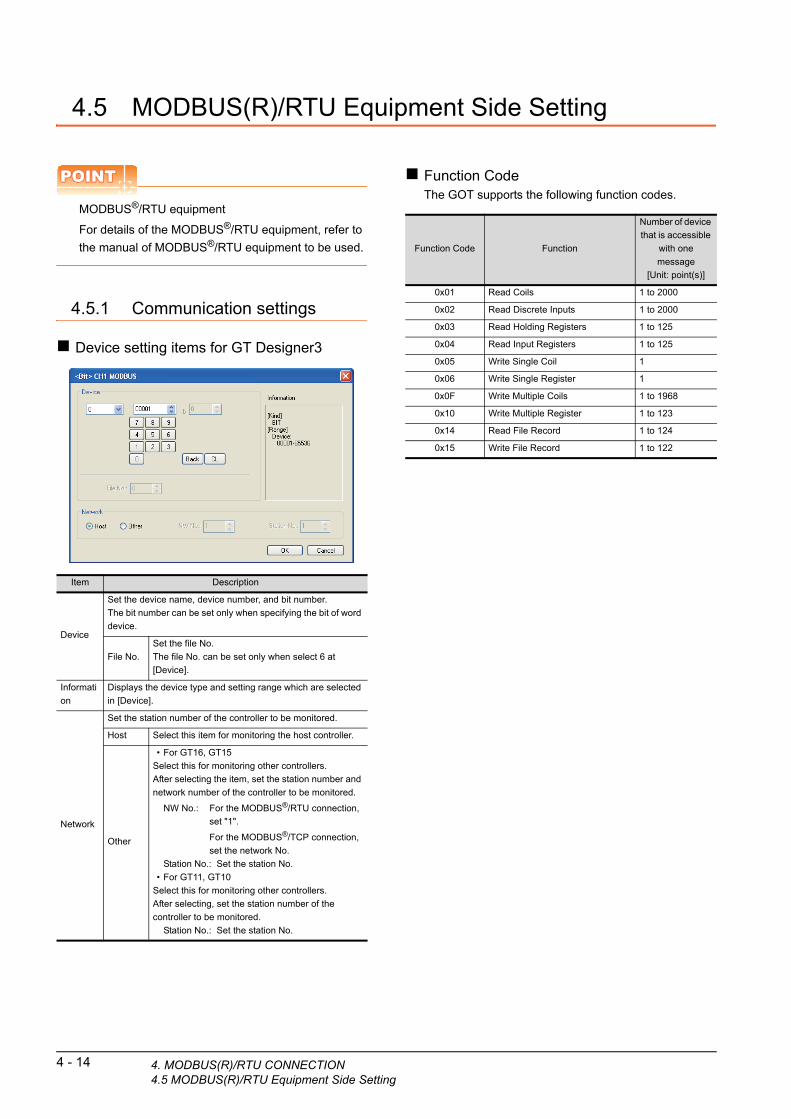
4 - 14 4. MODBUS(R)/RTU CONNECTION4.5 MODBUS(R)/RTU Equipment Side Setting
4.5 MODBUS(R)/RTU Equipment Side Setting
POINTPOINTPOINT
MODBUS®/RTU equipment
For details of the MODBUS®/RTU equipment, refer to
the manual of MODBUS®/RTU equipment to be used.
4.5.1 Communication settings
Device setting items for GT Designer3
Item Description
Device
Set the device name, device number, and bit number.
The bit number can be set only when specifying the bit of word
device.
File No.
Set the file No.
The file No. can be set only when select 6 at
[Device].
Informati
on
Displays the device type and setting range which are selected
in [Device].
Network
Set the station number of the controller to be monitored.
Host Select this item for monitoring the host controller.
Other
• For GT16, GT15
Select this for monitoring other controllers.
After selecting the item, set the station number and
network number of the controller to be monitored.
NW No.: For the MODBUS®/RTU connection,
set "1".
For the MODBUS®/TCP connection,
set the network No.
Station No.: Set the station No.
• For GT11, GT10
Select this for monitoring other controllers.
After selecting, set the station number of the
controller to be monitored.
Station No.: Set the station No.
Function CodeThe GOT supports the following function codes.
Function Code Function
Number of device
that is accessible
with one
message
[Unit: point(s)]
0x01 Read Coils 1 to 2000
0x02 Read Discrete Inputs 1 to 2000
0x03 Read Holding Registers 1 to 125
0x04 Read Input Registers 1 to 125
0x05 Write Single Coil 1
0x06 Write Single Register 1
0x0F Write Multiple Coils 1 to 1968
0x10 Write Multiple Register 1 to 123
0x14 Read File Record 1 to 124
0x15 Write File Record 1 to 122

1
PR
EP
AR
AT
OR
Y
PR
OC
ED
UR
ES
FO
R
MO
NIT
OR
ING
2
MIC
RO
CO
MP
UT
ER
C
ON
NE
CT
ION
(S
ER
IAL
)
3
MIC
RO
CO
MP
UT
ER
C
ON
NE
CT
ION
(E
TH
ER
NE
T)
4
MO
DB
US
(R)/
RT
U
CO
NN
EC
TIO
N
5
MO
DB
US
(R)/
TC
P
CO
NN
EC
TIO
N
6
CO
NN
EC
TIO
N T
O
SO
UN
D O
UT
PU
T
UN
IT
7
CO
NN
EC
TIO
N T
O
EX
TE
RN
AL
I/O
D
EV
ICE
8
FIN
GE
RP
RIN
T A
UTH
EN
TIC
ATIO
N
DE
VIC
E C
ON
NE
CTI
ON
AddressGT Designer3 converts the device numbers into decimal format according to the address map of the
MODBUS®/RTU equipment to be used.
The table below shows the representations on the
MODBUS®/RTU communication protocol and GT Designer3.
POINTPOINTPOINT
Address conversion example
When monitoring the holding register's address "1234H", GT Designer3 displays "4*****" since GT Designer3 processes the internal conversion in decimal format as follows:GT Designer3 converts the holding register's address "1234H" to "04660" in decimal format.Then, "+1" is added to this decimal address since the holding register's address on GT Designer3 always starts from "1."Therefore, the holding register's address "1234H" is displayed as "404661" on GT Designer3.
MODBUS/RTU Communication protocol
Representation on GT
Designer3Device name
Function code to be
used Address
Read Write
Coil 0x010x05
0x0F
0000
0001
to
FFFE
FFFF
000001
000002
to
065535
065536
Input relay 0x02 -
0000
0001
to
FFFE
FFFF
100001
100002
to
165535
165536
Input register 0x04 -
0000
0001
to
FFFE
FFFF
300001
300002
to
365535
365536
Holding
register0x03
0x06
0x10
0000
0001
to
FFFE
FFFF
400001
400002
to
465535
465536
Extension file
register0x14 0x15
0000
0001
to
270E
270F
600000
600001
to
609998
609999
Holding register
"4 04660" +1
"404661"
1234H
4.5
MODBUS communication control function on the GS device
(1) Function overviewThis function is to prevent the communication response delay that occurs because the devices on the MODBUS network differs from each other in network specification.This function is effective for the MODBUS network conditions as described below:• When only a part of function codes is supported
(Example: "0F" is not supported)• When the maximum transfer size of function code is
small (Example: The maximum number of coil read times is 1000)
(2) Communication settingWhen the MODBUS/RTU communication driver is assigned to multiple channel numbers using the multi-channel function, the following cases are possible. The communication settings are shared between the assigned multiple channel numbers, or the individual communication setting is configured to a specific channel number.By setting the device GS579, either the GS device used for sharing communication settings (GS570 to GS576) or the GS device used for individual communication setting (GS590 to GS617) is validated.
For details of GS devices (GS570 to GS576) and GS devices (GS590 to GS617), refer to the next page.
GS
deviceDescription Set value
GS579
Validity of
setting channel
number
Bit0: 0 Configure the Ch1 communication
settings between GS570 to
GS576.
1 Configure the Ch1 communication
settings between GS590 to
GS596.
Bit1: 0 Configure the Ch2 communication
settings between GS570 to
GS576.
1 Configure the Ch2 communication
settings between GS590 to
GS603.
Bit2: 0 Configure the Ch3 communication
settings between GS570 to
GS576.
1 Configure the Ch3 communication
settings between GS604 to
GS610
Bit3: 0 Configure the Ch4 communication
settings between GS570 to
GS576.
1 Configure the Ch4 communication
settings between GS611 to
GS617.
4. MODBUS(R)/RTU CONNECTION MODBUS(R)/RTU Equipment Side Setting
4 - 15

4 - 16 4. MODBUS(R)/RTU CONNECTION4.5 MODBUS(R)/RTU Equipment Side Setting
(a) When sharing communication settings between multiple channel numbersThe table below shows the settings for the GS device.
(b) When configuring individual communication settings for specific channel numbersThe table below shows the settings for the GS device.
GS device Description Set value
GS570 Command selection
Bit0: 0 Using Function Code "0F"1 Not using Function Code "0F"
Bit1: 0 Using Function Code "10"1 Not using Function Code "10"
GS571
Function Code "01"
Specification for the max. number of
coil read times
0:20001 to 2000: Specify the maximum number.Other than above: 2000
GS572
Function Code "02"
Specification for the max. number of
input relay read times
0:20001 to 2000: Specify the maximum number.Other than above: 2000
GS573
Function Code "03"
Specification for the max. number of
holding register read times
0:1251 to 125: Specify the maximum number.Other than above: 125
GS574
Function Code "04"
Specification for the max. number of
input register read times
0:1251 to 125: Specify the maximum number.Other than above: 125
GS575
Function Code "0F"
Specification for the max. number of
multiple-coil write times
0:8001 to 1968: Specify the maximum number.Other than above: 1968When Bit0 of GS570 is "1", the function code "0F" is not used, and therefore the setting of GS575 will be disabled.
GS576
Function Code "10"
Specification for the max. number of
multiple-holding register write times
0:1001 to 123: Specify the maximum number.Other than above: 123When Bit1 of GS570 is "1", the function code "10F" is not used, and therefore the setting of GS576 will be disabled.
GS deviceDescription Set value
Ch1 Ch2 Ch3 Ch4
GS590 GS597 GS604 GS611 Command selection
Bit0: 0 Using Function Code "0F"1 Not using Function Code "0F"
Bit1: 0 Using Function Code "10"1 Not using Function Code "10"
GS591 GS598 GS605 GS612
Function Code "01"
Specification for the max. number of
coil read times
0:20001 to 2000: Specify the maximum number.Other than above: 2000
GS592 GS599 GS606 GS613
Function Code "02"
Specification for the max. number of
input relay read times
0:20001 to 2000: Specify the maximum number.Other than above: 2000
GS593 GS600 GS607 GS614
Function Code "03"
Specification for the max. number of
holding register read times
0:1251 to 125: Specify the maximum number.Other than above: 125
GS594 GS601 GS608 GS615
Function Code "04"
Specification for the max. number of
input register read times
0:1251 to 125: Specify the maximum number.Other than above: 125
GS595 GS602 GS609 GS616
Function Code "0F"
Specification for the max. number of
multiple-coil write times
0:8001 to 1968: Specify the maximum number.Other than above: 1968When Bit0 of GS570 is "1", the function code "0F" is not used, and therefore the setting of GS575 will be disabled.
GS596 GS603 GS610 GS617
Function Code "10"
Specification for the max. number of
multiple-holding register write times
0:1001 to 123: Specify the maximum number.Other than above: 123When Bit1 of GS570 is "1", the function code "10F" is not used, and therefore the setting of GS576 will be disabled.

1
PR
EP
AR
AT
OR
Y
PR
OC
ED
UR
ES
FO
R
MO
NIT
OR
ING
2
MIC
RO
CO
MP
UT
ER
C
ON
NE
CT
ION
(S
ER
IAL
)
3
OC
OM
PU
TE
R
NE
CT
ION
E
RN
ET
)
4.5.2 Station number setting
In the MODBUS network, a maximum of 31 MODBUS®/RTU equipment can be connected to one GOT.
Assign a non-overlapped station number ranging from 1 to
247 arbitrarily to each MODBUS®/RTU equipment.
In the system configuration, the MODBUS®/RTU equipment with the station number set with the host address must be included.
The station number can be set without regard to the cable connection order. There is no problem even if station numbers are not consecutive.
Examples of station number setting
Station No.3
Station No.15
Station No.1GOT
MIC
RC
ON
(ET
H
4
4.6 Precautions
MO
DB
US
(R)/
RT
UC
ON
NE
CT
ION
5
MO
DB
US
(R)/
TC
P
CO
NN
EC
TIO
N
6
CO
NN
EC
TIO
N T
O
SO
UN
D O
UT
PU
T
UN
IT
7
CO
NN
EC
TIO
N T
O
EX
TE
RN
AL
I/O
D
EV
ICE
8
FIN
GE
RP
RIN
T A
UTH
EN
TIC
ATIO
N
DE
VIC
E C
ON
NE
CTI
ON
Reading the holding registersThe GOT reads the holding registers (400001) for checking whether the GOT can communicate with the controller.Therefore, if the equipment does not have holding registers (400001), normal communication may not be performed.
Station No. settings of the MODBUS®/RTU equipment side
In the system configuration, the MODBUS®/RTU equipment with the station number set with the host address must be included.For details of host address setting, refer to the following.
4.4.1 Setting communication interface (Communication settings)
GOT clock controlThe settings of "time adjusting" or "time broadcast" made on the GOT will be disabled on the PLC.
Disconnecting some of multiple connected equipmentThe GOT can disconnect some of multiple connected equipment by setting GOT internal device. For example, the faulty station where a communication timeout error occurs can be disconnected from connected equipment. For details of GOT internal device setting, refer to the following manual.
GT Designer3 Version1 Screen Design Manual
MODBUS communication control function on the GS deviceAt GOT startup, set MODBUS communication control function with project scripts, etc.If settings are changed after communication start, a communication error may occur.
Setting example for project script
4.
MODBUS(R)/RTU CONNECTION4.6 Precautions4 - 17

4 - 18 4. MODBUS(R)/RTU CONNECTION4.6 Precautions
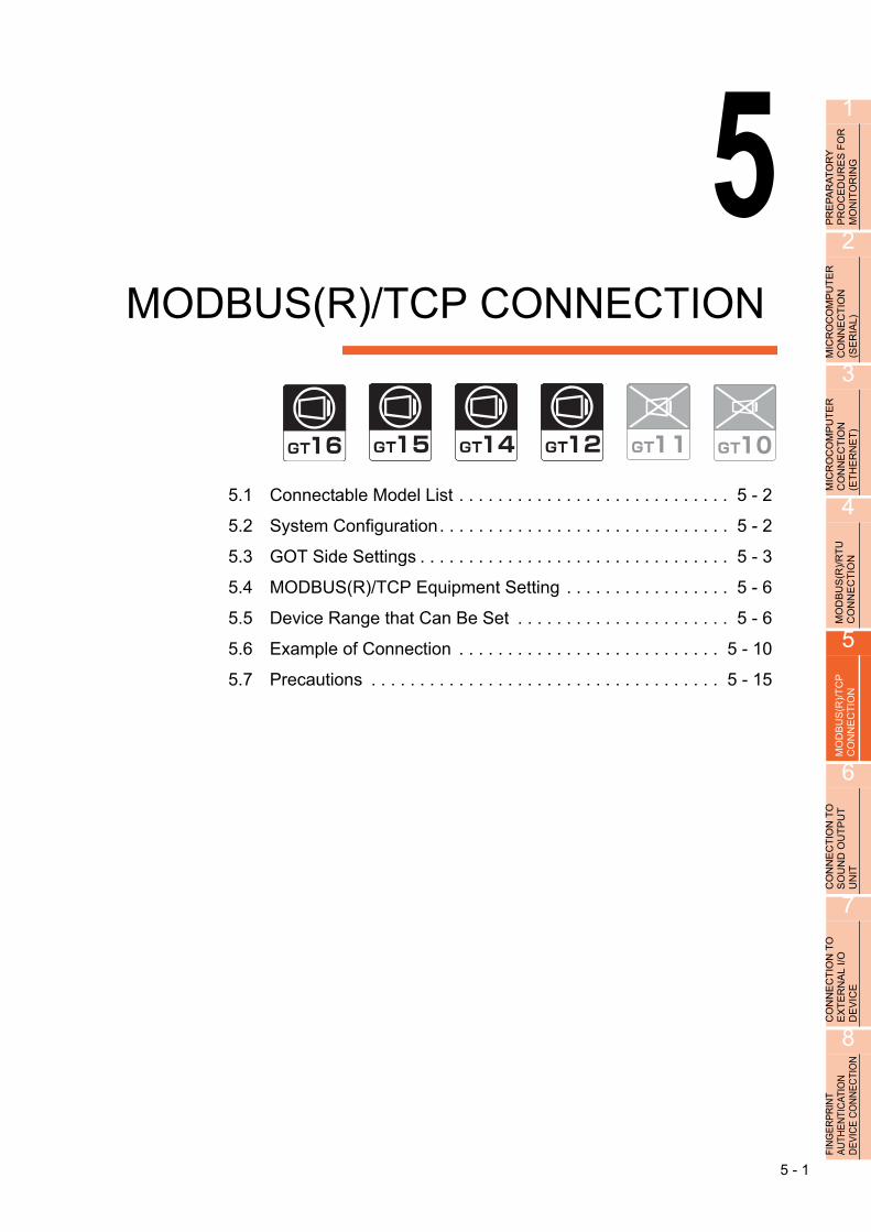
51
PR
EP
AR
AT
OR
Y
PR
OC
ED
UR
ES
FO
R
MO
NIT
OR
ING
2
MIC
RO
CO
MP
UT
ER
C
ON
NE
CT
ION
(S
ER
IAL
)
3
MIC
RO
CO
MP
UT
ER
C
ON
NE
CT
ION
(E
TH
ER
NE
T)
4
MO
DB
US
(R)/
RT
U
CO
NN
EC
TIO
N
5
MO
DB
US
(R)/
TC
P
CO
NN
EC
TIO
N
6
CO
NN
EC
TIO
N T
O
SO
UN
D O
UT
PU
T
UN
IT
7
CO
NN
EC
TIO
N T
O
EX
TE
RN
AL
I/O
D
EV
ICE
8
ING
ER
PR
INT
UTH
EN
TIC
ATIO
N
EV
ICE
CO
NN
EC
TIO
N
5.MODBUS(R)/TCP CONNECTION
5.1 Connectable Model List . . . . . . . . . . . . . . . . . . . . . . . . . . . . 5 - 2
5.2 System Configuration. . . . . . . . . . . . . . . . . . . . . . . . . . . . . . 5 - 2
5.3 GOT Side Settings . . . . . . . . . . . . . . . . . . . . . . . . . . . . . . . . 5 - 3
5.4 MODBUS(R)/TCP Equipment Setting . . . . . . . . . . . . . . . . . 5 - 6
5.5 Device Range that Can Be Set . . . . . . . . . . . . . . . . . . . . . . 5 - 6
5.6 Example of Connection . . . . . . . . . . . . . . . . . . . . . . . . . . . 5 - 10
5.7 Precautions . . . . . . . . . . . . . . . . . . . . . . . . . . . . . . . . . . . . 5 - 15
F A D
5 - 1
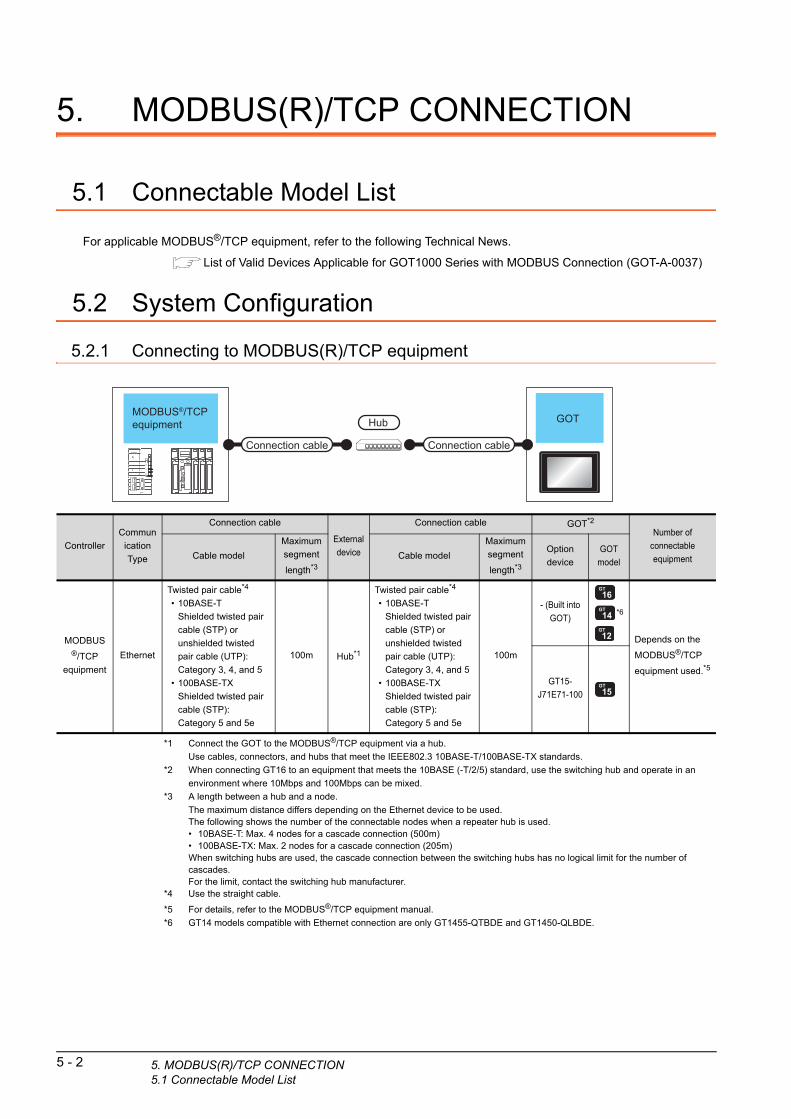
5 - 2 5. MODBUS(R)/TCP CONNECTION5.1 Connectable Model List
5. MODBUS(R)/TCP CONNECTION
5.1 Connectable Model List
For applicable MODBUS®/TCP equipment, refer to the following Technical News.
List of Valid Devices Applicable for GOT1000 Series with MODBUS Connection (GOT-A-0037)
5.2 System Configuration
5.2.1 Connecting to MODBUS(R)/TCP equipment
GOTHub
Connection cable Connection cable
MODBUS®/TCP equipment
*1 Connect the GOT to the MODBUS®/TCP equipment via a hub.
Use cables, connectors, and hubs that meet the IEEE802.3 10BASE-T/100BASE-TX standards.
*2 When connecting GT16 to an equipment that meets the 10BASE (-T/2/5) standard, use the switching hub and operate in an
environment where 10Mbps and 100Mbps can be mixed.
*3 A length between a hub and a node.
The maximum distance differs depending on the Ethernet device to be used.The following shows the number of the connectable nodes when a repeater hub is used.• 10BASE-T: Max. 4 nodes for a cascade connection (500m)• 100BASE-TX: Max. 2 nodes for a cascade connection (205m)When switching hubs are used, the cascade connection between the switching hubs has no logical limit for the number of cascades.For the limit, contact the switching hub manufacturer.
*4 Use the straight cable.
*5 For details, refer to the MODBUS®/TCP equipment manual.
*6 GT14 models compatible with Ethernet connection are only GT1455-QTBDE and GT1450-QLBDE.
Controller
Commun
ication
Type
Connection cable
External
device
Connection cable GOT*2
Number of
connectable
equipmentCable model
Maximum
segment
length*3
Cable model
Maximum
segment
length*3
Option
device
GOT
model
MODBUS®/TCP
equipment
Ethernet
Twisted pair cable*4
• 10BASE-T
Shielded twisted pair
cable (STP) or
unshielded twisted
pair cable (UTP):
Category 3, 4, and 5
• 100BASE-TX
Shielded twisted pair
cable (STP):
Category 5 and 5e
100m Hub*1
Twisted pair cable*4
• 10BASE-T
Shielded twisted pair
cable (STP) or
unshielded twisted
pair cable (UTP):
Category 3, 4, and 5
• 100BASE-TX
Shielded twisted pair
cable (STP):
Category 5 and 5e
100m
- (Built into
GOT)*6
Depends on the
MODBUS®/TCP
equipment used.*5
GT15-
J71E71-100

1
FO
R
5.3 GOT Side SettingsPR
EP
AR
AT
OR
YP
RO
CE
DU
RE
S
MO
NIT
OR
ING
2
MIC
RO
CO
MP
UT
ER
C
ON
NE
CT
ION
(S
ER
IAL
)
3
MIC
RO
CO
MP
UT
ER
C
ON
NE
CT
ION
(E
TH
ER
NE
T)
4
MO
DB
US
(R)/
RT
U
CO
NN
EC
TIO
N
5
MO
DB
US
(R)/
TC
P
CO
NN
EC
TIO
N
6
CO
NN
EC
TIO
N T
O
SO
UN
D O
UT
PU
T
UN
IT
7
CO
NN
EC
TIO
N T
O
EX
TE
RN
AL
I/O
D
EV
ICE
8
FIN
GE
RP
RIN
T A
UTH
EN
TIC
ATIO
N
DE
VIC
E C
ON
NE
CTI
ON
5.3.1 Setting communication interface (Communication settings)
Set the channel of the equipment to be connected to the GOT.
1. Select [Common] [Controller Setting] from the menu.
2. The Controller Setting window is displayed. Select the channel to be used from the list menu.
3. Set the following items.• Manufacturer: MODBUS• Controller Type: MODBUS• I/F: Interface to be used• Driver: MODBUS/TCP, Gateway
4. The detailed setting is displayed after Manufacturer, Controller Type, I/F, and Driver are set.Make the settings according to the usage environment.
5.3.2 Communication detail settings
Click the [OK] button when settings are completed.
POINTPOINTPOINT
The settings of connecting equipment can be set and confirmed in [I/F Communication Setting].For details, refer to the following.
1.1.2 I/F communication setting
2.
3.
4.
Click!
5.3.2 Communication detail settings
Make the settings according to the usage environment.
(1) GT16, GT14
Item Description Range
GOT NET No.Set the network No. of the GOT.
(Default: 1)1 to 239
GOT PLC No.Set the station No. of the GOT.
(Default: 1)1 to 247
GOT
IP Address*1
Set the IP address of the GOT.
(Default: 192.168.3.18)
0.0.0.0 to
255.255.255.255
Subnet Mask*1
Set the subnet mask for the sub
network.(Only for connection via
router)
If the sub network is not used, the
default value is set.
(Default: 255.255.255.0)
0.0.0.0 to
255.255.255.255
Default
Gateway*1
Set the router address of the
default gateway where the GOT is
connected.(Only for connection via
router)
(Default: 0.0.0.0)
0.0.0.0 to
255.255.255.255
Ethernet
Download Port
No.*1
Set the GOT port No. for Ethernet
download.
(Default: 5014)
1024 to 5010,
5014 to 65534
(Except for 5011,
5012, 5013 and
49153)
GOT
Communication
Port No.
Set the GOT port No. for the
connection with the Ethernet
module.
(Default: 5020)
1024 to 5010,
5014 to 65534
(Except for 5011,
5012, 5013 and
49153)
Startup Time
Specify the time period from the
GOT startup until GOT starts the
communication with the PLC CPU.
(Default: 3sec)
3 to 255sec
Timeout Time
Set the time period for a
communication to time out.
(Default: 3sec)
3 to 90sec
Delay Time
Set the delay time for reducing the
load of the network/destination
PLC.
(Default: 0ms)
0 to 10000
( 10 ms)
32bit Storage
Select the steps to store two words
(32-bit data).
(Default: LH Order)
LH Order/HL Order
5. MODBUS(R)/TCP CONNECTION5.3 GOT Side Settings
5 - 3

*1 Click the [Setting] button and perform the setting in the [GOT IP Address Setting] screen.
(2) GT15, GT12
Item Description Range
GOT NET No.Set the network No. of the GOT.
(Default: 1)1 to 239
GOT PLC No.Set the station No. of the GOT.
(Default: 1)1 to 247
GOT
IP Address
Set the IP address of the GOT.
(Default: 192.168.0.18)
0.0.0.0 to
255.255.255.255
Subnet Mask
Set the subnet mask for the sub
network.(Only for connection via
router)
If the sub network is not used, the
default value is set.
(Default: 255.255.255.0)
0.0.0.0 to
255.255.255.255
Default
Gateway
Set the router address of the
default gateway where the GOT is
connected.(Only for connection via
router)
(Default: 0.0.0.0)
0.0.0.0 to
255.255.255.255
Ethernet
Download Port
No. *2 *3
Set the GOT port No. for Ethernet
download.
(Default: 5014)
1024 to 5010,
5014 to 65534
(Except for 5011,
5012, 5013 and
49153)
GOT
Communication
Port No.
Set the GOT port No. for the
connection with the Ethernet
module.
(Default: 5020)
1024 to 5010,
5014 to 65534
(Except for 5011,
5012, 5013 and
49153)
Startup Time
Specify the time period from the
GOT startup until GOT starts the
communication with the PLC CPU.
(Default: 3sec)
3 to 255sec
5 - 4 5. MODBUS(R)/TCP CONNECTION5.3 GOT Side Settings
POINTPOINTPOINT
(1) Communication interface setting by the UtilityThe communication interface setting can be changed on the Utility's [Communication setting] after writing [Communication Settings] of project data.For details on the Utility, refer to the following manual.
User's Manual of GOT used.
(2) Precedence in communication settingsWhen settings are made by GT Designer3 or the Utility, the latest setting is effective.
Timeout Time
Set the time period for a
communication to time out.
(Default: 3sec)
3 to 90sec
Delay Time
Set the delay time for reducing the
load of the network/destination
PLC.
(Default: 0ms)
0 to 10000
( 10 ms)
32bit Storage
Select the steps to store two words
(32-bit data).
(Default: LH Order)
LH Order/HL Order
Item Description Range
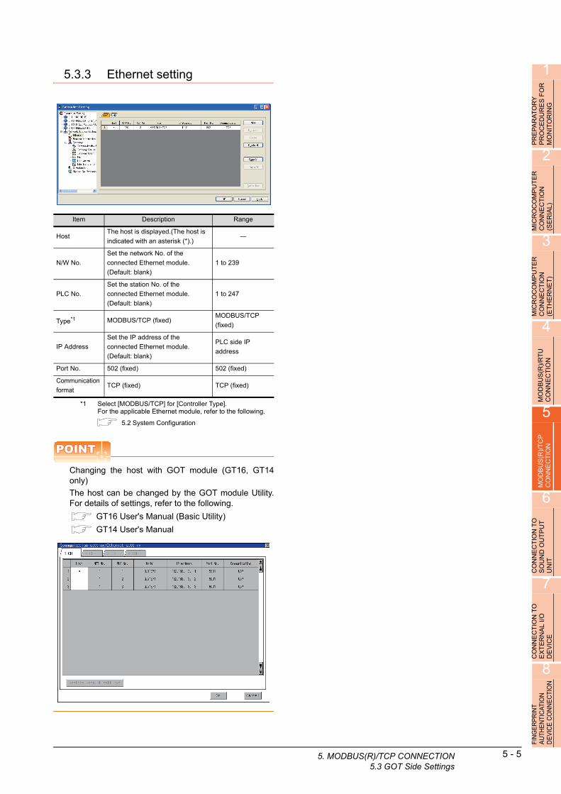
1
PR
EP
AR
AT
OR
Y
PR
OC
ED
UR
ES
FO
R
MO
NIT
OR
ING
2
MIC
RO
CO
MP
UT
ER
C
ON
NE
CT
ION
(S
ER
IAL
)
3
MIC
RO
CO
MP
UT
ER
C
ON
NE
CT
ION
(E
TH
ER
NE
T)
4
MO
DB
US
(R)/
RT
U
CO
NN
EC
TIO
N
5
MO
DB
US
(R)/
TC
P
CO
NN
EC
TIO
N
6
CO
NN
EC
TIO
N T
O
SO
UN
D O
UT
PU
T
UN
IT
7
CO
NN
EC
TIO
N T
O
EX
TE
RN
AL
I/O
D
EV
ICE
8
FIN
GE
RP
RIN
T A
UTH
EN
TIC
ATIO
N
DE
VIC
E C
ON
NE
CTI
ON
5.3.3 Ethernet setting
*1 Select [MODBUS/TCP] for [Controller Type].For the applicable Ethernet module, refer to the following.
5.2 System Configuration
POINTPOINTPOINT
Changing the host with GOT module (GT16, GT14only)
The host can be changed by the GOT module Utility.For details of settings, refer to the following.
GT16 User's Manual (Basic Utility)
GT14 User's Manual
Item Description Range
HostThe host is displayed.(The host is
indicated with an asterisk (*).)―
N/W No.
Set the network No. of the
connected Ethernet module.
(Default: blank)
1 to 239
PLC No.
Set the station No. of the
connected Ethernet module.
(Default: blank)
1 to 247
Type*1 MODBUS/TCP (fixed)MODBUS/TCP
(fixed)
IP Address
Set the IP address of the
connected Ethernet module.
(Default: blank)
PLC side IP
address
Port No. 502 (fixed) 502 (fixed)
Communication
formatTCP (fixed) TCP (fixed)
5. MODBUS(R)/TCP CONNECTION5.3 GOT Side Settings
5 - 5

5 - 6 5. MODBUS(R)/TCP CONNECTION5.4 MODBUS(R)/TCP Equipment Setting
5.4 MODBUS(R)/TCP Equipment Setting
For details of the MODBUS®/TCP equipment, refer to the manual of MODBUS®/RTU equipment to be used.
5.5 Device Range that Can Be Set
The device ranges of controller that can be used for GOT are as follows.Note that the device ranges in the following tables are the maximum values that can be set in GT Designer3.The device specifications of controllers may differ depending on the models, even though belonging to the same series.Please make the setting according to the specifications of the controller actually used.When a non-existent device or a device number outside the range is set, other objects with correct device settings may not be monitored.
Setting item
Item Description
Device
Set the device name, device number, and bit number.
The bit number can be set only when specifying the bit of word device.
File No.Set the file No.
The file No. can be set only when select 6 at [Device].
Information Displays the device type and setting range which are selected in [Device].
Network
Set the station number of the controller to be monitored.
Host Select this item for monitoring the host controller.
Other
• For GT16, GT15
Select this for monitoring other controllers.
After selecting the item, set the station number and network number of the controller to be monitored.
NW No.: For the MODBUS® /RTU connection, set "1".
For the MODBUS®/TCP connection, set the network No.
Station No.: Set the station No.
• For GT11, GT10
Select this for monitoring other controllers.
After selecting, set the station number of the controller to be monitored.
Station No.: Set the station No.

1
PR
EP
AR
AT
OR
Y
PR
OC
ED
UR
ES
FO
R
MO
NIT
OR
ING
2
MIC
RO
CO
MP
UT
ER
C
ON
NE
CT
ION
(S
ER
IAL
)
3
MIC
RO
CO
MP
UT
ER
C
ON
NE
CT
ION
(E
TH
ER
NE
T)
4
MO
DB
US
(R)/
RT
U
CO
NN
EC
TIO
N
5
MO
DB
US
(R)/
TC
P
CO
NN
EC
TIO
N
6
CO
NN
EC
TIO
N T
O
SO
UN
D O
UT
PU
T
UN
IT
7
CO
NN
EC
TIO
N T
O
EX
TE
RN
AL
I/O
D
EV
ICE
8
FIN
GE
RP
RIN
T A
UTH
EN
TIC
ATIO
N
DE
VIC
E C
ON
NE
CTI
ON
*1 Only reading is possible.
POINTPOINTPOINT
(1) Range of coils and input relays that can be monitoredThe device range of MODBUS equipment differs depending on the type.When using types that the device range for coils and input relays are other than hexadecimal, monitoring to the device maximum range may not be possible.In this case, the device range extends to the last number divisible by 16.Example: For a type whose coil device range is from 0 to 9999.
The range that can be actually monitored is from 0 to 9984.
(2) Address conversion exampleWhen monitoring the holding register's address "1234H", GT Designer3 displays "4*****" since GT Designer3 processes the internal conversion in decimal format as follows:GT Designer3 converts the holding register's address "1234H" to "04660" in decimal format.Then, "+1" is added to this decimal address since the holding register's address on GT Designer3 always starts from "1."Therefore, the holding register's address "1234H" is displayed as "404661" on GT Designer3.
Device name Setting rangeDevice No.
representation
Bit
devi
ce
Coils (0) 000001 to 065536
Decimal
Discretes input (1)*1 100001 to 165536
Wo
rd d
evic
e
Input registers (3)*1 300001 to 365536
DecimalHolding registers (4) 400001 to 465536
Extension file register (6)File No.: 0 to104
600000 to 609999
Holding register
"4 04660" +1
"404661"
1234H
5. MODBUS(R)/TCP CONNECTION5.5 Device Range that Can Be Set
5 - 7
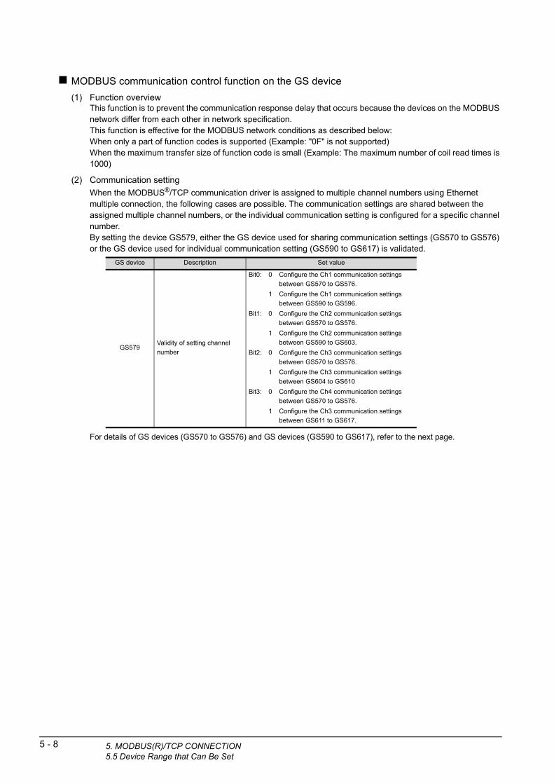
5 - 8 5. MODBUS(R)/TCP CONNECTION5.5 Device Range that Can Be Set
MODBUS communication control function on the GS device
(1) Function overviewThis function is to prevent the communication response delay that occurs because the devices on the MODBUS network differ from each other in network specification.This function is effective for the MODBUS network conditions as described below:When only a part of function codes is supported (Example: "0F" is not supported)When the maximum transfer size of function code is small (Example: The maximum number of coil read times is 1000)
(2) Communication setting
When the MODBUS®/TCP communication driver is assigned to multiple channel numbers using Ethernet multiple connection, the following cases are possible. The communication settings are shared between the assigned multiple channel numbers, or the individual communication setting is configured for a specific channel number.By setting the device GS579, either the GS device used for sharing communication settings (GS570 to GS576) or the GS device used for individual communication setting (GS590 to GS617) is validated.
GS device Description Set value
GS579Validity of setting channel
number
Bit0: 0 Configure the Ch1 communication settings
between GS570 to GS576.
1 Configure the Ch1 communication settings
between GS590 to GS596.
Bit1: 0 Configure the Ch2 communication settings
between GS570 to GS576.
1 Configure the Ch2 communication settings
between GS590 to GS603.
Bit2: 0 Configure the Ch3 communication settings
between GS570 to GS576.
1 Configure the Ch3 communication settings
between GS604 to GS610
Bit3: 0 Configure the Ch4 communication settings
between GS570 to GS576.
1 Configure the Ch3 communication settings
between GS611 to GS617.
For details of GS devices (GS570 to GS576) and G
devices (GS590 to GS617), refer to the next page. S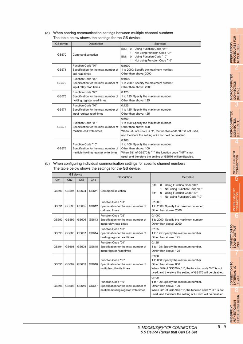
1
PR
EP
AR
AT
OR
Y
PR
OC
ED
UR
ES
FO
R
MO
NIT
OR
ING
2
MIC
RO
CO
MP
UT
ER
C
ON
NE
CT
ION
(S
ER
IAL
)
3
MIC
RO
CO
MP
UT
ER
C
ON
NE
CT
ION
(E
TH
ER
NE
T)
4
MO
DB
US
(R)/
RT
U
CO
NN
EC
TIO
N
5
MO
DB
US
(R)/
TC
P
CO
NN
EC
TIO
N
6
CO
NN
EC
TIO
N T
O
SO
UN
D O
UT
PU
T
UN
IT
7
CO
NN
EC
TIO
N T
O
EX
TE
RN
AL
I/O
D
EV
ICE
8
ION
(a) When sharing communication settings between multiple channel numbersThe table below shows the settings for the GS device.
(b) When configuring individual communication settings for specific channel numbersThe table below shows the settings for the GS device.
GS device Description Set value
GS570 Command selection
Bit0: 0 Using Function Code "0F"1 Not using Function Code "0F"
Bit1: 0 Using Function Code "10"1 Not using Function Code "10"
GS571
Function Code "01"
Specification for the max. number of
coil read times
0:10001 to 2000: Specify the maximum number.Other than above: 2000
GS572
Function Code "02"
Specification for the max. number of
input relay read times
0:1000
1 to 2000: Specify the maximum number.
Other than above: 2000
GS573
Function Code "03"
Specification for the max. number of
holding register read times
0:125
1 to 125: Specify the maximum number.
Other than above: 125
GS574
Function Code "04"
Specification for the max. number of
input register read times
0:125
1 to 125: Specify the maximum number.
Other than above: 125
GS575
Function Code "0F"
Specification for the max. number of
multiple-coil write times
0:800
1 to 800: Specify the maximum number.
Other than above: 800
When Bit0 of GS570 is "1", the function code "0F" is not used,
and therefore the setting of GS575 will be disabled.
GS576
Function Code "10"
Specification for the max. number of
multiple-holding register write times
0:100
1 to 100: Specify the maximum number.
Other than above: 100
When Bit1 of GS570 is "1", the function code "10F" is not
used, and therefore the setting of GS576 will be disabled.
GS deviceDescription Set value
Ch1 Ch2 Ch3 Ch4
GS590 GS597 GS604 GS611 Command selection
Bit0: 0 Using Function Code "0F"1 Not using Function Code "0F"
Bit1: 0 Using Function Code "10"1 Not using Function Code "10"
GS591 GS598 GS605 GS612
Function Code "01"
Specification for the max. number of
coil read times
0:1000
1 to 2000: Specify the maximum number.
Other than above: 2000
GS592 GS599 GS606 GS613
Function Code "02"
Specification for the max. number of
input relay read times
0:1000
1 to 2000: Specify the maximum number.
Other than above: 2000
GS593 GS600 GS607 GS614
Function Code "03"
Specification for the max. number of
holding register read times
0:125
1 to 125: Specify the maximum number.
Other than above: 125
GS594 GS601 GS608 GS615
Function Code "04"
Specification for the max. number of
input register read times
0:125
1 to 125: Specify the maximum number.
Other than above: 125
GS595 GS602 GS609 GS616
Function Code "0F"
Specification for the max. number of
multiple-coil write times
0:800
1 to 800: Specify the maximum number.
Other than above: 800
When Bit0 of GS570 is "1", the function code "0F" is not
used, and therefore the setting of GS575 will be disabled.
GS596 GS603 GS610 GS617
Function Code "10"
Specification for the max. number of
multiple-holding register write times
0:100
1 to 100: Specify the maximum number.
Other than above: 100
When Bit1 of GS570 is "1", the function code "10F" is not
used, and therefore the setting of GS576 will be disabled.
FIN
GE
RP
RIN
T A
UTH
EN
TIC
ATIO
ND
EV
ICE
CO
NN
EC
T
5. MODBUS(R)/TCP CONNECTION5.5 Device Range that Can Be Set
5 - 9

5 - 10 5. MODBUS(R)/TCP CONNECTION5.6 Example of Connection
5.6 Example of Connection
5.6.1 Connecting to SCHNEIDER PLC (Modicon Premium series and Modicon Quantum series)
System Configuration
MODBUS/TCP
Communication driver
Ethernetmodule
SCHNEIDERPLC GOTHub
Connection cable Connection cable
*1 Connect the GOT to the Ethernet module via a hub.Use cables, connectors, and hubs that meet the IEEE802.3 10BASE-T/100BASE-TX standards.
*2 When connecting GT16 to an equipment that meets the 10BASE (-T/2/5) standard, use the switching hub and operate in an environment where 10Mbps and 100Mbps can be mixed.
*3 A length between a hub and a node.
The maximum distance differs depending on the Ethernet device to be used.The following shows the number of the connectable nodes when a repeater hub is used.• 10BASE-T: Max. 4 nodes for a cascade connection (500m)• 100BASE-TX: Max. 2 nodes for a cascade connection (205m)When switching hubs are used, the cascade connection between the switching hubs has no logical limit for the number of cascades.For the limit, contact the switching hub manufacturer.
*4 Product manufactured by SCHNEIDER ELECTRIC SA.For details of the product, contact SCHNEIDER ELECTRIC SA.*5 Use the straight cable.*6 GT14 models compatible with Ethernet connection are only GT1455-QTBDE and GT1450-QLBDE.
controllerEthernet
module*4
Communi
cation
Type
Connection cableExternal
device
Connection cable GOT*2 Number of
connectable
equipmentCable model*5Max.
distanceCable model*5
Max.
distanceOption device
GOT
model
Modicon
Premium
Series
TSX ETY 4102
TSX ETY 5102
Ethernet
Twisted pair cable
• 10BASE-T
Shielded twisted
pair cable (STP)
or unshielded
twisted pair
cable (UTP):
Category 3, 4,
and 5
• 100BASE-TX
Shielded twisted
pair cable (STP):
Category 5 and
5e
100m*3 Hub*1
Twisted pair cable
• 10BASE-T
Shielded twisted
pair cable (STP)
or unshielded
twisted pair
cable (UTP):
Category 3, 4,
and 5
• 100BASE-TX
Shielded twisted
pair cable (STP):
Category 5 and
5e
100m*3
- (Built into GOT) *6
64 GOTs
for 1 PLCModicon
Quantum
Series
140 NOE 771 00
140 NOE 771 10
140 NWM 100 00
GT15-J71E71-100
PLC Side Setting
POINTPOINTPOINT
SCHNEIDER ELECTRIC PLC
For details of SCHNEIDER PLC, refer to the following manual.
SCHNEIDER PLC user's Manual

1
AR
AT
OR
Y
ED
UR
ES
FO
R
TO
RIN
G
(1) Parameter settingsSet the parameter settings with programming software for SCHNEIDER PLC.
(a) For Modicon Premium seriesSet for PL7 Pro programming software.
P C I
PR
EP
RO
MO
N
2
ICR
OC
OM
PU
TE
R
ON
NE
CT
ION
E
RIA
L)
Item Set value
Processors Connected CPU module
Memory cards Memory card to be used
Module Connected Ethernet module
IP Address IP address for Ethernet module
Size of global address
fields
Setting for device points
Bits: Coil, Input
Words: Input register, Maintenance register
M C (S
3
(b) For Modicon Quantum seriesSet for Concept programming software.
R
MICR
OC
OM
PU
TE
CO
NN
EC
TIO
N
(ET
HE
RN
ET
)
4
MO
DB
US
(R)/
RT
U
CO
NN
EC
TIO
N
5
MO
DB
US
(R)/
TC
P
CO
NN
EC
TIO
N
6
CO
NN
EC
TIO
N T
O
SO
UN
D O
UT
PU
T
UN
IT
7
CO
NN
EC
TIO
N T
O
EX
TE
RN
AL
I/O
D
EV
ICE
8
FIN
GE
RP
RIN
T A
UTH
EN
TIC
ATIO
N
DE
VIC
E C
ON
NE
CTI
ON
Item Set value
PLC Selection Connected CPU module
TCP/IP Ethernet Numbers of unit
I/O Module Selection Connected Ethernet module
Internet Address IP address for Ethernet module
5. MODBUS(R)/TCP CONNECTION5.6 Example of Connection
5 - 11

5 - 12 5. MODBUS(R)/TCP CONNECTION5.6 Example of Connection
5.6.2 Connecting to YOKOGAWA PLC (STARDOM)
System Configuration
MODBUS/TCP
Communication driver
YOKOGAWAPLC GOTHub
Connection cable Connection cable
*1 When connecting STARDOM to MODBUS®/TCP, Modbus Communication Portfolio License is required.
For details, refer to the following manual.
YOKOGAWA PLC user's Manual
*2 When connect a GOT to a PLC, connect to the PCL Ethernet port via a hub.
Use cables, connectors, and hubs that meet the IEEE802.3 10BASE-T/100BASE-TX standards.*3 When connecting GT16 to an equipment that meets the 10BASE (-T/2/5) standard, use the switching hub and operate in an
environment where 10Mbps and 100Mbps can be mixed.
*4 A length between a hub and a node.
The maximum distance differs depending on the Ethernet device to be used.The following shows the number of the connectable nodes when a repeater hub is used.• 10BASE-T: Max. 4 nodes for a cascade connection (500m)• 100BASE-TX: Max. 2 nodes for a cascade connection (205m)When switching hubs are used, the cascade connection between the switching hubs has no logical limit for the number of cascades.For the limit, contact the switching hub manufacturer.
*5 Use the straight cable.
*6 GT14 models compatible with Ethernet connection are only GT1455-QTBDE and GT1450-QLBDE.
PLC Side SettingMake the communication settings as shown below. For details of the communication settings, refer to the following manual.
Peripheral Software Manual for YOKOGAWA PLC
POINTPOINTPOINT
Connection between STARDOM and the PC for communication settings
For the communication settings of STARDOM, STARDOM and the PC for communication settings must be connected to Ethernet using the Resource Configurator (peripheral software).
controllerCommunic
ation Type
Connection cableExternal
device
Connection cable GOT*3 Number of
connectable
equipmentCable model*5Max.
distanceCable model*5
Max.
distanceOption device
GOT
Model
STARDOM*1
(NFCP100,
NFJT100)
Ethernet
Twisted pair cable
• 10BASE-T
Shielded twisted
pair cable (STP) or
unshielded twisted
pair cable (UTP):
Category 3, 4, and
5
• 100BASE-TX
Shielded twisted
pair cable (STP):
Category 5 and 5e
100m*4 Hub*2
Twisted pair cable
• 10BASE-T
Shielded twisted
pair cable (STP) or
unshielded twisted
pair cable (UTP):
Category 3, 4, and
5
• 100BASE-TX
Shielded twisted
pair cable (STP):
Category 5 and 5e
100m*4
- (Built into GOT) *6
126 GOTs
for 1 PLC
GT15-J71E71-100

1
PR
EP
AR
AT
OR
Y
PR
OC
ED
UR
ES
FO
R
MO
NIT
OR
ING
2
MIC
RO
CO
MP
UT
ER
C
ON
NE
CT
ION
(S
ER
IAL
)
3
MIC
RO
CO
MP
UT
ER
C
ON
NE
CT
ION
(E
TH
ER
NE
T)
4
MO
DB
US
(R)/
RT
U
CO
NN
EC
TIO
N
5
MO
DB
US
(R)/
TC
P
CO
NN
EC
TIO
N
6
CO
NN
EC
TIO
N T
O
SO
UN
D O
UT
PU
T
UN
IT
7
CO
NN
EC
TIO
N T
O
EX
TE
RN
AL
I/O
D
EV
ICE
8
FIN
GE
RP
RIN
T A
UTH
EN
TIC
ATIO
N
DE
VIC
E C
ON
NE
CTI
ON
(1) Modbus Communication Portfolio LicenseTo set the communication settings for STARDOM, an installation of Modbus Communication Portfolio License is required.For details of the communication settings, refer to the following manual.
STARDOM FCN/FCJ Guide
(2) Defining Logic POUDefine Logic POU using Logic Designer (peripheral software), and download the project to STARDOM.
(a) Start Logic Designer and create a new project using a template.Use [STARDOM Serial Communication] template.
(b) Insert Firmware Library to the new project.• Right-click [Library] under the project tree in Logic Designer.• Right-click [Insert] and select [Firmware Library].• Double-click the [SD_FCXPLCE_LIB] folder and double-click [SD_FCXPLCE_LIB.fwl] to select it.• The library path inserted in the procedures above is as follows.
{Install Folder}\LogicDesigner\Mwt\Plc\Fw_lib\SD_FCXPLCE_LIB\SD_FCXPLCE_LIB.fwl
(c) Insert User Library to the new project.• Right-click [Library] under the project tree in Logic Designer.• Right-click [Insert] and select [User Library].• Double-click [SD_CMODBUSE_PF.mwt], [SD_CUTIL_PF.mwt] and [SD_CMODBUSS_PF.mwt] to
select it.(When [STARDOM Serial Communication] is used for the template, [SD_CUTIL_PF.mwt] is inserted as default.)
• The library path inserted in the procedures above is as follows.{Install Folder}\LogicDesigner\Libraries\SD_CMODBUSE_PF.mwt{Install Folder}\LogicDesigner\Libraries\SD_CUTIL_PF.mwt{Install Folder}\LogicDesigner\Libraries\SD_CMODBUSS_PF.mwt
(d) Copy a sample project POU to the new project.• Open "SD_CMODBUSE_Sample1.mwt".• Right-click [ComEServerModbus*] in the Logic POU under the project tree in the
SD_CMODBUSE_Sample1 project, and select [Copy].• Right-click the [Logic POU] under the project tree in the previously created project, and select [Paste].• Double-click the [ComEServerModbus*] file in the [ComEServerModbus*] folder.• For the following terminals, set as shown below.
5. MODBUS(R)/TCP CONNECTION5.6 Example of Connection
5 - 13

5 - 14 5. MODBUS(R)/TCP CONNECTION5.6 Example of Connection
(e) Set devices to be monitored by a GOT.• Right-click the [ComEServerModbus*] file in the [ComEServerModbus*] folder in the logic POU under
the project tree and select [Insert] - [Cord worksheet].• Set the variable devices to be monitored.
Instantiate Logic POU.Define an already defined instance to Task0.• Right-click [Physical hardware] - [Configuration:IPC_33/FCX01:FCX/Tasks/Task0:CYCLIC] and select
[Insert] - [Program instance].• Define the program instance name and select ComEServerModbus for the program type.
(f) Defining Target SettingDefine the IP address of STARDOM to set the communication settings.Double-click [Physical hardware] - [Configuration:IPC_33/FCX01:FCX/Target Setting] and input the IP address or the host name.
(g) Downloading the project
• Execute [Build] - [Make].(Same as when pressing the function key F9).• Download after confirming that the compile error does not occur. Select [Download] in the project control
dialog displayed when [Online] - [Project control] is selected.• When the download is completed, select [Cold] and start STARDOM.
Device rangeWhen performing monitoring with the GOT connected to a YOKOGAWA PLC and setting devices for objects, use devices within the device range of the YOKOGAWA PLC.When a device outside the range is set on an object, an indefinite value is displayed on the object.(No error is displayed in the system alarm.)For details on the device range of YOKOGAWA PLCs, refer to the following manual:
YOKOGAWA PLC user's Manual
Precautions
(1) For dual-redundant configurationWhen STARDOM is configured with a redundant system, the connection is not supported.
(2) Not communicating with GOT and STARDOM in a specified periodWhen the GOT does not communicate with STARDOM in a specified period during the GOT is turned on, STARDOM disconnects the line for the GOT. As the line is disconnected, the GOT displays an error when the GOT monitors STARDAM after the disconnection.After the error displayed as the system alarm (No.402: timeout error) on the GOT, the normal communication is recovered and the GOT can monitor STARDOM.
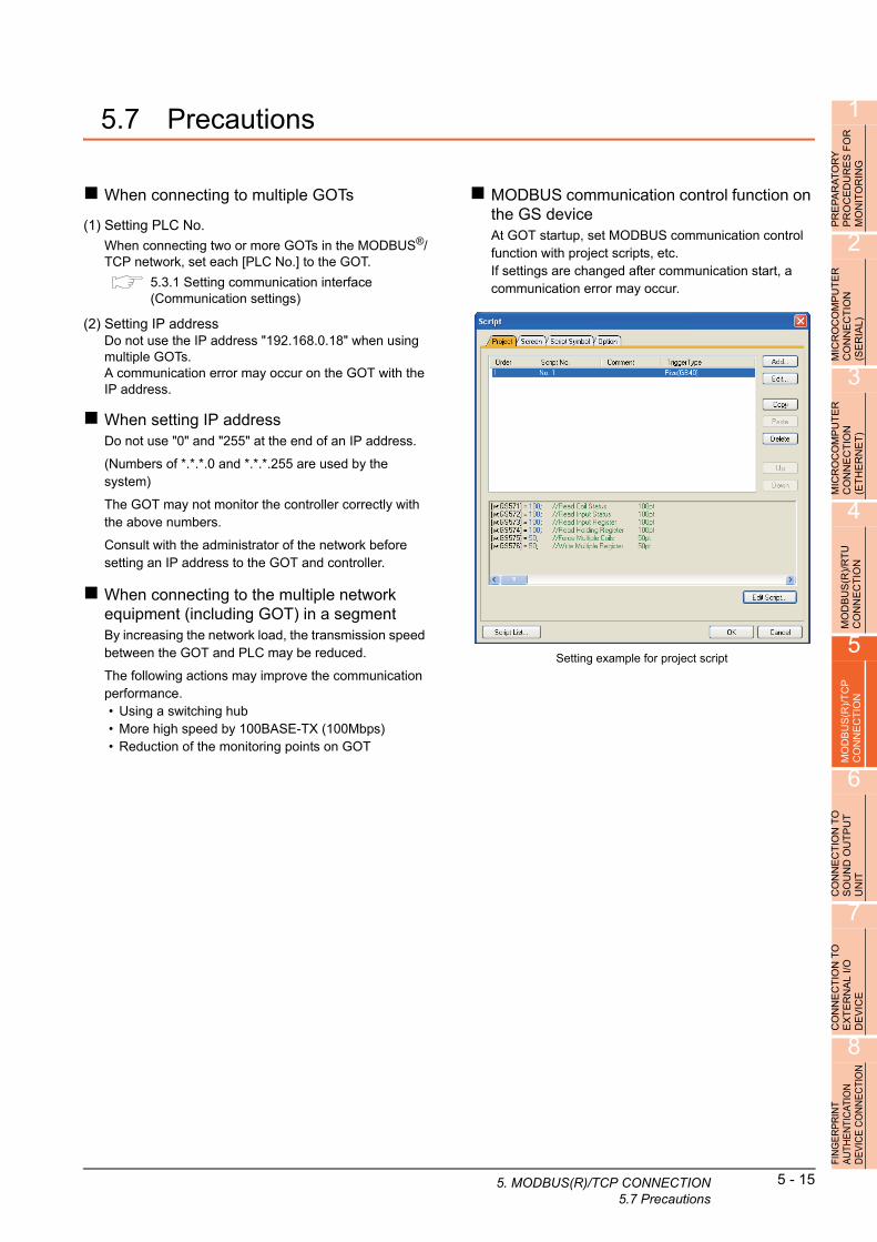
1
FO
R
5.7 PrecautionsPR
EP
AR
AT
OR
YP
RO
CE
DU
RE
S
MO
NIT
OR
ING
2
MIC
RO
CO
MP
UT
ER
C
ON
NE
CT
ION
(S
ER
IAL
)
3
MIC
RO
CO
MP
UT
ER
C
ON
NE
CT
ION
(E
TH
ER
NE
T)
4
MO
DB
US
(R)/
RT
U
CO
NN
EC
TIO
N
5
MO
DB
US
(R)/
TC
P
CO
NN
EC
TIO
N
6
CO
NN
EC
TIO
N T
O
SO
UN
D O
UT
PU
T
UN
IT
7
CO
NN
EC
TIO
N T
O
EX
TE
RN
AL
I/O
D
EV
ICE
8
FIN
GE
RP
RIN
T A
UTH
EN
TIC
ATIO
N
DE
VIC
E C
ON
NE
CTI
ON
When connecting to multiple GOTs
(1) Setting PLC No.
When connecting two or more GOTs in the MODBUS®/TCP network, set each [PLC No.] to the GOT.
5.3.1 Setting communication interface (Communication settings)
(2) Setting IP addressDo not use the IP address "192.168.0.18" when using multiple GOTs.A communication error may occur on the GOT with the IP address.
When setting IP addressDo not use "0" and "255" at the end of an IP address.
(Numbers of *.*.*.0 and *.*.*.255 are used by the system)
The GOT may not monitor the controller correctly with the above numbers.
Consult with the administrator of the network before setting an IP address to the GOT and controller.
When connecting to the multiple network equipment (including GOT) in a segmentBy increasing the network load, the transmission speed between the GOT and PLC may be reduced.
The following actions may improve the communication performance.• Using a switching hub• More high speed by 100BASE-TX (100Mbps)• Reduction of the monitoring points on GOT
MODBUS communication control function on the GS deviceAt GOT startup, set MODBUS communication control function with project scripts, etc.If settings are changed after communication start, a communication error may occur.
Setting example for project script
5.
MODBUS(R)/TCP CONNECTION5.7 Precautions5 - 15

5 - 16 5. MODBUS(R)/TCP CONNECTION5.7 Precautions

CONNECTIONS TO PERIPHERALEQUIPMENT
6. CONNECTION TO SOUND OUTPUT UNIT . . . . . . . . . . . . 6 - 1
7. CONNECTION TO EXTERNAL I/O DEVICE. . . . . . . . . . . . 7 - 1
8. FINGERPRINT AUTHENTICATION DEVICE CONNECTION. . . . . . . . . . . . . . . . . . . . . . . . . . . . . . . . . . . . . . . . . . . . . . . 8 - 1
9. BAR CODE READER CONNECTION . . . . . . . . . . . . . . . . . 9 - 1
10. PC REMOTE CONNECTION. . . . . . . . . . . . . . . . . . . . . . . 10 - 1
11. VNC(R) SERVER CONNECTION . . . . . . . . . . . . . . . . . . . .11 - 1
12. VIDEO/RGB CONNECTION . . . . . . . . . . . . . . . . . . . . . . . 12 - 1
13. PRINTER CONNECTION . . . . . . . . . . . . . . . . . . . . . . . . . 13 - 1
14. MULTIMEDIA CONNECTION . . . . . . . . . . . . . . . . . . . . . . 14 - 1
15. RFID CONNECTION . . . . . . . . . . . . . . . . . . . . . . . . . . . . . 15 - 1


61
PR
EP
AR
AT
OR
Y
PR
OC
ED
UR
ES
FO
R
MO
NIT
OR
ING
2
MIC
RO
CO
MP
UT
ER
C
ON
NE
CT
ION
(S
ER
IAL
)
3
MIC
RO
CO
MP
UT
ER
C
ON
NE
CT
ION
(E
TH
ER
NE
T)
4
MO
DB
US
(R)/
RT
U
CO
NN
EC
TIO
N
5
MO
DB
US
(R)/
TC
P
CO
NN
EC
TIO
N
6
CO
NN
EC
TIO
N T
O
SO
UN
D O
UT
PU
T
UN
IT
7
CO
NN
EC
TIO
N T
O
EX
TE
RN
AL
I/O
D
EV
ICE
8
ING
ER
PR
INT
UTH
EN
TIC
ATIO
N
EV
ICE
CO
NN
EC
TIO
N
6.CONNECTION TO SOUNDOUTPUT UNIT
6.1 Connectable Model List . . . . . . . . . . . . . . . . . . . . . . . . . . . . 6 - 2
6.2 System Configuration. . . . . . . . . . . . . . . . . . . . . . . . . . . . . . 6 - 2
6.3 GOT Side Settings . . . . . . . . . . . . . . . . . . . . . . . . . . . . . . . . 6 - 3
6.4 Precautions . . . . . . . . . . . . . . . . . . . . . . . . . . . . . . . . . . . . . 6 - 4
F A D
6 - 1
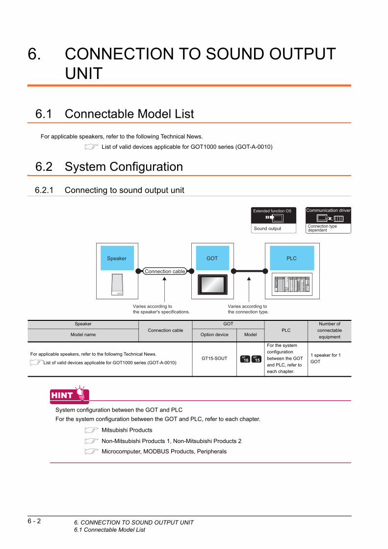
6 - 2 6. CONNECTION TO SOUND OUTPUT UNIT6.1 Connectable Model List
6. CONNECTION TO SOUND OUTPUT UNIT
6.1 Connectable Model List
For applicable speakers, refer to the following Technical News.
List of valid devices applicable for GOT1000 series (GOT-A-0010)
6.2 System Configuration
6.2.1 Connecting to sound output unit
Connection typedependent
Communication driverExtended function OS
Sound output
PLCGOTSpeaker
Varies according tothe connection type.
Varies according tothe speaker's specifications.
Connection cable
HINTHINTHINT
System configuration between the GOT and PLC
For the system configuration between the GOT and PLC, refer to each chapter.
Mitsubishi Products
Non-Mitsubishi Products 1, Non-Mitsubishi Products 2
Microcomputer, MODBUS Products, Peripherals
Speaker
Connection cable
GOT
PLC
Number of
connectable
equipmentModel name Option device Model
For applicable speakers, refer to the following Technical News.
List of valid devices applicable for GOT1000 series (GOT-A-0010)GT15-SOUT
For the system
configuration
between the GOT
and PLC, refer to
each chapter.
1 speaker for 1
GOT

1
6. C
FO
R
6.3 GOT Side SettingsPR
EP
AR
AT
OR
YP
RO
CE
DU
RE
S
MO
NIT
OR
ING
2
MIC
RO
CO
MP
UT
ER
C
ON
NE
CT
ION
(S
ER
IAL
)
3
MIC
RO
CO
MP
UT
ER
C
ON
NE
CT
ION
(E
TH
ER
NE
T)
4
MO
DB
US
(R)/
RT
U
CO
NN
EC
TIO
N
5
MO
DB
US
(R)/
TC
P
CO
NN
EC
TIO
N
6
CO
NN
EC
TIO
N T
O
SO
UN
D O
UT
PU
T
UN
IT
7
CO
NN
EC
TIO
N T
O
EX
TE
RN
AL
I/O
D
EV
ICE
8
FIN
GE
RP
RIN
T A
UTH
EN
TIC
ATIO
N
DE
VIC
E C
ON
NE
CTI
ON
6.3.1 Setting communication interface
Controller settingSet the channel of the equipment to be connected to the GOT.
1. Select [Common] [Controller Setting] from the menu.
2. The Controller Setting window is displayed. Select the channel to be used from the list menu.
3. Set Manufacturer, Controller Type, I/F, and Driver according to the connected equipment to be used.
4. The detailed setting is displayed after Manufacturer, Controller Type, I/F, and Driver are set.Make the settings according to the usage environment.
Click the [OK] button when settings are completed.
POINTPOINTPOINT
The settings of connecting equipment can be set and confirmed in [II/F Communication Setting]. For details, refer to the following.
1.1.2 I/F communication setting
2.
3.
4.
Click!
Sound output unit setting
1. Select [Common] [Peripheral Setting] [Sound Output] from the menu.
2. Set the interface to which the sound output unit is connected.
Click the [OK] button when settings are completed.
POINTPOINTPOINT
(1) Communication interface setting by the UtilityThe communication interface setting can be changed on the Utility's [Communication setting] after writing [Communication Settings] of project data.For details on the Utility, refer to the following manual.
User's Manual of GOT used.(2) Precedence in communication settings
When settings are made by GT Designer3 or the Utility, the latest setting is effective.
2.
Click!
ONNECTION TO SOUND OUTPUT UNIT6.3 GOT Side Settings
6 - 3

6 - 4 6. CONNECTION TO SOUND OUTPUT UNIT6.4 Precautions
6.4 Precautions
Sound output function setting on GT Designer3Before connecting the sound output unit, make the sound output file setting.
For details, refer to the following manual.
GT Designer3 Version1 Screen Design Manual

71
PR
EP
AR
AT
OR
Y
PR
OC
ED
UR
ES
FO
R
MO
NIT
OR
ING
2
MIC
RO
CO
MP
UT
ER
C
ON
NE
CT
ION
(S
ER
IAL
)
3
MIC
RO
CO
MP
UT
ER
C
ON
NE
CT
ION
(E
TH
ER
NE
T)
4
MO
DB
US
(R)/
RT
U
CO
NN
EC
TIO
N
5
MO
DB
US
(R)/
TC
P
CO
NN
EC
TIO
N
6
CO
NN
EC
TIO
N T
O
SO
UN
D O
UT
PU
T
UN
IT
7
CO
NN
EC
TIO
N T
O
EX
TE
RN
AL
I/O
D
EV
ICE
8
ING
ER
PR
INT
UTH
EN
TIC
ATIO
N
EV
ICE
CO
NN
EC
TIO
N
7.CONNECTION TO EXTERNAL I/ODEVICE
7.1 Connectable Model List . . . . . . . . . . . . . . . . . . . . . . . . . . . . 7 - 2
7.2 System Configuration. . . . . . . . . . . . . . . . . . . . . . . . . . . . . . 7 - 2
7.3 Connection Diagram . . . . . . . . . . . . . . . . . . . . . . . . . . . . . . 7 - 4
7.4 GOT Side Settings . . . . . . . . . . . . . . . . . . . . . . . . . . . . . . . 7 - 12
7.5 Precautions . . . . . . . . . . . . . . . . . . . . . . . . . . . . . . . . . . . . 7 - 13
F A D
7 - 1
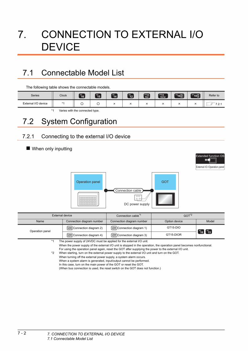
7 - 2 7. CONNECTION TO EXTERNAL I/O DEVICE7.1 Connectable Model List
7. CONNECTION TO EXTERNAL I/O DEVICE
7.1 Connectable Model List
The following table shows the connectable models.
*1 Varies with the connected type.
7.2 System Configuration
7.2.1 Connecting to the external I/O device
When only inputting
Series Clock Refer to
External I/O device *1 7.2.1
Extended function OS
External I/O /Operation panel
Operation panel GOT
Connection cable
DC power supply
*1 The power supply of 24VDC must be applied for the external I/O unit.
When the power supply of the external I/O unit is stopped in the operation, the operation panel becomes nonfunctional.For using the operation panel again, reset the GOT after supplying the power to the external I/O unit.
*2 When starting, turn on the external power supply to the external I/O unit and turn on the GOT.
When turning off the external power supply, a system alarm occurs.When a system alarm is generated, input/output cannot be performed.In this case, turn on the main power of the GOT or reset the GOT.(When bus connection is used, the reset switch on the GOT does not function.)
External device Connection cable*1 GOT*2
Name Connection diagram number Connection diagram number Option device Model
Operation panelConnection diagram 2) Connection diagram 1) GT15-DIO
Connection diagram 4) Connection diagram 3) GT15-DIOR

1
7. C
PR
EP
AR
AT
OR
Y
PR
OC
ED
UR
ES
FO
R
MO
NIT
OR
ING
2
MIC
RO
CO
MP
UT
ER
C
ON
NE
CT
ION
(S
ER
IAL
)
3
MIC
RO
CO
MP
UT
ER
C
ON
NE
CT
ION
(E
TH
ER
NE
T)
4
When inputting and outputting
Extended function OS
External I/O /Operation panel
GOTConnection cable 1)
Connection cable 2)
Connector/terminalblock convertormodule
General input device(Push button,etc.)
General output device(Lamp, relay)
Operation panel
DC power supply
Connection cable 1)
MO
DB
US
(R)/
RT
U
CO
NN
EC
TIO
N
5
MO
DB
US
(R)/
TC
P
CO
NN
EC
TIO
N
6
CO
NN
EC
TIO
N T
O
SO
UN
D O
UT
PU
T
UN
IT
7
CO
NN
EC
TIO
N T
O
EX
TE
RN
AL
I/O
D
EV
ICE
8
FIN
GE
RP
RIN
T A
UTH
EN
TIC
ATIO
N
DE
VIC
E C
ON
NE
CTI
ON
*1 The power supply of 24VDC must be applied for the external I/O unit.
When the power supply of the external I/O unit is stopped in the operation, the operation panel becomes nonfunctional.For using the operation panel again, reset the GOT after supplying the power to the external I/O unit.
*2 When the connector/terminal block converter module is used, the maximum input points are 64 points.
*3 When starting, turn on the external power supply to the external I/O unit and turn on the GOT.
When turning off the external power supply, a system alarm occurs.
When a system alarm is generated, input/output cannot be performed.
In this case, turn on the main power of the GOT or reset the GOT.
(When bus connection is used, the reset switch on the GOT does not function.)
Connection cable 1)Connector/terminal block converter
module*1*2
Connection cable 2) GOT*3
NameConnection diagram
number
Connection diagram
numberOption device Model
General input device
(Push button, etc.)
Operation panel
General output device
(Lamp, relay)
Connection
diagram 7)
A6TBY36-E
Connection diagram 7)Connection
diagram 5)GT15-DIO
Connection
diagram 8)
A6TBY54-Es
Connection diagram 8)
Connection
diagram 9)
A6TBY36-E
Connection diagram 9)Connection
diagram 6)GT15-DIOR
Connection
diagram 10)
A6TBY54-Es
Connection diagram 10)
ONNECTION TO EXTERNAL I/O DEVICE7.2 System Configuration
7 - 3

7 - 4 7. CONNECTION TO EXTERNAL I/O DEVICE7.3 Connection Diagram
7.3 Connection Diagram
7.3.1 Connection cable between external I/O unit and operation panel
The connection cable between the external I/O unit and the operation panel must be prepared by the user referring to the followings.
For GT15-DIOConnection diagram 1)
XD00XD01XD02XD03XD04XD05XD06XD07XD08XD09XD0AXD0BXD0CXD0DXD0EXD0F
XSCN00XSCN01XSCN02XSCN03XSCN04XSCN05XSCN06XSCN07
YD00YD01YD02YD03YD04YD05YD06YD07YD08YD09YD0AYD0BYD0CYD0DYD0EYD0FRUN
DC24VDC24VDC24VDC24VCOMCOMCOMCOMN.C.
XD00XD01XD02XD03XD04XD05XD06XD07XD08XD09XD0AXD0BXD0CXD0DXD0EXD0F
XSCN00XSCN01XSCN02XSCN03XSCN04XSCN05XSCN06XSCN07
1843194420452146224723482449255014391540164117426317328339341035113612371338304321292827265
DC24V
External I/O unit side Original operation panel
Cable for connecting an external input power supply
Connection diagram 2)
For 16-point input
For 128-point input*1
*1 The 128-point input can be executed with using a 16-point input signal (XD00 to XD0F) with an 8-point scan signal (XSCN00 to XSCN07).
*2 When two or more switches are pressed simultaneously, be sure to put the diode to each switch. (Only for 128-point input)
XD00XD01XD02XD03XD04XD05XD06XD07XD08XD09XD0AXD0BXD0CXD0DXD0EXD0F
XSCN00XSCN01XSCN02XSCN03XSCN04XSCN05XSCN06XSCN07
X000X010X020X030X040X050X060X070
X001
X002
X003
X004
X005
X006
X007
X008
X009
X00A
X00B
X00C
X00D
X00E
X00F
*2
XD00
XD01
XD02
XD03
XD04
XD05
XD06
XD07
XD08
XD09
XD0A
XD0B
XD0C
XD0D
XD0E
XD0F
XSCN00
XSCN01
XSCN02
XSCN03
XSCN04
XSCN05
XSCN06
XSCN07

1
PR
EP
AR
AT
OR
Y
PR
OC
ED
UR
ES
FO
R
MO
NIT
OR
ING
2
MIC
RO
CO
MP
UT
ER
C
ON
NE
CT
ION
(S
ER
IAL
)
3
MIC
RO
CO
MP
UT
ER
C
ON
NE
CT
ION
(E
TH
ER
NE
T)
4
MO
DB
US
(R)/
RT
U
CO
NN
EC
TIO
N
5
MO
DB
US
(R)/
TC
P
CO
NN
EC
TIO
N
6
CO
NN
EC
TIO
N T
O
SO
UN
D O
UT
PU
T
UN
IT
7
CO
NN
EC
TIO
N T
O
EX
TE
RN
AL
I/O
D
EV
ICE
8
FIN
GE
RP
RIN
T A
UTH
EN
TIC
ATIO
N
DE
VIC
E C
ON
NE
CTI
ON
For GT15-DIORConnection diagram 3)
XD00XD01XD02XD03XD04XD05XD06XD07XD08XD09XD0AXD0BXD0CXD0DXD0EXD0F
XSCN00XSCN01XSCN02XSCN03XSCN04XSCN05XSCN06XSCN07
YD00YD01YD02YD03YD04YD05YD06YD07YD08YD09YD0AYD0BYD0CYD0DYD0EYD0FRUN
DC24VDC24VDC24VDC24V
0V0V0V0V
N.C.
XD00XD01XD02XD03XD04XD05XD06XD07XD08XD09XD0AXD0BXD0CXD0DXD0EXD0F
XSCN00XSCN01XSCN02XSCN03XSCN04XSCN05XSCN06XSCN07
1843194420452146224723482449255014391540164117426317328339341035113612371338304321292827265
DC24V
External I/O unit side Original operation panel
Cable for connecting an external input power supply
7. C
Connection diagram 4)
For 16-point input
For 128-point input*1
*1 The 128-point input can be executed with using a 16-point input signal (XD00 to XD0F) with an 8-point scan signal (XSCN00 to XSCN07).
*2 When two or more switches are pressed simultaneously, be sure to put the diode to each switch. (Only for 128-point input)
XD00XD01XD02XD03XD04XD05XD06XD07XD08XD09XD0AXD0BXD0CXD0DXD0EXD0F
XSCN00XSCN01XSCN02XSCN03XSCN04XSCN05XSCN06XSCN07
X000X010X020X030X040X050X060X070
X001
X002
X003
X004
X005
X006
X007
X008
X009
X00A
X00B
X00C
X00D
X00E
X00F
*2
XD00
XD01
XD02
XD03
XD04
XD05
XD06
XD07
XD08
XD09
XD0A
XD0B
XD0C
XD0D
XD0E
XD0F
XSCN00
XSCN01
XSCN02
XSCN03
XSCN04
XSCN05
XSCN06
XSCN07
ONNECTION TO EXTERNAL I/O DEVICE7.3 Connection Diagram
7 - 5

Connector specifications
Precautions when preparing a cable
(1) Cable lengthMaximum cable length differs depending on the cable used.Make the cable length within the range that can satisfy the I/O specifications of the external I/O unit.
(2) GOT side connectorFor the GOT side connector, refer to the following.
1.4.1 GOT connector specifications
No. Name Model name Manufacturer
1) Connector
PCR-E50FS+
(GT15-DIO)
Honda Tsushin Kogyo
Co., Ltd.
PCS-E50FS+
(GT15-DIOR)
2)Connector
coverPCS-E50LA
3) CableUL 2464 AWG28 or
equivalent───
4)
Cable for
connecting an
external input
power supply
UL 1007 AWG24 or
equivalent───
Any connector selected by the user
24VDC power supply
1) 2) 4)3)
7 - 6 7. CONNECTION TO EXTERNAL I/O DEVICE7.3 Connection Diagram
7.3.2 Connection cable between external I/O unit and connector/terminal block converter module
The connection cable between the external I/O unit and the connector/terminal block converter module must be prepared by the user referring to the followings.
For GT15-DIOConnection diagram 5)
XD00XD01XD02XD03XD04XD05XD06XD07XD08XD09XD0AXD0BXD0CXD0DXD0EXD0F
XSCN00XSCN01XSCN02XSCN03XSCN04XSCN05XSCN06XSCN07
YD00YD01YD02YD03YD04YD05YD06YD07YD08YD09YD0AYD0BYD0CYD0DYD0EYD0FRUN
DC24VDC24VDC24VDC24VCOMCOMCOMCOMN.C.
XD00XD01XD02XD03XD04XD05XD06XD07
18
43
19
44
20
45
21
46
22
47
23
48
24
49
25
50
14
39
15
40
16
41
17
42
6
31
7
32
8
33
9
34
10
35
11
36
12
37
13
38
30
4
3
2
1
29
28
27
26
5
B20
A20
B19
A19
B18
A18
B17
A17
XSCN00XSCN01XSCN02XSCN03XSCN04XSCN05XSCN06XSCN07
YD00YD01YD02YD03YD04YD05YD06YD07YD08YD09YD0AYD0BYD0CYD0DYD0EYD0F
24V24V24V
0V0V
EmptyEmptyEmpty
B16
A16
B15
A15
B14
A14
B13
A13
B12
A12
B11
A11
B10
A10
B9
A9
B8
A8
B7
A7
B6
A6
B5
A5
B4
A4
B3
A3
B2
A2
B1
A1
External I/O unit side Terminal block converter side

1
PR
EP
AR
AT
OR
Y
PR
OC
ED
UR
ES
FO
R
MO
NIT
OR
ING
2
MIC
RO
CO
MP
UT
ER
C
ON
NE
CT
ION
(S
ER
IAL
)
3
MIC
RO
CO
MP
UT
ER
C
ON
NE
CT
ION
(E
TH
ER
NE
T)
4
MO
DB
US
(R)/
RT
U
CO
NN
EC
TIO
N
5
MO
DB
US
(R)/
TC
P
CO
NN
EC
TIO
N
6
CO
NN
EC
TIO
N T
O
SO
UN
D O
UT
PU
T
UN
IT
7
CO
NN
EC
TIO
N T
O
EX
TE
RN
AL
I/O
D
EV
ICE
8
FIN
GE
RP
RIN
T A
UTH
EN
TIC
ATIO
N
DE
VIC
E C
ON
NE
CTI
ON
For GT15-DIORConnection diagram 6)
XD00XD01XD02XD03XD04XD05XD06XD07XD08XD09XD0AXD0BXD0CXD0DXD0EXD0F
XSCN00XSCN01XSCN02XSCN03XSCN04XSCN05XSCN06XSCN07
YD00YD01YD02YD03YD04YD05YD06YD07YD08YD09YD0AYD0BYD0CYD0DYD0EYD0FRUN
DC24VDC24VDC24VDC24V
0V0V0V0V
N.C.
XD00XD01XD02XD03XD04XD05XD06XD07
XSCN00XSCN01XSCN02XSCN03XSCN04XSCN05XSCN06XSCN07
YD00YD01YD02YD03YD04YD05YD06YD07YD08YD09YD0AYD0BYD0CYD0DYD0EYD0F
24V24V24V
0V0V
EmptyEmptyEmpty
18
43
19
44
20
45
21
46
22
47
23
48
24
49
25
50
14
39
15
40
16
41
17
42
6
31
7
32
8
33
9
34
10
35
11
36
12
37
13
38
30
4
3
2
1
29
28
27
26
5
B20
A20
B19
A19
B18
A18
B17
A17
B16
A16
B15
A15
B14
A14
B13
A13
B12
A12
B11
A11
B10
A10
B9
A9
B8
A8
B7
A7
B6
A6
B5
A5
B4
A4
B3
A3
B2
A2
B1
A1
External I/O unit side Terminal block converter side
7. C
Connector specifications
Precautions when preparing a cable
(1) Cable lengthMaximum cable length differs depending on the cable used. Make the cable length within the range that can satisfy the I/O specifications of the external I/O unit.
(2) GOT side connectorFor the GOT side connector, refer to the following.
1.4.1 GOT connector specifications
No. Name Model name Manufacturer
1) Connector
PCR-E50FS+
(GT15-DIO)
Honda Tsushin Kogyo
Co., Ltd.
PCS-E50FS+
(GT15-DIOR)
2)Connector
coverPCS-E50LA
3)
4)
Connector
(with a cover)A6CON1
Mitsubishi Electric
Corporation
5) Connector FCN-361J040-AUFUJITSU
COMPONENT LIMITED6)Connector
coverFCN-360C040-B
7) CableUL 2464 AWG28 or
equivalent───
1) 2) 3) 4)5)
ONNECTION TO EXTERNAL I/O DEVICE7.3 Connection Diagram
7 - 7
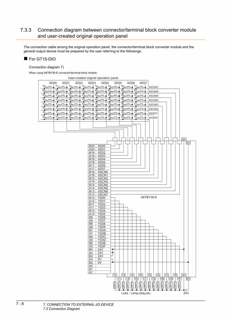
7 - 8 7. CONNECTION TO EXTERNAL I/O DEVICE7.3 Connection Diagram
7.3.3 Connection diagram between connector/terminal block converter module and user-created original operation panel
The connection cable among the original operation panel, the connector/terminal block converter module and the general output device must be prepared by the user referring to the followings.
For GT15-DIO
Connection diagram 7)
When using A6TBY36-E connector/terminal block module
User-created original operation panel
B20 XD00XD01XD02XD03XD04XD05XD06XD07XSCN0XSCN1XSCN2XSCN3XSCN4XSCN5XSCN6XSCN7YD00YD01YD02YD03YD04YD05YD06YD07YD08YD09YD0AYD0BYD0CYD0DYD0EYD0F24V24V24V0V
A20B19A19B18A18B17A17B16A16B15A15B14A14B13A13B12A12B11A11B10A10B9A9B8A8B7A7B6A6B5A5B4A4B3A3B2A2B1A1
0V
10 12 14 16 18 1A 1C 1E0V1F1D1B1917151311
24V
0V
A6TBY36-E
24V
24VLoad : Lamp,relay,etc.
XD00 XD01 XD02 XD03 XD04 XD05 XD06 XD0770 71
61
51
41
31
11
21
60
50
40
30
20
10
00 01
72
62
52
42
32
12
02
22
73
63
53
43
33
13
03
23
74
64
54
44
34
14
04
24
75
65
55
45
35
15
05
25
76
66
56
46
36
16
06
26
77
67
57
47
37
17
07
27
XSCN07
XSCN06
XSCN05
XSCN04
XSCN03
XSCN02
XSCN01
XSCN00
Load
Load
Load
Load
Load
Load
Load
Load
Load
Load
Load
Load
Load
Load
Load
Load

1
Connection diagram 8)7. C
OR
When using A6TBY54-E connector/terminal block modulePR
EP
AR
AT
OR
Y
PR
OC
ED
UR
ES
FM
ON
ITO
RIN
G
2
MIC
RO
CO
MP
UT
ER
C
ON
NE
CT
ION
(S
ER
IAL
)
3
MIC
RO
CO
MP
UT
ER
C
ON
NE
CT
ION
(E
TH
ER
NE
T)
4
MO
DB
US
(R)/
RT
U
CO
NN
EC
TIO
N
5
MO
DB
US
(R)/
TC
P
CO
NN
EC
TIO
N
6
CO
NN
EC
TIO
N T
O
SO
UN
D O
UT
PU
T
UN
IT
7
CO
NN
EC
TIO
N T
O
EX
TE
RN
AL
I/O
D
EV
ICE
8
FIN
GE
RP
RIN
T A
UTH
EN
TIC
ATIO
N
DE
VIC
E C
ON
NE
CTI
ON
B20 XD00XD01XD02XD03XD04XD05XD06XD07XSCN0XSCN1XSCN2XSCN3XSCN4XSCN5XSCN6XSCN7YD00YD01YD02YD03YD04YD05YD06YD07YD08YD09YD0AYD0BYD0CYD0DYD0EYD0F24V24V24V0V
A20B19A19B18A18B17A17B16A16B15A15B14A14B13A13B12A12B11A11B10A10B9A9B8A8B7A7B6A6B5A5B4A4B3A3B2A2B1A1
0V
0V-C-C-C-C-C-C-C-C-C
A6TBY54-E
24V
0V-C-C-C-C-C-C-C-C-C
1213
1415
1617
1819
1A1B
1C1D
1E1F
1011 24V
XD00 XD01 XD02 XD03 XD04 XD05 XD06 XD0770 71
61
51
41
31
11
21
60
50
40
30
20
10
00 01
72
62
52
42
32
12
02
22
XSCN07
XSCN06
XSCN05
XSCN04
XSCN03
XSCN02
XSCN01
XSCN00
73
63
53
43
33
13
03
23
74
64
54
44
34
14
04
24
75
65
55
45
35
15
05
25
76
66
56
46
36
16
06
26
77
67
57
47
37
17
07
27
User-created original operation panel
DC24VLoad : Lamp,relay,etc.
LoadLoad
LoadLoad
LoadLoad
LoadLoad
LoadLoad
LoadLoad
LoadLoad
LoadLoad
ONNECTION TO EXTERNAL I/O DEVICE7.3 Connection Diagram
7 - 9
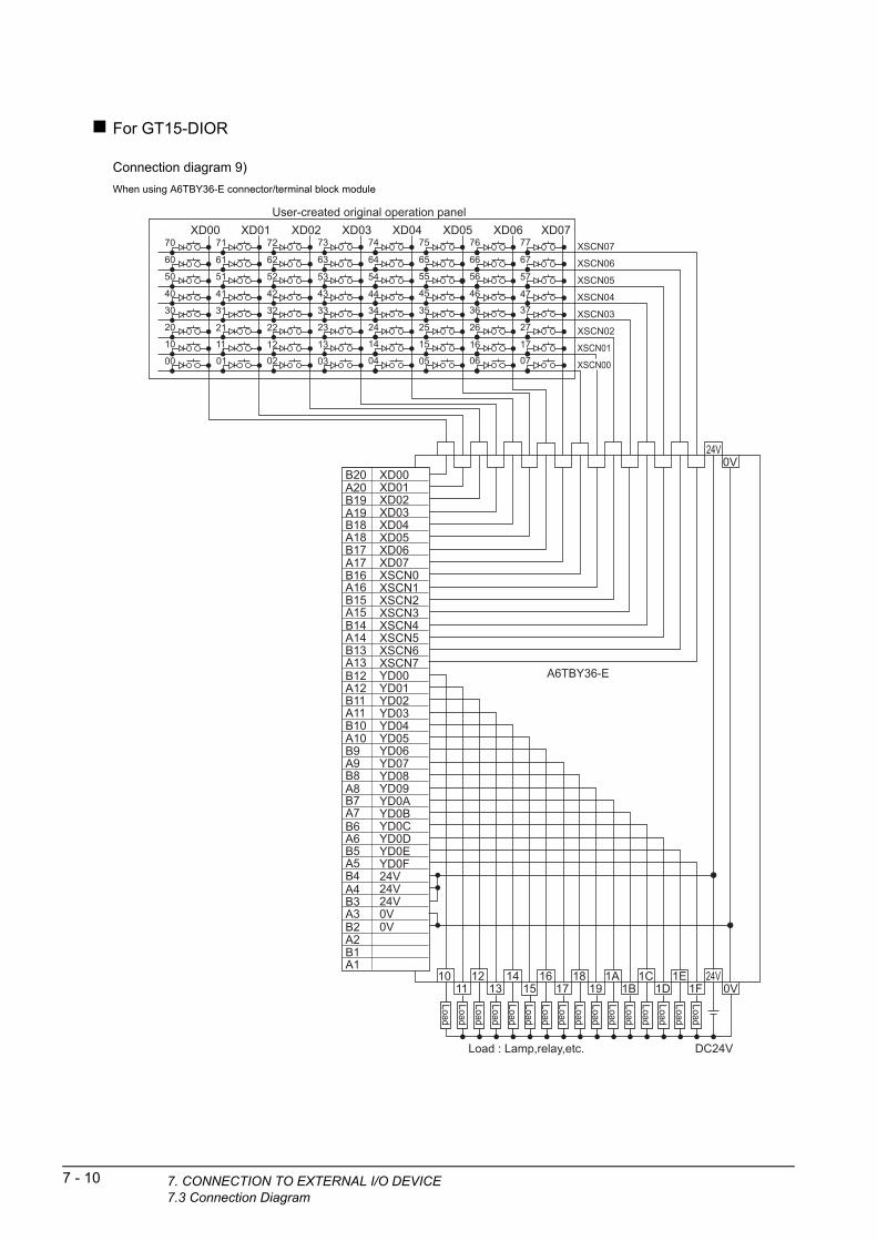
7 - 10 7. CONNECTION TO EXTERNAL I/O DEVICE7.3 Connection Diagram
For GT15-DIOR
Connection diagram 9)
When using A6TBY36-E connector/terminal block module
B20 XD00XD01XD02XD03XD04XD05XD06XD07XSCN0XSCN1XSCN2XSCN3XSCN4XSCN5XSCN6XSCN7YD00YD01YD02YD03YD04YD05YD06YD07YD08YD09YD0AYD0BYD0CYD0DYD0EYD0F24V24V24V0V
A20B19A19B18A18B17A17B16A16B15A15B14A14B13A13B12A12B11A11B10A10B9A9B8A8B7A7B6A6B5A5B4A4B3A3B2A2B1A1
0V
10 12 14 16 18 1A 1C 1E0V1F1D1B1917151311
24V
0V
A6TBY36-E
24V
XD00 XD01 XD02 XD03 XD04 XD05 XD06 XD0770 71
61
51
41
31
11
21
60
50
40
30
20
10
00 01
72
62
52
42
32
12
02
22
XSCN07
XSCN06
XSCN05
XSCN04
XSCN03
XSCN02
XSCN01
XSCN00
73
63
53
43
33
13
03
23
74
64
54
44
34
14
04
24
75
65
55
45
35
15
05
25
76
66
56
46
36
16
06
26
77
67
57
47
37
17
07
27
User-created original operation panel
DC24VLoad : Lamp,relay,etc.
Load
Load
Load
Load
Load
Load
Load
Load
Load
Load
Load
Load
Load
Load
Load
Load
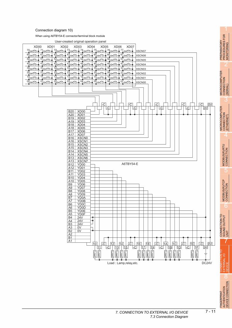
1
Connection diagram 10)7. C
OR
When using A6TBY54-E connector/terminal block modulePR
EP
AR
AT
OR
Y
PR
OC
ED
UR
ES
FM
ON
ITO
RIN
G
2
MIC
RO
CO
MP
UT
ER
C
ON
NE
CT
ION
(S
ER
IAL
)
3
MIC
RO
CO
MP
UT
ER
C
ON
NE
CT
ION
(E
TH
ER
NE
T)
4
MO
DB
US
(R)/
RT
U
CO
NN
EC
TIO
N
5
MO
DB
US
(R)/
TC
P
CO
NN
EC
TIO
N
6
CO
NN
EC
TIO
N T
O
SO
UN
D O
UT
PU
T
UN
IT
7
CO
NN
EC
TIO
N T
O
EX
TE
RN
AL
I/O
D
EV
ICE
8
FIN
GE
RP
RIN
T A
UTH
EN
TIC
ATIO
N
DE
VIC
E C
ON
NE
CTI
ON
B20 XD00XD01XD02XD03XD04XD05XD06XD07XSCN0XSCN1XSCN2XSCN3XSCN4XSCN5XSCN6XSCN7YD00YD01YD02YD03YD04YD05YD06YD07YD08YD09YD0AYD0BYD0CYD0DYD0EYD0F24V24V24V0V
A20B19A19B18A18B17A17B16A16B15A15B14A14B13A13B12A12B11A11B10A10B9A9B8A8B7A7B6A6B5A5B4A4B3A3B2A2B1A1
0V
0V-C-C-C-C-C-C-C-C-C
A6TBY54-E
24V
0V-C-C-C-C-C-C-C-C-C
1213
1415
1617
1819
1A1B
1C1D
1E1F
1011 24V
XD00 XD01 XD02 XD03 XD04 XD05 XD06 XD0770 71
61
51
41
31
11
21
60
50
40
30
20
10
00 01
72
62
52
42
32
12
02
22
XSCN07
XSCN06
XSCN05
XSCN04
XSCN03
XSCN02
XSCN01
XSCN00
73
63
53
43
33
13
03
23
74
64
54
44
34
14
04
24
75
65
55
45
35
15
05
25
76
66
56
46
36
16
06
26
77
67
57
47
37
17
07
27
User-created original operation panel
DC24VLoad : Lamp,relay,etc.
Load
Load
Load
Load
Load
Load
Load
Load
Load
Load
Load
Load
Load
Load
Load
Load
ONNECTION TO EXTERNAL I/O DEVICE7.3 Connection Diagram
7 - 11

7 - 12 7. CONNECTION TO EXTERNAL I/O DEVICE7.4 GOT Side Settings
7.4 GOT Side Settings
7.4.1 Setting communication interface
Controller settingSet the channel of the equipment to be connected to the GOT.
1. Select [Common] [Controller Setting] from the menu.
2. The Controller Setting window is displayed. Select the channel to be used from the list menu.
3. Set Manufacturer, Controller Type, I/F, and Driver according to the connected equipment to be used.
4. The detailed setting is displayed after Manufacturer, Controller Type, I/F, and Driver are set.Make the settings according to the usage environment.
Click the [OK] button when settings are completed.
POINTPOINTPOINT
The settings of connecting equipment can be set andconfirmed in [I/F Communication Setting]. For details,refer to the following.
1.1.2 I/F communication setting
2.
3.
4.
Click!
External I/O device setting
1. Select [Common] [Peripheral Setting] [Operation Panel] from the menu.
2. Set the interface to which the external I/O device is connected.
3. Check the [Use Operation Panel] to set the operation panel. For details on the operation panel settings, refer to the following manual.
GT Designer3 Version1 Screen Design Manual
Click the [OK] button when settings are completed.
POINTPOINTPOINT
(1) Communication interface setting by the UtilityThe communication interface setting can be changed on the Utility's [Communication setting] after writing [Communication Settings] of project data.For details on the Utility, refer to the following manual.
User's Manual of GOT used.(2) Precedence in communication settings
When settings are made by GT Designer3 or the Utility, the latest setting is effective.
2. 3.
Click!
1
7. C
FO
R
7.5 PrecautionsPR
EP
AR
AT
OR
YP
RO
CE
DU
RE
S
MO
NIT
OR
ING
2
MIC
RO
CO
MP
UT
ER
C
ON
NE
CT
ION
(S
ER
IAL
)
3
MIC
RO
CO
MP
UT
ER
C
ON
NE
CT
ION
(E
TH
ER
NE
T)
4
MO
DB
US
(R)/
RT
U
CO
NN
EC
TIO
N
5
MO
DB
US
(R)/
TC
P
CO
NN
EC
TIO
N
6
CO
NN
EC
TIO
N T
O
SO
UN
D O
UT
PU
T
UN
IT
7
CO
NN
EC
TIO
N T
O
EX
TE
RN
AL
I/O
D
EV
ICE
8
FIN
GE
RP
RIN
T A
UTH
EN
TIC
ATIO
N
DE
VIC
E C
ON
NE
CTI
ON
External I/O function setting on GT Designer3Before using the operation panel, make the operation panel setting.
For details, refer to the following manual.
GT Designer3 Version1 Screen Design Manual
ONNECTION TO EXTERNAL I/O DEVICE7.5 Precautions
7 - 13

7 - 14 7. CONNECTION TO EXTERNAL I/O DEVICE7.5 Precautions

81
PR
EP
AR
AT
OR
Y
PR
OC
ED
UR
ES
FO
R
MO
NIT
OR
ING
2
MIC
RO
CO
MP
UT
ER
C
ON
NE
CT
ION
(S
ER
IAL
)
3
MIC
RO
CO
MP
UT
ER
C
ON
NE
CT
ION
(E
TH
ER
NE
T)
4
MO
DB
US
(R)/
RT
U
CO
NN
EC
TIO
N
5
MO
DB
US
(R)/
TC
P
CO
NN
EC
TIO
N
6
CO
NN
EC
TIO
N T
O
SO
UN
D O
UT
PU
T
UN
IT
7
CO
NN
EC
TIO
N T
O
EX
TE
RN
AL
I/O
D
EV
ICE
8
ING
ER
PR
INT
UTH
EN
TIC
ATIO
N
EV
ICE
CO
NN
EC
TIO
N
8.FINGERPRINTAUTHENTICATION DEVICE
CONNECTION
8.1 Connectable Model List . . . . . . . . . . . . . . . . . . . . . . . . . . . . 8 - 2
8.2 System Configuration. . . . . . . . . . . . . . . . . . . . . . . . . . . . . . 8 - 2
8.3 GOT Side Settings . . . . . . . . . . . . . . . . . . . . . . . . . . . . . . . . 8 - 3
8.4 Precautions . . . . . . . . . . . . . . . . . . . . . . . . . . . . . . . . . . . . . 8 - 4
F A D
8 - 1

8 - 2 8. FINGERPRINT AUTHENTICATION DEVICE8.1 Connectable Model List
8. FINGERPRINT AUTHENTICATION DEVICE CONNECTION
8.1 Connectable Model List
The following table shows the connectable models.
*1 Varies with the connected type.
8.2 System Configuration
8.2.1 Connecting to fingerprint authentication device
Series Clock Refer to
Fingerprint authentication
device*1 8.2.1
Connection typedependent
Communication driver
Operator authentication
Extended function OS
Fingerprint
Extended function OS
Authentication
GOTFingerprintunit
Connection cable
PLC
Varies according to theconnection type.
Varies according tothe fingerprint unit'sspecifications.
HINTHINTHINT
System configuration between the GOT and PLC
For the system configuration between the GOT and PLC, refer to each chapter.
Mitsubishi Products
Non-Mitsubishi Products 1, Non-Mitsubishi Products 2
Microcomputer, MODBUS Products, Peripherals
Fingerprint unit
Connection cable
GOT
PLCNumber of connectable
equipmentModel nameOption
deviceModel
GT15-80FPA - (Built into GOT)
For the system configuration
between the GOT and PLC, refer to
each chapter.
1 fingerprint
authentication device
for 1 GOT
CONNECTION
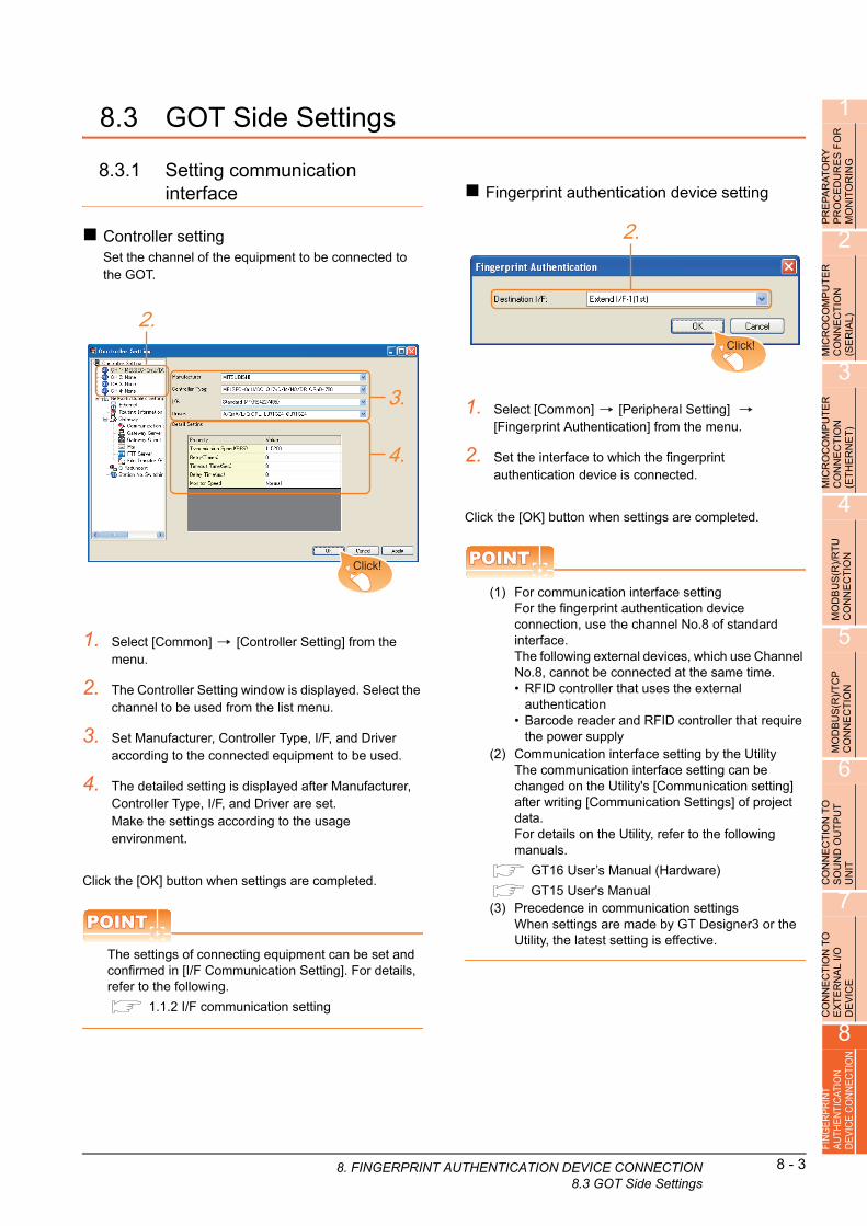
1
8. FINGERPRINT A
FO
R
8.3 GOT Side SettingsPR
EP
AR
AT
OR
YP
RO
CE
DU
RE
S
MO
NIT
OR
ING
2
MIC
RO
CO
MP
UT
ER
C
ON
NE
CT
ION
(S
ER
IAL
)
3
MIC
RO
CO
MP
UT
ER
C
ON
NE
CT
ION
(E
TH
ER
NE
T)
4
MO
DB
US
(R)/
RT
U
CO
NN
EC
TIO
N
5
MO
DB
US
(R)/
TC
P
CO
NN
EC
TIO
N
6
CO
NN
EC
TIO
N T
O
SO
UN
D O
UT
PU
T
UN
IT
7
CO
NN
EC
TIO
N T
O
EX
TE
RN
AL
I/O
D
EV
ICE
8
FIN
GE
RP
RIN
T A
UTH
EN
TIC
ATIO
N
DE
VIC
E C
ON
NE
CTI
ON
8.3.1 Setting communication interface
Controller settingSet the channel of the equipment to be connected to the GOT.
1. Select [Common] [Controller Setting] from the menu.
2. The Controller Setting window is displayed. Select the channel to be used from the list menu.
3. Set Manufacturer, Controller Type, I/F, and Driver according to the connected equipment to be used.
4. The detailed setting is displayed after Manufacturer, Controller Type, I/F, and Driver are set.Make the settings according to the usage environment.
Click the [OK] button when settings are completed.
POINTPOINTPOINT
The settings of connecting equipment can be set and confirmed in [I/F Communication Setting]. For details, refer to the following.
1.1.2 I/F communication setting
2.
3.
4.
Click!
Fingerprint authentication device setting
1. Select [Common] [Peripheral Setting] [Fingerprint Authentication] from the menu.
2. Set the interface to which the fingerprint authentication device is connected.
Click the [OK] button when settings are completed.
POINTPOINTPOINT
(1) For communication interface settingFor the fingerprint authentication device connection, use the channel No.8 of standard interface.The following external devices, which use Channel No.8, cannot be connected at the same time.• RFID controller that uses the external
authentication• Barcode reader and RFID controller that require
the power supply(2) Communication interface setting by the Utility
The communication interface setting can be changed on the Utility's [Communication setting] after writing [Communication Settings] of project data.For details on the Utility, refer to the following manuals.
GT16 User’s Manual (Hardware)
GT15 User's Manual(3) Precedence in communication settings
When settings are made by GT Designer3 or the Utility, the latest setting is effective.
2.
Click!
UTHENTICATION DEVICE CONNECTION8.3 GOT Side Settings
8 - 3
8 - 4 8. FINGERPRINT AUTHENTICATION DEVICE8.4 Precautions
8.4 Precautions
Fingerprint authentication settingSet the fingerprint authentication and operator authentication on the GT Designer3 and GOT.
For details, refer to the following manuals.
GT Designer3 Version1 Screen Design Manual
User's Manual of GOT used.
Controller settingThe fingerprint authentication device requires the power supply from the GOT. Therefore, set Channel No. 8 using the standard interface.
If the channel No. other than Channel No. 8 is set, the GOT does not recognize the device as a controller.
CONNECTION
99
BA
R C
OD
E R
EA
DE
R
CO
NN
EC
TIO
N
10
PC
RE
MO
TE
C
ON
NE
CT
ION
11
VN
C(R
) S
ER
VE
R
CO
NN
EC
TIO
N
12
VID
EO
/RG
B
CO
NN
EC
TIO
N
13
PR
INT
ER
C
ON
NE
CT
ION
14
MU
LTIM
ED
IA
CO
NN
EC
TIO
N
15
RF
ID C
ON
NE
CT
ION
9.BAR CODE READERCONNECTION
9.1 Connectable Model List . . . . . . . . . . . . . . . . . . . . . . . . . . . . 9 - 2
9.2 System Configuration. . . . . . . . . . . . . . . . . . . . . . . . . . . . . . 9 - 2
9.3 GOT Side Settings . . . . . . . . . . . . . . . . . . . . . . . . . . . . . . . . 9 - 3
9.4 System Configuration Examples . . . . . . . . . . . . . . . . . . . . . 9 - 5
9.5 Precautions . . . . . . . . . . . . . . . . . . . . . . . . . . . . . . . . . . . . . 9 - 7
9 - 1

9 - 2 9. BAR CODE READER CONNECTION9.1 Connectable Model List
ctio
9. BAR CODE READER CONNECTION
9.1 Connectable Model ListFor connectable bar code readers and system equipment, refer to the following Technical News.
List of valid devices applicable for GOT1000 series (GOT-A-0010)
9.2 System Configuration
9.2.1 Connecting to bar code reader
* For GT10, writing of the extended function OS is not required.
Connection typedependent
Communication driver
Barcode*
Extended function OS
Bar code reader
Connection cable 1) Conne
GOT PLC
Varies according to the connection type.
n cable 2)
GOT Number of
*1 For connectable bar code readers, system equipment, available bar code types and connection cables, refer to the following Technical News.
List of valid devices applicable for GOT1000 series (GOT-A-0010)
POINTPOINTPOINT
When using the RS-232 communication unit
Use the RS-232 communication unit of the GOT for connecting to a barcode reader.However, when the RS-232 communication unit is used, the power cannot be supplied to a bar code reader from the GOT.
HINTHINTHINT
System configuration between the GOT and PLCFor the system configuration between the GOT and PLC, refer to each chapter.
Mitsubishi ProductsNon-Mitsubishi Products 1, Non-Mitsubishi Products 2Microcomputer, MODBUS Products, Peripherals
Bar code readerConnection
cable 1)
Connection
cable 2)PLC connectable
equipmentOption device Model
*1
*1 - - (Built into GOT) For the system
configuration between
the GOT and PLC,
refer to each chapter.
1 bar code reader
for 1 GOT
*1GT10-C02H-6PT9P
(0.2m)- (Built into GOT)
*1 - GT15-RS2-9P

9
DE
R
9.3 GOT Side SettingsBA
R C
OD
E R
EA
CO
NN
EC
TIO
N
10
PC
RE
MO
TE
C
ON
NE
CT
ION
11
VN
C(R
) S
ER
VE
R
CO
NN
EC
TIO
N
12
VID
EO
/RG
B
CO
NN
EC
TIO
N
13
PR
INT
ER
C
ON
NE
CT
ION
14
MU
LTIM
ED
IA
CO
NN
EC
TIO
N
15
RF
ID C
ON
NE
CT
ION
9.3.1 Setting communication interface
Controller settingSet the channel of the equipment to be connected to the GOT.
1. Select [Common] [Controller Setting] from the menu.
2. The Controller Setting window is displayed. Select the channel to be used from the list menu.
3. Set Manufacturer, Controller Type, I/F, and Driver according to the connected equipment to be used.
4. The detailed setting is displayed after Manufacturer, Controller Type, I/F, and Driver are set.Make the settings according to the usage environment.
Click the [OK] button when settings are completed.
POINTPOINTPOINT
The settings of connecting equipment can be set and confirmed in [I/F Communication Setting]. For details, refer to the following.
1.1.2 I/F communication setting
2.
3.
4.
Click!
Bar code reader setting
1. Select [Common] [Peripheral Setting] [Bar Code] from the menu.
2. Set the interface to which the bar code reader is connected.
3. Check the [Use Bar Code] to set the function. For details on the function setting, refer to the following manual.
GT Designer3 Version1 Screen Design Manual
4. Clicking the detail setting button displays the Communication Detail Settings dialog box for each communication driver.Make the settings according to the usage environment.
9.3.2 Communication detail settings
Click the [OK] button when settings are completed.
POINTPOINTPOINT
(1) Communication interface settingWhen Channel No.8 is used, the following external devices, which use Channel No.8, cannot be connected at the same time.• Fingerprint authentication device• RFID controller that uses the external
authentication• RFID controller that requires the power supplyWhen connecting the above-mentioned devices at the same time, set [Bar Code] to Channels No. 5 to 7.
(2) Setting for the driverTo Channels No. 5 to 8, multiple [Bar Code] cannot be set.
2.
3.
4.
Click!
9. BAR CODE READER CONNECTION9.3 GOT Side Settings
9 - 3
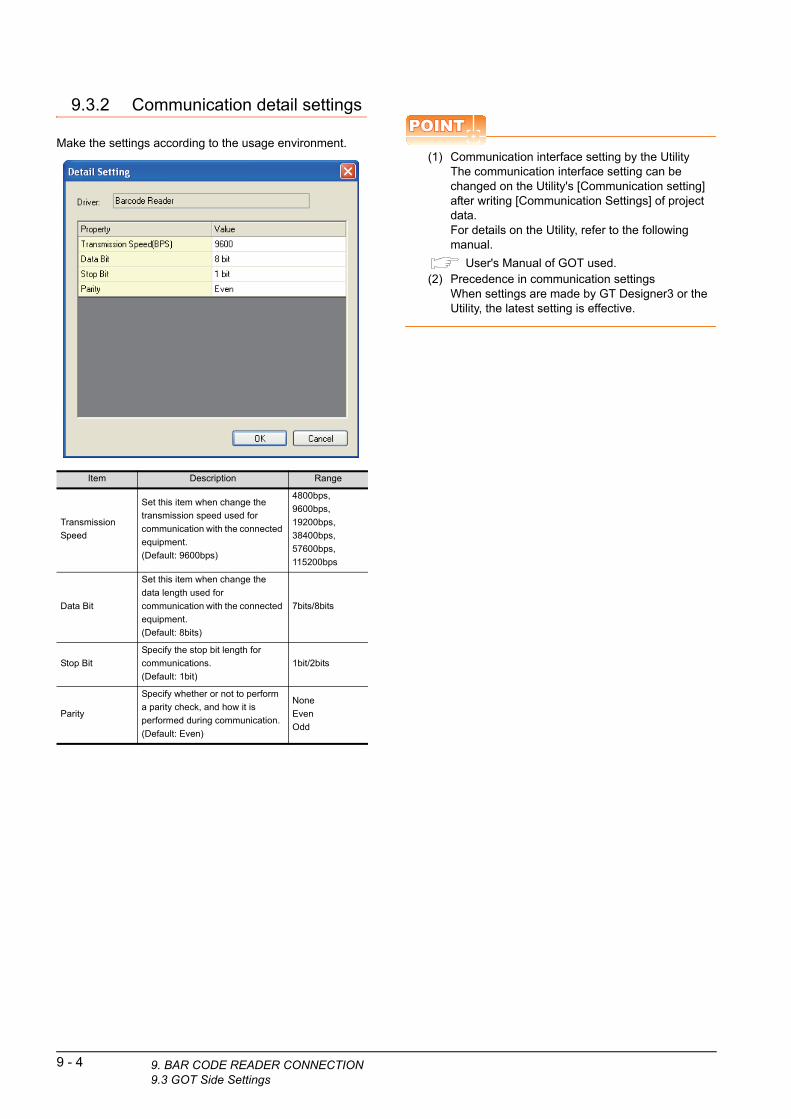
9.3.2 Communication detail settings
Make the settings according to the usage environment.
Item Description Range
Transmission
Speed
Set this item when change the
transmission speed used for
communication with the connected
equipment.
(Default: 9600bps)
4800bps,
9600bps,
19200bps,
38400bps,
57600bps,
115200bps
Data Bit
Set this item when change the
data length used for
communication with the connected
equipment.
(Default: 8bits)
7bits/8bits
Stop Bit
Specify the stop bit length for
communications.
(Default: 1bit)
1bit/2bits
Parity
Specify whether or not to perform
a parity check, and how it is
performed during communication.
(Default: Even)
None
Even
Odd
9 - 4 9. BAR CODE READER CONNECTION9.3 GOT Side Settings
POINTPOINTPOINT
(1) Communication interface setting by the UtilityThe communication interface setting can be changed on the Utility's [Communication setting] after writing [Communication Settings] of project data.For details on the Utility, refer to the following manual.
User's Manual of GOT used.(2) Precedence in communication settings
When settings are made by GT Designer3 or the Utility, the latest setting is effective.

9
DE
R
9.4 System Configuration ExamplesBA
R C
OD
E R
EA
CO
NN
EC
TIO
N
10
PC
RE
MO
TE
C
ON
NE
CT
ION
11
VN
C(R
) S
ER
VE
R
CO
NN
EC
TIO
N
12
VID
EO
/RG
B
CO
NN
EC
TIO
N
13
PR
INT
ER
C
ON
NE
CT
ION
14
MU
LTIM
ED
IA
CO
NN
EC
TIO
N
15
RF
ID C
ON
NE
CT
ION
A system configuration example for bar code reader connection is shown below.
System configuration
*1 The GOT and QCPU (Q mode) are connected through a bus.For bus connection, refer to the following manual.
GOT1000 Series Connection Manual (Mitsubishi Products) for GT Works3
1. The bar code is read with the bar code reader.
■ Bar code reader setting
2. The GOT receives the data sent from the bar code reader.
■ Setting of [Controller Setting] of GT Designer3
3. The received data are written to the PLC CPU.
■ Setting of [Bar Code] of GT Designer3
4. The data read with the bar code reader are written into the PLC CPU devices.
■ Confirmation on PLC side
123456789
Barcode
<GOT>
<QCPU (Q mode)>
Read data Terminator
CR0DH
1
31H
2
32H
3
33H
4
34H
5
35H
6
36H
7
37H
8
38H
9
39H
*1
Read data"123456789"
D0
D1
D2
D3
D4
D5
9(00H) (09H)
2(32H)
1(31H)
3(33H)
4(34H)
5( 35H)
6(36H)
7(37H)
8(38H)
9(39H)
SP(20H)
Read bytes
Stored data
Bar code reader settingThe bar code reader shall be configured as shown below.
POINTPOINTPOINT
Bar code reader setting
For the bar code reader setting, refer to the followingmanual.
User's Manual of the bar code reader
Setting of [Controller Setting] of GT Designer3
(1) Controller setting
(2) Communication detail settingsKeep consistency with the bar code reader setting.
POINTPOINTPOINT
[Controller Setting] of GT Designer3
For the setting method of [Controller Setting] of GTDesigner3, refer to the following.
9.3.1Setting communication interface
Item Set value
Transmission Speed 9600bps
Data Bit 8bit
Stop Bit 1bit
Parity Even
Header None
Terminator CR
Item Setting (Use default value.)
Transmission Speed 9600bps
Data Bit 8bit
Stop Bit 1bit
Parity Even
9. BAR CODE READER CONNECTION9.4 System Configuration Examples
9 - 5

Setting of [Bar Code] of GT Designer3
*1 Keep consistency with the bar code reader setting.
POINTPOINTPOINT
[Bar Code] of GT Designer3
For the [Bar Code] setting in GT Designer3, refer to thefollowing manual.
GT Designer3 Version1 Screen Design Manual
Item Set value
Read Data Direct Input to Object No
Device D0
Device Points 6
Header*1 None
Terminator*1 CR
Writing Byte Order Low High
Fills a blank when Imported data is
not filled in Writing PointsCheck (Filling Data is available)
Filling Data Space (020)
9 - 6 9. BAR CODE READER CONNECTION9.4 System Configuration Examples
Confirmation on PLC sideConnect GX Developer to the QCPU (Q-mode) and check if the data, which has been read with the bar code reader, are written in D0 to D5.
For the GX Developer operation method, refer to the following manual.
GX Developer Version Operating Manual
(1) Confirming the device values of D0 to D5 (when using GX Developer Version 8)
GX Developer [Online] [Monitor] [Device batch]
Startup procedure
ASCII codes are hexadecimals.
Specify [HEX] for [Value] of the GX
Developer and confirm the read data.

9
DE
R
9.5 PrecautionsBA
R C
OD
E R
EA
CO
NN
EC
TIO
N
10
PC
RE
MO
TE
C
ON
NE
CT
ION
11
VN
C(R
) S
ER
VE
R
CO
NN
EC
TIO
N
12
VID
EO
/RG
B
CO
NN
EC
TIO
N
13
PR
INT
ER
C
ON
NE
CT
ION
14
MU
LTIM
ED
IA
CO
NN
EC
TIO
N
15
RF
ID C
ON
NE
CT
ION
Bar code function setting on GT Designer3Before connecting the bar code reader, make the bar code function and system data settings.
For details, refer to the following manual.
GT Designer3 Version1 Screen Design Manual
Controller settingWhen using the barcode reader, which requires the power supply from the GOT, set Channel No. 8 using the standard interface.
With Channels No. 5 to 7 of the extension interface, the power cannot be supplied.
9. BAR CODE READER CONNECTION9.5 Precautions
9 - 7

9 - 8 9. BAR CODE READER CONNECTION9.5 Precautions

109
BA
R C
OD
E R
EA
DE
R
CO
NN
EC
TIO
N
10
PC
RE
MO
TE
C
ON
NE
CT
ION
11
VN
C(R
) S
ER
VE
R
CO
NN
EC
TIO
N
12
VID
EO
/RG
B
CO
NN
EC
TIO
N
13
PR
INT
ER
C
ON
NE
CT
ION
14
MU
LTIM
ED
IA
CO
NN
EC
TIO
N
15
RF
ID C
ON
NE
CT
ION
10.PC REMOTE CONNECTION
10.1 Connectable Model List . . . . . . . . . . . . . . . . . . . . . . . . . . . 10 - 2
10.2 Serial Connection. . . . . . . . . . . . . . . . . . . . . . . . . . . . . . . . 10 - 2
10.3 Ethernet Connection . . . . . . . . . . . . . . . . . . . . . . . . . . . . . 10 - 7
10 - 1

10 - 2 10. PC REMOTE CONNECTION10.1 Connectable Model List
10. PC REMOTE CONNECTION
10.1 Connectable Model ListThe RGB display is used for the remote personal computer operation connection.The following GOT models support the remote personal computer operation connection.
*1 GT1675-VN, GT1672-VN, GT1662-VN, and 1665-V cannot be used.
*2 GT1675-VN, GT1672-VN, and GT1662-VN cannot be used.
10.2 Serial Connection10.2.1 System Configuration
Connection type GOT model
Serial connection GT16*1, GT1585V-S, GT1575V-S
Ethernet connection GT16*2
Connection typedependent
Communication driver
Video/RGB input
Extended function OSExtended function OS
PC remote operation (serial)
PC GOTConnection cable 1)
PLC
Varies according to theconnection type.
Connection cable 2)
*1 The cable length differs depending on the specification of the personal computer to be used. Use the cable that is compatible
with the personal computer to be used.
*2 The connection cable 1) (RS-232 cable) and the connection cable 2) (analog cable) should be connected between the personal
computer and the GOT.
HINTHINTHINT
System configuration between the GOT and PLCFor the system configuration between the GOT and PLC, refer to each chapter.
Mitsubishi Products
Non-Mitsubishi Products 1, Non-Mitsubishi Products 2
Microcomputer, MODBUS Products, Peripherals
Personal computer
Connection cable 1)*2 GOT
PLC
Number of
connectable
equipmentCable modelMax.
distanceOption device Model
To be selected by the
user.
GT01-C30R2-9S
or
RS232 connection
diagram 1)
15m
- (Built into GOT)
For the system
configuration between
the GOT and PLC,
refer to each chapter.
1 personal
computer for 1
GOT
GT15-RS2-9P
Connection cable 2)*2 GOT
Cable modelMax.
distanceOption device Model
GT15-C50VG
or
Analog RGB connection
diagram 1)
*1
GT16M-R2
GT16M-V4R1
GT15V-75R1
GT15V-75V4R1

9
BA
R C
OD
E R
EA
DE
R
CO
NN
EC
TIO
N
10
PC
RE
MO
TE
C
ON
NE
CT
ION
11
VN
C(R
) S
ER
VE
R
CO
NN
EC
TIO
N
12
VID
EO
/RG
B
CO
NN
EC
TIO
N
13
PR
INT
ER
C
ON
NE
CT
ION
14
MU
LTIM
ED
IA
CO
NN
EC
TIO
N
15
RF
ID C
ON
NE
CT
ION
10.2.2 Connection Diagram
When using a 3m or longer RS-232 cable for connecting a GOT to a personal computer, the cable must be prepared by the user.The following shows each cable connection diagram.
RS-232 cable
(1) Connection diagram
RS232 connection diagram 1)
(2) Precautions when preparing a cable(a) Cable length
The length of the RS-232 cable must be 15m or less.
(b) GOT side connectorFor the GOT side connector, refer to the following.
1.4.1 GOT connector specifications
(c) Personal computer side connectorUse a connector compatible with the personal computer to be used.
PC side
CD
RD
SD
DTR
SG(GND)
DSR
RTS
CTS
FG
1
2
3
4
5
6
7
8
9
Shell
1
3
2
6
5
4
7
8
9
Shell
CD
SD
RD
DSR
SG(GND)
DTR
RTS
CTS
CI
FG
GOT side
Analog RGB cable
(1) Connection diagram
Analog RGB connection diagram 1)
(2) Precautions when preparing a cable(a) Cable length
The cable length differs depending on the specification of the personal computer to be used. Create a cable under the specifications of the personal computer.
(b) GOT side connectorUse the following as the video/RGB input unit and the RGB input unit connectors.For the GOT side connector and connector cover of the analog RGB cable, use the ones applicable to the GOT connector.
(c) Personal computer side connectorUse a connector compatible with the personal computer to be used.
GOT Connector typeConnector
typeManufacturer
GT16M-R2
17HE-R13150-73MC2D-Sub 15
pin (female)
DDK Ltd.
(DDK)
GT16M-V4R1
GT15V-75R1
GT15V-75V4R1
R
RGND
G
GGND
B
BGND
DGND
HSYNC
VSYNC
DGND
NC
NC
NC
NC
NC
R
RGND
G
GGND
B
BGND
GND
HSYNC
VSYNC
GND
GND
NC
GND
SDA
SCL
1
6
2
7
3
8
10
13
14
5
4
9
11
12
15
1
6
2
7
3
8
10
13
14
5
4
9
11
12
15
PC side GOT side
75Ω drohmcoaxial
Twisted pair
10. PC REMOTE CONNECTION10.2 Serial Connection
10 - 3

10.2.3 GOT Side Settings
Setting communication interface (Communication settings)Set the channel of the equipment to be connected to the GOT.
1. Select [Common] [Controller Setting] from the menu.
2. The Controller Setting window is displayed. Select the channel to be used from the list menu.
3. Set Manufacturer, Controller Type, I/F, and Driver according to the connected equipment to be used.
4. The detailed setting is displayed after Manufacturer, Controller Type, I/F, and Driver are set.Make the settings according to the usage environment.
Click the [OK] button when settings are completed.
POINTPOINTPOINT
The settings of connecting equipment can be set and confirmed in [I/F Communication Setting]. For details, refer to the following.
1.1.2 I/F communication setting
2.
3.
4.
Click!
10 - 4 10. PC REMOTE CONNECTION10.2 Serial Connection
Settings for the remote personal computer operation
1. Select [Common] [Peripheral Setting] [PC Remote Operation] from the menu.
2. Set the interface to which the personal computer is connected for the [Connecting I/F] of [PC Remote Operation (serial)].
Click the [OK] button when settings are completed.
2.
Click!

9
BA
R C
OD
E R
EA
DE
R
CO
NN
EC
TIO
N
10
PC
RE
MO
TE
C
ON
NE
CT
ION
11
VN
C(R
) S
ER
VE
R
CO
NN
EC
TIO
N
12
VID
EO
/RG
B
CO
NN
EC
TIO
N
13
PR
INT
ER
C
ON
NE
CT
ION
14
MU
LTIM
ED
IA
CO
NN
EC
TIO
N
15
RF
ID C
ON
NE
CT
ION
Settings for the video/RGB equipment
1. Select [Common] [Peripheral Setting] [Video/RGB Input] from the menu.
2. Set the interface to which the video/RGB equipment is connected.
3. Check the [Use Video/RGB Input] to set the function. For details on the function setting, refer to the following manual.
GT Designer3 Version1 Screen Design Manual
4. Clicking the detail setting button displays the Communication Detail Settings dialog box for each communication driver.Make the settings according to the usage environment.
10.2.4 Communication detail settings
Click the [OK] button when settings are completed.
POINTPOINTPOINT
Setting for the driver
To Channels No. 5 to 8, multiple [PC Remote Operation] cannot be set.
2.
3.
4.
Click!
10.2.4 Communication detail settings
(1) Serial connectionMake the settings according to the usage environment.
*1 When NTSC format is selected, the resolution is fixed to 640 480.
*2 For GT1675M-V and GT1665M-V, the resolution is fixed to 640 480.
*3 768 576 can be set only for the GT16.
POINTPOINTPOINT
(1) Communication interface settingWhen Channel No.8 is used, the following external devices, which use Channel No.8, cannot be connected at the same time.• Fingerprint authentication device• RFID controller that uses the external
authentication• Barcode reader and RFID controller that require
the power supplyWhen connecting the above-mentioned devices at the same time, set [PC Remote Operation] to Channels No. 5 to 7.
(2) Communication interface setting by the UtilityThe communication interface setting can be changed on the Utility's [Communication setting] after writing [Communication Settings] of project data.For details on the Utility, refer to the following manual.
User's Manual of GOT used.(3) Precedence in communication settings
When settings are made by GT Designer3 or the Utility, the latest setting is effective.
Item Description Range
Video Input
Signal*1Set the video input signal.(Default: NTSC)
NTSC, PAL
Video
Resolution*2Set the video resolution.
(Default: 640 480)
640 480,
720 480,
768 576*3
10. PC REMOTE CONNECTION10.2 Serial Connection
10 - 5

10.2.5 Installing and setting up computer remote operation driver.
Install and set up the remote personal computer operation driver to the personal computer.For installing and setting up the remote personal computer operation driver, refer to the following manual.
GT Designer3 Version1 Screen Design Manual
10.2.6 Precautions
Personal computer side settingBefore using the remote personal computer operation function, install the remote personal computer operation driver on the personal computer.
After the driver installation, check that the driver is correctly installed.
For details of the remote personal computer operation driver, refer to the following manual.
GT Designer3 Version1 Screen Design Manual
10 - 6 10. PC REMOTE CONNECTION10.2 Serial Connection
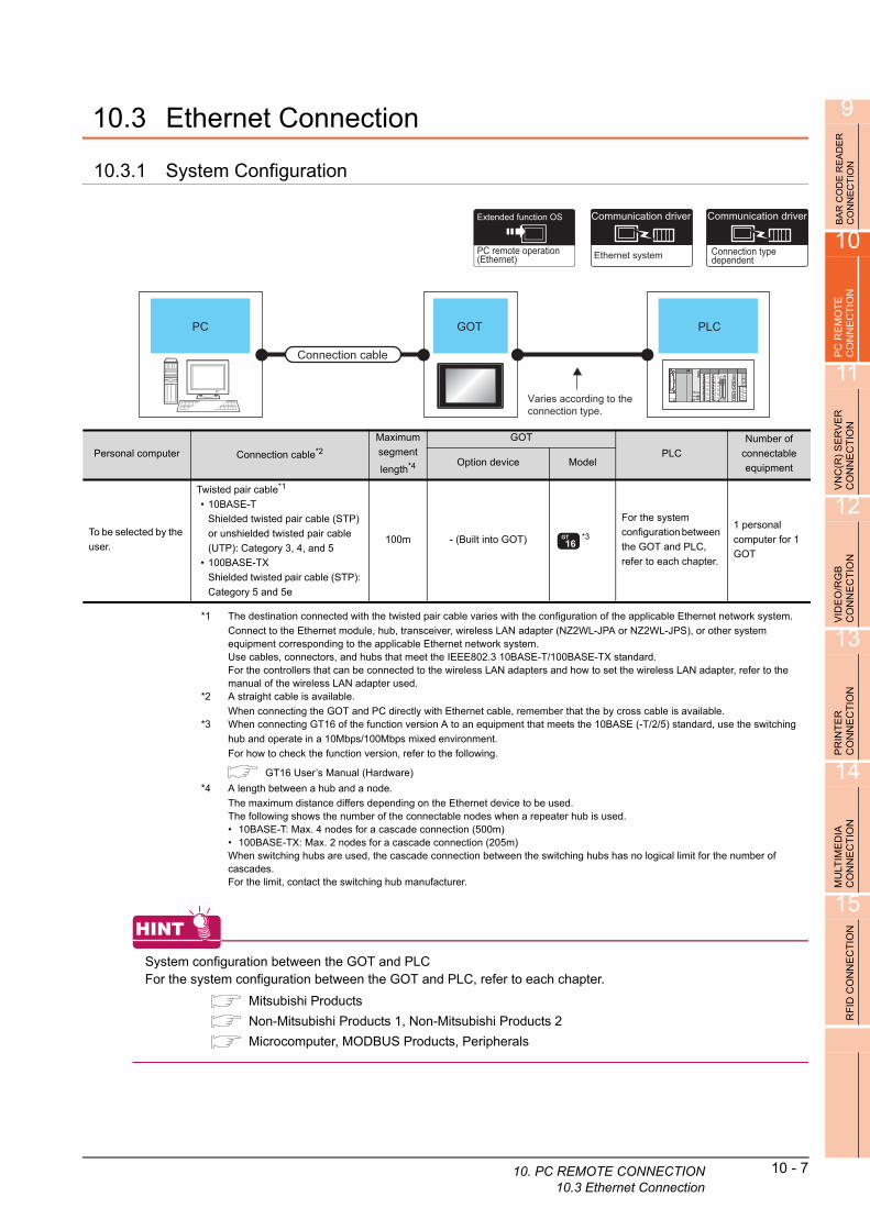
9
BA
R C
OD
E R
EA
DE
R
CO
NN
EC
TIO
N
10
PC
RE
MO
TE
C
ON
NE
CT
ION
11
VE
R
N
10.3 Ethernet Connection
10.3.1 System Configuration
Connection typedependent
Communication driverExtended function OS
PC remote operation (Ethernet)
Communication driver
Ethernet system
PC GOT
Connection cable
PLC
Varies according to theconnection type.
O
VNC
(R)
SE
RC
ON
NE
CT
I
12
IDE
O/R
GB
O
NN
EC
TIO
N
Personal computer Connection cable*2
Maximum
segment
length*4
GOT
PLC
Number of
connectable
equipmentOption device Model
To be selected by the
user.
Twisted pair cable*1
• 10BASE-T
Shielded twisted pair cable (STP)
or unshielded twisted pair cable
(UTP): Category 3, 4, and 5
• 100BASE-TX
Shielded twisted pair cable (STP):
Category 5 and 5e
100m - (Built into GOT) *3
For the system
configuration between
the GOT and PLC,
refer to each chapter.
1 personal
computer for 1
GOT
V C
*1 The destination connected with the twisted pair ble varies with the configuration of the applicable Ethernet network system.13
PR
INT
ER
C
ON
NE
CT
ION
14
MU
LTIM
ED
IA
CO
NN
EC
TIO
N
15
RF
ID C
ON
NE
CT
ION
ca
Connect to the Ethernet module, hub, transceiver, wireless LAN adapter (NZ2WL-JPA or NZ2WL-JPS), or other system equipment corresponding to the applicable Ethernet network system.Use cables, connectors, and hubs that meet the IEEE802.3 10BASE-T/100BASE-TX standard.For the controllers that can be connected to the wireless LAN adapters and how to set the wireless LAN adapter, refer to the manual of the wireless LAN adapter used.
*2 A straight cable is available.
When connecting the GOT and PC directly with Ethernet cable, remember that the by cross cable is available.*3 When connecting GT16 of the function version A to an equipment that meets the 10BASE (-T/2/5) standard, use the switching
hub and operate in a 10Mbps/100Mbps mixed environment.
For how to check the function version, refer to the following.
GT16 User’s Manual (Hardware)
*4 A length between a hub and a node.
The maximum distance differs depending on the Ethernet device to be used.The following shows the number of the connectable nodes when a repeater hub is used.• 10BASE-T: Max. 4 nodes for a cascade connection (500m)• 100BASE-TX: Max. 2 nodes for a cascade connection (205m)When switching hubs are used, the cascade connection between the switching hubs has no logical limit for the number of cascades.For the limit, contact the switching hub manufacturer.
HINTHINTHINT
System configuration between the GOT and PLCFor the system configuration between the GOT and PLC, refer to each chapter.
Mitsubishi Products
Non-Mitsubishi Products 1, Non-Mitsubishi Products 2
Microcomputer, MODBUS Products, Peripherals
10. PC REMOTE CONNECTION10.3 Ethernet Connection
10 - 7

10.3.2 GOT Side Settings
Setting communication interface (Communication settings)Set the channel of the equipment to be connected to the GOT.
1. Select [Common] [Controller Setting] from the menu.
2. The Controller Setting window is displayed. Select the channel to be used from the list menu.
3. Set Manufacturer, Controller Type, I/F, and Driver according to the connected equipment to be used.
4. The detailed setting is displayed after Manufacturer, Controller Type, I/F, and Driver are set.Make the settings according to the usage environment.
Click the [OK] button when settings are completed.
POINTPOINTPOINT
The settings of connecting equipment can be set and confirmed in [I/F Communication Setting]. For details, refer to the following.
1.1.2 I/F communication setting
2.
3.
4.
Click!
10 - 8 10. PC REMOTE CONNECTION10.3 Ethernet Connection
Settings for the PC remote operation
1. Select [Common] [Peripheral Setting] [PC Remote Operation] from the menu.
2. Set [Connecting I/F] of [PC Remote Operation] to [Disconnect].
3. Check the [Use PC Remote Operation (Ethernet)] of [PC Remote Operation (Ethernet)] to set. For details on the settings, refer to the following manual.
GT Designer3 Version1 Screen Design Manual
Click the [OK] button when settings are completed.
10.3.3 Install and setting the required software
Install and set the required software according to the system configuration.
For the settings, refer to the following manual.
GT Designer3 Version1 Screen Design Manual
10.3.4 Precautions
Ethernet system driverBefore using the PC remote operation function (Ethernet), install an Ethernet system communication driver to the GOT.Set the Ethernet system communication driver for the controller setting or peripheral setting.For the settings, refer to the following manual.
GT Designer3 Version1 Screen Design Manual
2.
Click!3.
119
BA
R C
OD
E R
EA
DE
R
CO
NN
EC
TIO
N
10
PC
RE
MO
TE
C
ON
NE
CT
ION
11
VN
C(R
) S
ER
VE
R
CO
NN
EC
TIO
N
12
VID
EO
/RG
B
CO
NN
EC
TIO
N
13
PR
INT
ER
C
ON
NE
CT
ION
14
MU
LTIM
ED
IA
CO
NN
EC
TIO
N
15
RF
ID C
ON
NE
CT
ION
11.VNC(R) SERVER CONNECTION
11.1 Connectable Model List . . . . . . . . . . . . . . . . . . . . . . . . . . . .11 - 2
11.2 System Configuration. . . . . . . . . . . . . . . . . . . . . . . . . . . . . .11 - 2
11.3 GOT Side Settings . . . . . . . . . . . . . . . . . . . . . . . . . . . . . . . .11 - 3
11.4 Setting in Personal Computer . . . . . . . . . . . . . . . . . . . . . . .11 - 4
11 - 1

11 - 2 11. VNC(R) SERVER CONNECTION11.1 Connectable Model List
11. VNC(R) SERVER CONNECTION
11.1 Connectable Model List
The VNC® server can be connected to the following VNC® client.
11.2 System Configuration
CPU Software
PC Ultra VNC
Connection typedependent
Communication driverCommunication driver
Ethernet system
Extended function OS
VNC Server
PC(VNC client)
Connection cable
PLC
Varies according to theconnection type.
RGOT
(VNC server)R
*1 The destination connected with the twisted pair cable varies with the configuration of the applicable Ethernet network system.
Connect to the Ethernet module, hub, transceiver, wireless LAN adapter (NZ2WL-JPA or NZ2WL-JPS), or other system
equipment corresponding to the applicable Ethernet network system.
Use cables, connectors, and hubs that meet the IEEE802.3 10BASE-T/100BASE-TX standard.
For the controllers that can be connected to the wireless LAN adapters and how to set the wireless LAN adapter, refer to the
manual of the wireless LAN adapter used.
*2 A straight cable is available.
When connecting the GOT and PC directly with Ethernet cable, remember that the by cross cable is available.
*3 When connecting GT16 of the function version A to an equipment that meets the 10BASE (-T/2/5) standard, use the switching
hub and operate in a 10Mbps/100Mbps mixed environment.
For how to check the function version, refer to the following.
GT16 User’s Manual (Hardware)
*4 A length between a hub and a node.
The maximum distance differs depending on the Ethernet device to be used.The following shows the number of the connectable nodes when a repeater hub is used.• 10BASE-T: Max. 4 nodes for a cascade connection (500m)• 100BASE-TX: Max. 2 nodes for a cascade connection (205m)When switching hubs are used, the cascade connection between the switching hubs has no logical limit for the number of cascades.For the limit, contact the switching hub manufacturer.
Personal computer
(VNC® client)Connection cable*1*2
Maximum
segment
length*4
GOT (VNC® server)PLC
Number of
connectable
equipmentOption device Model
To be selected by the
user.
Twisted pair cable
• 10BASE-T
Shielded twisted pair cable (STP)
or unshielded twisted pair cable
(UTP): Category 3, 4, and 5
• 100BASE-TX
Shielded twisted pair cable (STP):
Category 5 and 5e
100m - (Built into GOT) *3
For the system
configuration between
the GOT and PLC,
refer to each chapter.
1 personal
computer for 1
GOT

9
BA
R C
OD
E R
EA
DE
R
CO
NN
EC
TIO
N
10
PC
RE
MO
TE
C
ON
NE
CT
ION
HINTHINTHINT
System configuration between the GOT and PLCFor the system configuration between the GOT and PLC, refer to each chapter.
Mitsubishi Products
Non-Mitsubishi Products 1, Non-Mitsubishi Products 2
Microcomputer, MODBUS Products, Peripherals
11.3 GOT Side Settings
11VN
C(R
) S
ER
VE
R
CO
NN
EC
TIO
N
12
VID
EO
/RG
B
CO
NN
EC
TIO
N
13
PR
INT
ER
C
ON
NE
CT
ION
14
MU
LTIM
ED
IA
CO
NN
EC
TIO
N
15
RF
ID C
ON
NE
CT
ION
11.3.1 VNC(R) server function setting
1. Select [Common] [Peripheral Setting] [VNC Server] from the menu.
2. Check the [VNC Server] of [Use VNC Server] to set. For details on the settings, refer to the following manual.
GT Designer3 Version1 Screen Design Manual(Functions)
3. Click the [OK] button when settings are completed.
Click!
2.
11.3.2 Setting communication interface (Communication settings)
For using the VNC® server, Ethernet communication drivers must be set on the GOT, and set the Communication settings
1. Select [Common] [Controller Setting] from the menu.
2. The Controller Setting window is displayed. Select the channel to be used from the list menu.
3. Set Manufacturer, Controller Type, I/F, and Driver according to the connected equipment to be used.
4. The detailed setting is displayed after Manufacturer, Controller Type, I/F, and Driver are set.Make the settings according to the usage environment.Click the [OK] button when settings are completed.
2.
3.
4.
Click!
11. VNC(R) SERVER CONNECTION11.3 GOT Side Settings
11 - 3

11 - 4 11. VNC(R) SERVER CONNECTION11.4 Setting in Personal Computer
POINTPOINTPOINT
Ethernet-based driver
For using the VNC® server, any of the following Ethernet communication drivers must be set on the GOT.• Gateway• Ethernet Download• Ethernet (MELSEC), Q17nNC, CRnD-700• Ethernet (MELSEC), Q17nNC, CRnD-700, Gateway• Ethernet (FX), Gateway• Ethernet (OMRON), Gateway• Ethernet (TOSHIBA nv), Gateway• Ethernet (YASKAWA), Gateway• Ethernet (YOKOGAWA), Gateway• EtherNet/IP (AB), Gateway• Ethernet (SIEMENS S7), Gateway• MODBUS/TCP, Gateway• Ethernet (MICROCOMPUTER)
In the peripheral setting, set [Destination I/F] in [Ethernet Download] for the [PC (Data Transfer)] dialog box.To connect controllers including a programmable controller to the GOT by using the Ethernet connection, no setting is required.For the details of [Ethernet Download] , refer to the following
GT Designer3 Version1 Screen Design Manual (Fundamentals)
11.4 Setting in Personal Computer
For connecting the VNC® server to the personal computer (VNC® client), it is necessary to install the VNC® client software to the personal computer to be connected and set it.
Refer to the following for details of the VNC® client software installation method and setting method.
129
BA
R C
OD
E R
EA
DE
R
CO
NN
EC
TIO
N
10
PC
RE
MO
TE
C
ON
NE
CT
ION
11
VN
C(R
) S
ER
VE
R
CO
NN
EC
TIO
N
12
VID
EO
/RG
B
CO
NN
EC
TIO
N
13
PR
INT
ER
C
ON
NE
CT
ION
14
MU
LTIM
ED
IA
CO
NN
EC
TIO
N
15
RF
ID C
ON
NE
CT
ION
12.VIDEO/RGB CONNECTION
12.1 Connectable Model List . . . . . . . . . . . . . . . . . . . . . . . . . . . 12 - 2
12.2 System Configuration. . . . . . . . . . . . . . . . . . . . . . . . . . . . . 12 - 2
12.3 Connection Diagram . . . . . . . . . . . . . . . . . . . . . . . . . . . . . 12 - 4
12.4 GOT Side Settings . . . . . . . . . . . . . . . . . . . . . . . . . . . . . . . 12 - 6
12.5 Precautions . . . . . . . . . . . . . . . . . . . . . . . . . . . . . . . . . . . . 12 - 7
12 - 1

12 - 2 12. VIDEO/RGB CONNECTION12.1 Connectable Model List
12. VIDEO/RGB CONNECTION
12.1 Connectable Model List
The following GOT models support the Video/RGB connection.
*1 GT1675-VN, GT1672-VN, GT1662-VN, and GT1655-V cannot be used.
For the type of the video camera that can be connected, refer to the following Technical News.
List of valid devices applicable for GOT1000 series (GOT-A-0010)
GOT model
GT16*1, GT1585V-S, GT1575V-S
12.2 System Configuration
12.2.1 Displaying video image on GOT
Video/RGB input
Extended function OS
Connection cable
GOTVideo/RGB equipment including video cameras, vision sensors, and personal computers
*1 For connectable video camera types, refer to the following Technical News.
List of valid devices applicable for GOT1000 series (GOT-A-0010)
*2 The user must select a vision sensor or a personal computer to be used.
*3 The cable length differs according to the specifications of the video/RGB equipment.
*4 RGB can be input with two channels. For the switching between two channels, refer to the following manual.
GT Designer3 Version1 Screen Design Manual
Signal type Video/RGB equipment
Connection cable*3 GOTNumber of
connectable
equipment
Cable model
Connection diagram
number
Option device Model
NTSC/PAL
Equipment including video cameras*1 and vision
sensors*2 that outputs images by using the NTSC or
PAL signal
Coaxial connection
diagram 1)
GT16M-V4
GT16M-V4R1 4 video equipment
for 1 GOTGT15V-75V4
GT15V-75V4R1
Analog RGB
Equipment including video cameras*1, vision sensors*2,
and personal computers*2 that outputs images by using
the RGB signal
GT15-C50VG(5m)
or
Analog RGB
connection diagram 1)
GT16M-R2*42 RGB equipment
for 1 GOT
GT16M-V4R11 RGB equipment
for 1 GOTGT15V-75R1
GT15V-75V4R1

9
BA
R C
OD
E R
EA
DE
R
CO
NN
EC
TIO
N
10
PC
RE
MO
TE
C
ON
NE
CT
ION
11
VN
C(R
) S
ER
VE
R
CO
NN
EC
TIO
N
12
VID
EO
/RG
B
CO
NN
EC
TIO
N
13
POINTPOINTPOINT
(1) Power supply of video cameraDepending on the video camera type, noises from the power supply cable of the camera may cause a malfunction on the PLC or the GOT.In this case, apply the following line filter to the power line of the camera.Recommended line filter: TDK ZHC2203-11 (or equivalent)
(2) Power supply of vision sensorIf a video camera is used via a vision sensor, a power supply module may be required depending on the vision sensor to be used.
(3) Selection of Video signal output sourceDepending on the video camera or the system to be used, both the power supply module and the video camera can output video signals. If video signals are output from both the video camera and the power supply module, the voltage level of the signals become lower and the video image cannot be correctly displayed. In this case, use the output from the video camera.
(4) Power-On of video cameraTurn on the video camera simultaneously with the GOT.
12.2.2 Displaying GOT screen on external monitor
External monitor GOT
Connection cable
PR
INT
ER
C
ON
NE
CT
ION
14
MU
LTIM
ED
IA
CO
NN
EC
TIO
N
15
RF
ID C
ON
NE
CT
ION
*1 The cable length differs depending on the specification of the external monitor used by the user.
Signal
type
External monitor Connection cable
Distance
GOT Number of
connectable
equipmentModel name Model name Option device Model
Analog
RGB
For connectable external monitor types, refer to the
following Technical News.
List of valid devices applicable for GOT1000
series (GOT-A-0010)
GT15-C50VG(5m)
or
Analog RGB connection
diagram 2)
*1
GT16M-ROUT
1 for 1 GOTGT15V-75ROUT
12. VIDEO/RGB CONNECTION12.2 System Configuration
12 - 3

12 - 4 12. VIDEO/RGB CONNECTION12.3 Connection Diagram
12.3 Connection Diagram
The coaxial cable/analog RGB cable to connect the GOT to the Video/RGB equipment must be prepared by the user.
The following shows each cable connection diagram and relevant connectors.
12.3.1 Coaxial cable
The following provides the specifications, the connectors and creation method of the coaxial cable to connect the GOT to the video output equipment.
Connection diagramCoaxial connection diagram 1)Displaying video image on GOT
Cable specification
Connecting the BNC connector to the coaxial cableFor how to connect the BNC connector and coaxial cable, refer to the following.
1.4.2 Coaxial cable connector connection method
Precautions when preparing a cable
(1) Cable lengthThe cable length differs depending on the specification of the video camera or vision sensor to be used.
Create a cable under the specifications of the video camera/vision sensor.
(2) GOT side connectorUse the following as the video input unit connector.For the GOT side connector of the coaxial cable, use the ones compatible with the GOT connector.
(3) Video camera/vision sensor side connectorUse a connector compatible with the video camera/vision sensor to be used.
Item Specifications
Applicable cable 3C-2V, 5C-2V (JIS C 3501 compliant)
GOTConnector
model
Connector
typeManufacturer
GT16M-V4
227161-4 BNC Tyco International, Ltd.GT16M-V4R1
GT15V-75V4
GT15V-75V4R1
GOT side 75Ω drohmcoaxial
Signal SignalBNC connector BNC connectorGND GND
Video camera/vision sensor side
HINTHINTHINT
When the coaxial cable is longWhen the coaxial cable is long, video signals areattenuated by the cable.The use of a video signal amplifier is recommended tocorrect the attenuated signals.Connect a video signal amplifier in reference to thefollowing:• Coaxial cable: The cable length is 100m or more
when 3C-2V is used.• Coaxial cable: The cable length is 200m or more
when 5C-2V is used.
12.3.2 Analog RGB cable
Connection diagramAnalog RGB connection diagram 1)Displaying video image on GOT
Analog RGB connection diagram 2)Displaying GOT screen on external monitor
Vision sensor/PC side
RRGND
GGGND
BBGNDGND
HSYNCVSYNC
GNDGNDNC
GNDSDASC
RRGND
GGGND
BBGNDGND
HSYNCVSYNC
GNDNCNCNCNCNC
1
6
2
7
3
8
10
13
14
5
4
9
11
12
15
1
6
2
7
3
8
10
13
14
5
4
9
11
12
15
GOT side75Ω drohmcoaxial
Twisted pair
GOT side
RRGND
GGGND
BBGNDDGNDHSYNCVSYNCDGND
NCNCNCNCNC
RRGND
GGGND
BBGNDGND
HSYNCVSYNC
GNDGNDNC
GNDSDASCL
1
6
2
7
3
8
10
13
14
5
4
9
11
12
15
1
6
2
7
3
8
10
13
14
5
4
9
11
12
15
External monitor side75Ω drohmcoaxial
Twisted pair

9
BA
R C
OD
E R
EA
DE
R
CO
NN
EC
TIO
N
10
PC
RE
MO
TE
C
ON
NE
CT
ION
11
VN
C(R
) S
ER
VE
R
CO
NN
EC
TIO
N
12
VID
EO
/RG
B
CO
NN
EC
TIO
N
13
PR
INT
ER
C
ON
NE
CT
ION
14
MU
LTIM
ED
IA
CO
NN
EC
TIO
N
15
RF
ID C
ON
NE
CT
ION
Precautions when preparing a cable
(1) Cable lengthThe cable length differs depending on the specification of the vision sensor/PC to be used. Create a cable under the specifications of the vision sensor/PC.
(2) GOT side connectorUse the following as the video/RGB input unit, RGB input unit, and RGB output unit connectors.For the GOT side connector and connector cover of the analog RGB cable, use the ones applicable to the GOT connector.
(3) Vision sensor/PC side connectorUse a connector compatible with the vision sensor/personal computer to be used.
GOT Connector modelConnector
typeManufacturer
GT16M-R2
17HE-R13150-73MC2D-Sub 15-pin
(female)
DDK Ltd.
(DDK)
GT16M-V4R1
GT16M-ROUT
GT15V-75R1
GT15V-75V4R1
GT15V-75ROUT
12. VIDEO/RGB CONNECTION12.3 Connection Diagram
12 - 5
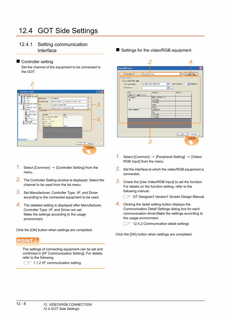
12 - 6 12. VIDEO/RGB CONNECTION12.4 GOT Side Settings
12.4 GOT Side Settings
12.4.1 Setting communication interface
Controller settingSet the channel of the equipment to be connected to the GOT.
1. Select [Common] [Controller Setting] from the menu.
2. The Controller Setting window is displayed. Select the channel to be used from the list menu.
3. Set Manufacturer, Controller Type, I/F, and Driver according to the connected equipment to be used.
4. The detailed setting is displayed after Manufacturer, Controller Type, I/F, and Driver are set.Make the settings according to the usage environment.
Click the [OK] button when settings are completed.
POINTPOINTPOINT
The settings of connecting equipment can be set and confirmed in [I/F Communication Setting]. For details, refer to the following.
1.1.2 I/F communication setting
2.
3.
4.
Click!
Settings for the video/RGB equipment
1. Select [Common] [Peripheral Setting] [Video/RGB Input] from the menu.
2. Set the interface to which the video/RGB equipment is connected.
3. Check the [Use Video/RGB Input] to set the function. For details on the function setting, refer to the following manual.
GT Designer3 Version1 Screen Design Manual
4. Clicking the detail setting button displays the Communication Detail Settings dialog box for each communication driver.Make the settings according to the usage environment.
12.4.2 Communication detail settings
Click the [OK] button when settings are completed.
2.
3.
4.
Click!

9
BA
R C
OD
E R
EA
DE
R
CO
NN
EC
TIO
N
10
PC
RE
MO
TE
C
ON
NE
CT
ION
11
VN
C(R
) S
ER
VE
R
CO
NN
EC
TIO
N
12
VID
EO
/RG
B
CO
NN
EC
TIO
N
13
PR
INT
ER
C
ON
NE
CT
ION
14
MU
LTIM
ED
IA
CO
NN
EC
TIO
N
15
TIO
N
12.4.2 Communication detail settings
Make the settings according to the usage environment.
*1 When NTSC format is selected, the resolution is fixed to 640 480.
*2 For GT1675M-V and GT1665M-V, the resolution is fixed to 640 480.
*3 768 576 can be set only for the GT16.
POINTPOINTPOINT
(1) Communication interface setting by the UtilityThe communication interface setting can be changed on the Utility's [Communication setting] after writing [Communication Settings] of project data.For details on the Utility, refer to the following manual.
User's Manual of GOT used.(2) Precedence in communication settings
When settings are made by GT Designer3 or the Utility, the latest setting is effective.
Item Description Range
Video Input
Signal*1Set the video input signal.
(Default: NTSC)NTSC, PAL
Video
Resolution*2
Set the video resolution.
(Default: 640 480)
640 480,
720 480,
768 576*3
12.4.3 Setting the video/RGB function
Set the video/RGB function.
For the video/RGB function setting, refer to the following manual.
GT Designer3 Version1 Screen Design Manual
ON
NE
C
12.5 PrecautionsRF
ID C
Connecting to PCWhen connecting to a PC, ground the earth wire of the PC.
12. VIDEO/RGB CONNECTION12.5 Precautions
12 - 7

12 - 8 12. VIDEO/RGB CONNECTION12.5 Precautions

139
BA
R C
OD
E R
EA
DE
R
CO
NN
EC
TIO
N
10
PC
RE
MO
TE
C
ON
NE
CT
ION
11
VN
C(R
) S
ER
VE
R
CO
NN
EC
TIO
N
12
VID
EO
/RG
B
CO
NN
EC
TIO
N
13
PR
INT
ER
C
ON
NE
CT
ION
14
MU
LTIM
ED
IA
CO
NN
EC
TIO
N
15
RF
ID C
ON
NE
CT
ION
13.PRINTER CONNECTION
13.1 Connectable Model List . . . . . . . . . . . . . . . . . . . . . . . . . . . 13 - 2
13.2 System Configuration. . . . . . . . . . . . . . . . . . . . . . . . . . . . . 13 - 2
13.3 GOT Side Settings . . . . . . . . . . . . . . . . . . . . . . . . . . . . . . . 13 - 4
13.4 Precautions . . . . . . . . . . . . . . . . . . . . . . . . . . . . . . . . . . . . 13 - 6
13 - 1
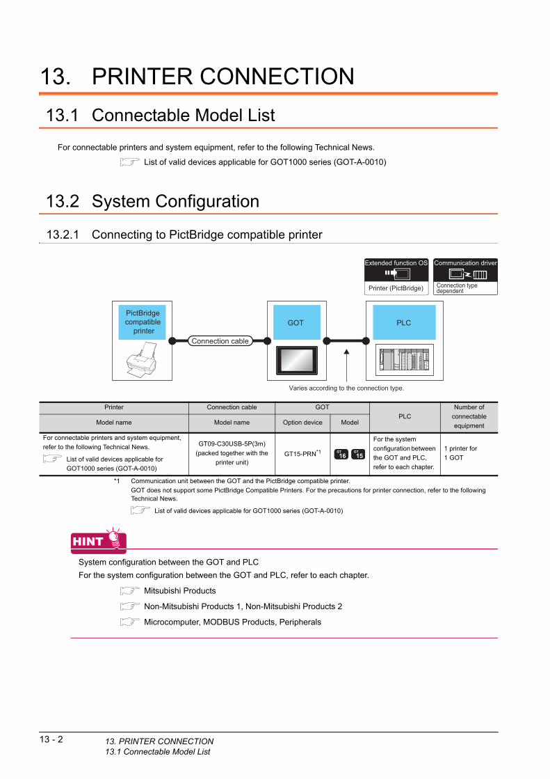
13 - 2 13. PRINTER CONNECTION13.1 Connectable Model List
13. PRINTER CONNECTION
13.1 Connectable Model List
For connectable printers and system equipment, refer to the following Technical News.
List of valid devices applicable for GOT1000 series (GOT-A-0010)
13.2 System Configuration
13.2.1 Connecting to PictBridge compatible printer
Connection typedependent
Communication driver
PLCGOTPictBridge compatible
printerConnection cable
Varies according to the connection type.
Printer (PictBridge)
Extended function OS
*1 Communication unit between the GOT and the PictBridge compatible printer.
GOT does not support some PictBridge Compatible Printers. For the precautions for printer connection, refer to the following Technical News.
List of valid devices applicable for GOT1000 series (GOT-A-0010)
HINTHINTHINT
System configuration between the GOT and PLC
For the system configuration between the GOT and PLC, refer to each chapter.
Mitsubishi Products
Non-Mitsubishi Products 1, Non-Mitsubishi Products 2
Microcomputer, MODBUS Products, Peripherals
Printer Connection cable GOT
PLC
Number of
connectable
equipmentModel name Model name Option device Model
For connectable printers and system equipment,
refer to the following Technical News.
List of valid devices applicable for
GOT1000 series (GOT-A-0010)
GT09-C30USB-5P(3m)
(packed together with the
printer unit)GT15-PRN*1
For the system
configuration between
the GOT and PLC,
refer to each chapter.
1 printer for
1 GOT

9
BA
R C
OD
E R
EA
DE
R
CO
NN
EC
TIO
N
10
PC
RE
MO
TE
C
ON
NE
CT
ION
13.2.2 Connecting to serial printer
PLCGOTSerialprinter
Connection cable 1) Connection cable 2)
Varies according to the connection type.
Connection typedependent
Communication driver
Printer (serial)
Extended function OS
11
VN
C(R
) S
ER
VE
R
CO
NN
EC
TIO
N
12
VID
EO
/RG
B
CO
NN
EC
TIO
N
13
PR
INT
ER
C
ON
NE
CT
ION
14
MU
LTIM
ED
IA
CO
NN
EC
TIO
N
15
RF
ID C
ON
NE
CT
ION
*1 The RS-232 cable differs depending on the specification of the printer to be used. Use the RS-232 cable that is compatible with
the printer to be used.
HINTHINTHINT
System configuration between the GOT and PLC
For the system configuration between the GOT and PLC, refer to each chapter.
Mitsubishi Products
Non-Mitsubishi Products 1, Non-Mitsubishi Products 2
Microcomputer, MODBUS Products, Peripherals
Printer Connection cable 1) Connection cable 2) GOT
PLC
Number of
connectable
equipmentModel name Model name Model name Option device Model
For connectable printers and
system equipment, refer to the
following Technical News.
List of valid devices
applicable for GOT1000
series (GOT-A-0010)
RS-232 cable
-- (Built into
GOT)For the system
configuration
between the GOT
and PLC, refer to
each chapter.
1 printer for
1 GOTGT10-C02H-6PT9P
(0.2m)
- (Built into
GOT)
- GT15-RS2-9P
13. PRINTER CONNECTION13.2 System Configuration
13 - 3

13 - 4 13. PRINTER CONNECTION13.3 GOT Side Settings
13.3 GOT Side Settings
13.3.1 Setting communication interface
Controller settingSet the channel of the equipment to be connected to the GOT.
1. Select [Common] [Controller Setting] from the menu.
2. The Controller Setting window is displayed. Select the channel to be used from the list menu.
3. Set Manufacturer, Controller Type, I/F, and Driver according to the connected equipment to be used.
4. The detailed setting is displayed after Manufacturer, Controller Type, I/F, and Driver are set.Make the settings according to the usage environment.
Click the [OK] button when settings are completed.
POINTPOINTPOINT
The settings of connecting equipment can be set and confirmed in [I/F Communication Setting]. For details, refer to the following.
1.1.2 I/F communication setting
2.
3.
4.
Click!
Printer setting
1. Select [Common] [Peripheral Setting] [Printer] from the menu.
2. Select the printer type.For GT14 and GT10, only "Serial" can be selected.
3. Set the interface to which the printer is connected.
4. When Serial is selected in Printer type, clicking the detail setting button displays the Communication Detail Settings dialog box for the communication driver. Make the settings according to the usage environment.
13.3.2 Communication detail settings
Click the [OK] button when settings are completed.
POINTPOINTPOINT
(1) Setting the communication interfaceWhen Channel No.8 is used for the serial printer, the following external devices, which use Channel No.8, cannot be connected at the same time.• Fingerprint authentication device• Barcode reader that requires the power supplyWhen connecting the above-mentioned devices at the same time, set the serial printer to Channels No. 5 to 7.For GT14 and GT11, the serial printer and barcode reader cannot be connected at the same time.
(2) Setting for the driverRegardless of the printer type, multiple printers are cannot be set.
2.
Click!
3.
4.(For GT16, GT15)

9
BA
R C
OD
E R
EA
DE
R
CO
NN
EC
TIO
N
10
PC
RE
MO
TE
C
ON
NE
CT
ION
11
VN
C(R
) S
ER
VE
R
CO
NN
EC
TIO
N
12
VID
EO
/RG
B
CO
NN
EC
TIO
N
13
PR
INT
ER
C
ON
NE
CT
ION
14
MU
LTIM
ED
IA
CO
NN
EC
TIO
N
15
RF
ID C
ON
NE
CT
ION
13.3.2 Communication detail settings
Make the settings according to the usage environment.
*1 When using the hard copy function, set to 8bit.
Item Description Range
Transmission
Speed
Set this item when change the
transmission speed used for
communication with printer.
(Default: 19200bps)
4800bps,
9600bps,
19200bps,
38400bps,
57600bps,
115200bps
Data Bit*1
Set this item when change the
data length used for
communication with printer.
(Default: 8bits)
7bits/8bits
Stop Bit
Specify the stop bit length for
communications.
(Default: 1bit)
1bit/2bits
Parity
Specify whether or not to
perform a parity check, and how
it is performed during
communication.
(Default: None)
None
Even
Odd
Retry
Set the number of retries to be
performed when a
communication error occurs.
(Default: 0times)
0 to 5times
Timeout Time
Set the time period for a
communication to time out.
(Default: 30sec)
3 to 90sec
Delay Time
Set this item to adjust the
transmission timing of the
communication request from the
GOT.
(Default: 0ms)
0 to 300ms
Control Method
Set this item when selecting the
XON/XOFF control for the
control method.
(Default: XON/XOFF)
XON/XOFF,
fixed
POINTPOINTPOINT
(1) Communication interface setting by the UtilityThe communication interface setting can be changed on the Utility's [Communication setting] after writing [Communication Settings] of project data.For details on the Utility, refer to the following manual.
User's Manual of GOT used.(2) Precedence in communication settings
When settings are made by GT Designer3 or the Utility, the latest setting is effective.
13. PRINTER CONNECTION13.3 GOT Side Settings
13 - 5

13 - 6 13. PRINTER CONNECTION13.4 Precautions
13.4 Precautions
Connection/disconnection of USB cable during print operationWhen the USB cable is disconnected during print operation, the printer hangs up depending on the model of PictBridge compatible printer. In this case, turn on the main power of the printer and then restart it.
When a printer cannot perform print operationWhile the initialization of the printer is being carried out at boot time, some models of PictBridge compatible printers send "Print Ready" signal to GOT.If printing operation is started from GOT, an error will occur and the printing operation will be disabled.If this occurs, restart a printer with the following procedure.
1. Disconnect the USB cable from the printer.
2. Turn the power of the printer OFF.
3. Disconnect the power supply cable of the printer and stop the printer completely.
4. Connect the power supply cable to the printer.
5. Turn the power of the printer ON and wait until the initialization processing of the printer is completed.
6. Connect the USB cable to the printer.
For the handling errors occurred on the printer, refer to the following.
Manual for the printer being used
149
BA
R C
OD
E R
EA
DE
R
CO
NN
EC
TIO
N
10
PC
RE
MO
TE
C
ON
NE
CT
ION
11
VN
C(R
) S
ER
VE
R
CO
NN
EC
TIO
N
12
VID
EO
/RG
B
CO
NN
EC
TIO
N
13
PR
INT
ER
C
ON
NE
CT
ION
14
MU
LTIM
ED
IA
CO
NN
EC
TIO
N
15
RF
ID C
ON
NE
CT
ION
14.MULTIMEDIA CONNECTION
14.1 Connectable Model List . . . . . . . . . . . . . . . . . . . . . . . . . . . 14 - 2
14.2 System Configuration. . . . . . . . . . . . . . . . . . . . . . . . . . . . . 14 - 2
14.3 Connection Diagram . . . . . . . . . . . . . . . . . . . . . . . . . . . . . 14 - 4
14.4 GOT Side Settings . . . . . . . . . . . . . . . . . . . . . . . . . . . . . . . 14 - 5
14.5 Precautions . . . . . . . . . . . . . . . . . . . . . . . . . . . . . . . . . . . . 14 - 7
14 - 1

14 - 2 14. MULTIMEDIA CONNECTION14.1 Connectable Model List
14. MULTIMEDIA CONNECTION
14.1 Connectable Model List
For the type of CF card that can be inserted or connectable video camera types, refer to the following Technical News.
List of valid devices applicable for GOT1000 series (GOT-A-0010)
POINTPOINTPOINT
Before making the multimedia connection
Update the software version of the multimedia unit to the latest version.For the version upgrade of the multimedia unit, refer to the following manual.
GT16 User’s Manual (Hardware)
14.2 System Configuration
14.2.1 Saving video image and displaying it on GOT
GOTVideo camera,Microphone,Speaker
Connection cable
Multimedia
Extended function OS
*1 The cable length differs depending on the specification of the video camera used by the user.
*2 For the CF card to be inserted into the multimedia unit, refer to the following.
• Type of CF card that can be inserted
List of valid devices applicable for GOT1000 series (GOT-A-0010)
• Precautions for using the CF card
14.4 GOT Side Settings
*3 For the type of the video camera that can be connected, refer to the following Technical News.
List of valid devices applicable for GOT1000 series (GOT-A-0010)
*4 GT1675-VN, GT1672-VN, GT1662-VN, and GT1655-V cannot be used.
Multimedia controller Signal type Connection cableMax.
distance
GOT Number of connectable
equipmentOption device Model
*3 NTSC/PALCoaxial connection
diagram 1)*1 GT16M-MMR*2 *4 1 multimedia controller for 1
GOT

9
BA
R C
OD
E R
EA
DE
R
CO
NN
EC
TIO
N
10
RE
MO
TE
N
NE
CT
ION
14.2.2 Sending video image to personal computer
GOT
Connection cable 1)
PC
interface 1) interface 2)
Video camera,Microphone,Speaker
Connection cable 2)
Multimedia
Extended function OS
Connection typedependent
Communication driver
Gateway (FTP)
Option OS
C O
P C11
VN
C(R
) S
ER
VE
R
CO
NN
EC
TIO
N
12
VID
EO
/RG
B
CO
NN
EC
TIO
N
13
PR
INT
ER
C
ON
NE
CT
ION
14
MU
LTIM
ED
IA
CO
NN
EC
TIO
N
15
RF
ID C
ON
NE
CT
ION
*1 The cable length differs depending on the specification of the video camera used by the user.
*2 The destination connected with the twisted pair cable varies with the configuration of the applicable Ethernet network system.
Connect to the Ethernet module, hub, transceiver, wireless LAN adapter (NZ2WL-JPA or NZ2WL-JPS), or other system equipment corresponding to the applicable Ethernet network system.Use cables, connectors, and hubs that meet the IEEE802.3 10BASE-T/100BASE-TX standards.For the controllers that can be connected to the wireless LAN adapters and how to set the wireless LAN adapter, refer to the manual of the wireless LAN adapter used.
*3 When connecting GT16 of the function version A to an equipment that meets the 10BASE (-T/2/5) standard, use the switching
hub and operate in a 10Mbps/100Mbps mixed environment.
For how to check the function version, refer to the following.
GT16 User’s Manual (Hardware)
*4 For the CF card to be inserted into the multimedia unit, refer to the following.
• Type of CF card that can be inserted
List of valid devices applicable for GOT1000 series (GOT-A-0010)
• Precautions for using the CF card
14.4 GOT Side Settings
*5 For the type of the video camera that can be connected, refer to the following Technical News.
List of valid devices applicable for GOT1000 series (GOT-A-0010)
*6 Install the multimedia interaction tool before use.
For details of the multimedia interaction tool, refer to the following manual.
GT Designer3 Version1 Screen Design Manual
*7 GT1675-VN, GT1672-VN, and GT1662-VN cannot be used.
*8 A length between a hub and a node.
The maximum distance differs depending on the Ethernet device to be used.The following shows the number of the connectable nodes when a repeater hub is used.• 10BASE-T: Max. 4 nodes for a cascade connection (500m)• 100BASE-TX: Max. 2 nodes for a cascade connection (205m)When switching hubs are used, the cascade connection between the switching hubs has no logical limit for the number of cascades.For the limit, contact the switching hub manufacturer.
POINTPOINTPOINT
Power supply of video cameraDepending on the video camera type, noises from the power supply cable of the camera may cause a malfunction on the PLC or the GOT. In this case, apply the following line filter to the power line of the camera.Recommended line filter: TDK ZHC2203-11 (or equivalent)
Multimedia
controller
Signal
type
Connection cable 1) GOT*2*3 Connection cable 2)Personal
computer*6
Number of
connectable
equipmentModel nameMax.
distance
Option device
(Interface 1))Model
Option device
(Interface 2))Cable model
Maximum
segment
length*8
*5NTSC
/PAL
Coaxial
connection
diagram 1)
*1 GT16M-MMR*4
*7
Ethernet
Interface
(Built into GOT)
Twisted pair cable• 10BASE-T
Shielded twistedpair cable (STP) or unshielded twisted pair cable (UTP): Category 3, 4, and 5
• 100BASE-TXShielded twisted pair cable (STP): Category 5 and 5e
100m
To be
selected
by the
user.
1 multimedia
controller for 1
GOTGT16M-MMR
14. MULTIMEDIA CONNECTION14.2 System Configuration
14 - 3

14 - 4 14. MULTIMEDIA CONNECTION14.3 Connection Diagram
14.3 Connection Diagram
The coaxial cable used for connecting the GOT to a video camera should be prepared by the user.
The following shows each cable connection diagram.
14.3.1 Coaxial cable
The following shows the connection diagrams and connector specifications of the coaxial cable used for connecting the GOT to a video camera.
Connection diagramCoaxial connection diagram 1)Displaying video image on GOT
Cable specification
Connecting the BNC connector to the coaxial cableFor connecting the BNC connector and coaxial cable, refer to the following.
1.4.2 Coaxial cable connector connection method
Precautions when preparing a cable
(1) Cable lengthThe cable length differs depending on the specification of the video camera to be used.Create a cable under the specification of the video camera.
(2) GOT side connectorUse the following as the multimedia unit connector.For the GOT side connector of the coaxial cable, use the ones compatible with the GOT connector.
(3) Video camera side connectorUse a connector compatible with the video camera to be used.
Item Specifications
Applicable cable 3C-2V, 5C-2V (JIS C 3501 compliant)
GOTConnector
model
Connector
typeManufacturer
GT16M-MMR 227161-4 BNC Tyco International, Ltd.
GOT side 75Ω drohmcoaxial
Signal SignalBNC connector BNC connectorGND GND
Video camera/vision sensor side
HINTHINTHINT
When the coaxial cable is long
When the coaxial cable is long, video signals areattenuated by the cable.The use of a video signal amplifier is recommended tocorrect the attenuated signals.Connect a video signal amplifier in reference to thefollowing:• Coaxial cable: The cable length is 100m or more
when 3C-2V is used.• Coaxial cable: The cable length is 200m or more
when 5C-2V is used.

9
DE
R
14.4 GOT Side SettingsBA
R C
OD
E R
EA
CO
NN
EC
TIO
N
10
PC
RE
MO
TE
C
ON
NE
CT
ION
11
VN
C(R
) S
ER
VE
R
CO
NN
EC
TIO
N
12
VID
EO
/RG
B
CO
NN
EC
TIO
N
13
PR
INT
ER
C
ON
NE
CT
ION
14
MU
LTIM
ED
IA
CO
NN
EC
TIO
N
15
RF
ID C
ON
NE
CT
ION
14.4.1 Setting communication interface
Controller settingSet the channel of the equipment to be connected to the GOT.
1. Select [Common] [Controller Setting] from the menu.
2. The Controller Setting window is displayed. Select the channel to be used from the list menu.
3. Set Manufacturer, Controller Type, I/F, and Driver according to the connected equipment to be used.
4. The detailed setting is displayed after Manufacturer, Controller Type, I/F, and Driver are set.Make the settings according to the usage environment.
Click the [OK] button when settings are completed.
POINTPOINTPOINT
The settings of connecting equipment can be set and confirmed in [I/F Communication Setting]. For details, refer to the following.
1.1.2 I/F communication setting
2.
3.
4.
Click!
Multimedia setting
1. Select [Common] [Peripheral Setting] [Multimedia] from the menu.
2. Set the interface to which the multimedia controller is connected.
3. Check the [Enable the setting of Multimedia] to set the function. For details on the communication settings, refer to the following manual.
GT Designer3 Version1 Screen Design Manual
4. Clicking the detail setting button displays the Communication Detail Settings dialog box for each communication driver.Make the settings according to the usage environment.
14.4.2 Communication detail settings
Click the [OK] button when settings are completed.
2.
3.
4.
Click!
14. MULTIMEDIA CONNECTION14.4 GOT Side Settings
14 - 5
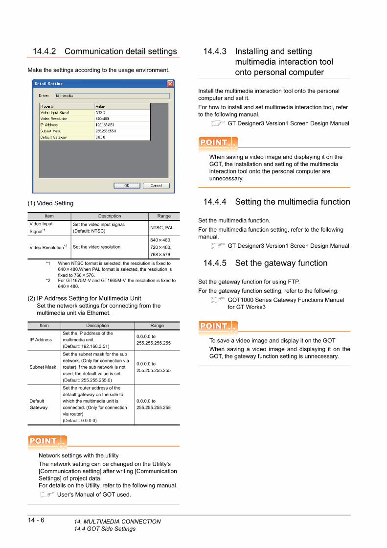
14.4.2 Communication detail settings
Make the settings according to the usage environment.
(1) Video Setting
*1 When NTSC format is selected, the resolution is fixed to 640 480.When PAL format is selected, the resolution is fixed to 768 576.
*2 For GT1675M-V and GT1665M-V, the resolution is fixed to 640 480.
(2) IP Address Setting for Multimedia UnitSet the network settings for connecting from the multimedia unit via Ethernet.
POINTPOINTPOINT
Network settings with the utility
The network setting can be changed on the Utility's [Communication setting] after writing [Communication Settings] of project data.For details on the Utility, refer to the following manual.
User's Manual of GOT used.
Item Description Range
Video Input
Signal*1Set the video input signal.
(Default: NTSC)NTSC, PAL
Video Resolution*2 Set the video resolution.
640 480,
720 480,
768 576
Item Description Range
IP Address
Set the IP address of the
multimedia unit.
(Default: 192.168.3.51)
0.0.0.0 to
255.255.255.255
Subnet Mask
Set the subnet mask for the sub
network. (Only for connection via
router) If the sub network is not
used, the default value is set.
(Default: 255.255.255.0)
0.0.0.0 to
255.255.255.255
Default
Gateway
Set the router address of the
default gateway on the side to
which the multimedia unit is
connected. (Only for connection
via router)
(Default: 0.0.0.0)
0.0.0.0 to
255.255.255.255
14 - 6 14. MULTIMEDIA CONNECTION14.4 GOT Side Settings
14.4.3 Installing and setting multimedia interaction tool onto personal computer
Install the multimedia interaction tool onto the personal computer and set it.
For how to install and set multimedia interaction tool, refer to the following manual.
GT Designer3 Version1 Screen Design Manual
POINTPOINTPOINT
When saving a video image and displaying it on the GOT, the installation and setting of the multimedia interaction tool onto the personal computer are unnecessary.
14.4.4 Setting the multimedia function
Set the multimedia function.
For the multimedia function setting, refer to the following manual.
GT Designer3 Version1 Screen Design Manual
14.4.5 Set the gateway function
Set the gateway function for using FTP.
For the gateway function setting, refer to the following.
GOT1000 Series Gateway Functions Manualfor GT Works3
POINTPOINTPOINT
To save a video image and display it on the GOT
When saving a video image and displaying it on theGOT, the gateway function setting is unnecessary.

9
DE
R
14.5 PrecautionsBA
R C
OD
E R
EA
CO
NN
EC
TIO
N
10
PC
RE
MO
TE
C
ON
NE
CT
ION
11
VN
C(R
) S
ER
VE
R
CO
NN
EC
TIO
N
12
VID
EO
/RG
B
CO
NN
EC
TIO
N
13
PR
INT
ER
C
ON
NE
CT
ION
14
MU
LTIM
ED
IA
CO
NN
EC
TIO
N
15
RF
ID C
ON
NE
CT
ION
When the multimedia function is usedThe multimedia function and the video/RGB function are written exclusively.
Select either of them to use.
CF card on the multimedia unitFor the CF card that can be inserted into the multimedia unit, formatting in FAT32 is recommended.
If the CF card formatted in FAT16 is inserted, the following phenomena may occur.• Reading, writing or saving of movie files takes time.• When a movie file is played, the movie momentarily
looks like as if it stopped.
14. MULTIMEDIA CONNECTION14.5 Precautions
14 - 7

14 - 8 14. MULTIMEDIA CONNECTION14.5 Precautions
159
BA
R C
OD
E R
EA
DE
R
CO
NN
EC
TIO
N
10
PC
RE
MO
TE
C
ON
NE
CT
ION
11
VN
C(R
) S
ER
VE
R
CO
NN
EC
TIO
N
12
VID
EO
/RG
B
CO
NN
EC
TIO
N
13
PR
INT
ER
C
ON
NE
CT
ION
14
MU
LTIM
ED
IA
CO
NN
EC
TIO
N
15
RF
ID C
ON
NE
CT
ION
15.RFID CONNECTION
15.1 Connectable Model List . . . . . . . . . . . . . . . . . . . . . . . . . . . 15 - 2
15.2 System Configuration. . . . . . . . . . . . . . . . . . . . . . . . . . . . . 15 - 2
15.3 GOT Side Settings . . . . . . . . . . . . . . . . . . . . . . . . . . . . . . . 15 - 3
15.4 Precautions . . . . . . . . . . . . . . . . . . . . . . . . . . . . . . . . . . . . 15 - 5
15 - 1

15 - 2 15. RFID CONNECTION15.1 Connectable Model List
15. RFID CONNECTION
15.1 Connectable Model List
For connectable RFID controllers and system equipment, refer to the following Technical bulletin.
List of valid devices applicable for GOT1000 series (GOT-A-0010)
Visit the Mitsubishi Electric FA Equipment Information Se
ce website (MELFANSweb) to refer to the Technical News. rvihttp://wwwf2.mitsubishielectric.co.jp/english/index.html15.2 System Configuration
15.2.1 Connecting to RFID
GOT
Connection cable
PLC
Varies according to the connection type.
RFID controller
RFID
Extended function OS
Connection typedependent
Communication driver
POINTPOINTPOINT
When using the RS-232 communication unitUse the RS-232 communication unit of the GOT for connecting to an RFID controller.However, when the RS-232 communication unit is used, the following operations cannot be supported.
(a) Using the external authentication(b) Supplying the power to an RFID controller from the GOT
HINTHINTHINT
System configuration between the GOT and PLC
For the system configuration between the GOT and PLC, refer to each chapter.
Mitsubishi Products
Non-Mitsubishi Products 1, Non-Mitsubishi Products 2
Microcomputer, MODBUS Products, Peripherals
RFID controllerConnection cable
GOTPLC
Number of connectable
equipmentModel name Option device Model
For connectable RFID controllers and system
equipment, refer to the following Technical
bulletin.
List of valid devices applicable for
GOT1000 series (GOT-A-0010)
Varies according to
specification of RFID
controllers.
- (Built into
GOT)
For the system
configuration
between the GOT
and PLC, refer to
each chapter.
1 RFID controller for
1 GOT
GT15-RS2-9P

9
DE
R
15.3 GOT Side SettingsBA
R C
OD
E R
EA
CO
NN
EC
TIO
N
10
PC
RE
MO
TE
C
ON
NE
CT
ION
11
VN
C(R
) S
ER
VE
R
CO
NN
EC
TIO
N
12
VID
EO
/RG
B
CO
NN
EC
TIO
N
13
PR
INT
ER
C
ON
NE
CT
ION
14
MU
LTIM
ED
IA
CO
NN
EC
TIO
N
15
RF
ID C
ON
NE
CT
ION
15.3.1 Setting communication interface
Controller settingSet the channel of the equipment to be connected to the GOT.
1. Select [Common] [Controller Setting] from the menu.
2. The Controller Setting window is displayed. Select the channel to be used from the list menu.
3. Set Manufacturer, Controller Type, I/F, and Driver according to the connected equipment to be used.
4. The detailed setting is displayed after Manufacturer, Controller Type, I/F, and Driver are set.Make the settings according to the usage environment.
Click the [OK] button when settings are completed.
POINTPOINTPOINT
The settings of connecting equipment can be set and confirmed in [I/F Communication Setting]. For details, refer to the following.
1.1.2 I/F communication setting
2.
3.
4.
Click!
RFID setting
1. Select [Common] [Peripheral Setting] [RFID] from the menu.
2. Set the interface to which the RFID controller is connected.
3. Check the [Use RFID] to set the function. For details on the function setting, refer to the following manual.
GT Designer3 Version1 Screen Design Manual
4. Clicking the detail setting button displays the Communication Detail Settings dialog box for each communication driver.Make the settings according to the usage environment.
15.3.2 Communication detail settings
Click the [OK] button when settings are completed.
POINTPOINTPOINT
(1) Communication interface settingWhen Channel No.8 is used, the following external devices, which use Channel No.8, cannot be connected at the same time.• Fingerprint authentication device• Barcode reader that requires the power supplyWhen connecting the above-mentioned devices at the same time, set [RFID] to Channels No. 5 to 7.
(2) Setting for the driverTo Channels No. 5 to 8, multiple [RFID] cannot be set.
2.
3.
4.
Click!
15. RFID CONNECTION15.3 GOT Side Settings
15 - 3

15.3.2 Communication detail settings
Item Description Range
Transmission Speed
Set this item when change the transmission speed used for communication with the connected equipment.(Default: 9600bps)
4800bps, 9600bps, 19200bps, 38400bps, 57600bps, 115200bps
Data Bit
Set this item when change the data length used for communication with the connected equipment.(Default: 8bits)
7bits/8bits
Stop BitSpecify the stop bit length for communications.(Default: 1bit)
1bit/2bits
Parity
Specify whether or not to perform a parity check, and how it is performed during communication.(Default: Even)
NoneEvenOdd
Sum CheckSet whether or not to perform a sum check during communication.(Default: Done)
Yes or No
Retry
Set the number of retries to be performed when a communication timeout occurs.When receiving no response after retries, the communication times out. (Default: 0time)
0 to 5times
Timeout TimeSet the time period for a communication to time out.(Default: 3sec)
3 to 30sec
Delay Time
Set this item to adjust the transmission timing of the communication request from the GOT.(Default: 0ms)
0 to 3000ms
Format
Select the communication format.(Default: 15)Dedicated protocol• Format 10 (LS Industrial Systems
Co., Ltd. LSR)• Format 11 (MARS TECHNO
SCIENCE Corp. ICU-60S)• Format 12 (MARS TECHNO
SCIENCE Corp. ICU-215 (Mifare))
Nonprocedural protocol• Format 15
10/11/12/15
15 - 4 15. RFID CONNECTION15.3 GOT Side Settings
POINTPOINTPOINT
(1) Communication interface setting by the UtilityThe communication interface setting can be changed on the Utility's [Communication setting] after writing [Communication Settings] of project data.For details on the Utility, refer to the following manuals.
User's Manual of GOT used.(2) Precedence in communication settings
When settings are made by GT Designer3 or the Utility, the latest setting is effective.

9
DE
R
15.4 PrecautionsBA
R C
OD
E R
EA
CO
NN
EC
TIO
N
10
PC
RE
MO
TE
C
ON
NE
CT
ION
11
VN
C(R
) S
ER
VE
R
CO
NN
EC
TIO
N
12
VID
EO
/RG
B
CO
NN
EC
TIO
N
13
PR
INT
ER
C
ON
NE
CT
ION
14
MU
LTIM
ED
IA
CO
NN
EC
TIO
N
15
RF
ID C
ON
NE
CT
ION
RFID function setting on GT Designer3Before connecting the RFID controller, set the RFID function and system data.
For details, refer to the following manual.
GT Designer3 Version1 Screen Design Manual
Controller setting
(1) When using the external authenticationWhen using the external authentication on the RFID controller, set Channel No. 8 using the standard interface.When connecting the RFID using Channels No. 5 to 7 of the extension interface, extension interface cannot be used.For details on the external authentication, refer to the following manual.
GT Designer3 Version1 Screen Design Manual
(2) When requiring the power supplyWhen using the RFID controller, which requires the power supply from the GOT, set Channel No. 8 using the standard interface.With Channels No. 5 to 7 of the extension interface, the power cannot be supplied.
Communication in multiple RFID readers/writers connectionWhen connecting multiple RFID readers/writers, some controllers may communicate with each RFID reader/writer.
For communicating the RFID controller with the each RFID reader/writer, set an interlock so that the RFID controller does not communicate with RFID readers/writers until the executing communication is completed.
15. RFID CONNECTION15.4 Precautions
15 - 5

15 - 6 15. RFID CONNECTION15.4 Precautions

INDEX
IND
EX
[B]
BAR CODE READER CONNECTION................... 9-1
[C]
Coaxial cable ....................................................... 1-27Communication module....................................... 1-15Connectable Model List
BAR CODE READER CONNECTION ............... 9-2CONNECTION TO EXTERNAL I/O DEVICE..... 7-2CONNECTION TO SOUND OUTPUT UNIT...... 6-2FINGERPRINT AUTHENTICATION DEVICE CONNECTION .................................... 8-2MODBUS(R)/RTU CONNECTION..................... 4-2MODBUS(R)/TCP CONNECTION..................... 5-2MULTIMEDIA CONNECTION.......................... 14-2PC REMOTE CONNECTION .......................... 10-2PRINTER CONNECTION ................................ 13-2RFID CONNECTION ....................................... 15-2VIDEO/RGB CONNECTION............................ 12-2VNC(R) SERVER CONNECTION ................... 11-2
Connection DiagramCONNECTION TO EXTERNAL I/O DEVICE..... 7-4MICROCOMPUTER CONNECTION (SERIAL)............................................................ 2-6MODBUS(R)/RTU CONNECTION..................... 4-4MULTIMEDIA CONNECTION.......................... 14-4PC REMOTE CONNECTION .......................... 10-3VIDEO/RGB CONNECTION............................ 12-4
CONNECTION TO EXTERNAL I/O DEVICE ........ 7-1CONNECTION TO SOUND OUTPUT UNIT ......... 6-1Controller Type ...................................................... 1-5Conversion cable................................................. 1-16
[D]
Device Range that Can Be SetMICROCOMPUTER CONNECTION (SERIAL).......................................................... 2-82MODBUS(R)/TCP CONNECTION..................... 5-6
[F]
FINGERPRINT AUTHENTICATION DEVICE CONNECTION ...................................................... 8-1
[G]
GOT connector specifications ............................. 1-24GOT Side Settings
BAR CODE READER CONNECTION ............... 9-3CONNECTION TO EXTERNAL I/O DEVICE... 7-12CONNECTION TO SOUND OUTPUT UNIT...... 6-3FINGERPRINT AUTHENTICATION DEVICE CONNECTION................................................... 8-3MICROCOMPUTER CONNECTION (ETHERNET) ................................................... 3-69
MICROCOMPUTER CONNECTION (SERIAL) .......................................................... 2-77MODBUS(R)/RTU CONNECTION................... 4-12MODBUS(R)/TCP CONNECTION ..................... 5-3MULTIMEDIA CONNECTION.......................... 14-5PC REMOTE CONNECTION................... 10-4,10-8PRINTER CONNECTION ................................ 13-4RFID CONNECTION........................................ 15-3VIDEO/RGB CONNECTION ............................ 12-6VNC(R) SERVER CONNECTION.................... 11-3
[I]
I/F........................................................................... 1-6I/F communication setting.................................... 1-10
[M]
MICROCOMPUTER CONNECTION (ETHERNET) ......................................................... 3-1MICROCOMPUTER CONNECTION (SERIAL)..... 2-1MODBUS(R)/RTU CONNECTION ........................ 4-1MODBUS(R)/TCP CONNECTION......................... 5-1MULTIMEDIA CONNECTION ............................. 14-1
[O]
Option unit ........................................................... 1-16
[P]
PC REMOTE CONNECTION .............................. 10-1Precautions
BAR CODE READER CONNECTION ............... 9-7CONNECTION TO EXTERNAL I/O DEVICE... 7-13CONNECTION TO SOUND OUTPUT UNIT...... 6-4FINGERPRINT AUTHENTICATION DEVICE CONNECTION ................................................... 8-4MICROCOMPUTER CONNECTION (ETHERNET) ................................................... 3-74MICROCOMPUTER CONNECTION (SERIAL) .......................................................... 2-83MODBUS(R)/RTU CONNECTION................... 4-17MODBUS(R)/TCP CONNECTION ................... 5-15MULTIMEDIA CONNECTION.......................... 14-7PRINTER CONNECTION ................................ 13-6VIDEO/RGB CONNECTION ............................ 12-7
PREPARATORY PROCEDURES FOR MONITORING ....................................................... 1-1PRINTER CONNECTION.................................... 13-1
[R]
RFID CONNECTION ........................................... 15-1
[S]
Station No. settingsMODBUS(R)/RTU CONNECTION................... 4-17
Index-1
System ConfigurationBAR CODE READER CONNECTION ............... 9-2CONNECTION TO EXTERNAL I/O DEVICE........................................................ 7-2,7-3CONNECTION TO SOUND OUTPUT UNIT...... 6-2FINGERPRINT AUTHENTICATION DEVICE CONNECTION................................................... 8-2MICROCOMPUTER CONNECTION (ETHERNET) ..................................................... 3-2MICROCOMPUTER CONNECTION (SERIAL) ............................................................ 2-4MODBUS(R)/RTU CONNECTION..................... 4-3MULTIMEDIA CONNECTION.................. 14-2,14-3PC REMOTE CONNECTION................... 10-2,10-7PRINTER CONNECTION ................................ 13-2RFID CONNECTION........................................ 15-2VIDEO/RGB CONNECTION.................... 12-2,12-3VNC(R) SERVER CONNECTION.................... 11-2
[T]
Terminating resistors of GOT .............................. 1-28
[V]
VIDEO/RGB CONNECTION ............................... 12-1VNC(R) SERVER CONNECTION ....................... 11-1
Index-2

REVISIONS
* The manual number is given on the bottom left of the back cover.
© 2009 MITSUBISHI ELECTRIC CORPORATION
Print Date * Manual Number Revision
Oct., 2009 SH(NA)-080871ENG-A First edition: Compatible with GT Works3 Version1.01B
Jan., 2010 SH(NA)-080871ENG-B Compatible with GT Works3 Version1.10L
• Correction of writing errors
• Station monitoring function (Ethernet multiple connection compatible, temperature controller connection
compatible), microcomputer (Ethernet connection compatible), PC remote (Ethernet connection compatible)
• In the communication detail settings for the Ethernet connection, the setting range of the GOT communication
port No. is changed.
May., 2010 SH(NA)-080871ENG-C Compatible with GT Works3 Version1.14Q
• In the communication detail settings for the Ethernet connection, the setting range of the GOT communication
port No. is changed.
Jun., 2010 SH(NA)-080871ENG-D Compatible with GT Works3 Version1.17T
• GT1675-VN, GT1672-VN, and GT1662-VN are added.
• Microcomputer connection (serial) (multiple-GT10 connection compatible), barcode reader connection, RFID
connection (direct input compatible for numerical input and ASCII input), printer connection (serial printer
compatible)
Oct., 2010 SH(NA)-080871ENG-E Compatible with GT Works3 Version1.19V
• MODBUS(R)/RTU connection, MODBUS(R)/TCP connection communication control function (multiple
connection) compatible
• Correction of microcomputer connection (Ethernet) formats 6 and 7 (4E frame)
• Microcomputer connection special interrupt code (RFID) compatible
Jan., 2011 SH(NA)-080871ENG-F Compatible with GT Works3 Version1.23Z
• Microcomputer connection (Ethernet) formats 8 and 9 (QnA compatible 3E frame) compatible
Apr., 2011 SH(NA)-080871ENG-G Compatible with GT Works3 Version1.28E
• GT1655-VTBD is added.
Jul., 2011 SH(NA)-080871ENG-H Compatible with GT Works3 Version1.31H
• The GT10 supports specifying a word device by using bits with the microcomputer connection.
Oct., 2011 SH(NA)-080871ENG-I Compatible with GT Works3 Version1.37P
• GT14, GT12 are added.
• VNC(R) server connection compatible
Jan., 2012 SH(NA)-080871ENG-J Compatible with GT Works3 Version1.40S
• "I/F Communication Setting" is compatible with "5V power supply".
• RS-232/485 signal conversion adaptor is added.
Apr., 2012 SH(NA)-080871ENG-K Compatible with GT Works3 Version1.45X
• The supplemental explanation for Ethernet cascade connection is added and the writing errors are corrected.
Jun., 2012 SH(NA)-080871ENG-L Compatible with GT Works3 Version1.54G
• The printer is compatible for GT14 and GT10.
• Ping test at the GT14 main unit compatible
Nov., 2012SH(NA)-080871ENG-M Compatible with GT Works3 Version1.63R
• Partial corrections
• SAFETY PRECAUTIONS changed
This manual confers no industrial property rights or any rights of any other kind, nor does it confer any patent licenses.
Mitsubishi Electric Corporation cannot be held responsible for any problems involving industrial property rights which may occur as a result
of using the contents noted in this manual.
REVISIONS - 1

REVISIONS - 2

WARRANTYPlease confirm the following product warranty details before using this product.
1. Gratis Warranty Term and Gratis Warranty RangeIf any faults or defects (hereinafter "Failure") found to be the responsibility of Mitsubishi occurs during use of the product within the gratis warranty term, the product shall be repaired at no cost via the sales representative or Mitsubishi Service Company.However, if repairs are required onsite at domestic or overseas location, expenses to send an engineer will be solely at the customer's discretion. Mitsubishi shall not be held responsible for any re-commissioning, maintenance, or testing on-site that involves replacement of the failed module.[Gratis Warranty Term]
The gratis warranty term of the product shall be for thirty-six (36) months after the date of purchase or delivery to a designated place.Note that after manufacture and shipment from Mitsubishi, the maximum distribution period shall be six (6) months, and the longest gratis warranty term after manufacturing shall be forty-two (42) months. The gratis warranty term of repair parts shall not exceed the gratis warranty term before repairs.
[Gratis Warranty Range](1) The customer shall be responsible for the primary failure diagnosis unless otherwise specified. If requested by the customer, Mitsubishi Electric Corporation or its representative firm may carry out the primary failure
diagnosis at the customer’s expence. The primary failure diagnosis will, however, be free of charge should the cause of failure be attributable to Mitsubishi Electric
Corporation.(2) The range shall be limited to normal use within the usage state, usage methods and usage environment, etc., which follow
the conditions and precautions, etc., given in the instruction manual, user's manual and caution labels on the product.(3) Even within the gratis warranty term, repairs shall be charged for in the following cases.
1. Failure occurring from inappropriate storage or handling, carelessness or negligence by the user. Failure caused by the user's hardware or software design.
2. Failure caused by unapproved modifications, etc., to the product by the user.3. When the Mitsubishi product is assembled into a user's device, Failure that could have been avoided if functions or
structures, judged as necessary in the legal safety measures the user's device is subject to or as necessary by industry standards, had been provided.
4. Failure that could have been avoided if consumable parts designated in the instruction manual had been correctly serviced or replaced.
5. Replacing consumable parts such as the battery, backlight and fuses.6. Failure caused by external irresistible forces such as fires or abnormal voltages, and Failure caused by force majeure
such as earthquakes, lightning, wind and water damage.7. Failure caused by reasons unpredictable by scientific technology standards at time of shipment from Mitsubishi.8. Any other failure found not to be the responsibility of Mitsubishi or that admitted not to be so by the user.
2. Onerous repair term after discontinuation of production(1) Mitsubishi shall accept onerous product repairs for seven (7) years after production of the product is discontinued.
Discontinuation of production shall be notified with Mitsubishi Technical Bulletins, etc.(2) Product supply (including repair parts) is not available after production is discontinued.
3. Overseas serviceOverseas, repairs shall be accepted by Mitsubishi's local overseas FA Center. Note that the repair conditions at each FA Center may differ.
4. Exclusion of loss in opportunity and secondary loss from warranty liabilityRegardless of the gratis warranty term, Mitsubishi shall not be liable for compensation to damages caused by any cause found not to be the responsibility of Mitsubishi, loss in opportunity, lost profits incurred to the user by Failures of Mitsubishi products, special damages and secondary damages whether foreseeable or not, compensation for accidents, and compensation for damages to products other than Mitsubishi products, replacement by the user, maintenance of on-site equipment, start-up test run and other tasks.
5. Changes in product specificationsThe specifications given in the catalogs, manuals or technical documents are subject to change without prior notice.
6. Product application(1) In using the Mitsubishi graphic operation terminal, the usage conditions shall be that the application will not lead to a major
accident even if any problem or fault should occur in the graphic operation terminal device, and that backup and fail-safe functions are systematically provided outside of the device for any problem or fault.
(2) The Mitsubishi graphic operation terminal has been designed and manufactured for applications in general industries, etc. Thus, applications in which the public could be affected such as in nuclear power plants and other power plants operated by respective power companies, and applications in which a special quality assurance system is required, such as for Railway companies or Public service purposes shall be excluded from the graphic operation terminal applications.In addition, applications in which human life or property that could be greatly affected, such as in aircraft, medical applications, incineration and fuel devices, manned transportation equipment for recreation and amusement, and safety devices, shall also be excluded from the graphic operation terminal range of applications.However, in certain cases, some applications may be possible, providing the user consults the local Mitsubishi representative outlining the special requirements of the project, and providing that all parties concerned agree to the special circumstances, solely at our discretion.
In some of three cases, however, Mitsubishi Electric Corporation may consider the possibility of an application, provided that the customer notifies Mitsubishi Electric Corporation of the intention, the application is clearly defined and any special quality is not required.

GOT is a registered trademark of Mitsubishi Electric Corporation.
Microsoft, Windows, Windows NT, Windows Server, Windows Vista, and Windows 7 are registered trademarks or trademarks
of Microsoft Corporation in the United States and other countries.
Adobe and Adobe Reader are registered trademarks of Adobe Systems Incorporated.
Pentium and Celeron are registered trademarks of Intel Corporation in the United States and other countries.
Ethernet is a trademark of Xerox Corporation in the United States.
MODBUS is a trademark of Schneider Electric SA.
VNC is a registered trademark of RealVNC Ltd. in the United States and other countries.
Other company and product names herein are either trademarks or registered trademarks of their respective owners.
SH(NA)-080871ENG-M

Connection Manual(Microcomputer, MODBUS Products, Peripherals)
Series
MODEL
MODELCODE
SW1-GTD3-U(CON4)-E
1D7MC5
SH(NA)-080871ENG-M(1211)MEE
for GT Works3
Specifications subject to change without notice.
Printed in Japan, November 2012.
When exported from Japan, this manual does not require application to the
Ministry of Economy, Trade and Industry for service transaction permission.
HEAD OFFICE : TOKYO BUILDING, 2-7-3 MARUNOUCHI, CHIYODA-KU, TOKYO 100-8310, JAPAN
NAGOYA WORKS : 1-14 , YADA-MINAMI 5-CHOME , HIGASHI-KU, NAGOYA , JAPAN

HEADQUARTERS
EUROPEMITSUBISHI ELECTRIC EUROPE B.V.German BranchGothaer Straße 8D-40880 RatingenPhone: +49 (0)2102 / 486-0Fax: +49 (0)2102 / 486-1120
CZECH REP.MITSUBISHI ELECTRIC EUROPE B.V.-org.sl.Czech BranchAvenir Business Park, Radlická 714/113aCZ-158 00 Praha 5Phone: +420 - 251 551 470Fax: +420 - 251-551-471
FRANCEMITSUBISHI ELECTRIC EUROPE B.V.French Branch25, Boulevard des BouvetsF-92741 Nanterre CedexPhone: +33 (0)1 / 55 68 55 68Fax: +33 (0)1 / 55 68 57 57
IRELANDMITSUBISHI ELECTRIC EUROPE B.V.Irish BranchWestgate Business Park, BallymountIRL-Dublin 24Phone: +353 (0)1 4198800Fax: +353 (0)1 4198890
ITALYMITSUBISHI ELECTRIC EUROPE B.V.Italian BranchViale Colleoni 7I-20041 Agrate Brianza (MB)Phone: +39 039 / 60 53 1Fax: +39 039 / 60 53 312
POLANDMITSUBISHI ELECTRIC EUROPE B.V.Poland BranchKrakowska 50PL-32-083 BalicePhone: +48 (0)12 / 630 47 00Fax: +48 (0)12 / 630 47 01
RUSSIAMITSUBISHI ELECTRIC EUROPE B.V.52, bld. 3 Kosmodamianskaya nab 8 floorRU-115054 МoscowPhone: +7 495 721-2070Fax: +7 495 721-2071
SPAINMITSUBISHI ELECTRIC EUROPE B.V.Spanish BranchCarretera de Rubí 76-80E-08190 Sant Cugat del Vallés (Barcelona)Phone: 902 131121 // +34 935653131Fax: +34 935891579
UKMITSUBISHI ELECTRIC EUROPE B.V.UK BranchTravellers LaneUK-Hatfield, Herts. AL10 8XBPhone: +44 (0)1707 / 27 61 00Fax: +44 (0)1707 / 27 86 95
JAPANMITSUBISHI ELECTRIC CORPORATIONOffice Tower “Z” 14 F8-12,1 chome, Harumi Chuo-KuTokyo 104-6212Phone: +81 3 622 160 60Fax: +81 3 622 160 75
USAMITSUBISHI ELECTRIC AUTOMATION, Inc.500 Corporate Woods ParkwayVernon Hills, IL 60061Phone: +1 847 478 21 00Fax: +1 847 478 22 53
EUROPEAN REPRESENTATIVES
AUSTRIAGEVAWiener Straße 89AT-2500 BadenPhone: +43 (0)2252 / 85 55 20Fax: +43 (0)2252 / 488 60
BELARUSTECHNIKONOktyabrskaya 19, Off. 705BY-220030 MinskPhone: +375 (0)17 / 210 46 26Fax: +375 (0)17 / 210 46 26
BELGIUMESCO DRIVES & AUTOMATIONCulliganlaan 3BE-1831 DiegemPhone: +32 (0)2 / 717 64 30Fax: +32 (0)2 / 717 64 31
BELGIUMKoning & Hartman b.v.Woluwelaan 31BE-1800 VilvoordePhone: +32 (0)2 / 257 02 40Fax: +32 (0)2 / 257 02 49
BOSNIA AND HERZEGOVINAINEA RBT d.o.o.Aleja Lipa 56BA-71000 SarajevoPhone: +387 (0)33 / 921 164Fax: +387 (0)33/ 524 539
BULGARIAAKHNATON4, Andrei Ljapchev Blvd., PO Box 21BG-1756 SofiaPhone: +359 (0)2 / 817 6000Fax: +359 (0)2 / 97 44 06 1
CROATIAINEA RBT d.o.o.Losinjska 4 aHR-10000 ZagrebPhone: +385 (0)1 / 36 940 - 01/ -02/ -03Fax: +385 (0)1 / 36 940 - 03
CZECH REPUBLICAutoCont C.S. s.r.o.Technologická 374/6CZ-708 00 Ostrava-PustkovecPhone: +420 595 691 150Fax: +420 595 691 199
DENMARKBeijer Electronics A/SLykkegårdsvej 17DK-4000 RoskildePhone: +45 (0)46/ 75 76 66Fax: +45 (0)46 / 75 56 26
ESTONIABeijer Electronics Eesti OÜPärnu mnt.160iEE-11317 TallinnPhone: +372 (0)6 / 51 81 40Fax: +372 (0)6 / 51 81 49
FINLANDBeijer Electronics OYPeltoie 37FIN-28400 UlvilaPhone: +358 (0)207 / 463 540Fax: +358 (0)207 / 463 541
GREECEUTECO5, Mavrogenous Str.GR-18542 PiraeusPhone: +30 211 / 1206 900Fax: +30 211 / 1206 999
HUNGARYMELTRADE Kft.Fertő utca 14.HU-1107 BudapestPhone: +36 (0)1 / 431-9726Fax: +36 (0)1 / 431-9727
LATVIABeijer Electronics SIARitausmas iela 23LV-1058 RigaPhone: +371 (0)784 / 2280Fax: +371 (0)784 / 2281
LITHUANIABeijer Electronics UABSavanoriu Pr. 187LT-02300 VilniusPhone: +370 (0)5 / 232 3101Fax: +370 (0)5 / 232 2980
EUROPEAN REPRESENTATIVES
MALTAALFATRADE Ltd.99, Paola HillMalta- Paola PLA 1702Phone: +356 (0)21 / 697 816Fax: +356 (0)21 / 697 817
MOLDOVAINTEHSIS srlbld. Traian 23/1MD-2060 KishinevPhone: +373 (0)22 / 66 4242Fax: +373 (0)22 / 66 4280
NETHERLANDSHIFLEX AUTOM.TECHNIEK B.V.Wolweverstraat 22NL-2984 CD RidderkerkPhone: +31 (0)180 – 46 60 04Fax: +31 (0)180 – 44 23 55
NETHERLANDSKoning & Hartman b.v.Haarlerbergweg 21-23NL-1101 CH AmsterdamPhone: +31 (0)20 / 587 76 00Fax: +31 (0)20 / 587 76 05
NORWAYBeijer Electronics ASPostboks 487NO-3002 DrammenPhone: +47 (0)32 / 24 30 00Fax: +47 (0)32 / 84 85 77
PORTUGALFonseca S.A.R. João Francisco do Casal 87/89PT - 3801-997 Aveiro, EsgueiraTelefono: +351 (0)234 / 303 900Fax: +351 (0)234 / 303 910
ROMANIASirius Trading & Services srlAleea Lacul Morii Nr. 3RO-060841 Bucuresti, Sector 6Phone: +40 (0)21 / 430 40 06Fax: +40 (0)21 / 430 40 02
SERBIAINEA RBT d.o.o.Izletnicka 10SER-113000 SmederevoPhone: +381 (0)26 / 615 401Fax: +381 (0)26 / 615 401
SLOVAKIASIMAP s.r.o.Jána Derku 1671SK-911 01 TrencínPhone: +421 (0)32 743 04 72Fax: +421 (0)32 743 75 20
SLOVAKIAPROCONT, spol. s r.o. PrešovKúpelná 1/ASK-080 01 PrešovPhone: +421 (0)51 7580 611Fax: +421 (0)51 7580 650
SLOVENIAINEA RBT d.o.o.Stegne 11SI-1000 LjubljanaPhone: +386 (0)1 / 513 8116Fax: +386 (0)1 / 513 8170
SWEDENBeijer Electronics ABBox 426SE-20124 MalmöPhone: +46 (0)40 / 35 86 00Fax: +46 (0)40 / 93 23 01
SWITZERLANDOmni Ray AGIm Schörli 5CH-8600 DübendorfPhone: +41 (0)44 / 802 28 80Fax: +41 (0)44 / 802 28 28
TURKEYGTSBayraktar Bulvari Nutuk Sok. No:5TR-34775 Yukarı Dudullu-Ümraniye-İSTANBULPhone: +90 (0)216 526 39 90Fax: +90 (0)216 526 3995
UKRAINECSC Automation Ltd.4-B, M. Raskovoyi St.UA-02660 KievPhone: +380 (0)44 / 494 33 55Fax: +380 (0)44 / 494-33-66
EURASIAN REPRESENTATIVES
KAZAKHSTANTOO KazpromavtomatikaUl. Zhambyla 28KAZ-100017 KaragandaPhone: +7 7212 / 50 10 00Fax: +7 7212 / 50 11 50
MIDDLE EAST REPRESENTATIVES
EGYPTI.C. SYSTEMS LTD.23 Al-Saad-Al-Alee St.EG-Sarayat, Maadi, CairoPhone: +20 (0) 2 / 235 98 548Fax: +20 (0) 2 / 235 96 625
ISRAELILAN & GAVISH Ltd.24 Shenkar St., Kiryat ArieIL-49001 Petah-TiqvaPhone: +972 (0)3 / 922 18 24Fax: +972 (0)3 / 924 0761
LEBANONCEG INTERNATIONALCebaco Center/Block A Autostrade DORALebanon - BeirutPhone: +961 (0)1 / 240 430Fax: +961 (0)1 / 240 438
AFRICAN REPRESENTATIVE
SOUTH AFRICACBI Ltd.Private Bag 2016ZA-1600 IsandoPhone: + 27 (0)11 / 977 0770Fax: + 27 (0)11 / 977 0761
Mitsubishi Electric Europe B.V. /// FA - European Business Group /// Gothaer Straße 8 /// D-40880 Ratingen /// GermanyTel.: +49(0)2102-4860 /// Fax: +49(0)2102-4861120 /// [email protected] /// www.mitsubishi-automation.com
MITSUBISHI ELECTRIC