
sffisawFeffi ffiffeF=ffi?=ffffi - Fieldtech Avionics & Instruments, Inc
437
-t I f t sffisawFeffi ffiffeF=ffi?=ffffi $rxBEB SB No. 1124-22-001 SB No. 1124-28-002 Revision No. 1 SB No. 1124-27-003 SB No. 1124-57-004 Revision No. 1 SB No. 1124-52-005 SB No. 1124-25-006 SB No. 1124-52-007 SB No . 1124-24-OOB Revision No. 2. SB No. 1124-32-009 SB No. 1124-33-010 Revision No. 2 : SB Noi. 1124-39-011 Revisioir No. 1 : : SB No. 1124-27-O12 SB No. 1124-23-01 3 iR No. 1124-29-014 Revision No. 1 Gear Warning Emergency and Corrections Horn Automatic Disable Entrance Light Module INDEX SUBJECT Navigation - Alternate Location for G/A (Go Around) and Vertical SYnc Buttons Inspection of FueI Sump Check Valve Lever and fnstallation of Manual Lever Handle Stop CANCELLED Drain Holes in Wing Trailing Edge Structure Doors fmproved Main Baggage Compartment Door Warning Switch fnstallation Cockpit Panels fnstallation/Rework ' ' Main Cabin Door Lower Flapper Re_tra.ct Spring Installation of Larger Capacity Priority Bus Diodes arid Elimination of Ground Pressure Bumps Overhead Panel Access and :alignment Improvement and/or Retrofit i CANCELTED VHF COM and Audio System Conformity Emergency Hydraulic Pump - Protective Cover Installation / @ F ffi { :v:'sv:r oxttf;;,.* * SUBSIDIARY OF ISRAEL AIRCRAFT II{DUSTRIES' LTD. BEN GURTON AIRPORT, ISMEL Jul/88 Page 1 of 6
-
Upload
khangminh22 -
Category
Documents
-
view
2 -
download
0
Transcript of sffisawFeffi ffiffeF=ffi?=ffffi - Fieldtech Avionics & Instruments, Inc

-tI
ft
sffisawFeffi ffiffeF=ffi?=ffffi
$rxBEB
SB No. 1124-22-001
SB No. 1124-28-002Revision No. 1
SB No. 1124-27-003
SB No. 1124-57-004Revision No. 1
SB No. 1124-52-005
SB No. 1124-25-006
SB No. 1124-52-007
SB No . 1124-24-OOBRevision No. 2.
SB No. 1124-32-009
SB No. 1124-33-010Revision No. 2
:
SB Noi. 1124-39-011Revisioir No. 1:
:SB No. 1124-27-O12
SB No. 1124-23-01 3
iR No. 1124-29-014Revision No. 1
Gear Warning
Emergency andCorrections
Horn Automatic Disable
Entrance Light Module
INDEX
SUBJECT
Navigation - Alternate Location for G/A (GoAround) and Vertical SYnc Buttons
Inspection of FueI Sump Check Valve Leverand fnstallation of Manual Lever Handle Stop
CANCELLED
Drain Holes in Wing Trailing Edge Structure
Doors fmproved Main Baggage CompartmentDoor Warning Switch fnstallation
Cockpit Panels fnstallation/Rework ' '
Main Cabin Door Lower Flapper Re_tra.ct Spring
Installation of Larger Capacity Priority BusDiodes arid Elimination of Ground PressureBumps
Overhead Panel Access and :alignmentImprovement and/or Retrofit
iCANCELTED
VHF COM and Audio System Conformity
Emergency Hydraulic Pump - Protective CoverInstallation
/
@ F ffi { :v:'sv:r oxttf;;,.* *SUBSIDIARY OF ISRAEL AIRCRAFT II{DUSTRIES' LTD.
BEN GURTON AIRPORT, ISMEL
Jul/88 Page 1 of 6

. SB'No. 1
SB No. 1
I i3"13;"1
I il"lti"lSB No. 1Revision
z-SB No. 1
NUI'!BER
SB No..1124-34-01 5Revision No. 1
SB No . 1124-23-01 5Revision No.
SB ,No , 1 124-27 -017
1 24-22-01 I1 24-52-019A
1 24-55-020No. 2
1 24-55-A21No. 3
1 24-26-022No. 1
1 24-34-023
SB No. 1124-22-024Eevision No. 1
sB No. \iza-zz-ozsARevision No. 1
SB No. .1124-53-026
SB No. 1124-34-027
SB No . 112.4-21 -028
S.B ..No . 1124-21 -O29;
SB No. 1124-32-030. Revision No. 1
' .SB No. 1124-22-031
z SB No. 1124-22-032
Warnings
Elimination of FCS 105Transition Errors
Improper Mach:
1124 SERVIEE BULLETIN INDEX
SUBJECT
VQR/LOC Antenna Bonding and phasing
Installation of Additional and fmprov'ed StaticWicks
Fllght Controls - Modification of Rudder ServoTrim Tab
Autoflight. Nuisance Autopilot Disengagement
Improved Cabin Entrance Door-Stay
Horizontal Stabilizer Aft Spar Splice FittingP/N 453005-501 (Hinge Assembly) rnspection
i
Horizontal Stabilizer Assembly fnspection,Repair and Improvement (AFC 20371
Fire Protection - Addition of Sonalert Hornto Fire Warning System
Navigation Elimination of
Altitrlde Mode
l Autoflight - EliminationWarning Failures
:
Closure of Tail Cone Vent
Enab1e cNS-s00A Series 38for Flight Director Systen
:
of 1-124A Overspeed
Ho'Ies\
Bank Command Option
NearReduction of Cooling Air Volume to Both DCContactorBoxes and Closure of Air OutletBattery Installation
';Baggage Compartment Heat System
Rerouting of Nbse Landing Gear Wiring
Vertical Gyro Fast Erect Switch
Collins VNI-80( ), Vertical NavigationIndicator Altitude Preslave Switch
Harness
Jul /88 Page 2 of 6

NUMBER
SB No. .1124-23-033Revision No. .1
SB No. 1124-3.3-034Revision No. 1
SB No. 1124-28-035Revision No. 1
SB No. 1124-.30-036Revision No. 1
SB No. 1124-52-037Revision No. 1
SB No. 1124-23-038Revision No. 1
SB No. 1124-34--039
SB No: 1124-52-040
SB No. 1124-23-041
SB No. 1124-56-042A.
SB No. 1124:24-043Revision No. 1
SB No. 1124-34-044Revision_ No. 1
SB No. 1124-32-045Revision No. 1
SB No. 1124-23-046
SB No. 1124-34-047
SB No. 1124-34-048Revision No. 1
1124 SERV]CE BULLETTN INDEX
,
EqEJECT
'400 Cycle Hum in VHF' COM Modulation
Logo Light Modification
Elimination of Erratic Fuel Quantityfndications
fce and Rain
PART I Windshield Heat Control WiringModification
PART II Windshield Heat Cycling Contactorrnspection and/or Replacement
FWD Baggage Door Positive Hold-OpenProvi sion
Stereo Configuration Errors
FPA-80 Option Improvements
RESERVED
Bypass of CTL(xX) Control Head'Volume Controls
Inner windsirield Repair
Starter/Generator Field Circuit WiringModification
331 -9G HSI Distance Display fmprovements
Inspection of IvtLG Actuatind Cyfinder InboardRod-End Bearings and Attach BoltsReplacement and Relocation of flight TelephoneAntenna
Navigation Static Source improvemeht forCopilotrs Altimeter
CoIIins VNI-80 Vertical Navigation fndicatorOperation fmprovement
JuI /88 Page 3 of 6

1124 seRvrcE BULLE'IrN rNDEx
Nut{sbR ' ,, . SIJBJECT
SB.Nb. '1.1241.?4-049 Navigation - Radar Waveguide Pressurizationand fnstallation of Silica GeI Container
- Assembly
l-23-050 Communication VHF COM 3 Systen fmprovementsSB No. 1121
. SB No. 1124-23-051 .Communications - Stereo System fmprovements
, 'B Ng. 1124-34-052 Navigation Glideslope Raw Data Scatloping
' SB No. 1124-34-053 Navigation - Compass and ADF/nUf System
. fmprovements
.' SB No. 1124t-24-054 ' Electrical Power FueI Quantit,y and ITTRevisign No; 1 Gauges to Priority Bus
/, 1
SB. No. 1.124-34-055 Navigation FMS-90/LRN-85 fmproveme-nts
SB. No..1124-'22-056 Autoflight Correctlon of Flight DirectorAnnunciator Self-Test Circuit
' SB.No'. ilZ'A-54-057 - Navigation - NCS-31 Display and Logic Powerl-Revision No. 1 Supply Improvements
-.SB No. 1124-33-058 Lights - CorrectionS and Improvements toRevision No. 2 Dimming System for Avionics Digital Displays
SB No. 1124-21 -059 RESERVED
SB No. 1124-33-060. Lights fnstrum,ent Light fntensity and Dlmner: Balance :
rit',:SB No. 1124-27-061 Flight Controls --'l{ing Flap Actuators,
Improvement/Repair
SB No. 1.124-27-062 F.light Controls Speed Brake fnadvertentI - Deployment
SB No. 1124-25-053A Equipment/Furnishings - Hot Liquid Container
SB No.' 1124-34-05 4 Navigation Repeat VOR/LOC SwltchingRbvision No. 1 Improvements ::
. SB No. 1124-24-055 DC Electrical System Remote Circult BieakerRandom'Tripping
' SB No. 1 1 24-30-055A lce and Rain Protection AOA and SAT TAS
^Rbvision No. 1 Probes Heat Wiring Improvement
SB No . 1124-34-067 Navigation - Retrofit of Collins VerticalGyro(s) a4d Improved Vertical Gyro Mounting
Jul/88 Page 4 of 6

. 1124 SERVICE BULLETIN INDEX
"/1 . , r .
_ ..NUMBER
- $UBJECT
' SB No.' 11ZA-53-068 - Doors - Nose iear Trunnion Access Doorrnstallation ,r
. SB No. 1124-33-.069 Lights Change in Power Source for CabinLighting SYstem
. .: rmprovement
.) SB No. 112444-A71 Navigation Copilotr s Altimeter Part NumberRevision No. 1 Changes ,
. Sg Wo. 1124-22-072A Autoflight Elevator and Rudder Servo fdlerArm Install New Attach Bolts ,
,
SB'No. 1124-23-073 Communications DMQ-I 8-1A ELT'Antenna Hum
.. Correction During High Speed Flight
:. .SB No. 1124-23-074 Communications Radio Telephone Improvements' .'Revision N6. 1- and Corrections
SB No. 1124-24-075 Electrical Power Cockpit Voice and FlightRevision No. 1 Data Recorder.Bus Changl
' ' SB No. 1124-21 -076A .Air Conditioning - Improved Cap Assembly for, Revision No. 1 Unused Port on Air Gasper P/N 1708 "wElt{Ac"
:gB No. 1124-35-077 Oi<ygen : Cabin Altitude Pressure Switch i
. , Remote Test'Conn6btion Installation f.:;SB No. 1124:28-078 Fuel Fuel StatuS System Improvements :
i'
. SB No. 1124-22-079 Autoflight Establish Linear DeviationSteering Command to Autopilot
SB No. 1124-23-O8O Communications Elimination of Cross-SideTransmitter Sidetone
.rSB No. flz|-zi-OAtl Communications Alternate .VHF COM 1 Antenna
SB No. 1124-23-082 Communication Replaeement of Audio SelectorPanel. Volume Controls
. SB No. 1124-28-083 FueI - Modification of FueI Transfer Pump
SB No. 1124-00-084 RESERVED
' SB No. 1124-25-085 Equipment/Furnishings Crew Seat SlideRelease Arm As3emblY fmProvement
Page 5 of 6. JuI/88

\,..NUMB.ER . I
' SF No. 1124-27-086
:,' SB No. 1124-Zg-Ogl
' sB IiIo. 1124-1 1 -0BBA
', SB No. 1124-21-089
sB No. 1124-34-0.90
SB No ..1124-71 -091-Ri:vision No.. 1
SB No. 1124-57-A92Revision No. 1
SB No. 1124-79-093
1124-32-094 l
1 1 24-27 -095
SB No. 1124-32-095
SB No. 11
1124 SERVICE BULLETIN INDEX
SUBJECT
Flight Controls fnspection and/orReplacement of LH and RH Elevator Reducer TubeCollars !
Fuel Removal of El,lI Filters fromfntertechnique Boost Pump CircuitPlacards & Markings Overwing and SinglePoint Fueling Filler Ports Placard Replacement
Air Conditioning fncorporation ofRefrigeration Unit Overtemperature ProtectionSystem (OPS)
fce and Rain Nac/Eng Anti-fce - Switch ' ,
Reliability (AFc 2071 )
Powerplant Forward Engine Mount FastenersInspection/neplacement (AFC 20651 '
Wings Flap Hinge Fastenersf nspec t i on/nep 1 a cement
OiI Engine Oil Pressure'IndicationInstallation (ArC 2066',
Landing Gear Selector Valve Arm -'secure iRolL Pin (AFC 2063'l :
arlight Controls gqq<e Rod-Endsf nspect ion/neplacement
j
Landing Gear F44-14 Rod-Endsf nspect ion/Replacement
Horizontal Stabilizer Scissors AssemblyP/N 453515-501 or -503 rnspect.ion
Page 6 of 6
No.:
No.
SB
SB
24-55-097
_r* :5
;ul/88

*!
instatlation 523'07ffi939
4 While the test pattern is being written on the' ' screen, press HOLD switch and note that the test
pattern progress stops and the display alternatesbetween TEST and HOLD.
w. Press HOLD switch again and allow test patternto be fully displayed. Note that the third or centerband alternates between red and black at a L-Hzrate - this is the contour band. The next bandsare yellow and the outer bands are green.
x. Press WX switch and any range switch that gives
a reasonable target display; either weather orground return. If necessary, adjust antenna TILTand INT.
y. Note that some portion of the display contours(ie, alternates between red and blaick).
z. Press NRM switch and note that the contour por-tion stops alternating and remains red, andNORM is displayed instead of WX.
aa. Rotate the GAIN switch through all positionsfrom MAX to MIN and note that at each step, ingoing from MAX to MIN, the number and size ofthe target(s) decreases. Note also that the dis-play alternates between NORM and GAIN forall GAIN switch positions below MAX.
ab. Press SBY switeh, set AZ switch to OFF, andnote that azimuth lines are not displayed.
^i\c. Press the MAP switch and note that the displaychanges colors; the contour areas change to pur-ple (magenta), the yellow remains yellow, andthe green changes to blue.
ad. Press SBY switch. Set TGT ALERT switch toON and note a small yellow "T" inside a red boxon the upper rh side of disPlay.
ae. If there is a radar target of contour level inten-sity within 15 degrees of dead ahead and within60 and 150 nmi, a flashing yellow "TGT" inside a
red box should appear on the display in place ofthe "T". This test can be omitted if no suitabletarget is available and there is no good reason tosuspect a problem in this feature.
af. Press the OFF switch. Turn aircraft power off as
required.
2.6 ANTENNA CALIBRATION ANDALIGNMENT PROCEDURE
2.6.1 Introduction
The following antenna tests are divided into two sec-
tions. Section 2.6.4 covers antenna testing without
^the antenna calibration/test, test fixture but using' -he gyro tilt table with the aircraft gyro mountedrand extended outside the aircraft.
2-20
Section 2.6.5 covers antenna testing with the antennacalibration/test, test fixture described in figures 5-8
and 5-9 and table 5-3 in the maintenance section. Theuse of the test fixture permits gyro inputs from thegyro externally mounted to the tilt table or from asuitable gyro simulator.
2.6.2 Test Equipment Required
The items of test equipment needed to complete thisantenna calibration procedure are:
a. A sensitive acldc meter with voltage range up to125 V ac and with good accuracies near 0 V
b. A portable dual-trace scope is ideal for some ofthe null adjustments, but it is not mandatory formost of the steps. On new installations, a scope isnecessary to ensure proper phase connection ofthe pitch and roll gyro inputs.
c. Adjustment tool, JFD 5284, CPN 024-0458-000, orequivalent
d. A well-calibrated protractor for angular mea-surement of the antenna tilt
e. A garo tilt table capable of +1S-degree roll and+10-degree pitch, both accurate to *L/e degree
f. The antenna calibration/test, test fixture, as
shown in figures 5-8 and 5-9 and table 5-3 in themaintenance section. The time and effort taken tofabricate this test fixture should be beneficial bysimplifying the procedures. It allows easy connec-tion and switch control of the gyro simulatorinputs and allows tilt control at the antenna loca-tion. The latter feature makes it unnecessary tohave a second technician avaiiable for indicatoroperation in the cockpit for most of the proce-
dures.
2.6.3 Test ond Calibrotion Ouervieut
2.6.3.1 Introduction
The stabilization circuits in the WXR-300 system arecapable of maintaining antenna tilt orientation towithin 10.25 degree in both tilt and azimuth. Effec-tive utilization of this capability depends on precise
alignment of the antenna with the aircraft centerline and careful attention to calibration aceuracies.
In this procedure it is necessary to supply a 10-
degree pitch-up and pitch-down and a 15-degree roll-right and roll-left input to the antenna for stabiliza-tion testing. The objective is to calibrate the antennato the specific characteristics of the installation.
Reaised 2L September 1986

With respect to the input signal, the greatest accu-racy in calibration is achieved by removing the garofrom its normal position in the aircraft and install-ing it on a tilt table. An alternate method is to patcha simulator into the installation to provide the neces-
sary gTro sigaal. This simulator should match, as
closely as possible, the output characteristics of thegyro it is simulating.
Two referenee points are used in these tests: O-degree
tilt (pitch) and 0-degree scan (azimuth). Zero tilt isestablished by aligning the eenter index mark on theantenna plate mount with an index mark on the coaxhousing flange (figure 2-19).
Do not forcefully rotate the antenna plate inthe tilt plane. Always use the TILT eontrolto adjust the tilt angle.
Zero scan is established by locating index marks on
the azimuth spur gear and drive housing (figure2-19).
2.6.3.2 Antenna STAB Precheek
Check antenna STAB circuitry prior to performingantenna testing and alignment. Set STAB switch toON, adjust both pitch and roll gyro inputs, and note
that both have an effect on antenna movement. Set
STAB switch OFF, adjust TII-ll control, and note thatthe antenna responds. Adjust both pitch and rollgyro inputs and note that there is no effect on
antenna movement.
2.6.4 Antenno Testing onil Alignment WithoutTest Fixture
2.6.4.1 Antenno Mounting Test and Alignment
a. Adjust the aircraft for 0 roll and pitch' Use alevel, not the gYro outPut.
b. Power up the avionic circuits on the aircraft.c. Check the gyro output; it should be 0 V ac in roll
and pitch.d. Switch the antenna azimuth scan to OFF.e. On the radar indicator or control unit, select
TEST mode.f. On the indicator or control unit, set the STAB
switch to OFF.g. Connect the ac meter between antenna plug J1-12
and antenna ground. Adjust the manual TILI on
the indicator or control unit for 0 V ac.
h. Disconnect the ac meter.
Reaised 24 SePtember 1986
i n stal I ati o n 523Q7 ffi939
I
Manually rotate the antenna plate dead ahead tothe azimuth index mark (see index marks on azi-muth spur gear and drive housing, figure 2-19).
At this point the antenna must be at 0 pitch indexmark (see index marks on antenna plate mountand on coax housing flanges, figure 2-19). If not,the antenna must be removed for beneh align-ment.Measure pitch axis of the antenna plate with theprotractor level; it should be 0 degree. If not, shimthe antenna mounting.Rotate the antenna plate in azimuth to the right(aircraft right) 60-degree index mark. With theprotractor level, measure the pitch axis andrecord degrees.
I
m. Rotate the antenna plate in azimuth to the left60-degree index mark. With the protractor level,measure the pitch axis and record degrees.
n. The right and left pitch angles should be thesame. If not, loosen the antenna mounting boltsand rotate the antenna on the aircraft bulkheadfor equal angles. The error shall be no greaterthan 0.250 degree.
o. Switch the antenna scan switch to ON.
2.6.4.2 Manuol Tilt Knob Adiustment ondMonuol Tilt Control Phodng Teat
a. Switch the antenna azimuth scan switch to OFF.
b. Select TEST mode on the radar indicator or con-trol unit.
c. Switch the STAB switch to OFF on the indicatoror control unit.
d. With the ac meter, monitor the antenna TILIcontrol voltage at Jl-12. Adjust the manual TILIcontrol knob on the indicator or control unit for 0-
volt ac output. If the TII,T control knob does notindicate 0 tilt, then loosen the setscrews and alignto the 0 mark and retighten the setscrews.
e. Adjust the manual tilt control up and down and
repeat step d.f. Adjust the manual tilt control up 10 degrees from
0 and note the antenna moves up 10 degrees.g. Switch the antenna scan switch to ON and discon-
nect the ac meter.
2.6.4.8 Quadroture Adiustment Test
Two calibration adjustments, PITCH PH and ROLLPH, are provided to compensate for the difference inphase angle of the gyro source with respect to the115-V ae, 4Cf-Hz reference. These adjustments are
located at the top of the chassis. The objective is toachieve a null condition in the tilt drive circuits when
k.
2-21

i n stall ati o n 523'07 ffi939
Ae pitch and roll angular inputs are satisfied. These' )justments are factory set for a null condition while
being driven by a standard 8-degree leading source.Experience has shown that many installationsdeviate from the standard. Therefore, this calibra-tion procedure matches the antenna to the particulargyro source present in the installation. This high-lights the desirability of using the aircraft gyroinstalled on a tilt table as the gyro signal source.
a. Remove the gyro from the aircraft and mount on
I the tilt table using the extender cable (figure
a 2-20).b. Switch the antenna scan switch to OFF.c. Select TEST mode on the radar indicator or con-
trol unit.d. Switch the STAB switch to ON, on the indicator
or control unit.e. Adjust the manual tilt on the indicator or control
unit to 0-degree tilt.f. Connect the scope across R1 (22-ohm, 3-watt
resistor) located on the base of the antenna,just above the connector and close to the drivemotor.
g. Manually rotate the antenna in azimuth to dead
ahead (0 azimuth mark).
^h. With the tilt table, adjust the garo for a 10-degreepitch-up while maintaining 0 roll (the antennashould move down in pitch). Adjust, if necessary,resistor R21 PITCH PHASE for best null acrossR1.
i. With the tilt table, adjust the gyro for a 10-degreepitch-down while maintaining 0 roll. Thenull should be the same as in step h; if not, adjustR21 for equal null between pitch up and down.
j. Manually rotate the antenna in azimuth to theright (aircraft right) 60-degree azimuth indexmark.
k. Adjust the gyro for a l5-degree left wing downwhile maintaining 0 pitch (the antenna shouldmove down in pitch). Adjust ROLL PHASE potR8 for best null across Rl.
l. Adjust the gTro for a 15-degree left wing up whilemaintaining 0 pitch. The null should be the same
as in step k; if not, adjust R8 for equal nullbetween left wing up and down.
m. Disconnect the scope and proceed to the roll gainadjustment procedure.
2.6.4.4 Roll Goin Adiustment Test
.a. Remove the gyro from the aircraft and mount onthe tilt table using the extender cable (figure
f z-zo).
b. Switch the antenna scan switch to OFF.c. Select TEST mode on the indicator or control
unit.d. Switch the STAB switch to OFF on the indicator.
or control unit.e. Adjust the manual tilt on the indicator or control
unit to 0-degree tilt.f. Manually rotate the antenna to the right (aircraft
right) to the 60-degree azimuth index mark.Check the pitch angle of the antenna and recordthe degrees.
g. Manually rotate the antenna to the left 60-degree
azimuth index mark. Check the pitch angle of theantenna and record degrees.
h. Switch the STAB switch to ON, on the indicatoror control unit.
i. Adjust the gyro for a l5-degree left wing-up out-put while maintaining 0 pitch output. Ensure thegyro does not precess during adjustments.
j. Check the antenna for a l3-degree pitch move-ment down from the degrees recorded in step g.
Adjust ROLL GAIN pot R1l if necessary toobtain 13 degrees.
k. Manually rotate the antenna to the right to the60-degree azimuth index mark. Ensure the gyrohas not precessed. Check the antenna for a 13-
degree pitch movement up from the degreesreeorded in step f; if not 13 degrees, adjust ROLLGAIN pot Rll for equal errors for azimuth rightand left. The maximum error allowable is *0.500degree for right or left.
l. Proceed to the piteh gain adjustment procedure-
2.6.4.5 Pitch Goin Adiusttnent Test
a. Remove the glyro from the aircraft and mount on
the tilt table using the extender cable (figure2-20).
b. Switch the antenna scan switch to OFF.c. Select TEST mode on the indicator or control
unit.d. Switch the STAB switeh to OFF on the indicator
or control unit.e. Adjust the manual tilt on the indicator or control
unit to 0-degree tilt.f. Manually rotate the antenna to 0 azimuth index
mark (figure 2-19). Check pitch angle of theantenna and record degrees.
g. Switch the STAB switch to ON, on the indicatoror control unit.
h. Adjust the garo for a 10-degree nose-up outputwhile maintaining 0 roll. Ensure the gyro does
not precess during adjustment.
2-22 Revised 2I September 1986

t.A.
Check the antenna for a l0-degree movementdown from the degrees recorded in step f; if not 10
degrees, adjust PITCH GAIN Pot R24.
Adjust the gyro for a l0-degree nose-down outputwhile maintaining 0 roll. Ensure the garo does
not precess during adjustments.Check the antenna for a 10-degee movement up
from the degrees recorded in step f; if not 10
degrees, adjust PITCH GAIN pot R24 for equalerrors for nose up and down. The maximum errorallowed is +0.500 degree for up or down.
l. Switch azimuth scan switch to ON and disconnectall test equipment.
m. Reinstall the gtfro, shimming to be true with air-craft by performing steps 2.6.4 a, b, and c of theantenna mounting Procedure.
2.6.5 Antenno Testing With Test Firture
2.6.5.1 Antenna Mounting Test
installation 523{7ffi939
k. Measure the pitch axis of the antenna plate withthe protractor level; it should be 0 If not,shim the antenna mounting.
l. Rotate the antenna Plate in to the right(aircaft right) 60-degree mark. With theprotractor level, measure e pitch axis andrecord degrees.
m. Rotate the antenna plat/ in azimuth to the left60-degree index mark./Witn the protractor level,
measure the pitch and record degrees.
n. The right and pitch angles should be thesame; if not, n the antenna mounting bolts
for equal angles. The error shall be no greaterthan 0.250 degree.
o. Switch the antenna scan switch to ON.
2.6.5.2 Monuol Tilt Knob AdiuetrnentManuol Tilt Control Phoeing
a.b.
Switch the antenna azimuth scan tch to OFF.Select TEST mode on the radar i rcator or con-
trol unit.c. Switch the STAB switch to on the text fix-
ture.d. On the test fixture, the TIUI switch to
IND. Using the ac , read the voltage withSELECT switch in t{e TILI position. Adjust themanual TILII knob on the indicator or
b.
Adjust the aircraft for 0 rollIevel, not the gyro outPut.Connect the antenna ealibratiodescribed in figures 5-8 andthe maintenance section. Po
circuits on the aircraft.c. Set the GYRO SIMITLA
switches to L/C GYRO'IND. Adjust the manual
d. Check the gyroknob to PITCH
On theSIM. U
pitch. Use a
test fixtureand table 5-3 inup the avionic
ROLL and PITCHthe TIII switch tocontrol knob on the
control unit to h 0-volt output. If the TILIIcontrol knob not indicate 0 tilt, then Ioosen
indicator or control uni reach 0-volt output. If the setscrg6s and align to the 0 mark andthe TILT control kno does not indicate 0 tilt,
r etighten/he setscrews.then loosen the and align to the 0 mark e. Adjustlhe manual tilt control up and down andand retighten the repea/step d.
t by rotating the SELECT
scope; it shouldROLL and read the meter/
0 V ac in roll and pitch.Switch the a nna azimuth scan to OFF.On the rada indicator or control unit, selectTESTOn theg.
h.re, set the STAB switch to OFF.
fixture, position the TIII switch tothe ac meter, read the voltage with
switch in the TILII position. Rotate theADJ on the test fixture for 0 V ac.
Ily rotate the antenna plate to dead ahead
to0 imuth index mark (see index marks on azi-spur gear and drive housing, figure 2-19).
this point, the antenna must be at the 0 pitchex mark (see index marks on antenna plate
I and on coax housing flanges, figure 2-19)'
If not, the antenna must be removed for bench
alignment.
f. Adjy'st the manual tilt control up 10 degrees from
g. S{'itch the antenna scan switch to,
Two calibration adjPH, are provided to
TCH PH and ROLLfor the difference inwith respect to thephase angle of the gyro
115-V ac, 400-Hz ref . These adjustments are
located at the toP of ehassis. The objective is toachieve a null co n in the tilt drive circuits when
lar inputs are satisfied. These
adjustments factory set for a null condition whilea standard 8-degree leading source.
has shown that many installations devi-the standard. Therefore, this calibrationate f
re matches the antenna to the particular
2I September 1986

. -FPR-2?-1995-r--{
DINGANAVIATION
tataL DUNCHN ffUIffTION L4A2419t596 P.E1
402.475.261|800.228.4277Fur:402.475.5541Telex;4t.4355CRS#J6VRI94F
o,," t{Til€# ofpages, includingthit - -- " .,.-,.,, .. ."--.
FaxTo:Company
Attention
Lincoln AirpdrtP.O. Box tlt87LincdlnNebraska6t501
Department
Fax Number
Department
Messager
Plea.ee contact Duncan Aviatlon iftrcnsn lsslon problena have occared.

. .IqFFI-2?-1955 1E I E1 DUNCFN FU I FT I EN.!
DUHCATI AVIATIOH IHC.
IIEATHER RATTAR STABITIZATION
L4A?4?9L59E P.A2
I'l{EORl
The purpose of rader stabilization is to keep the radar
antenna scanning parellel to the horieon as tne aircraft
changes roll and pitch atti+-udes. To aceoErplish this, the
radar excepts pitch and rerll error siElnaIs fron the vertical
gyro and continuously adju=ts the tilb of the antenna as it
scans f rom one side to ther other, The f lat plate collnon to
a]l nodern radar entennas, forms a narrow pencil beam of
microwave enerEly that is {'irst transu:itted by the radar in a
very short, high enerEly prrlse. After this very short transmit
pulse, the radar r,eceives echos of this RF energy frorr either
ground returns or weather returns, ( the primary Purpose of
airborne radar). Hicrowave transmi$sions are 'Iine of
sight'. The higher that i-he aircraft flies, the greater the
dist,ance of Bround returns that can be 'painted' by the
radar. At 40,000 feet, this distanee is approxiluately 2tl0
niles +rith level terrain, but can considerably further when
there are nountains or especially high ]eveI thunderstorns
crhieh can be Seen past the heriaon, uP to aPPsoxinateIy 300
niles, because of their height of up to 60,000 feet.
Normally the radar tilt is adiusted uP until the Hround
returns iust disappear. The 'pencil bean' is actually 7 L/2
degrees for a 72" fIat plate and Efets wider the further it
\- travels fron the antenna. A ninule change in tilt can make a

lrPR-Z?-1995 LAtET DUNCHN HUIFTION 14424?91596 F.03
tremendous difference in the aaount of ground returns
painted. A l/2 degree rolJ error, whieh could be caused by
either the Eyro or the radar stab, could cause e radar
opera?ing on the 100 nile ranEla to paint 40 miles of ground
returns on one side and no Elround rdf,urns on the other.
Each Fart on Lhe systen can have small errors grhich can
be aecumulative. The efltite Eysten can have a ne.xiarum error
of 2 degrees . This is why it is so irnportant tirat the pi ]ot
be eble to deternine the anount of error in his systerr.
, (See the test flight checL: out trrocedure) The radar anLenna
itself has a +/- 30 degree tilt Iinitation. Aircraft
naneuvers rhieh ca]1 for greater than 30 degrees of
eoEFensation *rr, obviously not be coltpletely conpensated
for. The antenna wiI] run uP against its stops
stabilieation errors ean be eeused by a nunber of Eyro
e;rors. The gyro nidht be nounted slightly of f in pitch or
roll. (Roll Frrors are always nuch nore noticeable) Aireraft
acceLerstion or decelerat:-on ean cauEie the gyro to Precessr
as do extended, shallow bank turns. Frecession errors can
cause s 3-5 degree stab error that ean ]ast ue to 5 uinutes.
preeession errors will show up as interuittent ground returns
on one side or the other, or first one side and then the
other. The errors s1owly €et snaller afEer the aireraft is
returned to straiElht and leveI fIillht, and the Evro corrects
itse 1f .

FrPR-e?-1995 1E I E3 DUNCRN FUIFTIEN L4F,24?9t596 F.A4
RADAR STABITIZATIOH
IH AIRCRAFT FUHCTIOHAL CHECKS AND ADJUSTHEHTS
The aircraft should be reasonably Ievel, hcwever does
not need to be exact. Your han$er f locr sheuld t{o3k f ine if
A/C tires are properly inflateC, and nose strut is not
extended or collapEed. If neeessary, A/C can be levelad with
f loor j acks .
uee a poHer cert to insure the A/c baLteries do not
becon6 diseharged. Loosen the vertieal €yro which provides
the inforsation to the racar, usually the pilots'
CAUTIOH I Be vary careful not to allow the Hyro to droP even
a very snall distance as t,he gyrCI could be easily damagedl
Note the nunber and position of any shinrs used to level the
Eyro. Turn on DC & AC poT.Itir , and the avion ics Easter if
equ ippad .
Allow tine for the vertical Evro flag to pul]' The rest
oftheprocedureHillwor[ibestwithtwopeople.Havethe
othpr person sit in the cockpit and verify that the Propef
Eyro iS loosened. Remove ::adone ta Hain accesB to the radar
antenna,
Turn radar to STANDB'r and select STAB 0N' Turn SCAN SW'
on the antenna to OFF if so equiPPed' CarefuLly nove the
antenna to the "daad ahead" Position
Pitch the Eyro nose uP (fwd part of Eyro tilLed up)
verify that the radar ant;nna tilts D0liN. If the antenna
tilts uF, then the pitch gyro HI and LC wires Bay be
, HPR-2?-1995 1E:43 DUNCHN RUIRTION r4a?4?31595 P.Es
rever5ed.
ilove the radar antenna left 60 degrees (toward pilotsside) Ro11 Hyro LEFT wind down (pilots side down) and verifythat the radar antenna ti--ts UF. If the antenna tilts down,
Ehen the roll- Eyro HI and L0 wires uray be reversed. If both
pitch and ro11 are reversed, then it is also possible that
the AC ref erence to the rridar is reversed. f t is also
possible that these condi':ions could be caused by a defective
radar antenna.
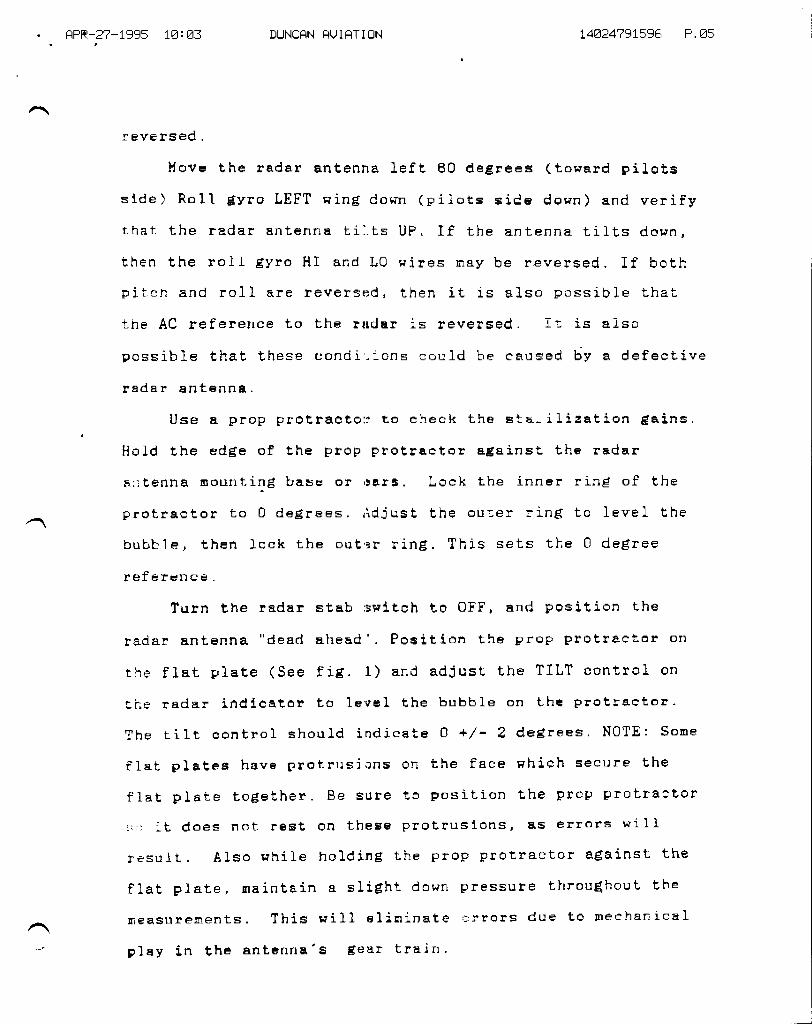
Use a prop protracto:1 to check the star-ilieaLion gains,
Hold the edBe of the prop protraetor agai-nst the radar
n::tenna noLlnt.ind base or r3Ets. Loch the inner rinEl of t,he
protrector to 0 degirees. ,ldjust the outer rinEi to level the
bubble, then ]ock the out'rr ring. This sets the 0 degree
reference .
Turn the radar stab rrwitch to OFF, and position the
radar antenna "desd ahead'. POSition the prop protraetar on
Ehe flat plate (See fig. 1) and adiust the TILT control on
the radar indicator to leyeI the hubble on the protractor.
The t i1t control should j.ndicate 0 +/ - 2 deElrees . N$TE : $one
flat plates have protrusions on the face r+hich secure the
flat Flate toElether. Be sure to position the Prop protraetor
!i:):L dOes not rest On theSe p3'9trusions, BE errors will
result. Also while holding the prop protractor against the
flat plate, f,Eintain a slight down pressure throu$houL the
E-rea$urernents . ThiS will el itninate ,:rrors due tO neehan ical
play in the s.ntenna'8 Sear train '1

HFR-z?-1935 1ErE4 DUNCFN HUIFTIEN 14824?91596 P. E5
Hove the ant6nna to the left 60 degrees. (pilot's side)
l{easure and record the difference ( if any) from the 0 degree
reference on the inner adjustnent scale, (See fig. ?) Now
move the radar antenna to the right 60 degrees. Again,
measure and record the difference fron: the 0 degree
reference.
UsinB the pilot's ADI f or reference' !:ove the gyro to
sinulate a 20 degree right roIL (See fig. 3) Use PaFer
touels or cloth to ro11 the gyro. The towels work pe]l
because they non't alloH the €yro to drop and they are easily
adjustable. Take your tirre and insure that you are aF close
aE pos5ible to.20 deglrees roI] and 0 degrees of piteh. Turn
the radar stsb switch 0N . li ith the rade.r antenna still in the
60 deEiree right position, record the chan$e tilt fron the
0 degree ref erenee. Now $()ve the radar anter.tta to ilie Ief t i-i
degf ree posit ion . Heasure and record the d if f erenca f rorr the
0 degree reference. (See fiE. 2)
Take these readirrE:s nnd subtract, thea from the O degree
reference. The reEult is Lhe stabilization correction. AdjuEt
the roll gain adiuetnenL so that the average of the results
i; equal to t7 7/2 de$rees. If the results a.re ndt within 2
jegrees of eaeh other, then the radar antrtrtr$, azinuth
resolver needs alignnent.
Next, adiust the gyro for a ?B degree tritch up and 0
Cegree ro11 . ( See f ig. 4') Hove the antenna to the ,'dead
ahead' Position ' Heasure lhe amount ol" chanE:e from the 0
degfree referenee. This is the stabilization pitch

HPR-Z?-1995 1E: A5''' '- DUNCFN I]UIFT]EN 14A?4791596 P.E?
correction, thich should 20 degrees D0liN. Adjust the pitch
dain pot if necesEary. This conpletes the stabilizati-on gain
adjustnents.
Renount the vertical €yro, nakinEf sure to return any
shins to their original Fositions - If applicable, turn the
scan sHiteh back 0N, As scon as the radome, cowls, panel$
ete^ are resEcured, the aireraft can be test flown to check
the stabilization operat,ic,n. tihen renounting thr'rarlome, be
sure to reeonnect any antennas of alcohol deiceing lines.
Verify that the antenna is; free to sreep nornally, both with
full up and down t,ilt, wit,hout hanEling up on any lines or
cos.xes.

FrFE-2?-1995 1E: E5 DUNCFN HUIHTIEN 14824?91596 P. EF
TEST FLIG}IT CHECKOUT
1.) The a.ircraft nust be test flown over fairly even
terrain, with little or nc, weather targets, as these tests
use ground returns to check basjc radar perfornance. Fly to
any convenient altitude at, or above 10,000 feet. Adjust the
tilt ta obtain naximum disitance of Srcund returns. Thre
distsnee in nautical nileri should be epproximately the square
root of the al.titude in feret. For exanpJ-e, at 1O,00tJ feet the
maxinum distance = 100 no:.1es. Keep in nind Lhat the altitude
usEd to calculate bhis dis;Eance is the altitude above the
tetrain, not jusL what the altineLer reads. The distance of
these rraximun ground returns should be very cltrse to the
calculated distance (with:-n 102). If it is not, then
soneLhinE: is Iiniting the perforns.nce ef the radar syst,en
(sonethinEl other than stabili,zation ) . Possible problens
include: def eetive rs.dome ( the radome is not acting Es a'
transparent window to the nicrowave signals that the radar
transuritts and receives), weak rada.r transmitter or receiwer,
misadjusted AFC (the reseiver is not tuned to the transnitter
frequency), defective wavrrguide (cracked, Corroded, Pinched,
or contanrinated with wale:r), defective antenna (physical
danage to the fage plate r)r corrosion in the wave$uide aSSy-
or rotary j oints ) .
STABlLIZATlOH CHECKS
z.) nhi1e flying straighr and leveI --rth the stabilizgtion
off, tilt, tire antenna dow."r slightlv frorn Lhe setting of
naxinuE distanee ground r,e+'urns. This should proCuce a f airly

HPR-.2?-1995 1E: E6 DUNCHN HUIRTIEN 14E.2479t596 P.E9
even band of ground returns whose inner edge is PARALLEL to
the ranEie ararks. (See fig.A) The display will vary
coflsiderably depending orr the type of radEr, the altitude of
the aircraft, afid the tilt setting. The inportant point isthat the =eturn is fairly even in width, Visually verify thatthe aircraf t is f l-ying Hiilgs leve1 to the horiEon. (Do not
sssurne that the vertical E;yro is correct. ) If the returns are
parallel to the ranEfe gtar!:s, Lhen the antenna is nounted
eorrectly. If the return i.s not paralle} to the ran$e marks,
than the antenna is not mcrunted level in the rol I axis . I f
the display haE nore grourrd returns on fhe right side,
(fig. B) then lhe antenna is nounted with the right side
dopn. If the display has lrore ground retulns on the left
side, (f ig. C) then the atrtenna is nounted lef I side down.
Deternine the entenna mounting error as follows: Adjust'
the tilt eontrol so that the ground felurns on the extreme
right side of the display are just evgn Hith a ranEie nark.
Beeord the tilt settinEl. iidiust the tilt control until tha
ground f etutns on the er(l:reme lef t side of the display are
just even sith the sa6e ru.nSfe ftark. Record the tilt settin€ '
The difference between th6 two settings is how nueh nounting
error there is between thr= E0 degree left and the E0 degrae
right positions - EXAHPLE: The antenna is Eounted nith the
Ieft side dor+n. (fig. C) The right tiIL settinEl is 2 degrees
up and the }eft tilt setting is 4 degrees utr. The.difference
iS Z degreeEi ot I degree On each side. The antenna cEn be
leveled by seltinEl uF the 0 degree teference at "dead ahead"

f,FF-z?-1995 tztA? DUNCFN FUIRTIEN 14824?91596 P.1A
as before, and changing the nountin5l to raise the right side
I degree (as ueasured on the flat plate at the right 60
degree position) and lower the left side 1 degree (as
measured on lhe flat plate at the left E0 degree position).
3.) Onee the antenna is nounted correctly per 2.) above, the
next flight, check is to verify that the Eyro is mounted
eorrect ly. l{ith the aircraf t f lyinEl straight and leve}, and
the inner edEle of the ground return set up to paint paral-leI
to the edge of a range nark, turn the stab ON. If the gfround
returns are unehanged, then the gyro is mounted correctly. if
the Bround returns shift as in fig. B, then lhe gyro is
nounted }eft side down anc should have shims addeci under the
left side of the gyro. If the returns shift as in fig.C,
then the right side of the' gyro is down and shims should be
added under the,t side. The' gyro should be leveled by a
qualified facility as the procedure is beyond the seope of
this pepef.
4. ) Once the radar antenna and the gyro are rqounted
correctly we can fi.nally cheek the stabilization Bainsl wit'h
the ground returns set uP to paint paralle] to the edde of a
range nark, and stabilizal;ion 0N, roll the aircraft into a 20
degree right bank. If the stabilization is perfect, then the
display pill nol eha.nge. .lf the display ehan€es as in fig. B,
then the stab is under co::recting. If the display chan$es as
in fig. c, then the stab -i-s ot/etr corl.ecting. 0n radars with a
ro11 Eiain pot ofl the indir:aLor, the stabilizatiorr correction
can be increased by turninSl the Eiain poq Cl{ or decreased by

rtFF-2?-1995 1E: E7 DUNCRN IqU I HT I ON L4A?4?9t=95 P.11
turningf the gai,n pot CCt{. 0rr radars without a rol} gain
adjustnent on the indicator, thre ancunt of over or under
correction can be deteruined during fl-iShL and readjusted on
the ground. To deternine the roll error, adjust the tilt to
paint the inner edEe of the ground retulns parallej to and
just touchinE a range nark ciuring straight and level flignt.
Record the tilt setting. Roll. the aircraft to 20 de$rees
right. Adjust the tilt contro] so that the inner edge of the
extrene riElht side of the display (60 degrees right) is just
chinEi the salie ranEle nark. Record the tilt setting - The
difference between the twc readinls is the amount of over or
under correction. EXPHPLE: The display shifts as in fie- B,
(the stab is under correcting) Tlis ti1t satting is 4 degrees
up with the aireraf t f lying IeveI. llith the aireraf t roll-ed
20 deE rees riEfht, the tilt setting is 7 deE:rees up (to bring
fhe extrene right side of returns ta just touch the sane
range nark) The differenee'is 3 degrees (the anount of under
correction) The stab ca.n t.hen be set up in the aircraft or on
the bench to eorrect an additional 3 degrees, (trer side)'
This Paper Has written by Steve llillians '
Lead Technician at Duncan Aviation Inc. Lineoln Ne 3/ 88

. I]PR-2?_1395 1E I EB DUNCFN HtJ I FT I I]N.a
FIGLTHE C,
'L4E?479t596 P.1l
lif'{-tI

. RFR-3?-1995 1E: A9'a
DUNCFN HUIHTION 14A74?9t596 P,13
FIG1JHE E

flFR-z?-1995 1E: E9 DUNCFN FUIFTIDN 14824?91596 P.14
FIGI]HE A
t*,,

. HFR-2?-1995 1E! 1E DUNCHN FUIHTIDNalt
FIGURE 2.
14824?91586 F.15
-t.
-20 I N/A
+16 t/2 *(-1) = +I7 L/2
60LEFT i O I6BRIGHTilll
-+-- ---+
STABILATION + 1OFF
z,B DEGREE:] -- - 1t tiz ; 0 +16 t/?RT I,|ING DN
20 DEGREES N/APITC}I UF
-16 I/2 -(+1) : -I7 1/2

",. .HFR-E?-1995 1E:18 DUNCHN HUIFTION t4a?4?9t=96 F.1E
FITUHE fiAnl
/t-*---F t FFI-FqFLI'i f;\' .-..' '^.-l--'
Tr-rrlrri r: f f .if=YT h.u','Ji.'l'rLi-r'r a-H
Uur;tlt't'f F$ffi#F,R$

! .tlPE-2?-1995 1E:11 DUNCFN FUIFTIEN t442479t59,5 P.1?
FiGLIEE f{t,*,f,1
.. ?.*r E]\I i ,r. fl l_lt--- f iJt-,.i:;,-f i-,,L,
.rt--.-
Fl FfH -r*,'|d.-.. -:i-'
-,,,rrf' e r'fit'r=lj''l' t'ib',,,'. r. 'r'r L!.-. L)gfutl$=r__ i
a
TOTFL P.1?

TW{sERyrcE BULLETITU
OPTIONAL
SERVICE BULLETIN NO. 1124-34-015 May 24, 1985
SUBJECT: VOR/LOC AIiITENNA BONDING AND PHASTNG.
1. PLANNTNG INFORMATTON
A- EFFECTIVITY
MODEL LL24/LL24A WESTWINDS, all serial numbers.
REASON
To eliminate VOR/LOCreception.
COMPLIATiICE
Compl-iance with thisDESCRIPTION
raw data scalloping and improve
Service Bulletin is optional.
This Service Bulletin describes procedures necessary toinstall a conductive gasket under VOR/LOC antenna base,ensure proper antenna radiation patterns and providesurface bonding to eliminate precipitation static.APPROVAL
The modifications described in this Service Bulletin havebeen shown to meet applicable ICAA/FAA regulations andare IAI Engineering approved.
B.
C.
D.
E.
/
@lf,lsrmsm*l!s;-*,*SUBSIDIARY OF ISRAEL AIRCRAFT INDUSTRIES, LTD.
BEN GURION AIRPORT, ISHAEL
sB 1124-34-0lsPage I of 6
SERVICE BULLETIN NO. 1124.34-015
F. MATERIAL
The material required by this service Bulletin may beobtained through Atrantic Aviation supply co.1 theirdistributors or may be obtained locally Lhrough:
CHOMERICS23839 S. Banning Blvd.Carson, CA 90745Phone: 1-800-22L-2879
G. TOOLING
None required.
H. IVEIGHT & BALAI{CE
Not applicable.
I. EI,ECTRTCAL LQAD DATA
Not applicable.
.T. REFERENCES
LL24/LL24A Maintenance Manual, Chapter 34-50-Ol.
K. PUBLICATIONS AFFECTED
LL24/LL24A rllugtrated parts catarog, chapter 34-50-00.
2. ACCOMPLISHMENT INSTRUCTIONS
A- Removg both voR/Loc antenna brades, #10 screws (g places)and *4 screws (A places through fillet). Tag cablEsfor proper reassernbly.
(1) -check data plates for proper p/N DMN4-15-3' bothblades must carry the same serial number and oneblade d -Ar the othef, d -B- This ensures you havea matched and balanced antenna.
(2) rnspect Leading edge of each antenna bLade forcracks or separation of erosion plate. Suchcracks may permit water to enter blade and createinternal corrosion. Obvious repair attempts atIeading edge should be considered suspect.
sB 1124-34-015Page 2 of, 6
May 24, 1985

J]1I(VJ-U.E IJUIL.E;J.'J.I\ NU, LLZ4-34-U L5
B. Remove P/N DMU21-2 mounting adapters. Using a wire brushclean the three mounting surfaces of each adapter, andapply Iridite PrlN L4-2 or equivalent per vendor instruc-tions.(1) CLean and fridite bottom of counterbored mounting
hoLes.
(2') Retain existing sponge gasket. Ensure it is securebetween the mounting surfaces using P/N 22L6 orequivalent adhesive.
Remove any sealant or body filler found at antenna mount-ing location. Clean and polish area under mountingadapter and do not remove paint within k inch of inside ofmounting adapter outline. Iridite the exposed area.
Clean and Iridite antenna mounting surfaces and counter-sink mounting holes of each antenna b1ade.
(1) Remove both end fillets and treat inner and uppersurfaces as above.
Remove all access panels on vertical stabilizer and rudder.Clean and polish each panel and surface mounting ho1e,including outer countersunk holes in panels. ApplyIridite L4-2 to areas exposed by cleaning.
Inspect and repair as required rudder hinge bonding strapsand vertical stabiLizer bond strap at bottom of verticalstabilizer rear spar.
(1) Measure across each bond strap (not to attachingbolts), a maximum of 0.1 ohm (normal is 0.01 ohm).
(21 Replace bond strap if broken or frayed.(3) Should a poor bond be indicated, remove strap, clean
and fridite attachment area, reassemble and retest.G. Reference Figure L, detail A. This is the top view of
the VORr/LOC antenna (upper blade shown RHS) .
(1) Inspect the coaxial cable interconnections betweenthe blades. Thses cables are of critical length,and must eonnect as shown: forward connector of each
sB 1124-34- 015Page 3 of 6
c.
D.
E.
F.
May 24, 1985

SERVICE BULLETTN NO 1124-34-015
blade together, and aft connectors together. Inspectblade connectors for a secure connection to thecoaxial cable shield braid.(a) Re-label connectors at blades as necessary to
ensure propel connection.
(2, Inspect the coaxiaL '|Tr forming VOR 1 and VOR 2downleads for secure shield braid connections andensure connectors to rTtr are in turn secure.
NOTE
Properly assernlol,ed connectorswill not allow connector bodyto twist on cab1e.
H. Cut Polasheet conductive gasket material to outline ofeach mounting adapter footprint. l,latch and cutclearance hol,es for mounting screws o
f. Reinstall all access panels.
J. Reinstall antenna bl-ade mounting adapters, with newgaskets between adapter and vertical stabilizer.(1) Use MS 35333 (-38 or -40) internal tooth lockwashers
of proper size under each screwhead prior to'install-ation. Discard original fLat washers except thoseused as spacers between blade and mounting adapter.
(2', r'ill counterbore with PR-1422 or eguivalent sealantupon completion.
K. Reinstall VOR/LOC antenna blades. Ensure connections areproPer.
(1) ReinstaLl fillets with MS 35333-8 washers. Discardoriginal flat washers.
(2'l Seal screwheads with PR-1422 sealant to preventcorrosion.
L. Should any decals such as flags or logos, have beenapplied to sideb of vertical itabilizer, remove them.These decals generate static, anrd will also interfere withWIF and VLF systems installed.
sB 1124-34-015Page { of, 6
May 24, 1985

3. BILL OF MATERIAL
QTY
A/R
A/R
I
A/R
I
I
4. AIRCRAFT RECORDS
SERVTCE BULLETIN NO. 1124.34.015
PA&T NT MBER DESCRTPTT:ON
22L6
PR-L422 Sealant (Mfg. pro
L4-2 i:ill.:: ;uuivalento7-oBo2-3oi-2 33:i:iTll.,i_"r
(Mfg. ehomerics)Adhesive (Mfg. 3M)
Ms 3s333-40 ;5.f;$::il31:";,,internal tooth
MS 35333-38 Lockwasher, #Ainternal tooth
Make the following entry in the aircraft 1og book:service Butletin No. IL24-Z$-OLS dated May ie,-iiAS,titled "VOR/LOC Antenna Bonding a"a-pfr."i-rgr,,' has U".r,accomplished this date
sB 1124-34-01sPage 5 of 6
May 24, 1985

SERVICE BULLETIN NO. ].124.34-0].5
TOP VIEW
;
COUPIING ARRANGEMENTOF TIIE TWO NAV REC ANTENNAS
It{cCONN
DETAIL A
sB 1124-34-015Page 6 of 6
FIGURE I
tttay 24, l9g5

sEH[/lcE PUBLrcNTloNS
notbeII
OPTIOIIAI,
SERVTCE BUIJSTTN NO. 1l2t-34-015Fvirion No. 1
SUBdtEet: VOVIOC AIITENA BONDING AND PEASING
IEAgON PORRBVTSIOX:
lulSrorArv or- r3llc L alrcalrr txou3ttraa. ritcacx ourox attrollr. tlarcr
Add text, to paragraplr 2.A. (1).
ACCO.IT|PUS$ {T TNSTRUCTIONS:
A.
(f) Check data plater for proper partnumberg. Matching the IDIN{-I5-3antenna r:equires itttiztng arrtennarwith ttre sane serial ntrmbir. Horever,one S,/
9eoodoc SalletonA/C S/N
Gootifioato of Go rn/ul,iatooe
PLEASE FILL IN THE REQUIRED DATA BELOW AND RETURN TO:
ISRAET AIRCMFT INDUSTRIES INTERNATIONAL. INC.P.O. BOX L0086WILIVIINGTON, DE 1.9850ATTN : TECHNICAT PUBIICATIONS
This is to certifl that hrestwind Serial Nunber-has conpliedwith Service Bulletin No. lt24-34-015
Aircraft Registration No.
Airframe Total
Compliance Date
OITINER:
Tine at Compliance HOURST /CyCLES:
S lgnature
ACCOMPLISHING AGENCY:
By
Please describe below any discrepancies found or difficultiesencountered during cornpliance :

tilflSEByTCE BULLETT,U
RECOT{MENDED
SERVICE BULLETIN NO. I124-34-023
SUBJECT: NAVIGATION - ELIMINATION OF III{PROPER
Decemeber 9, 1985
II{ACH WARNINGS
1. PLANNING INFORI,TATION
A. EFFECTIVITY
I{ODEL LL24 WESTWIND, all serial numbers prior to 423.
B. REASON
To eliminate misleading signals that cause theCopilot Mach Airspeed indicator to activate the MachWarning system in normal operating airspeed ranges.
COMPLIANCE
Conpliance with this service bulletin is recommended.
DESCRIPTION
Shielded wiring is installed between the VMO/MMO TESTswitch and the Copilot Mach airspeed indicator toremove EMI from adjacent cable bundle wiring.
E. APPROVAT
rhis service bulletin has been reviewed by the IsraelCivil Aviation Administration (ICAA). The designcontent conveyed herein cornplies with the applicableCiviI Aviation Regulations and is ICAA approved.
@ III s:::x*'p*n t'^ykn *,,*sB 1124-34-023Page I of 3
c.
D.
/
SUBSIDIARY OF ISRAEL AIRCRAFT INDUSTRIES, LTD.
BEN GURION AIRPORT, ISRAEL

SERVICE BULLETIN NO. LL24-34-023
F. MATERIAL
llaterial necessary to comply with this servicebulletin may be procured locally.
G. SPECIAL TOOLS
Not applicable.
H. WEIGHT AND BALANCE
Not applicable.
I. ELECTRICAL LOAD DATA
Not appticable.
J. REFERENCES
LL24 Wiring Diagram Manual, Chapter 34-10-04
K. PUBLICATIONS AFFECTED
LL24 Wir ing Diagram lvlanual, Chapter 34-I0-04 .
2. ACCOTI{PLISHMENT INSTRUCTIONS
A. Remove copilotr s instrument panel to gain access todisconnect plug p/J 20.
B. Remove, cap and stow wires W7SCZ2 from p250, pin 2and w86C22 from p250, pin 5.
C. Install a new #22 AWG twisted-pair shielded wire fromP20 to P250:
(1) One conductor (new W75B22WH) from p20-G toP250-2.
(2) The second conductor (new Wg6822BL) from p20-Hto p250-5.
(3) Connect shields; one end to p20-W, the other endto p250-9 with existing wire #W}AA22.
D. Remove, cap and stow wires W75822 to J20-G and Wg6B22from J20-H
E. Lower the forward overhead circuit breaker panel andlocate the V}IO,/MMO TEST switch. Identify for f uturereference the terminals used for wires w75A22 andW86A22. Remove, cap and stow these wires.
sB LL24-34-023 December g, lgg5Page 2 of 3

F.
G.
SERVICE BULLETIN NO. LL24.34-023
Install a new #22 AWG twisted-pair shielded hrire fromJ20 to the VMO,/MMO switch. Follow existing cablebundles down and across copilot's cockpit sidewaII.
Connect the above new shielded wire:
(f) One conductor (new W75A22WH) from J20-c toproper VMO/I{MO switch terminal *4 with-two poleor terminal #1 with one pole.
(21 The second conductor (new w86A22) from J}O-H toproper VMO,/MMO switch terminal #3.
(3) Connect shield to J20-W, terminate and insulateshield at vMO,/MMO swit6h.
Install copilotrs instrument panel and reassembleaircraft.(f) Perform necessary pitot and static tests to
ensure copilotrs system integrity.(2) Perform operational tests to alI systems
disturbed by disassembly.
Return aircraft to service.
H.
I.
3. MATERIAL INFORI,IATION
QTY
A/R
PART NUMBER DESCRIPTION
#22 AWG twisted-pairshielded wire(Mfg by RAYCHEII)
4.
55A112 L-22-35
RECORD COI{PIIANCE
A. Make the following entry in the aircraft log book:
Service Bulletin No. LL24-34-023 dated December 9,1985 titled "Navigation Elimination of ImproperWarnings" ha's been accomplished this date
B. Revise the Wiring Diagram lvlanual to ref lect changesaccomplished by this service bulletin.
sB 1124-34-023Page 3 of 3
Mach
December 9, 1985

9e+,npioe fiwllotin A/C S/N
Go,utifiooto o/ Gorn/olian oo
PLEASE FILL IN THE REQUIRED DATA BELOI\I AND RETURN TO:
ISRAEL AIRCRAFT INDUSTRIES INTERNATIONAL, INC.P.0. BOx 10086l{ILI{INGTON, DE 19850ATTN: TECHNICAL PUBLICATIONS
This is to certify that l{estwind Serial Number-has compliedwith Service Bulletin No. LL24-34-023
Aircraft Registration No.
Airframe Total Time at Compliance HoURS: /CYCLES:
Compliance Date
Otr{NER:
BySignature
ACCOMPLISi{ING AGENCY :
Please describe below any discrepancies found or difficultiesencountcred during conpliance :

TW{sEByrcE BULLETITU
OPTIONAL
SERVICE BULLETIN NO. LL24.34-027
SUBJECT: ENABLE GNS-500A SERTESFLIGHT DIRECTOR SYSTEM.
April 18, 1985
38 BA}IK COMMAND OPTION FOR
1. PLANNING INF'ORMATION
A. EFFECTIVITY
B.
MODEL LL24A WESTWTND aircraft equipped with Global series38 vLF Navigation system, serial numbers 29s through 426.
REASON
To alLow automatic leg change operation through thecoupLing of Composite -steering -signats from vir xev toAgtopiJ-ot System. Incorporation of this option wouldeliminate Lhe overshoot of a waypoint and ltlow moreprecise tracking of desired track.COMPLIAI\TCE
CompJ-iance with this Service Bul1etin is optional.DESCRIPTION
This service Bul-l-etin contains the information necessaryfor the addition of ro11 steering signals to theAutopiJ-ot System. Where possible, existing wires(previously capped and stowed) will be used. Specificwire routing is included in this bulletin.
c.
D.
/@ II I g;:fw wn t,!^!!nc;^. *,, *
SUBSIDIARY OF ISRAEL AIRCRAFT INDUSTRIES, LTD.
BEN GURION AIRPORT, ISRAEL
sB LI24-34-027Page 1 of 6

E.
F.
G.
H.
SERVICE BULLETTN NO. LI24-34-027
APPROVAI,
The modifications contained in this Service Bulletinhas been shown to meet applicable fCAA/FAA regulationsand are IAI Engineering approved.
MATERTAL
MateriaL required for this Service Bulletin mayobtained locally.
TOOLING
None
WEIGHT & BAI,AI{CE
Not appJ.icable.
ELECTRICAL LOAD DATA
Not applicabl-e.
REFERENCES
II24A Wiring Diagram Manual:Chapterz 34-60-Q2
22-L0-0522-L0-0234-50-0534-50-0634-50-L 8
PUBLICATIONS AFFECTED
LL24A Wiring Diagram Manual:Chapter: 34-05-02
02-l_0-0s22-L0-0234-50-0s34-50-0634-50-18
I.
J.
K.
sB 1124-34-027Page 2 of 6
April 18, 1985

SERVICE BULLETIN NO. LI24-34-027
2. ACCOMPLISHMENT INSTRUCTIONS
A- Locate and remove Grobar Rcu p/N roo5o-3-3B(x) andoEU p/N.10600-2-2(xx) from mounts. verify part numberof RCU is 10050-3-38F. rf other than -3BF
-contactGlobal Navigation rnc., or their service centers forupdate procedures and,/or verification of mod status.
B. Remove and retain hardware securing mounts to airframe.Position mounts to gain access to rear of RCU and oEUconnectors.
c. Locate wire #2TR4A22R (previously capped and stowed,part of an existing shielded, twisted pair) and insertin pin 2L of RCU connector.
D- Locate wire #2TR3A22B (previousry capped and stowed,part of above shielded, twisted pair) and insert in pin23 of RCU connector.
(I) Ensure shield is grounded at RCU mount.
E. Locate wire #2TRL8A22R (previously capped and stowed,part of an existing shielded, twisted pair) and insertin pin 2 of RCU connector.
(1) Ensure shieLd is grounded at RCU mount.
F. Locate wire #2TR39A22 (previously capped and stowed)and insert in pin 45 of OEU connlctoij.(1) Ensure shield is grounded at OEU mount.
NOTE
If OEU connector pin 45has wire #2TR170A22 insertedand connected to T-24 terminal20 by wire #2IRL70C22 (foundon later installations, LI24Aserial numbers 392 and subs)DO NOT REMOVE. Dj-sregardstep K and subsequent referenceto wire #TR39D22.
c. Locate wire #TR4D22R in pin L of D-r26p (located approxi-mately STA 264.0 right side). Extract pin, cap and stowwire. Insert new wire #2TR4E22R (part of shie-lded,twisted pair) in pin L of D-126p.
sB LL24-34-O27Page 3 of 6
April 18, 1985

H.
I.
J.
K.
M.
N.
SERVICE BULLETIN NO. 1124-34-027
Locate wire #2TR3D22B in pin Ivt of D-r26p. Extract pin,cap and stow wire. Insert new wire *2TR3E2ZB(second wire from step G above) in pin M of D-126p.
Locate wire #2TR18D22R in pin N of D-126p(part of existing shielded, twisted pair). Extract pin,cap and stow wire. Insert new wire #2TRI8E22R(center conductor of shieldedl single wire) in pin Nof D-125P. Remove, cap and stow wire #2TR17DB22B frompin P of D-26L.
Disconnect shields of wires capped and stowed in stepsG, H and r. connect shields of new wires added in slepsG, H and f together and insert in pin F of D-I26p withremaining existing shields.
Locate wire #2TR39C22 aE pin e of D-261p (locatedapproximateLy srA 264 right sTde). Extract pin cap andstow wire. Insert new wire #2TR39D22 in pin g ofD-261P. See Note above.
L. Route new wires installed in steps G, H and K abovealong existing eabl-e bundles to t-tg (located approxi-mately sTA 257 l_eft side). At T-19, instalt neiv-wiresas foll_ows:
(1) Wire #2TR4E22R to terminal #3.(2) Wire #2TR3E,22B to terminal #5.(3) wire #2TR39D22 to term:inal #1. see Note above.(4) Shield of shietded pair to terminal *7.(5) Add wire #2TR170D22 from T-24 terminal 20 to T-19terminal l_ (May al_ready exist from S/N 392) .
Route new wire #2TRI-8822R installed in step r above, arongexisting cabLe bundles to T-162 (located aiproximatelySTA 124 Left side) and attach to Lerminal i-3. Insulateexposed shiel_d braid.For 7L24A Model.aircraft prior to serial number 3g2,the following wire routing changes need to beaccomplished to maintain aircrait wiring conformity forthe Distance and Nav valid flag outputs of Global series38 systems.
(1) Move wire 5W274824 from T-17 terminal 17(located approximately STA 255 left side) to T-19terminal 1. (RNS flag input).
sB tL24-34- 027Page 4 of 6
April 18, l9g5

(2) Ivlove wire UD1R22 from T-I7 terminal 17 to T-19terminal 1. (DME #1 flag input).
(3) Move wire 2UDLR22 from T-17 terminal L7 to T-19termj.nal 1. (DME #2 flag input).
o. using hardware removed in step B above, re-instarlmounts for Gl_obal OEU and RCU.
P. Replace Global oEU and modified RCU firmly in mounts.
O. lerify.proper operation of Composite Steering using thefollowing procedures!
(f ) Se1ect VLF2 on pilot and./or co-piIot HSI.
(2) Generate airspeed input to Air Data Source ofapproximately 380 knots.
(3) PLace vLF in primary (vLF) navigation mode andensure valid HDG and TAS inputs to system on Navpage 2.
(4) couple \rLF to Auto-pilot system (select Nav mode,both Fj-ight Guidance panell).(5) Gene_rate groundspeed by updating present position,
on Nav page 4, in 5 arc-minute inlrements in rapidsuccession. rt may take as many as 6 updates togenerate a ground speed. verify groundspeed onNav page 2.
(6) Enter R7.5 miles in sxrx field on Nav page 3,Auto-pirot and Flight Director wirl inaicate rightturn.(7) Enter L7.5 miles in SXTX field on Nav page 3.Auto-piJ-ot and Fright Director will inhicate leftturn.
R. Reassemble aircraft and return to service.3. MATERIAI. INFORMATION
SERVICE BULLETTN NO. TTZq-Zq-027
PART NUMBERQTY
A/R
sB 1124-34-027Page 5 of 6
DESCRIPTION
Wire, #22 AWG,shielded
MrL 16878D
April 18, 19g5

QTY
A/R
A/R
A/R
A/R
A/R
SERVICE BULLETIN NO. TLz4-34-027
PART NUMBER
MrL 16878D
MIL 16878D
3276s4
320559
DESCRIPTION
Wire, #22 Awc,twisted pairshieldedWire, #22 AwG
Terminal, ringtorque(mts. AMP)Butt connector(Mfg. AMP)
MS 3L92A20-20A Pin, Male
4. RECORD COMPLIA}ICE
A. Make the following entry in the aircraft 1og book:Aircraft wiring modified per service Bulletin No.Lr24'34-027 dated April 18, 1985, titled "Enable cNs-sooASeries 38 Bank Command Option for Flight Director Syst€ilI. rl
B. Modify your Wiring Diagram Manual as required to reflectchanges performed by this modification.
sB LI24-34-027Page 6 of 6
April 18, L985

9eoryioe filwllotinA/ C S/N
Gootif;oato of Gorn/olianoo
PLEASE FILL IN THE REQUIRED DATA BELOW AND RETURN TO:
ISRAEL AIRCMFT INDUSTRIES INTERNATIONAL, INC.P.0. BOX 10086WILIVIINGTON, DE 19850ATTN: TECHNICAL PUBLICATIONS
This is to certify that l{estwind Serial Nunber-has conpliedwith Service Bulletin No. II24-34-027
Aircraft Registration No.
Airfrarne Total Time at Compliance HOURS: /cvclns:
Compliance Date
OIVNER:
By
ACCOMPLISHING AGENCY:
Please describe below any discrepancies found or difficuttiesencountered during conpliance:

TilT{sERvtcE BULLETLU
OPTIONAL
SERVICE BULLETTN NO. L124-34-039 July 14, 1996
SUBJECT: NAVIGATION - FPA-80 OPTION IMPROVEMENTS
1. PLANNING INFORMATION
A. EFFECTTVITY
MoDEL rL24 WESTWTNDS, all serial numbers prior to 413with FPA-80 option installed.B. REASON
Elimination of repetitive callouts of the ,'cHEcK BAROALTITUDE" function of the FpA-90 system.
C. COMPLIANCE
compliance with this service bulletin is optional.D. DESCRIPTION
This service bulletin provides i-nstructions to incor-porate aircraft wiring changes necessary foraccomplishment of this service bu11etin.
E. APPROVAL
This service bulletin has been reviewed by the rsraelcivil Aviation Ad.ministration (rcAA) . Tha designcontent conveyed herein compries with the applicablecivit Aviation Regulations and is rcAA appiovea.
F. MATERIAL
The material required for this service bulletin may beprocured Iocally.
/@lIIsmse*n*!,!#n*'*
SUBSIDIARY OF ISRAEL AIRCRAFT INDUSTRIES, LTD.
BEN GURION AIRPORT. ISRAEL
sB 1124-34-039Page I of 2

SERVICE BULLETIN NO. TL24-34-039
G. TOOLING
None.
H. WEIGHT & BALANCE
Not applicable.
I. ELECTRTCAL LOAD DATA
Not applicable.
J. REFERENCES
Modef LL24/LL24A Wiring Diagram Manual, Chapters34-30-05 and 2Z-IO-09.
K. PUBLICATIONS AF'FECTED
Mode1 LL24/IL24A Wiring Diagram Manual, Chapters34-30-05 and 22-IA-08.
2. ACCOMPLISHMENT INSTRUCTTONS
A. Remove Att. preselector unit to gain access to theconnector.
B. Remove wire sA361 from sprice at artitude preselectorDN27 pin N and wire FD31B. Leave wire FD31B to pin N.
c- Reconnect wire sA36r by splicing to existing wireFD41A going to DN2Z-R.
D. Reassemble connectors, mount Alt. preselector unit, andperform a complete ground test to ensure systemintegrity.3. MATERIAI INFORMATION
QTY PART NUMBER DESCRIPTION
A/R MIL-W-16878D #22AwG wire4. RECORD COMPLIANCE
A- Make the following entry in the aircraft 1og book:service Bulletin No. Lr24-34-ojg dated July 14, t9g6titled-"Navigation - FPA-80 option Improvements" has beenaccomplished this date
B- Revise wiring Diagram Manual to reflect the changesperformed by this service bu1letin.
sB 1124-34-039Page 2 of 2
July 14, 1986

tilI{SERyIqE BULLETTTU
OPTIONAL
SERVICE BULLETTN NO. LL24-23-CI41 June 74, 1985
SUBJECT: BYPASS OF CTL(XX) CONTROL HEAD VOLUME CONTROLS
1. PLANNING INFORMATION
A. EFFECTIVITY
(1) Accomplishment Instructions Part A: Mode1 LL24AVIESTWIND s/N 295 through 375 except 349.
(2) Accomplishment Instructions Part B: Model LL24WESTWTND S/N 29Ot 3I7t 357.
B. REASON
To permit proper operation of the 3468-3 audio controlcenter amplifj-er compression circuits by eliminating theseparate system volume controls. A11 COM/NAV systemvolume will be controlled by the master speaker/phonesvolume controls in the Aud.io Control Panel, to eliminatemultiple controls and large changes in received audiolevels caused by operating the CTL(XX) at other thanmaximum volume.
C. COMPLIANCE
Compliance with this Service Bulletin is optional.D. DESCRIPTION
This Service Bulletin describes the wiring changesnecessary for accomplishment of the reason stated above.
/ sB 1124-23-041Page 1 of 5@lillrcmmn*!,!!*.,*'*
SUBSIDIARY OF ISRAEL AIRCRAFT INDUSTRIES, LTD.
BEN GURION AIRPORT, ISRAEL

SERVICE BULLETIN NO. 1I24-23.04I
E. APPROVAL
The modification procedures described in this ServiceBulletin have been show to comply with the applicable ICAA/FAA regulatj-ons and are IAI Engineering approved.
F. MATERIAI
Material required may be obtained through AtlanticAviation Supply Company in Wilmington, Delaware or procuredloca11y.
G. TOOLING
None
H. WEIGHT AND BALANCE
Not applicable.
I. ELECTRICAL LOAD DATA
Not applicable
J. REFERENCES
LL24/LI24A Wiring Diagram Manual Chapters z 23-20-0L23-20-032 3-5 0-0 33 4-50-0 13 4-5 0-0 3
K. PUBLICATIONS AFFECTED
LL24/II24A Wiring Diagram Manual Chapters: 23-20-0L23-20-0334-50-013 4-5 0-0 3
2. ACCOMPLISHMENT INSTRUCTIONS
PART A
A. Remove CTL controls as necessary to gain access toconnectors.
(1) For COM 1 CTL-20:
(a) Remove jumper from B80J2-10 to spli-ce connectingwires 1RV33D and 1RV33B. Leave these wiresconnected at splice.
sB LI24-23-041Page 2 of 5
June L4, 1985

SERVICE BULLETIN NO. LLz4.23-04J-
(b) Remove wire 1RV32D from B80J2-23 and wire1RV328 from 880J2-13, splice these wirestogether.
(2) For COM 2 CTL-20:
(a) Remove jumper from B81J2-10 to splice connectingwires 2RV33D and 2RV33B. Leave these wiresconnected at splice.
(b) Remove wire 2RV32D from B9LJ2-23 and wire1RV328 from B81J2-13, splice these wirestogether.
(3) For NAV I CTL-30:
(a) Remove jumper from B85J2-10 to splice connectingwires 1RN25H and 1RN25G. Leave these wiresconnected at splice.
(b) Remove wire 1RN24H from B85J2-23 and wire1RN24c from B85J2-13, splice these wirestogether.
(4) For NAV 2 CTL-30:
(a) Remove jumper from B86J2-I0 to splice connectingwires 2RN25H and 2RN25G. Leave these wiresconnected at splice.
(b) Remove wire 2RN24H from 886J2-23 and wire2RN24c from 886J2-13, splice these wirestogether.
B. Reassemble connectors, install CTL controls, and performcomplete COM/NAV operational ground tests to ensuresystem integrity.
PART B
A. Remove CTL controls as necessary to gain access toconnectors.
(1) For COM 1 CTL-20:
(a) Remove jumper from 8209J2-L0 to splice connectingwires 1RV33B and 2RD33H. Leave these wiresconnected at splice.
sB 1124-23-XXXPage 3 of 5
June L4, 1985

(b)
(3) For
(a)
(4) For
(a)
3. MATERIAL INFORMATION
QTY
A/R
sB LI24-23-041Pase 4 of 5
SERVTCE BULLETTN NO. 112,1-23-O4L
Remove wire 2RD32H from 8209J2-23 and wire1RV32B from 8209J2-L3, splice these wirestogether.
COM 2 CTL-20:
Remove jumper from B22LJ2-L0 to splj-ceconnecting wires 2RV338 and 2RV33c. Leavethese wires connected at splice.Remove wire 2RV32B from B22IJ2-23 and wire2RV32c from B22LJ2-L3, splice these wirestogether.
NAV 1 CTL-30:
Remove jumper from 8208J2-L0 to spli-ceconnecting wires 1RN25A and 1RN25H. Leavethese wires connected at splice.Remove wire 1RN24H from 8208J2-23 and wire1RN24A from 8208J2-13, splice these wirestogether.
NAV 2 CTL-30:
Remove jumper from 8207J2-L0 to spliceconnecting wires 2RN25A and 2RN25H. Leavethese wires connected together at splice.Remove wire 2RN24H from 8207J2-23 and wire2RN24A from 8207J2-L3, splice these wirestogether.
(b)
(2) For
(a)
(b)
(b)
B. Reassemble connectors, install CTL controls, and performcomplete COM/NAV operational ground tests to ensuresystem integrity.
PART NUMBER
3511s
DESCRIPTION
Closed endspli-ce (Mfg.AMP )
June 14, 1gB5

SERVICE BULLETIN NO. ttZ 4-23-04L
4. RECORD COMPLIANCE
A. Make the following entry in the aircraft 1og book:Service Bulletin No. LIz4-23-041, dated June 14, 1985,titled Bypass of CTL (XX) Control Head Volume Controls,has been accomplished this date
B. Revise Wiring Diagram Manual to reflect the changesdescribed by this Service Bu1letin.
END
sB LL24-23-041Page 5 of 5
June L4, t9B5

SERVICE PUBLICATIONS
re\rision notice
SUB,IECT: 331A-9c HSI DISTAIICE DISPIAY IIr|PRO\IEMENTS
REASON FORREvrsroN: To add to Accomplishment rnstructions, part T,
Step B(2) and Step C(2).
2. Accomplishment fnstructionsPART T
(a) Add resistor (47K olun 2 watt) to HSIcable bundle. Splice one lead ofresistor to wire at pin 51 and spliceother end of resistor to wire at pin50. Properly insulate resistor leadsto prevent shorting.
OPTIONAL
SERVICE BULLETIN NO. LL24-34-044Revision No. I
,i/ISUIATAALUExa&u.&ar-ta'aw3
October 7, 1985't
sB 1124-34-044Page I of I
Sua3ror^FY oF TSFAEL AtFCnaFr TNOUSTntES. LrO8EN GURION AIRPOEI. ISRAEL

THSERyTqE BULLETI,U
OPTIONAL
SERVICE BULLETIN I{O. IL24-34-044 August 9, 1985
SUBJECT: 331A-9G HSI DISTANCE DISPLAY IMPROVEMENTS
I. PLANNING INFORMATION
A. EFFECTIVITY
MODEL LI24 WESTWIND, a1I serial numbers through 411 exceptr87, Lg8, 1gg, 1gl, Lgz, Lg1, 2!5, 290.
B. REASON
To permit pilot and copilot HSI to display VLF' distanceup to 31999 miles, and to permit proper HSI disptaydimming.
C. COMPLIANCE
Compliance with this Service Bulletin is optional.D. DESCRIPTION
The 331A-9c HSI status -0I2 and -019 is changed perCollins 331A-9c Service Bulletin #15 to accept INSdistance input. One wire is added and two wires reversedon VLF switch in aircraft for input labeling to the HSI.The circuit components on T-24 are removed and one jumperwire is added to update the display dimming circuitry, ifneeded.
E. APPROVAL
The modifications described in this Service Bulletinare IAI Engineering approved.
/ sB 1124-34-044Paqe 1 of 5
@ lI I st'x* ptv* :,!^!!,s;, *,, *SUBSIDIARY OF ISRAEL AIRCRAFT INDUSTRIES, LTD.
BEN GURION AIRPORT, ISRAEL

SERVICE BULLETIN NO. LT24-34-044
F. MATERIAI
The material required for this Service Bulletin can beobtained through Atlantic Aviation suppry co.7 wirmington,Delaware or purchased 1ocally.G. TOOLING
None
H. WEIGHT AND BALANCE
Not applicable.I. ELECTRICAI LOAD DATA
Not applicable.J. REFERENCES
rL24 wiring Diagram Manual chapters: 34-50-0234-5 0-0 434-50-0534-50-0634-50-14
K. PUBLICATIONS AFFECTED
rL24 wiring Diagram Ir{anuar chapters: 34-50-0234-50-0434-50-0534-50-0634-50-14
2. ACCOMPLISHIVIENT INSTRUCTIONS
PART I.A. Preliminary test procedures:
(l ) A/C and Avionics power ON.(2) VLF power oN and initialization sequence completed,inc_I-uding flight plan selection (le;-.fr""g.l . TO/FfoM waypoints must exceed 1,ooo'miies it, prop.,distance check.
OEU interface switch #3must be set to positionttCtt, ttDtt
r ttEtt , 01. lrFrl in
RCU, to enable VLF to out-put distance informationup to 31999 miles.
sB 1124-34-044Page 2 of 5
August 9, 1985

SERVICE BULLETIN NO. LL24-34-044
(3) Couple VLF to pilots HSI and observe DISTANCE read-out. ff decimal point appears, fol1ow modificationprocedures in instructions part B. beIow.
(41 Couple VLF to copilots HSI and observe DISTANCE read-out. If decimal point appears, follow modificationprocedures in instructions part C.
(5) In steps (3) and (4) above, Lf DISTANCE readout hasdecimal point while coupled to VLF, a status checkof the HSI (331A-9c) is required prior to aircraftwiring modification.
(6) Turn VLF OFF. Avionics power and A/C power OFF.
(7) Remove pilots and copilots HSIts and check status.(a) Part number ending in -0I5 conforms to require-
ment. Proceed to aircraft wiring modificationPart B. and/or C. as applicable.
(b) Part number ending in -0L2 or -0I9 requireCollins 331A-9c Service Bulletin #15 for properoperation. Send unit(s) to authorized CollinsService Center for modification. proceed toaircraft wiring modification part B. and/or C.as applicable.
B. Reference WDM #34-50-02 and 34-50-05. perform aircraftwiring modification as follows for pilots HSf:
(1) Make accessible connectors for pilots HSI.
(2) Remove, cap and stow wire #UD130A22 from pin 51 ofpilots HSr connector J-l. rnsert new wire #uD13oB22in pin 51, J-1. Route new wire along existing cablebundles through disconnect plug (any spare pin) toS5E (VLF switch) on pilots instrument panel.
(3) Gain access to terminals of S5E (VLF switch) andconnect new wire from step (2) to terminal #6.
(4) Reverse connections to terminals #S and #7 of switch.Ensure terminal #5 is to airframe ground and terminal#7 is to RL-92 coiI, X-2 after wire change.
(5) Reassemble pilots instrument panel and proceed toPart C, as required.
sB LI24-34-044Page 3 of 5
August 9 | 1985

SERVICE BULLETIN NO. LT24-34-044
C. Reference WDM #34-50-04 and 34-50-06. Perform aircraftwiring modification as follows for copilots HSI:
(1) t"lake accessible connectors for copilots HSI.
(21 Remove, cap and stow wire +2UDL30A22 from pin 51 ofcopilots HSI connector J-l. Insert new wire#2uDL30822 in pin 51, J-1. Route new wire alongexisting cable bundles through disconnect plug(any spare pin) to S23E (VLF switch) on copilotsinstrument panel.
(3) Gain access to terminals of S23E (VLF switch) andconnect new wire from step (2) to terminal #6.
(4) Reverse connections to terminals #5 and #7. Ensureterminal #S is to airframe ground and terminal #lis to RL-93 coil, X-2, after wire change.
(5) Reassemble copilots instrument paneI.
(6) Reinstall 331A-9c HSIrs in pilot and copilotinstrument panels.
(7', Perform follow-up inspection as per Part A."Preliminary test procedures." If decimal pointis lit while HSI is coupled to VLF, recheck wiringmodification and refer to appropriate equipmenttroubleshooting procedures.
(8) Perform check of display dimming function for pilotsand copilots HSI.(a) If display does not dim, proceed to Part II.
PART II.
A. Perform operational test of display dimming function forpilots and copilots HSI using DAY/NITE switch on instru-ment paneI.
(1) If HSI has dim control on frontispiece, DAY/NITEswitch has no effect. Use HSI dim control. If ithas no effect, a fault exists within the HSI.
(2) If display does not dim, and HSI does not have dimcontrol on frontispiece, follow procedures, refer-encing WDM, Chapters 34-50-05, 34-50-06 and34-50-l_4.
sB 1124-34-044Page 4 of 5
August 9, 1985

SERVICE tsULLETIN NO. LL24-34-044
(a) 'Remove and discard resistor(s) and diode(s)connected to I-24 (located approx. STA 25I leftside) terminals #15, #16 and #17.
(b) Install #22AWG jumper from terminal #15 toteminal #16 on I-24.(c) Ensure T-24 terminal #15 is connected Lo DAy/
NITE bus T-156 terminal #11 (located approx.STA 128 left side, A/C 240 subs) or T-35terminal #11 (located approx. STA I42 rightside, A/C prior Lo 240). on aircraft prior to240, I-24 may not be used. Check for continuitybetween HSI J-I pin 54 and T-35 terminal #11.
(1) HSI J1-54 should read 5VDC in ,,DAy,, orTTBRIGHT'' condition, and approximately 2.5VDC in rrDIMrr or I'NIGHTil condition.
(21 If voltage checks properly as in step (1)above, repair or replace HSI.
3. MATERIAL INFORMATION
QTY
A/RA/R
PART NUMBER
MIL 16878D327654
DESCRIPTION
Wire, #22AWGTerminal, RingTongue (Mfg. AIvIP)
4. RECORD COMPLIANCE
A. Make Lhe following entry in the aircraft log book:service Bulletin No. Lr24-34-044 dated auguit g, 1985titled rr331A-9G Hsr Distance Display tmpr6vements, hasbeen accomplished this date
END
B. update wiring_giagram Manual, chapters 34-50-02, 34-40-04l34-50-05, 34-50-06 and 34-50-14 al required to refrectwiring changes performed.
sB LL24-34-044Page 5 of 5
August 9, 1985

TTTT
SERyICE BULLETTTU
RECOMM ENDED
SERVICE BULLETIN NO. LL24.34-O47 February 6, 198?
SUBJECT: NAVIGATION STATIC SOURCE IMPROVEMENT FOR COPILOT'SALTIMETER
1. PLANNING INFORMATION
A. EFFECTIVITY
(1) MODEL LL24A WESTWINDS, serial numbers 239 and 295through 392 with (copitot's) encoding altimeter.
B. REASON
(1) To provide &n improved, independent, static source forcopilotrs altimeter.
(2) To eliminate ATC transponder altitude reportingerrors, where the #2 altimeter (copilot's) is analtitude encodlng altimeter.
c. COMPLI ANC E
Compliance with this
D ES CRIPTION
(1) This servicenecessary tosystem for the
D.
service bulletin is recommended.
bulletin descrlbes the proceduresinstall a second unheated statlc portcopilot's altimeter.
/@ III w:mm."*n: !n!#;.,*.,,*
SUBSIDIARY OF ISRAEL AIRCRAFT INDUSTRIES, LTD
BEN GURION AIRPORT, ISRAEL
sB LL24-34-O47Page 1 of 20

E.
F.
G.
SERVICE BULLETIN NO. LL24-94-047
(2) This modification is in compriance with AFc 2oL5 andpermits use of the Artim-eter position correctioncharts in the LLz4a Flight Manuar, Revision 10.
APPROVAL
This service bulretin has been reviewed by the rsraer civirAviation Administration (rcAA). The deslgn contentconveyed herein complies with the applicabre civil AviationRegulations and is ICAA approved.
M AT ERI AL
Material requiredSupply Comp&Dy,dealers or may be
TOOLING
may be obtained through Atlantic AviationWilmington, Delaw&re, their authorlzedobtained locally.
2.
None required.
H. WEIGHT & BALANCE
Not appllcabIe.
I. ELECTRICAL LOAD DATA
Not applicable.
J. REFERENCES
LL24 Maintenance Manual, chapter 6 (Dimensions) and chapter25 (Interior Furnishings).
K. PUBLICATIONS AFFECTED
LL24A Aircraft Fright Manuar (Ref. AFc 2o1b)LL24 Maintenance Manual, Chapter 34lL24 Illustrated parts C-atafo!
ACCOMPLISHM ENT INSTRUCTIONS
A. Bemoval of interior furnishings.(1) Remove interior from R/H side of aircraft to exposefuselage frames at y-station gr.Tg to y-station z4,o.zb(cockpit. rudder pedal area aft to forward burkhead oflavatory).
lsB LL24-34-O47Page 2 of ZO
February 6, L9ST

B.
SERVICE tsULLETIN NO. LL24-34.O47
(2) Remove interior from L/H side of aircraft to exposefuserage frames at y-station L74 to y-station z4o.zs.(Forward frame of escape hatch aft to forward bulkheadof lavatory).
(3) Remove aft section of headliner to expose fuserageframes at Y-Station 219.0b to y-station 24O.Zb.
NOTE
Cornices do notneed to be removed.
Install Alternate Static port
(1) Remove soundproofing material berow R/H emergencyhatch, between frames y-LT4 and y-194.
(2) Locate Y-station 181 and mark, locate z-station 2L.To(water line) and mark. (Refer to Figure 1.)
(3) Fabricate a doubter (p/N sr2g6gg.bL) from zozl-Ts ctad.050 thick aluminum as per dimensions in Figure 1A.Etch doubrer and treat with Arodlne LzoL, finish withepoxy primer.
Cover &rea betweenframes Y-L74 andY-223.75 R/H sideas necessary tocatch metal shavings.
(4) Measure, mark and cut outY-Station 181 and Z-Stationdoubler fabricated above (itemrivet holes and static-portlocation (Figure 1).
hole in fuselage at2L.7O (R/H side). Use
3) as a template forretaining screw holes
(5) Drill .25o inch hores for static-port cover as perdimensions in Figure 1. Attach (2 each) nut-platesP/N NAs1473-r/4-28 and spacers p/N cMATLTo4-4a toinside fuselage skin.
(6) countersink rivet and screw hores for port and doublerfrom the outside of fuselage skin. countersink .zsoholes for static port cover (Flgure 1).
sB LL24-34-O47Page 3 of 20
February 6, L987
SERVICE BULLETIN NO. LL24-34-O47
holes in R/H side frames at the
Ref. Doubler P/N Reference
CMA71737-503-31 Fig. 1B5723045-67 Fig. 18CMA7L737-503-19 Fig. 1BCMATL737-503-29 Fig. 1CNot applicable
(7) Cut outfollowing
Y-Sta.
.750 diameterStations:
Z-Sta.
32.7031.7030.7530.00Existing
219.05210.0020L.75194.00184.00
(8) Fabricate doublers out of 2oz4-TB clad .obo thickaruminum for each frame and install. Refer to Figures18 and 1C.
NOTE
Etch doublers and treat withAlodine 1201. Finish withepoxy primer.
(a) rnstall doubler on fwd side of frame 2Lg.os,pic_k1ng up existing rivet rocatlons, and instarlNAslo3g-Ag nut-plate on fwd side oi frame (Fig.1B).
(b) Doubler for frame Lg4 must be of sufficientlength to cover the existing hole at z-station28.20. (See Figure 1C.)
(c) rnstall NAslogg-Ag nut-plate on aft side offrames 210.00 and 20L.75 (Fig. 1B). (same as L/Hside.)
(d) Drill doubrers as necessary to pick up existingrivet patterns, nut-plates, etc. Add rivetswhere necessary.
(9) coat static port doubler on the side that will be nextto fuselage skin with pBL|zz searer or equivalent.Attach doubrer to fuserage (inner) skin wiln rivets( MS20426AD3).
( 10) r n starl- ^s_t_atic port p/N 4gg3obo using taminated shimP/N 5723633-b3 between port and doubler. Removeraminations from shim as necessary so outside surfaceof port is flush with outside skin of fuselage + .o1oinch- secure port with ANboz-632R10 screws,- enooti_06washers and MS21042_06 nuts (6 each) (Fie. 1i.'
sB LL24-34-O47Page 4 of 20
February 6, Lg8?

SERVICE BULLETIN NO. LL24-34-O47
(11) Apply a coat of pLL4.zz sealer or equlvalent overstatic port area, covering nut_plates, rlvets, nutsand outer diameters of port ind doubler.C. Install static line, teft side
(1) Remove ANg2g-6 cap from center port of L/H staticport, and retain for later use. use 2 each ANglg_6Dnuts and ANglg-6D sleeves and fabricate a tube from.375 oD x.Ogbw bosz-o aruminum tubing approximatery8.5 inches long. Bend tube as necessary to align iiwith the existing hole at z-station 29.io (waterline)at frame y-194 (refer to Figure 2).(2) Attach fabricated tube to center port of static port,attach a reducer (ANg1g-6D) to the other end of -tube
(Fig. 2).
(3) Fabricate a tube from .zso oD x .ogblf aruminum tubingusing 2 each ANglg-4D nuts and ANglg-4D sleeves-.Attach one end to the ANglg-6D reducer. Tube must beof sufflcient_ length to be routed aft through existingholes in frames y-194, Lg4, ZOL.74:2LO andapproximately 1.b inches pabt frarire ztg.oi.' Attach a90o elbow (AN821-4D) to tube end between frame zlg.O5and ZZT.TS.
NOTE
If stereo speaker is mountedbetween frames zLO and ZLI.OS andlnterferes with routing of tubeassembly, move speaker upapproximately L/4 inch bydrilling #LO holes in bracketsupportlng speaker, and enlargenotch on bracket to clear framehole.
(4) Support tube assembly at frames 2OL.75 and 2L9.O5 withMS21919WDG4 clamps by attaching to existing NAS1033-A3nut-plates with AN3-4A bolts and AN960PD10L washers.
(5) Install caterplllar grommet MS21266-4N or equivalent onframes not using DG clamps.
sB LL24-34-O47Page 5 of 20
February 6, L987

SERVICE BULLETIN NO. LL24-34-O47
D. Install Static Line, Overhead Sectlon
(1) Drlll a .44o-.44s dlaneter bole ln the channel atz-station 56.25 (L/ H slde even vlth ttop of cablnvindovs) between f rames 219.0b and 2zg.Ts. (Ref er toFigure 3.) rnstall a bulkhead unlon p/N AN832-4D rlth2 each, AN960pDz16L vashers and 1 each ANg24-4D nut.(2) Fabricate a tube approximately zL,s incbes long from
.25o oD x .03btr aluminum tublng wlth 2 each ANglg-4Dnuts and AN819-4D sleeves. Bend tube as necessary toroute forward and around wing inspection righthousing. (Refer to Flgure 4.)
(3) Renove DG clamp holding wing lnspection llght wi.res atZ-Station 38.2S and retain (FfS. 4). Route tubefabricated in step 2 through existing hole in channelat z-station 38.zs and attach ends to elbow andbulkhead union.
(4) clamp wing inspection right wires rith clamp removedin s!9p 3. _ support tube with Ms21919rDG4 cranp byattach-ing_ clanp to existing NAs1093-Ag nut-prate -sit[& AN960PD10L washer and AN3_4A bolt.
(5) rnspect R/H side chaanel at z-station s6.25 betseenframes 219.0s and 22s.7s, for wires routed throughpilot hole. rf no wires are routed, instalr union p7n4N832-4D as per lnstructions in Step 1.
(6) rf vlres are routed through channel, locate buttconnectors, mark and cut vires at butt connectors.Pull wires out of pilot hole at channel 56.25.Enrarge hole in channel to approxinately .b inch andlnstall a caterpillar grommet fi,SZLZ66_4N.
(7)
sB LL24-34-O47Page 6 of 20
&. cut a piece of .z5o oD x .035r aluminum tubing(approximately 6b inches).
b. Flare one end of tube and install aNglg-4D and4N818-4D sleeve and nut. Tube vill have to behand-formed to contour of overhead as it is beingrouted around fueelage.
February 6, L98?
SERVICE BULLETIN NO. LL24-34-O4?
Start at LIH slde by routlng unflared end of tubeup and beblnd cornlce next to frame 219.05. Routetube around cbannel at Z-Statlon 66.10 assurlng ltls routed between cbaanel and condltloned alr duct(Fig. 5). Aft most panel of cornice may have tobe removed to provlde visual access to channel atZ-Statlon 66.10, botb sldes. Route tube aroundR/H channel (2-66.10) ln same nanner as L/H slde(FlS.5).
[rap both sldes of tube with antl-abraslon tape orequlvalent at Z-Station 66.10.
Attach flared end to LIH union at Z-Station 56.25(Fig. 3).
NOTE
Form tube as necessary tosupport it cith theclanping procedure shownin Figure 5. Do not clamptube until it has been cutand fabricated to propersbape and length.
f. If bulkhead union is used in R/H channel Z-Station56.25, cut tube to proper length, attach endflttings (AN819-4D, AN818-4D sleeve and nut) andconnect to union. (Support tube as per Figure b.)
g. If bulkhead union is not used, cut tubeapproxinately 2.5 inches above cbannel (Z-Station56.25), attach end fittings and connect to a unionP/N AN815-4D. (Support tube as per Figure E.)
(8) Fabrlcate a tube from .3?5 oD x .03bw alumlnum tubingapproximately 2.5 inches in length using 2 eachAN819-6D sleeves and AN818-6D nuts.
(9) Bend tube approximately 3bo 40o, connect to centerport of R/H static port.(10) Install AN919-6D reducer to other end of tube.
sB LL24-34-O47Page 7 of 20
Co
d.
e.
February 6, 1987

( 16)
( 17)
sB LL24-34-O4?Page 8 of ZO
SERVICE BULLETIN NO. LL24-34-04?
(11) Attach _Tee p/N AN938-4D to aNg19-6D reducer, vlthcenter leg of ree faclng aft; attach 2 each ANgls-4Dunlons to other legs of Tee.
(L2) Attach 2 each aN929-4D caps to outer ports ofstatlc-pressure port (4EggObO).
(13) Fabrlcate a tube from .zso oD x .03sf, arumlnum tubing(approximately 44.a incbes) using 2 each AN819-4Dsleeves and AN81g-4D nuts.(14) Route tube aft through holes at frames y-1g4, Lg4,2OL.75, zLO, and 2Lg.O5.
(15) Connect one end of tube to leg facing aft of AN938-4DTee.
Attach AN821-4D elbow to end of tube at Y-219.05.
an d 219.05 withnut-plates using
(18) rnstall caterpillar gronmets Ms21266-4N or equivarentin frame holes.
(19) Fabrlcate a tube from .250 oD x .ogbw aruminum tubinglong enough to reach from union at z-station s6.2{,down and around forvard side of wing inspeciion lightand connect to elbow between y-frame 219.0b and 22g-.25(ffg. 4). (Refer to L/H side for reference.)(2o) rf electrical vlres were routed through channel atz-station b6.2s (R/H side), route wires throughchannel next to tube and connect as before.(2L) !"rp wires and tube with spiral wrap or equivalent atZ-Station 56.2b.
(22) support tube and wires with Ms21919wDG4 cranps bya'tteching to extsting NAs logg- A3 nut-plates atz-station 38.2s. use AN3-4A botts and angoopnrolwashers (FlS. 4).
Support tube at frames y-ZOL.?sMS21919WDG4 clamps by attaching toAN3-4A bolts and ANg6OpDtOL washers.
February 6, LggT

SERVICE BULLETIN NO. IL24-34-O47
E. Install Statlc Llnes, Rlght Slde
(1) Cut a lengtb of alumlnum tubing, approxlmately 49lncbes.
(2) Flare one end of tube and install a AN819-4D sleeveand AN818-4D nut.
(3) Route unflared end from frane Y-L74 forward to frame119.90, passlng tube through. unused holes in phenollcblocks.
(4) Bend flared end of tube as necessary to attach to Teeat static-port.
(5) Install nut and sleeve and flare opposite end oftube. Attach &n AN821-4D elbow.
(6) Fabricate a tube and route forward to next framefollowing exlsting tubing. Terminate tube betveenframe LL2.78 and 103.78.
(7) Attach an AN815-4D union to end of tube.
(8) Mark phenollc blocks at frames 103.78 and 89.?8 wherea .250 hole can be drilled.
(9) Remove phenolic blocks and align and drill .25O boles.
(10) Fabricate a tube long enough to reach from AN815-4Dunion at frame LL2.78 to cabin deck area past frane83.78 (follow existing tubing).
(11) Install phenolic blocks removed and drilled in step 9.
(L2) Attach a Tee P/N AN824-4D to end of tube.
(13) Attach drain P/N 3723052-505 to lower end of Tee.
(14) Fabricate a support from 2O24-Tg clad .O7L thickaluminum (Refer to Figure 6).
(15) Attach support to frame 44.50 with rlvets as shown inFlgure 6.
(16) Install AN832-4D union to support using AN960PD7LGLwashers and AN924-4D nut.
sB LL24-34-O47Page 9 of 20
February 6, 1987

F.
SERVICE BULLETIN NO. LL24-94-O47
(L7) Pabrlcate a tube and connect one end to center leg ofTee where draln ls and other end to unlon at frane44.50. Route tube vlth srrght angle so draln atframe 89.28 ls low spot.(18) support tube to other tubes with Ms21919rDG4 crampsusing AN3-4A bolts and AN96OPDIOL washers.
Altimeter Connection and Static Test(1) Fabricate a flex hose assembly from ltrL-H-bbgg_4material,- long enough to reach lrom union at frame44.5o through f rame gz.Tg and up to copilot'sartineter, using 2 each AN4z1-4D end ftitings.(2) Renove tube connected to copirot,s altimeter anddiscard.
(3) Remove union from the back of the altimeter andinstall & AN91g-6D reducer using a new sog10_906O-ring.(4) Connect flex hose to altimeter.(5 rnstalr ANg2g-6D cap removed in step c.1. to otherend where tube in Step Z was removed.(6) Connect a static tester toand proper operation
Maintenance Manual).
rnstall soundproofing and interior furnishings.(1) rnstall soundproofing material around R/H static portP/N Y3ZO (From gM Company).
G.
NOTE
If cabin temperature sensoris mounted on R/H side wherenew static port is installed,move sensor housing asnecessary to clear staticport.
Install cabln and cockpit interior.
system and check for leaks(Ref. Chapter g4-10-01
(2)
sB LL24-34-O47Page 10 of 20
February 6, LgB?

ga.ea.ea.eg.ea.ga.ea.ea.ea.ea.ea.ea.ea.ea.ea.ea.ea.ea.ea.ea.ga.ea.ga.ga.ea.ea.ea.ea.ea.ea.ea.ga.ea.ea.ga.e&.ea.
3.
SERVICE BULLETIN NO. LL24-34-O47
UATERIAL INFORUATION
QTY PART NUUBER
Ar{919-6DAN815-4DAN832-4DAN924-4DAN960-PD716LAN929-4DAN929-6DAN824-4D4N938-4DAN819-4DAN818-4D4N819-6D4N818-6DAN821-4D4N471-4DNAS 1033- A3NAS1473-L/4-28euA7L704-053NAS43DD3-40NAS43DD3- 13AN3-11AAN3-4AMS21042-06AN96OPDlOLAN507-632R104N906-06MS21042-06313765-505MS21266-4NMS21919 W DG45723633-535?23045-65MrL-H-5593-4 40',CMA7L737-503-13 (Fig. 6)48830503723052-505Y-370 (3M Co.) .25O
s0310-9062O24-Tg clad .0502O24-Tg clad .O7L.375 0D X .035W 5052-0.250 0D X .035[ 5052-0
343362111
2020
44324224I4
106
196661
L218
1111
1
1
1
DESCRIPTION
ReducerUnionUnionNutWashercapcapTeeTeeSleeveNutS1eeveNutEIbovFittingNut-PlateNut-PlateSpacerSpacerSpacerBoltBoltNutWasherScrewWasherNutGround CoverGrommetClanpShimDoublerFlex HoseSupportStatic Press PortDrain Assy.L2" X L2" Sheet(Soundprooflng)O-ringAlumlnum SheetAluminum 2.5" X 2"Aluminun Tublng (12")Aluminun Tublng (34 ft.)
1 ea.A/RA/RA/RA/R
sB LL24-34-O47Page 11 of 2O
February 6, 1987

QTY
A/RAIR
ea.Plnt
4. RECORD
5723633-81 (Fig.PRL422BL / 2cM A71737_503_31cM A71 737 _503_29cM A71737_503_195723Q4i-67 (Fig.MS20426ADMS20470AD
COMPLI ANC E
Tape AbrasionResistant (3M Co.)
DoublerSealerDoublerDoublerDoublerDoublerRlvetsRivets
RR
I11
112a/
^/
llake the followlng
Service Bulletintitled "NavlgationAltimeter" has been
1A)
(Fie. 1B)(Fie. 1C)(Fig. 1B)1B)
entry in the aircraft log book:
No. LL24-94-O47,Static Source
acconplished this date
SERVICE BULLETIN NO.
PART NUXBER
Splral SrapTte f,raps (plastlc)No. 542L
LL24-34-047
DESCRIPTION
dated FebruaryImprovement for
6, lgg7,Copilot's
sB Lt24-34-O47Page 12 of ZO
February 6, lgg?

6. 808 DIM. ON
CONTOUR
SH IM
5723633-53
cMA 71704-45 SPACEROr NASsOOWC 4L6 SPACERNASl 47 3-r/ 4-28 NUT PT,ATEOr NAS1473-C4 NUT PLATE
(z PLACES) F'TGURE 1
R/H SIDELOOKTNG OUTBD
Z-STATION25. 10
2.4T0 DIA. HOLETHRU FUSELAGE
SKTN
Z STATION2L.7 0.140 DIA. HOLE.L44 DIA HOLEAI\1507-632R10 SCREWMS21042-06 NUTAll950-05 WASHER(e Pr,AcEs)
4 8830s0PRESSURE PORT
BOTTOM OF DOUBLERP/N 5723633-51 TO BEFLUSH WITH CHEM-MILLLINE ON A/C SKrN (TNNER)
sB LL24-34-O47Page 13 of 20
SERVICE BULLETIN NO. LL24-34-O47
Y STATIONr81. 00
\\
\
February 6, 1987

SERVICE BULLETIN NO. LT24-34-O47
5EQ. sP
.140
.L44 DrA" HOLE(0 PLACES)TO MATCH2.875
2.4L0DIA. HOLE
#40HOLES
sB LL24-34-O47Page L4 of 20
l..-__2.70s. 40
DOUBLER P/N 5723633_51
FIGUPE 1A
.8d"
{:l
\
++
4.40
.30 TyP
February 6, L9ST

SERVICE BULLETIN NO. Lt24-34-O47
z - 31.70
CMAT 17 3 7-5 0 3-31DOUBLER
s723045-67DOUBLER
VIEW LOOKING FWD
z - 32.7PICK UPEXISTINGRIVETS(: PLACES
Scale
= 219.05
LOOKING AFT
cr4A7L737 -503-19DOUBLER
l+r.25! = 20I.75
VIEW LOOKING FWD
PICK UPEXTSTINGRIVETS(Z PLACES)
t - 30.75
VIEW
sB LL24-34-047Page 15 of 20
! = 210.00
February 6, 1987
FIGURE 18

SERVICE BULLETIN NO. LL24-34-O47
Y STATION 194.00
EXISTING HOLESFOR ANGLE BRACKETFOR CARDTABLE 5/32"
r.15+i
I = 30.00 _
z - 28.20
sR 1124-34-047Pa.ge 16 of 20
cMA71737-503-29DOUBLER
NOTCH BRACKETFOR HOLE
#4 I]NIVERSAL RIVETS(I PLACES)
EXISTING HOLE
r. eo--lSCALE 1:1
VIEW LOOKING FWD AT STATION194.00 R/H SrDE
EXTSTTNG 10/32BUNDLE (COULDOR DOWN)
HOLE TO TIE WIREBE FURTHER UP
+* ,'l-{i_
+l
FIGURE IC
February 6, L9BT

SERVICE BULLETIN NO. LL24-34-O47
AN919-6D REDUCERAlr819-4DAr{818-4D
SLEEVE
NUT
Z-STATION29 .30
L/4.025 0D x.035 TUBE5052.0
Y STATION184
Y STATIONL74
FABRICATED TUBE
.375 0D X.035 TUBE5052.0
Ai{819-6D SLEEVE
AN818-6D NUT
sB LL24-34-O47Page L7 of 20
L/H SIDE
FIGURE 2
February 6, 1987

SERVICE BULLETIN NO. LL24-34-O47
A}T924-4D NUTAN832-4D I]NION
2 ea. AN960pD7t6L WASHER
,,/
:iig DrA. HOLE INCHANNEL __l
IWING
LIGHT
sB 1124-34-047Page 18 of 20
L/H SrDE LOOKTNG OUTBD
(R/H TYP)
FABRTCATED TUBE
Z-STATION38. 75
FTGURE 4
INSP.HOUSTNG
FRAME FRAME
223.75 2I9.05
F'TGURE 3
February 6, 198?

L.25TYP 1,
SERVICE BULLETIN NO. LL24-34-O47
MS2I919WDG4Ar{3-11AMS2L042-3AN96OPDlOLNAS43DD3-40
2 PLACES PTCK UPHOLESR/H OPPOSTTE
CLAMPBOLTNUTWASHERSPACER
EXISTING
Z-STATION65. 10
1.00u
SPTRALTAPE
VIEW LOOKING FWD STA 219.05
c/L oE A/c
:_-:
WRAP OR AIiITI-ABRASION
sB LL24-34-O47Page 19 of 20
10P
VTEW LOOKING FWD STA 2I9.05
February 6, 1987
FIGURE 5

SERVICE BULLETIN NO. LL24-34-O47
-.-\.
*\\
@cMA71737-503-13
SUPPORT
'.^^XZ DrA. HoLE
20 x 450 4 PLACES
VIEW LOOKING AFTFRAME 44.50
FIGURE 6
EXISTING4 PLACES
PICK UPRIVETS
sB Lr24-34-O47Page 20 of 20
'?s
February 6, L9BZ

PARTS AVAILABILITY
ALERT
DUE TO LEAD TIME(S) ENCOUNTERED
IN PROCURING PARTS REQUIRED FOR
THE ACCOMPLISHMENT. OF THIS
TECHNICAL PUBLICATION, ALL
PABTS WILL BE AVAILABLE FROM
ATLANTIC AVIATION SUPPLY
CoMPANY ErcHT (8) WEEKS AFTER
RECEIPT OF ORDER.

9eooioe Swlletin
Go o,&;fri oa to of Go rn/o li aro o o
PLEASE FILL IN THE REQUIRED DATA BELOW AND RETURN TO:
ISMEL AIRCMFT INDUSTRIES INTERNATIONAL, INC.P.0. BOx 10086WILIVIINGTON, DE 198S0ATTN : TECHNICAL PUBLICATIONS
is to certify that l{estwind SerialService Bulletin No.Number- has complied
t tz4-34-047
Aircraft Registration No.
Airfrarne Total Time at Compliance /Cyc I es:
A/C S/N
Thiswi th
Conpliance Date
OITINER:
By
ACCOMPLISHING AGENCY:
Please describe. below any d.iscrepancies found or d.ifficurtiesencountered during conpliance :

SERVICE PUBLICATIONS
revision notice
,'*rA\_
OPTIONAL
sB NO. LL24-34-048Revision No. 1
December 9, 1985
SUBJECT: COLLINS \ruI-80 VERTICAL NAVIGATION INDICATOROPERATION IMPROVEI"IENT
REA^SON FOR To change aircraft effectivity in Part B.REVISION:
1. PI,ANNING TNFORMATION
A. EFFECTTVINT
(21 Accomplishment Instructions Part B: MODELI124A WEST!{fND, serial numbers 392 through410.
/ sB 1124-34-048
@lf,lwrw:lh** Pase I or r
SUESIOIAFY OF ISFA€L AIRCRA'I TNOUSTBIES. LTO
BEN GURION AIRPOR'. ISRA€L
.rga

TTT{
sERyrcE BULLETIIUOPTIONAL
SERVICE BULLETIN NO. LL24-34-048 November 8, 1985
SUBJECT: COLLINS VNI-80 VERTICAI NAVIGATION INDICATOROPERATION IMPROVEMENT
I. PLAI{NING INFORMATION
A. EFFECTIVITY
.(1) Accomplishment Instructions Part A: MODEL LL24AWESTWIND, all serial numbers prior to 420.
(2) Accomplishment Instructions Part B: MODEL LI24AWESTWIND, all serial numbers prior Eo 4L2.
B. REASON
(1) Accomplishment Instructions Part A: To enable theBac Loc logic input to the \AII-80 for proper Bac Locoperation.
(2) Accomplishment fnstructions Part B: To prevent afalse "ILS ONrr signal when left altimeter circuitbreaker is disconnected.
c. COI4PLIAIVCE
Compliance with this service bulletin is optional.
DESCRIPTION
(1) Accomplishment Instructions Part A: One wire isadded from terminal strip T-16 to relay Rl-84.
(2) Accomplishment Instructions Part B: One diode isadded to terminal strip T-160.
D.
/@frlsmsm*!,!!*.,*,,*
SUBSIDIARY OF ISRAEL AIRCRAFT INDUSTRIES, LTD.
BEN GURION AIRPORT. ISRAEL
sB LL24-34-048Page I of 3

SERVICE BULLETIN NO. LL24-34-048
E. APPROVAL
This service bulletin has been reviewed by the IsraelCivil Aviation Administration (CAA). The designcontent conveyed herein complies with the applicableCivil Aviation Regulation and is ICAA approved.
F. MATERIAL
Material required to perform this service bulletin may beobtained from Atlantic Aviation Supply or procured1oca11y.
G. TOOLING
None required
H. WEIGHT & BATANCE
Not affected
I. ELECTRTCAI LOAD DATA
Not affected
J. REFERENCES
H3"1,113:,;i'.,4A Wiring Diagram Manual' Chapters 34-30-01
K. PUBLICATIONS AFFECTED
MODEL LLz4/LL24A Wiring Diagram Manual, Chapters 34-30-01and 22-10-05.
2. ACCOMPLISHIIENT INSTRUCTIONS
A. Reference Wiring Diagram Manual, Chapters 34-30-01 and22-L0-05. Perform conformity check prior to accomplish-as follows:(1) Remove power from aircraft.
(2) Gain access to FGC #1, PIug J2, T-16 and recepta-c1e D103 (located near Sta. 259 LHS).
(3) Check continuity between FGC #1, Plug J2' Pin 16and receptacle DI03, Pin W. Resistance readingshould indicate short
sB 1124-34-048Page 2 of 3
November 8, 1985

SERVICE BULLETIN NO. LL24-34-048
(a) If indication is short, disregard followingstep. Proceed to step (4).
(b) If open condition exists, disconnect wire1RN519B22 from T15, 15, extend it as requiredand connect with splice to wire C9OA24 thatis connected to FGC #1, PLug J2, Pin 16.
(4') Reassemble aircraft and return to service.
B. Reference Wiring Diagram Manual, Chapter 34-30-01. per-form visual check and modification as required.(1) Visually inspect terminal strip T-150 for presence
of diode between terminals #8 and #9 (Iocatedbehind copilot ADf on center panel support).(a) If diode present, disregard following steps.
If not present, proceed to end.
(2') On T-160 locate wire #1RN626C22 at terminal #B andrelocate to terminal #9. Do not disturb other wireat terminal #8,
(4) Reassemble aircraft and return to service.3. I"IATERIAL fNFORMATION
PART NUMBER DESCRTPTIONQTY
A/RA/R
MIL 16878Ds0534
1 1N645
4. RECORD COMPLIAT{CE
#24 AWG WireTerminal RingTongue(Mf g. AMP)Diode
sB LL24-34-048Page 3 of 3
A. I{ake the following entry in the aircraf t log book:
Service Bulletin No. 1124-34-048 dated November g, I9g5titled "Collins \ II-80 Vertical Navigation IndicatorOperation Improvement" has been accomplished this date
B. Update Wiring Diagram Manual, Chapters 34-30-01 and22-L0-05 to reflect changes incorporated.
November 8, 1985

I IWTsERyrcE BULLETITU
SUBJECT: NAVTGATION - RADAR WAVEGUIDE PRESSURIzATIoN ANDTNSTAI,LATION OF SILTCA GEL"CONTATNER ASSEMBLY
1. PLAIiINING INFORMATION
EFFECTIVTTY
MODEL LL24 WESTWIND, all serial numbers prior to 4I3.except 154.REASON
To improve radar performance at altitude.NOTE
Aircraft serial number223 and subs are equippedwith a pressurized wave-guide. These aircraftwill need the silica gelcont,ainer, assembly clamps,bracket and hoses.
COIVIPLIAIiICE
At the operators discretion.DESCRIPTION
Provide cabin pressurization to the radar waveguide byinstalling the necessary plumbing, including the silicagel container, between forrpard pressure bul-khead and thewaveguide.
oprronRL
SERVTCE BULLETIN NO. LL24-34-049
/@ lll srn*sm* !,!#;n *,,*
A.
B.
c.
D.
December 2, 1985
sB LL24-34-049Page 1 of 8
SUBSIDIARY OF ISRAEL AIRCRAFT INDUSTRIES, LTD.
BEN GURION AIRPORT, ISRAEL

SERVICE BULLETIN NO. TL24-34-049
E. APPROVAL A
This service bulletin has been reviewed by the rsrae] civil_Avj_atj_on Administration (ICAA) . The desiln content con_veyed herein complies with the applicable civil AviationRegulati.ons and is fCAA approved.-F. MATERIAL
Material required may be obtained through AtlanticAviation supply company, wirmington, Delaware or theirauthorized representatives.
G. TOOLTNG
None
H. WEIGHT & BALANCE
Not applicable.
I. ELECTRTCAL LOAD DATA
Not applicable.
J. REFERENCES
Sperry Installation Manual on Primus 40 and 400 seriesweather radar.
collins rnstallation Manual on wxR-300 weather radarsystem.
Bendix rnstallation Manual RDR-1200 weather radar system.K. PUBLICATIONS AFFECTED
LL24 rllustrated parts catalog, chapter 34-40-00.Lr24 Maintenance Manual, chapter 34-40-01 thru 04, andChapter 5-20-00.
2. ACCOMPLISHMENT INSTRUCTIONS
A. Reference LL24 Maintenance Manual chapter 34-40-ol thru04 and instarr radar. waveguide pressu-rization systemas follows: (Aircraft employing waveguid"-pi.""orizationsystem, follow instructions- from Step A. (9) ) .(1) Remove radome and nose access panels.
sB 1124-34-049Page 2 of I December 2, 1995

SERVICE BULLETTN NO. II24-34- O49
(2) Disconnect waveguide at antenna and install pressurewindow^
-(sperry p/N 1715530-1 0r collins p/N s5s-0182-030) with o-rings. rt may be necessary toinstall a transiti-on waveguide section with thepressure window. (Sperry p/N l7lg1o5_501). SeeFigure I.
(3) Reconnect waveguide to antenna.(4) Disconnect waveguide at radar R/T unit and instarlpressurization port adapter (sperry p/N 171g170-501or collins p/N 629-9297-001) witrr -o-rings.
seeFigure l.(5) Reconnect waveguide at adapter.(6) Locate position on the forward pressure bulkhead23-43 inches_right of centerlin6 and 3.g inches upfrom the shelf in the nose compartment (sta z3o.2jdri1l -453 to .463 inch diametlr hore. (see Figure3).
CAUTTON
Care should be taken inregards to wire bundlesand plumbing routed be-hind bulkhead.
(7) crean burrs from hole and instarl union p/N ANg3 2-D4,back-up ring p/N s0311-904, o-ring p/N s0310-904 andnut p/N AN6289-D4. See det.ail Br-Figure 2.-(8) connect hose assembly p/N 359-4D-0359 to union.(9) rnstall silica ger container (collins p/N 013-1399-0r0) with bracket (rAr p/N 5863559-67) and clamps atfuselage station o.o, (see detail a, i.ig,rr"-i- j orin line at a convenient maintenance locition.
(10) Route hose installed in step (g) above to one end ofsilica gel container. usin] clamps and bolts,secure hose to existing sherf nut-plates. secureboth ends of hose with clamps.(11) Attach the second length of hose p,/lt 359-4D-0300 roopposi-te end of container and i""1" along sher-f toradar R/T and connect to pressurization port adapterinstalled in step 4 - secure both ends of hose withclamps. secure hose to existi-nJ--srrerf nut-platesusing cJ_amps and bolts.
sB LL24-34-049Page 3 of 8
December 2, 1995

SERVICE BULLETTN NO. LI24-34.049
Ensure all hose connections are secure.
Perform leak check of installation as follows:
(L2',l,
(13 )
QTY
1 (Note 1)I
(a)
(b)
(c)
Connect pressure source to union at aft sideof pressure bulkhead.
Pressurize system to not more than 10 pSI.Close shutoff valve on pressure source.
Leak check all hose fittings in nose compart_ment and correct any leakage.
PART NUMBER DESCRIPTION
3.
(14) Reassembre aircraft and return to service.MATERIA], INFORMATION
I
1 (wote
1A/RA/RIII22
A/R4
A/RA/RA/R
1A/RA/R
1
Note 1:
Note 2:
sB LL24-34-049Page 4 of I
013-1399-010 (Coltins)1718170-501 (Sperry) or629-8297-001 (CoIl1ns)1715530-1 (Sperry) or355-0182-030 (Collins)1718I05-501 (Sperry)
s8635s9-67 (rAr)MS90064-13MS90064-14AN832-D4so310-904so311-904AN6289-D4MS21919Dc-24MS21919DG-7AN737rw24AN3-4AAN96O-PDlOLMS21042-3359-4D-0359MS35333-38MS15 995-26359-4D-0300
Silica Gel ContainerPressurization portAdapter.Pressure Window
Transition Wave-guideContainer BracketO-RingO-RingUnionO-RingBackup ringNutClampClampClampBoItWasherNutHoseLockwashersCap Screws 8-32Hose
2l
Reference Lr24 service rnformati-on Letter 13, Rev.L I for information on replacement of Silica 6e1inserts.
Requirement for transition waveguide to be determinedupon inspection of existing insf,allation
December 2, l9g5

SERVICE BULLETIN NO. 1124-34-049
4. RECORD COMPLIANCE
Make the following entry in the aircraft 1og book:
service Bulletin No. rL24-34-049 dated December 2, 19g5titled "Navigation - Radar waveguide pressurization andrnstallation of silica Ger container Assembly', has beenaccomplished this date
sB LI24-34-049Page 5 of I
December 2, I9g5

SERVICE BULLETTN NO. LLz4-34-049
MS90064-13 O-Ring 2 ea. WAVEGUIDE( 17r8170-s01(629-8297-001
8-32 CAP SCREW 4 ea.MS35333-38 LOCKWASHER
4 ea.
Alit 737 Tw24CLAIvIP 1 ea.
DETAIL A
AI\I3-4A BOLT 4 ea \, \t.- --)\MS21919 DG7 CLAIUP 4 ea.\.,:-
AI{ g50plJ-lOT, hlAslltrlr A c a" - ---'\ \AIv 960PD-10L WASHER 4 ea. - --l -t\o$ i''-l[,,/
/w\J /:"^.""
SPERRY) OTCOLLINS )
1715530-1 PRESSURE WINDOW / \ \1 ea. SPERRY or / \\335-0192_030 COLLTNS 1 ea. / \--MS90064-14 2 ea. (SpERRy)
1718105 TRANSITIONWAVEGUIDE IF NEEDED (SPERRY)
sB IL24-34-049Page 6 of g
FIGURE 1
December 2, l9g5

SERVICE BULLETTN NO.
DETAIL A
AN6289-D4 NUT 2 ea.
013-13 99-020 DESTCCANTREFTLL
Alf-3-4 BOLT 2 ea.AI{950PD10L WASHER 2 ea.
5863559-67 BRACKET I ea.OPTTONAL MAY BE CLAMPED TOSHELF
s0310-904 O-Ring 1 ea.
BACKUPea.
AtI832-D4 ttNION I ea.
DETATL B
sB II24-34-O49Page 7 of g
LL24-34-049
rvrs2 1 9 t9 DG- 2 4 cLA-tflP2 ea.-/359-4D-0359
HOSE
-.af
13-1399-010 CONTATNER
35 9 4D-0 30 0HOSE
3 5 9-4D-0 35 9HOSE
s0311-90 4O-Ring 1
December 2 | 1985
FIGURE 2

SERVTCE BULLETIN NO. L724-34-O4g
FORWARD PRESSURE BULKHEAD LOOKING AFT
COMPARTMENTNOSEFLOOR
sB IL24-34_O49Page 8 of g
23.43"
+-L| 3.9"
FTGURE 3
December 2, 1985

9eo,ryioe ffial/otdnA/C S/N
Geo,t ;/;oato of 6o rn/o liarooo
PLEASE FILL IN THE REQUIRED DATA BELOW AND RETURN TO:
ISMEL AIRCRAFT INDUSTRIES INTERNATIONAL, INC.P.o. Box 10086 - )
WILIVIINGTON, DE 19850ATTN: TECHNICAL PUBTICATIONS
This is to certify that l{estwind serial Number-has compriedwj-th Service Bulletin No . LL24_34-O49
Aircraft Registration No.
Airfrane Total Time at Compliance HOURS: y'CYCLES:
Compliance Date
OI{NER:
ByD]-gnature
ACCOMPLISHING AGENCY:
Please describe.berow any discrepancies found or difficurtiesencountered during compliance:

TW{sEBytcE BULLETITU
OPTIONAL
SERVICE BULTETIN 1124-34.053 December 2, 1985
SUBJECT: NAVIGATION - COMPASS AND ADF/RMI SYSTEM IMPROVEMENTS
1. PLAI{NING INFORMATION
A. EFFECTIVITY
MODEL LL24/1L24A WESTWfND, aI1 serial numbers
B. REASON
To eliminate ground loops in the respective synchrosystems causing operational and display errors. For amore complete description, refer to parts B, C an<l E ofAccomplishment Instructions.
C. COMPLIANCE
Compliance with this service bulletin is optional.
D. DESCRIPTION
Additional ground wires are installed at terminal strips.An advisory is given prior to each part to cautionmaintenance and inspection personnel of hidden problemsand the necessary correction action to be taken shouldthese problems occur.
E. APPROVAL
This service bulletin has been reviewed by Israel CivitAviation Administration (ICAA). The design content con-'veyed herein complies with the applicable Civil AviationRegulations and are TCAA approved.
sB 1124-34-053Page I of 6
@ lfil srx*e*** *Y*,*,*SUBSIDIARY OF ISRAEL AIRCRAFT INDUSTRIES, LTD.
BEN GURION AIRPORT, ISRAEL
/

SERVICE BULLETIN NO. 1124-34-053
F. MATERIAL
The material necessary to perform this service bulletinmay be procured locally.
G. TOOLING
None.
H. WEIGHT AIiID BALA!{CE
Not applicable.
I. ELECTRICAL LOAD DATA
Not applicable.
J. REFERENCES
LL24/LL24A Wiring Diagram Manual., Chapters:
34-20-01 34-20-0434-20-02 34-50-0834-20-03 34-50-09
LL24 Ivlaintenance Manual, Chapters, I
34-20-01 34-50-03
K. PUBLICATIONS AFFECTED
LL24/LL24A Wiring Diagram Manual, Chapters:
34-20-02 34-50-0834-20-04 34-50-09
2. ACCOMPLISHMENT INSTRUCTIONS
PART A - Preparation: Compass System #1 and *2
A. Accomplishment of Part B and,/or Part C following mayresult in compass heading errors in the HSI or RMI cards,or both. Prior to accomplishment, position the aircraftto a quadrantal magnetic heading (45o, I35o, 22So or 3l5o)and record the exact heading displayed by each HSr andRMI.
A separation of the two compass systems may be considerednormal when not in flight due to the proxirnity of largemagnetic fields of unequal- value near the wing-mountedflux valve transmitters \
sB 1124-34-053Page 2 of 6
December 2, 1985

SERVICE BULLETIN NO. TL24-34-053
B. Since the pilot HSI and copilot RMI are interconnectedto the #f compass system, they must agree within + 2".The copilot HSf and pilot RMI are interconnected to the*2 compass and must likewise agree.
An error greater than + 2o between instruments on thesame compass may be due to instrument error, or the"ground loops" addressed by Part B and Part C following.
c. Prior to installing the described ground jumpersthem temporarily to observe the effect, if drly,previously recorded headings.
connecton the
(1) Should the RMI system jumpers create an errorlarger than t 2" as compared to the HSf (withoutaccompanying HSf displacement), do not install thatparticular jumper as there will have been anadditional ground loop created for your aircraftconfiguration.
(2) Should the HSI card jumpers create an error inexcess of the ability of the compass system compen-sation to correct (approximately + 10o), do notinstall that particular jumper.
Reswing compass system(s) i-f required to restore theaccuracy of each system to within the required + 20.
(1) Once the flux valve and compensator are properlyset, use only brass screws to mount the componentsand the covering access panels to prevent probablemagnetic interference from ferrous screws.
PART B - Compass #1: Reference Wiring Diagram Manual,Chapters 34-20-01 and 34-20-03.
A. To mi-nimize NCS-31 ground speed and/or VLF wind computa-tion errors, RNS-300 heading reference line noise, andto partially correct AP105/APS80 autopilot heading modeand heading hold submode ro11 wallow; add a six-inchhard ground to:(f) S/N 240 and subsequent, terminal strip T155-18 (HSr,
RMI, NCS, VLF and Autopilot).S/N 239 and prior, terminal strip T38-16 (HSI, NCS)and TI7-11 (RMI and Autopilot).
sB IL24-34453Page 3 of 6
D.
(2)
December 2, 19 85

SERVICE BULLETIN NO. 1124-34-053
PART C - Compass #2: Reference Wiring Diagram Manual,Chapters 34-20-02 and 34-20-04.
A. To correct improper system ground returns, removeVIR-3OA *2 NAV and establish aircraft power. Both PjvIT/HSI card systems must remain operati-onal. If correctionis required, install hard grounds at:(1) S/N 240 and subsequent, T301-1 and T30I-2.
(21 S/N 239 and prior, T51-1 and T51-2.
B. To minimize VLF wind compensation errors (where *2compass drives VLF #1 and/or #2) and to partially cor-rect AP105 autopilot heading mode and heading holdsubmode ro11 wallow (aircraft equipped with #Z FCS 105flight, director), add a hard ground to:(1) S/N 240 and subsequent, T33-8.
(21 S/N 239 and prior, T15-6 or T15-8 as applicable.
PART D - Preparation: ADF (RMI Systems #1 and #2).
A. Accomplishment of Part E following may result in achange of ADF display quadrantal error accuracy. suchchange may increase or decrease accuracy depending uponinitial ADF Quadrantal Error correction- instalred inthe aircraft and the aircraft wiring configuration.Prior to accomplishment, tune the ADF(s) to a stronglocal station (preferabry in the 200 rHz to 400 KHz iange)and ori-ent the aircraft to establish an ADF bearing inany of the four quadrants relative to the nose of theaircraft (45o, 1350 , 2Z5o or 3l5o relative) . Se1ect allpossible ADF bearing displays on each RMr and HSr andrecord the exact bearings.
B- Any change noted upon instalration of the followingground straps will require a minimum of a ground-bisedQuadrantal Error check; a flight test is r6comrnended.Please refer to Attachment 1 ior the colrins ADF-60 OEcprocedures. The same procedure may be used for theearlier DF206 systems.
(r) Attachment 1 contains strapping requirements forrevision of the ADF_60 sysllm OeC.
(2) Attachment 2 reflects the alternative 5g2A- (x) eEcmodules for the DF-206 systems. should a revisi-onto existing eEC be requiied, it will be ,r""""ruryto replace this modulesB IL24-34-053Page 4 of 6
December 2 | 1995

SERVICE BULLETIN NO. TL24-34-053
C. Determine the amount of additional QEC necessary bynoting the actual versus the required ADF RMI/HSIbearings exactly at each 45o quadrant relative to thenose of the aircraft.(1) For ADF-50 systems, determine the QtrC value of
existing strapping in the aircraft and remove thestraps from the ADF rack connectors. Compute newQEC requirement by determining the differencebetween the additional QEC needed with the originalQEC strapping value. Example:
RMI BRNG 50o, required BRNG 45o = -5o (toward nose) .Existing strapping + L4o, net QEC required + 14" - 5"= 9o. Use the 8o strapping requirements toobtain the required + 30 aceuracy.
(2) For DF-206 systems, determine by reference toAttachment 2 the QEC value of the existing 582A- (X)module mounted at the 137A6A loop antenna. Computenew QEC requirement by determining the differencebetween the additional QEC needed with the valueof the original 582A-(X). See example above.Replace the original 582A-(X) module as needed.
PART E - ADF Systems: Reference Wiring Diagram Manual,Chapters 34-50-08 and 34-50-09.
A. To eliminate ADF display wandering and the possibilityof a loss of needle reversal at cardinal bearings,especially with all possible ADF displays selected.
(1) ADF #f system, add a six-inch hard ground to:(a) S/N 240 and subsequent, terminal strip T31-14.
(b) S/N 239 and prior, terminal strip T15-13 and116-14.
(2) ADF t*2 system (including provisions), add a six-inchhard ground to:(a) S/N 240 and subsequent, terminal strip T9-3
and T9-6.
(b) S/N 239 and prior, terminal strip T15-13 andTI5-14.
B. Perform a Quadrantal Error test, revise QEC as outlinedin Part D.
sB LL24-34-053Page 5 of 6
December 2, 1985

3. MATERIAL INFORMATION
QTY
A/RA/R
A/R
SERVICE BULLETIN NO. IT24-34.053
PART NUMBER DESCRTPTION
l{rL-w-I6 8 7 8D50534
320554
#22AWc WireRing terminal(Mfg. AMP)Ring terminal(Mfg. AMP)
4. RECORD COMPLIANCE
A. I{ake the following entry in the aircraft 1og book:
service Bulletin 1124-34-053 dated December 2, r9g5tit.led "Navigation - Compass and ADF/RMI SystemImprovements" has been accomplished this date
B. Revise appropriate wiring Diagram Manual chapters torefrect the work performed by this service bulletin.
C. Upon compliance with PART D and/or PART E of thisservice bulletin, cancel service rnformation Letter No. G ,^.dated June L2, 1981 \
sB 1124-34-053Page 6 of 6
December 2, 1985

9eoryioe frJalletin A/c s/N
Geo,ti/i ooto o/ Go rn/, liatmoo
PLEASE FILL IN THE REQUIRED DATA BELOW AND RETURN TO:
ISMEL AIRCMFT INDUSTRIES INTERNATIONAL. INC.P.0. BOX 10086WILIVIINGTON, DE 19850ATTN: TECHNICAL PUBLICATIONS
This is to certi fy that l\i estwind Serial Number- has conpl iedwith Service Bulletin No. LL24-34-053
Aircraft Registration No.
Airframe Total Time at Compliance HOURS: /CYCLES:
Compliance Date
OI\INER:
BySignature
ACCOMPLISHING AGENCY:
Please describe below any discrepancies found or difficultiesencountered during compliance:

d. Position mode select switch to ADF. Observe thatpanel and dial lamps remain lit.
e. Tune the receiver to several stations, observingthat the bearing indicator indicates a bearingsuitable for the station received.
f. With the receiver tuned to a station frequency,note the bearing indication as reference. Activatethe self-test circuit. Pointer should rotate 90degrees from reference and return to referencewhen self-test switch is released.
When the ADF-60 system receives an un-usable signal, the RMI indicator will "park"horizontally.
g. Start the aircraft engines, if not already running,and other equipment likely to cause electrical in-terference (rotating beacons, flashing wingtiplights, deicing pumps). Repeat steps a through f,checking that ADF-60 system operation is not im-paired by static and noise overriding signals. Ifoperation of the ADF-60 system is impaired byother aircraft equipment, the source of thesespurious signals must be shielded and bonded.
I Z.S.t.t, HF Disable Chech (Cuetomer Option)
This check is applicable only to ADF-60Awith Service Bulletin 6 installed and ADF-
600 - 899.5 kHz900 - 1399.5 kHz7400 -17495kH2
Attachment IService Bulletin No. LL24-34-053
The following text is excerpted fromthe Collins ADF-60 Installation Manual.
2.5 t'OS't'tNS't' \t,t, t'l'toN't'lls't'sThese tests are to be performed with the ADF-60s1'stem and associated equipment installed in the air-craft.
Avoid testing the ADF-60 system in thehangar or elose to any large metal objectsthat could induce magnetic interference.
2.5.1 l'unctional 7-cst
a. Apply primary power to the ADF-60 system.b. Position mode select switch to ANT. Observe that
panel and dial lamps are lit.c. With aircraft audio system being driven by the
ADF-60( ) Receiver, check that signals can bereceived on the following bands:
installation 523-0766 1 86
608 with Service Bulletin 5 installed if thehf disable option is incorporated into theinterconnecting wiring.
a. Start the aircraft engines if not already running.b. Position the ADF system mode select switch to
ADF and tune the receiver to a nearby stationthat provides a good indication on the bearingindicator.
c. Select the hf COMM system on the audio eontrolpanel and select a clear frequency on the hfCOMM system.
d. Start turning the aircraft and note that the bear-ing indicator continues to point to the tuned sta-tion.
e. Continue turning the aircraft and key the hfCOMM system. Note that the bearing indicator'freezes' as the compass card continues to rotate.
f. Unkey the hf COMM and note that the bearingindicator slews and again points to the tuned sta-tion.
g. This completes the hf disable check.
2.5.2 Quadrantal Error CalibrationTwo methods of quadrantal error calibration aredescribed in the following paragraphs. One method isperformed with the ADF-60 system installed and theairplane on the ground. Basically this is accomplishedby turning the airplane to a series of predeterminedheadings relative to a suitable ground station andrecording the indicated bearings to the station. Fromthis information, the quadrantal error correction canbe computed. The location chosen for this methodshould be clear of buildings, overhead or undergroundconductors, and other possible reflecting objects. Formaximum accuracy, calibration should be done usinga frequency between 200 and 400 kHz.
A ground calibration should always be con-firmed by a flight check.
The other method consists of collecting the calibra-tion data during flight and then computing the ad-justment that is needed. The following precautionsshould be taken when performing the calibrationprocedures:
a. Do not attempt calibration during the period from2 hours trefore sunset to 2 hours after sunrise. Atthis time skywaves from distant stations may in-duce errors.
b. During flight, take the readings only when the air-craft is in level flight. Make all turns as smooth aspossible to avoid disturbing the directional gyro.
790 -279.5kH2280 - 399.5 kHz400 - 599.5 kHz
Reoiseil 19 February 1985 2-lr7

installation 523-07ffi 1 86
c. Perform the flight check on a calm day to minimizedrift and heading errors.
2.5.2.1 Airhorne CalibretionAirborne measurement of quadrantal error requiresthat the aircraft fly over a fixed point at least 16.1 km(10 miles) from a low-frequency radio station whileholding a fixed heading. The most convenient fixedpoint is an omnirange station. This is because om-nirange stations are easily located from the air andtheir angular position with respect to a low-frequency radio station is available from the radionavigation charts. The selected radio station shouldbe transmitting on a frequency of 200 to 400 kHz, andthe surrounding terrain should be flat. Choose a com-bination of an omnirange and radio station alreadyknown to give accurate ADF measurements. if suchare available.
Accurate measurements cannot be made unless theaircraft is in level flight attitude. If possible, thecalibration should be performed on a calm day tominimize drift and crab-angle problems.
a. Estimate amount of quadrantal error correction(QEC) required for the installation under test. Ifprevious QEC information is unknown, assume arequired QEC (refer to paragraph 2.1.4). Refer tofigure 2-38 and strap proper receiver mating con-nector contacts to obtain estimated QEC.
b. Fly to the vicinity of the omnirange station or fix-ed point selected. Position control mode selectswitch to ADF, and tune the ADF-60( ) to theselected radio station.
c. Fly over omnirange station (or fixed point) withfirst aircraft magnetic heading listed in figure 2-34. At the moment aircraft is directly over om-nirange station (or fixed point), record indicatedmagnetic bearing to the station (the bearing on thecompass card indicated by the ADF pointer).
d. Continue to fly straight for a short time; thenmake a broad turn and fly over omnirange station(or fixed point) with another aircraft magneticheading. Again, record indicated magnetic bearingto station when directly over the reference point.
e. Repeat step d for each remaining aircraft magneticheading. The test pattern should be flown withalternate left and right turns to prevent excessiveprecession of the gyros. The flight pattern of anaircraft performing this is shown in figure 2-Bb.
f. Subtract each INDICATED RADIO MAGNETICBEARING fTom AIRCRAFT MAGNETICHEADING (from the omnistation). Enter resultsin NET QUADRANTAL ERROR CORRECTIONcolumn. Figure 2-84 shows positive NET QECneeded in first quadrant, but the correction maybe negative.
g. Plot a graph of NET QEC against relative bearingto station. Figure 2-36 shows a sample graphusing the data from figure 2-84.
h. Critically examine QEC curve to see if it isreasonably regular and symmetrical. If it is not,check antenna location for aerials, projectionsnear the antenna, and large openings in thefuselage (doors) which could eause irregularities inthe rf field. If irregularities cannot be accountedfor, repeat calibration using a different stationand frequency. If second calibration produces adifferently shaped curve, then the insiallation i,rquestionable and the cause must be sought andeliminated.
t^
If the curve begins to the left or right of thevertical NET QEC axis, the ANT_60( ) _Antenna is not aligned with the air"iaftfore-tg-aft axis. If the curve is centcre(labove or below the horizontal relative lrcar-ing axis, the ANT-60( ) Antenna is i,,,t
Reaised 19 FeArunry 19851I24-34-053
ADF measurements can be no more ac-curate than the magnetic portion of theradio magnetic indicator. A magnetic ac-curacy of 1 degree is required for high_quality measurements.
The relative bearings to the station for which mea_surements should be made are given in figure 2_84,column 1. Construct a table as shown in figure Z_Biusing the bearings in column 1 but leaving the othercolumns blank. The figures of column 1 are relativebearings that are applicable to all cases. Use of thesebearings is recommended since they are convenientand adequate, but others may be selected if desired.
The other columns represent typical sample valuesfor a particular situation and will be different in eachaircraft. Column Z, AIRCRAFT MAGNETICI{Fli\DING, should be calculated prior to the flightand list magnetic headings that should be flown oierlht. calibration point. The bearings of column 2 areohl;rint'rl b1' subtracting RELATIVE BEARING TO'l'l lll ST,\TION lcolunrn 1) from the calibration pointlo stttion bcaring. which should be obtained frbm anr;rt). \\'hcn RELATI\rE BEARING TO THES'fl'ft())i is largt,r than AIRCRAFT MAGNETICllll,\l)lN(;. lrlrl :ltit) degrees to AIRCRAFTlU r\(lNl.l'fl(- IlFl.{DING trefore subtraeting. Columnil. figure 2-ll.l. dnta is taken rluring the flight. Column.l is cnlculated after the flight.
AttachmentService Bul-letin No.
/-.4s
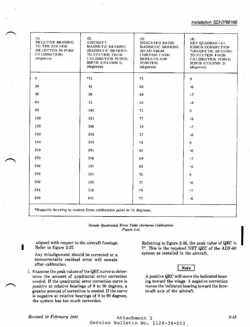
installation 523-07ffi 1 86
Sarnpl.e Quad,rantal En'or Table (Airbornp Calibration)Figure 2-34
aligned with respect to the aircraft fuselage. Referring to figure 2-36, the peak value of QEC isRefer to figure 2-37. 7'. This is the required NET QEC of the ADF-60
Any misalignment should be corrected or a system as installed in the aircraft.noncorrectable residual error will remainafter calibration.
i. Examine the peak values of the QEC curve to deter-mine the amount of quadrantal error correction A positive QEC will move the indicated bear-needed. If the quadrantal error correction curve is ing toward the wings. A negative correctionpositive at relative bearings of 0 to 90 degrees, a moves the indicated bearing toward the fore-greater amount of correction is needed. If the curve to-aft axis of the aircraft.is negative at relative bearings of 0 to 90 degrees,the system has too much correction.
Attachment IService Bull-etin No. 1124-34-053
(1)REI"AI'IVE BEARING1'O 1'II}] STATION(sll Ltjc't'llD BIr lroRllCA I,IBItAl'ION)(clcgrces)
(2\AIRCRAFTMAGNETIC HI]ADINC(MAGNETTC BHAItTNC'I'O S't'A't'tON I.'tt()MCA LIBIIAI.ION P()IN.I'}MINUS (COLUMN 1)(degrees)
(3)INDICATED RADIOMAGNETIC BEANING(nDAD FROMCOMPASS (IAIIDBHNI.:A'I'II ADI.'POINTER)(degrees)
(4)
NET QUADRANl'AI,I]RROR CONRECTION*(MAGNI]TIC BTJATIINC'TO S'TA'I'ION I.'ROMCA I,IBNATION POIN'I)MINUS (COLUMN 3)(dcgrees)
0
30
45
60
90
I20
135
150
180
2t0
225
240
270
300
315
330
*7r
4L
26
11
341
311
296
281
25L
22I
206
191
161
131
116
101
7l
65
64
65
7L
78
tt
7L
65
64
65
7I
77
?8
It
0
+6
+7
+6
0
-o
-7
-6
0
+6
+6
0
-6
-7
-6
*Magaetic bearing to station from calibration point is 21 degrees.
Reaised 19 February 1985 2-t9

installation 523-0761 86
j. If the result of the test (from preceding step i) iswithin 3 degrees of the estimated QEC (from stepa), then the system is correctly adjusted. If theresults differ by more than 3 degrees, remove thestrapping on the rear connector. Refer to figure 2-38 and restrap the mating connector contacts toeither increase or decrease the original estimate bythe amount of QEC indicated by the flight test.(Total QEC equals initial strapping plus derivedQEc.)
For sample error correction curve, figure Z-BG, anadditional 7 degrees of QEC are required. For aninitial strapping of 10 degrees, the total requiredQEC is 17 degrees. Jumper wire connecting 4-8,12-20 would be removed and 4-16 should be strap-ped (from figure 2-38).
Remember to remove jumpers from previ-ously strapped receiver mating connectorcontacts prior to strapping to obtain totalrequired QEC (preset QEC plus measuredQEC). If total QEC does not correspond withany entry in figure 2-38, strap to within 3degrees.
2.5.2.2 Ontund Calibrat ion
Calibration may be performed on the ground using aradio signal transmitted from a known geographiclocation and turning the aircraft to different relative
bearings. The bearing to the selected radio stationrelative to the heading of the aircraft must be ac-curately established. That angle may be determinedusing the aircraft compass system (if accuratelycalibrated) or by using a transit or pelorus sighted ona fixed object. The station selected should provide astrong, clear-channel signal and provide good non-fluctuating bearing indications. A flight check of theground calibration should be made using theprocedures in paragraph 2.5.2.I. Perform the groundcalibration as follows:
a. Locate the aircraft in an area that is clear ofbuildings, overhead wires, or other possible reflec-ting objects.
b. Channel the ADF-60 system to ADF mode andturn the compass system on. Tune in the selectedradio station (200 to 400 kHz) and point the air-craft directly toward the station.
c. Read and record the AIRCRAFT MAGNETICHEADING and INDICATED RADIO MAGNETICBEARING in a table similar to figure 2-84.
d. Turn the aircraft 30 degrees to the left and recordthe AIRCRAFT MAGNETIC HEADING andINDICATED RADIO MAGNETIC BEARING.
e. Continue this procedure by turning the aircraft tothe left and recording data from eaeh relative bear-ing listed in column I of figure 2-34.
f. Determine the NET QEC required and adjust theQEC according to the instructions given inparagraphs 2.5.2.1, steps f through j.
_ AttachmentServi_ce Bulletin No.
!-50
rI24-34_053Reuised 19 February t98S

t --RELATTVE BEARTNG TO STATTON
e/ 7P
\-o,rarora MAGNETTc HEADTNG
installation 523-07ffi 1 86
TPr- 2t 32 -O | 9
LOW FREQUENCYRANGE STATION
-^*'Ot'ro-$i -
-*A$)oz"a v(P'=
-/y
ADF-60 System, Calibration PatternFigwre 2-35 I
q@UtoUJo
z
FU
oon
UJFz
old
FUz
BELATIVEBEAR ING
Sample @tailrantal Er'ror Cor-rection CurueFiga,re 2-36
AttachmentService Bulletin No.
Reaised, 19 February 1985
II24-34-053
TP44040-O1 1
2-5 I

installation 523-07ffi 1 86
to
I
6aulpoEo;?9boUeao-,o-G8-q0:U
c-6FzE-eet -roFUz
lo
I
6
4
2
o
2
4
6
8,
o.
qUUGoUozoFoue_tooE-oEEUJFzE
e-lFU2
AANTENNA MOIJNYFT)
TPrt-404t -ot4
ANGLE WITH RESPECT TO AIRCRAFT CENTER LINE
I Quad,rantal En'or Cqmection Curles for Antenna Alignm.ent Er.rorsFigure 2-37
!-5t Attachment 1Service Bulletin frro. ffZa_34_053
ANTENNA MOUNTEO TO LEFT OR RIGHT OF AIRCRAFT CEI{TER LINE
Reaised t9 February tgti

installation 523-0761 A6
@70TAL O.E.C,(DEGREES) @ srnaereo REcETvER
TERMINALS
i9
17
1a
12
10
I
7
5
a
3
1
o
-1
-3
-1
1-20
a-16
4-12,16-20
1-12
+-4.12-m
4-€. 12-16
.1-8. 16-20
4-8
8-20
8-16
8-r2, 16-20
8-12
12-20
16-20
NO JUMPERS
NOTE:
O srnlp MouNT coNNEcroR coNTAcrs roACH IEVE REOUIREO O.E.C..
KEEP JUMPER WIRES TESS TXIX|l{ L€r{6Tt{.
INCREASING O.E.C. MOVES THETOWARD THE WINGS,
@
@
r27 ilM(5tncH€st
INDICATED AEAFING
ADF-OO { '
BECETVEBREAR CONNECTOR
Quad,rantal Error A iljustmentFigure 2-88
Attachment 1Service Bulletin No. 1124-34-053
TP4{0|42.Ot 1
T
Reaised 19 FeAruary 1988 2-58/2-5tt

ATTACHMENT 2
(ss 1124-34-0s3)
DF-206 QUADRANTAL ERROR CORRECTION
Correction Modu1e eEC *gEC Value with Collins part No.Model 582A-( ) Value 137A6A Antenna 522-xxxx-004
-10N
8N
5N
4N
2N
0
2
-46
I
-10
-L2
-L4
-16
-I8
-10
I6
4
2
0
+2+4+6+8+10
+L2
+14
+16
+18
+6+8+10
+L2
+14
+16
+18
+20
+22
+24
+25
+29
+30
+32
+33
-3181-
-3180-
-3179-
-3178-
-3L77-
-3176-
-2736-
-2737-
-2738-
-27 39-
-27 40-
-27 4l--27 42-
-27 43-
-27 44-
*31-7A6A Loop Antenna contains +160 QEC built in.

niltSERyICE BULLETTTU
RECOMMENDED
SERVICE BULLETIN NO. II24.34-055
SUBJECT: NAVIGATION - FI.{S-90,/LRN-85 IMPROVEII{ENTS
1. PLANNING INFORMATION
A. EFFECTIVITY:
(I) Accomplishment Instructions Part A:serial numbers 295 through 352,
(2, Accomplishment Instructions Part B:serial numbers 392 through 442 except
(3)
(4)
( s)
(6)
SUBSIDIARY OF ISRAEL AIRCRAFT INDUSTRIES, LTD.
BEN GURION AIRPORT, ISRAEL
January 22 t 1985
I'lodel 1124A
Model tt24A424 and EFIS
equipped aircraft.
Accomplishment Instructions Part C: tvlodel 1124Aserial numbers 353 through 390.
Accomplishment Instructions Part D: Ivlodel 1124Aserial numbers 295 through 442. I'todel LL24 all serialnumbers prior to 426 with LRN-85 installed as #fsystem.
Accomplishment Instructions Part E: Itlodels IL24 andIL24A prior to 426 with LRN-85 installed as #2 VIFINAVsystem.
Accomplishment Instructions Part F: ModeI 1124Aserial, numbers 295 through 372. Model IL24 serialnumbers 284 through 423 with LRN-85 as #f systeminstalled.
@ lI I st'x# p*t* !#;, *, nsB LL24-34-055Page I of 11
/

B.
SERVICE BULLETIN NO. 1124-34-055
(3) Accomplishment Instructions part C:from T-17 and rerouted to T-2.
REASON
(1) Accomplishrnent rnstructions part A: To ilruminate Ft{s"WARN" Annunciator for condition of 'vLFn in Approachmode", only when f.US-90 is coupled to the flightDirector and an inconpatible mode of operation isselected, while retaining all other FMS 't{ARNnconditions. This modif ication eliminates an F!,ts"WARN'| Annunciator except where operationallyrequired.
(21 Accomplishnent rnstructions part B: To correct awiring error disabling conposite steering to flightcomputer that wilr create improper flight directortracking of the VLF course, especially after legchanges.
(3) Accomprishnent rnstructions part c: To correct wiringerror of voR *1 flag into Fl.{s-90 to prevent inproperV,/p node operation when in "RpT NAv(v/t) t2" on-pilotsHSI.
(4) Acconplishment rnstructions part D and E: To nodifythe shield ground connections of the antenna signallines for the FI.ts-90,/tRN-95 vLF systens to impr6vereception.
(5) Acconprishment rnstructions part F: To place theRadio Tune unit (F!,ts-90 0nly) and the cRU,/cDU on thesame ground plane to prevent data lockup due to groundloop noises.
COMPLIANCE
compliance with parts B and c of this service burletin isrecommended, other parts A, D, E and F are optional.DESCRIPTION
(r) Accomplishment rnstructions part A: 4 wires are addedin aft avionics bay between existing rerays andterminal str ips.(21 Accomplishment rnstructions part B: one wire is
removed fron one terminal of T-16 and relocated toadjacent terminal.
c.
D.
One wire removed
sB 1124-34-055Page 2 of lI January 22, 1986

SERVICE BULLETIN NO. LL24-34-055
(4) Accomplishment Instructions Parts D and E: Previouslycapped and stowed wires are put back in use andshields are grounded at the CRU.
(5) Accomplishment Instructions Part F: A ground wire isadded between the Radio Tune Unit (FMS-90 only) , theComputer Display Unit and airframe ground.
E. APPROVAL
This service bulletin has been reviewed by the Israel CivilAviation Administration (ICAA). The design contentconveyed herein complies with the applicable Civil AviationRegulations and is ICAA approved.
F. I,TATERIAL
The material required for this service bulleti.n can beobtained through Atlantic Aviation or procured loca1ly.
G. TOOLING
None
/ \ H. WEIGHT AND BALANCE
Not applicable
I. ELECTRICAL IOAD DATA
Not affected
J. REFERENCES
l',IodeI IL24 Westwind Wiring Diagram l'lanua1, Chapters34-60-01 , 34-50-03 and 34-50-02.
K. PUBLICATIONS AFFECTED
Model IL24 Westwind Wiring Diagram lt{anual, Chapters34-60-0f, 34-60-03 and 34-50-02.
2. ACCOMPLISHMENT INSTRUCTIONS
A. Ref erence WDIU Chapter 34-60-01 and revise wir ing asfollows:
(I) Add two new #22Awc wires, one from RL85A pin 33 toarea of FGC *2 plugs and one wire from RL-85A pin 35to area of RL-84.
sB LL24-34-055Page 3 of 11
January 22, 1986

B.
SERVICE BULLETTN NO. 1124-34-055
l2l Remove $rire TR-201c from terminar strip T16-2, spliceand connect to RL-g4B pin 20 with new wire from RL-85Apin 36.
(3) Add a new f?2AWG wire from TL6-2 and connect to RL-64Bpin L7.
(4) splice the new wire from RL-8SA pin 33 with existingwire *2C349824 to FGC *2 ptug J-3 pin 13.
(5) Perform functionar test of Flight Director and FMs-90systen. rt will be necessary to cancel any existingFMS-90 "WARNi alert prior to these steps:(a) FMs "vtFlVD" switch in VLF position(b) FMS selected on HSr(c) select AppR mode on the Flight Director contror.starting with no nwARNn right, the above steps willturn owARNn on. selecting 'vD' on FMS or delerecting"AppRn will cancel "wARNn 1ight.
Reference wDM chapters 34-60-01 and 34-50-02. Revisewiring as follows:(f) Remove wire *TR198D22 from T-16 terminal *7 andrelocate to terminal #O with wire *TRl9gC22 ( inplace) .
(2') verify proper operation of composite steering usingthe following procedures:
(A) Select FMS on pilot and/or
(B) Place fMS-90 in Sirnulated
co-pilot HSf.
Navigation mode asfollows:
( 1) Irtode-switch(2') Key in code
register).(3) Key in code
register).(4) Key in code
register).(5) Key in code
register).
in TEST position.1015 (PSW in alphanuneric
1003 (SIt{ in alphanumeric
I015 (PSW in alphanumeric
1016 (Srn in alphanumeric
(C) Verify valid HDG in NAV node of operation.Manually enter TAS (350 kts) and cS (300 kts).
(D) couple FMs to Flight Director systen, using "NAv"mode.
sB 1124-34-055Page 4 of ll January 22r f9g6

SERVICE BULLETIN NO. LI24-34-055
(E) Key in parallel track of t?.5 miles. FIight Directorwill indicate left turn.
(F) Key in parallel track of R 2.5 miles. Flight Directorwill indicate right turn.
C. Reference WDM Chapters 34-60-01 and 34-50-02. Revisewiring as follows:(I) Remove wire #TR185C22 from T-17 terminal *20 and
relocate to T-7 terminal #5. Do not disturb otherwire segments attached to these terminals.
(2') Verify proper operation of FMS coupled to pilot andco-pilot HSI.
D. Reference WDlt Chapter 34-60-01 and Figure 1 attached.Perform the following wire changes.
(1) Locate and gain access to the FMS-9O/LRN-85 ComputerReceiver Unit #1 plug DB-I36C and make the followingchanges:
(a) Locate wire #TRl63A (Ft'ts-g0 on Westwind IIAircraft) or #TR139A (tRN-85 a/c 385 Westwind I)or #TR137 (LRN-85 on Westwind I except s/n 385) .Insert this wire in pin rFr of DB-I36C.
(b) Locate shield of wire in step (a) above andensure it connects to pin 'pu of DB-136C.
NOTE
In steps (a) and (b) above, these must bethe only connections to pins I Fr and I plof DB-136C.
(c) Locate shield of wires inserted in pins rA' andrBr of DB-136C and insert shield connection inpin rNr of DB-136C. There must be no otherconnections to this shield or pin.
(d) Reconnect DB-136C to CRU.
(21 Make accessible connector to Antenna Coupler Unit plugDB-13 4A.
sB LL24-34-055Page 5 of 11
January 22, 1986

SERVICE BULLETTN NO. 1124-34-055
(A) Locate wire segment inqerted in pin rFr ofDB-I36C (step (1) (a) above) and insert oppositeend in pin rCr of DB-134A. Refer to Figure I.No other connections to pin ,Ct of DB-134A.
(B) Isolate and insulate shields of wire segments topins tA,, tDt, and ,Bt , rCr of DB-134A. Shieldsare not connected to ground at this end, or toeach other.
(C) Ground Bonding Strap Installation:(Effective all aircraft serial numbers prior to433).
Remove antenna and coupler. polish and Iridite(P,/N L4-2) all unit and airfrane ground attachpoints. Refer Figure 2, locate existing angleP/N 5873606-21, drill .190-194 dianeter hole inangle to form a ground stud.
(1) rnstall a L/2" bond strap l/N 5923606-23 asshown in Figure 2 between ACU mounting boltand angle new ground stud using AN3-4A bolt,3 each AN96oKDl0L Washers, I.{S35338-43 spr ingwasher and MS21042-3 nut.
(21 Reinstall VLF antenna, assuring neh, screwhead and antenna are properly sealed withPR-1422 sealant or equivalent.
(3) Reinstall ACU.
(D) Check VLF for proper VLFIOII{EGA signalacquisition.
E. Reference wDlt chapter 34-60-03 and Figure 1 attached.Perforn the following wire changes:
(1) Locate and gain access to the LRN-95Computer Receiver Unit *2 plug DB-1360C andmade the following changes:
(a) tocate wire *2TR218A (LRN-BS *2 Systemon Westwind II) or }2TRI72A (LRN-85 *2Systen on Westwind f). Insert thiswire in pin rFr of DB-1360C.
(b) Locate shield of wire in step (a) aboveand ensure it connects to pin rpr ofDB-1360C.
sB 1124-34-055Page 6 of 11
January 22, 19BG

SERVICE BULLETIN NO. 1124-34-055
NOTE
In steps (a) and (b) above, thesemust be only connections to pinsrFr and rPr of DB-l350C.
(c) Locate shield of wire segments inserted in pinsrAr and 'Br of DB-1360C and insert shieldconnection in pin 'Nr of DB-1360C. There must beno other connections to this shield or pin.
(d) Reconnect DB-1360C to CRU.
l2l Make accessible connector to Antenna Coupler Unit plugDB-1340.
(a) Locate wire segment inserted in pin rFr ofDB-1360C (Step (1) (a) above) and insert oppositeend in pin rCr of DB-I340. Refer to Figure 1.No other connections to pin rCr of DB-1340.
(b) Isolate and insulate shields of wire segments topins A, Dr B and pin C of DB-1340. Shields arenot connected to ground at this end, or to eachother.
(c) Perform Part Dr paragraph (2) (C) and (D).
F. Reference l{DM Chapters 34-60-01 and 34-60-03. Perform thefollowing wiring changes:
(1) For the FI.{S-90 system add new ground wire as follows:
(a) tocate and gain access to cDU connector DN-40.
(b) Add new wire *TR40IB20 to pin 'c' of DN-40.Route along existing cable bundle and add tosplice with existing wire TR401A20 near the RTU(Radio Tune Unit) .
(c) Add additional length of wire #2OAWG to samesplice as in (b) above and connect opposite endto nearest airframe ground terminal.
(2) For the LRN-85 systems add new ground wire as follows:
(a) Locate and gain access to CDU connector.
(b) Add jumper fron pin rGr to rHr with splice. Addadditional length of #20AWG wire from splice tonearest airframe ground terminal.
sB LL24-34-055Page 7 of 11
January 22, 1985

SERVICE BULTETIN NO. 1124-34-055
(c) Reassemble connectors and check for properoperation of Cornputer Display Unit.
3. II{ATERIAL INFORMATION
QTY PART NUMBER DESCRIPTION
A/R, rrtILl6BTBD wire, *20AwcA/R II{ILI6878D Wire , *22AwG1 873606-23 L232 Braid t L/2"
(!lfg. Alpha)2 AN3-4A Bolt4 AN960KD10L Washer2 rIS35338-43 Spring !{asherI MS2l042-3 Nut
A/R L4-2 lriditeA/R pR-I422 Seatant
(or equivalent)
4. RECORD COMPTIANCE
A. Make the following entry in aircraft tog book:
Service BuIIetin No. LL24-34-055 dated January 22, I9g6titled nNavigation FMS-90,/IRN-85 Improvements' has beenaccomplished this date.
B. Revise LL24 Wiring Diagram lr{anual Chapters 34-60-01,34'60-02, 34-60-03 and 34-50-02 as required to reflect thechanges perforned by this service bulletin.
sB 1124-34-055Page 8 of 11
January 22, f986

CRUFMS/LRN
1.
2.
SERVTCE BULLETIN NO. LL24-34-055
NOTES
Production breakout disconnectsnot illustrated.
Wire segment numbers omj-tteddue to varied configurations.
ACUFMS/LRN
sB II24-34_055Page 9 of tI
January 22, t9 B6
FIGURE 1

SERVICE BULLETIN NO. rL24-34-0s5
JUMPER 1232 ALPHASHIELD FLAT BRAIDTINNED COPPER
1/2'' t^lIDTH
SUPPORTASSY.
FILL SHADED AREA WITHTIN SOLDER (2 PLC'S)
'l!! orn HoLE (2 plc,s)
FULL RAD. (2PLC,S)
I
3.85
COUPLER REF.
MS 35338-43SPRING WASHER
-4A BOLT
AN 96OKD1OLIdASHER
1,232 ALPHASHIELD FLAT BRAID
MS21069-3NUT.PLATE(EXISTING)
sB rI24_34_055Page 10 of 11
NOT TO SCALE
FIGURE #2
GROUND BONDING STRAP INSTALLATION
January 22, 19g6

SI1RVICE BULLI]TIN NO. rl.24-3 4-0 5 5
CHANNEL
A/C SKIN
1232 "ALPHA" SHIELD FLAT BRAID
MS 35338-43 SPRING WASHER
MS 21042-3 NUT
AN 96OKD1OLWASHER (3 REQ',D)
-l!! orn. HoLE
AN3-4A BOLT
IJ
oo
-21 ANGLE
NOT TO SCALE
FIGURE 3
sB LI24-34-055Page 11 of lt
January 22, 1986

II24-34-055

9eo,ryioe fiwlletin A/(: s/N
Geotifioote o/ Go rn/o li o ro o e
PLEASE FILL IN TTIE REQUIRED DATA BELOIV AND RETURN TO:
iSMEL AIRCMFT INDUSTRIES INTERNATIONAL, INC.P.0. BOx 10086WILIllINGTON, DE 19850ATTN: TECHNICAL PUBLICATiONS
This is to certify that lt/estwind Serial Nunber- has conl)1iedwith Service Bulletin No. LL24-34-055
Aircraft Registration No.
Airframe lotal Tirne at Compliancc HOURS: /CYCLES:
Compliance Date
OlrrNER:
BySignature
ACCOMPLISHINC AGENCY:
l)1case describe bclow any discrepancies found or difficultieserrcountcrcd during compliancc:

SERVICE PUBLICATIO.NS
revision noticeOPTIONAL
sERvrcE BULLETTN No. 1124_34_052 iranuary 31, 19g6Revision No. I
suBJECT: NAvrcATroN - Ncs-3r DrspLAy AND Locrc por{ER suppLyIUPROVEI{ENTS
REASON FORREVTSTON: To correct part numbers in paragraph 3.
3. IIATERIAL INFOR!,TATION
QTY PART NUUBER DESCRIPTION
2 KPT06B-14-5S Connectors or equivalentA/R 2024-T3 Atclad Mounting base
sB 1124-34-057Page I of INfEHtfrUt{A$;
t'','| ,.cut -|'n$ arnnt rgutsrot^ey oF tsRAgL alFcaAft |l{ougTRtgE. Lto
8EN OURION AIRPORT. ISRAEL

twtsERytcE BULLETITU
OPTTONAL
SERVICE BULLETIN NO. LL24-34-057 December 2t 1985
suBJEcr: NAVTGATTON - Ncs-31 DrspLAy AND Locrc powER suppl,yIMPROVEMENTS
1. PI,ANNING INFORMATION
EFFECTIVITY
(1) ACCOMPLISHI{ENT INSTRUCTIONS PART A AIiID B:
MODEL LL24 WESTWIND, serial numbers zSL, 259 andsubs with Collins 639U-1 NCS power supply.
(2) ACCOMPLISHMENT INSTRUCTIONS PART C:
MODEL LL24 WESTWIND, serial numbers 187 thru 250,and, 252 thru 258 including those with existingLT-52A power supplies.
REASON
(f) To reduce display garbling due to pohrer drainduring engine start and initial system posrer up.
(2) To provide improved logic and lighting voltagesource to NCS, especially r:nder low temperatureand low bus voltage conditions.
(3) The NCS-31 system microprocessor has an originalvendor operating temperature range of +5o to+141o Fahrenheit. Ambient temperatures approachingthe limits of these readings will cause the NCSto power up with garbled displays and cause thekeyboard tuning to become erratic.
A.
B.
/
@Hls*m*w*|#;-*,,*SUBSIDIARY OF ISRAEL AIRCRAFT INDUSTRIES, LTD.
BEN GURION AIRPORT. ISRAEL
sB 1124-34-057Page I of 8

c.
D.
SERVICE BULLETIN NO. LL24-34-057
It muet be recognized that this maximum operatingtemperature range will become smaller as the micro-processor and associated components a9€r resulting ina different temperature range creating the problem.
(a) It is the intent of this service bulletin tominimize the effects of reduced input voltageto the NCS system, by providing adequate pohrersources.
(b) The modifications described in this servicebulletin will not correct for marginal orimproper system operation caused by the NCSmicroprocessor or internal power supply, whichcan cause identical symptoms to those addressedby this service bulletin.
COMPLIANCE
Compliance with this service bulletin is optional.DESCRIPTION
ACCOMPLISHMENT INSTRUCTIONS PART A:
Add larger 9aug9 parallel paths for logic and displaypohrer distribution wires and provide shorter returns.This part should be accomplished prior to part B,and the system monitored for proper performance.
ACCOMPLTSHI{ENT INSTRUCTIONS PART B:
Replace Collins 639U-l NCS power supply with two(2) KGS LT-52A power supplies in the- eirent part Adoes not completely remedy the problem.
ACCOMPLISHMENT INSTRUCTTONS PART C:
Replace_original EMp type ps-274 power supplies withthe field repairable KGS type LT-52A.
APPROVAL
This service bulletin has been reviewed by the rsraelCivil Aviation Administrati on (ICAA) . Th; design-corrt"rrtconveyed herein compries with the applicabre ciiirAviation Regulations and is ICAA apiioved.
E.
sB LL24-34-057Page 2 of 8
December 2, 1985
SERVICE BULLETIN NO. LL24-34-057
F. MATERIAL
The material required for the accomplishment of thisservice bulletin may be obtained from Atlantic Aviationor from local sources
G. TOOLING
None
H. WEIGHT & BALANCE
Not applicable.
I. ELECTRICAL LOAD DATA
Not applicable.
J. REFERENCES
LL24 Wiring Diagram Manual, Chapters 34-50-12 and34-50-14.LL24 service Letter No. wul-2452, dated February 28, 1980.
K. PUBLICATTONS AFFECTED
IL24 Wiring Diagram Manual, Chapters 34-50-I2 and34-50-14.
2. ACCOMPLISHMENT INSTRUCTTONS
PART A
Reference Wiring Diagram Manual, Chapters 34-50-12 and34-50-14 for the below listed procedures.
(1) Remove all power from aircraft.(2') Locate and gain access to NCS-3I lighting and logic
power supply, 639U-1 (located at centerline, underfloor, between stations L74 and I84).
(3) At power supply connector DB-206 locate butt splicewith wire #Rp21A20N (will have four (4) other wiresin splice). Cut wire RP2IA20N near splice, stripboth ends and attach terminals.
sB LL24-34-057Page 3 of 8
December 2t 1985

SERVICE BULLETTN NO. LL24.34{57
(a) connect both terminals to nearest convenient ai_r-frame ground under center froor. Do not groundto access panel that mounts to the power supply.(4') Locate butt splice with wire #Rp2lAlg.
(a) Disconnect the wire going to pin ,,A,, from buttsplicer ot the butt splice. -
(b) Connect new wire #16 AWG to pin 'A, usingRp21C16 for wire label.
(5) At D8205 pin ''K'r splice new wire #Rp29Fr6 #16 Awcto existing wire #Rp29A2o and route to T-156 withwire added in step (4) (b). (T-156 located at stationL28 lefr side. )
(6) At r-156 connect wire #Rp2lcl6 to terminal 1l andwire #npZ9pt6 to terminal 15.
(7) on terrninal 9 of T-156 add rength of #16 Awc wireand connect opposite end to netrest airframe frouna.(8) Reference service Letter l'fiW-24s2 for power suppryadjustment procedures. rt is advisabie to =.i'trr.5.0 + -1 vDc rogic voltaEe by rneasuring at lne ucs
cDPU-pru9- A, pins 29 or go, irittt cDpu irugged in toprovide the proper road. use external po#5, duringadjustment procedures, and for the gggult por",supply set the vortage using the adjustment iniernarto the power supply.(9) Perform comprete functionar check of NCS systemto include engine start from battery power with
NCS ON.
(10) Reassemble aircraft and return to servicer or proceedwith Part B of Accomplishment rnstructions as desired.ACCOMPLISHMENT TNSTRUCTTONS
PART B
Reference wiring Diagram Manuar, chapters 34-50-12 and34-50-14 for repracement of 639u-t plwer supply with 2 eachLT-52A po$rer supplies, and follow ultow rislla'pr-""arrr"",(1) Remove all power from aircraft.
sB 1124-34-057Page 4 of g December 2, 1995

SERVICE BULLETIN NO. Lrz4-34-057
(21 Locate and remove 539U-t pohrer supply and mountingplate (located on center line, under floor betweenstations J-74 and 184). Discard plate and AN3-17Aattaching bolts.
(3) Modify existing mounting plate angles as shown in Figure#1 to accomodate installation of 2 each KGS LT-52A powersupplies and new plate p/N 5863569-3. Install powersupplies with AN3-25 bolts.
(4) Install mount and power supplies to airframe usingexisting angles and hardware shown on Figure #1 to mountnew plate. Label power supplies as 8206 and 8211 forreference and identificatibn purposes.
(5) At existing connector DB2OG, remove wires from pin rKland insert in new DB206 pin tC. t
(6) Remove twisted pair (wire #Rp27(D) 18R and #Rp28(D) 18B)from existing DB206 pins t!.t and 'G. I Cap and stow ,,8,1
segment of twisted pair.(7) Add length of #18AWG wire to wire #Rp27 (D) I8R using
butt splice with #18AWG pigtail at other end of splice.(8) Install pigtail wire added in step (7) above in pin rAr
of new D8206 and other added wire in pin fAr of newDB21I.
(9) Remove wires from pins tDt, tEt, rl,f and rRr of oldD8206.
(a) Insert two of removed wires in pin rBr of D8206(new) 1nd two in pin rBr of DB21I.
(10) Remove wires from pins rAr and rB' of old DB 206 andinstall in pin 'C' of DB21t. Remove wire RP95A2O frompin rMf of o1d D8206 and install in pin 'D' of DB2ll.Discard o1d D8206.
(11) Insert length of #20Awc wire in pin rD' of DB206. Attachother end of wire to one lead of resistor (5.1K ohm, \watt) using proper sleeving and sprice. Attach opposi-teend of resistor to ground point with wires in step (9)above.
(r2) Reference service Letter wN-2452 and part c(8) of thisservice bulletin for power suppry adjustment procedures.Set the 5.0 + .1 Vdc logic voltage by changing the valueof the 5.lK 5hm resistor installed in step 11 above.
sB LL24-34-057Page 5 of I
December 2 | 1985

SER5/ICE BULLETIN NO. 1I24-34-057
(13) Perform functional check of NCS-31 system to includedimming operation.
(14) Reassemble aircraft and return to service.ACCOMPLTSHMENT INSTRUCTIONS
PART C
Reference Wiring Diagram Manual, Chapters 34-50-12 and34-50-14 for replacement of ps-274 power suppries with KGSLT-52A power supplies for the NCS 1ogic and displayfunctions. Follow the below listed proceduress
(1) Remove all power fron aircraft.(2) Locate and remove ps-274 power supplies (approximate
location between stations 93 ana 1-og right- siae inside wall or under divan for older airciaft) and discardthe 4 ea. AN3-17A attaching bolts.(3)
(4)
Tf necessary, remove and modify the mounting plate toaccomodate the LT-52A power supplies.Reinstall mount with existing hardware and power sup-plies with new AN3-25 borts in same positioir. connlctusing existing prugs (physicarly and erectricarry [tresame).
(5) rnstall a #16AWG jumper to nearest airframe ground:
(r) s/N 192 throush 239 from rerminal srrip T32, rug 10.(b) s/N 240 and subsequent from terminar slrip T156-9or Tr57-10 as applicable. Refer to 34-50-12 forappropriate ground return for your wiring config-uration.(6) Add a new #16 AWG wire from D8206 pin C in parallelwith existing wire Rp29( )20 by thl shortesl route:
S/N 187 through 239 to terminal strip T36-4.S/N 240 and subs to terminal strip fiS6-lS.a new #16 AWG wire from DB2II pin C in parallelexisting wire Rp21( )re by thl shortesl route:S/N 187 through 239 to terminal strip T35_Il.S/N 240 and subs to terminal strip tiSO_ff.
(a)(b)
(7') Addwith
(a)(b)
sB LL2444-A57Page 6 of 8
December 2, 1985


9eo,ryioo Salletin A/C s/N
Geotifi oa to of Go rn/o li oro oo
PLEASE FILL IN THE REQUIRED DATA BELOW AND RETURN TO:
ISRAEL AIRCRAFT INDUSTRIES INTERNATIONAL, INC.P.O. BOX 10086WILIVIINGTON, DE 19850ATTN: TECHNICAL PUBLICATIONS
This is to certify that llrestwind Serial Number-has cornpliedwith Service Bulletin No. IL24-34-057
Aircraft Registration No.
Airframe Total Time at Conpliance HOURS: /cvclns:
Compliance Date
OWNER:
BySlgnature
ACCOMPLISHING AGENCY:
Please describe below any discrepancies found or difficultiesencountered during compliance :

TW{sERvtcE BULLETIIU
OPTIONAL
SERVICE BULLETIN NO. IL24.34-064 May 5, 1986
SWITCHTNG IMPROVEMENTSSUBJECT: NAVIGATION - REPEAT VOR,/LOC
1. PLANNING INFORMATION
A. EFFECTIVITY
(1) Accomplishment Instructions PART A:Model II24 Westwind, all serial numbers.Model IL24A Westwind, serial numbers 295 through 390.
(2) Accomplishment Instructions PART B:Model LI24A Westwind, serial numbers 295 through 390.
B. REASON
(1) Accomplishment Instructions PART A: To display aVOR/LOC flag in "RPT NAV" modes to alert operatorof a possible invalid nagivation display when theoffside HSI is not displaying VOR/LOC information.A conformity inspection test is included todetermine if the aircraft has previously compliedwith this part.
(2) Accomplishment Instructions PART B: To disable''NAV TEST" functions when in "RPT NAV" modes toprevent possible Flight Guidance System errorsduring "NAV TEST. " A conformity inspection test isincluded to determine if the ai-rcraft haspreviously complied with this part.
C. COMPLIANCE
Compliance with this service bull-etin is optional-
sB LI24-34-064Page I of 7
@ lill rcme** !,!Y;.,^.,,*
SUBSIDIARY OF ISRAEL AIRCRAFT INDUSTRIES, LTD
BEN GURION AIRPORT, ISRAEL
/

SERVICE BULLETIN NO. LL24-34-064
D. DESCRIPTION
Two wires are added for PART A and PART B between the HSItransfer relays RL84/RL85 and the RPT NAV relays RL30,/RL31.
E. APPROVAL
This service bulletin has been reviewed by the IsraelCivil Aviation Administration (ICAA). The design contentconveyed herein complies with the applicable CivilAviation Regulations and is ICAA approved.
F. MATERIAL
Material may be procured locaI1y.
G. TOOLING
None required.
H. WEIGHT AND BALANCE
Not affected.
I. ELECTRICAL LOAD DATA
Not affected.
J. REFERENCES
II24/IL24A Wiring Diagram Manual, Chapters:
3i:i3:31 3i:;3-3;K. PUBLICATIONS AFFECTED
IL24/II24A Wiring Diagram Manual, Chapters:
34-50-01 34-s0-0334-50-02 34-50-04
2. ACCOMPLISHMENT INSTRUCTIONS
PART A
A. Perform preliminary check of NAV switching. Do not selectany flight director modes, and the autopilot must bedisengaged. Both sj-des must be in normal VOR/LOC modeand a val j-d VOR/LOC signal must be present.
sB 1124-34-064Page 2 of 7
May 5, 1986

SERVICE BULLETIN NO. 1124-34-064
(1) At pilot position, select "RPT NAV 2r" Pilot I{SIflag must be retracted. Select Copilot to a VLFmode, Pilot HSI flag is in view.
B.
c.
D.
(2) Restore Pitot HSr to Normal voR,/Loc, select copilot"RPT NAV 1. " Copilot HSI flag must be retracted.Select Pilot to VLF mode, Copilot HSI flag is inview.
Conformity with the above tests indicates compliance andno further action is required. Unsatisfactory resultswill require modification in accordance with theremaining steps (reference Figure 1).
Remove wire 1RNB0A22 from RL84B-9 and the jumper wiresfrom RL848-10 and,/or RL848-11. Splice these wirestogether.
(1) This will result in a pitot "RPT NAV 2" annunciationwhenever "RPT NAV 2" is depressed, regardless ofinformation displayed on the Pilot HSI. Thisprevents switching the HSI into a possible invalidoperating condition.
Remove wire 2RN48C24 from RL30B-36, splice to new wire2RN48224, route and connect to RL85B-46.
(1) Aircraft with RL-30 P,/ttt 175096-001' remove wire2RN48C24 from DRL-3OC, Pin 24. Splice to new wire2RN48224, route and connect to RL85B-46.
Connect a new wire 2RN48Y24 from RL85B-45 to RL30B-36.
(f) Connect new wire 2RN48Y24 to DRL-3OC, pin 24 fromRL85B, pin 45 if steP D(1) aPPlies.
Remove wire 1RN4BD24 from RL31A-27 ' splice to new wire1RN48224, route and connect to RL84B-9.
(1) Aj-rcraft S/N 187-2I5: Wire lJo. 1RN48D24 mayconnect to RL-31B, pin 9. ff so, remove andsplice to new wire 1RN48224, route and connect toRL84B-9. Double check wire number removed.
Connect a new wire 1RN4 BY24 from RLB4B-10 to RL3 LA-27 -
(r) Connect new wire 1RN48Y24 from RLB4B-10 to RL3lB,pin 9 if step F(1) applies.
Repeat Step A for test and inspection.
sB 1124-34-064Page 3 of 7
E.
F
G.
H.
May 5l 1985

SERVICE BULLETIN NO. IL2444-A64
PART B
A. Restore Pil-ot and Copilot HSI to Normal VOR/LOC mode.
(1) At pilot positionr s€Iect "RPT IIAV 2" and attemptVTR-3OA self-test on #2 Nav cTL-30- Restore PilotHSI to Normal VOR/LOC.
(21 At copilot position, select "RPT NAV l" and attemptVIR-30A self-test on #1 NAV CTL-30. Restore CopilotHSI to Normal VOR/LOC.
B. Self-test in Step A must be inoperative, conformityindicates compliance and no further action is required.Should self-test be operational, modify in accordancewith the following steps (reference Figure 2).
C. Remove jumper wire, if anY, between T2L-L9 and T21-18.
D. Remove wire 1R|I4C24 from T21-18, splice to new wire1RN4224, route and connect to RL31A-IO.
E. Add new wire 1RN4Y24 and connect between RL31A-1I andT2 1-18 .
F. Remove jumper wire, if dny, between T17-5 and T16-1.
G. Add new wire:
(f) For dual Flight Director (#2 FGC80) systems:
(A) Remove wire 2CII3A24 from T16-1, splice to newwire 2C113224, route and connect to RL30A-4.
(2) For single Flight Director systems:
(A) Add new wire 2CL\3224 from Tt7-5 to RL30A-4.
H. Add new wire 3C113Y24 from RL30A-5 to T16-1.
I. Repeat Step A for test and inspection.
3. MATERIAL INFORMATION
QTY PART NUMBER DESCRIPTION
MIL-W-I6 87 8D50534323994
A/RA/RA/R
sB rI24-34-054Page 4 of 7
#24AWG WireTerminal, Mf9. AMPButt splice, Mf g. AI{P
l,lay 5, 1986
SERVICE BULLETIN NO. IL24-34-064
4. RECORD COMPLIANCE
A. Make the following entry in the aircraft log book:
Service Bulletin No. IL24-34-064 dated May 5, 1986titled "Navigation Repeat VOR/LOC SwitchingImprovements" has been accomplished this date
B. Revise IL24/II24A Wiring Diagram Manual as required toreflect the changes accomplished by this servicebulletin.
sB LL24-34-064Page 5 of 7
May 5, 1986

SERVICE BULLETIN NO. TL24-34-064
RL-30
i- --- -1
tl
R1.31
i--- -r
I
NAV 2[lXn' S - -2RN48D 24-- -i*-i- -zRN118Az4
T-STRIP \\\\
I
I L----rI I RN48Y24
TO R1.85
\\. - 2RN48C24 tl-zRN48Z24
NAV FLAG SWITCHING
FIGURE 1
N/C
N/C
sB 1124-34-064Page 6 of 7
R1.85
May 5, 1986

SERVICE BULLETIN NO. LL24-34-064
FGC #2V
TNA
TS -.2CrL3424
2C1137?4
-2RN4G24 - - -2C114A24
REMOVE JUMPER
IF INSTALLED
- 2RN4A24- ?CLT3Y24
-l RNl32824 -REMOVE JUMPER
IF INSTALLED
1 RN4Y24-tRN4A24-J A
t_l
CTL-30#2
NAV 2RCVR
crL-30#L
NAV 1
RCVR
R[30- A
-l RN4C24'-'nI
NEt.l WIRE
- -- EXI STI NG WI RE
NAV TEST LOCK-OUT
FIGURE 2
sB Lr24-34-064Page 7 of 7
T -t7
T-16
T-21 Tll' 5* u'
_,RN33A2lI{5
RL-31
May 5, I 986

9oo,,uioo frlw/letdnA/C S/N
6eo,ttf; oote a/ Gorn/, /iorooo
PLEASE FILL IN THE REQUIRED DATA BELOW AND RETURN TO:
ISRAEL AIRCMFT INDUSTRIES INTERNATIONAL, INC.P.0. BOx 10086WILIVIINGTON, DE 19850ATTN: TECHNICAL PUBLICATIONS
This is to certify that l{estwind Serial Number-has conpliedwith Service Bulletin No. ILZ4_34_OG4
Aircraft Registration No
Airframe Total Tirne at Compliance HOURS: /CYCLES:
Compliance Date
OI\INER:
BySignature
ACCOMPLISH]NG AGENCY:
Please describe below any discrepancies found or difficultiesencountered during compliance :

tw{sEBvrcE BULLETIIU
OPTIONAL
SERVTCE BULLETIN NO. LL24-34-067 January 8, 1986
VERTTCAL GYRO(S) ANDSUBJECT: NAVIGATION - RETROFIT OF COLLINSIMPROVED VERTICAL GYRO MOUNTING
1. PLANNING TNFORMATION
A. EFFECTIVITY
(1) MODEL 1,L24 WESTWfNDS, all serial numbers featuringnose deck mounted vertical gyro(s).
(2) IvIODEL LL24A WESTWINDS, serial numbers 295 through426 except those aircraft with split gyro installa-tion.
B. REASON
(1) To authorize retrofit of Collins 332D-11A or 332D-11T vertical gyro(s) for Model LL24 aircraftequipped with Sperry VG14 and/or VG-14A units.
(2') To reduce radar stabilization errors, autopilot ro11instability, ADI display errors and the need foraileron/rudder cross trimming by installing anadjustable 'rskew-p1ate'r mount on Model LI24 aircraft(Collins vertical gyro (s) installation only) .
(3) To improve gyro vibration isolation and "skew-plate"rigidity for Model LI24A aircraft.
C. COMPLTANCE
Compliance with this service bulletin is optional.
/@ lI I yrml w* t !,!!u";., *.,, *
SUBSIDIARY OF ISRAEL AIRCRAFT INDUSTRIES, LTD.
BEN GURION AIRPORT, ISRAEL
sB LL24-34-067Page 1 of 10

SERVICE BULLETIN NO. rr24-34-067
D. DESCRIPTION
PART A:
A "skew-p1ate" vertical gyro mount is installed on thenose deck of Model L\24 aircraft.
E.
F.
G.
H.
rnstructions for retrofitting collins vertical gyro(s) toModel LL24 aircraft equipped with Sperry units iieprovided.
PART B:
I'Skew-plate'r clamps and improved gyro mounting studassemblies are installed in Model ltzae aircrift.APPROVAL
This servi-ce bulletin has been reviewed by the rsraelCivil Aviation Administration (ICAA). Tha design contentconveyed herein complies with the applicable ci;ilAviation Regulations and is ICAA approved.MATERIAL
The materiar required to accomplish this service Bulletinmay be obtained.through Atrantic Aviation supply companyor their authorized dealers.
TOOLTNG
No special tools are required.WEIGHT & BALANCE DATA
PART NO. DESCRTPTTON UNIT wT (1b) ARM (in.)5 863559-53 Base-plate 1.65 863559-89 Skew-p1ate (s) O.BVG-14 Sperry gyro(s) 10.0VG-14A Sperry giro(s) 7.3332D-11A, -11T CoIIins gyro (s) 7.2
r. ELECTRICAL LOAD
-2.3-2.3-4-4-2.3
Not applicable
J. REFERENCES
service rnformation Letter No. LL24-22-o3g ',vertical GyroAdjustment procedure. rl
sB LI24-34-067Page 2 of 10
January 8, 1986

SERVICE BULLETIN NO. IL24-34-067
Service Information Letter No. LI24-22-039 "VerticalGyro Improvements.,l
LL24/LL24A llaintenance Manual, Chapter 22-01-00.IL24/IL24A Wiring Diagram Manual, Chapters 22-L0-02,22-L0-03, and 34-40-01.
K. PUBLTCATIONS AFFECTED
LI24/LI24A Illustrated Parts Catalog, Chapter 34-20-00will be revised to reflect the modifications described.LL24/LL24A Wiring Diagram Manual, Chapters 22-L0'02,22-L0-03, and 34-40-01 will be revised to reflect themodifications described.
2. ACCOMPLISHMENT INSTRUCTIONS
PART A: Model LL24 skew-pIate installation and gyro retrofit.
A. Gain access to the R/H nose deck and remove existinggyro(s).
B. If Sperry gyro(s) were removed, replace matingconnector(s) in aircraft with P/N IvlS3476L-I8-32S (referto Chart 1 for pin connection information).
C. Drill out rivets and remove existing gyro mounting Z
angles from nose deck structure. Remove anyuniversal head rivets that will prevent the 5 863559-53plate from laying flat on the nose deck structure.Countersink redundant holes and plug with MS14218ADrivets.
D. Remove the #Z inverter and oxygen bottle access coverassembly. Trim the outer edges of the oxygen bottleaccess cover so that it fits properly into the "joggle"provided in the nose deck.
E. rnstall P/N 5 863559-53 base-plate, P,/N 5 863559-89 skew-plate assembly(s) and P,/N 5 863559-103 clamps perFigure 1. Install nut-plates through oxygen bottleaccess cover or nose deck structure only (not throughP/N 5 863559-53 base-plate) using MS14218AD rivets.
F. Install Collins Vertical gyro(s) P/N 332D-11A or 332D-11T.It is recoiltmended that Collins Service Bulletins332D-11A/T-22, 24; 332D-11A-23 be accomplished prior toinstallation. Reference Service Information Letter No.IL24-22-039 "Vertical Gyro Improvements. "
sB 1124-34-067Page 3 of 10
January 8, 1986

SERVICE BULLETIN NO. IL24-34-067
G. Perform system tests per LL24/II24A Maintenance Manual,Chapter 22-0I-00 to ensure proper gyro outputs.
H. Level gyro(s) per Service Information Letter No.1"L24-22-038 "Vertical Gyro Adjustment procedure.,'Leveling can be accomplished by adding AN960-PD10Lwashers under the gyro mounts (Figure I Section B-B).Grind washer faces as required to achieve proper thick-NCSS.
I. Secure P,/N 5 863559-103 clamps. Install MS16562-21 pins.Torque gyro mounting nuts to 4 ft-lbs minimum., Ensurethat two fuII threads protrude through nuts.
J. Reinstarl the #z rnverter, secure nose deck compartmentand return aircraft to service.
PART B: Model rr24A clamp and stud assembly installation.A. Gain access to the RrlH nose deck and remove gyro(s). It
is recommended that collins service Bulretins 33zD-rrA/T-22, 24i 332D-11A-23 be accomplished before reinstalla-tion.
B. Measure the thickness of the skew-plate(s). rf thicknessis less than L/8 inch, remove, discard and order p,/N5 863559-89 skew-plate assembly(s) for later installation(PrlN 5 863559-93, 94, 95 stud assemblies will already beinstalled in skew-plate (s) ) .
If skew-p1ate(s) are I/A inch in thickness, dri1l outrivets securing the three stud assemblies per plate andreplace them with one each p/N 5 863559-93 , 94, 95 perskew-plate using MS20427-4C6 rivets (Figure 1).
c. Measure thickness of base-pIate. rf less than r/g inchin thickness, discard and replace with p,/N 5 9G3559-53base-plate.
D. Remove #Z inverter and oxygen bottle access cover assembly.Trim the outer edges of the access cover so that it fitsproperly in the "joggle" provided in the nose deck.
E. Remove any universal head rivets from the nose deckstructure that will prevent the p/N 5 963559-53 base-platefrom laying flat on the nose deck structure. countersinkredundant holes and plug with MS1421gAD rivets. Removeall rivnuts (if any) from nose deck.
sB 1124-34-067Page 4 of 10
January 8, 1986

SERVICE BULLETIN NO. LL24-34-067
F. Lay out and install P/N MS21075-3 nut-plates per Figure Iusing l4SI4218AD rivets. Install all nut-plates onbottom of nose deck structure and bottom of oxygenbottle access cover (not on P,/N 5 863559-53 base-plate).
G. fnstall oxygen bottle access cover base, plate p,/N5 853559-53, skew-plate(s) P/N 5 863559-89, and clampsP/N 5 863559-103. Refer to Figure I for hardwareinformation as well as which base-plate holes requirecountersinking.
H. Relocate desiccator assembly per Figure 1.
I. Reinstall gyro(s) and level per Service InformationLetter No. IL24-22-038 "Vertical Gyro AdjustmentProcedure. " Leveling can be accomplished by addingAN960-PD10L washers under the gyro mounts (Figure I,Section B-B). Grind washer faces as required to achieveproper thickness.
J. Secure P/N 5 863559-103 clamps. Install MS16562-2Ipins. Torque gyro mounting nuts to 4 ft-lbs minimum.Ensure that two full threads protrude through nuts.
K. Reinstall the #Z Inverterr s€cur€ the nose deck compart-ment and return aircraft to service.
3. MATERTAL INFORMATION
A. For MODEL LL24 Installation (See Accomplishment Instruc-tions, Part A).
QTY QTY(Single V.G. ) (Dual V.G. ) PART NO. DESCRTPTION
A/R1I
2I1
237
A/n 5 853559-61 Shim1 5 863559-53 Base-p1ate2 5 863559-89 Skew-plate
assy.4 5 863559-103 ClampI 5 863559-71 Placard2 332D-11A or **Gyro (Mfg.
332D-I1T Collins)4 *AN3-IOA Bolt6 *AN3-5A Bolt7 tcvts24694-s52 screw
sB 1124-34-067Page 5 of 10
January 8, 1986

SERVICE BULLETIN NO. TT24.34-067
I *MS27039-1-10 Screw27 *AN960-I0L Washer6 *AN960-PD10L Washer
(a1urn. )
I16
3
33821
A/R
66
1142
A/R*I\4S3476L-18-32S Connector*MS14218AD Rivet
*MS35338-43*M52I042-3*Ivts210 7 5-3*MS15 562-2t
Lock washerNutNut platePin
DESCRIPTTON
ClampStud Assy.Stud Assy.Stud Assy.PlacardShimBracketBoItWasherNut-pIateRivet, CSKPinWasher (alum)Rivet, CSKBase-plateSkew-pIate
* May be obtained Iocally.**Verify that Collins Service Bulletins 332D-IIA/T-22,24; 332D-11A-23 have been accomplished prior toinstallation.
B. For MoDEL 1124A rnstallation (see Accomplishment rnstruc-tions, Part B).
QTY(Single V.G. )
QTY(Dual V.G. )
4222
IA/R
1463
I246
A/R12
2I111
A/RI222623
A/R1I
PART NO.
5 863559-103**5 863559-93**5 863559-94**5 863559-955 863559-71s 863559-615 863559-67*AN3-10A*AN960-10L*MS21075-3*MS20 427-4C6*MS16562-21*AN96O-PD1OL*MS14218AD
**5 863559-53**5 853559-89* Play be obtaj-ned locally**Order P,/N 5 863559-53 bas+plate only if existing plate
is less than l/8 inch thick. order p/u 5 863559-80skew-plate (s) only if existing skew-plate (s) are lessthan r/8 inch thick (do not order p/N 5 963559-93, 94,95 stud assemblies in this event).
sB rI24-34-067Page 6 of l0
January 8, 1986
SERVICE BULLETIN NO. LL24-34-067
4. RECORD COMPLIANCE
Make the following entry in the aircraft log book:
service Bulletin No. 1124-34-067 dated January g, 19g6titled "Navigation - Retrofit of colrins verticar Gyro (s)and rmproved vertical Gyro Mounting,, has been accomplishedthis date
sB 1124-34-067Page 7 of 10
January 8, 1986

SERVICE BULLETIN NO. 1124-34-067
V. G. #2-D8225 FROM TO NOTESwrRE NUMBER VG L4/I4A 332DLI-A/T
v.G. #1-D825WIRE NUMBER
c52c24Rc53c24Bc54c24Yc55c24Rc56G24Rc57D24Yc58F22c801E20c802820Nc802A20N
sB 1124-34_067Paqe 8 of L0
2c1553824R x2cL5598248 y2cL556824 z2cIs46B24R p2CL549824R s3cL552824Y ;
A1B1cD2E2FNG
2CL543822cLLB22
2c802A20NSW4A22R (or SW33A22R)SW5A22B (or SW34A22B)sw6A22R (or SW35A22R)sw7A22B (of SW36A22Bl
NOTES:
1. Wiring Diagram ManualChapter 22-L0-02 may showthese wires reversed aLVertical Gyro. SperryVcI4/L4A pin numbersshown herein arecorrect.
2. Wiring Diagram ManualChapter 22-10-03 may showthese wires reversed atVertical Gyro. SperryVGI4/J-AA pin numbersshown herein are correct.
3. Sp1ice wires C802 ( ) fromYGL4/I4A aL 332D-ILA/T andconnect to 322D-ILA/T pinH and b.
4. Remove jumpers from VG74/I4A,install in 332D-LLA/T. Addadditional jumpers as shownusing #22 AWG wire.
T*4-l-y
r"4LU
r5
Y4
ni tf\_il 3
c[
Iecl
c-c
DDEEgV
rTL,
PIN CONNECTION INFORMATIONCHART 1
""rpJ [*L-P
H-l TR 4
tt3'l L1
January 8, 1986


TWIsERyrcE BULLETITU
OPTIONAL
sERvrcE BULLETTN No. 1124-34-070 January r5r 1986
SUBJECT: NAVIGATION . VLF,/OMEGA RECEIVER PERFORMANCE IMPROVEI4ENT
1. PLANNING INFORMATION
A. EFFECTIVITY
MODEL LL24/LL24A WESTWIND, aII serial numbers using"E-Field" antennas for VLF navigation systems.
B. REASON
To increase Vf,frlOmega receiver performance in the presenceof high aircraft-generated electrical noise when VtFsignal is of a marginal IeveI.This modification will NOT reduce noise generated byP-static interference.
COMPLIANCE
Compliance with this service bulletin is optional.DESCRIPTION
Replacement of existing VLF,/O'mega nE-FieIdtr antenna toreceiver/computer wiring with cabling containing greatlyimproved shielding will eliminate aircraft-generatedelectrical noise from degrading the VLF signals presentedto the system for navigation.
APPROVAL
This service bulletin has been reviewed by the IsraelCivil Aviation Adrninistration (ICAA). The design contentconveyed herein complies with the applicable CiviIAviation Regulations and is ICAA approved.
@ II I ws*#t tgs* t !,!Y;.. *.,, *sB II24-34-070Page 1 of 4
c.
D.
E.
SUBSIDIARY OF ISRAEL AIRCRAFT INDUSTRIES, LTD,
BEN GURION AIRPORT. ISRAEL

SERVICE BULLETIN NO. 1124-34-07O
F. I{ATERIAL
Material required may be obtained through Atlantic AviationSupply Company, through their authorized dealers or may beprocured from: Electronic Cable Specialists, 15722 W.Ryerson Roadr New Berlin, WI 53151, telephone: (414)797-9877 .
G. TOOLING
None required.. H. WEIGIIT AND BALANCE
Not applicable.
r. ELECTRICAL LOAD DATA
Not affected.
J. REFERENCES
LL24/LL24A wiring Diagram Manual, chapters 34-60-01,34-60-02 and 34-60-03.
K. PUBLICATIONS AFFECTED
1r24/Lr24A wiring Diagram Manual, chapters 34-60-ol,34-60-02 and 34-60-03.
2. ACCOTI{PLISHMENT TNSTRUCTIONS
A. Reference wiring Diagram Manuar for system desired andFigure I attached.
B. Measure quantity of cabling required prior to order. Cablep/r.t 462203 for Gl0bal cNS-500 0r p/w anzoa for corlinsLRN,/FI.{S systems (see Figure l).
C. Disconnect, cap and stow existing wires and shields at VLFantenna and computer/receiver unit.D. Install new cable assembly well clear of any cable bundlespresentry containing 400 Hz AC or high current drain Dcconsumer unit wiring. cramp as needed by physicalrequirementsr itt each bulkhead crossing is-a-ninimum.
sB LL24-34-070Page 2 of 4
January 15r 1986

SERVICE BULTETIN NO. LLz4-34-O7O
(1) Should it be necessary to run new cabling through theaft pressure vessel bulkhead (STA 269) , observenecessary precautions to prevent damage to existingwire bundles and to reseal as required by establishedprocedures to prevent pressure Ieak.
NOTE
Adding a new hole in the aftpressure bulkhead is forbiddeneven if it can facilitate cablerout ing .
E. ByPass any connectors observed between antenna andreceiver/computer, permitting an uninterrupted cable run.
F. Connect new wiring as shown on Figure l. Shield groundsmust connect as shown.
G. Ensure antennas are properly bonded. Should rebonding benecessary, apply Iridite to bare metal contact surfacesprior to reassembling and sealing antenna.
' 3. I{ATERIAL INFORMATION
QTY PART NUI,IBER DESCRIPTION
A/RA/R
A/R
^/R
412204 or462203
L4-2PRC L422
Cable assembly (For LRN/FMS)Cable assembly (For cNS-500
and lvlarcon i )rriditeSealant or equivalent
sB IL24-34-070Page 3 of 4
4. RECORD COMPLIANCE
A. Make the following entry in the aircraft log book:
service Bulletin No. LL24-34-070 dated January r5r 19g6titled'Navigation VtF/Omega Receiver performanceImprovement" has been accomplished this date
B. Revise the Wiring Diagram Manual to reflect the changesaccomplished by this service bulletin.
January 15, 1986

RCU
SERVICE BULLET]N NO. Lr24- 34-0 70
GLOBAL GNS-sOO SYSTEMS
ANTWIRE PIN 462203
GROUND PIN ''C'' AND
CONNECTOR SHELL TO
SKIN UNDER ANTENNA
COLLINS LRN/FMS SYSTEMS
ACE u'JIRE P/N 4t2204t,lHI
CRU
A
B
N
J
F
M
P
RPU
A
D
MARCONI SYSTEMS
ANT
REFERTNCE l^lIRING MANUAL CHAPTER 34.60FOR CONNECTOR IDENTIFICATiON
WIRE P/N 462203
OUTER SHIELD CONNECTEDTO RPU CONNECTOR SHELL
SINGLE CONDUCTOR SHIELDEDt^llRE IS UNUSED
t^,HIA
B
M
B
tln
A
sB 7124-34-070Page 4 of 4
FIGURE 1
Januar:1' IS , l9 g6

9e'u,uioe fiJalletin A/C S/N
GeoAifioato of Go rn/oli arooo
PLEASE FILL IN THE REQUIRED DATA BELOW AND RETURN TO:
ISMEL AIRCMFT INDUSTRIES INTERNATIONAL, INC.P.0. BOX 10086WILIVIINGTON, DE 19850ATTN: TECHNICAL PUBLICATIONS
This is to certify that ltrestwind Serial Number- has compliedwith selyigx&ukketin No . LL24-34-070
Aircraft Registration No
Airfrane Total Time at Compliance HOURS: /cvclns:
Compliance Date
OITINER:
BySignature
ACCOMPLISHING AGENCY:
Please describe below any discrepancies found or difficultiesencountered during compliance :

SERVICE PUBLICATIONS
revision notice
NAVIGATION - COPILOT'S ALTII,IETER PART NUMBER CHANGES
SERVICE BULLETINRevision No.1
SUBJ E CT:
REASON FORREVISION:
l
1;
(2)
REC()MMENDED
N0. tL24-34-071
e the effectivity(b), Accompli shment
June 30, 1987
in Part A.,Instructions.
paragraphs
2trP/N
oughP/N
MODEL I124/LI24Aand subsequent
sB 1124-34-071Revision No.1Page I of I
To chang(t)(a) and
& B:
numbers 181 andot's altimeter4883 7 7 8- 50 1.
numbers 254 thrilot's altimeter
NG INFORMATION
FECTIVITY
Accomplishment Instructions Parts A
(a) M0DEL 1124 ttEST}lINDS, serialthrough ?53 when the copil4883778-1 is repalced with P/N
(b) M0DEL f124 |l{ESTtIINDS, serial270 already equipped with cop4883 7 7 8- 50 1.
Accomplishment Instructions Part B:l.|ESTI,IINDS, serial numbers 27(reference parag raph 2.8(1)).
PLANNI
4.. EF
(1)
"-.
"-iA\
/@frlwxrmm**
SUSSIOIARV OF ISRAEL AIRCNAFT INOUSTRIES' LTO
8EN GUFION AIRPONI. tSRA€I

tilG{sERvtcE BULLETLU
RECOMU ENDED
SERVICE BULLETIN NO. LL24.34-O7L February 16, 1987
Service InfornationThis Service Bulletin No. LL24-34-O7I cancelsLetter No. 35 dated May 16, 1983 in its entirety.
SUBJECT: NAVIGATION COPILOT'S ALTIMETER PART NUMBER CHANGES
1. PLANNING INFORMATION
A. EFFECTIVITY
(1) Accomplishment Instructions Parts A & B:
(a) MODEL Lt24 WESTWINDS, seri.al number 181 and zLIthrough 258, when the copilo-t^'s altineter P/N4883778-1 is replaced with P/N 48837?8-501.
(b) MODEL LL24 fESTWINDS, serial numbers 259 through27O already equipped with copilot's altlneter P/N4883??8-501.
(2) Accomplishment Instructions Part B: MODEL tl24lLL24AwEsTwINDS, serial numbers 27L and subsequent(reference ParagraPh 2.B(1)).
B. REASON
(1) To pernit copllot's altimeter change from Kollsman P/N
ntt"i?;13;ll*,.3i.ifr'"'.1?l10-014 (rAr P/N 4883?78:1 to
(a) Kollsman P/N 844202-10-004 no longer avallable.
sB LL24-34-O7LPage 1 of I
@IIIw:m*m**t!*n*,nSUBSIDIARY OF ISRAEL AIRCRAFT INDUSTRIES, LTD.
BEN GURION AIRPORT. ISRAEL
/

(2)
SERVICE BULLETIN NO. LL24-34-O7L
To provide a varlable potentlometer required to controlthe altlmeter voltage lnput when equlpped wlth KollsmanAltimeter P/N 844202-10-014 (IAI pln 4883778-501).
The procedures described hereln do not apply toalrcraft presently equipped wlth altlmeters ofdifferent make or part number than specified above.
(3)
e.
sB LL24-34-O7LPage 2 of 8
D.
E.
F.
COMPLI ANC E
Compliance with this service bulletin is recomnended.
DES CRIPTION
(1) A minor wiring change and the addltion of a prlntedclrcult board to provide a regulated vibrator voltageto allow altimeter changeover for LL24 alrcraft serlalnumbers prlor to 27L.
APPROVAL
The service bulletin has been reviewed by the rsrael clvilAviation Administratlon (rcAA). The design content conveyedh ereln complles with the applicable civil AviattonRegulatlone and is ICAA approved.
M AT ERI AL
G.
H.
I.
J.
Materlal for this modlflcationAtlantic Aviatlon Supply Company,
TOOLING
None.
TEIGTIT AND BALANCE
Not affected.
ELECTRICAL LOAD DATA
Not affected.
REF ERENC ES
may be procured throughWilmington, Delaware.
tL24 Wirlng Dlagram Manual, Chapter 94-20-06.
February L6, 1987

SERVICE BULLETIN NO. TL24.34-O7I
K. PUBTICATIONS AFFECTED
LL24ltL24A Wlrlng Diagram Manual, Chapter 34-20-06.LL24lLL24A Illustrated Parts Catalog, Chapter 39-10-05.LL24lLL24A Malntenance Manual, Chapter 34-10-01.
ACCOMPLISHM ENT INSTRUCTIONS
PART A:
Reference tiring Diagram Manual, Chapter 34-20-06 andFlgures 1, 2 and 3 of this bulletin during nodlflcationprocedures.
(1) Remove all power from aircraft.(2) Disassenble and remove copilot's instrument panel aa
required to gain aecess to annunciator dlode boards atrear of lnstrument panel.
(3) Remove existlng dlode board mounting brackets fromstand-offs and dlscard brackets (retain hardyare forfollowing steps). Refer to Flgure 1.
(a) Use brackets P/N 5883775-REg and 5883775-RE4 orlocally fabricate new nounting brackets fromstandard and 10139-070-1 stock ALCLAD 2024-T35LL(two required second (5883775-RE4) bracketopposite of Figure 1 view).
(b) Use bracket P/N 5883775-RE5 or locally fabrlcatehold-down strap from .063 ALCLAD 2024-T6 stockper Figure 1.
(4) Secure new brackets in place on instrument panel uslnghardware from step (3) above.
(a) Align prlnted circuit board (PCB) receptacles onmounting brackets as per Figure 2 and markbrackets for drilling of mounting holes. Followsame procedure for pillars used for securingregulator board.
(b) Drill holes in braekets and mount PCB receptaclesusing Loctite on screw threads. Mount pillars insame manner with screws and spring washers asshown on Flgure 1.
sB LL24-34-O7LPage 3 of I
2.
A.
February 16, 1987

SERVICE BULLETIN NO. LL24-34-O7L
(c) Install new PCB and hold-down strap.receptacle 4s "J226."
(5) Perform wlring changes per Figure 3.
(6) Reassemble copilotrs instrunent panel.
PART B:
Label PCB
B. Test Procedures
(1) Perform operations check of PCB regulator andaltimeter. Check for excessive vlbrator noise. Ifnoise is excessive or needle stlcking is apparent,check and adjust regulator &s follovs:(a) Disconnect altimeter connector.
(b) Insert a 22O ohm, 2 watt resistor &cross pins Pand M of aircraft cable connector. Measurevoltage across the resiston. Read +18 to +2O Vdcacross resistor. If voltage reads different,adjust potentiometer on PCB (P/N 4833513-9) atJ-226.
NOT E
Vibrator nolse leveI increases a8voltage level increases. Stickingneedle problems develop at lowvoltage levels and/or colderambient temperatures. Aircraftserial number 27L and subsequenthave PCB located forward of pllotrswindshield temperature control box.
(2) Perform necessary pilot and static system tests forsystems affected by the removal of the instrumentpanel.
(a) If malfunction(s) exist, follow a,ppropriatetroubleshooting procedures.
(b) Return aircraft to service.
sB LL24-34-O7LPage 4 of I
February 16, 1987

3. MATERIAL INFORMATION
QTY
1
1
SERVICE BULLETIN NO. LL24-34-O7L
NEW PART NUMBER DESCRIPTION
22444222
Aln1
AIR111
833513-9143-015-01- 1 10
cM A7 1704-004NAS43DD3-8MS35206-245MS35338-42MS21073-06MS35206-327MS21042-06AN96OPD-6LMrL- W-16878D5883775-RE53205595883775-RE35883775-RE45883775-RE6
Regulator PCBPCB Receptacle(Mfe Amphenol)P1llarSpacerScrew 8-32 x Llz" LSpring sasherNut-plateScrevNutWasher#22AYG wlre
*Hold-down strapButt spllce
* Bracket* Bracket*Pad
*These parts may be fabricated locally.
4. RECORD COUPLIANCE
A. Make the followlng entry in the alrcraft log book:
Service Bulletin No. LL24-34-O71- dated February 16,1987titled "Navigation Copilotrs Altimeter Part NumberChanges" accomplished this date .
B. Make appropriate changes to Wlring Diagram Manual, Chapter34-20-06 and to the Illustrated Parts Catalog, asappropriate.
C. Revise Aircraft Serialized Equipment list if required byreplacement of altimeter.
sB LL24-34-O7LPage 5 of 8
February 16, 1987

SERVICE BULLETIN FO. LL24-34-O7L
5883775-RE4(sEE DETATL)
(srDEiiiilt f''zj.32TYPtL
cMAT 1704-004P I LLAR
NAS43DD3.BSPACER
5883775-RE5(sEE DETATL)
MS35338-42SPRING WASHER
MS35206-24SscREW (4 PLcs)
II .60I
T.25RTYP
5883775-RE3,.RE4 DETAILBRACKET, 2 REQ',D
SECOND BRACKET OPPOSITE VIEW
.28 TYP-r(vrEt.lLKG D0t'lN)
ir'ror-.28 5883775-RE5 DETAIL
HOLD.DOWN STRAP
Ll.2B
;;]PILLAR,2 REQUIRED
+il2.60------l -.1 ts.28
PAD 2.60x.55x.0625, NEOPRENE]/I6'' THICKNESSSHORE HARDNESS 30 + 40
NAVIGATION COPILOT'S ALTIMETER PART NUUBER CHANGES
sB LL24-34-O7LPage 6 of 8
ort(\I
F-r.o--l -4.qsF
Figure I of 3
February 16, L987

SERVICE BULLETIN NO. LL24-34-O?L
RECEPTABLE PCB
P/N 143-0t5-01-110PLASTIC KEY
P/N 143-754
.28 TYP
NUT PLATES4 REQUIREDMS2t 073-06
DRILL TO MATCH
EXISTING PANEL HOLES(TYP 4 PLACES)
SPACERS ( EXTSTTNG)
COP I LOT PANEL (REF)
RIVET (B REQUIRED)cRt 62-3-4
PCB'S AND(EXISTING)
February 16, t987Page 7 of I
ANNUNCIATORRECEPTABLES
NAVIG ATION COPILOT'S ALTIMETER PART NUII BER CHANGES
MOUNTING BRACKETS (REF)
'\--!- ---J_i _.)
.15 TYP
February 16, 1987
Flgure 2 of 3

SERVICE BULLETIN NO. IT24-34-O7L
FA3C22
-FA25A22- - -
^
II
I
I
I
I
I
I
J
tA2C22
- #22- )b- FA3820
PRINTED CIRCUIT BOARD REGULATOR
FA2B22-FA3A2ON-
J226
COPI LOT'SALT I METER 2L5l5E2o--l 33-lo-02
zlsosKzoJ (REF)
EXISTING hllRENEl.l WIRE
NAVIG ATION COPILOT'S ALTIMETER PART NUMBER CHANGES
sB IL24-34-O7LPage 8 of I
Figure 3 of 3
February 16, 1987

9eory'ioe fr]alletinA/ c s/N
6eo,tifc oote of 6o rn/o li anoe
PLEASE FILL IN THE REQUIRED DATA BELOW AND RETURN TO:
ISRAEL AIRCMFT INDUSTRIES INTERNATIONAL, INC.P.0. BOx 10086WILIVIINGTON, DE 19850ATTN: TECHNICAL PUBLICATIONS
This is to certify that tr{estwind Serial Number- has cornpliedwith Service Bulletin No.
.f 124-34-071Aircraft Registration No.
Airframe Total Time at Compliance HOURS: /CYCLES:
Conpliance Date
OI{NER:
BySignature
ACCOMPLISHING AGENCY:
Please describe below any discrepancies found or difficultiesencountered during compliance :

/
rWTsErvrcE BULLETTN
OPTIONAL
SERYICE BULLETIN NO. 1124-34-LO9
December Il, L991
459
December 11, 1991
SUBJECT: NAVIGATION - STATIC PORT TUBING SLOPE INSPECTION AND
CORRECTION
1. PLANNING INFORMATION
EFFECTTVITY
MODEL ll24| WESTWIND, serial numbers 394 through 422 and 425.
REASON
To prevent water accumulation in static system.
DESCRIPTION
This service bulletin describes procedures necessary to inspect the tube attached to
the center leg of the R/H independent static source for the proper slope and reroute
the tube if necessary.
COMPLIANCE
Compliance with this service bulletin is optional.
APPROVAL
This service bulletin has been reviewed by the Civil Aviation Administration ofIsrael (CAAI). The design content herein complies with the apptcable CivilAviation Regulations and is CAAI approved.
A.
B.
C.
D.
E.
sB 1124-34-109Page I of8

SERVICE BULLETIN NO. 1124.34-1W
F. MAN-HOUR REQUIREMENTS
The following information is for planning purposes only:
(l) Estimated man-hours: 16
(2) Suggested Number of personnel: 2
The above is an estimate only, based on experienced personnel complying with thisservice bulletin. It is possible, depending on individual experience tivets, ttratadditional or fewer man-hours are required to accomplish this bulletin.
G. MATERIAL
QTY. PART NITMRER NFSCRTPTION
3 MS208194D SLEEVE3 AN8I84D NUT1 AN8214D ELBOW
A/R .250 OD X .035W 5052-0 ALUMINUM TUBING:r.1 CMA7L737_503_31 DOUBLER*1 cMA7t737_503-29 DOUBLER*1 cMA7t737_503_19 DOUBLER:r1 5723A5_6t DOUBLER2 NAS1O33-A3 NUTPLATEA/R MS212664N GROMMET
* Doublers may be fabricated locally from .050 inch 2024-T3 Clad. Details inFigures 2 and 3.
Material required may be obtained through Astra let Corporation, New Castle,Delaware, or authorized ASTRANTESTWIND service centers.
H. TOOLING
No special tooling required.
I. WEIGHT AND BALANCE
. Not applicable.
sB 1124-34-1WPage 2 of 8
December Ll, l99l

SERVICE BULLETIN NO. IL24-34-I@
J. ELECTRICAL LOAD DATA
Not applicable.
K. REFERENCES
ll24ll124A Westwind Maintenance Manual, Chapters 25 and34.
L. PUBLICATIONS AFFECTED
None
2. ACCOMPLISHMENTINSTRUCTIONS
A. Removal of interior furnishings and tube angle inspection.
(1) Remove interior from right side of aircraft as necessary to expose fuselage framesat Sta. 174 to 240.25. (Forward frame of escape hatch aft to forward bulkheadof lavatory). Refer to ll24ll124A Westwind Maintenance Manual, Chapter25.
(2) Inspect static tube routed from static port through frames at Sta. 184 through219.05 for an upward angle routing. Refer to Figure 1.
(3) If tube slopes at an upward angle, no further work is required. Install interioritems removed in step 2.A.(1) and return aircraft to service. If tube slopes at adownward angle proceed to next st€p.
B. Reroute right static port tube.
(1) Disconnect tube at tee fitting adjacent to static port and at elbow fitting betweenframe Stations 2L9.05 and 223.75. Refer Figure 1 .
@ Remove clamps supporting tube and remove tube.
NOTE: Cover area between frames at Sta.184 and 223.75 as necessary to catchmetal shavings.
sB 1124-34-109Page 3 of 8
December 11, l99l

SERVICE BULLETIN NO. 1124-34-IW
(3) Cut out .750 diameter holes in frames at the following stations. Refer to Figures
1,2 and3.
Y-STA. Z-STA. RFF. NOURT FR P/N RFFFRFNCF
219.05 32.70 CMA7L737-503-31 FIG.2210.00 3t.70 5723M5-67 FIG.220t.75 30.75 CMA7L737-503-19 FIG.2194.00 30.00 cMA7r737-503-29 FIG. 3184.00 EXISTING NOT APPLICABLE
(4) Fabricate doublers out of 2024-T3 clad .050 thick aluminum for each frame and
install. Refer to Figure 2 and 3,
NOTE: Erch doublers and treat with Alodine 120L. Finish with epoxy primer.
(a) Instalt doubler on forward side of frame at Sta. 2L9.05 picking up existing
rivet locations, and install NAS1033-A3 nutplate on forward side offrame. Refer to Figure 2.
O) Doubler for frame at Sta. 194 must be of sufficient length to cover the
existing hole at Z station 28.20. Refer to Figure 3.
(c) Install NAS1033-43 nutplate on aft side of frames at Sta. 210.00 and20l.75for Adel clamp to support tube.
(d) Drill doublers as necessary to pick up existing rivet patterns, nutplahs, etc.
Add rivets where necessary using 6D to 8D spacing and maintaining 2D
edge distance.
(5) Use tube removed in step B.(1) if serviceable or fabricate a tube from .250 OD X.035W aluminum tubing (approximately 44.5 inches) using two each
MS208194D sleeves and AN8184D nuts.
(6) Route tube fabricated in step (5), aft through holes at frames Sta. 184, 194,
201.75 and 219.05, connect to tee at static port.
NOTE: If stereo speaker is mounted between frames at Sta. 210 and 219.05 and
interferes with routing of tube assembly, move speaker up approximately1/4 inch by drilling #10 holes in bracket supporting speaker, and enlarge
notch on bracket to clear frame hole.
sB 1124-34-109- Page 4 of8December 11, 1991

SERVICE BULLETIN NO. 1124-34-IW
A) Support tube frames at Sta. 201.75,210.00 and 219.05 with MS21919WDG4
clamps by attaching to nutplates using AN34A bolts and AN960PDI0Lwashers.
(8) Install caterpillar grommets MS2L2664N or equivalent in frame holes not using
DG clamps.
(9) Mark tube routed vertically between frames at Sta. 219.05 and223.75 toZ-Sta.56.10 for cutting. Remove clamps supporting tube, disconnect at Z-9ta.56.10and remove tube.
(10) Cut tube, install sleeve and nut, flare tube and install using clamps removed in
step 2.B.(9).
(11) Connect tube to fitting at Z-Sta. 56.10 and use elbow P/N AN8214D to connect
tubes together at Z-Stz. 32.70
(12) Connect a static tester to system and check for leaks and proper operation.Reference ll24 | ll24 A Westwind Maintenance Manual, Chapter 34- I 0-01.
C. Install cabin interior.
3. RECORD COMPLIANCE
A. Make the following entry in the aircraft log book:
ServiceBulletin 1124-34-109 dated December 11, 1991, titled "Navigation - Static
Port Tubing Slope Inspection and Correction," has been accomplished this date
B. Complete the attached Certificate of Compliance and return to Astra Jet Corporationin New Castle, Delaware.
sB 1124-34-109Page 5 of 8
December 11, l99l

SERVICE BULLETIN NO. II24-34-IW
STATIC TUBE
:
I
I
I
I
@INCORRECT SLOPE
l'664N821-4DELBOW
STATIC TUBEAN824.4D TEE
sB 1124-34-109Page 6 of 8
CORRECT SLOPE
VIEW LOOKING OUTB'DFIGT]RE 1
Z=21 .7O
R.H.S.
December ll,1991

SERVICE BULLETIN NO. 1124-34-LW
VIEW
z - 31.70
cMA71737-503-31DOUBLER
s723045-67DOUBLER
VIEW LOOKING FWD
PICK UPEXISTING
z = 32-7
PICK UPEXISTINGRIVETS(3 PLACES
= 2L9.05
LOOKING AFT
CI',1A717 3 7-50 3-I9DOUBLER
l-J-L.25Y = 20I.?5
VIEI,I LOOKfNG FWD
RIVETS(2 PLACES)
z - 30.7s
sB 1124-34-109Page 7 of 8
Add P/N MS20470AD4-4 rivets as necessary atspacing of 6D to 8D maintaining 2D edge distance.
DOUBLER INSTALLATIONS FRAMES 201.7 5, 210.00, 219.05FIGURE 2
Y = 210.00
December 11, 1991

SERVICE BULLETIN NO. I T24-34.1W
Y STATION 194.00
EXISTING IIOLESI'OR ANGLE BRACKETFOR CARDTABLE 5/32"
1.1s*l
z-30
l=28
cMA7173 7 -503-29DOUBLER
NOTCH BRACKETFOR HOLE
MS2O47OAD4-4 RIVETS(7 PLACES}
EXISTTNG HOLE
EXTSTTNG 10/32 HOLE TO TIE WrRELE (COULD BE FURTHER UP
OR DOWN)
FRAME !94.00
NOTE:
sB 1124-34-109Page 8 of 8
* ,'l-{j;
1.90-+'fSCALE I:1
VIEW LOOKING FWD AT STATION194.00 R/H SrDE
Add P/N MS20470AD4-4 rivets as necessary arspacing of 6D to 8D maintaining2D edge distance.
DOUBLER INSTALLATIONFIGTJRE 3
December II, l99l

im
rt-l1'mf,.Tl
oll-.{l/_\
?flm
om-{l,m
J(po-{-{o-nUr-o(,m
rzC]
t-
Sentire tsu[[etin
C ertificatt of C onp france
PLEASE FILL IN THE REOUIRED DATA BELOW AND RETURN TO:
Technical PublicationsAstra Jet Corporation278 Ouigley BoulevardNew Castle, DE 19720
This is to certify that WESTWIND Serial Number- has complied withService Bulletin No. j124_34_ j09
Aircraft Registration No.
Airframe Total Time at Compliance: Hours- Cycles-
Compliance Date:
Owner:
By:Signature
Accomplishing Agency:
Please describe below any discrepancies found or difficulties encounteredduring compliance:

TW{sERvt,cE BULLETITU
OPTIONAL
SERVICE BULLETIN NO. 1124 -35-077 February 'l , 198'6
SWITCH REMOTE TESTSUBJECT: OXYGEN - CABIN ALTITUDE PRESSURECONNECTION INSTALLATION
I. PI,ANNING INFORMATION
A. EFFECTIVITY
MODEL LI24/IL24A WESTWINDS, all serial numbers.
B. REASON
To provide improved access for cabin altitude pressureswitch test by installing a remote test connection.
C. COMPLIANCE
Compliance with this service bulletin is optional.
D. DESCRIPTION
rhis bulletin requires that a cut-out be made in the sidepanelr drr adapter added to the altitude switch, tubinginstalled and an elbow installation.
E. APPROVAL
This service bulletin has been reviewed by the Israe1Civil Aviation Administiation (ICAA). The design contentconveyed herein complies with the applicabte CivilAviation Regulations and is ICAA approved.
/
@ lII grms*n* !,!!u';n *.,,*
sB 1124-35-077Page I of I
SUBSIDIARY OF ISRAEL AIRCRAFT INDUSTRIES, LTD.
BEN GURION AIRPORT, ISRAEL
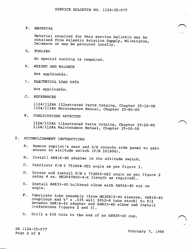
SERVICE BULLETTN NO. T124-35-077
F. MATERIAL .-
Material required for this service bulletin may beobtained from Atlantic Aviation supply, witmi_nit-n,Delaware or may be procured locally.G. TOOLING
No special tooling is required.H. WEIGHT AND BALANCE
Not applicable.r. ELECTRICAL LOAD DATA
Not applicable.
J. REFERENCES
LL24/LL24A rrlustrated parts catalog, chapter 35-ro-00Lr24/rr24A Maintenance Manual, chapf,er 35-00-00K. PUBLTCATIONS AFFECTED
rr24/L124A rllustrated parts catalog, chapter 35-10-00 -Lr24/rr24A Maintenance Manuar, chapi,er 35-00-00
2. ACCOMPLISHMENT TNSTRUCTIONS
A. Remove copilot's seat and R/H console side paner to gainaccess to altitude switch (p,/N IO18O0).
B- rnstall AN816-4D adapter in the altitude switch.c. Fabricate p/N 5 753004_RE3 angle as per Figure 1.D. Locate and install p/N 5 753004_RE3 angle as per Figure 2using 4 ea. MS20470AD_4_X (tength as r6euiieAj.E. rnstall AN833-4D bulkhead elbow with AN924_4D nut onang1e.
F' Fabricate tube assembly (from MS2o819-4D sleeves, ANglg-4Dcouplings and k" x .035 wal1 5052-0 tube stocrcr to fitbetween ANg16-4D adapter and ANg33-4D elbow and install(references Figureq 2 and 3).c. Drilt a #30 hole in the end of an AN929_4D cap.
I
sB 1124-35-077Page 2 of 8
February 7, 1986

4 ea.4 ea.1 ea.I ea.1 ea.I ea.2 ea.2 ea.A/R
1 ea.1 ea.1 ea.
SERVTCE BULLETIN NO. IT24-35.077
H. Paint the drilled cap red.
I. Install the drilled cap on the AN833-4D eIbow.
J. I4ake a 3.5" x 3.5" cut-out in side panel so as to a1lowaccess to remote test port with side panel installed(reference Figures 4 and 5).
K. rnstarl 4 ea. MS21059-3 nut-plates on side panel toretain access panel (reference Figure 5).
L. Fabricate 5.5" x 5.5" panel from Royalite or equivarentmaterial .08 or .09 thick (reference Figure 5).
M. Locate and dri1l 4 ea. holes to facilitate attachment ofaccess panel to side panel.
N. Tnstall placard on access panel and install access panelusing 4 ea. MS35206-263 screws.
O. Reinstall side panel and copilot,s seat.
3. MATERTAL INFORMATTON
QTY PART NUMBER DESCRIPTTON
MS3520 6-263MS21059-3AN816-4DAN833-4DAN92 4-4DAN929-4DMS20 8 19-4DAN818-4D\" x .035 wa1I
5052-05 753004-RE35 753004-RE95 753004-RE11
ScrewNut-p1ateAdapterBulkhead ElbowltrutCap AssernblySleeveCouplingTube
AngleAccess CoverPlacard
4. RECORD COMPLIANCE
Make the following entry in the aircraft log book:
service Bulletin No. rrz4-35-o77 dated February 7, 19g6titled "oxygen - cabin Altitude pressure switch RemoteTest connection rnstallation" has been accomplished thisdate
sB 1124-35-077Page 3 of I
February 7, 1986

SERVTCE BULLETTI{ i,IO. LL24-35.077
cn >-.F-T--I
lr).O_f\ >-.F
lrl-J=c?) ullrJ &,t(5
O lr-cf)|r,N
lr)
|lJJ
otor-t
,'{,,
Olr,
sB LI24-35-077Page 4 of I
>Z(JoFlt',
February 7, 19g6

SERVTCE BIJLLIITIN NO. LL24.35-077
L!t! d.
-vl UJ.doouJo-r!FJ &,oz.O--HO
(JJ<FJ<)Z
SFHa d.E <.o)ooo-C\J lr-
OrOz.c.taa5
.JHO- t/'rQ Jr.t',(-) - dlrlF<oY)sr
Igr(\l talorFZ,O
cf, Jr! (5&.=l<
OJ(\t=cn
=l!(5ztr@>z coOo<rJlr)
tlrrl>-;<vr l-
an
{.=dO
U''Fl!
d.
xI
<rI
t-\sfC\IU1
=<otrt L!
elrJ(J +H-LFH (5Cr
= z, lr)z,u1 -d.<,/1LrJ = U1EOlaj= JFF J-o-H <F<F F(5c:)J V,Z,
H-J
sfI(o
r-{@z.
JFt/,z.
|r)(\Jr=O(JOFOHF-{
=Q <,/1r-{
HFv1 -XJlrJ <
C\I
lrld=<5
u-
I
toro
JO=d
lrjaz )zo aF<
==oz, nco lJlJa&uJsr I
| <l-OsfOEC\IO\z o\ cf)J=A6< r\
<rI
cf)CN@z,
JF-atlz,
lt',U1
lJ-t6F
sB IL24-35-077Page 5 of 8
February 7, 1986

SERVTCE BULLETIN NO. LI24-35-077
lt1
z,trJTF
co
F
srol+ oilr{
@cor-l C)@ <\lZ. tt1<=
-j@
=lrJv1<t1'
cf)
3H(5
toIJJ U-EI
stOcr,rr)t\l.c)
z.lrJ Oco
oLdl- z,H
-=t- d.C5 lrlz, t-trJ lJl
tJ)
z,Lrl
TFOco
F
=(t,OF
lJ,Jr!odcoz<=urJF co lJ-
sB 1124-35_077Page 6 of g
j(nU1
February 7, 19g6

SEP-VICtr BULLITIN i.IO. Ll24-35-077
\tu
Y=54.38
32.0ALTITUDE SWITCH
I NTERIOR SiDE PANEL
F!'jD-1,
DETAIL OF 5 753004-RE9
VIEt^l LOOKING OUTBD R/H
FIGURE 4
P0siTI0N 5 753004-P.E9ACCESS COVER TO SUIT
10-50
SIDE
sB IL24-35-077Page 7 of 8
II\
February 7, 1986

SERVICtr BULLETI}J IiO. LL24-35-077
s.5 sQ
ili'-j
INSTALL MS2I059-3 NUT.PLATETO SIDE PANEL USINGMS35206-263 SCREW
DETAIL OF 5 753004.REgACCESS COVER
3.5 SQ
CUT OUT
IN SIDEPANEL
sB I124-3 5.-077Page 8 of I
5 753004-REl I
I RlrrruDE II pRESsURE swrrcH I
I TEST II CONNECTION I
FIGURE 5
February 7, 1996

9eoryioe Sallohn A/C S/N
Gootifioato of Gorn/oliarooo
PLEASE FILL IN THE REQUIRED DATA BELOW AND RETURN TO:
ISMEL AIRCMFT INDUSTRIES INTERNATIONAL. INC.P.0. BOx 10086WILIVIINGTON, DE 19850ATTN: TECHNICAL PUBLICATIONS
This is to certify that t{estwind Serial Nunber-has compliedwith Service Bulletin No .1124-35-077
Aircraft Registration No.
Airframe Total Time at Compliance HOURS: /CYCLES:
Compliance Date
OI{NER:
BySignature
ACCOMPLISHING AGENCY:
Please describe below any discrepancies found or difficultiesencountered during compliance :
PUBLICATIONS
revision noticeOPTIONAL
SERVICE BULLETIN NO. 1124-39-01-1 June L4, I9B5Revision No.1
SUBJECT: oVERIIEAD PAIIEL AccEss Al[D ALIGNMENT ruPRo\rE!{ENTAI{D,IOR RETROFIT
REASON FORREvrsroN: To change the service bulletin sequence number
. and some wording in paragraph 4. RecordCompliance.
4. RECORD COMPLIAI{CE
Itlake the following entry in the aircraft log book:
Service Bulletin No. 1124-39-011 dated February 5,1985 titled "Overhead panel Access and AligmmentfmProvglent AndrlOr Retrofitu rfas accomplished
A
/@lfll:wxrmlr.n*
SUISIOIANY OF ISRA€I AIRCNAFY INDUSTRIES. LTD- €EN OUFION AIRPORT. ISRA€L
sB 1124-39-011Page I of I

TilE{sERytcE BULLETITU
OPTIONAL
SERVICE BULLETIN NO. IT24-39-011
SUBJECT: O\ZERHEAD PANEL ACCESS AIiID ALIGNMENTRETROFIT.
February 5, 1985
TMPROVEMENT AI[D,/OR
I. PLANNING INFORMATION
c.
EFFECTIVITY
MODEL Ll24 WESTWINDS, all serial numbers prior to 259.
REASON
To alleviate the fitting aligriment and to ease the open-ing or closing of the overhead paneJ-. Two reinforcementparts 5883771-11 and -12 are retrofitted to stiffenthe overhead panel structure to prevent flexing therebyimproving panel alignment.
COMPLIAIiICE
Optional
DESCRIPTION
This bulletin adds a reinforcement to stiffen the over-head panel structure.APPROVAL
The modification procedure described in this servicebulletin has been shown to comply with the applicableICAA/FAA regulations and is fAI Engineering approved.
A.
B.
D.
E.
/@lill s^t:msm* !!#;, .,,*
SUBSIDIARY OF ISRAEL AIRCRAFT INDUSTRIES, LTD
BEN GURION AIRPORT, ISRAEL
sB 1124-39-011Page 1 of 4

SERVICE BULLETIN NO. IT24-39-O1I
F. MATERIAL
Contact Atlantic Aviation Supply Company in WilmingtonDelaware or their authorized representatives.
G. TOOLING
Special tqols are not required foi the modification.
H. WEIGHT & BALANCE
Not applicable.
I. ELECTRICAL LOAD DATA
Not applicable.
J. REFEFSNCE
MODEL LL24 Maintenance Manual Chapter 39-10-05, page 401.
K. PUBLICATIONS AFFECTED
MODEL II24 IPC, Chapter 39-10-00, Figure 1, page 0 willbe revised to properly identify cockpit panels.
2. ACCOMPLTSHMENT INSTRUCTTONS
(1) Gain access to station Y=75.650 by removing all overheadpanel fasteners per IL24 Westwind Maintenance Manualprocedure in 39-00-04r pa9€ 401.
(2) Layout and dri11 appropriate rivet holes per require-ments on Figure 1 and Figure 2. Drill rivet holes fora -11 or -12 pattern as required.
(3) Install rivets (.I25 typ. ) from forward side of stationY=75.650 and rivet the -11 and -I2 parts into pIace.
(4) Close the overhead panel per Westwind II24 MaintenanceManual Section 39-10-05r page 401.
sB IL24-39-011Page 2 of 4
February 5, 1985

SERVICE BULLETIN NO. IT24-39.017
3. MATERIAL TNFORMATION
QTY NEW P/N pESCRIPTTON OLp P/N
I 5883771-11 Angle (LH) NoneI 588377L-L2 Angle (RH) None20 MS20470AD4-7 Rivets None
4. RECORD COMPLIANCE
It{ake the following entry in the aircraft log book:
Service Bulletin No. IL24-39-0I0 dated Eebruary 5, 1985titled "Overhead Panel Access and Alignment Improve,mentAnd/Or Retrofit has been accomplished this date
END
sB 1124-39-011Page 3 of 4
February 5, 1985

SERVICE BULLETIN NO. 1124-39-011
vrEw LooKING TNBOARD, LEFT SrDE, STA. 75.650
FIGURE I
-L2 FOR R.H.S.LEFT
(vrEw rJooKrNG rWD)
INSTAILATTON SHOWN (ruT
COCKPIT OVERHEAD PANEL
OPPOSITE)
sB 1124-39-011Page 4 of 4
(-11)(-L2)
\
.- ?eqseaI
--.. \
--r+
v? 3'
FIGURE 2February 5, 1985

9oo,npioe fiwlletinA/C S/N
6eo,ti/i o ote o/ G" rn/o li atm oo
PLEASE FILL IN THE REOUIRED DATA BELOW AND RETURN TO:
ISRAEL AIRCMFT iNDUSTRIES INTERNATIONAL, INC.P.0. BOx 10086WILIVIINGTON, DE 19850ATTN: TECHNiCAL PUBLICATIONS
This is to certify that l{estwind Serial Number-has compliedwith Service Bulletin No. LL24-39-0tI
Aircraft Registration No
Airframe Total Time at Compliance HOURS: /CYCLES:
Compliance Date
OI{NER:
BySignature
ACCOMPLISTIING AGENCY :
Please describe below any discrepancies found or difficultiesencountered during cornpli-ance :

n2{sEBytcE BULLETIIU
OPTIONAL
SERVICE BULLETIN NO. LL24-52-OO5 January 4, 1985
DOOR WARNINGSUBJECT: DOORS-IMPROVED MAIN BAGGAGE COMPARTMENTSWITCH INSTALLATION
1. PLANNING INFORMATTON
EFFECTIVITY
MODEL LL24 WESTWIND aircraft, serial numbers L52, L54,L74, 181 and 185 thru 278.
REASON
To prevent a faLse forward fuselage baggage door "unlock"warning indication.
COMPI,,IAIiICE
At the customerrs discretion.
DESCRIPTION
This Service Bulletin provides the information necessaryto reLocate the fornrard fuselage baggage door unlocklight warning microswitch to a different position onthe door Latch mechanism, the change incorporates anew MS25253-1 microswitch, a JV-26 microswitch rocker,a CMA77203-039 mounting plate bracket (and two spacers)with sLotted holes (for switch adjustment) and a newlydesigned CMA77203-034 locking lever.
A.
B.
c.
D.
/ sB LL24-52-005Page I of 6
@lillsrmsmn*|,!#;,^^*SUBSIDIARY OF ISRAEL AIRCRAFT INDUSTRIES, LTD,
BEN GURION AIRPORT, ISRAEL

SERVICE BULLETIN NO. LL24-52-OO5
E. APPROVAL
' The replacement and relocation of, improved door warningswitch described in this service bulLetin have been shownto comply with the applicable rcAA/rAA regulatiotr" .tra-ir"fAI Engineering approved.
I'. ITIATERIAIJ
ltaterial required may be obtained through AtlanticAviation guppry compiny in wilrnington, 5"r"*"re or theirauthorized representatives.G. TOOLING
Special tools are not required for this modification.H. T{EIGHT AIID BALAI{CE
Not applicable.I. ELECTRICAI. LOAD DATA
Not applicable.J. REFSRENCES
LL24 Maintenance Manual, Chapter 52_30_00.LL24 fpC, Chapter 52-30-00. -
K. PUBLICATTONS AFFECTED
A- The LL24 Maintenance Manuar, chapter 52-30-00, wirlbe revised to reflect the instar.ration, rigging ;echeckout of the baggage door ratch *"irii"g swi.tch.B. Th"_ LL? rpc, chapter 52-30-00, wirr be revised toinclude the baggage door ratch'and ,"irring switchinformation in this Service BulLetin
2. ACCOIT{PLISHMENT INsTRUcTIoNs
A' Turn off the battery and electrical master switches andassure that external polrer ie not applied to aircrafi--B- peel back fabric riner from forrrard baggage door toexpose both latch cover plates and secure. Remove theupper and rower Latch nelhanism cover plates(9 screyrs each) .
sB LL24-52-005Page 2 of G January 4, t9g5

c.
D.
E.
F.
G.
H.
I.
SERVICE BULLETIN NO. LL24-52-OO5
Disconnect the two wires from each microswitch and tapeexposed terminals. Remove each microswitch from itsmounting bracket and discard. Leave in place existingmounting brackets.
Remove old P/N CWA 77203-034 locking lever from each locktumbler assembly. Drill out the four M520426AD3-6rivets that mount the latching assembly to the baggagedoor skin.
Drill out the two existing rivets in each of the upperIatch mechanism hinge blocks.
NOTE
Each upper hinge blockshould be held in pJ.aceby the latch hinge pinafter removal of thetwo rivets.
Locate and drill two holes in the new CMA 77203-039mounting plate as shown in Figure 1.
Before installing the two new mounting plates, insert acr4L 77203-041 spacer in each of the existing counterboredholes in the upper hinge blocks. fnstall thenew Cl'lA 77203-039 mounting pJ.ates on the two upperhinge blocks (using existing rivet holes) and rivet inplace utilizing MS2042AD4-L0 rivets. (See Figure 2').
Reinstall both lat,ch assemblies on the door skin with(4) each 14520426AD3-6 rivet,s. Shorte:r p/N JV-26switch rocker arm to LI/L6 inch from rocker pin beforemounting on microswitch.
Mount each microswitch and .IV-25 switch lever assemblieson each of the new CllA 77203-039 mounting plates andsecure with 2 each MS35206-2L9 screws, 2 each AI{960PD4Lwashers and 2 each MS21083-004 nuts. Reconnect wiresto each microswitch. Do not install cover plates atthis time,
Place each of the p/N CMA 77203-034 levers in the lockedposition. Using an ohmmeter adjust each switch downagainst one locking lever cam until the switch actuates(contacts open).
,J.
sB 1124-52-005Page 3 of 6
January 4, 1985

SERVICE BULLETIN NO. LL24-52-OO5
K. Close the main baggage compartment door and assurelatches are firmly in place. Insert baggage door key ineach lock tumbler and place in the "locked" position.
L. Apply electrical power to the aircraft (battery or APU)and place electrical master switch to the uonu position,Note the baggage door "Unlock" warning light on the cock-pit annunciator panel. The warning light should not beilluminated. If the warning light is illuminated, adjusteach microswitch until the warning light goes out. Thismay require bending of the rocker portion of the JV-26lever. Secure each microswitch.
NOTE
Some "freeplay" existson the new CII4A 77243-034locking levers. Thisfreeplay must be takeninto considerat,ion whenadjusting the microswitchand bending the JV-26rocker lever.
M. Install each cover plate and secure the baggage doorfabric liner.
3. MATERIAL INFORMATION
QTY
222424444I
PART NUMBER
MS25253-IJV-26cr4A772 03-0 39cMA77203-041cr,4A7720 3-0 3 4MS 35 2 06-2 19MSz1082-00 4ATI96OPD4LM520425AD4-10MS20 426AD3-6
DESCRIPTION
SwitchLever, SwitchPlageSpacerLever, lockScrewNutWasherRivetRivet
4, RECORD COMPLTANCE
Make the following entry in the aircraft 1og book:Service Bulletin No. LL24-52-005, dated ilanuary 4, 1985,titled "Doors-Improved Main Baggage Compartment Door WarningSwitchrnsta11ation,''hasbeenaccomp1ishedthisdate
sB LI24-52-005Page 4 of 6
,January 4, 1985

SCREWMS35206-2 19NUTMS21083-004WASHERAN96OPD4L(2 PLACES)
PLATEcMA 77203-039+2 SPACERS
cMA 77203-041
VIEW LOOKING OUTBD WITHFABRIC LINER AND LATCHCOVER REMOVED (Z PLACESoN EACH DOOR)
SERVICE BULLETIN NO. LL24-52-OO5
MICROSWITCHM52525 3-1
DriIl out exj-stingrivets. Pick upexisting locationsutilizing twoM520426AD4-10 rivets
2.00
\
1---
JV-26LEVER,SWITCH
NEW MICROSWTTCH
FIGURE 1
LEVER, LOCKcMA 77203-034
sB LL24-52-005Page 5 of 6
January 4, Igg5
TNSTALLATION

SERVICE BULLETIN NO.
WASHERATT96OPD4L
MS2 t0 83-00 4
rI24-52-005
?LL/L6"
MOUNTING PLATEcMA 77203-039
NUTS, 2 ReqrDl\
.,/' \ \JV-26 LEVER,SWITCH
cMA 77203-O4t b- @\( :"ffi113 \o-I t N^
,,/' ,J^ _l'@- -
/ )>*,/
MICROSWITCHMS25253-1
RIVETSt4s20426AD3-64 Reqrd
sB tl24-52-005l)a<;o 6 of 6
Pv
%II
RIVETMS204
2
s26AD4L2Reqrd
@.
V v.re/
"o"*t^rc LE\.ER
cwA 77203-034
OLD V3-I01 or I11SM2-TMfCROSWITCH (Remove anddiscard)
SCREWSMS35205-2 192 Reqrd
FIGURE 2
January 4, 1985
9oooioo fiwlletinA/C s/N
Geotifioato of Gom/oliatooo
PLEASE FILL IN THE REQUIRED DATA BELOW AND RETURN TO:
ISMEL AIRCRAFT INDUSTRIES INTERNATIONAL. INC.P.O. BOX 10086l{IILIIINGTON, DE 19850ATTN : TECHNICAL PUBLICATIONS
This is to certify that ltrestwind Serial Number-has compliedwith Service Bulletin No. LL24-52-005
Aircraft Registration No.
Airframe Total Tirne at Conpliance HOURS: /cYcLES:
Compliance Date
OWNER:
BySignature
ACCOMPLISHING AGENCY:
Please describe below any discrepancies found or difficultiesencountered during compliance :

TWISERyTCE BULLETT,U
OPTIONAL
SERVICE BULLETIN NO. IL24-52-007 January 4, 1985
SUBJECT: MAIN CABIN DOOR LOWER FLAPPER RETRACT SPRING.
1. PLAI{NING INFORMATION
A. EFFECTIVITY
MODEL LI24/LL24A WESTWINDS, serial numbers L52, 774, 181,185 thru 387, 389 thru 394.
B. REASON
To prevent lower flapper door seal from rubbing on thef use1age door frame.
C. COMPLIANCE
Compliance with this Service'Bulletin is optional.D, DESCRIPTION
This Service Bulletin describes the steps necessary toinstall a retract spring on the lower flapper assembly.
E. APPROVAL
The procedures described in this Service Bulletin havebeen shown to comply with the applicable ICAA/FAAregulations and are IAf Engineering approved.
/@ lII g;::x*'p** !,!!uc*. ^,*
SUBSIDIARY OF ISRAEL AIRCRAFT INDUSTRIES, LTD.BEN GURION AIRPORT, ISRAEL
sB LL24-52-007Page 1 of 6

SERVICE BULLETIN NO. IL24-52-OO7
F. MATERIAL
contact Atlantic Aviation supply co., wilmington, DE ortheir authorized representativel for parts r6quired toaccomplish this modification.G. TOOLING
None required.
H. WEIGHT & BALAAICE
Not applicable.
I. ELECTRICAL LOAD DATA
Not applicable.
J. REFERENCES
LL24 Maintenance Manual, Chapter_52_10_O0, page 1.rL24 rtlusrrared parrs catai5g, -ctiJpter-;i-i6:oo, -page r.Figure l.
K. PUBLICATIONS AFFECTED
The Lr24 rpc, and Maintenance Manual, chapter 52-lo-oowill be revised to reflect the installation of the newflapper door parts.2. ACCOMPLISHMENT INSTRUCTIONS
A' Remove cabin door interior lining, including ice chest andbar if applicable.B. using the measurements as outlined in Figure 3, locateand cut a hole in bottom door frame.
C. Secure ctip (5333045-I9t) by riveting (2 pls) to rheinner door structure, using the dimeision-outrined inFigure 2 and Figure 3.
sB rL24-52-007Page 2 of 6
,January 4, 1985

SERVICE BULLETIN NO. LI24-52.007
D. Drill a -063 diameter hole in the flapper angle to alignwith the hole cut in the door frame (slep B) "ilfer toFigure 2 for dimensions.
E. Attach.spring to the clip and flapper angre. check forsufficient clearance between spring and door structure.F- Reinstall cabin door interior which was removed inStep A.
3" MATERIAL TNFORMATION
QTY
1I2
PART NUMBER
53 3 3045-191M5245 86-661NASl7 3984-4
DESCRIPTION
ClipSpringRivet
4. RECORD COMPLIANCE
Make the forrowing entry in the aircraft rog book:service Bulletin No. Lr24-s2-oo7 dated January 4, 19g5,entitled "Main cabin Door Lower Flapper Retract spring,'has been accomplished on
sB 1I24-52-007Page 3 of 6
January 4, 1985

SERVICE BULLETIN NO. LI24-52-OO7
5s 33045-2 3FLAP(BOTTOM FRAME)
sB 1124-52-007F;r1)e 4 of 6
4 DooR
(ROTATED 90o)
FIGURE 1
.Ianuary 4t 1985

SERVICE BULLETTN NO. IT24.52.007
r,ts 24596-6 51SPRING 1-Req
5 333045-191CLTP
,rn\l--\== ri
AL
.063 DIA HOLEIN -123 ANGLS
POSITIONED 2.30FROM CENTER LINEDOOR AFT
.20
Figure 2
1.701.75
SECTION AK - AK
.75
sB II24-52-007Page 5 of 6
January 4, 1985

SERVICE BULLETIN NO. LL24-52-OO7
VIEW AL
Figure 3
\*- . gf RAD TYP
sB LL24-52-007Page 6 of 6
January 4, 1985

9eonpioe fr|alletinA/C s/N
Gootifi oote of 6o rnTL lioro oa
PLEASE FILL IN THE REQUIRED DATA BELOW AND RETURN TO:
ISRAEL A]RCRAFT INDUSTRIES INTERNATIONAL, INC.P.0. BOx 10086WILIllINGT0N, DE 19850ATTN: TECHNICAL PUBLICAT'iONS
This is to certify that l{estwind Serial Number-has compliedwith Service Bulletin No. L:-24-52-OO7
Aircraft Registration No.
Airframe Total Time at Compliance HOURS: /CYCLES:
Compliance Date
OIVNE R:
BySignature
ACCOMPLISHING AGENCY:
Plcasc clcscribe bclow any discrcpancies found or difficultiesencountercd during conpliance :

W{sERyrcE BULLETITU
I.
OPTIONAL
SERVICE BULLETIN NO. IL24-52-019A August 12, 1985(This Service Bulletin supersedes Service Bulletin No. LL24-52-019, dated May 18, 1985 in its entirety)
SUBJECT: IMPROVED CABIN ENTRANCE DOOR-STAY
PLATTNING TNF'ORMATION
A. EFFECTTVITY
MODEL LL24/LL24A WESTWINDS, all serial numbers prior to385, except 376.
B. REASON
To provide an improved method of restraining the cabinentrance door in the open position.
C. COMPLIANCE
Compliance with this service bulletin is optional.DESCRIPTION
This service bulletin provides instructions to removethe existing chain and reel instal-lation and replacewith a rigid slide-tube assembly.
E. APPROVAL
The modification described in this service bulletin hasbeen shown to comply with the applicable ICAA/FAAregulations and is IAf Engineering approved.
D.
/
@ lI I s:fms mn* !,!#;, *.,, *SUBSIDIARY OF ISRAEL AIRCRAFT INDUSTRIES, LTD.
BEN GURION AIRPORT, ISRAEL
sB LL24-52-019APage I of 6

SERVICE BULLETIN NO. TL24-52-019A
. F. MATERIAL
Material required may be obtained through AtlanticAviation Supply Co. or their authorized representatives.
G. SPECIAL TOOLS
None required.
H. WEIGHT & BALANCE
Not applicable.
I. ELECTRTCAL LOAD DATA
Not applicable.
J. REFERENCES
LL24/ll24A MAINTENANCE MANUAL
K. PUBLICATIONS AFFECTED
LL24/LL24A IPC Chapter 52, will be revised to reflectthe new door-stay assembly.
2. ACCOMPLISHMENT INSTRUCTIONS
A. Remove inside door trim paneI.
B. Remove pilotrs seat and cockpit interior trim paneljust below DV window.
C. Move eye-bo1t P/N 5123617-15 from its existing locationto position shown in Figure 1. PIug oId hole withscrew removed to install eye-boJ-t in new location.
D. Remove chain bushing PrlN 5123517-13, reel assernbly P/N5L236L7-7, and bracket assenbly 5123617-5 from entrancedoor and discard.
I E. Locate doubler P,/N 5I236I7-RE3 per Figure 3 and drillI eight #30 (.128 inch dia.) holes.
F. With doubler secured in place, temporarily locate anddrill I.I2 inch dia. hole through door and doubler.
I Ref. Figure 3.
G. S1ide door-stay assembly into door, locate and drilltwo #10 (.193 inch dia.) mounting holes"
sB LL24-52-019APage 2 of 6
August L2, 1985

1 ea.*9 ea.*4 ea.rcz ea.1 ea.A/R
I
SERVICE BULLETIN NO. TI24-52-019A
H. Remove stay assembly, locate nut-plates and drill #40(.098 inch dia.) holes for mounting nut-plates wj-th four(4) 14520426AD3-6 rivets. Ref. figure 3.
I. Place packer P/N 5123617-RE5 in hole where chain bushingwas removed and dril1 rivet hole through doubler. Bondpacker with 8A934 (Hysol) or EC22I6 (31,t1 .
,J. Countersink hole in door frame for nut-plate mounting.
K. Deburr all holes in door structure and on doubler andprime with zinc chromate or epoxy primer.
L. Rivet doubler and packer in place with M520426AD4-5rivets, slide stay assembly into door being sure toslip Adel clamps over tube and secure stay assemblywith screws and washers (supplied with door-stay ass'y).
r M. Drill two #I0 (.f93 inch dia.) holes midway betweenI lightening holes to secure Adel clamps. Ref. Figure 2.
N. Install two MS21919DG-14 Adel clamps with M527039-1-I3screws, NAS43DD-20 spacers, two AN960PD10L washers andMS2L042-3 nuts, (supplied with door-stay Ass'y).
O. Reinstall interior components removed in Steps 2.A and2.B-
P. FiIl space around packer and touch up paint as required.Return aircraft to service.
3. MATERIAL INFORMATION
QTY PART NUMBER DESCRIPTION
Stay assemblyRivetsRivetsNut-pIateNut-plateAdhe-sive
* May be obtained Iocally.
4. AIRCRAFT RECORDS
Make the following entry in the airplane 1og book:service Bulletin No. LL24-52-019A dated August L2, 1995,titled "Improved Cabin Door Stayr " has been accomplishedthi-s date
sB LL24-52-019APage 3 of 6
I
5L23617-s0 3MS2 0426AD4-5M520426AD3-6MS2 10 7 5-3MS2 10 55- 38A934 or EC22I6
August 12, 1985

SERVICE BULLETIN NO. LL24.52.OI9A
A REMOVE SCRNWY-47.30 WHERE
AND RELOCATE TO STATIONEYE-BOLT WAS REMOVED
TTIGURE ]. DOOR_STAY EYE_BOLT RELOCATION
sB II24-52-019APage 4 of 6
/L-\ (T@--t
\ \
VIEW LOOKING AT' PILOTS DV WINDOW
TO MAXIMUMSCREWS LOCATED
-.-\\.\
oo
OCC,O (,i (,, O,
,/r." REMOVE EyE BOLT p/N5123617-15 AND RELOCATE BETWEENSTATION Y-53.00 & Y-56.OPEN POSITION. USE ONEBETWEEN THESE STATIONS.
BO ACCORDINGOF EXISTING
August 12, 1985
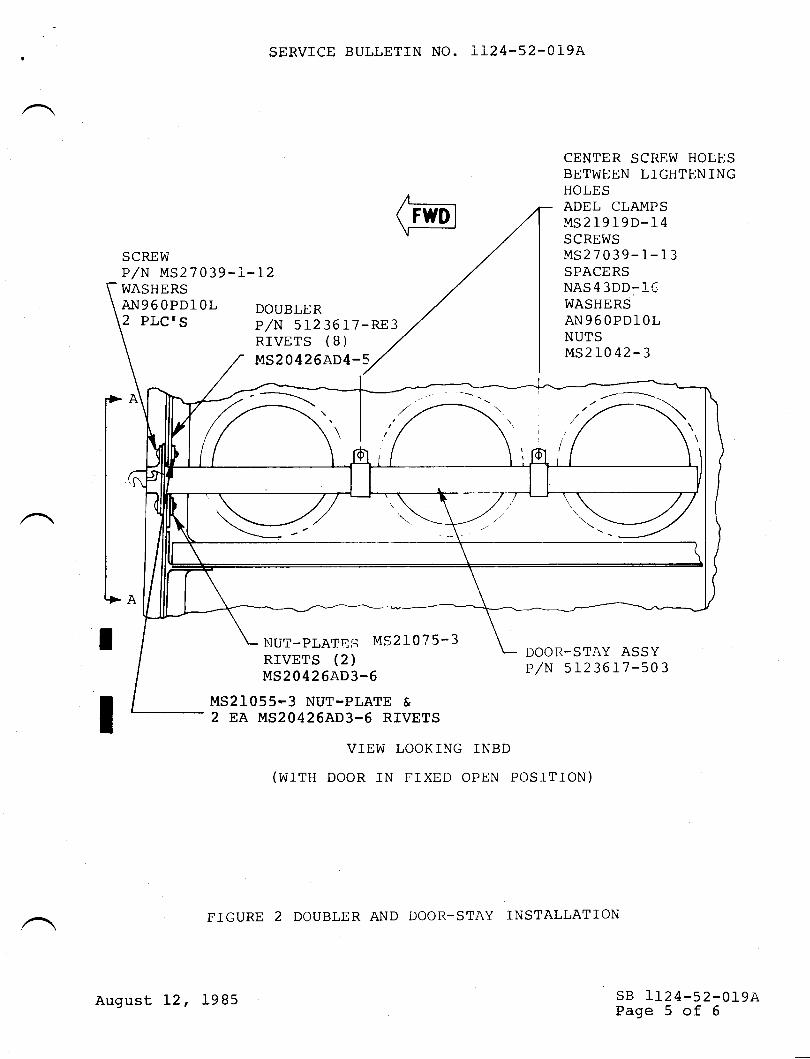
SCREWP/N MS27039-I-I2WASHERSA}J9 6 OPDl OL2 PLCIS
SERVICE BULLETIN NO. Lr24-52-019A
DOUBLERP,/N 5L23617-RE3RIVETS (B)MS20426AD4-5
NUT-PLATES rvls210?5-3RTVETS (2)Nts20426AD3-6
CENTER SCREW HOLESBETWEEN LIGHTENINGHOLESADEL CLAMPSMS21919D-14SCREWSr,4s27039-I-13SPACERSNAS4 3DD-iSWASHERSAN96 OPDIOLNUTSMS2 I0 42-3
DOOR-STAY ASSYP/N 5L23617-503
MS21O55-3 NUT-PLATE &
2 EA NIS2O426AD3-6 RIVETS
VIEW LOOKING INBD
(WTTU DOOR TN ITIXED OPEN POSITION)
FIGURE 2 DOUBLER AND DOOR-STAY INSTALLATION
sB IL24-52-01-9APage 5 of 6
\\/
August L2, 1985

SERVICE BULI,ETIN NO. LL24-52-019A
DOUBLERP/N 5I236I7-RE3
.25
DRILL #30 (B PLACES)THRU DOOR FRAMEAND DOUBLER
125
LOCATE IvtS21055-3NUT-PLATE FROM #TO HOLES
DRII,L #10 (2 PLACES)LOCATE FROM DOOR-STAY ASSEMBLY
DRILL T.I2 INCH DIA.THRU DOUBLER ANDDOOR FRAME.
243 .50
z)LOCATE AND INSTL.5L236I7-RE5 PACKERON DOUBLER AFTERDOUBLER IS LOCATEDWITH MS2O 426AD- 5 RIVET
TEE EXTRUSIONP/u 5333045-I3
24L.20
o.65
f-il,(I
B5
25
IMS?O426AD4-5 RIVETSMS2O426AD3-6 RIVETSM527039-1-12 SCREWS
l_. 50
.0625
DOOR STOP (REF)P/N 5333037-507
LOCATE MS21O75-3NUT-PLATE FROM #10HOLE
DETAIL A-AoU
e
I t:w
3IV
FIGURE
| ,( x)li I N(; n 'l' n I"'t' l,:tx;t,:
DOUBLE AND DOOR-STAY
()t,'IXX)t{
INSTALLATION
SB TL24.52-OI9APaqe 6 of 6 August L2, 1985

SERVICE PUBLICATIONS
re\rision notice
SUB,IECT: Fl{D BAGGAGE DOOR - POSITfVE HOLD-OPEN PROVfSION
OPTIONAT
SERVICE BULLETTN NO. LL24-52.037Revision No.1
MATERIAL INFORMATION
QTY PART: NT'IIBER
June L4, 1985
DESCRIPTION
RetainerAngIeAngle
Cherry Max RivetBlind RivetLockpinCaution DecalStowage DecalCable, Nylon(Carr Lane Mfg. Co. )
those reflected in
REASON FORREVISION: To change five part numbers in paragraph 3.
Material Information.
3.
I ea.I ea.I ea.8 ea.I ea.I ea.1 ea.I ea.I ea.
* Aollilw* A01t{w* A01!{W
* Aollim* A0llill{
These partFigure 1,
5313687-RE553I3587-RE453I3687-RE3cR3243-4-5NAS1739-5-4MSl7986-3255313687-RE75313687-RE9cL-73-KA-5
numbers supersede2 and 3.
sB IL24-52-037Page I of I/
@Wwrmmn*SUgSIOIAFY OF lSRA€L AIRCNAFT INOUSTRIES. LTO
BEX CUR]ON AIRPORT. ISRAEL

THsERvtcE BULLETIIU
OPTIONAL
SERVICE BULLETIN NO. IL24-52-037 May 27, 1985
SUBJECT: FWD BAGGAGE DOOR - POSITIVE HOLD-OPEN PROVTSTOIV
1. PLANNING INFORMATION
A. EFFECTIVITY
ivloDEL LI24/LL24A WESTWINDS, all serial numbers prior to426 except 416, 4L8, 42]- and 423.
B. REASON
To install provisions for positive hold-open of theforward baggage door to ease loading during gusty windconditions.
C. COMPLIANCE
Optional
D. DESCRIPTION
Two angles are installed on the forward baggage doorframe at the upper hinge along with a lock-pin and alock-pin storage bracket.
E. APPROVAL
The modifi-cation described in this Service Bulletin hasbeen shown to comply wtih the applicable ICAA/FAAregulations and is IAI Engineering approved.
/@ IA I st'*## p*t *,!n!!s., *,, n
SUBSIDIARY OF ISRAEL AIRCRAFT INDUSTRIES, LTD.
BEN GURION AIRPORT, ISRAEL
sB LL24-52-037Page 1 of 7

SERVICE BULLETIN NO. TL24-52437
F. MATERIAL
The material required may be obtained through AtlanticAviation Supply Company Wilmington, DE or theirauthorized representatives.
G. TOOLING
None reguired.
H. WEIGHT & BALANCE
Not applicable
I. ELECTRICAL LOAD DATA
Not applicable
J. REFERENCE
None
K. PUBLICATIONS AFFECTED
None
2. ACCOMPLISHMENT INSTRUCTIONS
A. Remove both aircraft battery connectors and externalDC power to aircraft (if installed).
B. Locate and remove eight rivets instarled immediatelyabove and below cut-out for upper hinge (see figure 1).These rivets may be either solid or blindfasteners.
c. using an assistant, observe angle installation on doorframe from inside the forward baggage compartment withbaggage door closed. position angres to door frame, markangles for final fit and trimming that wilr ensureclearance is adequate to door, door hinge bracketry andbracket hardware. Trim only that material necessary toprovide clearance required with door closed.
sB IL24-52-037Pa-ge 2 of 7
May 27 , :l-985

D.
SERVICE BULLETIN r{O. LL24-52-037
NOTE
Install angle with one inch1eg attached to door frameand 3/4" leg used for lockpin.
After final trimming of both angles, dril1 .I44 (#27)hol.es picking up existing fastener holes for attach-ment of angles to door frame with CR 3243-4-5 CherryMax rivets.
Temporarily install angles to door frame with clecos.Locate center of .1875 hole required for lock-pin instal-lation through upper angle, upper door hinge with door infu11y opened positi-on and lower angle (Ref. Figure 3).Dril1 .09325 (3/32") pilot hole through both brackets andupper door hinge. Care must be taken to ensureproper alignment is maintained during drilling process.
Remove angles, drill lock pin pilot holes to final sizeof .1875 (3/L6"). Drill upper door hinge lock-pin pilotl:ole to f inal size of .1875 (3/16") .
Deburr all drilled holes, clean areas to be paintedwith MEK and apply zinc chromate primer to al-l barealuminum surfaces.
Install both angles to door frame using eightCR3243-4-5 Cherry Max fasteners.
Install P/N MS17986-326 loclspin. Fit of lock-pinthrough angles and door hinge should be a slip fit.If necessary, lock-pin holes may be reamed slightly toprovide the best fit.Position lock-pin retainer, p/N S313697-.RE5f nearupper left hand corner of microswitch access pane1.Install channel as shown in Figure 2 | picking upexisting fasteners.
Attach lock-pin lanyard clip to an existing fasteneras shown in figure 2.
Return aircraft to service.
G.
H.
E.
F.
L.
M
I.
J.
K.
sB 1124-52-037Page 3 of 7
May 27, 1985

3. MATERIAI, TNFORMATION
QTY
1 ea.1 €d.I ea.8 ea.1 €€t.1 ea.1 ea.I ea.I ea.
4. RECORD COMPLIANCE
sB L124-52-037Page 4 of 7
SERVICE BULLETIN NO. LL24-52-037
PART NUMBER DESCRIPTION
Make the following entry in the aj-rcraft log book:service Bulletin No. 11"24-52-037, date ir{ay 27, 1945, titled"FwD Baggage Door - positive Hold-open provision, " has beenaccomplished this date
53136 87-RE55313687-RE45313 687-RE3cR3243-4-5NAS1739-5-4MS17986-326.5313587-RE75313687-RE9cL-73-KA-5
RetainerAngleAngle
Cherry Max RivetBlind RivetLockpin
Caution DecalStowage DecalCable, Nylon(Cam Lane Mfg. Co. )
May 27, 1985
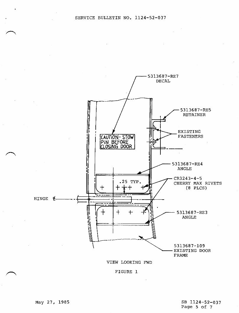
SERVICE BULLETIN NO. TL24-52-037
5313 68 7-RE7DECAL
HINGE (
VTEW LOOKING FWD
FTGURE 1
531_3687-RE5RETAINER
53 136 I 7-RE4ANGLE
cR3 2 4 3-4-5CHERRY MAX RIVETS
(8 PLCS)
531-3 6 8 7-RE3ANGLE
5313687-109EXISTING DOORFRAME
sB 1124-52-037Page 5 of 7
PIN BEFORE
.25 TYP.
+++
May 27, 1985

SERVICE BULLETIN NO. TT24-52.037
53 13 6 97-RE9DECAL
:
MS179 86-326LOCKPIN
cL-7 3-KA-5CABLE
53 136 87-RE4ANGLE
5313687-RE5RETAINER
EXISTINGFASTENERS
NAS1739-5-4BLIND RIVET
II
f vrcw LooKrNG ourBD
--/ L.H. srDE
FIGURE 25313687-RE3ANGLE
sB 1124-52-037Page 6 of 7
_t_I
_t_I
I-t-
May 27, 1995

SERVTCE BULLETIN NO. ].L24.52-037
VIEW LOOKING DOWN - TOP DOOR HINGE
FTGURE 3
5313687-RE4ANGLE
DRILL .1875 (3/L6"',) HOLE THRUTOP AND BOTTOM ANGLES AND DOORHTNGE
sB LL24-52-037Page 7 of 7
May 27, 1985

til}{sEBvrcE BULLET|IU
OPTIONAL
SERVICE BULLETIN NO. 1124-52440 April 22,1992
SUBJECT: DOORS - DOOR HANDLE WARNING SWTICH INSTALLATION ANDIMPROVED DOOR WIRE RETRACT TUBE INSTALLATION (AFC 2068).
1. PLANNING INFORMATION
A. EFFECTryITY
PART AMODEL ll24lL124A WESTWINDS, all serial numbers except 1124 S/N 42t and
subsequent and 1L24A, S/N 436 and subsequent.
PART BMODEL ll24ll124A WESTWINDS, all serial numbers.
B. REASON
PART ATo provide an additional warning switch which will provide cockpit indication ofcabin door handle rotation.
PART BTo install or improve the door wire retract tube installation.
C. DESCRIPTION
PART A of this service bulletin adds a microswitch to the door handle mechanism
that will work in conjunction with the existing cabin door warning system.
PART B of this service bulletin provides instruction to install or improve the door
wire retract tube installation.
AprIL22,830
sB 1124-52-M0Page 1 of20
1992

SERVICE BULLETIN NO. 1124.52.{/;0
i
D. COMPLIANCE
Compliance with this service bulletin is optional.
E. APPROVAL
This service bulletin has been reviewed by the Civil Aviation Adminisfiation ofIsrael (CAAD. The design content herein complies with the applicable CivilAviation Regulations and is CAAI approved.
F. MAN-HOURREQUIREMENTS
The following information is for planning purposes only:
PART A(1) Estimated man-hours: 16(2) Suggested number of personnel: I
PART B(1) Estimated man-hours: 16(2) Suggested number of personnel: 1
The above is an estimate only, based on experienced personnel complying wittr ttrisservice bulletin. It is possible, depending on individuat experience levels, thatadditional or fewer man-hours are required to accomplish this bulletin.
G. MATERI,AL
PART A
OTY. PART NUMBFR DESCRTPTION
4 AN364-832 NUT4 AN525-832-R8 scREw8 AN96O-8 WASHER2 M535206-220 scREw6 MS3533843 wAsnER2 M520427-M4-8 RwET6 MS2t042-3 NUT
sB 1124-52440Page2 of20
April 22,1992

SERVICE BULLETIN NO. LI24-52-MO
OTY.
2
4
2*1,r1
!r1
,r1
*1
1
1
A/R
QTY.
1
1
5
2
1
1
2
1
1
2
3
5
2
A/R210
2
2
I
PART NUMBFR
MS24665-151
MS20470AD-4-XNAS1096-3-21823676-5823676-9823676:7
823676-8823676-13v3-1001JV-2655A113r-20-396-92
DESCRTPTTON
COTTER PINRIVETSCREWCHANNELANGLEANGLEANGLEARMSWITCHACTUATORwrRE (RAYCHEM)OR EQUIVALENT
* Parts for PART A may be locally manufactured. Refer to Figures 4 and 5 forpart details.
PART B
PART NTIMRER
AN3-12AAN970-3AN96OKD-10AN96OKD-4AN96OKD4L6LMS210424MS35&9-242MS35207-281M535207-266MS21919DG12MS27039-1-08MS21042-3MS2528t-2MS35489-134I[|d535206-217
MS20470AD-4-XMS20470AD-5-XMS20470AD-6-XNAS43DD3-24
DFSCRTPTION
BOLTWASHERWASHERWASHERWASHERNUTNUTBOLTBOLTCLAMPBOLTNUTCLAMPGROMMETSCREWRryETRIVETRTVET
SPACER
sB 1124-52440Page 3 of20
April 22, 1992

SERVICE BULLETIN NO. 1124-52440
OTY.
It2t1t1t2t2I2t1f1t1tlA/RA/RA/R
PART NIIMRFR
NAS75-3-26823676-21823676-25
823676-29
823676-33823676-37
823676-39
82367643823676-458236764782367649AMP 326878TY523M OR EQItrV.55A1t3L-20-396-92
DFSCRTPTION
BUSHINGANGLEANGLEBUNGEE ASSYWIRE ASSYPULLEYANGLEDOUBLERFILLERGUARDTUBETERMINALTY-RAPwrRE(RAYCHEM)OR EQUTVALENT
H.
I.
J.
K.
t Parts for PART B may be locally manufactured. Refer to Figure 1l forpart details.
Material required may be obtained through Astra Jet Corporation, New Castle,Delaware, or authorized ASTRA/TVESTWIND Service Centers.
TOOLING
No special tools are required.
WEIGHT AND BALANCE
Not applicable.
ELECTRICAL LOAD DATA
Not applicable.
REFERENCES
LI24/ 1124A Westwind Wiring Manual.lL24l 1124A Westwind Maintenance Manual.
sB 1124-52-040Page 4 of 20
April 22, l9Y2

SERVICE BULLETIN NO. IT24-52.'MO
L. PUBLICATIONS AFFECTED
Il24lll24A Westwind Maintenance Manual, Chapters 52-10-00 and 52-70-00, willbe revised to reflect the rigging and checkout procedures of the cabin door handle
warning switch.
lI24ll124A Westwind Illustrated Parts Catalog, Chapter 52-70-00, has been revised
to reflect all parts installed by this service bulletin.
ll24tl124A Westwind Wiring Manual, Chapter 33-50-01.
2. ACCOMPLISHMENTINSTRUCTIONS
PART A - Door Handle Warning Switch Installation
1. Insure that battery and external power switches are off and pull the 'DOOR WARN'circuit breaker.
2. Remove interior furnishings from cabin door to facilitate access to door handle
mechanism.
3. Refer to chapter 52 in the ll24lL124A Westwind Maintenance Manual and remove the
cabin door assembly from the aircraft. Note the quantity and location of any shimswhich may be installed at the hinge points to aid in reassembly and rigging.
4. Mark the position of the hub crank with relation to the spindle. Disconnect forwardand aft rod assemblies from the hub crank. Disconnect ttre upper and lower controlassemblies from the hub crank. Remove bolt securing hub crank to spindle and
withdraw spindle from hub crank far enough to facilitate removal of hub crank fromdoor.
5. Install arm P/N 823676-13 to hub crank as illustrated in Figure 1.
6. Install P/N 823676-5 channel and P/N 823676-7 and P/N 823616-8 angles. Afterfitting and drilling, mount to existing channel as illustrated in Figures 1 and 2.
7. Assemble switch P/N V3-1001, actuator P/N JV-26, and shim to angle PIN 823676-9.Locate the angle/switch assembly to P/N 823676-5 channel as illustrated in Figure 1.
8. Reinstall hub crank to spindle and connect upper and lower control assemblies and the
forward and aft rod assemblies to the hub crank, using previously removedhardware.
sB 1124-52440Page 5 of 20
April22, 1992

SERVICE BULLETIN NO. 1124-52-UO
9. Adjust the switch so that it is actuated when the door handle completes its rotation tothe closed position. Allow .010 clearance of actuating arm to switch body so as notto damage the switch. Fore and aft switch adjustment can be made by looseningscrews retaining switch to P/N 823676-9 angle. Up and down adjustment can beaccomplished with P/N NAS 1096-3-21screws. Using an ohmmeter, verifyelectrical adjustment of switch. Insure all switch mounting hardware is secure.
NOTE: This switch is installed in parallel with existing door warning circuit anddoes not cancel existing switch function.
10. On aircraft not equipped with bar lighting, install wire retract tube assembly inaccordance with PART B.
11. On aircraft equipped with bar lighting, remove existing wires and install new wireusing P/N 55A113l-20-396-92 (Raychem) or equivalent wire. Secure new wire inthe same manner that the removed wire was secured.
NOTE: If desired, the improved wire retract tube assembly described in PART B,should be installed before installing door on aircraft.
12. Install cabin door on aircraft. (Reference lI24lll24A Westrvind MaintenanceManual, Chapter 52.)
13. Install and connect wiring from door handle warning switch to existing door warningswitch circuit as per Figure 3.
14. Isolate bar light wires if installed to prevent short circuit. Apply elecrical power toaircraft. Close 'DOOR WARN. circuit breaker. Perform operation check of dooroperating mechanism and "DOOR WARN" system as per ll24lLLz4|WestrvindMaintenance Manual, Chapters 52-10-00 and 52-70{0, Inspection, and check.
15. Re-install interior furnishings on cabin door.
16. Return aircraft to service.
PART B - Improved Door Wire Retract Thbe Assembly
1. Remove cabin door in accordance with pART A steps r,2 and3.
2. Remove existing wire retract tube assembly.
3. Install improved wire retract tube assembly in accordance with Figures 6, 7 , B, gand 10.
sB l124-52440Page 6 of20
April 22,1992

SERVICE BULLETIN NO. 1124-52-MO
4. Install cabin door in accordance with PART A steps 12, 13,15 and 16.
3. RECORD COMPLIANCE
A. Make the following entry in the aircraft log book:
Service Bulletin 1124-52-040, dated April 22, 1992, titled "Doors - Door HandleWarning Switch Installation and Improved Door Wire Retract Tube Installation(AFC 2068),' has been accomplished this date
B. Revise the lI24ll124A Westwind Wiring Diagram Manual as per Figure 4 of thisservice bulletin to reflect the changes made by this service bulletin.
C. Complete the attached Certificate of Compliance and return to Astra Jet Corporationin Wilmington, Delaware.
sB 1124-52440PageT of 20
April 22, t992


a,
823676-5CHANNEL
SERVICE BULLETIN NO. II24-52-MO
#[
AFT
tI
823676-8ANGLE
(oPP. 0F -7)
DOOR, OUTER
sKrN (REF. )
823676-7ANGLEIN'BD.----l
AN525-832-R8 SCREW OR MS2O47OAD4.X (TYP. 4 PLC'S)
AN364-832 NUTAN96O-8 WASHER (2)(TYP. 4 PLC'S}
SECTION A-A
(nrr. FIGURE I )
sB 1124-52-040
Page 9 of 20
April 22, 1992
FIGURE 2

SERVICE BULLETIN NO. 1124-52-0/;0
xxI
o^Ot!sr !Jtll El\v
=(J
-c)Flrj -J=aa
z.<(JT. Z,
EZ.oEo<o=
\o(\=
I
5l
:t3l
I
z.N
\oN
=
I
I
l,_
l'zo<\\o(\l
=
xxI
S LrJ
=
lrlE
frJ (J&,2;F
tn=utxZ lrl
-c)F
=.J1
<5z.Fan
xlrJ
a=z=z.ado-u\=lt! onc)z.EIJ.J UJe.Ft! o-u<lrl -&, a)
(\L:ZOLn
N
=
c!TtJ\N
sB 1124-52-040Page 10 of20
Jco
N(J\oN
=
-=oN(J\oC\l
=
April22, 1992
FIGURE 3

SERVICE BULLETIN NO. I124-52-UO
.25 x 450-.TYP(4PLcs)m
t-, ,o-J
.190 DrA.
. ie4 (TYP)
DETAIL P/N 823676-5 CHANNELMFG. FRoM ANDI o't37-2oo4 2024-T3s1r AA
.z5x.z5 ru(TYPE + ptcs) -
f*1''oir-( rti'rJf 1'05
/ so (rvp)
DETAIL P/N 823676-7 ANGLE-8 ANGLE OPPOSITE
MFG. FRoM AND10134-1201 2024-Tssr r 7\[
2\ rrrursn wtrH Epoxy eRIMER
I rtrrrtsH: cHRoMrc AcrD ANoDrzE pER MIL-A-8625E
PART DETAILSFIGURE 4
DETAIL SHIM (REF FIGURE 1)MFG. FROM .125" 2024-rgA
sB 1124-52-040Page 11 of20
April 22, 1992

-'-l
1. 10
SERVICE BULLETIN NO. 1124-52ry0
.25 DIA.TYP
1.50-l .25
--J--T
.60
.10 "-ox +3-
t.40
T-
DETAIL P/N 823676-'13 ARMMFG. FROM ,080" 2024-0 CLADA
HEAT TREAT TOT42 AFTER FORMING
I rrrursn wrrH Epoxy pRtMER
I rrrursn: cHRoMlc ActD ANoDtzE pER MIL-A-8625E
PART DETAIISFIGURE 5
DETAIL PN 823676-9 ANGLEMFG. FROM AND10134-1 407 2024-T3511 AA
SHOWN ACTUAL SIZEUSE AS TEMPLATE
sB 1124-52-040Paee 12 of 20
.20 TYP
.il3-..|.l6TYP (FULL RADIUS)
BEND DOWN900 x .16R
Apri|22, 1992

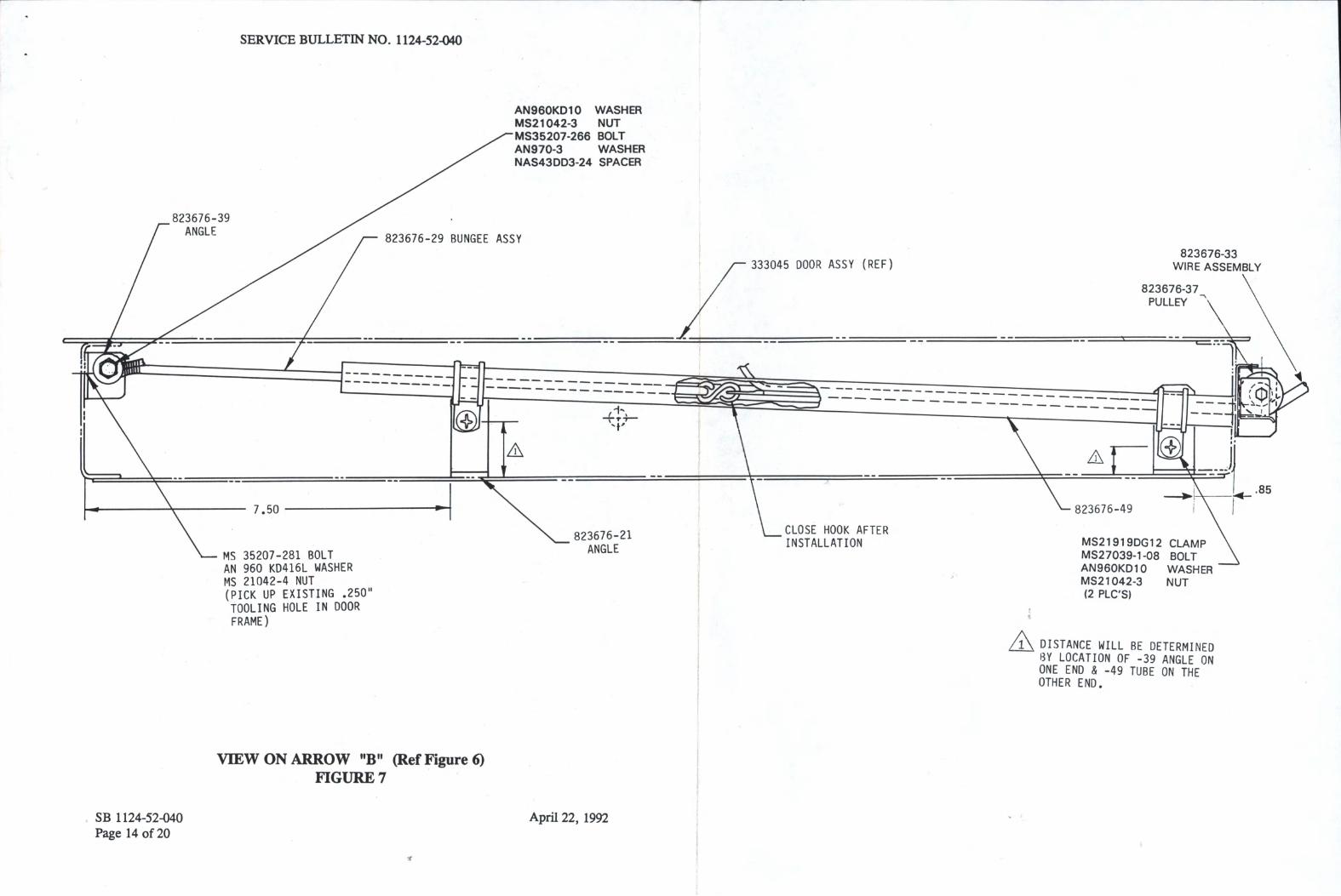

SERVICE BULLETIN NO. 1124-52{p;0
D00R (REF)
823676-43DOUBLER (SEE FIG.9 FOR
INSTALLATION)
EXISTiNG HOLE
UP
NAS 75-3-26 BUSHINGAN96OKDlO WASHERAN3-12A BOLTMS21042-3 NUT
I 82367 6-37PULLE Y.780" DIA HOLE
(REF)
823676-47GUARD
SECTION C - C
REF FIG 6
823676-47GUARD
.500"
MS2O47OAD6r?t\/ET (2 PLCS)
t)2367 6-39ANGL E
823676-39 ANGLE
823676.37 PULLEY
823676-33 DRAW t^JIRE ASSY.(MAt NTAt N .050" CLEARANCEBETWEEN DRAW I/IRE AND GUARD)
VIEW ON ARROW F
REF SEC C.C ABOVE
sB 1124-52-040Page i5 of20
April 22, 1992
FIGT]RE 8

SERVICE BULLETIN NO. 1124-52ry0
\--"
D00R STOP (REF)
F[,JD D00R FRAME (REF)
MS2047OAD5RTVET (3 PLCS)1 .65" .350" TYP
PICK UP EXISTINGFASTENERS
TYP 3 PLCS
.500" DI
EXiSTING HOLT THROUGH
DOOR FRAME ONLY
FRAME )
.950".250"
INNER FACE OF DOOR
MS2O426AD4-XRIVET
WHERE TUBE AND HOLE EXISTIN DOOR FRAME, REMOVE AND-DISCARD EXISTING TUBE ANDINSTALL 82367 6.45 FILLER
6;):--ln
.780'' DIA HOLE THROUGH
DOOR FRAME AND DOUBLER
2qn Q
TYP 4 P LCS
sT0P (REF)DOOR
AA
FINISH: EPOXY PRIMER PER MIL-P-23377P/N 823676-43 DOUBLER - Mfg. from .050" 2024T3 CLAD
I nru 834676-45 FTLLER - Mfs.from .050" 2024T3 CLAD
A FINISH: CONVERSION COATING PER M|L-C-5S41
VIEW D - D (Ref Figure 6)FIGURE 9
sB 1124-52-040Page 16 of20
n n ^8?3676-43 DOUBLER
AAA(INSTALL ON INSIDE SURFACE
OF DOOR
MS 204 7OAD4
RIVET
823676-45 FILLERAAA
/J\
++[-'\
\\*'-
MS20470AD6
April 22, 1992

SERVICE BULLETIN NO. I T24-52.t/;O
BULKHD REF.
MS2528I.2 CLAMP
MS2047OAD4
MSs3206-217 SCREl^l
AN96OKD4 WASHTR
MS35649-242 NUT(2 REQD)
VIBW ON ARROW IIETI
FIGT]RE 10
82367 6-25ANGLE
sB 1124-52440Page 17 of20
April 22, 1992
(Ref Figure 6)

SERVICE BULLETIN NO. 1124-52ry0
.20 x 450TYP.
T-75"
1_
1.7s'-l
l.-r0" -l
.20 x 450TYP.
[- 1'0"
.25 X 450
sB 1124-52-040Page 18 of20
:1DETAIL P/N 823676.21 ANGLE
MFG. FROM ANDl0134-1 602 2024-T3511 aa
DETAIL P/N 823676-25 ANGLEMFG. FROM AND10134-2003 2024'13511 aa
DETAIL P/N 823676-39 ANGLE TYP.
MFG. FROM ANDl0133-1 002 2024-T3511 aa
PART DETAII.SFIGTJRE 11 (SIIEET 1 OF 3)
^
April 22, 1992

SERVICE BULLETIN NO. 1124-52.U0
.340" DrA. HOLE
1.10" DIA
.18"TYP.
.190'RAD
["'l .12'RAD.
DETAIL P/N 823676.37 PULLEY
MFG. FROM 1.50" DIA
NYLON 6/6 SPEC. L.P-410 RODDETAIL P/N 823676-47 GUARD
MFG. FROM .050" 2024'0 CIAD
HEAT TREAT TOT42 AFTER FORMING
9.75"
DETAIL P/N 823676-29 BUNGEE ASSEMBLY
MFG. FROM 3/16" DIA. ELASTIC CORD
wPE lll MIL-C-5651D
F]NISH WITH EPOXY PRIMER PER MIL-P-23377
CLOSE HOOK AFTER ASSEMBLY
WRAP AND SEAL BUNGEE ENDS USING STANDARD SHOP PRACTICES
FINISH: CHROMIC ACID ANODIZE PER MIL-A-8625E
FINISH: CONVERSION COATING PER MIL€-S544
PART DETAII-SFTGURE 11 (SITEET 2 OF 3)
AA
.50'MAX(TYP)
MS87006-3"s" HooK
.30" DIA
sB 1124-52-040Page 19 of20
April 22, 1992


-.{m
rt-{1'mt'noI-{o?t)m
om+.Itm
-{q,o-.t-{oF.Tl
ot-.9am
t-
zo
r
Sentice tsuffetin
C ertificaa of C omp frarrce
PLEASE FILL IN THE REOUIRED DATA BELOW AND RETURN TO:
Technical PublicationsAstra Jet Corporation278 Ouigley BoulevardNew Castfe, DE 19720
This is to certify that WESTWIND Serial Number_ has complied withService Bulletin No.
1124-52-040
Aircraft Registration No.
Airframe Total Time at Compliance: Hours_ Cycleq
Compliance Date: _ By:Signature
Accomplishing Agency:
Please describe below any discrepancies found or difficulties encounteredduring compliance:

THSEByIc'E BULLETTTU
OPTIONAL
SERVICE BULLETIN NO. IL24-53-026 April 18, 1985
SUBJECT: CLOSURE OF TAIL CONE VENT HOLES
I. PLANNING INFORMATION
A. EFFECTIVITY
MODEL LL24/LL24A wESTwrND, all seriar numbers prior to426, except 4L3t 4L6t ALgt 42L, 423 and. 424.
REASON
To reduce excesslve alrflow to electronle equlpment.To ellmlnate the collectlon of rain water and/ormolshure ln the tal1 cone area.
COMPLIANCE
At the operators dlscretion.DESCRIPTION
rt has become evldent that the vent holes located on theleft and rlght slde of the ta1I cone assembly are notneeessary and that they are a source of tsaln or washwater entry. This servlce bulletln provides instructionsfor the approved method of closing these vent holes.APPROVAL
The modlflcatlon procedure descrlbed 1n thls servlcebul1et1n has been shown to comply wlth the appllcableICAA,/FAA regulatlons and 1s IAI Englneerlng approved.
a
tt
D.
tr
/
@ lill txrx*m** !,!Y;.,*,,*
SUBSIDIARY OF ISRAEL AIRCRAFT INDUSTRIES, LTD.BEN GURION AIRPORT, ISRAEL
sB LL24-53-026Page I of 4

F.
SERVICE BULLETIN NO. tL24-53-026
MATERIAL
Material required may be obtained through AtlanticAviation Supply Company, through their authorizeddealers or may be locally purchased.
TOOLING
None required.
WEIGHT & BALANCE
Not applicable.
ELECTRICAL LOAD DATA
Not applicable.
REFERENCES
None
PUBLTCATIONS AFFECTED
None
Prepare outside surface of tail cone assembly by sandingpaint from the vent hole pattern area. ereplre insidesurface by cleaning area where plate is to be installed.Remove baffle plate from vent hole area if installed.Position plates over the vent holes on inside surface oftail cone (Figure 1). Dril1 #40 holes in tail cone toalign with holes in prate. Remove burrs from ho1es7brush Alodine and apply zJ-nc chromate.
G.
H.
I.
J.
K.
2. ACCOMPLI SHMENT INSTRUCTTONS
A. Remove tail cone assembly from the aircraft inaccordance with estabrished maintenance procedures.Disconnect wiring to tail light assembly.
B. Fabricate two prates per Figure 1 dimensions and materialspecifications. Dril1 No. 40 holes in each plate asshown in Figure 1 using standard shop practice for properspacing and edge distance. Remove buris from holes,brush Alodine and apply zinc chromate.
c.
D.
sB LI24-53-026Page 2 of 4
April 18, 1995

SERVICE BULLETIN NO. 1124-53-026
E. Firl vent holes with epoxy and sand smooth. Touch up orrepaint tail cone assembly as required.
F. Reconnect tail light, wiring and reinstarl tair coneassembly.
3. MATERIAL INFORMATION
MS20426AD-3-4 Rivets
No. 01175
Plate, (See Fig.1for details)
Epoxy-WhiteLightnin I
Marson Corp.130 Cresent Ave.Chelsea, MA 02150
(or equivalent)4. RECORD COMPLTANCE
Make the following entry in the aircraft 1og as follows:Service Bulletin No. 1124-53-025 dated April 18, 1985, titled"closure of Tail cone vent Holes'f has been accomplished thisdate
END
QTY
A/R
2
1 QT.
PART NUMBER DESCRIPTTON
sB LL24-53- 926Page 3 of 4
April 18, 1985

SERVICE BULLETIN NO. IL24-53.026
Number 40 dril1pilot holeseighteen places
sB LL24-s3- 026Page 4 of 4
MS 2O42GAD-4(18 places)
Section View
CLOSURE OF TATL CONE
FTGURE 1
PLATE.040 Thick2O24T3 Aluminum
Plate
Vent holesepoxy
Plate
fiIled with
.-- i- * \1r o r\
".* ffi -t,
trt ,rt-,^,t,\ y\t\* ',il,lil, rtt\r* ',i1,*,,.u
"\yr .'i'F + 1
rt -o. A\
,1,':--19-'
Tail ConeProfi 1e
oooooo
oooooooo
VENT HOLES
April 18, 1985

TTTISERyI,CE BULLETTTU
OPTIONAL
SERVICE BULLETIN NO. LL24-53-068
SUBJECT: DOORS NOSE GEAR TRUNNION ACCESS
February 5, 1985
DOOR INSTALLATION
1. PLANNING INFORMATION
A. EFFECTIVITY
MoDEL LL24/LL24A wEsrwrNDs, all serial numbers.
B. REASON
To facilitate accesspoints.
C. COMPLIANCE
Conpliance with this
D. DESCRIPTTON
to nose landing gear trunnion grease
SUBSIDIARY OF ISRAEL AIRCRAFT INDUSTRIES, LTD,
BEN GURION AIRPORT, ISRAEL
E.
service bulletin is optional.
Tr,ro access doors are installed on the fuselage t,/tt and R/Hsides in the nose landing gear trunnion area.
APPROVAL
This service bulletin has been reviewed by t,he Israel CiviIAviation Administration (ICAA). The design contentconveyed herein complies wit,h the applicable CiviI AviationRegulations and is ICAA approved.
T\,TATERIAL
Material required for this service bulletin may be obtainedfrom Atlantic Aviation Supply Company, Wilmington, Delawareor their authorized dealers.
/@ fr I grmg lgvn* tts;- *.,, *
sB I124-53-058Page I of 7
F.

G.
SERVICE BULLETIN NO. 1124-53-068
TOOLING
No special tooling required.
WEIGIIT AND BALANCE
Not applicable.
ELECTRICAL LOAD DATA
Not applicable.
REFERENCE
None.
K. PUBLICATIONS AFFECTED
LL24 Maintenance ManualLL24 Illustrated parts Catalog
ACCOMPLISHI{ENT INSTRUCTIONS
A. Gain access to nose randing gear area by removing theradome.
B. cut access hole in L/H fuserage skin and radius corners.R/A installation typicat unleis otherwise noted. (Refer toFigure l. )
c. Using Figure I as a guide, fabricate doublers p,/NcMA7r518-50r-5 out of 2024-0 cond .050 thick clad, doorsP,/N CMA7151g-501-7 and fillers p,/N cMA7151g-501-g out of2024-T3 .050 thick cladr parts shatl be true alongcontour. Doublers to be heat treated 305-3g5oF for 16hours to T42. Alodine doublers, firrers and doors. paintwith epoxy primer.
rnstall doubrer, hinge and firler. Hinge pin to be peenedbefore installation. Refer to Figure r through 3, picking!p existing rivets on forward edge. using ttrit as i guidefol rivet spacing, drirr and countersink iemaining holesand install Msr42rgAD4 rivets, using standard shoppractices and complete installation.
IT.
I.
J.
2.
D.
E. Install latches on door in two places, drill andcountersink hores and instalr Ms20426AD3 rivets.Figure l. )
F. Install door on hinge assembly, drilland install MS20426AD4 rivets. (Refer
sB tl24-53-068Page 2 of 7
(Refer to
and countersink holesto Figure l. )
February 5r l9g6
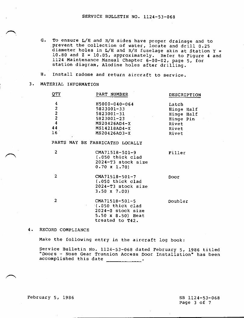
3.
SERVICE BULLETIN NO. TL24-53-068
G. To ensure L/H and R/H sides have proper drainage and toprevent the corlection of water, locate and drirl 0.25diameter holes in L/lt and R/H fuselage skin at station y =r0.90 and I = 10.05, approximately. Refer to Figure 4 andLL24 lt{aintenance Manuar chapter 6-00-02, page 5, forstation diagramr Alodine holes after drilling.
H. Install radome and return aircraft to service.MATERIAL INFORI'TATION
PART NUMBER DESCRIPTIONQTY
42224
4415
PARTS II{AY BE
2
H50 00-04 0-0 6 45823001-33582300I-315823001-23MS20 426AD4-XMSI4218AD4-XMS20426AD3-X
FABRICATED LOCALLY
cMA7t518-501-9(.050 thick clad2024-T3 stock size0.70 x 1.70)
cMA715I8-501-7(.050 thick clad2024-13 stock size3.50 x 7.00)
cMA71518-501-5'( .050 thick clad2024-0 stock size5.50 x 8.50) Heattreated to T42.
LatchHinge HalfHinge HalfHinge PinRivetRivetRive t
Fi lle r
Door
Doubler
4. RECORD COMPLIANCE
t'lake the following entry in the aircraf t log book:
Service Bulletin No. LL24-53-068 dated February 5r 1986 titled"Doors Nose Gear Trunnion Access Door Installation" has beenaccomplished this date
sB LL24-53-058Page 3 of 7
February 5 t 1986

Y = 14.850 Y = 10.000
'..._ *__Ji I
I4-{ i
/-.,;.4--,i./ f I l-fl r
i I r'f,-'-'ir:'i
|'-.-:i"*'- -hj"tv \"-.-J.''" /\-
- -t- lt-
Z= 17.0e0
+ -'E
SERVICE BULLETIN NO. LT24-53-068
NOTE:
DOUBLER AND DOOR
TO MATCH AIRCRAFTSKIN CONTOUR
l=26.400
cMA71518-501 -7DOOR
0.75 TRUE
/ ^rur-,
sPAcrNGAPPROX AS SHOI.IN
VI EI.I LOOKI NG I NBOARD L. H. SI DE
NORi"IAL TO SKIN
ACCESS DOOR INSTALLATION - LH SHOWN RH OPPOSITE
FIGURE 1
.30 TRUEI
I
II
3. 16
hSoF ITRUEIi
tl70 ll)tl
rE ilil irli,
I C0NToUR
6.00 |TRUE IAL0N6 I
CONTOUR I
CMAT 1518-501-5DOUBLER
O47R TRUETYP 4 PLCS
H5000-040-064LATCH (2 PLCS)
O.05 CONSTANT GAP
BETWEEN DOOR AND
SKI N
PICK UP EXISTINGRIVET THUS +
(sEE Frc.2)
Bf-
MS2O426AD4-XRIVET (2 PLCS)
5823001-3iHINGE HALF
CMAT 15 18-50 1 -9FI LLER
582300 1 -33HINGE HALF
GREASING POINT REF
O.7OR TRUE
TYP (4 PLCS)
JOGGL E
U.UJ X Zf
0.75R TRUE
TYP 4 PLCS
0.28 TYP 0.75 TRUETRUE
I
8.06TRUE
ALONG
CONTOUR
I
I4I+i
L
FUSELAGE SKIN REF
1.5R TRUE
TYP 4 PLCS
sB LL24-53-058Page 4 of 7
February 5, 1985

3273008 FITTINGREFERENCE
GREASE POINTREFERENCE
5823001 -33HINGE HALF
582300.| -23HINGE PIN
DOUBLER
FI LLER
SERVICE BULLETIN NO. 1124-53-05B
SECTION B-B
-
FIGURE 2
DOUBLER
DOOR
sB 1124-53-068Page 5 of 7
February 5, 1986

SERVICE BULLETTN NO. 1124-53-058
I
VIEIJ L0OKING AFT 0N Y=14.85
H5000-040-064LATCH 2 PLCS
5823001 -33HINGE HALF
7=17.090
DOOR REFERENCE
FUSELAGE SKIN REFERENCE
DOUBLER
sB II24-53-068PaEe 6 of 7
FIGURE 3
February 5, 19g6

SERVICE BULLETIN NO. LL24-53-068
FOR
DRAIN
t\l'l
ll .
Jr,ol\t/
DOOR LOCATIONR/H
I NS PECT I ON
HOLES
DOOR LOCATION L/H
LOCATION OF DR.AINHoLE L/'H
/SEE DETAILLOCATION OFHOLE R/H X = 9.30
FUS. SKIN
0.25 DIA HOLEIN SKIN
= 10.000
0.5"
O.5" REFERENCE
DETAIL IICII
VIEW LOOKING AFT ON STA Y=10.OOO(RH SH0WN LH oPPCSITE)
sB II24_53_o6sPage 7 of 7
X = 9.00
a*--E
February 5, 19g6FI G'JRE 4
SECTION A-A

9eo,aio" %al/otdnA/ C sjlN
Ge+,tiftoate "/ Go rn/oliatmoe
PLEASE FILL IN THE REQUIRED DATA BELOIII AND RETURN TO:
ISRAEL AIRCRAFT INDUSTRIES INTERNATIONAT, INC.P.O. BOX 10096 )
WILIVIINGTON, DE 19 8 5 0ATTN: TECHNICAL PUBLICATIONS
This is to certi fy that l{estl{ind serial Nunber- has compl iedwith Service Bulletin No. ttZ4-53_06g
Aircraft Registration No.
Airframe Total Time at Conpliance HOURS Z /CYCLES:
Compliance Date
OIVNER:
BySignature
ACCOMPLISHING AGENC\- :
Please describe belorv any discrepancies found or difficultiesencountered during compliance:

L,
TWT
sERyrcE BULLETTN
SUBJECT: FUSEI-AGE . ENLARGE EXISTING WING ATTACHMENT ACCESSHOLES IN THE AFT PRESSURE BULKHEAD AT FUSEI-AGESTATTON 269.879 FOR STRUCTURAL TNSPECTTON (AFC 2075).
L. PLANNINGINFORMATION
A. EFFECTIWTY
Model 1124 I ll24 A Westwind, all serial numbers.
B. REASON
To provide access for'non-destructive testing of the wing attachment fittingslocated at the aft pressure bulkhead sta269.879.
C. DESCRIPTION
This service bulletin provides instructions for fabricating the parts and enlargingthe four wing attachment fitting access holes to enable access to the fittings fornon-destructive testing.
D. COMPLIANCE
Compliance is recommended prior to the next scheduled structural non-destructive testing of the wing attachment fittings.
RECOMMENDED
SERVICE BULLETIN NO. 1124.53.T01
March 7,19901018
March 7,1990
sB 1124-53-101Page L of8

SERVICE BULLETIN NO. II24-53.IOL
E. APPROVAL
This service bulletin has been reviewed by the Civil Aviation Administration ofIsrael (CAAI). The design content herein complies with the applicable CivilAviation Regulations and is CAAI approved.
F. MAN-HOURREQUIREMENTS
The following information is for planning purposes only:
(1) Estimated man-hours:35 hours
(2) Suggested number of personnel:2
The above is an estimate only, based on experienced personnel complying withthis service bulletin.It is possible, depending on individual experience levels, thatadditional or fewer man-hours are required to accomplish this bulletin.
G. MATERIAL
O1-Y. PART NUMRFR NFSCRIPTION
A/R .050"20248 clad AluminumA/R Thickness NR2024B clad Aluminum (Shim Material)36 MS21069-13 Nutplates4 MS21073-I3 Nutplates40 MS27039-0808 Screws
40 AN960-D10 WashersLZ CCR274SS3-2 Rivets68 MS20426AD3 RivetsA/R MILC-5541 AlodineA/R Zinc chromate primerA/R PRL422B2 Sealant
The material required to accomplish this service bulletin maybe procurred locally.
H. TOOLING
Sheet metal equipment.
t.:,
P
sB 1124-53-101Page2 of 8
March 7,1990

SERVICE BULLETIN NO. II24-53-IO1
L WEIGI{TAND BAI-ANCE
Not applicable.
J. ELECTRICALLOAD DATA
Not applicable.
K. REFERENCES
1,1241 lL24A Westwind Maintenance Manual.
L. PUBLICATIONSAFFECTED
None.
2. ACCOMPLISHMENTINSTRUCTIONS
NOTE: All reworked areas and parts fabricated from2024T3 clad are to betreated with MIL-C-5541 alodine and coated with zinc chromate primer.
A. Gain access to the forward side of the aft pressure bulkhead at fuselage station269.879 by removing the interior furnishings as required. Reference the1, 124 | 1,124 A Westurind Maintenance Manual, Chapter 25-00-00.
B. Remove and save the insulating material from the pressure bulkhead as required togain access to the area to be reworked. Refer to Figure 1.
C. l-ocate four existing2.0" diameter wing attachment access hole covers PA.{313235-69.
(1) Remove and discard the four existing covers.
(2) Mark a3.20" diameter circle equi-distant around the four 2.0" diameter holes.Refer to Figure 2.
(3) Enlarge the holes to3.20" diameter. Refer to Figure 2. Smooth the edges andremove all burrs and scratches with #240 grit paper.
sB 1124-53-101Page 3 of 8
March 7,1990

D.
SERVICE BULLETIN NO. 1124-53-101
Remove the following rivets from the left and right side of the aft pressurebulkhead and enlarge the existing 16 holes to.190'-.194" diameteiaccording toFigure 2:
(1) three rivets from left and right rivet row atz 4g" reference.
(2) four rivets from left and right rivet row atz37.5', reference.
(3) one rivet from the left and right angle outboard of the upper access holes attheZ 46" reference.
For aircraft that have doublers on the forward side of the pressure bulkhead abovethe upper access holes, fabricate two shims, p/lrls 31323S-ifpS and _RE6, from2024T3 clad aluminum, same thickness as the doublers, according to Figures 2and 3. Install shims and nutplates per the instructions in Figure ias foliows:
(1) Clamp the PA'{s 313235-RE5 and -RE6 shims to the pressure bulkhead at theirrespective upper access holes.
(2) L"ocate and mark rivet and screw holes for the nine MS21069-13 and oneMS21073-I3 nutplates each side.
(3) Drill the holes for the nutplate rivets to.093"-.097" diameter and the nutplatescrew holes to .190"-.194" diameter.
Countersink the rivet holes to 100 degrees.
Remove all burrs. Treat reworked areas with alodine and coat with zincchromate primer.
(6) Assemble shims PA'{s 313235-RE5 and -RE6 and nutplates p6.{s MS21069-IJand MS21073-I3 to the pressure bulkhead with MS204Z6AD3rivets andCCR274SS3-2 blind rivets according to Figure 2.
F' Repeat steps F.(2), (3), (4) and (5) to prepare the lower access holes on all aircrafrand the upper access holes on aircrafiwithout doublers for the nutplateinstallation. Refer to Figure 2.
(1) Assemble nutplates P/lVs MS2106g-13 and MS21073-l3to the upper accessholes as required with MS2ft26AD3rivets and ccR274SS3-2 blind rivets.
a
E.
(4)
(s)
sB 1124-53-101Page 4 of8
March 7,1990

:SERVICE BULLETIN NO. II24-53.IOI
(2) Assemble nutplates PA.{s MS21069-I3 and MS21073-13 to the lower access
holes of all aircraft with MS20426AD3 rivets.
G. Fabricate covers PA.{s 313235-RE1, -RE2, -RE3 and -RE4 from.050" 2024T3 clad
aluminum. Drill screw attach holes.190'-.194" diameter according to Figures 2
and 3. Smooth all edges, remove all burrs, treat with alodine, and coat with zinc
chromate primer.
H. Install covers with PA.{ MS27039-0808 screws.
I. Seal fraying surfaces of shims (if installed), covers and screw heads with PR142282.
J. Install the insulating material that was removed in Step 2.B.
K. Install the interior furnishings that were removed in Step 2.A Reference thell24l Ll24 AWestrvind Maintenance Manual.
3. RECORD COMPLIANCE
A. Make the following entry in the aircraft log book:
Service Bulletin 1124-53-101, dated March 7,lgg0,titled "Fuselage - EnlargeExisting Wing Attachment Access Holes in the Aft Pressure Bulkhead at
Fuselage Station 269.879," has been accomplished this date
B. Complete the attached Certificate of Compliance and return to Astra JetCorporation in Wilmington, Delaware.
sB 1124-53-101Page 5 of 8
March 7,1990

SERVICE BULLETIN NO. 1124.53.101
WPICAL BOTH SIDES
AFT PRESSURIZED BULKHEAD ASSEMBLYVIEW - LOOKING AFT
sTA 269.879
-
TYPICAL BOTH
SIDES
Z=37.5"TYPICAL BOTHSIDES
sB 1124-53-101Page 6 of8
Figure 1
March 7,1990

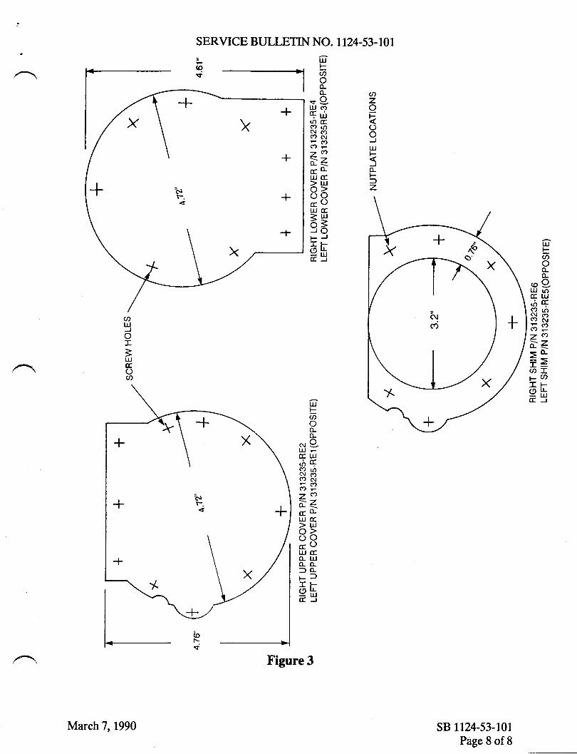
U)zIF
oo)UJF5(LF=z
SERVICE BULLETIN NO. 1T24.53.101
oFao(L(L
.f9llJ cf)qurto o:(t u)c{ ct(?) Al
7e)i<c(LttJ cc>t!o>ooE()TIJ (r> lLj-'-=JOpJ:CFehE.J
oFao(L(L
@gtlj rr,(rIU,oqq)loi;R6P7€);-z<o-
==O:T1- u)-FehCEJut
Faon
Ngtu-(r uJ,A cc{2 roSR6:7t).<oc(LuJ cr> LrJo>ooccoI,IJ (r(Lru(L(Ll(Lp):E F-ehccJ
sB 1124-53-101Page 8 of 8
-f
-Alr-.
atu)ox=tlJccOa
Figure 3
March 7,1990

-.tm
,,+'omf,.Tl
of,{o?f,m
om/\-{Tm
-{(Do{-'to.<'nor-0U)m
t-
zo3r
9oooioe Sallotdn A/C S/N
Geotifi ooto o/ Gon/o l,iarooo
PLEASE FILL IN THE REQUIRED DATA BELOW AND RETURN TO:
ISMEL AIRCRAFT INDUSTRIES INTERNATIONAL, INC.P.0. BOx 10086WILI'IINGTON, DE 19850ATTN: TECHNICAL PUBTICATIONS
This is to certify that tilestwind Serial Nunber-has conpliedwith Service Bulletin No.
1124-53-101
Aircraft Registration No.
Airframe Total Time at Cornpliance HoURS: /CYCLES:
Conpliance Date
OIIINER:
BySlgnature
ACCOMPLISHING AGENCY:
Please describe below any discrepancies found or difficultiesencountered during compliance :
,/'
Til?{
sErY,cE BULLETIN
OPTIONAL
SER.VICE BULLETIN NO. 1T24-53.102
October 9, 1991
5072
October 9,l99l
SU&IECT: FUSELAGE . DRAIN VALVES INSTALLATION IN TIIE FUSELAGELOWER SKIN. (AFC 2076)
1. PLANNING INFORMATION
A. EFFECTTVITY
MODEL II24l LI24AWESTWIND, all serial numbers.
B. REASON
To provide additional drains in the affected area to ensure proper and positive
drainage of any fluid accumulation under the passenger compartment floor.
C. COMPLIANCE
The compliance is optional and may be accomplished at the operator's discretion.
D. DESCRIPTION
Provides instructions for installing two differential pressure drain valves and
doublers.
E. APPROVAL
This service bultetin has been reviewed by the Civil Aviation Adminisfiation ofIsrael (CAAD. The design content herein complies with the applicable CivilAviation Regulations and is CAAI approved.
sB 1124-53-t02Page 1 of6

SERVICE BULLETIN NO. 1124-53-TA2
F. MAN-HOUR REQUIREMENTS
The following information is for planning purposes only:
(1) Estimated man-hours: 24
@ Suggested number of personnel: 2
The above is an estimate only, based on experienced personnel complying wittr ttrisservice bulletin. It is possible, depending on individual experience levels, thatadditional or fewer man-hours are required to accomplish this bulletin.
G. MATERTAL
OTY. PART NUMBFR DESCRIPTION
2 V25W784025-003 VALVE - BASrC2 V25W784025-005 RETATNERA/R 2024:13 CLAD .063' ALUMINUM4 NAS1739B-5 RTVET28 MS2O426AD4 RTVETA/R PR1422B SEALANTA/R MIL-C-5541 CHROMATE COATING
Material required may be obtained through Astra Jet Corporation, New Castle,Delaware, or authorized ASTRAAMESTWIND Service Centers.
H. TOOLING
No special tooling required.
I. WEIGHT AND BALANCE
Not applicable.
J. ELECTRICAL LOAD DATA
Not applicable.
K. REFERENCES
IL24/ll24A Westwind Maintenance Manual, Chapter 21, pertarning to groundpressurization.
sB 1124-53-102Page 2 of 6
October 9,1991

SERVICE BULLETIN NO. 1124-53-W2
L. PUBLICATIONS AFFECTED
None
2. ACCOMPLISHMENTINSTRUCTIONS
A. Iack aircraft to provide sufficient ground to fuselage working clearance.
B. Remove cockpit furnishings and floor to gain access to station 70.5.
C. Remove cabin or lavatory furnishings and floor to gain access to station 265.0.
D. Locate and cut out 0.90 inch t .010 diameter holes in the fuselage skin for the twodrain valve assemblies of P/N V25W784025405 retainer and {03 basic valve as
follows:
(1) Locate the center of the forward hole 5.15 inches forward of station 75.65,and3.50 inches to the right of the fuselage center line. Refer to Detail "A" ofFigures L and2.
@ ffi[lj,ii}",'# $#l,lg:*i?$:iii?;],'; *ffT'' the right or the
E. Fabricate two -RE3 doublers from the .063 inch 2024:t3 clad and drill fourteen (14)
0.125 inch and two (2) 0.156 inch diameter rivet holes in each doubler to the
dimensions given in Detail "A" and "8" of Figure 2.
F. Using the doublers as a template, drill fourteen (14) 0.125 inch and two (2) 0.156 inch
diameter rivet holes through the fuselage skin at each doubler location. Refer toFigure 1, Details "A", "B", and "C" and Figure 2 Details"A" and "8" for doubler
alignment.
G. Countersink all the rivet holes on the outer surface of the doublers, and the four innerdiameter rivet holes on the inner surface of the fuselage skin. Refer to Figure 2
Details "A" and "B".
H. Drill two .156 inch diameter holes in each drain valve retainer P/N V25W784V25$5.Refer to Figure 2 Details "An and "B".
I. Clean the surfaces of the doublers with MEK and wipe dry with clean cheese cloth.
Coat the surfaces with MIL-C-5541 chromate coating.
sB 1124-53-102Page 3 of 6
October 9, L99l

SERVICE BULLETIN NO. 1124.53.TU2
I. Brush coat the inner surfaces of the doublers with PR1422B sealant. Assemble andrivet the -RE3 doubler and the retainer P/N V25W784025-005 to the fuselage skin.Apply a fillet of PR1422 sealant around the outer diameter of the doubler andremove the excess sealant. Refer to Figure 1 Detail "Co, and Figure 2 Details "A"and "B".
K. After the sealant has dried, finish the reworked areas with matching paint.
L. Assemble valves, P/N V25W784025-003 into the retainers, P/N V25W784025{05.
M. Remove aircraft from jacks.
N. Pressurize aircraft in accordance with the LL24llI24A Westwind Maintenance Manualand check the drain valves for closure at 2 PSID.
O. Install the floor panels and furnishings that were removed in steps 2.8. andZ.C.
3. RECORD COMPLIANCE
A. Make the following entry in the aircraft log book
ServiceBulletin|I24-53-Io2datedoctoberg,|ggL,titled''Fuselage.DrainValvesInstallation in the Fuselage Lower Skin (AFC 2076)," has been accomplished thisdate
B. Complete the attached Certificate of Compliance and return to Astra Iet Corporationin New Castle, Delaware.
sB 1124-53-102Page 4 of 6
October 9, L99l

SERVICE BULLETIN NO. 1T24.53-TU
VALVE CLOSESAT 2 PSID
DRAINVALVE
DRAIN /AIR FLOW
frl
HYDRAULIC
-RE3DOUBLER
DEIAIL B ---/-| ./'
IAIN \LVE \ attit-\ r:9TUBES \
AIRCRAFTSKIN
iitilrlillltt lltl J!\i \irt
sB 1124-53-102Page 5 of6
October 9,l99l
FIGURE 1

SERVICE BULLETIN NO. 1T24-53-LO2
DRILL.125' DIA HOLE THRU SKIN AND.RE3 DOUBLER ONLY COUNTER SINKSKIN AND DOUBLER FOR DOUBLE FLUSHMS20426AD-4 RVEr WPTCAL 4 PLACES
v25W784025{03BASIC VALVE
v2svw84025-oosRETAINER
DRAINVALVEREF.
DRILL .125' HOLE THRU OOUELEN NNOSKIN FOR MS2O426A}4 RVEr. COUNTERSINKDOUBLER. ryPEAL 1O PI-ACES
DOUBLERON OUTSIDE
SURFACE OF SKIN
.156' DIA HOLE THRU IooualEn ANDVALVE \
TYPTCAL2 PIACES. I
\
1739&5 RMET. COUNTERSINK
-l
t0.90" + .010 DlA.HOLE IN SKINAND DOUBLER
E,DETAILA
DETAIL B
FIGURE 2
2.90"D1A"
(FOR DOUBLER -RE3)
xX\
DRILL.125" DIA HOLE THRU SKIN ANO-RE3 DOUBLER ONLY COUNTER SINKSKIN AND DOUBLER FOR DOUBLE FLUSHMS2O426AD4 RVET WPICAL 4 PTACES
xDRILL.156' DIA HOLE THRUSKIN, DOUBLER ANDVALVEFOR NAS1739&5 RIVET. COUNTERSINK
DOUBLER. ryPrcAL 2 PIACES.
FWD
tAregDRAIN
VALVEREF.
DRILL .125' HOLE THRU DOUBLER ANDSKIN FOR MS2O426AD.{ RMET. COUNTERSINKDOUBLER. TYPICAL 1O Pi.ACES
0.90" + .010 DlA.HOLE IN SKINAND DOUBLER
oora,-r, (ir]ON OUTSIDE \-/
sB 1124-53-102Page 6 of 6
PI.ACES
X-l-
t\
xix \ DRILL.lso'/l x.)-x Y sKrN, DOtFOR NAS
+-l\aI
k_t'/l ' f,,OUtsLEIl.
\,ATL-'Z'x-l'_/
Xxt'7/s. 5"
SURFACE OF SKIN
October 9,l99l

{m
f)
Il,mll.Tl
oI-{o7flm
o_/l^\. m/\+
Tm
-{tDoJ-{o
TIor-o(,m
rzo
r
Senti"ce tsuffetin
C ertifiratt of C onp fiattce
PLEASE F]LL lN THE REOUIRED DATA BELOW AND RETURN TO:
Technical PublicationsAstra Jet Corporation278 Ouigley BoulevardNew Castle, DE 19720
This is to certify that wEsTWIND Serial Number- has complied with
Service Bulletin No.1124-53-102
Aircraft Registration No.
-
Airframe Total Time at Compliance: Hours- Cycles
Compliance Date:
Owner:
By:Signature
Accomplishing AgencY:
Please describe below any discrepancies found or difficulties encountered
during compliance:

TWIsERvtcE BULLETIIU
OPTIONAL
SERVICE BULLETIN NO. 1124-54-112
October 7, 19925r79
October 7, 1992
SU&IECT: NACELLES - COWL DOOR CORROSION - INSPECTION, PREVENTIONAND REPAIR
1. PLANNINGINFORMATION
A. EFFECTryITY
MODEL Il24lll24A WESTWIND, all serial numbers.
B. REASON
Grumman Aerospace has received reports from various model aircraft operators that
corrosion has been found in cowl door skins in the area covered by stainless steel
fire shields. Westwind engine cowlings are of similar design to those affected by
corrosion.
C. DESCRIPTION
Inspect for corrosion, repair and apply preventative coating to inhibit future
corrosion.
D. COMPLIANCE
Compliance is optional and at the operator's convenience.
E. APPROVAL
This service bulletin has been reviewed by the Civil Aviation Administration ofIsrael (CAAI). The design content herein complies with the applicable CivilAviation Regulations and is CAAI approved.
sB l124-54-tl2Page I of5

SERVICE BULLETIN NO. I124-54-LT2
F. MAN-HOUR REQUIREMENTS
The following information is for planning purposes only:
(1) Estimated man-hours: Inspection -8Repair - 8 Per Cowl Door
(2) Suggested number of personnel: I
The above is an estimate only, based on experienced personnel complying wittr thisservice bulletin. It is possible, depending on individual experience levels, thatadditional or fewer man-hours are required to accomplish this bulletin.
G. MATERIAL
QTY. PART N(IMBER DESCRIPTTON
A/R II24I25-BIO3OO SKIN/DOUBLER SET1 pt. cM4l073B2 (PRl74lC2) SEALANTA/R NAS1O97AD4 RIVETA/R Lz00 ALODINEA/R PRIMER, SKYDROL RESISTANT A
Material required may be obtained through Astra Jet Corporation, New Castle,Delaware, or authorized ASTRA/WESTWIND Service Centers.
H. TOOLING
No special tooling required.
I. WEIGHT AND BALANCE
Not applicable.
J. ELECTRICAL LOAD DATA
Not applicable.
K. REFERENCES
None
sB 1124-54-lt2Page 2 of 5
October 7, 1992

SERVICE BULLETIN NO. II24-54-II2
L. PUBLICATIONS AFFECTED
None
2. ACCOMPLISHMENTINSTRUCTIONS
PART A - CORROSION INSPECTION AND PREVENTION
(l) Remove cowl doors from aircraft and place in a suitable cradle or other device to
prevent damage to doors.
(2\ Drill out fasteners attaching outer skin to stringers as far as is necessary to gain access
to the inside of the door outer skin, behind the stainless steel fire shield(approximately 12 inches from door edge). Refer to Figure 1.
(3) Visually inspect for evidence of corrosion of the outer skin.
(4) If no corrosion is found, proceed to step 2.A (5). If corrosion is found, proceed to
Part B.
(5) Apply P/N GM4l07382 sealant no more than .005 thick to "blind" side of CRES fire
shield.
(6) Reassemble outer skin, and fire shield with P/N NAS1097AD4 rivets. Install rivets
wet with PRl422 sealer.
(7) Paint door.
(8) Reinstall door on aircraft, check for proper fit.
(9) Proceed to Record ComPliance.
PART B - CORROSION REPAIR
(1) Repair door by splicing a new section of skin.
(2) Remove stainless steel fire shield and set aside for re-use.
(3) Pull old skin as far away from substructure as possible to prevent damage to the
substructure when cutting away old skin.
(4) Cut off old skin following a line half way between the second and third rows of rivets.
Care should be taken not to damage skin as it will be used as a template to cut new
skin section. Refer to Figure l.
sB l124-54-ll2Paee 3 of 5
October 7, 1992

SERVICE BULLETIN NO. II24-54-IT2It
(5) Use old skin as a template to mark new skin section from skin/doubler set ^P/N I 124125-810300 (use known offset equal to size of cutting tool to ensure
proper fit).
(6) Cut new skin section.
(7) Position new skin section and clamp in place.
(8) Locate doubler and back drill through existing structure and new door skin. Refer toFigure 1.
(9) Drill l/8 inch holes in doubler for two rows of P/N NASl097AD4 rivets.
CATITTON: CARE SHOULD BE TAKEN NOT TO DRILL THROUGH RADtrOF CHEM-MILLED AREAS OF SKIN.
(10) Coat external surface of doubler with Alodine 1200 and two coats epoxy primer.Coat internal surface of doubler with Alodine 1200 and two coats primer and .002 ttrickcoat of P/N GM4107382 sealant. Allow 24 hours to dry.
(l 1) Apply P/N GM4l073B2 sealant no more than .005 thick to "blind" side of CRESfrre shield.
'r'vrv rrrqr 'vvJ trrrvA rv l'urrr'l Jr(ts t,,l \'r\'c^)
(12) Rivet togettrer new skin, fire shield and doubler with P/N NASI O97AD4 rivets.Install rivets wet with pRL422 sealer.
(13) Apply aerodynamic sealer to all external air passage edges of doubler.
(14) Paint door.
(15) Reinstall door on aircraft, check for proper fit.
3. RECORD COMPLIANCE
A. Make the following entry in the aircraft log book:
Service Bulletin ll24-54-ll2 datet October 7, 1992, titled "Nacelles - Cowl DoorCorrosion - Inspection, Prevention and Repair", has been accomplished this date
B. Complete the attached Certificate of Compliance and return to Astra Jet Corporationin New Castle, Delaware.
sB I124-54-II2Page 4 of 5
October 7, 1992

l-rltlt+li+l
l*ioi+lt-j
fl
flI
+t
SERVICE BULLETIN NO. II24-54-II2
rr-t-'rll
-j -{--l+ltlt+'l+l
n I Iv lil
lll+t!+l
L-r" PrrcH MrN.1l+ r
lt . I
il-Ill;r-t
DOUBLER
REMOVE SKINFROM THIS AREA
r't- |
!i+ t
Irlltr-l
.! Lrn -t SKINSPLICELINE
{ -r-I- t-rttr*'
+i+-f -F +J+:
I+l-lT
Il+
++
+!
f
Itif.-il*linil+lll
CUT LINE
sB I124-54-lt2Page 5 of5
l'+ll,
r'lIri
-l--+11t4
e o -'*l-e o -;;f\- l- l. j;1+r t\
'1.! !__+- | _l_:l l- -l -'+ -1":-{--r'-t z-rlr-l +-t ar++-l
_u_ S_e g_qq _r_d{g_-l 'L@_@ o el.f_._ e e_'_u_-+-(D @ @ O(D@ O@@@@ I'ic)c)@@ rt, @ @@@ @+li ,l_ [_, _i_1_*_ r _+_J-r +-_+-_t 'F_;-'r_.-rl*l-r _+_-{J--f --+
I.0 1
PYLON SURFACE
l+- - --- --1 .++++'+++lT
_ _ _ __ _ir!r1l
il*tl+il,.4,,'
FIGURE 1
October 7, 1992

+m
t-lTml,.Tt
orlIo7Ilm
omJtTm
-l(Do-{-{or'lor-o@m
t-
zo
r
Sentire tsu[fctin
C ertifrcatt of C omp fiatrce
PLEASE FILL IN THE REOUIRED DATA BELOW AND RETURN TO:
Technical PublicationsAstra Jet Gorporation278 Quigley BoulevardNew Castfe, DE 19720
This is to certify that WESTWIND Serial Number_ has complied withService Bulletin No.
1 124-54-1 12
Aircraft Registration No.
Airframe Total Time at Compliance: Hours
Compliance Date: _
Owner:
Cycles
By:Signature
Accomplishing Agency:
Please describe below any discrepancies found or difficulties encounteredduring compliance:

/|
TW{sEBvrcE BULLETIN
RECOMMENDED
SERVICE BULLETIN NO. I124-53-114
october 28, 1992t047
October 28,1992
SUBJECT: FUSELAGE - FLOOR PANEL INSI]LATION REMOVAL
I. PLANNING INFORMATION
A. EFFECTIVITY
MODEL ll24lll24A WESTWIND. all serial numbers.
B. REASON
To eliminate the possibility of floor panel insulation at station 103.78 from comingloose and interfering with the normal operation of the pressurization system outflowvalves.
C. DESCRIPTION
This service bulletin provides instructions for removal of insulation on the bottom ofthe floor panels located above the outflow valves and installation of C-3201-25insulation if desired.
D. COMPLIANCE
It is recommended that this service bulletin be accomplished at the operator's earliestconvenience.
E. APPROVAL
This service bulletin has been reviewed by the Civil Aviation Administration of Israel
(CAAI). The design content herein complies with the applicable Civil AviationRegulations and is CAAI approved.
sB 1124-53-114Page 1 of3

SERVICE BULLETIN NO. II24-53-II4
F. MAN-HOUR RE,QUIREMENTS
The following information is for planning purposes only:
(1) Estimated man-hours: 3
(2) Suggested number of personnel: I
The above is an estimate only, based on experienced personnel complying with this
service bulletin. It is possible, depending on individual experience levels, thatadditional or fewer man-hours are required to accomplish this bulletin.
G. MATERIAL
OTY. PART NTIMBER
A/R C-320T-25 ALPSA
DESCRIPTION
INSULATION
Material required to accomplish this service bulletin may be procured locally orobtained through Astra Jet Corporation, New Castle, Delaware
H. TOOLING
No special tooling required.
I. WEIGHT AND BALANCE
Not applicable.
J. ELECTRICAL LOAD DATA
Not applicable.
K. REFERENCES
None
L. PUBLICATIONS AFFECTED
None
sB I124-53-rt4Page2 of 3
October 28, 1992

SERVICE BULLETIN NO. II24-53-II4
2. ACCOMPLISHMENTINSTRUCTIONS
A. Remove center floor panels at station 103.78 above the pressurization outflow valves.
B. Inspect the underside of the panels to determine if thin green insulation material is
present.
C. If green insulation material is installed, remove using a plastic scraper.
NOTE: Use caution to prevent damage to the corrosion protective coating on the
floor panels. If coating is damaged the panel must be treated withAlodine 1201.
D. Clean floor panels with MEK and allow panels to dry.
E. Cut C-3201-25 insulation to match floor panel and attach to underside of panel.
F. Reinstall floor panels.
3. RECORD COMPLIANCE
A. Make the following entry in the aircraft log book:
Service Bulletin ll24-53-ll4 dated October 28, 1992, titled "Fuselage - Floor Panel
Insulation Removal", has been accomplished this date
B. Complete the attached Certificate of Compliance and return to Astra Jet Corporation
in New Castle, Delaware.
sB 1124-53-114Page 3 of 3
October 28, 1992

-lm
ll
J1lma-t]ol,-.1
o7f,m
om.\Jtm
-{u,o{{oF.Tl
or-o@m
rzo
It-
Sentire tsuffetin
C ertificate of C omp ftattce
PLEASE FILL IN THE REOUIRED DATA BELOW AND RETURN TO:
Technical PublicationsAstra Jet Corporation278 Ouigley BoulevardNew Castle, DE 19720
This is to certify that WESTWIND Serial Number_ has complied withService Bulletin No. ".,24_53_114
Aircraft Registration No.
Airframe Total Time at Compliance: Hours
Compliance Date: _
Owner:
Cycles
By:Signature
Accomplishing Agency:
Please describe below any discrepancies found or difficulties encounteredduring compliance:

rw{sERvtcE BULLETIN
OPTIONAL
SER,VICE BULLETIN NO. I124-53-118 January 26,1994
SU&IECT: FUSELAGE - FRAME REINFORCEMENT REPAIR INSTALLATION
1. PLANNING INFORMATION
A. EFFECTIVITY
MODEL ll24ll124A WESTWIND, all serial numbers.
B. REASON
To provide a structural repair and reinforcement installation for left and right fuselage
sta. 166.25 through 2t9.05 frames inspected during the Structural Inspection Program.
Compliance with this service bulletin extends repetitive Structural Inspection Program
intervals of reinforced frames from 600 hours to 4800 hours.
C. DESCRIPTION
Instructions are provided for the installation of repair brackets and straps appticable to
left and right fuselage sta. 166.25 through 2L9.05 frames.
D. COMPLIANCE
Compliance is optional and at the operator's convenience.
E. APPROVAL
This service bulletin has been reviewed by the Civil Aviation Administration of Israel
(CAAI). The design content herein complies with the applicable Civil AviationRegulations and is CAAI approved.
January 26,1994rM4
sB 1124-53-118Page I of8

SERVICE BULLETIN NO. 1124-53-118
F. MAN-HOUR REQUIREMENTS
The following information is for planning purposes only:
(1) Estimated man-hours: 150
(2) Suggested number of personnel: 2
The above is an estimate only, based on experienced personnel complying with thisservice bulletin. It is possible, depending on individual experience levels, thatadditional or fewer man-hours are required to accomplish this bulletin.
G. MATERIAL
OTY. PART NIIMBER DFSCRIPTION
1 A06-WW5313003 KrT (STA. r74 & 194 FRAMES)5 A05-WW5313003 KIT (STA. 166, 184,201,210
or 219 FRAMESA/R MS2O47OAD5 RIVETA/R MS2O426AD4 RIVETA/R CR3242-4 RIVETA/R CR.32434 RryETA/R PRI422B2 SEALANT
NOTE: One kit P/N A06-WW5313003 contains required components to repair andreinforce left and right sides of fuselage frames 174 and 194.
One kit P/N A05-WW5313003 contains required components to repair andreinforce left and right sides of one (1) fuselage frame at sta. 166.25,184.00, 201.75,210.00 or 219.05.
Each kit P/N A06-WW5313003 0r P/N A05-WW5313003 contains blindrivets and bolts required. Additional rivets listed above as required (A/R)are not included in kits.
Refer to Table in Figure 3 for breakdown of kits.
Material required may be obtained through Astra Jet Corporation, New Castle,Delaware, or authorized ASTRA/TVESTWIND Service Centers.
H. TOOLING
No special tooling required.
sB 1124-53-118Page 2 of 8
January 26, 1994

SERVICE BULLETIN NO. LT24-53-IT8
I. WEIGHT AND BALANCE
Overall weight increase and center of gravity change will vary based upon numberand station location of kit(s) installed. Installer shall determine weight of ki(s)installed at each location and record for calculating aircraft weight and balance.
J. ELECTRICAL LOAD DATA
Not applicable.
K. REFERENCES
IAI Drawing A06WW5313003 and A05WW5313003.
L. PUBLICATIONS AFFECTED
| 124 / 1124A Westwind Maintenance Manual, Chapter 5-40-0 I .
2. ACCOMPLISHMENTINSTRUCTIONS
NOTE: It is suggested that both left and right sides of affected frame(s) be reinforcedconcurrently.
NOTE: Accomplishment instructions are for sta. 174.00 and 194.00 frames,
referencing Figure 1. Refer to Figure 2 for sta. 166.25,184.00, 201.75210.00 and 219.05 frames using the same instructions.
A. Remove inboard and outboard seat tracks. Remove fasteners securing floor panels fromsta. 149.75 to sta. 223.75 and remove panels.
B. Prior to installation of repair components, all cracks in frames must be stop drilled to.125", deburred and finished with epoxy primer.
C. Place bracket (1) in place on forward side of sta. 174.00 frame and mark existing rivetsrequiring removal.
NOTE: Bracket (1) is installed on forward side of sta. 174.00,20I.75 and 219.05frames. All other frames, bracket (1) is installed on aft side.
D. Remove marked rivets and transfer rivet locations to bracket (1). Pay particularattention to fit of bracket (1) in radius of flange and web of frame.
sB 1124-53-118Page 3 of 8
January 26,1994

SERVICE BULLETIN NO. 1I24-53-I18
E. Remove bracket and lay out additional rivet locations in reference to existing rivetholes. Drill pilot holes in bracket as required. Refer to Figure 1.
NOTE: Figure I is for reference only. Actual rivet pattern may differ. Adjust rivetlocations as required to insure proper pitch and edge distance.
F. Place bracket (l) on frame, secure in place and transfer new holes to frame. Drill rivetholes at transferred locations.
G. Determine location of angle (3) and remove existing rivets through aircraft skin andframe as required. Transfer these holes to angle (3). Iay out and drill additionalrivet holes in angle (3). Refer to Figure 1.
H. Locate angles (a) and (5) in position and transfer existing holes to angles (a) and (5).Refer to Figure 1.
I. With all components clamped in position, place filler (7) (sta. 174.00 and 194.00 framesonly) and floor panels in position.
J. Preform strap (2) to match contour of frame. Mark and drill fastener holes. Refer toFigure I and 3.
NOTE: Insure new fasteners do not interfere with existing structure.
NOTE: On sta. 194.00 frame only, include installation of filler (6) to compensate forfloor lap joint. Refer to Figure 1.
K. Remove all parts, deburr and finish with epoxy primer.
L. Install bracket (1), and angles (3), (4) and (5) with fasteners indicated in Figure 1.
NOTE: Coat faying surfaces of angle (3) and frame flange with sealant P/NPR|422B2. Install rivets which pass through aircraft skin wet with sealantP/N PRI422B2.
M. Install filler (7) (sta. 174.00 and 194.00 frames only), floor panels and strap (2) withfasteners indicated in Figure 3. Use existing type of fasteners, P/N MS2&126AD4,CR32424 and CR3243, to secure remainder of floor panel.
NOTE: Install rivets which pass through aircraft skin wet with sealant P/N PRL422B2.
NOTE: Install filler (6), to compensate for floor lap joint, at sta. 194.00 frame only.
sB 1124-53-118Page 4 of 8
January 26,1994

SERVICE BULLETIN NO. II24-53-LL8
N. Install seat tracks.
NOTE: Phenolic spacer under seat track will require notching at each repaired framelocation.
3. RECORD COMPLIANCE
A. Revise aircraft Airplane Flight Manual Weight and Balance.
B. Make the following entry in the aircraft log book:
Service Bulletin 1124-53-118 dated January 26,lgg4,titled "Fuselage - FrameReinforcement Repair Installation", has been accomplished this date
C. Complete the attached Certificate of Compliance and return to Astra Jet Corporationin New Castle, Delaware.
sB 1124-53-118Page 5 of 8
Ianuary 26,1994

B lti-1-
SERVICE BULLETIN NO. 1124-53-118
.FRAME REF.
(3I REOUIRED FOR
REPAIR oNLY-
N SECTION B-B
FLOOR REF.
(71
53 1 3088 REF.
FRAME REF.
a-+_F_ r__.-
A/C SKfN REF.-/ \PtcK uP EX|ST|NG
(3} REOUIREO FOR
REPAIR ONLY
. RIVET LOCATION
SECTION A-A
UP EXISTINGBIVET LOCATION
Fettener codaa
g8 xsz0426AD
8J xs?0470A0
tx cn73 'l t
ten cR3242
ItE cR3243
PICK UP EXISTINGLOCATION
B<\I
f (61 FoR Y = 1 94.00 ONLY
/ 2 PtAcEs
x = 20.0I
I
^R.
SERVICE BULLETIN NO. I124-53-118
PICK UP EXISTING
EXISTING STRAPww531668-7 REF.
BEF.
(3} REOUIRED
REPAIR ONLY
FRAME BEF.
ww5313511-17 REF.
PICK UP EXISTINGRIVET LOCATION
FLOOR REF.
(3} REOUIRED FOR
REPAIR ONt
A/C SKI
SECTION
STA.219.05
N REF.PICK UP EXISTINGRIVET LOCATION
A.A
PICK UP EXISTINGRIVET LOCATION
SECTION A-AFRAME 219.05 ONLY
,+
'+RCK UP EXISTINGRtvET LOgATTONFRAME 184.00 ONLYLEFT AND RIGHT
* "r SECTION B.BX = 20.0
I
\>
vrEW LOOKING FWD - STA. 166.25, 184.00 & 210.00LEFT SIDE SHOWN, RIGHT SIDE OPPOSITE
VIEW LOOKING AFT - STA. 2O1.75 & 219.05RIGHT SIDE SHOWN, LEFT SIDE OPPOSITE
NQIE: Refer to Figure 3 for top view of (2) strap inst'l and part numbers of items (1) - (7).
13} REOUIRED FOR
REPAIR ONLY
sB 1124-53-118Page 7 of 8
astrncr codes
tg rs20(2540
BJ r{s2047040
TX crTJll
lta cR!242
cR3243
B
'+
r{
'+
+
+
+--+-
I
+
January 26, t994
FIGURE 2

x*"ITEM \-.
t66.25 n4.m L84.00 194.00 20r.75 210.00 2r9.05
LH RH LH RH LH RH LH RH LH RH LH RH LH RH
(1) BracketA06-WW5313003 -oo2 -003 -003 -N2 m2 -003 -w2 -003 -003 -002 -m.2 -003 403 -002
(2) StrapA06-WW5313003 -005 -004 {04 -005
(2) StrapA05-WW5313003 -w2 -m.2 -m.2 m2 ffiz -m,2 m2 -m2
i.
Exist
:t
Exist
(3) AngleA06-WW5313003 408 409 {09 -008 {08 -009 408 409 -009 -008 408 -009 -009 -008
(a) Angle5323M -t9 -20 -20 -19 -19 -20 -19 -20 -20 -t9 -L9 -20 -20 -19
(s) Angle5323W -21 -22 -22 -2r -21 -22 -21 -22 -22 -2L -zt -22 -22 -21
(6) FillerA06-WW5313003 406 -006
(7) Filler5313011 -309 -309 -309 -309
* P/N WW53t368-7
SERVICE BULLETIN NO. 1124-53-LI8
STA. 166.25, I 84.00, 201.7 5, 2 10.00 8L 219.05 FRAMES
llrtt. C I:la.ae
'+'+++ +uF+++
^riF
^T
^4fF+++'++++'+
srA. 174.00 & 194.00 FRAMES
STRAP INTALLATIONFIGI]RE 3
fS++i+< iJ++++ gFq + #
E. r'.rlt rC6 frsitrorJ-r0rt-Cet W;Q' + + + + + + + +.,.t",t_+ + rP.----__ l-Fl'r8 r.f' n tu
sB 1124-53-118Page 8 of 8
January 26,1994

Jm
rt
-l1'ml,.Tl
oItJo7rlm
om-{.Itm
-{(Do{io.Tl
or_oU)m
rzo
r
Sentice tsuffetin
C ertifrcate of C omp ft,ance
PLEASE FILL IN THE REOUIRED DATA BELOW AND RETURN TO:
Technical PublicationsAstra Jet Corporation77 McCullough Drive, Suite 11
New Castle, DE 19720
This is to certify that WESTWIND Serial Number- has complied withService Bulletin No.
1124-53-1 18Aircraft Registration No.
-
Airframe Total Time at Compliance: Hours- Cycleq
Compliance Date:
Owner:
By:Signature
Accomplishing Agency:
Please describe below any discrepancies found or difficulties encounteredduring compliance:

/' nflSEBuTCE BULLETTTU
RECOMMENDED
SER,YICE BIJLLETIN NO. 1 124-53-123
SUUECT: FUSELAGE - DRAINAGE UNDER CABIN DECK
1. PLANNING INFORMATION
A. EFFECTIVITY
September 21,19941043
B.
C.
D.
E.
MODEL ll24|Il.24L WESTWINDS, all serial numbers.
REASON
Corrosion has been found under cabin deck on some aircraft.
DESCRIPTION
This service bulletin provides instructions to inspect structure under cabin deckfor blockage of drain paths and over-board drains, outboard of longerons X:9.00left and right.
COMPLIANCE
It is recommended that this service bulletin be accomplished at the next 600hundred hour periodic inspection.
APPROVAL
This service bulletin has been reviewed by the Civil Aviation Administration ofIsrael (CAAD. The design content herein complies with the applicable CivilAviation Regulations and is CAAI approved.
September 21,1994
sB 1124-53-123Page I of4

SERVICE BULLETIN NO. 1T24-53-123
F. MAN-HOURREQUIREMENTS
The following information is for planning purposes only:
(1) Estimated man-hours: 40
(2) Suggested number of personnel: 1
The above is an estimate only, based on experienced personnel complying withthis service bulletin. It is possible, depending on individual experience levels, thatadditional or fewer man-hours are required to accomplish this service bulletin.
NOTE: Man-hour estimate for inspection time only, i.e. inspect with mirrorand light and open/close cabin deck where necessary.
G. MATERIAL
QTY. PART NUMBER DFSCRIPTION. A/R CR3213 (NOM) CherryMax Rivet
A/R CR3243 (O/S) CherryMax RivetA/R MEK Methyl Ethyl KetoneA/R Fluid Resistant Epoxy primer
(Commercial aircraft gradeand quality)
Material may be obtained locally, or from authorized ASTRAAMESTWINDService Centers.
H. TOOLING
No special tooling required.
I. WEIGHT AND BALANCE
Not applicable
I. ELECTRICAL LOAD DATA
Not applicable
K. REFERENCES
None
L. PUBLICATIONS AFFECTED
None
' sB tt24-53-123Page 2 of4
ISeptember 21,1994

SERVICE BULLETIN NO. IL24-53-123
2. ACCOMPLISHMENT INSTRUCTIONS
A. Through access panels in cabin deck, and lightening holes in longerons X:9.00Ieftand right, from Y:119.00 to Y=259.00, inspect with light and mirror forevidence of debris or sealant in drain path at longeron caplftamelskin joint. ReferFigure 1.
NOTE: Lift and tie cabin deck out of way wherever necessary for inspection.
B. Carefully remove debris or sealant found in a drain path with appropriateinstrument, using caution to avoid damage to longeron cap, frame, or skin. A toolmade from phenolic, wedge shaped to match opening is helpful.
NOTE: Lift and tie cabin deck out of way wherever necessary for cleaning.
C. Flush clean with MEK and blow dry with compressed air.
D Fluid resistant epoxy prime after cleaning, using caution to avoid blocking drain pathwith new primer.
E. At aft pressure bulkhead, Y:269.879, and longeron X:9.00 left and rightintersections, locate #29 (.136.) drain hole. Lay-out and drill hole throughfuselage skin, 1.90 inch outboard of longeron and 4.00 inch forward of pressurebulkhead. Refer Figure 1. Drill through skin only. Adjust hole position ifnecessary. Alodine and prime drain holes.
F. Remove all debris, rivets, sealant, etc., and fasten down cabin deck.
3. RECORD COMPLIANCE
A. Make the following entry in the aircraft 1og book:
Service Bulletin No. 1L24-53-123 dated September 2I,1994, titled "Fuselage -Drainage Under Cabin Deck", has been accomplished this date
B. Complete the attached Certificate of Compliance and return to Astra JetCorporation in New Castle, Delaware.
sB 1124-53-123Page 3 of4
September 2t,199,4

SERVICE BULLETIN NO. 1,124-53-123
VIEW LOOKING FORWARD
\
))4[-
V
THDRAINTYP
sB 1124-53-123Page 4 of4
( OUTBDI
HOLE
September 21,1994
FIGTJRE 1

{m
t{Tmf,'no],-{o7u)m
onl-1lm
JTD
o{-{o.Tt
or-o@m
rz0
r
Service Bulletin
Certificate of Compliance
PLEASE FILL IN THE REOUIRED DATA BELOW AND RETURN TO:
Technical PublicationsAstra Jet Corporation77 McCullough Drive, Suite 11
New Castle, DE 19720
This is to certify that WESTWIND Serial Number- has complied withService Bulletin No.
1124-53-123Aircraft Registration No.
AirframeTota|TimeatComp|iance:HoursCyc|es-
Compliance Date:
Owner:
BySignature
Accomplishing Agency:
Please describe below any discrepancies found or difficulties encounteredduring compliance:

TW{SERyTCE BULLET,TU
RECOMMENDED
SERVICE BULLETIN NO. 1124-55-O2ORevision No. 2
(This Service Bulletin No. 1124-55-020 RevisionAugust 8, 1988 supersedes Service Bulletin No.April 2, 1985 and Revision No. 1 dated June 30,entirety. )
August 8, 1988
No. 2 dated1124-55-020 dated
1 986 in its
SUBJECT: HORIZONTAL STABILIZER AFT SPAR SPLICE FITTTNGp/N 453005-501 (HTNGE AssEMBLy) rNspncrroN
1. PTANNING INFORMATION
A. EF'FECTIVITY
MODEL westwind 1124 and1124A (westwind r and rr)r arlserial numbers.
B. REASON FOR REVISION 2z
Additional analysis has shown that the penetrantinspection of both 600 flight. hours for aircraft withoutscissors and 2400 flight hours for aircraft withscissors, must be repraced by visuar inspection every 300flight hours.
C. DESCRIPTION
This service bulletin requires a periodic visualinspection of the hinge assembly for possible cracking ofthe hinge outer Iug.
Both 600 and 2400 flight-hour interval penetrantinspections are cancelled and replaced by a 300flight-hour visual inspection.
/
@ III srxsp*t* !#;.,*'*SUBSIDIARY OF ISRAEL AIRCRAFT INDUSTRIES, LTD
BEN GURION AIRPORT, ISRAEL
sB 1124-55-020Page 1 of 4
SERVICE BULLETIN NO. 1124-55-020
D. COMPLIANCE
Accomplish hinge outer rug inspection within next 300flight hours and every 300 fli.tht hours thereafter.NorE: The 300-hour visuar inspection of the outer lugswill be incruded in the next revision of the
Mai.ntenance Manual, Chapter 5 "Time LimitsMaintenance checks'r and i,s appricable to ar1aircraft serial numbers.
E. APPROVAL
This Service Bulletin has been reviewed by the fsraelcivil Aviati-on Administration (rcAA), the inspectionherein complies with the appricabre civir avittionRegulation and is ICAA approved.
I F. MANHOURS REQUTRED
I rt is estimated that 1 /2 manhour is required toI accomplish this inspection. No additionar time isI required if performed during periodic inspection.
G. MATERIAL
Not applicable.
H. SPECIAL TOOLS
Not applicable.
I. WEIGHT AND BALANCE
Not Applicable.
J. REFERENCES
1124 Maintenance Manual Chapter 55_10_OO.
I K. PUBLTCATTONS AFFECTEDtI :124 Maintenance Manual will be revised to incorporater the new 300-hour inspection requirement.
2. ACCOMPLISHMENT INSTRUCTIONS
(1 ) Remove tail cone and empennage fairings necessary togain access to the horizontar stabiriier hingeassembly.
August 8, 1 988REVISION 2
sB 1124-55-020Page 2 of 4

SERVICE BULLETIN NO. 1124-55-020
2. ACCOMPLISHMENT INSTRUCTIONS (cont. )
(21 Inspect outboard lugs (Refer to Figure 1 ) for crackswith bright light and a 10X nagnifying glassr or forbroken lugs.
(3) If a dj-screpancy is found, refer to Service BulletinNo. 1124-55-021 Revision 3 for replacement or repairof the horizontal stabilizer spar splice.
(4) Additional information may be obtained bycontacting:
Astra Jet CorporationP.O. Box 10085Wilmington, DE 1 9850u. s.A.
Telephone ! (3021 322-7240Telex z 704034
August 8, 1988REVISION 2
sB 1124-55-020Page 3 of 4

SERVICE BULLETIN NO. 1124-55-020
REMO\IE TAIL CONE
EMPENNAGE FAIRING ATiID
SLIDE FAIRTNG TO EXPOSE
AREA OF INSPECTION
/lHORIZOT|TAL STABILIZERAI'T SPAR SPLICE FITTING(HTNES ASSE!,TBLY)
STABILIZER HINGE FITTING (REF)
INSPECT OUTBOARD LUGS FOR CRACKS
Z BROKEN LUGS
(7
August 8, 1988REVISION 2
sB 1124-55-020Page 4 of 4

-{m
!{!mD'no:D
Jo?f,m
om{T'm
-{@o-{{o'not--0am
t-z0
r
9eo,oioo SalletinA/C S/N
Geotifioato o/ Go tn/ol,iarooe
PLEASE FILL IN THE REQUIRED DATA BELOW AND RETURN TO:
ISMEL AIRCMFT INDUSTRIES INTERNATIONAL, INC.P.O. BOX 10086WILIvIINGTON, DE 19850ATTN: TECHNICAL PUBLICATIONS
This is to certify that htestwind Serial Number-has conpliedwith Service Bulletin No. 1124-55_020 Revision No. 2
Aircraft Registration No.
Airfrane Total Tirne at Compliance HOURS: /CYCLES:
Compliance Date
OIIINER:
BySlgnature
ACCOMPLISHING AGENCY:
Please describe below any discrepancies found or difficultiesencountered during conpliance :

/'-\ SERVICE PUBLrcATloNS
revision notice
^
R
SERVICE BULLETIN NO. 1124-55-021 July tl, t9B6Revision 2
suBJEcT: HoRTzoNTAL srABrr,rzER AssEl,tBLy. - rNspEcrroNREPAIR AND IMPROVEIiIENT (ATC 2037)
REASON FOR REVISION:
(I) To linit effectivity under paragraph lAto inclusive aircraft serial nurnbeis.
(2'l Figure 3 is revised to show the renoval ofthe grease fittings and to plug the holesas described in paragraph 2.D. (I.g).
1. PLANNING INFORI,IATION
A. EFFECTTVITY
I{ODEL LL24/LL24A WESTWINDS, serial numbers L52,L74t 181, 185 through 408, 410 through 4LZ, 4L4,415, 4L7, 419, 420, 422, and 425.
2. ACCOI.IPLISHMENT INSTRUCTIONS
D. Hinge Assernbly Inprovement
(4.4) If the above limits arbrc are met, install2 each P,/N 4453005-tl andP/n 4153005-7 bushings.
@Wwrwm** sB 1124-55-021Page I of 2
RECOI4!,IENDqD
SUtgrorARY oF tSnAEL AtRCAAFT TNDUSTeTES. LrO3EN OUnTON AtRPORT. TSFAE|.
R
/

SERVICE BULLETTN NO.Revision
1124-55-021No. 2
REI{OVE GREASE
FITTINGS (3 PLCS)
PT'LL OUT IHE EXTERIIALNEEDLE BEARTNGS FIRST
INSBILI{BOr.Tg {3
Ar{4C3APLCS)
.0007 to .0011interfbrence fitbefirueen lug andBearing (3 placestl'pical).
KRP (KARON}KRPsO5-14BTeflonBearing
XNSTAIL MIDDLE BEARING FTRST
FT'SEI.AGE FRAI.8 FrA.521.75 LUGS
KRP (KARON)KRPs05-I4B!eflonBearlng
sB 1124-55-021Page 2 of 2
D
SPLICE FITtrING
KRP (KARON}KRP505-1488eflonDelr*Bg
July 11, 1985
SERVICE PUBLICATIONS
revision noticeRECOMMENDED
SERVICE BULLETTN NO. LL24-55-O2LRevision No. I
November 18, 1985
SUBJECT:
REASON FORREVISTON:
1.G. (2) Add
P/N
TC330
3Mt9/1630,000
the following toDESCRIPTION
HoRIzoNTAI STABTLIzER A.SSEMBLY - INsPscTroN, REPAIRAND TMPROVEMENT (AFC 2037')
To revise text in the following paragraphs to aid inthe accomplishment of this service Uuttetin:1.c. (2) Special Tools c Fixtures?.D.(2.2.2, Prepare surface and flap-peen . . .2.D. (4.71 Hone all four . . o2.8.(L.22, Locate and mark . . .2.8. (L.22) uorn2.8.(L.26) Install lower scissors . . .2.F . (1.9) NOTE2.G. (1.7) If the total reading . . .Figure 11. page 32 of 34Figure L2. page 33 of 34
SPECIAI, TOOLS & FTXTURES:
"Scotch-Brite,, Surface Conditioning productsSt. Paul, Minnesota 55101, U.S.A.Flap Assemblies (9/L6" x Ik")Rotary pneumatic Tool capable of I5'O0O RpM
Delete the following words:
x L/L4 Flap-peening wheelRPM Pneumatic Dri1l
QTY
Shot-peening eguipmentorFlap-peeling equipment (3M Brand Roto-peen A/Rproducts)3M Company
A/R
I
sB LL24-55-O2LPage I of 5
fi{fmrv{nalAt trG..glmtrnanttwxx
SU'SIOIARY OF ISRAEL AIRCRAFT INOU6TFIES. LTDBET OUFIOI.I AINPORT. ISAAEL
A/R1

2.D. (2.2.21
(page 11)
2 .8. (L.221
(page 16)
SERVICE BULLETIN NO: 1124-55-021 Revision No. 1
Text of following paragraph revised to read as follows: -Prepare surface and flap-peen lug roots using 9/L6" x1 k " flap assemblies in accordance with 3M Companyinstructions (3u Co., rrsurface Conditioning ApplicationNotes"), peen to an intensity of 0.008A, coverage 100tas follows: (Refer to Figure 6).
Text of this paragraph and NOTE revised to read asfollows:
Locate and mark the position of the lower scissorsfitting on the horizontal stabilizer. Trim top skinof horizontal stabilizer if necessary to ensure thatfitting fits tightly against the fonpard surface ofthe P,zN 44530L7 splice assy. '
2.D.(4.71 Text revised to read as follows:
- (page 14) Hone all four (4) bushings in line using 7/8" Sunnen
I hone. Break edges after-honing (.010R ipprox.).
I
I
(page L7l NOTE:
2 .8. (L.261
(page 17)
I
Lower scissors fitting center line must beparallel to the aircraft center line. Ifnecessary, Ioosen the two outboard bolts inthe upper scissor fitting that were temporarilysecured in step (1.6) to allow alignment.
Add text to following paragraph to read as follows:Install lower scissors fitting on the horizontalstabilizer per figures 1I and-12. Shim as requiredbetween fitting and top surface of the horizontalstabilizer to match the fitting to the contour ofthe stabilizer skin.
.4,
sB IL24-55-02LPage 2 of 5
November 18, 1985

SERVICE "U"""tr*
*O. lLZ{-55-02I Revision No. I
2.F. (I.9) Ald text to I{OTE to reed as follows:(Pase le) ugrq:
::gt:il,ll5"il*l%"sff'is"il5l:ri31"E5nterseissor lug, bush*ngs must have *
"iA"--clearance of .003h to .O0S" after finalI torque. If necessary, torque or, ."rri""I scr.ssor caetelrated nut'to be reduced toI achieve the required side cteaiince.
2.G. (1.7) Revised text in followlnE paregraph to read as follows:(page 19) If the reading of ttre dial indicator exceeds 0.010,1
improved installation as per para. D.
SB 1124*55-021Page 3 of 5'
November 18, 1985

sERVrcE BULLETTN- No. 1124-55-02r Revision No. 1
GAP ttgtt44635L3UPPER FITTING
54L3A27 VERT STAB
413028 RrBFILI.ER
l.Gtl SCISSORS POSI?ION WITHHORIZ. STAB. MAXTMUM UP.
4453516 SCTSSORASSY
SCISSORS POSITIONWITH HORTZ. STAB.AT ZERO
sHrM BETI{EEN PA 44535L4 LO!{ERFIITING E HORIZ. STAB. IF REQ'DYIAT 2O2A-T3-THICKMSSAS REQ'D
GAD trgn
44s35L4IOI{ER FITTING
I
L._.j53L3032 FRiNrtE
4453OL7 SPLICE
4453513T'PPER FITTING
scrssoR
IOWERASSY
I
I
VIEI{ D
sts 1124-55-021Prqe 4 of 5
5453015 HORTZ. STAB.
VIEW LOOKING OUTBD oN c/t oE A/C
4413028 RrB
6
bMS 90 3 54 -5-
4EA
44530L7REF
INSTALI.ATION OF SCISSOILS ASSY
44s3516ASSY
44s35L4FITTING
SPLICE
FIGURE 11
November lB, l9B5

SERVTCE BULI.ETIN NO. 1L24-55*021 Revision No. 1
4453513T'PPER FIgING
c/L AltC
--
l.ts 90353-5-4 (10 EA)PtOt tlf Exrsrrncrrutusrn r€cMroNsIN FTTIING
4453514IOIIER FISTING
UIEIN E
INSTAIJATIOIi OFT'PPER FITflnlc
c/tA/c
wEIf .l'FINSTAI.IAtrION OF'
I$I{ER FITTING
13028 RrB
IIORIZONTAL STAB.PAr 5453015
EXISTI}IG FASf,ENERPOSTTXON'T:TP4PLCSRSPI.ACE WITHrr{s 90353-8-18
\)
sB lL24-55-021Page 5 of 5
++--++
November 18, 1985
FIGURE 12

TilT{sEBvrcE BULLETITU
RECOIT{It,T EN DED
SERVICE BUTLETIN NO. LL24-55-O2I
Service Letter No. WW-2479A dated Augustdated March 2L, 1978 are hereby cancelledservice bulletin.
AUGUST 5, tg85
6, L982 and SB WW-24-L4and replaced by this
SUBJECT:
1. PLANNING INFORMATION
A. EFFECTIVITY
HORIZONTAL STABILIZER ASSEMBLY INSPECTION, REPAIRAND IT{PROVEMENT (AFC 2037')
B.
c.
IIIODEL LI24 and 1124A WESTWIND, all serial numbers.
REASON
some cracked outer lugs of the Horizontar stabilizer hingeassembly have occurred in service.
COMPLIAN C E
(f) For D.(I) below, before next flight if inspectioninstruction per service Bulletin Lr24-55-020 revealsany crack in a hinge lug.
(2'l For D.(2) below, it is recommended that theinstallation improvements described by this servicebulletin be incorporated prior to the accumulation of24OO hours, or if aircraft total time already exceeds24OO hours, within 600 flight hours from theeffective date of this service bu1letin.
(3) For D.(3) below, it is recommended that the radialand axiar play be inspected every 600 hours untir theinstallation improvements per paragraph D.(2) havebeen completed.
(4) After accomplishing the installation improvementsherein, inspect outer lugs for cracks per SBLL24-55-020 after 600 hours and every 24OO flighthours thereafter.
sB LL24-55-021Page I of 34SUBSIDIARY OF ISRAEL AIRCRAFT INDUSTRIES, LTD.
BEN GURION AIRPORT, ISRAEL

D.
SERVICE BULLETIN NO. LL24-55-O2I
DESCRIPTION
This service bulletin provides:( r) rnformation for repracement of the Horizontarstabilizer spar splice, if found cracked during theinspection called for by Service Bultetin
LL24-55-020 dated aprit 2, 1985.
Instructions to improve installation (AFC 20371.(2)
(2.1) Replace bearings.(2.21 Shot-peen the hinge outer lug roots.(2.3) Install nesr stabilizer hinge pin.(2.41 Install scissors assembly.(3) Inspection procedure for radial and axial pIay.
E.
F.
APPROVAL
This service bulretin has been reviewed by the rsraelCivil Aviation Administration (IcAA). ThJ in"p""lioi-anOimprovements _herein compry with the appricabrl civiiAviation Regulations and are ICAA appi6veO.
WARRANTY POLICY/MATERIAL
(1) Th" improvements described herein wirl require adowntime of approxinately one week, and aierecommended to be completed at approved westwindService Centers only.
(21 rnstallation labor and the improvement kits per part3.(2) and 3.(3) wilt be proviOe-O at no charge to thefirst retail purchaser of an aircraft that have notexceeded 2000 flight hours or four (4) years(whichever expires f irst) as of Aprit rr- r9g5.
(3) Aircraft that do not meet the above criteria will beprovided the part 3.(2) and 3.(3) improvement kits atno charge. Kits are obtainable throigh approvedWestwind Service Centers only.(4) The part 3:!2) and 3.(3) kits are available at nocharge until December 31, 19g6.
sB LI24-55-021Page 2 of 34
AUGUST 5, tgg5

SERVICE BULLETIN NO. IL24-55-O2I
G. TOOLING
( 1) SPECIAL !,lEASURING TOOLS
Preferred Equipment
VTGR-6121
GR-9121
c F-502
599- 703 I- 3
DES CRIPTION
Sunnen DiaI Bore Gage(0.740 to 1.190 inch)Sunnen Dial Bore Gage( 1.180 t,o 2.000 inch)Sunnen-Setting fixture(0.500 to 2.000 inch)Brown & Sharpe DialIndicator (0.0005in./division)
L/L6" and 5/64"Radius gages (Templates)Sandbags (10 lbs. ea)
Optional lleasuring Equipment
NOTE: Following may be used in lieu ofabove with an *.
QTY
III
t
I25
equipment noted
P/N
599- 28 t- l0599- 28L-L2
599- 28L-20
599- 28 I-880
s99- 28L- 1080
599-281- 1680
DES CRIPTION
Brown & Sharpe Intrimik(.8000"-1.0000u)Brown & Sharpe Intrimik( 1.000 0 "- 1.2000 u
)
Brown & Sharpe Intrimik( 1.6000u-2.0000n)Brown & Sharpe .8000"Ring gageBrown & Sharpe 1.0000uRing gageBrown & Sharpe 1.6000"Ring gage
QTY
I
I
I
III
sB LL24-55-02rPage 3 of 34
AUGUST 5, 1985

SERVICE BULLETIN NO. TT24-55-O2I
(2') SPECIAL TOOLS & FIXTURES
A57QB
sB IL24-55-021Page 4 of 34
DESCRIPTION
Sunnen l{andrel DriveSunnen Hone 7/8"Sunnen Hone L L/L6"Sunnen Hone L 5/8"Honing stonesHoning stonesFluorescent PenetrantInsp. Kit-(ltagnafluxu z YGLO" )Honing OilSnap On BearingPullerI75o F Ternpil-stik Crayonl94o F Tempil-stik Crayon2000 F Tempil-stik Crayon250 WATT infra red lampsShot-peening equipmentorFlap-peening equipment
QTY
A/R'I
tI
1
4A/s
P/N
GGN- I 503c-P20-8753c-P28- LO623c-P28- L625P28-J57P20-A-69
UBVAWD
IIIIA/xA/RI
AUGUST 5, 1995

SERVICE BUTLETIN NO. LL24.55-021
I. ELECTRICAL LOAD
Not applicable.
J. REFERENCES
rr24 Maintenance Manual chapter 27-40-oo, page 4or, andChapter 55-10-00, page 2 and 3.lL24 rPc' chapter 27-40-00' page 2 and chapter 55-00-00,Page 2.
K. PUBLICATIONS AFFECTED
(1) service Bulletin No. ww-24-14 dat,ed 3-2L-79 andService Letter No. WW-2479A dated 8-6-92 arecancelled.
(21 LL24 Maintenance Dtanual will be revised toincorporate the inspection required (Chap. 5) and therework procedure. The LL24 rpc, chapter 55-00-00 andchapter 27-40-00 will be revised to reflect all newparts utilized in the rework of the Horizontalstabilizer Hinge Assembly, and the addition of thescissors.
(3) Airplane Fright ltanuar Table g-3 ,,Basic weight changeRecord" to be updated by operat,or.
2. AccoMPLISHMENT INSTRUCTIoNS
A. Hinge Assembly Inspection
( 1) Remove tail cone and empennage fairingsnecessary to gain access to the HorizontalStabilizer Hinge Assembly. See Figure l.Work out as much grease as possible from thehinge assembly by applying quick movements foreand aft at the tip of the HorizontalStabilizer. Clean up all grease before takingany measurement.
-Inspect for cracks as per Service BulletinLL24- 55-020.
(2)
(3)
sB LL24-55-021Page 5 of 34
AUGUST 5, 1995
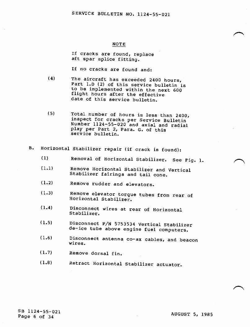
SERVICE BULLETIN NO. IL24-55-O2I
NOTE
(s)
If cracks are found, replaceaft spar splice fitting.If no cracks are found and:
The aircraft has exceeded 24OO hours,part l.D (z) of this service bulletin isto be implemented within the next 600flight hours after the effectivedate of this service bulletin.
Total number of hours is less than 2400,inspect for cracks per Service Bulletin'Number LL24-55-020 and axial and radialplay per part 2t para. G. of thisservice bulletin.
B. Horizontal Stabilizer repair (if crack is found):( 1)
( 1.1)
( 1.2)
( 1.3)
( 1.4)
( 1.5)
( 1.6)
( 1.7)
( 1.8)
(4)
Removal of Horizontal Stabilizer. See Fig. l.Remove Horizontal Stabilizer and VerticalStabilizer fairings and tail cone.
Remove rudder and elevators.Remove elevator torque tubes from rear ofHorizontal Stabilizei.Disconnect wires at rear of HorizontalStabilizer.
Disconnectde-ice tube
Disconnectwi.res.
Remove
Retract
P/N 5753534 Vertical Stabilizerabove engine fuel computers.
antenna co-ax cables, and beacon
dorsal fin.Horizontal Stabilizer actuator.
sB tL24-55-021Page 6 of 34
AUGUST 5, 1985

( 1.9)
( 1.10)
( 1.11)
( l.l2)
( 1.13)
( 1.14)
( l.t5)
( 1.16)
( l.l7)
( 1.18)
( l.o)
(r.l)( 1.2)
( 1.3)
( 1.4)
c. Repracement of Horizontar stabiLizer Aft spar spliceFitting P/n 4453005-50I-400.
SERVICE BULTETIN NO. IL24.55-O2r
Attach sling to Vertical Stabilizer so that itmay be raised straiEht up.
Remove Vertical Stabilizer attach bolts andremove Vertical Stabilizer.Extend Horizontal Stabilizer actuator.Disconnect de-ice lines at Horizontar stabiLlzerleading edge.
Attach sling to Horizontal StabiLLzer so that itmay be lifted straight up.
Place 2OO to 25O lbs of sandbags on HorizontalStabilizer leading edge near fuselage to balancestabilizer.
Remove Horizontal StabiLizer trim actuator upperattach bolts.
Remove cotter pin and nut from hinge pin.
Take up slack on sling so as to remove weightfrom hinge pin so that it can be moved withtight taps of brass hammer. Remove hinge pin.Lift Horizontal Stabilizer from fuselage and setonto dolly which holds stabilizer in a verticalposition, leading edge down.
Drill out all fasteners attaching the upper andIower skins to the left or right aft splr caps,plus fasteners attaching spar web to Jplice -
fitting P/N 4453005-50I, and to the end of eachrib. S,ee Figure 2.
Remove spar.
Remove all fasteners attaching other spar up toHorizontal Stabilizer Sta. 92.73. See figure Z.
Remove six ed. MS20007-38 bolts attaching spliceassembly to stabilizer frame.
Spread skin and remove splice fitting.
sB IL24-55-021Page 7 of 34
AUGUST 5, 1985

( 1.5)
( 1.6)
( 1.7)
( 1.8)
( 1.9)
( l.t0)
Hinge
( l.o)(l.l)
( 1.2)
sB LL24-55-021Page 8 of 34
D.
Holes must be exactly aligned withholes thru stabilizer frame. OIdsplice fitting may be used as theguide.
Slide spar splice into place in HorizontalStabilizer.
Reposition the removed spar.
Install the 6 ea. MS2000Z-39 bolts withMs20002c7 washers. Torque borts to 450 to 500IN-IDS.
Reinstall att fasteners. See Fig. 2 for typesand sizes of fasteners.
Assembly Improvement
Installation of new (Kanatics) bearings.Locate 2 heat lamps on each side of theairplaner Do closer than 5 inches from theoutboard bearing lugs.
Apply l75o F, l94o F and 2000 F Tempilstik markson each outboard lug and heat the lugs. Whenthe 175" F mark melts, remove heat lamps.
SERVICE BULLETIN NO. IL24-55-021
Verify that the outboard lugs of the new splicefitting P/N 4453005-50r-400 have been radiusedand flap or shot-peened.
Drill out the 6 holes for attachment bolts(MS20007-39) to .4370 to .4380 inch in newsplice fitting.NOTE:
CAUTION
Ensure that heat lamps are removedbefore the 200" F maik melts.If 2000 F is exceeded on anypart, contact IAII Inc. for repairprocedures.
(1.3) Remove the outboard bearings. (See Fig. 3.)Use Bearing puller.
AUGUST 5, 1985

( 1.4)
( 1.5)
( 1.6)
( 1.7)
(1.9)
NOTE: Ensure toctite covers the entiresurface of bolt and mating surfaces.
(1.9) rnspect the attach fitting bores using the diarbore gage (.0001" per graduation). Check themeasuring instrument with a precision ring gageimmediately prior to taking measurements. Forevery I0" F above 7Oo F subtract .0001" frombore measurements. For every l0o F below 20" Fadd .0001' to bore measurements.
Limits
( 1.10 )
For hole dia. see Table l.€1. Out of round 0.0003 max.b. Taper 0.0005 max.
If any bore is out of limits, itwiII be necessary to hone all threebearing bores utilizing the L 5/9"Sunnen hone.
If the limits above are met or can be met byhoning, calculate the average bore diameter foregch lug. (ltaximum reading + minimum readingdivided by 2l and select th-e appropriate bear-ingpart number for each lug from Table I in part3. Place AOG order.
SERVICE BULLETIN NO. LI24.55-O2I
Remove middle lug bearing and then pull bearingthru an outboard lug while it is st.ill warm(I75o F to 2000 F).
Discard all three bearings.
Clean the three bearing lugs and visuallyinspect for cracks.
Clean attach fitting bores with crocus cloth asnecessary. Locally dress any raised material.Remove no more than is absolutely necessary.
Remove the three (3) grease fittings and plugthe holes with AN4C3A bolts and AN960C416Lwashers. Secure bolts in place with toctite No.27L or No. 08831.
sB LL24-55-021Page 9 of 34
AUGUST 5, tgg5

(r.rl)
( l.t2)
( l.r3)
( 2.0)
( 2.1)
( 2.r.1)
(2.1.2)
( 2.r.3)
(2.r.4)
( 2.1.5)
( 2.1.6 )
sB IL24-55-021Page l0 of 34
SERVICE BULLETIN NO. IL24-55-021
Pack the threeminimum of onenitrogen.
Install niddlethe lug withinbefore bearingD.( 1.0).
new bearings in dry ice for ahour or cool with liquid
bearing so that it is centered in0.002 inch. Lugs may be heatedinstallation as per para.
Install the outboard bearings in theirrespective lugs to obtain spacing noted inFigure 7. Bearings are to be centered in lugswithin 0.005 inch.
Peening of Hinge Lug Roots (shot or flap).Shot-Peening.
Drill out rivet adjacent to each outboard hingelug per Figure 4.
Slide a steel sheet between the hinge and theskin and trim skin to permit access to lug roots(perFigures4&5).
Strip primer from outboard lug roots and area tobe radiused and shot-peened. (See Figures 4 &5).
9y hand filing and sanding, dress a L/I6" to5/64" radius or break-edge (21 places eachoutboard Iug as shown in Figure 5. The radiusmust be smooth, continuous and circular incross-section. Scratches, gouges, pits, etc.are not permitted anywhere in the area.
Mask hole for MS90354-6-10 fastener.As a minimurr 9lass bead peen the lug roots andbreak-edges per MIL-S-13165 using size 331 glass!.u9? (corresponds to tletal tmprovement CompanyGP 2341. Intensity to be .004" to .007" AlnenA.
AUGUST 5, 1985

SERVICE BULLETIN NO. Lt24-55-02I
(2.2) Flap-Peening.
NOTE:
(2.2.L',)
(2.2.2)
(2.2.3)
Flap-peening may be used as analternative to shot-peening inconjunction with the following:
Prepare for peening per para. (2.1.1) thru( 2.1.5).
Prepare surface and flap-peen 1ug roots using9/L6" x L L/4,' flap at gb,0OO RpM; to anintensity of 0.008A, coverage IO0t as follows:(Refer to Figure 6).
Before applying flap to the lug,E. Test for intensity as follows:b. Use a model of the area which is to bepeened, a 0.100,, aluminum sheet bent to the
above radius.
As the radius is smaller than the usual forthe.flap, it wiII require some practice toachieve the required coverage.
It will be noticed that the area adjacentto the radius will get the required-coverage (allow up to 400t) before theradius gets the full I00t coveragerequired. Therefore, after the adiacentale.a g_ets. approximately 4009 coverage, maskwith aluminum tape.
It will be noticed that one side of theradius gets better coverage than the other,therefore after masking, reverse the drilldirection and turn around the flap. Thiswill enable better access to the radiusside that did not get good coverage in thefirst application of the flap.
C.
d.
€.
sB IL24-55-021Page 11 of 34
AUGUST 5, 1985

SERVICE BULLETIN NO. LL24.55-O2I
(2.2.41
(2.2.5)
( 3.0)
( 3.1)
(3.2)
sB LL24-55-021Page L2 of 34
Clean peened area with MEK.
Brush Arodine the frap or shot-peened area andtouch up with Zinc Chromate priiner.Inspection of Hinge Bushings
Clean the four (4) bushing bores with crocuscloth as necessary. f,ocally dress any raisedmaterial. Remove no more rnaterial thlnabsolutely necessary.
Inspect the bushing bores using the dial boregage (.0001' per graduation). Check themeasuring instrument with a precision ring gageimmediately prior to taking measurement.
Limitsd. Out of round .0005".b. Taper .0005u.c. Average diameter .97 43" /.9250".If the above limits are met, the bushings neednot be replaced. If the above limits uieexceeded, it will be necessary to replace allfour (4) bushings per para. D-.(4.0) O'etow.
Note: If the bushings in HorizontalStabilizer splice are not replaced,perform axial clearances check perPara. G.
If clearance is less than 0.016inches, proceed with scissorsinstallation.
If clearance is more than 0.016inches, fabricate shims, usingAN960C-1416L washers to achievemaximum clearance of 0.016 inches.Shimming must be do1e. prior to upperscissors fitting positio-ning andassembly as per para. E.(1.-9) thruE. ( 1.11) .
AUGUST 5, 1985

( 4.0)
( 4.1)
( 4.2'
( 4.3)
(4.41
( 4.5)
SERVICE BULLETIN NO. LL24-55-O2I
Replacement of Hinge Bushings
Loosely rrrrap aluminum foil around theshot-peened area of the outboard hinge lugs, andutilize heat lamps and the rempirstiki to heathinge lugs to l75o F to 2000 F.-
Remove outer bushings, then the inner bushings.Clean the lug bores as in D.(3.1) above.
Inspect the lug bores as in D.(3.2) above.
Limits
sB IL24-55-021Page 13 of 34
€1. Out of round 0.00I".b. Taper 0.001,,.c. Average diameter I.O6}g"/l.06lgu (permits
installation of standard bushings)'.d. 4r^"-r-1q.". diameter one or more tugsI.0619"/L.0750" (requires installition ofoversize bushing(s).
If the above 1imits arbrc are met, install 2each P,/tt 4453005-l_1 and p/N 4453007-Z bushings.(See -Figure 71. If the above limits arUrO aremet, fabricate one or more oversize bushings perFigure 7 and install. If one or more lug 5or6sexceeds 1.0750", contact IAII for instructions.If limits a or b are not met, a1I 4 hinge boresmust be honed oversize (1.0750" rnax.) using a IL/L6" Sunnen hone. Oversize bushings per Figure7 will be required.
Apply grease to the 4 hinge bores. protect theshot-peened area of the hinge by wrappingloosely with aluminum foil. prolect ftie ,outboard lugs from overheating by wrappingloosely with aluminum foil. Heat the middle 2Iugs. Install the 2 p/N 4453005-2 bushings intl. center lugs so as to obtain spacing noted inFigure 7. Remove the aluminum foil froi tn"outer 2 lugs, allow them to reach temperatureand instarl the z p/N 4453005-rl bush-ings suchthat they are flush with the outboard flce ofthe lug.
AUGUST 5, I9g5

( 4.5)
(4.7\
sB 1124-55-02IPage 14 of 34
(4.8) Fit h_i_nge pin with AN960-t4t6L (ety. 2') washersinstalled under the head, thru the busirings toensure that the pin can be inserted when thestabilizer is reinstalled. Verify that theshank of the 2453007-2 pin does not protrudebeyond the end of the bushing. Shank- of pinshourd be set inside of bushing a minimuri of0.01G inch and a maximum of 0.603 inch.
SERVICE BULLETIN NO. LL24-55-O2I
.Inspect the gaps between the attach fittingbearings and hinge bushings to ensure thaC axialclearances will be within specification when thestabilizer is reinstalled in the aircraft. Heatthe hinge fitting before attempting to adjustthe position of a bushing. (See Figure 71.
Hone all four bushings in line using 7/g" Sunnenhone.
Limits
€ro Out of round .0005,'.b. Taper .0005n.c. Diameter .8743"/.8750".
NOT E: Hone bushings to the minimum diameternecessary to fit the p/tt 24S3OO7-7pin.
CAUTION
when fitting th9 pin through the hinge bushings,care is required to avoid gaUing thJ bushings-.If this occurs, the bushing(s) atiO pin mayrequire replacement. The bushing bores Jnd pinmust be immaculately clean and lubricated wiin#30 weight oil (not WD-40 or equiv.). The pinmust not be rotated nor driven in with moreforce than is exerted by tapping with a brasshammer.
AUGUST 5, lgg5

E. Scissors
( l.o)
( 1.1)
SERVICE BULLETIN NO. LL24-55-O2I
Installation
Drill out rivets and remove vertical stabilizerrib P/N 5413027-gI. See Fig. g.
Refer to Figures 8 and g. Remove the twooutboard AN4 bolts attaching 44L3O2g rib toforward spar of vertical stabilizer. Ream thesetwo holes to O.Z6SL-O.267L inch.Remove center AN4 bolt and ream hole to 0.265LO.267L inch.
Remove remaining two AN4 bolts.Drirr 5 €€r. 0.280u holes in 5413027-247 prate tomatch holes in spar and rib p/x 44l3o2g-. AttachMS21053 L4-9-3 nut channel to -247 plate using z€€r. 14520426-AD-3-3 rivets.Install -247 plate including nut channel onforward side of verticar spar. secure with twoeach NAS6604-l0x bolts thiu the outboard holesusing I4S2LO42-4 nuts and AN960C4L6L washers.
:95p,":-1+1y secure upper scissors atrach firtingP/tt 4453513 to Vertical Stabilizer usingNAS6604-14 bolts thru outboard holes i; attachfitting. Center hole is to be left open at thistime.
Drill out 4 ea. MS90353-g-15 blind fasteners atleading edge of Horizontal Stabilizer wherelower attach fitting will be secured per Figures1I & 12.
Place the Horizontal Stabilizer on the aircraftsuch that the fuselage frame and hinge fittingare joined.
If Horizontal Stabilizer hinge bushings werereplaced and gaps are as required in f.igure 7,proc-e_ed per para. (1.12) below. If not, insert'a 0.8'12 inch dia. drift pin 6.5 inches iongtapered on one end (may be made from old hingepin) thru hinge assembly.
Using feeler gages, measure clearance betweenthe outer bearing and each adjacent bushing. Iftotal clearance exceeds 0.012 inch, fabricateshims (make from AN960C-l4l6L washers).
sB LL24-55-021Page t5 of 34
( 1.2)
( 1.3)
( 1.4)
(r.s)
( 1.6)
( 1.7)
( 1.8)
( r.9)
( l. lo)
AUGUST 5, 1985

SERVICE BULLETIN NO. LT24-55-O2r
Retract drift pin, install shims.
Place the AN960C-I4l6L washers (ety. Zl underthe p/N 2453007-2 hinge pin head anO insert pinpushing out the drift pin.
( l.l1)( 1.12)
( t.t3)
( 1.14)
( l.r5)
( 1.16)
( r.t7)
( 1.r8)
( 1.r9)
( t.2o)
( 1.21)
(L.221
sB LL24-55-021Page 16 of 34
Pin, bushing bores, and bearing boresmust be clean and lubricated with #30weight oil.
Alternatively, pack the pin in dry ice for onehour and insert using no lubricatlon (pin wiIIshrink.001").rnstall Ao2ww540300t-z washer and the AN320c-r2nut.
Note:
NOTE: Washer (AO2WW540300I-7) should beinstalled flush with 1ug bushings.Torque the nut to 150 INCH 1bs. Remove thenut and washer and verfi-that the end of thepin shank is inset from the end of the bushing.Replace washer and nut and torque to 20-30INCH-lbs. above run on torque.rf a castellation lines up with one of the horesin the hinge pin, instarr the Ms24665-376 cotterp1n.
If a castellation does not line up with one ofthe holes, grind the back face of the nut untilone does and install the cotter pin.Connect Horizontal Stabilizer actuator.Place verticar stabilizer on aircraft and insertbolts thru the fore and aft attach points. Donot install nuts.
Furly retract Horizontar stabilizer actuator.Temporarily assemble and attach scissorsassembly to the upper fitting on the Verticalstabirizer, assuring that the scissors assembrymoves freely throughout its range.Locate and mark the position of the lowerscissors fitting on the Horizontal stabiil""r.
AUGUST 5, 1985

( 1.23)
(L.24)
( 1.25)
(r.26)-
(L.271
( 2.0)
(2.L)
(2.21
( 2.3)
(2.4)
( 2.5)
SERVICE BULLETIN NO. LL24-55.02I
Note: Lower scissors fitting center linemust be parallel to the aircraftcenter line.
Remove Vertical Stabilizer.Place approximately 2OO lbs. of sandbags onHorizontal Stabilizer leading edge near fuselageto balance Stabilizer.Disconnect Horizontal Stabilizer actuator andraise leading edge to facilitate installation oflower scissors fitting.CAUTION: When raising Horizontal Stabilizer
leading edge, ensure that bolt headsthru rear spar splice do not contact.fuselage banjo fitting.
Install lower scissors fitting on the HorizontalStabilizer per Figures lt and 12. Shim asrequired between fitting and HorizontalStabilizer. As each fastener is installed,ensure fitting remains aligned as marked andparallel to aircraft center line.Reconnect the Horizontal Stabilizer actuator.Scissor Adjustment.
Place Vertical Stabilizer on aircraft and insertbolts thru fore and aft attach points. Do notinstall nuts.
Fully retract Horizontal StabiLizer actuator.
toosen the two outboard bolt,s in the upperscissors fitting that were temporarily securedin Step (I.6), to allow fitting to move.Connect scissors assembly.
Disconnect Horizontal Stabilizer actuator.
Lift Horizontal Stabilizer to its maximumleading edge up position, so that scissors arefully closed. Tighten or loosen bolts attachingupper fitting until GAP 'Gu in Figure 1lmeasures 0.063u. Fleasure GAp 'rH'r andmanufacture shim or filler of 2O24-T3 alum tomatch upper fitting forward face and to fill GAp,t Hrt.
sB LI24-55-021Page L7 of 34
AUGUST 5, 1985

F.
(2.6'
(2.7)
( 2.8)
(2.9'
Scissors
( 1.0)
( 1.1)
SERVICE BULLETIN NO. LL24-55-021
InstaII filler in GAp rH,, and torque outboardbolts to 50 in-lbs.Repeat Step 2.5 and verify GAp 'G' & rHr.
Connect Horizontal Stabilizer trim actuator.Disconnect scissors at ce4ter. Slowly extendand retract trim actuator and en,sure thatscissors can be reassembled without bindingthroughout travel.
Final Assembly.
Remove Vertical StabilizerMeasure gap b.etween upper fitting (p/n 44535I3)and 4413028 rib (Gep "C,,) (should-be'approximately equal to GAp ,,H,'). I{anufacturefiller to match uqper face of 4453513 fitting of2024-T3 alum to fiII GAp "C,,.
Ream center hole of upper fitting p,/tt 4453513 tomatch hore thru forward spar of vertical and ribp/tt 44I3o2g (ream hole to 0.255I o.26iL incni. -
rnstarl NAS6604-l4x bott with AN960c4t6L washerin center hole - do not tighten.Loosen outboard bolts in upper attach fitting.Insert GAp !rCrr f iller. Install MS90353-5_4blind fasteners as shown in Figure iZ, Vi." E.
Torque NAS6604-14 & -l4X bolts to 50 to 70inch-Ibs.
rnstall 54r3027-81 rib in Verticar stabilizer.SeeFiguresS&9.
forwardTorque aft
( 1.2)
( 1.3)
( r.4)
( 1.5)
( 1.6)
( 1.7)
sB IL24-5s-021Page 18 of 34
Install Vertical Stabilizer. Torqueattach bolts to 200 300 inch-lbs.attach bolts as follows:Up to S/N 270 torque: 400-500 inch_lbs.
S,/n 27L-4L5 torque: 20O-4OO inch_lbs.S/tt 41G & subs torque: 200_300 inch_tns.(1.8) Assure that the center scissor rugs can beengaged without side roads and ttr"e- uor[ eisilyinserted with the Horizontar stabirizer in ineextreme up, down and 3 intermediate positions.
AUGUST 5, lgg5

( 1.9)
( 1. l0)
( l.1l)
G. INSPECTION FOR PLAY
( 1.0)
( 1.1)
(L.2)
( 1.3)
( 1.4)
( 1.5)
( r.6)
( 1.7)
SERVICE BULLETIN NO. LL24-55-O2I
Note:
Connect center scissors, safety castellated nut,and lubricate all points.
Tighten upper, lower and centerscissor castellated nuts to 55-?5inch-lbs. Center scissor lugbushings must have a side clearanceof .003' to .005u after final torque.
Move the Horizontal Stabilizer slowly up anddown to check clearances. Ensure wfren theHorizontat Stabili2er is in the maximum upposition (scissors fu[y crosed), that the gapbetween the scissors ano the Vertical stabilizer(Gap nG") is 0.05 inch minimum and "n"n tn"Horizontal Stabilizer is in zero position, thatGAP 'Jo between scissors and nofizontalStabilizer is 0.20 inch minimum.
Complete installation of Vertical Stabilizer,rudder and elevators.
fnspection of Splice Assembly for Radial play.C-Iamp a dial indicator (.0005u per division) tothe attach fitting so that tne -ptung., i"vertical and resting against the bottom of theleft hand outboarO trinle fug tfocaiion-"f inFigure l3).
Gentl_y. place 100 lbs. of sandbags on the R.H.stabilizer tip,Zero dial indicator.
Move all sandbags to the L.H. stabilizer tip.Record dial indicator reading.Repeat Steps (1) thru (5) for the R.H. outboardhinge lug.
If the total reading of the dial indicatorexceeds 0.010 inch, -it is recommended to performthe improved installation as per para. D.
sB LL24-55-02IPage 19 of 34
AucusT 5, 1985

SERVICE BULLETIN NO. IL24-55-021
(2.0)
(2.L|
(2.z',)
(2.3)
(2.4'
( 2.5)
( 3.0)
sB IL24-5s-021Page 20 of 34
Inspection of Splice Assembly for Axial play.
Clamp the dial indicator to the attach fittingso that the plunger is horizontal and resting'against the face of one of the outboard hingllugs (location 2 in Figure l3).Push horizontarry with hand forces on the reftand right stabilizer tips alternately, so thatthe Horizontar stabirizer moves thr6ugh its fulrrange of motion.
If axial play is less than .OIG' the aircraftmay be returned to service.
If axial play is between .016" and 0.040", theaircraft may be returned to service, but must bereinspected at I50 flight hour intervals.If axial play is greater than 0.040 inch, it isrecommended to perform the improved instalrationas per Para. D.
check Horizontar stabiLLzer trim actuator forwear and looseness by shaking HorizontalStabilizer at the tip and obs-erving foiiowingareas:
Upper and lower attach points.Rod ends.
If Horizontat Stabilizer hinge assembly iswithin the above limits, the aircraft *.y bereturned to service.3. MATERIAT INFORMATION
The forrowing parts are required to complete the repairs andimprovements described herlin and are ivailabre only fromapproved Westwind Service Centers.
(r)(2)
AUGUST 5, 1985

SERVICE BULLETIN NO. LL24-55-02I
(1) Replacement of
P/N
4453005-501-400MS 204 26AD5-Brls20426AD6-9MS90353-050sMS 903 53- 0s05MS 90353- 0606MS 90353- 06 t 2l"lS 90353- 0811f,rs 90353- 0813NAS 1738 B5- 4NAS 1739 B5-6NASI739B5-7NAS 1465-7NAS 1466- INAS 1466-9NAS 1080- 06
(2') Improvement of
P/N
See Table I onPage 2244s3005- 5
44s3005-1r4 4s 3005- 72453007-7AN 320 C-L2
IvlS24565-376AO2WW 5403001-7AN960C-1416L
AN960C-l2t6LMS 90354- 6- 10AN 4C 3AAN960C415No. 08831 orNo.371
Horizontal StabilLzer Spar Splice
DESCRIPTION
Splice Assy.RivetRivetFastenerFastenerFastenerFastenerFastenerFastenerFastenerFastenerFastenerFastenerFastenerFastenerColIar
hinge assembly.
DESCRIPTION
QTY
I322I52I823223819620204I32
#
*Bearing
Bushing(use as analternate forBushing 4453005-11,Bushing 4453005-5when in need of alonger Bushing.)BushingBushingHinge PinNut (StainlessSteel)Cotter PinWasherWashers ( ForShimming& under pinhead)WasherFastenerBoltWasher
Loctite
QTY
3
A/R
sB LL24-55-021Page 2L of 34
****
22II1I6
***
2233
A/R
Note that bearings cannot be ordered until the bores ofthe attach fitt,ing have been measured.
AUGUST 5, 1985

SERVICE BULLETIN NO. TL24-55-021
These parts are supplied with 4453005-501-400 SparSplice Assy.
NOTE: Above parts are supplied as Kit No. IAII-55-lA.(3) Scissors InstallationP/N
4453516- s0354130 27 -247NAS 6604- l4NAS 6504- l4XNAS6604- 10XAN960416LI'{S2I053 L4-9-3MS 90353- 8- I 8MS90354-6-6MS 90353- 5- 4MS 20426AD- 5- 6tls20426AD- 3- 3NAS 1466- 23NAS 1080-6vrs2Lo42- 4AN960C416L
NOTE: Above
DESCRIPTION
Scissors Assy.PIateBoltBoltBoltWasherNut ChannelFastenersFastenersFastenersRivetsRivetsFastenersCollarsNutsWasher
parts are supplied as
OTY
tI2I25I44102625523
Kit No. IAII 55-lB.TABLE
Attach Fitting Bore
I - BEARING SELECTION
Order Bearing P/N Out.er Race giameter
KRP-505-14B-01 L,6245/I.6247KRP-505-148-01-A L.6248/I.6250KRP-505-I4B-01-B I.625L/L.6253KRP-505-148-01-C t.6254/L.6256KRP-505-148-0l-X Specify to achieve
.0007/.0011 inter-ference fit.
L.6236/L.6239 *L.6239/L.624L *L.6242/L.6244 *L.6245/L.6247 *L.6248/L.6320
L.632L/L.7QOO Contact IAI International, Inc.* Stock item
4. RECORD COIt{PLIANCE
Make the following entry in the Aircraft Log Book:service Bulletin LL24-55-02r dated AUGUST 5t r985, titled"Horizontar stabilizer Assembly-rnspection, nepai-r anoImprovement" has been accomplished- (Oat-e) .
sB LI24-55-021Page 22 of 34
AUGUST 5, 1985

SERVICE BULLETIN NO. LL24-55-02L
REMO\ZE VERTICAL STABILIZERP^ 54L3027
RrB P,/N 54L3027-8LTO BE REI\rc\TED
SEE FTG. 8
REMOVE FAIRING PAI5313016 TO GArN ACCESS
REMOVE DORSAI FTNP,/N 5313734
TO GATN ACCESS
REMOVE HORIZONTALP^{ 545301s
5403034 TArL CONE &
STDE FAIRING TO GAIN ACCESS
STABILIZER
REMCVE PAPnr 5403002
PARTS TO BE REMOVED FROM A,/C
FIGURE I
sB IL24-55-021Page 23 of 34
AUGUST 5, L9g5
VIEVI SHOWING


SERVTCE BULLETTN NO. LI24-55-O2T
PULL OUT THE EXTERNALNEEDLE BEARINGS FIRST
SPLTCE FITTING
KRP (KARON)KRP5O5-I4BTeflonBearing
INSTALL MIDDLE BEARING FIRST
FUSELAGE FRAME STA.521.75 LUGS
iI
I
ua
I
Kt- r'X'\'i-li
i
\ _.,'
.0007 to .0011interference fitbetween lug andBearing (3 placestypical) .
KRP (KARON)KRP5O5.I48TeflonBearing
sB LL24-55-021Page 25 of 34
KRP (KARON)KRP505-I4BTeflonBearing
AUGUST 5, 1985
FTGURE 3

rLAP OR SHOT-PEEN LUG ROOTAREA (REMOVE PRTMERBEFORE PEENING)
IqINIMUM
DRTLL OUT EXISTING RI\ET(2 PI,ACES). PLUG HOLE AFTERSKIN IS TRIMMED AI{D AREA ISSHOT-PEENED WITH 14590354-6-10
SERVICE BULLETIN NO. 112 4-55-02 1
FLAP OR SHOT-PEEN LUGROOT AREA (RENIOVII
PRIMER BEFORE PE[NIN(;)
VIEW LOOKING FWD
.25RTYP
VIEW LOOKING UP
REMOVE SKIN IN SHADED AREAS (2 PLACES).AFTER SHOT-PEENING, TREAT BARE AREASWITH ALODINE 12OI AND PRIME WITHEPOXY PRTMER.
SHOT-PEEN AREA
FIGURE 4
sB LL24-55-021Page 26 of 34
HORIZONTAL STABILIZER AFT SPAR HINGE FITTING
/./-t \
-tk \ -.t -./\ * -'-.-'- X
.r,l"S-
AUGUST 5, 1gB5

SERVTCE BULLETIN NO. IL24-55-O2L
L/L6 TO 5/64 RADTUSOUTBOARD EDGE OF EACH LUG
sB LL24-55-021Page 27 of 34
AFT SPAR SPLTCEFITTING
AUGUST 5, l_985
FIGURE 5

SERVICE BULLETTN NO. LI24-55-02L
STEP I
ALUI4INUM MASKAFTER 4OOt
FOR ADJACENTCO\TERAGE
AREA OF RADIUSWITH GOOD COVERAGE
ON FIRST STEP
COVERED
IN STEP I
%. a couNrER
\,-.. J
\". -/
CLOCK},IISE
FLAP SHOT
STEP 2
sB LL24-55-02LPage 28 of 34
FIGURE 6
AUGUST 5, 1985

SERVICE BULLETIN NO. L124-55.02L
HORTZONTAL STABILIZERHINGE P,/N 4453005
4453005-7LOCATE TOCLEARANCESBUSHINGS &
4453005-7 BUSH
SHORT TO ACHIEVE THE GAP,
TRTMMED AS REQUIRED.
ROD 4130 COND F-4
-7BUSHING
DIA
BUSH
OBTAIN REQ,DBETWEEN
BEARINGS
4453005-11BUSH INSTALL
4453005-11BUSH INSTALLFLUSH WITHOUTER SURFACEOF LUG
| +0.0000o.9375 -0. 0050
sB LL24-55-021Page 29 of 34
FLUSH WITH AourER suRFAcE/\OF LUG .'-
l+-oo=+l
O\IER.SIZE BUSH FORREQ'D
IF BUSHING 4453005-11 IS TOOUSE BUSHINGS 4453005-5 OR -7
BUSHINGS TO BE MADE FROM
-11BUSHINGS .8745
.8743
;f,ti it_L
FABRTCATE OD TO PROVIDEO.OOI TO O.OO3 INCH INTERFERENCEFIT
+o. oo0-0.0050
LENGTH0.500 +
FOR -50 .0000.005 F-op----l
August 5, 1985
FIGURE 7

SERVICE BULLETTN NO. LL24-55-02I
PREPARATION FOR INST. OF SCISSOR ASSY
.d rP".
54L3027-65 RrBREF.
^;
4413028 RrB.SEE VIEW B-BFIGURE 9
REWORK
z85.L2
4413018 FITTING. FORREWORK SEE VIEW B-B INTIGURE9&VTEWCINFTGURE 10
FORIN
DRTLL OUT ALL FASTENERS INP/N 5413027-8I RrB & nREMOVE FROM VERT. STAB.,/I\
Y=49L.90
AFTER pr,ATE p/N 5413027 & NUT CHANNEL MS 21063 L4_g_3HAVE BEEN TNSTALT,ED, RrB P/N 5413027-8I MUsr BE RETNSTALLED
sB 1L24-55-021Page 30 of 34
-\l' \\ \i(\ \...X\. f -S:S\_. u \ -i')-ts*\- \,i- -1)r- -.0' t
..|}.R'--;,-=1:=y';/26 EA -v \ (i-rt- -i- -i- -i- -lANrs 2o426Aos-o ,^l.i\\- /.)
'\:?)
FIGURE 8
AUGUST 5, 1995

SERVICE BULLETTN NO. LL24.55-O2T
REMOVE AN4 BOLTS TROM OUTBOARD HOLES
REAM OUT HOLES TO 0.2651 to 0.2671 INCH
rNsrALL 2 EA NAS6604-10X BOLTS 'AN96OC416L WASHERS AND MS21O42-4 NUTS.
REMOVE Ar,I4 BOLT AI{D FEAM OUT HOLE TO
o-265L TO 0.2671 rNCI{.INSTALL NAS 6604-14X BOLT AFTER
SCISSORS AD.]USTMENT
4413028 RrB
VIEW B-B
ADD P/N 54L3O27-247PLATE AS SHOVflN
MS2O426AD3-3 RIVETS THRU -247& MS21O63 L4-9-3 NUT CHAIINELONI,Y
REMOVE 2 EA AN4
INSTALL 2 EA NAS
THRU SCISSORS
5413027-65 RrB
REMOVE ALL FASTENERS
rN P/N 54L3O27-8L RrBAI{D REMOVE FROM \ERT..STAB
5 EA NAS L466-23 FASTENERS &
, NAS 10S0*6 COLLARS
THRU SPAR AND -8I RIB
FIGURE 9
54L3027-65 RrB
44r30r8
VIEW C
ADD MS 2LO63 L4-9-3 NUTCHANNEL. NUT LOCATIONS TOMATCH EXTSTING HOLES IN FITTINGP/N 4413018 AS SHOWN
sB II24-55-02IPage 31 of 34
BOLTS6604-L4 BOLTS
ix(' /' ,,'$(.,,,"
4413018 FITTING REF
AUGUST 5, 1985
FIGURE 10

SERVICE BULLETIN NO. II24-55-021 Revision No. I
4463513UPPER FITTTNG
54L3O27 VERT STAB
4413028 RrB
FILLERSCISSORS POSITION WITHHORIZ. STAB. I'IAXIMUM UP.
4453516 SCTSSORASSY
SCISSORS POSITIONWITH HORTZ. STAB.AT ZERO
SHIM BETWEEN P^{ 4453514 LOWERFITTING & HORIZ. STAB. rF REQ'DI4AI 2O24_T3 -THICKNESSAS REQID
4453513UPPER FITTING
903s4-64EA
4453OL7 SPLICEREF
-6
bTNSTALI,ATION OT SCISSORS
FIGURE II
sB 1724-55-021_Page 32 of 34
. '|+Li \1s--rJ \
5313032 FIUUIE "'r'
44530L7 SPLTCE54s3o1s HoRrz. srAB. fu
vrEW LOOKTNG OUTBD ON C/L OF A/C
RIB
44535L6ASSY
44535L4FITTING
SCISSOR
LOWER
ASSY
44L3028
AUGUST 5, 1gB5

SERVICE BULLETIN NO. Lr24-55-02r Revision No. t
44535I3UPPER FITTING
c/L A/c
--
MS 90353-5-4 (r0 EA)PICK t'P EXISTINGFASTENER LOCATIONSIN FITTING
44535L4I"oWER FITTING
VIEW E
INSTALLATION OF
UPPER FITTING
c/L
A/c
VIEW FF
TNSTALLATION OFI,OWER FITTING
4413028 RrB
HORTZONTAL STAB.PA 545301s
EXISTING FASTENERPOSITION TYP 4 PLCSREPLACE WTTH
MS 90353-8-18
\D-r/
sB LI24-55-021Page 33 of 34
++i+t,t.
AUGUST 5, 1985
TIGURE 12

SERVICE BULLETTN NO. 1124-55-021
HORTZONTALHTNGE
HORTZONTALSTABTLTZERATTACH FITTTNG
I
I
AIRCRAFTCENTER].INE
HORTZONTAL STABTLIZER HTNGE INSPECTION
sB II24-55_021Page ,34 of 34
FTGURE 13
AUGUST 5, L9g5

9eo,ryioe fiwlletdnA/c s/N
6e o,t ;fc oate "f Go rn/o li aro oo
PLEASE FILL IN TIIE REQUIRED DATA BELOW AND RETURN TO:
ISRAEL AIRCRAFT INDUSTRIES INTERNATIONAL, INC.P.0. BOx 10086WILIVIINGTON, DE 19850ATTN: TECHNICAL PUBLICATIONS
This is to certify that lvestwind Serial Nurnber- has compliedwith Service Bulletin No. LLz4-55-021
Aircraft Registration No.
Airframe Total Time at Compliance HOURS: /CYCLES:
Conpliance Date
OtrVNE R:
By
ACCOMPLISHING AGENCY:
Please descri-be bclow any d.iscrepancies found or difficultiesencountered during compliance:

TW{sERvIcE BULLETIIU
RECOMMENDED
SERVICE BULLETIN NO. 1124-55-097 February 3, 1989
SUBJECT: HORIZONTAL STABILIZER SCISSORS ASSy p/x 45351 6-501OR -503 INSPECTION
1. PLANNING INFORMATION
A. EFFECTIVITY
WESTWTND MoDELS llzq/1124A - A1I serial numbers, exceptaircraft s/n 441.
B. REASON
Several cracked and/or loosened lower fittings ofscissors assembly have been detected in service.
C. DESCRIPTION
This service bulletin requires a periodic inspection ofthe scissors assembly in order to detect cracks orIoose fittings.
D. COMPLIANCE
Perform a visual inspection of scissors assembly each300 fight hours.
NOTE: Chapter 5 of the 1124 series maintenancemanual will be revised to reflect the new300-hour interval
E. APPROVAL
This service bulletin has been reviewed by the IsraelCivil Aviation Administration (ICAA). The inspection
sB 1124-55-097Page 1 of 6
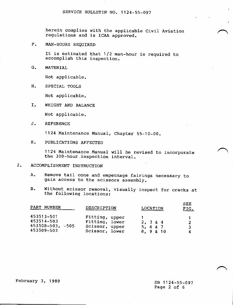
SERVICE BULLETIN NO. 1124-55-097
herei-n complies with the appricable civil Aviationregulations and is ICAA approved.
F. MAN-HOURS REQUTRED
ft is estimated that 1 /2 man-hour is required toaccomplish this inspection.
G. MATERIAL
Not applicable.
H. SPECIAL TOOLS
Not applicable.
I. WEIGHT AND BALANCE
Not applicable.
J. REFERENCE
1124 Maintenance Manual, Chapter 55-10-OO.
K. PUBLICATIONS AFFECTED
1124 Maintenance Manual wiII be revised to incorporatethe 300-hour .inspection interval.
2. ACCOMPLISHMENT INSTRUCTTON
A. Remove tail cone and empennage fairings necessary togain access to the scissors assembly.
B. Without scj-ssor removal, visually inspect for cracks atthe following locations:
SEEPART NUMBER DESCRIPTION LOCAIION F'IG.
45351 3-501 Fitting, upper 1 t45351 4-503 Fitting, Iower 2, 3 & 4 2453508-503, -505 Scissor, upper S, G & 7 3453509-503 Scissor, Iower g, g & 10 4
sB 't 124-55-097Page 2 of 6
February 3, 1989

SERVICE BULLETIN NO. 1124-55_097
C. ff cracks are revealed, rernove the scissor arms byremoving the two bolts (453511-501 ) and bolt (453510-s01 ).The aircraft may remain in service. If the aircraftremai-ns in service, inspection of the horizontalstabilizer aft spar splice fitting e/N 453005-501should be continued according to Service BuLletin No.1 1 24-55-020 .
For reinstallation instructions of the scissorsassembly and for procurement of replacement parts,contact Astra Jet Corporation, Wilmington, De1aware.
D. Inspect lovrer fitting (P/N 453514-503) for loose rj-vetsor gaps between fitting and horizontal stabilj-zer skin(see Figure 5).
E. If looseness and/or gaps between lower fitting andstabilizer skin are found, remove the scissors arms byremoving the 2 bolts (p/n 453511-501) and bolt (P/N4s3s1 0-s01 ).The aircraft may remain in service. If the aircraftremains in service, inspection of the horizontalstabilizer aft spar splice fitting p/N 453005-501should be continued according to Service Bulletin No.1 1 24-s5-020 .
For reinstallation instructions of the scissorsassembly and for procurement of replacement parts,contact Astra Jet Corporation, I{ilmington, Delaware.
F. If additional informatio:1,:..s .needed contact:
ASTRA JET CORPORATIOI'IP. O. BOX 1 0086WILIVTINGTON, DE 19850U. S.A.
PHONE: (3021 322-7240TELEX: 704034
sB 1 124-55-097Page 3 of 6
,,+February 3, 1 989

LOCATION
LOCATTON
LOCATION 4
SERVICE BULLETIN NO. 1124-55-097
UPPER FITTING P/N 4535'1 3-501FIGURE 1
LOWER PITTING P/N 45351 4-503FIGURE 2
LOCATION 2
sB 1124-55-097Page 4 of 6
-{-r-?-r*r-?- | t-r
-s-- -o- -+-{+l+t/
ix)
February 3, 1 989

LOCATTON 6
LOCATION 7
9 LOCATION 1 O
LOWER P/N 453509-503FIGURE 4
SERVICE BULLETIN NO. 1124-55-097
LOCATION 5
scrssoR - UPPER P/N 453508-503, -505FIGURE 3
LOCATION 8
LOCATION
scrssoR
sB 1124-55-097Page 5 of 6
February 3, 1989

SERVICE BULLETIN NO. 1124-55-097
45351 1 -501 BOLr
VERTICAL
45351 0-501
45351 4-503LOWER FITTING
STABILIZER
SPLICE
SCISSORS ASSEMBLYFIGURE
45351 3-501UPPER FITTING
453516-501 0R -503SCISSOR ASSEMBLY
INSPECT LOWER FITUNG F'ORLOOSENESS OR GAPS BETWEENFITTING AND HORIZONTALSTABILI.ZER SKIN
I
II
rJ
HORIZONTAL
vrEw LooKINc oUTBOARD ON C/L Or A/c
INSTALLATION5
sB 1 124-55-097Page 6 of 6
srABrLrzER { fWO
February 3, 1999

{m
TJ
-{!mf,'no1Jo7nm
om{.^./\.Itm
{(Do-t-{o'not-_oU)m
rz0
r
9eooioe fiulletdnA/C S/N
%oo,ti/iooto o/ Gom/,ldatmoe
PLEASE FIIL IN THE REQUIRED DATA BELOW AND RETURN TO:
ISMEL AIRCRAFT INDUSTRIES INTERNATIONAL, INC.P.O. BOX 10086WILI"IINGTON, DE 19850ATTN: TECHNICAL PUBLICATIONS
This is to certify that l{estwind Serial Number-has conpliedwith Service Bulletin No. SB 1124-55-097
Aircraft Registration No.
Airfrane Total Tine at Conpliance HOURS: /CYCLES:
Conpliance Date
OIVNER:
BySlgnature
ACCOMPLISHING AGENCY:
Please describe below any discrepancies found or difficultiesencountered during conpliance:

TWTsERvtcE BULLETITU
OPTIONAL
SER,VICE BT]LLETIN NO. 1 124-55-107 September 28, 1994
SUBIECT: STABILIZERS - HORIZONTAL STABILIZER LOWER SCISSOR FITTINGREPLACEMENT (AFC 2073',)
1. PLANNING INFORMATION
A. EFFECTIVITY
MODEL Ll24lI124A WESTWINDS, all serial numbers with Service BulletinNo. 1124-55421previously complied with (AFC 2037).
NOTE: Aircraft serial number 441 andaircraft with P/N 453504-501 fittingassembly installed in accordance with Engineering Order A06 WW5453015 UNEWU (AFC 2073), are in full compliance with this servicebulletin.
REASON
Reports from the field indicate that some stabilizer lower scissor fittings P/f.I453514have loosened or cracked in service. Reference Service Bulletin No. 1124-55497.
DESCRIPTION
This service bulletin provides instructions for the installation of a new combinedstabilizer scissor and stabilizer actuator fitting.
COMPLIANCE
Compliance is optional and at the operator's convenience.
B.
C.
D.
September 28, 1994t02l
sB 1124-55-107Page 1 of 14

SERVICE BI]LLETIN NO. I124-55-IW
E. APPROVAL
This service bulletin has been reviewed by the Civil Aviation Adminisffation ofIsrael (CAAD. The design content herein complies with the applicable CivilAviation Regulations and is CAAI approved.
F. MAN-HOUR REQUTREMENTS
The following information is for planning purposes only:
(1) Estimated man-hours: 50
(2\ Suggested number of personnel: 2
The above is an estimate only, based on experienced personnel complying wittr ttrisservice bulletin. It is possible, depending on individual experience levels, thatadditional or fewer man-hours are required to accomplish this bulletin.
G. MATERIAL
QTY. PART NTIMBER DFSCRIPTJON
*1 453504-501 FITTING ASSEMBLY*2 453517{03 WASHER*2 453517-005 WASHER*2 453517-N7 WASHER*2 453517-0@ WASHER*2 25W357226-005 BUSHTNG*1 453522-501 BOLT*2 NAS336CPA25 BOLT*2 NAS67O8DU19 BOLT*2 MS14144L8 NUT*2 MS24665-302 PIN, COTTER*2 AN960C816 WASHERA/R AN96OC816L WASHER4 MS9O353-08 OR.UO8 BLIND BOLT4 MS9O354-06 OR.UO6 BLIND BOLT
A/R PRt422 82 OR EQrV SEALERA/R EPOXY (FLUD RESTSTANT)
PRIMER
* Items with asterisk are included in kit P/N 453015 (NE!V) scissors kit.
Material required may be obtained through Astra Jet Corporation, New Castle,Delaware, or authorized ASTRAAMEST\WIND Service Centers.
sB 1124-55-107Page2 of 14
September 28,1994

SERVICE BULLETIN NO. 1T24-55-LA7
H. TOOLING
A special fixture, P/N AMD-1-WW4453504-501 is available on a rental basis fromAstra let Corporation. This tool is designed to ease picking-up existing holes in thestabilizer forward spar for the new fitting.
Bridge Port or equivalent.cobalt Drills.Carbide ReamersAMD-I-WW4 453504-501, Fixture Assembly.
I. WEIGHT AND BALANCE
Add 3.7 pounds at an arm of 492.75 inches.
J. ELECTRICAL LOAD DATA
Not applicable.
K. REFERENCES
ll24 I 1124A Westwind Maintenance Manual, Chapters 27 -20-W, 27 -30il,27 -40-0[, 30-10-00 and 55-30{0.1L2411124A Westwind Illustrated Parts Catalog, Chapters 55-1G00.1124 Service Bulletin ll24-55-W7.
L. PUBLICATIONS AFFECTED
ll24 | I124A Westwind Maintenance Manual.| 124 I 1124A Westwind Illustrated Parts Catalog.
2. ACCOMPLISHMENTINSTRUCTIONS
A. Install tail support stand.
B. Open the following circuit breakers:
(1) HORIZ TRIM - CONTR and OVRRD.
@ RUD - CONTR.
(3) LIGHTS - POS and ANTI COLL.
C. Remove tail cone and fairings, tail cone P/N 313034, empennage P/N 403002,horizontal stabilizer P/N 403004 and horizontal side fairing installationP/N 403016. Refer to Figure 1.
sB 1124-55-107Page 3 of 14
September 28,1994

D.
SERVICE BULLETIN NO. 1T24-55-IO7
Pre - Installation Inspection
(1) Connect external power to the aircraft.
(2) Close HORIZ TRIM - CONTR circuit breaker.
(3) Move the horizontal sabilizer to the maximum leading edge up position. Verifythat the gap between the upper scissor and the vertical stabilizer bottom rib(Gap "G") is 0.050 inch minimum. Refer to Figure 2.
(4) Move the horizontal stabilizer to the zero degree position. Verify that the gapbetween the scissor assembly and the horizontal stabilizer (Gap "J") is 0.200inch minimum. Refer to Figure 2.
(5) Open HORIZ TRIM - CONTR circuit breaker.
(6) Disconnect external power from the aircraft.
Disconnect scissor assembly P/N 453516 from lower scissor fitting Pft.I453514 atscissor lower hinge, by removing hinge bolt P/N 453510. Refer to Figure 2. Tiescissor assembly away from horizontal stabilizer. Save washer and nut for re-use.
Remove the vertical stabilizer and rudder from ttre aircraft. Reference Il24lll24{Westwind Maintenance Manual, Chapter 55-30-00.
NOTE: There are two (2) screws on each side of the vertical stabilizer leading edgethat are covered by the dorsal fin. To locate these screws, lay a straightedge on the exposed screws and measure forward on 2.50 inch centers,starting at the second exposed screw aft of the dorsal fin. Mark and cut.500 inch diameter holes in the dorsal fin and remove the screws. Referto Figure 1.
Preparation for lower scissor fitting, P/N 453504-501 installation.
(1) Disconnect deicer boot lines.
(2) Place a wood block between the fuselage banjo fitting and the stabilizer hingefitting to prevent damage to these parts (fuselage station 521.75).
(3) Support the stabilizer.
(4) Disconnect stabilizer actuator by removing cotter pins, nuts, bolts, and washers.Tie actuator assembly away from horizontal stabilizer.
(5) Remove six (6) each bolts P/N MS20006-34 attaching actuator fittingsP/N 453022 to stabilizer forward spar and remove fittings. ReferenceWestwind Illustrated Pars Catalog, Chapter 55-10-00 Figure 3. Save bolts forre-use.
E.
F.
G.
sB 1124-55-107Page 4 of 14
September 28,1994

SERVICE BULLETIN NO. 1124-55-107
(6) Drill out all fasteners attaching lower scissor fitting P/N 453514 to horizontalstabilizer.
Q) Pilot countersink four (4) holes in doubler, P/N 453015-161 on top of stabilizer.Inspect hole condition. Refer to Figure 2 View "8".
(8) Clamp-up doubler, P/N 453015-161 and skins, P/N 453015-167,Ieft hand and-168 right hand. Refer to Figure 2 View "B'.
(9) Insall four (4) blind bolts, P/N MS90353-08 or -U08, grip as required. Ifnecessary use first standard over size. Fasteners are to be installed wet withsealant P/N PRl422. Refer to Figure 2 View "B".
(10) Ensure that upper and lower doublers and skins are trimmed flush with verticalplane of the forward spar, P/N 4530L7, to clear new scissor/actuator fitting,P/N 453504.
H. Lower scissor fitting P/N 453504-501 set up.
(1) Locate template from special^fixture P/N AMD-1-WW-4453504-501 on theforward spar using "L" pin (!) in^left and right center holes, as shown inFigure 3, View "A". Template Q) is indexed to fixture with letter stamp "A".
(3) Remove template @ from aircraft.
(4) Clamp new fitting, P/N 453504-501 as shown in Figure 3, View "B", infixture (!. Adjust fitting in fixture as follows:
(a) Lower edge on stops on fixture.
(b) The left and right vertical edges can be shimmed equally between the stops,gaps "A" and "B".
(c) Tighten clamping bolts @ and veriff that fitting position has not changed,per above requirements.
(5) Refer to Figure 4, View uAu.
(a) Insert drill bushing @ in upper left hand position and drill r/ro inch pilot.
O) Remove bushing and drill hole to 23/u inch.
(c) Ream hole to 0.375 inch and install "L" pin @ through fitting and fixture,refer to Figure 4 View 'B".
sB 1124-55-107Page 5 of 14
September 28, 1994

SERVICE BULLETIN NO. 1124-55-IW
(6) Repeat the above for lower right hand hole position.
O Drill and ream the four (4) remaining holes.
(8) Remove fitting from fixture.
(9) Refer to Figure 4, View "C". fnsert center punches 6 in four (4) holes "A" onvertical plane of forward spar between six (6) scissor/actuator fitting attachbolt holes.
(10) Attach fitting to stabilizer loosely with the six (6) bolts removed in step G. (5).
NOTE: If bolts cannot be easily inserted to engage threads with nuts, reamholes as necessary to 0.3755, +.0000, -.0001 inch.
(11) While holding the fitting against the four (4) punches 6 , lightly tap the fitting tomark the position of the four (4) holes.
CAUTTON: EXCESSryE FORCE WILL DAMAGE TIIE CENTERPUNCHES.
(12) Remove fitting from stabilizer. Drill and ream holes to .199 to .202 inch.
(13) Spot face center and upper left and right bolt holes .70 inch diameter with a.016 inch radius in cut. Refer to Figure 5, View "A".
(14) Chamfer the above four (4) holes one hundred degrees (100") by .060 inchesdeep. Refer to Figure 5, View nB".
(15) Counter sink the lower left and right bolt holes one hundred degrees (100") by.750 inches in diameter. Refer to Figure 5, View "C".
(16) De-burr all holes and break sharp edges.
(17) Apply brush cadmium plating to machined areas with standard aero-spacemethods (fitting material is SAE 4340 steel per AMS 6359, heat treated 160 to180 KSD.
(18) Epoxy prime machined areas after plating.
I. Lower scissor fitting P/N 453504-501 installation. Refer to Figure 5.
(1) ApP.lY a thin coating of sealant, P/N PR1422 to fitting. Atrach fitting tostabilizer with four (4) bolts, p/N MS20006-34, wet with sealant.
sB 1124-55-107Page 6 of 14
September 28, 1994

SERVICE BULLETIN NO. 1124-55-IW
@ Install countersunk bolts P/N NAS336CPA25 wet with sealant in lower holes.
(3) Torque the six (6) bolts 160 to 190 inch pounds and observe proper squeeze outof sealant around fitting.
(4) Refer to Figure 5, view "A". Install blind bolts P/N MS90354-06 or -U06, wetwith sealant. Select gnp as required. If necesury, use first standard over size.
(5) Attach horizontal stabilizer actuator jacks to the fitting as shown in Figure 6,Detail *B" with bolts P/N NAS6708DU19, nuts P/N MS14144L8, bushingsP/N 25W357226-N5, washers P/N AN960C816 and -816L as required andcotter pins P/N MS24665-302.
(6) Connect deicer boot lines.
(7). Remove wood block and stabilizer support.
(8) Install vertical stabilizer and rudder. Reference Ll24ll124A WestwindMaintenance Manual, Chapter 55-30-00.
(9) Attach lower scissor, P/N 453509-503 to fitting. Refer to Figure 6.
(a) Use a combination of washers C pnq 4$5L7-003, -005, {07 and -009 toshim gaps as shown, compensating for misalignment of lower scissor andfitting.
O) Adjust Eap @ wiftr washers P/N AN960KD816L as required, avoidingclamp-up with bolt P/N 453522. Refer to Figure 6, Detail "A".
(c) Torque nut @ 55 to 75 inch pounds and install cotter pin.
(10) Lubricate scissor assembly with grease, Aero-Shell No. 7.
J. Post Installation Inspection
(l) Connect external power to aircraft.
(2) Close HORIZ TRIM - CONTR circuit breaker.
(3) Verify that scissor assembly gap "G" and gap "J" are within the limitations calledout in step 2.D (3) and (a).
(4) Perform operational check of the deicer boots. Reference ll24lll24L WestwindMaintenance Manual, Chapter 30-10-00.
(5) Close HORIZ TRIM - OVRRD and RUD - CONTR circuit breakers.
sB 1124-55-107Page7 of 14
September 28,1994

SERVICE BULLETIN NO. 1124-55-IW
(6) Perform operational check of rudder and rudder trim, elevators, and horizontalstabilizer. Reference ll24l ll24A Westwind Maintenance Manual, Chapters27-20il, 27-30-00 and 2740-00.
(7) Install fairings and tail cone.
NOTE: Check for clearance between bolt P/N NAS6708DU-19 and fairingP/N 403016 installation, aircraft serial numbers 427 and subs.
(8) Close circuit breakers LIGHTS - POS and ANTI COLL.
(9) Perform operational check of anti-collision and position light.
(10) Perform operational checks of relevant avionics systems.
(11) Disconnect external power from aircraft.
K. Perform a standard fiberglass repair to holes cut in dorsal fin.
L. Touch up paint as required.
M. Remove tail support stand.
3, RECORD COMPLIANCE
A. Make the following entry in the aircraft log book:
Service Bulletin No. I124-55-107 dated September 28, 1994, titled 'stabilizers -Horizontal Stabilizer Lower Scissor Fitting Replacement (AFC 2073), has beenaccomplished this date
B. Update the Airplane Flight Manual "Basic Weight Change Record", section VIII, table8-3, in accordance with step 1.I, "Weight and Balance".
C. Complete the attached Certificate of Compliance and return to Astra Jet Corporationin New Castle, Delaware.
sB 1124-55-107Page 8 of 14
September 28, 1994

SERVICE BULLETIN NO. 1124.55.1U7
VIEW ON ARROW "A"
VERTICAL STABILIZERPtN 413027
FAIRING INSTL.HORIZONTAL STABILIZERP/N 403004 (2 Pt-Sl
FAIRING INSTL.HORIZONTAL SIDEP/N 403016 (2 PLSI
EMPENNAGE FAIRINGP/N 403002
SCREWS UNDER FIN2 PLS. EACH SIDE
TAIL CONEP/N 313034
sB 1124-55-107Page 9 of 14
September 28, 1994
FIGT]RE 1

SERVICE BULLETIN NO. 1124-55-IW
VERT. STABILIZERFWD SPARP/N 413027
UPPER FITTINGP/N 453513
RIBP/N 413028
GAP'G,SCISSORS POSITIONWITH HORZ. STAB.MAXIMUM UP
BOLT ASSYP/N 453510 J
\.J>
+
SCISSOR ASSYP/N 453516
scrssoRs PosrroNWITH HORZ. STAB.AT ZERO
LOWER FITTINGP/N 453514
SPLICEP/N 453017
LOOKING
RIGHT SKINP/N 453015-168
PILOT COUNTERSINK &INSTALL BLIND BOLTSP/N MS90353-08 (4 PLCSI
+FWD
HORIZONAL STAB.P/N 453015
OUTBOARD ON C/L OF A/CVIEW A
DOUBLERP/N 453015-161J-/
++
LOOKING DOWN ON CENTER OF HORZ. STAB.VIEW B
sB r124-55-LO7Page 10 of 14
TRIM DOUBLER & SKINS FLUSH WITHVERT]CAL PLANE OF FRONT SPAR
FIGURE 2
September 28, 1994

ISERVICE BIJLLETIN NO. 1124-55.107
<-rwD
LOOKING RIGHTVIEW A
o@@e
TEMPLATE
CLAMPING BOLT
SPECIAL FIXTURE
"L" PIN
FITTING ONSTOPS
sB 1124-55-107Page ll of 14
September 28, 1994
FIGURE 3

SER,VICE BT]LLETIN NO. 1124.55.1W
+
+
+@e@@@
CLAMPING BOLT
SPECIAL FIXTURE
DRILL BUSHING
'L'PIN
CENTER PUNCHES
A
VIEWC.LOOKINGAFT
sB 1124-55-107Page 12 of 14
+
+
f
VIEW A VIEW B
FICTJRE 4
September 28,1994

SERVICE BULLETIN NO. 1124-55.W7
.06"+
A1 000
SPOT FACE .70" DIA..016" RADIUS, UPPER
AND CENTER HOLES,LEFT AND RIGHT
- .3745"-.3755"
-1COUNTERSINK1000 x .750" DlA.
BOLT P/N NAS336CPA25INSTALL WET WITH PR1422
.3745"-.3755"rVIEWCVIEW B
BOLT P/N MS20006-34INSTALL WET WITH PR1422
BLIND BOLTP/N MS9O354GRIP AS REO.INSTALL WETWITH PR1422
VIEWA-LOOKINGAFT
sB 1124-55-107Page 13 of 14
September 28,1994
FIGURE 5

SERVICE BULLETIN NO. 1T24-55.1M
CASTLEATED NUTP/N MSl414418COTTER PINP/N MS24665-302
WASHER P/N AN96OC816L
FITTINGP/N 453504-501
FILL GAP WITH WASHERSP/N AN960C8161OTY AS REOUIRED(MAX 2 ON EACH SIDE)
<_-ol.rTut ACTUATOR
BUSHINGP/N 25W357226-OO5
TP/N NAS67O8DU19
.01" MINIMUMINSTALL WASHERS TOINSURE MINIMUM GAPBETWEEN BOLT HEAD(UNDER BOLT HEAD}AND LUG OF FITTING
')! | \( -\, (-'llill,r
DETAIL A
sB 1124-55-107Page 14 of 14
lllllllllil-F,+r=.4-!
VIEW LOOKING AFT
DETAIL B
FIGURE 6
September 28,1994

{m
f,
{!mIt'noll-{o?ftm
omn{/\1lm
-{u,o-.{-.{o'Tlot--0U)m
rzo>t-
Sentbe :huffctin
Cettifrcate t Compftance
PLEASE FILL IN THE REOUIRED DATA BELOW AND RETURN TO:
Technical PublicationsAstra Jet Corporation77 McCullough Drive, Suite 11
New Castle, DE 19720
This is to certify that WESTWIND Serial Number- has complied withService Bulletin No.
1124-55-107Aircraft Registration No.
AirframeTota|TimeatComp]iance:Hours-Cyc|es-
Compliance Date: _ By:Signature
Owner: Accomplishing Agency:
Please describe below any discrepancies found or difficulties encounteredduring compliance:

TWISEByICE BULLETTTU
OPTIONAL
SERVICE BULLETIN NO. 1124-55-124 July 12, 1995
SUBJECT: STABILIZERS . HORIZONTAL STABILIZER UPPER SCISSOR FITTINGREPLACEMENT (AFC 20e7)
1. PLANNING INFORMATION
A. EFFECTIVITY
MODEL ll24lll24A WESTWINDS, all serial numbers with Service BulletinNo. I124-55-021previously complied with (AFC 2037).
B. REASON
Reports from the field indicate some stabilizer upper scissor fittingsP/N 453513-501 have loosened or cracked in service. Reference ServiceBulletin No. I 124-55-021.
C. DESCRIPTION
This service bulletin provides instructions for installation of a new upper scissorfitting incorporating improved material and attachment.
D. COMPLIANCE
Compliance with this service bulletin is optional.
E. APPROVAL
This service bulletin has been reviewed by the Civil Aviation Administration ofIsrael (CAAI). The design content herein complies with the applicable CivilAviation Regulations and is CAAI approved.
July 12, 1995
1059sB rt24-55-r24
Page I of8

SERVICE BULLETIN NO. 1124-55-124
F. MAN.HOUR REQUIREMENTS
The following information is for planning purposes only:
(l) Estimated man-hours: 30
(2\ Suggested number of personnel: 2
The above is an estimate only, based on experienced personnel compllng withthis service bulletin. It is possible, depending on individual experience levels, thatadditional or fewer man-hours are required to accomplish this bulletin.
G. MATERIAL
OTY. PART NUMBER DESCRIPTION
| 453513-503 Scissor Fitting, Upper12 MS21140U0504 Fastener. Blind2 NAS6704UI4 BoltI NAS6704UI4X Bolt2 MS2l l4lU06l4(NOM) Fastener, Blind26 N.[520426AD5-6 Rivet5 NASI466-23 Pin, Swage Locking5 NASI080-6 Collars2 NAS6708-34 Bolt2 NAS6709-34H Bolt2 MS21045-8 Nut2 MS21045-9 NutA/R 2024-T3 Aluminum,.07l"A/R PRl422 Sealant
Material required may be obtained through Astra Jet Corporation, New Castle,Delaware, or authorized ASTRAAVESTWIND Service Centers.
H. TOOLING
No special tooling required.
I. WEIGHT AND BALANCE
Not applicable.
J. ELECTRICAL LOAD DATA
Not applicable.
sB rt24-s5-r24Page 2 of8
July 12, 1995

SERVICE BULLETIN NO. 1124.55.124
K. REFERENCES
| 124 | | I 24A We stwind Maintenance Manual, 5 5-3 0-00.
L. PUBLICATIONSAFFECTED
I l24l I I 24A Westwind Illustrated Parts Catal og, 5 5-3 0-00.
2. ACCOMPLISHMENTINSTRUCTIONS
A. Remove tail cone and horizontal/vertical stabilizer fairings.
B. Remove upper scissor fitting P/N 453513-501
(l) Verify scissor gap "G" is .050 inch minimum and gap 'T" is .200 inch minimum.Refer to Figure l.
(2) Disconnect upper scissor from upper scissor fitting.
(3) Remove vertical stabilizer and rudder from aircraft. Reference 1l24lll241^We stwind Maintenance Manual, 5 5-3 0-00, R em oval/In stallation.
(4) Remove fasteners attaching upper scissor fitting to vertical stabilizer bottomrib. Remove three (3) bolts attaching upper scissor fitting to forward spar ofvertical stabilizer. Save fillers for re-use.
NOTE: Center bolt is over-size (NAS6604-l4X), to index fitting in positionafter scissors adjustment during original installation.
C. Install upper scissor fittingPN 453513-503
(l) Remove fasteners attaching rib PA{ 413027-81to leading edge skin atZw 18.50 inch and remove lockbolts attaching rib to spar. Remove rib.Refer to Figure 2.
NOTE: Existing holes through stabilizer fitting and forward spar may bepicked up with transfer punches. Although this method eliminatesrib removal, caution must be exercised to achieve correct holeposition.
(2) Remove two (2) fasteners through fitting P/N 413018 and forward spar, (one(l) each left and right of center line) just belowbottom rib PAI 413028.
sB l124-55-124Page 3 of8
Iuly 12, 1995

SERVICE BULLETIN NO. I 124-55.124
(3) Temporarily attach newupper scissor fittingPN 453513-503 to verticalstabilizer with bolts (over-size in center hole), and fillers from old fittinginstallation.
(4) Mount vertical stabilizer on aircraft.
(5) Connect scissor assembly to new fitting.
(6) VeriS scissor gap "Gu is .050 inch minimum and gap "J" is .200 inch minimum.Refer to Figure 1. Re-shim, with aluminum 2024-T3, if necessary to obtainrequired gaps.
(7\ Remove vertical stabilizer.
(8) Drill new fitting for fasteners. Refer to Figure 3:
(a) Pick up existing holes from bottom rib P/N 413028.
(b) Locate two (2) new holes through fitting and bottom rib. Maintainminimum .360 inch edge distance and minimum .710 inch hole pitch.
NOTE: Minimums may be reduced if necessary due to radius of newfitting. Refer to Figure 3 for limitations.
(c) Pick up existing holes (two (2) places) from fittingP/N 413018 andforward spar for new fitting.
(9) Measure gap between new fitting and forward spar. Fabricate filler, aluminum2424-T3,to suit gap. De-burr all holes in new fitting and filler(s).
(10) Alodine, rinse, and epory prime filler(s).
(ll) Install fittingwith newfasteners. Refer to Figure 3.
(12) Install rib PA{ 413027-81. Refer to Figure 2.
(13) Install vertical stabilizer with newbolts and nuts; bolts PN NAS6708-34 andnuts PA'{ MS2l045-8 for forward fitting; bolts PArI NAS6709-34H and nutsP/I{ MS21045-9 for aft fitting. Reference tl24lfi 24A WestwindMai nten ance Manual, 5 5-30-00, R em oval/In stallati on.
(14) Connect scissor assemblyto newupper scissor fitting.
D. Install horizontal/vertical stabilizer fairings and tail cone.
sB l124-55-124Page 4 of8
July 12, 1995

SERVICE BULLETIN NO. I124.55.124
3. RECORD COMPLIANCE
A. Make the following entry in the aircraft log book:
Service Bulletin No. 1124-55-12{ dated July 12, 1995, titled "Stabilizers -Horizontal Stabilizer Upper Scissor Fitting Replacement", has been accomplishedthis date
B. Complete the attached Certificate of Compliance and return to Astra JetCorporation in New Castle, Delaware.
sB 1124-55-124Page 5 of8
July 12, 1995

SERVICE BULLETIN NO. I124.55.124
UPPER SCISSOR FITTING
LOWERscrssoRFITTING
RrB (4130281
SCISSOR POSITION WITHHORIZONTAL STABILIZERIN MAXIMUM UP POSITION
SCISSOR POSITION WITHHORIZONTAL STABILIZER INMAXIMUM DOWN POSITION
l--'r1lt'7'
FRAME(313032t
+TUD
AL STABILIZER (453015)
FORWARDSPAR(453017)
VIEW LOOKING OUTBOARD ON CENTERLINE OF AIRCRAFT
sB ll24-s5-124Page 6 of8
FIGURE 1
July 12, 1995

SERVICE BULLETIN NO. I124-55-124
t{ oo
'f'r
Ar.
RrB P/N 413027-65 (REF)
&-\\a.\\:. >,.\
REMOVE ALL FASTENERS IN RIBP/N 413027.81 & REMOVE RIBFROM VERTICAL STABIL]ZER
-'\\osr\-\
r-i-
,) -t-
FASTENERS P/N NAS1466-23COLLARS P/N NAS1030-65 PLACES, THROUGH SPARAND RrB P/N 413027-081
RrB P/N 413028SEE VIEW B.B
z85.12
sB tt24-55-r24Page 7 of8
\an\
.\
{}*
RrvErs (26 EA.) 4zr-"S---+=-7.4ip/N MS20426AD5-6 l-i- ...X \ .ry1' //.(-', ---t)\*,//',
o,l,o FII'll?.,,VIEW LOOKING OUTBOARD ON CENTERLINE OF AIRCRAFT
INSTALL BOLT P/N NAS67O4U14X
REMOVEEXISTINGFASTENERS
INSTALL BOLTS P/N NAS67O4U14,2 PLACES, THROUGH SCISSOR FITTING
RtB P/N 413027-65
REMOVE ALL FASTENERS IN RIB
P/N 413027-81 & REMOVE RIB
FROM VERTICAL STABILIZER
VIEW B-B FITTING P/N 413018 (REFI
July 12, 1995
FIGURE 2

0.61" MINIMUM
BLIND FASTENERP/N MS21141U06142 PLACES
NOTE: ALL GRIP LENGTHS NOMINALMEASURE DURING ASSEMBLY
BOLT P/N NAS67O4U14, 2 PLACESBOLT P/N NAS67O4U14X, CENTER HOLE
BLIND FASTENERP/N MS21141UO612 PLACES
sB l124-55-124Page 8 of8
SERVICE BULLETIN NO. 1124-55.124
0.33" (REFI
BLIND FASTENERP/N MS21140U050412 PLACES
0.71" MINIMUM TYPICAL
0.36" MINIMUM TYPICAL
++
BLIND FASTENERP/N MS21140U05041 2 PLACES
RIB P/N 413028
FTTT|NG P/N 453513-503FILLER 0.071 " NOMINAL
VIEW LOOKING OUTBOARD ON CENTERLINE OF AIRCRAFT
+/+\ll+l
--r Tt++./
SECTION A.A
FIGURE 3
July 12, 1995

-{m
t){1'mt).Tt
oftIo?f,m
o.^ry/\i
I,m
IIDo{{o'Tlor-oCNm
rzC]
t-
Sentire tsuffetin
C ertificate of C omp fiatr"ce
PLEASE FILL IN THE REOUIRED DATA BELOW AND RETURN TO:
Technical PublicationsAstra Jet Corporation77 McCullough Drive, Suite 11New Castle, DE 19720
This is to certify that WESTWIND Serial Number- has complied withService Bulletin No.
1124-55-124Aircraft Registration No.
AirframeTota|TimeatComp|iance:Hours-Cycles-
Compliance Date: _ By:Signature
Owner: Accomplishing Agency:
Please describe below any discrepancies found or difficulties encounteredduring compliance:

XWT
SERyIqE BULLETTTUOPTIONAL
SERVICE BULLETIN N0. 1'124-56-042A September 10, 1gBE
This Service Bulletin No. 1124-56-042A dated September 10' 1986supersedes Service Bulletin No.1124-56-042 dated August 12,1gB5 in its entirety.
SUBJECT: h,IND0ldS - REPAIR 0F TH'E INNER UJINDSHIELD PANEL
1. PLANNING INFORMATION
A. EFFECTIVITY
|Yl0DEL llZa/1124A ldESTttINDS, alt se.rial numbers.
B. REASON
To provide typical repair method and materials requiredto repair inner rrrindshield at the uindshield heatterminal feed-through locations. This repair isapplicable to any of the six terminal locations.
COMPL I ANCE
Compliance rrrith this service bulletin is optional.
DESCRIPTION
Remove existing feed-through bushing, remove heat-damaged acrylic material, counterbore 1-inch holethrough rrrindshield at damage location and install P/NA01 ldld5343025-RE3, bushing assembly.
c.
D.
I
/ sB '1124-56-O424Page 1 of 6@ lI I sms e**t !,!E*, *,, n
SUBSIDIARY OF ISRAEL AIRCRAFT INDUSTRIES, LTD.BEN GURION AIRPORT, ISRAEL

E.
F.
SERVICE BULLETIN NO. 1124-56-042A
APPROVAL
This service bulletin has been revieided by the IsraelCivil Aviation Administration (fCnn). The designcontent conveyed herein complies urith the applicableCiviI Aviation Regulations and is ICAA approved.
MA TER I AL
filaterial required for this service bulletin may beobtained from Atlantic Aviation Supply Company,Itlilmington, Delaulare or their authorizedrepresentatives.
TOOL I NG
None.
IdEIGHT & BALANCE
Not applicable.ELECTRICAL LOAD DATA
Not applicable.
REFE RE NCE S
None.
G.
H.
r.
J.
K. PUBLICATIONS AFFECTED
1124/1124A llaintenance Manual, Chapter 56.
2. ACCOMPLISHMENT INSTRUCTIONS
NOTE
The urindshield repair procedure providedmay be used on uindshield heat probe feed-through locations ulhich have sufferedlocalized heat damage due to arcing of thecontact at that position.
The repair is approved for areas ofaffected surface damage one inch indiameter or less.
CAUT ION
Repair to damaged areas exceeding one inchdiameter is not approved.
sB 1124-56-042APaqe 2 of 6
September 10, 1986

SERVICE BULLETIN 1124-56-042A
A. Removal of damaged area and feed-through holepreparation (refer to Figure 1 ).(1 ) Remove electrical pou,er from aircraft.(2) Remove outer ulindshield panel to access damaged
area per instructions in 55-1 0-01 .
(3) Remove electrical terminal assembly from feed-through.
(4) Remove brass feed-through bushing.
(5) 0uter surface of inner uindshield may becrystallized adjacent to the brass bushing. Thiscrystallization must be removed prior to enlargingthe feed-through hole in preparation forinstallation of the -RE3 bushing assembly.
Remove crystallized acrylic material uith an airdriven rotary f ile operated at a lorrr speed. D0 NOTOVERHEAT SURROUNDING MATERIAL.
(6) Drill 1.000n diameter hole to accept -RE3 bushingas f ollorrls ( Orilting is accomplished f rom theinsid" ) :
(a) Remove instruments, avionics, instrument panelcomponents and interior furnishings asrequired for drilling access.
( U ) Cover areas belou urork site.( " ) Utilize 1 .000rt counterbore equipped ulith .3?5fl
pilot installed in a portable air drill motorregulated to 400 rpm.
(d) Use liberal applications of cooling lubricantsduring boring.
(e) Remove cutting tool frequently to relievebinding of chips and avoid overheating.
( f ) 0utside of rrlindshietd panel must be supportedurith a uood block as counterbore reaches theend of the cut to prevent chipping.
(g) After completion of the boring process, cleanthe hole and surrounding area urith AliphaticNaptha, Type I I, TT-N-95.
58 1124-56-0424Page 3 of 6
September 10, 1986
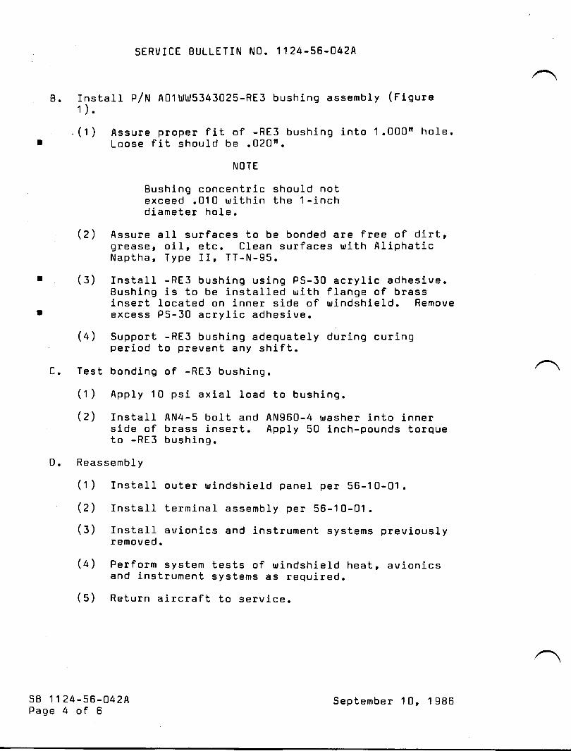
SERVICE BULLETIN NO. 1124-56-042A
B. Install P/N A01ltlt5343025-RE3 bushing assembly (F19ure1).
.(1 ) Assure proper fit of -RE3 bushing into 1.000n hoIe.I Loose fit should be .020n.
NOTE
Bushing concentric should notexceed .010 uithin the 1-inchdiameter hole.
(2) Assure all surfaces to be bonded are free of dirt,grease, oil, etc. Clean surf aces rrlith AliphaticNaptha, Type II, TT-N-95.
r (3) Install -RE3 bushing using PS-30 acrylic adhesive.Bushing is to be installed ulith flange of brassinsert located on inner side of uindshield. Remove
t excess PS-30 acrylic adhesive.
(a) Support -RE3 bushing adequately during curingperiod to prevent any shift.
C. Test bonding of -RE3 bushing.
(1 ) Apply 10 psi axial load to bushing.
(2) Install AN4-5 bolt and AN960-4 urasher into innerside of brass insert. Apply 50 inch-pounds torqueto -RE3 bushing.
D. Reassembly
(1) Install outer uindshield panel per 56-10-01 .
(2) InstaII terminal assembly per 56-1 0-01 .
(3) fnstall avionics and instrument systems previouslyremoved.
(a) Perform system tests of rrlindshield heatr BVionicsand instrument systems as required.
(5) Return aircraft to service.
5B 1124-56-042APage 4 of 6
September 10, 1986
QTY
A/RA/R
XNOTE:
SERVICE BULLETIN NO. 1124.56.042A
3. MATERIAL INFORMATION
PART NUMBER DESCRIPTION
A011d1J5343025-RE3 Eushing AssemblyPS-30 Acrylic Adhesivex
p5-30 acrylic cement is available from:
Cadillac Plastics & Chemical4070 Fulton Industrial Blvd. r 5.1/.AtIanta, GA 30336(aoa) osr -osoo
4. RECORD CCIMPLIANCE
Make the f ollorrling entry in the aircraf t log book:
Service Bulletin No. 1124-56-042A dated September 10' 1986titled trlnner bJindshield Repairrr has been accomplished thisdate
sB 1124-56-U42APage 5 of 6
September 10' 1986

SERVICE BULLETIN NO. 1124-56-042A
OUTER SURFACE
INNER SURFACE
BRASS FEED-THRU INSERT
AREA OF HEAT DAI{AGE
I INCH MAXIMT'MREPAIR,,ABLE
OUTER SURFACE
-RE3 BUSHING ASSY.
(BONDED WITH PS-30ACRYLIC CEMENT)
58 1124-56-042aPage 6 of 6
.gg0x
l. 000 "
FIGURE 1
September 10, 1986

9oo,ryioe friw/lotinA/ C s/N
6eo,tifi oote of Go rnTL lianoo
PLEASE FILL IN THE REQUIRED DATA BELOW AND RETURN TO:
ISMEL AIRCRAFT INDUSTRIES INTERNATIONAL, INC.P.0. BOx 10086WILIVIINGTON, DE 19850ATTN: TECHNICAL PUBLICATIONS
This is to certify that l{estwind Serial Number-has cornpliedwith Service Bulletin No.
1124-56-042A
Aircraft Regi-stration No
Airframe Total Tine at Compliance HOURS: /CYCLES:
Compliance Date
Otr{NER:
bySignature
ACCOMPLISHING AGENCY:
Please describe below any discrepancies found or difficultiesencountered during compliance :

PARTS AVAILABILITY
ALERT
DUE TO IEAD TIME(S) ENCOUNTERED IN
PROCURING PARTS REQUIRED FOR THE
ACCOMPLISHMENT OF THIS OPTIONAT
TECHNICAL PUBLICATION, ALL PARTS WILI,
NOT BE AVAITABLE FROM ATLANTIC AVIATION
SUPPLY COMPANY UNTIL

W{srnYrGE BULLETIT!
OPTIONAL
SERVICE BULLETIN NO. 1124-56-113 lune22, 1994
SUBJECT: WINDOWS - IMPROVED COCKPIT SIDE WINDOW INSTALLATION
1. PLANNING INFORMATION
A. EFFECTIVITY
MODEL ll24lll24{ WESTWINDS. all serial numbers.
B. REASON
Cockpit side windows (outer) have cracked in service at random attach points.
C. DESCRIPTION
This service bulletin provides instructions to install newly designed cockpit sidewindow assemblies. The new design incorporates features that reduce stressconcentration around bolt hole attachments. Assemblies include new fuselageskins to make windows interchangeable, which eliminates drilling operation forfuture replacement.
D. COMPLIANCE
Compliance is. optional and at the operators' convenience.
E. APPROVAL
This service bulletin has been reviewed by the Civil Aviation Administration ofIsrael (CAAI). The design content herein-complies with the applicable CivilAviation Regulations and is CAAI approved.
Iune22, 19941033
sB 1124-56-113Page 1 of7

SERVICE BULLETIN NO. 1124-56-113
F. MAN-HOURREQUIREMENTS
The following information is for planning purposes only:
(1) Estimated man-hours:
Left cockpit side window: 65
Right cockpit side window: 55
(2) Suggested number of personnel: 2
The above is an estimate only, based on experienced personnel complying withthis service bulletin. It is possible, depending on individual experience levels, thatadditional or fewer man-hours are required to accomplish this bulletin.
G. Material
OTY PART NUMBER DESCRIPTION
1 343017-507-51 LEFT COCKPIT SIDE WINDOWINSTALLATION
1 343003-50T-52 RIGHT COCKPIT SIDE WINDOWINSTALLATION
A/R 343031 SEAL, DV WINDOWA/R pR1422B SEALANT (OR EQUTVALENT)A/R 2024-T3 AL ALLOY SHEET FOR SHIMMING
Material required rnay be obtained through Astra Jet Corporation, New Castle,Delaware, or authorized ASTRA/WESTWIND Service Centers.
H. TOOLING
No special tooling required.
I. WEIGHT AND BALANCE
Not applicable
J. ELECTRICAL LOAD DATA
Not applicable
K. REFERENCES
Il24ll l24A Westwind Maintenance Manual, Chapter 53-00-00, 56-00-00,56-10-03, and 56-10{4. ' \Il24ll l24A Westwind Illustrated Parts Catalog, Chapter 56-10-00
sB I 124-56-1 l3Page 2 of 7
June22. 1994

SERVICE BULLETIN NO. IT24-56-T1,3
L. PUBLICATIONS AFFECTED
Il24lll24{ Westwind Maintenance Manual, Chapter 56-10-03 and 56-10-04.ll24lll24A Westwind Illustrated Parts Catalog, Chapter 56-10-00.
2, ACCOMPLISHMENT INSTRUCTIONS
A. Support aircraft to extent that structure is stable during drilling operation for sidewindow skin replacement.
B. Disconnect aircraft batteries.
C. Placard aircraft: NO ELECTRICAL POWER.
NOTE: The following instructions are for left cockpit side window installation,except for direct vision (DV) window installation, right installationprocedure is nearly opposite.
CAUTION: USE COLD LIGHTING EQUTPMENT ONLY, TO AVOIDDAMAGE TO ACRYLICS AND PLASTICS.
D. Prepare aircraft for window replacement as follows:
(1) Remove cockpit seats.
(2\ Remove fire warning relay box (under pilot seat) and forward relay box (underco-pilot seat).
(3) Remove trirn, upholstery, and equipment as necessary to access fastenersattaching side window skin to aircraft structure.
(4) Protect remaining cockpit equiprnent (consoles, throttle quadrant, instrumentpanel, windshield inner surface, etc.) from possible damage.
(5) Inspect DV window installation. Note fit in opening and flushness ormismatch to side window skin for reinstallation. Remove DV window,saving any shirn or shims, noting position for possible reuse. Inspectcondition of window seal. Replace if damaged.
(6) Mask off windshield outer surface and fuselage all around side window skinbutt joints.
(7) Carefully remove sealant in butt joints all around edge of side window skin.
CATITION: DO NOT USE METALLIC SCRAPERS OR WHEELS,DAMAGE TO STRUCTURE WILL LIKELY RESULT.USE PHENOLIC OR PLASTTC SCRAPERS AND CORKWHEELS FOR SEALANT REMOVAL.
sB 1124-56-113Page 3 of 7
June22, 1994

SERVICE BULT.ETIN NO. 1,124-56-113
E. Remove side window and skin as an assembly. Separating window from skin is not
necessary.
(1) Remove top row of fasteners first. Remove remaining fasteners in any
convenient sequence. To aid reassembly, ffiop fastener position (for grip
length) during disassembly.
(2) Separate skin from aircraft, beginning with lower aft corner, by carefully
forcing a cutting wedge (made from non-metallic material) between skin and
structure to break sealant bond.
(3) Remove all remaining sealant, noting position of any shims. Save shims forpossible reuse. Replace damaged shims as necessary during installation ofnew skin assembly.
F. Temporarily lay up new skin assembly to opening in aircraft structure.
NOTE: All the following work steps are best accomplished, though not required,at room temperature or warmer. Airframe and window temperatureshould be stabilized.
(l) Position skin assembly to best match contour of airframe. New skin maynotnecessarily match contours perfectly, since temperature changes can cause
acrylic materials to change shape. Gaps in contour are easilyclosed duringfit, trim and final assembly by tightening fasteners one by one, workingtoward gap(s).
(2) From inside aircraft, inspect all around new outer window for clearance fromstructure. If interference exists, mask to protect new skin along windowedge, trirn window as necessary to achieve clearance, and restore surfacefinish, reference ll24lIl24A Maintenance Manual, Chapter 56-00-00,Approved Repairs.
(3) Make from shop pattern paper a ternplate to match old skin edges and windowopening. U se tenrplate to lay out cut line on new skin.
(4) After initial trimrning, set new window and skin in opening and hold in place.Back drill holes through new skin, beginning with bottom row, working up tobut not including top row (nut strip). Clamp skin tightly in place with wingnut clecos, one by one as holes are drilled. If a gap is to great to safely closewithout darnaging hole in structure with a cleco, use bolts P/N AN4-X,washers P/N AN960-416, and nuts P/N AN3l5-4 (or equivalent).
sB 1124-56-113Page 4 of 7
Iune22, 1994

SERVICE BULLETIN NO. 1124-56-113
(5) Make a template from .050 inch AL Alloy 2024-0 (or equivalent), to locate toprow of holes. Use old window skin for pattern as follows:
(a) Back drill and bolt template to old skin in forward, center and aft holes ofsecond row, one by one.
(b) Form template to match contour of old skin and back drill top row ofholes.
(6) Bolt template to forward, center, and aft holes of second row on outside ofnew skin and pilot drill top row with # 30 drill and drill bushing. Use drillstop to prevent damage to nut plates on blind side. Remove template andcomplete drilling, again using drill stop.
(7) Clean out holes, install bolts and tighten.
(8) With new skin clamped tightly in place, inspect gaps in butt joints. Lay out cutline on new skin to achieve .020 to .050 inch gap in butt joints, constant allaround. Inspect butt joints all around for flushness. Measure any mismatch,and mark location and thickness, including taper for shims.
NOTE: Allowance must be made for sealant thickness (.010 to .015 inchnorninal), during final assembly.
G. Remove new skin assembly for final trimming.
( 1) Trim new skin along cut line as laid out. Remove sharp edges and sharpcorners. Chamfer inner surface of new skin edge .050" x 45'.
(2) Reuse or replace shirns as required.
(3) Install skin assembly with shims and clamp tightly in place all around. Verifygap and flushness requirement of paragraph 2.F.(8). Refit as required.
(4) After final fit is achieved, countersink all holes with piloted cutter andadjustable stop. Thoroughly clean with MEK and Scotch-Brite type pad allskin surfaces in preparation for sealing. Alodine, rinse, and spot prime bareareas with fluid resistant epoxy primer. Alodine, rinse, and epoxy primeshims.
(5) Clean and spot prime surfaces of frames all around fuselage opening.
CAIITION: DO NOT ALODINE ANY AREA ON AIRCRAFTSTRUCTURE. OXIDATION CAN OCCUR IN JOINTSNOT COMPLETELY RINSED AND NEUTRALIZED.
sB r124-56-113Page 5 of 7
June22, 1994

SERVICE BULLETIN NO. IT24-56-113
H. Install new side window and skin assembly.
(1) Mix sealant P/N PR|422B in accordance with manufacturers' instructions.
(2) Coat shims (if any) and surfaces of frames all around fuselage opening withsealant. Set shims and new skin assembly in place. Install new fasteners wetwith sealant under heads, in any convenient sequence. Torque fasteners50-70 inch pounds, observing squeeze out of sealant in skin butt joints, andall around skin and frames inside fuselage.
(3) Squeegee excess sealant from skin all around butt joints and allow to cure.Sand smooth and flush to skin prior to painting.
(4) Transfer all brackets, supports and angles, etc., from old window assembly tonew assembly, installing in same position for proper fit of window reveal andtrim.
I. Install DV window.
(1) Remove DV window hinge upper half P/N 343017-51. Install new hinge halfP/N 343017-51 on DV window with new hinge pin and stake both ends.
(2) Install DV window to achieve same or better fit as in paragraph 2.D.(5).Mismatch tolerance of DV window outer surface to new skin outer suiface is+ 0.000 - 0.125 inch.
(3) Leak check DV window as follows:
(a) Direct water spray at DV window.
(b) Check in cockpit for water penetration
(c) Open DV window and check for water dripping into cockpit from opening.
(4) If DV window fails leak check, verify seal is not damaged and create a form inplace airframe seal around window opening as follows:
(a) Secure DV window in open position with hold open stud.
(b) Clean inner surfaces of skin and zee angle all around window opening, toprovide good sealant bond.
(c) Mask outer surface of skin all around window opening.
(d) Coat inner surfaces frorn edge of opening to periphery of seal contactarea with liberal arnount of sealant p/N pRl422B.
sB r 124-56-113Page 6 of 7
Iune22, 1994

SERVICE BULLETIN NO. 1124-56-113
(e) Coat window and seal with release agent (petroleum jelly), close and latchwindow.
(0 Repeat cleaning, sealant coats, and release agent application, untilpositive squeeze out is achieved all around window seal on inner surfaceand outer surface of window.
J. Finish new installation to match aircraft colors.
K. Install all removed furnishings and equipment.
L. Perform operational checks of all systems affected.
3. RECORD COMPLIANCE
A. Make the following entry in the aircraft log book:
Service Bulletin No. I 124-56-113 dated June22, t994, titled "Windows -Improved Cockpit Side Window Installation", has been accomplished this date
B. Complete the attached Certificate of Compliance and return to Astra JetCorporation in New Castle, Delaware.
sB 1124-56-113PageT of 7
June22,1994

-.{m
i)
I1'mf,.Tl
orl-{o?rlm
om-{-um
iIDv-{-{o.Tl
or-oam
rzo
r
Serctice tsuffetin
Certificate of Compfiance
PLEASE FILL IN THE REOUIRED DATA BELOW AND RETURN TO:
Technical PublicationsAstra Jet Corporation77 McCullough Drive, Suite 11
New Castle, DE 19720
This is to certify that WESTWIND Serial Number- has complied withService Bulletin No.
1124-56-1 13
Aircraft Registration No.
-
Airframe Total Time at Compliance: Hours
Compliance Date:
-
Owner:
Signature
Accomplishing Agency:
Cycles
By:
Please describe below any discrepancies found or difficulties encountered
during compliance:

SERVICE PUBLICATIONS
revision noticeRECOMMENDED
SER\IrCE BULLETTN NO. LL24-57-004 September 9, I_985Revision No,l
SUBJECT: DRJAIN HOLES IN WING TRAILTNG EDGE STRUCTURE
REASON FORREVISION: To classify this service bulletin as
Recornmended.
sB 1124-57-004Page I of I
/@Wwrmm**
SUASIOIARY OF ISRAEL AIFCRAFT INDUSTFIES. LIOBEN GUNION AIFPONT, ISRAEL

tili{sERytcE BULLETINSERVICE BULLETIN NO. LL24-57-OO4 April 5, 1985
SUBiTECT: DRAIN HOLES IN WING TRAILING EDGE STRUCTURE
1. PLAI{NING TNFORMATION
ETFECTIVITY
MODEL LL24/LL24A WESTWINDS, alJ- serial numbers.
REASON
(1) To ensure that drain holes in wing trailing edgestructure are properly located and are the propersize.
(2) To ensure that proper drainage exists in theaffected area to prevent the collection of !"ater.
COMPLIATTCE
It is recommended that this service bulletin beaccomplished no Later than the next 150 hour inspection.
DESCRIPTTON
This service buLLetin requires an inspection of the winglower traiJ.ing edge structure to deternrine the conditionof existing drain paths and drain hol-es. It also pro-vides instructions to locate and driLl hol-es throughthe trailing edge skin that were not dril-J-ed duringproduction, and, to drill hole to proper size whereonly a piJ-ot hole exists.
A.
B.
c.
D.
/
@ III srmsp*t* t!!!,e.,o*,,n
SUBSIDIARY OF ISRAEL AIRCRAFT INDUSTRIES, LTD
BEN GURION AIRPORT, ISRAEL
sB LT24-57-OO4Page 1 of 6

SERVICE BULLETIN NO. IL24-57-OO4
E. APPROVAL
This service bulletin has been shown to comply with theapplicable ICAA/FAA regulations and is IAI Engineeringapproved.
F. MATERIAL
None required.
G. SPECIAL TOOLS
None required.
H. WEIGHT ATiID BALANCE
Not applicable.
I. ELECTRICAI LOAD DATA
Not applicable.
J. PUBIJICATIONS AFFECTED
None
2. ACCOMPLISHMENT INSTRUCTIONS
NOTE
Refer to attachedillustrations (Figures 1-3)for proper location ofdrain hol_es.
A. Apply external electric and hydraulic power to aircraftper aircraft Maintenance Manual. Lo$rer wing flaps to40o and raise speed brakes and lift dumpers.
CAUTION
B1eed off hydraulicpressure beforeturning off electricpower.
sB IL24-57-OO4Page 2 of 6
April 5, 1985

SERVICE BULLETIN NO. LL24-57-0O4
WARNING
Remove electric andhydraulic power forsafety of maintenancepersonnel.
B. Inspect trailing edge structure to ensure that allopenings between ribs and rear spar are clean and freeof dirt and debris. Ensure that all drain paths alongthe entire trailing edge structure are clean and open.
C. Inspect the lower skin of the trailing edge structure forthe presence of three (3) drain holes and that the holesare the proper size.
NOTE
Left and right wingsare typical.
If drain holes are inaccordance with thisservice bulletin r rrofurther action isrequired.
D. If drain holes are not locatedr oE holes are not theproper size, locate and driLL holes using standard shoppractices. Alodine holes after drilling.
E. Secure area and return aircraft to service.
3. MATERIAL TNFORMATTON
Not applicable.
4. AIRCRAFT RECORDS
Make the following entry in the aircraft 1og book:service Bulletin No. LL24-57-004 dated April 5, 1985, titledI'Drain Holes In Wing Trailing Edge Structurer'r has beenaccomplished this date
sB LI24-57-004Page 3 of 6
April 5, 1985
END

SERVICE BULLETIN }IO. 1124-57-OO4
DRAIN HOLE ATTHIS LOCATION PASSES THROUGH 7
MLG WHEEL FAIRING. i
654 SPAR
FLAP WELLSTRUCTURE
R]GHT WING
LEFT WING
-/ I | \I
AUXTLLARY / APPROXIMATESEE FIGURES
SHOWN (LOWER SURF'ACE)
TYPICAL
LOCATION OF DRAIN HOLES,2 & 3 FOR EXACT LOCATIONS.
sB LI24-57-OO4Page 4 of 6
FIGURE 1
April 5, 1985

SERVICE BULLETIN NO. LL24-57-OO4
+FWDLEFT
RIGHT
652
.250 DrA.HOLE
WING SHOWNWING TYPICAL
1 1tr
|NBD )
DRILLDRAIN
RIB ASSY.(REF. )
RIB ASSY.(REF. )
INBOARD FLAP HINGE ASSY. CUT-OUT(REF. )
sB LL24-57-004Page 5 of 6
April 5 | 1985
FIGURS 2.

SERVICE BULLETIN NO. LL24-57-OO4
+F}YD
o
o
o
oo
LEFT WING SHOWNRTGHT WING TYPICAL
TNSIDE SKIN PANEL(REF. ) OUTBOARD FLAP HINGE ASSY.
CUT-OUT(REr. )
sB IL24-57-004Page 6 of 6
126.000
DRTLL .250 DIA. DRAIN HOLE
RTB ASSY(REF. )
RIB ASSY.(Rer.1
FIGURX 3.
April S | 1995

(
SERVICE PUBLrcATONS
revision noticeREC0l,ll,lEl{DED
SERVICE BULLETIII l{0. lL?4-57-092 .lune 30, 1987Revision No.1
SUBJECT: }I II{GS - FLAP HINGE FASTEI{ERS - II{SPECTION/REPLACEI,IENT
R E ASON FORREvISI0N'
iJ;:?thtd:J'::'l' "i'.11"{.r
ofn'li;lr!l:'..T 13'lli
3. IIATERIAL IT{FORI{ATION
QTY PART NUI{BER DESCRIPTION
24* NASI6TI-081-6 Blind Fasteneror
24* P164A-6 (Alt P/N) Jo-Bolt
6* NAS1739B5-5 Rivet
Quantities per aircraft.
SUegrOrAeY OF rSRAEt arRCnaFT TNOUS?trES. tTDBEN OUNIOiI AIRPOAT. ISRAEI
s B 1r24- 57-092Revision No. tPage I of I

J twtsEBytcE BULLETITU
SERVICE BULLETIN NO.
RECOMM ENDED
LL24-57-O92
SUBJECT: WINGS - FLAP TIINGE F AST EN ERS
April 10, L987
TNSPECTTON/REPLAC EM ENT
1. PLANNING INFORMATION
A. EFFECTIVI?Y
MODEL Ll24/IL24A WESTIYIND, aII serial numbers.
B. REASON
To prevent potential stress corrosion failure of the flaphinge to flap fasteners made from H-11 steel.
C. COMPLIANCE
It is recommended that this servlce bulletin beaccomplished within the next 600 flight hours.
D. DESCRIPTION
This service bulletin requires &n inspection of theoutboard wing flap hinge to wing flap attach bolts todetermine if H-11 alloy steel bolts have been installed andprovides instructions to replace these bolts, if necessary.
E. APPROVAL
This service bulletin has been reviewed by the Israel CivilAviation Administration (ICAA). The lnspection andimprovements herein comply with the applicable CivilAviation Regulations and are ICAA approved.
F. M ATERIAL
Materlal required may be obtained through Atlantic AviationSupply Cornp&try, Wiimington, Delaware or thelr authorizedrep resentatives.
@ III s;rmsm*,!,t!r*, *.,,*SUBSIDIARY OF ISRAEL AIRCRAFT INDUSTRIES, LTD
BEN GURION AIRPORT, ISRAEL
sB LL24-57-092Page 1 of 4

G.
H.
SERVICE BULLETIN NO. LL24-57-O92
SPECIAL TOOLS
Not required.
W EIGHT AND BALANCE
Not applicable.
ELECTRICAL LOAD DATA
Not applicable.
RE FERENCES
I.
J.
\L?4/.LL24A Maintenance Manual, Chapter 22LL24/LL24A Illustrated parts Catalog, Chapter AT
K. PUBLICATIONS AFFECTED
LL24/LL24A Illustrated parts Catalog, Chapter bT
2. ACCOMPLISHMENT INSTRUCTIONS
A. Extend wing flaps to full down
B.
c.
D.
E.
F.
sB LL24-5?-O92Page 2 of 4
G.
control circuit breaker.
Remove flaps from aircraft.
position and disengage flap
Remove outboard and center outboard flap vanes.
Remove fiberglass wheel well fairing from flap.Remove outboard frap hinge access panels, top and bottom.
Remove 6 each rivets securlng each outboard flap hingeaccess panel leading edge support bracket and removebrackets.
Remove 8 each El{s8-90-4-8 or NAs11o4-gw borts from eachoutboard flap hinge assembly to flap assembly (see Figure1).
H. Remove outboard flap hinge assembly from flap.is &ssembled to inboard and outboard193513-L/-2 and is removed as an assembly.installed between fittings and flap; note shimreassembly.
NOTE: Hingefittings P/NShims may beposition for
Aprit 10, L98Z

QTY
8*
8*80*6*4*4*8*
L2*
L2*
SERVICE BULLETIN NO. LL24-57.O92
I. Inspect markings on bolt heads of fasteners which assemblefittings P/N 193513-1 and -2 to ftap hinge.
J. If bolts are ldentified as NAS1106 type bolts, proceed toStep L.
K. rf bolts are identified as ElTsB22 type bolts, replaceborts, one at a time, with new replacement bolts p/NBACBSOUS-6-26 or NAS1106-26W. Torque bolts to 120-150in-lbs.
L. Reinstall hinge assembly, with shims (if removed), torque geach Ews8-30-4-8 or NAS1104-8tT borts to b0-60 in-lbs.
M. Reinstall leadlng edge support brackets using NAS16?1-OBL-6or P164A-6 fasteners.
N. Reinstall hinge covers and wheel well fairings.O. Install flaps on alrcraft.
3. MATERIAL INFORMATION
PART NUMBER
B ACB30US-6-26or
NAS 1 106-26 W
NAS 1739B4-3NAS 173984-4NAS 173984-5rLP lK/ 42985M S20426B3NAS 1671-08L-6
or
D ES CRIPTION
Bolt
Bolt (alternate)RivetRivetRivetPop RivetRivet (length as required)Blind Fasteners
P164A-6 (AIt P/N) Jo-Bott*Quantities per aircraft.
4. RECORD COMPLIANCE
Make the following entry in the aircraft log book:
Service Bulletin No. lL24-57-O92 dated April 10, L987 titled"Wings Flap Hinge Fasteners Inspection/Replacement" has beenaccomplished this date .
sB LL24-57-092Page 3 of 4
April 10, 1987

SERVICE BULLETIN NO. LL24-57-O92
19351 3-2FITTING
oLD - EwsB2z-6-26A BoLT (4 Ea)NEW - BACB30US-6-26 BoLT (4 en)ALT - NASI 1 o6-25W BoLT (4 en)
NASl 1 04-8W 0REt{,s B- 30- 4- 8
lil?8li:3 If il lh'o)\ft-/._\97'
| 9351 3-1
93530-3193511-l1 9351 I -3OUTBOARD HI NGE
WING-TO-FLAP ATTACH FITTING
sB LL24-57-O92Page 4 of 4
FIGURE 1
Aprit 10, L987

-{m
t-l!m,'no!-{o7Im3om{!m
{@o-{{oF11or.9v,m
rz03It'
9eaadoe fialletin A/C S/N
Veotdfioate o/ Gom/oliatooe
PLEASE FILL iN THE REQUIRED DATA BELOW AND RETURN TO:
ISRAET AIRCRAFT INDUSTRIES INTERNATIONAL, INC.P.0. Box 10086l{IILMINGToN, DE 19850ATTN: TECHNICAL PUBLICATIONS
This is to certify that ltlestwind Serial Number-has complicdwith Service Bulletin No.
1 124-57-092Aircraft Registration No.
Airframe Total Tine at Compliance HouRs: /cYcLEs!
Conpliance Date
OWNER:
BySignature
ACCOMPLISHING AGENCY:
Please describe below any discrepancies found or di.fficultiesencountered during compliance :

ffiIlsEBvIcE BULLETTIU
RECOMMENDED
SERVICE BUILT'TIN NO. 1124.57-126
SUBJECT: WINGS. LEADING EDGE EXTENSION DRAINS
I. PLANNING INFORMATION
A. EFFECTIVITY
July 26,1995
MODEL I124 WESTWIND, all serial numbers.
B. REASON
Reports from the field indicate corrosion has been found on wing skin and leading
edge extension (droop section) during maintenance. In addition, fuel seepage
from wing integral fuel tank has caused damage to deicer boots, requiringpremature replacement.
C. DESCRIPTION
This service bulletin provides instructions to install drain holes in wing leadingedge extension skins.
D. COMPLIANCE
Compliance is recommended at the operator's earliest convenience.
E. APPROVAL
This service bulletin has been reviewed by the Civil Aviation Administration ofIsrael (CAAI). The design content herein complies with the applicable CivilAviation Regulations and is CAAI approved.
July 26,19951074
sB tl24-57-126Page I of4

SERVICE BULLETIN NO. I 124.57-126
F. MAN-HOUR REQUIREMENTS
The following is for planning purposes only:
(l) Estimated man hours: g
(2) Suggested number of personnel: I
The above is an estimate only, based on e4perienced personnel compllng withthis service bulletin. It is-possible, depending on individual r*dti;"; l&els, thatadditional or fewer man-hours are required i-o accomplish this bufGlin
G. MATERIAL
qTY. PART NUMBER DESCRIPTION
A/R EPOXY PRIMER4 1124.57.126 PLACARD (SILK SCREEN
RENTAL AVAILABLE)*AtR MS24694S49 scREW*A/R MS24694S50 scREW*A/R M524694552 scREW
* AN509-10R7, -10R8, -l0R l0 are equivalent screws, respectively (old standard).
Material required may be obtained thr-ough Astra Jet Corporation, New Castle,Delaware, or authorized ASTRA Service Centers.
H. TOOLING
No special tooling is required.
I. WEIGHT AND BALANCE
Not applicable.
J. ELECTRICAL LOAD DATA
Not applicable.
K. REFERENCES
None.
L. PUBLICATIONSAFFECTED
None.
sB tl24-57-t26Page 2 of 4
July 26, 1995
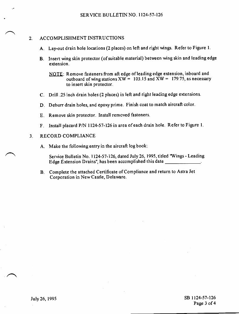
SERVICE BULLETIN NO. 1124-57.126
2. ACCOMPLISHMENTINSTRUCTIONS
A. Lay-out drain hole locations (2 places) on left and right wings. Refer to Figure l.
B. Insert wing skin protector (of suitable material) between wing skin and leading edgeextension.
NOTE: Remove fasteners from aft edge of leading edge extension, inboard andoutboard of wing stations XW : 103.15 and XW : 179.75, as necessaryto insert skin protector.
C. Drill .25 inch drain holes (2 places) in left and right leading edge extensions.
D. Deburr drain holes, and epoxy prime. Finish coat to match aircraft color.
E. Remove skin protector. Install removed fasteners.
F. Install placard PA{ I124-57-126 in area of each drain hole. Refer to Figure 1.
3. RECORD COMPLIANCE
A. Make the following entry in the aircraft log book:
Service Bulletin No. 1124-57-126, dated luly26,l995, titled 'Wings - LeadingEdge Extension Drains", has been accomplished this date
B. Complete the attached Certificate of Compliance and return to Astra JetCorporation in New Castle, Delaware.
sB ll24-s7-r26Page 3 of4
July 26, 1995

SERVICE BULLETIN NO. I124.57-126
Wing Leading Edge ExtensionView Looking Up, Right Side, Left Side Opposite
FIGURE T
sB rt24-57-t26Page 4 of 4
TRACE )ffV = 187.00 (REFJ
PLACARD
PN 1124-57-126 | FWo
\\ L_>|NBD
ffi0.2S lN. DIA I MUsr BE KEPr CLEAR
I
DRAIN HOLE -. O.75IN.----------*
+
-$'+4'++i(>i+-L9
TRACE XW= 109.50 (REF.)PLACARD
P/N 1124-57-126
t*oL------->INBD
0.25 tN. DtADRAIN HOLE
0.75lN.
q 9-r+ -ell .-l -J =
Iuly 26, 1995

-{m
t+'omI.Tl
of,-{o7ftm
o/^.mr\_{
tlm
-{q,o{-.{o.Tl
ot--aU,m
t-
z0>t-
Sentire tsuffetin
C etiftrate of C omp fiance
PLEASE FILL IN THE REOUIRED DATA BELOW AND RETURN TO:
Technical PublicationsAstra Jet Corporation77 McCullough Drive, Suite 11
New Castfe, DE 19720
This is to certify that WESTWIND Serial Number- has complied withService Bulletin No.
1124-57-126Aircraft Registration No.
-
AirframeTota|TimeatComp|iance:Hours-Cyc|es-
Compliance Date:
Owner:
Signature
Accomplishing Agency:
Please describe below any discrepancies found or difficulties encounteredduring compliance:

TilT{sERvtcE BULLETTIU
NO. 1124-71-09'l REVISION 2 June 2, 1 989
TRANSMTTTAL SHEET
This sheet transmits Revision 2 to Service Bulletin No. 1124-71-09',dated April 10, 1987, titled, "Powerplant Forward Engine MountFasteners Inspection/Replacementr" (AFC 20651.
REASON FOR REVISION:
This service bulletin is revised to:(1 ) Alter its classification from RECOMMENDED to MANDATORY in order to
assure the termination of inspection by accomplishing thefasteners replacement.
(21 The fasteners replacement period was revised from 1 2 calendarmonths to t'the next engine removal.tt
(3) The option for installation of new H-11 fasteners is removed.
NOTE: Equipment modified utilizLng the new BAC hardware inaccordance with Part II of previous issue of thisservice bulletin does not require further rework.
This service bulletin is reissued j-n its entirety to revise complianceunder paragraph 1.c. and to incorporate previous revision No. 1 datedNov. 20, 1987.
Bulletin title is revised to reflect Revision 1. Title page is revisedto reflect latest revision date.
This is a COMPLETE REVISION. Pages revj-sed are listed below. TheIetter rrRrr in the margin shows where changes are made. Please removeand discard all pages of previous issues and replace with pages of thisrevision.
June 2, 1 989Copyright 1 989
TRANSMITTALPage 1 of 2

SERVICE BULLEIIN NO. 1124-71-091
SECTION-1 ,,A.
Paragraph 1.A. EFFECTIVITY is revised to reflect Revision No. 1.
Paragraph 1.C. COMPLIANCE PART 1 is revised to eliminate calendar timellmitation and to stipulate bolts replacement at next engine removal.
SECTION-2
Part T, Paragraph E is revised to stipulate corroded fasteners forrepeated Part I inspection every 1 50 flight hours if not replaced.
Part II, Step C(1 ) is revised to reflect revision No. 1.
Part II, Step C(5) (a) of Revision No. 1 is removed.
SECTION-3
Material information is revised to reflect Revision No. 1.
SECTION-4
RECORD OF COMPLIANCE is revised to reflect Revision No. 1.
Figure 1 is revised to reflect Revision No. 1.
LIST OF EFFECTIVE PAGES:
Paqe No. Date Paqe No. Date
1 June 2, 19892 June 2, 1 9893 June 2, 19894 June 2, 1989
PREVIOUS ISSUES OF SB 1 1 24-71 -091
Initial issue dated Apr. 1 0, 1987Revision 1, dated Nov. 20, 1987
5 June 2, 1 9895 June 2, 19897 April 1 0, 19878 April 10, 1987
TRANSMITTALPage 2 of 2June 2, 1989

twtSERyICE BULLETTil
MANDATORY
R
SERVICE BULLETIN NO. 1124.71-091
SUBJECT: POWER PLANT FORWARD ENGINErNspecrron/nepr,acEMENT (AFc
April 10, 1987
MOUNT FASTENERS20651.
1. PLANNING INFORMATION
A. EF'F'ECTIVITY
Model 1124/ 1 1 24A Westwinds,except 432, 435 and 438.
all serial numbers prior to 441
B. REASON
To prevent potential stress corrosion failure of the forwardengine mount mounting bolts and nuts made from H-11 stee1.
C. COMPLIANCE
PART I - Within the next 1 50 hours for aircraft with morethan 600 hours for aircraft with less than 600 hours time inservice.
Repeat PART I instructions within maximum intervaLs of 300flight hours until compliance with the PART If instructionsfor replacj-ng the fasteners is accomplished.
PART II - At next engine removal for any reason, includingremoval for the next engine major periodic inspection,
D. DESCRTPTION
PART I of this service bulletin provides J-nspectionprocedures for the engine mount attach fasteners.PART II of this servj-ce bulletin provides instructions toreplace the engine mount attach fasteners.
RR
RRR
RRR
RR
RR
April 10, 1987Revision 2, June 2, 1989
sB 1124-71-091Page 1 of 8

SERVICE BULLETIN NO. 1124-71.091
E. APPROVAL
This service bulletin has been reviewed by the Israel CivilAviation Administration ( ICAA). The inspection andimprovements herein conply with the applicable Civil AviationRegulations and are ICAA approved.
F. MATERIAL
Material required may be obtained through Atlantic AviationSupply Company, Wilmington, Delaware, or their authorizedrepresentatives.
G. SPECIAL TOOLS
Torque wrench adaptor (see Figure 3).
H. WEIGHT AND BATANCE
Not applicable.
I. ELECTRICAL LOAD DATA
Not applicable.
J. REFERENCES
1124/1124A Maintenance Manual, Chapter 711124/1124A Illustrated parts Catalog, Chapter 71
K. PUBLTCATIONS AFFECTED
1124/1124A Illustrated parts Catalog, Chapter 71
2. ACCOMPLISHMENT INSTRUCTIONS
PART I: Gain access to fasteners attaching Fl0A-5-810555 forwardengine mount located at engine station 200.00 (seeFigure 1 ).
A. Remove access panels on underside of pylon, forward and aftof engine mount assembry. Remove top and bottom enginecowling.
B. Disconnect P/N 26948-2 Teleflex engine throttle controlquick-disconnect.
sB 1124-7 1 -091R Page2 of8 April 10, 1987Revision 2, June 2, 1989

c.
D.
SERVICE BULLETIN NO. 1124-71-091
Remove P/N F1 0A5P20230-1 fire extinguisher nozzLe.
Remove bolts securing fireshield to pylon and removefireshield section to gain access to pylon interior andengine mount hardware.
Visually inspect bolt heads and nuts for any signs ofcorrosion. If signs of corrosion are found and the fastenersare not replaced as a result of instructions given in Step F,then repeat Part I inspection every 1 50 flight hours insteadof 300 hours.
Apply torque of 180-220 in-Ibs to the nuts of the 7/16-inchdiameter bolts and a torque of 450-500 in-lbs to the nuts ofthe 9/16-inch diameter bolts. (If necessary, use extensionadaptor, Figure 3, or other suitable adaptor. ) If bolt ornut movement is observed while applying torque, comply withPart II of this servj-ce bulletin before further flight.
NOTE
When using an extension adaptor on a torque wrench, itis necessary to calculate the correct indicated torque.
G. ff corrosion is not detected and movement of bolts or nuts isnot observed while applying torque, replace fireshieldinginside pylon, connect fire extinguisher nozzJ-e and reconnectengine throttle controls. Replace access panels.
H. Repeat for other engine forward mount.
PART IT
A. Remove engine. Reference 1124/1124A Maintenance Manual,Chapter 71 -00-00.
B. Remove panels necessary to access forward engine mountfastener nuts. (See PART T, Steps A through D of thisservice bulletin. )
C. Remove and replace forward engine mount attach fasteners, oneat a timer ds follows:
(1 ) Remove and discard old fasteners, bolt, nut, washersunder bolt head and nut and PLI washer assy (see Figure1).
(21 Check for surface defects in fastener holes such ascorrosj-on, scratches, nicks or cuts intersecting a partsurface.
E.R
RRR
F.
RR
RApril 10, 1987Revision 2, June 2, 1989
sB 1124-7 1 -091Page 3 of 8

SERVICE BULLETIN NO. 1124-71.091
(3) Nuts, bolts and threads shallnicks, dents and sharp edges.
(41 No lubricant shall be used onhole.
(5) Install new bolt in hole with
be free of all burrs,
the fastener or in the
washers per Figure 1.
RRR
R
(6) Install new PLI washer assembly as required andassembled per Figure 2.
NOTE
Do not remove wax coating from inner pLI washer.
(71 Install new nut.
CAUTION
Never continue to tighten a bolt or nut which hasstarted to cross thread. Scrap bolt and nut if thisoccurs.
(8) Torque attaching bolt as follows:(a) Tighten nut snug against pLI washer set. (See
Detail B, Figure 2.1
(b) Tighten nut in gradual (1 /B turn maximum)increments. Test outer pl,f washer for rotation byinserting a scribe (or equivalent) in perimeterholes. When the outer washer can no long be moved,the desire preload torque has been obtained. (SeeDetails C and D, Figure 2.1
CAUTION
Do not overtighten. rf nut is tightened more than1 /A turn beyond point where outer pLI washerbecomes immovable, the entire bolt, nut and washerassembly must be replaced.
(9) Repeat steps 1 through 8 for remaining fasteners.
RsB 1124-7 1 -091Page 4 of I April 1 0, 19A7
Revision 2, June 2, 1989

SERVICE BULLETIN NO. 1124-71-091
D. Apply tamper-proof sealant, EC-1 252, White, to each torquedfastener installati.on.(1 ) Clean only those parts to receive sealant with Methyl
Ethyl Ketone (MEK).
(21 Apply strips of sealant across end of exposed bolt endtdown the nut and across the PLI washers so that anyturning action will break the stripe seal.
E. Replace fireshielding inside pylon, connect fire extinguishernozzLe and reconnect engine throttle controls. Replaceaccess panels.
F. Reinstall engine.
G. Repeat for other engine forward mount.
3. MATERIAL INFORMATION
QTY PART NUMBER DESCRIPTION
4* BACB3OUS9P29 BoIt4* BACB3OUS7P20 BoIt
R 4* 313721-11 Washer (under BACB3OUS9P29 BOLT HEAD)R 3* 313721-13 Washer (under BACB3OUS7920 BOLT HEAD)
z.rn ii 3l3l?l#:;"" ftlgt" (under BAcB30us7P20 BoLr HEAD)
4* BACN1 OHR-7CD Nut4* PLI-9-21.6 Pre-Ioad Indicating Washer Set4* PLT-7-12.4 Pre-load Indicating Washer Set
R 4* 313721-17 Washer (under PLI-9-21.6 Washer Set)
* Quantities for one engine mount
4. RECORD COMPLIANCE
R A. Make the following entry in the aircraft log book:
(1) If fasteners inspection complied with Part I, enter:Part I of Serviee Bulletin No. 1124-71-091, dated April10, 1987, titled, "Powerplant Forward Engine MountFasteners Inspectiol], " has been accomplished this date
R (2) If fasteners replacement complied with Part IIr enter: _
R Part II of Service Bulletin No. 1124-71-091 ' dated AprilR 10, 1987, Revision No. 2, June 2, 1989, titled,R "powerplant Forward Engine Mount Fasteners -RReptacement,''hasbeenaccomp1ishedthisdate
R B. Complete the attached certificate of compliance and return to,-R Astra Jet Corporation in Wilmington, Delaware.
RRRRR
April 10' 1987R Revision 2t June 2, 1989
sB 1124-7 1 -091Page 5 of I

SERVICE BULLETIN NO. LL24-7I-O9I
Fl0A-5-BI0555SORWARD ENGINE !,IOUNT
(ner.1
!
NAS1758L7 NUT(4 PLCS) - DISCARDBAOIIOHR-7CD NUT(4 PLcs) - NEw
PLT 7-L2.4PRE-LOAD INDTCATING
WASHER SET(4 PLCS)
INSTALLATION OF FORWARD ENGINE MOUNT
ATTACHMENT FASTENERS
FIGURE 1
MS2l297-07020 BOLT(4 PLCS) - DISCARDBACB3OUSTP2O BOLT(4 PLCS) - NEW
313721-L WASHER(3 PLCS) - DISCARD313721-13 WASHER(3 PLCS) - NEW
3L372I-5OI ANGLE - DISCARD
313721-503 AI.lcLE - NEW
(FWD on L.H. SIDE)(Art on R.H. SIDE)
3L372L.3 WASHER(4 PLCS) - DISCARD3I372I-11 WASHER
(4 PLCS) NEW
2 3L3742.I BOLT - DISCAID(nrn. 2 PLACES FI{D SIDE)
t'152L297-09029 BOLT - DISCARD
(RET. 2 PLACES AFT SIDE)
BACB3OUS9P29 BOLT (4 PLCS) - NNW
(2 PLCS FWD SIDE)(2 PLCS AFT SIDE)
April 10, 1987Revision 2, June 2, 1989
(4 PLCS) - DISCARDBACN1OHR-9CD(4 PLcs) - NEI^I
PLr 9-21"6
sB 1124-71-091Page 6 of I
PRE-LOAD INDICATINGWASHER SET(4 PLCS) 313721-9
(4 PLCS)3L372L-L7(4 PLCS)
WASHER
- ulJ\Jttr.lJWl{ilH.llK
. NEW

SERVICE BULLETIN NO. LL24-7L-O9L
^(\o\.\- |AT6, / Ltrr'lt sTEEL wAsHER
Y. )Y,/,<\ ,J(( \ \ YTNNER PLr WASHER\\ v \\.117:--Jl7
( \( L__\ fX \ SOUTER PLI WASHER\P)t'\-J
4-FLAT sTEEL WASHER
A. TYPICAL PLI WASHER ASSEMBLY
B. INITIAL POSITIONPLI WASHERS
OF
C. TIGHTENED TO DE-SIRED PRE.LOAD
D. TESTING OUTER WASHERFOR MOVEMENT
INSTALLATION OF PRE-LOAD INDICATING WASHERSUNDER NUTS
FIGURE 2
sB LL24-7t-O9lPage 7 of 8
April 10, 1987

,a- + .003.000
.\73
(
SERVICE BULLETIN NO. LL24-71.091
SCR I BE ON
.394 R
.02 4 xTYP -'l.2 REF.
-
.375 + .000
FI LLET
TORQUE WRENCH ADAPTOR
FIGURE 3
"3/8 DRlvE"
3/r," sroc*-' -l l--'003
Ilr-tl.EE
sB LI24-71-O91Page 8 of 8
A pril 10, L987

-.tm
I{!ma.Tl
oI{5?l)m
om{!m
-{@oJ{o'no1--oa)mrzI
r
9eo,ryioe 9etteo A/C S/N
Geo,tiftoate o/ 6om/o/ia,noo
PLEASE FILL IN THE REQUIRED DATA BELOI{ AND RETURN TO:
ASTRA JET CORPORATIONP. O. Box 10085Wilmlngton, DE 1 9850Attn: Technlcal Publications
This is to certify that westwind Serial Nunber has conpliedwith Service Letter No. IL24-71-09I Rev. 2
Aircraft Registration No.
Airframe Total Time at ComPliance
Conpliance Date
OI.INER:
Drr >rfl
ACCOI'{PLI SHING AGENCY :
Please describe below any discrepancies found or difficultiesencountered during comPliance:

SERVICERevision No. I
BULLETTN NO. 1124-7r_091 Novenber 20t l9g7
SUbJCCt: POWER PLANT . FORT{ARD ENGINE MOUNT FASTENERS-R rNspEcTroN,/REprecsuf[r-ierc 20G5)
REASON r.OR REVTSTON:
l) To limit aircraft seriar nunbers effectivety underparagraph 1.A. TPLANNTNG TNFoRMATION.i2l t{asher instarled under gacilorii-gpfi'"ra BAcB3ou slp20bort heade and ptr-9-2r.G ,JJrr", set ire ieplacedwith new reduced thickness to ascertain a[osab]ebolt thread protrusion.3) Record compil.ance in aircraft log book intwo parts: part f 'fnspection, ina-p"ri-lf
"Replacenent.r
I. PLANNING INFoRITIATIoN
A. EFFECTIVITY
Mod.e L-LL24;/LL24A titestwinds, all serial nunber.^s priorto 441 except 432, 435 and 43g.
2. ACCOI.{PLISHI,TENT INSTRUCTIONS
PART TI
c.(1). Renove and discard oId fasteners, bort, nut,washers un-der bolt head and nut and pl,r rasherassy (see figure_l).c.(5). rnsta[ new bolt in hole with washers per Fig. r.
(a) New (unused) H-11 steel bolts and nute nay.. beinstalled Lt for any reason the substitutefasteners are not Jvailable, s"uieci tothe linitations described i; p"rf-i comptianceof this service bulletin.
RR
RR
R
RRRRR
NIWIfrIPML JG"u&riga-rw*
SutEtot^Fv oF tsRA€L AtnCnarl tNou$TntGs8EN OUnION AtRFORT. TSFAEL
sB LL24-71-09IRevision No. IPage I of 3

SERVICA SftLLF:ilIN tO.,l
LL2l* ?l-091
RRR
3. xlf E FIAI., { $rog}r ATrOr
033 ptB.s: {uf sf8fr BACB30us gP29t'* BACB30us 7P2Ad* 313721-lt3* 313721-131* 3r37?r-5031* BACDIlOHR-9CD4t* BACNI0HR-7CD4* PLr- g- 21.54* PLr- 7-I2a4{* 313721-1?
t Quantities for
D ESCRTPTION
Bol.tBoltt{asher (under BACB3ousgp2g EOLTHasher (under BACB3OUSTpt0 BOLTAngle (under BAcB3ous 7P2a BOLTNutNutPre-load fndicating Washer SetPre-load indicating wast ei setWashqr (under p&r-9-21.6 wagher
one engine aount
HEAD)IIEAD)TIEAD)
Set)R
RRRRR
RRRRRR
RR
{. RECORD CQI{PLIANCE
A. r'lake the forlowing entry ia the aircraft rog books(1) rf fastenerE insp-ectioa eonrpried with part renter: part r ot. service g"u'eiin-l;.-iizl-71-0el dated Aprn ro,-iiai- iitia; ;'ji*.:?pranr
Forward engine _r.ount rr,*tbnl-rr-I rilJIitioo,,has been actonptish;d i[ii-a"t"(Z', If fasteners re.pllce^ment comnrr.ffientetr: part rr of_ service-iiriGtr,i lo.'t-iz*_z1_091 dated April r0, igSZl Revieion No. INovember 2O, tgal, tit}J;ro*"rpfant l-.Forwa.rd Engine u6unt-FistJners _ Replacernentr"has been aCconplisrr-ee t;;;-;;t;:,
B' conplete the attached certificatp of conprianceand return to rArr in $riG;;;;;.
sB LL24-7I-091Revision No. IPage 2 of 3
Novenber 20, l9g7

SERVICE BULLETIN NO. 1I24-7T-O9I
FI0A-5-B10555FOR!{ARD ENGINE MOT'NT(ner.1
NASI758L7 NUT(4 PLcs) - DrscARD
BACNIOHR-7CD NUT(4 PLCS) - NE!{
PLT 7-L2.4PRE-LOAD INDTCATING
WASHER SET(4 PLCS)
NAS1758L9 NUT(4 PLCS) - DrscjrRD
BACN1OHR-9CD(4 PLcs) - NE!{
PLr g-21"6PRE-IPAD INDICATINGWASHER SET(4 PLCS)
INSTALLATION OF FORWARD ENGINE !{OUNTATTACHMENT FASTENERS
FIGURE 1
!ts21297-07020 BoLT(4 PLcs) - DrscARD
BACB3OUSTP2O BOLT(4 PLCS) - NE!{313721-1 WASHER(3 PLcs) - DrscARD313721-13 WASHER(3 PLcs) - NEr{
313721-50l AI.IGLE - DISCARD313721-503 AI{GLE - NE!{(FWD on L.H. SIDE)(AFT on R.H. SIDE)
313721-3 WASHER(4 PLCS) - DISCAR.D313721-11 WASHER(4 PLCS) r{EW
2 3L3742.1 BOLT - DISCARD(REF. 2 PI.ACES E!{D SIDE)W2T297-09029 BOLT - DISCJ\RD(NST. 2 PLACES AFT SIDE)BAC3OUS9P29 BOLT (4 PLCS) - NEi.r(2 PLCS E!{D SrDE)(2 PLCS AFT SIDE)
s B 112 4- 71- 091Revision No. IPage 3 of 3
31372r-9(4 PLCS)313721-17(4 PLCS)
WASITER
- DISCARDWASHER
- NEI{
November 20, lgBz

rHsEBvrcE BULLET|IU
R
R
MANDATORY
SERVICE BULLETIN NO. 1124-71-091 April 10, 1987
SUBJECT: POWER PLANT FORWARD ENGTNE MOUNT FASTENERSTNSPECTTON/REPLACEMENT (AFC 20651.
PLANNING TNFORMATION
A. EFFECTTVITY
Model 1124/'11 24A westwinds,except 432, 435 and 438.
B. REASON
all serial numbers prior to 441
To prevent potential stress corrosion failure of the forwardengine mount mounting bolts and nuts made from H-1 1 steel.
C. COMPLIANCE
pART I - Within the next 1 50 hours for aircraft with morethan 600 hours or at 5OO hours for aircraft with less than500 hours time in service.
Repeat PART I instructions within maximum intervals of 300flight hours until compliance with the PART II instructionsfor replacing the fasteners is accomplished.
PART II - At next engine removal for any reason, includingremoval for the next engine major periodic inspection.
D. DESCRIPTTON
PART I of this service bulletin provides inspectionprocedures for the engine mount attach fasteners.
PART If of this service bulletin provides instructions toreplace the engine mount attach fasteners.
1.
RR
RRR
RRR
RR
RR
April 10, 1987Revision 2, June 2, 1989
sB 1124-71-091Page 1 of 8

SERVICE BULLETIN NO. 1124.71-091
E. APPROVAL
This service bulletin has been reviewed by the rsrael CivilAviation Administration (ICAA). The insp6ction andimprovements herein comply with the applicable Civil AviationRegulations and are ICAA lpproved.F. MATERIAL
Materiar requi-red may be obtained through Atlantic Aviationsupply company, wirmington, Delaware, oi their authorizedrepresentatives.
G. SPECIAL TOOLS
Torgue wrench adaptor (see Figure 3).H. WETGHT AND BALANCE
Not applicable.r. ELECTRICAL LOAD DATA
Not applicable.
J. REFERENCES
1124/1124A Maintenance Manual, Chapter 711124/1124A rllustrated parts iatalig, chapter 71
K. PUBLICATIONS AFF'ECTED
1124/1124A rrrustrated parts catarog, chapter 71
2. ACCOMPLISHMENT INSTRUCTIONS
PART r: Gain access to fasteners attaching FlOA-5-B10555 forwardengine mount located at engine stition 2oo.o0 (seeFigure 1 ).A' Remove-access panels on underside of pylon, forward and aftof engine mount assembry. Remove top-ind bottom enginecowling.
B' Disconnect P/N 26948-2 Tereflex engine throttre controlquick-disconnect.
sB 1124_7 1 _091R Page2 ofg April 10, 1997
Revision 2, June 2, 1999

B.
c.
D.
SERVICE BULLETIN NO. LLaA-7L-O}L
Dlsconnect p/N 26949-2 Teleflex engine throttte controtquick- dlscon nect.
Remove P/N F10Abpz02go-1 fire extinguisher nozzLe.
Remove borts securing fireshierd to pylon and removefireshield section to gain access to pyion interior andengine mount hardware.
visually inspect bolt heads and nuts for any signs ofcorrosion. rf corrosion is detected, comply wiin pART Irof this service bu[etin before turttrer triErri. - J
Apply torque of Lgo-zzo in-lbs to the nuts of the 7/16inch diameter bolts and a torque of 4so-boo in-lbs to thenuts of the 9/L6 inch diameter borts (if o""."""ry, useextension adaptor, Figure 3, or other suitable adaptor).rf bolt or nut movement is observed whire apptying- torqu.,comply with Part rr of this service burletin beforefurther flight.
NOTE
l[ hen using an extension adaptor on atorque wrench, it is necessary tocalculate the correct indicated torqrie.G' rf corrosion is not detected and movement of borts or nutsis not observed while apprying torquL, replacefireshielding inside pyron, cbnnect fire extinguishernozzLe and reconnect -engine throttle controts. Replaceaccess panels.
H. Repeat for other engine forward mount.
PART IIA' Remove engine. Reference 1L24/LL24A Maintenance M&nual,Chapter Z1-00-00.
Remove panels necessary to accessfastener nuts. (See pAnf I, Stepsservice bulletin.)Remove and replace forward engine mountone at a time, as follows:
E.
F.
B.
c.
forward engine mountA through D of this
attach fasteners,
sB LL24-7I-O9LPage 3 of 8
April 10, L987
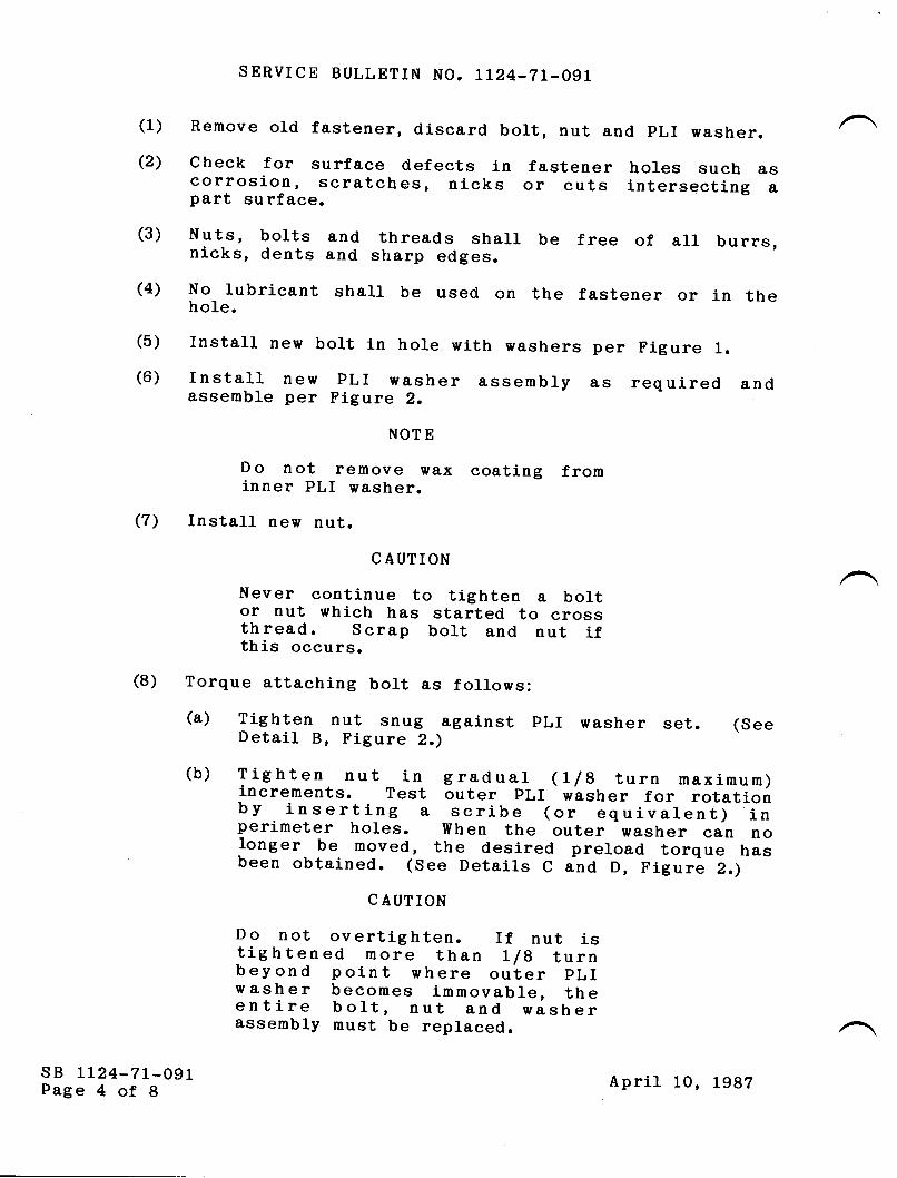
(1)
(2)
SERVICE BULLETIN NO. IL24.7L-O?L
Remove old fastener, discard bort, nut and pLI washer.
check for surface defects in fastener holes such ascorrosion, scratches, nicks or cuts intersecting apart surface.
Nuts, bolts and threads shalr be free of all burrs,nicks, dents and sharp edges.
No rubricant shalt be used on the fastener or in theho1e.
rnstall new bolt in hole with washers per Figure 1.
rnstall new PLr washer assembry as required andassemble per Figure 2.
NOT E
Do not remove wax coating frominner PLI w&sher.
Install new nut.
C AUTION
Never conti_nue to tighten a boltor nut which has started to crossthread. Scrap bolt and nut ifthis occurs.
(8) Torque attaching bolt &s follows:(a) Tighten nut snug against pLI washer set.Detail B, Figure 2.)
(See
(3)
(4)
(5)
(6)
(7)
sB LL24-7L-O9LPage 4 of 8
(b) Tighten nut in graduat (t/g turn maximum)increments. Test outer pLr washer for rotationby inserting a scribe (or equiuJf.ntj--loperimeter holes. when the outer washer can nolonger be moved, the desired preload torque hasbeen obtained. (See Details C and D, Figure 2.)
C AUTION
Do not overtighten. If nut istig htened more than Ilg turnbeyond point where outer pLIwasher becomes immovable, theentire bolt, nut and washerassembly must be replaced.
April 10, L98T

4*4*4*4*4*4*
SERVICE BULLETIN NO. LL24-7L.O}L
(9) Repeat steps 1 through g for remaining fasteners.D. Apply tamper-proof sealant, EC- Lzsz, white, to each torquedfastener installation.
(1) Clean only those parts to receive searant with MethytEthyI I(etone (MEK).
(2) Apply- stripe of searant across end of exposed boltend, down the nut and across the pLr washers so thatany turning action will break the stripe seal.E. Replace fireshielding inside pylon, connect fireextinguisher nozzLe ano reconnect engine throttrecontrols. Replace access panels.F. Reinstall engine.
G. Repeat for other engine forward mount.3. MATERIAL INFORMATION
QTY PART NUMBER
B ACB3OUS9P29BACB3OUS?P2OB A CNlOHR-9CDB ACNlOHR-7CDPLT-9_2L.6PLI.7-L2.4
D ES CRIPTION
BoltB oltNutNutPre-load Indicating I{asher SetPre-Ioad Indicating Washer Set
4.
*Quantities for one engine mount.
RECORD COMPLIANCE
Make the following entry in the aircraft log book:service Burletin No. LLz|-zr-ogL dated April 10, Lgg? titred"Powerplant Forward Engine Mount Fasteners : rnspection/Replacement, " part ___, has been accomplished thisdate
sB LL24-7L-O9LPage 5 of 8
April 10,1982
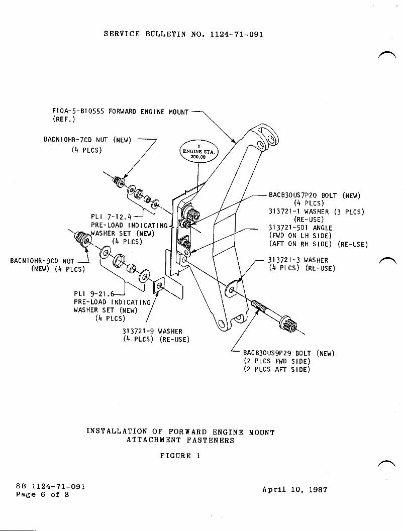
SERVICE BULLETIN NO. IL24-7L-O97
FlOA.5-810555 FORWARD ENGINE MOUNT(ner.;
BAcNIoHR-7cD NUT (NEt/)
(4 Plcs)
PL | 7-12.4
BACNl OHR-9CD(rurw1 (tr
BAcB30Us7P2o BoLT (ruew1
1+ elcs)313721-I trAsHER (3 plcs)
(nr- use)313721-501 ANGLE(rt.to oH r-n sroe)(err oru nn slor) (ne-use)
313721 -3 WASHER(4 plcs ) (ne- use )
313721-9 WASHER(4 PLcs) (ne-usE)
BAcB3ous9P29 BoLT (ruew)(z pr-cs FwD stDE)(z pr-cs Rrr sroe)
INSTALLATION OF FORWARD ENGINE MOUNTATTACHMENT FASTENERS
FIGURE 1
sB tL24-7L-O9LPage 6 of 8
PRE-LOAD INDICATINGAsHER sET (Hew)
(4 p t-cs )
pt-cs )
PLI 9-21PRE.LOAD I ND I CATI NG
t.lASHER sET (Hew)(4 pr-cs)
April 10, L987

SERVICE BULLETIN NO. LL24-?1-091
INNER PLI WASHER
A. TYPICAL PLI WASHER ASSEMBLY
B. INITIAL POSITIONPLI WASHERS
OF
C. TIGHTENED TO DE.SIRED PRE-LOAD
', .t,'t.._
."/'
D. TESTING OUTER WASHERFOR MOVEMENT
INSTALLATION OF PRE-LOAD INDICATING WASHERSUNDER NUTS
FIGURE 2
sB LL24-7L-O9LPage 7 of 8
April 10, L987

SERVICE BULLETIN NO. II24-71-091
.391{ R
.024 x 45'TYP
+ .003-.000
SCRI BE ON
_/l.2 REF. --l
.375 + .000
_t-t_ .\73
TORQUE WRENCH
F IGUR E
ADAPTOR
3
"3/8 DRl vE"
3/4"sroc-l I l-'oo3
T[;
sB Lr24-71-091Page 8 of 8
.O4O R FILLET
April 10, Lggz

-{m
fl
-lllmTJ.Tl
of,-{o?f,m
om-{1lm
-{(Do-|io.Tl
or-oam
rzo
t-
9etryioe Swlletin A/C S/N
Geo,tifcoote o/ 6orn/o lianoo
PLEASE FILL IN THE REOUIRED DATA BELOW AND RETURN TO:
ISMEL AIRCMFT INDUSTRIES INTERNATIONAL, INC.P.0. BOx 10086WILIVIINGTON, DE 19850ATTN: TECHNICAL PUBLICATIONS
This is to certify that lVestwind Serial Nunber-has cornpliedwith Service Bulletin No. LlZ4-71-Ogl
Aircraft Resistration No.
Aj-rfrane Total Tirne at Compliance HOURS: /CYCLES:
Compliance Date
OITINER:
BySignature
ACCOMPLISHING AGENCY:
Please describe below any discrepancies found or difficulti-esencountered during conpliance :

-{m
fl
-ltlmfl-Tl
of,-{o?flm
om{1lm
{TD
o-.{-{oF.Tl
ot--oU)m
t-
z0
t-
9eooioa fiallotin A/C S/N
Gootifi oa'te o/ 6o rn/o li orooo
PLEASE FILL IN THE REQUIRED DATA BELOW AND RETURN TO:
ISMEL AIRCMFT INDUSTRIES INTERNATIONAL, INC.P.0. Box 10086WILIvIINGTON, DE 19850ATTN: TECHNICAL PUBLICATIONS
Thi-s is to certify that l{estwind Serial Number- has cornplledwith Service Bulletin No. lL24-71-09L
Aircraft Reeistratlon No.
Airfrarne Total Time at Conpliance HoURS: /CYCLES:
Compliance Date
OIIINER:
BySignature
ACCOMPLISHING AGENCY:
Please describe below any discrepancies found or difficultiesencountered during conpliance :

WIsERyrcE BULLETITU
OPTIONAL
SE,RVICE BULLETIN NO. I124-78-ITI May 27, 1992
SU&IECT: EXHAUST - THRUST REVERSER FAULT TEST SWITCH RELIABILITYTMPROVEMENT (AFC 2084\
1. PLANNING INFORMATION
A. EFFECTIVITY
MODEL ll24/1,I24A WESTWIND. all serial numbers.
B. REASON
To extend the service life of the thrust reverser fault test switch, StacoP/N 30271-18-N or Otto Controls P/N P4-10120-2 as applicable.
C. DESCRIPTION
Arc suppression diodes are added across the piggy back solenoid.
D. COMPLIANCE
Compliance is optional and at the operator's convenience.
E. APPROVAL
This service bulletin has been reviewed by the Civil Aviation Administration of Israel(CAAD. The design content herein complies with the applicable Civil AviationRegulations and is CAAI approved.
May 27, 19925108
sB lr24-78-111Page 1 of4

SERVICE BI]LLETIN NO. 1124-78-III
F. MAN-HOUR REQUIREMENTS
The following information is for planning purposes only:
(1) Estimated man-hours: 4
(2) Suggested number of personnel: I
The above is an estimate only, based on experienced personnel complying with thisservice bulletin. It is possible, depending on individual levels, thatadditionat or fewer man-hours are required to accomplish this bulletin.
G. MATERIAL
OTY. PART NUMRIIR DFSCRIPTION
2 BJE66 ( OR EQUTVALENT) DrODE (DEUTSCTD4 327636 (AMP) STEP DOWN SPLTCE4 184l-r-5620 PrN (DEUTSCH)
Material required may be obtained through Astra Jet Corporation, New Castle,Delaware, or authorized ASTRA/$fESTWIND Service Centers.
H. TOOLING
No special tooling required.
I. WEIGIIT AND BALANCE
Not applicable.
J. ELECTRICAL LOAD DATA
Not applicable.
K. REFERENCES
ll24ll124A westwind wiring Diagram Manual, chapter 78-3oo1.L L24 / L l24A Westwind Maintenance Manual, Chapter 78-30-00.
L. PUBLICATIONS AFFECTED
ll24lll24L westwind wiring Diagram Manual, chapter 78-30{1.
sB 1124-78-111Page 2 of 4
May 27, 1992

SERVICE BULLETIN NO. 1124-78-1II
2. ACCOMPLISHMENTINSTRUCTIONS
NorE: Reference lr24lll24A westwind wiring Diagram Manu,al,Chapter 78-3041 and Figure 1.
A. Gain access to and remove forward relay panel for wiring modification of piggy backsolenoid test relay (PBSTR).
B. Locate jumper wire 155 from PBSTR contacts Al and B3 connecting to P8 pin small C(c-).
C. Cut wire 155, add new diode P/N BJE66 cathode (banded end) (with pin) using stepdown splice.
D. Locate jumper wire 153 from PBSTR contacts C1 and D3 connecting to P8 pinsmall I (It.
E. Cut wire 153, add new diode P/N BIE66 cathode (banded end) (with pin) using stepdown splice.
F. Locate wire 161 from PBSTR coil X2 connecting to P8 pin H. Splice the anode(free, unmarked) ends of both diodes above (with pins) to this wire.
G. Reassemble forward relay panel.
H. Perform operational check of thrust reversers. Reference lI24lll24A WestwindMaintenance Manual, Chapter 78-30-00, Maintenance practices.
3. RECORD COMPLIANCE
A. Make the following entry in the aircraft log book
Service Bulletin 1124-78-111 dated May 27, 1992, titled "Exhaust - Thrust ReverserFault Test Switch Reliability Improvement (AFC 2084)', has been accomplished thisdate
Revise lL24lll24A Westwind Wiring Diagram Manual, Chapter 78-30{1 to reflectchanges accomplished by this service bulletin.
Complete the attached Certificate of Compliance and return to Astra let Corporation inNew Castle, Delaware.
|u{ay 27, 1992 sB LL24:78-111Page 3 of4
B.
C.

t H gx M L E
E4 t56 E2 nl t53 t$
I I l%/s'f"'lslff"
SERVICE BULLETIN NO. 1T24:18-TII
H DX M IC
156 52 na t53 t56
I l%-fs'f". 1
;-isi"laz l-stes -tec
t oBlI crA3
iAtI e-167
x2
BEFORE
P8
FORWARD RELAY
PA}IEL39-30-02
FORWARD RELAY
PA,tIEL39-rc-02
P8
sB rt24-78-111Page 4 of 4
AFTER
PIGGY BACK SOLENOID TEST RELAY WIRING\FIGT]RE 1
May 27, 1992

-lmf,
-ll,mI'nof,,
-{o?flm
om{1'm
{q,o-{-lo'nor-oo)m
t-
zg
r
Sentbe tsuffetin
C ertificat" of C omp frntue
PLEASE FILL IN THE REOUIRED DATA BELOW AND RETURN TO:
Technical PublicationsAstra Jet Corporation278 Ouigley BoulevardNew Castfe, DE 19720
This is to certify that WESTWIND Serial Number_ has complied withService Bulletin No.
1124-78-111
Aircraft Registration No.
Airframe Total Time at Compliance: Hours=_____ Cycles_
Compliance Date:
Owner:
By:Signature
Accomplishing Agency:
Please describe below any discrepancies found orr difficulties encounteredduring compliance:

TW{sERytcE BULLETIIU
RECOMMENDED
SERVICE BULLETIN NO. 1124-79-093
SUBJECT: OIL - ENGINE - OIL PRESSURE(AFC 2056','
March 14, 1988
TNDICATION INSTALLATION
1. PLANNING INFORMATION
A. EFFECTIVTTY:
MODEL ltZA/1124A WESTWINDS, all serial numbers.
B. REASON
To check for defects (chafing, leakage) in engine oilpressure line, P/N F10A-5-P20228-1, install improvedand additional engine oil pressure component bracketsand support clamping.
C. COMPLIANCE
PART A: v{ithin next 50 hours and each 50 hoursthereafter until Part B is accomplished.
PART B: Within next 1 50 hours.
D. DESCRTPTION
PART A:
PART B:
Inspection of the engine oil pressure line,P/N F1 0A-5-P20228-1 .
Installation of improved engine oil pressuretransmitter mount bracket, improved engineoil pressure line support bracket and anadditional engine oil pressure line supportbracket and clamp.
/@frlw*vsm*!,!#;,*.,,o sB 1124-79-093
Page 1 of 6SUBSIDIARY OF ISRAEL AIRCRAFT INDUSTRIES, LTD.
BEN GURION AIRPORT, ISRAEL

SERVICE BULLETIN NO. 1124-79-093
E. APPROVAL
This service bulletin has been reviewed by the IsraelCivil Aviation Adminlstration ( ICAA). The deslgncontent conveyed herein complies with the applicableCivll Aviation Regulations and is ICAA approved.
F. MATERIAL
Material required for this service bulletin may beobtained from Atlantic Aviation Supply, Wilmington,Delaware or their authorized representatives.
G. TOOLING
None
H. WEIGHT AND BALANCE
Not affected.
I. ELECTRICAL LOAD DATA
Not affected.
J. REFERENCES
1124/1124A Illustrated Parts Catalog, Chapters71-00-00 and 79-30-00.
112411124A Maintenance Manual, 79-30-00.
TFE-731 Light Maintenance Manual, 79-10-01 , 79-20-07.
K. PUBLICATIONS AFFECTED
1124/1124A Illustrated Parts Catalog, Chapters71-00-00 and 79-30-00.
1124/1124A Maintenance Manual, Chapters 71-00-01 and79-30-00.
2. ACCOMPLISHII{ENT INSTRUCTIONS
A. PART A
( 1 ) Gain access to engine oil pressure indication systemcomponents at lower right side of left and rightengines.
(21 Inspect oil pressure line, p/N F10A-5-p20228-1, forleakage, condition, security, and clearance. Referto Figure 1.
sB 1124-79-093Page 2 of 6
March 14, 1988

SERVICE BULLETIN NO. 1124-79-093
(3) Replace leaking, chafed or damaged lines with nevtunit.(a) Perform leak check as required when oil line
is disturbed.
(4) Reinspect each 50 hours until Part B isaccomplished.
B. PART B (Refer to Figures 1 and 21.
NOTE: Workscope is identical for left and rightengine installation.
( 1 ) Gain access as in A. ( 1 ).(21 Remove P/N F'l0A-5-P20228-1, oil pressure line.
(a) Cap open fluid connections.
(3) Remove following components:
(a) F.10A-5-P20255-5 oil pressure transmittermount bracket.
(b) F1 0A-5-P20255-9 oil line support bracket.
(4) InstalI Fl0A-5-P2A255-51 oil pressure transmittermount bracket.
(a) Torque nuts securing transmitter mountbracket to engine oil pump housing (3 ea) to20 inch-pounds.
(5) Install F10A-5-P20255-47 oi1 pressure linesupport bracket.
(a) Torgue bolt/nut securing support bracket tooil cooler to 35 inch-pounds.
( 6 ) Install lvls9592 -066 bracket to existing mountpoint of fan bypass duct stiffener as shown inFigure 2. Attach bracket to stiffener usingMS35206-245 screw, MS21 043-08 nut and AN950-D8Lwasher.
(7) Reinstall oil pressure line removed in stepB.(2).
(8) Install clamp, NAS1715C4T on oil pressure line,F1 0A-5-P20228-1 .
sB 1124-79-093Page 3 of 6
March 14, 1988

SERVTCE BULLETIN NO. 1124.79-093
(9) Connect clamp to bracket using MS35206-244 screw,MS21043-08 nut, and AN960-D8L washer.
NOTE
Due to slight dimensional differences in theoiI pressure line installation, finalalignment between the support bracket andclamp may differ from engine to engine. Itmay be necessary to utilize an attachmentscrew of greater length in conjunction withAN960-D8L washers, as required, to achieveproper alignment between the bracket andclamp. Final installation must result in nopre-Ioad forces being applied to the oilpressure line.
( 1 0 ) Recheck oil pressure line ttgtr nuts for propertorque (1 35-1 50 inch-pounds).
(11) Perform leak check during ground engine run-up ofoil pressure line installation.
(121 Service engine oil.(13) Return aircraft to service.
3. MATERIAL INFORMATION
QTY PART NUMBER DESCRIPTION
A/R F10A-5-p20228-1 OiI Line, pressureIndicating
2 MS9592-066 Bracket2 V1535206-244 Screw2 M535206-245 Screw4 MS21 043-08 Nut4 AN960-DBL Washer2 NAS1 71 5C4T Clamp2 P1 0A-5-P20255-47 Bracket
Assembly,OiI line support
2 F1 0A-5-P20255-51 Bracket Assemb1y,lransmitter support
4. RECORD COIT,IPLIANCE
Make the following entry in the aircraft log book:
Service Bulletin No. 1124-79-093 dated March 14, 1988,titled "OiI Engine oil Pressure IndicationInstallation", has been accomplished thisdate
sB 1124-79-093Page 4 of 6
March 14, 1988

SERVICE BULLETIN NO. LT24.79-093
fr
/llitlLL
0rLTANK
Fl 0A-5-P20228-lOIL LINE.
Ft 0A-5-P20255-9SUPPORT BRACKET
OIL PRESSURELINE
Fl 0A-5-20255-5MOUNT BRACKET
OIL PRESSURE
TRANSMITTER
OI L TEMPERATURE
RES I STANCE BULB
ELECIN,ICALCONNECTION
VENTLINE
EXISTING ENGINE OIL PRESSURE SYSTEM INSTALLATION
FIGURE I
sB 1124-79-093Page 5 of 6
March .|4, .|988

Fl 0A-5-P20255=47BRACKET ANDNASI T'I5C4T CLAMP
SERVICE BULLETIN NO. 1124-79-093
LOCATE CLAMP AND
BRACKET INSTALLATIONAT THIS POINTMS9592-066 BRACKET
NASl 7I 5C4T CLAMP
ttil,'-
I
I
r l_--_,228-1F'l0A-5-P20
OIL LINE
Fl 0A-5-P20255-51BRACKET
NEW ENGINE OIL LINE INSTALLATION
FIGURE 2
sB 1124-79-093Page 6 of 6
March 14, lggg

-{m
ftJTmf,.Tl
ot){o?tm
o-A/\m
-{Tm
JTD
o-{-.1o'TlorIam
rzo3r
9ooodoo Sallotdn A/C s/N
Gtn't fioote o/ Gomy',liatmoo
PLEASE FILL IN THE REOUIRED DATA BELOW AND RETURN TO:
ISMEL AIRCRAFT INDUSTRIES INTERNATIONAL, INC.P.O. BoX 10086WILI'IINGTON, DE 19850ATTN: TECHNICAL PUBLICATIONS
This is to certify that filestwind Serial Nunber-has compliedwith Service Bulletin No.
LL24-79-098Aircraft Registration No
Airframe Total Tine at Compliance HOURS: /CYCLES:
Compliance Date
OI\INER:
BySlgnature
ACCOMPLISHING AGENCY:
Please describe below any discrepancies found or di.fficultiesencountered during conpliance :


![Awdrrtr]@ffi. - KVIC](https://static.fdokumen.com/doc/165x107/631d5607b8a98572c10d504e/awdrrtrffi-kvic.jpg)


