Setting up a C5PC with Siemens TIA Portal - wenglor
124
1D-/2D-Codescanner C5PC Connectivity for wenglor C5PC and Siemens Totally Integrated Automation (TIA) Portal v13 SP1 Update 8 Available as PDF version only Status: 15.05.2018 Version: 1.3 www.wenglor.com User Manual
-
Upload
khangminh22 -
Category
Documents
-
view
6 -
download
0
Transcript of Setting up a C5PC with Siemens TIA Portal - wenglor

1D-/2D-Codescanner C5PCConnectivity for wenglor C5PC and Siemens Totally Integrated Automation (TIA) Portal v13 SP1 Update 8
Available as PDF version only Status: 15.05.2018
Version: 1.3www.wenglor.com
User Manual

1 Contents 1 Introduction .......................................................................................................................................... 4
2 Protocol Switching in ESP and Weblink ................................................................................................ 4
2.1 ESP ................................................................................................................................................. 4
2.2 Weblink ......................................................................................................................................... 5
3 Using ProfiNET ...................................................................................................................................... 6
3.1 Overview ....................................................................................................................................... 6
3.2 Necessary Tools............................................................................................................................. 6
3.3 Device Identity .............................................................................................................................. 6
3.3.1 Vendor ID .............................................................................................................................. 6
3.3.2 Device ID ............................................................................................................................... 6
3.3.3 Vendor Name ........................................................................................................................ 6
3.3.4 Device Function ..................................................................................................................... 6
3.4 C5PC ProfiNET Object Model............................................................................................. 7
3.5 Input Modules ............................................................................................................................... 7
3.5.1 Input Small Legacy (C5PCPLC) .......................................................................................... 7
3.5.2 Input Big Legacy (C5PCPLC) ............................................................................................ 10
3.5.3 Input MXL (C5PCPLC) ...................................................................................................... 15
3.5.4 Input 1 Decode (C5PCPLC) .............................................................................................. 26
3.5.5 Input 4 Decode (C5PCPLC) .............................................................................................. 37
3.5.6 Input N Decode (C5PCPLC) .....................---------............................................................. 56
3.6 Output Modules .......................................................................................................................... 68
3.6.1 Output Legacy ..................................................................................................................... 68
3.6.2 Output Premier ................................................................................................................... 72
4 Siemens TIA Portal v13 SP1 Update 8 ................................................................................................. 75
4.1.1 Table 4.1.1 Hardware used in example ............................................................................... 75
4.2 Starting up TIA Portal .................................................................................................................. 75
4.3 Adding a Controller ..................................................................................................................... 76
4.4 Installing the C5PC GSDML File .................................................................................................. 90
4.5 Adding the C5PC Unit to the TIA Portal Project ......................................................................... 93
4.6 Assigning Name and IP Address .................................................................................................. 97
4.7 Adding Input/Output Modules ................................................................................................. 106
4.8 Importing the PLC Data Types defined by wenglor .................................................................. 108
wenglor C5PC 22

4.8.1 User Data Types for Input/Output Modules Table ........................................................... 109
4.9 Importing the Function and Data Blocks created by wenglor .................................................. 114
4.10 Adding a Function Block to an Organization Block ................................................................... 117
wenglor C5PC 33

1 Introduction This guide explains how to setup the wenglor 1D/2D Codescanner product with the Siemens TIA Portal. All files required for setup can be found on your wenglor unit in the wenglor Connectivity under ProfiNET. The files are also downloadable at our homepage www.wenglor.com.
2 Protocol Switching in ESP and Weblink This section describes how to enable ProfiNET in ESP and Weblink.
2.1 ESP Go to the communications tab in ESP and under Ethernet there will be a node called ProfiNET. To the
right click the dropdown box and select Enabled.
wenglor C5PC 44

2.2 Weblink
Go to the Application settings icon in the upper right hand corner and select the Advanced
settings icon . In advanced settings select the communications tab under the Ethernet
sections select Enabled in the dropdown box.
wenglor C5PC 55

3 Using ProfiNET This section provides information necessary for using the C5PC in a ProfiNET environment.
Note:
The unit’s communication protocol must be enabled and set to ProfiNET enabled forthe unit to begin using the ProfiNET protocol. Please follow the steps in Chapter 2Using Protocol Switching in ESP and Weblink.
3.1 Overview The ProfiNET interface will be identified as an Ident Systems. The interface will transmit data through RT Cyclic Messaging
3.2 Necessary Tools The following tools are helpful for configuring/debugging ProfiNET I/O
• ProfiNET Messaging Tool – can be a PLC or Software Tool, must be capable of
sending/receiving RT Cyclic Messages.
• Terminal emulation or serial communication tool that can connect to a TCP socket,
such as HyperTerminal.
• ESP – wenglor’s Easy Setup Program. This tool has the ability to find wenglorproducts on the network, configure their IP address, then configure all application
parameters.
3.3 Device Identity The wenglor ProfiNET device identity is the following:
3.3.1 Vendor ID wenglor’s Vendor ID is 0x01D3
3.3.2 Device ID The Device ID for the C5PC is 0x0501
3.3.3 Vendor Name The vendor name is wenglor
3.3.4 Device Function
The device function is:
MainFamily = Ident Systems
ProductFamily = wenglor ident
wenglor C5PC 66
StefanW
Notiz
Unmarked festgelegt von StefanW

3.4 C5PC ProfiNET Object ModelThe C5PC uses Real Time (RT) Cyclic messaging to communicate run time data to one Input and oneOutput data slot. The programmer can choose from one of the six input data blocks, and one of two output data blocks, to use in their program. These data blocks are explained in Section 3.5
3.5 Input Modules This section will go over all the input modules for the C5PC. Only one input module is allowed and each
input module varies in size to allow flexibility between controllers. Please not the input module must be
paired with the correct output module to function properly.
3.5.1 Input Small Legacy (C5PC PLC)This is a small, lightweight input data block. Designed to hold 64 bytes of information in the decode data string with minimal read cycle and device data. Below is a table showing the memory allocation for the data block
***NOTE: This input block must be paired with the Output Legacy to function correctly. ***
3.5.1.1 Input Small Legacy Table SHORT DESCRIPTION SIZE (BYTES)
USER-DEFINED TAG ECHO 4 COMMAND ECHO 4 OUTPUT CONTROL ECHO 4 READ CYCLE SEQUENCE COUNTER 4
DECODE DATA LENGTH 4
DECODE DATA STRING 64
Total Size: 84 Bytes
3.5.1.2 Input Small Legacy Description
This section will describe the members for Input Small Legacy data block.
3.5.1.2.1 User-Defined Tag Echo
These are a direct echo of the equivalent fields in the Output Legacy data block. They provide the
PLC programmer with a method of verifying that the OUT data has been received by the C5PC or any
method the programmer wishes to use these 4 bytes of data.
3.5.1.2.2 Command Echo These are a direct echo of the equivalent fields in the command field located in Output Legacy data block. This provides the PLC programmer with a method of verifying that the command data has been acknowledged by the C5PC.
3.5.1.2.3 Output Control Status
Provides the PLC programmer with the current status of the external physical outputs for the C5PC.
wenglor C5PC77

3.5.1.2.4 Read Cycle Sequence Counter
When this value changes, it indicates a new read cycle report is present. Read cycle report data is only valid when Sequence is not 0. Read cycle reports are only output during normal read cycles: continuous, serial, and triggered. Read cycle reports are not output during bar code configuration, read rate, auto-calibration, or ESP “Setup” mode.
3.5.1.2.5 Decode Length
The number of characters found in the decode string
3.5.1.2.6 Decode Data
Outputted decode data from the unit with one difference. Preamble and post amble symbols are not
added.
3.5.1.3 Input Small Legacy Member Location
The following table displays the location of the members for the Input Small Legacy data block.
3.5.1.3.1 Member Map Table
Member MH_ Target BitNumber Data Length
Byte Offset
User Defined Tag Echo Unsigned 32 4 Bytes 0
32 Bit Boundary
UserTag_1 Boolean User Defined Tag 0 1 Bit
UserTag_2 Boolean User Defined Tag 1 1 Bit
UserTag_3 Boolean User Defined Tag 2 1 Bit
UserTag_4 Boolean User Defined Tag 3 1 Bit
UserTag_5 Boolean User Defined Tag 4 1 Bit
UserTag_6 Boolean User Defined Tag 5 1 Bit
UserTag_7 Boolean User Defined Tag 6 1 Bit
UserTag_8 Boolean User Defined Tag 7 1 Bit
UserTag_9 Boolean User Defined Tag 8 1 Bit
UserTag_10 Boolean User Defined Tag 9 1 Bit
UserTag_11 Boolean User Defined Tag 10 1 Bit
UserTag_12 Boolean User Defined Tag 11 1 Bit
UserTag_13 Boolean User Defined Tag 12 1 Bit
UserTag_14 Boolean User Defined Tag 13 1 Bit
UserTag_15 Boolean User Defined Tag 14 1 Bit
UserTag_16 Boolean User Defined Tag 15 1 Bit
UserTag_17 Boolean User Defined Tag 16 1 Bit
UserTag_18 Boolean User Defined Tag 17 1 Bit
UserTag_19 Boolean User Defined Tag 18 1 Bit
UserTag_20 Boolean User Defined Tag 19 1 Bit
UserTag_21 Boolean User Defined Tag 20 1 Bit
UserTag_22 Boolean User Defined Tag 21 1 Bit
UserTag_23 Boolean User Defined Tag 22 1 Bit
8

UserTag_24 Boolean User Defined Tag 23 1 Bit
UserTag_25 Boolean User Defined Tag 24 1 Bit
UserTag_26 Boolean User Defined Tag 25 1 Bit
UserTag_27 Boolean User Defined Tag 26 1 Bit
UserTag_28 Boolean User Defined Tag 27 1 Bit
UserTag_29 Boolean User Defined Tag 28 1 Bit
UserTag_30 Boolean User Defined Tag 29 1 Bit
UserTag_31 Boolean User Defined Tag 30 1 Bit
UserTag_32 Boolean User Defined Tag 31 1 Bit
Command Echo Unsigned 32 4 Bytes 4
32 Bit Boundary
Trigger_Echo Boolean Command Echo 0 1 Bit
New Master Echo Boolean Command Echo 1 1 Bit
Reserved for future use Boolean Command Echo 2 - 7 6 Bits
Disable Scanning Echo Boolean Command Echo 8 1 Bit
Reserved for future use Boolean Command Echo 9 - 15 7 Bits
Clear Read Cycle Report and Counters Echo Boolean Command Echo 16 1 Bit
Unlatch Outputs Echo Boolean Command Echo 17 1 Bit
Reserved for future use Boolean Command Echo 18 - 31 14 Bits
Output Control Echo Unsigned 32 4 Bytes 8
32 Bit Boundary
Out1 Echo Boolean External Output 0 1 Bit
Out2 Echo Boolean External Output 1 1 Bit
Out3 Echo Boolean External Output 2 1 Bit
Reserved for future use Boolean External Output 3 - 31 29 Bits
32 Bit Boundary Read Cycle Sequence count Unsigned 32 Read Cycle Count 0-31 4 Bytes
12
32 Bit Boundary Decode Data Length Unsigned 32 Decode Data Length 0 - 31 4 Bytes 16
32 Bit Boundary DecodeData VisibleString 0 - 512 64 Bytes 20
wenglor C5PC 99

3.5.2 Input Big Legacy (C5PCPLC)The Input Big Legacy data block contains more device status information, some additional read cycle information and a longer bar code string capable of holding up to 128 bytes of information. Below is the table of the Input 128 Decode String data block and its members.
***NOTE: This input block must be paired with the Output Legacy to function correctly. ***
3.5.2.1 Input Big Legacy Table
SHORT DESCRIPTION SIZE (BYTES)
USER-DEFINED TAG ECHO 4 COMMAND ECHO 4 OUTPUT CONTROL ECHO 4 EXTERNAL INPUT STATUS 4 EXTERNAL OUTPUT STATUS 4
DEVICE STATUS 4
READ CYCLE SEQUENCE COUNTER 4
TRIGGER COUNT 4
DECODE/MATCH COUNT 4
MISMATCH COUNT 4
NOREAD COUNT 4
DECODE DATA LENGTH 4
DECODE DATA STRING 128
Total Size: 176 Bytes
3.5.2.2 Input Big Legacy Description
This section will describe the members for Input Big Legacy data block.
3.5.2.2.1 User-Defined Tag Echo
These are a direct echo of the equivalent fields in the Output Legacy data block. They provide the
PLC programmer with a method of verifying that the OUT data has been received by the C5PC or any
method the programmer wishes to use these 4 bytes of data.
3.5.2.2.2 Command Echo These are a direct echo of the equivalent fields in the command field located in Output Legacy data block. This provides the PLC programmer with a method of verifying that the command data has been acknowledged by the C5PC.
3.5.2.2.3 Output Control Echo
Provides the PLC programmer with the current status of the external physical outputs for the C5PC.
wenglor C5PC 1010

3.5.2.2.4 External Input Status
The current status of the physical input pins on the unit
3.5.2.2.4.1 External Input Status Bit Field
BIT PIN NAME
0 Trigger 1 New Master 2-31 Reserved for future use
0 = No current sensed on input
1 = Current sensed on input
3.5.2.2.5 External Output Status
The current status of the physical output pins on the unit
BIT PIN NAME
0 Output 1 1 Output 2 2 Output 3 3-31 Reserved for future use
0 = Output contact is open
1 = Output contact is closed
3.5.2.2.6 Device Status
Provides the current status of the unit. Below is the bit field table that defines each bit and the
relationship to the unit’s status
BIT PIN NAME
0 Reserved 1 New Master Requested 2-7 Reserved for future use 8 Scanning Disabled 9-15 Reserved for future use 16 In read cycle 17 Actively Scanning
3.5.2.2.7 Read Cycle Sequence Counter
When this value changes, it indicates a new read cycle report is present. Read cycle report data is only valid when Sequence is not 0. Read cycle reports are only output during normal read cycles: continuous, serial, and triggered. Read cycle reports are not output during bar code configuration, read rate, auto-calibration, or ESP “Setup” mode.
3.5.2.2.8 Trigger Counter
The message displays the total number of triggers that have occurred since power-on or the last Trigger
Counter Reset command
3.5.2.2.9 Decode/MatchCode Counter
The message displays either (1) the total number of good reads that match the master label or (2) the
total number of good reads, or decodes. The count begins from the last power-on or Match Code/Good
Read Counter Reset command. To count the good reads that match the master label, enable Match
Code; to count good reads only, disable Match Code
wenglor C5PC 1111

3.5.2.2.10 Mismatch Counter
The message displays the total number of symbols successfully read that do not match the master label
since power-on or the last Mismatch Counter command
3.5.2.2.11 NoRead Counter
The message displays the total number of noreads that have occurred since power-on or the last Noread
Counter Reset command
3.5.2.2.12 Decode Length
The number of characters found in the decode string
3.5.2.2.13 Decode Data
Outputted decode data from the unit with one difference. Preamble and post amble symbols are not
added.
3.5.2.3 Input Big Legacy Member Location
The following table displays the location of the members for the Input Big Legacy data block.
3.5.2.3.1 Member Map Table
Member DataType Target BitNumber Data
Length
Byte Offset
User Defined Tag Echo Unsigned 32 4 Bytes 0
32 Bit Boundary
UserTag_1 Boolean User Defined Tag 0 1 Bit
UserTag_2 Boolean User Defined Tag 1 1 Bit
UserTag_3 Boolean User Defined Tag 2 1 Bit
UserTag_4 Boolean User Defined Tag 3 1 Bit
UserTag_5 Boolean User Defined Tag 4 1 Bit
UserTag_6 Boolean User Defined Tag 5 1 Bit
UserTag_7 Boolean User Defined Tag 6 1 Bit
UserTag_8 Boolean User Defined Tag 7 1 Bit
UserTag_9 Boolean User Defined Tag 8 1 Bit
UserTag_10 Boolean User Defined Tag 9 1 Bit
UserTag_11 Boolean User Defined Tag 10 1 Bit
UserTag_12 Boolean User Defined Tag 11 1 Bit
UserTag_13 Boolean User Defined Tag 12
1 Bit
UserTag_14 Boolean User Defined Tag 13 1 Bit
UserTag_15 Boolean User Defined Tag 14 1 Bit
UserTag_16 Boolean User Defined Tag 15 1 Bit
UserTag_17 Boolean User Defined Tag 16 1 Bit
UserTag_18 Boolean User Defined Tag 17 1 Bit
UserTag_19 Boolean User Defined Tag 18 1 Bit
UserTag_20 Boolean User Defined Tag 19 1 Bit
UserTag_21 Boolean User Defined Tag 20 1 Bit
wenglor C5PC 1212

UserTag_22 Boolean User Defined Tag 21 1 Bit
UserTag_23 Boolean User Defined Tag 22 1 Bit
UserTag_24 Boolean User Defined Tag 23 1 Bit
UserTag_25 Boolean User Defined Tag 24 1 Bit
UserTag_26 Boolean User Defined Tag 25 1 Bit
UserTag_27 Boolean User Defined Tag 26 1 Bit
UserTag_28 Boolean User Defined Tag 27 1 Bit
UserTag_29 Boolean User Defined Tag 28 1 Bit
UserTag_30 Boolean User Defined Tag 29 1 Bit
UserTag_31 Boolean User Defined Tag 30 1 Bit
UserTag_32 Boolean User Defined Tag 31 1 Bit
Command Echo Unsigned 32 4 Bytes 4
32 Bit Boundary
Trigger_Echo Boolean Command Echo 0 1 Bit
New Master Echo Boolean Command Echo 1 1 Bit
Reserved for future use Boolean Command Echo 2 - 7 6 Bits
Disable Scanning Echo Boolean Command Echo 8 1 Bit
Reserved for future use Boolean Command Echo 9 - 15 7 Bits
Clear Read Cycle Report and Counters Echo Boolean Command Echo 16 1 Bit
Unlatch Outputs Echo Boolean Command Echo 17 1 Bit
Reserved for future use Boolean Command Echo 18 - 31 14 Bits
Output Control Echo Unsigned 32 4 Bytes 8
32 Bit Boundary
Out1 Echo Boolean External Output 0 1 Bit
Out2 Echo Boolean External Output 1 1 Bit
Out3 Echo Boolean External Output 2 1 Bit
Reserved for future use Boolean External Output 3 - 31 29 Bits
External Input Status (Physical Pint State) Unsigned 32 4 Bytes 12
32 Bit Boundary
Trigger Boolean External Input Status 0 1 Bit
New Master Boolean External Input Status 1 1 Bit
Reserved for future use Boolean External Input Status 2 - 31 30 Bits
External Output Status (Physical Pint State) Unsigned 32 4 Bytes 16
32 Bit Boundary
Out1 Boolean External Output Status 0 1 Bit
Out2 Boolean External Output Status 1 1 Bit
Out3 Boolean External Output Status 2 1 Bit
Reserved for future use Boolean External Output Status 3 - 31 29 Bits
Device Status Unsigned 32 4 Bytes 20
32 Bit Boundary
Reserved for future use Boolean Device Status 0 1 Bit
New Master Requested Boolean Device Status 1 1 Bit
Reserved for future use Boolean Device Status 2 - 7 6 Bits
Scanning Disabled Boolean Device Status 8 1 Bit
Reserved for future use Boolean Device Status 9 - 15 7 Bits
wenglor C5PC 1313

In Read Cycle Boolean Device Status 16 1 Bit
Actively Scanning Boolean Device Status 17 1 Bit
Reserved for future use Boolean Device Status 18 - 31 14 Bits
32 Bit Boundary Read Cycle Sequence Counter Unsigned 32 Read Cycle Sequence Counter 0 - 31 4 Bytes 24
32 Bit Boundary Trigger Count Unsigned 32 Trigger Count 0 - 31 4 Bytes 28
32 Bit Boundary Decode/Match Count Unsigned 32 Decode/Match Count 0 - 31 4 Bytes 32
32 Bit Boundary Mismatch Count Unsigned 32 Mismatch Count 0 - 31 4 Bytes 36
32 Bit Boundary NoRead Count Unsigned 32 Mismatch Count 0 - 31 4 Bytes 40
32 Bit Boundary Decode Data Length Unsigned 32 Decode Data Length 0 - 31 4 Bytes 44
32 Bit Boundary DecodeData VisibleString 0 - 1024 128 Bytes 48
wenglor C5PC 1414

3.5.3 Input MXL (C5PCPLC)Designed to hold 184 bytes of information in the decode data tag, this data can be for 1 decoded
string or a delimited number of decoded strings. In the case of a delimited number, the programmer
shall parse the decoded data by reading the delimiter in ESP and/or issuing the K Command <K222?>
to the command processor.
This input data block also contains a Read Cycle Report and a Decode Cycle Report after an inspection.
Details of these reports are described in detail later in the section.
***NOTE: This input block must use the Output Premier to function correctly***
3.5.3.1 Input MXL Table
SHORT DESCRIPTION SIZE (BYTES)
INFO BITS 1 DIAGNOSTIC SEQUENCE COUNT 1 CONFIGURATION SEQ. COUNT 1 RESERVED 1 DEVICE STATUS 4
FAULT 4
COUNTERS 24
READ CYCLE REPORT 8
DECODE CYCLE REPORT 16
DECODE LENGTH 4
DECODE DATA 184
Total Size: 248 Bytes
15

3.5.3.2 Input MXL Description
This section will describe the members for Input MXL data block.
3.5.3.2.1 Input Module Header
The following header is used at the beginning of the input (produced) data block. Definitions for the
members are included below.
3.5.3.2.1.1 Info Bits
Bit field of the input module status
INFO BIT FIELD
BIT RUNMODE 0 BIT CONNECTIONFAULTED 1 BIT DIAGNOSTICACTIVE 2 RESERVED 3-7
3.5.3.2.1.1.1 Run Mode
0 = not Run Mode, 1 = Run Mode
3.5.3.2.1.1.2 Connection Faulted
Connection to the target is 0 = up and working, 1 = not connected. The module always returns a zero in
this member. The controller overwrites the zero with a one when the connection is not up.
3.5.3.2.1.1.3 Diagnostic Active
0 = No diagnostics active, 1 = One or more diagnostic or prognostics thresholds reached
Note: “Diagnostic” means a detected condition that prevents the primary signal from propagating from a sensor to the controller, or from the controller to an actuator.
3.5.3.2.1.2 Diagnostic Sequence Count
SHORT NAME SIZE
DIAGNOSTIC SEQUENCE COUNT
SINT
Increments for each time a distinct diagnostic condition is detected, and also each time a distinct
diagnostic condition transitions from detected to not detected. Set to zero by product reset or power
cycle. Wraps from 255 (-1) to 1 skipping zero.
3.5.3.2.1.3 Configuration Change Detection
When a change in the working set has been detected by the device this bit will be set to 1. This means
that the configuration in the project no longer matches the configuration in the device.
Any forward open sets this value back to 0.
wenglor C5PC 1616

3.5.3.2.2 Device Status
This tag describes the current state of the device. In table 1.2.1 the bit field is mapped to allow the user
to know what state the device is in.
3.5.3.2.2.1 Device Status Bit Field
DEVICE STATUS
BIT FIELD Status
0 Online
1 Trigger Acknowledge
2 Exposure Done
3 Decoding
4 Data Is Ready
5 Read Cycle Pass
6 Read Cycle Fail
7 General Fault
8 New match code acknowledged
9 Match Code Enabled
10 Image Sensor Calibrating
11 Image Sensor Calibration Complete
12 Training
13 Training Complete
14 Optimizing
15 Optimization Complete
16 AutoImage Photometry Enabled
17 AutoImage Photometry Complete
18 Output1 Status
19 Output2 Status
20 Output3 Status
21 Buffer Overflow
21-31 Reserved
3.5.3.2.2.2 Online
The units Current Read Cycle State
state
0 = Read cycle is disabled thus the unit is offline but the unit can receive
commands. There is no data produced in the Input data block and no data
is consumed in the Output data block when in this state.
1 = Read Cycle is enabled and the unit can be triggered and data is
available for consumption and the unit will consume output data.
3.5.3.2.2.3 Trigger Acknowledged
This bit will go high when the unit has accepted the Trigger command in the Control tag. The user must
lower the Trigger bit in the control tag in order for this bit to go back 0.
17

3.5.3.2.2.4 Exposure Done
When the image sensor exposure is complete this bit will go high and the user can move the object in
the Field of view for the next image to be taken.
3.5.3.2.2.5 Decoding
When the unit is processing the image, this bit will be high. When the unit has completed the image
process this bit will go low.
3.5.3.2.2.6 Data is Ready
The Read Cycle and Data Cycle Reports are ready for consumption when this bit goes high.
3.5.3.2.2.7 Read Cycle Pass
If the read cycle has passed all criteria, this bit will go high. It will go low when the ready begins to
process the next image.
3.5.3.2.2.8 Ready Cycle Fail
If the read cycle has failed any of the criteria that was programmed, this bit will go high. It will go low
when the ready begins to process the next image.
3.5.3.2.2.9 General Fault
When a fault occurs in the unit, this bit will go high. The user can reference the Fault Code tag for the
error code and must remedy the problem. After the problem has been resolved the user can reset the
fault in the Control tag in the Output data block.
3.5.3.2.2.10 New Match Code Acknowledge
When active the unit has accepted the data read on the last trigger as the new match code. User shall
set the Learn New Match Code bit in the Control tag to zero when this bit goes high.
3.5.3.2.2.11 Match Code Enabled
When this bit is 1 the unit will use the Match Code function to determine the Inspection Results.
3.5.3.2.2.12 Image Sensor Calibrating
The unit is undergoing a calibration on one or all of the following:
Exposure
Gain
Focus (If the unit has Auto focus capabilities)When the unit has completed calibration this bit will be set to zero.
3.5.3.2.2.13 Image Sensor Calibration Complete
The unit has completed calibrating the image sensor for one or all of the following items:
Exposure
Gain
Focus (If the unit has Auto focus capabilities)The user shall set the Control bit Calibration Image Sensor to zero if they have not done so already.
18

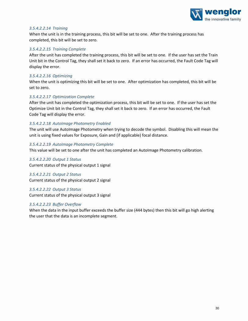
3.5.3.2.2.14 Training
When the unit is in the training process, this bit will be set to one. After the training process has
completed, this bit will be set to zero.
3.5.3.2.2.15 Training Complete
After the unit has completed the training process, this bit will be set to one. If the user has set the Train
Unit bit in the Control Tag, they shall set it back to zero. If an error has occurred, the Fault Code Tag will
display the error.
3.5.3.2.2.16 Optimizing
When the unit is optimizing this bit will be set to one. After optimization has completed, this bit will be
set to zero.
3.5.3.2.2.17 Optimization Complete
After the unit has completed the optimization process, this bit will be set to one. If the user has set the
Optimize Unit bit in the Control Tag, they shall set it back to zero. If an error has occurred, the Fault
Code Tag will display the error.
3.5.3.2.2.18 AutoImage Photometry Enabled
The unit will use AutoImage Photometry when trying to decode the symbol. Disabling this will mean the
unit is using fixed values for Exposure, Gain and (if applicable) focal distance.
3.5.3.2.2.19 AutoImage Photometry Complete
This value will be set to one after the unit has completed an AutoImage Photometry calibration.
3.5.3.2.2.20 Output 1 Status
Current status of the physical output 1 signal
3.5.3.2.2.21 Output 2 Status
Current status of the physical output 2 signal
3.5.3.2.2.22 Output 3 Status
Current status of the physical output 3 signal
3.5.3.2.2.23 Buffer Overflow
When the data in the input buffer exceeds the buffer size (172 bytes) then this bit will go high alerting
the user that the data is an incomplete segment.
3.5.3.2.3 Fault Code
This tag shall display the fault codes when the unit has faulted for any commands sent to it. When the
user issues the Reset Fault in the Control Tag, this value will be set to zero.
3.5.3.2.4 Counters
Displays the counters stored in the unit upon power up or after a configuration change. These counters
can be reset via the output command tag.
19

3.5.3.2.4.1 Counters Table
COUNTERS
NOREAD READCYCLE COUNTER DINT
MISMATCH PER READCYCLE COUNTER DINT
NOREAD COUNTER DINT
TRIGGER COUNTER DINT
MATCH CODE COUNTER DINT
MISMATCH COUNTER DINT
NOTE: Time starts over with power on but not with a <A> or <Z> type reset.
3.5.3.2.4.2 NoRead Cycle Counter
The message displays the total number of noread read cycles that have occurred since power-on or the
last Noread Read cycle Counter Reset command
3.5.3.2.4.3 MisMatch Per ReadCycle Counter
The message displays the total number of mismatched code pre readcycle that have occurred since
power-on or the last Mismatch per Readcycle Counter Reset command
3.5.3.2.4.4 NoRead Counter
The message displays the total number of noreads that have occurred since power-on or the last Noread
Counter Reset command
3.5.3.2.4.5 Trigger Counter
The message displays the total number of triggers that have occurred since power-on or the last Trigger
Counter Reset command
3.5.3.2.4.6 MatchCode Counter
The message displays either (1) the total number of good reads that match the master label or (2) the
total number of good reads, or decodes. The count begins from the last power-on or Match Code/Good
Read Counter Reset command. To count the good reads that match the master label, enable Match
Code; to count good reads only, disable Match Code
3.5.3.2.4.7 Mismatch Counter
The message displays the total number of symbols successfully read that do not match the master label
since power-on or the last Mismatch Counter command
20

3.5.3.2.5 Read Cycle Report
Information regarding the read cycle. Decode Data is referenced in the Decode Cycle Report
3.5.3.2.5.1 Read Cycle Report Table
SHORT DESCRIPTION SIZE
CAPTURE TIME INT
TOTAL DECODE TIME INT
TOTAL READCYCLE TIME INT
RESERVED INT
3.5.3.2.5.2 Capture Time
Total time it tool to capture the image
3.5.3.2.5.3 Total Decode Time
Total time spent decoding the symbol(s)
3.5.3.2.5.4 Total ReadCycle Time
Total Time Spent decoding the symbol which is the sum of the Capture, Decode and Overhead time.
3.5.3.2.6 Decode Cycle Report
Information on the decoded symbol
3.5.3.2.6.1 Decode Cycle Report Table
DESCRIPTOIN SIZE
DECODE LOCATION TOP INT
DECODE LOCATION LEFT INT
DECODE LOCATION HEIGHT INT
DECODE LOCATION WIDTH INT
CODE TYPE DINT
PIXELS PER ELEMENT FLOAT
3.5.3.2.6.2 Decode Location Top
Defines the row position of the upper-left starting point of the image window.
3.5.3.2.6.3 Decode Location Left
Defines the column position of the upper-left starting point of the image window.
3.5.3.2.6.4 Decode Location Height
Defines the size, in rows, of the image window. Maximum value is defined as the Maximum row size of
Image sensor, minus the row pointer value.
3.5.3.2.6.5 Decode Location Width
Defines the size, in rows, of the image window. Maximum value is defined as the Maximum row size of
Image sensor, minus the row pointer value.
21
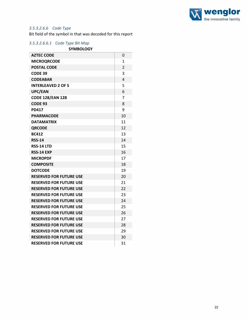
3.5.3.2.6.6 Code Type
Bit field of the symbol in that was decoded for this report
3.5.3.2.6.6.1 Code Type Bit Map
SYMBOLOGY
AZTEC CODE 0
MICROQRCODE 1
POSTAL CODE 2
CODE 39 3
CODEABAR 4
INTERLEAVED 2 OF 5 5
UPC/EAN 6
CODE 128/EAN 128 7
CODE 93 8
PD417 9
PHARMACODE 10
DATAMATRIX 11
QRCODE 12
BC412 13
RSS-14 14
RSS-14 LTD 15
RSS-14 EXP 16
MICROPDF 17
COMPOSITE 18
DOTCODE 19
RESERVED FOR FUTURE USE 20
RESERVED FOR FUTURE USE 21
RESERVED FOR FUTURE USE 22
RESERVED FOR FUTURE USE 23
RESERVED FOR FUTURE USE 24
RESERVED FOR FUTURE USE 25
RESERVED FOR FUTURE USE 26
RESERVED FOR FUTURE USE 27
RESERVED FOR FUTURE USE 28
RESERVED FOR FUTURE USE 29
RESERVED FOR FUTURE USE 30
RESERVED FOR FUTURE USE 31
22

3.5.3.2.6.7 Pixels Per Element
The number of pixels for each element, either dark or light for both x and y directions
3.5.3.2.6.8 Decode Length
The number of characters found in the decode string
3.5.3.2.7 Decode Length
The total number of characters contained in the Decode Data SINT array
3.5.3.2.8 Decode Data
Outputted decode data from the unit in ASCII with one difference. Preamble and post amble symbols
are not added.
3.5.3.3 Input MXL Member location
The following table is the Member location in the Input MXL data block.
3.5.3.3.1 Member Map Table
Member DataType Target BitNumber Data Length Byte Offset
InfoBits Unsigned32 1 Byte 0
32 Bit Boundary
BIT RunMode Boolean InfoBits 0 1 Bit
BIT ConnectionFaulted Boolean InfoBits 1 1 Bit
BIT DiagnosticActive Boolean InfoBits 2 1 Bit
Reserved Boolean InfoBits 3 - 7 5 Bits
DiagnosticSequenceCount Unsigned8 1Byte 1
ConfigurationChangeDetect Unsigned8 1 Byte
ConfigChangeDetect Unsigned8 ConfigurationChangeDetect 0 1 Bit
Reserved Unsigned8 ConfigurationChangeDetect 1 - 7 7 Bits
Reserved Unsigned8 1 Byte 3
DeviceStatus Unsigned32 4 Bytes 4
32 Bit Boundary
Online Boolean DeviceStatus 0 1 Bit
TriggerAcknowledge Boolean DeviceStatus 1 1 Bit
ExposureDone Boolean DeviceStatus 2 1 Bit
Decoding Boolean DeviceStatus 3 1 Bit
DataIsReady Boolean DeviceStatus 4 1 Bit
ReadCyclePass Boolean DeviceStatus 5 1 Bit
ReadCycleFail Boolean DeviceStatus 6 1 Bit
GeneralFault Boolean DeviceStatus 7 1 Bit
NewMatchCodeAcknowledged Boolean DeviceStatus 8 1 Bit
MatchCodeEnabled Boolean DeviceStatus 9 1 Bit
ImageSensorCalibrating Boolean DeviceStatus 10 1 Bit
ImageSensorCalibrationComplete Boolean DeviceStatus 11 1 Bit
Training Boolean DeviceStatus 12 1 Bit
TrainingComplete Boolean DeviceStatus 13 1 Bit
Optimizing Boolean DeviceStatus 14 1 Bit
23

OptimizingComplete Boolean DeviceStatus 15 1 Bit
AutoImagePhotometryEnabled Boolean DeviceStatus 16 1 Bit
AutoImagePhotometryComplete Boolean DeviceStatus 17 1 Bit
Output1Status Boolean DeviceStatus 18 1 Bit
Output2Status Boolean DeviceStatus 19 1 Bit
BufferOverflow Boolean DeviceStatus 20 1 Bit
Reserved - DeviceStatus 21-31 11 Bits
Fault Code Unsigned32 4 Bytes
32 Bit Boundary
CommandErrorDetected Boolean FaultCode 0 1 Bit 8
CommunicationError Boolean FaultCode 1 1 Bit
FlashSectorUnprotectedFailure Boolean FaultCode 2 1 Bit
HostPortBufferOverflow Boolean FaultCode 3 1 Bit
Reserved Boolean FaultCode 4 - 31 28 Bits
Counters Boolean 24 Bytes
32 Bit Boundary NoReadReadCycleCounter Unsigned32 Counters 0 - 31 4 Bytes 12
32 Bit
BoundaryMismatchPerReadcycleCounter Unsigned32 Counters 0 - 31 4 Bytes 16
32 Bit
BoundaryNoreadCounter Unsigned32 Counters 0 - 31 4 Bytes 20
32 Bit
BoundaryTriggerCounter Unsigned32 Counters 0 - 31 4 Bytes 24
32 Bit
BoundaryMatchCodeCounter Unsigned32 Counters 0 - 31 4 Bytes 28
32 Bit
BoundaryMismatchCounter Unsigned32 Counters 0 - 31 4 Bytes 32
ReadCycleReport Unsigned16 8 Bytes
32 Bit Boundary
CaptureTime Unsigned16 ReadCycleReport 0 - 15 2 Bytes 36
TotalDecodeTime Unsigned16 ReadCycleReport 0 - 15 2 Bytes 38
32 Bit Boundary
TotalReadCycleTime Unsigned16 ReadCycleReport 0 - 15 2 Bytes 40
Reserved Unsigned16 ReadCycleReport 0 - 15 2 Bytes 42
DecodeCycleReport 16 Bytes
32 Bit Boundary
DecodeLocationTop Unsigned16 DecodeCycleReport 0 - 15 2 Bytes 44
DecodeLocationLeft Unsigned16 DecodeCycleReport 0 - 15 2 Bytes 46
32 Bit Boundary
DecodeLocationHeight Unsigned16 DecodeCycleReport 0 - 15 2 Bytes 48
DecodeLocationWidth Unsigned16 DecodeCycleReport 0 - 15 2 Bytes 50
CodeType (Subset) Unsigned32 DecodeCycleReport 4 Bytes
32 Bit Boundary
AztecCode Boolean CodeType 0 1 Bit 52
MicroQRCode Boolean CodeType 1 1 Bit
PostalCode Boolean CodeType 2 1 Bit
Code39 Boolean CodeType 3 1 Bit
24

Codeabar Boolean CodeType 4 1 Bit
Interleaved2of5 Boolean CodeType 5 1 Bit
UPCEAN Boolean CodeType 6 1 Bit
Code128EAN128 Boolean CodeType 7 1 Bit
Code93 Boolean CodeType 8 1 Bit
PD417 Boolean CodeType 9 1 Bit
PharmaCode Boolean CodeType 10 1 Bit
DataMatrix Boolean CodeType 11 1 Bit
QRCode Boolean CodeType 12 1 Bit
BC412 Boolean CodeType 13 1 Bit
RSS14 Boolean CodeType 14 1 Bit
RSS14LTD Boolean CodeType 15 1 Bit
RSS14EXP Boolean CodeType 16 1 Bit
MicroPDF Boolean CodeType 17 1 Bit
Composite Boolean CodeType 18 1 Bit
DotCode Boolean CodeType 19 1 Bit
Reserved for future use Boolean CodeType 20 - 31 12 Bits
32 Bit
BoundaryPixelsPerElement Float32 DecodeCycleReport 0 - 31 4 Bytes 56
32 Bit
BoundaryDecodeLength Unsigned32 0 - 31 4 Bytes 60
32 Bit
BoundaryDecodeData VisibleString 0 - 1472 184 Bytes 64
25

3.5.4 Input 1 Decode (C5PCPLC)Designed to hold 436 bytes of information in the decode data tag. This data can be for 1 decoded
string or a delimited number of decoded strings. In the case of a delimited number, the programmer
shall parse the decoded data by reading the delimiter in ESP and/or issuing the K Command <K222?> to
the command processor.
This input data block also contains a Read Cycle Report and a Decode Cycle Report after an inspection.
Details of these reports are described in detail later in the section.
***NOTE: This input block must use the Output Premier to function correctly***
3.5.4.1 Input 1 Decode Table
SHORT DESCRIPTION SIZE (BYTES)
INFO BITS 1 DIAGNOSTIC SEQUENCE COUNT 1 CONFIGURATION SEQ. COUNT 1 RESERVED 1 DEVICE STATUS 4
FAULT 4
COUNTERS 24
READ CYCLE REPORT 8
DECODE CYCLE REPORT 16
DECODE LENGTH 4
DECODE DATA 436
Total Size: 500 Bytes
26

3.5.4.2 Input 1 Decode Description
This sub section will describe the tag and each field related for the Input 1 Decode data block.
3.5.4.2.1 Input Module Header
The following header is used at the beginning of the input (produced) data block. Definitions for the
members are included below.
3.5.4.2.1.1 Info Bits
Bit field of the input module status
INFO BIT FIELD
BIT RUNMODE 0 BIT CONNECTIONFAULTED 1 BIT DIAGNOSTICACTIVE 2 RESERVED 3-7
3.5.4.2.1.1.1 Run Mode
0 = not Run Mode, 1 = Run Mode
3.5.4.2.1.1.2 Connection Faulted
Connection to the target is 0 = up and working, 1 = not connected. The module always returns a zero in
this member. The controller overwrites the zero with a one when the connection is not up.
3.5.4.2.1.1.3 Diagnostic Active
0 = No diagnostics active, 1 = One or more diagnostic or prognostics thresholds reached
Note: “Diagnostic” means a detected condition that prevents the primary signal from propagating from a sensor to the controller, or from the controller to an actuator.
3.5.4.2.1.2 Diagnostic Sequence Count
SHORT NAME SIZE
DIAGNOSTIC SEQUENCE COUNT
SINT
Increments for each time a distinct diagnostic condition is detected, and also each time a distinct
diagnostic condition transitions from detected to not detected. Set to zero by product reset or power
cycle. Wraps from 255 (-1) to 1 skipping zero.
3.5.4.2.1.3 Configuration Change Detection
When a change in the working set has been detected by the device this bit will be set to 1. This means
that the configuration in the project no longer matches the configuration in the device.
Any forward open sets this value back to 0.
27

3.5.4.2.2 Device Status
This tag describes the current state of the device. In table 1.2.1 the bit field is mapped to allow the user
to know what state the device is in.
3.5.4.2.2.1 Device Status Bit Field
DEVICE STATUS
BIT FIELD Status
0 Online
1 Trigger Acknowledge
2 Exposure Done
3 Decoding
4 Data Is Ready
5 Read Cycle Pass
6 Read Cycle Fail
7 General Fault
8 New match code acknowledged
9 Match Code Enabled
10 Image Sensor Calibrating
11 Image Sensor Calibration Complete
12 Training
13 Training Complete
14 Optimizing
15 Optimization Complete
16 AutoImage Photometry Enabled
17 AutoImage Photometry Complete
18 Output1 Status
19 Output2 Status
20 Output3 Status
21 Buffer Overflow
22-31 Reserved
3.5.4.2.2.2 Online
The units Current Read Cycle State
state
0 = Read cycle is disabled thus the unit is offline but the unit can receive
commands. There is no data produced in the Input data block and no data
is consumed in the Output data block when in this state.
1 = Read Cycle is enabled and the unit can be triggered and data is
available for consumption and the unit will consume output data.
3.5.4.2.2.3 Trigger Acknowledged
This bit will go high when the unit has accepted the Trigger command in the Control tag. The user must
lower the Trigger bit in the control tag in order for this bit to go back 0.
28

3.5.4.2.2.4 Exposure Done
When the image sensor exposure is complete this bit will go high and the user can move the object in
the Field of view for the next image to be taken.
3.5.4.2.2.5 Decoding
When the unit is processing the image, this bit will be high. When the unit has completed the image
process this bit will go low.
3.5.4.2.2.6 Data is Ready
The Read Cycle and Data Cycle Reports are ready for consumption when this bit goes high.
3.5.4.2.2.7 Read Cycle Pass
If the read cycle has passed all criteria, this bit will go high. It will go low when the ready begins to
process the next image.
3.5.4.2.2.8 Ready Cycle Fail
If the read cycle has failed any of the criteria that was programmed, this bit will go high. It will go low
when the ready begins to process the next image.
3.5.4.2.2.9 General Fault
When a fault occurs in the unit, this bit will go high. The user can reference the Fault Code tag for the
error code and must remedy the problem. After the problem has been resolved the user can reset the
fault in the Control tag in the Output data block.
3.5.4.2.2.10 New Match Code Acknowledge
When active the unit has accepted the data read on the last trigger as the new match code. User shall
set the Learn New Match Code bit in the Control tag to zero when this bit goes high.
3.5.4.2.2.11 Match Code Enabled
When this bit is 1 the unit will use the Match Code function to determine the Inspection Results.
3.5.4.2.2.12 Image Sensor Calibrating
The unit is undergoing a calibration on one or all of the following:
Exposure
Gain
Focus (If the unit has Auto focus capabilities)When the unit has completed calibration this bit will be set to zero.
3.5.4.2.2.13 Image Sensor Calibration Complete
The unit has completed calibrating the image sensor for one or all of the following items:
Exposure
Gain
Focus (If the unit has Auto focus capabilities)The user shall set the Control bit Calibration Image Sensor to zero if they have not done so already.
29
3.5.4.2.2.14 Training
When the unit is in the training process, this bit will be set to one. After the training process has
completed, this bit will be set to zero.
3.5.4.2.2.15 Training Complete
After the unit has completed the training process, this bit will be set to one. If the user has set the Train
Unit bit in the Control Tag, they shall set it back to zero. If an error has occurred, the Fault Code Tag will
display the error.
3.5.4.2.2.16 Optimizing
When the unit is optimizing this bit will be set to one. After optimization has completed, this bit will be
set to zero.
3.5.4.2.2.17 Optimization Complete
After the unit has completed the optimization process, this bit will be set to one. If the user has set the
Optimize Unit bit in the Control Tag, they shall set it back to zero. If an error has occurred, the Fault
Code Tag will display the error.
3.5.4.2.2.18 AutoImage Photometry Enabled
The unit will use AutoImage Photometry when trying to decode the symbol. Disabling this will mean the
unit is using fixed values for Exposure, Gain and (if applicable) focal distance.
3.5.4.2.2.19 AutoImage Photometry Complete
This value will be set to one after the unit has completed an AutoImage Photometry calibration.
3.5.4.2.2.20 Output 1 Status
Current status of the physical output 1 signal
3.5.4.2.2.21 Output 2 Status
Current status of the physical output 2 signal
3.5.4.2.2.22 Output 3 Status
Current status of the physical output 3 signal
3.5.4.2.2.23 Buffer Overflow
When the data in the input buffer exceeds the buffer size (444 bytes) then this bit will go high alerting
the user that the data is an incomplete segment.
30

3.5.4.2.3 Fault Code
This tag shall display the fault codes when the unit has faulted for any commands sent to it. When the
user issues the Reset Fault in the Control Tag, this value will be set to zero.
3.5.4.2.3.1 Fault Code Bit Field
COUNTERS
COMMAND ERROR DETECTED 0
COMMUNICATION ERROR 1
FLASH SECTOR UNPROTECTED FAILURE 2
HOST PORT BUFFER OVERFLOW 3
RESERVED 4-31
3.5.4.2.4 Counters
Displays the counters stored in the unit upon power up or after a configuration change. These counters
can be reset via the output command tag.
3.5.4.2.4.1 Counters Table
COUNTERS
NOREAD READCYCLE COUNTER DINT
MISMATCH PER READCYCLE COUNTER DINT
NOREAD COUNTER DINT
TRIGGER COUNTER DINT
MATCH CODE COUNTER DINT
MISMATCH COUNTER DINT
NOTE: Time starts over with power on but not with a <A> or <Z> type reset.
3.5.4.2.4.2 NoRead Cycle Counter
The message displays the total number of noread read cycles that have occurred since power-on or the
last Noread Read cycle Counter Reset command
3.5.4.2.4.3 MisMatch Per ReadCycle Counter
The message displays the total number of mismatched code pre readcycle that have occurred since
power-on or the last Mismatch per Readcycle Counter Reset command
3.5.4.2.4.4 NoRead Counter
The message displays the total number of noreads that have occurred since power-on or the last Noread
Counter Reset command
3.5.4.2.4.5 Trigger Counter
The message displays the total number of triggers that have occurred since power-on or the last Trigger
Counter Reset command
3.5.4.2.4.6 MatchCode Counter
The message displays either (1) the total number of good reads that match the master label or (2) the
total number of good reads, or decodes. The count begins from the last power-on or Match Code/Good
31

Read Counter Reset command. To count the good reads that match the master label, enable Match
Code; to count good reads only, disable Match Code
3.5.4.2.4.7 Mismatch Counter
The message displays the total number of symbols successfully read that do not match the master label
since power-on or the last Mismatch Counter command
3.5.4.2.5 Read Cycle Report
Information regarding the read cycle. Decode Data is referenced in the Decode Cycle Report
3.5.4.2.5.1 Read Cycle Report Table
SHORT DESCRIPTION SIZE
CAPTURE TIME INT
TOTAL DECODE TIME INT
TOTAL READCYCLE TIME INT
RESERVED INT
3.5.4.2.5.2 Capture Time
Total time it tool to capture the image
3.5.4.2.5.3 Total Decode Time
Total time spent decoding the symbol(s)
3.5.4.2.5.4 Total ReadCycle Time
Total Time Spent decoding the symbol which is the sum of the Capture, Decode and Overhead time.
3.5.4.2.6 Decode Cycle Report
Information on the decoded symbol
3.5.4.2.6.1 Decode Cycle Report Table
DESCRIPTOIN SIZE
DECODE LOCATION TOP INT
DECODE LOCATION LEFT INT
DECODE LOCATION HEIGHT INT
DECODE LOCATION WIDTH INT
CODE TYPE DINT
PIXELS PER ELEMENT REAL
3.5.4.2.6.2 Decode Location Top
Defines the row position of the upper-left starting point of the image window.
3.5.4.2.6.3 Decode Location Left
Defines the column position of the upper-left starting point of the image window.
3.5.4.2.6.4 Decode Location Height
Defines the size, in rows, of the image window. Maximum value is defined as the Maximum row size of
Image sensor, minus the row pointer value.
32

3.5.4.2.6.5 Decode Location Width
Defines the size, in rows, of the image window. Maximum value is defined as the Maximum row size of
Image sensor, minus the row pointer value.
3.5.4.2.6.6 Code Type
Bit field of the symbol in that was decoded for this report
3.5.4.2.6.6.1 Code Type Bit Map
SYMBOLOGY
AZTEC CODE 0
MICROQRCODE 1
POSTAL CODE 2
CODE 39 3
CODEABAR 4
INTERLEAVED 2 OF 5 5
UPC/EAN 6
CODE 128/EAN 128 7
CODE 93 8
PD417 9
PHARMACODE 10
DATAMATRIX 11
QRCODE 12
BC412 13
RSS-14 14
RSS-14 LTD 15
RSS-14 EXP 16
MICROPDF 17
POSTAL CODE 18
DOTCODE 19
RESERVED FOR FUTURE USE 20
RESERVED FOR FUTURE USE 21
RESERVED FOR FUTURE USE 22
RESERVED FOR FUTURE USE 23
RESERVED FOR FUTURE USE 24
RESERVED FOR FUTURE USE 25
RESERVED FOR FUTURE USE 26
RESERVED FOR FUTURE USE 27
RESERVED FOR FUTURE USE 28
RESERVED FOR FUTURE USE 29
RESERVED FOR FUTURE USE 30
RESERVED FOR FUTURE USE 31
33

3.5.4.2.6.7 Pixels Per Element
The number of pixels for each element, either dark or light for both x and y directions
3.5.4.2.7 Decode Length
The number of characters found in the decode string
3.5.4.2.8 Decode Data
Outputted decode data from the unit in ASCII with one difference. Preamble and post amble symbols
are not added.
3.5.4.3 Input 1 Decode Member Location
The following table is the Member location in the Input 1 Decode data block.
3.5.4.3.1 Member Map Table
Member DataType Target BitNumber Style Data Length Byte Offset
InfoBits Unsigned32 1 Byte 0
32 Bit Boundary
BIT RunMode Boolean InfoBits 0 NA 1 Bit
BIT ConnectionFaulted Boolean InfoBits 1 NA 1 Bit
BIT DiagnosticActive Boolean InfoBits 2 NA 1 Bit
Reserved Boolean InfoBits 3 - 7 NA 5 Bits
DiagnosticSequenceCount Unsigned8 Decimal 1Byte 1
ConfigurationChangeDetect Unsigned8 1 Byte
ConfigChangeDetect Unsigned8 ConfigurationChangeDetect 0 BOOL 1 Bit
Reserved Unsigned8 ConfigurationChangeDetect 1 - 7 NA 7 Bits
Reserved Unsigned8 NA 1 Byte 3
DeviceStatus Unsigned32 4 Bytes 4
32 Bit Boundary
Online Boolean DeviceStatus 0 BOOL 1 Bit
TriggerAcknowledge Boolean DeviceStatus 1 BOOL 1 Bit
ExposureDone Boolean DeviceStatus 2 BOOL 1 Bit
Decoding Boolean DeviceStatus 3 BOOL 1 Bit
DataIsReady Boolean DeviceStatus 4 BOOL 1 Bit
ReadCyclePass Boolean DeviceStatus 5 BOOL 1 Bit
ReadCycleFail Boolean DeviceStatus 6 BOOL 1 Bit
GeneralFault Boolean DeviceStatus 7 BOOL 1 Bit
NewMatchCodeAcknowledged Boolean DeviceStatus 8 BOOL 1 Bit
MatchCodeEnabled Boolean DeviceStatus 9 BOOL 1 Bit
ImageSensorCalibrating Boolean DeviceStatus 10 BOOL 1 Bit
ImageSensorCalibrationComplete Boolean DeviceStatus 11 BOOL 1 Bit
Training Boolean DeviceStatus 12 BOOL 1 Bit
TrainingComplete Boolean DeviceStatus 13 BOOL 1 Bit
Optimizing Boolean DeviceStatus 14 BOOL 1 Bit
OptimizingComplete Boolean DeviceStatus 15 BOOL 1 Bit
AutoImagePhotometryEnabled Boolean DeviceStatus 16 BOOL 1 Bit
34

AutoImagePhotometryComplete Boolean DeviceStatus 17 BOOL 1 Bit
Output1Status Boolean DeviceStatus 18 BOOL 1 Bit
Output2Status Boolean DeviceStatus 19 BOOL 1 Bit
BufferOverflow Boolean DeviceStatus 20 BOOL 1 Bit
Reserved - DeviceStatus 21-31 NA 11 Bits
Fault Code Unsigned32 4 Bytes
32 Bit Boundary
CommandErrorDetected Boolean FaultCode 0 BOOL 1 Bit 8
CommunicationError Boolean FaultCode 1 BOOL 1 Bit
FlashSectorUnprotectedFailure Boolean FaultCode 2 BOOL 1 Bit
HostPortBufferOverflow Boolean FaultCode 3 BOOL 1 Bit
Reserved Boolean FaultCode 4 - 31 NA 28 Bits
Counters 24 Bytes
32 Bit Boundary NoReadReadCycleCounter Unsigned32 Counters 0 - 31 Decimal 4 Bytes 12
32 Bit Boundary MismatchPerReadcycleCounter Unsigned32 Counters 0 - 31 Decimal 4 Bytes 16
32 Bit Boundary NoreadCounter Unsigned32 Counters 0 - 31 Decimal 4 Bytes 20
32 Bit Boundary TriggerCounter Unsigned32 Counters 0 - 31 Decimal 4 Bytes 24
32 Bit Boundary MatchCodeCounter Unsigned32 Counters 0 - 31 Decimal 4 Bytes 28
32 Bit Boundary MismatchCounter Unsigned32 Counters 0 - 31 Decimal 4 Bytes 32
ReadCycleReport 8 Bytes
32 Bit Boundary
CaptureTime Unsigned16 ReadCycleReport 0 - 15 Decimal 2 Bytes 36
TotalDecodeTime Unsigned16 ReadCycleReport 0 - 15 Decimal 2 Bytes 38
32 Bit Boundary
TotalReadCycleTime Unsigned16 ReadCycleReport 0 - 15 Decimal 2 Bytes 40
Reserved Unsigned16 ReadCycleReport 0 - 15 NA 2 Bytes 42
DecodeCycleReport 16 Bytes
32 Bit Boundary
DecodeLocationTop Unsigned16 DecodeCycleReport 0 - 15 Decimal 2 Bytes 44
DecodeLocationLeft Unsigned16 DecodeCycleReport 0 - 15 Decimal 2 Bytes 46
32 Bit Boundary
DecodeLocationHeight Unsigned16 DecodeCycleReport 0 - 15 Decimal 2 Bytes 48
DecodeLocationWidth Unsigned16 DecodeCycleReport 0 - 15 Decimal 2 Bytes 50
CodeType (Subset) Unsigned32 DecodeCycleReport 4 Bytes
32 Bit Boundary
AztecCode Boolean CodeType 0 BOOL 1 Bit 52
MicroQRCode Boolean CodeType 1 BOOL 1 Bit
PostalCode Boolean CodeType 2 BOOL 1 Bit
Code39 Boolean CodeType 3 BOOL 1 Bit
Codeabar Boolean CodeType 4 BOOL 1 Bit
35

Interleaved2of5 Boolean CodeType 5 BOOL 1 Bit
UPCEAN Boolean CodeType 6 BOOL 1 Bit
Code128EAN128 Boolean CodeType 7 BOOL 1 Bit
Code93 Boolean CodeType 8 BOOL 1 Bit
PD417 Boolean CodeType 9 BOOL 1 Bit
PharmaCode Boolean CodeType 10 BOOL 1 Bit
DataMatrix Boolean CodeType 11 BOOL 1 Bit
QRCode Boolean CodeType 12 BOOL 1 Bit
BC412 Boolean CodeType 13 BOOL 1 Bit
RSS14 Boolean CodeType 14 BOOL 1 Bit
RSS14LTD Boolean CodeType 15 BOOL 1 Bit
RSS14EXP Boolean CodeType 16 BOOL 1 Bit
MicroPDF Boolean CodeType 17 BOOL 1 Bit
Composite Boolean CodeType 18 BOOL 1 Bit
DotCode Boolean CodeType 19 BOOL 1 Bit
Reserved for future use Boolean CodeType 20 - 31 BOOL 12 Bits
32 Bit Boundary PixelsPerElement Float32 DecodeCycleReport 0 - 31 Decimal 4 Bytes 56
32 Bit Boud DecodeLength Unsigned32 0 - 31 Decimal 4 Bytes 60
32 Bit Boundary DecodeData VisibleString 0 - 3488 ASCII 436 Bytes 64
36

3.5.5 Input 4 Decode (C5PCPLC)Designed to hold 4 decoded symbols with decode cycle reports. The read cycle report contains data for
the entire inspection while the decode # cycle report will contain data regarding the individual decoded
symbols. Please note that decode symbol 1 is 160 bytes long while 2 through 4 are 72 bytes long. The
unit will automatically place the largest decode symbol into Decode 1 Cycle Report and Decode 1 Data.
The remaining will be placed in the remaining tags. If no data is found than the decode cycle report
and the decode data will be null.
***NOTE 1: The inspection will not need to have 4 decode symbols to use this input data block. ***
***NOTE 2: This input block must use the Output Premier to function correctly***
3.5.5.1 Input 4 Decode Table
SHORT DESCRIPTION SIZE (BYTES)
INFO BITS 1 DIAGNOSTIC SEQUENCE COUNT 1 CONFIGURATION SEQ. COUNT 1 RESERVED 1 DEVICE STATUS 4
FAULT 4
COUNTERS 24
READ CYCLE REPORT 8
DECODE 1 CYCLE REPORT 16
DECODE 1 LENGTH 4
DECODE 1 DATA 160
DECODE 2 CYCLE REPORT 16
DECODE 2 LENGTH 4
DECODE 2 DATA 72
DECODE 3 CYCLE REPORT 16
DECODE 3 LENGTH 4
DECODE 3 DATA 72
DECODE 4 CYCLE REPORT 16
DECODE 4 LENGTH 4
DECODE 4 DATA 72
Total Size: 500 Bytes
37

3.5.5.2 Input 4 Decode Description
This sub section will describe the tag and each field related for the Input Assembly.
3.5.5.2.1 Input Module Header
The following header is used at the beginning of the input (produced) data block. Definitions for the
members are included below.
3.5.5.2.1.1 Info Bits
Bit field of the input module status
INFO BIT FIELD
BIT RUNMODE 0 BIT CONNECTIONFAULTED 1 BIT DIAGNOSTICACTIVE 2 RESERVED 3-7
3.5.5.2.1.1.1 Run Mode
0 = not Run Mode, 1 = Run Mode
3.5.5.2.1.1.2 Connection Faulted
Connection to the target is 0 = up and working, 1 = not connected. The module always returns a zero in
this member. The controller overwrites the zero with a one when the connection is not up.
3.5.5.2.1.1.3 Diagnostic Active
0 = No diagnostics active, 1 = One or more diagnostic or prognostics thresholds reached
Note: “Diagnostic” means a detected condition that prevents the primary signal from propagating from a sensor to the controller, or from the controller to an actuator.
3.5.5.2.1.2 Diagnostic Sequence Count
SHORT NAME SIZE
DIAGNOSTIC SEQUENCE COUNT
SINT
Increments for each time a distinct diagnostic condition is detected, and also each time a distinct
diagnostic condition transitions from detected to not detected. Set to zero by product reset or power
cycle. Wraps from 255 (-1) to 1 skipping zero.
3.5.5.2.1.3 Configuration Change Detection
When a change in the working set has been detected by the device this bit will be set to 1. This means
that the configuration in the project no longer matches the configuration in the device.
Any forward open sets this value back to 0.
38

3.5.5.2.2 Device Status
This tag describes the current state of the device. In table 1.2.1 the bit field is mapped to allow the user
to know what state the device is in.
3.5.5.2.2.1 Device Status Bit Field
DEVICE STATUS
BIT FIELD Status
0 Online
1 Trigger Acknowledge
2 Exposure Done
3 Decoding
4 Data Is Ready
5 Read Cycle Pass
6 Read Cycle Fail
7 General Fault
8 New match code acknowledged
9 Match Code Enabled
10 Image Sensor Calibrating
11 Image Sensor Calibration Complete
12 Training
13 Training Complete
14 Optimizing
15 Optimization Complete
16 AutoImage Photometry Enabled
17 AutoImage Photometry Complete
18 Output1 Status
19 Output2 Status
20 Output3 Status
21 Buffer Overflow
22-31 Reserved
3.5.5.2.2.2 Online
The units Current Read Cycle State
state
0 = Read cycle is disabled thus the unit is offline but the unit can receive
commands. There is no data produced in the Input data block and no data
is consumed in the Output data block when in this state.
1 = Read Cycle is enabled and the unit can be triggered and data is
available for consumption and the unit will consume output data.
3.5.5.2.2.3 Trigger Acknowledged
This bit will go high when the unit has accepted the Trigger command in the Control tag. The user must
lower the Trigger bit in the control tag in order for this bit to go back 0.
39

3.5.5.2.2.4 Exposure Done
When the image sensor exposure is complete this bit will go high and the user can move the object in
the Field of view for the next image to be taken.
3.5.5.2.2.5 Decoding
When the unit is processing the image, this bit will be high. When the unit has completed the image
process this bit will go low.
3.5.5.2.2.6 Data is Ready
The Read Cycle and Data Cycle Reports are ready for consumption when this bit goes high.
3.5.5.2.2.7 Read Cycle Pass
If the read cycle has passed all criteria, this bit will go high. It will go low when the ready begins to
process the next image.
3.5.5.2.2.8 Ready Cycle Fail
If the read cycle has failed any of the criteria that was programmed, this bit will go high. It will go low
when the ready begins to process the next image.
3.5.5.2.2.9 General Fault
When a fault occurs in the unit, this bit will go high. The user can reference the Fault Code tag for the
error code and must remedy the problem. After the problem has been resolved the user can reset the
fault in the Control tag in the Output data block.
3.5.5.2.2.10 New Match Code Acknowledge
When active the unit has accepted the data read on the last trigger as the new match code. User shall
set the Learn New Match Code bit in the Control tag to zero when this bit goes high.
3.5.5.2.2.11 Match Code Enabled
When this bit is 1 the unit will use the Match Code function to determine the Inspection Results.
3.5.5.2.2.12 Image Sensor Calibrating
The unit is undergoing a calibration on one or all of the following:
Exposure
Gain
Focus (If the unit has Auto focus capabilities)When the unit has completed calibration this bit will be set to zero.
3.5.5.2.2.13 Image Sensor Calibration Complete
The unit has completed calibrating the image sensor for one or all of the following items:
Exposure
Gain
Focus (If the unit has Auto focus capabilities)The user shall set the Control bit Calibration Image Sensor to zero if they have not done so already.
40

3.5.5.2.2.14 Training
When the unit is in the training process, this bit will be set to one. After the training process has
completed, this bit will be set to zero.
3.5.5.2.2.15 Training Complete
After the unit has completed the training process, this bit will be set to one. If the user has set the Train
Unit bit in the Control Tag, they shall set it back to zero. If an error has occurred, the Fault Code Tag will
display the error.
3.5.5.2.2.16 Optimizing
When the unit is optimizing this bit will be set to one. After optimization has completed, this bit will be
set to zero.
3.5.5.2.2.17 Optimization Complete
After the unit has completed the optimization process, this bit will be set to one. If the user has set the
Optimize Unit bit in the Control Tag, they shall set it back to zero. If an error has occurred, the Fault
Code Tag will display the error.
3.5.5.2.2.18 AutoImage Photometry Enabled
The unit will use AutoImage Photometry when trying to decode the symbol. Disabling this will mean the
unit is using fixed values for Exposure, Gain and (if applicable) focal distance.
3.5.5.2.2.19 AutoImage Photometry Complete
This value will be set to one after the unit has completed an AutoImage Photometry calibration.
3.5.5.2.2.20 Output 1 Status
Current status of the physical output 1 signal
3.5.5.2.2.21 Output 2 Status
Current status of the physical output 2 signal
3.5.5.2.2.22 Output 3 Status
Current status of the physical output 3 signal
3.5.5.2.2.23 Buffer Overflow
When the data in the input buffer exceeds the buffer size (444 bytes) then this bit will go high alerting
the user that the data is an incomplete segment.
3.5.5.2.3 Fault Code
This tag shall display the fault codes when the unit has faulted for any commands sent to it. When the
user issues the Reset Fault in the Control Tag, this value will be set to zero.
3.5.5.2.3.1 Fault Code Bit Field
COUNTERS
COMMAND ERROR DETECTED 0
COMMUNICATION ERROR 1
FLASH SECTOR UNPROTECTED FAILURE 2
HOST PORT BUFFER OVERFLOW 3
RESERVED 4-31
41

3.5.5.2.4 Counters
Displays the counters stored in the unit upon power up or after a configuration change. These counters
can be reset via the output command tag.
3.5.5.2.4.1 Counters Table
COUNTERS
NOREAD READCYCLE COUNTER DINT
MISMATCH PER READCYCLE COUNTER DINT
NOREAD COUNTER DINT
TRIGGER COUNTER DINT
MATCH CODE COUNTER DINT
MISMATCH COUNTER DINT
NOTE: Time starts over with power on but not with a <A> or <Z> type reset.
3.5.5.2.4.2 NoRead Cycle Counter
The message displays the total number of noread read cycles that have occurred since power-on or the
last Noread Read cycle Counter Reset command
3.5.5.2.4.3 MisMatch Per ReadCycle Counter
The message displays the total number of mismatched code pre readcycle that have occurred since
power-on or the last Mismatch per Readcycle Counter Reset command
3.5.5.2.4.4 NoRead Counter
The message displays the total number of noreads that have occurred since power-on or the last Noread
Counter Reset command
3.5.5.2.4.5 Trigger Counter
The message displays the total number of triggers that have occurred since power-on or the last Trigger
Counter Reset command
3.5.5.2.4.6 MatchCode Counter
The message displays either (1) the total number of good reads that match the master label or (2) the
total number of good reads, or decodes. The count begins from the last power-on or Match Code/Good
Read Counter Reset command. To count the good reads that match the master label, enable Match
Code; to count good reads only, disable Match Code
3.5.5.2.4.7 Mismatch Counter
The message displays the total number of symbols successfully read that do not match the master label
since power-on or the last Mismatch Counter command
42

3.5.5.2.5 Read Cycle Report
Information regarding the read cycle. Decode Data is referenced in the Decode Cycle Report
3.5.5.2.5.1 Read Cycle Report Table
SHORT DESCRIPTION SIZE
CAPTURE TIME INT
TOTAL DECODE TIME INT
TOTAL READCYCLE TIME INT
RESERVED INT
3.5.5.2.5.2 Capture Time
Total time it tool to capture the image
3.5.5.2.5.3 Total Decode Time
Total time spent decoding the symbol(s)
3.5.5.2.5.4 Total ReadCycle Time
Total Time Spent decoding the symbol which is the sum of the Capture, Decode and Overhead time.
3.5.5.2.6 Decode 1 Cycle Report
Information on the decoded symbol
3.5.5.2.6.1 Decode Cycle Report Table
DESCRIPTOIN SIZE
DECODE LOCATION TOP INT
DECODE LOCATION LEFT INT
DECODE LOCATION HEIGHT INT
DECODE LOCATION WIDTH INT
CODE TYPE DINT
PIXELS PER ELEMENT REAL
3.5.5.2.6.2 Decode Location Top
Defines the row position of the upper-left starting point of the image window.
3.5.5.2.6.3 Decode Location Left
Defines the column position of the upper-left starting point of the image window.
3.5.5.2.6.4 Decode Location Height
Defines the size, in rows, of the image window. Maximum value is defined as the Maximum row size of
Image sensor, minus the row pointer value.
3.5.5.2.6.5 Decode Location Width
Defines the size, in rows, of the image window. Maximum value is defined as the Maximum row size of
Image sensor, minus the row pointer value.
43

3.5.5.2.6.6 Code Type
Bit field of the symbol in that was decoded for this report
3.5.5.2.6.6.1 Code Type Bit Map
SYMBOLOGY
AZTEC CODE 0
MICROQRCODE 1
POSTAL CODE 2
CODE 39 3
CODEABAR 4
INTERLEAVED 2 OF 5 5
UPC/EAN 6
CODE 128/EAN 128 7
CODE 93 8
PD417 9
PHARMACODE 10
DATAMATRIX 11
QRCODE 12
BC412 13
RSS-14 14
RSS-14 LTD 15
RSS-14 EXP 16
MICROPDF 17
POSTAL CODE 18
DOTCODE 19
RESERVED FOR FUTURE USE 20
RESERVED FOR FUTURE USE 21
RESERVED FOR FUTURE USE 22
RESERVED FOR FUTURE USE 23
RESERVED FOR FUTURE USE 24
RESERVED FOR FUTURE USE 25
RESERVED FOR FUTURE USE 26
RESERVED FOR FUTURE USE 27
RESERVED FOR FUTURE USE 28
RESERVED FOR FUTURE USE 29
RESERVED FOR FUTURE USE 30
RESERVED FOR FUTURE USE 31
44

3.5.5.2.6.7 Pixels Per Element
The number of pixels for each element, either dark or light for both x and y directions
3.5.5.2.7 Decode 1 Length
The total number of characters contained in the Decode Data SINT array
3.5.5.2.8 Decode 1 Data
Outputted decode 1 symbol data from the unit with one difference. Preamble and post amble symbols
are not added. Maximum characters allowed is 160.
3.5.5.2.9 Decode 2 Cycle Report
Information on the decoded symbol
3.5.5.2.9.1 Decode Cycle Report Table
DESCRIPTOIN SIZE
DECODE LOCATION TOP INT
DECODE LOCATION LEFT INT
DECODE LOCATION HEIGHT INT
DECODE LOCATION WIDTH INT
CODE TYPE DINT
PIXELS PER ELEMENT REAL
3.5.5.2.9.2 Decode Location Top
Defines the row position of the upper-left starting point of the image window.
3.5.5.2.9.3 Decode Location Left
Defines the column position of the upper-left starting point of the image window.
3.5.5.2.9.4 Decode Location Height
Defines the size, in rows, of the image window. Maximum value is defined as the Maximum row size of
Image sensor, minus the row pointer value.
3.5.5.2.9.5 Decode Location Width
Defines the size, in rows, of the image window. Maximum value is defined as the Maximum row size of
Image sensor, minus the row pointer value.
45

3.5.5.2.9.6 Code Type
Bit field of the symbol in that was decoded for this report
3.5.5.2.9.6.1 Code Type Bit Map
SYMBOLOGY
AZTEC CODE 0
MICROQRCODE 1
POSTAL CODE 2
CODE 39 3
CODEABAR 4
INTERLEAVED 2 OF 5 5
UPC/EAN 6
CODE 128/EAN 128 7
CODE 93 8
PD417 9
PHARMACODE 10
DATAMATRIX 11
QRCODE 12
BC412 13
RSS-14 14
RSS-14 LTD 15
RSS-14 EXP 16
MICROPDF 17
POSTAL CODE 18
DOTCODE 19
RESERVED FOR FUTURE USE 20
RESERVED FOR FUTURE USE 21
RESERVED FOR FUTURE USE 22
RESERVED FOR FUTURE USE 23
RESERVED FOR FUTURE USE 24
RESERVED FOR FUTURE USE 25
RESERVED FOR FUTURE USE 26
RESERVED FOR FUTURE USE 27
RESERVED FOR FUTURE USE 28
RESERVED FOR FUTURE USE 29
RESERVED FOR FUTURE USE 30
RESERVED FOR FUTURE USE 31
3.5.5.2.9.7 Pixels Per Element
The number of pixels for each element, either dark or light for both x and y directions
3.5.5.2.10 Decode 2 Length
The total number of characters contained in the Decode Data SINT array
46

3.5.5.2.11 Decode 2 Data
Outputted decode 2 symbol data from the unit with one difference. Preamble and post amble symbols
are not added. Maximum characters allowed is 72.
3.5.5.2.12 Decode 3 Cycle Report
Information on the decoded symbol
3.5.5.2.12.1 Decode Cycle Report Table
DESCRIPTOIN SIZE
DECODE LOCATION TOP INT
DECODE LOCATION LEFT INT
DECODE LOCATION HEIGHT INT
DECODE LOCATION WIDTH INT
CODE TYPE DINT
PIXELS PER ELEMENT REAL
DECODE 3 LENGTH DINT DECODE DATA SINT[72]
3.5.5.2.12.2 Decode Location Top
Defines the row position of the upper-left starting point of the image window.
3.5.5.2.12.3 Decode Location Left
Defines the column position of the upper-left starting point of the image window.
3.5.5.2.12.4 Decode Location Height
Defines the size, in rows, of the image window. Maximum value is defined as the Maximum row size of
Image sensor, minus the row pointer value.
3.5.5.2.12.5 Decode Location Width
Defines the size, in rows, of the image window. Maximum value is defined as the Maximum row size of
Image sensor, minus the row pointer value.
47

3.5.5.2.12.6 Code Type
Bit field of the symbol in that was decoded for this report
3.5.5.2.12.6.1 Code Type Bit Map
SYMBOLOGY
AZTEC CODE 0
MICROQRCODE 1
POSTAL CODE 2
CODE 39 3
CODEABAR 4
INTERLEAVED 2 OF 5 5
UPC/EAN 6
CODE 128/EAN 128 7
CODE 93 8
PD417 9
PHARMACODE 10
DATAMATRIX 11
QRCODE 12
BC412 13
RSS-14 14
RSS-14 LTD 15
RSS-14 EXP 16
MICROPDF 17
POSTAL CODE 18
DOTCODE 19
RESERVED FOR FUTURE USE 20
RESERVED FOR FUTURE USE 21
RESERVED FOR FUTURE USE 22
RESERVED FOR FUTURE USE 23
RESERVED FOR FUTURE USE 24
RESERVED FOR FUTURE USE 25
RESERVED FOR FUTURE USE 26
RESERVED FOR FUTURE USE 27
RESERVED FOR FUTURE USE 28
RESERVED FOR FUTURE USE 29
RESERVED FOR FUTURE USE 30
RESERVED FOR FUTURE USE 31
3.5.5.2.12.7 Pixels Per Element
The number of pixels for each element, either dark or light for both x and y directions
3.5.5.2.13 Decode 3 Length
The total number of characters contained in the Decode Data SINT array
48

3.5.5.2.14 Decode 3 Data
Outputted decode 3 symbol data from the unit with one difference. Preamble and post amble symbols
are not added. Maximum characters allowed is 72.
3.5.5.2.15 Decode 4 Cycle Report
Information on the decoded symbol
3.5.5.2.15.1 Decode Cycle Report Table
DESCRIPTOIN SIZE
DECODE LOCATION TOP INT
DECODE LOCATION LEFT INT
DECODE LOCATION HEIGHT INT
DECODE LOCATION WIDTH INT
CODE TYPE DINT
PIXELS PER ELEMENT REAL
3.5.5.2.15.2 Decode Location Top
Defines the row position of the upper-left starting point of the image window.
3.5.5.2.15.3 Decode Location Left
Defines the column position of the upper-left starting point of the image window.
3.5.5.2.15.4 Decode Location Height
Defines the size, in rows, of the image window. Maximum value is defined as the Maximum row size of
Image sensor, minus the row pointer value.
3.5.5.2.15.5 Decode Location Width
Defines the size, in rows, of the image window. Maximum value is defined as the Maximum row size of
Image sensor, minus the row pointer value.
49

3.5.5.2.15.6 Code Type
Bit field of the symbol in that was decoded for this report
3.5.5.2.15.6.1 Code Type Bit Map
SYMBOLOGY
AZTEC CODE 0
MICROQRCODE 1
POSTAL CODE 2
CODE 39 3
CODEABAR 4
INTERLEAVED 2 OF 5 5
UPC/EAN 6
CODE 128/EAN 128 7
CODE 93 8
PD417 9
PHARMACODE 10
DATAMATRIX 11
QRCODE 12
BC412 13
RSS-14 14
RSS-14 LTD 15
RSS-14 EXP 16
MICROPDF 17
POSTAL CODE 18
DOTCODE 19
RESERVED FOR FUTURE USE 20
RESERVED FOR FUTURE USE 21
RESERVED FOR FUTURE USE 22
RESERVED FOR FUTURE USE 23
RESERVED FOR FUTURE USE 24
RESERVED FOR FUTURE USE 25
RESERVED FOR FUTURE USE 26
RESERVED FOR FUTURE USE 27
RESERVED FOR FUTURE USE 28
RESERVED FOR FUTURE USE 29
RESERVED FOR FUTURE USE 30
RESERVED FOR FUTURE USE 31
3.5.5.2.15.7 Pixels Per Element
The number of pixels for each element, either dark or light for both x and y directions
3.5.5.2.16 Decode 4 Length
The total number of characters contained in the Decode Data SINT array
50

3.5.5.2.17 Decode 4 Data
Outputted decode 4 symbol data from the unit with one difference. Preamble and post amble symbols
are not added. Maximum characters allowed is 72.
3.5.5.3 Input 4 Decode Member Location
The following table is where members for the Input 4 Decode data block are located.
3.5.5.3.1 Member Map Table
Member DataType Target BitNumber Hidden Style Radix Data Length
InfoBits Unsigned32 TRUE 1 Byte
32 Bit Boundar
y
BIT RunMode Boolean InfoBits 0 NA 1 Bit
BIT ConnectionFaulted Boolean InfoBits 1 NA 1 Bit
BIT DiagnosticActive Boolean InfoBits 2 NA 1 Bit
Reserved Boolean InfoBits 3 - 7 TRUE NA 5 Bits
DiagnosticSequenceCount Unsigned8 Decimal 1Byte
ConfigurationChangeDetect Unsigned8 1 Byte
ConfigChangeDetect Unsigned8 ConfigurationChangeDetect 0 BOOL 1 Bit
Reserved Unsigned8 ConfigurationChangeDetect 1 - 7 TRUE NA 7 Bits
Reserved Unsigned8 TRUE NA 1 Byte
DeviceStatus Unsigned32 4 Bytes
32 Bit Boundar
y
Online Boolean DeviceStatus 0 BOOL 1 Bit
TriggerAcknowledge Boolean DeviceStatus 1 BOOL 1 Bit
ExposureDone Boolean DeviceStatus 2 BOOL 1 Bit
Decoding Boolean DeviceStatus 3 BOOL 1 Bit
DataIsReady Boolean DeviceStatus 4 BOOL 1 Bit
ReadCyclePass Boolean DeviceStatus 5 BOOL 1 Bit
ReadCycleFail Boolean DeviceStatus 6 BOOL 1 Bit
GeneralFault Boolean DeviceStatus 7 BOOL 1 Bit
NewMatchCodeAcknowledged Boolean DeviceStatus 8 BOOL 1 Bit
MatchCodeEnabled Boolean DeviceStatus 9 BOOL 1 Bit
ImageSensorCalibrating Boolean DeviceStatus 10 BOOL 1 Bit
ImageSensorCalibrationComplete Boolean DeviceStatus 11 BOOL 1 Bit
Training Boolean DeviceStatus 12 BOOL 1 Bit
TrainingComplete Boolean DeviceStatus 13 BOOL 1 Bit
Optimizing Boolean DeviceStatus 14 BOOL 1 Bit
OptimizingComplete Boolean DeviceStatus 15 BOOL 1 Bit
AutoImagePhotometryEnabled Boolean DeviceStatus 16 BOOL 1 Bit
AutoImagePhotometryComplete Boolean DeviceStatus 17 BOOL 1 Bit
Output1Status Boolean DeviceStatus 18 BOOL 1 Bit
Output2Status Boolean DeviceStatus 19 BOOL 1 Bit
BufferOverflow Boolean DeviceStatus 20 BOOL 1 Bit
Reserved - DeviceStatus 21-31 TRUE NA 11 Bits
51

Fault Code Unsigned32 4 Bytes
32 Bit Boundar
y
CommandErrorDetected Boolean FaultCode 0 BOOL 1 Bit
CommunicationError Boolean FaultCode 1 BOOL 1 Bit
FlashSectorUnprotectedFailure Boolean FaultCode 2 BOOL 1 Bit
HostPortBufferOverflow Boolean FaultCode 3 BOOL 1 Bit
Reserved Boolean FaultCode 4 - 31 TRUE NA 28 Bits
Counters 24 Bytes
32 Bit Boundar
y NoReadReadCycleCounter Unsigned32 Counters 0 - 31 Decimal 4 Bytes
32 Bit Boundar
y MismatchPerReadcycleCounter Unsigned32 Counters 0 - 31 Decimal 4 Bytes
32 Bit
Boundar
y
NoreadCounter Unsigned32 Counters 0 - 31 Decimal 4 Bytes
32 Bit
Boundar
y
TriggerCounter Unsigned32 Counters 0 - 31 Decimal 4 Bytes
32 Bit
Boundar
y
MatchCodeCounter Unsigned32 Counters 0 - 31 Decimal 4 Bytes
32 Bit
Boundar
y
MismatchCounter Unsigned32 Counters 0 - 31 Decimal 4 Bytes
ReadCycleReport 8 Bytes
32 Bit Boundar
y
CaptureTime Unsigned16 ReadCycleReport 0 - 15 Decimal 2 Bytes
TotalDecodeTime Unsigned16 ReadCycleReport 0 - 15 Decimal 2 Bytes
32 Bit Boundar
y
TotalReadCycleTime Unsigned16 ReadCycleReport 0 - 15 Decimal 2 Bytes
Reserved Unsigned16 ReadCycleReport 0 - 15 TRUE NA 2 Bytes
Decode1CycleReport 16 Bytes
32 Bit Boundar
y
DecodeLocationTop Unsigned16 Decode1CycleReport 0 - 15 Decimal 2 Bytes
DecodeLocationLeft Unsigned16 Decode1CycleReport 0 - 15 Decimal 2 Bytes
32 Bit Boundar
y
DecodeLocationHeight Unsigned16 Decode1CycleReport 0 - 15 Decimal 2 Bytes
DecodeLocationWidth Unsigned16 Decode1CycleReport 0 - 15 Decimal 2 Bytes
Code1Type (Subset) Unsigned32 Decode1CycleReport 4 Bytes
32 Bit Boundar
y
AztecCode Boolean Code1Type 0 BOOL 1 Bit
MicroQRCode Boolean Code1Type 1 BOOL 1 Bit
PostalCode Boolean Code1Type 2 BOOL 1 Bit
Code39 Boolean Code1Type 3 BOOL 1 Bit
Codeabar Boolean Code1Type 4 BOOL 1 Bit
Interleaved2of5 Boolean Code1Type 5 BOOL 1 Bit
UPCEAN Boolean Code1Type 6 BOOL 1 Bit
Code128EAN128 Boolean Code1Type 7 BOOL 1 Bit
Code93 Boolean Code1Type 8 BOOL 1 Bit
PD417 Boolean Code1Type 9 BOOL 1 Bit
wenglor C5PC 52

PharmaCode Boolean Code1Type 10 BOOL 1 Bit
DataMatrix Boolean Code1Type 11 BOOL 1 Bit
QRCode Boolean Code1Type 12 BOOL 1 Bit
BC412 Boolean Code1Type 13 BOOL 1 Bit
RSS14 Boolean Code1Type 14 BOOL 1 Bit
RSS14LTD Boolean Code1Type 15 BOOL 1 Bit
RSS14EXP Boolean Code1Type 16 BOOL 1 Bit
MicroPDF Boolean Code1Type 17 BOOL 1 Bit
PostalCode Boolean Code1Type 18 BOOL 1 Bit
DotCode Boolean Code1Type 19 BOOL 1 Bit
Reserved for future use Boolean Code1Type 20 - 31 TRUE BOOL 12 Bits
32 Bit
Boundar
y
PixelsPerElement Float32 Decode1CycleReport 0 - 31 Decimal 4 Bytes
32 Bit
Boundar
y
Decode1Length Unsigned32 0 - 31 Decimal 4 Bytes
32 Bit
Boundar
y
Decode1Data VisibleString 0 - 1280 ASCII 160 Bytes
Decode2CycleReport 16 Bytes
32 Bit Boundar
y
DecodeLocationTop Unsigned16 Decode2CycleReport 0 - 15 Decimal 2 Bytes
DecodeLocationLeft Unsigned16 Decode2CycleReport 0 - 15 Decimal 2 Bytes
32 Bit Boundar
y
DecodeLocationHeight Unsigned16 Decode2CycleReport 0 - 15 Decimal 2 Bytes
DecodeLocationWidth Unsigned16 Decode2CycleReport 0 - 15 Decimal 2 Bytes
Code2Type (Subset) Unsigned32 Decode2CycleReport 4 Bytes
32 Bit Boundar
y
AztecCode Boolean Code2Type 0 BOOL 1 Bit
MicroQRCode Boolean Code2Type 1 BOOL 1 Bit
PostalCode Boolean Code2Type 2 BOOL 1 Bit
Code39 Boolean Code2Type 3 BOOL 1 Bit
Codeabar Boolean Code2Type 4 BOOL 1 Bit
Interleaved2of5 Boolean Code2Type 5 BOOL 1 Bit
UPCEAN Boolean Code2Type 6 BOOL 1 Bit
Code128EAN128 Boolean Code2Type 7 BOOL 1 Bit
Code93 Boolean Code2Type 8 BOOL 1 Bit
PD417 Boolean Code2Type 9 BOOL 1 Bit
PharmaCode Boolean Code2Type 10 BOOL 1 Bit
DataMatrix Boolean Code2Type 11 BOOL 1 Bit
QRCode Boolean Code2Type 12 BOOL 1 Bit
BC412 Boolean Code2Type 13 BOOL 1 Bit
RSS14 Boolean Code2Type 14 BOOL 1 Bit
RSS14LTD Boolean Code2Type 15 BOOL 1 Bit
wenglor C5PC 53

RSS14EXP Boolean Code2Type 16 BOOL 1 Bit
MicroPDF Boolean Code2Type 17 BOOL 1 Bit
PostalCode Boolean Code2Type 18 BOOL 1 Bit
DotCode Boolean Code2Type 19 BOOL 1 Bit
Reserved for future use Boolean Code2Type 20 - 31 TRUE BOOL 12 Bits
32 Bit Boundar
y PixelsPerElement Float32 Decode2CycleReport 0 - 31 Decimal 4 Bytes
32 Bit Boundar
y Decode2Length Unsigned32 0 - 31 Decimal 4 Bytes
32 Bit Boundar
y Decode2Data VisibleString 0 - 576 ASCII 72 Bytes
Decode3CycleReport 16 Bytes
32 Bit Boundar
y
DecodeLocationTop Unsigned16 Decode3CycleReport 0 - 15 Decimal 2 Bytes
DecodeLocationLeft Unsigned16 Decode3CycleReport 0 - 15 Decimal 2 Bytes
32 Bit Boundar
y
DecodeLocationHeight Unsigned16 Decode3CycleReport 0 - 15 Decimal 2 Bytes
DecodeLocationWidth Unsigned16 Decode3CycleReport 0 - 15 Decimal 2 Bytes
Code3Type (Subset) Unsigned32 Decode3CycleReport 4 Bytes
32 Bit Boundar
y
AztecCode Boolean Code3Type 0 BOOL 1 Bit
MicroQRCode Boolean Code3Type 1 BOOL 1 Bit
PostalCode Boolean Code3Type 2 BOOL 1 Bit
Code39 Boolean Code3Type 3 BOOL 1 Bit
Codeabar Boolean Code3Type 4 BOOL 1 Bit
Interleaved2of5 Boolean Code3Type 5 BOOL 1 Bit
UPCEAN Boolean Code3Type 6 BOOL 1 Bit
Code128EAN128 Boolean Code3Type 7 BOOL 1 Bit
Code93 Boolean Code3Type 8 BOOL 1 Bit
PD417 Boolean Code3Type 9 BOOL 1 Bit
PharmaCode Boolean Code3Type 10 BOOL 1 Bit
DataMatrix Boolean Code3Type 11 BOOL 1 Bit
QRCode Boolean Code3Type 12 BOOL 1 Bit
BC412 Boolean Code3Type 13 BOOL 1 Bit
RSS14 Boolean Code3Type 14 BOOL 1 Bit
RSS14LTD Boolean Code3Type 15 BOOL 1 Bit
RSS14EXP Boolean Code3Type 16 BOOL 1 Bit
MicroPDF Boolean Code3Type 17 BOOL 1 Bit
Composite Boolean Code3Type 18 BOOL 1 Bit
DotCode Boolean Code3Type 19 BOOL 1 Bit
Reserved for future use Boolean Code3Type 20 - 31 TRUE BOOL 12 Bits
32 Bit Boundar
y PixelsPerElement Float32 Decode3CycleReport 0 - 31 Decimal 4 Bytes
wenglor C5PC 54

32 Bit Boundar
y Decode3Length Unsigned32 0 - 31 Decimal 4 Bytes
32 Bit Boundar
y Decode3Data VisibleString 0 - 576 ASCII 72 Bytes
Decode4CycleReport 16 Bytes
32 Bit Boundar
y
DecodeLocationTop Unsigned16 Decode4CycleReport 0 - 15 Decimal 2 Bytes
DecodeLocationLeft Unsigned16 Decode4CycleReport 0 - 15 Decimal 2 Bytes
32 Bit Boundar
y
DecodeLocationHeight Unsigned16 Decode4CycleReport 0 - 15 Decimal 2 Bytes
DecodeLocationWidth Unsigned16 Decode4CycleReport 0 - 15 Decimal 2 Bytes
Code4Type (Subset) Unsigned32 Decode4CycleReport 4 Bytes
32 Bit Boundar
y
AztecCode Boolean Code4Type 0 BOOL 1 Bit
MicroQRCode Boolean Code4Type 1 BOOL 1 Bit
PostalCode Boolean Code4Type 2 BOOL 1 Bit
Code39 Boolean Code4Type 3 BOOL 1 Bit
Codeabar Boolean Code4Type 4 BOOL 1 Bit
Interleaved2of5 Boolean Code4Type 5 BOOL 1 Bit
UPCEAN Boolean Code4Type 6 BOOL 1 Bit
Code128EAN128 Boolean Code4Type 7 BOOL 1 Bit
Code93 Boolean Code4Type 8 BOOL 1 Bit
PD417 Boolean Code4Type 9 BOOL 1 Bit
PharmaCode Boolean Code4Type 10 BOOL 1 Bit
DataMatrix Boolean Code4Type 11 BOOL 1 Bit
QRCode Boolean Code4Type 12 BOOL 1 Bit
BC412 Boolean Code4Type 13 BOOL 1 Bit
RSS14 Boolean Code4Type 14 BOOL 1 Bit
RSS14LTD Boolean Code4Type 15 BOOL 1 Bit
RSS14EXP Boolean Code4Type 16 BOOL 1 Bit
MicroPDF Boolean Code4Type 17 BOOL 1 Bit
Composite Boolean Code4Type 18 BOOL 1 Bit
DotCode Boolean Code4Type 19 BOOL 1 Bit
Reserved for future use Boolean Code4Type 20 - 31 TRUE BOOL 12 Bits
32 Bit Boundar
y PixelsPerElement Float32 Decode4CycleReport 0 - 31 Decimal 4 Bytes
32 Bit Boundar
y Decode4Length Unsigned32 0 - 31 Decimal 4 Bytes
32 Bit Boundar
y Decode4Data VisibleString 0 - 576 ASCII 72 Bytes
wenglor C5PC 55

3.5.6 Input N Decode (C5PCPLC)Designed to include any number of decode symbols, this data block offers the most flexibility. In the
read cycle data will contains the Read Cycle Report and the Decode Cycle Report with the decode data.
Where this differs from the Input 1 Decode and Input 4 Decode is that in the Read cycle report will
contain how many decode symbols where found, how many decode cycle reports are contained in the
read cycle data and the offset for each decode cycle report. The user then go to the offset and read
the decode cycle report and the decode data at that specific location and perform any action that
needs to be done. (For instance move the data to a structure for the PLC program to use).
***NOTE: This input block must use the Output Premier to function correctly***
3.5.6.1 Input N Decode Table
SHORT DESCRIPTION SIZE (BYTES)
INFO BITS 1 DIAGNOSTIC SEQUENCE COUNT 1 CONFIGURATION SEQ. COUNT 1 RESERVED 1 DEVICE STATUS 4
FAULT 4
COUNTERS 24
READ CYCLE REPORT STATIC MEMBERS 8
RAW INPUT DATA 456
Total Size: 500 Bytes
wenglor C5PC 56

3.5.6.2 Input N Decode Description
This sub section will describe the tag and each field related for the Input N Decode data block.
3.5.6.2.1 Input N Decode Module Header
The following header is used at the beginning of the input (produced) data block. Definitions for the
members are included below.
3.5.6.2.1.1 Info Bits
Bit field of the input module status
INFO BIT FIELD
BIT RUNMODE 0 BIT CONNECTIONFAULTED 1 BIT DIAGNOSTICACTIVE 2 RESERVED 3-7
3.5.6.2.1.1.1 Run Mode
0 = not Run Mode, 1 = Run Mode
3.5.6.2.1.1.2 Connection Faulted
Connection to the target is 0 = up and working, 1 = not connected. The module always returns a zero in
this member. The controller overwrites the zero with a one when the connection is not up.
3.5.6.2.1.1.3 Diagnostic Active
0 = No diagnostics active, 1 = One or more diagnostic or prognostics thresholds reached
Note: “Diagnostic” means a detected condition that prevents the primary signal from propagating from a sensor to the controller, or from the controller to an actuator.
3.5.6.2.1.2 Diagnostic Sequence Count
SHORT NAME SIZE
DIAGNOSTIC SEQUENCE COUNT
SINT
Increments for each time a distinct diagnostic condition is detected, and also each time a distinct
diagnostic condition transitions from detected to not detected. Set to zero by product reset or power
cycle. Wraps from 255 (-1) to 1 skipping zero.
3.5.6.2.1.3 Configuration Change Detection
When a change in the working set has been detected by the device this bit will be set to 1. This means
that the configuration in the project no longer matches the configuration in the device.
Any forward open sets this value back to 0.
3.5.6.2.2 Device Status
This tag describes the current state of the device. In table 1.2.1 the bit field is mapped to allow the user
to know what state the device is in.
wenglor C5PC 57

3.5.6.2.2.1 Device Status Bit Field
DEVICE STATUS
BIT FIELD Status
0 Online
1 Trigger Acknowledge
2 Exposure Done
3 Decoding
4 Data Is Ready
5 Read Cycle Pass
6 Read Cycle Fail
7 General Fault
8 New match code acknowledged
9 Match Code Enabled
10 Image Sensor Calibrating
11 Image Sensor Calibration Complete
12 Training
13 Training Complete
14 Optimizing
15 Optimization Complete
16 AutoImage Photometry Enabled
17 AutoImage Photometry Complete
18 Output1 Status
19 Output2 Status
20 Output3 Status
21 Buffer Overflow
22-31 Reserved
3.5.6.2.2.2 Online
The units Current Read Cycle State
state
0 = Read cycle is disabled thus the unit is offline but the unit can receive
commands. There is no data produced in the Input data block and no data
is consumed in the Output data block when in this state.
1 = Read Cycle is enabled and the unit can be triggered and data is
available for consumption and the unit will consume output data.
3.5.6.2.2.3 Trigger Acknowledged
This bit will go high when the unit has accepted the Trigger command in the Control tag. The user must
lower the Trigger bit in the control tag in order for this bit to go back 0.
3.5.6.2.2.4 Exposure Done
When the image sensor exposure is complete this bit will go high and the user can move the object in
the Field of view for the next image to be taken.
wenglor C5PC 58

3.5.6.2.2.5 Decoding
When the unit is processing the image, this bit will be high. When the unit has completed the image
process this bit will go low.
3.5.6.2.2.6 Data is Ready
The Read Cycle and Data Cycle Reports are ready for consumption when this bit goes high.
3.5.6.2.2.7 Read Cycle Pass
If the read cycle has passed all criteria, this bit will go high. It will go low when the ready begins to
process the next image.
3.5.6.2.2.8 Ready Cycle Fail
If the read cycle has failed any of the criteria that was programmed, this bit will go high. It will go low
when the ready begins to process the next image.
3.5.6.2.2.9 General Fault
When a fault occurs in the unit, this bit will go high. The user can reference the Fault Code tag for the
error code and must remedy the problem. After the problem has been resolved the user can reset the
fault in the Control tag in the Output data block.
3.5.6.2.2.10 New Match Code Acknowledge
When active the unit has accepted the data read on the last trigger as the new match code. User shall
set the Learn New Match Code bit in the Control tag to zero when this bit goes high.
3.5.6.2.2.11 Match Code Enabled
When this bit is 1 the unit will use the Match Code function to determine the Inspection Results.
3.5.6.2.2.12 Image Sensor Calibrating
The unit is undergoing a calibration on one or all of the following:
Exposure
Gain
Focus (If the unit has Auto focus capabilities) When the unit has completed calibration this bit will be set to zero.
3.5.6.2.2.13 Image Sensor Calibration Complete
The unit has completed calibrating the image sensor for one or all of the following items:
Exposure
Gain
Focus (If the unit has Auto focus capabilities) The user shall set the Control bit Calibration Image Sensor to zero if they have not done so already.
3.5.6.2.2.14 Training
When the unit is in the training process, this bit will be set to one. After the training process has
completed, this bit will be set to zero.
wenglor C5PC 59

3.5.6.2.2.15 Training Complete
After the unit has completed the training process, this bit will be set to one. If the user has set the Train
Unit bit in the Control Tag, they shall set it back to zero. If an error has occurred, the Fault Code Tag will
display the error.
3.5.6.2.2.16 Optimizing
When the unit is optimizing this bit will be set to one. After optimization has completed, this bit will be
set to zero.
3.5.6.2.2.17 Optimization Complete
After the unit has completed the optimization process, this bit will be set to one. If the user has set the
Optimize Unit bit in the Control Tag, they shall set it back to zero. If an error has occurred, the Fault
Code Tag will display the error.
3.5.6.2.2.18 AutoImage Photometry Enabled
The unit will use AutoImage Photometry when trying to decode the symbol. Disabling this will mean the
unit is using fixed values for Exposure, Gain and (if applicable) focal distance.
3.5.6.2.2.19 AutoImage Photometry Complete
This value will be set to one after the unit has completed an AutoImage Photometry calibration.
3.5.6.2.2.20 Output 1 Status
Current status of the physical output 1 signal
3.5.6.2.2.21 Output 2 Status
Current status of the physical output 2 signal
3.5.6.2.2.22 Output 3 Status
Current status of the physical output 3 signal
3.5.6.2.2.23 Buffer Overflow
When the data in the input buffer exceeds the buffer size (456 bytes) then this bit will go high alerting
the user that the data is an incomplete segment.
3.5.6.2.3 Fault Code
This tag shall display the fault codes when the unit has faulted for any commands sent to it. When the
user issues the Reset Fault in the Control Tag, this value will be set to zero.
3.5.6.2.3.1 Fault Code Bit Field
COUNTERS
COMMAND ERROR DETECTED 0
COMMUNICATION ERROR 1
FLASH SECTOR UNPROTECTED FAILURE 2
HOST PORT BUFFER OVERFLOW 3
RESERVED FOR FUTURE EXPANSION 4-31
3.5.6.2.4 Counters
Displays the counters stored in the unit upon power up or after a configuration change. These counters
can be reset via the output command tag.
wenglor C5PC 60

3.5.6.2.4.1 Counters Table
COUNTERS
NOREAD READCYCLE COUNTER DINT
MISMATCH PER READCYCLE COUNTER DINT
NOREAD COUNTER DINT
TRIGGER COUNTER DINT
MATCH CODE COUNTER DINT
MISMATCH COUNTER DINT
NOTE: Time starts over with power on but not with a <A> or <Z> type reset.
3.5.6.2.4.2 NoRead Cycle Counter
The message displays the total number of noread read cycles that have occurred since power-on or the
last Noread Read cycle Counter Reset command
3.5.6.2.4.3 MisMatch Per ReadCycle Counter
The message displays the total number of mismatched code pre readcycle that have occurred since
power-on or the last Mismatch per Readcycle Counter Reset command
3.5.6.2.4.4 NoRead Counter
The message displays the total number of noreads that have occurred since power-on or the last Noread
Counter Reset command
3.5.6.2.4.5 Trigger Counter
The message displays the total number of triggers that have occurred since power-on or the last Trigger
Counter Reset command
3.5.6.2.4.6 MatchCode Counter
The message displays either (1) the total number of good reads that match the master label or (2) the
total number of good reads, or decodes. The count begins from the last power-on or Match Code/Good
Read Counter Reset command. To count the good reads that match the master label, enable Match
Code; to count good reads only, disable Match Code
3.5.6.2.4.7 Mismatch Counter
The message displays the total number of symbols successfully read that do not match the master label
since power-on or the last Mismatch Counter command
3.5.6.2.5 Read Cycle Data
Due to there being more than 1 Decode Report the read cycle data is grouped into a 460 byte data field.
The user shall use the Read Cycle Report to determine how many Decodes were found and the Decode
Report offsets for each decoded symbol found in the Read Cycle.
3.5.6.2.5.1 Read Cycle Report
Information regarding the read cycle. The difference in this Input data block is the variable length in this
field. The user can reference the Offset of each report found, which is indicted in the tag Number of
decode reports. Each Decode Cycle Report will have an offset to indicate to the user where to unpack
the data in the data block. The decode report is the same as in the Input Data block for 1 decode
symbol.
wenglor C5PC 61

3.5.6.2.5.1.1 Read Cycle Report Table
SHORT DESCRIPTION SIZE
CAPTURE TIME INT
TOTAL DECODE TIME INT
TOTAL READCYCLE TIME INT
NUMBER OF DECODES IN READ CYCLE
SINT
NUMBER OF DECODE REPORTS
SINT
OFFSET OF REPORT 1 DINT
OFFSET OF REPORT 2 DINT
… …
OFFSET OF REPORT N DINT
3.5.6.2.5.1.2 Capture Time
Total time it tool to capture the image
3.5.6.2.5.1.3 Total Decode Time
Total time spent decoding the symbol(s)
3.5.6.2.5.1.4 Total ReadCycle Time
Total Time Spent decoding the symbol which is the sum of the Capture, Decode and Overhead time.
3.5.6.2.5.1.5 Number of Decodes in Read Cycle
The total number of decoded symbols found during the read cycle
3.5.6.2.5.1.6 Number of Decode Reports
The total number of reports associated with the decode symbols. This will match the total number of
symbols found in the ready cycle.
wenglor C5PC 62

3.5.6.2.5.1.7 Offset of Report (n)
The offset value in bytes, where the Decode Cycle Report is located in the Read Cycle Data array. The
offset of report 1 will always be 8, meaning that the user always read byte 8 in the Read Cycle Report to
locate the Decode Cycle Report 1. (See figure below)
Byte 0 1 2 3 4 5 6 7 8 … n
Item Capture
Time
Total Decode
Time
Total Read Cycl
e Time
Number of
Decodes in Read Cycle
Number of
Decode Cycle
Report
Offset of
Report 1
… Offset of Report n
3.5.6.2.6 Decode Cycle Report
Information on the decoded symbol
3.5.6.2.6.1 Decode Cycle Report Table
DESCRIPTOIN SIZE
DECODE LOCATION TOP INT
DECODE LOCATION LEFT INT
DECODE LOCATION HEIGHT INT
DECODE LOCATION WIDTH INT
CODE TYPE DINT
PIXELS PER ELEMENT REAL
3.5.6.2.6.2 Decode Location Top
Defines the row position of the upper-left starting point of the image window.
3.5.6.2.6.3 Decode Location Left
Defines the column position of the upper-left starting point of the image window.
3.5.6.2.6.4 Decode Location Height
Defines the size, in rows, of the image window. Maximum value is defined as the Maximum row size of
Image sensor, minus the row pointer value.
3.5.6.2.6.5 Decode Location Width
Defines the size, in rows, of the image window. Maximum value is defined as the Maximum row size of
Image sensor, minus the row pointer value.
wenglor C5PC 63

3.5.6.2.6.6 Code Type
Bit field of the symbol in that was decoded for this report
3.5.6.2.6.6.1 Code Type Bit Map
SYMBOLOGY
AZTEC CODE 0
MICROQRCODE 1
POSTAL CODE 2
CODE 39 3
CODEABAR 4
INTERLEAVED 2 OF 5 5
UPC/EAN 6
CODE 128/EAN 128 7
CODE 93 8
PD417 9
PHARMACODE 10
DATAMATRIX 11
QRCODE 12
BC412 13
RSS-14 14
RSS-14 LTD 15
RSS-14 EXP 16
MICROPDF 17
POSTAL CODE 18
DOTCODE 19
RESERVED FOR FUTURE USE 20
RESERVED FOR FUTURE USE 21
RESERVED FOR FUTURE USE 22
RESERVED FOR FUTURE USE 23
RESERVED FOR FUTURE USE 24
RESERVED FOR FUTURE USE 25
RESERVED FOR FUTURE USE 26
RESERVED FOR FUTURE USE 27
RESERVED FOR FUTURE USE 28
RESERVED FOR FUTURE USE 29
RESERVED FOR FUTURE USE 30
RESERVED FOR FUTURE USE 31
wenglor C5PC 64

3.5.6.2.6.7 Pixels Per Element
The number of pixels for each element, either dark or light for both x and y directions
3.5.6.2.6.8 Decode Length
The number of characters found in the decode string
3.5.6.2.6.9 Decode Data
Outputted decode data from the unit with one difference. Preamble and post amble symbols are not
added.
3.5.6.3 Input N Decode Member Location
The following table is where members for the Input N Decode data block are located.
3.5.6.3.1 Member Map Table Member DataType Target BitNumber Style Data Length Byte Offset
InfoBits Unsigned32 1 Byte 0
32 Bit
Boundary
BIT RunMode Boolean InfoBits 0 NA 1 Bit
BIT ConnectionFaulted Boolean InfoBits 1 NA 1 Bit
BIT DiagnosticActive Boolean InfoBits 2 NA 1 Bit
Reserved Boolean InfoBits 3 - 7 NA 5 Bits 0
DiagnosticSequenceCount Unsigned8 Decimal 1Byte 1
ConfigurationChangeDetect Unsigned8 1 Byte 2
ConfigChangeDetect Unsigned8 ConfigurationChangeDetect 0 BOOL 1 Bit
Reserved Unsigned8 ConfigurationChangeDetect 1 - 7 NA 7 Bits
Reserved Unsigned8 NA 1 Byte 3
DeviceStatus Unsigned32 4 Bytes 4
32 Bit
Boundary
Online Boolean DeviceStatus 0 BOOL 1 Bit
TriggerAcknowledge Boolean DeviceStatus 1 BOOL 1 Bit
ExposureDone Boolean DeviceStatus 2 BOOL 1 Bit
Decoding Boolean DeviceStatus 3 BOOL 1 Bit
DataIsReady Boolean DeviceStatus 4 BOOL 1 Bit
ReadCyclePass Boolean DeviceStatus 5 BOOL 1 Bit
ReadCycleFail Boolean DeviceStatus 6 BOOL 1 Bit
GeneralFault Boolean DeviceStatus 7 BOOL 1 Bit
NewMatchCodeAcknowledged Boolean DeviceStatus 8 BOOL 1 Bit
MatchCodeEnabled Boolean DeviceStatus 9 BOOL 1 Bit
ImageSensorCalibrating Boolean DeviceStatus 10 BOOL 1 Bit
ImageSensorCalibrationComplete Boolean DeviceStatus 11 BOOL 1 Bit
wenglor C5PC 65

Training Boolean DeviceStatus 12 BOOL 1 Bit
TrainingComplete Boolean DeviceStatus 13 BOOL 1 Bit
Optimizing Boolean DeviceStatus 14 BOOL 1 Bit
OptimizingComplete Boolean DeviceStatus 15 BOOL 1 Bit
AutoImagePhotometryEnabled Boolean DeviceStatus 16 BOOL 1 Bit
AutoImagePhotometryComplete Boolean DeviceStatus 17 BOOL 1 Bit
Output1Status Boolean DeviceStatus 18 BOOL 1 Bit
Output2Status Boolean DeviceStatus 19 BOOL 1 Bit
BufferOverflow Boolean DeviceStatus 20 BOOL 1 Bit
Reserved - DeviceStatus 21-31 NA 11 Bits
Fault Code Unsigned32 4 Bytes 8
32 Bit
Boundary
CommandErrorDetected Boolean FaultCode 0 BOOL 1 Bit
CommunicationError Boolean FaultCode 1 BOOL 1 Bit
FlashSectorUnprotectedFailure Boolean FaultCode 2 BOOL 1 Bit
HostPortBufferOverflow Boolean FaultCode 3 BOOL 1 Bit
Reserved Boolean FaultCode 4 - 31 NA 28 Bits
Counters 24 Bytes 8
32 Bit
Boundary NoReadReadCycleCounter Unsigned32 Counters 0 - 31 Decimal 4 Bytes 12
32 Bit
Boundary MismatchPerReadcycleCounter Unsigned32 Counters 0 - 31 Decimal 4 Bytes 16
32 Bit
Boundary NoreadCounter Unsigned32 Counters 0 - 31 Decimal 4 Bytes 20
32 Bit
Boundary TriggerCounter Unsigned32 Counters 0 - 31 Decimal 4 Bytes 24
32 Bit
Boundary MatchCodeCounter Unsigned32 Counters 0 - 31 Decimal 4 Bytes 28
32 Bit
Boundary MismatchCounter Unsigned32 Counters 0 - 31 Decimal 4 Bytes 32
ReadCycleReport 8 Bytes
32 Bit
Boundary
CaptureTime Unsigned16 ReadCycleReport 0 - 15 Decimal 2 Bytes 36
TotalDecodeTime Unsigned16 ReadCycleReport 0 - 15 Decimal 2 Bytes 38
32 Bit
Boundary
TotalReadCycleTime Unsigned16 ReadCycleReport 0 - 15 Decimal 2 Bytes 40
NumberofDecodesInReadCycle Unsigned8 ReadCycleReport 0 - 7 1 Byte 41
NumberofDecodeReports Unsigned8 ReadCycleReport 0 - 7 1 Byte 42
RAWInputData Unsigned8 16 Bytes 44
wenglor C5PC 66

RawData Unsigned8 RAWInputData 0 - 3647 HEX 456 Bytes
wenglor C5PC 67

3.6 Output Modules This section will go over all the output modules for the C5PC. Only one output module is allowed and
each output module varies in size and functionality to allow flexibility between controllers. Please note
that the output module must be paired with the correct intput module to function properly.
3.6.1 Output Legacy The section describes the output assembly for the Ethernet/IP Communications for the C5PC. All
output commands will issue the targeted event in the unit and will be echoed in the input data block
when the unit has responded and issued the event successfully. All parameter changes made on the
next read cycle.
3.6.1.1 Output Legacy Table
SHORT DESCRIPTION PLC DATA TYPE SIZE (BYTES)
USER DEFINED TAGS DINT 4
COMMANDS DINT 4
EXTERNAL OUTPUT DINT 4
Total Size: 12 Bytes
3.6.1.2 Output Legacy Description
This sub section will describe the tag and each field related to the Output Legacy data block.
This module must be paired with one of the following input modules
Input Small Legacy
Input Big Legacy
3.6.1.2.1 User Defined Tags This provides the PLC programmer a method of uniquely identifying multiple readers in the system. This field
serves no functional purpose in the C5PC. The value sent by the PLC for this field is echoed back to the input
assemblies.
3.6.1.2.2 Commands
The section describes the commands that can be outputted to the unit. The unit will respond to a
successful acknowledgment and execution in the input data block.
3.6.1.2.2.1 Command Bit Field
BIT FIELD COMMAND
0 Trigger
1 New Master
2 Buffer Overflow
3-7 Reserved
8 Disable Scanning
9-15 Reserved
16 Clear Read Cycle Report and Counters
17 Unlatch Outputs
18-31 Reserved
wenglor C5PC 68

3.6.1.2.2.2 Trigger
Edge event-driven. Takes effect when read mode is Serial, Edge, or Level. A transition from 0 to 1 is a rising edge trigger event. A transition from 1 to 0 is a falling edge trigger event. The following sources all induce trigger events in the reader, including: • A serial command from a serial com port• EZ button• External Trigger input signal on connector A• Command: Trigger bit in the OUT data block
If the reader is to be exclusively triggered by the PLC, then all other trigger sources must be kept idle
3.6.1.2.2.3 New Master
Edge-event driven. A transition from 0 to 1 is a command to the unit similar to sending the <G> serial
command, or activating the New Master input on connector A. When activated, the New Master
function instructs the reader to store the next decode in the master symbol database.
3.6.1.2.2.4 Disable Scanning
Operates the same as the <H> and <I> commands. A transition from 0 to 1 is the same as sending an <I> command, which issues a “disable” event. A transition from 1 to 0 is the same thing as sending an <H> command, which issues an “enable” event. Note that the most recent command, either <H> or <I> serial commands or the Camera Action:DisableScanning command will always override the previous “scanning disable” state. To verify scanning status, observe the DeviceStatus field in asm 0x65.
3.6.1.2.2.5 Clear Read Cycle Report and Counters
Trigger, Decode/Match, Mismatch, Noread, Decoded Data string, and Sequence. A transition from 0 to 1 is similar to sending the commands <U><W><Y><O>, which clear the historical read cycle counters. Also, the Sequence counter and Decoded Data string will go to 0. Note that if this command is received while a read cycle is active, execution of the command will be delayed until the read cycle has ended, and the read cycle’s information will probably be lost.
3.6.1.2.2.6 Unlatch Outputs
If any outputs are configured for “Unlatch on Input1”, a transition from 0 to 1 will unlatch the output. See configuration commands K810-812. It is not necessary for Input 1 to be enabled.
3.6.1.2.3 External Output
This sub section details the External Output bit field for the Output Data block
BIT FIELD PIN NAME
0 Out1
1 Out2
2 Out3 3-31 Reserved
0 = open the output contact 1 = close the output contact Note: Not operational at this time.
wenglor C5PC 69

3.6.1.3 Output Legacy Member Location
The following table is where members for the Output assembly are located.
3.6.1.3.1 Member Map Table
Member DataType Target BitNumber Style Data Length
User Defined Tag DINT 4 Bytes
32 Bit Boundary
UserTag_1 Boolean User Defined Tag 0 BOOL 1 Bit
UserTag_2 Boolean User Defined Tag 1 BOOL 1 Bit
UserTag_3 Boolean User Defined Tag 2 BOOL 1 Bit
UserTag_4 Boolean User Defined Tag 3 BOOL 1 Bit
UserTag_5 Boolean User Defined Tag 4 BOOL 1 Bit
UserTag_6 Boolean User Defined Tag 5 BOOL 1 Bit
UserTag_7 Boolean User Defined Tag 6 BOOL 1 Bit
UserTag_8 Boolean User Defined Tag 7 BOOL 1 Bit
UserTag_9 Boolean User Defined Tag 8 BOOL 1 Bit
UserTag_10 Boolean User Defined Tag 9 BOOL 1 Bit
UserTag_11 Boolean User Defined Tag 10 BOOL 1 Bit
UserTag_12 Boolean User Defined Tag 11 BOOL 1 Bit
UserTag_13 Boolean User Defined Tag 12 BOOL 1 Bit
UserTag_14 Boolean User Defined Tag 13 BOOL 1 Bit
UserTag_15 Boolean User Defined Tag 14 BOOL 1 Bit
UserTag_16 Boolean User Defined Tag 15 BOOL 1 Bit
UserTag_17 Boolean User Defined Tag 16 BOOL 1 Bit
UserTag_18 Boolean User Defined Tag 17 BOOL 1 Bit
UserTag_19 Boolean User Defined Tag 18 BOOL 1 Bit
UserTag_20 Boolean User Defined Tag 19 BOOL 1 Bit
UserTag_21 Boolean User Defined Tag 20 BOOL 1 Bit
UserTag_22 Boolean User Defined Tag 21 BOOL 1 Bit
UserTag_23 Boolean User Defined Tag 22 BOOL 1 Bit
UserTag_24 Boolean User Defined Tag 23 BOOL 1 Bit
UserTag_25 Boolean User Defined Tag 24 BOOL 1 Bit
UserTag_26 Boolean User Defined Tag 25 BOOL 1 Bit
UserTag_27 Boolean User Defined Tag 26 BOOL 1 Bit
UserTag_28 Boolean User Defined Tag 27 BOOL 1 Bit
UserTag_29 Boolean User Defined Tag 28 BOOL 1 Bit
UserTag_30 Boolean User Defined Tag 29 BOOL 1 Bit
UserTag_31 Boolean User Defined Tag 30 BOOL 1 Bit
UserTag_32 Boolean User Defined Tag 31 BOOL 1 Bit
Commands DINT 4 Bytes
wenglor C5PC 70

32 Bit Boundary
Trigger Boolean Commands 0 BOOL 1 Bit
New Master Boolean Commands 1 BOOL 1 Bit
Reserved for future use Boolean Commands 2 - 7 BOOL 6 Bits
Disable Scanning Boolean Commands 8 BOOL 1 Bit
Reserved for future use Boolean Commands 9 - 15 BOOL 7 Bits
Clear Read Cycle Report and Counters Boolean Commands 16 BOOL 1 Bit
Unlatch Outputs Boolean Commands 17 BOOL 1 Bit
Reserved for future use Boolean Commands 18 - 31 BOOL 14 Bits
External Output DINT 4 Bytes
32 Bit Boundary
Out1 Boolean External Output 0 BOOL 1 Bit
Out2 Boolean External Output 1 BOOL 1 Bit
Out3 Boolean External Output 2 BOOL 1 Bit
Reserved for future use - External Output 3 - 31 BOOL 29 Bits
wenglor C5PC 71
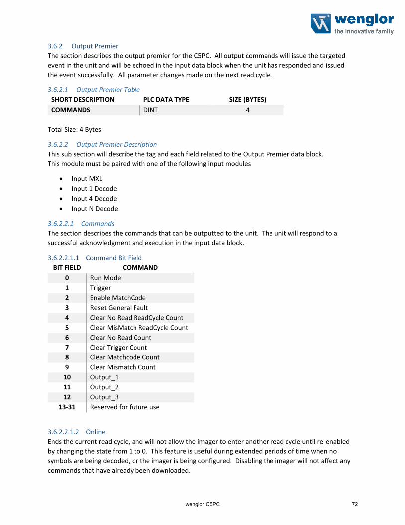
3.6.2 Output Premier
The section describes the output premier for the C5PC. All output commands will issue the targeted
event in the unit and will be echoed in the input data block when the unit has responded and issued
the event successfully. All parameter changes made on the next read cycle.
3.6.2.1 Output Premier Table
SHORT DESCRIPTION PLC DATA TYPE SIZE (BYTES)
COMMANDS DINT 4
Total Size: 4 Bytes
3.6.2.2 Output Premier Description
This sub section will describe the tag and each field related to the Output Premier data block.
This module must be paired with one of the following input modules
Input MXL
Input 1 Decode
Input 4 Decode
Input N Decode
3.6.2.2.1 Commands
The section describes the commands that can be outputted to the unit. The unit will respond to a
successful acknowledgment and execution in the input data block.
3.6.2.2.1.1 Command Bit Field
BIT FIELD COMMAND
0 Run Mode
1 Trigger
2 Enable MatchCode
3 Reset General Fault
4 Clear No Read ReadCycle Count
5 Clear MisMatch ReadCycle Count
6 Clear No Read Count
7 Clear Trigger Count
8 Clear Matchcode Count
9 Clear Mismatch Count
10 Output_1
11 Output_2
12 Output_3
13-31 Reserved for future use
3.6.2.2.1.2 Online
Ends the current read cycle, and will not allow the imager to enter another read cycle until re-enabled
by changing the state from 1 to 0. This feature is useful during extended periods of time when no
symbols are being decoded, or the imager is being configured. Disabling the imager will not affect any
commands that have already been downloaded.
wenglor C5PC 72

3.6.2.2.1.3 Trigger
Edge event-driven. Takes effect when read mode is Serial, Edge, or Level. A transition from 0 to 1 is a rising edge trigger event. A transition from 1 to 0 is a falling edge trigger event. The following sources all induce trigger events in the reader, including: • A serial command from a serial com port• EZ button• External Trigger input signal on connector A• Command: Trigger bit in the OUT data block
If the reader is to be exclusively triggered by the PLC, then all other trigger sources must be kept idle
3.6.2.2.1.4 Enable MatchCode
When the option is set to anything other than disabled the scanner will compare symbols read in the
read cycle to master symbols in a database. The results of this comparison can be used to specify the
output of the read cycle such as whether to output symbol data or change the state of the
programmable outputs. Matchcode is only functional in triggered modes. Multi-symbol matchcode is
supported but only with the matchcode type option set to true.
3.6.2.2.1.5 Reset General Fault
When a Fault occurs in the system, the user shall use this bit to try to reset the fault after they have remedied the problem (if applicable).
3.6.2.2.1.6 Clear Noread Readcycle Counter
Resets the total number of noread readcycles that have occurred since power-on or the last Noread
Readcycle Counter Reset command to 000000000.
3.6.2.2.1.7 Clear Mismatch Readcycle Counter
Resets the total number of mismatched code pre readcycle that have occurred since power-on or the
last Mismatch per Readcycle Counter Reset command to 000000000.
3.6.2.2.1.8 Clear Noread Counter
Resets the total number of noreads that have occurred since power-on or the last Noread Counter Reset
command to 000000000.
3.6.2.2.1.9 Clear Trigger Counter
Resets the total number of triggers that have occurred since power-on or the last Trigger Counter Reset
command to 000000000.
3.6.2.2.1.10 Clear Match Code Counter
Resets the Match Code/Good Read Counter to 000000000.
3.6.2.2.1.11 Clear Mismatch Counter
Resets the total number of symbols successfully read that do not match the master label since power-on
or the last Mismatch Counter command to 000000000.
3.6.2.2.1.12 Output 1
Raises Output 1 if set to 1 and set’s output 1 to 0 when this value is 0. This value can be read in the
input data block in bit 19 under the device status tag.
wenglor C5PC 73

3.6.2.2.1.13 Output 2
Raises Output 2 if set to 1 and set’s output 1 to 0 when this value is 0. This value can be read in the
input data block in bit 20 under the device status tag.
3.6.2.2.1.14 Output 3
Raises Output 2 if set to 1 and set’s output 1 to 0 when this value is 0. This value can be read in the
input data block in bit 20 under the device status tag.
3.6.2.3 Output Premier Member Location
The following table is where members for the Output Premier are located.
3.6.2.3.1 Member Map Table
Member DataType Target BitNumber Style Data Length
Commands DINT 4 Bytes
32 Bit Boundary
RunMode Boolean Commands 0 BOOL 1 Bit
Trigger Boolean Commands 1 BOOL 1 Bit
EnableMatchCode Boolean Commands 2 BOOL 1 Bit
ResetGeneralFault Boolean Commands 3 BOOL 1 Bit
ClearNoReadReadCycleCount Boolean Commands 4 BOOL 1 Bit
ClearMisMatchReadCycleCount Boolean Commands 5 BOOL 1 Bit
ClearNoReadCount Boolean Commands 6 BOOL 1 Bit
ClearTriggerCount Boolean Commands 7 BOOL 1 Bit
ClearMatchcodeCount Boolean Commands 8 BOOL 1 Bit
ClearMismatchCount Boolean Commands 9 BOOL 1 Bit
Output_1 Boolean Commands 10 BOOL 1 Bit
Output_2 Boolean Commands 11 BOOL 1 Bit
Output_3 Boolean Commands 12 BOOL 1 Bit
Reserved for future use Boolean Commands 13 - 31 BOOL 19 Bits
Reserved NA 496 Bytes
wenglor C5PC 74wenglor C5PC 74

4 Siemens TIA Portal v13 SP1 Update 8 This section will go over the necessary steps needed to add the C5PC unit to your Siemens PLC with Siemens TIA Portal v13 SP1 update 8. All files required for setup can be found on your C5PC unit in the wenglor Connectivity under ProfiNET. The files are also downloadable by going to wenglor homepage: www.wenglor.com
4.1.1 Table Hardware used in example
HARDWARE DESCRIPTION ARTICLE NUMBER VERSION SIEMENS PLC S7-1200 CPU 1212C AC/DC/Rly 6ES7 212-1BE40-0XB0 V4.1DIGITAL INPUT DI 16X24VDC 6ES7 221-1BH32-0XB0 V2.0DIGITAL OUTPUT DQ 16X24VDC 6ES7 222-1BH32-0XB0 V2.0
This section will go over the following:
1. Starting up TIA Portal
2. Adding a Controller (This example uses the controller in Table 4.1.1)
3. Installing the C5PC GSDML File
4. Adding the C5PC Unit
5. Adding Input/Output Slots
6. Importing the User Data Types defined by wenglor7. Importing the Function Blocks created by wenglor8. Reading/Writing Data to the C5PC
4.2 Starting up TIA Portal This section assumes that TIA Portal is installed on the machine the programmer is working on. The
section also assumes that this is a new project. If this is a not a new project than proceed to section
4.4 Installing the C5PC GSDML file to begin adding the C5PC to the project.
1. Double click the TIA Portal V13 Icon located on the desktop
2. Click Create New Project (1) and give your project a name (2). Click Create (3) when done.
wenglor C5PC 75wenglor C5PC 75

3. One the lower left hand corner select Project View
4.3 Adding a Controller 1. To add a controller double click Add new device in the Devices Panel
2. This example uses a Siemens S7-1200 CPU. Click Controllers SIMATIC S7-1200CPUCPU 1212C AC/DC/Rly PN and find Article Number 6ES7 212-1BE40-0XB0 and verify the
Version is correct at V4.1
wenglor C5PC 76wenglor C5PC 76

3. Give the Controller a Unique name so it does not conflict with any other ProfiNET devices on the
network. Click OK to add the controller to the project.
4. In this example the controller has a Digital Input Card installed into slot 2 and a Digital output
Card installed in slot 3. These will need to be added to the controller since they are missing.
5. Click on the Hardware catalog tab to display the hardware that can be added to the controller.
wenglor C5PC 77

5. Click on the Hardware catalog tab to display the hardware that can be added to the controller.
wenglor C5PC 78

wenglor C5PC 79
6. To add the Digital Input Card go to the Hardware Catalog panel go to DIDI 16x24VDC
6ES7 221-1BH32-0XB0 and verify that Version is 2.0
wenglor C5PC 79

7. To add the Input Card simply drag the icon to Slot 2
wenglor C5PC 80wenglor C5PC 80

8. To add the Digital Output Card go to the Hardware Catalog panel go to DQDQ 16x24VDC
6ES7 222-1BH32-0XB0 and verify that Version is 2.0
wenglor C5PC 81wenglor C5PC 81

9. To add the output card simply drag and drop the icon into Slot 3
wenglor C5PC 82

12. Next is to assign the IP Address to the PLC. Select Rack 0 Slot 1 in the Device Overview Panel
13. In the Properties Tab (1) select the General Tab (2) and select Ethernet Addresses (3)
14. In Interface networked with select Add new Subnet
wenglor C5PC 83

15. In IP protocol set the IP to the desired address. In this example the PLC IP Address is set to
10.10.5.28 with a subnet mask of 255.255.255.0
16. Save the project at this time by clicking the Save project icon
17. Compile the Project as this time by selecting the Compile Icon or by selection
EditCompile
18. Now download the current project to the PLC to assign the PLC a name (Step 3) and IP Address
(Step 15). To do this click the Download Icon to download the project to the controller
wenglor C5PC 84

19. Select the PG/PC Interface (1) dropdown and select the NIC Card that the PLC is plugged into on
the programmers computer (In this example the NIC card is the ASIX AX88179 USB 3.0 toGigabit Ethernet Adapter.
20. In Connections to interface/subnet: Select PN/IE_1 or the network interface name given in Step 14
wenglor C5PC 85

21. Click Start Search to find the PLC on the network. The PLC should be displayed in the
Compatible Devices in Target Subnet table. Click the Load button
wenglor C5PC 86

22. The Load Preview will display. Click Load to load the project into the PLC
23. The Load results will display. Click Finish to complete the process
wenglor C5PC 87

24. When loading has completed, the PLC should now be named with the name assigned in Step 3
and the IP Address assigned in Step 14. To verify this select the Accessible Devices Icon and
in the Dialog box click the Start Search button find the PLC with the new name and IP Address.
wenglor C5PC 88

4.4 Installing the C5PC GSDML File 25. To Install the C5PC GSDML file go to OptionsManage general station description files
(GSD)
26. Select the Browse icon
27. Navigate to the location of the GSDML File.
a. You can find a copy of this on the product side at wenglor webside
wenglor C5PC 89

28. The Content of imported path will display the C5PC GSDML File and verify the following
a. File Name:
b. Version is:
c. Status:
GSDML-V2.32-wenglor-C5PC-20161017V2.32
Not Yet installed
29. If the correct file is displayed with the correct version and the status is Not yet installed than
click on the box to the left (1) and click Install (2).
wenglor C5PC 90

30. When installation is complete a dialog box will display the Installation result. If the installation
failed than resolve the conflict before proceeding. Click close after a successful install.
31. TIA Portal will complete the installation process. To verify that the GSDML is installed go to
OptionsManage general station description files (GSD) as in Step 25. The status will now
display Already Installed.
wenglor C5PC 91

4.5 Adding the C5PC Unit to the TIA Portal Project 32. After installing the GSDML File the C5PC can now be added to the TIA portal project. To
add the C5PC, double click the Devices & networks icon in the Devices panel.
wenglor C5PC 92

33. Click on the Hardware catalog tab to display the hardware that can be added to the controller.
wenglor C5PC 93
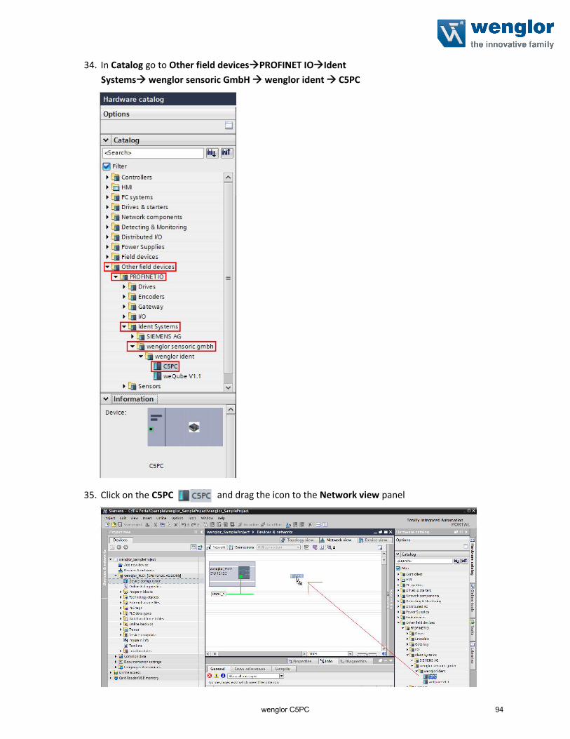
34. In Catalog go to Other field devicesPROFINET IOIdent
Systems wenglor sensoric GmbH wenglor ident C5PC
35. Click on the C5PC and drag the icon to the Network view panel
wenglor C5PC 94

36. The C5PC is now added to the network
37. Assign the C5PC to the same ProfiNET network by clicking the Not assigned (1) and
selecting the PLC Profinet interface (2). This example the interface name is called
MSCAN_PLC.PROFINET interface_1.
38. The Controller and the C5PC are now interfaced through the ProfiNET interface.
wenglor C5PC 95

4.6 Assigning Name and IP Address
39. Double click the C5PC icon to display the Device View.
40. Select the C5PC (1) icon then select the Properties (2) tab.
wenglor C5PC 96

41. Select General and change the name of the C5PC to a unique name for the ProfiNET
network. There cannot be another device named the same on the network!
42. Select PROFINET interface [X1] (1) Ethernet address (2) and scroll down to IP protocol (3).
Set the IP Address (4) to the desired IP address for the network. In this example the IP address
is set to 10.10.5.15.
43. Save the project by clicking the Save project icon
wenglor C5PC 97

44. To assign the name in Step 41 right click the C5PC (1) icon in the Device View and select
Assign device name (2).
45. Verify that the Type of PG/PC interface (1) is PN/IE and the PG/PC interface (2) is using the correct NIC card.
wenglor C5PC 98

46. Click Update list (1) to refresh the Accessible devices in the network table (2)
47. Verify the MAC address(1) matches the MAC address on the unit and that the Device(2) is an
Ident Systems
wenglor C5PC 99

48. The unit can also be easily identified by selecting the Flash LED. The Front Green LED’s will light
blink and well as the top bank of LED’s. This helps easily identify that the correct unit is about to
be assigned the name. To do this select the unit in the table and check the box Flash LED.
49. After the unit has been verified click Assign Name to assign the name to the unit.
wenglor C5PC 100

50. The status will change from No device name assigned to OK (1) and the PROFINET device name
(2) is updated to the PROFINET Device Name (3).
51. Click close to close the dialog box
wenglor C5PC 101

52. To download the IP Address compile the project and click download
53. In the Load Preview dialog click Load
54. In the Load Results dialog check the box Start All then click Finish
wenglor C5PC 102

wenglor C5PC 103

55. This part may take some time
56. Verify that the unit has the IP Address by clicking the Accessible Devices Icon and click the
Start Search (1) button to display all nodes on the interface (2). Notice the C5PC has the correct name (3) and IP Address (4).
57. Click Cancel to close the Accessible devices window.
wenglor C5PC 104

4.7 Adding Input/Output Modules 58. Navigate to the C5PC Device View. To do this double click Devices & networks and
double click the C5PC (1) icon in the Network view
59. In Device Overview make sure the Hardware Catalog is displayed. This can be done by selecting
the Hardware catalog tab
wenglor C5PC 105

60. In the Hardware catalog there are two folders to select. Select the Module folder to display the
Input and Output modules.
61. To add an input module select the Input module folder to display all the possible inputs. Double
click the desired input module and the module will load into Slot 1. In this example Input 1
Decode is used.
a. NOTE: Only one input is allowed. Please reference Section 3.5 Input Modules for
details of each member in the module and the description of each member.
wenglor C5PC 106

62. To add an output module select the Output module folder to display all the possible outputs.
Double click the desired output module and the module will load into Slot 2. In this example
Input 1 Decode and according to section 3.5.4 Output Premier must be used.
a. NOTE: Only one output is allowed. Please reference Section 3.6 Output Modules for
details of each member in the module and the description of each member.
4.8 Importing the PLC Data Types defined by wenglor 63. Before importing the function blocks, the program needs to have user defined PLC data types
imported first. These were created to help the user read the tags in a more human readable
format. Table 4.8.1 is a list of what User defined types need to be import for the specific
Input/Output Module
wenglor C5PC 107

4.8.1 User Data Types for Input/Output Modules Table MODULE NAME USER DATA TYPE NAME
INPUT SMALL LEGACY
INPUT BIG LEGACY
INPUT MXL
INPUT 1 DECODE
INPUT 4 DECODE
INPUT N DECODE
OUTPUT LEGACY
OUTPUT PREMIER
• WH_Input_Legacy_Small
• WH_Legacy_UserTag_Echo
• WH_Legacy_Command_Echo
• WH_Legacy_External_Outputs_Echo
• WH_Input_Legacy_Big
• WH_Legacy_UserTag_Echo
• WH_Legacy_Command_Echo
• WH_Legacy_External_Outputs_Echo
• WH_Legacy_Input_Status
• WH_Legacy_Ext_Output_Status
• WH_Legacy_Device_Status
• WH_Input_MXL_Decode
• WH_Input_Header
• WH_ReadCycle_Report
• WH_Input_MXL_Decode_Report
• WH_Input_1_Decode
• WH_Input_Header
• WH_ ReadCycle_Report
• WH_ Decode_Report_436Bytes
• WH_Input_4_Decode
• WH_Input_Header
• WH_ ReadCycle_Report
• WH_ Decode_Report_160Bytes
• WH_ Decode_Report_72Bytes
• WH_Input_N_Decode
• WH_Input_N_Header
• WH_Input_N_ReadCycle_Report
• WH_ Decode_Report_436Bytes
• WH_Ouput_Legacy
• WH_Legacy_User_Defined_Tags
• WH_Legacy_Cmds
• WH_Legacy_External_Outputs
• WH_Premier_Cmds
wenglor C5PC 108

64. To import the user data types go to the Project Tree and select the Controller Folder (1). In this
example the Controller folder is MSCAN_PLC1 [CPU 1510SP-1 PN]. Select External source file
(2) and double click Add new external file(3).
wenglor C5PC 109

65. When the Open Dialog window displays, navigate to the folder that contains the Input and
Output Modules loaded in Section 4.7. In this example the Input 1 Decode Module was added
with the corresponding Output Premier Module. Referencing Table 4.8.1 the following User
defined tags need to be added:
a. Input Module
i. WH_Input_1_Decode
ii. WH_Input_Header
iii. WH_ ReadCycle_Report
iv. WH_ Decode_Report_436Bytes
b. Output Module
i. WH_Premier_Cmds
In the zip file downloaded from the wenglor website, navigate to ModulesInput 1 Decode
and Output PremierUser Defined Tag and select all the files and click Open.
66. The files will be added in the External Source File but not added to the PLC Data Types folder.
wenglor C5PC 110

67. To add the external files to the PLC Data Types folder select all the imported files (1), right click
the and select Generate block from Source (2)
68. A Warning Dialog may display. Click OK to overwrite any existing User data types of the same
name.
wenglor C5PC 111

69. All the User data types will now be displayed in the PLC Data Type folder in the Devices Tab
70. Lastly, the project needs to be recompiled to complete the import of the User Data Types. To
do this right click PLC Data Type (1), select Compile (2) and select Software (rebuild all blocks)(3).
wenglor C5PC 112

71. The files located in External Source files are no longer needed. To remove them: select all files
(1), right click and click Delete (2)
4.9 Importing the Function and Data Blocks created by wenglor 72. After importing the PLC Data Types in Section 4.8, the Function and Data blocks can now be
imported. To import both files go to the Project Tree and select the Controller Folder (1). In
this example the Controller folder is wenglor_PLC1 [CPU 1212C AC/DC/Rly]. Select External
source file (2) and double click Add new external file(3).
wenglor C5PC 113

73. When the Open Dialog window displays, navigate to the folder that contains the Input and
Output Modules loaded in Section 4.7. In this example the Input 1 Decode Module was added
with the corresponding Output Premier Module. In the zip file downloaded from the wenglorwebsite, navigate to ModulesInput 1 Decode and Output PremierFunction Block and
select fb_WH_1_Decode.scl and click Open.
74. Perform the same step as above and navigate to ModulesInput 1 Decode and Output
PremierData Block and select db_C5PC_1_Decode.db and click Open.
wenglor C5PC 114

75. Two files should now be shown in External source files
76. Select both files (1) right click and select Generate blocks from source (2)
77. A Warning Dialog may display. Click OK to overwrite any existing functions blocks and/or data
blocks of the same name.
78. The function block and data block are now added to the Program Block folder
wenglor C5PC 115

79. The files located in External Source files are no longer needed. To remove them: select all files
(1), right click and click Delete (2)
80. Right Click the Controller Folder (1) and select Compile (1) Software (rebuild all blocks) (2)
4.10 Adding a Function Block to an Organization Block 81. To use the function block imported in Section 4.9 to an Organization Block in the project go to
the Device Tab click on Controller Folder (1), select Program Blocks (2) and double click on
the Organization Block (3) in which the function block will execute. In this example we have
an Organization Block called Main and will insert the function block here.
wenglor C5PC 116

82. Select the function block (1) added from Step 78 in Section 4.9. Drag and drop the function
block into the rung in which the program (2) will execute. In this example, Network 1 is the rung
that will execute the read/write function.
83. When the Call options dialog displays, name the data block instance to a desired name. In this
example the data block is named db_C5PC_Lab1. Click OK to add the data block
instance.
84. The function block is now added to the rung. All function blocks for the C5PC require the
following inputs
a. C5PC Input Start Address
b. C5PC Output Start Address
c. C5PC Data Block Number that data is written and read from
wenglor C5PC 117

85. To locate the Input Start Address, Output Start Address go to the Device Tab and go to
Distributed I/O (1)PROFINET IO- System(100): PN/IE_1 (2) Name of Device (3) and double
click Device configuration (4). In this example Name of Device is “mh_Lab1”
86. In the Device Overview (1) tab locate the I address (2) and Q Address (3) columns. Write down
the start address for the Input and Output Module. In this example the Input address starts at 1and the Output address starts at 1.
wenglor C5PC 118

87. Go back to the Device Tab click on Controller Folder (1), select Program Blocks(2) and double
click on the Organization Block (3) in which the function block was added.
88. In the function block add the Input Start Address and Output Start Address that were located in
step 86. In this example, step 86 showed the Input and Output starting at address 1
89. The DB_Number is the data block created in step 78 in Section 4.9. The number is either
automatically created or manually inputted by the programmer and can be found by looking at
the [DB#] to the right of the name. In this example the data block number is 1 ([DB1])
wenglor C5PC 119

90. Enter the DB_Number in the function block
91. Right Click the controller folder (1) and select Compile (2) Software (rebuild all blocks) (3)
92. Download the project to the controller by selecting the Download icon and clicking the
Load button when the Load preview dialog displays.
wenglor C5PC 120

93. When the Load results dialog displays, check the box Start all and click Finish
wenglor C5PC 121
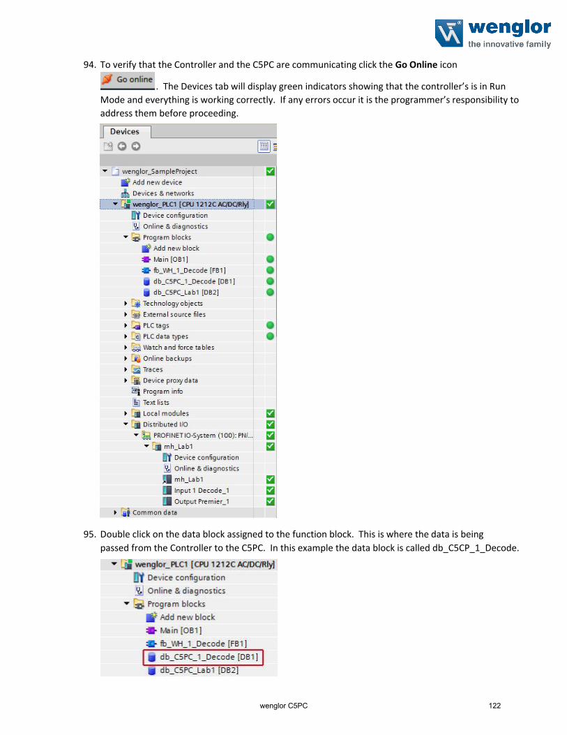
94. To verify that the Controller and the C5PC are communicating click the Go Online icon
. The Devices tab will display green indicators showing that the controller’s is in Run
Mode and everything is working correctly. If any errors occur it is the programmer’s responsibility to
address them before proceeding.
95. Double click on the data block assigned to the function block. This is where the data is being
passed from the Controller to the C5PC. In this example the data block is called db_C5CP_1_Decode.
wenglor C5PC 122

96. The data block viewer will display the contents of the Input and Output Modules. Click the
Monitor All icon to view the data in the Monitor value column
97. To trigger the unit simply right Click the Output bit Trigger and select Modify operand…
98. In Modify Value type 1 and select OK.
wenglor C5PC 123

99. The value will change from FALSE to TRUE
100. The decode string will populate with the decode data
wenglor C5PC 124