SERVICE & INSTALLATION RULES Manual No. 32 - SA ...
156
Issued – February 2020 Page 1 of 156 The use of this document is subject to the conditions stated in SA Power Networks disclaimer at the front of this document. © SA Power Networks 2020 SA Power Networks SERVICE & INSTALLATION RULES Manual No. 32 Published: February 2020 WARNING: Printed copies of this document ARE DEEMED UNCONTROLLED. The most up-to-date version is located on the Intranet/Internet.
-
Upload
khangminh22 -
Category
Documents
-
view
4 -
download
0
Transcript of SERVICE & INSTALLATION RULES Manual No. 32 - SA ...

TS 100: Electrical Design Standards for Underground Distribution Cable Networks (up to and including 33kV)
Issued – February 2020 Page 1 of 156 The use of this document is subject to the conditions stated in SA Power Networks disclaimer at the front of this document.
© SA Power Networks 2020
SA Power Networks
SERVICE & INSTALLATION RULES Manual No. 32
Published: February 2020
WAR
NIN
G: P
rinte
d co
pies
of t
his
docu
men
t AR
E D
EEM
ED U
NC
ON
TRO
LLED
. The
mos
t up-
to-d
ate
vers
ion
is lo
cate
d on
the
Intra
net/I
nter
net.
Service & Installation Rules
Issued – February 2020 Page 2 of 156 The use of this document is subject to the conditions stated in SA Power Networks disclaimer at the front of this document.
© SA Power Networks 2020
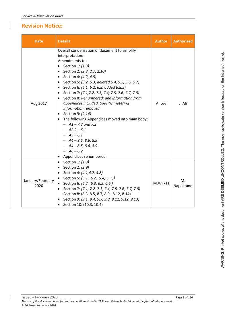
Revision Notice:
Date Details Author Authorised
Aug 2017
Overall condensation of document to simplify interpretation: Amendments to:
• Section 1: (1.3)
• Section 2: (2.3, 2.7, 2.10)
• Section 4: (4.2, 4.5)
• Section 5: (5.2, 5.3, deleted 5.4, 5.5, 5.6, 5.7)
• Section 6: (6.1, 6.2, 6.8, added 6.8.5)
• Section 7: (7.1,7.2, 7.3, 7.4, 7.5, 7.6, 7.7, 7.8)
• Section 8: Renumbered; and information from appendices included. Specific metering information removed
• Section 9: (9.14)
• The following Appendices moved into main body:
− A1 – 7.2 and 7.3
− A2.2 – 6.1
− A3 – 6.1
− A4 – 8.5, 8.6, 8.9
− A4 – 8.5, 8.6, 8.9
− A6 – 6.2
• Appendices renumbered.
A. Lee J. Ali
January/February 2020
• Section 1: (1.3)
• Section 2: (2.9)
• Section 4: (4.1,4.7, 4.8)
• Section 5: (5.1, 5.2, 5.4, 5.5,)
• Section 6: (6.2, 6.3, 6.5, 6.6 )
• Section 7: (7.1, 7.2, 7.3, 7.4, 7.5, 7.6, 7.7, 7.8) Section 8: (8.3, 8.5, 8.7, 8.9, 8.12, 8.14)
• Section 9: (9.1, 9.4, 9.7, 9.8, 9.11, 9.12, 9.13)
• Section 10: (10.3, 10.4)
M.Wilkes M.
Napolitano
WAR
NIN
G: P
rinte
d co
pies
of t
his
docu
men
t AR
E D
EEM
ED U
NC
ON
TRO
LLED
. The
mos
t up-
to-d
ate
vers
ion
is lo
cate
d on
the
Intra
net/I
nter
net.

Service & Installation Rules
Issued – February 2020 Page 3 of 156 The use of this document is subject to the conditions stated in SA Power Networks disclaimer at the front of this document.
© SA Power Networks 2020
SA Power Networks: SA Power Networks, ABN 13 332 330 749, a partnership of:
Spark Infrastructure SA (No.1) Pty Ltd, ABN 54 091 142 380
Spark Infrastructure SA (No.2) Pty Ltd, ABN 19 091 143 038
Spark Infrastructure SA (No.3) Pty Ltd, ABN 50 091 142 362
each incorporated in Australia
CKI Utilities Development Limited, ABN 65 090 718 880
PAI Utilities Development Limited, ABN 82 090 718 951
each incorporated in The Bahamas
1 Anzac Highway, Keswick, South Australia, 5035.
SA Power Networks Disclaimer: 1. The use of the information contained in this document is at your sole risk.
2. The Information within this document is subject to change without notice.
3. SA Power Networks, its agents, instrumentalities, officers and employees:
3.1 Make no representations, express or implied, as to the accuracy of the information contained within this document;
3.2 Accept no liability for any use of the said information or reliance placed on it; and
3.3 Make no representations, either expressed or implied, as to the suitability of the said information for any particular purpose.
4. SA Power Networks and its agencies and instrumentalities do not endorse or in any respect warrant any third-party products or services by virtue of any information, material or content referred to or included on, or linked to this document.
SA Power Networks Copyright©2020: This publication is copyright protected. SA Power Networks reserves to itself all rights in such material. You shall not reproduce any content of this document by any process without first obtaining SA Power Networks permission, except as permitted under the Copyright Act 1968.
Parts of this publication have been reproduced with the express permission of AGL Electricity, CitiPower, Powercor Australia, TRU Energy and United Energy Distribution.
All rights reserved.
W
ARN
ING
: Prin
ted
copi
es o
f thi
s do
cum
ent A
RE
DEE
MED
UN
CO
NTR
OLL
ED. T
he m
ost u
p-to
-dat
e ve
rsio
n is
loca
ted
on th
e In
trane
t/Int
erne
t.

Service & Installation Rules
Issued – February 2020 Page 4 of 156 The use of this document is subject to the conditions stated in SA Power Networks disclaimer at the front of this document.
© SA Power Networks 2020
Preface: These SA Power Networks Service and Installation Rules incorporate the ‘Technical Installation Rules’ referred to in Regulation 76 of the Electricity (General) Regulations 2012 under the Electricity Act 1996.
The Technical Installation Rules within this document are denoted by the symbol TIR adjacent to the relevant clause.
In accordance with Regulation 76 of the Electricity (General) Regulations 2012, the Technical Installation Rules have been prepared by SA Power Networks and approved by the Technical Regulator.
The parts of the SA Power Networks Service and Installation Rules which are not part of the Technical Installation Rules have been prepared and approved by SA Power Networks.
If a provision of the SA Power Networks Service and Installation Rules which is not part of the Technical Installation Rules is inconsistent with the Technical Installation Rules, the Technical Installation Rules shall prevail, and the provision shall, to the extent of the inconsistency, be invalid.
These SA Power Networks Service and Installation Rules supersede the SA Power Networks Service and Installation Rules 2017, effective from 29 February 2020.
WAR
NIN
G: P
rinte
d co
pies
of t
his
docu
men
t AR
E D
EEM
ED U
NC
ON
TRO
LLED
. The
mos
t up-
to-d
ate
vers
ion
is lo
cate
d on
the
Intra
net/I
nter
net.

Service & Installation Rules
Issued – February 2020 Page 5 of 156 The use of this document is subject to the conditions stated in SA Power Networks disclaimer at the front of this document.
© SA Power Networks 2020
Contents
Revision Notice: .............................................................................................. 2
SA Power Networks: ....................................................................................... 3
SA Power Networks Disclaimer: ...................................................................... 3
SA Power Networks Copyright©2020: ............................................................ 3
Preface: .......................................................................................................... 4
1. General ................................................................................................. 15
1.1 About this Manual ......................................................................................... 15
1.1.1 What this document is about ..................................................................... 15
1.1.2 Application of this document ..................................................................... 15
1.1.3 How to use this document .......................................................................... 15
1.1.4 Revisions and Alterations ........................................................................... 15
1.2 References..................................................................................................... 15
1.2.1 Acts & Regulations ..................................................................................... 15
1.2.2 Codes & Guidelines .................................................................................... 16
1.3 Definitions ..................................................................................................... 16
2. Introduction .......................................................................................... 23
2.1 Objective ....................................................................................................... 23
2.2 Scope ............................................................................................................ 23
2.3 Innovation ..................................................................................................... 23
2.4 Publication & Revision ................................................................................... 23
2.4.1 Administration ........................................................................................... 23
2.4.2 Publication ................................................................................................ 24
2.4.3 Revision ..................................................................................................... 24
2.5 Service & Installation Rules Management Contact ......................................... 24
2.6 Dispute Resolution ........................................................................................ 24
2.7 Application Responsibilities ........................................................................... 24
2.8 Failure to Comply with these Rules ................................................................ 24
2.9 Exceptional Circumstances ............................................................................. 25
2.10 Offences ........................................................................................................ 25
2.11 Necessity for Employing a Licensed Person .................................................... 25
2.12 Basic Industry Relationship ............................................................................ 26
2.12.1 Responsibilities .......................................................................................... 26
2.12.1.1 Distributor .......................................................................................... 26
2.12.1.2 Retailers .............................................................................................. 26
2.12.1.3 Customer Agents ................................................................................ 26
WAR
NIN
G: P
rinte
d co
pies
of t
his
docu
men
t AR
E D
EEM
ED U
NC
ON
TRO
LLED
. The
mos
t up-
to-d
ate
vers
ion
is lo
cate
d on
the
Intra
net/I
nter
net.

Service & Installation Rules
Issued – February 2020 Page 6 of 156 The use of this document is subject to the conditions stated in SA Power Networks disclaimer at the front of this document.
© SA Power Networks 2020
3. Customer Solutions Manager Areas & Contact Details........................... 27
3.1 State – Customer Solutions Manager Area Boundaries ................................... 27
3.2 Metro – Customer Solutions Manager Area Boundaries ................................. 28
4. General Rules ........................................................................................ 29
4.1 Safety (TIR) .................................................................................................... 29
4.2 Compliance with Regulations, Codes of Practice and these Rules (TIR)............ 29
4.2.1 Electrical Installations (TIR) ........................................................................ 29
4.2.2 Building & Structural Clearances (TIR) ......................................................... 29
4.3 Testing (TIR) .................................................................................................. 30
4.4 Equipment Acceptance (TIR) .......................................................................... 30
4.4.1 Equipment Required to be Accepted (TIR)................................................... 30
4.4.2 Equipment Not Required to be Accepted (TIR) ............................................ 30
4.5 Labelling (TIR) ................................................................................................ 31
4.6 Access to SA Power Networks Equipment (TIR) .............................................. 31
4.7 Locking Facilities (TIR) .................................................................................... 31
4.8 Electrical Industry Security Seal (TIR) ............................................................. 31
5. Supply Application, Connection & Disconnection .................................. 34
5.1 Conditions of Supply (TIR) .............................................................................. 34
5.1.1 Compliance with SA Power Networks S&I Rules and AS/NZS 3000 Wiring Rules (TIR) ................................................................................................. 34
5.2 Negotiations for Obtaining/Altering and Electricity Supply & Warning Against Premature Expenditure .................................................................................. 34
5.2.1 Alterations to Existing Installations............................................................. 35
5.2.2 Abolishment of Services and or Metering from Existing Installations ........... 35
5.3 Type of Supply and Load ................................................................................ 35
5.4 Authorised Service Capacity ........................................................................... 36
5.4.1 Application ................................................................................................ 36
5.4.1.1 Offer Letter ......................................................................................... 36
5.4.1.2 Agreed Maximum Demand ................................................................ 36
5.4.2 Control of Customer Load/Capacity (TIR) .................................................... 36
5.4.2.1 General (TIR)....................................................................................... 36
5.4.2.2 Capacity Control Device (TIR) ............................................................. 37
5.5 Typical Connection Process ............................................................................ 37
5.5.1 Connection to the SA Power Networks Distribution System ........................ 37
5.5.2 Reconnection to the SA Power Networks Distribution System (TIR) ............. 37
5.5.3 Reconnection where site remains disconnected >28days for safety reasons 37
5.5.4 Reconnection where site had been previous abolished (total permanent removal of supply) ..................................................................................... 37
WAR
NIN
G: P
rinte
d co
pies
of t
his
docu
men
t AR
E D
EEM
ED U
NC
ON
TRO
LLED
. The
mos
t up-
to-d
ate
vers
ion
is lo
cate
d on
the
Intra
net/I
nter
net.

Service & Installation Rules
Issued – February 2020 Page 7 of 156 The use of this document is subject to the conditions stated in SA Power Networks disclaimer at the front of this document.
© SA Power Networks 2020
6. Supply Characteristics and Supply Use................................................... 38
6.1 Supply (TIR) ................................................................................................... 38
6.1.1 Supply Systems (TIR) .................................................................................. 38
6.1.1.1 Supply Disturbances (TIR) ................................................................... 38
6.1.1.2 Phase Failure Protection (TIR) ............................................................ 38
6.1.2 Prospective Short Circuit Current (TIR) ........................................................ 38
6.1.3 Protective Systems (TIR) ............................................................................. 40
6.1.3.1 Earthing of Electrical Installations (TIR) ............................................. 40
6.2 Connection Points .......................................................................................... 40
6.2.1 Number of Services .................................................................................... 40
6.2.1.1 Subdivisions Incorporating Common Property ................................... 41
6.2.1.2 Subdivisions Not Incorporating Common Property ............................ 46
6.2.2 Number of Phases ...................................................................................... 53
6.2.3 Location ..................................................................................................... 55
6.3 Consumer Terminals ...................................................................................... 55
6.3.1 Number of Consumer Terminals per Point of Supply ................................... 55
6.3.2 Identification of Consumer Mains (TIR) ....................................................... 56
6.4 Identification of Multiple Supplies (TIR) ......................................................... 56
6.5 Customer Capacity Requirements (TIR) .......................................................... 56
6.5.1 Obligations (TIR) ........................................................................................ 56
6.5.2 Non Compliance (TIR) ................................................................................. 57
6.5.3 Power Factor (TIR) ..................................................................................... 57
6.5.4 Harmonics (TIR) ......................................................................................... 58
6.5.5 Balanced Load or Source (TIR) .................................................................... 59
6.5.6 Voltage Disturbance (TIR) ........................................................................... 59
6.5.7 Switched Loads (TIR) .................................................................................. 59
6.5.8 Voltage Drop (TIR) ..................................................................................... 59
6.5.9 Equipment Requiring Special Consideration (TIR) ........................................ 60
6.5.9.1 Interconnection of supplies ................................................................ 60
6.5.10 Starting Current of Motors (TIR) ................................................................. 60
6.5.10.1 General (TIR)....................................................................................... 60
6.5.10.2 Single Phase Motors (TIR) .................................................................. 61
6.5.10.3 Three Phase Motors 400 Volt (TIR) .................................................... 61
6.5.11 Test Method for Measurement of Motor Starting Current (TIR) ................... 61
6.5.11.1 Fall in Voltage Method (TIR) .............................................................. 61
6.5.11.2 Current Measurements Method (TIR) ................................................ 61
6.5.12 Restart Delay (TIR) ..................................................................................... 61
6.5.13 Installations with IES, Generators, Alternative or Parallel Supplies (TIR) ...... 62
WAR
NIN
G: P
rinte
d co
pies
of t
his
docu
men
t AR
E D
EEM
ED U
NC
ON
TRO
LLED
. The
mos
t up-
to-d
ate
vers
ion
is lo
cate
d on
the
Intra
net/I
nter
net.

Service & Installation Rules
Issued – February 2020 Page 8 of 156 The use of this document is subject to the conditions stated in SA Power Networks disclaimer at the front of this document.
© SA Power Networks 2020
6.6 Additional Sources of Supply by way of Renewable Energy Systems of Embedded Generating Units or IES ................................................................. 62
6.6.1 General ...................................................................................................... 62
6.6.1.1 Inverter Energy Systems (TIR)............................................................. 62
6.6.2 Connection of Break before Make Stand-by Generation-Unit or Alternative Source of Supply (TIR) ................................................................................ 63
6.6.3 Requirements for Parallel Embedded Generating Unit (TIR) ........................ 63
6.6.3.1 Network Connection Agreement (TIR) ............................................... 63
6.6.3.2 Notification Requirements (TIR) ......................................................... 63
6.6.4 Networks Connection of Inverter Energy Systems (TIR) ............................... 64
6.6.4.1 Inverter Requirements (TIR) ............................................................... 64
6.6.4.2 Installation and Connection to Grid (TIR) ........................................... 64
6.6.4.3 Metering (TIR) .................................................................................... 65
6.6.4.4 Standard Networks Connection Agreement (TIR) .............................. 65
6.6.5 Storage Systems ......................................................................................... 65
7. Low Voltage Supply Arrangements ........................................................ 66
7.1 Services ......................................................................................................... 66
7.1.1 General ...................................................................................................... 66
7.1.2 Type of Service........................................................................................... 66
7.1.3 Connections to Services ............................................................................. 66
7.2 Underground Distribution Areas .................................................................... 68
7.2.1 Consumer Terminals .................................................................................. 68
7.2.2 Underground Service ................................................................................. 69
7.2.2.1 Service Pits/Pillars .............................................................................. 69
7.2.2.2 Underground Service Cable Termination ........................................... 70
7.2.2.3 Terminals of a Pad Mounted Transformer ......................................... 71
7.2.2.4 Terminals of an Open Bushing Transformer....................................... 71
7.3 Overhead Distribution Network Areas ........................................................... 71
7.3.1 Overhead Lines .......................................................................................... 72
7.3.2 Over/Under Service ................................................................................... 76
7.3.3 LV Isolators on Pole (up to 200Amps) ......................................................... 77
7.3.4 Consumer Terminals .................................................................................. 78
7.3.5 Point of Attachment ................................................................................... 78
7.3.5.1 Overhead Distribution Network ......................................................... 78
7.3.5.2 Point of Attachment on Customer Support Poles ............................... 79
7.3.5.3 Transformers ...................................................................................... 81
7.3.5.4 Access to Point of Supply .................................................................... 81
7.3.6 Service Brackets ......................................................................................... 82
7.3.6.1 General ............................................................................................... 82
WAR
NIN
G: P
rinte
d co
pies
of t
his
docu
men
t AR
E D
EEM
ED U
NC
ON
TRO
LLED
. The
mos
t up-
to-d
ate
vers
ion
is lo
cate
d on
the
Intra
net/I
nter
net.

Service & Installation Rules
Issued – February 2020 Page 9 of 156 The use of this document is subject to the conditions stated in SA Power Networks disclaimer at the front of this document.
© SA Power Networks 2020
7.3.6.2 Provision ............................................................................................. 82
7.3.6.3 Specification, Acceptance and Installation......................................... 82
7.3.7 Aerial Service Lines Clearances ................................................................... 83
7.3.7.1 Existing Service Lines .......................................................................... 83
7.3.7.2 New and Replacement Service Lines .................................................. 83
7.3.7.3 Achievement and Maintenance of Clearances ................................... 83
7.3.8 Aerial Service Lines Sag .............................................................................. 84
7.4 Service Protection .......................................................................................... 84
7.4.1 Customers Protective Equipment (TIR) ....................................................... 84
7.4.2 SA Power Networks Protection Device Facilities (TIR) .................................. 84
7.4.2.1 Enclosures (TIR) .................................................................................. 84
7.4.2.2 Access (TIR) ......................................................................................... 85
7.4.2.3 Location (TIR) ..................................................................................... 85
7.4.2.4 Common Enclosure (TIR) .................................................................... 85
7.4.3 Security ..................................................................................................... 85
7.4.3.1 General ............................................................................................... 85
7.4.3.2 SA Power Networks Operation ........................................................... 85
7.4.4 Operation (TIR) .......................................................................................... 86
7.4.4.1 General (TIR)....................................................................................... 86
7.4.4.2 Emergency Services Personnel (TIR) ................................................... 86
7.4.4.3 Suitably Qualified Person (TIR) ........................................................... 86
7.4.4.4 Fuse removal by a Licensed Electrical Worker/Contractor (TIR) ........ 86
7.4.5 Service Protection Devices ......................................................................... 87
7.4.5.1 Connection point ................................................................................ 87
7.4.5.1.1 Connection Point protective devices up to an including 500kVA ........................................................................... 87
7.4.5.1.2 I2t Characteristics of LV Fuses ........................................ 88
7.4.5.1.3 Connection Point protective devices above 500kVA ...... 88
7.4.6 Acceptable Applications ............................................................................. 90
7.4.6.1 Underground Supply ........................................................................... 90
7.4.6.2 Overhead Supply ................................................................................ 90
7.4.6.2.1 General .......................................................................... 90
7.4.6.2.2 Supply to Customer Support Poles ................................. 90
7.4.6.3 Supply from SA Power Networks Pole ................................................ 90
7.4.6.3.1 Consumer Mains Located upon SA Power Networks Poles ............................................................................... 91
7.4.6.3.2 Customer’s Switchboard and Associated Equipment Mounted on SA Power Networks Poles ......................... 92
7.4.6.4 Supply Direct from Transformers ....................................................... 92
7.5 Isolating Devices ............................................................................................ 92
WAR
NIN
G: P
rinte
d co
pies
of t
his
docu
men
t AR
E D
EEM
ED U
NC
ON
TRO
LLED
. The
mos
t up-
to-d
ate
vers
ion
is lo
cate
d on
the
Intra
net/I
nter
net.

Service & Installation Rules
Issued – February 2020 Page 10 of 156 The use of this document is subject to the conditions stated in SA Power Networks disclaimer at the front of this document.
© SA Power Networks 2020
7.5.1 Meter Isolators (TIR) .................................................................................. 92
7.5.1.1 General (TIR)....................................................................................... 92
7.5.1.2 Features (TIR) ..................................................................................... 92
7.5.1.3 Rating (TIR) ......................................................................................... 93
7.5.1.4 Application (TIR) ................................................................................. 93
7.5.1.5 Installation (TIR) ................................................................................. 95
7.5.2 Location and Access to Isolation Devices..................................................... 95
7.5.2.1 Properties which are the Subject of a Strata Plan or Community Title ............................................................................................................ 95
7.5.2.2 Properties which are not the Subject of a Strata Plan or Community Title ..................................................................................................... 95
7.6 Safety When Working on or Near Distribution Network (TIR) ......................... 95
7.6.1 No Go Zone (TIR) ........................................................................................ 95
7.6.2 Underground Cables (TIR) .......................................................................... 96
7.6.3 Transformers (TIR) ..................................................................................... 96
7.6.4 Poles and Aerial Lines (TIR) ........................................................................ 96
7.6.5 HV Distribution Earthing Systems to LV Installations Earthing Clearance (TIR) .................................................................................................................. 96
7.6.6 Service Pits/Pillars (TIR) ............................................................................. 96
7.6.7 Supply Isolation (TIR) ................................................................................. 97
7.7 Consumer Mains ............................................................................................ 97
7.7.1 General (TIR) .............................................................................................. 97
7.7.1.1 Exclusion Zone (TIR) ............................................................................ 97
7.7.1.2 Unprotected Consumer Mains (TIR) ................................................... 98
7.7.1.3 Protected Consumer Mains (TIR) ........................................................ 99
7.7.1.4 Unprotected Consumer Mains Supplied from Transformers (TIR) ..... 99
7.7.2 Size of Consumer Mains (TIR) ..................................................................... 99
7.7.3 Identification of Consumer Mains (TIR) ..................................................... 100
7.7.4 Unmetered Consumer Mains, Submains, Wiring ....................................... 100
7.7.5 Terminations (TIR) ................................................................................... 101
7.7.6 Underground Consumer Mains (TIR) ......................................................... 101
7.7.6.1 Consumer Mains in Road Reserves (TIR) .......................................... 101
7.7.6.2 Consumer Mains on a Third Party Property (TIR) ............................. 101
7.7.7 Minimum Insulation Resistance (TIR) ........................................................ 101
7.7.8 Wiring Systems (TIR) ................................................................................ 101
7.7.9 Connections (TIR) ..................................................................................... 102
7.7.9.1 Pit/Pillar Connections (TIR) ............................................................... 102
7.7.9.2 Termination on a Distribution Pole (TIR) .......................................... 102
7.7.9.2.1 Work Practices (TIR) .................................................... 102
WAR
NIN
G: P
rinte
d co
pies
of t
his
docu
men
t AR
E D
EEM
ED U
NC
ON
TRO
LLED
. The
mos
t up-
to-d
ate
vers
ion
is lo
cate
d on
the
Intra
net/I
nter
net.

Service & Installation Rules
Issued – February 2020 Page 11 of 156 The use of this document is subject to the conditions stated in SA Power Networks disclaimer at the front of this document.
© SA Power Networks 2020
7.7.9.2.2 Installation (TIR) .......................................................... 103
7.8 Special Electrical Installations & Supply Arrangements ................................. 103
7.8.1 Limited Period Supplies ............................................................................ 103
7.8.1.1 Provision ........................................................................................... 103
7.8.1.2 Customer’s Electrical Installation (TIR)............................................. 103
7.8.1.3 Buildings in Course of Erection ......................................................... 103
7.8.2 Multiple Occupancies ............................................................................... 104
7.8.2.1 Plan ................................................................................................... 104
7.8.2.2 Subdivision........................................................................................ 104
7.8.2.3 Unmetered Conductors .................................................................... 104
7.8.2.4 Metering ........................................................................................... 104
7.8.2.5 Control (TIR) ..................................................................................... 104
7.8.2.6 Supply Arrangement Diagrams (TIR) ................................................ 105
7.8.2.7 Labelling (TIR) ................................................................................... 105
7.8.3 Equipment Installed on a Distribution Pole ............................................... 106
7.8.3.1 Use of Pole ........................................................................................ 106
7.8.3.2 Equipment Installation ..................................................................... 106
7.8.4 Electrical Installations on Public Land (TIR) ............................................... 107
7.8.4.1 General (TIR)..................................................................................... 107
7.8.4.2 Points of Supply and Consumer Terminals (TIR) ............................... 107
7.8.4.3 Labelling (TIR) ................................................................................... 107
7.8.5 Contiguous Land ...................................................................................... 107
7.8.6 Subdivisions ............................................................................................. 107
7.8.6.1 General ............................................................................................. 107
7.8.6.2 No Existing Electrical Installation or Supply ..................................... 108
7.8.6.3 Existing Electrical Installations or Supply ......................................... 108
7.8.6.4 Multiple Occupancies ....................................................................... 108
7.8.7 Unmetered Supplies ................................................................................. 108
8. LV Switchboards, Service Equipment & Metering ................................ 109
8.1 Scope .......................................................................................................... 109
8.2 Tariffs & Metering ....................................................................................... 109
8.3 Metering Obligations ................................................................................... 109
8.3.1 General (TIR) ............................................................................................ 109
8.3.2 Alterations & Additions ............................................................................ 109
8.4 Determination of Meter Type ...................................................................... 110
8.5 Location ...................................................................................................... 110
8.5.1 General .................................................................................................... 110
8.5.2 Single Residential ..................................................................................... 111
WAR
NIN
G: P
rinte
d co
pies
of t
his
docu
men
t AR
E D
EEM
ED U
NC
ON
TRO
LLED
. The
mos
t up-
to-d
ate
vers
ion
is lo
cate
d on
the
Intra
net/I
nter
net.

Service & Installation Rules
Issued – February 2020 Page 12 of 156 The use of this document is subject to the conditions stated in SA Power Networks disclaimer at the front of this document.
© SA Power Networks 2020
8.5.3 Single Non Residential (e.g. Commercial, Industrial, Primary Production) .. 116
8.5.4 Multiple Residential Installations ............................................................. 117
8.5.5 Multiple Non-Residential ......................................................................... 120
8.5.6 Single Customer Rural Installations........................................................... 122
8.5.7 Combined Residential – Non-Residential Use ............................................ 122
8.5.8 Public Land .............................................................................................. 122
8.5.9 Unsuitable Main Switchboard and Metering Locations .............................. 123
8.6 Clearances around Meter Enclosure ............................................................. 123
8.6.1 Individual Residential Installations ........................................................... 123
8.6.2 Multiple Residential and Commercial Installations .................................... 124
8.6.3 Gas Meter Enclosure Clearances ............................................................... 125
8.7 Main Switchboard/Meter Enclosure Metering Panel Mounting Height ......... 125
8.8 Access ......................................................................................................... 126
8.8.1 General .................................................................................................... 126
8.8.2 Locks ....................................................................................................... 127
8.9 Metering Panels, Surrounds & Enclosures (TIR) ............................................ 127
8.9.1 General (TIR) ............................................................................................ 127
8.9.2 Meter panels (TIR) ................................................................................... 127
8.9.2.1 Size (TIR) ........................................................................................... 127
8.9.2.2 Installation (TIR) ............................................................................... 128
8.9.2.3 Materials (TIR) .................................................................................. 128
8.9.2.4 Wiring Holes (TIR) ............................................................................. 128
8.9.2.5 Fixing Arrangements (TIR) ................................................................ 129
8.9.2.6 Wiring (TIR) ...................................................................................... 129
8.9.3 Metering Surrounds & Enclosures (TIR) ..................................................... 129
8.9.3.1 General (TIR)..................................................................................... 129
8.9.3.2 Meter Surrounds (TIR) ...................................................................... 130
8.9.3.3 Meter Enclosures (TIR) ..................................................................... 130
8.10 Equipment ................................................................................................... 131
8.10.1 Acceptance (TIR) ...................................................................................... 131
8.10.2 On Meter Panels or Within Enclosures (TIR) .............................................. 131
8.10.3 Security Seals ........................................................................................... 131
8.10.4 Customer’s Equipment ............................................................................. 131
8.11 Meter Panel Labelling (TIR) .......................................................................... 131
8.11.1 Single Occupancy (TIR) ............................................................................. 131
8.11.2 Multiple Occupancies (TIR) ....................................................................... 131
8.12 Protection (TIR) ........................................................................................... 131
8.13 Whole Current Metering .............................................................................. 132
WAR
NIN
G: P
rinte
d co
pies
of t
his
docu
men
t AR
E D
EEM
ED U
NC
ON
TRO
LLED
. The
mos
t up-
to-d
ate
vers
ion
is lo
cate
d on
the
Intra
net/I
nter
net.

Service & Installation Rules
Issued – February 2020 Page 13 of 156 The use of this document is subject to the conditions stated in SA Power Networks disclaimer at the front of this document.
© SA Power Networks 2020
8.13.1 Metering Enclosure Internal Panel Clearances .......................................... 132
8.13.2 Meter Panels ........................................................................................... 132
8.13.3 Equipment (TIR) ....................................................................................... 132
8.13.4 Isolation of Metering Equipment .............................................................. 132
8.13.4.1 Single Occupancy Metering .............................................................. 132
8.13.4.2 Multiple Occupancy Metering .......................................................... 132
8.14 LV Current Transformer Metering ................................................................ 133
8.14.1 General .................................................................................................... 133
8.14.2 Meter Panel ............................................................................................. 133
8.14.2.1 Location and Access ......................................................................... 133
8.14.2.2 Clearances ........................................................................................ 133
8.14.2.3 Wiring ............................................................................................... 134
9. High Voltage Electrical Installations ..................................................... 135
9.1 Scope .......................................................................................................... 135
9.2 Contractual Arrangements ........................................................................... 135
9.3 Systems of Supply ........................................................................................ 135
9.4 Preliminary Information .............................................................................. 135
9.5 Installation Design (TIR) ............................................................................... 136
9.5.1 Power Transformers (TIR) ......................................................................... 136
9.5.2 Protective Equipment (TIR) ...................................................................... 137
9.6 Conversion from Low Voltage to High Voltage Supply .................................. 137
9.7 General Design (TIR) .................................................................................... 137
9.7.1 Circuit Connections (TIR) .......................................................................... 137
9.7.2 Control of Incoming High Voltage Supply (TIR) .......................................... 137
9.7.2.1 Equipment or Connections upstream of metering transformers ..... 138
No equipment or connections are permitted on the mains side of the metering transformers other than: .................................................................. 138
9.7.3 Power Factor (TIR) ................................................................................... 138
9.7.4 Supply Disturbances (TIR) ......................................................................... 138
9.7.5 Voltage Unbalance Factor (TIR) ................................................................ 138
9.7.6 Safety Signs (TIR) ..................................................................................... 138
9.8 Protection (TIR) ........................................................................................... 139
9.8.1 Customer incoming circuit breaker protection requirements ..................... 139
9.8.2 Multiple supplies ..................................................................................... 139
9.8.3 Protection Settings ................................................................................... 139
9.8.3.1 Coordination ............................................................................................. 140
9.9 Insulation Coordination (TIR) ....................................................................... 140
9.10 Short Time Withstand Current (TIR) ............................................................. 140
WAR
NIN
G: P
rinte
d co
pies
of t
his
docu
men
t AR
E D
EEM
ED U
NC
ON
TRO
LLED
. The
mos
t up-
to-d
ate
vers
ion
is lo
cate
d on
the
Intra
net/I
nter
net.

Service & Installation Rules
Issued – February 2020 Page 14 of 156 The use of this document is subject to the conditions stated in SA Power Networks disclaimer at the front of this document.
© SA Power Networks 2020
9.11 Earthing (TIR) ............................................................................................... 141
9.11.1 General (TIR) ............................................................................................ 141
9.11.2 Size of Earthing Conductors (TIR) .............................................................. 141
9.11.3 Earthing of Metering Equipment (TIR) ...................................................... 141
9.12 SA Power Networks Acceptance Requirements ............................................ 142
9.13 Metering ..................................................................................................... 142
9.13.1 General Requirements ............................................................................. 142
9.13.2 Metering Instrument Enclosure Requirements .......................................... 143
9.13.2.1 Panel ................................................................................................. 143
9.13.2.2 Enclosure .......................................................................................... 143
9.13.3 Metering Transformers ............................................................................ 143
9.13.3.1 Compliance ....................................................................................... 143
9.13.3.2 Transformer Layout .......................................................................... 144
9.13.3.3 Secondary Wiring ............................................................................. 144
9.13.4 Access to Meters ...................................................................................... 145
9.13.5 SA Power Networks Connection Assets ..................................................... 145
9.14 Testing & Commissioning (TIR) ..................................................................... 145
9.15 Customer’s HV Installation Operation & Maintenance (TIR) ......................... 146
9.15.1 Operating Procedures (TIR) ...................................................................... 146
9.15.2 Trained Operators (TIR) ............................................................................ 146
9.15.3 Maintenance (TIR) ................................................................................... 146
10. Appendices.......................................................................................... 149
10.1 Appendix 1 – Single Phase URDs .................................................................. 149
10.2 Appendix 2 – SA Power Networks Service Fuse Time/Current Characteristics 151
Sheet 1 – For Service Fuse Type – ME & MF (TIR) ..................................................... 151
Sheet 2 – For Service Fuse Type – J (TIR) .................................................................. 151
Sheet 3 – For Service Fuse Type – NH Size 2 (TIR) ..................................................... 153
Sheet 4 – For Service Fuse Type – NH Size 3 (TIR) ..................................................... 154
Sheet 5 – For Service Fuse Type – NH Size 4A (TIR) .................................................. 155
10.3 Appendix 3 – Existing Metering Arrangements ............................................. 156
10.3.1 Meter Enclosures on High Voltage Poles ................................................... 156
10.3.2 Meter Enclosures containing service fuses (Elizabeth Area) ....................... 156
WAR
NIN
G: P
rinte
d co
pies
of t
his
docu
men
t AR
E D
EEM
ED U
NC
ON
TRO
LLED
. The
mos
t up-
to-d
ate
vers
ion
is lo
cate
d on
the
Intra
net/I
nter
net.

Service & Installation Rules
Issued – February 2020 Page 15 of 156 The use of this document is subject to the conditions stated in SA Power Networks disclaimer at the front of this document.
© SA Power Networks 2020
1. General
1.1 About this Manual
1.1.1 What this document is about
This document is designed to assist customers and electrical contractors by detailing:
• the method and type of supply from SA Power Networks distribution network;
• the requirements for electrical installations connected to SA Power Networks distribution network; and
• some of the customer’s obligations relating to that supply.
Additional requirements are contained in the Electricity Distribution Code, Connection and Supply Contract and the Electricity Metering Code, copies of which are available on SA Power Networks internet site or from SA Power Networks on request.
1.1.2 Application of this document
This document is intended for use by SA Power Networks staff, engineers, building work contractors, licensed electrical contractors and registered electrical workers who are directly engaged in activities associated with the connection of electricity supply to a customer’s property from the SA Power Networks distribution network.
The requirements of this document apply to customers and their agents in relation to electrical installations connected to or intended to be connected to SA Power Networks distribution networks. Alterations of, or, additions to an existing electrical installation shall be deemed to be a new electrical installation and are covered by the requirements of this document.
In accordance with the Electricity Act 1996 and Electricity (General) Regulations 2012, the requirements within this document also apply to electricity retailers and other parties such as Metering Providers participating in or executing duties under the National Electricity Rules in relation to installations connected (or intending to be connected) to SA Power Networks distribution network.
Unregistered persons may use this document for information purposes only, but are forbidden by law from undertaking electrical work and may be subject to criminal prosecution should they do so.
1.1.3 How to use this document
This is a self-contained document except where it specifically refers to other related documents. It supersedes previous versions of the SA Power Networks Service & Installation Rules.
1.1.4 Revisions and Alterations
SA Power Networks reserves the right to revise this publication. The current edition of this document is available on our website at www.sapowernetworks.com.au.
1.2 References
This list of references has been made as comprehensive as possible at the time of publication. However, other references may have been applicable at the time. The references listed may have been amended or made obsolete and new references may be applicable. The user is responsible to correct references applied.
1.2.1 Acts & Regulations
• Competition and Consumer Act 2010
• Electricity Act 1996 and Electricity (General) Regulations 2012
WAR
NIN
G: P
rinte
d co
pies
of t
his
docu
men
t AR
E D
EEM
ED U
NC
ON
TRO
LLED
. The
mos
t up-
to-d
ate
vers
ion
is lo
cate
d on
the
Intra
net/I
nter
net.
Service & Installation Rules
Issued – February 2020 Page 16 of 156 The use of this document is subject to the conditions stated in SA Power Networks disclaimer at the front of this document.
© SA Power Networks 2020
• Plumbers, Gas Fitters & Electricians Act 1995
• Work Health & Safety Act 2012 and Work Health & Safety Regulations 2012
1.2.2 Codes & Guidelines
• National Electricity Rules
• National Energy Retail Rules
• Electricity Distribution Code
• Electricity Retail Code
• Electricity Metering Code
• References, Administrators and their contact details include:
❖ Standards Australia www.standards.com.au
❖ Electricity Network Distributor www.sapowernetworks.com.au
❖ The Australian Energy Regulator www.aer.gov.au
❖ Australian Energy Market Operator www.aemo.com.au
❖ Australian Energy Market Commission www.aemc.gov.au
❖ SafeWork SA www.safework.sa.gov.au
1.3 Definitions
The definitions contained herein apply to these Service & Installation Rules.
Abolishment Total and permanent removal of a connection to the distribution network including any form of connection such as transformer connection, service line, pit/pillar connection and/or metering facility.
An abolishment may also be solely for removal of metering specific to the load that is connected to.
AEMO Australian Electricity Market Operator the company which operates and administers the National Electricity Market in Accordance with the National Electricity Rules.
AER Australian Energy Regulator – (AER) is Australia’s national energy market regulator and an independent statutory authority.
Aerial Line A powerline placed above the ground and in the open air but does not include bus bars or any direct current conductors used as traction trolley wires.
Agreed Maximum Demand
This is the demand reached during the summer period (November to the end of March) as per Attachment 17 Tariff Structure Statement in the 2020-25 Regulatory Proposal.
The agreed demand cannot exceed the Authorised Service Capacity.
AS/NZS 3000 Wiring Rules
The current version of the Wiring Rules published by Standards Australia.
WAR
NIN
G: P
rinte
d co
pies
of t
his
docu
men
t AR
E D
EEM
ED U
NC
ON
TRO
LLED
. The
mos
t up-
to-d
ate
vers
ion
is lo
cate
d on
the
Intra
net/I
nter
net.

Service & Installation Rules
Issued – February 2020 Page 17 of 156 The use of this document is subject to the conditions stated in SA Power Networks disclaimer at the front of this document.
© SA Power Networks 2020
Alteration of Service Provision
Where any electrical work occurs to an electrical Installation that involves the consumer mains, main switchboard, unmetered components or in any case where disconnection and reconnection to the distribution network is required for this work.
Authorised Person
The person in charge of the premises, or the registered electrical worker or licensed electrical contractor or other person appointed or selected by the person in charge of the premises, to perform certain duties associated with the electrical installation on the premises.
Authorised Service Capacity
The demand capacity as detailed in the ‘Offer for Supply’ which is accepted by the customer. This is the maximum demand capacity that the Service Protection Device, Consumer Terminals and upstream Distribution System have been designed to provide for. When a customer requests a reduction to their Agreed Maximum Demand the new Agreed Maximum Demand will be the Authorised Service Capacity.
Authority to Connect form
This authority will be relied upon by SA Power Networks when connecting/reconnecting an installation and is only to be used where it is not reasonably practicable to provide a printed Certificate of Compliance (CoC) on site. The authority confirms that a CoC has been issued for the electrical work/installation to be connected/reconnected.
Community Lot Is a separately owned Lot within a Community Title Scheme.
Community Title Scheme
Is the division of land into at least two lots and generally an area of common property. The Community Title Act provides for implied easements within a Community Title development. These implied easements only relate to private service infrastructure and do not apply to infrastructure that is owned by SA Power Networks.
Common Property
Property within a Community Title Scheme that is owned by the community corporation. The community corporation is comprised of all lot owners within the Community Title Scheme. Common property relates to those parts that do not form part of a lot and typically includes the land for the service infrastructure and driveways that are shared. Roads within Community Title Schemes are generally common property.
Connection Point A connection point to a transmission or distribution network. For the purpose of this document connection point also has the same meaning as Point of Supply as defined in AS/NZS 3000.
Consumer Mains Are the electrical conductors, owned and maintained by the customer, connecting the point of supply and the main switchboard and form part of the customers’ installation.
Consumer Terminals The junction at which the consumer mains connect to the SA Power Networks service cable or main supply conductors. Refer to Clause 6.3 (Consumer Terminals).
CT Metering A meter where electricity flow is measured by a meter using current transformers (CTs). Note: CT meters are used where the maximum demand of the installation is more than 100 amps.
WAR
NIN
G: P
rinte
d co
pies
of t
his
docu
men
t AR
E D
EEM
ED U
NC
ON
TRO
LLED
. The
mos
t up-
to-d
ate
vers
ion
is lo
cate
d on
the
Intra
net/I
nter
net.

Service & Installation Rules
Issued – February 2020 Page 18 of 156 The use of this document is subject to the conditions stated in SA Power Networks disclaimer at the front of this document.
© SA Power Networks 2020
Customer
A person or entity who has a connection point for supply of electricity available from a transmission or distribution network for consumption or generation by that person and includes:
• the occupier for the time being of a place to which electricity is supplied; and
• where the context requires, a person or entity seeking an electricity supply; and
• a person or entity of a class declared by regulation to be customers.
Customer Agent/s Customer agents are parties representing the customers. Such parties may include registered electrical workers, licensed electrical contractors, consulting engineers, architects, and equipment manufacturers.
Distributor A person who holds a Distribution Licence, or who is exempted from holding a licence of the Electricity Act.
• A ‘Distributor’ is also known as the Local Network Service Provider (LNSP).
For the purpose of this document SA Power Networks is the Distributor.
Distribution Network
The whole or a part of a system for the distribution of electricity, but does not include anything declared by regulation not to be a distribution network or part of a distribution network. For the purposes of these rules references to Distribution Network means the network poles, wires, underground cables, transformers, substations etc., operated by SA Power Networks, which transports electricity from the transmission system to a customer’s Connection Point.
Determined Maximum Demand
The electrical demand, both instantaneous and sustained load, in kVA or amps required from the Distributor’s supply system as assessed by the Responsible SA Power Networks Officer.
Distribution Licence
A licence authorising the operation of a distribution network, granted under the Electricity Act 1996.
Dual Fronted Property
A property that has a frontage on two independent boundaries, one of which is the street address and the other being another public area. Note: does not apply to corner properties.
Electricity Distribution Code
The Electricity Distribution Code administered by the Essential Services Commission of SA.
Electrical Certificate of Compliance
CoC
A registered electrical worker or contractor must, before the electrical installation is made available for energisation, complete a certificate of compliance to the extent required by the Technical Regulator, under the Electricity (General) Regulations 2012.
Electrical Installation
A set of wires and associated fittings, equipment and accessories installed in a place for the conveyance, control, measurement and/or use of electricity that is, or is to be, or has been, supplied for consumption in the place, but does not include:
• Electricity infrastructure owned or operated by an electricity entity • Any wires, fittings, equipment or accessories connected to and beyond
any electrical outlet at which fixed wiring terminates (other than any such outlet used to connect sections of fixed wiring).
WAR
NIN
G: P
rinte
d co
pies
of t
his
docu
men
t AR
E D
EEM
ED U
NC
ON
TRO
LLED
. The
mos
t up-
to-d
ate
vers
ion
is lo
cate
d on
the
Intra
net/I
nter
net.

Service & Installation Rules
Issued – February 2020 Page 19 of 156 The use of this document is subject to the conditions stated in SA Power Networks disclaimer at the front of this document.
© SA Power Networks 2020
Embedded Generating Unit
A generating unit connected within a distribution network and not having direct access to a transmission network.
Embedded Network
Embedded networks are private electricity networks which serve multiple premises and are located within, and connected to, a distribution or transmission system through a parent connection point in the National Electricity Market
IES Inverter Energy Systems
Licensed Contractor
A contractor licensed to perform electrical work under the Plumbers, Gas Fitters and Electricians Act 1995.
Main Switchboard
An enclosure or panel for the mounting of switchgear and protective devices for the primary control of the electrical installation. This Comprises of: A Panel or Enclosure , The Main Switch or Switches, Circuit Breakers, Main Earthing bar, Main Neutral Bar, MEN connection, Associated wiring and equipment. May also contain: Service Protective Device, Metering etc.
Metered Mains
Applicable generally to country areas where overhead wiring is owned and maintained by SA Power Networks connected through existing metering and provided to a number of connection points that may appear to be similar construction to infrastructure wiring.
Meter Isolator
A circuit breaker that isolates the supply to the metering equipment (including CTs where installed) and the corresponding installation or tenancy.
Metering Provider
A company registered with AEMO that provides and maintains metering installations in accordance with the National Electricity Rules requirements.
Note: For the purposes of these rules the term ‘Meter Installer’ has the same meaning as ‘Metering Provider’ and as defined in the Electricity Act 1996 Section 59 a ‘Prescribed Person’.
Metering Is metering instruments and associated fuses, links, transformers and wiring installed by a Metering Provider at the Metering Point as required by the National Electricity Rules.
Metering Coordinator
A person registered by AEMO who engages in the coordination and provision of metering services at the connection point.
Metering Point
Is the physical and electrical location at which metering equipment is connected.
MNP Manager Network Planning.
Must Is to be understood as mandatory.
NATA National Association of Testing Authorities
NER National Electricity Rules.
NMI National Metering Identifier
Occupancy An electrical installation or part thereof, which is supplied with electricity through a specific meter or meters and for which an individual electricity consumption account is rendered.
WAR
NIN
G: P
rinte
d co
pies
of t
his
docu
men
t AR
E D
EEM
ED U
NC
ON
TRO
LLED
. The
mos
t up-
to-d
ate
vers
ion
is lo
cate
d on
the
Intra
net/I
nter
net.

Service & Installation Rules
Issued – February 2020 Page 20 of 156 The use of this document is subject to the conditions stated in SA Power Networks disclaimer at the front of this document.
© SA Power Networks 2020
Occupancies Multiple or Multiple Occupancies
More than one Occupancy, Tenancy or separate NMI Metered or unmetered connection, connected to the same connection point.
Offer Letter A letter documenting an offer by SA Power Networks to a customer in relation to a contract to undertake and complete works for the supply of electricity.
Point of Attachment
Is the point that the aerial conductors of an overhead service are physically anchored on a customer’s building, pole or structure.
Point of Supply
Refer to Connection Point.
Principle Frontage Area (PFA)
Is the area between the road frontage boundary and any building/structure within 30m of the frontage boundary and may only extend 1.5m around the corner of the most forward wall of any building or structure.
Principle Frontage Property Boundary
Is that boundary between the real property and the gazetted road. However, where a property has boundaries with two (2) or more gazetted roads, the principal frontage boundary will be that which provides primary public/personal access.
Property Either what is commonly described as a Torrens Title allotment, a Community Title Scheme or Land which is owned by the Crown on which the owner/occupier has the right to the installation of an electricity supply. A property may include any combination of contiguous (adjacent) land and/or an individual title that constitutes a single development, to which an owner/occupier or a developer has the right to the installation of an electricity supply.
Public Land Land owned by the Crown or an instrumentality or agent of the Crown or by a council or other local government body, including any such land that is subject to native title.
PV Photo Voltaic System
Readily Accessible
Capable of being reached quickly and without climbing over or removing obstructions, mounting upon a chair, or using a movable ladder, and in any case, not more than two metres (2m) above the ground, floor or platform.
SA Power Networks Manager
Refers to the relevant SA Power Networks, Customer Solutions Manager for the areas depicted in Section 3 in the first instance, who may refer to other managers where further input is required
Regulator The agency authorised by law to administer the relevant Act, Code, Standard or requirement.
This may be:
• The Australian Energy Regulator (AER), • Office of the Technical Regulator (OTR), • Australian Competition and Consumer Commission (ACCC), • Essential Services Commission of SA (ESCOSA), • Australian Energy Market Commission (AEMC), • Australian Energy Market Operator (AEMO), • Or other agencies
WAR
NIN
G: P
rinte
d co
pies
of t
his
docu
men
t AR
E D
EEM
ED U
NC
ON
TRO
LLED
. The
mos
t up-
to-d
ate
vers
ion
is lo
cate
d on
the
Intra
net/I
nter
net.

Service & Installation Rules
Issued – February 2020 Page 21 of 156 The use of this document is subject to the conditions stated in SA Power Networks disclaimer at the front of this document.
© SA Power Networks 2020
Requested Maximum Demand
The maximum demand that the Customer or their agent have requested to be provided (as determined under AS/NZS3000 or by other method).
Retailer A holder of a licence under the South Australian Electricity Act, 1996 authorised to retail electricity.
Responsible Officer
The officer appointed by the relevant SA Power Networks Manager to be responsible for the application of these Rules. There may be multiple Responsible Officers with specific responsibilities, eg negotiation for supply, provision of transformers, specification of points of supply, types of supply, servicing and metering etc.
REC Registered Electrical Contractor
REW Registered Electrical Worker.
Rules Unless referring to another specific document the term Rules means this document.
SA Power Networks Manager
The SA Power Networks Manager or the authorised Officer serving that area of the customer’s installation. Note: The Minor Connections Group can be contacted via the Builders and Contractors Line on 1300 650 014.
Security Seal A device used by SA Power Networks and Metering Providers to seal the un-metered portion of a customer’s installation, the metering installation and SA Power Networks equipment.
Service Cable Refer to Service Line.
Service Fuse Refer to Service Protection Device.
Service Fuse Enclosure
Enclosure to house the Service Protection Device.
Service Point Refer to Connection Point.
Service Protection Device
A device provided by SA Power Networks, generally a fuse but may be a circuit breaker for larger installations, to protect SA Power Networks assets.
Service Line Constructed or designed or ordinarily used for the supply of electricity at low voltage; and through which electricity is or is intended to be supplied by an electricity entity to a customer from the distribution network of the entity.
Shall Is to be understood as mandatory.
Should Is to be understood as non–mandatory, ie advisory or recommended.
Strata Title Development
A ‘Strata Title Development’ is regarded as a ‘Community Title Scheme’ for the purpose of this document. All terms related to ‘Strata Title’ have the equivalent meaning to the terms relating to the ‘Community Title’.
Subdivision The division of land into two or more parts which can be disposed of separately.
Suitable (or suitably)
To the satisfaction of the relevant SA Power Networks Manager.
Supply Connection Facility
A facility containing consumer terminals, eg, pillar, cubicle, service fuse enclosure or other agreed facilities.
Swimming Pool Zone
Swimming pool zones as defined in AS/NZS3000
WAR
NIN
G: P
rinte
d co
pies
of t
his
docu
men
t AR
E D
EEM
ED U
NC
ON
TRO
LLED
. The
mos
t up-
to-d
ate
vers
ion
is lo
cate
d on
the
Intra
net/I
nter
net.

Service & Installation Rules
Issued – February 2020 Page 22 of 156 The use of this document is subject to the conditions stated in SA Power Networks disclaimer at the front of this document.
© SA Power Networks 2020
Temporary Unless otherwise agreed to by SA Power Networks, the term temporary shall mean for a period of time no longer than 12 months.
TIR The Technical Installation Rules referred to in regulation 76 of the Electricity (General) Regulations 2012 within this document are denoted by the symbol (TIR) adjacent to the relevant clause.
Torrens Title A Torrens Title land division is a division of land into at least two allotments, which are held / owned independently of one another. A Torrens Title land division requires that each new allotment has frontage to a public road or adequate access to a public road. There are generally no shared facilities or infrastructure as each allotment must have its own infrastructure arrangements in place.
Underground Service
The electricity distributors supply network to the connection point.
Un-metered Supply An authorised supply that is not metered.
Whole Current Meter
A meter where the electricity flow is directly measured by the meter ie the current under measurement passes through the meter itself.
Note: Whole current meters are generally used where the maximum demand of the installation is less than 100Amps.
WAR
NIN
G: P
rinte
d co
pies
of t
his
docu
men
t AR
E D
EEM
ED U
NC
ON
TRO
LLED
. The
mos
t up-
to-d
ate
vers
ion
is lo
cate
d on
the
Intra
net/I
nter
net.

Service & Installation Rules
Issued – February 2020 Page 23 of 156 The use of this document is subject to the conditions stated in SA Power Networks disclaimer at the front of this document.
© SA Power Networks 2020
2. Introduction
2.1 Objective
The objective of these Rules is to provide South Australian electricity customers, registered electrical workers and other people in the industry with the technical requirements for electrical installations connected to the SA Power Networks distribution network. Customer’s electrical installations must comply with the Wiring Rules in AS/NZS 3000 as they apply from time to time.
2.2 Scope
These Service and Installation Rules apply to new installations, alterations or additions to existing installations that are or are intended to be connected to the SA Power Networks distribution network.
It is not intended to apply any additional requirements to installations that were compliant at the time of the original installation and are not being altered. For the purpose of these Rules, a relocatable premise is considered a new installation when it is relocated.
This document is designed to assist users by detailing:
• the method and type of supply from the SA Power Networks distribution network
• the requirements for customer electrical installations connected to SA Power Networks distribution network
• some of the customers’ obligations relating to that supply
Additional requirements may be contained in the Electricity Distribution Code, Connection and Supply Contract and the Electricity Metering Code, copies of which are available on SA Power Networks internet site or from SA Power Networks on request.
There may be situations the Rules do not cover. This may include unusual connections, and alterations to legislation and codes. SA Power Networks must be consulted where these situations are encountered.
Where an electrical installation consists of an embedded network (as defined in the (SA) Electricity Metering Code) the requirements of these Rules apply to the operator of the embedded network (parent) and their electrical installation.
An embedded network ‘child’ customer (sub-metered) must liaise with the operator of the embedded network for conditions relating to their supply.
SA Power Networks has no obligation, responsibility or involvement with the embedded network ‘child’ customer.
Note: These Rules are not intended for application to off-grid networks. Conditions relating to these off-grid networks should be sought from the appropriate operator.
2.3 Innovation
These Rules do not preclude other methods, innovation, or technology that achieves the same outcomes as the specifications detailed in this document. Any such proposal should be put to SA Power Networks Manager Network Planning (MNP) for acceptance during concept/design phase and prior to commencement of work.
2.4 Publication & Revision
2.4.1 Administration
The revision, development and publication of these Rules are compiled and administered by SA Power Networks and subject to Technical Regulator approval.
WAR
NIN
G: P
rinte
d co
pies
of t
his
docu
men
t AR
E D
EEM
ED U
NC
ON
TRO
LLED
. The
mos
t up-
to-d
ate
vers
ion
is lo
cate
d on
the
Intra
net/I
nter
net.

Service & Installation Rules
Issued – February 2020 Page 24 of 156 The use of this document is subject to the conditions stated in SA Power Networks disclaimer at the front of this document.
© SA Power Networks 2020
2.4.2 Publication
The latest version is currently available on SA Power Networks website.
2.4.3 Revision
SA Power Networks reserves the right to revise this publication. Although changes to regulations are usually the catalyst for revision, users and interested parties are invited to provide written comment and suggestions to assist further development of the Rules at any time.
Correspondence for this purpose should be forwarded to the SA Power Networks MNP. Any approved written submissions will be incorporated in the annual review of this document and subject to Technical Regulator approval.
2.5 Service & Installation Rules Management Contact
Contact for any matters related to the content of these Rules may be made through written correspondence to the SA Power Networks MNP or website (www.sapowernetworks.com.au).
Any enquiries relating to a specific installation are to be directed to the SA Power Networks Responsible Officer assigned to the specific project.
If specific installation is not assigned to a Responsible Officer, then direct enquiry to the Builders and Contractors Line.
2.6 Dispute Resolution
Where a customer has a complaint involving these Rules, they should firstly contact the SA Power Networks Responsible Officer and register their concern.
If not resolved, the complaint may be referred to a higher level person than the SA Power Networks Responsible Officer within the management structure.
Where this does not result in a resolution, the complaint will be resolved in accordance with the SA Power Networks Customer Complaint & Inquiries Procedure.
2.7 Application Responsibilities
These Rules are applicable from 29 February 2020. As per Electricity (General) Regulations 2012, Regulation 11, work on an electrical installation completed within 6 months of the publication of this version of these Rules may be carried out in accordance with the previous version of the Service and Installation Rules.
Transitional arrangements or exemptions may be able to be made with SA Power Networks where it is deemed necessary to do so.
Metering Providers are responsible for compliance with metering requirements and any impact of their work on other requirements of these Rules.
Each customer has an initial and ongoing responsibility to ensure their electrical installation complies with these Rules and AS/NZS 3000 when carrying out any alterations, additions and repairs and any other conditions for supply. This is normally accomplished through their agents, eg their Registered Electrical Worker or Licensed Electrical Contractor. Refer to Section 5 for complete details on Supply Applications.
2.8 Failure to Comply with these Rules
Should an installation not satisfy the requirements of these Rules, connection of electricity supply may be delayed or withheld, and installations with supply may be disconnected until such time as the non-compliance/s has been rectified.
WAR
NIN
G: P
rinte
d co
pies
of t
his
docu
men
t AR
E D
EEM
ED U
NC
ON
TRO
LLED
. The
mos
t up-
to-d
ate
vers
ion
is lo
cate
d on
the
Intra
net/I
nter
net.

Service & Installation Rules
Issued – February 2020 Page 25 of 156 The use of this document is subject to the conditions stated in SA Power Networks disclaimer at the front of this document.
© SA Power Networks 2020
A fee will be charged where a failure to comply with these Rules occurs and in the Responsible Officer’s opinion a subsequent attendance is required to verify that the non-compliances within these Rules have been rectified.
Refer to SA Power Networks website for current fees.
2.9 Exceptional Circumstances
In exceptional circumstances, the stated requirements contained in these Rules may be waived or modified by submission of a written request.
The written request shall be accompanied by:
• a detailed statement of the reasons why non-compliance with these Rules is sought;
• a complete set of photos, plans or diagrams to assess the issue;
• a ‘Statement of Consent’ from the owner or controlling body of the installation.
No action should be taken until a written reply to such a request has been received.
Any request in this regard shall be emailed to: [email protected].
Posted requests shall be addressed to: Manager Network Planning, SA Power Networks, GPO Box 77, Adelaide 5001.
Where SA Power Networks agrees to a variation to the requirements of these Rules, a copy of SA Power Networks written acceptance to the variation must be provided to the Connecting Officer with the valid COC at the time of connection.
2.10 Offences
The Electricity Act 1996 and Electricity (General) Regulations 2012, codes and guidelines enacted under those and other legislation include regulations for protection of Distributor assets and qualification of persons who may work on those assets. Offences under these regulations include:
5. Any work on SA Power Networks network assets unless authorised by SA Power Networks.
6. The damage or interference of any SA Power Networks assets such as:
• fuse link removal
• break a seal or lock
• dismantle or detach any SA Power Networks cables or equipment
• interference with electricity meters, time switches, equipment and/or service cables
• obtaining electricity by fraud
7. Unauthorised entry of SA Power Networks assets eg substations and infrastructure.
If a person is found guilty of an offence, it could result in the imposition of substantial fines together with an order for damages to compensate SA Power Networks for any loss and court costs. It may also cause that person to have a criminal record.
2.11 Necessity for Employing a Licensed Person
The Plumbers, Gas Fitters and Electricians Act 1995 requires that all electrical work carried out on electrical installations connected to or intended to be connected to the SA Power Networks distribution network, subject to certain exemptions, will be performed by a registered Electrical Worker(s) who is suitably licensed for such work in South Australia.
WAR
NIN
G: P
rinte
d co
pies
of t
his
docu
men
t AR
E D
EEM
ED U
NC
ON
TRO
LLED
. The
mos
t up-
to-d
ate
vers
ion
is lo
cate
d on
the
Intra
net/I
nter
net.

Service & Installation Rules
Issued – February 2020 Page 26 of 156 The use of this document is subject to the conditions stated in SA Power Networks disclaimer at the front of this document.
© SA Power Networks 2020
2.12 Basic Industry Relationship
This section is intended to provide an understanding of the basic relationships of industry stakeholders, (regulators and distributor, retailers, Metering Providers, customer and their agents), in respect to connection of electrical installations to SA Power Networks distribution network. Refer to figure 2.1 ‘Stakeholders’
2.12.1 Responsibilities
2.12.1.1 Distributor
❖ Negotiate provision and connection to the distribution network.
❖ Transport and delivery of electricity from and back to distribution network for customers.
❖ Connect customer electrical installations to SA Power Networks distribution network and administer technical supply aspects of the connection.
❖ Determine the network tariff to be applied to the installation.
❖ Energise up to the line side of the meter isolator.
❖ Is responsible for matters such as electricity supply quality and reliability.
2.12.1.2 Retailers
❖ Purchase electricity and retail the electricity (transported by Distributors) to customers.
❖ Nominate rates and arrange customer’s contract for the purchase of electricity.
❖ Engage a Metering coordinator.
❖ Request Distributors to connect or disconnect the customer installations to the Distributor’s network in accordance with the customer’s contract with the Retailer.
2.12.1.3 Customer Agents
Customer agents are parties representing the customers. Such parties may include registered electrical workers, licensed electrical contractors, consulting engineers, architects, and equipment manufacturers.
Figure 2.1 Stakeholders
Meter Coordinator
Metering Provider
Meter Installer
WAR
NIN
G: P
rinte
d co
pies
of t
his
docu
men
t AR
E D
EEM
ED U
NC
ON
TRO
LLED
. The
mos
t up-
to-d
ate
vers
ion
is lo
cate
d on
the
Intra
net/I
nter
net.

Service & Installation Rules
Issued – February 2020 Page 27 of 156 The use of this document is subject to the conditions stated in SA Power Networks disclaimer at the front of this document.
© SA Power Networks 2020
3. Customer Solutions Manager Areas & Contact Details
3.1 State – Customer Solutions Manager Area Boundaries
WAR
NIN
G: P
rinte
d co
pies
of t
his
docu
men
t AR
E D
EEM
ED U
NC
ON
TRO
LLED
. The
mos
t up-
to-d
ate
vers
ion
is lo
cate
d on
the
Intra
net/I
nter
net.

Service & Installation Rules
Issued – February 2020 Page 28 of 156 The use of this document is subject to the conditions stated in SA Power Networks disclaimer at the front of this document.
© SA Power Networks 2020
3.2 Metro – Customer Solutions Manager Area Boundaries
WAR
NIN
G: P
rinte
d co
pies
of t
his
docu
men
t AR
E D
EEM
ED U
NC
ON
TRO
LLED
. The
mos
t up-
to-d
ate
vers
ion
is lo
cate
d on
the
Intra
net/I
nter
net.

Service & Installation Rules
Issued – February 2020 Page 29 of 156 The use of this document is subject to the conditions stated in SA Power Networks disclaimer at the front of this document.
© SA Power Networks 2020
4. General Rules
4.1 Safety (TIR)
All persons and contractors are responsible for all aspects of safety related to work performed by those persons and employees. The works should be performed in accordance with all relevant Acts, Regulations, Codes of Practice, Standards and the Rules within this document that are related to the safety of the work being performed.
Electrical contractors (including Metering Providers) are not to connect any wires that form part of the customer’s electrical installation to the SA Power Networks network at the connection point, other than work described in section 59 (4) of the Electricity Act 1996, where a prescribed person installs or replacing a meter.
Where any SA Power Networks employee discovers that there is an immediate risk resulting from:
• exposed live electrical parts which pose an immediate threat to safety
• Customers Generation and HV
• Faulty IES
• Excessive load
• a customer’s meter box is in such a condition as to pose a threat to electrical equipment integrity and safety
• a customer’s structure interferes with access to the SA Power Networks service point and would also pose a threat to SA Power Networks personnel in performing their service delivery to customers safely
• a customer’s structure reduces the prescribed safety clearances detailed in Regulation 10, Schedule 1 of the Electricity (General) Regulations 2012 under the Electricity Act 1996.
The employee will arrange to have the supply to the customer’s premise de-energised or isolation of supply of a portion of the installation to make the installation safe. In these situations, where possible, the customer at the premise will be notified immediately. Written notification of the disconnection will be left at the premise when a customer is not in attendance at the premise.
4.2 Compliance with Regulations, Codes of Practice and these Rules (TIR)
Any connection or reconnection to SA Power Networks distribution network is required to comply with the Electricity Act 1996 and the Electricity (General) Regulations 2012, all codes and any other relevant legislation or guidelines.
4.2.1 Electrical Installations (TIR)
The above clause 4.2 applies to the following electrical installations:
❖ New installations;
❖ Alteration to existing installations as prescribed in AS/NZS 3000;
❖ Addition to existing installations as prescribed in AS/NZS 3000; or
❖ Special electrical installations.
4.2.2 Building & Structural Clearances (TIR)
The above clause 4.2 applies to buildings and structures constructed in the vicinity of:
❖ Service pits/pillars where a minimum clearance of 1.2m is required as per Figure 4.1.
❖ Aerial lines where for clarification, the relevant SA Power Networks Manager is to be contacted in relation to the specific voltage level of the aerial line and the OTR is to be contacted in relation to specific clearance details.
❖ Padmounted transformers and switching cubicles, refer to TS102 Easement Standard for Distribution Networks, available on the SA Power Networks website.
WAR
NIN
G: P
rinte
d co
pies
of t
his
docu
men
t AR
E D
EEM
ED U
NC
ON
TRO
LLED
. The
mos
t up-
to-d
ate
vers
ion
is lo
cate
d on
the
Intra
net/I
nter
net.

Service & Installation Rules
Issued – February 2020 Page 30 of 156 The use of this document is subject to the conditions stated in SA Power Networks disclaimer at the front of this document.
© SA Power Networks 2020
Figure 4.1 – Example Service Pit/Pillar Building Clearance
4.3 Testing (TIR)
The Electricity Act 1996 and the Electricity (General) Regulations 2012 require all electrical installation work to be tested in accordance with that Act and Regulations. All electrical work to be connected to SA Power Networks must be tested by the customer’s registered electrical worker or licensed electrical contractor prior to a connection.
4.4 Equipment Acceptance (TIR)
Equipment used to interface with SA Power Networks assets in accordance with these Rules must comply with the Electricity Act 1996 and Electricity (General) Regulations 2012 and be of a standard suitable for interfacing safely with SA Power Networks assets.
4.4.1 Equipment Required to be Accepted (TIR)
SA Power Networks may refuse to connect equipment required to be accepted that has not been accepted, and/or is not suitably identified in accordance with these Rules.
Service raiser brackets, service fuse enclosures and whole current metering enclosures and surrounds that are commonly distributed by electrical wholesalers and similar distributors, are required to be accepted for use by SA Power Networks prior to being connected to supply.
Service raiser brackets specifications referenced in clause 7.3.6 and whole current metering panel and surrounds in clause 8.9.3.
All enquiries and submissions relating to acceptance of equipment should be forwarded to the Manager Network Planning (MNP) in accordance with clause 2.9 at the earliest opportunity.
4.4.2 Equipment Not Required to be Accepted (TIR)
It is recommended manufacturers and/or suppliers of equipment used to interface with SA Power Networks assets and not required to be submitted for acceptance, submit their proposed equipment and installation arrangement to the SA Power Networks MNP for comment prior to use where there is no certified evidence of such equipment’s compliance and/or its suitability for its intended purpose with SA Power Networks assets and these Rules.
Examples of such equipment that are not required to be accepted include whole current meter isolators and CT metering facilities.
SA Power Networks may require certified evidence of such equipment’s compliance and/or its suitability for its intended purpose. SA Power Networks may accept such equipment, provided it is satisfied with the evidence provided.
1.2m
WAR
NIN
G: P
rinte
d co
pies
of t
his
docu
men
t AR
E D
EEM
ED U
NC
ON
TRO
LLED
. The
mos
t up-
to-d
ate
vers
ion
is lo
cate
d on
the
Intra
net/I
nter
net.

Service & Installation Rules
Issued – February 2020 Page 31 of 156 The use of this document is subject to the conditions stated in SA Power Networks disclaimer at the front of this document.
© SA Power Networks 2020
Certified evidence may include provision of documents to certify compliance with the specification contained in these Rules and its intended purpose by a suitably qualified person, eg an engineer or consultant.
SA Power Networks may refuse to connect equipment where it is not satisfied that the relevant specifications have been met, and/or where suitable certified evidence is not provided.
4.5 Labelling (TIR)
Every label required by these Rules shall be permanent, indelible, legible from normal viewing level and suitable for the purpose for which it is intended for the life of the installation.
A minimum requirement for label is a product manufactured in block lettering and numbers not less than 6mm in height with an operating temperature rating of between -15°C and 100°C.
For exterior applications, a UV and moisture resistant material and marking that is suitable for the environmental conditions in which it is installed is required.
For interior applications, including within transformers, service pit/pillars and switchboards, and service fuse enclosures moisture resistant material is required.
Note: Insulation tape is not acceptable for this requirement.
4.6 Access to SA Power Networks Equipment (TIR)
A customer must provide SA Power Networks representative a safe, convenient and unhindered access to their equipment in accordance with the Connection and Supply Contract and these Rules for any purposes associated with the supply, metering of electricity and testing of the customer’s electrical installation including connection, disconnection or reconnection of supply.
4.7 Locking Facilities (TIR)
Where SA Power Networks equipment or metering equipment is enclosed or within a low security area, access to the area or enclosure must be with an approved lock which is compatible with SA Power Networks Master Key System. Refer to ‘ES’ and ‘CM’ types in Table 4.1.
Customer supplied service fuse enclosures containing SA Power Networks service fuses are to be locked with SA Power Networks service fuse enclosure lock as shown in Table 4.1. Other lock types called up in these Rules are detailed in Table 4.2.
4.8 Electrical Industry Security Seal (TIR)
All portions of an un-metered supply to a customer installation including access panels, junction boxes, metering equipment, lockable isolators, fuse boxes and enclosures shall be made ready for sealing using an authorised industry participant security seal. Sealing shall not rely on holes to be aligned through nuts and threaded studs.
Escutcheon panels which provide access to un-metered sections or terminals of switchboards shall also be provided with sealing facilities. Any sealing hole/s shall be at least 2mm in diameter. Any un-authorised person or persons found tampering or breaking a seal will be considered as acting in contravention of the Electricity Act 1996.
Where an SA Power Networks Lock is used to secure unmetered portions of an electrical installation, then these shall be regarded the same as a security seal
WAR
NIN
G: P
rinte
d co
pies
of t
his
docu
men
t AR
E D
EEM
ED U
NC
ON
TRO
LLED
. The
mos
t up-
to-d
ate
vers
ion
is lo
cate
d on
the
Intra
net/I
nter
net.

Service & Installation Rules
Issued – February 2020 Page 32 of 156 The use of this document is subject to the conditions stated in SA Power Networks disclaimer at the front of this document.
© SA Power Networks 2020
LOCK SUPPLIED BY CRITICAL DIMENSIONS USED FOR
ES Customer Lock
Customer provides lock.
Refer supplier ie. Master Locksmith or electrical wholesaler.
Low security enclosures such as Meter boxes, Cupboards, Gates, Electric key switch etc.
CM Customer Lock
Customer provides lock.
Refer supplier ie. Master Locksmith or electrical wholesaler. 5 Pin tumbler mechanism, diam. 30mm & depth 28mm.
Medium Security Metering enclosures, Switch rooms, Gates, Electric key switch, etc.
CM Customer Pad Lock
Customer provides lock.
Refer supplier ie. Master Locksmith or electrical wholesaler.
Medium Security Metering enclosures, Switch rooms, Personal access gates.
SA Power Networks Service Fuse Enclosure Lock
Customer provides lock. SA Power Networks replaces barrel at time of connection.
Refer supplier ie. Master Locksmith or electrical wholesaler. 6 Pin tumbler mechanism, diam. 30mm & depth 28mm.
Locking of service fuse enclosure. Operated by SA Power Networks personnel only.
WAR
NIN
G: P
rinte
d co
pies
of t
his
docu
men
t AR
E D
EEM
ED U
NC
ON
TRO
LLED
. The
mos
t up-
to-d
ate
vers
ion
is lo
cate
d on
the
Intra
net/I
nter
net.

Service & Installation Rules
Issued – February 2020 Page 33 of 156 The use of this document is subject to the conditions stated in SA Power Networks disclaimer at the front of this document.
© SA Power Networks 2020
Table 4.1 Customer Supplied SA Power Networks Master Key System Locks
LOCK SUPPLIED BY CRITICAL DIMENSIONS USED FOR
SA Power Networks Switching Lock
SA Power Networks provides lock.
A = 170mm B = 50mm C = 120mm D = Dia. 10mm
Locking of HV switchgear and earthing switches. Used by SA Power Networks personnel only.
SA Power Networks Meter Isolator lock
SA Power Networks provides lock.
A = 132mm B = 45mm C = 87mm D = Dia. 5mm
Locking of LV meter isolators and other devices by SA Power Networks personnel.
Table 4.2 SA Power Networks Supplied SA Power Networks Master Key System Locks
A
B
C
D
WAR
NIN
G: P
rinte
d co
pies
of t
his
docu
men
t AR
E D
EEM
ED U
NC
ON
TRO
LLED
. The
mos
t up-
to-d
ate
vers
ion
is lo
cate
d on
the
Intra
net/I
nter
net.

Service & Installation Rules
Issued – February 2020 Page 34 of 156 The use of this document is subject to the conditions stated in SA Power Networks disclaimer at the front of this document.
© SA Power Networks 2020
5. Supply Application, Connection & Disconnection
5.1 Conditions of Supply (TIR)
Compliance is required with the Electricity Act 1996, the Electricity (General) Regulations 2012, SA Electricity Distribution Code and all other relevant acts and codes associated with the supply of electricity.
5.1.1 Compliance with SA Power Networks S&I Rules and AS/NZS 3000 Wiring Rules (TIR)
The Certificate of Compliance (CoC), as applicable at the time of electrical installation works and issued by the installing registered electrical worker/licensed electrical contractor, is used to confirm that the electrical installation complies with AS/NZS 3000 and these Rules.
In order for SA Power Networks to make a connection, the Certificate of Compliance must be completed in accordance with the requirements of the Electricity (General) Regulations 2012.
Alternatively, an Authority to Connect form may be used where it is not reasonably practicable to provide a printed Certificate of Compliance on site.
If in the opinion of the Responsible Officer the certification of the electrical installation is incomplete or invalid or the electrical installation is considered unsafe, then it will not be connected or remain connected to the SA Power Networks distribution network.
Note: Also refer to clause 2.8.
5.2 Negotiations for Obtaining/Altering and Electricity Supply & Warning Against Premature Expenditure
At the earliest opportunity, negotiations should commence with SA Power Networks for the costs and availability of supply to:
• a new electrical installation, an addition or alteration to an existing electrical installation
• a change of load, generation, or storage capacity
• a new or altered supply point
Adequate written notice of the customer’s proposed requirements should be provided and the customer should be prepared to meet the costs involved.
Sufficient time must be allowed for SA Power Networks to plan, determine and negotiate appropriate supply arrangements.
No expense on the installation should be incurred by a prospective customer until negotiations for supply have been completed with SA Power Networks.
An offer may be provided with the conditions, which SA Power Networks agree to the connection of the proposed load. These Rules form part of any offer provided by SA Power Networks.
The conditions of the offer may affect your selection of equipment and the design of the project.
Points of consideration may be:
• the point and type of supply
• specifications of customer’s equipment
• the position of the metering and servicing equipment
• the point of attachment of an aerial service cable
• point of entry of an underground service cable
• the capacity of the network to accommodate the extra generation or storage capacity
• the location of any SA Power Networks equipment on the premises
• upgrading of existing customer’s installation to current standards
WAR
NIN
G: P
rinte
d co
pies
of t
his
docu
men
t AR
E D
EEM
ED U
NC
ON
TRO
LLED
. The
mos
t up-
to-d
ate
vers
ion
is lo
cate
d on
the
Intra
net/I
nter
net.

Service & Installation Rules
Issued – February 2020 Page 35 of 156 The use of this document is subject to the conditions stated in SA Power Networks disclaimer at the front of this document.
© SA Power Networks 2020
5.2.1 Alterations to Existing Installations
Where any electrical work occurs to an electrical Installation that involves the consumer mains, main switchboard, unmetered components, any additional metered connection or in any case where disconnection and reconnection to the distribution network is necessary for the work.
Where any electrical work is undertaken within an existing installation, which results in an additional appliance or equipment being installed of input capacity greater than 2.5kW, and the appropriate documentation as stated on our website must be completed and submitted to SA Power Networks.
Where equipment input capacity exceeds 5kW, the customer must have approval of the relevant SA Power Networks Manager prior to connection of that equipment.
5.2.2 Abolishment of Services and or Metering from Existing Installations
Abolish Meter only Single Customer Installation
Abolish Meter only is to remove meter or meters and associated meter wiring assigned to NMI where the NMI and at least a one meter remains active. It is the customers responsibility to arrange for an electrical contractor to remove and isolate unused cables or alternative/parallel supplies and/or consolidate the load at the main switchboard or beyond.
Abolish Meter only Multiple Customer Installation
Abolish Meter only is to remove meter or meters and associated metering wiring assigned to NMI. It is the customers responsibility to arrange for an electrical contractor to remove and isolate unused cables and or consolidate the load at the main switchboard or individual tenancy boards or beyond.
Abolishment of Service
Abolishment of Service or Supply to remove all meters assigned to NMI in conjunction with total and permanent disconnection from the distribution network
The customers electrical contractor is responsible to remove all portions of consumer mains from SA Power Networks equipment, this means consumer mains, conduit and mechanical protection and associated fixtures and fixings etc. must be removed from poles pits/pillars, transformers etc.
Abolishment of Meters associated with Metered Mains
Abolishment of Meters connected to Metered Mains also removes all portions of metered mains connected beyond that meter up to the associated connection points of that system. It is the customers responsibility to arrange for an electrical contractor to remove and isolate unused cables and/or consolidate the load at the main switchboard or beyond.
Note: In all cases any associated connections must not be consolidated at metering
5.3 Type of Supply and Load
The Connection and Supply Contract or Offer Letter specifies:
• the conditions for connection of the customer’s electrical installation to the electricity network;
• the type of supply including the voltage and number of phases; and
• the allocated supply capacity where this is applicable.
SA Power Networks should be contacted to determine the supply arrangements where a customer does not have:
• a specific electricity distribution connection agreement; or
• Offer Letter; or
• demand tariff agreement.
WAR
NIN
G: P
rinte
d co
pies
of t
his
docu
men
t AR
E D
EEM
ED U
NC
ON
TRO
LLED
. The
mos
t up-
to-d
ate
vers
ion
is lo
cate
d on
the
Intra
net/I
nter
net.

Service & Installation Rules
Issued – February 2020 Page 36 of 156 The use of this document is subject to the conditions stated in SA Power Networks disclaimer at the front of this document.
© SA Power Networks 2020
5.4 Authorised Service Capacity
5.4.1 Application
SA Power Networks will determine the service capacity upon agreement with the customer.
5.4.1.1 Offer Letter
For a new or altered supply, the service capacity available to the customer will be detailed in the Offer Letter. This will be the initial authorised service capacity. This authorised service capacity will remain for the life of the connection except where as varied as per 5.4.1.2.
SA Power Networks will require the customer to provide control equipment to limit the load to the agreed service capacity.
5.4.1.2 Agreed Maximum Demand
The agreed maximum demand is the maximum demand used to calculate the demand component of a customer’s network demand tariff charge.
A customer may renegotiate their agreed maximum demand subject to the requirements of the Distribution Code, the Electricity Act and the initial connection contract.
Any renegotiated agreed maximum demand request must take into consideration the following:
❖ reasonable expectations of future use
❖ past demand history
❖ changes to processes or type of business; or
❖ energy efficiency or demand control measures
When an agreed maximum demand is reduced at a customer’s request and the reduction is approved, then the new agreed maximum demand will also be the new Authorised Service capacity.
5.4.2 Control of Customer Load/Capacity (TIR)
5.4.2.1 General (TIR)
SA Power Networks will require a customer to provide load-limiting control no greater than the agreed service capacity.
A lockable load control device is required irrespective of direction of flow and must be installed, including when Inverter Energy Systems are installed in any existing electrical installation unless otherwise agreed.
Acceptable methods to control the maximum demand include the use of Circuit Breakers and/or Load Management Systems. Fuses are not an acceptable means of load control.
Where the supply is from a distribution transformer, use of a single main circuit breaker is mandatory (notwithstanding the requirements of AS/NZS 3000 in relation to the circuit protection for essential services).
This circuit breaker will combine the functions of maximum demand control and the customer’s main switch as per clause 7.4.5, except where a load management system performs the function of the maximum demand control.
WAR
NIN
G: P
rinte
d co
pies
of t
his
docu
men
t AR
E D
EEM
ED U
NC
ON
TRO
LLED
. The
mos
t up-
to-d
ate
vers
ion
is lo
cate
d on
the
Intra
net/I
nter
net.

Service & Installation Rules
Issued – February 2020 Page 37 of 156 The use of this document is subject to the conditions stated in SA Power Networks disclaimer at the front of this document.
© SA Power Networks 2020
5.4.2.2 Capacity Control Device (TIR)
Circuit Breakers
❖ Must be installed at the main switchboard in accordance with the Electricity Act and Regulations, the AS/NZS 3000, and these Rules;
❖ Must be arranged to ensure the aggregate rating of the device does not exceed the authorised service capacity where multiple devices are used; and
❖ Shall have access and means to seal any adjustable settings by the user of SA Power Networks security seal or equivalent means.
Load Management System/s
To prevent loss of supply, situations where the installation of a load management system should be considered include:
❖ where the electrical installation incorporates essential building services such as fire and smoke control equipment, evacuation equipment and or lifts;
❖ where prioritisation of loads is desirable in order to protect against the adverse effects of loss of supply eg, loss of production, spoilt goods etc.
5.5 Typical Connection Process
5.5.1 Connection to the SA Power Networks Distribution System
The process for connection to the SA Power Networks distribution system can be found on SA Power Networks website, www.sapowernetworks.com.au.
5.5.2 Reconnection to the SA Power Networks Distribution System (TIR)
For installations that have been disconnected for an extended period of time (12 months or greater) or any alterations made during the period of disconnection, SA Power Networks will require a valid Certificate of Compliance.
Meter isolator must be installed as per clause 7.5.1 with the same requirement as a repair.
Notwithstanding the above, for safety reasons, SA Power Networks reserves the right to request a valid Certificate of Compliance prior to reconnection.
5.5.3 Reconnection where site remains disconnected >28days for safety reasons
Where an electrical installation has been disconnected as instructed by an authorised officer or electricity officer for safety reasons for a period greater than 28 days from the day of disconnection, then any reconnection applied for after this period must be made as an Alteration of Service Provision and all conditions of an alteration then apply including the installation of a meter isolator and installation of retailer metering.
Examples are for significant physical damage, fire damage, potentially dangerous or illegal wiring,
5.5.4 Reconnection where site had been previous abolished (total permanent removal of supply)
The site must fully comply as a new electrical installation and new supply process.
This also applies to transportable houses/buildings, relocatable houses/buildings and event switchboards.
Components such as Consumer Mains, Main Switchboard and main Earthing System must comply to today’s standards.
WAR
NIN
G: P
rinte
d co
pies
of t
his
docu
men
t AR
E D
EEM
ED U
NC
ON
TRO
LLED
. The
mos
t up-
to-d
ate
vers
ion
is lo
cate
d on
the
Intra
net/I
nter
net.

Service & Installation Rules
Issued – February 2020 Page 38 of 156 The use of this document is subject to the conditions stated in SA Power Networks disclaimer at the front of this document.
© SA Power Networks 2020
6. Supply Characteristics and Supply Use
6.1 Supply (TIR)
6.1.1 Supply Systems (TIR)
SA Power Networks applies the 230/400V low voltage standard as recommended by AS 60038 – Standard Voltages. New installations must be designed for this standard low voltage. SA Power Networks may, subject to availability, undertake to provide:
3 Phase, 4 Wire 230/400 Volt System
A three phase, four-wire electricity supply of alternating current at a frequency of nominally 50 Hertz and having an approximate sinusoidal wave shape. The voltage is nominally 230/400 rms in accordance with AS60038 – Standard Voltages.
2 Phase, 3 Wire 230/460 Volt System
A two phase, three-wire electricity supply of alternating current at a frequency of nominally 50 Hertz and having an approximate sinusoidal wave shape. The voltage is nominally 230 rms in accordance with AS60038 – Standard Voltages.
Note: Refer to Appendix 1 for housing developments limited to 1 phase only supply arrangements.
The supply arrangements may be restricted in some locations for example, some country areas are limited to a SWER supply, similarly, some built-up areas are restricted to a single phase 230V system only.
The above supply voltages will have a sustained range of no more than +10% or not less than -6% under normal conditions.
6.1.1.1 Supply Disturbances (TIR)
SA Power Networks may modulate the normal 50Hz sinusoidal wave by signals of other frequencies for distribution network and load control and communication purposes.
SA Power Networks will endeavour to ensure that voltage fluctuations and total harmonic distortion will be limited in accordance with AS/NZS 61000.3 – Disturbances in Mains Supply Networks.
Due to the nature of transient voltages, and the uncontrollability of their source, SA Power Networks can’t provide any limitation on these types of supply disturbances.
Consequently, customers are advised to provide protective devices to protect equipment within their installation.
6.1.1.2 Phase Failure Protection (TIR)
It is recommended that Customers, with sensitive equipment on multi-phase installations, connected to the SA Power Networks network should provide the appropriate phase failure, over voltage and under voltage protection on their customer distribution board to protect their installation against the loss of one phase of the SA Power Networks supply.
6.1.2 Prospective Short Circuit Current (TIR)
Where a new or upgraded installation is supplied from a distribution network along a public road, the prospective fault current at the connection point will not generally exceed the following:
WAR
NIN
G: P
rinte
d co
pies
of t
his
docu
men
t AR
E D
EEM
ED U
NC
ON
TRO
LLED
. The
mos
t up-
to-d
ate
vers
ion
is lo
cate
d on
the
Intra
net/I
nter
net.

Service & Installation Rules
Issued – February 2020 Page 39 of 156 The use of this document is subject to the conditions stated in SA Power Networks disclaimer at the front of this document.
© SA Power Networks 2020
Residential Environment – Up to 63A Installations:
Greater than 50m from Supply Transformer
Table 6.1 shows the prospective fault current (kA) applicable to installations with a 63A service.
These maximum prospective phase to earth bolted fault currents are expected to occur on the load side of the consumer mains for commonly used cable sizes when the customer’s connection point is greater than 50m from the supply transformer.
Total Consumer Mains Length
Mains Size (mm2 Copper)
6 10 16 25 35 50 70 95
0 6.0 6.0 6.0 6.0 6.0 6.0 6.0 6.0
5m 5.3 5.6 5.7 5.8 5.9 5.9 5.9 5.9
10m 4.6 5.1 5.4 5.6 5.7 5.8 5.8 5.9
15m 3.9 4.7 5.1 5.4 5.6 5.7 5.7 5.8
20m 3.4 4.3 4.9 5.2 5.4 5.5 5.6 5.7
25m 3.0 3.9 4.6 5.0 5.3 5.4 5.5 5.6
50m 1.8 2.7 3.5 4.2 4.6 4.9 5.1 5.3
100m 1.0 1.6 2.2 3.0 3.5 4.0 4.4 4.7
200m 0.5 0.8 1.3 1.8 2.3 2.8 3.3 3.7
Table 6.1 – Prospective Fault Current (kA) for 63A service greater than 50m from supply transformer (TIR)
Greater than 10m and less than 50m from Supply Transformer
Table 6.2 shows the prospective fault current (kA) applicable to installations with a 63A service. Testing may indicate a lower fault current, therefore an appropriate size protection device may be used.
These maximum prospective phase to earth bolted fault currents are expected to occur on the load side of the consumer mains for commonly used cable sizes when the customer’s connection point is greater than 10m and less than 50m from the supply transformer.
Total Consumer Mains Length
Mains Size (mm2 Copper)
6 10 16 25 35 50 70 95
0 10.0 10.0 10.0 10.0 10.0 10.0 10.0 10.0
5m 8.1 8.8 9.2 9.5 9.6 9.7 9.7 9.8
10m 6.3 7.6 8.5 9.0 9.2 9.4 9.5 9.6
15m 5.0 6.6 7.7 8.5 8.8 9.0 9.2 9.4
20m 4.2 5.7 7.0 8.0 8.4 8.7 9.0 9.2
25m 3.5 5.0 6.4 7.5 8.1 8.4 8.8 9.0
50m 2.0 3.0 4.3 5.6 6.4 7.1 7.7 8.1
100m 1.0 1.7 2.5 3.6 4.4 5.2 6.1 6.7
200m 0.5 0.9 1.3 2.0 2.6 3.3 4.1 4.8
Table 6.2 – Prospective Fault Current (kA) for 63A service between 10 and 50m from supply transformer (TIR)
In residential environments where the installation requires a service greater than 63A, please consult the relevant SA Power Networks Manager.
Commercial / Industrial Environment Installations
Where a customer is supplied direct from a transformer greater than 315kVA, consult the relevant SA Power Networks Manager.
WAR
NIN
G: P
rinte
d co
pies
of t
his
docu
men
t AR
E D
EEM
ED U
NC
ON
TRO
LLED
. The
mos
t up-
to-d
ate
vers
ion
is lo
cate
d on
the
Intra
net/I
nter
net.

Service & Installation Rules
Issued – February 2020 Page 40 of 156 The use of this document is subject to the conditions stated in SA Power Networks disclaimer at the front of this document.
© SA Power Networks 2020
6.1.3 Protective Systems (TIR)
The SA Power Networks distribution network employs either a multiple earth neutral (MEN) or common multiple earth neutral (CMEN) earthing system. In general, the CMEN system only exists within defined town boundaries. All other areas are served by a MEN system. The relevant SA Power Networks Manager should be consulted on the precise configuration of the earthing system employed.
The service is supplied without an earth conductor. The neutral conductor performs the multiple functions of neutral and distribution network earth. Notwithstanding this, customers are required to ensure the adequacy and maintenance of the earthing system within their electrical installation.
6.1.3.1 Earthing of Electrical Installations (TIR)
The earthing of electrical installation shall be in accordance with AS/NZS 3000 – Wiring Rules requirements for a MEN earthing system. The MEN connection and outgoing earthing conductors shall be accessible for inspection and testing without the need to interfere with SA Power Networks or the Metering Provider’s security seal.
6.2 Connection Points
SA Power Networks will provide a connection to the distribution network that complies with the Electricity Act 1996 and Electricity (General) Regulations 2012 as amended and the SA Distribution Code. With the exception of SA Power Networks equipment and service fuses, the customer is responsible for the installation and supply of all equipment beyond the connection point.
6.2.1 Number of Services
In general, SA Power Networks will provide only one connection point to a property.
An installation on one or more adjacent titles or a multi tenanted development including Strata and Community Title Schemes, whether staged development or not, will be provided with a single connection point for the connection of one consumer mains.
Provided it is not necessary for SA Power Networks to undertake unreasonable augmentation of the network to provide an additional connection point, more than one connection point may be provided to a property in the following circumstances:
Multiple Occupancy
(i) comprising separate individual domestic dwellings intended to be occupied by different customers and does not include any common area assigned for electrical switchboards; and
(ii) the land associated with each of the domestic dwellings directly abuts a public road reserve; and
(iii) the buildings are separated by an area of land as per AS/NZS3000 MEN requirements; and
(iv) the land owner is prepared to submit a draft plan of subdivision to SA Power Networks, verifying any future subdivision of the land will not incorporate common property.
Individual connection arrangements for separate buildings or properties will only be considered for developments involving Torrens Titles where buildings and electrical installations are constructed such that they do not cross title boundaries (excluding consumer mains entering the road reserve or registered easement).
WAR
NIN
G: P
rinte
d co
pies
of t
his
docu
men
t AR
E D
EEM
ED U
NC
ON
TRO
LLED
. The
mos
t up-
to-d
ate
vers
ion
is lo
cate
d on
the
Intra
net/I
nter
net.
Service & Installation Rules
Issued – February 2020 Page 41 of 156 The use of this document is subject to the conditions stated in SA Power Networks disclaimer at the front of this document.
© SA Power Networks 2020
6.2.1.1 Subdivisions Incorporating Common Property
The electricity to all of the allotments shown on the plan of subdivision shall be supplied from a common distribution point which is connected to a single connection point where:
❖ the plan of subdivision incorporates common property; and
❖ the allotments shown on the plan of subdivision are affected by any Owners Corporation.
Notwithstanding the above, allotments shown on the plan of subdivision incorporating common property that are not affected by any Owners Corporation and abut a public road reserve may be provided with a separate connection point.
SA Power Networks may consider a request to provide more than one connection point under the relevant provisions of clause 6.2.1 (Number of Services).
The consumer mains, metering equipment, general distribution switchboard and the individual consumer sub-mains, installed for the purpose of supplying electricity to each of the allotments, must be placed within the common property.
For the purpose of supplying the electricity to each of the allotments intended to be supplied from a single point, each of the allotments must abut common property. Additional information related to the arrangement wiring and equipment is provided in clauses:
❖ 6.2 Connection Points
❖ 6.3 Consumer Terminals
❖ 8.5.4 Multiple Residential Installations
Further information is provided in the figures below.
Underground Consumer Mains drawings shall be provided in accordance with
AS/NZS 3000.
WAR
NIN
G: P
rinte
d co
pies
of t
his
docu
men
t AR
E D
EEM
ED U
NC
ON
TRO
LLED
. The
mos
t up-
to-d
ate
vers
ion
is lo
cate
d on
the
Intra
net/I
nter
net.

Service & Installation Rules
Issued – February 2020 Page 42 of 156 The use of this document is subject to the conditions stated in SA Power Networks disclaimer at the front of this document.
© SA Power Networks 2020
WAR
NIN
G: P
rinte
d co
pies
of t
his
docu
men
t AR
E D
EEM
ED U
NC
ON
TRO
LLED
. The
mos
t up-
to-d
ate
vers
ion
is lo
cate
d on
the
Intra
net/I
nter
net.

Service & Installation Rules
Issued – February 2020 Page 43 of 156 The use of this document is subject to the conditions stated in SA Power Networks disclaimer at the front of this document.
© SA Power Networks 2020
WAR
NIN
G: P
rinte
d co
pies
of t
his
docu
men
t AR
E D
EEM
ED U
NC
ON
TRO
LLED
. The
mos
t up-
to-d
ate
vers
ion
is lo
cate
d on
the
Intra
net/I
nter
net.

Service & Installation Rules
Issued – February 2020 Page 44 of 156 The use of this document is subject to the conditions stated in SA Power Networks disclaimer at the front of this document.
© SA Power Networks 2020
WAR
NIN
G: P
rinte
d co
pies
of t
his
docu
men
t AR
E D
EEM
ED U
NC
ON
TRO
LLED
. The
mos
t up-
to-d
ate
vers
ion
is lo
cate
d on
the
Intra
net/I
nter
net.

Service & Installation Rules
Issued – February 2020 Page 45 of 156 The use of this document is subject to the conditions stated in SA Power Networks disclaimer at the front of this document.
© SA Power Networks 2020
Community Title
Torrens or Community Title
Torrens or Community Title
WAR
NIN
G: P
rinte
d co
pies
of t
his
docu
men
t AR
E D
EEM
ED U
NC
ON
TRO
LLED
. The
mos
t up-
to-d
ate
vers
ion
is lo
cate
d on
the
Intra
net/I
nter
net.

Service & Installation Rules
Issued – February 2020 Page 46 of 156 The use of this document is subject to the conditions stated in SA Power Networks disclaimer at the front of this document.
© SA Power Networks 2020
6.2.1.2 Subdivisions Not Incorporating Common Property
❖ Allotments shown on the plan of subdivision, which does not incorporate common property, may be provided with a connection point for each allotment. For the purposes of establishing a single connection point for each of the allotments, all of the allotments shown on the plan of subdivision must abut a public road reserve.
The connection point, consumer terminals and metering equipment must be arranged in accordance with clauses:
❖ 6.2 Connection Points
❖ 6.3 Consumer Terminals
❖ 7.8.5 Contiguous Land
❖ 8.5.2 Single Residential
❖ 8.5.3 Single Non-Residential
Further information is provided in the figures below.
WAR
NIN
G: P
rinte
d co
pies
of t
his
docu
men
t AR
E D
EEM
ED U
NC
ON
TRO
LLED
. The
mos
t up-
to-d
ate
vers
ion
is lo
cate
d on
the
Intra
net/I
nter
net.

Service & Installation Rules
Issued – February 2020 Page 47 of 156 The use of this document is subject to the conditions stated in SA Power Networks disclaimer at the front of this document.
© SA Power Networks 2020
WAR
NIN
G: P
rinte
d co
pies
of t
his
docu
men
t AR
E D
EEM
ED U
NC
ON
TRO
LLED
. The
mos
t up-
to-d
ate
vers
ion
is lo
cate
d on
the
Intra
net/I
nter
net.

Service & Installation Rules
Issued – February 2020 Page 48 of 156 The use of this document is subject to the conditions stated in SA Power Networks disclaimer at the front of this document.
© SA Power Networks 2020
WAR
NIN
G: P
rinte
d co
pies
of t
his
docu
men
t AR
E D
EEM
ED U
NC
ON
TRO
LLED
. The
mos
t up-
to-d
ate
vers
ion
is lo
cate
d on
the
Intra
net/I
nter
net.

Service & Installation Rules
Issued – February 2020 Page 49 of 156 The use of this document is subject to the conditions stated in SA Power Networks disclaimer at the front of this document.
© SA Power Networks 2020
WAR
NIN
G: P
rinte
d co
pies
of t
his
docu
men
t AR
E D
EEM
ED U
NC
ON
TRO
LLED
. The
mos
t up-
to-d
ate
vers
ion
is lo
cate
d on
the
Intra
net/I
nter
net.

Service & Installation Rules
Issued – February 2020 Page 50 of 156 The use of this document is subject to the conditions stated in SA Power Networks disclaimer at the front of this document.
© SA Power Networks 2020
Torrens Title or Community Title
Torrens Title or Community Title
WAR
NIN
G: P
rinte
d co
pies
of t
his
docu
men
t AR
E D
EEM
ED U
NC
ON
TRO
LLED
. The
mos
t up-
to-d
ate
vers
ion
is lo
cate
d on
the
Intra
net/I
nter
net.

Service & Installation Rules
Issued – February 2020 Page 51 of 156 The use of this document is subject to the conditions stated in SA Power Networks disclaimer at the front of this document.
© SA Power Networks 2020
Torrens Title Or Community
Title
Torrens Title or Community Title
WAR
NIN
G: P
rinte
d co
pies
of t
his
docu
men
t AR
E D
EEM
ED U
NC
ON
TRO
LLED
. The
mos
t up-
to-d
ate
vers
ion
is lo
cate
d on
the
Intra
net/I
nter
net.

Service & Installation Rules
Issued – February 2020 Page 52 of 156 The use of this document is subject to the conditions stated in SA Power Networks disclaimer at the front of this document.
© SA Power Networks 2020
Torrens or Community Title
Torrens or Community Title
WAR
NIN
G: P
rinte
d co
pies
of t
his
docu
men
t AR
E D
EEM
ED U
NC
ON
TRO
LLED
. The
mos
t up-
to-d
ate
vers
ion
is lo
cate
d on
the
Intra
net/I
nter
net.

Service & Installation Rules
Issued – February 2020 Page 53 of 156 The use of this document is subject to the conditions stated in SA Power Networks disclaimer at the front of this document.
© SA Power Networks 2020
6.2.2 Number of Phases
A service will be provided as either, single or multi-phase.
Unless otherwise agreed by the relevant SA Power Networks Manager, the number of phases provided for a low voltage supply will be determined as indicated below.
In local supply areas supplied by:
3 Phase, 4 Wire 230/400 Volt System
Where an installation has one customer, the number of phases provided (up to a maximum level of three) will be primarily based on the service capacity required as specified in rows A1-3 of Table 6.4.
Where an installation has two or more potential customers, each with a maximum demand that does not exceed 63 Amperes per phase, the number of phases provided will be determined from rows B and C of Table 6.4.
However, where the maximum demand determined for two customers, both connected to the same phase, does not exceed a 63A, then a single-phase supply may be provided.
For example: ‘a house and granny flat’ where a load control circuit breaker ensures that the total maximum demand of the house and granny flat does not exceed the maximum service capacity.
Note: Service capacity is deemed as bi directional for both import or export of energy.
Reference Number of customers
Service Capacity required Number of Phases
A1 One Not exceeding 63A One (2 wire service)
A2 One Exceeding 63A but not exceeding 126A (equivalent single phase load)
Two (3 wire service)
Or
Three (4 wire service)
A3 One Exceeding 126A (equivalent single phase load)
Three (4 wire service)
B Two Not exceeding 63A per phase Two (3 wire service)
C1 Three Not exceeding 63A per phase Three (4 wire service)
C2 Three or more Exceeding 63A per phase Three (4 wire service)
Table 6.4
W
ARN
ING
: Prin
ted
copi
es o
f thi
s do
cum
ent A
RE
DEE
MED
UN
CO
NTR
OLL
ED. T
he m
ost u
p-to
-dat
e ve
rsio
n is
loca
ted
on th
e In
trane
t/Int
erne
t.

Service & Installation Rules
Issued – February 2020 Page 54 of 156 The use of this document is subject to the conditions stated in SA Power Networks disclaimer at the front of this document.
© SA Power Networks 2020
1 Phase, 3 Wire 230/460 Volt System (SWER, Rural or some Underground Residential Distribution Networks)
A three-phase service is not available to customers supplied via a single phase 230/460 Volt system. The number of phases (up to a maximum of two) will be based on a 25kVA transformers service capacity as specified in Table 6.5.
Note:
Where a 4 core cable is used to connect an installation as a 3 wire system, then the unused wire shall be terminated in a suitable connector and labelled at both ends.
SWER Transformer
Capacity
Voltage Supply Number of Customers
Service Capacity Required
Load Control Circuit Breaker (Main Switch /Meter Isolator)
10kVA 230V (2 wire) 1 Not exceeding 40Amps
40Amp (Meter Isolator)
10kVA 230V (2 wire) 2 or more Not exceeding 40Amps
40Amp (Load Control Main Switch)
25kVA 230V (2 wire) 1 Not exceeding 63Amps
63Amp (Meter Isolator)
25kVA 230V (2 wire) 2 or more Not exceeding 63Amps
63Amp (Load Control Main Switch)
25kVA 230V (2 wire) 1 Not exceeding 100Amps
100Amp or less (Meter Isolator)
25kVA 230V (2 wire) 2 or more Not exceeding 100Amsp
100Amps or less (Load Control Main Switch)
25kVA 460V (3 wire) 1 Not exceeding 100Amps (Total)
2 Pole 50Amp or less (Meter Isolator)
25kVA 460V (3 wire) 2 or more Not exceeding 100Amps (Total)
2 Pole 50Amp or less (Load Control Main Switch)
Table 6.5
1 Phase, 2 Wire 230 Volt Rural System
A single phase, two-wire 230 Volt 63A standard service arrangement is available only at a transformer. Where a customer requests greater than 63Amps, then the total transformer load shall not exceed 100Amps
2 Phase, 3 Wire 230/460 Volt Rural System
A two phase, three-wire 230/460volt 100Amp, service arrangement is available only at a transformer. An appropriately rated two-pole breaker not exceeding 50Amps shall be installed to limit the total transformer load to ensure that it does not exceed 100Amps.
Refer to clause 5.4 for authorised service capacity.
Note:
• 460Volt supplies must have an appropriately voltage rated circuit breaker
• Maximum service capacity normally available from a single SWER line is 25kVA at the transformer. A site may have two or more services from a transformer provided their total load does not exceed 100Amps.
WAR
NIN
G: P
rinte
d co
pies
of t
his
docu
men
t AR
E D
EEM
ED U
NC
ON
TRO
LLED
. The
mos
t up-
to-d
ate
vers
ion
is lo
cate
d on
the
Intra
net/I
nter
net.

Service & Installation Rules
Issued – February 2020 Page 55 of 156 The use of this document is subject to the conditions stated in SA Power Networks disclaimer at the front of this document.
© SA Power Networks 2020
• The absolute maximum service capacity from single-phase 11kV line is 50kVA per connection. This arrangement can only be provided by negotiation.
6.2.3 Location
In all cases, SA Power Networks reserves the right to determine the location of the connection point and consumer terminals. The customer may be required to arrange facilities for the installation of the service lines and conduits at the customer’s expense. Typical connection points are shown in Table 6.6.
Refer to clauses 7.2 and 7.3 and Section 9 High Voltage Electrical Installations for specific details of connection point and consumer terminal arrangements for low and high voltage supplies.
Supply Type Connection Point
Over / Under Services At the load side terminals of the service fuse, on a pole nominated by the SA Power Networks Manager in the vicinity of the property where supply is requested.
Overhead Lines At the load side terminals of the service fuse, mounted on the facia or façade of the customers building or structure.
Isolators on Pole At the load side terminals of the LV isolator, on a pole nominated by the SA Power Networks Manager in the vicinity of the property where supply is requested.
Service Pit / Pillar At the terminals or block inside the LV, service pit / pillar nominated by the SA Power Networks Manager in the vicinity of the property where supply is requested.
Terminals of An Adjacent Pad-Mounted Transformer
At the LV terminals of the LV transformer fuses or LV isolators inside the LV compartment of a pad mount transformer nominated by the SA Power Networks Manager on or adjacent to the property where supply is requested.
Service Fuse Enclosure Within 10m of The Boundary
At the load side terminals of the service fuse, inside the LV compartment of a service fuse enclosure nominated by SA Power Networks Manager on the property where supply is required.
High Voltage The point agreed between the SA Power Networks Manager and the Customer.
Table 6.6 – Connection Point/Customer Terminals Location
6.3 Consumer Terminals
6.3.1 Number of Consumer Terminals per Point of Supply
No more than one set of consumer mains shall be connected to each consumer terminal at a connection point.
SA Power Networks may agree to a customer’s request to provide more than one set of consumer terminals to a connection point dependent upon the circumstances. Refer to the relevant SA Power Networks Manager.
WAR
NIN
G: P
rinte
d co
pies
of t
his
docu
men
t AR
E D
EEM
ED U
NC
ON
TRO
LLED
. The
mos
t up-
to-d
ate
vers
ion
is lo
cate
d on
the
Intra
net/I
nter
net.

Service & Installation Rules
Issued – February 2020 Page 56 of 156 The use of this document is subject to the conditions stated in SA Power Networks disclaimer at the front of this document.
© SA Power Networks 2020
6.3.2 Identification of Consumer Mains (TIR)
Consumer mains originating at a pit/pillar, pole or transformer shall be labelled as close as practical to the cable ends adjacent to the consumer terminals at the connection point to identify the electrical installation they supply. Refer also to clause 7.7.3 for conductor identification details.
For over/under services on poles, the labelling shall be at the top of the mechanical protection
For services from a pit/pillar, the labelling is required to be attached to each cable of the consumer mains.
Labelling shall be in accordance with clause 4.5.
Consumer mains originating from an overhead service attached to the same building that the consumer mains supply, need not be labelled with the street address at the connection point.
6.4 Identification of Multiple Supplies (TIR)
In addition to the requirements of the Electricity Act and Regulations and AS/NZS 3000, a prominent warning notice alerting to the presence of multiple supplies shall be installed on the exterior of each main switchboard, all relevant sub boards and fire panel and as per AS/NZS4777.
The following applies where, in accordance with the provisions of clause 6.2:
• more than one connection point is provided to a property and/or more than one set of consumer terminals are connected to a connection point; and
− the property’s supply arrangements; and
− segregation between the electrical installations and occupancies un-metered wiring, switchboards and metering.
This identification shall be permanent, indelible and legible.
Labelling and diagrams are also required for supply changeover arrangements, generator connections and multiple metered installations.
The customer is responsible for the provision and maintenance of any diagrams and to ensure they are permanent, legible and are current at all times.
The diagrams must show the location of the point of supply for the electrical installation, the layout of un-metered wiring and additional metering points.
6.5 Customer Capacity Requirements (TIR)
Specific requirements for to ensure load/export stays within provided capacity.
6.5.1 Obligations (TIR)
Under the ‘Connection and Supply Contract’ from the Electricity Distribution Code, customers must use their best endeavour to ensure:
❖ protection equipment in the customer’s electrical installation is effectively coordinated with the electrical characteristics of the distribution network with all protection settings in accordance with required connection agreement;
❖ ensure that the distribution network and the reliability and quality of supply to other customers are not adversely affected by the customer’s actions or equipment;
❖ the customer must ensure that the maximum continuous current drawn by the installation does not exceed the authorised service capacity; and
❖ SA Power Networks agreement is obtained for additional loads as specified in clause 5.2.1 for alterations to existing installations.
Additional requirements of the Connection and Supply Contract are duplicated in these Rules for convenience of reference.
WAR
NIN
G: P
rinte
d co
pies
of t
his
docu
men
t AR
E D
EEM
ED U
NC
ON
TRO
LLED
. The
mos
t up-
to-d
ate
vers
ion
is lo
cate
d on
the
Intra
net/I
nter
net.

Service & Installation Rules
Issued – February 2020 Page 57 of 156 The use of this document is subject to the conditions stated in SA Power Networks disclaimer at the front of this document.
© SA Power Networks 2020
However, the current Contract should be referenced for specific detail. This clause also contains some specifications that are not included in the Contract.
Generally, all installation and maintenance of equipment beyond the load side of the point of supply is the customer’s responsibility. However, customers are required to make provision for the Metering Provider to safely house appropriate metering equipment and in some cases SA Power Networks service protection.
6.5.2 Non Compliance (TIR)
If, in the opinion of SA Power Networks, a person uses or deals with electricity supplied in such a manner as to cause undue interference with the supply to themselves or any other customer, SA Power Networks may direct the customers to take corrective action.
The connection by SA Power Networks is not to be taken as acceptance of any load or source whatsoever. It is the customer’s responsibility to ensure compliance with the Connection and Supply Contract.
6.5.3 Power Factor (TIR)
The customer must ensure that, at all times of monthly maximum demand, the power factor of the electrical installation is maintained within the relevant range set out in Table 6.7 below. At all other times, the customer must take all reasonable steps to maintain power factor within that same relevant range.
Supply voltage
Maximum Demand of electrical installation
Up to 100kVA 100kVA to 2MVA Exceeding 2MVA
Minimum
lagging Minimum
leading Minimum
lagging Minimum
leading Minimum
lagging Minimum
leading
<6.6kV 0.80 0.80 0.85 0.80 0.90 0.85
6.6kV to 66kV
0.80 0.80 0.85 0.85 0.90 0.90
Table 6.7
Whilst generating electricity and connected to the Network, the customer or proponent must maintain at the Connection Point a power factor dictated by the power quality response modes that are enabled from the inverter system which may vary from time to time to suit the Network requirements, taking into consideration the technical and reasonable limitations of the Generating System.
Where an embedded energy source (generation/PV/Battery etc) is required to have certain supply quality performance characteristics (e.g. power factor, volt/var) then those characteristics must not be modified by additional equipment except in the case of where that additional equipment and its impact on supply quality have also been specifically included in the approval assessment.
WAR
NIN
G: P
rinte
d co
pies
of t
his
docu
men
t AR
E D
EEM
ED U
NC
ON
TRO
LLED
. The
mos
t up-
to-d
ate
vers
ion
is lo
cate
d on
the
Intra
net/I
nter
net.

Service & Installation Rules
Issued – February 2020 Page 58 of 156 The use of this document is subject to the conditions stated in SA Power Networks disclaimer at the front of this document.
© SA Power Networks 2020
6.5.4 Harmonics (TIR)
The customer must ensure that harmonic distortion caused by the electrical installation or by any appliances is not in excess of the limits prescribed in AS/NZS 61000 part 3.2, 3.4 and 3.12 for low voltage and part 3.6 for high voltage.
Notwithstanding the above, no customer shall make a contribution to harmonic voltage distortion of the network greater than the values listed in Table 6.8 below.
Maximum allowable harmonic distortion
at the point of common coupling (PCC): %
• total
• any individual odd harmonic
• any individual even harmonic
1.67 % 1.33 % 0.67 %
Table 6.8
WAR
NIN
G: P
rinte
d co
pies
of t
his
docu
men
t AR
E D
EEM
ED U
NC
ON
TRO
LLED
. The
mos
t up-
to-d
ate
vers
ion
is lo
cate
d on
the
Intra
net/I
nter
net.

Service & Installation Rules
Issued – February 2020 Page 59 of 156 The use of this document is subject to the conditions stated in SA Power Networks disclaimer at the front of this document.
© SA Power Networks 2020
6.5.5 Balanced Load or Source (TIR)
The circuits of an installation, or separately metered part of an installation, which is connected by more than one phase, must be balanced as near as practicable over all the available active conductors.
Single-phase circuits of a multi-phase installation must be arranged such that under normal circumstances the out of balance current does not exceed 25A or 10% of the agreed maximum demand, whichever is the greater.
Export balance must be in accordance with AS/NZS4777.
6.5.6 Voltage Disturbance (TIR)
The customer must ensure that voltage disturbances caused by the use of the electrical installation or by any appliances do not result in voltage disturbances to other customers, greater than the limits prescribed in AS/NZS 61000 parts 3.3 and 3.5 for low voltage and part 3.7 for high voltage.
6.5.7 Switched Loads (TIR)
To meet the specifications regarding load balance and disturbing loads, the following rule will apply:
❖ In electrical installations of 100A or less, the maximum single-phase load that can be switched without specific authorisation from the relevant SA Power Networks Manager is shown in Table 6.9 below.
Local Supply System Load Rating
Single Phase 460/230 Volt connection of supply 20 Amperes
Two Phase 400/230 Volt connection of supply 20 Amperes
Three Phase 400/230 Volt connection of supply 25 Amperes
Table 6.9
Specific authorisation may be given by the relevant SA Power Networks Manager to switch larger loads provided it can be demonstrated that the voltage disturbances do not affect other customers. Refer to clause 6.5.6. A copy of any authorisation or approval must be provided to the Connect Officer at the time of connection.
Specific equipment included in this requirement is:
❖ Motors, including air conditioners and pumps
❖ Combined rating of all elements in an underfloor heating system
❖ Individual rating of water heating devices
❖ Combined rating of storage heaters (heat banks)
❖ Electric vehicle chargers
❖ Cyclic load which may cause disturbances
Electric cooking appliances in residential installations with a rating of less than 17kW are acceptable for the purpose of this clause.
6.5.8 Voltage Drop (TIR)
AS/NZS 3000 specifies the allowable voltage drop within an electrical installation. It is recommended to also consider any likely future generation requirements and AS4777.1 voltage rise limitations.
WAR
NIN
G: P
rinte
d co
pies
of t
his
docu
men
t AR
E D
EEM
ED U
NC
ON
TRO
LLED
. The
mos
t up-
to-d
ate
vers
ion
is lo
cate
d on
the
Intra
net/I
nter
net.

Service & Installation Rules
Issued – February 2020 Page 60 of 156 The use of this document is subject to the conditions stated in SA Power Networks disclaimer at the front of this document.
© SA Power Networks 2020
6.5.9 Equipment Requiring Special Consideration (TIR)
A customer proposing to connect the type(s) of equipment listed below must apply to SA Power Networks for approval to do so. SA Power Networks may refuse to permit or apply conditions and/or tests for the connection of equipment in the following categories if it considers that by such connection, the supply to other customers would likely be adversely affected.
Equipment, which could cause excessive variation of voltage on SA Power Networks distribution system as a result of its operation, eg motors with disturbing loads or control, gas discharge lighting, arc furnaces, welding machines, X-ray units, starting of large motors, rotary generators, inverters,
storage systems etc. This also includes power quality equipment (or similar) that impacts voltage
levels or other supply quality characteristics.
Equipment which could cause excessive distortion of the wave shape of SA Power Networks system voltage, eg rectifiers, frequency converters, load control devices using thyristor or saturable reactors etc.
No commitment or expense should be undertaken by any customer or prospective customer until an application has been made to SA Power Networks and advice has been received that the supply will be given and upon what terms and conditions it will be given.
6.5.9.1 Interconnection of supplies
No interconnection between supplies or between separately metered supplies (e.g. tenancies) behind the meter unless:
• SA Power networks specifically approved/agreed scheme/equipment
• Meter isolator function not compromised (readily accessible load side isolator)
• Single line diagram at main switch board showing interconnections etc.
• The installation is also in compliance with AS/NZS3000 and any other relevant standard.
6.5.10 Starting Current of Motors (TIR)
6.5.10.1 General (TIR)
The current taken by a motor of a type mentioned in this clause, under the conditions of starting, shall not exceed the values in Table 6.10 and Table 6.11 when measured by the methods outlined in clause 6.5.11.
Motor Size Allowable Current – I
not exceeding 1.5 kW I = 26 Amperes
exceeding 1.5 kW, but not exceeding 3.75 kW
I = (Motor kW x 17.5) Amperes
Exceeding 3.75 kW
(a) I = (Motor kW x 3.5) + 53 Amperes, or
(b) I = total kW of motors installed x 1.1 Amperes
Where, I = the starting current of the largest of the other
motors installed calculated in accordance with (a) above, whichever is the greatest.
Table 6.10 – Three Phase Motors 400 Volts
WAR
NIN
G: P
rinte
d co
pies
of t
his
docu
men
t AR
E D
EEM
ED U
NC
ON
TRO
LLED
. The
mos
t up-
to-d
ate
vers
ion
is lo
cate
d on
the
Intra
net/I
nter
net.

Service & Installation Rules
Issued – February 2020 Page 61 of 156 The use of this document is subject to the conditions stated in SA Power Networks disclaimer at the front of this document.
© SA Power Networks 2020
6.5.10.2 Single Phase Motors (TIR)
Motor Voltage Motor Size Allowable Current – I
230 Volts All sizes I = 45 Amperes
400 Volts
Not exceeding 1.5 kW I = 45 Amperes
Exceeding 1.5 kW, but not exceeding 3.75kW
I = (Motor kW x 9.5) + 26 Amperes
Table 6.11 – Single Phase Motors
6.5.10.3 Three Phase Motors 400 Volt (TIR)
The motors output kW ratings referred to in this clause refer to a motor’s output rating. The total motor load is the combined output ratings of motors’ installed in the particular electrical installation from which the proposed motor is to be supplied and includes the proposed motor.
No limitations’ need be placed on the starting current of any three phase motor which is not frequently started and the rating of which does not exceed 10% of the total motor load installed.
6.5.11 Test Method for Measurement of Motor Starting Current (TIR)
The starting currents of alternating current motors shall be determined by either of the following methods.
6.5.11.1 Fall in Voltage Method (TIR)
The starting current shall not cause a fall in voltage of more than 5% for more than 0.02 seconds when connected to a typical 400/230 Volt, three phase, 50Hz supply having a supply system impedance of:
❖ 0.2 + j 0.2 ohms (phase-neutral)
❖ 0.1 + j 0.1 ohms (line impedance per phase)
The fall in voltage shall be determined by the oscillographic method or any other method considered appropriate by SA Power Networks.
6.5.11.2 Current Measurements Method (TIR)
The starting current may be determined by the locked rotor method with low voltage, 50Hz, as appropriate, applied to the terminals of the motor. In the case of motors having rotors, which can’t readily be locked, the current may be measured with a back-stopped ammeter or by other methods approved by SA Power Networks.
6.5.12 Restart Delay (TIR)
Where the following appliances or equipment are installed:
❖ The installation’s total heating system rated at 6kW or greater; or
❖ Compressor equipment (including air conditioning) rated at greater than 2.4kW the customer must ensure that the equipment, appliance, socket outlet or final sub-circuit supplying the equipment has either:
− an under-voltage release with a manual reset; or
− an ON-delay timer which senses the supply voltage and, where automatically operated, has a minimum on delay of not less than 10 seconds.
−
WAR
NIN
G: P
rinte
d co
pies
of t
his
docu
men
t AR
E D
EEM
ED U
NC
ON
TRO
LLED
. The
mos
t up-
to-d
ate
vers
ion
is lo
cate
d on
the
Intra
net/I
nter
net.

Service & Installation Rules
Issued – February 2020 Page 62 of 156 The use of this document is subject to the conditions stated in SA Power Networks disclaimer at the front of this document.
© SA Power Networks 2020
6.5.13 Installations with IES, Generators, Alternative or Parallel Supplies (TIR)
Where customers’ generators and/or alternative supplies are used for standby generation, they must be connected in such a manner that they shall not feed back into the revenue metering facilities or SA Power Networks distribution network. Refer 6.6.
Any changeover mechanism used to switch between supplies shall break connection from the SA Power Networks supply prior to making connection to the generator supply.
Where customers are provided with alternative supplies from different sources within the SA Power Networks distribution network, these supplies shall be connected in such a way that they cannot be connected together i.e. to ensure isolation between the relevant sources within the SA Power Networks distribution network.
Changeover devices are required to interrupt one source of supply before connecting to the alternative source of supply. The changeover device must incorporate a mechanical interlock to prevent the simultaneous connection of the generator/alternative/parallel supply and the normal supply system.
Parallel supplies (eg Photo Voltaic and generators) must not be connected unless prior written approval has been given by the relevant SA Power Networks Manager. Requirements will be provided on application. For more detailed information on other sources of supply refer to clause 6.6.
6.6 Additional Sources of Supply by way of Renewable Energy Systems of Embedded Generating Units or IES
6.6.1 General
Any alternative source of supply that is intended to supplement the main supply is included in the requirements of this section. The term ‘embedded generation’ and ‘renewable energy systems’ includes systems such as co-generating units, diesel generators, photovoltaic systems, micro-hydro systems, wind turbines, and battery storage systems.
Connection for all ‘embedded systems’ must ensure that all connections are done in such a manner that isolation of the entire site is achieved by isolation of the customer main switches. This disconnection must allow safe access to all metering equipment and network connection points.
Where an embedded generating unit installation is proposed, including battery storage systems, the proposal shall be submitted to SA Power Networks for approval at the earliest opportunity.
For smaller IES 30kW and below Technical Standard - TS 129 Small Inverter Energy Systems (IES) -Capacity not exceeding 30kW and AS/NZS 4777. 1 &2 apply.
It is essential that SA Power Networks be formally consulted before any commitment to proceed is made. A connection agreement in accordance with the Distribution Code is required before an embedded generating unit can be connected to the customer’s installation.
Where applicable, the customer should also advise their Retailer of the proposal.
6.6.1.1 Inverter Energy Systems (TIR)
Inverter energy systems to be connected to the SA Power Networks distribution network must be commissioned to the requirements of ‘TS129 Small EG Connections - Capacity not exceeding 30kW’, ‘TS130 Technical Standard for Inverter Energy Systems (IES)- Capacity up to or equal to 200kVA’ or ‘TS131 Technical Standard for Large Inverter Energy Systems above 200kW or Rotating Generating Systems’ as applicable, unless specifically authorised by SA Power Networks.
WAR
NIN
G: P
rinte
d co
pies
of t
his
docu
men
t AR
E D
EEM
ED U
NC
ON
TRO
LLED
. The
mos
t up-
to-d
ate
vers
ion
is lo
cate
d on
the
Intra
net/I
nter
net.

Service & Installation Rules
Issued – February 2020 Page 63 of 156 The use of this document is subject to the conditions stated in SA Power Networks disclaimer at the front of this document.
© SA Power Networks 2020
6.6.2 Connection of Break before Make Stand-by Generation-Unit or Alternative Source of Supply (TIR)
Where an AS/NZS3010 compliant alternative source of supply, such as a generator is connected then arrangements shall enable an electrical installation to be disconnected from SA Power Networks distribution supply system prior to being connected to a private alternative source. The arrangement shall be such that the revenue metering equipment, SA Power Networks distribution supply system and service equipment cannot be energised in any form from the alternative source of supply.
This can be arranged either directly (automatically) or by suitable mechanical interlocking devices to prevent the simultaneous connection of the alternative supply to the SA Power Networks supply system.
The opening or closing of any associated switchgear door or cover shall not affect the interlocking system. A prominent label shall be fixed at the consumer terminals and the main switchboard and the sections of the electrical installation they supply including their point of control to show that such facilities exist.
If the alternative supply automatically comes into operation on the loss of SA Power Networks mains supply, a means of isolating the alternative supply from the SA Power Networks equipment shall be provided on the electrical installation main switchboard or distribution switchboard to which the alternative supply is connected.
Where a generator is directly connected under emergency conditions, the interlocking arrangement may be achieved by creating a physical break, eg disconnection of cables, which requires other than normal operational means to restore. The neutral shall not be switched or broken on the distribution supply (upstream) side of the MEN connection.
Refer also to the AS/NZS 3000 ‘Wiring Rules’ and AS/NZS 3010.1 ‘Electrical Installations – Supply by Generating Set’ for specific installation requirements.
6.6.3 Requirements for Parallel Embedded Generating Unit (TIR)
Specific requirements apply in respect of any proposal to incorporate parallel generation facilities, ‘Embedded Generating Units’, within an electrical installation. These requirements are specified in:
❖ The National Electricity Rules
❖ The Electricity Distribution Code
❖ Australian Standards as required by the Electricity Act 1996
❖ Work Health and Safety Act 2012
It is therefore essential that SA Power Networks be formally consulted before any commitment to proceed is made.
6.6.3.1 Network Connection Agreement (TIR)
The Electricity Distribution Code specifies that the Distributor must not connect embedded generating unit to the SA Power Networks distribution network unless it has entered into a connection agreement with the proponent in respect of that embedded generating unit.
6.6.3.2 Notification Requirements (TIR)
The proposal shall include:
❖ details of the proposed connection requirements
❖ specification of the facility to be connected
❖ details of the power transfer capability that the network should provide
❖ technical data to suit the size and complexity of the proposed facility to be connected
❖ a schematic diagram of the proposed electrical installation supply arrangements
WAR
NIN
G: P
rinte
d co
pies
of t
his
docu
men
t AR
E D
EEM
ED U
NC
ON
TRO
LLED
. The
mos
t up-
to-d
ate
vers
ion
is lo
cate
d on
the
Intra
net/I
nter
net.

Service & Installation Rules
Issued – February 2020 Page 64 of 156 The use of this document is subject to the conditions stated in SA Power Networks disclaimer at the front of this document.
© SA Power Networks 2020
SA Power Networks has prepared standard enquiry and application forms to enable SA Power Networks to process the application. These are available on SA Power Networks website.
6.6.4 Networks Connection of Inverter Energy Systems (TIR)
For single phase small inverter energy systems, including battery storage systems, connected to the grid, the maximum allowable size shall be 5kVA systems. SA Power Networks may provide an exemption to allow up to 10kVA if exporting to the grid is limited, using an approved limiting device, to 5kVA. For multi-phase system, the maximum allowable size shall be 30kVA with a tolerance of no greater than 5kVA unbalance between the phases. For larger multiphase system consult SA Power Networks.
For details on inverter energy systems connected to the distribution network refer to Technical Standards, TS129, TS130 and TS131.
Where the inverter system is used solely as a back-up or alternative supply for the electrical installation, refer to supply changeover arrangements in clause 6.6.2.
6.6.4.1 Inverter Requirements (TIR)
Only approved models that satisfy AS/NZS 4777.2 ‘Grid Connection of Energy Systems via Inverters - Inverter Requirements’ may be connected to the grid.
All inverters connected to the Network shall comply to the settings as per SA Power Networks Requirements. Refer to Technical Standards, TS129, TS130 and TS131 for details. These can be altered at the Network discretion and or requirement. Installation and requirements of all installations must comply with AS4777.1, AS4777.2 and AS5033.
Type Test certification of compliance with this standard must be provided to SA Power Networks prior to the grid connection of the inverter.
Settings shall be set as per SA Power Networks Requirements.
Refer to Technical Standards, TS129, TS130 and TS131 for details.
6.6.4.2 Installation and Connection to Grid (TIR)
The installation of the inverter shall be in accordance with the requirements of AS/NZS 3000, AS4777.1, AS4777.2 and AS5033 the appropriate Technical Standards TS129,TS130,TS131 and these Rules:
❖ The customer’s inverter must be connected to a dedicated circuit on the customer’s main switchboard or distribution switchboard closet to the inverter via a lockable isolating switch. This isolating switch must isolate all supply to the switchboard including any associated control circuits.
❖ All switchboards associated with the inverter energy system must be clearly and permanently labelled as having an Inverter Energy System connected to it. The circuit breaker, fuse or switch must also be clearly labelled.
❖ A label indicating that an alternative power supply system is connected to the electrical installation shall be fitted at the meter position and main switchboard. Refer to clause 4.5.
❖ For multiple inverter installations, all inverters must be connected to a Network Protection Unit.
❖ All National Meter Identifier (NMI) points must be limited to one Network Protection Unit placed as close to if not at the connection point. However, if this is not achievable application may be made for multiple NPU units to be installed.
❖ All Inverters and Network Protection units shall be installed in such a manner as to be accessible without the use of ladders, in locations requiring any form of access permit, placed in a manner to hinder maintenance of the unit.
WAR
NIN
G: P
rinte
d co
pies
of t
his
docu
men
t AR
E D
EEM
ED U
NC
ON
TRO
LLED
. The
mos
t up-
to-d
ate
vers
ion
is lo
cate
d on
the
Intra
net/I
nter
net.

Service & Installation Rules
Issued – February 2020 Page 65 of 156 The use of this document is subject to the conditions stated in SA Power Networks disclaimer at the front of this document.
© SA Power Networks 2020
❖ All inverters shall be capable of displaying all the required settings as laid out in the appropriate witness sheet or Technical Standard.
❖ Inverter settings must be established as correct at the time of installation in accordance with the requirements of the standards above. The settings may not be altered without written approval for SA Power Networks and may require reverification by SA Power Networks.
❖ Inverters, fixed isolation points, or control panel display shall not be mounted at a height greater than 2 meters.
❖ Multiple requiring NPU – is this for all sizes – many residential including battery/solar have multiple inverters
• One NPU per NMI unless otherwise agreed
• All inverters shall be capable of displaying all the required settings as laid out in the appropriate witness sheet or Technical Standard via screen, local Bluetooth, local Wi-Fi and password.
• Replacement inverters are subject to current requirements including requirements for approval prior to connection. The settings in any replacement inverter must to be to the requirements current at the time of installation or replacement approval. It may be the case that other existing inverters will be required to be reprogrammed or replaced to current settings in order to accommodate the replacement - the original settings must not be used unless specifically approved for that case.
6.6.4.3 Metering (TIR)
Under the Metering Code, a meter with import and export registers is required. This meter will be provided by the relevant Metering Provider.
It is recommended that the customer advise their Retailer of this requirement at the earliest opportunity.
6.6.4.4 Standard Networks Connection Agreement (TIR)
SA Power Networks can only agree to provide connection services for an Inverter Energy System to its distribution network in accordance with the terms and conditions of an approved standard connection agreement.
For a copy of the approved standard connection agreement for Small Embedded Generator Connection, refer to SA Power Networks website.
6.6.5 Storage Systems
Storage systems such as batteries shall be installed in accordance to the relevant Australian Standards (ie AS/NZS 4777, AS/NSZ 3000, etc.) which are published at the time of installation. Due consideration shall be given to ventilation, prevention of unauthorised access and electrical safety.
WAR
NIN
G: P
rinte
d co
pies
of t
his
docu
men
t AR
E D
EEM
ED U
NC
ON
TRO
LLED
. The
mos
t up-
to-d
ate
vers
ion
is lo
cate
d on
the
Intra
net/I
nter
net.

Service & Installation Rules
Issued – February 2020 Page 66 of 156 The use of this document is subject to the conditions stated in SA Power Networks disclaimer at the front of this document.
© SA Power Networks 2020
7. Low Voltage Supply Arrangements
7.1 Services
SA Power Networks will provide a standard connection that complies with the Electricity Act 1996, Electricity (General) Regulations 2012 and the SA Distribution Code. The customer is responsible for the installation and supply of all equipment beyond the connection point, with exception of the service protection equipment.
7.1.1 General
The customer, at their expense, shall provide adequate mounting and installation facilities for SA Power Networks service equipment in accordance with these Rules.
Service equipment supplied and installed by SA Power Networks shall remain the property of, and be maintained by SA Power Networks.
7.1.2 Type of Service
The type of service to be provided shall be determined in conjunction with clause 6.2, where SA Power Networks nominates the point of supply and consumer terminals location.
The service configuration provided by SA Power Networks is dependent upon:
❖ Service capacity; and
❖ Configuration of the local distribution network.
The service provided will be designed only to accommodate the customers’ determined maximum demand at the time of application (as supplied to SA Power Networks).
SA Power Networks will provide a standard service, in accordance with the Distribution Code, as described in Tables 7.1 and 7.2 below, unless an alternative connection configuration is requested by the customer.
Costs attributable to the customer will be determined at the time the service connection is scoped by the Responsible Officer.
The availability of a particular configuration of service may be restricted by conditions at or near a particular supply address. Where underground consumer mains are located within public land, the customer must obtain Council, Department of Planning, Transport & Infrastructure (DPTI) or the relevant Authorities approval to install underground electrical cables in the road reserve.
The customer is responsible for trenching, backfilling, reinstatement and any other associated cost applicable to the installation of underground consumer mains.
If SA Power Networks is required to trench, the cost will be scoped into the capital cost by the Responsible Officer.
7.1.3 Connections to Services
Cables required to be connection to service protective devices or to the point of supply or metering instruments, will be installed, identified (including the provision of permanent phase identification) and prepared prior to a connection (or reconnection) appointment, and will be a size, type and material compatible with SA Power Networks terminals.
For services of 100A or less, the following cable types are deemed not suitable for termination directly into SA Power Networks services or equipment:
❖ Neutral Screen marked ‘UNDERGROUND”
❖ Hard drawn copper
❖ Compressed or compacted cables
❖ XLPE
❖ MIMS
WAR
NIN
G: P
rinte
d co
pies
of t
his
docu
men
t AR
E D
EEM
ED U
NC
ON
TRO
LLED
. The
mos
t up-
to-d
ate
vers
ion
is lo
cate
d on
the
Intra
net/I
nter
net.

Service & Installation Rules
Issued – February 2020 Page 67 of 156 The use of this document is subject to the conditions stated in SA Power Networks disclaimer at the front of this document.
© SA Power Networks 2020
❖ Armoured cables
❖ Aluminium cables
These types of cables shall be converted to stranded soft drawn copper PVC (one cable per phase or neutral).
There are also limits on the size of conductors to be connected into SA Power Networks equipment such as service pits and metering. Refer to Tables 7.1 and 7.2
Service Termination
Cable Sizes and Type
Metering Flexible (with ferules) or Soft drawn PVC insulated or PVC insulated and PVC Sheathed copper cables no greater than 25mm².
Overhead or Over/Under Services up to 100A
Single copper cables no greater than 35mm² PVC insulated or PVC insulated and PVC sheathed cables (to provide the minimum required bending radii for the terminal loop). For multi-phase services the customer shall provide a suitable M8 crimp lug for the neutral. Refer Figures 7.2, 7.3 and 7.5.
Over/Under Services greater than 100A and up to 200A
Single copper cables no greater than 70mm². Customer to provide suitable M12 crimp lugs. Up to 150mm2 can be accommodated by prior arrangement.
Connection to Pole Top Isolators up to 200A
Single Copper cables per phase no greater than 240mm². Customer to provide suitable M12 crimp lugs. Refer Figure 7.6.
Connection of pole top isolators above 200A
Per agreement with the relevant Customer Solutions Manager. See table 7.4
100A Pit/Pillar Single copper cables no greater than 35mm² PVC insulated or PVC insulated and PVC sheathed cables. Customer to provide suitable crimp lugs. Refer Figure 7.5.
200A Pit Single Copper cables per phase no greater than 95mm². Suitable crimp lugs to be provided. Note: Electrical Contractor to supply crimping tool.
400A Pit Single Copper cables per phase no greater than 240mm². Suitable crimp lugs to be provided. Note: Electrical Contractor to supply crimping tool.
Table 7.1– Typical Customers Service Terminations
Padmount Transformer
150kVA 300kVA 500kVA
Copper cables suitable for loads no greater than 700A. Maximum size conductor per phase – single fuse disconnect - 2x300mm² Cu or 1x500mm²Cu.
750kVA 1.0MVA
Copper cables suitable for loads no greater than 1,000A and 1,400A. Maximum size conductor per phase – 4x500mm² Cu 1,250A Fuse Disconnect.
1.5MVA 2.0MVA
Copper cables suitable for loads no greater than 3,000A. Maximum size conductor per phase - 6x500mm² Cu.
Table 7.2 – Maximum Size of Customer Cables
WAR
NIN
G: P
rinte
d co
pies
of t
his
docu
men
t AR
E D
EEM
ED U
NC
ON
TRO
LLED
. The
mos
t up-
to-d
ate
vers
ion
is lo
cate
d on
the
Intra
net/I
nter
net.

Service & Installation Rules
Issued – February 2020 Page 68 of 156 The use of this document is subject to the conditions stated in SA Power Networks disclaimer at the front of this document.
© SA Power Networks 2020
Notes:
1. By prior arrangement, aluminium cables of the same number and dimensions are acceptable provided the required bi-metal lugs are provided and installed.
2. Where non-compliant cables (such as XLPE) are installed, they shall be converted to compliant cables prior to being connected to SA Power Networks equipment. eg suitable inline crimp sleaves external to SA Power Networks equipment.
3. SA Power Networks must be consulted where the suitability of proposed connection facilities is in doubt.
7.2 Underground Distribution Areas
In all cases, the type and installation of, and connection to an underground service cable is subject to the agreement of SA Power Networks.
Except in exceptional circumstances, an underground service shall be provided where:
❖ the area is serviced by underground distribution mains;
❖ the formal conditions under which supply is to be provided specify and underground service;
❖ the required clearances and facilities for an aerial service cable can’t be achieved and/or maintained;
❖ the determined maximum demand to be provided from the LV overhead distribution mains exceeds 63A per phase; and
❖ where the customer would normally be provided with an overhead line, but has requested, and SA Power Networks has agreed to the installation of an underground service.
A swimming pool zone as defined by AS/NZS3000 shall not contain any underground distribution infrastructure such as pits, pillars or transformers or their earthing systems.
In underground distribution areas, the SA Power Networks Manager for that area will provide a service configuration as indicated in Table 7.3.
Service Capacity required Standard Connection Configuration
Not exceeding 63A per phase • 100A service pit / pillar
63A up to 200A per phase • 100A service pit / pillar
• 200A service pillar
Exceeding 200A per phase
With agreement of SA Power Networks Manager
• Overhead transformer
• Padmount transformer
• Service fuse enclosure
• Service pit / pillar
Table 7.3
7.2.1 Consumer Terminals
SA Power Networks shall provide the consumer terminals.
The consumer terminals for underground consumer mains shall be one of the following:
Service Pit/Pillar
At the terminals or block inside the LV service pit/pillar nominated by the relevant SA Power Networks Manager on or adjacent to the property where supply is requested or from the nearest service pit if Council agrees to the installation of consumer mains in the road reserve.
WAR
NIN
G: P
rinte
d co
pies
of t
his
docu
men
t AR
E D
EEM
ED U
NC
ON
TRO
LLED
. The
mos
t up-
to-d
ate
vers
ion
is lo
cate
d on
the
Intra
net/I
nter
net.

Service & Installation Rules
Issued – February 2020 Page 69 of 156 The use of this document is subject to the conditions stated in SA Power Networks disclaimer at the front of this document.
© SA Power Networks 2020
Terminals of Padmount Transformer
At the LV terminals of the LV transformer fuses or LV isolators inside the LV compartment of a padmounted transformer nominated by SA Power Networks Manager on or adjacent to the property where supply is requested. Refer to SA Power Networks Padmounted Transformer Brochure NICC-802 on the SA Power Networks website.
Service Fuse Enclosure
Where SA Power Networks supply cable terminates directly into a service fuse enclosure which has been nominated by the relevant SA Power Networks Manager, then the consumer terminals are at the load side terminals of the service fuse.
7.2.2 Underground Service
7.2.2.1 Service Pits/Pillars
Where a customer is supplied via a SA Power Networks service pit/pillar, the customer will be provided with a point of supply at a junction terminal, fuse terminal or terminal block inside a pit/pillar. The customer is responsible for providing and maintaining all consumer mains and equipment from the point of supply with the exception of service fuses (where required).
For a residential development, the service pit/pillar will normally be located 600mm from the front boundary and 500mm from the side boundary of the customer’s property. Other locations may be approved with agreement between the relevant SA Power Networks Manager and the customer.
Any pit/pillar is installed with the express knowledge and agreement by the property owner that SA Power Networks may elect to supply the property it is installed on as well as adjacent properties.
Where consumer mains enter into a SA Power Networks service pit/pillar, they must enter through the aperture or ducting system provided. If no ducting is available, please consult the relevant SA Power Networks Manager.
The consumer mains will be of sufficient continuous length to effectively enable a connection between the customer’s main switchboard and the pit leaving cable tails of a minimum length of 600mm beyond the top of the pit/pillar lid (refer Figure 7.1).
It is recommended that a seal is installed to prevent the transmission of liquids, termites and vermin through the conduit or duct.
The ends of the cable not connected must be effectively terminated as per AS/NZS 3000 and protected by the equivalent of double insulation to prevent inadvertent contact with live conductors within the service pit/pillar.
For further details, refer to Figure 7.1.
WAR
NIN
G: P
rinte
d co
pies
of t
his
docu
men
t AR
E D
EEM
ED U
NC
ON
TRO
LLED
. The
mos
t up-
to-d
ate
vers
ion
is lo
cate
d on
the
Intra
net/I
nter
net.

Service & Installation Rules
Issued – February 2020 Page 70 of 156 The use of this document is subject to the conditions stated in SA Power Networks disclaimer at the front of this document.
© SA Power Networks 2020
Figure 7.1: Underground Services
7.2.2.2 Underground Service Cable Termination
Where a customer is supplied via SA Power Networks service lines to the customers’ service fuse enclosure, the customer will be provided with a point of supply at a terminal inside the enclosure. The customer is responsible for providing and maintaining all consumer mains and equipment from the point of supply to the customers’ main switchboard with the exception of service fuses (were required).
Subject to access and safety requirements, the position of the customer owned service fuse enclosure may be nominated by the customer, but must be mounted at a minimum height of 0.3m from the finished ground level up to a maximum height of 3.7m and be within 10m from the entry point of the SA Power Networks service lines onto the property. For further details, refer to the relevant SA Power Networks Manager.
WAR
NIN
G: P
rinte
d co
pies
of t
his
docu
men
t AR
E D
EEM
ED U
NC
ON
TRO
LLED
. The
mos
t up-
to-d
ate
vers
ion
is lo
cate
d on
the
Intra
net/I
nter
net.

Service & Installation Rules
Issued – February 2020 Page 71 of 156 The use of this document is subject to the conditions stated in SA Power Networks disclaimer at the front of this document.
© SA Power Networks 2020
7.2.2.3 Terminals of a Pad Mounted Transformer
Where a customer is supplied via a SA Power Networks transformer, that customer will be provided with a point of supply on the outgoing connections of the low voltage switchgear from inside the vault. The customer is responsible for providing and maintaining all consumer mains and equipment from the point of supply to the customers’ main switchboard. The transformer vault location agreed to by the relevant SA Power Networks Manager and the customer.
Where consumer mains enter into a SA Power Networks transformer vault, they must enter through the aperture or ducting system provided for consumer mains as shown in the SA Power Networks Transformer Brochure (NICC-802).
It is recommended that a seal is installed to prevent the transmission of liquids, termites and vermin through the conduit or duct that is the entry into SA Power Networks transformer vault.
(The ends of the cable not connected must be protected by the equivalent of double insulation to prevent inadvertent contact with live conductors within the transformer vault). For further details, refer to the relevant SA Power Networks Manager.
7.2.2.4 Terminals of an Open Bushing Transformer
The relevant SA Power Networks Manager will provide advice to the method of connection to the LV bushings of the transformer.
7.3 Overhead Distribution Network Areas
In general, the service connection point will be of a type as detailed below, however, due to circumstances in some localities or due to the nature of the customer’s load, an underground supply arrangement may be provided.
SA Power Networks shall be contacted where any clarification is required. The supply shall be placed underground where the required clearances and all other provisions of these Rules cannot be achieved or are not maintained.
Overhead distribution infrastructure including connection points shall not be located within a swimming pool zone or any overhead lines pass over any swimming pool zone as defined in AS/NZS3000.
In overhead distribution areas, the SA Power Networks Manager will nominate a standard service configuration as indicated in Table 7.4.
Once nominated, all remaining options shown in column 3 of Tables 7.3 and 7.4 become alternative configurations which may incur additional costs.
Service Capacity Required
Standard Connection Configuration Alternate Connection
Configuration
Not exceeding 63A per phase
• Over/under service on a pole; or
• An existing service pit / pillar
• Overhead 25mm2 Aluminium ABC service; or
• new service pit.
Exceeding 63A per phase • 100A over under on a pole • New service pit
Exceeding 100A per phase
• 200A over/under service on pole; or
• 200A isolators on pole, or
• 200A service pit / pillar
None
Exceeding 200A per phase
With agreement of SA Power Networks Customer Solutions Manager
• Overhead transformer
• Padmount transformer
• Service fuse enclosure
• Service pit / pillar
None
Table 7.4
WAR
NIN
G: P
rinte
d co
pies
of t
his
docu
men
t AR
E D
EEM
ED U
NC
ON
TRO
LLED
. The
mos
t up-
to-d
ate
vers
ion
is lo
cate
d on
the
Intra
net/I
nter
net.

Service & Installation Rules
Issued – February 2020 Page 72 of 156 The use of this document is subject to the conditions stated in SA Power Networks disclaimer at the front of this document.
© SA Power Networks 2020
7.3.1 Overhead Lines
Where a customer is supplied via an overhead line, the customer is responsible for providing and maintaining a suitable point of attachment for the attachment of the cables(s) and facilities for mounting of SA Power Networks service fuses. The point of attachment to the customer’s building or structure may be:
❖ An anchorage typically fixed to the timber fascia or wall using 10mm coach bolts or 10mm masonry anchors or other suitable fasteners of equivalent strength. Where masonry anchors are used, a minimum of 25mm thread must remain exposed.
❖ A raiser bracket typically fixed to the fascia and wall.
❖ The point of attachment must be generally on the same side of the building or structure as the pole from which the service emanates.
Attachment to the side of a building is not permitted unless:
❖ The point of supply location is more than 1.5m from the side boundary; and
❖ There is no likelihood of building extensions that would prevent direct access to the point of supply.
For further details, refer to Figure 7.2 and 7.3.
For a typical overhead supply arrangement where a customer requests an upgrade of the overhead service and or electrical installation and the existing service line passes over an adjacent property or is located in a side or rear street, then further individual assessment is required. A potential option may be available where a customer support pole, owned and provided by the customer is located on the road frontage boundary for the attachment of a service line and service fuse which is to be facing and be accessible from the road reserve with appropriate clearances.
Larger or rural properties where the pole is located on the property, the supply arrangement will be assessed on its merits.
WAR
NIN
G: P
rinte
d co
pies
of t
his
docu
men
t AR
E D
EEM
ED U
NC
ON
TRO
LLED
. The
mos
t up-
to-d
ate
vers
ion
is lo
cate
d on
the
Intra
net/I
nter
net.

Service & Installation Rules
Issued – February 2020 Page 73 of 156 The use of this document is subject to the conditions stated in SA Power Networks disclaimer at the front of this document.
© SA Power Networks 2020
Figure 7.2: Two Wire Overhead Services
WAR
NIN
G: P
rinte
d co
pies
of t
his
docu
men
t AR
E D
EEM
ED U
NC
ON
TRO
LLED
. The
mos
t up-
to-d
ate
vers
ion
is lo
cate
d on
the
Intra
net/I
nter
net.

Service & Installation Rules
Issued – February 2020 Page 74 of 156 The use of this document is subject to the conditions stated in SA Power Networks disclaimer at the front of this document.
© SA Power Networks 2020
Figure 7.3: Three & Four Wire Overhead Services
The minimum height of the service conductors above ground level (including the entry point into the service fuse box) must not be less than 2.7m at any point along the conductor.
The service fuse box must not be mounted more than 4m above the surrounding ground level. All service lines must be more than 600mm from overhead telephone, cable television or other services, if present.
WAR
NIN
G: P
rinte
d co
pies
of t
his
docu
men
t AR
E D
EEM
ED U
NC
ON
TRO
LLED
. The
mos
t up-
to-d
ate
vers
ion
is lo
cate
d on
the
Intra
net/I
nter
net.

Service & Installation Rules
Issued – February 2020 Page 75 of 156 The use of this document is subject to the conditions stated in SA Power Networks disclaimer at the front of this document.
© SA Power Networks 2020
The point of attachment must be capable of supporting the mechanical force that will be placed upon it by the overhead cable(s). For all services, the mechanical force may be up to 1kN along the service lines at the point of attachment. (Refer to clause 7.3.6 for service bracket specifications).
Where a customer requests an overhead line to a customer’s support pole, (ie free standing meter enclosure or temporary builders supply) it is the customer’s responsibility for providing a pole of adequate strength and height for mounting SA Power Networks overhead equipment. This pole shall be identified with a permanent tag (eg metal) stamped with ‘Private Pole’. The customers support pole must comply with the requirements of AS/NZS 3000.
For further details, refer to Figure 7.4.
Figure 7.4: Customer Service Poles
AS/NZS3000
WAR
NIN
G: P
rinte
d co
pies
of t
his
docu
men
t AR
E D
EEM
ED U
NC
ON
TRO
LLED
. The
mos
t up-
to-d
ate
vers
ion
is lo
cate
d on
the
Intra
net/I
nter
net.

Service & Installation Rules
Issued – February 2020 Page 76 of 156 The use of this document is subject to the conditions stated in SA Power Networks disclaimer at the front of this document.
© SA Power Networks 2020
7.3.2 Over/Under Service
Where a customer is supplied via an over/under service on a SA Power Networks pole, the customer will be provided with a point of supply at the load side terminals of a service protective device enclosure (generally a fuse box). The bottom of this enclosure will be between 3.0m and 3.7m above ground level. For further details, refer to Figure 7.5.
In situations where the consumer mains are installed before the over/under service is installed, the consumer mains must be able to reach to a height of 3.7m on all faces of the pole.
The customer is responsible for providing and maintaining all consumer mains and equipment from the point of supply to the customer’s main switchboard.
Figure 7.5: Over/Under Services
WAR
NIN
G: P
rinte
d co
pies
of t
his
docu
men
t AR
E D
EEM
ED U
NC
ON
TRO
LLED
. The
mos
t up-
to-d
ate
vers
ion
is lo
cate
d on
the
Intra
net/I
nter
net.

Service & Installation Rules
Issued – February 2020 Page 77 of 156 The use of this document is subject to the conditions stated in SA Power Networks disclaimer at the front of this document.
© SA Power Networks 2020
7.3.3 LV Isolators on Pole (up to 200Amps)
Where a customer is supplied via LV isolators on a pole, the customer will be provided with a point of supply at the load side terminals of the LV isolators. These isolators are normally installed below the LV crossarm. Depending upon the pole height, this will generally be between 6.0m and 11.0m above ground level. For requests above 200A, refer to table 7.4 and the relevant Customer Solutions Manager.
The customer is responsible for providing and maintaining all consumer mains and equipment from the point of supply to the customer’s main switchboard.
For further details, refer to Figure 7.6.
Figure 7.6: Customer Service Poles
WAR
NIN
G: P
rinte
d co
pies
of t
his
docu
men
t AR
E D
EEM
ED U
NC
ON
TRO
LLED
. The
mos
t up-
to-d
ate
vers
ion
is lo
cate
d on
the
Intra
net/I
nter
net.

Service & Installation Rules
Issued – February 2020 Page 78 of 156 The use of this document is subject to the conditions stated in SA Power Networks disclaimer at the front of this document.
© SA Power Networks 2020
7.3.4 Consumer Terminals
The consumer terminals shall be:
Over/Under Services
At the load side terminals of the service fuse, on a pole nominated by the relevant SA Power Networks Manager on or adjacent the property where supply is requested.
Overhead Lines
At the load side terminals of the service fuse, mounted on the fascia or façade of the customers building or structure.
Isolators on Pole
At the load side terminals of the LV isolator, on a pole nominated by the relevant SA Power Networks Manager on or adjacent the property where supply is requested.
Service Pit/Pillar
At the terminals or block inside the LV service pit/pillar nominated by the relevant SA Power Networks Manager on or adjacent to the property where supply is requested or from the nearest service pit if Council agrees to the installation of consumer mains in the road reserve.
Terminals of a Pad Mounted Transformer
At the LV terminals of the LV transformer fuses or LV isolators inside the LV compartment of a pad mounted transformer nominated by the relevant SA Power Networks Manager on or adjacent to the property where supply is requested.
SA Power Networks LV Mains installed into Service Fuse Enclosure within 10m of the Boundary
At the load side terminals of the service fuse nominated by the relevant SA Power Networks Manager.
7.3.5 Point of Attachment
7.3.5.1 Overhead Distribution Network
The Electricity Act 1996 and Electricity (General) Regulations 2012 regulate requirements for poles and posts including supports and structures used to support SA Power Networks aerial lines.
All supports for service brackets used to support aerial conductors are required to comply with the Act and Regulations. AS/NZS 3000 deals with the requirements of the customer’s installation.
The point of attachment, whether it be a structure, an extension or strut attached to a building or structure, or a private pole must be of sufficient strength to support the specified service bracket load applied by the service cable as detailed in clause 7.3.6.3 (Strength Rating).
The point of attachment of an aerial service cable to a customer’s electrical installation:
❖ Shall be selected in accordance with this clause and the details provided in Figures 7.2 and 7.3.
❖ Shall be not less than 2.7m or higher than 4.0m from the ground.
❖ Will not be installed above verandas, carports and roofs.
❖ Must be located to limit the length of service line to 20m. Refer Figure 7.7.
❖ The service line route needs to consider site use ie private roadways carrying commercial vehicles, site access and additional minimum height requirements in accordance with Electricity (General) Regulations 2012.
❖ Shall be located on the foremost portion of any structure facing the pole or point where the aerial service line originates, and in a position where the service lines can achieve and maintain all clearances unless a more appropriate location is available.
WAR
NIN
G: P
rinte
d co
pies
of t
his
docu
men
t AR
E D
EEM
ED U
NC
ON
TRO
LLED
. The
mos
t up-
to-d
ate
vers
ion
is lo
cate
d on
the
Intra
net/I
nter
net.

Service & Installation Rules
Issued – February 2020 Page 79 of 156 The use of this document is subject to the conditions stated in SA Power Networks disclaimer at the front of this document.
© SA Power Networks 2020
SA Power Networks shall be consulted where:
❖ The customer’s maximum demand is greater than 100Amps.
❖ An electrical installation on a corner allotment has potential to be serviced from either street
❖ The service line would cross the boundary of an adjacent property
❖ The customer proposes SA Power Networks install a service pole
❖ There is a possibility of the pole being relocated
❖ The point of attachment is proposed to be located on other than the foremost portion of the structure facing the pole or point where the service lines originates
❖ Vegetation may encroach on the proposed service lines clearance space
❖ The service lines may pass over a roof or structure
❖ The required clearances and provisions of this section may not be achieved or maintained
In all cases, the point of attachment must be located to achieve or exceed the minimum service lines clearances detailed in this clause and the minimum aerial line requirements in accordance with the Electricity Act 1996 and Electricity (General) Regulations 2012 are maintained, and a clearance of 600mm from communications services is maintained at the point of attachment.
Failure to consult SA Power Networks in the above cases and where clearances cannot be achieved or maintained may result in refusal to permit and or maintain an overhead supply.
Vegetation Clearing
Vegetation must be cleared from the service line in accordance with Schedule 1 Parts B and C of Electricity (Principle of Vegetation Clearance) Regulations 2010.
7.3.5.2 Point of Attachment on Customer Support Poles
A point of attachment can be installed on a customer’s support pole located on the customer’s property to terminate a temporary or permanent SA Power Networks service line.
As a customer support pole forms part of an electrical installation, regulations applicable to electrical installations include the standard of construction and permitted locations for customer support poles, including private builder supply poles.
The customer support pole must comply with the requirements of AS/NZS 3000 and provide a printed Certificate of Compliance, validly completed is required before a connection will be made. Refer to Figure 7.4.
The point of attachment on a customer support pole shall be located to achieve or exceed the required clearances and all other requirements of these Rules.
WAR
NIN
G: P
rinte
d co
pies
of t
his
docu
men
t AR
E D
EEM
ED U
NC
ON
TRO
LLED
. The
mos
t up-
to-d
ate
vers
ion
is lo
cate
d on
the
Intra
net/I
nter
net.

Service & Installation Rules
Issued – February 2020 Page 80 of 156 The use of this document is subject to the conditions stated in SA Power Networks disclaimer at the front of this document.
© SA Power Networks 2020
Figure 7.7: Stringing Tension Guidelines
2012
WAR
NIN
G: P
rinte
d co
pies
of t
his
docu
men
t AR
E D
EEM
ED U
NC
ON
TRO
LLED
. The
mos
t up-
to-d
ate
vers
ion
is lo
cate
d on
the
Intra
net/I
nter
net.

Service & Installation Rules
Issued – February 2020 Page 81 of 156 The use of this document is subject to the conditions stated in SA Power Networks disclaimer at the front of this document.
© SA Power Networks 2020
7.3.5.3 Transformers
For the requirements relating to transformers or other SA Power Networks equipment on customer premises, consult the relevant SA Power Networks Manager.
7.3.5.4 Access to Point of Supply
Customers are required to provide unimpeded access to the point of supply at all times.
Overhead Supply Points
For a point of supply attached to a customer’s structure or a SA Power Networks pole on a customer’s property, a clearance area of at least 1.5m in front and 600mm both sides of the supply point shall be maintained to enable a ladder to be placed to gain unimpeded, safe access.
The customer must not erect a structure (such as a carport) beneath the point of supply, or have plants, trees or other obstructions which prevents access to the point of supply from a location on the ground immediately beneath the point of supply.
Underground Supply Points
The customer is required to keep access to service pits/pillars installed on the customer’s property free from obstruction caused by fences or the like and maintain the appropriate ground level around the pillar/pit and over service lines and consumer mains. Refer Figure 7.8
Figure 7.8 – Service Pit/Pillar Work Zone
For access, a work zone clear of obstructions with minimum dimensions of 1m x 1m located immediately behind or adjacent and at the same ground level as at the pit/pillar will be adequate.
Older underground distribution areas may have a pit/pillar is located on a shared boundary. In this case no fence or obstruction shall be built over the pit/pillar and both property owners share the responsibility to maintain access and clearances on their respective properties.
For unusual situations or where a retaining wall may be built within 1.2m radius of the pit/pillar please submit a “request quotation for network extension/modification” for specific clearances or advice.
For Building and Structural Clearances refer to clause 4.2.2.
WAR
NIN
G: P
rinte
d co
pies
of t
his
docu
men
t AR
E D
EEM
ED U
NC
ON
TRO
LLED
. The
mos
t up-
to-d
ate
vers
ion
is lo
cate
d on
the
Intra
net/I
nter
net.

Service & Installation Rules
Issued – February 2020 Page 82 of 156 The use of this document is subject to the conditions stated in SA Power Networks disclaimer at the front of this document.
© SA Power Networks 2020
7.3.6 Service Brackets
7.3.6.1 General
All service brackets required by these Rules shall comply and be installed to comply with this specification and these Rules.
No metal parts of the service bracket shall enter the service fuse enclosure.
7.3.6.2 Provision
The customer shall provide, install and maintain a service bracket that complies with these Rules at the point of attachment for the attachment of the service line.
7.3.6.3 Specification, Acceptance and Installation
Service Bracket
For the purpose of this specification, there are two types of service brackets:
(i) Standard Service Bracket
A standard service bracket, which is supplied by SA Power Networks, is defined as a bracket attached to a building or structure to provide a point of attachment for the service line at the point where the bracket is fixed. Refer to Figures 7.2 and 7.3.
(ii) Service Raiser Bracket
A service raiser bracket, which is to be supplied and attached by the customer, is defined as a service bracket attached to a building or structure to provide a higher point of attachment for the service line. Refer to Figures 7.2 and 7.3.
Hook
The hook shall be a minimum of 10mm in diameter and constructed so as to retain a service line grip on the hook throughout an arc of 360 degrees in all directions from the normal without the service cable grip interfering with access to connection boxes or removal of their covers.
The hook must be able to accept closed hole and hook type service strain clamps.
Strength Rating
All service brackets and hooks shall have a minimum installed safe working load (SWL) of 1kN without fracture or permanent deformation.
The hook strength rating must be met throughout an area contained in the vertical planes 90 degrees either side of the bracket’s front vertical centreline and 60 degrees above or below the bracket’s from horizontal centreline.
When installed in accordance with its installation instructions, service brackets shall be of sufficient strength to withstand fracture or permanent deflection in excess of 30 degrees.
Marking
Service brackets that are required to be accepted shall be clearly and permanently marked with:
• Their strength rating (SWL); and
• Manufacturer identification.
These markings shall be readily and clearly visible to a person adjacent to the bracket with the bracket in service.
Failure to follow this process will usually result in SA Power Networks refusal to connect to the electricity supply until such time as the customer can provide evidence of suitability.
WAR
NIN
G: P
rinte
d co
pies
of t
his
docu
men
t AR
E D
EEM
ED U
NC
ON
TRO
LLED
. The
mos
t up-
to-d
ate
vers
ion
is lo
cate
d on
the
Intra
net/I
nter
net.

Service & Installation Rules
Issued – February 2020 Page 83 of 156 The use of this document is subject to the conditions stated in SA Power Networks disclaimer at the front of this document.
© SA Power Networks 2020
Corrosion Resistance
The corrosion resistance of all components of a service bracket shall be not less than that provided by galvanising in accordance with Australian Standard 4689 Hot Dipped Galvanised (Zinc) Coatings on Fabricated Ferrous Articles; Australian Standard 4791 Hot Dipped Galvanised (Zinc) Coatings on Open Section Ferrous Articles; Australian Standard 4792 Hot Dipped Galvanised (Zinc) Coatings on Hollow Section Ferrous Articles; and Australian Standard 1214-1983 Hot-Dip Galvanised Coatings for Threaded Fasteners – ISO Metric Coarse Thread Series.
Prevention of Conductor Insulation Damage
There shall be no sharp edges and projections that the service or consumer mains cables may come in contact with whether on external or internal surfaces. The connection box mounting plate shall not protrude beyond the edge of the connection box.
The service line bracket shall be constructed and installed in a manner to enable the service line and equipment to maintain clearance from the connection box and bracket in situ. All connection box access covers must be able to be removed without the necessity for the covers to contact the service line or equipment.
Provision for Earthing
Where single insulated consumer mains are installed, the raiser must be earthed in accordance with the requirements of AS/NZS 3000.
7.3.7 Aerial Service Lines Clearances
7.3.7.1 Existing Service Lines
The customer is responsible to ensure that modifications to the property they occupy do not breach the minimum clearances from ground, structures, objects, trees and vegetation to the service lines supplying the property they occupy required by the Rules and Regulations at the time of the service cable’s installation and the current Electricity Act, Legislation and Regulations relating to line vegetation clearance.
7.3.7.2 New and Replacement Service Lines
Unless advised otherwise by SA Power Networks, clearances for new and replaced aerial service lines initiated by the customer must comply with the requirements of the following:
❖ These Rules
❖ The Electricity (Principles of Vegetation Clearance) Regulations 2010
The customer is responsible to:
❖ Provide a point of attachment and arrangements on their property to ensure the clearances and conditions of these Rules, the current Electricity Act and Regulations are achieved and maintained; and
❖ Ensure that modifications to the property they occupy do not breach the minimum clearances require by these Rules and the current Electricity Act and Regulations from ground, structures, objects, trees and vegetation to the service cable supplying the property.
7.3.7.3 Achievement and Maintenance of Clearances
Where the customer is unable to provide facilities for the aerial service line to meet and maintain the required clearances within their property in accordance with these Rules, the property shall be supplied by an underground service at the customer’s expense.
SA Power Networks will make arrangements with the customer for appropriate clearances to be met where the aerial service line is to be replaced in circumstances other than by works initiated by the customer.
WAR
NIN
G: P
rinte
d co
pies
of t
his
docu
men
t AR
E D
EEM
ED U
NC
ON
TRO
LLED
. The
mos
t up-
to-d
ate
vers
ion
is lo
cate
d on
the
Intra
net/I
nter
net.

Service & Installation Rules
Issued – February 2020 Page 84 of 156 The use of this document is subject to the conditions stated in SA Power Networks disclaimer at the front of this document.
© SA Power Networks 2020
If the customer fails to maintain clearances prescribed by Electricity Regulations from vegetation within their property to the aerial service line supplying the property, SA Power Networks may clear that vegetation in accordance with the Electricity Act and Regulations at the customer’s expense.
The customer shall advise SA Power Networks where alterations to their property may in any way affect the clearances required for an aerial service line.
In all cases where clearances can’t be achieved and maintained, the property shall be supplied by means of an underground service at the customer’s cost.
7.3.8 Aerial Service Lines Sag
Aerial service lines will sag after installation due to temperature rise and construction loadings.
SA Power Networks will make appropriate allowances for this additional sag during the provision of these service arrangements to maintain clearances in accordance with the Electricity Act and Regulations.
Customers should make allowances for the maintenance of building and vegetation clearances as set out in the Electricity Act and Regulations.
7.4 Service Protection
In general, SA Power Networks will provide the service fuses and carriers for the protection of SA Power Networks service line. Refer to clause 7.4.5.
7.4.1 Customers Protective Equipment (TIR)
The customer’s protective equipment including the meter isolator must effectively grade with the SA Power Networks service protection device. Customers are also advised to install protective equipment to limit possible damage to their electrical installation or equipment which may be sensitive to voltage variation, transients, loss of one or more phases of supply or due to leakage current.
Refer to clause 6.5 and the Electricity Distribution Code.
To satisfy the Electricity Distribution Code, customers must control sustained overload, short circuits, phase loading, power factor, transient current, harmonic current, inrush current and other negative effects originating within the electrical installation to minimise adverse effects on other customers and the distribution network.
Compliance with this clause and clause 5.4 will assist control of sustained overload, short circuits and phase loading arising from electrical installations, and limit adverse voltage fluctuations on other customers and the distribution network.
Further to the above, the customer must ensure that the installation is kept within the required limits.
7.4.2 SA Power Networks Protection Device Facilities (TIR)
7.4.2.1 Enclosures (TIR)
❖ Enclosures containing SA Power Networks protective devices must have sufficient stability and strength to withstand distortion and contain any energy which might be caused in both normal and fault conditions.
❖ Where the service protective device(s) are to be installed in a metering enclosure, it shall comply with the requirements of AS/NZS 3000 – Wiring Rules. The customer will provide facilities for the securing of the incoming consumer mains conductor(s) to the panel.
❖ Metal enclosures which contain SA Power Networks service protection equipment must be neutralised or earthed in accordance with AS/NZS 3000 – Wiring Rules.
WAR
NIN
G: P
rinte
d co
pies
of t
his
docu
men
t AR
E D
EEM
ED U
NC
ON
TRO
LLED
. The
mos
t up-
to-d
ate
vers
ion
is lo
cate
d on
the
Intra
net/I
nter
net.

Service & Installation Rules
Issued – February 2020 Page 85 of 156 The use of this document is subject to the conditions stated in SA Power Networks disclaimer at the front of this document.
© SA Power Networks 2020
In general, metal enclosures containing service protection equipment shall be earthed by a conductor, with a cross sectional area not less than the consumer mains neutral conductor, connected to the main neutral conductor or bar. The termination shall be labelled ‘Unprotected Mains Bonding Conductor’.
7.4.2.2 Access (TIR)
Where the customer is required to make provisions for the service protection devices, the position provided shall be free of obstruction and access must be continuously available for SA Power Networks to safely operate on the device or devices at all hours.
7.4.2.3 Location (TIR)
Enclosures containing SA Power Networks service protection equipment, shall be in an exterior location that is accessible at all times. This must be within 10m of the property entry boundary and/or closest to the connection point.
A customer owned and supplied enclosure must be a minimum of 0.3m above the finished ground level and no greater than 3.7m to the top of the enclosure.
Where the location is 2.0m or less in height from finished ground level to the top of the enclosure then the same clearances apply for switchboards and metering enclosures. (Refer clause 8.6).
Where the location is greater than 2.0m in height, then the clearance for ladder access as stated in clause 7.3.5.4 is applicable.
7.4.2.4 Common Enclosure (TIR)
The electrical wiring associated with service protection devices installed in a common enclosure with other electrical installation control or protective equipment shall be segregated by barriers from that associated with such other equipment.
7.4.3 Security
7.4.3.1 General
Service protection devices should be located and arranged to limit the ability of unauthorised persons to interfere with and operate the device(s).
An acceptable method to restrict unauthorised interference is to locate device(s) other than those associated with overhead line mains within an enclosure fitted with a lock in accordance with clause 4.7.
7.4.3.2 SA Power Networks Operation
Where a separate enclosure is provided for the service fuse protection, the enclosure shall be secured by means of a lock. The locking facility shall be capable of accepting a SA Power Networks service fuse enclosure lock. Refer to clause 4.7.
Where the service fuses are installed within a meter enclosure, the customer may elect to lock the enclosure with a ES or CM lock as shown in clause 4.7.
Subject to the agreement of the Responsible Officer, other methods of security may be acceptable. Such other methods may include location of the device in an area restricted to authorised persons and locking with a lock in accordance with clause 4.7.
Persons interfering with SA Power Networks seals or locks or operating service protection devices other than in accordance with the conditions of these Rules may be subject to action, including legal action.
WAR
NIN
G: P
rinte
d co
pies
of t
his
docu
men
t AR
E D
EEM
ED U
NC
ON
TRO
LLED
. The
mos
t up-
to-d
ate
vers
ion
is lo
cate
d on
the
Intra
net/I
nter
net.

Service & Installation Rules
Issued – February 2020 Page 86 of 156 The use of this document is subject to the conditions stated in SA Power Networks disclaimer at the front of this document.
© SA Power Networks 2020
7.4.4 Operation (TIR)
7.4.4.1 General (TIR)
Fuse cartridges for service fuses shall be supplied and installed by SA Power Networks.
Service protection devices shall only be operated by:
❖ SA Power Networks; or
❖ Persons authorised by SA Power Networks; or
❖ Suitably Qualified Person, in accordance with the requirements of the Electricity Act 1996.
7.4.4.2 Emergency Services Personnel (TIR)
Emergency Services personnel should only operate service protection devices if so authorised by their organisation.
Where the service protection device is operated by emergency service personnel, it should only be operated to de-energise the electrical installation and shall not be operated to energise or re-energise the electrical installation.
Where emergency services personnel de-energise an electrical installation, SA Power Networks must be advised at the earliest opportunity.
7.4.4.3 Suitably Qualified Person (TIR)
Only a suitably qualified person, such as Authorised Officer, Electricity Officer or a Prescribed Person, are permitted to operate service protection devices.
7.4.4.4 Fuse removal by a Licensed Electrical Worker/Contractor (TIR)
Electrical Worker/Contractors who are suitably qualified, must obtain authorisation to remove service protection devices specific to that property. The service must remain de-energised until a Certificate of Compliance is received by the electricity officer responsible.
Approval will only be given per individual site on the day by Builders and Contractors ph.1300 650 014 provided that a specific appointment for the job is imminent.
For an unplanned event in an emergency such as fault condition, call Faults and Emergencies ph. 131366.
All calls will be voice recorded and noted in the appropriate system.
Approval will only be given for the following circumstances.
Emergency Operation:
❖ To prevent further damage to an installation or where immediate action is required to make safe to permit repairs to occur to consumer mains or main switchboard.
Alterations:
❖ To permit alterations or repairs to occur to consumer mains or main switchboard.
Approval will only be given for the following service fuse arrangements where Service rated at or below 100Amps:
❖ Overhead service mounted on a building in good condition (excludes damaged or open wire services) and must be in an accessible location that complies with the required clearances.
❖ Over/under service fuse box arrangement on a pole.
❖ Service fuse mounted on a meter panel.
Multiple customers will require the appropriate notification.
❖ Note: It is the responsibility of the Electrical Worker/Contractor to ensure that they are suitably qualified and trained with a relevant Safe Work Method Statements.
WAR
NIN
G: P
rinte
d co
pies
of t
his
docu
men
t AR
E D
EEM
ED U
NC
ON
TRO
LLED
. The
mos
t up-
to-d
ate
vers
ion
is lo
cate
d on
the
Intra
net/I
nter
net.

Service & Installation Rules
Issued – February 2020 Page 87 of 156 The use of this document is subject to the conditions stated in SA Power Networks disclaimer at the front of this document.
© SA Power Networks 2020
7.4.5 Service Protection Devices
7.4.5.1 Connection point
Protected Supplies
Where a service protective device is provided at the connection point then the main switchboard location must comply with the requirements of section 8.
Unprotected Supplies
Where no service protective device is provided at the connection point then the customer must provide a suitable service fuse enclosure.
7.4.5.1.1 Connection Point protective devices up to an including 500kVA
SA Power Networks will provide the service fuse(s).
The customer will be required to provide the main switch/meter isolator and under some circumstances provide a service fuse enclosure.
Where a customer owned service fuse enclosure is required then the service fuse enclosure is to be installed at the boundary where supply enters the property or adjacent to a pit etc. accessible and operational from the road reserve. The Service Fuse enclosure may also be located within 10m of the frontage boundary up to 15m in width provided that uninhibited access is available 24/7 and not behind any fences, walls or gates per figure 7.9 below.
Figure 7.9 Unprotected Consumer Main Permissible Zone
For larger properties within 10m of the connection point if supply is within the property and connection is greater than 10m from the frontage boundary.
Figure 7.10 Unprotected Consumer Larger properties
WAR
NIN
G: P
rinte
d co
pies
of t
his
docu
men
t AR
E D
EEM
ED U
NC
ON
TRO
LLED
. The
mos
t up-
to-d
ate
vers
ion
is lo
cate
d on
the
Intra
net/I
nter
net.

Service & Installation Rules
Issued – February 2020 Page 88 of 156 The use of this document is subject to the conditions stated in SA Power Networks disclaimer at the front of this document.
© SA Power Networks 2020
7.4.5.1.2 I2t Characteristics of LV Fuses
Characteristics of low voltage fuses used by SA Power Networks as service protective devices are given in AS/NZS 60269 Low Voltage Fuses – Fuses with Enclosed Fuse Links (specifically Parts 1 and 3).
Pre-arcing l2t characteristics for fuses conforming to AS/NZS 60269 are given in Table 7.6.
Details for larger services is available from the relevant SA Power Networks Manager.
Typical Time/Current curve for SA Power Networks service fuses are shown in Appendix 2.
Fuse Element Rating (Prior to de-rating)
I2t min (A2 . s . 1000) I2t max (A2 . s . 1000)
63A 9.0 27.0
80A 16.0 46.0
100A 27.0 86.0
Table 7.6
7.4.5.1.3 Connection Point protective devices above 500kVA
Protected Supplies
Where a service protective device is provided at the connection point then the main switchboard must location comply with the requirements of section 8.
Unprotected Supplies
Where no service protective device is provided at the connection point then the customer must provide a single circuit breaker. This circuit breaker will be the installations main switch.
In addition to clause 7.7.1.4 the main switchboard shall be located within 10m of the connection point but not within the SA Power Networks easements (including statutory easements), as shown in Figure 7.9.
HV earth in MEN area may change clearances. Please refer to the relevant project officer for clarification.
Figure 7.9
Refer also to 8.5.9 for unsuitable metering locations. The main switchboard cannot be within 4m of the transformer to ensure a 4m separation between the transformer’s HV earthing and the MSBs LV earthing. The MSB doors should open away from the transformer to reduce the risk of shock from step touch potential.
Single customer installations shall contain the Main Switch/Circuit Breaker, CT’s, MEN connection and metering facilities.
4m
WAR
NIN
G: P
rinte
d co
pies
of t
his
docu
men
t AR
E D
EEM
ED U
NC
ON
TRO
LLED
. The
mos
t up-
to-d
ate
vers
ion
is lo
cate
d on
the
Intra
net/I
nter
net.

Service & Installation Rules
Issued – February 2020 Page 89 of 156 The use of this document is subject to the conditions stated in SA Power Networks disclaimer at the front of this document.
© SA Power Networks 2020
Multiple customer installations may not necessarily contain metering facilities, but they shall have the site Main Switch/Circuit Breaker, MEN connection and relevant submain protection as a minimum
If the transformer is located within a CMEN area, the main switchboard may be closer than 4m provided a non-conductive wall or barrier is present to prevent step touch potential.
The circuit breaker which is used in place of a low voltage service protection device shall:
❖ have, or be installed with, a facility for preventing the handle to be operated when in the ‘off’ position by an SA Power Networks padlock as defined in clause 4.7;
❖ have access to any adjustable settings capable of being restricted to authorised persons by sealing or equivalent means;
❖ have all live terminals and connections enclose;
❖ will not have an auto – reclosing facility;
❖ if installed as a combined supply protection/load control device, the circuit breaker shall operate so as to prevent the authorised service capacity being exceeded if installed to control supply capacity in accordance with clause 5.4.1.2;
❖ if it is required by other standards that the essential services supply bypasses the main service protection device, those circuits must be individually protected at the main switchboard.
The circuit breaker required by this clause shall:
❖ comply to IEC 60934;
❖ have an instantaneous tripping characteristic settable between 2xIN and 10xIN;
❖ ensure grading, with the upstream (SA Power Networks) and downstream (customer’s) protective devices;
❖ have a rated short circuit current capacity equal to or greater than the prospective short circuit current at the point it is installed; and
❖ where the current carrying capacity of the neutral is less than that of the associated active conductors, then the circuit breaker shall have earth fault protection capable of preventing over-current in the neutral conductor. (See Note).
Short circuit ratings and SA Power Networks protection characteristics are available from the relevant SA Power Networks Manager.
Note:
It is suggested that the use of a circuit breaker that does not break the neutral with current settings to trip at neutral current greater than maximum out of balance current and less than neutral conductor current carrying capacity will satisfy the earth fault required.
W
ARN
ING
: Prin
ted
copi
es o
f thi
s do
cum
ent A
RE
DEE
MED
UN
CO
NTR
OLL
ED. T
he m
ost u
p-to
-dat
e ve
rsio
n is
loca
ted
on th
e In
trane
t/Int
erne
t.

Service & Installation Rules
Issued – February 2020 Page 90 of 156 The use of this document is subject to the conditions stated in SA Power Networks disclaimer at the front of this document.
© SA Power Networks 2020
7.4.6 Acceptable Applications
7.4.6.1 Underground Supply
This clause covers the service protection requirements where supply is provided from an underground service line or unfused service pit.
A customer shall supply an enclosure to accommodate the service protection devices.
The enclosure shall be installed at ground operating level at a minimum height of 0.3m and in a position free of obstruction and where access is readily available for:
❖ manual operation of the service protection device(s) from ground level; and
❖ safe work on the service protection device(s).
Alternatively, for enclosures rated at 200A or less, the enclosure may be installed in a location accessible by a service ladder and in all cases, the top of the enclosure must be no greater than 3.7m from ground level.
❖ All locks required to be operated to gain access to the service protection devices will be the type approved by SA Power Networks. Refer to clause 4.7.
The enclosure must:
❖ have sufficient stability and strength to withstand distortion and contain any energy which might be caused in both normal and fault conditions; and
❖ be neutralised or earthed in accordance with A/NZS 3000 where the enclosure is metallic.
In general, metal enclosures containing service protection equipment shall be earthed by a conductor, with a cross sectional area not less than the customer’s main neutral conductor, connected to the main neutral conductor or bar.
Where the service protection device(s) are to be installed in a metering enclosure, it shall comply with the requirements of AS/NZS 3000. The customer will provide facilities for the securing of the incoming consumer mains active conductor(s) to the panel.
7.4.6.2 Overhead Supply
7.4.6.2.1 General
This clause covers supply from an aerial service line.
The customer shall provide mounting facilities for the enclosure of the SA Power Networks service protection device.
The facility shall be located in a position free of obstruction and where access is readily available for:
1. manual operation of device(s) from a service ladder and in all cases, the top of the enclosure must be no greater than 4m and no less than 2.7m from ground level; and
2. safe access to work on the device(s) in accordance with clause 7.3. (Overhead Distribution Network Areas).
7.4.6.2.2 Supply to Customer Support Poles
SA Power Networks services can be attached to the customers’ support pole in accordance with clause 7.3.5.2 Refer to Figure 7.4.
7.4.6.3 Supply from SA Power Networks Pole
This clause covers customer’s equipment mounted on SA Power Networks poles.
WAR
NIN
G: P
rinte
d co
pies
of t
his
docu
men
t AR
E D
EEM
ED U
NC
ON
TRO
LLED
. The
mos
t up-
to-d
ate
vers
ion
is lo
cate
d on
the
Intra
net/I
nter
net.

Service & Installation Rules
Issued – February 2020 Page 91 of 156 The use of this document is subject to the conditions stated in SA Power Networks disclaimer at the front of this document.
© SA Power Networks 2020
7.4.6.3.1 Consumer Mains Located upon SA Power Networks Poles
Connection point will be determined by the responsible SA Power Networks officer for connection of the customers’ installation. Refer to Figures 7.5 and 7.6.
Connections to LV Isolators at pole top, refer to 7.3.3 for further requirements.
Mechanical Protection of Consumer Mains
The consumer mains shall be mechanically protected in accordance with AS/NZS 3000 – Wiring Rules. Consumer mains located on a SA Power Networks pole shall be mechanically protected to a minimum height of 2.4m and a maximum height of 2.6m from ground level. The enclosure or system shall be classified as WSX3 or better under AS/NZS 3013 and made of 3mm thick steel or an appropriately tested product.
Attachment method:
Shall be saddles or clamps in at least two positions using either:
❖ galvanised steel bolts;
❖ explosive power tool (Ramset/Hilti Tool etc.) threaded studs; or
• self-tapping screws,
The installation shall be in a manner such as to not cause a hazard to pedestrians or the link and able to be removed and reinstated with the use of a standard tool.
Note: Band Strap, cable ties or similar systems are not deemed suitable for securing of consumer mains mechanical protection. Drilling of concrete of Stobie poles is not permitted.
The electrical bonding on steel poles shall be:
❖ electrically bonded to the steel of the pole by a suitable enclosure with steel mounting tags or studs welded to the mechanical protection and attached to the steel of the pole in at least two positions by means of at least galvanised steel M8 bolts;
❖ electrically bonded to the steel of the pole by a minimum bonding conductor of 25mm2 attached to both the steel of the pole and mechanical protection by means of at least galvanised steel M8 bolts;
❖ electrically bonded to the steel of the pole by explosive power tool attached threaded stud or tapped hole of at least galvanised steel M8 threaded studs or bolts will also be deemed suitable for the electrical bond connection.
Note: Self-tapping screws, bolts etc. is not permitted for the bonding connection.
❖ All bonding contact surfaces shall be prepared, connected and protected to ensure electrical continuity and protection from corrosion;
WAR
NIN
G: P
rinte
d co
pies
of t
his
docu
men
t AR
E D
EEM
ED U
NC
ON
TRO
LLED
. The
mos
t up-
to-d
ate
vers
ion
is lo
cate
d on
the
Intra
net/I
nter
net.

Service & Installation Rules
Issued – February 2020 Page 92 of 156 The use of this document is subject to the conditions stated in SA Power Networks disclaimer at the front of this document.
© SA Power Networks 2020
Timber or wooden poles
Where a conductive mechanical protection is used then a junction box must be provided at the top of the mechanical protection to allow for a 25mm2 bonding conductor connected to the consumer mains neutral; or a nonconductive mechanical protection classified as WSX3 or better under AS/NZS 3013.
7.4.6.3.2 Customer’s Switchboard and Associated Equipment Mounted on SA Power Networks Poles
Customer’s equipment, other than consumer mains, cannot be mounted on SA Power Networks poles. SA Power Networks Manager Network Planning may provide exemption to other utilities or public authorities for specific applications.
Where an exemption is granted, the equipment must meet the requirements of 7.4.6.3.1.
No equipment other than consumer mains, and associated equipment, will be permitted on HV poles with a transformer, SWER poles or any pole with a switching device.
7.4.6.4 Supply Direct from Transformers
SA Power Networks will provide the consumer terminals at a low voltage transformer bushing or isolating device as part of the transformer installation. The customer shall provide and maintain adequate clearance and mechanical protection facilities appropriate for the transformer installation. Details are available from the relevant SA Power Networks Manager.
In some circumstances, SA Power Networks may provide service protection devices within the transformer installation.
Where the service protection devices are not provided by SA Power Networks as part of the transformer installation, the customer shall make this provision as part of their installation.
7.5 Isolating Devices
7.5.1 Meter Isolators (TIR)
7.5.1.1 General (TIR)
Where an electrical installation has one or more customers, a meter isolator shall be provided to individually isolate the metering equipment and outgoing sub-mains (circuits) associated with each customer.
The intent of the meter isolator is to provide a safe and convenient isolation point for:
❖ electrical contractors to work safely on the customer’s installations;
❖ emergency situations; and
❖ the Metering Provider to service and maintain the metering installation.
This requirement is applicable to all new and altered electrical installations. For altered electrical installations, refer to clause 7.5.1.4.
7.5.1.2 Features (TIR)
The meter isolator shall be a circuit breaker with its operational status clearly visible at all times and operating mechanism accessible for local operation by the customer. Meter isolators are to be lockable and have the terminals and load settings under SA Power Networks or metering provider’s security seal. The isolator is required to isolate the metering for a customer’s installation – including any CT chamber.
Provisions for the attachment of SA Power Networks security seal are required for all terminal covers as well as the adjustment mechanisms where an adjustable circuit breaker is used. The means of locking is required to be of adequate construction and permanently attached to either the circuit breaker or its enclosure.
Wherever reasonably practical, the meter isolator shall be located immediately adjacent the meter(s) or metering transformers which it isolates.
WAR
NIN
G: P
rinte
d co
pies
of t
his
docu
men
t AR
E D
EEM
ED U
NC
ON
TRO
LLED
. The
mos
t up-
to-d
ate
vers
ion
is lo
cate
d on
the
Intra
net/I
nter
net.
Service & Installation Rules
Issued – February 2020 Page 93 of 156 The use of this document is subject to the conditions stated in SA Power Networks disclaimer at the front of this document.
© SA Power Networks 2020
Where a large number of meter isolators are required, or for safe switchboard design the meter isolators may be installed in a separate sealed compartment of the switchboard. In such cases, the means of operating and locking each meter isolator shall be accessible without the need to open escutcheon panels or break the security seal.
The orientation and spacing of the meter isolators shall be such that any locks will not impede or obscure the operation or labels of any tenancies meter isolator or other device.
Each meter isolator shall be capable of being individually locked in the ‘OFF’ (open) position only. However, where safety services systems as defined in AS/NZS 3000 such as fire detection, warning and extinguishing systems, smoke control systems, evacuation systems and/or lifts are supplied through the meter isolator, then the meter isolator shall be provided with facilities for locking it in both the ‘ON’ (closed) and ‘OFF’ (open) positions.
Meter isolators & main switches must not controlled to be closed remotely (remote trip is acceptable). Hardwired remote close from an adjacent location within sight of the main switch/isolator is acceptable.
Except where safety services exist, for all single and multiple residential installations, the meter isolator shall be regarded as the main switch and shall be marked accordingly. Consequently, the enclosure housing this device becomes the main switchboard and the MEN connection shall be made within that enclosure. Refer to AS/NZS 3000 clauses 5.4.2 and associated sub-clauses.
7.5.1.3 Rating (TIR)
The rating of the circuit breaker for the meter it isolates must be sized or adjusted as close as practical to the maximum demand specified in the connection agreement between the customer and SA Power Networks.
The meter isolator will be required to grade with the SA Power Networks service protection device. Refer to clause 7.4.5 and Appendix 2 for SA Power Networks service fuse characteristics. Where approved motor starting prevents effective grading with SA Power Networks service fuse, then the meter isolator circuit breaker may be selected for effective grading for sustained overload protection characteristics only.
When selecting a suitable circuit breaker, consideration should be given to the environment in which it is to be installed (ie high ambient temperatures may affect some circuit breakers performance).
7.5.1.4 Application (TIR)
The requirement to install a meter isolator applies:
❖ to all new installations including Whole Current (WC), Current Transformer (CT) and High Voltage (HV);
❖ to all existing installations where an additional tariff is requested due to Inverter Energy Systems, or Off-Peak Controlled Load (OPCL);
❖ to all existing installations where attendance is required to change metering where the maximum demand has changed;
❖ where a customer has multiple meters due to tariff requirements and an additional tariff is requested;
❖ to existing installations where an alteration and/or upgrade has, or is being undertaken, including:
o where the consumer mains are replaced;
o where the meter enclosure or meter panel is replaced or relocated;
o where the main switchboard is replaced or relocated;
o where an additional tenancy is added;
o where the metering is changed from a CT to a WC or vice versa;
WAR
NIN
G: P
rinte
d co
pies
of t
his
docu
men
t AR
E D
EEM
ED U
NC
ON
TRO
LLED
. The
mos
t up-
to-d
ate
vers
ion
is lo
cate
d on
the
Intra
net/I
nter
net.

Service & Installation Rules
Issued – February 2020 Page 94 of 156 The use of this document is subject to the conditions stated in SA Power Networks disclaimer at the front of this document.
© SA Power Networks 2020
Asbestos meter panels must be changed for a modern insulated hinged panel.
If the meter enclosure is too small, in poor condition or no longer serviceable and requires replacement, then this will be treated as an alteration.
The simple change of any meter and/or installation of a meter isolator is not intended to apply additional requirements for alterations/upgrades.
Exceptions for Meter Isolators
Notwithstanding the above, an exception applies for the installation a meter isolator only in the following situations:
Retailer/Metering Provider initiated for:
❖ maintenance of metering, meter exchange (meter churn only) not initiated by customer works.
Customer initiated meter change for additional tariff for Inverter Energy Systems:
❖ CT or HV Metering change and there is no change to the consumer mains, meter location, the authorised capacity, or the current/voltage transformer ratio;
❖ where metering enclosure with metering facilities is remote (not within the same vicinity) to the main switchboard and the main earth is not within the same vicinity.
❖ where meter/s only (no customer equipment) are mounted on a SA Power Networks pole;
❖ where a Type 1 meter panel has a multi-phase meter with 3x service fuses on the panel and a meter isolator will not physically fit. Provided there is sufficient room for the Retailer metering, then the main switch shall be changed for a circuit breaker as a load control device per clause 5.4.2
❖ there are multiple occupancy installations with grouped meter positions and it is not reasonably practicable to be installed (such as no physical space or plug in metering).
Customer works for other reasons:
❖ where consumer mains (installations supplied at greater than 100A) are repaired, relocated or extended to a new supply point (ie junctioned in or to existing conductors).
❖ where consumer mains (installations supplied at or less than 100A) are repaired, relocated or extended but not replaced.
❖ Refer to clause 7.7.2 for replacement of consumer mains.
❖ the electrical installation requires reconnection of supply, including reconnection after 12 months, and no electrical work on the consumer mains or main switchboard has been undertaken.
WAR
NIN
G: P
rinte
d co
pies
of t
his
docu
men
t AR
E D
EEM
ED U
NC
ON
TRO
LLED
. The
mos
t up-
to-d
ate
vers
ion
is lo
cate
d on
the
Intra
net/I
nter
net.

Service & Installation Rules
Issued – February 2020 Page 95 of 156 The use of this document is subject to the conditions stated in SA Power Networks disclaimer at the front of this document.
© SA Power Networks 2020
7.5.1.5 Installation (TIR)
Where a single customer has multiple meters due to tariff requirements, a single meter isolator shall be used for isolation of that metering combination.
Example 1: Main Energy meter plus Off-Peak Controlled Load meter/s = 1 meter isolator.
Example 2: A property has business and residential metering on 2 separate NMIs, for use by the property owner, then a single circuit breaker as a main switch (circuit breaker)/panel isolator is required in addition to the individual meter isolator for the meter which is being exchanged.
Wherever reasonably practical, the meter isolator shall be located immediately adjacent to the meter(s) or metering transformers which it isolates.
The meter isolator can be installed on the existing meter panel providing it is in a serviceable condition, it doesn’t contain asbestos (refer 8.3.2) and it meets the minimum space requirements to apply and remove a Meter Isolator padlock.
Where a meter isolator has been installed to meet these requirements, an active link shall be provided. The neutral link shall be mounted either on the rear of the meter panel or within the enclosure behind the meter panel/meter isolator compartment. Active links are required to be provided for multiple meters requiring connection to the same phase (refer 8.13.3). Where there is insufficient room, or the installation of a link may cause other electrical hazards, this requirement need not be enforced.
7.5.2 Location and Access to Isolation Devices
7.5.2.1 Properties which are the Subject of a Strata Plan or Community Title
Where the installation is to be or is the subject of a Strata Plan or Community Title, all metering isolation equipment, including meter isolators and panel isolators, installed under the provisions of the Service & Installation Rules must be in a location which is common property and accessible at all times through common property as defined in the Strata Plan or Community Title.
Where there is no common land defined on the Community Title allocated for services, an agreed location between all parties and complying with all requirements of clause 8.5.4 shall be used when supplied via a single connection point.
Where supplied by separate connection points, each single customer supply shall comply with the requirements of 7.5.1.
7.5.2.2 Properties which are not the Subject of a Strata Plan or Community Title
Where the installation has multiple customers and is not the subject of a Strata Plan or Community Title, all metering isolation equipment, including meter isolators and panel isolators, installed under the provisions of the Service & Installation Rules must be located in a common area which is accessible at all times.
7.6 Safety When Working on or Near Distribution Network (TIR)
7.6.1 No Go Zone (TIR)
The Electricity Act 1996 and Electricity (General) Regulations 2012 require specific clearances to the distribution network be maintained at all times. The Office of the Technical Regulator (OTR) administers and provides information relating to the required clearances to the distribution network.
Where the required clearances can’t be maintained, SA Power Networks must be contacted to arrange the appropriate isolation or alterations to the distribution network to achieve the required clearances. Refer to SA Power Networks website for further details in relation to Network Access Procedure.
Customers and their agents must consider these requirements when planning any works near distribution network and employ a safe system of work.
WAR
NIN
G: P
rinte
d co
pies
of t
his
docu
men
t AR
E D
EEM
ED U
NC
ON
TRO
LLED
. The
mos
t up-
to-d
ate
vers
ion
is lo
cate
d on
the
Intra
net/I
nter
net.

Service & Installation Rules
Issued – February 2020 Page 96 of 156 The use of this document is subject to the conditions stated in SA Power Networks disclaimer at the front of this document.
© SA Power Networks 2020
7.6.2 Underground Cables (TIR)
Any work carried out by a customer or a customer’s agent in the vicinity of underground cables shall be carried out in accordance with clause 7.6.1.
Customers and their agents must contact ‘Dial Before Your Dig’ (telephone 1100) to obtain information on the location of any underground assets before any works involving excavations are commenced.
7.6.3 Transformers (TIR)
Under no circumstances shall a customer or a customer’s agent enter a substation/padmount transformer enclosure or climb a pole without a specific written approval and permission from SA Power Networks in accordance with the SA Power Networks Network Access Procedure.
Where cables are to be installed on or in a substation/padmount transformer enclosure, no excavation work greater than 0.3m within 3.0m of the substation/padmount transformer enclosure shall commence before the route of the cable has been approved by, and advice regarding the substation/padmount transformer enclosure earthing system obtained from the relevant SA Power Networks Manager.
Extensive earthing systems exist where ‘Single Wire Earth Return’ (SWER) distribution transformers are installed. Refer to the Electricity Act 1996 and Electricity (General) Regulations 2012 for specific clearance details.
For further details of the procedure for excavation in the vicinity of SA Power Networks equipment, refer to SA Power Networks Customer Information Brochure NICC-404, which is available on the SA Power Networks website.
SA Power Networks must be contacted to locate the earthing systems and where required to de-energise the transformer prior to trenching operations.
7.6.4 Poles and Aerial Lines (TIR)
Any works carried out by a customer or a customer’s agent in the vicinity of overhead lines or poles shall be carried out in accordance with 7.6.1 and the Electricity Act 1996 and Electricity (General) Regulations 2012.
7.6.5 HV Distribution Earthing Systems to LV Installations Earthing Clearance (TIR)
This applies to both Overhead and Underground High Voltage distribution areas.
Unless specifically authorised by the relevant SA Power Networks Manager, the customer’s:
❖ Underground electrical installation wiring (except consumer mains); or
❖ wiring embedded in a concrete floor (including underfloor heating); or
❖ structural metalwork or metallic cladding which is in contact with the electrical installation earthing system, including switchboards, metering enclosures, generators etc.; or
❖ Main earth electrode and associated wiring system
must not be located within 4.0m of a steel pole supporting SA Power Networks HV distribution network, or a transformer’s HV earthing system or any other HV distribution earthing system. Consumer mains can be installed within this zone subject to all other requirements of sub-section 7.6.
Note that damage to a high voltage earthing system can cause an extremely hazardous situation.
7.6.6 Service Pits/Pillars (TIR)
Any cables within a service pit/pillar shall be treated as ALIVE and shall not be handled without taking appropriate safety precautions. Access to service pits/pillars is only available via a Network Access Permit.
WAR
NIN
G: P
rinte
d co
pies
of t
his
docu
men
t AR
E D
EEM
ED U
NC
ON
TRO
LLED
. The
mos
t up-
to-d
ate
vers
ion
is lo
cate
d on
the
Intra
net/I
nter
net.

Service & Installation Rules
Issued – February 2020 Page 97 of 156 The use of this document is subject to the conditions stated in SA Power Networks disclaimer at the front of this document.
© SA Power Networks 2020
7.6.7 Supply Isolation (TIR)
SA Power Networks shall be contacted at the earliest opportunity to isolate supply where required to enable work to be performed safely. Refer to SA Power Networks website for further details in relation to Network Access Procedure.
7.7 Consumer Mains
7.7.1 General (TIR)
All electrical wiring work associated with the installation and maintenance of consumer mains shall be carried out in accordance with the Electricity Act 1996 and Electricity (General) Regulations 2012, the Rules and AS/NZS 3000.
In accordance with clause 6.2.3, SA Power Networks reserves the right to determine the location of the consumer terminals, and the method of termination of consumer mains where they are not specified by these Rules. The type of consumer mains connected to SA Power Networks equipment must conform to clause 7.1.3.
7.7.1.1 Exclusion Zone (TIR)
Consumer mains can only be installed externally on a building within the gas exclusion zone provided that they are greater than 250mm from the gas mains and gas meter box as indicated in Figure 7.10 and 7.12. The exclusion zone applies to all installations where there is a gas meter box below the electricity meter box or service fuse enclosure.
The exclusion zone for consumer mains entry into the cavity does not apply to entry through sleeves in the slab but must maintain 250mm separation underground between gas and electrical mains.
Figure 7.10 – Entry Zone and gas supply/gas meter clearances
WAR
NIN
G: P
rinte
d co
pies
of t
his
docu
men
t AR
E D
EEM
ED U
NC
ON
TRO
LLED
. The
mos
t up-
to-d
ate
vers
ion
is lo
cate
d on
the
Intra
net/I
nter
net.

Service & Installation Rules
Issued – February 2020 Page 98 of 156 The use of this document is subject to the conditions stated in SA Power Networks disclaimer at the front of this document.
© SA Power Networks 2020
7.7.1.2 Unprotected Consumer Mains (TIR)
Consumer mains which are not protected by short-circuit protection devices (eg service fuses), must not be allowed to enter a building other than the vertical planes of a cavity of an external wall, between ground level and the enclosure containing the service protective device(s).
Where this is prohibited due to the exclusion zone created by the installation of a gas meter box or proposed gas meter box, the consumer mains shall enter on either side within 500mm of the Main Switchboard, provided that, 250mm separation between the gas mains and the consumer mains or 250mm between the gas box and consumer mains (whichever is greater) as indicated in Figure 7.12.
Consumer Mains are permitted to enter only within 500mm of the MSB/Metering enclosure on either side wall, provided that the consumer mains, mechanical protection, is visable and that transition to cavity occurs at the lowest point practicable.
Where appropriate entry zone and clearances cannot be achieved, then the installation of a dedicated service fuse enclosure may be required.
Consumer mains (unprotected) must be mechanically protected as per AS/NZS3000.
Also refer to clause 8.6.3 for further detail around clearances between Gas metering enclosures and Electrical metering enclosures
Figure 7.11 – Underground Unprotected Consumer Mains Entry without gas meter box
WAR
NIN
G: P
rinte
d co
pies
of t
his
docu
men
t AR
E D
EEM
ED U
NC
ON
TRO
LLED
. The
mos
t up-
to-d
ate
vers
ion
is lo
cate
d on
the
Intra
net/I
nter
net.

Service & Installation Rules
Issued – February 2020 Page 99 of 156 The use of this document is subject to the conditions stated in SA Power Networks disclaimer at the front of this document.
© SA Power Networks 2020
Figure 7.12 – Underground Unprotected Consumer Mains Entry with gas meter box
7.7.1.3 Protected Consumer Mains (TIR)
Consumer mains which are protected by short-circuit devices (eg service fuses) may enter into or be installed internally in a building other than within the 250mm gas exclusion zone as indicated in Figures 7.10 and 7.12 when a gas box is present.
Also refer to clause 8.6.3 for further detail around clearances between Gas metering enclosures and Electrical metering enclosures
7.7.1.4 Unprotected Consumer Mains Supplied from Transformers (TIR)
Where supply is obtained direct from a distribution transformer with no low voltage protection at the connection point, then the main switchboard must be located in a continuously accessible exterior location.
Where the transformer is inside the building then the main switchboard must be in a room immediately adjacent to, or directly above, or directly below the transformer room. The transformer and the main switchboard must be accessible at all times to SA Power Networks personnel.
7.7.2 Size of Consumer Mains (TIR)
The size of the consumer mains should be selected with consideration to the requirements of the Electricity Act 1996 and Electricity (General) Regulations 2012, these Rules and AS/NZS 3000.
The neutral cable shall be the same size and number consistent with all active phases, unless where clause 7.4.5.1.3 permits a smaller neutral.
It is the responsibility of the contractor to ensure that the conductor or lug used is compatible with the connection point terminals. Refer to clause 7.1.3.
Where the connection point for any installation that is unprotected by an SA Power Networks service fuse at the connection point, then to allow for various SA Power Networks transformers, LV mains sizes and LV fuse ratings, the minimum size consumer mains shall be 16mm2 copper cable.
WAR
NIN
G: P
rinte
d co
pies
of t
his
docu
men
t AR
E D
EEM
ED U
NC
ON
TRO
LLED
. The
mos
t up-
to-d
ate
vers
ion
is lo
cate
d on
the
Intra
net/I
nter
net.

Service & Installation Rules
Issued – February 2020 Page 100 of 156 The use of this document is subject to the conditions stated in SA Power Networks disclaimer at the front of this document.
© SA Power Networks 2020
Where existing consumer mains are relocated or ‘repaired’ by replacement with larger conductors, the work may be considered as a repair and not considered upgrades for the purposes of this document.
In this case, the capacity of the installation must be limited by a meter isolator (circuit breaker) rated at no greater than the capacity of the consumer mains prior to the repairs or the authorised service capacity whichever is the lesser.
7.7.3 Identification of Consumer Mains (TIR)
All cables at consumer terminals and metering facilities shall be colour coded to clearly and permanently identify each active conductor and the neutral conductor.
This includes:
The consumer terminals
The service protective devices
The incoming supply to the metering enclosure
(a) Neutral Identification:
In all cases, the neutral conductor shall be a black conductor or a conductor with black sleeving. Any sleeving required is to be for 500mm from the termination point(s) within the connection facility (eg service fuse enclosure, service pit/pillar) or main switchboard or the entire exposed length of the conductor.
(b) Active Identification:
In all cases, the active conductor shall be an active colour as permitted by AS/NZS 3000 or a conductor sleeved with an active colour as permitted by AS/NZS 3000. Any sleeving required is to be for 500mm from the termination point(s) within the connection facility (eg service fuse enclosure, service pit/pillar) or main switchboard or the entire exposed length of the conductor.
(c) Phase Identification:
In the case of polyphase supplies, consumer mains are to be permanently identified red, white and blue. Where the active conductors as identified above are not the correct phase colours, a minimum length of 100mm sleeving in the correct phase colour shall be used to identify the conductor at the termination point(s).
Insulation tape is not an acceptable means of identification.
7.7.4 Unmetered Consumer Mains, Submains, Wiring
Customers’ equipment, including devices that consume or measure electricity, must not be connected to any unmetered conductor. This does not include metering equipment supplied by SA Power Networks or registered metering provider or equipment required by 7.5 or 7.4.5.2 for multiple customer installations.
Where unmetered sub-mains are intended to supply a separate group meter position, then a lockable circuit breaker shall be provided at the origin of the unmetered sub-mains.
Except for metering facilities, unmetered cables shall be completely enclosed in an approved conduit or ducting.
Any enclosure or link within a main switchboard or metering facilities that contains unmetered terminations must have provision for an industry security seal in accordance with clause 4.8.
Enclosures will not be required for metal armoured cable, metal sheathed cable, neutral screened cable or where other types of cables or conductors are readily open to view or located in normally inaccessible places or underground.
WAR
NIN
G: P
rinte
d co
pies
of t
his
docu
men
t AR
E D
EEM
ED U
NC
ON
TRO
LLED
. The
mos
t up-
to-d
ate
vers
ion
is lo
cate
d on
the
Intra
net/I
nter
net.
Service & Installation Rules
Issued – February 2020 Page 101 of 156 The use of this document is subject to the conditions stated in SA Power Networks disclaimer at the front of this document.
© SA Power Networks 2020
Joints in unmetered cables shall be made in such a manner as to prevent unauthorised access, interference or diversion of electricity supply, to the satisfaction of SA Power Networks such as a heat shrink joining system.
No accessible joints or terminals will be permitted along the route of the unmetered cables.
Any pits installed for the pulling of cables shall be filled with sand or soil to meet the AS/NZS 3000 requirement for underground cables.
Escutcheon panels, which provide access to unmetered sections or terminals of switchboards, shall also be provided with sealing facilities.
For repairs to whole current installations including, extending or relocating consumer mains, then inline crimp sleeves with heat shrink and enclosed in conduit is required.
Where no other option is possible and a junction box is used to make the joints, then the lid shall be glued shut with screws covered in a hard setting 2-part epoxy compound or similar to prevent removal.
7.7.5 Terminations (TIR)
Terminations of consumer mains shall be in accordance with the Electricity Act and Regulations, and these Rules. Where termination methods are not specified in these Rules, the relevant SA Power Networks Manager shall be consulted to determine acceptable arrangements.
7.7.6 Underground Consumer Mains (TIR)
7.7.6.1 Consumer Mains in Road Reserves (TIR)
Where underground consumer mains are to be located within a road reserve, the customer must obtain approval from Council or any other relevant authority prior to installation commencing.
7.7.6.2 Consumer Mains on a Third Party Property (TIR)
Consumer mains can enter a service pit/pillar on a third party’s property where the service pit/pillar is installed in the standard or an agreed location adjacent to the property boundary. Refer to 7.2.2.3.
For installations where the SA Power Networks service point is not in the standard or agreed location and underground consumer mains need to cross a third party’s land, a registered easement granted by the third party property owner for the installation of consumer mains is required.
Note: Such an easement is a private easement and SA Power Networks is not party to it.
7.7.7 Minimum Insulation Resistance (TIR)
The insulation resistance between conductors and between conductors and earth or metallic sheath of consumer mains shall comply with the minimum requirements of AS/NZS 3000.
7.7.8 Wiring Systems (TIR)
Consumer mains shall be installed in a manner that in the event of accidental damage being sustained, the likelihood of a short circuit between conductors or earth will operate electrical protection where fitted. To assist in achieving this result, the following applies:
❖ The route of underground consumer mains shall, to the extent of which is practicable, be selected so as to avoid distribution transformers earthing systems.
❖ Where any proposed unprotected consumer mains pass under any building or the route is not obvious (point to point) from connection point to service fuse enclosure then this must be changed to protected consumer mains.
❖ The consumer mains between the point of supply and the metering instruments will be completely enclosed in an approved conduit or ducting. Enclosures will not be required for metal armoured cable, metal sheathed cable, neutral screened cable or where other types of cables or conductors are readily open to view or located in normally inaccessible places or underground.
WAR
NIN
G: P
rinte
d co
pies
of t
his
docu
men
t AR
E D
EEM
ED U
NC
ON
TRO
LLED
. The
mos
t up-
to-d
ate
vers
ion
is lo
cate
d on
the
Intra
net/I
nter
net.

Service & Installation Rules
Issued – February 2020 Page 102 of 156 The use of this document is subject to the conditions stated in SA Power Networks disclaimer at the front of this document.
© SA Power Networks 2020
❖ Metal and non-flexible enclosures, sheathing or armouring of the consumer mains must not be joined rigidly to SA Power Networks service protection enclosures.
❖ The connection of any wiring enclosure to SA Power Networks service protection enclosure must be through adaptors etc that will enable convenient replacement of the service protection enclosure.
❖ For all overhead services, the minimum requirement is:
o Neutral Screen cable, or
o wiring systems in:
− UV stabilised flexible conduit; or
− UV stabilised Black Nylon corrugated conduit.
o For over/under services, the minimum requirement is:
− UV stabilised flexible conduit; or
− UV stabilised Black Nylon corrugated conduit.
o It is recommended that precautions be taken to avoid moisture entering the building via consumer mains enclosure.
o The requirements of other authorities for use of a common trench including clearances and minimum depth are to be met.
Armoured cables, mineral insulated metal-sheathed cables, neutral screened cables and metallic piping must not enter into SA Power Networks service pit/pillar.
7.7.9 Connections (TIR)
7.7.9.1 Pit/Pillar Connections (TIR)
Consumer mains to be terminated in service pits/pillars shall be prepared and installed by the customer’s agent in accordance with clause 7.7.3.
It is the responsibility of the contractor to ensure that the conductor or lugs used are compatible with the connection point terminals.
For installations with a maximum demand of less than 100A, stranded copper conductors with a cross sectional area between 6mm2 and 35mm2 as single conductors per phase or neutral will be suitable. Flexible cables must have ferrules installed. Refer clause 7.1.3 for compatibility details.
For installations with multiple cables per phase, only one cable per phase or neutral is to enter the pit.
The consumer mains cables for each electrical installation that are supplied from any pit/pillar shall be identified with a permanent water-resistant label at ground level and left neatly coiled within the pit. The label shall be a minimum of 400mm from the cut end of the tail provided for the connection.
The label shall be permanently marked specifying the lot or street number of the premises it supplies or for street lighting, the location, direction and number of lights on the circuit.
7.7.9.2 Termination on a Distribution Pole (TIR)
7.7.9.2.1 Work Practices (TIR)
Termination of consumer mains on a distribution pole must be carried out in accordance with clause 7.6 and all applicable industry requirements.
These include; but are not limited to the following:
❖ No Go Zone guidelines (refer clause 7.6.1)
❖ Clause 7.8.4 of these Rules
WAR
NIN
G: P
rinte
d co
pies
of t
his
docu
men
t AR
E D
EEM
ED U
NC
ON
TRO
LLED
. The
mos
t up-
to-d
ate
vers
ion
is lo
cate
d on
the
Intra
net/I
nter
net.

Service & Installation Rules
Issued – February 2020 Page 103 of 156 The use of this document is subject to the conditions stated in SA Power Networks disclaimer at the front of this document.
© SA Power Networks 2020
7.7.9.2.2 Installation (TIR)
The customer is responsible for the installation of the cables and equipment to maintain a minimum clearance in accordance with the Electricity Act and Regulations, SA Power Networks shall be responsible to perform any works within the No Go Zone.
Cables and equipment shall be placed in a position such that they are least liable to mechanical danger and shall not obscure a distribution pole identification mark or number.
They must not impede the access to the pole for fixing of other consumer mains. The relevant SA Power Networks Manager will determine under what conditions other equipment may be attached to SA Power Networks poles or structures.
Refer to clause 7.4.6.3.1 for specific details on mechanical protection of consumer mains.
7.8 Special Electrical Installations & Supply Arrangements
The following Rules apply for specific type of electrical installations and various supply arrangements. For unusual installations or situations not specifically covered in this document, the relevant SA Power Networks Manager must be consulted for any conditions or requirements that may be applicable.
7.8.1 Limited Period Supplies
7.8.1.1 Provision
SA Power Networks may, subject to supply being available and the payment of relevant charges, provide a supply to an electrical installation for a limited period, eg building supplies.
The customer should ascertain that the supply can be made available, and the conditions which would apply before commencement of any works.
Where a supply is provided for a limited period, it shall be disconnected at the time of connection of the permanent supply or expiry of the limited period, unless prior arrangements have been made by the customer for the retention of the supply and any relevant additional charge paid.
7.8.1.2 Customer’s Electrical Installation (TIR)
The Electricity Act 1996 and Electricity (General) Regulations 2012 requires all construction works to be carried out safely, whether new (under construction), altered or being demolished and to comply with the requirements of AS/NZS 3000.
The electrical installation shall be constructed in accordance with the servicing and metering arrangements as detailed in AS/NZS 3000 and these Rules and adequate protection must be installed to prevent damage to SA Power Networks servicing and metering equipment.
7.8.1.3 Buildings in Course of Erection
Where an electricity supply is required to a building in the course of erection for constructional purposes, supply may be given when the permanent consumer mains and metering facilities are installed in their permanent position.
The weatherproof main switchboard/meter enclosure must be installed in accordance with:
❖ the Electricity Act, Regulations, AS/NZS3000 Wiring Rules and these Rules;
❖ the manufacturer’s installation instructions; and
❖ be securely and rigidly fixed in its permanent position installed in a manner to prevent excessive vibration or movement.
To limit additional costs, the electrical installation should be constructed in a manner to avoid the necessity for further visits by SA Power Networks connection personnel; eg be connected to permanent consumer mains and include provision for the permanent metering equipment.
WAR
NIN
G: P
rinte
d co
pies
of t
his
docu
men
t AR
E D
EEM
ED U
NC
ON
TRO
LLED
. The
mos
t up-
to-d
ate
vers
ion
is lo
cate
d on
the
Intra
net/I
nter
net.

Service & Installation Rules
Issued – February 2020 Page 104 of 156 The use of this document is subject to the conditions stated in SA Power Networks disclaimer at the front of this document.
© SA Power Networks 2020
7.8.2 Multiple Occupancies
7.8.2.1 Plan
A plan for any electrical installation proposed to contain multiple occupancies; ie more than one separately metered occupancy, shall be submitted to the Responsible Officer for approval prior to the intended commencement of the electrical installation.
The plan must show the meter locations in relation to the main structural features and property boundaries, together with a schematic diagram indicating the proposed control, isolation and metering arrangements of the electrical installation and occupancies.
7.8.2.2 Subdivision
Where a multiple occupancy property is subdivided, is intended to be subdivided, or has potential for subdivision, consideration should be given in its original design to minimise future rectification for it to comply with the requirements of the Electricity Act and these Rules, particularly clause 8.8.3.
7.8.2.3 Unmetered Conductors
Customers’ equipment including devices that consume or measure electricity must not be connected to any unmetered conductor. This does not include metering equipment supplied by SA Power Networks or registered metering provider or equipment required by 7.5 or 7.4.5.2 for multiple customer installations.
Where unmetered sub-mains are intended to supply a separate group meter position, then a lockable circuit breaker shall be provided at the origin of the unmetered sub-mains.
Escutcheon panels, which provide access to unmetered sections or terminals of switchboards, shall also be provided with sealing facilities. Any junctions in unmetered conductors to have access covers secured with SAPN security seal.
7.8.2.4 Metering
Metering is to be installed in accordance with Section 8 of these Rules and the Metering Code. The installation must be designed to have metering installed as close as reasonably practical (both physically and electrically) to the point of supply.
Metering shall be located in groups, at the origin of the tenancy sub-mains. Metering groups is generally applied at 9 meters grouped together before a secondary group can be established. Metering must not be located within an individual tenancy unless prior written agreement has been obtained from the relevant SA Power Networks Manager.
7.8.2.5 Control (TIR)
The electrical installation for premises comprising a number of separately metered connections shall be controlled in accordance with the requirements of AS/NZS 3000 and these Rules.
(a) Meter Panels and Occupancies
Multiple metered connections require a single Main Switch/Panel Isolator/Load Control Circuit Breaker, where one panel of metered connections is controlled.
Where multiple metering panels are required then a single Main Switch/Load Control Circuit Breaker with additional panel isolators, one per panel to be isolated.
Panel isolators must provide isolation for the entire panel and group of respective meter isolators for that panel.
(b) Meter Isolator
The metering for each separately metered occupancy, shall be capable of individual isolation from supply by means of a meter isolator installed in accordance with clause 7.5.
WAR
NIN
G: P
rinte
d co
pies
of t
his
docu
men
t AR
E D
EEM
ED U
NC
ON
TRO
LLED
. The
mos
t up-
to-d
ate
vers
ion
is lo
cate
d on
the
Intra
net/I
nter
net.

Service & Installation Rules
Issued – February 2020 Page 105 of 156 The use of this document is subject to the conditions stated in SA Power Networks disclaimer at the front of this document.
© SA Power Networks 2020
7.8.2.6 Supply Arrangement Diagrams (TIR)
Where there is a risk of incorrect identification of the occupancies supply arrangements, including segregation between the electrical installations, occupancies unmetered wiring and switchboards and metering, supply arrangement diagrams that comply with clause 6.4 shall be installed and maintained.
7.8.2.7 Labelling (TIR)
Labels that comply with clause 4.5 and remain clearly visible after installation of all equipment shall be provided to:
❖ A Main Switch/Site Load Control device shall be labelled ‘MAIN SWITCH’
❖ Any Isolator per clause 7.8.2.5 (a) shall be labelled ‘PANEL ISOLATOR’
❖ Any Meter Isolator per clause 7.8.2.5 (b) shall be labelled ‘METER ISOLATOR’ (see note)
❖ Each portion of the installation shall be suitably identified by means of permanent labels at the isolating device, meter, switch, link, fuse or circuit breaker located at the origin of the circuits and at their main control.
❖ Where a building is subdivided, and a supply of electricity is given to occupiers of individual rooms, suites, shops, flats or the like, a means of identification such as a letter or number must be permanently marked on the main entrance door of each room, suite, shop or flat and on each corresponding fuse, circuit breaker and switchboard.
❖ Any protection device or isolator supplying essential services must indicate the portion/s of the electrical installation it controls and be labelled in accordance with clause 4.5.
Meter panels shall be labelled in accordance with clause 8.11.
Note: Devices that provide multiple functions, eg as a main switch and meter isolator, shall be labelled in accordance with these Rules in addition to the labelling requirements of AS/NZS 3000.
WAR
NIN
G: P
rinte
d co
pies
of t
his
docu
men
t AR
E D
EEM
ED U
NC
ON
TRO
LLED
. The
mos
t up-
to-d
ate
vers
ion
is lo
cate
d on
the
Intra
net/I
nter
net.

Service & Installation Rules
Issued – February 2020 Page 106 of 156 The use of this document is subject to the conditions stated in SA Power Networks disclaimer at the front of this document.
© SA Power Networks 2020
7.8.3 Equipment Installed on a Distribution Pole
7.8.3.1 Use of Pole
Equipment shall not be installed upon a distribution pole unless the equipment installed is:
❖ Underground consumer mains and its associated service protection device and consumer terminals as detailed in clause 7.7.9.1; or
❖ Installed in accordance with an agreement with SA Power Networks, the Shared Use of Poles Code and these Rules.
Typical equipment that is subject to an agreement with SA Power Networks and compliance with Shared Use of Poles Code includes:
❖ Electrical installations attached to poles for broadband transmissions and mobile library supplies; and
❖ Parts of electrical installations containing other than consumer terminals and service protection devices, eg circuit breakers, residual current devices or other control gear and cabling that supply electrical installations such as telecommunications equipment; and
❖ Lights, traffic signals, antennas, telecommunication/broadband cabling, signs, banners, decorations etc.
Application for installation of equipment on a distribution pole should be made in accordance with the appropriate process as outlined on our website at the earliest opportunity after a decision to proceed is made.
In all cases, where equipment other than network assets are located upon a distribution pole, the customer/person or body responsible for the equipment shall be responsible for the installation, maintenance and liability associated with their equipment.
This shall include the removal and/or relocation of the equipment if it impedes use of the pole by SA Power Networks, and the removal and reinstatement of their equipment upon pole maintenance, relocation or replacement.
7.8.3.2 Equipment Installation
Termination of underground consumer mains and a private overhead line shall be in accordance with clause 7.7.9.1 and clause 7.8.1 respectively and this clause.
The construction of any electrical installation or part thereof on a distribution pole not covered by clauses 7.7.9.1 and 7.8.4 shall be in accordance with the Electricity Act 1996 and Electricity (General) Regulations 2012 and AS/NZS 3000, the agreement as established in the Code to install the equipment, and this clause.
Equipment attached to poles other than consumer mains requires Manager Network Planning approval.
Unless otherwise agreed with SA Power Networks, all electrical installation equipment shall be located in a position such that the equipment:
❖ Is least liable to mechanical damage;
❖ Does not obscure a distribution pole identification mark or number;
❖ Maintains integrity and be appropriately spaced from network earthing conductors; and
❖ Does not interfere with safe access to other equipment located on the pole.
Consumer terminals installed on poles shall be located between 3.0m and 3.7m above ground level.
Equipment other than cables attached to pole shall not be lower than 2.5m above ground level. The installation of earth electrodes shall not be located within 4.0m of an SA Power Networks pole or sub-station earthing systems in MEN areas.
WAR
NIN
G: P
rinte
d co
pies
of t
his
docu
men
t AR
E D
EEM
ED U
NC
ON
TRO
LLED
. The
mos
t up-
to-d
ate
vers
ion
is lo
cate
d on
the
Intra
net/I
nter
net.

Service & Installation Rules
Issued – February 2020 Page 107 of 156 The use of this document is subject to the conditions stated in SA Power Networks disclaimer at the front of this document.
© SA Power Networks 2020
7.8.4 Electrical Installations on Public Land (TIR)
7.8.4.1 General (TIR)
Electrical installations supplied from and contained within public land shall comply with this clause and the other requirements of these Rules. SA Power Networks must be contacted prior to finalising any proposal to install an electrical installation on public land.
7.8.4.2 Points of Supply and Consumer Terminals (TIR)
The point of supply and consumer terminals for electrical installations supplied from and located upon public land shall be nominated by SA Power Networks and shall, unless otherwise agreed be:
❖ Within a service pit/pillar, normally at the boundary or adjacent to the portion of land the electrical installation occupies; or
❖ The consumer terminals located between 3.0m and 3.7m where the electrical installation is located upon a distribution pole or where underground mains originate at the pole; or
In accordance with clauses 6.2.2 and 7.3.
7.8.4.3 Labelling (TIR)
Electrical installation’s equipment located upon public and private land (eg a private road) shall be labelled where there is a risk of incorrect identification between electrical installation’s equipment and the distribution network.
Equipment that shall be labelled includes public lighting columns operated and maintained by bodies such as Department Planning, Transport and Infrastructure (DPTI), Local Councils and Body Corporate, and other equipment such as pillars and cubicles where there is a risk of incorrect identification. Refer to clause 10.1 of TS101 – Public Lighting Standard for Overhead and Underground Networks.
Labels shall include the responsible organisation and their contact telephone number and be installed in accordance with clause 4.5.
7.8.5 Contiguous Land
Where supply has been provided to a property that comprises of contiguous land in accordance with clause 6.2, and the electrical installation and/or occupancies wiring extend into or across property, the customer or controlling body will not have rights upon the land becoming non-contiguous rearrange the supply to comply with these Rules and the Electricity Act and Regulations.
7.8.6 Subdivisions
7.8.6.1 General
A copy of any Plan of Subdivision should be submitted to SA Power Networks during its planning stage or as soon as a decision is made to proceed.
References that should be considered that may affect the subdivision’s design include:
❖ Clause 6.2 and the definition of property and points of supply
❖ Clause 7.3.5 and other Rules such as metering arrangements in Section 8
❖ The Electricity Act and Regulations
Consideration for a Torrens Titles subdivision should include provision of an individual connection point for each residential allotment with the service pillar being located in the standard or agreed position to ensure the pillar can supply more than one allotment. Refer to 7.7.6.2.
Where an electrical installation is being designed and the development, property or building is of a type which may be subdivided, the design should be such as to minimise rectification at the time of sub-division to comply with these Rules.
It is the responsibility of the property owner/developer to communicate clearly the existing and proposed supply and electrical servicing arrangements to any prospective purchaser.
WAR
NIN
G: P
rinte
d co
pies
of t
his
docu
men
t AR
E D
EEM
ED U
NC
ON
TRO
LLED
. The
mos
t up-
to-d
ate
vers
ion
is lo
cate
d on
the
Intra
net/I
nter
net.
Service & Installation Rules
Issued – February 2020 Page 108 of 156 The use of this document is subject to the conditions stated in SA Power Networks disclaimer at the front of this document.
© SA Power Networks 2020
Applicants shall confirm the correct addressing for the allotments with the council prior to making an application for supply.
To assist with a subdivision or potential subdivision electrical design, it is recommended that an electrical contractor; electrical design consultant or similarly qualified person be engaged to assist with the design and development of the application.
Applicants should nominate proposed loadings for any proposed lot with a load above 63A and consider existing supply arrangements and the potential necessity for existing arrangements to be altered where applicable, prior to presenting any submission.
7.8.6.2 No Existing Electrical Installation or Supply
Where there is no electrical installation or supply within the area to be subdivided, the application should include the proposed lots and the proposed loadings that have been determined in accordance with clause 7.8.6.1.
7.8.6.3 Existing Electrical Installations or Supply
Where there is an existing electrical installation/s and supply within the area to be subdivided, the application should include the proposed lots and proposed loadings that have been determined in accordance with clause 7.8.6.1.
Where an area is subdivided into individual lots and does not contain common property, the point of supply and consumer terminals must be in accordance with clauses 6.2 and 6.3 and each electrical installation’s wiring shall not extend outside the property boundary or common property, except if and where permitted by the Electricity Act, Regulations and these Rules.
7.8.6.4 Multiple Occupancies
Where a multiple occupancy is to be subdivided and contains common property, the lots with access to the common property shall be supplied from and arranged such that the consumer terminals, unmetered switchboards and metering equipment are installed in common property in accordance with clauses 6.3, 7.8.2, 8.9 and 8.10, and all other supply arrangements must comply with these Rules.
Where a multiple occupancy is subdivided and does not contain common property, the point of supply and consumer terminals must be in accordance with clauses 6.2, 6.3 and all the electrical installation’s wiring shall not extend outside the property boundary, except if and where permitted by the Electricity Act, Regulations and these Rules.
7.8.7 Unmetered Supplies
Suitable applications and additional requirements for unmetered supplies are described in SA Power Networks Network Tariff & Negotiated Services Manual.
The following general conditions apply to new or altered unmetered supplies:
❖ An appropriate load limiting circuit breaker with provision for SA Power Networks security seal is to be used as specified in clause 4.3.5 of the Network Tariff & Negotiated Services Manual.
❖ Where the service is not protected by a fuse at the point of supply, the customer will provide suitable facilities for the installation of service fuses with consideration to the location of the installation and the circumstances under which the device needs to be accessed. Where a submersible fuse is required, the customer shall supply and maintain the submersible fuse carrier and enclosure within 10m of the connection point.
❖ SA Power Networks must be advised prior to any changes to the load characteristics.
❖ Approval must be gained (as appropriate) from any relevant authority for equipment installed in the road reserve.
❖ Socket outlets are NOT permitted in any unmetered installation other than for an approved Type-7 load.
WAR
NIN
G: P
rinte
d co
pies
of t
his
docu
men
t AR
E D
EEM
ED U
NC
ON
TRO
LLED
. The
mos
t up-
to-d
ate
vers
ion
is lo
cate
d on
the
Intra
net/I
nter
net.

Service & Installation Rules
Issued – February 2020 Page 109 of 156 The use of this document is subject to the conditions stated in SA Power Networks disclaimer at the front of this document.
© SA Power Networks 2020
8. LV Switchboards, Service Equipment & Metering
8.1 Scope
These Rules apply to all new installations, and additions to existing switchboards, service equipment and metering of energy connected to SA Power Networks distribution network. Where a situation arises where a Rule requires clarification, contact is to be made with the relevant Responsible Officer. As of 1/12/2017 all new metering is the responsibility of the Retailer. Up until, and including the 30 November 2017, the metering requirements are to be carried out in accordance to the previous version of the Service and Installation Rule, which is available on SA Power Networks website.
Refer to Section 9 – High Voltage Electrical Installations for Rules applicable to High Voltage Metering. The metering standards are covered by the National Electricity Rules, Electricity Metering Code, National Metrology Procedure and the Electricity Act 1996.
8.2 Tariffs & Metering
The customer or their agent should consult with the customer’s retailer at the earliest opportunity in order to determine their Retail Tariff and metering requirements.
The metering will also need to meet the Network Tariff requirements. In some cases, the customer or retailer can elect a Network Tariff (subject to eligibility criteria) and in some cases SA Power Networks is required to assign a tariff.
Details of current Network Tariffs are available from the SA Power Networks website.
8.3 Metering Obligations
8.3.1 General (TIR)
Separate meter(s) shall be provided for each individual customer and/or customer’s electrical installation.
The customer shall provide and maintain facilities in accordance with the applicable Metering Regulations and Codes, the Electricity Act and these Rules to accommodate the meters.
In general, this requires the customer to provide facilities that do not require the Metering Provider to interfere with the facilities and wiring to install the metering, other than that required to connect, fix and maintain the metering equipment.
8.3.2 Alterations & Additions
Where the customer initiates alterations, additions or relocation of existing metering, facilities that are in accordance with these Rules shall be provided.
Where an existing timber, Masonite or asbestos meter board or panel exists, it shall be replaced with a hinged insulated panel with appropriate clearances in accordance with these Rules.
For cases where a meter change occurs only involving PV, Meter Maintenance including the installation of a meter isolator, an exception is applied for Masonite or Timber meter panels, provided that they are in good serviceable condition in accordance with clause 7.5.1.5.
Asbestos material that may create an Occupational Health & Safety risk must not be in the enclosure containing the meter. The entire enclosure and cables must be free of any asbestos fibres and the panel must be in a sound condition. Repairs to the metering facility may be permitted where asbestos exists provided that the change will not cause any asbestos dust or loose fibres.
Where the location of the metering position is to be changed, it must comply with the requirements of clause 8.5 of these Rules:
❖ Have sufficient space to adequately accommodate the intended equipment; and
❖ Have minimum wiring space complying with clause 8.13.1 at the rear of the board or panel.
WAR
NIN
G: P
rinte
d co
pies
of t
his
docu
men
t AR
E D
EEM
ED U
NC
ON
TRO
LLED
. The
mos
t up-
to-d
ate
vers
ion
is lo
cate
d on
the
Intra
net/I
nter
net.

Service & Installation Rules
Issued – February 2020 Page 110 of 156 The use of this document is subject to the conditions stated in SA Power Networks disclaimer at the front of this document.
© SA Power Networks 2020
8.4 Determination of Meter Type
Where the determined maximum demand of any separately metered portion of an electrical installation exceeds 100A per active conductor, the metering will be of a CT meter type.
8.5 Location
8.5.1 General
The National Electricity Rules requires that metering is installed as close as practicable to the connection point. The location should be assessed both physically and electrically from the connection point.
The meter enclosure, in most cases, is the main switchboard and must be readily accessible to provide efficient and effective isolation of electricity supply from the electrical installation in emergency situations by persons such as emergency services personnel.
In addition, main switchboards/meters shall be located in accordance with these Rules to enable safe and ready access in accordance with clause 8.6 for installing, fixing, reading, testing, maintenance and removal of metering equipment without difficulty or hazard.
The main switchboard and meter isolator should be located:
• in a position as close as practicable to the public entrance to the property or premises;
• in areas to eliminate the necessity to enter secured areas and rooms or areas that are not normally entered by visitors or available for public access.
Clearances for meter panels shall be in accordance with clause 8.13.1 for Whole Current Metering and clause 8.14.2.2 for LV Current Transformer Metering.
There shall be no equipment or obstructions installed above or below the Main Switchboard/metering panel that project into the clearance zone per clause 8.6 from the front face of the Main Switchboard/metering enclosure from ground level to a height of 2.0m.
Main Switchboards and/or metering equipment is required to be installed outside hazardous areas defined in AS/NZ60079.
Where a perimeter fence restricts access between the building and the public access point, the main switchboard/metering equipment shall be:
• located to ensure convenient and safe access from the public access side of the fence; and
• installed in a suitable vandal resistant lockable enclosure which is located in a externally accessible part of the fence, which does not protrude outside the building line; or
• subject to the approval of the Responsible Officer, where an access door or gate is fitted, a lock shall be installed in accordance with clause 4.7. This lock shall be accessible from outside the door or gate.
Principal Frontage Area is generally applied to the area between the road frontage boundary and any building/structure within 30m and extends 1.5m around the corner as per examples in clause 8.5.2.
WAR
NIN
G: P
rinte
d co
pies
of t
his
docu
men
t AR
E D
EEM
ED U
NC
ON
TRO
LLED
. The
mos
t up-
to-d
ate
vers
ion
is lo
cate
d on
the
Intra
net/I
nter
net.

Service & Installation Rules
Issued – February 2020 Page 111 of 156 The use of this document is subject to the conditions stated in SA Power Networks disclaimer at the front of this document.
© SA Power Networks 2020
8.5.2 Single Residential
In individual residential installations, main switchboard, metering equipment and service protection devices shall be fixed outside the building where access without hindrance exists and is maintained.
Requirements:
• exterior location in Principle Frontage area;
• location readily accessible, free from animals;
• security system not compromised (during normal business hours);
• minimum working and access clearances maintained;
• locks required to be operated are keyed to SA Power Networks master key system; and
• metering enclosures are not permitted inside garages or carports.
Where the premises is on a larger allotment (greater than 1 hectare) the principle frontage area should be utilised when the supply point is on or near the principle frontage, where the supply is not from the principle frontage side an alternative meter position may be used where safe and convenient access to the same extent is readily achieved.
Figure 8.1 Suitable Metering Locations for Single Domestic Installation with Single Frontage
Legend: Acceptable Location Main Entrance Driveway Suggested Meter Positions
WAR
NIN
G: P
rinte
d co
pies
of t
his
docu
men
t AR
E D
EEM
ED U
NC
ON
TRO
LLED
. The
mos
t up-
to-d
ate
vers
ion
is lo
cate
d on
the
Intra
net/I
nter
net.

Service & Installation Rules
Issued – February 2020 Page 112 of 156 The use of this document is subject to the conditions stated in SA Power Networks disclaimer at the front of this document.
© SA Power Networks 2020
Figure 8.2 Suitable Metering Locations for Single Domestic Installation on corner blocks
Figure 8.3 Suitable Metering Locations for Single Domestic Dual Fronted Properties
WAR
NIN
G: P
rinte
d co
pies
of t
his
docu
men
t AR
E D
EEM
ED U
NC
ON
TRO
LLED
. The
mos
t up-
to-d
ate
vers
ion
is lo
cate
d on
the
Intra
net/I
nter
net.

Service & Installation Rules
Issued – February 2020 Page 113 of 156 The use of this document is subject to the conditions stated in SA Power Networks disclaimer at the front of this document.
© SA Power Networks 2020
Figure 8.4 Suitable Metering Locations for Torrens Titles Allotments Main Public Access via Reserve
Figure 8.5 Suitable Metering Locations for Torrens Titles Allotments Main Public Access via Lane
WAR
NIN
G: P
rinte
d co
pies
of t
his
docu
men
t AR
E D
EEM
ED U
NC
ON
TRO
LLED
. The
mos
t up-
to-d
ate
vers
ion
is lo
cate
d on
the
Intra
net/I
nter
net.

Service & Installation Rules
Issued – February 2020 Page 114 of 156 The use of this document is subject to the conditions stated in SA Power Networks disclaimer at the front of this document.
© SA Power Networks 2020
Figure 8.6 Suitable Metering Locations for Single Domestic Installations with High Security Perimeter Fence.
Where the design and structure of the building are such that the meter box cannot be located within the 1.5 metres of the corner of the building (eg where windows are installed within 1.5 metres of the corner of the building).
Figure 8.7 Suitable Metering Locations for Single Domestic Installations with window close to corner.
Meter enclosure built into
perimeter fence or low security
‘air lock’.
Meter enclosure built into
perimeter fence or low security
‘air lock’.
WAR
NIN
G: P
rinte
d co
pies
of t
his
docu
men
t AR
E D
EEM
ED U
NC
ON
TRO
LLED
. The
mos
t up-
to-d
ate
vers
ion
is lo
cate
d on
the
Intra
net/I
nter
net.

Service & Installation Rules
Issued – February 2020 Page 115 of 156 The use of this document is subject to the conditions stated in SA Power Networks disclaimer at the front of this document.
© SA Power Networks 2020
Non lockable personal access gate or gate locked with SA Power Networks master key system.
Figure 8.8 Suitable Metering Locations for Single Domestic Installations front boundary gate.
The building is constructed up to the ‘Principal Frontage Property Boundary’ and access is available along a side walkway on the real property. The meter position should be accessible to the same extent as the primary dwelling entrance ie between property entry point and the front door. The building is built to all boundaries thereby eliminating any access to the meter box except through a low security area.
Figure 8.8 Suitable Metering Locations for Single Domestic Installations fronting a road with no footpath
WAR
NIN
G: P
rinte
d co
pies
of t
his
docu
men
t AR
E D
EEM
ED U
NC
ON
TRO
LLED
. The
mos
t up-
to-d
ate
vers
ion
is lo
cate
d on
the
Intra
net/I
nter
net.

Service & Installation Rules
Issued – February 2020 Page 116 of 156 The use of this document is subject to the conditions stated in SA Power Networks disclaimer at the front of this document.
© SA Power Networks 2020
8.5.3 Single Non Residential (e.g. Commercial, Industrial, Primary Production)
The main switchboard, metering equipment and service protective devices shall be located in an exterior location as near as practical to the connection point and where Metering Providers and Electricity Officers can gain safe and unimpeded access.
Consideration should also be given to selecting a location that does not compromise the customer’s quarantine or security requirements.
(Commercial, Industrial, Primary Production)
Requirements:
• location readily accessible, free from animals;
• security system not compromised (during normal business hours);
• minimum working and access clearances maintained;
• locks required to be operated are keyed to SA Power Networks master key system;
• not reliant on special keys, access codes, security cards, property manager or their agent for access;
• location free from hazards (chemicals, machinery etc); and
• location free from quarantine restrictions.
Where the premises are built to the boundaries, and the premises will be accessible during normal business hours (eg shop), an interior location is acceptable subject to safe and convenient access being maintained. If the required access cannot be maintained, the customer must arrange for relocation of the metering enclosure to a compliant location at their expense.
Figure 8.9 Suitable Metering Locations for Single Non-residential Installation built to the boundary
WAR
NIN
G: P
rinte
d co
pies
of t
his
docu
men
t AR
E D
EEM
ED U
NC
ON
TRO
LLED
. The
mos
t up-
to-d
ate
vers
ion
is lo
cate
d on
the
Intra
net/I
nter
net.

Service & Installation Rules
Issued – February 2020 Page 117 of 156 The use of this document is subject to the conditions stated in SA Power Networks disclaimer at the front of this document.
© SA Power Networks 2020
8.5.4 Multiple Residential Installations
Where an electrical installation is of a type which may be subdivided, consideration to the metering and wiring arrangements should be made at the initial wiring stage to design the electrical installation in accordance with clauses 7.8.2 and 7.8.2.2 to minimise rectification in the event of subdivision.
Metering equipment shall, unless otherwise agreed with the relevant Metering Provider
• to comply with this clause and clause 8.8 and in a position to which all occupants and SA Power Networks have common right of access;
• with common property provided for the purpose or if no common property, then in accordance with the Community Title Act 1996 and with ongoing unhindered access for all Community Title owners and in accordance with all other requirements of these rules; and
• be grouped at the main switchboard for the electrical installation; or
• at the origin of each tenancy sub-main and be grouped at a number of distribution switchboard locations as determined by engineering considerations of supply. These conditions include voltage drop as, for example, in the case of multi-storey buildings etc.
The group meter position may be in a room, cupboard or alcove in a common area set aside for the purpose which complies with clause 8.5 and not within a single occupancy.
The door/s of rooms and enclosures housing metering equipment shall be labelled ‘Electricity Meters’. If the door is to be locked, it shall be locked with a lock in accordance with clause 8.8.2.
Refer to clauses 7.8.2 and 7.8.2.2 for Rules applying to potential or proposed subdivisions.
Breakdown boxes for any alterations must be moved to a group meter enclosure, subject to the requirements of the property title.
Metering equipment associated with an installation that is to be or is the subject of a Community Title or Strata Plan shall be installed in a location that is common property and accessible through common property as defined in the Strata Plan or Community Title.
Where an installation with multiple tenancies is not subject to Community Title or Strata Plan, the metering shall be located in a common area that is accessible during normal business hours.
Requirements:
• location area defined as a common area;
• access through common area;
• location readily accessible, free from animals;
• security system not compromised (during normal business hours);
• minimum working and access clearances maintained;
• locks required to be operated are keyed to SA Power Networks master key system;
❖ not reliant on special keys, access codes, security cards, property manager or their agent for access; metering installed in a group or groups;
❖ accessible to each tenant supplied via the installed meters;
❖ metering at origin of single customer sub-main; and
❖ metering enclosures are not permitted inside garages or carports.
WAR
NIN
G: P
rinte
d co
pies
of t
his
docu
men
t AR
E D
EEM
ED U
NC
ON
TRO
LLED
. The
mos
t up-
to-d
ate
vers
ion
is lo
cate
d on
the
Intra
net/I
nter
net.
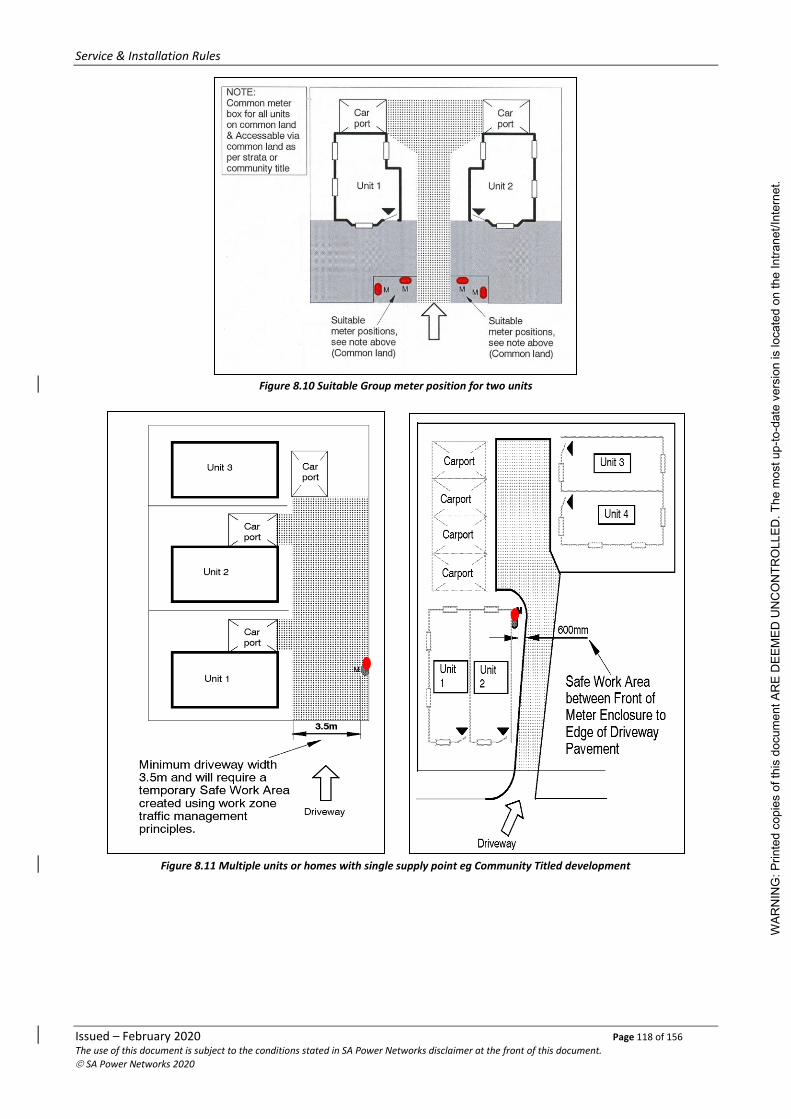
Service & Installation Rules
Issued – February 2020 Page 118 of 156 The use of this document is subject to the conditions stated in SA Power Networks disclaimer at the front of this document.
© SA Power Networks 2020
Figure 8.10 Suitable Group meter position for two units
Figure 8.11 Multiple units or homes with single supply point eg Community Titled development
WAR
NIN
G: P
rinte
d co
pies
of t
his
docu
men
t AR
E D
EEM
ED U
NC
ON
TRO
LLED
. The
mos
t up-
to-d
ate
vers
ion
is lo
cate
d on
the
Intra
net/I
nter
net.

Service & Installation Rules
Issued – February 2020 Page 119 of 156 The use of this document is subject to the conditions stated in SA Power Networks disclaimer at the front of this document.
© SA Power Networks 2020
Figure 8.12 Multiple units or homes with multiple supply points eg Community Titled development.
Figure 8.13 High Density single supply Residential Installation
Figure 8.14 Multi story Residential Installation
Meter box may be permitted
in a common low security
garage provided the
clearances are maintained
and any vehicle cannot be
parked within the clearance
zone – access via SA Power
Networks master key system
Refer to clause 8.5.4
WAR
NIN
G: P
rinte
d co
pies
of t
his
docu
men
t AR
E D
EEM
ED U
NC
ON
TRO
LLED
. The
mos
t up-
to-d
ate
vers
ion
is lo
cate
d on
the
Intra
net/I
nter
net.

Service & Installation Rules
Issued – February 2020 Page 120 of 156 The use of this document is subject to the conditions stated in SA Power Networks disclaimer at the front of this document.
© SA Power Networks 2020
8.5.5 Multiple Non-Residential
Metering equipment associated with an installation that is to be or is the subject of a Community Title or Strata Plan shall be installed in a location that is common property and accessible through common property as defined in the Strata Plan or Community Title.
Where an installation with multiple tenancies is not subject to Community Title or Strata Plan, the metering shall be located in a common area that is accessible during normal business hours.
Breakdown boxes for any alterations must be moved to a group meter enclosure, subject to the requirements of the property title.
Requirements:
❖ location area defined as a common area;
❖ access through common area;
❖ location readily accessible, free from animals;
❖ security system not compromised (during normal business hours);
❖ minimum working and access clearances maintained;
❖ locks required to be operated are keyed to SA Power Networks master key system;
❖ not reliant on special keys, access codes, security cards, property manager or their agent for access;
❖ metering installed in a group or groups;
❖ accessible to each tenant supplied via the installed meters;
❖ metering at origin of single customer sub-mains; and
❖ location free from quarantine restrictions.
Figure 8.15 Multi Non Residential Installation with single supply point
WAR
NIN
G: P
rinte
d co
pies
of t
his
docu
men
t AR
E D
EEM
ED U
NC
ON
TRO
LLED
. The
mos
t up-
to-d
ate
vers
ion
is lo
cate
d on
the
Intra
net/I
nter
net.

Service & Installation Rules
Issued – February 2020 Page 121 of 156 The use of this document is subject to the conditions stated in SA Power Networks disclaimer at the front of this document.
© SA Power Networks 2020
Figure 8.16 Multi Non Residential Installation with multiple supply point (Torrens Title)
High Density Single Supply
Figure 8.17 High Density Non Residential Installation with single supply point
WAR
NIN
G: P
rinte
d co
pies
of t
his
docu
men
t AR
E D
EEM
ED U
NC
ON
TRO
LLED
. The
mos
t up-
to-d
ate
vers
ion
is lo
cate
d on
the
Intra
net/I
nter
net.

Service & Installation Rules
Issued – February 2020 Page 122 of 156 The use of this document is subject to the conditions stated in SA Power Networks disclaimer at the front of this document.
© SA Power Networks 2020
Multi-Storey
Figure 8.18 Multi-story Non Residential Installation with group meters
8.5.6 Single Customer Rural Installations
These may be either domestic or non-domestic or a combination of both.
The metering enclosure shall be located in an exterior location as near as practical to the connection point and where SA Power Networks officers can gain safe and unimpeded access (not under carport). Consideration should also be given to selecting a location that does not compromise the customer’s quarantine or security requirements.
For the purpose of this section, a property generally greater than 4,000 sq. metres (1 acre) and not located within a township boundary can be considered as rural.
8.5.7 Combined Residential – Non-Residential Use
(Single or Multiple Customers)
Where an installation is used or designed for both Residential and Non-Residential use, the respective portions of the installation will need to be metered separately for Residential and Non-Residential tariffs.
The metering will be installed in a group subject to the same criteria as single and multiple residential.
8.5.8 Public Land
Where service protective devices, Main Switchboard and/or metering equipment is required to be installed on public land, it shall be located in a secure enclosure or premise which is at least 2m from a SA Power Networks LV service pole, 4m from the earthing of any High voltage infrastructure (ie HV pole, transformers, switching cubicles) and maintaining the working clearances around service pit/pillar as shown in Figure 7.8.
A lock shall be fitted to the metering enclosure entry in accordance with clause 4.7.
Refer 8.5.5
WAR
NIN
G: P
rinte
d co
pies
of t
his
docu
men
t AR
E D
EEM
ED U
NC
ON
TRO
LLED
. The
mos
t up-
to-d
ate
vers
ion
is lo
cate
d on
the
Intra
net/I
nter
net.

Service & Installation Rules
Issued – February 2020 Page 123 of 156 The use of this document is subject to the conditions stated in SA Power Networks disclaimer at the front of this document.
© SA Power Networks 2020
8.5.9 Unsuitable Main Switchboard and Metering Locations
Main switchboards and/or Metering equipment shall not be installed in the following locations:
❖ Behind a security door or gate;
❖ Areas to which access is normally restricted for security, health or other reasons including enclosed verandas and areas or yards which may be locked or house animals;
❖ SA Power Networks easements;
❖ Within 4.0m of SA Power Networks high voltage infrastructure (eg substations, HV poles, pole mounted transformers, padmount transformers, Ground Level transformer stations, switching cubicles);
❖ Areas intended for product display – such as inside shop windows;
❖ A carport or the area on the driveway side of a residential building where a carport is likely to be constructed;
❖ On a single occupancy building, over an external elevated area which is greater than 3.0m above finished ground level at the point at which access is obtained;
❖ Above a gas meter, which is not suitably enclosed;
❖ Where the use of a ladder would be necessary;
❖ Over stairways, landings, ramps, in narrow passageways or in other confined spaces,
❖ Vehicle docks, car parks, driveways and factory passageways where the metering equipment or a person working thereon would not be effectively protected;
❖ Positions in close proximity to or over machinery or open type switchgear;
❖ Locations liable to be affected by fumes, dampness, flooding, dust, noise, vibration or other external factors of such nature as may cause deterioration of equipment or unsatisfactory working conditions;
❖ Hazardous and wet areas defined in the AS/NZS3000 Wiring Rules;
❖ Where ambient temperature is maintained in excess of 45°C;
❖ Where exposed to weather unless installed in a suitably approved enclosure;
❖ Where there is insufficient light under normal circumstances;
❖ In fire isolated stairways, passageways or corridors;
❖ Where access is restricted by vegetation;
❖ In a swimming pool zone or where access is through a pool zone;
❖ Gender specific areas.
As metering equipment may produce a degree of noise, it should not be installed on a bedroom wall.
8.6 Clearances around Meter Enclosure
8.6.1 Individual Residential Installations
A minimum horizontal clearance of not less than 0.6 metres shall be provided in front of the meter box as shown in the figures below. In addition, an egress path of at least 600mm must be available in at least one direction. If the egress path is via the enclosure door side, the door must be easily removable or be able to be secured in the fully open position (180o). W
ARN
ING
: Prin
ted
copi
es o
f thi
s do
cum
ent A
RE
DEE
MED
UN
CO
NTR
OLL
ED. T
he m
ost u
p-to
-dat
e ve
rsio
n is
loca
ted
on th
e In
trane
t/Int
erne
t.

Service & Installation Rules
Issued – February 2020 Page 124 of 156 The use of this document is subject to the conditions stated in SA Power Networks disclaimer at the front of this document.
© SA Power Networks 2020
Figure 8.19 Meter enclosure clearance for individual residential installations
A minimum vertical clearance of 2 metres from ground level shall be maintained in this clearance zone. The removable enclosure door must be capable of moving through an arc of at least 120o.
8.6.2 Multiple Residential and Commercial Installations
A minimum horizontal clearance of not less than 0.6 metres, from any part of the meter box or equipment, including doors enclosing the meter board, in any normal position of opening, must be maintained as shown in the figure below.
Figure 8.20 Meter enclosure clearance for multiple residential and commercial installations
As per the individual residential installations an egress path must be in at least one direction. This access and egress path must be at least 900mm wide and 2200mm high.
A minimum vertical clearance of 2 metres from ground level shall be maintained in this clearance zone.
WAR
NIN
G: P
rinte
d co
pies
of t
his
docu
men
t AR
E D
EEM
ED U
NC
ON
TRO
LLED
. The
mos
t up-
to-d
ate
vers
ion
is lo
cate
d on
the
Intra
net/I
nter
net.

Service & Installation Rules
Issued – February 2020 Page 125 of 156 The use of this document is subject to the conditions stated in SA Power Networks disclaimer at the front of this document.
© SA Power Networks 2020
8.6.3 Gas Meter Enclosure Clearances
APA Networks National Standard for Domestic Gas Meter installations, from 1 July 2019 requires that there is a 500mm clearance between gas and electric meter boxes.
There must also be 500mm between gas mains/gas box and the main earth electrode, communications cable terminations or any source of ignition.
For enquiries regarding specific gas meter box clearances please call APA Group
Phone: 1300 001 001.
Figure 8.21 Domestic gas meter clearances to electrical
Note:
For existing electrical meter enclosures above or adjacent to existing gas meter enclosures, an alteration or upgrade of the electrical installation including replacement of electrical enclosure or consumer mains, shall not impose the requirements of gas enclosure clearances provided that the installation of both Gas and Electrical meter enclosures complied with the requirements of the original installation.
8.7 Main Switchboard/Meter Enclosure Metering Panel Mounting Height
For single domestic supplies up to and including 100amps, the top of a main switchboard/meter enclosure should not be mounted more than 2.0 metres in height and the bottom not less than 0.5 metres from the actual or finished ground, floor or platform level.
For all other supplies the metering panel height within an enclosure or section of the main switchboard should not be mounted more than 2.0 metres and the bottom of the metering panel height should not be less than 0.5 metres from the ground, floor or platform level.
In all cases the Main Switch, Panel and Meter Isolators, Metering Links and the MEN Link should not be designed to be at a height greater than 2.0m from the ground, floor or platform level.
Where a platform is required, the access to the platform, its size and any guard rails shall be constructed to AS1647.
Note: At time of connection the height shall be correct and remain correct.
WAR
NIN
G: P
rinte
d co
pies
of t
his
docu
men
t AR
E D
EEM
ED U
NC
ON
TRO
LLED
. The
mos
t up-
to-d
ate
vers
ion
is lo
cate
d on
the
Intra
net/I
nter
net.

Service & Installation Rules
Issued – February 2020 Page 126 of 156 The use of this document is subject to the conditions stated in SA Power Networks disclaimer at the front of this document.
© SA Power Networks 2020
Figure 8.22 Domestic meter location side wall
8.8 Access
8.8.1 General
The customer must provide convenient and unhindered access to metering locations and equipment, and all other supply related assets at the following times:
❖ Meter installation, reading and planned maintenance as a minimum, between the hours of 8:00am to 5:00pm Monday to Friday;
❖ At all times for supplying and metering fault rectification;
❖ At any other time agreed by SA Power Networks or Metering Provider and the customer or customer’s agent.
Within a multiple occupancy electrical installation, all occupants shall have common right of access to their occupancy’s metering equipment.
Unless otherwise agreed with SA Power Networks, the meter isolator shall be accessible in areas to eliminate the necessity to enter secured areas and rooms or areas that are not normally entered by visitors or available for public access.
Access to and the area around the metering equipment shall be kept clear, unobstructed, safe, clean and free of rubbish.
Where metering equipment is installed in a room or area set aside for the purpose, such room or area shall be provided with adequate illumination to AS/NZS 1680 for access.
Access to elevated positions shall be provided by an approved fixed stairway or ramp and handrail. Access by means of a ladder is not acceptable.
Where a perimeter fence restricts access between the metering equipment and public access point, the metering equipment shall be conveniently and safely accessible from the public access side of the fence.
Alternatively, a gate in the perimeter fence that enables access to the meter position may be locked with a lock in accordance with clause 4.7.
WAR
NIN
G: P
rinte
d co
pies
of t
his
docu
men
t AR
E D
EEM
ED U
NC
ON
TRO
LLED
. The
mos
t up-
to-d
ate
vers
ion
is lo
cate
d on
the
Intra
net/I
nter
net.

Service & Installation Rules
Issued – February 2020 Page 127 of 156 The use of this document is subject to the conditions stated in SA Power Networks disclaimer at the front of this document.
© SA Power Networks 2020
The customer shall ensure that access is not subsequently restricted or the location otherwise rendered unsuitable.
Should this occur, the customer shall restore suitable access or arrange for the relocation of the metering equipment at their expense.
8.8.2 Locks
Where locks are considered necessary by the customer or are required by these Rules, the customer shall arrange for the lock/s in accordance with clause 4.7 to be installed.
Locks shall be used only on doors or gates which provide access to the property and/or to an enclosure or room housing metering equipment, and shall be accessible from outside the door or gate.
8.9 Metering Panels, Surrounds & Enclosures (TIR)
8.9.1 General (TIR)
Meter mounting facilities shall be provided:
❖ in an approved metering enclosure with the customer’s switchboard equipment; or
❖ on an approved surround; or
❖ within or on facilities that are acceptable to SA Power Networks;
❖ that is of a type and in a location, accessible and prepared for the meter installation in accordance with these Rules.
However, facilities which meet equal or better outcomes than these Rules may be considered in accordance with clause 2.7. Whole current metering enclosures and surrounds that are intended to be stocked and marketed by Electrical Wholesalers and similar distributors are recommended to be accepted for use in accordance with clause 4.4 prior to being manufactured or connected to supply.
All metering panels, enclosures, surrounds and supplementary equipment shall comply with:
❖ the relevant Australian or IEC Standard/s applicable at the time of manufacture;
❖ the relevant Electricity Regulations, Metering Codes and the Rules applicable at the time of connection to the electricity supply network; and
❖ be suitable for use in normal service conditions of:
Ambient Air Temperature -
• Maximum 45oC
• Minimum -5oC
• Average 35oC (over 24-hour period)
❖ maximum altitude (above mean sea level) – 2000m.
❖ maximum temperature above ambient inside an enclosure – 15°C
8.9.2 Meter panels (TIR)
8.9.2.1 Size (TIR)
Meter panels shall be of a size to adequately accommodate the metering equipment to be installed upon it.
Consideration should be given to a larger size meter panel to accommodate:
❖ extra metering equipment for possible future tariff changes;
❖ extra SA Power Networks equipment such as service fuses;
❖ additional communication equipment as provided by approved Metering Provider; and
❖ meter isolator - refer Section 7.5.
WAR
NIN
G: P
rinte
d co
pies
of t
his
docu
men
t AR
E D
EEM
ED U
NC
ON
TRO
LLED
. The
mos
t up-
to-d
ate
vers
ion
is lo
cate
d on
the
Intra
net/I
nter
net.

Service & Installation Rules
Issued – February 2020 Page 128 of 156 The use of this document is subject to the conditions stated in SA Power Networks disclaimer at the front of this document.
© SA Power Networks 2020
8.9.2.2 Installation (TIR)
Meter panels shall be installed:
❖ within a suitable metering enclosure with the customer’s switchboard equipment; or
❖ within a suitable meter only enclosure; or
❖ on a suitable surround; or
❖ on facilities that are acceptable to SA Power Networks.
The customer is required to provide suitable pre-drilled meter panels for fixing of metering equipment and SA Power Networks service protection devices (where required).
8.9.2.3 Materials (TIR)
Meter panels shall be constructed of insulating material:
❖ to an equal or better standard than that required by the AS/NZS3000 Wiring Rules for switchboards; and
❖ suitable for its intended use and environment, including exposure to ultra violet where exposed to daylight.
8.9.2.4 Wiring Holes (TIR)
Meter panels shall be equipped with wiring holes:
❖ to suit each particular metering installation; and
❖ to accommodate SA Power Networks service protective devices where required; and
❖ of a size to enable free movement of cables through the panel and termination of conductor/s without damage to the cable insulation.
Height (mm) Width (mm) No. of cable holes
Single Phase 210 55 1 top, 1 bottom
Two Phase 210 110 2 top, 2 bottom
Three Phase 210 165 3 top, 3 bottom
Table 8.1: Service Protective Device Panel Space and Drilling Requirements
Figure 8.23 Meter panel hole spacing – Service protection devices
210
55
110
165
15
Ø12
15
WAR
NIN
G: P
rinte
d co
pies
of t
his
docu
men
t AR
E D
EEM
ED U
NC
ON
TRO
LLED
. The
mos
t up-
to-d
ate
vers
ion
is lo
cate
d on
the
Intra
net/I
nter
net.

Service & Installation Rules
Issued – February 2020 Page 129 of 156 The use of this document is subject to the conditions stated in SA Power Networks disclaimer at the front of this document.
© SA Power Networks 2020
8.9.2.5 Fixing Arrangements (TIR)
The meter panel shall be:
❖ capable of being opened to an angle of not less than 60 degrees from the closed position with all metering equipment installed;
❖ equipped with hinges;
❖ mounted on one vertical edge of the panel;
❖ constructed of a suitable non-corroding material that will maintain a structural and dimensional fit after metering equipment has been installed;
❖ of a lift-off double off-set type for meter panels installed within enclosures;
❖ of a lift-off hinges for meter panels on surrounds;
❖ secured in the closed position by a metal fastener or fasteners which requires the use of a tool to release.
8.9.2.6 Wiring (TIR)
Meter panel wiring shall be wired in accordance with these Rules or the Metering Provider specifications and the AS/NZS 3000 Wiring Rules.
Where other wiring passes behind the meter panel, it shall be located and secured in a manner which maintains the required clear metering panel space (both front and rear). This includes maintaining clear space for the meter wiring.
Unused meter panel wiring must be terminated in accordance with AS/NZS 3000 Wiring Rules.
Acceptable methods to comply with these requirements include the fitting of all intended metering equipment to the panel at the same time, or to ensure unused wiring is appropriately insulated and terminated at the rear of the panel or within a junction box.
8.9.3 Metering Surrounds & Enclosures (TIR)
8.9.3.1 General (TIR)
Meter surrounds and enclosures shall be constructed:
❖ to accommodate a meter panel in accordance with these Rules;
❖ to have sufficient stability and strength to withstand distortion and contain any energy which might be caused in both normal and fault conditions;
❖ any hinges or fixings used to support a meter panel will be of adequate strength to support the weight of the panel and meters therein without sag of the panel when in the open position;
❖ hinged meter panels must be capable of movement through an arc of not less than 60 degrees when metering equipment is fixed and connected. The movement of the panel will not be obstructed in any way and the device used to retain the hinged panel in the closed position must be in correct alignment when all necessary equipment is mounted on the panel;
❖ access doors of the hinged type must have the hinges mounted on the vertical side. Access doors of the sliding type must move horizontally; and
❖ means for securing the meter panel in the closed position must be accessible to the hand where the means for securing it is removed to open the panel eg a screw or nut.
WAR
NIN
G: P
rinte
d co
pies
of t
his
docu
men
t AR
E D
EEM
ED U
NC
ON
TRO
LLED
. The
mos
t up-
to-d
ate
vers
ion
is lo
cate
d on
the
Intra
net/I
nter
net.

Service & Installation Rules
Issued – February 2020 Page 130 of 156 The use of this document is subject to the conditions stated in SA Power Networks disclaimer at the front of this document.
© SA Power Networks 2020
8.9.3.2 Meter Surrounds (TIR)
Meter surrounds shall be constructed to the depth specified in clause 8.13.1 to accommodate the meter wiring and to support the meter panel and be constructed:
❖ to the specifications of clause 8.9.3.1;
❖ of sheet steel not be less than 1.2mm thick unless an acceptable strength is achieved with a thinner sheet which is reinforced by the manufacturing process or design or other material; and
❖ hot dipped galvanised with a coating weight of Z275 in accordance with AS 1397; or
❖ where painted, pre-treated in accordance with the paint supplier’s recommendation and coated with a material such as power coating or baked enamel giving a hard, durable finish with a service life of not less than 20 years; and
❖ with characteristics equal to or better than steel where materials other than steel are used.
8.9.3.3 Meter Enclosures (TIR)
Meter enclosures shall take the form of a box type enclosure that accommodates the meter panel, metering equipment and may also accommodate a switchboard.
Meter enclosures shall be:
❖ constructed with materials specified in clause 8.9.3.2 and installed in a manner so that the metering equipment is completely enclosed; and
❖ provided with a clearance as required in clauses 8.13.1 and 8.14.2.2.
Metering equipment must not be exposed to weather, moisture, dust, vibration or mechanical damage.
The customer will provide and maintain protection for the metering equipment, by virtue of location or enclosure that provides suitable protection against hazards likely to be present in the installed location.
(a) Type not Exposed to Weather or Adverse Environment
A meter enclosure not exposed to the weather may be constructed of any suitable material and may or may not be equipped with a door subject to satisfying the above.
(b) Type exposed to Weather or Adverse Environment
Meter enclosures exposed to the weather or adverse environment shall take the form of a box type enclosure equipped with a hinged door secured by an effective latch and be of sufficient strength and design to withstand all reasonable elements of its installed environment and be constructed:
❖ with ventilation and draining that will minimise condensation and provide for draining of moisture that might collect in the enclosures;
❖ with a minimum degree of protection of IP23;
❖ with a hinged door fitted with:
− a latch that is easily unlatched to open the door, and which retains the door in the closed position under all conditions that can reasonably be expected; and
− a retainer when the door is open and in a position to enable work to be performed on the meter panel and equipment safely and without interference. Alternatively, a door less than 0.5m2 which can be conveniently removed and replaced will be acceptable;
− be fitted with a lock in accordance with clause 4.7 when installed in public land, isolated and unattended locations and where locking is considered necessary by the customer or otherwise required by these Rules.
WAR
NIN
G: P
rinte
d co
pies
of t
his
docu
men
t AR
E D
EEM
ED U
NC
ON
TRO
LLED
. The
mos
t up-
to-d
ate
vers
ion
is lo
cate
d on
the
Intra
net/I
nter
net.

Service & Installation Rules
Issued – February 2020 Page 131 of 156 The use of this document is subject to the conditions stated in SA Power Networks disclaimer at the front of this document.
© SA Power Networks 2020
8.10 Equipment
8.10.1 Acceptance (TIR)
Refer to clause 4.4 for information regarding equipment acceptance and suitability of equipment.
8.10.2 On Meter Panels or Within Enclosures (TIR)
Equipment installed on meter panels shall be mounted with 12mm clearance to the edge, fixings or hinges to allow sufficient space to accommodate all equipment to be installed upon the panel in a manner which enables connection, disconnection and reconnection of all wiring and access to all terminals without dismantling other equipment, or creating a need to remove covers off equipment other than that being worked upon.
Equipment must be securely fixed to meter panels in accordance with the Wiring Rules. Fixing screws and fasteners should not protrude through the rear of the panel in a manner that could damage conductors, or create un-earthed exposed metal.
Customer’s equipment installed on the metering panel shall not in any way compromise or affect the integrity, accuracy or performance of the metering equipment.
With the exception of circuit breakers, unscreened magnetic devices such as transformers, equipment required for the control of generators shall not be installed on or behind the meter panel.
8.10.3 Security Seals
SA Power Networks and Metering Provider’s security seals used in an electrical installation shall be in accordance with clause 4.8.
8.10.4 Customer’s Equipment
Customer’s equipment including devices that consume or measure electricity must not be connected to the supply side of the metering point.
This does not include metering equipment supplied by SA Power Networks or registered metering provider or equipment required by 7.4.5.2, 7.8.2.5 and 8.13.3.
8.11 Meter Panel Labelling (TIR)
All labels shall be in accordance with clause 4.5 and shall remain clearly visible after installation of all equipment.
8.11.1 Single Occupancy (TIR)
Every single occupancy meter panel shall be equipped with a label in accordance with clause 4.5 displayed on the meter panel indicating the correct street address.
The correct street address can be obtained from the local Municipal Council.
8.11.2 Multiple Occupancies (TIR)
Each multiple occupancy meter panel, shall be labelled with the correct street address for each occupancy, and to indicate the relationship of meters, fuses and other equipment supplied from the meter panel.
A corresponding marking shall also be made on the conductors for each occupancy at the meter panel location to enable resent and future identification of conductors.
Additional labelling of multiple occupancies shall be in accordance with clause 7.8.2.7.
8.12 Protection (TIR)
The customer shall provide adequate and reasonable protection to prevent any physical damage to main switchboards and metering equipment.
WAR
NIN
G: P
rinte
d co
pies
of t
his
docu
men
t AR
E D
EEM
ED U
NC
ON
TRO
LLED
. The
mos
t up-
to-d
ate
vers
ion
is lo
cate
d on
the
Intra
net/I
nter
net.

Service & Installation Rules
Issued – February 2020 Page 132 of 156 The use of this document is subject to the conditions stated in SA Power Networks disclaimer at the front of this document.
© SA Power Networks 2020
The main switchboard and/or metering equipment and facilities shall be adequately protected against both advertent and inadvertent damage including; mechanical damage, vibration, effects of the weather, sea air, corrosion, damage from vehicles, vandalism and spread of fire etc.
Examples of adequate protection requirements include:
• Where the main switchboard and/or metering is located within an area or in any position capable of being struck by vehicles. Any area less than 0.6m from a driveway edge or trafficable area require that suitable protective barriers be provided and installed by the customer; and
• Where main switchboard and or metering is installed in a location that is not affected by weather such as in switchrooms, the equipment shall be located:
− in a suitable enclosure; or
− on a hinged insulated meter panel mounted on a suitable electrical enclosure/surround
• Where main switchboard and or metering is installed in locations exposed to the weather, suitable enclosures conforming to these Rules must be provided which are:
− constructed of galvanised steel or an equivalent material;
− have an IP rating suitable for the environment;
− installed in a manner to provide protection against vibration, vandalism, weather and all other external factors; and
− may be locked with a suitable lock in accordance with clause 4.7.
8.13 Whole Current Metering
Whole current metered electrical installations shall comply with clauses 8.1 and 8.13 where applicable and the following requirements.
8.13.1 Metering Enclosure Internal Panel Clearances
❖ A minimum of 175mm in front of the meter panel to the inner face of the door or any internal projection where the meter panel is enclosed; and
• A minimum of 75mm behind the meter panel.
8.13.2 Meter Panels
Meter panels shall be provided in accordance with clause 8.3 and 8.9 shall be arranged to accommodate the required combinations of metering and associated equipment.
For complex metering arrangements please contact the relevant metering provider.
8.13.3 Equipment (TIR)
The customer’s agent shall arrange for the supply, installation and wiring of:
❖ Meter isolator in accordance with clause 7.5
❖ Sealable metering neutral link
8.13.4 Isolation of Metering Equipment
Supply to each occupancy metering shall be capable of being individually isolated.
8.13.4.1 Single Occupancy Metering
Single occupancy metering equipment shall be capable of being isolated by the meter isolator. Refer to clause 7.5.
8.13.4.2 Multiple Occupancy Metering
The metering for each individual occupancy shall be capable of being individually isolated by a meter isolator installed in accordance with clause 7.5.
Note: Panel isolator per panel may also be required, refer clause 7.8.2.5.
WAR
NIN
G: P
rinte
d co
pies
of t
his
docu
men
t AR
E D
EEM
ED U
NC
ON
TRO
LLED
. The
mos
t up-
to-d
ate
vers
ion
is lo
cate
d on
the
Intra
net/I
nter
net.

Service & Installation Rules
Issued – February 2020 Page 133 of 156 The use of this document is subject to the conditions stated in SA Power Networks disclaimer at the front of this document.
© SA Power Networks 2020
8.14 LV Current Transformer Metering
8.14.1 General
Where in accordance with clause 8.4 current transformers (CT) metering is to be installed, the applicable requirements of clauses 8.1 to 8.13 and the following rules shall apply:
❖ The customer shall supply and install the current transformers and wiring loom and provide adequate space, housing and facilities for the current transformers and metering equipment as detailed in these Rules.
❖ Each metered connection CT facility shall be in a separate enclosure with a hinged door which is separate from the meter isolator and all other wiring.
❖ The meter isolator shall isolate all components of the associated metering arrangement ensuring that all metering components can be safely worked on without exposure to other LIVE parts of the switchboard.
❖ NATA approved test results are to be provided for the revenue metering CTs.
8.14.2 Meter Panel
8.14.2.1 Location and Access
The meter isolator and equipment shall be located in accordance with clause 8.4 and accessible in accordance with clause 8.8.
The meter panel is not permitted in a location subject to varying high intensity magnetic fields.
Heavy current carrying conductors shall not be installed behind or near the meter panel, unless effectively shielded by an earthed metallic screen.
8.14.2.2 Clearances
Unless approved by the Responsible Officer, CT metered installations shall be arranged to meet the following clearances:
❖ The lower edge of the meter panel space shall be not less than 0.5m or greater than 2.0m above the floor or ground level.
❖ A minimum of 175mm in front of the meter panel to the inner face of the door or any internal protection where the meter panel is enclosed.
❖ A minimum of not less than 75mm behind the panel.
❖ Main Switch or MEN link connection shall be no greater than 2.0m above the floor or ground
Clear space for working on meters shall be in accordance with clause 8.9.
Unless effectively shielded by an earthed metallic screen from heavy current carrying conductors, the following clearances stated in Table 8.2 shall be maintained between the conductors and meter panel:
RATING OF CONDUCTOR (Amps)
DISTANCE BETWEEN METER PANEL AND THE NEAREST CONDUCTOR (mm)
500 200
1000 400 Interpolate for intermediate values
2000 600
3000 800
Table 8.2 – Conductors to Meter Panel Clearances
WAR
NIN
G: P
rinte
d co
pies
of t
his
docu
men
t AR
E D
EEM
ED U
NC
ON
TRO
LLED
. The
mos
t up-
to-d
ate
vers
ion
is lo
cate
d on
the
Intra
net/I
nter
net.

Service & Installation Rules
Issued – February 2020 Page 134 of 156 The use of this document is subject to the conditions stated in SA Power Networks disclaimer at the front of this document.
© SA Power Networks 2020
8.14.2.3 Wiring
The meter panel shall be prepared with the CT metering wiring loom installed in corrugated conduit, terminated into the CT test block and wired in preparation for a Metering Provider to suitably install the appropriate metering.
❖ The CT Chamber shall only contain components as shown in figure 8.24 with single incoming connection from the meter isolator and single outgoing connection to the next point of isolation.
Figure 8.24 Current Transformer and busbar wiring diagram
WAR
NIN
G: P
rinte
d co
pies
of t
his
docu
men
t AR
E D
EEM
ED U
NC
ON
TRO
LLED
. The
mos
t up-
to-d
ate
vers
ion
is lo
cate
d on
the
Intra
net/I
nter
net.

Service & Installation Rules
Issued – February 2020 Page 135 of 156 The use of this document is subject to the conditions stated in SA Power Networks disclaimer at the front of this document.
© SA Power Networks 2020
9. High Voltage Electrical Installations
9.1 Scope
This section provides information and requirements for connection of customer’s electrical installations above 1000 volts. The intent is to ensure that customer’s electrical installation is safe for all personnel and operates in a manner that does not adversely affect the SA Power Networks distribution network.
These requirements are additional to the requirements of the South Australian Distribution Code and AS/NZS 3000 – Wiring Rules. They apply to new installations and also alterations and additions to existing installations.
HV supply at 3.3kV or 6.6kV is no longer available. In general, alterations to existing installations with supplies at these voltages must comply with these Rules. However, technical characteristics will differ from those outlines in Table 9.1 in clause 9.4 below. Further information will be provided by the SA Power Networks Manager.
Switching and maintenance of high voltage installations must only be undertaken by appropriately qualified and trained personnel.
In order for Market Participants to meet their maintenance requirements and the requirements of the National Electricity Rules, safe access to the High Voltage Instrument Transformers is necessary. Isolation of the customers High Voltage installation is required at intervals prescribed by the appropriate Market Participant.
9.2 Contractual Arrangements
A customer requiring a supply of electricity at high voltage shall be required to enter into:
• an Electricity Supply Contract with a Retailer; and
• a connection contract or a specific electricity distribution connection agreement.
9.3 Systems of Supply
SA Power Networks will negotiate the system of supply and the voltage of supply with regard to the proximity of its relevant high voltage systems to the customer’s point of supply and the nature of the customer’s load. One of the following nominal supply voltages may be made available:
• 7.6kV; 11kV; 33kV; and 66kV.
As most of the existing 7.6kV areas of supply are scheduled for conversion to 11kV, any customer currently taking supply at 7.6kV should take this into account. The supply shall be made available at a nominal frequency of 50 Hertz (cycles per second).
9.4 Preliminary Information
The customer should provide at the earliest possible notice (preferably 18 months) to their selected Retailer and SA Power Networks of the intention to plan for a high voltage supply.
The following preliminary information shall be provided to SA Power Networks:
• A single line diagram of the proposed installation. (Refer Figure 9.1 at the end of this section).
• An overall site plan showing the location of the HV equipment;
• The preferred point of supply (new installation);
• The anticipated maximum demand (MVA) required for the installation;
• Any proposed on-site generation;
• Any disturbing loads (eg large motors, arc furnaces, etc); and
• The HV metering design arrangements.
WAR
NIN
G: P
rinte
d co
pies
of t
his
docu
men
t AR
E D
EEM
ED U
NC
ON
TRO
LLED
. The
mos
t up-
to-d
ate
vers
ion
is lo
cate
d on
the
Intra
net/I
nter
net.

Service & Installation Rules
Issued – February 2020 Page 136 of 156 The use of this document is subject to the conditions stated in SA Power Networks disclaimer at the front of this document.
© SA Power Networks 2020
The customer must obtain formal approval from the relevant SA Power Networks Manager. Negotiations for supply should precede detailed design work, placement of orders for equipment and letting of contracts to avoid loss to the customer arising from designs or equipment being found by the Distributor to be unsuitable for connection to the supply system. The characteristics of the 11kV distribution network are detailed below.
System nominal voltage 11 kV r.m.s. phase to phase
System highest voltage 12 kV r.m.s. phase to phase
Frequency 50 Hz
Number of Phases 3
System neutral Solidly earthed
Earthing System (typical) CMEN (urban areas) / MEN (rural areas)
Maximum fault level rating 380 MVA (20 kA/ph symmetrical)
Short time current rating Supplied on request – Max fault clearing time of 0.5s
Power frequency withstand voltage 28 kV r.m.s.
Impulse withstand voltage 1.2/50 µs wave 95 kV peak (overhead lines) 75 kV peak (underground lines)
Table 9.1 – Electrical Characteristics
9.5 Installation Design (TIR)
The installations supply, protection, earthing and metering arrangements shall be:
• Installed to the satisfaction of SA Power Networks. Details to be provided on application;
• Arranged to comply to the requirements of clause 6.5, the Electricity Distribution Code, Metering Code and National Electricity Rules in respect to interference to SA Power Networks supply system; and
• Comply with all applicable Regulations, Codes of Practice and these Rules.
9.5.1 Power Transformers (TIR)
For compatibility with SA Power Networks equipment, transformers must comply with AS 2374 – Power Transformers (all parts)/ It is recommended (but not essential) that power transformers be purchased in accordance with the latest SA Power Networks power transformer purchase purchasing specification.
A copy of this specification is available on request from SA Power Networks Manager. The high voltage winding configuration must be either:
❖ unearthed star; or
❖ delta
There is no limitation on the secondary (or tertiary) winding configurations.
WAR
NIN
G: P
rinte
d co
pies
of t
his
docu
men
t AR
E D
EEM
ED U
NC
ON
TRO
LLED
. The
mos
t up-
to-d
ate
vers
ion
is lo
cate
d on
the
Intra
net/I
nter
net.

Service & Installation Rules
Issued – February 2020 Page 137 of 156 The use of this document is subject to the conditions stated in SA Power Networks disclaimer at the front of this document.
© SA Power Networks 2020
9.5.2 Protective Equipment (TIR)
Protective equipment must comply with AS 1025 – High Voltage Switchgear and Control Gear and AS 2067 – Switchgear Assemblies and Ancillary Equipment for Alternative Voltages Above 1kV.
Equipment must be rated to withstand the conditions in which it is installed (refer Table 9.1.
9.6 Conversion from Low Voltage to High Voltage Supply
When a customer seeks to convert their installation from a low voltage supply arrangement to a high voltage supply arrangement, consultation with the relevant SA Power Networks Manager is required.
9.7 General Design (TIR)
9.7.1 Circuit Connections (TIR)
The normal supply arrangement for up to 4MVA is via a single high voltage supply. For loads 4MVA or greater, multiple supply arrangements are required for reliability purposes.
Arrangements can usually be made for additional high voltage supplies where required. Paralleling of high voltage feeders may be permitted subject to the conditions as detailed in clause 9.7.2.
9.7.2 Control of Incoming High Voltage Supply (TIR)
The main control for each incoming supply shall consist of a single automatic circuit breaker equipped with earth fault and over current protection capable of making and breaking the maximum prospective fault currents on all three phases.
The main control circuit breaker shall:
❖ be located at ground level; and
❖ be located as near as possible to the customer’s point of supply; and
❖ prior to the metering transformers; and
❖ be readily accessible to authorised persons; and
❖ operate simultaneously in all active conductors; and
❖ only capable of local manual operation for closing. (remote trip/open is permissible)
❖ be able to be locked in the open position. The locking device must be capable of accepting a SA Power Networks padlock fitted with a 10mm shackle; and
❖ be provided with adequate means of isolation for maintenance purposes. This may be achieved by rack-out circuit breaker. Remote operation must be able to be conveniently disabled or deactivated and locked off for maintenance purposes; and
❖ This breaker must not be utilised as a means of control for generation purposes.
Normally, where more than one high voltage supply is provided to a customer, the main circuit breakers shall be interlocked in such a manner that paralleling of the high voltage supplies shall not be possible. Approved interlocking methods are:
❖ hard wired electrical interlocking; and/or
❖ mechanical interlocking
In any case, the customer must notify the SA Power Networks Network Operations Centre prior to transferring load.
Paralleling of high voltage feeders to provide a no break supply may also be considered, if technically viable and will be subject to the installation of additional protection at the zone substation and the electrical installation at the customer’s expense.
These contract conditions are to be a negotiated agreement with SA Power Networks and included in a network connection contract.
WAR
NIN
G: P
rinte
d co
pies
of t
his
docu
men
t AR
E D
EEM
ED U
NC
ON
TRO
LLED
. The
mos
t up-
to-d
ate
vers
ion
is lo
cate
d on
the
Intra
net/I
nter
net.

Service & Installation Rules
Issued – February 2020 Page 138 of 156 The use of this document is subject to the conditions stated in SA Power Networks disclaimer at the front of this document.
© SA Power Networks 2020
9.7.2.1 Equipment or Connections upstream of metering transformers
No equipment or connections are permitted on the mains side of the metering transformers other than:
❖ Capacitively coupled indicating LEDs or test points for the incoming consumers mains,
❖ The earthing switch for the incoming mains and
❖ The Main Control Circuit Breaker and it associated protection transformers
i.e. Customer equipment such as monitoring transformers must be installed on the customer (load) side of the metering transformers.
9.7.3 Power Factor (TIR)
Power factor averaged over any 5 minute period must be maintained at better than detailed in Table 9.2 or as specified in the SA Distribution Code at the time.
Maximum Demand Up to 100kVA Between 100kVA and 2MVA Over 2MVA
Voltage Leading Lagging Leading Lagging Leading Lagging
3.3kV 0.80 0.80 0.85 0.80 0.90 0.85
6.6 and 11kV 0.80 0.80 0.85 0.85 0.90 0.90
Table 9.2 – Minimum Power Factor
9.7.4 Supply Disturbances (TIR)
Supply disturbances caused by the electrical installation must comply with AS61000 Part 3.7.
9.7.5 Voltage Unbalance Factor (TIR)
The customer must ensure that the load drawn by the electrical installation does not cause the voltage unbalance factor at the service point, as defined in the SA Distribution Code to exceed that set out in Table 9.3.
Time Period Maximum Voltage Unbalance Factor
Continuous 1%
5 Minutes 1.5%
Instantaneous 3.0%
Table 9.3 – Voltage Unbalance Factor
9.7.6 Safety Signs (TIR)
Safety signs must be installed as detailed in AS/NZS3000 – Wiring Rules. All signs must comply with AS1319 – Warning Signs.
WAR
NIN
G: P
rinte
d co
pies
of t
his
docu
men
t AR
E D
EEM
ED U
NC
ON
TRO
LLED
. The
mos
t up-
to-d
ate
vers
ion
is lo
cate
d on
the
Intra
net/I
nter
net.

Service & Installation Rules
Issued – February 2020 Page 139 of 156 The use of this document is subject to the conditions stated in SA Power Networks disclaimer at the front of this document.
© SA Power Networks 2020
9.8 Protection (TIR)
Prior to placing orders for equipment, the customer shall discuss the installations protection requirements with SA Power Networks.
All protection settings for the customer’s incoming circuit breaker must be approved by SA Power Networks Protection and Control Planning Manager prior to connection to the network. No changes to the approved settings are permitted without written approval from the SA Power Networks Protection and Control Planning Manager as specified in Section 9.8.1.
9.8.1 Customer incoming circuit breaker protection requirements
The customer’s electrical installation shall have over-current protection initiated by protection relays comprising of at least:
❖ Inverse-time and instantaneous phase elements; and
❖ Inverse-time and instantaneous earth elements.
More complex protection arrangements may be required in particular cases to meet acceptable protection performance criteria depending on the electrical installation arrangement, the Distributor’s system arrangement and the required protection performance levels.
Wherever possible, the current transformers for the customer protection are to be located on the supply side of their incoming circuit breaker.
Protection settings and equipment shall be subject to the acceptance of SA Power Networks prior to commissioning. Supporting documentation is required if the customer uses relays that have not been previously assessed by SA Power Networks.
9.8.2 Multiple supplies
Paralleling of supplies is not permitted unless specifically approved by SA Power Networks for certain network conditions (refer to Section 9.7.2.). Paralleling may result in loss of security of supply (ie both supplies may trip for a fault instead of one) and fault levels may be increased beyond allowable limits.
9.8.3 Protection Settings
All protection settings for the customer’s incoming circuit breaker shall be approved by SA Power Networks Protection and Control Planning Manager prior to connection to the network.
The customer is required to provide the SA Power Networks Manager with full documentation of protection settings used as detailed in Table 9.4.
The Customer’s High Voltage Service CB Protection Relay Settings
Phase Over current Earth Over current
Relay Type x x
Current Pick-up Value in amps(A) x x
Time Multiplier Setting in (%) x x
Characteristic Description or Equation x x
Instantaneous Pick-up Value in amps(A) x x
Table 9.4 – Protection Settings Detail
The settings of the protection relay shall be fixed by the SA Power Networks security seal. Any modification of the settings shall be subject to the prior acceptance of SA Power Networks. The
WAR
NIN
G: P
rinte
d co
pies
of t
his
docu
men
t AR
E D
EEM
ED U
NC
ON
TRO
LLED
. The
mos
t up-
to-d
ate
vers
ion
is lo
cate
d on
the
Intra
net/I
nter
net.
Service & Installation Rules
Issued – February 2020 Page 140 of 156 The use of this document is subject to the conditions stated in SA Power Networks disclaimer at the front of this document.
© SA Power Networks 2020
protection relay labelling is to include a notice – ‘Settings only to be changed with prior approval from the Distributor’.
The SA Power Networks Protection and Control Planning Manager must be notified if the customer requires changes to their incoming circuit breaker or protection settings. Any changes to the customer’s existing settings are not permitted without written approval from the Protection and Control Planning Manager.
If alterations are being made to the incoming circuit breaker or associated protection, the installation and settings must meet the current standards.
9.8.3.1 Coordination The customer’s protection systems must be designed to coordinate with SA Power Networks feeder protection. The settings applied to the customer’s protection relays shall discriminate with SA Power Networks protective equipment to ensure that, for faults in the electrical installation, the customer’s circuit breaker will operate before the SA Power Networks protective equipment by at least 200 milliseconds. SA Power Networks requires that an instantaneous element be set for both overcurrent and earth fault protection and that a current grading margin between the upstream protection pickup settings and the customer’s incoming circuit breaker protection pickup settings of at least 20% is allowed.
In general, the customer’s primary phase fault protective devices for faults at the voltage level of the supply shall detect and clear bolted short circuit faults in a time not greater than 100 milliseconds at the fault level nominated at the point of supply. Any proposed operating time greater than 100 milliseconds shall be discussed with SA Power Networks at an early stage.
Where the electrical installation, downstream of the main switch includes any length of overhead line, Sensitive Earth Fault (SEF) protection must be fitted which grades with SA Power Networks SEF protection. The customer shall notify SA Power Networks of any customer equipment connected between any phase and neutral.
If SA Power Networks must modify its protection and control functionality as a result of the customer connection, the customer will be charged for the full cost of that work.
Feeder protection settings may be changed from time to time. Customers with HV supply may be advised of any permanent changes. It is the customer’s responsibility to ensure that correct coordination with SA Power Networks feeder protection is maintained after being advised of the change by SA Power Networks. SA Power Networks will not be responsible for any costs incurred in making such a change.
9.9 Insulation Coordination (TIR)
The safety clearances, separation of live parts and insulation levels (impulse strength) shall be in accordance with AS 2067 and AS 1824.1.
9.10 Short Time Withstand Current (TIR)
High voltage switchgear, conductors, associated equipment, and earthing systems shall be capable of withstanding the maximum fault current, which may be imposed for duration of at least one second, and in some cases for three seconds.
Actual fault currents and their maximum duration at any particular location on SA Power Networks high voltage system will be made available upon request.
WAR
NIN
G: P
rinte
d co
pies
of t
his
docu
men
t AR
E D
EEM
ED U
NC
ON
TRO
LLED
. The
mos
t up-
to-d
ate
vers
ion
is lo
cate
d on
the
Intra
net/I
nter
net.

Service & Installation Rules
Issued – February 2020 Page 141 of 156 The use of this document is subject to the conditions stated in SA Power Networks disclaimer at the front of this document.
© SA Power Networks 2020
9.11 Earthing (TIR)
9.11.1 General (TIR)
The earthing system of the customer’s high voltage installation shall comply with AS/NZS 2067 and these Rules.
In locations where SA Power Networks employs a Common Multiple Earth Neutral (CMEN) system of earthing, the customer’s HV and LV earthing systems shall be installed separately.
A single removable bonding point between the HV and LV earthing systems is required at each HV/LV customer transformer. The customer’s HV earthing system shall be connected to the SA Power Networks common neutral conductor via the customer’s neutral conductor.
In locations where SA Power Networks employs a Multiple Earth Neutral (MEN) system of earthing, the customer’s HV and LV earthing systems must be kept separate.
An approved earthing device is required to provide an earthing facility on the consumer mains. A mechanism which is capable of securing the earthing device in both the open and closed position, shall be fitted to the earthing device. The securing mechanism must be capable of accepting an SA Power Networks padlock with a 10mm shacking and may have provision for additional padlocks for the customer’s requirements.
Special attention should be paid to the management of ‘step and touch’ potentials that may occur under earth fault conditions associated with any earthing system installed within an electrical installation. Particular attention should be paid to the separation of independent earthing systems and the proximity of earthed infrastructure such as metallic fences and building to earthing systems so as to avoid the possibility of hazardous step and touch potentials.
Earthed primary neutral windings are not permitted on any transformer of the nominal supply voltage. It is recommended that the customer use Delta-Star transformers to comply with this requirement.
All metallic substation fences, doors or enclosures should be connected to the earthing system and a grading ring should be installed around the substation enclosure in accordance with AS 2067. Reinforcing in the substation floor or walls should be connected to the common earth terminal bar.
9.11.2 Size of Earthing Conductors (TIR)
Earthing systems shall be designed to withstand the maximum system design fault current levels as specified in clause 9.10.
All conductors used within the electrical installation for combined or separate earthing systems shall have a minimum equivalent copper cross-sectional area as follows:
❖ Sub transmission voltage earthing conductors: 66kV – 120mm2
❖ High voltage earthing conductors:
• 33kV – 70mm2
• 11kV – 95mm2
• 7.6kV – 95mm2
❖ Low voltage earthing conductors: 120mm2
9.11.3 Earthing of Metering Equipment (TIR)
The enclosure of the meter, metering transformers and any metal supporting structure/s shall be connected to the same earth grid as the Current Transformer and Voltage Transformer secondaries.
The customer is responsible for providing earthing of the metering enclosure to the requirements of AS/NZS 3000.
A suitable earth grid is required for all metering installations.
WAR
NIN
G: P
rinte
d co
pies
of t
his
docu
men
t AR
E D
EEM
ED U
NC
ON
TRO
LLED
. The
mos
t up-
to-d
ate
vers
ion
is lo
cate
d on
the
Intra
net/I
nter
net.

Service & Installation Rules
Issued – February 2020 Page 142 of 156 The use of this document is subject to the conditions stated in SA Power Networks disclaimer at the front of this document.
© SA Power Networks 2020
9.12 SA Power Networks Acceptance Requirements
Prior to supply being made available, the customer must submit the following details. SA Power Networks will assess only some aspects of the design for acceptance however this assessment and/or acceptance in no way infers or implies compliance in entirety with this document, Australian Standards or any other contractual or regulatory requirements.
• Final single line diagram;
• A schematic of the metering circuitry
• Agreed maximum demand;
• Main circuit breaker specification;
• Protection settings for main circuit breaker;
• Compliance to Distribution Code, eg Systems study etc;
• Copy of HV Metering VT and CT test certificates – refer to clause 9.13.3;
• Before final connection is made the customer must provide:
− A printed copy of the Certificate of Compliance;
− A copy of:
o The installations HV operating procedures – refer to clause 9.15.1;
o Commissioning and test certificates as determined by the customer and as prescribed by AS/NZS 3000 which must include trip tests on the incoming circuit breaker – refer also to clause 9.14;
o HV plant and equipment maintenance plan – refer to clause 9.15.2; and
o HV clearance to energise the installation.
9.13 Metering
The following high voltage metering requirements are applicable to single feeder high voltage installations (up to 66kV) and are consistent with the National Electricity Rules, the SA Metrology Procedures and the Electricity Metering Code.
Other high voltage installations such as dual high voltage feeders and cogeneration installations will require additional provisions.
9.13.1 General Requirements
Metering equipment shall be installed by the Metering Provider in accordance with the applicable requirements of Section 8 LV Metering and the following specifications. These include:
❖ A clear, illuminated (during normal business hours), paved and level space as specified in clause 8.8, shall be provided in front of the metering position to allow access for meter reading and to accommodate test personnel and their equipment. A clear space of 1.0m deep is required in front of the meter position for safe access by the Metering Provider and SA Power Networks personnel.
❖ Access must be direct (ground floor), or by stairs or lift. Ladder access is not acceptable.
❖ Metering equipment must not be subjected to industrial contamination, extremes in temperature, or vandalism.
❖ Enclosures must comply to the same requirements contained in clause 8.9.
WAR
NIN
G: P
rinte
d co
pies
of t
his
docu
men
t AR
E D
EEM
ED U
NC
ON
TRO
LLED
. The
mos
t up-
to-d
ate
vers
ion
is lo
cate
d on
the
Intra
net/I
nter
net.

Service & Installation Rules
Issued – February 2020 Page 143 of 156 The use of this document is subject to the conditions stated in SA Power Networks disclaimer at the front of this document.
© SA Power Networks 2020
9.13.2 Metering Instrument Enclosure Requirements
9.13.2.1 Panel
The customer shall provide the meter panel/s and a suitable enclosure or surround for mounting a lift-off hinged panel on which to mount the metering equipment.
A clear space of 2.1m high by 1.2m wide is required to provide access for mounting metering equipment. See clause 8.5.
The minimum size meter panel for a single HV metering installation shall be in accordance with 8.14.1.
Meter enclosures shall comply with clause 8.9. The door on meter enclosures shall be labelled ‘Electricity Meters’.
9.13.2.2 Enclosure
The customer shall install and maintain a metering instrument enclosure complying with the requirements of clause 8.9.
9.13.3 Metering Transformers
9.13.3.1 Compliance
Voltage transformers shall comply with AS60044.2 ‘Voltage Transformers for Measurement and Protection’, and the current transformers shall comply with AS 60044.1 ‘Current Transformers for Measurement and Protection’.
The transformers shall meet the performance requirements detailed in clause 9.4 (Table 9.1. For voltages other than 11kV, consult the relevant SA Power Networks Manager.
The metering transformers shall comply with the requirements of the National Electricity Rules. The metering transformers are to be mounted within the customer’s ground level high voltage switchgear and shall be acceptable to SA Power Networks. Dual Secondary metering transformers may be permitted provided in compliance with the National Electricity Rules. Dual purpose current transformers will not be permitted.
The CT and VT nameplate data is to be duplicated and displayed in the CT/VT marshalling point compartment.
Test certificates from a NATA registered laboratory shall be provided to SA Power Networks and the relevant Metering Provider prior to installation.
The test certificate shall show conclusive evidence that the transformers comply with the relevant Australian Standard specification. A copy shall be retained inside the metering enclosure.
The following minimum information shall be written in English and be included on the test certificate:
❖ Serial No.
❖ Make
❖ Rating
❖ Burden
❖ Class
❖ Specification
❖ Date of test
❖ Proof of compliance with high voltage insulation requirements
❖ Test ratio(s), Burden(s), Current(s), Voltages. Absolute values of Magnitude and Phase.
❖ Errors at each test point
❖ Statement of uncertainty in determination of errors.
WAR
NIN
G: P
rinte
d co
pies
of t
his
docu
men
t AR
E D
EEM
ED U
NC
ON
TRO
LLED
. The
mos
t up-
to-d
ate
vers
ion
is lo
cate
d on
the
Intra
net/I
nter
net.

Service & Installation Rules
Issued – February 2020 Page 144 of 156 The use of this document is subject to the conditions stated in SA Power Networks disclaimer at the front of this document.
© SA Power Networks 2020
9.13.3.2 Transformer Layout
The following requirements apply to the transformers and their enclosure:
❖ The metering transformers must be mounted within a HV chamber which is able to be placed under the SA Power Networks or the Metering Provider security seals.
❖ The layout of the transformers will be such that identification of transformer polarities can be readily established, and such that there is ready access to the secondary terminals of all transformers.
❖ No other devices apart from metering equipment (with the exception of anti-condensate heaters) shall be located within the HV chamber.
❖ The voltage transformers will be permanently mounted within the metering HV chamber.
❖ The secondary windings of the voltage transformers shall be protected with 32 Ampere HRC off set tag fuse bases fitted with 6 Ampere fuse links located at the test marshalling point.
❖ To permit the required maintenance and inspection by the Metering Provider, the CTs and VTs shall be located immediately after the main incoming circuit breaker.
❖ Provision shall be made within the HV chamber for the bonding of all high voltage conductors to earth, to facilitate disconnection of supply and work to be carried out on the metering transformers.
❖ The current and voltage transformers shall be completely encapsulated with the secondary terminal box part of the resin body of the transformer.
9.13.3.3 Secondary Wiring
The customer is responsible for supplying suitable wiring and facilities for the interconnection of the marshalling point terminals and the metering instrument terminals.
The following requirements apply in addition to the requirements of AS/NZS 3000.
❖ The secondary terminals of the metering transformers are to be connected to the metering loom via a terminal strip at the marshalling point.
❖ The marshalling point must be readily accessible for safe access and inspection to the same extent as required for a metering enclosure.
❖ The marshalling point shall also contain a suitable earthing bar to allow for the earthing of secondary wiring circuits.
❖ A security cover must be provided for the terminals at the marshalling point. The cover must be capable of being sealed in position with SA Power Networks or the Metering Provider’s security seal so as to prevent unauthorised access. Refer clause 4.8.
❖ Secondary wiring from the marshalling point to the meter position shall be wired, supplied and installed by the customer. The wiring shall be a maximum of 15m in length with a standard 10 core 2.5mm2 wiring loom, labelled in accordance with clause 8.14.7.
❖ A test block shall be provided on the same panel as intended to be used for the metering instrument.
❖ The test block must have facilities for bridging of the CT secondary circuits and opening of secondary VT circuits in order to facilitate meter testing and replacement.
❖ The test block must have a security cover and facilities for SA Power Networks or the Metering Provider’s security seal.
WAR
NIN
G: P
rinte
d co
pies
of t
his
docu
men
t AR
E D
EEM
ED U
NC
ON
TRO
LLED
. The
mos
t up-
to-d
ate
vers
ion
is lo
cate
d on
the
Intra
net/I
nter
net.
Service & Installation Rules
Issued – February 2020 Page 145 of 156 The use of this document is subject to the conditions stated in SA Power Networks disclaimer at the front of this document.
© SA Power Networks 2020
❖ All metering secondary circuit terminals are to be screw type as specified in AS/NZS3000.
❖ A schematic of the metering circuitry is to be supplied to the metering provider prior to connection and a permanent copy shall be retained in the metering instrument enclosure.
❖ Supplementary secondary wiring and marshalling to be segregated - fuses not to be under seal - split covers (common for generation).
Refer to Figure 9.1 for the Typical HV Metering Secondary Wiring Diagram – 3 CT Arrangement.
9.13.4 Access to Meters
Where other Metering Providers have metering installed in SA Power Networks’ substations and require access to their metering, they must apply to SA Power Networks Network Access group. SA Power Networks’ Network Access Procedure, Technical Standard TS-085 and the Request for Network Access form is available at www.sapowernetworks.com.au.
Charges will apply for persons requiring access and they will be advised at time of request for Network Access form has been processed.
9.13.5 SA Power Networks Connection Assets
Where the customer supply point is within a metering cubicle and SA Power Networks is no longer designated as the Responsible Person or Metering Provider in MSATS, then this cubicle will be the SA Power Networks connection point.
The designated metering coordinator is responsible for the testing and calibration of the current and voltage transformers within the cubicle.
In some circumstances, SA Power Networks will request that the metering CT and VT be relocated to an alternate position if SA Power Networks believes there is any risk to the reliability of supply to the customer supplied from this supply point.
SA Power Networks may enter into contractual arrangements with the customer’s Responsible Person for the testing, calibration and maintenance of current and voltage transformers associated with the metering installation on a case-by-case basis.
9.14 Testing & Commissioning (TIR)
For all new or altered high voltage electrical installations, SA Power Networks requires that all inspections and commissioning tests be carried out to ensure the installation complies with AS/NZS 3000 and the SA Power Networks Service and Installation Rules.
In addition to the AS/NZS 3000 requirements, SA Power Networks requires:
• A copy of the completed Electrical Certificate of Compliance covering the installation;
• Proof of HV and earthing system testing conducted after installation of equipment on site;
• An SA Power Networks officer witnesses the commissioning tests of the customer’s protection systems via primary injection test;
• NATA approved test results are to be provided for the revenue metering CTs and VTs.
The results of all tests shall be provided to the SA Power Networks Manager prior to connection of the installation. These tests shall be performed by a competent testing organisation.
SA Power Networks will not connect the whole or any part of the installation unless a validly completed Electrical Certificate of Compliance is provided.
Where any testing is carried out by SA Power Networks, the customer will be required to contribute to the cost of the services provided. SA Power Networks may, on application from the customer, carry out other specific testing of high voltage equipment at the customer’s expense.
WAR
NIN
G: P
rinte
d co
pies
of t
his
docu
men
t AR
E D
EEM
ED U
NC
ON
TRO
LLED
. The
mos
t up-
to-d
ate
vers
ion
is lo
cate
d on
the
Intra
net/I
nter
net.

Service & Installation Rules
Issued – February 2020 Page 146 of 156 The use of this document is subject to the conditions stated in SA Power Networks disclaimer at the front of this document.
© SA Power Networks 2020
Testing by SA Power Networks will only be done under conditions that allow SA Power Networks personnel to use standard isolation and safe working procedures laid down for the operation of similar SA Power Networks equipment.
This may involve completely de-energising the electrical installation, if proper provision has not been made for safe operation or isolation.
9.15 Customer’s HV Installation Operation & Maintenance (TIR)
9.15.1 Operating Procedures (TIR)
SA Power Networks requires HV customers to have, maintain and use up-to-date HV Operation Procedures and a trained operator.
The customer is responsible for providing suitably trained personnel to operate and maintain the customer’s equipment, refer clause 9.1. Unless specifically contracted, SA Power Networks will not provide personnel or equipment for such purposes.
SA Power Networks must be able to gain safe and unimpeded access to the main switch at all times.
A single line wiring diagram showing all aspects of the high voltage installation shall be provided in a suitable display enclosure adjacent to all control and isolating switches within the electrical installation.
9.15.2 Trained Operators (TIR)
The customer shall ensure that high voltage switches, other than control switches designated for the use of plant operators, shall be operated only be persons selected and authorised by the customer for that purpose.
The customer shall ensure 24-hour availability of a suitably trained High Voltage Operator to undertake switching operations on the high voltage assets as required by SA Power Networks for the purpose of inspection of HV metering transformers, load shedding, routine maintenance and emergency repair of the incoming high voltage supply cable.
The customer must provide SA Power Networks with a current list of their authorised high voltage operators. This list must be made available to the SA Power Networks’ Network Operation Centre.
9.15.3 Maintenance (TIR)
A customer who takes supply at high voltage shall ensure that the high voltage installation is maintained in good order to ensure that any malfunction will not create a hazard or cause interference to the SA Power Networks supply system.
The customer shall provide a written maintenance proposal for the Main Incoming Circuit Breaker and protection system before supply is made available.
The customer must provide upon request, documentation of maintenance records as evidence that the required maintenance has been carried out.
WAR
NIN
G: P
rinte
d co
pies
of t
his
docu
men
t AR
E D
EEM
ED U
NC
ON
TRO
LLED
. The
mos
t up-
to-d
ate
vers
ion
is lo
cate
d on
the
Intra
net/I
nter
net.
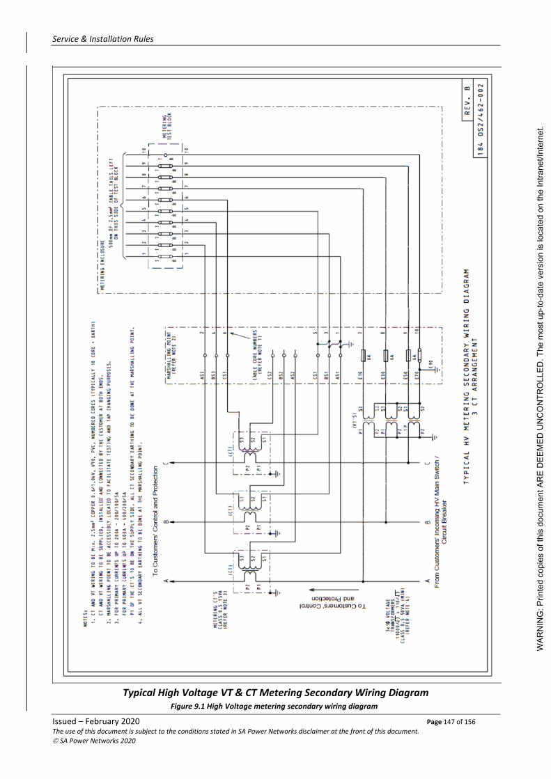
Service & Installation Rules
Issued – February 2020 Page 147 of 156 The use of this document is subject to the conditions stated in SA Power Networks disclaimer at the front of this document.
© SA Power Networks 2020
Typical High Voltage VT & CT Metering Secondary Wiring Diagram
Figure 9.1 High Voltage metering secondary wiring diagram
WAR
NIN
G: P
rinte
d co
pies
of t
his
docu
men
t AR
E D
EEM
ED U
NC
ON
TRO
LLED
. The
mos
t up-
to-d
ate
vers
ion
is lo
cate
d on
the
Intra
net/I
nter
net.

Service & Installation Rules
Issued – February 2020 Page 148 of 156 The use of this document is subject to the conditions stated in SA Power Networks disclaimer at the front of this document.
© SA Power Networks 2020
Overhead High Voltage Network
Underground High Voltage Network
Figure 9.2 Location of HV connection point
WAR
NIN
G: P
rinte
d co
pies
of t
his
docu
men
t AR
E D
EEM
ED U
NC
ON
TRO
LLED
. The
mos
t up-
to-d
ate
vers
ion
is lo
cate
d on
the
Intra
net/I
nter
net.

Service & Installation Rules
Issued – February 2020 Page 149 of 156 The use of this document is subject to the conditions stated in SA Power Networks disclaimer at the front of this document.
© SA Power Networks 2020
10. Appendices
10.1 Appendix 1 – Single Phase URDs
The following localities are served by single phase padmounted transformers. It is not possible to provide three phase services within these areas without augmentation to the SA Power Networks distribution mains.
Please note that some streets immediately adjoining those identified may be served from these transformers.
Suburb Name Street Name Street Name Street Name
Hallet Cove Valkyrie St
Reynella Lana St
Flagstaff Hill Portia St Emerald St Craigburn Dr
Cuillin Gr Daveys Rd Torresan Cr
Sarapta Ct
Aberfoyle Park Jaimey Gr Walters Cr
Nuriootpa Jones Munzberg
Gawler Myrtlebank Ct
Mount Gambier Tenison Heights Elm Ave, Chestnut Cl
Willow Av Jarrah St Millicent Rd
Casuarina Ct Jacaranda Ct Dino Pl
Lemana Ct Berrigan Ct Lark Pl
Jenkins St
Leigh Creek Coolabah St Coral Pl Belah St
Black Butt St Boobialla Pl Mulga St
Red Gum Pl Quandong Pl Mallee St
Kurrajong Pl Blackoak Dr Gimlet Pl
Ironbark Pl Myall Pl
Mount Barker Duffield St Murray St Acacia St
Fletcher Rd
Port Augusta West Crighton Dr McSporran Cr Butler Cr
Chinnery St McIntosh Cr Cole Cr
Taylor Cr Hardy Ct Freeman Ct
O’Reilly Ct Hobbs Ct
Pt Lincoln New West Rd
WAR
NIN
G: P
rinte
d co
pies
of t
his
docu
men
t AR
E D
EEM
ED U
NC
ON
TRO
LLED
. The
mos
t up-
to-d
ate
vers
ion
is lo
cate
d on
the
Intra
net/I
nter
net.

Service & Installation Rules
Issued – February 2020 Page 150 of 156 The use of this document is subject to the conditions stated in SA Power Networks disclaimer at the front of this document.
© SA Power Networks 2020
Suburb Name Street Name Street Name Street Name
Smithfield Warooka Dr Morialta Dr Parachilna Ct
Mora Cr Wahroonga Dr Adaluna Ct
Amaroo Ct Talia Ct Wilterna Dr
Para Hills (including Gulfview Heights)
Cornwall Dr Kara Ct McGill Ct
Glenarbon St Parkeston Ct Nelson Rd
Yulinda Tce
Salisbury Downs Delta Ct Amsterdam Cr Karungi Ct
Lerida Cr Soria St Venlo Ct
Felicia Ave Breda Ct De Mille St
Elstree St
Parafield Gardens Eugene Cr Salas Rd
Mitchell Park Maldon Ave Constable Ct
Marion Hersey Ct
Belair McGregor Ct Redgum Dr
Pasadena Redgum Dr Dianella Ct Tacoma Bl
Dernancourt Orange Grove Ct Donnika St
St Agnes Sarina Farm Rd Tregrehen Ct Claridge Ct
Modbury North Carruthers Dr Rose Ct
Pooraka Duffield Dr Templer Ct Batten Ct
Palmer Ct Cowan Dr Henderson Ave
Lock Cr Rains Rd Davidson Ct
Windsor Gardens Brady Ct
WAR
NIN
G: P
rinte
d co
pies
of t
his
docu
men
t AR
E D
EEM
ED U
NC
ON
TRO
LLED
. The
mos
t up-
to-d
ate
vers
ion
is lo
cate
d on
the
Intra
net/I
nter
net.

Service & Installation Rules
Issued – February 2020 Page 151 of 156 The use of this document is subject to the conditions stated in SA Power Networks disclaimer at the front of this document.
© SA Power Networks 2020
10.2 Appendix 2 – SA Power Networks Service Fuse Time/Current Characteristics
(c) Time/Current Curves for Typical SA Power Networks Service Fuse
Sheet 1 – For Service Fuse Type – ME & MF (TIR)
Sheet 2 – For Service Fuse Type – J (TIR)
WAR
NIN
G: P
rinte
d co
pies
of t
his
docu
men
t AR
E D
EEM
ED U
NC
ON
TRO
LLED
. The
mos
t up-
to-d
ate
vers
ion
is lo
cate
d on
the
Intra
net/I
nter
net.

Service & Installation Rules
Issued – February 2020 Page 152 of 156 The use of this document is subject to the conditions stated in SA Power Networks disclaimer at the front of this document.
© SA Power Networks 2020
WAR
NIN
G: P
rinte
d co
pies
of t
his
docu
men
t AR
E D
EEM
ED U
NC
ON
TRO
LLED
. The
mos
t up-
to-d
ate
vers
ion
is lo
cate
d on
the
Intra
net/I
nter
net.

Service & Installation Rules
Issued – February 2020 Page 153 of 156 The use of this document is subject to the conditions stated in SA Power Networks disclaimer at the front of this document.
© SA Power Networks 2020
Sheet 3 – For Service Fuse Type – NH Size 2 (TIR)
WAR
NIN
G: P
rinte
d co
pies
of t
his
docu
men
t AR
E D
EEM
ED U
NC
ON
TRO
LLED
. The
mos
t up-
to-d
ate
vers
ion
is lo
cate
d on
the
Intra
net/I
nter
net.

Service & Installation Rules
Issued – February 2020 Page 154 of 156 The use of this document is subject to the conditions stated in SA Power Networks disclaimer at the front of this document.
© SA Power Networks 2020
Sheet 4 – For Service Fuse Type – NH Size 3 (TIR)
WAR
NIN
G: P
rinte
d co
pies
of t
his
docu
men
t AR
E D
EEM
ED U
NC
ON
TRO
LLED
. The
mos
t up-
to-d
ate
vers
ion
is lo
cate
d on
the
Intra
net/I
nter
net.

Service & Installation Rules
Issued – February 2020 Page 155 of 156 The use of this document is subject to the conditions stated in SA Power Networks disclaimer at the front of this document.
© SA Power Networks 2020
Sheet 5 – For Service Fuse Type – NH Size 4A (TIR)
WAR
NIN
G: P
rinte
d co
pies
of t
his
docu
men
t AR
E D
EEM
ED U
NC
ON
TRO
LLED
. The
mos
t up-
to-d
ate
vers
ion
is lo
cate
d on
the
Intra
net/I
nter
net.

Service & Installation Rules
Issued – February 2020 Page 156 of 156 The use of this document is subject to the conditions stated in SA Power Networks disclaimer at the front of this document.
© SA Power Networks 2020
10.3 Appendix 3 – Existing Metering Arrangements
10.3.1 Meter Enclosures on High Voltage Poles
In locations where the metering enclosure is mounted on a HV distribution transformer pole, including SWER poles, specific installation requirements apply. This is due to the separate earthing systems used for the pole, the HV and LV. These earths are physically and electrically separate and must have no interconnection other than through the general ground.
The practice of meter boxes on pole ceased at least 40 years ago however many remain in service. These may be part of a metered mains installation or a hybrid/non-standard installation. The two main configurations were;
1. the meter box was bolted to the steel of the pole but not earthed (other than via the pole earth) and all the wiring within the meter box was double insulated; or
2. the meter box was supported off the pole by either insulators or timber supports and was provided with an independent (customer) main earth and customers switchgear.
The requirements below refer to the first case (meter box mounted directly in electrical contact with the pole).
Where the meter box is mounted directly in electrical contact with the pole then all the wiring within the enclosure must be double insulated.
At times, improper modifications may have been made to some of these installations including conversion from non-switchboard, to switchboard, additional (underground circuits), or changes to the meter wiring, where many of the changes have been non-compliant. When encountered this may result in supply being disconnected for safety, or expensive rectification works (Refer also to the Office of the Technical Regulator Regulation Roundup August 2015 page 3).
If an installation has had prior modifications where the separation of the earthing or double insulation has not been maintained, we recommend that the safety and suitability of the installation be carefully assessed before proceeding. Refer to the relevant SA Power Networks Manager for clarification.
Metering Providers are permitted to perform a meter change for maintenance or add a PV tariff only, in a one for one exchange (like for like using existing wiring). Metering Providers must ensure they maintain double insulation for all wiring in these cases along with maintaining existing phasing and load balance.
Any alterations/upgrades including the replacement of meter enclosure must relocate the meter enclosure away from the pole.
Meter Isolators and metering equipment on 460v systems must be rated accordingly.
All signage on HV and Transformer Poles must be observed.
10.3.2 Meter Enclosures containing service fuses (Elizabeth Area)
In the majority of the greater Elizabeth Area the meter enclosure may contain a timber meter panel with service fuses in the lower section on an asbestos panel.
These must not be converted into Main Switchboards by adding a meter isolator.
Only where a Metering Provider requires the old timber panel is replaced then this shall be with a modern insulated hinged panel attached to the original panel frame and using appropriate working in the vicinity of asbestos procedures for all parties.
WAR
NIN
G: P
rinte
d co
pies
of t
his
docu
men
t AR
E D
EEM
ED U
NC
ON
TRO
LLED
. The
mos
t up-
to-d
ate
vers
ion
is lo
cate
d on
the
Intra
net/I
nter
net.