UMLConsistency Rules
28
Carleton University, Technical Report SCE-14-02 January 2014 Page 1 of 28 UML consistency rules: a systematic mapping study Damiano Torre §,¶ Yvan Labiche § Marcela Genero ¶ § Carleton University, Department of Systems and Computer Engineering, Software Quality Engineering Laboratory 1125 Colonel By Drive, Ottawa, ON K1S5B6, Canada ¶ University of Castilla-La Mancha, Department of Technologies and Information Systems, ALARCOS Research Group, Paseo de la Universidad, 4 13071 Ciudad Real, Spain [email protected] [email protected] [email protected] ABSTRACT Context: The Unified Modeling Language (UML), with its 14 different diagram types, is the de-facto standard tool for object- oriented modeling and documentation. Since the various UML diagrams describe different aspects of one, and only one, software under development, they are not independent but strongly depend on each other in many ways. In other words, the UML diagrams describing a software must be consistent. Inconsistencies between these diagrams may be a source of the considerable increase of faults in software systems. It is therefore paramount that these inconsistencies be detected, analyzed and hopefully fixed. Objective: The aim of this article is to deliver a comprehensive summary of UML consistency rules as they are described in the literature to date to obtain an extensive and detailed overview of the current research in this area. Method: We performed a Systematic Mapping Study by following well-known guidelines. We selected 94 primary studies from a search with seven search engines performed in December 2012. Results: Different results are worth mentioning. First it appears that researchers tend to discuss very similar consistency rules, over and over again. Most rules are horizontal (98.07%) and syntactic (88.03%). The most used diagrams are the class diagram (71.28%), the state machine diagram (42.55%) and the sequence diagram (47.87%). Conclusion: The fact that many rules are duplicated in primary studies confirms the need for a well accepted list of consistency rules. This paper is a first step in this direction. Results indicate that much more work is needed to develop consistency rules for all 14 UML diagrams, in all dimensions of consistency (e.g., semantic and syntactic on the one hand, horizontal, vertical and evolution on the other hand). Categories and Subject Descriptors D.2.4 [Software Engineering]: Software/Program Verification - Model checking I.6.5 [Computing Methodologies]: Model Development General Terms Documentation, Languages, Verification. Keywords Unified Modeling Language (UML), UML consistency rules, Systematic Mapping Study. 1. INTRODUCTION The Model Driven Architecture (MDA) [1] promotes a set of transformations between successive models from requirements to analysis, to design, to implementation, and to deployment [2]. Recent years have seen a lot of attention into MDA in academia and industry [3-5], which resulted in models gaining even more importance in software development. The Unified Modeling Language (UML) [6] is the Object Management Group (OMG) most-used specification and the de-facto standard tool for object- oriented modeling and documentation [7-13]. It is the privileged modeling tool to implement the MDA. The architecture of the UML is based on a four-layer meta-model structure, and it provides 14 diagram types [6] for describing a system from different perspectives (e.g., structure, behavior) or abstraction levels (e.g., analysis, design), which helps deal with complex systems, distribute responsibilities among stakeholders, among other benefits. Since the various UML diagrams describe different aspects of one, and only one, software under development, they are not independent but strongly depend on each other in many ways. In other words, the UML diagrams describing a software must be consistent. As UML is not a formal notation, inconsistencies may arise in the design specification of a complex system (i.e., between the UML diagrams of that specification) when such specification requires multiple diagrams to describe different perspectives of the software [14]. When UML diagrams portray contradicting or conflicting meaning, the diagrams are said to be inconsistent [15]. Inconsistencies between different diagrams/views of a model may be a source of the considerable increase of faults in software systems [16, 17]. It is therefore paramount that these inconsistencies be detected, analyzed and hopefully fixed [18]. Even though many researchers have proposed, explicitly or not, rules to prevent or detect different types of inconsistencies, no well-accepted, as complete as possible set of consistency rules has so far been described and published. Although the UML standard itself contains some consistency rules, often referred to as well- formedness rules, the standard does not offer a complete list since for instance some consistency rules may be specific to the way the UML notation is used. This lack of well-accepted list of rules forces researchers to systematically define the consistency rules they rely on for their research [14]. Although this is good practice, this results, as confirmed by some of our results, in researchers describing similar or even identical consistency rules, over and over again. Our overall objective is to identify a set, as complete as possible, of well-accepted consistency rules for UML diagrams. In other words, the main research question that is guiding our work is the following: What is the current state of the art in terms of UML consistency rules? To achieve this goal, we need a systematic, as objective as possible identification of the rules which have been applied, or have been described, to ensure consistency between UML diagrams. Hence, the aim of this article is to deliver a comprehensive summary of the existing UML consistency rules (to the best of our knowledge) to obtain an extensive and detailed overview of the current research in this area.
-
Upload
independent -
Category
Documents
-
view
0 -
download
0
Transcript of UMLConsistency Rules

Carleton University, Technical Report SCE-14-02 January 2014
Page 1 of 28
UML consistency rules: a systematic mapping study Damiano Torre §,¶ Yvan Labiche § Marcela Genero ¶
§ Carleton University, Department of Systems and Computer Engineering,
Software Quality Engineering Laboratory 1125 Colonel By Drive, Ottawa, ON K1S5B6, Canada
¶ University of Castilla-La Mancha, Department of Technologies and Information Systems,
ALARCOS Research Group, Paseo de la Universidad, 4 13071 Ciudad Real, Spain
[email protected] [email protected] [email protected]
ABSTRACT Context: The Unified Modeling Language (UML), with its 14 different diagram types, is the de-facto standard tool for object-oriented modeling and documentation. Since the various UML diagrams describe different aspects of one, and only one, software under development, they are not independent but strongly depend on each other in many ways. In other words, the UML diagrams describing a software must be consistent. Inconsistencies between these diagrams may be a source of the considerable increase of faults in software systems. It is therefore paramount that these inconsistencies be detected, analyzed and hopefully fixed. Objective: The aim of this article is to deliver a comprehensive summary of UML consistency rules as they are described in the literature to date to obtain an extensive and detailed overview of the current research in this area. Method: We performed a Systematic Mapping Study by following well-known guidelines. We selected 94 primary studies from a search with seven search engines performed in December 2012. Results: Different results are worth mentioning. First it appears that researchers tend to discuss very similar consistency rules, over and over again. Most rules are horizontal (98.07%) and syntactic (88.03%). The most used diagrams are the class diagram (71.28%), the state machine diagram (42.55%) and the sequence diagram (47.87%). Conclusion: The fact that many rules are duplicated in primary studies confirms the need for a well accepted list of consistency rules. This paper is a first step in this direction. Results indicate that much more work is needed to develop consistency rules for all 14 UML diagrams, in all dimensions of consistency (e.g., semantic and syntactic on the one hand, horizontal, vertical and evolution on the other hand).
Categories and Subject Descriptors D.2.4 [Software Engineering]: Software/Program Verification - Model checking I.6.5 [Computing Methodologies]: Model Development
General Terms Documentation, Languages, Verification.
Keywords Unified Modeling Language (UML), UML consistency rules, Systematic Mapping Study.
1. INTRODUCTION The Model Driven Architecture (MDA) [1] promotes a set of transformations between successive models from requirements to analysis, to design, to implementation, and to deployment [2]. Recent years have seen a lot of attention into MDA in academia
and industry [3-5], which resulted in models gaining even more importance in software development. The Unified Modeling Language (UML) [6] is the Object Management Group (OMG) most-used specification and the de-facto standard tool for object-oriented modeling and documentation [7-13]. It is the privileged modeling tool to implement the MDA. The architecture of the UML is based on a four-layer meta-model structure, and it provides 14 diagram types [6] for describing a system from different perspectives (e.g., structure, behavior) or abstraction levels (e.g., analysis, design), which helps deal with complex systems, distribute responsibilities among stakeholders, among other benefits. Since the various UML diagrams describe different aspects of one, and only one, software under development, they are not independent but strongly depend on each other in many ways. In other words, the UML diagrams describing a software must be consistent. As UML is not a formal notation, inconsistencies may arise in the design specification of a complex system (i.e., between the UML diagrams of that specification) when such specification requires multiple diagrams to describe different perspectives of the software [14]. When UML diagrams portray contradicting or conflicting meaning, the diagrams are said to be inconsistent [15]. Inconsistencies between different diagrams/views of a model may be a source of the considerable increase of faults in software systems [16, 17]. It is therefore paramount that these inconsistencies be detected, analyzed and hopefully fixed [18].
Even though many researchers have proposed, explicitly or not, rules to prevent or detect different types of inconsistencies, no well-accepted, as complete as possible set of consistency rules has so far been described and published. Although the UML standard itself contains some consistency rules, often referred to as well-formedness rules, the standard does not offer a complete list since for instance some consistency rules may be specific to the way the UML notation is used. This lack of well-accepted list of rules forces researchers to systematically define the consistency rules they rely on for their research [14]. Although this is good practice, this results, as confirmed by some of our results, in researchers describing similar or even identical consistency rules, over and over again. Our overall objective is to identify a set, as complete as possible, of well-accepted consistency rules for UML diagrams. In other words, the main research question that is guiding our work is the following: What is the current state of the art in terms of UML consistency rules? To achieve this goal, we need a systematic, as objective as possible identification of the rules which have been applied, or have been described, to ensure consistency between UML diagrams. Hence, the aim of this article is to deliver a comprehensive summary of the existing UML consistency rules (to the best of our knowledge) to obtain an extensive and detailed overview of the current research in this area.

Carleton University, Technical Report SCE-14-02 January 2014
Page 2 of 28
To achieve this goal, we performed a Systematic Mapping Study (SMS) [19] as this is a research method that provides an objective procedure for identifying the quantity of existing research related to a research question. Performing a SMS has several benefits [20]: it gives a starting point for PhD students and in the longer term, it provides a body of knowledge to the next generation of researchers. To carrying out the SMS detailed in this paper we followed the guidelines of Kitchenham and Charters [21].
This paper is structured as follows. In section 2 we provide a brief discussion on related work. This is followed by a description of the SMS protocol we followed [21]: the SMS planning (section 3), the SMS execution (section 4), and the results (section 5). A preliminary discussion with the main findings, and the limitations and threats to validity is provided in section 6. Finally, section 7 draws the conclusions and provides directions for future works.
2. RELATED WORK As we have mentioned before, there are a lot of works on the consistency of UML diagrams. In the run-up to this SMS, we searched for surveys, literature reviews, mapping studies, or similar work on the topic of UML consistency. We only found six such publications, which we discuss in this section. It is important to note, as summarized later in this section that none of them answered our main research question (section 1).
To the best of our knowledge, the closest piece of work to our problem is a review on UML consistency management [3]. It is different from our SMS in several ways. The first important difference is the research protocol used during the review: they presented a Systematic Literature Review (SLR) while we present a SMS. The second main difference is the purpose: They focused only on the management of UML (in) consistencies, i.e., they focused on techniques to identify and fix inconsistencies, without discussing in details which inconsistencies had to be identified and fixed. In contrast our SMS focuses on those inconsistencies that need to be identified and fixed. A direct consequence of this difference is that we reviewed a broader number of papers about UML consistency (94 primary studies instead of 43), that approximately half of their primary studies are not primary studies in our SMS (only 24 of their primary studies are also primary studies in our SMS), and that our research overlaps (three of their six research questions are updated in our SMS, the other three being irrelevant in our context). Moreover the search periods are different: they cover the [2001-2007] period while we cover papers in the [2000-2012] period.
Another work about UML consistency presents a survey of consistency checking techniques for UML models [5]. The authors argue that formalizing UML models is preferable to verify consistency because this helps removing ambiguities and enforcing consistency. They briefly reviewed 17 articles, which represent less than a quarter of the number of primary studies in our SMS (94): only ten primary studies are common. During this survey the authors did not follow any SLR or SMS protocol, and they simply provided an initial summary of their findings about UML consistency checking techniques (not consistency rules).
Spanoudakis and Zisman [18] presented a survey on the problem of managing inconsistencies in software models, not specifically UML ones. The authors presented a conceptual framework that views inconsistency management as a process which incorporates activities for detecting overlaps and inconsistencies between software models, diagnosing and handling inconsistencies,
tracking the information generated along the way, and specifying and monitoring the exact way of carrying out each of these activities. They then surveyed all the research works published prior to 2001 that address one or more of the aspects of their conceptual framework/process. It is worth noting that the process they carried out did not follow a SLR or SMS protocol.
Another piece of work [22] showed a rule based method for consistency checking in UML models supported by a software prototype for the MagicDraw UML CASE tool. The authors presented 50 UML consistency rules involving one or more UML diagrams. They obtained those rules by reviewing eight articles, seven of which are also considered in our SMS. Their brief review did not follow a systematic protocol (SLR or SMS): no clear process to obtain the papers, no clear process to include or exclude such documents. After conducting our SMS we compared the list of primary studies between their work and our work and identified the missing paper (the one of the eight). We confirmed our search could not find it. We nevertheless read the paper and identified it was describing only one consistency rule and that this rule was about the consistency between requirements and classes. Since we already had such a rule in our list (between use case descriptions and classes) we stopped investigating this paper.
Ahmad and Nadeem [7] presented a survey focusing only on Description Logic (DL) based consistency checking approaches. As one result of their research, they said that only class diagram, sequence diagram and state diagram inconsistencies were covered in the surveyed papers and a few common types of inconsistencies were discussed. They briefly described the background of the DL formalism and they reviewed three articles, which are also reviewed in our SMS. Their survey did not follow any SLR or SMS protocol.
Finally Genero et al conducted a SMS about the quality of UML diagrams [4]. Since they were interested in UML diagram quality in general they did not focus on UML consistency and even less so on UML consistency rules. They nevertheless discuss UML consistency and write that semantic consistency is by far the semantic quality subtype that has been researched most (42% of their primary studies). They mention that 70.27% of the papers that research semantic quality focused on consistency issues. Moreover they mention that the majority of methods attempt to improve semantic quality do improve the consistency of UML diagrams. In addition, most of the rules, modeling conventions, guidelines and checklists related to semantic quality that they discuss were especially related to consistency problems. This confirms that identifying inconsistencies between UML diagrams is a very important activity in improving UML model quality.
To summarize, our search for answers to our main research question failed, which confirmed the need for a SMS about UML consistency rules. It is also important to note that published works that relate to our SMS are in general more informal literature surveys or comparisons with no defined research questions, no search process, no defined data extraction or data analysis process. Instead, our SMS follows a strict, well-known protocol.
3. SMS PLANNING In this section we present the main components of the protocol required to carry out a SMS [21].

Carleton University, Technical Report SCE-14-02 January 2014
Page 3 of 28
3.1 Research Questions The underlying motivation for the research questions was to determine the current state of the art about UML consistency rules and this guided the design of the review process. In order to identify the current state of the art on UML consistency rules, we considered seven research questions (RQs): Table 1.
Table 1. Research questions
Research questions Main motivation RQ1: What are the UML versions used by researchers in the approaches found?
To discover what UML versions are used in the approaches that handle the UML consistency.
RQ2: Which types of UML diagrams have been tackled in each approach found?
To discover the UML diagrams that research has focused upon, to reveal the UML diagrams that are considered more important than others, as well as to identify opportunities for further research.
RQ3: What are the UML consistency rules to check?
To find the UML consistency rules to check and to assess the state of the field.
RQ4: Which types of consistency problems have been tackled in the rules found?
To find the types of consistency problems tackled in the rules. The data found are categorized into three consistency dimensions split into three sub-dimensions: 1) horizontal, vertical and evolution consistency; 2) syntactic and semantic consistency; 3) observation and invocation consistency.
RQ5: Which research methods are used in research on UML model consistency?
To determine if the field is generally more applied or more basic research as well as to identify opportunities for future research. The papers found were categorized into six types: evaluation research, validation research proposal of solution, philosophical papers, opinion papers and personal experience papers.
RQ6: Is the approach presented automatic, manual or semi-automatic?
To discover how the approaches to check the UML consistency are implemented, in other word if their check system is presented with an automatic, manual or semi-automatic way.
RQ7: How the UML consistency rules are specified? How the UML consistency rules are checked?
To discover how the consistency rules to check the consistency of the UML diagrams are specified (e.g., Plain English, OCL, Promela) and to discover with which tools those consistency rules are checked (e.g., SPIN, OCL-Checker)
3.2 Search strategy Conducting a search for primary studies requires the identification of search strings (SS), and the specification of the parts of primary studies (papers) in which the search strings are looked for (the search fields). To identify our search strings, we followed the procedure of Brereton et al [23]:
1. Define the major terms;
2. Identify alternative spellings, synonyms or related terms for major terms;
3. Check the keywords in any relevant papers were already available;
4. Use the Boolean OR to incorporate alternative spellings, synonyms or related terms;
5. Use the Boolean AND to link the major terms.
The major search terms were “UML” and “Consistency” and the alternative spellings, synonymous or terms related to the major terms are presented in Table 2.
Table 2. Search string
Major Terms Alternative terms UML (uml OR unified modeling language OR
unified modelling language) Consistency (consistency OR inconsistency)
In the selection of the SS, we considered various alternatives. For example the SS used in the SLR on consistency management [3] was discarded due to the fact that it might not strictly focus on UML consistency rules: we are much more interested in collecting rules than in identifying consistency management issues and solutions. Other SSs were experimented with, but due to space limits, we cannot discuss below all those alternative search strings. In the set of alternative SSs, we selected the following one as it allowed us to retrieve the largest number of useful papers, i.e., the largest number of papers focusing on UML consistency:
((uml OR unified modeling language OR unified modelling language) AND (consistency OR inconsistency))
The search was limited to electronic papers and considered only peer-reviewed journals, international conferences and workshops in only the English language. We did not establish any restriction on publication years until 2012. We used the above mentioned SS with the following seven search engines: IEEE Digital Library, Science Direct, ACM Digital Library, Scopus, search field: Springer Link, search field: title, Google Scholar, and WILEY. The searches were limited to the following search fields: title, keywords and abstract.
3.3 Selection procedure and inclusion and exclusion criteria In this section we discuss the inclusion and exclusion criteria we used. We then discuss the process we followed to include a primary studies in this SMS. The inclusion criteria were:
Electronic Papers (EPs) focusing on UML diagrams consistency which contained at least one UML consistency rule;
EPs written in English;
EPs published in peer-reviewed journals, international conferences and workshops;
EPs published until December 12, 2012.
EPs which proposed UML consistency rules with a restriction (or extension) of the UML models that don't strictly follow the OMG standard [6].
The exclusion criteria were:
EPs not focusing on UML diagrams consistency;
EPs which did not present a full-text paper (title, abstract, complete body of the article and references) but were reduced to an abstract for instance;
EPs focusing on UML diagrams consistency which did not contain at least one UML consistency rule;
Duplicated EPs (e.g., returned by different search engines);
Carleton University, Technical Report SCE-14-02 January 2014
Page 4 of 28
EPs which discussed consistency rules between UML diagrams and other, non-UML sources of data, such as requirements or source code.
3.4 Data extraction strategy We extracted the data from the primary studies according to a number of criteria, which were directly derived from the research questions detailed in Table 1. Using each criterion to extract data required that we read the full-text of each of the 94 primary studies. Once recorded, we collected data in an Excel spreadsheet that represent our data form. From each primary study the following information was extracted and collected into the Excel data form:
Search engines: where the paper was found (see section 3.2);
Inclusion and Exclusion Criteria (see section 3.3);
Data related to Research Questions (see Section 3.1):
o What UML version was used;
o What are the UML consistency rules discussed (Appendices);
o What diagrams are involved in consistency rules: Class Diagram (CD), Collaboration Diagram (COD), Use Case Diagram (UCD), Communication Diagram (COMD), State Chart Diagram (SCD), Sequence Diagram (SD), Protocol State Machine Diagram (PSMD), Object Diagram (OD), Interaction Diagram (ID), Activity Diagram (AD), Composite Structure Diagram (CSD), Timing Diagram (TD), Interaction Overview Diagram (IOD), and Deployment Diagram (DD);
What is the dimension of the UML. Several possible dimensions of consistency appear in the literature, since there isn’t yet any standard for reasoning about consistency. Three UML consistency dimensions have been proposed though [25]:
o Horizontal, Vertical and Evolution Consistency: Horizontal consistency, also called intra-model consistency, refers to consistency within a model or between different diagrams of the model at the same level of abstraction, and within the same version [17]. Vertical Inconsistency, also called inter-model consistency, refers to consistency between models (and therefore their diagrams) at different levels of abstraction [26]. Evolution consistency refers to consistency between different versions of the same model (and therefore their diagrams), and has to be maintained when the model is in the process of evolution [17].
o Syntactic versus Semantic consistency: Syntactic consistency ensures that a specification conforms to the abstract syntax specified by the meta-model, and requires that the overall model has to be well formed [26]. Semantic consistency requires that the behavior of diagrams be semantically compatible [26]. Semantic consistency applies at one level of abstraction (with horizontal consistency), at different levels of abstraction (vertical consistency), and during model evolution (evolution consistency) [7].
o Observation versus Invocation consistency: Observation consistency requires that an instance of a subclass behave like an instance of its superclass, when viewed according
to the superclass description [27]. In terms of UML state diagrams (corresponding to protocol state machines) this can be rephrased as “after hiding all new events, each sequence of the subclass state diagram should be contained in the set of sequences of the superclass state diagram.” Invocation consistency requires that an instance of a subclass of a parent class can be used wherever an instance of the parent is required [27]. In terms of UML state diagrams (corresponding to protocol state machines), each sequence of transitions of the superclass state diagram should be contained in the set of sequences of transitions of the state diagram for the subclass.
o Tool support (Automatic, Semi-Automatic, Manual);
Automatic means that the UML consistency rules were full-automatic supported by an implemented and working tool;
Semi-automatic means that the UML consistency rules were partially automatic (for instance when the check of a UML diagrams need the support of user to finish the process;
Manual means that that the UML consistency rules were not supported by any implemented and automatic tool.
o What mechanisms were used to specify the rules: e.g., plain language, Promela, etc.;
o How the UML consistency rules are checked: e.g., SPIN, OCL-Checker, etc.;
o Type of research method followed in the paper, for which we used the following classification [28]:
Evaluation research (ER): this is a paper that investigates techniques that are implemented in practice and an evaluation of the technique is conducted. That means, the paper shows how the technique is implemented in practice (solution implementation) and what are the consequences of the implementation in terms of benefits and drawbacks (implementation evaluation).
Proposal of solution (PS): this is a paper that proposes a solution to a problem and argues for its relevance, without a full-blown validation.
Validation Research (VR): this is a paper that investigates the properties of a solution that has not yet been implemented in practice.
Philosophical papers (PP): this is a paper that sketches a new way of looking at things, a new conceptual framework, etc.
Opinion papers (OP): this is a paper that contains the author’s opinion about what is wrong or good about something, how something should be done, etc.
Personal experience papers (PEP): this is a paper that emphasizes more on what and not on why.
4. EXECUTION The planning for this SMS with the seven search engines begun in September 2012 and was completed on December 12, 2012. In this section we present the execution of the SS into the seven search engines and the selection of primary studies according to

Carleton University, Technical Report SCE-14-02 January 2014
Page 5 of 28
the inclusion/exclusion criteria previously described. In order to document the review process with sufficient details [21], we describe the multi-phase process of four sub-phases we followed:
First sub-phase (SP1): the search string was used to search with the seven search engines as mentioned earlier.
Second sub-phase (SP2): we deleted duplicates automatically, by using the RefWorks tool [29]; we also removed duplicates manually.
Third sub-phase (SP3): we obtained an initial set of studies by reading the title, abstract and keywords of all the papers obtained after SP2 while enforcing the inclusion and exclusion criteria. When reading just the title, abstract and keywords of a paper was not enough to decide to include or exclude it, we checked the full-text.
Fourth sub-phase (SP4): all the papers identified in SP3 were read in their entirety and the exclusion criteria were applied again. This resulted in the final set of primary studies.
Table 3 breaks down the number of papers we have found by sub-phases. SP1 in Table 3 are the first results which were obtained by running the SS into the seven search engines selected. The next two rows show the results obtained after applying SP2 and SP3 of the studies selection process. In the end, we collected 94 primary studies for further analysis. The complete list of references can be found in Appendix.
Table 3. Summary of primary studies selection
Sub phase IEEE Scopus Springer Link
Google Scholar
WILEY ACM Science Direct
Total
SP1: Raw results
363 601 163 341 9 87 39 1603
SP2: No duplicates
279 325 158 247 9 80 36 1134
SP3: First selection
62 64 61 28 4 33 14 266
SP4: Primary studies
16 21 20 12 1 16 8 94
5. RESULTS To reach the goal of this SMS, i.e., addressing the research questions listed in section 3.1, the 94 primary studies selected were classified according to the criteria detailed in section 3.4, then the results of the SMS reported in this section show the answers to the seven research questions previous presented.
A quantitative summary of the results for research questions RQ1, RQ2, RQ4, RQ5 and RQ6 is presented in Table 4. More details are provided in the following sub-sections.
Table 4. Results of SMS
Result Research question
Possible Answer # Papers Percentage
UML 1.1 1 1.06% UML 1.3 13 13.83% UML 1.4 6 6.38% UML 1.5 8 8.51% UML 2.0 31 32.98% UML 2.1.X 10 10.64% UML 2.2 2 2.13% UML 2.3 1 1.06% UML 2.4.1 1 1.06%
RQ1: UML versions
NF 18 19.15%
Ext. 1 1.06% Red. 2 2.13% Class Diagram 67 71.28% State Diagram 40 42.55% Protocol State Machine Diagram
5 5.32%
Sequence Diagram 45 47.87% Collaboration Diagram 8 8.51% Activity Diagram 12 12.77% Use Case Diagram 14 14.89% Object Diagram 4 4.26% Communication Diagram 2 2.13% Composite Structure Diagram
1 1.06%
RQ2: UML diagrams
Interaction Diagram 4 4.26% Horizontal 254 98.07% Vertical 5 1.93% 1st D Evolution 0 0.00% Semantic 228 88.03%
2nd D Syntactic 31 0.00% Invocation 3 1.16%
RQ4: Types of consistency problems
3rd D Observation 3 1.16%
ER 16 17.02% VR 28 29.79% PS 47 50.00% PP 0 0.00% OP 0 0.00%
RQ5: Research methods
PEP 3 3.19% Automatic 24 25.53% Semi-Automatic 29 30.85%
RQ6: Type of support
Manual 41 43.62%
5.1 UML version (RQ1) Figure 1 plots the number of papers presenting rules for specific versions of the UML.
Figure 1. UML version
The presence of 29.79% (28 of 94 papers) of the primary studies with an old version (1.x) of the UML shows that the issue of the UML consistency rules started to be relevant from the initial launch of the UML (which has been evolving since the second half of the 1990s [6]). UML 2.0 is the UML version mostly used in the primary studies: 32.98% (31 of 94 papers). The subsequent UML versions (2.1, 2.1.1 and 2.1.2) were merged into 2.1.X to obtain a more readable graph. NF means “not found” and it represents all those primary studies which did not report on the UML version used. “Ext.” and “Red.” represent primary studies which use an extension or simplification of the UML notation that do not strictly follow the UML standard [6].

Carleton University, Technical Report SCE-14-02 January 2014
Page 6 of 28
5.2 Types of UML diagrams (RQ2) In this section we discuss the different types of UML diagrams involved in primary studies. Figure 2 indicates that collected rules describe consistency on only eleven of the 14 UML diagrams. (We did not collect any rule involving the timing, interaction overview and deployment diagrams.)
Figure 2. UML diagrams
Not surprisingly, since these are the mostly used diagrams, the Class Diagram (71.28%), the Sequence Diagram (47.87%), and the State Machine Diagram (42.55%) are the diagrams mostly involved in consistency rules. Research on UML consistency rules has placed much less attention on the Use Case Diagram (14.89%) and the Activity Diagram (12.77%). The Collaboration Diagram was found in 8.51% of the primary studies. The least used diagrams are the Protocol State Machine Diagram, the Object Diagram, the Interaction Diagram, the Communication Diagram and the Composite Structure Diagram.
5.3 UML consistency rules (RQ3) The principal aspect shown in this RQ is that researchers involved into UML consistency rules typically define a number of similar consistency rules over and over again. Specifically, we collected a list of 603 UML consistency rules from the primary studies. After removing duplicates, or rules that are implied by another rule, we obtained a list of 259 UML consistency rules: The complete list of 259 UML consistency rules is presented in Appendix. In other words, only 42.95% (259 of 603) of the UML consistency rules initially collected were unique. The rest of the UML consistency rules were mostly due to duplications or implications (33.33%, 201 of 603). Other rules (23.71%, 143 of 603) were eliminated for a couple of reasons: they were not consistency rules (e.g., rules describing good modeling practices); they were explained in an ambiguous language; they were out of the scope of our research (e.g., focused on aspect-oriented multi-view modeling); yet others were simply inexact (i.e., either contradicting the UML metamodel, or contradicting UML-based modeling principles).
5.4 UML consistency dimensions (RQ4) This sub-section presents the results about the number of UML consistency rules divided into the UML consistency dimension presented in section 3.4.
The results show that the great majority of UML consistency rules are Horizontal and Syntactic rules, respectively with 98.07% (254 of 259 rules) and 88.03% (228 of 259 rules) of the total of collected UML consistency rules. Moreover, 21 (11.97%) Semantic rules involved in UML consistency were found. Researchers described strikingly many more syntactic than
semantic consistency rules. Also, although we have not yet compared the 259 rules with well-formedness rules of the UML standard, we suspect that a large majority of the syntactic consistency rules we collected are already in the UML standard: for instance several authors present the rule whereby a class cannot be a descendant (or ancestor) of itself in a class diagram, which is already a constraint of the UML metamodel. Proposals of UML consistency rules have placed much less attention on Vertical (1.93%), Invocation (1.16%) and Observation (1.16%) consistency. We were surprised to discover that no one Evolution consistency rule was proposed by researchers.
5.5 Research methods (RQ5) The results of the research method classification show that 50% (47 of 94 papers) of primary studies proposed solutions to the inconsistency problem (PS), 29.79% (28 of 94 papers) presented validation research (VR), 17.02% (16 of 94 papers) presented evaluation research (ER), and only 3.19% (3 of 94 papers) presented personal experience (PEP). We did not find any philosophical paper (PP) nor opinion paper (OP). This suggests the field is about problem solving.
5.6 Tool support (RQ6) The UML consistency rules presented by researchers are supported by automatic tools (25.53%, 24 of 94 papers), semi-automatic tools (30.58%, 29 of 94 papers), and finally the larger number of publications presented manual verification (43.62%, 41 of 94 papers).
5.7 UML consistency rules: specification and support (RQ7) Figure 3 shows that plain english (29.79%) is the most used language to specify UML consistency rules, followed by the Object Constraint Language (OCL) [6] (22.34%), Communicating Sequential Processes (CSP) and Promela (5.32% each). Using OCL makes sense since this is a constraint language that is part of the UML; it is mostly used in syntactic rules. Languages such as CSP and Promela have been used to specify semantic rules between the sequence diagram and the state machine diagram. The category "other" in Figure 3 summarizes all those proposals (23.40%, 22 of 94 papers) that present a specification mechanism that appears in only one primary study (for instance XML Equivalent Transformation (XET), Prolog, Constraint Logic Programming).
Figure 3. Language of UML consistency rules
Carleton University, Technical Report SCE-14-02 January 2014
Page 7 of 28
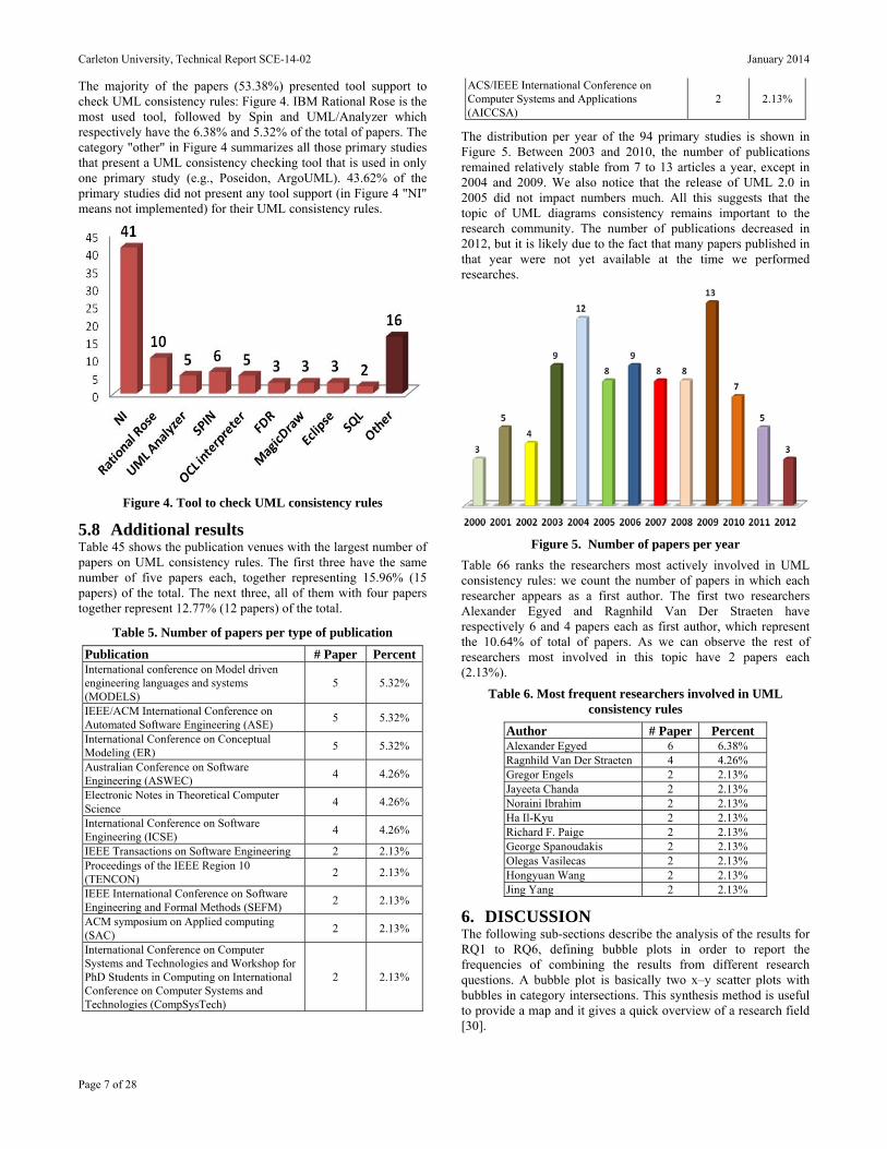
The majority of the papers (53.38%) presented tool support to check UML consistency rules: Figure 4. IBM Rational Rose is the most used tool, followed by Spin and UML/Analyzer which respectively have the 6.38% and 5.32% of the total of papers. The category "other" in Figure 4 summarizes all those primary studies that present a UML consistency checking tool that is used in only one primary study (e.g., Poseidon, ArgoUML). 43.62% of the primary studies did not present any tool support (in Figure 4 "NI" means not implemented) for their UML consistency rules.
Figure 4. Tool to check UML consistency rules
5.8 Additional results Table 45 shows the publication venues with the largest number of papers on UML consistency rules. The first three have the same number of five papers each, together representing 15.96% (15 papers) of the total. The next three, all of them with four papers together represent 12.77% (12 papers) of the total.
Table 5. Number of papers per type of publication
Publication # Paper PercentInternational conference on Model driven engineering languages and systems (MODELS)
5 5.32%
IEEE/ACM International Conference on Automated Software Engineering (ASE)
5 5.32%
International Conference on Conceptual Modeling (ER)
5 5.32%
Australian Conference on Software Engineering (ASWEC)
4 4.26%
Electronic Notes in Theoretical Computer Science
4 4.26%
International Conference on Software Engineering (ICSE)
4 4.26%
IEEE Transactions on Software Engineering 2 2.13% Proceedings of the IEEE Region 10 (TENCON)
2 2.13%
IEEE International Conference on Software Engineering and Formal Methods (SEFM)
2 2.13%
ACM symposium on Applied computing (SAC)
2 2.13%
International Conference on Computer Systems and Technologies and Workshop for PhD Students in Computing on International Conference on Computer Systems and Technologies (CompSysTech)
2 2.13%
ACS/IEEE International Conference on Computer Systems and Applications (AICCSA)
2 2.13%
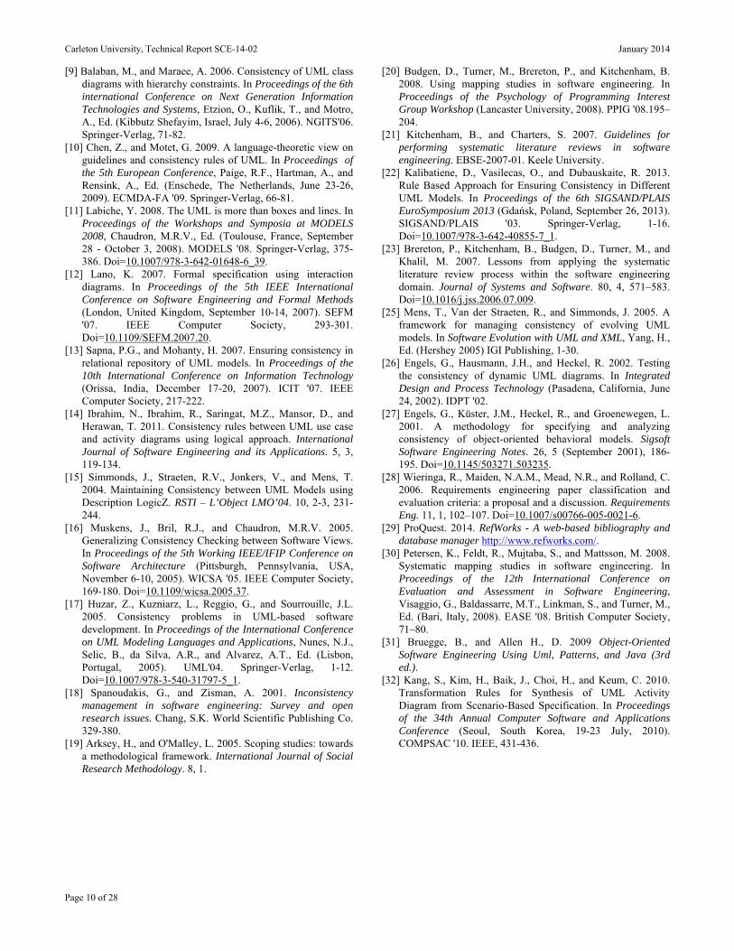
The distribution per year of the 94 primary studies is shown in Figure 5. Between 2003 and 2010, the number of publications remained relatively stable from 7 to 13 articles a year, except in 2004 and 2009. We also notice that the release of UML 2.0 in 2005 did not impact numbers much. All this suggests that the topic of UML diagrams consistency remains important to the research community. The number of publications decreased in 2012, but it is likely due to the fact that many papers published in that year were not yet available at the time we performed researches.
Figure 5. Number of papers per year
Table 66 ranks the researchers most actively involved in UML consistency rules: we count the number of papers in which each researcher appears as a first author. The first two researchers Alexander Egyed and Ragnhild Van Der Straeten have respectively 6 and 4 papers each as first author, which represent the 10.64% of total of papers. As we can observe the rest of researchers most involved in this topic have 2 papers each (2.13%).
Table 6. Most frequent researchers involved in UML consistency rules
Author # Paper Percent Alexander Egyed 6 6.38% Ragnhild Van Der Straeten 4 4.26% Gregor Engels 2 2.13% Jayeeta Chanda 2 2.13% Noraini Ibrahim 2 2.13% Ha Il-Kyu 2 2.13% Richard F. Paige 2 2.13% George Spanoudakis 2 2.13% Olegas Vasilecas 2 2.13% Hongyuan Wang 2 2.13% Jing Yang 2 2.13%
6. DISCUSSION The following sub-sections describe the analysis of the results for RQ1 to RQ6, defining bubble plots in order to report the frequencies of combining the results from different research questions. A bubble plot is basically two x–y scatter plots with bubbles in category intersections. This synthesis method is useful to provide a map and it gives a quick overview of a research field [30].

Carleton University, Technical Report SCE-14-02 January 2014
Page 8 of 28
6.1 Combining RQ1, RQ2 and RQ5 Combining the results of RQ1, RQ2 and RQ5, we obtained (Figure 6) the mapping of the research methods used depending on the year of publications and the type of UML diagrams. In the same way the different UML versions are shown according to the UML diagrams and year of papers published. The results about the UML versions show that with 23 proposals, the Class Diagram is the most used UML diagram with UML version 2.0. It is closely followed by the Sequence Diagram with 20 papers in the same UML version. This is an observation that we can consistently make across UML versions. Proposals which used State Diagrams were constant (in numbers) between UML versions 1.3 and 2.1.X; in fact the number of publications remained relatively stable from 4 to 9 articles for version reaching its peak with 9 articles for the UML version 2.0. Little has been proposed for UML versions 2.2 and 2.3, perhaps because of the small changes to the metamodel from UML 2.1.
As shown in Figure 6, most of the primary studies present rules that involve the Class Diagram, Sequence Diagram and State Diagram, respectively with 32.38% (34 papers), 23.81% (25 papers) and 21.90% (23 papers). It is important to note that the vast majority of the primary studies (23 primary studies, 35.94%) that perform some validation (classified as validation research) focus on the class diagram.
6.2 Combining RQ2, RQ3 and RQ4 First of all regarding the several dimensions that can be used to classify consistency rules (section 3.4), we note that 69.15% (65 of 94 papers) of the primary studies did not mention any such dimension, that 18.09% (17 of 94 papers) presented horizontal and vertical consistency rules, and only 4.26% mentioned also evolution consistency with those two dimensions.
As a consequence of RQ2, RQ3 and RQ4, Table 77 ranks horizontal and syntactic rules by diagram, horizontal consistency and syntactic consistency being the two dimensions with the largest number of UML consistency rules gathered. The class diagram, with 37.85% of rules, is the most used UML diagram involved in the definitions of UML (horizontal and syntactic) consistency rules. It is followed, as confirmed by other RQs in this paper, by State Diagram and Sequence Diagram respectively with 23.08% and 14.77% of the total of UML consistency rules presented in this work.
Table 7. Horizontal and Syntactic rules
Horizontal and Syntactic rules # Rules Percent Class Diagram 123 37.85% State Diagram 75 23.08% Sequence Diagram 48 14.77% Activity Diagram 23 7.08% Use Case Diagram 20 6.15% Collaboration Diagram 18 5.54% Composite Structure Diagram 8 2.46%
6.3 Combining RQ6 and RQ7 As shown earlier, most of the studies about UML consistency rules did not present any UML CASE tool to support those rules. In fact this aspect is confirmed by the fact that, as shown earlier, plain English is the language mostly used to specify UML consistency rules and there is still not a UML tool used by researchers that can be considered standard to execute UML consistency rules.
6.4 Combining RQ2 and RQ3 As a consequence of RQ2 and RQ3, Table 8 shows that the pairs of diagrams mostly involved in rules are CD-SD, CD-COD, and SD-SCD (52.10%).
Figure 6. Combining RQ1, RQ2 and RQ5

Carleton University, Technical Report SCE-14-02 January 2014
Page 9 of 28
Table 8. Consistency in 2 diagrams
Consistency between 2 diagrams # Rules Percent Class Diagram and Sequence Diagram 26 21.85% Class Diagram and State Diagram 25 21.01% Class Diagram and Collaboration Diagram 11 9.24% State Diagram and Sequence Diagram 9 7.56% Sequence Diagram and Activity Diagram 9 7.56% Sequence Diagram and Use Case Diagram 5 4.20% Activity Diagram and Use Case Diagram 5 4.20% Class Diagram and Use Case Diagram 5 4.20%
Error! Not a valid bookmark self-reference.9 shows that CD, SCD and SD are the diagrams mostly used in rules involving only one diagram (84.29%).
Table 9, Consistency in one diagram
Consistency in one diagram # Rules Percent Class Diagram 56 40.00% State Diagram 52 37.14% Sequence Diagram 10 7.14% Composite Structure Diagram 8 5.71% Activity Diagram 6 4.29% Use Case Diagram 3 2.14% Collaboration Diagram 3 2.14%
7. CONCLUSION In recent years, a great number of UML consistency rules have been presented by researchers to fix inconsistencies between UML diagrams. However, no mapping study exists that summarizes these UML consistency rules since the majority of studies are informal literature surveys.
This work presented the results obtained after carrying out a Systematic Mapping Study (SMS) of literature with the aim to identify and evaluate the current state of the art about UML consistency rules. The SMS was carried out following well-well-known guidelines [21]. From an initial set of 1134 papers, a total of 94 primary studies were found by following a precise selection protocol driven by seven research questions. Primary studies were then classified according to several criteria, also derived from those research questions.
One import observation we made is that researchers typically define a number of similar UML consistency rules over and over again, which suggests there is a need for a documented list of accepted consistency rules. This is one of our next steps.
Based on our interpretation of the SMS carried out in this paper, we observe that (in no particular order of importance):
There is not any UML CASE tool standard to run UML consistency rules;
The class diagram is the UML diagram mostly involved in UML consistency checking; it is followed in importance by the State Diagram and the Sequence Diagram. This is not entirely surprising since these are likely the most used UML diagrams.
A very few number of rules address the issue of vertical and evolution consistency. Even though the UML consistency topic is mature, it still needs to evolve to include definitions of UML consistency rules in all dimensions. Our SMS therefore shows areas where future work is needed.
The UML version 2.0 is the most used standard used to present UML consistency rules.
There is no UML consistency rule suggested for Timing, Interaction Overview and Deployment Diagrams. Besides the class, sequence, and state machine diagrams, there is a need for much addition research on consistency rules involving all 14 UML diagrams.
These observations definitely call for future work.
We also consider additional work to consolidate further the list of consistency rules we have collected. First, as already mentioned earlier in this paper, we intend to compare the rules we collected with the well-formedness rules the UML standard already contains. Second, we believe we can collect additional consistency rules from other sources. For instance, textbooks on UML-based object-oriented software development (e.g., [31]) suggest, implicitly or explicitly, consistency rules. Also, we are aware of research activities where some UML diagrams are synthesized from other diagrams (e.g., [32]): in doing so the authors rely or want to enforce some consistency rules between diagrams.
8. ACKNOWLEDGMENTS This research has been partly funded by a Discovery grant of the Natural Sciences and Engineering Research Council of Canada and the GEODAS-BC project (Ministerio de Economía y Competitividad and Fondo Europeo de Desarrollo Regional FEDER, TIN2012-37493-C03-01).
9. REFERENCES [1] Mukerji, J., and Miller, J. 2003. Overview and guide to OMG's
architecture. MDA Guide V1.0.1. Object Management Group. http://www.omg.org/mda/.
[2] Thomas, D. 2004. MDA: Revenge of the modelers or UML utopia? IEEE Software. 21, 3, 15–17. Doi=10.1109/MS.2004.1293067.
[3] Lucas, F.J., Molina, F., and Toval, A. 2009. A systematic review of UML model consistency management. Information and Software Technology. 51, 12, 1631-1645. Doi=10.1016/j.infsof.2009.04.009.
[4] Genero, M., Fernández-Saez, A.M., Nelson, H.J., Poels, G., and Piattini, M. 2011. A Systematic Literature Review on the Quality of UML Models. Journal of Database Management. 22, 3 (July-September 2011), 46-70.
[5] Usman, M., Nadeem, A., Tai-hoon, K., and Eun-suk, C. 2008. A Survey of Consistency Checking Techniques for UML Models. In Proceedings of the Advanced Software Engineering and Its Applications (Hainan Island, China, December 13-15, 2008). ASEA 2008. IEEE Computer Society, 57-62. Doi=10.1109/asea.2008.40.
[6] OMG. 2011. OMG Unified Modeling LanguageTM. Superstructure Version 2.4.1. Object Management Group.
[7] Ahmad, M.A., and Nadeem, A. 2010. Consistency checking of UML models using Description Logics: A critical review. In Proceedings of the 6th International Conference on Emerging Technologies (Islamabad, Pakistan, October 18-19, 2010). ICET '10. IEEE Computer Society, 310-315. Doi=10.1109/icet.2010.5638468.
[8] Alanazi, M.N., and Gustafson, D.A. 2009. Super state analysis for UML state diagrams. In Proceedings of the 2009 WRI World Congress on Computer Science and Information Engineering (Los Angeles, California, USA, 31 March - 2 April, 2009). CSIE '09. EEE Computer Society, 560-565.
Carleton University, Technical Report SCE-14-02 January 2014
Page 10 of 28
[9] Balaban, M., and Maraee, A. 2006. Consistency of UML class diagrams with hierarchy constraints. In Proceedings of the 6th international Conference on Next Generation Information Technologies and Systems, Etzion, O., Kuflik, T., and Motro, A., Ed. (Kibbutz Shefayim, Israel, July 4-6, 2006). NGITS'06. Springer-Verlag, 71-82.
[10] Chen, Z., and Motet, G. 2009. A language-theoretic view on guidelines and consistency rules of UML. In Proceedings of the 5th European Conference, Paige, R.F., Hartman, A., and Rensink, A., Ed. (Enschede, The Netherlands, June 23-26, 2009). ECMDA-FA '09. Springer-Verlag, 66-81.
[11] Labiche, Y. 2008. The UML is more than boxes and lines. In Proceedings of the Workshops and Symposia at MODELS 2008, Chaudron, M.R.V., Ed. (Toulouse, France, September 28 - October 3, 2008). MODELS '08. Springer-Verlag, 375-386. Doi=10.1007/978-3-642-01648-6_39.
[12] Lano, K. 2007. Formal specification using interaction diagrams. In Proceedings of the 5th IEEE International Conference on Software Engineering and Formal Methods (London, United Kingdom, September 10-14, 2007). SEFM '07. IEEE Computer Society, 293-301. Doi=10.1109/SEFM.2007.20.
[13] Sapna, P.G., and Mohanty, H. 2007. Ensuring consistency in relational repository of UML models. In Proceedings of the 10th International Conference on Information Technology (Orissa, India, December 17-20, 2007). ICIT '07. IEEE Computer Society, 217-222.
[14] Ibrahim, N., Ibrahim, R., Saringat, M.Z., Mansor, D., and Herawan, T. 2011. Consistency rules between UML use case and activity diagrams using logical approach. International Journal of Software Engineering and its Applications. 5, 3, 119-134.
[15] Simmonds, J., Straeten, R.V., Jonkers, V., and Mens, T. 2004. Maintaining Consistency between UML Models using Description LogicZ. RSTI – L’Object LMO’04. 10, 2-3, 231-244.
[16] Muskens, J., Bril, R.J., and Chaudron, M.R.V. 2005. Generalizing Consistency Checking between Software Views. In Proceedings of the 5th Working IEEE/IFIP Conference on Software Architecture (Pittsburgh, Pennsylvania, USA, November 6-10, 2005). WICSA '05. IEEE Computer Society, 169-180. Doi=10.1109/wicsa.2005.37.
[17] Huzar, Z., Kuzniarz, L., Reggio, G., and Sourrouille, J.L. 2005. Consistency problems in UML-based software development. In Proceedings of the International Conference on UML Modeling Languages and Applications, Nunes, N.J., Selic, B., da Silva, A.R., and Alvarez, A.T., Ed. (Lisbon, Portugal, 2005). UML'04. Springer-Verlag, 1-12. Doi=10.1007/978-3-540-31797-5_1.
[18] Spanoudakis, G., and Zisman, A. 2001. Inconsistency management in software engineering: Survey and open research issues. Chang, S.K. World Scientific Publishing Co. 329-380.
[19] Arksey, H., and O'Malley, L. 2005. Scoping studies: towards a methodological framework. International Journal of Social Research Methodology. 8, 1.
[20] Budgen, D., Turner, M., Brereton, P., and Kitchenham, B. 2008. Using mapping studies in software engineering. In Proceedings of the Psychology of Programming Interest Group Workshop (Lancaster University, 2008). PPIG '08.195–204.
[21] Kitchenham, B., and Charters, S. 2007. Guidelines for performing systematic literature reviews in software engineering. EBSE-2007-01. Keele University.
[22] Kalibatiene, D., Vasilecas, O., and Dubauskaite, R. 2013. Rule Based Approach for Ensuring Consistency in Different UML Models. In Proceedings of the 6th SIGSAND/PLAIS EuroSymposium 2013 (Gdańsk, Poland, September 26, 2013). SIGSAND/PLAIS '03. Springer-Verlag, 1-16. Doi=10.1007/978-3-642-40855-7_1.
[23] Brereton, P., Kitchenham, B., Budgen, D., Turner, M., and Khalil, M. 2007. Lessons from applying the systematic literature review process within the software engineering domain. Journal of Systems and Software. 80, 4, 571–583. Doi=10.1016/j.jss.2006.07.009.
[25] Mens, T., Van der Straeten, R., and Simmonds, J. 2005. A framework for managing consistency of evolving UML models. In Software Evolution with UML and XML, Yang, H., Ed. (Hershey 2005) IGI Publishing, 1-30.
[26] Engels, G., Hausmann, J.H., and Heckel, R. 2002. Testing the consistency of dynamic UML diagrams. In Integrated Design and Process Technology (Pasadena, California, June 24, 2002). IDPT '02.
[27] Engels, G., Küster, J.M., Heckel, R., and Groenewegen, L. 2001. A methodology for specifying and analyzing consistency of object-oriented behavioral models. Sigsoft Software Engineering Notes. 26, 5 (September 2001), 186-195. Doi=10.1145/503271.503235.
[28] Wieringa, R., Maiden, N.A.M., Mead, N.R., and Rolland, C. 2006. Requirements engineering paper classification and evaluation criteria: a proposal and a discussion. Requirements Eng. 11, 1, 102–107. Doi=10.1007/s00766-005-0021-6.
[29] ProQuest. 2014. RefWorks - A web-based bibliography and database manager http://www.refworks.com/.
[30] Petersen, K., Feldt, R., Mujtaba, S., and Mattsson, M. 2008. Systematic mapping studies in software engineering. In Proceedings of the 12th International Conference on Evaluation and Assessment in Software Engineering, Visaggio, G., Baldassarre, M.T., Linkman, S., and Turner, M., Ed. (Bari, Italy, 2008). EASE '08. British Computer Society, 71–80.
[31] Bruegge, B., and Allen H., D. 2009 Object-Oriented Software Engineering Using Uml, Patterns, and Java (3rd ed.).
[32] Kang, S., Kim, H., Baik, J., Choi, H., and Keum, C. 2010. Transformation Rules for Synthesis of UML Activity Diagram from Scenario-Based Specification. In Proceedings of the 34th Annual Computer Software and Applications Conference (Seoul, South Korea, 19-23 July, 2010). COMPSAC '10. IEEE, 431-436.
Carleton University, Technical Report SCE-14-02 January 2014
Page 11 of 28
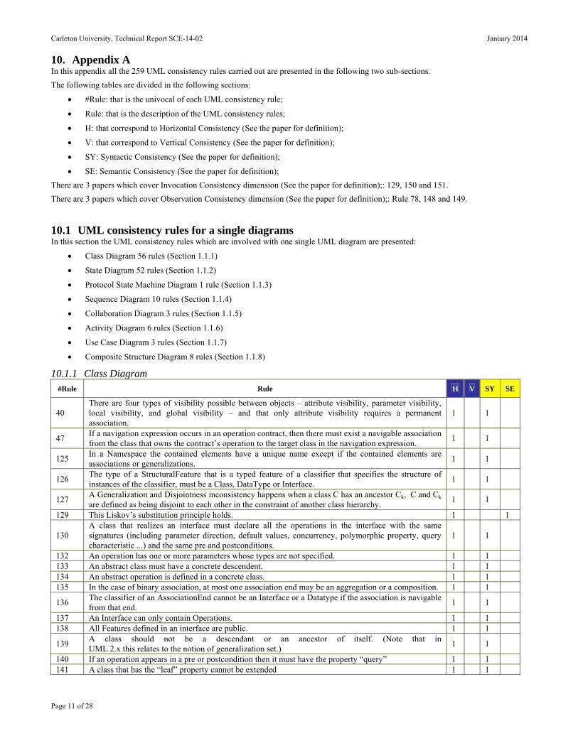
10. Appendix A In this appendix all the 259 UML consistency rules carried out are presented in the following two sub-sections.
The following tables are divided in the following sections:
#Rule: that is the univocal of each UML consistency rule;
Rule: that is the description of the UML consistency rules;
H: that correspond to Horizontal Consistency (See the paper for definition);
V: that correspond to Vertical Consistency (See the paper for definition);
SY: Syntactic Consistency (See the paper for definition);
SE: Semantic Consistency (See the paper for definition);
There are 3 papers which cover Invocation Consistency dimension (See the paper for definition);: 129, 150 and 151.
There are 3 papers which cover Observation Consistency dimension (See the paper for definition);: Rule 78, 148 and 149.
10.1 UML consistency rules for a single diagrams In this section the UML consistency rules which are involved with one single UML diagram are presented:
Class Diagram 56 rules (Section 1.1.1)
State Diagram 52 rules (Section 1.1.2)
Protocol State Machine Diagram 1 rule (Section 1.1.3)
Sequence Diagram 10 rules (Section 1.1.4)
Collaboration Diagram 3 rules (Section 1.1.5)
Activity Diagram 6 rules (Section 1.1.6)
Use Case Diagram 3 rules (Section 1.1.7)
Composite Structure Diagram 8 rules (Section 1.1.8)
10.1.1 Class Diagram
#Rule Rule H V SY SE
40 There are four types of visibility possible between objects – attribute visibility, parameter visibility, local visibility, and global visibility – and that only attribute visibility requires a permanent association.
1 1
47 If a navigation expression occurs in an operation contract, then there must exist a navigable association from the class that owns the contract’s operation to the target class in the navigation expression.
1 1
125 In a Namespace the contained elements have a unique name except if the contained elements are associations or generalizations.
1 1
126 The type of a StructuralFeature that is a typed feature of a classifier that specifies the structure of instances of the classifier, must be a Class, DataType or Interface.
1 1
127 A Generalization and Disjointness inconsistency happens when a class C has an ancestor Ck, C and Ck are defined as being disjoint to each other in the constraint of another class hierarchy.
1 1
129 This Liskov’s substitution principle holds. 1 1
130 A class that realizes an interface must declare all the operations in the interface with the same signatures (including parameter direction, default values, concurrency, polymorphic property, query characteristic ...) and the same pre and postconditions.
1 1
132 An operation has one or more parameters whose types are not specified. 1 1 133 An abstract class must have a concrete descendent. 1 1 134 An abstract operation is defined in a concrete class. 1 1 135 In the case of binary association, at most one association end may be an aggregation or a composition. 1 1
136 The classifier of an AssociationEnd cannot be an Interface or a Datatype if the association is navigable from that end.
1 1
137 An Interface can only contain Operations. 1 1 138 All Features defined in an interface are public. 1 1
139 A class should not be a descendant or an ancestor of itself. (Note that in UML 2.x this relates to the notion of generalization set.)
1 1
140 If an operation appears in a pre or postcondition then it must have the property “query” 1 1 141 A class that has the “leaf” property cannot be extended 1 1
Carleton University, Technical Report SCE-14-02 January 2014
Page 12 of 28
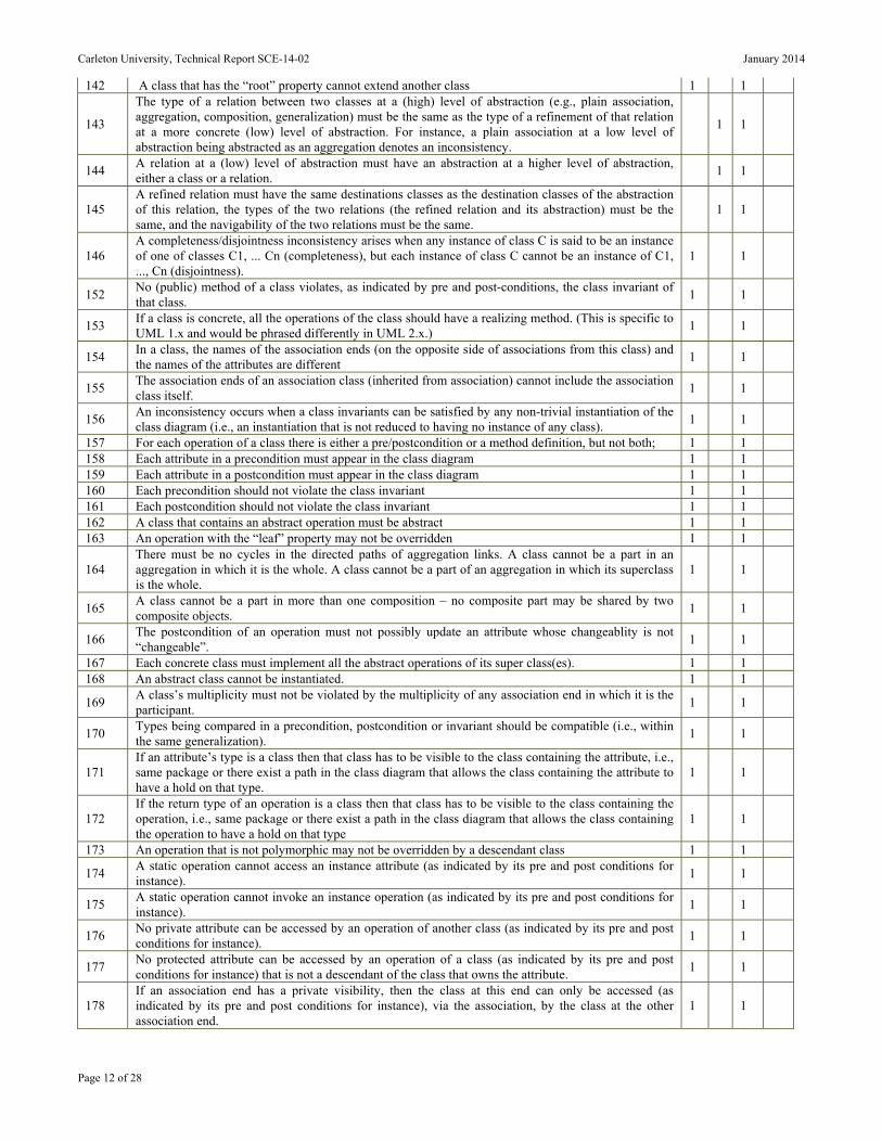
142 A class that has the “root” property cannot extend another class 1 1
143
The type of a relation between two classes at a (high) level of abstraction (e.g., plain association, aggregation, composition, generalization) must be the same as the type of a refinement of that relation at a more concrete (low) level of abstraction. For instance, a plain association at a low level of abstraction being abstracted as an aggregation denotes an inconsistency.
1 1
144 A relation at a (low) level of abstraction must have an abstraction at a higher level of abstraction, either a class or a relation.
1 1
145 A refined relation must have the same destinations classes as the destination classes of the abstraction of this relation, the types of the two relations (the refined relation and its abstraction) must be the same, and the navigability of the two relations must be the same.
1 1
146 A completeness/disjointness inconsistency arises when any instance of class C is said to be an instance of one of classes C1, ... Cn (completeness), but each instance of class C cannot be an instance of C1, ..., Cn (disjointness).
1 1
152 No (public) method of a class violates, as indicated by pre and post-conditions, the class invariant of that class.
1 1
153 If a class is concrete, all the operations of the class should have a realizing method. (This is specific to UML 1.x and would be phrased differently in UML 2.x.)
1 1
154 In a class, the names of the association ends (on the opposite side of associations from this class) and the names of the attributes are different
1 1
155 The association ends of an association class (inherited from association) cannot include the association class itself.
1 1
156 An inconsistency occurs when a class invariants can be satisfied by any non-trivial instantiation of the class diagram (i.e., an instantiation that is not reduced to having no instance of any class).
1 1
157 For each operation of a class there is either a pre/postcondition or a method definition, but not both; 1 1 158 Each attribute in a precondition must appear in the class diagram 1 1 159 Each attribute in a postcondition must appear in the class diagram 1 1 160 Each precondition should not violate the class invariant 1 1 161 Each postcondition should not violate the class invariant 1 1 162 A class that contains an abstract operation must be abstract 1 1 163 An operation with the “leaf” property may not be overridden 1 1
164 There must be no cycles in the directed paths of aggregation links. A class cannot be a part in an aggregation in which it is the whole. A class cannot be a part of an aggregation in which its superclass is the whole.
1 1
165 A class cannot be a part in more than one composition – no composite part may be shared by two composite objects.
1 1
166 The postcondition of an operation must not possibly update an attribute whose changeablity is not “changeable”.
1 1
167 Each concrete class must implement all the abstract operations of its super class(es). 1 1 168 An abstract class cannot be instantiated. 1 1
169 A class’s multiplicity must not be violated by the multiplicity of any association end in which it is the participant.
1 1
170 Types being compared in a precondition, postcondition or invariant should be compatible (i.e., within the same generalization).
1 1
171 If an attribute’s type is a class then that class has to be visible to the class containing the attribute, i.e., same package or there exist a path in the class diagram that allows the class containing the attribute to have a hold on that type.
1 1
172 If the return type of an operation is a class then that class has to be visible to the class containing the operation, i.e., same package or there exist a path in the class diagram that allows the class containing the operation to have a hold on that type
1 1
173 An operation that is not polymorphic may not be overridden by a descendant class 1 1
174 A static operation cannot access an instance attribute (as indicated by its pre and post conditions for instance).
1 1
175 A static operation cannot invoke an instance operation (as indicated by its pre and post conditions for instance).
1 1
176 No private attribute can be accessed by an operation of another class (as indicated by its pre and post conditions for instance).
1 1
177 No protected attribute can be accessed by an operation of a class (as indicated by its pre and post conditions for instance) that is not a descendant of the class that owns the attribute.
1 1
178 If an association end has a private visibility, then the class at this end can only be accessed (as indicated by its pre and post conditions for instance), via the association, by the class at the other association end.
1 1
Carleton University, Technical Report SCE-14-02 January 2014
Page 13 of 28
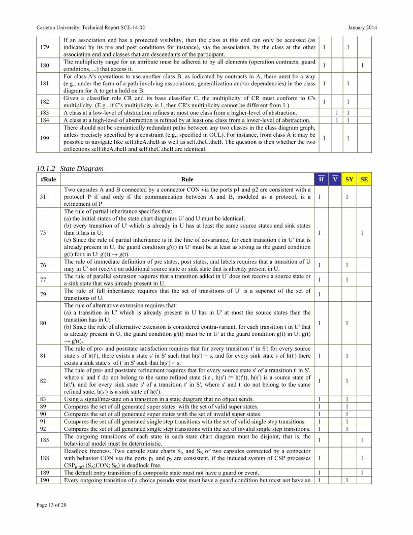
179 If an association end has a protected visibility, then the class at this end can only be accessed (as indicated by its pre and post conditions for instance), via the association, by the class at the other association end and classes that are descendants of the participant.
1 1
180 The multiplicity range for an attribute must be adhered to by all elements (operation contracts, guard conditions, ...) that access it.
1 1
181 For class A's operations to use another class B, as indicated by contracts in A, there must be a way (e.g., under the form of a path involving associations, generalization and/or dependencies) in the class diagram for A to get a hold on B.
1 1
182 Given a classifier role CR and its base classifier C, the multiplicity of CR must conform to C's multiplicity. (E.g., if C's multiplicity is 1, then CR's multiplicity cannot be different from 1.)
1 1
183 A class at a low-level of abstraction refines at most one class from a higher-level of abstraction. 1 1 184 A class at a high-level of abstraction is refined by at least one class from a lower-level of abstraction. 1 1
199
There should not be semantically redundant paths between any two classes in the class diagram graph, unless precisely specified by a constraint (e.g., specified in OCL). For instance, from class A it may be possible to navigate like self.theA.theB as well as self.theC.theB. The question is then whether the two collections self.theA.theB and self.theC.theB are identical.
1 1
10.1.2 State Diagram
#Rule Rule H V SY SE
31 Two capsules A and B connected by a connector CON via the ports p1 and p2 are consistent with a protocol P if and only if the communication between A and B, modeled as a protocol, is a refinement of P
1 1
75
The rule of partial inheritance specifies that: (a) the initial states of the state chart diagrams U' and U must be identical; (b) every transition of U' which is already in U has at least the same source states and sink states than it has in U; (c) Since the rule of partial inheritance is in the line of covariance, for each transition t in U' that is already present in U, the guard condition g'(t) in U' must be at least as strong as the guard condition g(t) for t in U: g'(t) → g(t).
1 1
76 The rule of immediate definition of pre states, post states, and labels requires that a transition of U may in U' not receive an additional source state or sink state that is already present in U.
1 1
77 The rule of parallel extension requires that a transition added in U' does not receive a source state or a sink state that was already present in U.
1 1
79 The rule of full inheritance requires that the set of transitions of U' is a superset of the set of transitions of U.
1
80
The rule of alternative extension requires that: (a) a transition in U' which is already present in U has in U' at most the source states than the transition has in U; (b) Since the rule of alternative extension is considered contra-variant, for each transition t in U' that is already present in U, the guard condition g'(t) must be in U' at the guard condition g(t) in U: g(t) → g'(t).
1 1
81 The rule of pre- and poststate satisfaction requires that for every transition t' in S': for every source state s of h(t'), there exists a state s' in S' such that h(s') = s, and for every sink state s of h(t') there exists a sink state s' of t' in S' such that h(s') = s.
1 1
82
The rule of pre- and poststate refinement requires that for every source state s' of a transition t' in S', where s' and t' do not belong to the same refined state (i.e., h(s') /= h(t')), h(s') is a source state of h(t'), and for every sink state s' of a transition t' in S', where s' and t' do not belong to the same refined state, h(s') is a sink state of h(t').
1 1
83 Using a signal/message on a transition in a state diagram that no object sends. 1 1 89 Compares the set of all generated super states with the set of valid super states. 1 1 90 Compares the set of all generated super states with the set of invalid super states. 1 1 91 Compares the set of all generated single step transitions with the set of valid single step transitions. 1 1 92 Compares the set of all generated single step transitions with the set of invalid single step transitions. 1 1
185 The outgoing transitions of each state in each state chart diagram must be disjoint, that is, the behavioral model must be deterministic.
1 1
188 Deadlock freeness. Two capsule state charts SA and SB of two capsules connected by a connector with behavior CON via the ports p1 and p2 are consistent, if the induced system of CSP processes CSPp1;p2 (SA;CON; SB) is deadlock free.
1 1
189 The default entry transition of a composite state must not have a guard or event. 1 1 190 Every outgoing transition of a choice pseudo state must have a guard condition but must not have an 1 1
Carleton University, Technical Report SCE-14-02 January 2014
Page 14 of 28
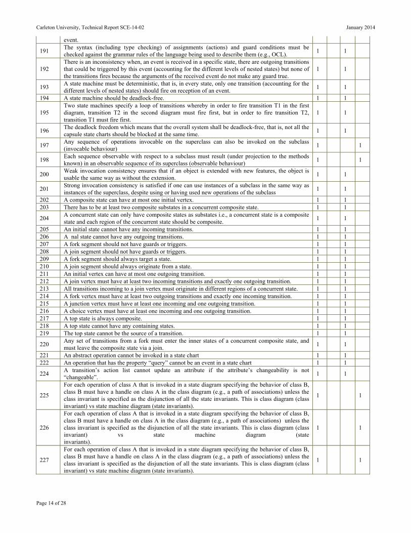
event.
191 The syntax (including type checking) of assignments (actions) and guard conditions must be checked against the grammar rules of the language being used to describe them (e.g., OCL).
1 1
192 There is an inconsistency when, an event is received in a specific state, there are outgoing transitions that could be triggered by this event (accounting for the different levels of nested states) but none of the transitions fires because the arguments of the received event do not make any guard true.
1 1
193 A state machine must be deterministic, that is, in every state, only one transition (accounting for the different levels of nested states) should fire on reception of an event.
1 1
194 A state machine should be deadlock-free. 1 1
195 Two state machines specify a loop of transitions whereby in order to fire transition T1 in the first diagram, transition T2 in the second diagram must fire first, but in order to fire transition T2, transition T1 must fire first.
1 1
196 The deadlock freedom which means that the overall system shall be deadlock-free, that is, not all the capsule state charts should be blocked at the same time.
1 1
197 Any sequence of operations invocable on the superclass can also be invoked on the subclass (invocable behaviour)
1 1
198 Each sequence observable with respect to a subclass must result (under projection to the methods known) in an observable sequence of its superclass (observable behaviour)
1 1
200 Weak invocation consistency ensures that if an object is extended with new features, the object is usable the same way as without the extension.
1 1
201 Strong invocation consistency is satisfied if one can use instances of a subclass in the same way as instances of the superclass, despite using or having used new operations of the subclass
1 1
202 A composite state can have at most one initial vertex. 1 1 203 There has to be at least two composite substates in a concurrent composite state. 1 1
204 A concurrent state can only have composite states as substates i.e., a concurrent state is a composite state and each region of the concurrent state should be composite.
1 1
205 An initial state cannot have any incoming transitions. 1 1 206 A nal state cannot have any outgoing transitions. 1 1 207 A fork segment should not have guards or triggers. 1 1 208 A join segment should not have guards or triggers. 1 1 209 A fork segment should always target a state. 1 1 210 A join segment should always originate from a state. 1 1 211 An initial vertex can have at most one outgoing transition. 1 1 212 A join vertex must have at least two incoming transitions and exactly one outgoing transition. 1 1 213 All transitions incoming to a join vertex must originate in different regions of a concurrent state. 1 1 214 A fork vertex must have at least two outgoing transitions and exactly one incoming transition. 1 1 215 A junction vertex must have at least one incoming and one outgoing transition. 1 1 216 A choice vertex must have at least one incoming and one outgoing transition. 1 1 217 A top state is always composite. 1 1 218 A top state cannot have any containing states. 1 1 219 The top state cannot be the source of a transition. 1 1
220 Any set of transitions from a fork must enter the inner states of a concurrent composite state, and must leave the composite state via a join.
1 1
221 An abstract operation cannot be invoked in a state chart 1 1 222 An operation that has the property “query” cannot be an event in a state chart 1 1
224 A transition’s action list cannot update an attribute if the attribute’s changeability is not “changeable”.
1 1
225
For each operation of class A that is invoked in a state diagram specifying the behavior of class B, class B must have a handle on class A in the class diagram (e.g., a path of associations) unless the class invariant is specified as the disjunction of all the state invariants. This is class diagram (class invariant) vs state machine diagram (state invariants).
1 1
226
For each operation of class A that is invoked in a state diagram specifying the behavior of class B, class B must have a handle on class A in the class diagram (e.g., a path of associations) unless the class invariant is specified as the disjunction of all the state invariants. This is class diagram (class invariant) vs state machine diagram (state invariants).
1 1
227
For each operation of class A that is invoked in a state diagram specifying the behavior of class B, class B must have a handle on class A in the class diagram (e.g., a path of associations) unless the class invariant is specified as the disjunction of all the state invariants. This is class diagram (class invariant) vs state machine diagram (state invariants).
1 1
Carleton University, Technical Report SCE-14-02 January 2014
Page 15 of 28
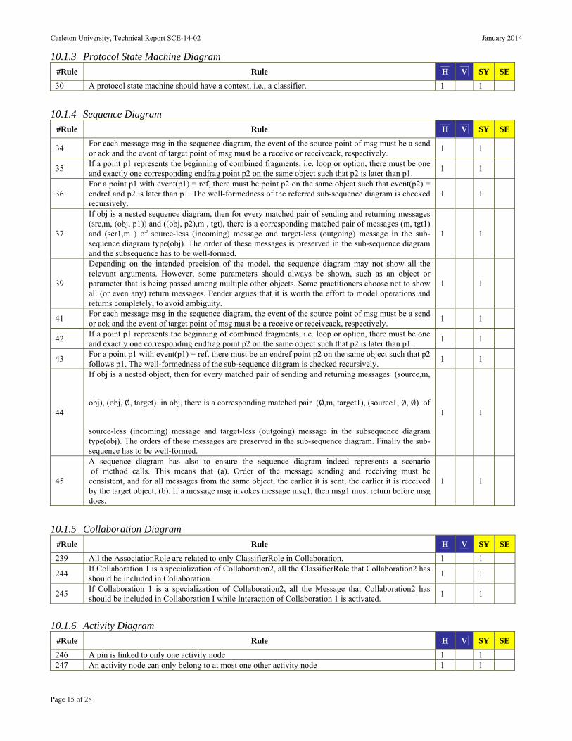
10.1.3 Protocol State Machine Diagram
#Rule Rule H V SY SE
30 A protocol state machine should have a context, i.e., a classifier. 1 1
10.1.4 Sequence Diagram
#Rule Rule H V SY SE
34 For each message msg in the sequence diagram, the event of the source point of msg must be a send or ack and the event of target point of msg must be a receive or receiveack, respectively.
1 1
35 If a point p1 represents the beginning of combined fragments, i.e. loop or option, there must be one and exactly one corresponding endfrag point p2 on the same object such that p2 is later than p1.
1 1
36 For a point p1 with event(p1) = ref, there must be point p2 on the same object such that event(p2) = endref and p2 is later than p1. The well-formedness of the referred sub-sequence diagram is checked recursively.
1 1
37
If obj is a nested sequence diagram, then for every matched pair of sending and returning messages (src,m, (obj, p1)) and ((obj, p2),m , tgt), there is a corresponding matched pair of messages (m, tgt1) and (scr1,m ) of source-less (incoming) message and target-less (outgoing) message in the sub-sequence diagram type(obj). The order of these messages is preserved in the sub-sequence diagram and the subsequence has to be well-formed.
1 1
39
Depending on the intended precision of the model, the sequence diagram may not show all the relevant arguments. However, some parameters should always be shown, such as an object or parameter that is being passed among multiple other objects. Some practitioners choose not to show all (or even any) return messages. Pender argues that it is worth the effort to model operations and returns completely, to avoid ambiguity.
1 1
41 For each message msg in the sequence diagram, the event of the source point of msg must be a send or ack and the event of target point of msg must be a receive or receiveack, respectively.
1 1
42 If a point p1 represents the beginning of combined fragments, i.e. loop or option, there must be one and exactly one corresponding endfrag point p2 on the same object such that p2 is later than p1.
1 1
43 For a point p1 with event(p1) = ref, there must be an endref point p2 on the same object such that p2 follows p1. The well-formedness of the sub-sequence diagram is checked recursively.
1 1
44
If obj is a nested object, then for every matched pair of sending and returning messages (source,m,
obj), (obj, , target) in obj, there is a corresponding matched pair ( ,m, target1), (source1, , ) of
source-less (incoming) message and target-less (outgoing) message in the subsequence diagram type(obj). The orders of these messages are preserved in the sub-sequence diagram. Finally the sub-sequence has to be well-formed.
1 1
45
A sequence diagram has also to ensure the sequence diagram indeed represents a scenario of method calls. This means that (a). Order of the message sending and receiving must be consistent, and for all messages from the same object, the earlier it is sent, the earlier it is received by the target object; (b). If a message msg invokes message msg1, then msg1 must return before msg does.
1 1
10.1.5 Collaboration Diagram
#Rule Rule H V SY SE
239 All the AssociationRole are related to only ClassifierRole in Collaboration. 1 1
244 If Collaboration 1 is a specialization of Collaboration2, all the ClassifierRole that Collaboration2 has should be included in Collaboration.
1 1
245 If Collaboration 1 is a specialization of Collaboration2, all the Message that Collaboration2 has should be included in Collaboration I while Interaction of Collaboration 1 is activated.
1 1
10.1.6 Activity Diagram
#Rule Rule H V SY SE
246 A pin is linked to only one activity node 1 1 247 An activity node can only belong to at most one other activity node 1 1

Carleton University, Technical Report SCE-14-02 January 2014
Page 16 of 28
248 A guard condition guards only one activity edge 1 1 249 An object is passed by one object flow 1 1 250 An activity node is executed by only one class 1 1 251 A precondition or postcondition can be only used to one activity node 1 1
10.1.7 Use Case Diagram
#Rule Rule H V SY SE
121 A use case description should contain at least one flow of steps. 1 1 123 A flow of steps in a use case description has to be of type either basic or alternate. 1 1
124 Each use case description corresponds to a use case in the use case diagram and each use case is specified by a use case description.
1 1
10.1.8 Composite Structure Diagram
#Rule Rule H V SY SE
252 If a delegation link exists between two ports, the direction (provided or required) of the ports must be the same.
1 1
253 If an assembly link exists between two ports, one of the ports (the source) must be a <<reversed>> port (required) and the other (the destination) must be a provided port.
1 1
254 If a link is typed with an association, the direction of the association must conform to the direction of the link (derived from the direction of the ports at the ends).
1 1
255 If a link outgoing from a port is statically typed with an association, then the association is necessarily directed (cf. rule 3) and the type pointed at by the association must belong to the set of transported interfaces for that link.
1 1
256 If a link originates in a component, then the link must be statically typed with an association, and the type of the entity at the other end of the link must be compatible with (i.e. be equal or a subtype of ) the type at the corresponding end of the association.
1 1
257 The set of transported interfaces of a link should not be void. 1 1
258 If several non-typed connectors start from one port, then the sets of interfaces transported by each of these connectors have to be pair wise disjoint.
1 1
259 The union of the sets of interfaces transported by each of the connectors originating from a port P must be equal to the set of interfaces provided/required by P.
1 1
10.2 UML consistency rules between two or more UML diagrams In this section the UML consistency rules which are involved between two or more UML diagram are presented:
Class Diagram and State Diagrams 25 rules (Section 1.2.1);
Class Diagram and Protocol State Machine Diagram 1 rule (Section 1.2.2);
Class Diagram and Sequence Diagram 26 rules (Section 1.2.3);
Class Diagram and Collaboration Diagram 11 rules (Section 1.2.4);
Class Diagram and Activity Diagram 4 rules (Section 1.2.5);
Class Diagram and Use Case Diagram 5 rules (Section 1.2.6);
Class Diagram and Object Diagram 2 rules (Section 1.2.7);
Class Diagram and Communication Diagram 2 rules (Section 1.2.8);
Class Diagram and Interaction Diagram 2 rules (Section 1.2.9);
State Diagram and Sequence Diagram 9 rules (Section 1.2.10);
State Diagram and Collaboration diagram 2 rules (Section 1.2.11);
State Diagram and Activity Diagram 2 rules (Section 1.2.12);
State Diagram and Object Diagram 1 rule (Section 1.2.13);
Sequence Diagram and Collaboration Diagram 2 rules (Section 1.2.14);
Sequence Diagram and Activity Diagram 9 rules (Section 1.2.15);
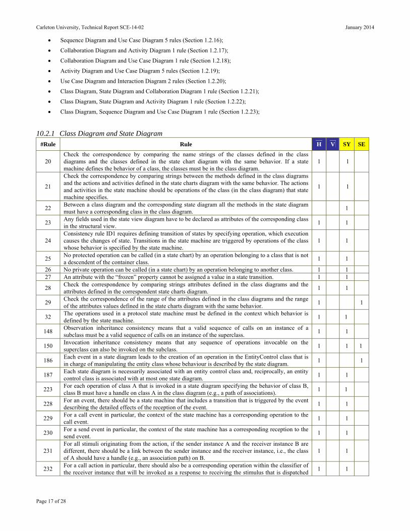
Carleton University, Technical Report SCE-14-02 January 2014
Page 17 of 28
Sequence Diagram and Use Case Diagram 5 rules (Section 1.2.16);
Collaboration Diagram and Activity Diagram 1 rule (Section 1.2.17);
Collaboration Diagram and Use Case Diagram 1 rule (Section 1.2.18);
Activity Diagram and Use Case Diagram 5 rules (Section 1.2.19);
Use Case Diagram and Interaction Diagram 2 rules (Section 1.2.20);
Class Diagram, State Diagram and Collaboration Diagram 1 rule (Section 1.2.21);
Class Diagram, State Diagram and Activity Diagram 1 rule (Section 1.2.22);
Class Diagram, Sequence Diagram and Use Case Diagram 1 rule (Section 1.2.23);
10.2.1 Class Diagram and State Diagram
#Rule Rule H V SY SE
20 Check the correspondence by comparing the name strings of the classes defined in the class diagrams and the classes defined in the state chart diagram with the same behavior. If a state machine defines the behavior of a class, the classes must be in the class diagram.
1 1
21
Check the correspondence by comparing strings between the methods defined in the class diagrams and the actions and activities defined in the state charts diagram with the same behavior. The actions and activities in the state machine should be operations of the class (in the class diagram) that state machine specifies.
1 1
22 Between a class diagram and the corresponding state diagram all the methods in the state diagram must have a corresponding class in the class diagram.
1
23 Any fields used in the state view diagram have to be declared as attributes of the corresponding class in the structural view.
1 1
24 Consistency rule ID1 requires defining transition of states by specifying operation, which execution causes the changes of state. Transitions in the state machine are triggered by operations of the class whose behavior is specified by the state machine.
1 1
25 No protected operation can be called (in a state chart) by an operation belonging to a class that is not a descendent of the container class.
1 1
26 No private operation can be called (in a state chart) by an operation belonging to another class. 1 1 27 An attribute with the “frozen” property cannot be assigned a value in a state transition. 1 1
28 Check the correspondence by comparing strings attributes defined in the class diagrams and the attributes defined in the correspondent state charts diagram.
1 1
29 Check the correspondence of the range of the attributes defined in the class diagrams and the range of the attributes values defined in the state charts diagram with the same behavior.
1 1
32 The operations used in a protocol state machine must be defined in the context which behavior is defined by the state machine.
1 1
148 Observation inheritance consistency means that a valid sequence of calls on an instance of a subclass must be a valid sequence of calls on an instance of the superclass.
1 1
150 Invocation inheritance consistency means that any sequence of operations invocable on the superclass can also be invoked on the subclass.
1 1 1
186 Each event in a state diagram leads to the creation of an operation in the EntityControl class that is in charge of manipulating the entity class whose behaviour is described by the state diagram.
1 1
187 Each state diagram is necessarily associated with an entity control class and, reciprocally, an entity control class is associated with at most one state diagram.
1 1
223 For each operation of class A that is invoked in a state diagram specifying the behavior of class B, class B must have a handle on class A in the class diagram (e.g., a path of associations).
1 1
228 For an event, there should be a state machine that includes a transition that is triggered by the event describing the detailed effects of the reception of the event.
1 1
229 For a call event in particular, the context of the state machine has a corresponding operation to the call event.
1 1
230 For a send event in particular, the context of the state machine has a corresponding reception to the send event.
1 1
231 For all stimuli originating from the action, if the sender instance A and the receiver instance B are different, there should be a link between the sender instance and the receiver instance, i.e., the class of A should have a handle (e.g., an association path) on B.
1 1
232 For a call action in particular, there should also be a corresponding operation within the classifier of the receiver instance that will be invoked as a response to receiving the stimulus that is dispatched
1 1
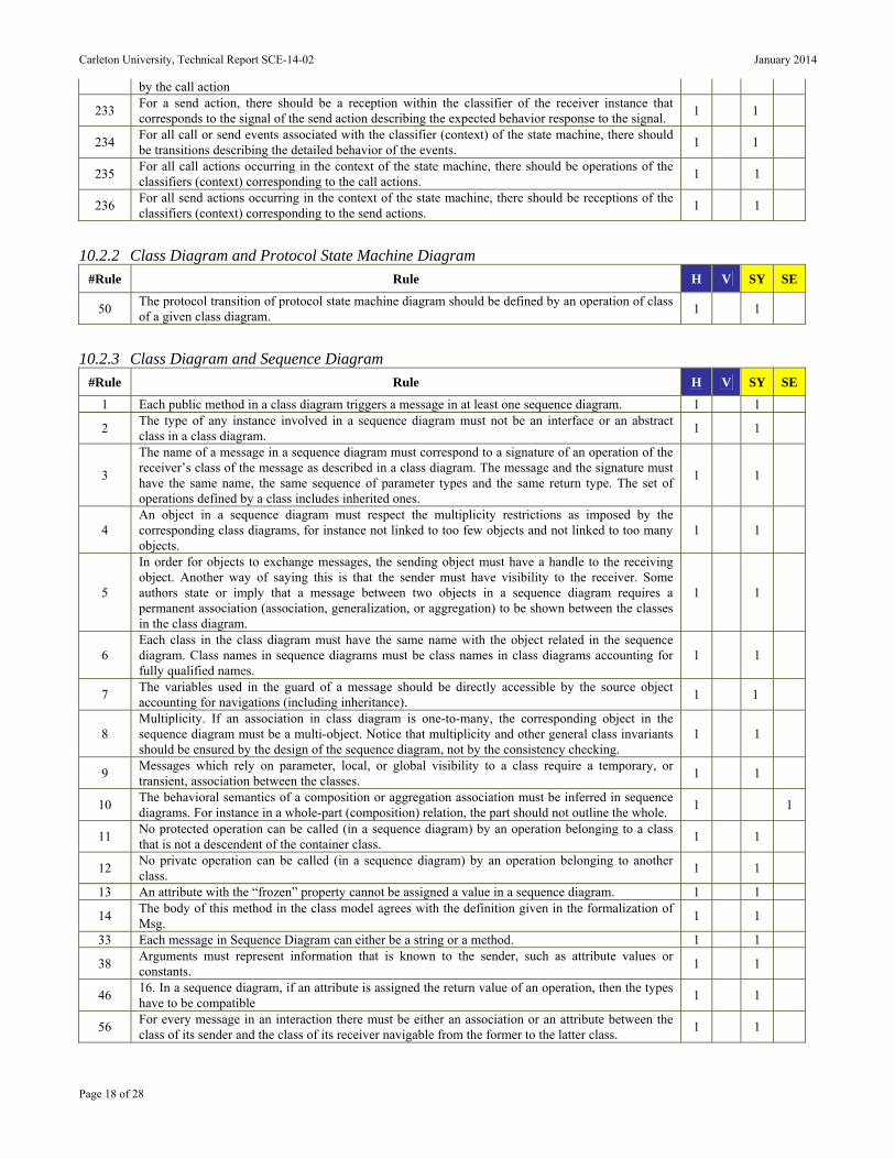
Carleton University, Technical Report SCE-14-02 January 2014
Page 18 of 28
by the call action
233 For a send action, there should be a reception within the classifier of the receiver instance that corresponds to the signal of the send action describing the expected behavior response to the signal.
1 1
234 For all call or send events associated with the classifier (context) of the state machine, there should be transitions describing the detailed behavior of the events.
1 1
235 For all call actions occurring in the context of the state machine, there should be operations of the classifiers (context) corresponding to the call actions.
1 1
236 For all send actions occurring in the context of the state machine, there should be receptions of the classifiers (context) corresponding to the send actions.
1 1
10.2.2 Class Diagram and Protocol State Machine Diagram
#Rule Rule H V SY SE
50 The protocol transition of protocol state machine diagram should be defined by an operation of class of a given class diagram.
1 1
10.2.3 Class Diagram and Sequence Diagram
#Rule Rule H V SY SE
1 Each public method in a class diagram triggers a message in at least one sequence diagram. 1 1
2 The type of any instance involved in a sequence diagram must not be an interface or an abstract class in a class diagram.
1 1
3
The name of a message in a sequence diagram must correspond to a signature of an operation of the receiver’s class of the message as described in a class diagram. The message and the signature must have the same name, the same sequence of parameter types and the same return type. The set of operations defined by a class includes inherited ones.
1 1
4 An object in a sequence diagram must respect the multiplicity restrictions as imposed by the corresponding class diagrams, for instance not linked to too few objects and not linked to too many objects.
1 1
5
In order for objects to exchange messages, the sending object must have a handle to the receiving object. Another way of saying this is that the sender must have visibility to the receiver. Some authors state or imply that a message between two objects in a sequence diagram requires a permanent association (association, generalization, or aggregation) to be shown between the classes in the class diagram.
1 1
6 Each class in the class diagram must have the same name with the object related in the sequence diagram. Class names in sequence diagrams must be class names in class diagrams accounting for fully qualified names.
1 1
7 The variables used in the guard of a message should be directly accessible by the source object accounting for navigations (including inheritance).
1 1
8 Multiplicity. If an association in class diagram is one-to-many, the corresponding object in the sequence diagram must be a multi-object. Notice that multiplicity and other general class invariants should be ensured by the design of the sequence diagram, not by the consistency checking.
1 1
9 Messages which rely on parameter, local, or global visibility to a class require a temporary, or transient, association between the classes.
1 1
10 The behavioral semantics of a composition or aggregation association must be inferred in sequence diagrams. For instance in a whole-part (composition) relation, the part should not outline the whole.
1 1
11 No protected operation can be called (in a sequence diagram) by an operation belonging to a class that is not a descendent of the container class.
1 1
12 No private operation can be called (in a sequence diagram) by an operation belonging to another class.
1 1
13 An attribute with the “frozen” property cannot be assigned a value in a sequence diagram. 1 1
14 The body of this method in the class model agrees with the definition given in the formalization of Msg.
1 1
33 Each message in Sequence Diagram can either be a string or a method. 1 1
38 Arguments must represent information that is known to the sender, such as attribute values or constants.
1 1
46 16. In a sequence diagram, if an attribute is assigned the return value of an operation, then the types have to be compatible
1 1
56 For every message in an interaction there must be either an association or an attribute between the class of its sender and the class of its receiver navigable from the former to the latter class.
1 1

Carleton University, Technical Report SCE-14-02 January 2014
Page 19 of 28
57 For any message received by an object in the interaction diagram, an operation with the same signature as the message must have been defined for one of the classes of the object in the class diagram.
1 1
58 The lower multiplicity bound of an association end that is attached to a class whose instances receive at least one message from instances of the class attached to the other end of its association must be greater or equal to 1.
1 1
59 A class operation has appeared in the interaction diagrams but was not declared in the class diagrams or there is a mismatch between an operation call in interaction diagrams regarding its declaration in class diagrams.
1 1
60 Classes and operations are used in the set of interaction diagrams 1 1 61 Objects in an interaction diagram are instances of classes in the class diagram. 1 1
62 Types in an interaction diagram appear in a class diagram. Message signatures refer to operations or (signal) classes in a class diagrams.
1 1
149 Observation inheritance consistency means that a valid sequence of calls on an instance of a subclass must be a valid sequence of calls on an instance of the superclass.
1 1
151 Invocation inheritance consistency means that any sequence of operations invocable on the superclass can also be invoked on the subclass.
1 1
10.2.4 Class Diagram and Collaboration Diagram
#Rule Rule H V SY SE
51 Check the correspondence by comparing the name strings of the classes defined in the class diagrams and the objects defined in the collaboration diagrams. Objects in the collaboration diagram must be defined as class in class diagram.
1 1
52 Check the correspondence by comparing the strings of the messages between objects in the collaboration diagrams and associations between corresponding classes in the class diagrams. Notion of "hold".
1 1
53 Check the correspondence by comparing strings between the methods defined in the class diagrams and the messages defined in the collaboration diagrams.
1 1
54 All the classes appear with at least one instance in at least one collaboration diagram of the model 1 1
55
A class-role having either a create, destroy or transient property must have an aggregation relationship with its creator or destructor class-role. Optional: because since creation doesn't only happen from aggregation. We also have composition, association dependencies.
1 1
119
In order for objects to exchange messages, the sending object must have a handle to the receiving object . Another way of saying this is that the sender must have visibility to the receiver. Some authors state or imply that a message between two objects in a collaboration diagram requires a permanent association (association, generalization, or aggregation) to be shown between the classes in the class diagram.
1 1
238 Collaboration is either Classifier or Operation. 1 1
240 All the ClassifierRole and AssociationRole in Collaboration are related to Classifiers and Associations in Namespace respectively.
1 1
241 Constraint can be related to only elements in ModelElement. 1 1
242 For every ClassifierRole in Collaboration, there exists Classifier in the same Foundation. So are true for Association-Role and Association.
1 1
243 If two roles (AssociationRole or ClassifierRo1e )have same name, they must describe the specialization of the parent role.
1 1
10.2.5 Class Diagram and Activity Diagram
#Rule Rule H V SY SE
63 A class name that appears in an activity diagram also appears in the class diagram. 1 1
64 An action that appears in an activity diagram must also appear in the class diagram as operation of a class.
1 1
65 Notion of "hold" like between CD and SD. Check the correspondence by comparing the strings of control flows between classes in the activity diagrams and associations in the class diagrams.
1 1
66 Swimlanes (Activity pattern in UML 2.0) in Activity diagram (represented as className in activity state) must be present as a unique class in class diagram.
1 1
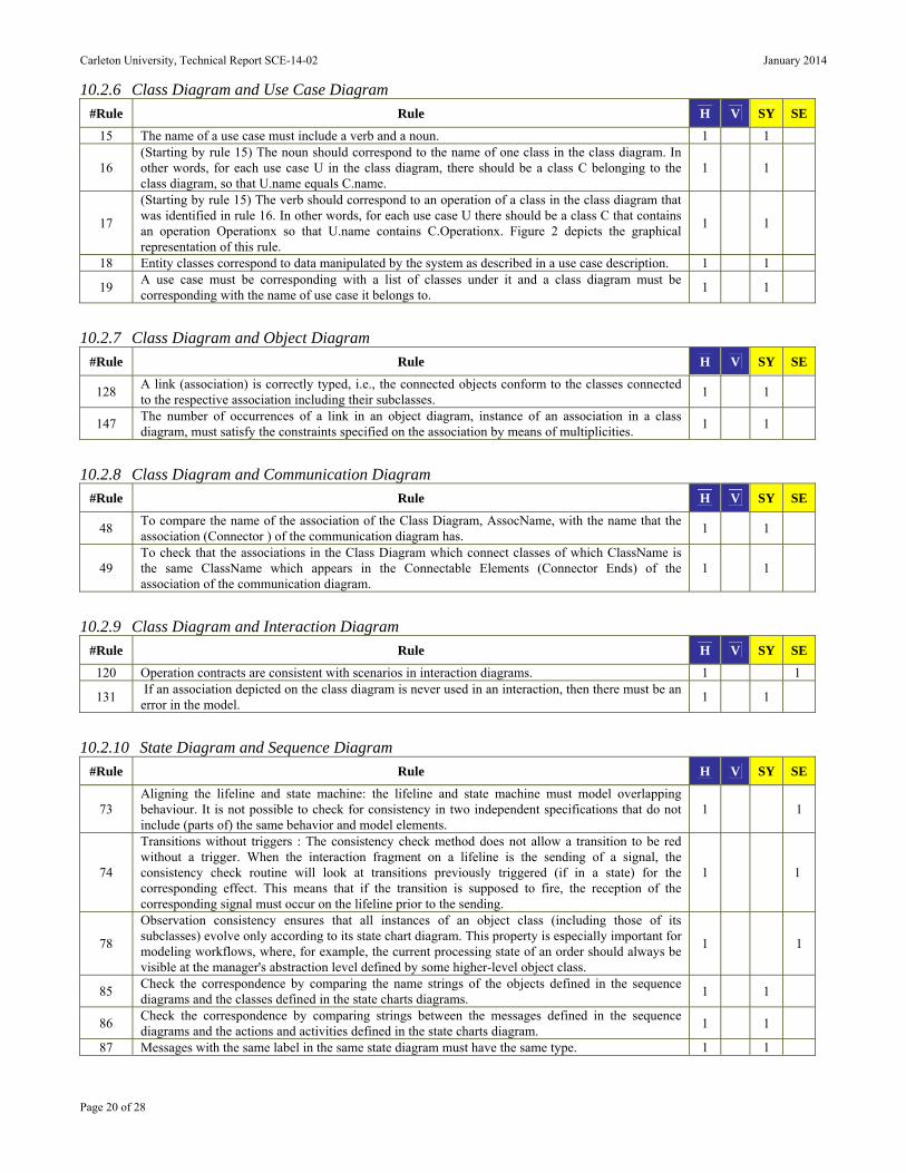
Carleton University, Technical Report SCE-14-02 January 2014
Page 20 of 28
10.2.6 Class Diagram and Use Case Diagram
#Rule Rule H V SY SE
15 The name of a use case must include a verb and a noun. 1 1
16 (Starting by rule 15) The noun should correspond to the name of one class in the class diagram. In other words, for each use case U in the class diagram, there should be a class C belonging to the class diagram, so that U.name equals C.name.
1 1
17
(Starting by rule 15) The verb should correspond to an operation of a class in the class diagram that was identified in rule 16. In other words, for each use case U there should be a class C that contains an operation Operationx so that U.name contains C.Operationx. Figure 2 depicts the graphical representation of this rule.
1 1
18 Entity classes correspond to data manipulated by the system as described in a use case description. 1 1
19 A use case must be corresponding with a list of classes under it and a class diagram must be corresponding with the name of use case it belongs to.
1 1
10.2.7 Class Diagram and Object Diagram
#Rule Rule H V SY SE
128 A link (association) is correctly typed, i.e., the connected objects conform to the classes connected to the respective association including their subclasses.
1 1
147 The number of occurrences of a link in an object diagram, instance of an association in a class diagram, must satisfy the constraints specified on the association by means of multiplicities.
1 1
10.2.8 Class Diagram and Communication Diagram
#Rule Rule H V SY SE
48 To compare the name of the association of the Class Diagram, AssocName, with the name that the association (Connector ) of the communication diagram has.
1 1
49 To check that the associations in the Class Diagram which connect classes of which ClassName is the same ClassName which appears in the Connectable Elements (Connector Ends) of the association of the communication diagram.
1 1
10.2.9 Class Diagram and Interaction Diagram
#Rule Rule H V SY SE
120 Operation contracts are consistent with scenarios in interaction diagrams. 1 1
131 If an association depicted on the class diagram is never used in an interaction, then there must be an error in the model.
1 1
10.2.10 State Diagram and Sequence Diagram
#Rule Rule H V SY SE
73 Aligning the lifeline and state machine: the lifeline and state machine must model overlapping behaviour. It is not possible to check for consistency in two independent specifications that do not include (parts of) the same behavior and model elements.
1 1
74
Transitions without triggers : The consistency check method does not allow a transition to be red without a trigger. When the interaction fragment on a lifeline is the sending of a signal, the consistency check routine will look at transitions previously triggered (if in a state) for the corresponding effect. This means that if the transition is supposed to fire, the reception of the corresponding signal must occur on the lifeline prior to the sending.
1 1
78
Observation consistency ensures that all instances of an object class (including those of its subclasses) evolve only according to its state chart diagram. This property is especially important for modeling workflows, where, for example, the current processing state of an order should always be visible at the manager's abstraction level defined by some higher-level object class.
1 1
85 Check the correspondence by comparing the name strings of the objects defined in the sequence diagrams and the classes defined in the state charts diagrams.
1 1
86 Check the correspondence by comparing strings between the messages defined in the sequence diagrams and the actions and activities defined in the state charts diagram.
1 1
87 Messages with the same label in the same state diagram must have the same type. 1 1

Carleton University, Technical Report SCE-14-02 January 2014
Page 21 of 28
88 If the message is of type T then the sender and the receiver components coincide. 1 1
93 Compares the set of all generated sequences with the set of sequences which are extracted from the provided UML sequence diagrams.
1 1
237 Components (lifelines) involved in a sequence diagram correctly cooperate as specified in state machines.
1 1
10.2.11 State Diagram and Collaboration Diagram
#Rule Rule H V SY SE
68 Check the correspondence by comparing the name strings of the objects defined in the collaboration diagrams with the classes defined in the state charts diagrams.
1 1
69 Check the correspondence by comparing strings between the messages defined in the collaboration diagrams and the actions and activities defined in the state charts diagram. It is optional because the diagrams may specify different unrelated behaviors.
1 1
10.2.12 State Diagram and Activity Diagram
#Rule Rule H V SY SE
71 Check the correspondence by comparing the name strings of the classes defined in the activity diagrams with the classes defined in the state charts diagrams.
1 1
72 Check the correspondence by comparing strings between the actions and activities defined in the state charts diagrams with the actions defined in the activity diagrams.
1 1
10.2.13 State Diagram and Object Diagram
#Rule Rule H V SY SE
84 The object diagram must have an object corresponds to a state machine. Optional since not every class is specified with a state machine.
1 1
10.2.14 Sequence Diagram and Collaboration Diagram
#Rule Rule H V SY SE
94 Check the correspondence by comparing the name strings of the objects defined in the collaboration diagrams and the objects defined in the collaboration diagrams.
1 1
95 Check the correspondence by comparing the name strings of the messages defined in the collaboration diagrams and the messages defined in the sequence diagrams for directions, sequence, source and destination.
1 1
10.2.15 Sequence Diagram and Activity Diagram
#Rule Rule H V SY SE
96 Each scenario of an operation that appears in a sequence diagram should be shown by an activity diagram of that operation if it exists.
1 1
97 The flows of interaction between objects in an activity diagram should be a flow of interactions in a sequence diagram.
1 1
98 A set of consecutive sequential messages without any branching or iteration that pass between objects in the same execution thread is mapped to one block in the corresponding activity diagram.
1 1
99 Messages with condition guards that are alternatives of the same condition in the sequence diagram are mapped to a branching structure in the activity diagram.
1 1
100 An iteration of one or more messages in the same thread of control is mapped to one activity block with the loop condition indicated on the incoming arrow.
1 1
101 A synchronous message between objects running in different threads of control is treated as a join operation on the receiving side in the corresponding activity diagram, and its reply marks the corresponding fork.
1 1
102 An asynchronous creation of an active object marks a fork operation in the corresponding activity diagram.
1 1
103 An asynchronous message sent to another thread of control indicates a join operation on the receiver side and a fork operation on the sender side in the corresponding activity diagram.
1 1
104 A composite subsequence block is translated into a composite activity in the corresponding activity 1 1
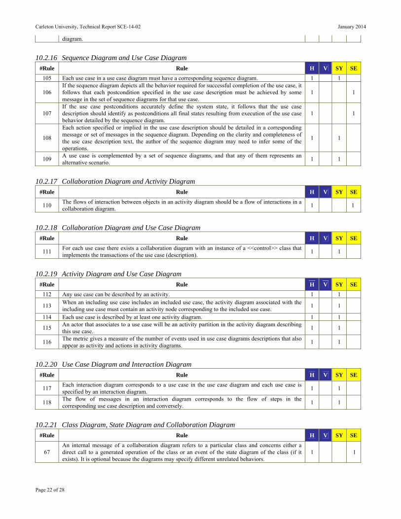
Carleton University, Technical Report SCE-14-02 January 2014
Page 22 of 28
diagram.
10.2.16 Sequence Diagram and Use Case Diagram
#Rule Rule H V SY SE
105 Each use case in a use case diagram must have a corresponding sequence diagram. 1 1
106 If the sequence diagram depicts all the behavior required for successful completion of the use case, it follows that each postcondition specified in the use case description must be achieved by some message in the set of sequence diagrams for that use case.
1 1
107 If the use case postconditions accurately define the system state, it follows that the use case description should identify as postconditions all final states resulting from execution of the use case behavior detailed by the sequence diagram.
1 1
108
Each action specified or implied in the use case description should be detailed in a corresponding message or set of messages in the sequence diagram. Depending on the clarity and completeness of the use case description text, the author of the sequence diagram may need to infer some of the operations.
1 1
109 A use case is complemented by a set of sequence diagrams, and that any of them represents an alternative scenario.
1 1
10.2.17 Collaboration Diagram and Activity Diagram
#Rule Rule H V SY SE
110 The flows of interaction between objects in an activity diagram should be a flow of interactions in a collaboration diagram.
1 1
10.2.18 Collaboration Diagram and Use Case Diagram
#Rule Rule H V SY SE
111 For each use case there exists a collaboration diagram with an instance of a <<control>> class that implements the transactions of the use case (description).
1 1
10.2.19 Activity Diagram and Use Case Diagram
#Rule Rule H V SY SE
112 Any use case can be described by an activity. 1 1
113 When an including use case includes an included use case, the activity diagram associated with the including use case must contain an activity node corresponding to the included use case.
1 1
114 Each use case is described by at least one activity diagram. 1 1
115 An actor that associates to a use case will be an activity partition in the activity diagram describing this use case.
1 1
116 The metric gives a measure of the number of events used in use case diagrams descriptions that also appear as activity and actions in activity diagrams.
1 1
10.2.20 Use Case Diagram and Interaction Diagram
#Rule Rule H V SY SE
117 Each interaction diagram corresponds to a use case in the use case diagram and each use case is specified by an interaction diagram.
1 1
118 The flow of messages in an interaction diagram corresponds to the flow of steps in the corresponding use case description and conversely.
1 1
10.2.21 Class Diagram, State Diagram and Collaboration Diagram
#Rule Rule H V SY SE
67 An internal message of a collaboration diagram refers to a particular class and concerns either a direct call to a generated operation of the class or an event of the state diagram of the class (if it exists). It is optional because the diagrams may specify different unrelated behaviors.
1 1

Carleton University, Technical Report SCE-14-02 January 2014
Page 23 of 28
10.2.22 Class Diagram, State Diagram and Activity Diagram
#Rule Rule H V SY SE
70 A precondition on an operation is in contradiction with a state machine or an activity graph including a call of such operation.
1 1
10.2.23 Class Diagram, Sequence Diagram and Use Case Diagram
#Rule Rule H V SY SE
122 An flow of steps in a use case descriptions has to be handled by at least one message in a sequence diagram, corresponding to at least one operation in a class diagram.
1 1
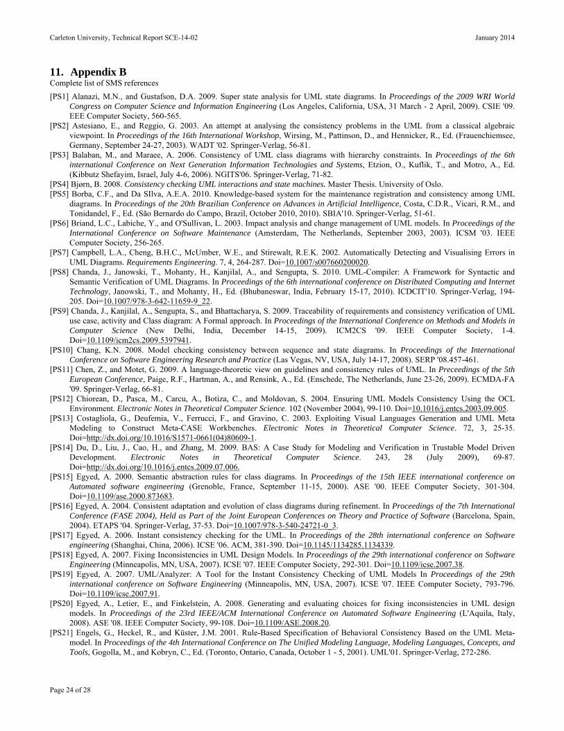
Carleton University, Technical Report SCE-14-02 January 2014
Page 24 of 28
11. Appendix B Complete list of SMS references
[PS1] Alanazi, M.N., and Gustafson, D.A. 2009. Super state analysis for UML state diagrams. In Proceedings of the 2009 WRI World Congress on Computer Science and Information Engineering (Los Angeles, California, USA, 31 March - 2 April, 2009). CSIE '09. EEE Computer Society, 560-565.
[PS2] Astesiano, E., and Reggio, G. 2003. An attempt at analysing the consistency problems in the UML from a classical algebraic viewpoint. In Proceedings of the 16th International Workshop, Wirsing, M., Pattinson, D., and Hennicker, R., Ed. (Frauenchiemsee, Germany, September 24-27, 2003). WADT '02. Springer-Verlag, 56-81.
[PS3] Balaban, M., and Maraee, A. 2006. Consistency of UML class diagrams with hierarchy constraints. In Proceedings of the 6th international Conference on Next Generation Information Technologies and Systems, Etzion, O., Kuflik, T., and Motro, A., Ed. (Kibbutz Shefayim, Israel, July 4-6, 2006). NGITS'06. Springer-Verlag, 71-82.
[PS4] Bjørn, B. 2008. Consistency checking UML interactions and state machines. Master Thesis. University of Oslo. [PS5] Borba, C.F., and Da SIlva, A.E.A. 2010. Knowledge-based system for the maintenance registration and consistency among UML
diagrams. In Proceedings of the 20th Brazilian Conference on Advances in Artificial Intelligence, Costa, C.D.R., Vicari, R.M., and Tonidandel, F., Ed. (São Bernardo do Campo, Brazil, October 2010, 2010). SBIA'10. Springer-Verlag, 51-61.
[PS6] Briand, L.C., Labiche, Y., and O'Sullivan, L. 2003. Impact analysis and change management of UML models. In Proceedings of the International Conference on Software Maintenance (Amsterdam, The Netherlands, September 2003, 2003). ICSM '03. IEEE Computer Society, 256-265.
[PS7] Campbell, L.A., Cheng, B.H.C., McUmber, W.E., and Stirewalt, R.E.K. 2002. Automatically Detecting and Visualising Errors in UML Diagrams. Requirements Engineering. 7, 4, 264-287. Doi=10.1007/s007660200020.
[PS8] Chanda, J., Janowski, T., Mohanty, H., Kanjilal, A., and Sengupta, S. 2010. UML-Compiler: A Framework for Syntactic and Semantic Verification of UML Diagrams. In Proceedings of the 6th international conference on Distributed Computing and Internet Technology, Janowski, T., and Mohanty, H., Ed. (Bhubaneswar, India, February 15-17, 2010). ICDCIT'10. Springer-Verlag, 194-205. Doi=10.1007/978-3-642-11659-9_22.
[PS9] Chanda, J., Kanjilal, A., Sengupta, S., and Bhattacharya, S. 2009. Traceability of requirements and consistency verification of UML use case, activity and Class diagram: A Formal approach. In Proceedings of the International Conference on Methods and Models in Computer Science (New Delhi, India, December 14-15, 2009). ICM2CS '09. IEEE Computer Society, 1-4. Doi=10.1109/icm2cs.2009.5397941.
[PS10] Chang, K.N. 2008. Model checking consistency between sequence and state diagrams. In Proceedings of the International Conference on Software Engineering Research and Practice (Las Vegas, NV, USA, July 14-17, 2008). SERP '08.457-461.
[PS11] Chen, Z., and Motet, G. 2009. A language-theoretic view on guidelines and consistency rules of UML. In Preceedings of the 5th European Conference, Paige, R.F., Hartman, A., and Rensink, A., Ed. (Enschede, The Netherlands, June 23-26, 2009). ECMDA-FA '09. Springer-Verlag, 66-81.
[PS12] Chiorean, D., Pasca, M., Carcu, A., Botiza, C., and Moldovan, S. 2004. Ensuring UML Models Consistency Using the OCL Environment. Electronic Notes in Theoretical Computer Science. 102 (November 2004), 99-110. Doi=10.1016/j.entcs.2003.09.005.
[PS13] Costagliola, G., Deufemia, V., Ferrucci, F., and Gravino, C. 2003. Exploiting Visual Languages Generation and UML Meta Modeling to Construct Meta-CASE Workbenches. Electronic Notes in Theoretical Computer Science. 72, 3, 25-35. Doi=http://dx.doi.org/10.1016/S1571-0661(04)80609-1.
[PS14] Du, D., Liu, J., Cao, H., and Zhang, M. 2009. BAS: A Case Study for Modeling and Verification in Trustable Model Driven Development. Electronic Notes in Theoretical Computer Science. 243, 28 (July 2009), 69-87. Doi=http://dx.doi.org/10.1016/j.entcs.2009.07.006.
[PS15] Egyed, A. 2000. Semantic abstraction rules for class diagrams. In Proceedings of the 15th IEEE international conference on Automated software engineering (Grenoble, France, September 11-15, 2000). ASE '00. IEEE Computer Society, 301-304. Doi=10.1109/ase.2000.873683.
[PS16] Egyed, A. 2004. Consistent adaptation and evolution of class diagrams during refinement. In Proceedings of the 7th International Conference (FASE 2004), Held as Part of the Joint European Conferences on Theory and Practice of Software (Barcelona, Spain, 2004). ETAPS '04. Springer-Verlag, 37-53. Doi=10.1007/978-3-540-24721-0_3.
[PS17] Egyed, A. 2006. Instant consistency checking for the UML. In Proceedings of the 28th international conference on Software engineering (Shanghai, China, 2006). ICSE '06. ACM, 381-390. Doi=10.1145/1134285.1134339.
[PS18] Egyed, A. 2007. Fixing Inconsistencies in UML Design Models. In Proceedings of the 29th international conference on Software Engineering (Minneapolis, MN, USA, 2007). ICSE '07. IEEE Computer Society, 292-301. Doi=10.1109/icse.2007.38.
[PS19] Egyed, A. 2007. UML/Analyzer: A Tool for the Instant Consistency Checking of UML Models In Proceedings of the 29th international conference on Software Engineering (Minneapolis, MN, USA, 2007). ICSE '07. IEEE Computer Society, 793-796. Doi=10.1109/icse.2007.91.
[PS20] Egyed, A., Letier, E., and Finkelstein, A. 2008. Generating and evaluating choices for fixing inconsistencies in UML design models. In Proceedings of the 23rd IEEE/ACM International Conference on Automated Software Engineering (L'Aquila, Italy, 2008). ASE '08. IEEE Computer Society, 99-108. Doi=10.1109/ASE.2008.20.
[PS21] Engels, G., Heckel, R., and Küster, J.M. 2001. Rule-Based Specification of Behavioral Consistency Based on the UML Meta-model. In Proceedings of the 4th International Conference on The Unified Modeling Language, Modeling Languages, Concepts, and Tools, Gogolla, M., and Kobryn, C., Ed. (Toronto, Ontario, Canada, October 1 - 5, 2001). UML'01. Springer-Verlag, 272-286.

Carleton University, Technical Report SCE-14-02 January 2014
Page 25 of 28
[PS22] Engels, G., Küster, J.M., Heckel, R., and Groenewegen, L. 2001. A methodology for specifying and analyzing consistency of object-oriented behavioral models. Sigsoft Software Engineering Notes. 26, 5 (September 2001), 186-195. Doi=10.1145/503271.503235.
[PS23] Hamed, H., and Salem, A. 2001. UML-L: a UML based design description language. In Proceedings of the ACS/IEEE International Conference on Computer Systems and Applications (Beirut, Lebanon, June 2001, 2001). AICCSA’01. IEEE Computer Society, 438-441. Doi=10.1109/aiccsa.2001.934037.
[PS24] Hammal, Y. 2008. A modular state exploration and compatibility checking of UML dynamic diagrams. In Proceedings of the 6th IEEE/ACS International Conference on Computer Systems and Applications (Doha, Qatar, 2008). AICCSA '08. IEEE Computer Society, 793-800. Doi=10.1109/AICCSA.2008.4493617.
[PS25] Hausmann, J.H., Heckel, R., and Sauer, S. 2002. Extended model relations with graphical consistency conditions. In Proceedings of the UML 2002 Workshop on Consistency Problems in UML-based Software Development (Blekinge Institute of Technology, 2002) Citeseer, 61-74.
[PS26] Hilsbos, M., and Song, I.-Y. 2004. Use of Tabular Analysis Method to Construct UML Sequence Diagrams. In Proceedings of the 23th International Conference on Conceptual Modeling (Shanghai, China, Nov 8-12, 2004). ER '04. Springer-Verlag, 740-752. Doi=10.1007/978-3-540-30464-7_55.
[PS27] Ibrahim, N., Ibrahim, R., and Saringat, M.Z. 2011. Definition of Consistency Rules between UML Use Case and Activity Diagram. In Proceedings of the 2nd International Conference, Kim, T.-h., Adeli, H., Robles, R.J., and Balitanas, M., Ed. (Daejeon, South Korea, April 13-15, 2011). UCMA '11. Springer-Verlag, 498-508. Doi=10.1007/978-3-642-20998-7_58.
[PS28] Ibrahim, N., Ibrahim, R., Saringat, M.Z., Mansor, D., and Herawan, T. 2011. Consistency rules between UML use case and activity diagrams using logical approach. International Journal of Software Engineering and its Applications. 5, 3, 119-134.
[PS29] Il-Kyu, H., and Byung-Wook, K. 2003. Meta-validation of UML structural diagrams and behavioral diagrams with consistency rules. In Proceedings of the IEEE Pacific Rim Conference on Communications, Computers and signal Processing (Victoria, B.C., Canada, August 28-30, 2003). PACRIM '03. IEEE Computer Society, 679-683. Doi=10.1109/pacrim.2003.1235872.
[PS30] Il-kyu, H., and Kang, B. 2008. Cross Checking Rules to Improve Consistency between UML Static Diagram and Dynamic Diagram. In Proceedings of the 9th International Conference on Intelligent Data Engineering and Automated Learning, Fyfe, C., Kim, D., Lee, S.-Y., and Yin, H., Ed. (Daejeon, South Korea, 2008). IDEAL '08. Springer-Verlag, 436-443. Doi=10.1007/978-3-540-88906-9_55.
[PS31] Jing, L., Zhiming, L., Jifeng, H., and Xiaoshan, L. 2004. Linking UML models of design and requirement. In Proceedings of the Australian Conference on Software Engineering (Melbourne, Australia, April 13-16, 2004). ASWEC '04. IEEE Computer Society, 329-338. Doi=10.1109/aswec.2004.1290486.
[PS32] Kaneiwa, K., and Satoh, K. 2010. On the complexities of consistency checking for restricted UML class diagrams. Theoretical Computer Science. 411, 2 (January 2010), 301-323. Doi=http://dx.doi.org/10.1016/j.tcs.2009.04.030.
[PS33] Kanjilal, A., Sengupta, S., and Bhattacharya, S. 2009. Analysis of object-oriented design: A metrics based approach. In Proceedings of the IEEE Region 10 Annual International Conference (Singapore; Singapore, November 23-26, 2009). TENCON '09. IEEE Computer Society, 1 - 6
[PS34] Khai, Z., Nadeem, A., and Lee, G.-s. 2011. A Prolog Based Approach to Consistency Checking of UML Class and Sequence Diagrams. In Proceedings of the Communication and Networking - International Conference (FGCN 2011), Held as Part of the Future Generation Information Technology Conference (FGIT 2011), in Conjunction with GDC 2011, Kim, T.-h., Adeli, H., Kim, H.-k., Kang, H.-j., Kim, K.J., Kiumi, A., and Kang, B.-H., Ed. (Jeju Island, South Korea, December 8-10, 2011). FGCN '11. Springer-Verlag, 85-96. Doi=10.1007/978-3-642-27207-3_10.
[PS35] Kienzle, J., Abed, W.A., and Klein, J. 2009. Aspect-oriented multi-view modeling. In Proceedings of the 8th ACM international conference on Aspect-oriented software development (Charlottesville, Virginia, USA, 2009). AOSD '09. ACM, 87-98. Doi=10.1145/1509239.1509252.
[PS36] Kim, S.K., and Carrington, D. 2004. A formal object-oriented approach to defining consistency constraints for UML models. In Proceedings of the Australian Conference on Software Engineering (Melbourne, Australia, April 13-16, 2004). ASWEC '04. IEEE Computer Society, 87-94.
[PS37] Kuster, J., and Stroop, J. 2001. Consistent design of embedded real-time systems with UML-RT. In Proceedings of the 4th International Symposium on Object-Oriented Real-Time Distributed Computing (Magdeburg, Germany, 2001). ISORC '01. IEEE Computer Society, 31-40. Doi=10.1109/isorc.2001.922815.
[PS38] Labiche, Y. 2008. The UML is more than boxes and lines. In Proceedings of the Workshops and Symposia at MODELS 2008, Chaudron, M.R.V., Ed. (Toulouse, France, September 28 - October 3, 2008). MODELS '08. Springer-Verlag, 375-386. Doi=10.1007/978-3-642-01648-6_39.
[PS39] Lagarde, F., Espinoza, H., Terrier, F., and Gérard, S. 2007. Improving uml profile design practices by leveraging conceptual domain models. In Proceedings of the 22nd IEEE/ACM international conference on Automated software engineering (Atlanta, Georgia, USA, 2007). ASE '07. ACM, 445-448. Doi=10.1145/1321631.1321705.
[PS40] Laleau, R.g., and Polack, F. 2008. Using formal metamodels to check consistency of functional views in information systems specification. Information and Software Technology. 50, 7-8, 797-814. Doi=http://dx.doi.org/10.1016/j.infsof.2007.10.007.
[PS41] Lange, C.F.J., and Chaudron, M.R.V. 2006. Effects of defects in UML models: an experimental investigation. In Proceedings of the 28th international conference on Software engineering (Shanghai, China, 2006). ICSE '06. ACM, 401-411. Doi=10.1145/1134285.1134341.
[PS42] Lano, K. 2007. Formal specification using interaction diagrams. In Proceedings of the 5th IEEE International Conference on Software Engineering and Formal Methods (London; United Kingdom, September 10-14, 2007). SEFM '07. IEEE Computer Society, 293-301. Doi=10.1109/SEFM.2007.20.
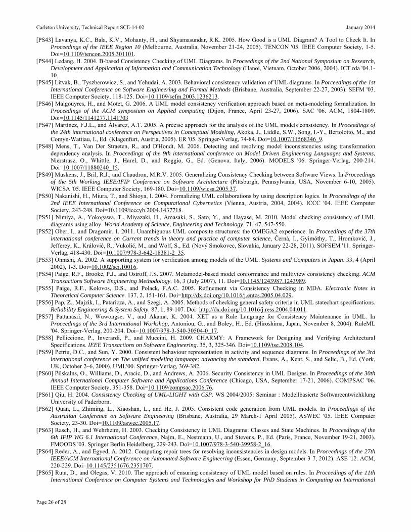
Carleton University, Technical Report SCE-14-02 January 2014
Page 26 of 28
[PS43] Lavanya, K.C., Bala, K.V., Mohanty, H., and Shyamasundar, R.K. 2005. How Good is a UML Diagram? A Tool to Check It. In Proceedings of the IEEE Region 10 (Melbourne, Australia, November 21-24, 2005). TENCON '05. IEEE Computer Society, 1-5. Doi=10.1109/tencon.2005.301101.
[PS44] Ledang, H. 2004. B-based Consistency Checking of UML Diagrams. In Proceedings of the 2nd National Symposium on Research, Development and Application of Information and Communication Technology (Hanoi, Vietnam, October 2006, 2004). ICT.rda '04.1-10.
[PS45] Litvak, B., Tyszberowicz, S., and Yehudai, A. 2003. Behavioral consistency validation of UML diagrams. In Porceedings of the 1st International Conference on Software Engineering and Formal Methods (Brisbane, Australia, September 22-27, 2003). SEFM '03. IEEE Computer Society, 118-125. Doi=10.1109/sefm.2003.1236213.
[PS46] Malgouyres, H., and Motet, G. 2006. A UML model consistency verification approach based on meta-modeling formalization. In Proceedings of the ACM symposium on Applied computing (Dijon, France, April 23-27, 2006). SAC '06. ACM, 1804-1809. Doi=10.1145/1141277.1141703
[PS47] Martínez, F.J.L., and Álvarez, A.T. 2005. A precise approach for the analysis of the UML models consistency. In Proceedings of the 24th international conference on Perspectives in Conceptual Modeling, Akoka, J., Liddle, S.W., Song, I.-Y., Bertolotto, M., and Comyn-Wattiau, I., Ed. (Klagenfurt, Austria, 2005). ER '05. Springer-Verlag, 74-84. Doi=10.1007/11568346_9.
[PS48] Mens, T., Van Der Straeten, R., and D'Hondt, M. 2006. Detecting and resolving model inconsistencies using transformation dependency analysis. In Proceedings of the 9th international conference on Model Driven Engineering Languages and Systems, Nierstrasz, O., Whittle, J., Harel, D., and Reggio, G., Ed. (Genova, Italy, 2006). MODELS '06. Springer-Verlag, 200-214. Doi=10.1007/11880240_15.
[PS49] Muskens, J., Bril, R.J., and Chaudron, M.R.V. 2005. Generalizing Consistency Checking between Software Views. In Proceedings of the 5th Working IEEE/IFIP Conference on Software Architecture (Pittsburgh, Pennsylvania, USA, November 6-10, 2005). WICSA '05. IEEE Computer Society, 169-180. Doi=10.1109/wicsa.2005.37.
[PS50] Nakanishi, H., Miura, T., and Shioya, I. 2004. Formalizing UML collaborations by using description logics. In Proceedings of the 2nd IEEE International Conference on Computational Cybernetics (Vienna, Austria, 2004, 2004). ICCC '04. IEEE Computer Society, 243-248. Doi=10.1109/icccyb.2004.1437718.
[PS51] Nimiya, A., Yokogawa, T., Miyazaki, H., Amasaki, S., Sato, Y., and Hayase, M. 2010. Model checking consistency of UML diagrams using alloy. World Academy of Science, Engineering and Technology. 71, 47, 547-550.
[PS52] Ober, I., and Dragomir, I. 2011. Unambiguous UML composite structures: the OMEGA2 experience. In Proceedings of the 37th international conference on Current trends in theory and practice of computer science, Černá, I., Gyimóthy, T., Hromkovič, J., Jefferey, K., Králović, R., Vukolić, M., and Wolf, S., Ed. (Nový Smokovec, Slovakia, January 22-28, 2011). SOFSEM '11. Springer-Verlag, 418-430. Doi=10.1007/978-3-642-18381-2_35.
[PS53] Ohnishi, A. 2002. A supporting system for verification among models of the UML. Systems and Computers in Japan. 33, 4 (April 2002), 1-3. Doi=10.1002/scj.10016.
[PS54] Paige, R.F., Brooke, P.J., and Ostroff, J.S. 2007. Metamodel-based model conformance and multiview consistency checking. ACM Transactions Software Engineering Methodology. 16, 3 (July 2007), 11. Doi=10.1145/1243987.1243989.
[PS55] Paige, R.F., Kolovos, D.S., and Polack, F.A.C. 2005. Refinement via Consistency Checking in MDA. Electronic Notes in Theoretical Computer Science. 137, 2, 151-161. Doi=http://dx.doi.org/10.1016/j.entcs.2005.04.029.
[PS56] Pap, Z., Majzik, I., Pataricza, A., and Szegi, A. 2005. Methods of checking general safety criteria in UML statechart specifications. Reliability Engineering & System Safety. 87, 1, 89-107. Doi=http://dx.doi.org/10.1016/j.ress.2004.04.011.
[PS57] Pattanasri, N., Wuwongse, V., and Akama, K. 2004. XET as a Rule Language for Consistency Maintenance in UML. In Proceedings of the 3rd International Workshop, Antoniou, G., and Boley, H., Ed. (Hiroshima, Japan, November 8, 2004). RuleML '04. Springer-Verlag, 200-204. Doi=10.1007/978-3-540-30504-0_17.
[PS58] Pelliccione, P., Inverardi, P., and Muccini, H. 2009. CHARMY: A Framework for Designing and Verifying Architectural Specifications. IEEE Transactions on Software Engineering. 35, 3, 325-346. Doi=10.1109/tse.2008.104.
[PS59] Petriu, D.C., and Sun, Y. 2000. Consistent behaviour representation in activity and sequence diagrams. In Proceedings of the 3rd international conference on The unified modeling language: advancing the standard, Evans, A., Kent, S., and Selic, B., Ed. (York, UK, October 2–6, 2000). UML'00. Springer-Verlag, 369-382.
[PS60] Pilskalns, O., Williams, D., Aracic, D., and Andrews, A. 2006. Security Consistency in UML Designs. In Proceedings of the 30th Annual International Computer Software and Applications Conference (Chicago, USA, September 17-21, 2006). COMPSAC '06. IEEE Computer Society, 351-358. Doi=10.1109/compsac.2006.76.
[PS61] Qiu, H. 2004. Consistency Checking of UML-LIGHT with CSP. WS 2004/2005: Seminar : Modellbasierte Softwareentwichklung University of Paderborn.
[PS62] Quan, L., Zhiming, L., Xiaoshan, L., and He, J. 2005. Consistent code generation from UML models. In Proceedings of the Australian Conference on Software Engineering (Brisbane, Australia, 29 March-1 April 2005). ASWEC '05. IEEE Computer Society, 23-30. Doi=10.1109/aswec.2005.17.
[PS63] Rasch, H., and Wehrheim, H. 2003. Checking Consistency in UML Diagrams: Classes and State Machines. In Proceedings of the 6th IFIP WG 6.1 International Conference, Najm, E., Nestmann, U., and Stevens, P., Ed. (Paris, France, November 19-21, 2003). FMOODS '03. Springer Berlin Heidelberg, 229-243. Doi=10.1007/978-3-540-39958-2_16.
[PS64] Reder, A., and Egyed, A. 2012. Computing repair trees for resolving inconsistencies in design models. In Proceedings of the 27th IEEE/ACM International Conference on Automated Software Engineering (Essen, Germany, September 3-7, 2012). ASE '12. ACM, 220-229. Doi=10.1145/2351676.2351707.
[PS65] Ruta, D., and Olegas, V. 2010. The approach of ensuring consistency of UML model based on rules. In Proceedings of the 11th International Conference on Computer Systems and Technologies and Workshop for PhD Students in Computing on International
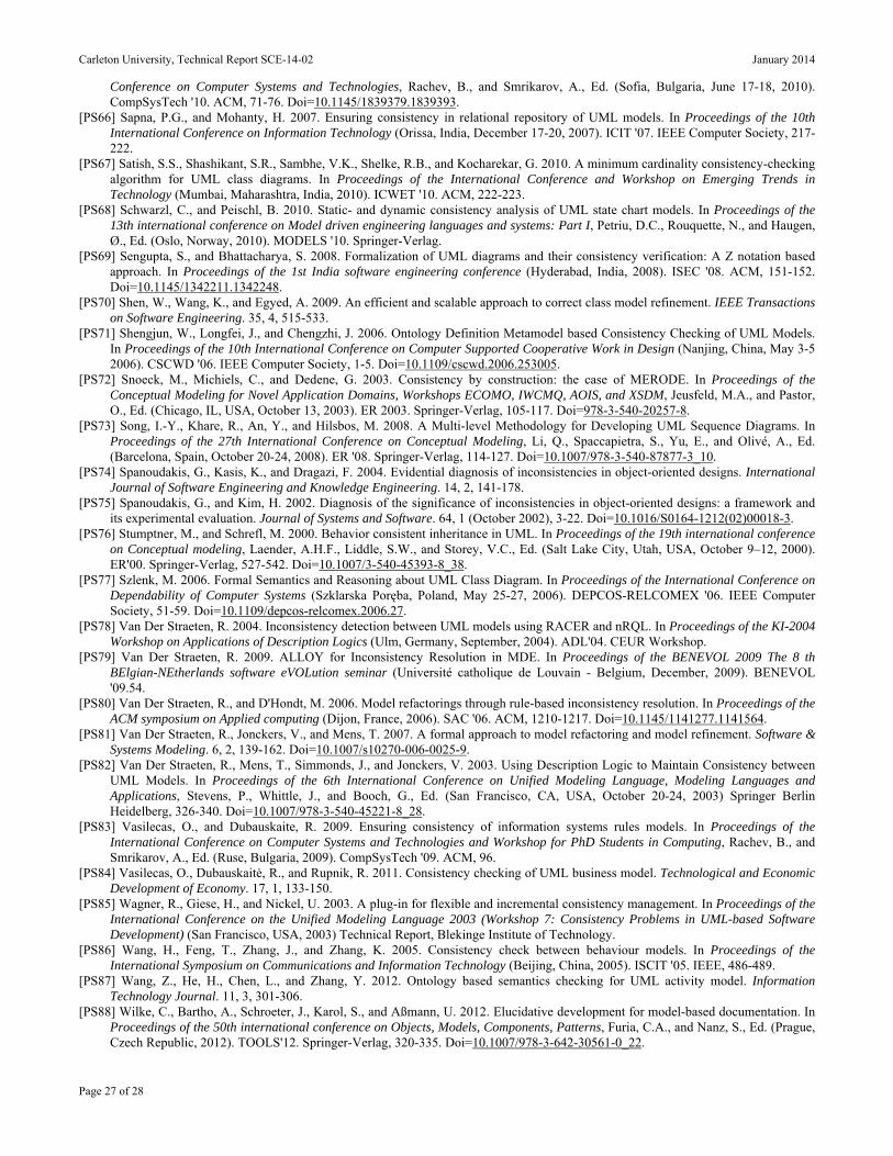
Carleton University, Technical Report SCE-14-02 January 2014
Page 27 of 28
Conference on Computer Systems and Technologies, Rachev, B., and Smrikarov, A., Ed. (Sofia, Bulgaria, June 17-18, 2010). CompSysTech '10. ACM, 71-76. Doi=10.1145/1839379.1839393.
[PS66] Sapna, P.G., and Mohanty, H. 2007. Ensuring consistency in relational repository of UML models. In Proceedings of the 10th International Conference on Information Technology (Orissa, India, December 17-20, 2007). ICIT '07. IEEE Computer Society, 217-222.
[PS67] Satish, S.S., Shashikant, S.R., Sambhe, V.K., Shelke, R.B., and Kocharekar, G. 2010. A minimum cardinality consistency-checking algorithm for UML class diagrams. In Proceedings of the International Conference and Workshop on Emerging Trends in Technology (Mumbai, Maharashtra, India, 2010). ICWET '10. ACM, 222-223.
[PS68] Schwarzl, C., and Peischl, B. 2010. Static- and dynamic consistency analysis of UML state chart models. In Proceedings of the 13th international conference on Model driven engineering languages and systems: Part I, Petriu, D.C., Rouquette, N., and Haugen, Ø., Ed. (Oslo, Norway, 2010). MODELS '10. Springer-Verlag.
[PS69] Sengupta, S., and Bhattacharya, S. 2008. Formalization of UML diagrams and their consistency verification: A Z notation based approach. In Proceedings of the 1st India software engineering conference (Hyderabad, India, 2008). ISEC '08. ACM, 151-152. Doi=10.1145/1342211.1342248.
[PS70] Shen, W., Wang, K., and Egyed, A. 2009. An efficient and scalable approach to correct class model refinement. IEEE Transactions on Software Engineering. 35, 4, 515-533.
[PS71] Shengjun, W., Longfei, J., and Chengzhi, J. 2006. Ontology Definition Metamodel based Consistency Checking of UML Models. In Proceedings of the 10th International Conference on Computer Supported Cooperative Work in Design (Nanjing, China, May 3-5 2006). CSCWD '06. IEEE Computer Society, 1-5. Doi=10.1109/cscwd.2006.253005.
[PS72] Snoeck, M., Michiels, C., and Dedene, G. 2003. Consistency by construction: the case of MERODE. In Proceedings of the Conceptual Modeling for Novel Application Domains, Workshops ECOMO, IWCMQ, AOIS, and XSDM, Jeusfeld, M.A., and Pastor, O., Ed. (Chicago, IL, USA, October 13, 2003). ER 2003. Springer-Verlag, 105-117. Doi=978-3-540-20257-8.
[PS73] Song, I.-Y., Khare, R., An, Y., and Hilsbos, M. 2008. A Multi-level Methodology for Developing UML Sequence Diagrams. In Proceedings of the 27th International Conference on Conceptual Modeling, Li, Q., Spaccapietra, S., Yu, E., and Olivé, A., Ed. (Barcelona, Spain, October 20-24, 2008). ER '08. Springer-Verlag, 114-127. Doi=10.1007/978-3-540-87877-3_10.
[PS74] Spanoudakis, G., Kasis, K., and Dragazi, F. 2004. Evidential diagnosis of inconsistencies in object-oriented designs. International Journal of Software Engineering and Knowledge Engineering. 14, 2, 141-178.
[PS75] Spanoudakis, G., and Kim, H. 2002. Diagnosis of the significance of inconsistencies in object-oriented designs: a framework and its experimental evaluation. Journal of Systems and Software. 64, 1 (October 2002), 3-22. Doi=10.1016/S0164-1212(02)00018-3.
[PS76] Stumptner, M., and Schrefl, M. 2000. Behavior consistent inheritance in UML. In Proceedings of the 19th international conference on Conceptual modeling, Laender, A.H.F., Liddle, S.W., and Storey, V.C., Ed. (Salt Lake City, Utah, USA, October 9–12, 2000). ER'00. Springer-Verlag, 527-542. Doi=10.1007/3-540-45393-8_38.
[PS77] Szlenk, M. 2006. Formal Semantics and Reasoning about UML Class Diagram. In Proceedings of the International Conference on Dependability of Computer Systems (Szklarska Poręba, Poland, May 25-27, 2006). DEPCOS-RELCOMEX '06. IEEE Computer Society, 51-59. Doi=10.1109/depcos-relcomex.2006.27.
[PS78] Van Der Straeten, R. 2004. Inconsistency detection between UML models using RACER and nRQL. In Proceedings of the KI-2004 Workshop on Applications of Description Logics (Ulm, Germany, September, 2004). ADL'04. CEUR Workshop.
[PS79] Van Der Straeten, R. 2009. ALLOY for Inconsistency Resolution in MDE. In Proceedings of the BENEVOL 2009 The 8 th BElgian-NEtherlands software eVOLution seminar (Université catholique de Louvain - Belgium, December, 2009). BENEVOL '09.54.
[PS80] Van Der Straeten, R., and D'Hondt, M. 2006. Model refactorings through rule-based inconsistency resolution. In Proceedings of the ACM symposium on Applied computing (Dijon, France, 2006). SAC '06. ACM, 1210-1217. Doi=10.1145/1141277.1141564.
[PS81] Van Der Straeten, R., Jonckers, V., and Mens, T. 2007. A formal approach to model refactoring and model refinement. Software & Systems Modeling. 6, 2, 139-162. Doi=10.1007/s10270-006-0025-9.
[PS82] Van Der Straeten, R., Mens, T., Simmonds, J., and Jonckers, V. 2003. Using Description Logic to Maintain Consistency between UML Models. In Proceedings of the 6th International Conference on Unified Modeling Language, Modeling Languages and Applications, Stevens, P., Whittle, J., and Booch, G., Ed. (San Francisco, CA, USA, October 20-24, 2003) Springer Berlin Heidelberg, 326-340. Doi=10.1007/978-3-540-45221-8_28.
[PS83] Vasilecas, O., and Dubauskaite, R. 2009. Ensuring consistency of information systems rules models. In Proceedings of the International Conference on Computer Systems and Technologies and Workshop for PhD Students in Computing, Rachev, B., and Smrikarov, A., Ed. (Ruse, Bulgaria, 2009). CompSysTech '09. ACM, 96.
[PS84] Vasilecas, O., Dubauskaitė, R., and Rupnik, R. 2011. Consistency checking of UML business model. Technological and Economic Development of Economy. 17, 1, 133-150.
[PS85] Wagner, R., Giese, H., and Nickel, U. 2003. A plug-in for flexible and incremental consistency management. In Proceedings of the International Conference on the Unified Modeling Language 2003 (Workshop 7: Consistency Problems in UML-based Software Development) (San Francisco, USA, 2003) Technical Report, Blekinge Institute of Technology.
[PS86] Wang, H., Feng, T., Zhang, J., and Zhang, K. 2005. Consistency check between behaviour models. In Proceedings of the International Symposium on Communications and Information Technology (Beijing, China, 2005). ISCIT '05. IEEE, 486-489.
[PS87] Wang, Z., He, H., Chen, L., and Zhang, Y. 2012. Ontology based semantics checking for UML activity model. Information Technology Journal. 11, 3, 301-306.
[PS88] Wilke, C., Bartho, A., Schroeter, J., Karol, S., and Aßmann, U. 2012. Elucidative development for model-based documentation. In Proceedings of the 50th international conference on Objects, Models, Components, Patterns, Furia, C.A., and Nanz, S., Ed. (Prague, Czech Republic, 2012). TOOLS'12. Springer-Verlag, 320-335. Doi=10.1007/978-3-642-30561-0_22.

Carleton University, Technical Report SCE-14-02 January 2014
Page 28 of 28
[PS89] Xiaoshan, L., Zhiming, L., and He, J. 2004. A formal semantics of UML sequence diagram. In Proceedings of the Australian Conference on Software Engineering (Melbourne, Australia, April 13-16, 2004). ASWEC '04. IEEE Computer Society, 168-177. Doi=10.1109/aswec.2004.1290469.
[PS90] Yang, J. 2009. A framework for formalizing UML models with formal language rCOS. In Proceedings of the 4th International Conference on Frontier of Computer Science and Technology (Shanghai, China, December 17-19, 2009). FCST '09. IEEE, 408-416.
[PS91] Yang, J., Long, Q., Liu, Z., and Li, X. 2004. A predicative semantic model for integrating UML models. In Proceedings of the 1st international Conference on Theoretical Aspects of Computing, Liu, Z., and Araki, K., Ed. (Guiyang, China, 2004). ICTAC '04. Springer-Verlag, 170-186. Doi=10.1007/978-3-540-31862-0_14.
[PS92] Zapata, C.M., González, G., and Gelbukh, A. 2007. A rule-based system for assessing consistency between UML models. In Proceedings of the 6th Mexican International Conference on Advances in Artificial Intelligence, Gelbukh, A., and Morales, F.K., Ed. (Aguascalientes, Mexico, November 4-10, 2007). MICAI'07. Springer-Verlag, 215-224. Doi=10.1007/978-3-540-76631-5_21.
[PS93] Zhao, X., Long, Q., and Qiu, Z. 2006. Model checking dynamic UML consistency. In Proceedings of the 8th International Conference on Formal Engineering Methods, Liu, Z., and He, J., Ed. (Macao, China, November 1-3, 2006). ICFEM '06. Springer-Verlag, 440-459. Doi=10.1007/11901433_24.
[PS94] Zisman, A., and Kozlenkov, A. 2001. Knowledge Base Approach to Consistency Management of UML Specifications. In Proceedings of the 16th IEEE international conference on Automated software engineering (Coronado Island, San Diego, CA, USA, 2001). ASE '01. IEEE Computer Society, 359.