
control_valves_regulators_actuat... - POLNA SA
181
-
Upload
khangminh22 -
Category
Documents
-
view
5 -
download
0
Transcript of control_valves_regulators_actuat... - POLNA SA

AUTOMATIC CONTROL ENGINEERING and HEAT ENGINEERING
POLNA S.A.
proven supplier of control valves
PRODUCT CATALOGUE
AUTOMATIC CONTROL ENGINEERINGand
HEAT ENGINEERING
www.polna.com.pl


„POLNA” S.A.
23 Obozowa Street, 37-700 Przemyśl, POLAND
Phone: +48 16 678 66 01Fax: +48 16 678 65 24 +48 16 678 37 10
website: www.polna.com.pl
+48 16 678 66 01 extension / mobile phone
The Board of Directors 200
Sales and Marketing Director 379 / +48 693 920 446
Marketing Department 248 / +48 533 301 083
Export [offers and orders] 258 / +48 609 369 810
Service 382 / +48 609 369 265 +48 16 678 66 25
Sales and Marketing Specialists
Control valves, assemblies of control valves with pneumatic and electrical actuatorsSelf-actuating regulators
Offers389 / +48 533 301 119269 / +48 609 369 965
+48 506 392 558
Orders realization 310 / +48 533 301 083
Central lubrication equipment, 248 / +48 533 301 083
Water distillers 210 / +48 693 920 435
E-mail addresses
Marketing and Sales Department [email protected]
Offers [domestic][email protected] [email protected]@polna.com.pl
Export [offers and orders] [email protected]
Service [email protected]
Purchasing Department [email protected]


Dear Ladies and Gentlemen,
we are proud to present you with POLNA’s great offer of a wide range of products from the automatic control engineering and heat engineering sectors, to central lubrication and laboratory equipment. We specialize in the designing and manufacturing of control valves, steam desuperheaters, needle valves, regulators, central lubrication equipment, distillers and re-distillers.
We aim at fulfilling the Customer’s needs. Our traditions date back over 90 years, which enhances the determination for constant improvement of our products, processes and everything that we do within our team and in the whole organization.
It is our mission to ensure:
• the highest quality and reliability of products for our Customers,• a stable increase of the company’s goodwill for our Shareholders,• the feeling of security and opportunities for development for our Employees,• business responsibility (protection of the natural environment and social interests).
Designing and manufacture of individual products is based on complete realization of the technical assumptions agreed on with the Customer. We are constantly broadening our offer of non-catalog products, aimed at individual needs of our recipients.
Kind regardsAndrzej Piszcz
The President of the Management Board, Executive Director

Zakłady Automatyki „POLNA” S.A.
“POLNA” S.A. specializes in designing and manufacturing of control valves used in technological installations in power, petrochemical, gas industries as well as many other branches of industry.
Sales network “POLNA” S.A. has a well-developed sales network in Poland and abroad. It sells its products directly and by means of distributors and trade partners. A detailed list of those companies can be found on the Company’s website.
Sales service “POLNA” S.A. delivers products to leading companies from various branches of industry. Our know-how concerning the selection of valves, operation or servicing the manufactured products ensures benefits for our customers. The benefits include high quality, competitiveness and technical support.
Technical service Specialists working for “POLNA” S.A. are properly qualified to provide assistance concerning technical matters with the selection of control valves and other products of their needs. As part of technical service, “POLNA” S.A. provides 24/7 post-sales support for the Customer involving technical consultation, visits in the plants and even post-warranty service.
Documentation and identification
All our company’s products have identification marks, showing their parameters in accordance with the marks enclosed in the product catalog. Each product leaving the company is provided with full technical and commercial documentation complying with the binding regulations.
Training “POLNA” S.A. offers training programs concerning the construction and selection of the manufactured products. The training programs are carried out in the Company’s seat and on customers’ premises. We share the knowledge and experience we have obtained with our Customers, distributors and business partners.
Development “POLNA” S.A. takes care to constantly develop especially concerning the designing of new products and improving the existing processes, being governed by the Customers’ needs.
Quality Management The Quality Management System and the quality policy of our company are based on the Process Approach and constant improvement. It enables us to increase the added value, thus making our products more attractive for the Customer.

PRZEMYŚL- Think it over and come!Przemyśl belongs to a select group of the oldest and most beautiful Polish towns. A thousand years old, tempestuous history of the town has been inseparably intertwined with the history of the whole Republic of Poland. It is located in the south-east corner of Poland, in the eastern part of Podkarpackie Voivodeship and in the valley of the river San. Przemyśl, together with its surroundings, has many tourist, recreation and historical virtues. The town also constitutes an important transport interchange, connecting the East with the West and the North with the South of Europe. Besides, it plays an important role in transboundary cooperation with Ukraine.
Our CompanyZakłady Automatyki POLNA S.A. is a company with a long tradition. It has been producing industrial fittings since the end of the 1960s. Over the years, the range of manufactured products has been systematically broadened and the construction solutions used have been improved. The current trademark has been used since 1972 and products bearing that trademark are well known among domestic and foreign customers.
Apart from standard catalogue products, POLNA specializes in special manufactures of valves adjusted to individual Customers’ requirements.
Our customers include some of the leading companies from various branches of industry:o ALSTOM POWER – power industryo SYNTHOS DWORY– chemical industryo SIEMENS – automatic controlo Polish Oil & Gas Company (PGNiG) – gas industryo ORLEN – petrochemical industryo FOSTER WHEELER – power industryo AUSTRIAN ENERGY – power industryo SKODA POWER – power industry
The quality of POLNA’s products is guaranteed by Quality Management System certificates it holds:- Quality Management System Certificate of Conformity with EN ISO 9001:2008 norm. - Quality Assurance System Certificate of Conformity with Directive 97/23/EC – Module H.- Quality Assurance System Certificate of Conformity with Directive 97/23/EC – Annex I, p.4.3.- We confirm compliance of control valves and actuators with ATEX Directive 94/9/EC.
More information about the company, its certificates and its product offer can be found on our website: www.polna.com.pl.
In industrial part of town is located PRZEMYŚL SUB-ZONE OF TARNOBRZEG SPECIAL ECONOMIC ZONE EURO-PARK WISŁOSAN (TSSE), www.tsse.pl.
Industrial valuesPrzemyśl has got a direct connection with the transit route Wrocław – Kraków – Korczowa (A4 and Road no.4).
The closest airport is located in Jasionka near Rzeszów (appr. 90 km from Przemyśl). The airport off ers national and international air connections (including cheap airlines).

Tourist valuesWelcome to Przemyśl! It is a beautiful and unique town. Mother nature herself took care of the picturesqueness nature of this part of the country, and its attractive location makes it possible to reach the Bieszczady highlands, the tourist routes of Pogórze Przemyskie, as well as the great city of Lvov, situated less than 100 kilometres from Przemyśl. For many centuries communication routes between East with West and North with South have crossed here, thanks to which the town was formed, Walking along its narrow streets, you can touch ten centuries of the town’s history with numerous material traces, almost a thousand of which have been registered as construction and architectural monuments.Being situated at the meeting point of cultures and religions of the East and West has resulted in a national diversity and rich cultural heritage, developed by generations of Polish, Ukrainian and Jewish communities. The periods of the Polish partitions and the reign of the Austro-Hungarian monarchy contributed to the very special nature of the town.
The Fortress of PrzemyślThe strategic location of Przemyśl induced the Austrian authorities to commence a construction of a huge fortress in the 19th century that played a significant role during WWI. Its presence, attractiveness and fame directed the tourist development of the town under the promotional name “Tourist Town Przemyśl Fortress”. The town attracts many tourists and lovers of fortifications with its ruins of massive forts and war cemeteries. Enthusiasts of militaria and fortification mysteries will surely find the bunkers of the Molotov Line attractive.
Active and cultural tourismPrzemyśl is one of the rare towns, in the centre of which you can sunbathe by the San River in the middle of summer and ski during winter down the 800-metre lit slope, equipped with ski-lift. Tourists, who appreciate the beauty of nature and landscapes, are fascinated with history, multiple cultures and prefer active leisure will surely feel wonderful here.
Natural sights, plenty of which can be found in Przemyśl and the Foothills, may be considered as combining ACTIVE AND CULTURAL tourism. The most valuable of these is Arboretum in Bolestraszyce (7 km from the town). Here you can see rare species of trees and bushes from all over the world. In the manor house dating back to the 19th century the Institute of Physical Geography was established.Castles, Cathedrals, Churches…The very location of Przemyśl, at the meeting point of cultures and religions, and their mutual inter-penetration, led to a unique effect in the form of abundant monuments of sacral, secular and military architecture, expressed in almost a thousand registered construction and architectural objects. The centre of the town is especially rich in historical buildings. The Casimir Castle dating back to the 14th century, with pallatium and rotunda of the turn of 10th and 11th centuries, remains of the fortified walls, Reformati Monastery and Benedictine Nunnery with churches of 16th century, Franciscan and Carmelite monastery complexes from the Baroque period, as well as many bourgeois town houses. The Market Square and narrow streets are the most frequently visited places in the town The good condition of these historical objects, clear signs, numerous leaflets, folders and guides has made it possible to move freely in this attractive area of the town. The very centre of the Old Town has its own “underground town”. The majority of buildings have basements and underpasses, which are often interconnected. Tatar Mound (Kopiec Tatarski) and the „Zniesienie” citadelUnique mounds only found in the Małopolska region of Poland – in Cracow and, particularly numerous, in Przemyśl area – will probably remain an archaeology mystery forever. The time of their creation is unknown; the Tatar Mound (Kopiec Tatarski) was a mystery as early as in the 16th century. The mound is worth visiting, since there is a wonderful view from this highest point in the area. Nearby, there are ruins of the citadel fort XVI “Zniesienie”. Even nowadays can we see steel rails here: the tracks on which huge mortars used to turn around. Przemyśl is a beautiful, interesting and unique place. It is worth coming to stay here.

Download this questionnaire from: http://www.polna.com.pl/en/catalogues-and-products.html

Measurement point no.
Manufacturer serial number ZAKLADY AUTOMATYKI
POLNA SA 37-700 Przemysl, ul. Obozowa 23
TECHNICAL SPECIFICATION FORM CONTROL VALVES
User serial number
1 Place of installation 57 Manufacturer Type
2 Function 58 Pneumatic � Diaphragm type � Piston type � . 3 Explosion hazard zone 59 Operation � Unilateral �Bilateral � . 4 Ambient temperature min max 60 Size Membrane working area
5 Allowed noise level 61 Stroke / rotation angle
6 Pipeline identification no. 62 Supply pressure min max
7 DN / PN Wall thickness mm 63 Input signal range
8 Pipeline material 64
9 Pipeline insulation � Thermal � Acoustic 65 Air connection
10 66 Other actuators � electric � hydraulic � hand operated
11 Pipeline connections 67
12 Working medium 68 Handwheel � Top � Lateral
13 Working medium at outlet � fluid � steam � gas 69
ACTU
ATO
R
14 70 Manufacturer Type
15 min norm max unit 71 Input signal � pneumatic � electric
16 Flow 72 Valve open at
17 Inlet pressure P1 73 Valve closed at
18 Outlet pressure P2 74 Operation � unilateral � bilateral
19 Temperature T1 75 Characteristics � linear � . 20 Medium density at inlet P1 or M 76 Air connections
21 Evaporation pressure Pv 77 Accessories � by-pass � manometers
22 Critical pressure Pc 78 Explosion-proof execution � spark-safe � explosion safe
23 Kinematic viscosity 79
POSI
TIO
N L
EVER
24 Specific heat y 80 Manufacturer Type
25 Compressibility coefficient Z 81 Switch type � mech. � approx. � pneum.
26 82 Switch position � closed � % stroke � open
27 Pressure with valve closed P1 P2 83 Switch operation �open �close
28 Supply air pressure min max 84 Explosion-proof execution � spark-safe � explosion-safe
29 Valve status w/o supply � open � closed � susp. 85
LIM
IT S
WIT
CH
ES
30
TEC
HN
ICAL
PAR
AMET
ERS
TO
BE
CO
NSI
DER
ED F
OR
VAL
VE
SELE
CTI
ON
86 Manufacturer Type
31 Max calculated flow ratio Kv 87 Valve type � 2-way � 3-way � 4-way
32 Min calculated flow ratio Kv 88 Valve supply failure status � open � closed � susp.
33 Selected catalogue Kv 89
34
Kv
/NO
ISE
Calculated noise level dB(A) 90 Air connection Connection size
35 Manufacturer Type 91 Electric parameters V Hz W
36 Body type 92 Explosion-proof execution � spark-safe � explosion-safe
37 Flow direction 93
SOLE
NO
ID V
ALV
E
38 Nominal pressure 94 � Reducing valve Manufacturer Type
39 Nominal sizes 95 � with filter � with manometer
40 End connections � flanged � flangeless � welding � threaded 96 � Location transmitter Manufacturer Type
41 97
42 Extended connections 98 � Pneumatic booster Manufacturer Type
43 Bonnet type �standard �extension �bellow seal �TA-Luft 99
44 100 � Blocking valve Manufacturer Type
45 Body / bonnet material / 101
46 Valve plug - valve seat unit � standard � silenced � . 102 Pulse tubes material
47 Characteristics � linear � equal percentage � on/off 103
ACC
ESSO
RIE
S
48 Valve plug / valve plug stem material / 104 Attestations � chemical and mechanical tests
49 Guiding sleeve / valve seat material / 105 Other examinations
50 106 Certificates � body/bonnet � bolts/nuts
51 Valve seat type � metallic � soft 107 � valve plug-valve seat unit
52 Valve plug - valve seat unit hardening coating 108
53 109
54 Tightness class 110
55 Packing � PTFE � graphite � . 111
56
VALV
E U
NIT
112
SPEC
IAL
REQ
UIR
EMEN
TS
Comments:
Design Fig. no.
Item Offer request no.
Change Date Name Change Date Signature Order no. Item no. No. of pcs.
Download this questionnaire from: www.polna.com.pl
CONTENT
Revision: CONTENT/10/2014Valid until the next revision
TECHNICAL INFORMATION
1. Products of automatic control engineering .................................................................................... 12. Harmful phenomena in the work of valves. .................................................................................... 113. Non-catalog production .............................................................................................................. 15
AUTOMATIC CONTROL ENGINEERING PRODUCTS
4. Single-ported globe control valves type Z .................................................................................... 295. Single-ported globe control valves type Z1A .................................................................................... 456. Control valves type Z1A - Design solutions for special applications ........................................... 637. Single-ported cage control valves type Z1B .................................................................................... 678. Control valves type Z1B - Design solutions for special applications ........................................... 879. MinimumflowvalvestypeZM1 and Z1B-M .................................................................................... 9110. Three-way control valves type Z3 ................................................................................................. 9511. Rotary plug control valves type Z33 ................................................................................................. 10312. Rotary plug control valves type Z33 with piston and rotary actutation ............................................. 11513. Double-ported control valves type Z10 ................................................................................... 11914. Reduction and cooling stations ................................................................................................. 12515. Steam desuperheaters: ring type SP-1, lance and piston type ST-1 ............................................. 12916. Diaphragm multi-spring pneumatic actuators type P/R .......................................................... 13517. Diaphragm multi-spring pneumatic actuators type P1/R1 .......................................................... 139
HEAT ENGINEERING
TECHNICAL INFORMATION18. Heat engineering products ............................................................................................................. 141
HEAT ENGINEERING PRODUCTS
19. Self-actuating pressure reducing regulators type ZSN 1 ......................................................... 14520. Self-actuating pressure relief regulators type ZSN 3 ...................................................................... 14921. Self-actuating differential pressure reducing regulators type ZSN 5 ............................................ 153
Page

NOTES:

PRODUCTS OF AUTOMATIC CONTROL ENGINEERING - TECHNICAL INFORMATION
1
CONTENT
Introduction ...................................................................................................................................... 1Design versions ............................................................................................................................... 2Material executions .......................................................................................................................... 3Nominal pressure ............................................................................................................................. 3Flow ratio ......................................................................................................................................... 4Flow characteristics ......................................................................................................................... 4Internal tightness ............................................................................................................................. 5Bonnet, types and packings ............................................................................................................. 6End connections, types .................................................................................................................... 7Hardening of valve internal parts ..................................................................................................... 7Drive selection ................................................................................................................................. 8Harmful effects in valve operation .................................................................................................... 9
INTRODUCTION
Fluidflowratioregulationappliances,whichkeeptherequiredregulationcharacteristics,arecriticalinindustrialautomatics systems. The main component of such appliances are controllers, which adjust the resistance for flowingfluid,anddrives(actuators),whichprovidemechanicenergyrequiredinsettingofcontrollers.
Thefollowingarerepresentativesofthisgroupofappliances,manufacturedbyZakładyAutomatyki POLNA SA:• globe and angle control valves,• three-way control valves,• butterflyvalves.Regarding the type of drive, controllers are manufactured in following executions:• with spring diaphragm pneumatic actuators,• with electric and electro-hydraulic actuators,• with pneumatic piston actuators,• with hand operated drive,• without drive.•Regarding the fact that valves are the largest group of controllers, the expression “valves” is hereinafter often
interchangeable with expression “controllers”.Whileselectingvalvesforspecificworkingconditionsoneshouldconsiderthefollowingaspects:1. valve design version,2. material execution,3. nominal pressure,4. flowcoefficient,5. flowcharacteristics,6. internal tightness,7. bonnet type and packing,8. body connection types,9. hardening of valve internal parts,10. selection of drive,11. harmful effects in valve operation.
Page

Technical information - valves2
1. DESIGN VERSIONS
The design version aspect applies only to valves. Valves can be subdivided using the following criteria:a) positionofbodyinletandoutlet • globe, • three-way, • angle,b) closingcomponent • withlinearmotionvalveplug, • withrotarymotionvalveplug,c) shapeofclosingcomponent • profilevalveplug, • perforatedvalveplug, • multi-stagevalveplug, • cagevalveplug,d) balancingofaxialforces • unbalanced, • balanced,e) reversibilityofoperation • reversibledesigndouble-portedvalves, • irreversibledesignsingle-portedvalves. Globe valves with linear situation of input and output are the basic, most common group of valves. Three-wayvalvesareusedininstallationswheremixingorseparationoffluidisrequired.Anglevalvesarepreferredoptioninapplicationswhereflashing(evaporation)andlargepressuredropsoccur.Avariationofangle valves are „ ” valves, with parallel but not axial body ends.
Rotaryplugglobevalvesarerecommendedincasesoflargeflowsanddemandforpreciseadjustmentinthebeginningofopening.Perforated(perforated)componentsareusedmostlytoreducenoiseemissions.Multi-stagevalveplugsreducecavitationandchokedflow. In cage valves there is a piston valve plug, working with perforated control cage. They are used for large pressure drops applications. Pressurebalancingofvalveaimsatequalizationofstaticpressureonbothsidesofvalveplug,bymeansofbalanceholesorinternalvalveplug(pilot).For selection of the valve balancing method the following factors must be taken into account: a)plug-pilot-flowdirection-abovetheplug(FlowToClose-FTC), -highleakageclass-(Vclass),- enhanced rangeability, - limited possibility to manufacture two-stage plugs to apply throttling cages.b)balancingandrelievingholesintheplug-flowdirectionundertheplug(FlowToOpen-FTO), -max.leakageclass(IVclass),- plug sealing subjects to wearing - it must be replaceable, - possibility to manufacture multi-stage plugs to and apply throttling cages.Reversibilityofvalveoperationdenotespossibilityofchangingitsfunction(pressingthevalveplugstemcancauseopeningorclosingofvalve)intheconsequenceofdifferentassemblyofvalveinternalparts.While selecting valve design one should consider the following aspects:• leakageclassSingle-ported valves are more tight than double-ported ones.• balancingofaxialforcesDouble-portedvalvesrequiresmallerresettingforcesandallowtransferringoflargerpressuredropsthaninthe case of single-ported valves with same actuators.• flowcoefficientSingle-portedvalvesfeaturebetterpossibilityofflowreduction,whereasdouble-portedvalvesandrotaryplugvalvesfeaturebetterflowcoefficientsthansingle-portedones,withsamevalvediameter.• nominalpressureIrreversible valves are used in applications with higher nominal pressure than in the case of reversible valves.• fluidviscosityIt isrecommended,thatsingle-portedvalvesareusedwithdensefluids,withviscosityv>10-5 [m2/s], where laminarflowmaybeobserved.

Technical information - valves 3
2. MATERIAL EXECUTIONS
Material execution is determined by material in which body is executed.Basic material executions of the body casts:- cast iron: EN-GJL 250, per PN-EN 1561- spheroidal iron: EN-GJS-400-15, per PN-EN 1563 EN-GJS-400-18LT, per PN-EN 1563 -carbonsteel: GP240GH,(1.0619), perPN-EN10213-2 G20Mn5,(1.6220) wgPN-EN10213-3 WCB, per ASTM A216-alloysteel: G17CrMo9-10,(1.7379), perPN-EN10213-2 WC9, per ASTM A217-stainlesssteel: GX5CrNiMo19-11-2,(1.4408), perPN-EN10213-4 CF8M, per ASTM A351Criteria for selection of material:• corrosionproofness,• workingtemperature,• nominalpressure,• requirementsoftechnicalspecifications(AD2000Merkblatt,WUDT-UC,ASMECode)Materialcorrosionproofnessdependsontypeoffluid,itstemperature,concentration,etc.Itistobeassessedbase don generally available tables and recommendations, or information by valve manufacturer. Relationship between working temperature and pressure are illustrated in tables in catalog product charts. Minimum operating temperature for all materials is -10°C.There is a possibility of lowering operating temperature, as below: -90°C forcarbonsteelsG20Mn5,(1.6220), -196 °C for stainless steels, GX5CrNiMo19-11-2,(1.4408)iCF8M,provided that:
• designpressureisreducedrespectively,• resultsofimpactstrengthtestsatworkingtemperaturearepositive,• heattreatment(stressrelieving)ofcastingisperformed. RequirementsofAD2000Merkblattspecification,sheetA4,donotallowpressureequipmentexecutioningreyiron,withexceptionofproductsexecutedunderArticle3.3ofPressureEquipmentDirectiveinaccordancewithTechnicalSpecificationWUDT-UC.
3. NOMINAL PRESSURE
Nominal pressure is a dimensionless marking of maximum operating pressure at ambient temperature, preceded with PN or CL symbol.Control valves are executed in following nominal pressures:PN6; 10; 16; 25; 40; 63; 100; 160; 250; 320; 400 per PN-EN 1092-1, DIN2548, DIN2549, DIN2550, DIN2551, PN-H-74306, PN-H-74307CL150; 300; 600; 900; 1500; 2500 per ANSI/ASME B16.5, PN-EN 1759-1PN20; 50; 110; 150; 260; 420 per PN-EN 1759-1, PN-ISO 7005-1PressuresPN20…420areequivalenttoCL150…2500.
4. FLOW RATIO
FlowcoefficientKvisthestreamofwaterin[m3/h],withtemperature5°Cto40°C,flowingthroughthevalve,atpressuredrop1[bar],forspecificstrokeofvalve.Kvcoefficientdescribesminimumhydraulicresistanceofvalve.FamiliaritywithKvcoefficientallowstodirectlydeterminevalvenominalsizeDNanddiameterofpipethevalveistobeconnectedto.ManydifferentKvvaluescanbeobtainedforsamenominalsizesDN,intheconsequenceofapplicationofreducedpassagesofvalveseats.Nominal(catalog)valueofflowcoefficientismarkedKvs.Relationshipsbetweenflowcoefficient,flowrateandpressuredropforvariousstatesofaggregationandflowconditions can be determined using formulas on page 5. SaidformulasallowapproximationofKvcoefficient.Theyhoweverdonotaccountforeffectsoffluidviscosity,changeindensityofflowingfluid,criticalflow,etc.FormoredetailsrefertoPN-EN60534-2-1“Industrial-processcontrolvalves.Flowcapacity-sizingequationsforfluidflowunderinstalledconditions.

Technical information - valves4
It is advised that DIVENT valve calculation and calculation program is used, which can be downloaded from the following website
www.polna.com.pl
Toensurecorrectworkofautomaticcontrolsandtoavoidoversizingofthevalve,adoptedcatalogvalueofflowcoefficientistobehigherthancalculated.Itisassumedthatmaximumvalueofcalculatedflowcoefficientistobeachievedwithinthe70…90%rangeofvalveplugstroke.
5. FLOW CHARACTERISTIC
Valveflowcharacteristicsistherelationbetweenflowvalueandclosingcomponentstroke.Regardingpressuredrop we can divide characteristics into internal and working characteristics.Internal characteristics describes relationbetween relative flowcoefficient “kv” and relative stroke “h” atconstant pressure drop in valve, where:
Workingcharacteristicdescribeschangeinflowinfunctionofstrokeatvariablepressuredropinvalve,ininstallation conditions.Valveshavethefollowingflowcharacteristics:• linear -„L”• equalpercentage -„P”• modified -„M”• quickopening -„S”Valvecharacteristicisobtainedbyproperdesignoffluidflowareabetweenvalvechokingcomponentsregardingthestroke.Thisfunctionisrealizedthroughcontouredvalveplugsorperforatedcomponents(perforatedvalveplugs,controlcages):- linear characteristic:equalincreaseinrelativestroke“h”correspondwithequalincreaseinrelativeflowcoefficient“kv”.
where: 0vk isaminimumcontrolledrelativeflowratio,
m - characteristic inclinationFor POLNA valves: = 0,02; m = 1
- equalpercentagecharacteristic:equalincreaseinrelativestroke“h”correspondswithequalpercentincreaseinrelativeflowcoefficient„kv”
where:nischaracteristicinclinationdrawninsemi-logarithmiccoordinates(h,lgkv).
- modifiedcharacteristic:isacharacteristicsinbetween“L”and“P”,createdforindividualneedsandspecificinstallations.Itmostlyisofequalpercentagenatureatthebeginningofstroke(h=0…0.3)andlinearinthesubsequentpartofstroke.- quickopeningcharacteristic:usedfor“open-close”on-offoperation;itallowsachievementofnominalflowatlowstroke(h=0.6…0.7)andincreaseinflowcoefficientbyca.20%regardingcatalogvalue,atfullstroke. Selectionbetweenvaluewithequalpercentageandlinearcharacteristicsdependsonrequirementsconcerningchangesinflowrateandpressureonvalve.Withsmallchangesinflowrateduringvalveoperation,upto50%,selectionofcharacteristicshasnomaterialeffect toperformanceofcontrolsystem.However forvalvesoperatingat largechanges inflowrate,withvariable pressure drop, and in case of doubt selection of constant per cent characteristics is recommended. Valves with linear characteristics are recommended for systems, where pressure drop on valve is independentfromflowrate,e.g.controloffluidlevel.

Technical information - valves 5
Valveplugswithquickopeningcharacteristicsaredesignatedexclusivelyforon-offoperation.Limitationsinapplicationofperforatedcomponentsareduetotheirsusceptibilitytocontaminantssuspendedinfluids,hencetheneedfortheirpermanentfiltering.
Kv [m3/h] -flowcoefficient(calculated)Q [m3/h] -fluidflowvolumeintensityQN [Nm3/h]-gasflowvolumeintensityinnormalconditions(0°C,760mmHg)G [kg/h] -flowmassintensityp1 [bar(a)] -absolutepressureupstreamvalvep2 [bar(a)] -absolutepressuredownstreamvalveΔp [bar] -pressuredroponvalve(availablepressuredrop)ρ1 [kg/m3] -fluiddensityupstreamvalveρN [kg/m3] -fluiddensityinnormalconditionsT1 [K] -fluidtemperaturebeforeagentv2 [m3/kg] -specificvolumeofsteamforparametersp2 and T1v [m3/kg] -specificvolumeofsteamforparameters(p1/2)andT1
Threewayandrotaryvalveplugvalvesfeaturelinearcharacteristics,whereasbutterflyvalvesfeaturecharacteristicssimilartoequalpercentagecharacteristicsintherangeofopeningangles0°…60°(Fig.2).
6. INTERNAL TIGHTNESS
Maximumleakageofclosurebyvalvechokingcomponents(“plug-seat”)isdescribedinleakageclassesasper PN-EN 60534-4.
Leakage class Allowed leakageII - 5•10-3KvsIV - 10 -4 Kvs
Fig. 1. Flow characteristics for valves Fig.2.Flowcharacteristicsforbutterflyvalves
Flow characteristic
equalpercentage
linear
quickopening
0,0
0,1
0,2
0,3
0,4
0,5
0,6
0,7
0,8
0,9
1,0
0,0 0,1 0,2 0,3 0,4 0,5 0,6 0,7 0,8 0,9 1,0
h
kv
a
Butterfly valve flow characteristics
0
0,1
0,2
0,3
0,4
0,5
0,6
0,7
0,8
0,9
1
0 10 20 30 40 50 60 70 80 90
αo
kv
Technical information - valves6
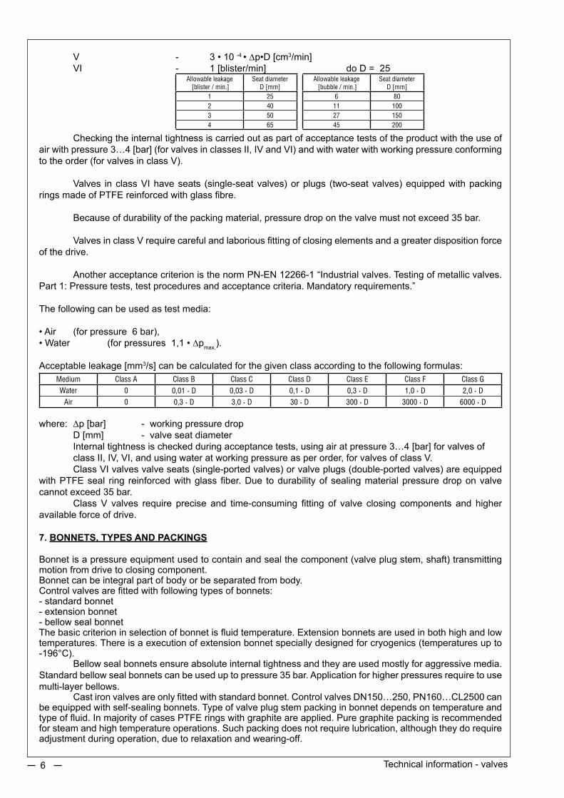
V - 3•10-4 •Dp•D[cm3/min] VI - 1 [blister/min] do D = 25
Allowable leakage [blister / min.]
Seat diameter D [mm]
Allowable leakage [bubble / min.]
Seat diameter D [mm]
1 25 6 802 40 11 1003 50 27 1504 65 45 200
Checking the internal tightness is carried out as part of acceptance tests of the product with the use of airwithpressure3…4[bar](forvalvesinclassesII,IVandVI)andwithwaterwithworkingpressureconformingtotheorder(forvalvesinclassV).
Valves inclassVIhaveseats (single-seatvalves)orplugs (two-seatvalves)equippedwithpackingringsmadeofPTFEreinforcedwithglassfibre.
Because of durability of the packing material, pressure drop on the valve must not exceed 35 bar. ValvesinclassVrequirecarefulandlaboriousfittingofclosingelementsandagreaterdispositionforceof the drive.
Another acceptance criterion is the norm PN-EN 12266-1 “Industrial valves. Testing of metallic valves. Part1:Pressuretests,testproceduresandacceptancecriteria.Mandatoryrequirements.”
The following can be used as test media:
•Air (forpressure6bar),•Water (forpressures1,1•Dpmax.).
Acceptable leakage [mm3/s] can be calculated for the given class according to the following formulas:Medium Class A Class B Class C Class D Class E Class F Class G
Water 0 0,01 • D 0,03 • D 0,1 • D 0,3 • D 1,0 • D 2,0 • D
Air 0 0,3 • D 3,0 • D 30 • D 300 • D 3000 • D 6000 • D
where: Dp [bar] - working pressure drop D [mm] - valve seat diameter Internal tightness is checked during acceptance tests, using air at pressure 3…4 [bar] for valves of class II, IV, VI, and using water at working pressure as per order, for valves of class V. ClassVIvalvesvalveseats(single-portedvalves)orvalveplugs(double-portedvalves)areequippedwithPTFEseal ring reinforcedwithglassfiber.Due todurabilityofsealingmaterialpressuredroponvalvecannot exceed 35 bar. ClassV valves require precise and time-consuming fitting of valve closing components and higheravailable force of drive.
7. BONNETS, TYPES AND PACKINGS
Bonnetisapressureequipmentusedtocontainandsealthecomponent(valveplugstem,shaft)transmittingmotion from drive to closing component.Bonnet can be integral part of body or be separated from body.Controlvalvesarefittedwithfollowingtypesofbonnets:- standard bonnet- extension bonnet- bellow seal bonnetThebasiccriterioninselectionofbonnetisfluidtemperature.Extensionbonnetsareusedinbothhighandlowtemperatures.Thereisaexecutionofextensionbonnetspeciallydesignedforcryogenics(temperaturesupto-196°C). Bellow seal bonnets ensure absolute internal tightness and they are used mostly for aggressive media. Standard bellow seal bonnets can be used uptopressure35bar.Applicationforhigherpressuresrequiretousemulti-layer bellows. Castironvalvesareonlyfittedwithstandardbonnet.ControlvalvesDN150…250,PN160…CL2500canbeequippedwithself-sealingbonnets.Typeofvalveplugstempackinginbonnetdependsontemperatureandtypeoffluid.InmajorityofcasesPTFEringswithgraphiteareapplied.Puregraphitepackingisrecommendedforsteamandhightemperatureoperations.Suchpackingdoesnotrequirelubrication,althoughtheydorequireadjustment during operation, due to relaxation and wearing-off.

Technical information - valves 7
Among maintenance-free packings are PTFE-V and TA Luft packings. PTFE-V ones are executed in PTFE in the formofV-profilerings,pressedtosealedsurfaceswithspiralspring.TALuftpackingcomprises twokitsofseal rings loadedwithpackageofdisksprings,andcompliant in termsof tightnessrequirementsof TA Luft:2002, Clause 5.2.6.4, and VDI 2440:2000.
8. END CONNECTIONS, TYPES
Body connections are used to connect valve to pipeline and they should provide tightness, pressure resistance, vibration resistance and pipeline deformations.Valves are executed with following types of connections:• flanged,• flangeless,• welding.Flanged connections are executed as per European (PN-EN 1092-1, PN-EN 1092-2, PN-EN 1759-1, DIN 2548, DIN 2549, DIN 2550, DIN 2551, PN-ISO 7005-1, PN-H-74306, PN-H-74307) and American (ANSI/ASMEB16.5)standards.Regardingsealingsurfacetypeflangescanbeexecutedwith:• raised face type B1, B2, B, RF• groove, type D, D1, GF, DL• recess type F, F1, FF• ring-joint, type J, RTJRotaryplugvalvesandbutterflyvalveshaveflangelessconnectionsofSandwichtype.Bodyisfittedbetweenpipelinecounter-flangesbymeansofboltedends.Valves with welding connections are designed for butt welding, BW type, or socket welding, SW type. Pipe dimensions and body lengths specified in catalog apply to execution of connections from body casting.Application of smaller pipe dimensions is limited due to minimum internal diameter of pipe that can be achieved fromcasting (D1min). Insuchcase reductionstub is tobewelded tobody,whichshall causeelongation ofvalvebodyby100mm(DN15…50),150mm(DN80,100),200mm(DN150)and300mm(DN200,250) –incaseofstubsfixedonbothsidesofthevalve.
9. HARDENING OF VALVE INTERNAL PARTS
In standard execution valve internal parts: valve plugs, valve seats, valve plug stems, cages, guiding sleeves are executed in high-alloy austenitic steel X6CrNiMoTi 17-12-2 (1.4571) as per PN-EN 10088-1. In order to improvemechanical and chemical resistance to fluid the following hardeningmethods of internal parts are used: stelliting, nitriding, heat treatment, protective coatings.Stelliting hardens the surface down to ca. 1 mm, to hardness of ca. 40 HRC. Stelliting can be applied to sealing phases of valve plug and valve seat, or additionally valve plug trim surfaces, openings of valve seats and guiding sleeves, valve plug stem friction surfaces.Plugs with the diameter smaller than 10mm can be made of solid stellite.
Nitriding(CrN)consistsinhardeningofcomponentsurfacesdowntoca.0.1mm,tohardnessofca.900HV, in the effect of plasma or diffusion processes. Nitriding is recommended for application with surfaces exposed to friction or erosion. Heat treatment is applied in order to achieve high durability and resistance to wear.Dependingonthematerialtypehardnessachievedisupto45HRC(1.4057)or55HRC(1.4125).Compositeprotectingcoatings(BELZONA)areappliedonbodyinternalsurfacesinordertoprotectthemfromerosion(flashing,abrasivefluids).
Hardening of valve internal parts is recommended in the following cases:•handlingoferosivefluids,•wetgasorsaturatedsteam,•dry,puregas(Dp>25bar(uptoDN100),Dp>12bar(DN>100)),•chockedflow,•initialcavitation:(liquidDp>10bar,temp.>315°C).
Contraindications for stelliting•boilerwaterpre-treatedwithhydrazine,•perforatedcomponents,

Technical information - valves8
10. SELECTION OF DRIVE
Valvesandbutterflyvalvescanbeequippedwithspringdiaphragmpneumaticactuator,pistonactuator,electric actuator, electro-hydraulic actuator, handwhell, or no drive at all. Equipmentwithoutdrivescanbecompletedbyenduserwithothertypesofactuators,suchasspringlessdiaphragm pneumatic, piston pneumatic acutator, crank actuator, and others, provided that such actuators are adapted to connection with valve bonnet and valve plug stem. Handoperatedequipmentismostlyusedforapplicationsrequiringon-offregulation.While selecting spring diaphragm pneumatic actuator the following is to be determined:• actuator type,• actuatorsize,• spring range,• supply pressure,• stroke,• requirementsconcerningaccessories.Selection of pneumatic actuator (whether direct or reverse action) depends on equipment operation controlsignalfailure.Whetherthevalveistostayopenorclosedoncontrolsignalfailureisthetechnicalrequirementofinstallation.Actuatorsize,springrangeandsupplypressurearetobetakenfromtablesincatalog,dependingonrequiredavailable force of actuator.Available force of actuator is to be lower than Fs calculated using the below formula:
Fs=0,785•10-4 •Dp•D2 + Fd
where: Fs [kN] - available force Dp [bar] - pressure drop on closed valve D [mm] - valve seat diameter Fd [kN] - tightening force
ValuesDandFdaretobetakenfromcatalogcharts,andΔpfromorder.
Disposition force of type „P” actuators - FSP[kN]isdependentontheactiveflankoftheactuatorA[cm2], supply
pressure pZ[kPa]andthefinalspringtravelp2 [kPa].
FSP=10-4•A•(pZ-p2)
Disposition force of type “R” actuators – FSR[kN]isdependentontheactiveflankoftheactuatorA[cm2]
and the initial spring travel p1 [kPa].
FSR=10-4•A•p1
Disposition forces FSP and FSR calculated that way are established without consideration of friction force ofmovableelements(spindleoftheactuatorandthevalve)ortolerancesofspringmanufactures,hencetheyshouldbetreatedwitha20%reserveregardingthosefactors.
The calculations refer to single-seat valves type Z, Z1A and Z1B in a closed position.
Catalog charts provide allowable pressure drops for various pneumatic actuators and various internal leakage classes of valves.Those values apply to single-ported valves, unbalanced, with fluid fed under the valve plug (FTO). Withfluidfedabovethevalveplug(FTC)allowablepressuredropmaybehigher,howeversuchanarrangement causes valve plug hitting the valve seat when closing and disturbances to control. Hence it is used mostly inon-offoperations,withactuatorequippedwithhigherstiffnesssprings.ForvalveswithvalveplugunbalanceditisassumedthatavailableforceFsisatleastequaltotighteningforceforclassVleakage. In the case of double-ported valves it is not possible to procure a table of allowable pressure drops, due todynamicforcesoccurring,whichdependoni.a.actualflowconditions(pressure,fluidtype,valveplugtype,valveoperationtype).Incasewhenknowledgeofforcesactingondouble-portedvalveplugstemisrequired,please contact manufacturer, stating all the data related to valve operation. Pneumatic actuator accessories may comprise the following:• top-mounted or side-mounted handwheel,• positioner:pneumatic,electro-pneumaticwithanalogordigitalsignal(smartpositioner),• air set,• three-way solenoid valve,

Technical information - valves 9
• position transmitter,• limit switches,• lock-up valve,• volume booster,• quickexhaustvalve.Handwheel is applied in case of control signal failure, as well as to limit valve stroke.
Application of positioners is recommended in following cases:• forsystemsrequiringlargepressuredropsonvalve,• for high working pressure,• forvalvesofnominaldiameterDN>100mm,• for distance between valve and reducing valve exceeding 50 m,• for three-way valves,• forsystemsrequiringhigh-speedaction,• forviscousorhighlycontaminatedfluidssedimentingonvalveseat,• for media of temperature higher than 250°C or lower than -20°C,• when spring range does not correspond with range of out signal from controller.Designation of accessories: -filterreductorisusedtoreducesupplyingpressuretorequiredvalueandtocleanincomingair. - solenoid valve assists remote switching of control circuit on and off. -positiontransmitterisusedtoreflectpositionofvalveplugstemintheformofunifiedpneumatic (e.g.20…100kPa)orelectric(e.g.4…20mA)signal. - limit switches are used to signal preset positions of actuator stem. - lock-up valve is used to block valve plug stem movement in current position with control signal missing. - volume booster is used to accelerate actuator time of action. -quickdrainvalveallowstoreduceactuatorchamberdrainagetime.
11. HARMFUL EFFECTS IN VALVE OPERATION
Harmfuleffectsinvalveoperation,suchasnoise,cavitation,chokedflow,flashing,arediscussedinthestudytitled „Harmful phenomena in the work of valves”.

Revision: INF/10/2014Valid until the next revision.
10
NOTES:

Harmful pHenomena in tHe work of valves. - TECHNICAL INFORMATION
11
The flow of medium through the valve (depending on the kind and parameters of the medium) may cause phenomena having a negative impact on the environment and be destructive to the product’s durability.Risk factors should be diagnosed in detail in order to be used for actions aimed at limiting or eliminating their negative influence.Harmful phenomena connected with the flow include the following factors:
• Noise• Cavitation• Evaporating (flashing)• Choked flowThe conditions in which the above-mentioned phenomena occur are explained by the following graphs:
where:p1 - pressure before the valve,p2 - pressure after the valve,pvc - pressure in the “vena contracta” zone,pv - pressure of evaporating.
Medium flowing through valve shall invariably cause noise.Adverse effect of noise is due to its harmful effect to health and working environment. Noise is also the symptom of processes inside the valve, generally reducing durability of appliance, including damage.Noise level is measured in [dBA] units, 1 m from the pipeline surface and valve axis, in the direction to medium outlet.Human ear is most sensitive to frequencies 3000 to 4000 Hz. Allowable workplace noise level depends on duration of exposure. For continuous work it is 85 dB(A), for short exposures, say 15 minutes a day, it is up to 115 dB(A). 3 dB(A) difference means double increase in noise level; hence two appliances generating 82 dB(A) are equivalent to one appliance generating 85 dB(A). Noise level drops by 3 dB(A) with each doubling of distance from pipeline.
p1 pVC p2
pV
normall flow cavitation flashing
choked flow Dp√
Harmful phenomena in the work of valves. - Technical Information12
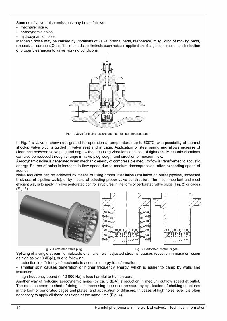
Sources of valve noise emissions may be as follows:- mechanic noise,- aerodynamic noise,- hydrodynamic noise.Mechanic noise may be caused by vibrations of valve internal parts, resonance, misguiding of moving parts, excessive clearance. One of the methods to eliminate such noise is application of cage construction and selection of proper clearances to valve working conditions.
Fig. 1. Valve for high pressure and high temperature operation
In Fig. 1 a valve is shown designated for operation at temperatures up to 500°C, with possibility of thermal shocks. Valve plug is guided in valve seat and in cage. Application of steel spring ring allows increase of clearance between valve plug and cage without causing vibrations and loss of tightness. Mechanic vibrations can also be reduced through change in valve plug weight and direction of medium flow. Aerodynamic noise is generated when mechanic energy of compressible medium flow is transformed to acoustic energy. Source of noise is increase in flow speed due to medium decompression, often exceeding speed of sound.Noise reduction can be achieved by means of using proper installation (insulation on outlet pipeline, increased thickness of pipeline walls), or by means of selecting proper valve construction. The most important and most efficient way is to apply in valve perforated control structures in the form of perforated valve plugs (Fig. 2) or cages (Fig. 3).
Fig. 2. Perforated valve plug Fig. 3. Perforated control cagesSplitting of a single stream to multitude of smaller, well adjusted streams, causes reduction in noise emission as high as by 10 dB(A), due to following:- reduction in efficiency of mechanic to acoustic energy transformation,- smaller spin causes generation of higher frequency energy, which is easier to damp by walls and insulation,- high frequency sound (> 10 000 Hz) is less harmful to human ears.Another way of reducing aerodynamic noise (by ca. 5 dBA) is reduction in medium outflow speed at outlet. The most common method of doing so is increasing the outlet pressure by application of choking structures in the form of perforated cages and plates, and application of diffusers. In cases of high noise level it is often necessary to apply all those solutions at the same time (Fig. 4).

Harmful phenomena in the work of valves. - Technical Information 13
Hydrodynamic noise is generated by flow of fluids, and its sources can be as follows:- turbulent flow interacting with valve and pipeline walls,- cavitation,- evaporation (flashing).Cavitation consists in local, usually in vena contracta area, evaporation of fluid due to pressure drop below evaporation pressure pv. Then, due to valve outlet pressure increase to value p2 > pv, implosion of generated steam bubbles occurs. In addition to noise, such a phenomenon features sudden accelerations and blows of two-phase mixture (fluid-steam), and resulting damages (Fig. 5) to valve or pipeline surfaces.Should outlet pressure stay lower than evaporation pressure (p2 < pv) fluid is permanently turned to mixture of fluid and steam, with steam share depending on pressure and temperature. This phenomenon is called evaporation (flashing). Then sudden increase in flow volume and speed occurs. Mixture stream erodes internal valve surfaces (Fig. 6) and pipeline, and is the source of noise as well. The most harmful phenomenon is however cavitation. Its effect can be reduced by means of application of proper materials and surface hardening technologies on one hand, and application of design methods for elimination or controlling of cavitation on the other hand. Another proven methods are: improving valve plug and valve seat durability by stelliting their phases or whole trims, diffusion or plasma nitriding, allowing achievement of surface hardness 950 HV to the depth of ca.0.1 mm, or through hot-setting to hardness 55 HRC. The basic design solution of anti-cavitation valves is execution with multi-stage valve plug (Fig. 7). The concept behind that solution is possibility of achieving pressure drops on each stage below critical value. It is however difficult to achieve effective choking on individual stages at the beginning of valve opening. In such cases we use contoured and perforated multi-stage valve plugs, with active structures which resistance depends on valve opening, and passive structures, in the form of cages and perforated plates (Fig. 8).
Fig. 7. Multi-stage anti-cavitation valve for small flows Fig. 8. Multi-stage anti-cavitation valve with various choking structures
Fig. 4. Valve for compressible media to operate in noise and choked flow
Fig. 5. Damage of valve due to cavitation
Fig. 6. Damage of valve due to flashing

Revision: HARMFUL EFFECTS/03/2011Valid until the next revision.
14
Fig. 9. Rotary valve for operation In flashing conditions
Fig. 10. Angle valve with anti-erosion seating
Fig. 11. Valve fitted with protective cageAlthough occurrence of flashing depends only on flow parameters, and cannot be eliminated through design changes, its damaging effects can - and have to – be eliminated.In addition to above discussed methods of improving durability of valve components, POLNA offers also application of hardening coatings on internal valve body surfaces, and application of valves fitted with anti-corrosion bushing (Fig. 9); angle valves (Fig. 10); and valves with protective cage (Fig. 11).
All above noise reduction methods applied in control valves by Zakłady Automatyki POLNA SA in Przemysl, are tailored to Customers’ needs.We design our valves after thorough analysis of phenomena occurring in flow process, based on detailed data and using specialized computer software DiVent and CONVAL®. Not only do our designs meet all standards, but also they solve problems the Customer’s are unaware of.CONVAL® software has a Polish version, made by our own company, and contains data about the POLNA product offer.

NON-CATALOG PRODUCTION
15
ZakładyAutomatyki“POLNA”S.A.inPrzemyślhavebeenoperatingnon-stopsince1899.
Since1960s,nineteensixties,itsmanyproductionprogramscanbedividedintofourproductgroups:
• automaticcontrolengineering(industrialautomation)• heatengineering• centrallubricationequipmentandsystems• laboratoryequipment:waterdistillers.
Thebiggestproductgroupconsistsofautomaticcontrolengineeringproducts.Thisproductionstartedin1967,whenalicenceforcontrolvalvesandpneumaticactuatorswaspurchasedfromMASONEILANcompany–oneoftheworldleadersinthisindustry.
Insubsequentyearsworkcontinuedonpost-licenseworksdevelopingandexpandingtherangeofandvarietiesofproducts,aswellasdevelopingitsowndesignsfortheneedsandrequirementsofthemarket.
SuchworkledtothecreationofabigofferofvalvesandpneumaticactuatorswithintheCompany’scatalog.TheproductrangeconsistsofvalvesranginginsizefromDN15upto300andwithnominalpressurefromPN6–400andwith flowcoefficients fromKvs0,01-6,300andwith castbodiesmade fromvariousmaterials:
• globevalves,passage,single-portvalveswithlinearmotionoftheplug:
TypesZ, Z1A, Z1B,
• globevalves,passage,double-portvalveswithlinearmotionoftheplug:
TypeZ10,
• globevalves,passage,single-port,withrotary-plug:
TypeZ33,
• globevalvesthree-wayvalveswithlinearmotionoftheplug:
TypeZ3,
• diaphragm,pneumatic,multi-springactuators:
TypeP/R,P1/R1.
16 SPECIALVALVES
Overthelasttensyears,theimportanceofnon-catalogproductshasincreased,astheyaredesignedandtoothetherequirementsoftheclientandthetechnologicalneedsoftheirproject.
Atpresent,theshareoftheautomaticcontrolengineeringproductsnowexceeds30%ofproduction,thusthenecessityofpresentingtheminmoredetail.
1. Valves constructed using forged elements. Theuseof forgings inpressureelementsofvalvesenables theuseof thisproduct towork in thehighestburdens in termsofpressure, temperatureand thecorrosiveenvironment,which isonlyachievedthankstotheproperselectionofmaterialsandconstructionsolutions.
Dependingontheneeds,wemanufacturevalveswithvariousconstructionsolutions:angle,passage,passage/angle(„”shapedwithparallel,non-axialends)andthreewayvalves.
POLNAalsooffersawholerangeofconnectionsforpipelines;flange(madetoENandANSIstandards)forBWwelding,directforthebody,flange-lessandothers.
Thematerialusedforthebodyischosendependsontheworkingpressureduringmaximumworkingtemperature.Themostcommonlyusedmaterialsare:
•S355J2G3(1.0570),•13CrMo4-5(1.7335),•14MoV6-3(1.7715),•X10CrMoVNb9-1(1.4903))andothers.
2. The Elimination or restriction of harmful effects related to flow. Theflowofsubstancesthroughavalve,dependingonit’stypeandparameterscancausesuchphenomenaashighnoise,cavitation,evaporation(flashing),chokedflowanderosionlevels,thatcouldhaveanegativeimpacton theenvironment, reducing the regulatoryvaluesof thevalveandhavinganegative impacton theproduct’sdurability. Toavoid suchan impact these factors shouldbeanalyzed indetail.Theseactionsaremainly focusedonrestrictingthespeedflowandthedivisionoftotalpressurereductiononthevalveintoafewsteps,sothatthepressurereductionsdonotexceedcriticallevels.
Multiholeelements(plugs,cages,plates),areincommonuse,andtheirmainrolebeingtolimitnoiselevels.Thedivisionofpressureisachievedbymeansofresistancestructureswithinthevalve,suchasmulti-stageplugs,cagesandthrottlingplates.
Reductionofflowspeedisachievedbydivisionofpressurereductiononthevalveand/orapplicationofenlargedoutflowdiameterinthevalve’sbodyorexpandingelements(diffusers).
Animportantroleisplayedbytheproperchoiceofmaterialsandthewaysofincreasinghardnessofinternalvalveelements.Weoftenutilizehardenedsurfacesusingstelliting,plasmaordiffusionnitriding,heatenhancingandprotectivecoating.
Allthesefactorswillonlyfulfilltheirroleifworkconditionsareknown,valvesareconstructedproperlywiththeskillsandknowledgeofourlongexperience.
TheopinionsofPOLNAproductusersprovethatwecandesignandmanufacturevalvescompletelyfulfillingeventheveryhighestoftheirrequirements.
3. Valves designed for work in aggressive or dangerous environments. POLNAproducesvalvesforworkwithdangeroussubstancessuchasoxygen,hydrogen,naturalgas,acidicgasescontainingH2Sandindangerousenvironmentswheretherearerisksofexplosions. Thepreparationconsistsofthecarefulcleaningofsurfacescomingintocontactwiththesubstanceusingbothmechanicalandchemicalmeans,aswellasusingmaterialsandwaysofproductionandcontrolcomplyingwithsafetyregulations.ProductsintendedforworkinatmosphereswithhighriskofexplosionaremanufacturedincompliancewiththeATEXdirective.

17SPECIALVALVES
4. Products adapted to the specifics of particular industries. Everybranchofindustryhasitsowncharacteristics,whichhavetobetakenintoconsiderationinthephaseofdesigning,manufactureandcontrolofautomaticcontrolengineering. Forproductsdesignedforpowerindustry,thepossibilityoftheoccurrenceofhightemperatureandpressure,thermalshocks,chokedflowsandexcessnoisemustbetakenintoconsideration.
POLNA has some tried and tested applications of product especially designed for various uses in powerindustry,suchas:
• boilerfeedvalves,alsofulfillingtheroleofstartingvalves,• reducingandcoolingstationswithintegratedinjectioninapressurereducingvalve,• elements of reducing and cooling stations with integrated steam pressure reducing valves,desuperheaters,injectionvalves.
Pressure reducing valves, passage and anglemodels,with balanced plugs, eliminating choked flow,with avastrangeofflowregulation.
Piston,ring,lanceandsteam-atomizingdesuperheaters.Anti-cavitationinjectionvalves.• minimumflowvalvesusedaspumpby-passvalves,• condensatepilingvalves• three-wayvalvesforpowerindustryapplications.
Forproductsdesigned for thegasandpetrochemical industry, chemical resistance, it is important to takeaccountofresistancetohighpressures,flowspeedsandsignificanttemperaturechanges,aswellasprotectionoftheenvironmentandworksafety.
Productsinclude:• pressurereducingvalvesforsignificantchangesofflowvalues,• valveseliminatingchokedflowandlimitingnoise,• valvesworkinginlowtemperatureenvironments(e.g.inSiberia),• depositwatervalves,• high-pressurenaturalgasvalves,• valvesusedincryogenics,• anti-cavitationvalvesandvalvesresistanttoerosion(flashing)forgasmines,stampingpressesandgasdistributionplants.
5. Valves complying with boiler regulations. Basicvalveproductsrefertoproductioninaccordancewiththe93/27/ECpressuredirective,concerningthefixingonpipelines. POLNA also has the capability ofmanufacturing valves designed for vessels, in accordancewithPL-EN12952-3:2004 norm (“Water-tub boilers and auxiliary installations –Part 3:Design and calculation forpressureparts”).
6. Custom built valves manufactured to the clients requirements. POLNAhasthecapabilitytodesignandmanufacturevalvesadjustedespeciallyforparticularuses.Detailed description of requirements is key. With the use of a professional computer program CONVAL wedeterminephenomenaoccurringinparticularpointsofavalve’swork.Thatinformation,togetherwithlong-standingexperience,enablesustodesignvalvesfulfillingtherecipient’srequirements.Tomentionjustafewexamplesshowingthevarietyofmanufactures,wehavemade:
-valvesforundergroundinstallations,withapropersolutionofvalve’sdrive,-high-pressurecontrolandcut-offvalvesforthefoodindustry,-awiderangeofvalvesadjustedtoworkinconditionsofcavitationrisk.Thestructuresofvalvestakeintoconsiderationtherequirementsconcerningchangesofflowvalues(regulatability)andreductionofpressureonthevalveoccurringatthechangeofvalve’sopening.Duetotheuniquityofthoseconditions,eachvalvemayhaveastructuredifferentfromtheothersintermsofdetailsoftechnicalsolution.

18 SPECIALVALVES
Boiler feed valve, also fulfilling the role of a starting valve.
Acastbody,materialG17CrMo9-10(1.7379),withaself-tighteningbonnet.Themainplugiscontrolledbyanauxiliaryplug(pilot),flowovertheplug(FTC).Amulti-steppilotallowstoregulatesmallflowsatbigpressurereductionswithouttheriskofcavitationoccurring. Themainplug:two-stepuptothemiddleoflift,withresistanceelements(plates).Whenopenedwider,nointernalthrottling;thefunctionoffillingtheboileriscarriedoutatasmallpressurereduced.Aprotectivecageontheseat.Itishighlyair-tight
Reducing and cooling station. AnanglesteampowerreductionvalveDN25/DN150,ismadeofX10CrMoVNb9-1(1.4903).Amulti-stageplugandresistanceplatesontheoutflowaimingateliminationofchokedflowandlimitingthenoiselevels.Thecoolingchamberisanintegralpartofthevalve.Alancedesuperheater,aninjectionvalvewithananti-cavitationstructure.
WATER
STEAM

19SPECIALVALVES
Steam reduction valve.
Anangularbodymadeof13CrMo4-5(1.7335).Aself-tighteningbonnet.Themainplug:cagetype,controlledbyanauxiliaryplug(pilot).Adiffuserintegralwiththebodyofthevalvewiththreeresistanceplates.
Piston desuperheater
RegulationscopeKvmax10;regulatability1:40,VclasstightnessinaccordancewithPN-EN60534-4standards.Thevalvepartwithaone-ortwo-stepprofileplugmadeofthe13CrMo4-5(1.7335).ThepipelinediameterrangestooverDN200.
STEAM
WATER
20 SPECIALVALVES
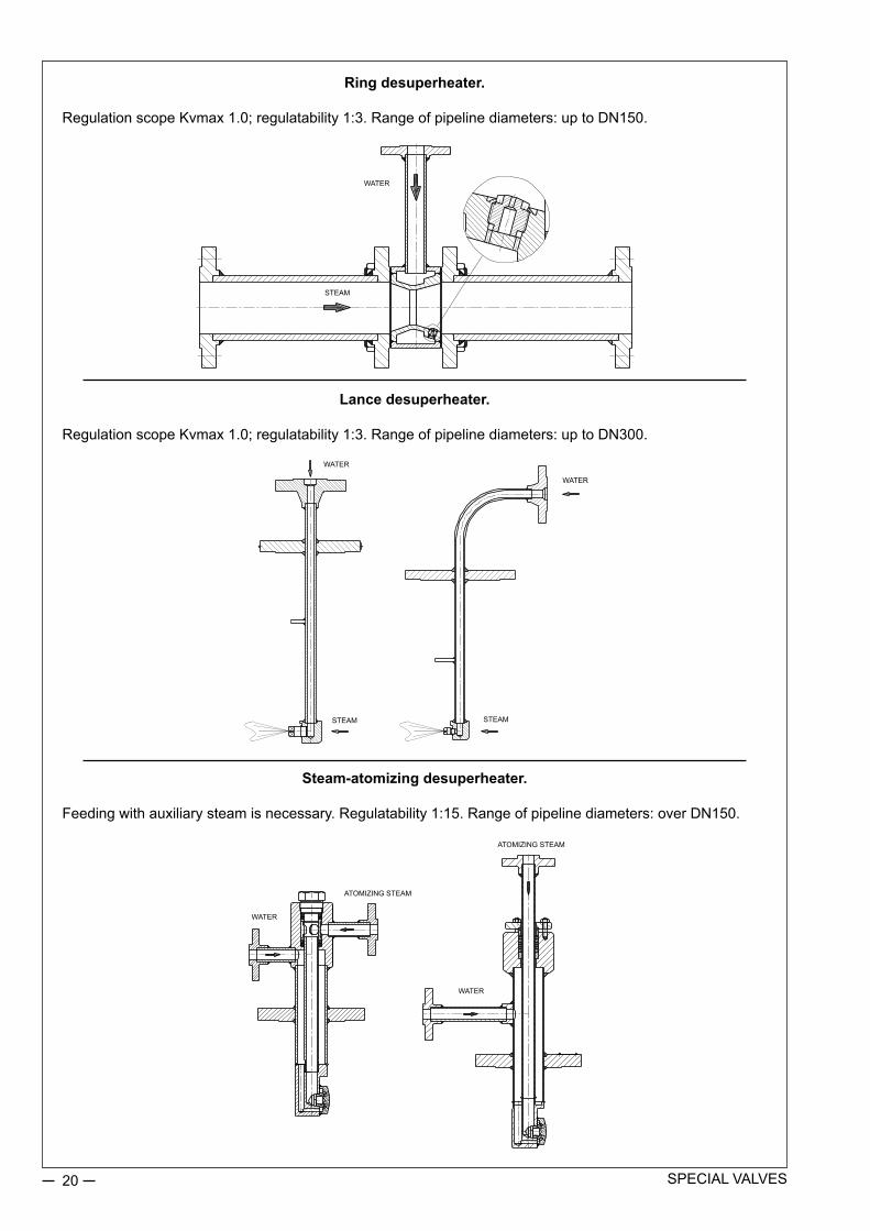
Ring desuperheater.
RegulationscopeKvmax1.0;regulatability1:3.Rangeofpipelinediameters:uptoDN150.
Lance desuperheater.
RegulationscopeKvmax1.0;regulatability1:3.Rangeofpipelinediameters:uptoDN300.
Steam-atomizing desuperheater.
Feedingwithauxiliarysteamisnecessary.Regulatability1:15.Rangeofpipelinediameters:overDN150.
WATER
STEAM
WATER
WATER
WATER
STEAM STEAM
WATER
ATOMIZINGSTEAM
ATOMIZINGSTEAM

21SPECIALVALVES
Minimum flow valve. Nominalsizeofthevalve:DN50PN320.It’susedforflowregulationapprox.60t/hatpressurereductionofupto200bar.Non-bonnetdesignwithapackingsealinthelowpressurezone. Athree-stepplugcombinedwithamulti-holesleevecreatessixstepsofthrottling.Perfectclosuretightnessasaresultofflowoverthepoppet(FTC).Adjustedtoon-offfunctionandcontrolone,usedinby-passsystemsoffeedingpumps.
Condensate piling valve.
It is fixeddirectly at the containerwith theoutflowdirected to the liquid surface,whicheliminatespotentialdestructionofthevessel’selementsbycavitationanderosion.
LustrowodywzbiornikuSuRFACEOFTHEWATERINTHEVESSEL

22 SPECIALVALVES
Valve with a two-step plug and a throttling cage with several throttling chambers.
Itisdesignedforapplicationsreducingnoiselevelandeliminatingcavitationorchokedflow.
Control valve for low environment temperatures.
DN300,CL600valveworksonnaturalgasinstallationsinSiberia.Abalancedplug,castselementsofthevalveandanactuatormadeofcaststeelarecapableofworkinginlowtemperaturesareavailableintheASTMA352LC2variety.Theelastomerpartsoftheactuator(diaphragm,seals)aremadeofsilicone.

23SPECIALVALVES
Deposit water valve.
Ananti-cavitationstructurewiththreemulti-holeresistanceplates.
Natural gas valve.
Anangularbody,pipelinecounterflangesdirectlyconnectedtothebody.Workingpressure450bar,nominalpressurePN700.Flowundertheplug(FTO);fullopeningoftheplugcutsoffaccessoftheagentandimpactofpressureonvalvestempacking.

24 SPECIALVALVES
Anti-cavitation valve.
Thebodyismadeofaforging,threadedends.Amulti-stepplug,andathrottlingcage.Non-servicepackingofstemfulfillingtightnessrequirementsaccordingtoTALuft.Itiscurrentlyinuseatthe“Dębno”gasmineinPoland.
Cut-off valve.
AflangebodyismadeofforgedX2CrNiMo17-12-2(1.4404)–316L.materialWorkingpressureisupto530bar.Two-partplugstructure:aninternalplugandamainplugforstaticreliefupontheopeningofthevalve..Flowovertheplug(FTC),highclosuretightness.Thisproducthasbeendesignedespeciallyforthefoodindustry.

25SPECIALVALVES
Anti-cavitation valve.
Thisproductsolvestheproblemofregulationandanti-cavitationprotectionatsmallopeningofthevalve.Theinternalplug–multi-step,themainplug–two-step,withathrottlingcageintheseat.Flowovertheplug(FTC).
Double-position anti-cavitation valve.
Thisproductsolvestheproblemofsmallflowsduringbigpressurereductionsandbigflowsatsmallpressurereductions,ifthereisariskofcavitationinbothcases.Athree-stepprofile/pistonplug,athrottlingcagedividedintochamberswithproperthrottling.

26 Revision:SPECIALVALVES/10/2014Validuntilthenextrevision.
High parameters control valve.
Thebody ismadeof forgedelementswith structure „ ”DN250PN320,Kvs320P.Thematerial used is13CrMo4-5(1.7335),aself-tighteningbonnet,aplugbalancedbyagraphitering.ManufactureconformingtoPN-EN129523:2004“Water-tubboilers”.
Angle valve with ceramic elements for liquid. Thevalvepresentedisofanti-cavitationdesign.
Ceramicelementsincludeplugandseat.
Suitablyshapedplugandseatcause a multi-stage pressuredropacrossavalveinordertolimitthedangerofcavitation.
Pressing cage inside theoutflowchamberismadeoffullstellite for protection againsterosionofvalvebodysurface.
Abodyofthepresentedanglevalve is of split design,whichenables an easy access tovalve internal parts, so as tofacilitatechecksandservicing.
Avalvebodyofangleorpassagedesign;diameters,pressures, typesof flangesshall beadjusted to thecustomer’sneeds.

27 Revision:SPECIALVALVES/10/2014Validuntilthenextrevision.
Angle valve to control the flow of steam. Angle valve works at thePątnówPowerPlant,aspartofa310ºCsteamsystem. Soastomaintaintheworkingparameters and meet theacceptable noise standards,two silencing plates areinstalledatthevalveoutletandaperforatedplugisused.
The angle body has weldingends with the nominal inletdiameter of DN150 and theoutletoneofDN250.
The long throttle allows toseparate sensitive elementsof the electrical actuator andgraphite seal of the valvestem from adverse conditionsoccurring at the valve (hightemperature).
ThetightnessclassofthevalveasspecifiedinPN-EN60534-4ishigher–V,andtheflowcoefficientis320Kvsatthelinearflowmode.
Passage flanged valve for 2-directional flows.
2-directionalvalvesareappliedingasengineeringincaseofachangeinfluidflowdirectionininstallation.BasicdesigncomprisespassagecagevalveDN300,PN100,Kv1350.
Plugdesignallows for rangeabilityof100:1.Plug ispressurebalancedby „u” typepackingsetprovidingtightnessinbothdirections.
Packing used, aswell as plug guiding tape provide forminimum friction factor and excellent tribologicalproperties.
Seat hole and outer plugsurfaces are stellited, controlcage and guiding sleeve areheattreatedandgasnitrided,stemismadeoftitanium.
Technology of increasinghardnessandmaterials usedguarantee long and reliableservice.

28 Revision:SPECIALVALVES/10/2014Validuntilthenextrevision.
High temperature control valve. The Z1A valve with a P-400 pneumatic actuator presented in thephotoisequippedwithaSMARTelectropneumaticpositionerandanairfilterreducer.
Thankstotheuseofappropriatematerialsforthebodyandbonnet,thevalvecancontroltheflowofaheliumandnitrogenmixturewiththetemperatureofupto600oC.
ValvebodyandbonnetwereentirelymadefromforgedsteelX10CrMoVNb9-1(P91).
Bodydesignwith threadedholes for screwsenablesdirect connectionwithpipelinecounterflanges.
Specialdesignofinternalpartsmadefromstainlesssteel,whichishardenedwithstellite,providesforproperflowregulationatextremepressuredrops.
Valve internalpartsweredesigned insuchaway toprotectplugandstemguidingelementsalongwithsealingsagainstwearing.Theyarecoveredthemfromstrikesofexpandingsteambymeansofaninternalcageofspecialdesign,whichisadditionallysealedbyapackingmadefromgraphiteofnuclearpurity(99,9998%ofpuregraphite).
Passage flangeless valve for working pressure of 530 bar.
All parts of the valve presented were made of 316L steel and counterflanges of X2CrNiMoN22-5-3 1.4462(DuPLEX).ThevalvesweremadefornominalpressureofPN630asperBN-911771-20/40standard,duetooccurrenceofworkingpressureof530bar.SealingbetweenvalvebodyandcounterflangeswasdesignedbasedonBX150gasketsinaccordancewithAPI6AClass15000.ThevalvesfeatureguaranteedClassVofplug/seatshut-offatthefullpressuredropof530bar,duetothatfluidflowwasdirectedovertheplug(FTC).Pressuredifferenceoverandundertheplugatshut-offcausesadditionalthrustandunitseal.Inordertoreducerequireddisposableforceofactuator,specialplugdesign(plugpressurebalancedbyinnerplug–socalledpilot)wasapplied.Pilotwasselectedinsuchawaythatforceneededforitsopeningwas7timeslowerthanthatofmainplug.Afterpilotopening,pressureaboveandunderthemainplugequalizeandfurtheropeningaimingatachievingafullpassagedoesnotrequirehigherdisposableforceofactuator.
Inordertopreventawearandtearofinternalpartscausedbyhighvelocityoffluid(liquidcarbondioxide)flow,plugs,seatsandguidingsleevesweremadeutilizingfullstellitedoverlaywiththehardnessof45HRC.Thevalvesareequippedwithpneumaticactuators,solenoidvalvesforcontrolandopen/closedpositionindicators.
The valves presentedwere designed andmanufactured forChemical Fertilizers Institute inNitrogenPlant inPulawy.

SINGLE-PORTED GLOBE CONTROL VALVES TYPE Z®
29
APPLICATIONS:
Single-ported globe control valves type Z® are used in automatic and remote control systems to control flow of gases and liquids. Wide range of material and design versions make the valves widely sought-after in chemical industry, heat and power generation industry, paper industry, food industry, metallurgy and coal mining (versions for Western Europe market is marked: BR11).
CHARACTERISTICS:
• range of nominal sizes from DN15 to DN250 for pressure values PN10 to CL300,• various materials of valve body cast and internal parts, adapted to specific working conditions,•wide range of f low rat ios and control characteristics,• reduction in aggressive and toxic media emissions to environment through application of bellow seal bonnets or bonnet packings meeting requirements of TA - LUFT,•easy assemb ly and d ismant l i ng o f va lve in te rna l par ts fo r ma in tenance and service,•high durability and reliability due to application of top-class materials and surface improvement processes (burnishing, stelliting, heat treatment, CrN coatings),•poss ib i l i ty o f mat ing wi th revers ib le action P/R (column) multi-spring actuators and changing the spring range with no extra parts (keeping the number of springs),•possibility of fitting actuators with top drive,•possibility of performing diagnostics of “valve-actuator” system due to application of smart electro-pneumatic positioners,•high tightness of closure due to application of soft valve seats (with PTFE seals in the whole range of flows and characteristics, for valve plugs, balanced and unbalanced,•same flow ratios and control characteristics for “hard” valve seats (metal-to-metal) and “soft” valve seats (metal-gasket), for valve plugs, balanced and unbalanced,•reliable actuator-stem and valve seat-body connections,•small guiding sleeve control forces due to application of balanced valve plugs in valves DN40…250,• top-class flat and bonnet packings,•wide range of electric actuators,•possibility of mating with NN type hand operated drives,•possibility of special executions for oxygen, hydrogen, gas fuels, low temperature mediums (liquid oxygen, liquid nitrogen), acid gases containing H2S; explosive atmospheres as per 94/9/EC - ATEX,•competitive prices – due to simple and functional design of valves and actuators and applied materials,•design and production process meets the requirements of Quality Management System ISO 9001 and Directive 97/23/EC, and regulations of AD2000 Merkblatt, designated for installation on pipelines,
Z ® is a trademark registered with Republic of Poland Patent Office.

Single-ported globe control valves type Z 30
Body (1): single-ported, flanged, cast in cast iron or cast steel.Nominal sizes: DN15; 20; 25; 32; 40; 50; 65; 80; 100; 125*); 150; 200; 250*) special execution, technical data according to individual inquiries.Nominal pressure: PN10; 16; 25; 40 (as per PN-EN 1092-1:2010 and PN-EN 1092-2:1999); CL150; CL300 (as per PN-EN 1759-1:2005).Steel flanges CL150; CL300 are so designed that they can be assembled with flanges executed per American standards ANSI/ASME B16.5 and MSS SP44. In American standards flanges are identified with nominal values in “Classes”, to which nominal pressure (PN) values as per PN-ISO 7005-1:2002 correspond.Equivalent identification as per PN are: CL150: PN 20 and CL300: PN 50.Table 1. Flanged end connections
DESIGN AND TECHNICAL SPECIFICATION:
Material Nominal pressureFacing of flange types
Raised face Groove Recess Ring - jointIdentification
Grey iron PN10; 16
B 2)
- - -Spheroidal iron PN10; 16; 25; 40 - - -
Cast steelPN10; 16; 25; 40 D F -
CL150 - -J (RTJ)
CL300 DL ( D1 1) F ( F1) 1) - only for CL300; 2) - B1 – (Ra=12.5 mm, concentric surface structure “C”), B2 – (Ra as agreed with the customer);
() - identification of connections as per ASME B16.5Possible execution of flanges per specification and indicated standards
Fig. 1. Bonnets DN15…100
Face-to-face dimensions: as per PN-EN 60534-3-1; 2000r. - Fig. no. 7 ; Table 19 and 20. Series 1 - for PN10; 16; 25; 40; series 37- for CL150; series 38 - for CL300Bonnet (2) - non-cast - assembled to body via assembly plate (DN15-100) - cast (DN150-250): a) standard, b) extension (for cast steel valves), c) bellows (for cast steel valves).
Standard Extension Bellow seal
DN15…50 DN65…100
TA LUFT packing (all types)

Single-ported globe control valves type Z 31
Valve plug (3) - contoured, balanced, unbalanced •control characteristics: - linear (L) - equal percentage (P) - quick-opening (S) •rangeability: - 50:1
Fig. 2. Valve plugs
Kvs 0,01…1DN15…50
Unbalanced valve plugs
Standard Extension Bellow seal
Fig. 1a. Bonnets DN125…250
Balanced valve plugs
Kvs 0,01…16 (DM/DW)DN15…50
Kvs 25…160DN40…100
Kvs 63…630DN125…250
Kvs 25…160DN40…100
Kvs 250…630DN125…250

Single-ported globe control valves type Z 32
Valve seat (4) - screwed in, with centering cone, sealing and preventing unscrewing: •hard version, •soft version (PTFE packing).Valve plug stem (5) - burnished or quenched and tempered, polished sealing contact surfaceDrain plug (6) - steel or stainless steel: allows cleaning of body interior (delivered separately)Body gasket (7) - asbestos-free: •flat – aramid and hardened graphite (1.4571); in metallic casing (1.4571), multiple edges •bonnet: - packings formed in various materials (PTFE-V; PTFE+graphite; expan ded graphite; braided graphite); - with TA Luft compression springs (PTFE-V; graphite)Table 2. Packing types with application ranges.
Leakage class: - basic: Class IV as per PN-EN 60534-4 - hard valve seat - bubble-tight Class VI as per PN-EN 60534-4 - soft valve seatTable 3. Listing of components with materials
NOTE:Hardening method used for hardening of valve internal parts comprises:a) stelliting – padding of surfaces with stellite: ~40HRCb) CrN coating – introducing chromium nitride to external layer of detail, to the depth of ca.0.1 mm;~950HVc) heat treatment: plug (~45HRC), seat (~35HRC), stem (~35HRC), guide sleeve (~45HRC)d) Maximum working temperature -200…+250°C (for KEFLOY 25 material), higher temperatures: upon con-sultation with the manufacturer.
Packing PN / CLTemperature [°C]
BonnetStandard Extension Bellow
PTFE-V
PN10…CL300-46...+200
-198...-46+200...+300
-100...+200PTFE + GraphitePTFE-V / TA-LUFT
Graphite+200...+300 +300...+450 +200...+400
Graphite / TA-LUFT
Item Component Materials
1 BodyEN-GJL 250
(EN-JL 1040)EN-GJS 400-18 LT
(EN-JS 1025)GP 240 GH(1.0619)
WCBGX5CrNiMo 19-11-2
(1.4408)CF8M
2 BonnetDN15…100 S 355 J2G3 (1.0570) X6CrNiMoTi 17-12-2 (1.4571)
DN125…250EN-GJL 250
(EN-JL 1040)EN-GJS 400-18 LT
(EN-JS 1025)GP 240 GH(1.0619)
WCBGX5CrNiMo 19-11-2
(1.4408)CF8M
3 PlugX6CrNiMoTi 17-12-2; (1.4571)
X6CrNiMoTi 17-12-2; (1.4571) + stellite + CrNX17CrNi 16-2 ; (1.4057) + heat treatment
4 Seat
X6CrNiMoTi 17-12-2; (1.4571)X6CrNiMoTi 17-12-2; (1.4571) + stelliteX6CrNiMoTi 17-12-2; (1.4571) + PTFE
X17CrNi 16-2; (1.4057) + heat treatment
5 StemX6CrNiMoTi 17-12-2; (1.4571)
X6CrNiMoTi 17-12-2; (1.4571) + stellite + CrNX17CrNi 16-2 ; (1.4057) + heat treatment
6 Drain plug S 355 J2G3 (1.0570) X6CrNiMoTi 17-12-2; (1.4571)
7 Body gasketin metal casing X6CrNiMoTi 17-12-2 (1.4571) ; NOVATEC PREMIUM;
SIGRAFLEX HOCHDRUCK; MWK-50 SPETOMET
8 Guiding sleeveX6CrNiMoTi 17-12-2; (1.4571) + CrN
X6CrNiMoTi 17-12-2; (1.4571) + stellite + CrNX17CrNi 16-2 ; (1.4057) + heat treatment
9 Compression plate C45 (1.0503); X30Cr13 (1.4028); X6CrNiMoTi 17-12-2; (1.4571)
10 Bolt 8.8 A4 - 70
11 Nut 8 A4 - 70
12 Packing PTFE + GRAFIT; PTFE - „V”; GRAPHITE13 Spring 12R10 (SANDVIK)14 O-ring Fluorine rubber (FKM)
15 Guiding sleeveX6CrNiMoTi 17-12-2; (1.4571) + CrN
X6CrNiMoTi 17-12-2; (1.4571) + stellite + CrNX17CrNi 16-2 ; (1.4057) + heat treatment
16 Seal ring PTFE + X6CrNiMoTi 17-12-2 (1.4571); TURCON + X6CrNiMoTi 17-12-2 (1.4571)17 Bellow X6CrNiMoTi 17-12-2; (1.4571)
Relevant materials standardsMaterial Standard
EN-GJL 250 ; (EN-JL 1040) PN-EN 1561EN-GJS 400-18 LT ; (EN-JS 1025) PN-EN 1563
GP 240 GH ; (1.0619) PN-EN 10213-2WCB ASTM A 216
GX5CrNiMo 19-11-2 ; (1.4408) PN-EN 10213-4CF8M ASTM A 351
S 355 J2G3 ; (1.0570) PN-EN 10025X6CrNiMoTi 17-12-2 ; (1.4571) PN-EN 10088
X17CrNi 16-2 ; (1.4057) PN-EN 10088C45 (1.0503) PN-EN 10083-1
X30Cr13 (1.4028) PN-EN 10088

Single-ported globe control valves type Z 33
Table 4. Working parameters for special executions of valves.
Fig. 3. Control valve DN15-100
a) with standard valve plug
b) with balanced valve plug
Valve executionWorking temperature [°C]
Max working pressure [bar]Min. Max.
With balanced plug -50+200
40With soft valve seat (PTFE) -100 35
With bellow seal bonnet -100 +400 35

Single-ported globe control valves type Z 34
Fig. 4. Control valve DN125-250
a) with standard valve plug
b) with balanced valve plug

Single-ported globe control valves type Z 35
Table 8. Material: GX5CrNiMo 19-11-2 (1.4408) as per PN-EN 10213-4
PN / CL Standard
Temperature [°C]
-10…50 100 150 200 250 300 350 400 425 450
Allowable working pressure [bar]
PN10EN 1092-1
10 10 9 8,4 7,9 7,4 7,1 6,8 - 6,7
PN16 16 16 14,5 13,4 12,7 11,8 11,4 10,9 - 10,7
CL150 PN-EN 1759-1 17,9 16,3 14,9 13,5 12,1 10,2 8,4 6,5 5,6 4,7
PN25EN 1092-1
25 25 22,7 21 19,8 18,5 17,8 17,1 - 16,8
PN40 40 40 36,3 33,7 31,8 29,7 28,5 27,4 - 26,9
CL300 PN-EN 1759-1 46,7 42,5 38,9 35,3 32,9 30,5 28,8 27,6 27,2 26,9
Table 5…11. Allowable working overpressure for materials at proper temperatures
Table 7. Material: GP240GH (1.0619) as per PN-EN 10213-2
PN / CL Standard
Temperature [°C]
-10…50 100 150 200 250 300 350 400
Allowable working pressure [bar]
PN10EN 1092-1
10 9,2 8,8 8,3 7,6 6,9 6,4 5,9
PN16 16 14,8 14 13,3 12,1 11 10,2 9,5
CL150 PN-EN 1759-1 17,3 15,4 14,6 13,8 12,1 10,2 8,4 6,5
PN25EN 1092-1
25 23,2 22 20,8 19 17,2 16 14,8
PN40 40 37,1 35,2 33,3 30,4 27,6 25,7 23,8
CL300 PN-EN 1759-1 45,3 40,1 38,1 36 32,9 29,8 27,8 25,7
NOTES:1. It is allowed to apply spheroidal iron,
carbon steel and acid proof cast steel for temperatures lower than given in Tables 5...11, provided that working pressure is reduced respectively, working temperature impact tests are performed and cast is heat treated. Details are to be consulted with manufacturer.
2. Working pressure for intermediate temperature values can be calculated by interpolation.
Table 10. Material: WCB as per ASTM A216
PN / CL Standard
Temperature [°C]
-10…50 100 150 200 250 300 350 375 400
Allowable working pressure [bar]
PN10EN 1092-1
10 10 9,7 9,4 9 8,3 7,9 7,7 6,7
PN16 16 16 15,6 15,1 14,4 13,4 12,8 12,4 10,8
CL150 PN-EN 1759-1 19,3 17,7 15,8 14 12,1 10,2 8,4 7,4 6,5
PN25EN 1092-1
25 25 24,4 23,7 22,5 20,9 20 19,4 16,9
PN40 40 40 39,1 37,9 36 33,5 31,9 31,1 27
CL300 PN-EN 1759-1 50 46,4 45,1 43,9 41,8 38,9 36,9 36,6 34,6
Table 11. Material: CF8M as per ASTM A351
PN / CL Standard
Temperature [°C]
-10…50 100 150 200 250 300 350 375 400 425 450
Allowable working pressure [bar]
PN10EN 1092-1
8,9 7,8 7,1 6,6 6,1 5,8 5,6 5,5 5,4 5,4 5,3
PN16 14,3 12,5 11,4 10,6 9,8 9,3 9 8,8 8,7 8,6 8,5
CL150 PN-EN 1759-1 18,4 16 14,8 13,6 12 10,2 8,4 7,4 6,5 5,6 4,6
PN25EN 1092-1
22,3 19,5 17,8 16,5 15,5 14,6 14,1 13,8 13,6 13,5 13,4
PN40 35,6 31,3 28,5 26,4 24,7 23,4 22,6 22,1 21,8 21,6 21,4
CL300 PN-EN 1759-1 48,1 42,3 38,6 35,8 33,5 31,6 30,4 29,6 29,3 29 29
Table 5. Material: EN-GJL 250 as per PN-EN 1561
PN Standard
Temperature [°C]
-10…120 150 180 200 230 250 300
Allowable working pressure [bar]
PN10PN-EN 1092-2
10 9 8,4 8 7,4 7 6
PN16 16 14,4 13,4 12,8 11,8 11,2 9,6
Table 6. Material: EN-GJS 400-18 LT as per PN-EN 1563
PN Standard
Temperature [°C]
-10…120 150 200 250 300 350
Allowable working pressure [bar]
PN10
PN-EN 1092-2
10 9,7 9,2 8,7 8 7
PN16 16 15,5 14,7 13,9 12,8 11,2
PN25 25 24,3 23 21,8 20 17,5
PN40 40 38,8 36,8 34,8 32 28
Table 9. Material: G20Mn5 (1.6220) wg PN-EN 10213-3
PN / CL Standard
Temperature [°C]
-40 100 150 200 250 300
Allowable working pressure [ [bar]
PN10
-
6 6 3,8 3,6 3,48 3,4
PN16 16 16 10,1 9,6 9,28 9,07
PN25 25 25 15,8 15 14,5 14,2
PN40 40 28 28 27 26 25
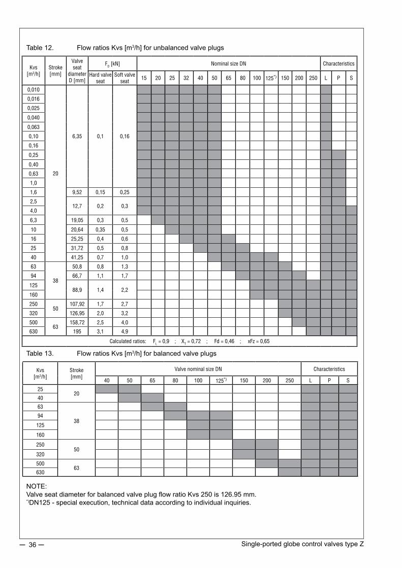
Single-ported globe control valves type Z 36
Table 12. Flow ratios Kvs [m3/h] for unbalanced valve plugs
Table 13. Flow ratios Kvs [m3/h] for balanced valve plugs
NOTE: Valve seat diameter for balanced valve plug flow ratio Kvs 250 is 126.95 mm. *)DN125 - special execution, technical data according to individual inquiries.
Kvs[m3/h]
Stroke[mm]
Valve seat
diameter D [mm]
FD [kN] Nominal size DN Characteristics
Hard valve seat
Soft valve seat
15 20 25 32 40 50 65 80 100 125*) 150 200 250 L P S
0,010
20
6,35 0,1 0,16
0,016
0,025
0,040
0,063
0,10
0,16
0,25
0,40
0,63
1,0
1,6 9,52 0,15 0,25
2,512,7 0,2 0,3
4,0
6,3 19,05 0,3 0,5
10 20,64 0,35 0,5
16 25,25 0,4 0,6
25 31,72 0,5 0,8
40 41,25 0,7 1,0
63
38
50,8 0,8 1,3
94 66,7 1,1 1,7
12588,9 1,4 2,2
160
25050
107,92 1,7 2,7
320 126,95 2,0 3,2
50063
158,72 2,5 4,0
630 195 3,1 4,9
Calculated ratios: FL = 0,9 ; XT = 0,72 ; Fd = 0,46 ; xFz = 0,65
Kvs[m3/h]
Stroke[mm]
Valve nominal size DN Characteristics
40 50 65 80 100 125*) 150 200 250 L P S
2520
40
63
3894
125
160
25050
320
50063
630

Single-ported globe control valves type Z 37
Dia
gram
1. E
qual
per
cent
age
flow
cha
ract
eris
tics
for c
ontro
l val
ves
Kvs
=0.2
5…63
0 m
3 /h

Single-ported globe control valves type Z 38
Table 14. Available force FS [kN] of pneumatic actuators
NOTE: 1. For direct actuators P adopted spring range is 20 – 100 kPa2. For electric and other actuators Δp value can be calculated using above formula and data from Tables 12 and 14, taking nominal load capacity as available force FS, as per actuator catalog chart.3. For balanced valve plugs available force Fs at least equal to FD value for soft valve seats in Table 12 should be adopted.
ALLOWABLE PRESSURE DROPS ∆p.Pressure drops ∆p [bar] in Tables 15 and 16 apply to closed valve and they are calculated for valve drive poten-tial. Actual pressure drops should not exceed 70% of allowable working pressure for given nominal pressure, material execution and working temperature, as per tables 5…11.
where ∆p [bar] - calculated pressure drop Fs [kN] - actuator available force (Table 14) FD [kN] - valve plug to valve seat pressure (Table 12) D - valve seat diameter [mm] (Table 12)
Fs = 0,785 • 10- 4 • D2 • ∆p + FD∆p =
Fs - FD
0,785 • 10- 4 • D2 or
Actuator size
Direct actuator P Reverse actuator RSupply pressure [kPa] Spring range [kPa]
140 250 400 20 - 10040 - 120;40 - 200
60 - 140 80 - 240 120 - 280 180 - 380
250 1,0 3,8 7,5 0,5 1,0 1,5 2,0 3,0 -400 1,6 6,0 12,0 0,8 1,6 2,4 3,2 4,8 -630 2,5 9,5 18,9 1,3 2,5 3,8 5,0 7,6 11,3
1000 4,0 15,0 30,0 2,0 4,0 6,0 8,0 12,0 18,0
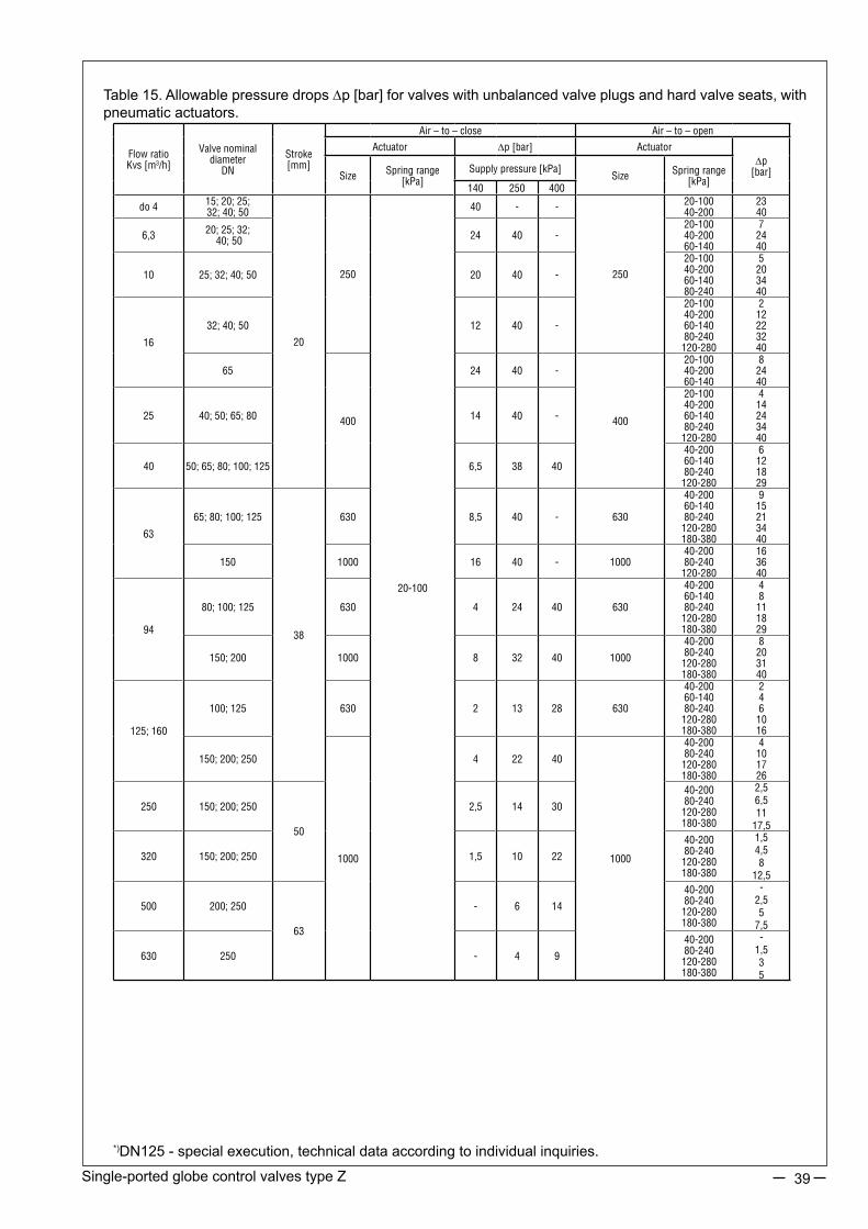
Single-ported globe control valves type Z 39
Table 15. Allowable pressure drops ∆p [bar] for valves with unbalanced valve plugs and hard valve seats, with pneumatic actuators.
Flow ratio Kvs [m3/h]
Valve nominal diameter
DN
Stroke[mm]
Air – to – close Air – to – open
Actuator ∆p [bar] Actuator∆p
[bar]Size Spring range [kPa]
Supply pressure [kPa]Size Spring range
[kPa]140 250 400
do 4 15; 20; 25;32; 40; 50
20
250
20-100
40 - -
250
20-10040-200
2340
6,3 20; 25; 32; 40; 50 24 40 -
20-10040-20060-140
72440
10 25; 32; 40; 50 20 40 -
20-10040-20060-14080-240
5203440
16
32; 40; 50 12 40 -
20-10040-20060-14080-240120-280
212223240
65
400
24 40 -
400
20-10040-20060-140
82440
25 40; 50; 65; 80 14 40 -
20-10040-20060-14080-240120-280
414243440
40 50; 65; 80; 100; 125 6,5 38 40
40-20060-14080-240120-280
6121829
63
65; 80; 100; 125
38
630 8,5 40 - 630
40-20060-14080-240120-280180-380
915213440
150 1000 16 40 - 100040-20080-240120-280
163640
94
80; 100; 125 630 4 24 40 630
40-20060-14080-240120-280180-380
48111829
150; 200 1000 8 32 40 1000
40-20080-240120-280180-380
8203140
125; 160
100; 125 630 2 13 28 630
40-20060-14080-240120-280180-380
2461016
150; 200; 250
1000
4 22 40
1000
40-20080-240120-280180-380
4101726
250 150; 200; 250
50
2,5 14 30
40-20080-240120-280180-380
2,56,511
17,5
320 150; 200; 250 1,5 10 22
40-20080-240120-280180-380
1,54,58
12,5
500 200; 250
63
- 6 14
40-20080-240120-280180-380
-2,55
7,5
630 250 - 4 9
40-20080-240120-280180-380
-1,535
*)DN125 - special execution, technical data according to individual inquiries.
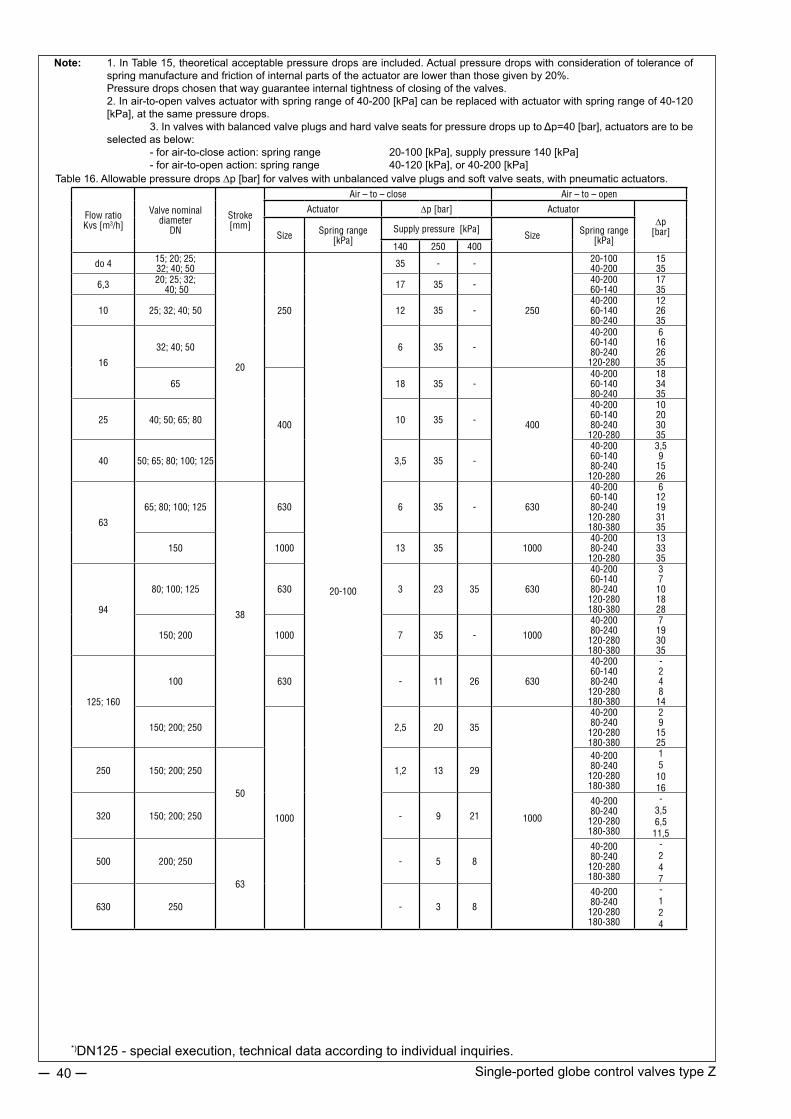
Single-ported globe control valves type Z 40
Table 16. Allowable pressure drops ∆p [bar] for valves with unbalanced valve plugs and soft valve seats, with pneumatic actuators.
Note: 1. In Table 15, theoretical acceptable pressure drops are included. Actual pressure drops with consideration of tolerance of spring manufacture and friction of internal parts of the actuator are lower than those given by 20%.
Pressure drops chosen that way guarantee internal tightness of closing of the valves. 2. In air-to-open valves actuator with spring range of 40-200 [kPa] can be replaced with actuator with spring range of 40-120
[kPa], at the same pressure drops. 3. In valves with balanced valve plugs and hard valve seats for pressure drops up to Δp=40 [bar], actuators are to be
selected as below: - for air-to-close action: spring range 20-100 [kPa], supply pressure 140 [kPa] - for air-to-open action: spring range 40-120 [kPa], or 40-200 [kPa]
Flow ratioKvs [m3/h]
Valve nominal diameter
DN
Stroke [mm]
Air – to – close Air – to – open
Actuator ∆p [bar] Actuator∆p
[bar]Size Spring range [kPa]
Supply pressure [kPa]Size Spring range
[kPa]140 250 400
do 4 15; 20; 25;32; 40; 50
20
250
20-100
35 - -
250
20-10040-200
1535
6,3 20; 25; 32; 40; 50 17 35 - 40-200
60-1401735
10 25; 32; 40; 50 12 35 -40-20060-14080-240
122635
16
32; 40; 50 6 35 -
40-20060-14080-240120-280
6162635
65
400
18 35 -
400
40-20060-14080-240
183435
25 40; 50; 65; 80 10 35 -
40-20060-14080-240120-280
10203035
40 50; 65; 80; 100; 125 3,5 35 -
40-20060-14080-240120-280
3,591526
63
65; 80; 100; 125
38
630 6 35 - 630
40-20060-14080-240120-280180-380
612193135
150 1000 13 35 100040-20080-240120-280
133335
94
80; 100; 125 630 3 23 35 630
40-20060-14080-240120-280180-380
37101828
150; 200 1000 7 35 - 1000
40-20080-240120-280180-380
7193035
125; 160
100 630 - 11 26 630
40-20060-14080-240120-280180-380
-24814
150; 200; 250
1000
2,5 20 35
1000
40-20080-240120-280180-380
291525
250 150; 200; 250
50
1,2 13 29
40-20080-240120-280180-380
151016
320 150; 200; 250 - 9 21
40-20080-240120-280180-380
-3,56,511,5
500 200; 250
63
- 5 8
40-20080-240120-280180-380
-247
630 250 - 3 8
40-20080-240120-280180-380
-124
*)DN125 - special execution, technical data according to individual inquiries.
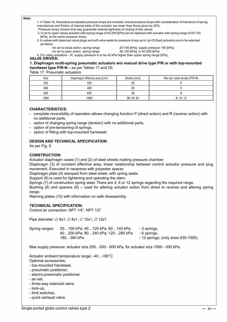
Single-ported globe control valves type Z 41
VALVE DRIVES:1. Diaphragm multi-spring pneumatic actuators w/o manual drive type P/R or with top-mounted handweel type P/R-N – as per Tables 17 and 20.Table 17. Pneumatic actuators
CHARACTERISTICS:- complete reversibility of operation allows changing function P (direct action) and R (reverse action) with no additional parts,- option of changing spring range (tension) with no additional parts,- option of pre-tensioning of springs,- option of fitting with top-mounted handweel.
DESIGN AND TECHNICAL SPECIFICATION:As per Fig. 5.
CONSTRUCTION:Actuator diaphragm cases (1) and (2) of steel sheets making pressure chamberDiaphragm (3) of constant effective area, linear relationship between control actuator pressure and plug movement. Executed in neoprene with polyester spacer.Diaphragm plate (4) stamped from steel sheet, with spring seats.Support (6) is used for tightening and operating the stem.Springs (7) of construction spring steel. There are 3, 6 or 12 springs regarding the required range.Bushing (8) and spacers (9) – used for altering actuator action from direct to reverse and altering spring range.Warning plates (10) with information on safe disassembly.
TECHNICAL SPECIFICATION:Control air connection: NPT 1/4”, NPT 1/2”
Pipe diameter: ∅6x1, ∅8x1, ∅10x1, ∅12x1
Spring ranges: 20…100 kPa; 40…120 kPa; 60…140 kPa - 3 springs, 40…200 kPa; 80…240 kPa; 120…280 kPa - 6 springs, 180…380 kPa - 12 springs; (only sizes 630-1000).
Max supply pressure: actuator size 250…630 - 600 kPa, for actuator size 1000 - 500 kPa.
Actuator ambient temperature range: -40…+80°COptional accessories:- top-mounted handweel,- pneumatic positioner,- electro-pneumatic positioner,- air-set,- three-way solenoid valve,- lock-up,- limit switches,- quick exhaust valve.
Note: 1. In Table 16, theoretical acceptable pressure drops are included. Actual pressure drops with consideration of tolerance of spring manufacture and friction of internal parts of the actuator are lower than those given by 20%. Pressure drops chosen that way guarantee internal tightness of closing of the valves. 2. In air-to-open valves actuator with spring range of 40-200 [kPa] can be replaced with actuator with spring range of 40-120 [kPa], at the same pressure drops. 3. In valves with balanced valve plugs and soft valve seats for pressure drops up to ∆p=35 [bar],actuators are to be selected as below: - for air-to-close action: spring range 20-100 [kPa], supply pressure 140 [kPa] - for air-to-open action: spring range 40-120 [kPa], or 40-200 [kPa] 4. For rotary actuators – R, supply pressure is to be 40 kPa higher than upper spring range [kPa].
Size Diaphragm effective area [cm2] Stroke [mm] Rev per rated stroke (P/R-N)
250 250 20 5
400 400 20 5
630 630 38 9
1000 1000 38; 50; 63 8; 10; 13

Single-ported globe control valves type Z 42
Fig. 5. P/R multi-spring actuator
EXTERNAL DIAMETERS AND CONNECTION DIAMETERS, WEIGHTS OF VALVES, PNEUMATIC ACTUATORS AND MANUAL DRIVES
Table 19. Valve connection diameters [mm]
Fig. 6. Valve connection dimensions
Note:1) R and ∅P can be as per customer request2) R=160 - for electrical actuators3) L and L1 - for valve plug location – valve closed4) L=138 - for electric actuators
2. Electric actuatorsThere is a possibility of employing any electric or electro-hydraulic actuator following adjustment of connecting elements. Details and technical specifications of electric actuators as per separate catalog charts.
3. NN manual drivesDrives allowing manual operation of valve, adapted to direct assembly on valve (with no extra parts).
Table 18. Drive sizes.
Size Stroke [mm] Rev per rated stroke250 20 5400 20 5630 38 91000 38; 50; 63 8; 10; 13
DN d1 d3 E L L1 P R
15…25
M12x1,2512 44
125 11112,5 110
32…50 118 102 16,5 13220,5 160
65…100 16 50 122 10416,5 132
20,5 160125…250 M16x1,5 20
95 200 18098 138 118 24,5 216
Type R Type P
*)DN125 - special execution, technical data according to individual inquiries.
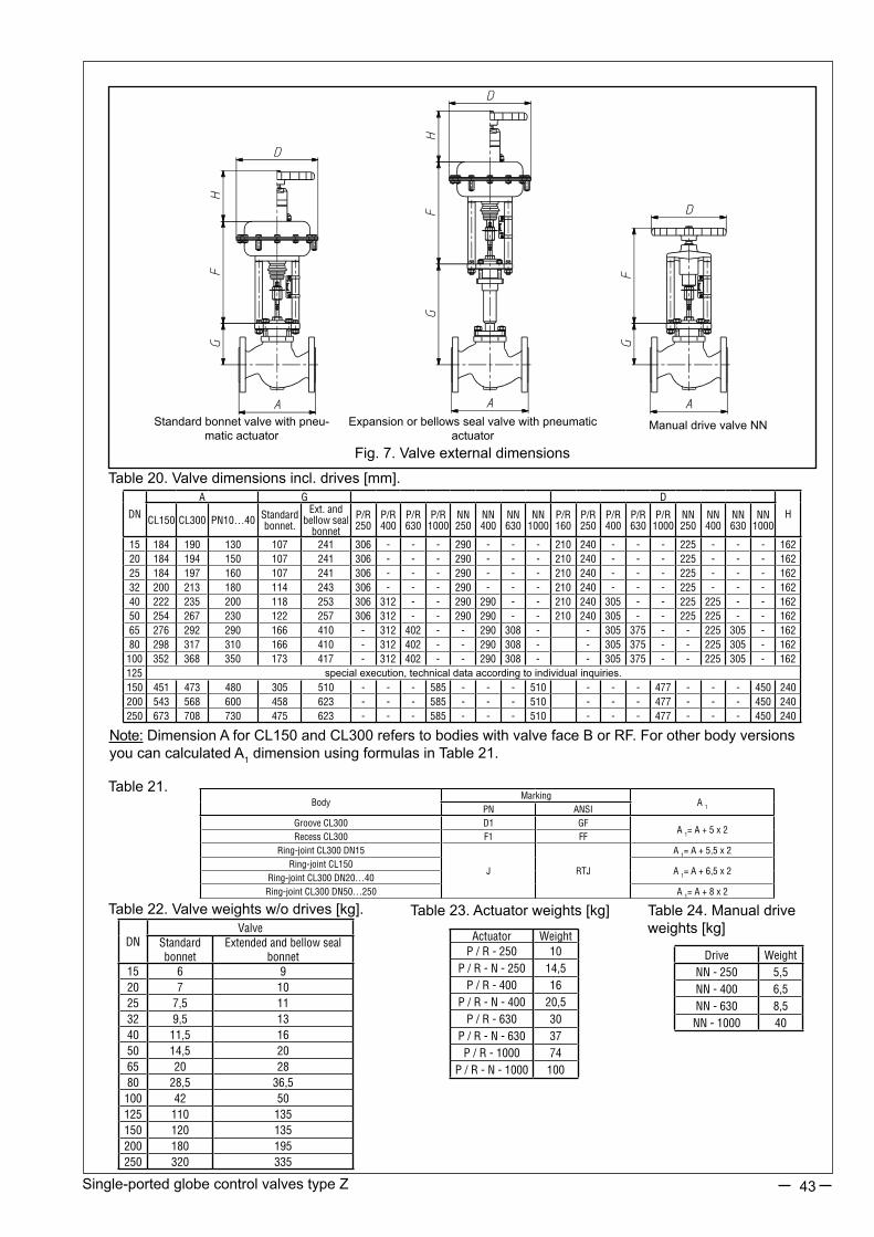
Single-ported globe control valves type Z 43
Fig. 7. Valve external dimensions
Standard bonnet valve with pneu-matic actuator
Expansion or bellows seal valve with pneumatic actuator
Manual drive valve NN
Table 20. Valve dimensions incl. drives [mm].
Note: Dimension A for CL150 and CL300 refers to bodies with valve face B or RF. For other body versions you can calculated A1 dimension using formulas in Table 21.
Table 22. Valve weights w/o drives [kg]. Table 23. Actuator weights [kg] Table 24. Manual drive weights [kg]
Table 21.Body
MarkingA 1PN ANSI
Groove CL300 D1 GFA 1= A + 5 x 2
Recess CL300 F1 FFRing-joint CL300 DN15
J RTJ
A 1= A + 5,5 x 2Ring-joint CL150
A 1= A + 6,5 x 2Ring-joint CL300 DN20…40Ring-joint CL300 DN50…250 A 1= A + 8 x 2
Drive WeightNN - 250 5,5NN - 400 6,5NN - 630 8,5NN - 1000 40
DNValve
Standard bonnet
Extended and bellow seal bonnet
15 6 920 7 1025 7,5 1132 9,5 1340 11,5 1650 14,5 2065 20 2880 28,5 36,5100 42 50125 110 135150 120 135200 180 195250 320 335
DN
A G D
HCL150 CL300 PN10…40 Standard bonnet.
Ext. and bellow seal
bonnet
P/R250
P/R400
P/R630
P/R1000
NN250
NN400
NN630
NN1000
P/R160
P/R250
P/R400
P/R630
P/R1000
NN250
NN400
NN630
NN1000
15 184 190 130 107 241 306 - - - 290 - - - 210 240 - - - 225 - - - 16220 184 194 150 107 241 306 - - - 290 - - - 210 240 - - - 225 - - - 16225 184 197 160 107 241 306 - - - 290 - - - 210 240 - - - 225 - - - 16232 200 213 180 114 243 306 - - - 290 - - - 210 240 - - - 225 - - - 16240 222 235 200 118 253 306 312 - - 290 290 - - 210 240 305 - - 225 225 - - 16250 254 267 230 122 257 306 312 - - 290 290 - - 210 240 305 - - 225 225 - - 16265 276 292 290 166 410 - 312 402 - - 290 308 - - 305 375 - - 225 305 - 16280 298 317 310 166 410 - 312 402 - - 290 308 - - 305 375 - - 225 305 - 162
100 352 368 350 173 417 - 312 402 - - 290 308 - - 305 375 - - 225 305 - 162125 special execution, technical data according to individual inquiries.150 451 473 480 305 510 - - - 585 - - - 510 - - - 477 - - - 450 240200 543 568 600 458 623 - - - 585 - - - 510 - - - 477 - - - 450 240250 673 708 730 475 623 - - - 585 - - - 510 - - - 477 - - - 450 240
Actuator WeightP / R - 250 10
P / R - N - 250 14,5P / R - 400 16
P / R - N - 400 20,5P / R - 630 30
P / R - N - 630 37P / R - 1000 74
P / R - N - 1000 100

Revision: Z/10/2014Valid until the next revision.
44
Leakage class:- basic: class IV 4 - bubble: class IV 6
Valve plug:- unbalanced 7- balanced 8
Choke cages:- no choke cages 0
Plug characteristics and type:- linear, contoured L- equal percentage P- quick-opening, (on-off) S- other X
Body material:- grey iron 1- spheroidal iron 2- carbon steel 3- stainless steel 5- other X
MARKING EXAMPLE:
Control valve type Z with reverse action pneumatic actuator with top-mounted handweel, extension bonnet, expanded graphite stem sealing, leakage class IV, equal percentage contoured plug, execution in stainless steel:
RN-Z-2E470P5
Marking is shown on valve nameplate.
Additional information:- nominal size [DN],- nominal pressure [PN],- max working temperature [TS],- max working pressure [PS],- test pressure [PT],- flow ratio [Kvs],- plug stroke [H],- plug stroke fluid group [1 or 2],- serial number and year of manufacture.
ORDERING:
The order should contain all information as per data questionnaire. Full information can be obtained from the Sales and Marketing Department or Technical and Development Department.
PARTITION AND MARKING
Type and action: - pneumatic with direct action: P - pneumatic with reverse action: R- pneumatic with top manual drive: PN; RN- electric: E- manual: NN
Bonnet:- standard: 1- extension: 2- bellow seal: 3- other: X
Packing:- PTFE, braided A- PTFE, typ V B- PTFE, for oxygen C- graphite, braided D- graphite, expanded E- TA-Luft, PTFE F- TA-Luft, graphite G
- Z - 0

SINGLE-PORTED GLOBE CONTROL VALVES TYPE Z1A®
45
FEATURES:
•various materials of valve body and in ternal par ts , adapted to specificworkingconditions,•design provides noise reduction,enhanced resistance to cavitation andflashing,andeliminationofchokedflow,•wide range of nominal pressu-res, PN10 toCL2500, and flow ratio and control characteristics,• reduction in aggressive and to-xic media emissions to environment t h rough app l i ca t i on o f be l l owseal bonnets or bonnet packings meetingrequirementsofTA-LUFT,•easy assembly and dismantling ofvalve internal parts for maintenance and service,•high durability and reliability dueto application of top-class materials and su r face improvement p ro -cesses (burnishing, stelliting, heat treatment,CrNcoating),•possibilityofmatingwithreversactionP/R(column)andP1/R1(castyoke)multi-springactuators,andchangingthespringrangewithnoextraparts(keepingthenumberofsprings),•possibilityoffittingactuatorswithside-mounted(P1/R1)ortop-mounted(P/R)handwheel,•possibility of performing diagnostics of “valve - actuator” due to application of smart electro-pneumatic positioners,•widerangeofelectricactuators,•special designs for oxygen, hydrogen, gas fuels, low temperature fluids (liquid oxygen, liquid nitrogen), acidgasescontainingH2S;withheatjacket;forpotentiallyexplosiveatmospheresasperATEXDirective 94/9/EC,•designandproductionprocessmeettherequirementsofQualityManagementSystemISO9001andDirective 97/23/EC,andregulationsofAD2000Merkblatt,designatedforinstallationonpipelines.
Z1A ®isatrademarkregisteredwithRepublicofPolandPatentOffice
APPLICATION AREA:
Single-portedglobecontrolvalvestypeZ1Aareusedinautomaticandremotecontrolinstalationsasflowcontrolelementstoadjustflowofliquids,steamandgases.Widerangeofmaterialanddesignversionsmakesthevalvesapplicableinmostdemandingworkingconditionsinpowergeneration,petroleumchemistry,heating,chemicalindustry,metallurgy,etc.versionsdesignatedforWesternEuropemarketcanbemarkedBR12.

Single-portedglobecontrolvalvestypeZ1A46
Body (1): single-ported,castNominalsize:DN15;20;25;40;50;80;100;150;200;250;300Nominal pressure: • PN10;16;25;40; 63;100;160;250;320;400(asperPN-EN1092-1:2010)• PN-H-74306:1985;PN-H-74307:1985.• CL150;CL300;CL600;CL900;CL1500;CL2500(asperPN-EN1759-1:2005).dividedasfollows: DN15...300: PN10...100;CL150…CL600*)
DN15...150: CL900;PN160*)
DN15...100: PN250…400;CL1500…CL2500*)
*)highernominalpressuresavailableafteragreementwiththemanufacturerConnections: -flanged:asperTable1 -buttweldingendsBW,asperTable19and18 -socketweldingendsSW,asperTable21SteelflangesCL150;CL300;CL600;CL900;CL1500;CL2500aresodesignedthattheycanbeassembledwithflangesasperAmericanstandardsANSI/ASMEB16.5andMSSSP44.InAmericanstandardsflangesareidentifiedwithnominalvaluesin“Classes”,towhichnominalpressure(PN)valuesasperPN-ISO7005-1:2002correspond.EquivalentidentificationasperPNare: CL150: PN20 CL300: PN50 CL600: PN 110 CL900: PN 150 CL1500: PN 260 CL2500: PN 420
Table1.Flangedendconnections
DESIGN AND TECHNICAL SPECIFIACTION:
Face-to-facedimensions: -flangedvalvesasperPN-EN60534-3-1;PN-M-74005;ISAS75.16-1993;Fig.5; Table 16; 17 -weldingendsvalves;Fig.5;Table18 -asperPN-EN60534-3-3:forPN10...100andCL150…600 -asforflangedvalvesPN160:forPN160andCL900 -asforflangedvalvesPN400:forPN250...400andCL1500…2500Materials: -asperTable 2; RelationshipbetweenworkingpressureandtemperatureasperTable3…9.Bonnet (2): - standard - extension -bellowsseal(PN10…40;CL150…300)Valve plug (3): -piston,sleeveguided,hard.Rangeability:50:1 - variants: contoured, piston - perforated,(multi-hole) -flowcharacteristics: equalpercentage-P linear - L quickopening -S(onlyforcontouredvalveplugs)Valve seat (4): -fitted-inandandsealedwithbody,hard(tightseatafterconsultingthemanufacturer)Valve plug stem (5): -burnished,polishedsealingface.Pressing cage (6A): -valveseattobodyfixture.Choke cage (6B): - perforatedvalveseatfixture,causingreductioninpressuredropbetweenseatandplug.Body gasket (7) and seat gasket (8):spiral,graphite+1.4404inallexecutions.Stem packing (9): -PTFE-Vpacking,compressedwithspringbolt(18), - ringgasketsformedinbraidedpackingcords(PTFE+GRAPHITE), - graphitekits(expandedandsilkygraphite)orgasketsformedinbraidedgraphitecords, -TA-LUFTsealingwithPTFE-Vpackingkitorgraphitekit;packingstructureasper Figs.1and2,rangeofapplicationsasperTable10.Leakage class:(asperPN-EN60534-4) -basic: (class IV) less than 0,01% Kvs -enhanced: (classV) 3. 10-4 D .∆p [cm3/min] whereD(mm)-isseatdiameterasperTable10 ∆p[bar]-actualpressuredropinclosedvalve.Fluid flow direction: tovalveplug.Flow coefficients: as per Table 11
Nominal pressureFacing of flange types
Raised face Groove Recess Ring - jointIdentification
PN10; 16; 25; 40; 63; 100; 160; 250; 320; 400 B 3) D 1) F 1) -CL150; 300 B 3) DL ( D1 2) F ( F1 1) J (RTJ)
CL600; 900; 1500; 2500 B 3) (RF) DL (GF) F (FF) J (RTJ)1) - do PN160; 2) - tylko dla CL300; 3) - B1 – (Ra=12.5 mm, concentric surface structure “C”), B2 – (Ra as agreed with the customer);
() - identification of connections as per ASME B16.5Possible execution of flanges per specification and indicated standards

Single-portedglobecontrolvalvestypeZ1A 47
Fig.1a.ValveZ1A-contouredvalveplugandcompressioncage
Fig.1b.ValveZ1A-contouredvalveplugandchokecage
Fig.1c.ValveZ1A-perforatedvalveplugandcompressioncage.
Fig.1d.ValveZ1A–perforatedvalveplugandchokecage

Single-portedglobecontrolvalvestypeZ1A48
Fig.1e.Controlvalve
Flangedbody Buttweldingendsbody(BW)
Contouredvalveplug Perforatedpistonvalveplug
Standard bonnet, PTFE-Vsealing
Extension bonnet, GRAPHITEsealing
Bellowssealbonnet,PTFE+GRAPHITEsealing
Extension bonnetTA-LUFTsealing

Single-portedglobecontrolvalvestypeZ1A 49
Table2.Partlistwithmaterials
NOTE:*)-tobeappliedfornominalpressuresPN10…CL600.Hardeningofvalveinternalsurfacescomprises:a)stelliting–paddingofsurfaceswithstellite:~40HRCb) CrNcoating–introducingchromiumnitridetoexternallayerofdetail,tothedepthofca.0,1mm;~950HVc)heattreatment:valveplug(~45HRC),valveseat(~35HRC),guidesleeve(~45HRC)
Item Part Materials
1 BodyGP 240 GH ; (1.0619)
WCBG17CrMo 9-10 ; (1.7379)
WC9GX5CrNiMo 19-11-2 ; (1.4408)
CF8M
2 BonnetDN15…50 S 355 J2G3 (1.0570) 13CrMo4-4 ; (1.7335)
X6CrNiMoTi 17-12-2 ; (1.4571)DN80…300
GP 240 GH ; (1.0619)WCB
G17CrMo 9-10 ; (1.7379)WC9
3 PlugX6CrNiMoTi 17-12-2; (1.4571)
X6CrNiMoTi 17-12-2; (1.4571) + stellite + CrNX17CrNi 16-2 ; (1.4057) + heat treatment
4 Seat X6CrNiMoTi 17-12-2; (1.4571)
X6CrNiMoTi 17-12-2; (1.4571) + stelliteX17CrNi 16-2; (1.4057) + heat treatment
5 SternX6CrNiMoTi 17-12-2; (1.4571)
X6CrNiMoTi 17-12-2; (1.4571) + stellite + CrNX17CrNi 16-2 ; (1.4057) + heat treatment
6A Compression cage X6CrNiMoTi 17-12-2; (1.4571)X17CrNi 16-2; (1.4057) + heat treatment6B Choke cage
7 Body gasketGRAPHITE (98%) + 1.4404 (spiral)
8 Seat gasket
9 Packing kit
PTFE + GRAPHITE
PTFE „V” (Rings)
GRAPHITE
10 Press sleeve X6CrNiMoTi 17-12-2; (1.4571)
11 Press lever S 355 J2G3 ; (1.0570)
12 Body screwPN10…CL300 8.8 A4 - 70 *)
PN63…CL2500 42CrMo4 (1.7225) 21CrMoV5-7 (1.7709) X6NiCrTiMoVB 25-15-2 (1.4980)
13 Body nutPN10…CL300 8.8 A4 - 70 *)
PN63…CL2500 42CrMo4 (1.7225) 21CrMoV5-7 (1.7709) X6NiCrTiMoVB 25-15-2 (1.4980)
14 Bonnet screw 8.8 A4 - 70 *)
15 Bonnet nut 8.8 A4 - 70 *)
16 Notched peg X6CrNiMoTi 17-12-2; (1.4571)
17 Spring 12R10 (SANDVIK)
18 Spacer sleeve X6CrNiMoTi 17-12-2; (1.4571)
19 Guide sleeveX6CrNiMoTi 17-12-2; (1.4571) + stellite + CrN
X17CrNi 16-2 ; (1.4057) + heat treatment
Relevant material standardsMaterial Standard
GP 240 GH ; (1.0619) PN-EN 10213-2WCB ASTM A 216
G17CrMo 9-10 ; (1.7379) PN-EN 10213-2WC9 ASTM A 217
GX5CrNiMo 19-11-2 ; (1.4408) PN-EN 10213-4CF8M ASTM A 351
S 355 J2G3 ; (1.0570) PN-EN 1002513CrMo4-4; (1.7335) PN-EN 10028
X6CrNiMoTi 17-12-2 ; (1.4571) PN-EN 10088X17CrNi 16-2 ; (1.4057) PN-EN 10088
C45 (1.0503) PN-EN 10083-1
X30Cr13 (1.4028) PN-EN 10088
8.8 EN 20898-1
A4-70 *) EN ISO 3506-2
42CrMo4 (1.7225) EN 10269
21CrMoV5-7 (1.7709) EN 10269
X6NiCrTiMoVB 25-15-2 (1.4980) EN 10269

Single-portedglobecontrolvalvestypeZ1A50
Table 4. Material: G17CrMo 9-10 (1.7379) as per PN-EN 10213-2
PN / CL Standard
Temperature [°C]
-10…50 100 150 200 250 300 350 400 425 450 475 500 510 520 530 540 550
Allowable working pressure [bar]
PN10-
10 10 10 10 10 10 9,7 9,2 9 8,8 7,6 6,4 5,6 4,9 4,2 3,7 3,2
PN16 16 16 16 16 16 16 15,6 14,8 14,4 14 12,1 10,2 8,9 7,8 6,8 5,9 5,1
CL150 PN-EN 1759-1 19,5 17,7 15,8 14 12,1 10,2 8,4 6,5 5,6 4,7 3,7 2,8 2,4 2 1,7 1,4 -
PN25EN 1092-1
25 25 25 25 25 25 24,4 23,2 22,6 22 19 16 14 12,2 10,7 9,2 8
PN40 40 40 40 40 40 40 39 37,1 36,1 35,2 30,4 25,7 22,4 19,6 17,1 14,8 12,9
CL300 PN-EN 1759-1 51,7 51,5 50,2 48,3 46,3 42,8 40,2 36,6 35,1 33,8 31,7 28,2 26,6 23,5 20,6 17,8 15,5
PN63EN 1092-1
63 63 63 63 63 63 61,5 58,5 57 55,5 48 40,5 35,4 30,9 27 23,4 20,4
PN100 100 100 100 100 100 100 97,6 92,8 90,4 88 76,1 64,2 56,1 49 42,8 37,1 32,3
CL600
PN-EN 1759-1
103 103 100 96,7 92,6 85,7 80,4 73,1 70,2 67,6 63,3 56,4 53,3 47,1 41,1 35,7 31,1
CL900 155 155 151 145 139 129 121 110 105 101 95 84,6 79,9 70,6 61,7 53,5 46,6
PN160 160 160 160 160 160 160 156,1 148,5 144,7 140,9 121,8 102,8 88,9 78,4 68,5 59,4 51,8
PN250 250 250 250 250 250 250 244 232,1 226,1 220,2 190,4 160,7 140,4 122,6 107,1 92,8 80,9
CL1500 259 258 251 242 232 214 201 183 175 169 158 141 133 118 103 89,1 77,7
PN320 320 320 320 320 320 320 312,3 297,1 289,5 281,9 243,7 205,7 179,8 156,9 137,1 118,8 103,6
PN400 400 400 400 400 400 400 390,4 371,4 361,8 352,3 304,7 257,1 224,7 196,1 171,4 148,5 129,5
CL2500 431 429 418 403 386 357 335 305 292 282 264 235 222 196 171 149 130
Table 5. Material: GX5CrNiMo 19-11-2 (1.4408) as per PN-EN 10213-4
PN / CL Standard
Temperature [°C]
-10…50 100 150 200 250 300 350 400 425 450 475 500 510 520 530 540 550 600
Allowable working pressure [bar]
PN10EN 1092-1
10 10 9 8,4 7,9 7,4 7,1 6,8 - 6,7 - 6,6 - - - - 6,5 5,6
PN16 16 16 14,5 13,4 12,7 11,8 11,4 10,9 - 10,7 - 10,5 - - - - 10,4 8,9
CL150 PN-EN 1759-1 17,9 16,3 14,9 13,5 12,1 10,2 8,4 6,5 5,6 4,7 3,7 2,8 2,4 2 1,7 1,4 - -
PN25EN 1092-1
25 25 22,7 21 19,8 18,5 17,8 17,1 - 16,8 - 16,5 - - - - 16,3 14
PN40 40 40 36,3 33,7 31,8 29,7 28,5 27,4 - 26,9 - 26,4 - - - - 26 22,4
CL300 PN-EN 1759-1 46,7 42,5 38,9 35,3 32,9 30,5 28,8 27,6 27,2 26,9 26,6 26,4 26,3 22,5 22,4 22,3 22,2 -
PN63EN 1092-1
63 63 57,3 53,1 50,1 46,8 45 43,2 - 42,4 - 41,7 - - - - 41,1 35,4
PN100 100 100 90,9 84,2 79,5 74,2 71,4 68,5 - 67,3 - 66,1 - - - - 65,2 56,1
CL600
PN-EN 1759-1
93,4 85 77,8 70,6 65,8 61 57,6 55,2 54,5 53,8 53,3 52,8 52,6 44,9 44,8 44,6 44,4 -
CL900 140 127 117 106 98,6 91,4 86,4 82,8 81,7 80,6 79,9 79,2 78,9 67,4 67,1 66,9 66,7 -
PN160 160 160 145,5 134,8 127,2 118,8 114,2 109,7 - 107,8 - 105,9 - - - - 104,3 89,9
PN250 250 250 227,3 210,7 198,8 185,7 178,5 171,4 - 168,4 - 165,4 - - - - 163 140,4
CL1500 233 212 194 176 164 152 144 138 136 134 133 132 132 112 112 111 111 -
PN320 320 320 291 269,7 254,4 237,7 228,5 219,4 - 215,6 - 211,8 - - - - 208,7 179,8
PN400 400 400 363,8 337,1 318 297,1 285,7 274,2 - 269,5 - 264,7 - - - - 260,9 224,7
CL2500 389 354 324 294 274 254 240 230 227 224 222 220 219 187 187 186 185 -
Table3…9.Allowableworkingoverpressureformaterialsatpropertemperatures.
Table 3. Material: GP240GH (1.0619) as per PN-EN 10213-2
PN / CL Standard
Temperature [°C]
-10…50 100 150 200 250 300 350 400
Allowable working pressure [bar]
PN10EN 1092-1
10 9,2 8,8 8,3 7,6 6,9 6,4 5,9
PN16 16 14,8 14 13,3 12,1 11 10,2 9,5
CL150 PN-EN 1759-1 17,3 15,4 14,6 13,8 12,1 10,2 8,4 6,5
PN25EN 1092-1
25 23,2 22 20,8 19 17,2 16 14,8
PN40 40 37,1 35,2 33,3 30,4 27,6 25,7 23,8
CL300 PN-EN 1759-1 45,3 40,1 38,1 36 32,9 29,8 27,8 25,7
PN63EN 1092-1
63 58,5 55,5 52,5 48 43,5 40,5 37,5
PN100 100 92,8 88 83,3 76,1 69 64,2 59,5
CL600
PN-EN 1759-1
90,5 80,2 76,1 72 65,8 59,7 55,5 51,4
CL900 136 120 114 108 98,7 89,5 83,3 77,1
PN160 160 148,5 140,9 133,3 121,9 110,4 102,8 95,2
PN250 250 232,1 220,2 208,3 190,4 172,6 160,7 148,8
CL1500 226 201 190 180 165 149 139 129
PN320 320 297,1 281,9 266,6 243,8 220,9 205,7 190,4
PN400 400 371,4 352,3 333,3 304,7 276,1 257,1 238
CL2500 377 334 317 300 274 249 231 214
NOTES:1. It is allowed to apply carbon steel andacid
proofcaststeel for temperatures lower thangiven inTables 3...9, provided thatworkingpressure is reduced respectively, workingtemperature impact tests are performed and castisheattreated.Detailsaretobeconsultedwithmanufacturer.
2. Workingpressureforintermediatetemperaturevaluescanbecalculatedbyinterpolation.
3. Temperature range for flanged connections:upto+537°C,forweldingconnections:upto+650°C

Single-portedglobecontrolvalvestypeZ1A 51
Table 7. Material: WCB as per ASTM A216
PN / CL Standard
Temperature [°C]
-10…50 100 150 200 250 300 350 375 400
Allowable working pressure [bar]
PN10EN 1092-1
10 10 9,7 9,4 9 8,3 7,9 7,7 6,7
PN16 16 16 15,6 15,1 14,4 13,4 12,8 12,4 10,8
CL150 PN-EN 1759-1 19,3 17,7 15,8 14 12,1 10,2 8,4 7,4 6,5
PN25EN 1092-1
25 25 24,4 23,7 22,5 20,9 20 19,4 16,9
PN40 40 40 39,1 37,9 36 33,5 31,9 31,1 27
CL300 PN-EN 1759-1 50 46,4 45,1 43,9 41,8 38,9 36,9 36,6 34,6
PN63EN 1092-1
63 63 61,5 59,6 56,8 52,7 50,3 49 42,5
PN100 100 100 97,7 94,7 90,1 83,6 79,8 77,8 67,5
CL600
PN-EN 1759-1
100,1 92,8 90,6 87,8 83,6 77,5 74 72,9 69,1
CL900 150,1 139,2 135,7 131,4 125,1 116,1 110,8 109,5 103,4
PN160 159,2 147,6 143,9 139,4 132,7 123,1 117,5 116,1 109,7
PN250 241,4 223,5 217,8 211,2 201,1 186,6 178,1 175,8 166,2
CL1500 250,5 231,9 226 219,2 208,7 193,6 184,8 182,4 172,5
PN320 313 289,9 282,6 273,9 260,8 242 231 227,9 215,6
PN400 396,4 367,3 358 346,9 330,3 306,6 292,6 288,6 273,1
CL2500 417,2 386,6 376,9 365,1 347,7 322,7 308 303,8 287,5
Table 8. Material: WC9 as per ASTM A217
PN / CL Standard
Temperature [°C]
-10…50 100 150 200 250 300 350 375 400 425 450 475 500 510 520 525 530 540 550
Allowable working pressure [bar]
PN10EN 1092-1
10 10 10 10 10 10 10 10 9,9 9,7 9,5 7,3 5,5 5 4,4 - 3,9 3,4 2,9
PN16 16 16 16 16 16 16 16 16 15,9 15,6 15,3 11,7 8,9 8 7,1 - 6,2 5,4 4,7
CL150 PN-EN 1759-1 19,5 17,7 15,8 14 12,1 10,2 8,4 7,4 6,5 5,6 4,6 3,7 2,8 - - 1,9 - 1,3 -
PN25EN 1092-1
25 25 25 25 25 25 25 25 24,8 24,4 23,9 18,3 14 12,6 11,2 - 9,8 8,5 7,4
PN40 40 40 40 40 40 40 40 40 39,7 39 38,3 29,2 22,3 20,2 18 - 15,7 13,6 12
CL300 PN-EN 1759-1 51,7 51,5 50,3 48,7 46,3 42,9 40,4 38,9 36,5 35,2 33,7 31,7 27,7 - - 21,6 - - 15,3
PN63EN 1092-1
63 63 63 63 63 63 63 63 62,5 61,5 60,3 46 35,2 31,9 28,3 - 24,8 21,4 18,8
PN100 100 100 100 100 100 100 100 100 99,2 97,6 95,6 73,1 55,9 50,6 44,9 - 39,3 34 29,9
CL600
PN-EN 1759-1
103,4 103,1 100,3 97,5 92,7 85,7 80,4 77,6 73,3 70,2 67,7 63,4 55,7 - - 43,3 - - 30,7
CL900 155,1 154,6 150,6 146,2 139 128,6 120,7 116,5 109,8 105,4 101,4 95,1 83,4 - - 64,9 - - 46
PN160 164,5 163,9 159,5 154,7 147,4 136,4 128 123,6 116,5 111,8 107,6 100,8 87,3 - - 68,9 - - 48,8
PN250 249,2 248,1 239,8 231,2 222,6 206,6 193,8 187 176,4 169,2 162,9 152,5 122,2 - - 104,4 - - 74,1
CL1500 258,6 257,7 250,8 244 231,8 214,4 201,1 194,1 183,1 175,6 169,1 158,2 138,9 - - 108,4 - - 76,9
PN320 323,2 321,9 312,3 302,3 289,2 268 251,4 242,5 228,8 219,4 211,4 197,8 165,7 - - 135,4 - - 96
PN400 409,4 408 397,1 385,7 366,8 339,4 318,5 307,1 289,7 277,9 267,7 250,7 218,5 - - 171,5 - - 121,5
CL2500 430,9 429,5 418,3 406,5 386,2 357,2 335,3 323,2 304,9 292,5 281,8 263,9 231,7 - - 180,5 - - 127,9
Table 9. Material: CF8M as per ASTM A351
PN / CL Standard
Temperature [°C]
-10…50 100 150 200 250 300 350 375 400 425 450 475 500 510 520 525 530 540 550 575 600 625 649
Allowable working pressure [bar]
PN10EN 1092-1
8,9 7,8 7,1 6,6 6,1 5,8 5,6 5,5 5,4 5,4 5,3 5,3 5,2 5,2 5,2 - 5,2 5,1 5,1 4,7 3,8 - -
PN16 14,3 12,5 11,4 10,6 9,8 9,3 9 8,8 8,7 8,6 8,5 8,5 8,4 8,3 8,3 - 8,3 8,3 8,2 7,6 6,1 - -
CL150 PN-EN 1759-1 18,4 16 14,8 13,6 12 10,2 8,4 7,4 6,5 5,6 4,6 3,7 2,8 - - 1,9 - 1,4 - - - - -
PN25EN 1092-1
22,3 19,5 17,8 16,5 15,5 14,6 14,1 13,8 13,6 13,5 13,4 13,3 13,2 13,1 13,1 - 13 13 12,9 12 9,6 - -
PN40 35,6 31,3 28,5 26,4 24,7 23,4 22,6 22,1 21,8 21,6 21,4 21,2 21 21 20,9 - 20,8 20,8 20,7 19,1 15,5 - -
CL300 PN-EN 1759-1 48,1 42,3 38,6 35,8 33,5 31,6 30,4 29,6 29,3 29 29 28,7 27,3 - - 25,2 - - 24 22,9 19,9 15,7 12,8
PN63EN 1092-1
56,1 49,2 44,9 41,6 38,9 36,9 35,5 34,9 34,4 34 33,7 33,5 33,2 33 32,9 - 32,8 32,7 32,6 30,2 24,4 - -
PN100 89,1 78,1 71,3 66 61,8 58,5 56,4 55,3 54,5 54 53,4 53,1 52,6 52,4 52,2 - 52,1 51,9 51,7 47,9 38,7 - -
CL600
PN-EN 1759-1
96,3 84,5 77,1 71,2 66,7 63,1 61 59,8 58,9 58,3 57,7 57,3 54,8 - - 50,6 - - 47,8 45,5 39,8 31,7 25,5
CL900 144,4 126,8 115,6 107 100,2 95 91,3 89,7 88,2 87,3 86,6 86 82,1 - - 75,9 - - 71,8 68,3 59,7 47,5 38,3
PN160 153,1 134,4 122,6 113,5 106,3 100,7 96,8 95,1 93,6 92,6 91,8 91,2 87,1 - - 80,5 - - 76,2 72,5 63,3 50,4 40,3
PN250 231,9 203,3 185,4 171,9 160,9 152,4 146,7 143,9 141,7 140,3 139,1 138,1 131,7 - - 121,8 - - 115,4 109,8 95,9 76,3 61
CL1500 240,6 210,9 192,4 178,4 167 158,1 152,2 149,3 147,1 145,6 144,3 143,3 136,7 - - 126,4 - - 119,8 114 99,5 79,2 63,8
PN320 300,8 263,7 240,6 223 208,7 197,6 190,3 186,7 184 182,1 180,3 179,2 170,9 - - 158 - - 149,7 142,5 124,4 98,9 79,2
PN400 381 334,1 304,8 282,4 264,2 250,3 241,1 236,5 233,1 230,7 228,4 227 216,6 - - 200,2 - - 189,5 180,5 157,7 125,1 100,4
CL2500 401 351,7 320,8 297,2 278,1 263,5 253,8 249 245,4 242,9 240,4 238,9 228 - - 210,7 - - 199,5 190 166 131,7 106,5
Table 6. Material: G20Mn5 (1.6220) wg PN-EN 10213-3
PN / CL Norma
Temperature [°C]
-40 100 150 200 250 300
Allowable working pressure [bar]
PN10
-
6 6 3,8 3,6 3,48 3,4
PN16 16 16 10,1 9,6 9,28 9,07
PN25 25 25 15,8 15 14,5 14,2
PN40 40 28 28 27 26 25
PN63 63 59 58 55 53 51
PN100 100 95 92 87 85 82
PN160 160 152 148 140 136 132

Single-portedglobecontrolvalvestypeZ1A52
Tablica10:Packingtypeswithapplicationranges.
)*PN10…40;CL150…300-forbelowsealbonnet)**-forweldingendsvalves
Fig.2.Bonnetpackings
PackingkitTA-LUFTPTFE-V
PackingkitTA-LUFTwithgraphitekit
DESIGNSDesignandmaterialoptionsaretobeselectedtosuitworkingconditions.Contouredplugandpresscagevalveisthebasicdesignfornormalworkingconditions.Incasesofnoiseemissionsexceedingthelevelacceptedbycustomer(normally85dBA)perforatedvalveplugsaretobeapplied,whichareexchangeablewithcontouredplugsandallownoisereductionby10dBAwithrespecttothebasicdesign.Furthernoisereduction(by5dBA)canbeachievedbyapplicationofchokecage,whichcausesreductioninpressuredropbetweenplugandseat.Suchdesignisalsorecommendedincaseofchokedflow,cavitationandflashing.PerforatedstructuresfeaturehigherpressurerecoverycoefficientFL,whichallowsachievementofhigherflowatthesameKvSandΔpasinbasicdesign.Incaseofcompressivemediaitisadvisabletoapplydiffusersatthevalveoutlet.Designvariantofvalveistobeselectedbasedoncomputer-aidedcalculationsofflowratio,noiselevel,mediumstatus,andeffectivenessofsuchactionsdependsonprecisionofdatasubmittedbycustomer.Injustifiedcases(noise,chokedflow)diffuserscanbefittedwithadditionalperforatedchokestructuresintheformofplatesassembledbetweenflangesorweldedindiffuserinterior.Oncustomer’srequest,alsowhenflowconditionsjustifysuchsolution,specialexecutionsarerecommendedconcerningmaterials,flowratios,controlcharacteristics,leakageclass,etc.
Packing(PTFE-V) Packing(PTFE+GRAPHITE)
Packing(GRAPHITE)
Packing PNTemperature [°C]
BonnetStandard Extension Bellow seal
PTFE-Vup to CL600 )* -46...+200
-198...-46+200...+300
-100...+200PTFE + GraphitePTFE-V / TA-LUFT
Graphiteup to CL2500 )* +200...+300 +300...+537 ,(+650)** +200...+400
Graphite / TA-LUFT

Single-portedglobecontrolvalvestypeZ1A 53
Table11.FlowratiosKvs.
Tabel12:AvailableforceFs[kN]ofpneumaticactuators
NOTE: 1.FordirectactuatorsP,P1adoptedspringrangeis20-100kPa.2.ForelectricandotheractuatorsΔpvaluecanbecalculatedusingaboveformulaandfiguresfromTables11, takingnominalloadcapacityasavailableforceFs,asperactuatorcatalogchart
ALLOWABLE PRESSURE DROPS ∆p.PressuredropsΔp[bar]inTables13applytoclosedvalveandtheyarecalculatedwithaccountforthevalvedriveperformance.Actualpressuredropsshouldnotexceed70%ofallowableworkingpressureforgivenno-minalpressure,materialexecutionandworkingtemperature,aspertables3…9.
where ∆p[bar] -calculatedpressuredrop Fs[kN] -actuatoravailableforce(tabel12) FD [kN] -valveplugtovalveseatpressure(tabel11) D[mm] -valveseatdiameter(tabel11)
NOTE1. -noexecutionsforPN250…CL25002. Quick-openingvalves(S)-onlyformaximumvaluesofKvsforindividualDN.
•
KvsStroke
Seat for.[D]
FD
Nominal size DNContoured
plugsPerforated
plugsCl. IV Cl. V
L P S L P [mm] [mm] [kN] 15 20 25 40 50 80 100 150 200 250 3000,1 - - - -
20
6,35 0,1 0,65
specialexecution,technicaldataaccordingtoindividualinquiries
0,16 - - - -0,25 - - -0,4 - - -0,63 - - -1,0 - - -1,6 - - - 9,52 0,15 1,02,5 - - -
12,7 0,2 1,34,0 4,8 - - •6,3 7,6 19,05 0,3 1,95 •10 12 6,3 20,64 0,33 2,1 •16 20 10 25,25 0,4 2,625 30 16 31,72 0,5 3,3 •40 48 25 41,25 0,7 4,6 •63 - 40
38
50,8 0,8 5,294 115 63 66,7 1,1 7,2 •125 -
125 94 88,9 1,4 9,1160 192 •250 - 180 125
50107,92 1,7 11
320 384 260 200 126,95 2,0 13500 600 425 320
63158,72 2,5 16
630 - 630 400 195 3,1 20800 960 720 500 80 203,2 3,2 21
Calculation coefficients
Contoured plugs: FL=0,9 ; XT=0,72; Fd=0,46; xFz=0,65Perforated plugs: FL=0,95 ; XT=0,78; Fd=0,1; xFz=0,75
Fs=0,785•10- 4•D2•∆p+FD∆p=
Fs-FD
0,785•10- 4•D2 or
Actuator size
Direct actuator P ; P1 Reverse actuator R ; R1Supply pressure [kPa] Spring range [kPa]
140 250 400 20 - 10040 - 120;40 - 200
60 - 140 80 - 240 120 - 280 180 - 380
250 1,0 3,8 7,5 0,5 1,0 1,5 2,0 3,0 -400 1,6 6,0 12,0 0,8 1,6 2,4 3,2 4,8 -630 2,5 9,5 18,9 1,3 2,5 3,8 5,0 7,6 11,3
R-630T - - - 2,6 5,0 7,6 10,0 15,2 22,61000 4,0 15,0 30,0 2,0 4,0 6,0 8,0 12,0 18,01500 6,0 22,5 45,0 3,0 6,0 9,0 12,0 18,0 27,01500T 12,0 45,0 90,0 6,0 12,0 18,0 24,0 36,0 54,0

Single-portedglobecontrolvalvestypeZ1A54
Table13:PressuredropsΔp[bar]forvalveswithpneumaticactuators,leakageclassclassIVandVVa
lve
seat
dia
met
er[m
m]
Actu
ator
siz
eAir-to-close
Spring range 20…100 kPa Air-to-open
IV class V class IV class V classSupply pressure [kPa] Spring range [kPa] Spring range [kPa]
140 250 400 140 250 400
20…
100
40…
120
40…
200
60…
140
80…
240
120…
280
180…
380
20…
100
40…
120
40…
200
60…
140
80…
240
120…
280
180…
380
∆p [bar]
to 12,7250 61 273 280 - 188 280 23 61 100 138 215 - - - 15 54 130 -400 107 280 - 23 280 - 47 110 173 236 280 - - 22 85 148 274 -
19,05250 24 118 240 - 62 190 7 24 41 58 93 - - - - - 36400 45 196 280 - 14 280 17 45 72 100 155 - - - 15 43 98
20,64
250 20 100 210 - 48 159 5 20 34 49 78 - - - - - 26 -400 37 166 280 - 115 280 14 37 60 84 131 - - - 9 32 79 -630 65 272 280 11 218 280 27 65 103 140 216 280 - 11 49 86 162 274
R-630T - - - - - - 65 140 216 280 280 280 11 86 162 237 280 280
25,25
250 12 67 142 - 23 98 2 12 22 32 52 - - - - - 8 -400 24 112 232 - 68 188 8 24 40 56 88 - - - - 12 44 -630 42 180 280 - 136 280 17 42 67 92 143 218 - - 23 48 98 174
R-630T - - - - - - 42 92 143 193 280 280 - 48 98 149 249 280
31,72
250 6 41 88 - 5 53 - 6 12 19 31 - - - - - - -400 14 70 145 - 34 110 4 14 24 34 54 - - - - - 19 -630 25 113 232 - 78 197 10 25 41 57 90 137 - - 6 21 54 101
R-630T - - - - - - 25 57 89 121 185 280 - 22 54 85 149 245
41,25
250 2 23 51 - - 24 - 2 6 10 17 - - - - - - -400 7 40 84 - 12 57 1 7 13 19 31 - - - - - 3 -630 13 63 130 - 35 102 4 13 22 31 49 75 - - - 3 21 48
R-630T - - - - - - 14 32 51 70 108 164 - 5 24 43 81 137
50,8630 9 43 90 - 21 69 2,5 9 15 21 34 53 - - - - 12 30
1000 16 71 146 - 49 124 6 16 26 36 56 86 - - 4 14 34 641500 25 107 218 3 85 196 10 25 40 55 84 129 - 3 18 33 62 107
66,7630 4 24 50 - 6 33 - 4 8 11 18 29 - - - - - 11
1000 8 40 83 - 22 65 3 8 14 20 31 48 - - - 2 14 301500 14 61 125 - 44 108 5 14 23 31 48 74 - - 5 14 30 56
88,9630 1,5 12 28 - - 15 - 1 3 5 9 16 - - - - - 3
1000 4 22 46 - 10 34 1 4 7 11 17 27 - - - - 5 141500 7 34 70 - 21 58 3 7 12 17 27 41 - - - 5 14 29
107,921000 3 14 30 - 4 20 - 3 5 7 11 18 - - - - 1 81500 5 23 47 - 13 37 1 5 8 11 18 28 - - - 1 8 17
1500T 11 48 96 1 37 86 5 11 18 24 37 57 - 1 8 14 27 47
126,951000 1,5 10 22 - 1 13 - 1 3 4 7 12 - - - - - 31500 3 16 34 - 8 25 - 3 6 8 13 20 - - - - 4 11
1500T 8 34 70 - 25 61 3 8 13 17 27 41 - - 4 9 18 33
158,721000 0,5 6 13 - - 6 - - 1 2 4 7 - - - - - -1500 2 10 21 - 3 14 - 2 3 5 8 12 - - - - 1 6
1500T 5 21 44 - 14 37 2 5 8 10 17 26 - - 1 4 10 19
1951500 - 7 14 - - 8 - 1 2 3 5 8 - - - - - 2
1500T 3 14 29 - 8 23 1 3 5 7 11 17 - - - 1 5 11
203,21500 - 6 13 - - 7 - - 2 3 4,5 7 - - - - - 2
1500T 3 13 27 - 7 21 - 3 4,5 6 10 16 - - - - 5 10
NOTE:1.InTable13,theoreticalacceptablepressuredropsareincluded.Actualpressuredropswithconsiderationoftoleranceofspringmanufactureandfrictionofinternalpartsoftheactuatorarelowerthanthosegivenby20%.Pressuredropschosenthatwayguaranteeinternaltightnessofclosingofthevalves.2.Invalvesworkingalongtheprocedure:“increasedcontrolpressure–valveopens”,theactuatorwithspringsranged40-120kPacanbereplacedwithanactuatorranged40-200kPa,withthesamepressuredrops.3.Forreverse-workingactuators(typeRorR1),supplypressureshouldbehigherthantheupperspringrangebyatleast40kPa.

Single-portedglobecontrolvalvestypeZ1A 55
Flangedconnecitonvalve
ValvewithweldingendsSW(DN15…50)
ValvewithweldingendsBW
Fig.5.Valveconnectiondimensions
DIMENSIONS AND WEIGHTS
Table14.Dimensionsandflowratiosforsilencerplates.
Multi-platesilencekitsarecustom-builtforrequirementsofindividualprocesses.
Fig.4.Installationofsilencerplates(orkits)
1 - Valve2;3-Silencerplates(kits)4-Reductionjoint
NOISE REDUCTION:Should noise due to cavitation or aerodynamic phenomena exceed level acceptable by customer, it can be reducedbyapplyingthefollowingsolutions:-perforatedvalveplugs(Fig.1andTable11)-silencierplatesonvalveoutletand/orinsideofreductionjoint(Fig.3,4andTable14)--reductionends(diffusers)-(Fig.4).
Fig.3.Silenceplate
DimensionE-valvepluglocation-valveclosed*) ConnectionwithP/R-1000actuator:E=195mmand F=115mm
DN 15 20 25 40 50 80 100 150 200 250 300 350
Kvs
4 6,3 10 25 40 94 160 320 500 800 1000 15003,6 5,7 9 22,5 36 84 144 288 450 720 900 13503,2 5 8 20 32 75 128 256 400 640 800 12002,8 4,4 7 17,5 28 66 112 224 350 560 700 1050
L [mm] 5 6 10 15 20Dp [mm] 45 58 68 88 102 138 162 218 285 345 410 465

Single-portedglobecontrolvalvestypeZ1A56
Table 15a: Control valves connection dimensions
NOTE:Weightofvalvewithstandardbonnetandwithoutactuator.
NOTE:1)KvsvalueforcontouredplugsLandP.ForotherplugsKvsasperTable11forsameseatdiameter.2)ForDN80andDN100valveswithTA-LUFTpackingd2=84,15
Table 15b: Control valves connection dimensions
DN 15…25 40 50
PN/CLPN10...CL300
PN63...CL600
CL900; PN160
PN250; CL1500
PN320PN400; CL2500
PN10...CL300
PN63...CL600
CL900; PN160
PN250; CL1500
PN320PN400; CL2500
PN10...CL300
PN63...CL600
CL900; PN160
PN250; CL1500
PN320PN400; CL2500
B max 63 70 75 80 90 75 85 93 98 110 83 98 108 105 118
CDS 135 149 193 145 172 214 155 175 237DW 306 320 364 316 348 385 326 345 402DM 254 - - - - - 254 - - - - - 270 - - - - -
Weight [kg]
8 8,5 9,5 15,5 17,5 19 20 22 23 22 25 28 31 33 34
DN 80 100 150
PN/CLPN10...CL300
PN63...CL600
CL900; PN160
PN250; CL1500
PN320PN400; CL2500
PN10...CL300
PN63...CL600
CL900; PN160
PN250; CL1500
PN320PN400; CL2500
PN10…CL300 PN63...CL600 CL900;PN160
B max 105 145 120 133 138 153 128 138 145 155 168 185 160 178 190
CDS 206 233 257 217 252 329 287 365DW 375 402 447 407 442 498 426 483DM 405 - - - - - 405 - - - - - 470 - -
Weight [kg]
40 43 44 50 51 52 65 72 75 86 89 95 132 147 156
DN 200 250
PN/CL PN10...CL300 PN63...CL600 PN10...CL300PN10...CL300
(kv800)PN63...CL600
B max 190 235 258 255
CDS 439 458DW 539 558DM 580 - 580 660 -
Weight [kg]
195 220 320 330 360
DN 15…50 40…50 80...100 80; 100 100 150 200 200; 250 250
Kvs 1) 0,1…16 25…40 63; 94125; 160
63…160 250; 320 94125; 160
250; 320 500 630 800
Stroke 20 38 50 38 50 63 80
d1 M12x1,25 M16x1,5 M20x1,5 M16x1,5 M20x1,5 M24x1,5
d2 2) 57,15 /
2 1/4”-16UN2A84,15 /
3 5/16”-16NS2A95,25 /
3 3/4”-12UN2A
d3 12 16 20 24
Actuator
250 400630
R-630T
63010001500
100015001500T
10001500
100015001500T
15001500T
DN300-special execution, technicaldataaccordingtoindividualinquiries. (table:15aand15b).

Single-portedglobecontrolvalvestypeZ1A 57
Table16.Controlvalvelength,flanges.
Table18:Controlvalvelength,weldingends.
Table17.Algorithmsforcalculationofcontrolvalvebodylengthforvalveswithflangedend: -withgroove -withrecess -withring-joint
NOTE:Dimensions„A”aslistedinTable16forCL150;CL300;Cl600;CL900;CL1500;CL2500applytobodies withBseat(RF).ForotherdesignsdimensionA1canbecalculatedusingrelationspresentedinTable17.
DN
Dimension A [mm]
PN / DIN CL
10; 16; 25; 40 63 - 100 160 250 - 320 400 CL150 CL300 CL600 CL900 CL1500 CL2500
15 130 230* 230* 260* 300*
184
190 203 236
273 30820 150230 230 260 300
194 206 241
25 160 197 210 248
40 200 260 260 300 350 222 235 251 270 311 359
50 230 300 300 350 400 254 267 286 311 340 400
80 310 380 380 450 500 298 317 336 387 460 498
100 350 430 430 520 580 352 368 394 464 530 575
150 480 550 550 ** ** 451 473 508 556 ** **
200 600 650 ** ** ** 543 568 610 ** ** **
250 730 775 ** ** ** 673 708 752 ** ** **
300 specialexecution,technicaldataaccordingtoindividualinquiries*CAUTION!ForDN15(asperPN)housinglengthswereadoptedasforDN20(withexceptionofPN10;16;25;40)
**highernominalpressuresavailableafteragreementwiththemanufacturer
DNDimension A [mm]Nominal pressure
PN 10...CL600 CL900…PN160 PN250...CL250015; 20; 25 210 230 300
40 251 260 35050 286 300 40080 337 380 500
100 394 430 580150 508 550 **200 610 ** **250 752 ** **300 specialexecution,technicaldataaccordingtoindividualinquiries
**highernominalpressuresavailableafteragreementwiththemanufacturer
Body type and identificationPressure CL DN A 1PN / ANSI
With groove DL / (GF)
With recess F / (FF)
CL300
15…250
A 1 = A + 5 x 2CL600CL900CL1500CL2500
A 1 = A - 1,5 x 2
With ring-jointJ / (RTJ)
CL30015 A 1 = A + 5,5 x 2
20…40A 1 = A +6,5 x 2
CL150 15…250
CL300 50…250 A 1 = A + 8 x 2
CL600CL900CL1500
15…40A 1 = A
CL2500 15…25
CL600 50…250
A 1 = A + 1,5 x 2CL900CL1500
50…100
CL900 150
CL250080 A 1 = A + 3 x 2
100 A 1 = A + 4,5 x 2

Single-portedglobecontrolvalvestypeZ1A58
Table19:ButtweldingendsBW
where: DZ[mm] -pipeexternaldiameter, DW[mm] -pipeinternaldiameter, t[mm] -pipewallthickness.
NOTE:•)-executionwithreductionstubsasperFig.7.
DN Pressure A max B min L
15 ... 25
PN 10...40, CL 150, 300 38 20
50
PN 63...100, CL 600 48 20PN 160, CL 900 40 23
PN 250...400, CL 1500,2500 48 23
40
PN 10...40, CL 150, 300 64 42PN 63...100, CL 600 75 42
PN 160, CL 900 66 38PN 250...400, CL 1500,2500 66 28
50PN 10...100, CL 150...600 80 55
PN 160, CL 900 80 50PN 250...400, CL 1500,2500 92 42
80
PN 10...40, CL 150, 300 110 82
75
PN 63...100, CL 600 122 82PN 160, CL 900 111 76
PN 250...400, CL 1500,2500 127 56
100PN 10...100, CL 150...600 144 102
PN 160, CL 900 144 102PN 250...400, CL 1500,2500 165 81
150PN 10...40, CL 150, 300 183 160
100PN 63...100, CL 600 196 160PN 160, CL 900 217 154
200 PN 10...40, CL 150, 300 243 200
150PN 63...100, CL 600 248 200
250 PN 10...40, CL 150, 300 291 248PN 63...100, CL 600 346 248
Table20:Dimensionsofnon-processedbuttweldingends(executedascast)andlengthsofreductionstubs.
Fig.6.Dimensionofbuttweldingendsexecutedascast
Fig.7.Reductionstub
Table18containsseriesofexamplebuttweldingconnections.Itisallowedtoexecuteconnectionsforotherdimensionsofpipes.Shouldpipedimensionsfallwithintherange ∅Bmin /∅Amax.(Fig.6,Table20),connectioncanbeexecutedascast.Otherwisereductionstub is tobeweldedtobodyend,whichshallresultinextensionofhousingbyLor2Lsize(Fig.7,Tabel20).Otherconnectiondimensionsarealloweduponconsultingwithmanufacturer.
DNDz
[mm]t
[mm]Dw
[mm]PN (DIN3239)
10 16 25 40 63 100 160 250 320 400
15 21,3
2 17,3 • x x x x x x x2,6 16,1 • x3,2 14,9 • x5 11,3 • x
20 26,9 2,3 22,3 x x x x x x
2533,7
2,6 28,5 x x x x x x2,9 27,9 x3,6 26,5 x5 23,7 x
7,119,5 • x
42,4 28,2 x
40 48,3
2,6 43,1 x x x x2,9 42,5 x x3,6 41,1 x5 38,3 x
6,3 35,7 x10 28,3 x
50 60,3
2,9 54,5 x x x x x3,2 53,9 x4 52,3 x
6,3 47,7 x8 44,3 x
12,5 35,3 x
8088,9
3,2 82,5 x x x x3,6 81,7 • x4 80,9 • x
6,3 76,3 x11 66,9 x
12,5 63,9 x
17,553,9 • x
114,3 79,3 x
100114,3
3,6 107,1 x x x x4 106,3 x5 104,3 x8 98,3 • x
14,2 85,9 x16 82,3 x
22,2 69,9 • x139,7 20 99,7 x
150168,3
4,5 159,3 x x x x5,6 157,1 • x7,1 154,1 • x
12,5143,3 • x
193,7 168,7 x
200219,1
5,9 207,3 x x6,3 206,5 x x7,1 204,9 x10 199,1 • x
244,5 12,5 219,5 x
250 273
6,3 260,4 x x7,1 258,8 x x8,8 255,4 x
12,5 248 x300 specialexecution,technicaldataaccordingtoindividualinquiries
DN ScheduleDz
[mm]t
[mm]Dw
[mm]ANSI (ASME 36.10 M)
CL150 CL300 CL600 CL900 CL1500 CL2500
1/2”40
21,32,8 15,7 • x x x x
80 3,7 13,9 • x160 4,8 11,7 • x
3/4”40
26,72,9 20,9 x x x x
80 3,9 18,9 • x160 5,6 15,5 • x
1”
40
33,4
3,4 26,6 x x x x80 4,5 24,4 x
160 6,4 20,6 • xXXS 9,1 15,2 • x
1 1/2”
40
48,3
3,7 40,9 • x x x x80 5,1 38,1 • x x x x x
160 7,1 34,1 xXXS 10,2 27,9 • x
2”
40
60,3
3,9 52,5 x x x x80 5,5 49,3 • x
160 8,7 42,9 xXXS 11,1 38,1 • x
3”
40
88,9
5,5 77,9 • x x x80 7,6 73,7 • x
160 11,1 66,7 xXXS 15,2 58,5 x
4”
40
114,3
6 102,3 x x x80 8,6 97,1 • x
120 11,1 92,1 • x160 13,5 87,3 • xXXS 17,1 80,1 • x
6”
40
168,3
7,1 154,1 • x x80 11 146,3 • x x120 14,3 139,7 • x160 18,3 131,7 • x
8”
20
219,1
6,4 206,3 x x30 7 205,1 x40 8,2 202,7 x60 10,3 198,5 • x80 12,7 193,7 • x
10”
20
273
6,4 260,2 x x30 7,8 257,4 x40 9,3 254,4 x60 12,7 247,6 • x80 15,1 242,8 • x
12” specialexecution,technicaldataaccordingtoindividualinquiries

Single-portedglobecontrolvalvestypeZ1A 59
Table 22: Pneumatic actuators
Table23:SizesandweightsofpneumaticactuatorsP/RandPN/RN-Fig.8.
Fig.8.ActuatorsP/R,PN/RN
VALVE ACTUATOR:
Pneumatic: -diaphragmmulti-springactuatorasperTable22: P1/R1 -castyoke,nohandwheel P1B/R1B -castyoke,side-mountedhandwheel P/R -columntype,nohandwheel PN/RN -columntype,top-mountedhandwheel
NOTE: P - direct action; air-to-close R - reverse action; air-to-open
Table21:SWsocketweldingendsDN D2 K
15 21,7 9,720 27
1325 3440 48,750 61 16
Type Size Diaphragm effective area [cm2] Stroke [mm] Revolutions per strokeP/R ; PN/RN 250 250
20 5
P1/R1 ; P/R ; P1B/R1B ; PN/RN
400 400630 630
20 ; 38 5 ; 9R-630T *) 2 x 630
1000 1000 38 ; 50 ; 63 8 ; 10 ; 13
P1/R1 ; P1B/R1B1500 1500
38 ; 50 ; 63 ; 80; 100 8 ; 10 ; 13 ; 16; 201500T 2 x 1500
*) - there are no top mounted handweel for R-630T
Actuator sizeD1 D2 H1 H2 Weight [kg]
mm P/R PN/RN250 240
225324 486 10 14,5
400 305 332 494 16 20,5630
375305 424 586 30 37
R-630T - 638 - 45 -1000 477 450 607 847 74 1001500
550- 704 - 95 -
1500T - 1008 - 200 -

Single-portedglobecontrolvalvestypeZ1A60
Table24:SizesandweightsofpneumaticactuatorsP1/R1andP1B/R1B-Fig.9.
Fig.9.ActuatorsP1/R1,P1B/R1BP1/R1-3000P1/R1,P1B/R1B-400...1500
Electric:-electricdrives;domesticandforeignelectro-hydraulicdrives(fordetailsandtechnicalspecification refertomanufacturers’catalogs)Manual:-manualdrivetype20,Fig.10Table25.
-maximumsupplypressure: actuatorsize250...630-600kPa actuatorsizeR-630Tand1000...1500-500kPa-accessories(uponrequest): handwheel,side-mountedhandwheel(P1/R1)ortop-mountedhandwheel(P/R), pneumatic positioner, electro-pneumatic positioner, smart electro-pneumatic positioner, air set, three-waysolenoidvalve, lock-upvalve, position transducer, limitswitches.
Controlairconnections: 1/4”NPT;NPT1/2”,Rc1/2”- tube diameters: 6x1 ; 8x1 ; 10x1; 12x1-springranges: 20...100kPa;40...120kPa;60...140kPa -3springs 40...200kPa;80...240kPa;120...280kPa -6springs 180...380kPa*) -12springs *)notapplicableforactuatorsP/R;P1/R1-250;400ForactuatorP1/R1-3000(Tandem)- foreachrangedoubletheabovenumbersofsprings.
Actuator sizeB D1 D2 H Weight [kg]
mm P1/R1 P1B/R1B400 255 305 225 453 20 28630 280 375 305 548 40 50
1000 340 477450
773 85 1051500
410 550833 120 150
3000 1138 225 255

Single-portedglobecontrolvalvestypeZ1A 61
Fig.10.Manualdrivetype20.
Table25:Handwheelsseries20-types,sizesandweights.
SPECIAL OPTIONS:
- oxygen and hydrogen option:Applicationofadequatematerials,mechanicalandchemicalcleaning,inspectionsandassemblyensurecom-patibilitywithoxygenandhydrogenflows.
- low temperature fluid option:Applicationofadequatematerialsandspecialbonnetdesignensuresreliableisolationofvalvedrivefromtheimpactoflowtemperatures.Usedmostlyforliquidoxygenandliquidnitrogen.
- acid gas option:PartsofvalvecanbemadeofmaterialsandunderconditionstoenablevalveoperationwithgasesofH2S contentasperNACEMR-0175.
- heat jacket option:Designandtechnicalparametersaspercustomer’sspecification.
- tight valve-seat option:WhenclassVItightnessisrequired(upto∆p<35bar)
– valves with non-cast bodies:Ifaspecialconstructionofthevalvebodyisneeded,itispossibletodesignavalveforindividualcustomer’sneeds(anglevalves–typeLandZ).
Marking:Example:20-38-57-M16-manualdrivetype20;stroke-38mm;d2=57,15mm;d1=M16x1,5
Type Stroke [mm] d1 d2 H D rev./stroke Weight [kg]20-20-57-M12
20 M12x1,2557,15
265
228 8 7,520-20-84-M12 84,1520-38-57-M16
38 M16x1,557,15
298 15 1020-38-84-M16 84,1520-38-95-M16 95,2520-50-84-M20
50 M20x1,584,15
385 45716
1620-50-95-M2095,2520-63-95-M24 63
M24x1,520
20-80-95-M24 80 533 610 19 24

Revision:Z1A/10/2014Validuntilthenextrevision.
62
Leakage class: - basic: class IV 4 - enhanced: class V 5-tight(special)classVI 6
Valve plug:- unbalanced 7
Choke cages:-nochokecages 0-onechokecage 1
Plug characteristics and type:- linear, contoured L-equalpercentage P-quick-opening,(on-off) S- linear, perforated T-equalpercentage,perforated V- other X
Body material:- carbon steel 3- alloy steel 4- stainless steel 5- other X
MARKING EXAMPLE:
ControlvalvetypeZ1Awithreverseactionpneumaticactuatorwithatop-mountedhandwheel,extensionbonnet,expandedgraphitestempacking,leakageclassIV,chokecage,equalpercentagecontouredplug,executionin alloy steel:
RN-Z1A-2E471P4
Markingisshownonvalvenameplate.
Additionaly,itshows:-nominalsize[DN],-nominalpressure[PN],-maxworkingtemperature[TS],-maxworkingpressure[PS],-testpressure[PT],-flowratio[Kvs],-plugstroke[H],-plugstrokefluidgroup[1or2],-serialnumberandyearofmanufacture.
ORDERING:
Theordershouldcontainallinformationasperdataquestionnaire.FullinformationcanbeobtainedfromtheSalesandMarketingDepartmentorTechnicalandDevelopmentDepartment.
CLASSIFICATIONANDMARKING:
Type and action:-pneumaticwithdirectaction: P ; P1- pneumaticwithreverseaction: R ; R1-pneumaticwithside-mountedhandwheel:P1B;R1B- pneumaticwithtop-mountedhandwheel: PN; RN- electric: E- manual: 20
Bonnet:- standard: 1- extension: 2-bellowseal: 3- other: X
Packing:-PTFE,braided A-PTFE,Vtype B-PTFE,foroxygen C-graphite,braided D-graphite,expanded E-TA-Luft,PTFE F-TA-Luft,graphite G
- Z1A - 7

SINGLE-PORTED GLOBE CONTROL VALVES TYPE Z1A®
Design solutions for special applications
63
Valve with profile plug and pressuring cage
Valveswithtwo-stepplugsaredesignedforeliminatingcavitationandchockedflow.Eachstepofthrottlinghasbeenpreciselyselected,soastogeneratepressuredropsbelowcriticalvaluesateachpointofwork.Valve’sinternalpartsaretoughenedorstellitedandnitrided.
INTRODUCTION:Product versions of valves type Z1A include numerous special executions adjusted especially for particular requirementsofinstallations,inwhichtheyaretobeinstalled.
Theflowoffluidthroughthevalve(dependingonthekindandparametersofthefluid)maycausephenomenahavinganegativeimpactontheenvironmentandbedestructivetotheproduct’sdurability.
Itoftenhappens that processparameters requireapplicationofvalvesdesignedstrictly for flowparame-ters,soastoeliminatetheoccurrenceofsuchphenomenaascavitation,chockedflow,noiseandtoprevent erosionofinternalparts.
This catalogue card presents some of most commonly used valve designs, which are comprised in Z1A series, butbeingspecialexecutions,werenotincludedinthemaincataloguecardofZ1Avalves.

64 Control valves type Z1A – special executions
Valve with two-step plug and throttling cage
Valveswithtwo-stepplugsaredesignedforeliminatingcavitationandchockedflow.Secondthrottlingcageistoimplementadditionalthrottlingstepandtoreducethenoiselevelthroughmultiholestructure.Valve’sinternalpartsaretoughenedorstellitedandnitrided.
Valve with three-step plug and throttling cage
Valves with three-step plugs are designed for eliminating cavitation and chocked flow for higherpressuredropsthanvalveswithtwo-stepplugs.Additionalthrottlingcageistoimplementadditionalthrottlingstepandtoreducethenoiselevelthroughmultiholestructure.Valve’sinternalpartsaretoughenedorstellitedandnitrided.
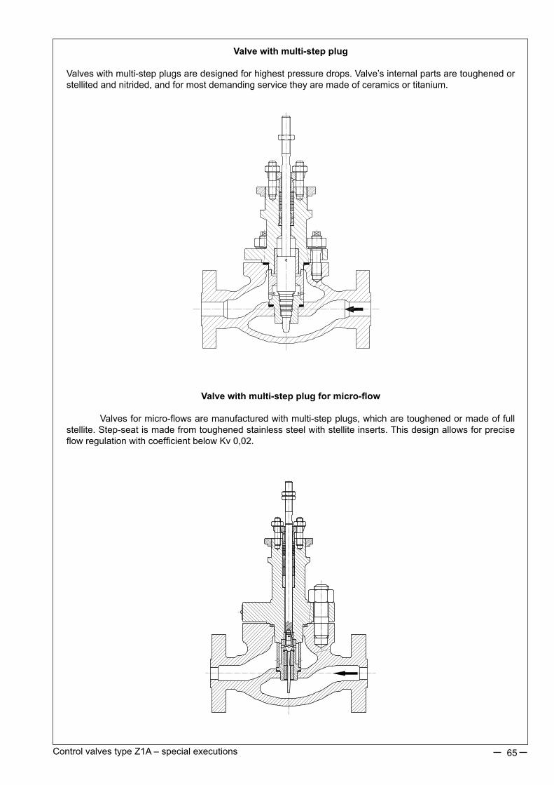
65Control valves type Z1A – special executions
Valve with multi-step plug
Valveswithmulti-stepplugsaredesignedforhighestpressuredrops.Valve’sinternalpartsaretoughenedorstellitedandnitrided,andformostdemandingservicetheyaremadeofceramicsortitanium.
Valve with multi-step plug for micro-flow
Valvesformicro-flowsaremanufacturedwithmulti-stepplugs,whicharetoughenedormadeoffullstellite.Step-seatismadefromtoughenedstainlesssteelwithstelliteinserts.ThisdesignallowsforpreciseflowregulationwithcoefficientbelowKv0,02.

Revision:specialexecutionsZ1A/06/2013Validuntilthenextrevision.
66
Valve with reverse flow (FTC) for flashing
Valves with fluid flow over the plug (FTC) are used for service with full evaporation (flashing).Aprotective cage with conical insert is mounted under the seat aiming at protection of valve body bottom against erosion.Allinternalpartsaremadeofhighlytoughenedstainlesssteel.
Valves DN150-300 for nominal pressures PN160-420
Valves for nominal pressures higher than those in the main catalogue card of Z1A valves are made availableuponcustomisedrequests.Duetolargebonnetdiameterandhighpressure,thepackingsysteminaformofconicalself-tightening(underpressure)sealwasused.Productversionswithprofileandperforatedplugsindifferentmaterialsareavailable.

DOUBLE-PORTED CONTROL VALVES TYPE Z1B®
67
FEATURES:
•various materials of valve body and internal parts, adapted to specific working conditions,•design provides noise reduction, enhanced resistance to cavitation and flashing, and elimination of choked flow,•wide range of nominal pressu-res, PN10 to CL2500, and flow ratio and control characteristics,• reduction in aggressive and toxic media emissions to environment through application of bellow seal bonnets or bonnet packings meeting requirements of TA - LUFT,•easy assembly and dismantling of valve internal parts for maintenance and service,•high durability and reliability due to application of top-class materials and surface improvement proces-ses (burnishing, stelliting, heat treatment, CrN coatings),•possibility of mating with reverse action P/R (column) and P1/R1 (cast yoke) multi-spring actuators, and changing the spring range with no extra parts (keeping the number of springs),•possibility of fitting actuators with lateral (P1/R1) or top (P/R) handwheel,•possibility of performing diagnostics of “valve-actuator” due to application of smart electro-pneumatic posi-tioners,•wide range of electric actuators,•special executions for oxygen, hydrogen, gas fuels, low temperature fluids (liquid oxygen, liquid nitrogen), acid gases containing H2S; with heat jacket; for explosive atmospheres as per ATEX Directive 94/23/EC,•design and production process meet the requirements of Quality Management System ISO 9001 and Directive 97/23/EC, and regulations of AD2000 Merkblatt, designated for installation on pipelines.
Z1B ® is a trademark registered with Republic of Poland Patent Office.
APPLICATION AREA:
Single-ported globe control valves type Z1B are used in automatic and remote control instalations as flow control elements to adjust flow of liquids, steam and gases. Wide range of materials, excellent pressure and temperature parameters, multiple design variants, meeting requirements of various processes, make the valves applicable under the most demanding working conditions in power generation, petroleum chemistry, heating, chemical industry, metallurgy, etc. Versions designated for Western Europe market can be marked BR12.
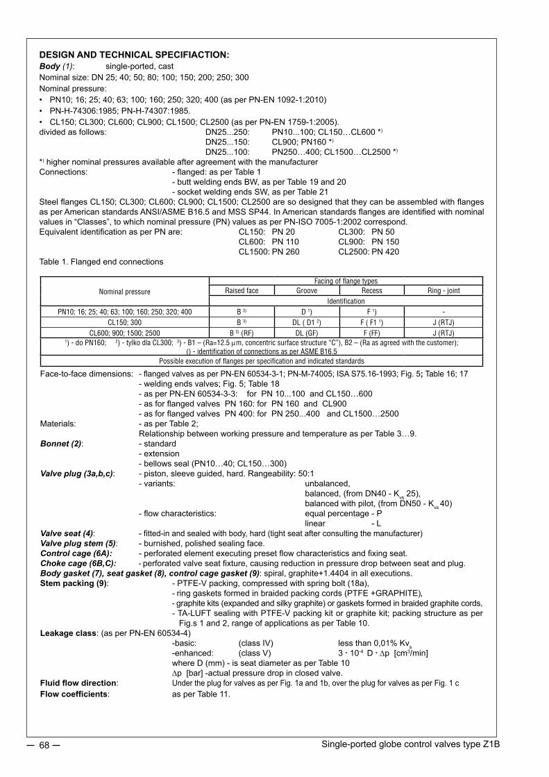
Single-ported globe control valves type Z1B68
DESIGN AND TECHNICAL SPECIFIACTION:Body (1): single-ported, castNominal size: DN 25; 40; 50; 80; 100; 150; 200; 250; 300Nominal pressure: • PN10; 16; 25; 40; 63; 100; 160; 250; 320; 400 (as per PN-EN 1092-1:2010)• PN-H-74306:1985; PN-H-74307:1985.• CL150; CL300; CL600; CL900; CL1500; CL2500 (as per PN-EN 1759-1:2005).divided as follows: DN25...250: PN10...100; CL150…CL600 *)
DN25...150: CL900; PN160 *)
DN25...100: PN250…400; CL1500…CL2500 *)
*) higher nominal pressures available after agreement with the manufacturerConnections: - flanged: as per Table 1 - butt welding ends BW, as per Table 19 and 20 - socket welding ends SW, as per Table 21Steel flanges CL150; CL300; CL600; CL900; CL1500; CL2500 are so designed that they can be assembled with flanges as per American standards ANSI/ASME B16.5 and MSS SP44. In American standards flanges are identified with nominal values in “Classes”, to which nominal pressure (PN) values as per PN-ISO 7005-1:2002 correspond.Equivalent identification as per PN are: CL150: PN 20 CL300: PN 50 CL600: PN 110 CL900: PN 150 CL1500: PN 260 CL2500: PN 420Table 1. Flanged end connections
Face-to-face dimensions: - flanged valves as per PN-EN 60534-3-1; PN-M-74005; ISA S75.16-1993; Fig. 5; Table 16; 17 - welding ends valves; Fig. 5; Table 18 - as per PN-EN 60534-3-3: for PN 10...100 and CL150…600 - as for flanged valves PN 160: for PN 160 and CL900 - as for flanged valves PN 400: for PN 250...400 and CL1500…2500Materials: - as per Table 2; Relationship between working pressure and temperature as per Table 3…9.Bonnet (2): - standard - extension - bellows seal (PN10…40; CL150…300) Valve plug (3a,b,c): - piston, sleeve guided, hard. Rangeability: 50:1 - variants: unbalanced, balanced, (from DN40 - Kvs 25), balanced with pilot, (from DN50 - Kvs 40) - flow characteristics: equal percentage - P linear - LValve seat (4): - fitted-in and sealed with body, hard (tight seat after consulting the manufacturer) Valve plug stem (5): - burnished, polished sealing face.Control cage (6A): - perforated element executing preset flow characteristics and fixing seat. Choke cage (6B,C): - perforated valve seat fixture, causing reduction in pressure drop between seat and plug. Body gasket (7), seat gasket (8), control cage gasket (9): spiral, graphite+1.4404 in all executions.Stem packing (9): - PTFE-V packing, compressed with spring bolt (18a), - ring gaskets formed in braided packing cords (PTFE +GRAPHITE), - graphite kits (expanded and silky graphite) or gaskets formed in braided graphite cords, - TA-LUFT sealing with PTFE-V packing kit or graphite kit; packing structure as per Fig.s 1 and 2, range of applications as per Table 10.Leakage class: (as per PN-EN 60534-4) -basic: (class IV) less than 0,01% Kvs -enhanced: (class V) 3 . 10-4 D .∆p [cm3/min] where D (mm) - is seat diameter as per Table 10 ∆p [bar] -actual pressure drop in closed valve.Fluid flow direction: Under the plug for valves as per Fig. 1a and 1b, over the plug for valves as per Fig. 1 cFlow coefficients: as per Table 11.
Nominal pressureFacing of flange types
Raised face Groove Recess Ring - jointIdentification
PN10; 16; 25; 40; 63; 100; 160; 250; 320; 400 B 3) D 1) F 1) -CL150; 300 B 3) DL ( D1 2) F ( F1 1) J (RTJ)
CL600; 900; 1500; 2500 B 3) (RF) DL (GF) F (FF) J (RTJ)1) - do PN160; 2) - tylko dla CL300; 3) - B1 – (Ra=12.5 mm, concentric surface structure “C”), B2 – (Ra as agreed with the customer);
() - identification of connections as per ASME B16.5Possible execution of flanges per specification and indicated standards

Single-ported globe control valves type Z1B 69
Fig. 1a. Valve Z1B - unbalanced plug. Fig. 1b. Valve Z1B - balanced plug.
Fig. 1c. Valve Z1B - balanced plug with pilot.

Single-ported globe control valves type Z1B70
Fig. 1d. Control valveFlanged body BW butt welding ends body
Unbalanced plug
Balanced plug with packing
Standard bonnet, PTFE-V sealing
Extension bonnet, GRAPHITE sealing
Bellows seal bonnet, PTFE+GRAPHITE sealing
Extension bonnet, TA-LUFT sealing
Control cage with choke cages I and II
Control cage with choke cage II
Control cage
Balanced plug with pilot
6b 6c

Single-ported globe control valves type Z1B 71
Table 2. Part list with materials
NOTE: *) to be applied for nominal pressures PN10…CL600Hardening of valve internal surfaces comprises:a) stelliting – padding of surfaces with stellite: ~40HRCb) CrN coating – introducing chromium nitride to external layer of detail, to the depth of ca.0.1 mm:~950HVc) heat treatment: valve plug (~45HRC), valve seat (~35HRC), stem (~35HRC), cages (~35HRC), guide sleeve (~45HRC), pilot (~55HRC).
Item Part Materials
1 BodyGP 240 GH ; (1.0619)
WCBG17CrMo 9-10 ; (1.7379)
WC9GX5CrNiMo 19-11-2 ; (1.4408)
CF8M
2 BonnetDN15…50 S 355 J2G3 (1.0570) 13CrMo4-4 ; (1.7335)
X6CrNiMoTi 17-12-2 ; (1.4571)DN80…300
GP 240 GH ; (1.0619)WCB
G17CrMo 9-10 ; (1.7379)WC9
3a,b,cUnbalanced plug
Balanced plugBalanced plug (pilot)
X6CrNiMoTi 17-12-2; (1.4571) + stellite + CrNX17CrNi 16-2 ; (1.4057) + heat treatment
4 Seat X6CrNiMoTi 17-12-2; (1.4571)
X6CrNiMoTi 17-12-2; (1.4571) + stelliteX17CrNi 16-2; (1.4057) + heat treatment
5 StemX6CrNiMoTi 17-12-2; (1.4571)
X6CrNiMoTi 17-12-2; (1.4571) + stellite + CrNX17CrNi 16-2 ; (1.4057) + heat treatment
6A Control cageX6CrNiMoTi 17-12-2; (1.4571)
X17CrNi 16-2; (1.4057) + heat treatment6B Choke cage I6C Choke cage II7 Body gasket
GRAPHITE (98%) + 1.4404 (spiral)8 Seat gasket9 Control cage gasket
10 Packing kit
PTFE + GRAPHITE
PTFE „V” (rings)
GRAPHITE
11 Pressing sleeve X6CrNiMoTi 17-12-2; (1.4571)
12 Pressing level S 355 J2G3 ; (1.0570)
13 Body screwPN10…CL300 8.8 A4 - 70 *)
PN63…CL2500 42CrMo4 (1.7225) 21CrMoV5-7 (1.7709) X6NiCrTiMoVB 25-15-2 (1.4980)
14 Body nutPN10…CL300 8.8 A4 - 70 *)
PN63…CL2500 42CrMo4 (1.7225) 21CrMoV5-7 (1.7709) X6NiCrTiMoVB 25-15-2 (1.4980)
15 Bonnet screw 8.8 A4 - 70 *)
16 Bonnet nut 8.8 A4 - 70 *)
17 Notched peg X6CrNiMoTi 17-12-2; (1.4571)
18a,b Spring 12R10 (SANDVIK), 9Ru10; ((1.4568) (SANDVIK)); Nimonic 90; (2.4969)
19 Spacer sleeve X6CrNiMoTi 17-12-2; (1.4571)
20 Guide sleeveX6CrNiMoTi 17-12-2; (1.4571) + stellite + CrN
X17CrNi 16-2 ; (1.4057) + heat treatment
21 Plug nut X6CrNiMoTi 17-12-2; (1.4571)
22 Plug sealing ring Expanded graphite23 Pilot X105CrMo17; (1.4125)24 Back nut X6CrNiMoTi 17-12-2; (1.4571)
Relevant material standardsMaterial Standard
GP 240 GH ; (1.0619) PN-EN 10213-2WCB ASTM A 216
G17CrMo 9-10 ; (1.7379) PN-EN 10213-2WC9 ASTM A 217
GX5CrNiMo 19-11-2 ; (1.4408) PN-EN 10213-4CF8M ASTM A 351
S 355 J2G3 ; (1.0570) PN-EN 1002513CrMo4-4; (1.7335) PN-EN 10028
X6CrNiMoTi 17-12-2 ; (1.4571) PN-EN 10088X17CrNi 16-2 ; (1.4057) PN-EN 10088X105CrMo17; (1.4125) PN-EN 10088
C45 (1.0503) PN-EN 10083-1
X30Cr13 (1.4028) PN-EN 10088
8.8 EN 20898-1
A4-70 *) EN ISO 3506-2
42CrMo4 (1.7225) EN 10269
21CrMoV5-7 (1.7709) EN 10269
X6NiCrTiMoVB 25-15-2 (1.4980) EN 10269

Single-ported globe control valves type Z1B72
Table 3…9. Allowable working overpressure for materials at relevant temperatures
Table 4. Material: G17CrMo 9-10 (1.7379) as per PN-EN 10213-2
PN / CL Standard
Temperature [°C]
-10…50 100 150 200 250 300 350 400 425 450 475 500 510 520 530 540 550
Allowable working pressure [bar]
PN10-
10 10 10 10 10 10 9,7 9,2 9 8,8 7,6 6,4 5,6 4,9 4,2 3,7 3,2
PN16 16 16 16 16 16 16 15,6 14,8 14,4 14 12,1 10,2 8,9 7,8 6,8 5,9 5,1
CL150 PN-EN 1759-1 19,5 17,7 15,8 14 12,1 10,2 8,4 6,5 5,6 4,7 3,7 2,8 2,4 2 1,7 1,4 -
PN25EN 1092-1
25 25 25 25 25 25 24,4 23,2 22,6 22 19 16 14 12,2 10,7 9,2 8
PN40 40 40 40 40 40 40 39 37,1 36,1 35,2 30,4 25,7 22,4 19,6 17,1 14,8 12,9
CL300 PN-EN 1759-1 51,7 51,5 50,2 48,3 46,3 42,8 40,2 36,6 35,1 33,8 31,7 28,2 26,6 23,5 20,6 17,8 15,5
PN63EN 1092-1
63 63 63 63 63 63 61,5 58,5 57 55,5 48 40,5 35,4 30,9 27 23,4 20,4
PN100 100 100 100 100 100 100 97,6 92,8 90,4 88 76,1 64,2 56,1 49 42,8 37,1 32,3
CL600
PN-EN 1759-1
103 103 100 96,7 92,6 85,7 80,4 73,1 70,2 67,6 63,3 56,4 53,3 47,1 41,1 35,7 31,1
CL900 155 155 151 145 139 129 121 110 105 101 95 84,6 79,9 70,6 61,7 53,5 46,6
PN160 160 160 160 160 160 160 156,1 148,5 144,7 140,9 121,8 102,8 88,9 78,4 68,5 59,4 51,8
PN250 250 250 250 250 250 250 244 232,1 226,1 220,2 190,4 160,7 140,4 122,6 107,1 92,8 80,9
CL1500 259 258 251 242 232 214 201 183 175 169 158 141 133 118 103 89,1 77,7
PN320 320 320 320 320 320 320 312,3 297,1 289,5 281,9 243,7 205,7 179,8 156,9 137,1 118,8 103,6
PN400 400 400 400 400 400 400 390,4 371,4 361,8 352,3 304,7 257,1 224,7 196,1 171,4 148,5 129,5
CL2500 431 429 418 403 386 357 335 305 292 282 264 235 222 196 171 149 130
Table 5. Material: GX5CrNiMo 19-11-2 (1.4408) as per PN-EN 10213-4
PN / CL Standard
Temperature [°C]
-10…50 100 150 200 250 300 350 400 425 450 475 500 510 520 530 540 550 600
Allowable working pressure [bar]
PN10EN 1092-1
10 10 9 8,4 7,9 7,4 7,1 6,8 - 6,7 - 6,6 - - - - 6,5 5,6
PN16 16 16 14,5 13,4 12,7 11,8 11,4 10,9 - 10,7 - 10,5 - - - - 10,4 8,9
CL150 PN-EN 1759-1 17,9 16,3 14,9 13,5 12,1 10,2 8,4 6,5 5,6 4,7 3,7 2,8 2,4 2 1,7 1,4 - -
PN25EN 1092-1
25 25 22,7 21 19,8 18,5 17,8 17,1 - 16,8 - 16,5 - - - - 16,3 14
PN40 40 40 36,3 33,7 31,8 29,7 28,5 27,4 - 26,9 - 26,4 - - - - 26 22,4
CL300 PN-EN 1759-1 46,7 42,5 38,9 35,3 32,9 30,5 28,8 27,6 27,2 26,9 26,6 26,4 26,3 22,5 22,4 22,3 22,2 -
PN63EN 1092-1
63 63 57,3 53,1 50,1 46,8 45 43,2 - 42,4 - 41,7 - - - - 41,1 35,4
PN100 100 100 90,9 84,2 79,5 74,2 71,4 68,5 - 67,3 - 66,1 - - - - 65,2 56,1
CL600
PN-EN 1759-1
93,4 85 77,8 70,6 65,8 61 57,6 55,2 54,5 53,8 53,3 52,8 52,6 44,9 44,8 44,6 44,4 -
CL900 140 127 117 106 98,6 91,4 86,4 82,8 81,7 80,6 79,9 79,2 78,9 67,4 67,1 66,9 66,7 -
PN160 160 160 145,5 134,8 127,2 118,8 114,2 109,7 - 107,8 - 105,9 - - - - 104,3 89,9
PN250 250 250 227,3 210,7 198,8 185,7 178,5 171,4 - 168,4 - 165,4 - - - - 163 140,4
CL1500 233 212 194 176 164 152 144 138 136 134 133 132 132 112 112 111 111 -
PN320 320 320 291 269,7 254,4 237,7 228,5 219,4 - 215,6 - 211,8 - - - - 208,7 179,8
PN400 400 400 363,8 337,1 318 297,1 285,7 274,2 - 269,5 - 264,7 - - - - 260,9 224,7
CL2500 389 354 324 294 274 254 240 230 227 224 222 220 219 187 187 186 185 -
Table 3. Material: GP240GH (1.0619) as per PN-EN 10213-2
PN / CL Standard
Temperature [°C]
-10…50 100 150 200 250 300 350 400
Allowable working pressure [bar]
PN10EN 1092-1
10 9,2 8,8 8,3 7,6 6,9 6,4 5,9
PN16 16 14,8 14 13,3 12,1 11 10,2 9,5
CL150 PN-EN 1759-1 17,3 15,4 14,6 13,8 12,1 10,2 8,4 6,5
PN25EN 1092-1
25 23,2 22 20,8 19 17,2 16 14,8
PN40 40 37,1 35,2 33,3 30,4 27,6 25,7 23,8
CL300 PN-EN 1759-1 45,3 40,1 38,1 36 32,9 29,8 27,8 25,7
PN63EN 1092-1
63 58,5 55,5 52,5 48 43,5 40,5 37,5
PN100 100 92,8 88 83,3 76,1 69 64,2 59,5
CL600
PN-EN 1759-1
90,5 80,2 76,1 72 65,8 59,7 55,5 51,4
CL900 136 120 114 108 98,7 89,5 83,3 77,1
PN160 160 148,5 140,9 133,3 121,9 110,4 102,8 95,2
PN250 250 232,1 220,2 208,3 190,4 172,6 160,7 148,8
CL1500 226 201 190 180 165 149 139 129
PN320 320 297,1 281,9 266,6 243,8 220,9 205,7 190,4
PN400 400 371,4 352,3 333,3 304,7 276,1 257,1 238
CL2500 377 334 317 300 274 249 231 214
NOTES:1. It is allowed to apply carbon steel and acid
proof cast steel for temperatures lower than given in Tables 3...9, provided that working pressure is reduced respectively, working temperature impact tests are performed and cast is heat treated. Details are to be consulted with manufacturer.
2. Working pressure for intermediate temperature values can be calculated by interpolation.
3. Temperature range for flanged connections: up to +537°C, for welding connections: up to +650°C

Single-ported globe control valves type Z1B 73
Table 7. Material: WCB as per ASTM A216
PN / CL Standard
Temperature [°C]
-10…50 100 150 200 250 300 350 375 400
Allowable working pressure [bar]
PN10EN 1092-1
10 10 9,7 9,4 9 8,3 7,9 7,7 6,7
PN16 16 16 15,6 15,1 14,4 13,4 12,8 12,4 10,8
CL150 PN-EN 1759-1 19,3 17,7 15,8 14 12,1 10,2 8,4 7,4 6,5
PN25EN 1092-1
25 25 24,4 23,7 22,5 20,9 20 19,4 16,9
PN40 40 40 39,1 37,9 36 33,5 31,9 31,1 27
CL300 PN-EN 1759-1 50 46,4 45,1 43,9 41,8 38,9 36,9 36,6 34,6
PN63EN 1092-1
63 63 61,5 59,6 56,8 52,7 50,3 49 42,5
PN100 100 100 97,7 94,7 90,1 83,6 79,8 77,8 67,5
CL600
PN-EN 1759-1
100,1 92,8 90,6 87,8 83,6 77,5 74 72,9 69,1
CL900 150,1 139,2 135,7 131,4 125,1 116,1 110,8 109,5 103,4
PN160 159,2 147,6 143,9 139,4 132,7 123,1 117,5 116,1 109,7
PN250 241,4 223,5 217,8 211,2 201,1 186,6 178,1 175,8 166,2
CL1500 250,5 231,9 226 219,2 208,7 193,6 184,8 182,4 172,5
PN320 313 289,9 282,6 273,9 260,8 242 231 227,9 215,6
PN400 396,4 367,3 358 346,9 330,3 306,6 292,6 288,6 273,1
CL2500 417,2 386,6 376,9 365,1 347,7 322,7 308 303,8 287,5
Table 8. Material: WC9 as per ASTM A217
PN / CL Standard
Temperature [°C]
-10…50 100 150 200 250 300 350 375 400 425 450 475 500 510 520 525 530 540 550
Allowable working pressure [bar]
PN10EN 1092-1
10 10 10 10 10 10 10 10 9,9 9,7 9,5 7,3 5,5 5 4,4 - 3,9 3,4 2,9
PN16 16 16 16 16 16 16 16 16 15,9 15,6 15,3 11,7 8,9 8 7,1 - 6,2 5,4 4,7
CL150 PN-EN 1759-1 19,5 17,7 15,8 14 12,1 10,2 8,4 7,4 6,5 5,6 4,6 3,7 2,8 - - 1,9 - 1,3 -
PN25EN 1092-1
25 25 25 25 25 25 25 25 24,8 24,4 23,9 18,3 14 12,6 11,2 - 9,8 8,5 7,4
PN40 40 40 40 40 40 40 40 40 39,7 39 38,3 29,2 22,3 20,2 18 - 15,7 13,6 12
CL300 PN-EN 1759-1 51,7 51,5 50,3 48,7 46,3 42,9 40,4 38,9 36,5 35,2 33,7 31,7 27,7 - - 21,6 - - 15,3
PN63EN 1092-1
63 63 63 63 63 63 63 63 62,5 61,5 60,3 46 35,2 31,9 28,3 - 24,8 21,4 18,8
PN100 100 100 100 100 100 100 100 100 99,2 97,6 95,6 73,1 55,9 50,6 44,9 - 39,3 34 29,9
CL600
PN-EN 1759-1
103,4 103,1 100,3 97,5 92,7 85,7 80,4 77,6 73,3 70,2 67,7 63,4 55,7 - - 43,3 - - 30,7
CL900 155,1 154,6 150,6 146,2 139 128,6 120,7 116,5 109,8 105,4 101,4 95,1 83,4 - - 64,9 - - 46
PN160 164,5 163,9 159,5 154,7 147,4 136,4 128 123,6 116,5 111,8 107,6 100,8 87,3 - - 68,9 - - 48,8
PN250 249,2 248,1 239,8 231,2 222,6 206,6 193,8 187 176,4 169,2 162,9 152,5 122,2 - - 104,4 - - 74,1
CL1500 258,6 257,7 250,8 244 231,8 214,4 201,1 194,1 183,1 175,6 169,1 158,2 138,9 - - 108,4 - - 76,9
PN320 323,2 321,9 312,3 302,3 289,2 268 251,4 242,5 228,8 219,4 211,4 197,8 165,7 - - 135,4 - - 96
PN400 409,4 408 397,1 385,7 366,8 339,4 318,5 307,1 289,7 277,9 267,7 250,7 218,5 - - 171,5 - - 121,5
CL2500 430,9 429,5 418,3 406,5 386,2 357,2 335,3 323,2 304,9 292,5 281,8 263,9 231,7 - - 180,5 - - 127,9
Table 9. Material: CF8M as per ASTM A351
PN / CL Standard
Temperature [°C]
-10…50 100 150 200 250 300 350 375 400 425 450 475 500 510 520 525 530 540 550 575 600 625 649
Allowable working pressure [bar]
PN10EN 1092-1
8,9 7,8 7,1 6,6 6,1 5,8 5,6 5,5 5,4 5,4 5,3 5,3 5,2 5,2 5,2 - 5,2 5,1 5,1 4,7 3,8 - -
PN16 14,3 12,5 11,4 10,6 9,8 9,3 9 8,8 8,7 8,6 8,5 8,5 8,4 8,3 8,3 - 8,3 8,3 8,2 7,6 6,1 - -
CL150 PN-EN 1759-1 18,4 16 14,8 13,6 12 10,2 8,4 7,4 6,5 5,6 4,6 3,7 2,8 - - 1,9 - 1,4 - - - - -
PN25EN 1092-1
22,3 19,5 17,8 16,5 15,5 14,6 14,1 13,8 13,6 13,5 13,4 13,3 13,2 13,1 13,1 - 13 13 12,9 12 9,6 - -
PN40 35,6 31,3 28,5 26,4 24,7 23,4 22,6 22,1 21,8 21,6 21,4 21,2 21 21 20,9 - 20,8 20,8 20,7 19,1 15,5 - -
CL300 PN-EN 1759-1 48,1 42,3 38,6 35,8 33,5 31,6 30,4 29,6 29,3 29 29 28,7 27,3 - - 25,2 - - 24 22,9 19,9 15,7 12,8
PN63EN 1092-1
56,1 49,2 44,9 41,6 38,9 36,9 35,5 34,9 34,4 34 33,7 33,5 33,2 33 32,9 - 32,8 32,7 32,6 30,2 24,4 - -
PN100 89,1 78,1 71,3 66 61,8 58,5 56,4 55,3 54,5 54 53,4 53,1 52,6 52,4 52,2 - 52,1 51,9 51,7 47,9 38,7 - -
CL600
PN-EN 1759-1
96,3 84,5 77,1 71,2 66,7 63,1 61 59,8 58,9 58,3 57,7 57,3 54,8 - - 50,6 - - 47,8 45,5 39,8 31,7 25,5
CL900 144,4 126,8 115,6 107 100,2 95 91,3 89,7 88,2 87,3 86,6 86 82,1 - - 75,9 - - 71,8 68,3 59,7 47,5 38,3
PN160 153,1 134,4 122,6 113,5 106,3 100,7 96,8 95,1 93,6 92,6 91,8 91,2 87,1 - - 80,5 - - 76,2 72,5 63,3 50,4 40,3
PN250 231,9 203,3 185,4 171,9 160,9 152,4 146,7 143,9 141,7 140,3 139,1 138,1 131,7 - - 121,8 - - 115,4 109,8 95,9 76,3 61
CL1500 240,6 210,9 192,4 178,4 167 158,1 152,2 149,3 147,1 145,6 144,3 143,3 136,7 - - 126,4 - - 119,8 114 99,5 79,2 63,8
PN320 300,8 263,7 240,6 223 208,7 197,6 190,3 186,7 184 182,1 180,3 179,2 170,9 - - 158 - - 149,7 142,5 124,4 98,9 79,2
PN400 381 334,1 304,8 282,4 264,2 250,3 241,1 236,5 233,1 230,7 228,4 227 216,6 - - 200,2 - - 189,5 180,5 157,7 125,1 100,4
CL2500 401 351,7 320,8 297,2 278,1 263,5 253,8 249 245,4 242,9 240,4 238,9 228 - - 210,7 - - 199,5 190 166 131,7 106,5
Table 6. Material: G20Mn5 (1.6220) wg PN-EN 10213-3
PN / CL Norma
Temperature [°C]
-40 100 150 200 250 300
Allowable working pressure [bar]
PN10
-
6 6 3,8 3,6 3,48 3,4
PN16 16 16 10,1 9,6 9,28 9,07
PN25 25 25 15,8 15 14,5 14,2
PN40 40 28 28 27 26 25
PN63 63 59 58 55 53 51
PN100 100 95 92 87 85 82
PN160 160 152 148 140 136 132

Single-ported globe control valves type Z1B74
Table 9. Packing types with application ranges.
)* PN10…40; CL150…3000 for below seal bonnet )** for welding ends valves
Fig. 2. Bonnet packings
Packing kit TA-LUFT PTFE-V Packing kit TA-LUFTwith graphite kit
DESIGNSingle-ported globe control valves Z1B are recommended for application under heavy-duty working conditions, with excessive noise, flashing or choked flow. Selection of designs and materials depends on working conditions. It is based on computer-aided calculations of flow coefficients, noise level, fluid status, and effectiveness of such actions depends on data submitted by customer. Application of perforated control elements allows noise reduction by 10dBA regarding execution with contoured plug. Further noise reduction (by 5 dBA) can be achieved by application of choke cage, which causes reduction in pressure drop between plug and seat. Such design is also recommended in case of choked flow, cavitation and flashing. Perforated structures feature higher pressure recovery coefficient FL, which allows achievement of higher flow at same Kvs and Δp as in basic design. Customers shall also appreciate possibility of achieving maximum flow ratio for all nominal sizes and control characteristics, and reduction in actuator costs due to application of balanced plugs. In case of compressive media it is advisable to apply diffusers at the valve outlet. In justified cases (noise, choked flow) diffusers can be fitted with additional perforated choke structures in the form of plates assembled between flanges or welded in diffuser interior. On customer’s request, also when flow conditions justify such solution, special executions are recommended concerning materials, flow ratios, control characteristics, leakage class, etc.
Packing (PTFE-V) Packing (PTFE+GRAPHITE)
Packing (GRAPHITE)
Packing PNTemperature [°C]
BonnetStandard Extension Bellow seal
PTFE-Vup to CL600 )* -46...+200
-198...-46+200...+300
-100...+200PTFE + GraphitePTFE-V / TA-LUFT
Graphiteup to CL2500 )* +200...+300 +300...+537 ,(+650)** +200...+400
Graphite / TA-LUFT

Single-ported globe control valves type Z1B 75
Table 11: Flow ratios Kvs.
Table 12: Available force FS [kN] of pneumatic actuators
NOTE: 1. For direct actuators P; P1 adopted spring range is 20 – 100 kPa2. For electric and other actuators Δp value can be calculated using above formula and data from Table 11, taking nominal load capacity as available force FS, as per actuator data sheet.
ALLOWABLE PRESSURE DROPS ∆p.Pressure drops Δp [bar] in Table 13 apply to closed valve and they are calculated with regard to the valve drive performance. Actual pressure drops should not exceed 70% of allowable working pressure for given nominal pressure, used material and working temperature, as per tables 3…9.
where ∆p [bar] - calculated pressure drop Fs [kN] - actuator available force (Table 12) FD [kN] - valve plug to valve seat pressure (Table 11) D [mm] - valve seat diameter (Table 11)NOTE1. Valves with balanced plug and with gasket are manufactured only in leakage class IV. For balanced plugs assume the available force of FS at least equal to FD for class V (Table 11).2. For valves relieved with a remote control, drive disposition forces need to be agreed on with the manufacturer.
NOTE1. - no executions for PN250…CL2500 K0 - no choke cages,2. **) - for PN10…CL300 - K0 K1 - one choke cage,3. „K” - maximum number of choke cages in valve. K2 - two choke cages.4. The number of choked cages does not concern the balanced valves by a pilot.
•
Fs = 0,785 • 10- 4 • D2 • ∆p + FD∆p =
Fs - FD
0,785 • 10- 4 • D2 or
Kvs StrokeSeat diameter
DFD Nominal size DN
IV kl. V kl.
L P [mm] [mm] [kN] 25 40 50 80 100 150 200 250 300
10
20
20,64 0,33 2,1 • K1**) K2 K2
special execution, technical data according to individual inquiries
16 25,25 0,4 2,6 K1 K2
25 31,72 0,5 3,3 • K1 K1 K2
40
38
41,25 0,7 4,6 • K1 K2 K2
63 50,8 0,8 5,2 K1 K2 K2
94 66,7 1,1 7,2 • K0 K1 K2 K2
12550 88,9 1,4 9,1
K1 K2 K2 K2
160 • K1 K2 K2 K2
20063 107,92 1,7 11
K1 K2 K2
250 K1 K2 K2
320 80 126,95 2,0 13 K1 K2 K2
500
100
158,72 2,5 16 K1 K2
630203,2 3,2 21
K1
800 - K1
Calculation coefficients
FL=0,95 ; XT=0,78; Fd=0,1; xFz=0,75
Actuator size
Direct actuator P ; P1 Reverse actuator R ; R1Supply pressure [kPa] Spring range [kPa]
140 250 400 20 - 10040 - 120;40 - 200
60 - 140 80 - 240 120 - 280 180 - 380
250 1,0 3,8 7,5 0,5 1,0 1,5 2,0 3,0 -400 1,6 6,0 12,0 0,8 1,6 2,4 3,2 4,8 -630 2,5 9,5 18,9 1,3 2,5 3,8 5,0 7,6 11,3
R-630T - - - 2,6 5,0 7,6 10,0 15,2 22,61000 4,0 15,0 30,0 2,0 4,0 6,0 8,0 12,0 18,01500 6,0 22,5 45,0 3,0 6,0 9,0 12,0 18,0 27,01500T 12,0 45,0 90,0 6,0 12,0 18,0 24,0 36,0 54,0

Single-ported globe control valves type Z1B76
Table 13: Pressure drops Δp [bar] for valves with pneumatic actuators, leakage class class IV and V
NOTE:1. In Table 13, theoretical acceptable pressure drops are included. Actual pressure drops with consideration of tolerance of spring manufacture and friction of internal parts of the actuator are lower than those given by 20%. Pressure drops chosen that way guarantee internal tightness of closing of the valves.2.In valves working along the procedure: “increased control pressure – valve opens”, the actuator with springs ranged 40-120 kPa can be replaced with an actuator ranged 40-200 kPa, with the same pressure drops.3. For reverse-working actuators (type R or R1), supply pressure should be higher than the upper spring range by at least 40kPa.
Valv
e se
at d
iam
eter
[mm
]
Actu
ator
siz
e
Air-to-closeSpring range 20…100 kPa Air-to-open
IV class V class IV class V classSupply pressure [kPa] Spring range [kPa] Spring range [kPa]
140 250 400 140 250 400
20…
100
40…
120
40…
200
60…
140
80…
240
120…
280
180…
380
20…
100
40…
120
40…
200
60…
140
80…
240
120…
280
180…
380
∆p [bar]
20,64
250 20 100 210 - 48 159 5 20 34 49 78 - - - - - 26 -400 37 166 280 - 115 280 14 37 60 84 131 - - - 9 32 79 -630 65 272 280 11 218 280 27 65 103 140 216 280 - 11 49 86 162 274
R-630T - - - - - - 65 140 216 280 280 280 11 86 162 237 280 280
25,25
250 12 67 142 - 23 98 2 12 22 32 52 - - - - - 8 -400 24 112 232 - 68 188 8 24 40 56 88 - - - - 12 44 -630 42 180 280 - 136 280 17 42 67 92 143 218 - - 23 48 98 174
R-630T - - - - - - 42 92 143 193 280 280 - 48 98 149 249 280
31,72
250 6 41 88 - 5 53 - 6 12 19 31 - - - - - - -400 14 70 145 - 34 110 4 14 24 34 54 - - - - - 19 -630 25 113 232 - 78 197 10 25 41 57 90 137 - - 6 21 54 101
R-630T - - - - - - 25 57 89 121 185 280 - 22 54 85 149 245
41,25630 13 63 130 - 35 102 4 13 22 31 49 75 - - - 3 21 48
R-630T - - - - - - 14 32 51 70 108 164 - 5 24 43 81 137
50,8630 9 43 90 - 21 69 2,5 9 15 21 34 53 - - - - 12 30
1000 16 71 146 - 49 124 6 16 26 36 56 86 - - 4 14 34 641500 25 107 218 3 85 196 10 25 40 55 84 129 - 3 18 33 62 107
66,7630 4 24 50 - 6 33 - 4 8 11 18 29 - - - - - 11
1000 8 40 83 - 22 65 3 8 14 20 31 48 - - - 2 14 301500 14 61 125 - 44 108 5 14 23 31 48 74 - - 5 14 30 56
88,91000 4 22 46 - 10 34 1 4 7 11 17 27 - - - - 5 141500 7 34 70 - 21 58 3 7 12 17 27 41 - - - 5 14 29
107,921000 3 14 30 - 4 20 - 3 5 7 11 18 - - - - 1 81500 5 23 47 - 13 37 1 5 8 11 18 28 - - - 1 8 17
1500T 11 48 96 1 37 86 5 11 18 24 37 57 - 1 8 14 27 47
126,951500 3 16 34 - 8 25 - 3 6 8 13 20 - - - - 4 11
1500T 8 34 70 - 25 61 3 8 13 17 27 41 - - 4 9 18 33
158,721500 2 10 21 - 3 14 - 2 3 5 8 12 - - - - 1 6
1500T 5 21 44 - 14 37 2 5 8 10 17 26 - - 1 4 10 19
203,21500 - 6 13 - - 7 - - 2 3 4,5 7 - - - - - 2
1500T 3 13 27 - 7 21 - 3 4,5 6 10 16 - - - - 5 10

Single-ported globe control valves type Z1B 77
Table 14: Dimensions and flow ratios for silencer plates
Multi-plate silencer kits are customized for requirements of individual processes.
Fig. 4. Installation of silencer plates (or kits).
1 - Valve2 ; 3 - Silencer plates (kits)4 - Reduction joint (diffuser)
NOISE REDUCTION:Should noise due to cavitation or aerodynamic phenomena exceed level acceptable by customer, it can be reduced by applying the following solutions:- perforated valve plugs (Fig. 1a, 1b and 1d)- silencer plates on valve outlet and/or inside of reduction joint (Fig. 3,4 and Table 13)- reduction ends (diffusers) - (Fig. 4)
Fig. 3. Silencer plate
DN 25 40 50 80 100 150 200 250 300 350
Kvs
10 25 40 94 160 320 500 800 1000 15009 22,5 36 84 144 288 450 720 900 13508 20 32 75 128 256 400 640 800 12007 17,5 28 66 112 224 350 560 700 1050
L [mm] 5 6 10 15 20Dp [mm] 68 88 102 138 162 218 285 345 410 465

Single-ported globe control valves type Z1B78
Flanged connection valve
Valve with welding ends SW (DN15…50)
Valve with welding ends BW
Fig. 5. Valve connection dimensions
DIMENSIONS AND WEIGHTS
Dimension E - valve plug location - valve closed*) Connection with P/R-1000 actuator: E=195 mm and F=115 mm
Table 15a: Control valves connection dimensions
NOTE: Weight of valve with standard bonnet and without actuator.
DN 25 40 50
PN/CLPN10...CL300
PN63...CL600
CL900; PN160
PN250; CL1500
PN320PN400; CL2500
PN10...CL300
PN63...CL600
CL900; PN160
PN250; CL1500
PN320PN400; CL2500
PN10...CL300
PN63...CL600
CL900; PN160
PN250; CL1500
PN320PN400; CL2500
B max 63 70 75 80 90 75 85 93 98 110 83 98 108 105 118
CDS 135 149 193 145 172 214 155 175 237DW 306 320 364 306 348 385 326 345 402DM 254 - - - - - 254 - - - - - 270 - - - - -
Weight [kg]
8 8,5 9,5 15,5 17,5 19 20 22 23 22 25 28 31 33 34
DN 80 100 150
PN/CLPN10...CL300
PN63...CL600
CL900; PN160
PN250; CL1500
PN320PN400; CL2500
PN10...CL300
PN63...CL600
CL900; PN160
PN250; CL1500
PN320PN400; CL2500
PN10…CL300 PN63...CL600 CL900;PN160
B max 105 145 120 133 138 153 128 138 145 155 168 185 160 178 190
CDS 206 233 257 217 252 329 287 365DW 375 402 447 407 442 498 426 483DM 405 - - - - - 405 - - - - - 470 - -
Weight [kg]
40 43 44 50 51 52 65 72 75 86 89 95 132 147 156
DN 200 250
PN/CL PN10...CL300 PN63...CL600 PN10...CL300PN10...CL300
(kv800)PN63...CL600
B max 190 235 258 255
CDS 439 458DW 539 558DM 580 - 580 660 -
Weight [kg]
195 220 320 330 360
DN300 - special execution, technical data according to individual inquiries. (table: 15a and 15b).

Single-ported globe control valves type Z1B 79
NOTE:1) For DN80 and DN100 valves with TA-LUFT packing d2 = 84.15
Table 15b: Control valves connection dimensions
Table 16. Control valve length, flanges.
Table 17. Algorithms for calculation of control valve body length for valves with flanged end - with groove - with races - with ring-joint
Note: Dimension A presented in Table 15 for CL150; CL300; CL600; CL900; CL1500; CL2500 apply to bodies with B seat (RF). For other executions dimension A1 can be calculated using relations presented in Table 17.
DN
Dimesion A [mm]
PN / DIN CL
10; 16; 25; 40 63 - 100 160 250 - 320 400 CL150 CL300 CL600 CL900 CL1500 CL2500
25 160 230 230 260 300 184 197 210 248 273 308
40 200 260 260 300 350 222 235 251 270 311 359
50 230 300 300 350 400 254 267 286 311 340 400
80 310 380 380 450 500 298 317 336 387 460 498
100 350 430 430 520 580 352 368 394 464 530 575
150 480 550 550 * * 451 473 508 556 * *
200 600 650 * * * 543 568 610 * * *
250 730 775 * * * 673 708 752 * * *
300 special execution, technical data according to individual inquiries* higher nominal pressures available after agreement with the manufacturer
Body type and identificationPressure CL DN A 1PN / ANSI
With groove DL / (GF)With races
F / (FF)
CL300
25…250
A 1 = A + 5 x 2CL600CL900CL1500CL2500
A 1 = A - 1,5 x 2
With ring-jointJ / (RTJ)
CL150 25…250A 1 = A +6,5 x 2
CL300 25…40
CL300 50…250 A 1 = A + 8 x 2
CL600CL900CL1500
25…40A 1 = A
CL2500 25
CL600 50…250
A 1 = A + 1,5 x 2CL900CL1500
50…100
CL900 150
CL250080 A 1 = A + 3 x 2
100 A 1 = A + 4,5 x 2
DN 25…50 50 80 80; 100 80; 100 100 150 200 200; 250 250
Kvs 10…25 40 25 40 63; 94 125; 160 63; 94 125; 160 200; 250 320 94125; 160
200; 250 320 500630; 800
Stroke 20 38 20 38 38 50 38 50 63 80 38 50 63 80 100
d1 M12x1,25 M16x1,5 M20x1,5 M16x1,5 M20x1,5 M24x1,5
d2 1) 57,15 / 2 1/4”-16UN2A 84,15 / 3 5/16”-16NS2A 95,25 / 3 3/4”-12UN2A
d3 12 16 20 24
Actuator
250400630
R-630T
630R-630T
250400630
R-630T
630R-630T
63010001500
10001500
63010001500
10001500
100015001500T
15001500T
10001500
100015001500T
15001500T

Single-ported globe control valves type Z1B80
Table 18: Control valve length, welding ends.
DNDimension A [mm]Nominal pressure
PN 10...CL600 CL900…PN160 PN250...CL250025 210 230 30040 251 260 35050 286 300 40080 337 380 500
100 394 430 580150 508 550 *200 610 * *250 752 * *300 special execution, technical data according to individual inquiries
* higher nominal pressures available after agreement with the manufacturer
Table 19: Butt welding ends BW.
Table 19 contains series of example butt welding connections.It is allowed to execute connections for other dimensions of pipes. Should pipe dimensions fall within the range ∅B min / ∅A max (Fig. 6, Table 20), connection can be executed as cast. Otherwise reduction stub is to be welded to body end, which shall result in extension of the housing by L or 2L size (Fig. 7, Table 20). Other connection dimensions are allowed upon consulting with manufacturer.
where: DZ [mm] - pipe external diameter, DW [mm] - pipe internal diameter, t [mm] - pipe wall thickness.
NOTE:•) - execution with reduction stubs as per Fig. 7.
DNDz
[mm]t
[mm]Dw
[mm]PN (DIN3239)
10 16 25 40 63 100 160 250 320 400
2533,7
2,6 28,5 x x x x x x
2,9 27,9 x
3,6 26,5 x
5 23,7 x
7,119,5 • x
42,4 28,2 x
40 48,3
2,6 43,1 x x x x
2,9 42,5 x x
3,6 41,1 x
5 38,3 x
6,3 35,7 x
10 28,3 x
50 60,3
2,9 54,5 x x x x x
3,2 53,9 x
4 52,3 x
6,3 47,7 x
8 44,3 x
12,5 35,3 x
8088,9
3,2 82,5 x x x x
3,6 81,7 • x
4 80,9 • x
6,3 76,3 x
11 66,9 x
12,5 63,9 x
17,553,9 • x
114,3 79,3 x
100114,3
3,6 107,1 x x x x
4 106,3 x
5 104,3 x
8 98,3 x
14,2 85,9 x
16 82,3 x
22,2 69,9 • x
139,7 20 99,7 x
150168,3
4,5 159,3 x x x x
5,6 157,1 • x
7,1 154,1 • x
12,5143,3 • x
193,7 168,7 x
200219,1
5,9 207,3 x x
6,3 206,5 x x
7,1 204,9 x
10 199,1 • x
244,5 12,5 219,5 x
250 273
6,3 260,4 x x
7,1 258,8 x x
8,8 255,4 x
12,5 248 x
300 special execution, technical data according to individual inquiries
DN ScheduleDz
[mm]t
[mm]Dw
[mm]
ANSI (ASME 36.10 M)
CL150 CL300 CL600 CL900 CL1500 CL2500
1”
40
33,4
3,4 26,6 x x x x
80 4,5 24,4 x
160 6,4 20,6 • x
XXS 9,1 15,2 • x
1 1/2”
40
48,3
3,7 40,9 • x x x x
80 5,1 38,1 • x x x x x
160 7,1 34,1 x
XXS 10,2 27,9 • x
2”
40
60,3
3,9 52,5 x x x x
80 5,5 49,3 • x
160 8,7 42,9 x
XXS 11,1 38,1 • x
3”
40
88,9
5,5 77,9 • x x x
80 7,6 73,7 • x
160 11,1 66,7 x
XXS 15,2 58,5 x
4”
40
114,3
6 102,3 x x x
80 8,6 97,1 • x
120 11,1 92,1 • x
160 13,5 87,3 • x
XXS 17,1 80,1 • x
6”
40
168,3
7,1 154,1 • x x
80 11 146,3 • x x
120 14,3 139,7 • x
160 18,3 131,7 • x
8”
20
219,1
6,4 206,3 x x
30 7 205,1 x
40 8,2 202,7 x
60 10,3 198,5 • x
80 12,7 193,7 • x
10”
20
273
6,4 260,2 x x
30 7,8 257,4 x
40 9,3 254,4 x
60 12,7 247,6 • x
80 15,1 242,8 • x
12’’ special execution, technical data according to individual inquiries

Single-ported globe control valves type Z1B 81
DN Pressure A max B min L
25
PN 10...40, CL 150, 300 38 20
50
PN 63...100, CL 600 48 20PN 160, CL 900 40 23
PN 250...400, CL 1500,2500 48 23
40
PN 10...40, CL 150, 300 64 42PN 63...100, CL 600 75 42
PN 160, CL 900 66 38PN 250...400, CL 1500,2500 66 28
50PN 10...100, CL 150...600 80 55
PN 160, CL 900 80 50PN 250...400, CL 1500,2500 92 42
80
PN 10...40, CL 150, 300 110 82
75
PN 63...100, CL 600 122 82PN 160, CL 900 111 76
PN 250...400, CL 1500,2500 127 56
100PN 10...100, CL 150...600 144 102
PN 160, CL 900 144 102PN 250...400, CL 1500,2500 165 81
150PN 10...40, CL 150, 300 183 160
100PN 63...100, CL 600 196 160PN 160, CL 900 217 154
200 PN 10...40, CL 150, 300 243 200
150PN 63...100, CL 600 248 200
250 PN 10...40, CL 150, 300 291 248PN 63...100, CL 600 346 248
Table 20: Dimensions of non-processed butt welding ends (executed as cast) and lengths of reduction stubs.
Fig. 6. Dimension of butt welding ends executed as cast
Fig. 7. Reduction stub
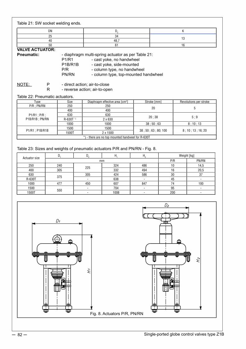
Single-ported globe control valves type Z1B82
Table 22: Pneumatic actuators.
Table 23: Sizes and weights of pneumatic actuators P/R and PN/RN - Fig. 8.
Fig. 8. Actuators P/R, PN/RN
VALVE ACTUATOR:Pneumatic: - diaphragm multi-spring actuator as per Table 21: P1/R1 - cast yoke, no handwheel P1B/R1B - cast yoke, side-mounted P/R - column type, no handwheel PN/RN - column type, top-mounted handwheel
NOTE: P - direct action; air-to-close R - reverse action; air-to-open
Table 21: SW socket welding ends.
DN D2 K
25 3413
40 48,750 61 16
Type Size Diaphragm effective area [cm2] Stroke [mm] Revolutions per strokeP/R ; PN/RN 250 250
20 5
P1/R1 ; P/R ; P1B/R1B ; PN/RN
400 400630 630
20 ; 38 5 ; 9R-630T *) 2 x 630
1000 1000 38 ; 50 ; 63 8 ; 10 ; 13
P1/R1 ; P1B/R1B1500 1500
38 ; 50 ; 63 ; 80; 100 8 ; 10 ; 13 ; 16; 201500T 2 x 1500
*) - there are no top mounted handweel for R-630T
Actuator sizeD1 D2 H1 H2 Weight [kg]
mm P/R PN/RN250 240
225324 486 10 14,5
400 305 332 494 16 20,5630
375305 424 586 30 37
R-630T - 638 - 45 -1000 477 450 607 847 74 1001500
550- 704 - 95 -
1500T - 1008 - 200 -

Single-ported globe control valves type Z1B 83
Table 24: Sizes and weights of pneumatic actuators P1/R1 and P1B/R1B - Fig. 9
Fig. 9. Actuators P1/R1, P1B/R1BP1/R1-3000P1/R1 , P1B/R1B - 400...1500
Electric: - electric drives; domestic and foreign electro-hydraulic drives (for details and technical specification refer to manufacturers catalogs)Manual: - manual drive type 20, Fig. 10 Table 25.
- maximum supply pressure: actuator size 250...630 - 600kPa actuator size R-630T and 1000...1500 - 500kPa - accessories (upon request): side-mounted handwheel (P1/R1) or topmounted handwheel (P/R) , pneumatic positioner, electro-pneumatic positioner, smart electro-pneumatic positioner, air-set, three-way solenoid valve, lock-up valve, position transmitter, limit switches.
Control air connections: 1/4” NPT ; NPT 1/2”, Rc 1/2”- tube diameters: 6x1 ; 8x1 ; 10x1; 12x1- spring ranges: 20...100kPa ; 40...120kPa ; 60...140kPa - 3 springs 40...200kPa ; 80...240kPa ; 120...280kPa - 6 springs 180...380kPa *) - 12 springs (not applicable for actuators P/R; P1/R1-250; 400)For actuator P1/R1-3000 (Tandem) - for each range double the above numbers of springs (tandem)
Actuator sizeB D1 D2 H Weight [kg]
mm P1/R1 P1B/R1B400 255 305 225 453 20 28630 280 375 305 548 40 501000 340 477
450773 85 105
1500410 550
833 120 1503000 1138 225 255

Single-ported globe control valves type Z1B84
Fig. 10. Manual drive type 20.
Table 25: Manual drives type 20 - types, sizes and weights.
SPECIAL OPTIONS:- oxygen and hydrogen option:Application of adequate materials, mechanical and chemical cleaning, inspections and assembly ensure com-patibility with oxygen and hydrogen flows.- low temperature media option:Application of adequate materials and special bonnet design ensures effective isolation of valve drive from the impact of low temperatures. Used mostly for liquid oxygen and liquid nitrogen.- acid gas option:Parts of the valve can be made of materials and under conditions ensuring valve operation with gases of H2S content as per NACE MR-0175.- heat jacket option:Design and technical parameters as per customer’s specification.- balanced valves with pilot:Construction allows achievement of high leakage class at high pressure drops and reduced available force of actuator, flow direction - above the plug. – valves with non-cast bodies:If a special construction of the valve body is needed, it is possible to design a valve for individual customer’s needs (angle valves – type L and Z).
Marking: Example: 20-38-57-M16 - manual drive type 20; stroke - 38mm; d2=57,15mm; d1=M16x1,5
Type Stroke [mm] d1 d2 H D rev/strokeWeight
[kg]
20-20-57-M1220
M12x1,2557,15
265
228 8 7,520-20-84-M12 84,1520-38-57-M12
3857,15
298 15 1020-38-57-M16
M16x1,5
20-38-84-M16 84,1520-38-95-M16 95,2520-50-57-M16
5057,15
385 45716
1620-50-84-M16 84,1520-50-95-M16 95,2520-63-84-M20
63M20x1,5
84,1520
20-63-95-M20 95,2520-80-84-M20
8084,15
533 610 19 2420-80-95-M2095,25
20-100-95-M24 100 M24x1,5

Revision: Z1B/10/2014Valid until the next revision.
85
Leakage class: - basic: class IV 4 - enhanced: class V 5- tight (special) cl. VI 6
Valve plug:- unbalanced 7- balanced with gasket 8- balanced with pilot 9
Choke cages:- no choke cages 0- one choke cage 1- two choke cages 2
Plug characteristics and type:- linear L- equal percentage P- other X
Body material:- carbon steel 3- alloy steel 4- stainless steel 5- other X
MARKING EXAMPLE:
Control valve type Z1B with pneumatic actuator of reverse type, complete with top-mounted handwheel, exten-sion bonnet, packing: expanded graphite, leakage class cl.VI, with throttling cage, balanced equal-percentage plug, body material: stainless steel.
RN-Z1B-2E481P5
Marking is shown on valve nameplate.
Additionaly, it shows:- nominal size [DN],- nominal pressure [PN],- max working temperature [TS],- max working pressure [PS],- test pressure [PT],- flow ratio [Kvs],- plug stroke [H],- plug stroke fluid group [1 or 2],- serial number and year of manufacture.
ORDERING:
In case of valves with choke cages please specify flow coefficients for the cage or other information that is necessary to calculate that parameter in accordance with the technical data questionnaire. Contact our staff from the Marketing and Sales Department as well as the Technical and Development Department for assistance to select the most suitable valves.
CLASSIFICATION AND MARKING:
Type and action:- pneumatic with direct action: P ; P1- pneumatic with reverse action: R ; R1- pneumatic with side-mounted handwheel P1B;R1B- pneumatic with top-mounted handwheel PN; RN- electric: E- manual 20
Bonnet:- standard: 1- extension: 2- bellow seal: 3- other X
Packing:- PTFE, braided A- PTFE, V type B- PTFE, for oxygen C- graphite, braided D- graphite, expanded E- TA-Luft, PTFE F- TA-Luft, graphite G
- Z1B -

Revision: Z1B/10/2014Valid until the next revision.
86
NOTES:
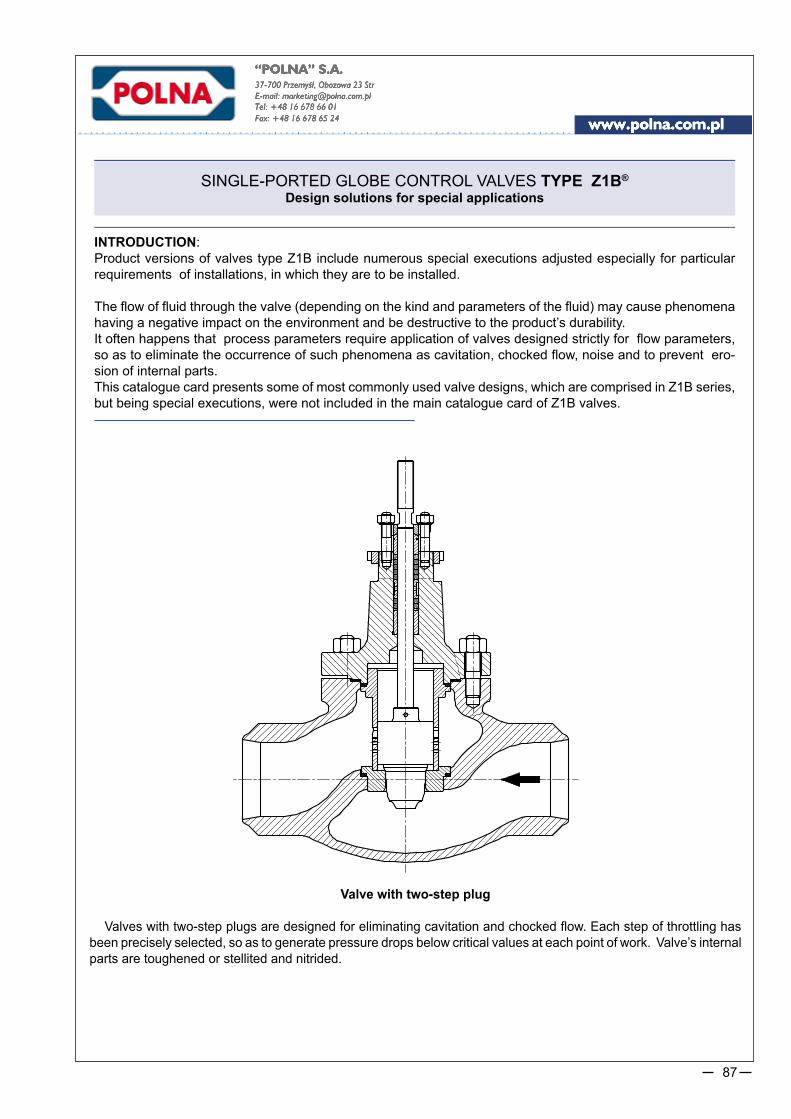
87
SINGLE-PORTED GLOBE CONTROL VALVES TYPE Z1B®
Design solutions for special applications
INTRODUCTION:Product versions of valves type Z1B include numerous special executions adjusted especially for particular requirements of installations, in which they are to be installed.
The flow of fluid through the valve (depending on the kind and parameters of the fluid) may cause phenomena having a negative impact on the environment and be destructive to the product’s durability. It often happens that process parameters require application of valves designed strictly for flow parameters, so as to eliminate the occurrence of such phenomena as cavitation, chocked flow, noise and to prevent ero-sion of internal parts.This catalogue card presents some of most commonly used valve designs, which are comprised in Z1B series, but being special executions, were not included in the main catalogue card of Z1B valves.
Valve with two-step plug
Valves with two-step plugs are designed for eliminating cavitation and chocked flow. Each step of throttling has been precisely selected, so as to generate pressure drops below critical values at each point of work. Valve’s internal parts are toughened or stellited and nitrided.

88 Control valves type Z1B – special executions
Valve with two-step plug and throttling cage
Valves with two-step plugs are designed for eliminating cavitation and chocked flow. Additional throttling cage is to implement additional throttling step and to reduce the noise level through multihole structure. Valve’s internal parts are toughened or stellited and nitrided.
Valve with three-step plug and filtrating element under the seat
Valves with two-step plugs are designed for eliminating cavitation and chocked flow for higher pressure drops than valves with two-step plugs. Additional filtrating structure under the seat is to protect internal parts against damaging effect of solid particles, which may be present in the fluid. Valve’s internal parts are toughened or stellited and nitrided.
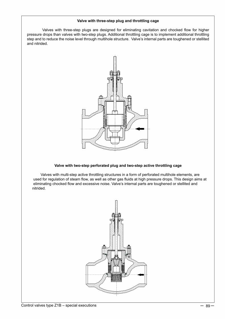
89Control valves type Z1B – special executions
Valve with three-step plug and throttling cage
Valves with three-step plugs are designed for eliminating cavitation and chocked flow for higher pressure drops than valves with two-step plugs. Additional throttling cage is to implement additional throttling step and to reduce the noise level through multihole structure. Valve’s internal parts are toughened or stellited and nitrided.
Valve with two-step perforated plug and two-step active throttling cage
Valves with multi-step active throttling structures in a form of perforated multihole elements, are used for regulation of steam flow, as well as other gas fluids at high pressure drops. This design aims at eliminating chocked flow and excessive noise. Valve’s internal parts are toughened or stellited and nitrided.

Revision: special executions Z1B/06/2013Valid until the next revision.
90
Valve with two-step plug pilot balanced and throttling plate
Valves with plug balanced by inner pilot are used for applications requiring increased rangeability. Due to plug being balanced by pilot, it is possible to achieve very high disposable pressure drops at small half-opening of the valve plug and high shut-off tightness of the valve. Valve’s internal parts are toughened or stellited and nitrided.
Valves DN150-300 for nominal pressures PN160-420
Valves for nominal pressures higher than those in the main catalogue card of Z1B valves are made available upon customised requests. Due to large bonnet diameter and high pressure, the packing system in a form of conical self-tightening (under pressure inside the valve) seal was used. Product versions with pressure balanced plugs in different materials are available.

MINIMUM FLOW VALVES TYPE Z1B-M
91
Więcej niż automatyka
More than Automation
FEATURES:• structure resistant to cavitation due to the application of multi-stage choking, labyrinth (multi-path) flow path,
and selection of proper materials, such as full stellite for the valve head and socket, titanium for the valve pin, highly cured choking cages, alloy cast steel for the body.
• high leakproofness of the lock,• guaranteed external leakproofness, sealed based on the requirements of the TA Luft provisions for the low
pressure zone,• easy access to the internal elements of the valve,• regulation or on-off function,• possibility to apply pneumatic, hydraulic or electric drives,• wide range of realization, possibility to adapt the valve to individual requirements of a client in terms of the
connectors, flow parameters and others• additional equipment: quick-drain valve for pneumatic actuators (fast opening), spring shock absorber for
hydraulic or electric actuators (flexible clamp of the valve head to the socket).• resistance to hydraulic impacts (water hammer),• high durability and reliability of operation.
APPLICATION:
The minimum flow valves are dedicated to be used in the sets for recirculation of the pumps feeding the power boilers. They secure the pumps against hydraulic and heating overloading in the case of low receipt of water by the boiler, thus allowing the minimum flow in the bypass circuit of the pump.
1) Condensate pump.2) Degasifier.3) Boiler feewater pump.4) Cut-off valve.5) Boiler feedwater start-up valve.6) Boiler feedwater control valve.7) Boiler.8) Minimum flow valve type Z1B-M.
Drawing 1. Diagram of the feeding water installation for the power boiler.
MINIMUM FLOW VALVE TYPE Z1B-M

92 Minimum flow valve type Z1B-M
NOTE:- maximum flow q
max with the assumption of maximum flow speed up to 8m/s,
- other types of connections – at request.
Table 1. Types of versions.
DESIGN AND TECHNICAL SPECIFIACTION:
Body: cast, pass-throughNominal dimension: DN50; 65; 80; 100 / 2”; 2,5”; 3”; 4”Nominal pressure: PN250; 320 / CL1500; 2500Flow coefficient: Kv 7; 10; 16; 20Characteristic: linearFlow direction: under the plug (FTO)Flow path in cages: as per drawing 5Pressure recovery coefficient: FL=0,97Leakproofness of the lock: min. class V as per PN-EN 60534-4Admissible working pressure: 250 barAdmissible work temperature: +250°CVersions: as per Table 1List of parts and materials: as per Table 2.
Fig.2 Structural typesDN50 ; 65. DN80 ; 100.
DN 50 65 80 100PN 250 320 250 320 250 320 250 320Kv 7 10 16 20
qmax[t/h] 50 65 130 200BW-Dzxg 60,3x6,3 60,3x8 76,1x8 76,1x11 88,9x11 88,9x12,5 114,3x14,2 114,3x16
`

93Minimum flow valve type Z1B-M
18
10
8
4
3
1
2
6
7
14
9
11
5
12
13
19
17
20
15
16
Table 2. Parts and Materials ListPoz. Name of part Material Norm
1 Body G17CrMo 9-10 ; (1.7379) * PN-EN 10213-2
2 Gland 13CrMo4-4 ; (1.7335)* PN-EN 10028
3 Plug Stellite No 6 -
4 Socket Stellite No 6 -
5 Pin Ti6Al4V Tytan Grade 5* ASTM 3348-08a
6 Cage setk X17CrNi 16-2 ; (1.4057) + heat processing PN-EN 10088
7 Body gasket
GRAPHITE (98%) + 1.4404 (spiral) -8 Socket gasket
9Regulation cage
gasket
10 Sealing set PTFE „V” (Rings) -
11 Clamp sleeve X6CrNiMoTi 17-12-2 ; (1.4571) PN-EN 10088
12 Clamp panel X6CrNiMoTi 17-12-2 ; (1.4571) PN-EN 10088
13 Body screw 21CrMoV5-7 ; (1.7709) PN-EN 10269
14 Body nut 21CrMoV5-7 ; (1.7709) PN-EN 10269
15
Gland screw A4-70 PN-EN ISo 3506-2
16 Gland nut A4-70 PN-EN ISo 3506-2
17 Peg with notches X6CrNiMoTi 17-12-2 ; (1.4571) PN-EN 10088
18 Disk springs X10CrNi18-8 ; (1.4310) PN-EN 10088
19 Distance sleeve X6CrNiMoTi 17-12-2 ; (1.4571) PN-EN 10088
20 Pilot sleeve X6CrNiMoTi 17-12-2 ; (1.4571) + CrN PN-EN 10088
50 d1
d3C
125
A
d2
Fig. 4 Connection dimensions of the valve.
Fig.3 Valve Z1B-M.
* - other materials on request.

Revision: Z1B-M/07/2014Valid until next revision
94
DRIVE TYPE:
Demand for available drive power:
Fs=19kN
Stroke:
DN50; 65: 20 mm DN80; 100: 38 mm
Recommended pneumatic membrane spring servomotors:
DN50; 65: P-630-20-5; P1-630-20-5; spring range 60...100kPa, pz=400kPa DN80; 100: P-630-38-1; P1-630-38-1; spring range 20...100kPa, pz=400kPa
NOTE:The actuators are equipped with a quick-drain valve and an electromagnetic valve. The remaining data - as per the catalogue cards of the P/R and P1/R1 actuator.
ORDERING:The order should describe the type of valve, DN, PN, Kv, type of connector, type of drive and valve work parameters which will be used for verifying the correctness of the client’s selection or for suggesting a more beneficial solution.
DN 50 65 80 100
PN 250 320 250 320 250 320 250 320
A 400 400 500 580
C 237 237 257 329
d1 M12x1,25 M16x1,5
d2 57,15 / 2 1/4” - 16UN2A
d3 12 16
Table 3. Connection dimensions of the valve
Fig.5 Flow path in cages.

THREE-WAY CONTROL VALVES TYPE Z3®
95
FEATURES:
•wide range of nominal dimensions, DN15…150 for nominal pressures PN10…40; CL150; CL300,• various materials of valve body and internal parts casts, adapted to specific working conditions,•wide range of flow coefficients,• reduction in aggressive and toxic fluids emissions to environment through application of bellow seal bonnets or bonnet packings meeting requirements of TA - LUFT,•easy assembly and dismantling of valve internal parts for maintenance and service,•high durability and reliability due to application of top-class materials and surface improvement processes (burnishing, stelliting, heat treatment, CrN coatings),•possibility of mating with P/R multi-spring actuators (basic option), P1/R1. Full reversibility of actuator operation and changing the spring range with no extra parts,•optional fitting of pneumatic actuators with a handwheel,•option of diagnostics of “valve - actuator” system, thanks to applicaiton of smart electro-pneumatic positioners,•high tightness of closure due to application of soft seats (PTFE sealing) in the whole range of flow ratios,•same flow ratios and control characteristics for “hard” (metal-to-metal) and “soft” (metal-gasket) seats,•reliable connection between actuator stem and valve, and between screwed in seat and body,• top-class flat sealing and bonnet packing,•broad range of electric actuators ,•possibility of mating with handwheels type 20 or NN,•special executions for oxygen, hydrogen, acidic gases with H2S content, explosive atmospheres - as per ATEX Directive 94/9/EC,•competitive prices due to simple and functional design of valves and actuators and materials applied,•design and production process meet the requirements of Quality Management System ISO 9001 and Directive 97/23/EC, and regulations of AD2000 Merkblatt, designated for installation on pipelines.
Z3 ® - is a trademark registered with Republic of Poland Patent Office
APPLICATION AREA:
Three-way control valves type Z3 are used in automatic systems and remote control systems as flow control elements to adjust flow of liquids and gases. Type Z3M is designed to mix two streams of medium, whereas type Z3R is designed to split one stream into two. Recommended for application in city-heating and HVAC systems and many branches of industry. They can be delivered with P/R actuators (basic option) or with P1/R1; P3/R3 acutators (upon request) electric actuators, handwheels type 20 or with no drives.

Three-way control valves Type Z396
Body (1): flanged, cast, with integrated bonnet (cast iron execution) or welded bonnet (cast steel execution). Nominal size: DN15; 20; 25; 32; 40; 50; 65; 80; 100; 150 *)
Nominal pressure: PN10; 16; 25; 40 (as per PN-EN 1092-1:2010 and PN-EN 1092-2:1999); CL150; CL300 (as per PN-EN 1759-1:2005) *)
*) higher nominal dimensions [DN] and higher nominal pressures are available after agreement with the manufacturerSteel flanges CL150; CL300 are so designed that they can be assembled with flanges executed per American standards ANSI/ASME B16.5 and MSS SP44. In American standards flanges are identified with nominal values in “Classes”, to which nominal pressure (PN) values as per PN-ISO 7005-1:2002 correspond.Equivalent identification as per PN are: CL150: PN 20 and CL300: PN 50.Table 1. Flanged end connections
DESIGN AND TECHNICAL SPECIFIACTION:
face-to-face dimensions (body): as per PN-EN 60534-3-1; 2000r; series 1 - for PN10; 16; 25; 40; series 37- for CL150; series 38 - for CL300Bonnet (1a) - standard or extension bonnet integrated with body; cast or welded depending on material - refer to Table 3Stub (2) - flanged: steel (rod); stub offset from axis as per Fig.5; Table 14Valve plug (3) - contoured-piston (with side type cuts), linear control characteristics - rangeability 50:1Seats (4) - screwed in (4.1) and fitted-in (4.2): • hard, • soft with PTFE packing Valve plug stem (5) - burnished or toughened with polished sealing face.Sealing (7,8) - body gaskets: spiral type, “graphite+1.4404”, bonnet gaskets: as per Table 2.Table 2. Packing types with application ranges.
Leakage class: - basic: Class IV as per PN-EN 60534-4 - hard valve seat - bubble-tight: Class VI as per PN-EN 60534-4 - soft valve seat
Packing PN / CLTemperature [°C] / Bonnet
Standard ExtensionPTFE-V
PN10…CL300-46...+200
-198...-46+200...+300
PTFE + GraphitePTFE-V / TA-LUFT
Graphite+200...+300 +300...+450
Graphite / TA-LUFT
Fig.1. Control valve Fig.2. Control valve with TA-LUFT sealing
Material Nominal pressureFacing of flange types
Raised face Groove Recess Ring - jointIdentification
Grey iron PN10; 16
B 2)
- - -Spheroidal iron PN10; 16; 25; 40 - - -
Cast steelPN10; 16; 25; 40 D F -
CL150 - -J (RTJ)
CL300 DL ( D1 1) F ( F1) 1) - only for CL300; 2) - B1 – (Ra=12.5 mm, concentric surface structure “C”), B2 – (Ra as agreed with the customer);
() - identification of connections as per ASME B16.5Possible execution of flanges per specification and indicated standards

Three-way control valves Type Z3 97
Table 3. Listing of components with materials
NOTE:Hardening method used for hardening of valve internal parts comprises:a) stelliting – padding of surfaces with stellite: ~40HRCb) CrN coating – introducing chromium nitride to external layer of detail, to the depth of ca.0.1 mm:~950HVc) heat treatment: valve plug (~45HRC), valve seat (~35HRC), guiding sleeve (~45HRC)
Poz. Component Materials
1 Body EN-GJL 250(EN-JL 1040)
EN-GJS 400-18 LT(EN-JS 1025)
GP 240 GH ; (1.0619)
WCB G20Mn5 (1.6220)GX5CrNiMo 19-11-2
(1.4408)CF8M
1a Bonnet S 355 J2G3(1.0570) G20Mn5 (1.6220) X6CrNiMoTi 17-12-2 (1.4571)
2 Stub S 355 J2G3 (1.0570)P355 NL2(1.1106)
X6CrNiMoTi 17-12-2 (1.4571)
3 Plug
X6CrNiMoTi 17-12-2 (1.4571)X6CrNiMoTi 17-12-2; (1.4571) + stellite + CrN
X17CrNi 16-2 ; (1.4057) + heat treatment
4.14.2
Screwed in seat
Fitted in seat
X6CrNiMoTi 17-12-2; (1.4571)X6CrNiMoTi 17-12-2; (1.4571) + stellite
X6CrNiMoTi 17-12-2; (1.4571) + PTFEX17CrNi 16-2; (1.4057) + heat treatment
5 StemX6CrNiMoTi 17-12-2; (1.4571)
X17CrNi 16-2; (1.4057);
6 Guiding sleeveX6CrNiMoTi 17-12-2; (1.4571) + CrN
X17CrNi 16-2; (1.4057) + CrN7 Body gasket Grafit (98%) + 1.4404 (spiral)
8 Packing kit
PTFE + GRAFITPTFE - „V”
GRAFIT9 Disk spring 12R10 (SANDVIK)
10.110.2
Bolt 8.8 A4 - 70
11.111.2
Nut 8 A4 - 70
12 Press lever C45 13 Fixing nut X6CrNiMoTi 17-12-2; (1.4571)
14.114.2
Press sleeve X6CrNiMoTi 17-12-2; (1.4571)
15.115.2
Spacer sleeve X6CrNiMoTi 17-12-2; (1.4571)
16 Nut (low) C45 X6CrNiMoTi 17-12-2; (1.4571)17 Peg X6CrNiMoTi 17-12-2; (1.4571)18 Compression plate X6CrNiMoTi 17-12-2; (1.4571)
Relevant material standardsMaterial Numer normy
EN-GJL 250 ; (EN-JL 1040) PN-EN 1561EN-GJS 400-18 LT ; (EN-JS 1025) PN-EN 1563
GP 240 GH ; (1.0619) PN-EN 10213-2WCB ASTM A 216
G20Mn5 ; (1.6220) PN-EN 10213-3GX5CrNiMo 19-11-2 ; (1.4408) PN-EN 10213-4
CF8M ASTM A 351 S 355 J2G3 ; (1.0570) PN-EN 10025P355 NL2 ; (1.1106) PN-EN 10028-3
X6CrNiMoTi 17-12-2 ; (1.4571) PN-EN 10088X17CrNi 16-2 ; (1.4057) PN-EN 10088
C45 PN-EN 10083-1
Special designs: Control valve with below seal and control valve with welded ends. (dimensions must be agreed with producer.
Fig. 3. Control valve with below seal Rys. 4. control valve with welded ends

Three-way control valves Type Z398
Table 4…10. Allowable working overpressure for materials at proper temperatures
NOTES:1. It is allowed to apply spheroidal iron,
carbon steel and acid proof cast steel for temperatures lower than given in Tables 4...10, provided that working pressure is reduced respectively, working temperature impact tests are performed and cast is heat treated. Details are to be consulted with manufacturer.
2. Working pressure for intermediate temperature values can be calculated by interpolation.
Table 7. Material: GX5CrNiMo 19-11-2 (1.4408) as per PN-EN 10213-4
PN / CL Standard
Temperature [°C]
-10…50 100 150 200 250 300 350 400 425 450
Allowable working pressure [bar]
PN10EN 1092-1
10 10 9 8,4 7,9 7,4 7,1 6,8 - 6,7
PN16 16 16 14,5 13,4 12,7 11,8 11,4 10,9 - 10,7
CL150 PN-EN 1759-1 17,9 16,3 14,9 13,5 12,1 10,2 8,4 6,5 5,6 4,7
PN25EN 1092-1
25 25 22,7 21 19,8 18,5 17,8 17,1 - 16,8
PN40 40 40 36,3 33,7 31,8 29,7 28,5 27,4 - 26,9
CL300 PN-EN 1759-1 46,7 42,5 38,9 35,3 32,9 30,5 28,8 27,6 27,2 26,9
Table 6. Material: GP240GH (1.0619) as per PN-EN 10213-2
PN / CL Standard
Temperature [°C]
-10…50 100 150 200 250 300 350 400
Allowable working pressure [bar]
PN10EN 1092-1
10 9,2 8,8 8,3 7,6 6,9 6,4 5,9
PN16 16 14,8 14 13,3 12,1 11 10,2 9,5
CL150 PN-EN 1759-1 17,3 15,4 14,6 13,8 12,1 10,2 8,4 6,5
PN25EN 1092-1
25 23,2 22 20,8 19 17,2 16 14,8
PN40 40 37,1 35,2 33,3 30,4 27,6 25,7 23,8
CL300 PN-EN 1759-1 45,3 40,1 38,1 36 32,9 29,8 27,8 25,7
Table 9. Material: WCB as per ASTM A216
PN / CL Standard
Temperature [°C]
-10…50 100 150 200 250 300 350 375 400
Allowable working pressure [bar]
PN10EN 1092-1
10 10 9,7 9,4 9 8,3 7,9 7,7 6,7
PN16 16 16 15,6 15,1 14,4 13,4 12,8 12,4 10,8
CL150 PN-EN 1759-1 19,3 17,7 15,8 14 12,1 10,2 8,4 7,4 6,5
PN25EN 1092-1
25 25 24,4 23,7 22,5 20,9 20 19,4 16,9
PN40 40 40 39,1 37,9 36 33,5 31,9 31,1 27
CL300 PN-EN 1759-1 50 46,4 45,1 43,9 41,8 38,9 36,9 36,6 34,6
Table 10. Material: CF8M as per ASTM A351
PN / CL Standard
Temperature [°C]
-10…50 100 150 200 250 300 350 375 400 425 450
Allowable working pressure [bar]
PN10EN 1092-1
8,9 7,8 7,1 6,6 6,1 5,8 5,6 5,5 5,4 5,4 5,3
PN16 14,3 12,5 11,4 10,6 9,8 9,3 9 8,8 8,7 8,6 8,5
CL150 PN-EN 1759-1 18,4 16 14,8 13,6 12 10,2 8,4 7,4 6,5 5,6 4,6
PN25EN 1092-1
22,3 19,5 17,8 16,5 15,5 14,6 14,1 13,8 13,6 13,5 13,4
PN40 35,6 31,3 28,5 26,4 24,7 23,4 22,6 22,1 21,8 21,6 21,4
CL300 PN-EN 1759-1 48,1 42,3 38,6 35,8 33,5 31,6 30,4 29,6 29,3 29 29
Table 4. Material: EN-GJL 250 as per PN-EN 1561
PN Standard
Temperature [°C]
-10…120 150 180 200 230 250 300
Allowable working pressure [bar]
PN10PN-EN 1092-2
10 9 8,4 8 7,4 7 6
PN16 16 14,4 13,4 12,8 11,8 11,2 9,6
Table 5. Material: EN-GJS 400-18 LT as per PN-EN 1563
PN Standard
Temperature [°C]
-10…120 150 200 250 300 350
Allowable working pressure [bar]
PN10
PN-EN 1092-2
10 9,7 9,2 8,7 8 7
PN16 16 15,5 14,7 13,9 12,8 11,2
PN25 25 24,3 23 21,8 20 17,5
PN40 40 38,8 36,8 34,8 32 28
Table 8. Material: G20Mn5 (1.6220) wg PN-EN 10213-3
PN / CL Standard
Temperature [°C]
-40 100 150 200 250 300
Allowable working pressure [ [bar]
PN10
-
6 6 3,8 3,6 3,48 3,4
PN16 16 16 10,1 9,6 9,28 9,07
PN25 25 25 15,8 15 14,5 14,2
PN40 40 28 28 27 26 25

Three-way control valves Type Z3 99
ALLOWABLE PRESSURE DROPS ∆p.Pressure drops Δp [bar] refer to closed valve and they are calculated for valve drive potential. Actual pressure drops should not exceed 70% of allowable working pressure for given nominal pressure, material execution and working temperature, as per tables 4…10.
where ∆p [bar] - calculated pressure drop Fs [kN] - actuator available force (Table 11) FD [kN] - valve plug to valve seat pressure (Table 10) D - valve seat diameter [mm] (Table 10)
Fs = 0,785 • 10- 4 • D2 • ∆p + FD∆p =
Fs - FD
0,785 • 10- 4 • D2 or
Kvs 0,63 1,0 1,6 2,5 4,0 6,3 10 16 25 40 63 94 125 160 250 320
Stroke [mm] 20 38 50
Seat dia. [mm] D 12,7 19,05 20,64 25,25 31,72 41,25 50,8 66,7 88,9 107,92 126,95
DN
15
20
25
32
40
50
65
80
100
150
Metallic seat FD [kN]
0,20,3
0,33 0,4 0,5 0,7 0,8 1,1 1,4 1,7 2,0
Soft seat 0,25 0,5 0,5 0,6 0,8 1,0 1,3 1,7 2,2 2,7 3,2
Calculation coefficients: FL = 0,9 ; XT = 0,7 ; Fd = 0,41 ; xFz = 0,65
higher nominal diameters and Kvs flow ratios are availabe after agreement with the manufacturer
Table 11: Kvs flow ratios and calculation coefficients (design).
When using pneumatic actuators their available forces are to be calculated separately for extreme position of stem, accounting for operation (direct or reverse), and valve operation (mixing or separation). To facilitate and simplify selection of pneumatic actuators spring ranges and supply pressures were unified, regardless of operation (simple or reverse). For parameters of pneumatic actuators to be used in calculation of available forces refer to Tables 13 and 13a.
Table 12: Available force FS [kN] of pneumatic actuators
NOTE: 1. For direct actuators P adopted spring range is 20 - 100 kPa 2. For electric and other actuators Δp value can be calculated using above formula and data from Tables 12 and 14, taking nominal load capacity as available force FS, as per actuator catalog chart.
Table 13 i 13a. Technical specification of pneumatic actuators
Actuator size
Direct actuator P Reverse actuator RSupply pressure [kPa] Spring range [kPa]
140 250 400 20 - 10040 - 120;40 - 200
60 - 140 80 - 240 120 - 280 180 - 380
250 1,0 3,8 7,5 0,5 1,0 1,5 2,0 3,0 -400 1,6 6,0 12,0 0,8 1,6 2,4 3,2 4,8 -630 2,5 9,5 18,9 1,3 2,5 3,8 5,0 7,6 11,31000 4,0 15,0 30,0 2,0 4,0 6,0 8,0 12,0 18,0
Parameter Unit Spring range
p1 - p2[kPa] 20…100 40...120 60...140 80...240 120...280 180...380
pZ[kPa] 250 400
AS[cm2] 250; 400; 630; 1000 630; 1000
Actuator type P / RSize 250 400 630 1000
H [mm] 20 38 38; 50; 63

Three-way control valves Type Z3100
where: H - stroke [mm] p1÷ p2 - spring range [kPa]; pZ- supply pressure [kPa]; As - effective area of actuator diaphragm [cm2];Available force of pneumatic actuators Fs [kN] is to be derived from below formulas, regarding valve function, actuator operation and pressure point (top or bottom port)a) Valve function: mixing FSP1 = 10 - 4 p1 • As ; FSR1 = 10 - 4 (pz - p2) • As FSP2 = 10 - 4 (pz - p2) • As ; FSR2 = 10 - 4 p1 • As
b) Valve function: diverting FSP1 = 10 - 4 (pz - p1) • As ; FSR1 = 10 - 4 p2 • As FSP2 = 10 - 4 p2 • As ; FSR2 = 10 - 4 (pz - p1) • AsInterpretation concerning individual available forces Fs of pneumatic actuators:FSP1 - direct P actuator; closed screwed-in port (top), FSP2 - direct P actuator; closed fitted-in port (bottom),FSR1 - direct R actuator; closed screwed in port (top),FSR2 - direct R actuator; closed fitted-in port (bottom).
NOTE:Ranges 20…100kPa and 180…380kPa are not recommended for mixing function due to high difference between available forces for top and bottom port.
Fig.5. P/R-Z3M - Mixing Fig.6. P/R-Z3R – Diverting
P actuator R actuator P actuator R actuator
A
Fig.7. External and connection dimensions
AB
B
A AB
B

Three-way control valves Type Z3 101
Dimensions UnitDN
15 20 25 32 40 50 65 80 100 150
A
PN10; 16; 25; 40
[mm]
130 150 160 180 200 230 290 310 350 480
CL150 - - 184 - 222 254 - 298 352 451
CL300 - - 197 - 235 267 - 317 368 473
B [mm] 140 162 184 215,5 233,5 240 295
CStandard bonnet
[mm]97 110 117 128 140 146 171 205
Extension bonnet 297 310 317 328 340 346 371 405
E 1) [mm] 125 195 *)
F [mm] 50 100
d 1 [mm] M12x1,25 M16x1,5
d 2 [mm] 57,15 84,15
d 3 - 2 1/4”-16UN2A 3 5/16”-16NS2A
Weight [kg] 8,5 10,5 12 15 18 26,5 36 55 75 1501) - valve in closed position, fitted-in bottom port; *) - dimension for P/R-1000, for actuators P1/R1 E=125; F=80
higher nominal dimensions [DN] are available after agreement with the manufacturer
ActuatorsDN
15 20 25 32 40 50 65 80 100 150
P / R - 250
P / R - 400
P / R - 630
P / R - 1000
Type Stroke [mm] d1 d2 H D Rev. / stroke Weight [kg]
20-20-57-M12 20M12x1,25 57,15
265228 8 7,5
20-38-57-M1238 298 15 10
20-38-84-M16M16x1,5 84,15
20-50-84-M16 50 385 457 16 16
Table 14. Control valves connection dimensions
Table 15. Application of pneumatic actuators
Table 16: Sizes and weights of pneumatic actuators P/R and PN/RN - Fig.6.Fig.8. Actuators P/R, PN/RN
Actuator sizeD1 D2 H1 H2 Weight [kg]
mm P/R PN/RN250 240
225377 474 10 14,5
400 305 385 484 16 20,5630 375 305 477 574 30 371000 477 450 660 835 74 100
Fig.9.Handwheel type 20
Table 17: Types, sizes and weights of handwheels type 20 - Fig.7.
Marking method: Example: 20-38-57-M12 - handwheel type 20; stroke 38 mm; d2=57.15mm; d1=M12x1.25

Revision: Z3/10/2014Valid until the next revision.
102
Leakage class: - basic: class IV 4 - bubble-tight: class VI 6
Valve plug:- unbalanced 7
Choke cages:- no choke cages 0
Plug characteristics and type:- linear, contoured-piston L- other X
Body material:- grey iron 1- spheroidal iron 2- carbon steel 3- stainless steel 5- other X
MARKING EXAMPLE:
Control valve type Z3, mixing function, reverse action pneumatic actuator with top-mounted handweel, extension bonnet, expanded graphite stem seal, leakage class IV, execution in stainless steel:
RN-Z3M-2E470L5
Marking is shown on valve nameplate.
Additional information:- nominal size [DN],- nominal pressure [PN],- max working temperature [TS],- max working pressure [PS],- test pressure [PT],- flow coefficient [Kvs],- plug stroke [H],- fluid group [1 or 2],- serial number and year of manufacture.
ORDERING:
The order should contain all information as per data questionnaire. Full information can be obtained from the Sales and Marketing Department or Technical Department.
CLASSIFICATION AND MARKING:
Type:- pneumatic with direct action: P - pneumatic with reverse action: R- pneumatic with top handwheel PN; RN- electric: E- manual 20
Bonnet:- standard: 1- extension: 2- other X
Packing:- PTFE, braided A- PTFE, V B- PTFE, for oxygen C- graphite, braided D- graphite, expanded E- TA-Luft, PTFE F- TA-Luft, graphite G
-
Z3MZ3R
- 07

ROTARY PLUG CONTROL VALVES TYPE Z33®
103
FEATURES:
•one-piece valve body (cast with bonnet), no static or dynamic sealing except shaft sealing chamber,• no “detachment effect” between plug and seat,• ability to change Kvs without changing plug or seat,• easy replacement of rotary, symmetrical plug,• elongated bonnet allows application of double sealing for shaft, meeting “low emission” standards equal to TA-LUFT conditions,• the same Kvs coefficients for “hard” and “soft” seats,• leakage class less than 0.01%Kvs for “hard” seats (metal-metal),• same flow direction for “hard” and “soft” seats,• valve-actuator connection accessible from outside, which allows pivoting actuator to valve axis by 90° increments,• special executions: with heat jacket, erosion-proof, for crystallizable media.
DESIGN AND TECHNICAL SPECIFICATION:Body (1) flanged or flangeless, cast in cast steelNominal sizes: DN 25; 40; 50; 80; 100; 150; 200; 250; 300Nominal pressures: PN10; 16; 25; 40 (as per PN-EN 1092-1:2006); CL150; CL300 (as per PN-EN 1759-1:2005).Steel flanges CL150; CL300 are so designed that they can be assembled with flanges executed per American standards ANSI/ASME B16.5 and MSS SP44. In American standards flanges are identified with nominal values in “Classes”, to which nominal pressure (PN) values as per PN-ISO 7005-1:2002 correspond.Equivalent identification as per PN are: CL150: PN 20 and CL300: PN 50.
Table 1. Nominal pressures and end connections
APPLICATION AREA:Rotary plug control valves Z33 represent the design of valves, where change in flow ratio is achieved through eccentrically set rotary plug. Such structures are particularly useful for control of flow under heavy-duty conditions, with high probability of cavitation and erosion.High rangeability (200:1) and wide range of material and design variants make them ideal for application in many branches of industry, such as power generation, metallurgy, chemical and petroleum industry, food industry, paper industry, etc.
Nominal pressureFacing of flange types
Raised face Groove Recess Ring-jointIdentification
PN10; 16; 25; 40 B 2) D F -CL150 - -
J (RTJ)CL300 DL ( D1 1) F ( F1)
1) - only for CL300; 2) - B1 – (Ra=12.5 mm, concentric surface structure “C”), B2 – (Ra as agreed with the customer);() - identification of connections as per ASME B16.5
Possible execution of flanges per specification and indicated standards
Z33® is a trademark registered with Republic of Poland Patent Office.

Rotary plug control valves type Z33104
Face-to-face dimensions:a) flanged valves as per PN-EN 60534-3-1:2000; Table 1, Series 1 as per ANSI B16.10:1992; Table 1 i 2, Series 19b) flangeless (sandwich) as per PN-EN 60534-3-2:2002 Bridge (2) functions as rotary closure, cast in grey iron or steel (welded),Valve plug (3) working piece in the form of globe section:• flow characteristics: - linear (L) - equal percentage (P) only with positioner• rangeability: 200 : 1
Valve seat (4) loosely resting in body opening; susceptible to fitting to spherical cap of valve plug • hard • soft (with PTFE sealing) Leakage class: - basic: class IV as per PN-EN 60534-4 - metallic seat - bubble-tight: class VI as per PN-EN 60534-4 - soft seatScrew plug (5) fixing seat to body (medium flow direction „under plug”); in special executions its function is preventing erosion (medium flow direction „above plug”)
Shaft (6) transmits torque from actuator to valve plug: burnished, with polished sealing interface.Guiding sleeves of plug (7) and shaft (8) - function as slide bearings; surface hardened (CrN coating) or PTFE coatedPacking (9) -packing kits formed in various materials (PTFE-V; PTFE+graphite; braided or expanded graphite); special “low emission” kit, with follower sprigs TA-LUFT.Table 2. Packing types with application ranges.
Packing Nominal pressure PN / CL Temperature [°C]
PTFE - V
PN10 - 40CL150; CL300
-46…+200PTFE + GraphitePTFE - V / TA-LUFT
Graphite +200…+250(+200…+450)*Graphite / TA-LUFT
* - drive retracted from valve (extended yoke)
NOTES:1. It is allowed to apply carbon steel and acid proof cast steel for temperatures lower than given in Tables 3...7,
provided that working pressure is reduced respectively, working temperature impact tests are performed and cast is heat treated. Details are to be consulted with manufacturer.
2. Working pressure for intermediate temperature values can be calculated by interpolation.
Table 3…7. Allowable working overpressure for materials at proper temperatures.
Table 6. Material: WCB wg ASTM A216
PN / CL Standard
Temperature [°C]
-10…50 100 150 200 250 300 350 375 400
Allowable working pressure [bar]
PN10EN 1092-1
10 10 9,7 9,4 9 8,3 7,9 7,7 6,7
PN16 16 16 15,6 15,1 14,4 13,4 12,8 12,4 10,8
CL150 PN-EN 1759-1 19,3 17,7 15,8 14 12,1 10,2 8,4 7,4 6,5
PN25EN 1092-1
25 25 24,4 23,7 22,5 20,9 20 19,4 16,9
PN40 40 40 39,1 37,9 36 33,5 31,9 31,1 27
CL300 PN-EN 1759-1 50 46,4 45,1 43,9 41,8 38,9 36,9 36,6 34,6
Table 7. Material: CF8M wg ASTM A351
PN / CL Standard
Temperature [°C]
-10…50 100 150 200 250 300 350 375 400 425 450
Allowable working pressure [bar]
PN10EN 1092-1
8,9 7,8 7,1 6,6 6,1 5,8 5,6 5,5 5,4 5,4 5,3
PN16 14,3 12,5 11,4 10,6 9,8 9,3 9 8,8 8,7 8,6 8,5
CL150 PN-EN 1759-1 18,4 16 14,8 13,6 12 10,2 8,4 7,4 6,5 5,6 4,6
PN25EN 1092-1
22,3 19,5 17,8 16,5 15,5 14,6 14,1 13,8 13,6 13,5 13,4
PN40 35,6 31,3 28,5 26,4 24,7 23,4 22,6 22,1 21,8 21,6 21,4
CL300 PN-EN 1759-1 48,1 42,3 38,6 35,8 33,5 31,6 30,4 29,6 29,3 29 29
Table 5. Material: G20Mn5 (1.6220) wg PN-EN 10213-3
PN / CL Norma
Temperature [°C]
-40 100 150 200 250 300
Allowable working pressure [bar]
PN10
-
6 6 3,8 3,6 3,48 3,4
PN16 16 16 10,1 9,6 9,28 9,07
PN25 25 25 15,8 15 14,5 14,2
PN40 40 28 28 27 26 25
Table 4. Material: GX5CrNiMo 19-11-2 (1.4408) wg PN-EN 10213-4
PN / CL Standard
Temperature [°C]
-10…50 100 150 200 250 300 350 400 425 450
Allowable working pressure [bar]
PN10PN-EN 1092-1
10 10 9 8,4 7,9 7,4 7,1 6,8 - 6,7
PN16 16 16 14,5 13,4 12,7 11,8 11,4 10,9 - 10,7
CL150 PN-EN 1759-1 17,9 16,3 14,9 13,5 12,1 10,2 8,4 6,5 5,6 4,7
PN25PN-EN 1092-1
25 25 22,7 21 19,8 18,5 17,8 17,1 - 16,8
PN40 40 40 36,3 33,7 31,8 29,7 28,5 27,4 - 26,9
CL300 PN-EN 1759-1 46,7 42,5 38,9 35,3 32,9 30,5 28,8 27,6 27,2 26,9
Table 3. Material: GP240GH (1.0619) wg PN-EN 10213-2
PN / CL Standard
Temperature [°C]
-10…50 100 150 200 250 300 350 400
Dopuszczalne ciśnienie robocze [bar]
PN10PN-EN 1092-1
10 9,2 8,8 8,3 7,6 6,9 6,4 5,9
PN16 16 14,8 14 13,3 12,1 11 10,2 9,5
CL150 PN-EN 1759-1 17,3 15,4 14,6 13,8 12,1 10,2 8,4 6,5
PN25PN-EN 1092-1
25 23,2 22 20,8 19 17,2 16 14,8
PN40 40 37,1 35,2 33,3 30,4 27,6 25,7 23,8
CL300 PN-EN 1759-1 45,3 40,1 38,1 36 32,9 29,8 27,8 25,7
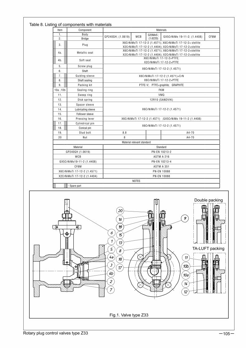
Rotary plug control valves type Z33 105
Table 8. Listing of components with materials
Fig.1. Valve type Z33
Double packing
TA-LUFT packing
Item Component Materials
1. BodyGP240GH; (1.0619) WCB
G20Mn5 ; (1.6220)
GX5CrNiMo 19-11-2; (1.4408) CF8M2. Bridge
3. PlugX6CrNiMoTi 17-12-2 (1.4571); X6CrNiMoTi 17-12-2+ stelliteX2CrNiMoTi 17-12-2 (1.4404); X2CrNiMoTi 17-12-2+stellite
4a. Metallic seatX6CrNiMoTi 17-12-2 (1.4571); X6CrNiMoTi 17-12-2+stelliteX2CrNiMoTi 17-12-2 (1.4404); X2CrNiMoTi 17-12-2+stellite
4b. Soft seatX6CrNiMoTi 17-12-2+PTFE;X2CrNiMoTi 17-12-2+PTFE
5. Screw plugX6CrNiMoTi 17-12-2 (1.4571)
6. Shaft
7. Guiding sleeve X6CrNiMoTi 17-12-2 (1.4571)+CrNX6CrNiMoTi 17-12-2+PTFE8. Shaft sealing
9. Packing kit PTFE-V; PTFE+graphite; GRAPHITE
10a ,10b Sealing ring FKM
11. Sweep ring VMQ
12. Disk spring 12R10 (SANDVIK)
13. Spacer sleeve
X6CrNiMoTi 17-12-2 (1.4571)14. Lubricating sleeve
15. Follower sleeve
16. Pressing lever X6CrNiMoTi 17-12-2 (1.4571) ;GX5CrNiMo 19-11-2 (1.4408)
17. Cylindrical pinX6CrNiMoTi 17-12-2 (1.4571)
18. Conical pin
19. Stud bolt 8.8 A4-70
20 Nut 8 A4-70
Material relevant standard
Material Standard
GP240GH (1.0619) PN-EN 10213-2
WCB ASTM A 216
GX5CrNiMo19-11-2 (1.4408) PN-EN 10213-4
CF8M ASTM A 351
X6CrNiMoTi 17-12-2 (1.4571) PN-EN 10088
X2CrNiMoTi 17-12-2 (1.4404) PN-EN 10088
NOTES
- Spare part

Rotary plug control valves type Z33106
Kvs FLOW RATIOS AND PRESSURE DROPS ∆pTable 9. Metallic seat (leakage class IV); reverse action actuator (air-to-open)
Table 10. Soft seat (leakage class VI); reverse action actuator (air-to-open)
* - Do not exceed nominal pressure** - For 120% setting it is recommended that listed pressure drops are reducedIn Tables 9...10, theoretical acceptable pressure drops are included. Actual pressure drops with considera-tion of tolerance of spring manufacture and friction of internal parts of the actuator are lower than those given by 20%. Pressure drops chosen that way guarantee internal tightness of closing of the valves.Calculated ratios:
FL=0,854, XT=0,6, FD=0,7, xFZ=0,58
Actuator type R99-1-R [120 cm2] R99-2-R [240 cm2] R99-3-R [780 cm2]
Spring range [kPa] 100-200 160-320 80-160 160-320 100-200 160-320
DNKvS
100%KvS
75%KvS
45%KvS**120%
Seat dia.[mm]
Maximum pressure drop [bar]
25 15 11 7 18 18 50* - - - - -
25 6 5 3 7 12 50* - - - - -
40 40 30 18 48 28,5 50* - - - - -
40 16 12 7 19 20 50* - - - - -
50 60 45 27 72 38 50* - - - - -
50 24 18 11 29 26 50* - - - - -
80 150 113 68 180 58 11 32 50* 50* - -
80 60 45 27 72 38 33 50* 50* 50* - -
100 240 180 108 288 72 2 13 27 50* - -
100 96 72 43 115 48 11 36 50* 50* - -
150 500 375 225 600 110 - - 9 23 50* 50*
150 200 150 90 240 72 - - 25 50* 50* 50*
200 800 600 360 960 136 - - - 13 44 50*
200 320 240 144 384 88 - - - 37 50* 50*
250 1250 938 563 1500 170 - - - 5 20 45
250 500 375 225 600 110 - - - 17 50* 50*
300 1800 1350 810 2160 200 - - - 2 12 28
300 720 540 324 864 126 - - - 10 34 50*
Actuator type R99-1-R [120 cm2] R99-2-R [240 cm2] R99-3-R [780 cm2]
Spring range [kPa] 100-200 160-320 80-160 160-320 100-200 160-320
DNKvS
100%KvS
75%KvS
45%KvS**120%
Seat dia.[mm]
Maximum pressure drop [bar]
25 15 11 7 18 18 50* - - - - -
25 6 5 3 7 12 50* - - - - -
40 40 30 18 48 28,5 50* - - - - -
40 16 12 7 19 20 50* - - - - -
50 60 45 27 72 38 50* - - - - -
50 24 18 11 29 26 50* - - - - -
80 150 113 68 180 58 14 35 50* 50* - -
80 60 45 27 72 38 38 50* 50* 50* - -
100 240 180 108 288 72 5 16 30 50* - -
100 96 72 43 115 48 15 40 50* 50* - -
150 500 375 225 600 110 - - 10 25 50* 50*
150 200 150 90 240 72 - - 28 50* 50* 50*
200 800 600 360 960 136 - - - 15 38 50*
200 320 240 144 384 88 - - - 39 50* 50*
250 1250 938 563 1500 170 - - - 6 18 39
250 500 375 225 600 110 - - - 19 48 50*
300 1800 1350 810 2160 200 - - - 3 11 25
300 720 540 324 864 126 - - - 11 30 50*

Rotary plug control valves type Z33 107
Table 12. Soft seat (leakage class VI); direct action actuator (air-to-close)
Table 11. Metallic seat (leakage class IV); direct action actuator (air-to-close)
Actuator type P99-1-P [120 cm2] P99-2-P [240 cm2] P99-3-P [780 cm2]
Voltage pressure [kPa] 240 400 240 400 240 400
DNKvS
100%KvS
75%KvS
45%KvS**120%
Seat dia.[mm]
Maximum pressure drop [bar]
25 15 11 7 18 18 50* 50* - - - -
25 6 5 3 7 12 50* 50* - - - -
40 40 30 18 48 28,5 50* 50* - - - -
40 16 12 7 19 20 50* 50* - - - -
50 60 45 27 72 38 50* 50* - - - -
50 24 18 11 29 26 50* 50* - - - -
80 150 113 68 180 58 11 50* 50* 50* - -
80 60 45 27 72 38 33 50* 50* 50* - -
100 240 180 108 288 72 2 24 27 50* - -
100 96 72 43 115 48 11 50* 50* 50* - -
150 500 375 225 600 110 - - 9 38 50* 50*
150 200 150 90 240 72 - - 25 50* 50* 50*
200 800 600 360 960 136 - - - 23 44 50*
200 320 240 144 384 88 - - - 50* 50* 50*
250 1250 938 563 1500 170 - - - 10 20 50*
250 500 375 225 600 110 - - - 29 50* 50*
300 1800 1350 810 2160 200 - - - 5 12 44
300 720 540 324 864 126 - - - 17 34 50*
Actuator type P99-1-P [120 cm2] P99-2-P [240 cm2] P99-3-P [780 cm2]
Voltage pressure [kPa] 240 400 240 400 240 400
DNKvS
100%KvS
75%KvS
45%KvS**120%
Seat dia.[mm]
Maximum pressure drop [bar]
25 15 11 7 18 18 50* 50* - - - -
25 6 5 3 7 12 50* 50* - - - -
40 40 30 18 48 28,5 50* 50* - - - -
40 16 12 7 19 20 50* 50* - - - -
50 60 45 27 72 38 50* 50* - - - -
50 24 18 11 29 26 50* 50* - - - -
80 150 113 68 180 58 14 50* 50* 50* - -
80 60 45 27 72 38 38 50* 50* 50* - -
100 240 180 108 288 72 5 27 30 50* - -
100 96 72 43 115 48 15 50* 50* 50* - -
150 500 375 225 600 110 - - 10 40 50* 50*
150 200 150 90 240 72 - - 28 50* 50* 50*
200 800 600 360 960 136 - - - 50* 38 50*
200 320 240 144 384 88 - - - 50* 50* 50*
250 1250 938 563 1500 170 - - - 11 18 50*
250 500 375 225 600 110 - - - 30 48 50*
300 1800 1350 810 2160 200 - - - 6 11 50*
300 720 540 324 864 126 - - - 19 30 50*
* - Do not exceed nominal pressure** - For 120% setting it is recommended that listed pressure drops are reducedIn Tables 11...12, theoretical acceptable pressure drops are included. Actual pressure drops with considera-tion of tolerance of spring manufacture and friction of internal parts of the actuator are lower than those given by 20%. Pressure drops chosen that way guarantee internal tightness of closing of the valves.Calculated ratios:
FL=0,854, XT=0,6, FD=0,7, xFZ=0,58

Rotary plug control valves type Z33108
VALVE DRIVESRotary pneumatic valves, diaphragm and spring type P/R - 99, with or without a handwheel - special design to drive Z33 valves.
Table 13. Types of rotary pneumatic acutators .
ACTUATOR CHARACTERISTICS:• total reversibility of action, allowing change in function from “air-to-close - P” to “air-to-open - R”, with no extra parts,• ability to mount actuator on valve, in various positions, pivotting with 90° increments,• option with a handwheel,• fixed diaphragm effective area, ensuring linear movement to pressure ratio,• optional NAMUR connections.
DESIGN AND TECHNICAL SPECIFICATION OF ACTUATOR:Body (21) - among the basic components of actuator, designed to hold and assemble other components; executed in grey or spheroidal iron.Yoke (28) - connects valve to actuator; executed in grey iron or pressed in steel sheets and welded.Diaphragm (25) and spring (26) case - make a pressure chamber and springs case; executed as steel die; welded or cast in spheroidal iron.Diaphragm (31) - executed in acrylic-butadiene rubber (NBR); reinforced with nylon insert.Diaphragm plate (24) - formed in plastic or cast in aluminum alloy.Lever (22) - transmits plane motion of membrane unit to rotary movement of crankshaft; executed in spheroidal cast-iron.Crankshaft (23) - in connection with lever makes an output (driving) element of actuator in the form of rotating pin with key grooves; cast in alloy steel and heat processed. Spring (29) - executed in construction spring steel; 2 springs for range 160 - 320 kPa.Bearing pin (27) - connects lever and crankshaft; in special execution (extended) projects from the body and connects actuator to accessories (positioner, limit switches, etc.); executed in alloy steel (stainless steel).
BASIC TECHNICAL SPECIFICATION OF ACTUATOR:• maximum supply pressure: 450 kPa• control air connection: G 1/4”• connection pipes diameter: ∅6x1 (∅8x1)• ambient temperature range: - 40°C …+ 80°C• control pressure change tolerance:- with no positioner: 4% of nominal range- with positioner: 1.5% of nominal range• hysteresis deviation:- with no positioner: 4% of stroke range- with positioner: 1% of stroke range• dead zone:- with no positioner: 2% of nominal pressure range- with positioner: 1% of nominal pressure range• optional accessories (on request):- handwheel,- positioner,- air set,- three-way solenoid valve,- lock-up valve,- limit switches,- quick exhaust valve.
SizeDiaphragm effective area
[cm 2]Spring range [kPa]
Rotation angle of output element (crankshaft)
P/R 99-1 120 100…200, 160…320250- 45O - 60O - 90OP/R 99-2 240 80…160, 160…320
P/R 99-3 780 100…200, 160…320

Rotary plug control valves type Z33 109
Fig. 2. Rotary pneumatic actuator (spring and diaphragm) type P/R-99
- Spare parts
No in fig. Part21 Body22 Lever
23 Crankshaft
24 Diaphragm plate
25 Diaphragm case
26 Spring case27 Bearing pin28 Yoke29 Spring (A+B)30 Front nameplate31 Diaphragm32 Screw33 Fork pin34 Stroke indicator35 Connector36 Fork37 Stroke limiter38 Adjusting nut
39 Securing nut
40 Ball bearing
41 Sealing ring
42 Needle bearing44 Closure plug
45 Handwheel screw
46 Wheel
47 Counterlever
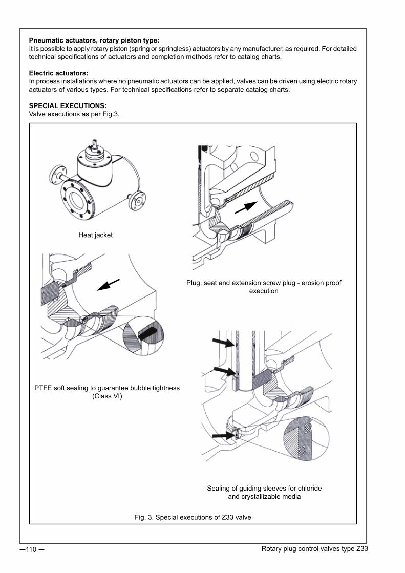
Rotary plug control valves type Z33110
Pneumatic actuators, rotary piston type:It is possible to apply rotary piston (spring or springless) actuators by any manufacturer, as required. For detailed technical specifications of actuators and completion methods refer to catalog charts.
Electric actuators:In process installations where no pneumatic actuators can be applied, valves can be driven using electric rotary actuators of various types. For technical specifications refer to separate catalog charts.
SPECIAL EXECUTIONS:Valve executions as per Fig.3.
Fig. 3. Special executions of Z33 valve
Heat jacket
Sealing of guiding sleeves for chloride and crystallizable media
PTFE soft sealing to guarantee bubble tightness (Class VI)
Plug, seat and extension screw plug - erosion proof execution

Rotary plug control valves type Z33 111
OPERATION PRINCIPLE (transformation of plane motion to rotary motion)
Adjustment of rotation angle of actuator type 99 (patent pending) via system of two levers. Lever (22) attached to diaphragm (24) plate always turns by 30°, hence stroke, pressure range and positioner feedback lever position do not change. With change in setting of bearing pin (27) turn angle of crankshaft (23) (and also valve shaft) changes too, within values 25°, 45°, 60° and 90°, which corresponds with changes in flow ratio values to 45%, 75%, 100% and 120% Kvs. In closed position of valve movement of bearing pin to crankshaft guide at the beginning of lever rotation is parallel, hence closed position of valve is maintained. Connector (35), which connects actuator to valve shaft, allows turning of actuator to valve by each 90°, and since it is accessible from outside it eliminates the need for actuator or valve disassembly. Required position (see Fig.5) can be set by manufacturer as per customer’s request.
Closed position Open to 45% Kvs (rotation angle 25°)
Open to 75% Kvs (rotation angle 45°)
Open to 100% Kvs (rotation angle 60°)
Fig. 4. Bearing pin (27) position on lever (22) regarding crankshaft (23) (valve shaft - Kvs) rotation angle.
Fig. 5. Possible actuator type P/R-99 positions to valve axis.
2. Air-to-close mode (fail-to-open)1. Air-to-open mode (fail-to-close position)

Rotary plug control valves type Z33112
SizeEnd connection
as per ISO 5211
L K G** F S Weight [kg]
99-1F07
110 3655
16 24 18F12 85
99-2F12
18060
8528 60 54F14 100
F16 200 130
99-3F14
200 60100
36 71 189F16 130
Table 14. Valve end connection sizes
EXTERNAL SIZES, END CONNECTION SIZES; WEIGHTS
Table 15. Actuator type 99 end connection sizes
+0,5+0,3
DNEnd connec-tion as per ISO 5211
E F G
25…50 F07 83 16 55
80…100 F1283 16
85116 28
150 F14113 28
100123 36
200…300 F16133 28
130120 36

Rotary plug control valves type Z33 113
Table 16. Dimensions of valves with actuators type 99
DN Flanges ActuatorH
[mm]h
[mm]d
[mm]A
[mm]C
[mm]L
[mm]LM
[mm]B
[mm]R
[mm]Q
[mm]V
[mm]T
[mm]Weight 1) [kg]
25 PN40 99-1 409 134 37 175 55 160 89 374 92 105 90 234 20
25 CL150 99-1 409 134 37 175 55 184 113 374 92 105 90 234 20
25 CL300 99-1 409 134 37 175 55 197 126 374 92 105 90 234 21
25 Sandw. 99-1 409 134 37 175 55 102 60 374 92 105 90 234 18
40 PN40 99-1 415 140 48 175 64 200 115 374 92 105 90 234 22
40 CL150 99-1 415 140 48 175 64 222 137 374 92 105 90 234 22
40 CL300 99-1 415 140 48 175 64 235 150 374 92 105 90 234 23
40 Sandw. 99-1 415 140 48 175 64 114 64 374 92 105 90 234 20
50 PN40 99-1 420 145 60 175 70 230 123 374 92 105 90 234 23
50 CL150 99-1 420 145 60 175 70 255 135 374 92 105 90 234 23
50 CL300 99-1 420 145 60 175 70 267 141 374 92 105 90 234 25
50 Sandw. 99-1 420 145 60 175 70 124 70 374 92 105 90 234 22
80 PN40 99-1 467 192 88 175 90 310 190 374 92 105 90 234 34
80 PN40 99-2 607 192 88 250 90 310 190 573 135 143 75 348 55
80 CL150 99-1 467 192 88 175 90 298 178 374 92 105 90 234 34
80 CL150 99-2 607 192 88 250 90 298 178 573 135 143 75 348 55
80 CL300 99-1 467 192 88 175 90 318 197 374 92 105 90 234 39
80 CL300 99-2 607 192 88 250 90 318 197 573 135 143 75 348 60
80 Sandw. 99-1 467 192 88 175 90 165 92 374 92 105 90 234 31
80 Sandw. 99-2 607 192 88 250 90 165 92 573 135 143 75 348 52
100 PN40 99-1 477 202 107 175 103 350 215 374 92 105 90 234 55
100 PN40 99-2 617 202 107 250 103 350 215 573 135 143 75 348 76
100 CL150 99-1 477 202 107 175 103 353 223 374 92 105 90 234 55
100 CL150 99-2 617 202 107 250 103 353 223 573 135 143 75 348 76
100 CL300 99-1 477 202 107 175 103 368 234 374 92 105 90 234 65
100 CL300 99-2 617 202 107 250 103 368 234 573 135 143 75 348 86
100 Sandw. 99-1 477 202 107 175 103 194 116 374 92 105 90 234 51
100 Sandw. 99-2 617 202 107 250 103 194 116 573 135 143 75 348 72
150 PN40 99-2 699 284 162 250 195 480 270 573 135 143 75 348 100
150 PN40 99-3 789 284 162 430 195 480 270 925 220 230 90 526 190
150 CL150 99-2 699 284 162 250 195 451 241 573 135 143 75 348 100
150 CL150 99-3 789 284 162 430 195 451 241 925 220 230 70 526 190
150 CL300 99-2 699 284 162 250 195 473 263 573 135 143 75 348 114
150 CL300 99-3 789 284 162 430 195 473 263 925 220 230 70 526 204
150 Sandw. 99-2 699 284 162 250 195 229 140 573 135 143 75 348 82
150 Sandw. 99-3 789 284 162 430 195 229 140 925 220 230 70 526 172
200 PN40 99-2 727 312 204 250 216 600 365 573 135 143 75 348 190
200 PN40 99-3 817 312 204 430 216 600 365 925 220 230 70 526 280
200 CL150 99-2 727 312 204 250 216 543 336,5 573 135 143 75 348 180
200 CL150 99-3 817 312 204 430 216 543 336,5 925 220 230 70 526 270
200 CL300 99-2 727 312 204 250 216 568 349 573 135 143 75 348 210
200 CL300 99-3 817 312 204 430 216 568 349 925 220 230 70 526 300
200 Sandw. 99-2 727 312 204 250 216 243 157 573 135 143 75 348 130
200 Sandw. 99-3 817 312 204 430 216 243 157 925 220 230 70 526 220
250 PN40 99-2 751 336 250 250 250 730 430 573 135 143 75 348 230
250 PN40 99-3 841 336 250 430 250 730 430 925 220 230 70 526 320
250 CL150 99-2 751 336 250 250 250 673 401,5 573 135 143 75 348 200
250 CL150 99-3 841 336 250 430 250 673 401,5 925 220 230 70 526 290
250 CL300 99-2 751 336 250 250 250 708 421 573 135 143 75 348 230
250 CL300 99-3 841 336 250 430 250 708 421 925 220 230 70 526 320
250 Sandw. 99-3 841 336 250 430 250 297 190 925 220 230 70 526 230
300 PN40 99-2 769 338 300 250 258 850 553 573 135 143 75 348 430
300 PN40 99-3 859 338 300 430 258 850 553 925 220 230 70 526 520
300 Sandw. 99-2 769 342 300 250 238 338 2) 197,5 573 135 143 75 348 300
300 Sandw. 99-3 859 342 300 430 238 338 2) 197,5 925 220 230 70 526 390
1) - Valve weight (w/o actuators)2) - non-compliant with PN-EN 60534-3-2
P/R-99-1
P/R-99-1
Actuator P/R-99-2Actuator P/R-99-3

Revision: Z33/06/2013Valid until the next revision.
114
CLASSIFICATION AND MARKING:
MARKING EXAMPLE:Control valve type Z33, with actuator type 99, reverse action, with no handwheel, flanged, linear characteristics, basic leakage class:
R99 - Z33 - FL - L - 4Marking is shown on valve nameplate.Additional information: nominal size (DN), nominal pressure (PN), max working temperature (TS), max working pres-sure (PS), test pressure (PT), flow ratio (Kvs), plug stroke fluid group (1), serial number / year of manufacture.
Type:- pneumatic, rotary, diaphragm-spring, direct action: P99- pneumatic, rotary, diaphragm-spring, reverse action: R99- pneumatic, rotary, diaphragm-spring, direct action, with a handwheel: PN99- pneumatic, rotary, diaphragm-spring, reverse action, with a handwheel: RN99- pneumatic, piston type: PT- electric: E
Type: Z33
Flow characteristics:- linear: L- equal percentage: PLeakage class:- basic: class IV as per PN-EN 60534-4: 4- blister: class VI as per PN-EN 60534-4: 6
End connection type:- flanged: FL- flangeless (sandwich): SD
MARKING EXAMPLE:Pneumatic actuator type 99, diaphragm effective area: 240 cm2; simple action, with handwheel, spring range 80…160 kPa; end connection F12:
PN-99 - 2 - 1 - F12ORDERINGThe order should contain all information as per data questionnaire. Full information can be obtained from the Sales and Marketing Department or Technical Department.
MARKING OF ACTUATOR TYPE 99:
Diaphragm effective area:- 120 cm2 1- 240 cm2 2- 780 cm2 3
Actuator types:- direct action actuator, with no handwheel: P- direct action actuator, with handwheel: PN- reverse action actuator, with no handwheel: R- reverse action actuator, with handwheel: RN
Type:
End connection as per ISO 5211:- F07; F12; F14; F16.
Spring range:- 80…160 kPa: 1- 160…320 kPa: 2- 100…200 kPa: 3
99
Actuator unit
Valve unit
Z33

ROTARY PLUG CONTROL VALVES TYPE Z33® WITH ELECTRIC AND PISTON ACTUATORS
115
FEATURES:
•capable to incorporate alternative drives manufactured with connecting ports to ISO 5211,• wide series of design types and variations,• extensive offer of additional equipments and accessories, • wide range of torque values, • small dimensions, • cost effectiveness in relation to technical performances.
TECHNICAL PARAMETERS OF VALVES:The valve with a rotary plug and a one-piece body, type BR 33.Sizes: DN 25; 40; 50; 80; 100; 150; 200; 250; 300.Pressure ranges and connection ports: PN10…40;CL150;300-withflanges CL300-withoutflanges(sandwichtype).FlowcoefficientKvs: 3...1800.Materials:body:carbonsteelGP240GH(1.0619),G20Mn5(1.6220) stainlesssteelGX5CiNiMo19-11-2(1.4408) interanalparts:X6CrNiMo17-12-2(1.4571).Temperature: -40...+250[°C](option+450[°C]).
Please refer to the data sheet “GLOBE VALVES WITH ROTARY PLUG TYPE BR 33” for further information.
ROTARY PISTON PNEUMATIC ACTUATION (AT SERIES): Design options: - double action, -singleaction(sprig-loadedtoreturntotheinitialposition).Maximum torque for individual ports to ISO 5211: Type: F 05 - 125 [Nm], F07-250[Nm], F 12 - 1000 [Nm], F 14 - 2000 [Nm] F16-4000[Nm].Control pressure: 300 do 800 [kPa].Ambienttemperature: -20...+80[°C](othertemperaturerangesuponagreement)Controlutilities: purifiedanddriedcompressedair,naturalgasesRotationangle: 90°
APPLICATION AREA:
The rotary plug control valves type Z33 have already been manufactured for coupling with diaphragm-type spring-loadedrotarypneumaticactuatorstypeP/R-99.Thepresentedsolutionsareintendedtoexpandtheoffer of acutation to cover rotary pneumatic actuators and electric motors that are available on the market in abundant diversity and used by a number of manufacturers.
Z33® isatrademarkregisteredwithRepublicofPolandPatentOffice.

Rotary plug control valves type Z33 with elecrtic and piston acutators116
DIMENSIONS FOR ASSEMBLY WITH A ROTARY ELECTRIC DRIVING UNIT:
Power supply: 230V AC; 24V AC; 3x400 V.Control signal: 0 - 10 V; 2 - 10 V; 0 - 20 mA; 4 - 20 mA.Designoptions: •infinitecontrol, •On/Off.Maximum torque: as per pneumatic actuators.Rotationangle: 90°Ambienttemperature: -20...+60°C(othertemperaturerangesuponagreement).Additionalequipment(optional): torque switches, limit switches, position transmitters of current or potentiometer types, position indicator, manual override.
Please refer to the data sheets provided by manufacturers of driving units for more detailed information.
PERMISSIBLE PRESSURE DROPS:
Permissible pressure drops across the closed valve depend on the following factors: - available torque of the actuator, - nominal diameter of the valve DN, - orificeseatdiameterD,- typeofvalveseatclosing(”metal”–“soft”)According to recommendations of actuator manufacturers the 25% surplus of available torque was adopted.
Fig. 1. Dimensional drawing for connections
DN Port type D1 D2 d L L1 K
25...50F 05 35 50 7
100
15 14
F 07 55 70 9 18 17
80...100
F 12 85 125 13130
22 27
150 140
F14 100 140 17 37 36
200...300 140F 16 130 165 22 48 46
View W

Rotary plug control valves type Z33 with elecrtic and piston acutators 117
where:
∆p[bar] -maximumpermissiblepressuredropacrosstheclosedvalve, Md[Nm] -maximumavailabletorqueoftheactuatorattheborderposition(valveclosed), D [mm] - internal diameter of the valve seat, C - coefficient that depends on relation between valve and seat diameters (full or reduced flow), in accordance to Table 2, K -coefficientthatdependsonvalvediameteranditsclosingtypeinaccordancetoTable2, K=K1-“metaltometal”closing (hard/metalseatedvalve-leakageclassIVtoPN-EN60534-4), K=K2 -“metaltoPTFE”closing (softseatedvalve-leakageclassVItoPN-EN60534-4).
Tabel2CalculationcoefficientsExample 1:
WhatisthepressuredropacrossthevalveZ33,withDN100,PN40fullflow,softseated,withtheactuatortypeAP6SRfromSIRCA,single-acting,6springsoneachsideoftheactuatorandclosingtorqueoftheactuator354Nm?
Md =354Nm;K=K2 =24,7;C=52,9
∆p = ⋅ ⋅ − =10 0 75 354 24 752 9
45 5( , , ),
, [bar]
Astherated(nominal)pressureofthevalveisPN40,thepressuredropshouldnotexceed∆p=40bar.
Example 2:The same actuator as in Example 1 has the connecting port F12 and can be combined with the valve DN 150. Whatisthepressureddropacrossthevalveforfullflowandsoftseatedplugpoweredbytheactuatorasabove?
Md =354Nm;K=K2 =52;C=169
∆p = ⋅ ⋅ − =10 0 75 354 52169
12 6( , ) , [bar]
Example 3:Findoutanelectricactuatorthatwillguaranteepressuredrop∆p=20baracrossthevalveDN80,fullflow,metalseatedpoppet,porttoconnecttheactuatorisF12orF07.
∆ ∆p M KC
M p C Kdd= ⋅ − → = ⋅ +10 0 75 10
7 5( , )
,where:
∆p=20bar;C=26,9;K=K1=9,26
Md = ⋅ + ⋅ =20 26 9 10 9 27 5
84, ,,
NmThus,theactuatorISOMACTSP2withtorqueof125NmandtheF07
connecting port to ISO 5211 was selected.
DN 25 40 50 80 100 150 200 250 300
D 12 18 20 28,5 26 38 38 58 48 72 72 110 88 136 110 170 126 200
C 0,45 1,03 2,2 4,6 3,9 8,2 11,5 26,9 23,5 52,9 72 169 131 312 253 635 390 980
K1 (metal-metal) 0,82 1,23 2,3 2,9 2,9 4,4 6,1 9,2 10,4 14,3 19,6 32 30,1 47,3 48 74,8 62 100
K2 (metal-PTFE) 1,23 2,05 3,5 4,6 5,1 7,3 10,2 15,3 16,9 24,7 33,8 52 49,5 77,4 77 123 106 165
∆p M KC
d= ⋅ −10 0 75( , )
ORDER PLACEMENT:
Orders must contain all the information that is required to calculate valve parameters based on the technical data questionnaire.PleasedonothesitatetoasktheofficersfromtheMarketingandSalesDepartmentaswellastheTechnical Department for assistance to choose valves that suit your needs.

Revision:Z33N/06/2013Valid until the next revision.
118
NOTES:

DOUBLE-PORTED CONTROL GLOBE VALVES TYPE Z®10
119
CONSTRUCTION:
The valves units incorporate the following major components:
Body (1):Flanges with plain mating surfaces, with a groove or a tongue to:PN-H-74306:1985, PN-H-74307:1985, ISO 2084-1974, ISO 2441-1975,as well as with the RF plain flange or with the RTJ groove to ANSI B16.10-1986, for welding to PN 160.
Nominal diameters: 20; 25; 32; 40; 50; 65; 80; 100; 150; 200; 250; 300.
Nominal pressures: 16; 25; 40; 63; 100; 160 or CL150; CL300; CL600.
In case of possible solidification of the flowing fluid or crystalline precipitation, which may lead to jamming the valve plug, the cast steel body can be fitted with a heat jacket, made from piping or die-pressed sheets that are joint together by welding.
The valve bodies with heating jackets are manufactured for valves: ● DN20...40 i DN150...200 for the rated pressures PN 16...40, ● DN50...100 for the rated pressures PN16...100.
The valves employ steam or hot oil with working temperature < 200°C.
● The following flange sized are used to connect the appliance to heating pipelines: ● DN15 PN16 acc. to PN-H-74731:1987 for DN20…80, ● DN25 PN16 acc. to PN-H-74731:1987 for DN100…200.
Standard bonnet (2) - is made of the same material as the valve body and can be of the following design options:– standard - for the fluid temperature -20...+260°C,– finned AB - for the fluid temperature +260...+650°C,– extended EB - for the fluid temperature -180...-20°C.– bellow-type DM - for the fluid temperature up to +300°C for the valves DN 20 … 100 with rated pressure PN16 … 25 as well as for the valves DN150 with rated pressure PN16.Bellow-type bonnets are used for toxic, explosive and flammable agents.
APPLICATION AREA:
The valves type Z10 with pressure balanced plug are used as final flow control units for automatic and remote control systems. They can be applied to adjust flow of fluids in various industries, such as chemical plants, steelworks, shipyards, etc. The offer includes valves with or without driving units, where pneumatic actuators with spring membranes, production of POLNA are used as standard driving appliances.

120 Double-ported control globe valves type Z10
a) standard b) finned AB c) extended EB d) bellow-type DM
Fig. 2. Bonnet types
Fig. 1 Valve parts
Bonnet sealing (3) - made in form of the rings, can be madr of the following materials:– PTFE – braided, – PTFE – V-shaped rings, – graphite – braided, – balanced graphite – rings

121Double-ported control globe valves type Z10
Plug (4) and Seat (5)Are made of stainless steel. X6CrNiMoTi 17-12-2 (1.4571) or stainless steel X17CrNi 16-2 (1.4057) heat processed.
When handing fluids with abrasive properties the hardfacing techniques can be applied, e.g.: Within the technology of hardening internal elements of valves, the following are used:a) stelliting of mating surfaces: ~ 40HRC (plugs and valve seats for the full range of valve diameters DN 20…300, stelliting the entire contour of plugs and seats for the valves DN 20…100),b) CrN coating – inserting chromium nitride into the external layer of a detail at the depth of approx. 0.1mm; ~950HVc) heat processing: plug (~45HRC), seat (~35HRC), stem (~35HRC), sleeve (~45HRC)
Seats with soft inserts (PTFE), only made of acid resistant steel, with retention of the maximum pressure drop to 35 bar and working temperature (-180°C…+180°C).
The following kinds of plugs are manufactured: ● profile, ● perforated.
Depending on the desired characteristic curve the following plug types are used:– equal percentage, contoured, – quick opening, poppet type – for on/off control,– linear, contoured.
Leakage class of the valve - below 0.5% KVS (II class to PN-EN 60534-4) – for hard plugs
- bubble tightness (VI class to PN-EN 60534-4) – for plugs with soft sealingTable 2. Types of plugs and valves function
Plug type and characteristic curve Plug symbol
The valve function is obtained by means of linear driverise of the control air pressure (pneumatic signal)
Equal percentage Popens valve closes valveQuick opening S
Linear L
To select type of sealing it is necessary to take account for character of the handled fluid, its temperature and working pressure.
Type and options of sealingMaximum allowable pressure Fluid temperature [oC]
fluid and gases steam standard finned extendedPTFE – braided
16025 -20...260 260...350
-180...-20PTFE – V-shaped ringsgraphite – braided 160 260...350 350...650balanced graphite – rings
Table 1. Type and options for bonnet sealing.
Hard plugs are manufactured for full passage via the valve seat as well as for volumetric flow reduced to 40% of the rated valve capacity and for flow coefficients as per Table 3.

122 Double-ported control globe valves type Z10
Table 4. Dimensions of the valve with a heating jacket – weight of heating jackets
Table 3. Flow coefficients KVS(m3/h)
Nominal diameter DN A G K L Weight of the
heating jacket[mm] [kg]
20253240506580100150200
230230260260300340380430550600
115115130125145158180200245270
33333955546478
100153198
258258258277299316343408503550
3,53,53,54,56,07,59,0
15,037,048,0
Nominal diameter
DN
Stroke[mm]
Full flow Reduced flow 0.4Plug flow characteristic
linear (L)equal percentage (P)
quick opening (S)linear (L)
equal percentage (P)quick opening (S)
20253240506580100150200250300
12,712,719,119,125,425,438,138,150,863,563,588,9
6,810,315,42441629416738564010001390
8,612,820,528,351,477
120215464840
13301930
446
9,416,325
37,667
154256395560
55
8,211,320,5314886
185336532772
Calculation coefficients: FL2=0,9, XT=0,75, Fd=0,34, xFz=0,58
Fig. 4. Overall dimensions of the valve body with a heating jacket
Valve stem (6) - made of stainless steel, X6CrNiMoTi 17-12-2 (1.4571) or X17CrNi 16-2 (1.4057) heat processed. Enables sturdy connection of the valve plug with the actuator shaft.
Draining plug (7) - is made of the same material as the valve body. Beside its principal function, which consists in sealing the bottom part of the valve body and guiding the valve plug, it can also be used for easy draining of dirt that is trapped in the valve sump during valve operation, with no need do dismantle the bonnet and actuator.

123Double-ported control globe valves type Z10
Nominal diameter
DN
Nominal pressure
PN
Body
B d1
d2-----
Maximum acceptable stem load [kN]
d3
Bonnet
Weightflanged for welding std. AB;EB DM
A G A G D0 Di C
[mm] [bar] [mm] [in] [mm] [kg]
2010 - 1625 - 40
63 - 160
150150230
7272
115
---
---
---
---
108
57,15
5/16”-24UNF3A-----
[4 kN]
2 1/4”-16UN2A
245 355445445—
7,07,58,0
2510 - 1625 - 40
63 - 160
160160230
7777
115
--
230
--
115
--
36
--
26245 355
445445—
7,58,08,5
3210 - 1625 - 40
63 - 160
180180260
8787
130
--
260
--
130
--
44
--
32115 260 370
505505—
10,511,012,0
40
10 - 1625 - 40
63 - 100160
200200260260
9595
125125
---
260
---
125
---
52
---
38
120120130130
275275275295
390390390400
475475——
16,016,517,020,0
50
10 - 1625 - 40
63 - 100160
230230300300
110110145145
---
300
---
145
---
67
---
51
145145145165 3/8”-24UNF3A
-----[6,3 kN]
315315315355
430430430475
590590——
23,024,025,030,5
65
10 - 1625 - 40
63 - 100160
290290340340
135135158158
---
340
---
158
---
84
---
64
160160160195
355355355415
460460460535
615615——
30,031,031,540,0
80
10 - 1625 - 40
63 - 100160
310310380380
145145180180
---
380
---
180
---
100
---
76
195195195205 1/2”-20UNF3A
-----[10 kN]
430430430450
525525525540
760760——
36,037,038,060,5
100
10 - 1625 - 40
63 - 100160
350350430430
165165200200
---
430
---
200
---
130
---
102
205205205240
445445445515
555555555630
780780——
63,064,065,585,0
150
10 - 1625 - 40
63 - 100160
480480550550
210210245245
---
550
---
245
---
192
---
152
280280280290
84,15
5/8”-18UNF3A-----
[16 kN]
3 5/16”-16NS2A
595595595700
735735735820
905———
137138140170
200
10 - 1625 - 40
63 - 100160
600600650650
270270295295
---
650
---
295
---
253
---
203
335335335355
3/4”-16UNF3A-----
[25 kN]
705705705790
840840840970
————
201204209252
250
10 - 1625 - 40
63 - 100160
730730775775
331331350350
---
775
---
350
---
318
---
254
375375375405
785785785965
8858858851085
————
350355365425
300
10 - 1625 - 40
63 - 100160
850850900900
346346375375
---
900
---
375
---
336
---
264
450450450525
95,25 3 3/4”-12UN2A
9609609601175
1140114011401340
————
530535545640
Note: Valve weight without actuator, with a standard bonnet
Table 5. Dimensions and weight of valves
OVERALL DIMENSIONS, CONNECTIONS AND WEIGHT OF VALVES
Fig. 4 Overall and connections dimensions
Dimensions – for the valve stemin the lowest limit position (valve closed)
*) In application with actuator P/R-1000 dimension 125mm = 195mm and 50mm =115mm.
Valve with welding ends

124 Revision: Z10/06/2013Valid until the next revision.
Leakage class: - basic: class II 2 - tight (special) cl. VI 6
Valve plug:- balanced 7
Choke cages:- no choke cages 0
Plug characteristics and type:- linear L- equal percentage P- quick opening S- other X
Body material:- cast iron 1- carbon steel 3- stainless steel 5- other X
MARKING EXAMPLE:
Control valve type Z10 with pneumatic actuator reverse action with top mounted handweel, extension bonnet, packing: graphite: expanded, leakage class VI with equal percentage plug, body material carbon steel:
RN-Z10-2E680P3Marking is shown on valve nameplate.
Additionaly, it shows:- nominal size [DN],- nominal pressure [PN],- max working temperature [TS],- max working pressure [PS],- test pressure [PT],- flow ratio [Kvs],- plug stroke [H],- plug stroke fluid group [1 or 2],- serial number and year of manufacture.
OTHER ACTUATORS:1. Pneumatic actuators type P/R or P1/R1 POLNA S.A production.2. The handwheel type 20 from Zakłady Automatyki POLNA S.A. 3. Other electric or electro-hydraulic actuatorsSelection of linear drives should be agreed on with Zakłady Automatyki “POLNA” S.A.Detailed information and technical data of actuators – according to separate catalogue sheets.For detailed information and technical parameters of specific actuators please refer to relevant datasheets.
ORDERING:
Orders must contain complete information that is necessary to calculate parameters of the valve in accordance with the technical data questionnaire. To find out the most suitable valves please refer to the staff of the Marketing and Sales Departments and Technical Department for assistance.
VALVE MARKING:
Type and action:- pneumatic with direct action: P ; P1- pneumatic with reverse action: R ; R1- pneumatic with side-mounted handwheel P1B;R1B- pneumatic with top-mounted handwheel PN; RN- electric: E- manual 20
Bonnet:- standard: 1- extension: 2- bellow seal: 3- ribbed 4- other X
Packing:- PTFE, braided A- PTFE, V type B- graphite, braided D- graphite, expanded E
- Z10 - 8 0

REDUCTION AND COOLING STATIONS
125
The main elements of the reduction and cooling stations are:- steam reduction valves- desuperheaters (injectors of cooling water)- injection valves
INTRODUCTION:The reduction and cooling stations are applied in the commercial power industry for maintaining the pressure and temperature of steam within the limits determined by the technological process by injecting the cooling liquid.

126 Reduction and colling stations
1. The reduction valves reduce the steam pressure to the set value.
It is recommended to use the Z1B type valves for high parameters of pressure and temperature. They provide the possibility to apply multi-opening and multi-stage choking structures and balanced valve heads. Those solutions allow the possibility to eliminate choked flow, to limit the level of noise and to reduce the overloading forces.The company offers not only straight-through valves but also angle valves made of forged rods.
Fig. 1. Steam reduction valve - DN25 /DN150 angle valve made of material X10CrMoVNb9-1 (1.4903). Multi-stage valve head and choking plates at the outflow for the purpose of eliminating choked flow and limiting the noise. The cooling chamber is an integral part of the valve. In the drawing there are also visible: wash pipe desuperheater, injection valve of the anti-cavitation structure.
Fig. 2. Angle valve with an electric actuator.

127Reduction and colling stations
2. Desuperheaters:- piston type- ring type- lance typeThe purpose of the desuperheaters is to transport the cooling water to the cooling chamber in the maximum atomization condition in the whole range of working pressures and flow.The most commonly used tools are the piston desuperheaters of the ST1 type. They consist of the valve part with a one- or two-stage valve head, and the head with injection nozzles. They provide a wide range of control (about 40:1), do not require an injection valve and may be equipped with a pneumatic or electric drive. They are applied in the DN150 pipelines.
For smaller diameters of the pipeline and lower requirements in terms of control (about 3:1), it is recommended to use the SP1 ring desuperheaters and lance desuperheaters. They require the use of an injection valve. The ring desuperheaters are fixed between the pipeline flanges. They contain 1..3 injection nozzles. The control of ring desuperheaters may be increased (up to about 15:1) by using multi-outlet injection valves.
Fig. 3 Piston desuperheater of the ST1 type, with a pneumatic actuator.
Fig. 4. Ring desuperheater.

Revision: SRS/07/2014Valid till next revision.
128
The lance desuperheaters are most frequently equipped with one injection nozzle and are recommended for the pipelines up to DN100.
3. Injection valves.
The role of injection valves is usually played by the control valves of the Z1A type. Due to the parameters of the cooling water, in many cases it is necessary that the valve be anti-cavitational.
Fig. 6. Valve of the Z1A type, with a multi-stage valve head and a choking cage.
Fig. 5 Lance desuperheaterSteam pipeline
coolingwaterinjection

STEAM DESUPERHEATERS: RING TYPE SP-1, LANCE AND PISTON TYPE ST-1
129
Więcej niż automatyka
More than Automation
SP-1 TYPE RING STEAM DESUPERHEATER
STEAM
WATER
FEATURES:• compact structure for installation between flanges• lack of movable parts• scope of adjustment up to max Kvs 1.0• adjustment 3:1 of control efficiency for coolingwaterpressure
PRINCIPLE OF OPERATION:
Thecoolingwaterissuppliedtotheinjectionnozzle(s)throughthefeedingflangestubpipeorwithaweldedconnection.Theamountofcoolingwatersuppliedtothesteampipelineisadjustedbychangingitspressureat the inlet to the desuperheater.
DESIGNdiameter of the steam pipeline: DN32 ... DN150 , PN16, 25, 40, 63, 100diameterofthecoolingwaterpipeline: DN25/40/50;PN40;63;100;160OtherDN/PNvalues,aswellastheflangeconnectionsaspertheANSInorms-uponrequest.
Nozzles:withemptyorfullspraycone,degree60…90°.
Materials:-body: S355J2G3;(1.0570);13CrMo4-5;(1.7335)-nozzles: X6CrNiMoTi17-12-2;(1.4571)Othermaterials-uponrequest.
APPLICATION:For the diameters of steam pipelines up to DN150

130 Desuperheters
ST-1 TYPE LANCE STEAM DESUPERHEATER
SUPERHEATEDSTEAM
COOLING WATER
FEATURES:• structureforflangeinstallationonthelateralstubpipe ofthecoolingchamber• lack of movable parts• scope of adjustment up to max Kvs 1.0• adjustment3:1ofcontrolefficiencyforcoolingwater pressure
PRINCIPLE OF OPERATION:
Thecoolingwaterissuppliedtotheinjectionnozzle(s)throughthefeedingflangestubpipeorwithaweldedconnection.Theamountofcoolingwatersuppliedtothesteampipelineisadjustedbychangingitspressureatthe inlet to the desuperheater.
DESIGNdiameter of the steam pipeline: od DN100, PN16, 25, 40, 63, 100diameterofthecoolingwaterpipeline: DN25/40/50;PN40;63;100;160OtherDN/PNvalues,aswellastheflangeconnectionsaspertheANSInorms-uponrequest.
Nozzles:withemptyorfullspraycone,degree60…90°.
Materials:-body: S355J2G3;(1.0570);13CrMo4-5;(1.7335)-nozzles: X6CrNiMoTi17-12-2;(1.4571)Othermaterials-uponrequest.
APPLICATION:For the diameters of steam pipelines over DN150.
Steam pipeline
coolingwaterinjection

131Desuperheters
FEATURES:
• possibilitytoproducethedesuperhe-aterswiththeflowcoefficientsconsistentwiththeclients'request,• resistancetodepressurizationasaresultofusingthespiral,elasticmetal-gra-phitegasketonthestubpipe,• widerangeofflangeconnections,• possibilitytoadaptthematerialstoclient'srequirements,• easyreplacementofthesocketandinternal elements of the desuperheater,• possibilitytoapplyonetypeofpneuma-tic membrane actuator within the scope of strokes up to 100 mm,• possibilitytoapplyotherdrivesattheclient'srequest:pneumatic,electrical,hydraulic.
PRINCIPLE OF OPERATION:
Thecoolingwaterisdeliveredfromalateralconnectortotheinsideofthedesuperheaterafteropeningtheseat.Theheadisequippedwithasetofindependentnozzleswiththefullsprayconeof90°.Insidetheheadthereisapistonsealedwithsteelelasticrings.Themovementofthepistoncausestheflowofwatertothenextnozzles,thusprovidingthelinearcharacteristicsoftheflow(orclosetostablepercentagecharacteristics).Theamountandefficiencyofthenozzlesandthestrokeofthepistonareadaptedtotherequiredflowcoefficient.Boththeheadandthenozzlesaresecuredagainstunscrewingwiththeuseofthedeformationoftheplasticsecurityring.Thedesuperheaterhasdividedstructure,whichallowstoeasilyreplacethesocketsandinternalelements.
DESIGN
Flange connectors:-water: DN25/40/50;PN40;63;100;160-steam: DN80/100/150;PN25;40;63;100OtherDN/PNvalues,aswellastheflangeconnectionsaspertheANSInorms-uponrequest.Nozzles:-withemptyorfullspraycone,degree60…90°.
ST-1 TYPE PISTON DESUPERHEATERAPPLICATION:
Itisappliedinthesystemofregulatingthesteamtemperatureintheindustryandenergysectors.Thetaskofthedesuper-heater is to provide the injection of water withperfectatomizationtothepipelineof superheated steam for the purpose of coolingittothesetparameters.
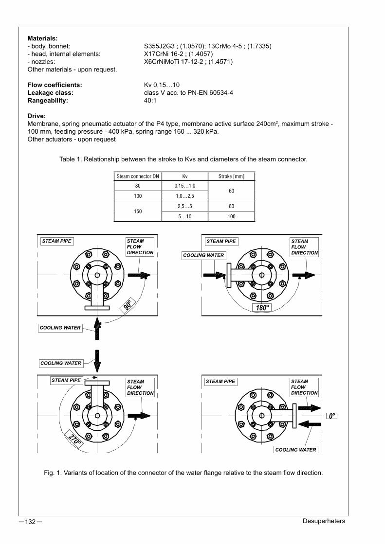
132 Desuperheters
STEAMFLOWDIRECTION
STEAM PIPE
COOLING WATER
COOLING WATER
COOLING WATER
COOLING WATER
STEAM PIPE STEAM PIPE
STEAM PIPE
STEAMFLOWDIRECTION
STEAMFLOWDIRECTION
STEAMFLOWDIRECTION
Table 1. Relationship between the stroke to Kvs and diameters of the steam connector.
Fig.1.Variantsoflocationoftheconnectorofthewaterflangerelativetothesteamflowdirection.
Materials:-body,bonnet: S355J2G3;(1.0570);13CrMo4-5;(1.7335)-head,internalelements: X17CrNi16-2;(1.4057)-nozzles: X6CrNiMoTi17-12-2;(1.4571)Othermaterials-uponrequest.
Flow coefficients: Kv0,15…10Leakage class: classVacc.toPN-EN60534-4Rangeability: 40:1
Drive:Membrane,springpneumaticactuatoroftheP4type,membraneactivesurface240cm2,maximumstroke-100mm,feedingpressure-400kPa,springrange160...320kPa.Otheractuators-uponrequest
Steam connector DN Kv Stroke [mm]
80 0,15…1,060
100 1,0…2,5
1502,5…5 80
5…10 100

133Desuperheters
Fig.3.Connectiondimensionsofdesuperheater(otherdimensionsuponclient’srequest).
Table 2. List of parts.
125
+ st
roke
(clo
sed
sock
et)
Fig.2.Structureofthedesuperheateranddimensionaloutline(otherdimensionsuponclient’srequest).
L.p. Part name
1. Head
2. Bonnet
3. Pin
4. Piston
5. Seat
6. Sealing set
7. Spiral gasket
8. Nut
9. Screw
10. Ring
11. Nozzles
12. P4 type actuator
WATER
STEAM

Revision:ST-1;SP-1/07/2014Validuntilthenextrevision.
134
Fig.4.Dimensions of the steam connector.
ItispossiblefortheZakładyAutomatyki„POLNA”SAtoproducethedesuper-heaterconnectoruponclient’srequest.Iftheclientproducessuchaconnectoronitsown,pleasespecifythediameterand the thickness of the pipe.TheconnectiondimensionsoftheconnectorarecooledasperthePN-EN1092-1:2010normforthe(C)typeoftheflange.Thesealingisstandardforthe(C/D)typeflangeconnection.ItisrecommendedtouseanelasticspiralwoundgasketmadeoftheX6CrNiMoTi17-12-2;(1.4571)material+GRAPHITE.
EXAMPLE DESIGNATION:Pneumaticactuator,size-240cm2,stroke60mm,controlpressurerange160...320kPa,steamconnectorDN80PN63,waterconnectorDN25PN40,steampipelineDN600PN40,locationofthewaterconnector270°,Kvs1,linearcharacteristics:
P4 - ST-1 - DN80/PN63 - DN25/PN40 - DN600/PN40 - 270° - Kvs 1L ORDERING (lance and ring desuperheaters): Beforeorderingthelanceandringdesuperheaters,contacttheMarketingandSalesDepartment.ORDERING (only piston desuperheaters):Whenorderingpleasestatethemarkingofthedriveaspertheproducer’scataloguecards,themarkingofthede-superheateranditsoperationparameters:thepressureandtemperatureoftheflowingmedium.Apartfromthea/mdata,thefollowinginformationisstatedontheratingplateofthedesuperheater:- maxworkingtemperature[TS],- max.workingpressure[PS]- testpressure[PT]- liquidgroup[2],- serialnumberandyearofmanufacturing.Theassistanceinselectingadesuperheaterisgrantedby:theMarketingandSalesDepartmentandtheTechnologyDepartment.
Table4.Dimensionsofthegasket.
Table3.Dimensionsofthesteamcounterflange.DN PN A s [min.] D x w B E f2 C2 H2 H3 R1 N1 K n L
80
25; 40
88,9
3,2 200 131,5
- 110
10
4,5
24 58
12
8
105 160
8
18
63 3,6 215136,5
28 72 112 170 22
100 4,0 230 32 78 120 180 26
100
25; 40
114,3
3,6 235
149 129 120
5
24 65 134 190 22
63 4,0 250 30 78 138 200 26
100 5,0 265 36 90 150 210 30
150
25; 40
168,3
4,5 300
203 183 170 15
28 75
10
192 250 26
63 5,6 345 36 95 202 280 33
100 7,1 355 44 115 210 290 12 33
DN Dimensions of the flange gasket
80131 x 111 x 3,2 (PN25; 40) 135 x 111 x 3,2 (PN63; 100)
100 148 x 130 x 3,2
150 202 x 184 x 3,2
MARKINGOFTHEPISTONDESUPERHEATER:
Kvs: aspertable1orthedataallowing to calculate it.
Location of the water flange:0°, 90°, 180°, 270°
Type:-pneumaticactuator: P4-electricactuator: E-hydrauilcactuator: H-other: X
Connector (steam side): DN / PN
Connector (water side): DN / PN
Steam pipeline: DN / PN
- -ST-1 - - - -

DIAPHRAGM MULTI-SPRING PNEUMATIC ACTUATORS TYPE P/R
135
APPLICATION AREAThe multi-spring membrane pneumatic actuators of P/R type are applied for control operation of control valves and other positioning elements in industrial automatic systems.There are three following design options of the acutator:- direct action (air - ejects the stem) - type P,- reverse action (air – retracts the stem) - type R,- direct action, handwheel - type PN,- reverse action, handwheel - type RN
TECHNICAL PARAMETERS input signal range: 20...100 kPa; spring range marking: 1 40...200 kPa; 2 40...120 kPa 3 80...240 kPa; 4 60...140 kPa; 5 120...280 kPa 6 180...380 kPa 7Number of springs: standard version: range 1, 3, 5 - 3 springs range 2, 4, 6 - 6 springs range 7 - 12 springs version TANDEM: range 1, 3, 5 - 6 springs range 2, 4, 6 - 12 springs range 7 - 24 springs- working temperature: - 40...+80°C- relative humidity: max. 98%
FEATURES
•completely reversible action, option to change spring range w/o extra parts, • actuator mounted on the columns,•wide range of the available forces,• linear relationship between rod displacement and control pressure as a result of using membranes with constant active area, •various ranges of spring pressures due to changeability of spring number and /or dislocation of distance fencers,•capability of the actuator o incorporate side-mounted handwheel,pneumatic or electro-pneumatic positioners, limit switches, air sets, three-way pneumatic solenoid valves, lockup valves, position transducers,•possibility to equip with accessories allowing to decrease or increase distortion time, •high strength of diaphragms, springs and packings,•small size and weight

Revision: P/R/10/2014Valid until the next revision.
136
DIMENSIONS AND WEIGHT
Actuator size
A B B1
C D1 D2 d1 E F1 F2 G
Weight
P, PN R, RN P,R PN, RN
[mm] [kg]
250 110 3118
112
86
240225
M12 22 306 468
M12x1,25
10 14,5
400
132 39
116 305
M16 28
312 474 16 20,5
630
20
134375
305 402 564 30 37
R-630T - - 616 - 45 52
1000 216 50 210 127 477 450 M24 42 585 825 M16x1,5 74 100
Table 2. Dimensions and weight of the actuators P/R-250…1000 .
SizeDiaphragm effective area Stroke
Spring range markingMax. supply pressure
[cm2] [mm] [kPa]250 250
20 1...6600400 400
630 63020; 38
1...7R-630T 2x630
5001000 1000 38; 50; 631500 1500 38; 50; 63; 80; 100
1500T 2x1500 50; 63; 80; 100
Table 1. Technical parameters.

Revision: P/R/10/2014Valid until the next revision.
137
Actuator size A B B1 d2 D1 d1 E F1 G
Weight
P,R
[mm] [kg]
1500
230 62
18 57,15
550 M27 42
679M16x1,5 M20x1,5M24x1,5
9522 84,15
2570
95,25
1500T
18 57,15
983 20022 84,15
2570
95,25
Table 3. Dimensions and weight of the actuators P/R-1500; 1500T.
Actuator size Stroke
C P R
[mm]
1500
38 142
102
50 15463 16780 184100 204
1500T
50 15463 16780 184100 204
DIMENSIONS AND WEIGHT
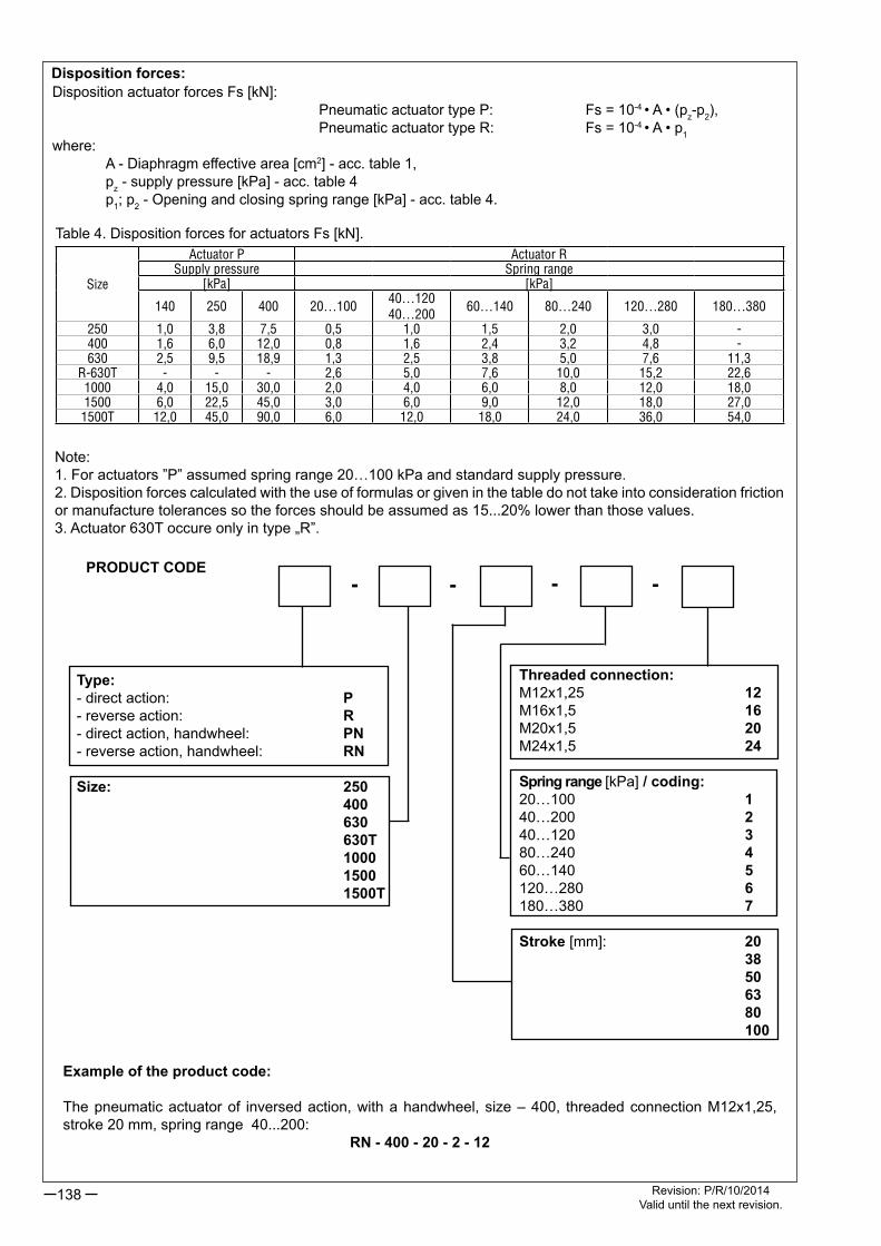
Revision: P/R/10/2014Valid until the next revision.
138
PRODUCT CODE
Type:- direct action: P- reverse action: R- direct action, handwheel: PN- reverse action, handwheel: RN
Size: 250 400 630 630T 1000 1500 1500T
Example of the product code:
The pneumatic actuator of inversed action, with a handwheel, size – 400, threaded connection M12x1,25, stroke 20 mm, spring range 40...200:
RN - 400 - 20 - 2 - 12
- - -
Threaded connection:M12x1,25 12M16x1,5 16M20x1,5 20M24x1,5 24
Spring range [kPa] / coding:20…100 140…200 240…120 380…240 460…140 5120…280 6180…380 7
Stroke [mm]: 20 38 50 63 80 100
-
Size
Actuator P Actuator RSupply pressure Spring range
[kPa] [kPa]
140 250 400 20…10040…12040…200
60…140 80…240 120…280 180…380
250 1,0 3,8 7,5 0,5 1,0 1,5 2,0 3,0 -400 1,6 6,0 12,0 0,8 1,6 2,4 3,2 4,8 -630 2,5 9,5 18,9 1,3 2,5 3,8 5,0 7,6 11,3
R-630T - - - 2,6 5,0 7,6 10,0 15,2 22,61000 4,0 15,0 30,0 2,0 4,0 6,0 8,0 12,0 18,01500 6,0 22,5 45,0 3,0 6,0 9,0 12,0 18,0 27,01500T 12,0 45,0 90,0 6,0 12,0 18,0 24,0 36,0 54,0
Table 4. Disposition forces for actuators Fs [kN].
Note:1. For actuators ”P” assumed spring range 20…100 kPa and standard supply pressure.2. Disposition forces calculated with the use of formulas or given in the table do not take into consideration friction or manufacture tolerances so the forces should be assumed as 15...20% lower than those values.3. Actuator 630T occure only in type „R”.
Disposition forces:Disposition actuator forces Fs [kN]: Pneumatic actuator type P: Fs = 10-4 • A • (pz-p2), Pneumatic actuator type R: Fs = 10-4 • A • p1where: A - Diaphragm effective area [cm2] - acc. table 1, pz - supply pressure [kPa] - acc. table 4 p1; p2 - Opening and closing spring range [kPa] - acc. table 4.

DIAPHRAGM MULTI-SPRING PNEUMATIC ACTUATORS TYPE P1/R1
139
Diaphragm effective area Stroke Spring range
[cm2] [mm] [kPa]
400 20 1…6
630 20; 38
1…71000 38; 50; 63
1500 38; 50; 63; 80; 100
1500T 50; 63; 80; 100
TECHNICAL PARAMETERS
- input signal range: 20…100 kPa; 40…120 kPa; 60…140 kPa - 3 springs 40…200 kPa; 80…240 kPa; 120…280 kPa - 6 springs 180…380 kPa - 12 springs Doubled number of springs (TANDEM version) for the 1500T actuator- max. supply pressure: 400 kPa (450 kPa for the range 180…380 kPa)- working temperature: - 40…+80°C- relative humidity: max. 98%
APPLICATION AREAThe multi-spring diaphragm pneumatic actuators of P1/R1 type are applied for control operation of control valves and other positioning elements in industrial automatic systems.There are three design options of the acutators:- direct action (air - ejects the stem) - type P1,- reverse action (air - retracts the stem) - type R1,- direct action, handwheel - type P1B,- reverse action, handwheel - type R1B
FEATURES
•completely reversible action, option to change spring range w/o extra parts, • rigid structure of cast yoke,•wide range of available forces,• l i nea r dependence o f s t em movement from control pressure, due to application of diaphragms with constant effective area, •various spring ranges achieved by changing the number of springs and/or changing position of spacer elements,•capabi l i ty o f the actuator to incorporate side-mounted handwheel, pneumatic or electro-pneumatic positioners, limit switches, air sets, three-way pneumatic solenoid valves, lockup valves, posi t ion transducers,•high strength of diaphragms, springs and packings,• low weights and small overall dimensions.

Revision: P1/R1/06/2013Valid until the next revision.
140
Connection thread:M12x1,25 12M16x1,5 16M20x1,5 20
Spud diameter [mm]:57,15 5784,15 8495,25 95
Spring range [kPa]:20…100 140…200 240…120 380…240 460…140 5120…280 6180…380 7
PRODUCT CODE
Type:- direct action: P1- reverse action: R1- direct action, with drive: P1B- reverse action, with drive: R1B
Size: 400 630 1000 1500 1500T
Stroke [mm]: 20 38 50 63 80 100
DIMENSIONS AND WEIGHTS
Example of the product code:The pneumatic actuator of reverse action, with handwheel, size – 400, stroke 20 mm, spring range 40…200 kPa, with yoke ∅57,15, and connection thread M12x1,25:
R1B - 400 - 20 - 2 - 57 - 12.
Actuator size
A BC
D E F dP1;P1B
R1;R1B
[mm]
400 453 305 127 10057,15
17,7 255 M12x1,25
630 548 375 127 10717,7
280M12x1,25M16x1,584,15 22,5
1000 773 477 153 9057,15 17,7
340M12x1,25M16x1,5 M20x1,584,15; 95,25 22,5
1500 833 550184 102
57,15 17,7
410
M12x1,25M16x1,5 M20x1,584,15; 95,25
22,51500T 1138 550 84,15; 95,25 M24x1,5
Actuator size
Weight
P1; R1 P1B; R1B
[kg]
400 20 28
630 40 50
1000 85 105
1500 120 150
1500T 225 255

HEAT ENGINEERING – TECHNICAL INFORMATION
141
INTRODUCTION:
Thermal centres play an important role within heat engineering. The following factors are the reasons for this: • Automationofathermalcentremakessettlementsbetweenthesupplierandconsumerofheatpossible,basedontheheatactuallyconsumed;atthesametimeitallowstoregulatetheheatreceiverinaccordancewiththesupplier’srequirements(limitingflowthroughthecentreandparametersofwaterreturningtothenetwork)andenabletheconsumertolimittheamountofheatreceivedattheirownwill,• Automationofthethermalcentreaccountsforthegreatestpercentageshareinpowersavingoutofthetotalsavingthatmaybeachievedthroughautomationofthewholeheatingsystemandinternalinstallationsofabuilding,• Without automation of the thermal centre, automation of internal installations of a building isimpossible,• Automationofathermalcentremakesheatsupplytoabuildingindependentoffluctuationsfromthenetworkparameterscausedbychangesinconsumptionfromneighbouringthermalcentres,• Ahighnumberof thermalcentresand thedemand forautomaticcontrolequipment resulting fromit,justifiesthedesignandmanufactureofspecializedassortmentsofsocalledheatengineeringequipment,includingself-operatingregulators.
GENERAL CHARACTERISTICS OF REGULATORS:
ZakładyAutomatyki“POLNA”S.A.inPrzemyślproducestwoseriesoftypesofselfoperatingregulators:• TypeZSN,withaflangedbodyrangingfromDN15to100,• TypeZSG,withathreadbodyendrangingfromDN15to32.
Theregulatorsaredesignedforfixedset-pointpressureregulation,regulationofpressuredifferencesand/orflowdifferencesintechnologicalinstallationsconnectedwiththeregulator’svalveinseriesorparallel.
Dependingonthepurpose,regulatorsaredividedintothefollowingtypes: ● • ZSN1;ZSG1–forregulationofpressureafterthevalve(reducer), ● • ZSN2–forregulationofpressureafterthevalve(reducer)withanintensifier, ● • ZSN3;ZSG3–forregulationofpressurebeforethevalve(bleedregulator), ● • ZSN5;ZSG5–forregulationofpressuredifferenceswithflowlimitationontheinstallationconnectedwith
theregulator’svalveinseries, ● • ZSN6;ZSG6–forregulationofpressuredifferenceswithflowlimitationontheinstallationconnectedwith
theregulator’svalveinseries(installationonthereturn), ● • ZSN7;ZSG7–forregulationofpressuredifferencesontheinstallationconnectedwiththeregulator’s
valveinparallel, ● • ZSN8;ZSG8–forflowregulation ● • ZSN91;ZSG9.1–forregulationofpressuredifferencesandflowregulationontheinstallationconnected
withtheregulator’svalveinseries(installationonthesupply), ● • ZSN92;ZSG9.2–forregulationofpressuredifferencesandflowregulationontheinstallationconnected
withtheregulator’svalveinseries(installationonthereturn), ● • ZSN10–forregulationofpressuredifferencesontheinstallationconnectedwiththeregulator’svalvein
series,withelectromagneticcontrol.

142 WAC-Technicalinformation
PRINCIPLESOFSELECTINGREGULATORS:
A. SELECTION OF REGULATOR’S VALVE
Selectionofaregulator’svalvemeansdeterminationofflowcoefficientKv,andthenthemaximumflowofthemediumthroughthevalveortheminimumpressuredroponit.
Figure1Inputdata:Q -flowvalue[m3/h],Kvs -catalogueflowcoefficient,pz -supplypressure[kPa],pressureinpoint1or5,Dpr -regulatedpressuredifference[kPa],whichmeanspressuredroponatechnologicalinstallationconnectedinserieswiththevalveoftheregulatorwhichneedstobestabilized.Pressuredifferencebetweenpoints3and4or5and6.Dpd -dispositionpressuredifference[kPa],whichmeanspressuredropbetweenthepointswiththehighestandthelowestpressureinthecentre.Pressuredifferencebetweenpoints1and4or5and8.p1 -pressureonvalve’sinlet(closingcomponent)[kPa](forsteamandgasesthisshouldberegardedastheabsolutepressure),p2 -pressureonvalve’soutlet[kPa](forsteamandgasesthisshouldberegardedastheabsolutepressure),Dp -pressuredroponthevalve’sclosingcomponent[kPa];(Dp=p1-p2),Dpp -pressuredifferenceontheflowlimiter:(20kPalub50kPa),
Inregulatorswithoutflowlimitation,installedonthesupplyoronthereturn,andinregulatorsZSN6andZSG6(installedonthereturn),pressuredroponthevalveshouldbeassumedforthecalculationofflowcoefficient:
Dp = p1-p2 = Dpd-Dpr
Forotherregulators,installedonthesupplyoronthereturn:Dp = p1-p2 = Dpd-Dpr-Dpp
1. Selection procedure for water.
PressuredropDp[kPa]ontheregulator’svalveis:Dp = p1-p2
Thecalculatedflowcoefficientofregulator’svalve[m3/h]is:
AftercalculatingtheminimumflowcoefficientKvthatway,youshouldchoosefromthedataboardoftheregulator,accordingtocataloguesheets,thenearestflowcoefficientKvs,sothat:
Kv≤0,85·Kvs
Theminimumpressuredroponafullyopenvalveoftheregulatorshouldbe:
Kv=Dp
10·Q√
Installationonthesupply Installationontherun-off

143WAC-Technicalinformation
and
-forregulatorswithaflowlimiter
-forregulatorswithaflowlimiter
Themaximumflowthroughthevalveis:
2. Selection procedure for use on steam and gases.Selectionforthoseapplicationsshouldbedonebythemanufactureroftheproduct.
B. NOISE.
Noiseisgeneratedbyavalveresultsfromcavitation(whenconcerningliquids)andexcessiveflowspeedonthevalveoutlet(whenconcerninggases). In regulatorsZSNandZSGnospecialconstructionmeansaredesigned to lower thepotentialnoise.Therefore,belowwejustmentionsituationswhenexcessivenoisemayoccur,whichneedtobecheckedafterselectionoftheregulator’svalve.Iftheboundaryconditionisexceeded,andtheexcessivenoiseisunacceptable(e.g.becauseoffasterwearingoutofthevalve’sclosingcomponentduetocavitation),systemicsolutionsshouldbeappliedtoavoidsuchnoise.
Suchsolutionareasfollows:• Byloweringthetemperatureonthevalve’sinlet(e.g.bymovingthevalvefromthesupplytotherun-off),• Byloweringthepressureonthevalve’sinlet(e.g.byinstallingdiaphragmsbeforethevalveoranadditionalreductionlevel)• Byincreasingthepressureonthevalve’sinlet(e.g.byinstallingdiaphragmsafterthevalveorusingchokingelementsintheformofmulti-holeplatesonthevalve’soutlet).
The reductionof noisehas someconditionsbynot exceeding theboundary flowspeed v= 3 [m/s] inwaterinstallations.Thisconditionlimitsthemaximumflowtothefollowingvalue:
Q1max.[m3/h]=8,5·10-3·DN2
Attheflowspeedofupto5[m/s],highernoiseandapossibilityofpartialcavitationhavetobetakenintoconsiderationandthatvalueshouldnotbeexceeded:
Q2max.[m3/h]=14·10-3·DN2
forDN50-Q1max.=21[m3/h]iQ2max.=35[m
3/h]
C. SELECTION OF SETTING RANGE
Thesettingrangeofaregulatorshouldbeselectedsothatthevalueofregulatedpressurewouldbeinthelowerhalfofthesettingrange.Thisensuresworkwithalowerspringtensionandresultsinbetterparametersofworkcharacteristics(proportionality,insensitivityandhysteresisranges). Apartfromsettingrangesrecommendedinourcataloguesheets,therearealsospecialrangesthatarepossible.
D. CALCULATION EXAMPLES.
Example 1.
Regulatorofpressuredifferences,installationonthesupply,forwater.
Technicaldata: ● Dispositionpressuredifference -Dpd=450kPa,
100·Q2
Dpmin.= Kvs2
100·Q2
Dpmin.= Kvs2+Dpp
Qmax.=0,1·Kvs·√Dp

Revision:AC/06/2013Validuntilthenextrevision.
144
● Regulatedpressuredifference -Dpr=60kPa, ● Maximumflow -Q=12m3/h
Calculations: Dp = p1-p2 = Dpd-Dpr=450-60=390kPa
Insuchacase,wechooseaZSN5regulator,Kvs8,settingrange40…160kPa.
Thenominaldiameteroftheregulatorwillbeselectedafterananalysisoftheflowspeeds:
Q1max.[m3/h]=8,5·10-3·DN2(nmax. =3m/s),
Q2max.[m3/h]=14·10-3·DN2(nmax. =5m/s),
● forDN25 Q1max.=5,3m
3/h;Q2max.=8,75m3/h,
● forDN32 Q1max.=8,7m3/h;Q2max.=14,3m
3/h,
● forDN40 Q1max.=13,6m3/h;Q2max.=22,4m
3/h,
BychoosingaDN25regulator,wehavetotakeintoaccountasignificantlevelofnoise.RegulatorDN32inaspecialKvs8productismorebeneficial.RegulatorDN40guaranteesthegreatestcomfortasfortheloudnessofwork.
Example 2.
Adual-functionregulatorofpressuredifferencesandflow,foraninstallationonthereturn,forwater.
Technicaldata: ● Dispositionpressuredifference -Dpd=400kPa, ● Regulatedpressuredifference -Dpr=180kPa, ● Maximumflow -Q=32m3/h ● Chokesettingassumed -Dpp=50kPa,
Calculations: Dp = p1-p2 = Dpd-Dpr-Dpp=400-180-50=170kPa
InsuchacasewewouldchooseaZSN92;DN50;Kvs32;withpressuredifferencessettingrange80…320kPa,chokesetting50kPa.
Dependingontheflowspeed,theflowis:
Q1max.=21m3/h;Q2max.=35m
3/h,
Theregulatorwillworkwithanincreasednoiselevel.Thefollowingconditionisfulfilled:
Dpd=400>2·Dpr=2·180=360
Withafullyopenchoke,thevalveworksasapressuredifferencesregulator.Themaximumflowisdependentontheacceptableflowspeed.TherangeofflowregulationdependsonthepositionofthechokeandsettingDpp.
Kv===6,0Dp
10·Q√ 390
10·12√
Kv===24,5Dp
10·Q√ 170
10·32√
Kvs==29 assumeKvs32Kv0,85
~~
Q =(0,1…1,0)·10-1·Kvs·√Dpp
Qmin. =0,1·10-1·32·√50=2,3m3/h
Qmax.=1·10-1·32·√50=23m3/h
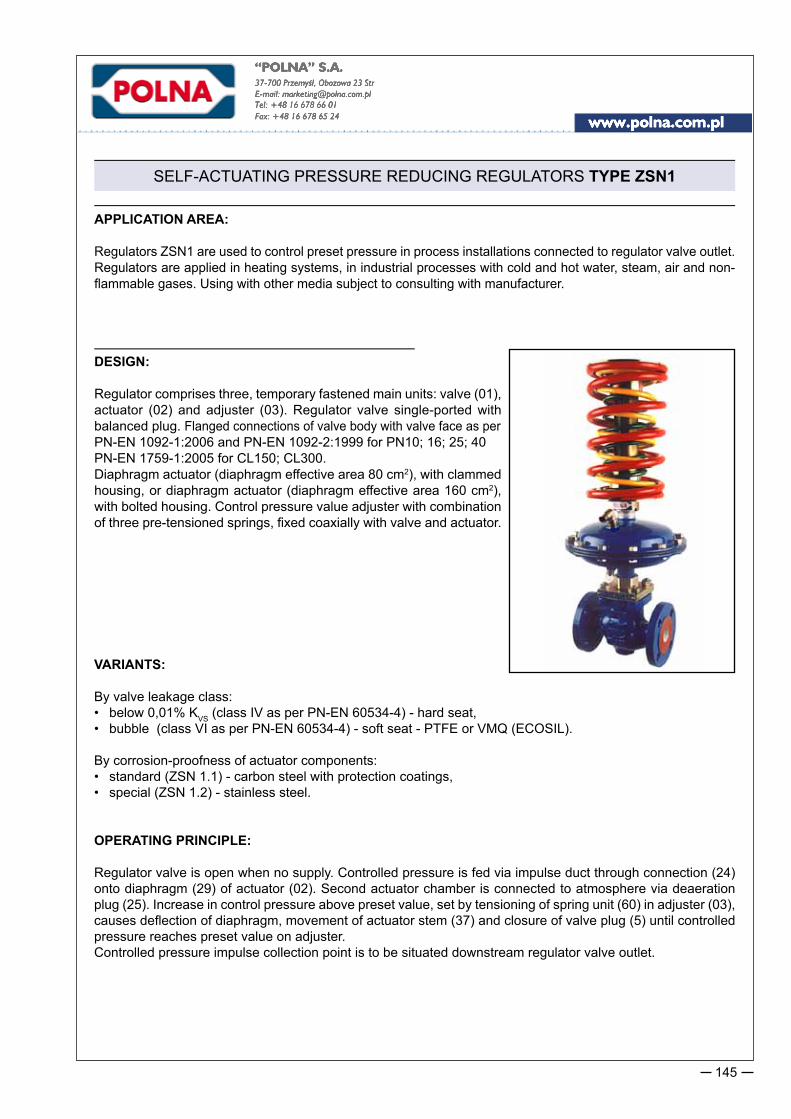
SELF-ACTUATING PRESSURE REDUCING REGULATORS TYPE ZSN1
145
APPLICATION AREA:
Regulators ZSN1 are used to control preset pressure in process installations connected to regulator valve outlet. Regulators are applied in heating systems, in industrial processes with cold and hot water, steam, air and non-flammable gases. Using with other media subject to consulting with manufacturer.
DESIGN:
Regulator comprises three, temporary fastened main units: valve (01), actuator (02) and adjuster (03). Regulator valve single-ported with balanced plug. Flanged connections of valve body with valve face as perPN-EN 1092-1:2006 and PN-EN 1092-2:1999 for PN10; 16; 25; 40PN-EN 1759-1:2005 for CL150; CL300.Diaphragm actuator (diaphragm effective area 80 cm2), with clammed housing, or diaphragm actuator (diaphragm effective area 160 cm2), with bolted housing. Control pressure value adjuster with combination of three pre-tensioned springs, fixed coaxially with valve and actuator.
VARIANTS:
By valve leakage class:• below 0,01% KVS (class IV as per PN-EN 60534-4) - hard seat,• bubble (class VI as per PN-EN 60534-4) - soft seat - PTFE or VMQ (ECOSIL).
By corrosion-proofness of actuator components:• standard (ZSN 1.1) - carbon steel with protection coatings,• special (ZSN 1.2) - stainless steel.
OPERATING PRINCIPLE:
Regulator valve is open when no supply. Controlled pressure is fed via impulse duct through connection (24) onto diaphragm (29) of actuator (02). Second actuator chamber is connected to atmosphere via deaeration plug (25). Increase in control pressure above preset value, set by tensioning of spring unit (60) in adjuster (03), causes deflection of diaphragm, movement of actuator stem (37) and closure of valve plug (5) until controlled pressure reaches preset value on adjuster. Controlled pressure impulse collection point is to be situated downstream regulator valve outlet.

Self-actuating pressure reducing regulators Type ZSN1146
DIMENSIONS AND WEIGHTS
DNA L Valve weight (01)
[mm] [kg]
15
470
130 4,0
20 150 5,1
25 160 5,6
32 485 180 8,5
40 490 200 10,6
50 495 230 14
65605
290 23
80 310 29
100 615 350 44
125 special execution, technical data according to individual inquiries150
Spring range
[kPa]
C
[mm]
Diaphragm
effective area[cm2]
Weight
Actuator
(02)
Adjuster (03)
DN 15...50 DN 65...100
40...160215 160 4,4
3,2 3,6
100...400 5,6 7,1
200...800150 80 2,4 6,8 8,5
280...1120
other spring ranges available on request

Self-actuating pressure reducing regulators Type ZSN1 147
TECHNICAL SPECIFICATIONS
1) other flow ratios Kvs subject to order specification.2) other ranges subject to order specification.
MATERIALS as per PNRegulator ZSN 1.1 ZSN 1.2
VALVE (01)
Body
grey iron EN-GJL-250spheroidal iron EN-GJS-400-18LT carbon steel GP240GH (1.0619)stainless steel GX5CrNiMo 19-11-2 (1.4408)
Plug and seatX6CrNiMoTi 17-12-2 (1.4571)
Guide sleevePacking EPDM3)
ACTUATOR (02)Housing carbon steel S235JRG2C (1.0122) stainless steel X6CrNiTi 18-10 (1.4541)
Stem X17CrNi 16-2 (1.4057)Diaphragm EPDM + polyester fabric3)
Packing EPDM3)
Adjuster (03)Adjuster components carbon steel C45 (1.0503)
Springs Spring steel 60Si7
3) other materials, subject to medium type.
NOMINAL PRESSURE, WORKING TEMPERATURE AND WORKING PRESSURE FLOW DIAGRAM FOR WATER
DN 15 20 25 32 40 50 65 80 100 125 150
KVS 1)
[m3/h]
full flow 3,2 5 8 12,5 20 32 50 80 125special execution
technical data according to individual inquiries
reduced flow1
1,62,5
1,62,53,2
2,53,25
5 8 12,5 20 32 50
Stroke [mm] 6 8 12 14
Noise coefficient Z 0,65 0,6 0,55 0,45 0,4 0,35
Control characteristics proportional
Spring range [kPa] 2) 40...160; 100...400; 200...800; 280...1120Maximum pressure in actuator
chamber [bar] 20
Allowed pressure drop in valve [bar]
12 10
Valve nominal pressure
valve body in grey iron PN 16
valve body in spheroidal iron PN 16; PN 25; PN 40
valve body in carbon steel and stainless steel PN 16; PN 25; PN 40
Maximum medium temperature [°C]
water200
steam
gases 80

Revision: ZSN1/06/2013Valid until the next revision.
148
ACCESSORIES
Delivered: Optional (ordered separately):- nut and cutting ring for impulse tube, - strainer FS1, - straight tube connection ∅ 6×1, - elbow tube connection ∅ 6×1, - connection stub NPT 1/4” - impulse tube ∅ 6×1, - adjustment wrench, - condensation tank, - needle valve ZWD 1.
INSTALLATIONRegulator is to be installed on horizontal pipeline. Medium flow direction is to conform to arrow on body. At medium temperature lower than 130°C regulator position is optional, at higher temperatures it is recommended to install regulator with adjuster unit (03) down. To ensure reliable operation of regulator apply strainer FS1 upstream, and needle valve ZWD 1 at impulse supply. When using regulators for steam applications condensation tank is required.
EXAMPLE OF APPLICATION
ORDERING
In your order specify type and marking, ZSN 1.1 or ZSN 1.2, DN nominal diameter, flow ratio Kvs, body material, spring range, tightness type (only orders for tight execution).
Example of order:
ZSN 1.2 - DN 40; PN 25; Kvs 20; spheroidal iron; 100…400 kPa; tight.

SELF-ACTUATING DIFFERENTIAL PRESSURE RELIEF REGULATORS TYPE ZSN3
149
APPLICATION AREA:
Regulators ZSN3 are used to control preset pressure in process installations connected to regulator valve inlet. Regulators are applied in heating systems, in industrial processes with cold and hot water, steam, air and non-flammable gases. Using with other media subject to consulting with manufacturer.
DESIGN:
Regulator comprises three, temporary fastened main units: valve (01), actuator (02) and adjuster (03). Regulator valve single-ported with balanced plug. Flanged connections of valve body with valve face as perPN-EN 1092-1:2006 and PN-EN 1092-2:1999 for PN10; 16; 25; 40PN-EN 1759-1:2005 for CL150; CL300.Body length as per:PN-EN 60534-3-1:2000 – Series 1 for PN10; 16; 25; 40;Series 37 for CL150; Series 38 for CL300Valve tightness – bubble (Class VI as per PN-EN 60534-4), tight seat in PTFE or VMQ (ECOSIL).Diaphragm actuator (diaphragm effective area 80 cm2), with clammed housing or diaphragm actuator (diaphragm effective area 160 cm2), with bolted housing. Control pressure value adjuster with combination of three pre-tensioned springs, fixed coaxially with valve and actuator.
VARIANTS:
By corrosion-proofness of actuator components: • standard (ZSN 3.1) - carbon steel with protection coatings,• special (ZSN 3.2) - stainless steel.
OPERATING PRINCIPLE:
Valve is closed when no supply. Controlled pressure is fed via impulse duct through connection (24) under diaphragm (29) of actuator (02). Actuator second chamber is connected to atmosphere via deaeration plug (25). Increase in control pressure above preset value, set by tensioning of spring unit (60) in adjuster (03), causes deflection of diaphragm, movement of actuator stem (37) and opening of valve plug (5) until controlled pressure reaches value preset in booster. Impulse collection point for controlled pressure is to be located upstream valve inlet.

Self-actuating differential pressure relief regulators Type ZSN 3150
DIMENSIONS AND WEIGHTS
DNA L Valve weight (01)
[mm] [kg]
15
470
130 4,0
20 150 5,1
25 160 5,6
32 485 180 8,5
40 490 200 10,6
50 495 230 14
65605
290 23
80 310 29
100 615 350 44
125 special execution, technical data according to individual inquiries150
Spring range
[kPa]
C
[mm]
Diaphragm
effective area[cm2]
Weight
Actuator
(02)
Adjuster (03)
DN 15...50 DN 65...100
40...160215 160 4,4
3,2 3,6
100...400 5,6 7,1
200...800150 80 2,4 6,8 8,5
280...1120
other spring ranges available on request

Self-actuating differential pressure relief regulators Type ZSN 3 151
TECHNICAL SPECIFICATIONS
MATERIALS as per PN
3) other materials, subject to medium type.
NOMINAL PRESSURE, WORKING TEMPERATURE AND WORKING PRESSURE FLOW DIAGRAM FOR WATER
1) other flow ratios Kvs subject to order specification.2) other ranges subject to order specification.
Regulator ZSN 3.1 ZSN 3.2VALVE (01)
Body
grey iron EN-GJL-250spheroidal iron EN-GJS-400-178LTcarbon steel GP240GH (1.0619)stainless steel GX5CrNiMo 19-11-2 (1.4408)
Plug and seatX6CrNiMoTi 17-12-2 (1.4571)
Guide sleevePacking EPDM3)
ACTUATOR (02)Housing carbon steel S235JRG2C (1.0122) stainless steel X6CrNiTi 18-10 (1.4541)
Stem X17CrNi 16-2 (1.4057)Diaphragm EPDM + polyester fabric3)
Packing EPDM3)
Adjuster (03)Adjuster components carbon steel C45 (1.0503)
Springs spring steel 60Si7
DN 15 20 25 32 40 50 65 80 100 125 150
KVS 1)
[m3/h]
full flow 3,2 5 8 12,5 20 32 50 80 125
special execution, technical data according to individual inquiries
reduced flow1
1,62,5
1,62,53,2
2,53,25
5 8 12,5 20 32 50
Stroke [mm] 6 8 12 14
Noise coefficient Z 0,65 0,6 0,55 0,45 0,4 0,35
Control characteristics proportional
Spring range [kPa] 2) 40...160; 100...400; 200...800; 280...1120Maximum pressure in actuator
chamber [bar] 20
Allowed pressure drop in valve [bar]
12 10
Valve nominal pressure
valve body in grey iron PN 16
valve body in spheroidal iron PN 16; PN 25; PN 40
valve body in carbon steel and stainless steel PN 16; PN 25; PN 40
Maximum medium temperature [°C]
water200
steam
gases 80

Revision: ZSN3/06/2013Valid until the next revivsion.
152
ACCESSORIES
Delivered: Optional (ordered separately):- nut and cutting ring for impulse tube, - strainer FS1, - straight tube connection ∅ 6×1, - connection stub NPT 1/4” - impulse tube ∅ 6×1, - adjustment wrench, - condensation tank, - needle valve ZWD 1.
ORDERING
In your order specify regulator type and marking, ZSN 3.1 or ZSN 3.2, DN nominal diameter, PN nominal pressure, flow ratio Kvs, body material, spring range.
Example of order:
ZSN 3.1 – DN 32; PN 16; Kvs 8; spheroidal iron; 200…800 kPa.
INSTALLATIONRegulator is to be installed on horizontal pipeline. Medium flow direction is to conform to arrow on body. At medium temperature lower than 130°C regulator position is optional, at higher temperatures it is recommended to install regulator with adjuster unit (03) down. To ensure reliable operation of regulator apply strainer FS1 upstream and needle valve ZWD 1 at impulse collection point. When applying regulator for steam installation of condensation tank is recommended.
EXAMPLES OF APPLICATION
Regulation

SELF-ACTUATING DIFFERENTIAL PRESSURE REDUCING REGULATORS TYPE ZSN5
153
APPLICATIONA AREA:
Regulators ZSN5 are used to control preset pressure in process installations connected to regulator valve inlet or outlet. Regulators are applied in heating systems, in industrial processes with cold and hot water, steam, air and non-flammable gases. Using with other media subject to consulting with manufacturer.
DESIGN:
Regulator comprises three, temporary fastened main units: valve (01), actuator (02) and adjuster (03). Regulator valve single-ported with balanced plug. Flanged connections of valve body with valve face as perPN-EN 1092-1:2006 and PN-EN 1092-2:1999 for PN10; 16; 25; 40PN-EN 1759-1:2005 for CL150; CL300.Body length as per:PN-EN 60534-3-1:2000 – Series 1 for PN10; 16; 25; 40;Series 37 for CL150; Series 38 for CL300Diaphragm actuator (diaphragm effective area 160 cm2, 320 cm2), with bolted housing. Control pressure value adjuster with combination of three pre-tensioned springs, fixed coaxially with valve and actuator.
VAIANTS:
By valve leakage class:• below 0,01% KVS (class IV as per PN-EN 60534-4) - hard seat,• bubble (class VI as per PN-EN 60534-4) - soft seat - PTFE or VMQ (ECOSIL).By corrosion-proofness of actuator components:• standard (ZSN 5.1) - carbon steel with protection coatings,• special (ZSN 5.2) - stainless steel.
OPERATING PRINCIPLE:
Valve is open when no supply. Impulse of higher pressure is fed via impulse duct through connection (24) and above diaphragm (29) of actuator (02) from adjuster (03) side. Impulse of lower pressure is fed via impulse duct through connection (24) and below diaphragm. Increase in control pressure above preset value, set by tensioning of spring (60) in adjuster (03), causes deflection of diaphragm, movement of actuator stem (37) and closure of valve plug (5) until controlled pressure reaches value preset in adjuster. When regulator is installed on supply of installation, impulse collection points are to be situated downstream regulator valve outlet. When regulator is installed on return of installation, impulse collection points are to be situated upstream valve inlet.

Self-actuating differential pressure reducing regulators Type ZSN 5154
DIMENSIONS AND WEIGHTS
DNA L
Valve weight
(01)
[mm] [kg]
15
470
130 4,0
20 150 5,1
25 160 5,6
32 485 180 8,5
40 490 200 10,6
50 495 230 14
65605
290 23
80 310 29
100 615 350 44
125 special execution, technical data according to individual inquiries150
Spring range
[kPa]
C
[mm]
Diaphragm effec-
tive area[cm2]
Weight
Actuator
(02)
Adjuster (03)
DN 15...50 DN 65...100
10...40282 320 9,1
2,4 2,8
20...803,2 3,6
40...160215 160 4,4
80...320 5,0 6,3
other spring ranges available on request

Self-actuating differential pressure reducing regulators Type ZSN 5 155
TECHNICAL SPECIFICATIONS
MATERIALS as per PN
3) other materials, subject to medium type.
NOMINAL PRESSURE, WORKING TEMPERATURE AND WORKING PRESSURE FLOW DIAGRAM FOR WATER
1) other flow ratios Kvs subject to order specification.2) other ranges subject to order specification.
Regulator ZSN 5.1 ZSN 5.2VALVE (01)
Body
grey iron EN-GJL-250spheroidal iron EN-GJS-400-178LTcarbon steel GP240GH (1.0619)stainless steel GX5CrNiMo 19-11-2 (1.4408)
Plug and seatX6CrNiMoTi 17-12-2 (1.4571)
Guide sleevePacking EPDM3)
ACTUATOR (02)Housing carbon steel S235JRG2C (1.0122) stainless steel X6CrNiTi 18-10 (1.4541)
Stem X17CrNi 16-2 (1.4057)Diaphragm EPDM + polyester fabric3)
Packing EPDM3)
Adjuster (03)Adjuster components carbon steel C45 (1.0503)
Springs spring steel 60Si7
DN 15 20 25 32 40 50 65 80 100 125 150
KVS 1)
[m3/h]
full flow 3,2 5 8 12,5 20 32 50 80 125special execution
technical data according to individual inquiries
reduced flow1
1,62,5
1,62,53,2
2,53,25
5 8 12,5 20 32 50
Stroke [mm] 6 8 12 14
Noise coefficient Z 0,65 0,6 0,55 0,45 0,4 0,35
Control characteristics proportional
Spring range [kPa] 2) 10...40; 20...80; 40...160; 80...320Maximum pressure in actuator
chamber [bar] 20
Allowed pressure drop in valve [bar] 12 10
Valve nominal pressure
valve body in grey iron PN 16
valve body in spheroidal iron PN 16; PN 25; PN 40
valve body in carbon steel and stainless steel PN 16; PN 25; PN 40
Maximum medium temperature [°C]
steam200
water
gases 80

Revision: ZSN5/06/2013Valid until the next revision.
156
ACCESSORIES
Delivered: Optional (ordered separately):- nut and cutting ring for impulse tube, - strainer FS1, - straight tube connection ∅ 6×1, - connection stub NPT 1/4” - impulse tube ∅ 6×1, - adjustment wrench, - condensation tank, - needle valve ZWD 1.
ORDERING
In your order specify type and marking, ZSN 5.1 or ZSN 5.2, DN nominal diameter, PN nominal pressure, flow ratio Kvs, body material, spring range, closure type (only for tight execution).
Example of order:
ZSN 5.2 – DN 50; PN 16; Kvs 32; spheroidal iron; 40…160 kPa, tight
INSTALLATIONRegulator is to be installed on horizontal pipeline. Medium flow direction is to conform to arrow on body. At medium temperature lower than 130°C regulator position is optional, at higher temperatures it is recommended to install regulator with adjuster unit (03) down. To ensure reliable operation apply strainer FS1 upstream and needle valve ZWD 1 at impulse collection point. When applying regulator for steam installation of condensation tank is recommended.
INSTALLATION

B140024_V10_SIL-Datasheet_Valve-BR11_Actuator-PIR_Polna
Seite 1 von 2
INGENIEURBÜRO URBAN – Dipl.-Ing. J. Urban Öffentl. Bestellung u. Vereidigung Zeichen für Sachverstand Unabhängigkeit Unparteilichkeit
Publicly certified The mark of quality in the expert profession Independence Impartiality Certificatión pública Señal de competencia Independencia Imparcialidad
© Ingenieurbüro Urban
Set of Components/Component Safety Data (acc. IEC 61508 and IEC 61511)
Set of Components Control Valve (BR11 / Z
®)
Diaphragm Multi-Spring Pneumatic Actuator (P/R & P1/R1)
Variants BR11 / Z® Standard / Extension / Bellow / Self-adjusting / TA-Air / balanced plug B130398_V10
Variants P/R & P1/R1 Type P/R & P1/R1 Single + Tandem (without handwheel)
Spring Range 1...7 B130392_V10
Manufacturer Zaklady Automatyki POLNA S.A.
Component Type Type A Ref. IEC 61508-2
Mode of Operation Low demand operation
Safety Function SF1: Actuator closes valve in specified time
SF2: Actuator opens valve in specified time
Safe State SS1: Actuator holds valve in closed position with specified leakage
SS2: Actuator holds valve in opened position with specified mass flow
Failure Rates [failure/109 hrs = FIT] with diagnosis
Failure Rate Distribution total safe dangerous detected dangerous undetected don’t care SFF [%]
Control Valve BR11/Z® (all) 112 58 30 24 29 79
Diaphragm Actuator P/R & P1/R1 (all) 3,135 2,950 57 128* 1 96
Diaphragm Actuator P/R & P1/R1 with
Control Valve BR11/Z®
(all variants) 3,247 3,008 87 152 30 95
* Design of actuator tolerates min. one spring failure without affecting safety function
Specification of component Architecture
Architecture 1oo1 1oo1 is the architecture of a single set of components/component of the analysed type.
Hardware Fault Tolerance HFT 0 Due to HFT=0, one failure has impact on the safety function. The influence of HFT on SIL capability is respected in (2) below.
MTTR [h] 32 MTTR is the time required for repair of the set of components/component in case of failure. MTTR has marginal influence on the pfd-value.
Diagnostic Coverage DC [%] 36 %
In case of missing automatic diagnosis (e.g. partial stroke test): DC = 0 %. In case of implemented partial stroke test: DC > 0% (value depends on efficiency of partial stroke test). Safe Failure Fraction SFF increased by higher DC. Influence of DC on SIL capability of the set of components/component is respected in (2) below (via SFF).
Verification of SIL Capability (examples with diagnosis) (see comments on next page/backside of this page)
Proof Test Interval 6 months 1 year 2 years 3 years 5 years
PFD (avg.) (IEC 61508-6, B3.2.2; λdu from FMEDA) 3.41 E-04 6.73 E-04 1.34 E-03 2.01 E-03 3.34 E-03
(1) quantitative achievable SIL (IEC 61508-1, Tab. 2)
SIL 3 SIL 3 SIL 2 SIL 2 SIL 2
(2) qualitative achievable SIL (IEC 61508-2, Tab. 2, Chapter 7.4.4.2.3) SIL 2 (Min {SIL single component})
Achievable SIL = Min {(1); (2)} SIL 2 SIL 2 SIL 2 SIL 2 SIL 2
Calculated (company/name/date/signature)
INGENIEURBÜRO URBAN
Anzinger Str. 24 D-85604 Pöring Pöring, 2014-03-13

B140024_V10_SIL-Datasheet_Valve-BR11_Actuator-PIR_Polna
Seite 2 von 2
INGENIEURBÜRO URBAN – Dipl.-Ing. J. Urban Öffentl. Bestellung u. Vereidigung Zeichen für Sachverstand Unabhängigkeit Unparteilichkeit
Publicly certified The mark of quality in the expert profession Independence Impartiality Certificatión pública Señal de competencia Independencia Imparcialidad
© Ingenieurbüro Urban
Explanations to the Data Sheet
The data sheet is divided in 4 areas:
Common technical description of the set of components/component (blue)
Failure rate (light green)
Specification of architecture of the set of components/component (light orange)
Verification of SIL capability (examples) (grey)
General description of the Part / Component:
Information on the set of components/component, type of component and component designator
Manufacturer information
Component type (Type A or Type B) acc. IEC 61508-2/7.4.4.1.2 und 7.4.4.1.3)
Mode of operation of the set of components/component (acc. IEC 61508-1)
Description of the safety function of the set of components/component
Description of the safe state of the set of components/component
Failure Rates
The failure rates and failure rate distribution are the results of the reliability calculation of the set of components/component and the Failure Modes Effects and Diagnostic Analysis (FMEDA). The failure rates can be used for further quantitative analysis of the set of components/component as pfd/pfh-calculation, Markov-Analysis, Fault Tree Analysis, and due to this for a quantitative evaluation of SIL-capability of the set of components/component. Based on the failure rate distribution the Safe Failure Fraction (SFF) is
calculated according the formula SFF [%] = (S + DD) / (S + DD + DU)
Failure rates are calculated in acc. with NSWC-06 LE10.
Failure rates for the set of components are calculated by serial addition of failure rates of each component of the set of components.
Specification of Component Architecture
The architecture of the set of components/component is described by following parameters:
Structure/architecture (single-channel, multi-channel expressed by 1oo1, 1oo2, 2oo3, etc.)
Hardware-Fault-Tolerance (HFT) (number of failures acceptable without dispatch on the safety function of the set of components/component)
Mean Time to Repair (MTTR): time to repair the set of components/component in case of failure
Diagnostic Coverage: The diagnostic coverage is resulting from the diagnostic structure/diagnostic measures for the set of components/component in case of application of automatic diagnosis (e.g. partial stroke test). The diagnostic coverage is considered in the FMEDA and the quantitative results of the analysis (see failure rates)
Verification of SIL-capability (examples)
The SIL capability of the set of components/component is of major interest for the user. Therefore with respect to default values and basic qualitative and quantitative preconditions for the set of components/component a verification of the product capability for use in safety loops is calculated for some examples of proof test intervals. In case of deviation of the application specific values from the used default values an application specific evaluation is required. The verification consists of two steps:
Step (1) = f{pfd; proof test interval}: quantitative verification by calculation of the pfd-value depending from the defined Proof Test Interval (6 months, 1 year, 2 years, 3 years, 5 years)
Step (2) = f{HFT; component type; SFF}: qualitative verification based on the architectural information of the set of components/component
The final achievable SIL is the minimum resulting SIL-value of step (1) and step (2): MIN {(1) ; (2)}.
According IEC 61508-2 the max. possible SIL-value for the set of components is given by the min. SIL-value of a single component of the set of components.
Caution: For a complete SIL-verification of a set of components/component additional measure to this quantitative analysis are required (methods and techniques used for the overall life cycle of the set of components/component). For proven-in use components a proven-in-use-assessment is possible.
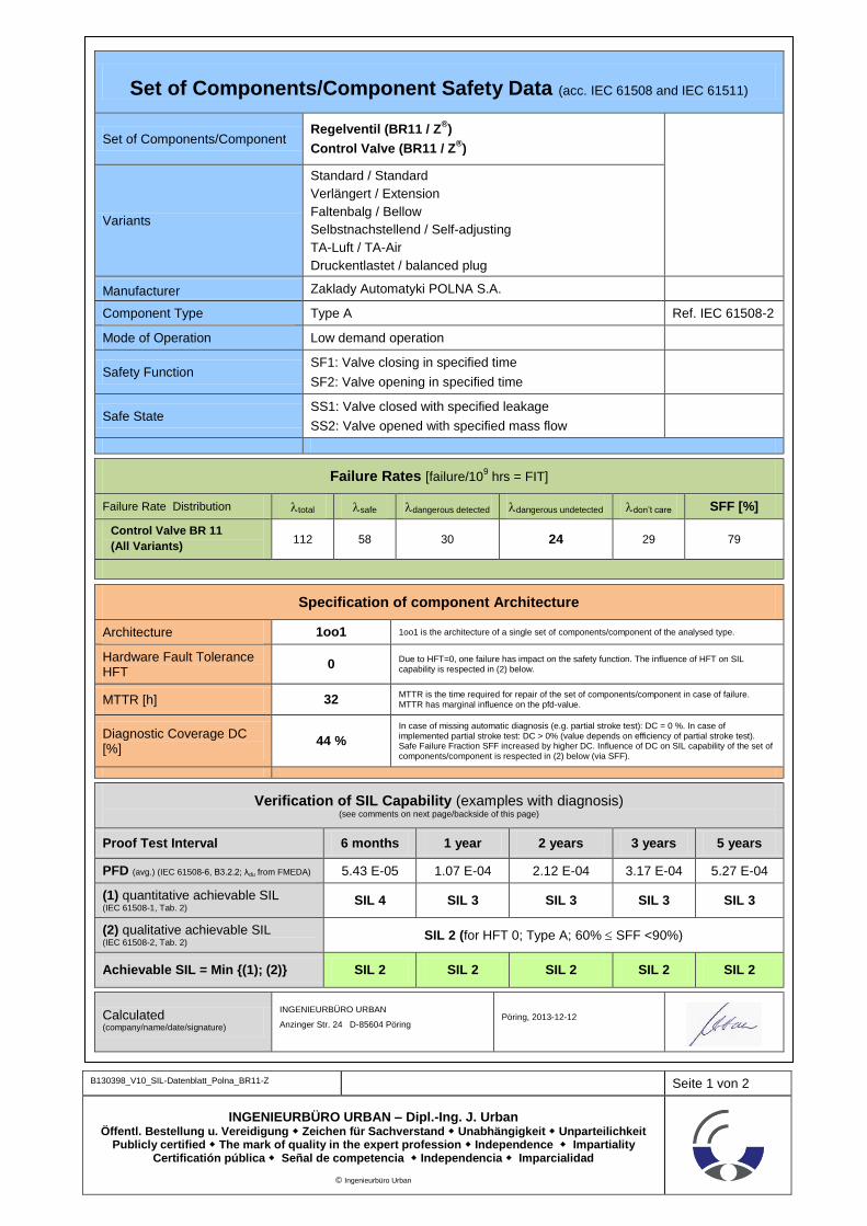
B130398_V10_SIL-Datenblatt_Polna_BR11-Z Seite 1 von 2
INGENIEURBÜRO URBAN – Dipl.-Ing. J. Urban Öffentl. Bestellung u. Vereidigung Zeichen für Sachverstand Unabhängigkeit Unparteilichkeit
Publicly certified The mark of quality in the expert profession Independence Impartiality Certificatión pública Señal de competencia Independencia Imparcialidad
© Ingenieurbüro Urban
Set of Components/Component Safety Data (acc. IEC 61508 and IEC 61511)
Set of Components/Component Regelventil (BR11 / Z
®)
Control Valve (BR11 / Z®)
Variants
Standard / Standard
Verlängert / Extension
Faltenbalg / Bellow
Selbstnachstellend / Self-adjusting
TA-Luft / TA-Air
Druckentlastet / balanced plug
Manufacturer Zaklady Automatyki POLNA S.A.
Component Type Type A Ref. IEC 61508-2
Mode of Operation Low demand operation
Safety Function SF1: Valve closing in specified time
SF2: Valve opening in specified time
Safe State SS1: Valve closed with specified leakage
SS2: Valve opened with specified mass flow
Failure Rates [failure/109 hrs = FIT]
Failure Rate Distribution total safe dangerous detected dangerous undetected don’t care SFF [%]
Control Valve BR 11
(All Variants) 112 58 30 24 29 79
Specification of component Architecture
Architecture 1oo1 1oo1 is the architecture of a single set of components/component of the analysed type.
Hardware Fault Tolerance HFT
0 Due to HFT=0, one failure has impact on the safety function. The influence of HFT on SIL capability is respected in (2) below.
MTTR [h] 32 MTTR is the time required for repair of the set of components/component in case of failure. MTTR has marginal influence on the pfd-value.
Diagnostic Coverage DC [%]
44 %
In case of missing automatic diagnosis (e.g. partial stroke test): DC = 0 %. In case of implemented partial stroke test: DC > 0% (value depends on efficiency of partial stroke test). Safe Failure Fraction SFF increased by higher DC. Influence of DC on SIL capability of the set of components/component is respected in (2) below (via SFF).
Verification of SIL Capability (examples with diagnosis) (see comments on next page/backside of this page)
Proof Test Interval 6 months 1 year 2 years 3 years 5 years
PFD (avg.) (IEC 61508-6, B3.2.2; λdu from FMEDA) 5.43 E-05 1.07 E-04 2.12 E-04 3.17 E-04 5.27 E-04
(1) quantitative achievable SIL (IEC 61508-1, Tab. 2) SIL 4 SIL 3 SIL 3 SIL 3 SIL 3
(2) qualitative achievable SIL (IEC 61508-2, Tab. 2) SIL 2 (for HFT 0; Type A; 60% SFF <90%)
Achievable SIL = Min {(1); (2)} SIL 2 SIL 2 SIL 2 SIL 2 SIL 2
Calculated (company/name/date/signature)
INGENIEURBÜRO URBAN
Anzinger Str. 24 D-85604 Pöring Pöring, 2013-12-12

B130398_V10_SIL-Datenblatt_Polna_BR11-Z Seite 2 von 2
INGENIEURBÜRO URBAN – Dipl.-Ing. J. Urban Öffentl. Bestellung u. Vereidigung Zeichen für Sachverstand Unabhängigkeit Unparteilichkeit
Publicly certified The mark of quality in the expert profession Independence Impartiality Certificatión pública Señal de competencia Independencia Imparcialidad
© Ingenieurbüro Urban
Explanations to the Data Sheet
The data sheet is divided in 4 areas:
Common technical description of the set of components/component (blue)
Failure rate (light green)
Specification of architecture of the set of components/component (light orange)
Verification of SIL capability (examples) (grey)
General description of the Part / Component:
Information on the set of components/component, type of component and component designator
Manufacturer information
Component type (Type A or Type B) acc. IEC 61508-2/7.4.4.1.2 und 7.4.4.1.3)
Mode of operation of the set of components/component (acc. IEC 61508-1)
Description of the safety function of the set of components/component
Description of the safe state of the set of components/component
Failure Rates
The failure rates and failure rate distribution are the results of the reliability calculation of the set of components/component and the Failure Modes Effects and Diagnostic Analysis (FMEDA). The failure rates can be used for further quantitative analysis of the set of components/component as pfd/pfh-calculation, Markov-Analysis, Fault Tree Analysis, and due to this for a quantitative evaluation of SIL-capability of the set of components/component. Based on the failure rate distribution the Safe Failure Fraction (SFF) is
calculated according the formula SFF [%] = (S + DD) / (S + DD + DU)
Failure rates are calculated in acc. with NSWC-06 LE10.
Specification of Component Architecture
The architecture of the set of components/component is described by following parameters:
Structure/architecture (single-channel, multi-channel expressed by 1oo1, 1oo2, 2oo3, etc.)
Hardware-Fault-Tolerance (HFT) (number of failures acceptable without dispatch on the safety function of the set of components/component)
Mean Time to Repair (MTTR): time to repair the set of components/component in case of failure
Diagnostic Coverage: The diagnostic coverage is resulting from the diagnostic structure/diagnostic measures for the set of components/component in case of application of automatic diagnosis (e.g. partial stroke test). The diagnostic coverage is considered in the FMEDA and the quantitative results of the analysis (see failure rates)
Verification of SIL-capability (examples)
The SIL capability of the set of components/component is of major interest for the user. Therefore with respect to default values and basic qualitative and quantitative preconditions for the set of components/component a verification of the product capability for use in safety loops is calculated for some examples of proof test intervals. In case of deviation of the application specific values from the used default values an application specific evaluation is required. The verification consists of two steps:
Step (1) = f{pfd; proof test interval}: quantitative verification by calculation of the pfd-value depending from the defined Proof Test Interval (6 months, 1 year, 2 years, 3 years, 5 years)
Step (2) = f{HFT; component type; SFF}: qualitative verification based on the architectural information of the set of components/component
The final achievable SIL is the minimum resulting SIL-value of step (1) and step (2): MIN {(1) ; (2)}.
Caution: For a complete SIL-verification of a set of components/component additional measure to this quantitative analysis are required (methods and techniques used for the overall life cycle of the set of components/component). For proven-in use components a proven-in-use-assessment is possible.

B130392_V10_SIL-Datenblatt_Polna_Actuator_PIR Seite 1 von 2
INGENIEURBÜRO URBAN – Dipl.-Ing. J. Urban Öffentl. Bestellung u. Vereidigung Zeichen für Sachverstand Unabhängigkeit Unparteilichkeit
Publicly certified The mark of quality in the expert profession Independence Impartiality Certificatión pública Señal de competencia Independencia Imparcialidad
© Ingenieurbüro Urban
Set of Components/Component Safety Data (acc. IEC 61508 and IEC 61511)
Set of Components/Component Pneumatischer Mehrfedermembranantrieb
Diaphragm Multi-Spring Pneumatic Actuator
Variants
Type P/R Single + Tandem (without handwheel)
Type P1/R1 Single + Tandem (without handwheel)
Spring Range 1...7
Manufacturer Zaklady Automatyki POLNA S.A.
Component Type Type A Ref. IEC 61508-2
Mode of Operation Low demand operation
Safety Function Actuator moves in safe position by spring force
Safe State Actuator in safe position and hold in safe position by spring force
Failure Rates [failure/109 hrs = FIT] with diagnosis
Failure Rate Distribution total safe dangerous detected dangerous undetected don’t care SFF [%]
Diaphragm Actuator
(P/R & P1/R1) (SINGLE) 1,573 1,479 29 65* 1 96
Diaphragm Actuator
(P/R & P1/R1) (TANDEM) 3,135 2,950 57 128* 1 96
* Design of actuator tolerates min. one spring failure without affecting safety function
Specification of component Architecture
Architecture 1oo1 1oo1 is the architecture of a single set of components/component of the analysed type.
Hardware Fault Tolerance HFT
0 Due to HFT=0, one failure has impact on the safety function. The influence of HFT on SIL capability is respected in (2) below.
MTTR [h] 32 MTTR is the time required for repair of the set of components/component in case of failure. MTTR has marginal influence on the pfd-value.
Diagnostic Coverage DC [%]
31 %
In case of missing automatic diagnosis (e.g. partial stroke test): DC = 0 %. In case of implemented partial stroke test: DC > 0% (value depends on efficiency of partial stroke test). Safe Failure Fraction SFF increased by higher DC. Influence of DC on SIL capability of the set of components/component is respected in (2) below (via SFF).
Verification of SIL Capability (examples Diaphragm Actuator SINGLE with diagnosis) (see comments on next page/backside of this page)
Proof Test Interval 6 months 1 year 2 years 3 years 5 years
PFD (avg.) (IEC 61508-6, B3.2.2; λdu from FMEDA) 1.45 E-04 2.88 E-04 5.72 E-04 8.57 E-04 1.43 E-03
(1) quantitative achievable SIL (IEC 61508-1, Tab. 2)
SIL 3 SIL 3 SIL 3 SIL 3 SIL 2
(2) qualitative achievable SIL (IEC 61508-2, Tab. 2) SIL 3 (for HFT 0; Type A; 90% SFF <99%)
Achievable SIL = Min {(1); (2)} SIL 3 SIL 3 SIL 3 SIL 3 SIL 2
Calculated (company/name/date/signature)
INGENIEURBÜRO URBAN
Anzinger Str. 24 D-85604 Pöring Pöring, 2013-12-13

B130392_V10_SIL-Datenblatt_Polna_Actuator_PIR Seite 2 von 2
INGENIEURBÜRO URBAN – Dipl.-Ing. J. Urban Öffentl. Bestellung u. Vereidigung Zeichen für Sachverstand Unabhängigkeit Unparteilichkeit
Publicly certified The mark of quality in the expert profession Independence Impartiality Certificatión pública Señal de competencia Independencia Imparcialidad
© Ingenieurbüro Urban
Explanations to the Data Sheet
The data sheet is divided in 4 areas:
Common technical description of the set of components/component (blue)
Failure rate (light green)
Specification of architecture of the set of components/component (light orange)
Verification of SIL capability (examples) (grey)
General description of the Part / Component:
Information on the set of components/component, type of component and component designator
Manufacturer information
Component type (Type A or Type B) acc. IEC 61508-2/7.4.4.1.2 und 7.4.4.1.3)
Mode of operation of the set of components/component (acc. IEC 61508-1)
Description of the safety function of the set of components/component
Description of the safe state of the set of components/component
Failure Rates
The failure rates and failure rate distribution are the results of the reliability calculation of the set of components/component and the Failure Modes Effects and Diagnostic Analysis (FMEDA). The failure rates can be used for further quantitative analysis of the set of components/component as pfd/pfh-calculation, Markov-Analysis, Fault Tree Analysis, and due to this for a quantitative evaluation of SIL-capability of the set of components/component. Based on the failure rate distribution the Safe Failure Fraction (SFF) is
calculated according the formula SFF [%] = (S + DD) / (S + DD + DU)
Failure rates are calculated in acc. with NSWC-06 LE10.
Specification of Component Architecture
The architecture of the set of components/component is described by following parameters:
Structure/architecture (single-channel, multi-channel expressed by 1oo1, 1oo2, 2oo3, etc.)
Hardware-Fault-Tolerance (HFT) (number of failures acceptable without dispatch on the safety function of the set of components/component)
Mean Time to Repair (MTTR): time to repair the set of components/component in case of failure
Diagnostic Coverage: The diagnostic coverage is resulting from the diagnostic structure/diagnostic measures for the set of components/component in case of application of automatic diagnosis (e.g. partial stroke test). The diagnostic coverage is considered in the FMEDA and the quantitative results of the analysis (see failure rates)
Verification of SIL-capability (examples)
The SIL capability of the set of components/component is of major interest for the user. Therefore with respect to default values and basic qualitative and quantitative preconditions for the set of components/component a verification of the product capability for use in safety loops is calculated for some examples of proof test intervals. In case of deviation of the application specific values from the used default values an application specific evaluation is required. The verification consists of two steps:
Step (1) = f{pfd; proof test interval}: quantitative verification by calculation of the pfd-value depending from the defined Proof Test Interval (6 months, 1 year, 2 years, 3 years, 5 years)
Step (2) = f{HFT; component type; SFF}: qualitative verification based on the architectural information of the set of components/component
The final achievable SIL is the minimum resulting SIL-value of step (1) and step (2): MIN {(1) ; (2)}.
Caution: For a complete SIL-verification of a set of components/component additional measure to this quantitative analysis are required (methods and techniques used for the overall life cycle of the set of components/component). For proven-in use components a proven-in-use-assessment is possible.

B140023_V10_SIL-Datasheet_Valve-BR33_Actuator-BR99_Polna
Seite 1 von 2
INGENIEURBÜRO URBAN – Dipl.-Ing. J. Urban Öffentl. Bestellung u. Vereidigung Zeichen für Sachverstand Unabhängigkeit Unparteilichkeit
Publicly certified The mark of quality in the expert profession Independence Impartiality Certificatión pública Señal de competencia Independencia Imparcialidad
© Ingenieurbüro Urban
Set of Components/Component Safety Data (acc. IEC 61508 and IEC 61511)
Set of Components Control Valve with Rotary Globe (BR33 / Z33
®)
Pneumatic Rotary Actuator (BR99)
Variants BR33 / Z33® Standard / Outer sleeve / Bearing sleeves sealings / TA-Air B130389_V10
Variants BR99 BR99-1/2/3/4-NT (without handwheel) B130395_V10
Manufacturer Zaklady Automatyki POLNA S.A.
Component Type Type A Ref. IEC 61508-2
Mode of Operation Low demand operation
Safety Function SF1: Actuator closes valve in specified time
SF2: Actuator opens valve in specified time
Safe State SS1: Actuator holds valve in closed position with specified leakage
SS2: Actuator holds valve in opened position with specified mass flow
Failure Rates [failure/109 hrs = FIT] with diagnosis
Failure Rate Distribution total safe dangerous detected dangerous undetected don’t care SFF [%]
Control Valve BR33/Z33® (all) 96 77 9 10 3 89
Rotary Actuator BR99 (all) 560 413 90 57 104 90
Actuator BR99 with Control
Valve BR33/Z33®
(all variants) 656 490 99 67 107 89
Specification of component Architecture
Architecture 1oo1 1oo1 is the architecture of a single set of components/component of the analysed type.
Hardware Fault Tolerance HFT
0 Due to HFT=0, one failure has impact on the safety function. The influence of HFT on SIL capability is respected in (2) below.
MTTR [h] 32 MTTR is the time required for repair of the set of components/component in case of failure. MTTR has marginal influence on the pfd-value.
Diagnostic Coverage DC [%] 60 %
In case of missing automatic diagnosis (e.g. partial stroke test): DC = 0 %. In case of implemented partial stroke test: DC > 0% (value depends on efficiency of partial stroke test). Safe Failure Fraction SFF increased by higher DC. Influence of DC on SIL capability of the set of components/component is respected in (2) below (via SFF).
Verification of SIL Capability (examples with diagnosis) (see comments on next page/backside of this page)
Proof Test Interval 6 months 1 year 2 years 3 years 5 years
PFD (avg.) (IEC 61508-6, B3.2.2; λdu from FMEDA) 1.52 E-04 2.99 E-04 5.92 E-04 8.86 E-04 1.47 E-03
(1) quantitative achievable SIL (IEC 61508-1, Tab. 2) SIL 3 SIL 3 SIL 3 SIL 3 SIL 2
(2) qualitative achievable SIL (IEC 61508-2, Tab. 2, Chapter 7.4.4.2.3)
SIL 2 (Min {SIL single component})
Achievable SIL = Min {(1); (2)} SIL 2 SIL 2 SIL 2 SIL 2 SIL 2
Calculated (company/name/date/signature)
INGENIEURBÜRO URBAN
Anzinger Str. 24 D-85604 Pöring Pöring, 2014-03-13
B140023_V10_SIL-Datasheet_Valve-BR33_Actuator-BR99_Polna
Seite 2 von 2
INGENIEURBÜRO URBAN – Dipl.-Ing. J. Urban Öffentl. Bestellung u. Vereidigung Zeichen für Sachverstand Unabhängigkeit Unparteilichkeit
Publicly certified The mark of quality in the expert profession Independence Impartiality Certificatión pública Señal de competencia Independencia Imparcialidad
© Ingenieurbüro Urban
Explanations to the Data Sheet
The data sheet is divided in 4 areas:
Common technical description of the set of components/component (blue)
Failure rate (light green)
Specification of architecture of the set of components/component (light orange)
Verification of SIL capability (examples) (grey)
General description of the Part / Component:
Information on the set of components/component, type of component and component designator
Manufacturer information
Component type (Type A or Type B) acc. IEC 61508-2/7.4.4.1.2 und 7.4.4.1.3)
Mode of operation of the set of components/component (acc. IEC 61508-1)
Description of the safety function of the set of components/component
Description of the safe state of the set of components/component
Failure Rates
The failure rates and failure rate distribution are the results of the reliability calculation of the set of components/component and the Failure Modes Effects and Diagnostic Analysis (FMEDA). The failure rates can be used for further quantitative analysis of the set of components/component as pfd/pfh-calculation, Markov-Analysis, Fault Tree Analysis, and due to this for a quantitative evaluation of SIL-capability of the set of components/component. Based on the failure rate distribution the Safe Failure Fraction (SFF) is
calculated according the formula SFF [%] = (S + DD) / (S + DD + DU)
Failure rates are calculated in acc. with NSWC-06 LE10.
Failure rates for the set of components are calculated by serial addition of failure rates of each component of the set of components.
Specification of Component Architecture
The architecture of the set of components/component is described by following parameters:
Structure/architecture (single-channel, multi-channel expressed by 1oo1, 1oo2, 2oo3, etc.)
Hardware-Fault-Tolerance (HFT) (number of failures acceptable without dispatch on the safety function of the set of components/component)
Mean Time to Repair (MTTR): time to repair the set of components/component in case of failure
Diagnostic Coverage: The diagnostic coverage is resulting from the diagnostic structure/diagnostic measures for the set of components/component in case of application of automatic diagnosis (e.g. partial stroke test). The diagnostic coverage is considered in the FMEDA and the quantitative results of the analysis (see failure rates)
Verification of SIL-capability (examples)
The SIL capability of the set of components/component is of major interest for the user. Therefore with respect to default values and basic qualitative and quantitative preconditions for the set of components/component a verification of the product capability for use in safety loops is calculated for some examples of proof test intervals. In case of deviation of the application specific values from the used default values an application specific evaluation is required. The verification consists of two steps:
Step (1) = f{pfd; proof test interval}: quantitative verification by calculation of the pfd-value depending from the defined Proof Test Interval (6 months, 1 year, 2 years, 3 years, 5 years)
Step (2) = f{HFT; component type; SFF}: qualitative verification based on the architectural information of the set of components/component
The final achievable SIL is the minimum resulting SIL-value of step (1) and step (2): MIN {(1) ; (2)}.
According IEC 61508-2 the max. possible SIL-value for the set of components is given by the min. SIL-value of a single component of the set of components.
Caution: For a complete SIL-verification of a set of components/component additional measure to this quantitative analysis are required (methods and techniques used for the overall life cycle of the set of components/component). For proven-in use components a proven-in-use-assessment is possible.

B130389_V10_SIL-Datenblatt_Polna_BR33-Z33 Seite 1 von 2
INGENIEURBÜRO URBAN – Dipl.-Ing. J. Urban Öffentl. Bestellung u. Vereidigung Zeichen für Sachverstand Unabhängigkeit Unparteilichkeit
Publicly certified The mark of quality in the expert profession Independence Impartiality Certificatión pública Señal de competencia Independencia Imparcialidad
© Ingenieurbüro Urban
Set of Components/Component Safety Data (acc. IEC 61508 and IEC 61511)
Set of Components/Component Regelventil mit Drehkegel (BR33 / Z33
®)
Control Valve with Rotary Globe (BR33 / Z33®)
Variants
Standard / Standard
Abströmhülse / Outer sleeve
Lagerabdichtung / Bearing sleeves sealings
TA-Luft / TA-Air
Manufacturer Zaklady Automatyki POLNA S.A.
Component Type Type A Ref. IEC 61508-2
Mode of Operation Low demand operation
Safety Function SF1: Valve closing in specified time
SF2: Valve opening in specified time
Safe State SS1: Valve closed with specified leakage
SS2: Valve opened with specified mass flow
Failure Rates [failure/109 hrs = FIT] with diagnosis
Failure Rate Distribution total safe dangerous detected dangerous undetected don’t care SFF [%]
Control Valve BR 33
(All Variants) 96 77 9 10 3 89
Specification of component Architecture
Architecture 1oo1 1oo1 is the architecture of a single set of components/component of the analysed type.
Hardware Fault Tolerance HFT
0 Due to HFT=0, one failure has impact on the safety function. The influence of HFT on SIL capability is respected in (2) below.
MTTR [h] 32 MTTR is the time required for repair of the set of components/component in case of failure. MTTR has marginal influence on the pfd-value.
Diagnostic Coverage DC [%]
47 %
In case of missing automatic diagnosis (e.g. partial stroke test): DC = 0 %. In case of implemented partial stroke test: DC > 0% (value depends on efficiency of partial stroke test). Safe Failure Fraction SFF increased by higher DC. Influence of DC on SIL capability of the set of components/component is respected in (2) below (via SFF).
Verification of SIL Capability (examples with diagnosis) (see comments on next page/backside of this page)
Proof Test Interval 6 months 1 year 2 years 3 years 5 years
PFD (avg.) (IEC 61508-6, B3.2.2; λdu from FMEDA) 2.25 E-05 4.44 E-05 8.82 E-05 1.32 E-04 2.20 E-04
(1) quantitative achievable SIL (IEC 61508-1, Tab. 2) SIL 4 SIL 4 SIL 4 SIL 3 SIL 3
(2) qualitative achievable SIL (IEC 61508-2, Tab. 2) SIL 2 (for HFT 0; Type A; 60% SFF <90%)
Achievable SIL = Min {(1); (2)} SIL 2 SIL 2 SIL 2 SIL 2 SIL 2
Calculated (company/name/date/signature)
INGENIEURBÜRO URBAN
Anzinger Str. 24 D-85604 Pöring Pöring, 2013-12-12

B130389_V10_SIL-Datenblatt_Polna_BR33-Z33 Seite 2 von 2
INGENIEURBÜRO URBAN – Dipl.-Ing. J. Urban Öffentl. Bestellung u. Vereidigung Zeichen für Sachverstand Unabhängigkeit Unparteilichkeit
Publicly certified The mark of quality in the expert profession Independence Impartiality Certificatión pública Señal de competencia Independencia Imparcialidad
© Ingenieurbüro Urban
Explanations to the Data Sheet
The data sheet is divided in 4 areas:
Common technical description of the set of components/component (blue)
Failure rate (light green)
Specification of architecture of the set of components/component (light orange)
Verification of SIL capability (examples) (grey)
General description of the Part / Component:
Information on the set of components/component, type of component and component designator
Manufacturer information
Component type (Type A or Type B) acc. IEC 61508-2/7.4.4.1.2 und 7.4.4.1.3)
Mode of operation of the set of components/component (acc. IEC 61508-1)
Description of the safety function of the set of components/component
Description of the safe state of the set of components/component
Failure Rates
The failure rates and failure rate distribution are the results of the reliability calculation of the set of components/component and the Failure Modes Effects and Diagnostic Analysis (FMEDA). The failure rates can be used for further quantitative analysis of the set of components/component as pfd/pfh-calculation, Markov-Analysis, Fault Tree Analysis, and due to this for a quantitative evaluation of SIL-capability of the set of components/component. Based on the failure rate distribution the Safe Failure Fraction (SFF) is
calculated according the formula SFF [%] = (S + DD) / (S + DD + DU)
Failure rates are calculated in acc. with NSWC-06 LE10.
Specification of Component Architecture
The architecture of the set of components/component is described by following parameters:
Structure/architecture (single-channel, multi-channel expressed by 1oo1, 1oo2, 2oo3, etc.)
Hardware-Fault-Tolerance (HFT) (number of failures acceptable without dispatch on the safety function of the set of components/component)
Mean Time to Repair (MTTR): time to repair the set of components/component in case of failure
Diagnostic Coverage: The diagnostic coverage is resulting from the diagnostic structure/diagnostic measures for the set of components/component in case of application of automatic diagnosis (e.g. partial stroke test). The diagnostic coverage is considered in the FMEDA and the quantitative results of the analysis (see failure rates)
Verification of SIL-capability (examples)
The SIL capability of the set of components/component is of major interest for the user. Therefore with respect to default values and basic qualitative and quantitative preconditions for the set of components/component a verification of the product capability for use in safety loops is calculated for some examples of proof test intervals. In case of deviation of the application specific values from the used default values an application specific evaluation is required. The verification consists of two steps:
Step (1) = f{pfd; proof test interval}: quantitative verification by calculation of the pfd-value depending from the defined Proof Test Interval (6 months, 1 year, 2 years, 3 years, 5 years)
Step (2) = f{HFT; component type; SFF}: qualitative verification based on the architectural information of the set of components/component
The final achievable SIL is the minimum resulting SIL-value of step (1) and step (2): MIN {(1) ; (2)}.
Caution: For a complete SIL-verification of a set of components/component additional measure to this quantitative analysis are required (methods and techniques used for the overall life cycle of the set of components/component). For proven-in use components a proven-in-use-assessment is possible.

B130395_V10_SIL-Datenblatt_Polna_BR99 Seite 1 von 2
INGENIEURBÜRO URBAN – Dipl.-Ing. J. Urban Öffentl. Bestellung u. Vereidigung Zeichen für Sachverstand Unabhängigkeit Unparteilichkeit
Publicly certified The mark of quality in the expert profession Independence Impartiality Certificatión pública Señal de competencia Independencia Imparcialidad
© Ingenieurbüro Urban
Set of Components/Component Safety Data (acc. IEC 61508 and IEC 61511)
Set of Components/Component Pneumatischer Schwenkantrieb (BR99)
Pneumatic Rotary Actuator (BR99)
Variants
BR99-1-NT (without handwheel)
BR99-2-NT (without handwheel)
BR99-3-NT (without handwheel)
BR99-4-NT (without handwheel)
Manufacturer Zaklady Automatyki POLNA S.A.
Component Type Type A Ref. IEC 61508-2
Mode of Operation Low demand operation
Safety Function Actuator moves in safe position by spring force
Safe State Actuator in safe position and hold in safe position by spring force
Failure Rates [failure/109 hrs = FIT] with diagnosis
Failure Rate Distribution total safe dangerous detected dangerous undetected don’t care SFF [%]
Rotary Actuator (BR99)
(All Variants) 560 413 90 57 104 90
Specification of component Architecture
Architecture 1oo1 1oo1 is the architecture of a single set of components/component of the analysed type.
Hardware Fault Tolerance HFT
0 Due to HFT=0, one failure has impact on the safety function. The influence of HFT on SIL capability is respected in (2) below.
MTTR [h] 32 MTTR is the time required for repair of the set of components/component in case of failure. MTTR has marginal influence on the pfd-value.
Diagnostic Coverage DC [%]
61 %
In case of missing automatic diagnosis (e.g. partial stroke test): DC = 0 %. In case of implemented partial stroke test: DC > 0% (value depends on efficiency of partial stroke test). Safe Failure Fraction SFF increased by higher DC. Influence of DC on SIL capability of the set of components/component is respected in (2) below (via SFF).
Verification of SIL Capability (examples with diagnosis) (see comments on next page/backside of this page)
Proof Test Interval 6 months 1 year 2 years 3 years 5 years
PFD (avg.) (IEC 61508-6, B3.2.2; λdu from FMEDA) 1.29 E-04 2.54 E-04 5.04 E-04 7.54 E-04 1.25 E-03
(1) quantitative achievable SIL (IEC 61508-1, Tab. 2)
SIL 3 SIL 3 SIL 3 SIL 3 SIL 2
(2) qualitative achievable SIL (IEC 61508-2, Tab. 2) SIL 3 (for HFT 0; Type A; 90% SFF <99%)
Achievable SIL = Min {(1); (2)} SIL 3 SIL 3 SIL 3 SIL 3 SIL 2
Calculated (company/name/date/signature)
INGENIEURBÜRO URBAN
Anzinger Str. 24 D-85604 Pöring Pöring, 2013-12-14

B130395_V10_SIL-Datenblatt_Polna_BR99 Seite 2 von 2
INGENIEURBÜRO URBAN – Dipl.-Ing. J. Urban Öffentl. Bestellung u. Vereidigung Zeichen für Sachverstand Unabhängigkeit Unparteilichkeit
Publicly certified The mark of quality in the expert profession Independence Impartiality Certificatión pública Señal de competencia Independencia Imparcialidad
© Ingenieurbüro Urban
Explanations to the Data Sheet
The data sheet is divided in 4 areas:
Common technical description of the set of components/component (blue)
Failure rate (light green)
Specification of architecture of the set of components/component (light orange)
Verification of SIL capability (examples) (grey)
General description of the Part / Component:
Information on the set of components/component, type of component and component designator
Manufacturer information
Component type (Type A or Type B) acc. IEC 61508-2/7.4.4.1.2 und 7.4.4.1.3)
Mode of operation of the set of components/component (acc. IEC 61508-1)
Description of the safety function of the set of components/component
Description of the safe state of the set of components/component
Failure Rates
The failure rates and failure rate distribution are the results of the reliability calculation of the set of components/component and the Failure Modes Effects and Diagnostic Analysis (FMEDA). The failure rates can be used for further quantitative analysis of the set of components/component as pfd/pfh-calculation, Markov-Analysis, Fault Tree Analysis, and due to this for a quantitative evaluation of SIL-capability of the set of components/component. Based on the failure rate distribution the Safe Failure Fraction (SFF) is
calculated according the formula SFF [%] = (S + DD) / (S + DD + DU)
Failure rates are calculated in acc. with NSWC-06 LE10.
Specification of Component Architecture
The architecture of the set of components/component is described by following parameters:
Structure/architecture (single-channel, multi-channel expressed by 1oo1, 1oo2, 2oo3, etc.)
Hardware-Fault-Tolerance (HFT) (number of failures acceptable without dispatch on the safety function of the set of components/component)
Mean Time to Repair (MTTR): time to repair the set of components/component in case of failure
Diagnostic Coverage: The diagnostic coverage is resulting from the diagnostic structure/diagnostic measures for the set of components/component in case of application of automatic diagnosis (e.g. partial stroke test). The diagnostic coverage is considered in the FMEDA and the quantitative results of the analysis (see failure rates)
Verification of SIL-capability (examples)
The SIL capability of the set of components/component is of major interest for the user. Therefore with respect to default values and basic qualitative and quantitative preconditions for the set of components/component a verification of the product capability for use in safety loops is calculated for some examples of proof test intervals. In case of deviation of the application specific values from the used default values an application specific evaluation is required. The verification consists of two steps:
Step (1) = f{pfd; proof test interval}: quantitative verification by calculation of the pfd-value depending from the defined Proof Test Interval (6 months, 1 year, 2 years, 3 years, 5 years)
Step (2) = f{HFT; component type; SFF}: qualitative verification based on the architectural information of the set of components/component
The final achievable SIL is the minimum resulting SIL-value of step (1) and step (2): MIN {(1) ; (2)}.
Caution: For a complete SIL-verification of a set of components/component additional measure to this quantitative analysis are required (methods and techniques used for the overall life cycle of the set of components/component). For proven-in use components a proven-in-use-assessment is possible.