Astronomical Databases and Virtual Observatories Surfing the ...
Sensitivity Studies for Third-GenerationGravitational Wave Observatories
S Hild3, M Abernathy3, F Acernese4,5, P Amaro-Seoane33,46,N Andersson7, K Arun8, F Barone4,5, B Barr3, M Barsuglia9,M Beker45, N Beveridge3, S Birindelli11, S Bose12, L Bosi1,S Braccini13, C Bradaschia13, T Bulik14, E Calloni4,15,G Cella13, E Chassande Mottin9, S Chelkowski16,A Chincarini17, J Clark18, E Coccia19,20, C Colacino13,J Colas2, A Cumming3, L Cunningham3, E Cuoco2,S Danilishin21, K Danzmann6, R De Salvo23, T Dent18,R De Rosa4,15, L Di Fiore4,15, A Di Virgilio13, M Doets10,V Fafone19,20, P Falferi24, R Flaminio25, J Franc25,F Frasconi13, A Freise16, D Friedrich6, P Fulda16, J Gair26,G Gemme17, E Genin2, A Gennai16, A Giazotto2,13,K Glampedakis27, C Graf6 M Granata9, H Grote6,G Guidi28,29, A Gurkovsky21, G Hammond3, M Hannam18,J Harms23, D Heinert32, M Hendry3, I Heng3, E Hennes45,J Hough4, S Husa44, S Huttner3, G Jones18, F Khalili21,K Kokeyama16, K Kokkotas27, B Krishnan33, T.G.F. Li45,M Lorenzini28, H Luck6, E Majorana34, I Mandel35,36,V Mandic31, M Mantovani13, I Martin3, C Michel25,Y Minenkov19,20, N Morgado25, S Mosca4,15, B Mours37,H Muller–Ebhardt6, P Murray3, R Nawrodt3,32, J Nelson3,R Oshaughnessy38, C D Ott39, C Palomba34, A Paoli2,G Parguez2, A Pasqualetti2, R Passaquieti13,40,D Passuello13, L Pinard25, W Plastino42, R Poggiani13,40,P Popolizio2, M Prato17, M Punturo1,2, P Puppo34,D Rabeling10,45, P Rapagnani34,41, J Read33, T Regimbau11,H Rehbein6, S Reid3, F Ricci34,41, F Richard2, A Rocchi19,S Rowan3, A Rudiger6, L Santamarıa23, B Sassolas25,B Sathyaprakash18, R Schnabel6, C Schwarz32, P Seidel32,A Sintes44, K Somiya39, F Speirits3, K Strain3, S Strigin21,P Sutton18, S Tarabrin6, A Thuring6, J van den Brand10,45,M van Veggel3, C van den Broeck45, A Vecchio16, J Veitch18,F Vetrano28,29, A Vicere28,29, S Vyatchanin21, B Willke6,G Woan3, K Yamamoto30
E-mail: [email protected]
1 INFN, Sezione di Perugia, I-6123 Perugia, Italy2 European Gravitational Observatory (EGO), I-56021 Cascina (Pi), Italy3 SUPA, School of Physics and Astronomy, The University of Glasgow, Glasgow,G12 8QQ, UK4 INFN, Sezione di Napoli, Italy5 Universita di Salerno, Fisciano, I-84084 Salerno, Italy
arX
iv:1
012.
0908
v1 [
gr-q
c] 4
Dec
201
0

Sensitivity Studies for Third-Generation Gravitational Wave Observatories 2
6 Max–Planck–Institut fur Gravitationsphysik and Leibniz UniversitatHannover, D-30167 Hannover, Germany7 University of Southampton, Southampton SO17 1BJ, UK8 LAL, Universite Paris-Sud, IN2P3/CNRS, F-91898 Orsay, France9 AstroParticule et Cosmologie (APC), CNRS; Observatoire de Paris, UniversiteDenis Diderot, Paris VII, France10 VU University Amsterdam, De Boelelaan 1081, 1081 HV, Amsterdam, TheNetherlands11 Universite Nice ‘Sophia–Antipolis’, CNRS, Observatoire de la Cote d’Azur,F-06304 Nice, France12 Washington State University, Pullman, WA 99164, USA13 INFN, Sezione di Pisa, Italy14 Astronomical Observatory, University of warsaw, Al Ujazdowskie 4, 00-478Warsaw, Poland15 Universita di Napoli ‘Federico II’, Complesso Universitario di Monte S.Angelo, I-80126 Napoli, Italy16 University of Birmingham, Birmingham, B15 2TT, UK17 INFN, Sezione di Genova, I-16146 Genova, Italy18 Cardiff University, Cardiff, CF24 3AA, UK19 INFN, Sezione di Roma Tor Vergata I-00133 Roma, Italy20 Universita di Roma Tor Vergata, I-00133, Roma, Italy21 Moscow State University, Moscow, 119992, Russia22 INFN, Laboratori Nazionali del Gran Sasso, Assergi l’Aquila, Italy23 LIGO, California Institute of Technology, Pasadena, CA 91125, USA24 INFN, Gruppo Collegato di Trento, Sezione di Padova; Istituto di Fotonica eNanotecnologie, CNR-Fondazione Bruno Kessler, I-38123 Povo, Trento, Italy25 Laboratoire des Materiaux Avances (LMA), IN2P3/CNRS, F-69622Villeurbanne, Lyon, France26 University of Cambridge, Madingley Road, Cambridge, CB3 0HA, UK27 Theoretical Astrophysics (TAT) Eberhard-Karls-Universitat Tubingen, Aufder Morgenstelle 10, D-72076 Tubingen, Germany28 INFN, Sezione di Firenze, I-50019 Sesto Fiorentino, Italy29 Universita degli Studi di Urbino ‘Carlo Bo’, I-61029 Urbino, Italy30 INFN, sezione di Padova, via Marzolo 8, 35131 Padova, Italy31 University of Minnesota, Minneapolis, MN 55455, USA32 Friedrich–Schiller–Universitat Jena PF, D-07737 Jena, Germany33 Max Planck Institute for Gravitational Physics (Albert Einstein Institute)Am Muhlenberg 1, D-14476 Potsdam, Germany34 INFN, Sezione di Roma 1, I-00185 Roma, Italy35 Department of Physics and Astronomy, Northwestern University, Evanston,IL 60208, USA36 NSF Astronomy and Astrophysics Postdoctoral Fellow37 LAPP-IN2P3/CNRS, Universite de Savoie, F-74941 Annecy-le-Vieux, France38 The Pennsylvania State University, University Park, PA 16802, USA39 Caltech–CaRT, Pasadena, CA 91125, USA40 Universita di Pisa, I-56127 Pisa, Italy41 Universita ‘La Sapienza’, I-00185 Roma, Italy42 INFN, Sezione di Roma Tre and Universita di Roma Tre, Dipartimento diFisica, I-00146 Roma, Italy43 Universita degli Studi di Firenze, I-50121, Firenze, Italy44 Departament de Fisica, Universitat de les Illes Balears, Cra. ValldemossaKm. 7.5, E-07122 Palma de Mallorca, Spain45 Nikhef, Science Park 105, 1098 XG Amsterdam, The Netherlands46 Institut de Ciencies de l’Espai (CSIC-IEEC), Campus UAB, Torre C-5,parells, 2na planta, ES-08193, Bellaterra, Barcelona, Spain
Abstract. Advanced gravitational wave detectors, currently under construc-tion, are expected to directly observe gravitational wave signals of astrophysicalorigin. The Einstein Telescope, a third-generation gravitational wave detector,has been proposed in order to fully open up the emerging field of gravitationalwave astronomy. In this article we describe sensitivity models for the Einstein

Sensitivity Studies for Third-Generation Gravitational Wave Observatories 3
Telescope and investigate potential limits imposed by fundamental noise sources.A special focus is set on evaluating the frequency band below 10 Hz where a com-plex mixture of seismic, gravity gradient, suspension thermal and radiation pres-sure noise dominates. We develop the most accurate sensitivity model, referredto as ET-D, for a third-generation detector so far, including the most relevantfundamental noise contributions.
PACS numbers: 04.80.Nn, 95.75.Kk
1. Introduction
The currently operating Gravitational Wave (GW) detectors LIGO [1], Virgo [2],GEO 600 [3] and TAMA [4] are based on extremely sensitive Michelson interferometers.While the sensitivity achieved by these first generation detectors is mainly limitedby shot noise, mirror thermal noise and seismic noise, for the second generationof instruments, such as Advanced LIGO [5], Advanced Virgo [6], GEO-HF [7] andLCGT [8], additional fundamental noise sources will start to play a role towards thelow-frequency end of the detection band: Thermal noise of the test mass suspension,photon radiation pressure noise and seismically driven gravity gradients acting onthe test masses. These three sources of noise will become even more important forthird-generation GW observatories such as the Einstein Telescope (ET) [9], [10], asthese detectors aim to significantly increase the detection band towards frequenciesas low as a few Hz [11], [13]. Therefore, major parts of the ET design are driven byexactly these noise sources. An overview of the importance of the sub-10 Hz band forastrophysical and cosmological analyses can be found in [9].
In this article we will give an overview of the currently ongoing ET designactivities with a special focus on the modelling of the achievable sensitivity takingthe most important fundamental noise sources into account. The first sensitivityestimate for a third-generation interferometer was described in [11], [12] and wasbased on a single interferometer covering the full frequency range from about 1 Hz to10 kHz. In the following we will refer to this sensitivity curve as ET-B. Subsequentlywe developed a more realistic design, taking cross-compatibility aspects of the variousinvolved technologies into account. This led to the so-called xylophone-design, inwhich one GW detector is composed of two individual interferometers: A low-power,cryogenic low-frequency interferometer and a high-power, room-temperature high-frequency interferometer. A detailed description of this xylophone detector sensitivity,in the following referred to as ET-C, can be found in [13]. The ET-C configuration willserve as a starting point for the investigations described in this article. We improvedthe sensitivity models for ET by including additional new noise sources as well asby amending and updating noise contributions already previously included. Theseimprovements, which led to a new sensitivity estimate, referred to as ET-D, will bepresented and discussed in this article.
In section 2 we discuss seismic and gravity gradient noise, followed by the quantumnoise contribution in section 3. Thermal noise of the suspensions and test masses willbe presented in section 4. An improved noise budget for the Einstein Telescope isthen given in section 5. We conclude with a brief overview of the configuration of afull third-generation observatory, consisting of several GW detectors.
Sensitivity Studies for Third-Generation Gravitational Wave Observatories 4
10−1
100
101
10−12
10−11
10−10
10−9
10−8
10−7
10−6
Frequency [Hz]
Seis
mic
dis
pla
cem
en
t [m
/sq
rt(H
z)]
Black Forest (BFO),12.9.2010
10−1
100
101
10−20
10−15
10−10
10−5
100
Frequency [Hz]
Tra
nfe
rfu
ncti
on
Superattenuator,17m, 6 stages
100
101
10−25
10−24
10−23
10−22
10−21
Frequency [Hz]
Str
ain
[1/s
qrt
(Hz)]
ET−B total noise
ET−C total noise
Seismic noise(50m suspension)
Seismic noise(17m suspension +Blackforest seismic)
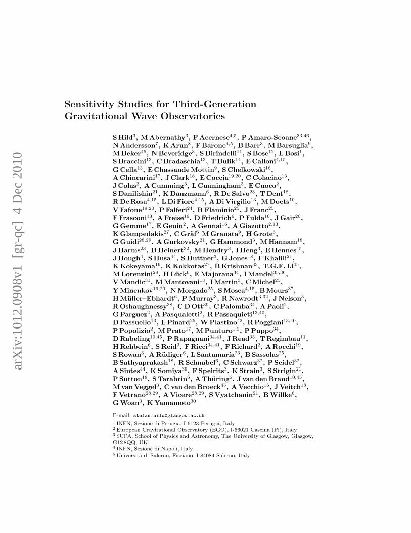
Figure 1. Seismic noise spectrum from an underground location in the BlackForest, Germany (left hand panel). Transfer function of a superattenuatorconsisting of 6 stages with an overall height of 17 m (center panel). The right handpanel shows the resulting seismic noise contribution for the 17 m superattenuatorfor the seismic excitation at the Black Forest site (green dashed line). Forcomparison also ET-B and ET-C are plotted. Their seismic noise contribution isbased on the assumption of a generic 5-stage 50 m suspension.
2. Seismic Isolation and Gravity Gradient Noise
Seismic noise couples into the differential arm length of a GW detector via two mainpaths. First of all, seismic excitation can mechanically couple through the suspensionand seismic isolation systems. Secondly, seismic noise excites density fluctuations inthe environment of the GW detector, which couple via gravitational attraction to thetest mass position. In the following we will refer to these two noise sources as seismicnoise and gravity gradient noise, respectively. The main difference between thesetwo noise sources is that while seismic noise can be reduced by application of complexseismic isolation systems, the only guaranteed way to reduce the gravity gradient noiseis to reduce the initial seismic excitation.‡ Therefore, third-generation GW detectorsare proposed to be built in quiet underground locations.
The seismic noise contribution of the low-frequency interferometer of ET-C wasbased on a seismic excitation of 5·10−9m/
√Hz/f2 (where f is the frequency in Hz) and
a generic 50 m tall seismic isolation system consisting of 5 passive pendulum stages,each of 10 m height. A more realistic seismic isolation design, based on the Virgo superattenuator concept [14], [15], has been developed recently [16]. To achieve a lower cut-off frequency the height of the individual pendulum stages of the super attenuator willbe extended to 2 m per stage. The overall isolation of the proposed modified superattenuator, consisting of 6 pendulum stages (each stage providing horizontal as wellas vertical isolation) and a total height of 17 m, is shown in the center panel of Figure1. Using the seismic excitation level, measured in an underground facility of the BlackForest Observatory (BFO) [17], [18], shown in the left panel of Figure 1, we can derivethe expected seismic noise contribution to the ET noise budget. The result is shown inthe right hand panel of Figure 1. Reducing the height of the seismic isolation system
‡ Many promising gravity gradient noise subtraction schemes have been suggested in the literature[19]. However, as none of these schemes has been demonstrated so far, we do not consider them inthis article.
Sensitivity Studies for Third-Generation Gravitational Wave Observatories 5
100
101
10−25
10−24
10−23
10−22
10−21
Frequency [Hz]
Str
ain
[1
/sq
rt(H
z)]
ET−B total noise
ET−C total noise
Gravity Gradients β=1.2
Gravity Gradients β=0.6
Gravity Gradients β=0.3
Gravity Gradients β=0.15
100
101
102
10−27
10−26
10−25
10−24
10−23
10−22
10−21
Frequency [Hz]
Str
ain
[1/s
qrt
(Hz)]
ET−C total noise
Suspension thermal noise
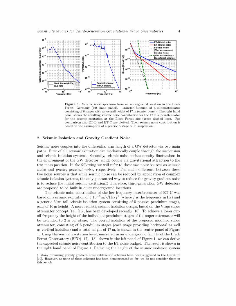
Figure 2. Left panel: Gravity gradient noise contribution to ET, for various βvalues, assuming the BFO spectrum shown in Figure 1 as seismic excitation level.Right panel: Suspension thermal noise of the low frequency interferometer of ETas described in [34]
from 50 to 17 m increases the cut-off frequency only slightly from about 1.2 to 1.7 Hz.Gravity gradient noise has been described in detail [20, 21, 22]. In our simulations
we estimate the power spectral density of the gravity gradient noise contribution as:
NGG(f)2 =4 · β2 ·G2 · ρ2
r
L2 · f4·X2
seis, (1)
where G is the gravitational constant, ρr the density of the rock around the GWdetector, L the arm length of the interferometer, f the frequency and X2
seis the powerspectral density of the ground motion. β accounts for the actual coupling transferfunction from seismic excitation to the differential arm length noise and depends forinstance on the wave type of the seismic excitation (e.g. ratio of P and S waves) andsoil characteristics.
Within the ET design study we carried out a campaign of measuring the seismicnoise in various underground locations across Europe. These measurements haveindicated that a couple of the test locations show a seismic excitation level similar to orbelow the BFO measurement [23]. Therefore, we assumed the BFO seismic excitationas a conservative estimate of a potential ET site. The left panel of Figure 2 showsthe corresponding gravity gradient noise contribution at the BFO site for differentβ. Since the detailed evaluation of a realistic β for potential ET sites is an ongoingactivity, we will use β = 0.58, as given in the literature [20, 21], in the following forthe ET-D sensitivity. Please note that our models do not take atmospheric newtoniannoise into account.
3. Shaping of Quantum Noise
Quantum noise, composed of photon shot noise at high-frequencies and photonradiation pressure noise at low frequencies, contributes significantly to the overallsensitivity of ET’s high frequency and low-frequency detectors. The high-frequencyinterferometers will feature a light power stored in the arm cavities of about 3 MW toreduce shot noise, while the low-frequency interferometers make use of only 18 kW oflight power in the arms, in order to reduce the radiation pressure noise. For ET-C the
Sensitivity Studies for Third-Generation Gravitational Wave Observatories 6
100
101
102
10−25
10−24
10−23
Frequency [Hz]
Str
ain
[1
/√H
z]
Quantum noise, ET−C LF
Quantum noise with realistic losses
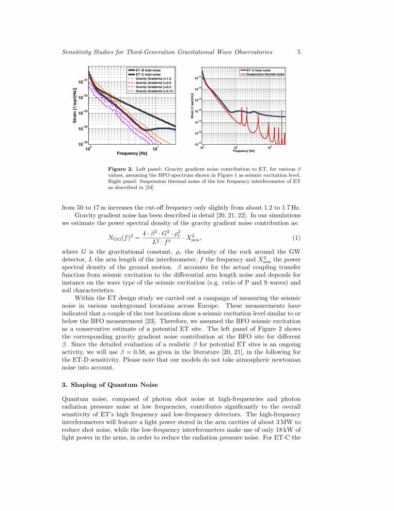
Figure 3. Left panel: Simplified schematic of an ET interferometer. Quantumnoise suppression is achieved by the injection of squeezed light states withfrequency dependent squeezing angle. The frequency dependent rotation of thesqueezing angle can be realised by using the dispersion of filter cavities, on whichthe squeezed light is reflected. Each ET low-frequency interferometer will requiretwo filter cavities, while each high-frequency interferometer only requires a singlefilter cavity. Right hand panel: Quantum noise contribution of the ET low-frequency interferometer, as described in [13] (dashed line) and with squeezinglosses from filter cavities taken into account (solid line) [27].
quantum noise contribution was optimised by making use of detuned (low-frequencyinterferometer) and tuned (high-frequency interferometer) signal recycling [24, 25],together with an assumed generic quantum noise reduction of 10 dB at all frequencies.
Such a broadband quantum noise reduction can in principle be achieved byinjecting squeezed light states with a frequency dependent squeezing angle [26] into theoutput port of the interferometer. Starting from a frequency independent squeezingangle, it is possible to use the dispersion occurring in reflection of a cavity, to createsqueezed light states with a frequency dependent squeezing angle. Figure 3 shows asimplified schematic of a dual recycled interferometer with arm cavities, consistingof a power recycling mirror (PRM), the beam splitter (BS), the arm cavity mirrors(IM and EM) and the signal recycling mirror (SRM). In addition the injection of thefrequency dependent squeezed light states is also shown: The squeezed light statesleave the squeezing source (Squeezer) and are reflected at two filter cavities beforethey are injected via a Faraday rotator into the interferometer mode. Finally, theinterferometer output mode, consisting of the squeezed field and the signal field, isdetected on the main photo diode (PD).
In general, for an interferometer with signal recycling two filter cavities arenecessary: One for compensating the dispersion of the signal recycling resonance andone to reduce radiation pressure noise. The bandwidth and detuning of the filtercavities depends on the actual optical parameters of the main interferometers (e.g.arm length, SRM reflectivity, tuning of the signal recycling cavity) and need to bematched very accurately to establish the full sensitivity improvement of the squeezed-light injection. For the ET-D high-frequency interferometer we have the special casethat only one filter cavity will be required, as it employs tuned signal recycling with abandwidth significantly larger than the cross-over frequency of radiation pressure and

Sensitivity Studies for Third-Generation Gravitational Wave Observatories 7
101
102
10−24
10−23
Frequency [Hz]
Str
ain
[1/√
Hz]
Gravity Gradients
Quantum noise: no signal recycling (1 FC)
Quantum noise: tuned signal recycling (1 FC)
Quantum noise: detuned signal recycling (2 FC)
101
102
10−25
10−24
10−23
10−22
Frequency [Hz]
Str
ain
[1/√
Hz]
Gravity Gradients
Quantum noise, 62cm mirror
Quantum noise, 52cm mirror
Quantum noise, 45cm mirror
Total mirror thermal noise, 62cm mirror
Total mirror thermal noise, 52cm mirror
Total mirror thermal noise, 45cm mirror
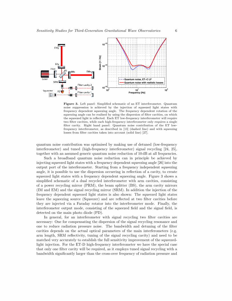
Figure 4. Left: Quantum noise contribution for a low-frequency ETinterferometer with different signal recycling options. For ET-D we assumeddetuned signal recycling with SRM reflectivity of 80 %. Also plotted are a tunedsignal recycling configuration using a 30 % reflectivity SRM and quantum noisewithout any signal recycling. In brackets the number of required filter cavities isstated. Right: Quantum noise and mirror thermal noise contributions for differentmirror diameters. The aspect ratio is kept constant for all scenarios. Reducingthe mirror size (and thus their weight) only slightly increases the mirror thermalnoise contributions, but significantly decreases the sensitivity at low frequencies,due to increased radiation pressure noise.
shot noise.The major loss mechanism for the squeezed light reflected off the filter cavities
originates from the fact that for frequencies close to the resonance of the filter cavities,the squeezed states partly enter the filter cavity and experience unavoidable roundtriplosses. We recently performed a detailed analysis of the requirements for the ET filtercavities as well as quantifying the squeezing losses inside the filter cavities [27], [28].We assumed a squeezing level of 10 dB, an antisqueezing level of 15 dB and a loss of75 ppm per roundtrip inside a filter cavity. In order to reduce the influence of theintra-cavity losses, we chose a rather long filter cavity length of 10 km, which allowsus to keep the filter cavity finesse at a moderate level. The right hand plot in Figure 3shows the corresponding quantum noise contributions of ET-D for the low frequencyinterferometer with filter cavity losses included (solid lines).
For the low frequency interferometer it is also interesting to compare differentsignal recycling options, properly accounting for the squeezing losses inside the filtercavities. The left hand plot of Figure 4 shows the ET-D configuration, employingdetuned signal recycling together with two filter cavities, in comparison to tunedsignal recycling as well as an configuration without signal recycling. Both of theselatter configurations require only a single filter cavity, but this comes at the price ofsignificantly lower sensitivity in the frequency band of interest (4–30 Hz).
4. Thermal noise contributions
Brownian fluctuations couple into the differential arm length signal as thermal noiseof the test mass itself and of its suspension. Both of these noise contributionscan be significantly reduced by lowering the temperature of the test masses andthe corresponding suspensions. The Japanese CLIO project [29] has successfullydemonstrated the operation of a laser interferometer at cryogenic temperatures. Therecently funded LCGT detector [8] is expected to transfer cryogenic technologies to a

Sensitivity Studies for Third-Generation Gravitational Wave Observatories 8
full scale second-generation GW detector.While for the ET high frequency interferometers even at room temperature the
various thermal noise contributions either do not play a significant role or can besufficiently reduced by increasing the beam size on the test masses and the use ofhigher-order Laguerre Gauss beam shapes [30] or so-called ‘Mesa’ beams [31], the ETlow-frequency interferometers are expected to operate at cryogenic temperature.
In the frequency band from 1 to 10 Hz suspension thermal noise is the dominatingthermal noise contribution. When operating the low frequency interferometer atcryogenic temperatures the last stage suspension does not only need to be compliantwith the thermal noise requirements, but the actual design is also driven by therequirement to extract any heat (deposited by the laser beams in the test masses)via the suspension. Our model [34] assumes a mirror temperature of 10 K, siliconfibres of 2 m length and 3 mm diameter as well as a temperature of the penultimatemass of 2 K. The righthand plot of Figure 2 shows the simulated suspension thermalnoise contribution for the ET low frequency detector [34] using a branched systemof multiple oscillators consisting of the main mirror, the penultimate mass and thereaction mass [32], [33].
Fused silica, which is the material of choice for the test masses of all firstgeneration GW detectors, has a high dissipation at low temperatures and thereforecannot be used as substrate material for cryogenic test masses [38], [39]. Sapphireand silicon have been proposed as alternative materials [8], [41] and there are strongR+D efforts to evaluate the optical and mechanical properties of these two candidatematerials. In the following we assume silicon as test material for ET, but sapphirewould yield similar results. A detailed noise analysis of a cryogenic test mass for ETis given in [40]. The total thermal noise of the test masses is a combination of coatingBrownian, substrate Brownian, substrate thermoeleastic and thermo-optic noise. Ofthese four contributions coating Brownian noise is the most important one because inthe frequency range of interest it is a factor of about 5 larger than any of the otherthermal noises. The power spectral density of coating brownian noise can be describedas
Sx(f) =4kBT
π2fY
d
r20
(Y ′
Yφ‖ +
Y
Y ′φ⊥
)(2)
where f is the frequency, d the total thickness of the coating, r0 describes the beamradius, Y and Y ′ are the Young’s modulus values for the substrate and coatingrespectively. φ‖ and φ⊥ are the mechanical loss values for the coating for strainsparallel and perpendicular to the coating surface [35].
Using silicon test masses (62 cm diameter, 30 cm thickness) of 10 K, a Young’smodulus of silicon of 164 GPa, loss angles of 5 × 10⁻⁵ and 2 × 10⁻⁴ for the low andhigh-refraction coating materials§, respectively, and a laser beam radius of 12 cm,we get a total mirror thermal noise contribution for the low-frequency detector asindicated by the orange dashed line in the right hand plot of Figure 4. In this scenariothe mirror thermal noise would be at least a factor of three below the quantum noisefor all frequencies. Hence, we could in principle consider reducing the beam sizeon the test masses, which could allow for the reduction of the mirror size. Smaller
§ Unfortunately the available measurements indicate higher loss angles for the coating materialsat cryogenic temperatures than at room temperature [42]. However, since research on cryogeniccoatings just started, we optimistically assumed that by the time construction of third-generationinstruments starts, coatings will be available featuring the same loss angles as current coatings atroom temperature [36, 37]
Sensitivity Studies for Third-Generation Gravitational Wave Observatories 9
100
101
102
10−25
10−24
10−23
10−22
10−21
Frequency [Hz]
Str
ain
[1/√
Hz]
Quantum noise
Seismic noise
Gravity Gradients
Suspension thermal noise
Total mirror thermal noise
Excess Gas
ET−LF: Total noise
101
102
103
104
10−25
10−24
10−23
10−22
10−21
Frequency [Hz]
Str
ain
[1/√
Hz]
Quantum noise
Seismic noise
Gravity Gradients
Suspension thermal noise
Total mirror thermal noise
Excess Gas
ET−HF: Total noise
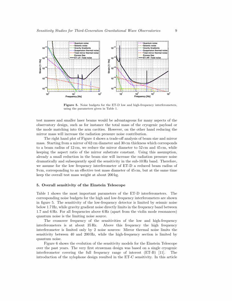
Figure 5. Noise budgets for the ET-D low and high-frequency interferometers,using the parameters given in Table 1.
test masses and smaller laser beams would be advantageous for many aspects of theobservatory design, such as for instance the total mass of the cryogenic payload orthe mode matching into the arm cavities. However, on the other hand reducing themirror mass will increase the radiation pressure noise contribution.
The right hand plot of Figure 4 shows a trade-off analysis of beam size and mirrormass. Starting from a mirror of 62 cm diameter and 30 cm thickness which correspondsto a beam radius of 12 cm, we reduce the mirror diameter to 52 cm and 45 cm, whilekeeping the aspect ratio of the mirror substrate constant. Using this assumption,already a small reduction in the beam size will increase the radiation pressure noisedramatically and subsequently spoil the sensitivity in the sub-10 Hz band. Therefore,we assume for the low frequency interferometer of ET-D a reduced beam radius of9 cm, corresponding to an effective test mass diameter of 45 cm, but at the same timekeep the overall test mass weight at about 200 kg.
5. Overall sensitivity of the Einstein Telescope
Table 1 shows the most important parameters of the ET-D interferometers. Thecorresponding noise budgets for the high and low-frequency interferometers are shownin figure 5. The sensitivity of the low-frequency detector is limited by seismic noisebelow 1.7 Hz, while gravity gradient noise directly limits in the frequency band between1.7 and 6 Hz. For all frequencies above 6 Hz (apart from the violin mode resonances)quantum noise is the limiting noise source.
The crossover frequency of the sensitivities of the low and high-frequencyinterferometers is at about 35 Hz. Above this frequency the high frequencyinterferometer is limited only by 2 noise sources: Mirror thermal noise limits thesensitivity between 40 and 200 Hz, while the high-frequency section is limited byquantum noise.
Figure 6 shows the evolution of the sensitivity models for the Einstein Telescopeover the past years. The very first strawman design was based on a single cryogenicinterferometer covering the full frequency range of interest (ET-B) [11]. Theintroduction of the xylophone design resulted in the ET-C sensitivity. In this article
Sensitivity Studies for Third-Generation Gravitational Wave Observatories 10
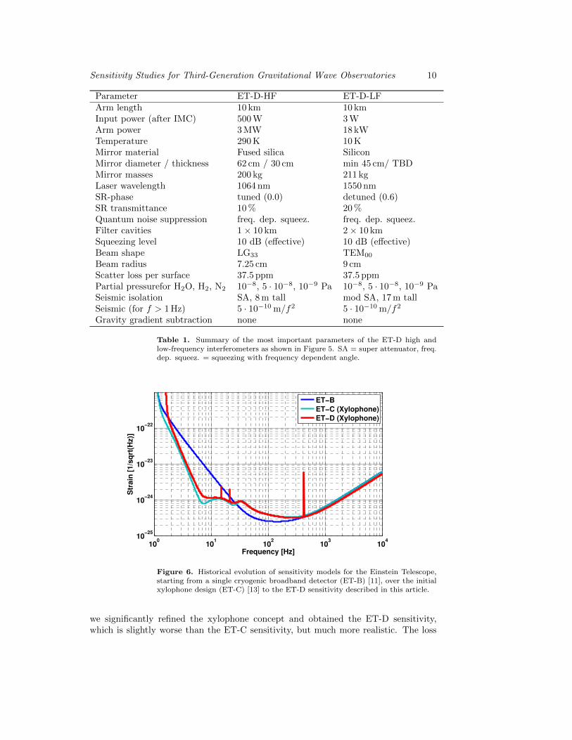
Parameter ET-D-HF ET-D-LFArm length 10 km 10 kmInput power (after IMC) 500 W 3 WArm power 3 MW 18 kWTemperature 290 K 10 KMirror material Fused silica SiliconMirror diameter / thickness 62 cm / 30 cm min 45 cm/ TBDMirror masses 200 kg 211 kgLaser wavelength 1064 nm 1550 nmSR-phase tuned (0.0) detuned (0.6)SR transmittance 10 % 20 %Quantum noise suppression freq. dep. squeez. freq. dep. squeez.Filter cavities 1× 10 km 2× 10 kmSqueezing level 10 dB (effective) 10 dB (effective)Beam shape LG33 TEM00
Beam radius 7.25 cm 9 cmScatter loss per surface 37.5 ppm 37.5 ppmPartial pressurefor H2O, H2, N2 10−8, 5 · 10−8, 10−9 Pa 10−8, 5 · 10−8, 10−9 PaSeismic isolation SA, 8 m tall mod SA, 17 m tallSeismic (for f > 1 Hz) 5 · 10−10 m/f2 5 · 10−10 m/f2
Gravity gradient subtraction none none
Table 1. Summary of the most important parameters of the ET-D high andlow-frequency interferometers as shown in Figure 5. SA = super attenuator, freq.dep. squeez. = squeezing with frequency dependent angle.
100
101
102
103
104
10−25
10−24
10−23
10−22
Frequency [Hz]
Str
ain
[1/s
qrt
(Hz)]
ET−B
ET−C (Xylophone)
ET−D (Xylophone)
Figure 6. Historical evolution of sensitivity models for the Einstein Telescope,starting from a single cryogenic broadband detector (ET-B) [11], over the initialxylophone design (ET-C) [13] to the ET-D sensitivity described in this article.
we significantly refined the xylophone concept and obtained the ET-D sensitivity,which is slightly worse than the ET-C sensitivity, but much more realistic. The loss

Sensitivity Studies for Third-Generation Gravitational Wave Observatories 11
of sensitivity below 1.7 Hz can be attributed to the application of a more realisticsuspension model yielding increased seismic noise. The slightly worse sensitivity inthe range between 2 and 8 Hz is the result of the inclusion of suspension thermalnoise for the cryogenic interferometer as well as the omission of any potential gravitygradient subtraction. The most significant difference between ET-C and ET-D showsup between 6 and 10 Hz and originates from including realistic squeezing lossesexperienced inside the filter cavities.
6. Building a Full Third-Generation Observatory
As discussed in the previous sections, one ET detector, covering the full detectionband will be made of two individual interferometers, one for low frequencies andone for high frequencies. However, the full ET observatory will consist of 3 detectorsarranged in triangular shape [43], thus ultimately 6 interferometers will form the wholeobservatory.
It needs to be pointed out that the sensitivities described in this article referto a single pair of low and high frequency interferometers of 10 km arm length andan opening angle of 90◦ (as shown in subplot A of figure 7). The actual effectivesensitivity of the full triangular ET observatory depends on the the orientation andpolarisation of the source of interest. Let us assume a source directly positioned abovethe observatory emitting GW of plus polarisation. In case of the configuration A infigure 7, the sensitivity, h(f)90, is then exactly represented by the ET-D trace infigure 6.
If we now decrease the opening angle of the two interferometers to 60◦ (seeconfiguration B in figure 7), the effective sensitivity for plus polarised GW is given by
h(f)60 =1
sin(60◦)× h(f)90 = 1.155× h(f)90, (3)
which is equivalent to shifting the ET-D curve in figure 6 up by about 15 %.Finally, if we consider the full triangle for a plus polarised source, we find that the
blue and red detectors in configuration C of figure 7 have the same sensitivity, whileno signal shows up in the green detector. If we combine the red and blue detectors,the noise of the two needs to be added in quadrature because it is uncorrelated, whilethe coherent signals need to be added up linearly. Thus the overall sensitivity of thefull triangular observatory can be written as
h(f)∆ =1√
(sin(60◦))2 + (sin(60◦))2× h(f)90 = 0.816× h(f)90, (4)
which would be equivalent to shifting the ET-D curve in figure 6 down by about 18 %.Subplot D of figure 7 shows a schematic drawing of the full ET observatory
configuration assumed for the ET-D sensitivity. Included are all main mirrors of the6 interferometers, as well as a total of 9 required filter cavities for the frequencydependent squeezing. In total this sums up to 7 laser beams per tunnel.
7. Summary and Future Plans
In this article we described a snapshot of the ongoing sensitivity studies for a Europeanthird-generation GW observatory. The ET-D sensitivity represents a much morerealistic sensitivity compared to previous models, because we included new noise

Sensitivity Studies for Third-Generation Gravitational Wave Observatories 12
Out
In
Out
In
Out
In
Out
In
Out
In
Out
InRed-LF
Red-HF Blu
-HF
Grn-LF
Blu-LF
Grn-HF
10km10km
10km
Einstein Telescope
Xylophone option
(ET-C and ET-D)
10
km
10km
10km
AA
B
C
D
90 deg90 deg90 deg
60 deg
Figure 7. Different interferometer configurations considered in this article.All sensitivities shown in this paper refer to a pair of low and high-frequencyinterferometers forming a single detector of 10 km arm length and an openingangle of 90◦. However, the full ET observatory will consist of 3 detectors with60◦ opening angle and arranged in the shape of a triangle. Solid lines representthe main laser beams, while dashed lines indicate squeezed light beams.
sources as well as improved the accuracy of several already previously includedfundamental noise sources. Key points of the new sensitivity model are the inclusion ofsuspension thermal noise and a realistic seismic isolation system for the low frequencyinterferometer and the proper accounting for squeezing losses inside the filter cavities.Finally it needs to be pointed out that the current model does not rely on anysubtraction techniques for gravity gradient noise.
In the future, we plan to further refine our sensitivity models by including noisecontributions from optical components outside the arm and filter cavities as well as bytaking technical contributions such as laser frequency and laser amplitude noise intoaccount.
Acknowledgments
The ET-D sensitivity data are available at http://www.et-gw.eu/etsensitivities.The authors are grateful for support from their hosting institutions and nationalfunding agencies. This work has been performed with the support of the EuropeanCommission under the Framework Programme 7 (FP7) ‘Capacities’, project EinsteinTelescope (ET) design study (Grant Agreement 211743) (http://www.et-gw.eu/)
References
[1] B.P. Abbott et al, 2009 Rep. Prog. Phys. 72 076901
Sensitivity Studies for Third-Generation Gravitational Wave Observatories 13
[2] F. Acernese et al, CQG 25 (2008) 114045.[3] H. Grote for the LSC, CQG 25 (2008) 114043.[4] Takahashi R (the TAMA Collaboration) 2004 Status of TAMA300 CQG 21 S403–8.[5] G.M. Harry (for the LIGO Scientific Collaboration) 2010 Class. Quantum Grav. 27 084006[6] wwwcascina.virgo.infn.it/advirgo/
[7] B. Willke et al, CQG 23 (2006) S207–S214.[8] K. Kuroda (the LCGT Collaboration ) CQG 23 (2006) S215-S221[9] M. Punturo et al, CQG 27 (2010) 084007[10] http://www.et-gw.eu/
[11] S. Hild et al, arXiv:0810.0604v2 [gr-qc] (2008)[12] A. Freise et al, General Relativity and Gravitation, 2010, 108-+[13] S. Hild et al, CQG 27 (2010) 015003[14] G. Ballardin et al Review of Scientific Instruments 72 (2001) 3643-3652[15] S. Braccini et al Astropart. Phys. 23 (2005) 55765[16] S. Braccini, presentation at GWADW 2010, Kyoto. Available at:
http://gw.icrr.u-tokyo.ac.jp/gwadw2010/program/2010 GWADW Braccini.ppt
[17] http://www.gik.uni-karlsruhe.de/en/bfo.html
[18] personal commuication T. Forbriger, Black Forest Observatory (BFO) Schiltach[19] M. Beker et al, General Relativity and Gravitation, Springer Netherlands, 2010, 1-34[20] P.R. Saulson, Phys. Rev. D, 30 (1984) 732-736[21] M. Beccaria et al CQG 15 (1998) 3339-3362[22] S.A. Hughes and K.S. Thorne, Phys. Rev. D 58 (1998) 122002[23] M. Beker, presentation at GWADW 2010, Kyoto. Available at:
http://gw.icrr.u-tokyo.ac.jp/gwadw2010/program/2010 GWADW Beker.pdf
[24] B.J. Meers, Phys. Rev. D, 38 (1988) 2317-2326[25] S. Hild et al, CQG 24 (2007) 1513-1523.[26] H.J. Kimble et al.: Phys. Rev. D 65(2002) 022002[27] A. Thuring: ’Filtercavities for GWADS’, ET-0104A-10 (2010), available at
https://tds.ego-gw.it/itf/tds/index.php
[28] A. Thuring et al.: ’Filter cavities for advanced Gravitational Wave Detectors and theirtechnical requirements’, in preparation.
[29] S. Miyoki et al.: Journal of Physics: Conference Series, 203, (2010) 012075[30] S. Chelkowski et al. Physical Review D 79, (2009), 122002[31] J. Miller et al Classical and Quantum Gravity, (2008), 25, 235016[32] P. Puppo, Journal of Physics: Conference Series 228, (2010) 012031[33] P. Puppo and F. Ricci, General Relativity and Gravitation, Springer Netherlands, 2010, 1-13[34] F. Ricci, presentation at GWADW 2010, Kyoto. Available at:
http://gw.icrr.u-tokyo.ac.jp/gwadw2010/program/2010 GWADW Ricci.pdf
[35] G.M. Harry et al Classical and Quantum Gravity 19 (2002).[36] G.M. Harry et al, Appl. Opt. 45 (2006) 1569–1574[37] G.M. Harry et al, CQG 24 (2007) 405-415[38] O.L. Anderson and H.E. Bommel, Journal of the American Ceramic Society, 38 (1955),
125–131.[39] J. Wiedersich et al, PRL 84 (2000) 2718–2721.[40] J. Franc et al, ET-021-09 (2009), available at https://tds.ego-gw.it/itf/tds/index.php
[41] S. Rowan, et al In: Proceedings of SPIE, vol. 4856 (2003)[42] I. Martin et al, CQG 25 (2008) 055005[43] A. Freise et al, CQG 26 (2009) 085012 (14pp)
Copyright © 2022 FDOKUMEN