Senior Design Report for ECE 477 – Spring 2006 - CiteSeerX
63
Senior Design Report for ECE 477 – Spring 2006 submitted by Prof. David G. Meyer May 10, 2006 School of Electrical & Computer Engineering
-
Upload
khangminh22 -
Category
Documents
-
view
0 -
download
0
Transcript of Senior Design Report for ECE 477 – Spring 2006 - CiteSeerX

Senior Design Report for
ECE 477 – Spring 2006
submitted by Prof. David G. Meyer
May 10, 2006
School of Electrical & Computer Engineering
Senior Design Report ECE 477 – Spring 2006
-ii-
Contents
Overview ……………………………………………………………………………………… 1
Self-Evaluation ……………………………………………………………………………….. 1
Course Policies and Procedures ………………………………………………………………. 3
Grade Determination ………………………………………………………………………….. 4
Lecture Schedule ……………………………………………………………………………… 5
Design Project Specifications ………………………………………………………………… 6
Milestones …………………………………………………………………………………….. 8
Outcome Assessment …………………………………………………………………………. 9
Appendix A: Senior Design Reports
Appendix B: Proposed Evaluation Form
Appendix C: ECE Course Assessment Report
Appendix D: FIE 2005 Paper on Capstone Design Outcome Assessment
Appendix E: Course Calendar
Senior Design Report ECE 477 – Spring 2006
-1-
Overview One of the unique features of ECE 477, Digital Systems Senior Design Project, is that each team gets to choose their own specific project (subject to some general constraints) and define specific success criteria germane to that project. In general, this approach to senior design provides students with a sense of project ownership as well as heightened motivation to achieve functionality. All project teams this semester successfully designed and built a printed circuit board, achieved at least basic functionality of their microcontroller-based hardware, and successfully integrated their application software. Some groups, in fact, continued to work on their projects after the semester was over, to add features and/or obtain a higher degree of functionality. In short, students not only devoted a lot of time to this course, but they also learned a lot. The complete set of Senior Design Reports is included as Appendix A. Self-Evaluation A number of changes were made Fall 2005 in an attempt to address various issues noted during previous offerings. These included the following:
The lecture schedule was “accelerated”, in order to cover key material in time for students to use it in their designs. Three lectures were held each week during the first half of the semester; during the second half of the semester, lecture meetings were conducted once every other week (mainly for coordination and general information).
An “early” notebook evaluation was added, in addition to the midterm and final evaluations. Progressive weights of 2, 3, and 5 were used in the grade determination. The goal of adding this early evaluation was to help students get started earlier on their lab notebooks, and to give them a better idea of how it would ultimately be evaluated (the final evaluation was used to determine success of the associated outcome demonstration).
The “OrCAD” homework (in which all students were required to be involved with a circuit design/PCB layout exercise in order to familiarize themselves with the CAD tools we use) was replaced with a “PCB footprint/parts acquisition” homework. This allowed the homework schedule to be moved up a week, which allowed the midterm design review to not only address schematic design issue, but PCB layout issues as well (previously, due to scheduling, it was only possible to get through schematic design prior to the midterm design review). The goal here was to provide more “eyes” (and time) to catch/correct PCB layout errors, thus improving the finished PCB success rate.
A template and style sheet for the on-line lab notebooks was provided, making it significantly easier for each team member to get “up and running” with their lab notebooks (and getting them in an acceptable format).
For the Spring 2006 offering, the changes instituted Fall 2005 were carried over, with a very significant additional change: a two-hour “Technical Communication Skills Practicum” (TCSP) session was conducted nearly every week, in place of the “third lecture” each week (see Course Calendar, Appendix E). In addition to providing a means of “accelerating” lecture coverage early on in the semester, more significantly it provided an opportunity for students to develop their technical presentation skills. A number of these sessions were devoted to “mini-presentations” by each team on the current report due (e.g., reliability and safety analysis, software design considerations, etc.). Not only did this forum give team members an opportunity to “practice” different portions of what would ultimately become their final presentation, but it also gave the course staff (as well as fellow students) an opportunity to provide constructive,
Senior Design Report ECE 477 – Spring 2006
-2-
formative feedback on different portions of the design project. This “experimental addition” to the course has been formally approved for inclusion in future offerings of ECE 477, with an increase in credit hours awarded from three to four (effective Fall 2006). Another significant change made was to shift the formal final presentations from “dead week” to finals week, and use the last class meetings for “mini-presentations” of each team’s project success criteria demonstration videos. This gave the course staff (and fellow students) an opportunity to “preview” the demonstration clips and offer suggestions for improvement. It also gave the entire class an opportunity to see first hand the success achieved by each team. This change positively impacted the quality of the final (archived video) presentations, which are posted on the course web site. A key aspect of the course that did not go well this semester, however, was our ability to motivate the non-contributors who had enrolled in the course, exacerbated by an enrollment capacity overload (note: 56 students do not fit in a 1000 square foot lab space simultaneously). The course staff estimated that we had, on average, approximately one “slacker” per team. Some cases were so egregious that we were forced to take the extraordinary action of failing three students, and awarding a grade of D to another. Several rather marginal lab notebooks could have earned failing grades for up to three or four additional students. Thankfully, the ECE Curriculum Committee has finally approved Prof. Meyer’s request (originally made Fall 2004) to add “consent of instructor” as a condition for enrollment, effective Fall 2006. The next report will document the impact of this change. With the next ABET visit looming large on the horizon, there are some issues common to senior design in ECE at Purdue that need to be addressed. First, among the three senior design options currently available, there appears to be little uniformity in: (a) outcome assessment methodology, (b) course grade determination, (c) design project deliverables, and (d) course evaluation instruments. An astute ABET visitor is likely to discover this and hold us accountable. It would be far better for us to acknowledge the problem, and take steps to mitigate the disparity that exists. A good “first step” might be to review the outcome assessment methodology described in Appendix D (“Capstone Design Outcome Assessment: Instruments for Quantitative Evaluation”) and try to determine a consensus approach that could be uniformly applied to all ECE senior design options. Another important step would be to develop and immediately begin using a “universal senior design evaluation form” (see Appendix B for the sample we have been using in ECE 477 the past few semesters). Adoption of web-based course evaluation has made possible the use of “customized” forms based on the type of course and personnel evaluated. Finally, the ECE Administration is encouraged to remain cognizant of the fact that ECE 477 is not a “standard 3-credit hour” load – the amount of evaluation and consultation required is several times that of a “normal” course. It is important not only to have two faculty involved, but also to provide at least 1.0 FTE T.A. as well.

Senior Design Report ECE 477 – Spring 2006
-3-
Course Policies and Procedures Course Description: A structured approach to the development and integration of embedded microcontroller hardware and software that provides senior-level students with significant design experience applying microcontrollers to a wide range of embedded systems (e.g., instrumentation, process control, telecommunication, intelligent devices, etc.). Objective: To provide practical experience developing integrated hardware and software for an embedded microcontroller system in an environment that models one which students will most likely encounter in industry. Instructors: Prof. D. G. Meyer, [email protected], Office: MSEE 238, Phone: 494-3476; and Prof. Mark Johnson, [email protected], Office: EE 268, Phone: 494-0636. Course Teaching Assistants: Brain Moerdyk ([email protected]) and Nick Schnettler ([email protected]). Course web site: http://shay.ecn.purdue.edu/~dsml/ece477 Course E-mail address: [email protected] Office Hours: Scheduled office hours will be posted on the course web site; other times may be arranged by E-mail appointment. Please make use of the “live” consultation hours available rather than E-mailing “long” or detailed questions specific to your project. Open Shop Lab: Room EE 067 is the laboratory for this course; students enrolled in ECE 477 will be given a key code that will provide them with 24-hour access. This facility is equipped with expensive, state-of-the-art instrumentation; students are expected to treat the equipment and furnishings with respect. There will be a “zero tolerance” policy for abuse/misuse of this lab: anyone who does so will be unceremoniously dropped from the course, receive a failing grade, and be prohibited from re-registering for the course. Theft will be prosecuted. Design Project: Of utmost importance in the "real world" is the ability to document and present technical information in a clear, organized, succinct, and well-illustrated fashion. In microprocessor-based designs, the ability to integrate hardware and software is a fundamental skill that should be possessed by all Computer Engineering graduates. The design project, formal written report, and videotaped presentation will give each student in this course the opportunity to develop these skills. Students will work on their design in teams of four. Lab Notebook: Developing good design documentation skills is an important part of this course. A significant part of your grade (10%) will be based on the individual lab notebook you maintain throughout the design and development process. Class Meetings: Scheduled class meetings are Tuesdays, 10:30-11:20 AM (EE 117); Wednesdays, 8:30-10:20 AM (WTHR 160); and Thursdays, 10:30-11:20 AM (EE 117). Attendance at all class meetings is required.

Senior Design Report ECE 477 – Spring 2006
-4-
Group Account and Team Webpage: Each team will be assigned an ECN group account to use as a repository for all their project documentation and for hosting a password-protected team web page. The team web page should contain datasheets for all components utilized, the schematic, board layout, software listings, interim reports, presentation slides, etc. It should also contain the individual lab notebooks for each team member as well as the progress reports (prepared in advance of the weekly progress briefings) for each team member. At the end of the semester, each team must submit a CD-ROM archive of the group account. Homework: Several “homeworks” will be assigned related to key stages of the design project. Some of the assignments will be completed as a team (1, 2, 7, 13, 15, 16, 17), two will be completed individually (8 and 14), and some will be completed by a selected team member (one from the set {4, 5, 6, 11} and one from the set {3, 9, 10, 12}).
1. Team Building and Project Idea 2. Project Proposal 3. Design Constraint Analysis and Component Selection Rationale 4. Packaging Specifications and Design 5. Schematic and Hardware Design Narrative/Theory of Operation 6. Board Layout and Narrative 7. PCB Submission and Parts Acquisition/Fit 8. Midterm Peer Review 9. Patent Liability Analysis 10. Software Design Narrative, Documentation, and Source Listing 11. Reliability and Safety Analysis 12. Social/Political/Environmental Analysis 13. User Manual 14. Confidential Peer Review 15. Senior Design Report 16. Final Report & Archive CD 17. Poster
Grade Determination Your course grade will be based on both team effort (50%) and individual contributions (50%):
TEAM COMPONENTS INDIVIDUAL COMPONENTS Design Review 10% Significance of Individual Contribution 10%Final Video Presentation 10% Lab Notebook Evals (2%, 3%, and 5%) 10%Final Report & Archive CD {16} 10% Design Component {4, 5, 6, or 11} 10%Project Success Criteria Satisfaction 5% Professional Component {3, 9, 10, or 12} 10%System Integration and Packaging 5% PCB Submission and Proof-of-Parts {7} 4% User Manual {12} 3% Presentation Peer Review {DR + FP} 2% Senior Design Report {15} 3% Confidential Peer Reviews {8 & 14 } 2% Poster {17} 4% Class Participation / Attendance 2%
Your Raw Weighted Percentage (RWP) will be calculated based on the weights, above, and then "curved" (i.e., mean-shifted) with respect to the upper percentile of the class to obtain a Normalized Weighted Percentage (NWP). Equal-width cutoffs will then be applied based on the Windowed Standard Deviation (WSD) of the raw class scores; the minimum Cutoff Width Factor (CWF) used will be 10 (i.e., the nominal cutoffs for A-B-C-D will be 90-80-70-60, respectively). Before final grades are assigned, the course instructor will carefully examine all "borderline" cases (i.e., NWP within 0.5% of cutoff). Once grades are assigned, they are FINAL and WILL NOT be changed. Note that all course outcomes must be demonstrated in order to receive a passing grade for the course.
These assignments are due on the prescribed due dates (typically Fridays) at NOON. The following penalties will be applied for work submitted late: 10% if submitted no more
than 24 hours late 20% if submitted no more
than 48 hours late 30% if submitted no more
than 72 hours late 100% if submitted any
later
These assignments are all due on Monday, May 1, at 5:00 PM. A penalty of 10% per day late will be assessed on these items through 5:00 PM on Thursday, May 4, after which time they will no longer be accepted.
Senior Design Report ECE 477 – Spring 2006
-5-
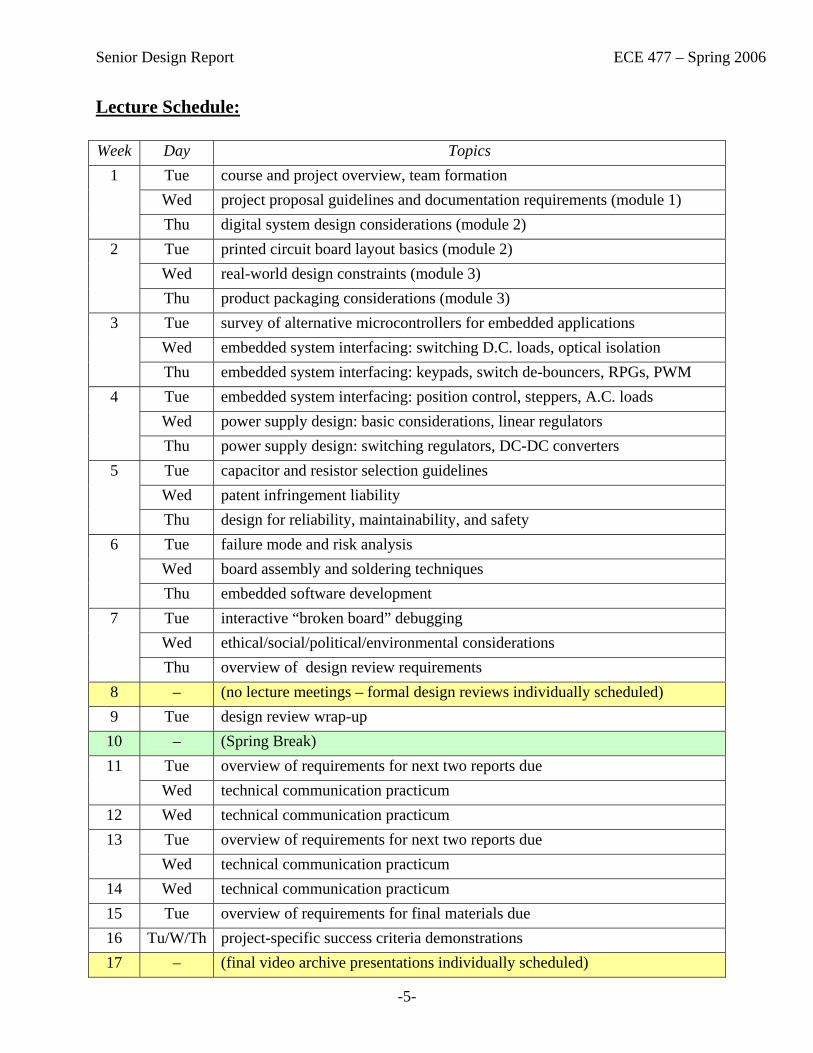
Lecture Schedule:
Week Day Topics Tue course and project overview, team formation Wed project proposal guidelines and documentation requirements (module 1)
1
Thu digital system design considerations (module 2) Tue printed circuit board layout basics (module 2) Wed real-world design constraints (module 3)
2
Thu product packaging considerations (module 3) Tue survey of alternative microcontrollers for embedded applications Wed embedded system interfacing: switching D.C. loads, optical isolation
3
Thu embedded system interfacing: keypads, switch de-bouncers, RPGs, PWM Tue embedded system interfacing: position control, steppers, A.C. loads Wed power supply design: basic considerations, linear regulators
4
Thu power supply design: switching regulators, DC-DC converters Tue capacitor and resistor selection guidelines Wed patent infringement liability
5
Thu design for reliability, maintainability, and safety Tue failure mode and risk analysis Wed board assembly and soldering techniques
6
Thu embedded software development Tue interactive “broken board” debugging Wed ethical/social/political/environmental considerations
7
Thu overview of design review requirements 8 – (no lecture meetings – formal design reviews individually scheduled) 9 Tue design review wrap-up 10 – (Spring Break)
Tue overview of requirements for next two reports due 11 Wed technical communication practicum
12 Wed technical communication practicum Tue overview of requirements for next two reports due 13 Wed technical communication practicum
14 Wed technical communication practicum 15 Tue overview of requirements for final materials due 16 Tu/W/Th project-specific success criteria demonstrations 17 – (final video archive presentations individually scheduled)
Senior Design Report ECE 477 – Spring 2006
-6-
Design Project Specifications Work on the design project is to be completed in teams of four students. The design project topic is flexible, and each group is encouraged to pick a product that uses the strengths and interest areas of their group members. The design must have the following components:
• Microprocessor: To help make the project tractable, microprocessor choices will be limited to 68HC12, PIC, Rabbit, and Atmel variants. Development tools are readily available in lab to support these devices. Further, the devices themselves are relatively low cost and readily available.
• Interface to Something: Your embedded system must interface to some other device or devices. It could be a computer, or it could be some embedded device such as a Palm Pilot, telephone line, TV, etc. Some interface standards that could be used are: serial to a computer, parallel to a computer, Universal Serial Bus (USB), Firewire, Ethernet, Infrared (IR), Radio Frequency (RF), etc. This requirement has a large amount of freedom. To help with some of the more complex interfaces such as Ethernet, USB, or Firewire there are dedicated chips which encapsulate the lowest layers of the interface. This makes using these interfaces easier to handle but not necessarily trivial. Be sure to investigate the interface(s) you wish to utilize and make a reasonable choice. (NOTE: Interfaces involving A.C. line current require special permission – see the instructor for details.)
• Custom printed circuit board: Through the process of the design, each group will be required to draw a detailed schematic. From the schematic, a two-layer (maximum) printed circuit board will be created. Board etching will be processed by the ECE Department (the first one is “free”, but any subsequent iterations are the team’s responsibility). The team is then responsible for populating the board (solder the parts on the board), and for completing the final stages of debugging and testing on their custom board.
• Be of personal interest to at least one team member: It is very difficult to devote the time and energy required to successfully complete a major design project in which you and/or your team members have no personal interest. There are lots of possibilities, ranging from toys and games to “useful and socially redeeming” household items, like audio signal processors and security systems.
• Be tractable: You should have a “basic idea” of how to implement your project, and the relative hardware/software complexity involved. For example, you should not design an “internet appliance” if you have no idea how TCP/IP works. Also, plan to use parts that are reasonably priced, have reasonable footprints, and are readily available. Be cognizant of the prototyping limitations associated with surface mount components.
• Be neatly packaged: The finished project should be packaged in a reasonably neat, physical sound, environmentally safe fashion. Complete specification and CAD layout of the packaging represents one of the project design components.
• Not involve a significant amount of “physical” construction: The primary objective of the project is to learn more about digital system design, not mechanical engineering! Therefore, most of the design work for this project should involve digital hardware and software.

Senior Design Report ECE 477 – Spring 2006
-7-
Project Proposal Each group should submit a proposal outlining their design project idea. This proposal should not be wordy or lengthy. It should include your design objectives, design/functionality overview, and project success criteria. The five success criteria common to all projects include the following:
• Create a bill of materials and order/sample all parts needed for the design • Develop a complete, accurate, readable schematic of the design • Complete a layout and etch a printed circuit board • Populate and debug the design on a custom printed circuit board • Package the finished product and demonstrate its functionality
In addition to the success criteria listed above, a set of five significant project-specific success criteria should be specified. The degree to which these success criteria are achieved will constitute one component of your team’s grade.
Forms for the preliminary and final versions of your team’s project proposal are available on the course web site. Use these skeleton files to create your own proposal. Note that the proposal should also include assignment of each team member to one of the design components as well as to one of the professional components of the project.
Design Review Part way through the design process, there will be a formal design review. This is a critical part of the design process. In industry, this phase of the design process can often make or break your project. A good design review is one where a design is actively discussed and engineers present concur with the current or amended design. The design review is in some cases the last chance to catch errors before the design is frozen, boards are etched, and hardware is purchased. A friend is not someone who rubber-stamps a design, but rather one who actively challenges the design to confirm the design is correct.
Approach the design review from a top-down, bottom-up perspective. First, present a block diagram of your design and explain the functional units. Then drop to the bottom level and explain your design at a schematic level. Be prepared to justify every piece of the design; a perfectly valid answer, however, is applying the recommended circuit from an application note. If you do use a circuit from an application note, have the documentation on hand and be able to produce it. Your grade for the design review will not be based on the number of errors identified in your design. The best engineers make mistakes, and the purpose of the design review is to catch them rather than spend hours of debugging later to find them. The design review will be graded primarily on how well the group understands their design and the professionalism with which they present it.
To facilitate the design review process, the class will be split into subgroups that will meet at individually scheduled times. Both the presenters and the assigned reviewers will be evaluated.
Senior Design Report ECE 477 – Spring 2006
-8-
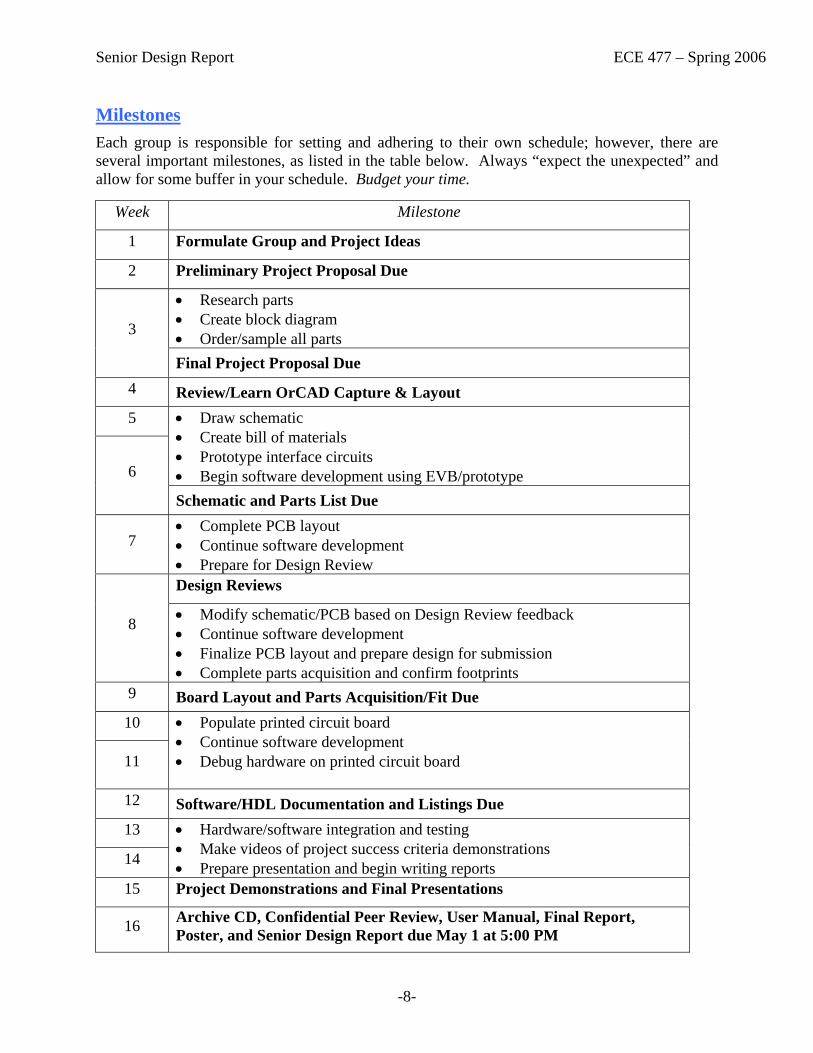
Milestones Each group is responsible for setting and adhering to their own schedule; however, there are several important milestones, as listed in the table below. Always “expect the unexpected” and allow for some buffer in your schedule. Budget your time.
Week Milestone
1 Formulate Group and Project Ideas
2 Preliminary Project Proposal Due
• Research parts • Create block diagram • Order/sample all parts 3
Final Project Proposal Due 4 Review/Learn OrCAD Capture & Layout 5 • Draw schematic
• Create bill of materials • Prototype interface circuits • Begin software development using EVB/prototype 6
Schematic and Parts List Due
7 • Complete PCB layout • Continue software development • Prepare for Design Review Design Reviews
8 • Modify schematic/PCB based on Design Review feedback • Continue software development • Finalize PCB layout and prepare design for submission • Complete parts acquisition and confirm footprints
9 Board Layout and Parts Acquisition/Fit Due 10
11
• Populate printed circuit board • Continue software development • Debug hardware on printed circuit board
12 Software/HDL Documentation and Listings Due 13
14
• Hardware/software integration and testing • Make videos of project success criteria demonstrations • Prepare presentation and begin writing reports
15 Project Demonstrations and Final Presentations
16 Archive CD, Confidential Peer Review, User Manual, Final Report, Poster, and Senior Design Report due May 1 at 5:00 PM
Senior Design Report ECE 477 – Spring 2006
-9-
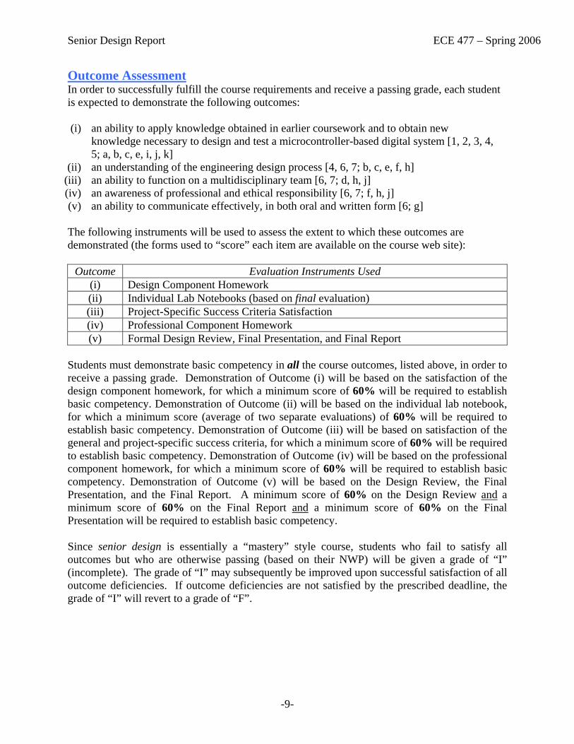
Outcome Assessment In order to successfully fulfill the course requirements and receive a passing grade, each student is expected to demonstrate the following outcomes: (i) an ability to apply knowledge obtained in earlier coursework and to obtain new
knowledge necessary to design and test a microcontroller-based digital system [1, 2, 3, 4, 5; a, b, c, e, i, j, k]
(ii) an understanding of the engineering design process [4, 6, 7; b, c, e, f, h] (iii) an ability to function on a multidisciplinary team [6, 7; d, h, j] (iv) an awareness of professional and ethical responsibility [6, 7; f, h, j] (v) an ability to communicate effectively, in both oral and written form [6; g] The following instruments will be used to assess the extent to which these outcomes are demonstrated (the forms used to “score” each item are available on the course web site):
Outcome Evaluation Instruments Used (i) Design Component Homework (ii) Individual Lab Notebooks (based on final evaluation) (iii) Project-Specific Success Criteria Satisfaction (iv) Professional Component Homework (v) Formal Design Review, Final Presentation, and Final Report
Students must demonstrate basic competency in all the course outcomes, listed above, in order to receive a passing grade. Demonstration of Outcome (i) will be based on the satisfaction of the design component homework, for which a minimum score of 60% will be required to establish basic competency. Demonstration of Outcome (ii) will be based on the individual lab notebook, for which a minimum score (average of two separate evaluations) of 60% will be required to establish basic competency. Demonstration of Outcome (iii) will be based on satisfaction of the general and project-specific success criteria, for which a minimum score of 60% will be required to establish basic competency. Demonstration of Outcome (iv) will be based on the professional component homework, for which a minimum score of 60% will be required to establish basic competency. Demonstration of Outcome (v) will be based on the Design Review, the Final Presentation, and the Final Report. A minimum score of 60% on the Design Review and a minimum score of 60% on the Final Report and a minimum score of 60% on the Final Presentation will be required to establish basic competency. Since senior design is essentially a “mastery” style course, students who fail to satisfy all outcomes but who are otherwise passing (based on their NWP) will be given a grade of “I” (incomplete). The grade of “I” may subsequently be improved upon successful satisfaction of all outcome deficiencies. If outcome deficiencies are not satisfied by the prescribed deadline, the grade of “I” will revert to a grade of “F”.

Senior Design Report ECE 477 – Spring 2006
Appendix A:
Senior Design Reports
Senior Design Report ECE 477 – Spring 2006
A-1
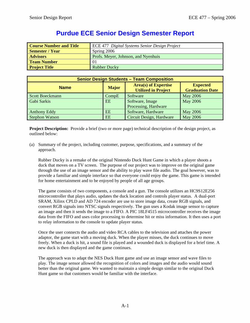
Purdue ECE Senior Design Semester Report Course Number and Title ECE 477 Digital Systems Senior Design Project Semester / Year Spring 2006 Advisors Profs. Meyer, Johnson, and Nyenhuis Team Number 01 Project Title Rubber Ducky
Senior Design Students – Team Composition
Name Major Area(s) of Expertise Utilized in Project
Expected Graduation Date
Scott Boeckmann CompE Software May 2006 Gabi Sarkis EE Software, Image
Processing, Hardware May 2006
Anthony Eddy EE Software, Hardware May 2006 Stephon Watson EE Circuit Design, Hardware May 2006 Project Description: Provide a brief (two or more page) technical description of the design project, as outlined below: (a) Summary of the project, including customer, purpose, specifications, and a summary of the
approach.
Rubber Ducky is a remake of the original Nintendo Duck Hunt Game in which a player shoots a duck that moves on a TV screen. The purpose of our project was to improve on the original game through the use of an image sensor and the ability to play wave file audio. The goal however, was to provide a familiar and simple interface so that everyone could enjoy the game. This game is intended for home entertainment and to be enjoyed by people of all age groups. The game consists of two components, a console and a gun. The console utilizes an HC9S12E256 microcontroller that plays audio, updates the duck location and controls player status. A dual-port SRAM, Xilinx CPLD and AD 724 encoder are use to store image data, create RGB signals, and convert RGB signals into NTSC signals respectively. The gun uses a Kodak image sensor to capture an image and then it sends the image to a FIFO. A PIC 18LF4515 microcontroller receives the image data from the FIFO and uses color processing to determine hit or miss information. It then uses a port to relay information to the console to update player status. Once the user connects the audio and video RCA cables to the television and attaches the power adaptor, the game start with a moving duck. When the player misses, the duck continues to move freely. When a duck is hit, a sound file is played and a wounded duck is displayed for a brief time. A new duck is then displayed and the game continues. The approach was to adapt the NES Duck Hunt game and use an image sensor and wave files to play. The image sensor allowed the recognition of colors and images and the audio would sound better than the original game. We wanted to maintain a simple design similar to the original Duck Hunt game so that customers would be familiar with the interface.

Senior Design Report ECE 477 – Spring 2006
A-2
(b) Description of how the project built upon the knowledge and skills acquired in earlier ECE coursework.
Due to the highly digital nature of the project, Rubber Ducky required skills from a multitude of previous ECE coursework. The console and gun microcontrollers were programmed in C and assembly so the knowledge gained in ECE 264 and ECE 362 was instrumental is this aspect. The experience from ECE 270 was important in programming the CPLD because it was done using ABEL code. The skills attained in ECE 201, ECE 202, ECE 207 and ECE 208 were very important in designing the layout of the PCB and component selection.
(c) Description of what new technical knowledge and skills, if any, were acquired in doing the project.
Technical Skill acquired: 1. Working with pre-existing materials – This skill includes the ability to use data sheets to
determine product specifications and requirements, interface code with pre-existing API’s, and adapting circuit designs to suit the specific project’s needs.
2. Circuit design and fabrication – A major component of the project included creating a circuit design that would implement the desired functionality of the project and then building the design on a PCB board.
3. Software Design – Due to the nature of microcontrollers, software design becomes a major concern. In many cases a micro might have limited space and processing power. As such, the software design must account for such limitations when implementing the project.
4. Teamwork – Working with a team requires the ability to layout project guidelines that focus individual members towards a common goal while maintaining there individual work preferences. Team work also requires each member to be accountable for their specific work such as to not delay other members of the team.
5. Time Management – With such a large scale project that requires such a great amount of time to complete, time managements became a large issue, especially with school work from other classes. As such, placing viable goals and meeting these checkpoints becomes vital to the success of the project.
(d) Description of how the engineering design process was incorporated into the project. Reference
must be made to the following fundamental steps of the design process: establishment of objectives and criteria, analysis, synthesis, construction, testing, and evaluation.
Before work was begun, a proposal was created for our project and the team chose five Project Specific Success Criteria: 1. Ability to display NTSC video game images 2. Ability to capture and screen shot using an image sensor. 3. Ability to detect a target in image data. 4. Ability to generate and audio signal. 5. Ability to run the “Duck Hunt” game and display player status. After this, work began on designing the project and all of its components. This included the project schematic, PCB layout, packaging, software code and other such components. With the design of the project completed, construction could begin. Each PCB board was populated with the desired pieces, software was written to perform the desired tasks and programmed into each microcontroller, and external devices were connected to the boards. After each piece was in place, testing of the board commenced. To do this, small components of the project were tested to ensure functionality. Afterwards, large pieces could be tested to ensure each individual component correctly interfaced with the others. At any point, if a failure occurred then the specific component would be further

Senior Design Report ECE 477 – Spring 2006
A-3
tested to determine the error, then adjusted to fix the problem. Once the project was completed, the success of each PSSC previously defined for the project was demonstrated.
(e) Summary of how realistic design constraints were incorporated into the project (consideration of
most of the following is required: economic, environmental, ethical, health & safety, social, political, sustainability, and manufacturability constraints). When designing our product, we took into account various design constraints. Our main concern was to provide a low power product and for the gun PCB to fit into a Nintendo Zapper casing. Economic concerns were not factored into our design because we wanted good hardware with which to test our product. Now that the product works, lower cost parts can be substituted into the design with minimal rework. When considering environmental impact we chose parts with low power consumption to prevent energy waste. Our product is safe because the wires are all covered and it has warnings to prevent improper usage. The idea of using a person or another animal as a target was discarded to prevent ethical concerns. A duck was found to be socially acceptable to shoot. We tested our product extensively to ensure sustainability and it has sturdy enclosures for both the gun and console to prevent damage from dropping.
(f) Description of the multidisciplinary nature of the project.
Our product uses different aspects of Electrical and Computer Engineering. The layout of the PCB and selection of components is a circuit design learned in electrical engineering. The color processing is another aspect of electrical engineering utilized in our project. The C and assembly software as well as HDL programming are computer engineering skills that were also used in our design. The design and assembly of the packaging required basic mechanical knowledge to properly fit all components into a small design. Finally, our product required much research into patents and liability issues as well as the skills necessary to sell our product. The technical skills are demonstrated in the actual product while the professional skills and research can be found through homework assignments.
(g) Description of project deliverables.
1. Main Console Box: This part includes the main console circuit board encased within a plastic
shell. Its purpose is to a) display the game images on the screen, b) play audio signals when appropriate, and c) control the game code.
2. Handheld gun / Image Sensor: This part of the project contains the image sensor used to detect
hits for the game. The gun is encased within an old Nintendo Zapper unit.
Senior Design Report ECE 477 – Spring 2006
A-4
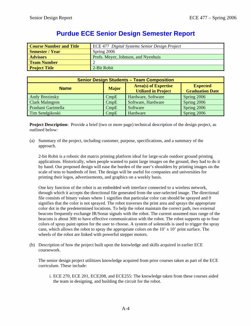
Purdue ECE Senior Design Semester Report Course Number and Title ECE 477 Digital Systems Senior Design Project Semester / Year Spring 2006 Advisors Profs. Meyer, Johnson, and Nyenhuis Team Number 2 Project Title 2-Bit Robit
Senior Design Students – Team Composition
Name Major Area(s) of Expertise Utilized in Project
Expected Graduation Date
Andy Brezinsky CmpE Hardware, Software Spring 2006 Clark Malmgren CmpE Software, Hardware Spring 2006 Prashant Garimella CmpE Software Spring 2006 Tim Sendgikoski CmpE Hardware Spring 2006 Project Description: Provide a brief (two or more page) technical description of the design project, as outlined below: (a) Summary of the project, including customer, purpose, specifications, and a summary of the
approach. 2-bit Robit is a robotic dot matrix printing platform ideal for large-scale outdoor ground printing applications. Historically, when people wanted to paint large images on the ground, they had to do it by hand. Our proposed design will ease the burden of the user’s shoulders by printing images on the scale of tens to hundreds of feet. The design will be useful for companies and universities for printing their logos, advertisements, and graphics on a weekly basis. One key function of the robot is an embedded web interface connected to a wireless network, through which it accepts the directional file generated from the user-selected image. The directional file consists of binary values where 1 signifies that particular color can should be sprayed and 0 signifies that the color is not sprayed. The robot traverses the print area and sprays the appropriate color dot in the predetermined locations. To help the robot maintain the correct path, two external beacons frequently exchange IR/Sonar signals with the robot. The current assumed max range of the beacons is about 30ft to have effective communication with the robot. The robot supports up to four colors of spray paint option for the user to choose. A system of solenoids is used to trigger the spray cans, which allows the robot to spray the appropriate colors on the 10’ x 10’ print surface. The wheels of the robot are linked with powerful stepper motors.
(b) Description of how the project built upon the knowledge and skills acquired in earlier ECE coursework.
The senior design project utilitizes knowledge acquired from prior courses taken as part of the ECE curriculum. These include:
i. ECE 270, ECE 201, ECE208, and ECE255: The knowledge taken from these courses aided
the team in designing, and building the circuit for the robot.
Senior Design Report ECE 477 – Spring 2006
A-5
ii. ECE 362: Microcontroller modules such as SPI, TIM, PWM, and embedded web server or embedded Ethernet were used in the project, as well embedded system design and programming in Assembly language.
iii. ECE264, ECE368: Programming skills acquired from ECE264 and ECE368 were used to
write image processing algorithms in C language for preparing the direction file for the robot. Most of code for programming the microcontroller, beacon system, motors was written in C using the Code Warrior software.
iv. ECE438: Some of the knowledge acquired from this course helped in writing the image
processing algorithms. (c) Description of what new technical knowledge and skills, if any, were acquired in doing the project.
While working on the project, we gained the experience of working with PCB and schematic software. Prior to taking this course, the design team had very minimal experience of working with this software. While populating the board, we learned more about soldering techniques to solder our components onto the printed circuit board. Use of the Code Warrior software for programming the microcontroller was another skill acquired during the project. The team faced mechanical challenges that we had to overcome while building the robot, such as insufficient torque from our stepper motors for the accurate motion of the robot. Solving these problems refined our experience in troubleshooting mechanical related tasks. Through the various technical writing assignments, we have gained much confidence in our technical writing skills.
(d) Description of how the engineering design process was incorporated into the project. Reference
must be made to the following fundamental steps of the design process: establishment of objectives and criteria, analysis, synthesis, construction, testing, and evaluation. After deciding the project idea, we established the five success criteria for our project. We discussed the different ways of implementing our design. While working on the initial assignments, we determined the various components that would go with our design. Soon, we began to prototype some of our components on the breadboards to test their functionality individually. Before populating the board, we made sure that we acquired all the necessary parts and components. After assembling all our hardware on the board, we began writing the software and simultaneously testing the individual components. The last weeks in the semester were spent on integrating all the parts together and testing the design before final demonstration.
(e) Summary of how realistic design constraints were incorporated into the project (consideration of
most of the following is required: economic, environmental, ethical, health & safety, social, political, sustainability, and manufacturability constraints).
While designing our prototype for commercial purposes, several realistic design constraints were uncovered. From an economic standpoint, we tried to minimize the cost of product through careful designing and effective manufacturing process. Since our design required spray cans, we made sure that the types of spray cans used were non-aerosol, non-permanent, water friendly that can cause minimal damage to the user and the environment. Our product needs to used in open environment rather than closed to avoid inhaling the emissions from the spray cans during the spray painting process. There has also been certain software routines implemented to ensure that robot doesn’t harm the user by accidentally stepping over its foot, or waste his resources by continuously spray painting outside the paint area. Special instructions were issued in user manual by the design team to ensure no damage to the product itself. These instructions included, to avoid running motors for extensive

Senior Design Report ECE 477 – Spring 2006
A-6
periods of time and cleaning the robot after printing. We also performed patent liability analysis to avoid infringement on any other patent.
(f) Description of the multidisciplinary nature of the project.
Designing the motor system, driving the chains for moving the robot, spraying the dot through the solenoids, and several other aspects of our design involved heavy mechanical engineering knowledge which our team had acquired after completion of the project. In addition to this, extensive knowledge of analog circuit design and embedded programming skills from prior courses helped the team to accomplish the goals of our project. We also utilized significant image processing algorithms.
(g) Description of project deliverables.
The project deliverables include the robot system and the two beacons. Also included are a user manual which contains all the important instructions for the user to ensure the robustness, reliability, and sustainability of our product.
Senior Design Report ECE 477 – Spring 2006
A-7
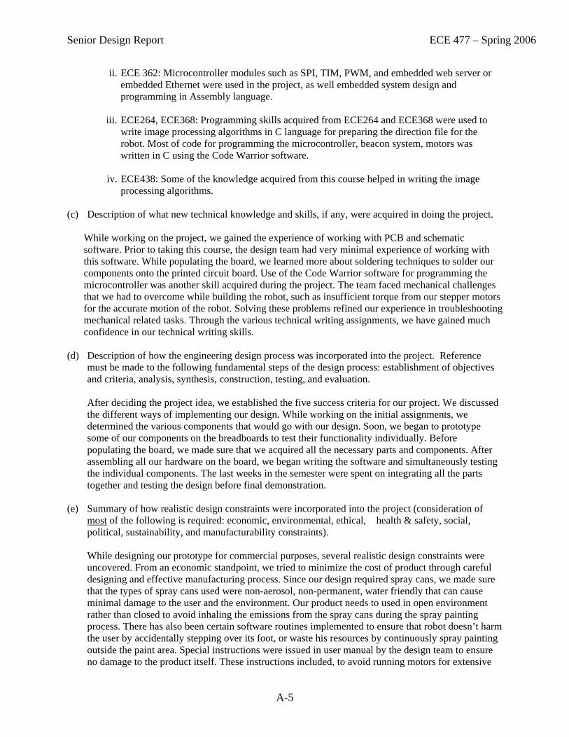
Purdue ECE Senior Design Semester Report Course Number and Title ECE 477 Digital Systems Senior Design Project Semester / Year Spring 2006 Advisors Profs. Meyer, Johnson, and Nyenhuis Team Number 3 Project Title iReader
Senior Design Students – Team Composition
Name Major Area(s) of Expertise Utilized in Project
Expected Graduation Date
Mat King EE PCB/Schematic, Analog May 2006 Thomas Higdon EE PCB/Schematic, Analog May 2006 Jeremy Tryba CmpE Software, Debugging May 2006 Daniel Wilhelm CmpE Software, Prototyping May 2006 Project Description: Provide a brief (two or more page) technical description of the design project, as outlined below: (a) Summary of the project, including customer, purpose, specifications, and a summary of the
approach.
The iReader is a portable digital text file reader intended for use by the average consumer who reads books or text documents. By inserting a USB thumbdrive containing text files, a user can conveniently read its contents on a graphical monochrome LCD. The iReader also features a Li-Ion battery, rechargeable through an AC adapter port, and a battery fuel gauge. The iReader utilizes two PCBs, the Display Unit (DU) and the External Interface Unit (EIU), designed so that only the DU must be redesigned to support a new display technology.
(b) Description of how the project built upon the knowledge and skills acquired in earlier ECE coursework.
This project utilized many skills learned in prior coursework, particularly ECE 270 and ECE 362. Buttons were debounced in software. Timing diagrams were used to correctly output pulses from microcontrollers. Data sheets were utilized to determine correct conditions for circuit debugging and design. The use of Freescale’s microcontrollers was continued, allowing us to use familiar peripherals and tools. Experience from mini-projects and lab work enabled faster prototyping and debugging. State machines were used extensively in the code for both microcontrollers.
(c) Description of what new technical knowledge and skills, if any, were acquired in doing the project.
New knowledge and skills were learned by developing the iReader. First, selecting viable components and interfacing them was newly learned for this project in addition to schematic design and PCB layout. Writing software for new microprocessors enhanced pre-existing knowledge of their differences and operation. New debugging techniques were discovered for when development boards were not available. Experience was also gained debugging analog and digital circuits by deriving expected voltage and current values from datasheets and analyzing damage after wiring mistakes.

Senior Design Report ECE 477 – Spring 2006
A-8
(d) Description of how the engineering design process was incorporated into the project. Reference must be made to the following fundamental steps of the design process: establishment of objectives and criteria, analysis, synthesis, construction, testing, and evaluation.
First, the project success criteria were designed, providing concrete project functionality goals. Second, components were analyzed for inclusion to meet functionality goals given portability and power constraints. Third, the schematic and PCB were designed. Some portions of the circuitry such as the LCD controller were prototyped. Fourth, the PCBs were populated, tested, and debugged. Software was authored for the microcontrollers to test each component. Finally, demonstrations were designed to display the functionality of every success criterion.
(e) Summary of how realistic design constraints were incorporated into the project (consideration of most of the following is required: economic, environmental, ethical, health & safety, social, political, sustainability, and manufacturability constraints).
Cost of the project was a central concern, requiring us to adopt an LCD display technology rather than a more power-efficient bistable display due to its economic benefits. Safety considerations were important as well – the most potentially harmful failures were determined and solutions were proposed. The product’s lifespan was also determined, noting what a user must do to sustain proper operation upon failure. For manufacturability, two PCBs were designed such that only one had to be remanufactured for a new display technology. To satisfy social and political constraints, a patent search was performed identifying patented portions of the project then recommendations were made to alleviate conflicts.
(f) Description of the multidisciplinary nature of the project.
This project emphasized skills requiring knowledge of electrical engineering (EE), computer engineering (CmpE), formal communications, and technical writing. The two EE team members focused on schematic design, PCB layout, and analog circuitry. The CmpE team members focused on software, prototyping, and circuit debugging. Everyone received experience in communications and technical writing.
(g) Description of project deliverables.
A portable, two-sectioned hinged device was developed which resembles a book. When open, the left side features an LCD display and the DU PCB. The right side houses a USB port, an AC adapter port, the EIU PCB, a rechargeable Li-Ion battery, and five buttons – Up, Down, Menu, Cancel, and Reset. When a USB thumbdrive is inserted into the USB port and the battery is charged, the device will allow a user to read text files stored on the thumbdrive. When an AC adapter is connected to the AC adapter port, the device will automatically charge the Li-Ion battery.
Senior Design Report ECE 477 – Spring 2006
A-9
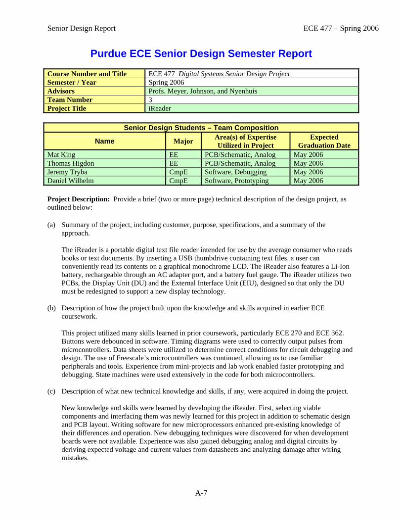
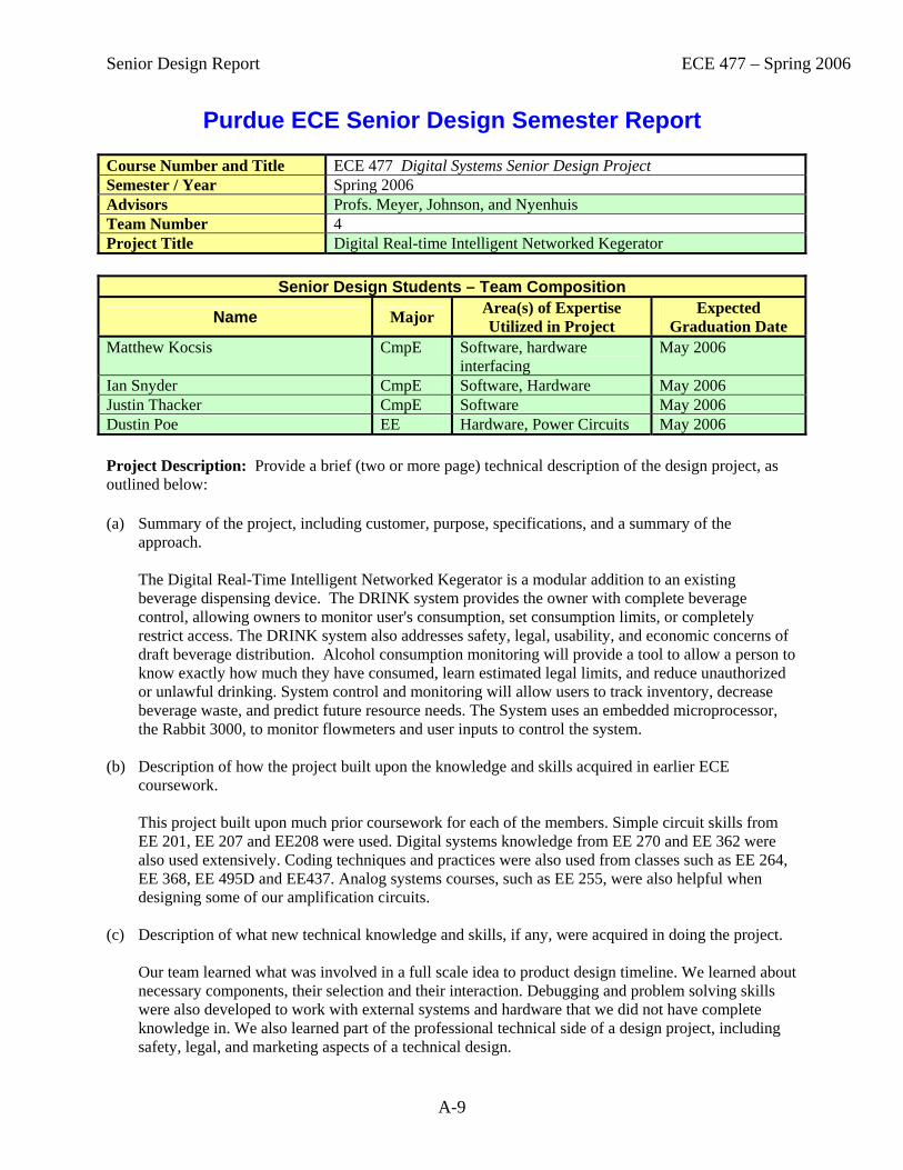
Purdue ECE Senior Design Semester Report Course Number and Title ECE 477 Digital Systems Senior Design Project Semester / Year Spring 2006 Advisors Profs. Meyer, Johnson, and Nyenhuis Team Number 4 Project Title Digital Real-time Intelligent Networked Kegerator
Senior Design Students – Team Composition
Name Major Area(s) of Expertise Utilized in Project
Expected Graduation Date
Matthew Kocsis CmpE Software, hardware interfacing
May 2006
Ian Snyder CmpE Software, Hardware May 2006 Justin Thacker CmpE Software May 2006 Dustin Poe EE Hardware, Power Circuits May 2006 Project Description: Provide a brief (two or more page) technical description of the design project, as outlined below: (a) Summary of the project, including customer, purpose, specifications, and a summary of the
approach.
The Digital Real-Time Intelligent Networked Kegerator is a modular addition to an existing beverage dispensing device. The DRINK system provides the owner with complete beverage control, allowing owners to monitor user's consumption, set consumption limits, or completely restrict access. The DRINK system also addresses safety, legal, usability, and economic concerns of draft beverage distribution. Alcohol consumption monitoring will provide a tool to allow a person to know exactly how much they have consumed, learn estimated legal limits, and reduce unauthorized or unlawful drinking. System control and monitoring will allow users to track inventory, decrease beverage waste, and predict future resource needs. The System uses an embedded microprocessor, the Rabbit 3000, to monitor flowmeters and user inputs to control the system.
(b) Description of how the project built upon the knowledge and skills acquired in earlier ECE coursework.
This project built upon much prior coursework for each of the members. Simple circuit skills from EE 201, EE 207 and EE208 were used. Digital systems knowledge from EE 270 and EE 362 were also used extensively. Coding techniques and practices were also used from classes such as EE 264, EE 368, EE 495D and EE437. Analog systems courses, such as EE 255, were also helpful when designing some of our amplification circuits.
(c) Description of what new technical knowledge and skills, if any, were acquired in doing the project.
Our team learned what was involved in a full scale idea to product design timeline. We learned about necessary components, their selection and their interaction. Debugging and problem solving skills were also developed to work with external systems and hardware that we did not have complete knowledge in. We also learned part of the professional technical side of a design project, including safety, legal, and marketing aspects of a technical design.

Senior Design Report ECE 477 – Spring 2006
A-10
(d) Description of how the engineering design process was incorporated into the project. Reference must be made to the following fundamental steps of the design process: establishment of objectives and criteria, analysis, synthesis, construction, testing, and evaluation.
During the design of this project, our team went through the entire engineering design process at many different levels. For each aspect of the project, for example the enclosure construction or the power supply design, we started by reviewing what the purpose of the specific component (or overall design) was. Once that was clear, we found products and assessed which of them would do a better job. Much of these assessments are included in our detailed design documentation. Once we received the necessary components, we put them together and made sure that they functioned as expected. Then we developed rigorous tests to make sure that the functionality of the component was consistent over time. After finishing a functional component, we then assessed if the component actually fit the need it was designed for. If at any stage during this process parts did not work or the result was not what was required, we stepped back in the design process and started moving forward with another solution.
(e) Summary of how realistic design constraints were incorporated into the project (consideration of
most of the following is required: economic, environmental, ethical, health & safety, social, political, sustainability, and manufacturability constraints).
Since this project was designed to actually be used by one of the team members, there were many realistic design constraints. The inclusion of alcohol in the design also stemmed some major legal and safety considerations. First, our design had to be completely functional and built, which set manufacturability and sustainability constraints. Ethical, health and safety constraints were also set because when used improperly, our product could be involved in loss of human life or severe legal ramifications. We designed our project in ways that prevent unauthorized access to alcoholic beverages, and we built in several methods for verifying user identity beyond simple tags. The addition of biometric identification further strengthened the security of the design.
(f) Description of the multidisciplinary nature of the project.
This project not only used electrical and computer engineering techniques, but it also required knowledge of fluid mechanics, marketing, metalwork, and psychology. Given the nature of monitoring and controlling liquid, knowledge of how fluids work and are controlled was crucial to the first steps of the design. Incorrect metering or control devices could render the device inaccurate or unusable. In order to build the entire system, we had to develop skills in metalwork and industrial design. We learned about properties of metals, how to cut, bend, and mill them, and how to protect the surface after construction. Psychology was also very important to this project. In order for it to be usable, thought was given to the way users would approach and attempt to use the system. Care was taken so that important controls were obvious and easy to use. Marketing was also considered during the initial design of the project when we picked features we wanted to implement. We researched other projects and designed our system to have features that would be most beneficial to the end users.
(g) Description of project deliverables.
Our project is completely built into a large chest freezer. Mounted on top of the freezer is a hinged metal enclosure housing most of the designed components and all wiring. On the front, a bill validator, an LCD, a biometric reader, and a knob is mounted in addition to 4 draft faucets. Opening the hinged cover on the back reveals all of the PCBs, the wiring, and the beverage tubing. Opening the chest freezer provides access to the kegs, tubing, and flowmeter / solenoid units.

Senior Design Report ECE 477 – Spring 2006
A-11
Purdue ECE Senior Design Semester Report Course Number and Title ECE 477 Digital Systems Senior Design Project Semester / Year Spring 2006 Advisors Profs. Meyer, Johnson, and Nyenhuis Team Number 5 Project Title D.E.A.Th.
Senior Design Students – Team Composition
Name Major Area(s) of Expertise Utilized in Project
Expected Graduation Date
David Jones CmpE Software Spring 2006 James Doty CmpE Software Spring 2006 Philip Smith EE Hardware Spring 2006 Brian Sutton CmpE Software Spring 2006 Project Description: (a) Summary of the project, including customer, purpose, specifications, and a summary of the
approach.
D.E.A.Th. is an autonomous tank designed to traverse a pre-defined path of GPS coordinates while providing feedback wirelessly to a host PC. The vehicle uses Ethernet to connect to a wireless router which allows for control of its peripherals from a remote location. These peripherals include the ability to aim and fire a cannon or to simply drive the tank manually. The waypoints to be traversed are initially passed over wireless to the device along with a command to start traversing the path. At this point the tank uses GPS and SONAR to navigate the path and avoid obstacles that block the desired path. This design provides an ideal device for law enforcement or military applications where an environment is too hostile or dangerous for humans to inspect or control.
(b) Description of how the project built upon the knowledge and skills acquired in earlier ECE
coursework.
This course was a culmination of the knowledge gained from our undergraduate studies. ECE 270 provided the foundation for digital design fundamentals while courses like ECE 362 gave us the necessary microcontroller programming skills to complete this project successfully. ECE 201 and 202 along with 255 were essential for the circuit design of the project and were invaluable for hardware debug. Having the ability to build a simple level shift circuit was essential to the design because of the multiple rails used to supply power to the devices. These skills developed in our ECE career made this project possible.
(c) Description of what new technical knowledge and skills, if any, were acquired in doing the project.
Many new technical skills were acquired through the course of this semester. Major devotion and time went into learning OrCAD Capture and Layout software. Many PCB layout considerations and design practices were learned and utilized in the design. These skills had not before been developed and, though difficult to learn, were incredibly important for the completion of the project. Various protocols were learned through peripheral interfacing such as the SiRF II Binary Protocol used for communicating with the GPS device. The ability to debug physical circuits, solder devices, and efficiently package the necessary components was gained in the completion of this course.
Senior Design Report ECE 477 – Spring 2006
A-12
(d) Description of how the engineering design process was incorporated into the project. Reference must be made to the following fundamental steps of the design process: establishment of objectives and criteria, analysis, synthesis, construction, testing, and evaluation.
Initially the project idea was formulated by our team based on our strengths and individual skill sets. Once the initial idea was decided upon further analysis was done to determine the various facets of the project. Ultimately success criteria were formulated for the evaluation of the final product. To begin work on the project, research was done on each individual component to make the right choices for the design. This included selecting the GPS module to be used along with various calculations to determine appropriate H-Bridges for the motor control. The most important component selection was the microcontroller. This device had to be chosen so that it would fit all of the projects requirements and provide the necessary computational power to handle guidance calculations. Once all of the necessary components were chosen the circuits were designed and implemented on PCB. The PCB was carefully designed and eventually populated. Each component of the PCB was tested to ensure that software could be successfully developed and tested. Ultimately the project was assembled in a manner that allowed for careful evaluation of the various components of the device.
(e) Summary of how realistic design constraints were incorporated into the project (consideration of
most of the following is required: economic, environmental, ethical, health & safety, social, political, sustainability, and manufacturability constraints).
This project faced many realistic design issues that would be seen in an industrial project. Care was taken to ensure that the various batter supplies would function in a safe manner and allow for easy handling. Many steps were taken to reduce the cost of the design. It would have been wonderful to spend more money on the project to provide more advanced features; however, this was impractical and inappropriate for the design given that cheaper alternatives existed that would make the completion of the project possible. Items inside the vehicle were carefully placed and mounted to ensure that it would be able to sustain physical stress over timer as well as to provide a space efficient and user-friendly look.
(f) Description of the multidisciplinary nature of the project.
This project required utilization of many disciplines of study. The project required mechanical engineering in regards to mounting the various peripherals to the body of the tank as well as the internal components such as the PBC. The circuits and hardware design relied heavily upon our electrical engineering background. All the while the software side of the project could not have been done without a relatively specialized computer science background which included assembly language programming and general embedded software design.
(g) Description of project deliverables.
This project is being delivered completely packaged with all of the necessary components to function except for a host PC. It will need a PC with wireless capabilities. It comes with a user manual and footage showing the completion of the project success criteria. As well all of the necessary reports along with the final presentation poster are being delivered.

Senior Design Report ECE 477 – Spring 2006
A-13
Purdue ECE Senior Design Semester Report Course Number and Title ECE 477 Digital Systems Senior Design Project Semester / Year Spring 2006 Advisors Profs. Meyer, Johnson, and Nyenhuis Team Number 6 Project Title The Soviet Challenge
Senior Design Students – Team Composition
Name Major Area(s) of Expertise Utilized in Project
Expected Graduation Date
Joseph Davidson CmpE Network programming, Hardware Implementing
May 2006
Kyle McGhee CmpE Software Design Graphics Implementing
May 2006
Allan Patterson CmpE PCB layout, Network programming
May 2006
Greg Snow CmpE Software Implementing, Graphics Implementing
May 2006
Project Description: Provide a brief (two or more page) technical description of the design project, as outlined below: (a) Summary of the project, including customer, purpose, specifications, and a summary of the
approach.
The Soviet Challenge is a handheld device, with 802.11 wireless capabilities. The primary purpose of this device is to run the client software associated with the game TetriNET, which is a multiplayer variation of Tetris, as well as classic Tetris. The target audience would be any Tetris or TetriNET enthusiasts who would like to be able to play these games in a handheld fashion. The TetriNET protocol is specified by the creators of the game, and the Soviet Challenge has to be able to perform TCP/IP communication with a specified server in order to send and receive updates to the game boards (one added feature of TetriNET is item usage, which allows a player to alter his own and his opponents game boards). Our approach was to investigate the existing TetriNET software, estimate the microcontroller needs for such a game, including wireless capabilities, and then to create a design of the device.
(b) Description of how the project built upon the knowledge and skills acquired in earlier ECE
coursework.
Two of the primary programming requirements of the Soviet Challenge were graphics display for the game boards, and wireless communications with a TetriNET server. These two skills relied heavily on the background our team received from ECE495E (Fundamentals of Computer Graphics) and ECE463 (Introduction To Computer Communication Networks), respectively. In addition, the microcontroller programming and operation utilized our background in ECE362 (Microprocessor Systems And Interfacing), and the data structures used in our code utilized our ECE368 (Data Structures) and ECE264 (Advanced C Programming) knowledge. Our use of a PLD and interpretation of device datasheets utilized our skills obtained in ECE270 (Introduction To Digital System Design), while our circuit design skills utilized our background from ECE255 (Introduction To Electronic Analysis And Design) and ECE208 (Electronic Devices And Design Laboratory).

Senior Design Report ECE 477 – Spring 2006
A-14
(c) Description of what new technical knowledge and skills, if any, were acquired in doing the project.
In designing the project, we learned quite a bit about communicating via a CompactFlash device, as well as using different communication protocols (RS-232, Centronix 8-bit parallel, Dallas’ 1-wire interface) for transmitting data between various components in our design. In addition, we learned how to use Orcad Layout to layout a printed circuit board (PCB). Also, we learned how to use CodeVision AVR and WinAVR development environments for targeting C code to an Atmel microcontroller. Finally, we learned about rechargeable Lithium-Ion batteries, and about designing a recharging circuit for monitoring charge stored inside these batteries.
(d) Description of how the engineering design process was incorporated into the project. Reference
must be made to the following fundamental steps of the design process: establishment of objectives and criteria, analysis, synthesis, construction, testing, and evaluation.
Our initial design of the Soviet Challenge required us to determine the necessary components for creating our device, as well as determining a set of obtainable parts that would all work together, as there were some issues with sourcing the initial graphics driver chip we desired. We broke the design down into several functional blocks: the battery circuit, the voltage regulator circuit, the recharging circuit, the graphics display interface, the wireless communication interface, the main microcontroller and oscillator circuit, the external button interface, and the reprogramming interface. Next, we were required to design these functional blocks so that they would all work together easily. For our purposes, we chose to run our design at 3.3V, as we were able to obtain all of the parts necessary for the device at a reasonably affordable rate at this level, with the exception of the battery recharger, which is designed to run at any voltage up to 21V. These circuits were all placed into a schematic, and then laid out on a PCB, which was sent to be fabricated. After obtaining our PCB, we ensured that the board was free from any manufacturing defects, and then proceeded to begin building the device, starting with the battery recharging and voltage regulating circuits. We began by first breadboarding these circuits to verify the proper operation that we specified, and then running them over a period of at least 12 hours on the PCB itself, and running the battery through multiple charge/discharge cycles. In this process, we were able to program the fuel cell chip, required for one of our project outcomes. Next, we added the remaining functional blocks, and worked on interfacing them with the microcontroller through some test code. Once we had the graphics display tested and the wireless card working, we were more or less ready to begin the process of porting Tetris and TetriNET to the microcontroller. One of our teammates worked on making a highly portable version of these games while we were testing the various function blocks of the device. In addition, another teammate developed a frontend menu system for us to navigate between the various functions of the device, including server settings, battery monitoring, game themes, and the games themselves. Next we assembled the button interface for the device, using a PLD as a set of multiplexers to reduce the number of pins required, and using various buttons from video game consoles, as they were specifically designed for a similar purpose to our own. After this, we made the necessary buttonholes for the device, and ran through several different prototypes for the buttons before developing a design which would properly trigger as we desired. Lastly, we ran some final tests on the code to ensure that it worked properly with our buttons and communicated correctly with a wireless router. Once we were satisfied that we had found any errors and worked to correct them, we closed up the device, and ensured proper operation. Finally, we all agreed that there were some tradeoffs we had made that we would have probably done differently, if we were to tackle the problem again knowing what we do now.
(e) Summary of how realistic design constraints were incorporated into the project (consideration of
most of the following is required: economic, environmental, ethical, health & safety, social, political, sustainability, and manufacturability constraints).

Senior Design Report ECE 477 – Spring 2006
A-15
In designing the Soviet Challenge, we sought to make it as affordable as we could, and the only place where we feel we could do better was in the graphics display. Due to the time constraints of the project, we were unable to source a more affordable screen and graphics driver, although our final choice was still considerably more affordable than some of the remaining alternatives, while still providing us with a reasonable resolution of 240 by 160 pixels, with 256 colors. In the environmental design of our project, we sought to obtain parts that were RoHS compliant, to reduce the quantities of hazardous chemicals present in the project. In addition, we used rechargeable Lithium-Ion batteries with a long lifespan and a well defined disposal method in our device in order to reduce the environmental hazard of disposed batteries. In terms of ethical impacts of our device, TetriNET is a freeware project, so we are merely attempting to help the TetriNET community by providing a new platform for them to play their game on. In terms of health and safety, we designed the Soviet Challenge so that the failure critical components in the device were backed up by a second component in the design, including a protection circuit attached to the batteries themselves. Additionally, we performed a Failure Mode, Effects, and Criticality Analysis (FMECA) on the Soviet Challenge, and confirmed these results. The TetriNET game itself is fairly nonviolent, and can be used to help with spatial recognition and puzzle solving skills, and is not meant to be politically motivated in any way – the name Soviet Challenge is merely a reference to the packaging for the Spectrum HoloByte release of the original Tetris game, being a product of a Russian programmer from the 1980s named Alexey Pazhitnov. In our maintainability analysis of the device, we determined that at the operating ranges of the devices we are using, the failure rates are low enough that the game should work for at least 7 years of continuous operation and usage, which is far longer than the playable lifespan of most video games in today’s society. Finally, our manufacturability analysis of the Soviet Challenge determined that all of the parts used in our design were readily obtainable in larger quantities, and as such, could be used in a larger scale production run of the device.
(f) Description of the multidisciplinary nature of the project.
Our project touches on three disciplines: primarily, electrical and computer engineering, but also mechanical engineering. The design of our circuitry was primarily an electrical engineering problem, while the operation and programming was mostly a computer engineering problem. The final aspect of the project; the case of the device, and the buttons used to control the device were a mechanical problem through and through, and as might be expected, lead to some of the larger final implementation headaches, requiring several complete redesigns to yield a satisfactory result.
(g) Description of project deliverables.
The final deliverables for our project are the handheld Soviet Challenge device, as well as a 14.4V DC wall wart used to power the battery charger. Additionally, the CompactFlash wireless card used for the device is removable, and could be packaged separately in order to reduce the final cost of the device, if desired.
Senior Design Report ECE 477 – Spring 2006
A-16
Purdue ECE Senior Design Semester Report Course Number and Title ECE 477 Digital Systems Senior Design Project Semester / Year Spring 2006 Advisors Profs. Meyer, Johnson, and Nyenhuis Team Number 7 Project Title Mouse Glove
Senior Design Students – Team Composition
Name Major Area(s) of Expertise Utilized in Project
Expected Graduation Date
Matteo Mannino EE Hardware Dec. 2006 Saad Sami CmpE Software May 2006 Andy Homar CmpE Software May 2006 Brian Eng CmpE Software May 2006 Project Description: Provide a brief (two or more page) technical description of the design project, as outlined below: (a) Summary of the project, including customer, purpose, specifications, and a summary of the
approach.
A present day computer mouse is limited to hard surfaces for accurate movement and control. This makes it difficult to properly operate a computer in situations that do not provide a hard surface for the user, such as when giving presentations, or operating a laptop in a rough environment. The goal of our project is to replace the current computer mouse interface with a control glove. The glove controls the movement of the mouse pointer with simple movements of the hand and wrist. Mouse buttons, scroller, and sensitivity are implemented with pressure and bend sensors on the fingers. The entire system includes two stations; a base station connected through a USB interface to a computer running Windows OS, and a battery powered mobile station connected to the control glove. Communication between the two stations is done through RF transmitters/receivers.
(b) Description of how the project built upon the knowledge and skills acquired in earlier ECE
coursework. Basic skills developed in ECE201 and ECE202 were required for circuit design and basic linear filter design. Skills developed in ECE301, ECE302, and ECE438 were applied in analyzing the accelerometer signals, methods of quantifying the signal, and proper sampling the signal. ECE255 was helpful for understanding how the level translator worked, which allowed us to find a method to pull up the output of the translator to a more desirable level. ECE362 was helpful for understanding the basic modules of our microcontrollers such as the ATD module and basic interrupt routines. ECE264 and ECE437 were useful for programming in the C language and understanding the basic routines of both controllers.
(c) Description of what new technical knowledge and skills, if any, were acquired in doing the project. Knowledge and skills were gained in how the USB module works and how it interfaces with a personal computer, power supply design for low-power battery driven applications, theory on how batteries operate, how pressure and bend sensor materials works, PCB design, constraint analysis, and reliability analysis.
Senior Design Report ECE 477 – Spring 2006
A-17
(d) Description of how the engineering design process was incorporated into the project. Reference must be made to the following fundamental steps of the design process: establishment of objectives and criteria, analysis, synthesis, construction, testing, and evaluation.
In establishing our objectives and criteria, we formed project specific success criteria that specified our goals for the project. The analysis of our implementation was incorporated in our constraint and packaging analysis, and the synthesis was mostly incorporated into our schematic design, PCB layout, and software design. Construction and testing consisted of populating our boards and burning in the battery power supply for both the glove PCB and the base station PCB, and writing the code to the microcontrollers. An evaluation of our overall designed followed after satisfying our success criteria.
(e) Summary of how realistic design constraints were incorporated into the project (consideration of most of the following is required: economic, environmental, ethical, health & safety, social, political, sustainability, and manufacturability constraints). The circuit board on the glove had to be fitted onto the user’s hand. Therefore, it had to be small, lightweight, durable, and not inhibit the user from using his or her keyboard. Furthermore, since the glove fits directly on the user’s hand, it must be designed to be very safe, so great consideration was taken into overheating and possible short circuits in the reliability analysis.
(f) Description of the multidisciplinary nature of the project. The area of haptic interfacing was important for our project. The overall goal of our project was to seamlessly integrate the desktop computer interface with intuitive and common human motions. This required a lot of research in hand movements in order to obtain the most natural ‘feel’ of operation. An appropriate model for our controller would be a feedback loop, with the position of the mouse pointer as user input, the output being the result of the hand movement, and the feedback being the user’s response and correction to the mouse pointer’s movement. Computer engineering was used for programming and interfacing our device with a personal computer. Electrical engineering was used for circuit design and signal processing.
(g) Description of project deliverables.
The delivery of our project consists of demonstrating our project specific success criteria to the instructors in charge. The deliverables are composed of our proposal, design component homework, professional component homework, presentations, two design reviews (midterm and final), each team member’s individual lab notebook, and the final report.

Senior Design Report ECE 477 – Spring 2006
A-18
Purdue ECE Senior Design Semester Report Course Number and Title ECE 477 Digital Systems Senior Design Project Semester / Year Spring 2006 Advisors Profs. Meyer, Johnson, and Nyenhuis Team Number 8 Project Title SLOW
Senior Design Students – Team Composition
Name Major Area(s) of Expertise Utilized in Project
Expected Graduation Date
Ayush Johari Computer Engineering
Web Server, Packaging Unknown
Varun Bansal Computer Engineering
Hardware, Web Server, Packaging
Unknown
Randall Hintz Computer Engineering
PCB, Software May 2006
Channon Sujjapong Computer Engineering
PCB, Software May 2006
Project Description: Provide a brief (two or more page) technical description of the design project, as outlined below: (a) Summary of the project, including customer, purpose, specifications, and a summary of the
approach.
The SLOW design is a system of ten 5x7 dot matrix LED’s used to display scrolling text messages, outdoor temperature and the current time. The system is intended to be used by retail stores or fast-food restaurants as a sign with scrolling text that customers can see and read. The user can login to an embedded web server through the internet to change the text messages displayed on the LED panel.
(b) Description of how the project built upon the knowledge and skills acquired in earlier ECE
coursework.
The knowledge and skills acquired in earlier ECE courses helped our team in a lot in completing our senior design project. Courses like ECE201 and ECE202 helped our team to successfully complete the overall circuit for the design. Our programming for the microcontroller was done in C and in asm. For the C part, programming skills learnt in ECE 264 helped a lot in understanding different concepts that were practiced in our project. For the asm part, courses like ECE362 helped us in programming the code for the LED panel and using various concepts like interrupt service routines, embedded system design learnt in the class to be utilized in our project. Also, various hardware debugging skills learnt in ECE362 made the debugging part of the project much easier. PCB experience gained in ECE 362 was instrumental in reducing the error count in the PCB layout for the senior design project.
(c) Description of what new technical knowledge and skills, if any, were acquired in doing the project. Our team has definitely attained a lot of new technical knowledge and skills from our senior design project. In our previous courses, we were always asked to make a schematic as per the specifications but in this project we had to make one from the start to the end. No one in team had experience with
Senior Design Report ECE 477 – Spring 2006
A-19
PCB drawing before this project. A couple of our team members had to spend a long amount of time drawing the PCB for the project and learned to create a fully functional PCB. The team also learnt to implement a web server on embedded devices. Finally, the team also learnt the technical skills behind soldering which were used during PCB population.
(d) Description of how the engineering design process was incorporated into the project. Reference
must be made to the following fundamental steps of the design process: establishment of objectives and criteria, analysis, synthesis, construction, testing, and evaluation.
The SLOW project was selected with a view that gave our team an opportunity to thoroughly use skills acquired in the past ECE courses while keeping it simple so that it could be completed in the given time frame. An in-depth analysis of the project had to be made before hand to lay out the objectives and success criteria that could be accomplished. The project was divided into 2 parts: professional and technical. The professional part included analysis of patent liability, ethical and environment impact, reliability, safety and design constraints. The technical part includes the PCB and schematic design, software considerations and packaging. Before populating all the parts on the PCB, several parts were tested before to minimize errors that could be caused after integration. Once the whole PCB was populated, it was tested under various operating conditions to prevent any malfunctioning to happen. This is how the engineering design process incorporated into our project.
(e) Summary of how realistic design constraints were incorporated into the project (consideration of
most of the following is required: economic, environmental, ethical, health & safety, social, political, sustainability, and manufacturability constraints). There were a couple of design constraints that were considered while developing the SLOW project. Constraints like costs were computed at the start of the product design to make sure that the cost is competitive to similar products sold in the market. There can only be mass marketing of the product if the product has a low cost as compared to the similar products sold in the market. The SLOW project does not pose any environmental hazards while in normal operation but steps need to be taken while manufacturing the product on larger scale. The reason is that the printed circuit board used in the unit will produce a large amount of industrial waste when produced on a larger scale. Appropriate instructions have been placed in the user manual to ensure that the user takes appropriate steps while disposing the device. We also kept in mind the health and safety issues with our project as it’s to be used by retail stores and restaurants.
(f) Description of the multidisciplinary nature of the project.
The SLOW project utilized a number of disciplines. The power supply circuit design and schematic design required the team to have good electrical engineering skills. The software development part required a lot of computer engineering skills. These two disciplines were the main driving force behind the project. The packaging required a lot of mechanical engineering skills. And the last, technical writing skills were used throughout the project for documentation.
(g) Description of project deliverables.
The project deliverables is the entire system working as specified in the proposal. The SLOW project can successfully display scrolling text messages, outdoor temperature and current time. We were also able to configure the LED panel through an embedded web server through the internet. Finally, the project must be safe and environmentally sound and not infringe with any patents.

Senior Design Report ECE 477 – Spring 2006
A-20
Purdue ECE Senior Design Semester Report Course Number and Title ECE 477 Digital Systems Senior Design Project Semester / Year Spring 2006 Advisors Profs. Meyer, Johnson, and Nyenhuis Team Number 9 Project Title Motion Tracking Camera Platform
Senior Design Students – Team Composition
Name Major Area(s) of Expertise Utilized in Project
Expected Graduation Date
Craig Noble EE Hardware May 2006 David Kristof EE Hardware May 2006 Tarun Chawla CompE Software May 2006 Eric Galamback CompE Software May 2006 Project Description: Provide a brief (two or more page) technical description of the design project, as outlined below: (a) Summary of the project, including customer, purpose, specifications, and a summary of the
approach.
The project is a motion tracking system. It uses a Freescale 16-bit microcontroller and a CMOS image sensor to capture and process images to locate differences between photos. "Reference" frames are taken periodically at a resolution of 176x72 pixels and are stored in memory. They are used as the basis for comparison against incoming frames. Each incoming frame is compared pixel by pixel to the reference frame. Difference data between the two images is stored in memory and consists of two arrays - one that is 176 elements (one for each column of pixels), and one that is 72 elements (one for each row of pixels). If the difference between a pixel in the reference frame and a pixel at the same location on a new frame exceeds a specified threshold, the difference values for the row and column that pixel is in are incremented by one. Each time difference data is finished being gathered for a frame the microcontroller runs a routine that locates the largest object in the camera's field of view that was not in the reference frame and outputs the appropriate PWM values to servo motors that move a laser pointer to point at the moving object. Timestamps of motion events are recorded as well and can be viewed on an LCD screen. There is also a calibration routine which allows a user to calibrate the device in case the laser's aim is not on target. The user uses two potentiometers to point to different locations on a static calibration image and is given instructions displayed on the LCD screen. While designing, group members strived to meet five basic objectives. The first was the ability to detect motion occurring in the camera's field of view. The next was the ability to calibrate the system relative to the camera's field of view. The next was to be able to track a moving body 10 feet away from the system, and the final two were to be able to record timestamps of motion events and be able to interact with a user through system controls (pushbuttons and potentiometers) as well as display instructions and feedback on an LCD screen. This project has multiple applications including security systems and robotics. For example, a firearm or taser could be installed in place of the laser pointer and used as an automated defense system. For robotics, the project could function as a robot's "eyes", being able to detect motion in certain areas and follow it or react to it.

Senior Design Report ECE 477 – Spring 2006
A-21
The initial weeks of the project consisted of information gathering. Group members learned about image processing, microcontrollers, servo motors, laser pointers, CMOS image sensors, LCD screens, and software techniques. Design constraints were analyzed, a theoretical packaging was drawn in CAD, specific parts were selected, software algorithms were drawn up, a schematic and PCB layout were created, and parts were prototyped on an evaluation board. Once the PCB arrived group members populated the PCB with the power circuit, microcontroller, oscillator, headers, and connected together all of the hardware. In the final weeks of the project software was updated and debugged until the project functioned.
(b) Description of how the project built upon the knowledge and skills acquired in earlier ECE coursework. The most helpful previous course was ECE 362. The project's chosen microcontroller is in the same family and has the same instruction set as the microcontrollers used in ECE 362. All of the software was written in the same assembly language instruction set as the microcontrollers used in ECE 362. Communication to the camera used an I2C bus. During ECE 495d, an ASIC design class, it was required to design an I2C slave and learn the I2C protocol. One of the group members took ECE 637 along with ECE477, an image processing class, and used techniques and information in that class for this project's image processing. During ECE 270 group members learned about Orcad Capture and learned basic digital design knowledge.
(c) Description of what new technical knowledge and skills, if any, were acquired in doing the project. There were a lot of new skills acquired during the course of the project. For hardware, group members learned how to create PCB layouts and how to solder surface mount parts. General hardware design knowledge was also gained during the course of the design. For software, group members learned how to interface to servo motors, push buttons, potentiometers, a CMOS image sensor, and an LCD screen. Group members also learned how to configure a microcontroller by connecting external pins to difference sources as well as configure registers onboard the microcontroller. Group members expanded assembly language skills in order to write code as efficiently as possible to make the project run in real time. Technical writing skills were emphasized through multiple report submissions, and presentation skills were practiced during many of the class meetings. Through these reports and presentations, the group learned how to put together and present technical presentations to the course staff and the students in other groups.
(d) Description of how the engineering design process was incorporated into the project. Reference must be made to the following fundamental steps of the design process: establishment of objectives and criteria, analysis, synthesis, construction, testing, and evaluation.
In the first few weeks of the project a detailed design constraint analysis was constructed. The analysis shaped nearly all design decisions for the project including part selection, image resolutions, and software algorithms. The design constraint analysis took into account the objectives listed in part (a). Group members found that both performing in real time and available memory space were the two most important constraints. The microcontroller needed to run fast enough to be able to track a target in real time and needed to have enough memory to store the "reference" image, difference data, timestamps, and real time clock data explained in part (a), as well as still have enough space left over for the stack to operate. Due to these constraints a Freescale microcontroller which had 14kB of RAM and could run up to 25 MHz was chosen. Image size was dictated by the amount of RAM as well as the time required to process each pixel. In order to ensure that the project would be functional, group members calculated the total amount of processor cycles between each pixel, then estimated cycle counts of the critical path of the algorithm.

Senior Design Report ECE 477 – Spring 2006
A-22
During the software design phase group members constantly reevaluated and rewrote the critical path to shorten it, resulting in a faster response time of the laser. All of the software was written in assembly to ensure that group members could have direct control over how fast functions executed since each assembly instruction and addressing mode has a static cycle count associated with it. Another constraint analyzed was the physical size of the project itself. Though it had no maximum size constraint, group members desired the project to be small enough to be practical in its intended application. During PCB design and packaging construction size constraints were kept in mind. The construction of the project matched these requirements and the overall packaging remained extremely similar to the original design. After construction of the project (which consisted of populating the PCB and creating the packaging), heavy testing was carried out to debug software, calculate calibration values, ensure the real time clock was running properly, and ensure that the system was able to track objects quickly. This required for multiple photos to be taken from the camera and evaluated in order to determine optimal camera settings, initialization times, and calibration values. Test programs were made using Python and Matlab to analyze data and debug the circuit, and numerous evaluation programs were written to test the individual modules on the microcontroller. Evaluating our system’s performance consisted of comparing results to the stated design objectives, which were all met and documented.
(e) Summary of how realistic design constraints were incorporated into the project (consideration of most of the following is required: economic, environmental, ethical, health & safety, social, political, sustainability, and manufacturability constraints). When selecting parts for the design the group performed some economic analysis. Research showed that there are several similar products that exist however they are all expensive. Where available, more software was written instead of adding additional hardware. For example, the design almost included a real time clock chip, but instead of including additional hardware, more software was written to handle the time with the timer channels. Where available, parts that are ROHS compliant were selected to try to reduce the environmental impact of the design. Unfortunately, some parts did not yet have ROHS compliant equivalents. The design also initially had an LDO regulator that was switched to a switching power supply, thus making the design more efficient. Since efficiency limits the damage done to the environment it would be unethical to have a design unnecessarily waste electricity. To protect the health of the user, a class 1 laser was selected to aim at the motion. A class 1 laser is non-ionizing so it will not cause any permanent damage, even is shined into the eyes of the user. As an extra precaution, a filter was placed in front of the laser to bring the intensity of the light down. The design’s sustainability was increased by giving the user a battery backup in the event of a power failure. To analyze the safety and reliability risks, an analysis of the major components was conducted, along with a FMECA chart detailing the potential product failure modes. The most important manufacturability considerations were on the PCB. All manufacturing tolerances for via sizes, trace widths, and trace spacing were rigidly enforced in the design.
(f) Description of the multidisciplinary nature of the project. The project used computer engineering skills, electrical engineering skills, and mechanical engineering skills. Software and digital design all required computer engineering skills, and a signal processing background provided the necessary knowledge to efficiently search an image for motion in real time. Techniques used to code relied heavily on knowledge gained in previous computer engineering classes. Power circuit design and servo motors required electrical engineering skills, and designing the packaging for the project required mechanical engineering skills.

Senior Design Report ECE 477 – Spring 2006
A-23
(g) Description of project deliverables. The project is contained in a black Serpac-153 hobby box. The box’s dimensions are 5.630”x3.250”x2.510”. The image sensor is exposed through a hole in the front face of the box, thus creating a field of vision limited by the optics of the lens and not by the packaging. The laser assembly is attached above the image sensor atop a rotating platform controlled by two servo motors. The pan motor is mounted so the shaft comes out the top of the box. A bracket that holds the tilt motor is attached to the pan motor. By moving the pan motor the tilt motor will also move. The laser is attached to the tilt motor and sits about an inch over the top of the box, creating a platform that may be adjusted to cover the entire field of vision. At the rear of the device, there is an AC adaptor recessed into the box. There is also a slide power switch that is mounted flush to the back of the box. There are three buttons on the top of the box, along the back edge. Above the buttons there is an LCD screen that is exposed through a hole cut in the top of the box. The text on the LCD is read properly while facing the rear of the device.
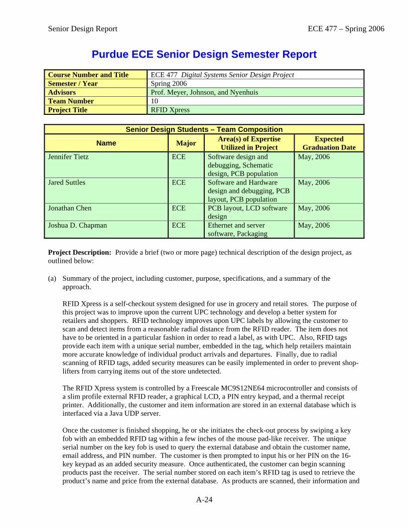
Senior Design Report ECE 477 – Spring 2006
A-24
Purdue ECE Senior Design Semester Report Course Number and Title ECE 477 Digital Systems Senior Design Project Semester / Year Spring 2006 Advisors Prof. Meyer, Johnson, and Nyenhuis Team Number 10 Project Title RFID Xpress
Senior Design Students – Team Composition
Name Major Area(s) of Expertise Utilized in Project
Expected Graduation Date
Jennifer Tietz ECE Software design and debugging, Schematic design, PCB population
May, 2006
Jared Suttles ECE Software and Hardware design and debugging, PCB layout, PCB population
May, 2006
Jonathan Chen ECE PCB layout, LCD software design
May, 2006
Joshua D. Chapman ECE Ethernet and server software, Packaging
May, 2006
Project Description: Provide a brief (two or more page) technical description of the design project, as outlined below: (a) Summary of the project, including customer, purpose, specifications, and a summary of the
approach.
RFID Xpress is a self-checkout system designed for use in grocery and retail stores. The purpose of this project was to improve upon the current UPC technology and develop a better system for retailers and shoppers. RFID technology improves upon UPC labels by allowing the customer to scan and detect items from a reasonable radial distance from the RFID reader. The item does not have to be oriented in a particular fashion in order to read a label, as with UPC. Also, RFID tags provide each item with a unique serial number, embedded in the tag, which help retailers maintain more accurate knowledge of individual product arrivals and departures. Finally, due to radial scanning of RFID tags, added security measures can be easily implemented in order to prevent shop-lifters from carrying items out of the store undetected. The RFID Xpress system is controlled by a Freescale MC9S12NE64 microcontroller and consists of a slim profile external RFID reader, a graphical LCD, a PIN entry keypad, and a thermal receipt printer. Additionally, the customer and item information are stored in an external database which is interfaced via a Java UDP server. Once the customer is finished shopping, he or she initiates the check-out process by swiping a key fob with an embedded RFID tag within a few inches of the mouse pad-like receiver. The unique serial number on the key fob is used to query the external database and obtain the customer name, email address, and PIN number. The customer is then prompted to input his or her PIN on the 16-key keypad as an added security measure. Once authenticated, the customer can begin scanning products past the receiver. The serial number stored on each item’s RFID tag is used to retrieve the product’s name and price from the external database. As products are scanned, their information and
Senior Design Report ECE 477 – Spring 2006
A-25
other cart statistics (i.e., the number of items scanned and total) are displayed on the LCD screen for the customer to view. After all of the customer’s products are scanned, the customer chooses whether to print a receipt or to just receive one via e-mail.
The intended purchaser of the RFID Xpress system is the owner of a grocery or large retail operation where item tracking can be improved. It is also intended that customer self-checkout lanes are already implemented, as our system is meant as a bolt-on solution to existing checkout lanes. The design approach included consideration of realistic design constraints, as well as retail owner applications, customer ease-of-use, and overall customer satisfaction.
(b) Description of how the project built upon the knowledge and skills acquired in earlier ECE
coursework.
The development of RFID Xpress relied heavily on knowledge and skills obtained through previous ECE courses. The microcontroller was programmed mainly in C, so our experience in ECE264 gave us the advanced C programming knowledge required to successfully write the 1,700 lines of embedded code. Assembly language programming knowledge from ECE362 also proved very helpful for understanding the auto-generated code from CodeWarrior, debugging the system, implementing timing and serial communication interrupts, and setting internal registers for the proper operation of the peripherals. This class also provided us with general embedded system design knowledge that was very useful. During the hardware design, course notes for ECE270 were consulted numerous times to remind us of basic digital system design principles. They were helpful for debugging techniques for the keypad using a 7-segment LED, for understanding sinking and sourcing current considerations, for datasheet comprehension, and for providing insight on general state machine design considerations.
(c) Description of what new technical knowledge and skills, if any, were acquired in doing the project.
Many new technical skills were acquired or improved during the design process of RFID Xpress. We all had previous experience with reading and understanding schematics, but for this project we were faced with the task of actually designing one from start to finish. No members of our team had any experience with PCB layout, but after the project was complete, we were able to understand the process of PCB design as well as identify key considerations for part placement and routing. Finally, few members of our team had experience with PCB population or soldering in general. While everyone’s soldering skills improved throughout the semester, we minimized the number of individuals actually soldering the final PCB to maintain quality and consistency.
(d) Description of how the engineering design process was incorporated into the project. Reference
must be made to the following fundamental steps of the design process: establishment of objectives and criteria, analysis, synthesis, construction, testing, and evaluation.
At the beginning of the semester, the team identified the following five Project Specific Success Criteria for RFID Xpress:
1. An ability to identify an item (and look up data on that item) based on its RFID tag. 2. An ability to identify a customer based on a key ring transponder and PIN code (entered on a
keypad). 3. An ability to display status information (e.g., item being scanned/price) on an LCD. 4. An ability to print and/or E-mail receipt, based on customer selection (via keypad). 5. An ability to gather product and customer data by querying an external database (using Ethernet).

Senior Design Report ECE 477 – Spring 2006
A-26
These minimal design objectives guided our progress throughout the semester and provided a basis for evaluation of our progress. We analyzed the specific needs of our project to select the most appropriate components. For example, it was essential that the microcontroller have Ethernet capability in order to communicate with the external database, as well as have at least two serial communication ports for the RFID reader and receipt printer. Several voltage regulators and converters were needed to generate the 3.3, 5.0, and 12.0 V requirements for all of the components. The packaging needs were also modified several times as we added components to our design. We also analyzed existing similar products on the market to identify points of parity and points of difference for our product.
In order to verify functionality of different modules of our design, we built isolated prototype circuits for the major components and gradually combined them into one large prototype of the whole system. We simultaneously developed and modified our schematic and PCB layout to meet the needs of our project. After the PCB was fabricated and all of the components were acquired, the PCB was populated in modules to make debugging easier. Throughout the whole design process, we developed software on one of three development boards we had acquired. This made for easy testing of software functionality, and easy porting over to our prototype. The software development was also completed in modules to verify functionality of the individual blocks. Eventually, the hardware and software were synthesized and simultaneous debugging of the hardware and software continued. The packaging for the system was constructed to fit the proportions of our major components, and the board and components were placed inside. Finally, the system was continually tested for various usage situations and any bugs were fixed. The system performance was evaluated to determine if it met the objectives laid out in the Project Specific Success Criteria.
(e) Summary of how realistic design constraints were incorporated into the project (consideration of
most of the following is required: economic, environmental, ethical, health & safety, social, political, sustainability, and manufacturability constraints).
Many design constraints were considered throughout the development process of RFID Xpress. Prior to the start of the project, we conducted thorough research into the expected costs of the prototype system as well as large-scale manufacturing. It was essential to lower the cost of production as much as possible to increase the mass marketability of our product. Ethical implications were also considered, as our project involved the use of personal customer identification information which, when in the wrong hands, could lead to identity theft. Thus, we included an added security feature of a PIN entry keypad. Health and safety considerations were examined carefully, as our product will be used by the general public on a regular basis. Much research has been conducted into the effects of long-term exposure to RF radiation, and the results strongly support the design of our system. Environmental considerations included the decision to use passive RFID tags rather than active, which contain low power lithium batteries which are hazardous to the environment. Social considerations were a large factor, as the use of RFID has yet to become accepted by mainstream society as a practical or safe method of product identification. Finally, the sustainability of the product was thoroughly analyzed to ensure long-lasting customer satisfaction and customer safety.
(f) Description of the multidisciplinary nature of the project. The development of RFID Xpress incorporated knowledge from many disciplines. Electrical engineering skills were required in the power supply and other circuit design process, while computer engineering skills helped in digital system design and software development. A fair amount of mechanical knowledge was necessary to properly select and modify the product packaging to meet the specific needs of the project. Marketing knowledge helped showcase the

Senior Design Report ECE 477 – Spring 2006
A-27
appeal of the product in the introduction of the User Manual. Finally, technical writing skills were utilized throughout the design process to professionally document our progress.
(g) Description of project deliverables.
The semester culminated in the delivery of a complete self-checkout system, controlled by a microcontroller. It includes an RFID reader external to the product casing, which includes a keypad for user PIN entry, an LCD to display the shopping cart and other pertinent information to the user, and a thermal receipt printer. Additionally, the system utilizes an Ethernet connection to synchronize the internal clock, send email receipts to the user, and query an external database for customer and product information. The project satisfies and surpasses all five of the Project Specific Success Criteria identified at the beginning of the semester. The system accurately detects a user key fob and queries a database for the user information related to the fob serial number. If the customer is located in the database, the LCD greets the user and prompts them for their PIN. The digits are properly stored and compared against the correct PIN, and valid users are authenticated. As items are scanned, the RFID serial number is queried in the database and the correct product name and price are returned. The user can remove items from the shopping cart, cancel the shopping session, or complete the shopping session by pressing specific buttons on the keypad. After the session is ended, the user can chose to receive a printed receipt in addition to the email receipt. The LCD provides visual confirmation to the user after each decision. The components are packaged in an appealing and user-friendly casing designed to be bolted onto existing check-out lanes.

Senior Design Report ECE 477 – Spring 2006
A-28
Purdue ECE Senior Design Semester Report Course Number and Title ECE 477 Digital Systems Senior Design Project Semester / Year Spring 2006 Advisors Profs. Meyer, Johnson, and Nyenhuis Team Number 11 Project Title Handy
Senior Design Students – Team Composition
Name Major Area(s) of Expertise Utilized in Project Expected Graduation Date
Zaizhuang Cheng EE PCB Layout, Circuit Design, Packaging, May 2006 Colin Tan EE PCB Layout, Circuit Design, Soldering. December 2006 Derrick Ko CompE Software Design, Circuit Design. December 2006 Naga Setiawan CompE Software Design, Circuit Design. Unknown Project Description: Provide a brief (two or more page) technical description of the design project, as outlined below: (a) Summary of the project, including customer, purpose, specifications, and a summary of the
approach.
Handy is a remote control that recognizes a hand gesture and sends the corresponding command to a commercial sound system. For the purpose of this project, Handy is interfaced with a Bose SoundDock and is able to send the following six commands: play/pause, volume up, volume down, next, back and off. The user is able to customize individual hand gestures for each command. To extend the life of the batteries, Handy enters a power-down sleep mode after it has not sensed any hand motion for ten seconds. Handy was designed for customers who need a hands-free remote control. Instead of searching for a button to press, the customer can just wave his hand over Handy to specify which command he wants to send to the sound system. This is useful for when the user is doing something that requires total concentration (e.g. driving) and cannot spare a glance at the remote control. The purpose of this project was to cater to this need, making it safer and more convenient for the user to control a sound system. The project had certain specifications associated with it to be considered useful and functional. Firstly, it must be able to transmit IR commands that conform to a commercial standard. Secondly, it must give the user the ability to program distinct hand movements. Thirdly, it must be able to recognize distinct hand movements and look up the infrared command code associated with each programmed movement. Fourthly, the user must be able to configure the device and display its status using a keypad/LCD. Finally, it must be able to conserve energy when it is not in use. To design Handy, we first came up with the idea of a hand gesture remote control and then decided what features to include. Then the components required to carry out the design were selected. Orcad capture and layout were used to draw out a detailed schematic and Printed Circuit Board (PCB) layout. All components were tested for functionality and then the PCB board was populated module by module once it arrived from the manufacturer. The power supply was populated first, followed by the microcontroller, LCD and optical encoder, infrared distance sensors and lastly the feedback

Senior Design Report ECE 477 – Spring 2006
A-29
LEDs. Once the hardware portion of the project was completed, the software portion was tested and completed. Then the product was packaged.
(b) Description of how the project built upon the knowledge and skills acquired in earlier ECE coursework.
This project relied heavily upon the knowledge and skills acquired from several different ECE classes, especially ECE 362 for microcontroller systems design and interfacing knowledge as well as ECE 270 for digital system design knowledge. ECE 362 provided the required knowledge and skill to work with and program the microcontroller that was central to the design of Handy. Other useful skills acquired from ECE 362 included interfacing the microcontroller with various peripherals and understanding of microcontroller datasheets. ECE 270 provided the basic knowledge of digital systems design and was especially useful in debouncing the pushbutton on the rotary pulse generator. The design process also utilized knowledge from ECE 201, 202, 207 and 208. The knowledge from these classes enabled the team to fully utilize the engineering tools available in the 477 laboratory. ECE 264: Advanced C programming and ECE 368: Data Structures provided the necessary skills and knowledge needed to complete the software portion of the project.
(c) Description of what new technical knowledge and skills, if any, were acquired in doing the project.
The team gained a lot of technical knowledge and skills during the design process of Handy. Creating the schematic for the design required the use of OrCad Capture, a program in which the team had minimal experience with in past courses. After creating and revising the schematic several times, the team gained a more in depth knowledge about how to use OrCad Capture. OrCad Layout, a program that no one in the team had used before, was then used to create the PCB layout. We learnt how to interface OrCad Capture with Layout and gained experience in proper designing of the PCB layout. The project also allowed us to gain experience in soldering. Soldering and desoldering our 100 pin surface mount microcontroller 5 times has given us the confidence to solder any device. On the software side, we learnt to work with AVR studio and CodeVision to write and download the program into the Atmel microcontroller.
(d) Description of how the engineering design process was incorporated into the project. Reference must be made to the following fundamental steps of the design process: establishment of objectives and criteria, analysis, synthesis, construction, testing, and evaluation.
At the start of the semester, the following five project specific success criteria were established: 1. Ability to transmit IR commands that conform to a commercial. 2. Ability to program distinct hand movements. 3. Ability to recognize distinct hand movements and look up the infrared
command code associated with each programmed movement 4. Ability to configure the device and display its status using a
optical encoder and LCD. 5. Ability to conserve energy when device is not in use.
The functionality of Handy was analyzed to determine what parts were needed and how best to integrate them together. Then the OrCad schematic and PCB layout were designed and submitted for manufacturing. The parts that arrived were first prototyped on bread board to ensure full functionality. When the PCB arrived, each module of Handy was constructed and soldered onto the board. Each module was tested separately before the next module was populated onto the board. The software was loaded into the microcontroller and tested. All bugs were ironed out and the overall functionality was evaluated to ensure that Handy met all five of the project specific success criteria.
Senior Design Report ECE 477 – Spring 2006
A-30
(e) Summary of how realistic design constraints were incorporated into the project (consideration of most of the following is required: economic, environmental, ethical, health & safety, social, political, sustainability, and manufacturability constraints). To reduce the overall cost of the project so that the final product would be affordable to most people, effort was made to reduce the cost of each component used in the design. Environmentally, the amount of infrared radiation emitted by Handy was cut down as much as possible. As a relatively short sensing distance was required, a higher value of resistance was used in the design of the infrared sensors to reduce the amount of infrared radiation emitted. To reduce emissions more, one infrared transmitter was used instead of three in the initial design. Ethically, a reliability analysis of the overall design was conducted and suggestions were made to ensure that the device had an acceptable mean time to failure. The suggestions included ways to ensure that the failures with a high criticality, which put the user at risk, were minimized. As such the ethical constraints are the same as the health and safety constraints. The social and political constraints were considered as extensive searches of the patent database were made to ensure that our design was not infringing upon any pre-existing patents. At each step of the design process, the sustainability and manufacturability constraints were taken into consideration. As such, Handy was designed in a modular way, making it easier to troubleshoot in the event of a failure. This also would make the manufacturing process more efficient during mass production. A user manual on how to use Handy along with a troubleshooting guideline was also written.
(f) Description of the multidisciplinary nature of the project.
This project made use of both the hardware and software aspects of digital system design and relied heavily upon both electrical engineering and computer engineering classes. First of all, the hardware had to be designed to carry out the functions that were required of Handy. The computer engineers on this project were largely unfamiliar with this portion of the project. Secondly, the software needed to be designed to integrate the hardware components together and combine them to produce a single product. As ECE 362 is a prerequisite for this class, all of us were familiar with digital systems design. However the electrical engineers on the team had not worked with the complexity of the program that was required for this project. Soldering on the printed circuit board is something that is not included in any ECE course, and it was a big factor in the success of the project. It required learning skills that a technician would be more likely to know. Also, the packaging required skills that are more likely to be learnt in a technical elective. To create the packaging, CAD was used and then the design was sent to the machine shop to be manufactured. The casing then had to be drilled, filed and assembled.
(g) Description of project deliverables. The final project deliverables includes a working hand gesture remote control interfaced with a Bose SoundDock that meets all the five project specific success criteria, a user manual with instructions on how to use the product, a poster show casing the product, notebooks for each team member detailing the contributions of each team member and a final report showing the entire design process.
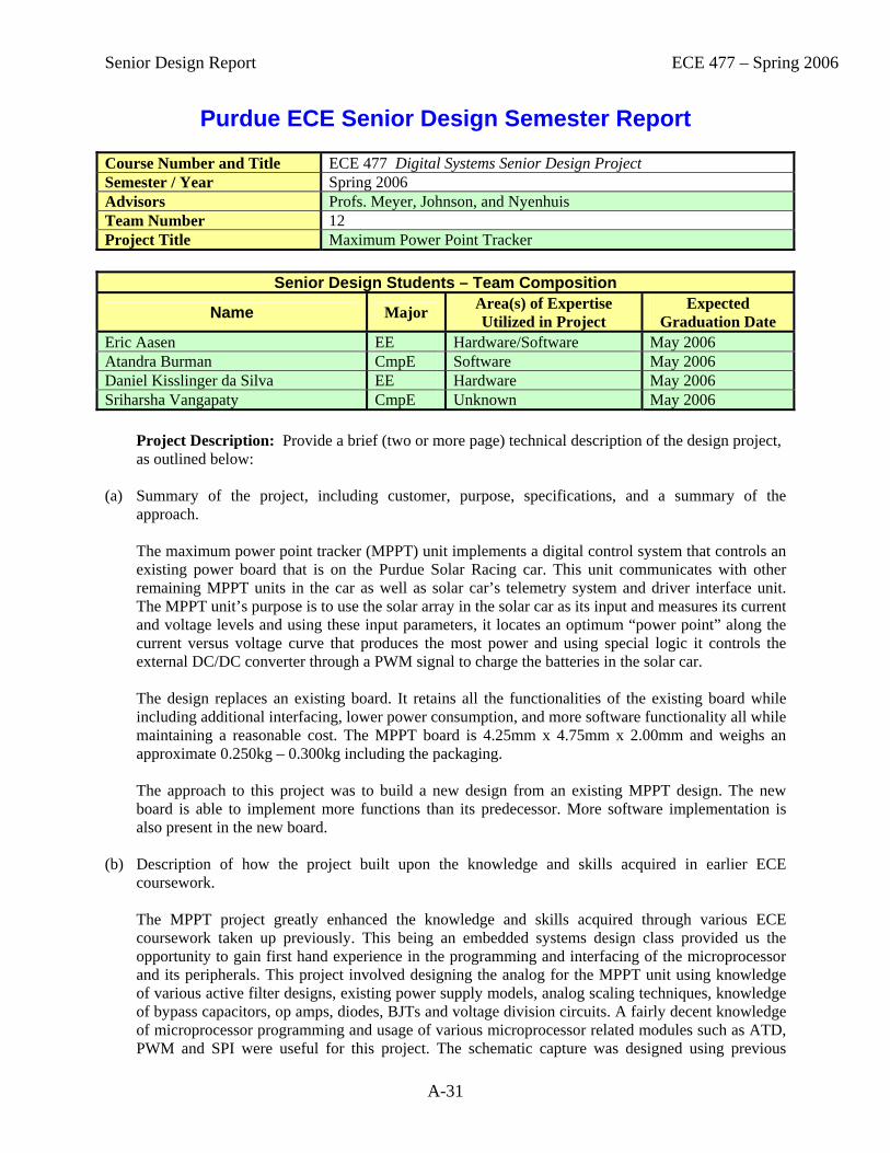
Senior Design Report ECE 477 – Spring 2006
A-31
Purdue ECE Senior Design Semester Report Course Number and Title ECE 477 Digital Systems Senior Design Project Semester / Year Spring 2006 Advisors Profs. Meyer, Johnson, and Nyenhuis Team Number 12 Project Title Maximum Power Point Tracker
Senior Design Students – Team Composition
Name Major Area(s) of Expertise Utilized in Project
Expected Graduation Date
Eric Aasen EE Hardware/Software May 2006 Atandra Burman CmpE Software May 2006 Daniel Kisslinger da Silva EE Hardware May 2006 Sriharsha Vangapaty CmpE Unknown May 2006
Project Description: Provide a brief (two or more page) technical description of the design project, as outlined below:
(a) Summary of the project, including customer, purpose, specifications, and a summary of the approach. The maximum power point tracker (MPPT) unit implements a digital control system that controls an existing power board that is on the Purdue Solar Racing car. This unit communicates with other remaining MPPT units in the car as well as solar car’s telemetry system and driver interface unit. The MPPT unit’s purpose is to use the solar array in the solar car as its input and measures its current and voltage levels and using these input parameters, it locates an optimum “power point” along the current versus voltage curve that produces the most power and using special logic it controls the external DC/DC converter through a PWM signal to charge the batteries in the solar car. The design replaces an existing board. It retains all the functionalities of the existing board while including additional interfacing, lower power consumption, and more software functionality all while maintaining a reasonable cost. The MPPT board is 4.25mm x 4.75mm x 2.00mm and weighs an approximate 0.250kg – 0.300kg including the packaging. The approach to this project was to build a new design from an existing MPPT design. The new board is able to implement more functions than its predecessor. More software implementation is also present in the new board.
(b) Description of how the project built upon the knowledge and skills acquired in earlier ECE coursework. The MPPT project greatly enhanced the knowledge and skills acquired through various ECE coursework taken up previously. This being an embedded systems design class provided us the opportunity to gain first hand experience in the programming and interfacing of the microprocessor and its peripherals. This project involved designing the analog for the MPPT unit using knowledge of various active filter designs, existing power supply models, analog scaling techniques, knowledge of bypass capacitors, op amps, diodes, BJTs and voltage division circuits. A fairly decent knowledge of microprocessor programming and usage of various microprocessor related modules such as ATD, PWM and SPI were useful for this project. The schematic capture was designed using previous
Senior Design Report ECE 477 – Spring 2006
A-32
knowledge of Design Entry CIS and PCB layout was finished using knowledge of Layout Plus. Further, knowledge of communication protocols such as UART enabled in structuring the debug mode for this project. In summary a wide area of electrical and computer engineering knowledge achieved from the various classes in our undergraduate classes greatly helped us successfully design our project.
(c) Description of what new technical knowledge and skills, if any, were acquired in doing the project.
The senior design project being an embedded systems project provides us a fairly large knowledge base for microprocessor programming and interfacing. In the course of this project we had an opportunity to learn to use various new tools. We learnt to use the MPLAB-PICDEM in circuit debugger for debugging C code written to program the PIC18F2680. We spent considerable amount of time researching and implementing the CAN protocol to enable sending and receiving CAN messages over the CAN network so as to communicate and service requests from the telemetry system and the driver interface unit. Besides this we also acquired knowledge about the individual component in our design by consistently referring to the extensive datasheets for these devices.
(d) Description of how the engineering design process was incorporated into the project. Reference must be made to the following fundamental steps of the design process: establishment of objectives and criteria, analysis, synthesis, construction, testing, and evaluation. First, the project objectives were clearly established as well as the success criteria. With those objectives in mind, the components to be used in the design were chosen. The design was done in order to achieve the project’s objectives. The parts used were the parts previously chosen to best meet the set objectives. After schematics were finalized, the design layout was created. Afterwards, the PCB was produced following the layout. The components were mounted to the PCB. The board was tested to make sure all components behave as designed. Software was installed at the same time and tested along with hardware. Once hardware and software were fully integrated, the PSSCs were demonstrated.
(e) Summary of how realistic design constraints were incorporated into the project (consideration of most of the following is required: economic, environmental, ethical, health & safety, social, political, sustainability, and manufacturability constraints). The project did not face significant economic constraints, because the boards will be produced in small numbers, i.e. only 8 of these boards will produced for the Purdue Solar Racing. Components that did not contain lead were always preferred when it did not impose significant cost increase. Safety features were added to both hardware and software, i.e. over voltage protection. Temperature sensor along with fan avoids board to become hot, increasing its lifetime.
(f) Description of the multidisciplinary nature of the project. Electrical Engineering knowledge was extensively used to design the project. Many considerations regarding power consumption, heat dissipation and parts’ size were considered when choosing components in the project. Computer Engineering knowledge was used to create an algorithm to find the maximum power point as well as for the interface with the communication protocols and the microcontroller used in the project. Technical English was used to write all homeworks, presentations, and final report.

Senior Design Report ECE 477 – Spring 2006
A-33
(g) Description of project deliverables. 1. Packaging – design of a packaging used by board. 2. Schematic – design of hardware. 3. PCB Layout – design of project’s PCB layout. 4. Parts List – list of all parts used in the board. 5. FMECA Worksheet – analysis of critical failures. 6. Software – all software used in the project. 7. Project Poster – poster advertising project. 8. User Manual – user manual for project. 9. Final Report – report containing all documentation related to project. 10. Senior Design Report

Senior Design Report ECE 477 – Spring 2006
A-34
Purdue ECE Senior Design Semester Report Course Number and Title ECE 477 Digital Systems Senior Design Project Semester / Year Spring 2006 Advisors Profs. Meyer, Johnson, and Nyenhuis Team Number 13 Project Title Brightriders Telemetry System
Senior Design Students – Team Composition
Name Major Area(s) of Expertise Utilized in Project
Expected Graduation Date
Elmer Chao EE Circuit Design/Layout May 2006 Matt Cozza CmpE Software Development May 2006 Joe Waugh CmpE Software Development May 2006 Evan Zelkowitz CmpE Schematic/Software May 2006 Project Description: Provide a brief (two or more page) technical description of the design project, as outlined below: (a) Summary of the project, including customer, purpose, specifications, and a summary of the
approach. The goal of the project was to create a telemetry system for the Purdue Solar Racing team. This system acts as a data collection unit as well as a way to bridge communication across multiple devices. It communicates with the car’s motor controller and battery pack, as well as containing multiple onboard sensors such as accelerometers and a temperature. All of this data is then sent over a wireless packet modem to a chase vehicle following the solar car. The telemetry system also communicates over a CANbus inside the car with a driver interface and several power point trackers that maintain efficiency from the solar array.
(b) Description of how the project built upon the knowledge and skills acquired in earlier ECE coursework. This project utilized many skills learned in previous courses. Most of the skills used were from ECE 362. The knowledge of SCI learned in that class helped lead to better understand the issues encountered with UART communication to all vehicle devices. The SPI skill set learned in ECE 362 were used for communication through a peripheral chip which was placed in the system to expand UART capabilities from one UART channel to four. Knowledge of A/D and timers was also used in order to gather data from the various onboard sensors, as well as to set timing interrupts for determining when to poll data sources for information. The skill of knowing how to deal with various device registers and how to change their behavior was of great use as well, mainly when working with CAN. The CAN peripheral had a huge amount of register settings, and without the knowledge learned in ECE 362 in this area, setting CAN up would have been fairly difficult.
(c) Description of what new technical knowledge and skills, if any, were acquired in doing the project. One major skill learned while doing this project was working with the CAN specification. It is a widely used network scheme throughout the automotive industry and is a very valued skill. Knowledge learned throughout this project included how to setup CAN, debug CAN issues, and how

Senior Design Report ECE 477 – Spring 2006
A-35
to create a CAN protocol for transmission of data between devices reliably. Another skill learned was how to communicate to multiple devices over a single SPI bus. Two SPI-UART chips were utilized in the design to expand UART capabilities and were required to switch between the chips whenever communication was necessary. From a hardware aspect, the entire team learned how to do layout, as well as soldering. None of the team members had any real solid experience in either of these disciplines, and after this project, the entire team now has the skill set necessary to take a design from a schematic all the way through PCB manufacture.
(d) Description of how the engineering design process was incorporated into the project. Reference must be made to the following fundamental steps of the design process: establishment of objectives and criteria, analysis, synthesis, construction, testing, and evaluation. During creation of this project, all of the initial objectives and criteria were created in concert with the solar team’s ideas in mind. Meetings were held every weekend to determine what considerations needed to be taken into account, from what data needed to be collected to what type of packaging was necessary in the final product. Once the hardware had been designed and soldering began, each trace on the PCB was tested for connectivity and each design block of the PCB, such as accelerometers, power, etc., were tested as they were soldered. During software creation testing started for each of the peripherals of the microcontroller and creating functions for communication to each of these parts, for ease of use later on in the design. Once it was understood that each of our peripherals were working, combining each of them together for our final design was started.
(e) Summary of how realistic design constraints were incorporated into the project (consideration of most of the following is required: economic, environmental, ethical, health & safety, social, political, sustainability, and manufacturability constraints). The main economic requirements were to keep the cost as low as possible. The Purdue Solar team was funding this project and so most of the parts were sampled. This allowed for the overall Purdue Solar budget to be allotted towards the more expensive items such as the necessary GPS units, as well as the other senior design team’s parts which needed to be ordered. Ethical and safety constraints mainly encompassed the safety of the driver. The system is not capable of changing any of the settings of the motor controller while the car is in motion, as this could cause serious damage to the motor and in turn the car which could harm the driver. The other main safety concern was the battery system. If the batteries were allowed to over-charge, it could cause a failure which would result in fire or leaking toxic chemicals. The battery data is constantly fed to the driver so that he or she may monitor their levels at all times and shutdown the power being fed to them in order to prevent any damaging effects. In consideration of the sustainability of the project, an attempt was made to allow maximum expansion capabilities in the system. Access was left open to as many of the microcontrollers peripherals as possible, so that future designs may incorporate them if need be. A DIP socket was chosen for the controller, so that in either case of emergency or if the design was to be changed, this component could be changed easily. In the social and political realm, the main concept of the project is to provide maximum functionality to a solar car. Further research into this area is necessary, especially in our current times due to the rising monetary and political costs of fossil fuels.
(f) Description of the multidisciplinary nature of the project. This project spanned multiple disciplines first and foremost by being a project for the Purdue Solar car. This brought in the discipline of the automotive realm, as well as the aeronautical engineering aspect which comprises a lot of the data that we collect.

Senior Design Report ECE 477 – Spring 2006
A-36
Inside our own team, there were multiple disciplines, as some members were computer engineers and one member was an electrical engineer. All team members brought knowledge and experience from the various disciplines to help complete this project.
(g) Description of project deliverables. The working telemetry system, in its housing, was delivered to the solar team. This housing contained the external connections necessary to connect all of the various UART devices. It also contained a bank of CAN connections so that multiple devices could be added to the car’s CANbus by connecting to these ports.

Senior Design Report ECE 477 – Spring 2006
A-37
Purdue ECE Senior Design Semester Report Course Number and Title ECE 477 Digital Systems Senior Design Project Semester / Year Spring 2006 Advisors Profs. Meyer, Johnson, and Nyenhuis Team Number 14 Project Title SPOT DASH
Senior Design Students – Team Composition
Name Major Area(s) of Expertise Utilized in Project
Expected Graduation Date
Yuk Hang Chan CompE Software Development, Documentation
May 2006
Nathanael Huffman EE Schematics and PCB Routing, Documentation, Hardware assembly
May 2006
Yuan-Jiun Sung EE PCB Design and Documentation
May 2007
Wei Zhou CompE Software Development, Documentation
May 2006
Project Description: Provide a brief (two or more page) technical description of the design project, as outlined below: (a) Summary of the project, including customer, purpose, specifications, and a summary of the
approach. The SPOT DASH is an improved driver interface system for the next generation Purdue solar car. The SPOT DASH system provides the driver with the most up-to-date information during a race and communicates with the chasing cars through a CANbus network. A LCD and two user interfacing buttons are mounted on the plastic enclosure and the steering wheel respectively. They’re used for information display and controlling user interface. Specifications have been requested by the Purdue Solar Racing club. Some key parameters relevant to the operation of the solar car will be available to the solar car driver. The Spot Dash allows the driver to navigate through system menus and make selections using an RPG and a push button. These parameters include GPS time and location, battery level, motor speed, temperature, driving time and distance, etc. A maximum of three car properties can be displayed on the LCD according to the driver preferences. The Spot Dash is able to switch to “debug” mode when an RS232 cable is connected. It also communicates with other devices on the car via CAN bus and obtains diagnostic information to be displayed on a LCD. An automatic LCD backlight power management system is also required for the Spot Dash to reduce power consumption and aid visibility to the driver. Several approaches were used by the design team to fulfill these specifications. First, the team came up with a list of design constraints relevant to the operation conditions of Purdue solar car. The team then selected hardware components based on these design considerations and project specifications. The team chooses a hybrid of interrupt and polling driven methods for the software organization. This allows SPOT DASH to maximize the response time to both the user input and CAN communication.

Senior Design Report ECE 477 – Spring 2006
A-38
(b) Description of how the project built upon the knowledge and skills acquired in earlier ECE coursework. This project built upon knowledge and skills acquired from several earlier ECE coursework. The fundamental knowledge from ECE201 and 202 and associated labs helped the team understand the basic operations of resistors, capacitors, inductors, and the power supply circuit. PLD programming experience from ECE270 and VHDL experience in ECE495d and ECE437 proved useful in the completion of the programmable logic portion. Basic transistor theory from ECE255 proved useful for building interfacing circuitry to drive devices which need more current than the microcontroller can source or sink. The mini project in ECE362 was especially important upon the completion of this project due to the use of a microcontroller. The LCD configuration, PCB design and basic functionalities of microcontroller along with assembly programming techniques to communicate with different peripherals were adopted from the mini project and utilized in this project.
(c) Description of what new technical knowledge and skills, if any, were acquired in doing the project. The Controller Area Network protocol and its operation along with data synchronization method were the most significant new technical knowledge acquired by the team. Understanding of the I2C protocol was necessary in order to communicate with the LCD. In addition, the skills of designing schematics and routing PCB were enhanced by the team. Some other key knowledge such as technical communication skills and writing style, understanding of solar array design considerations, maximum power point tracker (a solar car DC/DC converter), and CAD drawings were also acquired by the team members and contributed to the overall success of this project.
(d) Description of how the engineering design process was incorporated into the project. Reference must be made to the following fundamental steps of the design process: establishment of objectives and criteria, analysis, synthesis, construction, testing, and evaluation. The engineering design process played an important role throughout the implementation of entire project. The objective and criteria of the driver interface system were been established by the Purdue solar racing club before the formation of the design team, however, the team carefully analyzed the general needs and requirements and used these as guidelines to create the most appropriate project success criteria. The hardware components were then selected according to accomplish each project success criteria. The team then built the hardware schematic with the requirements in mind (Input current should be less 400 mA at 12V, PIC18 microcontroller must be used, and etc.) Several PCB design constraints were considered by the team before the start of the PCB design. Once the PCB was completed, the team let the PCB “burn in” for 12 hours and test supply voltage at each IC pin to make sure correct voltage was supplied. Software was then implemented and tested on the finalized PCB. Software and hardware debugging followed a systematic process: check cable connections, hardware check, and software logic errors to ensure the progress of this project. The final project was implemented with the PCB board and LCD mounted on a plastic enclosure. Another test and evaluation of the driver system were performed to ensure the correct functionality of the system and generated suggestions for future improvements.
(e) Summary of how realistic design constraints were incorporated into the project (consideration of most of the following is required: economic, environmental, ethical, health & safety, social, political, sustainability, and manufacturability constraints). Realistic design constraints were incorporated into the project and considered from different perspectives. Economically, the project cost was around $100 which is a reasonable price for an organization, especially the solar racing team. Several ethical and environmental considerations
Senior Design Report ECE 477 – Spring 2006
A-39
were also taken into account in the design of this project. For example, a high efficiency DC/DC converter was selected by the team to avoid wasted power consumption in the voltage conversion, a back light supported LCD was chosen to adapt to the dark environment within the solar car, and the documentation encourages recycling the driver interface system at the end of its lifecycle. The product’s lifecycle, setup instructions, operation constraints, and a failure modes and possible solutions table were also included in the user manual to aid the end users in troubleshooting and configuration.
(f) Description of the multidisciplinary nature of the project.
The SPOT DASH driver interface was the combination effort of engineering students from different disciplines. Electrical Engineering students utilized the knowledge they acquired from previous ECE course to design the hardware schematic and implement it on the PCB. Computer engineering students programmed the microcontroller to communicate with the various peripherals (LCD, CAN bus, RS232 etc) and honed their programming skills in an embedded environment. There was also indirect contact with other engineering disciplines (mechanical engineering and material engineering) used for reference in the completion of the packaging designs.
(g) Description of project deliverables. The SPOT DASH driver interface system will be installed and demonstrated on the Purdue solar car to demonstrate functionality. All of the software code was well documented, so that future expansion and maintenance can be carried out at ease. The following list shows the completed deliverables of this product, each of which was successfully implemented and demonstrated: 1. An ability to display vehicle status information on a LCD 2. An ability to navigate display menus and make selections using an RPG. 3. An ability to perform LCD backlight power management. 4. An ability to obtain vehicle diagnostic information via CANbus. 5. An ability to switch to “Debug” mode (via an RS-232 cable) in which a diagnostic menu is
displayed.

Senior Design Report ECE 477 – Spring 2006
Appendix B:
Proposed Evaluation Form
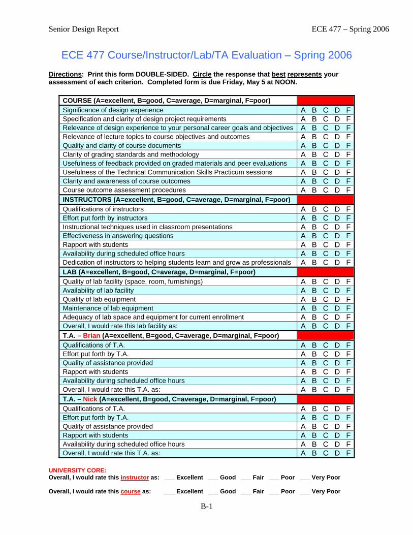
Senior Design Report ECE 477 – Spring 2006
B-1
ECE 477 Course/Instructor/Lab/TA Evaluation – Spring 2006 Directions: Print this form DOUBLE-SIDED. Circle the response that best represents your assessment of each criterion. Completed form is due Friday, May 5 at NOON.
COURSE (A=excellent, B=good, C=average, D=marginal, F=poor) Significance of design experience A B C D FSpecification and clarity of design project requirements A B C D FRelevance of design experience to your personal career goals and objectives A B C D FRelevance of lecture topics to course objectives and outcomes A B C D FQuality and clarity of course documents A B C D FClarity of grading standards and methodology A B C D FUsefulness of feedback provided on graded materials and peer evaluations A B C D FUsefulness of the Technical Communication Skills Practicum sessions A B C D FClarity and awareness of course outcomes A B C D FCourse outcome assessment procedures A B C D FINSTRUCTORS (A=excellent, B=good, C=average, D=marginal, F=poor) Qualifications of instructors A B C D FEffort put forth by instructors A B C D FInstructional techniques used in classroom presentations A B C D FEffectiveness in answering questions A B C D FRapport with students A B C D FAvailability during scheduled office hours A B C D FDedication of instructors to helping students learn and grow as professionals A B C D FLAB (A=excellent, B=good, C=average, D=marginal, F=poor) Quality of lab facility (space, room, furnishings) A B C D FAvailability of lab facility A B C D FQuality of lab equipment A B C D FMaintenance of lab equipment A B C D FAdequacy of lab space and equipment for current enrollment A B C D FOverall, I would rate this lab facility as: A B C D FT.A. – Brian (A=excellent, B=good, C=average, D=marginal, F=poor) Qualifications of T.A. A B C D FEffort put forth by T.A. A B C D FQuality of assistance provided A B C D FRapport with students A B C D FAvailability during scheduled office hours A B C D FOverall, I would rate this T.A. as: A B C D FT.A. – Nick (A=excellent, B=good, C=average, D=marginal, F=poor) Qualifications of T.A. A B C D FEffort put forth by T.A. A B C D FQuality of assistance provided A B C D FRapport with students A B C D FAvailability during scheduled office hours A B C D FOverall, I would rate this T.A. as: A B C D F
UNIVERSITY CORE: Overall, I would rate this instructor as: ___ Excellent ___ Good ___ Fair ___ Poor ___ Very Poor Overall, I would rate this course as: ___ Excellent ___ Good ___ Fair ___ Poor ___ Very Poor
Senior Design Report ECE 477 – Spring 2006
Appendix C:
ECE Course Assessment Report

Senior Design Report ECE 477 – Spring 2006
C-1
Course: ECE 477 Submitted by: D. G . Meyer Term: Spring 2006 Course PIC: D. G. Meyer 1. Were all course outcomes addressed during the administration of the course? If not, why not and
what actions do you recommend to remedy this problem in future offerings of this course? The following outcomes must be demonstrated to receive a passing grade in ECE 477: (i) an ability to apply knowledge obtained in earlier coursework and to obtain new knowledge
necessary to design, build, and test a microcontroller-based digital system (ii) an understanding of the engineering design process (iii) an ability to function on a multidisciplinary team (iv) an awareness of professional and ethical responsibility (v) an ability to communicate effectively, in both oral and written form All of these outcomes were addressed and, as indicated below, all students enrolled during the Spring 2006 offering of ECE 477 who received a passing grade successfully demonstrated each outcome.
2. Are the course outcomes appropriate? Yes.
3. Are the students adequately prepared for this course and are the course prerequisites and co-
requisites appropriate? If not, explain.
For the most part, yes, especially as the “pipeline” from the old ECE 266/267 has emptied.
4. Do you have any suggestions for improving this course? If so, explain.
The course staff members are very satisfied with the thorough outcome assessment strategy currently in place. Overall performance of the students enrolled this semester, however, was significantly below average for this course (overall GPA of 3.14, compared with a typical GPA of 3.50). This decline is attributed to being encumbered by an average of one “dead weight” person per team. This semester was marked by some unusually egregious cases in which several students did not attend class, did not come to lab, did not contribute to their team’s project, plagiarized report content, and copied/fabricated lab notebook content. Because of this behavior, three grades of “F” were awarded. The main improvement would take the form of an “application process” for gaining enrollment in the course, which thankfully has been approved by ECE Curriculum Committee to become effective Fall 2006.
Average Outcome Scores and Outcome Demonstration Statistics for ECE 477 Outcome # 1 Avg Score: 72.8% Passed: 56/ 56 = 100.00% Failed: 0/ 56 = 0.00% Outcome # 2 Avg Score: 72.8% Passed: 53/ 56 = 94.64% Failed: 3/ 56 = 5.36% Outcome # 3 Avg Score: 90.5% Passed: 56/ 56 = 100.00% Failed: 0/ 56 = 0.00% Outcome # 4 Avg Score: 74.2% Passed: 53/ 56 = 94.64% Failed: 3/ 56 = 5.36% Outcome # 5 Avg Score: 83.1% Passed: 56/ 56 = 100.00% Failed: 0/ 56 = 0.00% Demonstrated all five outcomes based on primary assessment: 53/ 56 = 94.64%
Remediation of Outcomes 1 and 4 was required for several students.
Senior Design Report ECE 477 – Spring 2006
Appendix D:
FIE 2005 Paper on Capstone Design Outcome Assessment
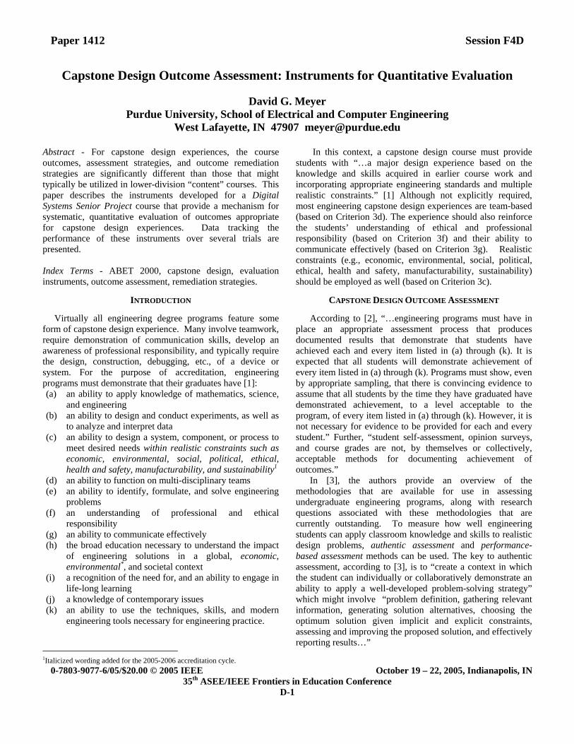
Paper 1412 Session F4D
0-7803-9077-6/05/$20.00 © 2005 IEEE October 19 – 22, 2005, Indianapolis, IN 35th ASEE/IEEE Frontiers in Education Conference
D-1
Capstone Design Outcome Assessment: Instruments for Quantitative Evaluation
David G. Meyer Purdue University, School of Electrical and Computer Engineering
West Lafayette, IN 47907 [email protected]
Abstract - For capstone design experiences, the course outcomes, assessment strategies, and outcome remediation strategies are significantly different than those that might typically be utilized in lower-division “content” courses. This paper describes the instruments developed for a Digital Systems Senior Project course that provide a mechanism for systematic, quantitative evaluation of outcomes appropriate for capstone design experiences. Data tracking the performance of these instruments over several trials are presented. Index Terms - ABET 2000, capstone design, evaluation instruments, outcome assessment, remediation strategies.
INTRODUCTION
Virtually all engineering degree programs feature some form of capstone design experience. Many involve teamwork, require demonstration of communication skills, develop an awareness of professional responsibility, and typically require the design, construction, debugging, etc., of a device or system. For the purpose of accreditation, engineering programs must demonstrate that their graduates have [1]: (a) an ability to apply knowledge of mathematics, science,
and engineering (b) an ability to design and conduct experiments, as well as
to analyze and interpret data (c) an ability to design a system, component, or process to
meet desired needs within realistic constraints such as economic, environmental, social, political, ethical, health and safety, manufacturability, and sustainability1
(d) an ability to function on multi-disciplinary teams (e) an ability to identify, formulate, and solve engineering
problems (f) an understanding of professional and ethical
responsibility (g) an ability to communicate effectively (h) the broad education necessary to understand the impact
of engineering solutions in a global, economic, environmental*, and societal context
(i) a recognition of the need for, and an ability to engage in life-long learning
(j) a knowledge of contemporary issues (k) an ability to use the techniques, skills, and modern
engineering tools necessary for engineering practice.
1Italicized wording added for the 2005-2006 accreditation cycle.
In this context, a capstone design course must provide students with “…a major design experience based on the knowledge and skills acquired in earlier course work and incorporating appropriate engineering standards and multiple realistic constraints.” [1] Although not explicitly required, most engineering capstone design experiences are team-based (based on Criterion 3d). The experience should also reinforce the students’ understanding of ethical and professional responsibility (based on Criterion 3f) and their ability to communicate effectively (based on Criterion 3g). Realistic constraints (e.g., economic, environmental, social, political, ethical, health and safety, manufacturability, sustainability) should be employed as well (based on Criterion 3c).
CAPSTONE DESIGN OUTCOME ASSESSMENT
According to [2], “…engineering programs must have in place an appropriate assessment process that produces documented results that demonstrate that students have achieved each and every item listed in (a) through (k). It is expected that all students will demonstrate achievement of every item listed in (a) through (k). Programs must show, even by appropriate sampling, that there is convincing evidence to assume that all students by the time they have graduated have demonstrated achievement, to a level acceptable to the program, of every item listed in (a) through (k). However, it is not necessary for evidence to be provided for each and every student.” Further, “student self-assessment, opinion surveys, and course grades are not, by themselves or collectively, acceptable methods for documenting achievement of outcomes.” In [3], the authors provide an overview of the methodologies that are available for use in assessing undergraduate engineering programs, along with research questions associated with these methodologies that are currently outstanding. To measure how well engineering students can apply classroom knowledge and skills to realistic design problems, authentic assessment and performance-based assessment methods can be used. The key to authentic assessment, according to [3], is to “create a context in which the student can individually or collaboratively demonstrate an ability to apply a well-developed problem-solving strategy” which might involve “problem definition, gathering relevant information, generating solution alternatives, choosing the optimum solution given implicit and explicit constraints, assessing and improving the proposed solution, and effectively reporting results…”

Paper 1412 Session F4D
0-7803-9077-6/05/$20.00 © 2005 IEEE October 19 – 22, 2005, Indianapolis, IN 35th ASEE/IEEE Frontiers in Education Conference
D-2
Some of the outstanding research issues associated with authentic assessment, cited in [3], include “development of well-designed scoring rubrics and methods for ensuring inter-rater reliability.” The authors go on to state that “guidelines also need to be developed which help faculty choose tasks that are good candidates for collecting authentic assessment data in engineering courses.” These are precisely the areas to which the work reported here contributes. A national survey of design courses and assessment is reported in [4]. The purpose of the study was to obtain a better understanding of the nature and scope of assessment practices within capstone design courses across engineering disciplines, and in particular, the extent to which current practices align with ABET EC 2000 expectations. Findings suggest uncertainty on the part of many faculty members concerning sound assessment practices, including using appropriate assessment strategies. Faculty identified several ways they wanted to improve the quality of their capstone assessments. About one-half of the respondents felt the measures should be more objective, wanting to develop more detailed scoring guidelines/rubrics and desiring clearer performance criteria. A significant number of respondents also wanted to increase the variety of assessment instruments. These are issues the work reported here attempts to address. Related work includes [5], where the authors describe an ECE capstone design experience and detail how project proposals are formulated and grades for the two-course sequence are determined. The authors do not, however, address the issue of design course outcome assessment. Another capstone design course evaluation strategy is described in [6]. Similar to [5], the authors provide a detailed strategy for grading a capstone design course (here, in Civil Engineering), but again do not address the issue of outcome assessment per se. Methods of assessing student learning in capstone design projects sponsored by industry are outlined in [7]. Here the emphasis is on expanding the project evaluation beyond the design report to include teaming skills as well as technical competence. Instruments used include company evaluations, status reports, student self-assessments, peer reviews, and oral reports (in addition to the traditional design report) to quantify student performance both as team members and design engineers. Unlike [5] and [6], no mention of design course grade determination is made in [7]; instead, the focus is on assessing teaming skills and technical competence over multiple trials. A different means of measuring capstone design project outcomes is described in [8]. Here, the focus is on quality measurements (in the context of an industrial sponsor), specifically the development of two distinct instruments intended to measure the quality of a design outcome: the Client Satisfaction Questionnaire (CSQ) and the Design Quality Rubric (DQR). While these are valuable tools for measuring the quality of the end-product (project deliverables), they do not specifically address the assessment of specific design course outcomes. In [9], the authors describe a method for assessing design knowledge (i.e., students’ knowledge of what constitutes the design process)
which might be construed as the complete antithesis of the methodology described in [8]. While it is interesting to understand how a given student’s knowledge about design changes from his/her freshman year to senior year, this work does not specifically address the issue of capstone design course outcome assessment. An illustration of how ABET assessment can be conducted within the framework of a capstone design course sequence (rather than on specific project topics themselves) is given in [10]. A variety of assessment techniques are detailed that provide both quantitative measurements and qualitative indicators that can be used to demonstrate achievement of outcomes (as well as to improve the design course sequence and the curriculum as a whole). While closely related to the work reported here, there are some important differences. First, in the work reported here, specific learning outcomes germane to capstone design are defined; in [10], the ABET Criterion 3 Program Outcomes are used directly. A systematic, quantitative strategy for assessing each of the design course learning outcomes is described in the work reported here; in [10], a “mapping” of instruments and criteria is provided, along with an algorithm for course grade determination. Assessment of outcomes in capstone design courses requires different strategies than in lower-division “content” courses. A good discussion of “what works and what doesn’t” can be found in [11]. As detailed in [12], the first decision toward effective outcome assessment in content courses is choice of evaluation instrument(s). Possibilities include exams (whole or question subsets), quizzes (written/oral), homework assignments, labs, and papers/presentations. Here, proctored exams/quizzes have proven to be most effective. For capstone design courses, however, there typically are no “exams” per se. Here, project deliverables such as papers, presentations, lab notebooks, and device functionality (“project success criteria satisfaction”) are generally the operable evaluation instruments. Another important issue is determination of outcome demonstration “passing thresholds”. Choices include static thresholds (plus what absolute value to choose) or dynamic thresholds (plus what algorithm should be used to “adjust” them). For content courses there is a fairly delicate balance between establishing reasonable, meaningful thresholds for outcome demonstration success that are decoupled to the extent possible from the “exam difficulty” (and other factors beyond the instructor’s control, such as which other courses have exams during the same time period). Here, a proven strategy is to apply dynamic thresholds on exams [12]. Use of EXAM MEAN – STANDARD DEVIATION as the dynamic threshold (limited to the range of 40% to 60%) has been shown to produce meaningful, predictable results. In the study documented in [12], approximately 80-90% of the students were able to successful demonstrate a given outcome on the primary outcome assessment exam based on use of such a dynamic threshold, while typically 90-95% were able to successfully demonstrate that outcome given a second opportunity (referred to as the final assessment).

Paper 1412 Session F4D
0-7803-9077-6/05/$20.00 © 2005 IEEE October 19 – 22, 2005, Indianapolis, IN 35th ASEE/IEEE Frontiers in Education Conference
D-3
Noting that the evaluation instruments typically used in capstone design courses are significantly different than those used in lower-division content courses, it makes sense that a different threshold strategy would be more appropriate as well. If the evaluation instruments involve “standardized” grading rubrics (i.e., that utilize a pre-determined set of evaluation criteria, scores, and weights), then application of fixed thresholds is appropriate. Note that different static thresholds might be applicable depending on the evaluation instrument utilized. A quantitative strategy for outcome assessment in a computer engineering capstone design course is presented in this paper that exemplifies these requirements. First, the course is described along with the stated learning outcomes. Next, the evaluation instruments used to quantitatively assess each outcome are illustrated. Finally, data tracking the performance of these instruments over several trials are presented. Observations concerning the results and implications for possible improvements conclude this paper.
CAPSTONE DESIGN COURSE SPECIFICS
In ECE at Purdue, there are currently three senior design options: (a) the EE Design Project course, in which all teams design and construct the same device during a given semester (targeted primarily at Electrical Engineering degree option students); (b) the Digital Systems Design Project course [13], where each team can design an embedded microcontroller based system of their choice (subject to instructor approval); and (c) the Engineering Projects in Community Service (EPICS) [14] course sequence, where teams of students work on service learning projects (of their choice, from the available set) that span multiple semesters. All ECE capstone design options at Purdue have the following learning outcomes in common (tied to the overall program outcomes indicated in parenthesis): 1. an ability to apply knowledge obtained in earlier
coursework and to obtain new knowledge necessary to design and test a system, component, or process to meet desired needs (a,b,c,e,i,j,k)
2. an understanding of the engineering design process (b,c,e,f,h)
3. an ability to function on a multidisciplinary team (d,h,j) 4. an awareness of professional and ethical responsibility
(f,h,j) 5. an ability to communicate effectively, in both oral and
written form (g). The discussion that follows will focus primarily on the
Digital Systems Design Course option. This course is advertised as “a structured approach to the development and integration of embedded microcontroller hardware and software that provides senior-level students with significant design experience applying microcontrollers to a wide range of embedded systems (e.g., instrumentation, process control, telecommunication, intelligent devices, etc.).” The fundamental course objective is to provide practical
experience developing integrated hardware and software for an embedded microcontroller system in an environment that models one which students will most likely encounter in industry.
A unique feature of this course, compared to the other two ECE senior design options at Purdue, is that students are able to choose the embedded, microcontroller-based system they ultimately design (subject to instructor approval). The basic constraints imposed are that the system design must utilize an “approved” microcontroller (typically a PIC, Rabbit, Atmel, HCS12, or ARM variant), meaningfully incorporate several “standard” interfaces (e.g., I2C, SPI, TCP/IP, RF, IR, Bluetooth, X10, etc.), be implemented on a custom-designed printed circuit board, be neatly (and appropriately) packaged, be of personal interest to at least one team member, and (last but not least) be tractable. To this end, each team of four students prepares and submits a project proposal (in “draft” and then “final” form, following an initial review). Included in this proposal are five, student-specified project success criteria by which the system functionality will be judged (there are five additional success criteria that are common to all projects, covering deliverables such as the schematic, the bill of materials, the printed circuit board layout, the packaging, and system integration).
Quantifying the assessment of the inherently qualitative course outcomes (listed previously) and determining appropriate thresholds to apply has been a major challenge. The “breakthrough” in quantifying the assessments of Outcomes 1 and 4, respectively, was creation of a series of four design component and four professional component “homework assignments” (in actuality, written reports that serve as the precursor of corresponding sections in the final written report). Implementation of this strategy requires a “fixed” team size of four members and a corresponding class enrollment that is an integer multiple of four. Here, each team member is required to pick one topic from each set to individually research and produce a formal written report, complete with references. Together, the two reports constitute a significant portion of each student’s grade (20%). Grading rubrics, such as the one illustrated in Figure 1, are used to evaluate the reports. A fixed threshold of 60% is the minimum requirement for successful outcome demonstration.
The design component reports are as follows:
1. Packaging Specifications and Design 2. Schematic and Hardware Design Narrative/Theory
of Operation 3. Printed Circuit Board Layout 4. Firmware Listing and Software Narrative
The professional component reports are as follows:
1. Design Constraint Analysis and Component Selection Rationale
2. Patent Liability Analysis 3. Reliability and Safety Analysis 4. Social/Political/Environmental Product Lifecycle
Impact Analysis
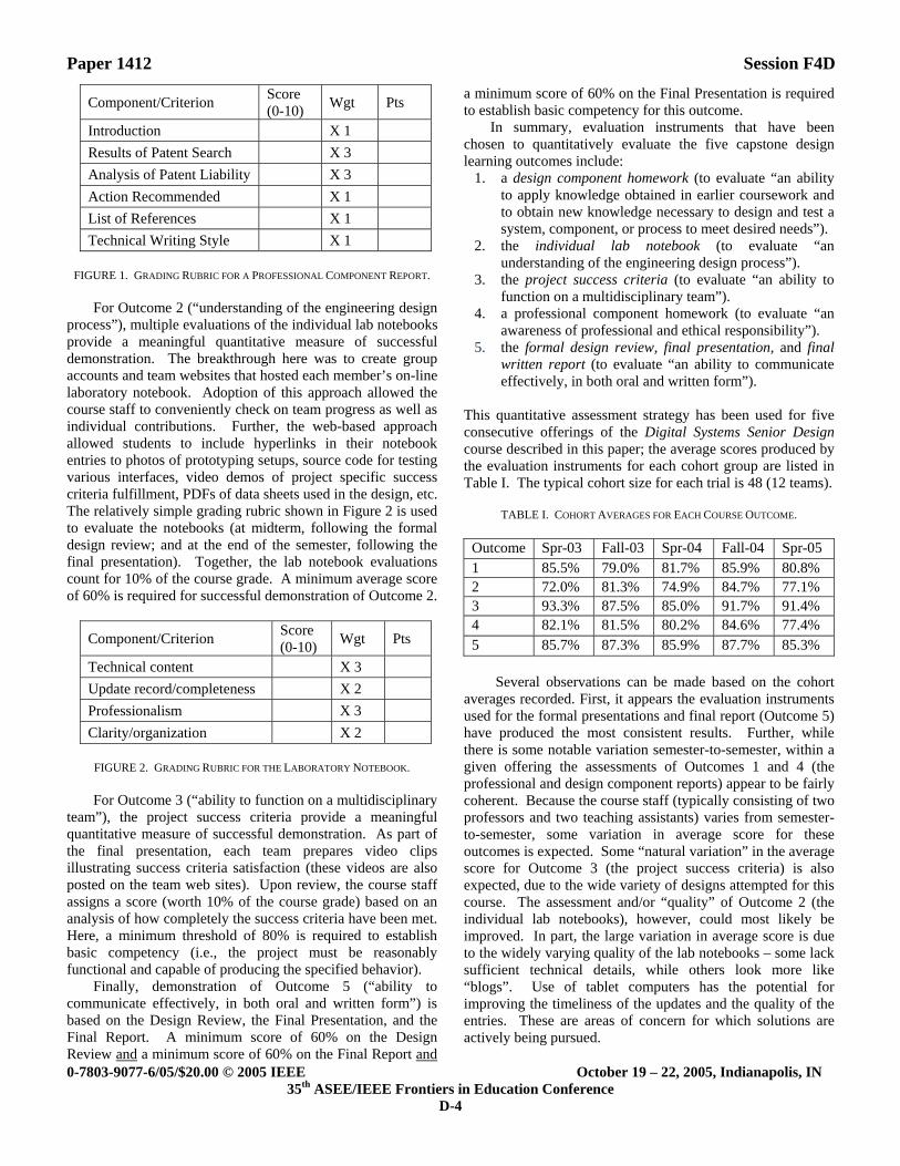
Paper 1412 Session F4D
0-7803-9077-6/05/$20.00 © 2005 IEEE October 19 – 22, 2005, Indianapolis, IN 35th ASEE/IEEE Frontiers in Education Conference
D-4
Component/Criterion Score (0-10) Wgt Pts
Introduction X 1 Results of Patent Search X 3 Analysis of Patent Liability X 3 Action Recommended X 1 List of References X 1 Technical Writing Style X 1
FIGURE 1. GRADING RUBRIC FOR A PROFESSIONAL COMPONENT REPORT.
For Outcome 2 (“understanding of the engineering design
process”), multiple evaluations of the individual lab notebooks provide a meaningful quantitative measure of successful demonstration. The breakthrough here was to create group accounts and team websites that hosted each member’s on-line laboratory notebook. Adoption of this approach allowed the course staff to conveniently check on team progress as well as individual contributions. Further, the web-based approach allowed students to include hyperlinks in their notebook entries to photos of prototyping setups, source code for testing various interfaces, video demos of project specific success criteria fulfillment, PDFs of data sheets used in the design, etc. The relatively simple grading rubric shown in Figure 2 is used to evaluate the notebooks (at midterm, following the formal design review; and at the end of the semester, following the final presentation). Together, the lab notebook evaluations count for 10% of the course grade. A minimum average score of 60% is required for successful demonstration of Outcome 2.
Component/Criterion Score (0-10) Wgt Pts
Technical content X 3 Update record/completeness X 2 Professionalism X 3 Clarity/organization X 2
FIGURE 2. GRADING RUBRIC FOR THE LABORATORY NOTEBOOK.
For Outcome 3 (“ability to function on a multidisciplinary
team”), the project success criteria provide a meaningful quantitative measure of successful demonstration. As part of the final presentation, each team prepares video clips illustrating success criteria satisfaction (these videos are also posted on the team web sites). Upon review, the course staff assigns a score (worth 10% of the course grade) based on an analysis of how completely the success criteria have been met. Here, a minimum threshold of 80% is required to establish basic competency (i.e., the project must be reasonably functional and capable of producing the specified behavior).
Finally, demonstration of Outcome 5 (“ability to communicate effectively, in both oral and written form”) is based on the Design Review, the Final Presentation, and the Final Report. A minimum score of 60% on the Design Review and a minimum score of 60% on the Final Report and
a minimum score of 60% on the Final Presentation is required to establish basic competency for this outcome.
In summary, evaluation instruments that have been chosen to quantitatively evaluate the five capstone design learning outcomes include:
1. a design component homework (to evaluate “an ability to apply knowledge obtained in earlier coursework and to obtain new knowledge necessary to design and test a system, component, or process to meet desired needs”).
2. the individual lab notebook (to evaluate “an understanding of the engineering design process”).
3. the project success criteria (to evaluate “an ability to function on a multidisciplinary team”).
4. a professional component homework (to evaluate “an awareness of professional and ethical responsibility”).
5. the formal design review, final presentation, and final written report (to evaluate “an ability to communicate effectively, in both oral and written form”).
This quantitative assessment strategy has been used for five consecutive offerings of the Digital Systems Senior Design course described in this paper; the average scores produced by the evaluation instruments for each cohort group are listed in Table I. The typical cohort size for each trial is 48 (12 teams).
TABLE I. COHORT AVERAGES FOR EACH COURSE OUTCOME.
Outcome Spr-03 Fall-03 Spr-04 Fall-04 Spr-05 1 85.5% 79.0% 81.7% 85.9% 80.8% 2 72.0% 81.3% 74.9% 84.7% 77.1% 3 93.3% 87.5% 85.0% 91.7% 91.4% 4 82.1% 81.5% 80.2% 84.6% 77.4% 5 85.7% 87.3% 85.9% 87.7% 85.3%
Several observations can be made based on the cohort
averages recorded. First, it appears the evaluation instruments used for the formal presentations and final report (Outcome 5) have produced the most consistent results. Further, while there is some notable variation semester-to-semester, within a given offering the assessments of Outcomes 1 and 4 (the professional and design component reports) appear to be fairly coherent. Because the course staff (typically consisting of two professors and two teaching assistants) varies from semester-to-semester, some variation in average score for these outcomes is expected. Some “natural variation” in the average score for Outcome 3 (the project success criteria) is also expected, due to the wide variety of designs attempted for this course. The assessment and/or “quality” of Outcome 2 (the individual lab notebooks), however, could most likely be improved. In part, the large variation in average score is due to the widely varying quality of the lab notebooks – some lack sufficient technical details, while others look more like “blogs”. Use of tablet computers has the potential for improving the timeliness of the updates and the quality of the entries. These are areas of concern for which solutions are actively being pursued.

Paper 1412 Session F4D
0-7803-9077-6/05/$20.00 © 2005 IEEE October 19 – 22, 2005, Indianapolis, IN 35th ASEE/IEEE Frontiers in Education Conference
D-5
OUTCOME REMEDIATION AND GRADE DETERMINATION
Despite being seniors about to be unleashed on the “real world” with degrees in hand, their “first attempt” at writing a formal, technical report may not always meet the minimum standards (and if they did, the application of thresholds would be meaningless). Opportunities for outcome remediation therefore need to be provided. Unlike the “content” courses referred to earlier in this paper (where outcome remediation is typically accomplished by providing a second exam over the same material), students who initially fail to demonstrate an outcome (e.g. receive a score on a design or professional homework below the prescribed passing threshold) must be given an opportunity for prompt remediation (e.g. rewriting the deficient paper, correcting the printed circuit board layout, etc.). One complication that arises is how to “count” the updated score toward the course grade. To prevent “abuse of the system”, it is probably wise to either average the original score with the revised score or award a nominally passing grade for the repeat submission. Experience has shown that if the higher score simply replaces the former score, students will quickly sense this “loophole” and exploit it to “buy time”.
Another issue related to remediation is the question of how to handle cases in which all the course outcomes have not been successfully demonstrated, yet the student has otherwise earned a passing grade. Unlike content courses, where repeating a course is a viable (and often the best) option, students in capstone design courses who are still deficient in a particular outcome (e.g., Outcome 3, due to a hardware or software “bug” that the team has been unable to resolve) should initially be awarded a grade of “I” (incomplete) and provided with a reasonable timetable to resolve the deficiency. If a team or individual is deficient in more than one outcome, however, then the best option might be requiring those individuals to repeat capstone design (perhaps electing an alternate option).
Another challenge for a team-oriented project course is ensuring equitable distribution of workload and grade determination based on both individual as well as corporate contributions. To this end, 50% of the course grade is based on team components, while the remaining 50% is based on individual components. The complete grading breakdown for the Digital Systems Design Project course is given in Table II.
TABLE II. WEIGHTS OF GRADING COMPONENTS.
TEAM COMPONENTS INDIVIDUAL COMPONENTS Design Review 10% Individual Contribution 10% Final Video Presentation 10% Lab Notebook Evaluations 10% Final Report & Archive CD 10% Design Component Rpt 10% Project Success Criteria 10% Professional Component Rpt 10% Project Proposal 2% OrCAD Exercise 2% User Manual 3% Presentation Peer Review 4% Senior Design Report 2% Confidential Peer Review 2% Poster 3% Weekly Progress Briefings 2%
SUMMARY AND CONCLUSIONS Different kinds of courses (in particular, “content” vs. “capstone design”) require different outcome assessment strategies, and finding the “best practices” for each case is non-trivial. As documented in [4], many assessment strategies have been employed in capstone design courses, yet uncertainty persists concerning sound practices. This paper has presented a systematic, quantitative strategy for assessing capstone design course outcomes and integrating the outcome assessment with course grade determination. Data from five consecutive trials show that meaningful results can be obtained despite inter-rater differences. Effective application of outcome assessment (using appropriate evaluation instruments, outcome demonstration success thresholds, and grading strategies) can truly promote and help learning.
REFERENCES
[1] http://www.abet.org/Linked%20Documents-UPDATE/Criteria%20and%20PP/05-06-EAC%20Criteria.pdf
[2] http://www.abet.org/Linked%20Documents-UPDATE/Program%20Docs/EAC%20Guidelines%20for%20Criterion3.pdf
[3] Atman, C. J., et al., “Matching Assessment Methods to Outcomes: Definitions and Research Questions,” 2000 American Society for Engineering Education Conference Proceedings.
[4] McKenzie, L. J., Trevisan, M. S., Davis, D. C., and Beyerlein, S. W., “Capstone Design Courses and Assessment: A National Study,” 2004 American Society for Engineering Education Conference Proceedings.
[5] Gesink, J., and Mousavinezhad, S. H., “An ECE Capstone Design Experience,” 2003 American Society for Engineering Education Conference Proceedings.
[6] Quadrato, C., and Welch, R. W., “Grading Capstone Design: On Time and On Target,” 2003 American Society for Engineering Education Conference Proceedings.
[7] Brackin, M. P., and Gibson, J. D., “Methods of Assessing Student Learning in Capstone Design Projects with Industry: A Five Year Review,” 2002 American Society for Engineering Education Conference Proceedings.
[8] Sobek, D. K., and Jain, V. K., “Two Instruments for Assessing Design Outcomes of Capstone Projects,” 2004 American Society for Engineering Education Conference Proceedings.
[9] Caso, R., Lee, J. H., Froyd, J., and Kohli, R., “Development of Design Assessment Instruments and Discussion of Freshman and Senior Design Assessment Results,” 2002 Frontiers in Education Conference Proceedings.
[10] Davis, K. C., “Assessment Opportunities in A Capstone Design Course,” 2004 American Society for Engineering Education Conference Proceedings.
[11] Jenkins, M. G., and Kramlich, J. C., “Assessment Methods under ABET EC2000 at the University of Washington – Lessons Learned: What Works and What Doesn’t,” 2002 American Society for Engineering Education Conference Proceedings.
[12] Meyer, D. G., "Outcome Assessment: Practical Realities and Lessons Learned", 2004 Frontiers in Education Conference Proceedings.
[13] http://shay.ecn.purdue.edu/~dsml/ece477
[14] Oakes, W. C., Jamieson, L. H., and Coyle, E. J., “EPICS: Meeting EC 2000 through Service-Learning,” 2001 American Society for Engineering Education Conference Proceedings.

Appendix E:
Course Calendar
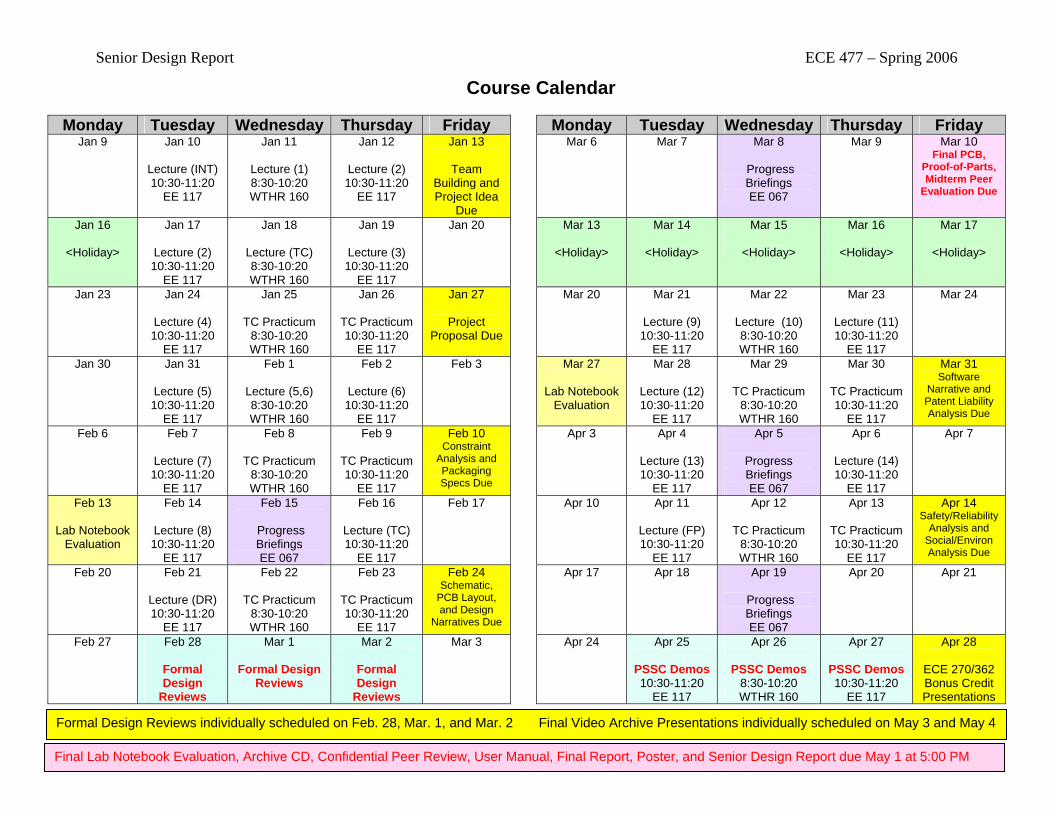
Senior Design Report ECE 477 – Spring 2006
Course Calendar
Monday Tuesday Wednesday Thursday Friday Monday Tuesday Wednesday Thursday Friday Jan 9
Jan 10
Lecture (INT) 10:30-11:20
EE 117
Jan 11
Lecture (1) 8:30-10:20 WTHR 160
Jan 12
Lecture (2) 10:30-11:20
EE 117
Jan 13
Team Building and Project Idea
Due
Mar 6
Mar 7
Mar 8
Progress Briefings EE 067
Mar 9 Mar 10 Final PCB,
Proof-of-Parts, Midterm Peer
Evaluation Due
Jan 16
<Holiday>
Jan 17
Lecture (2) 10:30-11:20
EE 117
Jan 18
Lecture (TC) 8:30-10:20 WTHR 160
Jan 19
Lecture (3) 10:30-11:20
EE 117
Jan 20
Mar 13
<Holiday>
Mar 14
<Holiday>
Mar 15
<Holiday>
Mar 16
<Holiday>
Mar 17
<Holiday>
Jan 23
Jan 24
Lecture (4) 10:30-11:20
EE 117
Jan 25
TC Practicum 8:30-10:20 WTHR 160
Jan 26
TC Practicum 10:30-11:20
EE 117
Jan 27
Project Proposal Due
Mar 20
Mar 21
Lecture (9) 10:30-11:20
EE 117
Mar 22
Lecture (10) 8:30-10:20 WTHR 160
Mar 23
Lecture (11) 10:30-11:20
EE 117
Mar 24
Jan 30
Jan 31
Lecture (5) 10:30-11:20
EE 117
Feb 1
Lecture (5,6) 8:30-10:20 WTHR 160
Feb 2
Lecture (6) 10:30-11:20
EE 117
Feb 3
Mar 27
Lab Notebook Evaluation
Mar 28
Lecture (12) 10:30-11:20
EE 117
Mar 29
TC Practicum 8:30-10:20 WTHR 160
Mar 30
TC Practicum 10:30-11:20
EE 117
Mar 31 Software
Narrative and Patent Liability Analysis Due
Feb 6
Feb 7
Lecture (7) 10:30-11:20
EE 117
Feb 8
TC Practicum 8:30-10:20 WTHR 160
Feb 9
TC Practicum 10:30-11:20
EE 117
Feb 10 Constraint
Analysis and Packaging Specs Due
Apr 3
Apr 4
Lecture (13) 10:30-11:20
EE 117
Apr 5
Progress Briefings EE 067
Apr 6
Lecture (14) 10:30-11:20
EE 117
Apr 7
Feb 13
Lab Notebook Evaluation
Feb 14
Lecture (8) 10:30-11:20
EE 117
Feb 15
Progress Briefings EE 067
Feb 16
Lecture (TC) 10:30-11:20
EE 117
Feb 17
Apr 10
Apr 11
Lecture (FP) 10:30-11:20
EE 117
Apr 12
TC Practicum 8:30-10:20 WTHR 160
Apr 13
TC Practicum 10:30-11:20
EE 117
Apr 14 Safety/Reliability
Analysis and Social/Environ Analysis Due
Feb 20
Feb 21
Lecture (DR) 10:30-11:20
EE 117
Feb 22
TC Practicum 8:30-10:20 WTHR 160
Feb 23
TC Practicum 10:30-11:20
EE 117
Feb 24 Schematic,
PCB Layout, and Design
Narratives Due
Apr 17
Apr 18
Apr 19
Progress Briefings EE 067
Apr 20 Apr 21
Feb 27
Feb 28
Formal Design
Reviews
Mar 1
Formal Design Reviews
Mar 2
Formal Design
Reviews
Mar 3
Apr 24
Apr 25
PSSC Demos 10:30-11:20
EE 117
Apr 26
PSSC Demos 8:30-10:20 WTHR 160
Apr 27
PSSC Demos 10:30-11:20
EE 117
Apr 28
ECE 270/362 Bonus Credit Presentations
Formal Design Reviews individually scheduled on Feb. 28, Mar. 1, and Mar. 2 Final Video Archive Presentations individually scheduled on May 3 and May 4
Final Lab Notebook Evaluation, Archive CD, Confidential Peer Review, User Manual, Final Report, Poster, and Senior Design Report due May 1 at 5:00 PM