SENECA NATION FINAL REPORT Installation of a 1.5MW ...
83
SENECA NATION FINAL REPORT Installation of a 1.5MW WIND TURBINE DOE GRANT # DE-EE0006475 ANTHONY GIACOBBE SENECA NATION/SENECA ENERGY DIRECTOR OF POWER & GAS 9/21/2017 Table of Contents I. Executive Summary II. Description of Activities III. Project Overview IV. Project Team V. NEPA VI. CESIR VII. Final Design VIII. Vensys IX. Post-construction monitoring X. Marketing/Publications XI. Pictures XII. Outcomes/Conclusions I. Executive Summary The Seneca Nation has long understood that energy resources have tremendous value. Recently, however, the Nation has come to appreciate the significance of the development and management of their own energy resources. Beginning with strategic energy planning that has resulted in a sound energy organization with a long-term Strategic Energy Plan, which is allowing the Seneca Nation to pursue a deliberate path to energy development and self-sufficiency. The Seneca Nation has watched their resources be exploited for hundreds of years with little economic benefit, and in turn have inherited a legacy of environmental and safety hazards. Seneca Energy is working to reverse this trend through renewable energy projects such as the Cattaraugus wind turbine. The single turbine will reduce CO2 output by 86,000,000 lbs./yr., equivalent to removing 147 cars off the road each year. The development of distributed generation resources of energy on Nation lands can not only ensure a source of reliable and competitively priced electricity, but could also provide economic development opportunities and sustain the Nation's existence as a viable, functioning community for future generations. In exercising its sovereignty, the Nation wishes to develop its renewable resources as a means to permanent financial stability as well as to further their political and cultural viability both regionally and nationally. The Seneca Nation, located on three primary territories in Western New York, has embarked on a
-
Upload
khangminh22 -
Category
Documents
-
view
1 -
download
0
Transcript of SENECA NATION FINAL REPORT Installation of a 1.5MW ...
SENECA NATION FINAL REPORT
Installation of a 1.5MW WIND TURBINE
DOE GRANT # DE-EE0006475
ANTHONY GIACOBBE
SENECA NATION/SENECA ENERGY
DIRECTOR OF POWER & GAS
9/21/2017
Table of Contents
I. Executive Summary
II. Description of Activities
III. Project Overview
IV. Project Team
V. NEPA
VI. CESIR
VII. Final Design
VIII. Vensys
IX. Post-construction monitoring
X. Marketing/Publications
XI. Pictures
XII. Outcomes/Conclusions
I. Executive Summary
The Seneca Nation has long understood that energy resources have tremendous value. Recently,
however, the Nation has come to appreciate the significance of the development and management of
their own energy resources. Beginning with strategic energy planning that has resulted in a sound
energy organization with a long-term Strategic Energy Plan, which is allowing the Seneca Nation to
pursue a deliberate path to energy development and self-sufficiency.
The Seneca Nation has watched their resources be exploited for hundreds of years with little economic
benefit, and in turn have inherited a legacy of environmental and safety hazards. Seneca Energy is
working to reverse this trend through renewable energy projects such as the Cattaraugus wind turbine.
The single turbine will reduce CO2 output by 86,000,000 lbs./yr., equivalent to removing 147 cars off
the road each year.
The development of distributed generation resources of energy on Nation lands can not only ensure a
source of reliable and competitively priced electricity, but could also provide economic development
opportunities and sustain the Nation's existence as a viable, functioning community for future
generations. In exercising its sovereignty, the Nation wishes to develop its renewable resources as a
means to permanent financial stability as well as to further their political and cultural viability both
regionally and nationally.
The Seneca Nation, located on three primary territories in Western New York, has embarked on a

long-range energy planning mission to establish a strategic plan for energy self-sufficiency. The
Strategic Energy Plan employs both renewable and non-renewable energy for the development of a
culturally appropriate, self-sufficient economy and serves as a roadmap to accomplish this vision.
With the long term goal of energy sovereignty, the Nation will endeavor to develop its resources to 1)
develop economic opportunities and job creation within the territories, and; 2) provide an alternative,
competitive source of energy for its governmental and business operations, and; 3) create a balanced
portfolio of renewable and non-renewable sources of energy to achieve a stable and economically sound
generation plan, and; 4) provide its members with programs for increased energy efficiency as well as
cost savings for electric supply.
II. Description of Activities
The Seneca Nation of Indians is currently in Phase III of a four-phase planning process in realizing
its energy vision. In July 2003, the Seneca Nation commenced a multi-phased, strategic energy
planning project. Phase I was completed in March 2004, funded primarily with Nation funds, with
some funding assistance from DOE and BIA. The objective of Phase I was to define the overall
goals of the Seneca Nation's long-range energy vision as it relates to energy self-sufficiency, future
needs and demand for services, and energy planning and development. Meetings and public
gatherings were held to provide a forum for dialogue between leaders, community members and
other stakeholders, to collaborate on energy options and ideas for development. The results were
published in the “Long Range Energy Plan, Phase One” Report.
Phase II included a preliminary energy use and rate analysis, short term (3 years) use projections,
a gas well inventory and condition report with recommendations for remediation, preliminary wind
assessment research and preparation for a full wind study, and an overview of the natural gas
resources and market dynamics. Some organizational development was initiated, and a high level
review of the Right of Way, natural gas settlement and various other legal documents were also
initiated. Recommendations for utility formation and more in-depth resource assessment were
among the report conclusions.
In 2013 under Phase III the Nation created Seneca Energy, LLC thereby chartering a Seneca
Nation utility organization capable of providing energy generation and distribution both on and
off territory. The Utility now encompasses both electric and gas generation/production and
delivery. The distributed generation initiatives are seen as an important component of the Seneca
Nation’s Strategic Energy Vision.
III. Project Overview
This project was initiated with an in-depth wind assessment on the Cattaraugus and Allegany
Territories. The assessment confirmed that there is a vast wind resource on the Cattaraugus
Territory off the coast of Lake Erie. The project was a culmination of years of planning and
research to identify and select the most advantageous project to begin building the cornerstone of
Seneca Energy’s strategic vision.
In February 2014, Seneca Energy and the Seneca Nation officially kicked off the Cattaraugus wind
turbine project. The project began with a nine month NEPA study, which resulted in a Finding
of No Significant Impact on 10/5/2015. The Seneca Construction Management Company was
responsible for the oversight of the civil and foundation construction which commenced shortly
after the FONSI was finalized.
With the winter coming, there was a delay in construction after the struggle to locate a single-
turbine available for purchase. Seneca Energy failed to make ample progress in negotiations for a
Turbine Sales Agreement (TSA) with both GE and Vestas. These are the top two turbine
manufacturers in the market and neither was interested in working with the Seneca Nation on this
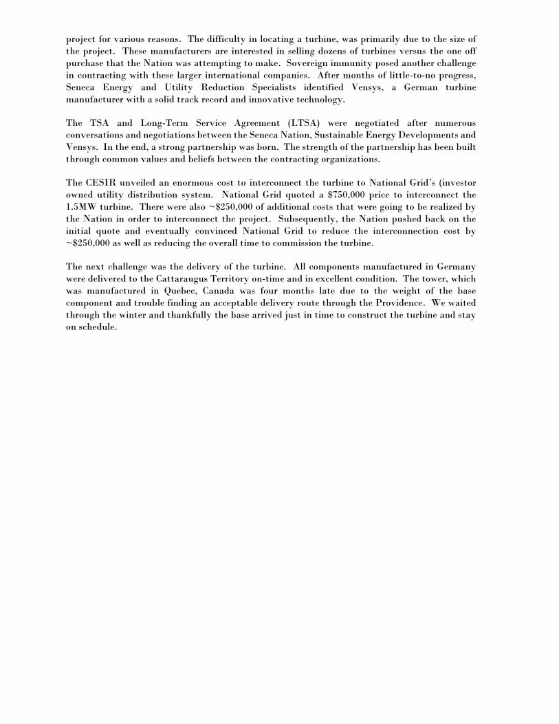
project for various reasons. The difficulty in locating a turbine, was primarily due to the size of
the project. These manufacturers are interested in selling dozens of turbines versus the one off
purchase that the Nation was attempting to make. Sovereign immunity posed another challenge
in contracting with these larger international companies. After months of little-to-no progress,
Seneca Energy and Utility Reduction Specialists identified Vensys, a German turbine
manufacturer with a solid track record and innovative technology.
The TSA and Long-Term Service Agreement (LTSA) were negotiated after numerous
conversations and negotiations between the Seneca Nation, Sustainable Energy Developments and
Vensys. In the end, a strong partnership was born. The strength of the partnership has been built
through common values and beliefs between the contracting organizations.
The CESIR unveiled an enormous cost to interconnect the turbine to National Grid’s (investor
owned utility distribution system. National Grid quoted a $750,000 price to interconnect the
1.5MW turbine. There were also ~$250,000 of additional costs that were going to be realized by
the Nation in order to interconnect the project. Subsequently, the Nation pushed back on the
initial quote and eventually convinced National Grid to reduce the interconnection cost by
~$250,000 as well as reducing the overall time to commission the turbine.
The next challenge was the delivery of the turbine. All components manufactured in Germany
were delivered to the Cattaraugus Territory on-time and in excellent condition. The tower, which
was manufactured in Quebec, Canada was four months late due to the weight of the base
component and trouble finding an acceptable delivery route through the Providence. We waited
through the winter and thankfully the base arrived just in time to construct the turbine and stay
on schedule.
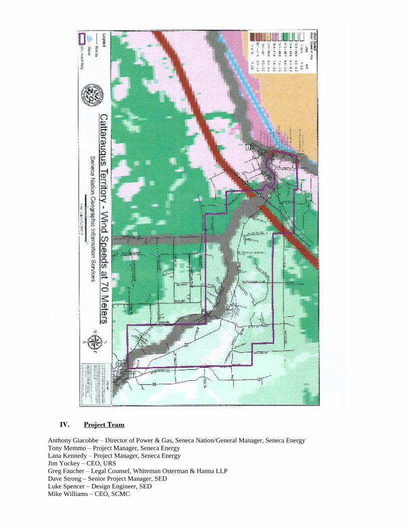
IV. Project Team
Anthony Giacobbe – Director of Power & Gas, Seneca Nation/General Manager, Seneca Energy
Tony Memmo – Project Manager, Seneca Energy
Lana Kennedy – Project Manager, Seneca Energy
Jim Yockey – CEO, URS
Greg Faucher – Legal Counsel, Whiteman Osterman & Hanna LLP
Dave Strong – Senior Project Manager, SED
Luke Spencer – Design Engineer, SED
Mike Williams – CEO, SCMC

Theo Peters – Vensys
Greg Fasano – NWT
Daniel Yanosh, Jr. – Fisher Associates
Numerous Seneca Nation Departments and external partners
V. NEPA Study
The NEPA study entailed an initial and final scoping period as well as a full Environmental
Assessment (EA) to determine whether or not there would be negative impacts on the environment
and/or population as a whole. It was determined after many months of studies and analysis that
there would be no significant impacts on any species. The Seneca Nation was provided with the
below FONSI on October 5, 2015. Throughout the EA process, the Seneca Nation consulted with
numerous Nation Departments, such as EPD, THPO, TERO and the Planning Dept. in addition to
outside agencies such as the DOE, USFWS and FAA.
Department of Energy Golden Field Office
15013 Denver West Parkway Golden, Colorado 80401
FINDING OF NO SIGNIFICANT IMPACT
THE SENECA NATION WIND
TURBINE PROJECT DOE/EA-2004
AGENCY: U.S. Department of Energy (DOE), Office of Energy Efficiency and
Renewable Energy
ACTION: Finding of No Significant Impact (FONSI)
SUMMARY: DOE is proposing to authorize the expenditure of federal funding to the
Seneca Nation of Indians (SNI) to design, permit, and construct up to a 2.0-megawatt wind
turbine on Tribal common lands in the Cattaraugus Territory, New York (Proposed
Project)1. In compliance with the National Environmental Policy Act (NEPA), DOE and
SNI jointly prepared and completed the Environmental Assessment for the Seneca Nation
Wind Turbine Project Cattaraugus Territory Erie County, New York (DOE/EA-2004) that
identified and evaluated the potential environmental impacts of providing federal funds to
SNI for this proposed project. The analysis completed in the environmental assessment
(EA) supports DOE's finding that providing federal funding for the Proposed Project will
not significantly affect the quality of the human and natural environment. The EA is hereby
incorporated into this FONSI by reference.
SNI's proposed project involves the construction, operation and maintenance, and
eventual decommissioning of a single wind turbine of up to 2.0 megawatts on 1.5 acres
of SNI-owned sovereign land located northeast of Lucky Layne, within the western
portion of the Cattaraugus Territory, Erie County, New York. Examples of the type of
wind turbine being considered by SNI include the GE 103 1.7 megawatt and the Vensys
1.5 megawatt models. The proposed project includes the construction of a gravel access
road, temporary crane pad, turbine foundation, and installation of transmission
equipment and cables. Regardless of which wind turbine model is selected, it would have
a maximum rotor diameter of approximately 330 feet and would connect at its hub

(midpoint) to an approximately 265-foot-tall tower (maximum). The total maximum
height of the wind turbine from the bottom of the tower to the blade tip at its highest
point is expected to be approximately 430 feet. The current estimated project cost is $6
million. The project would reduce electrical demands on the existing electricity service
provider from the existing SNI administrative buildings and be credited back to the
Cattaraugus Territory residents and electricity users. The project would also equalize
rates among SNI territories. Once installed, the turbine is anticipated to produce
approximately 5,000 megawatt-hours of electrical power annually.
Prior to the issuance of this FONSI, DOE authorized SNI to use a percentage of the federal funding for preliminary activities, which included initial planning and design, environmental studies, and preparation of the EA. These activities are associated with the Proposed Project and do not significantly impact the environment nor represent an irreversible commitment by DOE in advance of this finding for SNI's wind energy project.
Finding of No Significant Impact 1 DOE/EA-2004
DOE places a strong emphasis on avoiding, minimizing, and mitigating potential adverse
environmental impacts. SNI has committed to minimize or avoid potential environmental
effects to air quality, visual resources, biological resources, cultural resources, health and safety
of workers and the public, land uses, noise, socioeconomics and environmental justice,
transportation, and utilities and energy through the implementation of best management
practices (BMP) detailed in Section 3.4 of the EA. These commitments by SNI shall be
incorporated through DOE's financial assistance agreement.
Context of Potential Impacts
DOE must evaluate the significance of an action in several different contexts, such as society as
a whole (human and national), the affected region, the affected interests, and the locality.
Significance varies with the setting of the proposed action. For instance, in the case of a site-
specific action, significance would usually depend upon the effects in the locale rather than in
the world as a whole. Both short- and long-term effects are relevant.
The proposed project would be located on approximately 1.5 acres of SNI-owned sovereign
land in the Cattaraugus Territory (approximately one acre of previously disturbed land will be
graded). The project site lies approximately 630 feet northeast of Lucky Layne Road, is
immediately east of New York State Route (NY) 5 and west of existing railroad tracks. Lake
Erie is located approximately 1.5 miles west of the project site. The project site is currently
undeveloped, consisting of some previously cleared land, grasses, shrub vegetation, and
forested woodland. The site is adjacent to a larger parcel of land consisting of surface parking
and a mix of commercial/industrial structures. These physical structures include a 135-foot-tall
water tower immediately south of the project site, the Gil Lay Memorial Sports Arena, the SNI
Bingo Hall and associated structures, roadway NY 5 directly west of the project site and a rail
line directly east.
Based on the analysis in the EA, impacts of the Proposed Project would range from negligible
to minor due to the nature of the proposed activities. The effects are limited to the local
geographic area and are temporary and small-scale in nature. In addition, SNI has committed to
implementing the BMPs listed in Section 3.4 of the EA to minimize or avoid potential
environmental effects. The Proposed Project itself would not cause any significant or
cumulative adverse effects nationally, regionally, locally, or at the statewide level.
Intensity of Potential Impacts
The determination of impact significance also considers the intensity, or severity or extent, of
the impact. Intensity is evaluated against the factors listed in 40 CFR 1508.27, including:
1) Impacts that may be both beneficial and adverse:
In the EA, DOE considered and analyzed the beneficial and adverse impacts of the Proposed
Project. Construction and operation of the Proposed Project would result in negligible to minor
direct and indirect adverse impacts on the environment and would have slight beneficial impacts
on air quality and socioeconomics in the area. The BMPs committed to by SNI would further
minimize or eliminate the potential for adverse impacts to environmental resources.
Finding of No Significant Impact 2
DOE/EA-2004

The EA evaluated adverse effects of the Proposed Project separately from beneficial effects, to
determine whether such adverse effects would have been significant in their own right, and no
such effects were found to be significant. The Proposed Project would have potential beneficial,
yet minimal or unmeasurable effects to air quality, the local economy, and to SNI's electric
utility consumption. In no cases did the analysis in the EA use beneficial effects to offset the
potential significance of any adverse effect. In addition, the EA did not use any long-term
beneficial effects to offset the potential significance of any short-term adverse effects.
Accordingly, DOE concludes the Proposed Project will not have any significant adverse
impacts and that the Proposed Project would have negligible to minor beneficial impacts to the
resources evaluated in the EA.
2) The degree to which the proposed action affects public health or safety:
The EA evaluated whether the Proposed Project would have disproportionately high or adverse
human health or environmental effects, and whether it would be a likely target for intentional
destructive acts that could affect public safety. The EA addressed several potential impacts that
the Proposed Project could have on public and worker health and safety — tower collapse and
blade throw, shadow flicker and blade glint and glare, severe weather, exposure to
electromagnetic fields, and hazards to roadways, railways, and airspace and aircraft. Analysis in
the EA determined that the impacts to these resources would be non-existent to minimal.
SNI's committed BMPs for health and safety will further reduce the potential for adverse impacts
to occur. SNI will ensure that all contractors adhere to construction- and operation-specific health
and safety plans and that the wind turbine would be marked according to Federal Aviation
Administration airspace safety regulations. SNI would prepare a health and safety plan to ensure
that established policies and procedures are followed for a safe work environment.
Based on the findings in the EA and implementation of SNI's committed BMPs, DOE concludes
that there will be no adverse effects to public and worker health or safety. The Proposed Project
would not be a likely target for intentional destructive acts and it will not cause any significant,
cumulative or long-term effects on health and safety.
3) Unique characteristics of the geographic area such as proximity to historic or cultural
resources, park lands, prime farmlands, wetlands, wild and scenic rivers, or ecologically
critical areas.
The Proposed Project is not located in any unique geographic or ecologically critical area, and
there are no park lands, wet areas/wetlands, or protected rivers nearby that would be affected.
The New York State Cultural Resources Identification System (CRIS) lists an archaeological
site in the Cattaraugus Territory located within approximately one mile of the proposed project
site that is eligible for listing on the National Register of Historic Places (NRHP). SNI Tribal
Historic Preservation Office (THPO) staff conducted an onsite preconstruction survey to
evaluate the proposed site for the presence of archaeological or historic resources. Pursuant to
Section 106 of the National Historic Preservation Act, the THPO made a finding of "no effect"
to cultural resources from the SNI Wind Turbine Project.
Finding of No Significant Impact 3
DOE/EA-2004
Based on the analysis provided in the EA, DOE has concluded that the Proposed Project
would not cause any adverse effects on unique characteristics of the geographic area.
4) The degree to which the effects on the quality of the human environment are likely to be
highly controversial:
The analysis in the EA demonstrates that the effects of the Proposed Project on the natural and
human environment would be minimal. During both the public scoping and public comment
period, no factual evidence was presented that questioned the technical and scientific analyses
of the EA or supporting documents.
5) The degree to which the possible effects on the human environment are highly uncertain
or involve unique or unknown risks:
The possible effects on the human environment from wind turbine installation have been
fully analyzed and supported by previous projects, studies, and publications (EA, Section
5.0). The Proposed Project does not involve new technology, and therefore, possible effects
are readily ascertainable and would not involve unique or unknown risks.
6) The degree to which the action may establish a precedent for future actions with
significant effects or represents a decision in principle about a future consideration:
Neither scoping nor public comment for the Proposed Project raised any disputes pertaining to
the appropriate scope of the Proposed Project, connectedness of other actions, or reasonably
foreseeable future actions. The Proposed Project would increase the energy independence of
SNI as a whole and create electrical utility rate cost equivalency between two SNI territories
(Cattaraugus and Allegany), as well as result in energy cost stabilization and savings, which
could motivate other Tribal communities to seek similar energy independence and long-term
access to reasonably priced electric power. However, the impacts associated with the Proposed
Project would be minimal, and it is unlikely that the project would establish a precedent for
future actions with significant effects in other communities.
7) Whether the action is related to other actions with individually insignificant but
cumulatively significant impacts:
DOE considered and analyzed in the EA the cumulative effects of the Proposed Project with
other past, present, and reasonably foreseeable future actions. Information on existing and
planned wind energy facilities was obtained from the New York State Department of
Environmental Conservation renewable energy website. The Proposed Project would add one
additional wind turbine to 314 existing wind turbines and 62 proposed wind turbines associated
with several projects located within approximately 40 miles of the SNI wind turbine site. Also,
the site is adjacent to several SNI business and industrial buildings and would result in grading
and development of approximately one acre of forested land. Additional possible SNI
development in the immediate area could include industrial or business parks and greenhouses.
The impacts of the Proposed Project are expected to be minor and localized so the spatial
extent of potential cumulative impacts was limited to adjacent areas of the project location.
Based on the above summary and the analysis in the EA, DOE has determined that there are
no potential impacts to resources identified in the EA that would be cumulatively significant.
Finding of No Significant Impact 4
DOE/EA-2004
8) The degree to which the action may adversely affect districts, sites, highways, structures, or objects listed in or eligible for listing in the National Register of Historic Places or may cause loss or destruction of significant scientific, cultural, or historical resources:
CRIS identifies historic structures in the vicinity that are listed or eligible for listing on the
NRHP and include numerous residential and other buildings in the Village of Silver Creek near
the shore of Lake Erie, approximately 3.5 miles southwest of the proposed wind turbine
location. In addition, CRIS identifies eight buildings and structures listed on the NRHP that are
associated with the SNI administrative office location approximately six miles southeast of the
project site. The potential historic context and experiences associated with the resources located
in the Village of Silver Creek and in the area of the SNI offices would not be affected by the
proposed wind turbine due to the general inability to see the turbine structure because of large
distances involved and terrain and vegetation obstructions.
Based on analysis provided in the EA and consultations with the SNI THPO, DOE has concluded
that the Proposed Project will not adversely affect cultural or historic resources in the area.
9) The degree to which the action may adversely affect an endangered or threatened species or
its habitat that has been determined to be critical under the Endangered Species Act of 1973:
DOE consulted with the U.S. Fish and Wildlife Service (USFWS) regarding the potential
presence of listed species and critical habitat in the area. One species, the northern long-eared
bat (Myotis septentrionalis), that occurs in Erie County in the region surrounding the project site
has recently been listed as threatened by the USFWS (80 FR 17974, April 2, 2015). Although
suitable summer and roosting habitat does exist for this species in a wider region from the
project site in western New York, there is no known suitable hibernacula habitat in the
immediate project area. DOE believes that mortality of a northern long-eared bat is extremely
unlikely to occur because of project construction and operating procedures and BMPs (EA,
Section 3.4). There are no critical habitat areas designated by the USFWS for any federally
endangered or threatened species in Erie County.
Based on analyses provided in the EA and consultations with the USFWS, DOE has
concluded that the Proposed Project "may affect, but is not likely to adversely affect" the
northern long-eared bat. The USFWS concurred with DOE's finding on July 24, 2015.
10) Whether the action threatens a violation of federal, state, or local law or
requirements imposed for the protection of the environment:
DOE recognizes the sovereign nature of Native American governments and lands, specifically
SNI and the Cattaraugus Territory, in defining and regulating the environmental resources
associated with proposed actions on SNI lands. As such, SNI regulatory agencies and processes
comprise the main environmental compliance responsibilities associated with this project and
are entirely consistent with other federal regulatory requirements for protection of the
environment. SNI has committed to protecting the environment by implementing the BMPs as
detailed in Section 3.4 of the EA. These commitments shall be incorporated through DOE's
financial assistance agreement.
Finding of No Significant Impact 5
DOE/EA-2004
CONCLUSION: Based on the analysis in the EA and the above considerations, DOE finds that
the decision to provide federal funding for the Proposed Project is not a major federal action
that constitutes a significant effect on the human environment. This finding and decision are
based on the considerations of DOE's regulations (10 CFR Part 1021) implementing NEPA (42
U.S.C. 4321 et seq) and the Council on Environmental Quality's criteria for significance (40
CFR 1508.27), both with regard to the context and intensity of impacts analyzed in the EA.
Accordingly, the Proposed Project does not require the preparation of an environmental impact
statement.
For questions about this FONSI or the final EA, please contact:
Casey Strickland
NEPA Document Manager
U.S. Department of Energy
Golden Field Office 15013 Denver West Parkway
Golden, Colorado 80401
For information about the DOE NEPA process, please contact:
Office of NEPA Policy and Compliance
U.S. Department of Energy
1000 Independence Avenue, SW
Washington, DC 20585 http://energy.gov/nepa/office-nepa-policy-and-compliance
Issued in Golden, Colorado this 5 ft ay of October, 2015.
Timothy J. Meeks Acting Manager
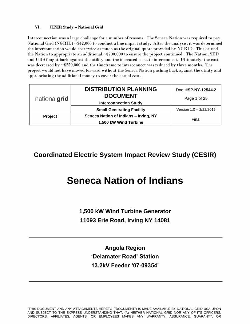
VI. CESIR Study – National Grid
Interconnection was a large challenge for a number of reasons. The Seneca Nation was required to pay
National Grid (NGRID) ~$42,000 to conduct a line impact study. After the analysis, it was determined
the interconnection would cost twice as much as the original quote provided by NGRID. This caused
the Nation to appropriate an additional ~$700,000 to ensure the project continued. The Nation, SED
and URS fought back against the utility and the increased costs to interconnect. Ultimately, the cost
was decreased by ~$250,000 and the timeframe to interconnect was reduced by three months. The
project would not have moved forward without the Seneca Nation pushing back against the utility and
appropriating the additional money to cover the actual cost.
DISTRIBUTION PLANNING DOCUMENT
Interconnection Study
Doc. #SP.NY-12544.2
Page 1 of 25
Small Generating Facility Version 1.0 – 2/22/2016
Project Seneca Nation of Indians – Irving, NY
1,500 kW Wind Turbine Final
Coordinated Electric System Impact Review Study (CESIR)
Seneca Nation of Indians
1,500 kW Wind Turbine Generator
11093 Erie Road, Irving NY 14081
Angola Region
‘Delamater Road’ Station
13.2kV Feeder ‘07-09354’
"THIS DOCUMENT AND ANY ATTACHMENTS HERETO ("DOCUMENT") IS MADE AVAILABLE BY NATIONAL GRID USA UPON AND SUBJECT TO THE EXPRESS UNDERSTANDING THAT: (A) NEITHER NATIONAL GRID NOR ANY OF ITS OFFICERS, DIRECTORS, AFFILIATES, AGENTS, OR EMPLOYEES MAKES ANY WARRANTY, ASSURANCE, GUARANTY, OR

REPRESENTATION WITH RESPECT TO THE CONTENTS OF THE DOCUMENT OR THE ACCURACY OR COMPLETENESS OF THE INFORMATION CONTAINED OR REFERENCED IN THE DOCUMENT, AND (B) NATIONAL GRID USA, ITS OFFICERS, DIRECTORS, AFFILIATES, AGENTS, AND EMPLOYEES SHALL NOT HAVE ANY LIABILITY OR RESPONSIBILITY FOR INACCURACIES, ERRORS, OR OMISSIONS IN, OR ANY BUSINESS OR POLICY DECISIONS MADE BY ANY DIRECT OR INDIRECT RECIPIENT IN RELIANCE ON, THIS DOCUMENT OR THE INFORMATION CONTAINED OR REFERENCED THEREIN; ALL SUCH LIABILITY IS EXPRESSLY DISCLAIMED."
PRINTED COPIES ARE NOT DOCUMENT CONTROLLED.
FOR THE LATEST AUTHORIZED VERSION PLEASE REFER TO THE DISTRIBUTION ASSET MANAGEMENT DOCUMENTS CABINET IN DOCUMENTUM.
W.O #: 10019529249
App File: NY-12544 Seneca Nation of Indians– Final CESIR.doc
Originating Department: Retail Connections Engineering - NY
Sponsor: Technical Sales & Engineering Support - NY

DISTRIBUTION PLANNING DOCUMENT
Interconnection Study
Doc. #SP.NY-12544.2
Page 2 of 25
Small Generating Facility Version 1.0 – 2/22/2016
Project Seneca Nation of Indians – Irving, NY
1,500 kW Wind Turbine Final
TABLE OF CONTENTS
Section Page
INTRODUCTION 3
1.0 PROJECT DESCRIPTION 4
2.0 SCOPE 4
2.1 OBJECTIVES 5
2.2 BACKGROUND 6
3.0 UTILITY SYSTEM IMPACTS 8
3.1 THERMAL AND VOLTAGE ANALYSIS 8
3.2 POWER FLOW SENSITIVITY ANALYSIS AND RESULTS 8
3.3 OPERATIONAL RESTRICTIONS AND IMPACT 9
4.0 SYSTEM PROTECTION 9
4.1 SYSTEM PROTECTION ANALYSIS 9
4.1.1 Short Circuit Analysis 9
4.1.2 Coordination Study 10
5.0 INTERCONNECTION METHOD CONCLUSIONS AND ALTERNATIVES 12
6.0 INTERCONNECTION CUSTOMER ATTACHMENT FACILITIES REQUIREMENTS 13
6.1 MAIN SERVICE EQUIPMENT REQUIREMENTS 13
6.2 GROUNDING REQUIREMENTS 13
6.3 BALANCE OF INTERCONNECTION CUSTOMER FACILITIES 14
7.0 METERING AND TELEMETERING 15
7.1 REVENUE METERING 15
7.2 TELEMETERING – ENERGY MANAGEMENT SYSTEM (EMS) 15
8.0 INSPECTIONS AND COMPLIANCE VERIFICATION 16
9.0 TESTING AND COMMISSIONING 17
10.0 ENERGIZATION AND SYNCHRONIZATION 17
11.0 OPERATION AND MAINTENANCE 17
12.0 CONCEPTUAL COST ESTIMATE 18
13.0 SCHEDULING AND INTERCONNECTION CUSTOMER’S PROGRESS CHECKLIST 20
14.0 REVISION HISTORY 20
ATTACHMENT 1: GIS OF SUB-TRANSMISSION TAP TO CUSTOMER LOCATION 21
ATTACHMENT 2: INTERCONNECTION CUSTOMER’S PROPOSED ONE-LINE DIAGRAM 22
PRINTED COPIES ARE NOT DOCUMENT CONTROLLED.
FOR THE LATEST AUTHORIZED VERSION PLEASE REFER TO THE DISTRIBUTION ASSET MANAGEMENT DOCUMENTS CABINET IN DOCUMENTUM.
W.O #: 10019529249
App File: NY-12544 Seneca Nation of Indians– Final CESIR.doc
Originating Department: Retail Connections Engineering - NY
Sponsor: Technical Sales & Engineering Support - NY
DISTRIBUTION PLANNING DOCUMENT
Interconnection Study
Doc. #SP.NY-12544.2
Page 3 of 25
Small Generating Facility Version 1.0 – 2/22/2016
Project Seneca Nation of Indians – Irving, NY
1,500 kW Wind Turbine Final
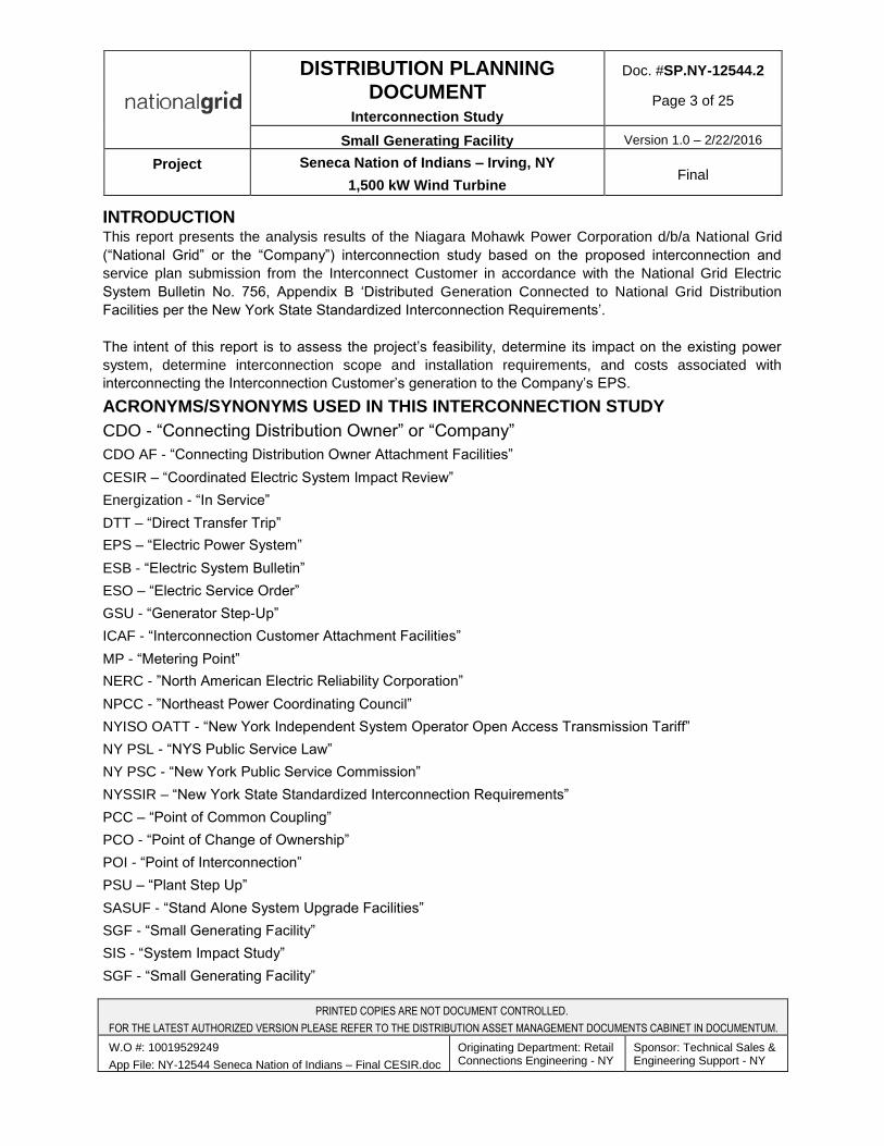
INTRODUCTION This report presents the analysis results of the Niagara Mohawk Power Corporation d/b/a National Grid
(“National Grid” or the “Company”) interconnection study based on the proposed interconnection and
service plan submission from the Interconnect Customer in accordance with the National Grid Electric
System Bulletin No. 756, Appendix B ‘Distributed Generation Connected to National Grid Distribution
Facilities per the New York State Standardized Interconnection Requirements’.
The intent of this report is to assess the project’s feasibility, determine its impact on the existing power
system, determine interconnection scope and installation requirements, and costs associated with
interconnecting the Interconnection Customer’s generation to the Company’s EPS.
ACRONYMS/SYNONYMS USED IN THIS INTERCONNECTION STUDY
CDO - “Connecting Distribution Owner” or “Company”
CDO AF - “Connecting Distribution Owner Attachment Facilities”
CESIR – “Coordinated Electric System Impact Review”
Energization - “In Service”
DTT – “Direct Transfer Trip”
EPS – “Electric Power System”
ESB - “Electric System Bulletin”
ESO – “Electric Service Order”
GSU - “Generator Step-Up”
ICAF - “Interconnection Customer Attachment Facilities”
MP - “Metering Point”
NERC - ”North American Electric Reliability Corporation”
NPCC - ”Northeast Power Coordinating Council”
NYISO OATT - “New York Independent System Operator Open Access Transmission Tariff”
NY PSL - “NYS Public Service Law”
NY PSC - “New York Public Service Commission”
NYSSIR – “New York State Standardized Interconnection Requirements”
PCC – “Point of Common Coupling”
PCO - “Point of Change of Ownership”
POI - “Point of Interconnection”
PSU – “Plant Step Up”
SASUF - “Stand Alone System Upgrade Facilities”
SGF - “Small Generating Facility”
SIS - “System Impact Study”
SGF - “Small Generating Facility”
PRINTED COPIES ARE NOT DOCUMENT CONTROLLED.
FOR THE LATEST AUTHORIZED VERSION PLEASE REFER TO THE DISTRIBUTION ASSET MANAGEMENT DOCUMENTS CABINET IN DOCUMENTUM.
W.O #: 10019529249
App File: NY-12544 Seneca Nation of Indians – Final CESIR.doc
Originating Department: Retail Connections Engineering - NY
Sponsor: Technical Sales & Engineering Support - NY
DISTRIBUTION PLANNING DOCUMENT
Interconnection Study
Doc. #SP.NY-12544.2
Page 4 of 25
Small Generating Facility Version 1.0 – 2/22/2016
Project Seneca Nation of Indians – Irving, NY
1,500 kW Wind Turbine Final
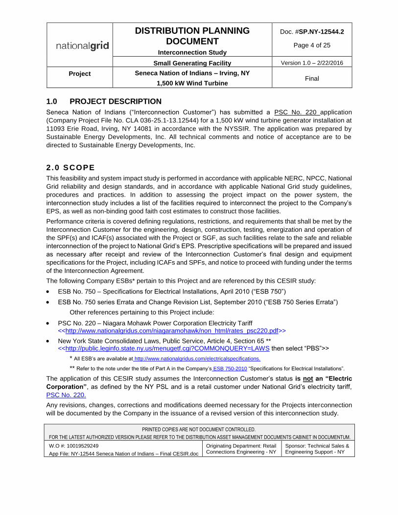
1.0 PROJECT DESCRIPTION
Seneca Nation of Indians (“Interconnection Customer”) has submitted a PSC No. 220 application
(Company Project File No. CLA 036-25.1-13.12544) for a 1,500 kW wind turbine generator installation at
11093 Erie Road, Irving, NY 14081 in accordance with the NYSSIR. The application was prepared by
Sustainable Energy Developments, Inc. All technical comments and notice of acceptance are to be
directed to Sustainable Energy Developments, Inc.
2.0 SCOPE
This feasibility and system impact study is performed in accordance with applicable NERC, NPCC, National
Grid reliability and design standards, and in accordance with applicable National Grid study guidelines,
procedures and practices. In addition to assessing the project impact on the power system, the
interconnection study includes a list of the facilities required to interconnect the project to the Company’s
EPS, as well as non-binding good faith cost estimates to construct those facilities.
Performance criteria is covered defining regulations, restrictions, and requirements that shall be met by the
Interconnection Customer for the engineering, design, construction, testing, energization and operation of
the SPF(s) and ICAF(s) associated with the Project or SGF, as such facilities relate to the safe and reliable
interconnection of the project to National Grid’s EPS. Prescriptive specifications will be prepared and issued
as necessary after receipt and review of the Interconnection Customer’s final design and equipment
specifications for the Project, including ICAFs and SPFs, and notice to proceed with funding under the terms
of the Interconnection Agreement.
The following Company ESBs* pertain to this Project and are referenced by this CESIR study:
ESB No. 750 – Specifications for Electrical Installations, April 2010 (“ESB 750”)
ESB No. 750 series Errata and Change Revision List, September 2010 (“ESB 750 Series Errata”)
Other references pertaining to this Project include:
PSC No. 220 – Niagara Mohawk Power Corporation Electricity Tariff <<http://www.nationalgridus.com/niagaramohawk/non_html/rates_psc220.pdf>>
New York State Consolidated Laws, Public Service, Article 4, Section 65 ** <<http://public.leginfo.state.ny.us/menugetf.cgi?COMMONQUERY=LAWS then select “PBS”>>
* All ESB’s are available at http://www.nationalgridus.com/electricalspecifications.
** Refer to the note under the title of Part A in the Company’s ESB 750-2010 “Specifications for Electrical Installations”.
The application of this CESIR study assumes the Interconnection Customer’s status is not an “Electric
Corporation”, as defined by the NY PSL and is a retail customer under National Grid’s electricity tariff,
PSC No. 220.
Any revisions, changes, corrections and modifications deemed necessary for the Projects interconnection
will be documented by the Company in the issuance of a revised version of this interconnection study.
PRINTED COPIES ARE NOT DOCUMENT CONTROLLED.
FOR THE LATEST AUTHORIZED VERSION PLEASE REFER TO THE DISTRIBUTION ASSET MANAGEMENT DOCUMENTS CABINET IN DOCUMENTUM.
W.O #: 10019529249
App File: NY-12544 Seneca Nation of Indians – Final CESIR.doc
Originating Department: Retail Connections Engineering - NY
Sponsor: Technical Sales & Engineering Support - NY
DISTRIBUTION PLANNING DOCUMENT
Interconnection Study
Doc. #SP.NY-12544.2
Page 5 of 25
Small Generating Facility Version 1.0 – 2/22/2016
Project Seneca Nation of Indians – Irving, NY
1,500 kW Wind Turbine Final
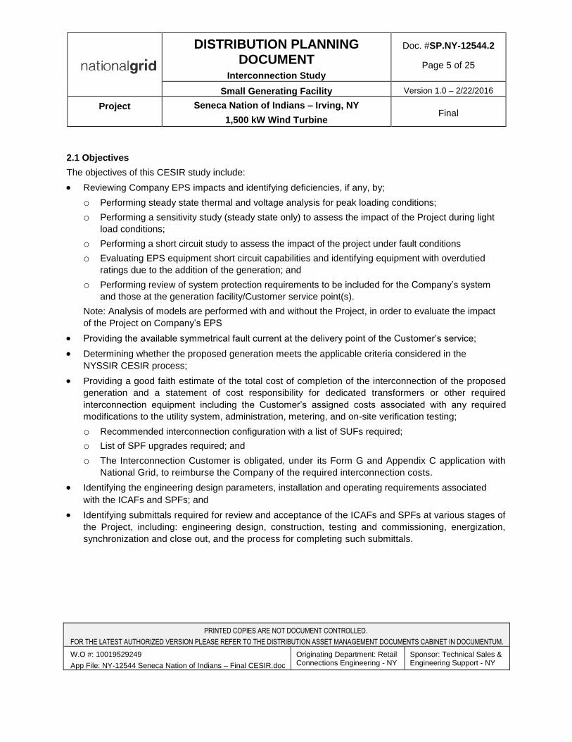
2.1 Objectives
The objectives of this CESIR study include:
Reviewing Company EPS impacts and identifying deficiencies, if any, by;
o Performing steady state thermal and voltage analysis for peak loading conditions;
o Performing a sensitivity study (steady state only) to assess the impact of the Project during light
load conditions;
o Performing a short circuit study to assess the impact of the project under fault conditions
o Evaluating EPS equipment short circuit capabilities and identifying equipment with overdutied
ratings due to the addition of the generation; and
o Performing review of system protection requirements to be included for the Company’s system
and those at the generation facility/Customer service point(s).
Note: Analysis of models are performed with and without the Project, in order to evaluate the impact
of the Project on Company’s EPS
Providing the available symmetrical fault current at the delivery point of the Customer’s service;
Determining whether the proposed generation meets the applicable criteria considered in the
NYSSIR CESIR process;
Providing a good faith estimate of the total cost of completion of the interconnection of the proposed
generation and a statement of cost responsibility for dedicated transformers or other required
interconnection equipment including the Customer’s assigned costs associated with any required
modifications to the utility system, administration, metering, and on-site verification testing;
o Recommended interconnection configuration with a list of SUFs required;
o List of SPF upgrades required; and
o The Interconnection Customer is obligated, under its Form G and Appendix C application with
National Grid, to reimburse the Company of the required interconnection costs.
Identifying the engineering design parameters, installation and operating requirements associated
with the ICAFs and SPFs; and
Identifying submittals required for review and acceptance of the ICAFs and SPFs at various stages of
the Project, including: engineering design, construction, testing and commissioning, energization,
synchronization and close out, and the process for completing such submittals.
PRINTED COPIES ARE NOT DOCUMENT CONTROLLED.
FOR THE LATEST AUTHORIZED VERSION PLEASE REFER TO THE DISTRIBUTION ASSET MANAGEMENT DOCUMENTS CABINET IN DOCUMENTUM.
W.O #: 10019529249
App File: NY-12544 Seneca Nation of Indians – Final CESIR.doc
Originating Department: Retail Connections Engineering - NY
Sponsor: Technical Sales & Engineering Support - NY
DISTRIBUTION PLANNING DOCUMENT
Interconnection Study
Doc. #SP.NY-12544.2
Page 6 of 25
Small Generating Facility Version 1.0 – 2/22/2016
Project Seneca Nation of Indians – Irving, NY
1,500 kW Wind Turbine Final
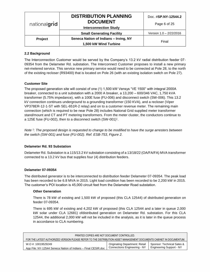
2.2 Background
The Interconnection Customer would be served by the Company’s 13.2 kV radial distribution feeder 07-
09354 from the Delameter Rd. substation. The Interconnect Customer proposes to install a new primary
net-metered service. This service new primary service would need to be connected at Pole 28, to the north
of the existing recloser (R93400) that is located on Pole 26 (with an existing isolation switch on Pole 27).
Customer Site
The proposed generation site will consist of one (1) 1,500 kW Vensys “VE 1500” with integral 2000A
breaker, connected to a unit substation with a 2000 A breaker, a 13,200 – 600/346 VAC, 1,750 kVA
transformer (5.75% impedance), with a 100E fuse (FU-006) and disconnect switch (SW-006). This 13.2
kV connection continues underground to a grounding transformer (150 KVA), and a recloser (Viper
VP378ER-12-1-ST with SEL-651R-2 relay) and on to a customer revenue meter. The remaining main
connection (which is required to be near Pole 28) includes National Grid supplied meter transformer
stand/mount and CT and PT metering transformers. From the meter cluster, the conductors continue to
a 125E fuse (FU-002), then to a disconnect switch (SW-001)1.
Note 1: The proposed design is requested to change to be modified to have the surge arresters between
the switch (SW-001) and fuse (FU-002). Ref. ESB-753, Figure 2.
Delameter Rd. 93 Substation
Delameter Rd. Substation is a 115/13.2 kV substation consisting of a 13/18/22 (OA/FA/FA) MVA transformer
connected to a 13.2 kV bus that supplies four (4) distribution feeders.
Delameter 07-09354
The distributed generator is to be interconnected to distribution feeder Delameter 07-09354. The peak load
has been recorded to be 6.8 MVA in 2015. Light load condition has been recorded to be 2,200 kW in 2015.
The customer’s POI location is 45,000 circuit feet from the Delameter Road substation.
Other Generation
There is 78 kW of existing and 1,500 kW of proposed (this CLA 12544) of distributed generation on
feeder 07-09354.
There is 695 kW of existing and 4,202 kW of proposed (this CLA 12544 and a later in queue 2,000
kW solar under CLA 12681) ofdistributed generation on Delameter Rd. substation. For this CLA
12544, the additional 2,000 kW will not be included in the analysis, as it is later in the queue process
in accordance to CLA numbering.
PRINTED COPIES ARE NOT DOCUMENT CONTROLLED.
FOR THE LATEST AUTHORIZED VERSION PLEASE REFER TO THE DISTRIBUTION ASSET MANAGEMENT DOCUMENTS CABINET IN DOCUMENTUM.
W.O #: 10019529249
App File: NY-12544 Seneca Nation of Indians – Final CESIR.doc
Originating Department: Retail Connections Engineering - NY
Sponsor: Technical Sales & Engineering Support - NY
DISTRIBUTION PLANNING DOCUMENT
Interconnection Study
Doc. #SP.NY-12544.2
Page 7 of 25
Small Generating Facility Version 1.0 – 2/22/2016
Project Seneca Nation of Indians – Irving, NY
1,500 kW Wind Turbine Final
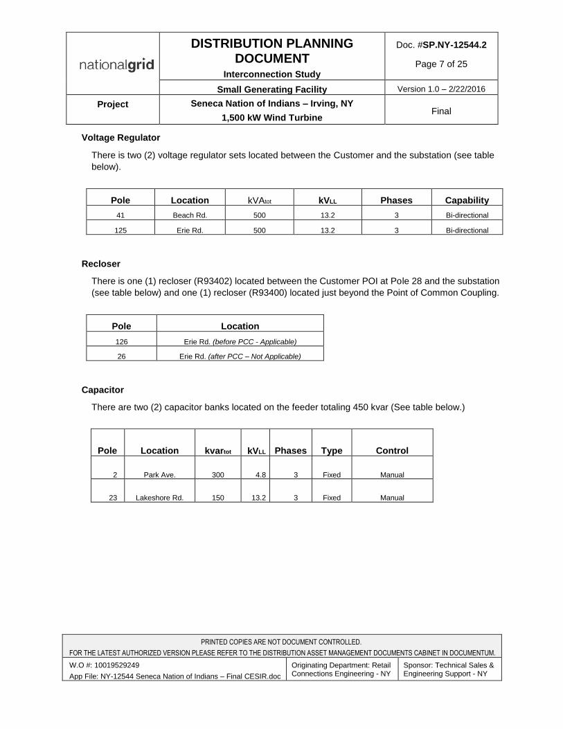
Voltage Regulator
There is two (2) voltage regulator sets located between the Customer and the substation (see table
below).
Pole Location kVAtot kVLL Phases Capability
41 Beach Rd. 500 13.2 3 Bi-directional
125 Erie Rd. 500 13.2 3 Bi-directional
Recloser
There is one (1) recloser (R93402) located between the Customer POI at Pole 28 and the substation
(see table below) and one (1) recloser (R93400) located just beyond the Point of Common Coupling.
Pole Location
126 Erie Rd. (before PCC - Applicable)
26 Erie Rd. (after PCC – Not Applicable)
Capacitor
There are two (2) capacitor banks located on the feeder totaling 450 kvar (See table below.)
Pole Location kvartot kVLL Phases Type Control
2 Park Ave. 300 4.8 3 Fixed Manual
23 Lakeshore Rd. 150 13.2 3 Fixed Manual
PRINTED COPIES ARE NOT DOCUMENT CONTROLLED.
FOR THE LATEST AUTHORIZED VERSION PLEASE REFER TO THE DISTRIBUTION ASSET MANAGEMENT DOCUMENTS CABINET IN DOCUMENTUM.
W.O #: 10019529249
App File: NY-12544 Seneca Nation of Indians – Final CESIR.doc
Originating Department: Retail Connections Engineering - NY
Sponsor: Technical Sales & Engineering Support - NY
DISTRIBUTION PLANNING DOCUMENT
Interconnection Study
Doc. #SP.NY-12544.2
Page 8 of 25
Small Generating Facility Version 1.0 – 2/22/2016
Project Seneca Nation of Indians – Irving, NY
1,500 kW Wind Turbine Final
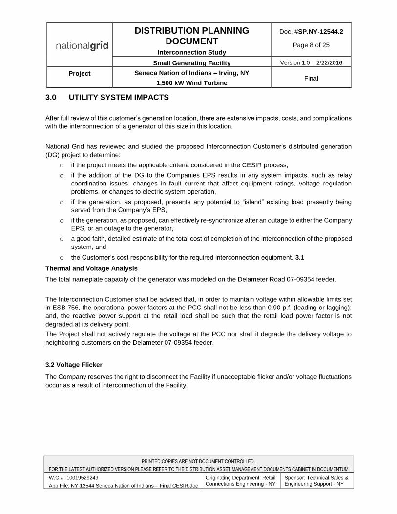
3.0 UTILITY SYSTEM IMPACTS
After full review of this customer’s generation location, there are extensive impacts, costs, and complications
with the interconnection of a generator of this size in this location.
National Grid has reviewed and studied the proposed Interconnection Customer’s distributed generation
(DG) project to determine:
o if the project meets the applicable criteria considered in the CESIR process,
o if the addition of the DG to the Companies EPS results in any system impacts, such as relay
coordination issues, changes in fault current that affect equipment ratings, voltage regulation
problems, or changes to electric system operation,
o if the generation, as proposed, presents any potential to “island” existing load presently being
served from the Company’s EPS,
o if the generation, as proposed, can effectively re-synchronize after an outage to either the Company
EPS, or an outage to the generator,
o a good faith, detailed estimate of the total cost of completion of the interconnection of the proposed
system, and
o the Customer’s cost responsibility for the required interconnection equipment. 3.1
Thermal and Voltage Analysis
The total nameplate capacity of the generator was modeled on the Delameter Road 07-09354 feeder.
The Interconnection Customer shall be advised that, in order to maintain voltage within allowable limits set
in ESB 756, the operational power factors at the PCC shall not be less than 0.90 p.f. (leading or lagging);
and, the reactive power support at the retail load shall be such that the retail load power factor is not
degraded at its delivery point.
The Project shall not actively regulate the voltage at the PCC nor shall it degrade the delivery voltage to
neighboring customers on the Delameter 07-09354 feeder.
3.2 Voltage Flicker
The Company reserves the right to disconnect the Facility if unacceptable flicker and/or voltage fluctuations
occur as a result of interconnection of the Facility.
PRINTED COPIES ARE NOT DOCUMENT CONTROLLED.
FOR THE LATEST AUTHORIZED VERSION PLEASE REFER TO THE DISTRIBUTION ASSET MANAGEMENT DOCUMENTS CABINET IN DOCUMENTUM.
W.O #: 10019529249
App File: NY-12544 Seneca Nation of Indians – Final CESIR.doc
Originating Department: Retail Connections Engineering - NY
Sponsor: Technical Sales & Engineering Support - NY
DISTRIBUTION PLANNING DOCUMENT
Interconnection Study
Doc. #SP.NY-12544.2
Page 9 of 25
Small Generating Facility Version 1.0 – 2/22/2016
Project Seneca Nation of Indians – Irving, NY
1,500 kW Wind Turbine Final
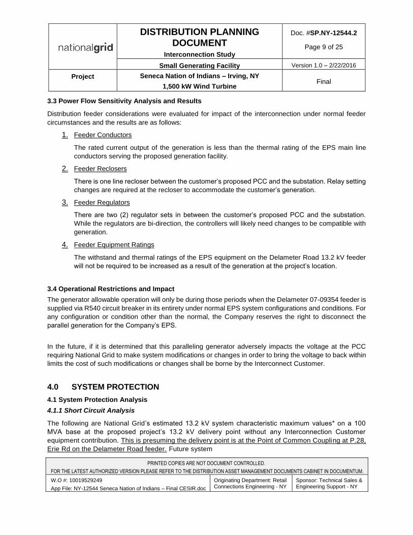
3.3 Power Flow Sensitivity Analysis and Results
Distribution feeder considerations were evaluated for impact of the interconnection under normal feeder
circumstances and the results are as follows:
1. Feeder Conductors
The rated current output of the generation is less than the thermal rating of the EPS main line
conductors serving the proposed generation facility.
2. Feeder Reclosers
There is one line recloser between the customer’s proposed PCC and the substation. Relay setting
changes are required at the recloser to accommodate the customer’s generation.
3. Feeder Regulators
There are two (2) regulator sets in between the customer’s proposed PCC and the substation.
While the regulators are bi-direction, the controllers will likely need changes to be compatible with
generation.
4. Feeder Equipment Ratings
The withstand and thermal ratings of the EPS equipment on the Delameter Road 13.2 kV feeder
will not be required to be increased as a result of the generation at the project’s location.
3.4 Operational Restrictions and Impact
The generator allowable operation will only be during those periods when the Delameter 07-09354 feeder is
supplied via R540 circuit breaker in its entirety under normal EPS system configurations and conditions. For
any configuration or condition other than the normal, the Company reserves the right to disconnect the
parallel generation for the Company’s EPS.
In the future, if it is determined that this paralleling generator adversely impacts the voltage at the PCC
requiring National Grid to make system modifications or changes in order to bring the voltage to back within
limits the cost of such modifications or changes shall be borne by the Interconnect Customer.
4.0 SYSTEM PROTECTION
4.1 System Protection Analysis
4.1.1 Short Circuit Analysis
The following are National Grid’s estimated 13.2 kV system characteristic maximum values* on a 100
MVA base at the proposed project’s 13.2 kV delivery point without any Interconnection Customer
equipment contribution. This is presuming the delivery point is at the Point of Common Coupling at P.28,
Erie Rd on the Delameter Road feeder. Future system
PRINTED COPIES ARE NOT DOCUMENT CONTROLLED.
FOR THE LATEST AUTHORIZED VERSION PLEASE REFER TO THE DISTRIBUTION ASSET MANAGEMENT DOCUMENTS CABINET IN DOCUMENTUM.
W.O #: 10019529249
App File: NY-12544 Seneca Nation of Indians – Final CESIR.doc
Originating Department: Retail Connections Engineering - NY
Sponsor: Technical Sales & Engineering Support - NY
DISTRIBUTION PLANNING DOCUMENT
Interconnection Study
Doc. #SP.NY-12544.2
Page 10 of 25
Small Generating Facility Version 1.0 – 2/22/2016
Project Seneca Nation of Indians – Irving, NY
1,500 kW Wind Turbine Final
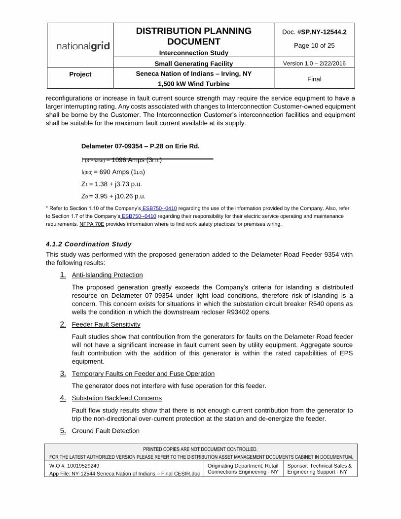
reconfigurations or increase in fault current source strength may require the service equipment to have a
larger interrupting rating. Any costs associated with changes to Interconnection Customer-owned equipment
shall be borne by the Customer. The Interconnection Customer’s interconnection facilities and equipment
shall be suitable for the maximum fault current available at its supply.
Delameter 07-09354 – P.28 on Erie Rd.
I (3-Phase) = 1096 Amps (3LLL)
I(3I0) = 690 Amps (1LG)
Z1 = 1.38 + j3.73 p.u.
Z0 = 3.95 + j10.26 p.u.
* Refer to Section 1.10 of the Company’s ESB750--0410 regarding the use of the information provided by the Company. Also, refer
to Section 1.7 of the Company’s ESB750--0410 regarding their responsibility for their electric service operating and maintenance
requirements. NFPA 70E provides information where to find work safety practices for premises wiring.
4.1.2 Coordination Study
This study was performed with the proposed generation added to the Delameter Road Feeder 9354 with
the following results:
1. Anti-Islanding Protection
The proposed generation greatly exceeds the Company’s criteria for islanding a distributed
resource on Delameter 07-09354 under light load conditions, therefore risk-of-islanding is a
concern. This concern exists for situations in which the substation circuit breaker R540 opens as
wells the condition in which the downstream recloser R93402 opens.
2. Feeder Fault Sensitivity
Fault studies show that contribution from the generators for faults on the Delameter Road feeder
will not have a significant increase in fault current seen by utility equipment. Aggregate source
fault contribution with the addition of this generator is within the rated capabilities of EPS
equipment.
3. Temporary Faults on Feeder and Fuse Operation
The generator does not interfere with fuse operation for this feeder.
4. Substation Backfeed Concerns
Fault flow study results show that there is not enough current contribution from the generator to
trip the non-directional over-current protection at the station and de-energize the feeder.
5. Ground Fault Detection
PRINTED COPIES ARE NOT DOCUMENT CONTROLLED.
FOR THE LATEST AUTHORIZED VERSION PLEASE REFER TO THE DISTRIBUTION ASSET MANAGEMENT DOCUMENTS CABINET IN DOCUMENTUM.
W.O #: 10019529249
App File: NY-12544 Seneca Nation of Indians – Final CESIR.doc
Originating Department: Retail Connections Engineering - NY
Sponsor: Technical Sales & Engineering Support - NY
DISTRIBUTION PLANNING DOCUMENT
Interconnection Study
Doc. #SP.NY-12544.2
Page 11 of 25
Small Generating Facility Version 1.0 – 2/22/2016
Project Seneca Nation of Indians – Irving, NY
1,500 kW Wind Turbine Final
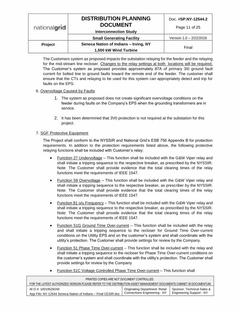
The Customers system as proposed impacts the substation relaying for the feeder and the relaying
for the mid-stream line recloser. Changes to the relay settings at both locations will be required.
The Customer’s system as proposed provides approximately 87A of primary 3I0 ground fault
current for bolted line to ground faults toward the remote end of the feeder. The customer shall
ensure that the CTs and relaying to be used for this system can appropriately detect and trip for
faults on the EPS.
6. Overvoltage Caused by Faults
1. The system as proposed does not create significant overvoltage conditions on the
feeder during faults on the Company’s EPS when the grounding transformers are in
service.
2. It has been determined that 3V0 protection is not required at the substation for this
project.
7. SGF Protective Equipment
The Project shall conform to the NYSSIR and National Grid’s ESB 756 Appendix B for protection
requirements. In addition to the protection requirements listed above, the following protective
relaying functions shall be included with Customer’s relay:
Function 27 Undervoltage – This function shall be included with the G&W Viper relay and
shall initiate a tripping sequence to the respective breaker, as prescribed by the NYSSIR.
Note: The Customer shall provide evidence that the total clearing times of the relay
functions meet the requirements of IEEE 1547.
Function 59 Overvoltage – This function shall be included with the G&W Viper relay and
shall initiate a tripping sequence to the respective breaker, as prescriber by the NYSSIR.
Note: The Customer shall provide evidence that the total clearing times of the relay
functions meet the requirements of IEEE 1547.
Function 81 o/u Frequency – This function shall be included with the G&W Viper relay and
shall initiate a tripping sequence to the respective breaker, as prescribed by the NYSSIR.
Note: The Customer shall provide evidence that the total clearing times of the relay
functions meet the requirements of IEEE 1547.
Function 51G Ground Time Over-current – This function shall be included with the relay
and shall initiate a tripping sequence to the recloser for Ground Time Over-current
conditions on the Utility EPS and on the customer’s system and shall coordinate with the
utility’s protection. The Customer shall provide settings for review by the Company.
Function 51 Phase Time Over-current – This function shall be included with the relay and
shall initiate a tripping sequence to the recloser for Phase Time Over-current conditions on
the customer’s system and shall coordinate with the utility’s protection. The Customer shall
provide settings for review by the Company.
Function 51C Voltage Controlled Phase Time Over-current – This function shall
PRINTED COPIES ARE NOT DOCUMENT CONTROLLED.
FOR THE LATEST AUTHORIZED VERSION PLEASE REFER TO THE DISTRIBUTION ASSET MANAGEMENT DOCUMENTS CABINET IN DOCUMENTUM.
W.O #: 10019529249
App File: NY-12544 Seneca Nation of Indians – Final CESIR.doc
Originating Department: Retail Connections Engineering - NY
Sponsor: Technical Sales & Engineering Support - NY
DISTRIBUTION PLANNING DOCUMENT
Interconnection Study
Doc. #SP.NY-12544.2
Page 12 of 25
Small Generating Facility Version 1.0 – 2/22/2016
Project Seneca Nation of Indians – Irving, NY
1,500 kW Wind Turbine Final
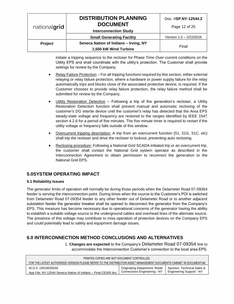
initiate a tripping sequence to the recloser for Phase Time Over-current conditions on the
Utility EPS and shall coordinate with the utility’s protection. The Customer shall provide
settings for review by the Company.
Relay Failure Protection – For all tripping functions required by this section, either external
relaying or relay failure protection, where a hardware or power supply failure for the relay
automatically trips and blocks close of the associated protective device, is required. If the
Customer chooses to provide relay failure protection, the relay failure method shall be
submitted for review by the Company.
Utility Restoration Detection – Following a trip of the generation’s recloser, a Utility
Restoration Detection function shall prevent manual and automatic reclosing of the
customer's DG intertie device until the customer's relay has detected that the Area EPS
steady-state voltage and frequency are restored to the ranges identified by IEEE 1547
section 4.2.6 for a period of five minutes. The five minute timer is required to restart if the
utility voltage or frequency falls outside of this window.
Overcurrent tripping description: A trip from an overcurrent function (51, 51G, 51C, etc)
shall trip the recloser and drive the recloser to lockout, preventing auto reclosing.
Reclosing procedure: Following a National Grid SCADA initiated trip or an overcurrent trip,
the customer shall contact the National Grid system operator as described in the
Interconnection Agreement to obtain permission to reconnect the generation to the
National Grid EPS.
5.0SYSTEM OPERATING IMPACT
5.1 Reliability Issues
The generator limits of operation will normally be during those periods when the Delameter Road 07-09354
feeder is serving the interconnection point. During times when the source to the Customer’s POI is switched
from Delameter Road 07-09354 feeder to any other feeder out of Delameter Road or to another adjacent
substation feeder the generator breaker shall be opened to disconnect the generator from the Company’s
EPS. This measure has become necessary due to operational concerns of the generator having the ability
to establish a suitable voltage source to the underground cables and overhead lines of the alternate source.
The presence of this voltage may contribute to miss-operation of protective devices on the Company EPS
and could potentially lead to safety and equipment damage issues.
6.0 INTERCONNECTION METHOD CONCLUSIONS AND ALTERNATIVES
1. Changes are expected to the Company’s Delameter Road 07-09354 line to
accommodate the Interconnection Customer’s connection to the local area EPS.
PRINTED COPIES ARE NOT DOCUMENT CONTROLLED.
FOR THE LATEST AUTHORIZED VERSION PLEASE REFER TO THE DISTRIBUTION ASSET MANAGEMENT DOCUMENTS CABINET IN DOCUMENTUM.
W.O #: 10019529249
App File: NY-12544 Seneca Nation of Indians – Final CESIR.doc
Originating Department: Retail Connections Engineering - NY
Sponsor: Technical Sales & Engineering Support - NY
DISTRIBUTION PLANNING DOCUMENT
Interconnection Study
Doc. #SP.NY-12544.2
Page 13 of 25
Small Generating Facility Version 1.0 – 2/22/2016
Project Seneca Nation of Indians – Irving, NY
1,500 kW Wind Turbine Final
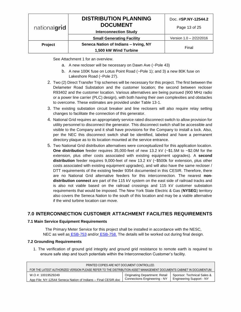
See Attachment 1 for an overview.
a. A new recloser will be necessary on Dawn Ave (~Pole 43)
b. A new 100K fuse on Lotus Point Road (~Pole 1); and 3) a new 80K fuse on
Lakeshore Road (~Pole 27).
2. Two (2) Direct Transfer Trip schemes will be necessary for this project. The first between the
Delameter Road Substation and the customer location; the second between recloser
R93402 and the customer location. Various alternatives are being pursued (900 MHz radio
or a power line carrier (PLC) design), with both having their own complexities and obstacles
to overcome. These estimates are provided under Table 13-1.
3. The existing substation circuit breaker and line reclosers will also require relay setting
changes to facilitate the connection of this generator.
4. National Grid requires an appropriately service rated disconnect switch to allow provision for
utility personnel to disconnect the generator. This disconnect switch shall be accessible and
visible to the Company and it shall have provisions for the Company to install a lock. Also,
per the NEC this disconnect switch shall be identified, labeled and have a permanent
directory plaque as to its location mounted at the service entrance.
5. Two National Grid distribution alternatives were conceptualized for this application location.
One distribution feeder requires 35,000-feet of new 13.2 kV (~$1.5M to ~$2.0M for the
extension, plus other costs associated with existing equipment upgrades). A second
distribution feeder requires 9,000-feet of new 13.2 kV (~$500k for extension, plus other
costs associated with existing equipment upgrades), and will also have the same recloser /
DTT requirements of the existing feeder 9354 documented in this CESIR. Therefore, there
are no National Grid alternative feeders for this interconnection. The nearest non-
distribution connect are part of the 115 kV system on the east side of railroad tracks and
is also not viable based on the railroad crossings and 115 kV customer substation
requirements that would be imposed. The New York State Electric & Gas (NYSEG) territory
also covers the Seneca Nation to the south of this location and may be a viable alternative
if the wind turbine location can move.
7.0 INTERCONNECTION CUSTOMER ATTACHMENT FACILITIES REQUIREMENTS
7.1 Main Service Equipment Requirements
The Primary Meter Service for this project shall be installed in accordance with the NESC,
NEC as well as ESB-753 and/or ESB-758. The details will be worked out during final design.
7.2 Grounding Requirements
1. The verification of ground grid integrity and ground grid resistance to remote earth is required to
ensure safe step and touch potentials within the Interconnection Customer’s facility.
PRINTED COPIES ARE NOT DOCUMENT CONTROLLED.
FOR THE LATEST AUTHORIZED VERSION PLEASE REFER TO THE DISTRIBUTION ASSET MANAGEMENT DOCUMENTS CABINET IN DOCUMENTUM.
W.O #: 10019529249
App File: NY-12544 Seneca Nation of Indians – Final CESIR.doc
Originating Department: Retail Connections Engineering - NY
Sponsor: Technical Sales & Engineering Support - NY

DISTRIBUTION PLANNING DOCUMENT
Interconnection Study
Doc. #SP.NY-12544.2
Page 14 of 25
Small Generating Facility Version 1.0 – 2/22/2016
Project Seneca Nation of Indians – Irving, NY
1,500 kW Wind Turbine Final
2. The Interconnection Customer shall provide affirmation of their ground grid integrity for the ground grid
resistance according to ESB-753 or ESB-758. The Company typically recommends the 4-point Fall-
of-Potential Method of testing; refer to IEEE Std. 81 for testing method standards.
7.3 Balance of Interconnection Customer Facilities
The design and construction of the remaining Interconnection Customer-owned facilities shall be in
accordance with the Company’s ESB’s 750 and 756 Appendix B; the latest edition of applicable ANSI and
IEEE Standards; the “National Electrical Safety Code”, the “National Electrical Code”, and good engineering
practice.
1. The Interconnection Customer will need to abide by the voltage, frequency and power factor
requirements in ESB 756 Appendix B and as specified in this study. The Company will not be
providing any compensatory load shedding. The Company will review for acceptance the
Interconnection Customer’s proposed settings of those relays that the Company’s Protection
Engineering Dept. designates as being required to satisfy the Company protection practices.
For multifunction microprocessor based relays:
Any relay setting approved by the Company shall not be changed or modified at any time
without the prior written consent of the Company.
The manufacturer and model of the relay protection shall be shown on the functional single-
line diagram.
The proposed relay protection and settings shall be submitted for the Company’s
acceptance review along, with AC 3-line and DC elementary control drawings.
The Company-designated relays will be witness-tested/verified by the Company’s
personnel prior to energization.
2. The Interconnection Customer is solely responsible for the protection of their SGF plant
equipment. The Interconnection Customer is required to provide electrical equipment and
relays with ranges and rating that will allow proper SGF relay system coordination with
Company protection systems. Coordination margins and parameters will be determined by the
Company.
3. The Interconnection Customer shall ensure the duty rating of the service equipment and
overcurrent devices meet the requirements of the latest edition of the National Electrical Code
enforced by the authority having jurisdiction (AHJ).
4. The Company requires a Sequence of Operations (SOO) from the Customer. The Company
also requires an operating description from the Interconnection Customer for normal, alternate
and emergency (if proposed) operations, if the Customer desires to operate in these modes
and in the event of any changes to the existing procedures have changed.
PRINTED COPIES ARE NOT DOCUMENT CONTROLLED.
FOR THE LATEST AUTHORIZED VERSION PLEASE REFER TO THE DISTRIBUTION ASSET MANAGEMENT DOCUMENTS CABINET IN DOCUMENTUM.
W.O #: 10019529249
App File: NY-12544 Seneca Nation of Indians – Final CESIR.doc
Originating Department: Retail Connections Engineering - NY
Sponsor: Technical Sales & Engineering Support - NY

DISTRIBUTION PLANNING DOCUMENT
Interconnection Study
Doc. #SP.NY-12544.2
Page 15 of 25
Small Generating Facility Version 1.0 – 2/22/2016
Project Seneca Nation of Indians – Irving, NY
1,500 kW Wind Turbine Final
8.0 METERING AND TELEMETERING
8.1 Revenue Metering
The Customer has applied for net metering for this installation. A new net meter will be installed for this
Project under the following assumptions and conditions:
The instrument transformers and associated metering cluster mount for an outdoor overhead
primary service installation will be furnished by the Company to be installed by the customer.
The Customer will make all primary voltage connections.
The Company will install a bi-directional meter upon the Company’s acceptance of the
Customer’s generator installation. The Company will make all secondary voltage connections.
Company supplied voltage transformers shall be 70:1 ratio for applications on a 13.2 kV
service.
Company current transformers will be a 25:5 or 30:5 (depending on storeroom availability) with
a rating factor of 3.
8.2 Telemetering – National Grid’s SCADA Interconnection
In accordance with ESB-756B 2014, Section 6.4.1, a connection to the National Grid EMS is required
to connect to the National Grid system, based on this project’s size and interconnection voltage. This
could potentially utilize an SEL relay with DNP 3.0 values required via a telecommunication medium
(specifically Telephone Company's Circuits)
The customer will be responsible for the following regarding Communications circuit ordering
from the Local Servicing Telephone Company:
1. The customer shall provide a serial cable (between the relaying and routing
equipment, a GarrettCom DX940), control power circuit (AC or DC), and the
telephone circuit to the telecommunication equipment location.
2. Create an HVP high voltage protection form to be signed by customer and submitted to the
telephone company.
3. Initiate a request into the telephone company for a 64K/MPLS circuit, routed to the
National Grid EMS system (specifically, Network 24).
4. The customer / telephone company to determine either the necessity for Teleline Wireline
Isolation (e.g. Positron cabinet) or an indoor phone board location for the Positron or
optical multiplexer mounting.
5. The customer shall include mounting the cabinets in their scope of work.
6. The customer will install all underground 4-inch, Schedule 80 conduits to the
telephone company street pole.
7. National Grid will terminate the cables on the telecommunication equipment.
PRINTED COPIES ARE NOT DOCUMENT CONTROLLED.
FOR THE LATEST AUTHORIZED VERSION PLEASE REFER TO THE DISTRIBUTION ASSET MANAGEMENT DOCUMENTS CABINET IN DOCUMENTUM.
W.O #: 10019529249
App File: NY-12544 Seneca Nation of Indians – Final CESIR.doc
Originating Department: Retail Connections Engineering - NY
Sponsor: Technical Sales & Engineering Support - NY
DISTRIBUTION PLANNING DOCUMENT
Interconnection Study
Doc. #SP.NY-12544.2
Page 16 of 25
Small Generating Facility Version 1.0 – 2/22/2016
Project Seneca Nation of Indians – Irving, NY
1,500 kW Wind Turbine Final
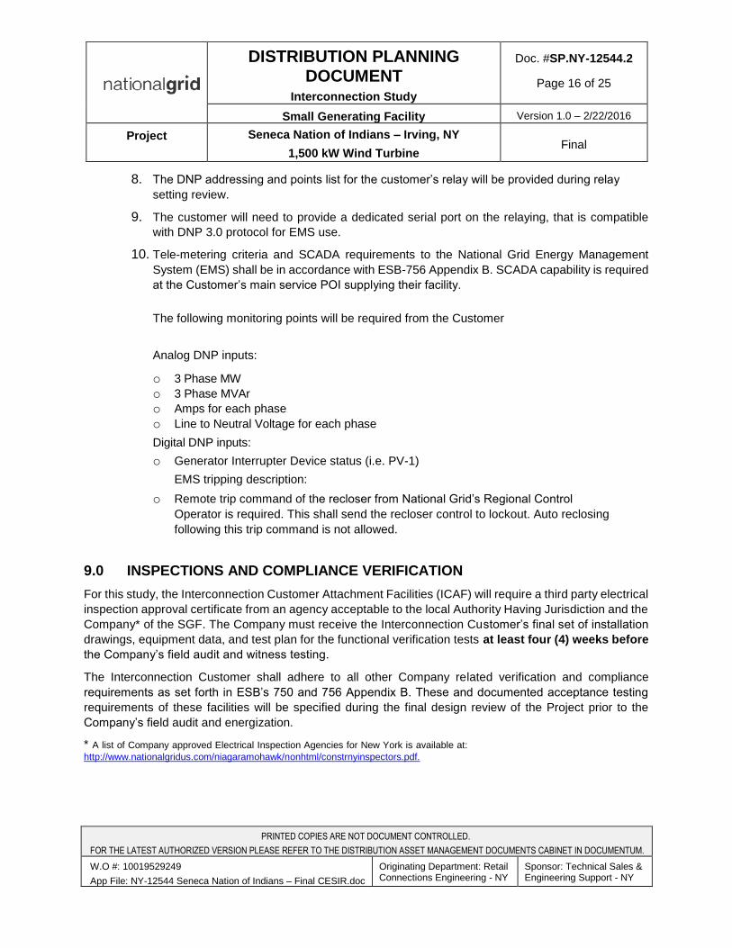
8. The DNP addressing and points list for the customer’s relay will be provided during relay
setting review.
9. The customer will need to provide a dedicated serial port on the relaying, that is compatible
with DNP 3.0 protocol for EMS use.
10. Tele-metering criteria and SCADA requirements to the National Grid Energy Management
System (EMS) shall be in accordance with ESB-756 Appendix B. SCADA capability is required
at the Customer’s main service POI supplying their facility.
The following monitoring points will be required from the Customer
Analog DNP inputs:
o 3 Phase MW
o 3 Phase MVAr
o Amps for each phase
o Line to Neutral Voltage for each phase
Digital DNP inputs:
o Generator Interrupter Device status (i.e. PV-1)
EMS tripping description:
o Remote trip command of the recloser from National Grid’s Regional Control
Operator is required. This shall send the recloser control to lockout. Auto reclosing
following this trip command is not allowed.
9.0 INSPECTIONS AND COMPLIANCE VERIFICATION
For this study, the Interconnection Customer Attachment Facilities (ICAF) will require a third party electrical
inspection approval certificate from an agency acceptable to the local Authority Having Jurisdiction and the
Company* of the SGF. The Company must receive the Interconnection Customer’s final set of installation
drawings, equipment data, and test plan for the functional verification tests at least four (4) weeks before
the Company’s field audit and witness testing.
The Interconnection Customer shall adhere to all other Company related verification and compliance
requirements as set forth in ESB’s 750 and 756 Appendix B. These and documented acceptance testing
requirements of these facilities will be specified during the final design review of the Project prior to the
Company’s field audit and energization.
* A list of Company approved Electrical Inspection Agencies for New York is available at:
http://www.nationalgridus.com/niagaramohawk/nonhtml/constrnyinspectors.pdf.
PRINTED COPIES ARE NOT DOCUMENT CONTROLLED.
FOR THE LATEST AUTHORIZED VERSION PLEASE REFER TO THE DISTRIBUTION ASSET MANAGEMENT DOCUMENTS CABINET IN DOCUMENTUM.
W.O #: 10019529249
App File: NY-12544 Seneca Nation of Indians – Final CESIR.doc
Originating Department: Retail Connections Engineering - NY
Sponsor: Technical Sales & Engineering Support - NY
DISTRIBUTION PLANNING DOCUMENT
Interconnection Study
Doc. #SP.NY-12544.2
Page 17 of 25
Small Generating Facility Version 1.0 – 2/22/2016
Project Seneca Nation of Indians – Irving, NY
1,500 kW Wind Turbine Final
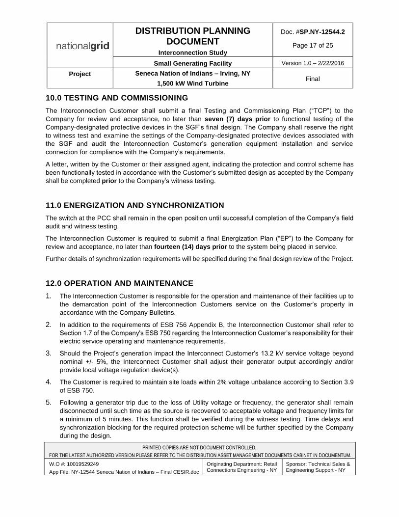
10.0 TESTING AND COMMISSIONING
The Interconnection Customer shall submit a final Testing and Commissioning Plan (“TCP”) to the
Company for review and acceptance, no later than seven (7) days prior to functional testing of the
Company-designated protective devices in the SGF’s final design. The Company shall reserve the right
to witness test and examine the settings of the Company-designated protective devices associated with
the SGF and audit the Interconnection Customer’s generation equipment installation and service
connection for compliance with the Company’s requirements.
A letter, written by the Customer or their assigned agent, indicating the protection and control scheme has
been functionally tested in accordance with the Customer’s submitted design as accepted by the Company
shall be completed prior to the Company’s witness testing.
11.0 ENERGIZATION AND SYNCHRONIZATION
The switch at the PCC shall remain in the open position until successful completion of the Company’s field
audit and witness testing.
The Interconnection Customer is required to submit a final Energization Plan (“EP”) to the Company for
review and acceptance, no later than fourteen (14) days prior to the system being placed in service.
Further details of synchronization requirements will be specified during the final design review of the Project.
12.0 OPERATION AND MAINTENANCE
1. The Interconnection Customer is responsible for the operation and maintenance of their facilities up to
the demarcation point of the Interconnection Customers service on the Customer’s property in
accordance with the Company Bulletins.
2. In addition to the requirements of ESB 756 Appendix B, the Interconnection Customer shall refer to
Section 1.7 of the Company's ESB 750 regarding the Interconnection Customer’s responsibility for their
electric service operating and maintenance requirements.
3. Should the Project’s generation impact the Interconnect Customer’s 13.2 kV service voltage beyond
nominal +/- 5%, the Interconnect Customer shall adjust their generator output accordingly and/or
provide local voltage regulation device(s).
4. The Customer is required to maintain site loads within 2% voltage unbalance according to Section 3.9
of ESB 750.
5. Following a generator trip due to the loss of Utility voltage or frequency, the generator shall remain
disconnected until such time as the source is recovered to acceptable voltage and frequency limits for
a minimum of 5 minutes. This function shall be verified during the witness testing. Time delays and
synchronization blocking for the required protection scheme will be further specified by the Company
during the design.
PRINTED COPIES ARE NOT DOCUMENT CONTROLLED.
FOR THE LATEST AUTHORIZED VERSION PLEASE REFER TO THE DISTRIBUTION ASSET MANAGEMENT DOCUMENTS CABINET IN DOCUMENTUM.
W.O #: 10019529249
App File: NY-12544 Seneca Nation of Indians – Final CESIR.doc
Originating Department: Retail Connections Engineering - NY
Sponsor: Technical Sales & Engineering Support - NY
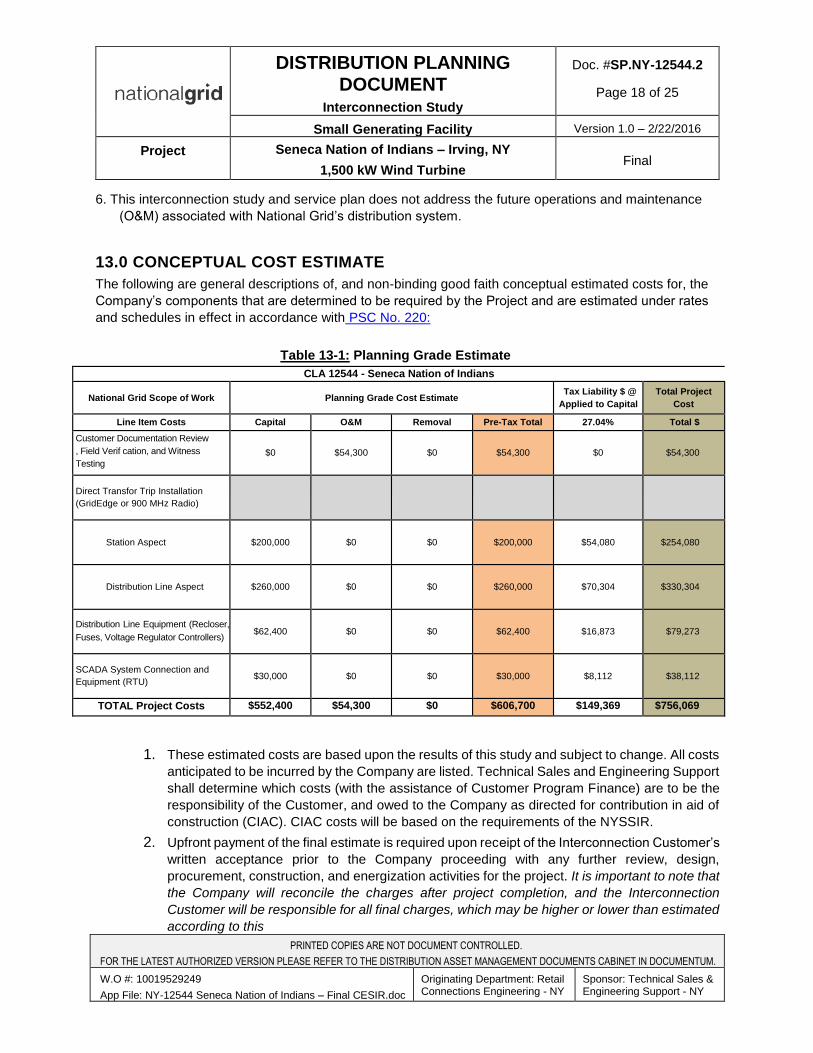
DISTRIBUTION PLANNING DOCUMENT
Interconnection Study
Doc. #SP.NY-12544.2
Page 18 of 25
Small Generating Facility Version 1.0 – 2/22/2016
Project Seneca Nation of Indians – Irving, NY
1,500 kW Wind Turbine Final
6. This interconnection study and service plan does not address the future operations and maintenance
(O&M) associated with National Grid’s distribution system.
13.0 CONCEPTUAL COST ESTIMATE
The following are general descriptions of, and non-binding good faith conceptual estimated costs for, the
Company’s components that are determined to be required by the Project and are estimated under rates
and schedules in effect in accordance with PSC No. 220:
Table 13-1: Planning Grade Estimate
CLA 12544 - Seneca Nation of Indians
National Grid Scope of Work Planning Grade Cost Estimate Tax Liability $ @
Applied to Capital
Total Project
Cost
Line Item Costs Capital O&M Removal Pre-Tax Total 27.04% Total $
Customer Documentation Review
, Field Verif cation, and Witness
Testing
$0 $54,300 $0 $54,300 $0 $54,300
Direct Transfor Trip Installation
(GridEdge or 900 MHz Radio)
Station Aspect $200,000 $0 $0 $200,000 $54,080 $254,080
Distribution Line Aspect $260,000 $0 $0 $260,000 $70,304 $330,304
Distribution Line Equipment (Recloser,
Fuses, Voltage Regulator Controllers) $62,400 $0 $0 $62,400 $16,873 $79,273
SCADA System Connection and
Equipment (RTU) $30,000 $0 $0 $30,000 $8,112 $38,112
TOTAL Project Costs $552,400 $54,300 $0 $606,700 $149,369 $756,069
1. These estimated costs are based upon the results of this study and subject to change. All costs
anticipated to be incurred by the Company are listed. Technical Sales and Engineering Support
shall determine which costs (with the assistance of Customer Program Finance) are to be the
responsibility of the Customer, and owed to the Company as directed for contribution in aid of
construction (CIAC). CIAC costs will be based on the requirements of the NYSSIR.
2. Upfront payment of the final estimate is required upon receipt of the Interconnection Customer’s
written acceptance prior to the Company proceeding with any further review, design,
procurement, construction, and energization activities for the project. It is important to note that
the Company will reconcile the charges after project completion, and the Interconnection
Customer will be responsible for all final charges, which may be higher or lower than estimated
according to this
PRINTED COPIES ARE NOT DOCUMENT CONTROLLED.
FOR THE LATEST AUTHORIZED VERSION PLEASE REFER TO THE DISTRIBUTION ASSET MANAGEMENT DOCUMENTS CABINET IN DOCUMENTUM.
W.O #: 10019529249
App File: NY-12544 Seneca Nation of Indians – Final CESIR.doc
Originating Department: Retail Connections Engineering - NY
Sponsor: Technical Sales & Engineering Support - NY
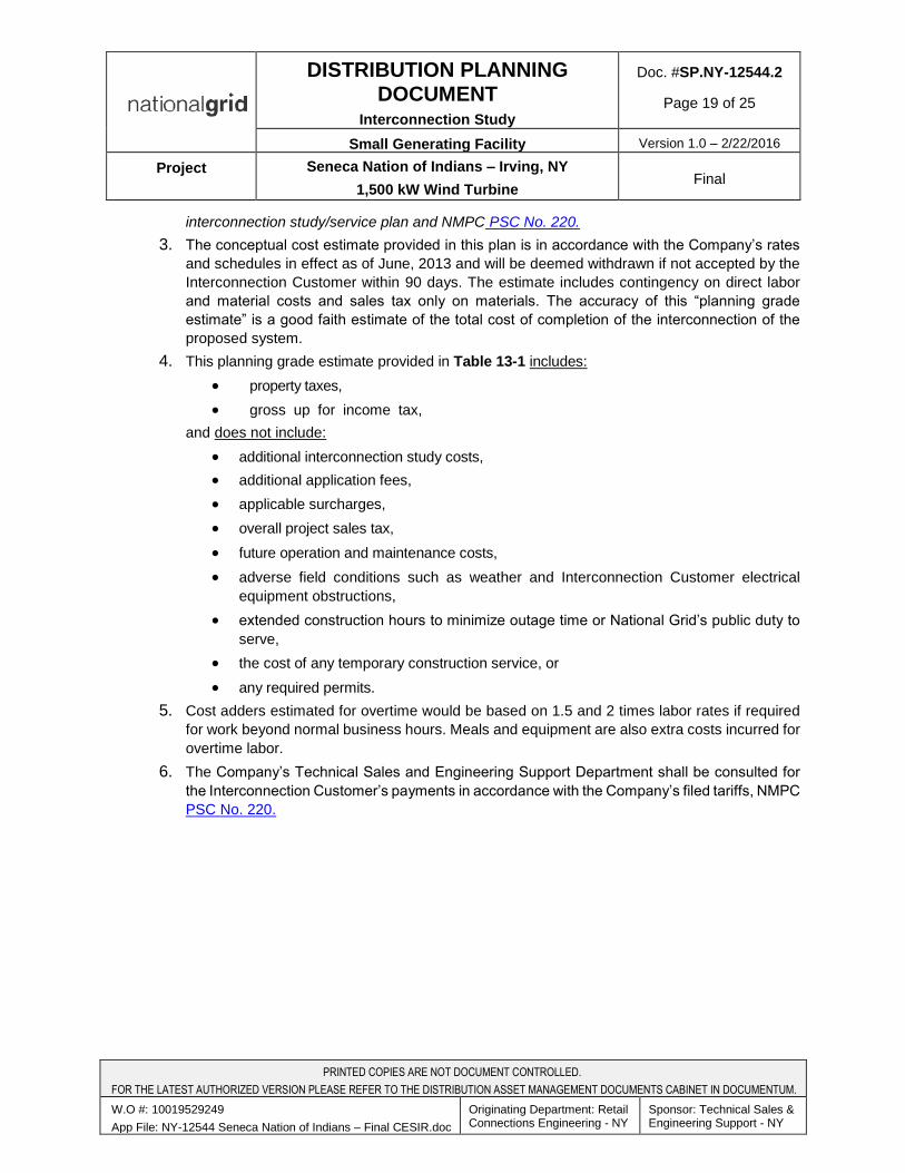
DISTRIBUTION PLANNING DOCUMENT
Interconnection Study
Doc. #SP.NY-12544.2
Page 19 of 25
Small Generating Facility Version 1.0 – 2/22/2016
Project Seneca Nation of Indians – Irving, NY
1,500 kW Wind Turbine Final
interconnection study/service plan and NMPC PSC No. 220.
3. The conceptual cost estimate provided in this plan is in accordance with the Company’s rates
and schedules in effect as of June, 2013 and will be deemed withdrawn if not accepted by the
Interconnection Customer within 90 days. The estimate includes contingency on direct labor
and material costs and sales tax only on materials. The accuracy of this “planning grade
estimate” is a good faith estimate of the total cost of completion of the interconnection of the
proposed system.
4. This planning grade estimate provided in Table 13-1 includes:
property taxes,
gross up for income tax,
and does not include:
additional interconnection study costs,
additional application fees,
applicable surcharges,
overall project sales tax,
future operation and maintenance costs,
adverse field conditions such as weather and Interconnection Customer electrical
equipment obstructions,
extended construction hours to minimize outage time or National Grid’s public duty to
serve,
the cost of any temporary construction service, or
any required permits.
5. Cost adders estimated for overtime would be based on 1.5 and 2 times labor rates if required
for work beyond normal business hours. Meals and equipment are also extra costs incurred for
overtime labor.
6. The Company’s Technical Sales and Engineering Support Department shall be consulted for
the Interconnection Customer’s payments in accordance with the Company’s filed tariffs, NMPC
PSC No. 220.
PRINTED COPIES ARE NOT DOCUMENT CONTROLLED.
FOR THE LATEST AUTHORIZED VERSION PLEASE REFER TO THE DISTRIBUTION ASSET MANAGEMENT DOCUMENTS CABINET IN DOCUMENTUM.
W.O #: 10019529249
App File: NY-12544 Seneca Nation of Indians – Final CESIR.doc
Originating Department: Retail Connections Engineering - NY
Sponsor: Technical Sales & Engineering Support - NY
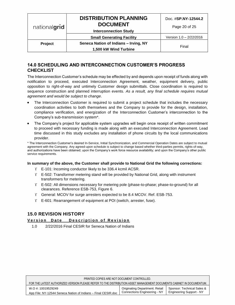
DISTRIBUTION PLANNING DOCUMENT
Interconnection Study
Doc. #SP.NY-12544.2
Page 20 of 25
Small Generating Facility Version 1.0 – 2/22/2016
Project Seneca Nation of Indians – Irving, NY
1,500 kW Wind Turbine Final
14.0 SCHEDULING AND INTERCONNECTION CUSTOMER’S PROGRESS CHECKLIST
The Interconnection Customer’s schedule may be effected by and depends upon receipt of funds along with
notification to proceed, executed Interconnection Agreement, weather, equipment delivery, public
opposition to right-of-way and untimely Customer design submittals. Close coordination is required to
sequence construction and planned interruption events. As a result, any final schedule requires mutual
agreement and would be subject to change.
The Interconnection Customer is required to submit a project schedule that includes the necessary
coordination activities to both themselves and the Company to provide for the design, installation,
compliance verification, and energization of the Interconnection Customer’s interconnection to the
Company’s sub-transmission system*.
The Company’s project for applicable system upgrades will begin once receipt of written commitment
to proceed with necessary funding is made along with an executed Interconnection Agreement. Lead
time discussed in this study excludes any installation of phone circuits by the local communications
provider.
* The Interconnection Customer’s desired In-Service, Initial Synchronization, and Commercial Operation Dates are subject to mutual agreement with the Company. Any agreed-upon schedule is subject to change based whether third-parties permits, rights-of-way, and authorizations have been obtained; upon the Company’s work force resource availability; and upon the Company’s other public service requirements.
In summary of the above, the Customer shall provide to National Grid the following corrections:
E-101: Incoming conductor likely to be 336.4 kcmil ACSR.
E-502: Transformer metering stand will be provided by National Grid, along with instrument
transformers for metering.
E-502: All dimensions necessary for metering pole (phase-to-phase; phase-to-ground) for allclearances. Reference ESB-753, Figure 6.
General: MCOV for surge arresters expected to be 8.4 MCOV. Ref. ESB-753.
E-601: Rearrangement of equipment at POI (switch, arrester, fuse).
15.0 REVISION HISTORY
V e r s i o n D a t e D e s c r i p t i o n o f R e v i s i o n
1.0 2/22/2016 Final CESIR for Seneca Nation of Indians
PRINTED COPIES ARE NOT DOCUMENT CONTROLLED.
FOR THE LATEST AUTHORIZED VERSION PLEASE REFER TO THE DISTRIBUTION ASSET MANAGEMENT DOCUMENTS CABINET IN DOCUMENTUM.
W.O #: 10019529249
App File: NY-12544 Seneca Nation of Indians – Final CESIR.doc
Originating Department: Retail Connections Engineering - NY
Sponsor: Technical Sales & Engineering Support - NY
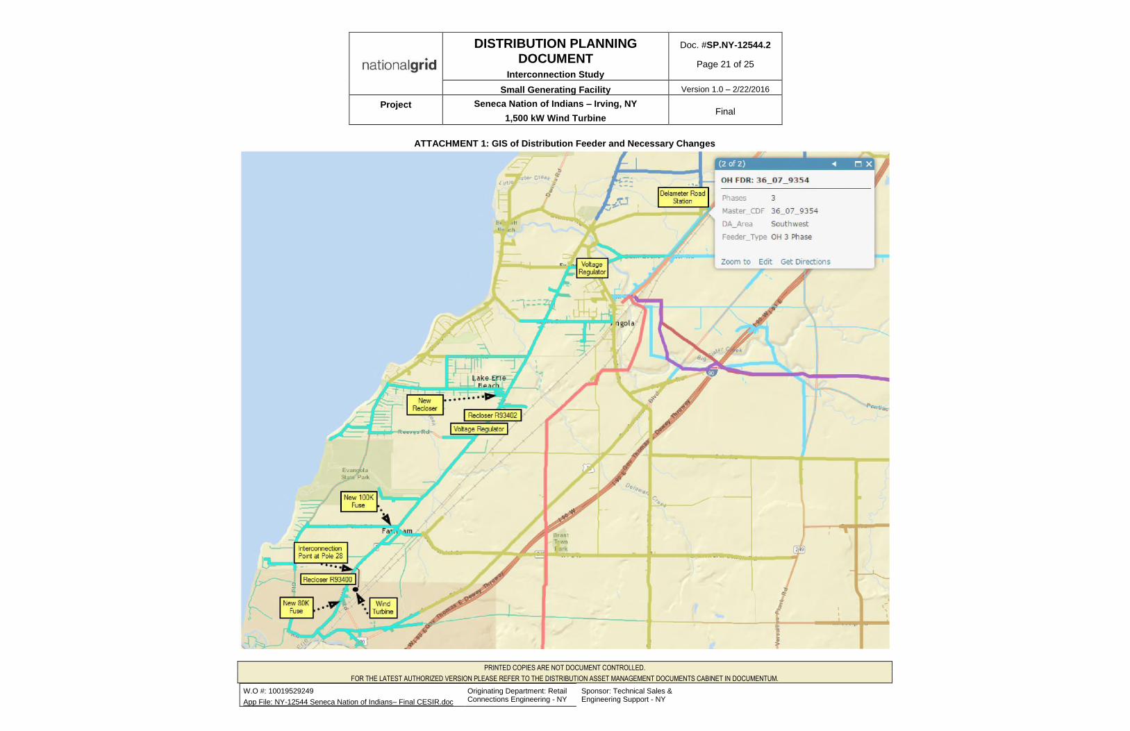
DISTRIBUTION PLANNING DOCUMENT
Interconnection Study
Doc. #SP.NY-12544.2
Page 21 of 25
Small Generating Facility Version 1.0 – 2/22/2016
Project Seneca Nation of Indians – Irving, NY
1,500 kW Wind Turbine Final
ATTACHMENT 1: GIS of Distribution Feeder and Necessary Changes
PRINTED COPIES ARE NOT DOCUMENT CONTROLLED.
FOR THE LATEST AUTHORIZED VERSION PLEASE REFER TO THE DISTRIBUTION ASSET MANAGEMENT DOCUMENTS CABINET IN DOCUMENTUM.
W.O #: 10019529249
App File: NY-12544 Seneca Nation of Indians– Final CESIR.doc
Originating Department: Retail Connections Engineering - NY
Sponsor: Technical Sales & Engineering Support - NY

DISTRIBUTION PLANNING DOCUMENT
Interconnection Study
Doc. #SP.NY-12544.2
Page 22 of 25
Small Generating Facility Version 1.0 – 2/22/2016
Project Seneca Nation of Indians – Irving, NY
1,500 kW Wind Turbine Final
ATTACHMENT 2: Interconnection Customer’s Proposed One-Line Diagram E-601
PRINTED COPIES ARE NOT DOCUMENT CONTROLLED.
FOR THE LATEST AUTHORIZED VERSION PLEASE REFER TO THE DISTRIBUTION ASSET MANAGEMENT DOCUMENTS CABINET IN DOCUMENTUM.
W.O #: 10019529249
App File: NY-12544 Seneca Nation of Indians– Final CESIR.doc
Originating Department: Retail Connections Engineering - NY
Sponsor: Technical Sales & Engineering Support - NY
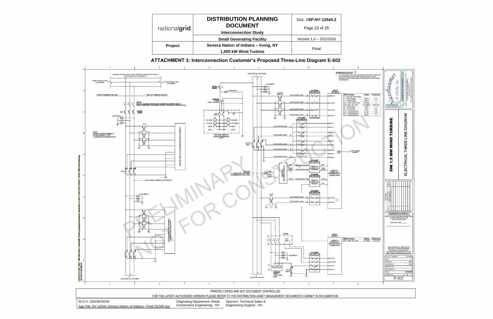
DISTRIBUTION PLANNING DOCUMENT
Interconnection Study
Doc. #SP.NY-12544.2
Page 23 of 25
Small Generating Facility Version 1.0 – 2/22/2016
Project Seneca Nation of Indians – Irving, NY
1,500 kW Wind Turbine Final
ATTACHMENT 3: Interconnection Customer’s Proposed Three-Line Diagram E-602
PRINTED COPIES ARE NOT DOCUMENT CONTROLLED.
FOR THE LATEST AUTHORIZED VERSION PLEASE REFER TO THE DISTRIBUTION ASSET MANAGEMENT DOCUMENTS CABINET IN DOCUMENTUM.
W.O #: 10019529249
App File: NY-12544 Seneca Nation of Indians– Final CESIR.doc
Originating Department: Retail Connections Engineering - NY
Sponsor: Technical Sales & Engineering Support - NY
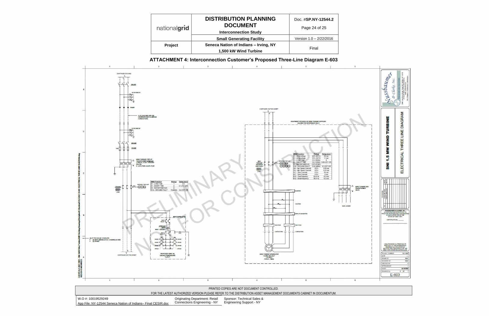
DISTRIBUTION PLANNING DOCUMENT
Interconnection Study
Doc. #SP.NY-12544.2
Page 24 of 25
Small Generating Facility Version 1.0 – 2/22/2016
Project Seneca Nation of Indians – Irving, NY
1,500 kW Wind Turbine Final
ATTACHMENT 4: Interconnection Customer’s Proposed Three-Line Diagram E-603
PRINTED COPIES ARE NOT DOCUMENT CONTROLLED.
FOR THE LATEST AUTHORIZED VERSION PLEASE REFER TO THE DISTRIBUTION ASSET MANAGEMENT DOCUMENTS CABINET IN DOCUMENTUM.
W.O #: 10019529249
App File: NY-12544 Seneca Nation of Indians– Final CESIR.doc
Originating Department: Retail Connections Engineering - NY
Sponsor: Technical Sales & Engineering Support - NY

ATTACHMENT 5: Interconnection Customer’s Proposed Site Plan E-101
DISTRIBUTION PLANNING DOCUMENT
Interconnection Study
Doc. #SP.NY-12544.2
Page 25 of 25
Small Generating Facility Version 1.0 – 2/22/2016
Project Seneca Nation of Indians – Irving, NY
1,500 kW Wind Turbine Final
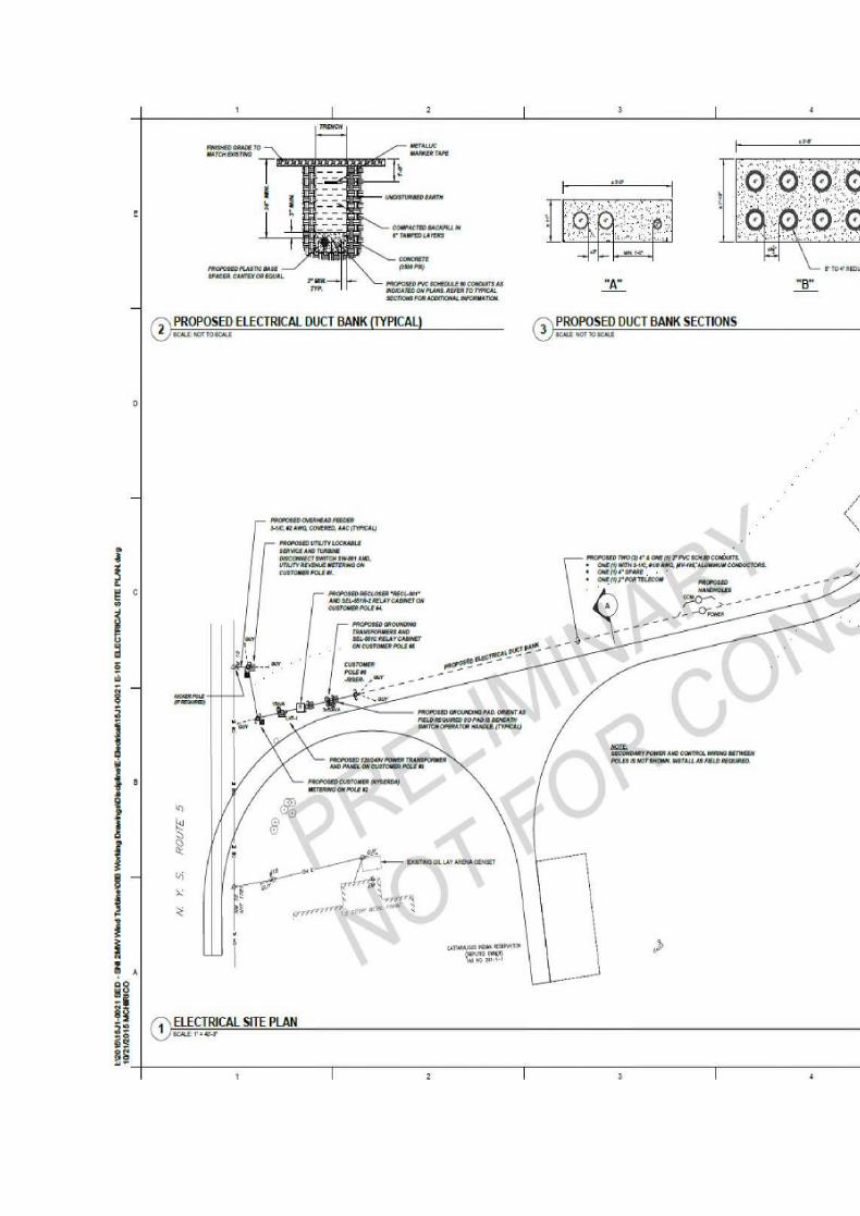

PRINTED COPIES ARE NOT DOCUMENT CONTROLLED.
FOR THE LATEST AUTHORIZED VERSION PLEASE REFER TO THE DISTRIBUTION ASSET MANAGEMENT DOCUMENTS CABINET IN DOCUMENTUM.
W.O #: 10019529249
App File: NY-12544 Seneca Nation of Indians– Final CESIR.doc
Originating Department: Retail Connections Engineering - NY
Sponsor: Technical Sales & Engineering Support - NY
VII. Final Design
Sent to Lizana Pierce & Jami Ally via email due to size.
VIII. Vensys
Vensys is a German manufacturer with state-of-the art technology. VENSYS wind turbines
don’t need high-maintenance gear units that are highly susceptible to wear. They are based on
the generator concept of a synchronous machine with permanent magnet excitation. The
rotating speed of the rotor is transferred directly to the multi-polar generator. The gearless
technology combined with savings in excitation power result in a higher energy yield. With the
1.5 MW platform, the generator is cooled by outside air. The VENSYS frequency converter is
also air-cooled.
Permanent Magnet Technology
High energy conversion efficiency = higher yield
VENSYS makes it possible to utilize permanent magnet technology as used in electric drives in
navigation and electric vehicles for wind energy technology. VENSYS wind turbines are
equipped with a directly driven synchronous generator with permanent magnet excitation. High-
quality permanent magnets are fixed to the outer shell of the rotor. Simple yet innovative.
No excitation losses = even higher yield
In contrast to electrical excitation, permanent magnet technology does not have the disadvantage
of additional excitation losses. The savings in excitation power are thus fully available as
additional energy yield in VENSYS wind turbines.
This is a major asset especially when working in the partial-load range and helps to reduce the
heat in the generator. Also, there is no need to transfer the excitation power with slip rings
The Blade Pitch System
Special technical feature of VENSYS wind turbines are the lubrication-free and low-maintenance
toothed belt which transmits the force between the pitch drive and the rotor blade. The drive
system minimizes wear and increases safety.
The drive of the blade is equipped with an energy storage device, which makes it possible to drive
the blades into braking position in the event of a grid blackout. The capacitors can deliver the
necessary power even in low temperatures.
_Oh
VENSYS 1.5 MW
Rev. E
Date: 14th September 2011
Name of the document:
Technical Description_VE1k5MW RevE.docx
Author: Checked:
Dipl.-Wirt.-Ing. (FH) homas Muller Dipl.-Ing. (FH) Dirk Weber-Winter
Technical Sales Support: Release:
CO, II* (ti/ Dipl.-Wirt.-Ing. (FH) Thomas Muller Dipl.-Ing. (FH) Mathieu Kunz
VENSYS Energy AG
Im Langental 6 • 66539 Neunkirchen
T +49 6821 9517-0 • F +49 6821 9517-111 O VENSYS
Issued: Thomas Müller subect to change 14th September 2011
Checked: Dirk Weber-Winter Technical Description_VE1k5MW RevE.docx
1. Content
1. Content ........................................................................................................................................... 2
2. List of changes ............................................................................................................................... 3
3. Types of WECs .............................................................................................................................. 3
4. General information ....................................................................................................................... 4
5. The design of the base frame ........................................................................................................ 5
6. The rotor ........................................................................................................................................ 6
7. The multipole synchronous generator ........................................................................................... 6
8. The converter ................................................................................................................................. 7
9. The blade pitch system and the braking system ............................................................................ 8
10. The nacelle ..................................................................................................................................... 9
11. The yaw system ............................................................................................................................ 10
12. The control system ....................................................................................................................... 10
13. The tower ...................................................................................................................................... 11
14. The foundation .............................................................................................................................. 11
15. The technical data of the VENSYS 70 ......................................................................................... 12
16. The technical data of the VENSYS 77 ......................................................................................... 13
17. The technical data of the VENSYS 82 ......................................................................................... 14
18. The technical data of the VENSYS 87 ......................................................................................... 15
VENSYS Energy AG Page 2 of 15 Im Langental 6 • 66539 Neunkirchen
T +49 6821 9517-0 • F +49 6821 9517-111
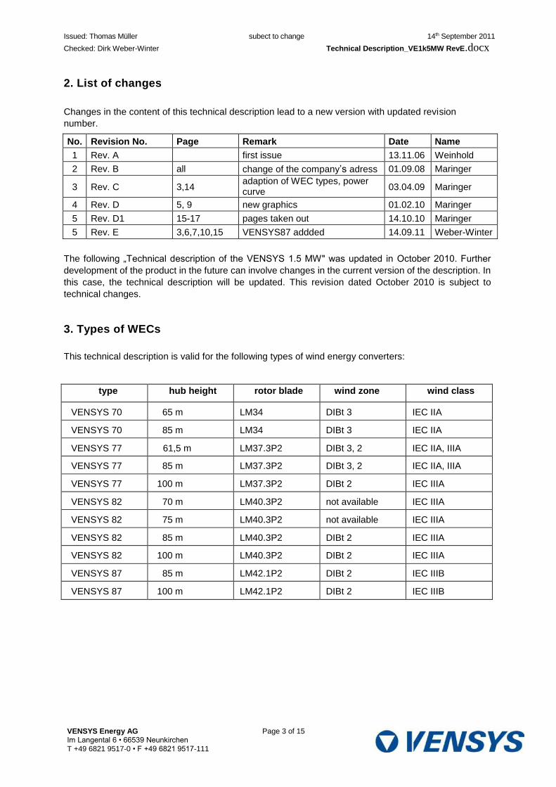
Issued: Thomas Müller subect to change 14th September 2011
Checked: Dirk Weber-Winter Technical Description_VE1k5MW RevE.docx
2. List of changes
Changes in the content of this technical description lead to a new version with updated revision
number.
No. Revision No. Page Remark Date Name
1 Rev. A first issue 13.11.06 Weinhold
2 Rev. B all change of the company’s adress 01.09.08 Maringer
3 Rev. C 3,14 adaption of WEC types, power curve
03.04.09 Maringer
4 Rev. D 5, 9 new graphics 01.02.10 Maringer
5 Rev. D1 15-17 pages taken out 14.10.10 Maringer
5 Rev. E 3,6,7,10,15 VENSYS87 addded 14.09.11 Weber-Winter
The following „Technical description of the VENSYS 1.5 MW" was updated in October 2010. Further
development of the product in the future can involve changes in the current version of the description. In
this case, the technical description will be updated. This revision dated October 2010 is subject to
technical changes.
3. Types of WECs
This technical description is valid for the following types of wind energy converters:
type hub height rotor blade wind zone wind class
VENSYS 70 65 m LM34 DIBt 3 IEC IIA
VENSYS 70 85 m LM34 DIBt 3 IEC IIA
VENSYS 77 61,5 m LM37.3P2 DIBt 3, 2 IEC IIA, IIIA
VENSYS 77 85 m LM37.3P2 DIBt 3, 2 IEC IIA, IIIA
VENSYS 77 100 m LM37.3P2 DIBt 2 IEC IIIA
VENSYS 82 70 m LM40.3P2 not available IEC IIIA
VENSYS 82 75 m LM40.3P2 not available IEC IIIA
VENSYS 82 85 m LM40.3P2 DIBt 2 IEC IIIA
VENSYS 82 100 m LM40.3P2 DIBt 2 IEC IIIA
VENSYS 87 85 m LM42.1P2 DIBt 2 IEC IIIB
VENSYS 87 100 m LM42.1P2 DIBt 2 IEC IIIB
VENSYS Energy AG Page 3 of 15 Im Langental 6 • 66539 Neunkirchen
T +49 6821 9517-0 • F +49 6821 9517-111
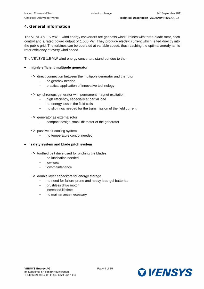
Issued: Thomas Müller subect to change 14th September 2011
Checked: Dirk Weber-Winter Technical Description_VE1k5MW RevE.docx
4. General information
The VENSYS 1.5 MW – wind energy converters are gearless wind turbines with three-blade rotor, pitch
control and a rated power output of 1.500 kW. They produce electric current which is fed directly into
the public grid. The turbines can be operated at variable speed, thus reaching the optimal aerodynamic
rotor efficiency at every wind speed.
The VENSYS 1.5 MW wind energy converters stand out due to the:
highly efficient multipole generator
-> direct connection between the multipole generator and the rotor no gearbox needed
practical application of innovative technology
-> synchronous generator with permanent magnet excitation high efficiency, especially at partial load
no energy loss in the field coils
no slip rings needed for the transmission of the field current
-> generator as external rotor compact design, small diameter of the generator
-> passive air cooling system no temperature control needed
safety system and blade pitch system
-> toothed belt drive used for pitching the blades no lubrication needed
low-wear
low-maintenance
-> double layer capacitors for energy storage no need for failure-prone and heavy lead-gel batteries
brushless drive motor
increased lifetime
no maintenance necessary
VENSYS Energy AG Page 4 of 15 Im Langental 6 • 66539 Neunkirchen T +49 6821 9517-0 • F +49 6821 9517-111

Issued: Thomas Müller subect to change 14th September 2011
Checked: Dirk Weber-Winter Technical Description_VE1k5MW RevE.docx
5. The design of the base frame
Picture 1: VENSYS 1.5 MW – Base frame
1 Rotor blade 6 Yaw drive
2 Casted hub 7 Wind measuring equipment
with obstruction lights
3 Blade pitch system 8 Main frame
4 Generator-rotor 9 Tower
5 Generator-stator 10 Auxiliary crane
VENSYS Energy AG Page 5 of 15 Im Langental 6 • 66539 Neunkirchen
T +49 6821 9517-0 • F +49 6821 9517-111
3
1
2
5
4
8
9
7
10
6

Issued: Thomas Müller subect to change 14th September 2011
Checked: Dirk Weber-Winter Technical Description_VE1k5MW RevE.docx
6. The rotor
The aerodynamically formed rotor blades of the VENSYS wind energy converters dissipate the energy
of the wind into the rotary motion of the rotor.
The three blades of the VENSYS 1.5 MW turbine’s rotor are moved with an active blade pitch system
(pitch). The blades themselves are made of glasfiber reinforced plastic (GRP). The rotor has a diameter
of 70 m, 77 m, 82m or 87 m and the swept area amounts to 3.886 m2, 4.637 m2, 5.026 m2 resp. 5.890
m2. Lightning strokes are transmitted from the rotor blade via the casted parts and the tower into the
foundation.
The rotor blades are screwed with the slewing bearings, which connect them to the casted hub. The
pitch system moves the rotor blades automatically according to the wind speed, to limit the rotor in its
power output or to slow the rotor down without causing wear in the components. During maintenance,
the rotor is locked with a positive-fitting locking system.
7. The multipole synchronous generator
The generator dissipates the rotational energy of the rotor into electric current. It is a multi-pole
synchronous generator with permanent magnet excitation and is driven directly by the rotor that is to
say that no gearbox is needed. The generator is composed of the parts:
Generator-stator with three-phase winding
Generator-rotor with permanent magnets
The generator operates wearfree and all components, with the exception of the main bearing, are
maintenance-free.
The generator-stator
The stator is a welded construct which is fixed to the nacelle. It is used as supporting structure for
the laminated core and the three-phase windings.
The laminated core is made of single segment sheets. To reduce the eddy currents as far as
possible, the sheets are insulated against each other. After the six-phase winding has been
mounted, the stator is impregnated with high quality insulating resin.
Cooling fins are punched into the electric sheets to create a larger surface for heat dissipation. The
patented passive cooling system (DE 19636591C) leads the incoming air through an air duct directly
on the outside of the laminated core. This cooling method makes it possible to encapsulate the
electrically active parts, thus preventing corrosion on the windings.
The power output of the turbine is increased with the wind speed and the temperature of the
generator will rise. This heat must be dissipated to avoid overheating. However, at the same time,
the increasing wind speed swells the flow speed of the air in the air duct and thus the cooling effect.
This self-regulating mechanism avoids the use of active ventilators or pumps for the regulation the
heat.
VENSYS Energy AG Page 6 of 15 Im Langental 6 • 66539 Neunkirchen
T +49 6821 9517-0 • F +49 6821 9517-111

Issued: Thomas Müller subect to change 14th September 2011
Checked: Dirk Weber-Winter Technical Description_VE1k5MW RevE.docx
The generator-rotor
The generator-rotor of the VENSYS turbine is a welded construct that is designed as external rotor.
The use of permanent magnets and the design as external rotor make it possible to keep the outer
diameter of the generator considerably smaller compared to the usual design with field coils. The
VENSYS 1.5 MW external rotor is only a bit larger than the diameter of the air gap, while the
standard design protrudes considerably over the height of the laminated core and the stator’s
supporting structure. This special VENSYS-design offers many advantages: The smaller the
generator, the lighter it is and so it is a lot easier to transport.
The generator-rotor is connected directly to the rotor of the turbine, which drives the generator
directly. The permanent magnets on the inside of the rotor piling create the necessary magnetic
field. The use of this direct driven multipole synchronous generator avoids the use of a main
gearbox, which currently cause many problems in the megawatt turbines due to their limited lifetime
and their sensivity to overload.
It has several advantages not to use a gearbox: First there will be no problems caused by the
reduced lifetime or the sensivity to overload of the gearbox. Then there are no energy losses due to
the gearbox, which are most obvious at partial load. Another advantage is that the noise emission
of the turbine will be reduced, as gearboxes normally create at lot of noise, which must be damped
with extensive silencing measures. Finally, there is no need for oil changes and no danger of oil
leakages. The permanent magnets do not have the same energy losses as the field coils and the
slip rings which are normally used to transport the necessary excitation energy.
All these advantages lead to a higher energy yield, lower insurance costs, an increased lifetime of
the turbine and lower general expenses / costs for maintenance.
8. The converter
The converter and the transformer, which is located downstream to the converter system, connect the
turbine with the public grid. Both components are located inside the tower base of the turbine, thus it is
not necessary to install an additional, separate transformer station.
The converter, which has been especially designed for the use with a synchronous generator, feeds the
whole power output of the turbine into the public grid. Thus, it is possible to decouple the generator
totally from the grid. This feature makes it possible to operate the turbine at variable speed between 9
and 19 rpm (VENSYS 70) resp. 9 and 17.3 rpm (VEN-SYS 77, VENSYS 82, VENSYS 87). This improves
the energy yield at partial load and reduces the loads on the turbine’s structure at full load.
A 12-pulse uncontrolled rectifier with a step-up chopper, which is located downstream to the rectifier, is
used on the generator side. This system is simple and robust and avoids voltage peaks (du/dt loads) in
the generator’s windings.
In the converter part on the grid side, two separate IGBT systems are uses per phase, leading to very
low harmonic loads on the grid. The whole converter system is air-cooled.
VENSYS Energy AG Page 7 of 15 Im Langental 6 • 66539 Neunkirchen
T +49 6821 9517-0 • F +49 6821 9517-111
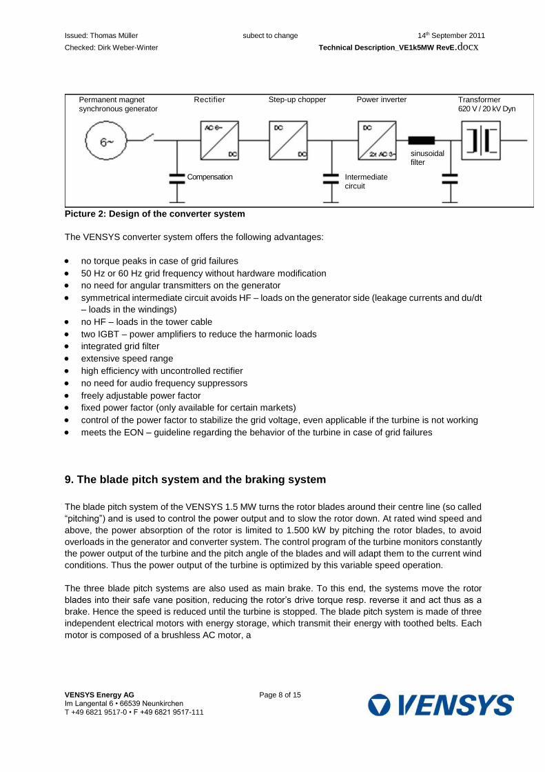
Issued: Thomas Müller subect to change 14th September 2011
Checked: Dirk Weber-Winter Technical Description_VE1k5MW RevE.docx
Picture 2: Design of the converter system
The VENSYS converter system offers the following advantages:
no torque peaks in case of grid failures
50 Hz or 60 Hz grid frequency without hardware modification
no need for angular transmitters on the generator
symmetrical intermediate circuit avoids HF – loads on the generator side (leakage currents and du/dt
– loads in the windings)
no HF – loads in the tower cable
two IGBT – power amplifiers to reduce the harmonic loads
integrated grid filter
extensive speed range
high efficiency with uncontrolled rectifier
no need for audio frequency suppressors
freely adjustable power factor
fixed power factor (only available for certain markets)
control of the power factor to stabilize the grid voltage, even applicable if the turbine is not working
meets the EON – guideline regarding the behavior of the turbine in case of grid failures
9. The blade pitch system and the braking system
The blade pitch system of the VENSYS 1.5 MW turns the rotor blades around their centre line (so called
“pitching”) and is used to control the power output and to slow the rotor down. At rated wind speed and
above, the power absorption of the rotor is limited to 1.500 kW by pitching the rotor blades, to avoid
overloads in the generator and converter system. The control program of the turbine monitors constantly
the power output of the turbine and the pitch angle of the blades and will adapt them to the current wind
conditions. Thus the power output of the turbine is optimized by this variable speed operation.
The three blade pitch systems are also used as main brake. To this end, the systems move the rotor
blades into their safe vane position, reducing the rotor’s drive torque resp. reverse it and act thus as a
brake. Hence the speed is reduced until the turbine is stopped. The blade pitch system is made of three
independent electrical motors with energy storage, which transmit their energy with toothed belts. Each
motor is composed of a brushless AC motor, a
VENSYS Energy AG Page 8 of 15 Im Langental 6 • 66539 Neunkirchen
T +49 6821 9517-0 • F +49 6821 9517-111
Permanent magnet synchronous generator
Compensation
Rectifier Step-up chopper Power inverter
Intermediate circuit
sinusoidal filter
Transformer 620 V / 20 kV Dyn
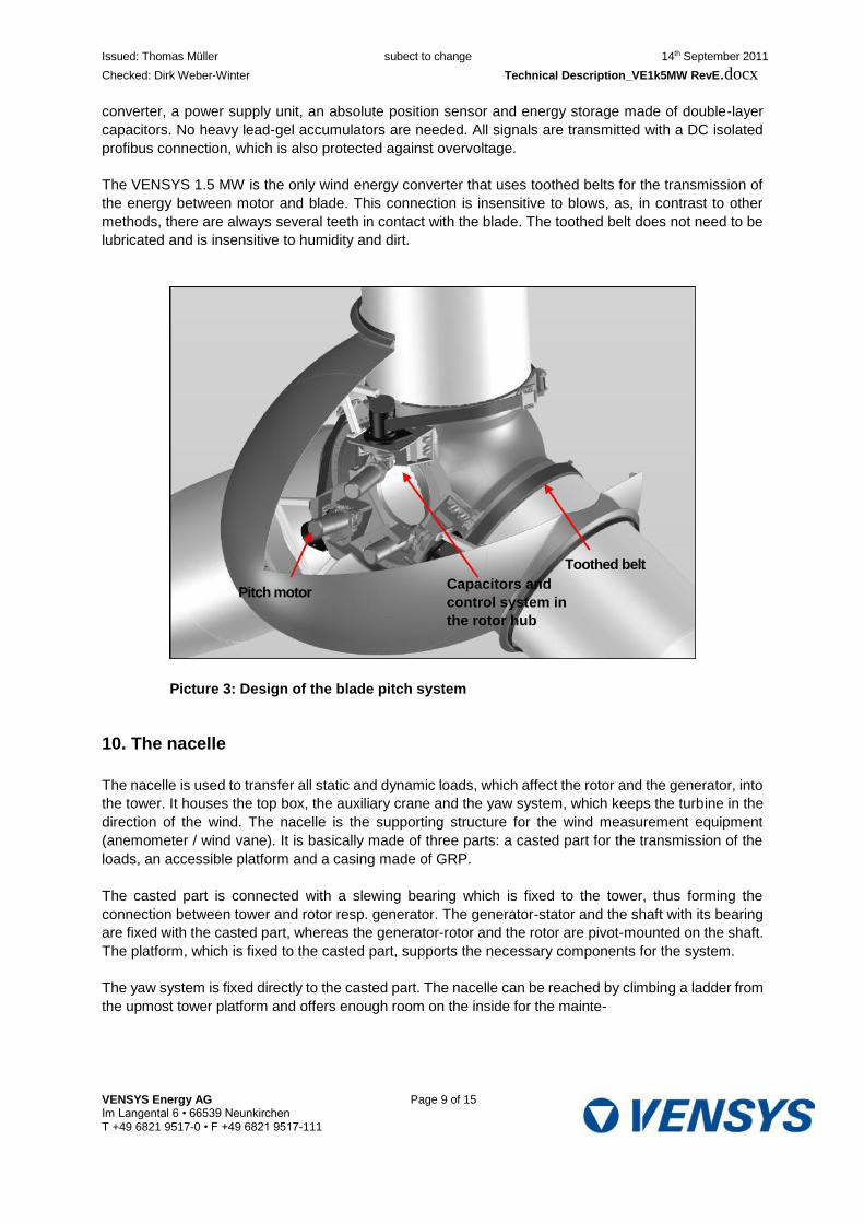
Issued: Thomas Müller subect to change 14th September 2011
Checked: Dirk Weber-Winter Technical Description_VE1k5MW RevE.docx
converter, a power supply unit, an absolute position sensor and energy storage made of double-layer
capacitors. No heavy lead-gel accumulators are needed. All signals are transmitted with a DC isolated
profibus connection, which is also protected against overvoltage.
The VENSYS 1.5 MW is the only wind energy converter that uses toothed belts for the transmission of
the energy between motor and blade. This connection is insensitive to blows, as, in contrast to other
methods, there are always several teeth in contact with the blade. The toothed belt does not need to be
lubricated and is insensitive to humidity and dirt.
Picture 3: Design of the blade pitch system
10. The nacelle
The nacelle is used to transfer all static and dynamic loads, which affect the rotor and the generator, into
the tower. It houses the top box, the auxiliary crane and the yaw system, which keeps the turbine in the
direction of the wind. The nacelle is the supporting structure for the wind measurement equipment
(anemometer / wind vane). It is basically made of three parts: a casted part for the transmission of the
loads, an accessible platform and a casing made of GRP.
The casted part is connected with a slewing bearing which is fixed to the tower, thus forming the
connection between tower and rotor resp. generator. The generator-stator and the shaft with its bearing
are fixed with the casted part, whereas the generator-rotor and the rotor are pivot-mounted on the shaft.
The platform, which is fixed to the casted part, supports the necessary components for the system.
The yaw system is fixed directly to the casted part. The nacelle can be reached by climbing a ladder from
the upmost tower platform and offers enough room on the inside for the mainte-
VENSYS Energy AG Page 9 of 15 Im Langental 6 • 66539 Neunkirchen
T +49 6821 9517-0 • F +49 6821 9517-111
Pitch motor Capacitors and
control system in
the rotor hub
Toothed belt
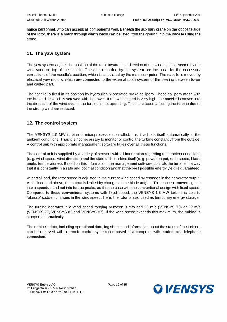
Issued: Thomas Müller subect to change 14th September 2011
Checked: Dirk Weber-Winter Technical Description_VE1k5MW RevE.docx
nance personnel, who can access all components well. Beneath the auxiliary crane on the opposite side
of the rotor, there is a hatch through which loads can be lifted from the ground into the nacelle using the
crane.
11. The yaw system
The yaw system adjusts the position of the rotor towards the direction of the wind that is detected by the
wind vane on top of the nacelle. The data recorded by this system are the basis for the necessary
corrections of the nacelle’s position, which is calculated by the main computer. The nacelle is moved by
electrical yaw motors, which are connected to the external tooth system of the bearing between tower
and casted part.
The nacelle is fixed in its position by hydraulically operated brake callipers. These callipers mesh with
the brake disc which is screwed with the tower. If the wind speed is very high, the nacelle is moved into
the direction of the wind even if the turbine is not operating. Thus, the loads affecting the turbine due to
the strong wind are reduced.
12. The control system
The VENSYS 1.5 MW turbine is microprocessor controlled, i. e. it adjusts itself automatically to the
ambient conditions. Thus it is not necessary to monitor or control the turbine constantly from the outside.
A control unit with appropriate management software takes over all these functions.
The control unit is supplied by a variety of sensors with all information regarding the ambient conditions
(e. g. wind speed, wind direction) and the state of the turbine itself (e. g. power output, rotor speed, blade
angle, temperatures). Based on this information, the management software controls the turbine in a way
that it is constantly in a safe and optimal condition and that the best possible energy yield is guaranteed.
At partial load, the rotor speed is adjusted to the current wind speed by changes in the generator output.
At full load and above, the output is limited by changes in the blade angles. This concept converts gusts
into a speedup and not into torque peaks, as it is the case with the conventional design with fixed speed.
Compared to these conventional systems with fixed speed, the VENSYS 1.5 MW turbine is able to
“absorb” sudden changes in the wind speed. Here, the rotor is also used as temporary energy storage.
The turbine operates in a wind speed ranging between 3 m/s and 25 m/s (VENSYS 70) or 22 m/s
(VENSYS 77, VENSYS 82 and VENSYS 87). If the wind speed exceeds this maximum, the turbine is
stopped automatically.
The turbine’s data, including operational data, log sheets and information about the status of the turbine,
can be retrieved with a remote control system composed of a computer with modem and telephone
connection.
VENSYS Energy AG Page 10 of 15 Im Langental 6 • 66539 Neunkirchen
T +49 6821 9517-0 • F +49 6821 9517-111
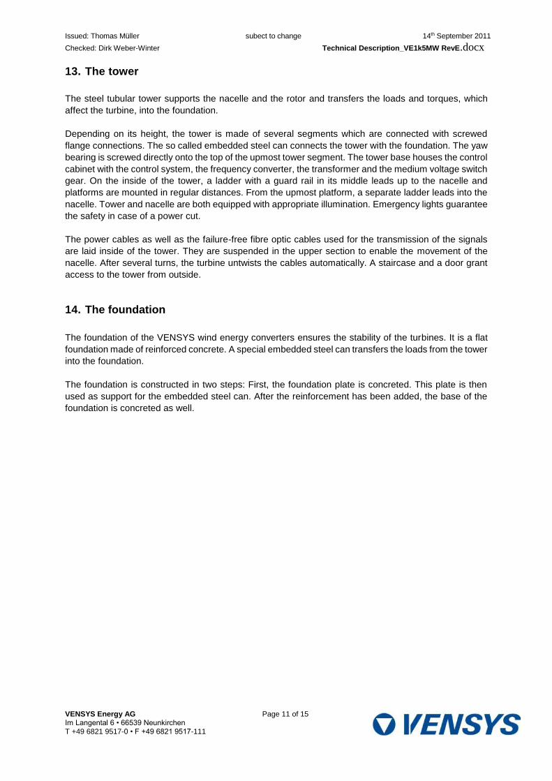
Issued: Thomas Müller subect to change 14th September 2011
Checked: Dirk Weber-Winter Technical Description_VE1k5MW RevE.docx
13. The tower
The steel tubular tower supports the nacelle and the rotor and transfers the loads and torques, which
affect the turbine, into the foundation.
Depending on its height, the tower is made of several segments which are connected with screwed
flange connections. The so called embedded steel can connects the tower with the foundation. The yaw
bearing is screwed directly onto the top of the upmost tower segment. The tower base houses the control
cabinet with the control system, the frequency converter, the transformer and the medium voltage switch
gear. On the inside of the tower, a ladder with a guard rail in its middle leads up to the nacelle and
platforms are mounted in regular distances. From the upmost platform, a separate ladder leads into the
nacelle. Tower and nacelle are both equipped with appropriate illumination. Emergency lights guarantee
the safety in case of a power cut.
The power cables as well as the failure-free fibre optic cables used for the transmission of the signals
are laid inside of the tower. They are suspended in the upper section to enable the movement of the
nacelle. After several turns, the turbine untwists the cables automatically. A staircase and a door grant
access to the tower from outside.
14. The foundation
The foundation of the VENSYS wind energy converters ensures the stability of the turbines. It is a flat
foundation made of reinforced concrete. A special embedded steel can transfers the loads from the tower
into the foundation.
The foundation is constructed in two steps: First, the foundation plate is concreted. This plate is then
used as support for the embedded steel can. After the reinforcement has been added, the base of the
foundation is concreted as well.
VENSYS Energy AG Page 11 of 15 Im Langental 6 • 66539 Neunkirchen
T +49 6821 9517-0 • F +49 6821 9517-111
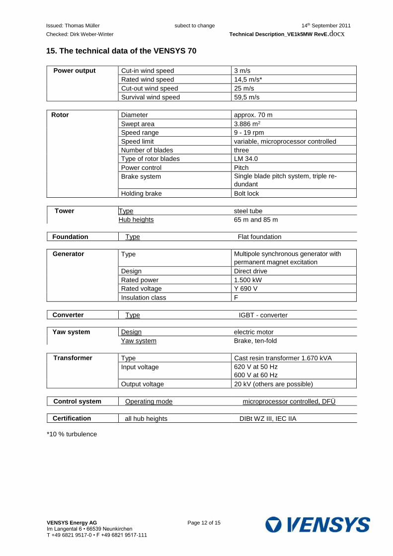
Issued: Thomas Müller subect to change 14th September 2011
Checked: Dirk Weber-Winter Technical Description_VE1k5MW RevE.docx
15. The technical data of the VENSYS 70
Power output Cut-in wind speed 3 m/s
Rated wind speed 14,5 m/s*
Cut-out wind speed 25 m/s
Survival wind speed 59,5 m/s
Rotor Diameter approx. 70 m
Swept area 3.886 m2
Speed range 9 - 19 rpm
Speed limit variable, microprocessor controlled
Number of blades three
Type of rotor blades LM 34.0
Power control Pitch
Brake system Single blade pitch system, triple re-
dundant
Holding brake Bolt lock
Tower Type steel tube
Hub heights 65 m and 85 m
Foundation Type Flat foundation
Generator Type Multipole synchronous generator with
permanent magnet excitation
Design Direct drive
Rated power 1.500 kW
Rated voltage Y 690 V
Insulation class F
Converter Type IGBT - converter
Yaw system Design electric motor
Yaw system Brake, ten-fold
Transformer Type Cast resin transformer 1.670 kVA
Input voltage 620 V at 50 Hz
600 V at 60 Hz
Output voltage 20 kV (others are possible)
Control system Operating mode microprocessor controlled, DFÜ
Certification all hub heights DIBt WZ III, IEC IIA
*10 % turbulence
VENSYS Energy AG Page 12 of 15 Im Langental 6 • 66539 Neunkirchen T +49 6821 9517-0 • F +49 6821 9517-111
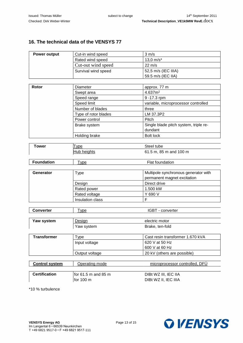
Issued: Thomas Müller subect to change 14th September 2011
Checked: Dirk Weber-Winter Technical Description_VE1k5MW RevE.docx
16. The technical data of the VENSYS 77
Power output Cut-in wind speed 3 m/s
Rated wind speed 13,0 m/s*
Cut-out wind speed 22 m/s
Survival wind speed 52,5 m/s (IEC IIIA)
59.5 m/s (IEC IIA)
Rotor Diameter approx. 77 m
Swept area 4.637m2
Speed range 9 -17.3 rpm
Speed limit variable, microprocessor controlled
Number of blades three
Type of rotor blades LM 37.3P2
Power control Pitch
Brake system Single blade pitch system, triple re-
dundant
Holding brake Bolt lock
Tower Type Steel tube
Hub heights 61.5 m, 85 m and 100 m
Foundation Type Flat foundation
Generator Type Multipole synchronous generator with
permanent magnet excitation
Design Direct drive
Rated power 1.500 kW
Rated voltage Y 690 V
Insulation class F
Converter Type IGBT - converter
Yaw system Design electric motor
Yaw system Brake, ten-fold
Transformer Type Cast resin transformer 1.670 kVA
Input voltage 620 V at 50 Hz
600 V at 60 Hz
Output voltage 20 kV (others are possible)
Control system Operating mode microprocessor controlled, DFÜ
Certification for 61.5 m and 85 m
for 100 m
DIBt WZ III, IEC IIA
DIBt WZ II, IEC IIIA
*10 % turbulence
VENSYS Energy AG Page 13 of 15 Im Langental 6 • 66539 Neunkirchen T +49 6821 9517-0 • F +49 6821 9517-111
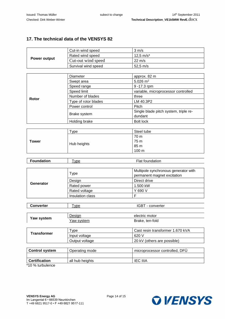
Issued: Thomas Müller subect to change 14th September 2011
Checked: Dirk Weber-Winter Technical Description_VE1k5MW RevE.docx
17. The technical data of the VENSYS 82
Power output
Cut-in wind speed 3 m/s
Rated wind speed 12,5 m/s*
Cut-out wind speed 22 m/s
Survival wind speed 52,5 m/s
Rotor
Diameter approx. 82 m
Swept area 5.026 m2
Speed range 9 -17.3 rpm
Speed limit variable, microprocessor controlled
Number of blades three
Type of rotor blades LM 40.3P2
Power control Pitch
Brake system Single blade pitch system, triple re-
dundant
Holding brake Bolt lock
Tower
Type Steel tube
Hub heights
70 m
75 m
85 m
100 m
Foundation Type Flat foundation
Generator
Type Multipole synchronous generator with
permanent magnet excitation
Design Direct drive
Rated power 1.500 kW
Rated voltage Y 690 V
Insulation class F
Converter Type IGBT - converter
Yaw system Design electric motor
Yaw system Brake, ten-fold
Transformer Type Cast resin transformer 1.670 kVA
Input voltage 620 V
Output voltage 20 kV (others are possible)
Control system Operating mode microprocessor controlled, DFÜ
Certification all hub heights IEC IIIA
*10 % turbulence
VENSYS Energy AG Page 14 of 15 Im Langental 6 • 66539 Neunkirchen
T +49 6821 9517-0 • F +49 6821 9517-111
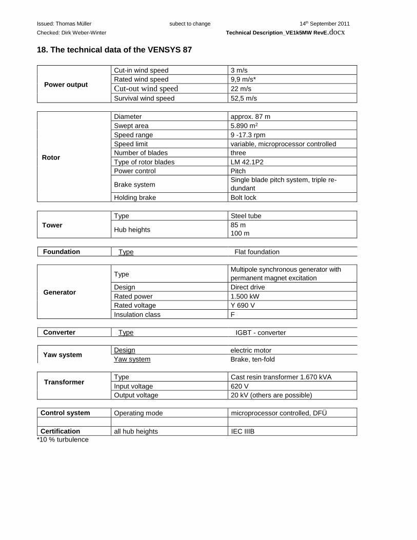
Issued: Thomas Müller subect to change 14th September 2011
Checked: Dirk Weber-Winter Technical Description_VE1k5MW RevE.docx
18. The technical data of the VENSYS 87
Power output
Cut-in wind speed 3 m/s
Rated wind speed 9,9 m/s*
Cut-out wind speed 22 m/s
Survival wind speed 52,5 m/s
Rotor
Diameter approx. 87 m
Swept area 5.890 m2
Speed range 9 -17.3 rpm
Speed limit variable, microprocessor controlled
Number of blades three
Type of rotor blades LM 42.1P2
Power control Pitch
Brake system Single blade pitch system, triple re-
dundant
Holding brake Bolt lock
Tower
Type Steel tube
Hub heights 85 m
100 m
Foundation Type Flat foundation
Generator
Type Multipole synchronous generator with
permanent magnet excitation
Design Direct drive
Rated power 1.500 kW
Rated voltage Y 690 V
Insulation class F
Converter Type IGBT - converter
Yaw system Design electric motor
Yaw system Brake, ten-fold
Transformer Type Cast resin transformer 1.670 kVA
Input voltage 620 V
Output voltage 20 kV (others are possible)
Control system Operating mode microprocessor controlled, DFÜ
Certification all hub heights IEC IIIB
*10 % turbulence
VENSYS Energy AG Page 15 of 15 Im Langental 6 • 66539 Neunkirchen
T +49 6821 9517-0 • F +49 6821 9517-111
Power Curve
VENSYS 82 - 1.5 MW
Subject to technical modifications

VENSYS Energy AG 1 / 3 Date: 07-11-13

Vhub[m/s] Power [kW]
3.0 20.7 3.5 48.7 4.0 83.8 4.5 126.7 5.0 179.4 5.5 244.1 6.0 320.8 6.5 412.7 7.0 518.3 7.5 639.7 8.0 775.2 8.5 921.9 9.0 1073.3 9.5 1222.8
10.0 1343.8 10.5 1418.9 11.0 1466.8 11.5 1489.6 12.0 1496.3 12.5 1499.3
13.0 1500.0
22.0 1500.0
3.0 5.0 7.0 9.0 11.0 13.0 15.0 17.0 19.0 21.0
Vhub [m/s]
Pow
er [k
W]
1600
1400
1200
1000
400
200
800
600
0
Wind turbine data:
Turbine: VENSYS 82
Rated power: 1500 kW
Rotor diameter 82 m
Cut-in wind speed: 3.0 m/s
Cut-out wind speed: 22.0 m/s
Determination for the power curve verification:
Verification according to: IEC 61400-12-1:2005
Wind speed at hub height: 10 min average
Measurement of power: Low voltage side, 620 V
Air density: 1.225 kg/m3
Turbulence intensity: 6% ≤ Ti ≤ 12 %
Wind shear exponent: 0 ≤ α ≤ 0.2
Wind flow inclination: 0° ± 2°
Subject to technical modifications
VENSYS Energy AG 2 / 3 Date: 07-11-13

Thrust coefficient
Simulation: static
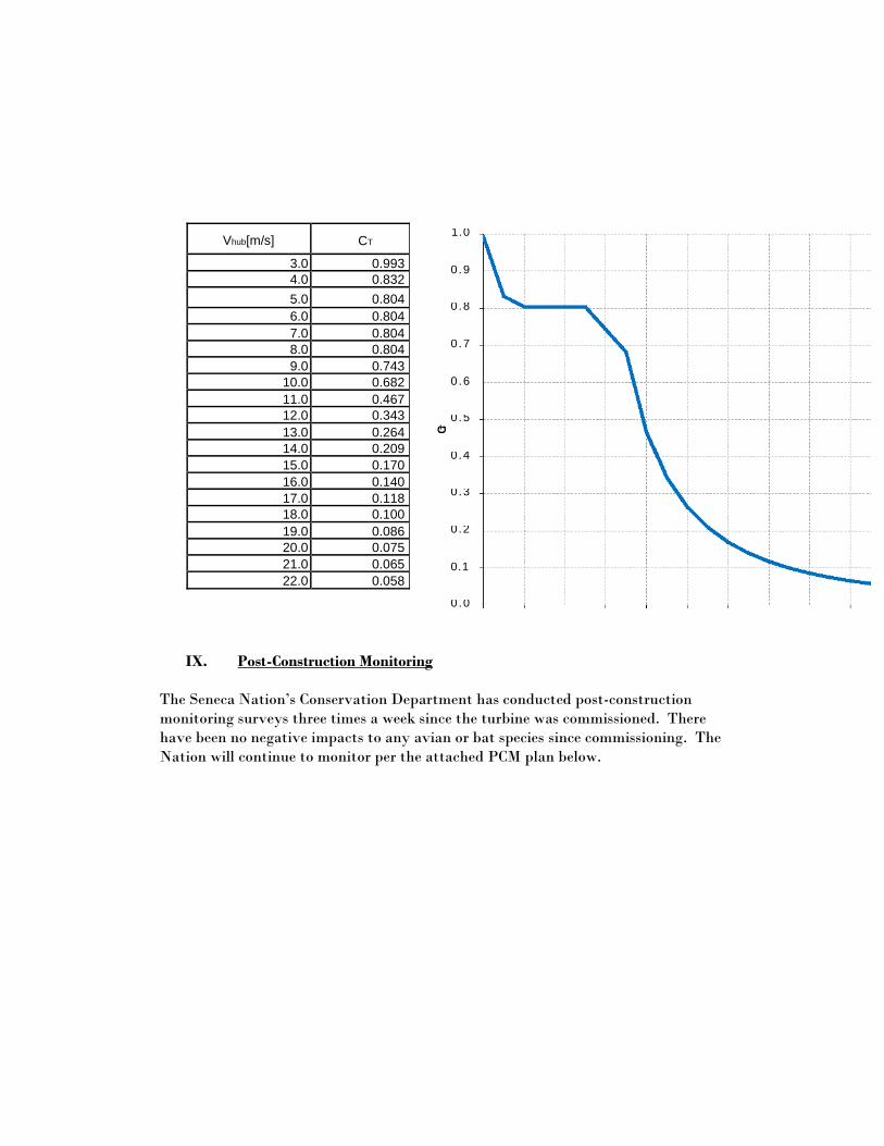
Vhub[m/s] CT
3.0 0.993
4.0 0.832
5.0 0.804
6.0 0.804
7.0 0.804
8.0 0.804
9.0 0.743
10.0 0.682
11.0 0.467
12.0 0.343
13.0 0.264
14.0 0.209
15.0 0.170
16.0 0.140
17.0 0.118
18.0 0.100
19.0 0.086
20.0 0.075
21.0 0.065
22.0 0.058
CT
0.9
0 .8
0 .7
0 .6
0 .5
0 .4
0 .3
0 .2
0.1
0 .0
1.0
IX. Post-Construction Monitoring
The Seneca Nation’s Conservation Department has conducted post-construction
monitoring surveys three times a week since the turbine was commissioned. There
have been no negative impacts to any avian or bat species since commissioning. The
Nation will continue to monitor per the attached PCM plan below.
POST-CONSTRUCTION AVIAN AND BAT FATALITY MONITORING PLAN
FOR
THE SENECA NATION
WIND TURBINE
CATTARAUGUS TERRITORY ERIE COUNTY, NEW YORK
AUGUST 2016
Post-Construction Avian and Bat Fatality Monitoring Plan
CONTENTS
1.0 INTRODUCTION ................................................................................................................... 1
2.0 MONITORING OBJECTIVES ...................................................................................... 1
3.0 WIND TURBINE CURTAILMENT .............................................................................. 1
4.0 MONITORING PROTOCOL ........................................................................................ 2
4.1 Delineation of Search Area and Visibility Mapping .......................................................... 2
4.1.1 Search Area ...................................................................................................................... 2
4.1.2 Vegetation and Visibility Mapping .................................................................................. 2
4.1.3 Searchable Area ................................................................................................................ 2
4.2 General Survey Protocol .................................................................................................... 3
4.2.1 Transects ........................................................................................................................... 3
4.2.2 Survey Period and Frequency ........................................................................................... 3
4.2.3 Weather Monitoring ......................................................................................................... 4
4.2.4 Carcass Searches .............................................................................................................. 4
4.3 Field Bias and Error Assessment ....................................................................................... 5
4.3.1 Carcass Removal Estimation ............................................................................................ 5
4.3.2 Searcher Efficiency .......................................................................................................... 5
4.4 Estimates of Fatalities ....................................................................................................... 6
5.0 PROCEDURE DEVELOPMENT AND TRAINING ................................................... 6
6.0 REPORTING AND DOCUMENTATION .................................................................... 6
7.0 ADAPTIVE MANAGEMENT ........................................................................................ 7
8.0 REFERENCES ........................................................................................................................ 7
iii August 22, 2016
Post-Construction Avian and Bat Fatality Monitoring Plan
1.0 INTRODUCTION
The Seneca Nation (SNI), with the assistance of funding through the U.S. Department of
Energy’s (DOE) Tribal Energy Program under the Office of Energy Efficiency and Renewable
Energy, has constructed a 1.5-megawatt wind turbine on SNI-owned sovereign lands in the
Cattaraugus Territory, Erie County, New York. The hub height of the wind turbine is 278 feet
(85 meters) with a rotor diameter of 270 feet (blade length of approximately 135 feet)
(82 meters) and maximum height (hub height plus blade length) of approximately 413 feet. The
wind turbine is being constructed on approximately 1.5 acres of land northeast of Lucky Layne
Road on the east side of New York State Route 5. The wind turbine site is largely undeveloped
land consisting of previously cleared land, grasses, shrub vegetation, and forested land. The site
is adjacent to a larger SNI land parcel with parking lots and a mix of commercial structures
including the Gil Lay Memorial Sports Arena and SNI Bingo Hall.
In October 2015, DOE and SNI published the Environmental Assessment for the Seneca Nation
Wind Turbine Project (DOE/EA-2004; Wind Turbine EA) (DOE 2015) and subsequent Finding
of No Significant Impact pursuant to the requirements of the National Environmental Policy Act
(42 U.S.C. § 4321 et seq.). In the EA, DOE and SNI concluded that the wind turbine project
“may affect, but is not likely to adversely affect” the federally threatened northern long-eared bat
(Myotis septentrionalis). However, because of uncertainty over the presence of the northern
long-eared bat and the potential for migratory birds in the project vicinity, SNI has decided to
conduct avian and bat mortality monitoring. This Post-Construction Avian and Bat Fatality
Monitoring Plan describes those actions that SNI is taking to monitor any potential bird and bat
mortality caused by the wind turbine.
2.0 MONITORING OBJECTIVES
The objectives of this Plan are to accomplish the following:
Document the species of bird or bat fatalities in the project vicinity, if any;
Estimate the number of bird and bat fatalities, if any, during the spring, summer, and fall
based on standardized searches with adjustments for searcher efficiency, carcass removal
rates, and a search area correction factor (i.e., when searching less than 100 percent of
the area); and
Use the data and information to identify the potential need for any adjustments to wind
turbine operations.
3.0 WIND TURBINE CURTAILMENT
Research at operating wind energy facilities suggest that curtailing, or delaying the operation of a
turbine until winds reach a higher speed (i.e., the “cut-in” wind speed), will significantly reduce
bat mortality because bats are known to be more active at lower wind speeds and reduce activity
(foraging, migrating, and swarming) at higher wind speeds and, thus, minimize their exposure to
rotating blades (Horn et al. 2008; Baerwald et al. 2009; Arnett et al. 2011). In the Wind Turbine
EA, SNI decided on a cut-in wind speed of 6.9 meters per second (15.4 miles per hour) between
dusk and dawn from April 1 through October 31. This time of day (darkness) and year (late spring
through early fall) coincides with the time of greatest potential bat activity and bird
1 August 22, 2016

Post-Construction Avian and Bat Fatality Monitoring Plan
migration. This curtailment speed may be modified in the future based on results of the
monitoring studies described in this plan (see Section 7).
4.0 MONITORING PROTOCOL
The monitoring protocols include all the actions and processes undertaken to achieve the
objectives specified in Section 2. Field procedures have been prepared for many of the protocols
described in the following sections to provide specific guidance and direction to the SNI field
staff implementing these actions. The field procedures will also ensure that monitoring activities
are uniformly and consistently implemented regardless of who performs the tasks. The
procedures also will provide training documents for the SNI staff.
4.1 Delineation of Search Area and Visibility Mapping
4.1.1 Search Area
The search area comprises the area surrounding the base of the wind turbine on which birds and
bats are likely to fall if struck by the turbine blades. There are several recommendations for the
size of the search area, such as maximum tip height of the turbine measured along the ground
from the tower base, twice the turbine blade length, 50 percent of tip height, rotor hub height,
and one and one-half times the rotor diameter. Other studies suggest that most bat mortalities
occur within a smaller area around the base of the turbine. Poulton and Erickson (2010) found
that bat carcasses were generally found within 130 feet of the tower and that nearly all bat
fatalities occurred within a radius of 50 percent of the tip height distance measured along the
ground. Kerns and Kerlinger (2004) reported that most bat fatalities fell within a 98-foot (30-
meter) radius around the base of the turbine. Bird fatalities typically are found over a larger area
than bat fatalities. SNI defined the search area surrounding the wind turbine in conjunction with
characteristics of the remaining vegetation surrounding the tower.
4.1.2 Vegetation and Visibility Mapping
The ability to find carcasses (i.e., searcher efficiency), if present, is greatly dependent on
vegetation. Bare ground and short-mown grass fields would have the greatest visibility for
finding carcasses. Areas that are forested or covered with shrub thickets are typically
unsearchable. SNI has defined the types of land cover surrounding the wind turbine as well
as the different visibility classes.
4.1.3 Searchable Area
The searchable area is a subset of the search area discussed in Section 4.1.1, selected because it
is the area in which fatalities are reasonably expected to be found based on vegetation
characteristics (see Section 4.1.2). The searchable area is the area that would actually be
searched to locate any potential bird and bat fatalities; this area has been delineated, marked in
the field, and will be mapped in a geographic information system (GIS).
2 August 22, 2016
Post-Construction Avian and Bat Fatality Monitoring Plan
4.2 General Survey Protocol
General search protocol covers a variety of survey procedures for conducting the field surveys.
These include establishing and marking of transects, determining the period and frequency of
surveys, monitoring weather, and searching for the carcasses.
4.2.1 Transects
Transects are the linear paths that are walked while searching for bird or bat carcasses. The
transects for the SNI wind turbine are spaced approximately 16 feet (5 meters) apart to allow
about 8 feet of searchable space on either side. Field surveyors could space transects closer
together if vegetation height reduces visibility. Although transects are typically linear in
orientation, the actual search path used by a surveyor can or should be a zig-zag path centered on
the transect line to allow closer inspection of the ground area.
SNI has established transects and marked them within the entire searchable area to ensure
complete coverage. Transects will be mapped and integrated into a GIS map coverage of the
study area. Pre-establishing and marking transects makes it easier to conduct consistent, repeated
surveys.
4.2.2 Survey Period and Frequency
The survey period is the annual period during which birds and bats are potentially present and
most at risk for mortality caused by the wind turbine. For the SNI wind turbine, this time period
is April 1 through October 31, as specified in the Wind Turbine EA (DOE 2015). This is the time
period in which fatality surveys will be conducted. Although monitoring at other wind energy
facilities in the United States indicates that mortality can occur throughout this period, the data
clearly suggest that, at least for bats, a higher rate of mortality occurs in August and September
during a period of increased bat activity, possibly related to breeding and fall migration (Arnett
et al. 2008; Baerwald and Barclay 2011).
Survey frequency is how often surveys are conducted. Frequency is often expressed as a search
interval or number of days between successive surveys. This interval maybe lengthened or
shortened depending on the estimated carcass removal rates (see Section 4.3). If carcasses are
being actively scavenged and removed (e.g., avian or mammalian predators, domestic cats, or
insects), a shorter search interval may be necessary.
The distribution of potential mortalities across the annual time period is important not only for
understanding potential impacts to birds and bats but also from a wind turbine operational
perspective. Therefore, surveys are distributed throughout April 1 through October 31 to
coincide with major ecological events such as peak spring raptor and songbird migration and
spring bat dispersal (April and May), resident bird and bat activity (June and July), and fall bird
and bat migration (August through October). Both birds and bats are more vulnerable to turbine
blade strikes during periods of increased activity and movement (e.g., migration, foraging, and
breeding). Until data are obtained from the carcass removal rate trials, SNI will conduct surveys
using a 7-day search interval; that is, transects would be walked, searching for bird or bat
carcasses every 7 days. Once the data are obtained, the search interval will be reevaluated
annually between November and March, and any changes will be documented by revising the
3 August 22, 2016
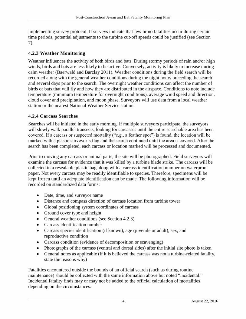
Post-Construction Avian and Bat Fatality Monitoring Plan
implementing survey protocol. If surveys indicate that few or no fatalities occur during certain
time periods, potential adjustments to the turbine cut-off speeds could be justified (see Section
7).
4.2.3 Weather Monitoring
Weather influences the activity of both birds and bats. During stormy periods of rain and/or high
winds, birds and bats are less likely to be active. Conversely, activity is likely to increase during
calm weather (Baerwald and Barclay 2011). Weather conditions during the field search will be
recorded along with the general weather conditions during the night hours preceding the search
and several days prior to the search. The overnight weather conditions can affect the number of
birds or bats that will fly and how they are distributed in the airspace. Conditions to note include
temperature (minimum temperature for overnight conditions), average wind speed and direction,
cloud cover and precipitation, and moon phase. Surveyors will use data from a local weather
station or the nearest National Weather Service station.
4.2.4 Carcass Searches
Searches will be initiated in the early morning. If multiple surveyors participate, the surveyors
will slowly walk parallel transects, looking for carcasses until the entire searchable area has been
covered. If a carcass or suspected mortality (“e.g., a feather spot”) is found, the location will be
marked with a plastic surveyor’s flag and the search continued until the area is covered. After the
search has been completed, each carcass or location marked will be processed and documented.
Prior to moving any carcass or animal parts, the site will be photographed. Field surveyors will
examine the carcass for evidence that it was killed by a turbine blade strike. The carcass will be
collected in a resealable plastic bag along with a carcass identification number on waterproof
paper. Not every carcass may be readily identifiable to species. Therefore, specimens will be
kept frozen until an adequate identification can be made. The following information will be
recorded on standardized data forms:
Date, time, and surveyor name
Distance and compass direction of carcass location from turbine tower
Global positioning system coordinates of carcass
Ground cover type and height
General weather conditions (see Section 4.2.3)
Carcass identification number
Carcass species identification (if known), age (juvenile or adult), sex, and
reproductive condition
Carcass condition (evidence of decomposition or scavenging)
Photographs of the carcass (ventral and dorsal sides) after the initial site photo is taken
General notes as applicable (if it is believed the carcass was not a turbine-related fatality,
state the reasons why)
Fatalities encountered outside the bounds of an official search (such as during routine
maintenance) should be collected with the same information above but noted “incidental.”
Incidental fatality finds may or may not be added to the official calculation of mortalities
depending on the circumstances.
4 August 22, 2016
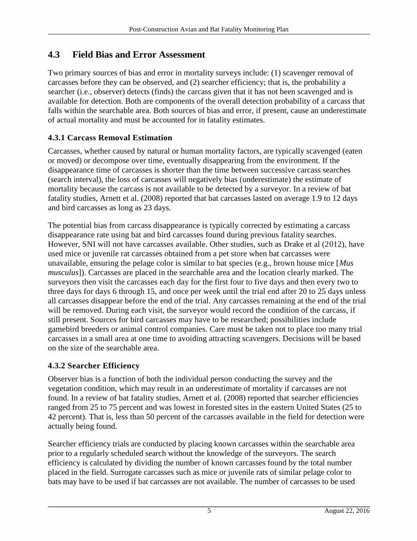
Post-Construction Avian and Bat Fatality Monitoring Plan
4.3 Field Bias and Error Assessment
Two primary sources of bias and error in mortality surveys include: (1) scavenger removal of
carcasses before they can be observed, and (2) searcher efficiency; that is, the probability a
searcher (i.e., observer) detects (finds) the carcass given that it has not been scavenged and is
available for detection. Both are components of the overall detection probability of a carcass that
falls within the searchable area. Both sources of bias and error, if present, cause an underestimate
of actual mortality and must be accounted for in fatality estimates.
4.3.1 Carcass Removal Estimation
Carcasses, whether caused by natural or human mortality factors, are typically scavenged (eaten
or moved) or decompose over time, eventually disappearing from the environment. If the
disappearance time of carcasses is shorter than the time between successive carcass searches
(search interval), the loss of carcasses will negatively bias (underestimate) the estimate of
mortality because the carcass is not available to be detected by a surveyor. In a review of bat
fatality studies, Arnett et al. (2008) reported that bat carcasses lasted on average 1.9 to 12 days
and bird carcasses as long as 23 days.
The potential bias from carcass disappearance is typically corrected by estimating a carcass
disappearance rate using bat and bird carcasses found during previous fatality searches.
However, SNI will not have carcasses available. Other studies, such as Drake et al (2012), have
used mice or juvenile rat carcasses obtained from a pet store when bat carcasses were
unavailable, ensuring the pelage color is similar to bat species (e.g., brown house mice [Mus
musculus]). Carcasses are placed in the searchable area and the location clearly marked. The
surveyors then visit the carcasses each day for the first four to five days and then every two to
three days for days 6 through 15, and once per week until the trial end after 20 to 25 days unless
all carcasses disappear before the end of the trial. Any carcasses remaining at the end of the trial
will be removed. During each visit, the surveyor would record the condition of the carcass, if
still present. Sources for bird carcasses may have to be researched; possibilities include
gamebird breeders or animal control companies. Care must be taken not to place too many trial
carcasses in a small area at one time to avoiding attracting scavengers. Decisions will be based
on the size of the searchable area.
4.3.2 Searcher Efficiency
Observer bias is a function of both the individual person conducting the survey and the
vegetation condition, which may result in an underestimate of mortality if carcasses are not
found. In a review of bat fatality studies, Arnett et al. (2008) reported that searcher efficiencies
ranged from 25 to 75 percent and was lowest in forested sites in the eastern United States (25 to
42 percent). That is, less than 50 percent of the carcasses available in the field for detection were
actually being found.
Searcher efficiency trials are conducted by placing known carcasses within the searchable area
prior to a regularly scheduled search without the knowledge of the surveyors. The search
efficiency is calculated by dividing the number of known carcasses found by the total number
placed in the field. Surrogate carcasses such as mice or juvenile rats of similar pelage color to
bats may have to be used if bat carcasses are not available. The number of carcasses to be used
5 August 22, 2016
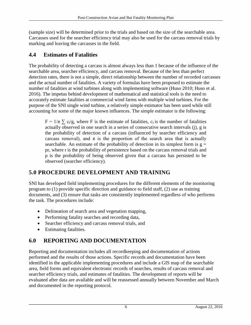
Post-Construction Avian and Bat Fatality Monitoring Plan
(sample size) will be determined prior to the trials and based on the size of the searchable area.
Carcasses used for the searcher efficiency trial may also be used for the carcass removal trials by
marking and leaving the carcasses in the field.
4.4 Estimates of Fatalities
The probability of detecting a carcass is almost always less than 1 because of the influence of the
searchable area, searcher efficiency, and carcass removal. Because of the less than perfect
detection rates, there is not a simple, direct relationship between the number of recorded carcasses
and the actual number of fatalities. A variety of formulas have been proposed to estimate the
number of fatalities at wind turbines along with implementing software (Huso 2010; Huso et al.
2016). The impetus behind development of mathematical and statistical tools is the need to
accurately estimate fatalities at commercial wind farms with multiple wind turbines. For the
purpose of the SNI single wind turbine, a relatively simple estimator has been used while still
accounting for some of the major known influences. The simple estimator is the following:
F = 1/π ∑ cj/g, where F is the estimate of fatalities, cj is the number of fatalities
actually observed in one search in a series of consecutive search intervals (j), g is
the probability of detection of a carcass (influenced by searcher efficiency and
carcass removal), and π is the proportion of the search area that is actually
searchable. An estimate of the probability of detection in its simplest form is g =
pr, where r is the probability of persistence based on the carcass removal trials and
p is the probability of being observed given that a carcass has persisted to be
observed (searcher efficiency).
5.0 PROCEDURE DEVELOPMENT AND TRAINING
SNI has developed field implementing procedures for the different elements of the monitoring
program to (1) provide specific direction and guidance to field staff, (2) use as training
documents, and (3) ensure that tasks are consistently implemented regardless of who performs
the task. The procedures include:
Delineation of search area and vegetation mapping,
Performing fatality searches and recording data,
Searcher efficiency and carcass removal trials, and
Estimating fatalities.
6.0 REPORTING AND DOCUMENTATION
Reporting and documentation includes all recordkeeping and documentation of actions
performed and the results of those actions. Specific records and documentation have been
identified in the applicable implementing procedures and include a GIS map of the searchable
area, field forms and equivalent electronic records of searches, results of carcass removal and
searcher efficiency trials, and estimates of fatalities. The development of reports will be
evaluated after data are available and will be reassessed annually between November and March
and documented in the reporting protocol.
6 August 22, 2016
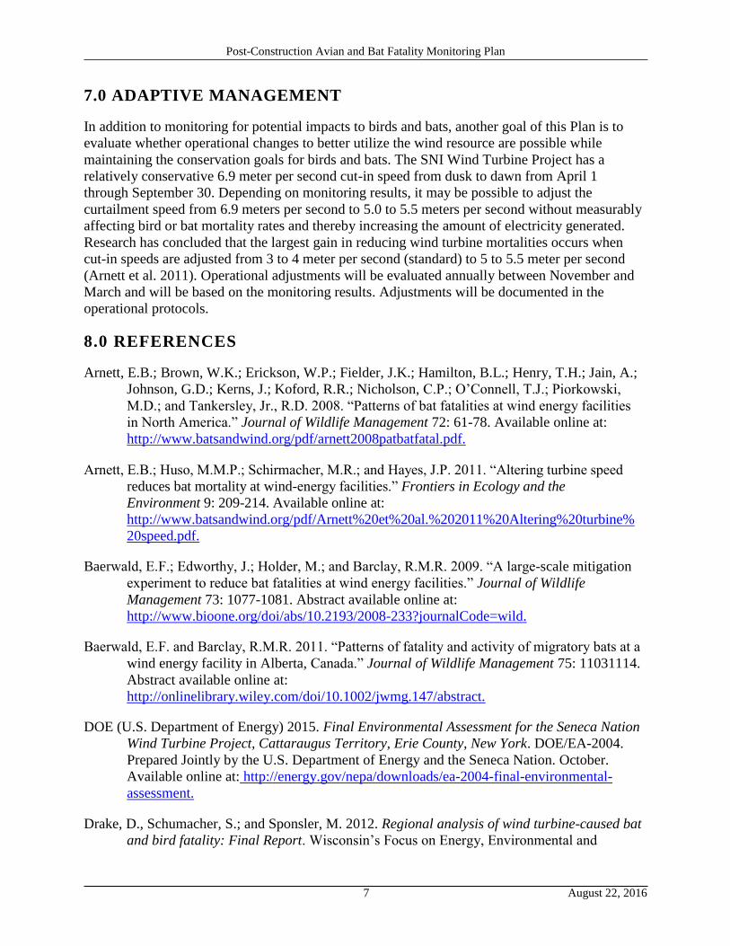
Post-Construction Avian and Bat Fatality Monitoring Plan
7.0 ADAPTIVE MANAGEMENT
In addition to monitoring for potential impacts to birds and bats, another goal of this Plan is to
evaluate whether operational changes to better utilize the wind resource are possible while
maintaining the conservation goals for birds and bats. The SNI Wind Turbine Project has a
relatively conservative 6.9 meter per second cut-in speed from dusk to dawn from April 1
through September 30. Depending on monitoring results, it may be possible to adjust the
curtailment speed from 6.9 meters per second to 5.0 to 5.5 meters per second without measurably
affecting bird or bat mortality rates and thereby increasing the amount of electricity generated.
Research has concluded that the largest gain in reducing wind turbine mortalities occurs when
cut-in speeds are adjusted from 3 to 4 meter per second (standard) to 5 to 5.5 meter per second
(Arnett et al. 2011). Operational adjustments will be evaluated annually between November and
March and will be based on the monitoring results. Adjustments will be documented in the
operational protocols.
8.0 REFERENCES
Arnett, E.B.; Brown, W.K.; Erickson, W.P.; Fielder, J.K.; Hamilton, B.L.; Henry, T.H.; Jain, A.;
Johnson, G.D.; Kerns, J.; Koford, R.R.; Nicholson, C.P.; O’Connell, T.J.; Piorkowski,
M.D.; and Tankersley, Jr., R.D. 2008. “Patterns of bat fatalities at wind energy facilities
in North America.” Journal of Wildlife Management 72: 61-78. Available online at:
http://www.batsandwind.org/pdf/arnett2008patbatfatal.pdf.
Arnett, E.B.; Huso, M.M.P.; Schirmacher, M.R.; and Hayes, J.P. 2011. “Altering turbine speed
reduces bat mortality at wind-energy facilities.” Frontiers in Ecology and the
Environment 9: 209-214. Available online at:
http://www.batsandwind.org/pdf/Arnett%20et%20al.%202011%20Altering%20turbine%
20speed.pdf.
Baerwald, E.F.; Edworthy, J.; Holder, M.; and Barclay, R.M.R. 2009. “A large-scale mitigation
experiment to reduce bat fatalities at wind energy facilities.” Journal of Wildlife
Management 73: 1077-1081. Abstract available online at:
http://www.bioone.org/doi/abs/10.2193/2008-233?journalCode=wild.
Baerwald, E.F. and Barclay, R.M.R. 2011. “Patterns of fatality and activity of migratory bats at a
wind energy facility in Alberta, Canada.” Journal of Wildlife Management 75: 11031114.
Abstract available online at:
http://onlinelibrary.wiley.com/doi/10.1002/jwmg.147/abstract.
DOE (U.S. Department of Energy) 2015. Final Environmental Assessment for the Seneca Nation
Wind Turbine Project, Cattaraugus Territory, Erie County, New York. DOE/EA-2004.
Prepared Jointly by the U.S. Department of Energy and the Seneca Nation. October.
Available online at: http://energy.gov/nepa/downloads/ea-2004-final-environmental-
assessment.
Drake, D., Schumacher, S.; and Sponsler, M. 2012. Regional analysis of wind turbine-caused bat
and bird fatality: Final Report. Wisconsin’s Focus on Energy, Environmental and
7 August 22, 2016
Post-Construction Avian and Bat Fatality Monitoring Plan
Economic Research and Development Program. Available online at:
https://focusonenergy.com/sites/default/files/research/1007Drake FinalReportx.pdf.
Horn, J.W.; Arnett, E.B.; and Kunz, T.H. 2008. “Behavioral responses of bats to operating wind
turbines.” Journal of Wildlife Management 72: 123-132. Available online at:
http://www.bu.edu/cecb/files/2009/08/Horn et al 2008.pdf.
Huso, M.M.P. 2011. “An estimator of wildlife fatality from observed carcasses.” Environmetrics
22: 318-329. Available online at:
http://www.midwestwindhcp.com/documents/3_Appendices/Appendix_G_Survey_Proto
cols/MWE App G Huso 2011 Estimator PRD.pdf.
Huso, M.; Dalthrop, D.; Miller, T.J.; and Bruns, D. 2016. “Wind energy development: methods to
assess bird and bat fatality rates post-construction.” Human-Wildlife Interactions 10:62.70.
Available online at:
http://berrymaninstitute.org/files/uploads/pdf/journal/spring2016/WindEnergyDevelopme
ntMethodsHusoEtal.pdf.
Kerns, J. and Kerlinger, P. 2004. A Study of Bird and Bat Collision Fatalities at the
Mountaineer Wind Energy Center, Tucker County, West Virginia: Annual Report for
2003. Prepared for FPL Energy and the Mountaineer Wind Energy Center Technical
Review Committee by Curry and Kerlinger, LLC. Available online at:
http://www.wvhighlands.org/Birds/MountaineerFinalAvianRpt-%203-15-04PKJK.pdf.
Poulton, V.; Erickson, W.; and Western EcoSystems Technology, Inc. 2010. Judith Gap Wind
Farm Wheatland County, Montana, Final Report: Results from June-October 2009 study
and comparison with 2006-2007 study. Technical report prepared by WEST, Inc. for
Judith Gap Energy LLC. Available online at:
http://www.batsandwind.org/pdf/Judith%20Gap%20Mar2010.pdf.

X. Marketing/Publications
The Seneca Nation hosted a groundbreaking and ribbon cutting event that were attended by DOE,
various Departments, various external partners, community members and numerous local media
outlets. Articles and videos that were produced from those events and subsequent interviews are
attached below.
emPOWERING the Nation
Please join Seneca Energy as we
officially unveil the 1st
wind turbine on Nation Territory!
17 When: Friday, April 7, 20
11:00am - 12:00p m
Where: Gil Lay Memorial Arena
11093 Erie Road
Irving, NY 14081
Luncheon immediately followi ng at:
Cattaraugus Indian
Reservation Volunteer Fire
Department 12879 Route 438
Irving, NY 14081
DOE NREL ARTICLE
SENECA NATION OF INDIANS LEVERAGES DOE
SUPPORT FOR WIND TURBINE PROJECT
April 28, 2016 - 11:19am
Tweet
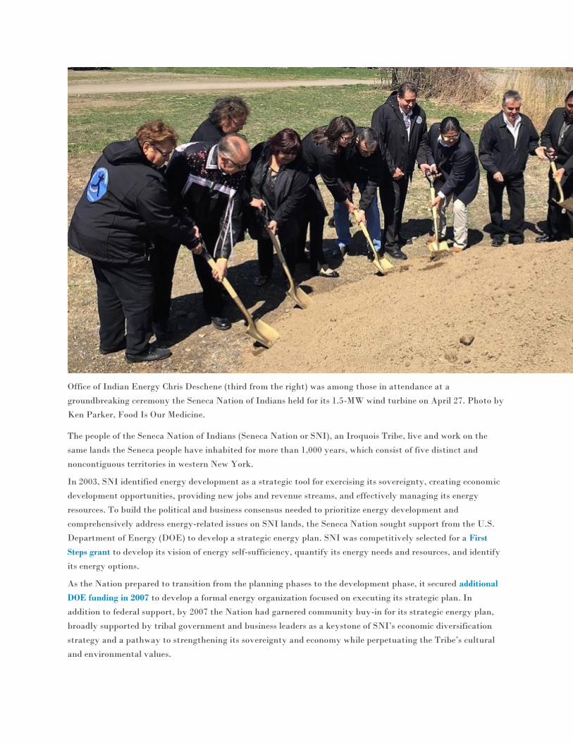
Office of Indian Energy Chris Deschene (third from the right) was among those in attendance at a
groundbreaking ceremony the Seneca Nation of Indians held for its 1.5-MW wind turbine on April 27. Photo by
Ken Parker, Food Is Our Medicine.
The people of the Seneca Nation of Indians (Seneca Nation or SNI), an Iroquois Tribe, live and work on the
same lands the Seneca people have inhabited for more than 1,000 years, which consist of five distinct and
noncontiguous territories in western New York.
In 2003, SNI identified energy development as a strategic tool for exercising its sovereignty, creating economic
development opportunities, providing new jobs and revenue streams, and effectively managing its energy
resources. To build the political and business consensus needed to prioritize energy development and
comprehensively address energy-related issues on SNI lands, the Seneca Nation sought support from the U.S.
Department of Energy (DOE) to develop a strategic energy plan. SNI was competitively selected for a First
Steps grant to develop its vision of energy self-sufficiency, quantify its energy needs and resources, and identify
its energy options.
As the Nation prepared to transition from the planning phases to the development phase, it secured additional
DOE funding in 2007 to develop a formal energy organization focused on executing its strategic plan. In
addition to federal support, by 2007 the Nation had garnered community buy-in for its strategic energy plan,
broadly supported by tribal government and business leaders as a keystone of SNI’s economic diversification
strategy and a pathway to strengthening its sovereignty and economy while perpetuating the Tribe’s cultural
and environmental values.
Challenge:
As SNI transitioned from planning to development, it began to focus its efforts on achieving long-term energy
security. In particular, SNI wanted to stabilize electricity rates of tribal members in the Cattaraugus Territory.
Tribal members in the Allegheny Territory have access to low-cost electricity through New York Power
Authority hydropower, but tribal members in the Cattaraugus Territory do not have access to this low-cost
power and pay two to three times as much for electricity. SNI was also looking to displace fossil and nuclear fuel
sources with SNI-owned renewable power, a long-term strategic goal of the Seneca Nation and a way to reduce
greenhouse gas emissions. Finally, SNI sought to create a tribal utility organization, another key goal of the
Seneca Nation’s strategic energy plan.
“The Tribe saw opportunities to diversify its economy, reduce emissions, and deploy renewable energy,” said
Anthony Giacobbe, general manager of Seneca Energy, a wholly owned subsidiary of SNI and the foundation
for the new tribal utility organization.
Solution:
To advance its ongoing efforts to identify renewable and nonrenewable energy options, in 2007 SNI sought
technical assistance through DOE’s National Renewable Energy Laboratory (NREL). Under NREL’s
Anemometer Loan Program, the Seneca Nation installed meteorological towers in several locations from
November 2007 through February 2009 to assess the available wind resource potential on SNI land. An
installation near Lake Erie revealed a substantial resource favorable to the development of a community-scale
wind energy project.
After examining potential environmental impacts at that location, the Seneca Nation decided to move the
planned turbine site about a mile south of the lakefront, in part to avoid the disruption of wildlife, including
turtle populations. SNI also used the 2007 DOE First Steps Grant to develop a tribal energy organization and a
DOE Energy Efficiency and Conservation Block Grant to refine its proposed wind project. To capitalize on that
early wind resource monitoring and fund the installation of the wind turbine, the Tribe applied for funding
under DOE’s Fiscal Year 2013 Community-Scale Clean Energy Projects in Indian Country Funding
Opportunity Announcement (FOA).
In response to the DOE FOA, SNI proposed to install a 1.8-megawatt community wind turbine with a
maximum hub height of approximately 265 feet, maximum rotor diameter of approximately 330 feet, and
overall maximum height of approximately 430 feet on the selected site. The project was estimated to produce
approximately 4.5 million kilowatt-hours (kWh) of electricity per year, resulting in a 35% annual energy
savings for the Tribe. In 2014, the SNI Wind Turbine Project was competitively selected to receive $1.5 million
in DOE funding to supplement the Tribe’s $4.5 million investment in the installation of the wind turbine.
“Since the Seneca Nation first applied for a DOE First Steps grant to develop a strategic
energy action plan in 2003, they have compounded the returns on that initial DOE
investment, demonstrating progressive forward movement in their pursuit of energy
sufficiency through clean energy development,” said Lizana Pierce, Program Manager for
DOE’s Office of Indian Energy. “It is wonderful to see those initial seed funds evolve into
the installation of a wind turbine that can power half the Seneca Nation.”
Working with Sustainable Energy Developments (SED) of Rochester, New York, SNI advanced to the

implementation phase of the project. The Nation held a groundbreaking ceremony for its 1.5-MW turbine on
April 27, and is scheduled to be operational by the end of 2016.
“Today’s groundbreaking marks a final milestone on the path to displacing fossil and nuclear fuel sources with
tribally owned renewable power, which has been a long-term strategic goal of the Seneca Nation,” said Office of
Indian Energy Director Chris Deschene. “The Office of Indian Energy is proud to stand shoulder-to-shoulder
with the Seneca Nation and other tribal governments working to identify and implement viable, innovative
energy and infrastructure solutions that are foundational to creating stability, preserving their way of life, and
improving quality of life in their communities.”
Benefits:
Intertribal—This successful community-scale tribal wind energy project can serve as a model for other
tribal nations, as Giacobbe and others share successes and lessons learned with tribes and intertribal
organizations interested in pursuing wind energy development.
Societal—The installation has resulted in the hiring of three SNI members for construction
management alongside SED, and 10–15 other tribal members for construction. Further, the Nation is
considering a solar energy project on another site, which could result in another full-time position
managing the Nation’s renewable energy assets.
Economic—Using aggregated net-metering through National Grid, Inc., the Nation will be
compensated for electricity at the rate of $0.08 per kilowatt-hour, which could save the Nation an
estimated $360,000 annually. As a result, some 1,000 SNI households will see monthly reductions in
their electric bills.
Environmental—The new wind turbine is expected to cut 86 million pounds of carbon dioxide
emissions annually, as well as reduce other greenhouse gas emissions.
“The Department of Energy has supported the Seneca Nation throughout this long process, which we really
appreciate” Giacobbe said. “We’ve made great strides in the last couple of years to meet those early strategic
energy goals as well as provide price parity across our Territories. This project is the first step towards building
an even stronger Nation for future generations.”
—Written by Ernie Tucker
Channel 4 Buffalo TV News Media
Seneca Nation to break ground on $6M wind turbine
project
By Mark Belcher, News 4 Digital Producer Published: April 25, 2016, 3:57 pm
IRVING, N.Y. (WIVB) — A large construction project will begin Wednesday in Irving that
will change the area’s skyline.
Seneca Nation officials say a $6 million project will construct wind turbines on the nation’s
Cattaraugus Territory on Erie Road in Irving.
The project, which is backed by the Department of Energy Deployment and New York
State’s NYSERDA authority, is expected to be completed before 2017.
Wind turbine projects near Lake Erie have been hotly contested by wildlife conservationists
who say the large structures will impact migratory patterns for local fowl and birds.
Buffalo Business First Print Media
James Fink Reporter - Buffalo Business First
The Seneca Nation of Indians has started work on a wind turbine that will help reduce… more
Calling it a milestone in its energy independence long term goal, the Seneca Nation of Indians
has started work on a wind turbine that will help reduce reliance on outside energy sources
for its Cattaraugus Territory.
The $6 million project, jointly funded by the Seneca Nation of Indians, U.S. Department of
Energy and New York State Energy Research and Development Authority, is being
constructed on a 1.5 acre site near Irving off of Lucky Layne Road and the Gil Lay Sports
Arena.

Officials expect the turbine to be operational by the end of the year.
“We are harnessing the tremendous power of natural resources to generate new economic
opportunities for our people and bring about a long sought level of self-reliance for the
Seneca Nation,” said Maurice John Sr., Seneca Nation of Indians president.
John said the turbine will reduce energy costs on the Cattaraugus Territory by an estimate
40 percent, with the savings spread to residents and businesses on that portion of the Seneca
Nation territory.
The turbine has the capacity to produce up to 1.5 megawatts, or 4.5 million kilowatt hours,
of electricity.
Jamestown Newspaper
Seneca Nation of Indians Break Ground
on Muliti-Million Dollar Wind Turbine By Mark Goshgarian
Wednesday, April 27, 2016 at 05:21 PM EDT
IRVING, N.Y. -- There was a slight, yet fitting breeze Wednesday in Irving, Chautauqua County as
members of the Seneca Nation of Indians broke ground on a $6 million new wind turbine project. The
turbine is expected to produce 1 1/2 half megawatts of electricity and help power the Cattaraugus
territory.
"This is really a milestone. Renewable energy really aligns with the Nation's core values and how we
approach projects, in this case infrastructure," said Michael Kimelberg, Seneca Nation Chief Operating
Officer.
The project is expected to promote economic development and sharply reduce carbon emissions, which
aligns with the Nation's other renewable energy projects.
"We have a solar array down in Allegany that's going to help everyone, reduce their cost of living, but also
promote these renewable energy sources that are available to us," said Todd Gates, Seneca Nation
Treasurer.
Energy leaders say the goal is to promote sovereignty, generate revenue, preserve the environment and
expand energy infrastructure.

"I'm really proud to say with this project, we're doing all four of those, so it is a strong first piece as we
move toward achieving our strategic energy plan," said Anthony Giacobbe, Seneca Energy General
Manager.
Funding for the project came from state and federal grants through the Department of Energy.
"We are charged with working to help tribes throughout the country whether through technical
assistance, whether through financial assistance, grant in this case but also developing programs,"
said Christopher Deschene, Office of Indian Energy Policy and Programs Director.
Seneca leaders say not only will the project benefit the environment, it'll also generate a significant savings
for the rate payers living on the Nation's territories.
"I know everyone pays their electric, and we want to see that come down a little bit," said Gates.
The turbine is scheduled to be installed and operational by the end of the year.
XI. Pictures/Time-Lapse Video
Seneca Nation – Time-Lapse Construction Video
https://www.youtube.com/watch?v=5eTVBLFQnbs
Seneca Nation – State of the Nation Address 2017
https://www.youtube.com/watch?v=29xK-sibdGY
Robert Woods Foundation – Award Video
http://www.rwjf.org/en/library/features/culture-of-health-prize/2017-winner-seneca-nation-ny.html


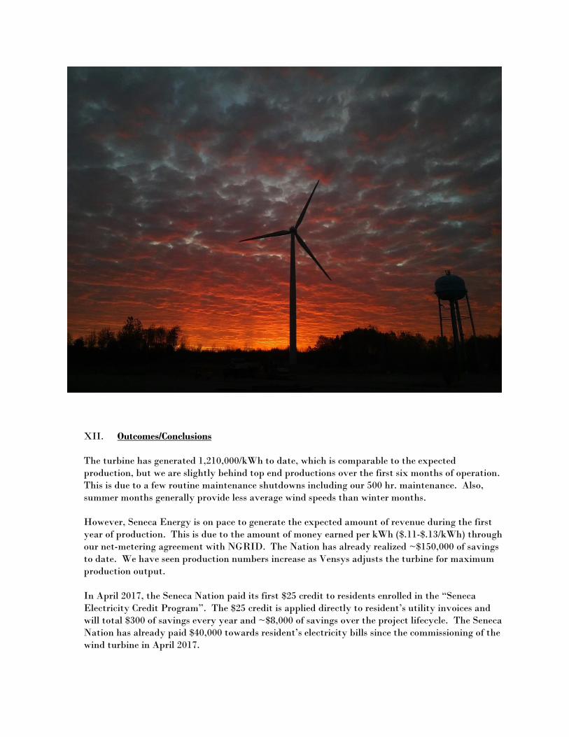
XII. Outcomes/Conclusions
The turbine has generated 1,210,000/kWh to date, which is comparable to the expected
production, but we are slightly behind top end productions over the first six months of operation.
This is due to a few routine maintenance shutdowns including our 500 hr. maintenance. Also,
summer months generally provide less average wind speeds than winter months.
However, Seneca Energy is on pace to generate the expected amount of revenue during the first
year of production. This is due to the amount of money earned per kWh ($.11-$.13/kWh) through
our net-metering agreement with NGRID. The Nation has already realized ~$150,000 of savings
to date. We have seen production numbers increase as Vensys adjusts the turbine for maximum
production output.
In April 2017, the Seneca Nation paid its first $25 credit to residents enrolled in the “Seneca
Electricity Credit Program”. The $25 credit is applied directly to resident’s utility invoices and
will total $300 of savings every year and ~$8,000 of savings over the project lifecycle. The Seneca
Nation has already paid $40,000 towards resident’s electricity bills since the commissioning of the
wind turbine in April 2017.

The Seneca Electricity Credit Program was one of the primary driving factors for the project and
we continue to have additional residents enroll for the program each month. Our goal is to
continue to add residents to our credit program and assist them in keeping electricity rates down,
so that they can use their money for other necessary living expenses.
The Seneca Nation and Seneca Energy are extremely proud of the Cattaraugus wind turbine as
well as all of the other exciting energy projects taking place on territory. We are continuing to
follow our Strategic Energy Plan as we move forward towards achieving energy self-sufficiency.