Semi-active MR technology for enhancing vehicle stability and ...
151
University of Wollongong University of Wollongong Research Online Research Online University of Wollongong Thesis Collection 1954-2016 University of Wollongong Thesis Collections 2016 Semi-active MR technology for enhancing vehicle stability and ride comfort Semi-active MR technology for enhancing vehicle stability and ride comfort Shuaishuai Sun University of Wollongong Follow this and additional works at: https://ro.uow.edu.au/theses University of Wollongong University of Wollongong Copyright Warning Copyright Warning You may print or download ONE copy of this document for the purpose of your own research or study. The University does not authorise you to copy, communicate or otherwise make available electronically to any other person any copyright material contained on this site. You are reminded of the following: This work is copyright. Apart from any use permitted under the Copyright Act 1968, no part of this work may be reproduced by any process, nor may any other exclusive right be exercised, without the permission of the author. Copyright owners are entitled to take legal action against persons who infringe their copyright. A reproduction of material that is protected by copyright may be a copyright infringement. A court may impose penalties and award damages in relation to offences and infringements relating to copyright material. Higher penalties may apply, and higher damages may be awarded, for offences and infringements involving the conversion of material into digital or electronic form. Unless otherwise indicated, the views expressed in this thesis are those of the author and do not necessarily Unless otherwise indicated, the views expressed in this thesis are those of the author and do not necessarily represent the views of the University of Wollongong. represent the views of the University of Wollongong. Recommended Citation Recommended Citation Sun, Shuaishuai, Semi-active MR technology for enhancing vehicle stability and ride comfort, Doctor of Philosophy thesis, School of Mechanical, Materials and Mechatronic Engineering, University of Wollongong, 2016. https://ro.uow.edu.au/theses/4805 Research Online is the open access institutional repository for the University of Wollongong. For further information contact the UOW Library: [email protected]
-
Upload
khangminh22 -
Category
Documents
-
view
1 -
download
0
Transcript of Semi-active MR technology for enhancing vehicle stability and ...
University of Wollongong University of Wollongong
Research Online Research Online
University of Wollongong Thesis Collection 1954-2016 University of Wollongong Thesis Collections
2016
Semi-active MR technology for enhancing vehicle stability and ride comfort Semi-active MR technology for enhancing vehicle stability and ride comfort
Shuaishuai Sun University of Wollongong
Follow this and additional works at: https://ro.uow.edu.au/theses
University of Wollongong University of Wollongong
Copyright Warning Copyright Warning
You may print or download ONE copy of this document for the purpose of your own research or study. The University
does not authorise you to copy, communicate or otherwise make available electronically to any other person any
copyright material contained on this site.
You are reminded of the following: This work is copyright. Apart from any use permitted under the Copyright Act
1968, no part of this work may be reproduced by any process, nor may any other exclusive right be exercised,
without the permission of the author. Copyright owners are entitled to take legal action against persons who infringe
their copyright. A reproduction of material that is protected by copyright may be a copyright infringement. A court
may impose penalties and award damages in relation to offences and infringements relating to copyright material.
Higher penalties may apply, and higher damages may be awarded, for offences and infringements involving the
conversion of material into digital or electronic form.
Unless otherwise indicated, the views expressed in this thesis are those of the author and do not necessarily Unless otherwise indicated, the views expressed in this thesis are those of the author and do not necessarily
represent the views of the University of Wollongong. represent the views of the University of Wollongong.
Recommended Citation Recommended Citation Sun, Shuaishuai, Semi-active MR technology for enhancing vehicle stability and ride comfort, Doctor of Philosophy thesis, School of Mechanical, Materials and Mechatronic Engineering, University of Wollongong, 2016. https://ro.uow.edu.au/theses/4805
Research Online is the open access institutional repository for the University of Wollongong. For further information contact the UOW Library: [email protected]
Department of Mechanical, Materials & Mechatronic
Semi-active MR technology for enhancing vehicle stability and ride
comfort
Shuaishuai Sun
This thesis is presented as part of the requirement for the
Award of the Degree of Doctor of Philosophy
of the Engineering
University of Wollongong
August 2016
ii
DECLARATION
I, Shuaishuai Sun, declare that this thesis, submitted in fulfilment of the requirements
for the award of Doctor of Philosophy, of the School of Mechanical, Materials and
Mechatronics Engineering, University of Wollongong, is wholly my own work
unless otherwise referenced or acknowledged. The document has not been submitted
for qualifications at any other academic institution.
Shuaishuai Sun
August, 2016
iii
ABSTRACT
With the popularisation and rapid development of railway transportation, how to
maintain train stability and reduce unwanted vibration to make the ride more
comfortable has become an emerging research topic. This is why this project has
included magnetorheological (MR) technology into railway vehicles to improve their
performance.
Critical speed is an index and a key technology that directly indicates train stability,
which is why the critical speeds of trains are calculated and analysed based on the
dynamic equations of railway vehicles. These analyses revealed that secondary
lateral damping and primary longitudinal stiffness are the most sensitive suspension
parameters influencing critical speeds. In an attempt to improve dynamic
performance, the secondary lateral dampers were replaced with conventional
magnetorheological fluid (MRF) dampers; with the simulation and experimental
results indicating that the semi-active suspension installed with MR dampers raised
the critical speed and achieved a higher level of stability. The primary longitudinal
stiffness is meant to be stiff when a train is running straight to maintain the stability
and then soft when the train is turning, for better trafficability. To solve this
dilemma, an innovative magnetorheological elastomer (MRE) based primary
longitudinal rubber joint with variable stiffness characteristics has been developed.
The simulation shows that controlling the MRE joint when a train runs on straight
and curved track can satisfy these apparently conflicting requirements and realise
good trafficability on curved track and high stability on straight track.
The second major task of this thesis is to control vibrations so that a higher level of
ride comfort can be achieved. To this end, an advanced MR damper with high
adjustability of damping and stiffness has been designed and fabricated. The results
field, amplitude, and frequency tests using an MTS machine verified its variable
stiffness and damping capability. A new model that can predict the performance of
the damper very well was then developed. The effect that this variable stiffness and
damping damper has on trains was investigated numerically and the results verified
that it definitely improved the ride comfort. Other attempts to improve ride comfort
resulted in the development of two advanced seat suspensions, with one targeting
lateral vibration control and the other for vertical vibration control. To control seat
suspension for lateral vibration, four MRE isolators were fabricated, and then the
iv
property of the isolator(s) was tested and the performance of the seat suspension was
evaluated. The results indicated a much more comfortable ride than the passive seat
suspension due to the MRE isolator based seat suspension. Moreover, with regards to
other types of seat suspension to control vertical vibration, an innovative rotary MR
damper was used to build the seat suspension. The rotary MR damper based
suspension uses less MRF; it has low sealing requirements, and it avoids settlement.
An evaluation of the capability of the rotary MR damper based seat suspension to
reduce vibration by simulation and experimental methods further verified its
effectiveness controlling vibration.
v
ACKNOWLEDGEMENTS
First and foremost, I would like to express my wholehearted appreciation to my
supervisor, Prof. Weihua Li, who guides me during all my time at the University of
Wollongong. At the beginning of my PhD study, it is Prof. Weihua Li who leads me
onto the right track on my research by offering valuable suggestions and guidelines.
During our weekly meeting, Prof. Weihua Li, as an expert in MR area possessing
tremendous knowledge, always provides me valuable recommendations and
suggestions to advance my research progress. He also always tries his best to satisfy
all my needs to conduct my research and always fully support my right movements
on research. In addition, he is not only a research supervisor but more importantly a
life guider. He always teaches me how to be a wise person and the importance of
being respectful. His hardworking attitude always inspires me to achieve more
outcomes. It is the unselfish help, inspirational guidance, encouragement and patient
from Prof. Weihua Li that lead me where I am today and I highly appreciate him for
everything.
I also would like to thank my co-supervisors, Dr. Huaxia Deng, Prof. Haiping Du
and Prof. Gursel Alici who give me very helpful discussion during my PhD study. In
addition, I would like to extend my deep sense of gratitude to all my family, my
lovely parents, brothers and sister, and my wife, Jian Yang. Your encouragement and
emotional support helped me pass through many tough stages during my research.
I also want to extend my gratitude to all my good friends and colleagues, Donghong
Ning, Xin Tang, Dan Yuan, Xinxin Shao, Wenfei Li, Zhiwei Xing, Tanju Yildirim,
Jun Zhang, Sheng Yan, Gangrong Peng, for your stay with me and happiness you
shared with me. Finally, I would like to thank all of you who helped me to grow up
to the person I am now.
vi
TABLE OF CONTENTS
DECLARATION ......................................................................................................... ii
ABSTRACT ................................................................................................................ iii
ACKNOWLEDGEMENTS ......................................................................................... v
TABLE OF CONTENTS ............................................................................................ vi
LIST OF FIGURES ..................................................................................................... x
LIST OF TABLES .................................................................................................... xiv
1 Introduction ............................................................................................................... 1
1.1 Research Background and Motivation ......................................................... 1
1.2 Research objectives ...................................................................................... 2
1.3 Outline .......................................................................................................... 3
2 Literature review ....................................................................................................... 5
2.1 Adaptive suspension for railway vehicles .......................................................... 5
2.1.1 Semi-active damper for railway vehicles ................................................. 5
2.1.2 Adaptive wheelset positioning technology for railway vehicles.............. 6
2.2 MR materials and their applications ............................................................ 7
2.2.1 MRF materials and their applications ...................................................... 7
2.2.2 MRE materials and their applications ...................................................... 9
2.3 Variable stiffness and damping for vibration control ................................ 12
2.4 Semi-active MR seat suspension ................................................................ 15
2.5 Conclusions ................................................................................................ 17
3 Analysis of vibration and stability of railway vehicles and its improvement with
MR damper ................................................................................................................ 18
3.1 Introduction ................................................................................................ 18
3.2 Mathematical model and calculation of train’s critical speeds .................. 19
3.2.1 Analytical model of train ....................................................................... 19
3.2.2 Calculation of the critical speed of a train ............................................. 22
3.2.3 Theoretical analysis of the effect of an MR damper on train critical
speed 25
3.3 The effect of train speed on the damping ratio of each train DOF ............ 26
3.4 The influence of suspension parameters on critical speeds of each train
DOF 29
3.5 The sensitivity analysis of the critical speed of a train .............................. 34
vii
3.6 The simulation of a train with an MR damper ........................................... 38
3.6.1 Modelling of a train ................................................................................ 39
3.6.2 Modelling of MR damper....................................................................... 40
3.6.3 The control strategy................................................................................ 42
3.6.4 Assembly of semi-active train and simulation ....................................... 42
3.6.5 Simulation and results ............................................................................ 43
3.7 The experimental research on the effect of the MR damper on the stability
of a train ................................................................................................................. 45
3.7.1 Experimental facilities ........................................................................... 45
3.7.2 Setup of experiment system ................................................................... 46
3.7.3 Results of experiment ............................................................................. 47
3.8 Conclusion ................................................................................................. 48
4 Investigation of the MRE rubber joint for train ...................................................... 49
4.1 Introduction ................................................................................................ 49
4.2 The design and working mechanism of the MRE joint.............................. 50
4.3 Prototype .................................................................................................... 52
4.3.1 Fabrication and characterise of MRE ..................................................... 52
4.3.2 Assembly of MRE joint ......................................................................... 53
4.4 Dynamic testing of the MRE rubber joint .................................................. 55
4.4.1 Testing .................................................................................................... 55
4.4.2 Testing results and discussion ................................................................ 55
4.5 Simulation evaluation of the MRE joint on a train .................................... 58
4.5.1 Test the trafficability of the train on a curve track ................................. 58
4.5.2 The stability evaluation of the train with MRE rubber joint .................. 63
4.6 Conclusion ................................................................................................. 63
5 Compact variable stiffness and damping damper for vehicle suspension system .. 64
5.1 Introduction ................................................................................................ 64
5.2 Variable stiffness and damping damper ..................................................... 64
5.2.1 Design and working principle of the advanced MR damper.................. 64
5.2.2 Prototype of the advanced MR damper .................................................. 66
5.2.3 Test and result discussion....................................................................... 67
5.2.4 Modelling and parameter identification ................................................. 73
5.3 Simulation of railway vehicle with variable stiffness and damping damper
80
viii
5.3.1 Control strategy ...................................................................................... 81
5.3.2 Simulation results and discussions ......................................................... 83
5.4 Conclusion ................................................................................................. 84
6 Horizontal Vibration Reduction of a Seat Suspension Using MRE Isolators ......... 86
6.1 Introduction ................................................................................................ 86
6.2 Structure and working principle of the MRE isolator ................................ 86
6.3 Prototype and testing of the MRE isolator ................................................. 88
6.3.1 Fabrication of the MRE isolator ............................................................. 88
6.3.2 Experimental testing............................................................................... 88
6.3.3 Frequency shift property evaluation ...................................................... 91
6.4 Vibration suppression evaluation of seat suspension mounted with four
MRE isolators ........................................................................................................ 92
6.4.1 Structure of the seat suspension mounted with MRE isolators .............. 92
6.4.2 Experimental testing system .................................................................. 93
6.4.3 Control algorithm ................................................................................... 94
6.4.4 Experimental results ............................................................................... 94
6.5 Conclusions ................................................................................................ 97
7 A seat suspension with a rotary MR damper for vertical vibration control ............ 99
7.1 Introduction ................................................................................................ 99
7.2 The structure and design of the seat suspension ........................................ 99
7.2.1 The structure of the innovative seat suspension with rotary MR damper
99
7.2.2 The design of the rotary MR damper based seat suspension ............... 100
7.3 The property test of the seat suspension and results discussion .............. 103
7.3.1 Testing method ..................................................................................... 103
7.3.2 Test results ........................................................................................... 103
7.4 Numerical effectiveness evaluation of the rotary MR seat suspension.... 107
7.4.1 The dynamic model of the seat suspension .......................................... 107
7.4.2 Control algorithm ................................................................................. 109
7.4.3 The numerical simulation results ......................................................... 109
7.5 Experimental effectiveness evaluation of the rotary MR seat suspension111
7.5.1 Test system ........................................................................................... 111
7.5.2 Test results ........................................................................................... 112
7.6 Conclusion ............................................................................................... 115
ix
8 Conclusions and future work ................................................................................ 117
8.1 Improving the stability of railway vehicles .............................................. 117
8.1.1 Analysing the mechanism of the vibration and stability of railway
vehicles ............................................................................................................. 117
8.1.2 Application of the MR damper for railway vehicles ............................ 117
8.1.3 Investigation of the MRE rubber joint for train ................................... 118
8.2 Reduced vibration and improved ride comfort of railway vehicles ......... 118
8.2.1 Compact variable stiffness and damping damper for railway vehicles 118
8.2.2 Advanced seat suspensions with MR technology ................................ 119
8.3 Recommendation for future work ............................................................ 120
8.3.1 Optimisation of the design of variable stiffness and damping dampers
120
8.3.2 Optimise the stiffness variation range of the MRE rubber joint .......... 121
8.3.3 Experimental investigation of a train mounted with variable stiffness and
damping damper or an MRE rubber joint ........................................................ 121
References ................................................................................................................ 122
PUBLICATIONS DURING MY PHD STUDY ..................................................... 134
x
LIST OF FIGURES
Figure 2.1 State variation of MRF (© 2005 Lord Corporation) .................................. 8
Figure 2.2 Schematic of magnetic particle dispersion [57]........................................ 10
Figure 2.3The transmissibility of one DOF with different suspension systems [82]. 12
Figure 2.4The schematic structure of the MrEPI [90] ............................................... 15
Figure 2.5 Variable stiffness and damping mechanism [92]...................................... 15
Figure 2.6 Experimental setup for vibration control [105] ........................................ 16
Figure 3.1 Analytical model of a train ....................................................................... 20
Figure 3.2 Damping ratios of the front truck wheelsets ............................................. 26
Figure 3.3 Damping ratios of the rear truck wheelsets .............................................. 27
Figure 3.4 Damping ratios of truck frames ................................................................ 28
Figure 3.5 Damping ratios of car body response modes ............................................ 28
Figure 3.6 Critical speed versus primary lateral damping ......................................... 30
Figure 3.7 Critical speed versus secondary lateral damping ...................................... 31
Figure 3.8 Critical speed versus primary lateral stiffness .......................................... 32
Figure 3.9 Critical speed versus secondary lateral stiffness ...................................... 33
Figure 3.10 Train critical speed versus various bogie damping................................. 36
Figure 3.11 Train critical speed versus various bogie stiffness ................................. 36
Figure 3.12 Sensitivity of train critical speed versus various bogie damping ........... 37
Figure 3.13 Sensitivity of train critical speed versus various bogie stiffness ............ 37
Figure 3.14 The average sensitivity of train critical speed with respect to different
bogie stiffness and damping parameters ............................................................ 38
Figure 3.15 Dynamic model of a train ....................................................................... 39
Figure 3.16 Dynamic model of suspension of train .................................................. 39
Figure 3.17 MR damper model .................................................................................. 40
Figure 3.18 Force-displacement (a) and force-velocity (b) relationship of MR damper
............................................................................................................................ 41
Figure 3.19 Composition of semi-active train model................................................. 42
Figure 3.20 The displacement of wheelset vs the speed of the train with a passive-off
damper ................................................................................................................ 43
Figure 3.21The displacement of wheelset vs the speed of the train with a passive-on
damper ................................................................................................................ 44
xi
Figure 3.22 The displacement of the wheelset vs the speed of a train with an semi-
acitve MR damper .............................................................................................. 44
Figure 3.23 Railway vehicle ...................................................................................... 46
Figure 3.24 Installation of MR dampers .................................................................... 47
Figure 3.25 RMS of lateral acceleration of the bogie ................................................ 48
Figure 4.1 The structure of the MRE rubber joint ..................................................... 50
Figure 4.2 The working mechanism of the MRE rubber joint: (a) Train runs on curve
line with soft longitudinal stiffness (b) Train runs on straight line with hard
longitudinal stiffness .......................................................................................... 52
Figure 4.3 The storage modulus and loss modulus of MRE under different magnetic
flux densities: (a) Storage modulus; (b) Loss modulus ...................................... 54
Figure 4.4 The prototype of the MRE rubber joint .................................................... 54
Figure 4.5 Test of the MRE rubber joint .................................................................... 55
Figure 4.6 The response of the MRE rubber joint to different magnetic field........... 56
Figure 4.7 The stiffness variation under different currents ........................................ 56
Figure 4.8 The response of the MRE rubber joint to different amplitudes ................ 57
Figure 4.9 The response of the MRE rubber joint to different frequencies ............... 58
Figure 4.10 The angle of the attack ............................................................................ 58
Figure 4.11 The angle of attack on curve track with 600m radius ............................. 59
Figure 4.12 The lateral displacement of the wheelset on curve track with 600m radius
............................................................................................................................ 60
Figure 4.13 The lateral force of the wheelset on curve track with 600m radius ........ 61
Figure 4.14 The angle of attack on curve track with 3000m radius .......................... 61
Figure 4.15 The lateral displacement of the wheelset on curve track with 3000m
radius .................................................................................................................. 62
Figure 4.16 The lateral force of the wheelset on curve track with 3000m radius ...... 62
Figure 5.1 Design and photograph of the advanced MR damper .............................. 65
Figure 5.2 Scheme of Connection Mode ................................................................... 65
Figure 5.3 Force displacement relationship under I1=0A .......................................... 69
Figure 5.4 Effective stiffness as a function of the current applied to the external
damper ................................................................................................................ 70
Figure 5.5 Variable damping performance under various currents ........................... 72
Figure 5.6 Equivalent damping and energy consumption as a function of the applied
current to the internal damper ............................................................................ 73
xii
Figure 5.7 Force-displacement loops under different frequency ............................... 73
Figure 5.8 Phenomenological model for the advanced MR damper .......................... 74
Figure 5.9 The flow chart of parameter identification using IP-GA .......................... 76
Figure 5.10 Comparison between the simulated response and the measured response:
(a) Variable damping property (b) Variable stiffness property .......................... 78
Figure 5.11 Comparison between the simulated response and the measured response:
(a) Variable damping property (b) Variable stiffness property .......................... 79
Figure 5.12 Control system of variable stiffness and damping suspension ............... 81
Figure 5.13 Car body response in time domain ......................................................... 82
Figure 5.14 Car body response in frequency domain ................................................ 84
Figure 5.15 Acceleration RMS of car body ............................................................... 84
Figure 6.1 Structure of the MRE isolator ................................................................... 88
Figure 6.2 The experiment setup for testing the dynamic performance of MRE
isolator ................................................................................................................ 89
Figure 6.3 Relationship between force and displacement under different currents ... 90
Figure 6.4 Relationship between equivalent stiffness and current ............................. 90
Figure 6.5 Relationship between force and displacement with different amplitudes 91
Figure 6.6 Transmissibility of the MRE isolator under different currents ................. 92
Figure 6.7 Structure of the MRE seat suspension ...................................................... 93
Figure 6.8 Experiment setup for seat vibration testing: (a) Schematic diagram (b)
Experimental setup ............................................................................................. 93
Figure 6.9 The equivalent SDOF system ................................................................... 94
Figure 6.10 Acceleration and displacement responses of seat suspension under
different sinusoidal excitations: (a) 5Hz. (b) 7Hz. (c) 10Hz ............................ 96
Figure 6.11 Responses of seat under sweep frequency sinusoidal excitation ............ 97
Figure 7.1 The structure of the innovative seat suspension: (a) working mechanism
(b) photograph of the suspension system ......................................................... 100
Figure 7.2 The structure of the rotary MR damper .................................................. 101
Figure 7.3 The test results of the seat suspension :(a) different currents (b) different
amplitudes (c) different frequencies................................................................. 105
Figure 7.4 The comparison between the experimental peak force and calculated peak
force.................................................................................................................. 106
Figure 7.5 The mathematic model of seat suspension ............................................. 108
Figure 7.6 The fitting result of the mathematic model............................................. 108
xiii
Figure 7.7 The simulation response of seat under harmonic excitation ................... 110
Figure 7.8 The simulation response of seat under random excitation...................... 111
Figure 7.9 The effectiveness evaluation system for the seat vibration control: (a)
Sketch (b) Experiment...................................................................................... 112
Figure 7.10 The test results of the MR seat suspension under harmonic excitation: (a)
1.3Hz (b) 1.75Hz .............................................................................................. 113
Figure 7.11 The transmissibility of the MR seat suspension under different
frequencies ....................................................................................................... 114
Figure 7.12 The performance of MR seat suspension under random excitation ..... 115
xiv
LIST OF TABLES
Table 3.1 Nomenclature of train dynamic model symbol .......................................... 23
Table 3.2 The value of the key initial parameter ....................................................... 24
Table 3.3 Motions of the 15-degree-of-freedom train model ................................... 24
Table 3.4 Nomenclature of critical speeds of each DOF ........................................... 30
Table 4.1 value of the main size................................................................................. 50
Table 5.1 The parameters of the two springs ............................................................. 67
Table 5.2 The identified parameters........................................................................... 77
Table 6.1 The reduction percentage under different frequencies ............................... 97
Table 7.1The size of the rotary MR damper ............................................................ 102
Table 7.2 The parameters for the MRF-132DG ....................................................... 102
Table 7.3The identified model parameters............................................................... 108
Table 7.4 The rules of the Fuzzy controller ............................................................. 109
Table 7.5 The acceleration RMS values .................................................................. 115
1
1 INTRODUCTION
1.1 Research Background and Motivation
Trains are an efficient solution to the high demand for transportation in a society in a
globalised economy. Compared to other forms of transportation, trains have
advantages of high speed travel, they are safe [1-3], environmentally friendlier, and
deliver cheaper unit delivery costs. However, these advantages can be offset by
challenges such as induced vibration and noise that inevitably lead to a series of
problems such as instability and unsatisfactory ride comfort; these are the most
serious issues that need to be addressed [3, 4] because train stability is closely related
to the comfort and even safety of passengers; in fact, high stability can also protect
the train and the rail from damage caused by mutual friction and collisions. Stability
is normally characterised by critical speed, such that the higher the critical speed the
more stable the train is. This is why the critical speed of a railway vehicle is intrinsic
and independent of the type of excitation type; it is a fixed scalar once the suspension
system of a train has been configured and assembled, and therefore an adjustable
semi-active suspension system rather than passive suspension is potentially a far
better choice for achieving a high critical speed [5]. The theoretical results show that
the secondary lateral damper and the primary longitudinal stiffness are the
parameters most closely related to the critical speed, so finding advanced technology
to make a secondary lateral damper and a longitudinal rubber joint controllable to
improve the critical speed becomes an urgent task.
In terms of a secondary lateral damper, apart from passive control, semi-active
control has the potential to improve the critical speed because it requires less energy
and can adjust the system parameters in real time [6, 7]. Many researchers have done
excellent work on the semi-active control of railway vehicles [8-10], and the
application of MR technology to railway vehicles has been reported by several
groups [11, 12]. However, the above research mainly focused on improving ride
comfort, whereas research into using MR dampers to improve the critical speed is
rare. In order to help fill this gap, this research investigated the application of a
traditional MR damper to improve critical speed both theoretically and
experimentally.
As well as the secondary lateral damper, the primary longitudinal rubber joint is
another important component that affects the critical speed. To date, passive rubber
2
joints are widely used in railway vehicle, and while having harder longitudinal
stiffness guarantees stability in a straight track, it leads to bad trafficability as a train
begins to turn. A perfect primary longitudinal joint is supposed to overcome this
conflict, i.e. it should be stiff when the train is running straight and then soft as it is
turning. To solve this problem, this research proposed an innovative MRE based
rubber joint whose stiffness is controllable. With this characteristic, the new MRE
joint can provide hard stiffness to ensure stability when a railway vehicle runs on
straight track and offer soft stiffness to realise good trafficability on a curved track.
To control the ride comfort, many semi-active devices have been developed in recent
years and then used to reduce vibration of railway vehicles. However, variable
stiffness and damping suspension systems with better vibration control than
suspension systems with only variable damping has not been investigated in existing
literature, and furthermore, a practical variable stiffness and damping device suitable
for railway vehicles has not yet been reported. To compensate for this deficiency,
this thesis developed a compact variable stiffness and damping MR damper which is
suitable for trains, and whose contribution to ride comfort has also been investigated.
Using the train suspension system to mitigate vibration from its source is a good
idea, but it cannot be denied that preventing vibration from being transmitted to the
drivers or passengers using an advanced seat suspension is a much more efficient
way to improve ride comfort. Since trains experience vibration vertically and
laterally, this thesis investigated two different seat suspensions. One is an MRE
based seat suspension for controlling lateral vibration and the other is rotary MR
damper based seat suspension for controlling vertical vibration.
1.2 Research objectives
The overall aim of the research is to develop controllable devices to improve the
overall dynamic performance of trains, including improving the stability, reducing
vibration, enhancing ride comfort, and improving trafficability on curved track.
The specific objectives of this research are as follows:
(1). Analysing the stability mechanism of railway vehicles based on a 15 degrees of
freedom dynamic model, and determine the parameters that affect its stability.
(2). Analyse how affectively traditional MR dampers and MRE based stiffness
variable rubber joints improve the stability and trafficability of railway vehicles.
3
(3). Develop a compact variable stiffness and damping MR damper for railway
vehicles and build a mathematic model to predict the dynamic performance of a
variable stiffness and damping MR damper.
(4). Develop advanced seat suspensions to reduce the lateral and vertical vibrations
in railway vehicles.
1.3 Outline
This thesis starts with an introduction of the research background and motivation,
objectives, and outline.
Chapter 2 presents a literature review on existing adaptive technology for railway
vehicles, including semi-active dampers and wheelset positioning technology, MR
materials and their applications, variable stiffness and damping devices, and seat
suspension technologies.
Chapter 3 describes building a 15 DOFs model of railway vehicles to analyse their
stability. The influence that each suspension parameter has on a train’s vibration and
critical speed was analysed theoretically and indicated that the secondary lateral
damper and primary longitudinal stiffness are the two important parameters that
affect stability. The secondary lateral damper was subsequently replaced by a MR
damper and its contribution to improving stability was investigated theoretically and
experimentally.
In Chapter 4 the effect that primary longitudinal stiffness has on the critical speed of
railway vehicles was further investigated and verified, and an innovative MRE based
rubber joint was prototyped and tested. Including MRE in the rubber joint design
improves the variable stiffness; an advantage that satisfied the requirements for hard
and soft stiffness. The simulation result indicated that the innovative MRE joint can
provide hard stiffness to stabilise a train running at high speed in a straight line and
also offer soft stiffness to realise good trafficability when it passes thought a curved
line.
Chapter 5 focuses on improving the vibration and ride comfort of railway vehicles.
To achieve this, an innovative MRF based damper which synergises the attributes of
variable stiffness and variable damping via a compact assembly of two MRF
damping units and springs was developed, and its ability to improve the dynamic
performance was theoretically verified.
4
Chapter 6 and Chapter 7 presents two innovative MR technology based semi-active
seat suspensions to further improve the ride comfort. Four MRE isolators are
prototyped and assembled for a seat suspension to control lateral vibration and a
rotary damper is mounted on a seat suspension to control vertical vibration. An
evaluation of this vibration control indicates that the MR technology based seat
suspension performed better than passive seat suspensions.
Chapter 8 concludes the main findings of this thesis and discusses future research
work.
5
2 LITERATURE REVIEW
2.1 Adaptive suspension for railway vehicles
2.1.1 Semi-active damper for railway vehicles
Active and semi-active control is two typical methods used to improve system
performances. Whereas active control is better at reducing vibration, the
disadvantages of possible instability, complex control algorithms, and large power
consumption limit its common use. More interest has recently been given to semi-
active control because it requires less power, the hardware is cheaper, and it performs
well. In fact a great deal of research work on semi-active control of railway vehicles
has already been done. For example, O’Neill and Wale [13] have done some pioneer
work on the application of semi-active suspensions to improve the ride quality of
trains. In their study, solenoid valves and semi-active dampers were developed to
control vibration, while Tang developed a semi-active damper with a butterfly valve
and mounted it on a quarter vehicle which was then tested in their laboratory [14].
Stribersky et al. [15] designed another hydraulic damper whose orifice was
controlled by a fast-acting throttle valve. The hydraulic damper improves ride quality
by up to 15% according to the measured RMS of the accelerations. Some semi-active
suspension systems for railway vehicle have been commercialised by Kayaba (KYB)
Corporation in Japan, or by KONI Railway in the Netherlands. However, the
composition of the oil cylinders and mechanical valves reduces the reliability and
response time of variable orifice dampers, which also increases their maintenance
costs.
Another semi-active control method can be realised by placing smart fluids into the
damper. Electrorheological (ER) fluids and MR fluids are two typical controllable
fluids which can change from a free flowing viscous fluid into a semi-solid. Their
composition without extra moving parts makes them simple and reliable. ER fluids
are excited by high voltage, which limits its use in many areas because of safety
concerns, whereas MR fluids only need a low voltage source to excite a magnetic
field, which means a semi-active suspension with MR fluids is better suited for
trains. As a semi-active control device, an MR damper uses the unique characteristics
of MR fluids to provide simple, quiet, rapid-response interfaces between electronic
controls and mechanical systems, which makes it an ideal option for trains.
6
2.1.2 Adaptive wheelset positioning technology for railway vehicles
It is becoming more important for rail vehicles to operate at high speed in order to
improve transportation efficiency, but so too is improving the steering capability
when they run on curved track in order to achieve low maintenance costs for both
vehicles and tracks [16]. Consequently, compatibility between the dynamic stability
which allows trains to operate at high speed and good curved track trafficability
while maintaining low maintenance is an urgent requirement for modern railway
vehicles.
The stability of trains running at high speed requires stiff wheelset positioning that
will resist the hunting motion of wheelsets and soft wheelset positioning stiffness to
achieve good curving performance. This leads to an incompatibility between stability
design and curving performance when designing the wheelset positioning stiffness of
conventional passive trucks. In order to overcome this conflict, the GontiTech
Company developed a radial hydraulically controlled wheelset positioning system
which mainly contains the guide column for the truck frame, positioning rubber, and
hydraulic oil. This ingenious design uses the different excitation frequency induced
by the distinct running speed of the train on straight track and curve track. This
positioning system can offer soft longitudinal stiffness under lower excitation
frequency when the train runs on a curved line at lower speed and provide hard
longitudinal stiffness under high excitation frequency when the train operates on a
straight line at higher speeds. With this method the proposed wheelset positioning
system overcomes the conflict between high speed stability and curved line
performance to a certain extent, but there is still room for improvement.
Another way to overcome this conflict is to introduce active control to the truck
design. Some existing research has reported on an investigation into active control to
realise good steering and high speed stability [17-20]. Unfortunately, active control
will lead to problems such as high power consumption, large expense on hardware,
and even instability due to improper control.
Semi-active control however, is a compromise between active and passive control
with the advantages of fail-safe characteristics, lower power consumption, and
cheaper hardware; and it is a better way to solve this conflict. Suda et al. proposed an
asymmetric truck to achieve both good curving performance and stability. In [21-24],
the primary longitudinal stiffness of the leading and trailing wheelsets is asymmetric,
7
which means the longitudinal stiffness of the leading wheelset is softer than the
trailing wheelset. Soft longitudinal stiffness can decrease the lateral force and the
angle of attack of the leading wheelsets which improves curved track trafficability,
while the hard longitudinal stiffness of the trailing wheelset can keep the train stable
at high speed. This longitudinal stiffness of the wheelsets can be reversed when a
train’s running direction changes. The simulation result and experimental result
verified that the proposed asymmetric suspension solved the conflict between high
speed stability and curving track performance. This kind of truck has been assembled
on a Series 383 EMU train and is now in daily use. However, according to the
evaluation this asymmetric system still decreases the critical speed compared to a
conventional symmetric system. Since MRE is an important member of the MR
material family, it can vary its stiffness rapidly, which makes it an ideal material to
develop an adaptive wheelset positioning technology, but since this has rarely been
investigated this research will help to fill the gap.
2.2 MR materials and their applications
MR materials, as typical smart controllable materials whose properties can be
controlled by an external magnetic field, consist mainly of Magnetorheological
fluids, elastomers, gel and foams[25]. MRF is in a fluid state and its shear stress is
very sensitive to a magnetic field, which means it can be used to develop variable
damping dampers. On the other hand MRE is an elastomeric material whose stiffness
can be controlled by a magnetic field. MR foam means MRF is constrained in a
capillary action in an absorbent matrix such as a sponge, open-celled foam, felt or
fabric. MR gel is relative younger than the other three and it is in gel state between
solid and fluid. Since MRF and MRE are the two MR materials used most
frequently, their property and applications will be further introduced in the following
two sections.
2.2.1 MRF materials and their applications
MRF materials
Dating back to 1948, Jacob Rabinow discovered MRF at the US National Bureau of
Standards, which are a class of smart fluids whose yield stress is controllable. MRFs
consist of magnetic particles at micron size, e.g., iron or cobalt particles, and carrier
fluid e.g., silicone oil or hydraulic oil [26, 27]. The magnetic particles in MRF can
8
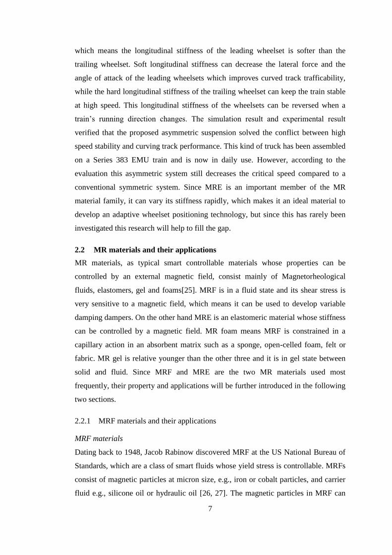
freely move in their carrier fluid when no magnetic field is applied, as shown in
Figure 2.1(a), but they lose their free mobility and form a chain-like structure along
the direction in which a magnetic field is applied. This means the magnetic field
enables the magnetic particles to become polarised and then attract one another, as
shown in Figure 2.1(b). The variability of the structural arrangement of these
ferromagnetic particles gives MRF the ability to change its viscosity and yield stress.
From the perspective of traditional materials, MRF is outstanding because its soft
morphology and controllable rheology by an external magnetic field means it can
achieve a rheological transition and exhibit viscoelastic properties within a few
milliseconds.
(a) Without magnetic field applied (b) Magnetic field applied
Figure 2.1 State variation of MRF (© 2005 Lord Corporation)
MR damper and its application to railway vehicles
To date, various semi-active devices using MRFs have been developed, of which MR
dampers that offer variable damping and reliable operations at a modest cost have
been extensively used in vehicle suspension systems, landing gear systems, ship
vibration reduction systems, civil structures, and so on [28-35].
The application of MR dampers on trains has been reported by a few groups; for
example, Liao and Wang [36] studied the application of an MR damper to control the
vertical vibration of trains, while Wang and Liao [37, 38] further verified that an MR
damper improved a train’s ride comfort by replacing four secondary lateral dampers
with MR dampers. A model of a full scale railway vehicle with 17 degrees of
freedom was integrated with an MR damper and its controller was built. A dynamic
model of the train was then used to design a linear quadratic Gaussian control law for
the MR damper. Random and periodical track irregularities based on real testing data
were incorporated into the dynamic model to evaluate the semi-active suspension
9
system, and the results showed that the semi-active suspension system can provide
better ride comfort than the passive on or passive off modes.
Some MR dampers for railway vehicle have been designed and prototyped, for
instance, Guo and Gong developed a twin-tube and bypass MR damper for railway
vehicles [39], and Lau and Liao [40] designed an MR damper for secondary lateral
damper of railway vehicles. Many control algorithms for MR dampers have also
been developed; Zong et al. [10] investigated a robust control algorithm for an MR
damper to suppress lateral vibration, and then verified its effectiveness using the
simulation method. Ma and Yang investigated a self-adapted fuzzy control and
adaptive fuzzy control for the secondary lateral semi-active damper of the railway
vehicle, respectively [41, 42]. Wang and Liao designed an LQG control algorithm for
the secondary vertical MR damper and proved its effectiveness by numerical
simulation [37]. Ha et al. developed a fuzzy sky to ground hook control algorithm for
a secondary lateral MR damper [43]. Some experimental evaluations of using an MR
damper to reduce vibrations in a railway vehicle were carried out by testing scaled or
full scaled railway vehicles mounted with MR dampers. Shin et al developed and
tested a 1/5 scaled MR damper used to replace a secondary lateral damper in a
railway vehicle [44, 45]. This scaled MR damper was then mounted onto a 1/5 scaled
railway vehicle and then tested on a scaled test rig. The skyhook control algorithm
and H∞ control algorithm were designed to control the MR damper at work, and the
test results verified that the MR damper definitely reduced vibration in a railway
vehicle. Lee et al. designed and developed an MR damper which was then mounted
onto a full scale railway vehicle [46], controlled it with the skyhook control
algorithm and tested it on a roller rig. The results indicated that the MR damper
improved the ride comfort level by approximately 1dB. The research mentioned
above focused mainly improving the ride comfort with MR technology, but the
contribution an MR damper makes to train stability has rarely been investigated. This
thesis therefore carries out an experimental and numerical study to investigate the
effect that an MR damper has on the critical speed of trains.
2.2.2 MRE materials and their applications
MRE materials
10
MRE is a stiffness variable smart material that generally consists of micro-sized
magnetic particles dispersed in a non-magnetic matrix[47]. In a magnetic field the
ferromagnetic particles inside MRE have an MR effect which increases its stiffness
and damping, but it immediately returns to soft state when the magnetic field is
removed. Compared to MRFs, MREs have the advantage of high stability and no
sealing issues [48].
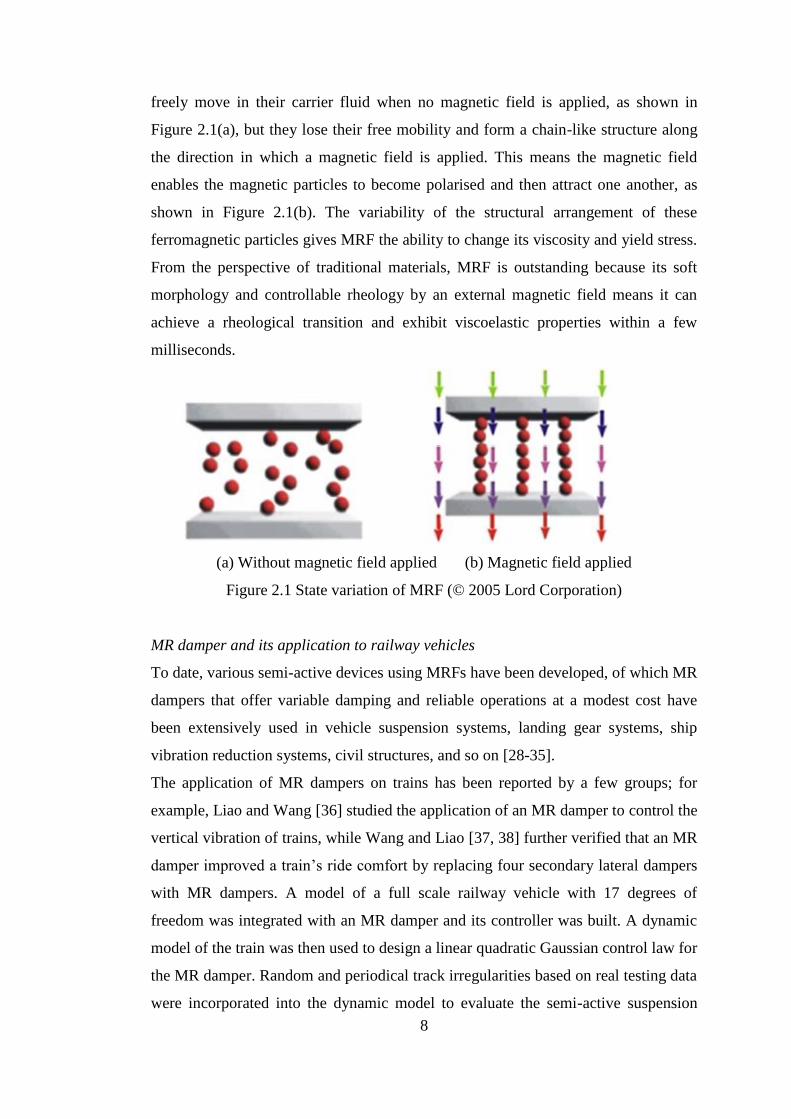
There are two main types of typical MREs, depending on the curing method used:
anisotropic MR elastomers and isotropic MR elastomers. Take silicon rubber based
MRE fabrication as an example. In the first step, iron particles are placed into a
container and then silicon oil is poured in; this is then mixed with silicone rubber
until all the materials are mixed thoroughly. The mixture is then placed into a
vacuum case to remove any air bubbles [49-51], and then removed and poured into a
mould. After 24 hours of curing at room temperature, this isotropic MRE can be
fabricated [52]. The iron particles inside MRE will be randomly dispersed, as shown
in Figure 2.2(a). In terms of anisotropic MRE [53], curing should be completed in the
presence of a strong magnetic field [54-56] because this enables the ferromagnetic
particles to form chained structures, as shown in Figure 2.2(b)
(a) Without a magnetic field (b) With a magnetic field
Figure 2.2 Schematic of magnetic particle dispersion [57]
Many studies [57, 58] have reported the dynamic property test of MRE specimens, of
which the main conclusions are: (1) an increase in the volume percentage of
ferromagnetic particles in MRE improves the modulus variation range; (2) The
increase in the shear modulus of MRE varies when magnetic flux density with
different strengths is applied, and it will saturate at stronger magnetic flux densities;
(3) There is a sharp reduction in the MR effect at high strains. The main reason for
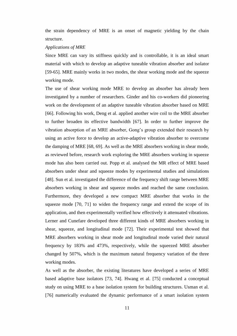
11
the strain dependency of MRE is an onset of magnetic yielding by the chain
structure.
Applications of MRE
Since MRE can vary its stiffness quickly and is controllable, it is an ideal smart
material with which to develop an adaptive tuneable vibration absorber and isolator
[59-65]. MRE mainly works in two modes, the shear working mode and the squeeze
working mode.
The use of shear working mode MRE to develop an absorber has already been
investigated by a number of researchers. Ginder and his co-workers did pioneering
work on the development of an adaptive tuneable vibration absorber based on MRE
[66]. Following his work, Deng et al. applied another wire coil to the MRE absorber
to further broaden its effective bandwidth [67]. In order to further improve the
vibration absorption of an MRE absorber, Gong’s group extended their research by
using an active force to develop an active-adaptive vibration absorber to overcome
the damping of MRE [68, 69]. As well as the MRE absorbers working in shear mode,
as reviewed before, research work exploring the MRE absorbers working in squeeze
mode has also been carried out. Popp et al. analysed the MR effect of MRE based
absorbers under shear and squeeze modes by experimental studies and simulations
[48]. Sun et al. investigated the difference of the frequency shift range between MRE
absorbers working in shear and squeeze modes and reached the same conclusion.
Furthermore, they developed a new compact MRE absorber that works in the
squeeze mode [70, 71] to widen the frequency range and extend the scope of its
application, and then experimentally verified how effectively it attenuated vibrations.
Lerner and Cunefare developed three different kinds of MRE absorbers working in
shear, squeeze, and longitudinal mode [72]. Their experimental test showed that
MRE absorbers working in shear mode and longitudinal mode varied their natural
frequency by 183% and 473%, respectively, while the squeezed MRE absorber
changed by 507%, which is the maximum natural frequency variation of the three
working modes.
As well as the absorber, the existing literatures have developed a series of MRE
based adaptive base isolators [73, 74]. Hwang et al. [75] conducted a conceptual
study on using MRE to a base isolation system for building structures. Usman et al.
[76] numerically evaluated the dynamic performance of a smart isolation system
12
using MRE and validated the capability of isolating unwanted vibration by attaching
an MRE isolator to a structure with five DOFs. The results showed that the MRE
isolation system outperformed a conventional system by reducing the response of a
structure under various seismic excitations. Behrooz et al. [77, 78] presented the
performance of a MRE based variable stiffness and damping isolator (VSDI) used in
a scaled building system. Li et al. further developed a large scale and highly
adjustable laminated MRE isolator for protecting buildings from earthquakes [79,
80]. In [81], Li et al. presented a successful development and experimental
evaluation of a smart base isolation utilising MRE. In order to realise negative
changing stiffness, Yang et al. developed a stiffness softening MRE base isolator by
adopting two permanent magnets that can energise the MRE continuously without
consuming power, while the solenoids produce an electromagnetic field that is
opposed to the permanent magnetic field, so the lateral stiffness of the MRE isolator
can be lower. This new stiffness softening base isolator can operate in a passive hard
mode under normal operating conditions without requiring any power and keep the
building stable, and it only needs to be activated to a soft or semi-active mode when
certain earthquake events trigger the system.
2.3 Variable stiffness and damping for vibration control
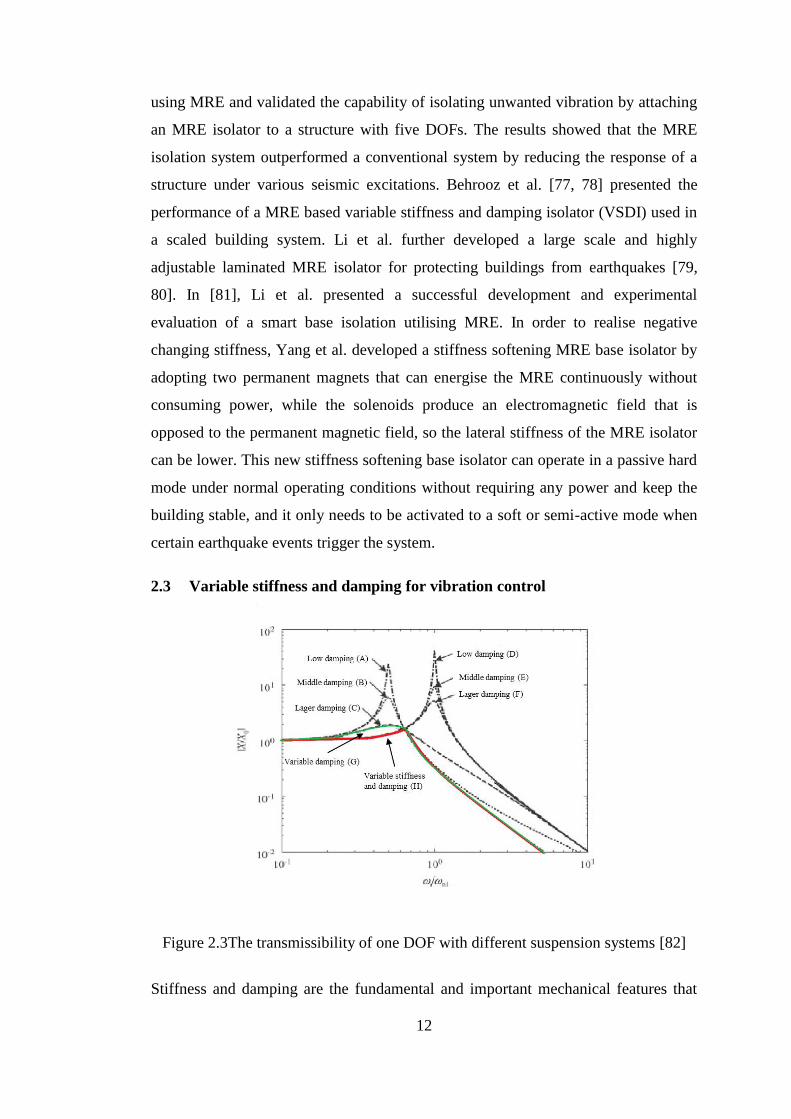
Figure 2.3The transmissibility of one DOF with different suspension systems [82]
Stiffness and damping are the fundamental and important mechanical features that
13
must be controlled in many technical systems in order to achieve the desired dynamic
behaviour and address any undesired vibration. The reduction of vibration has been
inevitably connected to the concepts of variable damping or variable stiffness,
wherein ‘variable’ means controllability, real-time, and reversibility. The dynamic
performance of a single DOF system with variable stiffness and damping
characteristics can be obtained, as Figure 2.3 shows. Here, variations in damping will
induce changes in the resonance magnitude by adjusting the dissipated vibration
energy (compare lines A, B, C or lines D, E, F), and the variable stiffness will change
the transmissibility of vibration by changing the natural frequencies of the controlled
system (compare line A and D or B and E or C and F). The figure shows that variable
damping can suppress vibration better than a constant damping system. Specifically,
variable damping can achieve lower transmissibility, shown as the green line G. In
fact the figure indicates that another important conclusion can be drawn, the
transmissibility of the variable stiffness and damping system can be lowered further,
which is shown as the red line H. Many studies have been carried out based on this
foundation or with the concept of dual controllability of stiffness and damping [83-
86]. Liao et al. embedded a voice coil motor into an MRE isolator to realise variable
stiffness and damping characteristics [54]. Zhang et al. [87, 88] developed a variable
stiffness and damping MR damper that contains an air spring, separate films, an MR
valve and accumulator. The dynamic response obtained experimentally showed that
the stiffness and damping can be adjusted over a relatively large range. Following
this research, Sun et al. investigated an innovative suspension system for railway
vehicles that include an MRF based variable stiffness air spring and an MR damper.
This research theoretically verified that the variable stiffness and damping
suspension suppresses vibration better than suspensions with only variable damping
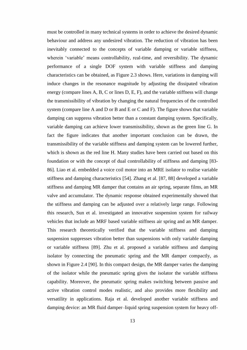
or variable stiffness [89]. Zhu et al. proposed a variable stiffness and damping
isolator by connecting the pneumatic spring and the MR damper compactly, as
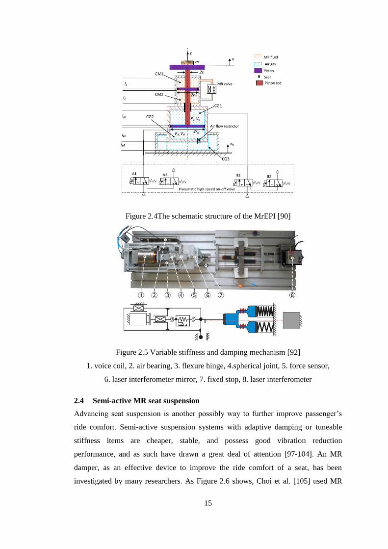
shown in Figure 2.4 [90]. In this compact design, the MR damper varies the damping
of the isolator while the pneumatic spring gives the isolator the variable stiffness
capability. Moreover, the pneumatic spring makes switching between passive and
active vibration control modes realistic, and also provides more flexibility and
versatility in applications. Raja et al. developed another variable stiffness and
damping device: an MR fluid damper–liquid spring suspension system for heavy off-
14
road vehicles. This new device can change its damping and stiffness and its
maximum force can reach 10000N [91], but its stiffness and damping cannot change
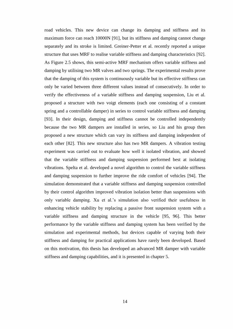
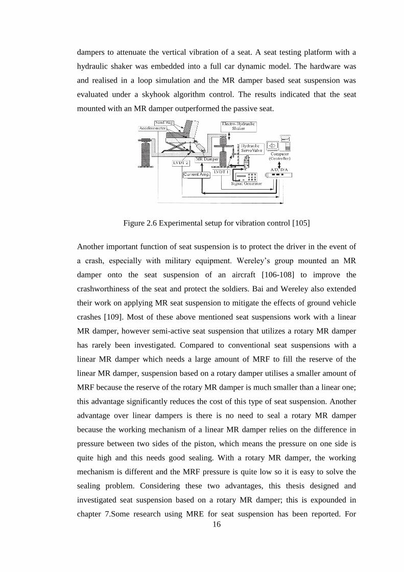
separately and its stroke is limited. Greiner-Petter et al. recently reported a unique
structure that uses MRF to realise variable stiffness and damping characteristics [92].
As Figure 2.5 shows, this semi-active MRF mechanism offers variable stiffness and
damping by utilising two MR valves and two springs. The experimental results prove
that the damping of this system is continuously variable but its effective stiffness can
only be varied between three different values instead of consecutively. In order to
verify the effectiveness of a variable stiffness and damping suspension, Liu et al.
proposed a structure with two voigt elements (each one consisting of a constant
spring and a controllable damper) in series to control variable stiffness and damping
[93]. In their design, damping and stiffness cannot be controlled independently
because the two MR dampers are installed in series, so Liu and his group then
proposed a new structure which can vary its stiffness and damping independent of
each other [82]. This new structure also has two MR dampers. A vibration testing
experiment was carried out to evaluate how well it isolated vibration, and showed
that the variable stiffness and damping suspension performed best at isolating
vibrations. Spelta et al. developed a novel algorithm to control the variable stiffness
and damping suspension to further improve the ride comfort of vehicles [94]. The
simulation demonstrated that a variable stiffness and damping suspension controlled
by their control algorithm improved vibration isolation better than suspensions with
only variable damping. Xu et al.’s simulation also verified their usefulness in
enhancing vehicle stability by replacing a passive front suspension system with a
variable stiffness and damping structure in the vehicle [95, 96]. This better
performance by the variable stiffness and damping system has been verified by the
simulation and experimental methods, but devices capable of varying both their
stiffness and damping for practical applications have rarely been developed. Based
on this motivation, this thesis has developed an advanced MR damper with variable
stiffness and damping capabilities, and it is presented in chapter 5.
15
Figure 2.4The schematic structure of the MrEPI [90]
Figure 2.5 Variable stiffness and damping mechanism [92]
1. voice coil, 2. air bearing, 3. flexure hinge, 4.spherical joint, 5. force sensor,
6. laser interferometer mirror, 7. fixed stop, 8. laser interferometer
2.4 Semi-active MR seat suspension
Advancing seat suspension is another possibly way to further improve passenger’s
ride comfort. Semi-active suspension systems with adaptive damping or tuneable
stiffness items are cheaper, stable, and possess good vibration reduction
performance, and as such have drawn a great deal of attention [97-104]. An MR
damper, as an effective device to improve the ride comfort of a seat, has been
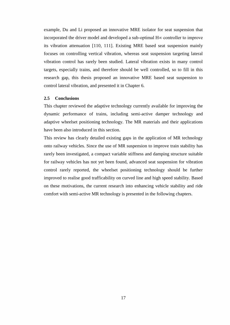
investigated by many researchers. As Figure 2.6 shows, Choi et al. [105] used MR
16
dampers to attenuate the vertical vibration of a seat. A seat testing platform with a
hydraulic shaker was embedded into a full car dynamic model. The hardware was
and realised in a loop simulation and the MR damper based seat suspension was
evaluated under a skyhook algorithm control. The results indicated that the seat
mounted with an MR damper outperformed the passive seat.
Figure 2.6 Experimental setup for vibration control [105]
Another important function of seat suspension is to protect the driver in the event of
a crash, especially with military equipment. Wereley’s group mounted an MR
damper onto the seat suspension of an aircraft [106-108] to improve the
crashworthiness of the seat and protect the soldiers. Bai and Wereley also extended
their work on applying MR seat suspension to mitigate the effects of ground vehicle
crashes [109]. Most of these above mentioned seat suspensions work with a linear
MR damper, however semi-active seat suspension that utilizes a rotary MR damper
has rarely been investigated. Compared to conventional seat suspensions with a
linear MR damper which needs a large amount of MRF to fill the reserve of the
linear MR damper, suspension based on a rotary damper utilises a smaller amount of
MRF because the reserve of the rotary MR damper is much smaller than a linear one;
this advantage significantly reduces the cost of this type of seat suspension. Another
advantage over linear dampers is there is no need to seal a rotary MR damper
because the working mechanism of a linear MR damper relies on the difference in
pressure between two sides of the piston, which means the pressure on one side is
quite high and this needs good sealing. With a rotary MR damper, the working
mechanism is different and the MRF pressure is quite low so it is easy to solve the
sealing problem. Considering these two advantages, this thesis designed and
investigated seat suspension based on a rotary MR damper; this is expounded in
chapter 7.Some research using MRE for seat suspension has been reported. For
17
example, Du and Li proposed an innovative MRE isolator for seat suspension that
incorporated the driver model and developed a sub-optimal H∞ controller to improve
its vibration attenuation [110, 111]. Existing MRE based seat suspension mainly
focuses on controlling vertical vibration, whereas seat suspension targeting lateral
vibration control has rarely been studied. Lateral vibration exists in many control
targets, especially trains, and therefore should be well controlled, so to fill in this
research gap, this thesis proposed an innovative MRE based seat suspension to
control lateral vibration, and presented it in Chapter 6.
2.5 Conclusions
This chapter reviewed the adaptive technology currently available for improving the
dynamic performance of trains, including semi-active damper technology and
adaptive wheelset positioning technology. The MR materials and their applications
have been also introduced in this section.
This review has clearly detailed existing gaps in the application of MR technology
onto railway vehicles. Since the use of MR suspension to improve train stability has
rarely been investigated, a compact variable stiffness and damping structure suitable
for railway vehicles has not yet been found, advanced seat suspension for vibration
control rarely reported, the wheelset positioning technology should be further
improved to realise good trafficability on curved line and high speed stability. Based
on these motivations, the current research into enhancing vehicle stability and ride
comfort with semi-active MR technology is presented in the following chapters.
18
3 ANALYSIS OF VIBRATION AND STABILITY OF RAILWAY VEHICLES
AND ITS IMPROVEMENT WITH MR DAMPER
3.1 Introduction
Generally, two main reasons induce the high-speed train vibration: the resonance and
instability of the vehicle/structure system. Resonance refers to the phenomenon that
the external disturbance of the vehicle is equal or close to the natural frequency of
the whole system. For solving this resonance issue, a well-designed passive damper
is commonly used. However, the parameters of passive damper are fixed, which
means that once the system is designed, the damper cannot be adjusted. Additionally,
a fixed passive damper may become ineffective due to other phenomena such as
instability of the vehicle which is speed dependent. When the train speed reaches a
critical value, the amplitude of the train vibration grows exponentially with time and
theoretically reaches infinity in a linear system. For the reason that this instability of
the vehicle/structure system is intrinsic and independent of the excitation type, a
conventional passive damper is unadequate to maintain the system stability. It is
therefore crucial to study the mechanism of this train instability and find a
controllable damper that can address the issues.
In this chapter, the problems of stability and vibration of the railway vehicle were
systematically analysed. Specifically, a 15 DOF dynamic model of a train was
developed. Based on this dynamic model and equations, the damping ratio of each
DOF of 15 was calculated. When the damping ratio reduces and crosses the zero line,
the train becomes unstable and reaches its critical speed. Thus, the critical speed of
each DOF with respect to the suspension stiffness and damping was worked out. The
sensitivity of a train’s critical speed with respect to the suspension parameters were
analysed as well. The result reveals that the secondary lateral damper impacts the
train’s critical speed most as well as the primary longitudinal stiffness. As a result,
the secondary lateral damper which is the most influential damper was replaced with
a controllable MR damper to improve the train stability. In order to investigate the
effect of MR dampers on train’s critical speed, a train installed with MR dampers
was simulated by a combined simulation of ADAMS and MATLAB. Then the MR
dampers installed in a train are tested in a roller rig test platform to explore the effect
of MRF damping on train stability.
19
3.2 Mathematical model and calculation of train’s critical speeds
Many other typical train mathematical models have been presented in existing
literatures [112]. Wang [37] established a 17-DOF train model to study the effect of
the semi-active suspension on train’s stability. Liu [113] proposed four different train
dynamic models with 17-DOF, 19-DOF, 31-DOF, and 35-DOF, respectively, in his
PhD thesis. Considering all of the DOFs for characterizing train dynamics is not
really necessary, it just makes the calculation process more complicated. For this
reason, many researchers put forward a train component dynamic model with less
DOF. For example, Scheffel proposes an 8-DOF train wheelset model [114]. The
main disadvantage of these component models is that they cannot reflect the dynamic
performance of the whole train. Considering the both accuracy and modelling
complex, a 15-DOF train dynamic model is adopted in this section. The damping
ratio of each DOF, as well as the train critical speed, is worked out based on the train
dynamic equations.
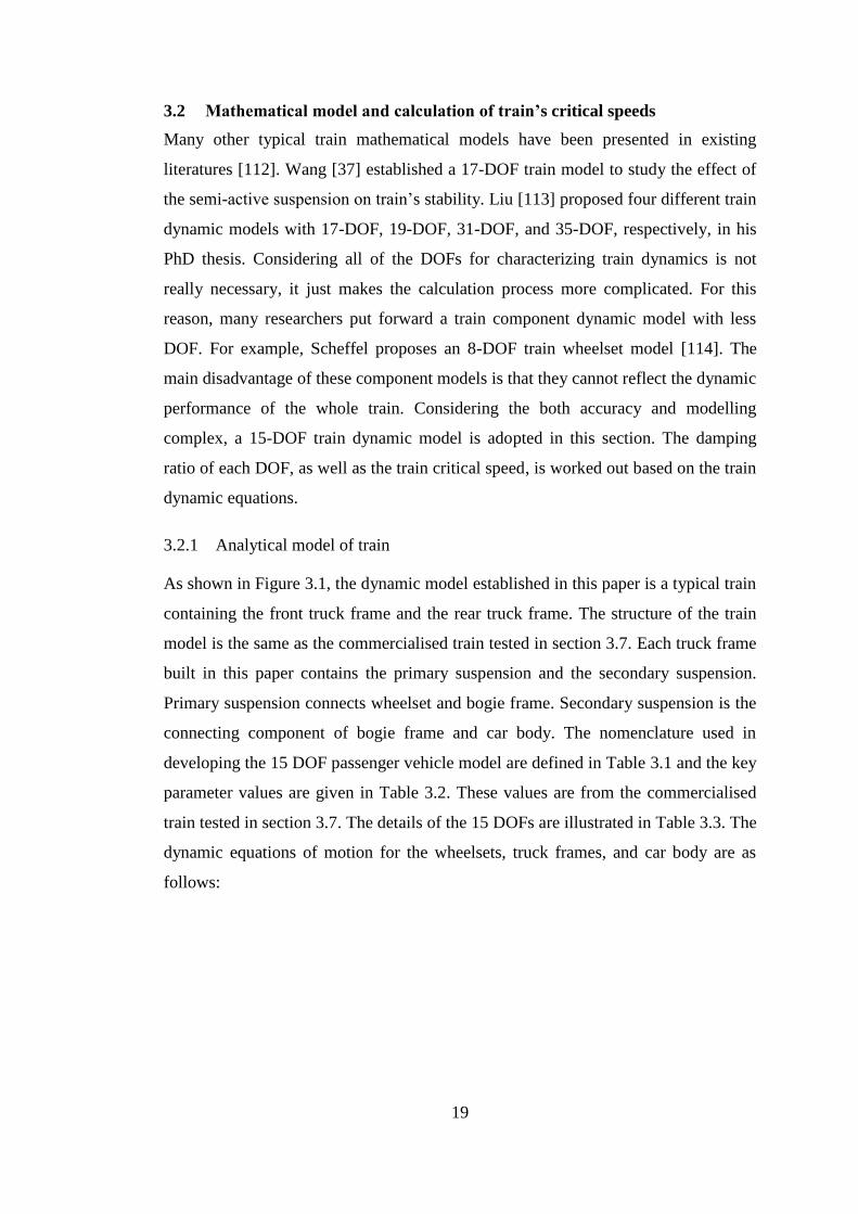
3.2.1 Analytical model of train
As shown in Figure 3.1, the dynamic model established in this paper is a typical train
containing the front truck frame and the rear truck frame. The structure of the train
model is the same as the commercialised train tested in section 3.7. Each truck frame
built in this paper contains the primary suspension and the secondary suspension.
Primary suspension connects wheelset and bogie frame. Secondary suspension is the
connecting component of bogie frame and car body. The nomenclature used in
developing the 15 DOF passenger vehicle model are defined in Table 3.1 and the key
parameter values are given in Table 3.2. These values are from the commercialised
train tested in section 3.7. The details of the 15 DOFs are illustrated in Table 3.3. The
dynamic equations of motion for the wheelsets, truck frames, and car body are as
follows:
20
Figure 3.1 Analytical model of a train
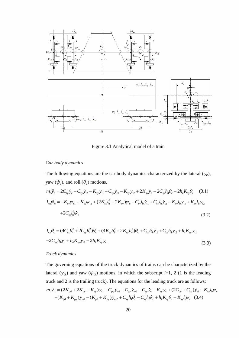
Car body dynamics
The following equations are the car body dynamics characterized by the lateral (𝑦c),
yaw (𝜓c), and roll (𝜃c) motions.
c c sy c sy t2 sy t1 sy t1 sy t2 sy c sy 4 c 4 sy c2 2 2 2 m y C y C y K y C y K y K y C h h K (3.1)
2
cz c sy t1 sy t2 sy b sy c sy b t1 sy b t2 sy b t1 sy b t2(2 2 ) I K K K l K C l y C l y K l y K l y
2
sy b c2 C l (3.2)
2 2 2 2
cx c sz 4 sy 4 c sz 3 sy 4 c sy 4 t1 sy 4 t2 4 sy t1(4 2 ) (4 2 ) I C b C h K b K h C h y C h y h K y
sy 4 c 4 sy t2 4 sy c2 2 C h y h K y h K y (3.3)
Truck dynamics
The governing equations of the truck dynamics of trains can be characterized by the
lateral (𝑦t𝑖) and yaw (𝜓t𝑖) motions, in which the subscript i=1, 2 (1 is the leading
truck and 2 is the trailing truck). The equations for the leading truck are as follows:
t t1 pd py sy t1 py 1 py 2 sy c sy c py sy t1 sy b c(2 2 ) (2 ) m y K K K y C y C y C y K y C C y K l
pd py 1 pd py 2 sy 4 c sy b c 4 sy c sy b c( ) ( ) K K y K K y C h C l h K K l (3.4)
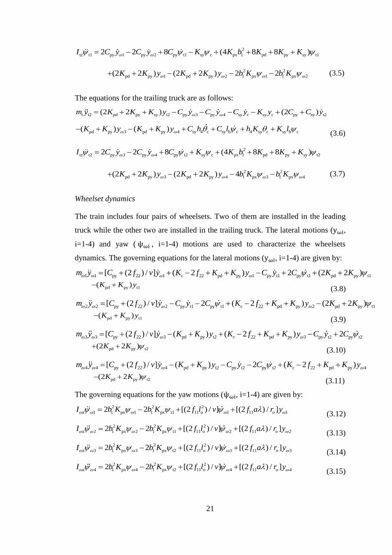
21
2
tz t1 py 1 py 2 py t1 sy c px 1 pd py sy t12 2 8 (4 8 8 ) I C y C y C K K b K K K
2 2
pd py 1 pd py 2 1 px 1 1 px 2(2 2 ) (2 2 ) 2 2 K K y K K y b K b K (3.5)
The equations for the trailing truck are as follows:
t t2 pd py sy t2 py 3 py 4 sy c sy c py sy t2(2 2 ) (2 ) m y K K K y C y C y C y K y C C y
pd py 3 pd py 4 sy 4 c sy b c 4 sy c sy b c( ) ( ) K K y K K y C h C l h K K l (3.6)
2
tz t2 py 3 py 4 py t2 sy c px 1 pd py sy t22 2 8 (4 8 8 ) I C y C y C K K b K K K
2 2
pd py 3 pd py 4 1 px 3 1 px 4(2 2 ) (2 2 ) 4 K K y K K y b K b K (3.7)
Wheelset dynamics
The train includes four pairs of wheelsets. Two of them are installed in the leading
truck while the other two are installed in the trailing truck. The lateral motions (yωi,
i=1-4) and yaw ( ψωi , i=1-4) motions are used to characterize the wheelsets
dynamics. The governing equations for the lateral motions (yωi, i=1-4) are given by:
1 1 py 22 1 c 22 pd py 1 py t1 py t1 pd py t1[ (2 ) / ] ( 2 ) 2 (2 2 ) m y C f v y K f K K y C y C K K
pd py t1( ) K K y (3.8)
2 2 py 22 2 py t1 py t1 c 22 pd py 2 pd py t1[ (2 ) / ] 2 ( 2 ) (2 2 ) m y C f v y C y C K f K K y K K
pd py t1( ) K K y (3.9)
3 3 py 22 3 pd py t2 c 22 pd py 3 py t2 py t2[ (2 ) / ] ( ) ( 2 ) 2 m y C f v y K K y K f K K y C y C
pd py t2(2 2 ) K K (3.10)
4 4 py 22 4 pd py t2 py t2 py t2 c 22 pd py 4[ (2 ) / ] ( ) 2 ( 2 ) m y C f v y K K y C y C K f K K y
pd py t2(2 2 ) K K (3.11)
The governing equations for the yaw motions (ψωi, i=1-4) are given by:
2 2 2
z 1 1 px 1 1 px t1 11 o 1 11 o 12 2 [(2 ) / ] [(2 ) / ] I b K b K f l v f a r y (3.12)
2 2 2
z 2 1 px 2 1 px t1 11 o 2 11 o 22 2 [(2 ) / ] [(2 ) / ] I b K b K f l v f a r y (3.13)
2 2 2
z 3 1 px 3 1 px t2 11 o 3 11 o 32 2 [(2 ) / ] [(2 ) / ] I b K b K f l v f a r y (3.14)
2 2 2
z 4 1 px 4 1 px t2 11 o 4 11 o 42 2 [(2 ) / ] [(2 ) / ] I b K b K f l v f a r y (3.15)
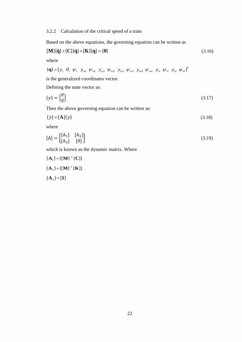
22
3.2.2 Calculation of the critical speed of a train
Based on the above equations, the governing equation can be written as
[ ]{ } [ ]{ } [ ]{ } { } M q C q K q 0 (3.16)
where
T
c c c 1 1 2 2 3 3 4 4 t1 t1 t2 t2{ } [ ] y y y y y y yq
is the generalized coordinates vector.
Defining the state vector as:
{𝑦} = {𝑞�̇�} (3.17)
Then the above governing equation can be written as:
{ } [ ]{ }y yA (3.18)
where
[A] = [[A1] [A2][A3] [0]
] (3.19)
which is known as the dynamic matrix. Where
1
1[ ] [[ ] [ ]]A M C
1
2[ ] [[ ] [ ]]A M K
3[ ] [ ]A I
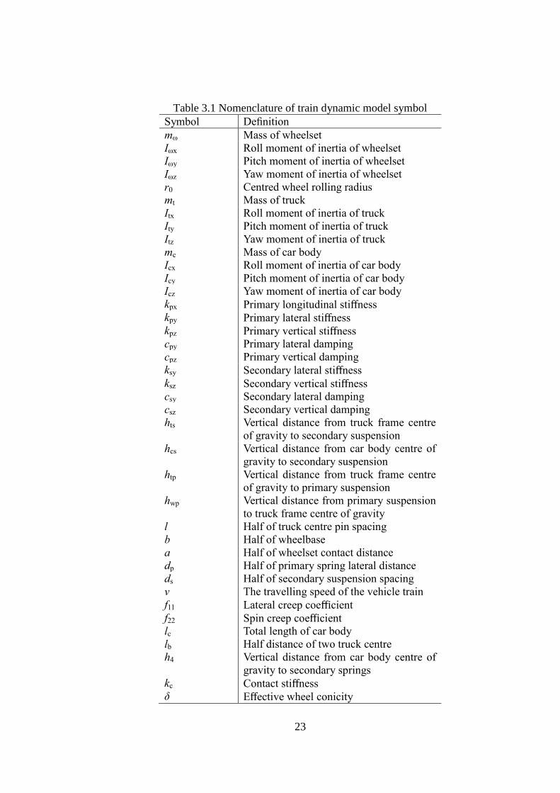
23
Table 3.1 Nomenclature of train dynamic model symbol
Symbol Definition
mω Mass of wheelset
Iωx Roll moment of inertia of wheelset
Iωy Pitch moment of inertia of wheelset
Iωz Yaw moment of inertia of wheelset
r0 Centred wheel rolling radius
mt Mass of truck
Itx Roll moment of inertia of truck
Ity Pitch moment of inertia of truck
Itz Yaw moment of inertia of truck
mc Mass of car body
Icx Roll moment of inertia of car body
Icy Pitch moment of inertia of car body
Icz Yaw moment of inertia of car body
kpx Primary longitudinal stiffness
kpy Primary lateral stiffness
kpz Primary vertical stiffness
cpy Primary lateral damping
cpz Primary vertical damping
ksy Secondary lateral stiffness
ksz Secondary vertical stiffness
csy Secondary lateral damping
csz Secondary vertical damping
hts Vertical distance from truck frame centre
of gravity to secondary suspension
hcs Vertical distance from car body centre of
gravity to secondary suspension
htp Vertical distance from truck frame centre
of gravity to primary suspension
hwp Vertical distance from primary suspension
to truck frame centre of gravity
l Half of truck centre pin spacing
b Half of wheelbase
a Half of wheelset contact distance
dp Half of primary spring lateral distance
ds Half of secondary suspension spacing
v The travelling speed of the vehicle train
f11 Lateral creep coefficient
f22 Spin creep coefficient
lc Total length of car body
lb Half distance of two truck centre
h4 Vertical distance from car body centre of
gravity to secondary springs
kc Contact stiffness
δ Effective wheel conicity
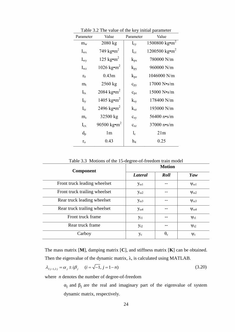
24
Table 3.2 The value of the key initial parameter
Parameter Value Parameter Value
mw 2080 kg Icy 1500800 kg•m2
Iwx 749 kg•m2 Icz 1200500 kg•m
2
Iwy 125 kg•m2 kpx 780000 N/m
Iwz 1026 kg•m2 kpy 960000 N/m
r0 0.43m kpz 1046000 N/m
mt 2560 kg cpy 17000 N•s/m
Itx 2084 kg•m2 cpz 15000 N•s/m
Ity 1405 kg•m2 ksy 178400 N/m
Itz 2496 kg•m2 ksz 193000 N/m
mc 32500 kg csy 56400 n•s/m
Icx 90500 kg•m2 csz 37000 n•s/m
dp 1m lc 21m
ro 0.43 h4 0.25
Table 3.3 Motions of the 15-degree-of-freedom train model
Component Motion
Lateral Roll Yaw
Front truck leading wheelset yω1 -- ψω1
Front truck trailing wheelset yω2 -- ψω2
Rear truck leading wheelset yω3 -- ψω3
Rear truck trailing wheelset yω4 -- ψω4
Front truck frame yt1 -- ψt1
Rear truck frame yt2 -- ψt2
Carboy yc θc ψc
The mass matrix [M], damping matrix [C], and stiffness matrix [K] can be obtained.
Then the eigenvalue of the dynamic matrix, λ, is calculated using MATLAB.
2 1,2 j j j ji ( 1, 1 ) i j n (3.20)
where n denotes the number of degree-of-freedom
αj and βj are the real and imaginary part of the eigenvalue of system
dynamic matrix, respectively.

25
The damping ratio can be expressed as follows:
2 2/ j j j j (3.21)
Following the above equations, the damping ratios of the 15 DOFs can be worked
out. As the train speed is included in the train dynamic matrix, any variation in the
speed of the train induces a change in the damping ratio. Thus, as the train speed
increases, the damping ratios may reduce and cross the zero line. The train speed at
the point where the damping ratio crosses the zero line is the critical speed.
Consequentially, the critical speeds of each DOF can be worked out.
3.2.3 Theoretical analysis of the effect of an MR damper on train critical speed
The motion of the vehicle with MR dampers is given by:
[ ]{ ( )} [ ( )]{ ( )} [ ( )]{ ( )} [ ( , , )] [ ] x t v x t v x t A x xM C K F 0 (3.22)
where {x(t)} is the general displacement column, [M], [C], and [K] are the mass,
damping, and stiffness matrices, respectively. They are speed dependent and can be
derived by multi-body dynamics analysis. F(A, x, �̈�) is the introduced force by MR
damper which is related to current and displacement.
If the vehicle system has a passive damper, the eigenvalue equation is derived as:
2
p[ ] [[ ( )] [ ]] [ ( )] [ ] v vM C C K 0 (3.23)
where [Cp] is the damping of the passive damper. From Eq. (2.22), the eigenvalue of
the vehicle/structure system is speed dependent. At certain speeds, the real part of the
eigenvalue may become positive, which induces the vehicle/structure instability. This
speed is called the critical speed. When the train becomes unstable, the amplitude of
the motion grows exponentially in time and theoretically achieves infinity in a linear
system. The intrinsic instability of the vehicle/structure system is independent of the
type of excitation. Therefore, once the whole system has been designed, a passive
damper cannot improve the stability property in the system because the eigenvalue is
determined when the parameters of the system are fixed. Similarly, if the vehicle
system has an MR damper, the eigenvalue equation becomes:
2
MR MR[ ] [[ ( )] [ ]] [[ ( )] [ ]] [ ] v vM C C K K 0 (3.24)
where [CMR] and [KMR] are the variable damping and variable stiffness induced by
MR dampers, respectively, and these two parameters definitely have impacts on the
critical speed. With a properly designed MR damper and a suitable control algorithm,
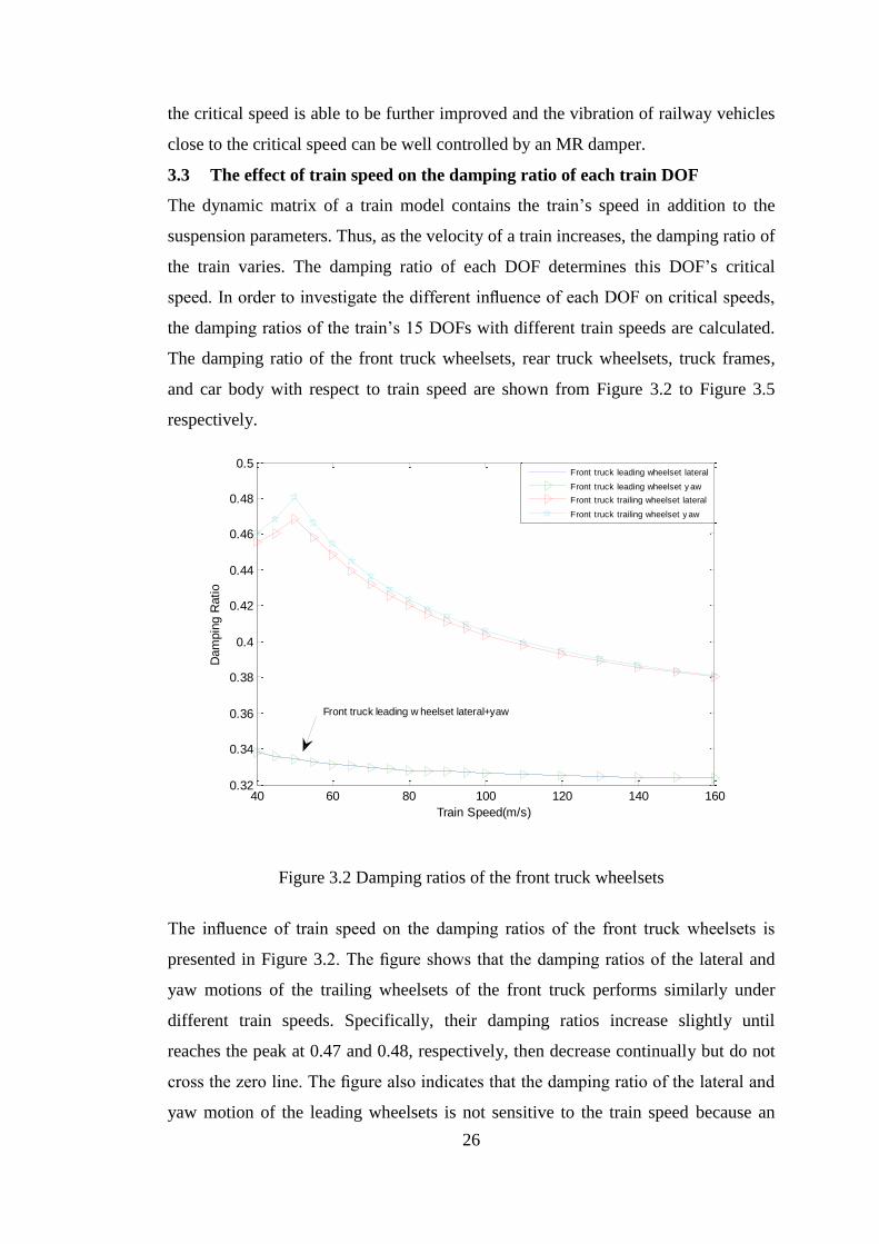
26
the critical speed is able to be further improved and the vibration of railway vehicles
close to the critical speed can be well controlled by an MR damper.
3.3 The effect of train speed on the damping ratio of each train DOF
The dynamic matrix of a train model contains the train’s speed in addition to the
suspension parameters. Thus, as the velocity of a train increases, the damping ratio of
the train varies. The damping ratio of each DOF determines this DOF’s critical
speed. In order to investigate the different influence of each DOF on critical speeds,
the damping ratios of the train’s 15 DOFs with different train speeds are calculated.
The damping ratio of the front truck wheelsets, rear truck wheelsets, truck frames,
and car body with respect to train speed are shown from Figure 3.2 to Figure 3.5
respectively.
Figure 3.2 Damping ratios of the front truck wheelsets
The influence of train speed on the damping ratios of the front truck wheelsets is
presented in Figure 3.2. The figure shows that the damping ratios of the lateral and
yaw motions of the trailing wheelsets of the front truck performs similarly under
different train speeds. Specifically, their damping ratios increase slightly until
reaches the peak at 0.47 and 0.48, respectively, then decrease continually but do not
cross the zero line. The figure also indicates that the damping ratio of the lateral and
yaw motion of the leading wheelsets is not sensitive to the train speed because an
40 60 80 100 120 140 1600.32
0.34
0.36
0.38
0.4
0.42
0.44
0.46
0.48
0.5
Train Speed(m/s)
Dam
pin
g R
atio
Front truck leading w heelset lateral+yaw
Front truck leading wheelset lateral
Front truck leading wheelset y aw
Front truck trailing wheelset lateral
Front truck trailing wheelset y aw
27
increase in train speed from 40m/s to 160m/s only decreases the damping ratio of the
leading wheelset by 3%.
Figure 3.3 Damping ratios of the rear truck wheelsets
Figure 3.3 shows the influence of train speed on the damping ratios of the rear truck
wheelsets. The figure indicates that the damping ratio of the leading wheelset of rear
truck reduces significantly and crosses the zero line at 133m /s, which is the critical
speed of the rear truck leading wheelset. The damping ratio of the trailing wheelset
of rear truck is basically unchanged at first but decreases sharply when train’s speed
is over 100m/s, and then crosses the zero line at 110m /s which is the critical speed
of the leading wheelset of rear truck.
40 60 80 100 120 140 160-0.1
0
0.1
0.2
0.3
0.4
0.5
0.6
0.7
Train Speed(m/s)
Da
mp
ing
Ra
to
Rear truck leading w heelse lateral+yaw
Rear truck leading wheelset lateral
Rear truck leading wheelset y aw
Rear truck trailing wheelset lateral
Rear truck trailing wheelset y aw
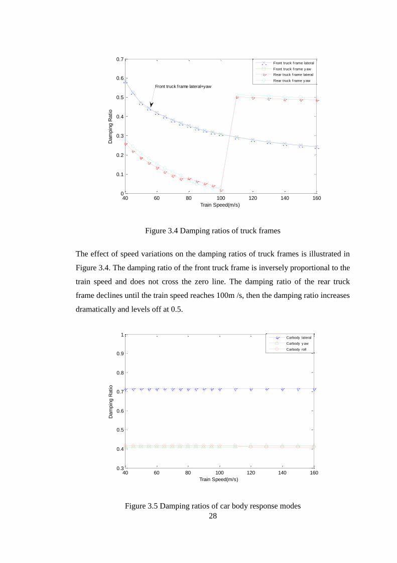
28
Figure 3.4 Damping ratios of truck frames
The effect of speed variations on the damping ratios of truck frames is illustrated in
Figure 3.4. The damping ratio of the front truck frame is inversely proportional to the
train speed and does not cross the zero line. The damping ratio of the rear truck
frame declines until the train speed reaches 100m /s, then the damping ratio increases
dramatically and levels off at 0.5.
Figure 3.5 Damping ratios of car body response modes
40 60 80 100 120 140 1600
0.1
0.2
0.3
0.4
0.5
0.6
0.7
Train Speed(m/s)
Dam
pin
g R
atio
Front truck frame lateral+yaw
Front truck f rame lateral
Front truck f rame y aw
Rear truck f rame lateral
Rear truck f rame y aw
40 60 80 100 120 140 1600.3
0.4
0.5
0.6
0.7
0.8
0.9
1
Train Speed(m/s)
Dam
pin
g R
atio
Carbody lateral
Carbody y aw
Carbody roll

29
As shown in Figure 3.5, the damping ratio of the car body is basically not influenced
by the train speed. The damping ratio always remains above the zero line means the
car body is stable even though the train reaches a high level of speed. Based on the
above figures, the damping ratios of each DOF respect to different train speed vary
from each other. From the damping ratio analysis, the rear truck wheelset and rear
truck frame are more unstable than other components of the train.
3.4 The influence of suspension parameters on critical speeds of each train
DOF
When the damping ratio reduces and crosses the zero line, the train reaches its
critical speed. The change of suspension parameters induces a variation of the
crossing point which determines each DOF’s critical speed. Therefore, the critical
speed of a train is directly related to the suspension parameters and it is crucial to
study the effect of suspension parameters on the critical speeds of each train DOF.
As the train speed increases, some certain train DOFs become unstable, which means
that those unstable DOFs have achieved their critical speed. Once any one of the 15
DOFs reaches its critical speed, the whole train is regarded as to have reached its
critical speed. Thus the critical speed of the whole train is determined by the smallest
one of the 15 critical speeds. Critical speeds which exceed 200m/s are out of
discussion in this paper because the current operating speed is much lower than
200m/s. The following figures show the effect of the train suspension parameters on
the critical speeds of several train DOFs. For the sake of simplicity in describing the
following figures, C with different subscripts represents the critical speeds of
different train DOFs. Specifically, C with two subscript letters represents the critical
speeds of the truck frame. The first letter, ‘f ’or ‘r’, is used to represent the front and
rear truck frames, respectively. The secondary letter, ‘l’ or ‘y’, represents the lateral
motion and the yaw motion. C with three subscript letters represents the critical
speeds of the wheelsets. The first letter, ‘f’ or ‘r’, is used to identify the front truck
frame and the rear truck frame, respectively. The secondary letter (‘t’ or ‘l’) is used
to identify the trailing and leading wheelsets. The third letter (‘l’ or ‘y’) identifies the
lateral and yaw motions. The different meanings of each symbol are also shown in
Table 3.4.
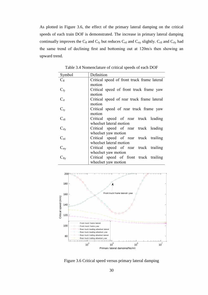
30
As plotted in Figure 3.6, the effect of the primary lateral damping on the critical
speeds of each train DOF is demonstrated. The increase in primary lateral damping
continually improves the Cfl and Cfy but reduces Crtl and Crty slightly. Crll and Crly had
the same trend of declining first and bottoming out at 120m/s then showing an
upward trend.
Table 3.4 Nomenclature of critical speeds of each DOF
Symbol Definition
Cfl Critical speed of front truck frame lateral
motion
Cfy Critical speed of front truck frame yaw
motion
Crl Critical speed of rear truck frame lateral
motion
Cry Critical speed of rear truck frame yaw
motion
Crll Critical speed of rear truck leading
wheelset lateral motion
Crly Critical speed of rear truck leading
wheelset yaw motion
Crtl Critical speed of rear truck trailing
wheelset lateral motion
Crty Critical speed of rear truck trailing
wheelset yaw motion
Cfty Critical speed of front truck trailing
wheelset yaw motion
Figure 3.6 Critical speed versus primary lateral damping
104
105
106
107
80
100
120
140
160
180
Primary lateral damping(Ns/m)
Critical speed (
m/s
)
Front truck frame lateral+ yaw
Front truck f rame lateral
Front truck f rame y aw
Rear truck leading wheelset lateral
Rear truck leading wheelset y aw
Rear truck trailing wheelset lateral
Rear truck trailing wheelset y aw
200
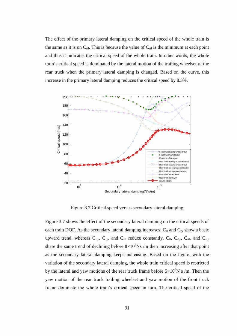
31
The effect of the primary lateral damping on the critical speed of the whole train is
the same as it is on Crtl. This is because the value of Crtl is the minimum at each point
and thus it indicates the critical speed of the whole train. In other words, the whole
train’s critical speed is dominated by the lateral motion of the trailing wheelset of the
rear truck when the primary lateral damping is changed. Based on the curve, this
increase in the primary lateral damping reduces the critical speed by 8.3%.
Figure 3.7 Critical speed versus secondary lateral damping
Figure 3.7 shows the effect of the secondary lateral damping on the critical speeds of
each train DOF. As the secondary lateral damping increases, Crl and Cry show a basic
upward trend, whereas Cfty, Cfy, and Crll reduce constantly. Cfl, Crly, Crtl, and Crty
share the same trend of declining before 8×10⁴Ns /m then increasing after that point
as the secondary lateral damping keeps increasing. Based on the figure, with the
variation of the secondary lateral damping, the whole train critical speed is restricted
by the lateral and yaw motions of the rear truck frame before 5×10⁴N s /m. Then the
yaw motion of the rear truck trailing wheelset and yaw motion of the front truck
frame dominate the whole train’s critical speed in turn. The critical speed of the
103
104
105
20
40
60
80
100
120
140
160
180
Secondary lateral damping(N*s/m)
Critical speed (
m/s
)
Front truck trailing wheelset yaw
Front truck frame lateral
Front truck frame yaw
Rear truck leading wheelset lateral
Rear truck leading wheelset yaw
Rear truck trailing wheelset lateral
Rear truck trailing wheelset yaw
Rear truck frame lateral
Rear truck frame yaw
railway vehicle
200
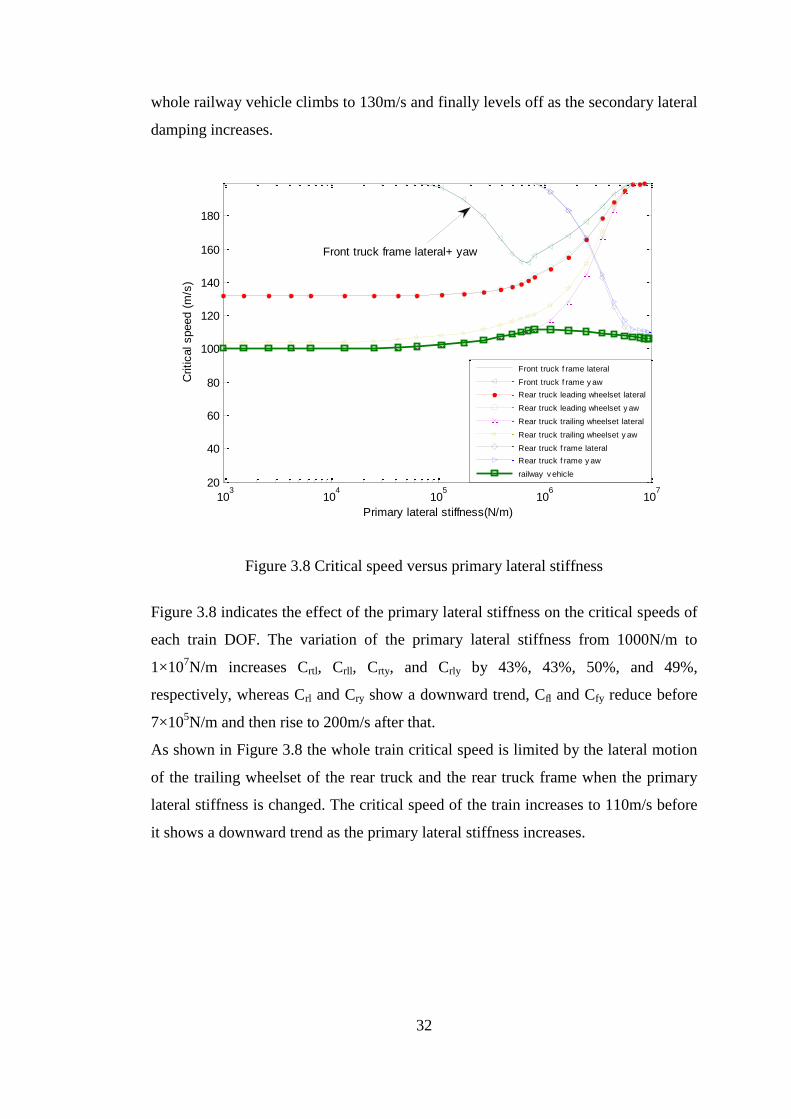
32
whole railway vehicle climbs to 130m/s and finally levels off as the secondary lateral
damping increases.
Figure 3.8 Critical speed versus primary lateral stiffness
Figure 3.8 indicates the effect of the primary lateral stiffness on the critical speeds of
each train DOF. The variation of the primary lateral stiffness from 1000N/m to
1×10⁷N/m increases Crtl, Crll, Crty, and Crly by 43%, 43%, 50%, and 49%,
respectively, whereas Crl and Cry show a downward trend, Cfl and Cfy reduce before
7×10⁵N/m and then rise to 200m/s after that.
As shown in Figure 3.8 the whole train critical speed is limited by the lateral motion
of the trailing wheelset of the rear truck and the rear truck frame when the primary
lateral stiffness is changed. The critical speed of the train increases to 110m/s before
it shows a downward trend as the primary lateral stiffness increases.
103
104
105
106
107
20
40
60
80
100
120
140
160
180
Primary lateral stiffness(N/m)
Critical speed (
m/s
)
Front truck frame lateral+ yaw
Front truck f rame lateral
Front truck f rame y aw
Rear truck leading wheelset lateral
Rear truck leading wheelset y aw
Rear truck trailing wheelset lateral
Rear truck trailing wheelset y aw
Rear truck f rame lateral
Rear truck f rame y aw
railway v ehicle
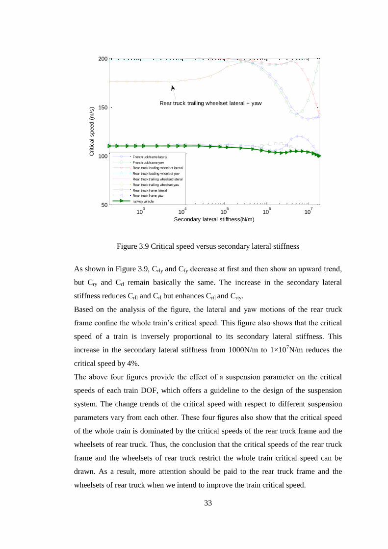
33
Figure 3.9 Critical speed versus secondary lateral stiffness
As shown in Figure 3.9, Crly and Cfy decrease at first and then show an upward trend,
but Cry and Crl remain basically the same. The increase in the secondary lateral
stiffness reduces Crll and Crl but enhances Crtl and Crty.
Based on the analysis of the figure, the lateral and yaw motions of the rear truck
frame confine the whole train’s critical speed. This figure also shows that the critical
speed of a train is inversely proportional to its secondary lateral stiffness. This
increase in the secondary lateral stiffness from 1000N/m to 1×10⁷N/m reduces the
critical speed by 4%.
The above four figures provide the effect of a suspension parameter on the critical
speeds of each train DOF, which offers a guideline to the design of the suspension
system. The change trends of the critical speed with respect to different suspension
parameters vary from each other. These four figures also show that the critical speed
of the whole train is dominated by the critical speeds of the rear truck frame and the
wheelsets of rear truck. Thus, the conclusion that the critical speeds of the rear truck
frame and the wheelsets of rear truck restrict the whole train critical speed can be
drawn. As a result, more attention should be paid to the rear truck frame and the
wheelsets of rear truck when we intend to improve the train critical speed.
103
104
105
106
107
50
100
150
200
Secondary lateral stiffness(N/m)
Critical speed (
m/s
)
Rear truck trailing wheelset lateral + yaw
Front truck frame lateral
Front truck frame yaw
Rear truck leading wheelset lateral
Rear truck leading wheelset yaw
Rear truck trailing wheelset lateral
Rear truck trailing wheelset yaw
Rear truck frame lateral
Rear truck frame yaw
railway vehicle
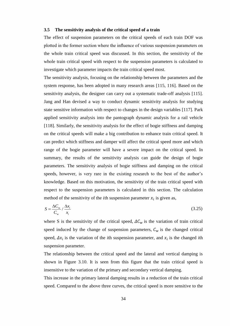
34
3.5 The sensitivity analysis of the critical speed of a train
The effect of suspension parameters on the critical speeds of each train DOF was
plotted in the former section where the influence of various suspension parameters on
the whole train critical speed was discussed. In this section, the sensitivity of the
whole train critical speed with respect to the suspension parameters is calculated to
investigate which parameter impacts the train critical speed most.
The sensitivity analysis, focusing on the relationship between the parameters and the
system response, has been adopted in many research areas [115, 116]. Based on the
sensitivity analysis, the designer can carry out a systematic trade-off analysis [115].
Jang and Han devised a way to conduct dynamic sensitivity analysis for studying
state sensitive information with respect to changes in the design variables [117]. Park
applied sensitivity analysis into the pantograph dynamic analysis for a rail vehicle
[118]. Similarly, the sensitivity analysis for the effect of bogie stiffness and damping
on the critical speeds will make a big contribution to enhance train critical speed. It
can predict which stiffness and damper will affect the critical speed more and which
range of the bogie parameter will have a severe impact on the critical speed. In
summary, the results of the sensitivity analysis can guide the design of bogie
parameters. The sensitivity analysis of bogie stiffness and damping on the critical
speeds, however, is very rare in the existing research to the best of the author’s
knowledge. Based on this motivation, the sensitivity of the train critical speed with
respect to the suspension parameters is calculated in this section. The calculation
method of the sensitivity of the 𝑖th suspension parameter 𝑥𝑖 is given as,
w
w
/
i
i
C xS
C x (3.25)
where S is the sensitivity of the critical speed, 𝛥𝐶w is the variation of train critical
speed induced by the change of suspension parameters, 𝐶w is the changed critical
speed, 𝛥𝑥𝑖 is the variation of the ith suspension parameter, and 𝑥𝑖 is the changed ith
suspension parameter.
The relationship between the critical speed and the lateral and vertical damping is
shown in Figure 3.10. It is seen from this figure that the train critical speed is
insensitive to the variation of the primary and secondary vertical damping.
This increase in the primary lateral damping results in a reduction of the train critical
speed. Compared to the above three curves, the critical speed is more sensitive to the
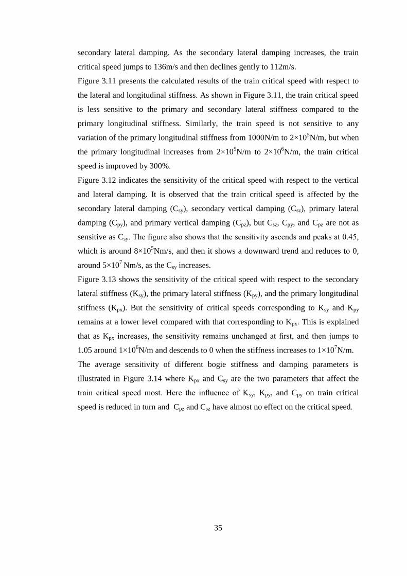
35
secondary lateral damping. As the secondary lateral damping increases, the train
critical speed jumps to 136m/s and then declines gently to 112m/s.
Figure 3.11 presents the calculated results of the train critical speed with respect to
the lateral and longitudinal stiffness. As shown in Figure 3.11, the train critical speed
is less sensitive to the primary and secondary lateral stiffness compared to the
primary longitudinal stiffness. Similarly, the train speed is not sensitive to any
variation of the primary longitudinal stiffness from 1000N/m to 2×10⁵N/m, but when
the primary longitudinal increases from 2×10⁵N/m to 2×10
6N/m, the train critical
speed is improved by 300%.
Figure 3.12 indicates the sensitivity of the critical speed with respect to the vertical
and lateral damping. It is observed that the train critical speed is affected by the
secondary lateral damping (Csy), secondary vertical damping (Csz), primary lateral
damping (Cpy), and primary vertical damping (Cpz), but Csz, Cpy, and Cpz are not as
sensitive as Csy. The figure also shows that the sensitivity ascends and peaks at 0.45,
which is around 8×10⁵Nm/s, and then it shows a downward trend and reduces to 0,
around 5×10⁷
Nm/s, as the Csy increases.
Figure 3.13 shows the sensitivity of the critical speed with respect to the secondary
lateral stiffness (Ksy), the primary lateral stiffness (Kpy), and the primary longitudinal
stiffness (Kpx). But the sensitivity of critical speeds corresponding to Ksy and Kpy
remains at a lower level compared with that corresponding to Kpx. This is explained
that as Kpx increases, the sensitivity remains unchanged at first, and then jumps to
1.05 around 1×10⁶N/m and descends to 0 when the stiffness increases to 1×10
7N/m.
The average sensitivity of different bogie stiffness and damping parameters is
illustrated in Figure 3.14 where Kpx and Csy are the two parameters that affect the
train critical speed most. Here the influence of Ksy, Kpy, and Cpy on train critical
speed is reduced in turn and Cpz and Csz have almost no effect on the critical speed.
36
Figure 3.10 Train critical speed versus various bogie damping
Figure 3.11 Train critical speed versus various bogie stiffness
103
104
105
106
107
50
60
70
80
90
100
110
120
130
140
damping(N*m/s)
Critical speed(m
/s)
critical speed v ersus primary lateral damping
critical speed v ersus primary v ertical damping
critical speed v ersus secondary lateral damping
critical speed v ersus secondary v ertical damping
103
104
105
106
107
20
40
60
80
100
120
140
160
180
200
Stiffness(N/m)
Critical speed(m
/s)
critical speed v ersus primary lateral stif f ness
critical speed v ersus secondary lateral stif f ness
critical speed v ersus primary longitudinal stif f ness
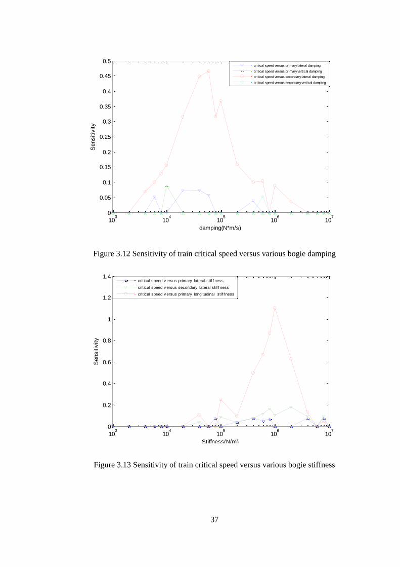
37
Figure 3.12 Sensitivity of train critical speed versus various bogie damping
Figure 3.13 Sensitivity of train critical speed versus various bogie stiffness
103
104
105
106
107
0
0.05
0.1
0.15
0.2
0.25
0.3
0.35
0.4
0.45
0.5
damping(N*m/s)
Sensitiv
ity
critical speed versus primary lateral damping
critical speed versus primary vertical damping
critical speed versus secondary lateral damping
critical speed versus secondary vertical damping
103
104
105
106
107
0
0.2
0.4
0.6
0.8
1
1.2
1.4
Stiffness(N/m)
Sensitiv
ity
critical speed v ersus primary lateral stif f ness
critical speed v ersus secondary lateral stif f ness
critical speed v ersus primary longitudinal stif f ness
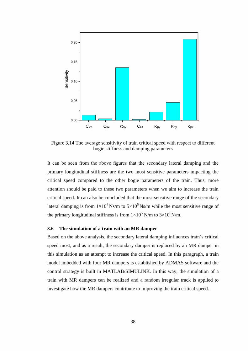
38
Figure 3.14 The average sensitivity of train critical speed with respect to different
bogie stiffness and damping parameters
It can be seen from the above figures that the secondary lateral damping and the
primary longitudinal stiffness are the two most sensitive parameters impacting the
critical speed compared to the other bogie parameters of the train. Thus, more
attention should be paid to these two parameters when we aim to increase the train
critical speed. It can also be concluded that the most sensitive range of the secondary
lateral damping is from 1×10⁴
Ns/m to 5×10⁵ Ns/m while the most sensitive range of
the primary longitudinal stiffness is from 1×10⁵ N/m to 3×10
6N/m.
3.6 The simulation of a train with an MR damper
Based on the above analysis, the secondary lateral damping influences train’s critical
speed most, and as a result, the secondary damper is replaced by an MR damper in
this simulation as an attempt to increase the critical speed. In this paragraph, a train
model imbedded with four MR dampers is established by ADMAS software and the
control strategy is built in MATLAB/SIMULINK. In this way, the simulation of a
train with MR dampers can be realized and a random irregular track is applied to
investigate how the MR dampers contribute to improving the train critical speed.
0.00
0.05
0.10
0.15
0.20
KpxKsyKpyCszCsyCpz
Sen
sitiv
ity
Cpy
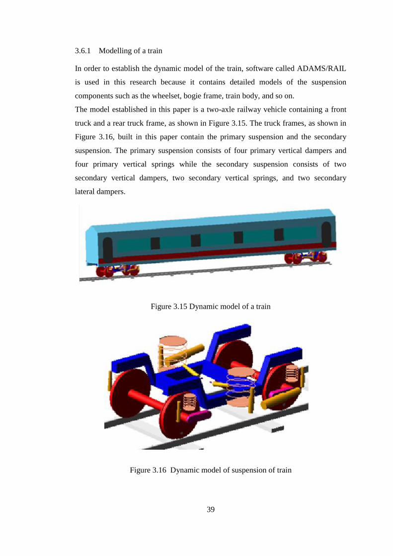
39
3.6.1 Modelling of a train
In order to establish the dynamic model of the train, software called ADAMS/RAIL
is used in this research because it contains detailed models of the suspension
components such as the wheelset, bogie frame, train body, and so on.
The model established in this paper is a two-axle railway vehicle containing a front
truck and a rear truck frame, as shown in Figure 3.15. The truck frames, as shown in
Figure 3.16, built in this paper contain the primary suspension and the secondary
suspension. The primary suspension consists of four primary vertical dampers and
four primary vertical springs while the secondary suspension consists of two
secondary vertical dampers, two secondary vertical springs, and two secondary
lateral dampers.
Figure 3.15 Dynamic model of a train
Figure 3.16 Dynamic model of suspension of train
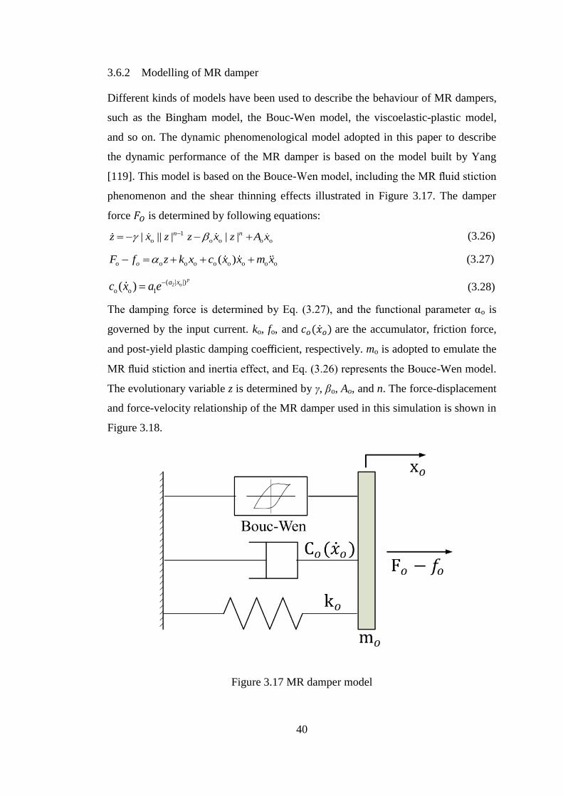
40
3.6.2 Modelling of MR damper
Different kinds of models have been used to describe the behaviour of MR dampers,
such as the Bingham model, the Bouc-Wen model, the viscoelastic-plastic model,
and so on. The dynamic phenomenological model adopted in this paper to describe
the dynamic performance of the MR damper is based on the model built by Yang
[119]. This model is based on the Bouce-Wen model, including the MR fluid stiction
phenomenon and the shear thinning effects illustrated in Figure 3.17. The damper
force 𝐹𝑂 is determined by following equations:
1
o o o o o| || | | | n nz x z z x z A x (3.26)
o o o o o o o o o( ) oF f z k x c x x m x (3.27)
2 o( | |)
o o 1( )
pa x
c x a e (3.28)
The damping force is determined by Eq. (3.27), and the functional parameter αo is
governed by the input current. ko, fo, and 𝑐𝑜(�̇�𝑜) are the accumulator, friction force,
and post-yield plastic damping coefficient, respectively. mo is adopted to emulate the
MR fluid stiction and inertia effect, and Eq. (3.26) represents the Bouce-Wen model.
The evolutionary variable z is determined by γ, βo, Ao, and n. The force-displacement
and force-velocity relationship of the MR damper used in this simulation is shown in
Figure 3.18.
Figure 3.17 MR damper model
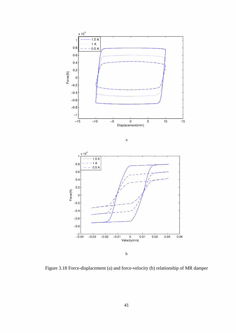
41
a
b
Figure 3.18 Force-displacement (a) and force-velocity (b) relationship of MR damper
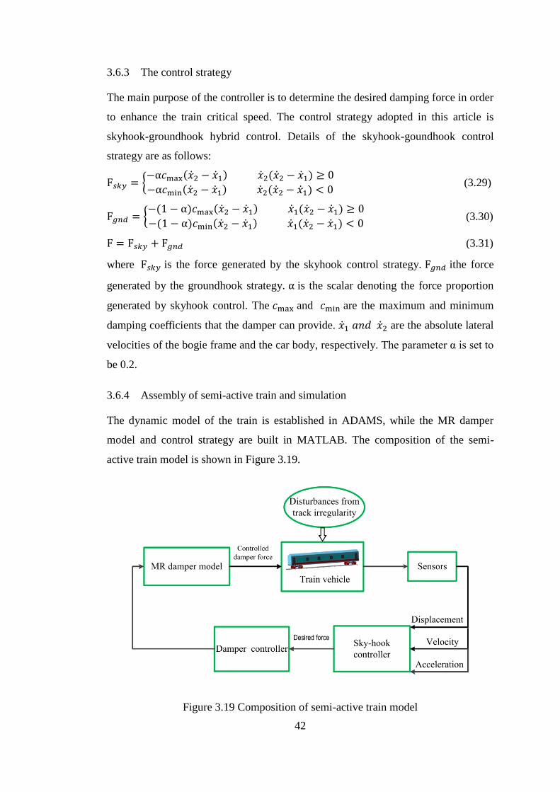
42
3.6.3 The control strategy
The main purpose of the controller is to determine the desired damping force in order
to enhance the train critical speed. The control strategy adopted in this article is
skyhook-groundhook hybrid control. Details of the skyhook-goundhook control
strategy are as follows:
F𝑠𝑘𝑦 = {−α𝑐max(�̇�2 − �̇�1) �̇�2(�̇�2 − �̇�1) ≥ 0
−α𝑐min(�̇�2 − �̇�1) �̇�2(�̇�2 − �̇�1) < 0 (3.29)
F𝑔𝑛𝑑 = {−(1 − α)𝑐max(�̇�2 − �̇�1) �̇�1(�̇�2 − �̇�1) ≥ 0
−(1 − α)𝑐min(�̇�2 − �̇�1) �̇�1(�̇�2 − �̇�1) < 0 (3.30)
F = F𝑠𝑘𝑦 + F𝑔𝑛𝑑 (3.31)
where F𝑠𝑘𝑦 is the force generated by the skyhook control strategy. F𝑔𝑛𝑑 ithe force
generated by the groundhook strategy. α is the scalar denoting the force proportion
generated by skyhook control. The 𝑐max and 𝑐min are the maximum and minimum
damping coefficients that the damper can provide. �̇�1 𝑎𝑛𝑑 �̇�2 are the absolute lateral
velocities of the bogie frame and the car body, respectively. The parameter α is set to
be 0.2.
3.6.4 Assembly of semi-active train and simulation
The dynamic model of the train is established in ADAMS, while the MR damper
model and control strategy are built in MATLAB. The composition of the semi-
active train model is shown in Figure 3.19.
Figure 3.19 Composition of semi-active train model
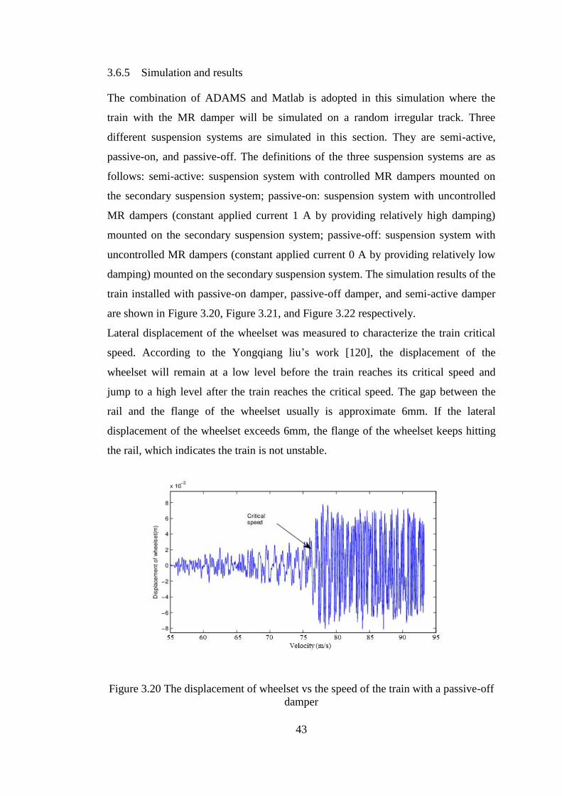
43
3.6.5 Simulation and results
The combination of ADAMS and Matlab is adopted in this simulation where the
train with the MR damper will be simulated on a random irregular track. Three
different suspension systems are simulated in this section. They are semi-active,
passive-on, and passive-off. The definitions of the three suspension systems are as
follows: semi-active: suspension system with controlled MR dampers mounted on
the secondary suspension system; passive-on: suspension system with uncontrolled
MR dampers (constant applied current 1 A by providing relatively high damping)
mounted on the secondary suspension system; passive-off: suspension system with
uncontrolled MR dampers (constant applied current 0 A by providing relatively low
damping) mounted on the secondary suspension system. The simulation results of the
train installed with passive-on damper, passive-off damper, and semi-active damper
are shown in Figure 3.20, Figure 3.21, and Figure 3.22 respectively.
Lateral displacement of the wheelset was measured to characterize the train critical
speed. According to the Yongqiang liu’s work [120], the displacement of the
wheelset will remain at a low level before the train reaches its critical speed and
jump to a high level after the train reaches the critical speed. The gap between the
rail and the flange of the wheelset usually is approximate 6mm. If the lateral
displacement of the wheelset exceeds 6mm, the flange of the wheelset keeps hitting
the rail, which indicates the train is not unstable.
Figure 3.20 The displacement of wheelset vs the speed of the train with a passive-off
damper
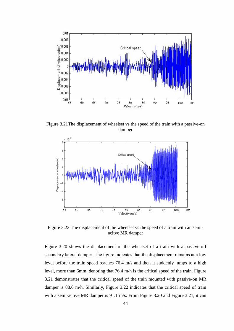
44
Figure 3.21The displacement of wheelset vs the speed of the train with a passive-on
damper
Figure 3.22 The displacement of the wheelset vs the speed of a train with an semi-
acitve MR damper
Figure 3.20 shows the displacement of the wheelset of a train with a passive-off
secondary lateral damper. The figure indicates that the displacement remains at a low
level before the train speed reaches 76.4 m/s and then it suddenly jumps to a high
level, more than 6mm, denoting that 76.4 m/h is the critical speed of the train. Figure
3.21 demonstrates that the critical speed of the train mounted with passive-on MR
damper is 88.6 m/h. Similarly, Figure 3.22 indicates that the critical speed of train
with a semi-active MR damper is 91.1 m/s. From Figure 3.20 and Figure 3.21, it can
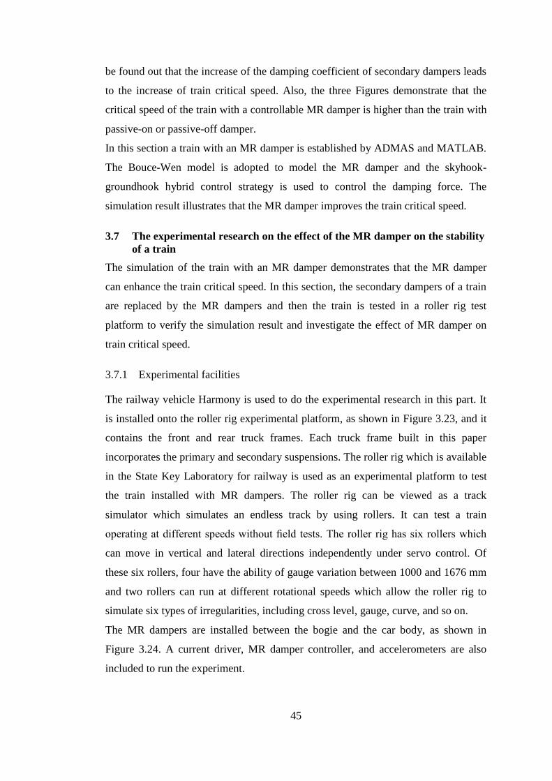
45
be found out that the increase of the damping coefficient of secondary dampers leads
to the increase of train critical speed. Also, the three Figures demonstrate that the
critical speed of the train with a controllable MR damper is higher than the train with
passive-on or passive-off damper.
In this section a train with an MR damper is established by ADMAS and MATLAB.
The Bouce-Wen model is adopted to model the MR damper and the skyhook-
groundhook hybrid control strategy is used to control the damping force. The
simulation result illustrates that the MR damper improves the train critical speed.
3.7 The experimental research on the effect of the MR damper on the stability
of a train
The simulation of the train with an MR damper demonstrates that the MR damper
can enhance the train critical speed. In this section, the secondary dampers of a train
are replaced by the MR dampers and then the train is tested in a roller rig test
platform to verify the simulation result and investigate the effect of MR damper on
train critical speed.
3.7.1 Experimental facilities
The railway vehicle Harmony is used to do the experimental research in this part. It
is installed onto the roller rig experimental platform, as shown in Figure 3.23, and it
contains the front and rear truck frames. Each truck frame built in this paper
incorporates the primary and secondary suspensions. The roller rig which is available
in the State Key Laboratory for railway is used as an experimental platform to test
the train installed with MR dampers. The roller rig can be viewed as a track
simulator which simulates an endless track by using rollers. It can test a train
operating at different speeds without field tests. The roller rig has six rollers which
can move in vertical and lateral directions independently under servo control. Of
these six rollers, four have the ability of gauge variation between 1000 and 1676 mm
and two rollers can run at different rotational speeds which allow the roller rig to
simulate six types of irregularities, including cross level, gauge, curve, and so on.
The MR dampers are installed between the bogie and the car body, as shown in
Figure 3.24. A current driver, MR damper controller, and accelerometers are also
included to run the experiment.
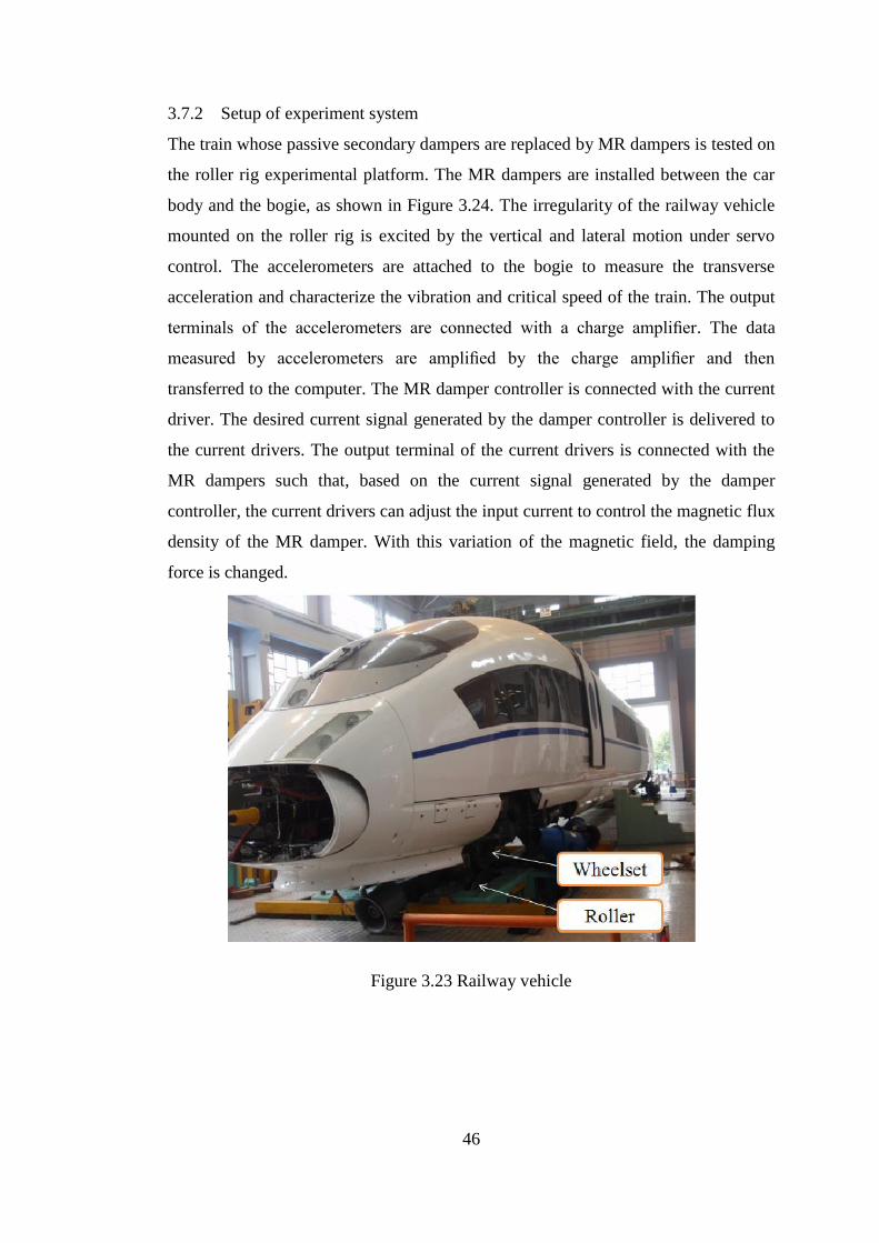
46
3.7.2 Setup of experiment system
The train whose passive secondary dampers are replaced by MR dampers is tested on
the roller rig experimental platform. The MR dampers are installed between the car
body and the bogie, as shown in Figure 3.24. The irregularity of the railway vehicle
mounted on the roller rig is excited by the vertical and lateral motion under servo
control. The accelerometers are attached to the bogie to measure the transverse
acceleration and characterize the vibration and critical speed of the train. The output
terminals of the accelerometers are connected with a charge amplifier. The data
measured by accelerometers are amplified by the charge amplifier and then
transferred to the computer. The MR damper controller is connected with the current
driver. The desired current signal generated by the damper controller is delivered to
the current drivers. The output terminal of the current drivers is connected with the
MR dampers such that, based on the current signal generated by the damper
controller, the current drivers can adjust the input current to control the magnetic flux
density of the MR damper. With this variation of the magnetic field, the damping
force is changed.
Figure 3.23 Railway vehicle
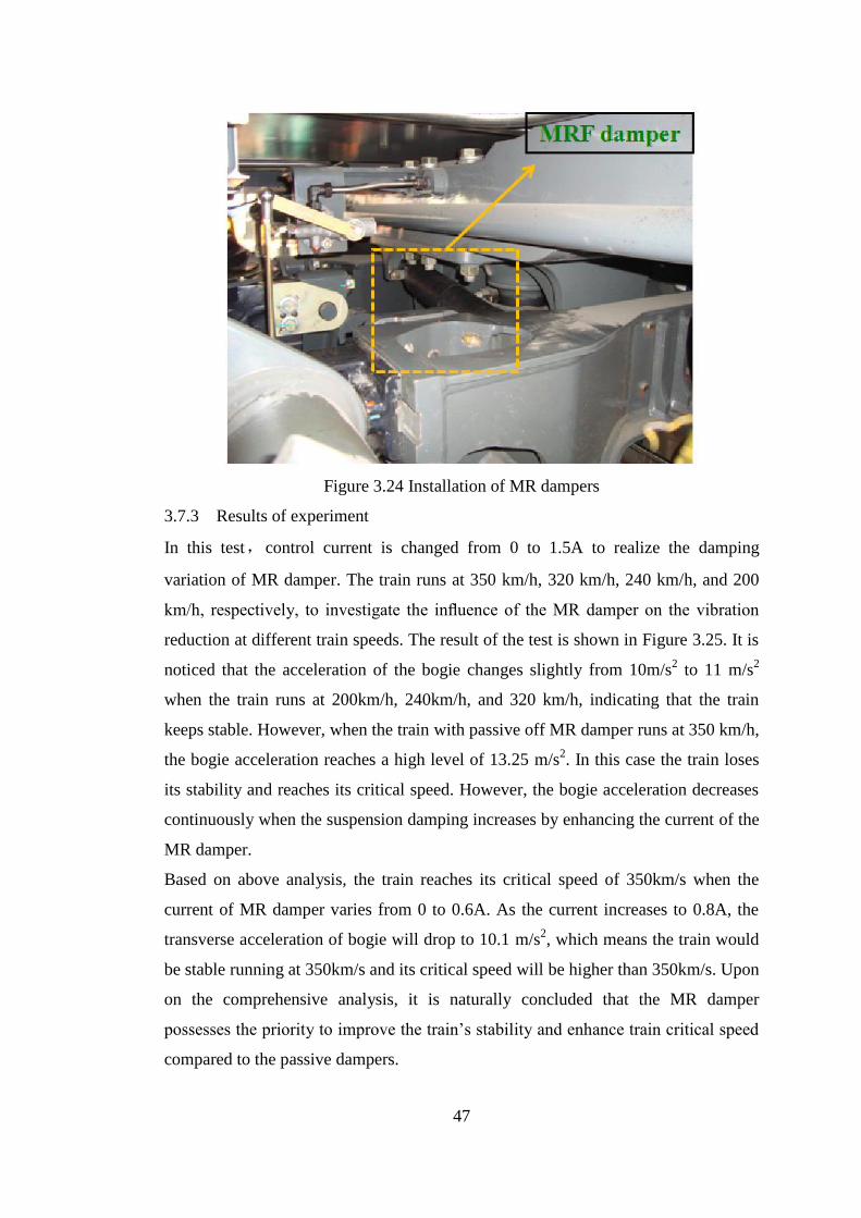
47
Figure 3.24 Installation of MR dampers
3.7.3 Results of experiment
In this test,control current is changed from 0 to 1.5A to realize the damping
variation of MR damper. The train runs at 350 km/h, 320 km/h, 240 km/h, and 200
km/h, respectively, to investigate the influence of the MR damper on the vibration
reduction at different train speeds. The result of the test is shown in Figure 3.25. It is
noticed that the acceleration of the bogie changes slightly from 10m/s2 to 11 m/s
2
when the train runs at 200km/h, 240km/h, and 320 km/h, indicating that the train
keeps stable. However, when the train with passive off MR damper runs at 350 km/h,
the bogie acceleration reaches a high level of 13.25 m/s2. In this case the train loses
its stability and reaches its critical speed. However, the bogie acceleration decreases
continuously when the suspension damping increases by enhancing the current of the
MR damper.
Based on above analysis, the train reaches its critical speed of 350km/s when the
current of MR damper varies from 0 to 0.6A. As the current increases to 0.8A, the
transverse acceleration of bogie will drop to 10.1 m/s2, which means the train would
be stable running at 350km/s and its critical speed will be higher than 350km/s. Upon
on the comprehensive analysis, it is naturally concluded that the MR damper
possesses the priority to improve the train’s stability and enhance train critical speed
compared to the passive dampers.
48
Figure 3.25 RMS of lateral acceleration of the bogie
3.8 Conclusion
In this chapter the governing equations of a 15 DOF train were developed. The
damping ratio of each train DOF and the critical speed of trains were calculated
based on the train dynamics equations. The results reveal that the train critical speed
is mainly dominated by the truck frame and the rear truck wheelsets. The sensitivity
of the critical speed with respect to the suspension parameters is calculated to analyse
the different effect of bogie parameters on the train critical speed. The results
indicate that the secondary lateral damping and the primary longitudinal stiffness are
the two most sensitive parameters impacting the critical speed. Then a train whose
secondary dampers are replaced by MR dampers was simulated by a combined
simulation of ADAMS and MATLAB. The simulation results indicate that the MR
damper significantly improve the train critical speed. The results of the experiment
also verify the semi-active dampers’ ability to improve the train’s stability and
critical speed.
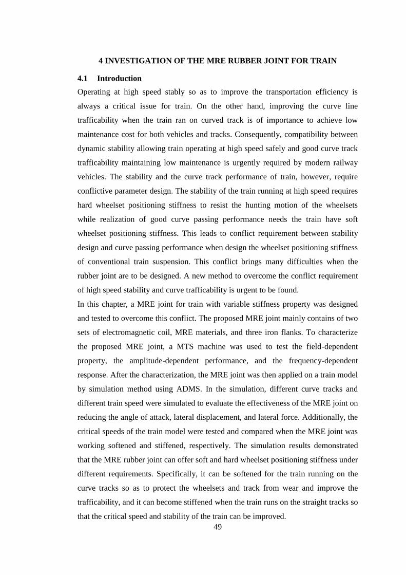
49
4 INVESTIGATION OF THE MRE RUBBER JOINT FOR TRAIN
4.1 Introduction
Operating at high speed stably so as to improve the transportation efficiency is
always a critical issue for train. On the other hand, improving the curve line
trafficability when the train ran on curved track is of importance to achieve low
maintenance cost for both vehicles and tracks. Consequently, compatibility between
dynamic stability allowing train operating at high speed safely and good curve track
trafficability maintaining low maintenance is urgently required by modern railway
vehicles. The stability and the curve track performance of train, however, require
conflictive parameter design. The stability of the train running at high speed requires
hard wheelset positioning stiffness to resist the hunting motion of the wheelsets
while realization of good curve passing performance needs the train have soft
wheelset positioning stiffness. This leads to conflict requirement between stability
design and curve passing performance when design the wheelset positioning stiffness
of conventional train suspension. This conflict brings many difficulties when the
rubber joint are to be designed. A new method to overcome the conflict requirement
of high speed stability and curve trafficability is urgent to be found.
In this chapter, a MRE joint for train with variable stiffness property was designed
and tested to overcome this conflict. The proposed MRE joint mainly contains of two
sets of electromagnetic coil, MRE materials, and three iron flanks. To characterize
the proposed MRE joint, a MTS machine was used to test the field-dependent
property, the amplitude-dependent performance, and the frequency-dependent
response. After the characterization, the MRE joint was then applied on a train model
by simulation method using ADMS. In the simulation, different curve tracks and
different train speed were simulated to evaluate the effectiveness of the MRE joint on
reducing the angle of attack, lateral displacement, and lateral force. Additionally, the
critical speeds of the train model were tested and compared when the MRE joint was
working softened and stiffened, respectively. The simulation results demonstrated
that the MRE rubber joint can offer soft and hard wheelset positioning stiffness under
different requirements. Specifically, it can be softened for the train running on the
curve tracks so as to protect the wheelsets and track from wear and improve the
trafficability, and it can become stiffened when the train runs on the straight tracks so
that the critical speed and stability of the train can be improved.
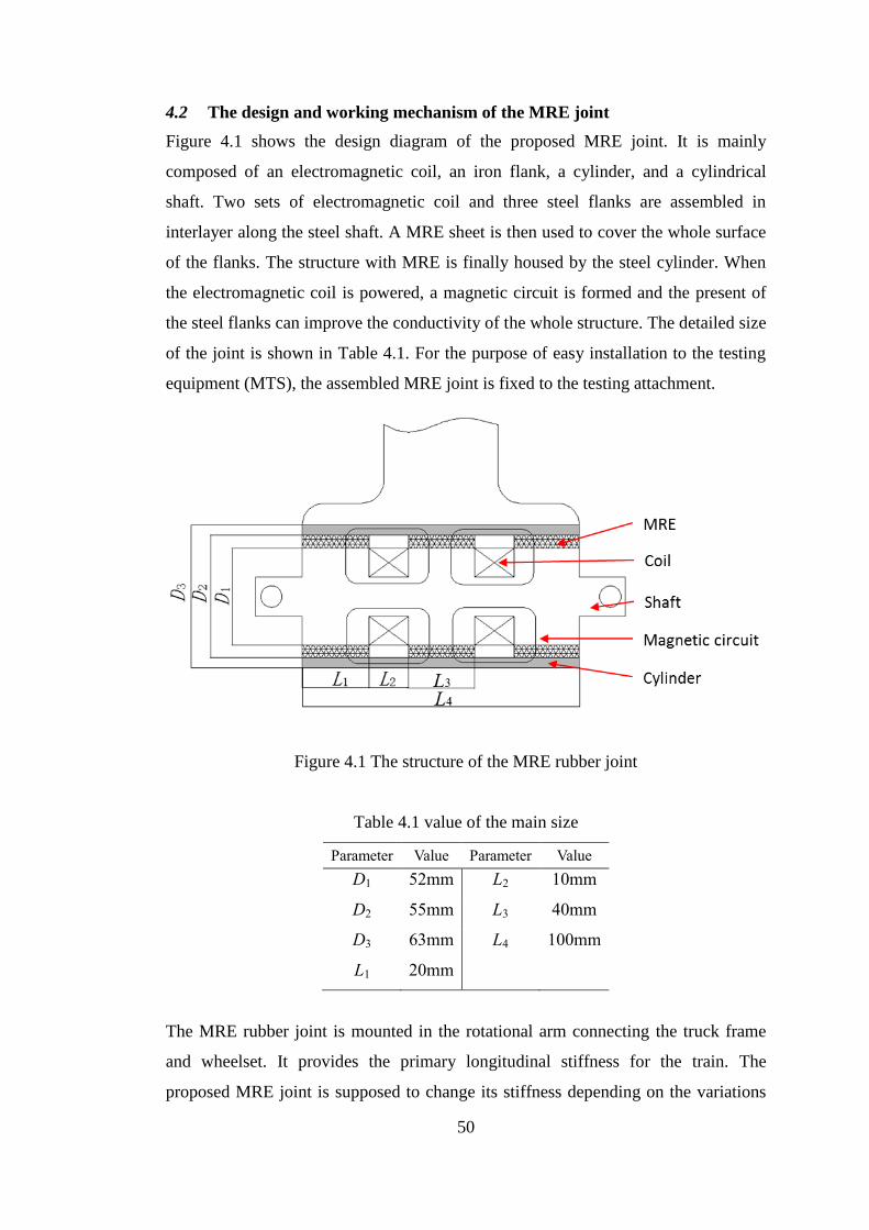
50
4.2 The design and working mechanism of the MRE joint
Figure 4.1 shows the design diagram of the proposed MRE joint. It is mainly
composed of an electromagnetic coil, an iron flank, a cylinder, and a cylindrical
shaft. Two sets of electromagnetic coil and three steel flanks are assembled in
interlayer along the steel shaft. A MRE sheet is then used to cover the whole surface
of the flanks. The structure with MRE is finally housed by the steel cylinder. When
the electromagnetic coil is powered, a magnetic circuit is formed and the present of
the steel flanks can improve the conductivity of the whole structure. The detailed size
of the joint is shown in Table 4.1. For the purpose of easy installation to the testing
equipment (MTS), the assembled MRE joint is fixed to the testing attachment.
Figure 4.1 The structure of the MRE rubber joint
Table 4.1 value of the main size
Parameter Value Parameter Value
D1 52mm L2 10mm
D2 55mm L3 40mm
D3 63mm L4 100mm
L1 20mm
The MRE rubber joint is mounted in the rotational arm connecting the truck frame
and wheelset. It provides the primary longitudinal stiffness for the train. The
proposed MRE joint is supposed to change its stiffness depending on the variations
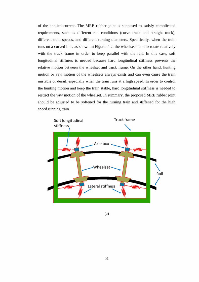
51
of the applied current. The MRE rubber joint is supposed to satisfy complicated
requirements, such as different rail conditions (curve track and straight track),
different train speeds, and different turning diameters. Specifically, when the train
runs on a curved line, as shown in Figure. 4.2, the wheelsets tend to rotate relatively
with the truck frame in order to keep parallel with the rail. In this case, soft
longitudinal stiffness is needed because hard longitudinal stiffness prevents the
relative motion between the wheelset and truck frame. On the other hand, hunting
motion or yaw motion of the wheelsets always exists and can even cause the train
unstable or derail, especially when the train runs at a high speed. In order to control
the hunting motion and keep the train stable, hard longitudinal stiffness is needed to
restrict the yaw motion of the wheelset. In summary, the proposed MRE rubber joint
should be adjusted to be softened for the turning train and stiffened for the high
speed running train.
(a)
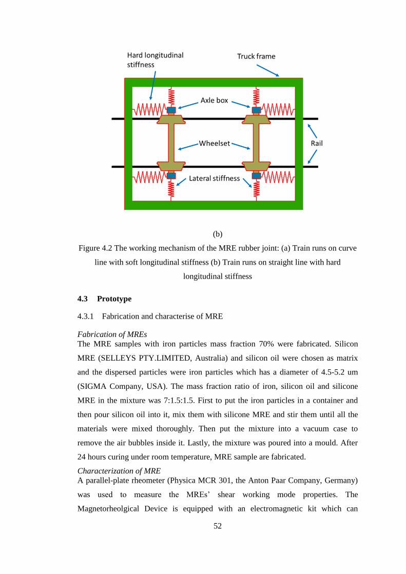
52
(b)
Figure 4.2 The working mechanism of the MRE rubber joint: (a) Train runs on curve
line with soft longitudinal stiffness (b) Train runs on straight line with hard
longitudinal stiffness
4.3 Prototype
4.3.1 Fabrication and characterise of MRE
Fabrication of MREs
The MRE samples with iron particles mass fraction 70% were fabricated. Silicon
MRE (SELLEYS PTY.LIMITED, Australia) and silicon oil were chosen as matrix
and the dispersed particles were iron particles which has a diameter of 4.5-5.2 um
(SIGMA Company, USA). The mass fraction ratio of iron, silicon oil and silicone
MRE in the mixture was 7:1.5:1.5. First to put the iron particles in a container and
then pour silicon oil into it, mix them with silicone MRE and stir them until all the
materials were mixed thoroughly. Then put the mixture into a vacuum case to
remove the air bubbles inside it. Lastly, the mixture was poured into a mould. After
24 hours curing under room temperature, MRE sample are fabricated.
Characterization of MRE
A parallel-plate rheometer (Physica MCR 301, the Anton Paar Company, Germany)
was used to measure the MREs’ shear working mode properties. The
Magnetorheolgical Device is equipped with an electromagnetic kit which can
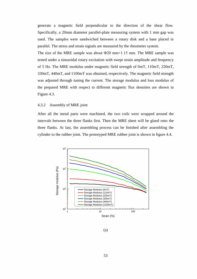
53
generate a magnetic field perpendicular to the direction of the shear flow.
Specifically, a 20mm diameter parallel-plate measuring system with 1 mm gap was
used. The samples were sandwiched between a rotary disk and a base placed in
parallel. The stress and strain signals are measured by the rheometer system.
The size of the MRE sample was about Ф20 mm×1.15 mm. The MRE sample was
tested under a sinusoidal rotary excitation with swept strain amplitude and frequency
of 5 Hz. The MRE modulus under magnetic field strength of 0mT, 110mT, 220mT,
330mT, 440mT, and 1100mT was obtained, respectively. The magnetic field strength
was adjusted through tuning the current. The storage modulus and loss modulus of
the prepared MRE with respect to different magnetic flux densities are shown in
Figure 4.3.
4.3.2 Assembly of MRE joint
After all the metal parts were machined, the two coils were wrapped around the
intervals between the three flanks first. Then the MRE sheet will be glued onto the
three flanks. At last, the assembling process can be finished after assembling the
cylinder to the rubber joint. The prototyped MRE rubber joint is shown in figure 4.4.
1 10 10010
3
104
105
106
Sto
rag
e m
od
ulu
s (
Pa
)
Strain (%)
Storage Modulus (0mT)
Storage Modulus (110mT)
Storage Modulus (220mT)
Storage Modulus (330mT)
Storage Modulus (440mT)
Storage Modulus (1100mT)
(a)
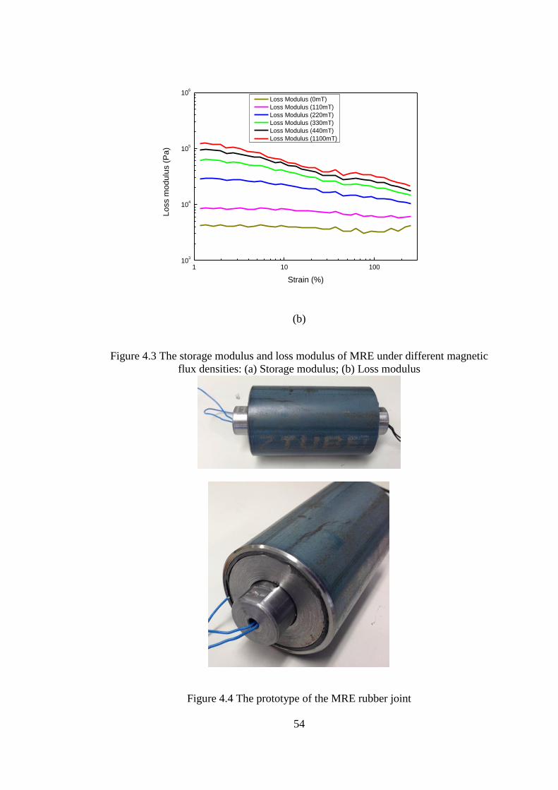
54
1 10 10010
3
104
105
106
Lo
ss m
od
ulu
s (
Pa
)
Strain (%)
Loss Modulus (0mT)
Loss Modulus (110mT)
Loss Modulus (220mT)
Loss Modulus (330mT)
Loss Modulus (440mT)
Loss Modulus (1100mT)
(b)
Figure 4.3 The storage modulus and loss modulus of MRE under different magnetic
flux densities: (a) Storage modulus; (b) Loss modulus
Figure 4.4 The prototype of the MRE rubber joint
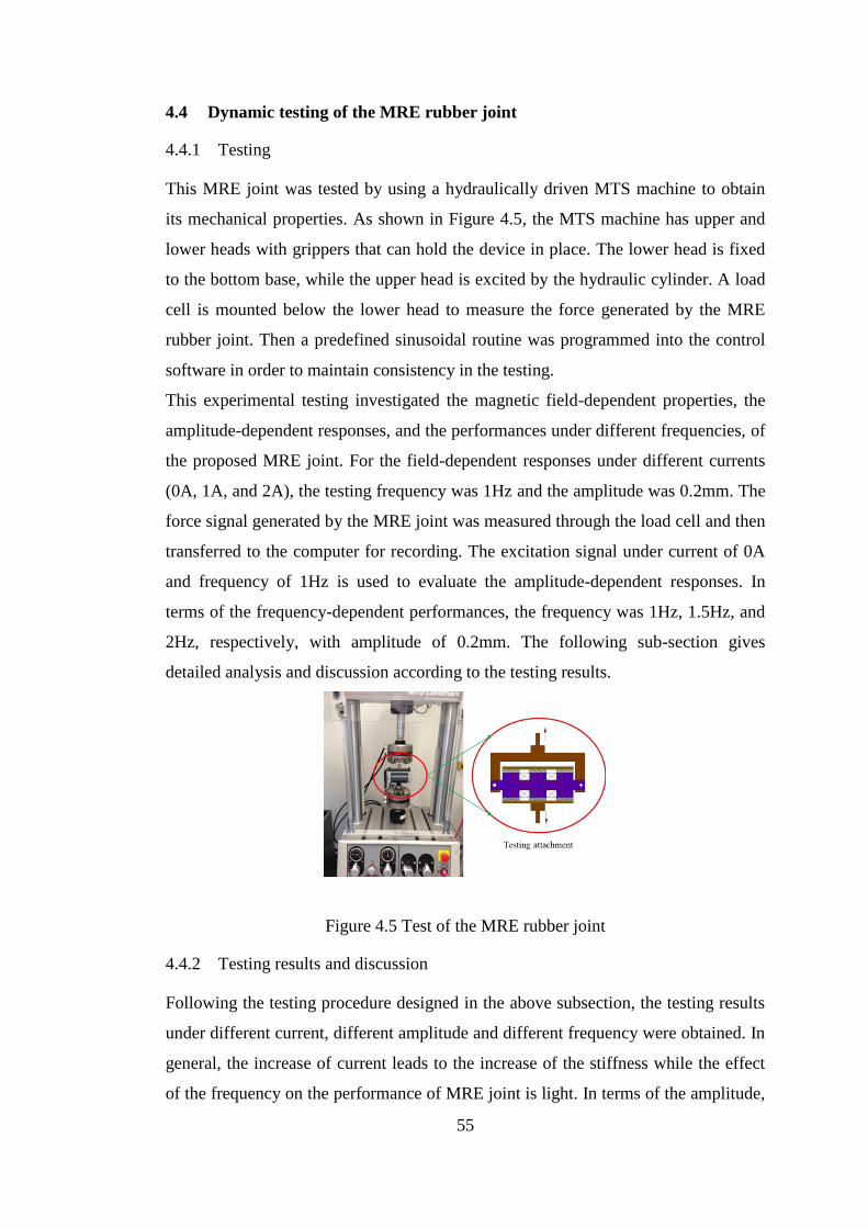
55
4.4 Dynamic testing of the MRE rubber joint
4.4.1 Testing
This MRE joint was tested by using a hydraulically driven MTS machine to obtain
its mechanical properties. As shown in Figure 4.5, the MTS machine has upper and
lower heads with grippers that can hold the device in place. The lower head is fixed
to the bottom base, while the upper head is excited by the hydraulic cylinder. A load
cell is mounted below the lower head to measure the force generated by the MRE
rubber joint. Then a predefined sinusoidal routine was programmed into the control
software in order to maintain consistency in the testing.
This experimental testing investigated the magnetic field-dependent properties, the
amplitude-dependent responses, and the performances under different frequencies, of
the proposed MRE joint. For the field-dependent responses under different currents
(0A, 1A, and 2A), the testing frequency was 1Hz and the amplitude was 0.2mm. The
force signal generated by the MRE joint was measured through the load cell and then
transferred to the computer for recording. The excitation signal under current of 0A
and frequency of 1Hz is used to evaluate the amplitude-dependent responses. In
terms of the frequency-dependent performances, the frequency was 1Hz, 1.5Hz, and
2Hz, respectively, with amplitude of 0.2mm. The following sub-section gives
detailed analysis and discussion according to the testing results.
Figure 4.5 Test of the MRE rubber joint
4.4.2 Testing results and discussion
Following the testing procedure designed in the above subsection, the testing results
under different current, different amplitude and different frequency were obtained. In
general, the increase of current leads to the increase of the stiffness while the effect
of the frequency on the performance of MRE joint is light. In terms of the amplitude,
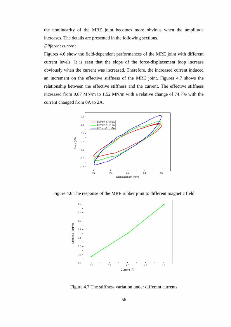
56
the nonlinearity of the MRE joint becomes more obvious when the amplitude
increases. The details are presented in the following sections.
Different current
Figures 4.6 show the field-dependent performances of the MRE joint with different
current levels. It is seen that the slope of the force-displacement loop increase
obviously when the current was increased. Therefore, the increased current induced
an increment on the effective stiffness of the MRE joint. Figures 4.7 shows the
relationship between the effective stiffness and the current. The effective stiffness
increased from 0.87 MN/m to 1.52 MN/m with a relative change of 74.7% with the
current changed from 0A to 2A.
-0.2 -0.1 0.0 0.1 0.2
-0.3
-0.2
-0.1
0.0
0.1
0.2
0.3
Fo
rce
(kN
)
Displacement (mm)
0.2mm-1Hz-0A
0.2mm-1Hz-1A
0.2mm-1Hz-2A
Figure 4.6 The response of the MRE rubber joint to different magnetic field
0.0 0.5 1.0 1.5 2.00.8
0.9
1.0
1.1
1.2
1.3
1.4
1.5
Stiffn
ess (
MN
/m)
Current (A)
Figure 4.7 The stiffness variation under different currents
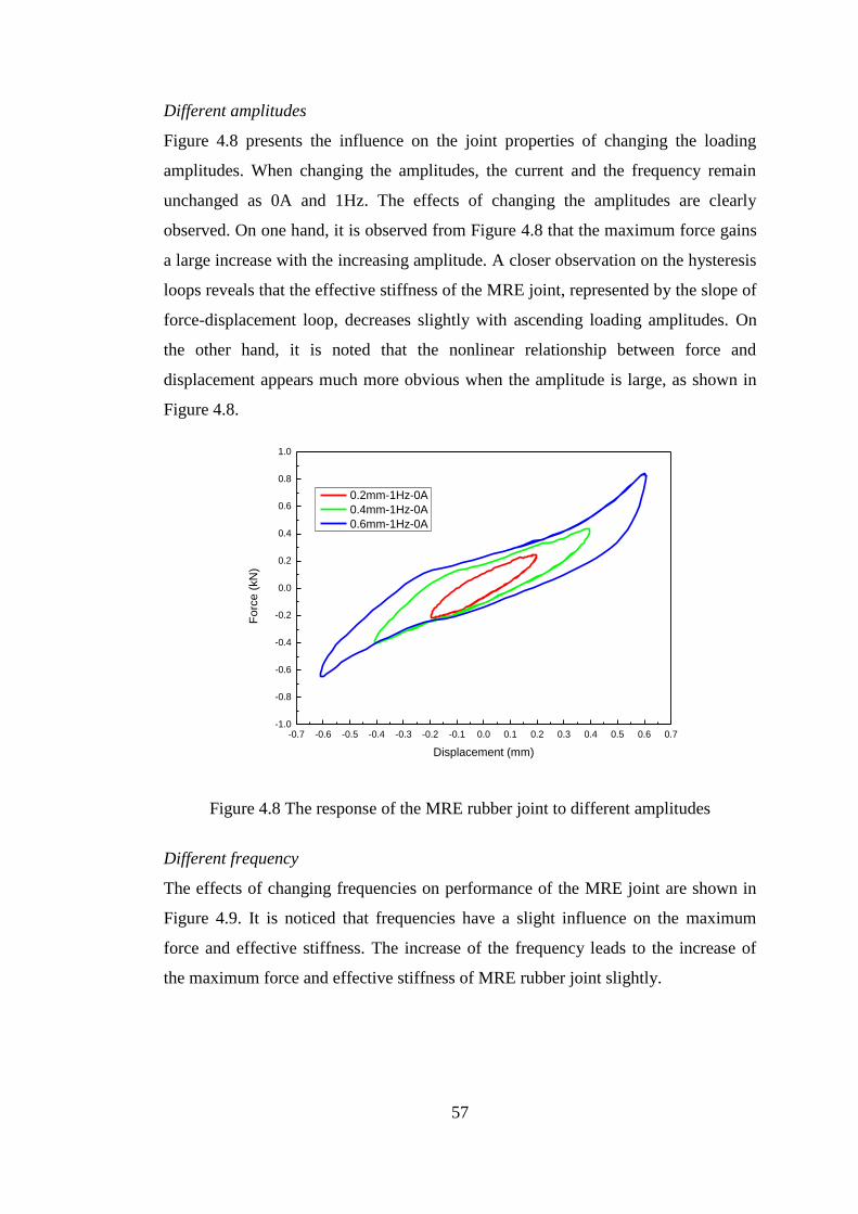
57
Different amplitudes
Figure 4.8 presents the influence on the joint properties of changing the loading
amplitudes. When changing the amplitudes, the current and the frequency remain
unchanged as 0A and 1Hz. The effects of changing the amplitudes are clearly
observed. On one hand, it is observed from Figure 4.8 that the maximum force gains
a large increase with the increasing amplitude. A closer observation on the hysteresis
loops reveals that the effective stiffness of the MRE joint, represented by the slope of
force-displacement loop, decreases slightly with ascending loading amplitudes. On
the other hand, it is noted that the nonlinear relationship between force and
displacement appears much more obvious when the amplitude is large, as shown in
Figure 4.8.
-0.7 -0.6 -0.5 -0.4 -0.3 -0.2 -0.1 0.0 0.1 0.2 0.3 0.4 0.5 0.6 0.7-1.0
-0.8
-0.6
-0.4
-0.2
0.0
0.2
0.4
0.6
0.8
1.0
Fo
rce
(kN
)
Displacement (mm)
0.2mm-1Hz-0A
0.4mm-1Hz-0A
0.6mm-1Hz-0A
Figure 4.8 The response of the MRE rubber joint to different amplitudes
Different frequency
The effects of changing frequencies on performance of the MRE joint are shown in
Figure 4.9. It is noticed that frequencies have a slight influence on the maximum
force and effective stiffness. The increase of the frequency leads to the increase of
the maximum force and effective stiffness of MRE rubber joint slightly.
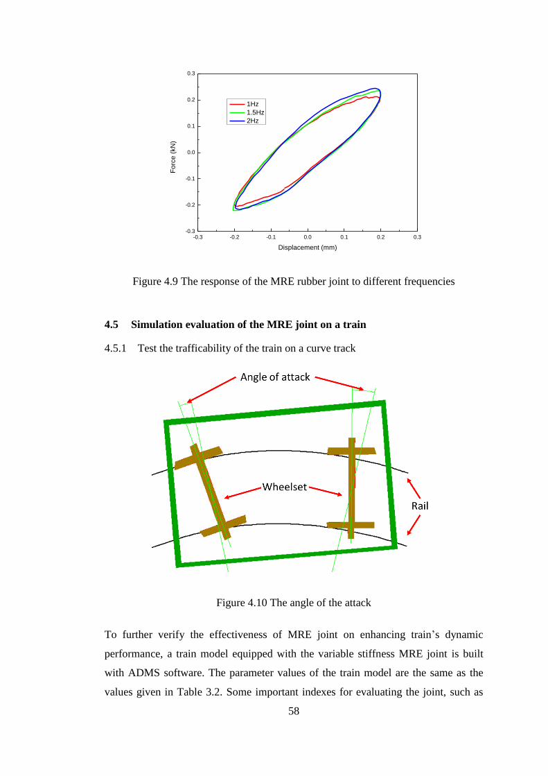
58
-0.3 -0.2 -0.1 0.0 0.1 0.2 0.3-0.3
-0.2
-0.1
0.0
0.1
0.2
0.3
Fo
rce
(kN
)
Displacement (mm)
1Hz
1.5Hz
2Hz
Figure 4.9 The response of the MRE rubber joint to different frequencies
4.5 Simulation evaluation of the MRE joint on a train
4.5.1 Test the trafficability of the train on a curve track
Figure 4.10 The angle of the attack
To further verify the effectiveness of MRE joint on enhancing train’s dynamic
performance, a train model equipped with the variable stiffness MRE joint is built
with ADMS software. The parameter values of the train model are the same as the
values given in Table 3.2. Some important indexes for evaluating the joint, such as
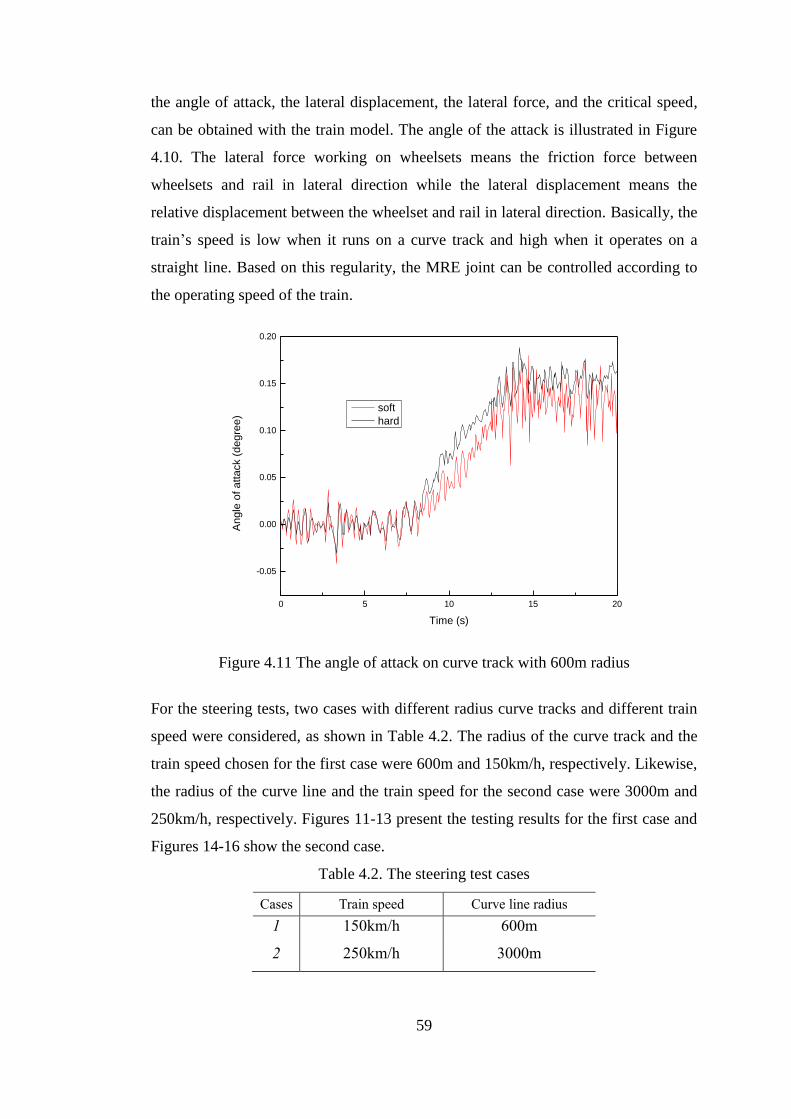
59
the angle of attack, the lateral displacement, the lateral force, and the critical speed,
can be obtained with the train model. The angle of the attack is illustrated in Figure
4.10. The lateral force working on wheelsets means the friction force between
wheelsets and rail in lateral direction while the lateral displacement means the
relative displacement between the wheelset and rail in lateral direction. Basically, the
train’s speed is low when it runs on a curve track and high when it operates on a
straight line. Based on this regularity, the MRE joint can be controlled according to
the operating speed of the train.
0 5 10 15 20
-0.05
0.00
0.05
0.10
0.15
0.20
An
gle
of a
tta
ck (
de
gre
e)
Time (s)
soft
hard
Figure 4.11 The angle of attack on curve track with 600m radius
For the steering tests, two cases with different radius curve tracks and different train
speed were considered, as shown in Table 4.2. The radius of the curve track and the
train speed chosen for the first case were 600m and 150km/h, respectively. Likewise,
the radius of the curve line and the train speed for the second case were 3000m and
250km/h, respectively. Figures 11-13 present the testing results for the first case and
Figures 14-16 show the second case.
Table 4.2. The steering test cases
Cases Train speed Curve line radius
1 150km/h 600m
2 250km/h 3000m
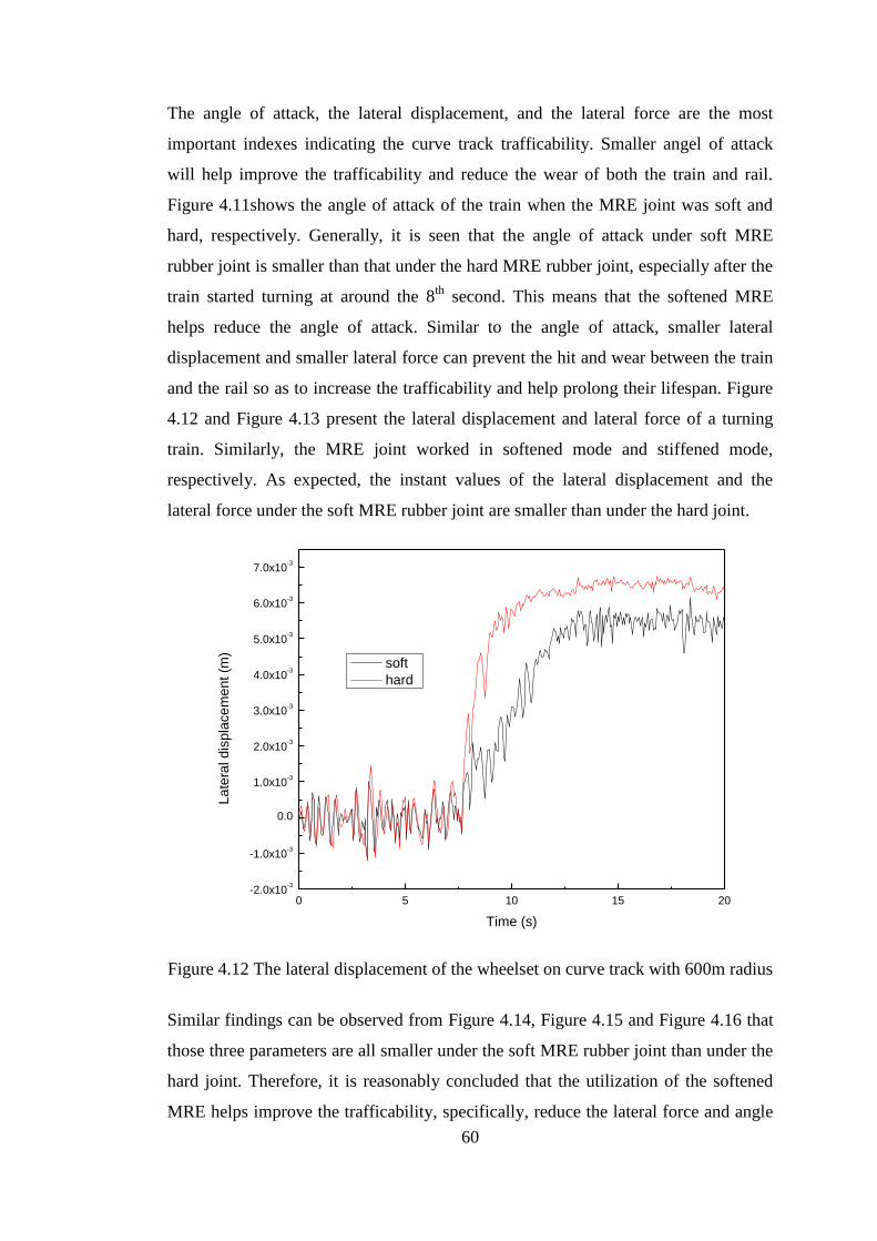
60
The angle of attack, the lateral displacement, and the lateral force are the most
important indexes indicating the curve track trafficability. Smaller angel of attack
will help improve the trafficability and reduce the wear of both the train and rail.
Figure 4.11shows the angle of attack of the train when the MRE joint was soft and
hard, respectively. Generally, it is seen that the angle of attack under soft MRE
rubber joint is smaller than that under the hard MRE rubber joint, especially after the
train started turning at around the 8th
second. This means that the softened MRE
helps reduce the angle of attack. Similar to the angle of attack, smaller lateral
displacement and smaller lateral force can prevent the hit and wear between the train
and the rail so as to increase the trafficability and help prolong their lifespan. Figure
4.12 and Figure 4.13 present the lateral displacement and lateral force of a turning
train. Similarly, the MRE joint worked in softened mode and stiffened mode,
respectively. As expected, the instant values of the lateral displacement and the
lateral force under the soft MRE rubber joint are smaller than under the hard joint.
0 5 10 15 20-2.0x10
-3
-1.0x10⁻³
0.0
1.0x10⁻³
2.0x10⁻³
3.0x10⁻³
4.0x10⁻³
5.0x10⁻³
6.0x10⁻³
7.0x10⁻³
La
tera
l d
isp
lace
me
nt (m
)
Time (s)
soft
hard
Figure 4.12 The lateral displacement of the wheelset on curve track with 600m radius
Similar findings can be observed from Figure 4.14, Figure 4.15 and Figure 4.16 that
those three parameters are all smaller under the soft MRE rubber joint than under the
hard joint. Therefore, it is reasonably concluded that the utilization of the softened
MRE helps improve the trafficability, specifically, reduce the lateral force and angle
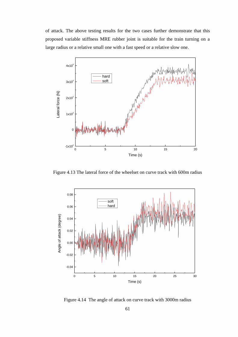
61
of attack. The above testing results for the two cases further demonstrate that this
proposed variable stiffness MRE rubber joint is suitable for the train turning on a
large radius or a relative small one with a fast speed or a relative slow one.
0 5 10 15 20-1x10
4
0
1x10⁴
2x10⁴
3x10⁴
4x10⁴
La
tera
l fo
rce
(N
)
Time (s)
hard
soft
Figure 4.13 The lateral force of the wheelset on curve track with 600m radius
0 5 10 15 20 25 30
-0.04
-0.02
0.00
0.02
0.04
0.06
0.08
An
gle
of a
tta
ck (
de
gre
e)
Time (s)
soft
hard
Figure 4.14 The angle of attack on curve track with 3000m radius
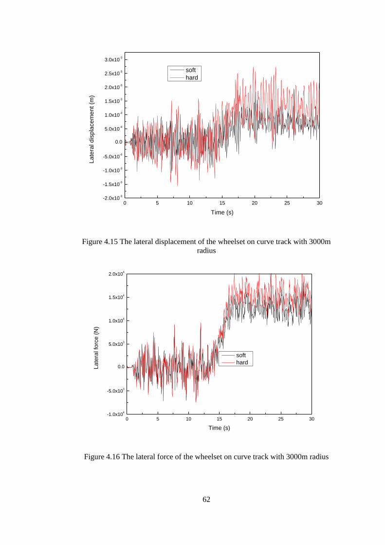
62
0 5 10 15 20 25 30-2.0x10
-3
-1.5x10⁻³
-1.0x10⁻³
-5.0x10⁻⁴
0.0
5.0x10⁻⁴
1.0x10⁻³
1.5x10⁻³
2.0x10⁻³
2.5x10⁻³
3.0x10⁻³
La
tera
l d
isp
lace
me
nt (m
)
Time (s)
soft
hard
Figure 4.15 The lateral displacement of the wheelset on curve track with 3000m
radius
0 5 10 15 20 25 30-1.0x10
4
-5.0x10³
0.0
5.0x10³
1.0x10⁴
1.5x10⁴
2.0x10⁴
La
tera
l fo
rce
(N
)
Time (s)
soft
hard
Figure 4.16 The lateral force of the wheelset on curve track with 3000m radius
63
4.5.2 The stability evaluation of the train with MRE rubber joint
The above mentioned three important indexes (angle of attack, lateral displacement,
and lateral force) indicate the behaviours of train running on curve track. In this
subsection the critical speed indicating the stability of a running train on a straight
track will be investigated. The larger the critical speed, the running train tends to be
more stable. The effect of the longitudinal stiffness on the train’s critical speed can
be calculated by the dynamic model of the train presented in section 3.2. Based on
the model calculation results shown in Figure 3.11, the increase of the longitudinal
stiffness from 0.87 MN/m to 1.52 MN/m leads the critical speed of train increase
from 97m/s to 170m/s. This means when the effective stiffness of the joint stiffens
increases, the critical speed increases. The train will be more stable utilizing the hard
MRE rubber joint when running on a straight track. Combining the findings of this
subsection and the above subsection, it can be concluded that the controlled MRE
joint can offer both high speed stability and good curve track trafficability for train
while the passive soft and passive hard rubber joint only can satisfy one of them.
4.6 Conclusion
This chapter presented a variable stiffness MRE joint and its application on a train.
The mechanical property testing using a MTS machine has verified that this
proposed MRE rubber joint is capable of changing its effective stiffness when the
applied current was changed. In order to evaluate its effectiveness on train, a series
of simulation work using ADAMS was conducted. The simulated responses of the
angle of attack, the lateral displacement, and the lateral force were provided and the
analysis results indicate that the trafficability is improved and the wear can be
reduced when using the soft MRE rubber joint. The calculation results on the straight
track demonstrate that the train reaches a larger critical speed under the hard MRE
joint, which means the train is more stable with hard longitudinal stiffness. To
conclude, the proposed variable stiffness MRE joint is to be controlled hard when the
train is running straightly at high speed to keep the train stable and to be controlled
soft when the train is turning on a curve track to obtain good trafficability. Therefore,
MRE joint can provide the train both good curve track trafficability and high speed
stability.
64
5 COMPACT VARIABLE STIFFNESS AND DAMPING DAMPER FOR
VEHICLE SUSPENSION SYSTEM
5.1 Introduction
Speaking of the solutions to addressing the undesired vibrations, stiffness and
damping are fundamental yet important mechanical features to be controlled for
many technical systems to achieve a desired dynamic behavior. The variation of
damping will induce a change on the resonance magnitude through adjusting the
dissipated vibration energy, and the variable stiffness will change the vibration
transmissibility by changing the natural frequencies of the controlled system. Besides
pure damping or stiffness controllable system mentioned above, system capable of
changing both stiffness and damping is another advanced semi-active vibration
control method and performs better than pure damping controllable or pure stiffness
controllable system. Many studies have been carried out with the concept of dual
controllability of stiffness and damping. Although the better performance of the
variable stiffness and damping system on vibration control has been verified,
compact devices capable of varying both their stiffness and damping for practical
applications have rarely been developed.
Based on the above motivation and further enhance the vibration reduction
performance of the train, an innovative compact variable damping and stiffness
damper was fabricated and analysed in this chapter. The variable stiffness and
damping damper contains inside and outside damping cylinders which are the main
characteristics. The advanced damper is compact and can be easily installed into the
scaled train without any change to the original configuration. The performance of
train with variable stiffness and damping damper was evaluated numerically.
5.2 Variable stiffness and damping damper
5.2.1 Design and working principle of the advanced MR damper
Figure 5.1 shows the structure design and the prototype of the proposed advanced
MR damper. The advanced MR damper mainly consists of two coaxial damping
cylinders and two springs with different stiffness. The damping cylinders are
composed of an internal damping cylinder, which connects the top connector and
bottom connecter, and an outer damping cylinder, which links the two springs. The
internal damping cylinder is composed of a piston rod, electromagnetic coils, seals
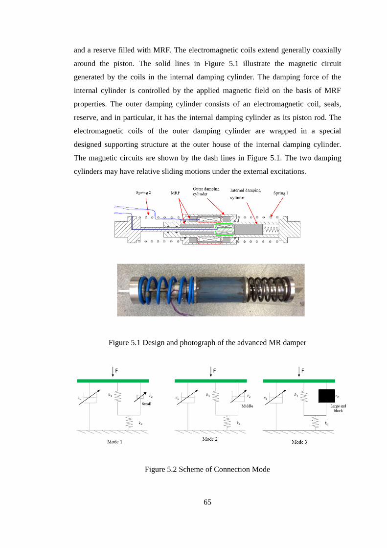
65
and a reserve filled with MRF. The electromagnetic coils extend generally coaxially
around the piston. The solid lines in Figure 5.1 illustrate the magnetic circuit
generated by the coils in the internal damping cylinder. The damping force of the
internal cylinder is controlled by the applied magnetic field on the basis of MRF
properties. The outer damping cylinder consists of an electromagnetic coil, seals,
reserve, and in particular, it has the internal damping cylinder as its piston rod. The
electromagnetic coils of the outer damping cylinder are wrapped in a special
designed supporting structure at the outer house of the internal damping cylinder.
The magnetic circuits are shown by the dash lines in Figure 5.1. The two damping
cylinders may have relative sliding motions under the external excitations.
Figure 5.1 Design and photograph of the advanced MR damper
Figure 5.2 Scheme of Connection Mode
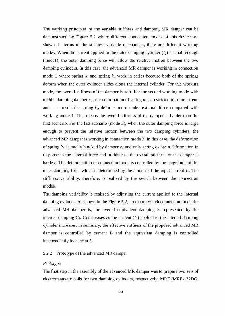
66
The working principles of the variable stiffness and damping MR damper can be
demonstrated by Figure 5.2 where different connection modes of this device are
shown. In terms of the stiffness variable mechanism, there are different working
modes. When the current applied to the outer damping cylinder (I2) is small enough
(mode1), the outer damping force will allow the relative motion between the two
damping cylinders. In this case, the advanced MR damper is working in connection
mode 1 where spring k1 and spring k2 work in series because both of the springs
deform when the outer cylinder slides along the internal cylinder. For this working
mode, the overall stiffness of the damper is soft. For the second working mode with
middle damping damper 𝑐2, the deformation of spring 𝑘1 is restricted to some extend
and as a result the spring 𝑘2 deforms more under external force compared with
working mode 1. This means the overall stiffness of the damper is harder than the
first scenario. For the last scenario (mode 3), when the outer damping force is large
enough to prevent the relative motion between the two damping cylinders, the
advanced MR damper is working in connection mode 3. In this case, the deformation
of spring 𝑘1 is totally blocked by damper 𝑐2 and only spring 𝑘2 has a deformation in
response to the external force and in this case the overall stiffness of the damper is
hardest. The determination of connection mode is controlled by the magnitude of the
outer damping force which is determined by the amount of the input current I2. The
stiffness variability, therefore, is realized by the switch between the connection
modes.
The damping variability is realized by adjusting the current applied to the internal
damping cylinder. As shown in the Figure 5.2, no matter which connection mode the
advanced MR damper is, the overall equivalent damping is represented by the
internal damping C1. C1 increases as the current (I1) applied to the internal damping
cylinder increases. In summary, the effective stiffness of the proposed advanced MR
damper is controlled by current I2 and the equivalent damping is controlled
independently by current I1.
5.2.2 Prototype of the advanced MR damper
Prototype
The first step in the assembly of the advanced MR damper was to prepare two sets of
electromagnetic coils for two damping cylinders, respectively. MRF (MRF-132DG,
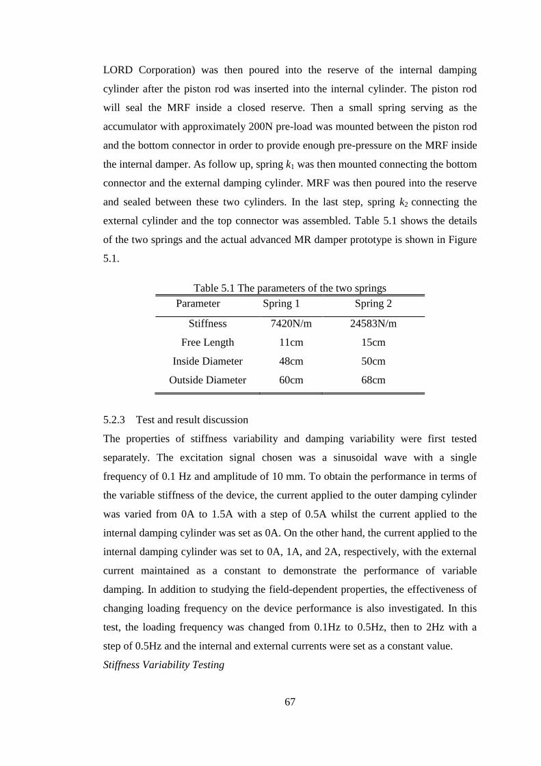
67
LORD Corporation) was then poured into the reserve of the internal damping
cylinder after the piston rod was inserted into the internal cylinder. The piston rod
will seal the MRF inside a closed reserve. Then a small spring serving as the
accumulator with approximately 200N pre-load was mounted between the piston rod
and the bottom connector in order to provide enough pre-pressure on the MRF inside
the internal damper. As follow up, spring k1 was then mounted connecting the bottom
connector and the external damping cylinder. MRF was then poured into the reserve
and sealed between these two cylinders. In the last step, spring k2 connecting the
external cylinder and the top connector was assembled. Table 5.1 shows the details
of the two springs and the actual advanced MR damper prototype is shown in Figure
5.1.
Table 5.1 The parameters of the two springs
Parameter Spring 1 Spring 2
Stiffness 7420N/m 24583N/m
Free Length 11cm 15cm
Inside Diameter 48cm 50cm
Outside Diameter 60cm 68cm
5.2.3 Test and result discussion
The properties of stiffness variability and damping variability were first tested
separately. The excitation signal chosen was a sinusoidal wave with a single
frequency of 0.1 Hz and amplitude of 10 mm. To obtain the performance in terms of
the variable stiffness of the device, the current applied to the outer damping cylinder
was varied from 0A to 1.5A with a step of 0.5A whilst the current applied to the
internal damping cylinder was set as 0A. On the other hand, the current applied to the
internal damping cylinder was set to 0A, 1A, and 2A, respectively, with the external
current maintained as a constant to demonstrate the performance of variable
damping. In addition to studying the field-dependent properties, the effectiveness of
changing loading frequency on the device performance is also investigated. In this
test, the loading frequency was changed from 0.1Hz to 0.5Hz, then to 2Hz with a
step of 0.5Hz and the internal and external currents were set as a constant value.
Stiffness Variability Testing
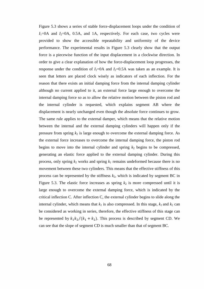
68
Figure 5.3 shows a series of stable force-displacement loops under the condition of
I1=0A and I2=0A, 0.5A, and 1A, respectively. For each case, two cycles were
provided to show the accessible repeatability and uniformity of the device
performance. The experimental results in Figure 5.3 clearly show that the output
force is a piecewise function of the input displacement in a clockwise direction. In
order to give a clear explanation of how the force-displacement loop progresses, the
response under the condition of I1=0A and I2=0.5A was taken as an example. It is
seen that letters are placed clock wisely as indicators of each inflection. For the
reason that there exists an initial damping force from the internal damping cylinder
although no current applied to it, an external force large enough to overcome the
internal damping force so as to allow the relative motion between the piston rod and
the internal cylinder is requested, which explains segment AB where the
displacement is nearly unchanged even though the absolute force continues to grow.
The same rule applies to the external damper, which means that the relative motion
between the internal and the external damping cylinders will happen only if the
pressure from spring k2 is large enough to overcome the external damping force. As
the external force increases to overcome the internal damping force, the piston rod
begins to move into the internal cylinder and spring k2 begins to be compressed,
generating an elastic force applied to the external damping cylinder. During this
process, only spring k2 works and spring k1 remains undeformed because there is no
movement between these two cylinders. This means that the effective stiffness of this
process can be represented by the stiffness k2, which is indicated by segment BC in
Figure 5.3. The elastic force increases as spring k2 is more compressed until it is
large enough to overcome the external damping force, which is indicated by the
critical inflection C. After inflection C, the external cylinder begins to slide along the
internal cylinder, which means that k1 is also compressed. In this stage, k1 and k2 can
be considered as working in series, therefore, the effective stiffness of this stage can
be represented by 𝑘1𝑘2 (𝑘1 + 𝑘2)⁄ . This process is described by segment CD. We
can see that the slope of segment CD is much smaller than that of segment BC.
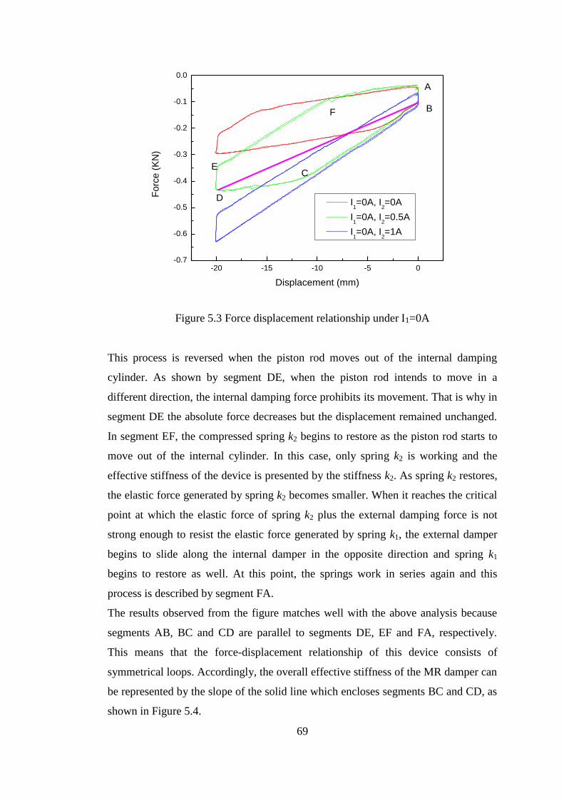
69
-20 -15 -10 -5 0-0.7
-0.6
-0.5
-0.4
-0.3
-0.2
-0.1
0.0
Fo
rce
(K
N)
Displacement (mm)
I1=0A, I
2=0A
I1=0A, I
2=0.5A
I1=0A, I
2=1A
A
B
C
D
E
F
Figure 5.3 Force displacement relationship under I1=0A
This process is reversed when the piston rod moves out of the internal damping
cylinder. As shown by segment DE, when the piston rod intends to move in a
different direction, the internal damping force prohibits its movement. That is why in
segment DE the absolute force decreases but the displacement remained unchanged.
In segment EF, the compressed spring k2 begins to restore as the piston rod starts to
move out of the internal cylinder. In this case, only spring k2 is working and the
effective stiffness of the device is presented by the stiffness k2. As spring k2 restores,
the elastic force generated by spring k2 becomes smaller. When it reaches the critical
point at which the elastic force of spring k2 plus the external damping force is not
strong enough to resist the elastic force generated by spring k1, the external damper
begins to slide along the internal damper in the opposite direction and spring k1
begins to restore as well. At this point, the springs work in series again and this
process is described by segment FA.
The results observed from the figure matches well with the above analysis because
segments AB, BC and CD are parallel to segments DE, EF and FA, respectively.
This means that the force-displacement relationship of this device consists of
symmetrical loops. Accordingly, the overall effective stiffness of the MR damper can
be represented by the slope of the solid line which encloses segments BC and CD, as
shown in Figure 5.4.
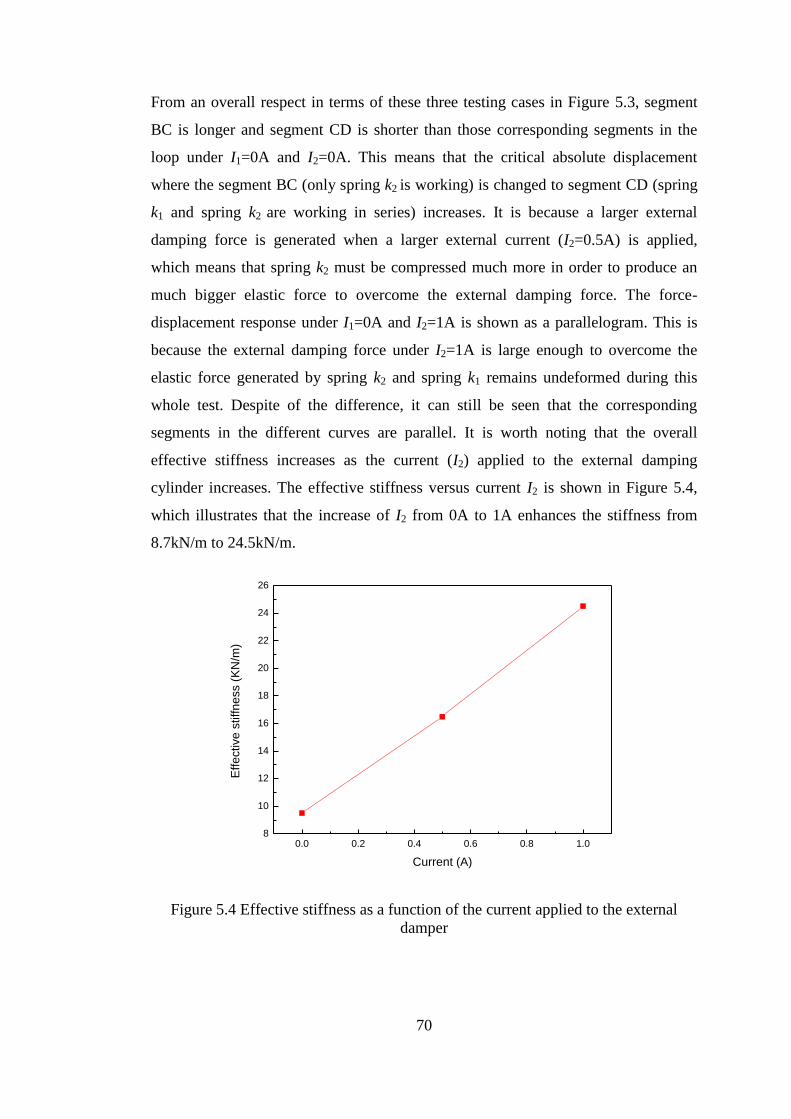
70
From an overall respect in terms of these three testing cases in Figure 5.3, segment
BC is longer and segment CD is shorter than those corresponding segments in the
loop under I1=0A and I2=0A. This means that the critical absolute displacement
where the segment BC (only spring k2 is working) is changed to segment CD (spring
k1 and spring k2 are working in series) increases. It is because a larger external
damping force is generated when a larger external current (I2=0.5A) is applied,
which means that spring k2 must be compressed much more in order to produce an
much bigger elastic force to overcome the external damping force. The force-
displacement response under I1=0A and I2=1A is shown as a parallelogram. This is
because the external damping force under I2=1A is large enough to overcome the
elastic force generated by spring k2 and spring k1 remains undeformed during this
whole test. Despite of the difference, it can still be seen that the corresponding
segments in the different curves are parallel. It is worth noting that the overall
effective stiffness increases as the current (I2) applied to the external damping
cylinder increases. The effective stiffness versus current I2 is shown in Figure 5.4,
which illustrates that the increase of I2 from 0A to 1A enhances the stiffness from
8.7kN/m to 24.5kN/m.
0.0 0.2 0.4 0.6 0.8 1.08
10
12
14
16
18
20
22
24
26
Effe
ctive
stiffn
ess (
KN
/m)
Current (A)
Figure 5.4 Effective stiffness as a function of the current applied to the external
damper
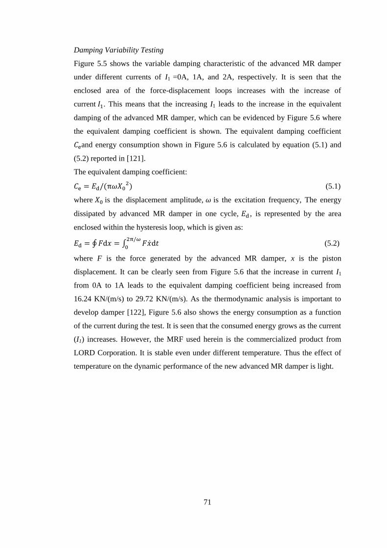
71
Damping Variability Testing
Figure 5.5 shows the variable damping characteristic of the advanced MR damper
under different currents of I1 =0A, 1A, and 2A, respectively. It is seen that the
enclosed area of the force-displacement loops increases with the increase of
current 𝐼1. This means that the increasing I1 leads to the increase in the equivalent
damping of the advanced MR damper, which can be evidenced by Figure 5.6 where
the equivalent damping coefficient is shown. The equivalent damping coefficient
𝐶eand energy consumption shown in Figure 5.6 is calculated by equation (5.1) and
(5.2) reported in [121].
The equivalent damping coefficient:
𝐶e = 𝐸d/(π𝜔𝑋02) (5.1)
where 𝑋0 is the displacement amplitude, 𝜔 is the excitation frequency, The energy
dissipated by advanced MR damper in one cycle, 𝐸d , is represented by the area
enclosed within the hysteresis loop, which is given as:
𝐸d = ∮ 𝐹d𝑥 = ∫ 𝐹�̇�d𝑡2π/𝜔
0 (5.2)
where F is the force generated by the advanced MR damper, x is the piston
displacement. It can be clearly seen from Figure 5.6 that the increase in current I1
from 0A to 1A leads to the equivalent damping coefficient being increased from
16.24 KN/(m/s) to 29.72 KN/(m/s). As the thermodynamic analysis is important to
develop damper [122], Figure 5.6 also shows the energy consumption as a function
of the current during the test. It is seen that the consumed energy grows as the current
(I1) increases. However, the MRF used herein is the commercialized product from
LORD Corporation. It is stable even under different temperature. Thus the effect of
temperature on the dynamic performance of the new advanced MR damper is light.
72
-20 -15 -10 -5 0-0.5
-0.4
-0.3
-0.2
-0.1
0.0
Fo
rce (
kN
)
Displacement (mm)
I1=0A, I
2=0.25A
I1=1A, I
2=0.25A
I1=2A, I
2=0.25A
Figure 5.5 Variable damping performance under various currents
Frequency dependent response
This part gives an analysis of the effectiveness of changing the loading frequency on
the damper performance, as shown in Figure 5.7. In this test, the loading frequency
was chosen as 0.1Hz, 0.5Hz, 1Hz, 1.5Hz, and 2Hz, respectively. It is seen that the
force generated by the advanced MR damper increases slightly though the loading
frequency increases, and that the effective stiffness and equivalent damping are
almost independent of the loading frequency. The loop shape, however, tends to be
more smooth as the frequency grows.
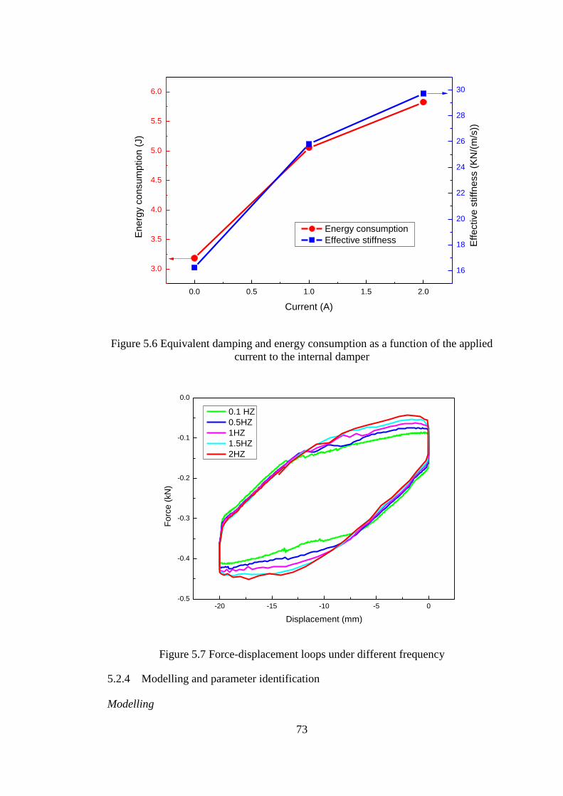
73
0.0 0.5 1.0 1.5 2.0
3.0
3.5
4.0
4.5
5.0
5.5
6.0
Energy consumption
Effective stiffness
Current (A)
En
erg
y c
on
su
mp
tio
n (
J)
16
18
20
22
24
26
28
30
Eff
ective
stiff
ne
ss (
KN
/(m
/s))
Figure 5.6 Equivalent damping and energy consumption as a function of the applied
current to the internal damper
-20 -15 -10 -5 0-0.5
-0.4
-0.3
-0.2
-0.1
0.0
Fo
rce
(kN
)
Displacement (mm)
0.1 HZ
0.5HZ
1HZ
1.5HZ
2HZ
Figure 5.7 Force-displacement loops under different frequency
5.2.4 Modelling and parameter identification
Modelling
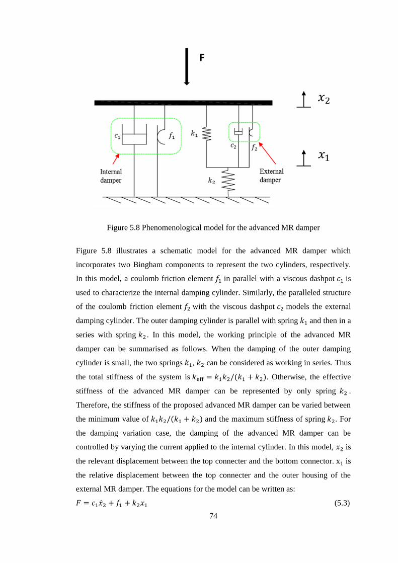
74
Figure 5.8 Phenomenological model for the advanced MR damper
Figure 5.8 illustrates a schematic model for the advanced MR damper which
incorporates two Bingham components to represent the two cylinders, respectively.
In this model, a coulomb friction element 𝑓1 in parallel with a viscous dashpot 𝑐1 is
used to characterize the internal damping cylinder. Similarly, the paralleled structure
of the coulomb friction element 𝑓2 with the viscous dashpot 𝑐2 models the external
damping cylinder. The outer damping cylinder is parallel with spring 𝑘1 and then in a
series with spring 𝑘2 . In this model, the working principle of the advanced MR
damper can be summarised as follows. When the damping of the outer damping
cylinder is small, the two springs 𝑘1, 𝑘2 can be considered as working in series. Thus
the total stiffness of the system is 𝑘eff = 𝑘1𝑘2/(𝑘1 + 𝑘2). Otherwise, the effective
stiffness of the advanced MR damper can be represented by only spring 𝑘2 .
Therefore, the stiffness of the proposed advanced MR damper can be varied between
the minimum value of 𝑘1𝑘2/(𝑘1 + 𝑘2) and the maximum stiffness of spring 𝑘2. For
the damping variation case, the damping of the advanced MR damper can be
controlled by varying the current applied to the internal cylinder. In this model, 𝑥2 is
the relevant displacement between the top connecter and the bottom connector. x1 is
the relative displacement between the top connecter and the outer housing of the
external MR damper. The equations for the model can be written as:
𝐹 = 𝑐1�̇�2 + 𝑓1 + 𝑘2𝑥1 (5.3)
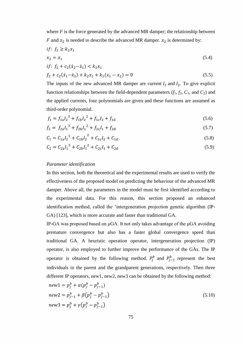
75
where F is the force generated by the advanced MR damper; the relationship between
𝐹 and 𝑥2 is needed to describe the advanced MR damper. 𝑥2 is determined by:
𝑖𝑓: 𝑓2 ≥ 𝑘2𝑥1
𝑥2 = 𝑥1 (5.4)
𝑖𝑓: 𝑓2 + 𝑐2(�̇�2−�̇�1) < 𝑘2𝑥1
𝑓2 + 𝑐2(�̇�1−�̇�2) + 𝑘2𝑥1 + 𝑘1(𝑥1 − 𝑥2) = 0 (5.5)
The inputs of the new advanced MR damper are current 𝐼1 and 𝐼2. To give explicit
function relationships between the field-dependent parameters (f1, f2, C1, and C2) and
the applied currents, four polynomials are given and these functions are assumed as
third-order polynomial.
𝑓1 = 𝑓1a𝐼23 + 𝑓1b𝐼2
2 + 𝑓1c𝐼2 + 𝑓1d (5.6)
𝑓2 = 𝑓2a𝐼13 + 𝑓2b𝐼1
2 + 𝑓2c𝐼1 + 𝑓2d (5.7)
𝐶1 = 𝐶1a𝐼23 + 𝐶1b𝐼2
2+ 𝐶1c𝐼2 + 𝐶1d (5.8)
𝐶2 = 𝐶2a𝐼13 + 𝐶2b𝐼1
2 + 𝐶2c𝐼1 + 𝐶2d (5.9)
Parameter identification
In this section, both the theoretical and the experimental results are used to verify the
effectiveness of the proposed model on predicting the behaviour of the advanced MR
damper. Above all, the parameters in the model must be first identified according to
the experimental data. For this reason, this section proposed an enhanced
identification method, called the ‘intergeneration projection genetic algorithm (IP-
GA) [123], which is more accurate and faster than traditional GA.
IP-GA was proposed based on μGA. It not only takes advantage of the μGA avoiding
premature convergence but also has a faster global convergence speed than
traditional GA. A heuristic operation operator, intergeneration projection (IP)
operator, is also employed to further improve the performance of the GAs. The IP
operator is obtained by the following method. 𝑃𝑗𝑏 and 𝑃𝑗−1
𝑏 represent the best
individuals in the parent and the grandparent generations, respectively. Then three
different IP operators, new1, new2, new3 can be obtained by the following method:
𝑛𝑒𝑤1 = 𝑝𝑗𝑏 + 𝛼(𝑝𝑗
𝑏 − 𝑝𝑗−1𝑏 )
𝑛𝑒𝑤2 = 𝑝𝑗−1𝑏 + 𝛽(𝑝𝑗
𝑏 − 𝑝𝑗−1𝑏 ) (5.10)
𝑛𝑒𝑤3 = 𝑝𝑗𝑏 + 𝛾(𝑝𝑗
𝑏 − 𝑝𝑗−1𝑏 )
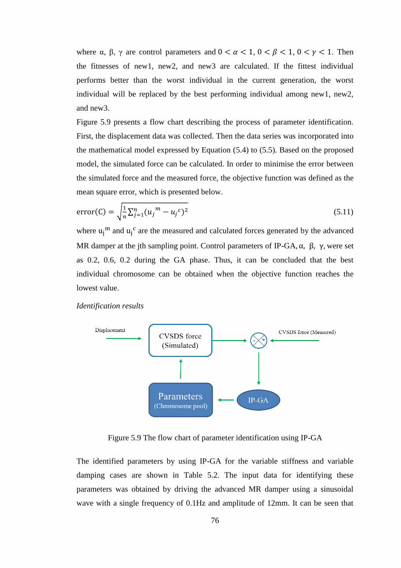
76
where α, β, γ are control parameters and 0 < 𝛼 < 1, 0 < 𝛽 < 1, 0 < 𝛾 < 1. Then
the fitnesses of new1, new2, and new3 are calculated. If the fittest individual
performs better than the worst individual in the current generation, the worst
individual will be replaced by the best performing individual among new1, new2,
and new3.
Figure 5.9 presents a flow chart describing the process of parameter identification.
First, the displacement data was collected. Then the data series was incorporated into
the mathematical model expressed by Equation (5.4) to (5.5). Based on the proposed
model, the simulated force can be calculated. In order to minimise the error between
the simulated force and the measured force, the objective function was defined as the
mean square error, which is presented below.
error(C) = √1
𝑛∑ (𝑢𝑗
𝑚 − 𝑢𝑗𝑐𝑛
𝑗=1 )2 (5.11)
where ujm and uj
c are the measured and calculated forces generated by the advanced
MR damper at the jth sampling point. Control parameters of IP-GA, α, β, γ, were set
as 0.2, 0.6, 0.2 during the GA phase. Thus, it can be concluded that the best
individual chromosome can be obtained when the objective function reaches the
lowest value.
Identification results
Figure 5.9 The flow chart of parameter identification using IP-GA
The identified parameters by using IP-GA for the variable stiffness and variable
damping cases are shown in Table 5.2. The input data for identifying these
parameters was obtained by driving the advanced MR damper using a sinusoidal
wave with a single frequency of 0.1Hz and amplitude of 12mm. It can be seen that
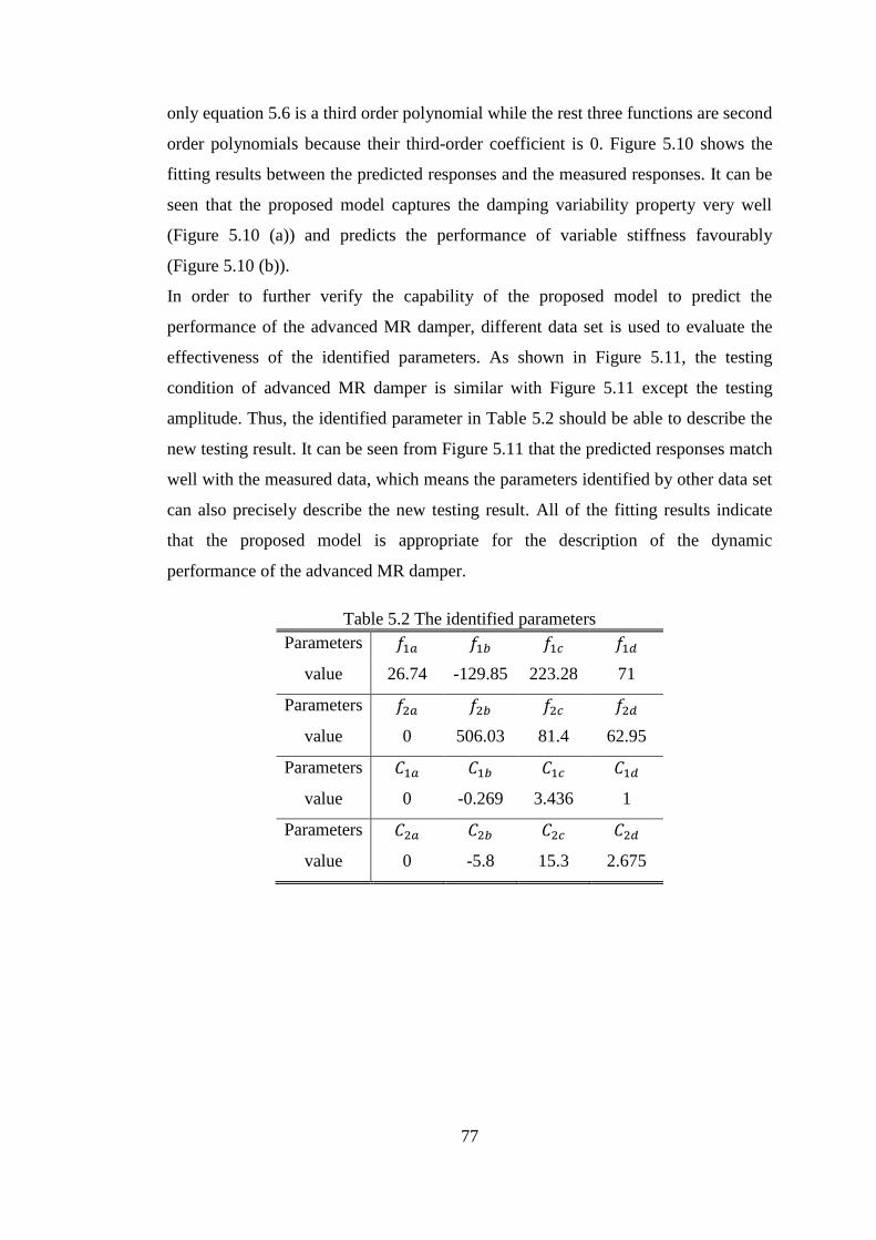
77
only equation 5.6 is a third order polynomial while the rest three functions are second
order polynomials because their third-order coefficient is 0. Figure 5.10 shows the
fitting results between the predicted responses and the measured responses. It can be
seen that the proposed model captures the damping variability property very well
(Figure 5.10 (a)) and predicts the performance of variable stiffness favourably
(Figure 5.10 (b)).
In order to further verify the capability of the proposed model to predict the
performance of the advanced MR damper, different data set is used to evaluate the
effectiveness of the identified parameters. As shown in Figure 5.11, the testing
condition of advanced MR damper is similar with Figure 5.11 except the testing
amplitude. Thus, the identified parameter in Table 5.2 should be able to describe the
new testing result. It can be seen from Figure 5.11 that the predicted responses match
well with the measured data, which means the parameters identified by other data set
can also precisely describe the new testing result. All of the fitting results indicate
that the proposed model is appropriate for the description of the dynamic
performance of the advanced MR damper.
Table 5.2 The identified parameters
Parameters 𝑓1𝑎 𝑓1𝑏 𝑓1𝑐 𝑓1𝑑
value 26.74 -129.85 223.28 71
Parameters 𝑓2𝑎 𝑓2𝑏 𝑓2𝑐 𝑓2𝑑
value 0 506.03 81.4 62.95
Parameters 𝐶1𝑎 𝐶1𝑏 𝐶1𝑐 𝐶1𝑑
value 0 -0.269 3.436 1
Parameters 𝐶2𝑎 𝐶2𝑏 𝐶2𝑐 𝐶2𝑑
value 0 -5.8 15.3 2.675
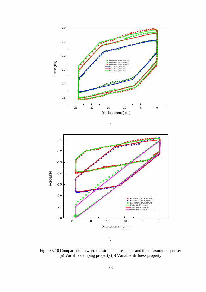
78
-25 -20 -15 -10 -5 0
-0.5
-0.4
-0.3
-0.2
-0.1
0.0
Experiment (I1=0A, I2=0.25A)
Experiment (I1=1A, I2=0.25A)
Experiment (I1=2A, I2=0.25A)
Model (I1=0A, I2=0.25A)
Model (I1=1A, I2=0.25A)
Model (I1=2A, I2=0.25A)
Fo
rce (
kN
)
Displacement (mm)
a
-25 -20 -15 -10 -5 0-0.8
-0.7
-0.6
-0.5
-0.4
-0.3
-0.2
-0.1
Experiment (I1=0A, I2=0A)
Experiment (I1=0A, I2=0.5A)
Experiment (I1=0A, I2=1A)
Model (I1=0A, I2=0A)
Model (I1=0A, I2=0.5A)
Model (I1=0A, I2=1A)
Fo
rce/k
N
Displacement/mm
b
Figure 5.10 Comparison between the simulated response and the measured response:
(a) Variable damping property (b) Variable stiffness property
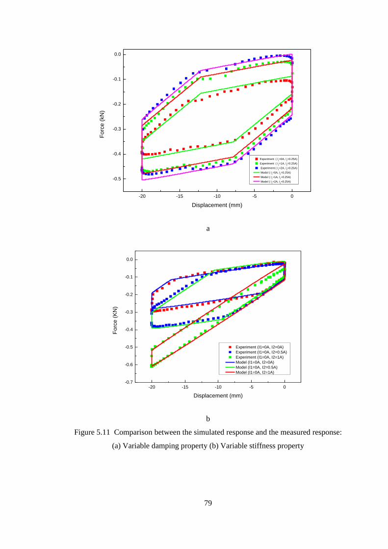
79
-20 -15 -10 -5 0
-0.5
-0.4
-0.3
-0.2
-0.1
0.0
Fo
rce
(kN
)
Displacement (mm)
Experiment ( I1=0A, I
2=0.25A)
Experiment ( I1=1A, I
2=0.25A)
Experiment ( I1=2A, I
2=0.25A)
Model ( I1=0A, I
2=0.25A)
Model ( I1=1A, I
2=0.25A)
Model ( I1=2A, I
2=0.25A)
a
-20 -15 -10 -5 0-0.7
-0.6
-0.5
-0.4
-0.3
-0.2
-0.1
0.0
Fo
rce (
KN
)
Displacement (mm)
Experiment (I1=0A, I2=0A)
Experiment (I1=0A, I2=0.5A)
Experiment (I1=0A, I2=1A)
Model (I1=0A, I2=0A)
Model (I1=0A, I2=0.5A)
Model (I1=0A, I2=1A)
b
Figure 5.11 Comparison between the simulated response and the measured response:
(a) Variable damping property (b) Variable stiffness property
80
In summary, an innovative variable stiffness and damping damper is developed and
analysed. The test results verified its capability to change both stiffness and damping.
The proposed model also can predict the dynamic performance of the device.
5.3 Simulation of railway vehicle with variable stiffness and damping damper
In order to verify the effectiveness of the advanced damper on vibration control, a
train mounted with the damper is evaluated in this section. As the developed variable
stiffness and damping damper presented in the above section is a scaled damper for
the train, the force generated by the advanced damper is amplified by 5 times in the
simulation conducted in this section. The variable stiffness and damping suspension
including a control system is presented in Figure 5.12. ADAMS/RAIL is used to
establish the dynamic model of the train. The model established in this study is a
two-axle railway vehicle containing a front truck and a rear truck frame. The primary
suspension consists of four primary vertical dampers and four primary vertical
springs while the secondary suspension consists of four secondary vertical dampers,
four secondary vertical springs, and four secondary lateral dampers. Four secondary
lateral dampers are replaced by the variable stiffness and damping MR dampers.
Accelerometers are mounted on the car body and the truck frame to measure their
lateral accelerations. The measured acceleration signals are transferred to the
damping controllers and the stiffness controllers to control the secondary lateral
damping and stiffness, respectively.
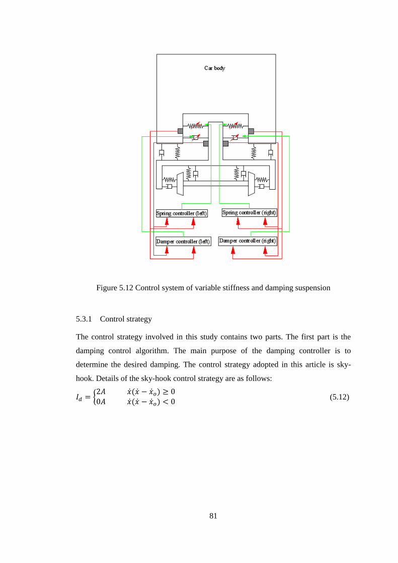
81
Figure 5.12 Control system of variable stiffness and damping suspension
5.3.1 Control strategy
The control strategy involved in this study contains two parts. The first part is the
damping control algorithm. The main purpose of the damping controller is to
determine the desired damping. The control strategy adopted in this article is sky-
hook. Details of the sky-hook control strategy are as follows:
𝐼𝑑 = {2𝐴 �̇�(�̇� − �̇�𝑜) ≥ 00𝐴 �̇�(�̇� − �̇�𝑜) < 0
(5.12)
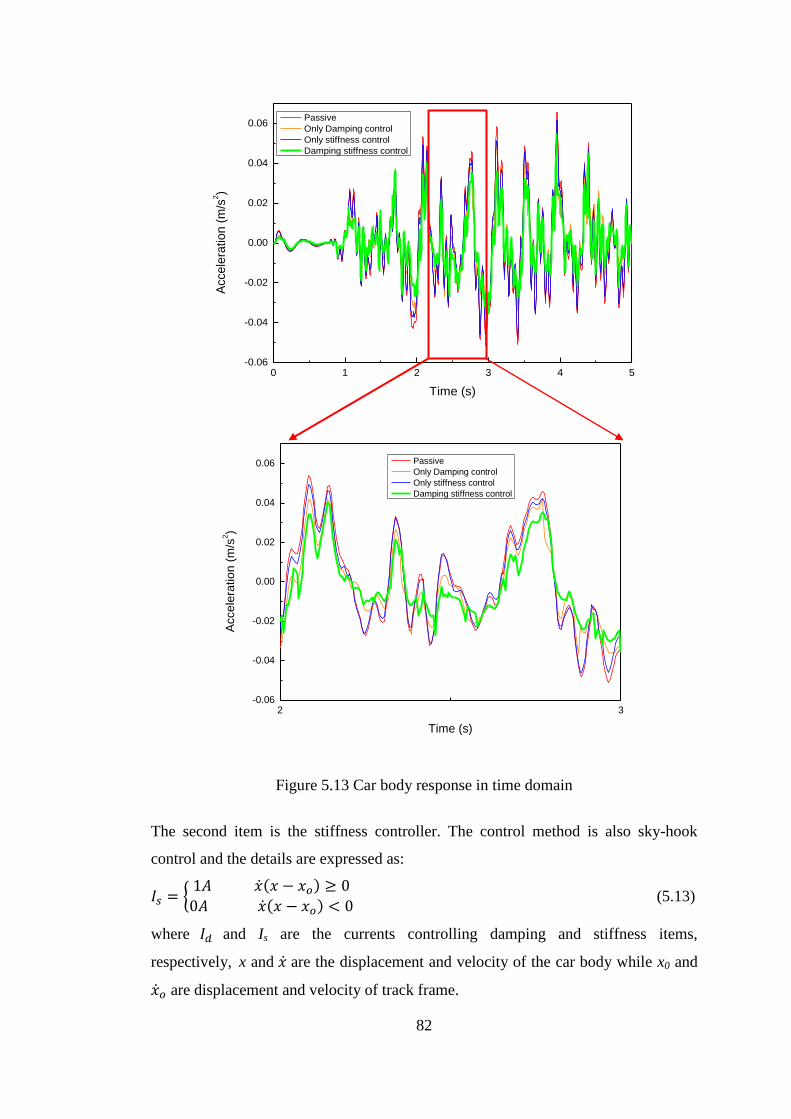
82
Figure 5.13 Car body response in time domain
The second item is the stiffness controller. The control method is also sky-hook
control and the details are expressed as:
𝐼𝑠 = {1𝐴 �̇�(𝑥 − 𝑥𝑜) ≥ 0
0𝐴 �̇�(𝑥 − 𝑥𝑜) < 0 (5.13)
where 𝐼𝑑 and Is are the currents controlling damping and stiffness items,
respectively, x and �̇� are the displacement and velocity of the car body while x0 and
�̇�𝑜 are displacement and velocity of track frame.
0 1 2 3 4 5-0.06
-0.04
-0.02
0.00
0.02
0.04
0.06
Accele
ratio
n (
m/s
2)
Time (s)
Passive
Only Damping control
Only stiffness control
Damping stiffness control
2 3-0.06
-0.04
-0.02
0.00
0.02
0.04
0.06
Accele
ratio
n (
m/s
2)
Time (s)
Passive
Only Damping control
Only stiffness control
Damping stiffness control
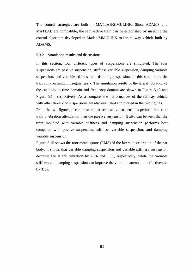
83
The control strategies are built in MATLAB/SIMULINK. Since ADAMS and
MATLAB are compatible, the semi-active train can be established by inserting the
control algorithm developed in Matlab/SIMULINK to the railway vehicle built by
ADAMS.
5.3.2 Simulation results and discussions
In this section, four different types of suspensions are simulated. The four
suspensions are passive suspension, stiffness variable suspension, damping variable
suspension, and variable stiffness and damping suspension. In this simulation, the
train runs on random irregular track. The simulation results of the lateral vibration of
the car body in time domain and frequency domain are shown in Figure 5.13 and
Figure 5.14, respectively. As a compare, the performances of the railway vehicle
with other three kind suspensions are also evaluated and plotted in the two figures.
From the two figures, it can be seen that semi-active suspensions perform better on
train’s vibration attenuation than the passive suspension. It also can be seen that the
train mounted with variable stiffness and damping suspension performs best
compared with passive suspension, stiffness variable suspension, and damping
variable suspension.
Figure 5.15 shows the root mean square (RMS) of the lateral acceleration of the car
body. It shows that variable damping suspension and variable stiffness suspension
decrease the lateral vibration by 23% and 11%, respectively, while the variable
stiffness and damping suspension can improve the vibration attenuation effectiveness
by 31%.
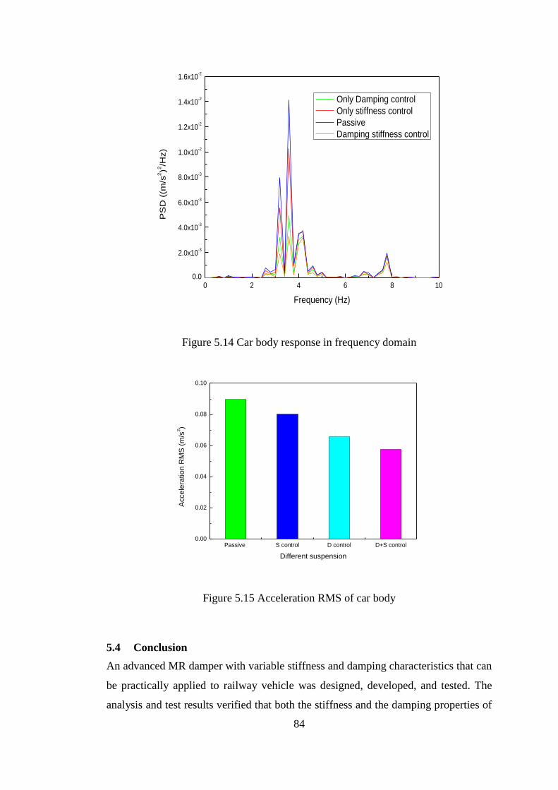
84
Figure 5.14 Car body response in frequency domain
Figure 5.15 Acceleration RMS of car body
5.4 Conclusion
An advanced MR damper with variable stiffness and damping characteristics that can
be practically applied to railway vehicle was designed, developed, and tested. The
analysis and test results verified that both the stiffness and the damping properties of
0 2 4 6 8 100.0
2.0x10⁻³
4.0x10⁻³
6.0x10⁻³
8.0x10⁻³
1.0x10⁻²
1.2x10⁻²
1.4x10⁻²
1.6x10⁻²
PS
D (
(m/s
2)2
/Hz)
Frequency (Hz)
Only Damping control
Only stiffness control
Passive
Damping stiffness control
Passive S control D control D+S control0.00
0.02
0.04
0.06
0.08
0.10
Acce
lera
tio
n R
MS
(m
/s2)
Different suspension
85
the damper can be controlled. The stiffness of the damper can vary from 8.7kN/m to
24.5kN/m while the equivalent damping coefficient has the ability to change from
16.24 KN/(m/s) to 29.72 KN/(m/s). An innovative model was established and
identified to describe the proposed MR damper. The successful development of the
compact variable stiffness and damping damper proves that the concept of variable
stiffness and damping suspension system for train is feasible.
By replacing the conventional secondary lateral dampers by the variable stiffness and
damping dampers, the railway vehicle with variable stiffness and damping
suspension is established. ADAMS/rail and Matlab/Simulink software are used to
evaluate the performance of the semi-active railway vehicle. The simulation results
illustrate that the variable stiffness and damping suspension performs the best on
train’s vibration attenuation and offers higher level of ride comfort compared with
passive suspension, stiffness variable suspension and damping variable suspension.
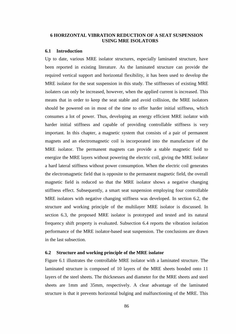
86
6 HORIZONTAL VIBRATION REDUCTION OF A SEAT SUSPENSION
USING MRE ISOLATORS
6.1 Introduction
Up to date, various MRE isolator structures, especially laminated structure, have
been reported in existing literature. As the laminated structure can provide the
required vertical support and horizontal flexibility, it has been used to develop the
MRE isolator for the seat suspension in this study. The stiffnesses of existing MRE
isolaters can only be increased, however, when the applied current is increased. This
means that in order to keep the seat stable and avoid collision, the MRE isolators
should be powered on in most of the time to offer harder initial stiffness, which
consumes a lot of power. Thus, developing an energy efficient MRE isolator with
harder initial stiffness and capable of providing controllable stiffness is very
important. In this chapter, a magnetic system that consists of a pair of permanent
magnets and an electromagnetic coil is incorporated into the manufacture of the
MRE isolator. The permanent magnets can provide a stable magnetic field to
energize the MRE layers without powering the electric coil, giving the MRE isolator
a hard lateral stiffness without power consumption. When the electric coil generates
the electromagnetic field that is opposite to the permanent magnetic field, the overall
magnetic field is reduced so that the MRE isolator shows a negative changing
stiffness effect. Subsequently, a smart seat suspension employing four controllable
MRE isolators with negative changing stiffness was developed. In section 6.2, the
structure and working principle of the multilayer MRE isolator is discussed. In
section 6.3, the proposed MRE isolator is prototyped and tested and its natural
frequency shift property is evaluated. Subsection 6.4 reports the vibration isolation
performance of the MRE isolator-based seat suspension. The conclusions are drawn
in the last subsection.
6.2 Structure and working principle of the MRE isolator
Figure 6.1 illustrates the controllable MRE isolator with a laminated structure. The
laminated structure is composed of 10 layers of the MRE sheets bonded onto 11
layers of the steel sheets. The thicknesses and diameter for the MRE sheets and steel
sheets are 1mm and 35mm, respectively. A clear advantage of the laminated
structure is that it prevents horizontal bulging and malfunctioning of the MRE. This
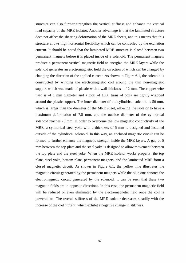
87
structure can also further strengthen the vertical stiffness and enhance the vertical
load capacity of the MRE isolator. Another advantage is that the laminated structure
does not affect the shearing deformation of the MRE sheets, and this means that this
structure allows high horizontal flexibility which can be controlled by the excitation
current. It should be noted that the laminated MRE structure is placed between two
permanent magnets before it is placed inside of a solenoid. The permanent magnets
produce a permanent vertical magnetic field to energize the MRE layers while the
solenoid generates an electromagnetic field the direction of which can be changed by
changing the direction of the applied current. As shown in Figure 6.1, the solenoid is
constructed by winding the electromagnetic coil around the thin non-magnetic
support which was made of plastic with a wall thickness of 2 mm. The copper wire
used is of 1 mm diameter and a total of 1000 turns of coils are tightly wrapped
around the plastic support. The inner diameter of the cylindrical solenoid is 50 mm,
which is larger than the diameter of the MRE sheet, allowing the isolator to have a
maximum deformation of 7.5 mm, and the outside diameter of the cylindrical
solenoid reaches 75 mm. In order to overcome the low magnetic conductivity of the
MRE, a cylindrical steel yoke with a thickness of 5 mm is designed and installed
outside of the cylindrical solenoid. In this way, an enclosed magnetic circuit can be
formed to further enhance the magnetic strength inside the MRE layers. A gap of 5
mm between the top plate and the steel yoke is designed to allow movement between
the top plate and the steel yoke. When the MRE isolator works properly, the top
plate, steel yoke, bottom plate, permanent magnets, and the laminated MRE form a
closed magnetic circuit. As shown in Figure 6.1, the yellow line illustrates the
magnetic circuit generated by the permanent magnets while the blue one denotes the
electromagnetic circuit generated by the solenoid. It can be seen that these two
magnetic fields are in opposite directions. In this case, the permanent magnetic field
will be reduced or even eliminated by the electromagnetic field once the coil is
powered on. The overall stiffness of the MRE isolator decreases steadily with the
increase of the coil current, which exhibit a negative change in stiffness.

88
Figure 6.1 Structure of the MRE isolator
6.3 Prototype and testing of the MRE isolator
6.3.1 Fabrication of the MRE isolator
The MRE material with mass fraction ratios of 80:10:10 of iron, silicon oil, and
silicone rubber was used to fabricate the laminated MRE isolator. The MREs were
prepared as follows. First, iron particles, silicon rubber, and silicon oil were mixed
thoroughly. Then the mixture was placed inside a vacuum case to remove the air
bubbles before it was poured into a mold. After curing for 5 days at room
temperature, the MER samples were ready for fabricating the MRE isolator with the
laminated structure. After the permanent magnets were mounted on each end of the
laminated MRE pillar, the whole core structure was fixed to the bottom plate of the
isolator. Then the outer cylinder that includes the solenoid and the steel yoke was
mounted onto the bottom plate. Finally, the top steel plate was fixed to the top
permanent magnet.
6.3.2 Experimental testing
An experimental platform was setup to test the performance of the MRE isolator. As
shown in Figure 6.2, the bottom steel plate of the MRE isolator was connected to a
horizontal shaking table which was excited by a shaker (Vibration Test Systems,
89
AURORA, Model No.: VG 100-8). The shaker was excited by the signal from the
amplifier (YE5871), the signal of which was provided by Data Acquisition (DAQ)
(Type: LabVIEW PCI-6221, National Instruments Corporation U.S.A) and a
computer. A force sensor was mounted between a fixed rig and the top plate of the
MRE isolator to measure the elastic force generated by the MRE isolator. The signals
were amplified by the charge amplifier (YE5851A from SINOCERA Piezotronics,
Inc) and then transferred to the computer through the DAQ board to be processed. A
laser sensor (MICRO-EPSILON Company) was employed to monitor the movement
of the bottom steel plate of the MRE isolator. This displacement signal was
transferred to the computer after it was measured. One DC power supply (GW
INSTEK GPC-3030D) was used to tune the currents of the coil to control the
strength of the magnetic field produced by the electromagnets and the stiffness of the
MRE. Through these equipment the relationship between the displacement of the top
plate and the relevant elastic force under different magnetic field could be obtained.
Figure 6.2 The experiment setup for testing the dynamic performance of MRE
isolator
To obtain the magnetic field-dependent performance, five different currents (0A, 1A,
2A, 3A, 4A) were used to energize the MRE isolator. Figure 6.3 presents the
magnetic field-dependent characteristic of the MRE isolator. It can be seen that
increase in the applied currents leads to an obvious decrease in the lateral stiffness
(indicated by the slope of the force-displacement loop), which verifies the negative
changing stiffness effect of the proposed MRE isolator. The field dependence of
overall stiffness can be seen in Figure 6.4, where the lateral stiffness of the MRE
isolator has a considerably large decrease from 23903 N/m at 0A to 11442 N/m at
4A. It can also be seen that the damping varies little with the coil current. The
response of the MRE isolator to different amplitudes was also evaluated. Figure 6.5
shows the amplitude-dependent characteristic of the MRE isolator. The testing
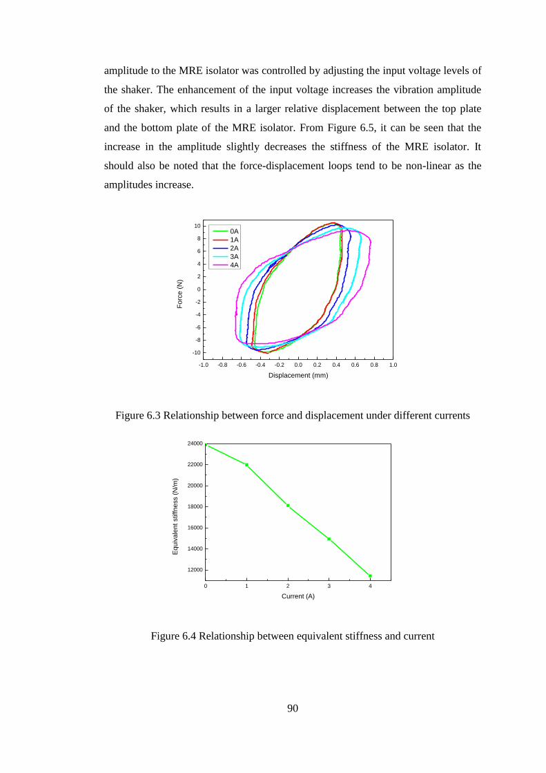
90
amplitude to the MRE isolator was controlled by adjusting the input voltage levels of
the shaker. The enhancement of the input voltage increases the vibration amplitude
of the shaker, which results in a larger relative displacement between the top plate
and the bottom plate of the MRE isolator. From Figure 6.5, it can be seen that the
increase in the amplitude slightly decreases the stiffness of the MRE isolator. It
should also be noted that the force-displacement loops tend to be non-linear as the
amplitudes increase.
-1.0 -0.8 -0.6 -0.4 -0.2 0.0 0.2 0.4 0.6 0.8 1.0
-10
-8
-6
-4
-2
0
2
4
6
8
10
Fo
rce
(N
)
Displacement (mm)
0A
1A
2A
3A
4A
Figure 6.3 Relationship between force and displacement under different currents
0 1 2 3 4
12000
14000
16000
18000
20000
22000
24000
Eq
uiv
ale
nt stiffn
ess (
N/m
)
Current (A)
Figure 6.4 Relationship between equivalent stiffness and current
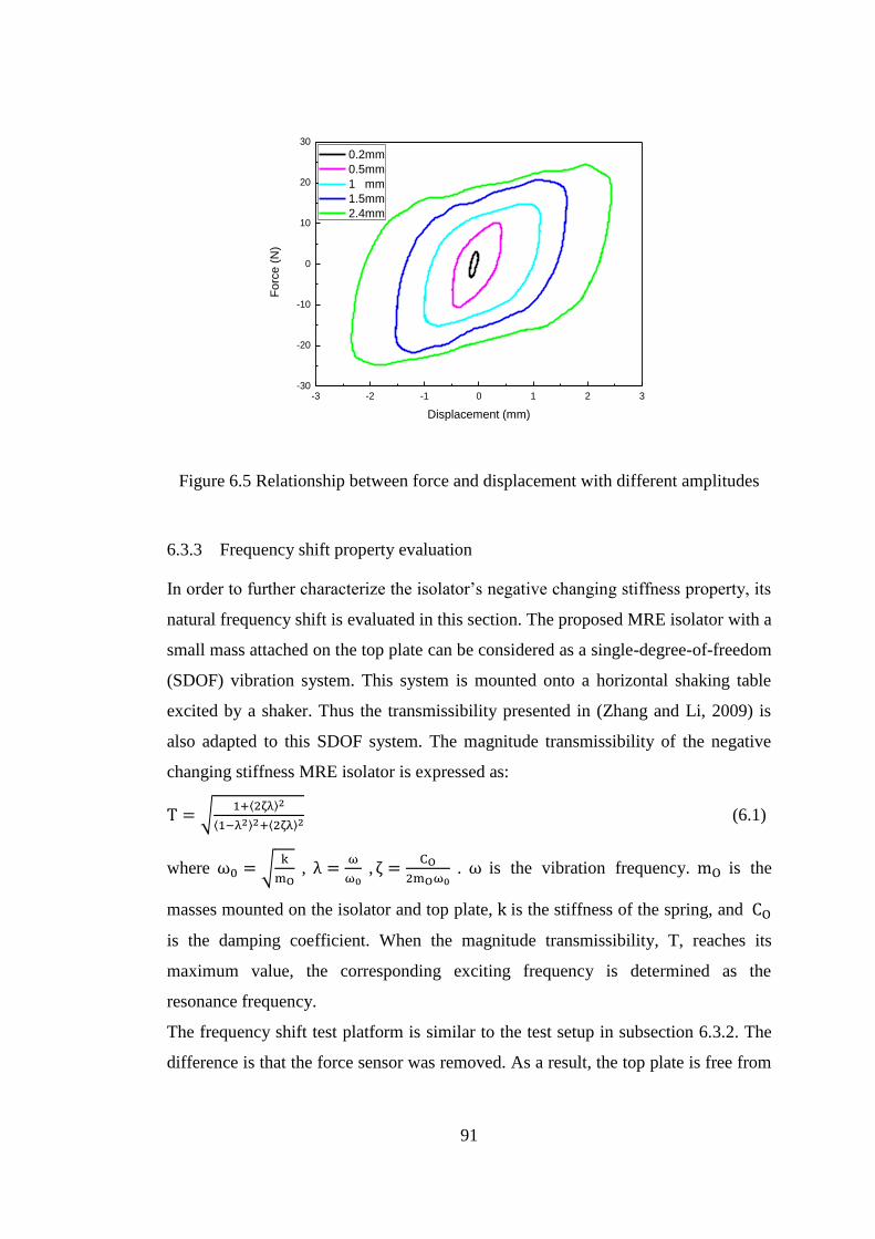
91
-3 -2 -1 0 1 2 3-30
-20
-10
0
10
20
30
Fo
rce
(N
)
Displacement (mm)
0.2mm
0.5mm
1 mm
1.5mm
2.4mm
Figure 6.5 Relationship between force and displacement with different amplitudes
6.3.3 Frequency shift property evaluation
In order to further characterize the isolator’s negative changing stiffness property, its
natural frequency shift is evaluated in this section. The proposed MRE isolator with a
small mass attached on the top plate can be considered as a single-degree-of-freedom
(SDOF) vibration system. This system is mounted onto a horizontal shaking table
excited by a shaker. Thus the transmissibility presented in (Zhang and Li, 2009) is
also adapted to this SDOF system. The magnitude transmissibility of the negative
changing stiffness MRE isolator is expressed as:
T = √1+⟨2ζλ⟩2
⟨1−λ2⟩2+⟨2ζλ⟩2 (6.1)
where ω0 = √k
mO , λ =
ω
ω0 , ζ =
CO
2mOω0 . ω is the vibration frequency. mO is the
masses mounted on the isolator and top plate, k is the stiffness of the spring, and CO
is the damping coefficient. When the magnitude transmissibility, T, reaches its
maximum value, the corresponding exciting frequency is determined as the
resonance frequency.
The frequency shift test platform is similar to the test setup in subsection 6.3.2. The
difference is that the force sensor was removed. As a result, the top plate is free from

92
the fixed rig. Two accelerometers were used to replace the laser sensor to measure
the accelerations of the top and bottom plates of the MRE isolator.
Five currents, 0A, 1A, 2A, 3A, 4A, were applied to the MRE isolator in this
experiment. Figure 6.6 illustrates the transmissibility of the MRE isolator. This
figure shows that as the current varies from 0A to 4A, the natural frequency of the
negative MRE isolator decreases from 32Hz to 21Hz. The test result shows that the
increase in current decreases the natural frequency of the MRE isolator, which means
that the stiffness declines when the current increases.
10 20 30 40 500.0
0.5
1.0
1.5
2.0
2.5
3.0
3.5
4.0
Tra
nsm
issib
ility
Frequency (Hz)
0A
1A
2A
3A
4A
Figure 6.6 Transmissibility of the MRE isolator under different currents
6.4 Vibration suppression evaluation of seat suspension mounted with four
MRE isolators
6.4.1 Structure of the seat suspension mounted with MRE isolators
The structure of the seat suspension is illustrated in Figure 6.7. This seat suspension
consists of two parts: the vertical vibration control part and the horizontal vibration
control part. The structure of the vertical part is the same as a commercial seat
suspension which has leaf springs and dampers. The leaf springs are mainly used to
support the weight of the driver while the dampers are used to further suppress the
vibration of the seat in the vertical direction. In the horizontal part, four MRE
isolators are mounted between the vertical part and the cushion. In this way, the
horizontal vibration can be controlled by adjusting the stiffness of the MRE isolators.
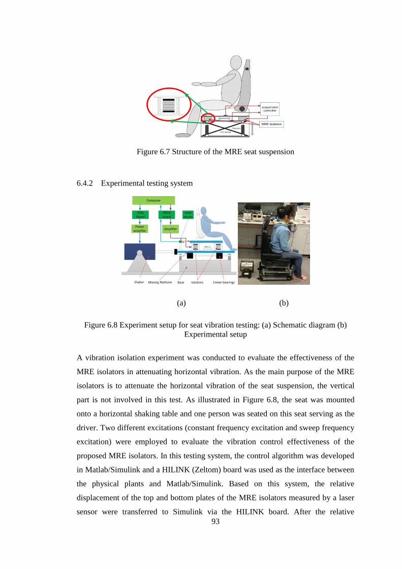
93
Figure 6.7 Structure of the MRE seat suspension
6.4.2 Experimental testing system
(a) (b)
Figure 6.8 Experiment setup for seat vibration testing: (a) Schematic diagram (b)
Experimental setup
A vibration isolation experiment was conducted to evaluate the effectiveness of the
MRE isolators in attenuating horizontal vibration. As the main purpose of the MRE
isolators is to attenuate the horizontal vibration of the seat suspension, the vertical
part is not involved in this test. As illustrated in Figure 6.8, the seat was mounted
onto a horizontal shaking table and one person was seated on this seat serving as the
driver. Two different excitations (constant frequency excitation and sweep frequency
excitation) were employed to evaluate the vibration control effectiveness of the
proposed MRE isolators. In this testing system, the control algorithm was developed
in Matlab/Simulink and a HILINK (Zeltom) board was used as the interface between
the physical plants and Matlab/Simulink. Based on this system, the relative
displacement of the top and bottom plates of the MRE isolators measured by a laser
sensor were transferred to Simulink via the HILINK board. After the relative
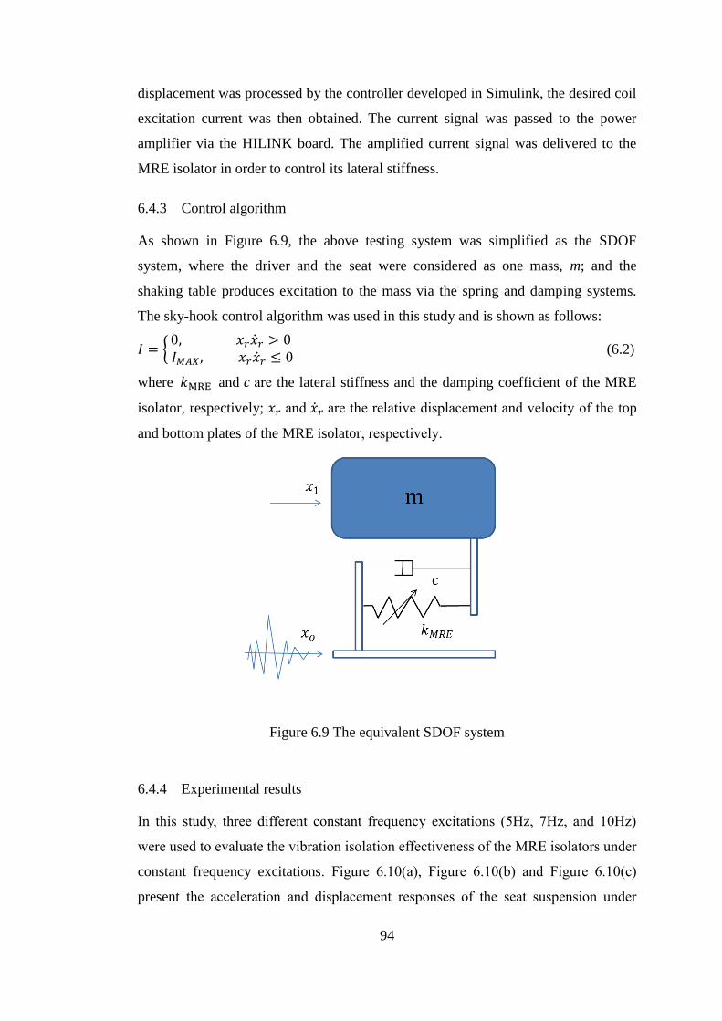
94
displacement was processed by the controller developed in Simulink, the desired coil
excitation current was then obtained. The current signal was passed to the power
amplifier via the HILINK board. The amplified current signal was delivered to the
MRE isolator in order to control its lateral stiffness.
6.4.3 Control algorithm
As shown in Figure 6.9, the above testing system was simplified as the SDOF
system, where the driver and the seat were considered as one mass, m; and the
shaking table produces excitation to the mass via the spring and damping systems.
The sky-hook control algorithm was used in this study and is shown as follows:
𝐼 = {0, 𝑥𝑟�̇�𝑟 > 0 𝐼𝑀𝐴𝑋 , 𝑥𝑟�̇�𝑟 ≤ 0
(6.2)
where 𝑘MRE and 𝑐 are the lateral stiffness and the damping coefficient of the MRE
isolator, respectively; 𝑥𝑟 and �̇�𝑟 are the relative displacement and velocity of the top
and bottom plates of the MRE isolator, respectively.
Figure 6.9 The equivalent SDOF system
6.4.4 Experimental results
In this study, three different constant frequency excitations (5Hz, 7Hz, and 10Hz)
were used to evaluate the vibration isolation effectiveness of the MRE isolators under
constant frequency excitations. Figure 6.10(a), Figure 6.10(b) and Figure 6.10(c)
present the acceleration and displacement responses of the seat suspension under
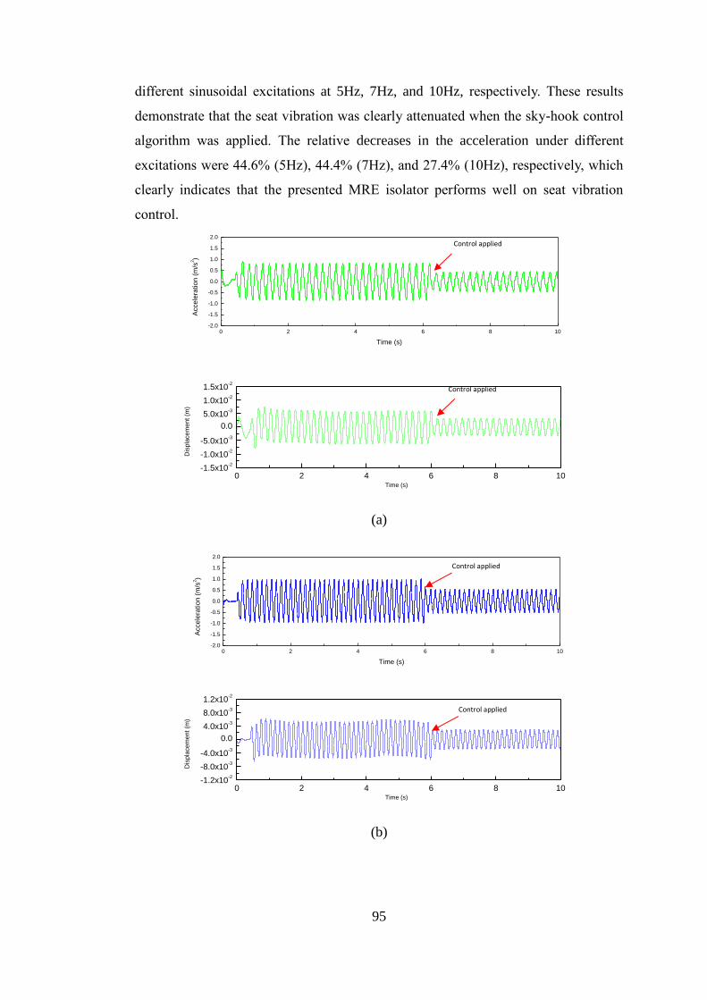
95
different sinusoidal excitations at 5Hz, 7Hz, and 10Hz, respectively. These results
demonstrate that the seat vibration was clearly attenuated when the sky-hook control
algorithm was applied. The relative decreases in the acceleration under different
excitations were 44.6% (5Hz), 44.4% (7Hz), and 27.4% (10Hz), respectively, which
clearly indicates that the presented MRE isolator performs well on seat vibration
control.
0 2 4 6 8 10-1.5x10
-2
-1.0x10⁻²
-5.0x10⁻³
0.0
5.0x10⁻³
1.0x10⁻²
1.5x10⁻²
Dis
pla
cem
ent
(m)
Time (s)
(a)
0 2 4 6 8 10-1.2x10
-2
-8.0x10⁻³
-4.0x10⁻³
0.0
4.0x10⁻³
8.0x10⁻³
1.2x10⁻²
Dis
pla
cem
ent
(m)
Time (s)
(b)
0 2 4 6 8 10-2.0
-1.5
-1.0
-0.5
0.0
0.5
1.0
1.5
2.0
Acce
lera
tio
n (
m/s
2)
Time (s)
0 2 4 6 8 10-2.0
-1.5
-1.0
-0.5
0.0
0.5
1.0
1.5
2.0
Acce
lera
tio
n (
m/s
2)
Time (s)
Control applied
Control applied
Control applied
Control applied
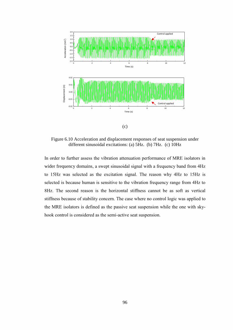
96
0 2 4 6 8 10 12-0.02
-0.01
0.00
0.01
0.02
Dis
pla
ce
me
nt (m
)
Time (s)
(c)
Figure 6.10 Acceleration and displacement responses of seat suspension under
different sinusoidal excitations: (a) 5Hz. (b) 7Hz. (c) 10Hz
In order to further assess the vibration attenuation performance of MRE isolators in
wider frequency domains, a swept sinusoidal signal with a frequency band from 4Hz
to 15Hz was selected as the excitation signal. The reason why 4Hz to 15Hz is
selected is because human is sensitive to the vibration frequency range from 4Hz to
8Hz. The second reason is the horizontal stiffness cannot be as soft as vertical
stiffness because of stability concern. The case where no control logic was applied to
the MRE isolators is defined as the passive seat suspension while the one with sky-
hook control is considered as the semi-active seat suspension.
0 2 4 6 8 10 12-2.0
-1.5
-1.0
-0.5
0.0
0.5
1.0
1.5
2.0
Acce
lera
tio
n (
m/s
2)
Time (s)
Control applied
Control applied
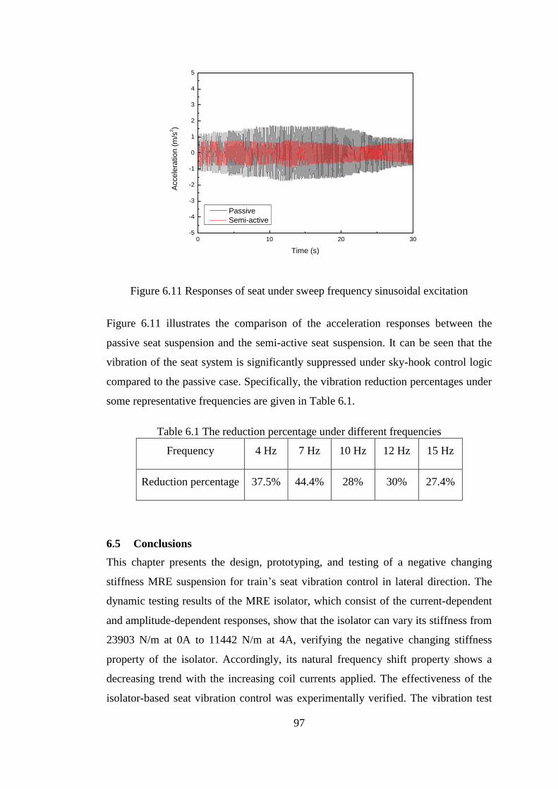
97
Figure 6.11 Responses of seat under sweep frequency sinusoidal excitation
Figure 6.11 illustrates the comparison of the acceleration responses between the
passive seat suspension and the semi-active seat suspension. It can be seen that the
vibration of the seat system is significantly suppressed under sky-hook control logic
compared to the passive case. Specifically, the vibration reduction percentages under
some representative frequencies are given in Table 6.1.
Table 6.1 The reduction percentage under different frequencies
Frequency 4 Hz 7 Hz 10 Hz 12 Hz 15 Hz
Reduction percentage 37.5% 44.4% 28% 30% 27.4%
6.5 Conclusions
This chapter presents the design, prototyping, and testing of a negative changing
stiffness MRE suspension for train’s seat vibration control in lateral direction. The
dynamic testing results of the MRE isolator, which consist of the current-dependent
and amplitude-dependent responses, show that the isolator can vary its stiffness from
23903 N/m at 0A to 11442 N/m at 4A, verifying the negative changing stiffness
property of the isolator. Accordingly, its natural frequency shift property shows a
decreasing trend with the increasing coil currents applied. The effectiveness of the
isolator-based seat vibration control was experimentally verified. The vibration test
0 10 20 30-5
-4
-3
-2
-1
0
1
2
3
4
5
Accele
ratio
n (
m/s
2)
Time (s)
Passive
Semi-active
98
result of a real seat suspension employing four MRE isolators clearly demonstrates
that negative changing stiffness MRE suspension can suppress the seat vibration
more effectively and offer better ride comfort than the passive isolation suspension.
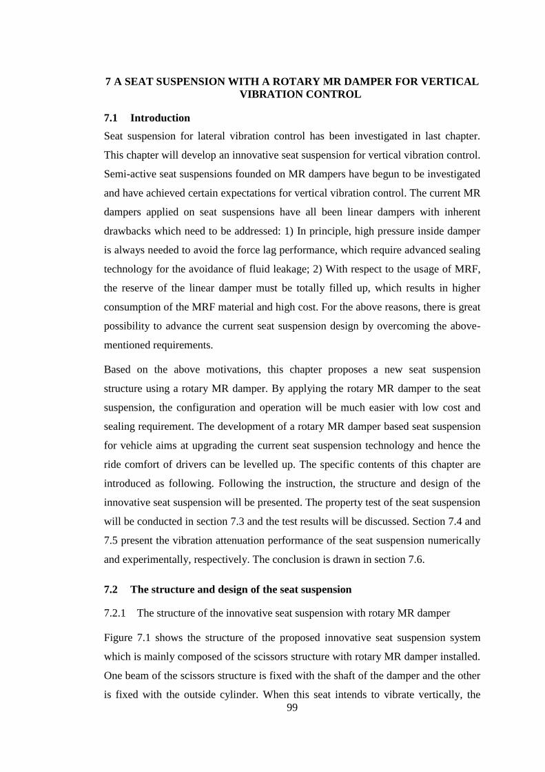
99
7 A SEAT SUSPENSION WITH A ROTARY MR DAMPER FOR VERTICAL
VIBRATION CONTROL
7.1 Introduction
Seat suspension for lateral vibration control has been investigated in last chapter.
This chapter will develop an innovative seat suspension for vertical vibration control.
Semi-active seat suspensions founded on MR dampers have begun to be investigated
and have achieved certain expectations for vertical vibration control. The current MR
dampers applied on seat suspensions have all been linear dampers with inherent
drawbacks which need to be addressed: 1) In principle, high pressure inside damper
is always needed to avoid the force lag performance, which require advanced sealing
technology for the avoidance of fluid leakage; 2) With respect to the usage of MRF,
the reserve of the linear damper must be totally filled up, which results in higher
consumption of the MRF material and high cost. For the above reasons, there is great
possibility to advance the current seat suspension design by overcoming the above-
mentioned requirements.
Based on the above motivations, this chapter proposes a new seat suspension
structure using a rotary MR damper. By applying the rotary MR damper to the seat
suspension, the configuration and operation will be much easier with low cost and
sealing requirement. The development of a rotary MR damper based seat suspension
for vehicle aims at upgrading the current seat suspension technology and hence the
ride comfort of drivers can be levelled up. The specific contents of this chapter are
introduced as following. Following the instruction, the structure and design of the
innovative seat suspension will be presented. The property test of the seat suspension
will be conducted in section 7.3 and the test results will be discussed. Section 7.4 and
7.5 present the vibration attenuation performance of the seat suspension numerically
and experimentally, respectively. The conclusion is drawn in section 7.6.
7.2 The structure and design of the seat suspension
7.2.1 The structure of the innovative seat suspension with rotary MR damper
Figure 7.1 shows the structure of the proposed innovative seat suspension system
which is mainly composed of the scissors structure with rotary MR damper installed.
One beam of the scissors structure is fixed with the shaft of the damper and the other
is fixed with the outside cylinder. When this seat intends to vibrate vertically, the
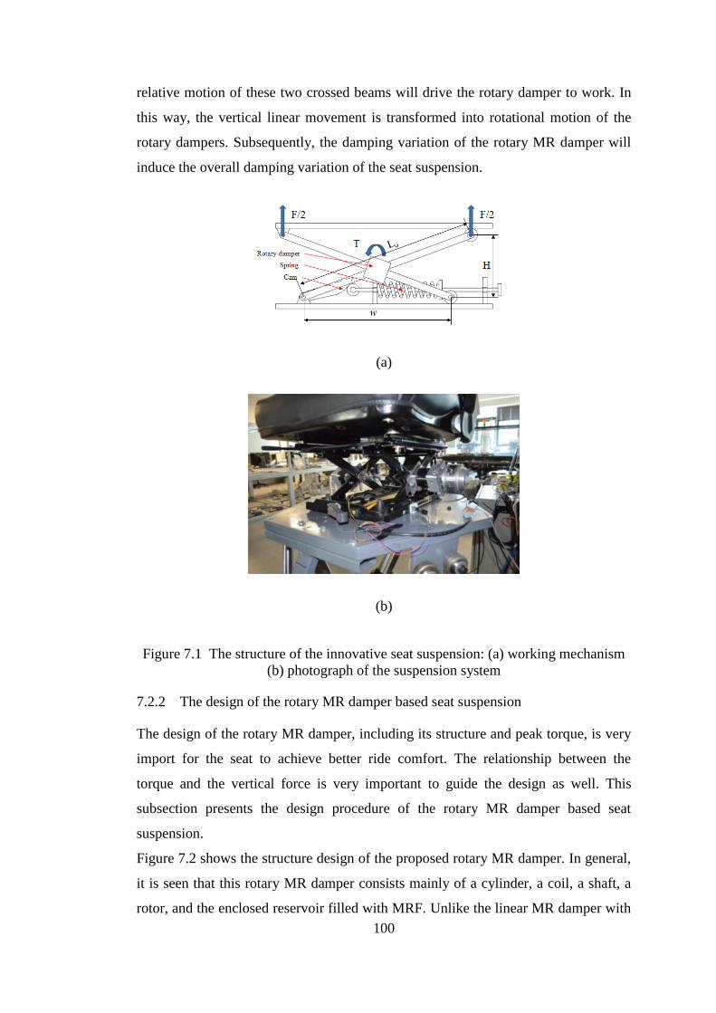
100
relative motion of these two crossed beams will drive the rotary damper to work. In
this way, the vertical linear movement is transformed into rotational motion of the
rotary dampers. Subsequently, the damping variation of the rotary MR damper will
induce the overall damping variation of the seat suspension.
(a)
(b)
Figure 7.1 The structure of the innovative seat suspension: (a) working mechanism
(b) photograph of the suspension system
7.2.2 The design of the rotary MR damper based seat suspension
The design of the rotary MR damper, including its structure and peak torque, is very
import for the seat to achieve better ride comfort. The relationship between the
torque and the vertical force is very important to guide the design as well. This
subsection presents the design procedure of the rotary MR damper based seat
suspension.
Figure 7.2 shows the structure design of the proposed rotary MR damper. In general,
it is seen that this rotary MR damper consists mainly of a cylinder, a coil, a shaft, a
rotor, and the enclosed reservoir filled with MRF. Unlike the linear MR damper with

101
single shaft, the rotary MR damper does not need a spring or gas chamber to provide
the initial pressure in the damper. The rotor is made of low-carbon steel and the shaft
is made of aluminium. The choice of material for different parts is under the
consideration of magnetic circuit design. The coil is composed by winding the
copper wire around the rotor. When the coil is energized, two sets of magnetic circuit
are formed as is shown in Figure 7.2. This magnetic circuit design guarantees that the
magnetic flux passes through MRF.
Figure 7.2 The structure of the rotary MR damper
The peak torque is the most important index for the rotary MR damper design and
directly determines the ride comfort of the seat suspension. The calculation method is
shown as following [124]:
𝑇𝜏 =4𝜋𝜇𝑒𝑞𝑅𝑜
4
(𝑛𝑒 + 3)𝑑[1 − (
𝑅𝑖
𝑅𝑜)𝑛𝑒+3] 𝛺 +
4𝜋𝜏𝑦𝑒
3(𝑅𝑜
3 − 𝑅𝑖3)
+2𝜋𝑅𝑜2𝐿𝑎(𝜏𝑦𝑎 + 𝐾𝑎(
𝛺𝑅𝑂
𝑑𝑜)𝑛𝑎) (7.1)
𝑇𝜏𝑜 =4𝜋𝜇𝑒𝑞𝑜𝑅𝑜
4
(𝑛𝑜 + 3)𝑑[1 − (
𝑅𝑖
𝑅𝑜)𝑛𝑜+3] 𝛺 +
4𝜋𝜏𝑜
3(𝑅𝑜
3 − 𝑅𝑖3)
+2𝜋𝑅𝑜2𝑤𝑑(𝜏𝑜 + 𝐾𝑜(
𝛺𝑅𝑂
𝑑𝑜)𝑛𝑜) (7.2)
where 𝑇𝜏 is the torque with magnetic field and 𝑇𝜏𝑜 is the torque without magnetic
field. 𝜏𝑦𝑒, 𝐾𝑒, and 𝑛𝑒, are yield stress, the consistency and the behaviour index of the
MRF in the end-face duct. 𝜇𝑒𝑞 , governed by 𝜇𝑒𝑞 = 𝐾𝑒 (𝑅𝑜𝛺
𝑑)𝑛𝑒−1, is the equivalent
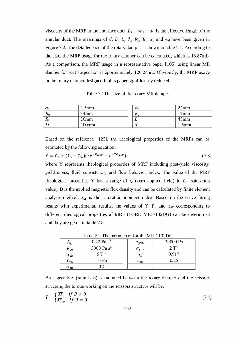
102
viscosity of the MRF in the end-face duct. La ≅ 𝑤d − 𝑤c is the effective length of the
annular duct. The meanings of d, D, L, do, Ro, Ri, wc and wd have been given in
Figure 7.2. The detailed size of the rotary damper is shown in table 7.1. According to
the size, the MRF usage for the rotary damper can be calculated, which is 13.87mL.
As a comparison, the MRF usage in a representative paper [105] using linear MR
damper for seat suspension is approximately 126.24mL. Obviously, the MRF usage
in the rotary damper designed in this paper significantly reduced.
Table 7.1The size of the rotary MR damper
do 1.5mm wc 22mm
Ro 34mm wd 12mm
Ri 20mm L 45mm
D 100mm d 1.5mm
Based on the reference [125], the rheological properties of the MRFs can be
estimated by the following equation:
Y = 𝑌∞ + (𝑌𝑜 − 𝑌∞)(2𝑒−𝐵𝛼𝑆𝑌 − 𝑒−2𝐵𝛼𝑆𝑌) (7.3)
where Y represents rheological properties of MRF including post-yield viscosity,
yield stress, fluid consistency, and flow behavior index. The value of the MRF
rheological properties Y has a range of 𝑌𝑜 (zero applied field) to 𝑌∞ (saturation
value). B is the applied magnetic flux density and can be calculated by finite element
analysis method. 𝛼𝑆𝑌 is the saturation moment index. Based on the curve fitting
results with experimental results, the values of Y, 𝑌∞ and 𝛼𝑆𝑌 corresponding to
different rheological properties of MRF (LORD MRF-132DG) can be determined
and they are given in table 7.2.
Table 7.2 The parameters for the MRF-132DG
𝐾𝑂 0.22 Pa sn 𝜏𝑦∞ 30000 Pa
𝐾∞ 3900 Pa sn 𝛼𝑠𝑡𝑦 2 T
-1
𝛼𝑠𝑘 5 T-1
𝑛𝑂 0.917
𝜏𝑦𝑂 10 Pa 𝑛∞ 0.25
𝛼𝑠𝑛 32
As a gear box (ratio is 8) is mounted between the rotary damper and the scissors
structure, the torque working on the scissors structure will be:
𝑇 = {8𝑇𝜏 𝑖𝑓 𝐵 ≠ 08𝑇𝜏𝑜 𝑖𝑓 𝐵 = 0 (7.4)
103
The relationship between the MR damper torque and the vertical damping force
working on seat suspension is essential to guide the seat suspension design. Figure
7.1 shows the geometry of the seat suspension and the relationship between the MR
damper torque T and vertical damping force 𝑓𝑀𝑅𝐹 can be obtained as:
𝑓𝑀𝑅𝐹 = 2𝑇/w = 2𝑇/ √𝐿𝑜2 − H2 (7.5)
where Lo is the length of the beam of scissor structure, H is the height of the
suspension. Lo is a constant value of 0.287 m, and H can be measured in real-time.
Thus the overall force generated by the seat suspension can be obtained by:
Fz = 𝑘𝑥 + 𝑓r + 𝑓𝑀𝑅𝐹 (7.6)
where k is the stiffness of the seat suspension, x is the displacement of the seat
suspension, fr is the friction force.
In summary, the above section provides the design principle which will offer useful
guideline for the seat suspension design with rotary MR damper. The comparison of
the calculation pick force with the tested peak force is shown in Figure 7.4.
7.3 The property test of the seat suspension and results discussion
7.3.1 Testing method
The dynamic properties of the seat suspension system is tested and evaluated in this
section in terms of its field-dependent responses, amplitude, and frequency-
dependent performances. The seat suspension was fixed onto a computer-controlled
MTS machine (Load Frame Model: 370.02, MTS Systems Corporation). A DC
power with two channels was ready to energize the magnetic fields of the specimen
whenever needed. Once the testing started, the specimen moved in accordance with
the preprogramed sinusoidal routine.
7.3.2 Test results
A series of experimental tests were conducted to evaluate and characterize the
performance of the innovative seat suspension using the above described
experimental setup. For field-dependent tests, various harmonic inputs under
different current levels, which are used to energize the magnetic field working on the
MRF, were chosen to load this seat suspension. The properties of variable damping
can be observed in Figure 7.3(a). It is seen that the force-displacement relationships
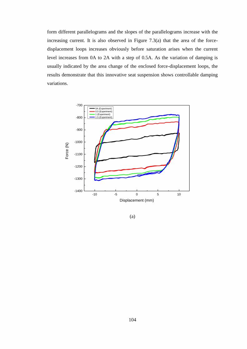
104
form different parallelograms and the slopes of the parallelograms increase with the
increasing current. It is also observed in Figure 7.3(a) that the area of the force-
displacement loops increases obviously before saturation arises when the current
level increases from 0A to 2A with a step of 0.5A. As the variation of damping is
usually indicated by the area change of the enclosed force-displacement loops, the
results demonstrate that this innovative seat suspension shows controllable damping
variations.
-10 -5 0 5 10-1400
-1300
-1200
-1100
-1000
-900
-800
-700
Fo
rce
(N
)
Displacement (mm)
0A (Experiment)
0.5 (Experiment)
1 (Experiment)
1.5 (Experiment)
(a)
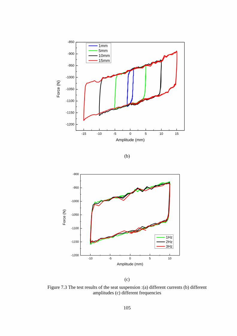
105
-15 -10 -5 0 5 10 15
-1200
-1150
-1100
-1050
-1000
-950
-900
-850
Fo
rce
(N
)
Amplitude (mm)
1mm
5mm
10mm
15mm
(b)
-10 -5 0 5 10-1200
-1150
-1100
-1050
-1000
-950
-900
Fo
rce
(N
)
Amplitude (mm)
1Hz
2Hz
3Hz
(c)
Figure 7.3 The test results of the seat suspension :(a) different currents (b) different
amplitudes (c) different frequencies
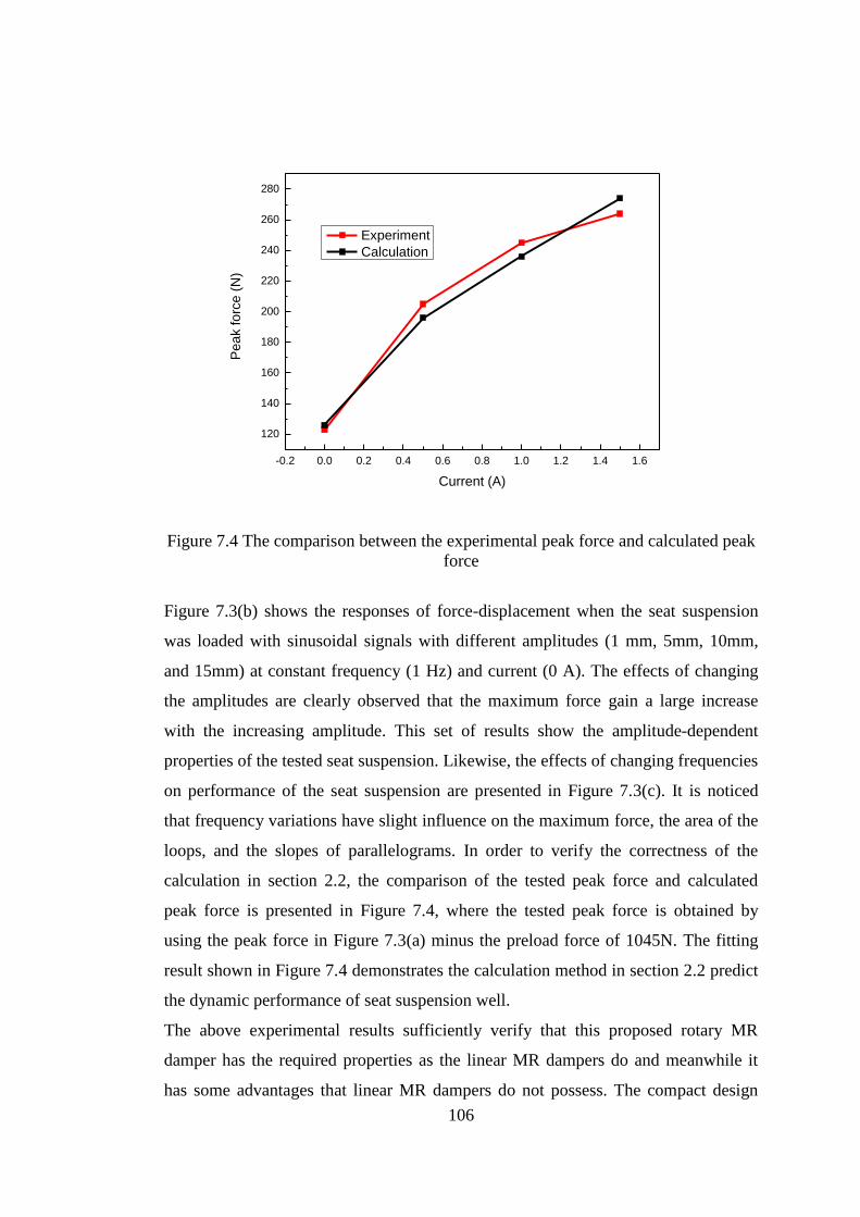
106
-0.2 0.0 0.2 0.4 0.6 0.8 1.0 1.2 1.4 1.6
120
140
160
180
200
220
240
260
280
Pe
ak fo
rce
(N
)
Current (A)
Experiment
Calculation
Figure 7.4 The comparison between the experimental peak force and calculated peak
force
Figure 7.3(b) shows the responses of force-displacement when the seat suspension
was loaded with sinusoidal signals with different amplitudes (1 mm, 5mm, 10mm,
and 15mm) at constant frequency (1 Hz) and current (0 A). The effects of changing
the amplitudes are clearly observed that the maximum force gain a large increase
with the increasing amplitude. This set of results show the amplitude-dependent
properties of the tested seat suspension. Likewise, the effects of changing frequencies
on performance of the seat suspension are presented in Figure 7.3(c). It is noticed
that frequency variations have slight influence on the maximum force, the area of the
loops, and the slopes of parallelograms. In order to verify the correctness of the
calculation in section 2.2, the comparison of the tested peak force and calculated
peak force is presented in Figure 7.4, where the tested peak force is obtained by
using the peak force in Figure 7.3(a) minus the preload force of 1045N. The fitting
result shown in Figure 7.4 demonstrates the calculation method in section 2.2 predict
the dynamic performance of seat suspension well.
The above experimental results sufficiently verify that this proposed rotary MR
damper has the required properties as the linear MR dampers do and meanwhile it
has some advantages that linear MR dampers do not possess. The compact design
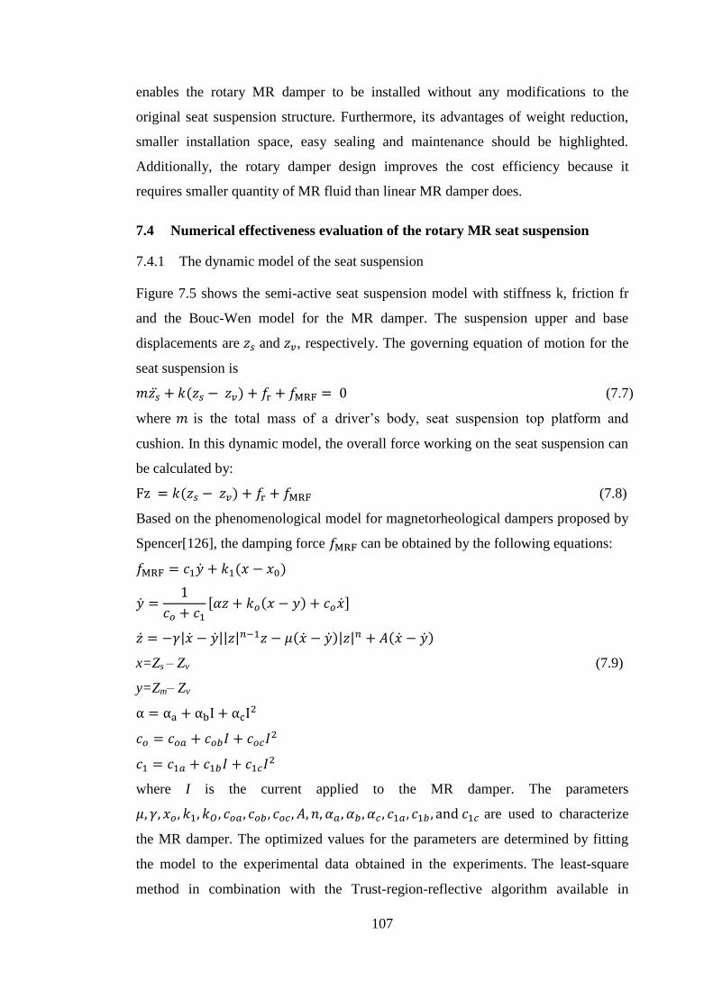
107
enables the rotary MR damper to be installed without any modifications to the
original seat suspension structure. Furthermore, its advantages of weight reduction,
smaller installation space, easy sealing and maintenance should be highlighted.
Additionally, the rotary damper design improves the cost efficiency because it
requires smaller quantity of MR fluid than linear MR damper does.
7.4 Numerical effectiveness evaluation of the rotary MR seat suspension
7.4.1 The dynamic model of the seat suspension
Figure 7.5 shows the semi-active seat suspension model with stiffness k, friction fr
and the Bouc-Wen model for the MR damper. The suspension upper and base
displacements are 𝑧𝑠 and 𝑧𝑣, respectively. The governing equation of motion for the
seat suspension is
𝑚𝑧�̈� + 𝑘(𝑧𝑠 − 𝑧𝑣) + 𝑓r + 𝑓MRF = 0 (7.7)
where 𝑚 is the total mass of a driver’s body, seat suspension top platform and
cushion. In this dynamic model, the overall force working on the seat suspension can
be calculated by:
Fz = 𝑘(𝑧𝑠 − 𝑧𝑣) + 𝑓r + 𝑓MRF (7.8)
Based on the phenomenological model for magnetorheological dampers proposed by
Spencer[126], the damping force 𝑓MRF can be obtained by the following equations:
𝑓MRF = 𝑐1�̇� + 𝑘1(𝑥 − 𝑥0)
�̇� =1
𝑐𝑜 + 𝑐1
[𝛼𝑧 + 𝑘𝑜(𝑥 − 𝑦) + 𝑐𝑜�̇�]
�̇� = −𝛾|�̇� − �̇�||𝑧|𝑛−1𝑧 − 𝜇(�̇� − �̇�)|𝑧|𝑛 + 𝐴(�̇� − �̇�)
x=Zs – Zv (7.9)
y=Zm– Zv
α = αa + αbI + αcI2
𝑐𝑜 = 𝑐𝑜𝑎 + 𝑐𝑜𝑏𝐼 + 𝑐𝑜𝑐𝐼2
𝑐1 = 𝑐1𝑎 + 𝑐1𝑏𝐼 + 𝑐1𝑐𝐼2
where I is the current applied to the MR damper. The parameters
𝜇, 𝛾, 𝑥𝑜 , 𝑘1, 𝑘𝑂 , 𝑐𝑜𝑎, 𝑐𝑜𝑏 , 𝑐𝑜𝑐, 𝐴, 𝑛, 𝛼𝑎, 𝛼𝑏 , 𝛼𝑐 , 𝑐1𝑎, 𝑐1𝑏 , and 𝑐1𝑐 are used to characterize
the MR damper. The optimized values for the parameters are determined by fitting
the model to the experimental data obtained in the experiments. The least-square
method in combination with the Trust-region-reflective algorithm available in
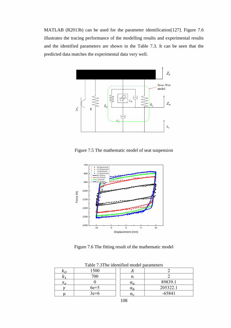
108
MATLAB (R2013b) can be used for the parameter identification[127]. Figure 7.6
illustrates the tracing performance of the modelling results and experimental results
and the identified parameters are shown in the Table 7.3. It can be seen that the
predicted data matches the experimental data very well.
Figure 7.5 The mathematic model of seat suspension
-10 -5 0 5 10-1400
-1300
-1200
-1100
-1000
-900
-800
-700
Fo
rce
(N
)
Displacement (mm)
0A (Experiment)
0.5 (Experiment)
1 (Experiment)
1.5 (Experiment)
0A (Theory)
0.5 (Theory)
1 (Theory)
1.5 (Theory)
Figure 7.6 The fitting result of the mathematic model
Table 7.3The identified model parameters
𝑘𝑂 1500 𝐴 2
𝑘1 700 𝑛 2
𝑥𝑜 0 α𝑎 89839.1
𝛾 6e+5 α𝑏 205322.1
μ 3e+6 α𝑐 -65841
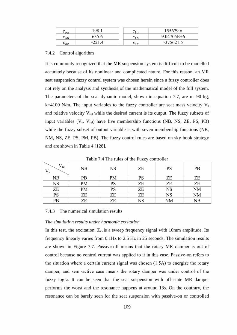
109
𝑐𝑜𝑎 198.1 𝑐1𝑎 155679.6
𝑐𝑜𝑏 635.6 𝑐1𝑏 9.04705E+6
𝑐𝑜𝑐 -221.4 𝑐1𝑐 -375621.5
7.4.2 Control algorithm
It is commonly recognized that the MR suspension system is difficult to be modelled
accurately because of its nonlinear and complicated nature. For this reason, an MR
seat suspension fuzzy control system was chosen herein since a fuzzy controller does
not rely on the analysis and synthesis of the mathematical model of the full system.
The parameters of the seat dynamic model, shown in equation 7.7, are m=90 kg,
k=4100 N/m. The input variables to the fuzzy controller are seat mass velocity Vs
and relative velocity Vrel while the desired current is its output. The fuzzy subsets of
input variables (Vs, Vrel) have five membership functions (NB, NS, ZE, PS, PB)
while the fuzzy subset of output variable is with seven membership functions (NB,
NM, NS, ZE, PS, PM, PB). The fuzzy control rules are based on sky-hook strategy
and are shown in Table 4 [128].
Table 7.4 The rules of the Fuzzy controller
Vrel
Vs NB NS ZE PS PB
NB PB PM PS ZE ZE
NS PM PS ZE ZE ZE
ZE PM PS ZE NS NM
PS ZE ZE ZE NS NM
PB ZE ZE NS NM NB
7.4.3 The numerical simulation results
The simulation results under harmonic excitation
In this test, the excitation, Zv, is a sweep frequency signal with 10mm amplitude. Its
frequency linearly varies from 0.1Hz to 2.5 Hz in 25 seconds. The simulation results
are shown in Figure 7.7. Passive-off means that the rotary MR damper is out of
control because no control current was applied to it in this case. Passive-on refers to
the situation where a certain current signal was chosen (1.5A) to energize the rotary
damper, and semi-active case means the rotary damper was under control of the
fuzzy logic. It can be seen that the seat suspension with off state MR damper
performs the worst and the resonance happens at around 13s. On the contrary, the
resonance can be barely seen for the seat suspension with passive-on or controlled
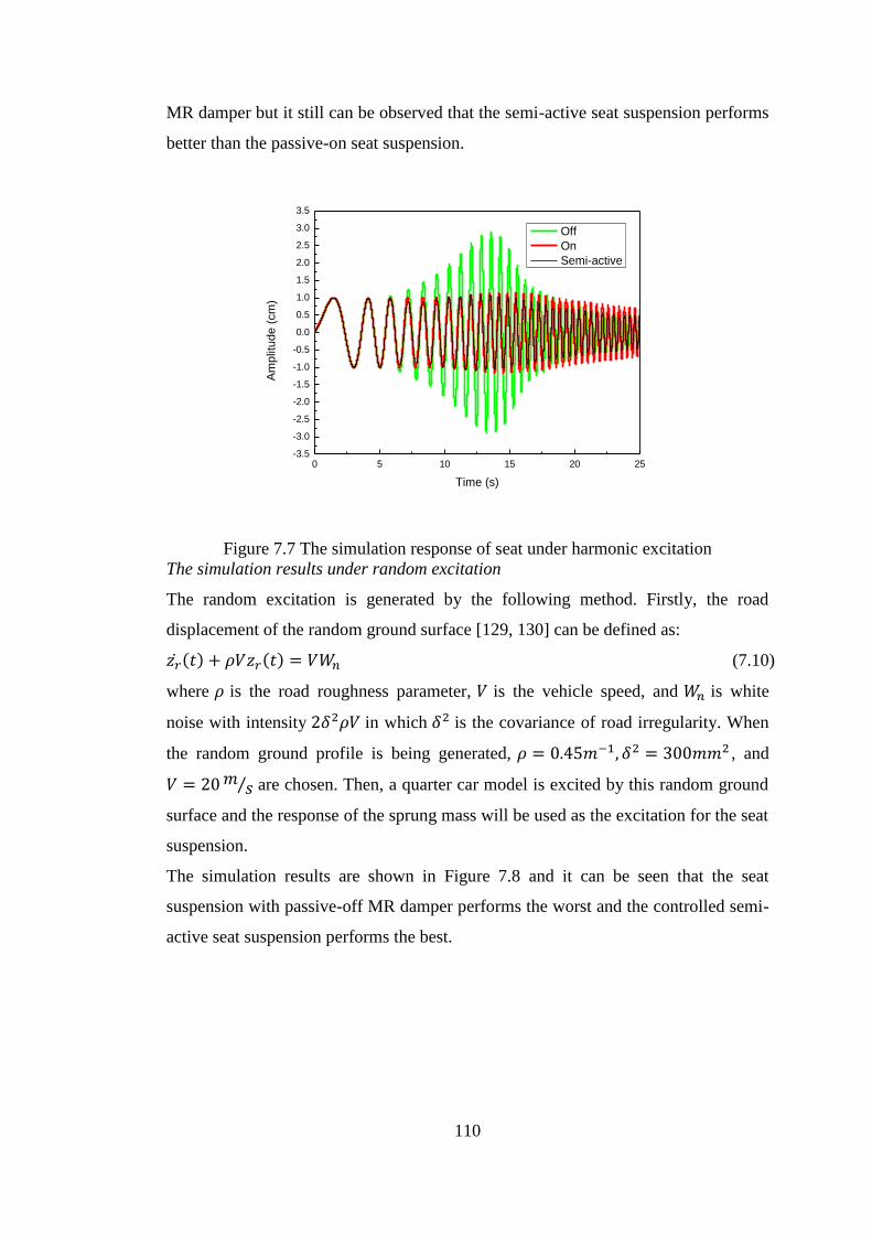
110
MR damper but it still can be observed that the semi-active seat suspension performs
better than the passive-on seat suspension.
0 5 10 15 20 25-3.5
-3.0
-2.5
-2.0
-1.5
-1.0
-0.5
0.0
0.5
1.0
1.5
2.0
2.5
3.0
3.5
Am
plit
ud
e (
cm
)
Time (s)
Off
On
Semi-active
Figure 7.7 The simulation response of seat under harmonic excitation
The simulation results under random excitation
The random excitation is generated by the following method. Firstly, the road
displacement of the random ground surface [129, 130] can be defined as:
𝑧�̇�(𝑡) + 𝜌𝑉𝑧𝑟(𝑡) = 𝑉𝑊𝑛 (7.10)
where 𝜌 is the road roughness parameter, 𝑉 is the vehicle speed, and 𝑊𝑛 is white
noise with intensity 2𝛿2𝜌𝑉 in which 𝛿2 is the covariance of road irregularity. When
the random ground profile is being generated, 𝜌 = 0.45𝑚−1, 𝛿2 = 300𝑚𝑚2 , and
𝑉 = 20 𝑚𝑠⁄ are chosen. Then, a quarter car model is excited by this random ground
surface and the response of the sprung mass will be used as the excitation for the seat
suspension.
The simulation results are shown in Figure 7.8 and it can be seen that the seat
suspension with passive-off MR damper performs the worst and the controlled semi-
active seat suspension performs the best.
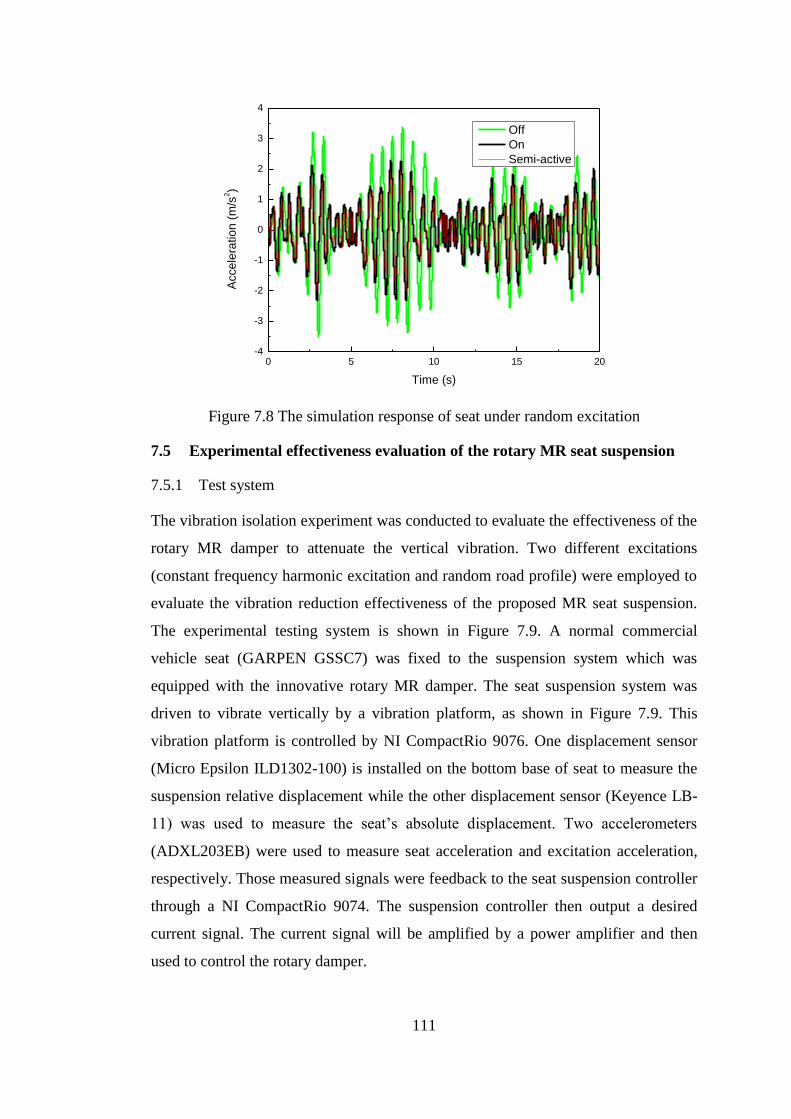
111
Figure 7.8 The simulation response of seat under random excitation
7.5 Experimental effectiveness evaluation of the rotary MR seat suspension
7.5.1 Test system
The vibration isolation experiment was conducted to evaluate the effectiveness of the
rotary MR damper to attenuate the vertical vibration. Two different excitations
(constant frequency harmonic excitation and random road profile) were employed to
evaluate the vibration reduction effectiveness of the proposed MR seat suspension.
The experimental testing system is shown in Figure 7.9. A normal commercial
vehicle seat (GARPEN GSSC7) was fixed to the suspension system which was
equipped with the innovative rotary MR damper. The seat suspension system was
driven to vibrate vertically by a vibration platform, as shown in Figure 7.9. This
vibration platform is controlled by NI CompactRio 9076. One displacement sensor
(Micro Epsilon ILD1302-100) is installed on the bottom base of seat to measure the
suspension relative displacement while the other displacement sensor (Keyence LB-
11) was used to measure the seat’s absolute displacement. Two accelerometers
(ADXL203EB) were used to measure seat acceleration and excitation acceleration,
respectively. Those measured signals were feedback to the seat suspension controller
through a NI CompactRio 9074. The suspension controller then output a desired
current signal. The current signal will be amplified by a power amplifier and then
used to control the rotary damper.
0 5 10 15 20-4
-3
-2
-1
0
1
2
3
4
Accele
ratio
n (
m/s
2)
Time (s)
Off
On
Semi-active
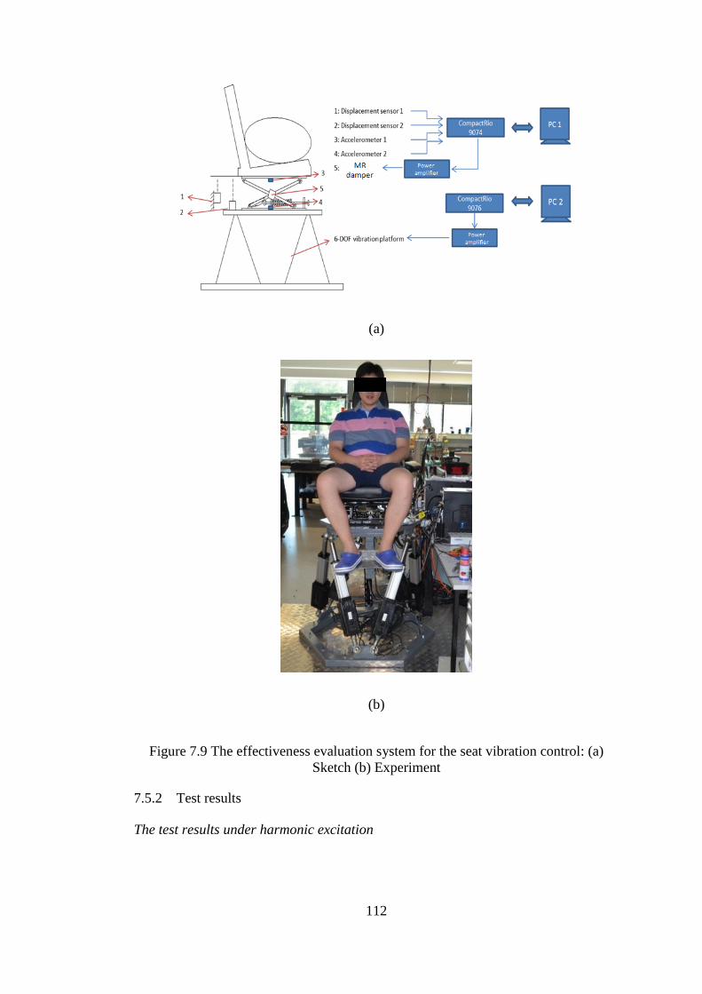
112
(a)
(b)
Figure 7.9 The effectiveness evaluation system for the seat vibration control: (a)
Sketch (b) Experiment
7.5.2 Test results
The test results under harmonic excitation

113
(a)
0 5 10 15 20 25 30 35 40-3
-2
-1
0
1
2
3
Accele
ratio
n (
m/s
2)
Time (s)
Passive-onSemi-activePassive-off
(b)
Figure 7.10 The test results of the MR seat suspension under harmonic excitation: (a)
1.3Hz (b) 1.75Hz
In this test, different harmonic signals with different frequencies were used to excite
the seat suspension. The responses of the seat suspension under two frequencies,
1.3Hz and 1.75Hz, are given as representatives. Figure 7.10(a) and Figure 7.10(b)
present the acceleration responses of the seat suspension under 1.3Hz and 1.75Hz,
0 5 10 15 20 25 30 35-5
-4
-3
-2
-1
0
1
2
3
4
5
Passive-onSemi-active
Acce
lara
tio
n (
m/s
2)
Time (s)
Passive-off
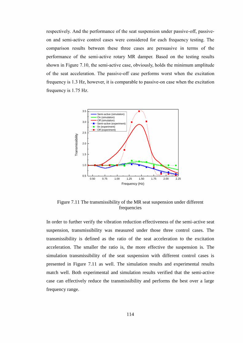
114
respectively. And the performance of the seat suspension under passive-off, passive-
on and semi-active control cases were considered for each frequency testing. The
comparison results between these three cases are persuasive in terms of the
performance of the semi-active rotary MR damper. Based on the testing results
shown in Figure 7.10, the semi-active case, obviously, holds the minimum amplitude
of the seat acceleration. The passive-off case performs worst when the excitation
frequency is 1.3 Hz, however, it is comparable to passive-on case when the excitation
frequency is 1.75 Hz.
0.50 0.75 1.00 1.25 1.50 1.75 2.00 2.250.5
1.0
1.5
2.0
2.5
3.0
3.5
Tra
nsm
issib
ility
Frequency (Hz)
Semi-active (simulation)
On (simulation)
Off (simulation)
Semi-active (experiment)
0n (experiment)
Off (experiment)
Figure 7.11 The transmissibility of the MR seat suspension under different
frequencies
In order to further verify the vibration reduction effectiveness of the semi-active seat
suspension, transmissibility was measured under those three control cases. The
transmissibility is defined as the ratio of the seat acceleration to the excitation
acceleration. The smaller the ratio is, the more effective the suspension is. The
simulation transmissibility of the seat suspension with different control cases is
presented in Figure 7.11 as well. The simulation results and experimental results
match well. Both experimental and simulation results verified that the semi-active
case can effectively reduce the transmissibility and performs the best over a large
frequency range.
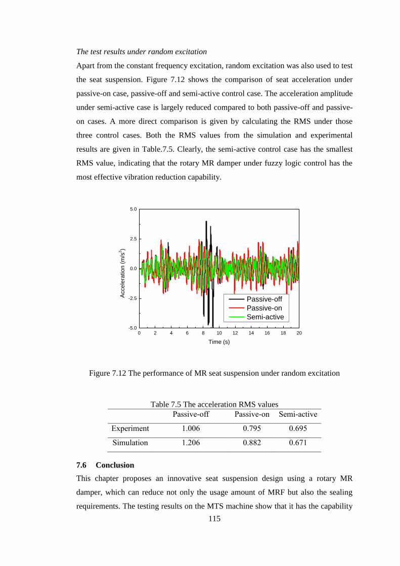
115
The test results under random excitation
Apart from the constant frequency excitation, random excitation was also used to test
the seat suspension. Figure 7.12 shows the comparison of seat acceleration under
passive-on case, passive-off and semi-active control case. The acceleration amplitude
under semi-active case is largely reduced compared to both passive-off and passive-
on cases. A more direct comparison is given by calculating the RMS under those
three control cases. Both the RMS values from the simulation and experimental
results are given in Table.7.5. Clearly, the semi-active control case has the smallest
RMS value, indicating that the rotary MR damper under fuzzy logic control has the
most effective vibration reduction capability.
0 2 4 6 8 10 12 14 16 18 20-5.0
-2.5
0.0
2.5
5.0
Acce
lera
tio
n (
m/s
2)
Time (s)
Passive-off
Passive-on
Semi-active
Figure 7.12 The performance of MR seat suspension under random excitation
Table 7.5 The acceleration RMS values
Passive-off Passive-on Semi-active
Experiment 1.006 0.795 0.695
Simulation 1.206 0.882 0.671
7.6 Conclusion
This chapter proposes an innovative seat suspension design using a rotary MR
damper, which can reduce not only the usage amount of MRF but also the sealing
requirements. The testing results on the MTS machine show that it has the capability
116
to vary damping in response to the current change. Then an evaluation system is
constructed, including the semi-active vehicle seat suspension, the control loop and
vibration platform providing the excitations to this system. The vibration reduction
effectiveness of the seat suspension is evaluated under two kinds of excitations, i.e.
constant frequency excitation and random excitation. For both of the situations, the
seat acceleration under fuzzy logic control holds the minimum value, which verified
the semi-active rotary MR damper based seat suspension performs the best regarding
the vibration attenuation effectiveness.
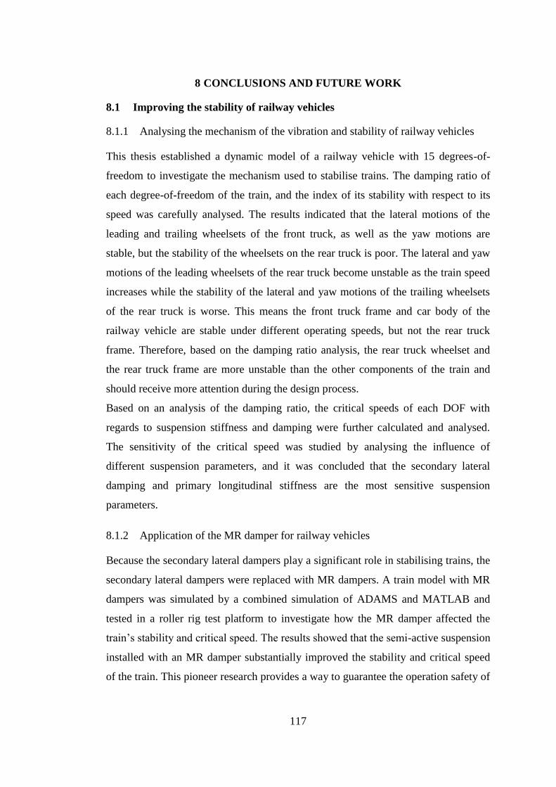
117
8 CONCLUSIONS AND FUTURE WORK
8.1 Improving the stability of railway vehicles
8.1.1 Analysing the mechanism of the vibration and stability of railway vehicles
This thesis established a dynamic model of a railway vehicle with 15 degrees-of-
freedom to investigate the mechanism used to stabilise trains. The damping ratio of
each degree-of-freedom of the train, and the index of its stability with respect to its
speed was carefully analysed. The results indicated that the lateral motions of the
leading and trailing wheelsets of the front truck, as well as the yaw motions are
stable, but the stability of the wheelsets on the rear truck is poor. The lateral and yaw
motions of the leading wheelsets of the rear truck become unstable as the train speed
increases while the stability of the lateral and yaw motions of the trailing wheelsets
of the rear truck is worse. This means the front truck frame and car body of the
railway vehicle are stable under different operating speeds, but not the rear truck
frame. Therefore, based on the damping ratio analysis, the rear truck wheelset and
the rear truck frame are more unstable than the other components of the train and
should receive more attention during the design process.
Based on an analysis of the damping ratio, the critical speeds of each DOF with
regards to suspension stiffness and damping were further calculated and analysed.
The sensitivity of the critical speed was studied by analysing the influence of
different suspension parameters, and it was concluded that the secondary lateral
damping and primary longitudinal stiffness are the most sensitive suspension
parameters.
8.1.2 Application of the MR damper for railway vehicles
Because the secondary lateral dampers play a significant role in stabilising trains, the
secondary lateral dampers were replaced with MR dampers. A train model with MR
dampers was simulated by a combined simulation of ADAMS and MATLAB and
tested in a roller rig test platform to investigate how the MR damper affected the
train’s stability and critical speed. The results showed that the semi-active suspension
installed with an MR damper substantially improved the stability and critical speed
of the train. This pioneer research provides a way to guarantee the operation safety of
118
railway vehicle and has the potential to further improve the operation speed of the
commercialised trains.
8.1.3 Investigation of the MRE rubber joint for train
The conflicting stiffness requirements of the bogie’s rubber joint to keep the curve
passing performance and strain stability have plagued rail designers for decades.
Specifically, the rubber joint is required to be able to provide hard wheelset
positioning stiffness to maintain high speed stability when the train runs on straight
line at high speed and be soft to improve the train’s curve passing performance when
the train runs on curve track at a lower speed. The stiffness controllability of MRE
makes it a potential option to solve this conflict. However, how to embed the MRE to
the bogies to achieve the aim has been a big challenge. This thesis innovatively
proposed and designed an MRE based rubber joint which was capable of providing
variable primary longitudinal stiffness. To be exact, this thesis has successfully
designed, prototyped, and analysed a variable stiffness MRE joint to satisfy the
conflicting requirements. The result proved that the proposed MRE joint could
change its effective stiffness when the applied current was changed. A model train
built with ADMS software was used to evaluate how effectively it could maintain
high speed stability on straight track and good trafficability on a curved track. The
simulated responses of the angle of attack, lateral displacement, the lateral force of
the train running on curved track and the critical speed of train operating on a straight
line indicated that trafficability on a curved track had improved and its high speed
stability was maintained when an MRE joint was used. With the MRE joint
developed in this thesis, the wear between the rail and the wheelset will be mitigated
and subsequently the maintenance cost of the train operation will be reduced.
8.2 Reduced vibration and improved ride comfort of railway vehicles
8.2.1 Compact variable stiffness and damping damper for railway vehicles
According to the literature, the superiority of the variable stiffness and damping
system over the pure stiffness variable or pure damping variable system has been
verified experimentally and numerically. However, it still remains a big challenge to
design such a compact variable stiffness and damping system which is suitable for
railway vehicle. Based on this motivation, an innovative compact MRF damper with
119
variable stiffness and damping was designed, prototyped, tested, and analysed in this
thesis. The shape and size of this advanced MR damper are similar to those of the
traditional damper. In addition, this new damper can easily replace the original bogie
damper. The damper testing has verified that the stiffness and damping properties of
the advanced MRF damper can be controlled; indeed its stiffness and damping can
vary from 8.7kN/m to 24.5kN/m and from 16.24 KN/(m/s) to 29.72 KN/(m/s),
respectively. A mathematical model was then established. These results showed that
the proposed model can accurately predict the dynamic performance of the compact
advanced MR damper, and therefore this successful development makes the variable
stiffness and damping suspension feasible for railway vehicles.
The ability of the variable stiffness and damping suspension system to reduce
vibration was then evaluated numerically. ADAMS/Rail and Matlab/Simulink
software were used to build the train model as well as the control loop to evaluate the
property of the semi-active railway vehicle. The results showed that the variable
stiffness and damping suspension performed better than the passive suspension,
variable stiffness suspension, and variable damping suspension in terms of
attenuating vibrations and improving ride comfort. Furthermore, the application of
the advanced MRF damper developed in this thesis is not limited to railway vehicles.
It is also a good option to be used in many other areas such as automotive vehicle
and building protection from earthquake. It is believed that this proposed variable
stiffness and damping technology has potential to lead a breakthrough in vibration
control field.
8.2.2 Advanced seat suspensions with MR technology
Investigating the advanced seat suspension, as another feasible strategy to improve
ride comfort, also constitutes an important part in this research. Since vibration exists
laterally and vertically, two different seat suspensions used to control lateral and
vertical vibrations were developed, respectively. Regarding the seat suspension for
lateral vibration attenuation, rare research work has been done. The seat suspension
proposed in this thesis for lateral vibration attenuation contained four laminated
MRE isolators. The MRE isolators were tested and found that their stiffness variation
could reach to 109% when the current increased from 0A to 4A. This proved that the
120
MRE isolator can improve ride comfort in a lateral direction better than passive seat
suspension.
As for the seat suspension for vertical vibration, linear MR damper based seat
suspension has been widely studied. However, linear MR damper requires large
amount of MRF to fill up its reservoir, which subsequently increases the suspension
cost. It has always been a priority to reduce the cost. This thesis proposes a new seat
suspension structure using a rotary MR damper. The rotary damper based seat
suspension only utilizes a smaller quantity of MRF because the reservoir of the
rotary MR damper is much smaller than that of a linear one. This advantage
significantly reduces the cost of the seat suspension. An MTS machine was used to
test the seat suspension and verified its damping controllability. After that, a
vibration platform was used to evaluate its vibration attenuation performance and the
testing results demonstrated its excellent capability on vibration control.
In summary, the most important aspect to be considered for developing railway
vehicle is safety and ride comfort as the operating speed is now much closer to the
critical speed. At the critical speed the current system for mitigating vibration may
not function, which is an unavoidable challenge in the development of train
techniques. The development and application of innovative MR technology in this
thesis are believed to significantly contribute to improving the stability and ride
comfort of the railway vehicle and potentially increase the speed of commercial
trains in the future. In addition, the maintenance cost of the train and rail is another
important consideration. The rubber joint developed in this thesis definitely can
reduce the rail and wheelset wear when the train runs on curve track, which
subsequently lower the maintenance cost. In conclusion, the innovation MR
technology developed in this thesis can critically improve train’s dynamic
performance, including its stability, ride comfort and curve passing performance.
There is great chance to commercialise all the achievements in this thesis to further
improve train’s operation speed and reduce its maintenance cost.
8.3 Recommendation for future work
8.3.1 Optimisation of the design of variable stiffness and damping dampers
The result of testing variable stiffness and damping damper verified its capability,
but the damping variation range is approximately 2, which is lower than a mature
121
MR damper even though it can satisfy the requirements for trains. This narrow
damping range is due to the magnetic field being saturated in the shaft of the internal
piston, so the design of the internal damping unit must be improved and optimised.
That means the size of the shaft, the gap between the piston and the cylinder, and the
number of turns in the coil within a certain volume must be optimised to improve the
maximum magnetic flux density in MRF.
8.3.2 Optimise the stiffness variation range of the MRE rubber joint
The stiffness variation range of the MRE joint presented in section 4 is 74.7%, which
satisfies our needs at this stage. But it must be broadened because the storage
modulus of the MRE varied approximately10 times when the magnetic field
increased from 0 mT to 440 mT. There are two methods for carrying out this
optimisation; the first is to optimise the structure of the MRE joint to enhance the
magnetic flux density in MRE, and then use a finite element to optimise the magnetic
field. Another method is to consider other possible structures to change the working
mode of the MRE. The MRE in present design is working in squeeze mode, so
changing it to shear mode with a different structure may improve its stiffness
variation range.
8.3.3 Experimental investigation of a train mounted with variable stiffness and
damping damper or an MRE rubber joint
This thesis has already investigated the use of a conventional MR damper on railway
vehicles. A full scale train mounted with MR damper was tested and analysed, but a
train with variable stiffness and damping dampers or an MRE joint has not been
tested because it is difficult to gain access to a full scale test rig. This would be a
very worthwhile experiment in the author’s opinion.
122
REFERENCES
[1] M. Givoni, "Development and Impact of the Modern High‐speed Train: A
Review," Transport reviews, vol. 26, pp. 593-611, 2006.
[2] C. E. Hanson, J. C. Ross, and D. A. Towers, "High-speed ground
transportation noise and vibration impact assessment," Report, 2012.
[3] R. S. Raghunathan, H. D. Kim, and T. Setoguchi, "Aerodynamics of high-
speed railway train," Progress in Aerospace sciences, vol. 38, pp. 469-514, 2002.
[4] J. Han, Y. Hayashi, P. Jia, and Q. Yuan, "Economic Effect of High-Speed
Rail: Empirical Analysis of Shinkansen’s Impact on Industrial Location," Journal of
Transportation Engineering, vol. 138, pp. 1551-1557, 2012.
[5] K. Sasaki, "A Lateral Semi-Active Suspension of Tilting Train," Quarterly
Report of RTRI, vol. 41, pp. 11-15, 2000.
[6] E. Elbeheiry and D. Karnopp, "Optimal control of vehicle random vibration
with constrained suspension deflection," Journal of sound and vibration, vol. 189, pp.
547-564, 1996.
[7] T. Gordon, "Non-linear optimal control of a semi-active vehicle suspension
system," Chaos, Solitons & Fractals, vol. 5, pp. 1603-1617, 1995.
[8] D. Baiasu, G. Ghita, and I. Sebesan, "Control system with
magnetorheological fluid device for mitigation of the railway vehicle hunting
oscillations," in Journal of Physics: Conference Series, 2013, Art no. 012043.
[9] C. Spelta, S. M. Savaresi, F. Codecà, M. Montiglio, and M. Ieluzzi, "Smart‐
Bogie: Semi‐Active Lateral Control of Railway Vehicles," Asian Journal of
Control, vol. 14, pp. 875-890, 2012.
[10] L.-H. Zong, X.-L. Gong, S.-H. Xuan, and C.-Y. Guo, "Semi-active H∞
control of high-speed railway vehicle suspension with magnetorheological dampers,"
Vehicle System Dynamics, pp. 1-27, 2013.
[11] D. Fischer and R. Isermann, "Mechatronic semi-active and active vehicle
suspensions," Control Engineering Practice, vol. 12, pp. 1353-1367, 2004.
[12] S. Sun, H. Deng, W. Li, H. Du, Y. Q. Ni, J. Zhang, et al., "Improving the
critical speeds of high-speed trains using magnetorheological technology," Smart
Materials and Structures, vol. 22, Art no. 115012, 2013.
[13] H. O'Neill and G. Wale, "Semi-active suspension improves rail vehicle ride,"
Computing & Control Engineering Journal, vol. 5, pp. 183-188, 1994.
123
[14] J. Tang, "Passive and semi-active airspring suspensions for rail passenger
vehicles—theory and practice," Proceedings of the Institution of Mechanical
Engineers, Part F: Journal of Rail and Rapid Transit, vol. 210, pp. 103-117, 1996.
[15] A. Stribersky, A. Kienberger, G. Wagner, and H. Müller, "Design and
evaluation of a semi-active damping system for rail vehicles," Vehicle System
Dynamics, vol. 29, pp. 669-681, 1998.
[16] Y. Suda, R. Anderson, and K. Yamada, "Dynamics of Unsymmetric
Suspension Trucks With Semiactive control," Vehicle System Dynamics, vol. 23, pp.
480-496, 1994.
[17] T. Mei and R. Goodall, "Recent development in active steering of railway
vehicles," Vehicle System Dynamics, vol. 39, pp. 415-436, 2003.
[18] G. Shen and R. Goodall, "Active yaw relaxation for improved bogie
performance," Vehicle System Dynamics, vol. 28, pp. 273-289, 1997.
[19] T. Mei and R. Goodall, "Optimal control strategies for active steering of
railway vehicles," in Proc. IFAC, 1999, pp. 251-256.
[20] T. Mei and R. Goodall, "LQG and GA solutions for active steering of railway
vehicles," IEE Proceedings-Control Theory and Applications, vol. 147, pp. 111-117,
2000.
[21] Y. Suda, "High speed stability and curving performance of longitudinally
unsymmetric trucks with semi-active control," Vehicle System Dynamics, vol. 23,
pp. 29-52, 1994.
[22] Y. Suda, R. Nishimura, N. Kato, A. Matsumoto, Y. Sato, H. Ohno, et al.,
"self-steering trucks using unsymmetric suspension with independently rotatting
wheels-comparison between stand tests and calculations," in the dynamics of
vehicles on roads and on tracks-supplement to vehicle system dynamics, volume 33.
proceedings of the 16th iavsd symposium held in pretoria, south africa, august 30-
september 3, 1999, 2000.
[23] Y. Suda and R. Anderson J, "Improvement of dynamic performance of trucks
with longitudinally unsymmetric structures by semi-active control for rail vehicles,"
JSME international journal. Ser. C, Dynamics, control, robotics, design and
manufacturing, vol. 37, pp. 542-548, 1994.
124
[24] Y. Suda and J. Grencik, "The mechanism of enhanced curving performance
of unsymmetric suspension trucks under acting traction/brake torque," Vehicle
System Dynamics, vol. 25, pp. 629-640, 1996.
[25] J. D. Carlson and M. R. Jolly, "MR fluid, foam and elastomer devices,"
Mechatronics, vol. 10, pp. 555-569, 2000.
[26] N. Wereley, A. Chaudhuri, J.-H. Yoo, S. John, S. Kotha, A. Suggs, et al.,
"Bidisperse magnetorheological fluids using Fe particles at nanometer and micron
scale," Journal of Intelligent Material Systems and Structures, vol. 17, pp. 393-401,
2006.
[27] B. J. Park, K. H. Song, and H. J. Choi, "Magnetic carbonyl iron nanoparticle
based magnetorheological suspension and its characteristics," Materials Letters, vol.
63, pp. 1350-1352, 2009.
[28] S. Hietanen, "ER fluids and MR materials-Basic properties and some
application developments," in vtt symposium, 2003, pp. 33-50.
[29] H. Jung, B. Spencer Jr, Y. Ni, and I. Lee, "State-of-the-art of semiactive
control systems using MR fluid dampers in civil engineering applications," Structural
Engineering and Mechanics, vol. 17, pp. 493-526, 2004.
[30] D. C. Batterbee, N. D. Sims, R. Stanway, and M. Rennison,
"Magnetorheological landing gear: 2. Validation using experimental data," Smart
Materials and Structures, vol. 16, Art no. 2441, 2007.
[31] D. Batterbee, N. Sims, R. Stanway, and Z. Wolejsza, "Magnetorheological
landing gear: 1. A design methodology," Smart Materials and Structures, vol. 16, Art
no. 2429, 2007.
[32] Z Deng, X. Yao, and D. Zhang, "Research on the dynamic performance of
ship isolator systems that use magnetorheological dampers," Journal of Marine
Science and Application, vol. 8, pp. 291-297, 2009.
[33] A. Muhammad, X. Yao, and Z. Deng, "Review of magnetorheological (MR)
fluids and its applications in vibration control," Journal of Marine Science and
Application, vol. 5, pp. 17-29, 2006.
[34] J. D. Carlson, "MR fluids and devices in the real world," International Journal
of Modern Physics B, vol. 19, pp. 1463-1470, 2005.
125
[35] M. J. Craft, "Design optimization of MagneShock magnetorheological shock
absorbers and development of fuzzy logic control algorithms for semi-active vehicle
suspensions," 2004.
[36] W. Liao and D. Wang, "Semiactive vibration control of train suspension
systems via magnetorheological dampers," Journal of Intelligent Material Systems
and Structures, vol. 14, pp. 161-172, 2003.
[37] D. Wang and W. Liao, "Semi-active suspension systems for railway vehicles
using magnetorheological dampers. Part I: system integration and modelling,"
Vehicle System Dynamics, vol. 47, pp. 1305-1325, 2009.
[38] D. Wang and W. Liao, "Semi-active suspension systems for railway vehicles
using magnetorheological dampers. Part II: simulation and analysis," Vehicle System
Dynamics, vol. 47, pp. 1439-1471, 2009.
[39] C. Guo, X. Gong, L. Zong, C. Peng, and S. Xuan, "Twin-tube-and bypass-
containing magneto-rheological damper for use in railway vehicles," Proceedings of
the Institution of Mechanical Engineers, Part F: Journal of Rail and Rapid Transit,
vol. 229, pp. 48-57, 2015.
[40] Y. Lau and W. Liao, "Design and analysis of magnetorheological dampers for
train suspension," Proceedings of the Institution of Mechanical Engineers, Part F:
Journal of Rail and Rapid Transit, vol. 219, pp. 261-276, 2005.
[41] X. N. Ma and S. P. Yang, "Self-adapt fuzzy control of a semi-active
suspension of high-speed locomotive with MR dampers," in Machine Learning and
Cybernetics, 2008 International Conference on, 2008, pp. 2120-2124.
[42] J. Yang, J. Li, and Y. Du, "Adaptive fuzzy control of lateral semi-active
suspension for high-speed railway vehicle," in Computational Intelligence, ed:
Springer, 2006, pp. 1104-1115.
[43] S. Ha, S. Choi, G. Lee, and W. Yoo, "Control performance evaluation of
railway vehicle MR suspension using fuzzy sky-ground hook control algorithm," in
Journal of Physics: Conference Series, 2013, Art no. 012042.
[44] Y. J. Shin, W. H. You, H. M. Hur, J. H. Park, and G. S. Lee, "Improvement
of Ride Quality of Railway Vehicle by Semi-active Secondary Suspension System on
Roller Rig Using Magnetorheological Damper," Advances in Mechanical
Engineering, vol. 6, Art no. 298382, 2014.
126
[45] Y. J. Shin, W. H. You, H. M. Hur, and J. H. Park, "Semi-active control to
reduce carbody vibration of railway vehicle by using scaled roller rig," Journal of
mechanical science and technology, vol. 26, pp. 3423-3431, 2012.
[46] N. J. Lee, C. G. Kang, W. S. Lee, and T. Dongen, "Roller rig tests of a semi-
active suspension system for a railway vehicle," in Control, Automation and Systems
(ICCAS), 2012 12th International Conference on, 2012, pp. 117-122.
[47] Y. Li, J. Li, W. Li, and H. Du, "A state-of-the-art review on
magnetorheological elastomer devices," Smart Materials and Structures, vol. 23, Art
no. 123001, 2014.
[48] K. M. Popp, M. Kröger, W. hua Li, X. Z. Zhang, and P. B. Kosasih, "MRE
properties under shear and squeeze modes and applications," Journal of Intelligent
Material Systems and Structures, vol. 21, pp. 1471-1477, 2010.
[49] M. Kallio, The elastic and damping properties of magnetorheological
elastomers: VTT Technical Research Centre of Finland, 2005.
[50] T. Tian, W. Li, G. Alici, H. Du, and Y. Deng, "Microstructure and
magnetorheology of graphite-based MR elastomers," Rheologica acta, vol. 50, pp.
825-836, 2011.
[51] T. Tian, W. Li, and Y. Deng, "Sensing capabilities of graphite based MR
elastomers," Smart materials and structures, vol. 20, Art no. 025022, 2011.
[52] X. Gong, X. Zhang, and P. Zhang, "Fabrication and characterization of
isotropic magnetorheological elastomers," Polymer testing, vol. 24, pp. 669-676,
2005.
[53] J. Kaleta, M. Królewicz, and D. Lewandowski, "Magnetomechanical
properties of anisotropic and isotropic magnetorheological composites with
thermoplastic elastomer matrices," Smart Materials and Structures, vol. 20, Art no.
085006, 2011.
[54] G. Liao, X. Gong, S. Xuan, C. Kang, and L. Zong, "Development of a real-
time tunable stiffness and damping vibration isolator based on magnetorheological
elastomer," Journal of Intelligent Material Systems and Structures, vol. 23, pp. 25-
33, 2012.
[55] Y. Shen, M. F. Golnaraghi, and G. Heppler, "Experimental research and
modeling of magnetorheological elastomers," Journal of Intelligent Material Systems
and Structures, vol. 15, pp. 27-35, 2004.
127
[56] L. Chen, X. Gong, and W. Li, "Microstructures and viscoelastic properties of
anisotropic magnetorheological elastomers," Smart materials and structures, vol. 16,
Art no. 2645, 2007.
[57] G. Stepanov, S. Abramchuk, D. Grishin, L. Nikitin, E. Y. Kramarenko, and
A. Khokhlov, "Effect of a homogeneous magnetic field on the viscoelastic behavior
of magnetic elastomers," Polymer, vol. 48, pp. 488-495, 2007.
[58] W. Li, Y. Zhou, and T. Tian, "Viscoelastic properties of MR elastomers
under harmonic loading," Rheologica acta, vol. 49, pp. 733-740, 2010.
[59] A.-M. A. Lerner, "The design and implementation of a magnetorheological
silicone composite state-switched absorber," 2005.
[60] S. Hanagud, "The state-switched absorber used for vibration control of
continuous systems," Citeseer, 2005.
[61] S. Sun, H. Deng, J. Yang, W. Li, H. Du, G. Alici, et al., "An adaptive tuned
vibration absorber based on multilayered MR elastomers," Smart Materials and
Structures, vol. 24, Art no. 045045, 2015.
[62] X. Zhang and W. Li, "Adaptive tuned dynamic vibration absorbers working
with MR elastomers," Smart Structures and Systems, Vol.5, pp.517-529, 2009.
[63] H. Deng and X. Gong, "Application of magnetorheological elastomer to
vibration absorber," Communications in Nonlinear Science and Numerical
Simulation, vol. 13, pp. 1938-1947, 2008.
[64] H. Deng and X. Gong, "Adaptive tuned vibration absorber based on
magnetorheological elastomer," Journal of intelligent material systems and
structures, vol. 18, pp. 1205-1210, 2007.
[65] J. Yang, S. Sun, H. Du, W. Li, G. Alici, and H. Deng, "A novel
magnetorheological elastomer isolator with negative changing stiffness for vibration
reduction," Smart Materials and Structures, vol. 23, Art no. 105023, 2014.
[66] J. M. Ginder, W. F. Schlotter, and M. E. Nichols, "Magnetorheological
elastomers in tunable vibration absorbers," in SPIE's 8th Annual International
Symposium on Smart Structures and Materials, 2001, pp. 103-110.
[67] H. Deng, X. Gong, and L. Wang, "Development of an adaptive tuned
vibration absorber with magnetorheological elastomer," Smart materials and
structures, vol. 15, Art no. N111, 2006.
128
[68] C. Peng and X. L. Gong, "Active-Adaptive Vibration Absorbers and its
Vibration Attenuation Performance," Applied Mechanics and Materials, vol. 312, pp.
262-267, 2013.
[69] C. Kang, X. Gong, X. Chen, and G. Liao, "Control system for an adaptive-
active tuned vibration absorber based on magnetorheological elastomers," Journal of
Vibration and Shock, vol. 6, Art no. 008, 2012.
[70] S. Sun, Y. Chen, J. Yang, T. Tian, H. Deng, W. Li, et al., "The development
of an adaptive tuned magnetorheological elastomer absorber working in squeeze
mode," Smart Materials and Structures, vol. 23, Art no. 075009, 2014.
[71] S. Sun, H. Deng, J. Yang, W. Li, H. Du, and G. Alici, "Performance
evaluation and comparison of magnetorheological elastomer absorbers working in
shear and squeeze modes," Journal of Intelligent Material Systems and Structures,
Art no. 1045389X14568819, 2015.
[72] A. A. Lerner and K. A. Cunefare, "Performance of MRE-based vibration
absorbers," Journal of Intelligent Material Systems and Structures, vol. 19, pp. 551-
563, 2008.
[73] M. Kallio, T. Lindroos, S. Aalto, E. Järvinen, T. Kärnä, and T. Meinander,
"Dynamic compression testing of a tunable spring element consisting of a
magnetorheological elastomer," Smart Materials and Structures, vol. 16, Art no. 506,
2007.
[74] Y. Zhou, W. H. Li, and M. N. Hadi, "Performance comparison between an
MRF damper and an MRE isolator incorporated with a building structure," Applied
Mechanics and Materials, vol. 37, pp. 862-865, 2010.
[75] I. H. Hwang, J. H. Lim, and J. S. Lee, "A study on base isolation performance
of magneto-sensitive rubbers," Journal of the Earthquake Engineering Society of
Korea, vol. 10, pp. 77-84, 2006.
[76] M. Usman, S. Sung, D. Jang, H. Jung, and J. Koo, "Numerical investigation
of smart base isolation system employing MR elastomer," in Journal of Physics:
Conference Series, 2009, Art no. 012099.
[77] M. Behrooz, X. Wang, and F. Gordaninejad, "Performance of a new
magnetorheological elastomer isolation system," Smart Materials and Structures, vol.
23, Art no. 045014, 2014.
129
[78] M. Behrooz, X. Wang, and F. Gordaninejad, "Modeling of a new semi-
active/passive magnetorheological elastomer isolator," Smart Materials and
Structures, vol. 23, Art no. 045013, 2014.
[79] Y. Li, J. Li, T. Tian, and W. Li, "A highly adjustable magnetorheological
elastomer base isolator for applications of real-time adaptive control," Smart
Materials and Structures, vol. 22, Art no. 095020, 2013.
[80] Y. Li, J. Li, W. Li, and B. Samali, "Development and characterization of a
magnetorheological elastomer based adaptive seismic isolator," Smart Materials and
Structures, vol. 22, Art no. 035005, 2013.
[81] J. Li, Y. Li, W. Li, and B. Samali, "Development of adaptive seismic
isolators for ultimate seismic protection of civil structures," in SPIE Smart Structures
and Materials+ Nondestructive Evaluation and Health Monitoring, 2013, pp.
86920H-86920H-12.
[82] Y. Liu, H. Matsuhisa, and H. Utsuno, "Semi-active vibration isolation system
with variable stiffness and damping control," Journal of sound and vibration, vol.
313, pp. 16-28, 2008.
[83] G. Y. Pan and F. Q. Fan, "Research on semi-active suspension system with
variable stiffness and damping," in Applied Mechanics and Materials, 2012, pp. 584-
589.
[84] H. P. Gavin and N. S. Doke, "Resonance suppression through variable
stiffness and damping mechanisms," in 1999 Symposium on Smart Structures and
Materials, 1999, pp. 43-53.
[85] K. K. Walsh, K. D. Grupenhof, K. L. Little, A. Martin, and C. A. Moore Jr,
"Development and testing of a newly proposed continuously variable
stiffness/damping device for vibration control," in SPIE Smart Structures and
Materials+ Nondestructive Evaluation and Health Monitoring, 2012, pp. 83452N-
83452N-16.
[86] F. Zhou, P. Tan, W. Yan, and L. Wei, "Theoretical and experimental research
on a new system of semi-active structural control with variable stiffness and
damping," Earthquake Engineering and Engineering Vibration, vol. 1, pp. 130-135,
2002.
[87] X. Zhang, X. Wang, W. Li, and K. Kostidis, "Variable stiffness and damping
MR isolator," in Journal of Physics: Conference Series, 2009, Art no. 012088.
130
[88] W. Li, X. Wang, X. Zhang, and Y. Zhou, "Development and analysis of a
variable stiffness damper using an MR bladder," Smart materials and structures, vol.
18, Art no. 074007, 2009.
[89] S. Sun, H. Deng, and W. Li, "A variable stiffness and damping suspension
system for trains," in SPIE Smart Structures and Materials+ Nondestructive
Evaluation and Health Monitoring, 2014, pp. 90570P-90570P-12.
[90] X. Zhu, X. Jing, and L. Cheng, "A magnetorheological fluid embedded
pneumatic vibration isolator allowing independently adjustable stiffness and
damping," Smart Materials and Structures, vol. 20, Art no. 085025, 2011.
[91] P. Raja, X. Wang, and F. Gordaninejad, "A high-force controllable MR fluid
damper–liquid spring suspension system," Smart Materials and Structures, vol. 23,
Art no. 015021, 2014.
[92] C. Greiner-Petter, A. S. Tan, and T. Sattel, "A semi-active
magnetorheological fluid mechanism with variable stiffness and damping," Smart
Materials and Structures, vol. 23, Art no. 115008, 2014.
[93] Y. Liu, H. Matsuhisa, H. Utsuno, and J. G. Park, "Vibration isolation by a
variable stiffness and damping system," JSME International Journal Series C, vol.
48, pp. 305-310, 2005.
[94] C. Spelta, F. Previdi, S. M. Savaresi, P. Bolzern, M. Cutini, C. Bisaglia, et al.,
"Performance analysis of semi-active suspensions with control of variable damping
and stiffness," Vehicle System Dynamics, vol. 49, pp. 237-256, 2011.
[95] Y. Xu and M. Ahmadian, "Improving the capacity of tire normal force via
variable stiffness and damping suspension system," Journal of Terramechanics, vol.
50, pp. 121-132, 2013.
[96] Y. Xu, M. Ahmadian, and R. Sun, "Improving Vehicle Lateral Stability based
on Variable Stiffness and Damping Suspension System via MR Damper," 2014.
[97] S. McManus, K. St Clair, P. Boileau, J. Boutin, and S. Rakheja, "Evaluation
of vibration and shock attenuation performance of a suspension seat with a semi-
active magnetorheological fluid damper," Journal of sound and vibration, vol. 253,
pp. 313-327, 2002.
[98] X. Wu and M. Griffin, "A semi-active control policy to reduce the occurrence
and severity of end-stop impacts in a suspension seat with an electrorheological fluid
damper," Journal of sound and vibration, vol. 203, pp. 781-793, 1997.
131
[99] A. H. F. Lam and W. H. Liao, "Semi-active control of automotive suspension
systems with magneto-rheological dampers," International journal of vehicle design,
vol. 33, pp. 50-75, 2003.
[100] M. A. Karkoub and M. Zribi, "Active/semi-active suspension control using
magnetorheological actuators," International journal of systems science, vol. 37, pp.
35-44, 2006.
[101] C. Y. Lai and W.-H. Liao, "Vibration control of a suspension system via a
magnetorheological fluid damper," Journal of Vibration and Control, vol. 8, pp. 527-
547, 2002.
[102] M. Ieluzzi, P. Turco, and M. Montiglio, "Development of a heavy truck semi-
active suspension control," Control Engineering Practice, vol. 14, pp. 305-312, 2006.
[103] S. B. Choi and Y. M. Han, "Vibration control of electrorheological seat
suspension with human-body model using sliding mode control," Journal of sound
and vibration, vol. 303, pp. 391-404, 2007.
[104] S. Gad, H. Metered, A. Bassuiny, and A. A. Ghany, "Vibration Control of
Semi-active MR Seat Suspension for Commercial Vehicles Using Genetic PID
Controller," in Vibration Engineering and Technology of Machinery, ed: Springer,
2015, pp. 721-732.
[105] S. B. Choi, M. H. Nam, and B. K. Lee, "Vibration control of a MR seat
damper for commercial vehicles," Journal of Intelligent Material Systems and
Structures, vol. 11, pp. 936-944, 2000.
[106] G. J. Hiemenz, Y. T. Choi, and N. M. Wereley, "Semi-active control of
vertical stroking helicopter crew seat for enhanced crashworthiness," Journal of
aircraft, vol. 44, pp. 1031-1034, 2007.
[107] G. J. Hiemenz, W. Hu, and N. M. Wereley, "Semi-active magnetorheological
helicopter crew seat suspension for vibration isolation," Journal of aircraft, vol. 45,
pp. 945-953, 2008.
[108] Y. T. Choi and N. M. Wereley, "Biodynamic response mitigation to shock
loads using magnetorheological helicopter crew seat suspensions," Journal of
aircraft, vol. 42, pp. 1288-1295, 2005.
[109] X. X. Bai and N. M. Wereley, "Magnetorheological impact seat suspensions
for ground vehicle crash mitigation," in SPIE Smart Structures and Materials+
Nondestructive Evaluation and Health Monitoring, 2014, pp. 90570R-90570R-12.
132
[110] H. Du, W. Li, and N. Zhang, "Semi-active variable stiffness vibration control
of vehicle seat suspension using an MR elastomer isolator," Smart materials and
structures, vol. 20, Art no. 105003, 2011.
[111] W. Li, X. Zhang, and H. Du, "Development and simulation evaluation of a
magnetorheological elastomer isolator for seat vibration control," Journal of
Intelligent Material Systems and Structures, vol. 23, pp. 1041-1048, 2012.
[112] G. Gao and S. Yang, "Semi-active control performance of railway vehicle
suspension featuring magnetorheological dampers," in Industrial Electronics and
Applications, 2006 1ST IEEE Conference on, 2006, pp. 1-5.
[113] H. Y. Liu, "Study on the key dynamic problem in high-speed train," PhD
Thesis, Southwest Jiaotong University, Chengdu, 2003.
[114] H. Scheffel, R. Froehling, and P. Heyns, "Curving and stability analysis of
self-steering bogies having a variable yaw constraint," Vehicle System Dynamics,
vol. 23, pp. 425-436, 1994.
[115] A. Khludnev, A. Novotny, J. Sokołowski, and A. Żochowski, "Shape and
topology sensitivity analysis for cracks in elastic bodies on boundaries of rigid
inclusions," Journal of the Mechanics and Physics of Solids, vol. 57, pp. 1718-1732,
2009.
[116] S. Giusti, A. Novotny, E. de Souza Neto, and R. Feijóo, "Sensitivity of the
macroscopic elasticity tensor to topological microstructural changes," Journal of the
Mechanics and Physics of Solids, vol. 57, pp. 555-570, 2009.
[117] J. H. Jang and C. S. Han, "The state sensitivity analysis of the front wheel
steering vehicle: in the time domain," KSME International Journal, vol. 11, pp. 595-
604, 1997.
[118] T. J. Park, C. S. Han, and J. H. Jang, "Dynamic sensitivity analysis for the
pantograph of a high-speed rail vehicle," Journal of Sound and Vibration, vol. 266,
pp. 235-260, 2003.
[119] G. Yang, Large-scale magnetorheological fluid damper for vibration
mitigation: modeling, testing and control, 2001.
[120] Y. Q. Liu, "Semi-active Control of High-speed EMUs and Time Delay
Analysis Based on Magnetorheological Damper," PhD Thesis, Beijing Jiaotong
University, Beijing, 2011.
133
[121] W. Li, G. Yao, G. Chen, S. Yeo, and F. Yap, "Testing and steady state
modeling of a linear MR damper under sinusoidal loading," Smart Materials and
Structures, vol. 9, Art no. 95, 2000.
[122] Z. L. Y. Z. Y. Peng and Y. Dongxiao, "theoretic investigation on
thermodynamics of the vehicle hydraulic shock absorber [J]," Journal of Vibration
and Shock, vol. 1, Art no. 026, 2006.
[123] Y. Xu, G. Li, and Z. Wu, "A novel hybrid genetic algorithm using local
optimizer based on heuristic pattern move," Applied Artificial Intelligence, vol. 15,
pp. 601-631, 2001.
[124] Q. Nguyen and S. Choi, "Selection of magnetorheological brake types via
optimal design considering maximum torque and constrained volume," Smart
Materials and Structures, vol. 21, Art no. 015012, 2011.
[125] M. Zubieta, S. Eceolaza, M. Elejabarrieta, and M. Bou-Ali,
"Magnetorheological fluids: characterization and modeling of magnetization," Smart
Materials and Structures, vol. 18, Art no. 095019, 2009.
[126] B. S. Jr, S. Dyke, M. Sain, and J. Carlson, "Phenomenological model for
magnetorheological dampers," Journal of Engineering Mechanics, vol. 123, pp. 230-
238, 1997.
[127] J. Yang, H. Du, W. Li, Y. Li, J. Li, S. Sun, et al., "Experimental study and
modeling of a novel magnetorheological elastomer isolator," Smart Materials and
Structures, vol. 22, Art no. 117001, 2013.
[128] M. Yu, C. Liao, W. Chen, and S. Huang, "Study on MR semi-active
suspension system and its road testing," Journal of Intelligent Material Systems and
Structures, vol. 17, pp. 801-806, 2006.
[129] S.-B. Choi and W.-K. Kim, "Vibration control of a semi-active suspension
featuring electrorheological fluid dampers," Journal of sound and vibration, vol. 234,
pp. 537-546, 2000.
[130] H. Du, J. Lam, K. Cheung, W. Li, and N. Zhang, "Direct voltage control of
magnetorheological damper for vehicle suspensions," Smart Materials and
Structures, vol. 22, Art no. 105016, 2013.
134
PUBLICATIONS DURING MY PHD STUDY
Book Chapter
1. J. Yang, S. S. Sun, H. Du & W. Li, (2015). A novel magnetorheological elastomer
isolator with achievable negative stiffness for vibration reduction. Smart Materials
Actuators: Recent Advances in Characterization and Applications (pp. 79-100).
United States: Nova Science Publishers.
Refereed Journal Articles
2. S. S. Sun; J. Yang; W. Li, H. Deng; H. Du; G. Alici; T. Yan, Development of a
compact isolator working with magnetorheological elastomers and fluids,
Mechanical Systems and Signal Processing (Accepted).
3. S. S. Sun; D. Ning, J. Yang; H. Du; S. Zhang, W. Li, A seat suspension with a rotary
magnetorheological damper for heavy duty vehicles, Smart Materials and Structures
(Accepted).
4. S. S. Sun, J. Yang, W. Li, H. Deng, H. Du, G. Alici, T. Yan, An innovative MRE
absorber with double natural frequencies for wide frequency bandwidth vibration
absorption, Smart Materials and Structures 25, 055035, 2016.
5. S. S. Sun, H. X. Deng, H. Du, W. H. Li, J. Yang, G. P. Liu, G. Alici, and T. H. Yan,
“A Compact Variable Stiffness and Damping Shock Absorber for Vehicle
Suspension”, IEEE-ASME Transactions on Mechatronics, 20, 2621-2629, 2015.
6. S. S. Sun, H. Deng, J. Yang, W. H. Li, H. Du, and G. Alici, “Performance evaluation
and comparison of MRE absorbers working in shear and squeeze modes”, Journal of
Intelligent Material Systems and Structures, 26, 1757-1763, 2015.
7. S. S. Sun, J. Yang, W. H. Li, H. X. Deng, H. Du, and G. Alici, “Development of an
MRE adaptive tuned vibration absorber with self-sensing capability”, Smart
Materials and Structures, 24, 095012, 2015.
8. S. S. Sun, J. Yang, W. H. Li, H. Deng, H. Du, and G. Alici, “Development of a novel
variable and damping magnetorheological fluid damper”, Smart Materials and
Structures, 24, 085021, 2015.
9. S. S. Sun, J. Yang, H. Du, W. H. Li, G. Alici, H. X. Deng, and M. Nakano
“Horizontal vibration reduction of a seat suspension using negative changing
135
stiffness magnetorheological elastomer isolators”, International Journal of Vehicle
Design, 68, 104-118, 2015.
10. S. S. Sun, H. X. Deng, H. Du, W. H. Li, G. Alici, and M. Nakano, “An Adaptive
Tuned Vibration Absorber Based on Multilayered MR Elastomers”, Smart Materials
and Structures, 24, 045045, 2015.
11. S. S. Sun, Y. Chen, T. F. Tian, H. X. Deng, W. H. Li, H. Du, and G. Alici, “The
Development of an Adaptive Tuned Magnetorheological Elastomer Absorber
Working in Squeeze Mode”, Smart Materials & Structures, 23, 075009, 2014.
12. S. S. Sun, H. X. Deng, W. H. Li, H. Du, Y. Q. Ni, and J. Yang, “Improving the
critical speeds of high-speed train using magnetorheological technology”, Smart
Materials and Structures, 22, 115012, 2013. (featured article, issue cover, 2013
Highlight)
13. M. Przybylski, S. S. Sun, W. Li, Development and characterization of a multi-layer
magnetorheological elastomer isolator based on a Halbach array, Smart Materials
and Structures (Accepted)
14. N. Jiang, S. S. Sun, Y. Ouyang, M. Xu, W. Li, S. Zhang, A Highly Adaptive
Magnetorheological Fluid Robotic Leg for Efficient Terrestrial Locomotion, Smart
Materials and Structures (Accepted)
15. D. Ning, S. S. Sun, H. Li, H. Du, W. Li, Active control of an innovative seat
suspension system with acceleration measurement based friction estimation, Journal
of Sound and Vibration. (Accepted)
16. G. Hu, Y. Lu, S. S. Sun and W. Li, Performance analysis of a magnetorheolgical
damper with energy harvesting ability, Shock and Vibration (Accepted)
17. D. Ning, S. S. Sun, J. Zhang, H. Du, W. Li and X. Wang, An active seat suspension
design for vibration control of heavy duty vehicles, Low Frequency Noise, Vibration
& Active Control (Accepted).
18. J. Yang, S. S. Sun, T. F. Tian, W. H. Li, H. Du, G. Alici, and M. Nakano,
“Development of a novel multi-layer MRE isolator for suppression of building
vibrations under seismic events”, Mechanical Systems and Signal Processing, 70,
811-820, 2016.
19. Z. Xing, M. Yu, S. S. Sun, J. Fu, and W. H. Li, “A hybrid magnetorheological
elastomer-fluid (MRE-F) isolation mount: development and experimental
validation”, Smart Materials and Structures, 25, 015026, 2015.
136
20. J. Yang, S. S. Sun, W. H. Li, H. Du, G. Alici, and M. Nakano, “Development of a
linear damper working with MR Shear Thickening Fluids”, Journal of Intelligent
Material Systems and Structures, 26, 1811-1817, 2015.
21. H. X. Deng, L. J. Zhou, S. Y. Zhao, W. H. Li, S. S. Sun, J. Zhang, and L. D. Yu,
“The dynamic behavior of high speed train using magnetorheological technology on
the curve track”, Applied Mechanics and Materials, 782, 210-218, 2015.
22. J. Yang, S. S. Sun, H. Du, W. H. Li, G. Alici, H. X. Deng, “A novel
magnetorheological elastomer isolator with negative changing stiffness for vibration
reduction”, Smart Materials and Structures, 23, 105023, 2014.
23. J. Yang, S. S. Sun, H. Du, G. Alici, T. Yan, and W. Li, “Fabrication and
characterization of magnetorheological shear-stiffened elastomers”, Front. Mater.
1:22. doi: 10.3389/fmats.2014.00022
24. J. Yang, H. Du, W. H. Li, Y. C. Li, J. C. Li, S. S. Sun, and H. X. Deng,
“Experimental study and modeling of a novel magnetorheological elastomer”, Smart
Materials and Structures, 22, 117001, 2013.
25. S. Zhao, H. Deng, J. Zhang, L. Yu, S. S. Sun, W. Li, and L. Zhou, “A novel MR
device with variable stiffness and damping capacity”, International Journal of
Aerospace and Lightweight Structures, 3, 325-335, 2013.